performance series full poe nvr remote user guide
TRANSCRIPT

Document 800-21261V3 – Rev A – 05/2016
Remote User Guide
Performance Series Full PoENetwork Video Recorder
HEN04112 HEN08112 HEN16122HEN04122 HEN08122 HEN16142HEN04102 HEN08142 HEN16162
HEN08102 HEN16102


RemoteUser Guide

Revisions
Issue Date Revisions
A 08/2015 New document. (Based on 800-20017)
V1 Rev A 10/2015 Added a note in the Configurations section, table 3-2.
V2 Rev A 03/2016 Amended the list of NVR models.
V3 Rev A 05/2016 Removed any reference to Google Chrome.
Contents | 5
800-21261V3 - A - 05/2016
Contents 1
About This Document . . . . . . . . . . . . . . . . . . . . . . . . . . . . . . . . . . . . . . . . . . . . . 13Overview of Contents. . . . . . . . . . . . . . . . . . . . . . . . . . . . . . . . . . . . . . . . . . . . . 13Related Documents . . . . . . . . . . . . . . . . . . . . . . . . . . . . . . . . . . . . . . . . . . . . . 14
1 Logging In . . . . . . . . . . . . . . . . . . . . . . . . . . . . . . . . . . . . . . . . . . . . . . . . 15Preparing to Use the Device Web Client . . . . . . . . . . . . . . . . . . . . . . . . . . . . . . . . . . . 15
PC Requirements . . . . . . . . . . . . . . . . . . . . . . . . . . . . . . . . . . . . . . . . . . . . 15Before You Log In . . . . . . . . . . . . . . . . . . . . . . . . . . . . . . . . . . . . . . . . . . . . 15
Logging In . . . . . . . . . . . . . . . . . . . . . . . . . . . . . . . . . . . . . . . . . . . . . . . . . . 16LAN Mode . . . . . . . . . . . . . . . . . . . . . . . . . . . . . . . . . . . . . . . . . . . . . . . . . . 18
Section 1: Function Buttons . . . . . . . . . . . . . . . . . . . . . . . . . . . . . . . . . . . . . . . 19Section 2: Monitor Channels and Function Buttons . . . . . . . . . . . . . . . . . . . . . . . . . . 20
Monitor Channels . . . . . . . . . . . . . . . . . . . . . . . . . . . . . . . . . . . . . . . . . . 20Start Talk Button . . . . . . . . . . . . . . . . . . . . . . . . . . . . . . . . . . . . . . . . . . 21Instant Record Button. . . . . . . . . . . . . . . . . . . . . . . . . . . . . . . . . . . . . . . . 22Local Play Button . . . . . . . . . . . . . . . . . . . . . . . . . . . . . . . . . . . . . . . . . . 22
Section 3: PTZ Control Panel, Image and Alarm Configuration Panels . . . . . . . . . . . . . . . . 22PTZ Control Panel . . . . . . . . . . . . . . . . . . . . . . . . . . . . . . . . . . . . . . . . . 22Image and Alarm Configuration Panels . . . . . . . . . . . . . . . . . . . . . . . . . . . . . . 22
Section 4: Viewer Configuration Controls . . . . . . . . . . . . . . . . . . . . . . . . . . . . . . . . 23WAN Login . . . . . . . . . . . . . . . . . . . . . . . . . . . . . . . . . . . . . . . . . . . . . . . . . . 23
The Difference Between LAN and WAN . . . . . . . . . . . . . . . . . . . . . . . . . . . . . . . . . 24Logging Out . . . . . . . . . . . . . . . . . . . . . . . . . . . . . . . . . . . . . . . . . . . . . . . . . 25Uninstalling the Web Control . . . . . . . . . . . . . . . . . . . . . . . . . . . . . . . . . . . . . . . . . 25
2 Live Viewing . . . . . . . . . . . . . . . . . . . . . . . . . . . . . . . . . . . . . . . . . . . . . . . 27Live Viewing . . . . . . . . . . . . . . . . . . . . . . . . . . . . . . . . . . . . . . . . . . . . . . . . . 27Image/Relay-out Settings. . . . . . . . . . . . . . . . . . . . . . . . . . . . . . . . . . . . . . . . . . . 29
Configuring Image Settings . . . . . . . . . . . . . . . . . . . . . . . . . . . . . . . . . . . . . . . 29Information . . . . . . . . . . . . . . . . . . . . . . . . . . . . . . . . . . . . . . . . . . . . . . . . . . 30
Version . . . . . . . . . . . . . . . . . . . . . . . . . . . . . . . . . . . . . . . . . . . . . . . . . . 30Log . . . . . . . . . . . . . . . . . . . . . . . . . . . . . . . . . . . . . . . . . . . . . . . . . . . . 30Connection Log . . . . . . . . . . . . . . . . . . . . . . . . . . . . . . . . . . . . . . . . . . . . . 31Online User . . . . . . . . . . . . . . . . . . . . . . . . . . . . . . . . . . . . . . . . . . . . . . . 32
3 Configuration . . . . . . . . . . . . . . . . . . . . . . . . . . . . . . . . . . . . . . . . . . . . . . 33Setup . . . . . . . . . . . . . . . . . . . . . . . . . . . . . . . . . . . . . . . . . . . . . . . . . . . . . 33
Configuring the Camera Setup through the Remote Interface . . . . . . . . . . . . . . . . . . 33Configuring Camera Image Settings . . . . . . . . . . . . . . . . . . . . . . . . . . . . . . . . 33Configuring Encoding Settings . . . . . . . . . . . . . . . . . . . . . . . . . . . . . . . . . . . 35Configuring the Channel Name . . . . . . . . . . . . . . . . . . . . . . . . . . . . . . . . . . 39
Configuring the Network Setup . . . . . . . . . . . . . . . . . . . . . . . . . . . . . . . . . . . . . 40Configuring TCP/IP . . . . . . . . . . . . . . . . . . . . . . . . . . . . . . . . . . . . . . . . . 40Configuring the Connection . . . . . . . . . . . . . . . . . . . . . . . . . . . . . . . . . . . . 42Configuring WIFI . . . . . . . . . . . . . . . . . . . . . . . . . . . . . . . . . . . . . . . . . . 43Configuring 3G . . . . . . . . . . . . . . . . . . . . . . . . . . . . . . . . . . . . . . . . . . . 43

www.honeywell.com/security
6 | Performance Series Full Poe Embedded NVR Remote User Guide
Configuring PPPoE . . . . . . . . . . . . . . . . . . . . . . . . . . . . . . . . . . . . . . . . . 45Configuring DDNS . . . . . . . . . . . . . . . . . . . . . . . . . . . . . . . . . . . . . . . . . 46Quick DDNS and Client-end Introduction . . . . . . . . . . . . . . . . . . . . . . . . . . . . . 48Configuring the IP Filter. . . . . . . . . . . . . . . . . . . . . . . . . . . . . . . . . . . . . . . 49Configuring Email . . . . . . . . . . . . . . . . . . . . . . . . . . . . . . . . . . . . . . . . . . 50Configuring FTP . . . . . . . . . . . . . . . . . . . . . . . . . . . . . . . . . . . . . . . . . . 51Configuring UPnP. . . . . . . . . . . . . . . . . . . . . . . . . . . . . . . . . . . . . . . . . . 52Configuring SNMP . . . . . . . . . . . . . . . . . . . . . . . . . . . . . . . . . . . . . . . . . 53Multicast. . . . . . . . . . . . . . . . . . . . . . . . . . . . . . . . . . . . . . . . . . . . . . . 55Auto-Registration . . . . . . . . . . . . . . . . . . . . . . . . . . . . . . . . . . . . . . . . . . 55Alarm Centre . . . . . . . . . . . . . . . . . . . . . . . . . . . . . . . . . . . . . . . . . . . . 56HTTPS. . . . . . . . . . . . . . . . . . . . . . . . . . . . . . . . . . . . . . . . . . . . . . . . 57Configuring Switch Settings . . . . . . . . . . . . . . . . . . . . . . . . . . . . . . . . . . . . 62
Configuring Event Settings . . . . . . . . . . . . . . . . . . . . . . . . . . . . . . . . . . . . . . . 62Configuring Video Detection . . . . . . . . . . . . . . . . . . . . . . . . . . . . . . . . . . . . 62Configuring Alarms . . . . . . . . . . . . . . . . . . . . . . . . . . . . . . . . . . . . . . . . . 68Configuring Alarm Outputs . . . . . . . . . . . . . . . . . . . . . . . . . . . . . . . . . . . . . 71Configuring for Abnormalities . . . . . . . . . . . . . . . . . . . . . . . . . . . . . . . . . . . 71
Configuring Storage . . . . . . . . . . . . . . . . . . . . . . . . . . . . . . . . . . . . . . . . . . . 73Configuring Storage Schedules . . . . . . . . . . . . . . . . . . . . . . . . . . . . . . . . . . 73Configuring Local Storage . . . . . . . . . . . . . . . . . . . . . . . . . . . . . . . . . . . . . 76Configuring Manual Recording Storage Settings . . . . . . . . . . . . . . . . . . . . . . . . . 76
Configuring General Settings . . . . . . . . . . . . . . . . . . . . . . . . . . . . . . . . . . . . . . 77General Settings . . . . . . . . . . . . . . . . . . . . . . . . . . . . . . . . . . . . . . . . . . 77Configuring Display Settings . . . . . . . . . . . . . . . . . . . . . . . . . . . . . . . . . . . . 80Configuring PTZ Settings . . . . . . . . . . . . . . . . . . . . . . . . . . . . . . . . . . . . . . 82Accounts . . . . . . . . . . . . . . . . . . . . . . . . . . . . . . . . . . . . . . . . . . . . . . 83Automatic Maintenance. . . . . . . . . . . . . . . . . . . . . . . . . . . . . . . . . . . . . . . 87Import/Export . . . . . . . . . . . . . . . . . . . . . . . . . . . . . . . . . . . . . . . . . . . . 88Default. . . . . . . . . . . . . . . . . . . . . . . . . . . . . . . . . . . . . . . . . . . . . . . . 88Upgrade. . . . . . . . . . . . . . . . . . . . . . . . . . . . . . . . . . . . . . . . . . . . . . . 89
4 Playback . . . . . . . . . . . . . . . . . . . . . . . . . . . . . . . . . . . . . . . . . . . . . . . . . 91Playback . . . . . . . . . . . . . . . . . . . . . . . . . . . . . . . . . . . . . . . . . . . . . . . . . . . 91
Downloading Video . . . . . . . . . . . . . . . . . . . . . . . . . . . . . . . . . . . . . . . . . . . 93Loading More . . . . . . . . . . . . . . . . . . . . . . . . . . . . . . . . . . . . . . . . . . . . 94
5 Alarms . . . . . . . . . . . . . . . . . . . . . . . . . . . . . . . . . . . . . . . . . . . . . . . . . . 97Activating Alarms . . . . . . . . . . . . . . . . . . . . . . . . . . . . . . . . . . . . . . . . . . . . . . . 97
Index . . . . . . . . . . . . . . . . . . . . . . . . . . . . . . . . . . . . . . . . . . . . . . . . . . . . . . 1

Figures | 7
800-21261V3 - A - 05/2016
Figures 1
Figure 1-1 IE Window . . . . . . . . . . . . . . . . . . . . . . . . . . . . . . . . . . . . . . . . . . . . . 16
Figure 1-2 Controls Installation Popup Message . . . . . . . . . . . . . . . . . . . . . . . . . . . . . . . 17
Figure 1-3 Unblocking Security Plug-ins . . . . . . . . . . . . . . . . . . . . . . . . . . . . . . . . . . . 17
Figure 1-4 Web Service Login Window . . . . . . . . . . . . . . . . . . . . . . . . . . . . . . . . . . . . 18
Figure 1-5 LAN Mode Main Window . . . . . . . . . . . . . . . . . . . . . . . . . . . . . . . . . . . . . 19
Figure 1-6 LAN Main Window Function Tabs . . . . . . . . . . . . . . . . . . . . . . . . . . . . . . . . . 19
Figure 1-7 Monitor Channels Section and Function Buttons . . . . . . . . . . . . . . . . . . . . . . . . . 20
Figure 1-8 Main Stream and Extra Stream . . . . . . . . . . . . . . . . . . . . . . . . . . . . . . . . . . 21
Figure 1-9 Start Talk Button . . . . . . . . . . . . . . . . . . . . . . . . . . . . . . . . . . . . . . . . . . 21
Figure 1-10 Talk Mode Options. . . . . . . . . . . . . . . . . . . . . . . . . . . . . . . . . . . . . . . . . 21
Figure 1-11 Instant Record Button . . . . . . . . . . . . . . . . . . . . . . . . . . . . . . . . . . . . . . . 22
Figure 1-12 Local Play - Select a File Interface. . . . . . . . . . . . . . . . . . . . . . . . . . . . . . . . . 22
Figure 1-13 WAN Mode Interface. . . . . . . . . . . . . . . . . . . . . . . . . . . . . . . . . . . . . . . . 24
Figure 1-14 Login Interface . . . . . . . . . . . . . . . . . . . . . . . . . . . . . . . . . . . . . . . . . . . 25
Figure 2-1 Live View Video Window. . . . . . . . . . . . . . . . . . . . . . . . . . . . . . . . . . . . . . 28
Figure 2-2 Image Settings . . . . . . . . . . . . . . . . . . . . . . . . . . . . . . . . . . . . . . . . . . . 29
Figure 2-3 Version Configuration Interface . . . . . . . . . . . . . . . . . . . . . . . . . . . . . . . . . . 30
Figure 2-4 Log Configuration Interface . . . . . . . . . . . . . . . . . . . . . . . . . . . . . . . . . . . . 31
Figure 2-5 Connection Log Interface . . . . . . . . . . . . . . . . . . . . . . . . . . . . . . . . . . . . . 32
Figure 2-6 Online User Configuration Interface . . . . . . . . . . . . . . . . . . . . . . . . . . . . . . . . 32
Figure 3-1 Camera Conditions Interface . . . . . . . . . . . . . . . . . . . . . . . . . . . . . . . . . . . 34
Figure 3-2 Encoding Interface. . . . . . . . . . . . . . . . . . . . . . . . . . . . . . . . . . . . . . . . . 36
Figure 3-3 Snapshot Settings Interface . . . . . . . . . . . . . . . . . . . . . . . . . . . . . . . . . . . . 37
Figure 3-4 Video Overlay Configurations . . . . . . . . . . . . . . . . . . . . . . . . . . . . . . . . . . . 38
Figure 3-5 Save Path Configuration Interface . . . . . . . . . . . . . . . . . . . . . . . . . . . . . . . . . 39
Figure 3-6 Channel Name Configuration Interface . . . . . . . . . . . . . . . . . . . . . . . . . . . . . . 40
Figure 3-7 TCP/IP Configuration Interface . . . . . . . . . . . . . . . . . . . . . . . . . . . . . . . . . . 41
Figure 3-8 Connection Configuration Interface . . . . . . . . . . . . . . . . . . . . . . . . . . . . . . . . 42
Figure 3-9 Wifi Configuration Interface . . . . . . . . . . . . . . . . . . . . . . . . . . . . . . . . . . . . 43
Figure 3-10 CDMA/GPRS Configuration Interface . . . . . . . . . . . . . . . . . . . . . . . . . . . . . . . 44
Figure 3-11 Mobile Setup Configuration Interface . . . . . . . . . . . . . . . . . . . . . . . . . . . . . . . 45
Figure 3-12 PPPoE Configuration Interface . . . . . . . . . . . . . . . . . . . . . . . . . . . . . . . . . . 46
Figure 3-13 DDNS Configuration Interface . . . . . . . . . . . . . . . . . . . . . . . . . . . . . . . . . . . 47
Figure 3-14 IP Filter Configuration Interface . . . . . . . . . . . . . . . . . . . . . . . . . . . . . . . . . . 49
Figure 3-15 Email Configuration Interface. . . . . . . . . . . . . . . . . . . . . . . . . . . . . . . . . . . . 50

www.honeywell.com/security
8 | Performance Series Full Poe Embedded NVR Remote User Guide
Figure 3-16 FTP Configuration Interface . . . . . . . . . . . . . . . . . . . . . . . . . . . . . . . . . . . . 51
Figure 3-17 UPnP Configuration Interface . . . . . . . . . . . . . . . . . . . . . . . . . . . . . . . . . . . 53
Figure 3-18 SNMP Configuration Interface . . . . . . . . . . . . . . . . . . . . . . . . . . . . . . . . . . . 54
Figure 3-19 Multicast Configuration Interface . . . . . . . . . . . . . . . . . . . . . . . . . . . . . . . . . 55
Figure 3-20 Auto Register Configuration Interface . . . . . . . . . . . . . . . . . . . . . . . . . . . . . . . 56
Figure 3-21 Alarm Centre Configuration Interface . . . . . . . . . . . . . . . . . . . . . . . . . . . . . . . 56
Figure 3-22 HTTPS Configuration Interface . . . . . . . . . . . . . . . . . . . . . . . . . . . . . . . . . . 57
Figure 3-23 Create Server Certificate Window . . . . . . . . . . . . . . . . . . . . . . . . . . . . . . . . . 58
Figure 3-24 Server Certificate Confirmation Message . . . . . . . . . . . . . . . . . . . . . . . . . . . . . 58
Figure 3-25 File Download Warning . . . . . . . . . . . . . . . . . . . . . . . . . . . . . . . . . . . . . . 58
Figure 3-26 Certificate Window . . . . . . . . . . . . . . . . . . . . . . . . . . . . . . . . . . . . . . . . . 59
Figure 3-27 Certificate Import Wizard . . . . . . . . . . . . . . . . . . . . . . . . . . . . . . . . . . . . . 59
Figure 3-28 Certificate Import Wizard - Certificate Store Window . . . . . . . . . . . . . . . . . . . . . . . 60
Figure 3-29 Certificate Import Wizard - Completion Message . . . . . . . . . . . . . . . . . . . . . . . . . 60
Figure 3-30 Security Warning. . . . . . . . . . . . . . . . . . . . . . . . . . . . . . . . . . . . . . . . . . 61
Figure 3-31 Certificate Import - Confirmation Message . . . . . . . . . . . . . . . . . . . . . . . . . . . . 61
Figure 3-32 Connection Interface. . . . . . . . . . . . . . . . . . . . . . . . . . . . . . . . . . . . . . . . 61
Figure 3-33 Switch Configuration Interface. . . . . . . . . . . . . . . . . . . . . . . . . . . . . . . . . . . 62
Figure 3-34 Motion Detect Configuration Interface. . . . . . . . . . . . . . . . . . . . . . . . . . . . . . . 63
Figure 3-35 Video Loss Configuration Interface . . . . . . . . . . . . . . . . . . . . . . . . . . . . . . . . 67
Figure 3-36 Camera Tampering Configuration Interface. . . . . . . . . . . . . . . . . . . . . . . . . . . . 67
Figure 3-37 WEB - Alarm Configuration Interface . . . . . . . . . . . . . . . . . . . . . . . . . . . . . . . 68
Figure 3-38 WEB - Net Alarm Configuration Interface . . . . . . . . . . . . . . . . . . . . . . . . . . . . . 71
Figure 3-39 WEB - Alarm Output Configuration Interface . . . . . . . . . . . . . . . . . . . . . . . . . . . 71
Figure 3-40 WEB - Abnormality Configuration Interface . . . . . . . . . . . . . . . . . . . . . . . . . . . . 71
Figure 3-41 Configuring for Abnormalities . . . . . . . . . . . . . . . . . . . . . . . . . . . . . . . . . . . 72
Figure 3-42 Schedule Configuration Interface . . . . . . . . . . . . . . . . . . . . . . . . . . . . . . . . . 74
Figure 3-43 Set Configuration Interface . . . . . . . . . . . . . . . . . . . . . . . . . . . . . . . . . . . . 75
Figure 3-44 Local Storage Interface . . . . . . . . . . . . . . . . . . . . . . . . . . . . . . . . . . . . . . 76
Figure 3-45 Manual Recording Storage Interface . . . . . . . . . . . . . . . . . . . . . . . . . . . . . . . 77
Figure 3-46 General Settings Interface . . . . . . . . . . . . . . . . . . . . . . . . . . . . . . . . . . . . . 78
Figure 3-47 Date & Time Configuration Interface . . . . . . . . . . . . . . . . . . . . . . . . . . . . . . . 79
Figure 3-48 Holiday Settings Configuration Interface . . . . . . . . . . . . . . . . . . . . . . . . . . . . . 80
Figure 3-49 Display Configuration Interface . . . . . . . . . . . . . . . . . . . . . . . . . . . . . . . . . . 80
Figure 3-50 Tour Configuration Interface. . . . . . . . . . . . . . . . . . . . . . . . . . . . . . . . . . . . 81
Figure 3-51 WEB - RS232 Configuration Interface . . . . . . . . . . . . . . . . . . . . . . . . . . . . . . . 82
Figure 3-52 PAN/TILT/ZOOM Configuration Interface . . . . . . . . . . . . . . . . . . . . . . . . . . . . . 83
Figure 3-53 User Name Account Configurations. . . . . . . . . . . . . . . . . . . . . . . . . . . . . . . . 84
Figure 3-54 Add User Configuration Interface . . . . . . . . . . . . . . . . . . . . . . . . . . . . . . . . . 85
Figure 3-55 Modify User Configuration Interface. . . . . . . . . . . . . . . . . . . . . . . . . . . . . . . . 85
Figure 3-56 Group Configuration Interface . . . . . . . . . . . . . . . . . . . . . . . . . . . . . . . . . . . 86
Figure 3-57 Add Group Configuration Interface . . . . . . . . . . . . . . . . . . . . . . . . . . . . . . . . 86
Figure 3-58 Modify Group Configuration Interface . . . . . . . . . . . . . . . . . . . . . . . . . . . . . . . 87
Figure 3-59 Auto Maintain Configuration Interface . . . . . . . . . . . . . . . . . . . . . . . . . . . . . . . 87
Figure 3-60 Import/Export Interface . . . . . . . . . . . . . . . . . . . . . . . . . . . . . . . . . . . . . . 88

Figures | 9
800-21261V3 - A - 05/2016
Figure 3-61 Default Settings Interface . . . . . . . . . . . . . . . . . . . . . . . . . . . . . . . . . . . . . 88
Figure 3-62 Upgrade Interface . . . . . . . . . . . . . . . . . . . . . . . . . . . . . . . . . . . . . . . . . 89
Figure 4-1 Playback Interface . . . . . . . . . . . . . . . . . . . . . . . . . . . . . . . . . . . . . . . . . 92
Figure 4-2 List of Recorded Video Clips . . . . . . . . . . . . . . . . . . . . . . . . . . . . . . . . . . . 92
Figure 4-3 Playing Back Video . . . . . . . . . . . . . . . . . . . . . . . . . . . . . . . . . . . . . . . . 93
Figure 4-4 Downloading Recorded Video. . . . . . . . . . . . . . . . . . . . . . . . . . . . . . . . . . . 94
Figure 4-5 Download by File/Download by Time Interfaces . . . . . . . . . . . . . . . . . . . . . . . . . 95
Figure 5-1 Alarm Configuration Interface . . . . . . . . . . . . . . . . . . . . . . . . . . . . . . . . . . . 98

www.honeywell.com/security
10 | Performance Series Full Poe Embedded NVR Remote User Guide

Tables | 11
800-21261V3 - A - 05/2016
Tables 1
Table 1-1 PC Requirements . . . . . . . . . . . . . . . . . . . . . . . . . . . . . . . . . . . . . . . . . . 15
Table 1-2 Viewer Configuration Controls . . . . . . . . . . . . . . . . . . . . . . . . . . . . . . . . . . . 23
Table 2-1 Live View Video Window Controls . . . . . . . . . . . . . . . . . . . . . . . . . . . . . . . . . 28
Table 2-2 Live View Video Window Controls . . . . . . . . . . . . . . . . . . . . . . . . . . . . . . . . . 28
Table 2-3 Image Settings . . . . . . . . . . . . . . . . . . . . . . . . . . . . . . . . . . . . . . . . . . . 29
Table 2-4 Log Configurations . . . . . . . . . . . . . . . . . . . . . . . . . . . . . . . . . . . . . . . . . 31
Table 3-1 Camera Conditions . . . . . . . . . . . . . . . . . . . . . . . . . . . . . . . . . . . . . . . . . 34
Table 3-2 Encoding Configurations . . . . . . . . . . . . . . . . . . . . . . . . . . . . . . . . . . . . . . 36
Table 3-3 Snapshot Settings . . . . . . . . . . . . . . . . . . . . . . . . . . . . . . . . . . . . . . . . . 38
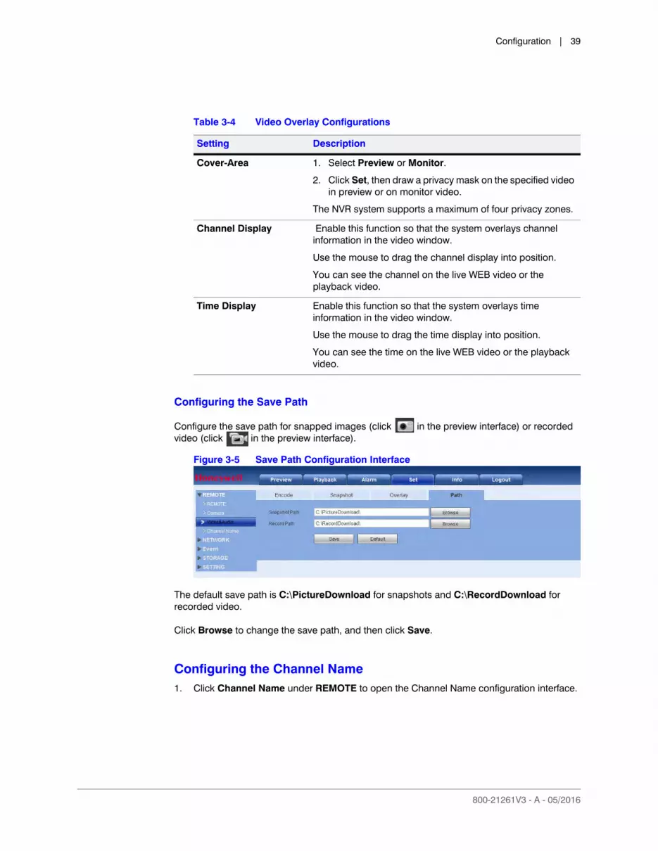
Table 3-4 Video Overlay Configurations . . . . . . . . . . . . . . . . . . . . . . . . . . . . . . . . . . . 39
Table 3-5 TCP/IP Configurations . . . . . . . . . . . . . . . . . . . . . . . . . . . . . . . . . . . . . . . 41
Table 3-6 Network Connection Configurations . . . . . . . . . . . . . . . . . . . . . . . . . . . . . . . . 42
Table 3-7 CDMA/GPRS Configurations . . . . . . . . . . . . . . . . . . . . . . . . . . . . . . . . . . . . 44
Table 3-8 DDNS Configuration Options . . . . . . . . . . . . . . . . . . . . . . . . . . . . . . . . . . . . 46
Table 3-9 DDNS Configurations . . . . . . . . . . . . . . . . . . . . . . . . . . . . . . . . . . . . . . . . 47
Table 3-10 Email Configurations . . . . . . . . . . . . . . . . . . . . . . . . . . . . . . . . . . . . . . . . 50
Table 3-11 FTP Configurations . . . . . . . . . . . . . . . . . . . . . . . . . . . . . . . . . . . . . . . . . 52
Table 3-12 SNMP Configurations. . . . . . . . . . . . . . . . . . . . . . . . . . . . . . . . . . . . . . . . 54
Table 3-13 Switch Configurations . . . . . . . . . . . . . . . . . . . . . . . . . . . . . . . . . . . . . . . 62
Table 3-14 WEB - Motion Detection Configurations . . . . . . . . . . . . . . . . . . . . . . . . . . . . . . 64
Table 3-15 WEB - Alarm Configurations . . . . . . . . . . . . . . . . . . . . . . . . . . . . . . . . . . . . 69
Table 3-16 Configuring for Abnormalities . . . . . . . . . . . . . . . . . . . . . . . . . . . . . . . . . . . 73
Table 3-17 Scheduled Storage Settings . . . . . . . . . . . . . . . . . . . . . . . . . . . . . . . . . . . . 74
Table 3-18 Schedule Configurations. . . . . . . . . . . . . . . . . . . . . . . . . . . . . . . . . . . . . . 76
Table 3-19 Recording Storage Interface . . . . . . . . . . . . . . . . . . . . . . . . . . . . . . . . . . . . 77
Table 3-20 General Settings Configurations . . . . . . . . . . . . . . . . . . . . . . . . . . . . . . . . . . 78
Table 3-21 Date & Time Configurations . . . . . . . . . . . . . . . . . . . . . . . . . . . . . . . . . . . . 79
Table 3-22 GUI Configurations . . . . . . . . . . . . . . . . . . . . . . . . . . . . . . . . . . . . . . . . . 80
Table 3-23 Display Tour Settings . . . . . . . . . . . . . . . . . . . . . . . . . . . . . . . . . . . . . . . . 81
Table 3-24 RS232 Web Configurations. . . . . . . . . . . . . . . . . . . . . . . . . . . . . . . . . . . . . 82
Table 3-25 PAN/TILT/ZOOM Configuration Interface. . . . . . . . . . . . . . . . . . . . . . . . . . . . . . 83
Table 3-26 Import/Export Operations. . . . . . . . . . . . . . . . . . . . . . . . . . . . . . . . . . . . . . 88
Table 5-1 Alarm Configurations . . . . . . . . . . . . . . . . . . . . . . . . . . . . . . . . . . . . . . . . 98

www.honeywell.com/security
12 | Performance Series Full Poe Embedded NVR Remote User Guide

800-21261V3 - A - 05/2016
About This Document
This document describes how to access Honeywell’s Performance Series Full PoE Network Video Recorder remotely using a browser-based web client.
This document is intended primarily for remote users.
Overview of Contents
This document contains the following chapters:
• Chapter 1, Logging In
• Chapter 2, Live Viewing
• Chapter 3, Configuration
• Chapter 4, Playback
• Chapter 5, Alarms
www.honeywell.com/security
14 | Performance Series Full Poe Embedded NVR Remote User Guide
Related Documents
For more information about using the Performance Series Full PoE Network Video Recorder, refer to the following documents:
* These part numbers are subject to change. Please consult the Performance Series Full PoE Network Video Recorder product webpage for the latest versions of these documents.
Document title Part number*
Performance Series IP Network Video Recorder User Guide 800-21090
Performance Series IP NVR Quick Connection Guide 800-21088
Performance Series IP NVR Quick Network Guide 800-21089

800-21261V3 - A - 05/2016
1Logging In 1
This chapter includes:
• PC requirements for the web client software
• Logging in to the web client software
• The web client software’s main page
Preparing to Use the Device Web Client
PC Requirements
Before You Log In
Ensure that the following conditions are met:
• Ensure that the network connection is good.
• Ensure that the NVR and PC network setup is correct. See the network setup: Main MenuSettingNetwork.
• Ping to ensure that the network connection is good. Ping *** *** *** *** (where *** *** *** *** is the NVR’s IP address). The return TTL should be less than 225.
Table 1-1 PC Requirements
Component Minimum Requirement
Processor Quad core
System memory (RAM) 2G or higher
Non-integrated video card 256M or higher

www.honeywell.com/security
16 | Performance Series Full Poe Embedded NVR Remote User Guide
Note Before you uninstall the web control, close all web pages. If you do not, then the uninstallation procedure might result in an error.
• The current NVR supports various browsers such as Apple Safari and Mozilla Firefox. The NVR supports multiple-channel monitoring (depending on your model) on an Apple PC.
Logging In
1. Open a Web browser window.
Note These instructions were created using IE. You can use Internet Explorer (IE), Safari, or FireFox.
Figure 1-1 IE Window
2. Enter the NVR IP address in the address field.
Enter the IP address
Logging In | 17
800-21261V3 - A - 05/2016
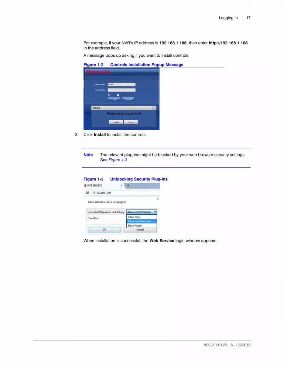
For example, if your NVR’s IP address is 192.168.1.108, then enter http://192.168.1.108 in the address field.
A message pops up asking if you want to install controls.
Figure 1-2 Controls Installation Popup Message
3. Click Install to install the controls.
Note The relevant plug-ins might be blocked by your web browser security settings. See Figure 1-3.
Figure 1-3 Unblocking Security Plug-ins
When installation is successful, the Web Service login window appears.

www.honeywell.com/security
18 | Performance Series Full Poe Embedded NVR Remote User Guide
Figure 1-4 Web Service Login Window
4. Enter your username (default: admin) and password (default: admin), then click Login.
Note For security, we recommend that you modify your password on your first log in.
LAN Mode
The LAN main window is divided into 4 main sections. See Figure 1-5. In LAN mode, you can select different channels and different modes at the bottom of the interface.

Logging In | 19
800-21261V3 - A - 05/2016
Figure 1-5 LAN Mode Main Window
Section 1: Function Buttons
Figure 1-6 LAN Main Window Function Tabs
There are six function tabs:
• Preview: You are currently in the Preview (Live) mode, where you can see all these tabs.
• Playback: See Local Play Button on page 22
• Alarm: See Alarms on page 95
• Setup: See Configuration on page 33
• Info: See Information on page 30
• Logout: See Logging Out on page 25
4
23
1

www.honeywell.com/security
20 | Performance Series Full Poe Embedded NVR Remote User Guide
Section 2: Monitor Channels and Function Buttons
Figure 1-7 Monitor Channels Section and Function Buttons
Monitor Channels
The Monitor Channels section displays monitor channels that are successfully connected to the NVR. Left-click to select a channel for viewing, or click Start All.
Note The Start All button changes to Open All on the GUI.
Main Stream and Extra Stream - Navigate your mouse to a camera channel window to find the Main Stream and the Extra Stream.
The Start All button enables/disables all channels in the real-time monitor. You can also select the Main Stream or the Extra Stream.

Logging In | 21
800-21261V3 - A - 05/2016
Figure 1-8 Main Stream and Extra Stream
Start Talk Button
Figure 1-9 Start Talk Button
Enabling Bi-Directional Communication
1. Click to enable bi-directional communication.
2. Click in the control panel on the right to select the bi-directional communication mode. There are four options for the communication mode: DEFAULT, G711a, G711u, and PCM.
Figure 1-10 Talk Mode Options
Note After you enable bi-directional communication, if the audio input port that goes from the device to the client end is using the first channel audio input port, then the system will not encode the audio data from that one channel. Refer to the Setting Up Bi-Directional Communication Connection section in the User Guide for more about the audio connections.
Disabling Bi-Directional Communication
After turning on Bi-directional Communication, the Start Talk button turns into an End Talk button. Click this button to end bi-directional communication.

www.honeywell.com/security
22 | Performance Series Full Poe Embedded NVR Remote User Guide
Instant Record Button
Figure 1-11 Instant Record Button
Click Instant Record, and the button turns blue. The NVR begins manual recording. Click Instant Record again to restore the NVR to the previous recording mode.
Local Play Button
The NVR can play back saved files (in the.dav format) in the PC.
1. Click Local Play, and an interface appears for selecting the playback file.
Figure 1-12 Local Play - Select a File Interface
2. Select a file, then click Open. A media player opens and plays the selected video.
Section 3: PTZ Control Panel, Image and Alarm Configuration Panels
PTZ Control Panel
Refer to the User Guide for more about controlling PTZ cameras.
Image and Alarm Configuration Panels
Refer to the User Guide or see Configuring Image Settings on page 29 for more information about Image settings.
Refer to the User Guide or see Alarms on page 95 for more information about Alarms.
Logging In | 23
800-21261V3 - A - 05/2016
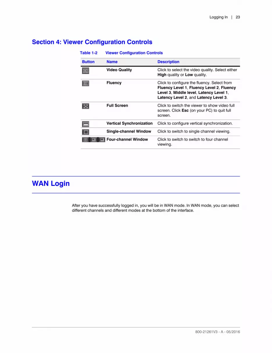
Section 4: Viewer Configuration Controls
WAN Login
After you have successfully logged in, you will be in WAN mode. In WAN mode, you can select different channels and different modes at the bottom of the interface.
Table 1-2 Viewer Configuration Controls
Button Name Description
Video Quality Click to select the video quality. Select either High quality or Low quality.
Fluency Click to configure the fluency. Select from Fluency Level 1, Fluency Level 2, Fluency Level 3, Middle level, Latency Level 1, Latency Level 2, and Latency Level 3.
Full Screen Click to switch the viewer to show video full screen. Click Esc (on your PC) to quit full screen.
Vertical Synchronization Click to configure vertical synchronization.
Single-channel Window Click to switch to single channel viewing.
Four-channel Window Click to switch to switch to four channel viewing.
www.honeywell.com/security
24 | Performance Series Full Poe Embedded NVR Remote User Guide
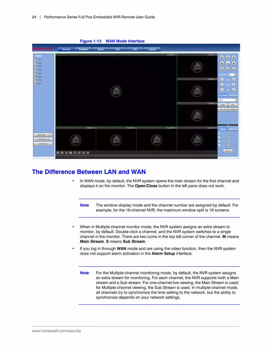
Figure 1-13 WAN Mode Interface
The Difference Between LAN and WAN• In WAN mode, by default, the NVR system opens the main stream for the first channel and
displays it on the monitor. The Open/Close button in the left pane does not work.
Note The window display mode and the channel number are assigned by default. For example, for the 16-channel NVR, the maximum window split is 16 screens.
• When in Multiple-channel monitor mode, the NVR system assigns an extra stream to monitor, by default. Double-click a channel, and the NVR system switches to a single channel in the monitor. There are two icons in the top left corner of the channel. M means Main Stream. S means Sub Stream.
• If you log in through WAN mode and are using the video function, then the NVR system does not support alarm activation in the Alarm Setup interface.
Note For the Multiple-channel monitoring mode, by default, the NVR system assigns an extra stream for monitoring. For each channel, the NVR supports both a Main stream and a Sub stream. For one-channel live viewing, the Main Stream is used; for Multiple-channel viewing, the Sub Stream is used. In multiple-channel mode, all channels try to synchronize the time setting to the network, but the ability to synchronize depends on your network settings.

Logging In | 25
800-21261V3 - A - 05/2016
Note Because of bandwidth limitations, the NVR system can not support monitoring and playback at the same time. To enhance search speed, the NVR system automatically closes the monitoring or playback interface when you are searching for recorded video in the configuration interface.
Logging Out
Click the Logout tab in the Main Menu. The NVR returns to the Login interface.
Figure 1-14 Login Interface
Uninstalling the Web Control
You can use the web un-install tool uninstall_web.bat to uninstall the web control plugin.
Note Before un-installing the web control plugin, close all web pages. If you do not, then you might experience an error.

www.honeywell.com/security
26 | Performance Series Full Poe Embedded NVR Remote User Guide
800-21261V3 - A - 05/2016
2Live Viewing 2
This chapter includes:
• A description of the NVR web client.
• Descriptions of image/relay output settings, including image settings.
• Descriptions of the Information available for viewing in live view, including system version, log, connection log, and online user information.
Live Viewing
Left-click a channel name in Section 2, the Monitors Channel section, to select that channel for viewing.
The video window shows statistics about the video.

www.honeywell.com/security
28 | Performance Series Full Poe Embedded NVR Remote User Guide
Figure 2-1 Live View Video Window
Table 2-1 Live View Video Window Controls
Table 2-2 Live View Video Window Controls
Control Description
Display Device Information
Shows the following information about the video:• IP address• Channel number• Bit rate• Stream: Select either M for Main stream or S for sub stream.
Digital Zoom Click this button and then left drag the mouse in the zone to zoom in. Right-click the mouse to return to the original viewing status.
Local Record When you click the Local Record button, the system/NVR begins recording.
The recorded file is saved to the default system folder: \RecordDownload.
Snapshot Click to take a snapshot of the currently viewed video. All images are saved to the default system folder: \picture download.
StreamChannel Number SnapshotSnapshot Audio
IP Address Bit RateDigital Zoom
Local Record
Close Window
Live Viewing | 29
800-21261V3 - A - 05/2016
Image/Relay-out Settings
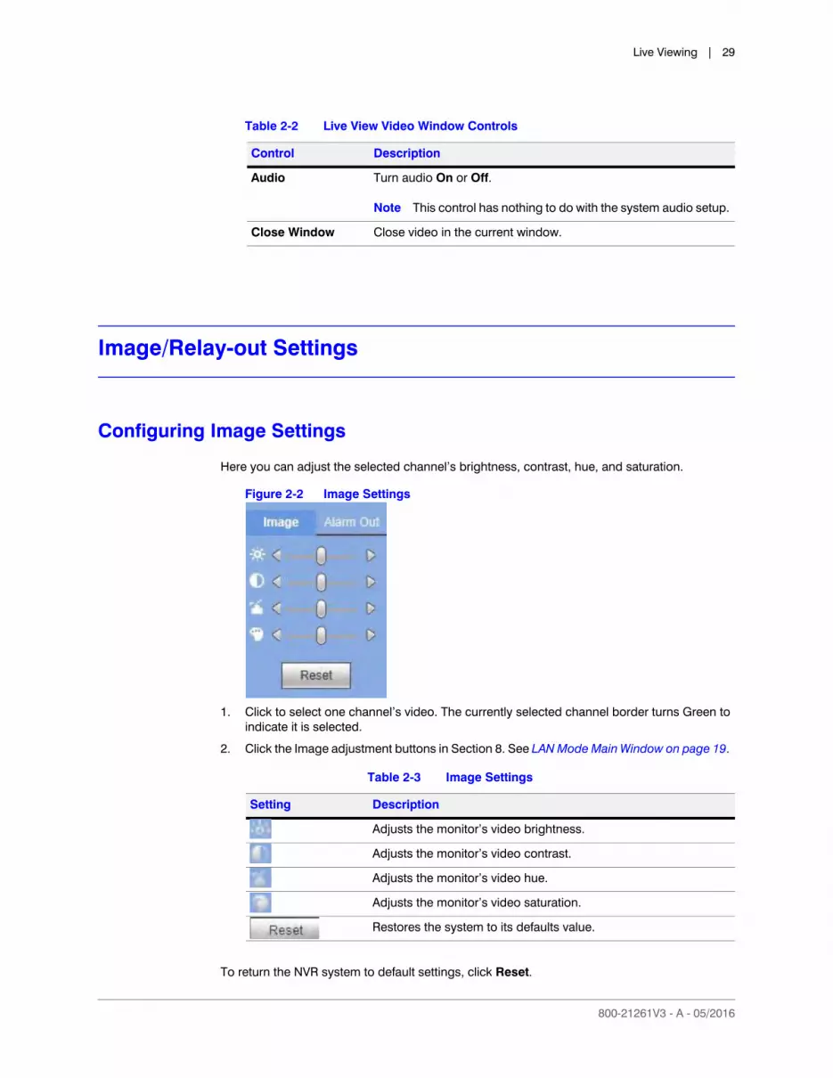
Configuring Image Settings
Here you can adjust the selected channel’s brightness, contrast, hue, and saturation.
Figure 2-2 Image Settings
1. Click to select one channel’s video. The currently selected channel border turns Green to indicate it is selected.
2. Click the Image adjustment buttons in Section 8. See LAN Mode Main Window on page 19.
To return the NVR system to default settings, click Reset.
Audio Turn audio On or Off.
Note This control has nothing to do with the system audio setup.
Close Window Close video in the current window.
Table 2-2 Live View Video Window Controls
Control Description
Table 2-3 Image Settings
Setting Description
Adjusts the monitor’s video brightness.
Adjusts the monitor’s video contrast.
Adjusts the monitor’s video hue.
Adjusts the monitor’s video saturation.
Restores the system to its defaults value.
www.honeywell.com/security
30 | Performance Series Full Poe Embedded NVR Remote User Guide
Note All of these configurations apply to the Web Viewer only.
Information
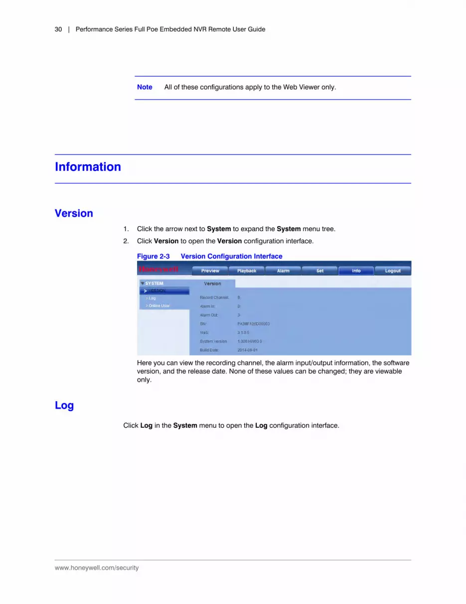
Version1. Click the arrow next to System to expand the System menu tree.
2. Click Version to open the Version configuration interface.
Figure 2-3 Version Configuration Interface
Here you can view the recording channel, the alarm input/output information, the software version, and the release date. None of these values can be changed; they are viewable only.
Log
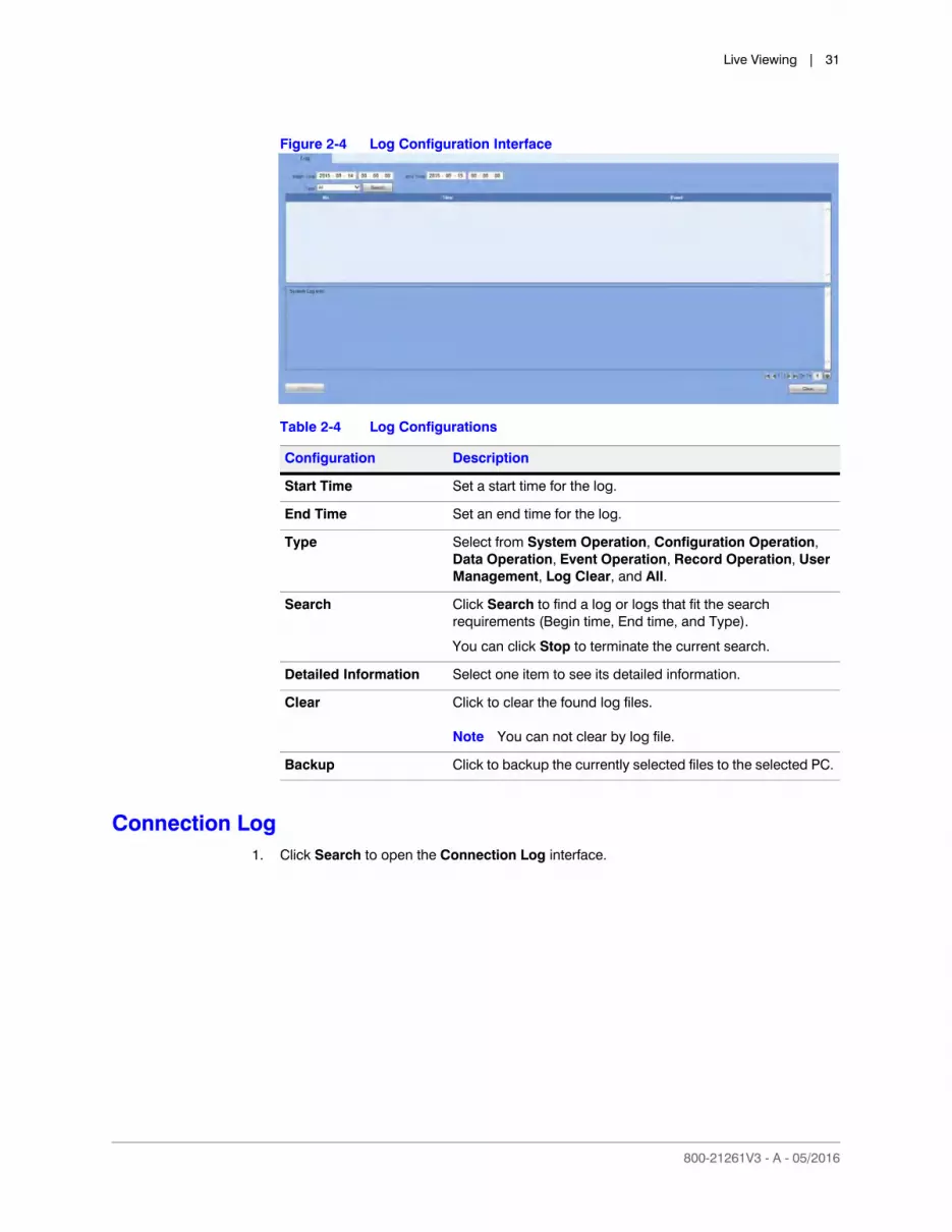
Click Log in the System menu to open the Log configuration interface.
Live Viewing | 31
800-21261V3 - A - 05/2016
Figure 2-4 Log Configuration Interface
Connection Log1. Click Search to open the Connection Log interface.
Table 2-4 Log Configurations
Configuration Description
Start Time Set a start time for the log.
End Time Set an end time for the log.
Type Select from System Operation, Configuration Operation, Data Operation, Event Operation, Record Operation, User Management, Log Clear, and All.
Search Click Search to find a log or logs that fit the search requirements (Begin time, End time, and Type).
You can click Stop to terminate the current search.
Detailed Information Select one item to see its detailed information.
Clear Click to clear the found log files.
Note You can not clear by log file.
Backup Click to backup the currently selected files to the selected PC.

www.honeywell.com/security
32 | Performance Series Full Poe Embedded NVR Remote User Guide
Figure 2-5 Connection Log Interface
2. Set a Start and End Time, select a Channel.
3. Click Search to find the connection log.
Online User
Click Online User in the System menu to open the Online User interface.
Figure 2-6 Online User Configuration Interface
You can see what users are currently online.
800-21261V3 - A - 05/2016
3Configuration 3
This chapter includes descriptions about how to configuring the following:
• Camera setup
• Network setup
• Event settings
• Storage
• General settings, including the following:
• the device’s name and number
• the interface language
• the video standard
• what happens when the HDD is full
• the pack duration
Setup
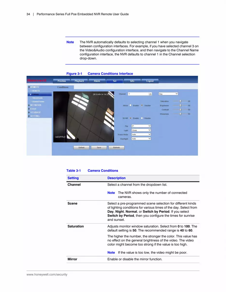
Configuring the Camera Setup through the Remote Interface
If the NVR connects to an IP camera through a private protocol, then the Camera Conditions page displays. If the NVR connects to an IP camera through the ONVIF protocol, then the Camera Conditions does not display.
Configuring Camera Image Settings
In the Camera Conditions window, you can view the camera device properties. Any changes are immediately active after you set them.
Click Camera under REMOTE to open the Conditions interface.
www.honeywell.com/security
34 | Performance Series Full Poe Embedded NVR Remote User Guide
Note The NVR automatically defaults to selecting channel 1 when you navigate between configuration interfaces. For example, if you have selected channel 3 on the Video&Audio configuration interface, and then navigate to the Channel Name configuration interface, the NVR defaults to channel 1 in the Channel selection drop-down.
Figure 3-1 Camera Conditions Interface
Table 3-1 Camera Conditions
Setting Description
Channel Select a channel from the dropdown list.
Note The NVR shows only the number of connected cameras.
Scene Select a pre-programmed scene selection for different kinds of lighting conditions for various times of the day. Select from Day, Night, Normal, or Switch by Period. If you select Switch by Period, then you configure the times for sunrise and sunset.
Saturation Adjusts monitor window saturation. Select from 0 to 100. The default setting is 50. The recommended range is 40 to 60.
The higher the number, the stronger the color. This value has no effect on the general brightness of the video. The video color might become too strong if the value is too high.
Note If the value is too low, the video might be poor.
Mirror Enable or disable the mirror function.

Configuration | 35
800-21261V3 - A - 05/2016
Configuring Encoding Settings
Configuring the Encoding
Click VIDEO&AUDIO under Remote to open the Encoding interface.
Brightness Adjusts the monitor window brightness. The default setting is 50.
The higher the number, the brighter the video. When you select a value, the bright and dark elements of the video are adjusted. Use this function to adjust video brightness when the entire picture is too dark or too bright. Select from 0 to 100. The recommended range is 40 to 60.
Note The video might become washed out if you select a high brightness value.
Contrast Adjusts monitor window contrast. Select from 0 to 100. The default setting is 50. The recommended range is 40 to 60.
The higher the value, the higher the contrast between light and dark elements in the image. Use when the video brightness is good, but the contrast is not.
The video might become washed out if you select a low contrast value. If the value is too high, the dark sections might lose brightness and the light parts might become overexposed.
Sharpness Affects the edge definition of objects in the image. The higher the setting, the more image detail is apparent.
Note Noise in the image might become noticeable at higher settings.
Period Divide a day (24-hour period) into two periods, then set different sharpness, brightness, contrast, saturation, and gain settings for each period.
3D NR Enable/disable 3D noise reduction.
Flip Select an angle on which the video will be flipped.
Light Adjust Backlight Compensation. Select either Low or High.
Scene Mode Select from several configured color modes such as Auto, Sunny, Night, or Customized. Selecting a Scene Mode will adjust the hue, brightness, and contrast of the video. If you select Customized, then you select the hue, brightness, and contrast of the video.
Day/Night Select from Colorful, Auto, or B/W.
Table 3-1 Camera Conditions
Setting Description

www.honeywell.com/security
36 | Performance Series Full Poe Embedded NVR Remote User Guide
Figure 3-2 Encoding Interface
Note If the NVR fails to retrieve the configuration information for your selected camera/channel, then you should navigate to a different window (such as Snapshot or Overlay), then navigate back to the Encode window.
Table 3-2 Encoding Configurations
Setting Description
Channel Select a channel from the dropdown list
Code Stream Type Select from Main Stream, Motion Stream, and Alarm Stream. You can select different encoding frame rates for different recorded events.
The NVR system supports active control frame function (ACF), which allows you to record in different frame rates.
For example, you can use a high frame rate to record important events, and configure a lower frame rate for recording scheduled events. ACF allows you to set different frame rates for motion detection recording and alarm recording.
Video Enable Click to enable the extra video stream. Enabled by default.
Compression The main bit stream supports H.264. The extra stream supports H.264 and MJPG.

Configuration | 37
800-21261V3 - A - 05/2016
Configuring Snapshot Settings
Figure 3-3 Snapshot Settings Interface
Resolution The NVR system supports various resolutions, which you can select from a dropdown list.
Note The selection is different for each NVR series. The Performance Series Full PoE Network Video Recorders can automatically detect a connected 720p or 1080p camera’s configured resolution (as 720p or 1080p) But you must manually configure the resolution (960H or below) for analog cameras, and 1080p HQA cameras that are in SD mode.
Frame Rate PAL: 1 to 25 fpsNTSC: 1 to 30 fps
Bit Rate Type Select either CBR (constant bit rate) or VBR (variable bit rate).
Note If your device is connected to the NVR through ONVIF, then you can not select VBR. If your device is connected to the NVR through a private protocol, then you can select either CBR or VBR.
Bit Rate Main Stream: Select a bit rate to change the video quality. The larger the bit rate, the better the video quality. We recommend that you accept the default bit rate. The GUI also displays the reference bit rate range and frame rate for the selected resolution.
Extra Stream: In DBR, the bit rate is the maximum value. For dynamic video, the NVR system will decrease the frame rate or video quality to maintain the bit rate. The value is null for VBR mode.
Enable Watermark Allows you to verify that the video has not been tampered.
Watermark String Enter the text for the watermark. The default watermark is DigitalCCTV. The maximum text length is 85 characters. You can use only letters, numbers, and an underline.
Table 3-2 Encoding Configurations
Setting Description
www.honeywell.com/security
38 | Performance Series Full Poe Embedded NVR Remote User Guide
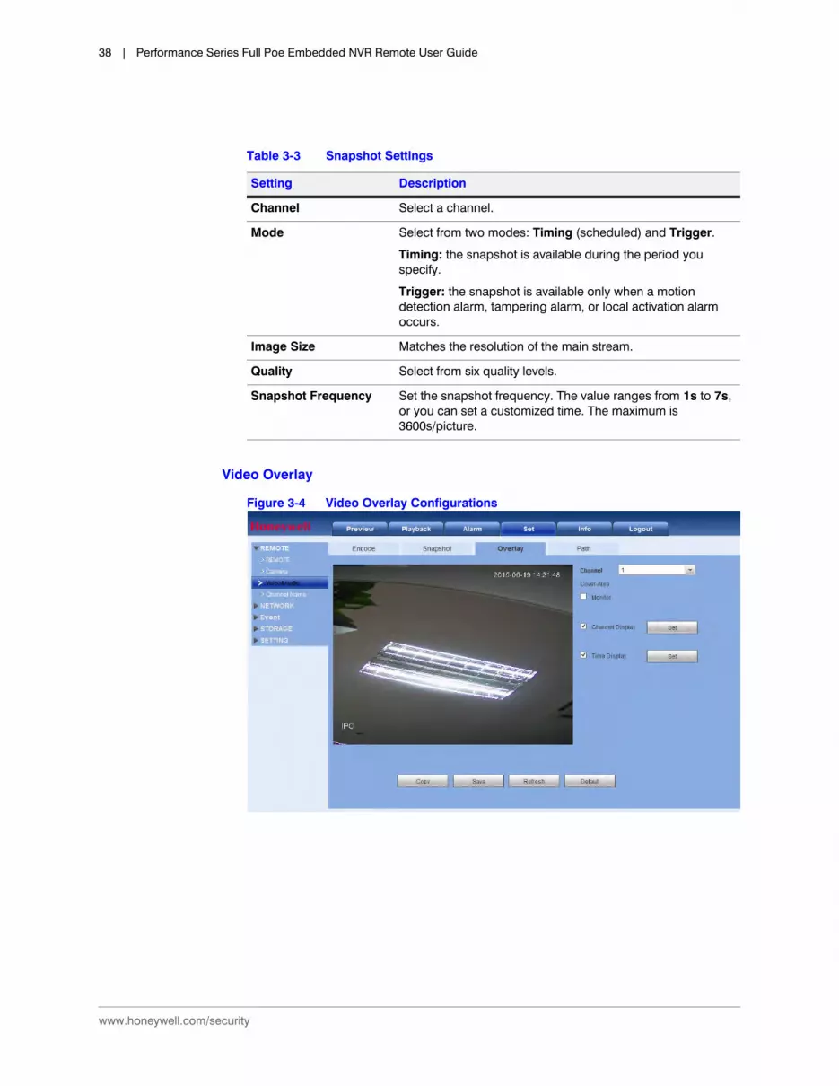
Video Overlay
Figure 3-4 Video Overlay Configurations
Table 3-3 Snapshot Settings
Setting Description
Channel Select a channel.
Mode Select from two modes: Timing (scheduled) and Trigger.
Timing: the snapshot is available during the period you specify.
Trigger: the snapshot is available only when a motion detection alarm, tampering alarm, or local activation alarm occurs.
Image Size Matches the resolution of the main stream.
Quality Select from six quality levels.
Snapshot Frequency Set the snapshot frequency. The value ranges from 1s to 7s, or you can set a customized time. The maximum is 3600s/picture.
Configuration | 39
800-21261V3 - A - 05/2016
Configuring the Save Path
Configure the save path for snapped images (click in the preview interface) or recorded video (click in the preview interface).
Figure 3-5 Save Path Configuration Interface
The default save path is C:\PictureDownload for snapshots and C:\RecordDownload for recorded video.
Click Browse to change the save path, and then click Save.
Configuring the Channel Name1. Click Channel Name under REMOTE to open the Channel Name configuration interface.
Table 3-4 Video Overlay Configurations
Setting Description
Cover-Area 1. Select Preview or Monitor.
2. Click Set, then draw a privacy mask on the specified video in preview or on monitor video.
The NVR system supports a maximum of four privacy zones.
Channel Display Enable this function so that the system overlays channel information in the video window.
Use the mouse to drag the channel display into position.
You can see the channel on the live WEB video or the playback video.
Time Display Enable this function so that the system overlays time information in the video window.
Use the mouse to drag the time display into position.
You can see the time on the live WEB video or the playback video.

www.honeywell.com/security
40 | Performance Series Full Poe Embedded NVR Remote User Guide
Figure 3-6 Channel Name Configuration Interface
2. Enter a new channel name, then click Save.
Configuring the Network Setup
Configuring TCP/IP
Click TCP/IP under NETWORK to open the TCP/IP configuration interface.

Configuration | 41
800-21261V3 - A - 05/2016
Figure 3-7 TCP/IP Configuration Interface
Table 3-5 TCP/IP Configurations
Configuration Description
Mode There are two modes: STATIC and DHCP. • The IP address, submask, and gateway is inactive and
not configurable when you select the DHCP mode to automatically search for the IP address.
• If you select STATIC mode, then you need to manually configure the IP address, submask, and gateway.
• If you select DHCP mode, then you can only view the IP address, submask, and gateway. You can not configure these values.
• If you switch from the DHCP mode to the static mode, then you need to reset the IP parameters.
• The IP address, submask, gateway, and DHCP are read-only values when the PPPoE dial is OK.
MAC Address Displays the MAC address. This field is not configurable.
MTU Use the default MTU (maximum transmission unit) value.
IP Version Select the IP version, either IPv4 or IPv6.
You can use either version to access the camera’s IP address.
IP Address 1. Use your PC’s keyboard to enter the IP address.
2. Set the Subnet mask and Default gateway.
Subnet Mask If you selected the STATIC mode, then enter a Subnet Mask value.
Default Gateway If you selected the STATIC mode, then enter a Default Gateway value.
Preferred DNS Enter the DNS IP address.

www.honeywell.com/security
42 | Performance Series Full Poe Embedded NVR Remote User Guide
Configuring the Connection
Click Connection under NETWORK to open the Connection configuration interface.
Figure 3-8 Connection Configuration Interface
Alternate DNS Enter an alternate DNS IP address.
Note For the IPv6 version IP address, the Preferred DNS and Alternate DNS shall be no more the 128 digits. They also can not be left blank.
LAN Download Enable this function so that the system can process the downloaded data first. The download speed is 1.5X or 2.0X of the normal speed.
Table 3-5 TCP/IP Configurations
Configuration Description
Table 3-6 Network Connection Configurations
Configuration Description
Max Connection The maximum Web connection for the same NVR. The value ranges from 1 to 20. The default is 20.
TCP Port The default is 37777. You can enter the actual port number, if necessary.
UDP Port The default is 37778. You can enter the actual port number, if necessary.
HTTP Port The default is 80. You can enter the actual port number, if necessary.
RTSP Port The default is 554.
RTSP Format A non-configurable field that shows the RTSP format.

Configuration | 43
800-21261V3 - A - 05/2016
Configuring WIFI
Note This section applies only to devices with Wifi capability, such as tablet computers, smartphones, and laptop computers.
1. Click Wifi under NETWORK to open the Wifi configuration interface.
Figure 3-9 Wifi Configuration Interface
2. Click to enable Wifi.
3. Double-click the name of a wireless device to connect to it.
Note Click Refresh to update the list of wireless network information.
Configuring 3G
Configuring CDMA/GPRS
1. Click 3G under NETWORK to open the 3G configuration interface.
2. Click the CDMA/GPRS tab to open the CDMA/GPRS configuration interface.

www.honeywell.com/security
44 | Performance Series Full Poe Embedded NVR Remote User Guide
Figure 3-10 CDMA/GPRS Configuration Interface
Table 3-7 CDMA/GPRS Configurations
Configuration Description
WLAN Type Select a 3G network type to distinguish this 3G module from different ISPs. Choose from WCDMA, CDMA1x, for example.
APN & Dial No. APN and the Dial No. are important PPPoE parameters. The APN (Access Point Name) and the Dial No. are automatically received by the NVR after connecting to a 3G module.
Dial/SMS Activate Enable/disable Dial/SMS Activate. When enabled, if the user sends an "ON" message by phone to the NVR, then the NVR dials and connects with CDMA/GPRS. If the user sends an "OFF" message by phone to the NVR, then the NVR breaks the link with CDMA/GPRS.
AUTH Authorization. Choose from PAP, CHAP, or NO_AUTH.
Username / Password Enter a username and password for logging onto the 3G network.
Pulse Interval Configure a time for ending the 3G connection after you close the extra stream monitor. For example, if you select 60 here, the NVR ends the 3G connection 60 seconds after you close the extra stream monitor.
Configuration | 45
800-21261V3 - A - 05/2016
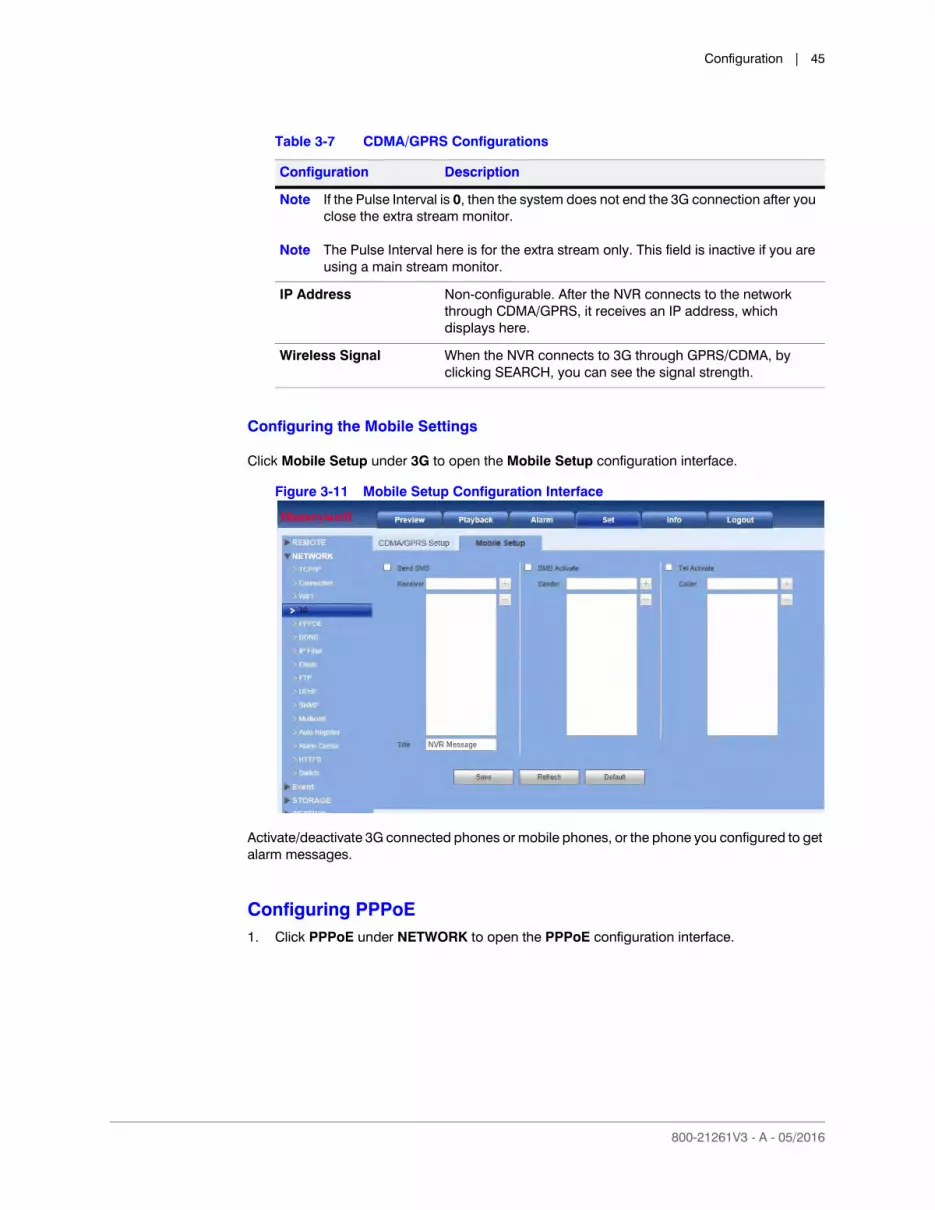
Configuring the Mobile Settings
Click Mobile Setup under 3G to open the Mobile Setup configuration interface.
Figure 3-11 Mobile Setup Configuration Interface
Activate/deactivate 3G connected phones or mobile phones, or the phone you configured to get alarm messages.
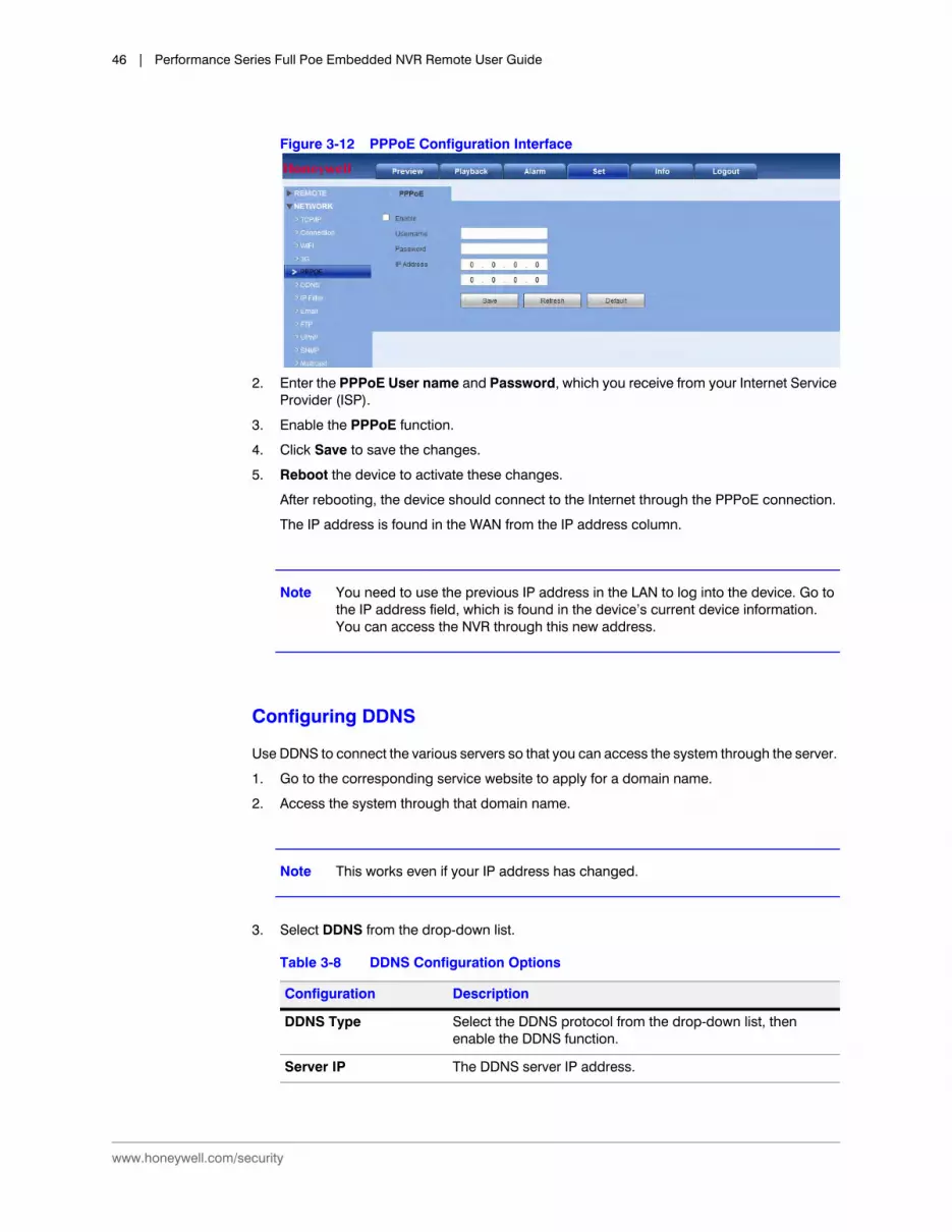
Configuring PPPoE1. Click PPPoE under NETWORK to open the PPPoE configuration interface.
Note If the Pulse Interval is 0, then the system does not end the 3G connection after you close the extra stream monitor.
Note The Pulse Interval here is for the extra stream only. This field is inactive if you are using a main stream monitor.
IP Address Non-configurable. After the NVR connects to the network through CDMA/GPRS, it receives an IP address, which displays here.
Wireless Signal When the NVR connects to 3G through GPRS/CDMA, by clicking SEARCH, you can see the signal strength.
Table 3-7 CDMA/GPRS Configurations
Configuration Description
www.honeywell.com/security
46 | Performance Series Full Poe Embedded NVR Remote User Guide
Figure 3-12 PPPoE Configuration Interface
2. Enter the PPPoE User name and Password, which you receive from your Internet Service Provider (ISP).
3. Enable the PPPoE function.
4. Click Save to save the changes.
5. Reboot the device to activate these changes.
After rebooting, the device should connect to the Internet through the PPPoE connection.
The IP address is found in the WAN from the IP address column.
Note You need to use the previous IP address in the LAN to log into the device. Go to the IP address field, which is found in the device’s current device information. You can access the NVR through this new address.
Configuring DDNS
Use DDNS to connect the various servers so that you can access the system through the server.
1. Go to the corresponding service website to apply for a domain name.
2. Access the system through that domain name.
Note This works even if your IP address has changed.
3. Select DDNS from the drop-down list.
Table 3-8 DDNS Configuration Options
Configuration Description
DDNS Type Select the DDNS protocol from the drop-down list, then enable the DDNS function.
Server IP The DDNS server IP address.
Configuration | 47
800-21261V3 - A - 05/2016
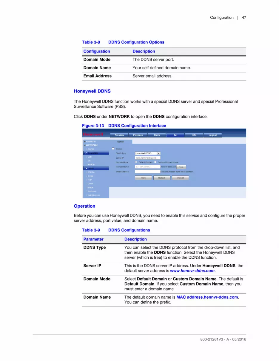
Honeywell DDNS
The Honeywell DDNS function works with a special DDNS server and special Professional Surveillance Software (PSS).
Click DDNS under NETWORK to open the DDNS configuration interface.
Figure 3-13 DDNS Configuration Interface
Operation
Before you can use Honeywell DDNS, you need to enable this service and configure the proper server address, port value, and domain name.
Domain Mode The DDNS server port.
Domain Name Your self-defined domain name.
Email Address Server email address.
Table 3-8 DDNS Configuration Options
Configuration Description
Table 3-9 DDNS Configurations
Parameter Description
DDNS Type You can select the DDNS protocol from the drop-down list, and then enable the DDNS function. Select the Honeywell DDNS server (which is free) to enable the DDNS function.
Server IP This is the DDNS server IP address. Under Honeywell DDNS, the default server address is www.hennvr-ddns.com.
Domain Mode Select Default Domain or Custom Domain Name. The default is Default Domain. If you select Custom Domain Name, then you must enter a domain name.
Domain Name The default domain name is MAC address.hennvr-ddns.com. You can define the prefix.
www.honeywell.com/security
48 | Performance Series Full Poe Embedded NVR Remote User Guide
Note Do not register frequently. You need to wait at least 60 seconds between registration requests. Too many registration requests might leave your server vulnerable to attacks.
Note The system DDNS server might take back a domain name that is idle for one year. If you configure your email address in the DDNS configuration, you will get a notification email before the domain name is taken back.
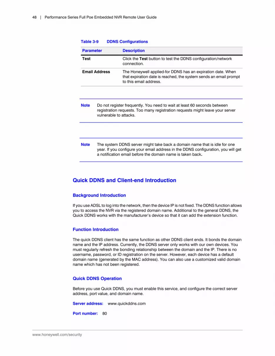
Quick DDNS and Client-end Introduction
Background Introduction
If you use ADSL to log into the network, then the device IP is not fixed. The DDNS function allows you to access the NVR via the registered domain name. Additional to the general DDNS, the Quick DDNS works with the manufacturer’s device so that it can add the extension function.
Function Introduction
The quick DDNS client has the same function as other DDNS client ends. It bonds the domain name and the IP address. Currently, the DDNS server only works with our own devices. You must regularly refresh the bonding relationship between the domain and the IP. There is no username, password, or ID registration on the server. However, each device has a default domain name (generated by the MAC address). You can also use a customized valid domain name which has not been registered.
Quick DDNS Operation
Before you use Quick DDNS, you must enable this service, and configure the correct server address, port value, and domain name.
Server address: www.quickddns.com
Port number: 80
Test Click the Test button to test the DDNS configuration/network connection.
Email Address The Honeywell applied-for DDNS has an expiration date. When that expiration date is reached, the system sends an email prompt to this email address.
Table 3-9 DDNS Configurations
Parameter Description
Configuration | 49
800-21261V3 - A - 05/2016
Domain name: There are two modes: Default domain name and customized domain name. Except for the default domain name registration, you can also use a customized domain name. After you have successfully registered a domain name, you can log in using it instead of the device IP.
User name: Optional. Enter your email address.
IMPORTANT! Do not register frequently. You must wait at least 60 seconds between attempts at logging in. Too many attempts might cause a server crash.
The system might take back a domain name if it is idle for one year. If your email is set up correctly, you will get an email notification before the domain name is canceled.
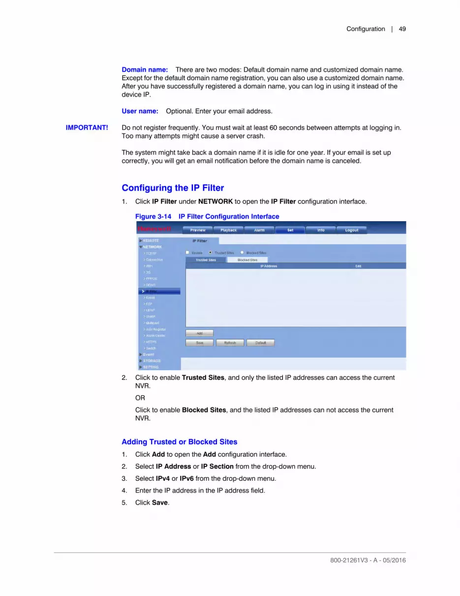
Configuring the IP Filter1. Click IP Filter under NETWORK to open the IP Filter configuration interface.
Figure 3-14 IP Filter Configuration Interface
2. Click to enable Trusted Sites, and only the listed IP addresses can access the current NVR.
OR
Click to enable Blocked Sites, and the listed IP addresses can not access the current NVR.
Adding Trusted or Blocked Sites
1. Click Add to open the Add configuration interface.
2. Select IP Address or IP Section from the drop-down menu.
3. Select IPv4 or IPv6 from the drop-down menu.
4. Enter the IP address in the IP address field.
5. Click Save.
www.honeywell.com/security
50 | Performance Series Full Poe Embedded NVR Remote User Guide
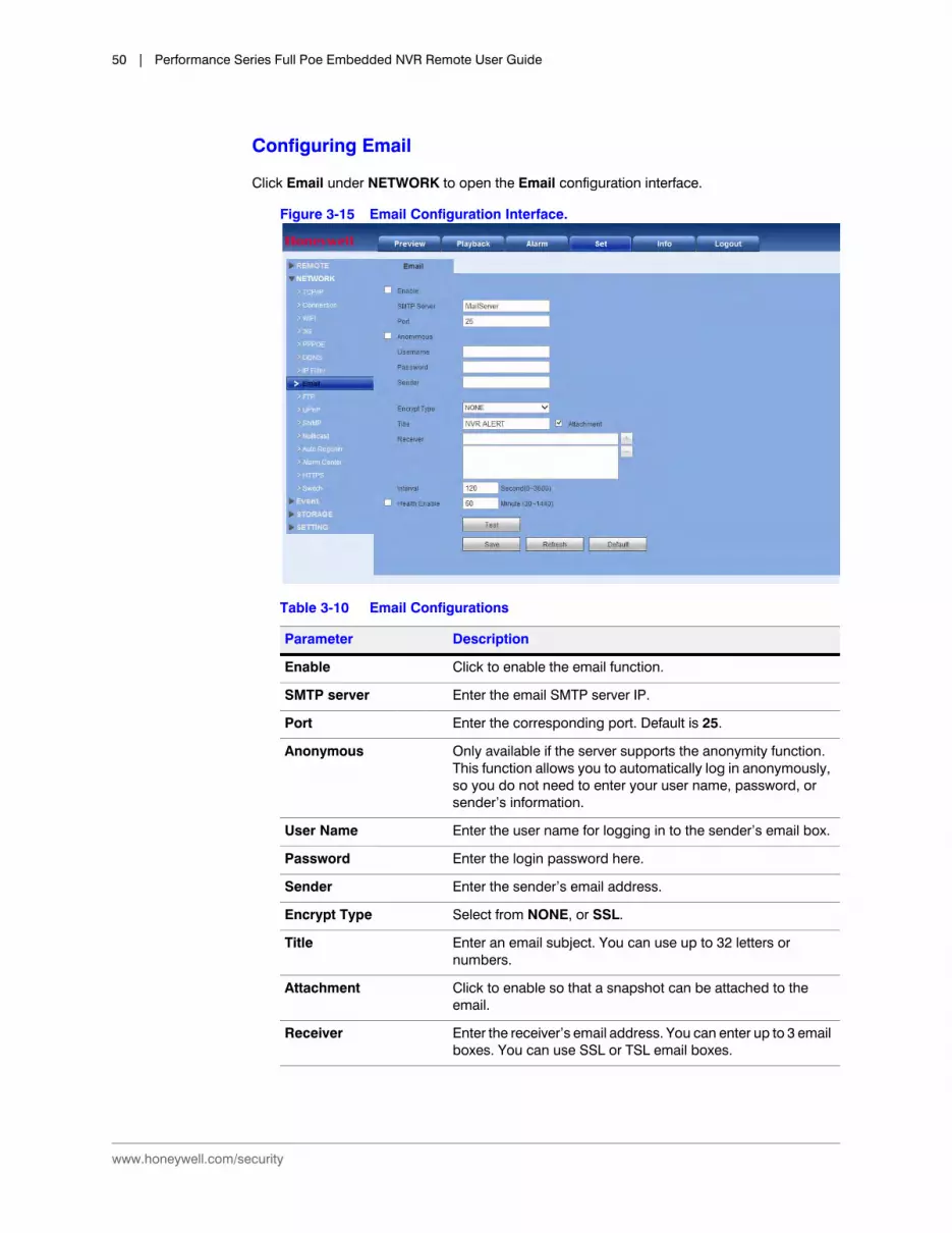
Configuring Email
Click Email under NETWORK to open the Email configuration interface.
Figure 3-15 Email Configuration Interface.
Table 3-10 Email Configurations
Parameter Description
Enable Click to enable the email function.
SMTP server Enter the email SMTP server IP.
Port Enter the corresponding port. Default is 25.
Anonymous Only available if the server supports the anonymity function. This function allows you to automatically log in anonymously, so you do not need to enter your user name, password, or sender’s information.
User Name Enter the user name for logging in to the sender’s email box.
Password Enter the login password here.
Sender Enter the sender’s email address.
Encrypt Type Select from NONE, or SSL.
Title Enter an email subject. You can use up to 32 letters or numbers.
Attachment Click to enable so that a snapshot can be attached to the email.
Receiver Enter the receiver’s email address. You can enter up to 3 email boxes. You can use SSL or TSL email boxes.

Configuration | 51
800-21261V3 - A - 05/2016
Configuring FTP
FTP allows you to configure settings for remote storage. Before you can enable FTP, you must download or buy an FTP service tool. Refer to the Network Settings chapter of your User Guide for more information.
Click FTP under NETWORK to open the FTP configuration interface.
Figure 3-16 FTP Configuration Interface
Interval The interval for sending ranges from 0 to 3600 seconds. 0 means that there is no interval.
Note The system will not send an email immediately when the alarm occurs. When an alarm, motion detection, or video abnormality triggers an email, the system sends out the email according to the interval that is specified here. This function is very useful when there are too many emails activated by events, which might result in an overload for the email server.
Health enable Click to enable the email health check. The NVR sends a test email to check the network connection.
After enabling Health Enable, you can configure how frequently the NVR sends out emails to test the network connection.
Update Period (Interval) Allows the system to send out a test email to check the connection.
Check the box to enable this function, and then set the corresponding interval for the system to send out regular test emails.
Test Click Test to send a test email. A popup message appears to indicate the state of the network connection.
Table 3-10 Email Configurations
Parameter Description

www.honeywell.com/security
52 | Performance Series Full Poe Embedded NVR Remote User Guide
Click Test to test the FTP connection. A popup window shows the status of the connection.
Configuring UPnP
UPnP allows you to establish the mapping relationship between the LAN and the public network. Here you can also add, modify, or remove a UPnP item.
Preparing for UPnP
1. In the Windows OS, click StartControl PanelAdd or remove programs.
2. Click Add/Remove Windows Components, and then select Network Services from the Windows Component Wizard.
3. Click Details, then check Internet Gateway Device Discovery and Control client and UPnP User Interface. Then click OK to begin the installation.
4. Enable UPnP from the internet. If your UPnP is enabled in the Windows OS, then the NVR can automatically detect it through the My Network Places.
Configuring UPnP
1. Click UPnP in the NETWORK configuration interface to open the UPnP configuration interface.
Table 3-11 FTP Configurations
Setting Description
Server IP Enter the IP address for the server.
Port Enter the Port number for the server.
Username Enter the user name for logging into the server.
Password Enter the password for logging into the server.
Anonymous Click to enable/disable anonymously logging into the server.
Remote Directory When the remote directory is null, the NVR automatically creates folders according to the IP, time, and channel.
File Length Here you determine the size of the upload file. If the setup file size is larger than the actual file, then the system uploads the entire file. If the setup file size is smaller than the actual file, then the system uploads only the set file size. If you enter 0 here, then the system uploads all corresponding files.
Image Upload Interval
This is the interval that the CVR waits through before uploading an image to the FTP site. Select from 0 to 3600 seconds. 0 means that there is no interval.
Channel Select a channel.
Weekday Select a weekday.
Time Periods You can configure up to two time periods per channel.
Recording Type Select from Alarm, Motion, or Regular.

Configuration | 53
800-21261V3 - A - 05/2016
Figure 3-17 UPnP Configuration Interface
2. Configure the following settings:
3. (Optional) Add, edit, or delete a mapping relationship from the Port Mapping List:
Add a mapping relationship: Click Add and then, in the Port Info dialog box, select the Protocol (TCP or UDP), enter the Internal Port and External Port details, and then click OK. To ensure data transmission, the internal and external ports should be the same. Avoid using ports 1 to 255 or 256 to 1023.
Edit a mapping relationship: Click the mapping relationship that you want to edit, and then, in the Port Info dialog box, edit the Service Name, Protocol, Internal Port, and/or External Port details, and then click OK.
Delete a mapping relationship: Click the mapping relationship that you want to delete, and then click Delete.
4. Click Apply to save your settings.
5. Click OK to exit the Setting menu.
Configuring SNMP
SNMP allows the communication between the network management work station software and the proxy of the managed device. It is reserved for a third party developer.
Click SNMP under NETWORK to open the SNMP configuration interface.
Enable Click to enable or disable UPnP.
LAN IP Enter the NVR’s IP address from the TCP/IP page.
WAN IP Enter the router’s IP address.

www.honeywell.com/security
54 | Performance Series Full Poe Embedded NVR Remote User Guide
Figure 3-18 SNMP Configuration Interface
Table 3-12 SNMP Configurations
Configuration Description
SNMP Port The listening port of the proxy program of the NVR. It is a UDP port, not a TCP port. This value ranges from 1 to 65535. The default is 161.
Read Community This is a string, and it is a command between the managing processes and the proxy process. Read Community defines the authentication, the access control, and the management relationship between one proxy and one managers’ group. Ensure that the device and the proxy are the same. The Read Community reads all the objects the SNMP supports in the specified name. The default is Public.
Write Community This is a string, and it is a command between the managing processes and the proxy process. It defines the authentication, the access control, and the management relationship between one proxy and one manager’s group. Ensure that the device and the proxy are the same. The Write Community reads, writes, and/or accesses all of the objects the SNMP supports in the specified name. The default is Write.
Trap Address The Trap information destination address from the device’s proxy program.
Trap Port The Trap information destination port from the device’s proxy program. The Trap port allows the gateway device and the client-end PC in the LAN to exchange information.
SNMP Version If you check V1, then the system processes only the V1 information.
If you check V2, then the system processes only the V2 information.

Configuration | 55
800-21261V3 - A - 05/2016
Multicast
Multicast is a transmission mode for data packets. When there are multiple hosts to receive the same data packets, multiple cast is the best option for reducing the bandwidth and the CPU load. The source host can send out just one data for transit. This function also depends on the relationship of the group member and the router group.
1. Click Multicast under NETWORK to open the Multicast configuration interface.
Figure 3-19 Multicast Configuration Interface
2. Select Enable to enable multicast.
3. Enter a multicast IP address in the IP Address box. The address must be valid for multicasting and should be in the range 224.0.0.0 to 239.255.255.255 for IPv4 or have the prefix ff00::/8. An address in the range 239.252.0.0 to 239.255.255.255 is recommended.
4. Enter a multicast port number in the Port box, or use the default setting (36666).
5. Click Apply to save your settings.
6. Click OK to exit the Setting menu.
Auto-Registration
Auto Register allows the device to automatically register to the proxy you have specified. This allows you to use the client-end to access the NVR through the proxy. The proxy acts as a switch. In network service, the device supports IPv4 server addresses or domains.
1. Click Auto Register under NETWORK to open the Auto Register configuration interface.
www.honeywell.com/security
56 | Performance Series Full Poe Embedded NVR Remote User Guide
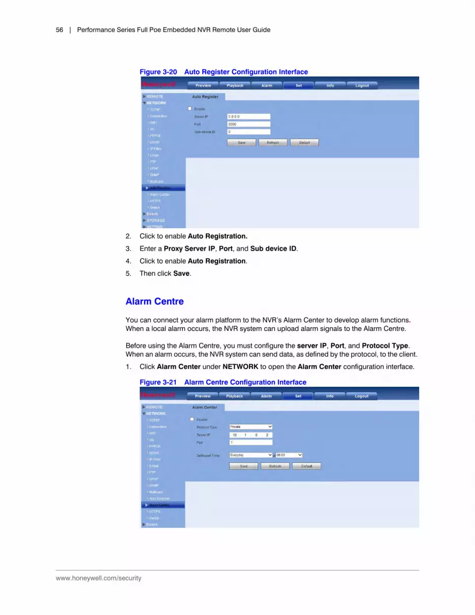
Figure 3-20 Auto Register Configuration Interface
2. Click to enable Auto Registration.
3. Enter a Proxy Server IP, Port, and Sub device ID.
4. Click to enable Auto Registration.
5. Then click Save.
Alarm Centre
You can connect your alarm platform to the NVR’s Alarm Center to develop alarm functions. When a local alarm occurs, the NVR system can upload alarm signals to the Alarm Centre.
Before using the Alarm Centre, you must configure the server IP, Port, and Protocol Type. When an alarm occurs, the NVR system can send data, as defined by the protocol, to the client.
1. Click Alarm Center under NETWORK to open the Alarm Center configuration interface.
Figure 3-21 Alarm Centre Configuration Interface
Configuration | 57
800-21261V3 - A - 05/2016
HTTPS
With these settings, you can ensure that the PC successfully logs in through HTTPS to guarantee communication data security. This reliable and stable technology can secure user information and device safety.
Note If you have changed the device’s IP, then you’ll need to implement the server certificate again.
Note If this is your first time to use HTTPS on your PC, then you’ll need to download the root certificate.
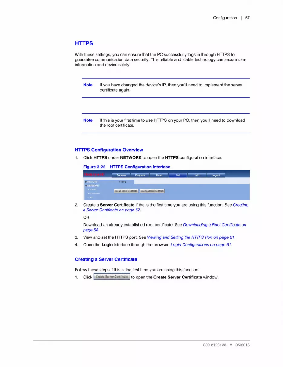
HTTPS Configuration Overview
1. Click HTTPS under NETWORK to open the HTTPS configuration interface.
Figure 3-22 HTTPS Configuration Interface
2. Create a Server Certificate if the is the first time you are using this function. See Creating a Server Certificate on page 57.
OR
Download an already established root certificate. See Downloading a Root Certificate on page 58.
3. View and set the HTTPS port. See Viewing and Setting the HTTPS Port on page 61.
4. Open the Login interface through the browser. Login Configurations on page 61.
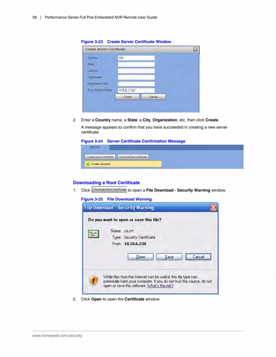
Creating a Server Certificate
Follow these steps if this is the first time you are using this function.
1. Click to open the Create Server Certificate window.
www.honeywell.com/security
58 | Performance Series Full Poe Embedded NVR Remote User Guide
Figure 3-23 Create Server Certificate Window
2. Enter a Country name, a State, a City, Organization, etc, then click Create.
A message appears to confirm that you have succeeded in creating a new server certificate.
Figure 3-24 Server Certificate Confirmation Message
Downloading a Root Certificate
1. Click to open a File Download - Security Warning window.
Figure 3-25 File Download Warning
2. Click Open to open the Certificate window.
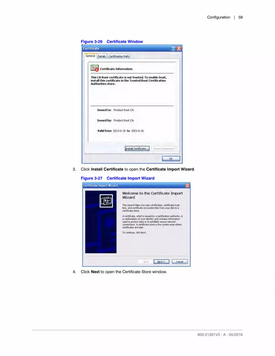
Configuration | 59
800-21261V3 - A - 05/2016
Figure 3-26 Certificate Window
3. Click Install Certificate to open the Certificate Import Wizard.
Figure 3-27 Certificate Import Wizard
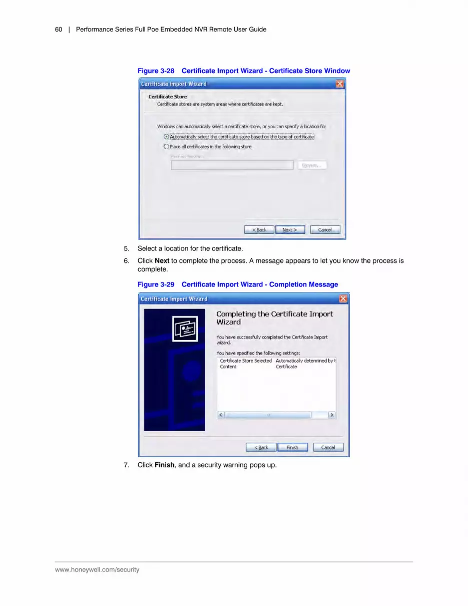
4. Click Next to open the Certificate Store window.
www.honeywell.com/security
60 | Performance Series Full Poe Embedded NVR Remote User Guide
Figure 3-28 Certificate Import Wizard - Certificate Store Window
5. Select a location for the certificate.
6. Click Next to complete the process. A message appears to let you know the process is complete.
Figure 3-29 Certificate Import Wizard - Completion Message
7. Click Finish, and a security warning pops up.

Configuration | 61
800-21261V3 - A - 05/2016
Figure 3-30 Security Warning
8. Click Yes. When the installation is complete, a confirmation message appears.
Figure 3-31 Certificate Import - Confirmation Message
Viewing and Setting the HTTPS Port
Click Connection under Network to open the Connection interface.
Figure 3-32 Connection Interface
Login Configurations
1. Open the browser, then enter https://xx.xx.xx.xx:port, where xx.xx.xx.xx is your device’s IP or domain name.
The port is your HTTPS port. If you are using 443 (the default HTTPS value), then you do not need to add port information here.
2. Enter https://xx.xx.xx.xx to access.
If you have the correct settings, then you should see the login interface.

www.honeywell.com/security
62 | Performance Series Full Poe Embedded NVR Remote User Guide
Configuring Switch Settings
You can change the IP Address, Subnet Mask, and Default Gateway for setting the PoE switch settings.
1. Click Switch under Network to open the Switch interface.
Figure 3-33 Switch Configuration Interface
2. Configure the following settings:
3. Click Apply to save your settings.
Configuring Event Settings
Configuring Video Detection
Motion Detection Configurations
You can configure the system to generate a motion detection alarm when the minimum amount of motion (as defined by you) is detected in the video.
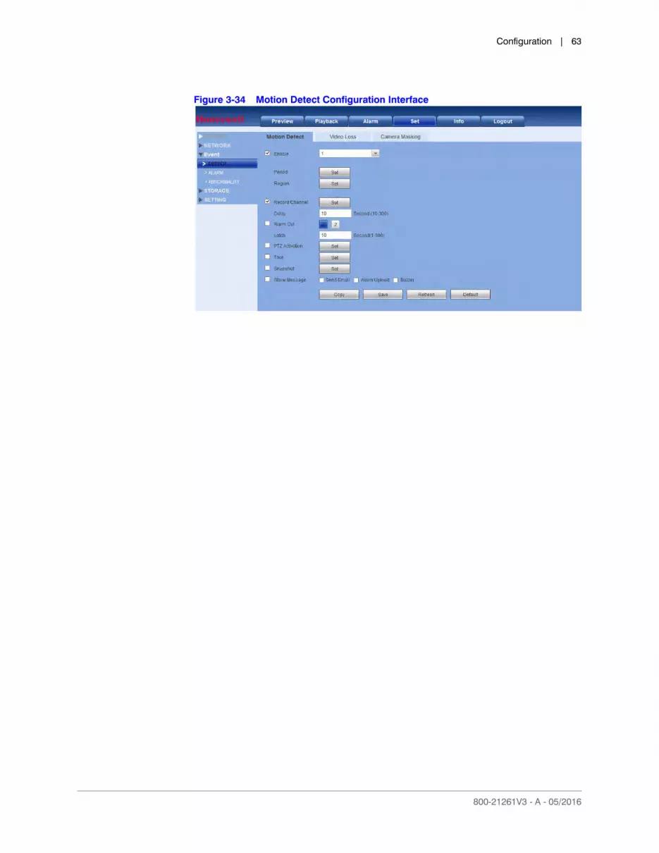
Click Detect under EVENT to open the Motion Detect configuration interface.
Table 3-13 Switch Configurations
Configuration Description
IP Address Enter a new IP address.
Subnet Mask Enter a new subnet mask.
Default Gateway Enter a new default gateway.
Configuration | 63
800-21261V3 - A - 05/2016
Figure 3-34 Motion Detect Configuration Interface
www.honeywell.com/security
64 | Performance Series Full Poe Embedded NVR Remote User Guide
Table 3-14 WEB - Motion Detection Configurations
Configuration Description
Enable Click to enable motion detection. Select a channel from the drop-down list.
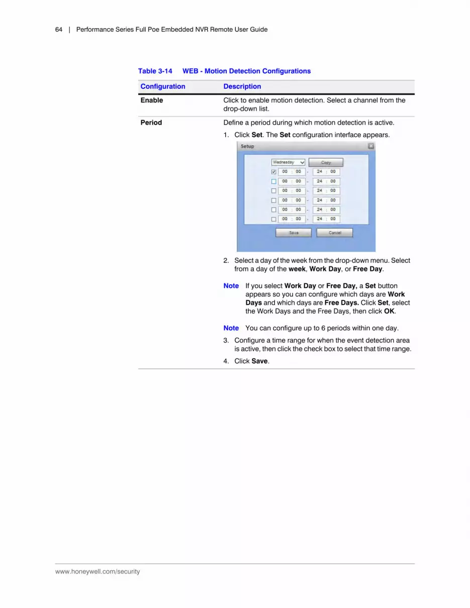
Period Define a period during which motion detection is active.
1. Click Set. The Set configuration interface appears.
2. Select a day of the week from the drop-down menu. Select from a day of the week, Work Day, or Free Day.
Note If you select Work Day or Free Day, a Set button appears so you can configure which days are Work Days and which days are Free Days. Click Set, select the Work Days and the Free Days, then click OK.
Note You can configure up to 6 periods within one day.
3. Configure a time range for when the event detection area is active, then click the check box to select that time range.
4. Click Save.

Configuration | 65
800-21261V3 - A - 05/2016
Region 1. Select a motion detection type.
2. Click Set. The Motion Detection Set configuration interface appears.
3. Select the event detection area by left-clicking and dragging the mouse.
There are 396 (PAL) or 330 (NTSC) small zones.
Green: Indicates the current cursor position.
Grey: Indicates the event detection zone.
Black: Indicates a disarmed zone.
4. Select a Sensitivity, from 1 to 100. The higher the number, the higher the sensitivity.
5. Click Save to save the configurations. Click Esc to exit the setup without saving the changes.
Record Channel The system automatically starts recording selected channels when a motion detection alarm occurs.
Note You need to set the motion detection recording period.
Go to StorageSchedule to configure the current channel for scheduled recording. Refer to the User Guide for more information about Configuring Recording Schedule Storage Settings.
Delay The system can delay recording for a specified amount of time after an alarm has ended. Select from 10s to 300s.
Alarm Out Select the device output port, 1 or 2. Select the corresponding port(s) so the system can activate the corresponding alarm devices when an alarm occurs.
Latch The system can delay the alarm output for a specified time after an alarm ends. The value ranges from 1s to 300s.
Table 3-14 WEB - Motion Detection Configurations
Configuration Description

www.honeywell.com/security
66 | Performance Series Full Poe Embedded NVR Remote User Guide
Video Loss Detection Configurations
You can configure the system to generate a video loss alarm when the minimum amount of video loss (as defined by you) is detected in the video.
PTZ Activation When PTZ activation is configured, the system can activate PTZ operation when an alarm is detected.
1. Click Setup to open the PTZ Activation configuration interface.
2. Select a preset, tour, or pattern from the drop-down menu.
3. Click Save.
Tour Click to enable a tour to be triggered by an alarm. The system supports 1/8-window tour. Refer to the User Guide for more about tour interval setup. On the Display Settings tab, when there are two tours enabled by default, you can configure the system so an alarm triggers the system to enable the alarm tours you configured here. If there is no alarm, then the system uses the tour setup that was configured in the Display interface.
Snapshot Click to enable the Snapshot function. Channel snapshots are taken according to the schedule you configure. Alarm snapshots are taken when an alarm occurs.
Show Message Click to enable a pop-up message on your local host PC screen to let you know an alarm has occurred.
Send Email The system can send an email when an alarm is detected. When you have enabled the Snapshot function, the system can also send an image attached to the email. Go to NetworkEmail to configure the email settings. Refer to the User Guide for more information.
Alarm Upload Enable this function, and when a motion event is detected, an alarm message is uploaded to the NVR.
Buzzer Click to enable the Buzzer function. When an alarm occurs, the buzzer beeps.
Table 3-14 WEB - Motion Detection Configurations
Configuration Description
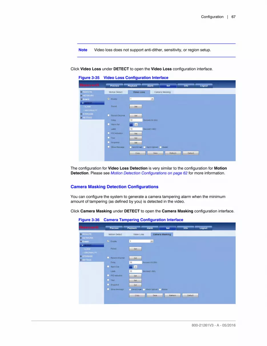
Configuration | 67
800-21261V3 - A - 05/2016
Note Video loss does not support anti-dither, sensitivity, or region setup.
Click Video Loss under DETECT to open the Video Loss configuration interface.
Figure 3-35 Video Loss Configuration Interface
The configuration for Video Loss Detection is very similar to the configuration for Motion Detection. Please see Motion Detection Configurations on page 62 for more information.
Camera Masking Detection Configurations
You can configure the system to generate a camera tampering alarm when the minimum amount of tampering (as defined by you) is detected in the video.
Click Camera Masking under DETECT to open the Camera Masking configuration interface.
Figure 3-36 Camera Tampering Configuration Interface
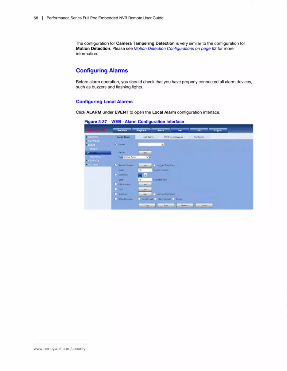
www.honeywell.com/security
68 | Performance Series Full Poe Embedded NVR Remote User Guide
The configuration for Camera Tampering Detection is very similar to the configuration for Motion Detection. Please see Motion Detection Configurations on page 62 for more information.
Configuring Alarms
Before alarm operation, you should check that you have properly connected all alarm devices, such as buzzers and flashing lights.
Configuring Local Alarms
Click ALARM under EVENT to open the Local Alarm configuration interface.
Figure 3-37 WEB - Alarm Configuration Interface
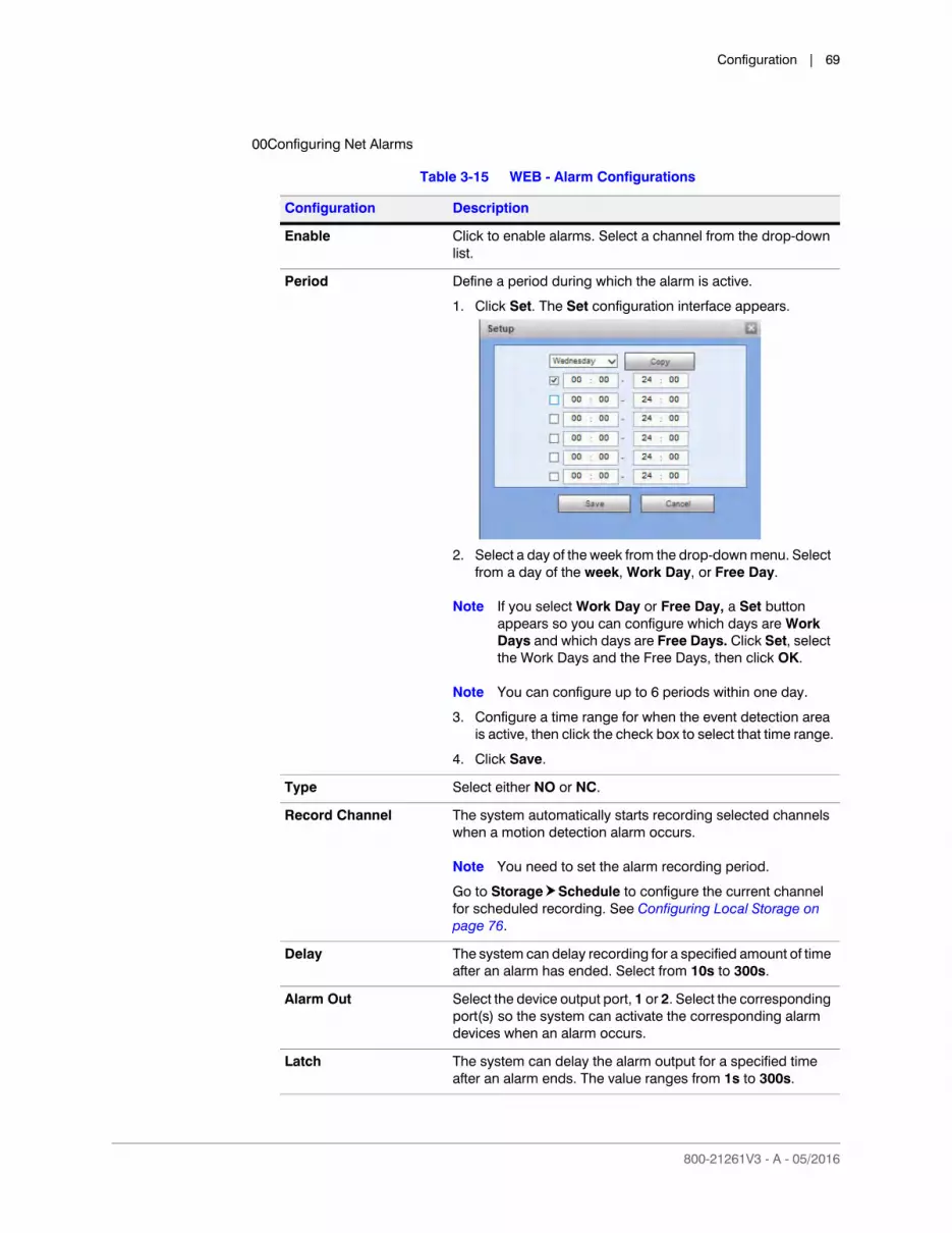
Configuration | 69
800-21261V3 - A - 05/2016
00Configuring Net Alarms
Table 3-15 WEB - Alarm Configurations
Configuration Description
Enable Click to enable alarms. Select a channel from the drop-down list.
Period Define a period during which the alarm is active.
1. Click Set. The Set configuration interface appears.
2. Select a day of the week from the drop-down menu. Select from a day of the week, Work Day, or Free Day.
Note If you select Work Day or Free Day, a Set button appears so you can configure which days are Work Days and which days are Free Days. Click Set, select the Work Days and the Free Days, then click OK.
Note You can configure up to 6 periods within one day.
3. Configure a time range for when the event detection area is active, then click the check box to select that time range.
4. Click Save.
Type Select either NO or NC.
Record Channel The system automatically starts recording selected channels when a motion detection alarm occurs.
Note You need to set the alarm recording period.
Go to StorageSchedule to configure the current channel for scheduled recording. See Configuring Local Storage on page 76.
Delay The system can delay recording for a specified amount of time after an alarm has ended. Select from 10s to 300s.
Alarm Out Select the device output port, 1 or 2. Select the corresponding port(s) so the system can activate the corresponding alarm devices when an alarm occurs.
Latch The system can delay the alarm output for a specified time after an alarm ends. The value ranges from 1s to 300s.

www.honeywell.com/security
70 | Performance Series Full Poe Embedded NVR Remote User Guide
Network Alarm are the alarm signals from the TCP/IP. You cannot select the sensor type or anti-dither functions.
Click Net Alarm in the ALARM configuration interface.
PTZ Activation When PTZ activation is configured, the system can activate PTZ operation when an alarm is detected.
1. Click Setup to open the PTZ Activation configuration interface.
2. Select a preset, tour, or pattern from the drop-down menu.
3. Click Save.
Tour Click to enable a tour to be triggered by an alarm. The system supports 1/8-window tour. See Configuring Display Settings on page 80 for tour interval setup. On the Display Settings tab, when there are two tours enabled by default, you can configure the system so an alarm triggers the system to enable the alarm tours you configured here. If there is no alarm, then the system uses the tour setup that was configured in the Display interface.
Snapshot Click to enable the Snapshot function. Channel snapshots are taken according to the schedule you configure. Alarm snapshots are taken when an alarm occurs.
Show Message Click to enable a pop-up message on your local host PC screen to let you know an alarm has occurred.
Send Email The system can send an email when an alarm is detected. When you have enabled the Snapshot function, the system can also send an image attached to the email. Go to Main MenuSettingNetworkEmail to configure the email settings. See Configuring Email on page 50.
Alarm Upload Select the check box to enable the system to upload an alarm signal to the network (including to an alarm center and/or web client).
Buzzer Click to enable the Buzzer function. When an alarm occurs, the buzzer beeps.
Table 3-15 WEB - Alarm Configurations
Configuration Description
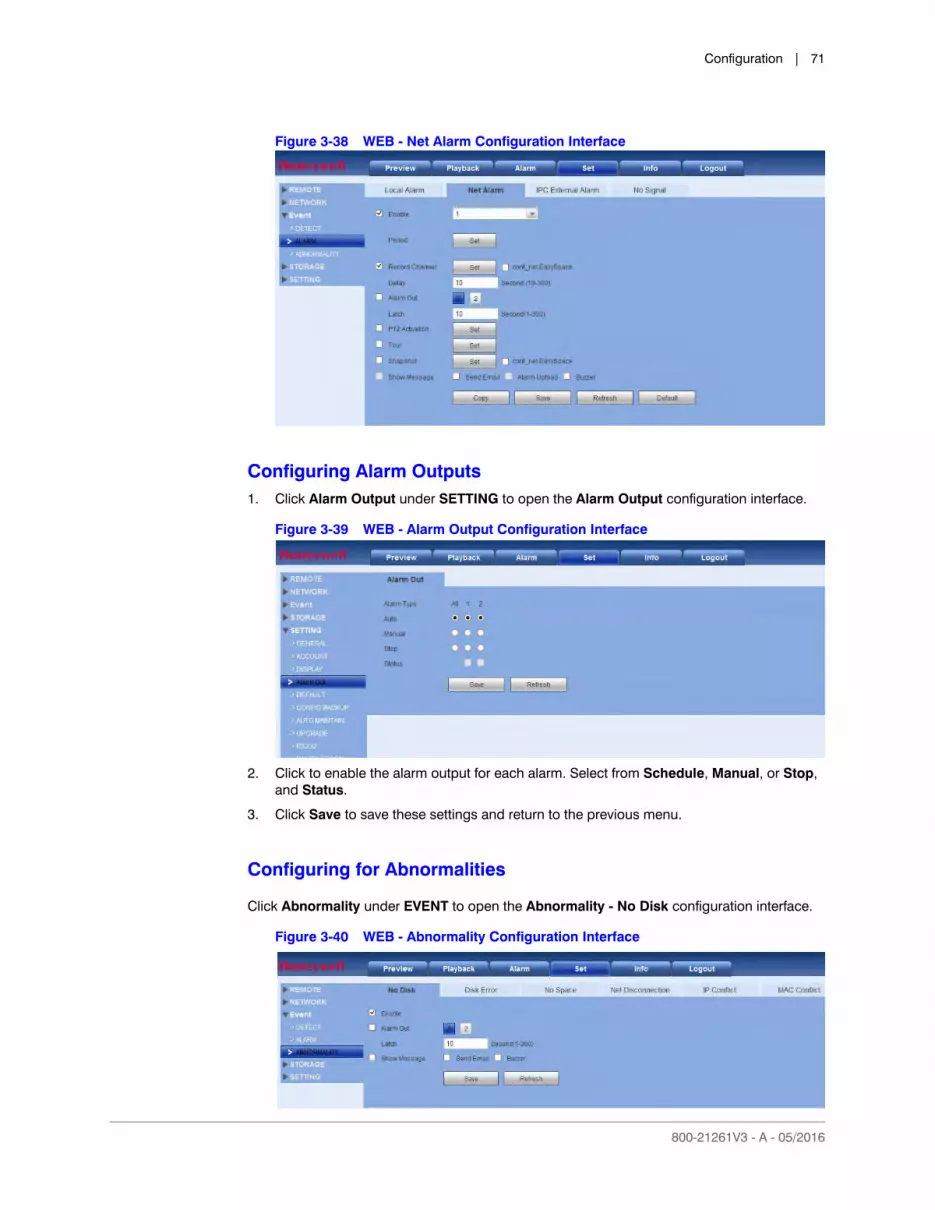
Configuration | 71
800-21261V3 - A - 05/2016
Figure 3-38 WEB - Net Alarm Configuration Interface
Configuring Alarm Outputs1. Click Alarm Output under SETTING to open the Alarm Output configuration interface.
Figure 3-39 WEB - Alarm Output Configuration Interface
2. Click to enable the alarm output for each alarm. Select from Schedule, Manual, or Stop, and Status.
3. Click Save to save these settings and return to the previous menu.
Configuring for Abnormalities
Click Abnormality under EVENT to open the Abnormality - No Disk configuration interface.
Figure 3-40 WEB - Abnormality Configuration Interface
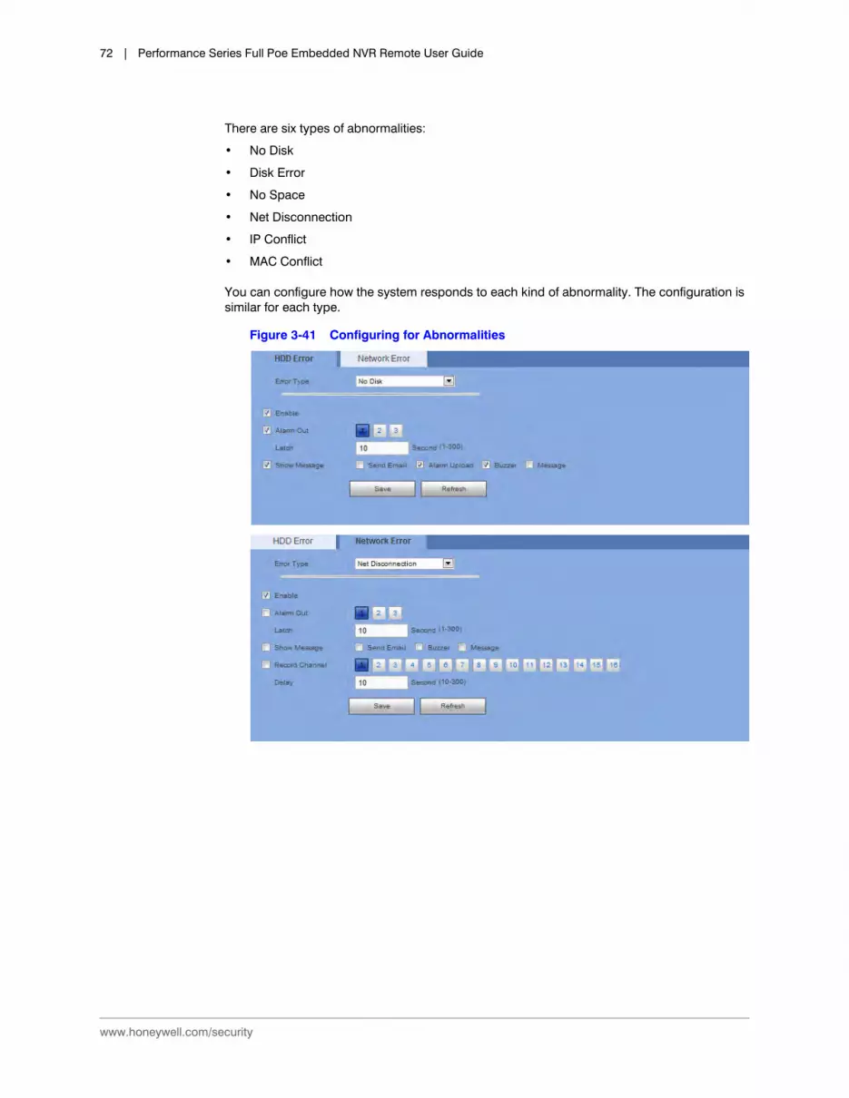
www.honeywell.com/security
72 | Performance Series Full Poe Embedded NVR Remote User Guide
There are six types of abnormalities:
• No Disk
• Disk Error
• No Space
• Net Disconnection
• IP Conflict
• MAC Conflict
You can configure how the system responds to each kind of abnormality. The configuration is similar for each type.
Figure 3-41 Configuring for Abnormalities

Configuration | 73
800-21261V3 - A - 05/2016
Configuring Storage
Configuring Storage Schedules
You can add or remove schedules for recording.
There are four recording modes: General (auto), Motion Detect, Alarm, and MD&Alarm. You can configure up to six periods per day.
1. Click Schedule under STORAGE to open the Schedule configuration interface.
Table 3-16 Configuring for Abnormalities
Configuration Description
Event Type Select from No Disk, Disk Error, Disk No Space, Net Disconnection, IP Conflict, and MAC Conflict.
Less Than: (For No Space configuration only) Configure the minimum percentage of free space on the disk. An alarm lets you know when the disk capacity is low. You need to click to enable this function.
Enable Click to enable this function.
Alarm Out Select the device output port, 1 or 2. Select the corresponding port(s) so the system can activate the corresponding alarm devices when an alarm occurs.
Latch The system can delay the alarm output for a specified time after an alarm ends. The value ranges from 1s to 300s.
Show Message Click to enable a pop-up message on your local host PC screen to let you know an alarm has occurred.
Send Email The system can send an email when an alarm is detected. When you have enabled the Snapshot function, the system can also send an image attached to the email. Go to Main MenuSettingNetworkEmail to configure the email settings. Refer to the User Guide for more information.
Buzzer Click to enable the Buzzer function. When an alarm occurs, the buzzer beeps.

www.honeywell.com/security
74 | Performance Series Full Poe Embedded NVR Remote User Guide
Figure 3-42 Schedule Configuration Interface
The schedules are color-coded by type:
• Green: General recording/snapshot.
• Yellow: Motion detection recording/snapshot.
• Red: Alarm recording/snapshot.
• Blue: MD&Alarm recording/snapshot.
Table 3-17 Scheduled Storage Settings
Setting Description
Channel Select a channel from the drop-down list
Pre-record Enter a pre-recording time here. Select from 0 to 30.
Redundancy You can configure the NVR to backup recorded files onto two different HDDs. Click to enable.
Note Before you can enable this function, you must configure at least one HDD as redundant. Go to Main MenuSettingStorageHDD Management).
This function is not available if there is only one HDD.
Snapshot Click to enable Snapshot.
Holiday Click to enable Holiday.

Configuration | 75
800-21261V3 - A - 05/2016
2. Click Setup. The Setup configuration interface opens.
Figure 3-43 Set Configuration Interface
Setup (Sunday to Saturday)
Click Setup, then set a recording period. See step 2 below.
You can configure up to six periods in one day. If you do not click a day at the bottom of the Setup interface, then the changes you make are for today.
Setup (Holiday) Click Setup, then set a recording period. See step 2 below.
You can configure up to six periods in one day. If you click Holiday at the bottom of the Setup interface, then the currently selected channel will record according to these holiday settings.
Copy Allows you to copy a channel’s setup to one or more other channels. Click Copy in the Configuration interface to open the Copy interface.
Select channels to which to copy the current configurations, then click Save.
Table 3-17 Scheduled Storage Settings
Setting Description

www.honeywell.com/security
76 | Performance Series Full Poe Embedded NVR Remote User Guide
3. Configure the schedule, then click Save.
4. Click Save to save the settings, and then click Save to save the Schedule configuration.
Configuring Local Storage
Click Storage under STORAGE to open the Local Storage configuration interface.
The Local Storage interface shows HDD information. You can also configure read-only, read-write, redundancy (if there is more than one HDD), and format settings.
Figure 3-44 Local Storage Interface
Configuring Manual Recording Storage Settings
Click Record under Storage to open the Record configuration interface.
Table 3-18 Schedule Configurations
Configuration Description
Channel Select a channel from the drop-down list.
Regular Check to enable the Regular schedule mode.
Motion Check to enable the Motion Detection schedule mode.
Alarm Check to enable the Alarm mode.
MD&Alarm Check to enable the MD&Alarm mode.

Configuration | 77
800-21261V3 - A - 05/2016
Figure 3-45 Manual Recording Storage Interface
Configuring General Settings
General Settings
Click General under SETTING to open the General settings configuration interface.
Table 3-19 Recording Storage Interface
Setting Description
Channel See the channel numbers, including the maximum number of channels.
Auto Select Schedule, and the system enables the automatic recording function as you set it in the Recording Schedule Setup: General, Motion Detection, or Alarm. See Configuring Storage Schedules on page 73.
Manual This is the highest priority. Enable the corresponding channel to record not matter what period was applied in the Recording Setup.
Off Stop recording the current channel no matter what recording setup is applied to that channel.
Start All/Stop All Click the All button, and then enable or disable recording on all channels.

www.honeywell.com/security
78 | Performance Series Full Poe Embedded NVR Remote User Guide
Figure 3-46 General Settings Interface
Date and Time Settings
Click the Date & Time tab in the GENERAL configuration interface to open the Date & Time configuration interface.
Table 3-20 General Settings Configurations
Configuration Description
Device Name Enter a device name.
Device No. Enter a channel number.
Language Select a GUI language from the drop-down list.
Note You need to reboot the device/NVR to activate this change.
Video Standard Select the video standard, either NTSC or PAL.
HDD Full Select what happens when the NVR’s storage is full. Select either Stop Recording or OverWrite.
Stop Recording: If the HDD is full, the NVR stops recording.
OverWrite: If the currently working HDD is full and the next HDD is also full, the NVR overwrites the previous files.
Pack Duration Select the recording duration. Select from 1 to 60 minutes. The default is 60 minutes.
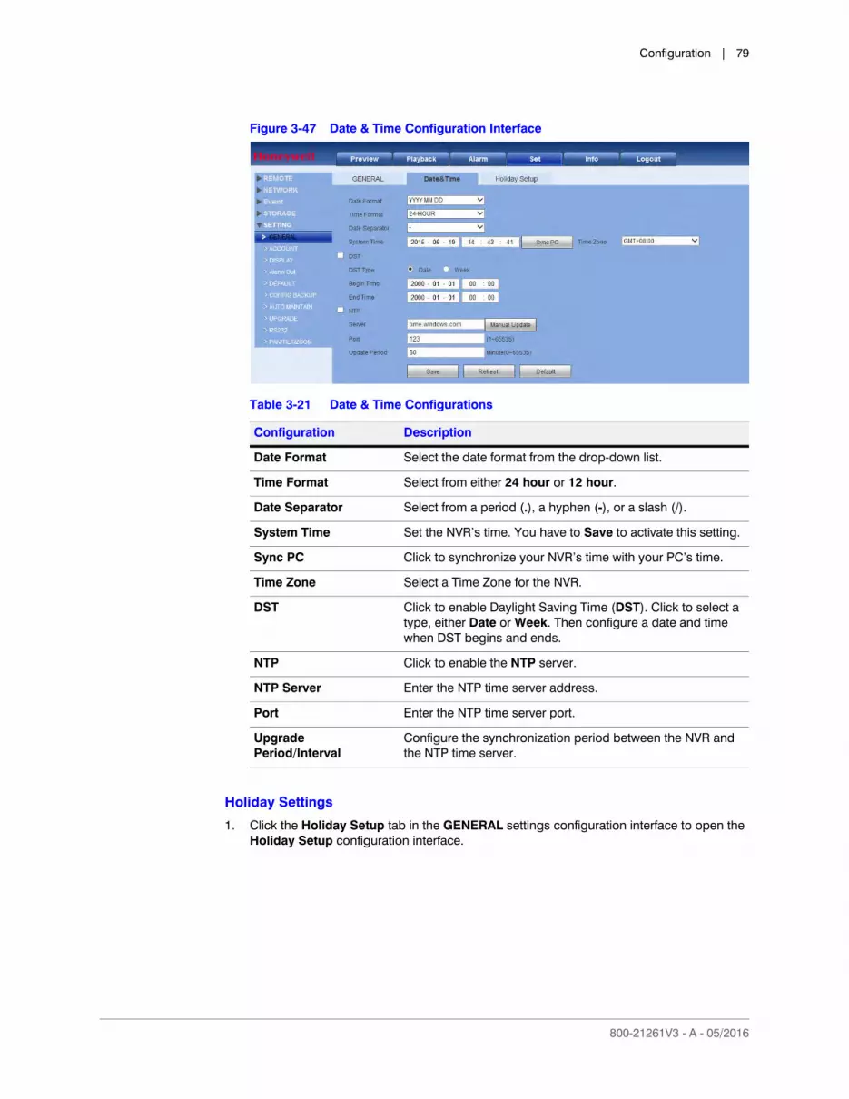
Configuration | 79
800-21261V3 - A - 05/2016
Figure 3-47 Date & Time Configuration Interface
Holiday Settings
1. Click the Holiday Setup tab in the GENERAL settings configuration interface to open the Holiday Setup configuration interface.
Table 3-21 Date & Time Configurations
Configuration Description
Date Format Select the date format from the drop-down list.
Time Format Select from either 24 hour or 12 hour.
Date Separator Select from a period (.), a hyphen (-), or a slash (/).
System Time Set the NVR’s time. You have to Save to activate this setting.
Sync PC Click to synchronize your NVR’s time with your PC’s time.
Time Zone Select a Time Zone for the NVR.
DST Click to enable Daylight Saving Time (DST). Click to select a type, either Date or Week. Then configure a date and time when DST begins and ends.
NTP Click to enable the NTP server.
NTP Server Enter the NTP time server address.
Port Enter the NTP time server port.
Upgrade Period/Interval
Configure the synchronization period between the NVR and the NTP time server.
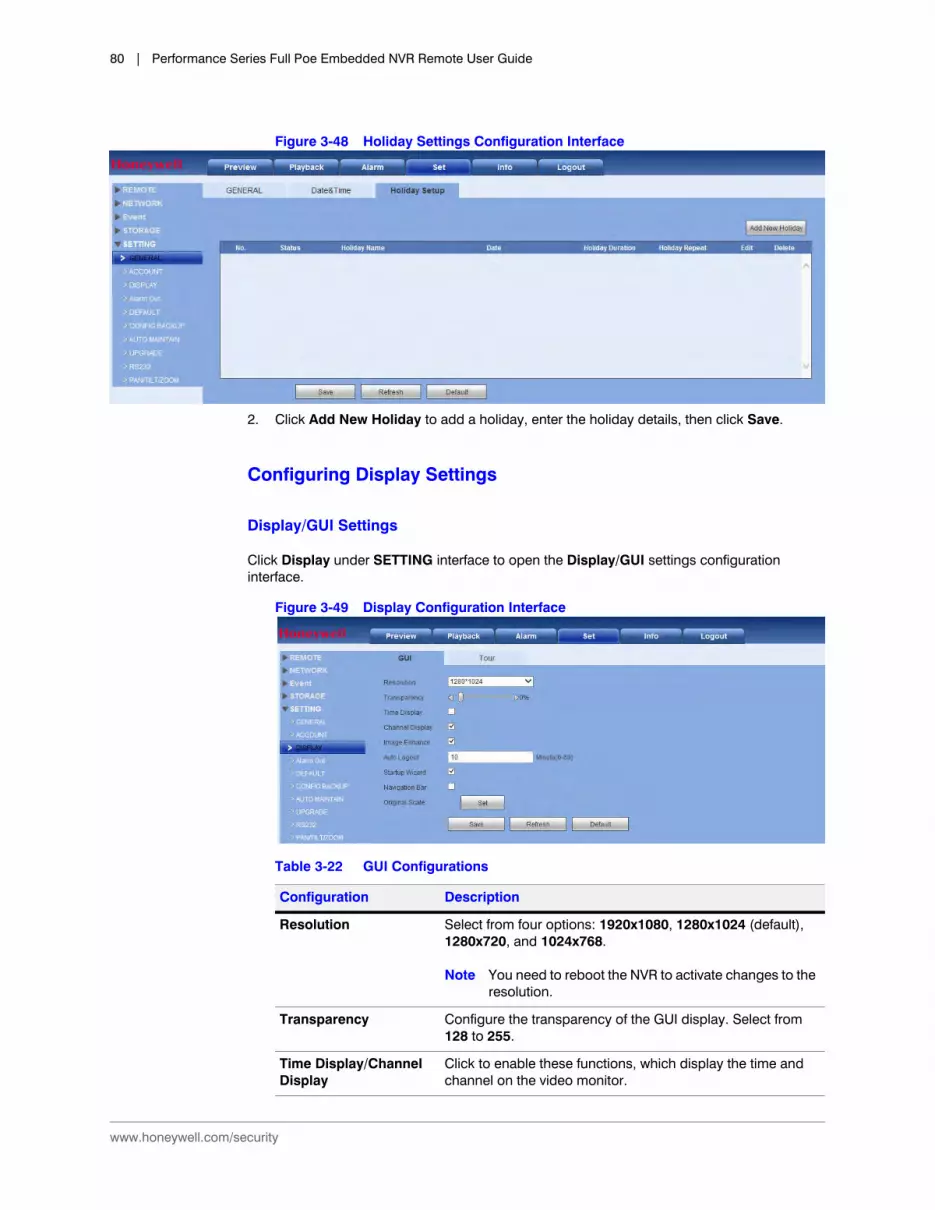
www.honeywell.com/security
80 | Performance Series Full Poe Embedded NVR Remote User Guide
Figure 3-48 Holiday Settings Configuration Interface
2. Click Add New Holiday to add a holiday, enter the holiday details, then click Save.
Configuring Display Settings
Display/GUI Settings
Click Display under SETTING interface to open the Display/GUI settings configuration interface.
Figure 3-49 Display Configuration Interface
Table 3-22 GUI Configurations
Configuration Description
Resolution Select from four options: 1920x1080, 1280x1024 (default), 1280x720, and 1024x768.
Note You need to reboot the NVR to activate changes to the resolution.
Transparency Configure the transparency of the GUI display. Select from 128 to 255.
Time Display/Channel Display
Click to enable these functions, which display the time and channel on the video monitor.
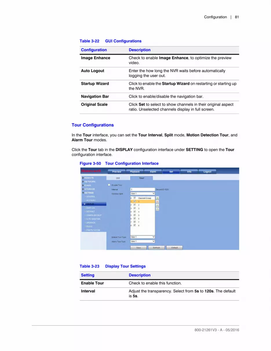
Configuration | 81
800-21261V3 - A - 05/2016
Tour Configurations
In the Tour interface, you can set the Tour Interval, Split mode, Motion Detection Tour, and Alarm Tour modes.
Click the Tour tab in the DISPLAY configuration interface under SETTING to open the Tour configuration interface.
Figure 3-50 Tour Configuration Interface
Image Enhance Check to enable Image Enhance, to optimize the preview video.
Auto Logout Enter the how long the NVR waits before automatically logging the user out.
Startup Wizard Click to enable the Startup Wizard on restarting or starting up the NVR.
Navigation Bar Click to enable/disable the navigation bar.
Original Scale Click Set to select to show channels in their original aspect ratio. Unselected channels display in full screen.
Table 3-22 GUI Configurations
Configuration Description
Table 3-23 Display Tour Settings
Setting Description
Enable Tour Check to enable this function.
Interval Adjust the transparency. Select from 5s to 120s. The default is 5s.
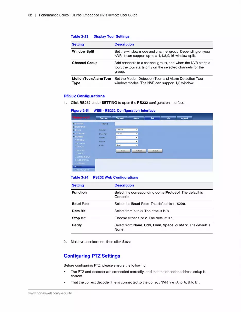
www.honeywell.com/security
82 | Performance Series Full Poe Embedded NVR Remote User Guide
RS232 Configurations
1. Click RS232 under SETTING to open the RS232 configuration interface.
Figure 3-51 WEB - RS232 Configuration Interface
2. Make your selections, then click Save.
Configuring PTZ Settings
Before configuring PTZ, please ensure the following:
• The PTZ and decoder are connected correctly, and that the decoder address setup is correct.
• That the correct decoder line is connected to the correct NVR line (A to A; B to B).
Window Split Set the window mode and channel group. Depending on your NVR, it can support up to a 1/4/8/9/16-window split.
Channel Group Add channels to a channel group, and when the NVR starts a tour, the tour starts only on the selected channels for the group.
Motion Tour/Alarm Tour Type
Set the Motion Detection Tour and Alarm Detection Tour window modes. The NVR can support 1/8 window.
Table 3-23 Display Tour Settings
Setting Description
Table 3-24 RS232 Web Configurations
Setting Description
Function Select the corresponding dome Protocol. The default is Console.
Baud Rate Select the Baud Rate. The default is 115200.
Data Bit Select from 5 to 8. The default is 8.
Stop Bit Choose either 1 or 2. The default is 1.
Parity Select from None, Odd, Even, Space, or Mark. The default is None.

Configuration | 83
800-21261V3 - A - 05/2016
Click PAN/TILT/ZOOM under SETTING to open the PAN/TILT/ZOOM configuration interface
Figure 3-52 PAN/TILT/ZOOM Configuration Interface
Accounts
Some Basic User and Group Rules• You can use up to 6 characters for user names and group names. You can not use a
space at the beginning or end of a name. You can use characters, numbers, and an underline (_).
• You can add up to 64 users and 20 groups (these are also the default settings). The default setting includes two group levels: user and admin. Configure the Group privileges, and then assign users to their groups according to the privileges those users require.
• User management involves assigning privileges to groups, and users to groups. User names can not be the same as group names; user names and group names must be unique. Users can belong to only one group.
Click Account under SETTING to open the Account settings configuration interface.
Table 3-25 PAN/TILT/ZOOM Configuration Interface
Setting Description
Channel Select a channel.
PTZ Type Select Remote for the PTZ type. A remotely connected IP camera is connected through the network.

www.honeywell.com/security
84 | Performance Series Full Poe Embedded NVR Remote User Guide
User Name
Figure 3-53 User Name Account Configurations
There are two default users:
• admin
• a hidden user
The hidden default user is for internal use only, and can not be deleted. If users log in without selecting a login user, the hidden default user is automatically used. You can configure some rights for the default hidden user, such as monitor rights so that the user can view channels without logging in.
Note User rights can not exceed group rights.
TIP! General users should have fewer rights than administrators.
Adding a User
1. Click Add User. The Add User configuration interface opens.
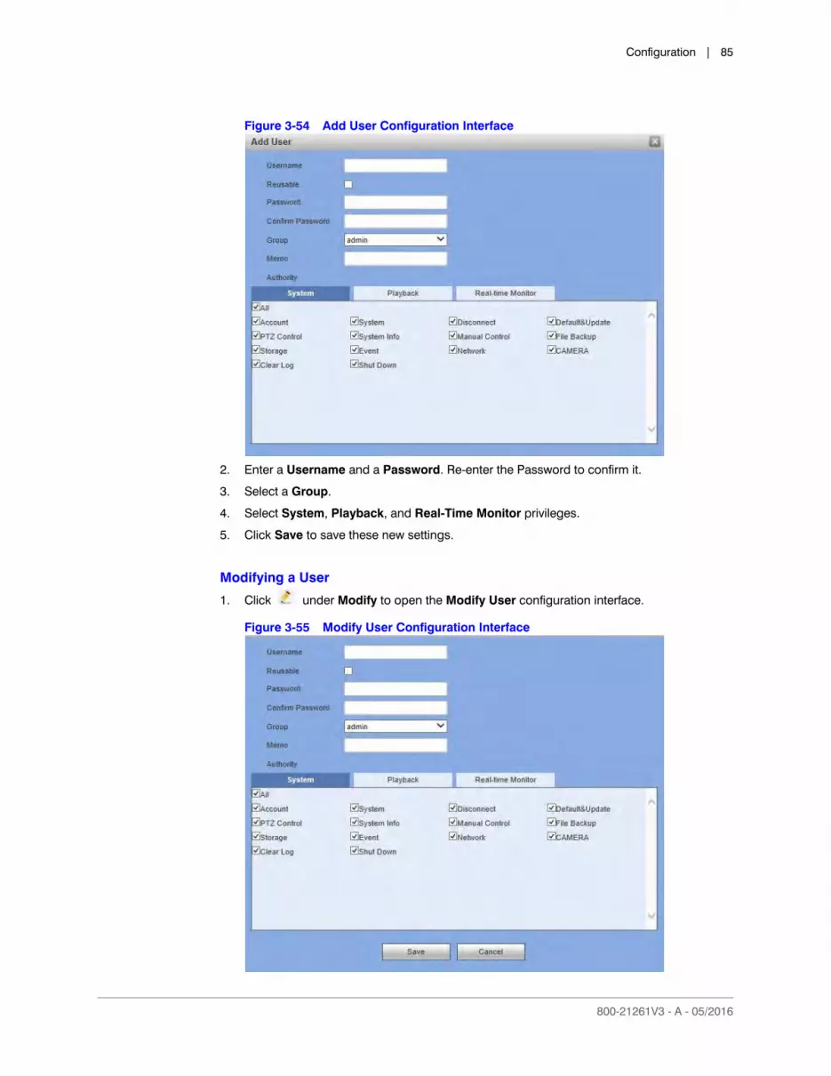
Configuration | 85
800-21261V3 - A - 05/2016
Figure 3-54 Add User Configuration Interface
2. Enter a Username and a Password. Re-enter the Password to confirm it.
3. Select a Group.
4. Select System, Playback, and Real-Time Monitor privileges.
5. Click Save to save these new settings.
Modifying a User
1. Click under Modify to open the Modify User configuration interface.
Figure 3-55 Modify User Configuration Interface
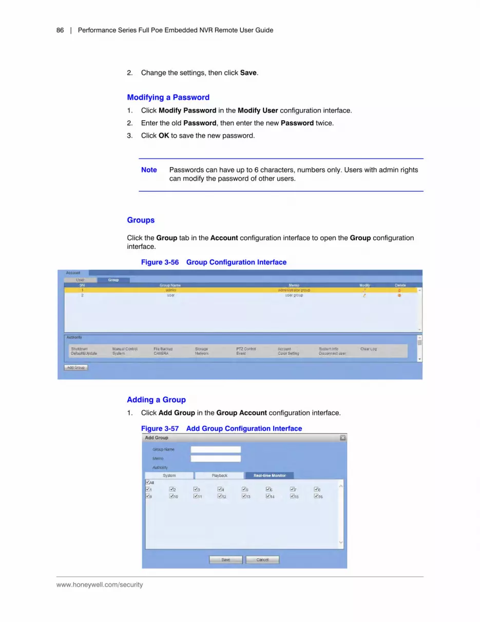
www.honeywell.com/security
86 | Performance Series Full Poe Embedded NVR Remote User Guide
2. Change the settings, then click Save.
Modifying a Password
1. Click Modify Password in the Modify User configuration interface.
2. Enter the old Password, then enter the new Password twice.
3. Click OK to save the new password.
Note Passwords can have up to 6 characters, numbers only. Users with admin rights can modify the password of other users.
Groups
Click the Group tab in the Account configuration interface to open the Group configuration interface.
Figure 3-56 Group Configuration Interface
Adding a Group
1. Click Add Group in the Group Account configuration interface.
Figure 3-57 Add Group Configuration Interface

Configuration | 87
800-21261V3 - A - 05/2016
2. Enter a Group name.
3. Select System, Playback, and Real-time Monitor privileges.
4. Click Save to save these new settings.
Modifying a Group
1. Click under Modify to open the Modify Group configuration interface.
Figure 3-58 Modify Group Configuration Interface
2. Modify the Group privileges, then click Save to save the changes.
Automatic Maintenance1. Click Auto Maintain under SETTING to open the Auto Maintain configuration interface.
Figure 3-59 Auto Maintain Configuration Interface

www.honeywell.com/security
88 | Performance Series Full Poe Embedded NVR Remote User Guide
2. Select when the NVR automatically reboots, both day and time.
3. Select when the NVR automatically deletes old files.
4. Click Save to save the new settings.
Note Click Manual Reboot to manually reboot the NVR.
Import/Export
Click Config Backup under SETTING to open the Import/Export configuration interface.
Figure 3-60 Import/Export Interface
Default
You can select to return Channel, Network, Event, Storage, and/or System settings to their defaults.
1. Click Default under SETTING to open the Default configuration interface.
Figure 3-61 Default Settings Interface
Table 3-26 Import/Export Operations
Activity Description
Import Use to import local setup files to the NVR system.
Export Use to export the corresponding WEB setup to your local PC.

Configuration | 89
800-21261V3 - A - 05/2016
2. Click to select, or select All, then click Default.
Upgrade
Click Upgrade under SETTING to open the Upgrade configuration interface.
Figure 3-62 Upgrade Interface
1. Click Browse, then click to select the upgrade file.
2. Click Upgrade to begin the update.
The file name will end with .bin.
Note During the upgrade process, do not unplug the power cable, network cable, or shut down the device.
CAUTION An improper upgrade program could result in a device malfunction.

www.honeywell.com/security
90 | Performance Series Full Poe Embedded NVR Remote User Guide

800-21261V3 - A - 05/2016
4Playback 4
This chapter includes descriptions of the following:
• Playing back recorded video
• Downloading recorded video
Playback
1. Click the Playback tab at the top of the Main window.
The Playback interface appears.
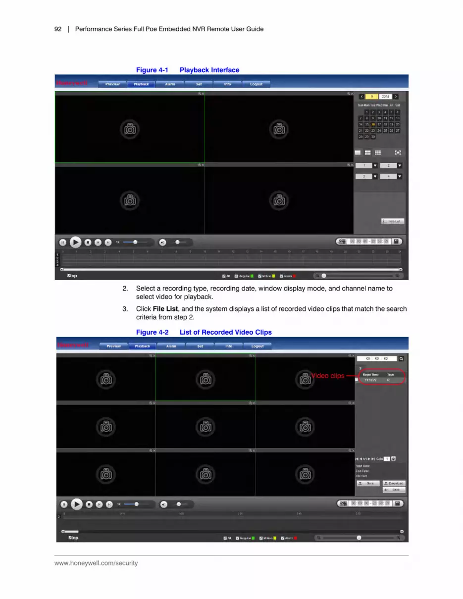
www.honeywell.com/security
92 | Performance Series Full Poe Embedded NVR Remote User Guide
Figure 4-1 Playback Interface
2. Select a recording type, recording date, window display mode, and channel name to select video for playback.
3. Click File List, and the system displays a list of recorded video clips that match the search criteria from step 2.
Figure 4-2 List of Recorded Video Clips
Video clips
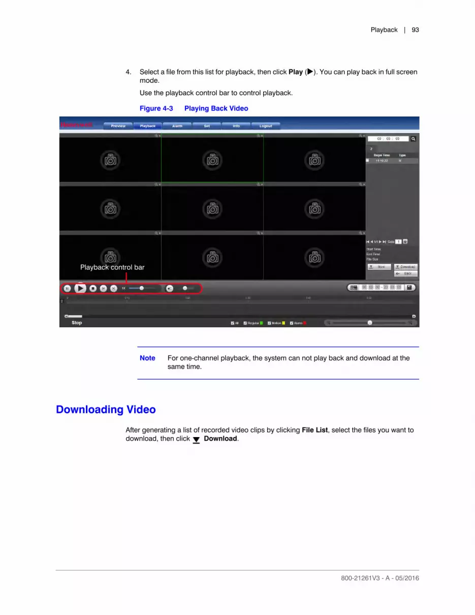
Playback | 93
800-21261V3 - A - 05/2016
4. Select a file from this list for playback, then click Play (). You can play back in full screen mode.
Use the playback control bar to control playback.
Figure 4-3 Playing Back Video
Note For one-channel playback, the system can not play back and download at the same time.
Downloading Video
After generating a list of recorded video clips by clicking File List, select the files you want to download, then click Download.
Playback control bar

www.honeywell.com/security
94 | Performance Series Full Poe Embedded NVR Remote User Guide
Figure 4-4 Downloading Recorded Video
The Download button becomes the Stop button, and it indicates the downloading progress (in a percentage).
Go to your default Saved Path file to view the downloaded files. See Configuring the Save Path on page 39.
Loading More
Click More in Fig 13-94, and the Download by File/Download by Time interfaces appear.

Playback | 95
800-21261V3 - A - 05/2016
Figure 4-5 Download by File/Download by Time Interfaces
In this window, you can search for recordings or snapshots. Select the channel, recording type, and the recording time.

www.honeywell.com/security
96 | Performance Series Full Poe Embedded NVR Remote User Guide

800-21261V3 - A - 05/2016
5Alarms 5
This chapter describes how to remotely activate the alarms.
Activating Alarms
Click the Alarm tab at the top of the Main window. The Alarm configuration interface appears.
Note For information about configuring alarms, refer to the User Guide.

www.honeywell.com/security
98 | Performance Series Full Poe Embedded NVR Remote User Guide
Figure 5-1 Alarm Configuration Interface
Table 5-1 Alarm Configurations
Configuration Type Configuration Description
Alarm Type
Motion Detect Click to enable Motion Detection. The system will then trigger an alarm when motion is detected under the specified circumstances.
Video Masking Click to enable Video Masking. The system triggers an alarm when camera masking occurs.
Video Loss Click to enable Video Loss. The system then an alarm when video loss occurs.
IPC External Alarm
Click to enable the camera’s External Alarm, the On/Off signal from the network camera. It activates the NVR to locally activate.
External Alarm An alarm that is connected to the NVR, such as an infrared detector.
Disk Error Click to enable the Disk Error alarm. The system triggers an alarm when a disk error occurs.
Disk Full Click to enable the Disk Full alarm. The system triggers an alarm when the disk is full.
No Signal Click to enable the No Signal alarm. The system triggers an alarm when the network camera and the NVR are disconnected.
Operation Prompt Click to enable the Prompt. Then the system automatically pops up an alarm icon on the Alarm button on the Main interface when there is an alarm.
Alarm Sound
Play Alarm Sound
Click to enable the Alarm Sound. Then the system triggers an alarm sound when an alarm occurs. You can choose the sound.
Sound Path Select the sound file.

Alarms | 99
800-21261V3 - A - 05/2016
You can use the webpage un-install tool uninstall_web.bat to uninstall the web control plugin.
Note Before uninstalling the Web control, close all web pages. If you do not, then you might experience an error.

www.honeywell.com/security
100 | Performance Series Full Poe Embedded NVR Remote User Guide

| 1
800-21261V3 - A - 05/2016
Index
Numerics3G configurations
WLAN type 44
Aadding
groups 86users 84
adjustingmonitor brightness 29monitor contrast 29monitor saturation 29
alarm outmotion detection 65, 69
alarmsabnormalities 73configuring sound file 98disk error 98disk full 98enable sound 98errors 73external alarms 98motion detection 98no signal 98video loss 98video masking 98
APN 44attachments, email 50audio On/Off, live video 29authorization 44
Bbackup 31bi-directional communication 21bit rate
live video 28blocked sites 49brightness 29browsers 16button
instant record 22start talking 21
buzzerabnormality 73error 73motion detection 66, 70
CCDMA1X 44channel display 80channel number, live video 28clear log 31configuration
controls 23operation 31
configuringabnormality alarm out 73abnormality buzzer 73abnormality email 73abnormality latch 73abnormality message 73alarm schedule 76alarm sound file 98anonymous email 50APN 44AUTH 44buzzer 66, 70CDMA AUTH 44DDNS server IP 46DDNS type 46, 47Dial No. 44email attachment 50email encryption 50email interval 51email password 50email port 50email receiver 50email sender 50email SMTP 50email title 50email user name 50emails 66, 70error alarm out 73error buzzer 73error email 73

www.honeywell.com/security
2 | Performance Series Full Poe Embedded NVR Remote User Guide
error latch 73error message 73HTTP port 42latch 65, 69maximum network connection 42MD&Alarm schedule 76messages 66, 70monitor hue 29motion detection alarm out 65, 69motion detection buzzer 66, 70motion detection emails 66, 70motion detection latch 65, 69motion detection message 66, 70motion detection period 64, 69motion detection PTZ activation 66, 70motion detection recording channel 65, 69motion detection region 65motion detection relay 65, 69motion detection schedule 76motion detection snapshot 66, 70motion detection tour 66, 70network TCP port 42PTZ activation 66, 70pulse interval 44RTSP port 42snapshot 66, 70SNMP port 54SNMP read community 54SNMP trap address 54SNMP trap port 54SNMP version 54SNMP write community 54storage channel 76TCP/IP address remotely 41TCP/IP alternate DNS remotely 42TCP/IP LAN download remotely 42TCP/IP MAC address remotely 41TCP/IP mode remotely 41TCP/IP preferred DNS remotely 41TCP/IP version remotely 41tours 66, 70UDP port 42video quality 23
contrast 29
Ddata operation 31date
format 79separator 79
daylight saving time 79DDNS
default server address 47domain mode 47domain name 47email address 47Honeywell 47
server IP 46, 47type 46types 47
defaultDDNS server address 47domain name 47Honeywell DDNS server address 47HTTP port 42maximum network connections 42resolution 80RTSP port 42saved path 94settings 29SNMP port 54SNMP read community 54SNMP write community 54TCP port 42UDP port 42users 84
detailsinformation, log 31
devicename 78number 78
Dial No. 44digital zoom
live video 28disconnection 72
net 72disk
error 72, 73no space error 73
displayingchannel 80device information 28time 80
domain mode 47DDNS 47
domain nameDDNS 47default 47
downloading video 93DST 79
Eemail
anonymous 50attachments 50enabling health email 51encryption 50interval settings 51password 50port settings 50receiver 50sender 50SMTP settings 50snapshots 50

| 3
800-21261V3 - A - 05/2016
test 51title 50user name 50
email addressDDNS 47
emailsabnormality 73error 73motion detection 66, 70
enablingalarm disk error 98alarm disk full 98alarm sound 98alarm video masking 98alarms video loss 98external alarms 98health email 51motion detection 98no signal alarm 98prompt 98
encryption 50end time, log 31error
disk 72internet disconnection 72IP conflict 72MAC conflict 72net disconnection 72no disk 72no space 72
event operation 31event type
no disk 73
Ffile
list 93video format 22
finding, device name 78fluency 23formatting
date 79date separator 79time 79
four-channel window 23full screen 23function buttons for LAN 19
Ggroup
rules 83groups
adding 86modifying 87
GUIlanguage 78
transparency 80
HHDD
full 78overwrite 78stop recording 78
hidden default user 84Honeywell DDNS 47HTTP port
configuration 42default 42
hue 29
Iimage
enhance 81instant record button 22internet 72
disconnection 72interval, email 51IP
conflict error 72IP address
live video 28IP configuration
blocked sites 49trusted sites 49
ISP 46
LLAN mode
function buttons 19language 78latch
abnormality 73error 73settings 65, 69
live videoaudio On/Off 29bit rate 28channel number 28digital zoom 28IP address 28local recording 28recording system folder 28snapshot 28snapshot system folder 28
local recording, live video 28log
backup 31clear 31configuration operation 31data operation 31detailed information 31end time 31

www.honeywell.com/security
4 | Performance Series Full Poe Embedded NVR Remote User Guide
event operation 31record operation 31search 31system operation 31type 31user management 31
MMAC address
conflict error 72, 73maximum network connections
default 42MD&alarm 74messages
abnormality 73error 73motion detection 66, 70
modifyinggroups 87passwords 86users 85
monitorbrightness 29channels 20contrast 29hue 29saturation 29
motion detectionalarm out 65, 69buzzer 66, 70emails 66, 70enabling 98latch settings 65, 69messages 66, 70period 64, 69PTZ activation 66, 70recording channel 65, 69region 65relay settings 65, 69snapshot 66, 70tours 66, 70
Nnet disconnection 72
IP conflict 73network connection
configuring maximum connections 42no disk error 72no space error 72NTP 79
port 79server 79upgrade period 79
NTSC 78NVR
time 79
Ppack duration 78PAL 78passwords
email 50modifying 86PPPoE 46
PCrequirements 15time 79
playbackbutton 22file list 92interface 92
playing recorded video 22ports
email settings 50NTP 79SNMP 54SNMP trap address 54SNMP trap port 54
PPPoEpassword 46username 46
PPS 47preparing for UPnP 52processor 15professional surveillance software 47prompt enabling 98PTZ
activating motion detection 66, 70pulse interval configurations 44
RRAM 15read community 54record operation 31recording
duration 78recording channel
motion detection 65, 69region, motion detection 65related documents 14relay
motion detection 65, 69requirements
non-integrated video card 15processor 15system memory 15
resolution 80default 80
restore to default settings 29RTSP port
configurations 42

| 5
800-21261V3 - A - 05/2016
Ssaturation 29save path
default 94schedules
alarm 76MD&Alarm 76motion detection 76
searchlog 31
server IP 46DDNS 47
single-channel window 23SMTP 50snapshot
live video 28motion detection settings 66, 70
SNMPdefault port 54default read community setting 54port settings 54read community 54trap address 54trap port 54version 54write community 54write community default 54
start talking button 21storage
blue 74channel 76green 74red 74yellow 74
systemoperation 31time 79
TTCP
port default 42TCP port
configuration 42TCP/IP
address remote configurations 41alternate DNS remote configurations 42LAN download remote configurations 42MAC address remote configurations 41preferred DNS remote configurations 41
version remote configurations 41TCP/IP mode
remote configurations 41test
email 51time
NVR 79zone 79
time display 80time format 79time sync 79tours
motion detection 66, 70transparency 80trusted sites 49
UUDP port
configuration 42default 42
upgrade period 79UPnP
preparations 52user management 31user name
email 50user rules 83username
PPPoE 46users
adding 84modifying 85
Vvertical synchronization 23video
card 15file format 22playback 22quality 23standard 78
video, downloading 93viewer configuration controls 23
WWCDMA 44WLAN type 44write community 54

www.honeywell.com/security
6 | Performance Series Full Poe Embedded NVR Remote User Guide


© 2016 Honeywell International Inc. All rights reserved. No part of this publication may be reproduced by any means without written permission from Honeywell. The information in this publication is believed to be accurate in all respects. However, Honeywell cannot assume responsibility for any consequences resulting from the use thereof. The information contained herein is subject to change without notice. Revisions or new editions to this publication may be issued to incorporate such changes.
Document 800-21261V3 – Rev A – 05/2016
www.honeywell.com/security+1 800 323 4576 (North America only)
https://www.honeywellsystems.com/ss/techsupp/index.html
Honeywell Security Products Americas (Head Office)2700 Blankenbaker Pkwy, Suite 150Louisville, KY 40299, USAwww.honeywell.com/security +1 800 323 4576
Honeywell Security Europe/South AfricaAston Fields Road, Whitehouse Industrial EstateRuncorn, WA7 3DL, United Kingdomwww.honeywell.com/security/uk +44 (0) 1928 754 028
Honeywell Security Products AmericasCaribbean/Latin America9315 NW 112th Ave.Miami, FL 33178, USAwww.honeywell.com/security/clar +1 305 805 8188
Honeywell Security Asia Pacific35F Tower A, City Center, 100 Zun Yi RoadShanghai 200051, Chinawww.asia.security.honeywell.com +86 21 2219 6888
Honeywell Security Middle East/N. AfricaEmaar Business Park, Sheikh Zayed RoadBuilding No. 2, Office No. 301Post Office Box 232362Dubai, United Arab Emirateswww.honeywell.com/security/me +971 (0) 4 450 5800
Honeywell Security Northern EuropeAmpèrestraat 411446 TR Purmerend, The Netherlandswww.honeywell.com/security/nl +31 (0) 299 410 200
Honeywell Security DeutschlandJohannes-Mauthe-Straße 1472458 Albstadt, Germanywww.honeywell.com/security/de +49 (0) 7431 801-0
Honeywell Security FranceImmeuble LavoisierParc de Haute Technologie3-7 rue Georges Besse92160 Antony, Francewww.honeywell.com/security/fr +33 (0) 1 40 96 20 50
Honeywell Security Italia SpAVia della Resistenza 53/5920090 BuccinascoMilan, Italywww.honeywell.com/security/it +39 (0) 2 4888 051
Honeywell Security EspañaAvenida de Italia, n° 7, 2a plantaC.T. Coslada28821 Coslada, Madrid, Spainwww.honeywell.com/security/es +34 902 667 800