remote monitoring 1
TRANSCRIPT

Remote Monitoring 1
Lecture 4
RMON1 (RFC 1757 ) (supplementary: Chapter 5 of tutorial slides)
1
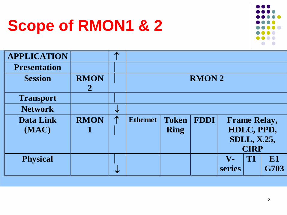
Scope of RMON1 & 2
APPLICATION
Presentation
Session RMON
2 RMON 2
Transport
Network
Data Link
(MAC)
RMON
1
Ethernet Token
Ring
FDDI Frame Relay,
HDLC, PPD,
SDLL, X.25,
CIRP
Physical
V-
series
T1 E1
G703
2
RMON Goals
Off-line operation
Proactive monitoring
Problem detection and reporting
Value-added-data
Multiple managers
In short,
An SNMP manager can learn of the amount of traffic into
and out of each device with MIB-II, but can’t easily learn
about the traffic on the LAN as a whole.
3
Control of Remote Monitors
RMON MIB contains features that support
extensive control from the management
station, which falls into two categories:
Configuration Configuration dictates the type and form of data to be collected.
The MIB is organized into a number of functional groups. Each
group contains one or more control tables and one or more
associated data tables.
Action invocation SNMP Set operation is used to issue a command, a process
called action invocation.
An object can be used to represent a command, so that a
specific action is taken if the object is set to a specific value.
This is possible using RMON MIB objects.
4
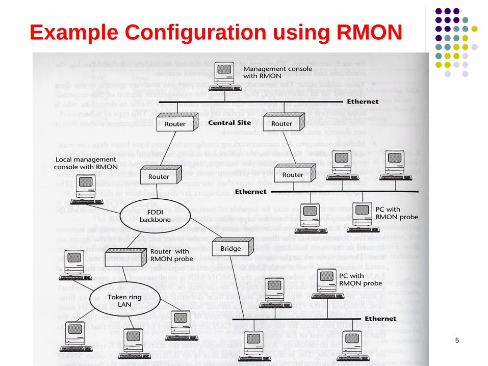
Example Configuration using RMON
5
Multiple Managers The problem of concurrent access:
Concurrent requests for resources could exceed the capability of
the monitor to supply those resources.
A manager may capture and hold monitor resources for a long
period of time.
Resources could be assigned to manager that crashes without
releasing the resource.
Associated with each control table is a columnar
object that identifies the owner of a particular row of
the table and of the associated function.
Ownership label could be:
IP address, management station name, network
manager’s name, location, or phone number
6
Multiple Managers (Cont.)
The ownership label can be used in the
following ways:
A manager may recognize resources it owns
and no longer needs.
A network operator can identify the manager
that owns a particular resource or function.
A network operator may have authority
unilaterally to free resources which another
network operation has reserved.
If a manager experiences a re-initialization, it
can recognize resources it has reserved.
7
Table Management
In the SNMPv1 framework, the procedure for
adding and deleting table rows are, to say the
least, unclear.
SNMPv2 provides a clearer but more
complex set of procedure for adding and
deleting rows, compared to that for SNMPv1.
The RMON specification includes a set of
textual conventions and procedural rules.
8
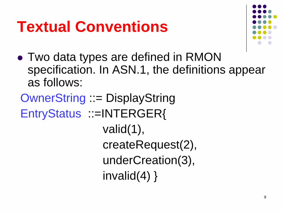
Textual Conventions
Two data types are defined in RMON specification. In ASN.1, the definitions appear as follows:
OwnerString ::= DisplayString
EntryStatus ::=INTERGER{
valid(1),
createRequest(2),
underCreation(3),
invalid(4) }
9
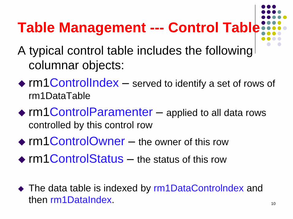
Table Management --- Control Table
A typical control table includes the following
columnar objects:
rm1ControlIndex – served to identify a set of rows of
rm1DataTable
rm1ControlParamenter – applied to all data rows
controlled by this control row
rm1ControlOwner – the owner of this row
rm1ControlStatus – the status of this row
The data table is indexed by rm1DataControlndex and
then rm1DataIndex.
10
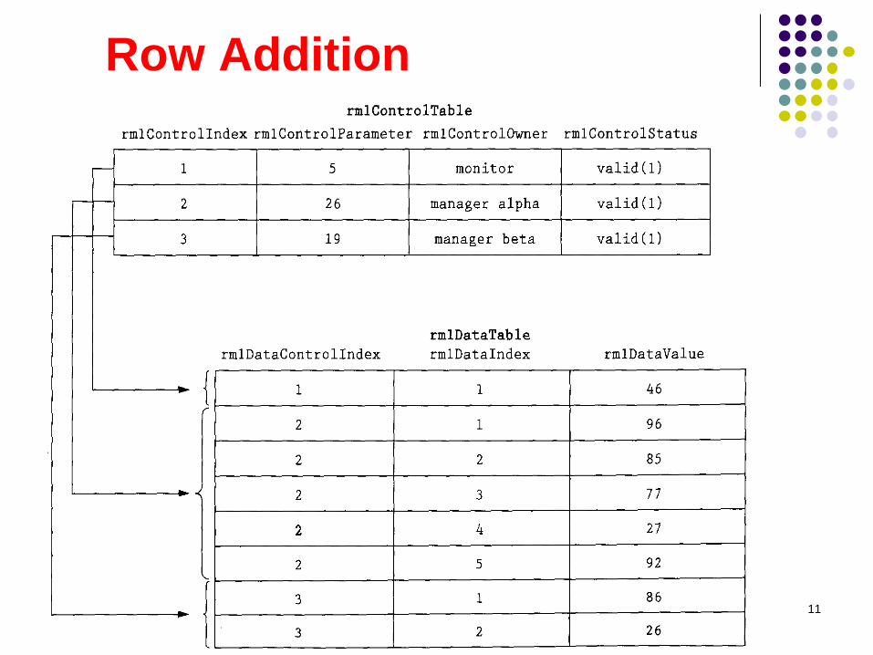
Row Addition
11
RMON Polka
To resolve the problem of concurrent table
addition attempts from multiple mgmt stations:
1. If a management station attempts to create a new row,
and the index object value(s) do not exist, the row is
created with a status object value of createRequest(2)
2. Immediate after completing the create operation, the
agent sets the status object value to underCreation(3)
3. Rows shall exist in underCreation state until the
management station has finished creation. At this point,
the management station sets the status valid (1)
4. If an attempt is made to create a new row, with a
createRequest status, and the row already exists, an
error will be returned. 12
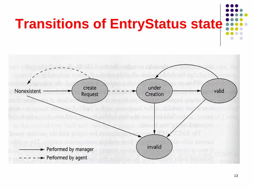
Transitions of EntryStatus state
13
Row Modification and Deletion
A row is deleted by setting the status
object value (by manager) for the row
to Invalid.
The owner of the row can therefore
delete by issuing the appropriate
SetRequest PDU.
A row can be modified by first
invalidating the row and then providing
the row with new parameter values.
14
RMON1 MIB (mib-2 16)
The RMON MIB is divided into ten groups:
Statistics (1)
History (2)
Alarm (3)
Host (4)
HostTopN (5)
Matrix (6)
Filter (7)
Capture (8)
Event (9)
tokenRing (10) 15
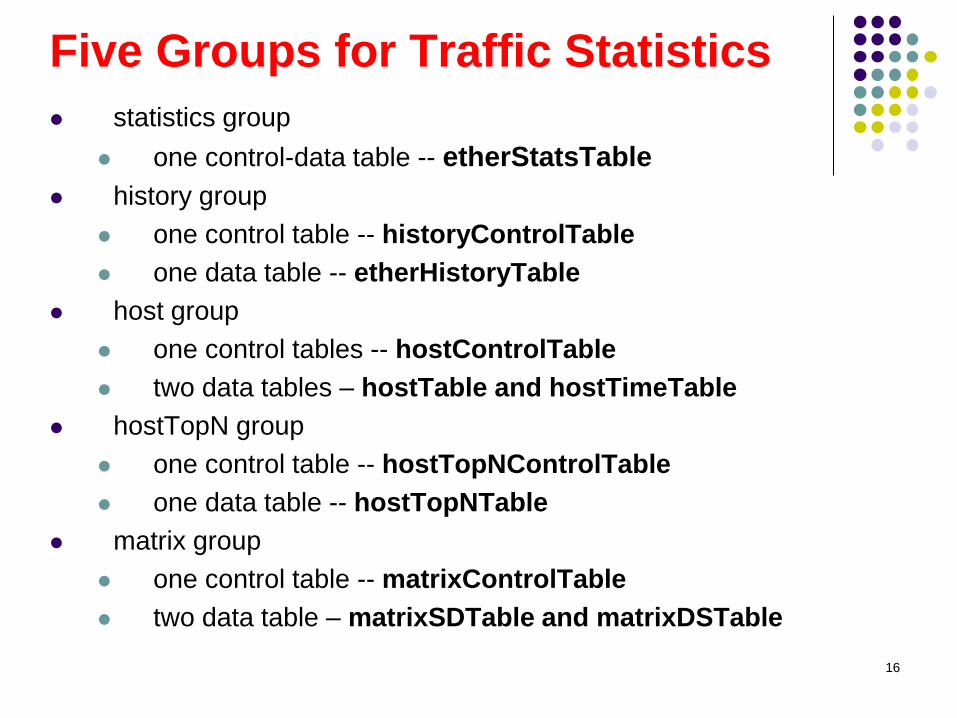
Five Groups for Traffic Statistics
statistics group
one control-data table -- etherStatsTable
history group
one control table -- historyControlTable
one data table -- etherHistoryTable
host group
one control tables -- hostControlTable
two data tables – hostTable and hostTimeTable
hostTopN group
one control table -- hostTopNControlTable
one data table -- hostTopNTable
matrix group
one control table -- matrixControlTable
two data table – matrixSDTable and matrixDSTable
16
Statistics Group (1/2)
Statistics are in the form of counters that start
from zero when a valid entry is entered.
Collect a variety of counts for each attached
subnetwork, including byte, packet, error, and
frame size counts. It is interested to compare
the objects in MIB-II interfaces group.
Indexed by etherStatsIndex in
etherStatsTable
3 Read-write objects: etherStatsDataSource,
etherStatsOwner, and etherStatsStatus
17
Statistics Group (2/2)
Two noncounter objects:
etherStatsIndex – an integer row index
etherStatsDataSource – identify the
interface that is the source of the data in this
row
Provide useful information about the load on a
subnet and the overall health of the subnet
(including CRC alignment errors, collisions,
undersized or oversized packets)
Statistics on traffic into the monitor across an
interface vs total traffic into and out of an
agent’s interface (in MIB-2 interfaces group)
18
History Group The group is used to define sampling functions for one
or more interfaces of the monitor.
A sample scheme is dictated by historyControlBucketsGranted (50)
and historyControlInterval (1800 s)
etherHistoryUtilization =
[(etherStatsPkts*(96+64) + etherStatsOctets*8) /
(historyControlInterval * 100 Mbits) ] * 100%, where 64-
bit preamble and 96-bit inter-frame gap.
Each row of etherHistoryTable, called a bucket, holds
the statistics gathered during one sampling interval.
etherHistoryPkts = difference between etherStatsPkts
at the end of that sampling interval and the beginning
(refer to p226,229 of the textbook for details)
19
Host Group
Gather statistics about specific hosts on the LAN.
hostControlTableSize determines the number of rows
in hostTable and hostTimeTable, N=number of rows in
hostTable = sum of hostControlTableSize of each index
hostTable is indexed by MAC address of the host as
well as by the interface index (as in the probe)
hostTimeTable contains the same information as
hostTable but indexed by the creation order rather than
the MAC address
All the information in host group is obtainable directly
from each host via MIB-II information in the interfaces
group.
hostControlLastDeleteTime is the value of sysUpTime
corresponding to the last time that an entry was deleted.
20
HostTopN Group Maintain statistics about the set of hosts on one
subnetwork that top a list based on some parameter
Data is derived from host group.
Manager creates a row of control table to specify a new
report. The control entry instructs the monitor to
measure the difference between the beginning and
ending values of a particular host group variable over a
specified sampling interval.
The sampling period value is stored in both
hostTopNDuration and hostTopNTimeRemaining
If the manager wishes to generate an additional report
for a new time period, it first gets the results then resets
hostTopNTimeRemaining to the value in
hostTopNDuration, which causes the associated data
rows to be deleted and a new report to be prepared. 21
Matrix Group
Record information about the traffic between pairs of hosts on a subnetwork, and store info. in the form of a matrix.
Useful in finding out which devices are making the most use of a server.
When the monitor detects a new conversation that involves a new host pairing, it creates two new rows in both data tables. If the limit specified in matrixControlTableSize is reached, the least recently used entries are deleted.
matrixSDTable stores statistics on the traffic from a particular source host to a number of destinations. It is indexed by matrixSDSourceAddress, matrixSDDestinationAddress, and matrixSDIndex.
22
Four Groups for Alarms and Filters
alarm group
1 control table -- alarmTable
filter group
2 control table – filterTable and channelTable
packet capture group
1 control tables -- bufferControlTable
1 data table -- captureBufferTable
event group
1 control table -- eventTable
1 data table -- logTable
23
Group Dependencies
All of the groups in the RMON MIB are optional.
However, the following three groups are
dependent:
The alarm group requires the implementation
of the event group
The hostTopN group requires the
implementation of host group
The packet capture group requires the
implementation of the filter group
The filter group requires the implementation
of the event and the packet capture group 24
Alarm Group (1C) (1/3)
Is used to define a set of thresholds for network performance. If a threshold is crossed, an alarm is generated and sent to the NMS.
For example, an alarm could be generated if there are more than 500 CRC errors in any 5-minutes period.
Object types of alarmVariable: INTEGER, counter, gauge, and TimeTicks.
alarmSampleType: absoluteValue(1) or deltaValue(2)
alarmStartupAlarm: risingAlarm(1), fallingAlarm(2), or risingOrFallingAlarm(3)
25
Alarm Group (1C) (2/3)
Rules for the generation of rising-alarm events:
1. if the first sampled value obtained after the row
becomes valid is less than the rising threshold, then a
rising event is generated the first time that the sample
value becomes greater than or equal to the rising
threshold.
2. if the first sampled value obtained after the row
becomes valid is greater than or equal to the rising
threshold, and if the value of alarmStartupAlarm is 1
or 3, then a rising event is generated.
26
Alarm Group (1C) (3/3)
Rules for the generation of rising-alarm events:
3. if the first sampled value obtained after the row becomes valid is greater than or equal to the rising threshold, and if the value of alarmStartupAlarm is 2, then a rising event is generated the first time that the sample value again becomes greater than or equal to the rising threshold after having falling below the rising threshold.
4. After a rising-alarm event is generated, another such event will not be generated until the sampled value has fallen below the rising threshold, reached the falling threshold, and reached the rising threshold again.
Hysteresis Mechanism (refer to the diagram in tutorial slides of simpleweb)
27
Filter Group (2C) (1/6)
Two kinds of filters: data filter and status filter.
The stream of packets that pass the filtering
test is referred to as a channel.
A channel is defined by a set of filters.
If the channel is in an enabled state, it can be
configured to generate an event, defined in the
event group.
The packets passing through the channel can
be captured if the mechanism is defined in the
capture group.
28
Filter Group (2C) (2/6) Channel can be configured to generate an event, defined
in the event group, when a packet passes through the
channel and the channel is in an enabled state,
channelDataControl is on.
Depending upon the channelAcceptType (acceptedMatched or
acceptFailed), channelEventIndex, and channelEventStatus
(eventReady, eventFired, eventAlwaysReady)
In event group, eventIndex = channelEventIndex ( of channelTable),
and eventType could be none, log, snmp-trap, or log-and-trap.
The packets passing through a channel can be captured
if the mechanism is defined in the capture group.
In packet capture group, bufferControlChannelIndex =
channelIndex of channelTable
29
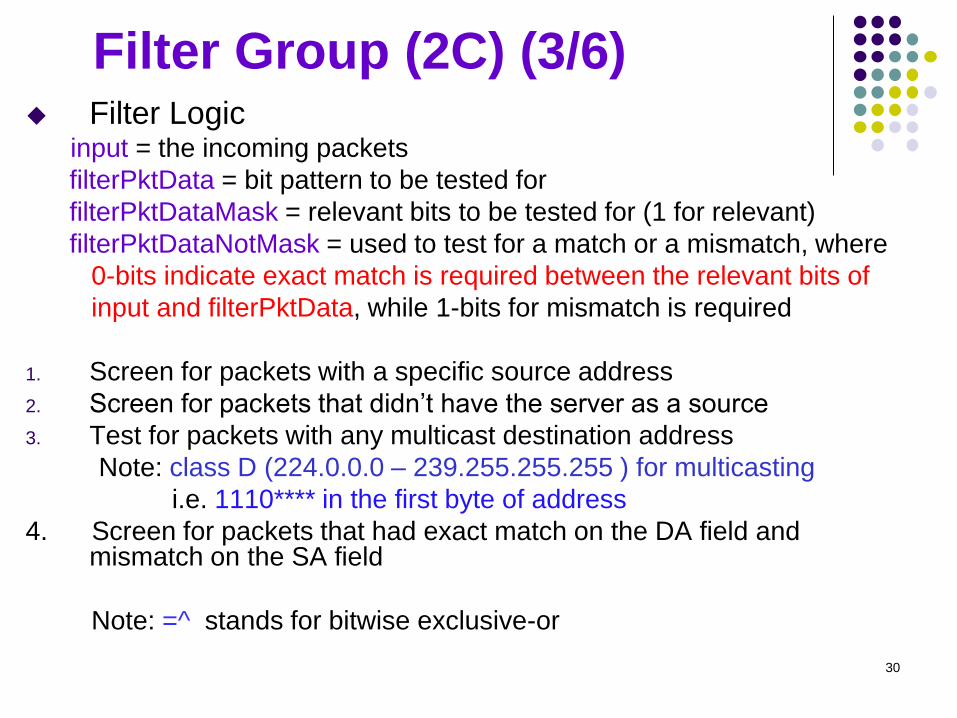
Filter Group (2C) (3/6) Filter Logic input = the incoming packets
filterPktData = bit pattern to be tested for
filterPktDataMask = relevant bits to be tested for (1 for relevant)
filterPktDataNotMask = used to test for a match or a mismatch, where
0-bits indicate exact match is required between the relevant bits of
input and filterPktData, while 1-bits for mismatch is required
1. Screen for packets with a specific source address
2. Screen for packets that didn’t have the server as a source
3. Test for packets with any multicast destination address
Note: class D (224.0.0.0 – 239.255.255.255 ) for multicasting
i.e. 1110**** in the first byte of address
4. Screen for packets that had exact match on the DA field and mismatch on the SA field
Note: =^ stands for bitwise exclusive-or
30
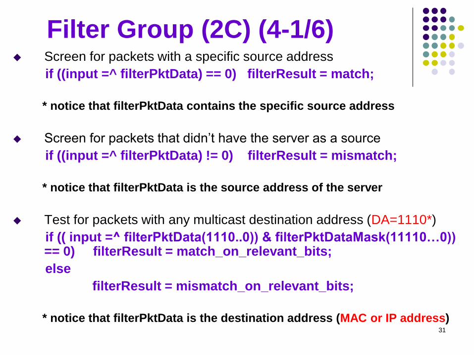
Filter Group (2C) (4-1/6) Screen for packets with a specific source address
if ((input =^ filterPktData) == 0) filterResult = match;
* notice that filterPktData contains the specific source address
Screen for packets that didn’t have the server as a source
if ((input =^ filterPktData) != 0) filterResult = mismatch;
* notice that filterPktData is the source address of the server
Test for packets with any multicast destination address (DA=1110*)
if (( input =^ filterPktData(1110..0)) & filterPktDataMask(11110…0)) == 0) filterResult = match_on_relevant_bits;
else
filterResult = mismatch_on_relevant_bits;
* notice that filterPktData is the destination address (MAC or IP address)
31
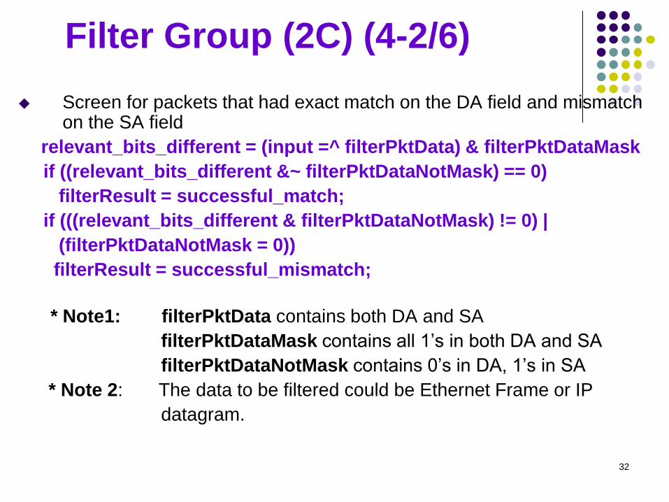
Filter Group (2C) (4-2/6)
Screen for packets that had exact match on the DA field and mismatch on the SA field
relevant_bits_different = (input =^ filterPktData) & filterPktDataMask
if ((relevant_bits_different &~ filterPktDataNotMask) == 0)
filterResult = successful_match;
if (((relevant_bits_different & filterPktDataNotMask) != 0) |
(filterPktDataNotMask = 0))
filterResult = successful_mismatch;
* Note1: filterPktData contains both DA and SA
filterPktDataMask contains all 1’s in both DA and SA
filterPktDataNotMask contains 0’s in DA, 1’s in SA
* Note 2: The data to be filtered could be Ethernet Frame or IP
datagram.
32
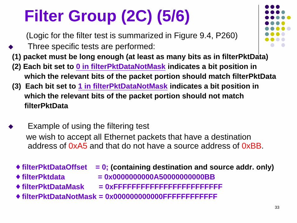
Filter Group (2C) (5/6) (Logic for the filter test is summarized in Figure 9.4, P260)
Three specific tests are performed:
(1) packet must be long enough (at least as many bits as in filterPktData)
(2) Each bit set to 0 in filterPktDataNotMask indicates a bit position in
which the relevant bits of the packet portion should match filterPktData
(3) Each bit set to 1 in filterPktDataNotMask indicates a bit position in
which the relevant bits of the packet portion should not match
filterPktData
Example of using the filtering test
we wish to accept all Ethernet packets that have a destination address of 0xA5 and that do not have a source address of 0xBB.
♦ filterPktDataOffset = 0; (containing destination and source addr. only)
♦ filterPktdata = 0x0000000000A50000000000BB
♦ filterPktDataMask = 0xFFFFFFFFFFFFFFFFFFFFFFFF
♦ filterPktDataNotMask = 0x000000000000FFFFFFFFFFFF
33
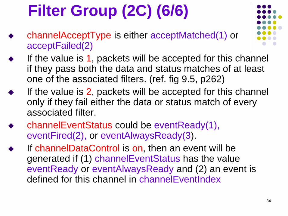
Filter Group (2C) (6/6)
channelAcceptType is either acceptMatched(1) or acceptFailed(2)
If the value is 1, packets will be accepted for this channel if they pass both the data and status matches of at least one of the associated filters. (ref. fig 9.5, p262)
If the value is 2, packets will be accepted for this channel only if they fail either the data or status match of every associated filter.
channelEventStatus could be eventReady(1), eventFired(2), or eventAlwaysReady(3).
If channelDataControl is on, then an event will be generated if (1) channelEventStatus has the value eventReady or eventAlwaysReady and (2) an event is defined for this channel in channelEventIndex
34
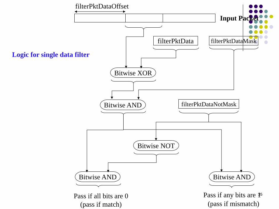
Bitwise XOR
filterPktData filterPktDataMask
Bitwise AND filterPktDataNotMask
Bitwise NOT
Bitwise AND Bitwise AND
Input Packet
filterPktDataOffset
Pass if all bits are 0
(pass if match)
Pass if any bits are 1
(pass if mismatch)
35
Logic for single data filter
Packet Capture Group (1C1D)
Used to set up a buffering scheme for capturing packets
from one of the channels in the filter group, two tables:
bufferControlTable and captureBufferTable.
bufferControlTable defines one buffer to capture and
store packets from one channel. (1 row per channel)
Several buffer control parameters determine how much
of a packet is stored in the buffer and how much is
available for delivery to a management station in one
SNMP get or getNext request: ~CaptureSliceSize (CS),
~DownloadSliceSize (DS), ~DownloadOffset (DO), and
~PacketData (PD), ~PacketLength (PL), …
Length of PD, PDL = MIN (PL, CS)
PD = the octets 0..min(actualStoredData-1, 99), initially,
DO=0 and DS=100 (default value in capture buffer) 36
Event Group (1C1D)
This group supports the definition of events.
An event is triggered by a condition located elsewhere
in the MIB. (A useful feature for manager’s control.)
An event can trigger an action defined elsewhere in the
MIB, may cause information to be logged, or cause an
SNMP trap message to be issued.
evenType could be one of none(1), log(2), snmp-trap(3),
log-and-trap(4)
The key use of the event group is in conjunction with
the alarm group. Also, the filter group can reference an
event that will occur when a packet is captured.
alarmRisingEventIndex or alarmFallingEventIndex matches with
the eventIndex of eventTable for the conjunction.
37
Remote Monitoring 2
Lecture 5
RMON2 (RFC 1997,2021 ) (supplementary: Chapter 5 of tutorial slides)
38
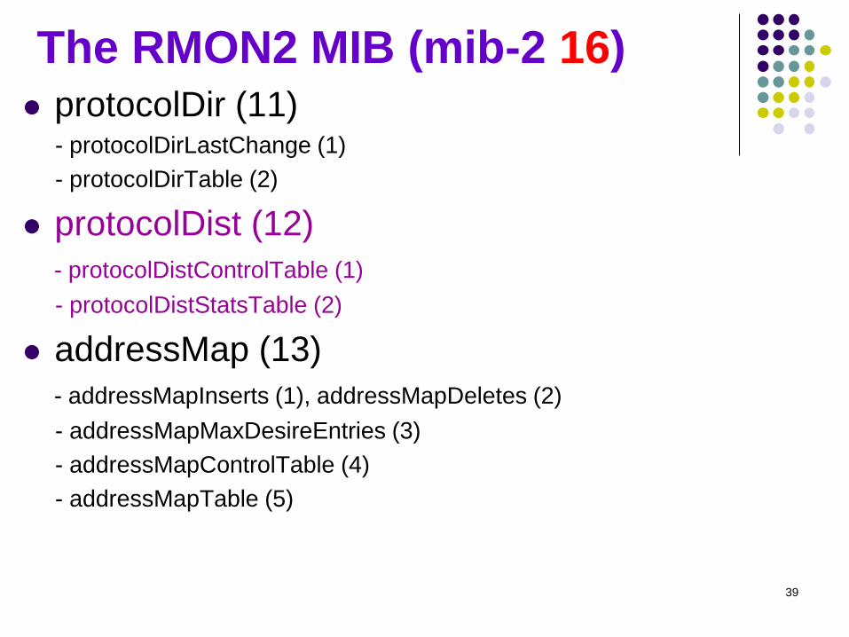
The RMON2 MIB (mib-2 16) protocolDir (11) - protocolDirLastChange (1)
- protocolDirTable (2)
protocolDist (12)
- protocolDistControlTable (1)
- protocolDistStatsTable (2)
addressMap (13)
- addressMapInserts (1), addressMapDeletes (2)
- addressMapMaxDesireEntries (3)
- addressMapControlTable (4)
- addressMapTable (5)
39
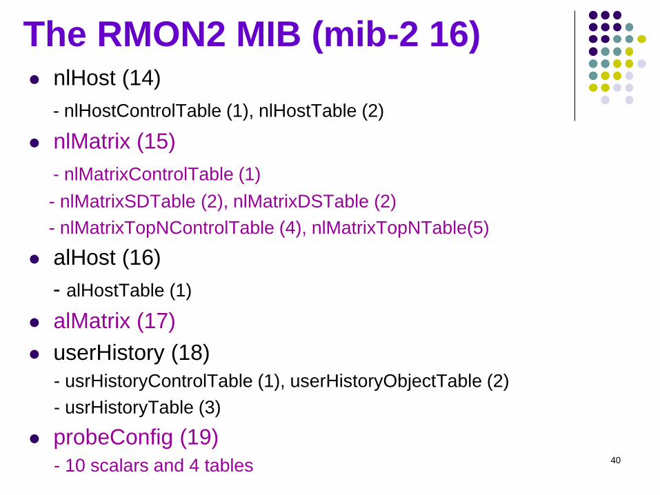
The RMON2 MIB (mib-2 16) nlHost (14)
- nlHostControlTable (1), nlHostTable (2)
nlMatrix (15)
- nlMatrixControlTable (1)
- nlMatrixSDTable (2), nlMatrixDSTable (2)
- nlMatrixTopNControlTable (4), nlMatrixTopNTable(5)
alHost (16)
- alHostTable (1)
alMatrix (17)
userHistory (18)
- usrHistoryControlTable (1), userHistoryObjectTable (2)
- usrHistoryTable (3)
probeConfig (19)
- 10 scalars and 4 tables 40
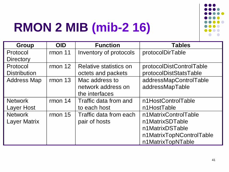
RMON 2 MIB (mib-2 16) Table 8.4 RMON2 MIB Groups and Tables
Group OID Function Tables
ProtocolDirectory
rmon 11 Inventory of protocols protocolDirTable
ProtocolDistribution
rmon 12 Relative statistics onoctets and packets
protocolDistControlTableprotocolDistStatsTable
Address Map rmon 13 Mac address tonetwork address onthe interfaces
addressMapControlTableaddressMapTable
NetworkLayer Host
rmon 14 Traffic data from andto each host
n1HostControlTablen1HostTable
NetworkLayer Matrix
rmon 15 Traffic data from eachpair of hosts
n1MatrixControlTablen1MatrixSDTablen1MatrixDSTablen1MatrixTopNControlTablen1MatrixTopNTable
ApplicationLayer Host
rmon 16 Traffic data byprotocol from and toeach host
a1HostTable
ApplicationLayer Matrix
rmon 17 Traffic data byprotocol betweenpairs of hosts
a1MatrixSDTablea1MatrixDSTablea1MatrixTopNControlTablea1MatrixTopNTable
User HistoryCollection
rmon 18 User-specifiedhistorical data onalarms and statistics
usrHistoryControlTableusrHistoryObjectTableusrHistoryTable
ProbeConfiguration
rmon 19 Configuration of probeparameters
serialConfigTablenetConfigTabletrapDestTableserialConnectionTable
RMONConformance
rmon 20 RMON2 MIBCompliances andCompliance Groups
See Section 8.4.2
41
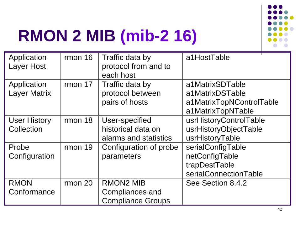
RMON 2 MIB (mib-2 16)
Table 8.4 RMON2 MIB Groups and Tables
Group OID Function Tables
Protocol Directory
rmon 11 Inventory of protocols protocolDirTable
Protocol Distribution
rmon 12 Relative statistics on octets and packets
protocolDistControlTable protocolDistStatsTable
Address Map rmon 13 Mac address to network address on the interfaces
addressMapControlTable addressMapTable
Network Layer Host
rmon 14 Traffic data from and to each host
n1HostControlTable n1HostTable
Network Layer Matrix
rmon 15 Traffic data from each pair of hosts
n1MatrixControlTable n1MatrixSDTable n1MatrixDSTable n1MatrixTopNControlTable n1MatrixTopNTable
Application Layer Host
rmon 16 Traffic data by protocol from and to each host
a1HostTable
Application Layer Matrix
rmon 17 Traffic data by protocol between pairs of hosts
a1MatrixSDTable a1MatrixDSTable a1MatrixTopNControlTable a1MatrixTopNTable
User History Collection
rmon 18 User-specified historical data on alarms and statistics
usrHistoryControlTable usrHistoryObjectTable usrHistoryTable
Probe Configuration
rmon 19 Configuration of probe parameters
serialConfigTable netConfigTable trapDestTable serialConnectionTable
RMON Conformance
rmon 20 RMON2 MIB Compliances and Compliance Groups
See Section 8.4.2
42
Network & Application Visibility (1/2)
RMON2 provides the probe capability above the MAC level Based on network-layer protocol and IP-address
Based on an application-level traffic
The capability of seeing above MAC layer can answer questions, such as: If a router is overloaded because of high amount of
outgoing traffic, what local hosts are responsible for, and to what destination?
If there is a high load of pass-through traffic, arriving via one router and departing via another router, what networks or hosts are responsible for the bulk of this traffic?
43
Network & Application Visibility (2/2)
In Network-Layer Visibility, RMON2 probe can not only monitor the total traffic into and out of routers(RMON1 does), but also to determine the ultimate source of incoming traffic arriving via the router or the ultimate destination of outgoing traffic leaving via the router.
Generate charts and graphs depicting traffic percentage
By protocols
By applications (Notice that: any protocol above the network layer is
considered as “application level protocol”)
44
New Functional Features in RMON2
Two new features of table indexing:
Indexing with external objects SMI for SNMPv2 defines a possible usage for an object not
part of a particular table as an index for that table. RMNO2 adopts this definition.
Time filter indexing
return values only for those values have changed since last poll.
Status objects are specified as having syntax RowStatus (textual convention defined in SNMPv2, p358) rather than EntryStatus.
45
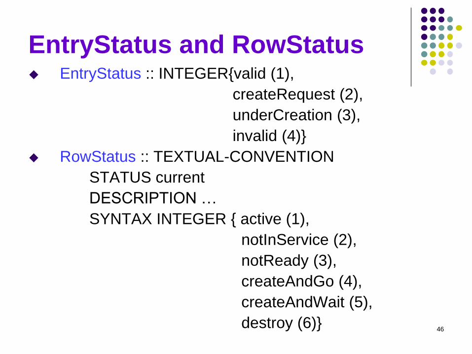
EntryStatus and RowStatus EntryStatus :: INTEGER{valid (1),
createRequest (2),
underCreation (3),
invalid (4)}
RowStatus :: TEXTUAL-CONVENTION
STATUS current
DESCRIPTION …
SYNTAX INTEGER { active (1),
notInService (2),
notReady (3),
createAndGo (4),
createAndWait (5),
destroy (6)}
46
EntryStatus (RMON Polka)
47
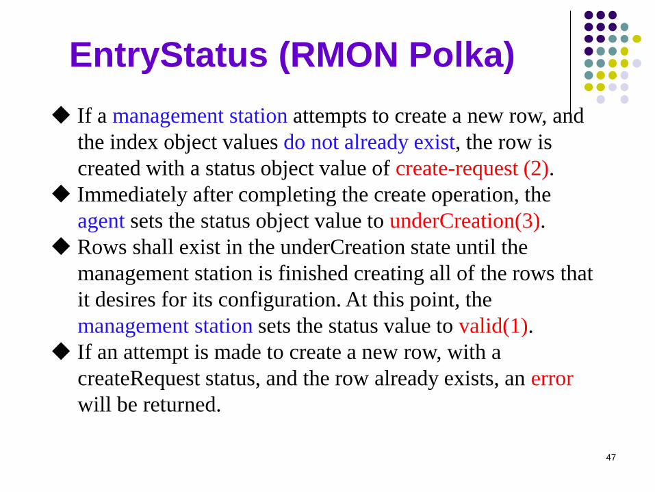
If a management station attempts to create a new row, and
the index object values do not already exist, the row is
created with a status object value of create-request (2).
Immediately after completing the create operation, the
agent sets the status object value to underCreation(3).
Rows shall exist in the underCreation state until the
management station is finished creating all of the rows that
it desires for its configuration. At this point, the
management station sets the status value to valid(1).
If an attempt is made to create a new row, with a
createRequest status, and the row already exists, an error
will be returned.
RowStatus (defined in SMIv2)
48
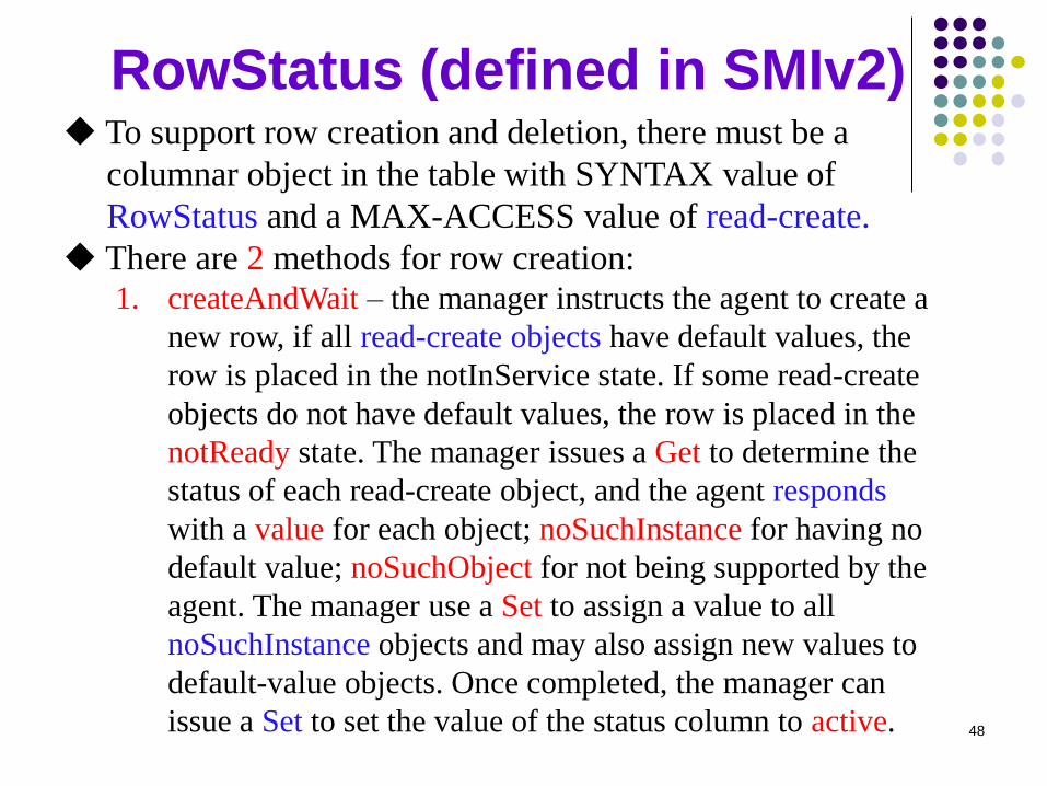
To support row creation and deletion, there must be a
columnar object in the table with SYNTAX value of
RowStatus and a MAX-ACCESS value of read-create.
There are 2 methods for row creation: 1. createAndWait – the manager instructs the agent to create a
new row, if all read-create objects have default values, the
row is placed in the notInService state. If some read-create
objects do not have default values, the row is placed in the
notReady state. The manager issues a Get to determine the
status of each read-create object, and the agent responds
with a value for each object; noSuchInstance for having no
default value; noSuchObject for not being supported by the
agent. The manager use a Set to assign a value to all
noSuchInstance objects and may also assign new values to
default-value objects. Once completed, the manager can
issue a Set to set the value of the status column to active.
RowStatus (defined in SMIv2)
49
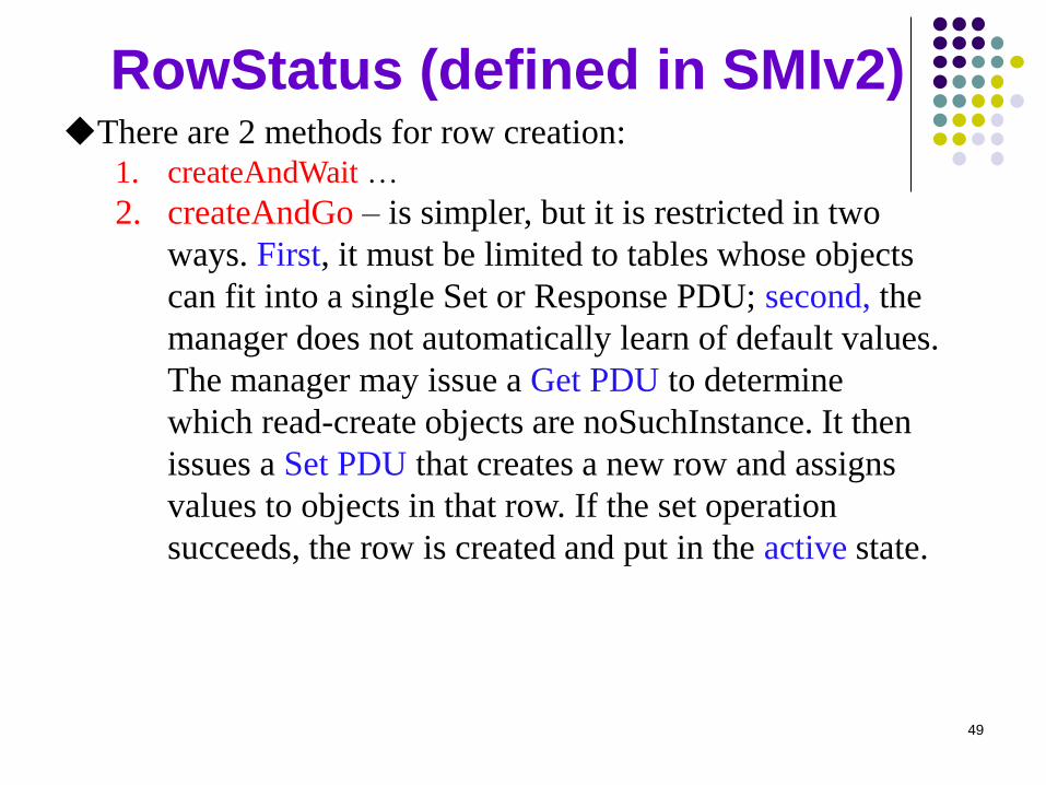
There are 2 methods for row creation: 1. createAndWait …
2. createAndGo – is simpler, but it is restricted in two
ways. First, it must be limited to tables whose objects
can fit into a single Set or Response PDU; second, the
manager does not automatically learn of default values.
The manager may issue a Get PDU to determine
which read-create objects are noSuchInstance. It then
issues a Set PDU that creates a new row and assigns
values to objects in that row. If the set operation
succeeds, the row is created and put in the active state.
Indexing with External Objects
Refer to the examples in p217 and p282
(correction of rm2ControlEntry and
rm2DataEntry by Rm2…)
Notice that the data table has one (indexing)
object not defined in the table definition,
which is the external object.
50
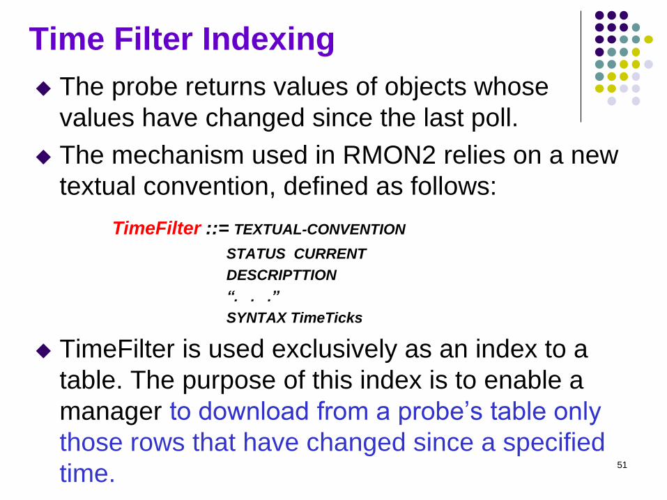
Time Filter Indexing
The probe returns values of objects whose
values have changed since the last poll.
The mechanism used in RMON2 relies on a new
textual convention, defined as follows:
TimeFilter ::= TEXTUAL-CONVENTION
STATUS CURRENT
DESCRIPTTION
“. . .”
SYNTAX TimeTicks
TimeFilter is used exclusively as an index to a
table. The purpose of this index is to enable a
manager to download from a probe’s table only
those rows that have changed since a specified
time. 51
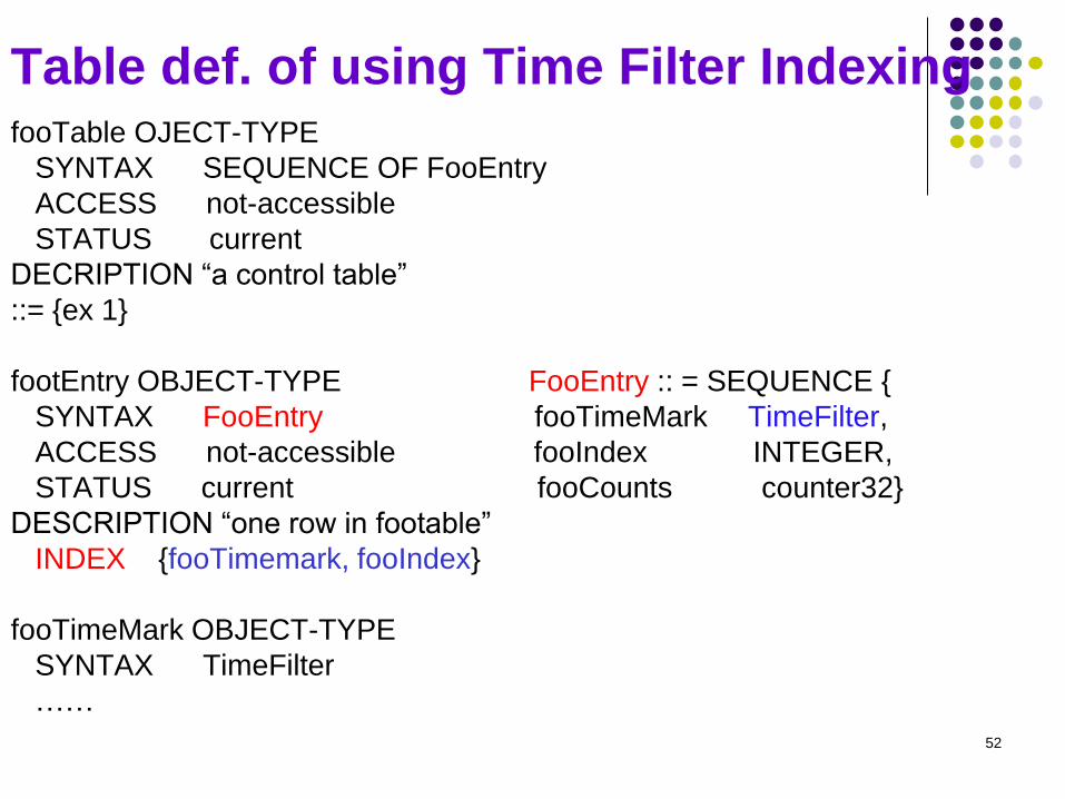
Table def. of using Time Filter Indexing fooTable OJECT-TYPE
SYNTAX SEQUENCE OF FooEntry
ACCESS not-accessible
STATUS current
DECRIPTION “a control table”
::= {ex 1}
footEntry OBJECT-TYPE FooEntry :: = SEQUENCE {
SYNTAX FooEntry fooTimeMark TimeFilter,
ACCESS not-accessible fooIndex INTEGER,
STATUS current fooCounts counter32}
DESCRIPTION “one row in footable”
INDEX {fooTimemark, fooIndex}
fooTimeMark OBJECT-TYPE
SYNTAX TimeFilter
……
52
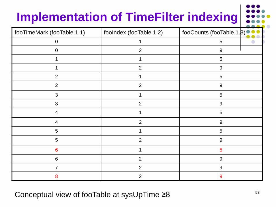
Implementation of TimeFilter indexing fooTimeMark (fooTable.1.1) fooIndex (fooTable.1.2) fooCounts (fooTable.1.3)
0 1 5
0 2 9
1 1 5
1 2 9
2 1 5
2 2 9
3 1 5
3 2 9
4 1 5
4 2 9
5 1 5
5 2 9
6 1 5
6 2 9
7 2 9
8 2 9
Conceptual view of fooTable at sysUpTime ≥8 53
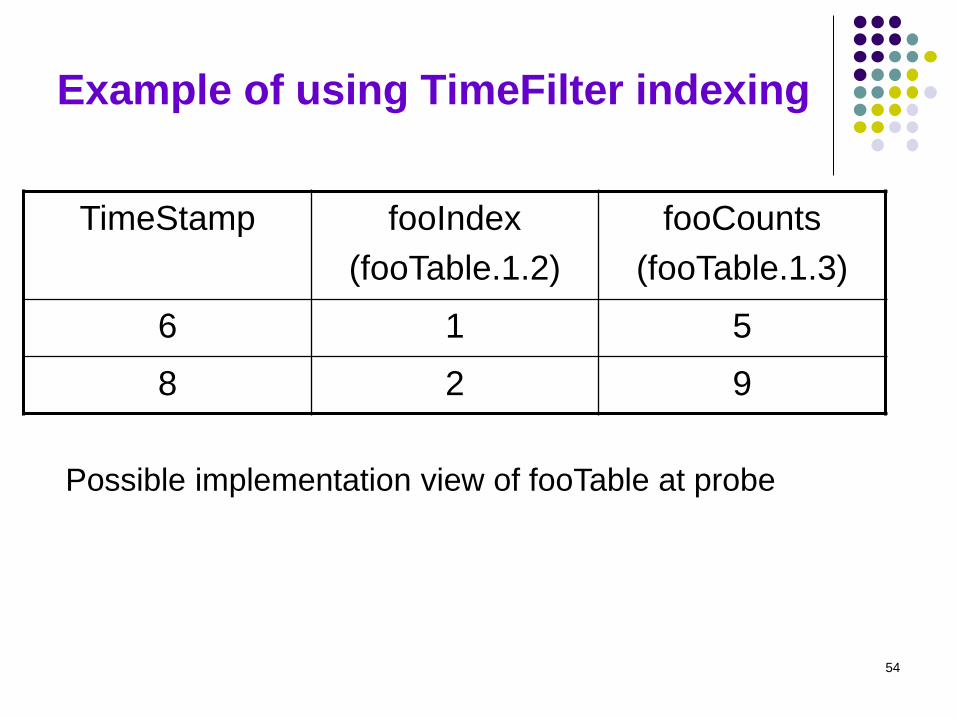
Example of using TimeFilter indexing
TimeStamp fooIndex
(fooTable.1.2)
fooCounts
(fooTable.1.3)
6 1 5
8 2 9
Possible implementation view of fooTable at probe
54
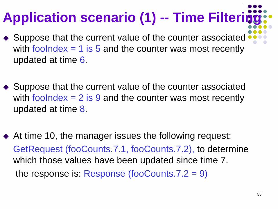
Application scenario (1) -- Time Filtering
Suppose that the current value of the counter associated
with fooIndex = 1 is 5 and the counter was most recently
updated at time 6.
Suppose that the current value of the counter associated
with fooIndex = 2 is 9 and the counter was most recently
updated at time 8.
At time 10, the manager issues the following request:
GetRequest (fooCounts.7.1, fooCounts.7.2), to determine
which those values have been updated since time 7.
the response is: Response (fooCounts.7.2 = 9)
55
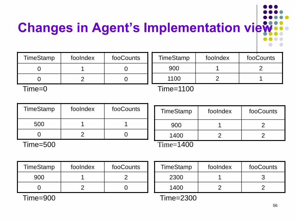
Changes in Agent’s Implementation view
TimeStamp fooIndex fooCounts
0 1 0
0 2 0
TimeStamp fooIndex fooCounts
900 1 2
1100 2 1
TimeStamp fooIndex fooCounts
900 1 2
0 2 0
TimeStamp fooIndex fooCounts
2300 1 3
1400 2 2
TimeStamp fooIndex fooCounts
500 1 1
0 2 0
TimeStamp fooIndex fooCounts
900 1 2
1400 2 2
Time=0
Time=2300 Time=900
Time=1400 Time=500
Time=1100
56
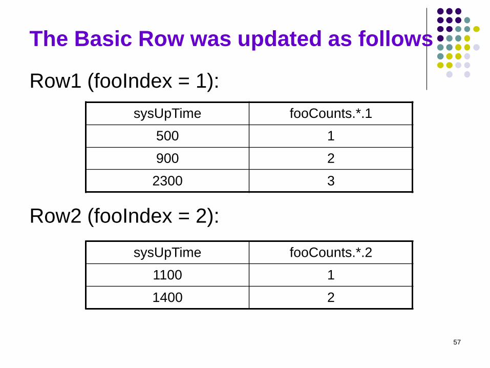
The Basic Row was updated as follows
Row1 (fooIndex = 1):
sysUpTime fooCounts.*.1
500 1
900 2
2300 3
Row2 (fooIndex = 2):
sysUpTime fooCounts.*.2
1100 1
1400 2
57
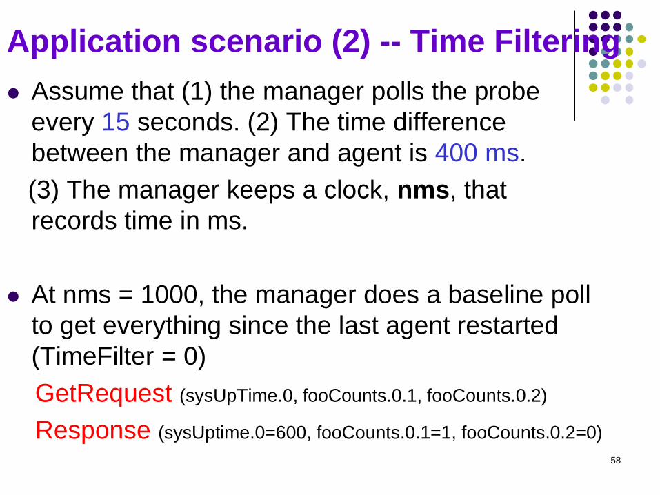
Application scenario (2) -- Time Filtering
Assume that (1) the manager polls the probe
every 15 seconds. (2) The time difference
between the manager and agent is 400 ms.
(3) The manager keeps a clock, nms, that
records time in ms.
At nms = 1000, the manager does a baseline poll
to get everything since the last agent restarted
(TimeFilter = 0)
GetRequest (sysUpTime.0, fooCounts.0.1, fooCounts.0.2)
Response (sysUptime.0=600, fooCounts.0.1=1, fooCounts.0.2=0)
58
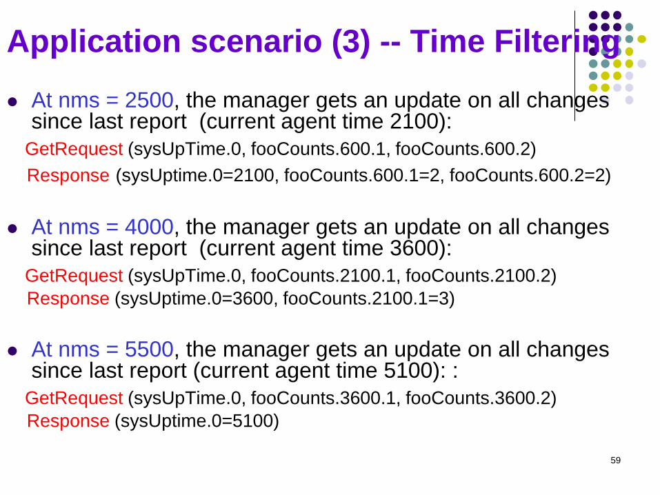
Application scenario (3) -- Time Filtering
At nms = 2500, the manager gets an update on all changes since last report (current agent time 2100):
GetRequest (sysUpTime.0, fooCounts.600.1, fooCounts.600.2)
Response (sysUptime.0=2100, fooCounts.600.1=2, fooCounts.600.2=2)
At nms = 4000, the manager gets an update on all changes since last report (current agent time 3600):
GetRequest (sysUpTime.0, fooCounts.2100.1, fooCounts.2100.2)
Response (sysUptime.0=3600, fooCounts.2100.1=3)
At nms = 5500, the manager gets an update on all changes since last report (current agent time 5100): :
GetRequest (sysUpTime.0, fooCounts.3600.1, fooCounts.3600.2)
Response (sysUptime.0=5100)
59
Protocol Directory Group (1C)
One scalar object, protocolDirLastChange, and
one table, protocolDirTable, for an RMON2 manager to
learn which protocols a probe interprets.
The group includes:
protocolDirTable covers MAC-, Network-, and
higher-layer protocols and is indexed by
protocolDirID and protocolDirParameters.
protocolDirLastChange contains the time of
the last table update.
60
Protocol identifier (1/2)
The protocolDirID object contains a unique octet string for a specific protocol.
The root of the tree is the identifier of a MAC-level protocol.
Each protocol level is identifiers by one or more 32-bit values, and each such value is encoded as four subidentifiers, [a.b.c.d].
Several well-known assigned numbers: ether2 = 1 [0.0.0.1] llc = 2 [0.0.0.2]
snap = 3 [0.0.0.3] vsnap = 4 [0.0.0.4]
ianaAssigned = 5 [0.0.0.5]
61

Protocol Identifier (2/2)
General format cnt protocolDirID cnt protocolDirParameters
IP over Ethernet MAC type is 0x0080, UDP over IP with protocol value 17,and SNMP uses UDP port number 161. protocolDirID has velue:
ether2.ip.udp.snmp (16.0.0.0.1.0.0.8.0.0.0.0.17.0.0.0.161)
protocolDirParameters is structured as a one-octet count field followed by a set of N-octets parameters, one for each protocol.
Protocol directory table also contains LocalIndex, Descr, Owener, Status, and 3 configuration enumerated values: DirHostConfig, HostConfig, and MatrixConfig
62
Protocol Distribution Group (1C1D)
Summarize how many octets and packets have
been sent from each of the protocol supported.
protocolDistControlTable controls collection pf basic
statistics for all supported protocols, and
protocolDistStatsTable records the data.
protocolDistStatsTable includes one row for each
protocol in protocolDirTable for which at one packet
has been seen. It is indexed by
protocolDistControlIndex and protocolDirLocalIndex.
protocolDistStatsTable contains two objects:
protocolDistStatPkts and protocolDistStatsOctets
63
Address Map Group (1C1D, 1/2)
Match each network address to a specific MAC-address and to a specific port on the network interface.
Helpful in node discovery and network topology applications.
Contain 3 scalars objects, one control table addressMapControlTable, and one data table addressMapTable.
There is a single central data table containing entries that provide the mapping between IP and MAC addresses.
Data table is not indexed by a row of the control table.
64
Address Map Group (1C1D, 2/2)
addressMapTable collects address mappings based on source MAC and network addresses.
An entry is created for all protocols in the protocol directory table whose value of protocolDirAddressMapConfig is equal to supportedOn(3).
addressMapTable is indexed by 4 objects: ~TimeMark, protocolDirLocalIndex, ~NetworkAddress, ~Source.
Given a network address for a particular protocol observed on a particular interface within a particular amount of time, the MAC address for that network address can be read.
This group is useful in detecting duplicate IP addresses.
65
Host Groups (1C1D)
nlHost group allows users to decode packets based on their network-layer addresses.
alHost group creates entries for all application layer protocols in the protocol directory table whose value of ~AlHostConfig is equal to supportedOn(3).
nlHostTable is indexed by 4 objects: ~ControlIndex, ~TimeMark, ~Address, and protocolDirLocalIndex.
alHostTable is indexed by 5 objects: ~TimeMark, nlControlIndex, nlHostAddress, protocolDirLocalIndex, protocolDirLocalIndex (for network and application protocols respectively)
alHostTable allows users to trace traffic in/out of a host on the basis of application protocol.
66
Matrix Groups (?C3D, 1/2)
nlMatrix and alMatrix groups gather statistics based
on network layer address and application layer
protocol
nlMatrix contains 2 control tables and 3 data tables
(2 for matrix statistics, 1 for topN statistics).
HostTopN ranks individual hosts on one subnetwork,
while RMON2 TopN statistics ranks the traffic
between pairs of hosts.
alMatrix contains 1 control table and 3 data tables.
alMatrixDSTable is indexed by 6 objects from 3
tables.
67
Matrix Groups (?C3D, 2/2)
An sample object instance of alMatrixSDTable: alMatrixSDPkts.1.783459.18.4.128.2.6.6.4.128.2.6.7.34
[1] the first row of nlMatrixControlTable
[783497] time in time ticks for this row
[4.128.2.6.6] and [4.128.2.6.7] specify the source and destination hosts
[18] specify the network layer protocol defined by row 18
of protocolDirTable
[34] specify the application layer protocol defined by row
34 of protocolDirTable
Both nlMatrixTopNRateBase and alMatrixTopNRateBase specify two objects for table sorting: ~TopNPkts and ~TopNOctets
68
User History Collection Group
Periodically polls particular statistics/variables
and then logs that data based on user-
defined parameters
Allows the network manager configures
history studies of any counter in the system
Three-level hierarchy of tables:
userHistoryControlTable (for sampling details),
userHistoryObjectTable, and
userHistoryTable.
69
Probe Configuration Group
Defines a set of configuration parameters for
probes to enhance interoperability among
probes and managers.
Contains 9 scalar objects and 4 tables:
serialConfigTable, netConfigTable,
trapDestTable, and serialConnectionTable
70
Extensions to RMON1 for RMON2 Devices
A createTime object is added to all control
table
A droppedFrames object is added to a
number of tables, included as a filter object in
all filter definitions
The object filterProtocolDirLocalIndex is
added to filterTable
71