performance of masonry enclosure walls: lessons learned from recent earthquakes
TRANSCRIPT

Vol.11, No.1 EARTHQUAKE ENGINEERING AND ENGINEERING VIBRATION March, 2012
Correspondence to: Romeu Silva Vicente, University of Aveiro, Civil Engineering Department, Campus Universitário de Santiago, Aveiro, PT 3810-193, PortugalTel: +351 962457241E-mail: [email protected]
†Assistant Professor; ‡Researcher/PhD Student; §Associate Professor; *Full Professor
Received June 19, 2011; Accepted October 26, 2011
Earthq Eng & Eng Vib (2012) 11: 23-34 DOI: 10.1007/s11803-012-0095-3
Performance of masonry enclosure walls: lessons learned from recent earthquakes
Romeu Silva Vicente1†, Hugo Rodrigues1‡, Humberto Varum1§, Aníbal Costa1* and José António Raimundo Mendes da Silva2§
1. University of Aveiro, Civil Engineering Department, Campus Universitário de Santiago, Aveiro, PT 3810-193, Portugal
2. University of Coimbra, Civil Engineering, Pinhal de Marrocos, Polo II, Coimbra, PT 3030, Portugal
Abstract: This paper discusses the issue of performance requirements and construction criteria for masonry enclosure and infi ll walls. Vertical building enclosures in European countries are very often constituted by non-load-bearing masonry walls, using horizontally perforated clay bricks. These walls are generally supported and confi ned by a reinforced concrete frame structure of columns and beams/slabs. Since these walls are commonly considered to be nonstructural elements and their infl uence on the structural response is ignored, their consideration in the design of structures as well as their connection to the adjacent structural elements is frequently negligent or insuffi ciently detailed. As a consequence, nonstructural elements, as for wall enclosures, are relatively sensitive to drift and acceleration demands when buildings are subjected to seismic actions. Many international standards and technical documents stress the need for design acceptability criteria for nonstructural elements, however they do not specifi cally indicate how to prevent collapse and severe cracking, and how to enhance the overall stability in the case of moderate to high seismic loading. Furthermore, a review of appropriate measures to improve enclosure wall performance and both in-plane and out-of-plane integrity under seismic actions is addressed.
Keywords: RC structures; masonry enclosure walls; infi ll walls; in-plane; out-of-plane; cracking; performance improvement
1 Introduction
Nonstructural elements, such as masonry infi lls and enclosure walls, parapets, balconies, chimneys, suspended ceilings, as well as piping systems may suffer distortions and excessive deformation during an earthquake, or even fall and compromise human life and serviceability and functionality of the building itself. Repair costs and disruption of normal use due to earthquake damage to nonstructural elements often exceeds the structural repair costs. In the case of the Northridge earthquake, the cost of repairs to nonstructural elements of essential buildings (hospitals, police departments, electrical substations, etc.) rose to billions of dollars (FEMA, 2005). In the Aquila earthquake, nonstructural damage to industrial building stock was estimated to be over 10,000,000 Euros (EEFIT, 2009).
External masonry walls throughout Europe have changed a great deal in the last decade, as a result of new goals and challenges related to thermal performance and condensation control in buildings. One of the most contradictory measures on this matter is external thermal bridge correction using traditional horizontally perforated clay bricks. This technique has led to the improvement of thermal behavior, but also to some new risks, such as subsequent defects and insuffi cient performance requirements when subjected to seismic actions. One of the most common causes for the instability and poor behavior of masonry enclosure and infi ll walls when subjected to seismic motions is their reduced support-width on the concrete slabs or beams. This reduced wall support is normally required to minimize thermal bridge effects over internal surfaces, such as mold growth and condensation (internal and external). With this procedure, the project designers’ intent is to cover the concrete structure externally with a thin clay brick slip (normally half width or less of clay brick) that increases, locally, the thermal resistance.
2 Masonry infills and enclosure walls
2.1 Thermal bridge correction
24 EARTHQUAKE ENGINEERING AND ENGINEERING VIBRATION Vol.11
New European thermal codes (RCCTE, 2006; Spanish Technical Building Code, 2006; Decreto Legislativo, 2005; Décret n°2006-592, 2006) and building energy standards have translated the EU Directive 2002/91/CE on Energetic Effi ciency in Buildings (EPBD) ( Directive 2002/91/CE, 2002). The introduction of the “Energy Performance Building Directive” (Directive 2002/91/CE, 2002) and, subsequently, the requirements and construction procedures of concern led to the reformulation of the new thermal codes encouraging thermal bridge correction, limiting a U-value (W/m2ºC) for superfi cial thermal bridges and consequently attenuating linear thermal bridges. EN-ISO 10211 (2007) defi nes thermal bridges as an area of the exterior envelope for which there is a pronounced reduction of thermal resistance. These areas have a high potential for mold growth and development of condensation problems (internal and superfi cial).
The new codes and standards established improved quality and precise energy effi ciency requirements for new or renovated buildings, thus creating a legislative framework that harmonizes building standards throughout Europe. In the parts that support a sustainable approach, these codes are very well adapted; however, when it comes to promoting technological innovation in the construction process, their contribution is less ambitious. It is accepted that each country has its own construction and technological traditions in terms of materials and construction processes, but in the case of Mediterranean countries that share technological construction features, as in the case of Portugal, Spain, France and Italy, technological know-how is far from a consensus of construction processes, in particular to thermal bridge correction.
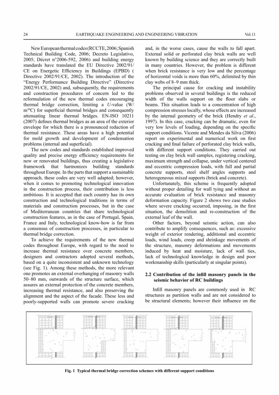
To achieve the requirements of the new thermal codes throughout Europe, with regard to the need to increase thermal resistance over concrete members, designers and contractors adopted several methods, based on a quite inconsistent and unknown technology (see Fig. 1). Among these methods, the more relevant one promotes an external overhanging of masonry walls 50–80 mm, outwards of the structure surface, which assures an external protection of the concrete members, increasing thermal resistance, and also preserving the alignment and the aspect of the facade. These less and poorly-supported walls can promote severe cracking
and, in the worse cases, cause the walls to fall apart. External solid or perforated clay brick walls are well known by building science and they are correctly built in many countries. However, the problem is different when brick resistance is very low and the percentage of horizontal voids is more than 60%, delimited by thin clay webs of 8–9 mm thick.
The principal cause for cracking and instability problems observed in several buildings is the reduced width of the walls support on the fl oor slabs or beams. This situation leads to a concentration of high compression stresses locally, whose effects are increased by the internal geometry of the brick (Hendry et al., 1997). In this case, cracking can be dramatic, even for very low levels of loading, depending on the specifi c support conditions. Vicente and Mendes da Silva (2006) report on experimental and numerical work on fi rst cracking and fi nal failure of perforated clay brick walls, with different support conditions. They carried out testing on clay brick wall samples, registering cracking, maximum strength and collapse, under vertical centered and eccentric compression loads, with full and partial concrete supports, steel shelf angles supports and heterogeneous mixed supports (brick and concrete).
Unfortunately, this scheme is frequently adopted without proper detailing for wall tying and without an accurate evaluation of brick resistance and masonry deformation capacity. Figure 2 shows two case studies where severe cracking occurred, imposing, in the fi rst situation, the demolition and re-construction of the external leaf of the wall.
Other factors, beyond seismic action, can also contribute to amplify consequences, such as: excessive weight of exterior rendering, additional and eccentric loads, wind loads, creep and shrinkage movements of the structure, masonry deformations and movements induced by heat and moisture, lack of wall ties, lack of technological knowledge in design and poor workmanship skills (particularly at singular points).
2.2 Contribution of the infi ll masonry panels in the seismic behavior of RC buildings
Infi ll masonry panels are commonly used in RC structures as partition walls and are not considered to be structural elements; however their infl uence on the
Fig. 1 Typical thermal bridge correction schemes with different support conditions

No.1 Romeu Silva Vicente et al.: Performance of masonry enclosure walls: lessons learned from recent earthquakes 25
global behavior of RC frames subjected to earthquake loadings is well recognized (Crisafulli et al., 2000; Rodrigues et al., 2009). The infi ll masonry panels, if properly distributed and considered in the design of new structures, can have a benefi cial effect, or the negative effects associated with irregularities that they may introduce can be considered in the design process (Varum, 2003). Not considering infi ll masonry panels can lead to important inaccuracies in the evaluation of the structural response, since they can change stiffness, strength, torsion effects due to the irregular location of the infi ll walls, energy dissipation of the global structure and induce local mechanisms.
Considering the severe structural damage or collapse of RC buildings observed in recent earthquakes, two principal mechanisms have been documented. The fi rst is associated with cases where masonry infi ll walls leave a short portion of the column clear, creating a short column. This situation is created by openings in the infi ll walls, for doors or windows, or for landing slabs of staircases. If this effect was not considered in the design, the short column with increased stiffness will be subjected to a high level of shear force which can lead to shear failure of the column. Secondly, the absence of the infi ll masonry panels in one story, frequently on the ground fl oor used for car parking or commercial purposes, induces a sudden change in the story stiffness in height, leading to a potential global soft-story mechanism. Moreover, the asymmetric distribution of the infi ll masonry panels can introduce torsion phenomenon not predicted in the design, which can introduce additional forces not originally considered, especially in concrete columns of the outer frames (Fardis, 2006).
In the Kocaeli, Turkey, earthquake in 1999, buildings with horizontally perforated clay unit infi ll walls only above the fi rst story, usually to allow for commercial space on the ground level, may have experienced stiffness discontinuities, which may have contributed to their collapse by concentrating the drift demands in the fi rst story (Sezen et al., 2003).
In the Bingöl, Turkey, earthquake in 2003, much of the damage and collapse of RC frame buildings is
attributed to the infi ll masonry walls in terms of: soft-story collapses associated with the absence of infi ll masonry walls in the ground stories, failures due to a short column that developed due to structural arrangements or openings provided in infi ll walls between columns, the presence of large and heavy overhangs leading to severe damage in the enclosure due to the vertical ground acceleration during the earthquake, and the destruction of gable walls under the roofs of many buildings that fell down during the earthquake (Dogangun, 2004).
In the 2008 earthquake in Wenchuan, Sichuan Province, China, the damage to most of the buildings with RC frame structures was not very severe. The damage mainly occurred in the enclosure structures and infi lling walls, especially circular fi ller walls. Such nonstructural damage also brings considerable economic loss and can be harmful to people’s safety (Ye et al., 2008). The recent earthquakes show that infi ll masonry panels introduce signifi cant changes in the structural behavior of RC buildings. They can bring a benefi cial contribution to the structural safety or lead to unexpected damage or collapse of RC buildings, and as such, the contribution and participation of infi ll masonry panels in the seismic behavior of RC buildings must be considered in the design of new structures and assessment of the existent building stock.
3 Abruzzo earthquake
3.1 Damaged masonry enclosure walls
Nonstructural elements, in general, are very vulnerable to earthquake action, mostly due to a lack of earthquake design and construction detailing of these elements. As a result, even light to moderate earthquake shaking/acceleration or drift levels can cause damage to nonstructural elements and this damage may result in life safety hazards, immediate evacuation and loss of function of buildings, limiting the use of interior spaces.
Based on post-seismic damage assessment information, some examples, representative of
Fig. 2 Two examples of severe mechanical defects resulting from inadequate correction of thermal bridges, using partially supported masonry walls

26 EARTHQUAKE ENGINEERING AND ENGINEERING VIBRATION Vol.11
systematic masonry enclosure wall failures, are reported and discussed. The damage suffered by masonry enclosures and infi ll walls in the April 6, 2009 Abruzzo earthquake in Italy, particularly in the city of Aquila, is reported due to its representative characteristics of Mediterranean construction. Widespread nonstructural damage, mainly out-of-plane collapse (of the outer leaf of cavity walls), in-plane mechanisms and mixed mechanism were observed. The Abruzzo earthquake struck several villages with different intensities; the maximum acceleration registered was 0.675 g, widely exceeding the 0.25 g defi ned in the design code. Within the reconnaissance mission of the authors, a group of systematic problems, often the consequence of bad construction practice, was observed.
3.2 Out-of-plane mechanisms
As a result of the set of damage mechanisms that can develop during an earthquake, the out-of-plane movement of masonry facade walls is very common, but depends particularly on the effi ciency of the connection between the facade itself and orthogonal walls (Shi, 2008; D’Ayala and Speranza, 2003). Out-of-plane mechanisms are characterized by brittle behavior and
are therefore a threat to human safety, as was the case following the collapse of wall panels in the Messina earthquake in 1908 and Carlentini earthquake in 1990, in Italy where many lives were lost (Ortigia, 2000).
The out-of-plane failure mechanisms and associated cracking patterns are infl uenced by several aspects, but more potentially by: (1) the connection effi ciency to orthogonal walls and inner leaf panels; (2) the connection effi ciency to upper and lower RC beams, as well as columns; and (3) the wall support conditions over concrete slab or beam.
Focusing on external masonry enclosure walls, Fig. 3 shows nonstructural damage of masonry enclosure walls of a six story concrete framed building after the earthquake. Possible causes that led to this level of damage are related to susceptibility of the balconies to higher vertical accelerations, slenderness of the masonry leafs, non-confi nement of the external leaf, and the lack of ties or anchoring systems either to the inner leaf or the structural concrete frame. In Fig. 3, the existence of thin brick slips with defi cient adhesion to the concrete beams and insuffi cient width support of the outer leaf (perforated brick) over the slab/beam is also evident.
Figure 4 shows the extensive disconnection of the veneer wall and its backing wall due to the lack of wall
Fig. 3 Cracking and collapse of the outer leaf of a double leaf wall
Fig. 4 Total disconnection of the outer veneer cladding wall

No.1 Romeu Silva Vicente et al.: Performance of masonry enclosure walls: lessons learned from recent earthquakes 27
ties, lateral constraint at corner angles, and insulation fi xing system to the moment frame resisting structure. In Eurocode 6 (CEN, 2005), Section 8.5.2.2, it is recommended that the minimum number of ties, ntmin, for a cavity wall or veneer wall and its backing wall should not be less than 2/m2.
In both cases, the inadequate mortar jointing of the brick wall is visible, which is, unfortunately, a common practice associated with very poor workmanship. Slender walls are very sensitive to acceleration and displacement and conditioned to peripheral connection and support conditions to the concrete frame structure, as well as the connection effi ciency to inner leaves and orthogonal walls (see Fig. 5(a)). As shown in Fig. 5(b), the disconnection and cracking of the exterior wall panel is the result of the relative rotation of the wall leading to out-of-plane movement. In Fig. 5(c), the development of horizontal hinges is noticeable, defi ning the out-of-plane kinematics.
Due to all these aspects, an out-of-plane mechanism can occur. However, this mechanism can occur for lower levels of acceleration if previous in-plane damage is infl icted over the wall as shown in Fig. 5 or if secondary elements are connected to the external walls, such as
equipment (air-conditioning), outdoor signage, etc.In moderate seismic regions, Eurocode 8 (CEN,
2004), specifi cally Section 4.3.5 which refers to nonstructural elements, obliges the designers to verify the effects of seismic action over these components, as well as their connections and attachments to the main concrete frame. In the case of masonry infi lls, if connected, they contribute to the resistant structural system and should respect the compliance criteria specifi ed for confi ned masonry. Particular attention should be paid to masonry panels with a high slenderness ratio, as will be discussed in Section 4.2.
3.3 In-plane mechanisms
In-plane damage to external enclosure walls is a result of their lower deformation capacity in relation to the principal concrete moment frame structural elements (beams and columns) to inter-story drift levels. Therefore, damage levels are proportional to inter-story drift levels. Figure 6(a) shows typical separation cracks between the structural elements (beams and columns) and masonry wall panel. Figure 6(b) shows shear diagonal cracking due to in-plane forces and bed joint
Fig. 5 (a) Out of plane collapse of infi ll walls;( b) Wall panel rotation; (c) Horizontal hinge formation; (d) Total collapse of the single leaf wall
Fig. 6 (a) Structural frame-wall separation cracking; (b) Shear induced diagonal cracking; (c) Corner crushing of wall panels
a) b) c)

28 EARTHQUAKE ENGINEERING AND ENGINEERING VIBRATION Vol.11
sliding that leads to the detachment of mortar renders and the outer shell of the horizontally perforated fi re clay masonry units, and Fig. 6(c) shows crushing and cracking at the wall corners.
In-plane damage is inevitable when masonry infi lls and enclosure walls contribute to the overall response of the building to seismic action. Figure 7(a) shows typical in-plane damage and short column mechanism due to the presence of openings in masonry enclosure walls. Figures 7(b) and 7(c) show the damage mechanism due to diagonal cracking (stair-step confi guration) along with horizontal bed joint sliding.
3.4 Other damage
Unconfi ned masonry panels, shown to have no vertical concrete struts or posts at corner angles, suffered out-of-plane collapse as shown in Fig. 8. Mixed mechanisms that compromise in-plane and out-of-plane integrity and behavior are very dependent on the directivity of the seismic action as well as the vertical component. The lack of reinforcing steel (light wire
meshes), wall ties and anchors fi xed to the columns and cast into the bedding planes of the masonry, and reinforced concrete posts and belts across the panels through the full thickness of the wall, is particularly important in cases of masonry enclosure walls of great extension or of complex and irregular geometry as shown in Figs. 8(b) and 8 (c). All these problems are aggravated and potentially increase the out-of-plane collapse of masonry wall panels and in-plane damage discussed in Sections 3.1.1 and 3.1.2.
The incorporation of secondary elements, concrete posts and belts across the panels and through the full thickness of the wall, as referred to in Section 4.3.6.4 of Eurocode 8 (CEN, 2004), limit the damage suffered and consequently reduce the risk of human life loss.
4 Structural performance requirements and compliance criteria
4.1 Design codes and international recommendations
Fig. 8 (a) Wall collapse of unconfi ned masonry panels due to lack of post at corner angle;(b) Collapse of outer leaf disproven of posts, belts or anchoring systems; (c) Total collapse of the outer masonry leaf with no wall tie or steel wire mesh
Fig. 7 (a) Short column; (b) In–plane cracking and crushing of masonry wall (c) Horizontal bed joint sliding

No.1 Romeu Silva Vicente et al.: Performance of masonry enclosure walls: lessons learned from recent earthquakes 29
With a greater awareness of the importance of infi ll masonry elements in the behavior of RC buildings in the last few years, the new codes have included some provisions regarding consideration of the infi lls and their infl uence on the structural response, namely Eurocode 6 (CEN, 2005), Eurocode 8 (CEN, 2004), FEMA 310 (1998), ATC-40 (1996) and the New Zealand Guidelines (NZSEE, 2006).
The Eurocode 8 (CEN, 2004) includes recommendations for the verifi cation of the safety of nonstructural elements, acknowledging that in case of failure, they represent a risk to human life and can affect the main structure of the building. Eurocode 8 (CEN, 2004) also refers to the safety verifi cation of nonstructural elements as well as their connections and attachments or anchorages during the design, considering that the local transmission of actions to the structure by the fastening of nonstructural elements and their infl uence on the structural behavior should be taken into account. For the particular case of infi ll masonry panels, in particular if the masonry infi lls are in contact with the frame (i.e., without special separation joints), but without structural connection to it (through wall ties, reinforced concrete belts and posts, or shear connectors), they can affect the ductility class of the structure. In particular, for panels that might be vulnerable to out-of-plane failure, the provision of ties can reduce the hazard of falling masonry. For structural systems belonging to all ductility classes, DCL, M or H, appropriate measures should be taken to avoid brittle failure and premature disintegration of the infi ll walls (particularly for masonry panels with openings or with friable materials), as well as the partial or total out-of-plane collapse of slender masonry panels. Particular attention should be paid to masonry panels with a slenderness ratio greater than 15.
FEMA 310 (1998) in the basic nonstructural component checklist for building evaluation, defi nes that nonstructural components such as partitions, masonry veneers, cladding and parapets, should respect the compliance criteria in accordance to seismic zoning (fi xtures, spacings and anchoring) and the evaluation procedure should be based on the forces and drift limits.
The ATC-40 (1996) acknowledges that the cost and disruption of bringing nonstructural systems in older buildings into conformance with current codes is high. Although these systems have suffered considerable damage in past earthquakes, the damage has generally not caused extensive hazardous conditions. Nonstructural systems, therefore, have not been reviewed in most retrofi ts to date.
However, large, highly vulnerable elements have often been investigated for their potential to fall and cause injury. The criteria used to determine the need to investigate is unclear, but vulnerability to damage and the extent of occupant exposure are initial considerations. The extent of the retrofi t is often a cost consideration. The nonstructural performance level of hazards reduced
is intended to include only major hazards and encourage cost effective risk reduction.
The defi nition of limit states for infi ll masonry panels can be directly related to the inter-story drift demand. Based on the equivalent strut model, Magenes and Pampanin (2004) have proposed drift values for the damage level of a masonry infi ll panel corresponding to a certain limit state, depending on the axial deformation. For example, an inter-story drift value in the range of 0.4%–1.0% can be associated to the infi ll panel’s failure.
The FEMA-306 (1999) and FEMA-307 (1999) documents also provide reference values for inter-story drift ratios for RC buildings with infi ll masonry panels. The drift limits proposed differ with the type of masonry, from 1.5% for brick masonry to 2.5% for ungrouted concrete block masonry. These documents also indicate a drift reference value of 0.25% for the initiation of diagonal cracking (Bell and Davidson, 2001).
Other authors recommend inter-story drifts to be considered for the serviceability check range from 0.2% to 0.5%, depending on the type of partitions. Values around 0.2% are recommended for brick masonry infi lls in contact with the surrounding frame (Valiasis and Stylianidis, 1989) whereas 0.5% is more appropriate for plywood, plaster, gypsum and similar light panels (Freeman, 1977). The New Zealand Guidelines for assessment and improvement of the structural performance of buildings in earthquakes (NZSEE, 2006) considers the infi ll masonry contribution in RC frame buildings.
To consider the in-plane behavior, the equivalent diagonal strut model is used for numerical analysis, considering four failure modes: sliding shear failure, compression failure of the equivalent diagonal strut, diagonal tension failure, and general shear failure of the panel. The drift limits for infi ll panels governed by the shear behavior mode are 1.5% for brick masonry, 2.0% for grouted concrete block masonry and 2.5% for ungrouted concrete block masonry. For the out-of-plane behavior, a simplifi ed method is presented to assess the infi ll capacity based on the slenderness of the infi ll masonry panel.
4.2 Improving integrity and overall stability
Improving the overall stability of masonry enclosure walls involves reducing their vulnerability to all types of geometrical constraints, bad workmanship, and different actions, as synthesised in Fig. 9. All the factors identifi ed in Fig. 9 contribute to a lack of stability and cracking.
To improve the integrity and overall stability of the masonry infi ll panels, appropriate measures are proposed to improve in-plane and out-of-plane integrity and the performance behavior under seismic action, as well to reduce the risk of premature disintegration of walls, namely: (1) wall ties, (2) anchors, fasteners and shear connectors, (3) mortar bed joint steel wire mesh reinforcement, (4) dimensions and minimal width

30 EARTHQUAKE ENGINEERING AND ENGINEERING VIBRATION Vol.11
(slenderness ratio, overlapping), (5) complementary units, (6) shelf angles, and (7) reinforced concrete posts and belts, among others.
Eurocode 8 (CEN, 2005) points out examples of measures in accordance with ductility classes, to improve both in-plane and out-of-plane integrity and behavior such as the inclusion of light steel wire meshes well anchored on one face of the wall, wall ties fi xed to the columns and cast into masonry mortar bed, and reinforced concrete posts and belts across the wall. It also indicates that if there are large openings or perforations in any of the infi ll panels, their edges should be trimmed with belts and posts. Figure 10 shows the typical external thermal bridge correction solution of a cavity wall with the correct use of wall ties and minimal partial width support over the concrete beam of at least 2/3 of the outer wall leaf, as defi ned in the French DTU 20.1 (CSTB, 1985).
The Eurocode 8 (CEN, 2005) considers the two leaves of a cavity wall to be effectively tied together if the number of wall ties is at least two ties/m² (as shown
in Fig. 11). Note that wall ties should be corrosion resistant and chosen from the relevant exposure class defi ned in the code.
The use of a minimal quantity of steel wire welded mesh for horizontal bed joint reinforcement is recommended by the European codes (CEN, 2005 and 2004) to enhance masonry integrity, while offering a higher level of stability and serviceability with the increase of strength to fl exural and shear forces. The use of horizontal bed joint reinforcement has proven to be an effective measure in reducing the probability of out-of-plane collapse, even in situations after in-plane damage has taken place (see Fig. 12).
Shelf angles and brackets are primarily used in situations of challenging geometry of facades, such as curved walls and veneer wall solutions (solid clay brickwork) with no direct support of the connection system to the structure or interior leaf. In these cases, resourcing to a secondary support system is important to correctly design the fi xture spacing and stiffness of the support elements (see Fig. 13).
Fig. 9 Combination of various aspects that contribute to cracking and overall stability (Vicente, 2002)
hλ=h/ee
Partial support conditions
2/3 wall width
2/3L
1/2 wall width
1/2L
Wall panel dimensions
Excessive slenderness
Irregularities and eccentricities
(workmanship) Lack of wall ties wire mesh,
anchors, etc
Material characteristics
hL
Wind action Temperatureaction
Salts(chemical attack) Seismic action
Irreversible expansion (wall facade colour)
Cracking and lack of stability
Expansion moisture
Structure deformability
Wall expansion +
structure shrinkage
wWind
pressure
ΔL1
Geometry Execution Other factors
Fig. 10 Use of wall ties in the connection of two leaves of a cavity wall
Wall tie
2.5 to 4 cm
ΔL2
ΔL3
L

No.1 Romeu Silva Vicente et al.: Performance of masonry enclosure walls: lessons learned from recent earthquakes 31
The need to produce complementary brick/block formats (see Fig. 13(b)) is necessary so that thermal bridge correction of the concrete frame structure and singular points (corner angles, lintels, etc.) are properly solved without compromising the stability demands of wall panels to several actions, particularly wind or earthquake, as well as other compatibility issues.
In-plane and out-of-plane damage is highly infl uenced by masonry arrangement, bricklaying features, and dimension ratios (slenderness, overlapping). FEMA 356 (2000) defi nes maximum h/t ratios (h: wall height; t: wall thickness) for different seismic zones (low, moderate, high) and performance levels (IO – immediate
Fig. 12 Wire welded horizontal reinforcement
Fig. 13 (a) Shelf angle systems; (b) Complementary masonry units
Fig. 11 Wall tie spacing criteria
Fig. 14 Maximum h/t geometrical ratios defi ned in FEMA 356 (2000), Vicente et al. (2011)
ht
s
L
Maximum h/t ratios
Performance Low Moderate High levels seismic zone seismic zone seismic zone
IO 14 13 8
LS 15 14 9
CP 16 15 10
225 mmStandard spacing for cavity walls of 900mmx450mm (2.5 wall ties/m2)Near openings (doors and windows) spacing of 300mm and near vertical movement joints spacing of 450mm
450-900 mm
225 mm 225 mm900 mm
Insulation material
Fixtures
a)
Brick
Shelf angle
Connection to the main structure
Secondary structure
Shelf angle
b)
300 mm 300 mm
225 mm
450 mm
225 mm

32 EARTHQUAKE ENGINEERING AND ENGINEERING VIBRATION Vol.11
occupancy; LS – life safety; CP – collapse prevention) as shown in Fig. 14.
As referenced in EC8 (CEN, 2005), particular measures should be taken to avoid premature partial or total collapse of masonry panels with a slenderness ratio (ratio of the smaller of length or height to thickness) of greater than 15.
To reduce slenderness ratios (h/t or h/L), the inclusion of horizontal reinforced concrete belts and vertical reinforced concrete posts to confi ne masonry by reducing the wall panel height (h) or length (L) is important in improving the behavior and capacity of the wall panel, since the incorporation of secondary casted elements allows greater interaction with the primary resistant frame structure as shown in Fig. 15.
For confi ned masonry buildings, reinforced concrete posts (tie columns) are placed at every intersection of the longitudinal and transverse walls, and horizontal reinforced concrete belts cast in the masonry are placed at the spacing of story mid-height and have the width of the masonry panel, as shown in Fig. 15(a). Connection between an orthogonal wall can be assured using anchoring systems combined with light steel wire mesh reinforcement as shown on Fig. 15(b).
5 Conclusions
Over the last two decades, building code provisions for nonstructural components have not addressed anchorage and restraint systems in detail as integral parts of the design. From the Abruzzo earthquake technical reconnaissance mission, in the areas of surveyed damage, it was noted on numerous occasions that when components were adequately restrained, in compliance with code provisions of good construction practice,
the extent of nonstructural damage was considerably reduced. It is well known that non-load-bearing masonry design and its execution are insuffi ciently supported on a solid technological knowledge, particularly for external enclosure detailing and execution used to enhance thermal performance. The external correction of thermal bridges using clay brick walls is still a construction issue after so many years, due to a lack of knowledge on this matter.
Non-load-bearing masonry design and verifi cation must be promoted, particularly for adequate detailing of singular points. The encouragement of the use of simplifi ed design to evaluate stresses and movements due to various factors (wind and seismic action, thermal and moisture expansion) is fundamental to identify problems and expected behavior. Therefore, it is quite important to survey new constructions – where external correction of thermal bridges was applied – to learn more about their behavior and to initiate eventual retrofi tting actions. Special attention should be given to walls of great extension. It is necessary to improve workmanship practices by the use of anchors, fasteners, joint reinforcement, shelf angles and wall ties connecting internal and external leaves of cavity walls to a common practice, particularly in the case of partially supported walls over slabs and beams.
It is urgent to promote masonry design, including non-load-bearing wall design, particularly for singular points, use of a minimal quantity of steel reinforcement and construction detailing. All the normative documents and design guidelines analyzed in this research must provide more prescriptive solutions for non load-bearing walls using the results from validated and tested solutions.
From the accumulated experience from various earthquake events around the world, it is possible to re-evaluate current code provisions and introduce improvements to reduce the risk to people, property, and the economy from failure of masonry walls, as well as all nonstructural components during earthquakes.
Acknowledgements
The authors thank the entire technical team from the University of Aveiro and the Faculty of Engineering of the University of Porto. They also would like to thank the local Italian Civil Protection Corps and fi refi ghters, and Prof. Giorgio Monti from the University of Rome, for all their help and for granting accessibility to the affected areas.
References
ATC-40 (1996), “Seismic Evaluation and Retrofi t of Concrete Buildings,” Technical Report, ATC-40, Applied Technology Council, Redwood City, California.Bell DK and Davidson BJ (2001), “Evaluation of
Secondary element
Masonry infi ll
Concrete frame structure
Transversal view Frontal view
RC column
Anchoring system
Connection to structural element Connection to orthogonal wall
Fig. 15 (a) Masonry secondary elements (posts and belts); (b) Anchors and fasteners
a)
b)

No.1 Romeu Silva Vicente et al.: Performance of masonry enclosure walls: lessons learned from recent earthquakes 33
Earthquake Risk Buildings with Masonry Infi ll Panels,” 2001 Technical Conference, Future Directions: A Vision for Earthquake Engineering in New Zealand, New Zealand Society for Earthquake Engineering Taupo, New Zealand.CEN (2004), Eurocode 8: Design of Structures for Earthquake Resistance – Part 1: General Rules, Seismic Actions and Rules for Buildings, European Committee for Standardisation, Brussels.CEN (2005), Eurocode 6: Part 1-1 – General Rules for buildings – Rules for Reinforced and Unreinforced Masonry, European Committee for Standardisation, Brussels.Crisafulli FJ, Carr AJ and Park R (2000), “Analytical Modelling of Infi lled Frames Structures - A General Review,” Bulletin of the New Zealand Society for Earthquake Engineering, 33: 30–47.CSTB (Groupe de Coordination des Textes Techniques) - DTU 20.1 (référence AFNOR DTU P10-202) - “Parois et murs en maçonnerie de petits éléments,” Cahier CSTB 2024, livraison 262, CSTB, Paris, September 1985.D’Ayala, D and Speranza E (2003), “Defi nition of Collapse Mechanisms and Seismic Vulnerability of Historic Masonry Buildings,” Earthquake Spectra, 19: 479–509.Decreto Legislativo (2005), 192/2005, 19th August 2005, Attuazione della direttiva 2002/91/CE relativa al rendimento energetico nell´ edilizia. Gazzetta Uffi ciale n. 222 del 23 de Settembre de 2005.Décret n°2006-592 (2006), 24 du Mai 2006 relatif aux caractéristiques thermiques et à la performance énergétique dês constructions.Directive 2002/91/CE (2002), 16/12/2002 - Energy Performance of Building (EPBD), European Parliament Council, 2002.Dogangun A (2004), “Performance of Reinforced Concrete Buildings During the May 1, 2003 Bingol Earthquake in Turkey,” Engineering Structures, 26(6): 841–856.EEFIT (2009), The L’Aquila, Italy Earthquake of 6 April 2009 – A preliminary Field Report by EEFIT.EN ISO 10211 (2007), Thermal bridges in Building Construction – Heat Flows and Surface Temperatures – Detailed Calculations, Brussels, 2007.Fardis MN (2006), “Seismic Design Issues for Masonry-Infi lled RC Frames,” Proceedings of the First European Conference on Earthquake Engineering and Seismology, Paper 313.FEMA-306 (1999), Evaluation of Earthquake Damaged Concrete and Masonry Wall Buildings — Basic Procedures Manual, Federal Emergency Management Agency, Washington, D.C.FEMA-307 (1999), Evaluation of Earthquake Damaged Concrete and Masonry Wall Buildings — Technical Resources, Federal Emergency Management Agency,
Washington, D.C.FEMA 310 (1998), NEHRP handbook for the seismic evaluation of existing buildings – a Prestandard, Federal Emergency Management Agency, Washington D.C.FEMA-356 (2000), Prestandard and Commentary for the Seismic Rehabilitation of Buildings, American Society of Civil Engineers and Federal Emergency Management Agency, Washington D.C.FEMA 74 (2005), Earthquake Hazard Mitigation for Nonstructural Elements, Field Manual, Federal Emergency Management Agency, September 2005.Freeman SA (1977), “Racking Tests of High Rise Building Partitions,” Journal of Structural Division, ASCE, 103: ST8.Hendry AW, Sinha BP and Davies SR (1997), Design of Masonry Structures, Load Bearing Brickwork Design, 3rd edition.Magenes G and Pampanin S (2004), “Seismic Response of Gravity-load Design Frames with Masonry Infi lls,” 13th World Conference on Earthquake Engineering, Vancouver, B.C, Canada.NZSEE (2006), Assessment and Improvement of the Structural Performance of Buildings in Earthquakes, New Zealand Society for Earthquake Engineering, Recommendations of a NZSEE Study Group on Earthquake Risk Buildings, June 2006.Ortigia (2000), Securtiy and Conservation of Historical Centres, Giuffrè. A. (eds.), The Case of Ortigia; Editore Laterza & Figli Spa, Rome-Bari (in Italian).RCCTE (2006), Decree-law No. 80/2006, 04/04/2006 - Regulation of Thermal Behaviour Characteristics in Buildings.Rodrigues H, Varum H and Costa AG (2009), “Simplifi ed Macro-model for Infi ll Masonry Panels,” Journal of Earthquake Engineering, 14(3): 390–416.Sezen H, Whittaker AS, Elwood KJ and Mosalam KM (2003), “Performance of Reinforced Concrete Buildings During the August 17, 1999 Kocaeli, Turkey Earthquake, and Seismic Design and Construction Practise in Turkey,” Engineering Structures, 25(1): 103–114.Shi P (2008), “China Wenchuan Earthquake Disaster and Its Loss Assessment,” International Disaster and Risk Conference, Davos, 2008.Spanish Technical Building Code - Royal Decree 314/2006 of 17 March 2006.Valiasis TN and Stylianidis KC (1989), “Masonry Infi lled R/C Frames under Horizontal Loading - Experimental Results,” European Earthquake Engineering, 3(3): 10–20.Varum H (2003), Seismic Assessment, Strengthening and Repair of Existing Buildings Department of Civil Engineering,” PhD Thesis, University of Aveiro, Portugal, . Vicente R (2002), “Pathology of Masonry Enclosure

34 EARTHQUAKE ENGINEERING AND ENGINEERING VIBRATION Vol.11
Walls, Mechanical Behaviour of Enclosure Walls with External Thermal bridge Correction,” MSc Thesis, Civil Engineering, University of Coimbra, 2002 (in Portuguese).Vicente R, Mendes da Silva, J.A.R. (2006), “Defects of Non-loadbearing Masonry Walls due to Partial Basal Supports,” Journal of Construction and Building Materials, 21:1977–1990.
Vicente R, Rodrigues H, Varum H and Mendes da Silva JAR (2011), “Evaluation of Strengthening Techniques of Traditional Masonry Buildings: Case Study of a Four-Building Aggregate,” — ASCE’s Journal of Performance of Constructed Facilities, 25, 202 (2011); doi:10.1061/(ASCE)CF.1943-5509.0000164 (15 pages).Ye Lieping, Lu Xinzheng, Qu Zhe and Feng Peng (2008), “Analysis on Building Seismic Damage in the Wenchuan Earthquake,” 14th WCEE, Beijing, China.