performance analysis and optimization of centrifugal fan
TRANSCRIPT
International Journal of Emerging Trends in Engineering and Development Issue 3, Vol.2 (May 2013)
Available online on http://www.rspublication.com/ijeted/ijeted_index.htm ISSN 2249-6149
R S. Publication, [email protected] Page 261
“PERFORMANCE ANALYSIS AND OPTIMIZATION OF
CENTRIFUGAL FAN”
Research Paper
Author-1:
Student Name- Keyur k Patel1
Mobile no. +919033103451
University- Gujarat Technology University
Branch- Mechanical engineering
Master of engineering in subject of Thermal Engineering
College name-LDRP-ITR, Near ITI, KH-5 Circle, Gandhinagar, Gujarat -382015,
Author-2:
Guide Name- Assistant professor. Prajesh M. Patel2
Mobile no. +919409065134
University- Gujarat Technology University
Department- Mechanical engineering (LDRP-ITR at Gandhinagar, Gujarat)
College name-LDRP-ITR, Near ITI, KH-5 Circle, Gandhinagar, Gujarat -382015,
_________________________________________________________________________
ABSTRACT
Fans are one of the types of turbo machinery which are used to move air continuously with
slight increase in static pressure. Fans are widely used in industrial and commercial
applications from shop ventilation to material handling, boiler applications, transporting gas
or materials and most use in the HVAC industry today. The performance of the centrifugal
fan is analyzed by its performance curves. The flow between the blades is always
complicated for understanding. The losses created like entry losses at impeller, impeller
losses, leakage loss and volute losses always occur in the centrifugal fan. Hence, by reducing
the losses of centrifugal fan, performance of centrifugal fan has been improved.
To improve the efficiency of centrifugal fan, various analytical softwares are available
which give the information about complex flow inside the centrifugal fan. The model of the
centrifugal fan is made in Solid work 2009 (made by Dassault System Company).
Performance analysis has been carried out by experimental and ANSYS CFX software.For
the analysis backward-swept blade centrifugal fan having 12 number of blade is selected.
Then experimental readings has been collected and analysis by software. Then experimental
readings and software analysis results compared. Now, the parameters like inlet blade angle,
outlet blade angle, number of blade have been changed for analysis. From results obtained of
by changed geometry has been optimized by Tauguchi method.
Keywords: Centrifugal fan, Computational Fluid Dynamics (CFD) analysis, and
Optimization with taguchi method.
_________________________________________________________________________
1. INTRODUCTION
A centrifugal fan is a mechanical device for moving air or other gases. These fans
increase the speed of air stream with the rotating impellers. Centrifugal fan use a rotating
impeller to move air first radially outward towards by centrifugal action, and then
tangentially away from the blade tips. As the air moves from the impeller hub to the blade
tips, it gains kinetic energy. This kinetic energy is then converted to a static pressure and
International Journal of Emerging Trends in Engineering and Development Issue 3, Vol.2 (May 2013)
Available online on http://www.rspublication.com/ijeted/ijeted_index.htm ISSN 2249-6149
R S. Publication, [email protected] Page 262
increase the pressure of the air or gas stream which in turn moves them against the resistance
caused by ducts, dampers and other components. Industrial application of fans are to supply
ventilation or combustion air, to circulated air or other gases through equipment and the
exhaust air or other vapours from equipment.
Meakhail and Park [1] have studied the impeller-diffuser-volute casing interaction in
centrifugal fan experimentally and validated it numerically. They have used steady analysis
results as an initial parameter for unsteady analysis later on. N. Vibhakar and Masutage [2]
experimented on a backward curved radial tipped blade centrifugal fan. The centrifugal fan
designed by unified method is simulated using computational fluid dynamics (CFD)
approach. O. P. Singh [3] discussed in this paper, effect of geometric parameters of a
centrifugal fan with backward- and forward-curved blades has been investigated. The results
show that increase in the number of blades increases the flow coefficient accompanied by
increase in power coefficient. K. Vasudeva Karanth [4] Study about the Effect of Radial Gap
on impeller-diffuser flow of a centrifugal Fan. With the development of PIV and CFD tools
such as moving mesh techniques and numerical methodology involving moving mesh
technique is used. Li Chunxi [5] discussed about the influence of enlarged impeller in
unchanged volute on G4-73 type centrifugal fan performance is investigated in this paper.
Result Show that the total pressure increases after the impeller enlargement.
In this course of work, fan geometry is obtained as per solid works. CFD analysis
carried out in this work is to understand the impeller interaction at parameter number of
blade , inlet angle, outlet angle and evaluate the flow behaviour inside centrifugal fan by
using ANSYS software.
2. METHODOLOGY: For the analysis backward-swept centrifugal fan having 12 number of blade is selected.
Following data is collected for the given problem is shown in table 1.
Table 1: DATA COLLETED
Part Name Parameters Symbol Dimensions
Impeller Inlet diameter d1 276 mm
Outlet diameter d2 425 mm
Blade
Number N 12
Inlet blade angle 1 20.50
Outlet blade angle 2 26.50
Width bblade 107 mm
Thickness tblade 5mm
Volute Casing
Diameter D1 253mm
D2 286mm
D3 324mm
D4 328mm
D5 449mm
D6 575mm
D7 599 mm
Impeller Rotation Speed(rpm) N 2850rpm
The model of centrifugal fan is made in solid works 2009 (made by Dassault system
company).Then Experimental reading to be collected.Experimental reading will be analyzed
in software.Experimental and software result will be compared. And than Optimization for
the given problem will be carried out by Tauguchi method.
International Journal of Emerging Trends in Engineering and Development Issue 3, Vol.2 (May 2013)
Available online on http://www.rspublication.com/ijeted/ijeted_index.htm ISSN 2249-6149
R S. Publication, [email protected] Page 263
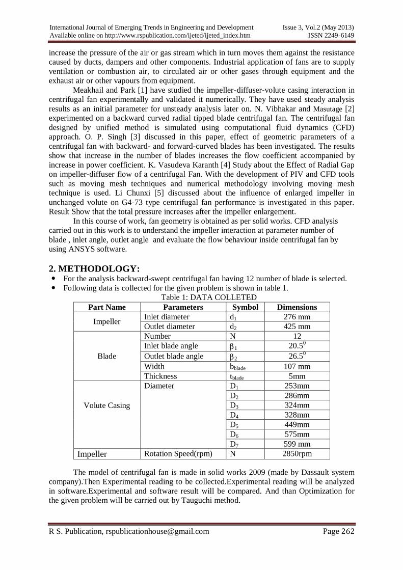
Fig 1: Experimental picture of Centrifugal fan
Table 2: Changed parameters of impeller
Sr.
no.
Parameters Existing
data
Case-1 Case-2
1 Number of blade 12 10 14
2 Blade inlet angle 20.5˚ 18.5˚ 22.5˚
3 Blade outlet angle 26.5˚ 24.5˚ 28.5˚
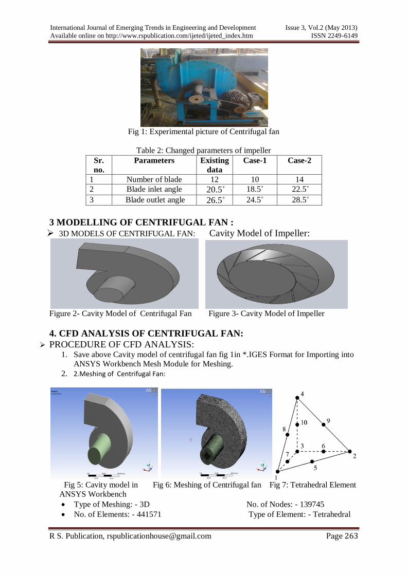
3 MODELLING OF CENTRIFUGAL FAN :
3D MODELS OF CENTRIFUGAL FAN: Cavity Model of Impeller:
Figure 2- Cavity Model of Centrifugal Fan Figure 3- Cavity Model of Impeller
4. CFD ANALYSIS OF CENTRIFUGAL FAN:
PROCEDURE OF CFD ANALYSIS: 1. Save above Cavity model of centrifugal fan fig 1in *.IGES Format for Importing into
ANSYS Workbench Mesh Module for Meshing.
2. 2.Meshing of Centrifugal Fan:
Fig 5: Cavity model in Fig 6: Meshing of Centrifugal fan Fig 7: Tetrahedral Element
ANSYS Workbench
Type of Meshing: - 3D No. of Nodes: - 139745
No. of Elements: - 441571 Type of Element: - Tetrahedral
International Journal of Emerging Trends in Engineering and Development Issue 3, Vol.2 (May 2013)
Available online on http://www.rspublication.com/ijeted/ijeted_index.htm ISSN 2249-6149
R S. Publication, [email protected] Page 264
3.Save Above model in *.CMDB Format for importing into ANSYS CFX Pre shown in fig 8.
4.Define Domain for Pipe.
5. Define Heat Transfer and Turbulence Model.
6.Define Domain for Impeller.
7.Define Domain for Casing.
8. Define Inlet for Centrifugal Fan.
9.Define Outlet for Centrifugal Fan.
10. Define Interface between Pipe and Impeller.
11. Define Interface between Pipe and casing.
12. Define Solver Control Criteria for Interface between Impeller and Casing.
13.Run the Analysis.
14. Get the Results.
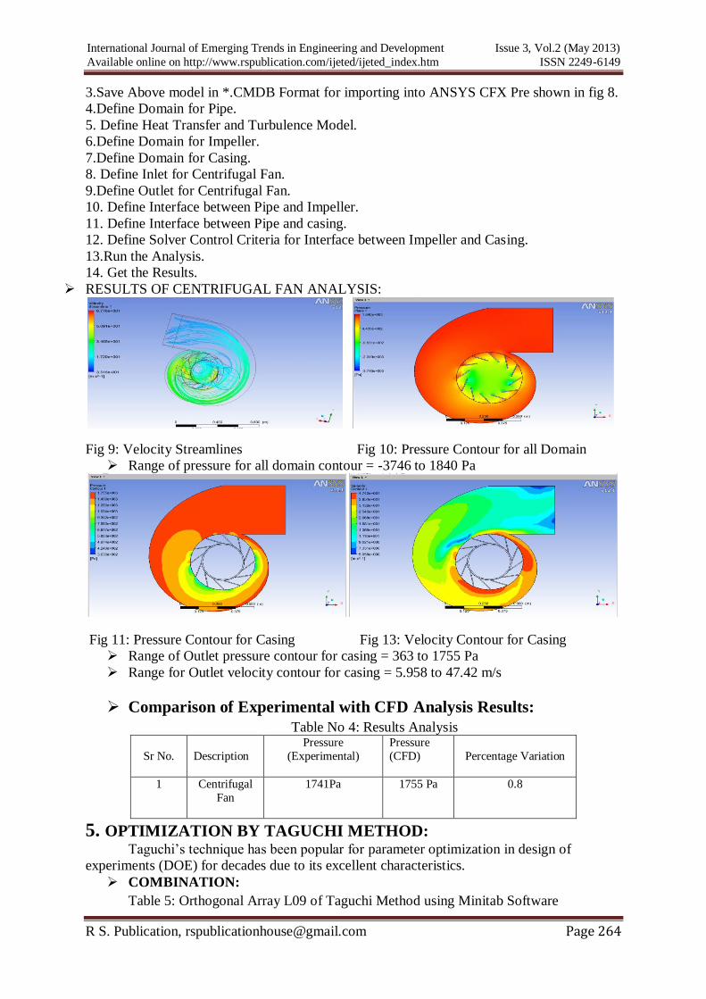
RESULTS OF CENTRIFUGAL FAN ANALYSIS:
Fig 9: Velocity Streamlines Fig 10: Pressure Contour for all Domain
Range of pressure for all domain contour = -3746 to 1840 Pa
Fig 11: Pressure Contour for Casing Fig 13: Velocity Contour for Casing
Range of Outlet pressure contour for casing = 363 to 1755 Pa
Range for Outlet velocity contour for casing = 5.958 to 47.42 m/s
Comparison of Experimental with CFD Analysis Results:
Table No 4: Results Analysis
Sr No.
Description
Pressure
(Experimental)
Pressure
(CFD)
Percentage Variation
1
Centrifugal
Fan
1741Pa
1755 Pa
0.8
5. OPTIMIZATION BY TAGUCHI METHOD:
Taguchi‟s technique has been popular for parameter optimization in design of
experiments (DOE) for decades due to its excellent characteristics.
COMBINATION:
Table 5: Orthogonal Array L09 of Taguchi Method using Minitab Software
International Journal of Emerging Trends in Engineering and Development Issue 3, Vol.2 (May 2013)
Available online on http://www.rspublication.com/ijeted/ijeted_index.htm ISSN 2249-6149
R S. Publication, [email protected] Page 265
NO. Inlet Angle Outlet Angle No. of Blades
Fan 1 18.5 24.5 10
Fan 2 18.5 26.5 12
Fan 3 18.5 28.5 14
Fan 4 20.5 24.5 12
Fan 5 20.5 26.5 14
Fan 6 20.5 28.5 10
Fan 7 22.5 24.5 14
Fan 8 22.5 26.5 10
Fan 9 22.5 28.5 12
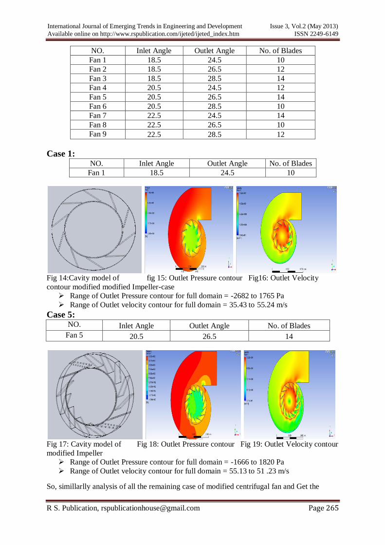
Case 1: NO. Inlet Angle Outlet Angle No. of Blades
Fan 1 18.5 24.5 10
Fig 14:Cavity model of fig 15: Outlet Pressure contour Fig16: Outlet Velocity
contour modified modified Impeller-case
Range of Outlet Pressure contour for full domain = -2682 to 1765 Pa
Range of Outlet velocity contour for full domain = 35.43 to 55.24 m/s
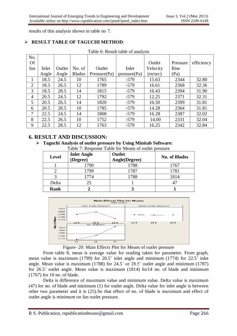
Case 5: NO. Inlet Angle Outlet Angle No. of Blades
Fan 5 20.5 26.5 14
Fig 17: Cavity model of Fig 18: Outlet Pressure contour Fig 19: Outlet Velocity contour
modified Impeller
Range of Outlet Pressure contour for full domain = -1666 to 1820 Pa
Range of Outlet velocity contour for full domain = 55.13 to 51 .23 m/s
So, simillarlly analysis of all the remaining case of modified centrifugal fan and Get the
International Journal of Emerging Trends in Engineering and Development Issue 3, Vol.2 (May 2013)
Available online on http://www.rspublication.com/ijeted/ijeted_index.htm ISSN 2249-6149
R S. Publication, [email protected] Page 266
results of this analysis shown in table no 7.
RESULT TABLE OF TAGUCHI METHOD:
Table 6: Result table of analysis
No.
Of
fan Inlet
Angle
Outlet
Angle
No. of
Blades
Outlet
Pressure(Pa)
Inlet
pressure(Pa)
Outlet
Velocity
(m/sec)
Pressure
Rise
(Pa)
efficiency
1 18.5 24.5 10 1765 -579 15.63 2344 32.80
2 18.5 26.5 12 1789 -579 16.61 2368 32.36
3 18.5 28.5 14 1815 -579 16.43 2394 31.90
4 20.5 24.5 12 1792 -579 12.25 2371 32.31
5 20.5 26.5 14 1820 -579 16.50 2399 31.81
6 20.5 28.5 10 1785 -579 14.28 2364 31.81
7 22.5 24.5 14 1808 -579 16.28 2387 32.02
8 22.5 26.5 10 1752 -579 14.00 2331 32.04
9 22.5 28.5 12 1763 -579 16.25 2342 32.84
6. RESULT AND DISCUSSION: Taguchi Analysis of outlet pressure by Using Minitab Software:
Table 7: Response Table for Means of outlet pressure
Level Inlet Angle
(Degree)
Outlet
Angle(Degree) No. of Blades
1 1790 1788 1767
2 1799 1787 1781
3 1774 1788 1814
Delta 25 1 47
Rank 2 3 1
Figure- 20: Main Effects Plot for Means of outlet pressure
From table 8, mean is average value for reading taken for parameter. From graph,
mean value is maximum (1799) for 20.5˚ inlet angle and minimum (1774) for 22.5˚ inlet
angle. Mean value is maximum (1788) for 24.5˚ or 28.5˚ outlet angle and minimum (1787)
for 26.5˚ outlet angle. Mean value is maximum (1814) for14 no. of blade and minimum
(1767) for 10 no. of blade.
Delta is difference of maximum value and minimum value. Delta value is maximum
(47) for no. of blade and minimum (1) for outlet angle. Delta value for inlet angle is between
other two parameter and it is (25).So that effect of no. of blade is maximum and effect of
outlet angle is minimum on fan outlet pressure.
International Journal of Emerging Trends in Engineering and Development Issue 3, Vol.2 (May 2013)
Available online on http://www.rspublication.com/ijeted/ijeted_index.htm ISSN 2249-6149
R S. Publication, [email protected] Page 267
Table 8: Response Table for Signal to Noise Ratios Larger is better
Level Inlet Angle (Degree) Outlet Angle (Degree) No. of Blades
1 65.05 65.05 64.95
2 65.10 65.04 65.01
3 64.98 65.05 65.17
Delta 0.12 0.01 0.23
Rank 2 3 1
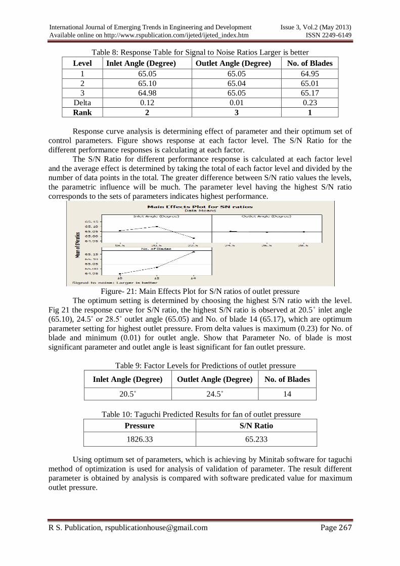
Response curve analysis is determining effect of parameter and their optimum set of
control parameters. Figure shows response at each factor level. The S/N Ratio for the
different performance responses is calculating at each factor.
The S/N Ratio for different performance response is calculated at each factor level
and the average effect is determined by taking the total of each factor level and divided by the
number of data points in the total. The greater difference between S/N ratio values the levels,
the parametric influence will be much. The parameter level having the highest S/N ratio
corresponds to the sets of parameters indicates highest performance.
Figure- 21: Main Effects Plot for S/N ratios of outlet pressure
The optimum setting is determined by choosing the highest S/N ratio with the level.
Fig 21 the response curve for S/N ratio, the highest S/N ratio is observed at 20.5˚ inlet angle
(65.10), 24.5˚ or 28.5˚ outlet angle (65.05) and No. of blade 14 (65.17), which are optimum
parameter setting for highest outlet pressure. From delta values is maximum (0.23) for No. of
blade and minimum (0.01) for outlet angle. Show that Parameter No. of blade is most
significant parameter and outlet angle is least significant for fan outlet pressure.
Table 9: Factor Levels for Predictions of outlet pressure
Inlet Angle (Degree) Outlet Angle (Degree) No. of Blades
20.5˚
24.5˚ 14
Table 10: Taguchi Predicted Results for fan of outlet pressure
Pressure S/N Ratio
1826.33 65.233
Using optimum set of parameters, which is achieving by Minitab software for taguchi
method of optimization is used for analysis of validation of parameter. The result different
parameter is obtained by analysis is compared with software predicated value for maximum
outlet pressure.
International Journal of Emerging Trends in Engineering and Development Issue 3, Vol.2 (May 2013)
Available online on http://www.rspublication.com/ijeted/ijeted_index.htm ISSN 2249-6149
R S. Publication, [email protected] Page 268
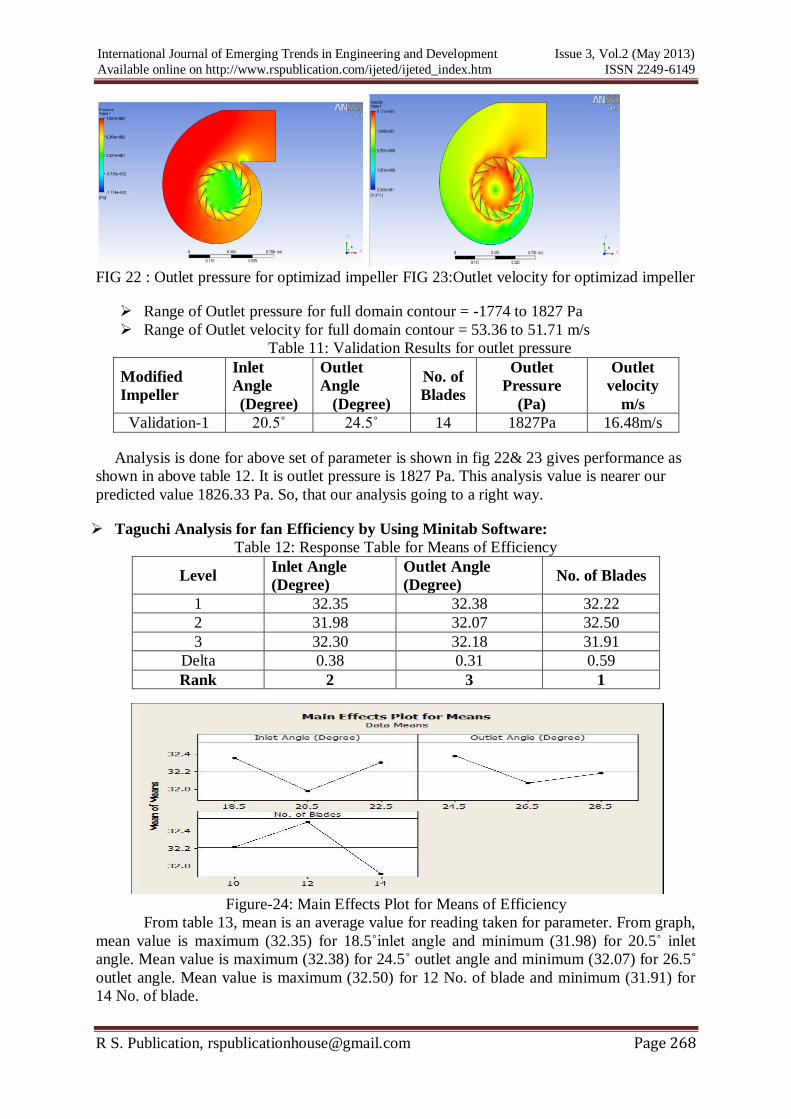
FIG 22 : Outlet pressure for optimizad impeller FIG 23:Outlet velocity for optimizad impeller
Range of Outlet pressure for full domain contour = -1774 to 1827 Pa
Range of Outlet velocity for full domain contour = 53.36 to 51.71 m/s
Table 11: Validation Results for outlet pressure
Modified
Impeller
Inlet
Angle
(Degree)
Outlet
Angle
(Degree)
No. of
Blades
Outlet
Pressure
(Pa)
Outlet
velocity
m/s
Validation-1 20.5˚ 24.5˚ 14 1827Pa 16.48m/s
Analysis is done for above set of parameter is shown in fig 22& 23 gives performance as
shown in above table 12. It is outlet pressure is 1827 Pa. This analysis value is nearer our
predicted value 1826.33 Pa. So, that our analysis going to a right way.
Taguchi Analysis for fan Efficiency by Using Minitab Software:
Table 12: Response Table for Means of Efficiency
Level Inlet Angle
(Degree)
Outlet Angle
(Degree) No. of Blades
1 32.35 32.38 32.22
2 31.98 32.07 32.50
3 32.30 32.18 31.91
Delta 0.38 0.31 0.59
Rank 2 3 1
Figure-24: Main Effects Plot for Means of Efficiency
From table 13, mean is an average value for reading taken for parameter. From graph,
mean value is maximum (32.35) for 18.5˚inlet angle and minimum (31.98) for 20.5˚ inlet
angle. Mean value is maximum (32.38) for 24.5˚ outlet angle and minimum (32.07) for 26.5˚
outlet angle. Mean value is maximum (32.50) for 12 No. of blade and minimum (31.91) for
14 No. of blade.
International Journal of Emerging Trends in Engineering and Development Issue 3, Vol.2 (May 2013)
Available online on http://www.rspublication.com/ijeted/ijeted_index.htm ISSN 2249-6149
R S. Publication, [email protected] Page 269
Delta is difference of maximum value and minimum value. Delta value is maximum
for No. of blade (0.59) and minimum (0.31) for outlet angle. Delta value for inlet angle is
between other two parameter and it is (0.38).So that effect of No. of blade is maximum and
effect of outlet angle is minimum on fan efficiency.
Table 13: Response Table for S/N Ratios for Means of Efficiency
Level Inlet Angle (Degree) Outlet Angle (Degree) No. of Blades
1 30.20 30.20 30.16
2 30.10 30.12 30.24
3 30.18 30.15 30.08
Delta 0.10 0.08 0.16
Rank 2 3 1
Figure- 25: Main Effects Plot for S/N Ratio for Efficiency
The optimum setting is determined by choosing the highest S/N ratio with level.
Fig.25, the response curve for S/N ratio, the highest S/N ratio is observed at inlet angle 18.5˚
(30.20), outlet angle 24.5˚ (30.20) and No. of blade 12 (30.24), which are optimum parameter
setting for fan efficiency. From delta value is maximum (0.16) for No. of blade and minimum
(0.8) for outlet angle. Parameter No. of blade is most significant parameter and outlet angle is
least significant for fan efficiency.
Table 14: Factor Level for Predictions for Efficiency
Inlet Angle (Degree) Outlet Angle (Degree) No. of Blades
18.5˚ 24.5˚ 12
Table 15: Predicted Results of Efficiency for centrifugal fan
Efficiency S/N Ratio
32.81 30.321
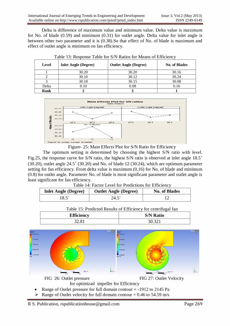
FIG 26: Outlet pressure FIG 27: Outlet Velocity
for optimizad impeller for Efficiency
Range of Outlet pressure for full domain contour = -1912 to 2145 Pa
Range of Outlet velocity for full domain contour = 0.46 to 54.59 m/s
International Journal of Emerging Trends in Engineering and Development Issue 3, Vol.2 (May 2013)
Available online on http://www.rspublication.com/ijeted/ijeted_index.htm ISSN 2249-6149
R S. Publication, [email protected] Page 270
Table 16: Validation Results of Efficiency for centrifugal fan
Modified
Impeller
Inlet
Angle
(Degree)
Outlet
Angle
(Degree)
No. of
Blades
Outlet
Pressure
(Pa)
Outlet
velocity
m/s
Efficiency
Validation-
2 18.5˚ 24.5˚ 12 2145Pa 16.54 m/s
32.57
Analysis is done for above set of parameter shown in fig 26 & 27 gives performance
as shown in above table 17. It is Efficiency is 32.57. This analysis value is nearer our
predicted value 32.81. So, that our analysis going to a right way.
7. CONCLUSION
The following conclusions are derived from the analysis:
The software predicated outlet pressure is 1826 Pa, pressure rise is 2405 Pa, and
efficiency is 32.81%. The value of validation analysis of centrifugal fan outlet
pressure is 1827 Pa and efficiency is 32.81%. Validation analysis value compared
with predicated value.
These analysis values of centrifugal fan outlet pressure and efficiency are very closer
to the predicated values.
Result obtained from validation analysis using optimum parameter combination gives
excellent agreement with predicated results.
By the taguchi in the centrifugal fan as increase the number of blade increase the
pressure and efficiency. And also inlet angle decrease and outlet angle increase so
that increase the pressure of the fan.
Also prove that taguchi parameter concept is more powerful and efficient tool for
maximize pressure (head) and efficiency.
REFERENCE
PAPERS:-
[1] Meakhail T. and Park S. O., A study of impeller-diffuser-volute casing interaction in a
centrifugal fan, Journal of Turbomachinery, Vol. 127, pp. 84-90, January 2005
[2] Shah K. H., Vibhakar N. N. and Channiwala S. A. “Unified design and comparative
performance evaluation of forward and backward curved radial tipped centrifugal fan”,
International Journal of emerging trends in engineering and development Issue 2, Vol.1 (Jan-
2012) ISSN 2249-6149.
[3] O. P. Singh, Rakesh Khilwani, T. Sreenivasulu, M. Kannan. “parametric study of
centrifugal fan performance: experiments and numerical simulation”. International Journal of
Advances in Engineering & Technology, May (2011), Vol. 1,Issue 2,pp.33-50.
[4] K.Vasudeva Karanth and N. Yagnesh Sharma. “CFD Analysis on the Effect of Radial
Gap on Impeller-Diffuser Flow Interaction as well as on the Flow Characteristics of a
Centrifugal Fan”. Hindawi Publishing CorporationInternational Journal of Rotating
Machinery. Volume 2009, Article ID 293508
[5] Li Chunxi , Wang Song Ling and Jia Yakui , “The performance of a centrifugal fan with
enlarged impeller‟‟ Energy Conversion and Management 52 (2011) 2902–2910.
[6] Sheam-Chyun Lin, Ming-Lun Tsai. “An integrated performance analysis for a backward-
inclined centrifugal fan”, Computers & Fluids 56 (2012) 24–38
[7] N. Yagnesh Sharma1 and K. Vasudeva Karanth2, „‟Numerical Analysis of a Centrifugal
Fan for Improved Performance using Splitter Vanes‟‟ World Academy of Science,
Engineering and Technology 36 (2009) 453-459