rootstm centrifugal compressors - psi prolew
TRANSCRIPT
www.howden.com
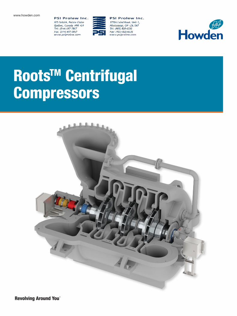
RootsTM Centrifugal Compressors
B_Centrifugal Bro_4.12.indd 1 31/08/2015 11:36:48
2
GE Oil & Gas is a global leader in the design and manufacture of air and gas handling solutions. GE leverages its history of technical innovation to address key environmental issues and to pro-vide quality manufactured products to custom-ers around the globe.Roots blowers, compressors and controls have been applied to multiple applications in a wide array of industries such as: pneumatic con-veying, gas separation, wastewater treatment, steam recompression, petrochemical production, and many others.Roots blowers, compressors and controls are available in varying size ranges with a broad spectrum of performance and controllability.
Howden’s range of Roots centrifugal compressors are available in varying sizes with a broad spectrum of performance and controllability.
Howden is a truly global company, with an established presence in more than 26 countries across every continent. Our network of local support services enables us to respond urgently to customer queries and maintenance requirements, and we understand the importance of local circumstances, from environmental legislation to energy costs.
Every product we deliver is backed by an unequivocal lifetime commitment to spare parts and product support. Replacement parts are made using the original production drawings, so that compatibility and quality are guaranteed. We also offer a full upgrade and enhancement program that allows customers to take advantage of new developments, or adapt existing equipment to changed conditions.
B_Centrifugal Bro_4.12.indd 2 31/08/2015 11:36:48
3
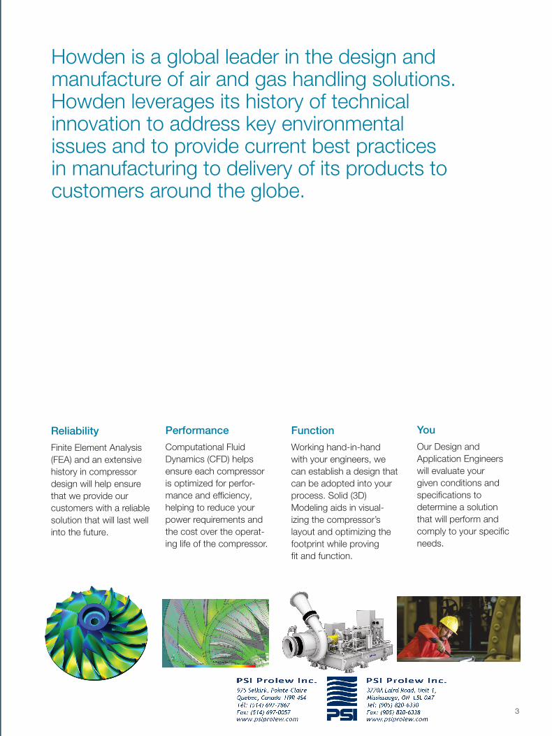
Howden is a global leader in the design and manufacture of air and gas handling solutions. Howden leverages its history of technical innovation to address key environmental issues and to provide current best practices in manufacturing to delivery of its products to customers around the globe.
Reliability
Finite Element Analysis (FEA) and an extensive history in compressor design will help ensure that we provide our customers with a reliable solution that will last well into the future.
Performance
Computational Fluid Dynamics (CFD) helps ensure each compressor is optimized for perfor-mance and efficiency, helping to reduce your power requirements and the cost over the operat-ing life of the compressor.
Function
Working hand-in-hand with your engineers, we can establish a design that can be adopted into your process. Solid (3D) Modeling aids in visual-izing the compressor’s layout and optimizing the footprint while proving fit and function.
You
Our Design and Application Engineers will evaluate your given conditions and specifications to determine a solution that will perform and comply to your specific needs.
B_Centrifugal Bro_4.12.indd 3 31/08/2015 11:36:49
4
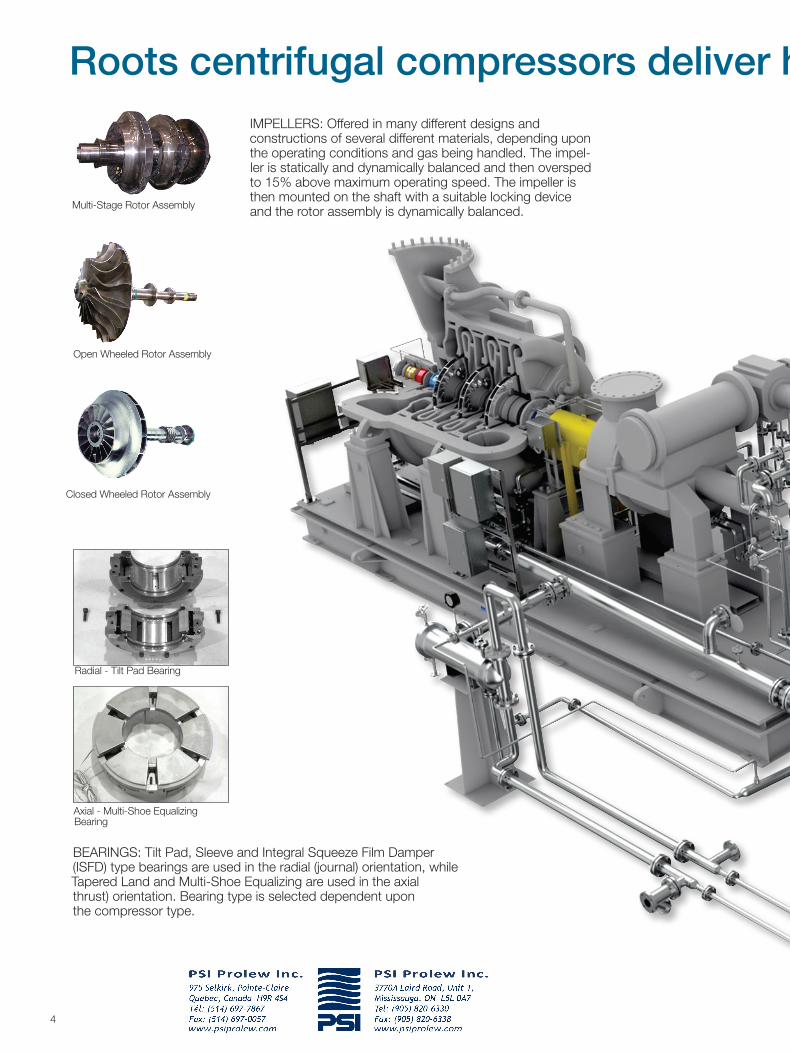
Roots centrifugal compressors deliver high performance and low maintenance.
Radial - Tilt Pad Bearing
Axial - Multi-Shoe Equalizing Bearing
BEARINGS: Tilt Pad, Sleeve and Integral Squeeze Film Damper (ISFD) type bearings are used in the radial (journal) orientation, while Tapered Land and Multi-Shoe Equalizing are used in the axial thrust) orientation. Bearing type is selected dependent upon the compressor type.
IMPELLERS: Offered in many different designs and constructions of several different materials, depending upon the operating conditions and gas being handled. The impel-ler is statically and dynamically balanced and then oversped to 15% above maximum operating speed. The impeller is then mounted on the shaft with a suitable locking device and the rotor assembly is dynamically balanced.Multi-Stage Rotor Assembly
Open Wheeled Rotor Assembly
Closed Wheeled Rotor Assembly
B_Centrifugal Bro_4.12.indd 4 31/08/2015 11:36:50

5
Roots centrifugal compressors deliver high performance and low maintenance.
LUBE OIL SYSTEM: Lube system can be provided in three dif-ferent configurations: integral, console mounted to the baseplate, and console mounted off the baseplate. Each system will consist of a main and auxiliary oil pump, oil cooler, oil filter, bypass valve for temperature control, oil reservoir (minimum 3 minute retention), and necessary safety switches and gauges.
SEALS: Air applications use the Standard Labyrinth Seal, while Double Labyrinth, Carbon Ring and Dry Mechanical Seals are used for gas applications. Buffer and suction ports can be provided for additional retention of the process gas. Gas-tight shutoff sealing is also available to ensure gas retention when the compressor is not operating.
Standard Labyrinth Buffered Labyrinth Buffered Carbon Ring Double Opposed Dry Gas Seal w/ Buffer
B_Centrifugal Bro_4.12.indd 5 31/08/2015 11:36:51
6
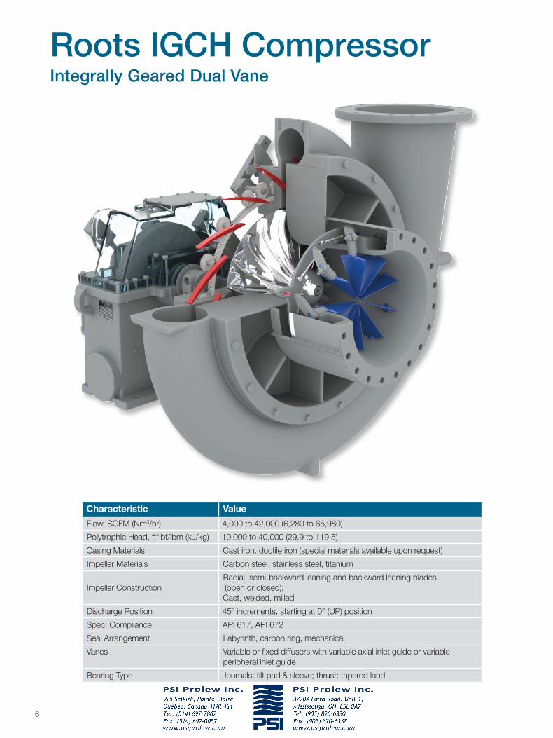
Roots IGCH CompressorIntegrally Geared Dual Vane
Characteristic Value
Flow, SCFM (Nm3/hr) 4,000 to 42,000 (6,280 to 65,980)
Polytrophic Head, ft*lbf/lbm (kJ/kg) 10,000 to 40,000 (29.9 to 119.5)
Casing Materials Cast iron, ductile iron (special materials available upon request)
Impeller Materials Carbon steel, stainless steel, titanium
Impeller ConstructionRadial, semi-backward leaning and backward leaning blades (open or closed); Cast, welded, milled
Discharge Position 45° increments, starting at 0° (UP) position
Spec. Compliance API 617, API 672
Seal Arrangement Labyrinth, carbon ring, mechanical
Vanes Variable or fixed diffusers with variable axial inlet guide or variable peripheral inlet guide
Bearing Type Journals: tilt pad & sleeve; thrust: tapered land
B_Centrifugal Bro_4.12.indd 6 31/08/2015 11:36:52

7
Gas Composition: Ambient Air
Inlet Conditions: AIR, 14.5 PSIA, 100° F, 80% RH (1.00 bar(a), 38° C, 80% RH)Barometer: 14.7 PSIA (1.013 bar(a))
12 16 20 24 30
4
5
6
7
8
9
10
11
12
13
14
15
16
17
18
19
20
0 5000 10000 15000 20000 25000 30000 35000 40000 45000 50000
CAPACITY - SCFM (14.7 PSIA, 68° F, 36% RH)
DIS
CHAR
GE
PRES
SURE
- PS
IG
0.28
0.34
0.41
0.48
0.55
0.62
0.69
0.76
0.83
0.90
0.97
1.03
1.10
1.17
1.24
1.31
1.380 7854 15709 23563 31417 39272 47126 54980 62834 70689 78543
CAPACITY - Nm3/hr (1.013 bar(a), 0° C, 0% RH)
DIS
CHAR
GE
PRES
SURE
- ba
r(g)
1000 HP (750 kW)
1400 HP (1045 kW)
1800 HP (1340 kW)
2200 HP (1640 kW)
2600 HP (1940 kW)
3000 HP (2240 kW)
3400 HP (2535 kW)
150 HP (110 kW
)200 H
P (150 kW)
600 HP (450 kW)
800 HP (600 kW)
400 HP (300 kW
)
Frame Frame Frame Frame Frame
Roots IGCH Compressor Performance Map
Variable Diffuser Vanes (VDV’s) shown in minimum to maximum position. Roots’ control system will independently modulate both the IGV’s and VDV’s to optimize the performance point as process conditions vary.
B_Centrifugal Bro_4.12.indd 7 31/08/2015 11:36:52
8
Name Description
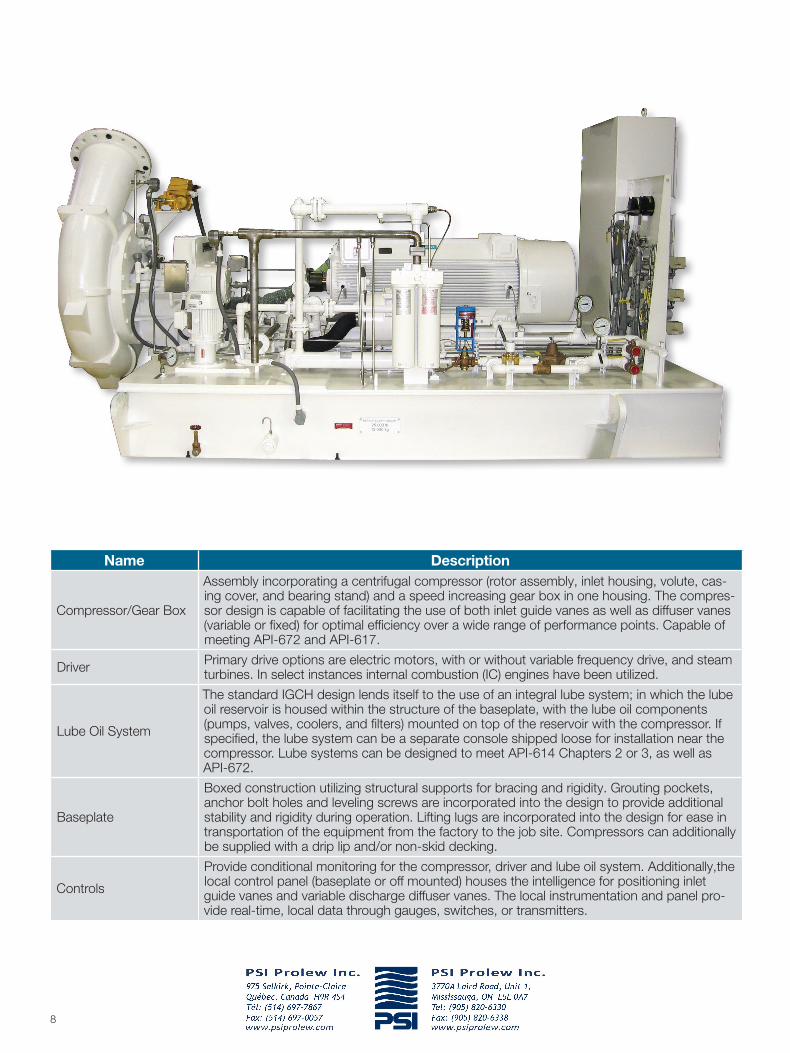
Compressor/Gear Box
Assembly incorporating a centrifugal compressor (rotor assembly, inlet housing, volute, cas-ing cover, and bearing stand) and a speed increasing gear box in one housing. The compres-sor design is capable of facilitating the use of both inlet guide vanes as well as diffuser vanes (variable or fixed) for optimal efficiency over a wide range of performance points. Capable of meeting API-672 and API-617.
Driver Primary drive options are electric motors, with or without variable frequency drive, and steam turbines. In select instances internal combustion (IC) engines have been utilized.
Lube Oil System
The standard IGCH design lends itself to the use of an integral lube system; in which the lube oil reservoir is housed within the structure of the baseplate, with the lube oil components (pumps, valves, coolers, and filters) mounted on top of the reservoir with the compressor. If specified, the lube system can be a separate console shipped loose for installation near the compressor. Lube systems can be designed to meet API-614 Chapters 2 or 3, as well as API-672.
Baseplate
Boxed construction utilizing structural supports for bracing and rigidity. Grouting pockets, anchor bolt holes and leveling screws are incorporated into the design to provide additional stability and rigidity during operation. Lifting lugs are incorporated into the design for ease in transportation of the equipment from the factory to the job site. Compressors can additionally be supplied with a drip lip and/or non-skid decking.
Controls
Provide conditional monitoring for the compressor, driver and lube oil system. Additionally,the local control panel (baseplate or off mounted) houses the intelligence for positioning inlet guide vanes and variable discharge diffuser vanes. The local instrumentation and panel pro-vide real-time, local data through gauges, switches, or transmitters.
B_Centrifugal Bro_4.12.indd 8 31/08/2015 11:36:53

9
Unit Size
A* inches (mm) B*
inches (mm)C
inches (mm)D
inches (mm)E
inches (mm)Weight lbs (kgs)
MIGV’S** MPGV’S**
12" IGCH 12 (300) N/A 12 (300) 170 (4300) 84 (2130) 65 (1650) 20,000 (9,070)
16" IGCH 16 (400) 20 (500) 16 (400) 185 (4700) 84 (2130) 70 (1780) 26,000 (11,800)
20" IGCH 20 (500) 24 (600) 20 (500) 200 (5080) 84 (2130) 73 (1850) 33,500 (15,200)
24" IGCH 24 (600) 30 (750) 24 (600) 220 (5600) 84 (2130) 84 (2130) 42,000 (19,050)
30" IGCH 30 (750) 36 (900) 30 (750) 230 (5840) 108 (2740) 95 (2410) 54,000 (24,500)
Roots IGCH Compressor Dimension Table
*Flanges are rated at 25# (Typ.) and drilled per ANSI B16.5 & B16.47A.
** MIGV’S - Movable Inlet Guide Vanes; MPGV’s - Movable Peripheral Inlet Guide Vanes
A
DIS
CHA
RGE
D
E
C
BDIS
CHA
RGE
INLET
DRIVER
B_Centrifugal Bro_4.12.indd 9 31/08/2015 11:36:54

10
Characteristic Value
Flow, SCFM (Nm3/hr) 5,000 to 225,000 (7,850 to 353,440)
Polytrophic Head, ft*lbf/lbm (kJ/kg)
10,000 to 40,000 (29.9 to 119.5)
Casing Materials Cast iron, ductile iron (special materials available upon request)
Impeller Materials Carbon steel, stainless steel, titanium
Impeller Construction Radial, semi-backward leaning and backward leaning blades (open or closed); cast, welded, milled
Discharge Position 45° increments, starting at 0° (UP) position
Spec. Compliance API 617
Seal Arrangement Labyrinth, carbon ring, mechanical
Variable Vanes Variable axial inlet guide or variable peripheral inlet guide
Bearing Type Journal: tilt pad; thrust: multi-shoe equalizing
Roots OIB Compressor
B_Centrifugal Bro_4.12.indd 10 31/08/2015 11:36:54

11
OIB Compressor with variable inlet guide vanes and
open impellerOIB Compressor with variable peripheral inlet guide
vanes and closed impeller
35 45 50 75 100 150 200 260
2
4
6
8
10
12
14
16
18
20
0000520000020000510000010000500.14
0.28
0.41
0.55
0.69
0.83
0.97
1.10
1.24
1.38517293271413926532680751345870
14000 HP (10440 kW)
15000 HP (11190 kW)
16000 HP (11930 kW)
17000 HP (12680 kW)
12000 HP (8950 kW)10000 HP (7460 kW)8000 HP (5965 kW)
6500 HP (4850 kW)5500 HP (4100 kW)4500 HP (3355 kW)4000 HP (2985 kW)
3500 HP (2610 kW)
3000 HP (2240 kW)
2500 HP (1865 kW)
2000 HP (1490 kW)
1500 HP (1120 kW)
1250 HP (930 kW)
1000 HP (750 kW)
750 HP (560 kW)
500 HP (375 kW)
250 HP (190 kW)
13000 HP (9695 kW)
11000 HP (8200 kW)9000 HP (6710 kW)
7000 HP (5220 kW)6000 HP (4475 kW)
5000 HP (3730 kW)
DIS
CHAR
GE
PRES
SURE
- PS
IG
CAPACITY - SCFM (14.7 PSIA, 68°F, 36 % RH)
Gas Composition: Ambient AirInlet Conditions: AIR, 14.5 PSIA, 100°F, 80% RH (1.00 bar (a), 38°C, 80% RH)
Barometer: 14.7 PSIA (1.013 bar (a))
CAPACITY - Nm3/hr (1.013 bar (a), 0°C, 0% RH)
DIS
CHAR
GE
PRES
SURE
- ba
r (g
)
Roots OIB Compressor Map
B_Centrifugal Bro_4.12.indd 11 31/08/2015 11:36:55

12
Name Description
CompressorOverhung style centrifugal compressor consisting of a rotor assembly, inlet housing, volute, casing cover, and bearing stand. Optional inlet guide vanes allow for process control in the absence of a variable speed drive or inlet throttling valve. Capable of meeting API-617.
Gear Box
Speed increasing gear box designed to increase the driver input speed up to the rated com-pressor speed. The low speed shaft can incorporate the main oil pump of the lube system, when required. Compressor may also be supplied without gear box if driver can meet the rated compressor speed and power. Capable of meeting API-613.
Driver Primary drive options are electric motors, with or without variable frequency drive, and steam turbines. In select instances internal combustion (IC) engines have been utilized.
Lube Oil System
There are three main options for the compressor lube system. First, an integral lube system; in which the lube oil reservoir is housed within the structure of the baseplate, with the lube oil components (pumps, valves, coolers, and filters) mounted on top of the reservoir with the compressor. Second, a console lube system, with separate reservoir, mounted to the baseplate frame. Lastly, the lube system can be a separate console shipped loose for installation near the compressor. Lube systems can be designed to meet API-614 Chapters 2 or 3.
Baseplate
Boxed construction utilizing structural supports for bracing and rigidity. Grouting pockets, anchor bolt holes and leveling screws are incorporated into the design to provide additional stability and rigidity during operation. Lifting lugs are incorporated into the design for ease in transportation of the equipment from the factory to the job site. Compressors can additionally be supplied with a drip lip and/or non-skid decking.
Controls
Provide conditional monitoring for the compressor, driver and lube oil system. Additionally,the local control panel (baseplate or off mounted) houses the intelligence for positioning inlet guide vanes. The local instrumentation and panel provide real-time, local data through gauges, switch-es, or transmitters.
B_Centrifugal Bro_4.12.indd 12 31/08/2015 11:36:56
13
Unit Size
A* inches (mm) B*
inches (mm)
C inches (mm)
D inches (mm)
E inches (mm)
Weight lbs (kgs)
W/ IGV’S W/O IGV’S
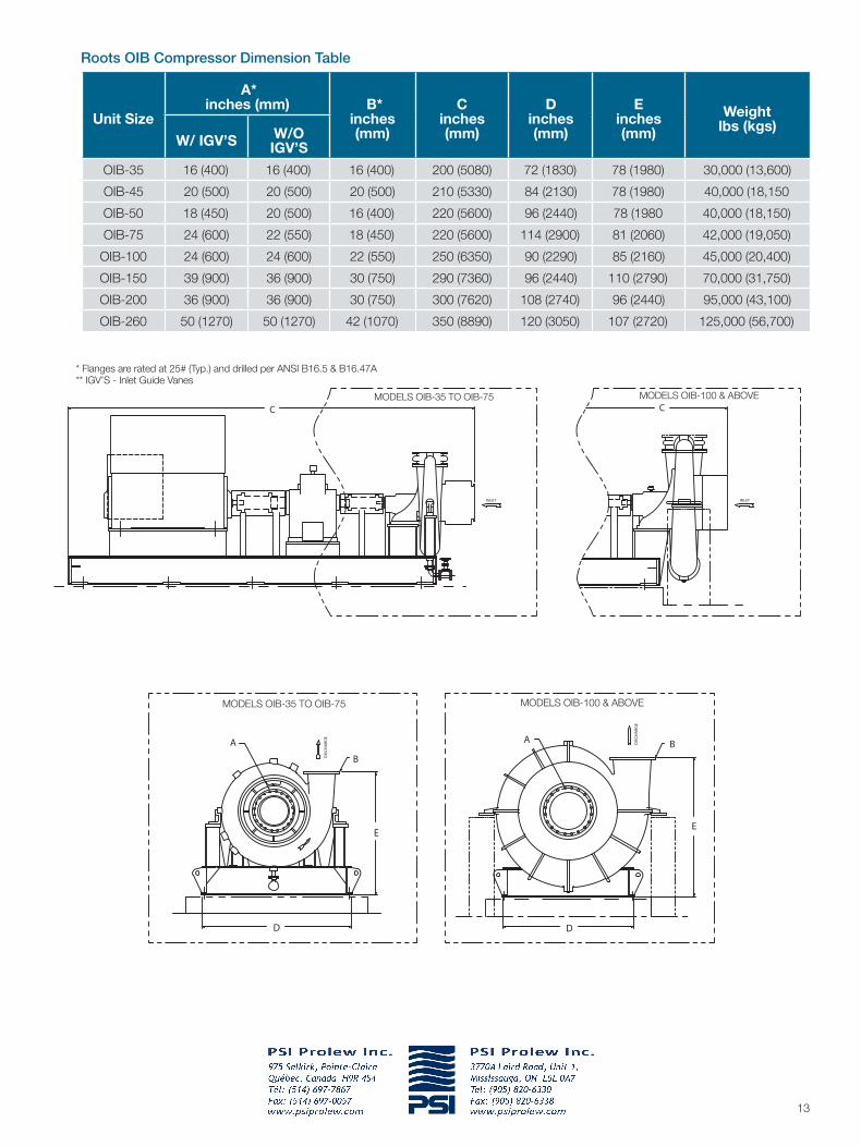
OIB-35 16 (400) 16 (400) 16 (400) 200 (5080) 72 (1830) 78 (1980) 30,000 (13,600)
OIB-45 20 (500) 20 (500) 20 (500) 210 (5330) 84 (2130) 78 (1980) 40,000 (18,150
OIB-50 18 (450) 20 (500) 16 (400) 220 (5600) 96 (2440) 78 (1980 40,000 (18,150)
OIB-75 24 (600) 22 (550) 18 (450) 220 (5600) 114 (2900) 81 (2060) 42,000 (19,050)
OIB-100 24 (600) 24 (600) 22 (550) 250 (6350) 90 (2290) 85 (2160) 45,000 (20,400)
OIB-150 39 (900) 36 (900) 30 (750) 290 (7360) 96 (2440) 110 (2790) 70,000 (31,750)
OIB-200 36 (900) 36 (900) 30 (750) 300 (7620) 108 (2740) 96 (2440) 95,000 (43,100)
OIB-260 50 (1270) 50 (1270) 42 (1070) 350 (8890) 120 (3050) 107 (2720) 125,000 (56,700)
Roots OIB Compressor Dimension Table
* Flanges are rated at 25# (Typ.) and drilled per ANSI B16.5 & B16.47A ** IGV’S - Inlet Guide Vanes
D
DIS
CHA
RGE
D
A A
BB
EE
DIS
CHA
RGE
MODELS OIB-35 TO OIB-75 MODELS OIB-100 & ABOVE
MODELS OIB-100 & ABOVEMODELS OIB-35 TO OIB-75
INLETINLET
C C
B_Centrifugal Bro_4.12.indd 13 31/08/2015 11:36:56

14
Roots Type HHorizontally-Split Multi-Stage Compressor
Characteristic Value
Flow, SCFM (Nm3/hr) 6,000 to 67,000 (9,430 to 105,250)
Polytrophic Head, ft*lbf/lbm (kJ/kg) 14,000 to 65,000 (41.8 to 194.3)
Casing Materials Cast iron, ductile iron (special materials available upon request)
Impeller Materials Carbon steel, stainless steel
Impeller Construction Semi-backward leaning and backward leaning blades (closed); welded or milled & welded
Spec. Compliance API 617
Seal Arrangement Labyrinth, carbon ring, mechanical
Vanes Variable or fixed inlet guide vanes
Bearing Type Journal: tilt pad; thrust: multi-shoe equalizing
Compressor Stages 2, 3, 4 (specialty staging available)
B_Centrifugal Bro_4.12.indd 14 31/08/2015 11:36:56

15
H Multi-Stage bearing and seal housing H Multi-Stage casing with inter-stage diaphragms and rotor assembly
HN-19
HQ-35HR-42
HP-30
4 STAGE
3 STAGE
2 STAGE
HT-48
5
15
25
35
45
55
65
75
0 10000 20000 30000 40000 50000 60000 70000 800000.34
1.03
1.72
2.41
3.10
3.79
4.48
5.170 15709 31417 47126 62834 78543 94252 109960 125669
CAPACITY - Nm3/hr (1.013 bar (a), 0°C, 0% RH)D
ISCH
ARG
E PR
ESSU
RE -
PSIG
DIS
CHAR
GE
PRES
SURE
- ba
r (g
)
CAPACITY - SCFM (14.7 PSIA, 68°F, 36 % RH)
6000 HP (4475 kW)
7000 HP (5220 kW)
5500 HP (4100 kW)
8000 HP (5965 kW)
9000 HP (6710 kW)
6500 HP (4850 kW)
12000 HP (8950 kW)11000 HP (8200 kW)
10000 HP (7460 kW)
5000 HP (3730 kW)
4500 HP (3355 kW)
4000 HP (2985 kW
)
3500 HP (2610 kW
)
2000 HP (1490 kW
)2500 H
P (1865 kW)
3000 HP (2240 kW
)
1500 HP (1120 kW
)
1250 HP (930 kW
)
1000 HP (750 kW
)750 HP (560 kW
)
500 HP (375 kW
)
250 HP (190 kW
)
Gas Composition: Ambient AirInlet Conditions: AIR, 14.5 PSIA, 100°F, 80% RH (1.00 bar (a), 38°C, 80% RH)
Barometer: 14.7 PSIA (1.013 bar (a))
Roots H-Multi Stage Compressor Map
B_Centrifugal Bro_4.12.indd 15 31/08/2015 11:36:57

16
Name Description
Compressor
Horizontally split centrifugal compressor consisting of top and bottom casing halves, rotor as-sembly, inter-stage diaphragms, seals, and bearing stands. Inlet section is capable of housing fixed or variable guide vanes for flow conditioning/ process control. Adaptable for up or down inlet and discharge connection orientations. Capable of meeting API-617.
DriverPrimary drive options are electric motors, with or without variable frequency drive, and steam tur-bines. In select instances internal combustion (IC) engines have been utilized. A separate speed increasing gear box can be included if needed for performance.
Lube Oil System
There are three main options for the compressor lube system. First, an integral lube system; in which the lube oil reservoir is housed within the structure of the baseplate, with the lube oil components (pumps, valves, coolers, and filters) mounted on top of the reservoir with the compressor. Second, a console lube system, with separate reservoir, mounted to the baseplate frame. Lastly, the lube system can be a separate console shipped loose for installation near the compressor. Lube systems can be designed to meet API-614 Chapters 2 or 3.
Baseplate
Boxed construction utilizing structural supports for bracing and rigidity. Grouting pockets, anchor bolt holes and leveling screws are incorporated into the design to provide additional stability and rigidity during operation. Lifting lugs are incorporated into the design for ease in transportation of the equipment from the factory to the job site. Compressors can additionally be supplied with a drip lip and/or non-skid decking.
Controls
Provide conditional monitoring for the compressor, driver and lube oil system. Additionally,the local control panel (baseplate or off mounted) houses the intelligence for positioning inlet guide vanes. The local instrumentation and panel provide real-time, local data through gauges, switch-es, or transmitters.
B_Centrifugal Bro_4.12.indd 16 31/08/2015 11:36:57

17
Unit Size A* inches (mm)
B* inches (mm)
C** inches (mm)
D inches (mm)
E inches (mm)
Weight lbs (kgs)
HN 18 (450) 14 (350) 192 (4880) 72 (1830) 78 (1980) 35,000 (15,875)
HP 30 (750) 24 (600) 220 (5600) 102 (2590) 98 (2490) 71,500 (32,430)
HQ 36 (900) 24 (600) 240 (6100) 108 (2740) 120 (3050) 78,000 (35,380)
HR 42 (1050) 24 (600) 250 (6350) 120 (3050) 132 (3350) 92,000 (41,730)
HT 48 (1200) 36 (900) 260 (6600) 138 (3500) 150 (3810) 130,000 (58,970)
Roots Type H Multi-Stage Dimensional Table
*Flanges are rated at 25# (Typ.) and drilled per ANSI B16.5 & B16.47A **Total length is subject to change based on number of stages or the need for a gear box NOTE: Inlet and Discharge of Compressor may be oriented in either the top or bottom direction, or any combination of the two. NOTE: Compressor may be driven through Inlet or Discharge End.
A
E
B
INLE
T
DISCH
ARG
E
D
C
B_Centrifugal Bro_4.12.indd 17 31/08/2015 11:36:57

18
Roots Wastewater Controls
• Save 25% to 40% of your energy costs, as compared to manual control
• Reduce consumption and demand charges
• Assistance in obtaining utility rebates
• Most open valve control to minimize system pressure
• Coordinate aeration demand and blower supply air flows
Instrumentation and Control
• Inlet guide vane and variable diffuser vane control
• Compressor conditional monitoring: - Vibration/displacement - Temperature - Pressure - Speed
• Active compressor surge control system, ensuring continual operation of your compressor.
• Application specific control algorithms
• Digital and/or analog compressor instrumentation panel
• NEMA 4, 4X and 12 electrical enclosure options
Technology Options
IntelliView® process controller
PLC's supported:
- ABB - Allen Bradley/Rockwell Automation Co., Inc. - Siemens AG - Other major manufacturers
Optional monitoring systems:
- Bently Nevada - Compressor Controls Corporation (CCC) - IRD - Other major manufacturers
Control solutions specific to your applicationEvery Roots centrifugal compressor is designed to meet specific application requirements. To accomplish this we design control solutions to monitor the health of the compressor and its operation. We accomplish this with sophisticated instrumentation and high tech controls that provide conditional monitoring for such diverse systems as the compressor, lube oil systems, and an array of drive options. In addition to these primary device controls, we provide the intelligence for positioning inlet guide vanes and variable discharge diffuser vanes for optimal application performance.
B_Centrifugal Bro_4.12.indd 18 31/08/2015 11:36:58
19
Service and Repair Warranties
Howden backs all maintenance and repair work performed at GE facilities or in the field.
• One year parts and workmanship including competitor’s parts
ISO-9001 and ISO-14000 Certified- Houston, TX, & Connersville, IN
Superior Field Services
• Full job-site troubleshooting services and capabilities
• Vibration & noise analysis
• Alignment (all major components)
• Job-site repair and replacement - Bearings - Seals - Rotating assemblies - Couplings
• 24 to 48-hour emergency services response for most areas
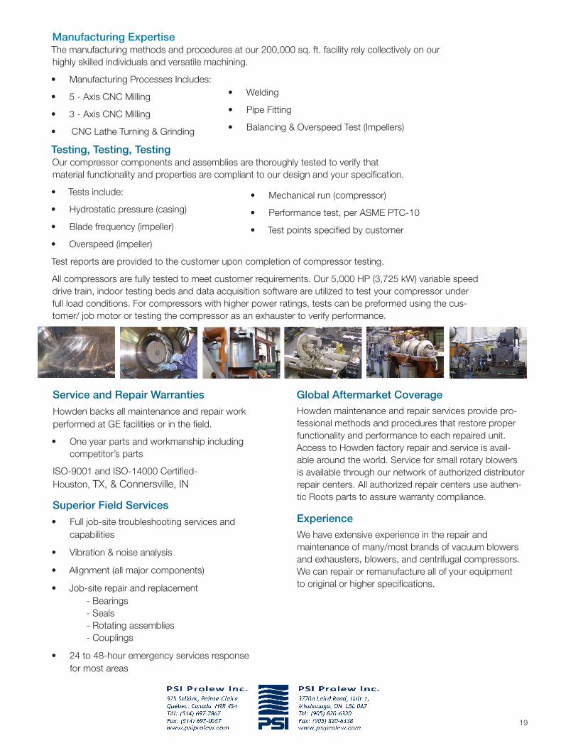
Manufacturing Expertise The manufacturing methods and procedures at our 200,000 sq. ft. facility rely collectively on our highly skilled individuals and versatile machining.
• Manufacturing Processes Includes:
• 5 - Axis CNC Milling
• 3 - Axis CNC Milling
• CNC Lathe Turning & Grinding
• Welding
• Pipe Fitting
• Balancing & Overspeed Test (Impellers)
Testing, Testing, TestingOur compressor components and assemblies are thoroughly tested to verify that material functionality and properties are compliant to our design and your specification.
• Tests include:
• Hydrostatic pressure (casing)
• Blade frequency (impeller)
• Overspeed (impeller)
Test reports are provided to the customer upon completion of compressor testing.
All compressors are fully tested to meet customer requirements. Our 5,000 HP (3,725 kW) variable speed drive train, indoor testing beds and data acquisition software are utilized to test your compressor under full load conditions. For compressors with higher power ratings, tests can be preformed using the cus-tomer/ job motor or testing the compressor as an exhauster to verify performance.
• Mechanical run (compressor)
• Performance test, per ASME PTC-10
• Test points specified by customer
Global Aftermarket CoverageHowden maintenance and repair services provide pro-fessional methods and procedures that restore proper functionality and performance to each repaired unit. Access to Howden factory repair and service is avail-able around the world. Service for small rotary blowers is available through our network of authorized distributor repair centers. All authorized repair centers use authen-tic Roots parts to assure warranty compliance.
ExperienceWe have extensive experience in the repair and maintenance of many/most brands of vacuum blowers and exhausters, blowers, and centrifugal compressors. We can repair or remanufacture all of your equipment to original or higher specifications.
B_Centrifugal Bro_4.12.indd 19 31/08/2015 11:36:59

www.howden.com
©Howden Group Limited. All rights reserved. 2015.Howden and the flying H logo are registered trade marks belonging to Howden Group Limited.
At the heart of your operationsHowden people live to improve our products and services and for over 160 years our world has revolved around our customers. This dedication means our air and gas handling equipment adds maximum value to your operations. We have innovation in our hearts and every day we focus on providing you with the best solutions for your vital operations.
Howden Roots
Howden Roots900 W. Mount St.ConnersvilleIndianaUSA47331
Tel: +1 765 827 9200Web: www.howden.com
B_Centrifugal Bro_4.12.indd 20 31/08/2015 11:37:00