oxymitter 5000 oxygen transmitter | emerson
TRANSCRIPT

http://www.raihome.com
Instruction ManualIM-106-350, Rev 2.2July 2008
Oxymitter 5000Oxygen Transmitter

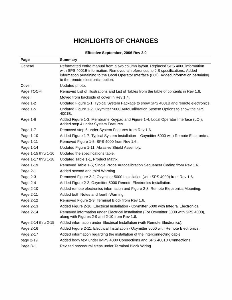
HIGHLIGHTS OF CHANGES
Effective September, 2006 Rev 2.0
Page Summary
General Reformatted entire manual from a two column layout. Replaced SPS 4000 information with SPS 4001B information. Removed all references to JIS specifications. Added information pertaining to the Local Operator Interface (LOI). Added information pertaining to the remote electronics option.
Cover Updated photo.
Page TOC-4 Removed List of Illustrations and List of Tables from the table of contents in Rev 1.6.
Page i Moved from backside of cover in Rev 1.4.
Page 1-2 Updated Figure 1-1, Typical System Package to show SPS 4001B and remote electronics.
Page 1-5 Updated Figure 1-2, Oxymitter 5000 AutoCalibration System Options to show the SPS 4001B.
Page 1-6 Added Figure 1-3, Membrane Keypad and Figure 1-4, Local Operator Interface (LOI). Added step 4 under System Features.
Page 1-7 Removed step 6 under System Features from Rev 1.6.
Page 1-10 Added Figure 1-7, Typical System Installation – Oxymitter 5000 with Remote Electronics.
Page 1-11 Removed Figure 1-5, SPS 4000 from Rev 1.6.
Page 1-14 Updated Figure 1-11, Abrasive Shield Assembly.
Page 1-15 thru 1-16 Updated the specifications table.
Page 1-17 thru 1-18 Updated Table 1-1, Product Matrix.
Page 1-19 Removed Table 1-5, Single Probe Autocalibration Sequencer Coding from Rev 1.6.
Page 2-1 Added second and third Warning.
Page 2-3 Removed Figure 2-2, Oxymitter 5000 Installation (with SPS 4000) from Rev 1.6.
Page 2-4 Added Figure 2-2, Oxymitter 5000 Remote Electronics Installation.
Page 2-10 Added remote electronics information and Figure 2-8, Remote Electronics Mounting.
Page 2-11 Added both Notes and fourth Warning.
Page 2-12 Removed Figure 2-9, Terminal Block from Rev 1.6.
Page 2-13 Added Figure 2-10, Electrical Installation - Oxymitter 5000 with Integral Electronics.
Page 2-14 Removed information under Electrical installation (For Oxymitter 5000 with SPS 4000), along with Figures 2-9 and 2-10 from Rev 1.6.
Page 2-14 thru 2-15 Added information under Electrical Installation (with Remote Electronics).
Page 2-16 Added Figure 2-11, Electrical Installation - Oxymitter 5000 with Remote Electronics.
Page 2-17 Added information regarding the installation of the interconnecting cable.
page 2-19 Added body text under IMPS 4000 Connections and SPS 4001B Connections.
Page 3-1 Revised procedural steps under Terminal Block Wiring.
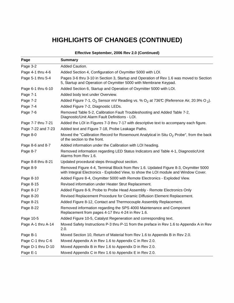
HIGHLIGHTS OF CHANGES (CONTINUED)
Effective September, 2006 Rev 2.0 (Continued)
Page Summary
Page 3-2 Added Caution.
Page 4-1 thru 4-6 Added Section 4, Configuration of Oxymitter 5000 with LOI.
Page 5-1 thru 5-4 Pages 3-6 thru 3-10 in Section 3, Startup and Operation of Rev 1.6 was moved to Section 5, Startup and Operation of Oxymitter 5000 with Membrane Keypad.
Page 6-1 thru 6-10 Added Section 6, Startup and Operation of Oxymitter 5000 with LOI.
Page 7-1 Added body text under Overview.
Page 7-2 Added Figure 7-1, O2 Sensor mV Reading vs. % O2 at 736°C (Reference Air, 20.9% O 2).
Page 7-4 Added Figure 7-2, Diagnostic LEDs.
Page 7-6 Removed Table 5-2, Calibration Fault Troubleshooting and Added Table 7-2, Diagnostic/Unit Alarm Fault Definitions - LOI.
Page 7-7 thru 7-21 Added the LOI in Figures 7-3 thru 7-17 with descriptive text to accompany each figure.
Page 7-22 and 7-23 Added text and Figure 7-18, Probe Leakage Paths.
Page 8-0 Moved the "Calibration Record for Rosemount Analytical in Situ O2 Probe", from the back of the section to the front.
Page 8-6 and 8-7 Added information under the Calibration with LOI heading.
Page 8-7 Removed information regarding LED Status Indicators and Table 4-1, Diagnostic/Unit Alarms from Rev 1.6.
Page 8-8 thru 8-21 Updated procedural steps throughout section.
Page 8-9 Removed Figure 4-4, Terminal Block from Rev 1.6. Updated Figure 8-3, Oxymitter 5000 with Integral Electronics - Exploded View, to show the LOI module and Window Cover.
Page 8-10 Added Figure 8-4, Oxymitter 5000 with Remote Electronics - Exploded View.
Page 8-15 Revised information under Heater Strut Replacement.
Page 8-17 Added Figure 8-9, Probe to Probe Head Assembly - Remote Electronics Only
Page 8-20 Revised Replacement Procedure for Ceramic Diffusion Element Replacement.
Page 8-21 Added Figure 8-12, Contact and Thermocouple Assembly Replacement.
Page 8-22 Removed information regarding the SPS 4000 Maintenance and Component Replacement from pages 4-17 thru 4-24 in Rev 1.6.
Page 10-5 Added Figure 10-5, Catalyst Regeneration and corresponding text.
Page A-1 thru A-14 Moved Safety Instructions P-3 thru P-11 from the preface in Rev 1.6 to Appendix A in Rev 2.0.
Page B-1 Moved Section 10, Return of Material from Rev 1.6 to Appendix B in Rev 2.0.
Page C-1 thru C-6 Moved Appendix A in Rev 1.6 to Appendix C in Rev 2.0.
Page D-1 thru D-10 Moved Appendix B in Rev 1.6 to Appendix D in Rev 2.0.
Page E-1 Moved Appendix C in Rev 1.6 to Appendix E in Rev 2.0.
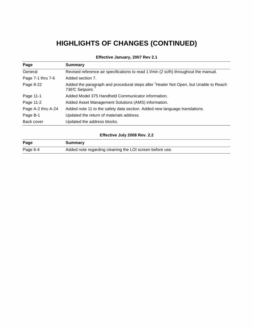
HIGHLIGHTS OF CHANGES (CONTINUED)
Effective January, 2007 Rev 2.1
Effective July 2008 Rev. 2.2
Page Summary
General Revised reference air specifications to read 1 l/min (2 scfh) throughout the manual.
Page 7-1 thru 7-6 Added section 7.
Page 8-22 Added the paragraph and procedural steps after 'Heater Not Open, but Unable to Reach 736°C Setpoint. '
Page 11-1 Added Model 375 Handheld Communicator information.
Page 11-2 Added Asset Management Solutions (AMS) information.
Page A-2 thru A-24 Added note 11 to the safety data section. Added new language translations.
Page B-1 Updated the return of materials address.
Back cover Updated the address blocks.
Page Summary
Page 6-4 Added note regarding cleaning the LOI screen before use.

Instruction ManualIM-106-350, Rev 2.2July 2008
TOC-1
Oxymitter 5000
Table of Contents
Essential Instructions . . . . . . . . . . . . . . . . . . . . . . . . . . . . . . . . . . . . . . . . i
SECTION iIntroduction
Preface. . . . . . . . . . . . . . . . . . . . . . . . . . . . . . . . . . . . . . . . . . . . . . . . . . ivDefinitions . . . . . . . . . . . . . . . . . . . . . . . . . . . . . . . . . . . . . . . . . . . . . . . ivSymbols . . . . . . . . . . . . . . . . . . . . . . . . . . . . . . . . . . . . . . . . . . . . . . . . . ivOxymitter 5000 with Fieldbus Communications . . . . . . . . . . . . . . . . . . . vWhat You Need To Know. . . . . . . . . . . . . . . . . . . . . . . . . . . . . . . . . . . . vCan You Use the Quick Start Guide? . . . . . . . . . . . . . . . . . . . . . . . . . viiiQuick Start Guide for Oxymitter 5000 Systems . . . . . . . . . . . . . . . . . . . ixQuick Reference Guide Manual Calibration Instructions . . . . . . . . . . . . x
SECTION 1Description and Specifications
Component Checklist . . . . . . . . . . . . . . . . . . . . . . . . . . . . . . . . . . . . . .1-1System Overview . . . . . . . . . . . . . . . . . . . . . . . . . . . . . . . . . . . . . . . . .1-1
Scope . . . . . . . . . . . . . . . . . . . . . . . . . . . . . . . . . . . . . . . . . . . . . . .1-1Foundation fieldbus Technology . . . . . . . . . . . . . . . . . . . . . . . . . . .1-3System Description . . . . . . . . . . . . . . . . . . . . . . . . . . . . . . . . . . . . .1-3System Configuration . . . . . . . . . . . . . . . . . . . . . . . . . . . . . . . . . . .1-4System Features. . . . . . . . . . . . . . . . . . . . . . . . . . . . . . . . . . . . . . .1-5Handling the Oxymitter 5000 . . . . . . . . . . . . . . . . . . . . . . . . . . . . .1-7System Considerations . . . . . . . . . . . . . . . . . . . . . . . . . . . . . . . . . .1-7
IMPS 4000 (Optional). . . . . . . . . . . . . . . . . . . . . . . . . . . . . . . . . . . . .1-11SPS 4001B (Optional) . . . . . . . . . . . . . . . . . . . . . . . . . . . . . . . . . . . .1-11
Mounting . . . . . . . . . . . . . . . . . . . . . . . . . . . . . . . . . . . . . . . . . . . .1-11Operation . . . . . . . . . . . . . . . . . . . . . . . . . . . . . . . . . . . . . . . . . . .1-11
Probe Options . . . . . . . . . . . . . . . . . . . . . . . . . . . . . . . . . . . . . . . . . .1-12Diffusion Elements . . . . . . . . . . . . . . . . . . . . . . . . . . . . . . . . . . . .1-12
Specifications . . . . . . . . . . . . . . . . . . . . . . . . . . . . . . . . . . . . . . . . . . .1-15
SECTION 2Installation
Mechanical Installation. . . . . . . . . . . . . . . . . . . . . . . . . . . . . . . . . . . . .2-2Selecting Location. . . . . . . . . . . . . . . . . . . . . . . . . . . . . . . . . . . . . .2-2Probe Installation . . . . . . . . . . . . . . . . . . . . . . . . . . . . . . . . . . . . . .2-2Remote Electronics Installation. . . . . . . . . . . . . . . . . . . . . . . . . . .2-10
Electrical Installation (with Integral Electronics) . . . . . . . . . . . . . . . . .2-11Electrical Installation (with Remote Electronics) . . . . . . . . . . . . . . . .2-14
Install Interconnecting Cable. . . . . . . . . . . . . . . . . . . . . . . . . . . . .2-17Pneumatic Installation . . . . . . . . . . . . . . . . . . . . . . . . . . . . . . . . . . . .2-17IMPS 4000 Connections . . . . . . . . . . . . . . . . . . . . . . . . . . . . . . . . . .2-19SPS 4001B Connections . . . . . . . . . . . . . . . . . . . . . . . . . . . . . . . . . .2-19
SECTION 3Configuration of Oxymitter 5000 with Membrane Keypad
Verify Installation . . . . . . . . . . . . . . . . . . . . . . . . . . . . . . . . . . . . . . . . .3-1Mechanical Installation . . . . . . . . . . . . . . . . . . . . . . . . . . . . . . . . . .3-1Terminal Block Wiring . . . . . . . . . . . . . . . . . . . . . . . . . . . . . . . . . . .3-1Oxymitter 5000 Configuration . . . . . . . . . . . . . . . . . . . . . . . . . . . . .3-2
Logic I/O. . . . . . . . . . . . . . . . . . . . . . . . . . . . . . . . . . . . . . . . . . . . . . . .3-4Recommended Configuration . . . . . . . . . . . . . . . . . . . . . . . . . . . . .3-5
Instruction ManualIM-106-350, Rev. 2.2
July 2008
TOC-2
Oxymitter 5000
SECTION 4Configuration of Oxymitter 5000 with LOI
Verify installation . . . . . . . . . . . . . . . . . . . . . . . . . . . . . . . . . . . . . . . . . 4-1Mechanical Installation . . . . . . . . . . . . . . . . . . . . . . . . . . . . . . . . . . 4-1Terminal Block Wiring. . . . . . . . . . . . . . . . . . . . . . . . . . . . . . . . . . . 4-1Oxymitter 5000 Configuration. . . . . . . . . . . . . . . . . . . . . . . . . . . . . 4-2
Logic I/O . . . . . . . . . . . . . . . . . . . . . . . . . . . . . . . . . . . . . . . . . . . . . . . 4-4Recommended Configuration. . . . . . . . . . . . . . . . . . . . . . . . . . . . . 4-5
SECTION 5Startup and Operation of Oxymitter 5000 with Membrane Keypad
Power Up . . . . . . . . . . . . . . . . . . . . . . . . . . . . . . . . . . . . . . . . . . . . . . . 5-1Operation . . . . . . . . . . . . . . . . . . . . . . . . . . . . . . . . . . . . . . . . . . . . . . . 5-2
Overview. . . . . . . . . . . . . . . . . . . . . . . . . . . . . . . . . . . . . . . . . . . . . 5-2
SECTION 6Startup and Operation of Oxymitter 5000 with LOI
Power Up . . . . . . . . . . . . . . . . . . . . . . . . . . . . . . . . . . . . . . . . . . . . . . . 6-1Start Up Oxymitter 5000 Calibration . . . . . . . . . . . . . . . . . . . . . . . . . . 6-3Navigating the Local Operator Interface . . . . . . . . . . . . . . . . . . . . . . . 6-3
Overview. . . . . . . . . . . . . . . . . . . . . . . . . . . . . . . . . . . . . . . . . . . . . 6-3Lockout . . . . . . . . . . . . . . . . . . . . . . . . . . . . . . . . . . . . . . . . . . . . . . 6-3
LOI Key Designations . . . . . . . . . . . . . . . . . . . . . . . . . . . . . . . . . . . . . 6-4LOI Menu Tree. . . . . . . . . . . . . . . . . . . . . . . . . . . . . . . . . . . . . . . . . . . 6-4Oxymitter 5000 Setup at the LOI . . . . . . . . . . . . . . . . . . . . . . . . . . . . . 6-6LOI Installation. . . . . . . . . . . . . . . . . . . . . . . . . . . . . . . . . . . . . . . . . . . 6-9Oxymitter 5000 Test Points . . . . . . . . . . . . . . . . . . . . . . . . . . . . . . . . 6-10
SECTION 7Model 375 Handheld Communicator
Overview . . . . . . . . . . . . . . . . . . . . . . . . . . . . . . . . . . . . . . . . . . . . . . . 7-1Fieldbus Terminal Block Connections . . . . . . . . . . . . . . . . . . . . . . . . . 7-1Off-Line and On-Line Operations. . . . . . . . . . . . . . . . . . . . . . . . . . . . . 7-2Logic I/O Configurations . . . . . . . . . . . . . . . . . . . . . . . . . . . . . . . . . . . 7-3Fieldbus Menu Tree. . . . . . . . . . . . . . . . . . . . . . . . . . . . . . . . . . . . . . . 7-4FOUNDATION Fieldbus O2 CAL Method . . . . . . . . . . . . . . . . . . . . . . 7-5
SECTION 8Troubleshooting
Overview . . . . . . . . . . . . . . . . . . . . . . . . . . . . . . . . . . . . . . . . . . . . . . . 8-1General . . . . . . . . . . . . . . . . . . . . . . . . . . . . . . . . . . . . . . . . . . . . . . . . 8-3Alarm Indications . . . . . . . . . . . . . . . . . . . . . . . . . . . . . . . . . . . . . . . . . 8-3Alarm Contacts . . . . . . . . . . . . . . . . . . . . . . . . . . . . . . . . . . . . . . . . . . 8-4Identifying and Correcting Alarm Indications . . . . . . . . . . . . . . . . . . . . 8-5Heater Not Open, but Unable to Reach 736°C Setpoint . . . . . . . . . . 8-22Calibration Passes but Still Reads Incorrectly . . . . . . . . . . . . . . . . . . 8-22
SECTION 9Maintenance and Service
Overview . . . . . . . . . . . . . . . . . . . . . . . . . . . . . . . . . . . . . . . . . . . . . . . 9-1Calibration with Keypad . . . . . . . . . . . . . . . . . . . . . . . . . . . . . . . . . . . . 9-1
Automatic Calibration . . . . . . . . . . . . . . . . . . . . . . . . . . . . . . . . . . . 9-2Semi-Automatic Calibration . . . . . . . . . . . . . . . . . . . . . . . . . . . . . . 9-3Manual Calibration with Membrane Keypad. . . . . . . . . . . . . . . . . . 9-3
FOUNDATION Fieldbus O2 CAL Method . . . . . . . . . . . . . . . . . . . . . . 9-5Calibration with LOI . . . . . . . . . . . . . . . . . . . . . . . . . . . . . . . . . . . . . . . 9-6Oxymitter 5000 Repair. . . . . . . . . . . . . . . . . . . . . . . . . . . . . . . . . . . . . 9-8
Removal and Replacement of Probe . . . . . . . . . . . . . . . . . . . . . . . 9-8Replace Entire Integral Electronics (with Housing) . . . . . . . . . . . 9-11Electronic Assembly Replacement . . . . . . . . . . . . . . . . . . . . . . . . 9-12Terminal Block Replacement . . . . . . . . . . . . . . . . . . . . . . . . . . . . 9-13Fuse Replacement . . . . . . . . . . . . . . . . . . . . . . . . . . . . . . . . . . . . 9-13
Instruction ManualIM-106-350, Rev 2.2July 2008
TOC-3
Oxymitter 5000
Entire Probe Replacement (Excluding Probe Head). . . . . . . . . . .9-14Heater Strut Replacement . . . . . . . . . . . . . . . . . . . . . . . . . . . . . .9-15Cell Replacement . . . . . . . . . . . . . . . . . . . . . . . . . . . . . . . . . . . . .9-17Ceramic Diffusion Element Replacement . . . . . . . . . . . . . . . . . . .9-20
SECTION 10Replacement Parts
Probe Replacement Parts . . . . . . . . . . . . . . . . . . . . . . . . . . . . . . . . .10-1Electronics Replacement Parts . . . . . . . . . . . . . . . . . . . . . . . . . . . . .10-6
SECTION 11Optional Accessories
Model 375 Handheld Communicator . . . . . . . . . . . . . . . . . . . . . . . . .11-1Asset Management Solutions (AMS) . . . . . . . . . . . . . . . . . . . . . . . . .11-2By-Pass Packages . . . . . . . . . . . . . . . . . . . . . . . . . . . . . . . . . . . . . . .11-2IMPS 4000 Intelligent Multiprobe Test Gas Sequencer . . . . . . . . . . .11-3SPS 4001B Single Probe Autocalibration Sequencer . . . . . . . . . . . .11-4O2 Calibration Gas . . . . . . . . . . . . . . . . . . . . . . . . . . . . . . . . . . . . . . .11-5Catalyst Regeneration . . . . . . . . . . . . . . . . . . . . . . . . . . . . . . . . . . . .11-6
APPENDIX ASafety Data
Safety Instructions . . . . . . . . . . . . . . . . . . . . . . . . . . . . . . . . . . . . . . . A-2Safety Data Sheet for Ceramic Fiber Products . . . . . . . . . . . . . . . . A-24
APPENDIX BReturn of Material
Returning Material . . . . . . . . . . . . . . . . . . . . . . . . . . . . . . . . . . . . . . . B-1
APPENDIX CFieldbus Parameter Description
Fieldbus Parameters . . . . . . . . . . . . . . . . . . . . . . . . . . . . . . . . . . . . . C-1
APPENDIX DAnalog Input (AI) Function Block
Simulation . . . . . . . . . . . . . . . . . . . . . . . . . . . . . . . . . . . . . . . . . . . . . D-3Filtering . . . . . . . . . . . . . . . . . . . . . . . . . . . . . . . . . . . . . . . . . . . . . . . D-4Signal Conversion . . . . . . . . . . . . . . . . . . . . . . . . . . . . . . . . . . . . . . . D-5
Direct. . . . . . . . . . . . . . . . . . . . . . . . . . . . . . . . . . . . . . . . . . . . . . . D-5Indirect . . . . . . . . . . . . . . . . . . . . . . . . . . . . . . . . . . . . . . . . . . . . . D-5Indirect Square Root . . . . . . . . . . . . . . . . . . . . . . . . . . . . . . . . . . . D-5
Block Errors . . . . . . . . . . . . . . . . . . . . . . . . . . . . . . . . . . . . . . . . . . . . D-5Modes . . . . . . . . . . . . . . . . . . . . . . . . . . . . . . . . . . . . . . . . . . . . . . . . D-6Alarm Detection . . . . . . . . . . . . . . . . . . . . . . . . . . . . . . . . . . . . . . . . . D-6Status Handling . . . . . . . . . . . . . . . . . . . . . . . . . . . . . . . . . . . . . . . . . D-7Advanced Features . . . . . . . . . . . . . . . . . . . . . . . . . . . . . . . . . . . . . . D-8Application Information. . . . . . . . . . . . . . . . . . . . . . . . . . . . . . . . . . . . D-8
Channel. . . . . . . . . . . . . . . . . . . . . . . . . . . . . . . . . . . . . . . . . . . . . D-8L_TYPE. . . . . . . . . . . . . . . . . . . . . . . . . . . . . . . . . . . . . . . . . . . . . D-8Scaling . . . . . . . . . . . . . . . . . . . . . . . . . . . . . . . . . . . . . . . . . . . . . D-8
Application Examples. . . . . . . . . . . . . . . . . . . . . . . . . . . . . . . . . . . . . D-9Temperature Transmitter . . . . . . . . . . . . . . . . . . . . . . . . . . . . . . . D-9Pressure Transmitter used to Measure Level in an Open Tank . D-10Differential Pressure Transmitter to Measure Flow. . . . . . . . . . . D-12
Troubleshooting . . . . . . . . . . . . . . . . . . . . . . . . . . . . . . . . . . . . . . . . D-13
Instruction ManualIM-106-350, Rev. 2.2
July 2008
TOC-4
Oxymitter 5000
APPENDIX EPID Function Block
Setpoint Selection and Limiting . . . . . . . . . . . . . . . . . . . . . . . . . . . . . E-6Filtering . . . . . . . . . . . . . . . . . . . . . . . . . . . . . . . . . . . . . . . . . . . . . . . . E-6Feedforward Calculation. . . . . . . . . . . . . . . . . . . . . . . . . . . . . . . . . . . E-6Tracking . . . . . . . . . . . . . . . . . . . . . . . . . . . . . . . . . . . . . . . . . . . . . . . E-6Output Selection and Limiting. . . . . . . . . . . . . . . . . . . . . . . . . . . . . . . E-7Bumpless Transfer and Setpoint Tracking . . . . . . . . . . . . . . . . . . . . . E-7PID Equation Structures . . . . . . . . . . . . . . . . . . . . . . . . . . . . . . . . . . . E-7Reverse and Direct Action . . . . . . . . . . . . . . . . . . . . . . . . . . . . . . . . . E-7Reset Limiting . . . . . . . . . . . . . . . . . . . . . . . . . . . . . . . . . . . . . . . . . . . E-8Block Errors . . . . . . . . . . . . . . . . . . . . . . . . . . . . . . . . . . . . . . . . . . . . E-8Modes . . . . . . . . . . . . . . . . . . . . . . . . . . . . . . . . . . . . . . . . . . . . . . . . . E-8Alarm Detection . . . . . . . . . . . . . . . . . . . . . . . . . . . . . . . . . . . . . . . . . E-9Status Handling . . . . . . . . . . . . . . . . . . . . . . . . . . . . . . . . . . . . . . . . E-10Application Information . . . . . . . . . . . . . . . . . . . . . . . . . . . . . . . . . . . E-10
Closed Loop Control . . . . . . . . . . . . . . . . . . . . . . . . . . . . . . . . . . E-10Application Examples . . . . . . . . . . . . . . . . . . . . . . . . . . . . . . . . . . . . E-11
Basic PID Block for Steam Heater Control . . . . . . . . . . . . . . . . . E-11Feedforward Control . . . . . . . . . . . . . . . . . . . . . . . . . . . . . . . . . . E-12Cascade Control with Master and Slave Loops. . . . . . . . . . . . . . E-13Cascade Control with Override . . . . . . . . . . . . . . . . . . . . . . . . . . E-14
Troubleshooting . . . . . . . . . . . . . . . . . . . . . . . . . . . . . . . . . . . . . . . . E-16
Instruction Manual IM-106-350, Rev 2.2July 2008 Oxymitter 5000
http://www.raihome.com
Oxymitter Oxygen TransmittersREAD THIS PAGE BEFORE PROCEEDING!
ESSENTIAL INSTRUCTIONS
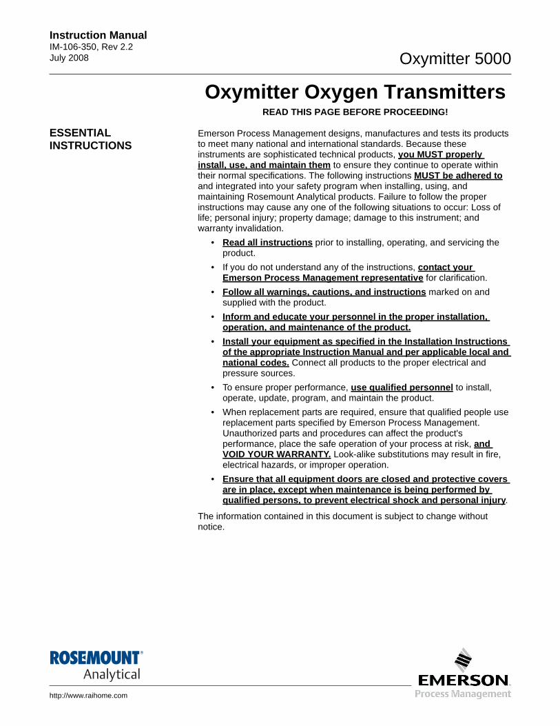
Emerson Process Management designs, manufactures and tests its products to meet many national and international standards. Because these instruments are sophisticated technical products, you MUST properly install, use, and maintain them to ensure they continue to operate within their normal specifications. The following instructions MUST be adhered to and integrated into your safety program when installing, using, and maintaining Rosemount Analytical products. Failure to follow the proper instructions may cause any one of the following situations to occur: Loss of life; personal injury; property damage; damage to this instrument; and warranty invalidation.
• Read all instructions prior to installing, operating, and servicing the product.
• If you do not understand any of the instructions, contact your Emerson Process Management representative for clarification.
• Follow all warnings, cautions, and instructions marked on and supplied with the product.
• Inform and educate your personnel in the proper ins tallation, operation, and maintenance of the product.
• Install your equipment as specified in the Installa tion Instructions of the appropriate Instruction Manual and per appli cable local and national codes. Connect all products to the proper electrical and pressure sources.
• To ensure proper performance, use qualified personnel to install, operate, update, program, and maintain the product.
• When replacement parts are required, ensure that qualified people use replacement parts specified by Emerson Process Management. Unauthorized parts and procedures can affect the product's performance, place the safe operation of your process at risk, and VOID YOUR WARRANTY. Look-alike substitutions may result in fire, electrical hazards, or improper operation.
• Ensure that all equipment doors are closed and prot ective covers are in place, except when maintenance is being perf ormed by qualified persons, to prevent electrical shock and personal injury .
The information contained in this document is subject to change without notice.

Instruction Manual IM-106-350, Rev 2.2July 2008 Oxymitter 5000
http://www.raihome.com
Section i Introduction
Preface . . . . . . . . . . . . . . . . . . . . . . . . . . . . . . . . . . . . . . . . . page ivDefinitions . . . . . . . . . . . . . . . . . . . . . . . . . . . . . . . . . . . . . . page ivSymbols . . . . . . . . . . . . . . . . . . . . . . . . . . . . . . . . . . . . . . . . page ivOxymitter 5000 with Fieldbus Communications . . . . . . . page vWhat You Need To Know . . . . . . . . . . . . . . . . . . . . . . . . . . page vCan You Use the Quick Start Guide? . . . . . . . . . . . . . . . . page viiiQuick Start Guide for Oxymitter 5000 Systems . . . . . . . . page ixQuick Reference Guide Manual Calibration Instructio ns page x
Oxymitter 5000
iv
Instruction ManualIM-106-350, Rev 2.2
July 2008
PREFACE The purpose of this manual is to provide information concerning the components, functions, installation and maintenance of the Oxymitter 5000 Oxygen Transmitter.
Some sections may describe equipment not used in your configuration. The user should become thoroughly familiar with the operation of this module before operating it. Read this instruction manual completely.
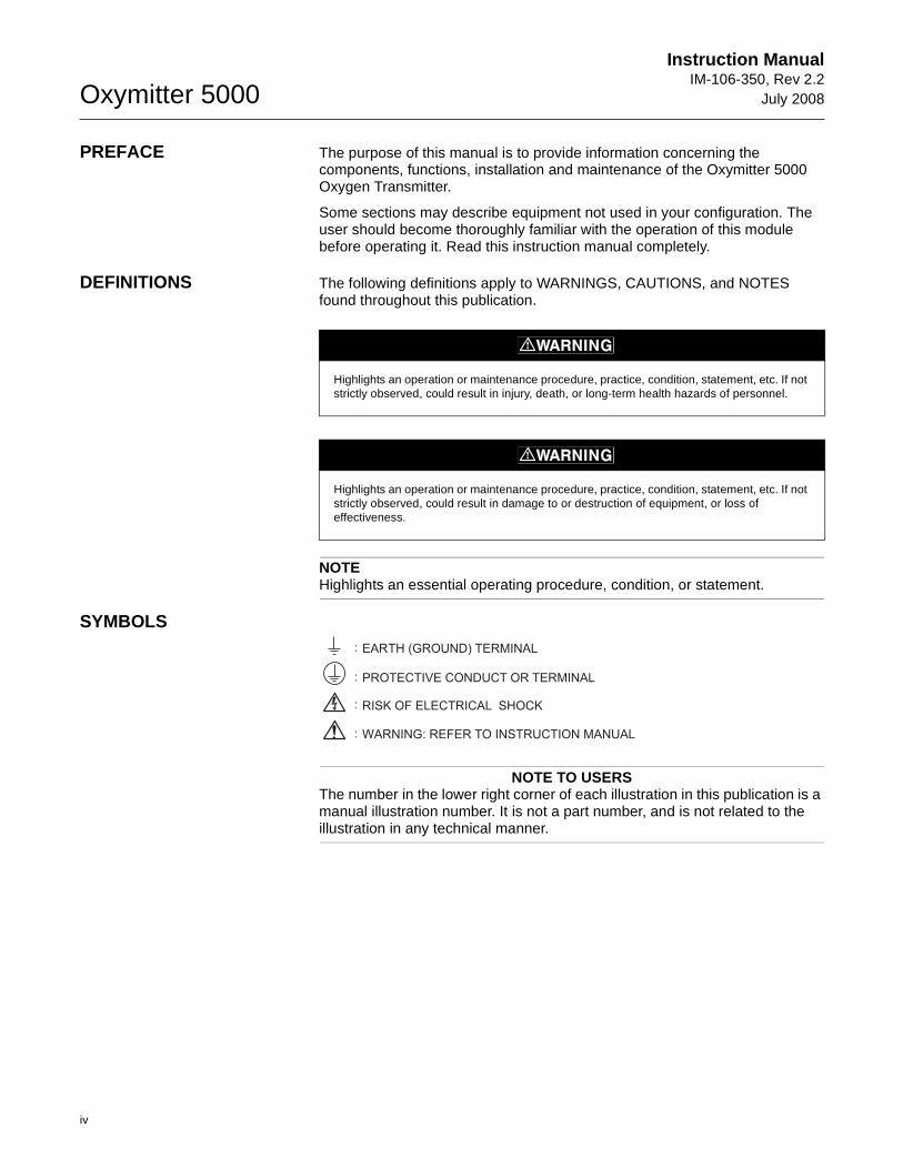
DEFINITIONS The following definitions apply to WARNINGS, CAUTIONS, and NOTES found throughout this publication.
NOTEHighlights an essential operating procedure, condition, or statement.
SYMBOLS
NOTE TO USERSThe number in the lower right corner of each illustration in this publication is a manual illustration number. It is not a part number, and is not related to the illustration in any technical manner.
Highlights an operation or maintenance procedure, practice, condition, statement, etc. If not strictly observed, could result in injury, death, or long-term health hazards of personnel.
Highlights an operation or maintenance procedure, practice, condition, statement, etc. If not strictly observed, could result in damage to or destruction of equipment, or loss of effectiveness.
RISK OF ELECTRICAL SHOCK
WARNING: REFER TO INSTRUCTION MANUAL
PROTECTIVE CONDUCT OR TERMINAL
EARTH (GROUND) TERMINAL:
:
:
:
Instruction Manual IM-106-350, Rev 2.2July 2008
v
Oxymitter 5000
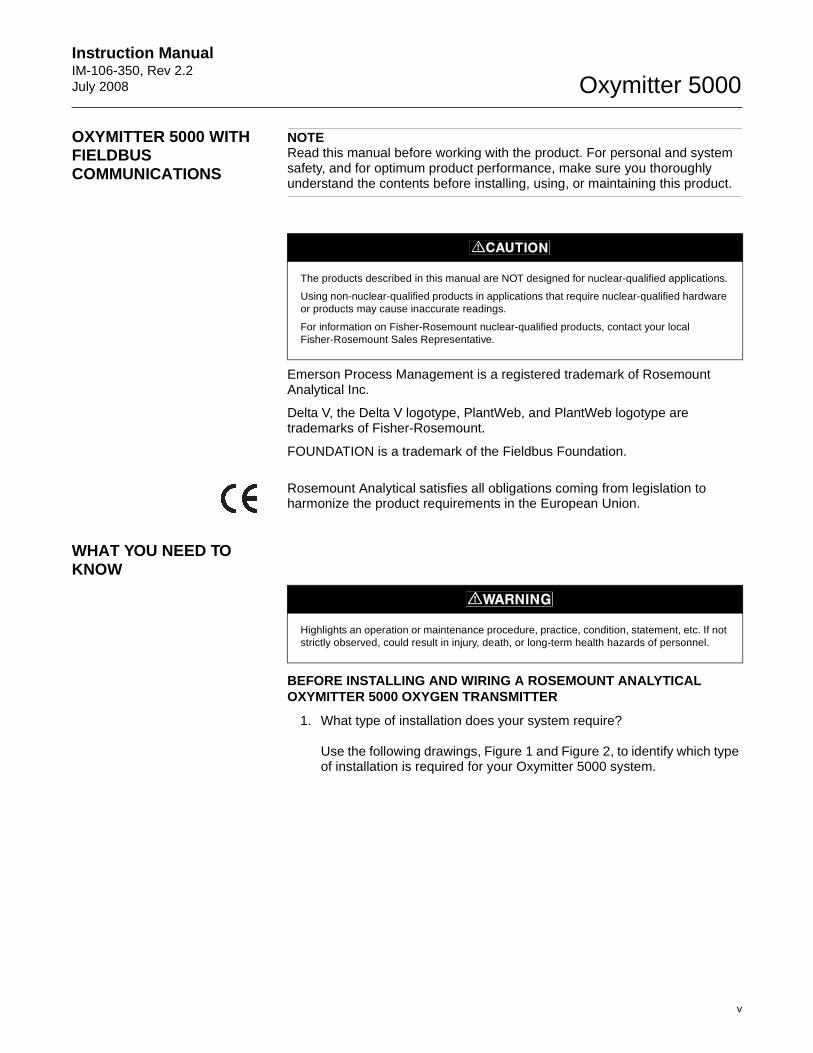
OXYMITTER 5000 WITH FIELDBUS COMMUNICATIONS
NOTERead this manual before working with the product. For personal and system safety, and for optimum product performance, make sure you thoroughly understand the contents before installing, using, or maintaining this product.
Emerson Process Management is a registered trademark of Rosemount Analytical Inc.
Delta V, the Delta V logotype, PlantWeb, and PlantWeb logotype are trademarks of Fisher-Rosemount.
FOUNDATION is a trademark of the Fieldbus Foundation.
Rosemount Analytical satisfies all obligations coming from legislation to harmonize the product requirements in the European Union.
WHAT YOU NEED TO KNOW
BEFORE INSTALLING AND WIRING A ROSEMOUNT ANALYTICAL OXYMITTER 5000 OXYGEN TRANSMITTER
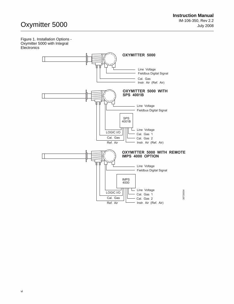
1. What type of installation does your system require?
Use the following drawings, Figure 1 and Figure 2, to identify which type of installation is required for your Oxymitter 5000 system.
The products described in this manual are NOT designed for nuclear-qualified applications.
Using non-nuclear-qualified products in applications that require nuclear-qualified hardware or products may cause inaccurate readings.
For information on Fisher-Rosemount nuclear-qualified products, contact your local Fisher-Rosemount Sales Representative.
APPROVEDUSC
Highlights an operation or maintenance procedure, practice, condition, statement, etc. If not strictly observed, could result in injury, death, or long-term health hazards of personnel.
Oxymitter 5000
vi
Instruction ManualIM-106-350, Rev 2.2
July 2008
Figure 1. Installation Options - Oxymitter 5000 with Integral Electronics
Cal. Gas 1
Cal. Gas 1
Cal. Gas
Cal. Gas
Cal. Gas 2
Cal. Gas 2
OXYMITTER 5000
OXYMITTER 5000 WITHSPS 4001B
OXYMITTER 5000 WITH REMOTEIMPS 4000 OPTION
IMPS4000
Line Voltage
Line Voltage
Line Voltage
Line Voltage
Line Voltage
Fieldbus Digital Signal
Instr. Air (Ref. Air)
Cal. Gas
LOGIC I/O
LOGIC I/O
Instr. Air (Ref. Air)
Instr. Air (Ref. Air)
Ref. Air
Ref. Air
38
73
00
54
SPS4001B
Fieldbus Digital Signal
Fieldbus Digital Signal
Instruction Manual IM-106-350, Rev 2.2July 2008
vii
Oxymitter 5000
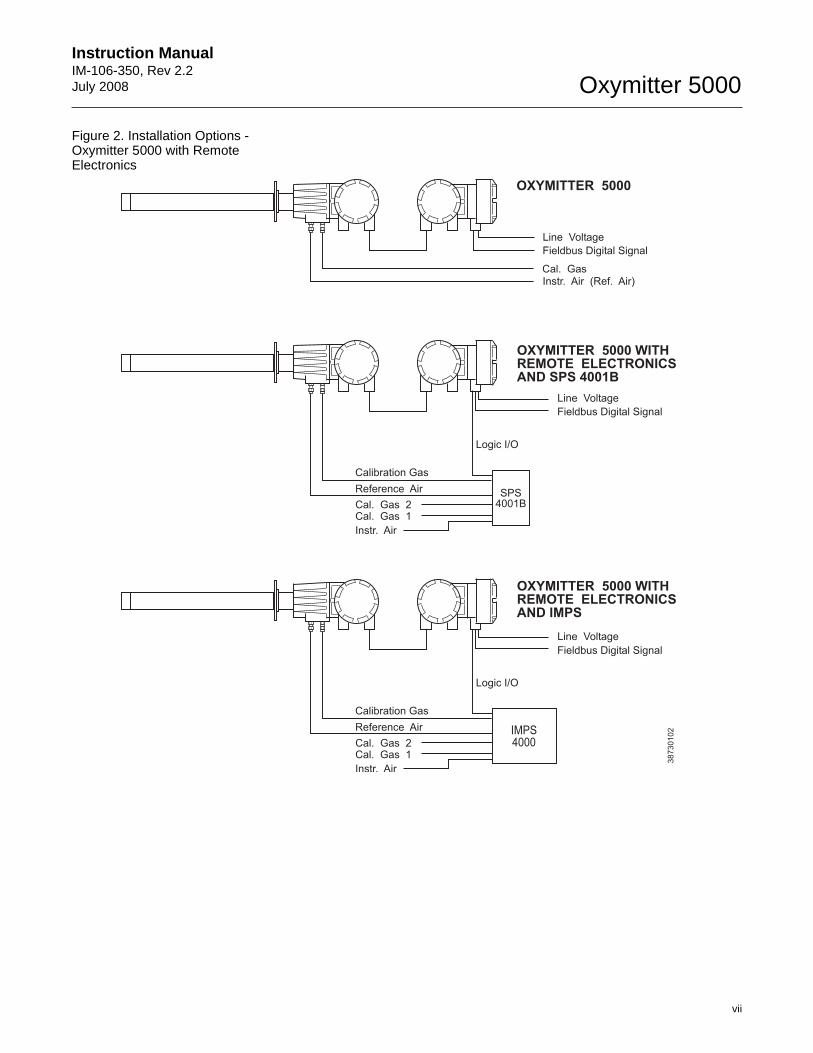
Figure 2. Installation Options - Oxymitter 5000 with Remote Electronics
OXYMITTER 5000
Instr. Air (Ref. Air)Cal. Gas
Line Voltage
38
73
01
02
OXYMITTER 5000REMOTE ELECTRONICSAND IMPS
WITH
OXYMITTER 5000REMOTE ELECTRONICSAND SPS 4001B
WITH
Cal. Gas 1
Cal. Gas 1
Cal. Gas 2
Cal. Gas 2
Line Voltage
Line Voltage
Instr. Air
Instr. Air
Reference Air
Reference Air
Calibration Gas
Calibration Gas
Logic I/O
Logic I/O
SPS4001B
IMPS4000
Fieldbus Digital Signal
Fieldbus Digital Signal
Fieldbus Digital Signal
Oxymitter 5000
viii
Instruction ManualIM-106-350, Rev 2.2
July 2008
CAN YOU USE THE QUICK START GUIDE?
Use this Quick Start Guide if...
1. Your system requires an Oxymitter 5000 with or without the SPS 4001B OPTION. Installation options for the Oxymitter 5000 are shown in Figure 1.
2. Your system does NOT require an IMPS 4000 OPTION installation.
3. Your system does NOT use a Remote Electronics as shown in Figure 2.
4. You are familiar with the installation requirements for the Oxymitter 5000 Oxygen Transmitter. You are familiar with the installation requirements for the Oxymitter 5000 Oxygen Transmitter with a SPS 4001B.
If you cannot use the Quick Start Guide, turn to Se ction 2: Installation, in this Instruction Manual.
Instruction Manual IM-106-350, Rev 2.2July 2008
ix
Oxymitter 5000
QUICK START GUIDE FOR OXYMITTER 5000 SYSTEMS
Before using the Quick Start Guide, please read "WH AT YOU NEED TO KNOW BEFORE INSTALLING AND WIRING A ROSEMOUNT ANALYTICAL OXYMITTER 5000 OXYGEN TRANSMITTER" on th e preceding page.
1. Install the Oxymitter 5000 in an appropriate location on the stack or duct. Refer to "Selecting Location" in Section 2: Installation, for information on selecting a location for the Oxymitter 5000.
2. If using an SPS 4001B, connect the calibration gasses to the appropriate fittings on the SPS 4001B manifold.
3. Connect reference air to the Oxymitter 5000 or SPS 4001B, as applicable.
4. If using an SPS 4001B, make the wiring connections as shown in the SPS 4001B Single Probe Autocalibration Sequencer Instruction Manual.
5. If NOT using an SPS 4001B, make the following wire connections as shown in Figure 3: line voltage, fieldbus digital signal, and logic I/O.
6. Verify the Oxymitter 5000 switch configuration is as desired. Refer to "Oxymitter 5000 Configuration", in Section 3: Configuration of Oxymitter 5000 with Membrane Keypad, or "Oxymitter 5000 Configuration", in Section 4: Configuration of Oxymitter 5000 with LOI.
7. Apply power to the Oxymitter 5000; the cell heater will turn on. Allow approximately one half hour for the cell to heat to operating temperature. Once the ramp cycle has completed and the Oxymitter 5000 is at normal operation, proceed with step 8 or 9.
8. If using an SPS 4001B, initiate a semi-automatic calibration.
9. If NOT using an SPS 4001B, perform a manual calibration. Refer to "Calibration with Keypad" or "Calibration with LOI" both in Section 9: Maintenance and Service, in this instruction manual.
NOTEIf your system has a membrane keypad you can refer to the Quick Start Guide on the following pages.
Oxymitter 5000
x
Instruction ManualIM-106-350, Rev 2.2
July 2008
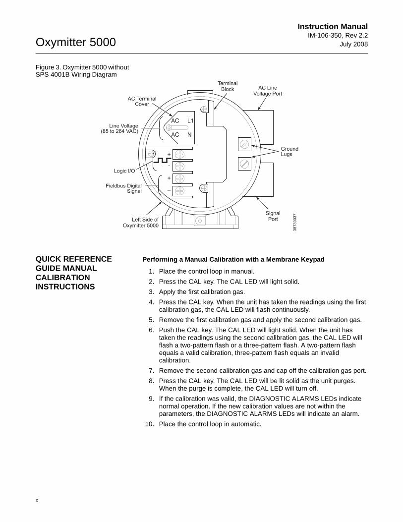
Figure 3. Oxymitter 5000 without SPS 4001B Wiring Diagram
QUICK REFERENCE GUIDE MANUAL CALIBRATION INSTRUCTIONS
Performing a Manual Calibration with a Membrane Key pad
1. Place the control loop in manual.
2. Press the CAL key. The CAL LED will light solid.
3. Apply the first calibration gas.
4. Press the CAL key. When the unit has taken the readings using the first calibration gas, the CAL LED will flash continuously.
5. Remove the first calibration gas and apply the second calibration gas.
6. Push the CAL key. The CAL LED will light solid. When the unit has taken the readings using the second calibration gas, the CAL LED will flash a two-pattern flash or a three-pattern flash. A two-pattern flash equals a valid calibration, three-pattern flash equals an invalid calibration.
7. Remove the second calibration gas and cap off the calibration gas port.
8. Press the CAL key. The CAL LED will be lit solid as the unit purges. When the purge is complete, the CAL LED will turn off.
9. If the calibration was valid, the DIAGNOSTIC ALARMS LEDs indicate normal operation. If the new calibration values are not within the parameters, the DIAGNOSTIC ALARMS LEDs will indicate an alarm.
10. Place the control loop in automatic.
AC L1
AC N
+
+
-
–
TerminalBlock AC Line
Voltage Port
SignalPortLeft Side of
Oxymitter 5000
38
73
00
37
AC TerminalCover
Line Voltage(85 to 264 VAC)
GroundLugs
Logic I/O
Fieldbus DigitalSignal
Instruction Manual IM-106-350, Rev 2.2July 2008
xi
Oxymitter 5000
Technical Support Hotline:
For assistance with technical problems, please call the Customer Support Center (CSC). The CSC is staffed 24 hours a day, 7 days a week.
Phone: 1-800-433-6076 1-440-914-1261
In addition to the CSC, you may also contact Field Watch. Field Watch coordinates Emerson Process Management’s field service throughout the U.S. and abroad.
Phone: 1-800-654-RSMT (1-800-654-7768)
Emerson Process Management may also be reached via the Internet through e-mail and the World Wide Web:
e-mail: [email protected]
World Wide Web: www.raihome.com

Oxymitter 5000
xii
Instruction ManualIM-106-350, Rev 2.2
July 2008
Instruction Manual IM-106-350, Rev 2.2July 2008 Oxymitter 5000
http://www.raihome.com
Section 1 Description and Specifications
Component Checklist . . . . . . . . . . . . . . . . . . . . . . . . . . . . . page 1-1System Overview . . . . . . . . . . . . . . . . . . . . . . . . . . . . . . . . page 1-1IMPS 4000 (Optional) . . . . . . . . . . . . . . . . . . . . . . . . . . . . . page 1-11SPS 4001B (Optional) . . . . . . . . . . . . . . . . . . . . . . . . . . . . . page 1-11Probe Options . . . . . . . . . . . . . . . . . . . . . . . . . . . . . . . . . . . page 1-12Specifications . . . . . . . . . . . . . . . . . . . . . . . . . . . . . . . . . . . page 1-15
COMPONENT CHECKLIST
A typical Rosemount Analytical Oxymitter 5000 Oxygen Transmitter should contain the items shown in Figure 1-1. Record the part number, serial number, and order number for each component of your system in the table located on the first page of this manual.
Also, use the product matrix in Table 1-1 at the end of this section to compare your order number against your unit. The first part of the matrix defines the model. The last part defines the various options and features of the Oxymitter 5000. Ensure the features and options specified by your order number are on or included with the unit.
SYSTEM OVERVIEW
Scope This Instruction Manual is designed to supply details needed to install, start up, operate, and maintain the Oxymitter 5000. Integral signal conditioning electronics outputs a digital FOUNDATION fieldbus signal representing an O2 value and provides a membrane keypad or fully functional Local Operator Interface (optional) for setup, calibration, and diagnostics. This same information, plus additional details, can be accessed via fieldbus digital communications.
Oxymitter 5000
1-2
Instruction ManualIM-106-350, Rev 2.2
July 2008
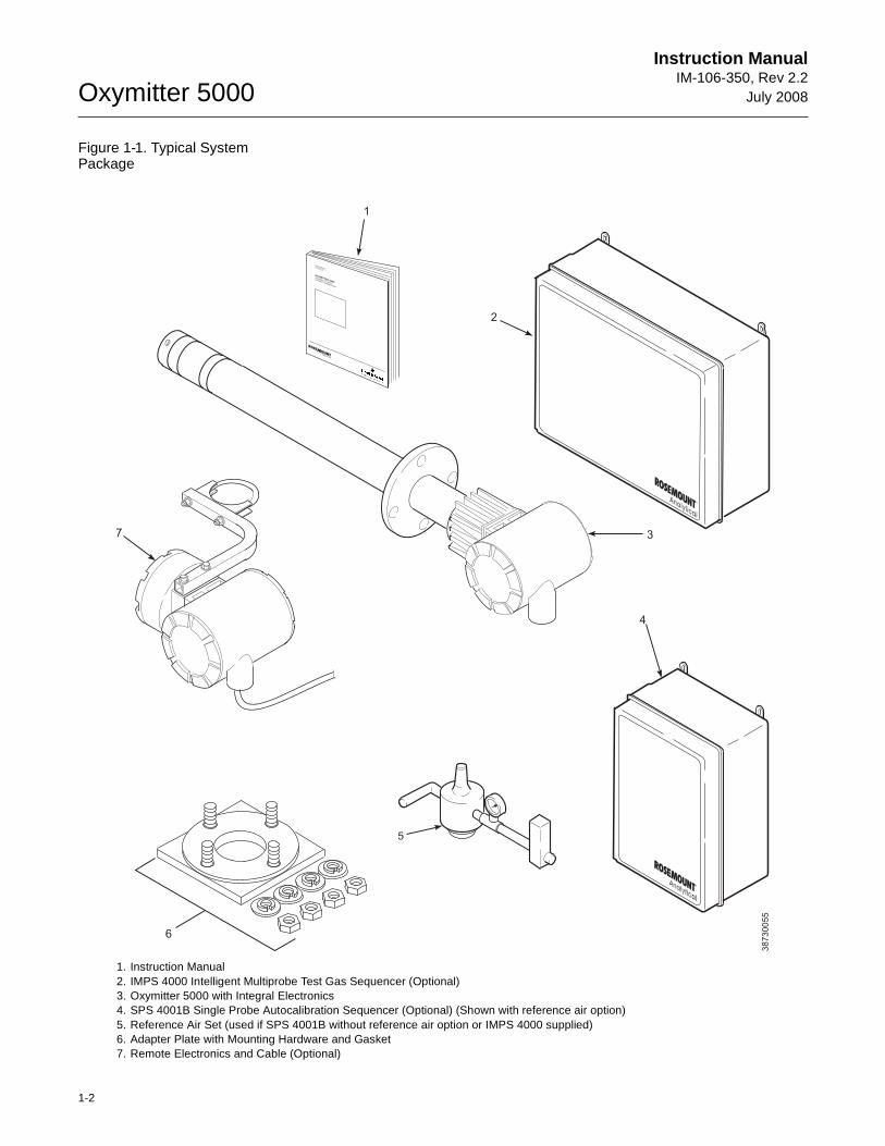
Figure 1-1. Typical System Package
1. Instruction Manual2. IMPS 4000 Intelligent Multiprobe Test Gas Sequencer (Optional) 3. Oxymitter 5000 with Integral Electronics4. SPS 4001B Single Probe Autocalibration Sequencer (Optional) (Shown with reference air option)5. Reference Air Set (used if SPS 4001B without reference air option or IMPS 4000 supplied)6. Adapter Plate with Mounting Hardware and Gasket7. Remote Electronics and Cable (Optional)
5
1
4
3
38
73
00
55
6
7
2
Analytical
Analytical
Analytical
OXYMITTER 4000
HAZARDOUS AREA
OXYGEN TRANSMITTER
Instruction Manual
IM-106-340C Rev. 4.2
December 2005
Instruction Manual IM-106-350, Rev 2.2July 2008
1-3
Oxymitter 5000
Foundation fieldbus Technology
Foundation fieldbus is an all digital, serial, two-way communication system that interconnects field equipment such as sensors, actuators, and controllers. Fieldbus is a Local Area Network (LAN) for instruments used in both process and manufacturing automation with built-in capacity to distribute the control application across the network. The fieldbus environment is the base level group of digital networks in the hierarchy of planet networks.
The fieldbus retains the desirable features of the 4-20 mA analog system, including a standardized physical interface to the wire, bus powered devices on a single wire, and intrinsic safety options, and enables additional capabilities, such as:
• Increased capabilities due to full digital communications
• Reduced wiring and wire terminations due to multiple devices on one set of wires
• Increased selection of suppliers due to interoperability
• Reduced loading on control room equipment with the distribution of some control and input/output functions to field devices
• Speed options for process control and manufacturing applications
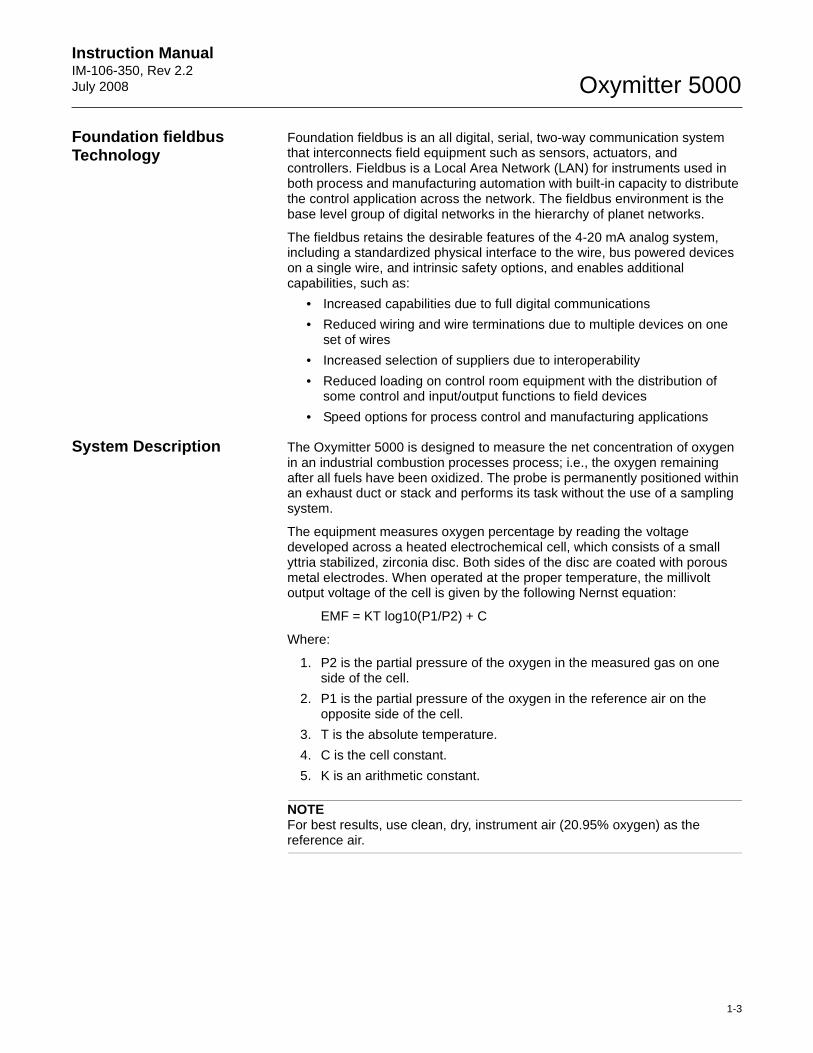
System Description The Oxymitter 5000 is designed to measure the net concentration of oxygen in an industrial combustion processes process; i.e., the oxygen remaining after all fuels have been oxidized. The probe is permanently positioned within an exhaust duct or stack and performs its task without the use of a sampling system.
The equipment measures oxygen percentage by reading the voltage developed across a heated electrochemical cell, which consists of a small yttria stabilized, zirconia disc. Both sides of the disc are coated with porous metal electrodes. When operated at the proper temperature, the millivolt output voltage of the cell is given by the following Nernst equation:
EMF = KT log10(P1/P2) + C
Where:
1. P2 is the partial pressure of the oxygen in the measured gas on one side of the cell.
2. P1 is the partial pressure of the oxygen in the reference air on the opposite side of the cell.
3. T is the absolute temperature.
4. C is the cell constant.
5. K is an arithmetic constant.
NOTEFor best results, use clean, dry, instrument air (20.95% oxygen) as the reference air.
Oxymitter 5000
1-4
Instruction ManualIM-106-350, Rev 2.2
July 2008
When the cell is at operating temperature and there are unequal oxygen concentrations across the cell, oxygen ions will travel from the high oxygen partial pressure side to the low oxygen partial pressure side of the cell. The resulting logarithmic output voltage is approximately 50 mV per decade. The output is proportional to the inverse logarithm of the oxygen concentration. Therefore, the output signal increases as the oxygen concentration of the sample gas decreases. This characteristic enables the Oxymitter 5000 to provide exceptional sensitivity at low oxygen concentrations.
The Oxymitter 5000 measures net oxygen concentration in the presence of all the products of combustion, including water vapor. Therefore, it may be considered an analysis on a "wet" basis. In comparison with older methods, such as the portable apparatus, which provides an analysis on a "dry" gas basis, the "wet" analysis will, in general, indicate a lower percentage of oxygen. The difference will be proportional to the water content of the sampled gas stream.
System Configuration Oxymitter 5000 units are available in seven length options, giving the user the flexibility to use an in situ penetration appropriate to the size of the stack or duct. The options on length are 18 in. (457 mm), 3 ft (0,91 m), 6 ft (1,83 m), 9 ft (2,7 m), 12 ft (3,66 m), 15 ft (4,57 m), and 18 ft (5,49 m).
The integral electronics control probe temperature and provide an output that represents the measured oxygen concentration. The power supply can accept voltages of 90-250VAC and 50/60 Hz; therefore no setup procedures are required. The oxygen sensing cell is maintained at a constant temperature by modulating the duty cycle of the probe heater portion of the integral electron-ics. The integral electronics accepts millivolt signals generated by the sensing cell and produces the outputs to be used by remotely connected devices. The output is a FOUNDATION fieldbus digital communication signal.
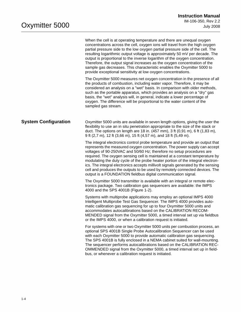
The Oxymitter 5000 transmitter is available with an integral or remote elec-tronics package. Two calibration gas sequencers are available: the IMPS 4000 and the SPS 4001B (Figure 1-2).
Systems with multiprobe applications may employ an optional IMPS 4000 Intelligent Multiprobe Test Gas Sequencer. The IMPS 4000 provides auto-matic calibration gas sequencing for up to four Oxymitter 5000 units and accommodates autocalibrations based on the CALIBRATION RECOM-MENDED signal from the Oxymitter 5000, a timed interval set up via fieldbus or the IMPS 4000, or when a calibration request is initiated.
For systems with one or two Oxymitter 5000 units per combustion process, an optional SPS 4001B Single Probe Autocalibration Sequencer can be used with each Oxymitter 5000 to provide automatic calibration gas sequencing. The SPS 4001B is fully enclosed in a NEMA cabinet suited for wall-mounting. The sequencer performs autocalibrations based on the CALIBRATION REC-OMMENDED signal from the Oxymitter 5000, a timed interval set up in field-bus, or whenever a calibration request is initiated.
Instruction Manual IM-106-350, Rev 2.2July 2008
1-5
Oxymitter 5000
Figure 1-2. Oxymitter 5000 AutoCalibration System Options
System Features 1. The CALIBRATION RECOMMENDED feature detects when the sensing cell is likely out of limits. This may eliminate the need to calibrate on a "time since last cal" basis.
2. The cell output voltage and sensitivity increase as the oxygen concentration decreases.
OXYMITTER 5000
38730092
AnalyticalAnalytical
IMPS 4000(1 to 4 Probes)
SPS 4001B(1 Probe)
Oxymitter 5000
1-6
Instruction ManualIM-106-350, Rev 2.2
July 2008
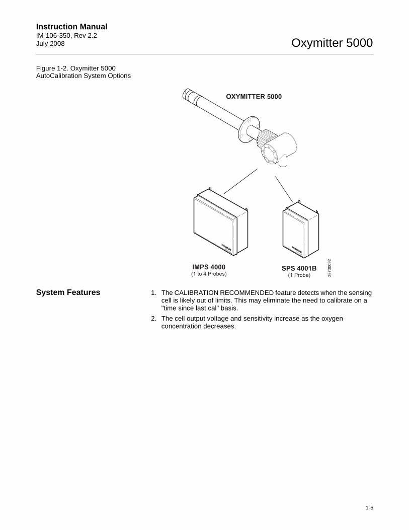
Figure 1-3. Membrane Keypad
3. Membrane keypad, Figure 1-3, and FOUNDATION fieldbus communication are standard.
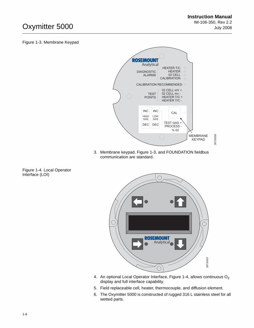
Figure 1-4. Local Operator Interface (LOI)
4. An optional Local Operator Interface, Figure 1-4, allows continuous O2 display and full interface capability.
5. Field replaceable cell, heater, thermocouple, and diffusion element.
6. The Oxymitter 5000 is constructed of rugged 316 L stainless steel for all wetted parts.
DIAGNOSTICALARMS
TESTPOINTS
HEATER T/CHEATER02 CELL
CALIBRATION
CALIBRATION RECOMMENDED
02 CELL mV +02 CELL mv -HEATER T/C +HEATER T/C -
INC INC
DEC DEC
HIGHGAS
LOWGAS
CAL
TEST GAS +PROCESS -
% 02
MEMBRANEKEYPAD
38
73
00
56
38
73
00
57
Instruction Manual IM-106-350, Rev 2.2July 2008
1-7
Oxymitter 5000
7. The electronics are adaptable for line voltages from 90-250 VAC; therefore, no configuration is necessary.
8. The Oxymitter 5000 membrane keypad is available in five languages:
EnglishFrenchGermanItalianSpanish
9. An operator can calibrate and diagnostically troubleshoot the Oxymitter 5000 in one of four ways:
a. Membrane Keypad. The membrane keypad, housed within the right side of the electronics housing, provides fault indication by way of flashing LEDs. Calibration can be performed from the membrane keypad.
b. LOI. The optional LOI takes the place of the membrane keypad and allows local communication with the electronics. Refer to Section 6 for more information.
c. FOUNDATION fieldbus Interface. The Oxymitter 5000's output carries a signal containing the oxygen level encoded in digital format. This digital output can also be used to communicate with the Oxymitter and access all of the Oxymitter’s status information.
d. Optional IMPS 4000. The Programmable Logic Controller (PLC) in the IMPS 4000 provides fault indications using flashing LEDs and LCD display messages. Refer to the IMPS 4000 Intelligent Multiprobe Test Gas Sequencer Instruction Manual for more information.
Handling the Oxymitter 5000
System Considerations Prior to installing your Oxymitter 5000, make sure you have all the components necessary to make the system installation. Ensure all the components are properly integrated to make the system functional.
After verifying that you have all the components, select mounting locations and determine how each component will be placed in terms of available line voltage, ambient temperatures, environmental considerations, convenience, and serviceability.
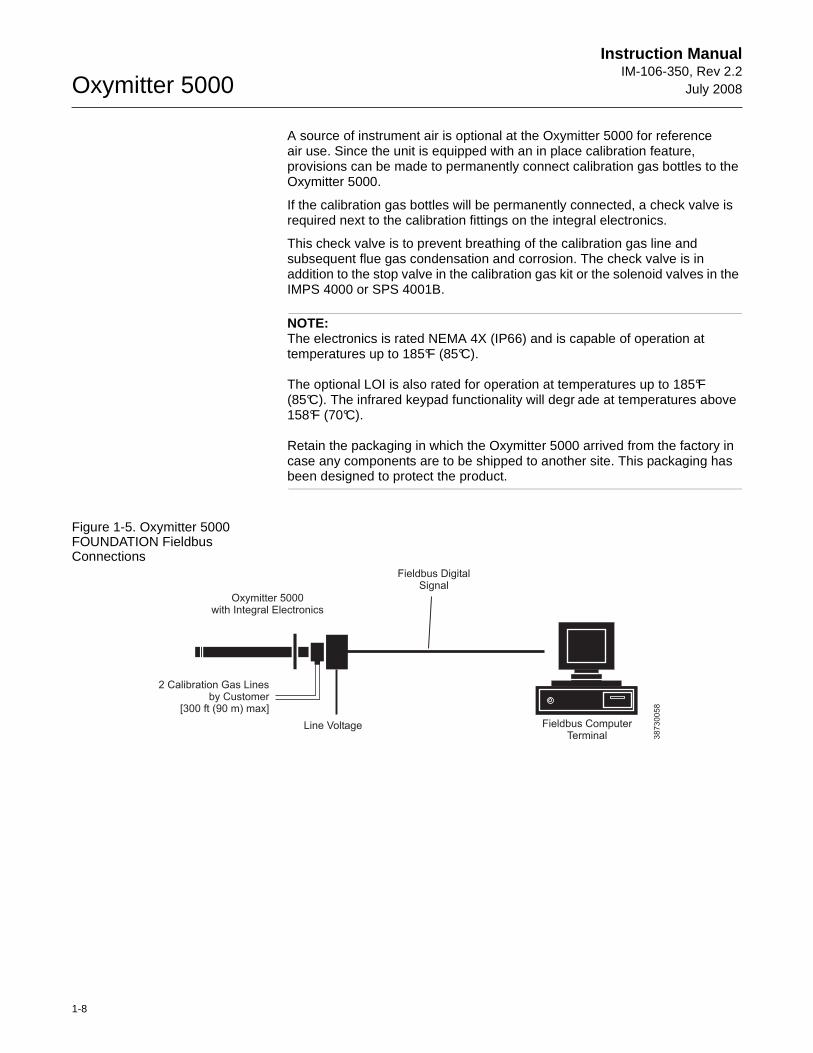
Figure 1-5 shows a typical system wiring.
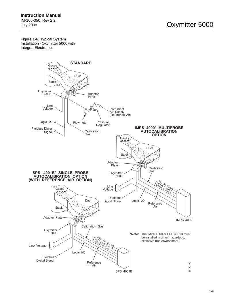
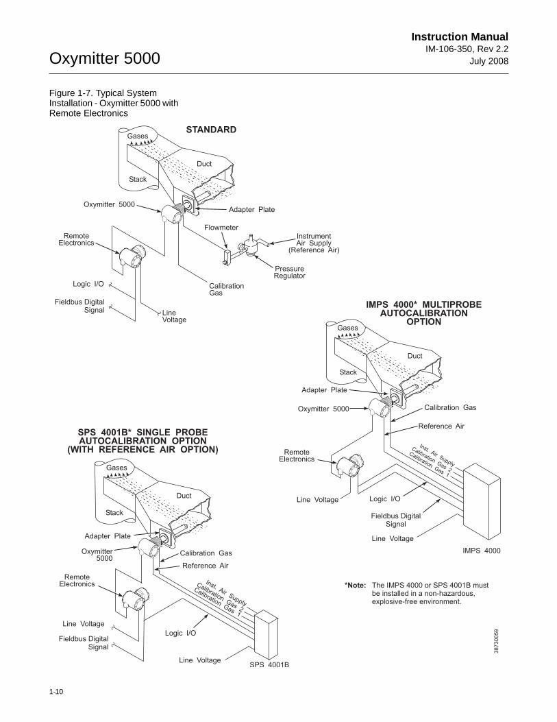
A typical system installation for an Oxymitter 5000 with integral electronics is shown in Figure 1-6. A typical system installation for an Oxymitter 5000 with remote electronics is shown in Figure 1-7.
It is important that printed circuit boards and integrated circuits are handled only when adequate antistatic precautions have been taken to prevent possible equipment damage.
The Oxymitter 5000 is designed for industrial applications. Treat each component of the system with care to avoid physical damage. Some probe components are made from ceramics, which are susceptible to shock when mishandled.
Oxymitter 5000
1-8
Instruction ManualIM-106-350, Rev 2.2
July 2008
A source of instrument air is optional at the Oxymitter 5000 for referenceair use. Since the unit is equipped with an in place calibration feature, provisions can be made to permanently connect calibration gas bottles to the Oxymitter 5000.
If the calibration gas bottles will be permanently connected, a check valve is required next to the calibration fittings on the integral electronics.
This check valve is to prevent breathing of the calibration gas line and subsequent flue gas condensation and corrosion. The check valve is in addition to the stop valve in the calibration gas kit or the solenoid valves in the IMPS 4000 or SPS 4001B.
NOTE:The electronics is rated NEMA 4X (IP66) and is capable of operation at temperatures up to 185°F (85°C).
The optional LOI is also rated for operation at temperatures up to 185°F (85°C). The infrared keypad functionality will degr ade at temperatures above 158°F (70°C).
Retain the packaging in which the Oxymitter 5000 arrived from the factory in case any components are to be shipped to another site. This packaging has been designed to protect the product.
Figure 1-5. Oxymitter 5000 FOUNDATION Fieldbus Connections
38730058
Fieldbus DigitalSignal
2 Calibration Gas Linesby Customer
[ ( ) max]300 ft 90 m
Fieldbus ComputerTerminal
Line Voltage
Oxymitter 5000with Integral Electronics
Instruction Manual IM-106-350, Rev 2.2July 2008
1-9
Oxymitter 5000
Figure 1-6. Typical System Installation - Oxymitter 5000 with Integral Electronics
Oxymitter5000
SPS 4001B
ReferenceAir
Logic I/O
Calibration Gas
Adapter Plate
Stack
Duct
Gases
CalibrationGas
1
CalibrationGas
2
Inst. Air SupplyLine Voltage
Duct
Stack
Gases
CalibrationGas
AdapterPlate
LineVoltage
Logic I/O
InstrumentAir Supply(Reference Air)
PressureRegulator
Flowmeter
STANDARD
Oxymitter5000
Fieldbus DigitalSignal
Oxymitter5000
IMPS 4000* MULTIPROBEAUTOCALIBRATION
OPTION
IMPS 4000
ReferenceAir
Logic I/O
CalibrationGas
AdapterPlate
Stack
Duct
Gases
CalibrationGas
1
CalibrationGas
2
Inst. Air SupplyLine
Voltage
FieldbusDigital Signal
SPS 4001B* SINGLE PROBEAUTOCALIBRATION OPTION
(WITH REFERENCE AIR OPTION)
FieldbusDigital Signal
*Note: The IMPS 4000 or SPS 4001B mustbe installed in a non-hazardous,explosive-free environment.
38730100
Oxymitter 5000
1-10
Instruction ManualIM-106-350, Rev 2.2
July 2008
Figure 1-7. Typical System Installation - Oxymitter 5000 with Remote Electronics
38730059
Duct
Stack
Gases
CalibrationGas
Adapter Plate
LineVoltage
Logic I/O
InstrumentAir Supply
(Reference Air)
PressureRegulator
Flowmeter
STANDARD
Oxymitter 5000
Oxymitter 5000
Fieldbus DigitalSignal
IMPS 4000
Reference Air
Calibration Gas
Adapter Plate
Stack
Duct
Gases
CalibrationGas
1
CalibrationGas
2
Inst. Air Supply
Line Voltage
Fieldbus DigitalSignal
RemoteElectronics
RemoteElectronics
Logic I/OLine Voltage
*Note: The IMPS 4000 or SPS 4001B mustbe installed in a non-hazardous,explosive-free environment.
SPS 4001B* SINGLE PROBEAUTOCALIBRATION OPTION
(WITH REFERENCE AIR OPTION)
Oxymitter5000
SPS 4001B
Logic I/O
Calibration Gas
Adapter Plate
Stack
Duct
Gases
CalibrationGas
1
CalibrationGas
2
Inst. Air Supply
RemoteElectronics
Line Voltage
Line Voltage
Reference Air
Fieldbus DigitalSignal
IMPS 4000* MULTIPROBEAUTOCALIBRATION
OPTION
Instruction Manual IM-106-350, Rev 2.2July 2008
1-11
Oxymitter 5000
IMPS 4000 (OPTIONAL) Information on the IMPS 4000 is available in the IMPS 4000 Intelligent Multiprobe Test Gas Sequencer Instruction Manual.
SPS 4001B (OPTIONAL) The SPS 4001B Single Probe Autocalibration Sequencer provides the capability of performing automatic, timed or on demand, calibrations of a single Oxymitter 5000 without sending a technician to the installation site.
Mounting The SPS 4001B is fully enclosed in a NEMA cabinet suited for wall-mounting. This cabinet provides added protection against dust and minor impacts. The SPS 4001B consists of a manifold and a calibration gas flowmeter. The mani-fold provides electrical feedthroughs and calibration gas ports to route power and signal connections and calibration gases to and from the sequencer. In addition, the manifold houses two calibration gas solenoids that sequence the gases to the Oxymitter 5000, a pressure switch that detects low calibration gas pressure, and two PC boards. A terminal strip housed within the terminal cover provides convenient access for all user connections.
Components optional to the SPS 4001B include a reference air flowmeter and pressure regulator. The reference air flowmeter indicates the flow rate of reference air continuously flowing to the Oxymitter 5000. The reference air pressure regulator ensures the instrument air (reference air) flowing to the Oxymitter 5000 is at a constant pressure [20 psi (138 kPa)]. The regulator also has a filter to remove particulates in the reference air and a drain valve to bleed the moisture that collects in the filter bowl.
Brass fittings and Teflon tubing are standard. Stainless steel fittings and tubing are optional. Also, disposable calibration gas bottles are available as an option or can be purchased through a local supplier.
Operation The SPS 4001B works in conjunction with the Oxymitter 5000's CALIBRA-TION RECOMMENDED feature to perform an autocalibration. This feature automatically performs a gasless calibration check every hour on the Oxymit-ter 5000. If a calibration is recommended and its contact output signal is set for "handshaking" with the sequencer, the Oxymitter 5000 sends a signal to the sequencer. The sequencer automatically performs a calibration upon receiving the signal. Thus, no human interface is required for the automatic calibration to take place.
For further SPS 4001B information, refer to the SPS 4001B Single Probe Autocalibration Sequencer Instruction Manual.
Oxymitter 5000
1-12
Instruction ManualIM-106-350, Rev 2.2
July 2008
PROBE OPTIONS
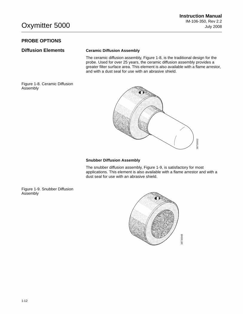
Diffusion Elements Ceramic Diffusion Assembly
The ceramic diffusion assembly, Figure 1-8, is the traditional design for the probe. Used for over 25 years, the ceramic diffusion assembly provides a greater filter surface area. This element is also available with a flame arrestor, and with a dust seal for use with an abrasive shield.
Figure 1-8. Ceramic Diffusion Assembly
Snubber Diffusion Assembly
The snubber diffusion assembly, Figure 1-9, is satisfactory for most applications. This element is also available with a flame arrestor and with a dust seal for use with an abrasive shield.
Figure 1-9. Snubber Diffusion Assembly
38
73
00
02
38
73
00
48
Instruction Manual IM-106-350, Rev 2.2July 2008
1-13
Oxymitter 5000
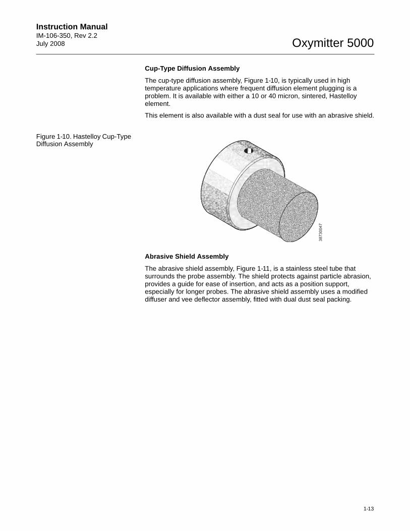
Cup-Type Diffusion Assembly
The cup-type diffusion assembly, Figure 1-10, is typically used in high temperature applications where frequent diffusion element plugging is a problem. It is available with either a 10 or 40 micron, sintered, Hastelloy element.
This element is also available with a dust seal for use with an abrasive shield.
Figure 1-10. Hastelloy Cup-Type Diffusion Assembly
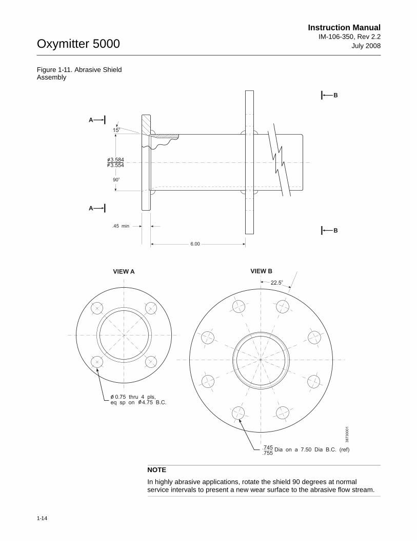
Abrasive Shield Assembly
The abrasive shield assembly, Figure 1-11, is a stainless steel tube that surrounds the probe assembly. The shield protects against particle abrasion, provides a guide for ease of insertion, and acts as a position support, especially for longer probes. The abrasive shield assembly uses a modified diffuser and vee deflector assembly, fitted with dual dust seal packing.
38730047
Oxymitter 5000
1-14
Instruction ManualIM-106-350, Rev 2.2
July 2008
Figure 1-11. Abrasive Shield Assembly
NOTE
In highly abrasive applications, rotate the shield 90 degrees at normal service intervals to present a new wear surface to the abrasive flow stream.
VIEW A VIEW B
A
B
A
B
15o
6.00
.45 min
90o
3.5843.554
22.5o
Dia on a 7.50 Dia B.C. (ref).745.755
0.75 thru 4 pls,eq sp on 4.75 B.C.
38730001
Instruction Manual IM-106-350, Rev 2.2July 2008
1-15
Oxymitter 5000
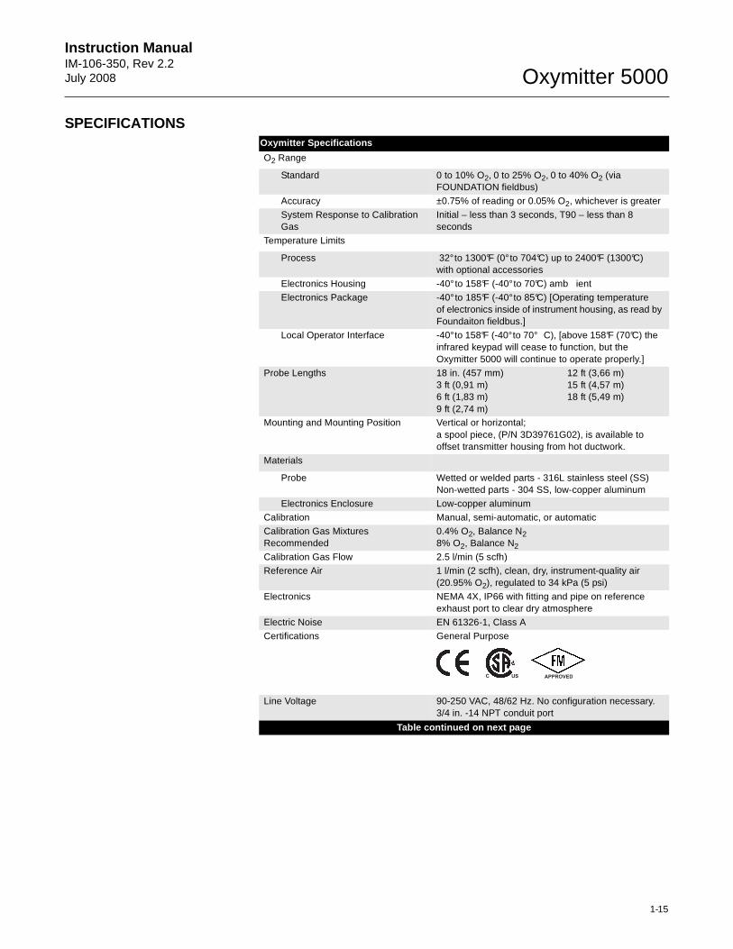
SPECIFICATIONSOxymitter Specifications
O2 Range
Standard 0 to 10% O2, 0 to 25% O2, 0 to 40% O2 (via FOUNDATION fieldbus)
Accuracy ±0.75% of reading or 0.05% O2, whichever is greater
System Response to Calibration Gas
Initial – less than 3 seconds, T90 – less than 8 seconds
Temperature Limits
Process 32° to 1300°F (0° to 704°C) up to 2400°F (1300°C) with optional accessories
Electronics Housing -40° to 158°F (-40° to 70°C) amb ient
Electronics Package -40° to 185°F (-40° to 85°C) [Operating temperature of electronics inside of instrument housing, as read by Foundaiton fieldbus.]
Local Operator Interface -40° to 158°F (-40° to 70° C), [above 158°F (70°C) the infrared keypad will cease to function, but the Oxymitter 5000 will continue to operate properly.]
Probe Lengths 18 in. (457 mm) 12 ft (3,66 m)3 ft (0,91 m) 15 ft (4,57 m)6 ft (1,83 m) 18 ft (5,49 m)9 ft (2,74 m)
Mounting and Mounting Position Vertical or horizontal; a spool piece, (P/N 3D39761G02), is available to offset transmitter housing from hot ductwork.
Materials
Probe Wetted or welded parts - 316L stainless steel (SS)Non-wetted parts - 304 SS, low-copper aluminum
Electronics Enclosure Low-copper aluminum
Calibration Manual, semi-automatic, or automatic
Calibration Gas Mixtures Recommended
0.4% O2, Balance N2 8% O2, Balance N2
Calibration Gas Flow 2.5 l/min (5 scfh)
Reference Air 1 l/min (2 scfh), clean, dry, instrument-quality air (20.95% O2), regulated to 34 kPa (5 psi)
Electronics NEMA 4X, IP66 with fitting and pipe on reference exhaust port to clear dry atmosphere
Electric Noise EN 61326-1, Class A
Certifications General Purpose
Line Voltage 90-250 VAC, 48/62 Hz. No configuration necessary. 3/4 in. -14 NPT conduit port
Table continued on next page
APPROVEDUSC
Oxymitter 5000
1-16
Instruction ManualIM-106-350, Rev 2.2
July 2008
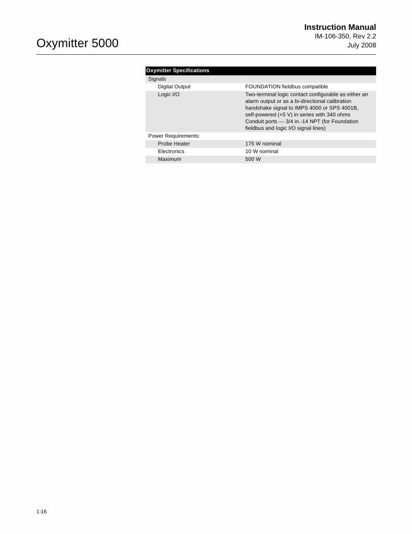
SignalsDigital Output FOUNDATION fieldbus compatible
Logic I/O Two-terminal logic contact configurable as either an alarm output or as a bi-directional calibration handshake signal to IMPS 4000 or SPS 4001B, self-powered (+5 V) in series with 340 ohmsConduit ports — 3/4 in.-14 NPT (for Foundation fieldbus and logic I/O signal lines)
Power Requirements:
Probe Heater 175 W nominalElectronics 10 W nominal
Maximum 500 W
Oxymitter Specifications
Instruction Manual IM-106-350, Rev 2.2July 2008
1-17
Oxymitter 5000
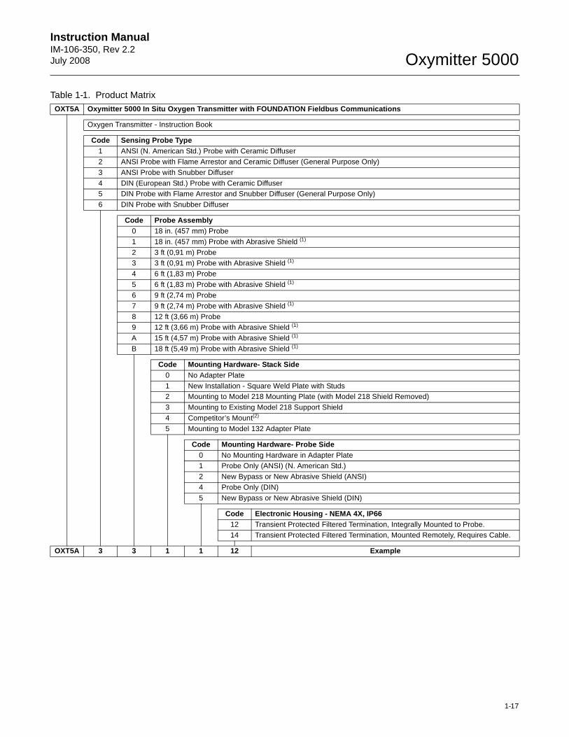
Table 1-1. Product MatrixOXT5A Oxymitter 5000 In Situ Oxygen Transmitter with FOUNDATION Fieldbus Communications
Oxygen Transmitter - Instruction Book
Code Sensing Probe Type1 ANSI (N. American Std.) Probe with Ceramic Diffuser
2 ANSI Probe with Flame Arrestor and Ceramic Diffuser (General Purpose Only)
3 ANSI Probe with Snubber Diffuser
4 DIN (European Std.) Probe with Ceramic Diffuser5 DIN Probe with Flame Arrestor and Snubber Diffuser (General Purpose Only)
6 DIN Probe with Snubber Diffuser
Code Probe Assembly0 18 in. (457 mm) Probe
1 18 in. (457 mm) Probe with Abrasive Shield (1)
2 3 ft (0,91 m) Probe 3 3 ft (0,91 m) Probe with Abrasive Shield (1)
4 6 ft (1,83 m) Probe
5 6 ft (1,83 m) Probe with Abrasive Shield (1)
6 9 ft (2,74 m) Probe
7 9 ft (2,74 m) Probe with Abrasive Shield (1)
8 12 ft (3,66 m) Probe 9 12 ft (3,66 m) Probe with Abrasive Shield (1)
A 15 ft (4,57 m) Probe with Abrasive Shield (1)
B 18 ft (5,49 m) Probe with Abrasive Shield (1)
Code Mounting Hardware- Stack Side0 No Adapter Plate
1 New Installation - Square Weld Plate with Studs2 Mounting to Model 218 Mounting Plate (with Model 218 Shield Removed)
3 Mounting to Existing Model 218 Support Shield
4 Competitor’s Mount(2)
5 Mounting to Model 132 Adapter Plate
Code Mounting Hardware- Probe Side0 No Mounting Hardware in Adapter Plate1 Probe Only (ANSI) (N. American Std.)
2 New Bypass or New Abrasive Shield (ANSI)
4 Probe Only (DIN)
5 New Bypass or New Abrasive Shield (DIN)
Code Electronic Housing - NEMA 4X, IP6612 Transient Protected Filtered Termination, Integrally Mounted to Probe.14 Transient Protected Filtered Termination, Mounted Remotely, Requires Cable.
OXT5A 3 3 1 1 12 Example
Oxymitter 5000
1-18
Instruction ManualIM-106-350, Rev 2.2
July 2008
NOTES:High Sulfur Service:High sulfur cell can be selected for any probe; add a line item note to your purchase order requesing the high sulfur ZrO2 cell in place of the standard ZrO2 cell.
Add 4232 UOM to the system matrix UOM total.(1) Recommended uses: High velocity particulates in flue stream, installation within 10 ft (3,5 m) of soot blowers or heavy salt cake buildup.
Applications: Pulverized coal, recovery boilers, lime kiln.(2) Where possible, specify ANSI or DIN designation; otherwise, provide details of the existing mounting plate as follows:
(3) Startup, calibration, and operation can be implemented using the standard membrane keypad. Remote access and additional functionality available via Fieldbus Communications (DeltaV).
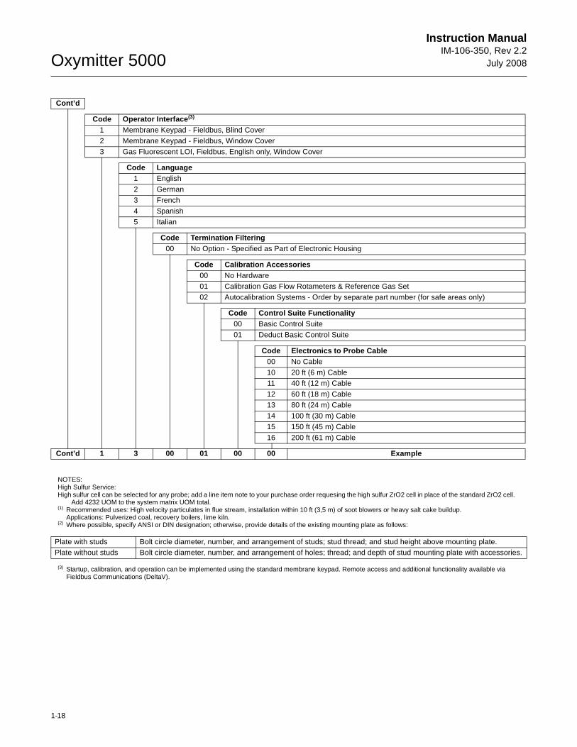
Cont’d
Code Operator Interface (3)
1 Membrane Keypad - Fieldbus, Blind Cover
2 Membrane Keypad - Fieldbus, Window Cover
3 Gas Fluorescent LOI, Fieldbus, English only, Window Cover
Code Language1 English
2 German
3 French
4 Spanish
5 Italian
Code Termination Filtering00 No Option - Specified as Part of Electronic Housing
Code Calibration Accessories00 No Hardware
01 Calibration Gas Flow Rotameters & Reference Gas Set
02 Autocalibration Systems - Order by separate part number (for safe areas only)
Code Control Suite Functionality00 Basic Control Suite
01 Deduct Basic Control Suite
Code Electronics to Probe Cable00 No Cable
10 20 ft (6 m) Cable11 40 ft (12 m) Cable
12 60 ft (18 m) Cable
13 80 ft (24 m) Cable
14 100 ft (30 m) Cable
15 150 ft (45 m) Cable
16 200 ft (61 m) Cable
Cont’d 1 3 00 01 00 00 Example
Plate with studs Bolt circle diameter, number, and arrangement of studs; stud thread; and stud height above mounting plate.Plate without studs Bolt circle diameter, number, and arrangement of holes; thread; and depth of stud mounting plate with accessories.
Instruction Manual IM-106-350, Rev 2.2July 2008
1-19
Oxymitter 5000
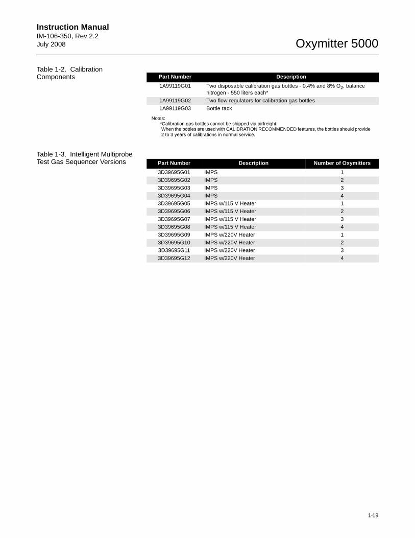
Table 1-2. Calibration Components
Notes:*Calibration gas bottles cannot be shipped via airfreight.When the bottles are used with CALIBRATION RECOMMENDED features, the bottles should provide 2 to 3 years of calibrations in normal service.
Table 1-3. Intelligent Multiprobe Test Gas Sequencer Versions
Part Number Description
1A99119G01 Two disposable calibration gas bottles - 0.4% and 8% O2, balance nitrogen - 550 liters each*
1A99119G02 Two flow regulators for calibration gas bottles
1A99119G03 Bottle rack
Part Number Description Number of Oxymitters
3D39695G01 IMPS 1
3D39695G02 IMPS 2
3D39695G03 IMPS 3
3D39695G04 IMPS 43D39695G05 IMPS w/115 V Heater 1
3D39695G06 IMPS w/115 V Heater 2
3D39695G07 IMPS w/115 V Heater 3
3D39695G08 IMPS w/115 V Heater 4
3D39695G09 IMPS w/220V Heater 1
3D39695G10 IMPS w/220V Heater 23D39695G11 IMPS w/220V Heater 3
3D39695G12 IMPS w/220V Heater 4

Oxymitter 5000
1-20
Instruction ManualIM-106-350, Rev 2.2
July 2008
Instruction Manual IM-106-350, Rev 2.2July 2008 Oxymitter 5000
http://www.raihome.com
Section 2 Installation
Mechanical Installation . . . . . . . . . . . . . . . . . . . . . . . . . . . page 2-2Electrical Installation (with Integral Electronics) . . . . . . . page 2-11Electrical Installation (with Remote Electronics) . . . . . . . page 2-14Pneumatic Installation . . . . . . . . . . . . . . . . . . . . . . . . . . . . page 2-17IMPS 4000 Connections . . . . . . . . . . . . . . . . . . . . . . . . . . . page 2-19SPS 4001B Connections . . . . . . . . . . . . . . . . . . . . . . . . . . page 2-19
Before installing this equipment, read the "Safety Instructions" for the wiring and installation of this apparatus in Appendix A of this Instruction Manual. Failure to follow safety instructions could result in serious injury or death.
Install all protective equipment covers and safety ground leads after installation. Failure to install covers and ground leads could result in serious injury or death.
The Oxymitter 5000 (OXT5A) can be installed in general purpose areas only. Do not install the OXT5A in hazardous areas. For hazardous areas use the OXT5C.
Oxymitter 5000
2-2
Instruction ManualIM-106-350, Rev 2.2
July 2008
MECHANICAL INSTALLATION
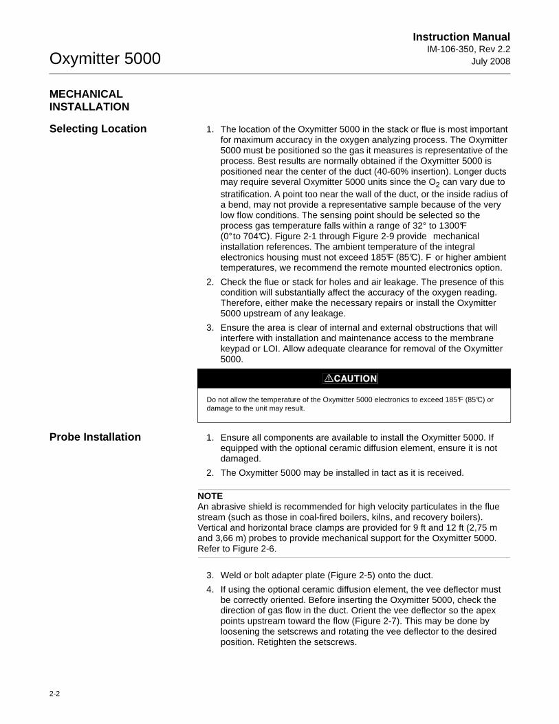
Selecting Location 1. The location of the Oxymitter 5000 in the stack or flue is most important for maximum accuracy in the oxygen analyzing process. The Oxymitter 5000 must be positioned so the gas it measures is representative of the process. Best results are normally obtained if the Oxymitter 5000 is positioned near the center of the duct (40-60% insertion). Longer ducts may require several Oxymitter 5000 units since the O2 can vary due to stratification. A point too near the wall of the duct, or the inside radius of a bend, may not provide a representative sample because of the very low flow conditions. The sensing point should be selected so the process gas temperature falls within a range of 32° to 1300°F (0° to 704°C). Figure 2-1 through Figure 2-9 provide mechanical installation references. The ambient temperature of the integral electronics housing must not exceed 185°F (85°C). F or higher ambient temperatures, we recommend the remote mounted electronics option.
2. Check the flue or stack for holes and air leakage. The presence of this condition will substantially affect the accuracy of the oxygen reading. Therefore, either make the necessary repairs or install the Oxymitter 5000 upstream of any leakage.
3. Ensure the area is clear of internal and external obstructions that will interfere with installation and maintenance access to the membrane keypad or LOI. Allow adequate clearance for removal of the Oxymitter 5000.
Probe Installation 1. Ensure all components are available to install the Oxymitter 5000. If equipped with the optional ceramic diffusion element, ensure it is not damaged.
2. The Oxymitter 5000 may be installed in tact as it is received.
NOTEAn abrasive shield is recommended for high velocity particulates in the flue stream (such as those in coal-fired boilers, kilns, and recovery boilers). Vertical and horizontal brace clamps are provided for 9 ft and 12 ft (2,75 m and 3,66 m) probes to provide mechanical support for the Oxymitter 5000. Refer to Figure 2-6.
3. Weld or bolt adapter plate (Figure 2-5) onto the duct.
4. If using the optional ceramic diffusion element, the vee deflector must be correctly oriented. Before inserting the Oxymitter 5000, check the direction of gas flow in the duct. Orient the vee deflector so the apex points upstream toward the flow (Figure 2-7). This may be done by loosening the setscrews and rotating the vee deflector to the desired position. Retighten the setscrews.
Do not allow the temperature of the Oxymitter 5000 electronics to exceed 185°F (85°C) or damage to the unit may result.
Instruction Manual IM-106-350, Rev 2.2July 2008
2-3
Oxymitter 5000
Figure 2-1. Oxymitter 5000 Probe Installation
Co
ve
r R
em
ova
l a
nd
Acce
ss
(305)
(305)
12
12
Ad
d t
o D
im “
A”
for
pro
be
with
Ce
ram
ic D
iffu
se
ra
nd
Fla
me
Arr
esto
r
5.1
4(1
31
)
With
Sta
nd
ard
Snu
bb
er
Diffu
se
r
Dim
"A
"
Ad
d t
o D
im “
A”
for
pro
be
with
Ce
ram
icD
iffu
se
r
Dim
"B
”
Rem
oval E
nvelo
pe
Ele
c C
onn
3/4
NP
T
AN
SI 1
/4 (
6.3
5)
Tube
DIN
6 m
mT
ube
Bo
tto
m V
iew
PS
U
E
I
TP
IC
RH
WE
NT
HG
C
KE
NI -
E
E RW
AVIS
OL
P-
XO
MT
A GNI
N-
R
I
T
L A
I
VE
-E
EH
4.7
7 (
121)
6.0
2 (
153)
12.5
0 (
318)
GA
SC
AL
.
500 V
A
R
SE
RIA
L N
O.
TA
G N
O.
OX
YM
ITT
ER
5000
VO
LT
S: W
AT
TS
:
OU
TP
UT
: L
INE
FU
SE
:
Rosem
ountA
naly
tical In
c.
Solo
n, O
H 44139
85-2
64 V
AC
4
8-6
2 H
z
TM
800-4
33-6
076
4-2
0 m
A
R
5 A
mps
TM
HA
RT
SM
AR
T F
AM
ILY
RE
F.
GA
S
-
-
RH
G
T
I
NE
WH
CI
T
KEPE
A
ITC
U
EVLI
-MN
INLO
AR
P
NI
XE-
WG
ES
IVA
TOS
E
HER
P
6.5
2(1
66)
2.8
9(7
3)
1.5
5(3
9)
3.8
0(9
6)
Pro
ce
ss f
low
mu
st
be
in
this
dire
ctio
n w
ith
re
sp
ect
to d
efle
cto
r 3
53
4B
48
G0
1
Dia
Ma
x2
.27
(5
8)
Insu
late
if
exp
ose
d t
oA
mb
ien
t w
ea
the
r co
nd
itio
ns
Dim
en
sio
ns a
re in
inch
es w
ith
mill
ime
ters
in p
are
nth
ese
s.
No
te:
3535B
18H
02
3535B
45H
01
DIN
AN
SI
0.0
62
TH
K G
asket
Hole
Fla
nge
(4)
Hole
sE
q S
pon B
C
Dia
Dia
DIN
AN
SI
4512C
19H
01
4.7
5(1
21
)
4512C
17H
01
6.0
0(1
53
)
(20)
0.7
5
(14
5)
5.7
1
(18)
0.7
1
7.2
8(1
85
)
DIM
"A
"
3 ft
9 ft
6 ft
PR
OB
E
18
in
.
12
ft
DIM
"B
"
(21
79
)8
5.8
(30
94
)1
21
.8
(40
08
)1
57
.8(3
60
7)
14
2
(26
92
)1
06
70
(17
78
)
(86
4)
34
(12
65
)4
9.8
(80
8)
31
.8(4
06
)1
6
38
73
00
49
15
ft
(49
23
)1
93
.8(4
52
1)
17
8
18
ft
(58
37
)2
29
.8(5
43
6)
21
4
Tab
le 1
. M
ou
nti
ng
Fla
ng
e
Tab
le 2
. In
sta
llati
on
/Rem
oval
Re
fA
ir
Ca
l G
as
Oxymitter 5000
2-4
Instruction ManualIM-106-350, Rev 2.2
July 2008
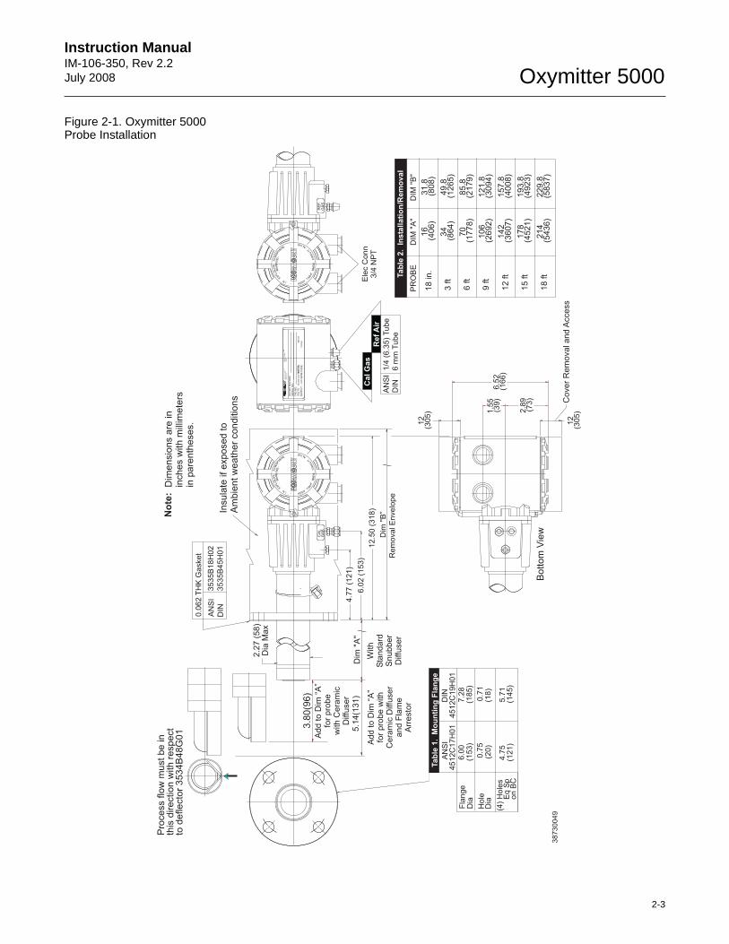
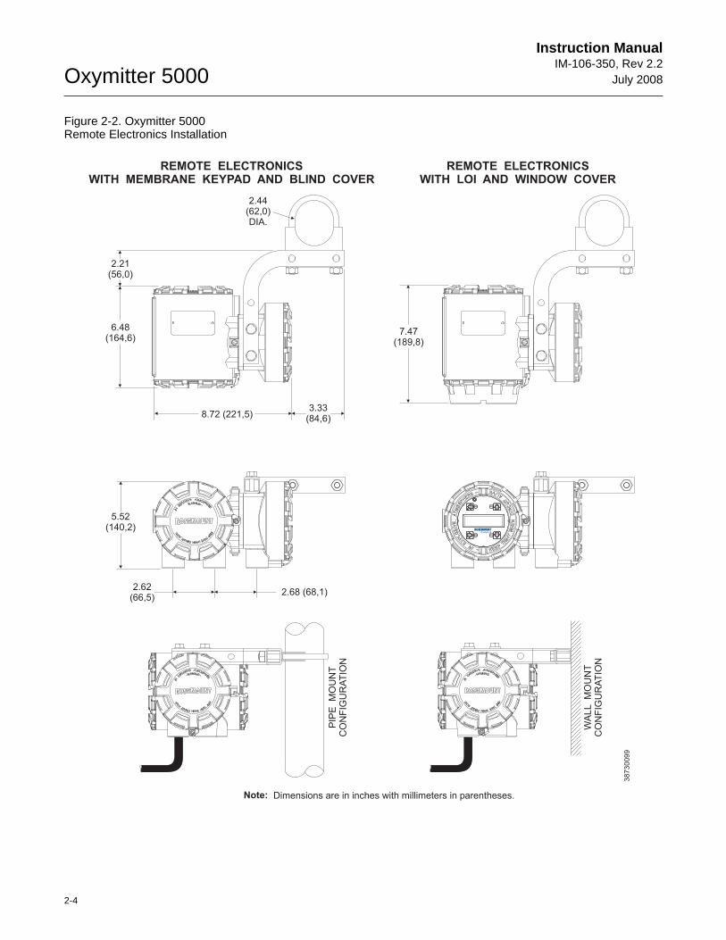
Figure 2-2. Oxymitter 5000 Remote Electronics Installation
2.21(56,0)
6.48(164,6)
8.72 (221,5)3.33
(84,6)
2.44(62,0)DIA.
7.47(189,8)
5.52(140,2)
2.62(66,5)
2.68 (68,1)
PIP
E
MO
UN
TC
ON
FIG
UR
AT
ION
38
73
00
99
WA
LL
MO
UN
TC
ON
FIG
UR
AT
ION
REMOTE ELECTRONICSWITH LOI AND WINDOW COVER
REMOTE ELECTRONICSWITH MEMBRANE KEYPAD AND BLIND COVER
Dimensions are in inches with millimeters in parentheses.Note:
Instruction Manual IM-106-350, Rev 2.2July 2008
2-5
Oxymitter 5000
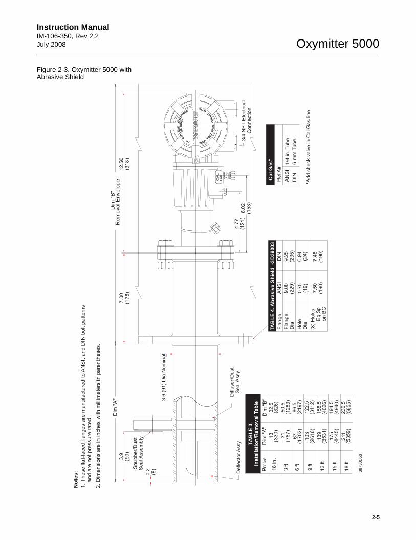
Figure 2-3. Oxymitter 5000 with Abrasive Shield
PS
U
E
I
TP
IC
RH
WE
NT
HG
C
KE
NI -
E
E RW
AVIS
OL
P-
XO
MT
A GNI
N-
R
I
T
LA
I
VE
-E
EH
Deflecto
rA
ssy
9 ft
12 ft
(3112)
(4026)
139
(3531)
158.5
Pro
be
3 ft
6 ft
Dim
"B
"
(1283)
(2197)
(2616)
103
67
(1702)
(787)
31
Dim
"A
"
122.5
86.5
50.5
Diffu
ser/
Dust
Seal A
ssy
*Add c
heck v
alv
e in C
al G
as lin
e
6.0
2(1
53)
4.7
7(1
21)
3/4
NP
TE
lectr
ical
Connection
RefA
ir
AN
SI
DIN
1/4
in.T
ube
6 m
mT
ube
GA
SC
AL.
Snubber/
Dust
Seal A
ssem
bly
0.2
(5)
3.6
(91)
Dia
Nom
inal
3.9
(99)
Dim
"A
"
and a
re n
ot pre
ssure
rate
d.
1.T
hese
flat-
faced
flanges
are
manufa
ctu
red
toA
NS
I,D
IN b
olt p
attern
sand
No
tes:
Rem
ovalE
nvelo
pe
Dim
"B
"
7.0
0(1
78)
12.5
0(3
18)
38
73
00
50
(8)
Hole
sE
q S
pon B
C
Hole
Dia
Fla
nge
Dia
9.0
0(2
29)
9.2
5(2
35)
(19)
0.7
5(2
4)
0.9
4
7.5
0(1
90)
7.4
8(1
90)
Fla
nge
AN
SI
DIN
2.
Dim
en
sio
ns a
re in
in
ch
es w
ith
mill
ime
ters
in
pa
ren
the
se
s.
15 ft
(4940)
175
(4445)
194.5
18 ft
(5855)
211
(5359)
230.5
18 in.
(826)
(330)
13
32.5
Cal G
as*
TA
BL
E 4
.A
bra
siv
e S
hie
ld -3
D39003
TA
BL
E 3
.In
sta
llati
on
/Rem
oval Tab
le
Oxymitter 5000
2-6
Instruction ManualIM-106-350, Rev 2.2
July 2008
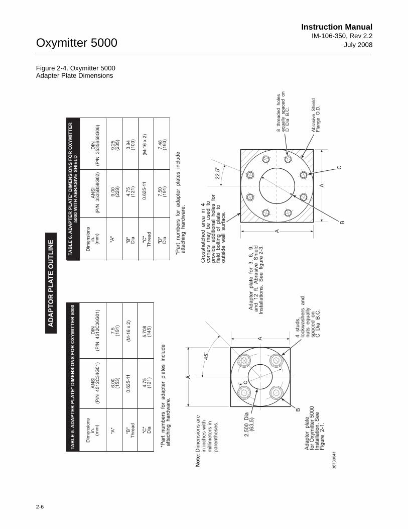
Figure 2-4. Oxymitter 5000 Adapter Plate Dimensions
22
.5o
BC
8 th
rea
de
d h
ole
se
qu
ally
spa
ce
d o
nD
D
ia B
.C.
Ab
rasiv
e S
hie
ldF
lan
ge
O
.D.
A
A
Dim
en
sio
ns
in.
(mm
)
Dim
en
sio
ns
in.
(mm
)A
NS
I(P
/N
45
12
C3
4G
01
)A
NS
I(P
/N
35
35
B58
G0
2)
DIN
(P/N
4
51
2C
36
G0
1)
DIN
(P/N
3
53
5B
58
G0
6)
"A"
"A"
"B"
Th
rea
d"B
"D
ia
"D"
Dia
"C"
Dia
"C"
Th
rea
d
6.0
0(1
53
)9
.00
(22
9)
0.6
25
-11
4.7
5(1
21
)
7.5
0(1
91
)
4.7
5(1
21
)0
.62
5-1
1
7.5
(19
1)
9.2
5(2
35
)
(M-1
6 x
2)
3.9
4(1
00
)
7.4
8(1
90
)
5.7
08
(14
5)
(M-1
6 x
2)
*Pa
rt
nu
mb
ers
fo
r a
da
pte
r p
late
s
inclu
de
atta
ch
ing
h
ard
wa
re.
*Pa
rt
nu
mb
ers
fo
r a
da
pte
r p
late
s
inclu
de
atta
ch
ing
h
ard
wa
re.
Ad
ap
ter
pla
te
for
3,
6,
9,
an
d
12
ft.
Ab
rasiv
e
Sh
ield
Insta
llatio
ns.
Se
e
fig
ure
2-3
.
Cro
ssh
atc
he
d
are
a
in
4co
rne
rs
ma
y
be
u
se
d
top
rovid
e
ad
ditio
na
l h
ole
s
for
fie
ld
bo
ltin
g
of
pla
te
too
uts
ide
w
all
su
rfa
ce
.
Ad
ap
ter
pla
tefo
r O
xym
itte
r 5
00
0In
sta
llatio
n.
Se
eF
igu
re
2-1
.
4
stu
ds,
lockw
ash
ers
a
nd
nu
ts
eq
ua
llyspa
ce
d
on
C
Dia
B
.C.
A
A
2.5
00
D
ia(6
3,5
)
45
o
C
B
No
te:D
ime
nsio
ns a
rein
in
ch
es w
ith
mill
ime
ters
in
pa
ren
the
se
s.
38
73
00
41
AD
AP
TO
R P
LA
TE
OU
TL
INE
TA
BL
E 5
.A
DA
PT
ER
PL
AT
E*
DIM
EN
SIO
NS
FO
R O
XY
MIT
TE
R 5
000
TA
BL
E 6
.A
DA
PT
ER
PL
AT
E*
DIM
EN
SIO
NS
FO
R O
XY
MIT
TE
R5
00
0 W
ITH
AB
RA
SIV
E S
HIE
LD
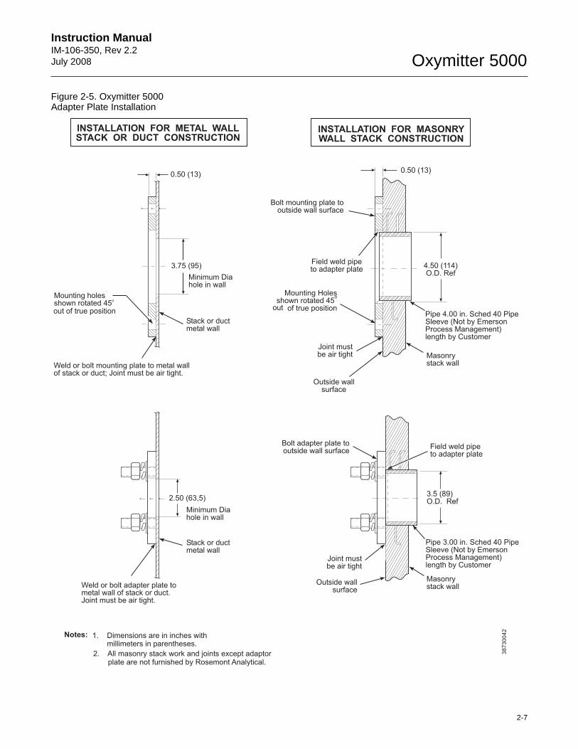
Instruction Manual IM-106-350, Rev 2.2July 2008
2-7
Oxymitter 5000
Figure 2-5. Oxymitter 5000 Adapter Plate Installation
38730042
0.50 13( )
3.75 95( )
Minimum Diahole in wall
Stack or ductmetal wall
Mounting holesshown rotated 45
o
Weld or bolt mounting plate to metal wallof stack or duct; Joint must be air tight.
0.50 13( )
4.50 114( )O.D. Ref
Pipe 4.00 in. Sched 40 PipeSleeve (Not by EmersonProcess Management)length by Customer
Masonrystack wall
Outside wallsurface
Joint mustbe air tight
Mounting Holesshown rotated 45
of true position
o
Field weld pipeto adapter plate
Bolt mounting plate tooutside wall surface
2.50 (63,5)
Minimum Diahole in wall
Stack or ductmetal wall
Weld or bolt adapter plate tometal wall of stack or duct.Joint must be air tight.
Field weld pipeto adapter plate
3.5 (89)O.D. Ref
Pipe 3.00 in. Sched 40 PipeSleeve (Not by
)length by Customer
EmersonProcess Management
Masonrystack wall
Outside wallsurface
Joint mustbe air tight
Bolt adapter plate tooutside wall surface
INSTALLATION FOR MASONRYWALL STACK CONSTRUCTION
INSTALLATION FOR METAL WALLSTACK OR DUCT CONSTRUCTION
Notes: 1. Dimensions are in within parentheses.
inchesmillimeters
out of true position out
2. All masonry stack work and joints except adaptorplate are not furnished by Rosemont Analytical.
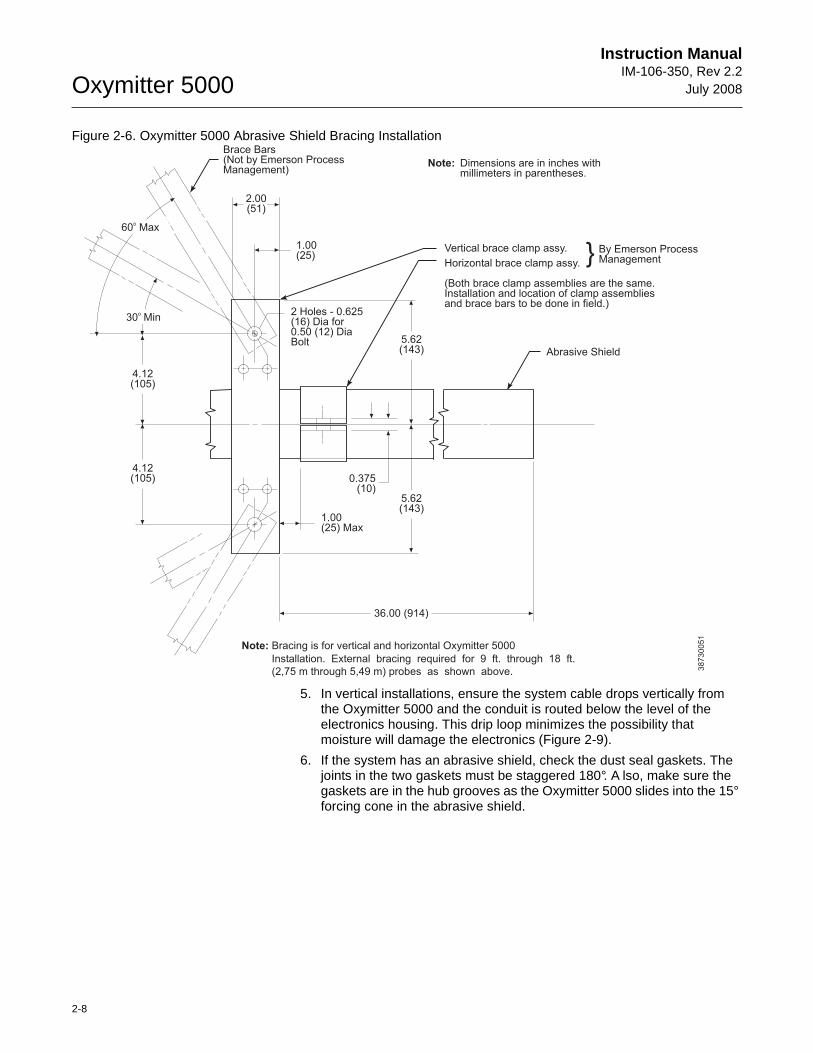
Oxymitter 5000
2-8
Instruction ManualIM-106-350, Rev 2.2
July 2008
Figure 2-6. Oxymitter 5000 Abrasive Shield Bracing Installation
5. In vertical installations, ensure the system cable drops vertically from the Oxymitter 5000 and the conduit is routed below the level of the electronics housing. This drip loop minimizes the possibility that moisture will damage the electronics (Figure 2-9).
6. If the system has an abrasive shield, check the dust seal gaskets. The joints in the two gaskets must be staggered 180°. A lso, make sure the gaskets are in the hub grooves as the Oxymitter 5000 slides into the 15° forcing cone in the abrasive shield.
Brace Bars(Not by Emerson ProcessManagement)
2.00(51)
Note: Dimensions are in inches withmillimeters in parentheses.
Vertical brace clamp assy.
Abrasive Shield
Horizontal brace clamp assy.
(Both brace clamp assemblies are the same.Installation and location of clamp assembliesand brace bars to be done in field.)
By Emerson ProcessManagement}
2 Holes - 0.625(16) Dia for0.50 (12) DiaBolt
Note: Bracing is for vertical and horizontal Oxymitter 5000
1.00(25) Max
0.375(10)
1.00(25)
4.12(105)
4.12(105)
60 Maxo
30o
5.62(143)
5.62(143)
36.00 (914)
Installation. External bracing required for 9 ft. through 18 ft.
(2,75 m through 5,49 m) probes as shown above. 38730051
Min
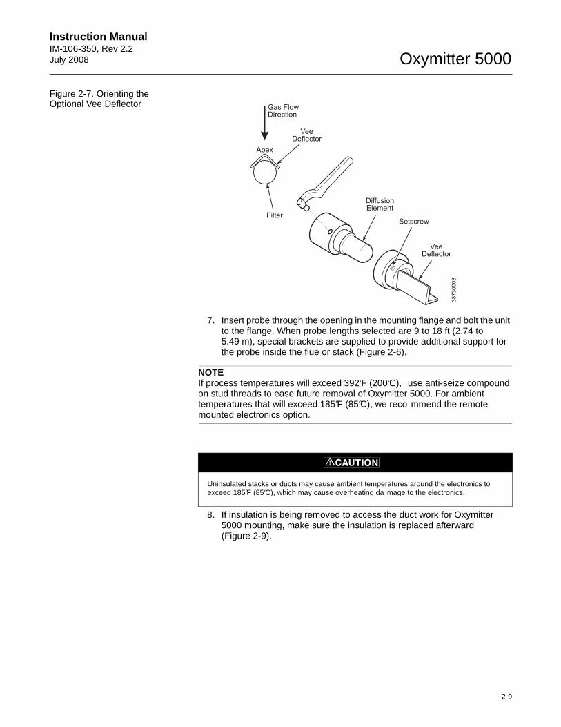
Instruction Manual IM-106-350, Rev 2.2July 2008
2-9
Oxymitter 5000
Figure 2-7. Orienting the Optional Vee Deflector
7. Insert probe through the opening in the mounting flange and bolt the unit to the flange. When probe lengths selected are 9 to 18 ft (2.74 to 5.49 m), special brackets are supplied to provide additional support for the probe inside the flue or stack (Figure 2-6).
NOTEIf process temperatures will exceed 392°F (200°C), use anti-seize compound on stud threads to ease future removal of Oxymitter 5000. For ambient temperatures that will exceed 185°F (85°C), we reco mmend the remote mounted electronics option.
8. If insulation is being removed to access the duct work for Oxymitter 5000 mounting, make sure the insulation is replaced afterward(Figure 2-9).
VeeDeflector
VeeDeflector
DiffusionElement
SetscrewFilter
Gas FlowDirection
Apex
38
73
00
03
Uninsulated stacks or ducts may cause ambient temperatures around the electronics to exceed 185°F (85°C), which may cause overheating da mage to the electronics.
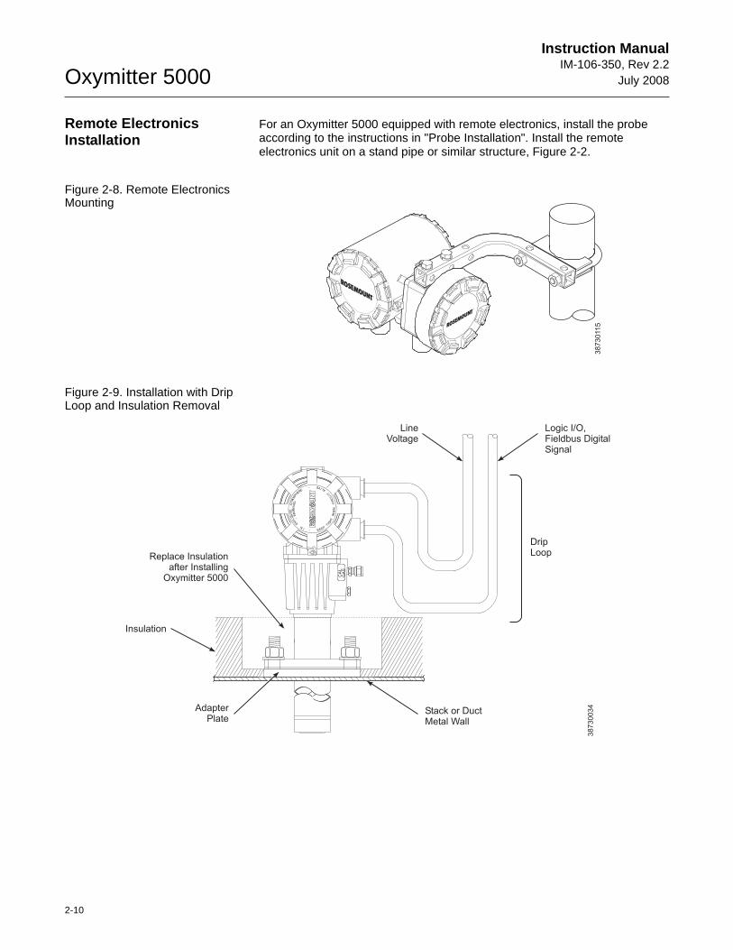
Oxymitter 5000
2-10
Instruction ManualIM-106-350, Rev 2.2
July 2008
Remote Electronics Installation
For an Oxymitter 5000 equipped with remote electronics, install the probe according to the instructions in "Probe Installation". Install the remote electronics unit on a stand pipe or similar structure, Figure 2-2.
Figure 2-8. Remote Electronics Mounting
Figure 2-9. Installation with Drip Loop and Insulation Removal
38
73
011
5
PS
U
E
I
TP
IC
RH
WE
NT
HG
C
KE
NI -
E
E RW
AVIS
OL
P-
XO
MT
A GNI
N-
R
I
T
LA
I
VE
-E
EH
GA
SC
AL.
DripLoop
Logic I/O,Fieldbus DigitalSignal
LineVoltage
Replace Insulationafter Installing
Oxymitter 5000
Insulation
AdapterPlate
Stack or DuctMetal Wall
38730034
Instruction Manual IM-106-350, Rev 2.2July 2008
2-11
Oxymitter 5000
ELECTRICAL INSTALLATION (WITH INTEGRAL ELECTRONICS)
For Oxymitter 5000 with Integral Electronics
All wiring must conform to local and national codes.
NOTETo maintain proper earth grounding, ensure a positive connection exists between the sensor housing, the electronics housing, and earth. The connecting ground wire must be 14 AWG minimum. Refer to Figure 2-10.
NOTELine voltage, signal, and relay wiring must be rated for at least 221°F (105°C).
1. Remove cover (31).
2. Connect Line Voltage.
a. Connect the line, or L1 wire to the L1 terminal and the neutral, or L2 wire, to the N terminal (Figure 2-10). The Oxymitter 5000 automatically will configure itself for 90-250 VAC line voltage and 50/60 Hz. The power supply requires no setup.
3. Connect fieldbus Digital Signal and Logic I/O Calibration Handshake Leads. Use individual shielded twisted wire pairs. Terminate the shield only at the electronics housing.
Disconnect and lock out power before connecting the power supply.
Install all protective covers and safety ground leads after installation. Failure to install covers and ground leads could result in serious injury or death.
To meet the Safety Requirements of IEC 1010 (EC requirement), and ensure safe operation of this equipment, connection to the main electrical power supply must be made through a circuit breaker (min 10 A) which will disconnect all current-carrying conductors during a fault situation. This circuit breaker should also include a mechanically operated isolating switch. If not, then another external means of disconnecting the supply from the equipment should be located close by. Circuit breakers or switches must comply with a recognized standard such as IEC 947.
The probe and probe abrasive shield are heavy. Use proper lifting and carrying procedures to avoid personnel injury.
Oxymitter 5000
2-12
Instruction ManualIM-106-350, Rev 2.2
July 2008
a. Fieldbus Digital Signal. The fieldbus digital signal carries the O2 value. This digital signal can also be used to communicate with the Oxymitter.
b. Calibration Handshake/Logic I/O. The output can either be an alarm or provide the handshaking to interface with an IMPS 4000 or SPS 4001B. For more information, refer to "Calibration Handshake Signal" in Section 4: Configuration of Oxymitter 5000 with LOI, and either the IMPS 4000 Intelligent Multiprobe Test Gas Sequencer Instruction Manual or the SPS 4001B Single Probe Autocalibration Sequencer Instruction Manual.
c. If autocalibration is not utilized, a common bi-directional logic contact is provided for any of the diagnostic alarms listed in Table 8-1. The assignment of alarms which can actuate this contact can be modified to one of seven additional groupings listed in Table 3-1 and Table 4-1.
The logic contact is self-powered, +5 VDC, 340 ohm series resistance. An interposing relay will be required if this contact is to be utilized to annunciate a higher voltage device, such as a light or horn, and may also be required for certain DCS input cards. A Potter & Brumfield R10S-E1Y1-J1.0K 3.2 mA DC or an equal interposing relay will be mounted where the contact wires terminate in the control/relay room.
d. Install cover (31, Figure 9-3).
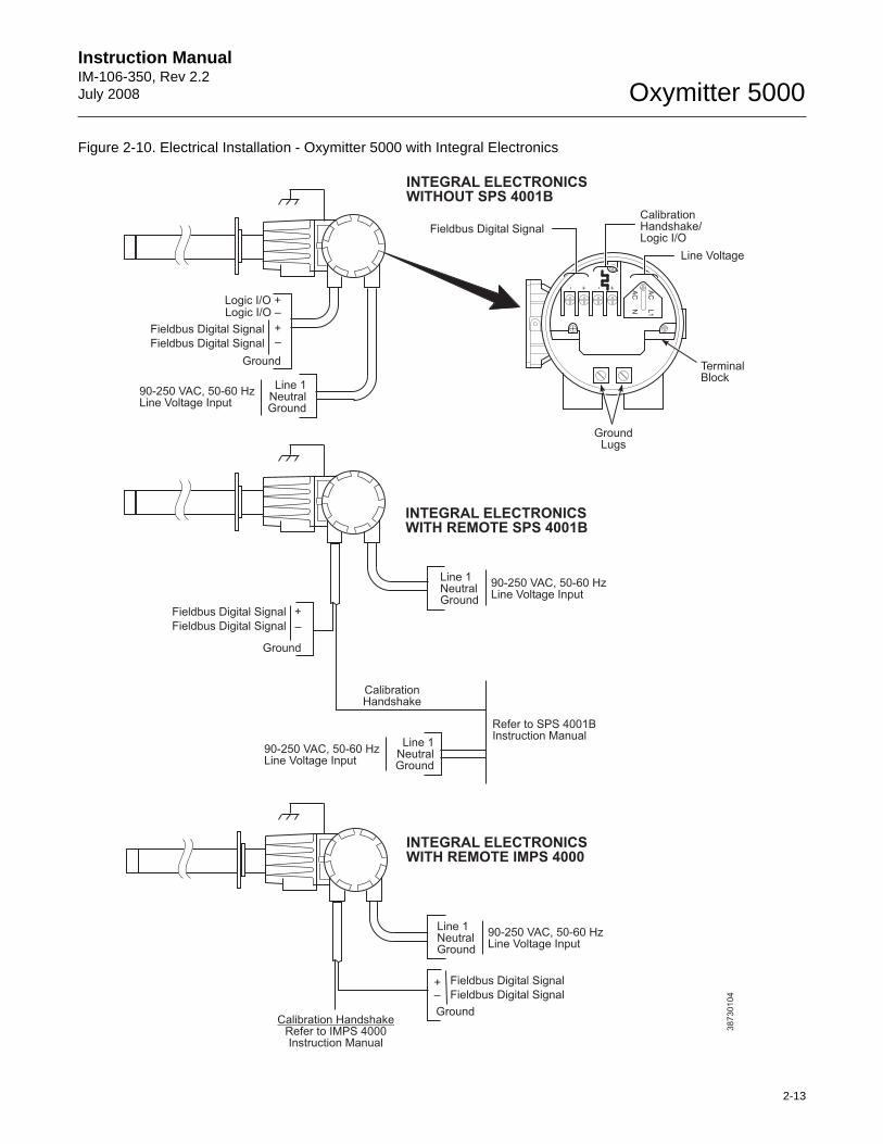
Instruction Manual IM-106-350, Rev 2.2July 2008
2-13
Oxymitter 5000
Figure 2-10. Electrical Installation - Oxymitter 5000 with Integral Electronics
38
73
01
04
INTEGRAL ELECTRONICSWITHOUT SPS 4001B
AC
L1
AC
N
++ --
Logic I/O +Logic I/O –
Ground
Line 1NeutralGround
90-250 VAC, 50-60 HzLine Voltage Input
Calibration HandshakeRefer to IMPS 4000Instruction Manual
INTEGRAL ELECTRONICSWITH REMOTE SPS 4001B
INTEGRAL ELECTRONICSWITH REMOTE IMPS 4000
Line 1NeutralGround
90-250 VAC, 50-60 HzLine Voltage Input
CalibrationHandshake
Line Voltage
CalibrationHandshake/Logic I/O
TerminalBlock
GroundLugs
Line 1NeutralGround
+
–
Ground
90-250 VAC, 50-60 HzLine Voltage Input
90-250 VAC, 50-60 HzLine Voltage Input
Line 1NeutralGround
Ground
Fieldbus Digital Signal +
–
+–
Refer to SPS 4001BInstruction Manual
Fieldbus Digital Signal
Fieldbus Digital Signal
Fieldbus Digital Signal
Fieldbus Digital Signal
Fieldbus Digital Signal
Fieldbus Digital Signal
Oxymitter 5000
2-14
Instruction ManualIM-106-350, Rev 2.2
July 2008
ELECTRICAL INSTALLATION (WITH REMOTE ELECTRONICS)
For Oxymitter 5000 with Remote Electronics
All wiring must conform to local and national codes.
NOTETo maintain proper earth grounding, ensure a positive connection exists between the sensor housing, the electronics housing, and earth. The connecting ground wire must be 14 AWG minimum. Refer to Figure 2-11.
NOTELine voltage, signal, and relay wiring must be rated for at least 221°F (105°C).
1. Remove cover (31) from remote electronics.
2. Connect Line Voltage.
a. Connect the line, or L1 wire to the L1 terminal and the neutral, or L2 wire, to the N terminal (Figure 2-11). The Oxymitter 5000 automatically will configure itself for 90-250 VAC line voltage and 50/60 Hz. The power supply requires no setup.
3. Connect fieldbus Digital Signal and Logic I/O Calibration Handshake Leads, see Figure 2-10. Use individual shielded twisted wire pairs. Terminate the shield only at the electronics housing.
Disconnect and lock out power before connecting the power supply.
Install all protective covers and safety ground leads after installation. Failure to install covers and ground leads could result in serious injury or death.
To meet the Safety Requirements of IEC 1010 (EC requirement), and ensure safe operation of this equipment, connection to the main electrical power supply must be made through a circuit breaker (min 10 A) which will disconnect all current-carrying conductors during a fault situation. This circuit breaker should also include a mechanically operated isolating switch. If not, then another external means of disconnecting the supply from the equipment should be located close by. Circuit breakers or switches must comply with a recognized standard such as IEC 947.
The probe and probe abrasive shield are heavy. Use proper lifting and carrying procedures to avoid personnel injury.
Instruction Manual IM-106-350, Rev 2.2July 2008
2-15
Oxymitter 5000
a. Fieldbus Digital Signal. The fieldbus digital signal carries the O2 value. This digital signal can also be used to communicate with the Oxymitter.
b. Calibration Handshake/Logic I/O. The output can either be an alarm or provide the handshaking to interface with an IMPS 4000 or SPS 4001B. For more information, refer to "Calibration Handshake Signal" in Section 4: Configuration of Oxymitter 5000 with LOI, and either the IMPS 4000 Intelligent Multiprobe Test Gas Sequencer Instruction Manual or the SPS 4001B Single Probe Autocalibration Sequencer Instruction Manual.
c. If autocalibration is not utilized, a common bi-directional logic contact is provided for any of the diagnostic alarms listed in Table 8-1. The assignment of alarms which can actuate this contact can be modified to one of seven additional groupings listed in Table 4-1.
The logic contact is self-powered, +5 VDC, 340 ohm series resistance. An interposing relay will be required if this contact is to be utilized to annunciate a higher voltage device, such as a light or horn, and may also be required for certain DCS input cards. A Potter & Brumfield R10S-E1Y1-J1.0K 3.2 mA DC or an equal interposing relay will be mounted where the contact wires terminate in the control/relay room.
4. Install cover (31, Figure 9-4).
5. Install Interconnecting Cable.
a. Remove cover (3) from junction box (5). Connect the electronics end of the interconnecting cable to the "FROM PROBE" side of the terminal block (Figure 2-11).
b. Remove housing cover (31).
c. Connect the heater power leads, the thermocouple leads and the oxygen signal leads at the terminal block. The leads are tagged for polarity.
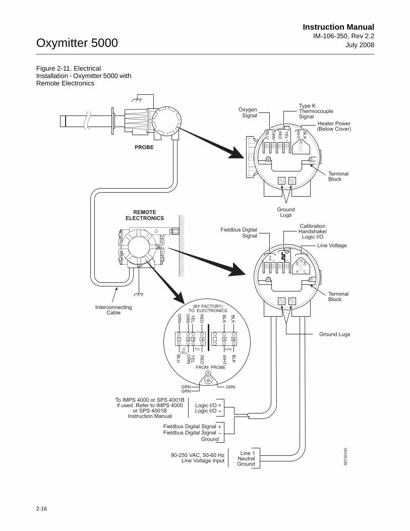
Oxymitter 5000
2-16
Instruction ManualIM-106-350, Rev 2.2
July 2008
Figure 2-11. Electrical Installation - Oxymitter 5000 with Remote Electronics
OxygenSignal
++ --
TerminalBlock
GroundLugs
38
73
01
05
Fieldbus DigitalSignal
AC
L1
AC
N
++ --4
-20
TerminalBlock
Ground Lugs1 2 3 4 5 6
GR
N
OR
NY
EL
RE
D
BLK
BLK
BLU
OR
NY
EL
RE
D
WH
T
BLK
HTRT/COCELL
2
(BY FACTORY)TO ELECTRONICS
FROM PROBE
BL
U
OR
N
RE
D
YE
L
BL
K
WH
T
PROBE
REMOTEELECTRONICS
To IMPS 4000 or SPS 4001Bif used. Refer to IMPS 4000
orInstruction Manual
SPS 4001BLogic I/O +Logic I/O -
Line 1NeutralGround
90-250 VAC, 50-60 HzLine Voltage Input
InterconnectingCable
+–
Ground
GRNGRNGRN
Line Voltage
CalibrationHandshake/
Logic I/O
Heater Power(Below Cover)
Type KThermocoupleSignal
Fieldbus Digital SignalFieldbus Digital Signal
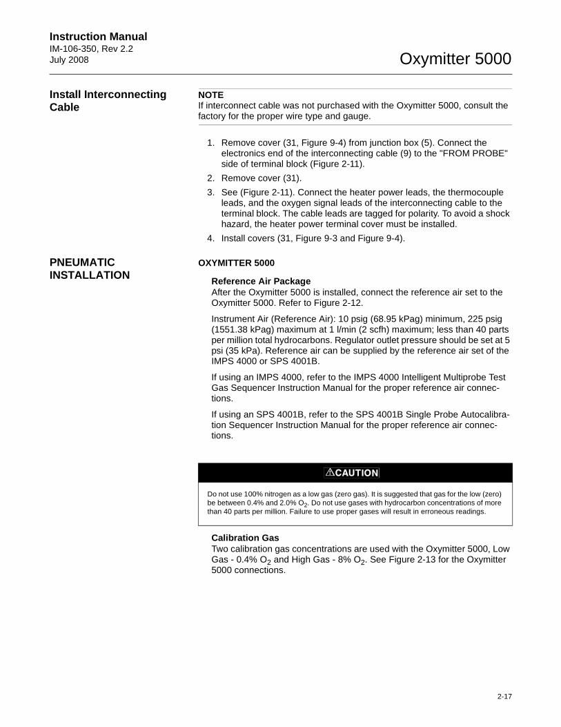
Instruction Manual IM-106-350, Rev 2.2July 2008
2-17
Oxymitter 5000
Install Interconnecting Cable
NOTEIf interconnect cable was not purchased with the Oxymitter 5000, consult the factory for the proper wire type and gauge.
1. Remove cover (31, Figure 9-4) from junction box (5). Connect the electronics end of the interconnecting cable (9) to the "FROM PROBE" side of terminal block (Figure 2-11).
2. Remove cover (31).
3. See (Figure 2-11). Connect the heater power leads, the thermocouple leads, and the oxygen signal leads of the interconnecting cable to the terminal block. The cable leads are tagged for polarity. To avoid a shock hazard, the heater power terminal cover must be installed.
4. Install covers (31, Figure 9-3 and Figure 9-4).
PNEUMATIC INSTALLATION
OXYMITTER 5000
Reference Air PackageAfter the Oxymitter 5000 is installed, connect the reference air set to the Oxymitter 5000. Refer to Figure 2-12.
Instrument Air (Reference Air): 10 psig (68.95 kPag) minimum, 225 psig (1551.38 kPag) maximum at 1 l/min (2 scfh) maximum; less than 40 parts per million total hydrocarbons. Regulator outlet pressure should be set at 5 psi (35 kPa). Reference air can be supplied by the reference air set of the IMPS 4000 or SPS 4001B.
If using an IMPS 4000, refer to the IMPS 4000 Intelligent Multiprobe Test Gas Sequencer Instruction Manual for the proper reference air connec-tions.
If using an SPS 4001B, refer to the SPS 4001B Single Probe Autocalibra-tion Sequencer Instruction Manual for the proper reference air connec-tions.
Calibration GasTwo calibration gas concentrations are used with the Oxymitter 5000, Low Gas - 0.4% O2 and High Gas - 8% O2. See Figure 2-13 for the Oxymitter 5000 connections.
Do not use 100% nitrogen as a low gas (zero gas). It is suggested that gas for the low (zero) be between 0.4% and 2.0% O2. Do not use gases with hydrocarbon concentrations of more than 40 parts per million. Failure to use proper gases will result in erroneous readings.
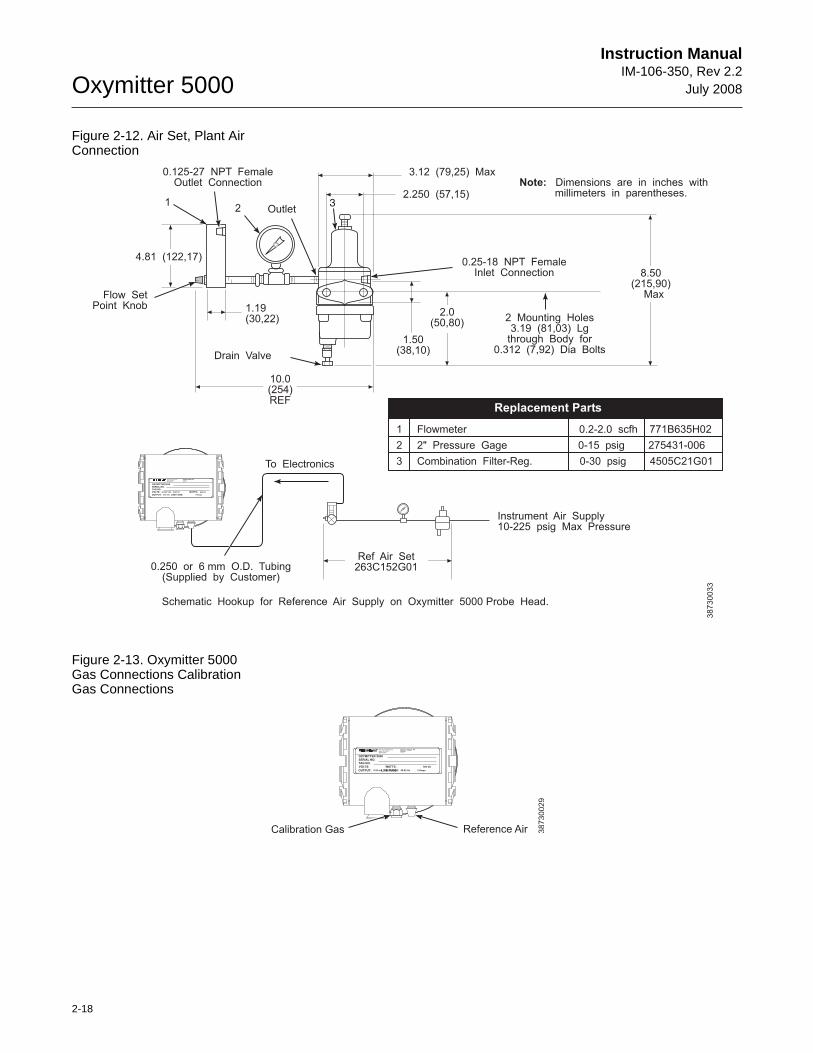
Oxymitter 5000
2-18
Instruction ManualIM-106-350, Rev 2.2
July 2008
Figure 2-12. Air Set, Plant Air Connection
Figure 2-13. Oxymitter 5000 Gas Connections Calibration Gas Connections
To Electronics
Ref Air Set263C152G01
1 Flowmeter 0.2-2.0 scfh 771B635H02
2 2" Pressure Gage 0-15 psig 275431-006
3 Combination Filter-Reg. 0-30 psig 4505C21G01
Note: Dimensions are in inches withmillimeters in parentheses.
12
3
4.81 (122,17)
Flow SetPoint Knob
0.125-27 NPT FemaleOutlet Connection
1.19(30,22)
10.0(254)REF
Drain Valve
3.12 (79,25) Max
8.50(215,90)
Max
2.0(50,80)
2 Mounting Holes3.19 (81,03) Lg
through Body for0.312 (7,92) Dia Bolts
1.50(38,10)
2.250 (57,15)
Schematic Hookup for Reference Air Supply on Oxymitter 5000 Probe Head.
Outlet
0.25-18 NPT FemaleInlet Connection
Instrument Air Supply10-225 psig Max Pressure
38730033
0.250 or 6 mm O.D. Tubing(Supplied by Customer)
500 VA
SERIAL NO.TAG NO.
OXYMITTER 5000
WATTS:VOLTS:
FUSE:LINEOUTPUT:
Rosemount Analytical Inc.
Solon, OH 44139
85-264 VAC 48-62 Hz
TM
800-433-6076
4-20 mA
R
5 Amps
TMHARTSMART FAMILY
Replacement Parts
500 VA
R
SERIAL NO.
TAG NO.
OXYMITTER 5000
VOLTS: WATTS:
OUTPUT: LINE FUSE:
Rosemount Analytical Inc.
Solon, OH 44139
85-264 VAC 48-62 Hz
TM
800-433-6076
4-20 mA
R
5 Amps
TMHART
SMART FAMILY
Calibration Gas Reference Air 38730029
Instruction Manual IM-106-350, Rev 2.2July 2008
2-19
Oxymitter 5000
IMPS 4000 CONNECTIONS
See the IMPS 4000 Intelligent Multiprobe Sequencer Instruction Manual for wiring and pneumatic connection.
SPS 4001B CONNECTIONS
See the SPS 4001B Single Probe Autocalibration Sequencer Instruction Manual for wiring and pneumatic connection.
NOTE:
Upon completing installation, make sure that the Oxymitter 5000 is turned on and operating prior to firing up the combustion process. Damage can result from having a cold Oxymitter 5000 exposed to the process gases.
During outages, and if possible, leave all Oxymitter 5000 units running to prevent condensation and premature aging from thermal cycling.
If the ducts will be washed down during outage, MAKE SURE to power down the Oxymitter 5000 units and remove them from the wash areas.

Oxymitter 5000
2-20
Instruction ManualIM-106-350, Rev 2.2
July 2008
Instruction Manual IM-106-350, Rev 2.2July 2008 Oxymitter 5000
http://www.raihome.com
Section 3 Configuration of Oxymitter 5000 with Membrane Keypad
Verify Installation . . . . . . . . . . . . . . . . . . . . . . . . . . . . . . . . page 3-1Logic I/O . . . . . . . . . . . . . . . . . . . . . . . . . . . . . . . . . . . . . . . page 3-4
VERIFY INSTALLATION
NOTERefer to Appendices C, D, and E for fieldbus information concerning the Hazardous Area Oxymitter 5000.
Mechanical Installation Ensure the Oxymitter 5000 is installed correctly. See Section 2: Installation.
Terminal Block Wiring 1. Remove cover (31) to expose terminal block (29).
2. Check the terminal block wiring (Figure 3-1). Be sure the power, fieldbus signal, and the logic outputs are properly connected and secure. To avoid a shock hazard, the power terminal cover must be installed. For units with remote electronics, check the terminal block wiring at the probe and at the remote electronics unit.
3. Install housing cover (31, Figure 9-3 or Figure 9-4) on terminal block (29).
Install all protective equipment covers and safety ground leads before equipment startup. Failure to install covers and ground leads could result in serious injury or death.
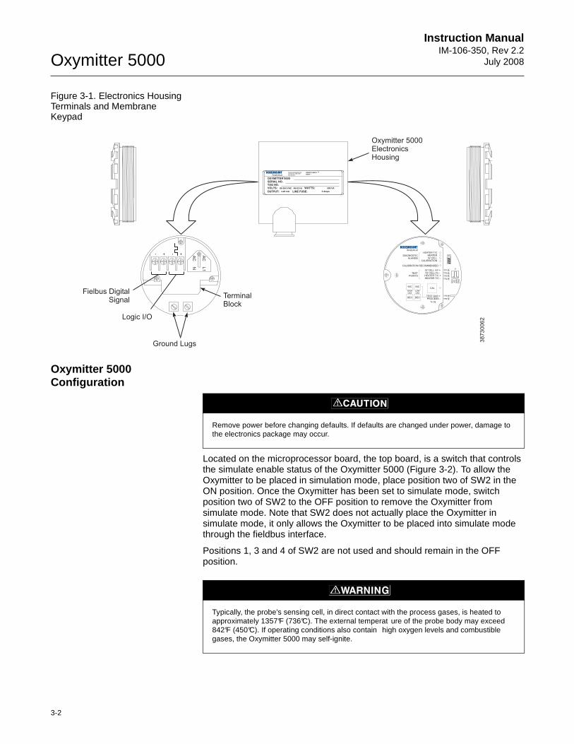
Oxymitter 5000
3-2
Instruction ManualIM-106-350, Rev 2.2
July 2008
Figure 3-1. Electronics Housing Terminals and Membrane Keypad
Oxymitter 5000 Configuration
Located on the microprocessor board, the top board, is a switch that controls the simulate enable status of the Oxymitter 5000 (Figure 3-2). To allow the Oxymitter to be placed in simulation mode, place position two of SW2 in the ON position. Once the Oxymitter has been set to simulate mode, switch position two of SW2 to the OFF position to remove the Oxymitter from simulate mode. Note that SW2 does not actually place the Oxymitter in simulate mode, it only allows the Oxymitter to be placed into simulate mode through the fieldbus interface.
Positions 1, 3 and 4 of SW2 are not used and should remain in the OFF position.
38730062
AC
L1
AC
N
++ --
500 VA
SERIAL NO.TAG NO.
OXYMITTER 5000
WATTS:VOLTS:
FUSE:LINEOUTPUT:
Rosemount Analytical Inc.Orrville, OH 44667-0901
85-264 VAC 48-62 Hz
TM
800-433-6076
4-20 mA
R
5 Amps
TMHARTSMART FAMILY
DIAGNOSTICALARMS
TESTPOINTS
HEATER T/CHEATER02 CELL
CALIBRATION
CALIBRATION RECOMMENDED
02 CELL mV +02 CELL mv -
HEATER T/C +HEATER T/C -
INC INC
DEC DEC
HIGHGAS
LOWGAS
CAL
TEST GAS +PROCESS -
% 02
SW2
TP1J1
TP2
TP3
RE
DY
EL
GR
NO
RG
TP4
TP5
TP6
ON
Fielbus DigitalSignal
Logic I/O
Ground Lugs
TerminalBlock
Oxymitter 5000ElectronicsHousing
Remove power before changing defaults. If defaults are changed under power, damage to the electronics package may occur.
Typically, the probe's sensing cell, in direct contact with the process gases, is heated to approximately 1357°F (736°C). The external temperat ure of the probe body may exceed 842°F (450°C). If operating conditions also contain high oxygen levels and combustible gases, the Oxymitter 5000 may self-ignite.
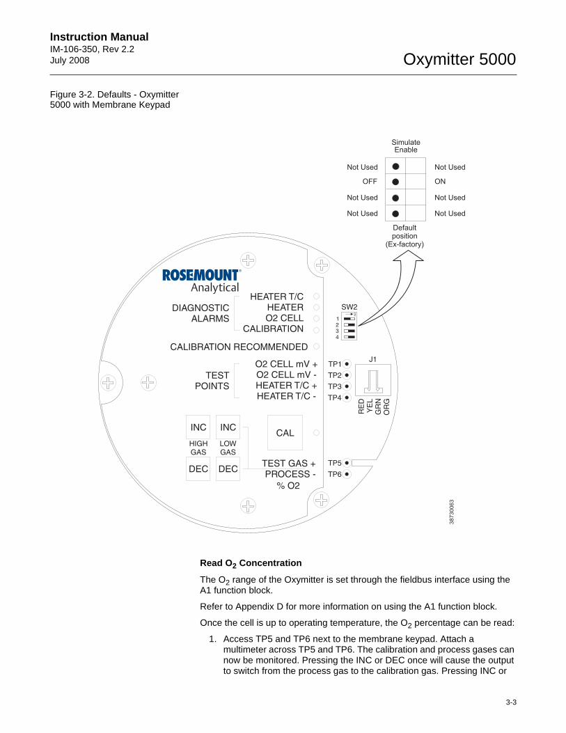
Instruction Manual IM-106-350, Rev 2.2July 2008
3-3
Oxymitter 5000
Figure 3-2. Defaults - Oxymitter 5000 with Membrane Keypad
Read O2 Concentration
The O2 range of the Oxymitter is set through the fieldbus interface using the A1 function block.
Refer to Appendix D for more information on using the A1 function block.
Once the cell is up to operating temperature, the O2 percentage can be read:
1. Access TP5 and TP6 next to the membrane keypad. Attach a multimeter across TP5 and TP6. The calibration and process gases can now be monitored. Pressing the INC or DEC once will cause the output to switch from the process gas to the calibration gas. Pressing INC or
38
73
00
63
DIAGNOSTICALARMS
TESTPOINTS
HEATER T/CHEATERO2 CELL
CALIBRATION
CALIBRATION RECOMMENDED
O2 CELL mV +O2 CELL mV -HEATER T/C +HEATER T/C -
INC INC
DEC DEC
HIGHGAS
LOWGAS
CAL
TEST GAS +PROCESS -
% O2
SW2
TP1J1
TP2
TP3
RE
DY
EL
GR
NO
RG
TP4
TP5
TP6
ON
Not Used
OFF
Defaultposition
(Ex-factory)
1234
Not Used
Not Used
Not Used
ON
Not Used
Not Used
SimulateEnable
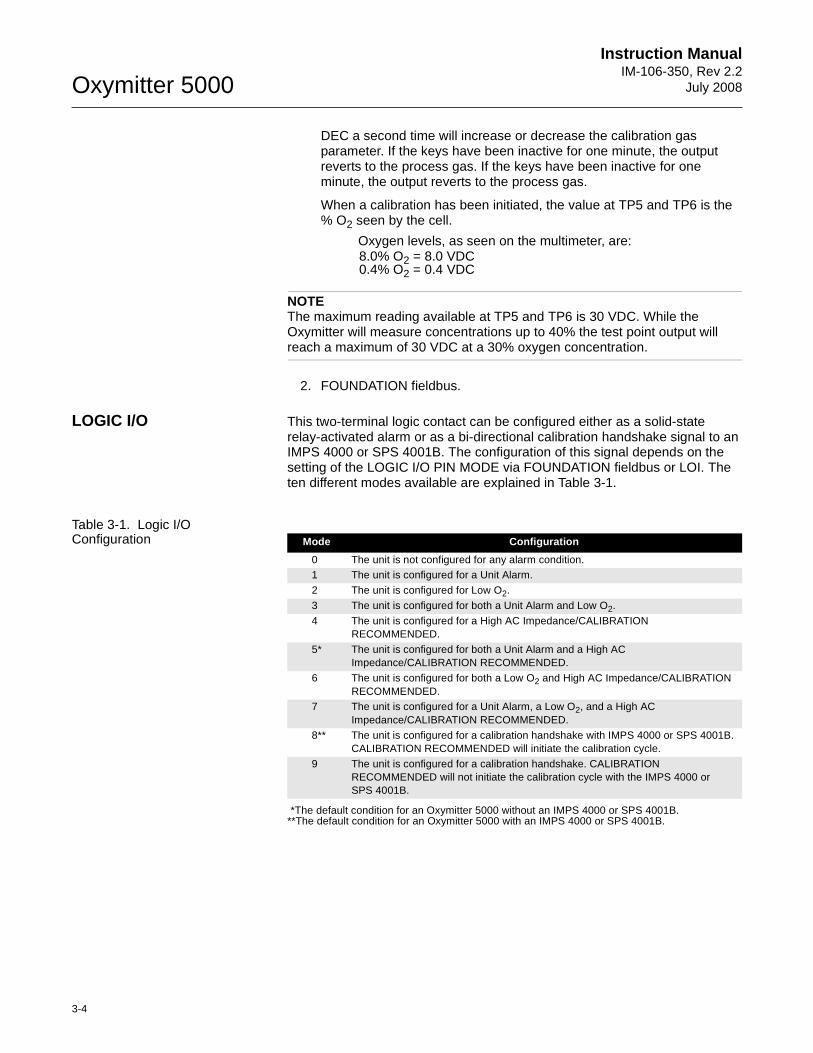
Oxymitter 5000
3-4
Instruction ManualIM-106-350, Rev 2.2
July 2008
DEC a second time will increase or decrease the calibration gas parameter. If the keys have been inactive for one minute, the output reverts to the process gas. If the keys have been inactive for one minute, the output reverts to the process gas.
When a calibration has been initiated, the value at TP5 and TP6 is the % O2 seen by the cell.
Oxygen levels, as seen on the multimeter, are:8.0% O2 = 8.0 VDC0.4% O2 = 0.4 VDC
NOTEThe maximum reading available at TP5 and TP6 is 30 VDC. While the Oxymitter will measure concentrations up to 40% the test point output will reach a maximum of 30 VDC at a 30% oxygen concentration.
2. FOUNDATION fieldbus.
LOGIC I/O This two-terminal logic contact can be configured either as a solid-state relay-activated alarm or as a bi-directional calibration handshake signal to an IMPS 4000 or SPS 4001B. The configuration of this signal depends on the setting of the LOGIC I/O PIN MODE via FOUNDATION fieldbus or LOI. The ten different modes available are explained in Table 3-1.
Table 3-1. Logic I/O Configuration
*The default condition for an Oxymitter 5000 without an IMPS 4000 or SPS 4001B.**The default condition for an Oxymitter 5000 with an IMPS 4000 or SPS 4001B.
Mode Configuration
0 The unit is not configured for any alarm condition.1 The unit is configured for a Unit Alarm.
2 The unit is configured for Low O2.
3 The unit is configured for both a Unit Alarm and Low O2.
4 The unit is configured for a High AC Impedance/CALIBRATION RECOMMENDED.
5* The unit is configured for both a Unit Alarm and a High AC Impedance/CALIBRATION RECOMMENDED.
6 The unit is configured for both a Low O2 and High AC Impedance/CALIBRATION RECOMMENDED.
7 The unit is configured for a Unit Alarm, a Low O2, and a High AC Impedance/CALIBRATION RECOMMENDED.
8** The unit is configured for a calibration handshake with IMPS 4000 or SPS 4001B. CALIBRATION RECOMMENDED will initiate the calibration cycle.
9 The unit is configured for a calibration handshake. CALIBRATION RECOMMENDED will not initiate the calibration cycle with the IMPS 4000 or SPS 4001B.
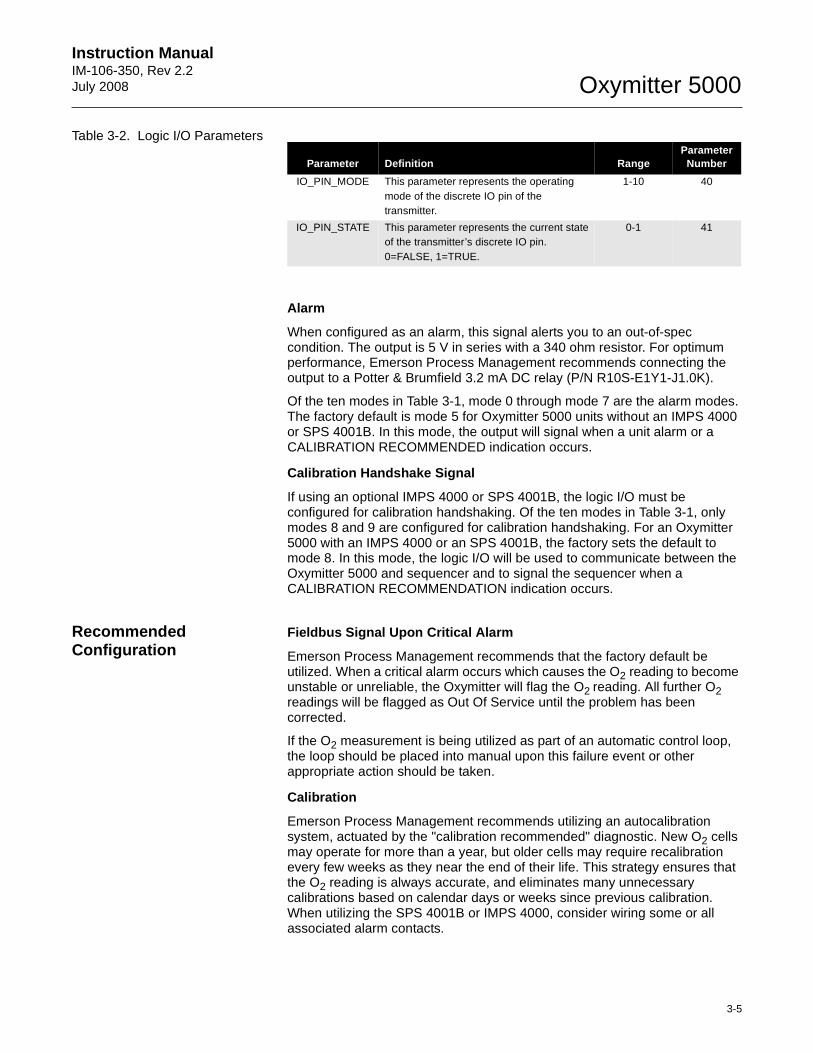
Instruction Manual IM-106-350, Rev 2.2July 2008
3-5
Oxymitter 5000
Table 3-2. Logic I/O Parameters
Alarm
When configured as an alarm, this signal alerts you to an out-of-spec condition. The output is 5 V in series with a 340 ohm resistor. For optimum performance, Emerson Process Management recommends connecting the output to a Potter & Brumfield 3.2 mA DC relay (P/N R10S-E1Y1-J1.0K).
Of the ten modes in Table 3-1, mode 0 through mode 7 are the alarm modes. The factory default is mode 5 for Oxymitter 5000 units without an IMPS 4000 or SPS 4001B. In this mode, the output will signal when a unit alarm or a CALIBRATION RECOMMENDED indication occurs.
Calibration Handshake Signal
If using an optional IMPS 4000 or SPS 4001B, the logic I/O must be configured for calibration handshaking. Of the ten modes in Table 3-1, only modes 8 and 9 are configured for calibration handshaking. For an Oxymitter 5000 with an IMPS 4000 or an SPS 4001B, the factory sets the default to mode 8. In this mode, the logic I/O will be used to communicate between the Oxymitter 5000 and sequencer and to signal the sequencer when a CALIBRATION RECOMMENDATION indication occurs.
Recommended Configuration
Fieldbus Signal Upon Critical Alarm
Emerson Process Management recommends that the factory default be utilized. When a critical alarm occurs which causes the O2 reading to become unstable or unreliable, the Oxymitter will flag the O2 reading. All further O2 readings will be flagged as Out Of Service until the problem has been corrected.
If the O2 measurement is being utilized as part of an automatic control loop, the loop should be placed into manual upon this failure event or other appropriate action should be taken.
Calibration
Emerson Process Management recommends utilizing an autocalibration system, actuated by the "calibration recommended" diagnostic. New O2 cells may operate for more than a year, but older cells may require recalibration every few weeks as they near the end of their life. This strategy ensures that the O2 reading is always accurate, and eliminates many unnecessary calibrations based on calendar days or weeks since previous calibration. When utilizing the SPS 4001B or IMPS 4000, consider wiring some or all associated alarm contacts.
Parameter Definition RangeParameter
Number
IO_PIN_MODE This parameter represents the operating mode of the discrete IO pin of the transmitter.
1-10 40
IO_PIN_STATE This parameter represents the current state of the transmitter’s discrete IO pin. 0=FALSE, 1=TRUE.
0-1 41
Oxymitter 5000
3-6
Instruction ManualIM-106-350, Rev 2.2
July 2008
1. CALIBRATION INITIATE. Contact from the control room to an SPS 4001B or IMPS 4000 (one per probe) provides the ability to manually initiate a calibration at any time from the control room. Note that calibrations can also be initiated via fieldbus, or from the keypad on the Oxymitter 5000.
2. IN CALIBRATION. One contact per probe provides notification to the control room that the "calibration recommended" diagnostic has initiated an automatic calibration through the SPS 4001B or IMPS 4000. If the O2 signal is being utilized in an automatic control loop, this contact should be utilized to place the control loop into manual during calibration.
3. CALIBRATION FAILED. One contact per probe from an SPS 4001B or IMPS 4000 to the control room for notification that the calibration procedure failed. Grouped with this alarm is an output from a pressure switch which indicates when the calibration gas bottles are empty.
Instruction Manual IM-106-350, Rev 2.2July 2008 Oxymitter 5000
http://www.raihome.com
Section 4 Configuration of Oxymitter 5000 with LOIVerify installation . . . . . . . . . . . . . . . . . . . . . . . . . . . . . . . . page 4-1Logic I/O . . . . . . . . . . . . . . . . . . . . . . . . . . . . . . . . . . . . . . . page 4-4
VERIFY INSTALLATION
NOTERefer to Appendices C, D, and E for fieldbus information concerning the Hazardous Area Oxymitter 5000.
Mechanical Installation Ensure the Oxymitter 5000 is installed correctly. See Section 2: Installation.
Terminal Block Wiring 1. Remove cover (31) to expose terminal block (29).
2. Check the terminal block wiring, Figure 4-1. Be sure the power, fieldbus digital signal, and logic outputs are properly connected and secure. To avoid a shock hazard, the power terminal cover must be installed. For units with remote electronics, check the terminal block wiring at the probe and at the remote electronics unit.
3. Install housing cover (31, Figure 9-3 or Figure 9-4) on terminal block (29).
Install all protective equipment covers and safety ground leads before equipment startup. Failure to install covers and ground leads could result in serious injury or death.
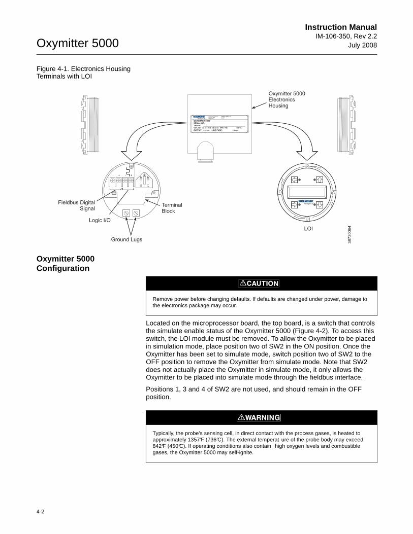
Oxymitter 5000
4-2
Instruction ManualIM-106-350, Rev 2.2
July 2008
Figure 4-1. Electronics Housing Terminals with LOI
Oxymitter 5000 Configuration
Located on the microprocessor board, the top board, is a switch that controls the simulate enable status of the Oxymitter 5000 (Figure 4-2). To access this switch, the LOI module must be removed. To allow the Oxymitter to be placed in simulation mode, place position two of SW2 in the ON position. Once the Oxymitter has been set to simulate mode, switch position two of SW2 to the OFF position to remove the Oxymitter from simulate mode. Note that SW2 does not actually place the Oxymitter in simulate mode, it only allows the Oxymitter to be placed into simulate mode through the fieldbus interface.
Positions 1, 3 and 4 of SW2 are not used, and should remain in the OFF position.
38730064
AC
L1
AC
N
++ --
500 VA
SERIAL NO.TAG NO.
OXYMITTER 5000
WATTS:VOLTS:
FUSE:LINEOUTPUT:
Rosemount Analytical Inc.
Solon, OH 44139
85-264 VAC 48-62 Hz
TM
800-433-6076
4-20 mA
R
5 Amps
TMHARTSMART FAMILY
Fieldbus DigitalSignal
Logic I/O
Ground Lugs
TerminalBlock
Oxymitter 5000ElectronicsHousing
LOI
Remove power before changing defaults. If defaults are changed under power, damage to the electronics package may occur.
Typically, the probe's sensing cell, in direct contact with the process gases, is heated to approximately 1357°F (736°C). The external temperat ure of the probe body may exceed 842°F (450°C). If operating conditions also contain high oxygen levels and combustible gases, the Oxymitter 5000 may self-ignite.
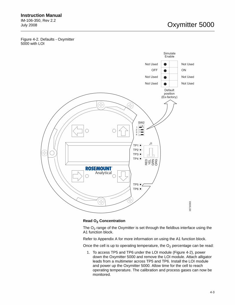
Instruction Manual IM-106-350, Rev 2.2July 2008
4-3
Oxymitter 5000
Figure 4-2. Defaults - Oxymitter 5000 with LOI
Read O2 Concentration
The O2 range of the Oxymitter is set through the fieldbus interface using the A1 function block.
Refer to Appendix A for more information on using the A1 function block.
Once the cell is up to operating temperature, the O2 percentage can be read:
1. To access TP5 and TP6 under the LOI module (Figure 4-2), power down the Oxymitter 5000 and remove the LOI module. Attach alligator leads from a multimeter across TP5 and TP6. Install the LOI module and power up the Oxymitter 5000. Allow time for the cell to reach operating temperature. The calibration and process gases can now be monitored.
38
73
00
65
SW2
1234
TP1J1
TP2
TP3
RE
DY
EL
GR
NO
RG
TP4
TP5
TP6
Defaultposition
(Ex-factory)
SimulateEnable
Not Used
OFF
Not Used
Not Used
Not Used
ON
Not Used
Not Used
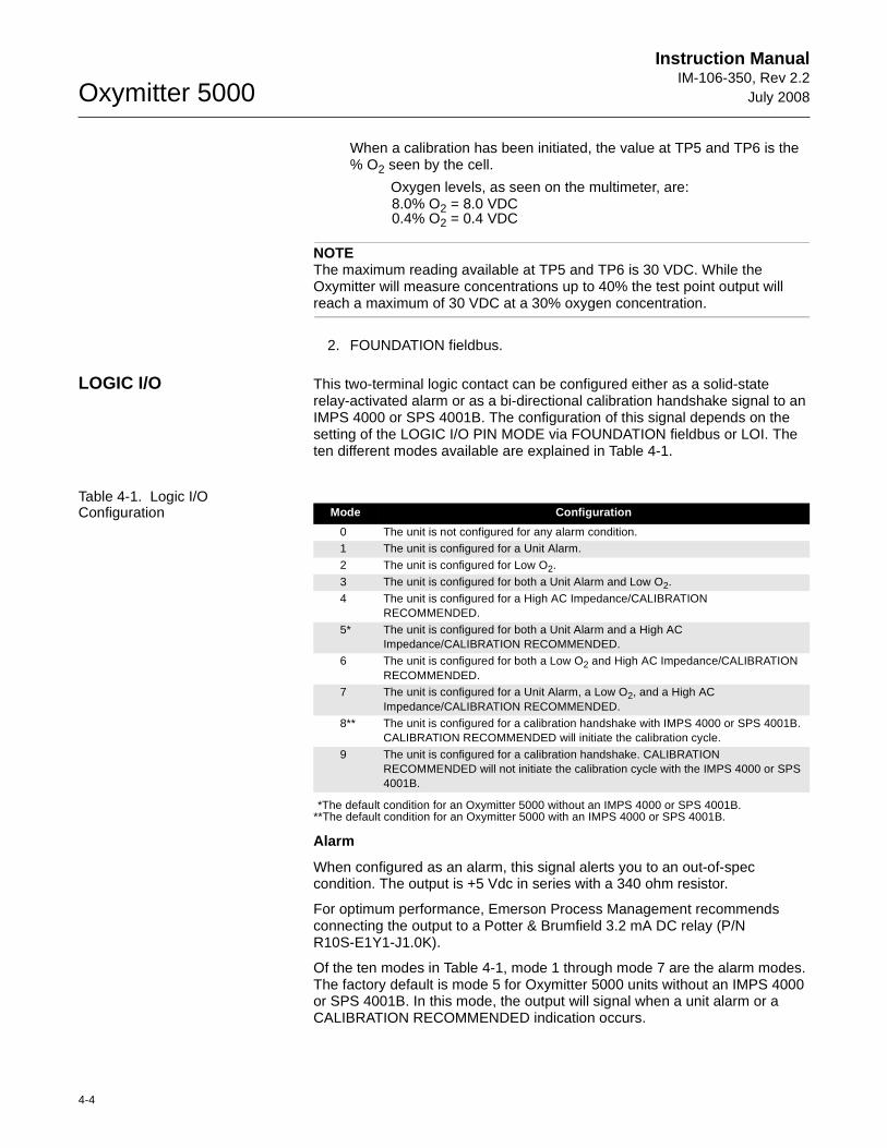
Oxymitter 5000
4-4
Instruction ManualIM-106-350, Rev 2.2
July 2008
When a calibration has been initiated, the value at TP5 and TP6 is the % O2 seen by the cell.
Oxygen levels, as seen on the multimeter, are:8.0% O2 = 8.0 VDC0.4% O2 = 0.4 VDC
NOTEThe maximum reading available at TP5 and TP6 is 30 VDC. While the Oxymitter will measure concentrations up to 40% the test point output will reach a maximum of 30 VDC at a 30% oxygen concentration.
2. FOUNDATION fieldbus.
LOGIC I/O This two-terminal logic contact can be configured either as a solid-state relay-activated alarm or as a bi-directional calibration handshake signal to an IMPS 4000 or SPS 4001B. The configuration of this signal depends on the setting of the LOGIC I/O PIN MODE via FOUNDATION fieldbus or LOI. The ten different modes available are explained in Table 4-1.
Table 4-1. Logic I/O Configuration
*The default condition for an Oxymitter 5000 without an IMPS 4000 or SPS 4001B.**The default condition for an Oxymitter 5000 with an IMPS 4000 or SPS 4001B.
Alarm
When configured as an alarm, this signal alerts you to an out-of-spec condition. The output is +5 Vdc in series with a 340 ohm resistor.
For optimum performance, Emerson Process Management recommends connecting the output to a Potter & Brumfield 3.2 mA DC relay (P/N R10S-E1Y1-J1.0K).
Of the ten modes in Table 4-1, mode 1 through mode 7 are the alarm modes. The factory default is mode 5 for Oxymitter 5000 units without an IMPS 4000 or SPS 4001B. In this mode, the output will signal when a unit alarm or a CALIBRATION RECOMMENDED indication occurs.
Mode Configuration
0 The unit is not configured for any alarm condition.1 The unit is configured for a Unit Alarm.
2 The unit is configured for Low O2.
3 The unit is configured for both a Unit Alarm and Low O2.
4 The unit is configured for a High AC Impedance/CALIBRATION RECOMMENDED.
5* The unit is configured for both a Unit Alarm and a High AC Impedance/CALIBRATION RECOMMENDED.
6 The unit is configured for both a Low O2 and High AC Impedance/CALIBRATION RECOMMENDED.
7 The unit is configured for a Unit Alarm, a Low O2, and a High AC Impedance/CALIBRATION RECOMMENDED.
8** The unit is configured for a calibration handshake with IMPS 4000 or SPS 4001B. CALIBRATION RECOMMENDED will initiate the calibration cycle.
9 The unit is configured for a calibration handshake. CALIBRATION RECOMMENDED will not initiate the calibration cycle with the IMPS 4000 or SPS 4001B.
Instruction Manual IM-106-350, Rev 2.2July 2008
4-5
Oxymitter 5000
Calibration Handshake Signal
If using an optional IMPS 4000 or SPS 4001B, the logic I/O must be configured for calibration handshaking. Of the ten modes in Table 4-1, only modes 8 and 9 are configured for calibration handshaking. For an Oxymitter 5000 with an IMPS 4000 or an SPS 4001B, the factory sets the default to mode 8. In this mode, the logic I/O will be used to communicate between the Oxymitter 5000 and the sequencer and to signal the sequencer when a CALIBRATION RECOMMENDED indication occurs.
Recommended Configuration
Fieldbus Signal Upon Critical Alarm
Emerson Process Management recommends that the factory default be utilized. When a critical alarm occurs which causes the O2 reading to become unstable or unreliable, the Oxymitter will flag the O2 reading. All further O2 readings will be flagged as Out Of Service until the problem has been corrected.
If the O2 measurement is being utilized as part of an automatic control loop, the loop should be placed into manual upon this failure event or other appropriate action should be taken.
Calibration
Emerson Process Management recommends utilizing an autocalibration system, actuated by the "calibration recommended" diagnostic. New O2 cells may operate for more than a year, but older cells may require recalibration every few weeks as they near the end of their life. This strategy ensures that the O2 reading is always accurate, and eliminates many unnecessary calibrations based on calendar days or weeks since previous calibration. When utilizing the SPS 4001B or IMPS 4000, consider wiring some or all associated alarm contacts.
1. CALIBRATION INITIATE. Contact from the control room to an SPS 4001B or IMPS 4000 (one per probe) provides the ability to manually initiate a calibration at any time from the control room. Note that calibrations can also be initiated via fieldbus, or from the keypad on the Oxymitter 5000.
2. IN CALIBRATION. One contact per probe provides notification to the control room that the "calibration recommended" diagnostic has initiated an automatic calibration through the SPS 4001B or IMPS 4000. If the O2 signal is being utilized in an automatic control loop, this contact should be utilized to place the control loop into manual during calibration.
3. CALIBRATION FAILED. One contact per probe from an SPS 4001B or IMPS 4000 to the control room for notification that the calibration procedure failed. Grouped with this alarm is an output from a pressure switch which indicates when the calibration gas bottles are empty.

Oxymitter 5000
4-6
Instruction ManualIM-106-350, Rev 2.2
July 2008
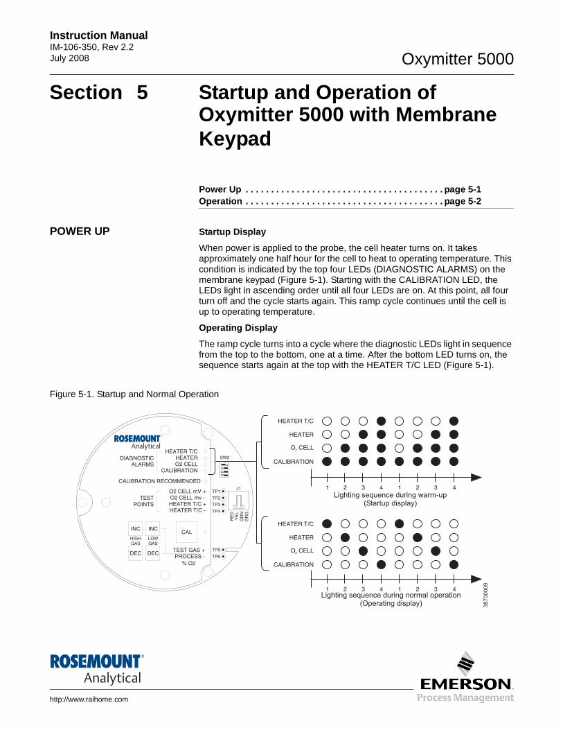
Instruction Manual IM-106-350, Rev 2.2July 2008 Oxymitter 5000
http://www.raihome.com
Section 5 Startup and Operation of Oxymitter 5000 with Membrane Keypad
Power Up . . . . . . . . . . . . . . . . . . . . . . . . . . . . . . . . . . . . . . . page 5-1Operation . . . . . . . . . . . . . . . . . . . . . . . . . . . . . . . . . . . . . . . page 5-2
POWER UP Startup Display
When power is applied to the probe, the cell heater turns on. It takes approximately one half hour for the cell to heat to operating temperature. This condition is indicated by the top four LEDs (DIAGNOSTIC ALARMS) on the membrane keypad (Figure 5-1). Starting with the CALIBRATION LED, the LEDs light in ascending order until all four LEDs are on. At this point, all four turn off and the cycle starts again. This ramp cycle continues until the cell is up to operating temperature.
Operating Display
The ramp cycle turns into a cycle where the diagnostic LEDs light in sequence from the top to the bottom, one at a time. After the bottom LED turns on, the sequence starts again at the top with the HEATER T/C LED (Figure 5-1).
Figure 5-1. Startup and Normal Operation
DIAGNOSTICALARMS
TESTPOINTS
HEATER T/CHEATERO2 CELL
CALIBRATION
CALIBRATION RECOMMENDED
O2 CELL mV +O2 CELL mv -HEATER T/C +HEATER T/C -
INC INC
DEC DEC
HIGHGAS
LOWGAS
CAL
TEST GAS +PROCESS -
% O2
SW2
TP1J1
TP2
TP3
RE
DY
EL
GR
NO
RG
TP4
TP5
TP6
ON
HEATER T/C
HEATER
O CELL2
CALIBRATION
1 2 3 4 1 2 3 4
HEATER T/C
HEATER
O CELL2
CALIBRATION
1 2 3 4 1 2 3 4
Lighting sequence during normal operation(Operating display)
Lighting sequence during warm-up(Startup display)
38
73
00
09
Oxymitter 5000
5-2
Instruction ManualIM-106-350, Rev 2.2
July 2008
Error
If there is an error condition at startup, one of the diagnostics LEDs will be blinking. Refer to Section 8: Troubleshooting, to determine the cause of the error. Clear the error, cycle power, and the operating display should return.
Keypad
The five membrane keys on the membrane keypad are only used during calibration to adjust the high and low gas and to initiate the calibration sequence (Figure 5-2).
Reference Air
Ensure reference air, if used, is set to 1 l/min (2 scfh)
OPERATION
Overview Ensure the Oxymitter 5000 is at normal operation. The diagnostic LEDs will display the operating cycle. All other LEDs should be off (Figure 5-1).
DIAGNOSTIC ALARM LEDs
If there is an error in the system, one of these LEDs will flash various blink codes (Section 8: Troubleshooting). In the case of multiple errors, only one will be displayed based on a priority system. Correct the problem and cycle power. The operating display will return or the next error will be displayed. The alarms are:
HEATER T/CHEATERO2 CELLCALIBRATION
CALIBRATION RECOMMENDED LED
Turns on when the system determines that a calibration is recommended. Further information is available in Section 9: Maintenance and Service.
TEST POINTS
Test points 1 through 6 will allow you to monitor with a multimeter: the heater thermocouple, O2 cell millivolt, and the process O2.
1. TP1 and TP2 monitor the oxygen cell millivolt output which equates to the percentage of oxygen present.
2. TP3 and TP4 monitor the heater thermocouple.
3. TP5 and TP6 monitor the process gas or the calibration gas parameter.
CAL LED
The CAL LED is on steady or flashing during calibration. Further information is available in Section 9: Maintenance and Service.
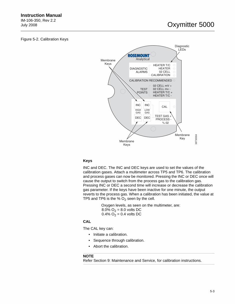
Instruction Manual IM-106-350, Rev 2.2July 2008
5-3
Oxymitter 5000
Figure 5-2. Calibration Keys
Keys
INC and DEC. The INC and DEC keys are used to set the values of the calibration gases. Attach a multimeter across TP5 and TP6. The calibration and process gases can now be monitored. Pressing the INC or DEC once will cause the output to switch from the process gas to the calibration gas. Pressing INC or DEC a second time will increase or decrease the calibration gas parameter. If the keys have been inactive for one minute, the output reverts to the process gas. When a calibration has been initiated, the value at TP5 and TP6 is the % O2 seen by the cell.
Oxygen levels, as seen on the multimeter, are:8.0% O2 = 8.0 volts DC0.4% O2 = 0.4 volts DC
CAL
The CAL key can:
• Initiate a calibration.
• Sequence through calibration.
• Abort the calibration.
NOTERefer Section 9: Maintenance and Service, for calibration instructions.
DIAGNOSTICALARMS
TESTPOINTS
HEATER T/CHEATER02 CELL
CALIBRATION
CALIBRATION RECOMMENDED
02 CELL mV +02 CELL mv -HEATER T/C +HEATER T/C -
INC INC
DEC DEC
HIGHGAS
LOWGAS
CAL
TEST GAS +PROCESS -
% 02
MembraneKeys
MembraneKeys
MembraneKey
DiagnosticLEDs
38
73
00
04

Oxymitter 5000
5-4
Instruction ManualIM-106-350, Rev 2.2
July 2008
Instruction Manual IM-106-350, Rev 2.2July 2008 Oxymitter 5000
http://www.raihome.com
Section 6 Startup and Operation of Oxymitter 5000 with LOI
Power Up . . . . . . . . . . . . . . . . . . . . . . . . . . . . . . . . . . . . . . . page 6-1Start Up Oxymitter 5000 Calibration . . . . . . . . . . . . . . . . . page 6-3Navigating the Local Operator Interface . . . . . . . . . . . . . page 6-3LOI Key Designations . . . . . . . . . . . . . . . . . . . . . . . . . . . . . page 6-4LOI Menu Tree . . . . . . . . . . . . . . . . . . . . . . . . . . . . . . . . . . . page 6-4Oxymitter 5000 Setup at the LOI . . . . . . . . . . . . . . . . . . . . page 6-6LOI Installation . . . . . . . . . . . . . . . . . . . . . . . . . . . . . . . . . . page 6-9Oxymitter 5000 Test Points . . . . . . . . . . . . . . . . . . . . . . . . page 6-10
POWER UP Startup Display
When power is applied to the probe, the cell heater turns on. It takes approximately one half hour for the cell to heat to operating temperature. This condition is indicated by a "warm up" display on the LOI (Figure 6-1). This message will continue to display until the cell is up to operating temperature.
Operating Display
The normal operating display is the % O2 concentration. The "normal" display is shown in Figure 6-2.
Error
If there is an error condition at startup, an alarm message will be displayed. Refer to Section 8: Troubleshooting, to determine the cause of the error. Clear the error, cycle power, and the % O2 display should return.
LOI
The Local Operator Interface can be used to change the software and alarm settings, to adjust the high and low gas settings, and to initiate the calibration sequence. Refer to the LOI menu (Figure 6-4).
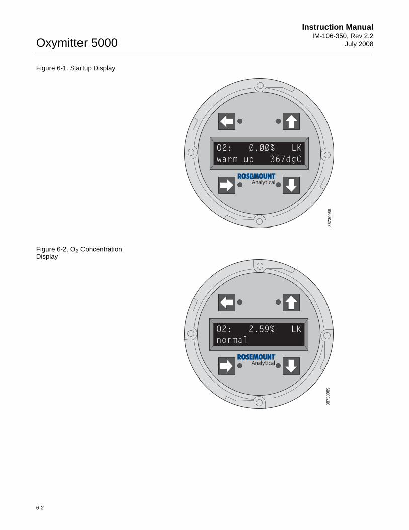
Oxymitter 5000
6-2
Instruction ManualIM-106-350, Rev 2.2
July 2008
Figure 6-1. Startup Display
Figure 6-2. O2 Concentration Display
O2: Ø.ØØ% LK
warm up 367dgC
38
73
00
88
38
73
00
89
O2: 2.59% LK
normal
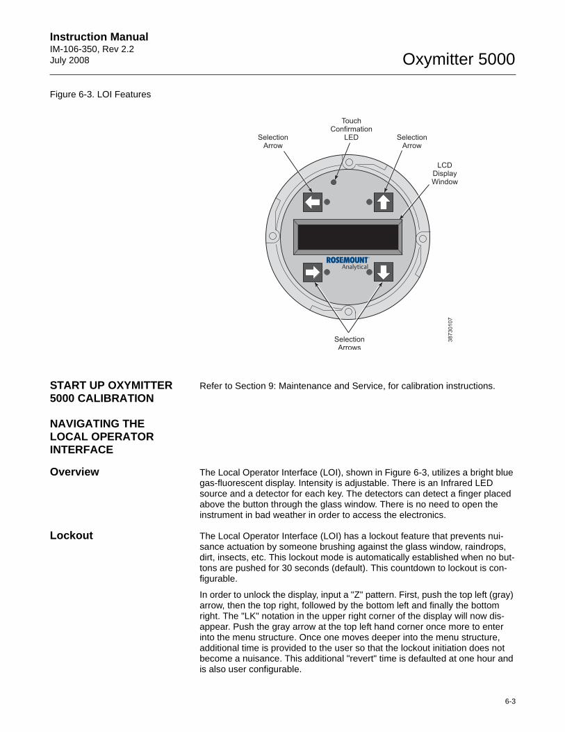
Instruction Manual IM-106-350, Rev 2.2July 2008
6-3
Oxymitter 5000
Figure 6-3. LOI Features
START UP OXYMITTER 5000 CALIBRATION
Refer to Section 9: Maintenance and Service, for calibration instructions.
NAVIGATING THE LOCAL OPERATOR INTERFACE
Overview The Local Operator Interface (LOI), shown in Figure 6-3, utilizes a bright blue gas-fluorescent display. Intensity is adjustable. There is an Infrared LED source and a detector for each key. The detectors can detect a finger placed above the button through the glass window. There is no need to open the instrument in bad weather in order to access the electronics.
Lockout The Local Operator Interface (LOI) has a lockout feature that prevents nui-sance actuation by someone brushing against the glass window, raindrops, dirt, insects, etc. This lockout mode is automatically established when no but-tons are pushed for 30 seconds (default). This countdown to lockout is con-figurable.
In order to unlock the display, input a "Z" pattern. First, push the top left (gray) arrow, then the top right, followed by the bottom left and finally the bottom right. The "LK" notation in the upper right corner of the display will now dis-appear. Push the gray arrow at the top left hand corner once more to enter into the menu structure. Once one moves deeper into the menu structure, additional time is provided to the user so that the lockout initiation does not become a nuisance. This additional "revert" time is defaulted at one hour and is also user configurable.
38730107
SelectionArrow
TouchConfirmation
LED
LCDDisplayWindow
SelectionArrow
SelectionArrows
Oxymitter 5000
6-4
Instruction ManualIM-106-350, Rev 2.2
July 2008
NOTEAlways clean dust and soil away from the LOI screen each time the LOI is used. Excessive dust can prevent the LOI from entering lockout. This condition can cause uncommanded operations to occur.
LOI KEY DESIGNATIONS The gray key (top left) will move one level higher in the menu structure. When entering numbers, this key will move the cursor to the left. This key also dou-bles as an "Enter" key, once numbers are entered, and when the cursor is moved to its left-most position. The new data entry value will appear in the top line of the LOI display once it is accepted.
The blue key (bottom left) acts as a selector when choosing from among a number of menu items. This key will move the cursor to the right when enter-ing numbers.
Up/Down keys (to the left side of the keypad) are used to increment up and down when selecting from a series of menu picks. They are used for incrementing values up and down for data input.
LOI MENU TREE This LOI menu for the Oxymitter 5000 is shown in Figure 6-4. This menu tree is specific to the Oxymitter 5000. The menu tree will assist in navigating the LOI.
Menu items in normal text display information only. Menu items in italics per-mit data entry. Menu items in bold text are procedures.
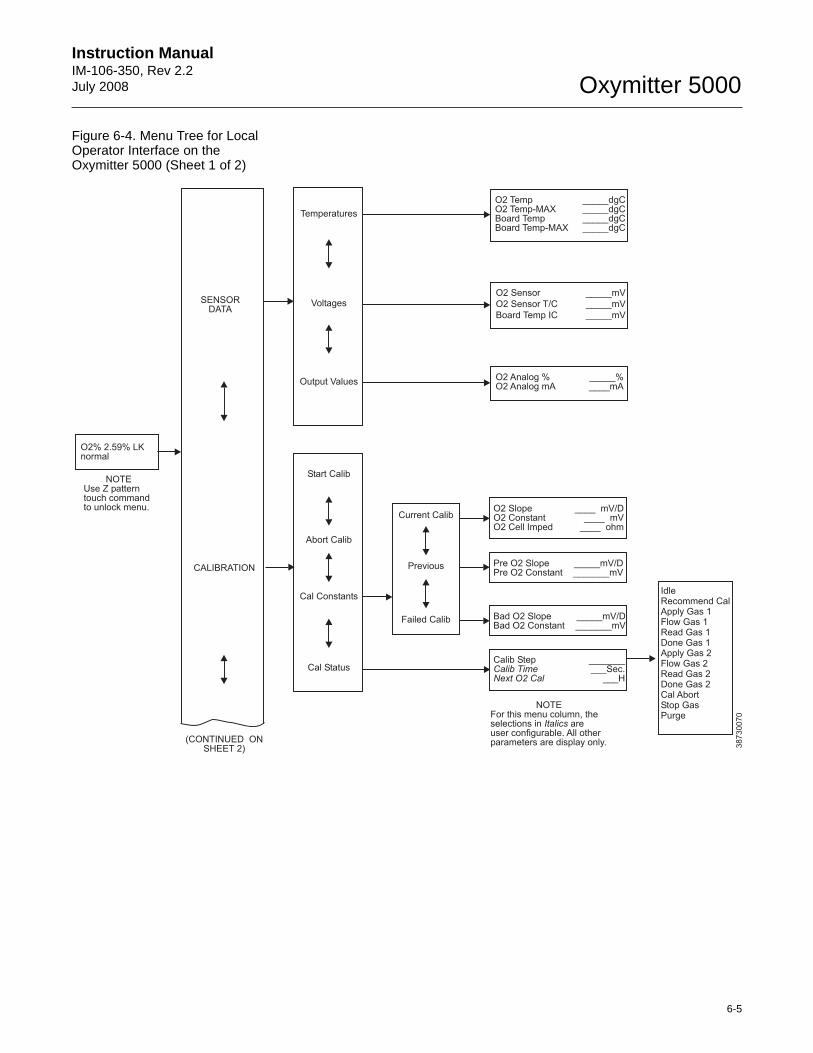
Instruction Manual IM-106-350, Rev 2.2July 2008
6-5
Oxymitter 5000
Figure 6-4. Menu Tree for Local Operator Interface on the Oxymitter 5000 (Sheet 1 of 2)
Temperatures
SENSORDATA
Voltages
O2 Analog % _____%O2 Analog mA ____mA
Output Values
O2 2.59% LKnormal
%
38
73
00
70
(CONTINUED ONSHEET 2)
O2 Temp _____dgCO2 Temp-MAX _____dgCBoard Temp _____dgCBoard Temp-MAX _____dgC
O2 Sensor _____mV
O2 Sensor T/C _____mV
Board Temp IC _____mV
CALIBRATION
Start Calib
Abort Calib
Cal Constants
O2 Slope ____ mV/DO2 Constant ____ mVO2 Cell Imped ____ ohm
Cal Status
Current Calib
Previous
Failed Calib
Pre O2 Slope _____mV/DPre O2 Constant _______mV
Bad O2 Slope _____mV/DBad O2 Constant _______mV
Calib Step __________Sec.
___HCalib TimeNext O2 Cal
NOTEFor this menu column, theselections in areuser configurable. All otherparameters are display only.
Italics
IdleRecommend CalApply Gas 1Flow Gas 1Read Gas 1Done Gas 1Apply Gas 2Flow Gas 2Read Gas 2Done Gas 2Cal AbortStop GasPurge
NOTEUse Z patterntouch commandto unlock menu.
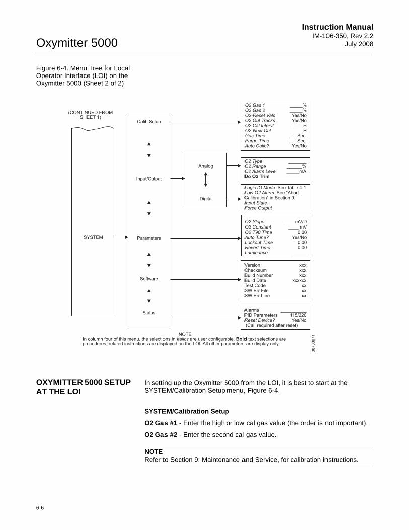
Oxymitter 5000
6-6
Instruction ManualIM-106-350, Rev 2.2
July 2008
Figure 6-4. Menu Tree for Local Operator Interface (LOI) on the Oxymitter 5000 (Sheet 2 of 2)
OXYMITTER 5000 SETUP AT THE LOI
In setting up the Oxymitter 5000 from the LOI, it is best to start at the SYSTEM/Calibration Setup menu, Figure 6-4.
SYSTEM/Calibration Setup
O2 Gas #1 - Enter the high or low cal gas value (the order is not important).
O2 Gas #2 - Enter the second cal gas value.
NOTERefer to Section 9: Maintenance and Service, for calibration instructions.
SYSTEM
O2 Gas 1O2 Gas 2O2-Reset ValsO2O2 Cal IntervlO2-Gas TimePurge Time
_____%_____%
____H
___Sec.
Yes/NoYes/No
____H
___Sec.Yes/No
Out Tracks
Next Cal
Auto Calib?
O2 TypeO2 RangeO2 Alarm Leve
_____________%
l _____mADo O2 Trim
Calib Setup
Input/Output
Parameters
Status
Software
38730071
(CONTINUED FROMSHEET 1)
Analog
Digital
NOTEIn column four of this menu, the selections in are user configurable. text selections areprocedures; related instructions are displayed on the LOI. All other parameters are display only.
Italics Bold
Version xxxChecksum xxxBuild Number xxxBuild Date xxxxxxTest Code xxSW Err File xxSW Err Line xx
Alarms __________PID Parameters 115/220
Yes/No(Cal. required after reset)Reset Device?
O2 SlopeO2 ConstantO2 T90 TimeAuto Tune?Lockout TimeRevert TimeLuminance
____ mV/D____ mV
0:00Yes/No
0:000:00
______
Logic IO ModeLow O2 Alarm
Input StateForce Output
See Table 4-1See “Abort
Calibration” in Section 9.
Instruction Manual IM-106-350, Rev 2.2July 2008
6-7
Oxymitter 5000
NOTEEmerson Process Management recommends 0.4% O2 and 8% O2 for calibration gases.
O2 Reset Values - Resets factory default values.
O2 Cal Interval - If automatic calibration is selected, this selects the interval between calibrations.
O2 Next Cal - If automatic calibration is selected, this selects the time until the first initial calibration takes place.
Gas Time - How long should each cal gas flow. Factory default is 300 seconds, but the user may want to vary this depending on the length of calibration gas tubing runs.
Purge Time - Used if the O2 output is selected to hold the last value during calibration. After the second cal gas is removed, how long until the sensor comes back to the normal process reading, and the fieldbus digital signal can be released.
Auto Calib? - Select "Yes" if an SPS or IMPS autocalibration system is part of the system.
SYSTEM/Input/Output
Analog
Pertaining to the analog fieldbus digital signal representing O2.
O2 Type - Fieldbus digital signal may be configured to increase with increasing O2 or the reverse.
O2 Range - Upper O2 range is user selectable.
O2 Alarm Level - User can configure the digital output to alarm at a given O2 level.
Digital
A bi-directional logic signal may be configured as an alarm, or as a calibration handshake signal.
Logic I/O Mode - One of 9 different sets of conditions can be set for the digital signal. See Table 8-2.
Low O2 Alarm - If any of the conditions noted above include a low O2 process alarm, set the value here.
Input State - Notes the current condition of the bi-directional digital signal.
Force Output - Forces the output state of the signal to either open or closed. This is used primarily when diagnosing potential problems with this signal.
SYSTEM/Parameters
O2 Slope - O2 slope is data regarding the strength of the sensing cell output. This information is automatically calculated after a calibration, and the user does not normally input this data.
Oxymitter 5000
6-8
Instruction ManualIM-106-350, Rev 2.2
July 2008
O2 Constant - O2 constant is the amount of voltage a cell generates with ambient air as the calibration gas. Again, this is normally calculated as a result of calibration, and is not normally input by the user.
O2 T90 Time - Some users may feel that the O2 reading is too active for certain processes. This feature permits the user to dampen the O2 signal. The default value is zero seconds dampening.
Auto Tune - The electronics detects the line voltage powering the instrument automatically and picks proper algorithms for heater control. User can force a high voltage algorithm, or a low, but Auto Tune is the default, and is recommended.
Lockout Time - Keypad lockout time default is 30 sec., but it is user configurable. A "Z" keypad pattern will unlock the keypad.
Revert Time - Once a user goes one level deep into the menu structure, an additional "revert time" is provided to prevent nuisance lockouts. One hour is the default, and it is user configurable.
Luminance - Gas fluorescence brightness is user adjustable.
SYSTEM/Status
Alarms - Diagnostic alarms. Section 8: Troubleshooting.
PID Parameter - Displays the line voltage, powering the Oxymitter, and infers the temperature control algorithm being used to control heater temperature.
Reset Device - Device can be reset here as opposed to re-powering. Calibration parameters will be lost.
SYSTEM/Software
This is data regarding the Oxymitter 5000 software version, and errors that may have occurred.
SENSOR DATA
Displays information about the O2 cell and thermocouple.
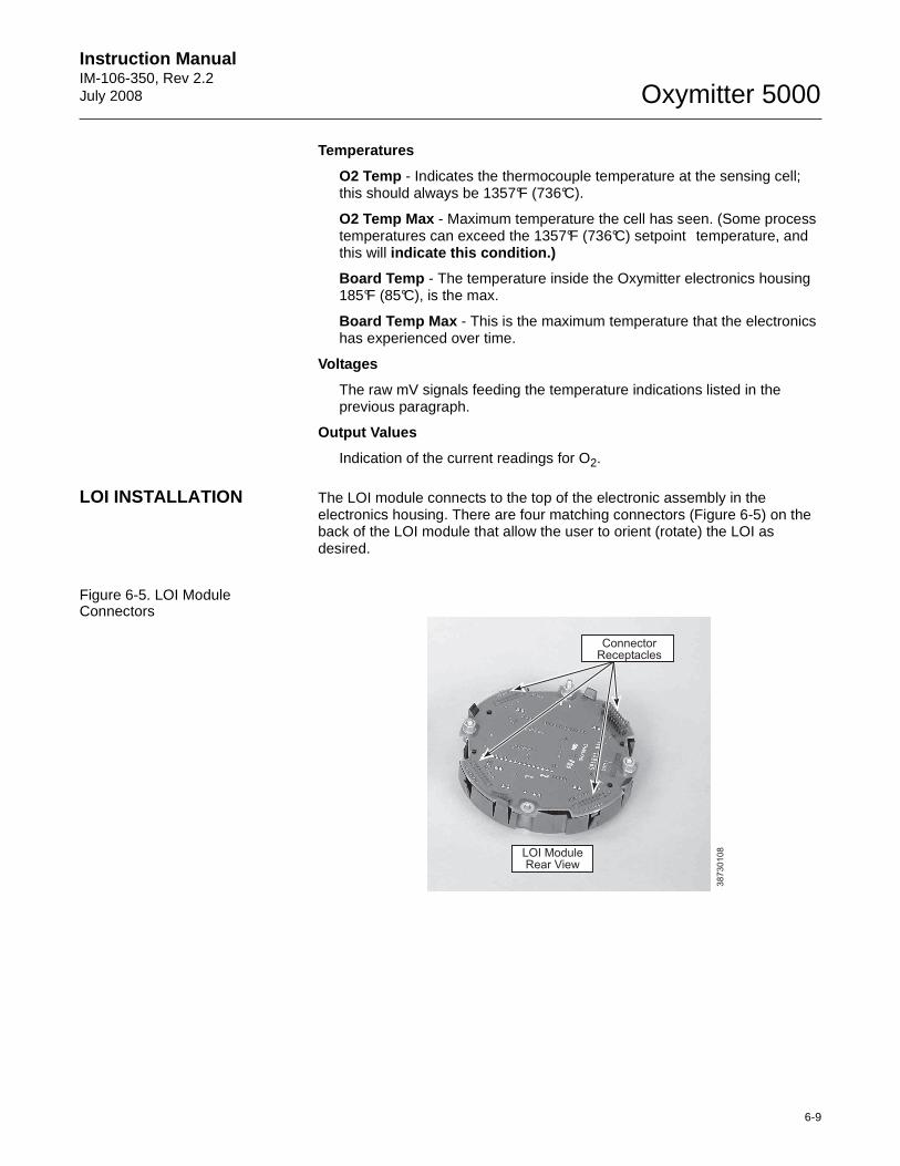
Instruction Manual IM-106-350, Rev 2.2July 2008
6-9
Oxymitter 5000
Temperatures
O2 Temp - Indicates the thermocouple temperature at the sensing cell; this should always be 1357°F (736°C).
O2 Temp Max - Maximum temperature the cell has seen. (Some process temperatures can exceed the 1357°F (736°C) setpoint temperature, and this will indicate this condition.)
Board Temp - The temperature inside the Oxymitter electronics housing 185°F (85°C), is the max.
Board Temp Max - This is the maximum temperature that the electronics has experienced over time.
Voltages
The raw mV signals feeding the temperature indications listed in the previous paragraph.
Output Values
Indication of the current readings for O2.
LOI INSTALLATION The LOI module connects to the top of the electronic assembly in the electronics housing. There are four matching connectors (Figure 6-5) on the back of the LOI module that allow the user to orient (rotate) the LOI as desired.
Figure 6-5. LOI Module Connectors
38
73
01
08
ConnectorReceptacles
LOI ModuleRear View
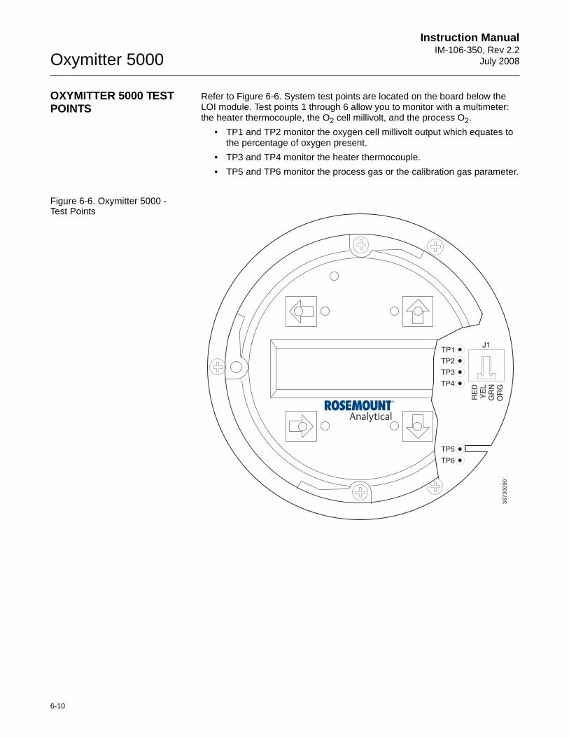
Oxymitter 5000
6-10
Instruction ManualIM-106-350, Rev 2.2
July 2008
OXYMITTER 5000 TEST POINTS
Refer to Figure 6-6. System test points are located on the board below the LOI module. Test points 1 through 6 allow you to monitor with a multimeter: the heater thermocouple, the O2 cell millivolt, and the process O2.
• TP1 and TP2 monitor the oxygen cell millivolt output which equates to the percentage of oxygen present.
• TP3 and TP4 monitor the heater thermocouple.
• TP5 and TP6 monitor the process gas or the calibration gas parameter.
Figure 6-6. Oxymitter 5000 - Test Points
38
73
00
90
TP1J1
TP2
TP3
RE
DY
EL
GR
NO
RG
TP4
TP5
TP6
Instruction Manual IM-106-350, Rev 2.2July 2008 Oxymitter 5000
http://www.raihome.com
Section 7 Model 375 Handheld CommunicatorOverview . . . . . . . . . . . . . . . . . . . . . . . . . . . . . . . . . . . . . . . page 7-1Fieldbus Terminal Block Connections . . . . . . . . . . . . . . . page 7-1Off-Line and On-Line Operations . . . . . . . . . . . . . . . . . . . page 7-2Logic I/O Configurations . . . . . . . . . . . . . . . . . . . . . . . . . . page 7-3Fieldbus Menu Tree . . . . . . . . . . . . . . . . . . . . . . . . . . . . . . page 7-4FOUNDATION Fieldbus O 2 CAL Method . . . . . . . . . . . . . . page 7-5
OVERVIEW The Model 375 Handheld Communicator is a communications interface device. It provides a common communications link to all microprocessor-based instruments. The handheld communicator contains an 8 x 21 character liquid crystal display (LCD) and 25 keys. A pocket-sized manual, included with the communicator, details the specific functions of all the keys.
To interface with the Oxymitter 5000 the communicator requires a termination point along a common terminal block with the Oxymitter 5000. The Handheld Communicator accomplishes this task by using a fieldbus digital signal to net-work the components.
The Handheld Communicator may be interfaced with a personal computer (PC), providing that special software has been installed. To connect the Hand-held Communicator to a PC an interface adapter is required.
Refer to the proper Handheld Communicator documentation in regard to the PC interface option.
FIELDBUS TERMINAL BLOCK CONNECTIONS
Any device implemented into the system is routed through the fieldbus termi-nal block. The Handheld Communicator uses the supplied lead set to connect to the terminal block while the Oxymitter 5000 uses the wires connected to the probe as shown in Figure 7-1. To interface the Handheld Communicator with a personal computer load the designated AMS software into the PC. Then connect the PC to the terminal block as shown in Figure 7-1.
Refer to the proper Handheld Communicator documentation in regard to the PC interface option.
Explosions can result in death or serious injury. Do not make connections to the Handheld Communicator's serial port, digital signal line, or NiCad recharger jack in an explosive atmosphere.
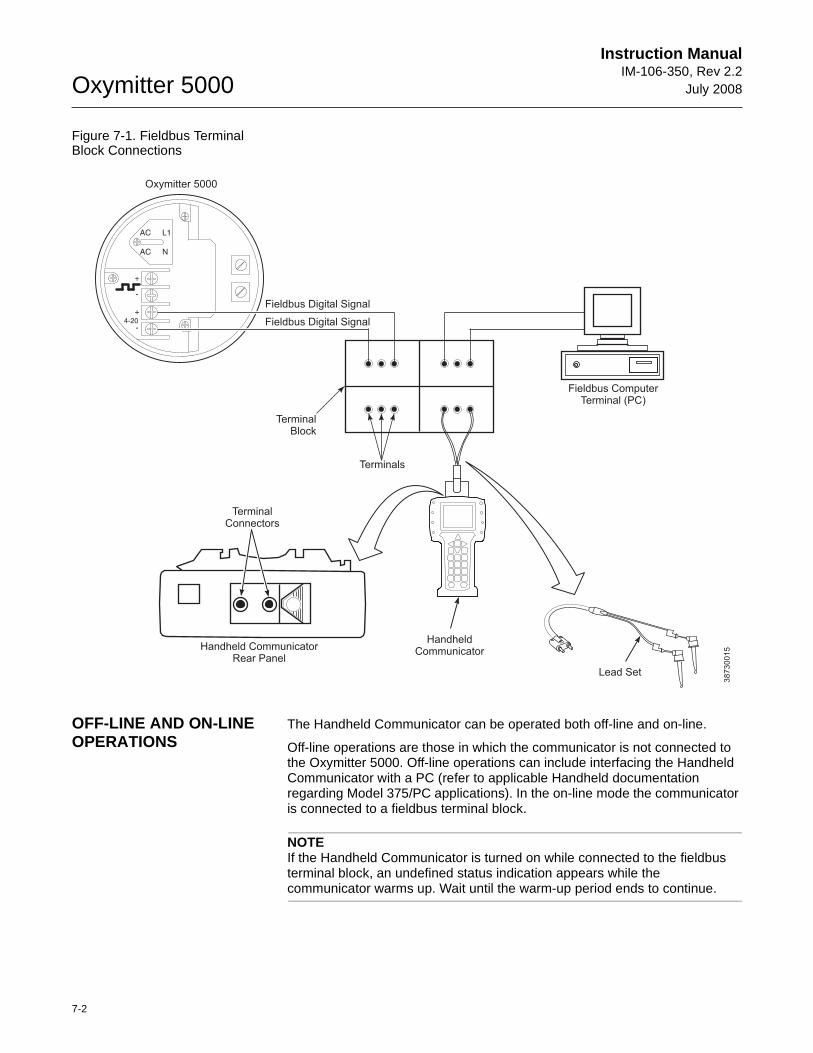
Oxymitter 5000
7-2
Instruction ManualIM-106-350, Rev 2.2
July 2008
Figure 7-1. Fieldbus Terminal Block Connections
OFF-LINE AND ON-LINE OPERATIONS
The Handheld Communicator can be operated both off-line and on-line.
Off-line operations are those in which the communicator is not connected to the Oxymitter 5000. Off-line operations can include interfacing the Handheld Communicator with a PC (refer to applicable Handheld documentation regarding Model 375/PC applications). In the on-line mode the communicator is connected to a fieldbus terminal block.
NOTEIf the Handheld Communicator is turned on while connected to the fieldbus terminal block, an undefined status indication appears while the communicator warms up. Wait until the warm-up period ends to continue.
38730015
AC L1
AC N
+
+
-
-4-20
Fieldbus Digital Signal
HandheldCommunicator
Lead Set
Handheld CommunicatorRear Panel
TerminalBlock
Terminals
Oxymitter 5000
Fieldbus Digital Signal
TerminalConnectors
Fieldbus ComputerTerminal (PC)
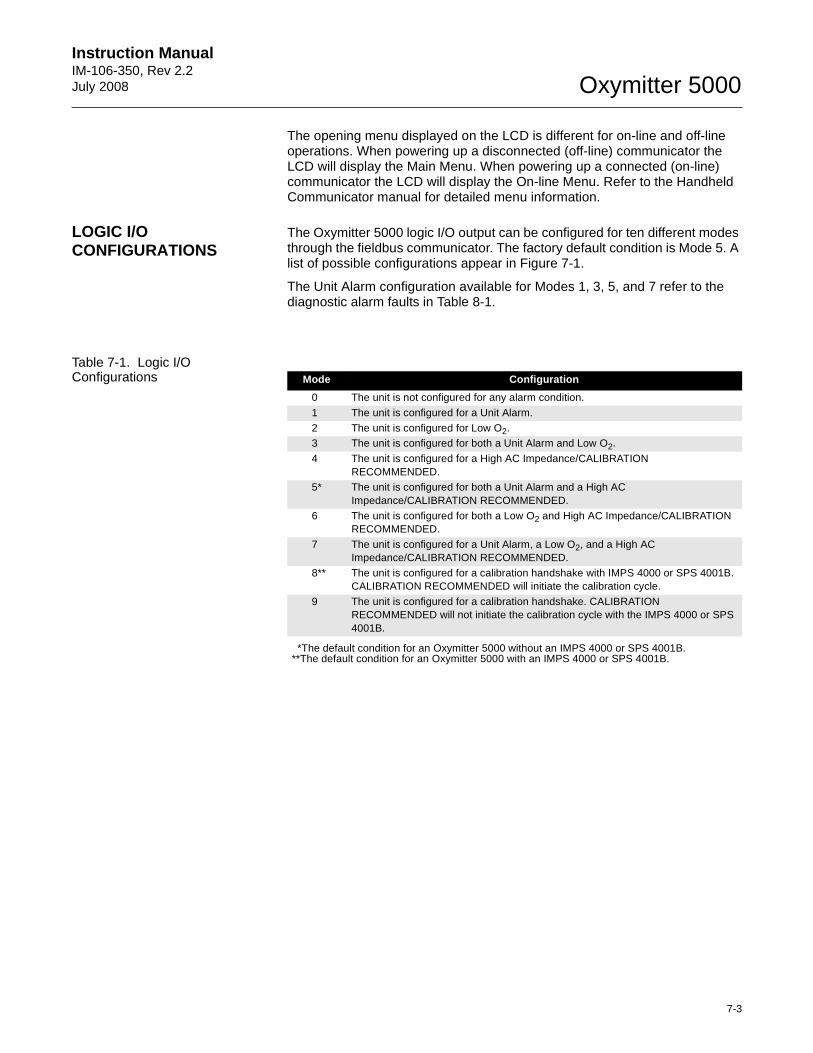
Instruction Manual IM-106-350, Rev 2.2July 2008
7-3
Oxymitter 5000
The opening menu displayed on the LCD is different for on-line and off-line operations. When powering up a disconnected (off-line) communicator the LCD will display the Main Menu. When powering up a connected (on-line) communicator the LCD will display the On-line Menu. Refer to the Handheld Communicator manual for detailed menu information.
LOGIC I/O CONFIGURATIONS
The Oxymitter 5000 logic I/O output can be configured for ten different modes through the fieldbus communicator. The factory default condition is Mode 5. A list of possible configurations appear in Figure 7-1.
The Unit Alarm configuration available for Modes 1, 3, 5, and 7 refer to the diagnostic alarm faults in Table 8-1.
Table 7-1. Logic I/O Configurations
*The default condition for an Oxymitter 5000 without an IMPS 4000 or SPS 4001B.**The default condition for an Oxymitter 5000 with an IMPS 4000 or SPS 4001B.
Mode Configuration
0 The unit is not configured for any alarm condition.
1 The unit is configured for a Unit Alarm.
2 The unit is configured for Low O2.3 The unit is configured for both a Unit Alarm and Low O2.
4 The unit is configured for a High AC Impedance/CALIBRATION RECOMMENDED.
5* The unit is configured for both a Unit Alarm and a High AC Impedance/CALIBRATION RECOMMENDED.
6 The unit is configured for both a Low O2 and High AC Impedance/CALIBRATION RECOMMENDED.
7 The unit is configured for a Unit Alarm, a Low O2, and a High AC Impedance/CALIBRATION RECOMMENDED.
8** The unit is configured for a calibration handshake with IMPS 4000 or SPS 4001B. CALIBRATION RECOMMENDED will initiate the calibration cycle.
9 The unit is configured for a calibration handshake. CALIBRATION RECOMMENDED will not initiate the calibration cycle with the IMPS 4000 or SPS 4001B.
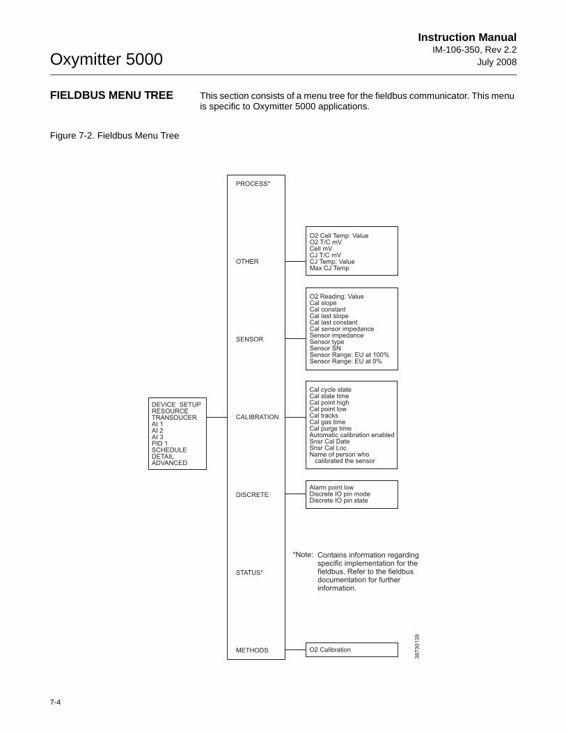
Oxymitter 5000
7-4
Instruction ManualIM-106-350, Rev 2.2
July 2008
FIELDBUS MENU TREE This section consists of a menu tree for the fieldbus communicator. This menu is specific to Oxymitter 5000 applications.
Figure 7-2. Fieldbus Menu Tree
DEVICE SETUPRESOURCETRANSDUCERAI 1AI 2AI 3PID 1SCHEDULEDETAILADVANCED
38730139
PROCESS*
OTHER
SENSOR
CALIBRATION
DISCRETE
STATUS*
METHODS
O2 Cell Temp: ValueO2 T/C mVCell mVCJ T/C mVCJ Temp: ValueMax CJ Temp
O2 Reading: ValueCal slopeCal constantCal last slopeCal last constantCal sensor impedanceSensor impedanceSensor typeSensor SNSensor Range: EU at 100%Sensor Range: EU at 0%
Cal cycle stateCal state timeCal point highCal point lowCal tracksCal gas timeCal purge timeAutomatic calibration enabledSnsr Cal DateSnsr Cal LocName of person who
calibrated the sensor
Contains information regardingspecific implementation for thefieldbus. Refer to the fieldbusdocumentation for furtherinformation.
*Note:
Alarm point lowDiscrete IO pin modeDiscrete IO pin state
O2 Calibration
Instruction Manual IM-106-350, Rev 2.2July 2008
7-5
Oxymitter 5000
FOUNDATION FIELDBUS O2 CAL METHOD
To perform a calibration using the FOUNDATION fieldbus use the following procedure.
1. From the computer running the fieldbus control program, run the O2 Cal Method.
2. In the first O2 CAL screen, a "Loop should be removed from automatic control" warning appears. Remove the Oxymitter 5000 from any automatic control loops to avoid a potentially dangerous operating condition and press OK.
3. From this point follow the on-screen prompts to complete the calibration procedure. When a step is complete select Proceed to Next Step and press the Next button.
4. During the wait periods, such as during a purge, the Time Remaining display may be updated by selecting Update and pressing Next button.
Failure to remove the Oxymitter 5000 from automatic control loops prior to performing this procedure may result in dangerous operating conditions.

Oxymitter 5000
7-6
Instruction ManualIM-106-350, Rev 2.2
July 2008
Instruction Manual IM-106-350, Rev 2.2July 2008 Oxymitter 5000
http://www.raihome.com
Section 8 Troubleshooting
Overview . . . . . . . . . . . . . . . . . . . . . . . . . . . . . . . . . . . . . . . page 8-1General . . . . . . . . . . . . . . . . . . . . . . . . . . . . . . . . . . . . . . . . page 8-3Alarm Indications . . . . . . . . . . . . . . . . . . . . . . . . . . . . . . . . page 8-3Alarm Contacts . . . . . . . . . . . . . . . . . . . . . . . . . . . . . . . . . . page 8-4Identifying and Correcting Alarm Indications . . . . . . . . . page 8-5Heater Not Open, but Unable to Reach 736°C Setpoint . page 8-22Calibration Passes but Still Reads Incorrectly . . . . . . . . page 8-22
OVERVIEW While the Oxymitter 5000 electronics provides a significant number of diagnostic alarms to assist in troubleshooting potential problems, it is good to place these alarms in perspective with respect to the instrument's operating principles:
When the Zirconium Oxide sensing cell is heated to its setpoint [1357°F (736°C)], the cell will generate a voltage that rep resents the difference between the process O2% and the reference O2% inside the probe (20.95% O2 ambient air).
Test points, Figure 8-1, are provided to read the raw millivolt value generated by the thermocouple that controls the cell temperature and also the raw cell signal.
The cell temperature at test points 3 and 4 should always be stable at approximately 29 to 30 millivolts, which represent the [1357°F (736°C)] setpoint temperature.
When flowing calibration gasses, the raw cell millivolt value at test points 1 and 2 should represent the levels on the chart in Figure 8-1. Note that the raw cell millivolt value increases logarithmically as the O2 concentration decreases.

Oxymitter 5000
8-2
Instruction ManualIM-106-350, Rev 2.2
July 2008
Figure 8-1. O2 Sensor mV Reading vs. % O2 at 1357°F (736°C) (Reference Air, 20.9% O2)
38730096
1001010.01 0.100
50
100
150
200
Concentration O (%)2
EM
F (
mV
)
O Sensor Performance at 13572
OF (736
OC)
O2 % 100 20 15 10 9 8 7 6 5 4
EMF(mV) -34 1.0 7.25 16.1 18.4 21.1 23.8 27.2 31.2 36.0
O2 % 3 2 1 0.8 0.6 0.5 0.4 0.2 0.1 0.01
EMF(mV) 42.3 51.1 66.1 71.0 77.5 81.5 86.3 101.4 116.6 166.8
Instruction Manual IM-106-350, Rev 2.2July 2008
8-3
Oxymitter 5000
GENERAL The troubleshooting section describes how to identify and isolate faults that may develop in the Oxymitter 5000. When troubleshooting, reference the following.
GroundingIt is essential that adequate grounding precautions are taken when installing the system. Thoroughly check both the probe and electronics to ensure the grounding quality has not degraded during fault finding. The system provides facilities for 100% effective grounding and the total elimination of ground loops.
Electrical NoiseThe Oxymitter 5000 has been designed to operate in the type of environment normally found in a boiler room or control room. Noise suppression circuits are employed on all field terminations and main inputs. When fault finding, evaluate the electrical noise being generated in the immediate circuitry of a faulty system. Ensure all cable shields are connected to earth.
Loose Integrated CircuitsThe Oxymitter 5000 uses a microprocessor and supporting integrated circuits (IC). If the electronics are handled roughly during installation or located where subjected to severe vibration, the ICs could work loose. Before troubleshoot-ing the system, ensure all ICs are fully seated.
Electrostatic DischargeElectrostatic discharge can damage the ICs used in the electronics. Before removing or handling the processor board or the ICs, ensure you are at ground potential.
ALARM INDICATIONS Once an alarm condition is identified, the Oxymitter 5000 electronics offers a number of diagnostics to interpret the specific alarm.
If the Oxymitter 5000 has the simple keypad operator interface, the majority of fault conditions will be indicated by one of the four LEDs referred to as diagnostic, or unit alarms on the operator's keypad (Figure 8-2). An LED will flash a code that will correspond to an error message. Only one LED will blink at a time. An alarm code guide is provided inside the screw-on cover for the electronics.
Alarm indications will also be available via fieldbus computer terminal or the optional LOI. When the error is corrected and/or power is cycled, the diagnos-tic alarms will clear or the next error on the priority list will appear.
Install all protective equipment covers and safety ground leads after troubleshooting. Failure to install covers and ground leads could result in serious injury or death.
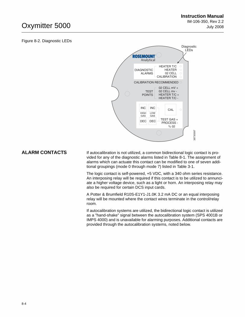
Oxymitter 5000
8-4
Instruction ManualIM-106-350, Rev 2.2
July 2008
Figure 8-2. Diagnostic LEDs
ALARM CONTACTS If autocalibration is not utilized, a common bidirectional logic contact is pro-vided for any of the diagnostic alarms listed in Table 8-1. The assignment of alarms which can actuate this contact can be modified to one of seven addi-tional groupings (mode 0 through mode 7) listed in Table 3-1.
The logic contact is self-powered, +5 VDC, with a 340 ohm series resistance. An interposing relay will be required if this contact is to be utilized to annunci-ate a higher voltage device, such as a light or horn. An interposing relay may also be required for certain DCS input cards.
A Potter & Brumfield R10S-E1Y1-J1.0K 3.2 mA DC or an equal interposing relay will be mounted where the contact wires terminate in the control/relay room.
If autocalibration systems are utilized, the bidirectional logic contact is utilized as a "hand-shake" signal between the autocalibration system (SPS 4001B or IMPS 4000) and is unavailable for alarming purposes. Additional contacts are provided through the autocalibration systems, noted below.
38
73
00
97
DIAGNOSTICALARMS
TESTPOINTS
HEATER T/CHEATER02 CELL
CALIBRATION
CALIBRATION RECOMMENDED
02 CELL mV +02 CELL mv -HEATER T/C +HEATER T/C -
INC INC
DEC DEC
HIGHGAS
LOWGAS
CAL
TEST GAS +PROCESS -
% 02
DiagnosticLEDs
Instruction Manual IM-106-350, Rev 2.2July 2008
8-5
Oxymitter 5000
SPS 4001B and IMPS 4000, 1-4 probes
• One contact closure per probe from the control room to the SPS 4001B or IMPS 4000 for "calibration initiate".
• One contact output per probe from the SPS 4001B or IMPS 4000 to the control room for "in calibration" notification.
• One contact output per probe from the SPS 4001B or IMPS 4000 to the control room for "calibration failed" notification. (Includes output from pressure switch indicating "cal gas bottles empty").
Additional IMPS 4000 Alarm Contacts
• One contact per IMPS 4000 for "low calibration gas flowing".
• One contact per IMPS 4000 for "high calibration gas flowing".
IDENTIFYING AND CORRECTING ALARM INDICATIONS
For an Oxymitter 5000 with a membrane keypad, faults are indicated by four diagnostic, or unit, alarm LEDs. A pattern of repeating blinks define the problem. A condensed table of the errors and the corresponding blink codes can be found on the inside right cover of the electronics housing. Table 8-1 also identifies the blink code and fault status of each LED.
For an Oxymitter 5000 with the optional LOI, alarm messages are displayed on the LOI display window when the alarm status display is accessed via the LOI menu. A listing of the alarm/fault messages and the related fault status descriptions and fault numbers are shown in Table 8-2.
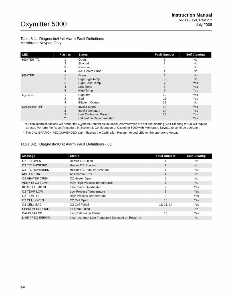
8-6
Instruction ManualIM-106-350, Rev 2.2
July 2008Oxymitter 5000
Table 8-1. Diagnostic/Unit Alarm Fault Definitions - Membrane Keypad Only
*Critical alarm conditions will render the O2 measurement as unusable. Alarms which are not self-clearing (Self-Clearing = NO) will require a reset. Perform the Reset Procedure in Section 3: Configuration of Oxymitter 5000 with Membrane Keypad to continue operation.
**The CALIBRATION RECOMMENDED alarm flashes the Calibration Recommended LED on the operator's keypad.
Table 8-2. Diagnostic/Unit Alarm Fault Definitions - LOI
LED Flashes Status Fault Number Self Clearing
HEATER T/C 1234
OpenShortedReversedA/D Comm Error
1234
NoNoNoNo
HEATER 12345
OpenHigh High TempHigh Case TempLow TempHigh Temp
56789
NoNoYesYesYes
O2 CELL 134
High mVBadEEprom Corrupt
101112
YesYesNo
CALIBRATION 123**
Invalid SlopeInvalid ConstantLast Calibration FailedCalibration Recommended
131415
YesYesYesYes
Message Status Fault Number Self Clearing
O2 T/C OPEN Heater T/C Open 1 No
O2 T/C SHORTED Heater T/C Shorted 2 No
O2 T/C REVERSED Heater T/C Polarity Reversed 3 No
ADC ERROR A/D Comm Error 4 No
O2 HEATER OPEN O2 Heater Open 5 NoVERY HI O2 TEMP Very High Process Temperature 6 No
BOARD TEMP HI Electronics Overheated 7 Yes
O2 TEMP LOW Low Process Temperature 8 Yes
O2 TEMP HI High Process Temperature 9 Yes
O2 CELL OPEN O2 Cell Open 10 Yes
O2 CELL BAD O2 Cell Failed 11, 13, 14 YesEEPROM CORRUPT EEprom Failed 12 No
CALIB FAILED Last Calibration Failed 15 Yes
LINE FREQ ERROR Incorrect Input Line Frequency Detected on Power Up No

Instruction Manual IM-106-350, Rev 2.2July 2008
8-7
Oxymitter 5000
Figure 8-3. Fault 1, Open ThermocoupleFault 1, Open Thermocouple
Figure 8-3 shows the electronic assembly for an Oxymitter 5000 with a membrane keypad (upper view) and a Oxymitter 5000 with an LOI (lower view). The upper view also shows J1 and test points TP1 through TP6, located on the microprocessor board, below the membrane keypad or the LOI module.
Membrane Keypad
When Fault 1 is detected, the HEATER T/C LED flashes once, pauses for three seconds, and repeats.
1. Check connector J1. Ensure the connector is properly seated.
2. Using a multimeter, measure the voltage from TP3+ to TP4-. If the reading is 1.2 VDC ±0.1 VDC, the thermocouple is open.
3. Remove power. Disconnect J1. Measure the resistance across the red and yellow thermocouple leads. The resistance should be approximately 1 ohm.
4. If the thermocouple is open, see "Heater Strut Replacement" in Section 9: Maintenance and Service.
LOI
When Fault 1 is detected, the LOI displays the "O2 T/C Open" message.
1. Remove power. Unscrew and remove the LOI module from the electronic assembly.
2. Reconnect power to the Oxymitter 5000.
3. Perform the diagnostic steps 1 through 4 shown for the membrane keypad.
38
73
00
72
LOI
KEYPAD
DIAGNOSTICALARMS
TESTPOINTS
HEATER T/CHEATERO2 CELL
CALIBRATION
CALIBRATION RECOMMENDED
O2 CELL mV +O2 CELL mv -HEATER T/C +HEATER T/C -
INC INC
DEC DEC
HIGHGAS
LOWGAS
CAL
TEST GAS +PROCESS -
% O2
SW2
TP1J1
TP2
TP3
RE
DY
EL
GR
NO
RG
TP4
TP5
TP6
ON
Alarms
O2 T/C Open
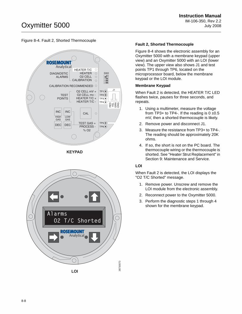
8-8
Instruction ManualIM-106-350, Rev 2.2
July 2008Oxymitter 5000
Figure 8-4. Fault 2, Shorted ThermocoupleFault 2, Shorted Thermocouple
Figure 8-4 shows the electronic assembly for an Oxymitter 5000 with a membrane keypad (upper view) and an Oxymitter 5000 with an LOI (lower view). The upper view also shows J1 and test points TP1 through TP6, located on the microprocessor board, below the membrane keypad or the LOI module.
Membrane Keypad
When Fault 2 is detected, the HEATER T/C LED flashes twice, pauses for three seconds, and repeats.
1. Using a multimeter, measure the voltage from TP3+ to TP4-. If the reading is 0 ±0.5 mV, then a shorted thermocouple is likely.
2. Remove power and disconnect J1.
3. Measure the resistance from TP3+ to TP4-. The reading should be approximately 20K ohms.
4. If so, the short is not on the PC board. The thermocouple wiring or the thermocouple is shorted. See "Heater Strut Replacement" in Section 9: Maintenance and Service.
LOI
When Fault 2 is detected, the LOI displays the "O2 T/C Shorted" message.
1. Remove power. Unscrew and remove the LOI module from the electronic assembly.
2. Reconnect power to the Oxymitter 5000.
3. Perform the diagnostic steps 1 through 4 shown for the membrane keypad.
38
73
00
73
LOI
KEYPAD
Alarms
O2 T/C Shorted
DIAGNOSTICALARMS
TESTPOINTS
HEATER T/CHEATERO2 CELL
CALIBRATION
CALIBRATION RECOMMENDED
O2 CELL mV +O2 CELL mv -HEATER T/C +HEATER T/C -
INC INC
DEC DEC
HIGHGAS
LOWGAS
CAL
TEST GAS +PROCESS -
% O2
SW2
TP1J1
TP2
TP3
RE
DY
EL
GR
NO
RG
TP4
TP5
TP6
ON
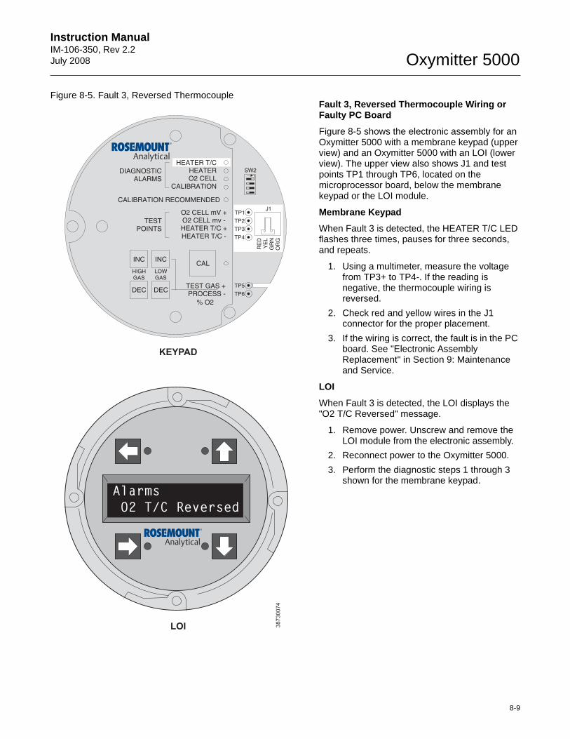
Instruction Manual IM-106-350, Rev 2.2July 2008
8-9
Oxymitter 5000
Figure 8-5. Fault 3, Reversed ThermocoupleFault 3, Reversed Thermocouple Wiring or Faulty PC Board
Figure 8-5 shows the electronic assembly for an Oxymitter 5000 with a membrane keypad (upper view) and an Oxymitter 5000 with an LOI (lower view). The upper view also shows J1 and test points TP1 through TP6, located on the microprocessor board, below the membrane keypad or the LOI module.
Membrane Keypad
When Fault 3 is detected, the HEATER T/C LED flashes three times, pauses for three seconds, and repeats.
1. Using a multimeter, measure the voltage from TP3+ to TP4-. If the reading is negative, the thermocouple wiring is reversed.
2. Check red and yellow wires in the J1 connector for the proper placement.
3. If the wiring is correct, the fault is in the PC board. See "Electronic Assembly Replacement" in Section 9: Maintenance and Service.
LOI
When Fault 3 is detected, the LOI displays the "O2 T/C Reversed" message.
1. Remove power. Unscrew and remove the LOI module from the electronic assembly.
2. Reconnect power to the Oxymitter 5000.
3. Perform the diagnostic steps 1 through 3 shown for the membrane keypad.
38
73
00
74
Alarms
O2 T/C Reversed
DIAGNOSTICALARMS
TESTPOINTS
HEATER T/CHEATERO2 CELL
CALIBRATION
CALIBRATION RECOMMENDED
O2 CELL mV +O2 CELL mv -HEATER T/C +HEATER T/C -
INC INC
DEC DEC
HIGHGAS
LOWGAS
CAL
TEST GAS +PROCESS -
% O2
SW2
TP1J1
TP2
TP3
RE
DY
EL
GR
NO
RG
TP4
TP5
TP6
ON
LOI
KEYPAD
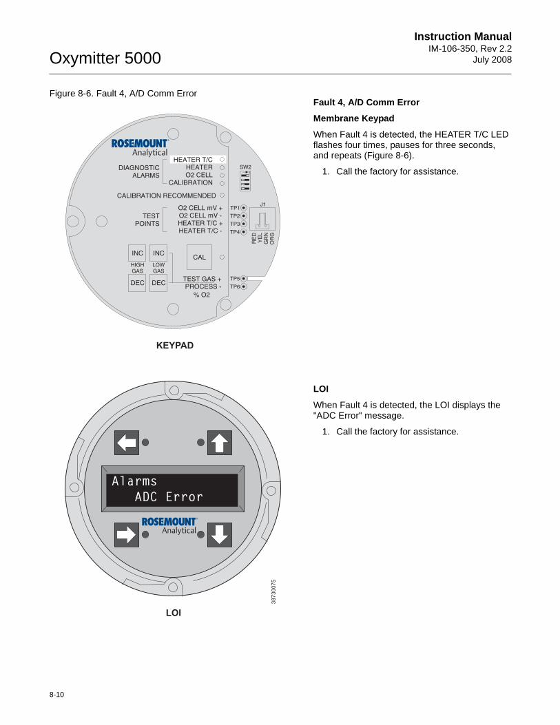
8-10
Instruction ManualIM-106-350, Rev 2.2
July 2008Oxymitter 5000
Figure 8-6. Fault 4, A/D Comm Error Fault 4, A/D Comm Error
Membrane Keypad
When Fault 4 is detected, the HEATER T/C LED flashes four times, pauses for three seconds, and repeats (Figure 8-6).
1. Call the factory for assistance.
LOI
When Fault 4 is detected, the LOI displays the "ADC Error" message.
1. Call the factory for assistance.
38
73
00
75
DIAGNOSTICALARMS
TESTPOINTS
HEATER T/CHEATERO2 CELL
CALIBRATION
CALIBRATION RECOMMENDED
O2 CELL mV +O2 CELL m -HEATER T/C +HEATER T/C -
V
INC INC
DEC DEC
HIGHGAS
LOWGAS
CAL
TEST GAS +PROCESS -
% O2
SW2
TP1J1
TP2
TP3
RE
DY
EL
GR
NO
RG
TP4
TP5
TP6
ON
LOI
KEYPAD
Alarms
ADC Error
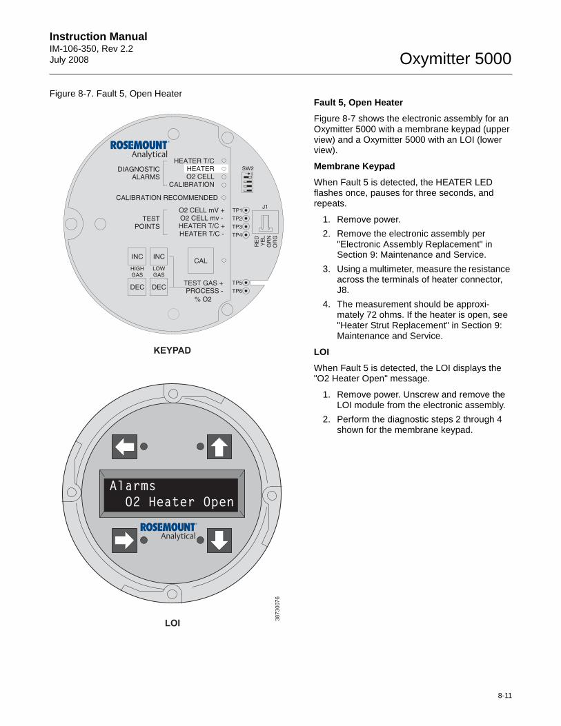
Instruction Manual IM-106-350, Rev 2.2July 2008
8-11
Oxymitter 5000
Figure 8-7. Fault 5, Open Heater Fault 5, Open Heater
Figure 8-7 shows the electronic assembly for an Oxymitter 5000 with a membrane keypad (upper view) and a Oxymitter 5000 with an LOI (lower view).
Membrane Keypad
When Fault 5 is detected, the HEATER LED flashes once, pauses for three seconds, and repeats.
1. Remove power.
2. Remove the electronic assembly per "Electronic Assembly Replacement" in Section 9: Maintenance and Service.
3. Using a multimeter, measure the resistance across the terminals of heater connector, J8.
4. The measurement should be approxi-mately 72 ohms. If the heater is open, see "Heater Strut Replacement" in Section 9: Maintenance and Service.
LOI
When Fault 5 is detected, the LOI displays the "O2 Heater Open" message.
1. Remove power. Unscrew and remove the LOI module from the electronic assembly.
2. Perform the diagnostic steps 2 through 4 shown for the membrane keypad.
38
73
00
76
LOI
KEYPAD
Alarms
O2 Heater Open
DIAGNOSTICALARMS
TESTPOINTS
HEATER T/CHEATERO2 CELL
CALIBRATION
CALIBRATION RECOMMENDED
O2 CELL mV +O2 CELL mv -HEATER T/C +HEATER T/C -
INC INC
DEC DEC
HIGHGAS
LOWGAS
CAL
TEST GAS +PROCESS -
% O2
SW2
TP1J1
TP2
TP3
RE
DY
EL
GR
NO
RG
TP4
TP5
TP6
ON
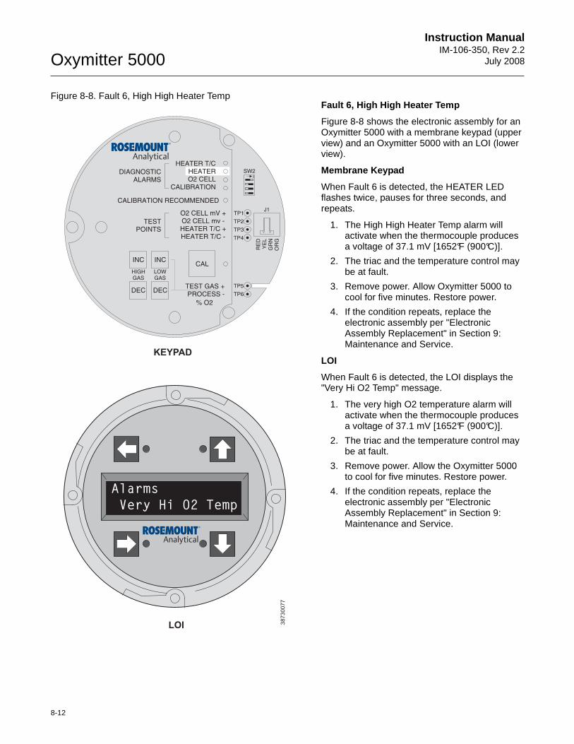
8-12
Instruction ManualIM-106-350, Rev 2.2
July 2008Oxymitter 5000
Figure 8-8. Fault 6, High High Heater Temp Fault 6, High High Heater Temp
Figure 8-8 shows the electronic assembly for an Oxymitter 5000 with a membrane keypad (upper view) and an Oxymitter 5000 with an LOI (lower view).
Membrane Keypad
When Fault 6 is detected, the HEATER LED flashes twice, pauses for three seconds, and repeats.
1. The High High Heater Temp alarm will activate when the thermocouple produces a voltage of 37.1 mV [1652°F (900°C)].
2. The triac and the temperature control may be at fault.
3. Remove power. Allow Oxymitter 5000 to cool for five minutes. Restore power.
4. If the condition repeats, replace the electronic assembly per "Electronic Assembly Replacement" in Section 9: Maintenance and Service.
LOI
When Fault 6 is detected, the LOI displays the "Very Hi O2 Temp" message.
1. The very high O2 temperature alarm will activate when the thermocouple produces a voltage of 37.1 mV [1652°F (900°C)].
2. The triac and the temperature control may be at fault.
3. Remove power. Allow the Oxymitter 5000 to cool for five minutes. Restore power.
4. If the condition repeats, replace the electronic assembly per "Electronic Assembly Replacement" in Section 9: Maintenance and Service.
38
73
00
77
LOI
KEYPAD
Alarms
Very Hi O2 Temp
DIAGNOSTICALARMS
TESTPOINTS
HEATER T/CHEATERO2 CELL
CALIBRATION
CALIBRATION RECOMMENDED
O2 CELL mV +O2 CELL mv -HEATER T/C +HEATER T/C -
INC INC
DEC DEC
HIGHGAS
LOWGAS
CAL
TEST GAS +PROCESS -
% O2
SW2
TP1J1
TP2
TP3
RE
DY
EL
GR
NO
RG
TP4
TP5
TP6
ON

Instruction Manual IM-106-350, Rev 2.2July 2008
8-13
Oxymitter 5000
Figure 8-9. Fault 7, High Case TempFault 7, High Case Temp
Figure 8-9 shows the electronic assembly for an Oxymitter 5000 with a membrane keypad (upper view) and an Oxymitter 5000 with an LOI (lower view).
Membrane Keypad
When Fault 7 is detected, The HEATER LED flashes three times, pauses for three seconds, and repeats.
1. If the case temperature exceeds [185°F (85°C)], the temperature control will shut off and a fieldbus alarm will be sent.
2. This signifies that the environment where the Oxymitter 5000 is installed exceeds the ambient temperature requirements or that heat due to convection is causing case temperature to rise above the limit.
3. Placing a spool piece between the stack flange and the Oxymitter 5000 flange may eliminate this problem.
4. If a spool piece does not solve the problem, relocation is the only solution.
LOI
When Fault 7 is detected, the LOI displays the "Board Temp Hi" message. Refer to the comments in paragraphs 1 through 4 above.
38
73
00
78
LOI
KEYPAD
Alarms
Board Temp Hi
DIAGNOSTICALARMS
TESTPOINTS
HEATER T/CHEATERO2 CELL
CALIBRATION
CALIBRATION RECOMMENDED
O2 CELL mV +O2 CELL mv -HEATER T/C +HEATER T/C -
INC INC
DEC DEC
HIGHGAS
LOWGAS
CAL
TEST GAS +PROCESS -
% O2
SW2
TP1J1
TP2
TP3
RE
DY
EL
GR
NO
RG
TP4
TP5
TP6
ON

8-14
Instruction ManualIM-106-350, Rev 2.2
July 2008Oxymitter 5000
Figure 8-10. Fault 8, Low Heater Temp Fault 8, Low Heater Temp
Figure 8-10 shows the electronic assembly for an Oxymitter 5000 with a membrane keypad (upper view) and an Oxymitter 5000 with an LOI (lower view).
Membrane Keypad
When Fault 8 is detected, the HEATER LED flashes four times, pauses for three seconds, and repeats.
1. The low heater temperature alarm is active when the thermocouple reading has dropped below 28.6 mV.
2. If the thermocouple reading continues to ramp downward for one minute and does not return to the temperature set point of approximately 29.3 mV, then an Open Heater fault will be displayed.
3. Power down the electronics. Remove the electronic assembly per "Electronic Assembly Replacement" in Section 9: Maintenance and Service. Using a multimeter, measure the resistance across the terminals of heater connector, J8.
4. If the heater is good, the reading will be approximately 70 ohms. If the heater is open, see "Heater Strut Replacement" in Section 9: Maintenance and Service.
LOI
When Fault 8 is detected, the LOI displays the "O2 Temp Low" message. Refer to the comments and procedures in paragraphs 1 through 4 above.
38
73
00
79
LOI
KEYPAD
Alarms
O2 Temp Low
DIAGNOSTICALARMS
TESTPOINTS
HEATER T/CHEATERO2 CELL
CALIBRATION
CALIBRATION RECOMMENDED
O2 CELL mV +O2 CELL mv -HEATER T/C +HEATER T/C -
INC INC
DEC DEC
HIGHGAS
LOWGAS
CAL
TEST GAS +PROCESS -
% O2
SW2
TP1J1
TP2
TP3
RE
DY
EL
GR
NO
RG
TP4
TP5
TP6
ON
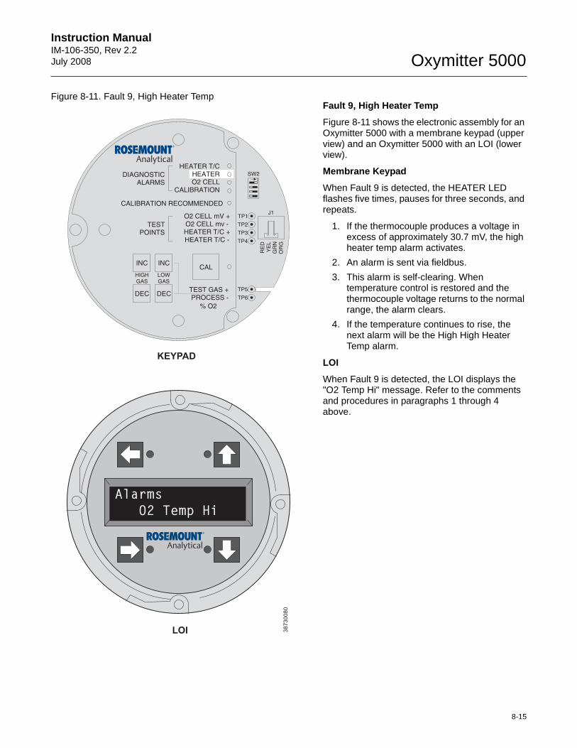
Instruction Manual IM-106-350, Rev 2.2July 2008
8-15
Oxymitter 5000
Figure 8-11. Fault 9, High Heater Temp Fault 9, High Heater Temp
Figure 8-11 shows the electronic assembly for an Oxymitter 5000 with a membrane keypad (upper view) and an Oxymitter 5000 with an LOI (lower view).
Membrane Keypad
When Fault 9 is detected, the HEATER LED flashes five times, pauses for three seconds, and repeats.
1. If the thermocouple produces a voltage in excess of approximately 30.7 mV, the high heater temp alarm activates.
2. An alarm is sent via fieldbus.
3. This alarm is self-clearing. When temperature control is restored and the thermocouple voltage returns to the normal range, the alarm clears.
4. If the temperature continues to rise, the next alarm will be the High High Heater Temp alarm.
LOI
When Fault 9 is detected, the LOI displays the "O2 Temp Hi" message. Refer to the comments and procedures in paragraphs 1 through 4 above.
38
73
00
80
LOI
KEYPAD
DIAGNOSTICALARMS
TESTPOINTS
HEATER T/CHEATERO2 CELL
CALIBRATION
CALIBRATION RECOMMENDED
O2 CELL mV +O2 CELL mv -HEATER T/C +HEATER T/C -
INC INC
DEC DEC
HIGHGAS
LOWGAS
CAL
TEST GAS +PROCESS -
% O2
SW2
TP1J1
TP2
TP3
RE
DY
EL
GR
NO
RG
TP4
TP5
TP6
ON
Alarms
O2 Temp Hi
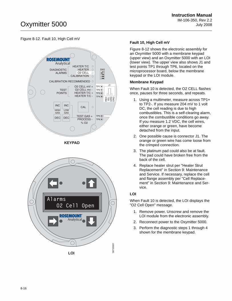
8-16
Instruction ManualIM-106-350, Rev 2.2
July 2008Oxymitter 5000
Figure 8-12. Fault 10, High Cell mV Fault 10, High Cell mV
Figure 8-12 shows the electronic assembly for an Oxymitter 5000 with a membrane keypad (upper view) and an Oxymitter 5000 with an LOI (lower view). The upper view also shows J1 and test points TP1 through TP6, located on the microprocessor board, below the membrane keypad or the LOI module.
Membrane Keypad
When Fault 10 is detected, the O2 CELL flashes once, pauses for three seconds, and repeats.
1. Using a multimeter, measure across TP1+ to TP2-. If you measure 204 mV to 1 volt DC, the cell reading is due to high combustibles. This is a self-clearing alarm, once the combustible conditions go away. If you measure 1.2 VDC, the cell wires, either orange or green, have become detached from the input.
2. One possible cause is connector J1. The orange or green wire has come loose from the crimped connection.
3. The platinum pad could also be at fault. The pad could have broken free from the back of the cell.
4. Replace heater strut per "Heater Strut Replacement" in Section 9: Maintenance and Service. If necessary, replace the cell and flange assembly per "Cell Replace-ment" in Section 9: Maintenance and Ser-vice.
LOI
When Fault 10 is detected, the LOI displays the "O2 Cell Open" message.
1. Remove power. Unscrew and remove the LOI module from the electronic assembly.
2. Reconnect power to the Oxymitter 5000.
3. Perform the diagnostic steps 1 through 4 shown for the membrane keypad.
38
73
00
81
LOI
KEYPAD
DIAGNOSTICALARMS
TESTPOINTS
HEATER T/CHEATERO2 CELL
CALIBRATION
CALIBRATION RECOMMENDED
O2 CELL mV +O2 CELL mv -HEATER T/C +HEATER T/C -
INC INC
DEC DEC
HIGHGAS
LOWGAS
CAL
TEST GAS +PROCESS -
% O2
SW2
TP1J1
TP2
TP3
RE
DY
EL
GR
NO
RG
TP4
TP5
TP6
ON
Alarms
O2 Cell Open
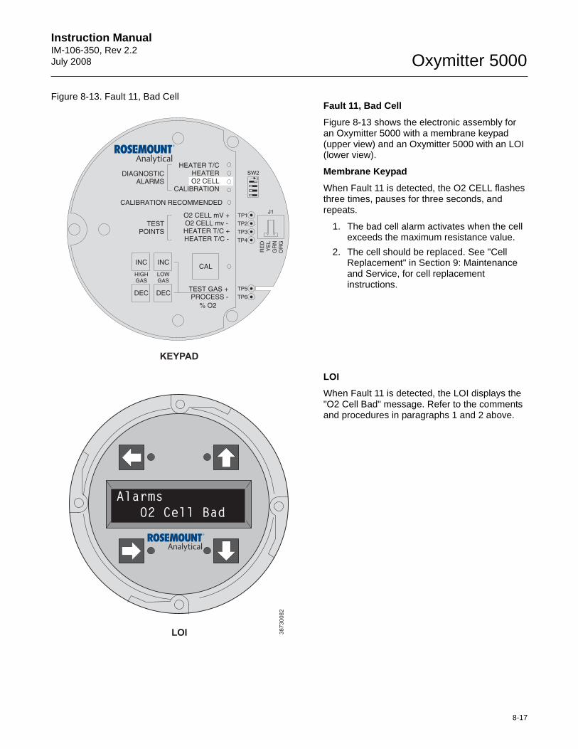
Instruction Manual IM-106-350, Rev 2.2July 2008
8-17
Oxymitter 5000
Figure 8-13. Fault 11, Bad Cell Fault 11, Bad Cell
Figure 8-13 shows the electronic assembly for an Oxymitter 5000 with a membrane keypad (upper view) and an Oxymitter 5000 with an LOI (lower view).
Membrane Keypad
When Fault 11 is detected, the O2 CELL flashes three times, pauses for three seconds, and repeats.
1. The bad cell alarm activates when the cell exceeds the maximum resistance value.
2. The cell should be replaced. See "Cell Replacement" in Section 9: Maintenance and Service, for cell replacement instructions.
LOI
When Fault 11 is detected, the LOI displays the "O2 Cell Bad" message. Refer to the comments and procedures in paragraphs 1 and 2 above.
38
73
00
82
LOI
KEYPAD
DIAGNOSTICALARMS
TESTPOINTS
HEATER T/CHEATERO2 CELL
CALIBRATION
CALIBRATION RECOMMENDED
O2 CELL mV +O2 CELL mv -HEATER T/C +HEATER T/C -
INC INC
DEC DEC
HIGHGAS
LOWGAS
CAL
TEST GAS +PROCESS -
% O2
SW2
TP1J1
TP2
TP3
RE
DY
EL
GR
NO
RG
TP4
TP5
TP6
ON
Alarms
O2 Cell Bad
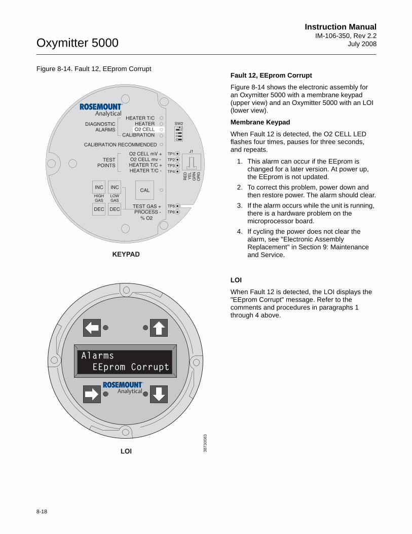
8-18
Instruction ManualIM-106-350, Rev 2.2
July 2008Oxymitter 5000
Figure 8-14. Fault 12, EEprom Corrupt Fault 12, EEprom Corrupt
Figure 8-14 shows the electronic assembly for an Oxymitter 5000 with a membrane keypad (upper view) and an Oxymitter 5000 with an LOI (lower view).
Membrane Keypad
When Fault 12 is detected, the O2 CELL LED flashes four times, pauses for three seconds, and repeats.
1. This alarm can occur if the EEprom is changed for a later version. At power up, the EEprom is not updated.
2. To correct this problem, power down and then restore power. The alarm should clear.
3. If the alarm occurs while the unit is running, there is a hardware problem on the microprocessor board.
4. If cycling the power does not clear the alarm, see "Electronic Assembly Replacement" in Section 9: Maintenance and Service.
LOI
When Fault 12 is detected, the LOI displays the "EEprom Corrupt" message. Refer to the comments and procedures in paragraphs 1 through 4 above.
38
73
00
83
LOI
KEYPAD
DIAGNOSTICALARMS
TESTPOINTS
HEATER T/CHEATERO2 CELL
CALIBRATION
CALIBRATION RECOMMENDED
O2 CELL mV +O2 CELL mv -HEATER T/C +HEATER T/C -
INC INC
DEC DEC
HIGHGAS
LOWGAS
CAL
TEST GAS +PROCESS -
% O2
SW2
TP1J1
TP2
TP3
RE
DY
EL
GR
NO
RG
TP4
TP5
TP6
ON
Alarms
EEprom Corrupt
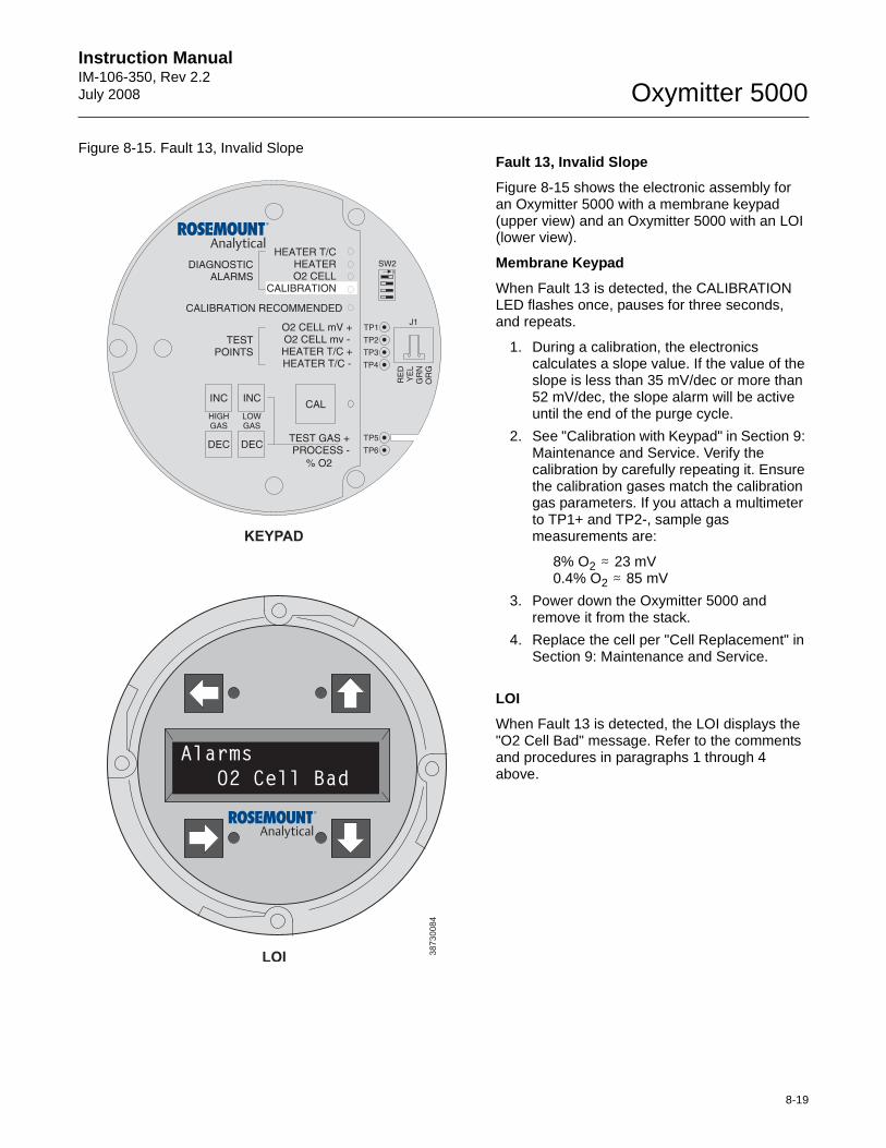
Instruction Manual IM-106-350, Rev 2.2July 2008
8-19
Oxymitter 5000
Figure 8-15. Fault 13, Invalid Slope Fault 13, Invalid Slope
Figure 8-15 shows the electronic assembly for an Oxymitter 5000 with a membrane keypad (upper view) and an Oxymitter 5000 with an LOI (lower view).
Membrane Keypad
When Fault 13 is detected, the CALIBRATION LED flashes once, pauses for three seconds, and repeats.
1. During a calibration, the electronics calculates a slope value. If the value of the slope is less than 35 mV/dec or more than 52 mV/dec, the slope alarm will be active until the end of the purge cycle.
2. See "Calibration with Keypad" in Section 9: Maintenance and Service. Verify the calibration by carefully repeating it. Ensure the calibration gases match the calibration gas parameters. If you attach a multimeter to TP1+ and TP2-, sample gas measurements are:
8% O2 . 23 mV0.4% O2 . 85 mV
3. Power down the Oxymitter 5000 and remove it from the stack.
4. Replace the cell per "Cell Replacement" in Section 9: Maintenance and Service.
LOI
When Fault 13 is detected, the LOI displays the "O2 Cell Bad" message. Refer to the comments and procedures in paragraphs 1 through 4 above.
38730084
DIAGNOSTICALARMS
TESTPOINTS
HEATER T/CHEATERO2 CELL
CALIBRATION
CALIBRATION RECOMMENDED
O2 CELL mV +O2 CELL mv -HEATER T/C +HEATER T/C -
INC INC
DEC DEC
HIGHGAS
LOWGAS
CAL
TEST GAS +PROCESS -
% O2
SW2
TP1J1
TP2
TP3
RE
DY
EL
GR
NO
RG
TP4
TP5
TP6
ON
LOI
KEYPAD
Alarms
O2 Cell Bad
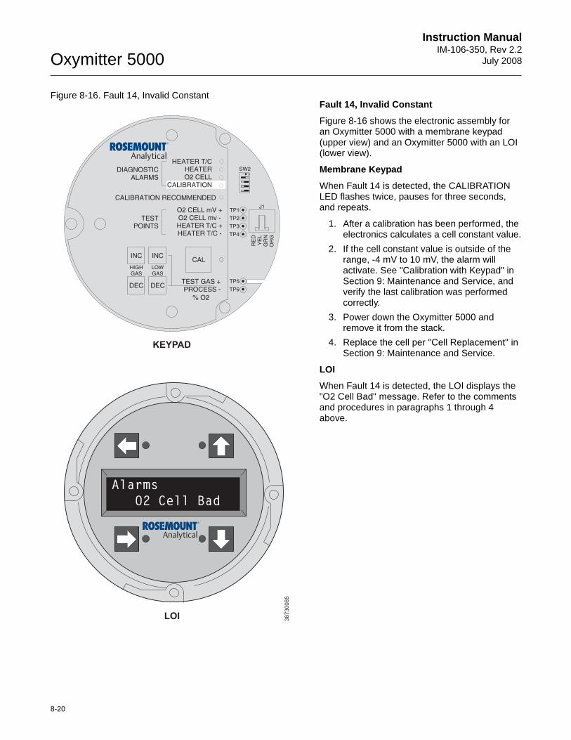
8-20
Instruction ManualIM-106-350, Rev 2.2
July 2008Oxymitter 5000
Figure 8-16. Fault 14, Invalid ConstantFault 14, Invalid Constant
Figure 8-16 shows the electronic assembly for an Oxymitter 5000 with a membrane keypad (upper view) and an Oxymitter 5000 with an LOI (lower view).
Membrane Keypad
When Fault 14 is detected, the CALIBRATION LED flashes twice, pauses for three seconds, and repeats.
1. After a calibration has been performed, the electronics calculates a cell constant value.
2. If the cell constant value is outside of the range, -4 mV to 10 mV, the alarm will activate. See "Calibration with Keypad" in Section 9: Maintenance and Service, and verify the last calibration was performed correctly.
3. Power down the Oxymitter 5000 and remove it from the stack.
4. Replace the cell per "Cell Replacement" in Section 9: Maintenance and Service.
LOI
When Fault 14 is detected, the LOI displays the "O2 Cell Bad" message. Refer to the comments and procedures in paragraphs 1 through 4 above.
38
73
00
85
DIAGNOSTICALARMS
TESTPOINTS
HEATER T/CHEATERO2 CELL
CALIBRATION
CALIBRATION RECOMMENDED
O2 CELL mV +O2 CELL mv -HEATER T/C +HEATER T/C -
INC INC
DEC DEC
HIGHGAS
LOWGAS
CAL
TEST GAS +PROCESS -
% O2
SW2
TP1J1
TP2
TP3
RE
DY
EL
GR
NO
RG
TP4
TP5
TP6
ON
LOI
KEYPAD
Alarms
O2 Cell Bad
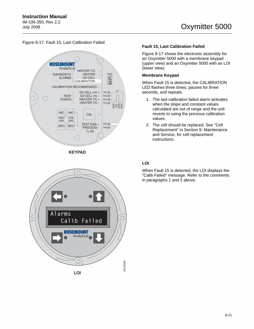
Instruction Manual IM-106-350, Rev 2.2July 2008
8-21
Oxymitter 5000
Figure 8-17. Fault 15, Last Calibration Failed Fault 15, Last Calibration Failed
Figure 8-17 shows the electronic assembly for an Oxymitter 5000 with a membrane keypad (upper view) and an Oxymitter 5000 with an LOI (lower view).
Membrane Keypad
When Fault 15 is detected, the CALIBRATION LED flashes three times, pauses for three seconds, and repeats.
1. The last calibration failed alarm activates when the slope and constant values calculated are out of range and the unit reverts to using the previous calibration values.
2. The cell should be replaced. See "Cell Replacement" in Section 9: Maintenance and Service, for cell replacement instructions.
LOI
When Fault 15 is detected, the LOI displays the "Calib Failed" message. Refer to the comments in paragraphs 1 and 2 above.
38730086
DIAGNOSTICALARMS
TESTPOINTS
HEATER T/CHEATERO2 CELL
CALIBRATION
CALIBRATION RECOMMENDED
O2 CELL mV +O2 CELL mv -HEATER T/C +HEATER T/C -
INC INC
DEC DEC
HIGHGAS
LOWGAS
CAL
TEST GAS +PROCESS -
% O2
SW2
TP1J1
TP2
TP3
RE
DY
EL
GR
NO
RG
TP4
TP5
TP6
ON
LOI
KEYPAD
Alarms
Calib Failed
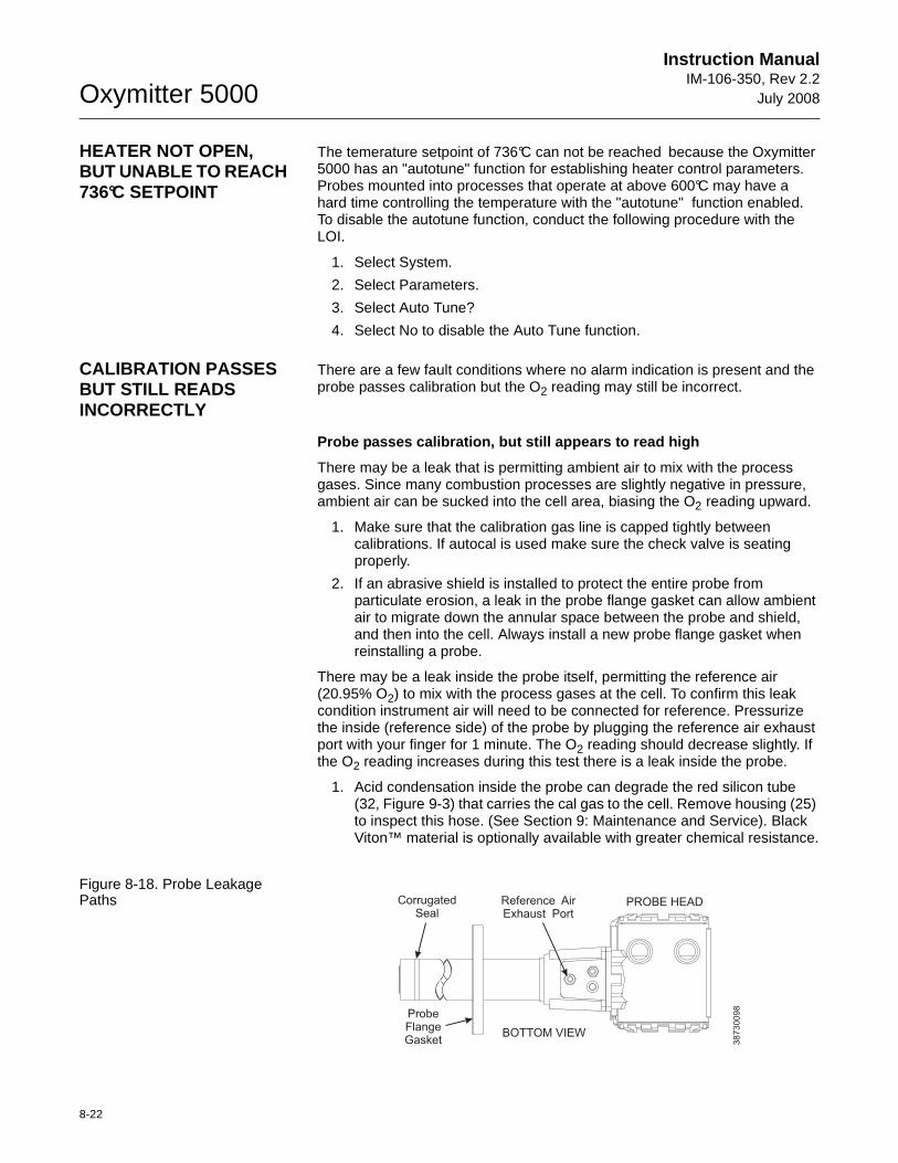
Oxymitter 5000
8-22
Instruction ManualIM-106-350, Rev 2.2
July 2008
HEATER NOT OPEN, BUT UNABLE TO REACH 736°C SETPOINT
The temerature setpoint of 736°C can not be reached because the Oxymitter 5000 has an "autotune" function for establishing heater control parameters. Probes mounted into processes that operate at above 600°C may have a hard time controlling the temperature with the "autotune" function enabled. To disable the autotune function, conduct the following procedure with the LOI.
1. Select System.
2. Select Parameters.
3. Select Auto Tune?
4. Select No to disable the Auto Tune function.
CALIBRATION PASSES BUT STILL READS INCORRECTLY
There are a few fault conditions where no alarm indication is present and the probe passes calibration but the O2 reading may still be incorrect.
Probe passes calibration, but still appears to read high
There may be a leak that is permitting ambient air to mix with the process gases. Since many combustion processes are slightly negative in pressure, ambient air can be sucked into the cell area, biasing the O2 reading upward.
1. Make sure that the calibration gas line is capped tightly between calibrations. If autocal is used make sure the check valve is seating properly.
2. If an abrasive shield is installed to protect the entire probe from particulate erosion, a leak in the probe flange gasket can allow ambient air to migrate down the annular space between the probe and shield, and then into the cell. Always install a new probe flange gasket when reinstalling a probe.
There may be a leak inside the probe itself, permitting the reference air (20.95% O2) to mix with the process gases at the cell. To confirm this leak condition instrument air will need to be connected for reference. Pressurize the inside (reference side) of the probe by plugging the reference air exhaust port with your finger for 1 minute. The O2 reading should decrease slightly. If the O2 reading increases during this test there is a leak inside the probe.
1. Acid condensation inside the probe can degrade the red silicon tube (32, Figure 9-3) that carries the cal gas to the cell. Remove housing (25) to inspect this hose. (See Section 9: Maintenance and Service). Black Viton™ material is optionally available with greater chemical resistance.
Figure 8-18. Probe Leakage Paths
BOTTOM VIEW
38
73
00
98
PROBE HEADCorrugatedSeal
Reference AirExhaust Port
ProbeFlangeGasket
Instruction Manual IM-106-350, Rev 2.2July 2008
8-23
Oxymitter 5000
2. The sensing cell is bolted to the end of the probe and uses a corrugated metallic seal (5, Figure 9-3) to separate the process gases from the ambient reference air. This seal can be used only one time so always replace this seal when a cell is removed or replaced. Always apply anti-seize compound on both sides of the corrugations.
Probe passes calibration but still appears to read low
The diffusion element at the end of the probe is a passive filter. It plugs very slowly since there is no active flow being drawn across it. In applications that have a heavy particulate loading (coal or wood fired boilers, cement and lime kilns, catalyst regeneration, recovery boilers, etc.), this diffusion element will eventually plug.
It is important not to pressurize the sensing cell during calibrations by flowing excessive cal gas against a plugged diffuser. Calibration flow rates should be set only when a new diffuser is installed. As the diffuser plugs do not adjust the flow rates upward.
How do I detect a plugged diffuser?
The O2 signal's speed of response will degrade. The O2 trend in the control room will become smoother.
When calibrating, the calibration gas flow rate will be noted to be lower. Never readjust this flow upwards. Adjust this flow only when a new diffuser is installed.
Always note the time it takes for the cell to recover to the normal process value after the cal gas is removed. As the diffuser plugs this recovery time will get longer and longer. Use the Calibration Record form provided in this manual.
Can I calibrate a badly plugged diffuser?
It may not be possible to immediately replace a plugged diffuser while the process is on line.
One can calibrate the probe without pressurizing the cell by adjusting the calibration gas flow rate downward before calibration. For instance, say the process is at 3% and the first calibration gas is 8%. Adjust the flow of cal gas downward until the reading begins to migrate from 8% to lower values indicating that process gases are now mixing in with the calibration gases.
Adjust the flow rate back up until this mixing is just eliminated. Calibrate at this flow rate. Replace the diffuser at the first opportunity.
Install all protective equipment covers and safety ground leads after troubleshooting. Failure to install covers and ground leads could result in serious injury or death.
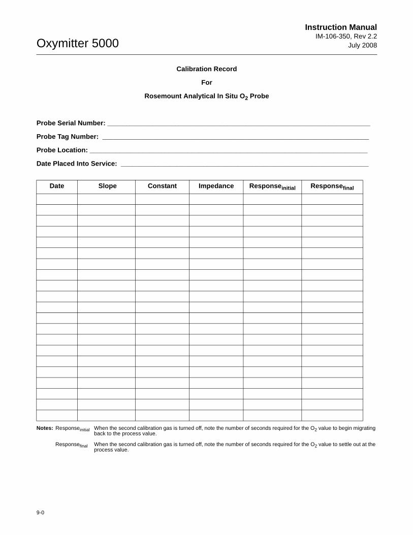
Oxymitter 5000
9-0
Instruction ManualIM-106-350, Rev 2.2
July 2008
Calibration Record
For
Rosemount Analytical In Situ O 2 Probe
Probe Serial Number: ______________________________ ________________________________________
Probe Tag Number: ________________________________ _______________________________________
Probe Location: ___________________________________ _______________________________________
Date Placed Into Service: ________________________ __________________________________________
Notes: Responseinitial When the second calibration gas is turned off, note the number of seconds required for the O2 value to begin migrating back to the process value.
Responsefinal When the second calibration gas is turned off, note the number of seconds required for the O2 value to settle out at the process value.
Date Slope Constant Impedance Response initial Response final
Instruction Manual IM-106-350, Rev 2.2July 2008 Oxymitter 5000
http://www.raihome.com
Section 9 Maintenance and Service
Overview . . . . . . . . . . . . . . . . . . . . . . . . . . . . . . . . . . . . . . . page 9-1Calibration with Keypad . . . . . . . . . . . . . . . . . . . . . . . . . . . page 9-1FOUNDATION Fieldbus O 2 CAL Method . . . . . . . . . . . . . . page 9-5Calibration with LOI . . . . . . . . . . . . . . . . . . . . . . . . . . . . . . page 9-6Oxymitter 5000 Repair . . . . . . . . . . . . . . . . . . . . . . . . . . . . page 9-8
OVERVIEW This section identifies the calibration methods available and provides the procedures to maintain and service the Oxymitter 5000.
CALIBRATION WITH KEYPAD
During a calibration, two calibration gases with known O2 concentrations are applied to the Oxymitter 5000. Slope and constant values calculated from the two calibration gases determine if the Oxymitter 5000 is correctly measuring the net concentration of O2 in the industrial process. A calibration record sheet has been provided at the front of this section to track performance.
Before calibrating, verify that the calibration gas parameters are correct by setting the gas concentrations used when calibrating the unit (see "Overview" in Section 5: Startup and Operation of Oxymitter 5000 with Membrane Keypad, or Section 6: Startup and Operation of Oxymitter 5000 with LOI) and by setting the calibration gas flowmeter. The calibration gas flowmeter regulates the calibration gas flow and must be set to 5 scfh. Only adjust the flowmeter to 5 scfh after placing a new diffusion element on the end of the Oxymitter 5000. Adjusting the flowmeter at any other time can pressurize the cell and bias the calibration.
In applications with a heavy dust loading the O2 probe diffusion element may become plugged over time, causing a slower speed of response. The best way to detect a plugged diffusion element is to note the time it takes the Oxymitter 5000 to return to the normal process reading after the last calibration gas is removed and the calibration gas line is blocked off. A plugged diffusion element also can be indicated by a slightly lower reading on the flowmeter.
Change the diffusion element when the calibration gas flowmeter reads slightly lower during calibration or when response to the process flue gases becomes very slow. Each time the diffusion element is changed, reset the
Install all protective equipment covers and safety ground leads after equipment repair or service. Failure to install covers and ground leads could result in serious injury or death.
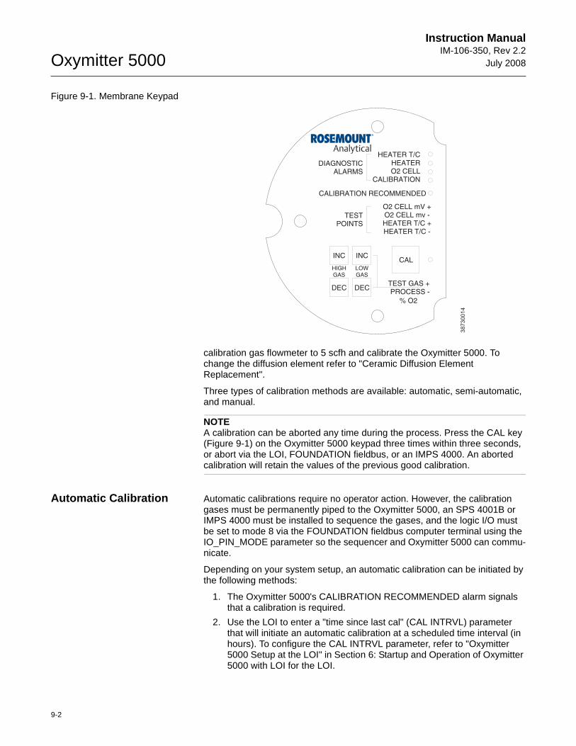
Oxymitter 5000
9-2
Instruction ManualIM-106-350, Rev 2.2
July 2008
Figure 9-1. Membrane Keypad
calibration gas flowmeter to 5 scfh and calibrate the Oxymitter 5000. To change the diffusion element refer to "Ceramic Diffusion Element Replacement".
Three types of calibration methods are available: automatic, semi-automatic, and manual.
NOTEA calibration can be aborted any time during the process. Press the CAL key (Figure 9-1) on the Oxymitter 5000 keypad three times within three seconds, or abort via the LOI, FOUNDATION fieldbus, or an IMPS 4000. An aborted calibration will retain the values of the previous good calibration.
Automatic Calibration Automatic calibrations require no operator action. However, the calibration gases must be permanently piped to the Oxymitter 5000, an SPS 4001B or IMPS 4000 must be installed to sequence the gases, and the logic I/O must be set to mode 8 via the FOUNDATION fieldbus computer terminal using the IO_PIN_MODE parameter so the sequencer and Oxymitter 5000 can commu-nicate.
Depending on your system setup, an automatic calibration can be initiated by the following methods:
1. The Oxymitter 5000's CALIBRATION RECOMMENDED alarm signals that a calibration is required.
2. Use the LOI to enter a "time since last cal" (CAL INTRVL) parameter that will initiate an automatic calibration at a scheduled time interval (in hours). To configure the CAL INTRVL parameter, refer to "Oxymitter 5000 Setup at the LOI" in Section 6: Startup and Operation of Oxymitter 5000 with LOI for the LOI.
38730014
DIAGNOSTICALARMS
TESTPOINTS
HEATER T/CHEATERO2 CELL
CALIBRATION
CALIBRATION RECOMMENDED
O2 CELL mV +O2 CELL mv -HEATER T/C +HEATER T/C -
INC INC
DEC DEC
HIGHGAS
LOWGAS
CAL
TEST GAS +PROCESS -
% O2
Instruction Manual IM-106-350, Rev 2.2July 2008
9-3
Oxymitter 5000
3. Enter a time to next calibration using the TIME_TO _NEXT_CAL parameter via fieldbus. Calibrations will then occur regularly at this interval.
4. If using an IMPS 4000, enter a time interval via the IMPS 4000 keypad that will initiate an automatic calibration at a scheduled time interval (in hours). To set the CalIntvX parameter of the CHANGE PRESETS display mode refer to the IMPS 4000 Intelligent Multiprobe Test Gas Sequencer Instruction Manual for more information.
Once an automatic calibration is initiated, by any of the methods previously described, the Oxymitter 5000's CALIBRATION RECOMMENDED alarm signals an IMPS 4000 or SPS 4001B to initiate a calibration. The sequencer sends an "in cal" signal to the control room so that any automatic control loops can be placed in manual. Then the sequencer begins to sequence the calibration gases.
Semi-Automatic Calibration
Semi-automatic calibrations only require operator initiation. However, the calibration gases must be permanently piped to the Oxymitter 5000, an SPS 4001B or IMPS 4000 must be installed to sequence the gases, and the logic I/O must be set to mode 8 or 9 via the FOUNDATION fieldbus computer terminal to allow the sequencer and the Oxymitter 5000 to communicate.
Depending on your system setup, a semi-automatic calibration can be initiated by the following methods:
1. Oxymitter 5000 with membrane keypad. Press the CAL key on the Oxymitter 5000 keypad.
2. Oxymitter 5000 with LOI. Select "Start Calib" from the CALIBRATION menu.
3. IMPS 4000. Use the IMPS 4000 keypad to change the InitCalX parameter of the CHANGE PRESETS display mode from 0000 to 0001. Refer to the IMPS 4000 Intelligent Multiprobe Test Gas Sequencer Instruction Manual for more information.
4. FOUNDATION fieldbus. Use fieldbus to perform the O2 CAL method.
5. Remote Contact. Initiate a calibration from a remote location via the remote contact input connection provided by an IMPS 4000 or SPS 4001B. Refer to the documentation available for the control system in use for more information.
Once a semi-automatic calibration is initiated by any of the methods previously described, the Oxymitter 5000's CALIBRATION RECOMMENDED alarm signals an IMPS 4000 or SPS 4001B to initiate a calibration. The sequencer sends an "in cal" signal to the control room so that any automatic control loops can be placed in manual. Then the sequencer begins to sequence the calibration gases.
Manual Calibration with Membrane Keypad
Manual calibrations must be performed at the Oxymitter 5000 site and will require operator intervention throughout the process. Manual calibration instructions, in condensed form, can also be found on the inside of the right electronics housing cover. See Figure 9-2.
Use the following procedure to perform a manual calibration:
1. Place control loop in manual.
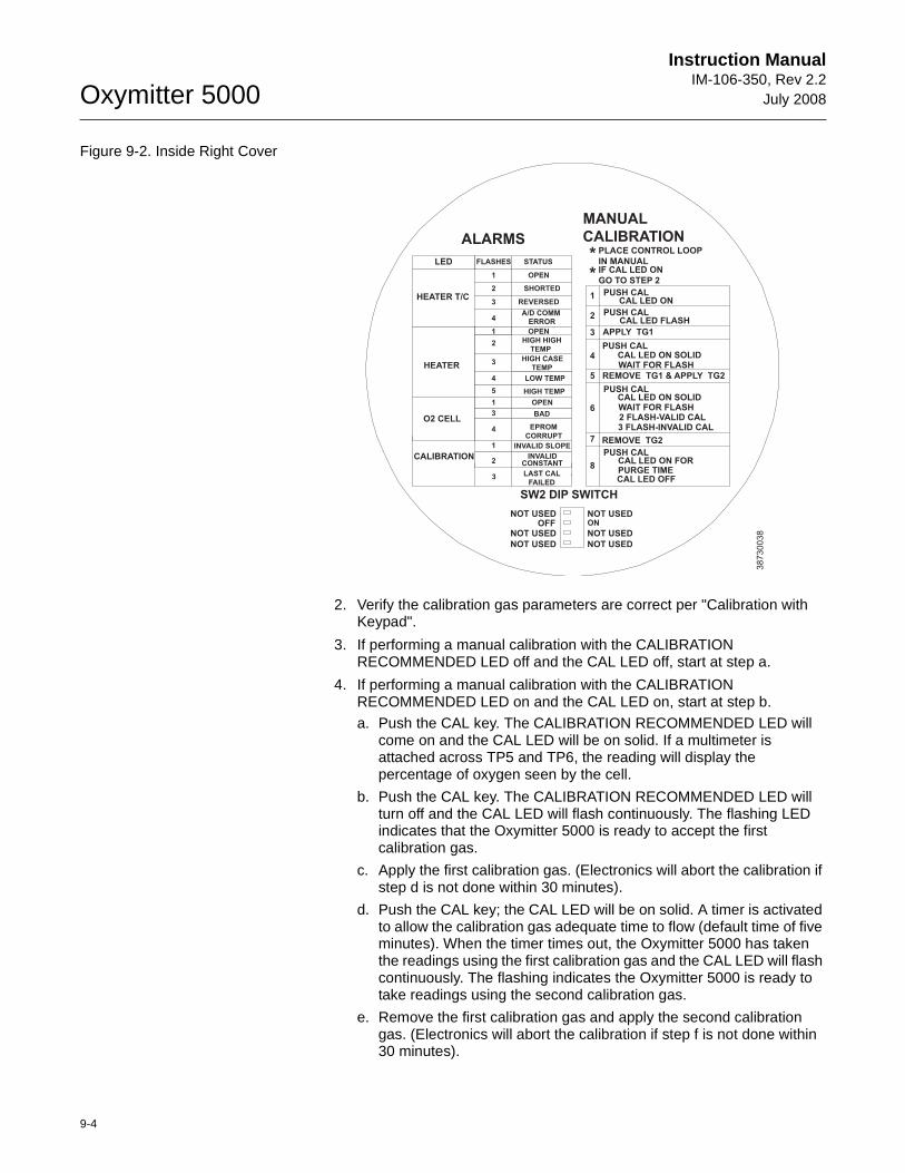
Oxymitter 5000
9-4
Instruction ManualIM-106-350, Rev 2.2
July 2008
Figure 9-2. Inside Right Cover
2. Verify the calibration gas parameters are correct per "Calibration with Keypad".
3. If performing a manual calibration with the CALIBRATION RECOMMENDED LED off and the CAL LED off, start at step a.
4. If performing a manual calibration with the CALIBRATION RECOMMENDED LED on and the CAL LED on, start at step b.
a. Push the CAL key. The CALIBRATION RECOMMENDED LED will come on and the CAL LED will be on solid. If a multimeter is attached across TP5 and TP6, the reading will display the percentage of oxygen seen by the cell.
b. Push the CAL key. The CALIBRATION RECOMMENDED LED will turn off and the CAL LED will flash continuously. The flashing LED indicates that the Oxymitter 5000 is ready to accept the first calibration gas.
c. Apply the first calibration gas. (Electronics will abort the calibration if step d is not done within 30 minutes).
d. Push the CAL key; the CAL LED will be on solid. A timer is activated to allow the calibration gas adequate time to flow (default time of five minutes). When the timer times out, the Oxymitter 5000 has taken the readings using the first calibration gas and the CAL LED will flash continuously. The flashing indicates the Oxymitter 5000 is ready to take readings using the second calibration gas.
e. Remove the first calibration gas and apply the second calibration gas. (Electronics will abort the calibration if step f is not done within 30 minutes).
SW2 DIP SWITCH
OFF ON
NOT USEDNOT USED
LED
HEATER
O2 CELL
CALIBRATION
HEATER T/C
STATUS
OPEN
SHORTED
REVERSED
HIGH HIGH
TEMP
HIGH CASE
TEMP
LOW TEMP
HIGH TEMP
OPEN
BAD
EPROM
CORRUPT
INVALID SLOPE
INVALIDCONSTANT
FLASHES
1
2
3
4
1
2
OPEN
3
4
5
1
3
4
1
2
PUSH CALCAL LED ON
APPLY TG1
PUSH CALCAL LED ON SOLID
REMOVE TG1 & APPLY TG2
PUSH CALCAL LED ON SOLIDWAIT FOR FLASH
REMOVE TG2
PUSH CAL
1
2
3
4
5
6
7
ALARMS
MANUAL
CALIBRATION
CAL LED ON FORPURGE TIME
WAIT FOR FLASH
CAL LED OFF
PUSH CALCAL LED FLASH
2 FLASH-VALID CAL3 FLASH-INVALID CAL
8
PLACE CONTROL LOOP
IN MANUALIF CAL LED ON
GO TO STEP 2
**
3 LAST CAL
FAILED
A/D COMMERROR
38
73
00
38NOT USEDNOT USED
NOT USEDNOT USED
Instruction Manual IM-106-350, Rev 2.2July 2008
9-5
Oxymitter 5000
f. Push the CAL key; the CAL LED will be on solid. The timer is activated for the second calibration gas flow. When the timer times out, the CAL LED will flash a 2 pattern flash or a 3 pattern flash (2 pattern flash equals a valid calibration, 3 pattern flash equals an invalid calibration). If the slope or the constant is out of specification, a diagnostic alarm LED will be flashing. The diagnostic alarm will remain active until the purge cycle is over. If the three pattern flash occurs without a diagnostic alarm, the calibration gases could be the same or the calibration gas was not turned on.
A flashing CAL LED indicates the calibration is done. (See Section 8: Troubleshooting, for an explanation of the 2 pattern and 3 pattern flashes).
g. Remove the second calibration gas and cap off the calibration gas port.
h. Push the CAL key; the CAL LED will be on solid as the unit purges. (Default purge time is three minutes). When the purge is complete, the CAL LED will turn off and the Oxymitter 5000 output unlocks from its held value and begins to read the process O2.
If the calibration was valid, the DIAGNOSTIC ALARMS LEDs will indicate normal operation. If either new calibration value (slope or constant) is not within parameters, the DIAGNOSTIC ALARMS LED will indicate an alarm. (See Section 8: Troubleshooting, for alarm codes). If the calibration was invalid, the Oxymitter 5000 will return to normal operation, as it was before a calibration was initiated, and the parameters will not be updated.
5. Place control loop in automatic.
FOUNDATION FIELDBUS O2 CAL METHOD
To perform a calibration using the FOUNDATION fieldbus, use the following procedure.
1. From the computer running the fieldbus control program, run the O2 Cal Method.
2. In the first O2 CAL screen, a "Loop should be removed from automatic control" warning appears. Remove the Oxymitter 5000 from any automatic control loops to avoid a potentially dangerous operating condition and press OK.
3. From this point, following the on-screen prompts to complete the calibration procedure. When a step is complete, select Proceed to Next Step and press the Next button.
4. During the wait periods, such as during a purge, the Time Remaining display may be updated by selecting Update and pressing Next button.
Failure to remove the Oxymitter 5000 from automatic control loops prior to performing this procedure may result in dangerous operating conditions.
Oxymitter 5000
9-6
Instruction ManualIM-106-350, Rev 2.2
July 2008
CALIBRATION WITH LOI Refer to Figure 6-4 for a view of the LOI menu tree. To calibrate the Oxymitter 5000 from the LOI, access the CALIBRATION/ Start Calibration menu.
CALIBRATION/Start Calibration
This is the starting point for calibrations. The LOI will instruct the user through this entire procedure. Select "Abort Calib" at any time to abort the calibration.
1. The LOI displays the following:
Apply Gas 1Hit E when ready
The Oxymitter 5000 is ready to accept the first calibration gas. Apply the first calibration gas. (Electronics will abort the calibration if this step is not done within 30 minutes).
2. Touch the Enter key to start the Gas 1 flow. A timer is activated to allow the calibration gas adequate time to flow (default time of five minutes). The LOI displays:
Flow Gas 1 xxxxsRead Gas 1 xxxxsDone Gas 1
The display counts down the seconds remaining to flow Gas 1, then the time remaining for sensing the O2 concentration of Gas 1. Done Gas 1 indicates completion.
3. Remove the first calibration gas and apply the second calibration gas. (Electronics will abort the calibration if this step is not done within 30 minutes). The LOI displays the following:
Apply Gas 2Hit E when ready
4. Touch the Enter arrow to start the Gas 2 flow. The timer is activated and the LOI displays:
Flow Gas 2 xxxxsRead Gas 2 xxxxsDone Gas 2Stop GasHit E when ready
5. Remove the second calibration gas and cap off the calibration gas port. Then touch the Enter arrow to indicate completion. The timer is activated and the LOI displays:
Purge xxxxs
The default purge time is three minutes. When the gas purge timer times out the Oxymitter 5000 begins to read the process O2.
Abort Calibration
Exits the calibration. After calibration gases are removed, and the purge times out, the instrument goes back to normal operational mode.
Instruction Manual IM-106-350, Rev 2.2July 2008
9-7
Oxymitter 5000
Cal Constants - Results of the Calibration
Current calibrationIf the calibration passed these values will be updated. Log these values on the calibration log sheet supplied. If the process has high levels of particulate, the response back to the process after cal gas is also removed.
Previous CalibrationValues from the prior good calibration.
Failed CalibrationBad calibration values are not loaded into the electronics.
Calibration Status
Calibration StepThe current step in an active calibration procedure.
Calibration TimeTime until the next scheduled calibration.
Next O2 CalTime until the next O2 calibration, if different than the next scheduled calibration.
Oxymitter 5000
9-8
Instruction ManualIM-106-350, Rev 2.2
July 2008
OXYMITTER 5000 REPAIR
Each of the following procedures details how to remove and replace a specific component of the Oxymitter 5000.
Removal and Replacement of Probe
1. Remove.
a. Turn off power to the system.
b. Shut off the calibration gases at the cylinders and the instrument air.
c. Disconnect the calibration gas and instrument air lines from the Oxymitter 5000.
d. Remove left housing cover (31, Figure 9-3 or Figure 9-4).
e. Remove all signal and power wiring to the probe.
f. Remove insulation to access the mounting bolts.
g. Unbolt the Oxymitter 5000 from the stack and take it to a clean work area.
h. Allow the unit to cool to a comfortable working temperature.
2. Replace.
a. Bolt the Oxymitter 5000 to the stack and install the insulation.
b. Connect all signal and power leads at the probe. Refer to Section 2: Installation, for detailed wiring instructions.
c. Connect the calibration gas and instrument air lines to probe.
d. Install left housing cover (31, Figure 9-3 or Figure 9-4).
e. Turn on instrument air.
f. Restore power to the system; refer to "Power Up" in Section 5: Startup and Operation of Oxymitter 5000 with Membrane Keypad or "Power Up" in Section 6: Startup and Operation of Oxymitter 5000 with LOI. When the probe is at operating temperature, calibrate the probe per "Calibration with Keypad".
NOTERecalibration is required whenever electronic cards or sensing cell is replaced.
It is recommended that the Oxymitter 5000 be removed from the stack for all service activities. The unit should be allowed to cool and be taken to a clean work area. Failure to comply may cause severe burns.
Disconnect and lock out power before working on any electrical components. There is voltage up to 115 VAC.
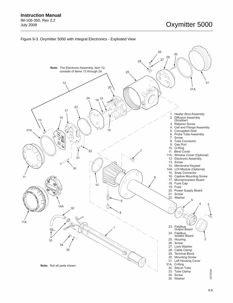
Instruction Manual IM-106-350, Rev 2.2July 2008
9-9
Oxymitter 5000
Figure 9-3. Oxymitter 5000 with Integral Electronics - Exploded View
1
35
2930
3112
Note: The Electronic Assembly, item 12,consists of items 13 through 24.
1. Heater Strut Assembly2. Diffusion Assembly
(Snubber)
3. Retainer Screw4. Cell and Flange Assembly5. Corrugated Seal6. Probe Tube Assembly7. Screw8. Tube Connector9. Gas Port
10. O-Ring11. Blind Cover
11A. Window Cover (Optional)12. Electronic Assembly13. Screw14. Membrane Keypad
14A. LOI Module (Optional)15. Snap Connector16. Captive Mounting Screw17. Microprocessor Board18. Fuse Cap19. Fuse20. Power Supply Board
25. Housing
26. Screw27. Lock Washer28. Cable Clamp29. Terminal Block30. Mounting Screw
31A. O-Ring32. Silicon Tube33. Tube Clamp34. Screw35. Washer
Note: Not all parts shown.
38730068
32
33
34
31. Left Housing Cover
31A
14A
11A
9
8
6
5
4 3
2
10
7
15
1819
20
25
26
2728
21. Screw22. Washer
23. FieldbusOutput Board
24. FieldbusIsolator Board
16
1314
17
11
31A
23
24
22
21
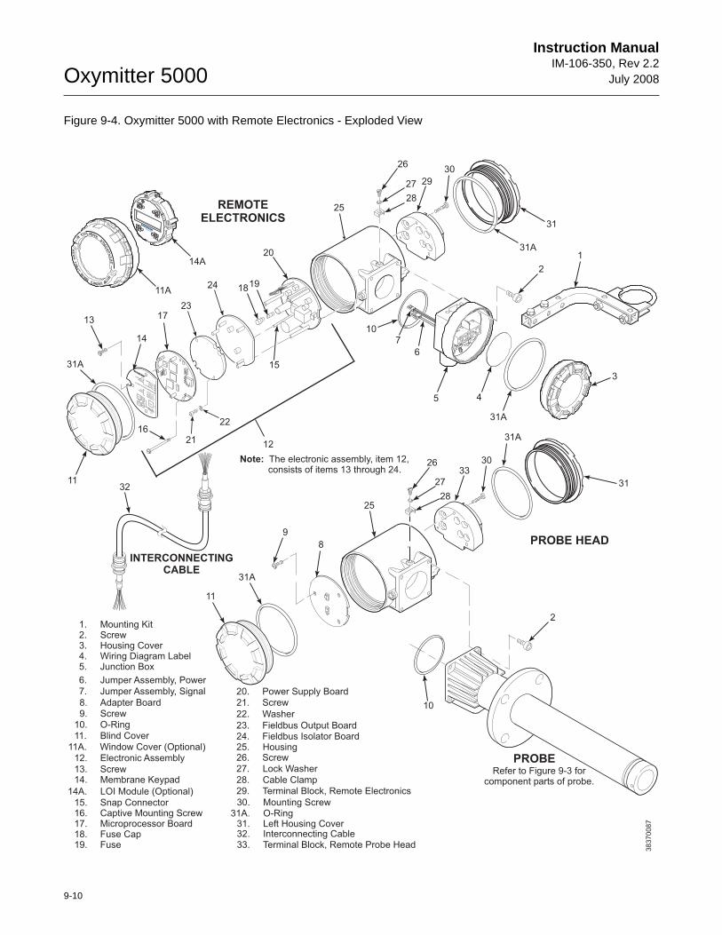
Oxymitter 5000
9-10
Instruction ManualIM-106-350, Rev 2.2
July 2008
Figure 9-4. Oxymitter 5000 with Remote Electronics - Exploded View
38370087
1819
20
15
31
29
26
27
28
30
25
10
45
6
7
3
2
1
31A
31A
11
31A
8
9
24
23
22
21
Note: The electronic assembly, item 12,consists of items 13 through 24.
20. Power Supply Board
25. Housing
32
25
26
27
28
3330
2
11
17
16
13
14
12
11A
14A
10
31
REMOTEELECTRONICS
PROBE HEAD
INTERCONNECTINGCABLE
PROBERefer to Figure 9-3 for
component parts of probe.
1. Mounting Kit2. Screw3. Housing Cover4. Wiring Diagram Label5. Junction Box
6. Jumper Assembly, Power
7. Jumper Assembly, Signal
10. O-Ring
11. Blind Cover
11A. Window Cover (Optional)
12. Electronic Assembly
13. Screw14. Membrane Keypad
14A. LOI Module (Optional)
15. Snap Connector16. Captive Mounting Screw17. Microprocessor Board18. Fuse Cap19. Fuse
26. Screw
27. Lock Washer
28. Cable Clamp
29. Terminal Block, Remote Electronics
30. Mounting Screw
31. Left Housing Cover32. Interconnecting Cable33. Terminal Block, Remote Probe Head
31A
31A
31A. O-Ring
8. Adapter Board9. Screw
21. Screw
22. Washer
23. Fieldbus Output Board24. Fieldbus Isolator Board
Instruction Manual IM-106-350, Rev 2.2July 2008
9-11
Oxymitter 5000
Replace Entire Integral Electronics (with Housing)
NOTEOnly perform this procedure on units with integral electronics.
NOTERecalibration is required whenever electronic cards or sensing cell is replaced.
1. Follow the instructions in "Removal and Replacement of Probe" to remove the Oxymitter 5000 from the stack or duct.
2. Remove the right housing cover uncovering the electronic assembly (Figure 9-5).
3. Depress and remove the J1 (cell and T/C) connector from the J1 socket. Loosen the three captive mounting screws (16, Figure 9-3 or Figure 9-4) on the microprocessor board (top board).
4. The J8 connector (heater leads) (Figure 9-6) can be accessed by moving the J1 connector leads out of the slot on the microprocessor board (17) and sliding the electronic assembly (12) partially out of the housing (Figure 9-3 or Figure 9-4).
5. Squeeze the J8 connector on the sides and carefully remove. The electronic assembly can now be completely removed from the housing.
6. Remove four screws (7, Figure 9-3) from the probe finned housing. The probe and the electronic housing can now be separated.
7. When reinstalling or replacing the electronic housing make sure that O-ring (10) is in good condition. Place the J1 and J8 connectors in the hole on the flat side of the electronic housing.
8. Hold the J1 and J8 connectors out and to the probe side of the electronic housing. Make sure that the conduit port of the electronic housing is on the same side as the CAL and REF gas ports. Replace the four screws and tighten.
9. Reconnect the J8 connector to the power supply board. Make sure the connector is secure.
10. Holding the J1 connector leads, slide the electronic assembly the rest of the way into the housing. Align the electronic assembly so that it fits flush on the pins. To ensure that it is flush, gently try to rotate the electronics. If the electronics rotates, repeat the alignment.
11. Reconnect the J1 connector to the microprocessor board. Ensure the connector is secure and tighten the three captive screws on the microprocessor board (top board).
12. Replace the housing cover and ensure it is tight.
13. Follow the instructions in "Removal and Replacement of Probe" to install the Oxymitter 5000 into the stack or duct.
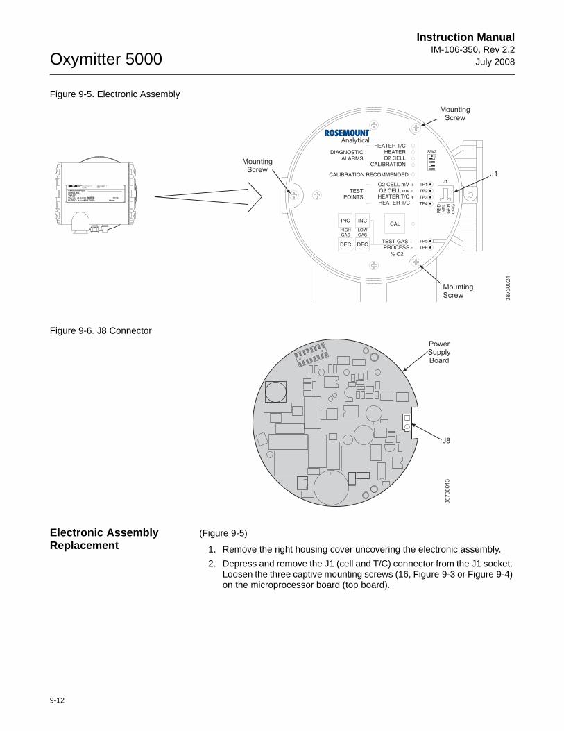
Oxymitter 5000
9-12
Instruction ManualIM-106-350, Rev 2.2
July 2008
Figure 9-5. Electronic Assembly
Figure 9-6. J8 Connector
Electronic Assembly Replacement
(Figure 9-5)
1. Remove the right housing cover uncovering the electronic assembly.
2. Depress and remove the J1 (cell and T/C) connector from the J1 socket. Loosen the three captive mounting screws (16, Figure 9-3 or Figure 9-4) on the microprocessor board (top board).
500 VA
R
SERIAL NO.TAG NO.
OXYMITTER 4000
VOLTS: WATTS:
OUTPUT: LINE FUSE:
Rosemount Analytical Inc.
Solon, OH 44139
85-264 VAC 48-62 Hz
TM
800-433-6076
4-20 mA
R
5 Amps
TMHART
SMART FAMILY
38730024
DIAGNOSTICALARMS
TESTPOINTS
HEATER T/CHEATERO2 CELL
CALIBRATION
CALIBRATION RECOMMENDED
O2 CELL mV +O2 CELL mv -HEATER T/C +HEATER T/C -
INC INC
DEC DEC
HIGHGAS
LOWGAS
CAL
TEST GAS +PROCESS -
% O2
SW2
TP1J1
TP2
TP3
RE
DY
EL
GR
NO
RG
TP4
TP5
TP6
ON
J1
MountingScrew
MountingScrew
MountingScrew
38
73
00
13
J8
PowerSupplyBoard
Instruction Manual IM-106-350, Rev 2.2July 2008
9-13
Oxymitter 5000
3. The J8 connector (heater leads) can be accessed by moving the J1 con-nector leads out of the slot on microprocessor board (17) and sliding the electronic assembly (12) partially out of the housing (Figure 9-6).
4. Squeeze the J8 connector on the sides and carefully remove. The elec-tronic assembly can now be completely removed from the housing.
5. Reconnect the J8 connector to the power supply board. Make sure the connector is secure.
6. Holding the J1 connector leads, slide the electronic assembly the rest of the way into the housing. Align the electronic assembly so that it fits flush on the pins. To ensure that it is flush gently try to rotate the elec-tronics. If the electronics rotate, repeat the alignment.
7. Reconnect the J1 connector to the microprocessor board. Ensure the connector is secure and tighten the three captive mounting screws on the microprocessor board (top board).
8. Replace the housing cover and ensure it is tight.
Terminal Block Replacement
1. Unscrew left housing cover (31, Figure 9-3).
2. Loosen mounting screws (30) on terminal block (29) and carefully lift the block out of the housing.
3. Carefully align the new terminal block on the pins so that it sits flat in the housing. The round end of the terminal block should be on the opposite side of the housing conduit ports and should not be able to rotate.
4. Tighten the three mounting screws and ensure the terminal block is secure in the housing.
Fuse Replacement (Figure 9-7)
1. Remove the right housing cover uncovering the electronic assembly.
2. Depress and remove the J1 (cell and T/C) connector from the J1 socket. Loosen the three captive mounting screws (16, Figure 9-3 or Figure 9-4) on the microprocessor board (top board).
3. The J8 connector (heater leads) (Figure 9-6) can be accessed by mov-ing the J1 connector leads out of the slot on the microprocessor board (17, Figure 9-3 or Figure 9-4) and sliding the electronic assembly (12) partially out of the housing.
4. Squeeze the J8 connector on the sides and carefully remove. The elec-tronic assembly can now be completely removed from the housing.
5. Completely remove the three mounting screws (16) on the microproces-sor board (17).
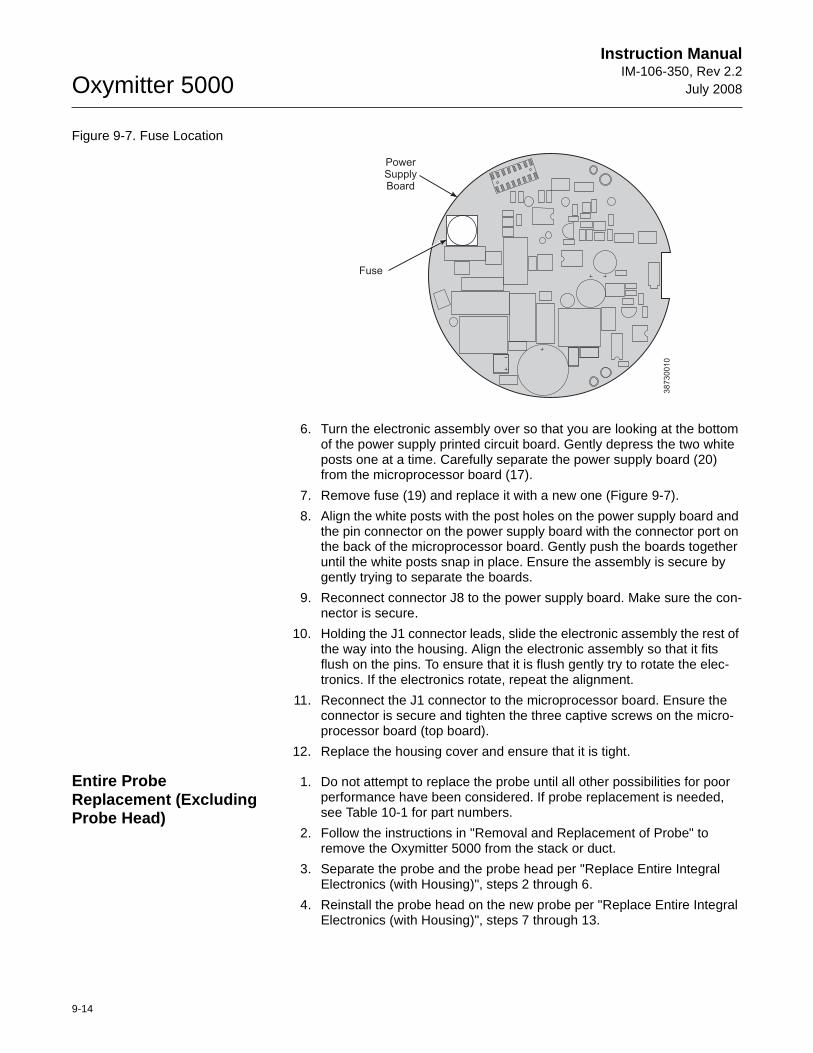
Oxymitter 5000
9-14
Instruction ManualIM-106-350, Rev 2.2
July 2008
Figure 9-7. Fuse Location
6. Turn the electronic assembly over so that you are looking at the bottom of the power supply printed circuit board. Gently depress the two white posts one at a time. Carefully separate the power supply board (20) from the microprocessor board (17).
7. Remove fuse (19) and replace it with a new one (Figure 9-7).
8. Align the white posts with the post holes on the power supply board and the pin connector on the power supply board with the connector port on the back of the microprocessor board. Gently push the boards together until the white posts snap in place. Ensure the assembly is secure by gently trying to separate the boards.
9. Reconnect connector J8 to the power supply board. Make sure the con-nector is secure.
10. Holding the J1 connector leads, slide the electronic assembly the rest of the way into the housing. Align the electronic assembly so that it fits flush on the pins. To ensure that it is flush gently try to rotate the elec-tronics. If the electronics rotate, repeat the alignment.
11. Reconnect the J1 connector to the microprocessor board. Ensure the connector is secure and tighten the three captive screws on the micro-processor board (top board).
12. Replace the housing cover and ensure that it is tight.
Entire Probe Replacement (Excluding Probe Head)
1. Do not attempt to replace the probe until all other possibilities for poor performance have been considered. If probe replacement is needed, see Table 10-1 for part numbers.
2. Follow the instructions in "Removal and Replacement of Probe" to remove the Oxymitter 5000 from the stack or duct.
3. Separate the probe and the probe head per "Replace Entire Integral Electronics (with Housing)", steps 2 through 6.
4. Reinstall the probe head on the new probe per "Replace Entire Integral Electronics (with Housing)", steps 7 through 13.
38
73
00
10
Fuse
PowerSupplyBoard
Instruction Manual IM-106-350, Rev 2.2July 2008
9-15
Oxymitter 5000
Heater Strut Replacement
This paragraph covers heater strut replacement. Do not attempt to replace the heater strut until all other possibilities for poor performance have been considered. If heater strut replacement is needed, order a replacement heater strut (Table 10-1). Refer to Figure 9-3 or Figure 9-4 to view the component parts of the Oxymitter 5000.
1. Follow the instructions in "Removal and Replacement of Probe" to remove the Oxymitter 5000 from the stack or duct.
2. For a unit with integral electronics, disconnect electronics per "Replace Entire Integral Electronics (with Housing)", steps 2 through 5.
3. For a unit with remote electronics, remove cover (11, Figure 9-4) from housing (25) along with adapter board (8) and screw (9) from heater strut assembly (1, Figure 9-3).
4. Remove four screws (2, Figure 9-4). Remove the probe from housing (25).
5. Remove tube clamps (33, Figure 9-3) and silicon tubes (32, Figure 9-3) from the CAL and REF gas ports and the CAL and REF gas lines.
6. Loosen, but do not remove, three screws (34, Figure 9-3). The spring tension will release and the heater strut assembly should move up.
7. When the spring tension is released, remove three screws (34). Grasp the wire loop and carefully slide the heater strut assembly (Figure 9-8) out of the probe tube.
8. When replacing the strut, orient the probe so the small calibration gas tube is at the 6 o'clock position of the probe tube. Align the slot on the heater plate with the calibration gas line in the probe tube. Slide the strut into the probe tube. It will turn to align the hole on the back plate of the strut with the calibration gas line. When the hole and the calibration gas line are aligned correctly, the strut will slide in the rest of the way.
9. As the strut installation nears completion, install the guide rod into the calibration gas tube to assist in guiding the calibration gas tube through the hole in the end of the strut.
10. Push down on the back plate of the strut to make sure you have spring tension and then tighten the three screws on the back plate.
11. Replace the CAL and REF gas silicon tubes.
12. For units with integral electronics, install the entire electronics per "Replace Entire Integral Electronics (with Housing)", steps 7 through 13.
Use heat resistant gloves and clothing when removing probe. Do not attempt to work on the probe until it has cooled to room temperature. The probe can be as hot as 800°F (427°C). This can cause severe burns.
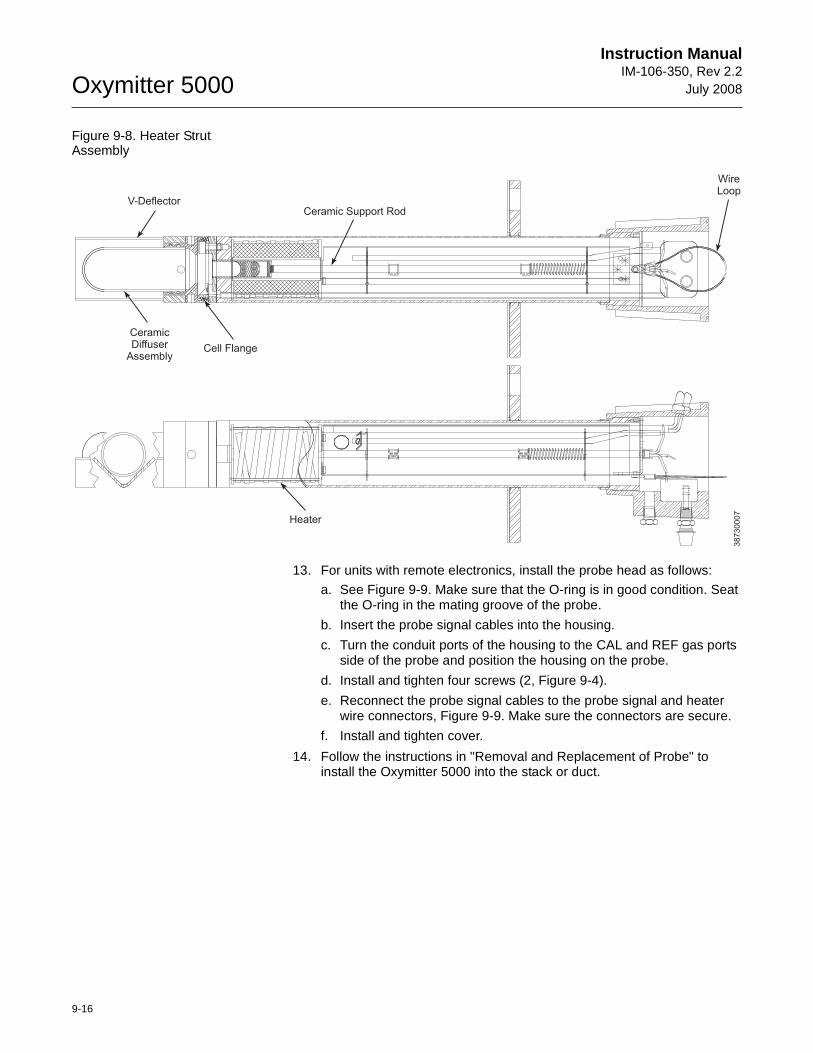
Oxymitter 5000
9-16
Instruction ManualIM-106-350, Rev 2.2
July 2008
Figure 9-8. Heater Strut Assembly
13. For units with remote electronics, install the probe head as follows:
a. See Figure 9-9. Make sure that the O-ring is in good condition. Seat the O-ring in the mating groove of the probe.
b. Insert the probe signal cables into the housing.
c. Turn the conduit ports of the housing to the CAL and REF gas ports side of the probe and position the housing on the probe.
d. Install and tighten four screws (2, Figure 9-4).
e. Reconnect the probe signal cables to the probe signal and heater wire connectors, Figure 9-9. Make sure the connectors are secure.
f. Install and tighten cover.
14. Follow the instructions in "Removal and Replacement of Probe" to install the Oxymitter 5000 into the stack or duct.
Ceramic Support Rod
Cell Flange
CeramicDiffuser
Assembly
V-Deflector
Heater
WireLoop
38730007
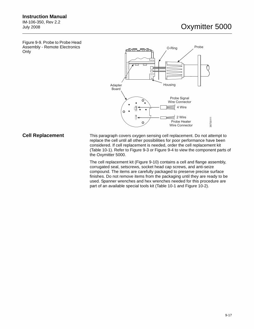
Instruction Manual IM-106-350, Rev 2.2July 2008
9-17
Oxymitter 5000
Figure 9-9. Probe to Probe Head Assembly - Remote Electronics Only
Cell Replacement This paragraph covers oxygen sensing cell replacement. Do not attempt to replace the cell until all other possibilities for poor performance have been considered. If cell replacement is needed, order the cell replacement kit (Table 10-1). Refer to Figure 9-3 or Figure 9-4 to view the component parts of the Oxymitter 5000.
The cell replacement kit (Figure 9-10) contains a cell and flange assembly, corrugated seal, setscrews, socket head cap screws, and anti-seize compound. The items are carefully packaged to preserve precise surface finishes. Do not remove items from the packaging until they are ready to be used. Spanner wrenches and hex wrenches needed for this procedure are part of an available special tools kit (Table 10-1 and Figure 10-2).
Probe SignalWire Connector
Probe HeaterWire Connector
4 Wire
2 Wire
Housing
O-Ring Probe
38
73
0111
AdapterBoard
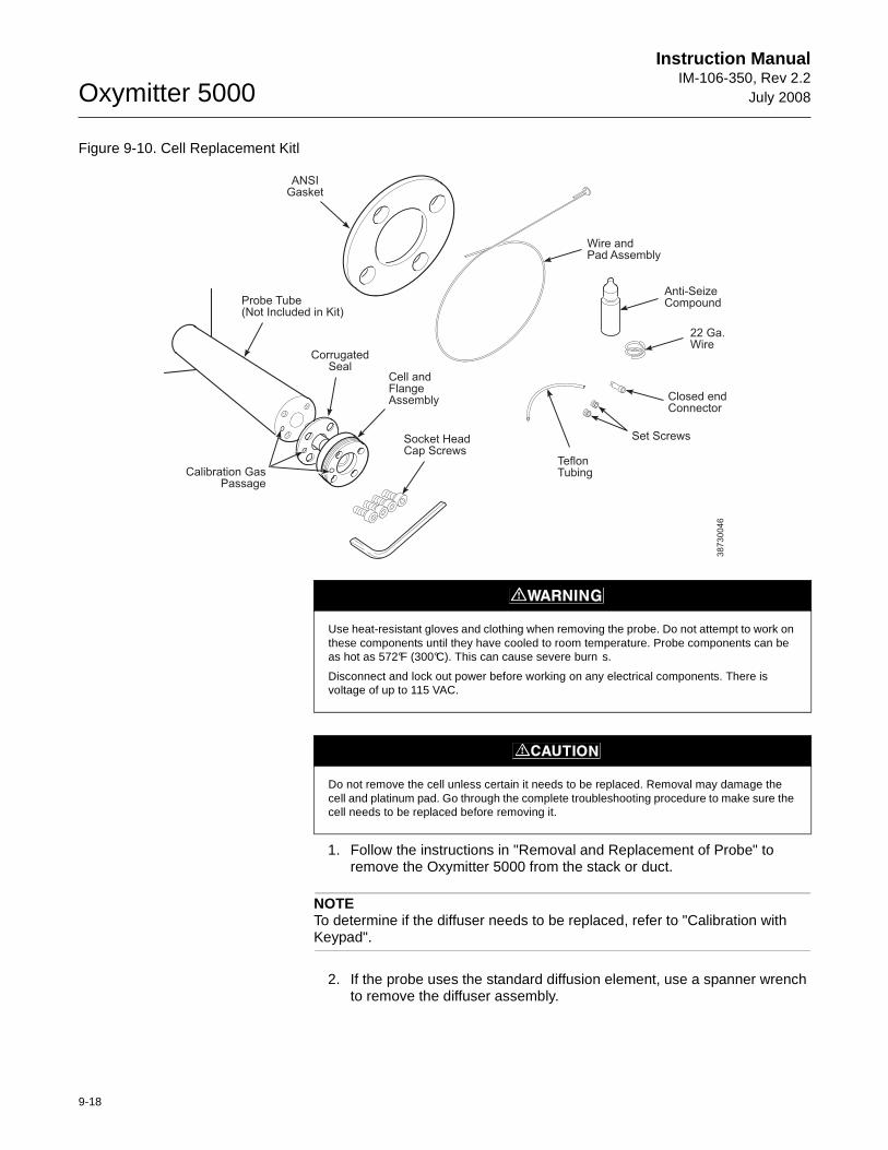
Oxymitter 5000
9-18
Instruction ManualIM-106-350, Rev 2.2
July 2008
Figure 9-10. Cell Replacement Kitl
1. Follow the instructions in "Removal and Replacement of Probe" to remove the Oxymitter 5000 from the stack or duct.
NOTETo determine if the diffuser needs to be replaced, refer to "Calibration with Keypad".
2. If the probe uses the standard diffusion element, use a spanner wrench to remove the diffuser assembly.
38730046
Wire andPad Assembly
Anti-SeizeCompound
22 Ga.Wire
Closed endConnector
Set Screws
TeflonTubing
Socket HeadCap Screws
Cell andFlangeAssembly
Calibration GasPassage
ANSIGasket
Probe Tube(Not Included in Kit)
CorrugatedSeal
Use heat-resistant gloves and clothing when removing the probe. Do not attempt to work on these components until they have cooled to room temperature. Probe components can be as hot as 572°F (300°C). This can cause severe burn s.
Disconnect and lock out power before working on any electrical components. There is voltage of up to 115 VAC.
Do not remove the cell unless certain it needs to be replaced. Removal may damage the cell and platinum pad. Go through the complete troubleshooting procedure to make sure the cell needs to be replaced before removing it.
Instruction Manual IM-106-350, Rev 2.2July 2008
9-19
Oxymitter 5000
3. If equipped with the optional ceramic diffusion assembly, remove and discard the setscrews and remove the vee deflector (Figure 9-11). Use spanner wrenches from the probe disassembly kit (Table 10-1 and Figure 10-2), to turn the hub free from the retainer. Inspect the diffusion element. If damaged, replace the element.
4. Loosen the four socket head cap screws from the cell and flange assembly and remove the assembly and the corrugated seal. The cell flange has a notch that may be used to gently pry the flange away from the probe. Note that the contact pad inside of the probe will sometimes fuse to the oxygen sensing cell. If the cell is fused to the contact pad, push the cell assembly back into the probe (against spring pressure) and quickly twist the cell assembly. The cell and contact pad should separate. If the contact pad stays fused to the cell, a new contact/thermocouple assembly must be installed. Disconnect the cell and the thermocouple wires at the crimp connections and withdraw the cell with the wires still attached.
5. For units with integral electronics, disconnect the entire electronics per "Replace Entire Integral Electronics (with Housing)", steps 2 through 5.
6. Remove four screws (7, Figure 9-3) from the probe finned housing. The probe and the probe head can now be separated.
7. If the contact assembly is damaged, replace the strut or the contact pad. Instructions for replacing the contact pad are in the cell replacement kit.
8. Remove and discard the corrugated seal. Clean the mating faces of the probe tube and retainer. Remove burrs and raised surfaces with a block of wood and crocus cloth. Clean the threads on the retainer and hub.
9. Rub a small amount of anti-seize compound on both sides of the new corrugated seal.
10. Assemble the cell and flange assembly, corrugated seal, and probe tube. Make sure the calibration tube lines up with the calibration gas passage in each component. Apply a small amount of anti-seize compound to the screw threads and use the screws to secure assembly. Torque to 35 in-lbs (4 N·m).
11. Install the entire electronics per "Replace Entire Integral Electronics (with Housing)", steps 7 through 13.
12. Apply anti-seize compound to the threads of the cell assembly, hub, and setscrews. Reinstall the hub on the cell assembly. Using pin spanner wrenches, torque to 10 ft-lbs (14 N·m). If applicable, reinstall the vee deflector, orienting apex toward gas flow. Secure with the setscrews and anti-seize compound. Torque to 25 in-lbs (2.8 N·m).
13. On systems equipped with an abrasive shield, install the dust seal gaskets, with joints 180° apart.
14. Reinstall the probe and gasket on the stack flange.
15. Follow the instructions in "Removal and Replacement of Probe" to install the Oxymitter 5000 into the stack or duct. If there is an abrasive shield in the stack, make sure the dust seal gaskets are in place as they enter the 15° reducing cone.
16. Turn on power and monitor thermocouple output. It should stabilize at 29.3+0.2 mV. Set reference air flow at 1 l/min (2 scfh). After the Oxymitter 5000 stabilizes, calibrate the unit. If new components have been installed, repeat calibration after 24 hours of operation.
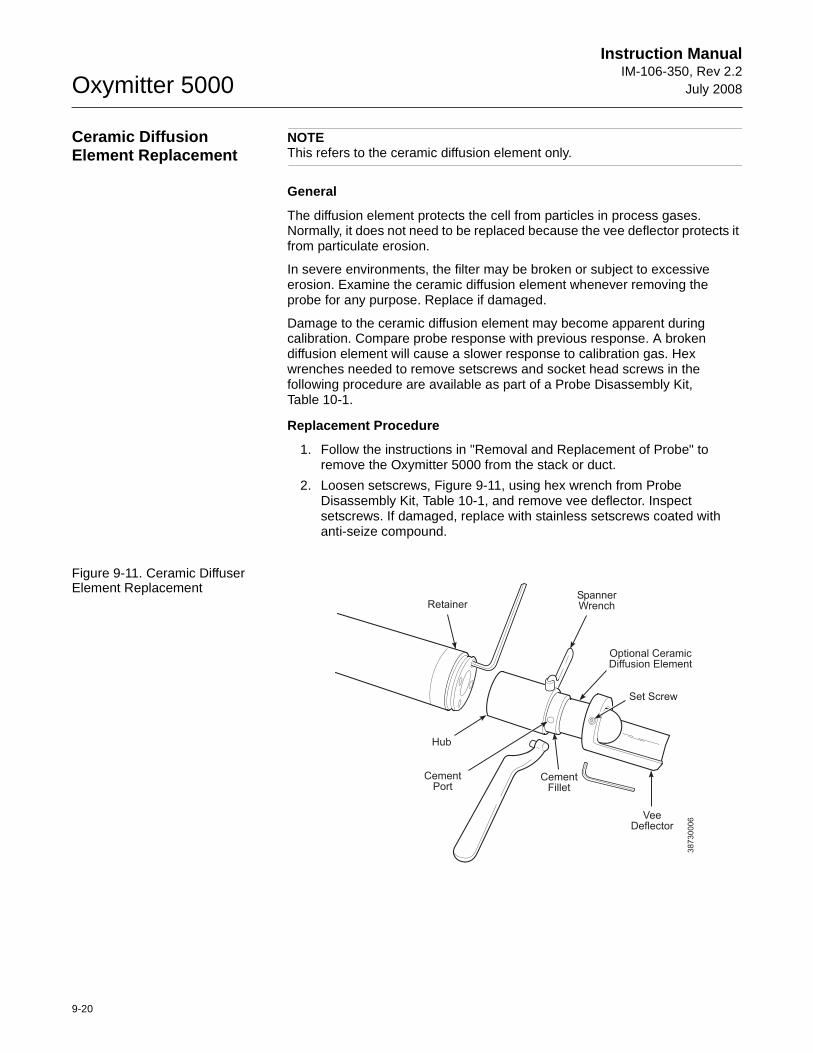
Oxymitter 5000
9-20
Instruction ManualIM-106-350, Rev 2.2
July 2008
Ceramic Diffusion Element Replacement
NOTEThis refers to the ceramic diffusion element only.
General
The diffusion element protects the cell from particles in process gases. Normally, it does not need to be replaced because the vee deflector protects it from particulate erosion.
In severe environments, the filter may be broken or subject to excessive erosion. Examine the ceramic diffusion element whenever removing the probe for any purpose. Replace if damaged.
Damage to the ceramic diffusion element may become apparent during calibration. Compare probe response with previous response. A broken diffusion element will cause a slower response to calibration gas. Hex wrenches needed to remove setscrews and socket head screws in the following procedure are available as part of a Probe Disassembly Kit, Table 10-1.
Replacement Procedure
1. Follow the instructions in "Removal and Replacement of Probe" to remove the Oxymitter 5000 from the stack or duct.
2. Loosen setscrews, Figure 9-11, using hex wrench from Probe Disassembly Kit, Table 10-1, and remove vee deflector. Inspect setscrews. If damaged, replace with stainless setscrews coated with anti-seize compound.
Figure 9-11. Ceramic Diffuser Element Replacement
RetainerSpannerWrench
Optional CeramicDiffusion Element
Set Screw
VeeDeflector
CementFillet
CementPort
Hub
38730006
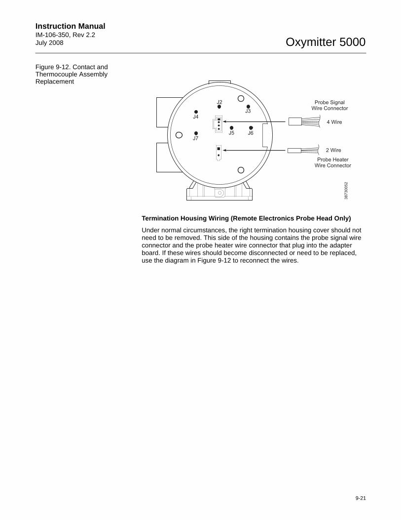
Instruction Manual IM-106-350, Rev 2.2July 2008
9-21
Oxymitter 5000
Figure 9-12. Contact and Thermocouple Assembly Replacement
Termination Housing Wiring (Remote Electronics Prob e Head Only)
Under normal circumstances, the right termination housing cover should not need to be removed. This side of the housing contains the probe signal wire connector and the probe heater wire connector that plug into the adapter board. If these wires should become disconnected or need to be replaced, use the diagram in Figure 9-12 to reconnect the wires.
38
73
00
52
J4
J7
J2
J5 J6
J3
Probe SignalWire Connector
Probe HeaterWire Connector
4 Wire
2 Wire

Oxymitter 5000
9-22
Instruction ManualIM-106-350, Rev 2.2
July 2008
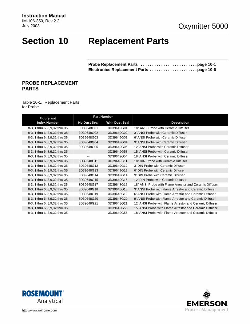
Instruction Manual IM-106-350, Rev 2.2July 2008 Oxymitter 5000
http://www.raihome.com
Section 10 Replacement Parts
Probe Replacement Parts . . . . . . . . . . . . . . . . . . . . . . . . . page 10-1Electronics Replacement Parts . . . . . . . . . . . . . . . . . . . . . page 10-6
PROBE REPLACEMENT PARTS
Table 10-1. Replacement Parts for Probe
Figure and Index Number
Part Number
No Dust Seal With Dust Seal Description
8-3, 1 thru 6, 8,9,32 thru 35 3D39648G01 3D39649G01 18" ANSI Probe with Ceramic Diffuser
8-3, 1 thru 6, 8,9,32 thru 35 3D39648G02 3D39649G02 3' ANSI Probe with Ceramic Diffuser
8-3, 1 thru 6, 8,9,32 thru 35 3D39648G03 3D39649G03 6' ANSI Probe with Ceramic Diffuser
8-3, 1 thru 6, 8,9,32 thru 35 3D39648G04 3D39649G04 9' ANSI Probe with Ceramic Diffuser
8-3, 1 thru 6, 8,9,32 thru 35 3D39648G05 3D39649G05 12' ANSI Probe with Ceramic Diffuser8-3, 1 thru 6, 8,9,32 thru 35 -- 3D39649G53 15' ANSI Probe with Ceramic Diffuser
8-3, 1 thru 6, 8,9,32 thru 35 -- 3D39649G54 18' ANSI Probe with Ceramic Diffuser
8-3, 1 thru 6, 8,9,32 thru 35 3D39648G11 3D39649G11 18" DIN Probe with Ceramic Diffuser
8-3, 1 thru 6, 8,9,32 thru 35 3D39648G12 3D39649G12 3' DIN Probe with Ceramic Diffuser
8-3, 1 thru 6, 8,9,32 thru 35 3D39648G13 3D39649G13 6' DIN Probe with Ceramic Diffuser
8-3, 1 thru 6, 8,9,32 thru 35 3D39648G14 3D39649G14 9' DIN Probe with Ceramic Diffuser8-3, 1 thru 6, 8,9,32 thru 35 3D39648G15 3D39649G15 12' DIN Probe with Ceramic Diffuser
8-3, 1 thru 6, 8,9,32 thru 35 3D39648G17 3D39648G17 18" ANSI Probe with Flame Arrestor and Ceramic Diffuser
8-3, 1 thru 6, 8,9,32 thru 35 3D39648G18 3D39648G18 3' ANSI Probe with Flame Arrestor and Ceramic Diffuser
8-3, 1 thru 6, 8,9,32 thru 35 3D39648G19 3D39648G19 6' ANSI Probe with Flame Arrestor and Ceramic Diffuser
8-3, 1 thru 6, 8,9,32 thru 35 3D39648G20 3D39648G20 9' ANSI Probe with Flame Arrestor and Ceramic Diffuser
8-3, 1 thru 6, 8,9,32 thru 35 3D39648G21 3D39648G21 12' ANSI Probe with Flame Arrestor and Ceramic Diffuser8-3, 1 thru 6, 8,9,32 thru 35 -- 3D39649G55 15' ANSI Probe with Flame Arrestor and Ceramic Diffuser
8-3, 1 thru 6, 8,9,32 thru 35 -- 3D39649G56 18' ANSI Probe with Flame Arrestor and Ceramic Diffuser
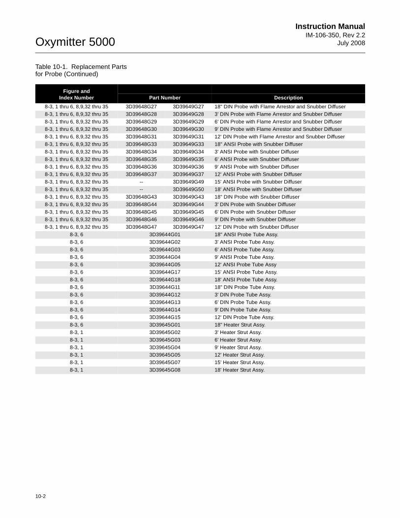
Oxymitter 5000
10-2
Instruction ManualIM-106-350, Rev 2.2
July 2008
Table 10-1. Replacement Parts for Probe (Continued)
Figure and Index Number Part Number Description
8-3, 1 thru 6, 8,9,32 thru 35 3D39648G27 3D39649G27 18" DIN Probe with Flame Arrestor and Snubber Diffuser
8-3, 1 thru 6, 8,9,32 thru 35 3D39648G28 3D39649G28 3' DIN Probe with Flame Arrestor and Snubber Diffuser
8-3, 1 thru 6, 8,9,32 thru 35 3D39648G29 3D39649G29 6' DIN Probe with Flame Arrestor and Snubber Diffuser8-3, 1 thru 6, 8,9,32 thru 35 3D39648G30 3D39649G30 9' DIN Probe with Flame Arrestor and Snubber Diffuser
8-3, 1 thru 6, 8,9,32 thru 35 3D39648G31 3D39649G31 12' DIN Probe with Flame Arrestor and Snubber Diffuser
8-3, 1 thru 6, 8,9,32 thru 35 3D39648G33 3D39649G33 18" ANSI Probe with Snubber Diffuser
8-3, 1 thru 6, 8,9,32 thru 35 3D39648G34 3D39649G34 3' ANSI Probe with Snubber Diffuser
8-3, 1 thru 6, 8,9,32 thru 35 3D39648G35 3D39649G35 6' ANSI Probe with Snubber Diffuser
8-3, 1 thru 6, 8,9,32 thru 35 3D39648G36 3D39649G36 9' ANSI Probe with Snubber Diffuser8-3, 1 thru 6, 8,9,32 thru 35 3D39648G37 3D39649G37 12' ANSI Probe with Snubber Diffuser
8-3, 1 thru 6, 8,9,32 thru 35 -- 3D39649G49 15' ANSI Probe with Snubber Diffuser
8-3, 1 thru 6, 8,9,32 thru 35 -- 3D39649G50 18' ANSI Probe with Snubber Diffuser
8-3, 1 thru 6, 8,9,32 thru 35 3D39648G43 3D39649G43 18" DIN Probe with Snubber Diffuser
8-3, 1 thru 6, 8,9,32 thru 35 3D39648G44 3D39649G44 3' DIN Probe with Snubber Diffuser
8-3, 1 thru 6, 8,9,32 thru 35 3D39648G45 3D39649G45 6' DIN Probe with Snubber Diffuser8-3, 1 thru 6, 8,9,32 thru 35 3D39648G46 3D39649G46 9' DIN Probe with Snubber Diffuser
8-3, 1 thru 6, 8,9,32 thru 35 3D39648G47 3D39649G47 12' DIN Probe with Snubber Diffuser
8-3, 6 3D39644G01 18" ANSI Probe Tube Assy.
8-3, 6 3D39644G02 3' ANSI Probe Tube Assy.
8-3, 6 3D39644G03 6' ANSI Probe Tube Assy.
8-3, 6 3D39644G04 9' ANSI Probe Tube Assy.8-3, 6 3D39644G05 12' ANSI Probe Tube Assy
8-3, 6 3D39644G17 15' ANSI Probe Tube Assy.
8-3, 6 3D39644G18 18' ANSI Probe Tube Assy.
8-3, 6 3D39644G11 18" DIN Probe Tube Assy.
8-3, 6 3D39644G12 3' DIN Probe Tube Assy.
8-3, 6 3D39644G13 6' DIN Probe Tube Assy.8-3, 6 3D39644G14 9' DIN Probe Tube Assy.
8-3, 6 3D39644G15 12' DIN Probe Tube Assy.
8-3, 6 3D39645G01 18" Heater Strut Assy.
8-3, 1 3D39645G02 3' Heater Strut Assy.
8-3, 1 3D39645G03 6' Heater Strut Assy.
8-3, 1 3D39645G04 9' Heater Strut Assy.8-3, 1 3D39645G05 12' Heater Strut Assy.
8-3, 1 3D39645G07 15' Heater Strut Assy.
8-3, 1 3D39645G08 18' Heater Strut Assy.
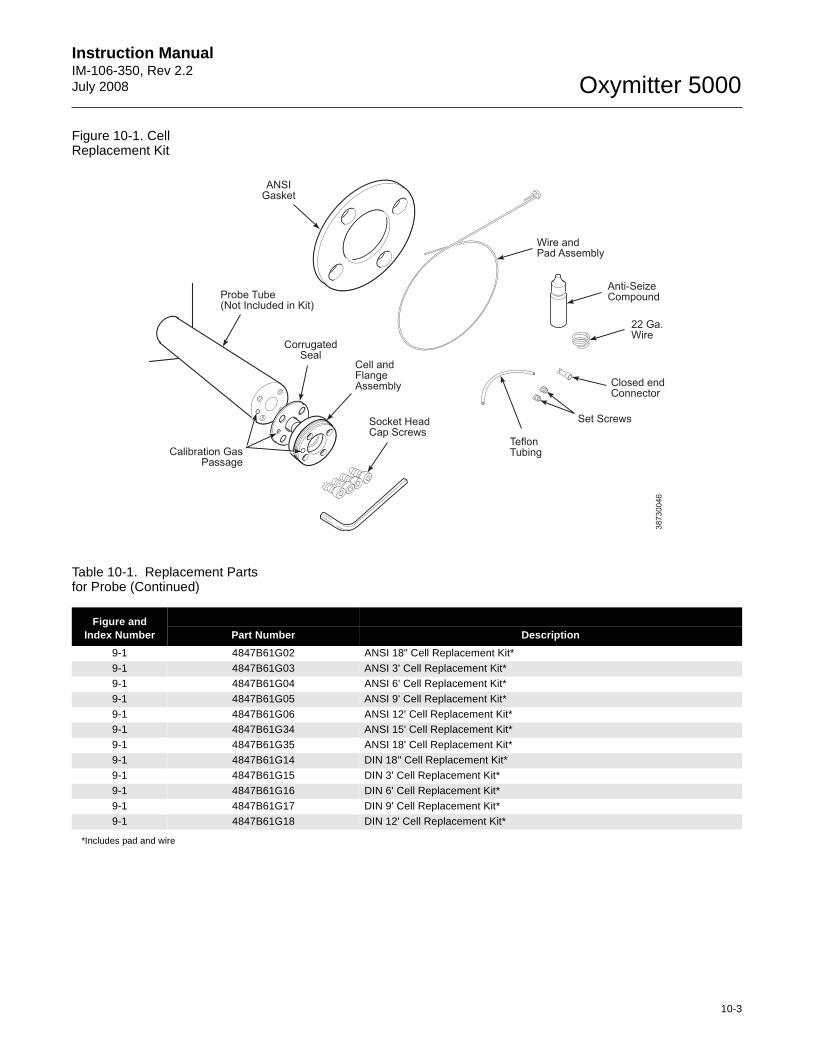
Instruction Manual IM-106-350, Rev 2.2July 2008
10-3
Oxymitter 5000
Figure 10-1. CellReplacement Kit
Table 10-1. Replacement Parts for Probe (Continued)
*Includes pad and wire
38730046
Wire andPad Assembly
Anti-SeizeCompound
22 Ga.Wire
Closed endConnector
Set Screws
TeflonTubing
Socket HeadCap Screws
Cell andFlangeAssembly
Calibration GasPassage
ANSIGasket
Probe Tube(Not Included in Kit)
CorrugatedSeal
Figure and Index Number Part Number Description
9-1 4847B61G02 ANSI 18" Cell Replacement Kit*
9-1 4847B61G03 ANSI 3' Cell Replacement Kit*
9-1 4847B61G04 ANSI 6' Cell Replacement Kit*
9-1 4847B61G05 ANSI 9' Cell Replacement Kit*
9-1 4847B61G06 ANSI 12' Cell Replacement Kit*9-1 4847B61G34 ANSI 15' Cell Replacement Kit*
9-1 4847B61G35 ANSI 18' Cell Replacement Kit*
9-1 4847B61G14 DIN 18" Cell Replacement Kit*
9-1 4847B61G15 DIN 3' Cell Replacement Kit*
9-1 4847B61G16 DIN 6' Cell Replacement Kit*
9-1 4847B61G17 DIN 9' Cell Replacement Kit*
9-1 4847B61G18 DIN 12' Cell Replacement Kit*
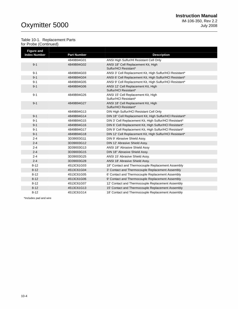
Oxymitter 5000
10-4
Instruction ManualIM-106-350, Rev 2.2
July 2008
Table 10-1. Replacement Parts for Probe (Continued)
*Includes pad and wire
Figure and Index Number Part Number Description
4849B94G01 ANSI High Sulfur/Hl Resistant Cell Only
9-1 4849B94G02 ANSI 18" Cell Replacement Kit, High Sulfur/HCl Resistant*
9-1 4849B94G03 ANSI 3' Cell Replacement Kit, High Sulfur/HCl Resistant*
9-1 4849B94G04 ANSI 6' Cell Replacement Kit, High Sulfur/HCl Resistant*
9-1 4849B94G05 ANSI 9' Cell Replacement Kit, High Sulfur/HCl Resistant*9-1 4849B94G06 ANSI 12' Cell Replacement Kit, High
Sulfur/HCl Resistant*
9-1 4849B94G26 ANSI 15' Cell Replacement Kit, High Sulfur/HCl Resistant*
9-1 4849B94G27 ANSI 18' Cell Replacement Kit, High Sulfur/HCl Resistant*
4849B94G13 DIN High Sulfur/HCl Resistant Cell Only
9-1 4849B94G14 DIN 18" Cell Replacement Kit, High Sulfur/HCl Resistant*
9-1 4849B94G15 DIN 3' Cell Replacement Kit, High Sulfur/HCl Resistant*9-1 4849B94G16 DIN 6' Cell Replacement Kit, High Sulfur/HCl Resistant*
9-1 4849B94G17 DIN 9' Cell Replacement Kit, High Sulfur/HCl Resistant*
9-1 4849B94G18 DIN 12' Cell Replacement Kit, High Sulfur/HCl Resistant*
2-4 3D39003G11 DIN 9' Abrasive Shield Assy.
2-4 3D39003G12 DIN 12' Abrasive Shield Assy.
2-4 3D39003G13 ANSI 18" Abrasive Shield Assy2-4 3D39003G15 DIN 18" Abrasive Shield Assy.
2-4 3D39003G25 ANSI 15' Abrasive Shield Assy.
2-4 3D39003G28 ANSI 18' Abrasive Shield Assy.
8-12 4513C61G03 18" Contact and Thermocouple Replacement Assembly
8-12 4513C61G04 3' Contact and Thermocouple Replacement Assembly
8-12 4513C61G05 6' Contact and Thermocouple Replacement Assembly8-12 4513C61G06 9' Contact and Thermocouple Replacement Assembly
8-12 4513C61G07 12' Contact and Thermocouple Replacement Assembly
8-12 4513C61G13 15' Contact and Thermocouple Replacement Assembly
8-12 4513C61G14 18' Contact and Thermocouple Replacement Assembly
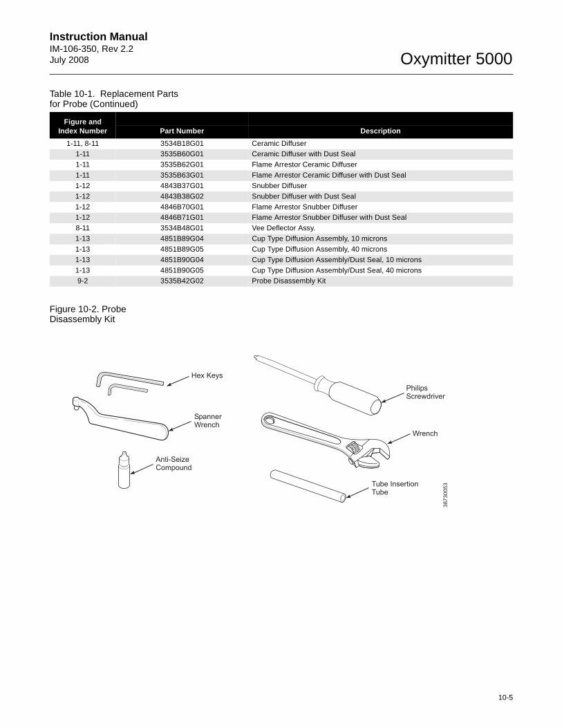
Instruction Manual IM-106-350, Rev 2.2July 2008
10-5
Oxymitter 5000
Table 10-1. Replacement Parts for Probe (Continued)
Figure 10-2. Probe Disassembly Kit
Figure and Index Number Part Number Description
1-11, 8-11 3534B18G01 Ceramic Diffuser1-11 3535B60G01 Ceramic Diffuser with Dust Seal
1-11 3535B62G01 Flame Arrestor Ceramic Diffuser
1-11 3535B63G01 Flame Arrestor Ceramic Diffuser with Dust Seal
1-12 4843B37G01 Snubber Diffuser
1-12 4843B38G02 Snubber Diffuser with Dust Seal
1-12 4846B70G01 Flame Arrestor Snubber Diffuser1-12 4846B71G01 Flame Arrestor Snubber Diffuser with Dust Seal
8-11 3534B48G01 Vee Deflector Assy.
1-13 4851B89G04 Cup Type Diffusion Assembly, 10 microns
1-13 4851B89G05 Cup Type Diffusion Assembly, 40 microns
1-13 4851B90G04 Cup Type Diffusion Assembly/Dust Seal, 10 microns
1-13 4851B90G05 Cup Type Diffusion Assembly/Dust Seal, 40 microns9-2 3535B42G02 Probe Disassembly Kit
Hex Keys
Wrench
Tube InsertionTube
PhilipsScrewdriver
SpannerWrench
Anti-SeizeCompound
38730053
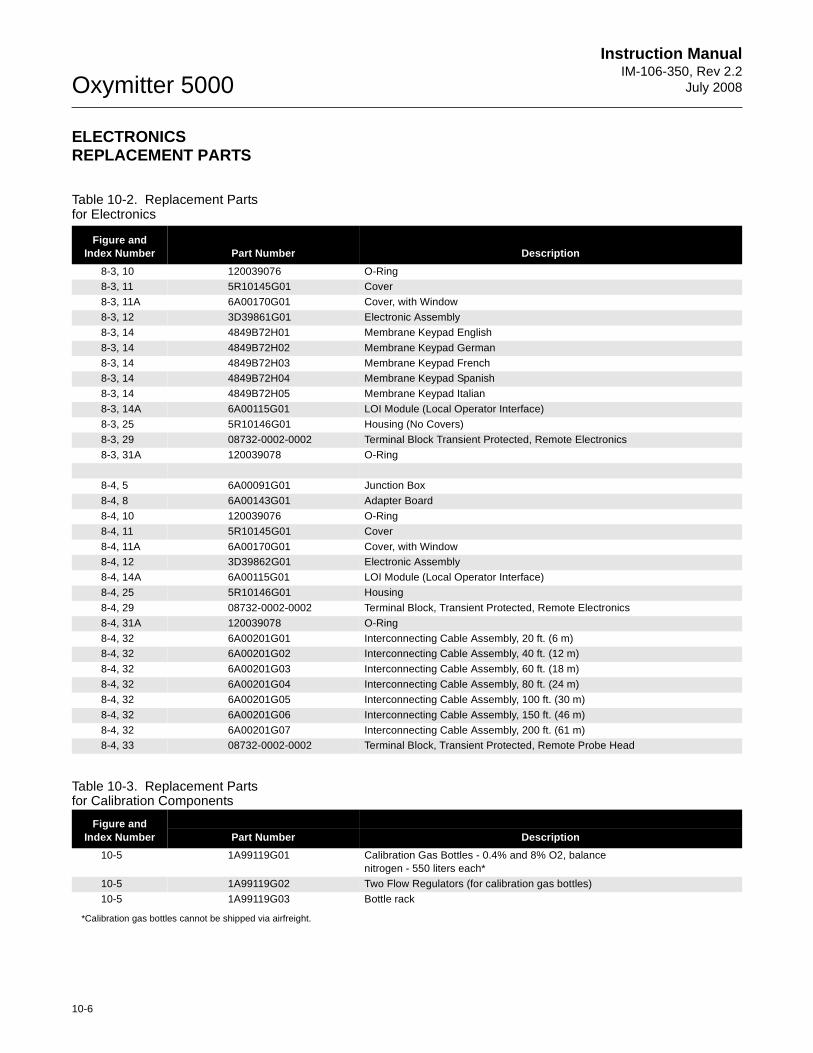
Oxymitter 5000
10-6
Instruction ManualIM-106-350, Rev 2.2
July 2008
ELECTRONICS REPLACEMENT PARTS
Table 10-2. Replacement Parts for Electronics
Table 10-3. Replacement Parts for Calibration Components
*Calibration gas bottles cannot be shipped via airfreight.
Figure and Index Number Part Number Description
8-3, 10 120039076 O-Ring8-3, 11 5R10145G01 Cover
8-3, 11A 6A00170G01 Cover, with Window
8-3, 12 3D39861G01 Electronic Assembly
8-3, 14 4849B72H01 Membrane Keypad English
8-3, 14 4849B72H02 Membrane Keypad German
8-3, 14 4849B72H03 Membrane Keypad French8-3, 14 4849B72H04 Membrane Keypad Spanish
8-3, 14 4849B72H05 Membrane Keypad Italian
8-3, 14A 6A00115G01 LOI Module (Local Operator Interface)
8-3, 25 5R10146G01 Housing (No Covers)
8-3, 29 08732-0002-0002 Terminal Block Transient Protected, Remote Electronics
8-3, 31A 120039078 O-Ring
8-4, 5 6A00091G01 Junction Box
8-4, 8 6A00143G01 Adapter Board
8-4, 10 120039076 O-Ring
8-4, 11 5R10145G01 Cover
8-4, 11A 6A00170G01 Cover, with Window8-4, 12 3D39862G01 Electronic Assembly
8-4, 14A 6A00115G01 LOI Module (Local Operator Interface)
8-4, 25 5R10146G01 Housing
8-4, 29 08732-0002-0002 Terminal Block, Transient Protected, Remote Electronics
8-4, 31A 120039078 O-Ring
8-4, 32 6A00201G01 Interconnecting Cable Assembly, 20 ft. (6 m)8-4, 32 6A00201G02 Interconnecting Cable Assembly, 40 ft. (12 m)
8-4, 32 6A00201G03 Interconnecting Cable Assembly, 60 ft. (18 m)
8-4, 32 6A00201G04 Interconnecting Cable Assembly, 80 ft. (24 m)
8-4, 32 6A00201G05 Interconnecting Cable Assembly, 100 ft. (30 m)
8-4, 32 6A00201G06 Interconnecting Cable Assembly, 150 ft. (46 m)
8-4, 32 6A00201G07 Interconnecting Cable Assembly, 200 ft. (61 m)8-4, 33 08732-0002-0002 Terminal Block, Transient Protected, Remote Probe Head
Figure and Index Number Part Number Description
10-5 1A99119G01 Calibration Gas Bottles - 0.4% and 8% O2, balance nitrogen - 550 liters each*
10-5 1A99119G02 Two Flow Regulators (for calibration gas bottles)
10-5 1A99119G03 Bottle rack
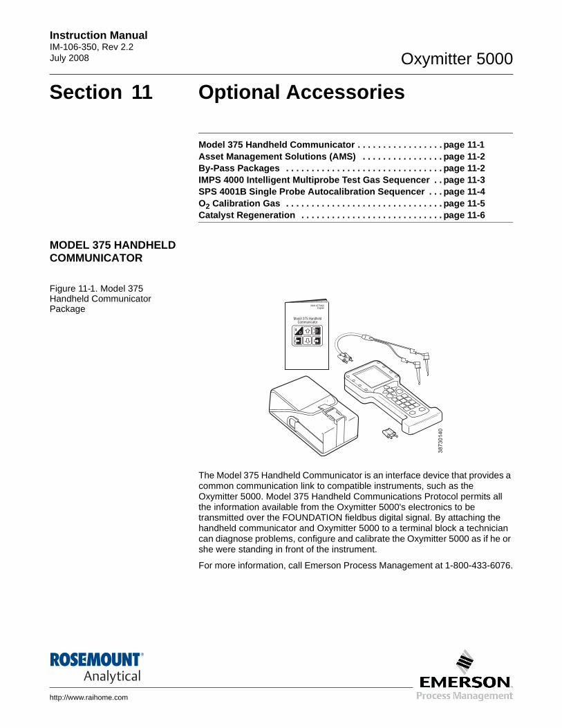
Instruction Manual IM-106-350, Rev 2.2July 2008 Oxymitter 5000
http://www.raihome.com
Section 11 Optional Accessories
Model 375 Handheld Communicator . . . . . . . . . . . . . . . . . page 11-1Asset Management Solutions (AMS) . . . . . . . . . . . . . . . . page 11-2By-Pass Packages . . . . . . . . . . . . . . . . . . . . . . . . . . . . . . . page 11-2IMPS 4000 Intelligent Multiprobe Test Gas Sequencer . . page 11-3SPS 4001B Single Probe Autocalibration Sequencer . . . page 11-4O2 Calibration Gas . . . . . . . . . . . . . . . . . . . . . . . . . . . . . . . page 11-5Catalyst Regeneration . . . . . . . . . . . . . . . . . . . . . . . . . . . . page 11-6
MODEL 375 HANDHELD COMMUNICATOR
Figure 11-1. Model 375 Handheld Communicator Package
The Model 375 Handheld Communicator is an interface device that provides a common communication link to compatible instruments, such as the Oxymitter 5000. Model 375 Handheld Communications Protocol permits all the information available from the Oxymitter 5000's electronics to be transmitted over the FOUNDATION fieldbus digital signal. By attaching the handheld communicator and Oxymitter 5000 to a terminal block a technician can diagnose problems, configure and calibrate the Oxymitter 5000 as if he or she were standing in front of the instrument.
For more information, call Emerson Process Management at 1-800-433-6076.
o
Model 375 HandheldCommunicator
MAN 4275A00English
38730140
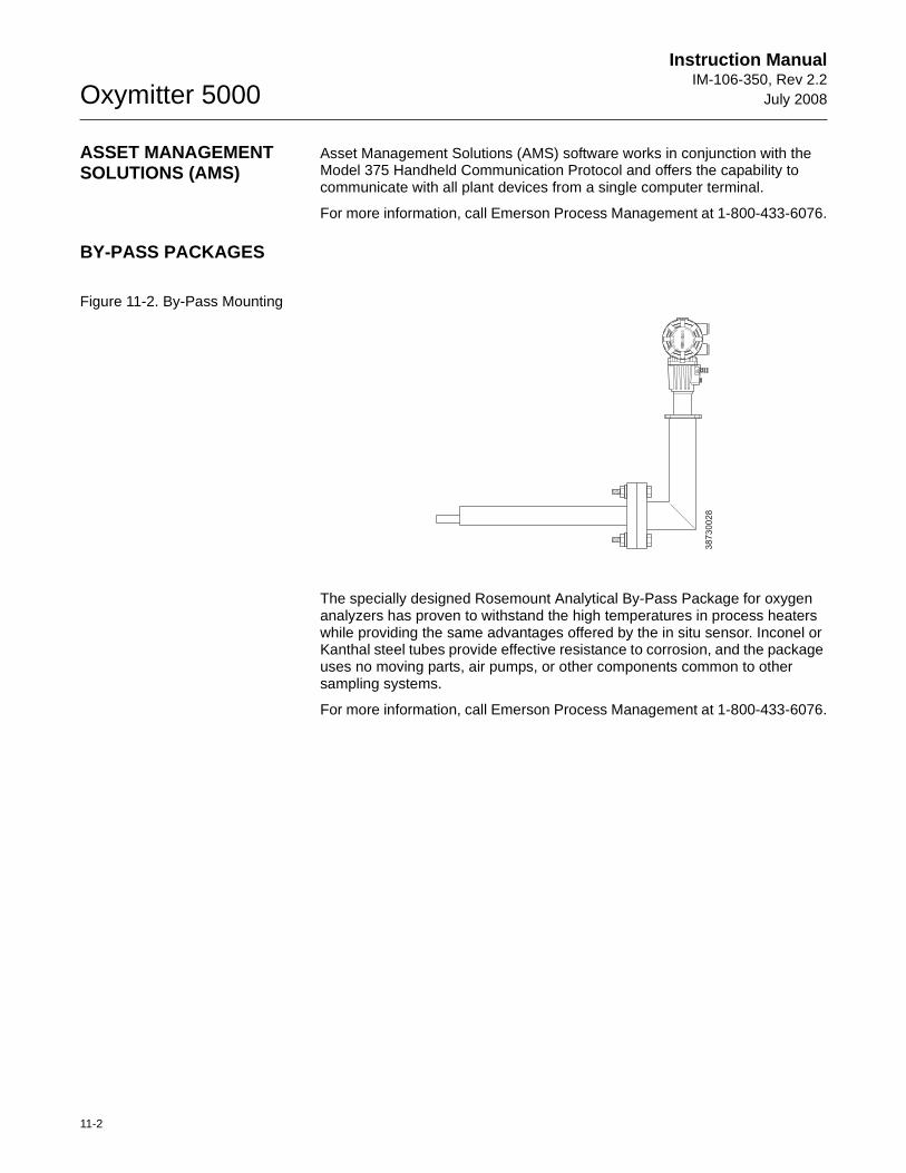
Oxymitter 5000
11-2
Instruction ManualIM-106-350, Rev 2.2
July 2008
ASSET MANAGEMENT SOLUTIONS (AMS)
Asset Management Solutions (AMS) software works in conjunction with the Model 375 Handheld Communication Protocol and offers the capability to communicate with all plant devices from a single computer terminal.
For more information, call Emerson Process Management at 1-800-433-6076.
BY-PASS PACKAGES
Figure 11-2. By-Pass Mounting
The specially designed Rosemount Analytical By-Pass Package for oxygen analyzers has proven to withstand the high temperatures in process heaters while providing the same advantages offered by the in situ sensor. Inconel or Kanthal steel tubes provide effective resistance to corrosion, and the package uses no moving parts, air pumps, or other components common to other sampling systems.
For more information, call Emerson Process Management at 1-800-433-6076.
PS
U
E
I
TP
IC
RH
WE
NT
HG
C
E
NI
E
E RW
AVIS
OL
P-
XO
MT
A GNI
N-
R
I
T
L A
I
VE
-E
EH
GA
SC
AL
.
38730028
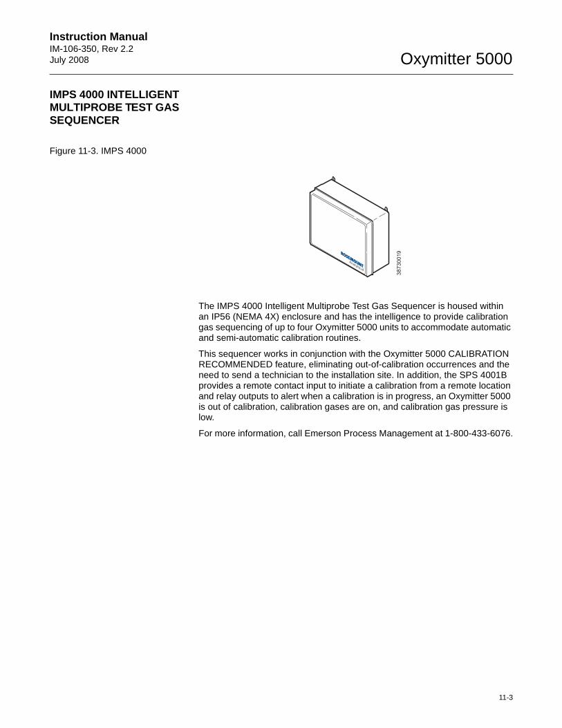
Instruction Manual IM-106-350, Rev 2.2July 2008
11-3
Oxymitter 5000
IMPS 4000 INTELLIGENT MULTIPROBE TEST GAS SEQUENCER
Figure 11-3. IMPS 4000
The IMPS 4000 Intelligent Multiprobe Test Gas Sequencer is housed within an IP56 (NEMA 4X) enclosure and has the intelligence to provide calibration gas sequencing of up to four Oxymitter 5000 units to accommodate automatic and semi-automatic calibration routines.
This sequencer works in conjunction with the Oxymitter 5000 CALIBRATION RECOMMENDED feature, eliminating out-of-calibration occurrences and the need to send a technician to the installation site. In addition, the SPS 4001B provides a remote contact input to initiate a calibration from a remote location and relay outputs to alert when a calibration is in progress, an Oxymitter 5000 is out of calibration, calibration gases are on, and calibration gas pressure is low.
For more information, call Emerson Process Management at 1-800-433-6076.
38730019
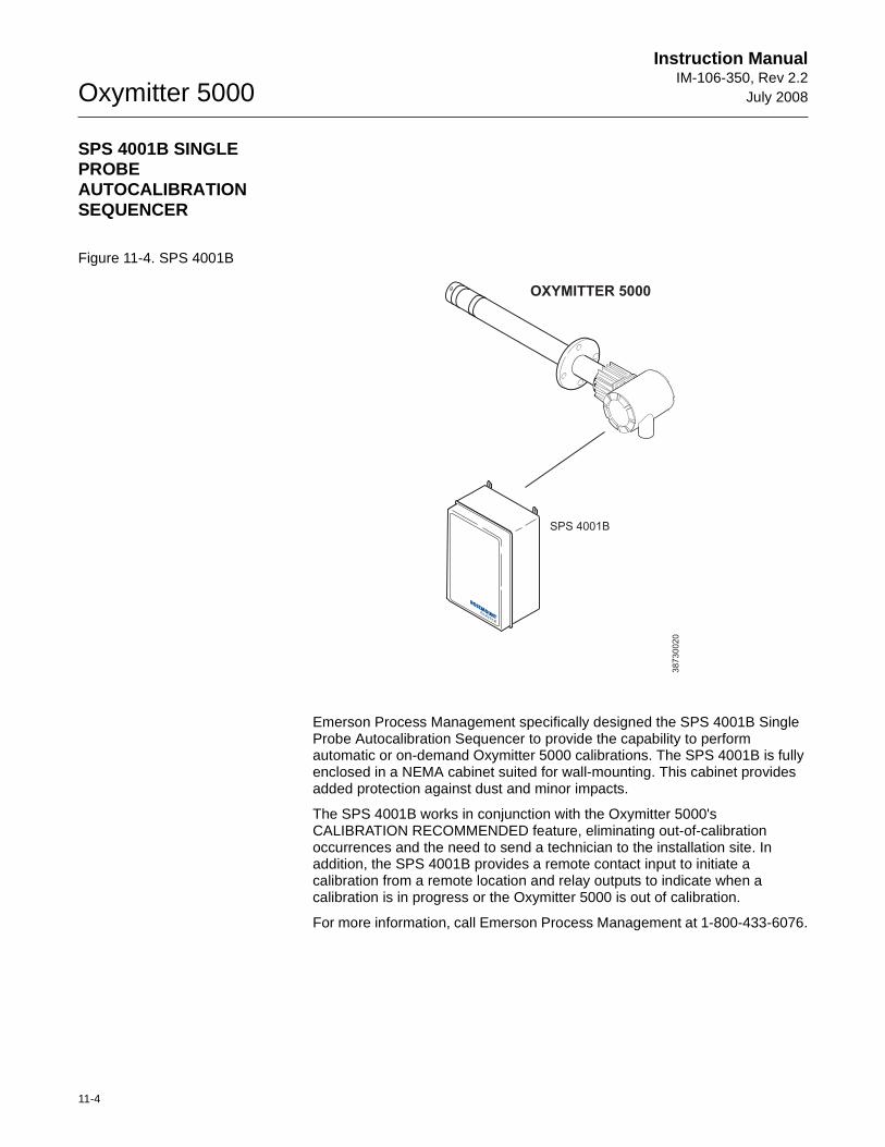
Oxymitter 5000
11-4
Instruction ManualIM-106-350, Rev 2.2
July 2008
SPS 4001B SINGLE PROBE AUTOCALIBRATION SEQUENCER
Figure 11-4. SPS 4001B
Emerson Process Management specifically designed the SPS 4001B Single Probe Autocalibration Sequencer to provide the capability to perform automatic or on-demand Oxymitter 5000 calibrations. The SPS 4001B is fully enclosed in a NEMA cabinet suited for wall-mounting. This cabinet provides added protection against dust and minor impacts.
The SPS 4001B works in conjunction with the Oxymitter 5000's CALIBRATION RECOMMENDED feature, eliminating out-of-calibration occurrences and the need to send a technician to the installation site. In addition, the SPS 4001B provides a remote contact input to initiate a calibration from a remote location and relay outputs to indicate when a calibration is in progress or the Oxymitter 5000 is out of calibration.
For more information, call Emerson Process Management at 1-800-433-6076.
38730020
SPS 4001B
OXYMITTER 5000
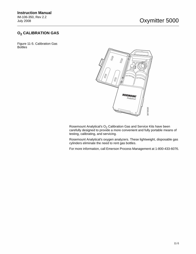
Instruction Manual IM-106-350, Rev 2.2July 2008
11-5
Oxymitter 5000
O2 CALIBRATION GAS
Figure 11-5. Calibration Gas Bottles
Rosemount Analytical's O2 Calibration Gas and Service Kits have been carefully designed to provide a more convenient and fully portable means of testing, calibrating, and servicing.
Rosemount Analytical's oxygen analyzers. These lightweight, disposable gas cylinders eliminate the need to rent gas bottles.
For more information, call Emerson Process Management at 1-800-433-6076.38730026
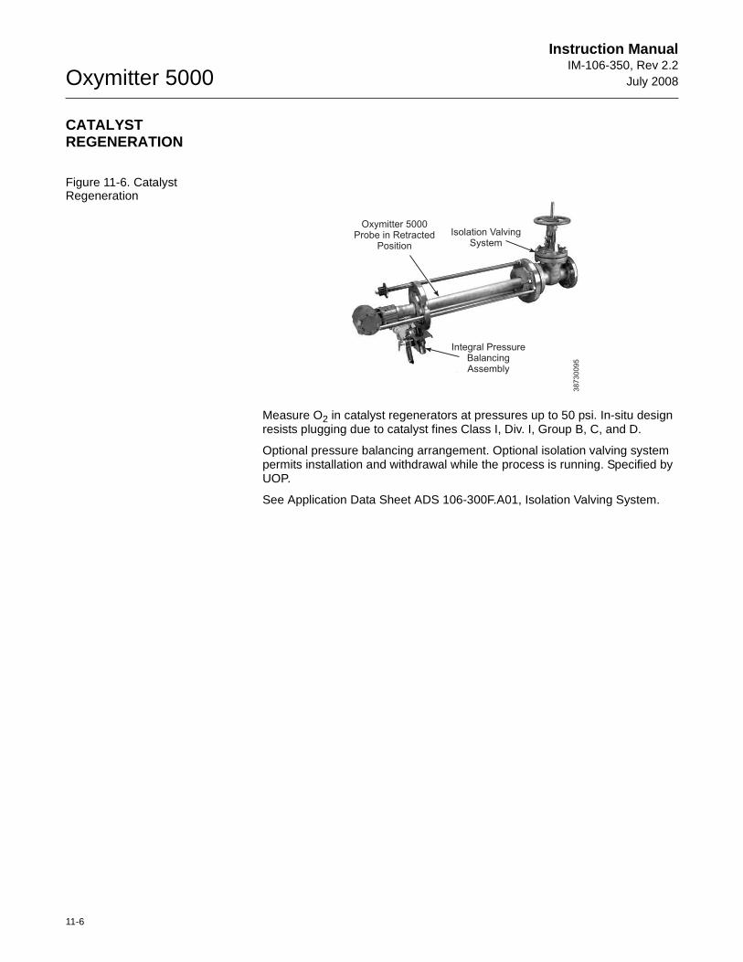
Oxymitter 5000
11-6
Instruction ManualIM-106-350, Rev 2.2
July 2008
CATALYST REGENERATION
Figure 11-6. Catalyst Regeneration
Measure O2 in catalyst regenerators at pressures up to 50 psi. In-situ design resists plugging due to catalyst fines Class I, Div. I, Group B, C, and D.
Optional pressure balancing arrangement. Optional isolation valving system permits installation and withdrawal while the process is running. Specified by UOP.
See Application Data Sheet ADS 106-300F.A01, Isolation Valving System.
38730095
Oxymitter 5000Probe in Retracted
Position
Isolation ValvingSystem
Integral PressureBalancingAssembly

Instruction Manual IM-106-350, Rev 2.2July 2008 Oxymitter 5000
http://www.raihome.com
Appendix A Safety Data
Safety Instructions . . . . . . . . . . . . . . . . . . . . . . . . . . . . . . . . . . . . . page A-2Safety Data Sheet for Ceramic Fiber Products . . . . . . . . . . . . . page A-24
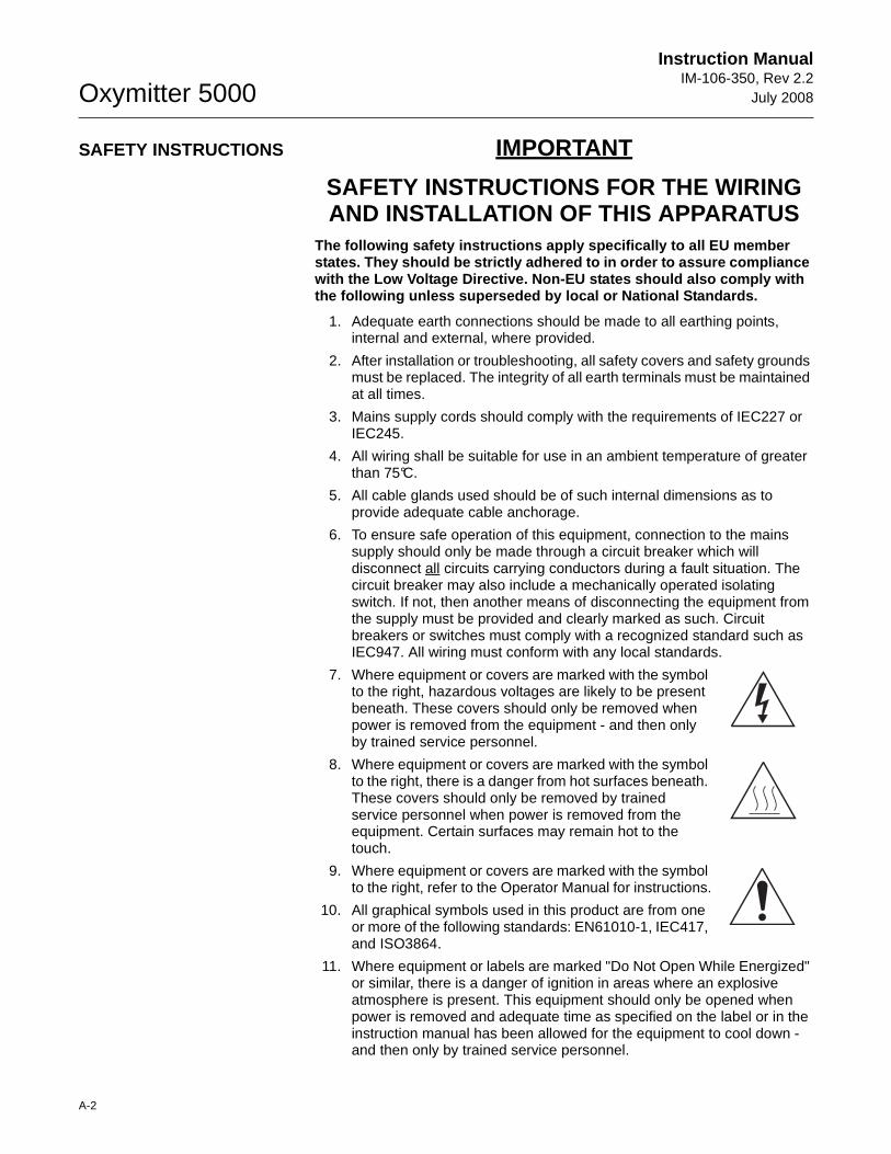
Oxymitter 5000
A-2
Instruction ManualIM-106-350, Rev 2.2
July 2008
SAFETY INSTRUCTIONS IMPORTANT
SAFETY INSTRUCTIONS FOR THE WIRING AND INSTALLATION OF THIS APPARATUS
The following safety instructions apply specificall y to all EU member states. They should be strictly adhered to in order to assure compliance with the Low Voltage Directive. Non-EU states shoul d also comply with the following unless superseded by local or Nationa l Standards.
1. Adequate earth connections should be made to all earthing points, internal and external, where provided.
2. After installation or troubleshooting, all safety covers and safety grounds must be replaced. The integrity of all earth terminals must be maintained at all times.
3. Mains supply cords should comply with the requirements of IEC227 or IEC245.
4. All wiring shall be suitable for use in an ambient temperature of greater than 75°C.
5. All cable glands used should be of such internal dimensions as to provide adequate cable anchorage.
6. To ensure safe operation of this equipment, connection to the mains supply should only be made through a circuit breaker which will disconnect all circuits carrying conductors during a fault situation. The circuit breaker may also include a mechanically operated isolating switch. If not, then another means of disconnecting the equipment from the supply must be provided and clearly marked as such. Circuit breakers or switches must comply with a recognized standard such as IEC947. All wiring must conform with any local standards.
7. Where equipment or covers are marked with the symbol to the right, hazardous voltages are likely to be present beneath. These covers should only be removed when power is removed from the equipment - and then only by trained service personnel.
8. Where equipment or covers are marked with the symbol to the right, there is a danger from hot surfaces beneath. These covers should only be removed by trained service personnel when power is removed from the equipment. Certain surfaces may remain hot to the touch.
9. Where equipment or covers are marked with the symbol to the right, refer to the Operator Manual for instructions.
10. All graphical symbols used in this product are from one or more of the following standards: EN61010-1, IEC417, and ISO3864.
11. Where equipment or labels are marked "Do Not Open While Energized" or similar, there is a danger of ignition in areas where an explosive atmosphere is present. This equipment should only be opened when power is removed and adequate time as specified on the label or in the instruction manual has been allowed for the equipment to cool down - and then only by trained service personnel.
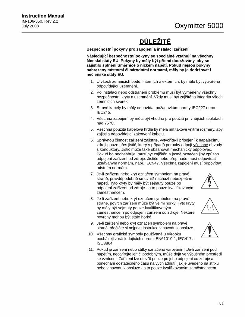
Instruction Manual IM-106-350, Rev 2.2July 2008
A-3
Oxymitter 5000
DŮLEŽITÉ Bezpečnostní pokyny pro zapojení a instalaci za řízení
Následující bezpe čnostní pokyny se speciáln ě vztahují na všechny členské státy EU. Pokyny by m ěly být p řísně dodržovány, aby se zajistilo spln ění Směrnice o nízkém nap ětí. Pokud nejsou pokyny nahrazeny místními či národními normami, m ěly by je dodržovat i nečlenské státy EU.
1. U všech zemnicích bodů, interních a externích, by mělo být vytvořeno odpovídající uzemnění.
2. Po instalaci nebo odstranění problémů musí být vyměněny všechny bezpečnostní kryty a uzemnění. Vždy musí být zajištěna integrita všech zemnicích svorek.
3. Sí˙ové kabely by měly odpovídat požadavkům normy IEC227 nebo IEC245.
4. Všechna zapojení by měla být vhodná pro použití při vnějších teplotách nad 75 °C.
5. Všechna použitá kabelová hrdla by měla mít takové vnitřní rozměry, aby zajistila odpovídající zakotvení kabelu.
6. Správnou činnost zařízení zajistíte, vytvoříte-li připojení k napájecímu zdroji pouze přes jistič, který v případě poruchy odpojí všechny obvody s konduktory. Jistič může také obsahovat mechanický odpojovač. Pokud ho neobsahuje, musí být zajištěn a jasně označen jiný způsob odpojení zařízení od zdroje. Jističe nebo přepínače musí odpovídat uznávaným normám, např. IEC947. Všechna zapojení musí odpovídat místním normám.
7. Je-li zařízení nebo kryt označen symbolem na pravé straně, pravděpodobně se uvnitř nachází nebezpečné napětí. Tyto kryty by měly být sejmuty pouze po odpojení zařízení od zdroje - a to pouze kvalifikovaným zaměstnancem.
8. Je-li zařízení nebo kryt označen symbolem na pravé straně, povrch zařízení může být velmi horký. Tyto kryty by měly být sejmuty pouze kvalifikovaným zaměstnancem po odpojení zařízení od zdroje. Některé povrchy mohou být stále horké.
9. Je-li zařízení nebo kryt označen symbolem na pravé straně, přečtěte si nejprve instrukce v návodu k obsluze.
10. Všechny grafické symboly používané u výrobku pocházejí z následujících norem: EN61010-1, IEC417 a ISO3864.
11. Pokud je zařízení nebo štítky označeno varováním „Je-li zařízení pod napětím, neotvírejte jej“ či podobným, může dojít ve výbušném prostředí ke vznícení. Zařízení lze otevřít pouze po jeho odpojení od zdroje a ponechání dostatečného času na vychladnutí, jak je uvedeno na štítku nebo v návodu k obsluze - a to pouze kvalifikovaným zaměstnancem.
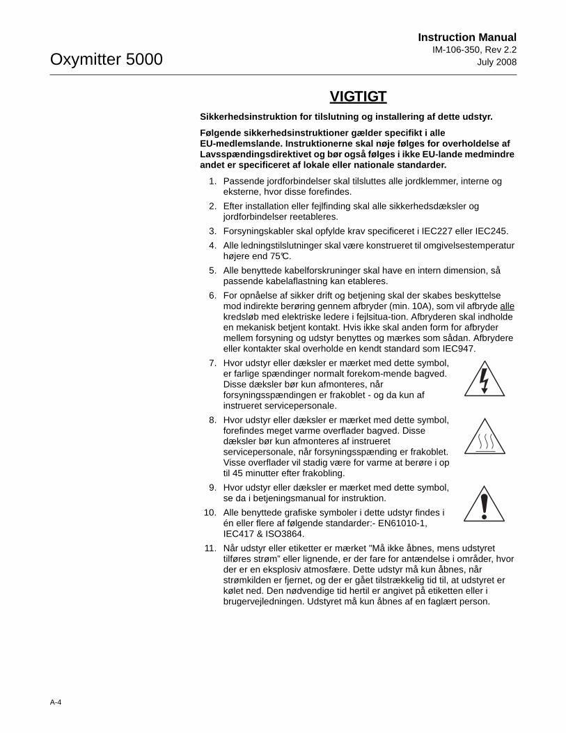
Oxymitter 5000
A-4
Instruction ManualIM-106-350, Rev 2.2
July 2008
VIGTIGTSikkerhedsinstruktion for tilslutning og installeri ng af dette udstyr.
Følgende sikkerhedsinstruktioner gælder specifikt i alle EU-medlemslande. Instruktionerne skal nøje følges f or overholdelse af Lavsspændingsdirektivet og bør også følges i ikke E U-lande medmindre andet er specificeret af lokale eller nationale sta ndarder.
1. Passende jordforbindelser skal tilsluttes alle jordklemmer, interne og eksterne, hvor disse forefindes.
2. Efter installation eller fejlfinding skal alle sikkerhedsdæksler og jordforbindelser reetableres.
3. Forsyningskabler skal opfylde krav specificeret i IEC227 eller IEC245.
4. Alle ledningstilslutninger skal være konstrueret til omgivelsestemperatur højere end 75°C.
5. Alle benyttede kabelforskruninger skal have en intern dimension, så passende kabelaflastning kan etableres.
6. For opnåelse af sikker drift og betjening skal der skabes beskyttelse mod indirekte berøring gennem afbryder (min. 10A), som vil afbryde alle kredsløb med elektriske ledere i fejlsitua-tion. Afbryderen skal indholde en mekanisk betjent kontakt. Hvis ikke skal anden form for afbryder mellem forsyning og udstyr benyttes og mærkes som sådan. Afbrydere eller kontakter skal overholde en kendt standard som IEC947.
7. Hvor udstyr eller dæksler er mærket med dette symbol, er farlige spændinger normalt forekom-mende bagved. Disse dæksler bør kun afmonteres, når forsyningsspændingen er frakoblet - og da kun af instrueret servicepersonale.
8. Hvor udstyr eller dæksler er mærket med dette symbol, forefindes meget varme overflader bagved. Disse dæksler bør kun afmonteres af instrueret servicepersonale, når forsyningsspænding er frakoblet. Visse overflader vil stadig være for varme at berøre i op til 45 minutter efter frakobling.
9. Hvor udstyr eller dæksler er mærket med dette symbol, se da i betjeningsmanual for instruktion.
10. Alle benyttede grafiske symboler i dette udstyr findes i én eller flere af følgende standarder:- EN61010-1, IEC417 & ISO3864.
11. Når udstyr eller etiketter er mærket "Må ikke åbnes, mens udstyret tilføres strøm” eller lignende, er der fare for antændelse i områder, hvor der er en eksplosiv atmosfære. Dette udstyr må kun åbnes, når strømkilden er fjernet, og der er gået tilstrækkelig tid til, at udstyret er kølet ned. Den nødvendige tid hertil er angivet på etiketten eller i brugervejledningen. Udstyret må kun åbnes af en faglært person.
Instruction Manual IM-106-350, Rev 2.2July 2008
A-5
Oxymitter 5000
BELANGRIJKVeiligheidsvoorschriften voor de aansluiting en ins tallatie van dit toestel.
De hierna volgende veiligheidsvoorschriften zijn vo oral bedoeld voor de EU lidstaten. Hier moet aan gehouden worden om de o nderworpenheid aan de Laag Spannings Richtlijn (Low Voltage Direct ive) te verzekeren. Niet EU staten zouden deze richtlijnen moeten volge n tenzij zij reeds achterhaald zouden zijn door plaatselijke of nation ale voorschriften.
1. Degelijke aardingsaansluitingen moeten gemaakt worden naar alle voorziene aardpunten, intern en extern.
2. Na installatie of controle moeten alle veiligheidsdeksels en -aardingen terug geplaatst worden. Ten alle tijde moet de betrouwbaarheid van de aarding behouden blijven.
3. Voedingskabels moeten onderworpen zijn aan de IEC227 of de IEC245 voorschriften.
4. Alle bekabeling moet geschikt zijn voor het gebruik in omgevingstemperaturen, hoger dan 75°C.
5. Alle wartels moeten zo gedimensioneerd zijn dat een degelijke kabel bevestiging verzekerd is.
6. Om de veilige werking van dit toestel te verzekeren, moet de voeding door een stroomonderbreker gevoerd worden (min 10A) welke alle draden van de voeding moet onderbreken. De stroomonderbreker mag een mechanische schakelaar bevatten. Zoniet moet een andere mogelijkheid bestaan om de voedingsspanning van het toestel te halen en ook duidelijk zo zijn aangegeven. Stroomonderbrekers of schakelaars moeten onderworpen zijn aan een erkende standaard zoals IEC947.
7. Waar toestellen of deksels aangegeven staan met het symbool is er meestal hoogspanning aanwezig. Deze deksels mogen enkel verwijderd worden nadat de voedingsspanning werd afgelegd en enkel door getraind onderhoudspersoneel.
8. Waar toestellen of deksels aangegeven staan met het symbool is er gevaar voor hete oppervlakken. Deze deksels mogen enkel verwijderd worden door getraind onderhoudspersoneel nadat de voedingsspanning verwijderd werd. Sommige oppper-vlakken kunnen 45 minuten later nog steeds heet aanvoelen.
9. Waar toestellen of deksels aangegeven staan met het symbool gelieve het handboek te raadplegen.
10. Alle grafische symbolen gebruikt in dit produkt, zijn afkomstig uit een of meer van devolgende standaards: EN61010-1, IEC417 en ISO3864.
11. Op plaatsen waar uitrusting of etiketten zijn voorzien van een melding als "Niet openen bij aanwezigheid van spanning" bestaat er brandgevaar in omgevingen waar een explosieve atmosfeer aanwezig is. Deze uitrusting mag uitsluitend worden geopend wanneer het niet meer onder spanning staat en de uitrusting gedurende de voorgeschreven tijd op het etiket of in de handleiding is afgekoeld - en dan uitsluitend door voldoende opgeleid onderhoudspersoneel.
Oxymitter 5000
A-6
Instruction ManualIM-106-350, Rev 2.2
July 2008
BELANGRIJKVeiligheidsinstructies voor de bedrading en install atie van dit apparaat.
Voor alle EU lidstaten zijn de volgende veiligheids instructies van toepassing. Om aan de geldende richtlijnen voor laa gspanning te voldoen dient men zich hieraan strikt te houden. Oo k niet EU lidstaten dienen zich aan het volgende te houden, tenzij de l okale wetgeving anders voorschrijft.
1. Alle voorziene interne- en externe aardaansluitingen dienen op adequate wijze aangesloten te worden.
2. Na installatie, onderhouds- of reparatie werkzaamheden dienen alle beschermdeksels /kappen en aardingen om reden van veiligheid weer aangebracht te worden.
3. Voedingskabels dienen te voldoen aan de vereisten van de normen IEC 227 of IEC 245.
4. Alle bedrading dient geschikt te zijn voor gebruik bij een omgevings temperatuur boven 75°C.
5. Alle gebruikte kabelwartels dienen dusdanige inwendige afmetingen te hebben dat een adequate verankering van de kabel wordt verkregen.
6. Om een veilige werking van de apparatuur te waarborgen dient de voeding uitsluitend plaats te vinden via een meerpolige automatische zekering (min.10A) die alle spanningvoerende geleiders verbreekt indien een foutconditie optreedt. Deze automatische zekering mag ook voorzien zijn van een mechanisch bediende schakelaar. Bij het ontbreken van deze voorziening dient een andere als zodanig duidelijk aangegeven mogelijkheid aanwezig te zijn om de spanning van de apparatuur af te schakelen. Zekeringen en schakelaars dienen te voldoen aan een erkende standaard zoals IEC 947.
7. Waar de apparatuur of de beschermdeksels/kappen gemarkeerd zijn met het volgende symbool, kunnen zich hieronder spanning voerende delen bevinden die gevaar op kunnen leveren. Deze beschermdeksels/kappen mogen uitsluitend verwijderd worden door getraind personeel als de spanning is afgeschakeld.
8. Waar de apparatuur of de beschermdeksels/kappen gemarkeerd zijn met het volgende symbool, kunnen zich hieronder hete oppervlakken of onderdelen bevinden. Bepaalde delen kunnen mogelijk na 45 min. nog te heet zijn om aan te raken.
9. Waar de apparatuur of de beschermdeksels/kappen gemarkeerd zijn met het volgende symbool, dient men de bedieningshandleiding te raadplegen.
10. Alle grafische symbolen gebruikt bij dit produkt zijn volgens een of meer van de volgende standaarden: EN 61010-1, IEC 417 & ISO 3864.
11. Op plaatsen waar uitrusting of etiketten zijn voorzien van een melding als "Niet openen bij aanwezigheid van spanning" bestaat er brandgevaar in omgevingen waar een explosieve atmosfeer aanwezig is. Deze uitrusting mag uitsluitend worden geopend wanneer het niet meer onder spanning staat en de uitrusting gedurende de voorgeschreven tijd op het etiket of in de handleiding is afgekoeld - en dan uitsluitend door voldoende opgeleid onderhoudspersoneel.
Instruction Manual IM-106-350, Rev 2.2July 2008
A-7
Oxymitter 5000
WICHTIGSicherheitshinweise für den Anschluß und die Instal lation dieser Geräte.
Die folgenden Sicherheitshinweise sind in allen Mit gliederstaaten der europäischen Gemeinschaft gültig. Sie müssen strick t eingehalten werden, um der Niederspannungsrichtlinie zu genügen . Nichtmitgliedsstaaten der europäischen Gemeinschaft sollten die national gültigen Normen und Richtlinien einhalten.
1. Alle intern und extern vorgesehenen Erdungen der Geräte müssen ausgeführt werden.
2. Nach Installation, Reparatur oder sonstigen Eingriffen in das Gerät müssen alle Sicherheitsabdeckungen und Erdungen wieder installiert werden. Die Funktion aller Erdverbindungen darf zu keinem Zeitpunkt gestört sein.
3. Die Netzspannungsversorgung muß den Anforderungen der IEC227 oder IEC245 genügen.
4. Alle Verdrahtungen sollten mindestens bis 75°C ih re Funktion dauerhaft erfüllen.
5. Alle Kabeldurchführungen und Kabelverschraubungen sollten in Ihrer Dimensionierung so gewählt werden, daß diese eine sichere Verkabelung des Gerätes ermöglichen.
6. Um eine sichere Funktion des Gerätes zu gewährleisten, muß die Spannungsversorgung über mindestens 10 A abgesichert sein. Im Fehlerfall muß dadurch gewährleistet sein, daß die Spannungsversorgung zum Gerät bzw. zu den Geräten unterbrochen wird. Ein mechanischer Schutzschalter kann in dieses System integriert werden. Falls eine derartige Vorrichtung nicht vorhanden ist, muß eine andere Möglichkeit zur Unterbrechung der Spannungszufuhr gewährleistet werden mit Hinweisen deutlich gekennzeichnet werden. Ein solcher Mechanismus zur Spannungsunterbrechung muß mit den Normen und Richtlinien für die allgemeine Installation von Elektrogeräten, wie zum Beispiel der IEC947, übereinstimmen.
7. Mit dem Symbol sind Geräte oder Abdeckungen gekennzeichnet, die eine gefährliche (Netzspannung) Spannung führen. Die Abdeckungen dürfen nur entfernt werden, wenn die Versorgungsspannung unterbrochen wurde. Nur geschultes Personal darf an diesen Geräten Arbeiten ausführen.
8. Mit dem Symbol sind Geräte oder Abdeckungen gekennzeichnet, in bzw. unter denen heiße Teile vorhanden sind. Die Abdeckungen dürfen nur entfernt werden, wenn die Versorgungsspannung unterbrochen wurde. Nur geschultes Personal darf an diesen Geräten Arbeiten ausführen. Bis 45 Minuten nach dem Unterbrechen der Netzzufuhr können derartig Teile noch über eine erhöhte Temperatur verfügen.
9. Mit dem Symbol sind Geräte oder Abdeckungen gekennzeichnet, bei denen vor dem Eingriff die entsprechenden Kapitel im Handbuch sorgfältig durchgelesen werden müssen.
10. Alle in diesem Gerät verwendeten graphischen Symbole entspringen einem oder mehreren der nachfolgend aufgeführten Standards: EN61010-1, IEC417 & ISO3864.
11. Wenn Geräte oder Etiketten mit dem Hinweis "Nicht unter Spannung öffnen" oder ähnlichen Hinweisen versehen sind, besteht in explosionsgefährdeten Umgebungen Entzündungsgefahr. Das Gerät darf nur geöffnet werden, wenn es nicht ans Stromnetz angeschlossen und entsprechend der Zeitangaben auf dem Etikett bzw. in der Betriebsanleitung ausreichend abgekühlt ist. Das Gerät darf nur von geschultem Service-Personal geöffnet werden.
Oxymitter 5000
A-8
Instruction ManualIM-106-350, Rev 2.2
July 2008
ΣΗΜΑΝΤΙΚΟ Οδηγιεσ ασφαλειασ για την καλωδιωση και εγκατασταση τησ συσκευησ
Οι ακόλουθες οδηγίες ασφαλείας εφαρµόζονται ειδικά για όλες τις χώρες µέλη της Ευρωπαϊκής Κοινότητας. Θα πρέπει να ακολουθούνται αυστηρά ώστε να εξασφαλιστεί η συµβατότητα µε τις οδηγίες για τη Χαµηλή Τάση. Χώρες που δεν είναι µέλη της Ευρωπαϊκής Κοινότητας θα πρέπει επίσης να ακολουθούν τις οδηγίες, εκτός εάν αυτές αντικαθίστανται από τα Τοπικά ή Εθνικά πρότυπα.
1. Επαρκείς συνδέσεις γείωσης θα πρέπει να γίνονται σε όλα τα σηµεία γείωσης, εσωτερικά και εξωτερικά, όπου υπάρχουν.
2. Μετά την εγκατάσταση ή την αντιµετώπιση σφαλµάτων, όλα τα καλύµµατα ασφαλείας και οι γειώσεις ασφαλείας πρέπει να επανεγκαθίστανται. Η καλή κατάσταση όλων των ακροδεκτών γείωσης πρέπει να συντηρείται διαρκώς.
3. Τα καλώδια τροφοδοσίας πρέπει να πληρούν τις απαιτήσεις των IEC227 ή IEC245.
4. Όλες οι καλωδιώσεις θα πρέπει να είναι κατάλληλες για χρήση σε θερµοκρασία χώρου υψηλότερη από 75°C.
5. Όλοι οι στυπιοθλίπτες θα πρέπει να είναι τέτοιων εσωτερικών διαστάσεων, ώστε να παρέχουν επαρκή στερέωση των καλωδίων.
6. Για τη διασφάλιση ασφαλούς λειτουργίας αυτής της συσκευής, η σύνδεση τροφοδοσίας θα πρέπει να γίνεται µόνο µέσω ασφαλειοδιακόπτη, ο οποίος θα αποσυνδέει όλους τους ηλεκτροφόρους αγωγούς των κυκλωµάτων, στη διάρκεια κατάστασης σφάλµατος. Ο ασφαλειοδιακόπτης µπορεί επίσης να περιλαµβάνει µηχανικό διακόπτη αποµόνωσης. Εάν δεν περιλαµβάνει, τότε άλλα µέσα αποσύνδεσης της συσκευής από την τροφοδοσία πρέπει να παροχηθούν και να σηµανθούν σαφώς ως τέτοια. Οι ασφαλειοδιακόπτες ή διακόπτες πρέπει να συµµορφώνονται µε αναγνωρισµένα πρότυπα όπως το IEC947. Όλες οι καλωδιώσεις πρέπει να συµµορφώνονται µε τα τοπικά πρότυπα.
7. Όπου συσκευές ή καλύµµατα είναι σηµασµένα µε το σύµβολο που εικονίζεται δεξιά, επικίνδυνες τάσεις ενυπάρχουν κάτω από αυτά. Αυτά τα καλύµµατα θα πρέπει να αφαιρούνται µόνο όταν έχει αφαιρεθεί η τροφοδοσία από τη συσκευή - και στην περίπτωση αυτή, µόνο από ειδικευµένο τεχνικό προσωπικό.
8. Όπου συσκευές ή καλύµµατα είναι σηµασµένα µε το σύµβολο που εικονίζεται δεξιά, υπάρχει κίνδυνος από καυτές επιφάνειες κάτω από αυτά. Τέτοια καλύµµατα θα πρέπει να αφαιρούνται µόνο από ειδικευµένο τεχνικό προσωπικό, όταν έχει αφαιρεθεί η τροφοδοσία από τη συσκευή. Κάποιες επιφάνειες µπορούν να παραµένουν ζεστές στην αφή.
9. Όπου συσκευές ή καλύµµατα είναι σηµασµένα µε το σύµβολο που εικονίζεται δεξιά, ανατρέξτε στις οδηγίες χρήσης της συσκευής.
10. Όλα τα γραφικά σύµβολα που χρησιµοποιούνται σε αυτό το προϊόν είναι από ένα ή περισσότερα από τα εξής πρότυπα: EN61010-1, IEC417 και ISO3864.
11. Όπου συσκευή ή ετικέτα είναι σηµασµένη µε την ένδειξη "Μην ανοίγετε ενώ βρίσκεται σε λειτουργία" ή άλλη παρόµοια, υπάρχει κίνδυνος ανάφλεξης σε περιοχές µε εκρηκτική ατµόσφαιρα. Ο παρών εξοπλισµός πρέπει να ανοίγεται µόνο όταν είναι εκτός ρεύµατος και αφού παρέλθει ο κατάλληλος χρόνος που αναγράφεται στην ετικέτα ή στο εγχειρίδιο οδηγιών ώστε να ψυχθεί και µόνο από εκπαιδευµένο προσωπικό συντήρησης.
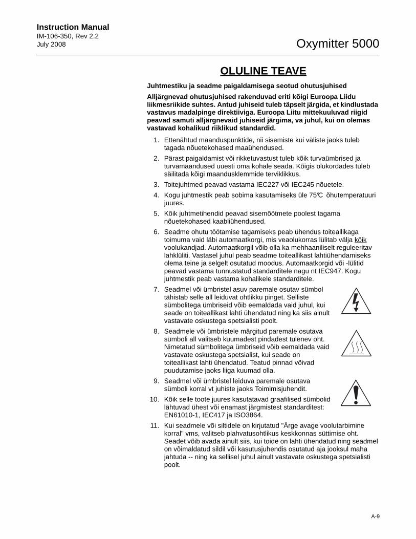
Instruction Manual IM-106-350, Rev 2.2July 2008
A-9
Oxymitter 5000
OLULINE TEAVE Juhtmestiku ja seadme paigaldamisega seotud ohutusj uhised
Alljärgnevad ohutusjuhised rakenduvad eriti kõigi E uroopa Liidu liikmesriikide suhtes. Antud juhiseid tuleb täpselt järgida, et kindlustada vastavus madalpinge direktiiviga. Euroopa Liitu mit tekuuluvad riigid peavad samuti alljärgnevaid juhiseid järgima, va ju hul, kui on olemas vastavad kohalikud riiklikud standardid.
1. Ettenähtud maanduspunktide, nii sisemiste kui väliste jaoks tuleb tagada nõuetekohased maaühendused.
2. Pärast paigaldamist või rikketuvastust tuleb kõik turvaümbrised ja turvamaandused uuesti oma kohale seada. Kõigis olukordades tuleb säilitada kõigi maandusklemmide terviklikkus.
3. Toitejuhtmed peavad vastama IEC227 või IEC245 nõuetele.
4. Kogu juhtmestik peab sobima kasutamiseks üle 75°C õhutemperatuuri juures.
5. Kõik juhtmetihendid peavad sisemõõtmete poolest tagama nõuetekohased kaabliühendused.
6. Seadme ohutu töötamise tagamiseks peab ühendus toiteallikaga toimuma vaid läbi automaatkorgi, mis veaolukorras lülitab välja kõik voolukandjad. Automaatkorgil võib olla ka mehhaaniliselt reguleeritav lahklüliti. Vastasel juhul peab seadme toiteallikast lahtiühendamiseks olema teine ja selgelt osutatud moodus. Automaatkorgid või -lülitid peavad vastama tunnustatud standarditele nagu nt IEC947. Kogu juhtmestik peab vastama kohalikele standarditele.
7. Seadmel või ümbristel asuv paremale osutav sümbol tähistab selle all leiduvat ohtlikku pinget. Selliste sümbolitega ümbriseid võib eemaldada vaid juhul, kui seade on toiteallikast lahti ühendatud ning ka siis ainult vastavate oskustega spetsialisti poolt.
8. Seadmele või ümbristele märgitud paremale osutava sümboli all valitseb kuumadest pindadest tulenev oht. Nimetatud sümbolitega ümbriseid võib eemaldada vaid vastavate oskustega spetsialist, kui seade on toiteallikast lahti ühendatud. Teatud pinnad võivad puudutamise jaoks liiga kuumad olla.
9. Seadmel või ümbristel leiduva paremale osutava sümboli korral vt juhiste jaoks Toimimisjuhendit.
10. Kõik selle toote juures kasutatavad graafilised sümbolid lähtuvad ühest või enamast järgmistest standarditest: EN61010-1, IEC417 ja ISO3864.
11. Kui seadmele või siltidele on kirjutatud "Ärge avage voolutarbimine korral" vms, valitseb plahvatusohtlikus keskkonnas süttimise oht. Seadet võib avada ainult siis, kui toide on lahti ühendatud ning seadmel on võimaldatud sildil või kasutusjuhendis osutatud aja jooksul maha jahtuda -- ning ka sellisel juhul ainult vastavate oskustega spetsialisti poolt.
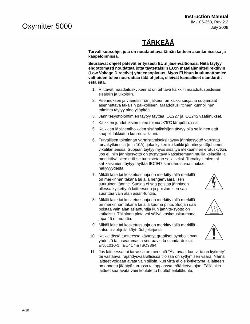
Oxymitter 5000
A-10
Instruction ManualIM-106-350, Rev 2.2
July 2008
TÄRKEÄÄTurvallisuusohje, jota on noudatettava tämän laitte en asentamisessa ja kaapeloinnissa.
Seuraavat ohjeet pätevät erityisesti EU:n jäsenvalt ioissa. Niitä täytyy ehdottomasti noudattaa jotta täytettäisiin EU:n mat alajännitedirektiivin (Low Voltage Directive) yhteensopivuus. Myös EU:hun kuulumattomien valtioiden tulee nou-dattaa tätä ohjetta, elleivät kansalliset standardit estä sitä.
1. Riittävät maadoituskytkennät on tehtävä kaikkiin maadoituspisteisiin, sisäisiin ja ulkoisiin.
2. Asennuksen ja vianetsinnän jälkeen on kaikki suojat ja suojamaat asennettava takaisin pai-koilleen. Maadoitusliittimen kunnollinen toiminta täytyy aina ylläpitää.
3. Jännitesyöttöjohtimien täytyy täyttää IEC227 ja IEC245 vaatimukset.
4. Kaikkien johdotuksien tulee toimia >75°C lämpötil oissa.
5. Kaikkien läpivientiholkkien sisähalkaisijan täytyy olla sellainen että kaapeli lukkiutuu kun-nolla kiinni.
6. Turvallisen toiminnan varmistamiseksi täytyy jännitesyöttö varustaa turvakytkimellä (min 10A), joka kytkee irti kaikki jännitesyöttöjohtimet vikatilanteessa. Suojaan täytyy myös sisältyä mekaaninen erotuskytkin. Jos ei, niin jännitesyöttö on pystyttävä katkaisemaan muilla keinoilla ja merkittävä siten että se tunnistetaan sellaiseksi. Turvakytkimien tai kat-kaisimien täytyy täyttää IEC947 standardin vaatimukset näkyvyydestä.
7. Mikäli laite tai kosketussuoja on merkitty tällä merkillä on merkinnän takana tai alla hengenvaarallisen suuruinen jännite. Suojaa ei saa poistaa jänniteen ollessa kytkettynä laitteeseen ja poistamisen saa suorittaa vain alan asian-tuntija.
8. Mikäli laite tai kosketussuoja on merkitty tällä merkillä on merkinnän takana tai alla kuuma pinta. Suojan saa poistaa vain alan asiantuntija kun jännite-syöttö on katkaistu. Tällainen pinta voi säilyä kosketuskuumana jopa 45 mi-nuuttia.
9. Mikäli laite tai kosketussuoja on merkitty tällä merkillä katso lisäohjeita käyt-töohjekirjasta.
10. Kaikki tässä tuotteessa käytetyt graafiset symbolit ovat yhdestä tai useammasta seuraavis-ta standardeista: EN61010-1, IEC417 & ISO3864.
11. Jos laitteessa tai tarrassa on merkintä "Älä avaa, kun virta on kytketty" tai vastaava, räjähdysvaarallisissa tiloissa on syttymisen vaara. Nämä laitteet voidaan avata vain silloin, kun virta ei ole kytkettynä ja laitteen on annettu jäähtyä tarrassa tai oppaassa määritetyn ajan. Tällöinkin laitteet saa avata vain koulutettu huoltohenkilökunta.

Instruction Manual IM-106-350, Rev 2.2July 2008
A-11
Oxymitter 5000
IMPORTANTConsignes de sécurité concernant le raccordement et l'installation de cet appareil.
Les consignes de sécurité ci-dessous s'adressent pa rticulièrement à tous les états membres de la communauté européenne. Elles doivent être strictement appliquées afin de satisfaire aux directives concernant la basse tension. Les états non membres de la commu nauté européenne doivent également appliquer ces consignes sauf si e lles sont en contradiction avec les standards locaux ou nationau x.
1. Un raccordement adéquat à la terre doit être effectuée à chaque borne de mise à la terre, interne et externe.
2. Après installation ou dépannage, tous les capots de protection et toutes les prises de terre doivent être remis en place, toutes les prises de terre doivent être respectées en permanence.
3. Les câbles d'alimentation électrique doivent être conformes aux normes IEC227 ou IEC245.
4. Tous les raccordements doivent pouvoir supporter une température ambiante supérieure à 75°C.
5. Tous les presse-étoupes utilisés doivent avoir un diamètre interne en rapport avec les câbles afin d'assurer un serrage correct sur ces derniers.
6. Afin de garantir la sécurité du fonctionnement de cet appareil, le raccordement à l'alimentation électrique doit être réalisé exclusivement au travers d'un disjoncteur (minimum 10A.) isolant tous les conducteurs en cas d'anomalie. Ce disjoncteur doit également pouvoir être actionné manuellement, de façon mécanique. Dans le cas contraire, un autre système doit être mis en place afin de pouvoir isoler l'appareil et doit être signalisé comme tel. Disjoncteurs et interrupteurs doivent être conformes à une norme reconnue telle IEC947.
7. Lorsque les équipements ou les capots affichent le symbole suivant, cela signifie que des tensions dangereuses sont présentes. Ces capots ne doivent être démontés que lorsque l'alimentation est coupée, et uniquement par un personnel compétent.
8. Lorsque les équipements ou les capots affichent le symbole suivant, cela signifie que des surfaces dangereusement chaudes sont présentes. Ces capots ne doivent être démontés que lorsque l'alimentation est coupée, et uniquement par un personnel compétent. Certaines surfaces peuvent rester chaudes jusqu'à 45 mn.
9. Lorsque les équipements ou les capots affichent le symbole suivant, se reporter au manuel d'instructions.
10. Tous les symboles graphiques utilisés dans ce produit sont conformes à un ou plusieurs des standards suivants: EN61010-1, IEC417 & ISO3864.
11. Les équipements comportant une étiquette avec la mention " Ne pas ouvrir sous tension " ou toute autre mention similaire peuvent créer un risque d'incendie dans les environnements explosifs. Ces équipements ne doivent être ouverts que lorsqu'ils sont hors tension et que la durée de refroidissement requise indiquée sur l'étiquette ou dans le manuel d'instructions s'est écoulée. En outre ils ne doivent être ouverts que par un personnel qualifié.
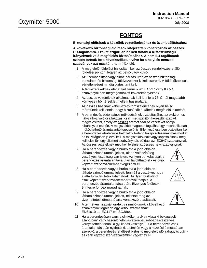
Oxymitter 5000
A-12
Instruction ManualIM-106-350, Rev 2.2
July 2008
FONTOS Biztonsági el ıírások a készülék vezetékeléséhez és üzembeállításá hoz
A következ ı biztonsági el ıírások kifejezetten vonatkoznak az összes EU-tagállamra. Ezeket szigorúan be kell tartani a K isfeszültség ő irányelvnek való megfelelés biztosításához. A nem E U-tagállamok szintén tartsák be a következ ıket, kivéve ha a helyi és nemzeti szabványok azt másként nem írják el ı.
1. A megfelelı földelést biztosítani kell az összes rendelkezésre álló földelési ponton, legyen az belsı vagy külsı.
2. Az üzembeállítás vagy hibaelhárítás után az összes biztonsági burkolatot és biztonsági földvezetéket ki kell cserélni. A földelıkapcsok sértetlenségét mindig biztosítani kell.
3. A tápvezetékeknek eleget kell tenniük az IEC227 vagy IEC245 szabványokban megfogalmazott követelményeknek.
4. Az összes vezetéknek alkalmasnak kell lennie a 75 °C-nál magasabb környezeti hımérséklet melletti használatra.
5. Az összes használt kábelvezetı tömszelencének olyan belsı méretőnek kell lennie, hogy biztosítsák a kábelek megfelelı lekötését.
6. A berendezés biztonságos mőködésének biztosításához az elektromos hálózathoz való csatlakozást csak megszakítón keresztül szabad megvalósítani, amely az összes áramot szállító vezetéket bontja hibahelyzet esetén. A megszakító magában foglalhat egy mechanikusan mőködtethetı áramtalanító kapcsolót is. Ellenkezı esetben biztosítani kell a berendezés elektromos hálózatról történı lekapcsolásának más módját, és ezt világosan jelezni kell. A megszakítóknak vagy kapcsolóknak meg kell felelniük egy elismert szabványnak, például az IEC947 szabványnak. Az összes vezetéknek meg kell felelnie az összes helyi szabványnak.
7. Ha a berendezés vagy a burkolata a jobb oldalon látható szimbólummal jelzett, alatta valószínőleg veszélyes feszültség van jelen. Az ilyen burkolat csak a berendezés áramtalanítása után távolítható el - és csak képzett szervizszakember végezheti el.
8. Ha a berendezés vagy a burkolata a jobb oldalon látható szimbólummal jelzett, fenn áll a veszélye, hogy alatta forró felületek találhatóak. Az ilyen burkolatot csak képzett szervizszakember távolíthatja el a berendezés áramtalanítása után. Bizonyos felületek érintésre forróak maradhatnak.
9. Ha a berendezés vagy a burkolata a jobb oldalon látható szimbólummal jelzett, tekintse meg az Üzemeltetési útmutató arra vonatkozó utasításait.
10. A terméken használt grafikus szimbólumok a következı szabványok legalább egyikébıl származnak: EN61010-1, IEC417 és ISO3864.
11. Ha a berendezésen vagy a címkéken a „Ne nyissa ki bekapcsolt állapotban” vagy hasonló felhívás szerepel, robbanásveszélyes környezetben fennáll a gyulladás veszélye. Ez a berendezés csak áramtalanítás után nyitható ki, a címkén vagy a kezelési útmutatóban szereplı, a berendezés lehőlését biztosító megfelelı idıi ráhagyás után - és csak képzett szervizszakember végezheti el.
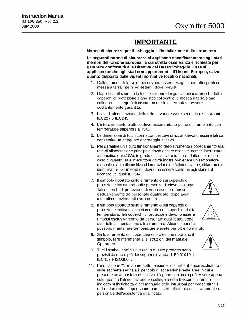
Instruction Manual IM-106-350, Rev 2.2July 2008
A-13
Oxymitter 5000
IMPORTANTENorme di sicurezza per il cablaggio e l'installazio ne dello strumento.
Le seguenti norme di sicurezza si applicano specifi catamente agli stati membri dell'Unione Europea, la cui stretta osservan za è richiesta per garantire conformità alla Direttiva del Basso Volta ggio. Esse si applicano anche agli stati non appartenenti all'Uni one Europea, salvo quanto disposto dalle vigenti normative locali o na zionali.
1. Collegamenti di terra idonei devono essere eseguiti per tutti i punti di messa a terra interni ed esterni, dove previsti.
2. Dopo l'installazione o la localizzazione dei guasti, assicurarsi che tutti i coperchi di protezione siano stati collocati e le messa a terra siano collegate. L'integrità di ciscun morsetto di terra deve essere costantemente garantita.
3. I cavi di alimentazione della rete devono essere secondo disposizioni IEC227 o IEC245.
4. L'intero impianto elettrico deve essere adatto per uso in ambiente con temperature superiore a 75°C.
5. Le dimensioni di tutti i connettori dei cavi utilizzati devono essere tali da consentire un adeguato ancoraggio al cavo.
6. Per garantire un sicuro funzionamento dello strumento il collegamento alla rete di alimentazione principale dovrà essere eseguita tramite interruttore automatico (min.10A), in grado di disattivare tutti i conduttori di circuito in caso di guasto. Tale interruttore dovrà inoltre prevedere un sezionatore manuale o altro dispositivo di interruzione dell'alimentazione, chiaramente identificabile. Gli interruttori dovranno essere conformi agli standard riconosciuti, quali IEC947.
7. Il simbolo riportato sullo strumento o sui coperchi di protezione indica probabile presenza di elevati voltaggi. Tali coperchi di protezione devono essere rimossi esclusivamente da personale qualificato, dopo aver tolto alimentazione allo strumento.
8. Il simbolo riportato sullo strumento o sui coperchi di protezione indica rischio di contatto con superfici ad alta temperatura. Tali coperchi di protezione devono essere rimossi esclusivamente da personale qualificato, dopo aver tolto alimentazione allo strumento. Alcune superfici possono mantenere temperature elevate per oltre 45 minuti.
9. Se lo strumento o il coperchio di protezione riportano il simbolo, fare riferimento alle istruzioni del manuale Operatore.
10. Tutti i simboli grafici utilizzati in questo prodotto sono previsti da uno o più dei seguenti standard: EN61010-1, IEC417 e ISO3864.
11. L'indicazione "Non aprire sotto tensione" o simili sull'apparecchiatura o sulle etichette segnala il pericolo di accensione nelle aree in cui è presente un'atmosfera esplosiva. L'apparecchiatura può essere aperta solo quando l'alimentazione è scollegata ed è trascorso il tempo indicato sull'etichetta o nel manuale delle istruzioni per consentirne il raffreddamento. L'operazione può essere effettuata esclusivamente da personale dell'assistenza qualificato.
Oxymitter 5000
A-14
Instruction ManualIM-106-350, Rev 2.2
July 2008
SVARBU šio prietaiso laid ų prijungimo ir instaliacijos saugos instrukcijos
Toliau išvardinti saugumo reikalavimai taikomi konk rečiai visoms ES šalims nar ÷ms. J ų turi b ūti griežtai paisoma, kad b ūtų užtikrintai laikomasi Žemos įtampos direktyvos. Ne ES nar ÷s taip pat turi laikytis toliau pateikiam ų reikalavim ų nebent juos pakei čia vietiniai ar Nacionaliniai standartai.
1. Turi būti atliktas tinkamas įžeminimas visuose įžeminimo taškuose, vidiniuose ir išoriniuose, kur numatyta.
2. Visos apsaugin÷s dangos ir įžemikliai po instaliacijos ar remonto turi būti pakeisti. Visų įžeminimo terminalų vientisumo priežiūra turi būti atliekama nuolat.
3. Matinimo tinklo laidai turi atitikti IEC227 ar IEC245 reikalavimus.
4. Visi laidai turi būti tinkami naudojimui aplinkos temperatūtoje, aukštesn÷je nei 75°C.
5. Visi naudojamų kabelių riebokšliai turi būti tokių vidinių matmenų, kad būtų galimas tinkamas kabelio pritvirtinimas.
6. Saugaus šio prietaiso veikimo užtikrinimui, prijungimas prie maitinimo tinklo turi būti atliekamas tik per automatinį pertraukiklį, kuris atjungs visas grandines nešančius konduktorius linijos gedimo metu. Automatinis pertraukiklis taip pat gali tur÷ti mechaniškai veikiantį įzoliavimo jungiklį. Jeigu ne, tuomet turi būti nurodytos kitos įrenginio atjungimo priemon÷s, ir aiškai pažym÷tos, kad jos tokios yra. Automatiniai perjungikliai ar jungikliai turi atitikti pripažintus standartus, tokius kaip IEC947. Visi laidai turi atitikti visus vietinius standartus.
7. Kur įrenginys ar dangos yra pažym÷ti simboliu dešin÷je, žemiau turi būti pavojinga įtampa. Šios dangos turi būti nuimamos tik tada, kai srov÷ yra pašalinta iš įrenginio - ir tik tuomet tai turi atlikti apmokytas personalas.
8. Ten kur įrenginys ar dangos yra pažym÷ti simboliu dešin÷je, ten yra pavojus nuo karštų paviršių apačioje. Šios dangos gali būti nuimamos tik apmokyto personalo, kai srov÷ yra pašalinta iš įrenginio. Tam tikri paviršiai gali išlikti karšti liečiant.
9. Ten kur įrenginys ar dangos yra pažym÷ti simboliu d÷šin÷je, žr. nurodymus Valdymo instrukcijose.
10. Visi grafiniai simboliai naudojami šiam produktui yra iš vieno ar daugiau toliau išvardintų standartų: EN61010-1, IEC417, ir ISO3864.
11. Ten, kur įrenginys ar etiket÷s yra pažym÷ti "Neatidaryti esant srov÷s tiekimui" ar panašiai, yra užsidegimo pavojus tose vietose, kur yra sprogstamoji atmosfera. Šis įrenginys gali būti atidarytas tuomet, kai yra pašalinta srov÷, ir pra÷jęs atitinkamas laikas, nurodytas etiket÷je ar valdymo instrukcijoje, pakankamas įrenginio ataušimui - ir tai tik apmokyto personalo.
Instruction Manual IM-106-350, Rev 2.2July 2008
A-15
Oxymitter 5000
SVARĪGI Droš ības nor ādījumi š īs iek ārtas pievienošanai un uzst ādīšanai
Turpm ākie droš ības nor ādījumi attiecas uz vis ām ES dal ībvalst īm. Tie ir stingri j āievēro, lai nodrošin ātu atbilst ību Zemsprieguma direkt īvai. Turpm āk nor ādītais j āievēro ar ī valst īs, kas nav ES dal ībvalstis, ja vien šos nor ādījumus neaizst āj viet ējie vai valsts standarti.
1. Visi pieejamie iekšējie un ārējie zemējuma punkti ir atbilstoši jāiezemē.
2. Pēc uzstādīšanas vai problēmu risināšanas visi drošības pārsegi un drošības zemējuma savienojumi ir jāpievieno atpakaĜ. Visiem zemējuma savienojumiem vienmēr jābūt iezemētiem.
3. Elektropadeves vadiem jāatbilst IEC227 vai IEC245 prasībām.
4. Visai elektroinstalācijai jābūt piemērotai lietošanai apkārtējā temperatūrā, kas pārsniedz 75°C.
5. Visu izmantoto kabeĜu blīvju iekšējiem izmēriem jābūt tādiem, lai atbilstoši nostiprinātu kabeli.
6. Lai nodrošinātu šīs iekārtas drošu darbību, savienojums ar elektropadeves tīklu jāizveido, izmantojot slēdzi, kas kĜūmes gadījumā atvienos visas ėēdes, kurās ir vadītāji. Slēdzī var būt iestrādāts arī mehānisks pārtraucējslēdzis. Ja tāda nav, tad ir jāuzstāda cita veida ierīce iekārtas atvienošanai no strāvas padeves un tā atbilstoši un skaidri jāmarėē. Slēdžiem jāatbilst kādam vispāratzītam standartam, piemēram, IEC947. Visai elektroinstalācijai jāatbilst vietējiem standartiem.
7. Vietās, kur iekārta vai tās pārsegi ir marėēti ar labajā pusē norādīto simbolu, visticamāk, zem tiem ir bīstams spriegums. Šos pārsegus drīkst noĦemt tikai tad, ja iekārta ir atvienota no strāvas padeves, – un šos darbus drīkst veikt tikai atbilstoši apmācīti remontdarbu darbinieki.
8. Vietās, kur iekārta vai tās pārsegi ir marėēti ar labajā pusē norādīto simbolu, apdraudējumu izraisa zem tiem esošās karstās virsmas. Šos pārsegus drīkst noĦemt tikai atbilstoši apmācīti remontdarbu darbinieki, kad iekārta ir atvienota no strāvas padeves. Iespējams, dažas virsmas arī pēc iekārtas atvienošanas paliks karstas.
9. Ja iekārta vai pārsegi ir marėēti ar labajā pusē esošo simbolu, skatiet operatora rokasgrāmatā ietvertos norādījumus.
10. Visi šajā izstrādājumā izmantotie grafiskie simboli atbilst vienam vai vairākiem no šiem standartiem: EN61010-1, IEC417 un ISO3864.
11. Ja iekārtai vai uzlīmēm ir marėējums "Neatvērt, kamēr pieslēgta strāvai" vai tamlīdzīga norāde, tas nozīmē, ka sprādzienbīstamā vidē ir uzliesmošanas bīstamība. Šo iekārtu drīkst atvērt tikai tad, ja ir atvienota strāva un ir nogaidīts iekārtas atdzišanai nepieciešamais laiks, kas norādīts uzlīmē vai ekspluatācijas rokasgrāmatā, – un šos darbus drīkst veikt tikai atbilstoši apmācīti remontdarbu darbinieki.
Oxymitter 5000
A-16
Instruction ManualIM-106-350, Rev 2.2
July 2008
1. Konnessjonijiet adegwati ta' l-ert għandhom isiru għall-punti kollha ta' l-ert, interni u esterni, fejn ikun ipprovdut.
2. Wara l-installazzjoni jew meta tipprova ssolvi xi problema, l-għatjien kollha tas-sigurtà u l-erts tas-sigurtà għandhom jitpoġġew lura f'posthom. L-integrità tat-terminali kollha ta' l-ert għandha tinżamm f'kull ħin.
3. Il-wajers tal-provvista tad-dawl għandhom ikunu konformi ml-ħtiġijiet ta' IEC227 jew IEC245.
4. Il-wiring kollu għandu jkun adattat għall-użu f'temperatura ta' l-ambjent ta' iktar minn 75°C.
5. Il-glands tal-kejbils kollha li jintużw iridu jkunu ta' daqs intern tali li jipprovdu ankoraġġ adegwat lill-kejbil.
6. Biex tiżgura t-tħaddim sigur ta' dan it-tagħmir, il-konnessjoni mal-provvista tad-dawl għandha ssir biss permezz ta' circuit breaker li jiskonnetta l-kondutturi kollha li jkunu jġorru ċ-ċirkuwiti f'sitwazzjoni meta jkun hemm il-ħsara. Is-circuit breaker jista wkoll jinkludi swiċċ li jiżola li jaħdem b'mod mekkaniku. Jekk dan ma jkunx il-każ, mezz ieħor ta' kif it-tagħmir jiġi skonnettjat minn mal-provvista tad-dawl għandu jkun ipprovdut, u jkun immrkat b'mod ċar li hu hekk. Is-circuit breakers jew swiċċijiet iridu jkunu konformi ma' standard rikonoxxut bħal IEC947. Il-wiring kollu jrid ikun konformi ma' l-istandards lokali, jekk ikun hemm.
7. Meta t-tagħmir jew l-għatjien ikunu mmarkati bis-simbolu fuq il-lemin, x'aktarx li jkun hemm vultaġġi perikolużi taħthom. Dawn l-għatjien għandhom jitneħħew biss meta titneħħa l-provvista tad-dawl mit-tagħmir - u minn ħaddiema tal-manutenzjoni mħarrġa biss.
8. Meta t-tagħmir jew l-għatjien ikunu mmarkati bis-simbolu fuq il-lemin, ikun hemm periklu mill-uċuħ jaħarqu li jkun hemm taħthom. Dawn l-għatjien għandhom jitneħħew biss minn ħaddiema tal-manutenzjoni mħarrġa meta titneħħa l-provvista tad-dawl mit-tagħmir. Ċerti wċuħ jistgħu jibqgħu jaħarqu meta tmisshom.
9. Meta t-tagħmir jew l-għatjien ikunu mmarkati bis-simbolu fuq il-lemin, irreferi għall-Manwal ta' l-Operatur għall-istruzzjonijiet.
10. Is-simboli grafiċi kollha użati f'dan il-prodott huma minn wieħed jew iktar mill-istandards li ġejjin: EN61010-1, IEC417, u ISO3864.
11. Fejn it-tagħmir u t-tikketti huma mmarkati bil-kliem “Tiftaħx Meta Jkun Enerġizzat” jew kliem simili, hemm periklu ta' nar f'żoni fejn atmosfera esplossiva hi preżenti. It-tagħmir għandu jinfetaħ biss meta l-provvista tad-dawl tkun mitfija u jkun għadda ħin biżżejjed, kif speċifikat fuq it-tikketta jew fil-manwal ta' l-istruzzjonijiet, biex it-tagħmir ikun kesaħ – u t-tagħmir għandu jinfetaħ biss minn staff li jkun imħarreġ.
L-istruzzjonijiet tas-sigurtà japplikaw speċifikament għall-Istati Membri ta' l-UE. Dawn għandhom jiġu osservati b'mod strett biex tkun żgurata l-konformità mad-Direttiva dwar il-Vultaġġ Baxx. Stati li mhumiex membri ta' l-UE għandhom ukoll ikunu konformi ma' dan li ġej ħlief jekk dawn ikunu sostituti mill-Istandards lokali jew Nazzjonali.
STRUZZJONIJIET TAS-SIGURTÀ GĦALL-WIRING U L-INSTALLAZZJONI TAT-TAGĦMIR
IMPORTANTI
Instruction Manual IM-106-350, Rev 2.2July 2008
A-17
Oxymitter 5000
VIKTIGSikkerhetsinstruks for tilkobling og installasjon a v dette utstyret.
Følgende sikkerhetsinstruksjoner gjelder spesifikt alle EU medlemsland og land med i EØS-avtalen. Instruksjonene skal følg es nøye slik at installasjonen blir i henhold til lavspenningsdirek tivet. Den bør også følges i andre land, med mindre annet er spesifiser t av lokale- eller nasjonale standarder.
1. Passende jordforbindelser må tilkobles alle jordingspunkter, interne og eksterne hvor disse forefinnes.
2. Etter installasjon eller feilsøking skal alle sikkerhetsdeksler og jordforbindelser reetableres. Jordingsforbindelsene må alltid holdes i god stand.
3. Kabler fra spenningsforsyning skal oppfylle kravene spesifisert i IEC227 eller IEC245.
4. Alle ledningsforbindelser skal være konstruert for en omgivelsestemperatur høyere en 750°C.
5. Alle kabelforskruvninger som benyttes skal ha en indre dimensjon slik at tilstrekkelig avlastning oppnåes.
6. For å oppnå sikker drift og betjening skal forbindelsen til spenningsforsyningen bare skje gjennom en strømbryter (minimum 10A) som vil bryte spenningsforsyningen til alle elektriske kretser ved en feilsituasjon. Strømbryteren kan også inneholde en mekanisk operert bryter for å isolere instrumentet fra spenningsforsyningen. Dersom det ikke er en mekanisk operert bryter installert, må det være en annen måte å isolere utstyret fra spenningsforsyningen, og denne måten må være tydelig merket. Kretsbrytere eller kontakter skal oppfylle kravene i en annerkjent standard av typen IEC947 eller tilsvarende.
7. Der hvor utstyr eller deksler er merket med symbol for farlig spenning, er det sannsynlig at disse er tilstede bak dekslet. Disse dekslene må bare fjærnes når spenningsforsyning er frakoblet utstyret, og da bare av trenet servicepersonell.
8. Der hvor utstyr eller deksler er merket med symbol for meget varm overflate, er det sannsynlig at disse er tilstede bak dekslet. Disse dekslene må bare fjærnes når spenningsforsyning er frakoblet utstyret, og da bare av trenet servicepersonell. Noen overflater kan være for varme til å berøres i opp til 45 minutter etter spenningsforsyning frakoblet.
9. Der hvor utstyret eller deksler er merket med symbol, vennligst referer til instruksjonsmanualen for instrukser.
10. Alle grafiske symboler brukt i dette produktet er fra en eller flere av følgende standarder: EN61010-1, IEC417 & ISO3864.
11. Når utstyr eller merkelapper bærer advarselen "Må ikke åpnes under spenning" eller lignende, innbærer det fare for eksplosjon i områder med en eksplosiv atmosfære. Utstyret skal bare åpnes når det ikke er noen strømtilførsel, og etter at det har hatt tilstrekkelig tid til å kjøle ned, som spesifisert på merkelappen eller i håndboken. Selv da skal utstyret bare åpnes av erfarne serviceteknikere.
Oxymitter 5000
A-18
Instruction ManualIM-106-350, Rev 2.2
July 2008
WAśNE! Zalecenia dotycz ące bezpiecze ństwa w zakresie podł ączania i instalacji tego urz ądzenia
Następuj ące zalecenia dotycz ą zwłaszcza stosowania urz ądzenia we wszystkich krajach Unii Europejskiej. Nale Ŝy si ę ściśle do nich stosowa ć w celu zapewnienia zgodno ści z dyrektyw ą niskonapi ęciow ą. W przypadku instalacji urz ądzenia w krajach nienale Ŝących do Unii Europejskiej nale Ŝy równie Ŝ przestrzega ć poni Ŝszych zalece ń, chyba Ŝe są one zast ąpione lokalnymi lub ogólnokrajowymi standardami.
1. Urządzenie naleŜy podłączyć kablem uziemiającym do wszystkich punktów uziemienia (wewnętrznych i zewnętrznych).
2. Po instalacji lub czynnościach serwisowych naleŜy zamknąć wszystkie pokrywy zabezpieczające i ponownie podłączyć uziemienie. NaleŜy pilnować, by nie doszło do przerwania uziemienia.
3. Przewody zasilające powinny być zgodne z wymaganiami normy IEC227 lub IEC245.
4. Wszystkie przewody powinny być odpowiednie do uŜytku w środowisku o temperaturze wyŜszej niŜ 75°C.
5. Wszystkie dławnice powinny mieć wymiary wewnętrzne zapewniające pewne umocowanie przewodów.
6. W celu zapewnienia bezpiecznej pracy urządzenie naleŜy podłączyć do sieci tylko za pośrednictwem wyłącznika automatycznego, który w razie awarii odłączy wszystkie obwody, w których przepływa prąd. Wyłącznik automatyczny moŜe być równieŜ wyposaŜony w mechaniczny odłącznik napięcia. W przeciwnym razie naleŜy zapewnić i jasno oznaczyć inną moŜliwość odłączenia urządzenia od zasilania. Wyłączniki automatyczne oraz odłączniki powinny być zgodne z uznawanymi standardami, takimi jak norma IEC947. Wszystkie przewody muszą być zgodne z lokalnymi przepisami.
7. Pod pokrywami lub elementami urządzenia oznaczonymi symbolem pokazanym na rysunku po prawej stronie moŜe występować niebezpieczne napięcie elektryczne. Te pokrywy mogą być zdejmowane tylko po odłączeniu zasilania, wyłącznie przez odpowiednio przeszkolonych pracowników serwisu.
8. Pod pokrywami lub elementami urządzenia oznaczonymi symbolem pokazanym na rysunku po prawej stronie znajdują się gorące powierzchnie. Te pokrywy mogą być zdejmowane tylko po odłączeniu zasilania, wyłącznie przez odpowiednio przeszkolonych pracowników serwisu. Niektóre powierzchnie mogą pozostać nagrzane przez pewien czas po odłączeniu zasilania.
9. W przypadku sprzętu oraz pokryw oznaczonych symbolem pokazanym na rysunku po prawej stronie naleŜy zapoznać się ze wskazówkami w Instrukcji operatora i stosować się do nich.
10. Wszystkie symbole graficzne zastosowane do oznaczenia produktu pochodzą z następujących norm: EN61010-1, IEC417 lub ISO3864.
11. Oznaczenie „Nie otwierać, gdy urządzenie jest pod napięciem” lub podobne oznaczenia informują o ryzyku zapłonu w miejscach, gdzie występuje zagroŜenie wybuchem. Urządzenie naleŜy otwierać tylko po odłączeniu zasilania i po upływie czasu na ostygnięcie urządzenia oznaczonego na etykiecie lub w instrukcji obsługi. Urządzenie mogą otwierać wyłącznie odpowiednio przeszkoleni pracownicy serwisu.
Instruction Manual IM-106-350, Rev 2.2July 2008
A-19
Oxymitter 5000
IMPORTANTEInstruções de segurança para ligação e instalação d este aparelho.
As seguintes instruções de segurança aplicam-se esp ecificamente a todos os estados membros da UE. Devem ser observada s rigidamente por forma a garantir o cumprimento da Directiva sob re Baixa Tensão. Relativamente aos estados que não pertençam à UE, d everão cumprir igualmente a referida directiva, exceptuando os cas os em que a legislação local a tiver substituído.
1. Devem ser feitas ligações de terra apropriadas a todos os pontos de terra, internos ou externos.
2. Após a instalação ou eventual reparação, devem ser recolocadas todas as tampas de segurança e terras de protecção. Deve manter-se sempre a integridade de todos os terminais de terra.
3. Os cabos de alimentação eléctrica devem obedecer às exigências das normas IEC227 ou IEC245.
4. Os cabos e fios utilizados nas ligações eléctricas devem ser adequados para utilização a uma temperatura ambiente até 75ºC.
5. As dimensões internas dos bucins dos cabos devem ser adequadas a uma boa fixação dos cabos.
6. Para assegurar um funcionamento seguro deste equipamento, a ligação ao cabo de alimentação eléctrica deve ser feita através de um disjuntor (min. 10A) que desligará todos os condutores de circuitos durante uma avaria. O disjuntor poderá também conter um interruptor de isolamento accionado manualmente. Caso contrário, deverá ser instalado qualquer outro meio para desligar o equipamento da energia eléctrica, devendo ser assinalado convenientemente. Os disjuntores ou interruptores devem obedecer a uma norma reconhecida, tipo IEC947.
7. Sempre que o equipamento ou as tampas contiverem o símbolo, é provável a existência de tensões perigosas. Estas tampas só devem ser retiradas quando a energia eléctrica tiver sido desligada e por Pessoal da Assistência devidamente treinado.
8. Sempre que o equipamento ou as tampas contiverem o símbolo, há perigo de existência de superfícies quentes. Estas tampas só devem ser retiradas por Pessoal da Assistência devidamente treinado e depois de a energia eléctrica ter sido desligada. Algumas superfícies permanecem quentes até 45 minutos depois.
9. Sempre que o equipamento ou as tampas contiverem o símbolo, o Manual de Funcionamento deve ser consultado para obtenção das necessárias instruções.
10. Todos os símbolos gráficos utilizados neste produto baseiam-se em uma ou mais das seguintes normas: EN61010-1, IEC417 e ISO3864.
11. Sempre que o equipamento ou as etiquetas apresentarem o aviso "Não abrir quando ligado à corrente" ou semelhante, existe um risco de ignição em atmosferas explosivas. Este equipamento só deve ser aberto depois de desligado da corrente eléctrica e o tempo de arrefecimento adequado especificado na etiqueta ou no manual de instruções ter decorrido. O equipamento só pode ser aberto por técnicos qualificados.
Oxymitter 5000
A-20
Instruction ManualIM-106-350, Rev 2.2
July 2008
DÔLEŽITÉ Bezpečnostné pokyny pre zapojenie káblov a inš taláciu toh to prístroja
Nasledovné bezpe čnostné pokyny sa vzt’ahujú konkrétne na všetky členské štáty EÚ. Musia byt’ striktne dodržané, aby sa zaistila zhoda so Smernicou o nízkom napätí. Štáty, ktoré nie sú členskými štátmi EÚ by mali nasledovné pokyny taktiež dodržiavat’, pokia ľ nie sú nahradené miestnymi alebo národnými normami.
1. Adekvátne uzemnenia musia byt’ vykonané na všetkých bodoch uzemnenia, interných aj externých, tam, kde sú poskytnuté.
2. Po inštalácii alebo riešení problémov musia byt’ všetky bezpečnostné kryty a bezpečnostné uzemnenia vymenené. Integrita všetkých uzemňovacích terminálov musí byt’ vždy zachovaná.
3. Káble siet’ového napájania musia byt’ v zhode s požiadavkami IEC227 alebo IEC245.
4. Všetky káblové pripojenia by mali byt’ vhodné pre používanie v teplote okolia vyššej, ako 75°C.
5. Všetky použité káblové priechodky musia mat’ také vnútorné rozmery, aby poskytovali adekvátne uchopenie kábla.
6. Pre zaistenie bezpečnej prevádzky tohto zariadenia musí byt’ pripojenie k siet’ovému napájaniu zapojené len cez prerušovač obvodu, ktorý počas poruchovej situácie odpojí všetky obvody elektrických vodičov. Prerušovač obvodu by mal obsahovat’ aj mechanicky ovládaný úsekový vypínač. Ak nie, musí byt’ poskytnutý iný spôsob odpojenia zariadenia od siet’ového napájania a tento spôsob musí byt’ zreteľne označený. Prerušovače obvodu alebo spínače musia byt’ v zhode s uznanou normou, ako napr. IEC947. Všetky káblové pripojenia musia vyhovovat’ akýmkoľvek miestnym normám.
7. Tam, kde je zariadenie alebo kryty označené symbolom na pravej strane, sa pravdepodobne nachádza nebezpečné napätie. Tieto kryty by sa mali odoberat’ len vtedy, keď je zariadenie odpojené od elektrickej energie a len vyškoleným servisným personálom.
8. Tam, kde je zariadenie alebo kryty označené symbolom na pravej strane, existuje nebezpečenstvo horúcich povrchov. Tieto kryty by mali byt’ odstraňované len vyškoleným servisným personálom, pričom je zariadenie odpojené od elektrickej energie. Určité povrchy môžu ostat’ horúce na dotyk.
9. V miestach, kde je zariadenie alebo kryty označené symbolom na pravej strane, si kvôli pokynom pozrite Operátorskú príručku.
10. Všetky obrázkové symboly použité pri tomto produkte zodpovedajú jednej alebo viacerým nasledujúcim normám: EN61010-1, IEC417 a ISO3864.
11. V miestach, kde je zariadenie alebo značky označené nápisom "Neotvárat’ pod elektrickým prúdom" alebo podobné, existuje nebezpečenstvo vznietenia v oblastiach s prítomnost’ou výbušného ovzdušia. Toto zariadenie sa smie otvárat’ len v prípade odpojenia od elektrického napájania a ponechania zariadenia vychladnút’ po dobu uplynutia dostatočného času tak, ako je to uvedené na štítku alebo v návode na použitie - a len vyškoleným servisným personálom.
Instruction Manual IM-106-350, Rev 2.2July 2008
A-21
Oxymitter 5000
POMEMBNO Varnostna navodila za povezavo in vgradnjo naprave
Naslednja varnostna navodila veljajo za vse države članice EU. Zaradi zagotovitve skladnosti z nizkonapetostno direktivo morate navodila strogo upoštevati. V državah, ki niso članice EU, je treba upoštevati tudi naslednje smernice, razen če jih ne zamenjujejo lokalni ali nacionalnimi standardi.
1. Do vseh ozemljitvenih točk, notranjih in zunanjih, ki so na voljo, morajo biti speljane ustrezne ozemljitvene povezave.
2. Po vgradnji ali odpravljanju težav je treba namestiti vse varnostne pokrove in zaščitne ozemljitve. Brezhibnost vseh ozemljitvenih priključkov je treba nenehno preverjati.
3. Omrežni napajalni kabli morajo biti skladni z zahtevami standarda IEC227 ali IEC245.
4. Vsa napeljava mora biti primerna za uporabi pri temperaturi okolja, višji od 75 °C.
5. Notranje dimenzije kabelskih tesnilk morajo zagotavljati ustrezno pritrditev kablov.
6. Za zagotovitev varnega delovanja opreme mora biti povezava z omrežnim napajanjem vzpostavljena prek odklopnega stikala, ki v primeru napake izklopi vse tokokroge s prevodniki. Odklopno stikalo lahko vključuje tudi mehansko izolacijsko stikalo. V nasprotnem primeru morajo biti zagotovljeni in jasno označeni drugi načini za izklop opreme iz napajanja. Odklopna in druga stikala morajo biti skladna z uveljavljenimi standardi, kot je IEC947. Vsa napeljava mora biti skladna z lokalnimi standardi.
7. V opremi ali pod pokrovi, ki so označeni s simbolom na desni, je prisotna nevarna napetost. Te pokrove je dovoljeno odstraniti samo, če je napajanje opreme izklopljeno. To lahko izvaja samo usposobljeno servisno osebje.
8. Pri opremi ali pod pokrovi, ki so označeni s simbolom na desni, so prisotne nevarne vroče površine. Te pokrove lahko odstranjuje samo usposobljeno servisno osebje. Napajanje opreme mora biti izklopljeno. Določene površine so lahko vroče.
9. Pri opremi ali pokrovih, ki so označeni s simbolom na desni, si za navodila oglejte priročnik za upravljanje.
10. Vsi uporabljeni grafični simboli so iz enega ali več naslednjih standardov: EN61010-1, IEC417 in ISO3864.
11. Če je na opremi ali oznakah navedeno "Ne odpirajte, če je pod napetostjo" ali podobno opozorilo, je na območjih z eksplozivnim ozračjem prisotna nevarnost vžiga. To opremo je dovoljeno odpirati samo, če je napajanje izklopljeno in je poteklo dovolj časa, da se oprema ohladi, kot je navedeno na oznaki ali v priročniku z navodili. Opremo lahko odpira samo usposobljeno servisno osebje.
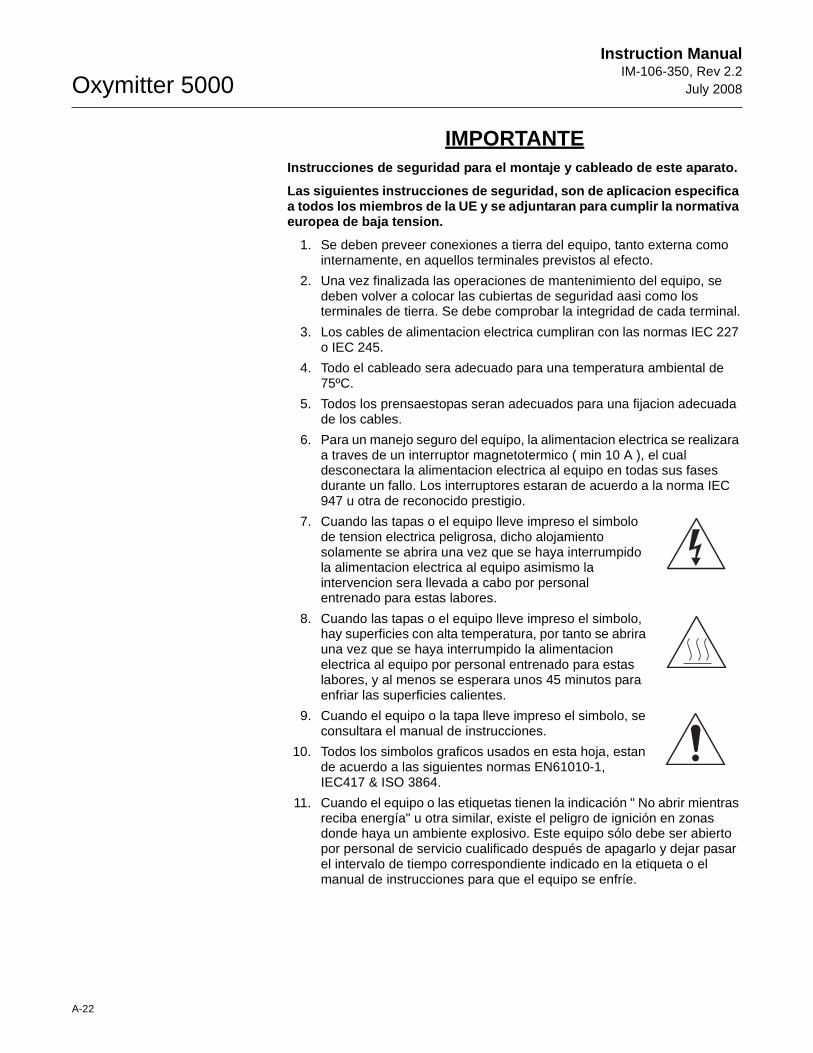
Oxymitter 5000
A-22
Instruction ManualIM-106-350, Rev 2.2
July 2008
IMPORTANTEInstrucciones de seguridad para el montaje y cablea do de este aparato.
Las siguientes instrucciones de seguridad, son de a plicacion especifica a todos los miembros de la UE y se adjuntaran para cumplir la normativa europea de baja tension.
1. Se deben preveer conexiones a tierra del equipo, tanto externa como internamente, en aquellos terminales previstos al efecto.
2. Una vez finalizada las operaciones de mantenimiento del equipo, se deben volver a colocar las cubiertas de seguridad aasi como los terminales de tierra. Se debe comprobar la integridad de cada terminal.
3. Los cables de alimentacion electrica cumpliran con las normas IEC 227 o IEC 245.
4. Todo el cableado sera adecuado para una temperatura ambiental de 75ºC.
5. Todos los prensaestopas seran adecuados para una fijacion adecuada de los cables.
6. Para un manejo seguro del equipo, la alimentacion electrica se realizara a traves de un interruptor magnetotermico ( min 10 A ), el cual desconectara la alimentacion electrica al equipo en todas sus fases durante un fallo. Los interruptores estaran de acuerdo a la norma IEC 947 u otra de reconocido prestigio.
7. Cuando las tapas o el equipo lleve impreso el simbolo de tension electrica peligrosa, dicho alojamiento solamente se abrira una vez que se haya interrumpido la alimentacion electrica al equipo asimismo la intervencion sera llevada a cabo por personal entrenado para estas labores.
8. Cuando las tapas o el equipo lleve impreso el simbolo, hay superficies con alta temperatura, por tanto se abrira una vez que se haya interrumpido la alimentacion electrica al equipo por personal entrenado para estas labores, y al menos se esperara unos 45 minutos para enfriar las superficies calientes.
9. Cuando el equipo o la tapa lleve impreso el simbolo, se consultara el manual de instrucciones.
10. Todos los simbolos graficos usados en esta hoja, estan de acuerdo a las siguientes normas EN61010-1, IEC417 & ISO 3864.
11. Cuando el equipo o las etiquetas tienen la indicación " No abrir mientras reciba energía" u otra similar, existe el peligro de ignición en zonas donde haya un ambiente explosivo. Este equipo sólo debe ser abierto por personal de servicio cualificado después de apagarlo y dejar pasar el intervalo de tiempo correspondiente indicado en la etiqueta o el manual de instrucciones para que el equipo se enfríe.
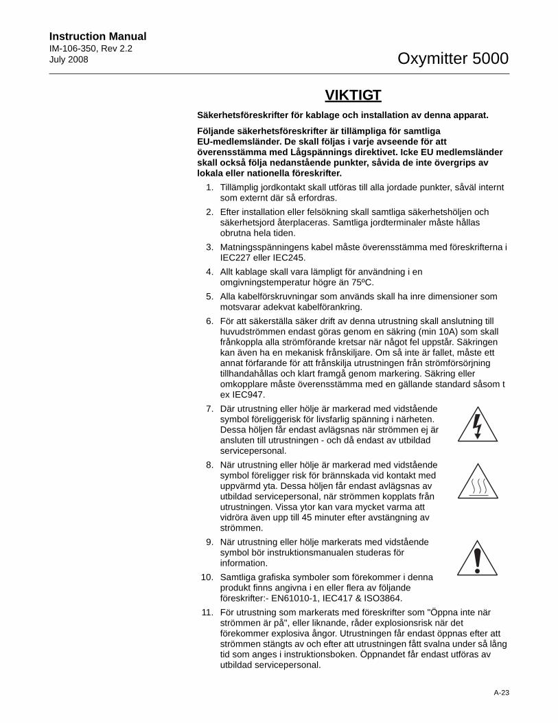
Instruction Manual IM-106-350, Rev 2.2July 2008
A-23
Oxymitter 5000
VIKTIGTSäkerhetsföreskrifter för kablage och installation av denna apparat.
Följande säkerhetsföreskrifter är tillämpliga för s amtliga EU-medlemsländer. De skall följas i varje avseende för att överensstämma med Lågspännings direktivet. Icke EU medlemsländer skall också följa nedanstående punkter, såvida de i nte övergrips av lokala eller nationella föreskrifter.
1. Tillämplig jordkontakt skall utföras till alla jordade punkter, såväl internt som externt där så erfordras.
2. Efter installation eller felsökning skall samtliga säkerhetshöljen och säkerhetsjord återplaceras. Samtliga jordterminaler måste hållas obrutna hela tiden.
3. Matningsspänningens kabel måste överensstämma med föreskrifterna i IEC227 eller IEC245.
4. Allt kablage skall vara lämpligt för användning i en omgivningstemperatur högre än 75ºC.
5. Alla kabelförskruvningar som används skall ha inre dimensioner som motsvarar adekvat kabelförankring.
6. För att säkerställa säker drift av denna utrustning skall anslutning till huvudströmmen endast göras genom en säkring (min 10A) som skall frånkoppla alla strömförande kretsar när något fel uppstår. Säkringen kan även ha en mekanisk frånskiljare. Om så inte är fallet, måste ett annat förfarande för att frånskilja utrustningen från strömförsörjning tillhandahållas och klart framgå genom markering. Säkring eller omkopplare måste överensstämma med en gällande standard såsom t ex IEC947.
7. Där utrustning eller hölje är markerad med vidstående symbol föreliggerisk för livsfarlig spänning i närheten. Dessa höljen får endast avlägsnas när strömmen ej är ansluten till utrustningen - och då endast av utbildad servicepersonal.
8. När utrustning eller hölje är markerad med vidstående symbol föreligger risk för brännskada vid kontakt med uppvärmd yta. Dessa höljen får endast avlägsnas av utbildad servicepersonal, när strömmen kopplats från utrustningen. Vissa ytor kan vara mycket varma att vidröra även upp till 45 minuter efter avstängning av strömmen.
9. När utrustning eller hölje markerats med vidstående symbol bör instruktionsmanualen studeras för information.
10. Samtliga grafiska symboler som förekommer i denna produkt finns angivna i en eller flera av följande föreskrifter:- EN61010-1, IEC417 & ISO3864.
11. För utrustning som markerats med föreskrifter som "Öppna inte när strömmen är på", eller liknande, råder explosionsrisk när det förekommer explosiva ångor. Utrustningen får endast öppnas efter att strömmen stängts av och efter att utrustningen fått svalna under så lång tid som anges i instruktionsboken. Öppnandet får endast utföras av utbildad servicepersonal.
Oxymitter 5000
A-24
Instruction ManualIM-106-350, Rev 2.2
July 2008
SAFETY DATA SHEET FOR CERAMIC FIBER PRODUCTS
JULY 1, 1996
SECTION I. IDENTIFICATION
PRODUCT NAMECeramic Fiber Heaters, Molded Insulation Modules and Ceramic Fiber Radiant Heater Panels.
CHEMICAL FAMILYVitreous Aluminosilicate Fibers with Silicon Dioxide.
CHEMICAL NAMEN.A.
CHEMICAL FORMULAN.A.
MANUFACTURER'S NAME AND ADDRESS
Watlow Columbia2101 Pennsylvania DriveColumbia, MO 65202573-814-1300, ext. 5170 573-474-9402
HEALTH HAZARD SUMMARY WARNING
• Possible cancer hazard based on tests with laboratory animals.
• May be irritating to skin, eyes and respiratory tract.
• May be harmful if inhaled.
• Cristobalite (crystalline silica) formed at high temperatures (above 1800ºF) can cause severe respiratory disease.
SECTION II. PHYSICAL DATA
APPEARANCE AND ODORCream to white colored fiber shapes. With or without optional white to gray granular surface coating and/or optional black surface coating.
SPECIFIC WEIGHT: 12-25 LB./CUBIC FOOT
BOILING POINT: N.A.
VOLATILES (% BY WT.): N.A.
WATER SOLUBILITY: N.A.
Instruction Manual IM-106-350, Rev 2.2July 2008
A-25
Oxymitter 5000
SECTION III. HAZARDOUS INGREDIENTS
MATERIAL, QUANTITY, AND THRESHOLD/EXPOSURE LIMIT VA LUES
Aluminosilicate (vitreous) 99+ % 1 fiber/cc TWA
CAS. No. 142844-00-0610 fibers/cc CL
Zirconium Silicate0-10% 5 mg/cubic meter (TLV)
Black Surface Coating**0 - 1% 5 mg/cubic meter (TLV)
Armorphous Silica/Silicon Dioxide0-10% 20 mppcf (6 mg/cubic meter)
PEL (OSHA 1978) 3 gm cubic meter
(Respirable dust): 10 mg/cubic meter,
Intended TLV (ACGIH 1984-85)
**Composition is a trade secret.
SECTION IV. FIRE AND EXPLOSION DATA
FLASH POINT: None
FLAMMABILITY LIMITS: N.A.
EXTINGUISHING MEDIAUse extinguishing agent suitable for type of surrounding fire.
UNUSUAL FIRE AND EXPLOSION HAZARDS / SPECIAL FIRE FIGHTING PROCEDURESN.A.
SECTION V. HEALTH HAZARD DATA
THRESHOLD LIMIT VALUE(See Section III)
EFFECTS OF OVER EXPOSURE
• EYE - Avoid contact with eyes. Slightly to moderately irritating. Abrasive action may cause damage to outer surface of eye.
• INHALATION - May cause respiratory tract irritation. Repeated or prolonged breathing of particles of respirable size may cause inflammation of the lung leading to chest pain, difficult breathing, coughing and possible fibrotic change in the lung (Pneumoconiosis). Pre-existing medical conditions may be aggravated by exposure: specifically, bronchial hyper-reactivity and chronic bronchial or lung disease.
• INGESTION - May cause gastrointestinal disturbances. Symptoms may include irritation and nausea, vomiting and diarrhea.
• SKIN - Slightly to moderate irritating. May cause irritation and inflammation due to mechanical reaction to sharp, broken ends of fibers.
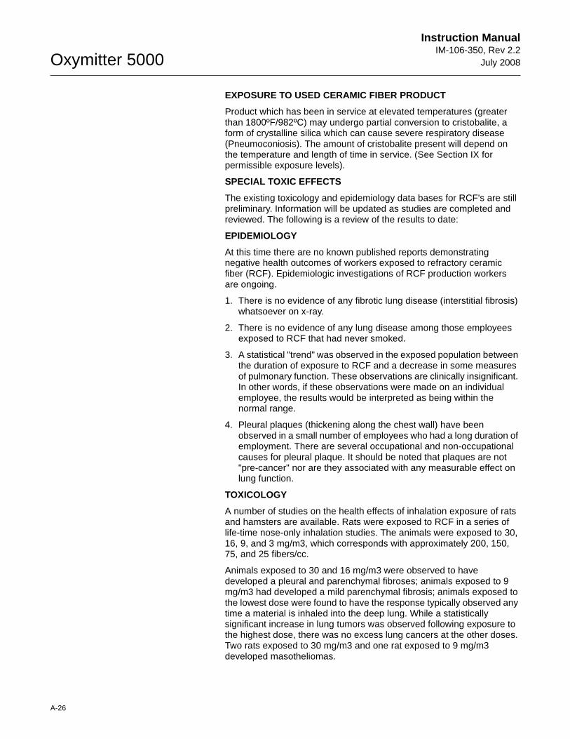
Oxymitter 5000
A-26
Instruction ManualIM-106-350, Rev 2.2
July 2008
EXPOSURE TO USED CERAMIC FIBER PRODUCT
Product which has been in service at elevated temperatures (greater than 1800ºF/982ºC) may undergo partial conversion to cristobalite, a form of crystalline silica which can cause severe respiratory disease (Pneumoconiosis). The amount of cristobalite present will depend on the temperature and length of time in service. (See Section IX for permissible exposure levels).
SPECIAL TOXIC EFFECTS
The existing toxicology and epidemiology data bases for RCF's are still preliminary. Information will be updated as studies are completed and reviewed. The following is a review of the results to date:
EPIDEMIOLOGY
At this time there are no known published reports demonstrating negative health outcomes of workers exposed to refractory ceramic fiber (RCF). Epidemiologic investigations of RCF production workers are ongoing.
1. There is no evidence of any fibrotic lung disease (interstitial fibrosis) whatsoever on x-ray.
2. There is no evidence of any lung disease among those employees exposed to RCF that had never smoked.
3. A statistical "trend" was observed in the exposed population between the duration of exposure to RCF and a decrease in some measures of pulmonary function. These observations are clinically insignificant. In other words, if these observations were made on an individual employee, the results would be interpreted as being within the normal range.
4. Pleural plaques (thickening along the chest wall) have been observed in a small number of employees who had a long duration of employment. There are several occupational and non-occupational causes for pleural plaque. It should be noted that plaques are not "pre-cancer" nor are they associated with any measurable effect on lung function.
TOXICOLOGY
A number of studies on the health effects of inhalation exposure of rats and hamsters are available. Rats were exposed to RCF in a series of life-time nose-only inhalation studies. The animals were exposed to 30, 16, 9, and 3 mg/m3, which corresponds with approximately 200, 150, 75, and 25 fibers/cc.
Animals exposed to 30 and 16 mg/m3 were observed to have developed a pleural and parenchymal fibroses; animals exposed to 9 mg/m3 had developed a mild parenchymal fibrosis; animals exposed to the lowest dose were found to have the response typically observed any time a material is inhaled into the deep lung. While a statistically significant increase in lung tumors was observed following exposure to the highest dose, there was no excess lung cancers at the other doses. Two rats exposed to 30 mg/m3 and one rat exposed to 9 mg/m3 developed masotheliomas.
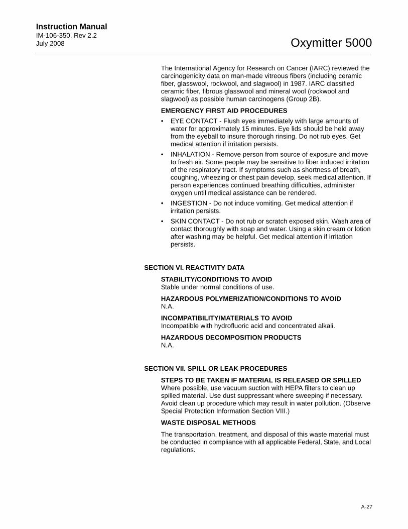
Instruction Manual IM-106-350, Rev 2.2July 2008
A-27
Oxymitter 5000
The International Agency for Research on Cancer (IARC) reviewed the carcinogenicity data on man-made vitreous fibers (including ceramic fiber, glasswool, rockwool, and slagwool) in 1987. IARC classified ceramic fiber, fibrous glasswool and mineral wool (rockwool and slagwool) as possible human carcinogens (Group 2B).
EMERGENCY FIRST AID PROCEDURES
• EYE CONTACT - Flush eyes immediately with large amounts of water for approximately 15 minutes. Eye lids should be held away from the eyeball to insure thorough rinsing. Do not rub eyes. Get medical attention if irritation persists.
• INHALATION - Remove person from source of exposure and move to fresh air. Some people may be sensitive to fiber induced irritation of the respiratory tract. If symptoms such as shortness of breath, coughing, wheezing or chest pain develop, seek medical attention. If person experiences continued breathing difficulties, administer oxygen until medical assistance can be rendered.
• INGESTION - Do not induce vomiting. Get medical attention if irritation persists.
• SKIN CONTACT - Do not rub or scratch exposed skin. Wash area of contact thoroughly with soap and water. Using a skin cream or lotion after washing may be helpful. Get medical attention if irritation persists.
SECTION VI. REACTIVITY DATA
STABILITY/CONDITIONS TO AVOIDStable under normal conditions of use.
HAZARDOUS POLYMERIZATION/CONDITIONS TO AVOIDN.A.
INCOMPATIBILITY/MATERIALS TO AVOIDIncompatible with hydrofluoric acid and concentrated alkali.
HAZARDOUS DECOMPOSITION PRODUCTSN.A.
SECTION VII. SPILL OR LEAK PROCEDURES
STEPS TO BE TAKEN IF MATERIAL IS RELEASED OR SPILLE DWhere possible, use vacuum suction with HEPA filters to clean up spilled material. Use dust suppressant where sweeping if necessary. Avoid clean up procedure which may result in water pollution. (Observe Special Protection Information Section VIII.)
WASTE DISPOSAL METHODS
The transportation, treatment, and disposal of this waste material must be conducted in compliance with all applicable Federal, State, and Local regulations.
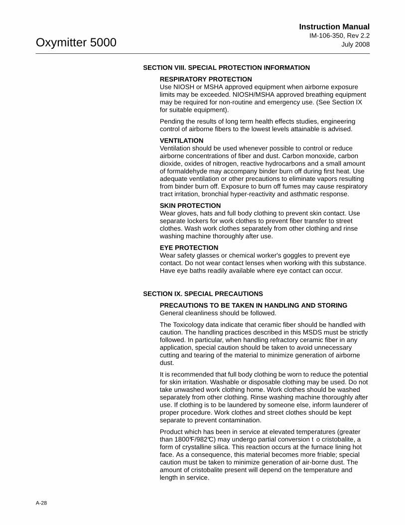
Oxymitter 5000
A-28
Instruction ManualIM-106-350, Rev 2.2
July 2008
SECTION VIII. SPECIAL PROTECTION INFORMATION
RESPIRATORY PROTECTIONUse NIOSH or MSHA approved equipment when airborne exposure limits may be exceeded. NIOSH/MSHA approved breathing equipment may be required for non-routine and emergency use. (See Section IX for suitable equipment).
Pending the results of long term health effects studies, engineering control of airborne fibers to the lowest levels attainable is advised.
VENTILATIONVentilation should be used whenever possible to control or reduce airborne concentrations of fiber and dust. Carbon monoxide, carbon dioxide, oxides of nitrogen, reactive hydrocarbons and a small amount of formaldehyde may accompany binder burn off during first heat. Use adequate ventilation or other precautions to eliminate vapors resulting from binder burn off. Exposure to burn off fumes may cause respiratory tract irritation, bronchial hyper-reactivity and asthmatic response.
SKIN PROTECTIONWear gloves, hats and full body clothing to prevent skin contact. Use separate lockers for work clothes to prevent fiber transfer to street clothes. Wash work clothes separately from other clothing and rinse washing machine thoroughly after use.
EYE PROTECTIONWear safety glasses or chemical worker's goggles to prevent eye contact. Do not wear contact lenses when working with this substance. Have eye baths readily available where eye contact can occur.
SECTION IX. SPECIAL PRECAUTIONS
PRECAUTIONS TO BE TAKEN IN HANDLING AND STORINGGeneral cleanliness should be followed.
The Toxicology data indicate that ceramic fiber should be handled with caution. The handling practices described in this MSDS must be strictly followed. In particular, when handling refractory ceramic fiber in any application, special caution should be taken to avoid unnecessary cutting and tearing of the material to minimize generation of airborne dust.
It is recommended that full body clothing be worn to reduce the potential for skin irritation. Washable or disposable clothing may be used. Do not take unwashed work clothing home. Work clothes should be washed separately from other clothing. Rinse washing machine thoroughly after use. If clothing is to be laundered by someone else, inform launderer of proper procedure. Work clothes and street clothes should be kept separate to prevent contamination.
Product which has been in service at elevated temperatures (greater than 1800°F/982°C) may undergo partial conversion t o cristobalite, a form of crystalline silica. This reaction occurs at the furnace lining hot face. As a consequence, this material becomes more friable; special caution must be taken to minimize generation of air-borne dust. The amount of cristobalite present will depend on the temperature and length in service.
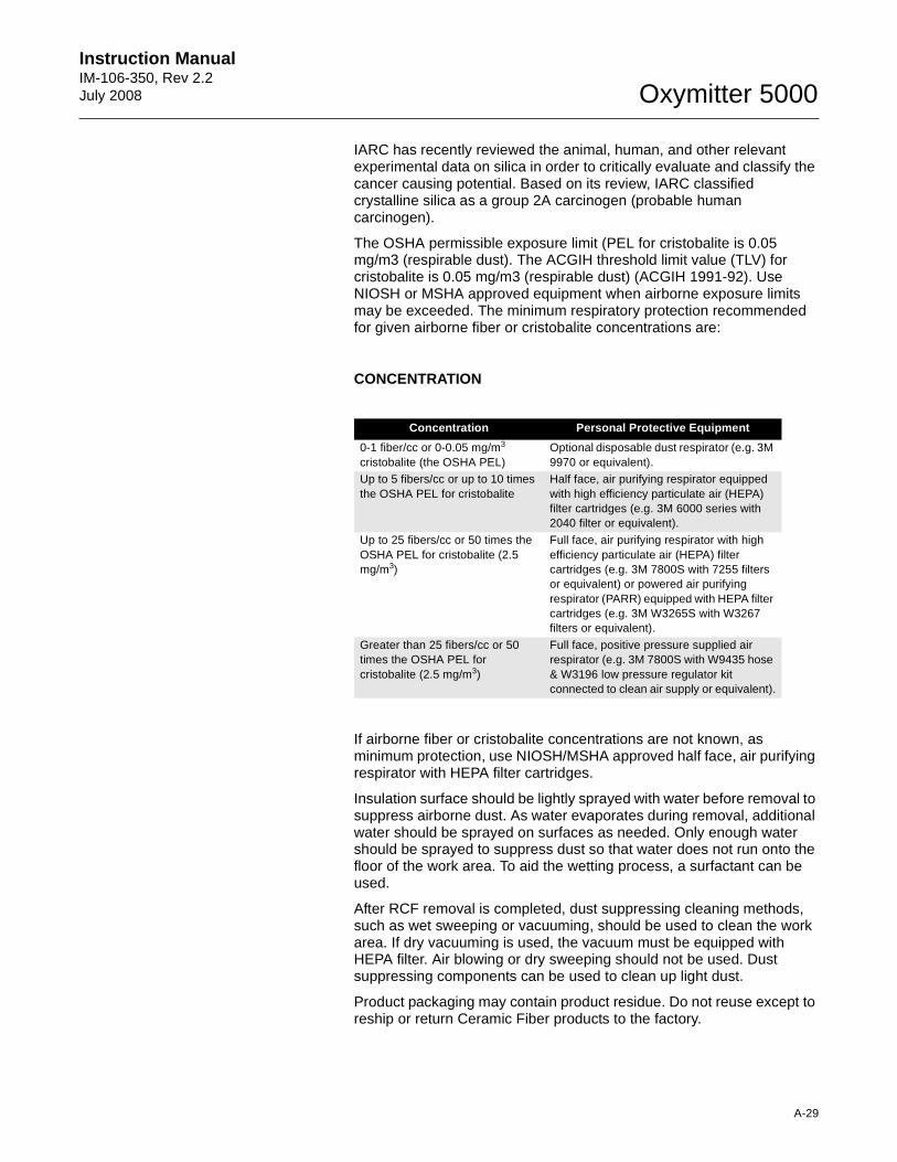
Instruction Manual IM-106-350, Rev 2.2July 2008
A-29
Oxymitter 5000
IARC has recently reviewed the animal, human, and other relevant experimental data on silica in order to critically evaluate and classify the cancer causing potential. Based on its review, IARC classified crystalline silica as a group 2A carcinogen (probable human carcinogen).
The OSHA permissible exposure limit (PEL for cristobalite is 0.05 mg/m3 (respirable dust). The ACGIH threshold limit value (TLV) for cristobalite is 0.05 mg/m3 (respirable dust) (ACGIH 1991-92). Use NIOSH or MSHA approved equipment when airborne exposure limits may be exceeded. The minimum respiratory protection recommended for given airborne fiber or cristobalite concentrations are:
CONCENTRATION
If airborne fiber or cristobalite concentrations are not known, as minimum protection, use NIOSH/MSHA approved half face, air purifying respirator with HEPA filter cartridges.
Insulation surface should be lightly sprayed with water before removal to suppress airborne dust. As water evaporates during removal, additional water should be sprayed on surfaces as needed. Only enough water should be sprayed to suppress dust so that water does not run onto the floor of the work area. To aid the wetting process, a surfactant can be used.
After RCF removal is completed, dust suppressing cleaning methods, such as wet sweeping or vacuuming, should be used to clean the work area. If dry vacuuming is used, the vacuum must be equipped with HEPA filter. Air blowing or dry sweeping should not be used. Dust suppressing components can be used to clean up light dust.
Product packaging may contain product residue. Do not reuse except to reship or return Ceramic Fiber products to the factory.
Concentration Personal Protective Equipment
0-1 fiber/cc or 0-0.05 mg/m3 cristobalite (the OSHA PEL)
Optional disposable dust respirator (e.g. 3M 9970 or equivalent).
Up to 5 fibers/cc or up to 10 times the OSHA PEL for cristobalite
Half face, air purifying respirator equipped with high efficiency particulate air (HEPA) filter cartridges (e.g. 3M 6000 series with 2040 filter or equivalent).
Up to 25 fibers/cc or 50 times the OSHA PEL for cristobalite (2.5 mg/m3)
Full face, air purifying respirator with high efficiency particulate air (HEPA) filter cartridges (e.g. 3M 7800S with 7255 filters or equivalent) or powered air purifying respirator (PARR) equipped with HEPA filter cartridges (e.g. 3M W3265S with W3267 filters or equivalent).
Greater than 25 fibers/cc or 50 times the OSHA PEL for cristobalite (2.5 mg/m3)
Full face, positive pressure supplied air respirator (e.g. 3M 7800S with W9435 hose & W3196 low pressure regulator kit connected to clean air supply or equivalent).
Oxymitter 5000
A-30
Instruction ManualIM-106-350, Rev 2.2
July 2008
GENERAL PRECAUTIONS FOR HANDLING AND STORING HIGH PRESSURE GAS CYLINDERS
Edited from selected paragraphs of the CompressedGas Association's "Handbook of Compressed Gases"published in 1981Compressed Gas Association1235 Jefferson Davis HighwayArlington, Virginia 22202Used by Permission
1. Never drop cylinders or permit them to strike each other violently.
2. Cylinders may be stored in the open, but in such cases, should be protected against extremes of weather and, to prevent rusting, from the dampness of the ground. Cylinders should be stored in the shade when located in areas where extreme temperatures are prevalent.
3. The valve protection cap should be left on each cylinder until it has been secured against a wall or bench, or placed in a cylinder stand, and is ready to be used.
4. Avoid dragging, rolling, or sliding cylinders, even for short distance; they should be moved by using a suitable handtruck.
5. Never tamper with safety devices in valves or cylinders.
6. Do not store full and empty cylinders together. Serious suckback can occur when an empty cylinder is attached to a pressurized system.
7. No part of cylinder should be subjected to a temperature higher than 52°C (125°F). A flame should never be permitted to come in contact with any part of a compressed gas cylinder.
8. Do not place cylinders where they may become part of an electric circuit. When electric arc welding, precautions must be taken to prevent striking an arc against the cylinder.
Instruction Manual IM-106-350, Rev 2.2July 2008 Oxymitter 5000
http://www.raihome.com
Appendix B Return of Material
RETURNING MATERIAL If factory repair of defective equipment is require d, proceed as follows:
1. Secure a return authorization number from a Emerson Process Management Office or representative before returning the equipment. Equipment must be returned with complete identification in accordance with Emerson Process Management instructions or it will not be accepted.
In no event will Emerson Process Management be responsible for equipment returned without proper authorization and identification.
2. Carefully pack defective unit in a sturdy box with sufficient shock absorbing material to ensure that no additional damage will occur during shipping.
3. In a cover letter, describe completely:
a. The symptoms from which it was determined that the equipment is faulty.
b. The environment in which the equipment has been operating (housing, weather, vibration, dust, etc.).
c. Site from which equipment was removed.
d. Whether warranty or nonwarranty service is requested.
e. Complete shipping instructions for return of equipment.
f. Reference the return authorization number.
4. Enclose a cover letter and purchase order and ship the defective equipment according to instructions provided in Emerson Process Management Return Authorization, prepaid, to:
Emerson Process ManagementRMR DepartmentDaniel Headquarters11100 Britmore Park DriveHouston, TX 77041
If warranty service is requested, the defective unit will be carefully inspected and tested at the factory. If failure was due to conditions listed in the standard Rosemount Analytical warranty, the defective unit will be repaired or replaced at Emerson Process Management's option, and an operating unit will be returned to the customer in accordance with shipping instructions furnished in the cover letter.
For equipment no longer under warranty, the equipment will be repaired at the factory and returned as directed by the purchase order and shipping instructions.

Oxymitter 5000
B-2
Instruction ManualIM-106-350, Rev 2.2
July 2008
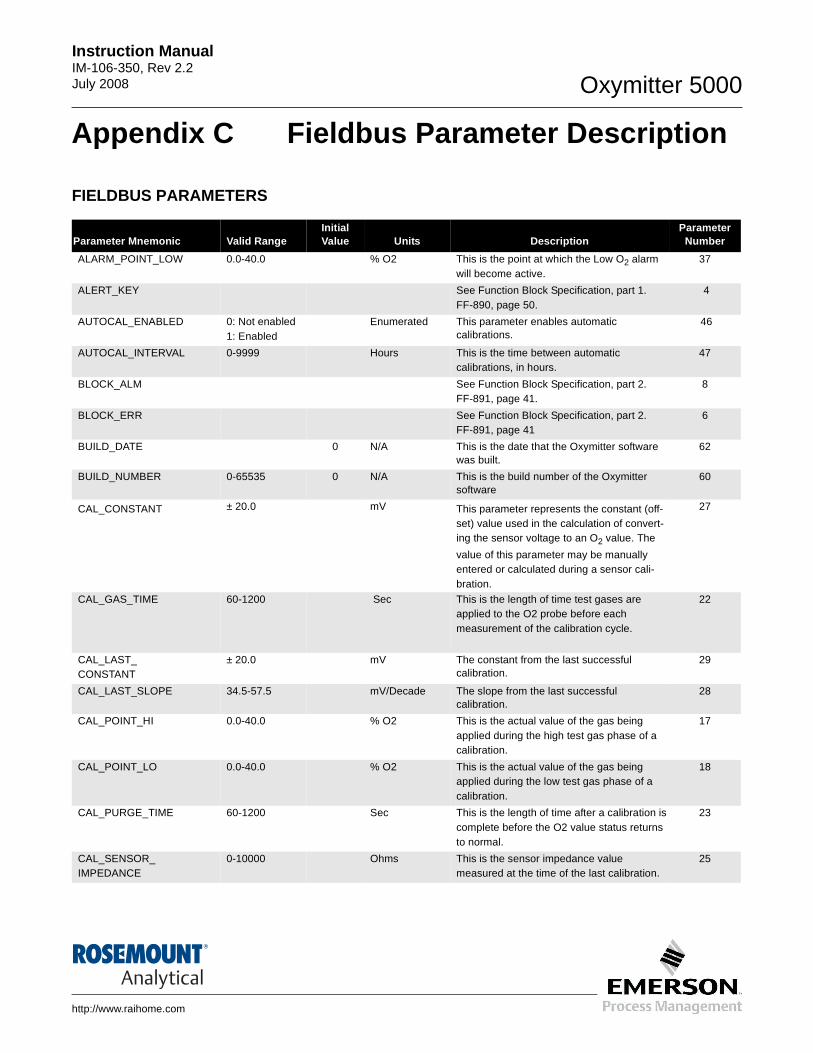
Instruction Manual IM-106-350, Rev 2.2July 2008 Oxymitter 5000
http://www.raihome.com
Appendix C Fieldbus Parameter Description
FIELDBUS PARAMETERS
Parameter Mnemonic Valid RangeInitial Value Units Description
Parameter Number
ALARM_POINT_LOW 0.0-40.0 % O2 This is the point at which the Low O2 alarm will become active.
37
ALERT_KEY See Function Block Specification, part 1. FF-890, page 50.
4
AUTOCAL_ENABLED 0: Not enabled1: Enabled
Enumerated This parameter enables automatic calibrations.
46
AUTOCAL_INTERVAL 0-9999 Hours This is the time between automatic calibrations, in hours.
47
BLOCK_ALM See Function Block Specification, part 2. FF-891, page 41.
8
BLOCK_ERR See Function Block Specification, part 2. FF-891, page 41
6
BUILD_DATE 0 N/A This is the date that the Oxymitter software was built.
62
BUILD_NUMBER 0-65535 0 N/A This is the build number of the Oxymitter software
60
CAL_CONSTANT ± 20.0 mV This parameter represents the constant (off-set) value used in the calculation of convert-ing the sensor voltage to an O2 value. The
value of this parameter may be manually entered or calculated during a sensor cali-bration.
27
CAL_GAS_TIME 60-1200 Sec This is the length of time test gases are applied to the O2 probe before each measurement of the calibration cycle.
22
CAL_LAST_CONSTANT
± 20.0 mV The constant from the last successful calibration.
29
CAL_LAST_SLOPE 34.5-57.5 mV/Decade The slope from the last successful calibration.
28
CAL_POINT_HI 0.0-40.0 % O2 This is the actual value of the gas being applied during the high test gas phase of a calibration.
17
CAL_POINT_LO 0.0-40.0 % O2 This is the actual value of the gas being applied during the low test gas phase of a calibration.
18
CAL_PURGE_TIME 60-1200 Sec This is the length of time after a calibration iscomplete before the O2 value status returns to normal.
23
CAL_SENSOR_ IMPEDANCE
0-10000 Ohms This is the sensor impedance value measured at the time of the last calibration.
25
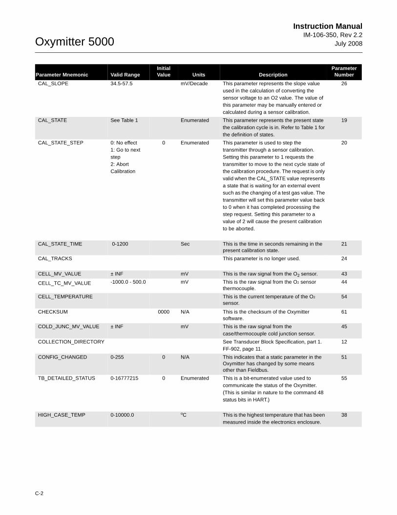
Oxymitter 5000
C-2
Instruction ManualIM-106-350, Rev 2.2
July 2008
CAL_SLOPE 34.5-57.5 mV/Decade This parameter represents the slope value used in the calculation of converting the sensor voltage to an O2 value. The value of this parameter may be manually entered or calculated during a sensor calibration.
26
CAL_STATE See Table 1 Enumerated This parameter represents the present state the calibration cycle is in. Refer to Table 1 for the definition of states.
19
CAL_STATE_STEP 0: No effect1: Go to next step2: Abort Calibration
0 Enumerated This parameter is used to step the transmitter through a sensor calibration. Setting this parameter to 1 requests the transmitter to move to the next cycle state of the calibration procedure. The request is only valid when the CAL_STATE value represents a state that is waiting for an external event such as the changing of a test gas value. The transmitter will set this parameter value back to 0 when it has completed processing the step request. Setting this parameter to a value of 2 will cause the present calibration to be aborted.
20
CAL_STATE_TIME 0-1200 Sec This is the time in seconds remaining in the present calibration state.
21
CAL_TRACKS This parameter is no longer used. 24
CELL_MV_VALUE ± INF mV This is the raw signal from the O2 sensor. 43
CELL_TC_MV_VALUE -1000.0 - 500.0 mV This is the raw signal from the O2 sensor thermocouple.
44
CELL_TEMPERATURE This is the current temperature of the O2 sensor.
54
CHECKSUM 0000 N/A This is the checksum of the Oxymitter software.
61
COLD_JUNC_MV_VALUE ± INF mV This is the raw signal from the case/thermocouple cold junction sensor.
45
COLLECTION_DIRECTORY See Transducer Block Specification, part 1. FF-902, page 11.
12
CONFIG_CHANGED 0-255 0 N/A This indicates that a static parameter in the Oxymitter has changed by some means other than Fieldbus.
51
TB_DETAILED_STATUS 0-16777215 0 Enumerated This is a bit-enumerated value used to communicate the status of the Oxymitter. (This is similar in nature to the command 48 status bits in HART.)
55
HIGH_CASE_TEMP 0-10000.0 oC This is the highest temperature that has been measured inside the electronics enclosure.
38
Parameter Mnemonic Valid RangeInitial Value Units Description
Parameter Number
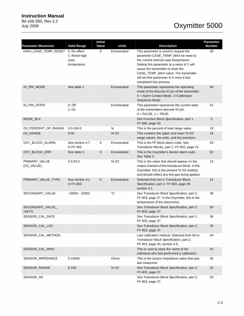
Instruction Manual IM-106-350, Rev 2.2July 2008
C-3
Oxymitter 5000
HIGH_CASE_TEMP_RESET 0: No effect1: Reset high case temperature
0 Enumerated This parameter is used to request the parameter CASE_TEMP_MAX be reset to the current internal case temperature. Setting this parameter at a value of 1 will cause the transmitter to reset the CASE_TEMP_MAX value. The transmitter will set this parameter to 0 once it has completed this process.
39
IO_PIN_MODE See table 2 Enumerated This parameter represents the operating mode of the discrete IO pin of the transmitter. 0 = Alarm Contact Mode, 1=Calibration Sequence Mode.
40
IO_PIN_STATE 0: Off1: On
Enumerated This parameter represents the current state of the transmitters discrete IO pin. 0 = FALSE, 1 = TRUE.
41
MODE_BLK See Function Block Specification, part 1. FF-890, page 50.
5
O2_PERCENT_OF_RANGE 0.0-100.0 % This is the percent of total range value. 15
O2_RANGE 0-40 % O2 This contains the upper and lower % O2 range values, the units, and the precision.
16
OXY_BLOCK_ALARM See section 4.7 in FF-903
0 Enumerated This is the FF block alarm code. See Transducer Blocks, part 2. FF-903, page 41.
53
OXY_BLOCK_ERR See table 3 0 Enumerated This is the Oxymitter's device alarm code. See Table 3.
52
PRIMARY_VALUE (O2_VALUE)
0.0-25.0 % O2 This is the value that should appear on the output channel of the transducer block. In the Oxymitter, this is the present % O2 reading and should reflect any test gas being applied.
13
PRIMARY_VALUE_TYPE See section 4.1 in FF-903
0 Enumerated Selected from list in Transducer Block Specification, part 2. FF-903, page 39, section 4.1.
14
SECONDARY_VALUE -10000 - 10000 oC See Transducer Block Specification, part 2. FF-903, page 37. In the Oxymitter, this is the temperature of the electronics.
49
SECONDARY_VALUE_UNITS
See Transducer Block Specification, part 2. FF-903, page 37.
50
SENSOR_CAL_DATE See Transducer Block Specification, part 2. FF-903, page 37.
36
SENSOR_CAL_LOC See Transducer Block Specification, part 2. FF-903, page 37.
35
SENSOR_CAL_METHOD Last calibration method. Selected from list in Transducer Block Specification, part 2. FF-903, page 40, section 4.5.
34
SENSOR_CAL_WHO This is used to store the name of the individual who last performed a calibration.
42
SENSOR_IMPEDANCE 0-10000 Ohms This is the sensor impedance value that was last measured.
30
SENSOR_RANGE 0-100 % O2 See Transducer Block Specification, part 2. FF-903, page 37.
32
SENSOR_SN See Transducer Block Specification, part 2. FF-903, page 37.
33
Parameter Mnemonic Valid RangeInitial Value Units Description
Parameter Number
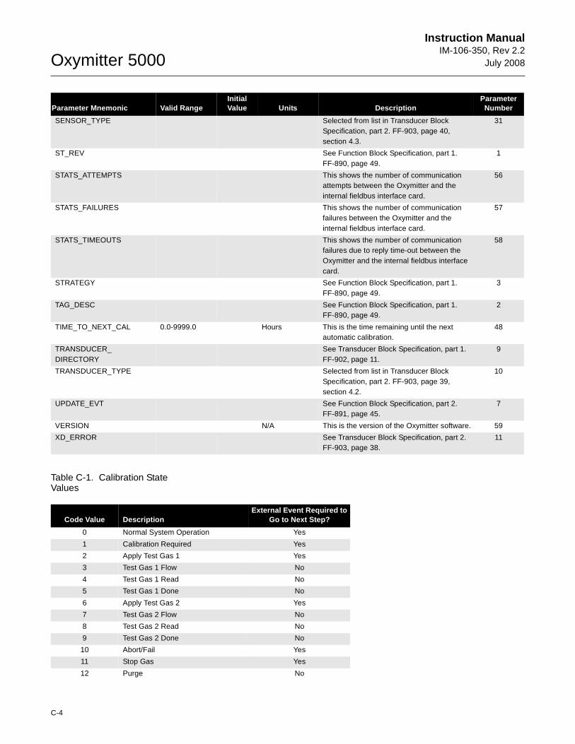
Oxymitter 5000
C-4
Instruction ManualIM-106-350, Rev 2.2
July 2008
Table C-1. Calibration State Values
SENSOR_TYPE Selected from list in Transducer Block Specification, part 2. FF-903, page 40, section 4.3.
31
ST_REV See Function Block Specification, part 1. FF-890, page 49.
1
STATS_ATTEMPTS This shows the number of communication attempts between the Oxymitter and the internal fieldbus interface card.
56
STATS_FAILURES This shows the number of communication failures between the Oxymitter and the internal fieldbus interface card.
57
STATS_TIMEOUTS This shows the number of communication failures due to reply time-out between the Oxymitter and the internal fieldbus interface card.
58
STRATEGY See Function Block Specification, part 1. FF-890, page 49.
3
TAG_DESC See Function Block Specification, part 1. FF-890, page 49.
2
TIME_TO_NEXT_CAL 0.0-9999.0 Hours This is the time remaining until the next automatic calibration.
48
TRANSDUCER_DIRECTORY
See Transducer Block Specification, part 1. FF-902, page 11.
9
TRANSDUCER_TYPE Selected from list in Transducer Block Specification, part 2. FF-903, page 39, section 4.2.
10
UPDATE_EVT See Function Block Specification, part 2. FF-891, page 45.
7
VERSION N/A This is the version of the Oxymitter software. 59
XD_ERROR See Transducer Block Specification, part 2. FF-903, page 38.
11
Parameter Mnemonic Valid RangeInitial Value Units Description
Parameter Number
Code Value DescriptionExternal Event Required to
Go to Next Step?
0 Normal System Operation Yes
1 Calibration Required Yes
2 Apply Test Gas 1 Yes
3 Test Gas 1 Flow No
4 Test Gas 1 Read No
5 Test Gas 1 Done No
6 Apply Test Gas 2 Yes
7 Test Gas 2 Flow No
8 Test Gas 2 Read No
9 Test Gas 2 Done No
10 Abort/Fail Yes
11 Stop Gas Yes
12 Purge No
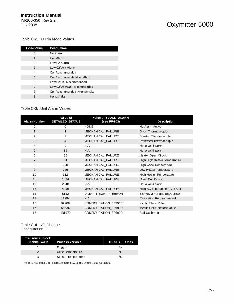
Instruction Manual IM-106-350, Rev 2.2July 2008
C-5
Oxymitter 5000
Table C-2. IO Pin Mode Values
Table C-3. Unit Alarm Values
Table C-4. I/O Channel Configuration
Refer to Appendix D for instructions on how to implement these variables.
Code Value Description
0 No Alarm
1 Unit Alarm
2 Low 02 Alarm
3 Low 02/Unit Alarm
4 Cal Recommended
5 Cal Recommended/Unit Alarm
6 Low 02/Cal Recommended
7 Low 02/Unit/Cal Recommended
8 Cal Recommended->Handshake
9 Handshake
Alarm NumberValue of
DETAILED_STATUSValue of BLOCK_ALARM
(see FF-903) Description
0 0 NONE No Alarm Active
1 1 MECHANICAL_FAILURE Open Thermocouple
2 2 MECHANICAL_FAILURE Shorted Thermocouple
3 4 MECHANICAL_FAILURE Reversed Thermocouple
4 8 N/A Not a valid alarm
5 16 N/A Not a valid alarm
6 32 MECHANICAL_FAILURE Heater Open Circuit
7 64 MECHANICAL_FAILURE High High Heater Temperature
8 128 MECHANICAL_FAILURE High Case Temperature
9 256 MECHANICAL_FAILURE Low Heater Temperature
10 512 MECHANICAL_FAILURE High Heater Temperature
11 1024 MECHANICAL_FAILURE Open Cell Circuit
12 2048 N/A Not a valid alarm
13 4096 MECHANICAL_FAILURE High AC Impedance / Cell Bad
14 8192 DATA_INTEGRITY_ERROR EEPROM Parameters Corrupt
15 16384 N/A Calibration Recommended
16 32768 CONFIGURATION_ERROR Invalid Slope Value
17 65536 CONFIGURATION_ERROR Invalid Cell Constant Value
18 131072 CONFIGURATION_ERROR Bad Calibration
Transducer Block Channel Value Process Variable XD_SCALE Units
1 Oxygen %
2 Case Temperature oC
3 Sensor Temperature oC
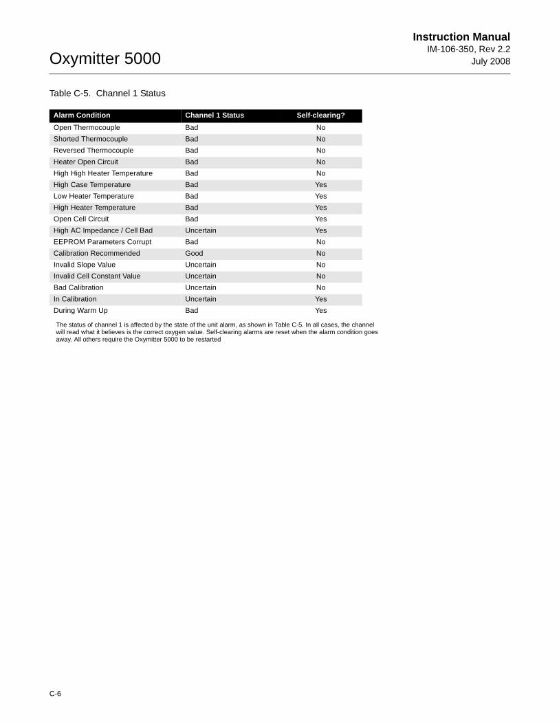
Oxymitter 5000
C-6
Instruction ManualIM-106-350, Rev 2.2
July 2008
Table C-5. Channel 1 Status
The status of channel 1 is affected by the state of the unit alarm, as shown in Table C-5. In all cases, the channel will read what it believes is the correct oxygen value. Self-clearing alarms are reset when the alarm condition goes away. All others require the Oxymitter 5000 to be restarted
Alarm Condition Channel 1 Status Self-clearing?
Open Thermocouple Bad No
Shorted Thermocouple Bad No
Reversed Thermocouple Bad No
Heater Open Circuit Bad No
High High Heater Temperature Bad No
High Case Temperature Bad Yes
Low Heater Temperature Bad Yes
High Heater Temperature Bad Yes
Open Cell Circuit Bad Yes
High AC Impedance / Cell Bad Uncertain Yes
EEPROM Parameters Corrupt Bad No
Calibration Recommended Good No
Invalid Slope Value Uncertain No
Invalid Cell Constant Value Uncertain No
Bad Calibration Uncertain No
In Calibration Uncertain Yes
During Warm Up Bad Yes
Instruction Manual IM-106-350, Rev 2.2July 2008 Oxymitter 5000
http://www.raihome.com
Appendix D Analog Input (AI) Function Block
Simulation . . . . . . . . . . . . . . . . . . . . . . . . . . . . . . . . . . . . . . page D-3Filtering . . . . . . . . . . . . . . . . . . . . . . . . . . . . . . . . . . . . . . . . page D-4Signal Conversion . . . . . . . . . . . . . . . . . . . . . . . . . . . . . . . page D-5Block Errors . . . . . . . . . . . . . . . . . . . . . . . . . . . . . . . . . . . . page D-5Modes . . . . . . . . . . . . . . . . . . . . . . . . . . . . . . . . . . . . . . . . . page D-6Alarm Detection . . . . . . . . . . . . . . . . . . . . . . . . . . . . . . . . . page D-6Status Handling . . . . . . . . . . . . . . . . . . . . . . . . . . . . . . . . . . page D-7Advanced Features . . . . . . . . . . . . . . . . . . . . . . . . . . . . . . . page D-8Application Information . . . . . . . . . . . . . . . . . . . . . . . . . . . page D-8Application Examples . . . . . . . . . . . . . . . . . . . . . . . . . . . . page D-9Troubleshooting . . . . . . . . . . . . . . . . . . . . . . . . . . . . . . . . . page D-13
The Analog Input (AI) function block processes field device measurements and makes them available to other function blocks. The output value from the AI block is in engineering units and contains a status indicating the quality of the measurement. The measuring device may have several measurements or derived values available in different channels. Use the channel number to define the variable that the AI block processes.
The AI block supports alarming, signal scaling, signal filtering, signal status calculation, mode control, and simulation. In Automatic mode, the block’s output parameter (OUT) reflects the process variable (PV) value and status. In Manual mode, OUT may be set manually. The Manual mode is reflected on the output status. A discrete output (OUT_D) is provided to indicate whether a selected alarm condition is active. Alarm detection is based on the OUT value and user specified alarm limits. Figure D-1 illustrates the internal components of the AI function block, and Table D-1 lists the AI block parameters and their units of measure, descriptions, and index numbers.
OUT = The block output value and status
OUT_D = Discrete output that signals a selectedalarm condition
OUT_D
AI OUT
38
73
011
6
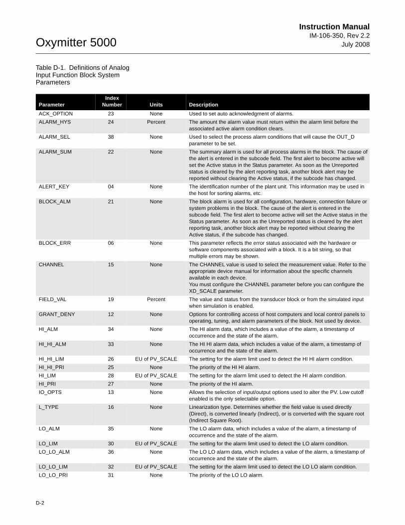
Oxymitter 5000
D-2
Instruction ManualIM-106-350, Rev 2.2
July 2008
Table D-1. Definitions of Analog Input Function Block System Parameters
ParameterIndex
Number Units Description
ACK_OPTION 23 None Used to set auto acknowledgment of alarms.
ALARM_HYS 24 Percent The amount the alarm value must return within the alarm limit before the associated active alarm condition clears.
ALARM_SEL 38 None Used to select the process alarm conditions that will cause the OUT_D parameter to be set.
ALARM_SUM 22 None The summary alarm is used for all process alarms in the block. The cause of the alert is entered in the subcode field. The first alert to become active will set the Active status in the Status parameter. As soon as the Unreported status is cleared by the alert reporting task, another block alert may be reported without clearing the Active status, if the subcode has changed.
ALERT_KEY 04 None The identification number of the plant unit. This information may be used in the host for sorting alarms, etc.
BLOCK_ALM 21 None The block alarm is used for all configuration, hardware, connection failure or system problems in the block. The cause of the alert is entered in the subcode field. The first alert to become active will set the Active status in the Status parameter. As soon as the Unreported status is cleared by the alert reporting task, another block alert may be reported without clearing the Active status, if the subcode has changed.
BLOCK_ERR 06 None This parameter reflects the error status associated with the hardware or software components associated with a block. It is a bit string, so that multiple errors may be shown.
CHANNEL 15 None The CHANNEL value is used to select the measurement value. Refer to the appropriate device manual for information about the specific channels available in each device.You must configure the CHANNEL parameter before you can configure the XD_SCALE parameter.
FIELD_VAL 19 Percent The value and status from the transducer block or from the simulated input when simulation is enabled.
GRANT_DENY 12 None Options for controlling access of host computers and local control panels to operating, tuning, and alarm parameters of the block. Not used by device.
HI_ALM 34 None The HI alarm data, which includes a value of the alarm, a timestamp of occurrence and the state of the alarm.
HI_HI_ALM 33 None The HI HI alarm data, which includes a value of the alarm, a timestamp of occurrence and the state of the alarm.
HI_HI_LIM 26 EU of PV_SCALE The setting for the alarm limit used to detect the HI HI alarm condition.
HI_HI_PRI 25 None The priority of the HI HI alarm.
HI_LIM 28 EU of PV_SCALE The setting for the alarm limit used to detect the HI alarm condition.
HI_PRI 27 None The priority of the HI alarm.
IO_OPTS 13 None Allows the selection of input/output options used to alter the PV. Low cutoff enabled is the only selectable option.
L_TYPE 16 None Linearization type. Determines whether the field value is used directly (Direct), is converted linearly (Indirect), or is converted with the square root (Indirect Square Root).
LO_ALM 35 None The LO alarm data, which includes a value of the alarm, a timestamp of occurrence and the state of the alarm.
LO_LIM 30 EU of PV_SCALE The setting for the alarm limit used to detect the LO alarm condition.
LO_LO_ALM 36 None The LO LO alarm data, which includes a value of the alarm, a timestamp of occurrence and the state of the alarm.
LO_LO_LIM 32 EU of PV_SCALE The setting for the alarm limit used to detect the LO LO alarm condition.
LO_LO_PRI 31 None The priority of the LO LO alarm.
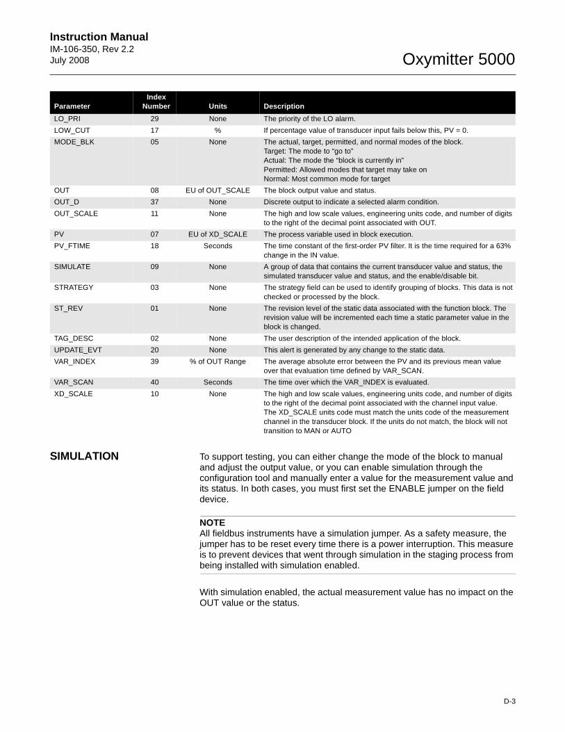
Instruction Manual IM-106-350, Rev 2.2July 2008
D-3
Oxymitter 5000
SIMULATION To support testing, you can either change the mode of the block to manual and adjust the output value, or you can enable simulation through the configuration tool and manually enter a value for the measurement value and its status. In both cases, you must first set the ENABLE jumper on the field device.
NOTEAll fieldbus instruments have a simulation jumper. As a safety measure, the jumper has to be reset every time there is a power interruption. This measure is to prevent devices that went through simulation in the staging process from being installed with simulation enabled.
With simulation enabled, the actual measurement value has no impact on the OUT value or the status.
LO_PRI 29 None The priority of the LO alarm.
LOW_CUT 17 % If percentage value of transducer input fails below this, PV = 0.
MODE_BLK 05 None The actual, target, permitted, and normal modes of the block. Target: The mode to “go to” Actual: The mode the “block is currently in” Permitted: Allowed modes that target may take on Normal: Most common mode for target
OUT 08 EU of OUT_SCALE The block output value and status.
OUT_D 37 None Discrete output to indicate a selected alarm condition.
OUT_SCALE 11 None The high and low scale values, engineering units code, and number of digits to the right of the decimal point associated with OUT.
PV 07 EU of XD_SCALE The process variable used in block execution.
PV_FTIME 18 Seconds The time constant of the first-order PV filter. It is the time required for a 63% change in the IN value.
SIMULATE 09 None A group of data that contains the current transducer value and status, the simulated transducer value and status, and the enable/disable bit.
STRATEGY 03 None The strategy field can be used to identify grouping of blocks. This data is not checked or processed by the block.
ST_REV 01 None The revision level of the static data associated with the function block. The revision value will be incremented each time a static parameter value in the block is changed.
TAG_DESC 02 None The user description of the intended application of the block.
UPDATE_EVT 20 None This alert is generated by any change to the static data.
VAR_INDEX 39 % of OUT Range The average absolute error between the PV and its previous mean value over that evaluation time defined by VAR_SCAN.
VAR_SCAN 40 Seconds The time over which the VAR_INDEX is evaluated.
XD_SCALE 10 None The high and low scale values, engineering units code, and number of digits to the right of the decimal point associated with the channel input value.The XD_SCALE units code must match the units code of the measurement channel in the transducer block. If the units do not match, the block will not transition to MAN or AUTO
ParameterIndex
Number Units Description
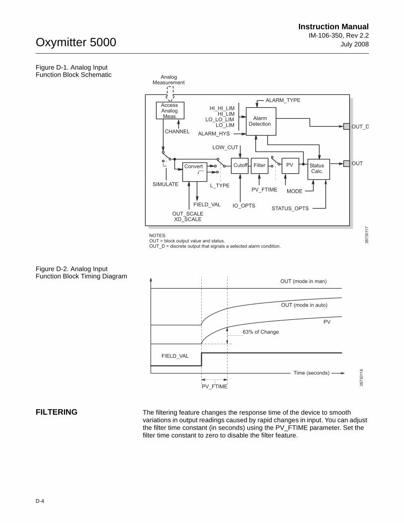
Oxymitter 5000
D-4
Instruction ManualIM-106-350, Rev 2.2
July 2008
Figure D-1. Analog Input Function Block Schematic
Figure D-2. Analog Input Function Block Timing Diagram
FILTERING The filtering feature changes the response time of the device to smooth variations in output readings caused by rapid changes in input. You can adjust the filter time constant (in seconds) using the PV_FTIME parameter. Set the filter time constant to zero to disable the filter feature.
AnalogMeasurement
AccessAnalogMeas.
CHANNEL
SIMULATE
OUT_SCALEXD_SCALE
FIELD_VAL
L_TYPE
IO_OPTS
PV_FTIME MODE
STATUS_OPTS
HI_HI_LIMHI_LIM
LO_LO_LIMLO_LIM
ALARM_HYS
ALARM_TYPE
OUT_D
OUTPVConvert Cutoff StatusCalc.
AlarmDetection
NOTES:OUT = block output value and status.OUT_D = discrete output that signals a selected alarm condition.
LOW_CUT
38
73
011
7
Filter
PV_FTIME
63% of Change
OUT (mode in man)
OUT (mode in auto)
PV
FIELD_VAL3
87
30
11
8
Time (seconds)
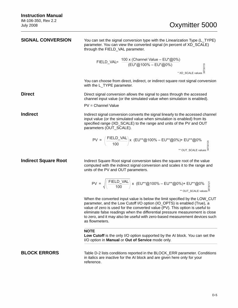
Instruction Manual IM-106-350, Rev 2.2July 2008
D-5
Oxymitter 5000
SIGNAL CONVERSION You can set the signal conversion type with the Linearization Type (L_TYPE) parameter. You can view the converted signal (in percent of XD_SCALE) through the FIELD_VAL parameter.
You can choose from direct, indirect, or indirect square root signal conversion with the L_TYPE parameter.
Direct Direct signal conversion allows the signal to pass through the accessed channel input value (or the simulated value when simulation is enabled).
PV = Channel Value
Indirect Indirect signal conversion converts the signal linearly to the accessed channel input value (or the simulated value when simulation is enabled) from its specified range (XD_SCALE) to the range and units of the PV and OUT parameters (OUT_SCALE).
Indirect Square Root Indirect Square Root signal conversion takes the square root of the value computed with the indirect signal conversion and scales it to the range and units of the PV and OUT parameters.
When the converted input value is below the limit specified by the LOW_CUT parameter, and the Low Cutoff I/O option (IO_OPTS) is enabled (True), a value of zero is used for the converted value (PV). This option is useful to eliminate false readings when the differential pressure measurement is close to zero, and it may also be useful with zero-based measurement devices such as flowmeters.
NOTELow Cutoff is the only I/O option supported by the AI block. You can set the I/O option in Manual or Out of Service mode only.
BLOCK ERRORS Table D-2 lists conditions reported in the BLOCK_ERR parameter. Conditions in italics are inactive for the AI block and are given here only for your reference.
FIELD_VAL100 x (Channel Value – EU*@0%)
(EU*@100% – EU*@0%)=
* XD_SCALE values 38
73
011
9
PVFIELD_VAL
100x (EU**@100% – EU**@0%)+ EU**@0%=
** OUT_SCALE values 38
73
01
20
PVFIELD_VAL
100x (EU**@100% – EU**@0%)+ EU**@0%=
** OUT_SCALE values 38
73
01
21
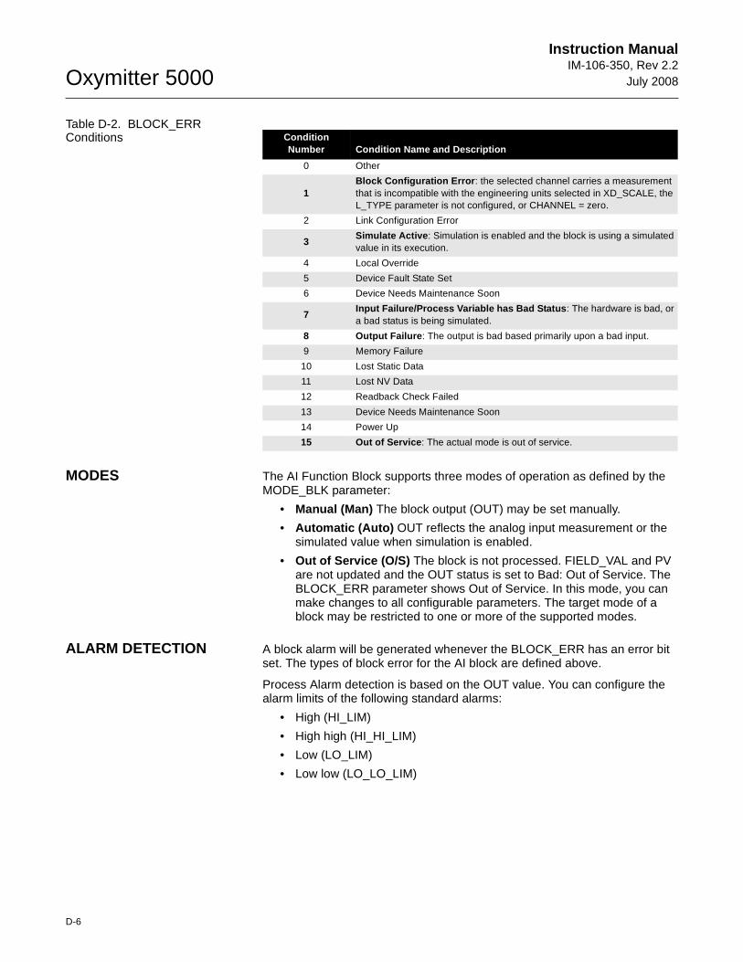
Oxymitter 5000
D-6
Instruction ManualIM-106-350, Rev 2.2
July 2008
Table D-2. BLOCK_ERR Conditions
MODES The AI Function Block supports three modes of operation as defined by the MODE_BLK parameter:
• Manual (Man) The block output (OUT) may be set manually.
• Automatic (Auto) OUT reflects the analog input measurement or the simulated value when simulation is enabled.
• Out of Service (O/S) The block is not processed. FIELD_VAL and PV are not updated and the OUT status is set to Bad: Out of Service. The BLOCK_ERR parameter shows Out of Service. In this mode, you can make changes to all configurable parameters. The target mode of a block may be restricted to one or more of the supported modes.
ALARM DETECTION A block alarm will be generated whenever the BLOCK_ERR has an error bit set. The types of block error for the AI block are defined above.
Process Alarm detection is based on the OUT value. You can configure the alarm limits of the following standard alarms:
• High (HI_LIM)
• High high (HI_HI_LIM)
• Low (LO_LIM)
• Low low (LO_LO_LIM)
ConditionNumber Condition Name and Description
0 Other
1Block Configuration Error : the selected channel carries a measurement that is incompatible with the engineering units selected in XD_SCALE, the L_TYPE parameter is not configured, or CHANNEL = zero.
2 Link Configuration Error
3Simulate Active : Simulation is enabled and the block is using a simulated value in its execution.
4 Local Override
5 Device Fault State Set
6 Device Needs Maintenance Soon
7Input Failure/Process Variable has Bad Status : The hardware is bad, or a bad status is being simulated.
8 Output Failure : The output is bad based primarily upon a bad input.
9 Memory Failure
10 Lost Static Data
11 Lost NV Data
12 Readback Check Failed
13 Device Needs Maintenance Soon
14 Power Up
15 Out of Service : The actual mode is out of service.
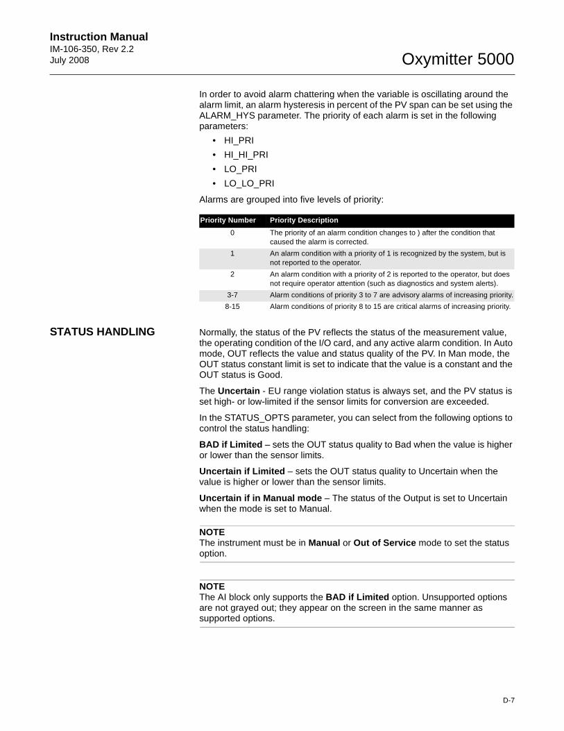
Instruction Manual IM-106-350, Rev 2.2July 2008
D-7
Oxymitter 5000
In order to avoid alarm chattering when the variable is oscillating around the alarm limit, an alarm hysteresis in percent of the PV span can be set using the ALARM_HYS parameter. The priority of each alarm is set in the following parameters:
• HI_PRI
• HI_HI_PRI
• LO_PRI
• LO_LO_PRI
Alarms are grouped into five levels of priority:
STATUS HANDLING Normally, the status of the PV reflects the status of the measurement value, the operating condition of the I/O card, and any active alarm condition. In Auto mode, OUT reflects the value and status quality of the PV. In Man mode, the OUT status constant limit is set to indicate that the value is a constant and the OUT status is Good.
The Uncertain - EU range violation status is always set, and the PV status is set high- or low-limited if the sensor limits for conversion are exceeded.
In the STATUS_OPTS parameter, you can select from the following options to control the status handling:
BAD if Limited – sets the OUT status quality to Bad when the value is higher or lower than the sensor limits.
Uncertain if Limited – sets the OUT status quality to Uncertain when the value is higher or lower than the sensor limits.
Uncertain if in Manual mode – The status of the Output is set to Uncertain when the mode is set to Manual.
NOTEThe instrument must be in Manual or Out of Service mode to set the status option.
NOTEThe AI block only supports the BAD if Limited option. Unsupported options are not grayed out; they appear on the screen in the same manner as supported options.
Priority Number Priority Description
0 The priority of an alarm condition changes to ) after the condition that caused the alarm is corrected.
1 An alarm condition with a priority of 1 is recognized by the system, but is not reported to the operator.
2 An alarm condition with a priority of 2 is reported to the operator, but does not require operator attention (such as diagnostics and system alerts).
3-7 Alarm conditions of priority 3 to 7 are advisory alarms of increasing priority.
8-15 Alarm conditions of priority 8 to 15 are critical alarms of increasing priority.
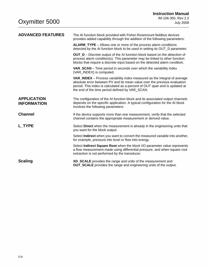
Oxymitter 5000
D-8
Instruction ManualIM-106-350, Rev 2.2
July 2008
ADVANCED FEATURES The AI function block provided with Fisher-Rosemount fieldbus devices provides added capability through the addition of the following parameters:
ALARM_TYPE – Allows one or more of the process alarm conditions detected by the AI function block to be used in setting its OUT_D parameter.
OUT_D – Discrete output of the AI function block based on the detection of process alarm condition(s). This parameter may be linked to other function blocks that require a discrete input based on the detected alarm condition.
VAR_SCAN – Time period in seconds over which the variability index (VAR_INDEX) is computed.
VAR_INDEX – Process variability index measured as the integral of average absolute error between PV and its mean value over the previous evaluation period. This index is calculated as a percent of OUT span and is updated at the end of the time period defined by VAR_SCAN.
APPLICATION INFORMATION
The configuration of the AI function block and its associated output channels depends on the specific application. A typical configuration for the AI block involves the following parameters:
Channel If the device supports more than one measurement, verify that the selected channel contains the appropriate measurement or derived value.
L_TYPE Select Direct when the measurement is already in the engineering units that you want for the block output.
Select Indirect when you want to convert the measured variable into another, for example, pressure into level or flow into energy.
Select Indirect Square Root when the block I/O parameter value represents a flow measurement made using differential pressure, and when square root extraction is not performed by the transducer.
Scaling XD_SCALE provides the range and units of the measurement and OUT_SCALE provides the range and engineering units of the output.
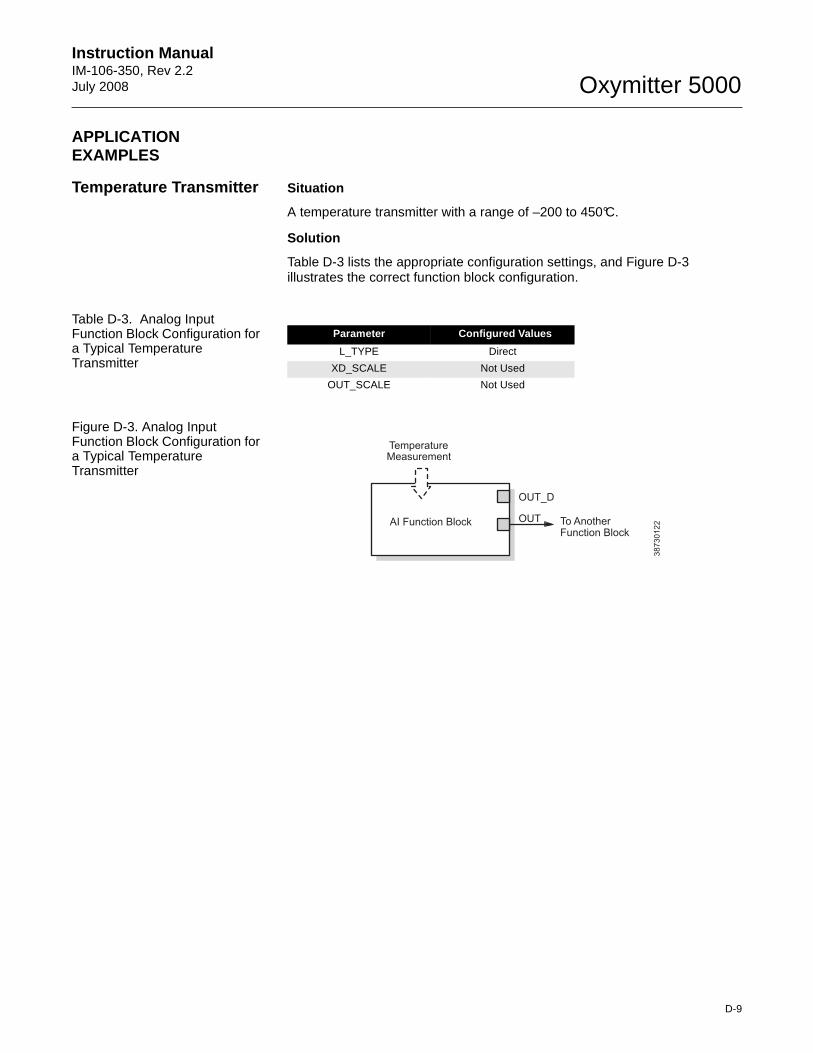
Instruction Manual IM-106-350, Rev 2.2July 2008
D-9
Oxymitter 5000
APPLICATION EXAMPLES
Temperature Transmitter Situation
A temperature transmitter with a range of –200 to 450°C.
Solution
Table D-3 lists the appropriate configuration settings, and Figure D-3 illustrates the correct function block configuration.
Table D-3. Analog Input Function Block Configuration for a Typical Temperature Transmitter
Figure D-3. Analog Input Function Block Configuration for a Typical Temperature Transmitter
Parameter Configured Values
L_TYPE Direct
XD_SCALE Not Used
OUT_SCALE Not Used
38
73
01
22
TemperatureMeasurement
To AnotherFunction Block
OUT_D
OUTAI Function Block
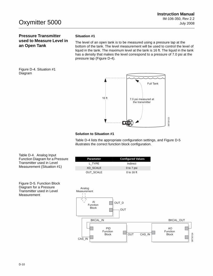
Oxymitter 5000
D-10
Instruction ManualIM-106-350, Rev 2.2
July 2008
Pressure Transmitter used to Measure Level in an Open Tank
Situation #1
The level of an open tank is to be measured using a pressure tap at the bottom of the tank. The level measurement will be used to control the level of liquid in the tank. The maximum level at the tank is 16 ft. The liquid in the tank has a density that makes the level correspond to a pressure of 7.0 psi at the pressure tap (Figure D-4).
Figure D-4. Situation #1 Diagram
Solution to Situation #1
Table D-4 lists the appropriate configuration settings, and Figure D-5 illustrates the correct function block configuration.
Table D-4. Analog Input Function Diagram for a Pressure Transmitter used in Level Measurement (Situation #1)
Figure D-5. Function Block Diagram for a Pressure Transmitter used in Level Measurement
38
73
01
23
16 ft 7.0 psi measured atthe transmitter
Full Tank
Parameter Configured Values
L_TYPE Indirect
XD_SCALE 0 to 7 psi
OUT_SCALE 0 to 16 ft
38
73
01
24
AnalogMeasurement
AIFunction
Block
OUT_D
OUT
PIDFunction
Block
AOFunction
Block
BKCAL_IN
CAS_IN
CAS_INOUT
BKCAL_OUT
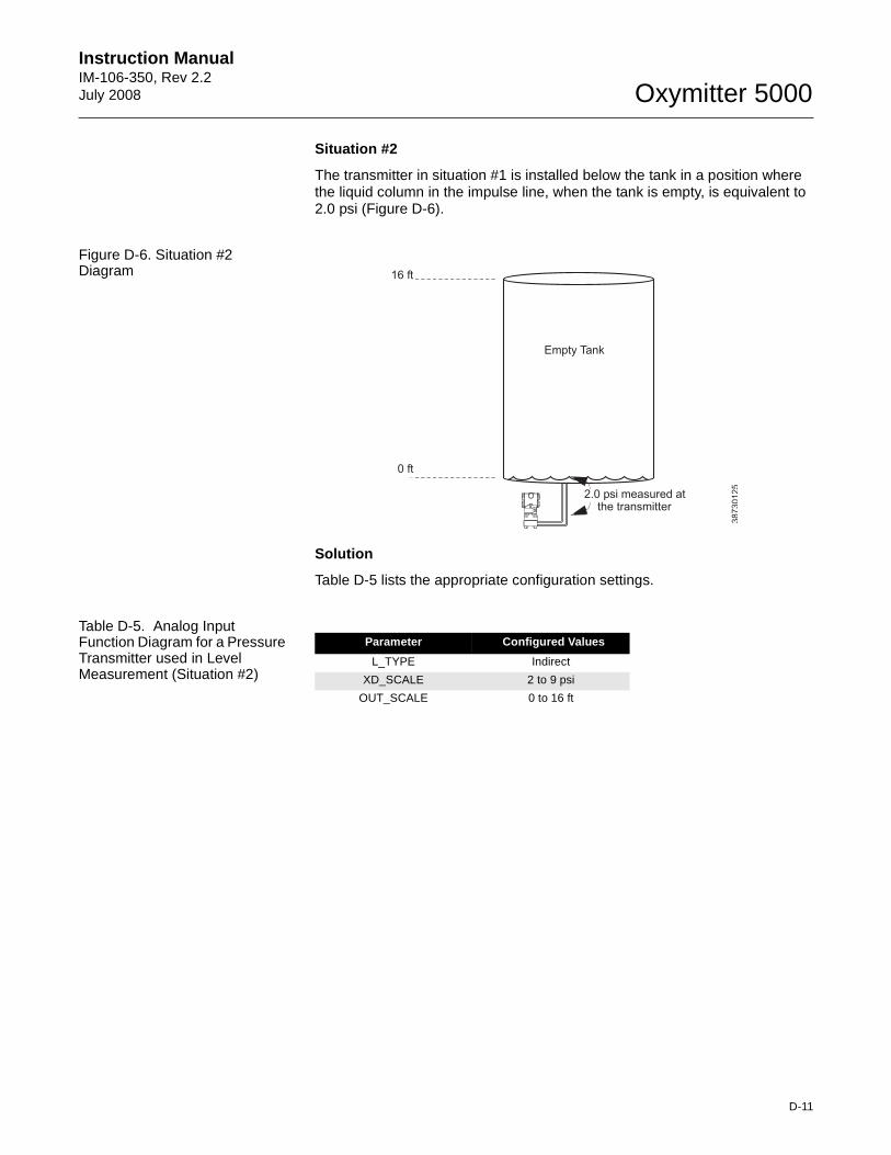
Instruction Manual IM-106-350, Rev 2.2July 2008
D-11
Oxymitter 5000
Situation #2
The transmitter in situation #1 is installed below the tank in a position where the liquid column in the impulse line, when the tank is empty, is equivalent to 2.0 psi (Figure D-6).
Figure D-6. Situation #2 Diagram
Solution
Table D-5 lists the appropriate configuration settings.
Table D-5. Analog Input Function Diagram for a Pressure Transmitter used in Level Measurement (Situation #2)
38
73
01
25
16 ft
0 ft
2.0 psi measured atthe transmitter
Empty Tank
Parameter Configured Values
L_TYPE Indirect
XD_SCALE 2 to 9 psi
OUT_SCALE 0 to 16 ft
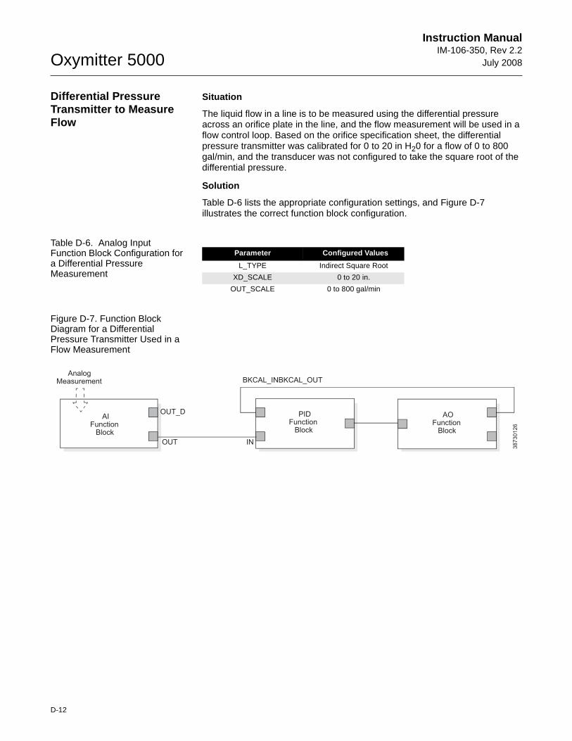
Oxymitter 5000
D-12
Instruction ManualIM-106-350, Rev 2.2
July 2008
Differential Pressure Transmitter to Measure Flow
Situation
The liquid flow in a line is to be measured using the differential pressure across an orifice plate in the line, and the flow measurement will be used in a flow control loop. Based on the orifice specification sheet, the differential pressure transmitter was calibrated for 0 to 20 in H20 for a flow of 0 to 800 gal/min, and the transducer was not configured to take the square root of the differential pressure.
Solution
Table D-6 lists the appropriate configuration settings, and Figure D-7 illustrates the correct function block configuration.
Table D-6. Analog Input Function Block Configuration for a Differential Pressure Measurement
Figure D-7. Function Block Diagram for a Differential Pressure Transmitter Used in a Flow Measurement
Parameter Configured Values
L_TYPE Indirect Square Root
XD_SCALE 0 to 20 in.
OUT_SCALE 0 to 800 gal/min
38
73
01
26
AIFunction
Block
PIDFunction
Block
AOFunction
Block
OUT_D
OUT
AnalogMeasurement BKCAL_INBKCAL_OUT
IN
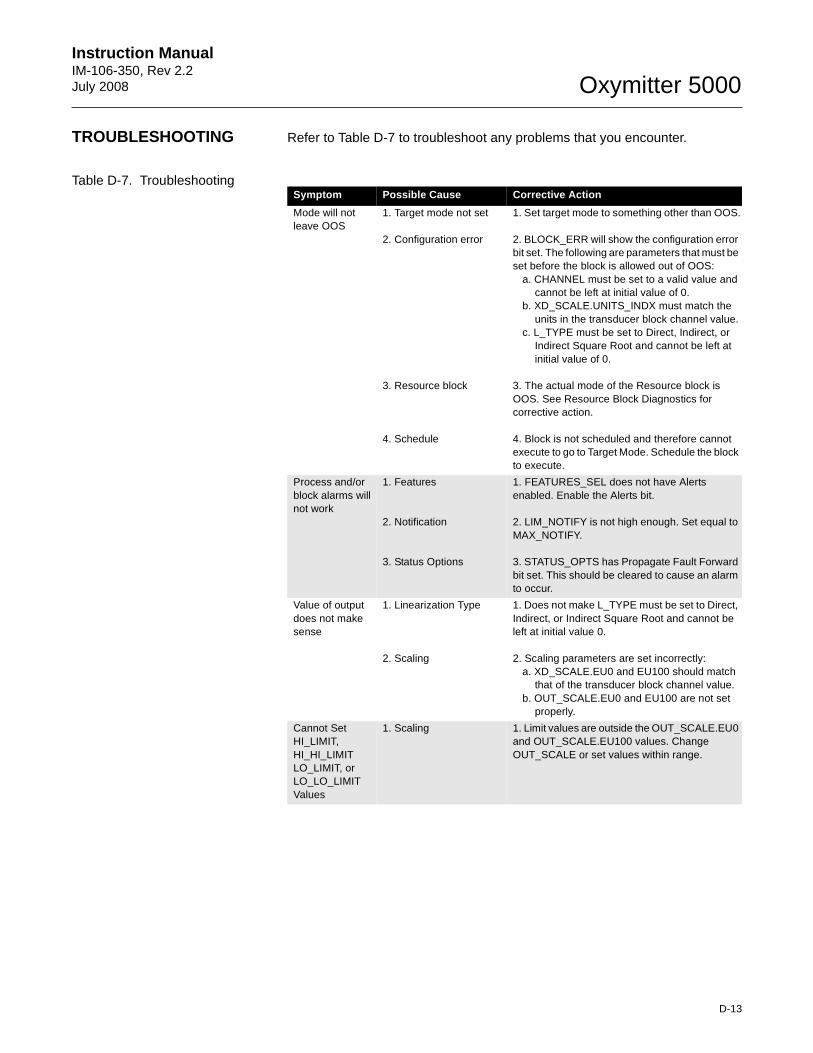
Instruction Manual IM-106-350, Rev 2.2July 2008
D-13
Oxymitter 5000
TROUBLESHOOTING Refer to Table D-7 to troubleshoot any problems that you encounter.
Table D-7. TroubleshootingSymptom Possible Cause Corrective Action
Mode will not leave OOS
1. Target mode not set
2. Configuration error
3. Resource block
4. Schedule
1. Set target mode to something other than OOS.
2. BLOCK_ERR will show the configuration error bit set. The following are parameters that must be set before the block is allowed out of OOS:
a. CHANNEL must be set to a valid value and cannot be left at initial value of 0.
b. XD_SCALE.UNITS_INDX must match the units in the transducer block channel value.
c. L_TYPE must be set to Direct, Indirect, or Indirect Square Root and cannot be left at initial value of 0.
3. The actual mode of the Resource block is OOS. See Resource Block Diagnostics for corrective action.
4. Block is not scheduled and therefore cannot execute to go to Target Mode. Schedule the block to execute.
Process and/or block alarms will not work
1. Features
2. Notification
3. Status Options
1. FEATURES_SEL does not have Alerts enabled. Enable the Alerts bit.
2. LIM_NOTIFY is not high enough. Set equal to MAX_NOTIFY.
3. STATUS_OPTS has Propagate Fault Forward bit set. This should be cleared to cause an alarm to occur.
Value of output does not make sense
1. Linearization Type
2. Scaling
1. Does not make L_TYPE must be set to Direct, Indirect, or Indirect Square Root and cannot be left at initial value 0.
2. Scaling parameters are set incorrectly:a. XD_SCALE.EU0 and EU100 should match
that of the transducer block channel value.b. OUT_SCALE.EU0 and EU100 are not set
properly.
Cannot Set HI_LIMIT,HI_HI_LIMITLO_LIMIT, orLO_LO_LIMITValues
1. Scaling 1. Limit values are outside the OUT_SCALE.EU0 and OUT_SCALE.EU100 values. Change OUT_SCALE or set values within range.

Oxymitter 5000
D-14
Instruction ManualIM-106-350, Rev 2.2
July 2008
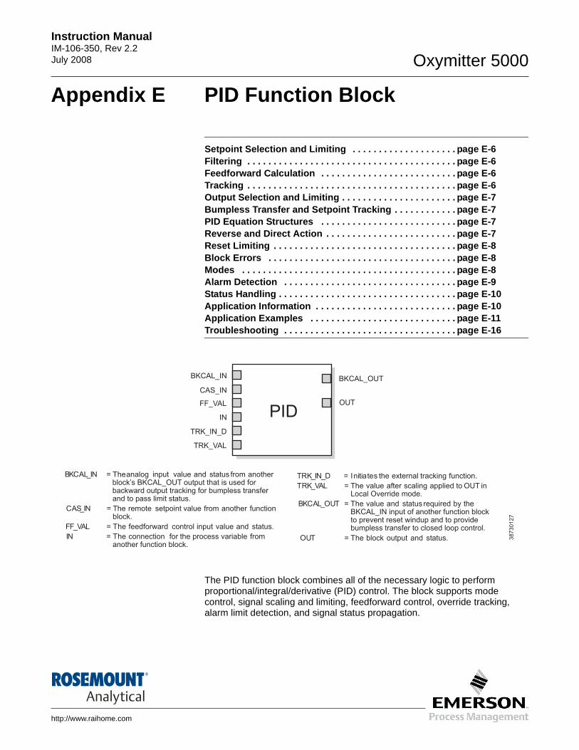
Instruction Manual IM-106-350, Rev 2.2July 2008 Oxymitter 5000
http://www.raihome.com
Appendix E PID Function Block
Setpoint Selection and Limiting . . . . . . . . . . . . . . . . . . . . page E-6Filtering . . . . . . . . . . . . . . . . . . . . . . . . . . . . . . . . . . . . . . . . page E-6Feedforward Calculation . . . . . . . . . . . . . . . . . . . . . . . . . . page E-6Tracking . . . . . . . . . . . . . . . . . . . . . . . . . . . . . . . . . . . . . . . . page E-6Output Selection and Limiting . . . . . . . . . . . . . . . . . . . . . . page E-7Bumpless Transfer and Setpoint Tracking . . . . . . . . . . . . page E-7PID Equation Structures . . . . . . . . . . . . . . . . . . . . . . . . . . page E-7Reverse and Direct Action . . . . . . . . . . . . . . . . . . . . . . . . . page E-7Reset Limiting . . . . . . . . . . . . . . . . . . . . . . . . . . . . . . . . . . . page E-8Block Errors . . . . . . . . . . . . . . . . . . . . . . . . . . . . . . . . . . . . page E-8Modes . . . . . . . . . . . . . . . . . . . . . . . . . . . . . . . . . . . . . . . . . page E-8Alarm Detection . . . . . . . . . . . . . . . . . . . . . . . . . . . . . . . . . page E-9Status Handling . . . . . . . . . . . . . . . . . . . . . . . . . . . . . . . . . . page E-10Application Information . . . . . . . . . . . . . . . . . . . . . . . . . . . page E-10Application Examples . . . . . . . . . . . . . . . . . . . . . . . . . . . . page E-11Troubleshooting . . . . . . . . . . . . . . . . . . . . . . . . . . . . . . . . . page E-16
The PID function block combines all of the necessary logic to perform proportional/integral/derivative (PID) control. The block supports mode control, signal scaling and limiting, feedforward control, override tracking, alarm limit detection, and signal status propagation.
38
73
01
27
BKCAL_IN = Theanalog input value and status from anotherblock’s BKCAL_OUT output that is used forbackward output tracking for bumpless transferand to pass limit status.
CAS_IN = setpointThe remote value from another functionblock.
FF_VAL = The feedforward control input value and status.
IN = The connection for the process variable fromanother function block.
PIDOUT
BKCAL_OUTBKCAL_IN
CAS_IN
FF_VAL
IN
TRK_IN_D
TRK_VAL
TRK_IN_D = Initiates the external tracking function.
TRK_VAL = The value after scaling applied to OUT inLocal Override mode.
BKCAL_OUT = The value and status required by theBKCAL_IN input of another function blockto prevent reset windup and to providebumpless transfer to closed loop control.
OUT = The block output and status.
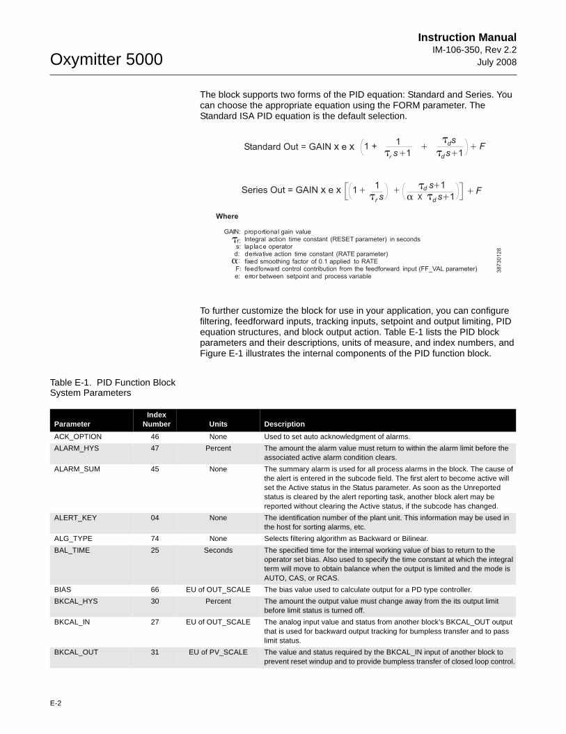
Oxymitter 5000
E-2
Instruction ManualIM-106-350, Rev 2.2
July 2008
The block supports two forms of the PID equation: Standard and Series. You can choose the appropriate equation using the FORM parameter. The Standard ISA PID equation is the default selection.
To further customize the block for use in your application, you can configure filtering, feedforward inputs, tracking inputs, setpoint and output limiting, PID equation structures, and block output action. Table E-1 lists the PID block parameters and their descriptions, units of measure, and index numbers, and Figure E-1 illustrates the internal components of the PID function block.
Table E-1. PID Function Block System Parameters
Standard Out = GAIN ex x1
rs 1+
ds
ds 1+1 + F+
Series Out = GAIN ex x 11
r s+ d s 1
x
+
d s 1+F+
Where
GAIN: proportional gain value
r: Integral action time constant (RESET parameter) in secondss: laplace operatord: derivative action time constant (RATE parameter)
fixed smoothing factor of 0.1 applied to RATEF: feedforward control contribution from the feedforward input (FF_VAL parameter)e: error between setpoint and process variable
+t t
t
tt+
a
t
a:
t
38
73
01
28
ParameterIndex
Number Units Description
ACK_OPTION 46 None Used to set auto acknowledgment of alarms.
ALARM_HYS 47 Percent The amount the alarm value must return to within the alarm limit before the associated active alarm condition clears.
ALARM_SUM 45 None The summary alarm is used for all process alarms in the block. The cause of the alert is entered in the subcode field. The first alert to become active will set the Active status in the Status parameter. As soon as the Unreported status is cleared by the alert reporting task, another block alert may be reported without clearing the Active status, if the subcode has changed.
ALERT_KEY 04 None The identification number of the plant unit. This information may be used in the host for sorting alarms, etc.
ALG_TYPE 74 None Selects filtering algorithm as Backward or Bilinear.
BAL_TIME 25 Seconds The specified time for the internal working value of bias to return to the operator set bias. Also used to specify the time constant at which the integral term will move to obtain balance when the output is limited and the mode is AUTO, CAS, or RCAS.
BIAS 66 EU of OUT_SCALE The bias value used to calculate output for a PD type controller.
BKCAL_HYS 30 Percent The amount the output value must change away from the its output limit before limit status is turned off.
BKCAL_IN 27 EU of OUT_SCALE The analog input value and status from another block’s BKCAL_OUT output that is used for backward output tracking for bumpless transfer and to pass limit status.
BKCAL_OUT 31 EU of PV_SCALE The value and status required by the BKCAL_IN input of another block to prevent reset windup and to provide bumpless transfer of closed loop control.
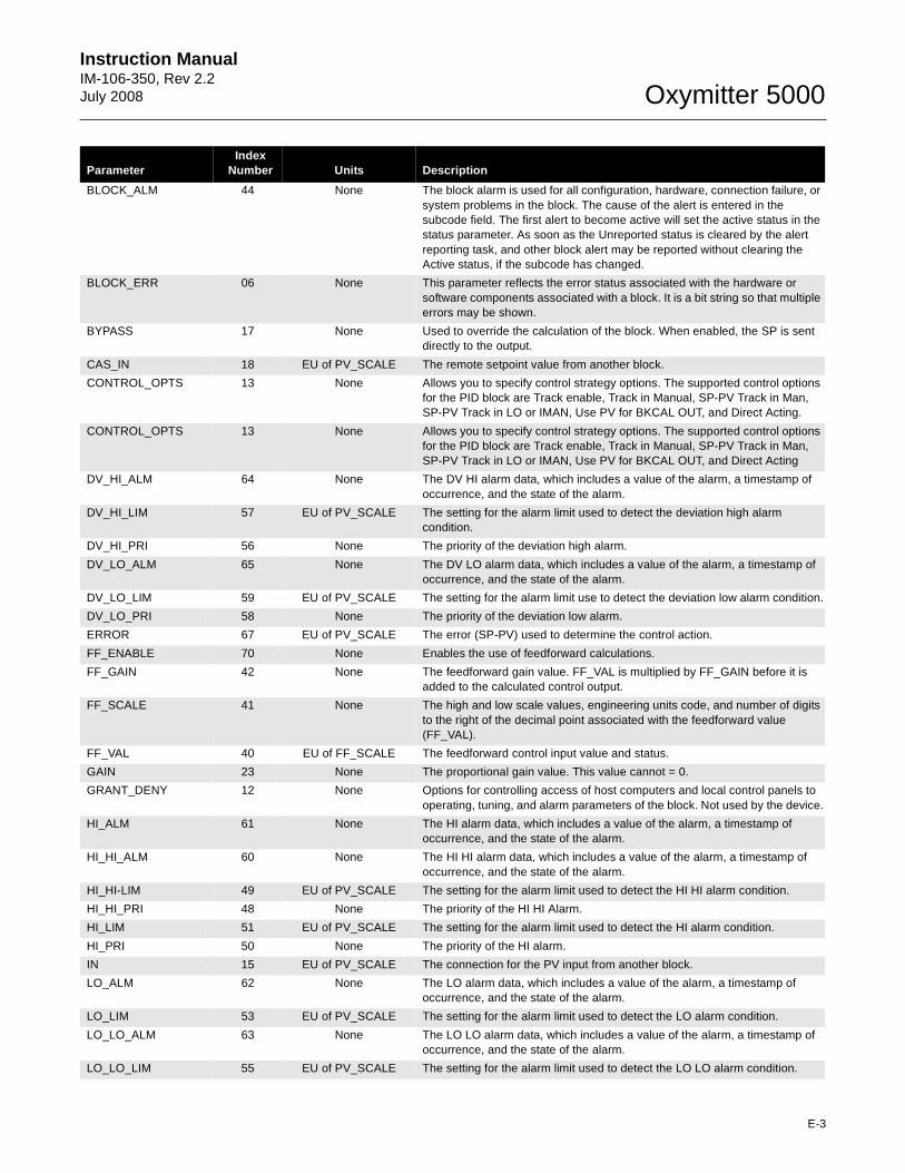
Instruction Manual IM-106-350, Rev 2.2July 2008
E-3
Oxymitter 5000
BLOCK_ALM 44 None The block alarm is used for all configuration, hardware, connection failure, or system problems in the block. The cause of the alert is entered in the subcode field. The first alert to become active will set the active status in the status parameter. As soon as the Unreported status is cleared by the alert reporting task, and other block alert may be reported without clearing the Active status, if the subcode has changed.
BLOCK_ERR 06 None This parameter reflects the error status associated with the hardware or software components associated with a block. It is a bit string so that multiple errors may be shown.
BYPASS 17 None Used to override the calculation of the block. When enabled, the SP is sent directly to the output.
CAS_IN 18 EU of PV_SCALE The remote setpoint value from another block.
CONTROL_OPTS 13 None Allows you to specify control strategy options. The supported control options for the PID block are Track enable, Track in Manual, SP-PV Track in Man, SP-PV Track in LO or IMAN, Use PV for BKCAL OUT, and Direct Acting.
CONTROL_OPTS 13 None Allows you to specify control strategy options. The supported control options for the PID block are Track enable, Track in Manual, SP-PV Track in Man, SP-PV Track in LO or IMAN, Use PV for BKCAL OUT, and Direct Acting
DV_HI_ALM 64 None The DV HI alarm data, which includes a value of the alarm, a timestamp of occurrence, and the state of the alarm.
DV_HI_LIM 57 EU of PV_SCALE The setting for the alarm limit used to detect the deviation high alarm condition.
DV_HI_PRI 56 None The priority of the deviation high alarm.
DV_LO_ALM 65 None The DV LO alarm data, which includes a value of the alarm, a timestamp of occurrence, and the state of the alarm.
DV_LO_LIM 59 EU of PV_SCALE The setting for the alarm limit use to detect the deviation low alarm condition.
DV_LO_PRI 58 None The priority of the deviation low alarm.
ERROR 67 EU of PV_SCALE The error (SP-PV) used to determine the control action.
FF_ENABLE 70 None Enables the use of feedforward calculations.
FF_GAIN 42 None The feedforward gain value. FF_VAL is multiplied by FF_GAIN before it is added to the calculated control output.
FF_SCALE 41 None The high and low scale values, engineering units code, and number of digits to the right of the decimal point associated with the feedforward value (FF_VAL).
FF_VAL 40 EU of FF_SCALE The feedforward control input value and status.
GAIN 23 None The proportional gain value. This value cannot = 0.
GRANT_DENY 12 None Options for controlling access of host computers and local control panels to operating, tuning, and alarm parameters of the block. Not used by the device.
HI_ALM 61 None The HI alarm data, which includes a value of the alarm, a timestamp of occurrence, and the state of the alarm.
HI_HI_ALM 60 None The HI HI alarm data, which includes a value of the alarm, a timestamp of occurrence, and the state of the alarm.
HI_HI-LIM 49 EU of PV_SCALE The setting for the alarm limit used to detect the HI HI alarm condition.
HI_HI_PRI 48 None The priority of the HI HI Alarm.
HI_LIM 51 EU of PV_SCALE The setting for the alarm limit used to detect the HI alarm condition.
HI_PRI 50 None The priority of the HI alarm.
IN 15 EU of PV_SCALE The connection for the PV input from another block.
LO_ALM 62 None The LO alarm data, which includes a value of the alarm, a timestamp of occurrence, and the state of the alarm.
LO_LIM 53 EU of PV_SCALE The setting for the alarm limit used to detect the LO alarm condition.
LO_LO_ALM 63 None The LO LO alarm data, which includes a value of the alarm, a timestamp of occurrence, and the state of the alarm.
LO_LO_LIM 55 EU of PV_SCALE The setting for the alarm limit used to detect the LO LO alarm condition.
ParameterIndex
Number Units Description
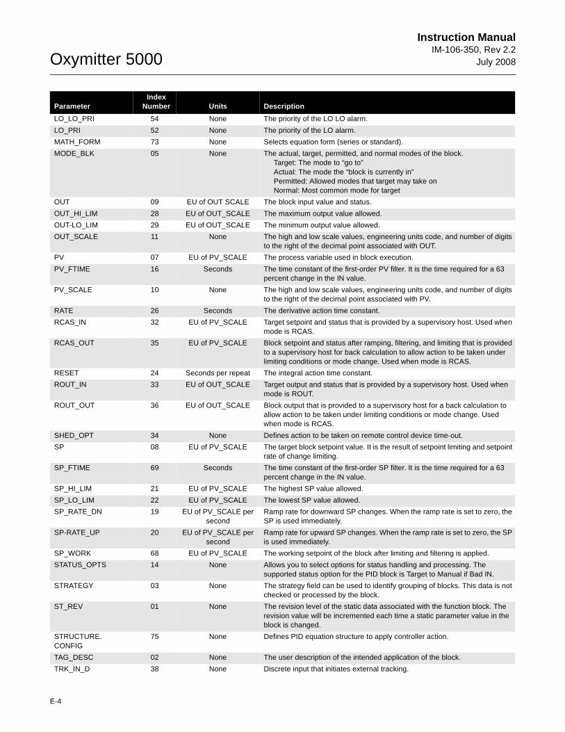
Oxymitter 5000
E-4
Instruction ManualIM-106-350, Rev 2.2
July 2008
LO_LO_PRI 54 None The priority of the LO LO alarm.
LO_PRI 52 None The priority of the LO alarm.
MATH_FORM 73 None Selects equation form (series or standard).
MODE_BLK 05 None The actual, target, permitted, and normal modes of the block.Target: The mode to “go to”Actual: The mode the “block is currently in”Permitted: Allowed modes that target may take on Normal: Most common mode for target
OUT 09 EU of OUT SCALE The block input value and status.
OUT_HI_LIM 28 EU of OUT_SCALE The maximum output value allowed.
OUT-LO_LIM 29 EU of OUT_SCALE The minimum output value allowed.
OUT_SCALE 11 None The high and low scale values, engineering units code, and number of digits to the right of the decimal point associated with OUT.
PV 07 EU of PV_SCALE The process variable used in block execution.
PV_FTIME 16 Seconds The time constant of the first-order PV filter. It is the time required for a 63 percent change in the IN value.
PV_SCALE 10 None The high and low scale values, engineering units code, and number of digits to the right of the decimal point associated with PV.
RATE 26 Seconds The derivative action time constant.
RCAS_IN 32 EU of PV_SCALE Target setpoint and status that is provided by a supervisory host. Used when mode is RCAS.
RCAS_OUT 35 EU of PV_SCALE Block setpoint and status after ramping, filtering, and limiting that is provided to a supervisory host for back calculation to allow action to be taken under limiting conditions or mode change. Used when mode is RCAS.
RESET 24 Seconds per repeat The integral action time constant.
ROUT_IN 33 EU of OUT_SCALE Target output and status that is provided by a supervisory host. Used when mode is ROUT.
ROUT_OUT 36 EU of OUT_SCALE Block output that is provided to a supervisory host for a back calculation to allow action to be taken under limiting conditions or mode change. Used when mode is RCAS.
SHED_OPT 34 None Defines action to be taken on remote control device time-out.
SP 08 EU of PV_SCALE The target block setpoint value. It is the result of setpoint limiting and setpoint rate of change limiting.
SP_FTIME 69 Seconds The time constant of the first-order SP filter. It is the time required for a 63 percent change in the IN value.
SP_HI_LIM 21 EU of PV_SCALE The highest SP value allowed.
SP_LO_LIM 22 EU of PV_SCALE The lowest SP value allowed.
SP_RATE_DN 19 EU of PV_SCALE per second
Ramp rate for downward SP changes. When the ramp rate is set to zero, the SP is used immediately.
SP-RATE_UP 20 EU of PV_SCALE per second
Ramp rate for upward SP changes. When the ramp rate is set to zero, the SP is used immediately.
SP_WORK 68 EU of PV_SCALE The working setpoint of the block after limiting and filtering is applied.
STATUS_OPTS 14 None Allows you to select options for status handling and processing. The supported status option for the PID block is Target to Manual if Bad IN.
STRATEGY 03 None The strategy field can be used to identify grouping of blocks. This data is not checked or processed by the block.
ST_REV 01 None The revision level of the static data associated with the function block. The revision value will be incremented each time a static parameter value in the block is changed.
STRUCTURE.CONFIG
75 None Defines PID equation structure to apply controller action.
TAG_DESC 02 None The user description of the intended application of the block.
TRK_IN_D 38 None Discrete input that initiates external tracking.
ParameterIndex
Number Units Description
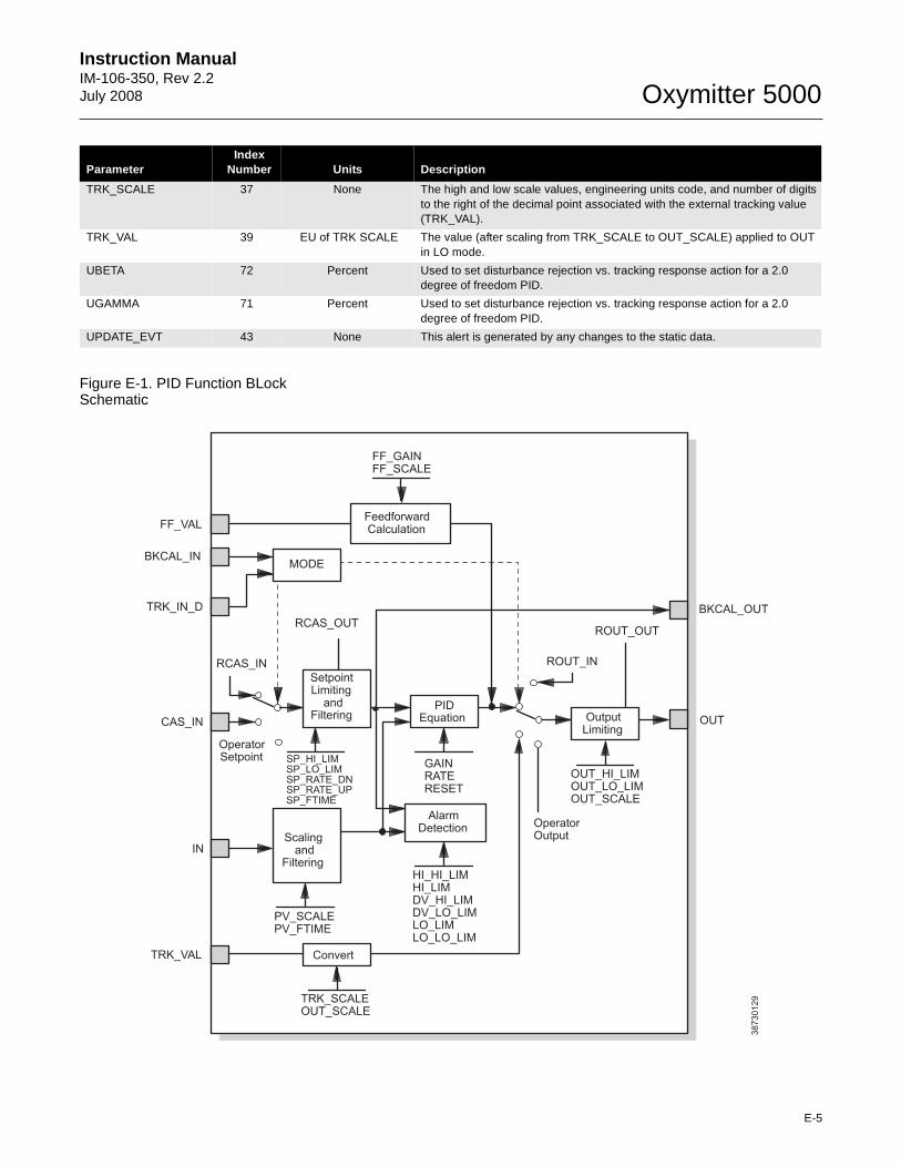
Instruction Manual IM-106-350, Rev 2.2July 2008
E-5
Oxymitter 5000
Figure E-1. PID Function BLock Schematic
TRK_SCALE 37 None The high and low scale values, engineering units code, and number of digits to the right of the decimal point associated with the external tracking value (TRK_VAL).
TRK_VAL 39 EU of TRK SCALE The value (after scaling from TRK_SCALE to OUT_SCALE) applied to OUT in LO mode.
UBETA 72 Percent Used to set disturbance rejection vs. tracking response action for a 2.0 degree of freedom PID.
UGAMMA 71 Percent Used to set disturbance rejection vs. tracking response action for a 2.0 degree of freedom PID.
UPDATE_EVT 43 None This alert is generated by any changes to the static data.
ParameterIndex
Number Units Description
38
73
01
29
FF_VAL
BKCAL_IN
TRK_IN_D
CAS_IN
IN
TRK_VAL
FF_GAINFF_SCALE
RCAS_OUT
RCAS_IN
SP_HI_LIMSP_LO_LIMSP_RATE_DNSP_RATE_UPSP_FTIME
GAINRATERESET
FeedforwardCalculation
MODE
SetpointLimiting
andFiltering
PIDEquation Output
Limiting
ROUT_OUT
ROUT_IN
OUT_HI_LIMOUT_LO_LIMOUT_SCALE
OperatorOutput
AlarmDetection
Scalingand
Filtering
PV_SCALEPV_FTIME
HI_HI_LIMHI_LIMDV_HI_LIMDV_LO_LIMLO_LIMLO_LO_LIM
TRK_SCALEOUT_SCALE
BKCAL_OUT
OUT
Convert
OperatorSetpoint
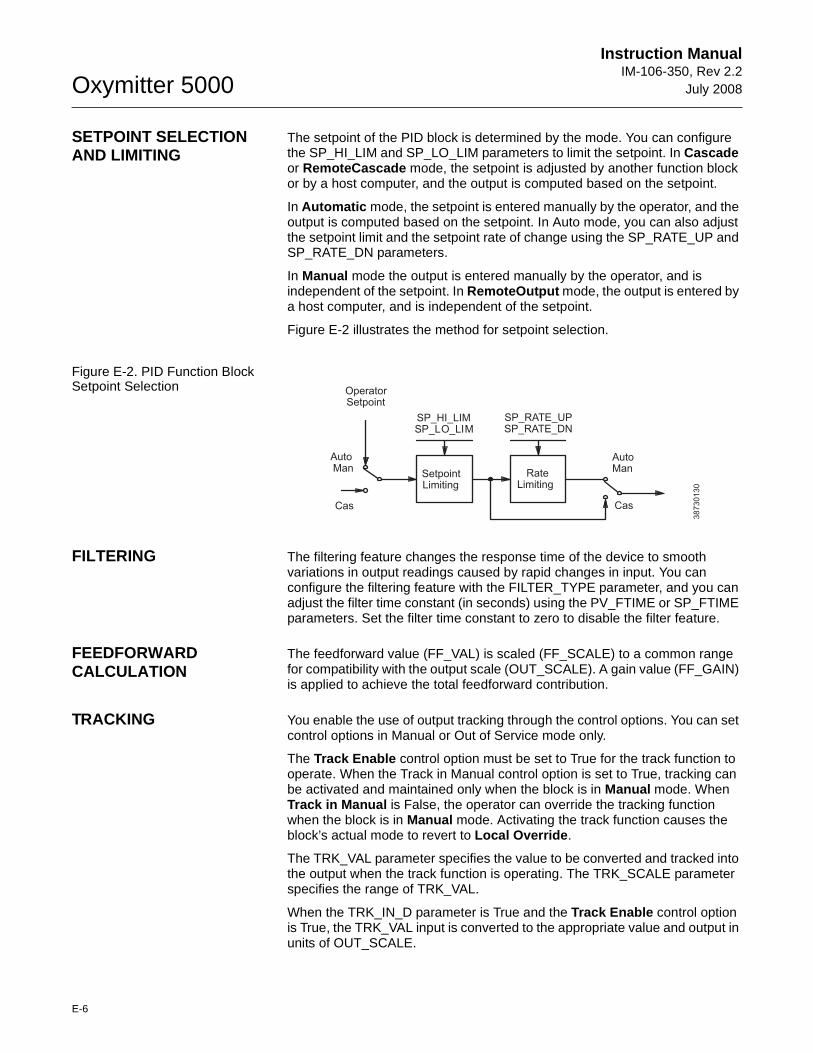
Oxymitter 5000
E-6
Instruction ManualIM-106-350, Rev 2.2
July 2008
SETPOINT SELECTION AND LIMITING
The setpoint of the PID block is determined by the mode. You can configure the SP_HI_LIM and SP_LO_LIM parameters to limit the setpoint. In Cascade or RemoteCascade mode, the setpoint is adjusted by another function block or by a host computer, and the output is computed based on the setpoint.
In Automatic mode, the setpoint is entered manually by the operator, and the output is computed based on the setpoint. In Auto mode, you can also adjust the setpoint limit and the setpoint rate of change using the SP_RATE_UP and SP_RATE_DN parameters.
In Manual mode the output is entered manually by the operator, and is independent of the setpoint. In RemoteOutput mode, the output is entered by a host computer, and is independent of the setpoint.
Figure E-2 illustrates the method for setpoint selection.
Figure E-2. PID Function Block Setpoint Selection
FILTERING The filtering feature changes the response time of the device to smooth variations in output readings caused by rapid changes in input. You can configure the filtering feature with the FILTER_TYPE parameter, and you can adjust the filter time constant (in seconds) using the PV_FTIME or SP_FTIME parameters. Set the filter time constant to zero to disable the filter feature.
FEEDFORWARD CALCULATION
The feedforward value (FF_VAL) is scaled (FF_SCALE) to a common range for compatibility with the output scale (OUT_SCALE). A gain value (FF_GAIN) is applied to achieve the total feedforward contribution.
TRACKING You enable the use of output tracking through the control options. You can set control options in Manual or Out of Service mode only.
The Track Enable control option must be set to True for the track function to operate. When the Track in Manual control option is set to True, tracking can be activated and maintained only when the block is in Manual mode. When Track in Manual is False, the operator can override the tracking function when the block is in Manual mode. Activating the track function causes the block’s actual mode to revert to Local Override .
The TRK_VAL parameter specifies the value to be converted and tracked into the output when the track function is operating. The TRK_SCALE parameter specifies the range of TRK_VAL.
When the TRK_IN_D parameter is True and the Track Enable control option is True, the TRK_VAL input is converted to the appropriate value and output in units of OUT_SCALE.
38
73
01
30
OperatorSetpoint
SP_HI_LIMSP_LO_LIM
SP_RATE_UPSP_RATE_DN
SetpointLimiting
RateLimiting
AutoMan
AutoMan
CasCas
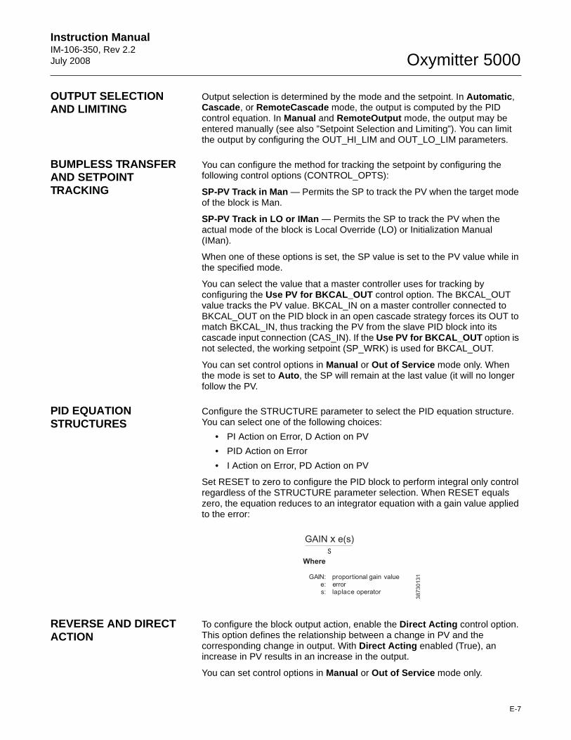
Instruction Manual IM-106-350, Rev 2.2July 2008
E-7
Oxymitter 5000
OUTPUT SELECTION AND LIMITING
Output selection is determined by the mode and the setpoint. In Automatic , Cascade , or RemoteCascade mode, the output is computed by the PID control equation. In Manual and RemoteOutput mode, the output may be entered manually (see also ”Setpoint Selection and Limiting”). You can limit the output by configuring the OUT_HI_LIM and OUT_LO_LIM parameters.
BUMPLESS TRANSFER AND SETPOINT TRACKING
You can configure the method for tracking the setpoint by configuring the following control options (CONTROL_OPTS):
SP-PV Track in Man — Permits the SP to track the PV when the target mode of the block is Man.
SP-PV Track in LO or IMan — Permits the SP to track the PV when the actual mode of the block is Local Override (LO) or Initialization Manual (IMan).
When one of these options is set, the SP value is set to the PV value while in the specified mode.
You can select the value that a master controller uses for tracking by configuring the Use PV for BKCAL_OUT control option. The BKCAL_OUT value tracks the PV value. BKCAL_IN on a master controller connected to BKCAL_OUT on the PID block in an open cascade strategy forces its OUT to match BKCAL_IN, thus tracking the PV from the slave PID block into its cascade input connection (CAS_IN). If the Use PV for BKCAL_OUT option is not selected, the working setpoint (SP_WRK) is used for BKCAL_OUT.
You can set control options in Manual or Out of Service mode only. When the mode is set to Auto , the SP will remain at the last value (it will no longer follow the PV.
PID EQUATION STRUCTURES
Configure the STRUCTURE parameter to select the PID equation structure. You can select one of the following choices:
• PI Action on Error, D Action on PV
• PID Action on Error
• I Action on Error, PD Action on PV
Set RESET to zero to configure the PID block to perform integral only control regardless of the STRUCTURE parameter selection. When RESET equals zero, the equation reduces to an integrator equation with a gain value applied to the error:
REVERSE AND DIRECT ACTION
To configure the block output action, enable the Direct Acting control option. This option defines the relationship between a change in PV and the corresponding change in output. With Direct Acting enabled (True), an increase in PV results in an increase in the output.
You can set control options in Manual or Out of Service mode only.
38
73
01
31
GAIN e(s)xs
Where
GAIN: proportional gain valuee: errors: laplace operator
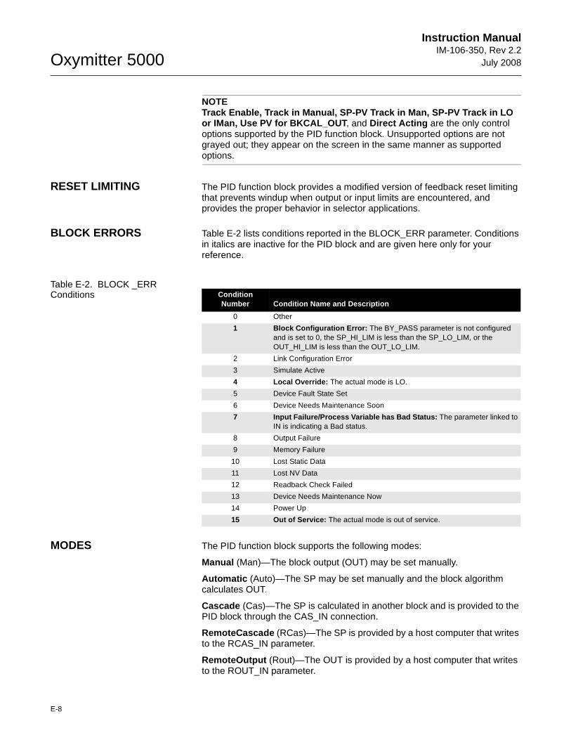
Oxymitter 5000
E-8
Instruction ManualIM-106-350, Rev 2.2
July 2008
NOTETrack Enable, Track in Manual, SP-PV Track in Man, SP-PV Track in LO or IMan, Use PV for BKCAL_OUT , and Direct Acting are the only control options supported by the PID function block. Unsupported options are not grayed out; they appear on the screen in the same manner as supported options.
RESET LIMITING The PID function block provides a modified version of feedback reset limiting that prevents windup when output or input limits are encountered, and provides the proper behavior in selector applications.
BLOCK ERRORS Table E-2 lists conditions reported in the BLOCK_ERR parameter. Conditions in italics are inactive for the PID block and are given here only for your reference.
Table E-2. BLOCK _ERR Conditions
MODES The PID function block supports the following modes:
Manual (Man)—The block output (OUT) may be set manually.
Automatic (Auto)—The SP may be set manually and the block algorithm calculates OUT.
Cascade (Cas)—The SP is calculated in another block and is provided to the PID block through the CAS_IN connection.
RemoteCascade (RCas)—The SP is provided by a host computer that writes to the RCAS_IN parameter.
RemoteOutput (Rout)—The OUT is provided by a host computer that writes to the ROUT_IN parameter.
ConditionNumber Condition Name and Description
0 Other
1 Block Configuration Error: The BY_PASS parameter is not configured and is set to 0, the SP_HI_LIM is less than the SP_LO_LIM, or the OUT_HI_LIM is less than the OUT_LO_LIM.
2 Link Configuration Error
3 Simulate Active
4 Local Override: The actual mode is LO.
5 Device Fault State Set
6 Device Needs Maintenance Soon
7 Input Failure/Process Variable has Bad Status: The parameter linked to IN is indicating a Bad status.
8 Output Failure
9 Memory Failure
10 Lost Static Data
11 Lost NV Data
12 Readback Check Failed
13 Device Needs Maintenance Now
14 Power Up
15 Out of Service: The actual mode is out of service.
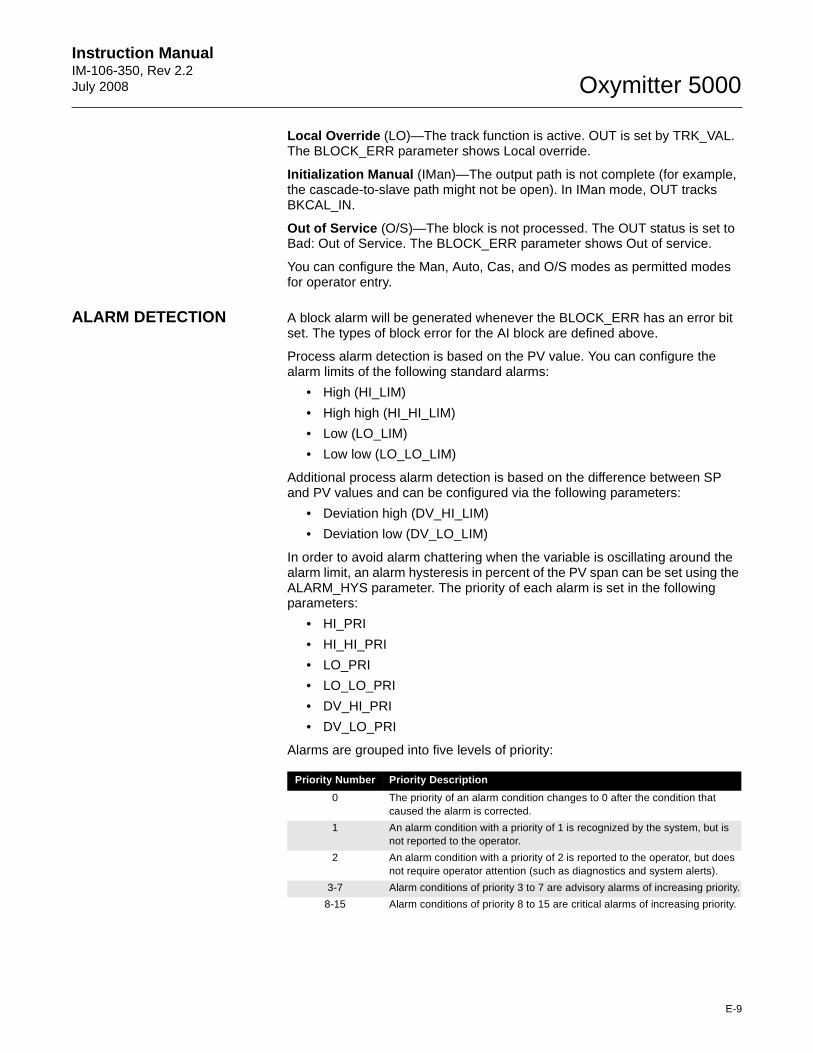
Instruction Manual IM-106-350, Rev 2.2July 2008
E-9
Oxymitter 5000
Local Override (LO)—The track function is active. OUT is set by TRK_VAL. The BLOCK_ERR parameter shows Local override.
Initialization Manual (IMan)—The output path is not complete (for example, the cascade-to-slave path might not be open). In IMan mode, OUT tracks BKCAL_IN.
Out of Service (O/S)—The block is not processed. The OUT status is set to Bad: Out of Service. The BLOCK_ERR parameter shows Out of service.
You can configure the Man, Auto, Cas, and O/S modes as permitted modes for operator entry.
ALARM DETECTION A block alarm will be generated whenever the BLOCK_ERR has an error bit set. The types of block error for the AI block are defined above.
Process alarm detection is based on the PV value. You can configure the alarm limits of the following standard alarms:
• High (HI_LIM)
• High high (HI_HI_LIM)
• Low (LO_LIM)
• Low low (LO_LO_LIM)
Additional process alarm detection is based on the difference between SP and PV values and can be configured via the following parameters:
• Deviation high (DV_HI_LIM)
• Deviation low (DV_LO_LIM)
In order to avoid alarm chattering when the variable is oscillating around the alarm limit, an alarm hysteresis in percent of the PV span can be set using the ALARM_HYS parameter. The priority of each alarm is set in the following parameters:
• HI_PRI
• HI_HI_PRI
• LO_PRI
• LO_LO_PRI
• DV_HI_PRI
• DV_LO_PRI
Alarms are grouped into five levels of priority:
Priority Number Priority Description
0 The priority of an alarm condition changes to 0 after the condition that caused the alarm is corrected.
1 An alarm condition with a priority of 1 is recognized by the system, but is not reported to the operator.
2 An alarm condition with a priority of 2 is reported to the operator, but does not require operator attention (such as diagnostics and system alerts).
3-7 Alarm conditions of priority 3 to 7 are advisory alarms of increasing priority.
8-15 Alarm conditions of priority 8 to 15 are critical alarms of increasing priority.
Oxymitter 5000
E-10
Instruction ManualIM-106-350, Rev 2.2
July 2008
STATUS HANDLING If the input status on the PID block is Bad, the mode of the block reverts to Manual . In addition, you can select the Target to Manual if Bad IN status option to direct the target mode to revert to manual. You can set the status option in Manual or Out of Service mode only.
NOTETarget to Manual if Bad IN is the only status option supported by the PID function block. Unsupported options are not grayed out; they appear on the screen in the same manner as supported options.
APPLICATION INFORMATION
The PID function block is a powerful, flexible control algorithm that is designed to work in a variety of control strategies. The PID block is configured differently for different applications. The following examples describe the use of the PID block for closed-loop control (basic PID loop), feedforward control, cascade control with master and slave, and complex cascade control with override.
Closed Loop Control To implement basic closed loop control, compute the error difference between the process variable (PV) and setpoint (SP) values and calculate a control output signal using a PID (Proportional Integral Derivative) function block.
The proportional control function responds immediately and directly to a change in the PV or SP. The proportional term GAIN applies a change in the loop output based on the current magnitude of the error multiplied by a gain value.
The integral control function reduces the process error by moving the output in the appropriate direction. The integral term RESET applies a correction based on the magnitude and duration of the error. Set the RESET parameter to zero for integral only control. To reduce reset action, configure the RESET parameter to be a large value.
The derivative term RATE applies a correction based on the anticipated change in error. Derivative control is typically used in temperature control where large measurement lags exist.
The MODE parameter is a switch that indicates the target and actual mode of operation. Mode selection has a large impact on the operation of the PID block:
• Manual mode allows the operator to set the value of the loop output signal directly.
• Automatic mode allows the operator to select a setpoint for automatic correction of error using the GAIN, RESET, and RATE tuning values.
• Cascade and Remote Cascade modes use a setpoint from another block in a cascaded configuration.
• Remote Out mode is similar to Manual mode except that the block output is supplied by an external program rather than by the operator.
• Initialization Manual is a non-target mode used with cascade configurations while transitioning from manual operation to automatic operation.
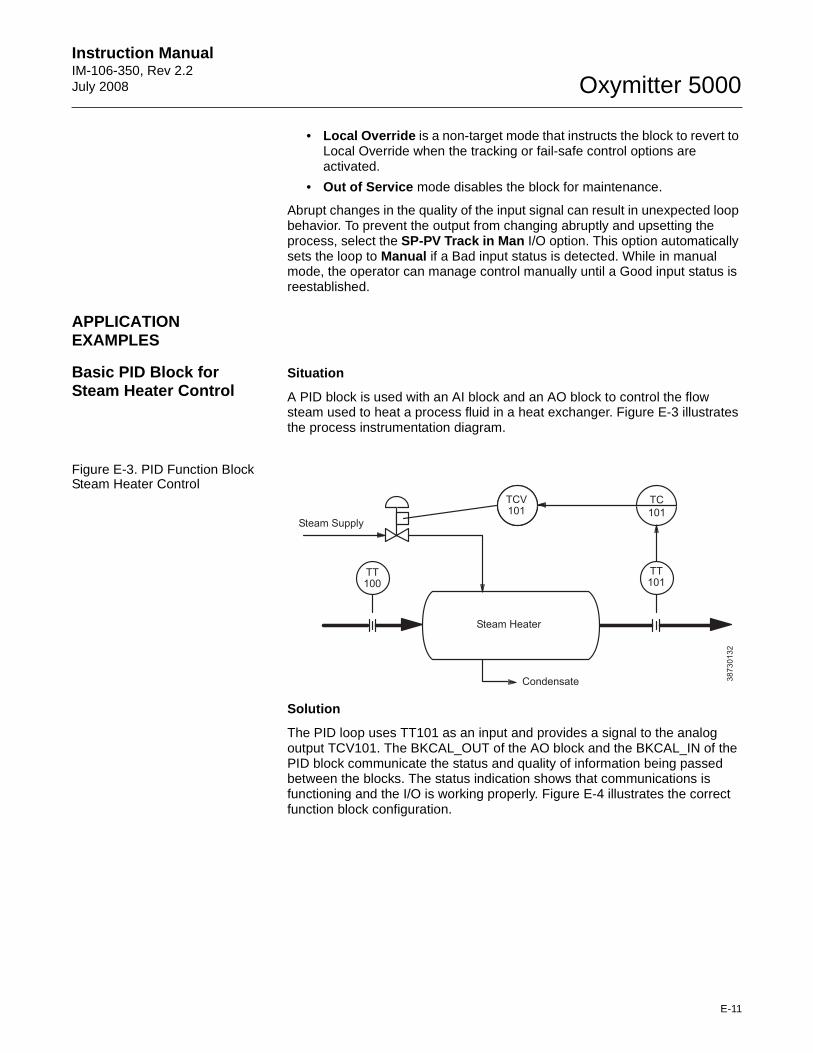
Instruction Manual IM-106-350, Rev 2.2July 2008
E-11
Oxymitter 5000
• Local Override is a non-target mode that instructs the block to revert to Local Override when the tracking or fail-safe control options are activated.
• Out of Service mode disables the block for maintenance.
Abrupt changes in the quality of the input signal can result in unexpected loop behavior. To prevent the output from changing abruptly and upsetting the process, select the SP-PV Track in Man I/O option. This option automatically sets the loop to Manual if a Bad input status is detected. While in manual mode, the operator can manage control manually until a Good input status is reestablished.
APPLICATION EXAMPLES
Basic PID Block for Steam Heater Control
Situation
A PID block is used with an AI block and an AO block to control the flow steam used to heat a process fluid in a heat exchanger. Figure E-3 illustrates the process instrumentation diagram.
Figure E-3. PID Function Block Steam Heater Control
Solution
The PID loop uses TT101 as an input and provides a signal to the analog output TCV101. The BKCAL_OUT of the AO block and the BKCAL_IN of the PID block communicate the status and quality of information being passed between the blocks. The status indication shows that communications is functioning and the I/O is working properly. Figure E-4 illustrates the correct function block configuration.
Steam Supply
TCV101
Steam Heater
Condensate
TC
101
TT101
TT100
38
73
01
32
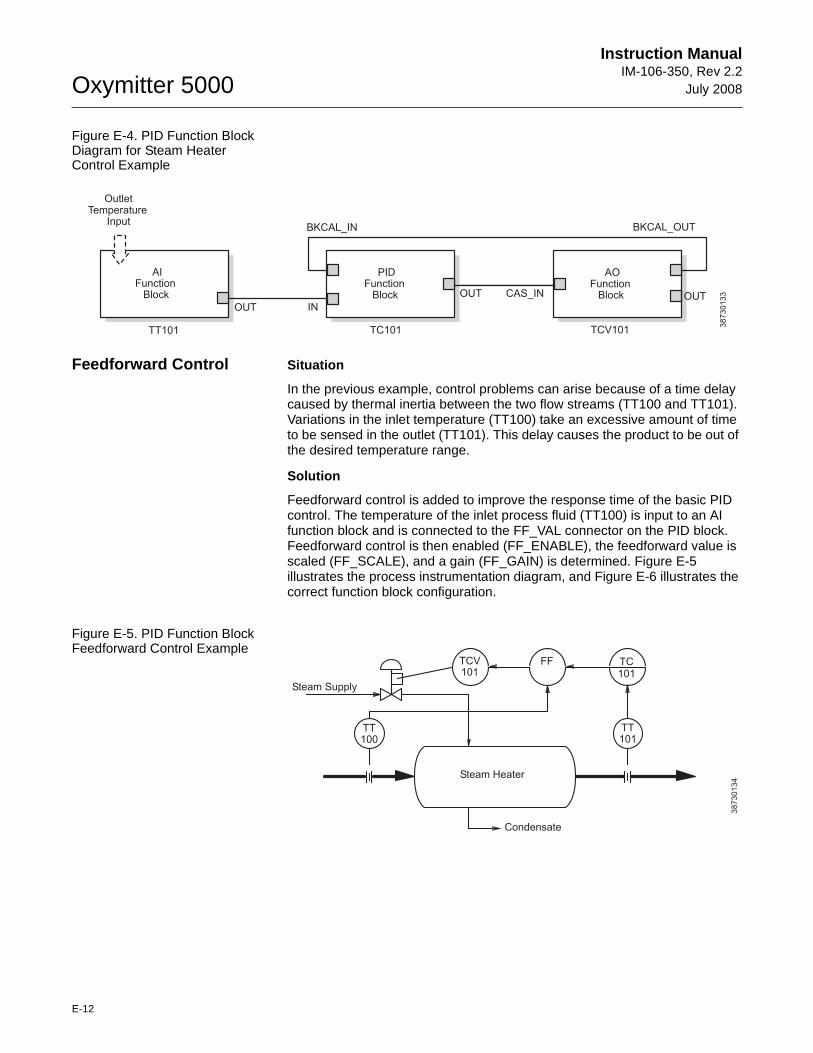
Oxymitter 5000
E-12
Instruction ManualIM-106-350, Rev 2.2
July 2008
Figure E-4. PID Function Block Diagram for Steam Heater Control Example
Feedforward Control Situation
In the previous example, control problems can arise because of a time delay caused by thermal inertia between the two flow streams (TT100 and TT101). Variations in the inlet temperature (TT100) take an excessive amount of time to be sensed in the outlet (TT101). This delay causes the product to be out of the desired temperature range.
Solution
Feedforward control is added to improve the response time of the basic PID control. The temperature of the inlet process fluid (TT100) is input to an AI function block and is connected to the FF_VAL connector on the PID block. Feedforward control is then enabled (FF_ENABLE), the feedforward value is scaled (FF_SCALE), and a gain (FF_GAIN) is determined. Figure E-5 illustrates the process instrumentation diagram, and Figure E-6 illustrates the correct function block configuration.
Figure E-5. PID Function Block Feedforward Control Example
OutletTemperature
Input
AIFunction
Block
PIDFunction
Block
AOFunction
Block
TT101 TC101 TCV101
BKCAL_IN BKCAL_OUT
OUT IN
CAS_INOUT OUT
38
73
01
33
38
73
01
34
Steam Supply
TCV101
Steam Heater
Condensate
TC101
TT101
TT100
FF
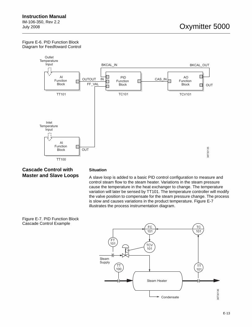
Instruction Manual IM-106-350, Rev 2.2July 2008
E-13
Oxymitter 5000
Figure E-6. PID Function Block Diagram for Feedfoward Control
Cascade Control with Master and Slave Loops
Situation
A slave loop is added to a basic PID control configuration to measure and control steam flow to the steam heater. Variations in the steam pressure cause the temperature in the heat exchanger to change. The temperature variation will later be sensed by TT101. The temperature controller will modify the valve position to compensate for the steam pressure change. The process is slow and causes variations in the product temperature. Figure E-7 illustrates the process instrumentation diagram.
Figure E-7. PID Function Block Cascade Control Example
OutletTemperature
Input
InletTemperature
Input
BKCAL_IN BKCAL_OUT
OUT
OUT
OUTOUT IN CAS_IN
FF_VAL
AIFunction
Block
AIFunction
Block
PIDFunction
Block
AOFunction
Block
TT101 TC101 TCV101
TT100
38
73
01
35
38
73
01
36
SteamSupply
FC
101
Steam Heater
Condensate
TC
101
TT101
FT101
TT100
TCV101
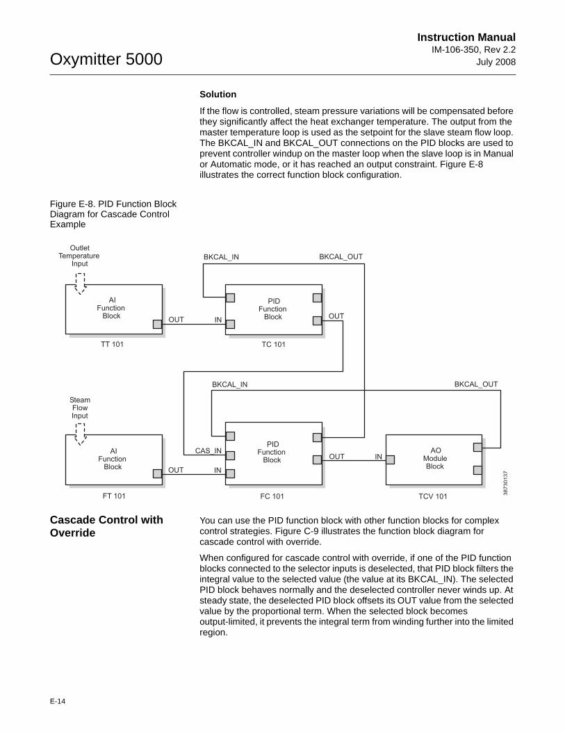
Oxymitter 5000
E-14
Instruction ManualIM-106-350, Rev 2.2
July 2008
Solution
If the flow is controlled, steam pressure variations will be compensated before they significantly affect the heat exchanger temperature. The output from the master temperature loop is used as the setpoint for the slave steam flow loop. The BKCAL_IN and BKCAL_OUT connections on the PID blocks are used to prevent controller windup on the master loop when the slave loop is in Manual or Automatic mode, or it has reached an output constraint. Figure E-8 illustrates the correct function block configuration.
Figure E-8. PID Function Block Diagram for Cascade Control Example
Cascade Control with Override
You can use the PID function block with other function blocks for complex control strategies. Figure C-9 illustrates the function block diagram for cascade control with override.
When configured for cascade control with override, if one of the PID function blocks connected to the selector inputs is deselected, that PID block filters the integral value to the selected value (the value at its BKCAL_IN). The selected PID block behaves normally and the deselected controller never winds up. At steady state, the deselected PID block offsets its OUT value from the selected value by the proportional term. When the selected block becomes output-limited, it prevents the integral term from winding further into the limited region.
OutletTemperature
Input
AIFunction
Block
PIDFunction
Block
AIFunction
Block
SteamFlowInput
PIDFunction
Block
AOModuleBlock
OUT IN
OUT IN
OUT INCAS_IN
BKCAL_OUTBKCAL_IN
BKCAL_OUTBKCAL_IN
OUT
FT 101 FC 101 TCV 101
TT 101 TC 101
38
73
01
37
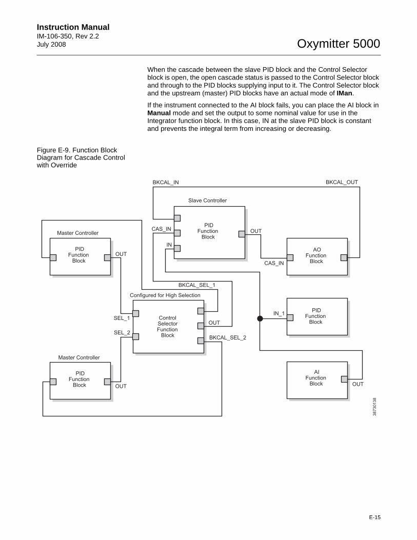
Instruction Manual IM-106-350, Rev 2.2July 2008
E-15
Oxymitter 5000
When the cascade between the slave PID block and the Control Selector block is open, the open cascade status is passed to the Control Selector block and through to the PID blocks supplying input to it. The Control Selector block and the upstream (master) PID blocks have an actual mode of IMan.
If the instrument connected to the AI block fails, you can place the AI block in Manual mode and set the output to some nominal value for use in the Integrator function block. In this case, IN at the slave PID block is constant and prevents the integral term from increasing or decreasing.
Figure E-9. Function Block Diagram for Cascade Control with Override
38
73
01
38
PIDFunction
Block
AOFunction
Block
PIDFunction
Block
ControlSelectorFunction
Block
PIDFunction
Block
PIDFunction
Block
AIFunction
Block
Configured for High Selection
Master Controller
Slave Controller
Master Controller
OUT
OUT
OUT
OUT OUT
IN_1
CAS_IN
CAS_IN
IN
SEL_1
SEL_2BKCAL_SEL_2
BKCAL_SEL_1
BKCAL_OUTBKCAL_IN
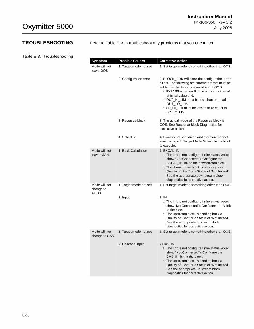
Oxymitter 5000
E-16
Instruction ManualIM-106-350, Rev 2.2
July 2008
TROUBLESHOOTING Refer to Table E-3 to troubleshoot any problems that you encounter.
Table E-3. TroubleshootingSymptom Possible Causes Corrective Action
Mode will not leave OOS
1. Target mode not set
2. Configuration error
3. Resource block
4. Schedule
1. Set target mode to something other than OOS.
2. BLOCK_ERR will show the configuration error bit set. The following are parameters that must be set before the block is allowed out of OOS:
a. BYPASS must be off or on and cannot be left at initial value of 0.
b. OUT_HI_LIM must be less than or equal to OUT_LO_LIM.
c. SP_HI_LIM must be less than or equal to SP_LO_LIM.
3. The actual mode of the Resource block is OOS. See Resource Block Diagnostics for corrective action.
4. Block is not scheduled and therefore cannot execute to go to Target Mode. Schedule the block to execute.
Mode will not leave IMAN
1. Back Calculation 1. BKCAL_INa. The link is not configured (the status would
show “Not Connected”). Configure the BKCAL_IN link to the downstream block.
b. The downstream block is sending back a Quality of “Bad” or a Status of “Not Invited”. See the appropriate downstream block diagnostics for corrective action.
Mode will not change toAUTO
1. Target mode not set
2. Input
1. Set target mode to something other than OOS.
2. INa. The link is not configured (the status would
show “Not Connected”). Configure the IN link to the block.
b. The upstream block is sending back a Quality of “Bad” or a Status of “Not Invited”. See the appropriate upstream block diagnostics for corrective action.
Mode will not change to CAS
1. Target mode not set
2. Cascade Input
1. Set target mode to something other than OOS.
2.CAS_INa. The link is not configured (the status would
show “Not Connected”). Configure the CAS_IN link to the block.
b. The upstream block is sending back a Quality of “Bad” or a Status of “Not Invited”. See the appropriate up stream block diagnostics for corrective action.
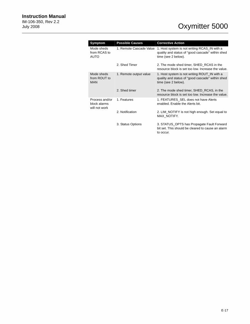
Instruction Manual IM-106-350, Rev 2.2July 2008
E-17
Oxymitter 5000
Mode sheds from RCAS to AUTO
1. Remote Cascade Value
2. Shed Timer
1. Host system is not writing RCAS_IN with a quality and status of “good cascade” within shed time (see 2 below).
2. The mode shed timer, SHED_RCAS in the resource block is set too low. Increase the value.
Mode sheds from ROUT to MAN
1. Remote output value
2. Shed timer
1. Host system is not writing ROUT_IN with a quality and status of “good cascade” within shed time (see 2 below).
2. The mode shed timer, SHED_RCAS, in the resource block is set too low. Increase the value.
Process and/or block alarmswill not work
1. Features
2. Notification
3. Status Options
1. FEATURES_SEL does not have Alerts enabled. Enable the Alerts bit.
2. LIM_NOTIFY is not high enough. Set equal to MAX_NOTIFY.
3. STATUS_OPTS has Propagate Fault Forward bit set. This should be cleared to cause an alarm to occur.
Symptom Possible Causes Corrective Action

Oxymitter 5000
E-18
Instruction ManualIM-106-350, Rev 2.2
July 2008
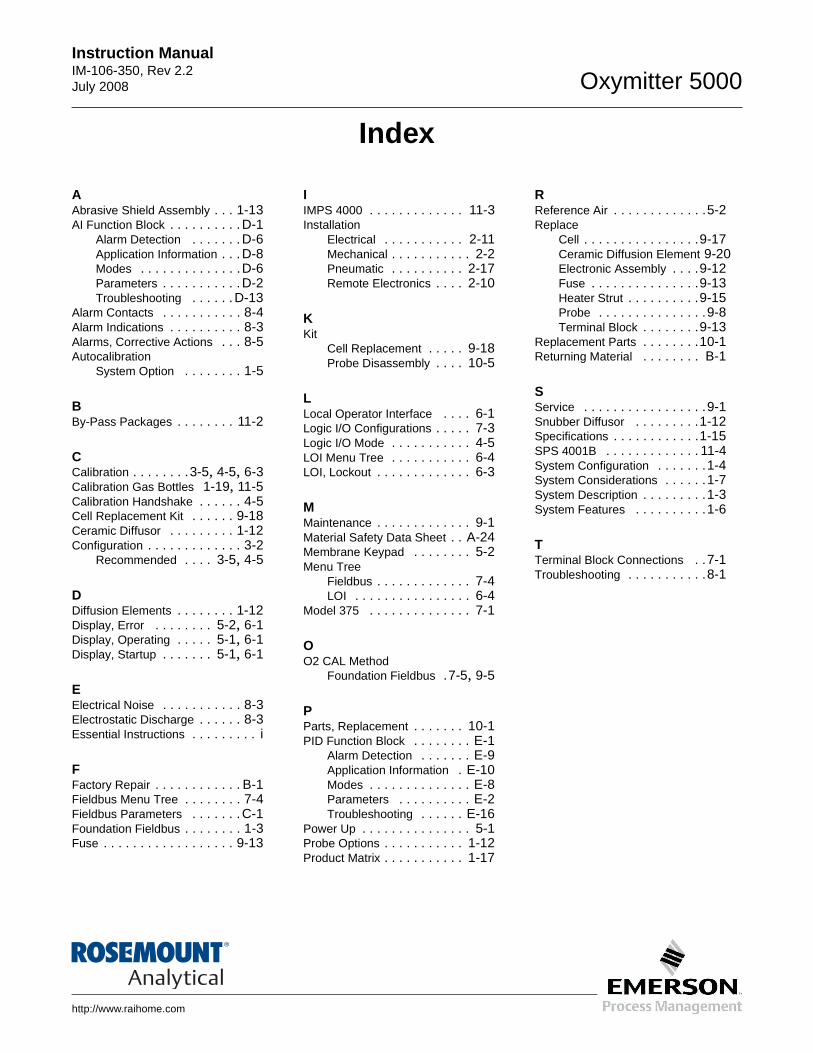
http://www.raihome.com
Instruction ManualIM-106-350, Rev 2.2July 2008 Oxymitter 5000
Index
AAbrasive Shield Assembly . . . 1-13AI Function Block . . . . . . . . . .D-1
Alarm Detection . . . . . . .D-6Application Information . . .D-8Modes . . . . . . . . . . . . . .D-6Parameters . . . . . . . . . . .D-2Troubleshooting . . . . . .D-13
Alarm Contacts . . . . . . . . . . . 8-4Alarm Indications . . . . . . . . . . 8-3Alarms, Corrective Actions . . . 8-5Autocalibration
System Option . . . . . . . . 1-5
BBy-Pass Packages . . . . . . . . 11-2
CCalibration . . . . . . . .3-5, 4-5, 6-3Calibration Gas Bottles 1-19, 11-5Calibration Handshake . . . . . . 4-5Cell Replacement Kit . . . . . . 9-18Ceramic Diffusor . . . . . . . . . 1-12Configuration . . . . . . . . . . . . . 3-2
Recommended . . . . 3-5, 4-5
DDiffusion Elements . . . . . . . . 1-12Display, Error . . . . . . . . 5-2, 6-1Display, Operating . . . . . 5-1, 6-1Display, Startup . . . . . . . 5-1, 6-1
EElectrical Noise . . . . . . . . . . . 8-3Electrostatic Discharge . . . . . . 8-3Essential Instructions . . . . . . . . . i
FFactory Repair . . . . . . . . . . . . B-1Fieldbus Menu Tree . . . . . . . . 7-4Fieldbus Parameters . . . . . . .C-1Foundation Fieldbus . . . . . . . . 1-3Fuse . . . . . . . . . . . . . . . . . . 9-13
IIMPS 4000 . . . . . . . . . . . . . 11-3Installation
Electrical . . . . . . . . . . . 2-11Mechanical . . . . . . . . . . . 2-2Pneumatic . . . . . . . . . . 2-17Remote Electronics . . . . 2-10
KKit
Cell Replacement . . . . . 9-18Probe Disassembly . . . . 10-5
LLocal Operator Interface . . . . 6-1Logic I/O Configurations . . . . . 7-3Logic I/O Mode . . . . . . . . . . . 4-5LOI Menu Tree . . . . . . . . . . . 6-4LOI, Lockout . . . . . . . . . . . . . 6-3
MMaintenance . . . . . . . . . . . . . 9-1Material Safety Data Sheet . . A-24Membrane Keypad . . . . . . . . 5-2Menu Tree
Fieldbus . . . . . . . . . . . . . 7-4LOI . . . . . . . . . . . . . . . . 6-4
Model 375 . . . . . . . . . . . . . . 7-1
OO2 CAL Method
Foundation Fieldbus .7-5, 9-5
PParts, Replacement . . . . . . . 10-1PID Function Block . . . . . . . . E-1
Alarm Detection . . . . . . . E-9Application Information . E-10Modes . . . . . . . . . . . . . . E-8Parameters . . . . . . . . . . E-2Troubleshooting . . . . . . E-16
Power Up . . . . . . . . . . . . . . . 5-1Probe Options . . . . . . . . . . . 1-12Product Matrix . . . . . . . . . . . 1-17
RReference Air . . . . . . . . . . . . .5-2Replace
Cell . . . . . . . . . . . . . . . .9-17Ceramic Diffusion Element 9-20Electronic Assembly . . . .9-12Fuse . . . . . . . . . . . . . . .9-13Heater Strut . . . . . . . . . .9-15Probe . . . . . . . . . . . . . . .9-8Terminal Block . . . . . . . .9-13
Replacement Parts . . . . . . . .10-1Returning Material . . . . . . . . B-1
SService . . . . . . . . . . . . . . . . .9-1Snubber Diffusor . . . . . . . . .1-12Specifications . . . . . . . . . . . .1-15SPS 4001B . . . . . . . . . . . . . 11-4System Configuration . . . . . . .1-4System Considerations . . . . . .1-7System Description . . . . . . . . .1-3System Features . . . . . . . . . .1-6
TTerminal Block Connections . .7-1Troubleshooting . . . . . . . . . . .8-1

Instruction ManualIM-106-350, Rev 2.2
July 2008
Index-2
Oxymitter 5000
WARRANTYRosemount Analytical warrants that the equipment manufactured and sold by it will, upon shipment, be free of defects in workmanship or material. Should any failure to conform to this warranty become apparent during a period of one year after the date of shipment, Rosemount Analytical shall, upon prompt written notice from the purchaser, correct such nonconformity by repair or replacement, F.O.B. factory of the defective part or parts. Correction in the manner provided above shall constitute a fulfillment of all liabilities of Rosemount Analytical with respect to the quality of the equipment.
THE FOREGOING WARRANTY IS EXCLUSIVE AND IN LIEU OF ALL OTHER WARRANTIES OF QUALITY WHETHER WRITTEN, ORAL, OR IMP LIED (INCLUDING ANY WARRANTY OF MERCHANTABILITY OF FITNE SS FOR PURPOSE).
The remedy(ies) provided above shall be purchaser's sole remedy(ies) for any failure of Rosemount Analytical to comply with the warranty provisions, whether claims by the purchaser are based in contract or in tort (including negligence).
Rosemount Analytical does not warrant equipment against normal deterioration due to environment. Factors such as corrosive gases and solid particulates can be detrimental and can create the need for repair or replacement as part of normal wear and tear during the warranty period.
Equipment supplied by Rosemount Analytical Inc. but not manufactured by it will be subject to the same warranty as is extended to Rosemount Analytical by the original manufacturer.
At the time of installation it is important that the required services are supplied to the system and that the electronic controller is set up at least to the point where it is controlling the sensor heater. This will ensure, that should there be a delay between installation and full commissioning that the sensor being supplied with ac power and reference air will not be subjected to component deterioration.
39487/08
© 2008 Emerson Process Management. All rights reserved.
Rosemount Analytical and the Rosemount Analytical logotype are registered trademarks of Rosemount Analytical Inc.HART is a registered trademark of the HART Communications Foundation.All other marks are the property of their respective owners.
Instruction ManualIM-106-350, Rev 2.2
July 2008Oxymitter 5000
GAS CHROMATOGRAPHY CENTER AND LATIN AMERICAEmerson Process ManagementRosemount Analytical Inc.11100 Brittmoore Park DriveHouston, TX 77041T 713 467 6000F 713 827 3329
ASIA-PACIFICEmerson Process ManagementAsia Pacific Private Limited1 Pandan CrescentSingapore 128461Republic of SingaporeT 65 6 777 8211F 65 6 777 0947E [email protected]
ROSEMOUNT ANALYTICAL EUROPEEmerson Process ManagementGmbh & co. OHGIndustriestrasse 163594 HasselrothGermanyT 49 6055 884 0F 49 6055 884 209
WORLD HEADQUARTERSEmerson Process ManagementRosemount Analytical Inc.6565P Davis Industrial ParkwaySolon, OH 44139T 440 914 1261T 800 433 6076F 440 914 1262E [email protected]
EUROPE, MIDDLE EAST, AFRICAEmerson Process ManagementShared Services LimitedHeath PlaceBognor RegisWest Sussex PO22 9SHEnglandT 44 1243 863121F 44 1243 845354
http://www.raihome.com
Oxymitter 5000
Part no.____________
Serial no.____________
Order no.____________