solahd product catalog january 2017 - emerson
TRANSCRIPT
SolaHD is the cornerstone brands of Emerson's Electrical Apparatus and Lighting business; trusted worldwide to power your process control applications in the most demanding applications worldwide.
The Emerson logo is a trademark and service mark of Emerson Electric Co. © 2016 Emerson Electric Co. Appleton and O-Z/Gedney brand logos are registered trademarks of Appleton Grp LLC. All other marks are the property of their respective owners. © 2016 Emerson Automation Solutions. All rights reserved.
Emerson.com
LinkedIn.com/company/emerson
United States (Headquarters) Appleton Grp LLC9377 W. Higgins RoadRosemont, IL 60018United StatesT +1 800 621 1506
Australia Sales OfficeBayswater, Victoria T +61 3 9721 0348
Europe ATX SASEspace Industriel Nord35, rue André Durouchez, CS 9801780084 Amiens Cedex 2, FranceT +33 3 2254 1390
China Sales OfficeShanghai T +86 21 3338 7000
CanadaEGS Electrical Group Canada Ltd.99 Union StreetElmira ON, N3B 3L7CanadaT +1 888 765 2226
Middle East Sales OfficeDammam, Saudi ArabiaT +966 13 510 3702
Chile Sales OfficeLas CondesT +56 2928 4819
India Sales OfficeChennaiT +91 44 3919 7300
Korea Sales OfficeSeoulT +82 2 3483 1555
Asia Pacific EGS Private Ltd.Block 4008, Ang Mo Kio Ave 10, #04-16 TechPlace 1, Singapore 569625 T +65 6556 1100
Latin America EGS Comercializadora Mexico S de RL de CVCalle 10 N°145 Piso 3Col. San Pedro de los PinosDel. Álvaro ObregonCiudad de México. 01180T +52 55 5809 5049
Innovative solutions to optimize operational performance, improve efficiencies, preserve data and increase equipment longevity.
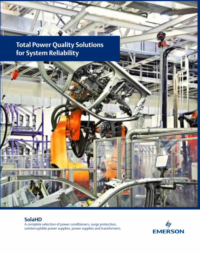
SolaHDA complete selection of power conditioners, surge protection, uninterruptible power supplies, power supplies and transformers.
Total Power Quality Solutions for System Reliability
SolaH
D Total Pow
er Qu
ality Solu
tion
s for System
Reliability

Table of Contents
Visit our website at www.emerson.com or contact Technical Services at (800) 377-4384 with any questions. © January 2017
1
Catalog Index ................................................................................................................................................2-3
Introduction ...................................................................................................................................................4-9
Power Solutions Flow Charts ...............................................................................................................10-11
Glossary of Terms ....................................................................................................................................12-16
Power Quality Solutions1: Power Conditioning and Surge Protection (Single and Three Phase up to 1400A) .............17
2: Uninterruptible Power Supplies (UPS) (350 to 20 kVA) .......................................................57
Control Power Solutions3: Power Supplies (Single and Three Phase from 14.4 Watts to 4920 Watts) ......................120
4: Industrial Control Transformers (50 VA to 5 KVA) .............................................................183
Power Distribution Solutions5: General Purpose Shielded Transformers (50 VA to 500 kVA)............................................202
6: Buck-Boost Transformers (100 VA to 10 kVA) .................................................................245
Index
1EWPS1K Series -------------------- 1161EWPS3K Series -------------------- 1161EWPS4K Series -------------------- 116
23-13- Series Power Conditioners ---4223-22-112-2 Power Conditioners ----42 23-23 Series Power Conditioners ----4223-28- Series Power Conditioners ---42 3EWPS1K Series -------------------- 1163EWPS3K Series -------------------- 1163EWPS4K Series -------------------- 116 K4E2H Series ------------------------ 225 K13E2H Series ----------------------- 225 K13E2H Series ----------------------- 225
63-13- Series ---------------------------48 63-23- Series ---------------------------44 63-28- Series ---------------------------4463-29- Series ---------------------------4563-31- Series ---------------------------45 63-32- Series ---------------------------4563TAA Series ---------------------------5563TCA Series---------------------------55 63TCC Series --------------------------55 63TDA Series ---------------------------55
A2D115HW ----------------------------94A2D120HW -----------------------------94 A2D130HW -----------------------------94
DT631 Series Power Conditioner -- 240 DT651 Series Power Conditioner -- 240 DT661 Series Power Conditioner -- 240
E---- Series Transformers ----------- 188E---D Series Transformers ---------- 190E---E Series Transformers ----------- 188E---EW Series Transformers -------- 188E---EWA Series Transformers ------ 188E--- EWB Series Transformers ------ 188E---JL Series Transformers --------- 190E---JN Series Transformers --------- 190E--- TC Series Transformers -------- 195E--- TE Series Transformers -------- 195
E--- TF Series Transformers -------- 196E--- TH Series Transformers -------- 196E----W Series Transformers --------- 189E----WA Series Transformers ------- 189E----WB Series Transformers ------- 189ES12H Series Transformers --------- 210ES5H Series Transformers ---------- 210ES5HB Series Transformers -------- 218 ES5HF Series Transformers --------- 220E2H--S Series Transformers -------- 214E2H--SCU Series Transformers ---- 214E2HB Series Transformers ---------- 219E2HF Series Transformers ---------- 220E3H Series Transformers ------------ 213E5H Series Transformers ------------ 219E5HB Series Transformers ---------- 219E5HF Series Transformers ---------- 220E6H Series Transformers ------------ 213E79H Transformers ------------------ 214E81H Series Transformers ---------- 212E84H Series Transformers ---------- 212E85H Series Transformers ---------- 213 FB2 Cover Kit ------------------------ 191FB2X Cover Kit ----------------------- 191FBP Cover Kit ------------------------ 191FBPC1 Cover Kit --------------------- 191
GL Series Power Supplies ---------- 163
HS1B Series Transformers ---------- 230 HS1F Series Transformers ---------- 230 HS10B Series Transformers -------- 230 HS10F Series Transformers --------- 230HS12F Series Transformers --------- 231 HS14F Series Transformers --------- 231 HS5F Series Transformers ---------- 230 HSS1F Series Transformers -------- 230HSS10F Series Transformers ------- 230HSS5F Transformer ------------------ 230 HSZ Series Transformers ------------ 199HT1F Series Transformers ---------- 232 HT5F Series Transformers ---------- 232 HT6F Series Transformers ---------- 232 HT7F Series Transformers ---------- 233
HT79 Series Transformers ---------- 233 HT84 Series Transformers ---------- 228HT85 Series Transformers ---------- 233 HTS1F Series Transformers --------- 232 HTS5F Series Transformers --------- 232
ICE Transformers --------------------- 197IP20 Cover Kit ------------------------ 191
MEU Service Program --------------- 118MUU Service Program --------------- 118MS4 Service Program --------------- 118MS5 Service Program --------------- 118
IS-RELAY UPS Accessory ---------- 115RELAYCARD-SDU UPS Accessory --65
Visit our website at www.emerson.com or contact Technical Services at (800) 377-4384 with any questions. © January 2017
2
Index
S1K Series UPS ------------------------71S3K Series UPS ------------------------73S4K144BAT UPS Battery -------------90S4K144INTBAT UPS Battery ---------89S4K288BAT UPS Battery -------------90S4K240BAT UPS Battery ----------- 101S4K2U Series UPS --------------------75S4K2U48BAT UPS Battery -----------81S4K2U96BAT UPS Battery -----------81S4K4U Series UPS --------------------86S4K5U Series UPS --------------------97S4K6U Series UPS --------------------86S4KPAD Series UPS Accessory ------91S5KC Series UPS Module ---------- 104S5KREPOKIT UPS Option ---------- 115SBE Series Transformers ------------ 192SBEDIN Cover Kit -------------------- 191SCD Series Power Supplies -------- 154 SCP Series Power Supplies -------- 152SCP-X Series Power Supplies ------ 160SHP Series Power Supplies -------- 171SDN-C Series Power Supplies ----- 124SDN-C Redundancy Series Power Supplies ------------------------------- 141SDN-P Series Power Supplies ------ 132SDN Redundant Series Power Supplies ---------------------- 137 SDP Series Power Supplies -------- 144SDU AC Series UPS -------------------65SDU-A AC Series UPS ----------------67SDU DC Series UPS -------------------60SDU-PMBRK UPS Accessory --------61SL Series Power Supplies ----------- 156 SNMPWEBCARD UPS Option -------93SRS1832 UPS Option -----------------93STC Series Power Protection ---------36STF Series Power Protection ---------27STFE Elite Power Protection ----------33STFV Plus Series Power Protection --30STV 25K - Series Surge Protective Devices -------------25 STV 100K- Series Surge Protective Devices -------------23STV 200/400K - Series Surge Protective Devices -------------20
SUS4K UPS Start-Up --------------- 118T----Series Transformers ------------ 193UPSMON-USB UPS Accessory ------65
W Transformer Accessory ----------- 191WA Transformer Accessory --------- 191WB Transformer Accessory --------- 191WS Series Weather Shields --------- 210
Y Series ------------------------------- 192
Visit our website at www.emerson.com or contact Technical Services at (800) 377-4384 with any questions. © January 2017
3
Industrial Facility Wide Protection
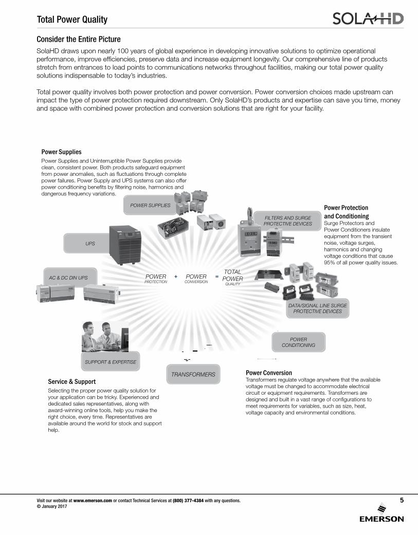
Power Products (14.4 watts to 500 kVA)
Anywhere in your facility from the service entrance to the most critical production equipment, SolaHD can power your process control applications with our power conversion and power quality products.
SolaHD offers industrial grade products to meet the most demanding applications worldwide.
• Factory automation• Inspection, test and instrumentation equipment • Laboratory and non-patient medical • High efficiency applications (Energy Star®)• UL508 environments such as waste water treatment • Harsh environment and remote site locations• Building automation• Service automation• Process control
SolaHD offers many products suited for harsh environments including our encapsulated power supplies and transformers. We also offer a wide range of Class 1 Division 2 products.
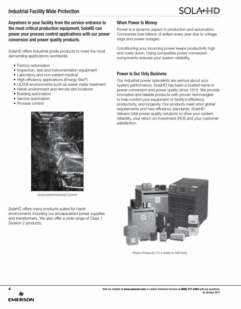
Automotive/Industrial Control
When Power Is MoneyPower is a dynamic aspect in production and automation. Companies lose billions of dollars every year due to voltage sage and power outages.
Conditioning your incoming power keeps productivity high and costs down. Using compatible power conversion components ensures your system reliability.
Power Is Our Only BusinessOur industrial power specialists are serious about your system performance. SolaHD has been a trusted name in power conversion and power quality since 1915. We provide innovative and reliable products with proven technologies to help control your equipment or facility’s efficiency, productivity, and longevity. Our products meet strict global requirements and new efficiency standards. SolaHD delivers total power quality solutions to drive your system reliability, your return on investment (ROI) and your customer satisfaction.
Visit our website at www.emerson.com or contact Technical Services at (800) 377-4384 with any questions. © January 2017
4
Total Power Quality
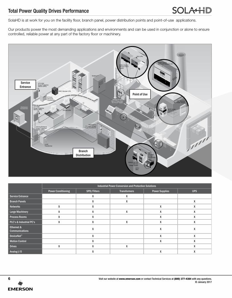
Consider the Entire PictureSolaHD draws upon nearly 100 years of global experience in developing innovative solutions to optimize operational performance, improve efficiencies, preserve data and increase equipment longevity. Our comprehensive line of products stretch from entrances to load points to communications networks throughout facilities, making our total power quality solutions indispensable to today’s industries.
Total power quality involves both power protection and power conversion. Power conversion choices made upstream can impact the type of power protection required downstream. Only SolaHD’s products and expertise can save you time, money and space with combined power protection and conversion solutions that are right for your facility.
Service & SupportSelecting the proper power quality solution for your application can be tricky. Experienced and dedicated sales representatives, along with award-winning online tools, help you make the right choice, every time. Representatives are available around the world for stock and support help.
Power SuppliesPower Supplies and Uninterruptible Power Supplies provide clean, consistent power. Both products safeguard equipment from power anomalies, such as fluctuations through complete power failures. Power Supply and UPS systems can also offer power conditioning benefits by filtering noise, harmonics and dangerous frequency variations.
Power Protection and Conditioning Surge Protectors and Power Conditioners insulate equipment from the transient noise, voltage surges, harmonics and changing voltage conditions that cause 95% of all power quality issues.
Power Conversion Transformers regulate voltage anywhere that the available voltage must be changed to accommodate electrical circuit or equipment requirements. Transformers are designed and built in a vast range of configurations to meet requirements for variables, such as size, heat, voltage capacity and environmental conditions.
DATA/SIGNAL LINE SURGE PROTECTIVE DEVICES
FILTERS AND SURGE PROTECTIVE DEVICES
POWER SUPPLIES
TRANSFORMERS
SUPPORT & EXPERTISE
POWER CONDITIONING
AC & DC DIN UPS
UPS
POWER PROTECTION
POWER CONVERSION
TOTALPOWER
QUALITy
+ =
Visit our website at www.emerson.com or contact Technical Services at (800) 377-4384 with any questions. © January 2017
5
Total Power Quality Drives Performance
INPUT
OUTPUT
Power SupplySCP 100S24X-CM
STFVSPD
SDN2.5-24-100DIN DC
Power Supply
Active Tracking Filter®
STFV Series
STV100KSurge Protective Device (SPD)
K-FactorHarmonicTransformer
STV100KSurge Protective Device (SPD)
SDN40-24-480CDIN 3-Phase InputDC Power Supply
Off-Line UPS
Service EntranceSurge Protective Device (SPD)
LVGPTransformer
S5KC Modular UPS
MCR SeriesConstant Voltage
Power Conditioner
DistributionTransformer MCR Series
ConstantVoltage PowerConditioner
Solatron™
SHP ModularDC Power Supply
SDN-C Series DIN DC Power Supply
SDU UPS
SBEIndustrial Control Transformer
Active Tracking Filter®
STFV Series
INPUT
OUTPUT
Power SupplySCP 100S24X-CP1
Power SupplySCP SCP100S24X-CP1
SolaHD is at work for you on the facility floor, branch panel, power distribution points and point-of-use applications.
Our products power the most demanding applications and environments and can be used in conjunction or alone to ensure controlled, reliable power at any part of the factory floor or machinery.
Service Entrance
Branch Distribution
Point of Use
Industrial Power Conversion and Protection Solutions
Power Conditioning SPD/Filters Transformers Power Supplies UPS
Service Entrance X X
Branch Panels X X X
Networks X X X X
Large Machinery X X X X X
Process Rooms X X X X
PLC’s & Industrial PC’s X X X X X
Ethernet & Communications X X X
DeviceNet™ X X X
Motion Control X X X
Drives X X X X
Analog I/O X X X
Visit our website at www.emerson.com or contact Technical Services at (800) 377-4384 with any questions. © January 2017
6
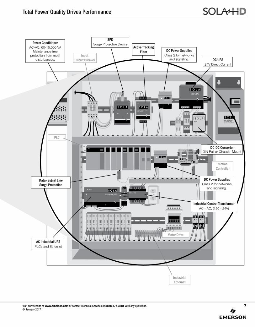
Total Power Quality Drives Performance
SDU 24-BATEMIndustrial DC UPSExternal Battery Module
SDP4-24-100LT
Industrial UPS
SCD
S O L A HD
DC UPS
Active Tracking® FilterSTF Series
SDU10-24
SPDSurge Protective Device
DC UPS24V Direct Current
PLC
DC Power SuppliesClass 2 for networks
and signaling.
Input Circuit Breaker
Motion Controller
Motor Drive
Power ConditionerAC-AC, 60-15,000 VA
Maintenance free protection from most
disturbances.
Active Tracking Filter
Industrial Ethernet
DC-DC Converter DIN Rail or Chassis Mount
DC Power SuppliesClass 2 for networks
and signaling.
Data/Signal LineSurge Protection
Industrial Control TransformerAC - AC, (120 - 24V)
AC Industrial UPSPLCs and Ethernet
Visit our website at www.emerson.com or contact Technical Services at (800) 377-4384 with any questions. © January 2017
7
Total Power Quality Solutions
Isolation Transformers
UPS
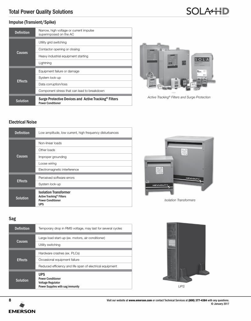
Definition Narrow, high voltage or current impulse superimposed on the AC
Causes
Utility grid switching
Contactor opening or closing
Heavy industrial equipment starting
Lightning
Effects
Equipment failure or damage
System lock-up
Data corruption/loss
Component stress that can lead to breakdown
Solution Surge Protective Devices and Active Tracking® FiltersPower Conditioner
Impulse (Transient/Spike)
Definition Low amplitude, low current, high frequency disturbances
Causes
Non-linear loads
Other loads
Improper grounding
Loose wiring
Electromagnetic interference
EffectsPerceived software errors
System lock-up
SolutionIsolation TransformerActive Tracking® FiltersPower ConditionerUPS
Electrical Noise
Definition Temporary drop in RMS voltage, may last for several cycles
CausesLarge load start-up (ex. motors, air conditioner)
Utility switching
Effects
Hardware crashes (ex. PLCs)
Occasional equipment failure
Reduced efficiency and life span of electrical equipment
SolutionUPSPower ConditionerVoltage RegulatorPower Supplies with sag immunity
Sag
Active Tracking® Filters and Surge Protection
Visit our website at www.emerson.com or contact Technical Services at (800) 377-4384 with any questions. © January 2017
8
Total Power Quality Solutions
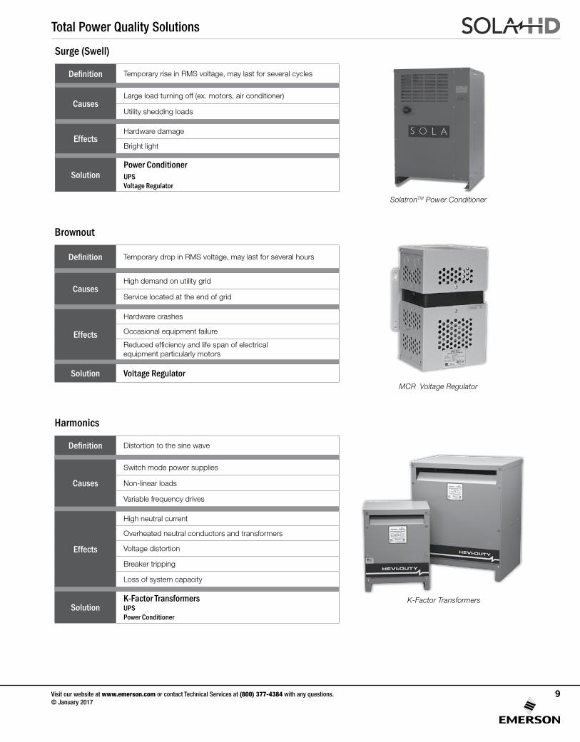
SolatronTM Power Conditioner
Definition Temporary rise in RMS voltage, may last for several cycles
CausesLarge load turning off (ex. motors, air conditioner)
Utility shedding loads
EffectsHardware damage
Bright light
SolutionPower ConditionerUPSVoltage Regulator
Surge (Swell)
Definition Temporary drop in RMS voltage, may last for several hours
CausesHigh demand on utility grid
Service located at the end of grid
Effects
Hardware crashes
Occasional equipment failure
Reduced efficiency and life span of electrical equipment particularly motors
Solution Voltage Regulator
Brownout
Definition Distortion to the sine wave
Causes
Switch mode power supplies
Non-linear loads
Variable frequency drives
Effects
High neutral current
Overheated neutral conductors and transformers
Voltage distortion
Breaker tripping
Loss of system capacity
SolutionK-Factor TransformersUPSPower Conditioner
Harmonics
MCR Voltage Regulator
K-Factor Transformers
Visit our website at www.emerson.com or contact Technical Services at (800) 377-4384 with any questions. © January 2017
9
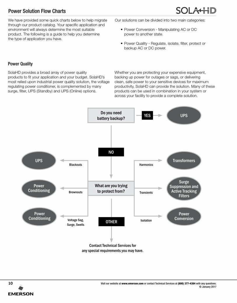
Power Solution Flow Charts
We have provided some quick charts below to help migrate through our product catalog. Your specific application and environment will always determine the most suitable product. The following is a guide to help you determine the type of application you have.
SolaHD provides a broad array of power quality products to fit your application and your budget. SolaHD’s most relied upon industrial power quality solution, the voltage regulating power conditioner, is complemented by many surge, filter, UPS (Standby) and UPS (Online) options.
Power Quality
Our solutions can be divided into two main categories:
• Power Conversion - Manipulating AC or DC power to another state.
• Power Quality - Regulate, isolate, filter, protect or backup AC or DC power.
Whether you are protecting your expensive equipment, backing up power for outages or sags, or delivering clean, safe power to your sensitive devices for maximum productivity, SolaHD can provide the solution. Many of these products can be used in combination in your system or across your facility to provide a complete solution.
Contact Technical Services for any special requirements you may have.
Do you need battery backup?
What are you trying to protect from?
NO
OTHER
TransformersUPSBlackouts
Brownouts
Voltage Sag, Surge, Swells
Harmonics
Transients
Isolation
UPS
Surge Suppression and Active Tracking
Filters
Power Conditioning
Power Conversion
Power Conditioning
YES
Visit our website at www.emerson.com or contact Technical Services at (800) 377-4384 with any questions. © January 2017
10
Power Solution Flow Charts
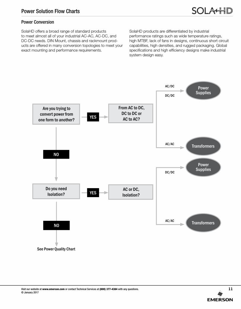
SolaHD offers a broad range of standard products to meet almost all of your industrial AC-AC, AC-DC, and DC-DC needs. DIN Mount, chassis and rackmount prod-ucts are offered in many conversion topologies to meet your exact mounting and performance requirements.
SolaHD products are differentiated by industrial performance ratings such as wide temperature ratings, high MTBF, lack of fans in designs, continuous short circuit capabilities, high densities, and rugged packaging. Global specifications and high efficiency designs make industrial system design easy.
Power Conversion
See Power Quality Chart
Are you trying to convert power from
one form to another?
Do you need Isolation?
AC or DC,Isolation?
From AC to DC, DC to DC or AC to AC?
NO
NO Transformers
Transformers
DC/DC
DC/DC
AC/DC
AC/AC
AC/AC
Power Supplies
Power Supplies
YES
YES
Visit our website at www.emerson.com or contact Technical Services at (800) 377-4384 with any questions. © January 2017
11
Power Protection and Conditioning
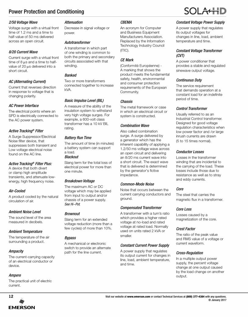
2/50 Voltage WaveVoltage surge with a virtual front time of 1.2 ms and a time to half-value of 50 ms delivered across an open circuit.
8/20 Current WaveCurrent surge with a virtual front time of 8 ms and a time to half-value of 20 ms delivered into a short circuit.
AC (Alternating Current) Current that reverses direction in response to voltage that is changing polarity.
AC Power InterfaceThe electrical points where an SPD is electrically connected to the AC power system.
Active Tracking® FilterA Surge Suppressor/Electrical Noise filter device, that suppresses both transient and Low voltage electrical noise found on the AC line.
Active Tracking® Filter Plus: A device that both divert or clamp high amplitude transients, and attenuate low-energy, high frequency noise.
Air-CooledA product cooled by the natural circulation of air.
Ambient Noise LevelThe sound level of the area measured in decibels.
Ambient TemperatureThe temperature of the air surrounding a product.
AmpacityThe current-carrying capacity of an electrical conductor or device.
AmpereThe practical unit of electric current.
AttenuationDecrease in signal voltage or power.
AutotransformerA transformer in which part of one winding is common to both the primary and secondary circuits associated with that winding.
BankedTwo or more transformers connected together to increase kVA.
Basic Impulse Level (BIL)A measure of the ability of the insulation system to withstand very high voltage surges. For example, a 600-volt class transformer has a 10 kV BIL rating.
Battery Run TimeThe amount of time (in minutes) a battery system can support a load.BlackoutSlang term for the total loss of electrical power for more than one minute.
Breakdown VoltageThe maximum AC or DC voltage which may be applied from input to output and/or chassis of a power supply. See Hi-Pot.
BrownoutSlang term for an extended voltage reduction (more than a few cycles) of more than 10%.
BypassA mechanical or electronic switch to provide an alternate path for the line current.
CBEMAAn acronym for Computer and Business Equipment Manufacturers Association. Replaced by the Information Technology Industry Council (ITIC).
CE Mark(Conformité Européenne) - A marking that shows the product meets the fundamental safety, health, environmental and consumer protection requirements of the European Community.
ChassisThe metal framework or case in which an electrical circuit or system is constructed.
Combination WaveAlso called combination surge. A surge delivered by a generator which has the inherent capability of applying a 1.2/50 ms voltage wave across an open circuit and delivering an 8/20 ms current wave into a short circuit. The exact wave that is delivered is determined by the generator's fictive impedance.
Common-Mode NoiseNoise that occurs between the current carrying conductors and ground.
Compensated TransformerA transformer with a turn’s ratio which provides a higher rated voltage at no-load and rated voltage at rated load. Normally used on units rated 2 kVA or smaller.
Constant Current Power SupplyA power supply that regulates its output current for changes in line, load, ambient temperature, and time.
Constant Voltage Power SupplyA power supply that regulates its output voltages for changes in line, load, ambient temperature and time.
Constant Voltage Transformer (CVT)A power conditioner that provides a stable and regulated sinewave output voltage.
Continuous DutyThe service requirement that demands operation at a constant load for an indefinite period of time.
Control TransformerUsually referred to as an Industrial Control transformer. Designed for good voltage regulation characteristics when low power factor and /or large inrush currents are drawn (5 to 15 times normal).
Conductor LossesLosses in the transformer winding that are incidental to the carrying of the load. These losses include those due to resistance as well as to stray and eddy currents.
CoreThe steel that carries the magnetic flux in a transformer.
Core LossLosses caused by a magnetization of the core.
Crest FactorThe ratio of the peak value and RMS value of a voltage or current waveform.
Cross-RegulationIn a multiple output power supply, the percent voltage change at one output caused by the load change on another output.
Visit our website at www.emerson.com or contact Technical Services at (800) 377-4384 with any questions. © January 2017
12
Power Protection and Conditioning
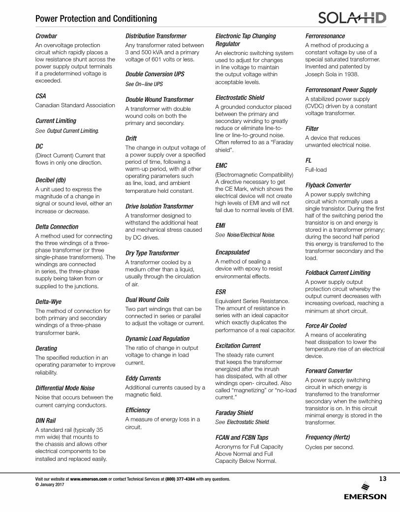
CrowbarAn overvoltage protection circuit which rapidly places a low resistance shunt across the power supply output terminals if a predetermined voltage is exceeded.
CSACanadian Standard Association
Current Limiting
See Output Current Limiting.
DC(Direct Current) Current that flows in only one direction.
Decibel (db)A unit used to express the magnitude of a change in signal or sound level, either an increase or decrease.
Delta ConnectionA method used for connecting the three windings of a three-phase transformer (or three single-phase transformers). The windings are connected in series, the three-phase supply being taken from or supplied to the junctions.
Delta-WyeThe method of connection for both primary and secondary windings of a three-phase transformer bank.
DeratingThe specified reduction in an operating parameter to improve reliability.
Differential Mode NoiseNoise that occurs between the current carrying conductors. DIN RailA standard rail (typically 35 mm wide) that mounts to the chassis and allows other electrical components to be installed and replaced easily.
Distribution TransformerAny transformer rated between 3 and 500 kVA and a primary voltage of 601 volts or less.
Double Conversion UPS
See On-line UPS
Double Wound TransformerA transformer with double wound coils on both the primary and secondary.
DriftThe change in output voltage of a power supply over a specified period of time, following a warm-up period, with all other operating parameters such as line, load, and ambient temperature held constant.
Drive Isolation TransformerA transformer designed to withstand the additional heat and mechanical stress caused by DC drives.
Dry Type TransformerA transformer cooled by a medium other than a liquid, usually through the circulation of air.
Dual Wound CoilsTwo part windings that can be connected in series or parallel to adjust the voltage or current.
Dynamic Load RegulationThe ratio of change in output voltage to change in load current.
Eddy CurrentsAdditional currents caused by a magnetic field.
EfficiencyA measure of energy loss in a circuit.
Electronic Tap Changing RegulatorAn electronic switching system used to adjust for changes in line voltage to maintain the output voltage within acceptable levels.
Electrostatic ShieldA grounded conductor placed between the primary and secondary winding to greatly reduce or eliminate line-to-line or line-to-ground noise. Often referred to as a “Faraday shield”.
EMC(Electromagnetic Compatibility) A directive necessary to get the CE Mark, which shows the electrical device will not create high levels of EMI and will not fail due to normal levels of EMI.
EMISee Noise/Electrical Noise.
EncapsulatedA method of sealing a device with epoxy to resist environmental effects.
ESREquivalent Series Resistance. The amount of resistance in series with an ideal capacitor which exactly duplicates the performance of a real capacitor.
Excitation CurrentThe steady rate current that keeps the transformer energized after the inrush has dissipated, with all other windings open- circuited. Also called “magnetizing” or “no-load current.”
Faraday ShieldSee Electrostatic Shield.
FCAN and FCBN TapsAcronyms for Full Capacity Above Normal and Full Capacity Below Normal.
FerroresonanceA method of producing a constant voltage by use of a special saturated transformer. Invented and patented by Joseph Sola in 1938.
Ferroresonant Power SupplyA stabilized power supply (CVDC) driven by a constant voltage transformer.
FilterA device that reduces unwanted electrical noise.
FLFull-load
Flyback ConverterA power supply switching circuit which normally uses a single transistor. During the first half of the switching period the transistor is on and energy is stored in a transformer primary; during the second half period this energy is transferred to the transformer secondary and the load.
Foldback Current LimitingA power supply output protection circuit whereby the output current decreases with increasing overload, reaching a minimum at short circuit.
Force Air CooledA means of accelerating heat dissipation to lower the temperature rise of an electrical device.
Forward ConverterA power supply switching circuit in which energy is transferred to the transformer secondary when the switching transistor is on. In this circuit minimal energy is stored in the transformer.
Frequency (Hertz)
Cycles per second.
Visit our website at www.emerson.com or contact Technical Services at (800) 377-4384 with any questions. © January 2017
13
Power Protection and Conditioning
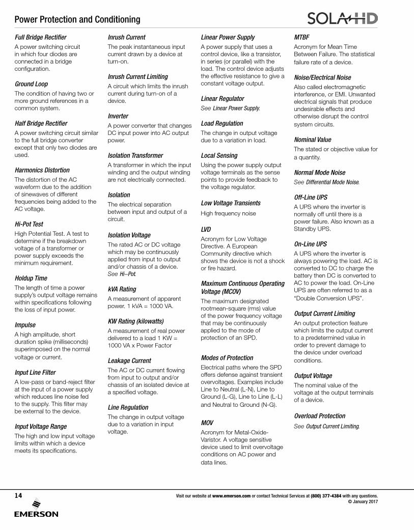
Full Bridge RectifierA power switching circuit in which four diodes are connected in a bridge configuration.
Ground LoopThe condition of having two or more ground references in a common system.
Half Bridge RectifierA power switching circuit similar to the full bridge converter except that only two diodes are used.
Harmonics DistortionThe distortion of the AC waveform due to the addition of sinewaves of different frequencies being added to the AC voltage.
Hi-Pot TestHigh Potential Test. A test to determine if the breakdown voltage of a transformer or power supply exceeds the minimum requirement.
Holdup TimeThe length of time a power supply’s output voltage remains within specifications following the loss of input power.
ImpulseA high amplitude, short duration spike (milliseconds) superimposed on the normal voltage or current.
Input Line FilterA low-pass or band-reject filter at the input of a power supply which reduces line noise fed to the supply. This filter may be external to the device.
Input Voltage RangeThe high and low input voltage limits within which a device meets its specifications.
Inrush CurrentThe peak instantaneous input current drawn by a device at turn-on.
Inrush Current LimitingA circuit which limits the inrush current during turn-on of a device.
InverterA power converter that changes DC input power into AC output power.
Isolation TransformerA transformer in which the input winding and the output winding are not electrically connected.
IsolationThe electrical separation between input and output of a circuit.
Isolation VoltageThe rated AC or DC voltage which may be continuously applied from input to output and/or chassis of a device. See Hi-Pot.
kVA RatingA measurement of apparent power. 1 kVA = 1000 VA.
KW Rating (kilowatts)A measurement of real power delivered to a load 1 KW = 1000 VA x Power Factor
Leakage CurrentThe AC or DC current flowing from input to output and/or chassis of an isolated device at a specified voltage.
Line RegulationThe change in output voltage due to a variation in input voltage.
Linear Power SupplyA power supply that uses a control device, like a transistor, in series (or parallel) with the load. The control device adjusts the effective resistance to give a constant voltage output.
Linear RegulatorSee Linear Power Supply.
Load RegulationThe change in output voltage due to a variation in load.
Local SensingUsing the power supply output voltage terminals as the sense points to provide feedback to the voltage regulator.
Low Voltage Transients
High frequency noise
LVDAcronym for Low Voltage Directive. A European Community directive which shows the device is not a shock or fire hazard.
Maximum Continuous Operating Voltage (MCOV)The maximum designated rootmean-square (rms) value of the power frequency voltage that may be continuously applied to the mode of protection of an SPD.
Modes of ProtectionElectrical paths where the SPD offers defense against transient overvoltages. Examples include Line to Neutral (L-N), Line to Ground (L-G), Line to Line (L-L) and Neutral to Ground (N-G).
MOVAcronym for Metal-Oxide-Varistor. A voltage sensitive device used to limit overvoltage conditions on AC power and data lines.
MTBFAcronym for Mean Time Between Failure. The statistical failure rate of a device.
Noise/Electrical NoiseAlso called electromagnetic interference, or EMI. Unwanted electrical signals that produce undesirable effects and otherwise disrupt the control system circuits.
Nominal ValueThe stated or objective value for a quantity.
Normal Mode NoiseSee Differential Mode Noise.
Off-Line UPSA UPS where the inverter is normally off until there is a power failure. Also known as a Standby UPS.
On-Line UPSA UPS where the inverter is always powering the load. AC is converted to DC to charge the battery then DC is converted to AC to power the load. On-Line UPS are often referred to as a “Double Conversion UPS”.
Output Current LimitingAn output protection feature which limits the output current to a predetermined value in order to prevent damage to the device under overload conditions.
Output VoltageThe nominal value of the voltage at the output terminals of a device.
Overload Protection
See Output Current Limiting.
Visit our website at www.emerson.com or contact Technical Services at (800) 377-4384 with any questions. © January 2017
14
Power Protection and Conditioning
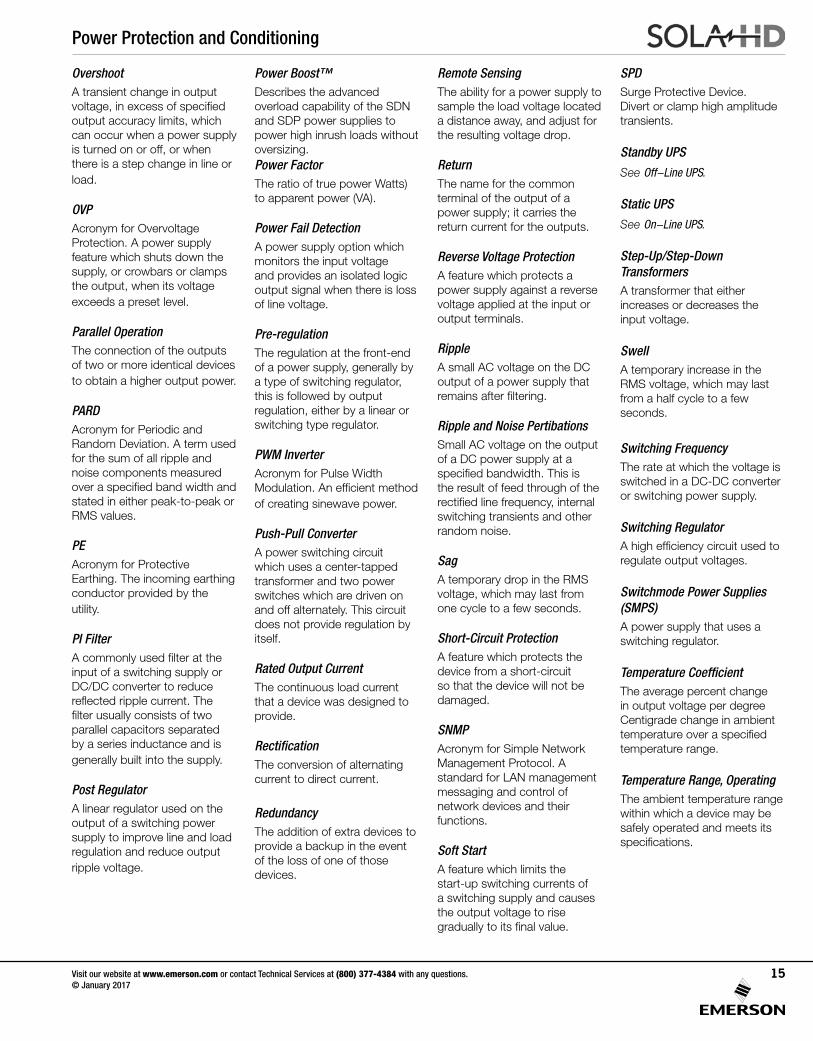
OvershootA transient change in output voltage, in excess of specified output accuracy limits, which can occur when a power supply is turned on or off, or when there is a step change in line or load.
OVPAcronym for Overvoltage Protection. A power supply feature which shuts down the supply, or crowbars or clamps the output, when its voltage exceeds a preset level.
Parallel OperationThe connection of the outputs of two or more identical devices to obtain a higher output power.
PARDAcronym for Periodic and Random Deviation. A term used for the sum of all ripple and noise components measured over a specified band width and stated in either peak-to-peak or RMS values.
PEAcronym for Protective Earthing. The incoming earthing conductor provided by the utility.
PI FilterA commonly used filter at the input of a switching supply or DC/DC converter to reduce reflected ripple current. The filter usually consists of two parallel capacitors separated by a series inductance and is generally built into the supply.
Post RegulatorA linear regulator used on the output of a switching power supply to improve line and load regulation and reduce output ripple voltage.
Power Boost™Describes the advanced overload capability of the SDN and SDP power supplies to power high inrush loads without oversizing.Power FactorThe ratio of true power Watts) to apparent power (VA).
Power Fail DetectionA power supply option which monitors the input voltage and provides an isolated logic output signal when there is loss of line voltage.
Pre-regulationThe regulation at the front-end of a power supply, generally by a type of switching regulator, this is followed by output regulation, either by a linear or switching type regulator.
PWM InverterAcronym for Pulse Width Modulation. An efficient method of creating sinewave power.
Push-Pull ConverterA power switching circuit which uses a center-tapped transformer and two power switches which are driven on and off alternately. This circuit does not provide regulation by itself.
Rated Output CurrentThe continuous load current that a device was designed to provide.
RectificationThe conversion of alternating current to direct current.
RedundancyThe addition of extra devices to provide a backup in the event of the loss of one of those devices.
Remote SensingThe ability for a power supply to sample the load voltage located a distance away, and adjust for the resulting voltage drop.
ReturnThe name for the common terminal of the output of a power supply; it carries the return current for the outputs.
Reverse Voltage ProtectionA feature which protects a power supply against a reverse voltage applied at the input or output terminals.
RippleA small AC voltage on the DC output of a power supply that remains after filtering.
Ripple and Noise PertibationsSmall AC voltage on the output of a DC power supply at a specified bandwidth. This is the result of feed through of the rectified line frequency, internal switching transients and other random noise.
SagA temporary drop in the RMS voltage, which may last from one cycle to a few seconds.
Short-Circuit ProtectionA feature which protects the device from a short-circuit so that the device will not be damaged.
SNMPAcronym for Simple Network Management Protocol. A standard for LAN management messaging and control of network devices and their functions.
Soft StartA feature which limits the start-up switching currents of a switching supply and causes the output voltage to rise gradually to its final value.
SPDSurge Protective Device. Divert or clamp high amplitude transients.
Standby UPS
See Off-Line UPS.
Static UPS
See On-Line UPS.
Step-Up/Step-Down TransformersA transformer that either increases or decreases the input voltage.
Swell A temporary increase in the RMS voltage, which may last from a half cycle to a few seconds.
Switching FrequencyThe rate at which the voltage is switched in a DC-DC converter or switching power supply.
Switching RegulatorA high efficiency circuit used to regulate output voltages.
Switchmode Power Supplies (SMPS)A power supply that uses a switching regulator.
Temperature CoefficientThe average percent change in output voltage per degree Centigrade change in ambient temperature over a specified temperature range.
Temperature Range, OperatingThe ambient temperature range within which a device may be safely operated and meets its specifications.
Visit our website at www.emerson.com or contact Technical Services at (800) 377-4384 with any questions. © January 2017
15
Power Protection and Conditioning
Temperature Range, StorageThe ambient temperature range within which a device may be safely stored, non-operating, with no degradation in its subsequent operation.
Thermal ProtectionAn internal safeguard circuit that shuts down the unit in the event of excess internal temperatures.
THD Acronym for Total Harmonic Distortion. The ratio of the harmonic content to the fundamental frequency expressed as a percent of the fundamental.
Transfer TimeThe amount of time a device takes to switch from one mode of operation to another.
TransformerAn electrical device that changes AC voltage from one level to another.
Transformer Turns RatioThe ratio of primary turns to secondary turns.
Transient A high amplitude, short duration (milliseconds) spike superimposed on the normal voltage or current. Sometimes called a spike or a surge.
Transient Recovery TimeThe time required for the output voltage of a device to settle within specified output accuracy limits following a step change in output load current or a step change in input voltage.
Transverse Mode NoiseSee Differential Mode Noise.
TVSSTransient Voltage Surge Suppressor. Also known as SPD
ULAcronym for Underwriters Laboratories tested.
UL Recognized Designation given to components that when used properly in an end product are deemed to be safe.
UL ListedDesignation given to products ready for end use.
UndervoltageSee Brownout.
UPSAcronym for Uninterruptible Power Supply. A device which supplies power to the critical load when the existing AC line voltage is not within normal operating values, or fails completely.
VAAcronym for Voltamp. A measure of power. 1000 VA = 1 kVA.
VFDVariable Frequency Drive.
Voltage BalanceThe difference in magnitude, in percent, between the two output voltages of a dual output power supply where the voltages have equal nominal values with opposite polarities.
Warm-Up DriftThe initial change in output voltages of a device from turn-on until it reaches thermal equilibrium.
Warm-Up TimeThe time required, after initial turn-on, for a device to meet its performance specifications.
Visit our website at www.emerson.com or contact Technical Services at (800) 377-4384 with any questions. © January 2017
16
Power Quality Solutions
Visit our website at www.emerson.com or contact Technical Services at (800) 377-4384 with any questions. © January 2017
17
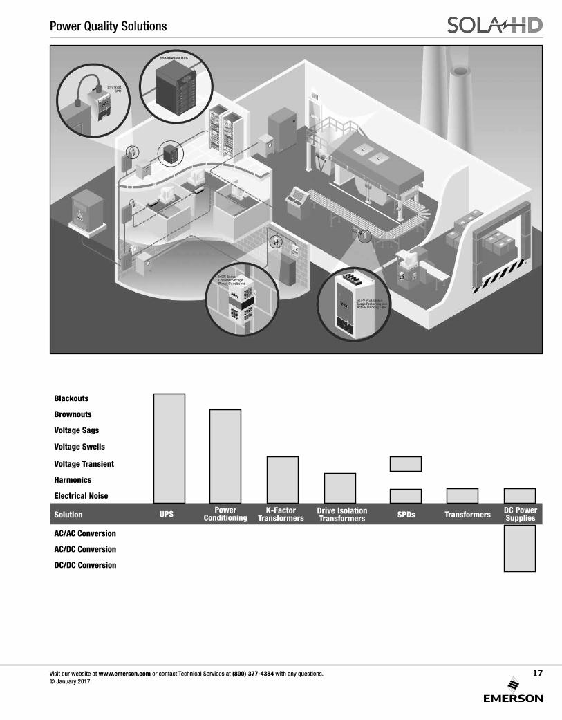
Blackouts
Brownouts
Voltage Sags
Voltage Swells
Voltage Transient
Harmonics
Electrical Noise
Solution
AC/AC Conversion
AC/DC Conversion
DC/DC Conversion
UPS PowerConditioning
Drive IsolationTransformers SPDs DC Power
SuppliesK-Factor
Transformers Transformers
Power Protection and Conditioning
Visit our website at www.emerson.com or contact Technical Services at (800) 377-4384 with any questions. © January 2017
18
Surge Protection and Active Tracking® FilteringIntroduction .........................................................................19
STV 200/400K Three Phase Series ......................................20
STV 100K Single and Three Phase Series ............................23
STV 25K DIN Rail Mount Series ...........................................25
STF Series Three Phase Active Tracking® Filters ..................27
STFV Plus Series Active Tracking® Filters with Surge Protection ..................................................................30
STFE Elite Series Active Tracking® Filters with Surge Protection ..................................................................32
STC Series of Data/Signal Line Surge Protection .................36
Power Conditioning
CVS Hardwired (± 1% Output Regulation) ...........................42
MCR Hardwired (± 3% Output Regulation) ...........................44
Connection Diagrams ..........................................................46
MCR Portable (± 3% Output Regulation) .............................48
Model Comparison/BTU Output Chart .................................50
Operating Characteristics ...................................................51
SOLATRON™ Plus Three Phase Power Conditioners .........54
Power Protection and Conditioning
Visit our website at www.emerson.com or contact Technical Services at (800) 377-4384 with any questions. © January 2017
19
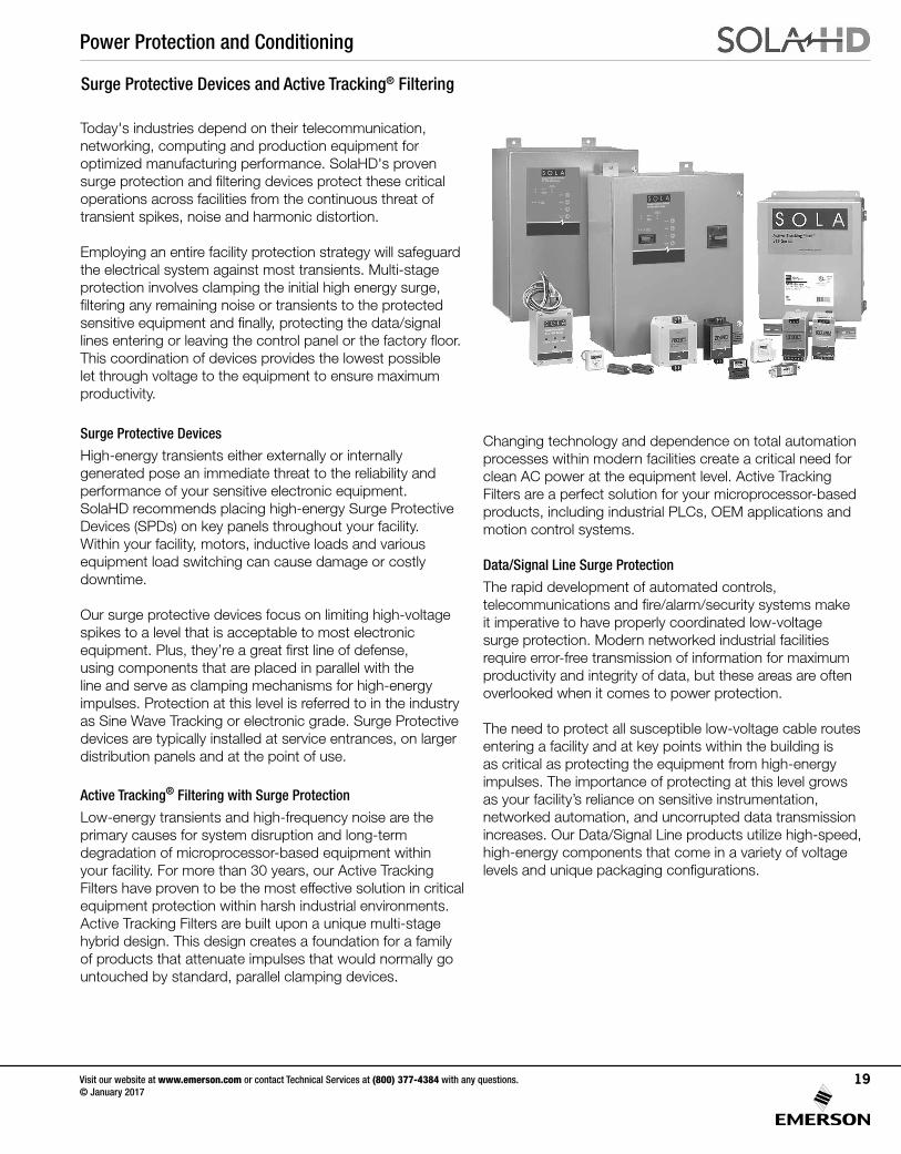
Today's industries depend on their telecommunication, networking, computing and production equipment for optimized manufacturing performance. SolaHD's proven surge protection and filtering devices protect these critical operations across facilities from the continuous threat of transient spikes, noise and harmonic distortion.
Employing an entire facility protection strategy will safeguard the electrical system against most transients. Multi-stageprotection involves clamping the initial high energy surge, filtering any remaining noise or transients to the protectedsensitive equipment and finally, protecting the data/signal lines entering or leaving the control panel or the factory floor.This coordination of devices provides the lowest possible let through voltage to the equipment to ensure maximum productivity.
Surge Protective Devices
High-energy transients either externally or internally generated pose an immediate threat to the reliability and performance of your sensitive electronic equipment. SolaHD recommends placing high-energy Surge Protective Devices (SPDs) on key panels throughout your facility. Within your facility, motors, inductive loads and various equipment load switching can cause damage or costly downtime.
Our surge protective devices focus on limiting high-voltage spikes to a level that is acceptable to most electronic equipment. Plus, they’re a great first line of defense, using components that are placed in parallel with the line and serve as clamping mechanisms for high-energy impulses. Protection at this level is referred to in the industry as Sine Wave Tracking or electronic grade. Surge Protective devices are typically installed at service entrances, on larger distribution panels and at the point of use.
Active Tracking® Filtering with Surge Protection
Low-energy transients and high-frequency noise are the primary causes for system disruption and long-term degradation of microprocessor-based equipment within your facility. For more than 30 years, our Active Tracking Filters have proven to be the most effective solution in critical equipment protection within harsh industrial environments. Active Tracking Filters are built upon a unique multi-stage hybrid design. This design creates a foundation for a family of products that attenuate impulses that would normally go untouched by standard, parallel clamping devices.
Surge Protective Devices and Active Tracking® Filtering
Changing technology and dependence on total automation processes within modern facilities create a critical need for clean AC power at the equipment level. Active Tracking Filters are a perfect solution for your microprocessor-basedproducts, including industrial PLCs, OEM applications and motion control systems.
Data/Signal Line Surge Protection
The rapid development of automated controls, telecommunications and fire/alarm/security systems make it imperative to have properly coordinated low-voltage surge protection. Modern networked industrial facilities require error-free transmission of information for maximum productivity and integrity of data, but these areas are often overlooked when it comes to power protection.
The need to protect all susceptible low-voltage cable routes entering a facility and at key points within the building is as critical as protecting the equipment from high-energy impulses. The importance of protecting at this level growsas your facility’s reliance on sensitive instrumentation, networked automation, and uncorrupted data transmission increases. Our Data/Signal Line products utilize high-speed, high-energy components that come in a variety of voltagelevels and unique packaging configurations.
Power Protection and Conditioning
Visit our website at www.emerson.com or contact Technical Services at (800) 377-4384 with any questions. © January 2017
20
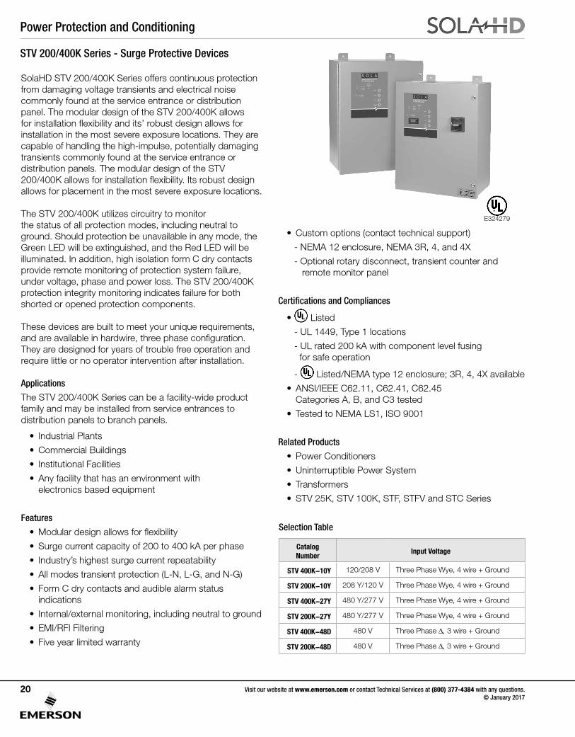
STV 200/400K Series - Surge Protective Devices
SolaHD STV 200/400K Series offers continuous protection from damaging voltage transients and electrical noise commonly found at the service entrance or distribution panel. The modular design of the STV 200/400K allows for installation flexibility and its’ robust design allows for installation in the most severe exposure locations. They are capable of handling the high-impulse, potentially damaging transients commonly found at the service entrance or distribution panels. The modular design of the STV 200/400K allows for installation flexibility. Its robust design allows for placement in the most severe exposure locations.
The STV 200/400K utilizes circuitry to monitor the status of all protection modes, including neutral to ground. Should protection be unavailable in any mode, the Green LED will be extinguished, and the Red LED will be illuminated. In addition, high isolation form C dry contacts provide remote monitoring of protection system failure, under voltage, phase and power loss. The STV 200/400K protection integrity monitoring indicates failure for both shorted or opened protection components.
These devices are built to meet your unique requirements, and are available in hardwire, three phase configuration. They are designed for years of trouble free operation and require little or no operator intervention after installation.
Applications
The STV 200/400K Series can be a facility-wide product family and may be installed from service entrances to distribution panels to branch panels.
• Industrial Plants
• Commercial Buildings
• Institutional Facilities
• Any facility that has an environment with electronics based equipment
Features
• Modular design allows for flexibility
• Surge current capacity of 200 to 400 kA per phase
• Industry’s highest surge current repeatability
• All modes transient protection (L-N, L-G, and N-G)
• Form C dry contacts and audible alarm status indications
• Internal/external monitoring, including neutral to ground
• EMI/RFI Filtering
• Five year limited warranty
• Custom options (contact technical support)
- NEMA 12 enclosure, NEMA 3R, 4, and 4X
- Optional rotary disconnect, transient counter and remote monitor panel
Certifications and Compliances
• Listed
- UL 1449, Type 1 locations
- UL rated 200 kA with component level fusing for safe operation
- Listed/NEMA type 12 enclosure; 3R, 4, 4X available
• ANSI/IEEE C62.11, C62.41, C62.45 Categories A, B, and C3 tested
• Tested to NEMA LS1, ISO 9001
Related Products
• Power Conditioners
• Uninterruptible Power System
• Transformers
• STV 25K, STV 100K, STF, STFV and STC Series
Selection Table
Catalog Number
Input Voltage
STV 400K-10Y 120/208 V Three Phase Wye, 4 wire + Ground
STV 200K-10Y 208 Y/120 V Three Phase Wye, 4 wire + Ground
STV 400K-27Y 480 Y/277 V Three Phase Wye, 4 wire + Ground
STV 200K-27Y 480 Y/277 V Three Phase Wye, 4 wire + Ground
STV 400K-48D 480 V Three Phase ∆, 3 wire + Ground
STV 200K-48D 480 V Three Phase ∆, 3 wire + Ground
E324279
Power Protection and Conditioning
Visit our website at www.emerson.com or contact Technical Services at (800) 377-4384 with any questions. © January 2017
21
STV 200/400K Specifications
ParametersCatalog Number
STV200K-10Y STV200K-27Y STV200K-48D STV400K-10Y STV400K-27Y STV400K-48D
Input Voltage
208 Y/120 V 480 Y/277 V 480 V 208 Y/120 V 480 Y/277 V 480 V
3Ph Wye,4 W + G
3Ph Wye,4 W + G
3Ph Delta,3 W + G
3Ph Wye,4 W + G
3Ph Wye,4 W + G
3Ph Delta, 3 W + G
Maximum ContinuousOperating Voltage (MCOV)
125% of the nominal level for 120 V; 115% for all other voltages
Line Frequency 47–63 Hz
Response Time < 0.5 ns
Enclosure Metal, UL Listed /NEMA type 12 (3R, 4, 4X also available)
Mounting Type Wall Mounted (mounting hardware ¼ in.)
Connection Internally connected
Status Indication Red and green LED status indicators, audible alarm, summary alarm contacts
Operating Temperature -40°C to +50°C
Operating Humidity 0% to 95% non-condensing
Noise Attenuation 50 dB maximum
Modes of Protection All Modes: L–N, L–L, L–G, N–G *
Short Circuit Current Rating (SCCR)
200 kA
Nominal Discharge Current Rating (In)
20 kA
Warranty 5 year limited warranty
UL 1449, Type 1 Voltage Protection Ratings (VPRs)
Line to Neutral 800 V 1200 V N/A 700 V 1200 V N/A
Line to Line 1200 V 2000 V 2000 V 1200 V 1800 V 2000 V
Line to Ground 900 V 1200 V 1800 V 800 V 1200 V 1800 V
Neutral to Ground 700 V 1000 V N/A 700 V 1000 V N/A
Peak Surge Current Capability
Per Phase 200 kA 200 kA 200 kA 400 kA 400 kA 400 kA
Line to Neutral 100 kA 100 kA N/A 200 kA 200 kA N/A
Line to Line 100 kA 100 kA 100 kA 200 kA 200 kA 200 kA
Line to Ground 100 kA 100 kA 100 kA 200 kA 200 kA 200 kA
Neutral to Ground 100 kA 100 kA N/A 200 kA 200 kA N/A
* Delta Model does not offer N–G mode of protection
Power Protection and Conditioning
Visit our website at www.emerson.com or contact Technical Services at (800) 377-4384 with any questions. © January 2017
22
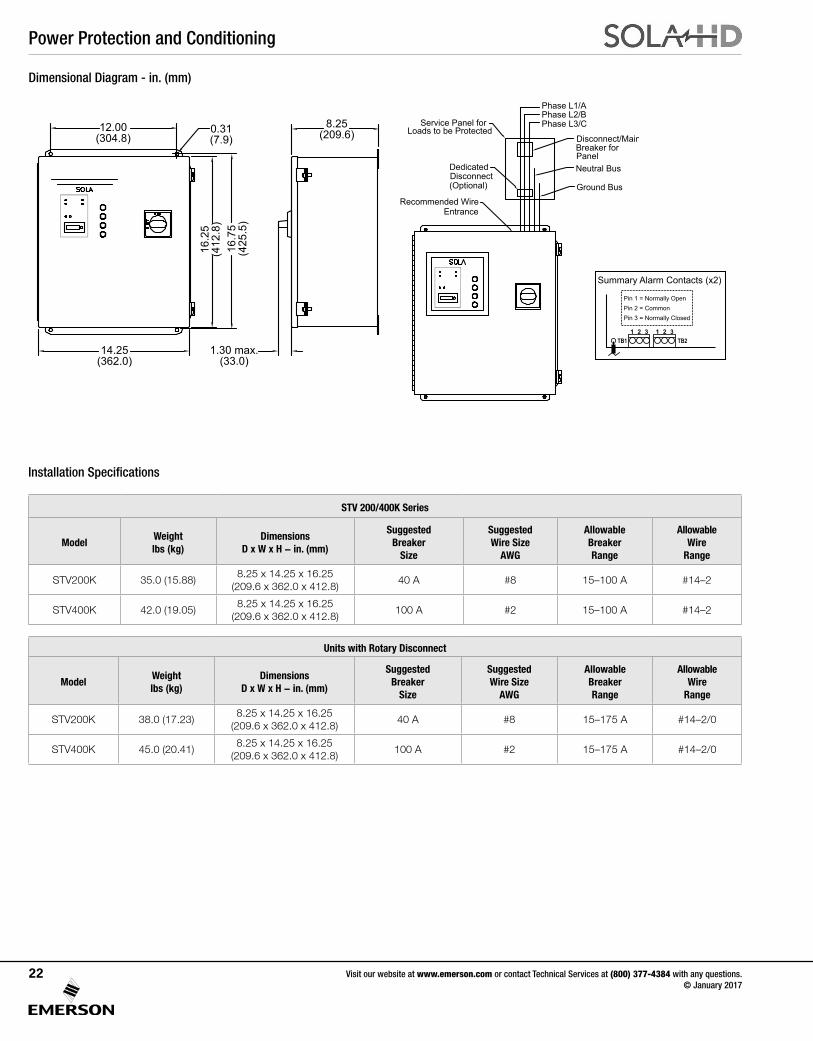
Dimensional Diagram - in. (mm)
Installation Specifications
8.25(209.6)
1.30 max.(33.0)
12.00(304.8)
14.25(362.0)
16.2
5(4
12.8
)16
.75
(425
.5)
0.31(7.9)
Phase L1/APhase L2/BPhase L3/CService Panel for
Loads to be ProtectedDisconnect/Main
Neutral Bus
Ground Bus
PanelBreaker for
Recommended WireEntrance
Dedicated
(Optional)Disconnect
Summary Alarm Contacts (x2)
Pin 1 = Normally OpenPin 2 = CommonPin 3 = Normally Closed
TB1 TB21 2 3 1 2 3
STV 200/400K Series
ModelWeightlbs (kg)
DimensionsD x W x H - in. (mm)
SuggestedBreaker
Size
SuggestedWire Size
AWG
AllowableBreakerRange
AllowableWire
Range
STV200K 35.0 (15.88)8.25 x 14.25 x 16.25
(209.6 x 362.0 x 412.8)40 A #8 15–100 A #14–2
STV400K 42.0 (19.05)8.25 x 14.25 x 16.25
(209.6 x 362.0 x 412.8)100 A #2 15–100 A #14–2
Units with Rotary Disconnect
ModelWeightlbs (kg)
DimensionsD x W x H - in. (mm)
SuggestedBreaker
Size
SuggestedWire Size
AWG
AllowableBreakerRange
AllowableWire
Range
STV200K 38.0 (17.23)8.25 x 14.25 x 16.25
(209.6 x 362.0 x 412.8)40 A #8 15–175 A #14–2/0
STV400K 45.0 (20.41)8.25 x 14.25 x 16.25
(209.6 x 362.0 x 412.8)100 A #2 15–175 A #14–2/0
Power Protection and Conditioning
Visit our website at www.emerson.com or contact Technical Services at (800) 377-4384 with any questions. © January 2017
23
The STV 100K Series - Surge Protective Devices
SolaHD’s STV 100K hardwired surge protective devices are designed for installation at the service entrance, branch panel or a dedicated sensitive electronic load. These units feature all mode protection, LED and audible alarm status indication, sinewave tracking and form “C” dry contacts. The STV 100K series also contains the highest levels of safety built into the product including thermal fusing and a short circuit current protection rating of 100kA.
Applications
• Distribution Panels (<1200 A)
• Branch, Lighting and Control Panels
• Factory Automation Installations
• Dedicated Industrial Equipment
Features
• 100,000 amp peak current rating provides all mode protection against severe transients
• Low clamping levels for more effective protection
• LED status and audible alarms
• Compact, rugged metal
Certifications and Compliances
• Listed
- UL 1449, type 2 locations
- Listed/NEMA type 12 enclosure
- CSA C22.2 No. 8, CSA TI I-IIB, TI A-24
• ABS Type Approved
• RoHS Compliant
Related Products
• Power Conditioners
• UPS
• Drive Isolation and K-Factor Transformers
Selection Table
Dimensional Diagram - in. (mm)
Catalog Number
Input Voltage
STV 100K-10S 120/240 V Single Phase 3 wire + Ground
STV 100K-10Y 208 Y/120 V Three Phase Wye 4 wire + Ground
STV 100K-10N 120 V Single Phase 2 wire + Ground
STV 100K-24L 240 V Single Phase 2 wire + Ground
STV 100K-23Y 400 Y/230 V Three Phase Wye 4 wire + Ground
STV 100K-27Y 480 Y/277 V Three Phase Wye 4 wire + Ground
STV 100K-24D 240 V Three Phase ∆ 3 wire + Ground
STV 100K-48D 480 V Three Phase ∆ 3 wire + Ground
STV 100K-10D4 240/120 CT Three Phase ∆ 4 wire + Ground
STV 100K-24D4 480/240 CT Three Phase ∆ 4 wire + Ground
Figure 1: Mechanical Dimensions Unit shown is a three-phase wye
6.00(152.4)
6.75(171.5)
0.38(9.7)
4.00(101.6) 0.10
(2.5)
3.20(81.3)
0.50(12.7)
2.00(50.8)
E324279ASCO
Power Protection and Conditioning
Visit our website at www.emerson.com or contact Technical Services at (800) 377-4384 with any questions. © January 2017
24
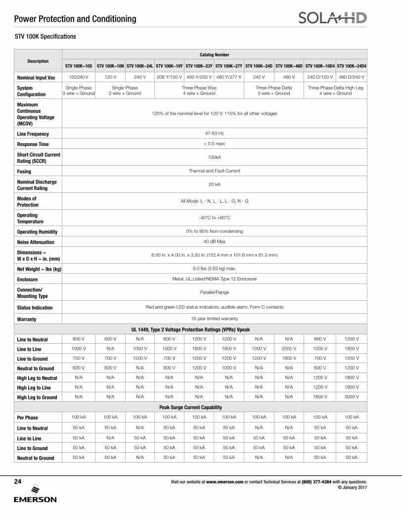
STV 100K Specifications
Short Circuit Current Rating (SCCR)
100kA
Fusing Thermal and Fault Current
Nominal Discharge Current Rating
20 kA
Modes of Protection
All Mode: L - N, L - L, L - G, N - G
Operating Temperature
-40°C to +60°C
Operating Humidity 0% to 95% Non-condensing
Noise Attenuation 40 dB Max
Dimensions - W x D x H - in. (mm)
6.00 in. x 4.00 in. x 3.20 in. (152.4 mm x 101.6 mm x 81.3 mm)
Net Weight - lbs (kg) 8.0 lbs (3.63 kg) max.
Enclosure Metal, UL Listed/NEMA Type 12 Enclosure
Connection/Mounting Type
Parallel/Flange
Status Indication Red and green LED status indicators, audible alarm, Form C contacts
Warranty 10 year limited warranty
UL 1449, Type 2 Voltage Protection Ratings (VPRs) Vpeak
Line to Neutral 600 V 600 V N/A 600 V 1200 V 1200 V N/A N/A 600 V 1200 V
Line to Line 1000 V N/A 1000 V 1000 V 1800 V 1800 V 1000 V 2000 V 1000 V 1800 V
Line to Ground 700 V 700 V 1200 V 700 V 1200 V 1200 V 1200 V 1800 V 700 V 1200 V
Neutral to Ground 600 V 600 V N/A 600 V 1200 V 1000 V N/A N/A 600 V 1200 V
High Leg to Neutral N/A N/A N/A N/A N/A N/A N/A N/A 1200 V 1800 V
High Leg to Line N/A N/A N/A N/A N/A N/A N/A N/A 1200 V 1800 V
High Leg to Ground N/A N/A N/A N/A N/A N/A N/A N/A 1800 V 3000 V
Peak Surge Current Capability
Per Phase 100 kA 100 kA 100 kA 100 kA 100 kA 100 kA 100 kA 100 kA 100 kA 100 kA
Line to Neutral 50 kA 50 kA N/A 50 kA 50 kA 50 kA N/A N/A 50 kA 50 kA
Line to Line 50 kA N/A 50 kA 50 kA 50 kA 50 kA 50 kA 50 kA 50 kA 50 kA
Line to Ground 50 kA 50 kA 50 kA 50 kA 50 kA 50 kA 50 kA 50 kA 50 kA 50 kA
Neutral to Ground 50 kA 50 kA N/A 50 kA 50 kA 50 kA N/A N/A 50 kA 50 kA
DescriptionCatalog Number
STV 100K-10S STV 100K-10N STV 100K-24L STV 100K-10Y STV 100K-23Y STV 100K-27Y STV 100K-24D STV 100K-48D STV 100K-10D4 STV 100K-24D4
Nominal Input Vac 120/240 V 120 V 240 V 208 Y/120 V 400 Y/230 V 480 Y/277 V 240 V 480 V 240 D/120 V 480 D/240 V
System Configuration
Single Phase 3 wire + Ground
Single Phase 2 wire + Ground
Three Phase Wye 4 wire + Ground
Three Phase Delta 3 wire + Ground
Three Phase Delta High Leg 4 wire + Ground
Maximum Continuous Operating Voltage (MCOV)
125% of the nominal level for 120 V; 115% for all other voltages
Line Frequency 47-63 Hz
Response Time < 0.5 nsec
Power Protection and Conditioning
Visit our website at www.emerson.com or contact Technical Services at (800) 377-4384 with any questions. © January 2017
25
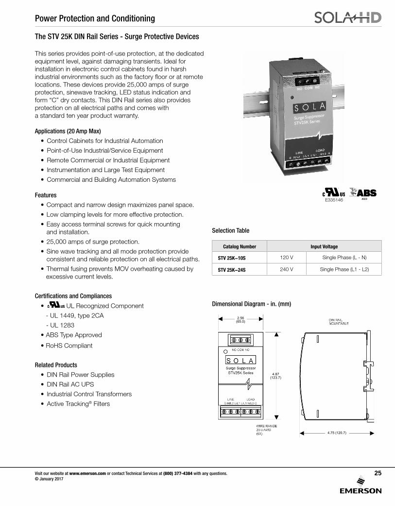
Catalog Number Input Voltage
STV 25K-10S 120 V Single Phase (L - N)
STV 25K-24S 240 V Single Phase (L1 - L2)
Selection Table
The STV 25K DIN Rail Series - Surge Protective Devices
Dimensional Diagram - in. (mm)
2.56(65.0)
4.87(123.7)
4.75 (120.7)
E335146
This series provides point-of-use protection, at the dedicated equipment level, against damaging transients. Ideal for installation in electronic control cabinets found in harsh industrial environments such as the factory floor or at remote locations. These devices provide 25,000 amps of surge protection, sinewave tracking, LED status indication and form “C” dry contacts. This DIN Rail series also provides protection on all electrical paths and comes with a standard ten year product warranty.
Applications (20 Amp Max)
• Control Cabinets for Industrial Automation
• Point-of-Use Industrial/Service Equipment
• Remote Commercial or Industrial Equipment
• Instrumentation and Large Test Equipment
• Commercial and Building Automation Systems
Features
• Compact and narrow design maximizes panel space.
• Low clamping levels for more effective protection.
• Easy access terminal screws for quick mounting and installation.
• 25,000 amps of surge protection.
• Sine wave tracking and all mode protection provide consistent and reliable protection on all electrical paths.
• Thermal fusing prevents MOV overheating caused by excessive current levels.
Certifications and Compliances
• UL Recognized Component
- UL 1449, type 2CA
- UL 1283
• ABS Type Approved
• RoHS Compliant
Related Products
• DIN Rail Power Supplies
• DIN Rail AC UPS
• Industrial Control Transformers
• Active Tracking® Filters
ASCO
Power Protection and Conditioning
Visit our website at www.emerson.com or contact Technical Services at (800) 377-4384 with any questions. © January 2017
26
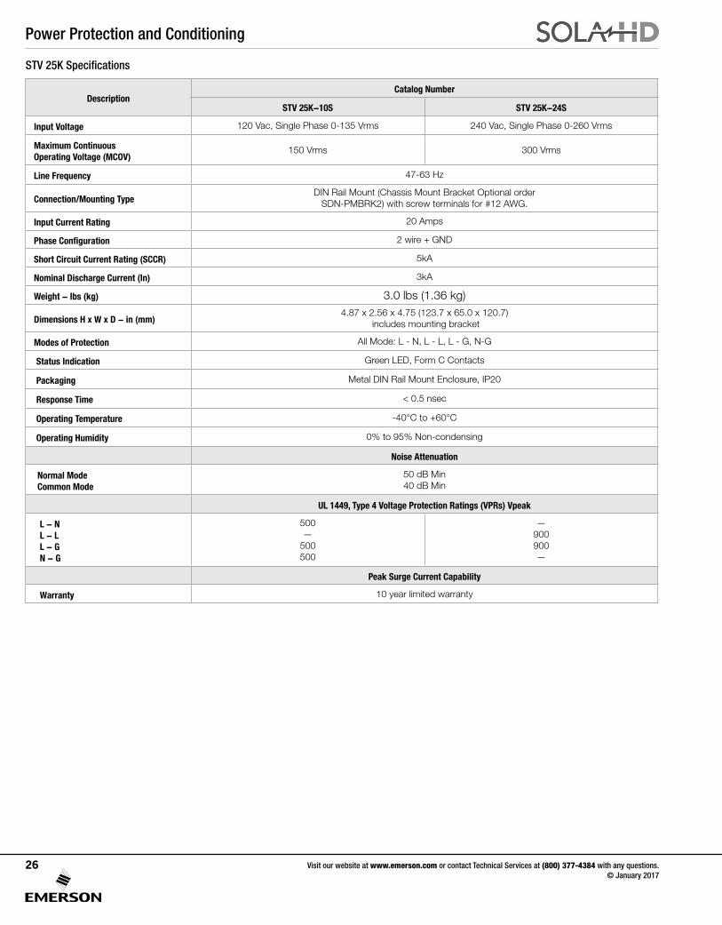
STV 25K Specifications
DescriptionCatalog Number
STV 25K-10S STV 25K-24S
Input Voltage 120 Vac, Single Phase 0-135 Vrms 240 Vac, Single Phase 0-260 Vrms
Maximum Continuous Operating Voltage (MCOV)
150 Vrms 300 Vrms
Line Frequency 47-63 Hz
Connection/Mounting TypeDIN Rail Mount (Chassis Mount Bracket Optional order
SDN-PMBRK2) with screw terminals for #12 AWG.
Input Current Rating 20 Amps
Phase Configuration 2 wire + GND
Short Circuit Current Rating (SCCR) 5kA
Nominal Discharge Current (In) 3kA
Weight - lbs (kg) 3.0 lbs (1.36 kg)
Dimensions H x W x D - in (mm)4.87 x 2.56 x 4.75 (123.7 x 65.0 x 120.7)
includes mounting bracket
Modes of Protection All Mode: L - N, L - L, L - G, N-G
Status Indication Green LED, Form C Contacts
Packaging Metal DIN Rail Mount Enclosure, IP20
Response Time < 0.5 nsec
Operating Temperature -40°C to +60°C
Operating Humidity 0% to 95% Non-condensing
Noise Attenuation
Normal ModeCommon Mode
50 dB Min40 dB Min
UL 1449, Type 4 Voltage Protection Ratings (VPRs) Vpeak
L - NL - LL - GN - G
500—
500500
—900900—
Peak Surge Current Capability
Warranty 10 year limited warranty
Power Protection and Conditioning
Visit our website at www.emerson.com or contact Technical Services at (800) 377-4384 with any questions. © January 2017
27
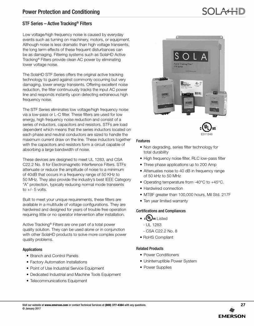
STF Series – Active Tracking® Filters
Low voltage/high frequency noise is caused by everyday events such as turning on machinery, motors, or equipment. Although noise is less dramatic than high voltage transients, the long term effects of these frequent disturbances can be as damaging. Filtering systems such as SolaHD Active Tracking® Filters provide clean AC power by eliminating lower voltage noise.
The SolaHD STF Series offers the original active tracking technology to guard against commonly occurring but very damaging, lower energy transients. Offering excellent noise reduction, the filter continuously tracks the input AC power line and responds instantly upon detecting extraneous high frequency noise.
The STF Series eliminates low voltage/high frequency noise via a low-pass or L-C filter. These filters are used for low energy, high frequency noise reduction and consist of a series of inductors, capacitors and resistors. STFs are load dependent which means that the series inductors located on each phase and neutral conductors are sized to handle the maximum current draw on the line. These inductors together with the capacitors and resistors form a circuit capable of absorbing a large bandwidth of noise.
These devices are designed to meet UL 1283, and CSA C22.2 No. 8 for Electromagnetic Interference Filters. STFs attenuate or reduce the amplitude of noise to a minimum of 40dB that occurs in a frequency range of 50 KHz to 50 MHz. They also provide the industry’s best IEEE Category “A” protection, typically reducing normal mode transients to +/- 5 volts.
Built to meet your unique requirements, these filters are available in a multitude of voltage configurations. They are hardwired and designed for years of trouble free operation requiring little or no operator intervention after installation.
Active Tracking® Filters are one part of a total power quality solution. They can be used alone or in conjunction with other SolaHD products to solve more complex power quality problems.
Applications
• Branch and Control Panels
• Factory Automation Installations
• Point of Use Industrial Service Equipment
• Dedicated Industrial and Machine Tools Equipment
• Telecommunications Equipment
Features
• Non degrading, series filter technology for total durability
• High frequency noise filter, RLC low-pass filter
• Three phase applications up to 200 Amp
• Attenuates noise to 40 dB in frequency range of 50 kHz to 50 MHz
• Operating temperature from -40°C to +45°C.
• Hardwired connection
• MTBF greater than 100,000 hours, Mil Std. 217F
• Ten year limited warranty
Certifications and Compliances
• Listed
- UL 1283
- CSA C22.2 No. 8
• RoHS Compliant
Related Products
• Power Conditioners
• Uninterruptible Power System
• Power Supplies
E311348
Power Protection and Conditioning
Visit our website at www.emerson.com or contact Technical Services at (800) 377-4384 with any questions. © January 2017
28
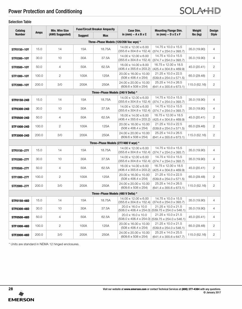
Catalog Number
AmpsMin. Wire Size
(AWG Suggested)
Fuse/Circuit Breaker Ampacity Case Dim. in (mm) - A x B x C
Mounting Flange Dim. in (mm) - D x E x F
Weightlbs (kg)
DesignStyleSuggest Max
Three-Phase Models (120/208 Vac wye) *
STF0150-10Y 15.0 14 15A 18.75A14.00 x 12.00 x 6.00
(355.6 x 304.8 x 152.4)14.75 x 10.0 x 15.5
(374.7 x 254.0 x 393.7)35.0 (19.90) 4
STF0300-10Y 30.0 10 30A 37.5A14.00 x 12.00 x 6.00
(355.6 x 304.8 x 152.4)14.75 x 10.0 x 15.5
(374.7 x 254.0 x 393.7)35.0 (19.90) 4
STF0500-10Y 50.0 4 50A 62.5A16.00 x 14.00 x 8.00
(406.4 x 355.6 x 203.2) 16.75 x 12.00 x 18.5
(425.4 x 304.8 x 469.9)45.0 (20.41) 2
STF1000-10Y 100.0 2 100A 125A20.00 x 16.00 x 10.00
(508 x 406.4 x 254)21.25 x 10.0 x 22.5
(539.8 x 254.0 x 571.5)65.0 (29.48) 2
STF2000-10Y 200.0 3/0 200A 250A24.00 x 20.00 x 10.00
(609.6 x 508 x 254)25.25 x 14.0 x 26.5
(641.4 x 355.6 x 673.1)115.0 (52.16) 2
Three-Phase Models (240 V Delta) *
STF0150-24D 15.0 14 15A 18.75A14.00 x 12.00 x 6.00
(355.6 x 304.8 x 152.4)14.75 x 10.0 x 15.5
(374.7 x 254.0 x 393.7)35.0 (19.90) 4
STF0300-24D 30.0 10 30A 37.5A14.00 x 12.00 x 6.00
(355.6 x 304.8 x 152.4)14.75 x 10.0 x 15.5
(374.7 x 254.0 x 393.7)35.0 (19.90) 4
STF0500-24D 50.0 4 50A 62.5A16.00 x 14.00 x 8.00
(406.4 x 355.6 x 203.2)16.75 x 12.00 x 18.5
(425.4 x 304.8 x 469.9)45.0 (20.41) 2
STF1000-24D 100.0 2 100A 125A20.00 x 16.00 x 10.00
(508 x 406.4 x 254)21.25 x 10.0 x 22.5
(539.8 x 254.0 x 571.5)65.0 (29.48) 2
STF2000-24D 200.0 3/0 200A 250A24.00 x 20.00 x 10.00
(609.6 x 508 x 254)25.25 x 14.0 x 26.5
(641.4 x 355.6 x 673.1)115.0 (52.16) 2
Three-Phase Models (277/480 V wye) *
STF0150-27Y 15.0 14 15A 18.75A14.00 x 12.00 x 6.00
(355.6 x 304.8 x 152.4)14.75 x 10.0 x 15.5
(374.7 x 254.0 x 393.7)35.0 (19.90) 4
STF0300-27Y 30.0 10 30A 37.5A14.00 x 12.00 x 6.00
(355.6 x 304.8 x 152.4)14.75 x 10.0 x 15.5
(374.7 x 254.0 x 393.7)35.0 (19.90) 4
STF0500-27Y 50.0 4 50A 62.5A16.00 x 14.00 x 8.00
(406.4 x 355.6 x 203.2)16.75 x 12.00 x 18.5
(425.4 x 304.8 x 469.9)45.0 (20.41) 2
STF1000-27Y 100.0 2 100A 125A20.00 x 16.00 x 10.00
(508 x 406.4 x 254)21.25 x 10.0 x 22.5
(539.8 x 254.0 x 571.5)65.0 (29.48) 2
STF2000-27Y 200.0 3/0 200A 250A24.00 x 20.00 x 10.00
(609.6 x 508 x 254)25.25 x 14.0 x 26.5
(641.4 x 355.6 x 673.1)115.0 (52.16) 2
Three-Phase Models (480 V Delta) *
STF0150-48D 15.0 14 15A 18.75A 14.00 x 12.00 x 6.00(355.6 x 304.8 x 152.4)
14.75 x 10.0 x 15.5(374.6 x 254.0 x 393.7) 35.0 (19.90) 4
STF0300-48D 30.0 10 30A 37.5A 20.0 x 16.0 x 10.0(508.0 x 406.4 x 254.0)
21.25 x 10.0 x 21.5(539.75 x 254.0 x 546.1) 35.0 (19.90) 4
STF0500-48D 50.0 4 50A 62.5A20.0 x 16.0 x 10.0
(508.0 x 406.4 x 254.0)21.25 x 10.0 x 21.5
(539.75 x 254.0 x 546.1)45.0 (20.41) 4
STF1000-48D 100.0 2 100A 125A20.00 x 16.00 x 10.00
(508 x 406.4 x 254)21.25 x 10.0 x 21.5
(539.8 x 254.0 x 546.1)65.0 (29.48) 2
STF2000-48D 200.0 3/0 200A 250A24.00 x 20.00 x 10.00
(609.6 x 508 x 254)25.25 x 14.0 x 25.5
(641.4 x 355.6 x 647.7)115.0 (52.16) 2
Selection Table
* Units are standard in NEMA 12 hinged enclosures.
Power Protection and Conditioning
Visit our website at www.emerson.com or contact Technical Services at (800) 377-4384 with any questions. © January 2017
29
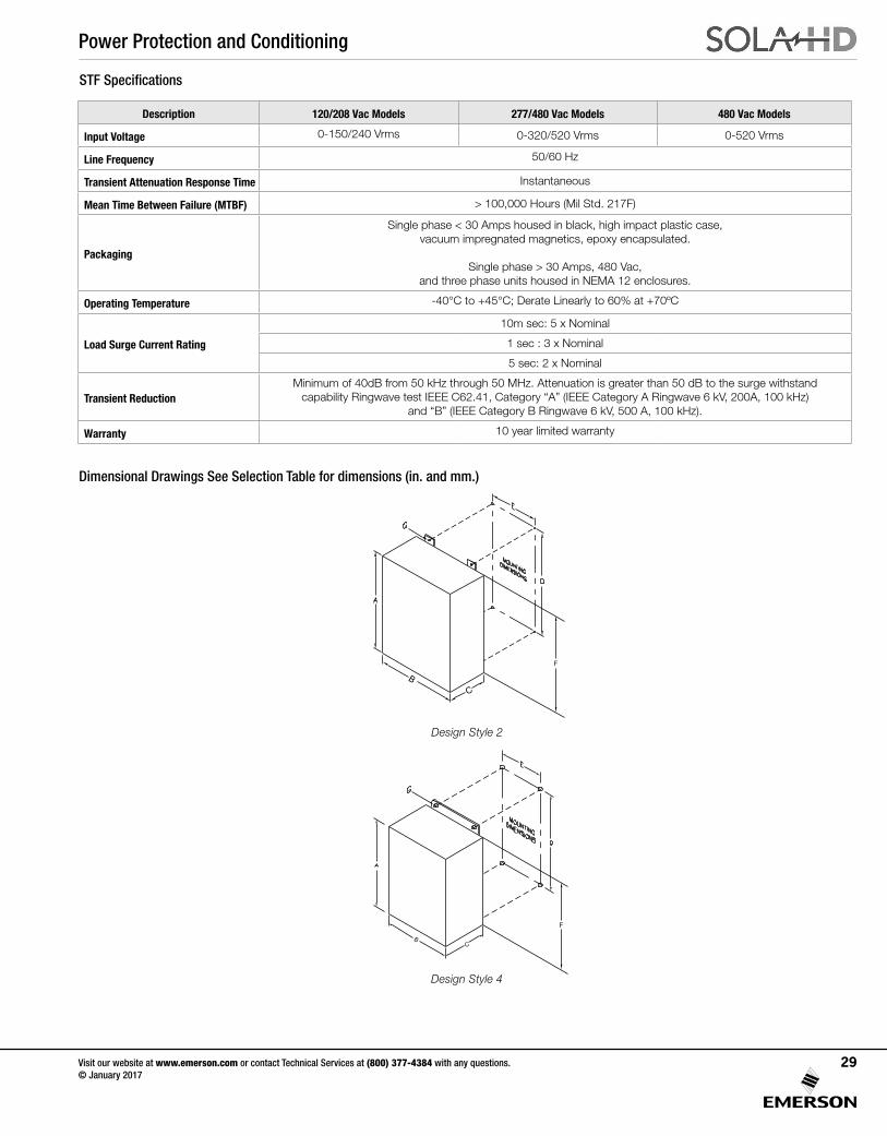
Dimensional Drawings See Selection Table for dimensions (in. and mm.)
F
Design Style 2
F
Design Style 4
STF Specifications
Description 120/208 Vac Models 277/480 Vac Models 480 Vac Models
Input Voltage 0-150/240 Vrms 0-320/520 Vrms 0-520 Vrms
Line Frequency 50/60 Hz
Transient Attenuation Response Time Instantaneous
Mean Time Between Failure (MTBF) > 100,000 Hours (Mil Std. 217F)
Packaging
Single phase < 30 Amps housed in black, high impact plastic case, vacuum impregnated magnetics, epoxy encapsulated.
Single phase > 30 Amps, 480 Vac, and three phase units housed in NEMA 12 enclosures.
Operating Temperature -40°C to +45°C; Derate Linearly to 60% at +70ºC
Load Surge Current Rating
10m sec: 5 x Nominal
1 sec : 3 x Nominal
5 sec: 2 x Nominal
Transient ReductionMinimum of 40dB from 50 kHz through 50 MHz. Attenuation is greater than 50 dB to the surge withstand
capability Ringwave test IEEE C62.41, Category “A” (IEEE Category A Ringwave 6 kV, 200A, 100 kHz) and “B” (IEEE Category B Ringwave 6 kV, 500 A, 100 kHz).
Warranty 10 year limited warranty
Power Protection and Conditioning
Visit our website at www.emerson.com or contact Technical Services at (800) 377-4384 with any questions. © January 2017
30
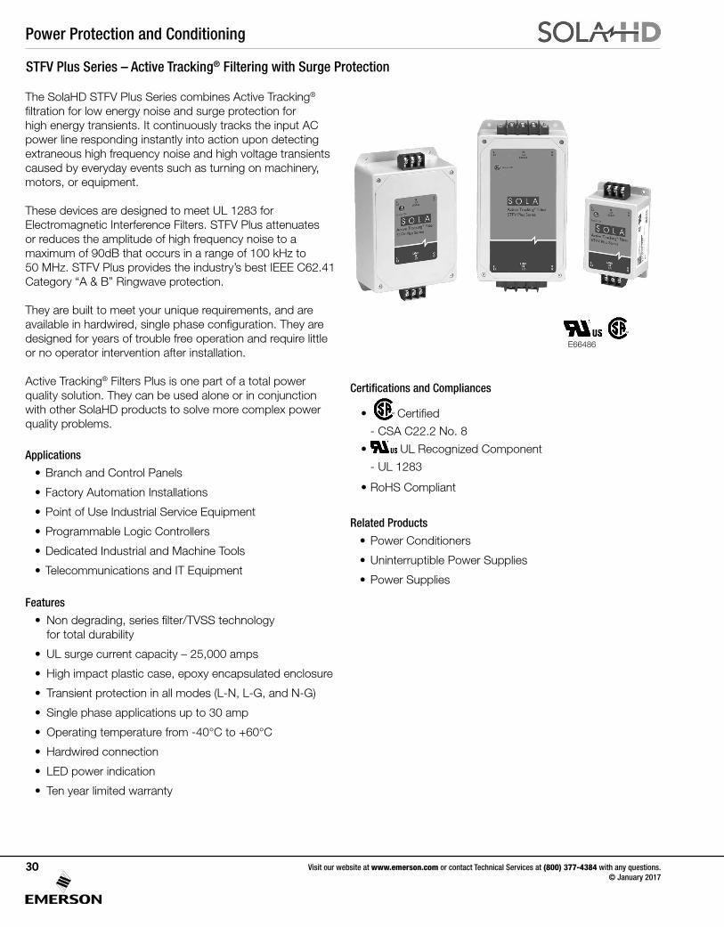
STFV Plus Series – Active Tracking® Filtering with Surge Protection
The SolaHD STFV Plus Series combines Active Tracking® filtration for low energy noise and surge protection for high energy transients. It continuously tracks the input AC power line responding instantly into action upon detecting extraneous high frequency noise and high voltage transients caused by everyday events such as turning on machinery, motors, or equipment.
These devices are designed to meet UL 1283 for Electromagnetic Interference Filters. STFV Plus attenuates or reduces the amplitude of high frequency noise to a maximum of 90dB that occurs in a range of 100 kHz to 50 MHz. STFV Plus provides the industry’s best IEEE C62.41 Category “A & B” Ringwave protection.
They are built to meet your unique requirements, and are available in hardwired, single phase configuration. They are designed for years of trouble free operation and require little or no operator intervention after installation.
Active Tracking® Filters Plus is one part of a total power quality solution. They can be used alone or in conjunction with other SolaHD products to solve more complex power quality problems.
Applications
• Branch and Control Panels
• Factory Automation Installations
• Point of Use Industrial Service Equipment
• Programmable Logic Controllers
• Dedicated Industrial and Machine Tools
• Telecommunications and IT Equipment
Features
• Non degrading, series filter/TVSS technology for total durability
• UL surge current capacity – 25,000 amps
• High impact plastic case, epoxy encapsulated enclosure
• Transient protection in all modes (L-N, L-G, and N-G)
• Single phase applications up to 30 amp
• Operating temperature from -40°C to +60°C
• Hardwired connection
• LED power indication
• Ten year limited warranty
Certifications and Compliances
• Certified
- CSA C22.2 No. 8
• UL Recognized Component
- UL 1283
• RoHS Compliant
Related Products
• Power Conditioners
• Uninterruptible Power Supplies
• Power Supplies
E66486
Power Protection and Conditioning
Visit our website at www.emerson.com or contact Technical Services at (800) 377-4384 with any questions. © January 2017
31
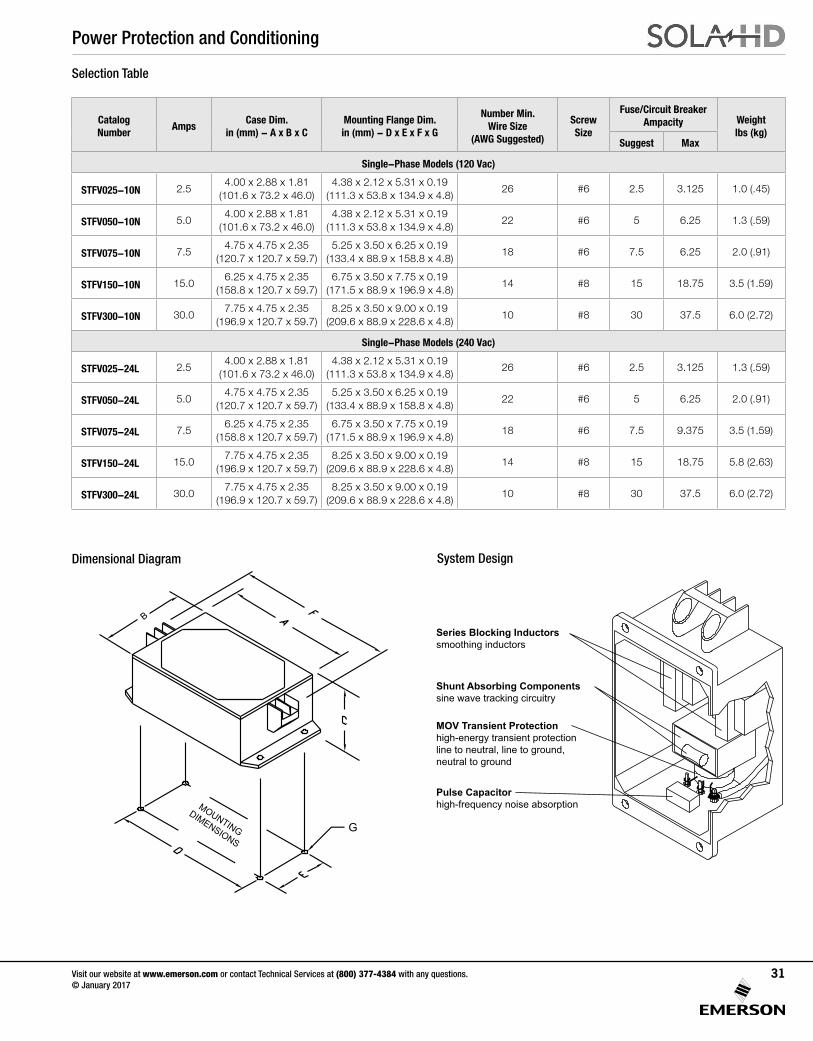
Catalog Number
AmpsCase Dim.
in (mm) - A x B x CMounting Flange Dim. in (mm) - D x E x F x G
Number Min. Wire Size
(AWG Suggested)
Screw Size
Fuse/Circuit Breaker Ampacity Weight
lbs (kg)Suggest Max
Single-Phase Models (120 Vac)
STFV025-10N 2.54.00 x 2.88 x 1.81
(101.6 x 73.2 x 46.0)4.38 x 2.12 x 5.31 x 0.19
(111.3 x 53.8 x 134.9 x 4.8)26 #6 2.5 3.125 1.0 (.45)
STFV050-10N 5.04.00 x 2.88 x 1.81
(101.6 x 73.2 x 46.0)4.38 x 2.12 x 5.31 x 0.19
(111.3 x 53.8 x 134.9 x 4.8)22 #6 5 6.25 1.3 (.59)
STFV075-10N 7.54.75 x 4.75 x 2.35
(120.7 x 120.7 x 59.7) 5.25 x 3.50 x 6.25 x 0.19
(133.4 x 88.9 x 158.8 x 4.8)18 #6 7.5 6.25 2.0 (.91)
STFV150-10N 15.06.25 x 4.75 x 2.35
(158.8 x 120.7 x 59.7)6.75 x 3.50 x 7.75 x 0.19
(171.5 x 88.9 x 196.9 x 4.8)14 #8 15 18.75 3.5 (1.59)
STFV300-10N 30.07.75 x 4.75 x 2.35
(196.9 x 120.7 x 59.7)8.25 x 3.50 x 9.00 x 0.19
(209.6 x 88.9 x 228.6 x 4.8)10 #8 30 37.5 6.0 (2.72)
Single-Phase Models (240 Vac)
STFV025-24L 2.54.00 x 2.88 x 1.81
(101.6 x 73.2 x 46.0)4.38 x 2.12 x 5.31 x 0.19
(111.3 x 53.8 x 134.9 x 4.8)26 #6 2.5 3.125 1.3 (.59)
STFV050-24L 5.04.75 x 4.75 x 2.35
(120.7 x 120.7 x 59.7) 5.25 x 3.50 x 6.25 x 0.19
(133.4 x 88.9 x 158.8 x 4.8)22 #6 5 6.25 2.0 (.91)
STFV075-24L 7.56.25 x 4.75 x 2.35
(158.8 x 120.7 x 59.7)6.75 x 3.50 x 7.75 x 0.19
(171.5 x 88.9 x 196.9 x 4.8)18 #6 7.5 9.375 3.5 (1.59)
STFV150-24L 15.07.75 x 4.75 x 2.35
(196.9 x 120.7 x 59.7)8.25 x 3.50 x 9.00 x 0.19
(209.6 x 88.9 x 228.6 x 4.8)14 #8 15 18.75 5.8 (2.63)
STFV300-24L 30.07.75 x 4.75 x 2.35
(196.9 x 120.7 x 59.7)8.25 x 3.50 x 9.00 x 0.19
(209.6 x 88.9 x 228.6 x 4.8)10 #8 30 37.5 6.0 (2.72)
Selection Table
MOUNTING
DIMENSIONS
Dimensional Diagram System Design
Series Blocking Inductorssmoothing inductors
Shunt Absorbing Componentssine wave tracking circuitry
MOV Transient Protectionhigh-energy transient protectionline to neutral, line to ground,neutral to ground
Pulse Capacitorhigh-frequency noise absorption
Power Protection and Conditioning
Visit our website at www.emerson.com or contact Technical Services at (800) 377-4384 with any questions. © January 2017
32
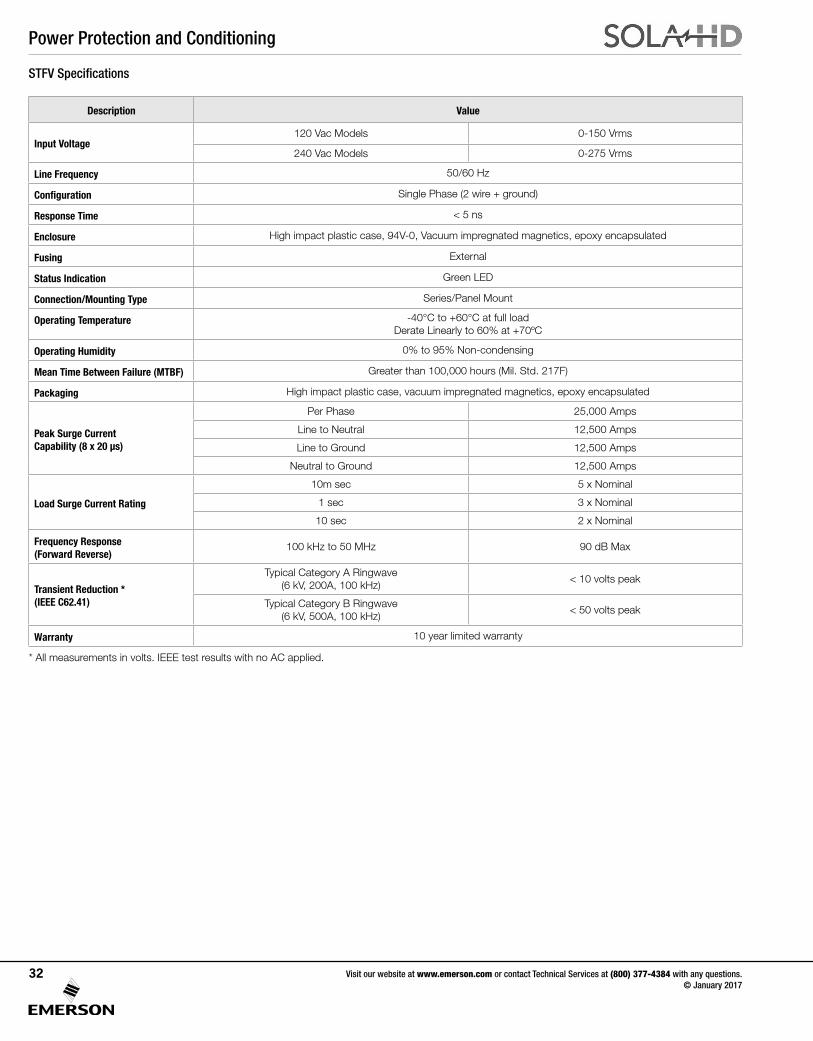
Description Value
Input Voltage120 Vac Models 0-150 Vrms
240 Vac Models 0-275 Vrms
Line Frequency 50/60 Hz
Configuration Single Phase (2 wire + ground)
Response Time < 5 ns
Enclosure High impact plastic case, 94V-0, Vacuum impregnated magnetics, epoxy encapsulated
Fusing External
Status Indication Green LED
Connection/Mounting Type Series/Panel Mount
Operating Temperature -40°C to +60°C at full loadDerate Linearly to 60% at +70ºC
Operating Humidity 0% to 95% Non-condensing
Mean Time Between Failure (MTBF) Greater than 100,000 hours (Mil. Std. 217F)
Packaging High impact plastic case, vacuum impregnated magnetics, epoxy encapsulated
Peak Surge CurrentCapability (8 x 20 µs)
Per Phase 25,000 Amps
Line to Neutral 12,500 Amps
Line to Ground 12,500 Amps
Neutral to Ground 12,500 Amps
Load Surge Current Rating
10m sec 5 x Nominal
1 sec 3 x Nominal
10 sec 2 x Nominal
Frequency Response (Forward Reverse)
100 kHz to 50 MHz 90 dB Max
Transient Reduction *(IEEE C62.41)
Typical Category A Ringwave(6 kV, 200A, 100 kHz)
< 10 volts peak
Typical Category B Ringwave(6 kV, 500A, 100 kHz)
< 50 volts peak
Warranty 10 year limited warranty
STFV Specifications
* All measurements in volts. IEEE test results with no AC applied.
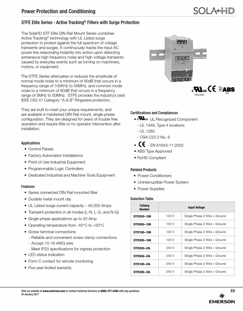
Power Protection and Conditioning
Visit our website at www.emerson.com or contact Technical Services at (800) 377-4384 with any questions. © January 2017
33
STFE Elite Series - Active Tracking® Filters with Surge Protection
The SolaHD STF Elite DIN Rail Mount Series combines Active Tracking® technology with UL Listed surge protection to protect against the full spectrum of voltage transients and surges. It continuously tracks the input AC power line responding instantly into action upon detecting extraneous high frequency noise and high voltage transients caused by everyday events such as turning on machinery, motors, or equipment.
The STFE Series attenuates or reduces the amplitude of normal mode noise to a minimum of 90dB that occurs in a frequency range of 100KHz to 50MHz, and common mode noise to a minimum of 60dB that occurs in a frequency range of 5MHz to 50MHz. STFE provides the industry’s best IEEE C62.41 Category “A & B” Ringwave protection.
They are built to meet your unique requirements, and are available in hardwired DIN Rail mount, single phase configuration. They are designed for years of trouble free operation and require little or no operator intervention after installation.
Applications
• Control Panels
• Factory Automation Installations
• Point of Use Industrial Equipment
• Programmable Logic Controllers
• Dedicated Industrial and Machine Tools Equipment
Features
• Series connected DIN Rail mounted filter
• Durable metal mount clip
• UL Listed surge current capacity – 45,000 Amps
• Transient protection in all modes (L-N, L-G, and N-G)
• Single phase applications up to 20 Amp
• Operating temperature from -40°C to +50°C
• Screw terminal connections- Reliable and convenient screw clamp connections- Accept 10-16 AWG wire- Meet IP20 specifications for ingress protection
• LED status indication
• Form C contact for remote monitoring
• Five year limited warranty
Selection Table
Catalog Number
Input Voltage
STFE030-10N 120 V Single Phase 2 Wire + Ground
STFE050-10N 120 V Single Phase 2 Wire + Ground
STFE100-10N 120 V Single Phase 2 Wire + Ground
STFE200-10N 120 V Single Phase 2 Wire + Ground
STFE030-24L 240 V Single Phase 2 Wire + Ground
STFE050-24L 240 V Single Phase 2 Wire + Ground
STFE100-24L 240 V Single Phase 2 Wire + Ground
STFE200-24L 240 V Single Phase 2 Wire + Ground
Certifications and Compliances
• UL Recognized Component
- UL 1449, Type 4 locations
- UL 1283
- CSA C22.2 No. 8
• - EN 61643-11:2002
• ABS Type Approved
• RoHS Compliant
Related Products
• Power Conditioners
• Uninterruptible Power System
• Power Supplies
E66486ASCO
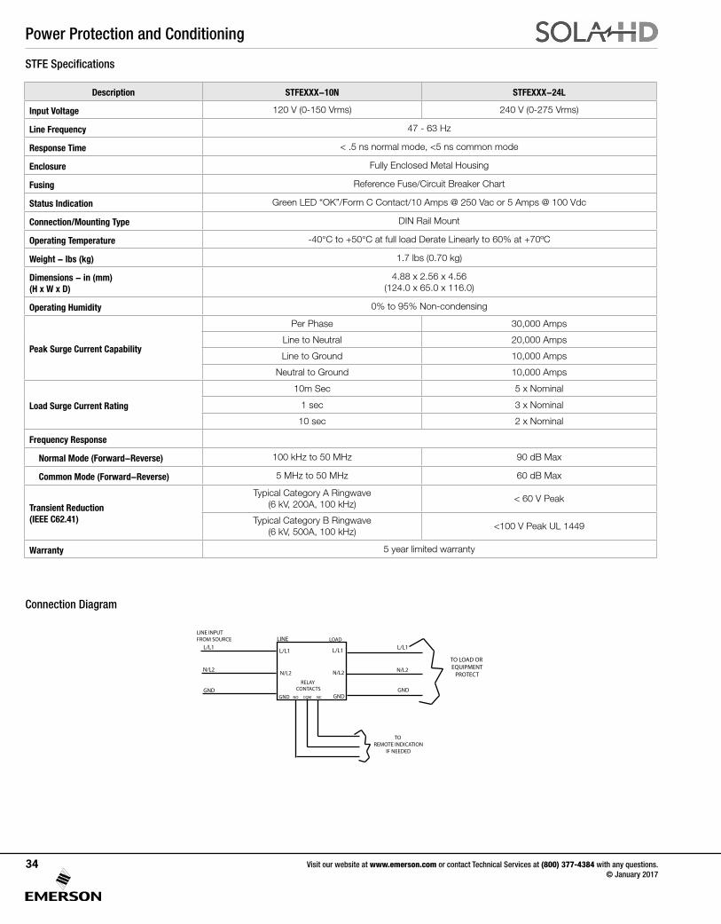
Power Protection and Conditioning
Visit our website at www.emerson.com or contact Technical Services at (800) 377-4384 with any questions. © January 2017
34
Description STFEXXX-10N STFEXXX-24L
Input Voltage 120 V (0-150 Vrms) 240 V (0-275 Vrms)
Line Frequency 47 - 63 Hz
Response Time < .5 ns normal mode, <5 ns common mode
Enclosure Fully Enclosed Metal Housing
Fusing Reference Fuse/Circuit Breaker Chart
Status Indication Green LED “OK”/Form C Contact/10 Amps @ 250 Vac or 5 Amps @ 100 Vdc
Connection/Mounting Type DIN Rail Mount
Operating Temperature -40°C to +50°C at full load Derate Linearly to 60% at +70ºC
Weight - lbs (kg) 1.7 lbs (0.70 kg)
Dimensions - in (mm) (H x W x D)
4.88 x 2.56 x 4.56 (124.0 x 65.0 x 116.0)
Operating Humidity 0% to 95% Non-condensing
Peak Surge Current Capability
Per Phase 30,000 Amps
Line to Neutral 20,000 Amps
Line to Ground 10,000 Amps
Neutral to Ground 10,000 Amps
Load Surge Current Rating
10m Sec 5 x Nominal
1 sec 3 x Nominal
10 sec 2 x Nominal
Frequency Response
Normal Mode (Forward-Reverse) 100 kHz to 50 MHz 90 dB Max
Common Mode (Forward-Reverse) 5 MHz to 50 MHz 60 dB Max
Transient Reduction (IEEE C62.41)
Typical Category A Ringwave (6 kV, 200A, 100 kHz)
< 60 V Peak
Typical Category B Ringwave (6 kV, 500A, 100 kHz)
<100 V Peak UL 1449
Warranty 5 year limited warranty
STFE Specifications
Connection Diagram
LINE LOADL/L1
N/L2
GND
L/L1
N/L2
GND
L/L1
TO REMOTE INDICATION
IF NEEDED
TO LOAD OR EQUIPMENT
PROTECTRELAY
CONTACTSNO COM NC
L/L1
N/L2N/L2
GNDGND
LINE INPUTFROM SOURCE
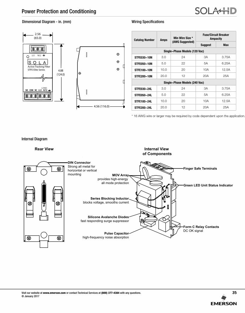
Power Protection and Conditioning
Visit our website at www.emerson.com or contact Technical Services at (800) 377-4384 with any questions. © January 2017
35
Dimensional Diagram - in. (mm)
Active Tracking FilterSTFE Elite Series
NO COM NC L/L1 N/12
L/L1 N/L2
2.56(65.0)
4.56 (116.0)
4.88(124.0)
Catalog Number AmpsMin Wire Size *
(AWG Suggested)
Fuse/Circuit Breaker Ampacity
Suggest Max
Single-Phase Models (120 Vac)
STFE030-10N 3.0 24 3A 3.75A
STFE050-10N 5.0 22 5A 6.25A
STFE100-10N 10.0 20 10A 12.5A
STFE200-10N 20.0 12 20A 25A
Single-Phase Models (240 Vac)
STFE030-24L 3.0 24 3A 3.75A
STFE050-24L 5.0 22 5A 6.25A
STFE100-24L 10.0 20 10A 12.5A
STFE200-24L 20.0 12 20A 25A
Wiring Specifications
Internal View of Components
MOV Arrayprovides high-energy
all mode protection
Series Blocking Inductorblocks voltage, smooths current
Silicone Avalanche Diodesfast responding surge suppressor
Finger Safe Terminals
Green LED Unit Status Indicator
Pulse Capacitorhigh-frequency noise absorption
Form C Relay ContactsDC OK signal
Rear View
DIN ConnectorStrong all metal forhorizontal or verticalmounting
Internal Diagram
* 16 AWG wire or larger may be required by code dependent upon the application.
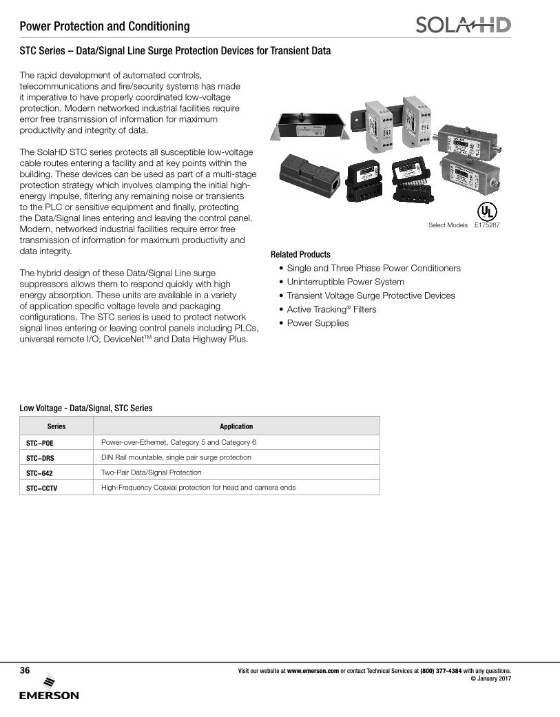
Power Protection and Conditioning
Visit our website at www.emerson.com or contact Technical Services at (800) 377-4384 with any questions. © January 2017
36
STC Series – Data/Signal Line Surge Protection Devices for Transient Data
The rapid development of automated controls, telecommunications and fire/security systems has made it imperative to have properly coordinated low-voltage protection. Modern networked industrial facilities require error free transmission of information for maximum productivity and integrity of data.
The SolaHD STC series protects all susceptible low-voltage cable routes entering a facility and at key points within the building. These devices can be used as part of a multi-stage protection strategy which involves clamping the initial high-energy impulse, filtering any remaining noise or transients to the PLC or sensitive equipment and finally, protecting the Data/Signal lines entering and leaving the control panel. Modern, networked industrial facilities require error free transmission of information for maximum productivity and data integrity.
The hybrid design of these Data/Signal Line surge suppressors allows them to respond quickly with high energy absorption. These units are available in a variety of application specific voltage levels and packaging configurations. The STC series is used to protect network signal lines entering or leaving control panels including PLCs, universal remote I/O, DeviceNetTM and Data Highway Plus.
Series Application
STC-POE Power-over-Ethernet, Category 5 and Category 6
STC-DRS DIN Rail mountable, single pair surge protection
STC-642 Two-Pair Data/Signal Protection
STC-CCTV High-Frequency Coaxial protection for head and camera ends
Low Voltage - Data/Signal, STC Series
Related Products
• Single and Three Phase Power Conditioners
• Uninterruptible Power System
• Transient Voltage Surge Protective Devices
• Active Tracking® Filters
• Power Supplies
E175287Select Models
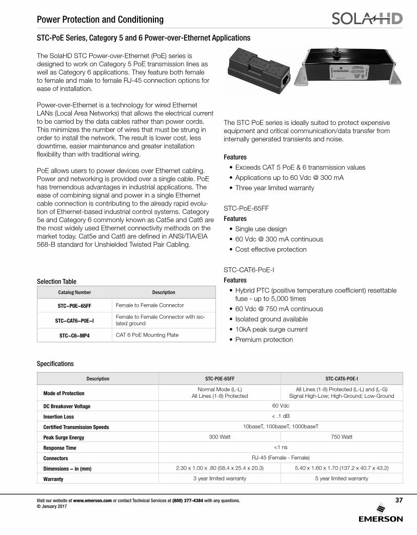
Power Protection and Conditioning
Visit our website at www.emerson.com or contact Technical Services at (800) 377-4384 with any questions. © January 2017
37
STC-PoE Series, Category 5 and 6 Power-over-Ethernet Applications
The SolaHD STC Power-over-Ethernet (PoE) series is designed to work on Category 5 PoE transmission lines as well as Category 6 applications. They feature both female to female and male to female RJ-45 connection options for ease of installation.
Power-over-Ethernet is a technology for wired Ethernet LANs (Local Area Networks) that allows the electrical current to be carried by the data cables rather than power cords. This minimizes the number of wires that must be strung in order to install the network. The result is lower cost, less downtime, easier maintenance and greater installation flexibility than with traditional wiring.
PoE allows users to power devices over Ethernet cabling. Power and networking is provided over a single cable. PoE has tremendous advantages in industrial applications. The ease of combining signal and power in a single Ethernet cable connection is contributing to the already rapid evolu-tion of Ethernet-based industrial control systems. Category 5e and Category 6 commonly known as Cat5e and Cat6 are the most widely used Ethernet connectivity methods on the market today. Cat5e and Cat6 are defined in ANSI/TIA/EIA 568-B standard for Unshielded Twisted Pair Cabling.
Specifications
Selection Table
Catalog Number Description
STC-P0E-65FF Female to Female Connector
STC-CAT6-P0E-IFemale to Female Connector with iso-lated ground
STC-C6-MP4 CAT 6 PoE Mounting Plate
The STC PoE series is ideally suited to protect expensive equipment and critical communication/data transfer from internally generated transients and noise.
Features
• Exceeds CAT 5 PoE & 6 transmission values
• Applications up to 60 Vdc @ 300 mA
• Three year limited warranty
STC-PoE-65FF
Features
• Single use design
• 60 Vdc @ 300 mA continuous
• Cost effective protection
STC-CAT6-PoE-I
Features
• Hybrid PTC (positive temperature coefficient) resettable fuse - up to 5,000 times
• 60 Vdc @ 750 mA continuous
• Isolated ground available
• 10kA peak surge current
• Premium protection
Description STC-P0E-65FF STC-CAT6-POE-I
Mode of ProtectionNormal Mode (L-L)
All Lines (1-8) ProtectedAll Lines (1-8) Protected (L-L) and (L-G)
Signal High-Low; High-Ground; Low-Ground
DC Breakover Voltage 60 Vdc
Insertion Loss < .1 dB
Certified Transmission Speeds 10baseT, 100baseT, 1000baseT
Peak Surge Energy 300 Watt 750 Watt
Response Time <1 ns
Connectors RJ-45 (Female - Female)
Dimensions - in (mm) 2.30 x 1.00 x .80 (58.4 x 25.4 x 20.3) 5.40 x 1.60 x 1.70 (137.2 x 40.7 x 43.2)
Warranty 3 year limited warranty 5 year limited warranty
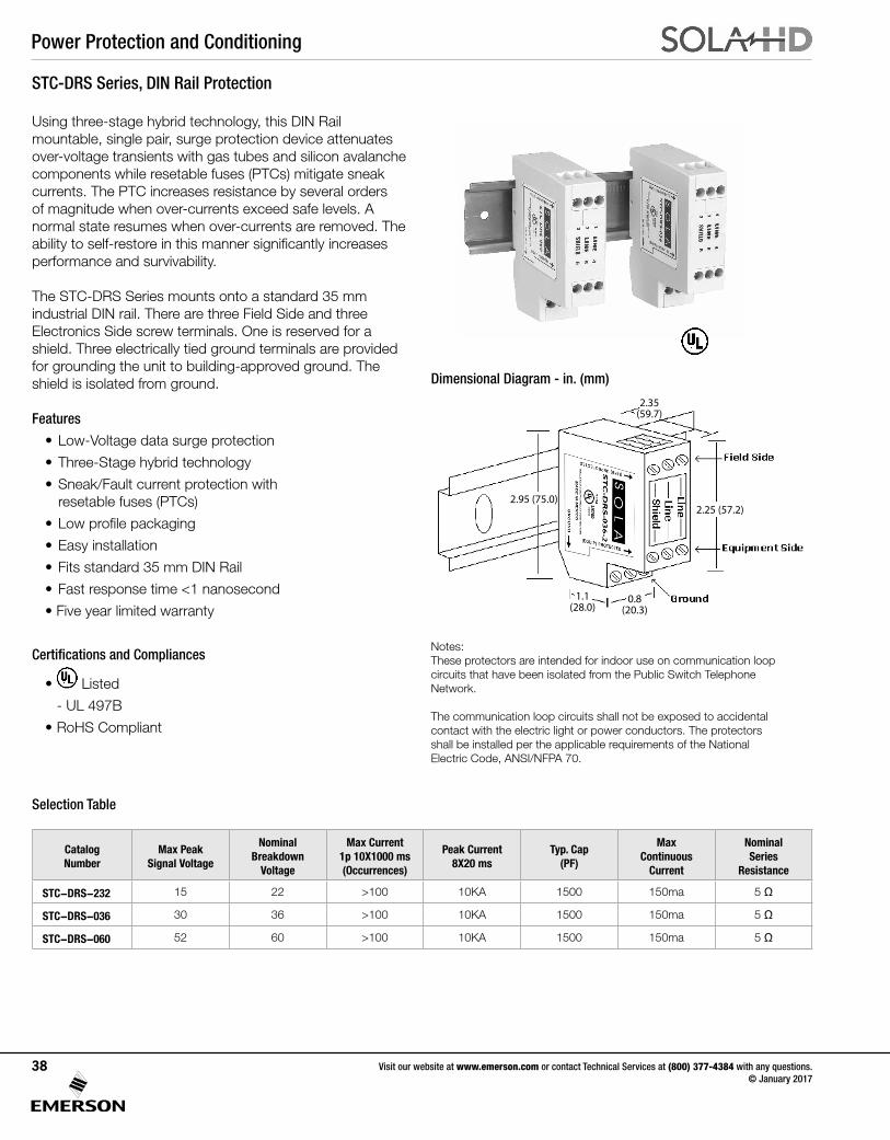
Power Protection and Conditioning
Visit our website at www.emerson.com or contact Technical Services at (800) 377-4384 with any questions. © January 2017
38
STC-DRS Series, DIN Rail Protection
Catalog Number
Max Peak Signal Voltage
Nominal Breakdown
Voltage
Max Current 1p 10X1000 ms (Occurrences)
Peak Current8X20 ms
Typ. Cap(PF)
Max Continuous
Current
Nominal Series
Resistance
STC-DRS-232 15 22 >100 10KA 1500 150ma 5 Ω
STC-DRS-036 30 36 >100 10KA 1500 150ma 5 Ω
STC-DRS-060 52 60 >100 10KA 1500 150ma 5 Ω
Notes:These protectors are intended for indoor use on communication loopcircuits that have been isolated from the Public Switch TelephoneNetwork.
The communication loop circuits shall not be exposed to accidentalcontact with the electric light or power conductors. The protectorsshall be installed per the applicable requirements of the NationalElectric Code, ANSI/NFPA 70.
Using three-stage hybrid technology, this DIN Rail mountable, single pair, surge protection device attenuates over-voltage transients with gas tubes and silicon avalanche components while resetable fuses (PTCs) mitigate sneak currents. The PTC increases resistance by several orders of magnitude when over-currents exceed safe levels. A normal state resumes when over-currents are removed. The ability to self-restore in this manner significantly increases performance and survivability.
The STC-DRS Series mounts onto a standard 35 mm industrial DIN rail. There are three Field Side and three Electronics Side screw terminals. One is reserved for a shield. Three electrically tied ground terminals are provided for grounding the unit to building-approved ground. The shield is isolated from ground.
Features
• Low-Voltage data surge protection
• Three-Stage hybrid technology
• Sneak/Fault current protection with resetable fuses (PTCs)
• Low profile packaging
• Easy installation
• Fits standard 35 mm DIN Rail
• Fast response time <1 nanosecond
• Five year limited warranty
Certifications and Compliances
• Listed
- UL 497B
• RoHS Compliant
Selection Table
Dimensional Diagram - in. (mm)
2.95 (75.0)2.25 (57.2)
0.8(20.3)
1.1(28.0)
2.35(59.7)
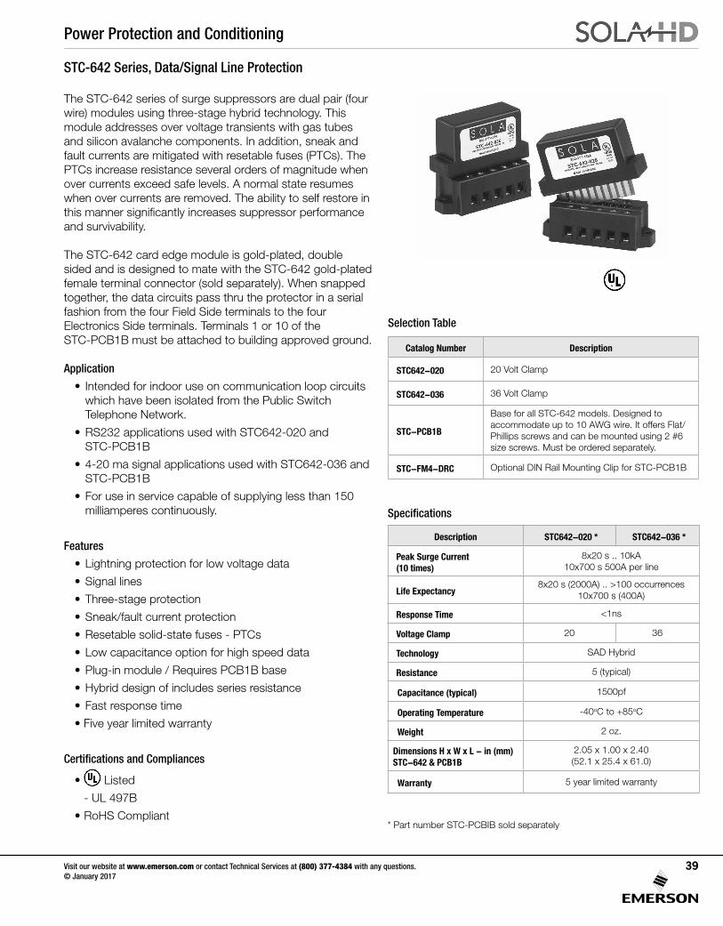
Power Protection and Conditioning
Visit our website at www.emerson.com or contact Technical Services at (800) 377-4384 with any questions. © January 2017
39
STC-642 Series, Data/Signal Line Protection
The STC-642 series of surge suppressors are dual pair (four wire) modules using three-stage hybrid technology. Thismodule addresses over voltage transients with gas tubes and silicon avalanche components. In addition, sneak and fault currents are mitigated with resetable fuses (PTCs). The PTCs increase resistance several orders of magnitude when over currents exceed safe levels. A normal state resumes when over currents are removed. The ability to self restore in this manner significantly increases suppressor performance and survivability.
The STC-642 card edge module is gold-plated, double sided and is designed to mate with the STC-642 gold-plated female terminal connector (sold separately). When snapped together, the data circuits pass thru the protector in a serial fashion from the four Field Side terminals to the four Electronics Side terminals. Terminals 1 or 10 of the STC-PCB1B must be attached to building approved ground.
Application
• Intended for indoor use on communication loop circuits which have been isolated from the Public Switch Telephone Network.
• RS232 applications used with STC642-020 and STC-PCB1B
• 4-20 ma signal applications used with STC642-036 and STC-PCB1B
• For use in service capable of supplying less than 150 milliamperes continuously.
Features
• Lightning protection for low voltage data
• Signal lines
• Three-stage protection
• Sneak/fault current protection
• Resetable solid-state fuses - PTCs
• Low capacitance option for high speed data
• Plug-in module / Requires PCB1B base
• Hybrid design of includes series resistance
• Fast response time
• Five year limited warranty
Certifications and Compliances
• Listed
- UL 497B
• RoHS Compliant
Specifications
Description STC642-020 * STC642-036 *
Peak Surge Current (10 times)
8x20 s .. 10kA10x700 s 500A per line
Life Expectancy8x20 s (2000A) .. >100 occurrences
10x700 s (400A)
Response Time <1ns
Voltage Clamp 20 36
Technology SAD Hybrid
Resistance 5 (typical)
Capacitance (typical) 1500pf
Operating Temperature -40oC to +85oC
Weight 2 oz.
Dimensions H x W x L - in (mm) STC-642 & PCB1B
2.05 x 1.00 x 2.40 (52.1 x 25.4 x 61.0)
Warranty 5 year limited warranty
Catalog Number Description
STC642-020 20 Volt Clamp
STC642-036 36 Volt Clamp
STC-PCB1B
Base for all STC-642 models. Designed to accommodate up to 10 AWG wire. It offers Flat/ Phillips screws and can be mounted using 2 #6 size screws. Must be ordered separately.
STC-FM4-DRC Optional DIN Rail Mounting Clip for STC-PCB1B
* Part number STC-PCBIB sold separately
Selection Table
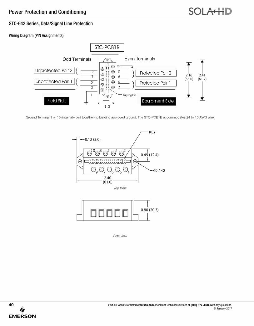
Power Protection and Conditioning
Visit our website at www.emerson.com or contact Technical Services at (800) 377-4384 with any questions. © January 2017
40
STC-642 Series, Data/Signal Line Protection
Wiring Diagram (PIN Assignments)
Ground Terminal 1 or 10 (internally tied together) to building approved ground. The STC-PCB1B accommodates 24 to 10 AWG wire.
0.12 (3.0)
0.49 (12.4)
0.80 (20.3)
2.40(61.0)
2.41(61.2)
2.16(55.0)
Top View
Side View
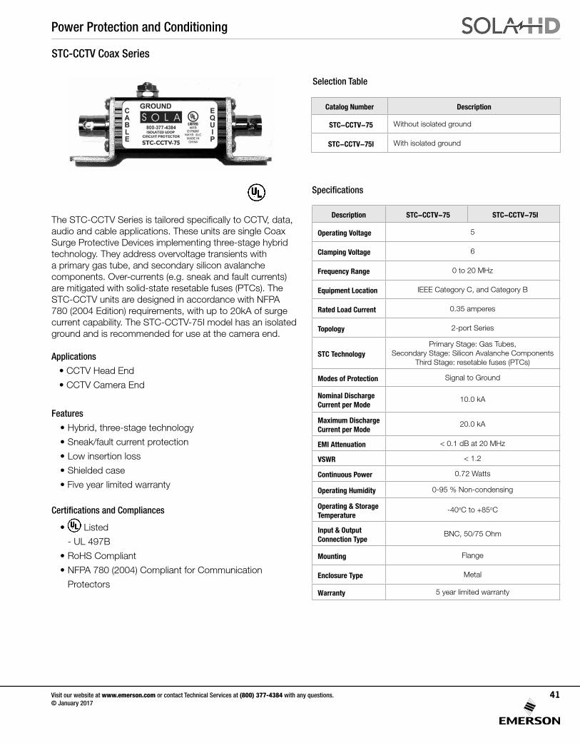
Power Protection and Conditioning
Visit our website at www.emerson.com or contact Technical Services at (800) 377-4384 with any questions. © January 2017
41
The STC-CCTV Series is tailored specifically to CCTV, data, audio and cable applications. These units are single Coax Surge Protective Devices implementing three-stage hybrid technology. They address overvoltage transients with a primary gas tube, and secondary silicon avalanche components. Over-currents (e.g. sneak and fault currents) are mitigated with solid-state resetable fuses (PTCs). The STC-CCTV units are designed in accordance with NFPA 780 (2004 Edition) requirements, with up to 20kA of surge current capability. The STC-CCTV-75I model has an isolated ground and is recommended for use at the camera end.
Applications
• CCTV Head End
• CCTV Camera End
Features
• Hybrid, three-stage technology
• Sneak/fault current protection
• Low insertion loss
• Shielded case
• Five year limited warranty
Certifications and Compliances
• Listed
- UL 497B
• RoHS Compliant
• NFPA 780 (2004) Compliant for Communication
Protectors
STC-CCTV Coax Series
Specifications
Description STC-CCTV-75 STC-CCTV-75I
Operating Voltage 5
Clamping Voltage 6
Frequency Range 0 to 20 MHz
Equipment Location IEEE Category C, and Category B
Rated Load Current 0.35 amperes
Topology 2-port Series
STC TechnologyPrimary Stage: Gas Tubes,
Secondary Stage: Silicon Avalanche ComponentsThird Stage: resetable fuses (PTCs)
Modes of Protection Signal to Ground
Nominal Discharge Current per Mode
10.0 kA
Maximum Discharge Current per Mode
20.0 kA
EMI Attenuation < 0.1 dB at 20 MHz
VSWR < 1.2
Continuous Power 0.72 Watts
Operating Humidity 0-95 % Non-condensing
Operating & Storage Temperature
-40oC to +85oC
Input & Output Connection Type
BNC, 50/75 Ohm
Mounting Flange
Enclosure Type Metal
Warranty 5 year limited warranty
Catalog Number Description
STC-CCTV-75 Without isolated ground
STC-CCTV-75I With isolated ground
Selection Table
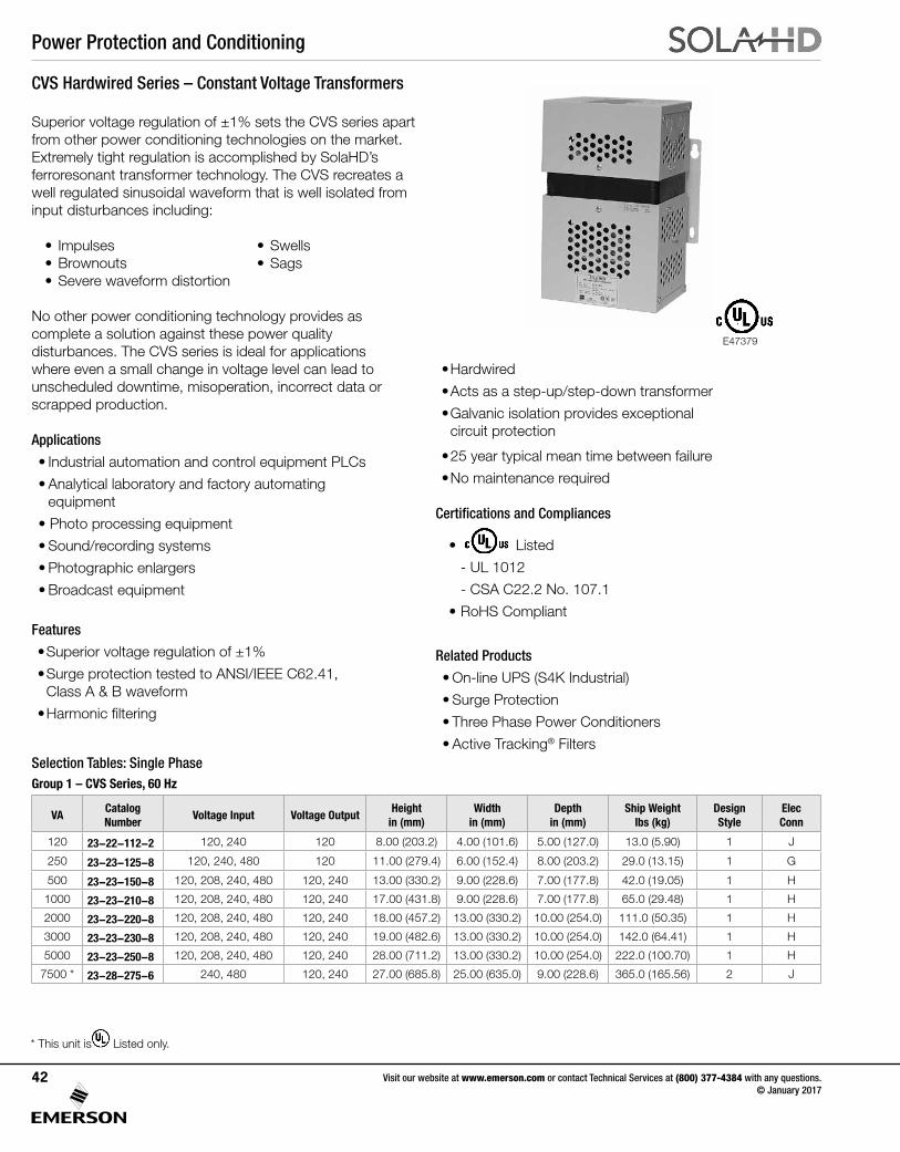
Power Protection and Conditioning
Visit our website at www.emerson.com or contact Technical Services at (800) 377-4384 with any questions. © January 2017
42
Superior voltage regulation of ±1% sets the CVS series apart from other power conditioning technologies on the market. Extremely tight regulation is accomplished by SolaHD’s ferroresonant transformer technology. The CVS recreates a well regulated sinusoidal waveform that is well isolated from input disturbances including:
• Impulses • Swells• Brownouts • Sags• Severe waveform distortion
No other power conditioning technology provides as complete a solution against these power quality disturbances. The CVS series is ideal for applications where even a small change in voltage level can lead to unscheduled downtime, misoperation, incorrect data or scrapped production.
Applications
• Industrial automation and control equipment PLCs
• Analytical laboratory and factory automating equipment
• Photo processing equipment
• Sound/recording systems
• Photographic enlargers
• Broadcast equipment
Features
• Superior voltage regulation of ±1%
• Surge protection tested to ANSI/IEEE C62.41, Class A & B waveform
• Harmonic filtering
Selection Tables: Single PhaseGroup 1 – CVS Series, 60 Hz
CVS Hardwired Series – Constant Voltage Transformers
* This unit is Listed only.
• Hardwired
• Acts as a step-up/step-down transformer
• Galvanic isolation provides exceptional circuit protection
• 25 year typical mean time between failure
• No maintenance required
Certifications and Compliances
• Listed
- UL 1012
- CSA C22.2 No. 107.1
• RoHS Compliant
Related Products
• On-line UPS (S4K Industrial)
• Surge Protection
• Three Phase Power Conditioners
• Active Tracking® Filters
VACatalog Number
Voltage Input Voltage OutputHeight
in (mm)Width
in (mm)Depth
in (mm)Ship Weight
lbs (kg)Design Style
Elec Conn
120 23-22-112-2 120, 240 120 8.00 (203.2) 4.00 (101.6) 5.00 (127.0) 13.0 (5.90) 1 J
250 23-23-125-8 120, 240, 480 120 11.00 (279.4) 6.00 (152.4) 8.00 (203.2) 29.0 (13.15) 1 G
500 23-23-150-8 120, 208, 240, 480 120, 240 13.00 (330.2) 9.00 (228.6) 7.00 (177.8) 42.0 (19.05) 1 H
1000 23-23-210-8 120, 208, 240, 480 120, 240 17.00 (431.8) 9.00 (228.6) 7.00 (177.8) 65.0 (29.48) 1 H
2000 23-23-220-8 120, 208, 240, 480 120, 240 18.00 (457.2) 13.00 (330.2) 10.00 (254.0) 111.0 (50.35) 1 H
3000 23-23-230-8 120, 208, 240, 480 120, 240 19.00 (482.6) 13.00 (330.2) 10.00 (254.0) 142.0 (64.41) 1 H
5000 23-23-250-8 120, 208, 240, 480 120, 240 28.00 (711.2) 13.00 (330.2) 10.00 (254.0) 222.0 (100.70) 1 H
7500 * 23-28-275-6 240, 480 120, 240 27.00 (685.8) 25.00 (635.0) 9.00 (228.6) 365.0 (165.56) 2 J
E47379
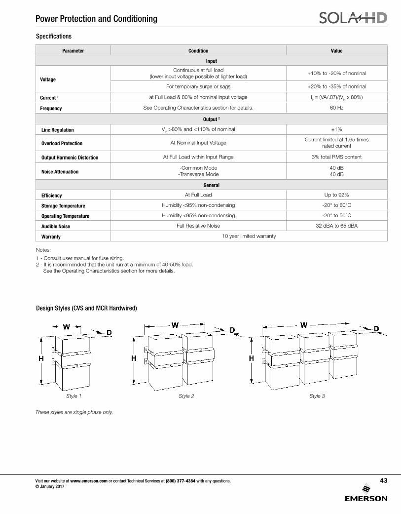
Power Protection and Conditioning
Visit our website at www.emerson.com or contact Technical Services at (800) 377-4384 with any questions. © January 2017
43
Design Styles (CVS and MCR Hardwired)
Style 1 Style 2 Style 3
Specifications
Parameter Condition Value
Input
Voltage
Continuous at full load (lower input voltage possible at lighter load)
+10% to -20% of nominal
For temporary surge or sags +20% to -35% of nominal
Current 1 at Full Load & 80% of nominal input voltage Iin ≅ (VA/.87)/(Vin x 80%)
Frequency See Operating Characteristics section for details. 60 Hz
Output 2
Line Regulation Vin >80% and <110% of nominal ±1%
Overload Protection At Nominal Input VoltageCurrent limited at 1.65 times
rated current
Output Harmonic Distortion At Full Load within Input Range 3% total RMS content
Noise Attenuation-Common Mode
-Transverse Mode40 dB 40 dB
General
Efficiency At Full Load Up to 92%
Storage Temperature Humidity <95% non-condensing -20° to 80°C
Operating Temperature Humidity <95% non-condensing -20° to 50°C
Audible Noise Full Resistive Noise 32 dBA to 65 dBA
Warranty 10 year limited warranty
These styles are single phase only.
Notes:
1 - Consult user manual for fuse sizing. 2 - It is recommended that the unit run at a minimum of 40-50% load. See the Operating Characteristics section for more details.
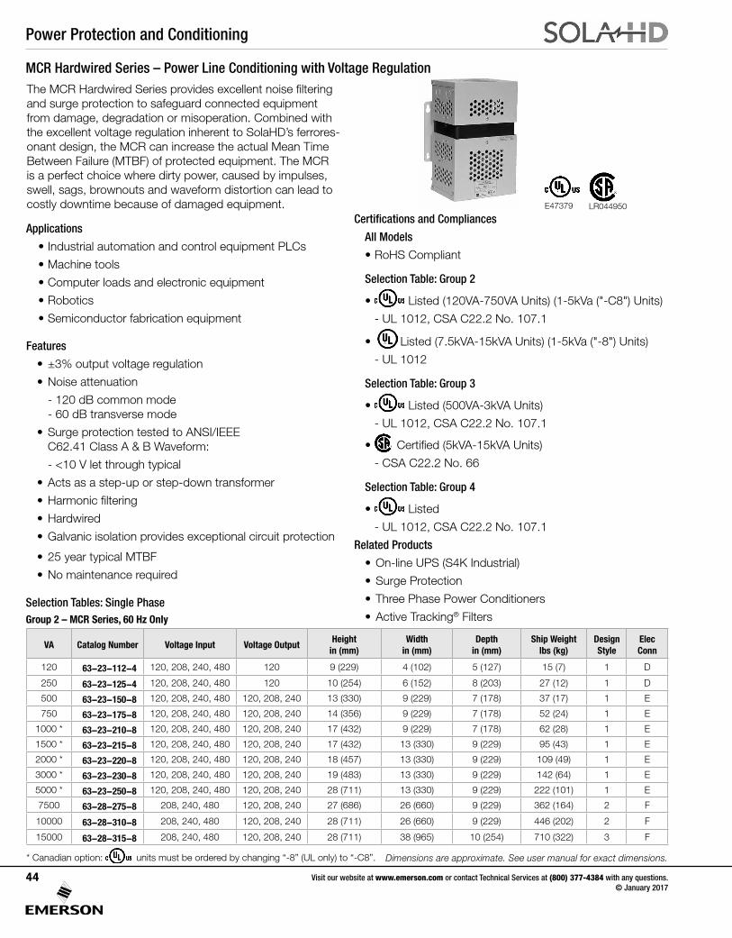
Power Protection and Conditioning
Visit our website at www.emerson.com or contact Technical Services at (800) 377-4384 with any questions. © January 2017
44
The MCR Hardwired Series provides excellent noise filtering and surge protection to safeguard connected equipment from damage, degradation or misoperation. Combined with the excellent voltage regulation inherent to SolaHD’s ferrores-onant design, the MCR can increase the actual Mean Time Between Failure (MTBF) of protected equipment. The MCR is a perfect choice where dirty power, caused by impulses, swell, sags, brownouts and waveform distortion can lead to costly downtime because of damaged equipment.
Applications
• Industrial automation and control equipment PLCs
• Machine tools
• Computer loads and electronic equipment
• Robotics
• Semiconductor fabrication equipment
Features
• ±3% output voltage regulation
• Noise attenuation
- 120 dB common mode - 60 dB transverse mode
• Surge protection tested to ANSI/IEEE C62.41 Class A & B Waveform:
- <10 V let through typical
• Acts as a step-up or step-down transformer
• Harmonic filtering
• Hardwired
• Galvanic isolation provides exceptional circuit protection
• 25 year typical MTBF
• No maintenance required
Selection Tables: Single Phase Group 2 – MCR Series, 60 Hz Only
* Canadian option: units must be ordered by changing “-8” (UL only) to “-C8”. Dimensions are approximate. See user manual for exact dimensions.
VA Catalog Number Voltage Input Voltage OutputHeight
in (mm)Width
in (mm)Depth
in (mm)Ship Weight
lbs (kg)Design Style
Elec Conn
120 63-23-112-4 120, 208, 240, 480 120 9 (229) 4 (102) 5 (127) 15 (7) 1 D
250 63-23-125-4 120, 208, 240, 480 120 10 (254) 6 (152) 8 (203) 27 (12) 1 D
500 63-23-150-8 120, 208, 240, 480 120, 208, 240 13 (330) 9 (229) 7 (178) 37 (17) 1 E
750 63-23-175-8 120, 208, 240, 480 120, 208, 240 14 (356) 9 (229) 7 (178) 52 (24) 1 E
1000 * 63-23-210-8 120, 208, 240, 480 120, 208, 240 17 (432) 9 (229) 7 (178) 62 (28) 1 E
1500 * 63-23-215-8 120, 208, 240, 480 120, 208, 240 17 (432) 13 (330) 9 (229) 95 (43) 1 E
2000 * 63-23-220-8 120, 208, 240, 480 120, 208, 240 18 (457) 13 (330) 9 (229) 109 (49) 1 E
3000 * 63-23-230-8 120, 208, 240, 480 120, 208, 240 19 (483) 13 (330) 9 (229) 142 (64) 1 E
5000 * 63-23-250-8 120, 208, 240, 480 120, 208, 240 28 (711) 13 (330) 9 (229) 222 (101) 1 E
7500 63-28-275-8 208, 240, 480 120, 208, 240 27 (686) 26 (660) 9 (229) 362 (164) 2 F
10000 63-28-310-8 208, 240, 480 120, 208, 240 28 (711) 26 (660) 9 (229) 446 (202) 2 F
15000 63-28-315-8 208, 240, 480 120, 208, 240 28 (711) 38 (965) 10 (254) 710 (322) 3 F
Certifications and Compliances
All Models
• RoHS Compliant
Selection Table: Group 2
• Listed (120VA-750VA Units) (1-5kVa ("-C8") Units)
- UL 1012, CSA C22.2 No. 107.1
• Listed (7.5kVA-15kVA Units) (1-5kVa ("-8") Units)
- UL 1012
Selection Table: Group 3
• Listed (500VA-3kVA Units)
- UL 1012, CSA C22.2 No. 107.1
• Certified (5kVA-15kVA Units)
- CSA C22.2 No. 66
Selection Table: Group 4
• Listed
- UL 1012, CSA C22.2 No. 107.1
Related Products
• On-line UPS (S4K Industrial)
• Surge Protection
• Three Phase Power Conditioners
• Active Tracking® Filters
E47379 LR044950
MCR Hardwired Series – Power Line Conditioning with Voltage Regulation
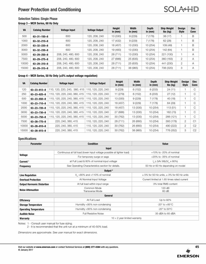
Power Protection and Conditioning
Visit our website at www.emerson.com or contact Technical Services at (800) 377-4384 with any questions. © January 2017
45
Group 4 – MCR Series, 50 Hz Only (±5% output voltage regulation)
Selection Tables: Single PhaseGroup 3 – MCR Series, 60 Hz Only
Specifications
VA Catalog Number Voltage Input Voltage OutputHeight
in (mm)Width
in (mm)Depth
in (mm)Ship Weight
lbs (kg)Design Style
Elec Conn
500 63-31-150-8 600 120, 208, 240 13 (330) 9 (229) 7 (178) 38 (17) 1 B
1000 63-32-210-8 600 120, 208, 240 17 (432) 9 (229) 7 (178) 62 (28) 1 B
2000 63-32-220-8 600 120, 208, 240 18 (457) 13 (330) 10 (254) 109 (49) 1 B
3000 63-32-230-8 600 120, 208, 240 19 (483) 13 (330) 10 (254) 142 (64) 1 B
5000 63-29-250-8 208, 240, 480, 600 120, 208, 240 28 (711) 13 (330) 10 (254) 221 (100) 1 A
7500 63-29-275-8 208, 240, 480, 600 120, 208, 240 27 (686) 25 (635) 10 (254) 360 (163) 2 A
10000 63-29-310-8 208, 240, 480, 600 120, 208, 240 28 (711) 25 (635) 10 (254) 441 (200) 2 A
15000 63-29-315-8 208, 240, 480, 600 120, 208, 240 28 (711) 38 (965) 10 (254) 706 (320) 3 A
VA Catalog Number Voltage Input Voltage OutputHeight
in (mm)Width
in (mm)Depth
in (mm)Ship Weight
lbs (kg)Design Style
Elec Conn
120 63-23-612-8 110, 120, 220, 240, 380, 415 110, 120, 220, 240 9 (229) 6 (152) 8 (203) 24 (11) 1 C
250 63-23-625-8 110, 120, 220, 240, 380, 415 110, 120, 220, 240 11 (279) 6 (152) 8 (203) 27 (12) 1 C
500 63-23-650-8 110, 120, 220, 240, 380, 415 110, 120, 220, 240 13 (330) 9 (229) 7 (178) 40 (18) 1 C
1000 63-23-710-8 110, 120, 220, 240, 380, 415 110, 120, 220, 240 18 (457) 9 (229) 7 (178) 64 (29) 1 C
2000 63-23-720-8 110, 120, 220, 240, 380, 415 110, 120, 220, 240 18 (457) 13 (330) 10 (254) 113 (51) 1 C
3000 63-23-730-8 110, 120, 220, 240, 380, 415 110, 120, 220, 240 27 (686) 13 (330) 10 (254) 162 (73) 1 C
5000 63-23-750-8 110, 120, 220, 240, 380, 415 110, 120, 220, 240 30 (762) 13 (330) 10 (254) 266 (121) 1 C
7500 63-28-775-8 220, 240, 380, 415 110, 120, 220, 240 28 (711) 26 (660) 10 (254) 393 (178) 2 C1
10000 63-28-810-8 220, 240, 380, 415 110, 120, 220, 240 30 (762) 26 (660) 10 (254) 490 (222) 2 C2
15000 63-28-815-8 220, 240, 380, 415 110, 120, 220, 240 30 (762) 38 (965) 10 (254) 776 (352) 3 C2
Parameter Condition Value
Input
VoltageContinuous at full load (lower input voltage possible at lighter load) +10% to -20% of nominal
For temporary surge or sags +20% to -35% of nominal
Current 1 at Full Load & 80% of nominal input voltage Iin ≅ (VA/.89)/(Vin x 80%)
Frequency See Operating Characteristics section for details. 50 Hz or 60 Hz depending on model
Output 2
Line Regulation Vin >80% and <110% of nominal ± 5% for 50 Hz units, ± 3% for 60 Hz units
Overload Protection At Nominal Input Voltage Current limited at 1.65 times rated current
Output Harmonic Distortion At full load within input range 3% total RMS content
Noise AttenuationCommon Mode
Transverse Mode120 dB 60 dB
General
Efficiency At Full Load Up to 92%
Storage Temperature Humidity <95% non-condensing -20° to +85°C
Operating Temperature Humidity <95% non-condensing -20° to 50°C
Audible Noise Full Resistive Noise 35 dBA to 65 dBA
Warranty 10 + 2 year limited warranty
Notes: 1 - Consult user manual for fuse sizing. 2 - It is recommended that the unit run at a minimum of 40-50% load.
Dimensions are approximate. See user manual for exact dimensions.
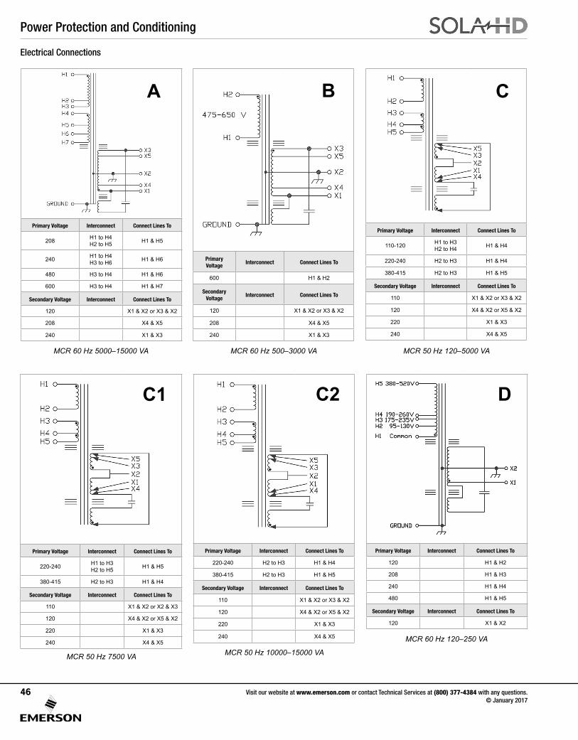
Power Protection and Conditioning
Visit our website at www.emerson.com or contact Technical Services at (800) 377-4384 with any questions. © January 2017
46
Primary Voltage Interconnect Connect Lines To
208 H1 to H4 H2 to H5 H1 & H5
240 H1 to H4 H3 to H6 H1 & H6
480 H3 to H4 H1 & H6
600 H3 to H4 H1 & H7
Secondary Voltage Interconnect Connect Lines To
120 X1 & X2 or X3 & X2
208 X4 & X5
240 X1 & X3
Primary Voltage
Interconnect Connect Lines To
600 H1 & H2
Secondary Voltage
Interconnect Connect Lines To
120 X1 & X2 or X3 & X2
208 X4 & X5
240 X1 & X3
Primary Voltage Interconnect Connect Lines To
110-120 H1 to H3H2 to H4 H1 & H4
220-240 H2 to H3 H1 & H4
380-415 H2 to H3 H1 & H5
Secondary Voltage Interconnect Connect Lines To
110 X1 & X2 or X3 & X2
120 X4 & X2 or X5 & X2
220 X1 & X3
240 X4 & X5
Primary Voltage Interconnect Connect Lines To
220-240 H1 to H3H2 to H5 H1 & H5
380-415 H2 to H3 H1 & H4
Secondary Voltage Interconnect Connect Lines To
110 X1 & X2 or X2 & X3
120 X4 & X2 or X5 & X2
220 X1 & X3
240 X4 & X5
Primary Voltage Interconnect Connect Lines To
220-240 H2 to H3 H1 & H4
380-415 H2 to H3 H1 & H5
Secondary Voltage Interconnect Connect Lines To
110 X1 & X2 or X3 & X2
120 X4 & X2 or X5 & X2
220 X1 & X3
240 X4 & X5
Primary Voltage Interconnect Connect Lines To
120 H1 & H2
208 H1 & H3
240 H1 & H4
480 H1 & H5
Secondary Voltage Interconnect Connect Lines To
120 X1 & X2
Electrical Connections
MCR 60 Hz 5000–15000 VA MCR 60 Hz 500–3000 VA MCR 50 Hz 120–5000 VA
MCR 50 Hz 7500 VA MCR 50 Hz 10000–15000 VA
MCR 60 Hz 120–250 VA
B C
C1 C2 D
A
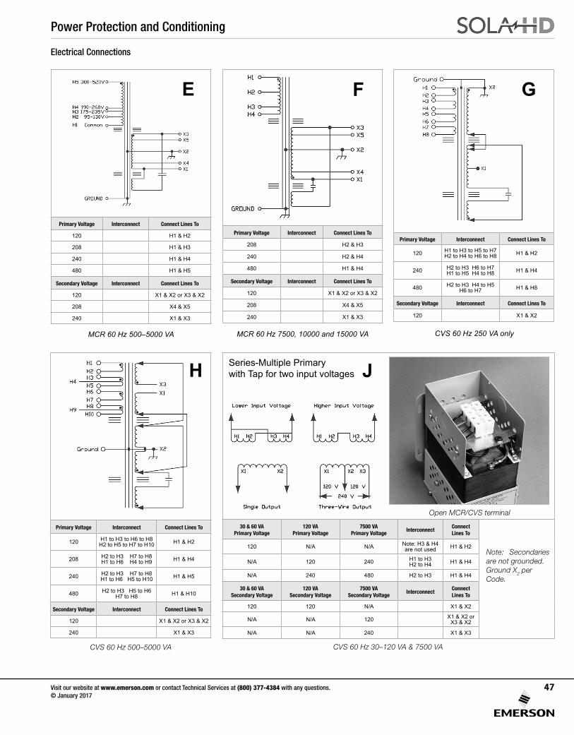
Power Protection and Conditioning
Visit our website at www.emerson.com or contact Technical Services at (800) 377-4384 with any questions. © January 2017
47
Primary Voltage Interconnect Connect Lines To
120 H1 to H3 to H6 to H8H2 to H5 to H7 to H10 H1 & H2
208 H2 to H3 H7 to H8H1 to H6 H4 to H9 H1 & H4
240 H2 to H3 H7 to H8H1 to H6 H5 to H10 H1 & H5
480 H2 to H3 H5 to H6H7 to H8 H1 & H10
Secondary Voltage Interconnect Connect Lines To
120 X1 & X2 or X3 & X2
240 X1 & X3
30 & 60 VAPrimary Voltage
120 VAPrimary Voltage
7500 VAPrimary Voltage
InterconnectConnect Lines To
120 N/A N/A Note: H3 & H4are not used H1 & H2
N/A 120 240 H1 to H3H2 to H4 H1 & H4
N/A 240 480 H2 to H3 H1 & H4
30 & 60 VASecondary Voltage
120 VASecondary Voltage
7500 VASecondary Voltage
InterconnectConnect Lines To
120 120 N/A X1 & X2
N/A N/A 120 X1 & X2 orX3 & X2
N/A N/A 240 X1 & X3
Primary Voltage Interconnect Connect Lines To
120 H1 to H3 to H5 to H7 H2 to H4 to H6 to H8 H1 & H2
240 H2 to H3 H6 to H7 H1 to H5 H4 to H8 H1 & H4
480 H2 to H3 H4 to H5 H6 to H7 H1 & H8
Secondary Voltage Interconnect Connect Lines To
120 X1 & X2
Primary Voltage Interconnect Connect Lines To
120 H1 & H2
208 H1 & H3
240 H1 & H4
480 H1 & H5
Secondary Voltage Interconnect Connect Lines To
120 X1 & X2 or X3 & X2
208 X4 & X5
240 X1 & X3
MCR 60 Hz 500–5000 VA MCR 60 Hz 7500, 10000 and 15000 VA CVS 60 Hz 250 VA only
CVS 60 Hz 500–5000 VA
E F G
H JSeries-Multiple Primarywith Tap for two input voltages
Electrical Connections
CVS 60 Hz 30–120 VA & 7500 VA
Note: Secondaries are not grounded. Ground X2 per Code.
Open MCR/CVS terminal
Primary Voltage Interconnect Connect Lines To
208 H2 & H3
240 H2 & H4
480 H1 & H4
Secondary Voltage Interconnect Connect Lines To
120 X1 & X2 or X3 & X2
208 X4 & X5
240 X1 & X3
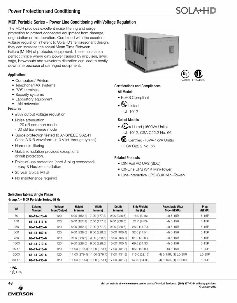
Power Protection and Conditioning
Visit our website at www.emerson.com or contact Technical Services at (800) 377-4384 with any questions. © January 2017
48
The MCR provides excellent noise filtering and surge protection to protect connected equipment from damage, degradation or misoperation. Combined with the excellent voltage regulation inherent to SolaHD’s ferroresonant design, they can increase the actual Mean Time Between Failure (MTBF) of protected equipment. These units are a perfect choice where dirty power caused by impulses, swell, sags, brownouts and waveform distortion can lead to costly downtime because of damaged equipment.
Applications
• Computers/ Printers • Telephone/FAX systems • POS terminals • Security systems • Laboratory equipment • LAN networksFeatures
• ±3% output voltage regulation
• Noise attenuation - 120 dB common mode - 60 dB transverse mode
• Surge protection tested to ANSI/IEEE C62.41 Class A & B waveform (<10 V let-through typical)
• Harmonic filtering
• Galvanic isolation provides exceptional circuit protection.
• Point-of-use protection (cord & plug connected) - Easy & Flexible Installation
• 25 year typical MTBF
• No maintenance required
Certifications and Compliances
All Models
• RoHS Compliant
• Listed
- UL 1012
Select Models
• Listed (1500VA Units)
- UL 1012, CSA C22.2 No. 66
• Certified (70VA-1kVA Units)
- CSA C22.2 No. 66
Related Products
• DIN Rail AC UPS (SDU)
• Off-Line UPS (S1K Mini-Tower)
• Line-Interactive UPS (S3K Mini-Tower)
MCR Portable Series – Power Line Conditioning with Voltage Regulation
E47379
Selection Tables: Single PhaseGroup A – MCR Portable Series, 60 Hz
VACatalog Number
VoltageInput/Output
Height in (mm)
Width in (mm)
Depth in (mm)
Ship Weight lbs (kg)
Receptacle (No.) Type (NEMA)
Plug (NEMA)
70 63-13-070-6 120 6.00 (152.4) 7.00 (177.8) 9.00 (228.6) 18.0 (8.16) (4) 5-15R 5-15P
150 63-13-115-6 120 6.00 (152.4) 7.00 (177.8) 9.00 (228.6) 21.0 (9.53) (4) 5-15R 5-15P
250 63-13-125-6 120 6.00 (152.4) 7.00 (177.8) 9.00 (228.6) 26.0 (11.79) (4) 5-15R 5-15P
500 63-13-150-6 120 9.00 (228.6) 9.00 (228.6) 16.00 (406.4) 32.0 (14.51) (4) 5-15R 5-15P
750 63-13-175-6 120 9.00 (228.6) 9.00 (228.6) 16.00 (406.4) 64.0 (29.03) (4) 5-15R 5-15P
1000 63-13-210-6 120 9.00 (228.6) 9.00 (228.6) 16.00 (406.4) 69.0 (31.30) (4) 5-15R 5-15P
1500* 63-13-215-6 120 11.00 (279.4) 11.00 (279.4) 17.00 (431.8) 95.0 (43.09) (6) 5-15R 5-20P
2000 63-13-220-6 120 11.00 (279.4) 11.00 (279.4) 17.00 (431.8) 115.0 (52.16) (4) 5-15R, (1) L5-30R L5-30P
3000* 63-13-230-6 120 11.00 (279.4) 11.00 (279.4) 17.00 (431.8) 143.0 (64.86) (4) 5-15R, (1) L5-30R 5-50P
* * Only
LR044950
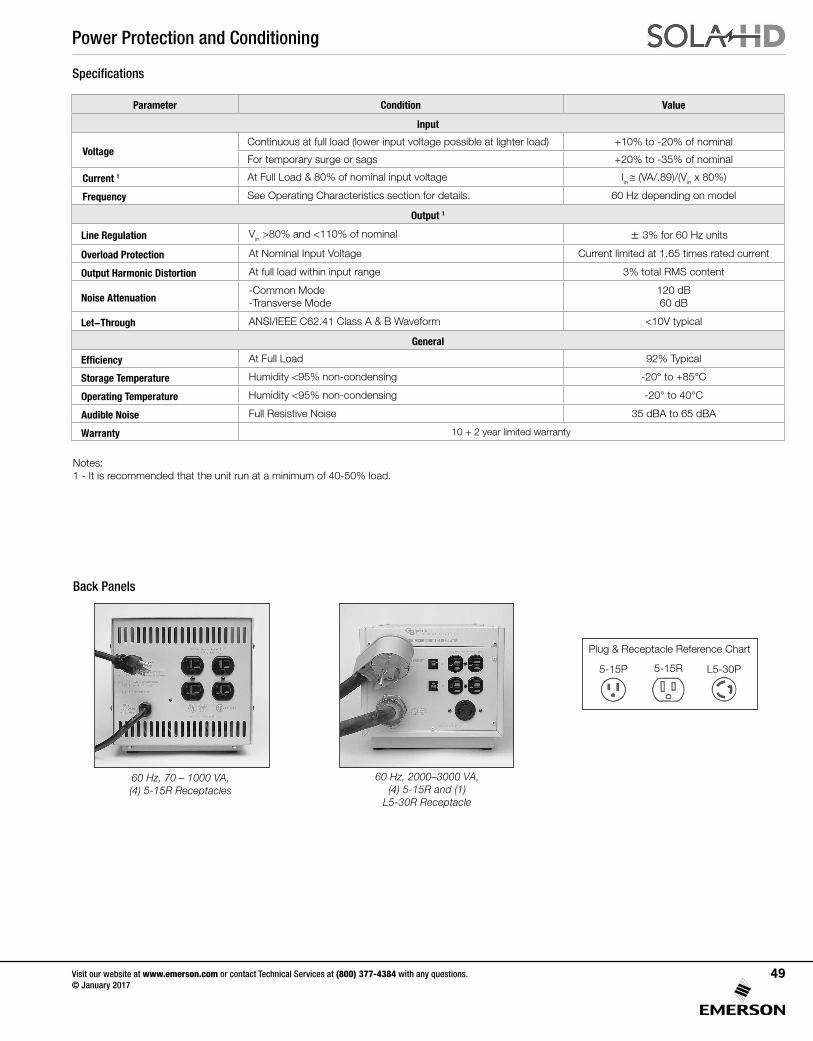
Power Protection and Conditioning
Visit our website at www.emerson.com or contact Technical Services at (800) 377-4384 with any questions. © January 2017
49
Plug & Receptacle Reference Chart
5-15R5-15P L5-30P
Back Panels
60 Hz, 2000–3000 VA, (4) 5-15R and (1)
L5-30R Receptacle
60 Hz, 70 – 1000 VA, (4) 5-15R Receptacles
Specifications
Parameter Condition Value
Input
VoltageContinuous at full load (lower input voltage possible at lighter load) +10% to -20% of nominal
For temporary surge or sags +20% to -35% of nominal
Current 1 At Full Load & 80% of nominal input voltage Iin ≅ (VA/.89)/(Vin x 80%)
Frequency See Operating Characteristics section for details. 60 Hz depending on model
Output 1
Line Regulation Vin >80% and <110% of nominal ± 3% for 60 Hz units
Overload Protection At Nominal Input Voltage Current limited at 1.65 times rated current
Output Harmonic Distortion At full load within input range 3% total RMS content
Noise Attenuation-Common Mode -Transverse Mode
120 dB 60 dB
Let-Through ANSI/IEEE C62.41 Class A & B Waveform <10V typical
General
Efficiency At Full Load 92% Typical
Storage Temperature Humidity <95% non-condensing -20° to +85°C
Operating Temperature Humidity <95% non-condensing -20° to 40°C
Audible Noise Full Resistive Noise 35 dBA to 65 dBA
Warranty 10 + 2 year limited warranty
Notes: 1 - It is recommended that the unit run at a minimum of 40-50% load.
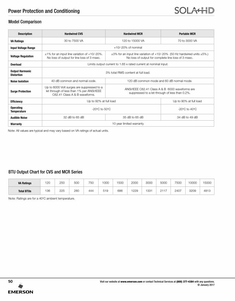
Power Protection and Conditioning
Visit our website at www.emerson.com or contact Technical Services at (800) 377-4384 with any questions. © January 2017
50
Model Comparison
BTU Output Chart for CVS and MCR Series
Note: Ratings are for a 40oC ambient temperature.
Description Hardwired CVS Hardwired MCR Portable MCR
VA Ratings 30 to 7500 VA 120 to 15000 VA 70 to 3000 VA
Input Voltage Range +10/-20% of nominal
Voltage Regulation±1% for an input line variation of +10/-20%.
No loss of output for line loss of 3 msec.±3% for an input line variation of +10/-20% (50 Hz hardwired units ±5%.)
No loss of output for complete line loss of 3 msec.
Overload Limits output current to 1.65 x rated current at nominal input.
Output Harmonic Distortion
3% total RMS content at full load.
Noise Isolation 40 dB common and normal code. 120 dB common mode and 60 dB normal mode.
Surge ProtectionUp to 6000 Volt surges are suppressed to a let through of less than 1% per ANSI/IEEE
C62.41 Class A & B waveforms.
ANSI/IEEE C62.41 Class A & B 6000 waveforms are suppressed to a let-through of less than 0.2%.
Efficiency Up to 92% at full load Up to 90% at full load
Operating Temperature
-20oC to 50oC -20oC to 40oC
Audible Noise 32 dB to 65 dB 35 dB to 65 dB 34 dB to 49 dB
Warranty 10 year limited warranty
VA Ratings 120 250 500 750 1000 1500 2000 3000 5000 7500 10000 15000
Total BTUs 136 225 280 444 519 686 1229 1331 2117 2407 3209 4813
Note: All values are typical and may vary based on VA ratings of actual units.
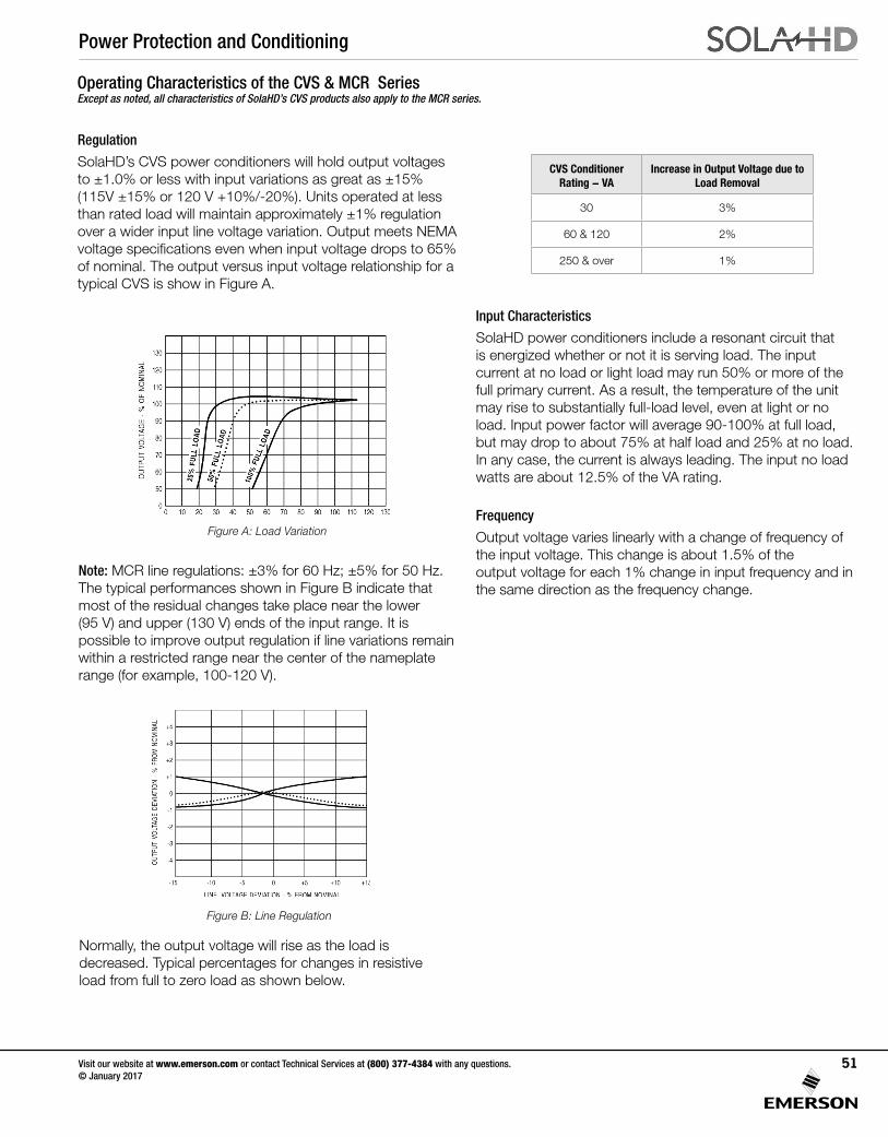
Power Protection and Conditioning
Visit our website at www.emerson.com or contact Technical Services at (800) 377-4384 with any questions. © January 2017
51
Regulation
SolaHD’s CVS power conditioners will hold output voltages to ±1.0% or less with input variations as great as ±15% (115V ±15% or 120 V +10%/-20%). Units operated at less than rated load will maintain approximately ±1% regulation over a wider input line voltage variation. Output meets NEMA voltage specifications even when input voltage drops to 65% of nominal. The output versus input voltage relationship for a typical CVS is show in Figure A.
Figure A: Load Variation
Note: MCR line regulations: ±3% for 60 Hz; ±5% for 50 Hz. The typical performances shown in Figure B indicate that most of the residual changes take place near the lower (95 V) and upper (130 V) ends of the input range. It is possible to improve output regulation if line variations remain within a restricted range near the center of the nameplate range (for example, 100-120 V).
Figure B: Line Regulation
Normally, the output voltage will rise as the load is decreased. Typical percentages for changes in resistive load from full to zero load as shown below.
Input Characteristics
SolaHD power conditioners include a resonant circuit that is energized whether or not it is serving load. The input current at no load or light load may run 50% or more of the full primary current. As a result, the temperature of the unit may rise to substantially full-load level, even at light or no load. Input power factor will average 90-100% at full load, but may drop to about 75% at half load and 25% at no load. In any case, the current is always leading. The input no load watts are about 12.5% of the VA rating.
Frequency
Output voltage varies linearly with a change of frequency of the input voltage. This change is about 1.5% of the output voltage for each 1% change in input frequency and in the same direction as the frequency change.
CVS Conditioner Rating - VA
Increase in Output Voltage due to Load Removal
30 3%
60 & 120 2%
250 & over 1%
Operating Characteristics of the CVS & MCR Series Except as noted, all characteristics of SolaHD’s CVS products also apply to the MCR series.
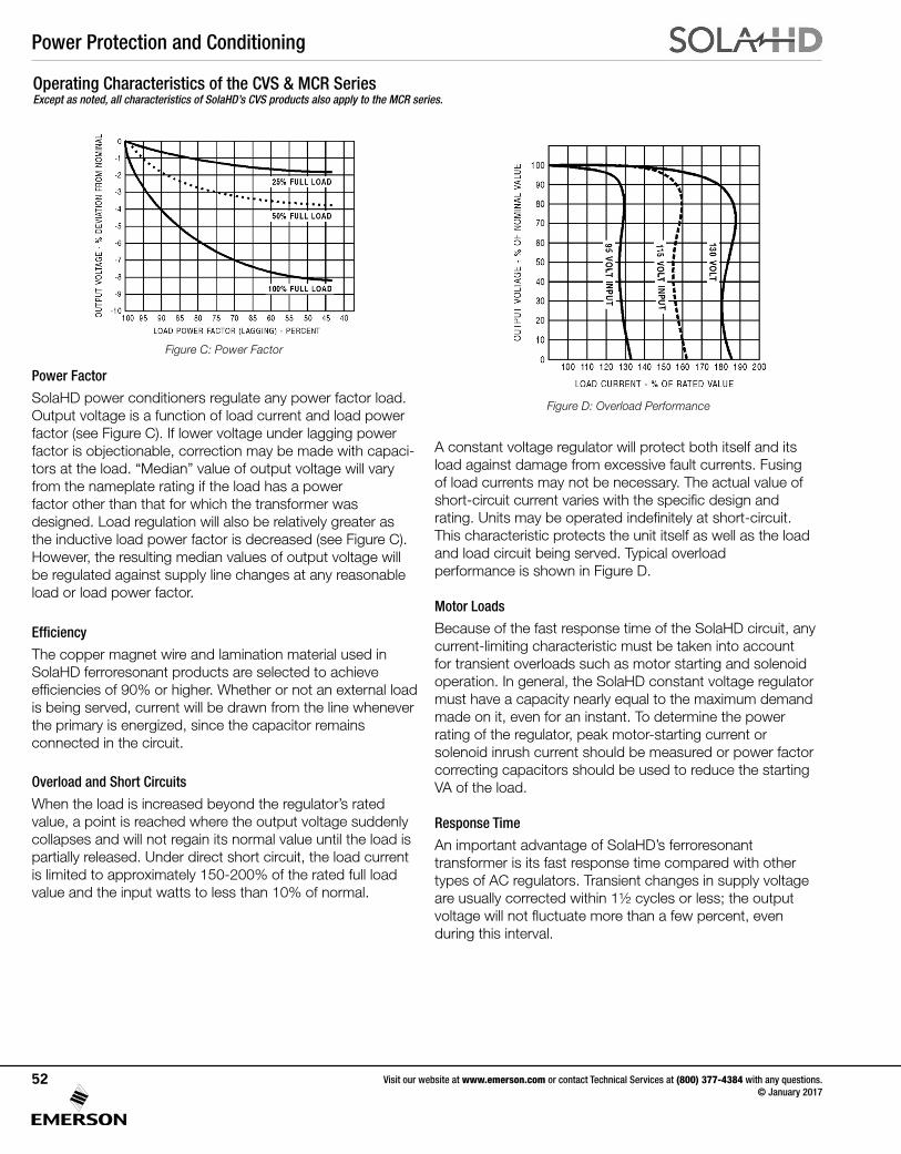
Power Protection and Conditioning
Visit our website at www.emerson.com or contact Technical Services at (800) 377-4384 with any questions. © January 2017
52
A constant voltage regulator will protect both itself and its load against damage from excessive fault currents. Fusing of load currents may not be necessary. The actual value of short-circuit current varies with the specific design and rating. Units may be operated indefinitely at short-circuit. This characteristic protects the unit itself as well as the load and load circuit being served. Typical overload performance is shown in Figure D.
Motor Loads
Because of the fast response time of the SolaHD circuit, any current-limiting characteristic must be taken into account for transient overloads such as motor starting and solenoid operation. In general, the SolaHD constant voltage regulator must have a capacity nearly equal to the maximum demand made on it, even for an instant. To determine the power rating of the regulator, peak motor-starting current or solenoid inrush current should be measured or power factor correcting capacitors should be used to reduce the starting VA of the load.
Response Time
An important advantage of SolaHD’s ferroresonant transformer is its fast response time compared with other types of AC regulators. Transient changes in supply voltage are usually corrected within 1½ cycles or less; the output voltage will not fluctuate more than a few percent, even during this interval.
Figure D: Overload Performance
Figure C: Power Factor
Power Factor
SolaHD power conditioners regulate any power factor load. Output voltage is a function of load current and load power factor (see Figure C). If lower voltage under lagging power factor is objectionable, correction may be made with capaci-tors at the load. “Median” value of output voltage will vary from the nameplate rating if the load has a power factor other than that for which the transformer was designed. Load regulation will also be relatively greater as the inductive load power factor is decreased (see Figure C). However, the resulting median values of output voltage will be regulated against supply line changes at any reasonable load or load power factor.
Efficiency
The copper magnet wire and lamination material used in SolaHD ferroresonant products are selected to achieve efficiencies of 90% or higher. Whether or not an external load is being served, current will be drawn from the line whenever the primary is energized, since the capacitor remains connected in the circuit.
Overload and Short Circuits
When the load is increased beyond the regulator’s rated value, a point is reached where the output voltage suddenly collapses and will not regain its normal value until the load is partially released. Under direct short circuit, the load current is limited to approximately 150-200% of the rated full load value and the input watts to less than 10% of normal.
Operating Characteristics of the CVS & MCR Series Except as noted, all characteristics of SolaHD’s CVS products also apply to the MCR series.
Power Protection and Conditioning
Visit our website at www.emerson.com or contact Technical Services at (800) 377-4384 with any questions. © January 2017
53
Temperature
SolaHD’s ferroresonant power conditioners are very stable with respect to temperature. The change in output voltage is only 0.025%/°C. Units are factory adjusted to +2%/-0% of nominal, with full load and nominal input voltage. This adjustment to the high side of nominal is to compensate for the natural temperature drift of about 1% that takes place during initial turn-on or warm-up. When the unit warms up to operating temperature, the voltage typically falls about 1%.
At a stable operating temperature, the output voltage will change slightly with varying ambient temperatures. This shift is equal to approximately 1% for each 40°C of temperature change. The normal maximum temperature rise of a SolaHD power conditioner may fall anywhere in the range of 40°C to 110°C depending on the type and rating. The nominal design ambient range is between -20°C and +50°C (-20°C to +40°C for 70 - 1000 VA, 60 Hz portable models).
External Magnetic Field
In almost all applications, this effect may be disregarded.The exclusive SolaHD “wide outside leg” construction reduces stray magnetic fields to a practical minimum. On critical applications, care should be taken in orientation of the core with respect to critical circuits to minimize the effect of the field.
Phase Shift
The phase difference which exists between input and output voltages is in the range of 120 degrees to 140 degrees at full load. This phase difference varies with the magnitude and power factor of the load, and to a lesser extent, with changes in line voltage and load power factor.
Transient Protection
Ferroresonant power conditioners protect input transients (caused by lightning and load switching) from damaging the sensitive electronic load. A typical surge protective device (SPD) tries to ‘clamp’ a transient by diverting it to ground. A ferroresonant power conditioner “blocks” the transient. This ‘blocking’ action is achieved by total physical separation from input (primary) to output (secondary). Because of this difference in operation, it is difficult to apply the same specifications to a ferroresonant power conditioner. Some parallels can be made however.
One, is that under load, the let-through voltage of a ferroresonant power conditioner (SPD refers to "clamping voltage”) is less than 10 V above the point where the sine wave would normally be at any given time. The ferroresonant power conditioner is an ‘active tracking’ suppressor with several advantages. The Ferro power conditioner will not shunt the transient to the ground line as SPD devices typically do. Shunting the transient to ground can cause the disturbance to be transmitted to other sensitive loads within a facility. This can pose serious problems with electronic or microprocessor-based equipment, especially if there is poor grounding within a facility. Other advantages provided by ferroresonant power conditioners include noise filtering, filtering of harmonic distortion and protection against voltage fluctuations such as sags or swells. These features are not provided by standard surge protection devices but are often misrepresented or misused by SPD manufacturers trying to market their product as a “Do All” power quality device.
Operating Characteristics of the CVS & MCR Series Except as noted, all characteristics of SolaHD’s CVS products also apply to the MCR series.
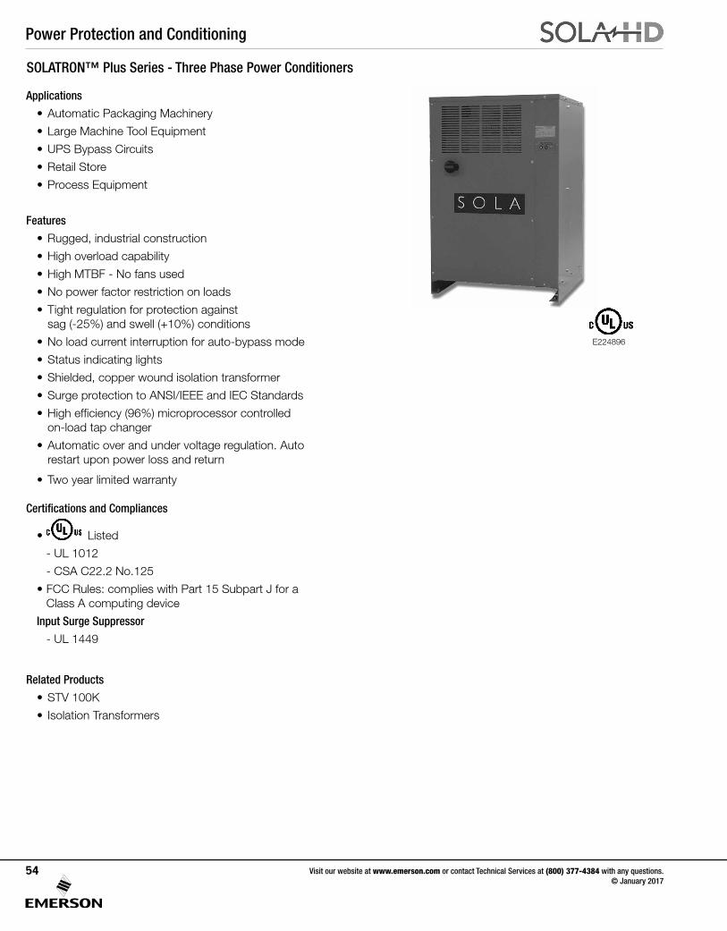
Power Protection and Conditioning
Visit our website at www.emerson.com or contact Technical Services at (800) 377-4384 with any questions. © January 2017
54
SOLATRON™ Plus Series - Three Phase Power Conditioners
Applications
• Automatic Packaging Machinery
• Large Machine Tool Equipment
• UPS Bypass Circuits
• Retail Store
• Process Equipment
Features
• Rugged, industrial construction
• High overload capability
• High MTBF - No fans used
• No power factor restriction on loads
• Tight regulation for protection against sag (-25%) and swell (+10%) conditions
• No load current interruption for auto-bypass mode
• Status indicating lights
• Shielded, copper wound isolation transformer
• Surge protection to ANSI/IEEE and IEC Standards
• High efficiency (96%) microprocessor controlled on-load tap changer
• Automatic over and under voltage regulation. Auto restart upon power loss and return
• Two year limited warranty
Certifications and Compliances
• Listed
- UL 1012
- CSA C22.2 No.125
• FCC Rules: complies with Part 15 Subpart J for a Class A computing device
Input Surge Suppressor
- UL 1449
Related Products
• STV 100K
• Isolation Transformers
E224896
Power Protection and Conditioning
Visit our website at www.emerson.com or contact Technical Services at (800) 377-4384 with any questions. © January 2017
55
Noise Suppression Performance Specifications
Selection Table
Protection Specifications
Under Voltage
Output voltage will switch to bypass mode when input is less than 50% of nominal. Regulated output voltage will be re-established once input voltage is with specifications.
Short Circuit Protection Input circuit breaker
Over Temperature Protection
Amber lamp indication of over temperature at approximately 180°C. Unit switches to by-pass mode until internal temperature is reduced to specified values.
Common Mode Noise Attenuation
150 dB at 100 kHz
Normal Mode Noise Attenuation
65 dB at 100 kHz
Surge Protection Tested to ANSI/IEEE standard C62.41 A&B
Output kVA Catalog Number Vac Input Vac Output Ship Weight lbs (kg)
208 Vac Input, 208Y/120 Vac Output, 60 Hz
20 63TAA320 208 208Y/120 600.0 (273.00)
30 63TAA330 208 208Y/120 750.0 (341.00)
50 63TAA350 208 208Y/120 950.0 (432.00)
75 63TAA375 208 208Y/120 1200.0 (545.00)
480 Vac Input, 208Y/120 Vac Output, 60 Hz
20 63TCA320 480 208Y/120 600.0 (273.00)
30 63TCA330 480 208Y/120 750.0 (341.00)
50 63TCA350 480 208Y/120 950.0 (432.00)
75 63TCA375 480 208Y/120 1200.0 (545.00)
480 Vac Input, 480Y/277 Vac Output, 60 Hz
20 63TCC320 480 480Y/277 600.0 (273.00)
30 63TCC330 480 480Y/277 750.0 (341.00)
50 63TCC350 480 480Y/277 950.0 (432.00)
75 63TCC375 480 480Y/277 1200.0 (545.00)
600 Vac Input, 208Y/120 Vac Output, 60 Hz
20 63TDA320 600 208Y/120 600.0 (273.00)
30 63TDA330 600 208Y/120 750.0 (341.00)
50 63TDA350 600 208Y/120 950.0 (432.00)
75 63TDA375 600 208Y/120 1200.0 (545.00)
Custom Voltages240 Vac Input, 240Y/139 Vac Output, 60 Hz480 Vac Input, 240Y/139 Vac Output, 60 Hz600 Vac Input, 240Y/139 Vac Output, 60 Hz
Contact Technical Services for custom voltages.
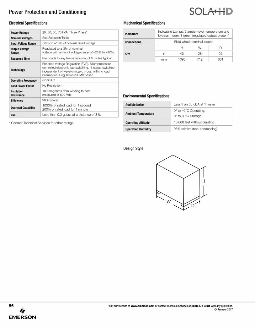
Power Protection and Conditioning
Visit our website at www.emerson.com or contact Technical Services at (800) 377-4384 with any questions. © January 2017
56
Mechanical Specifications
Environmental Specifications
IndicatorsIndicating Lamps: 2 amber (over temperature and bypass mode), 1 green (regulated output present)
Connections Field wired, terminal blocks
Size
H W D
in 43 28 26
mm 1093 712 661
Audible Noise Less than 65 dBA at 1 meter
Ambient Temperature 0° to 40°C Operating,
0° to 80°C Storage
Operating Altitude 10,000 feet without derating
Operating Humidity 95% relative (non-condensing)
Electrical Specifications
Power Ratings 20, 30, 50, 75 kVA, Three Phase*
Nominal Voltages See Selection Table
Input Voltage Range -25% to +10% of nominal rated voltage
Output VoltageRange
Regulated to ± 3% of nominal voltage with an input voltage range of –25% to +10%.
Response Time Responds to any line variation in <1.5 cycles typical.
Technology
Enhance Voltage Regulation (EVR), Microprocessor controlled electronic tap switching. 6 steps, switched independent of waveform zero cross, with no load interruption. Regulation is RMS based.
Operating Frequency 57-63 Hz
Load Power Factor No Restriction
Insulation Resistance
100 megohms from winding to core measured at 500 Vdc
Efficiency 96% typical
Overload Capability1000% of rated load for 1 second200% of rated load for 1 minute
EMI Less than 0.2 gauss at a distance of 3 ft.
Design Style
* Contact Technical Services for other ratings.
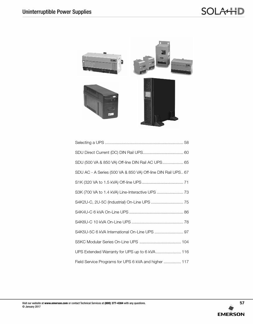
Uninterruptible Power Supplies
Visit our website at www.emerson.com or contact Technical Services at (800) 377-4384 with any questions. © January 2017
57
Selecting a UPS .................................................................... 58
SDU Direct Current (DC) DIN Rail UPS ................................... 60
SDU (500 VA & 850 VA) Off-line DIN Rail AC UPS .................. 65
SDU AC - A Series (500 VA & 850 VA) Off-line DIN Rail UPS .. 67
S1K (320 VA to 1.5 kVA) Off-line UPS .................................... 71
S3K (700 VA to 1.4 kVA) Line-Interactive UPS ....................... 73
S4K2U-C, 2U-5C (Industrial) On-Line UPS ............................ 75
S4K4U-C 6 kVA On-Line UPS ............................................... 86
S4K6U-C 10 kVA On-Line UPS ............................................. 78
S4K5U-5C 6 kVA International On-Line UPS ......................... 97
S5KC Modular Series On-Line UPS .................................... 104
UPS Extended Warranty for UPS up to 6 kVA ...................... 116
Field Service Programs for UPS 6 kVA and higher ............... 117
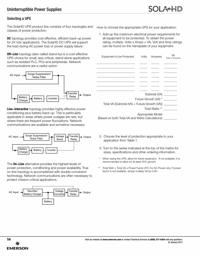
Uninterruptible Power Supplies
Visit our website at www.emerson.com or contact Technical Services at (800) 377-4384 with any questions. © January 2017
58
The SolaHD UPS product line consists of four topologies and classes of power protection:
DC topology provides cost effective, efficient back-up power for 24 Vdc applications. The SolaHD DC UPS will support the load during AC power loss or power supply failure.
Off-Line topology (also called stand-by) is a cost-effective UPS choice for small, less critical, stand-alone applications such as isolated PLC, PCs and peripherals. Network communications are a useful option.
Line-Interactive topology provides highly effective power conditioning plus battery back-up. This is particularly applicable in areas where power outages are rare, but where there are frequent power fluctuations. Network communications are available and sometime necessary.
The On-Line alternative provides the highest levels of power protection, conditioning and power availability. True on-line topology is accomplished with double conversion technology. Network communications are often necessary to protect mission-critical applications.
Selecting a UPS
How to choose the appropriate UPS for your application:
1. Add up the maximum electrical power requirements for all equipment to be protected. To obtain the power
rating, multiply: Volts x Amps = VA. Volt and Amp ratings can be found on the nameplate of your equipment.
Equipment to be Protected Volts Amperes VA (Volts x Amperes)
_____________________________ ______ ______ __________
_____________________________ ______ ______ __________
_____________________________ ______ ______ __________
_____________________________ ______ ______ __________
_____________________________ ______ ______ __________
_____________________________ ______ ______ __________
_____________________________ ______ ______ __________
Subtotal (VA) __________
Future Growth (VA) * __________
Total VA [Subtotal (VA) + Future Growth (VA)] __________
Total Watts ** __________
Appropriate Model (Based on both Total VA and Watts Calculations) __________
2. Choose the level of protection appropriate to your application from Table 1.
3. Turn to the series indicated at the top of the matrix for sizes, specifications and other ordering information.
* When sizing the UPS, allow for future expansion. If not available, it is recommended to allow for at least 25% growth.
** Total Watt = Total VA x Power Factor (P.F.) for AC Power only. If power factor is not available, simply multiply VA by 0.65.
Surge Suppression/Noise Filter
Battery Charger
Battery Inverter
Transfer Relay
AC Input
Output
Surge Suppression/Noise Filter
Battery Charger
Battery Inverter
AC Input OutputVoltageBoost
TransferRelay
OutputRecritfer/Battery Charger
VoltageConverter
TransferRelay
Battery
AC Input
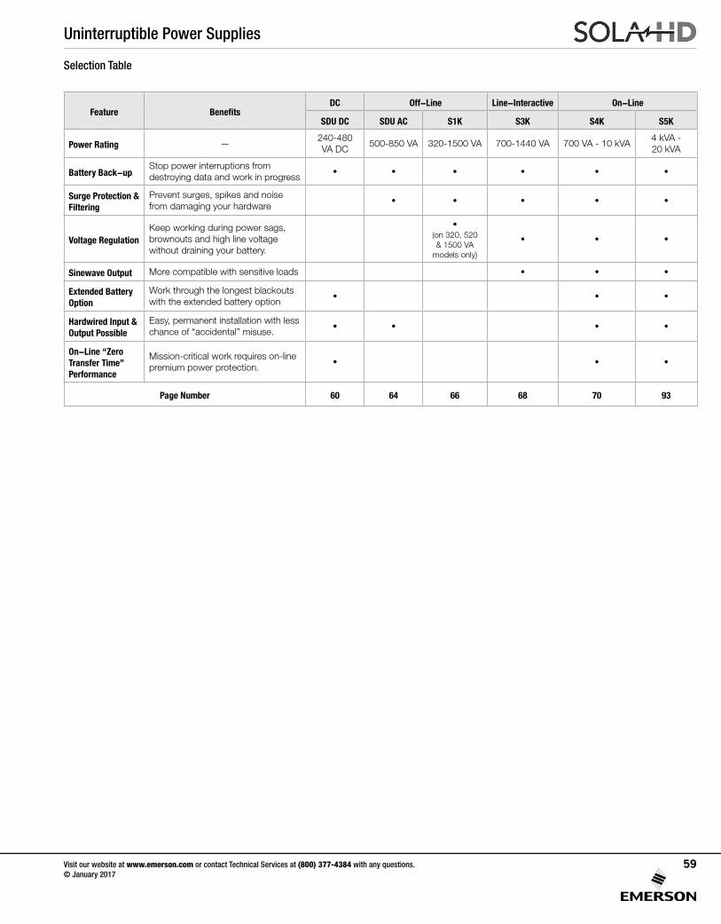
Uninterruptible Power Supplies
Visit our website at www.emerson.com or contact Technical Services at (800) 377-4384 with any questions. © January 2017
59
Selection Table
Feature BenefitsDC Off-Line Line-Interactive On-Line
SDU DC SDU AC S1K S3K S4K S5K
Power Rating —240-480 VA DC
500-850 VA 320-1500 VA 700-1440 VA 700 VA - 10 kVA4 kVA - 20 kVA
Battery Back-upStop power interruptions from destroying data and work in progress • • • • • •
Surge Protection & Filtering
Prevent surges, spikes and noise from damaging your hardware • • • • •
Voltage RegulationKeep working during power sags, brownouts and high line voltage without draining your battery.
•(on 320, 520 & 1500 VA
models only)
• • •
Sinewave Output More compatible with sensitive loads • • •
Extended Battery Option
Work through the longest blackouts with the extended battery option • • •
Hardwired Input & Output Possible
Easy, permanent installation with less chance of “accidental” misuse. • • • •
On-Line “Zero Transfer Time” Performance
Mission-critical work requires on-line premium power protection. • • •
Page Number 60 64 66 68 70 93
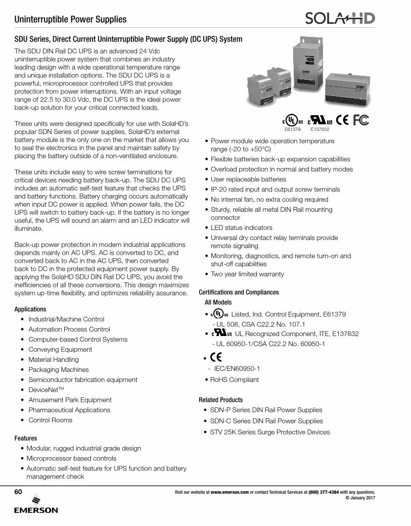
Uninterruptible Power Supplies
SDU Series, Direct Current Uninterruptible Power Supply (DC UPS) System The SDU DIN Rail DC UPS is an advanced 24 Vdc uninterruptible power system that combines an industry leading design with a wide operational temperature range and unique installation options. The SDU DC UPS is a powerful, microprocessor controlled UPS that provides protection from power interruptions. With an input voltage range of 22.5 to 30.0 Vdc, the DC UPS is the ideal power back-up solution for your critical connected loads.
These units were designed specifically for use with SolaHD’s popular SDN Series of power supplies. SolaHD’s external battery module is the only one on the market that allows you to seal the electronics in the panel and maintain safety by placing the battery outside of a non-ventilated enclosure.
These units include easy to wire screw terminations for critical devices needing battery back-up. The SDU DC UPS includes an automatic self-test feature that checks the UPS and battery functions. Battery charging occurs automatically when input DC power is applied. When power fails, the DC UPS will switch to battery back-up. If the battery is no longer useful, the UPS will sound an alarm and an LED indicator will illuminate.
Back-up power protection in modern industrial applications depends mainly on AC UPS. AC is converted to DC, and converted back to AC in the AC UPS, then converted back to DC in the protected equipment power supply. By applying the SolaHD SDU DIN Rail DC UPS, you avoid the inefficiencies of all these conversions. This design maximizes system up-time flexibility, and optimizes reliability assurance.
Applications
• Industrial/Machine Control
• Automation Process Control
• Computer-based Control Systems
• Conveying Equipment
• Material Handling
• Packaging Machines
• Semiconductor fabrication equipment
• DeviceNetTM
• Amusement Park Equipment
• Pharmaceutical Applications
• Control Rooms
Features
• Modular, rugged industrial grade design
• Microprocessor based controls
• Automatic self-test feature for UPS function and battery management check
• Power module wide operation temperature range (-20 to +50°C)
• Flexible batteries back-up expansion capabilities
• Overload protection in normal and battery modes
• User replaceable batteries
• IP-20 rated input and output screw terminals
• No internal fan, no extra cooling required
• Sturdy, reliable all metal DIN Rail mounting connector
• LED status indicators
• Universal dry contact relay terminals provide remote signaling
• Monitoring, diagnostics, and remote turn-on and shut-off capabilities
• Two year limited warranty
Certifications and Compliances
All Models
• Listed, Ind. Control Equipment, E61379
- UL 508, CSA C22.2 No. 107.1•
UL 60950 E137632
CUL/CSA-C22.2No. 234-M90
UL Recognized Component, ITE, E137632
- UL 60950-1/CSA C22.2 No. 60950-1
•
- IEC/EN60950-1
• RoHS Compliant
Related Products
• SDN-P Series DIN Rail Power Supplies
• SDN-C Series DIN Rail Power Supplies
• STV 25K Series Surge Protective Devices
E137632E61379
Visit our website at www.emerson.com or contact Technical Services at (800) 377-4384 with any questions. © January 2017
60
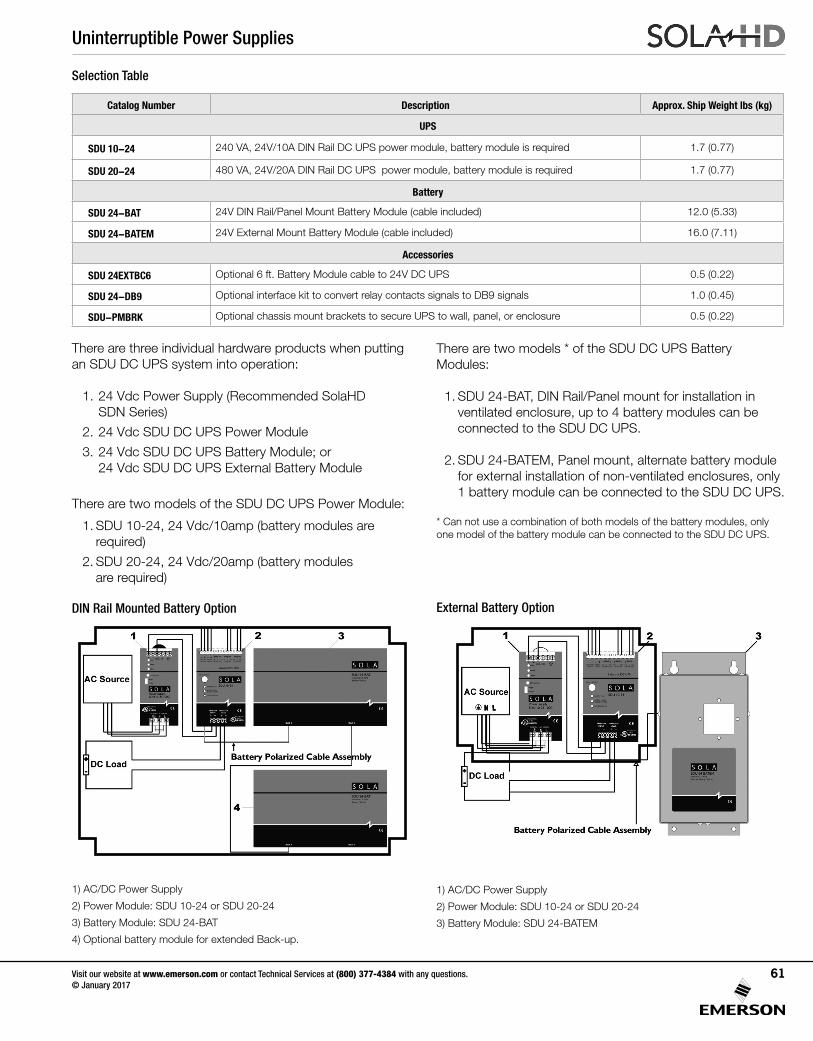
Uninterruptible Power Supplies
There are three individual hardware products when putting an SDU DC UPS system into operation:
1. 24 Vdc Power Supply (Recommended SolaHD SDN Series)
2. 24 Vdc SDU DC UPS Power Module
3. 24 Vdc SDU DC UPS Battery Module; or 24 Vdc SDU DC UPS External Battery Module
There are two models of the SDU DC UPS Power Module:
1. SDU 10-24, 24 Vdc/10amp (battery modules are required)
2. SDU 20-24, 24 Vdc/20amp (battery modules are required)
Selection Table
Catalog Number Description Approx. Ship Weight lbs (kg)
UPS
SDU 10-24 240 VA, 24V/10A DIN Rail DC UPS power module, battery module is required 1.7 (0.77)
SDU 20-24 480 VA, 24V/20A DIN Rail DC UPS power module, battery module is required 1.7 (0.77)
Battery
SDU 24-BAT 24V DIN Rail/Panel Mount Battery Module (cable included) 12.0 (5.33)
SDU 24-BATEM 24V External Mount Battery Module (cable included) 16.0 (7.11)
Accessories
SDU 24EXTBC6 Optional 6 ft. Battery Module cable to 24V DC UPS 0.5 (0.22)
SDU 24-DB9 Optional interface kit to convert relay contacts signals to DB9 signals 1.0 (0.45)
SDU-PMBRK Optional chassis mount brackets to secure UPS to wall, panel, or enclosure 0.5 (0.22)
There are two models * of the SDU DC UPS Battery Modules:
1. SDU 24-BAT, DIN Rail/Panel mount for installation in ventilated enclosure, up to 4 battery modules can be connected to the SDU DC UPS.
2. SDU 24-BATEM, Panel mount, alternate battery module for external installation of non-ventilated enclosures, only 1 battery module can be connected to the SDU DC UPS.
* Can not use a combination of both models of the battery modules, only one model of the battery module can be connected to the SDU DC UPS.
DIN Rail Mounted Battery Option
1) AC/DC Power Supply
2) Power Module: SDU 10-24 or SDU 20-24
3) Battery Module: SDU 24-BATEM
1) AC/DC Power Supply
2) Power Module: SDU 10-24 or SDU 20-24
3) Battery Module: SDU 24-BAT
4) Optional battery module for extended Back-up.
External Battery Option
Visit our website at www.emerson.com or contact Technical Services at (800) 377-4384 with any questions. © January 2017
61
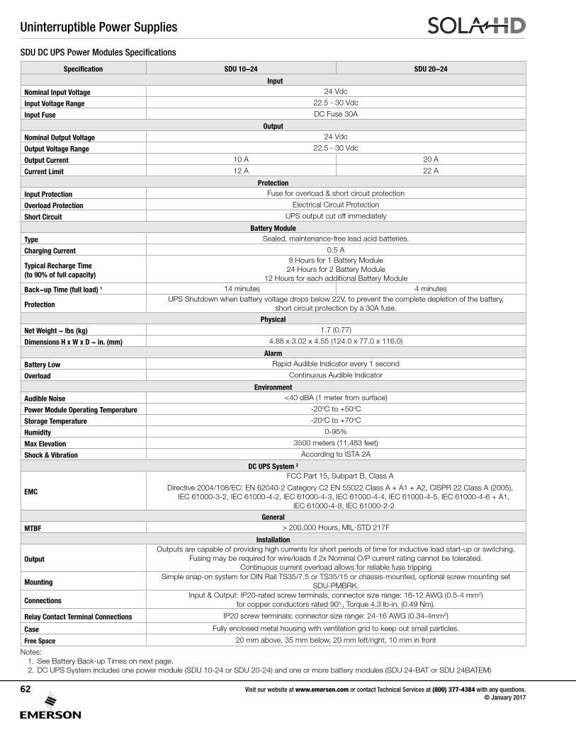
Uninterruptible Power Supplies
Specification SDU 10-24 SDU 20-24
Input
Nominal Input Voltage 24 Vdc
Input Voltage Range 22.5 - 30 Vdc
Input Fuse DC Fuse 30A
Output
Nominal Output Voltage 24 Vdc
Output Voltage Range 22.5 - 30 Vdc
Output Current 10 A 20 A
Current Limit 12 A 22 A
Protection
Input Protection Fuse for overload & short circuit protection
Overload Protection Electrical Circuit Protection
Short Circuit UPS output cut off immediately
Battery Module
Type Sealed, maintenance-free lead acid batteries.
Charging Current 0.5 A
Typical Recharge Time (to 90% of full capacity)
8 Hours for 1 Battery Module24 Hours for 2 Battery Module
12 Hours for each additional Battery Module
Back-up Time (full load) 1 14 minutes 4 minutes
ProtectionUPS Shutdown when battery voltage drops below 22V, to prevent the complete depletion of the battery,
short circuit protection by a 30A fuse.
Physical
Net Weight - lbs (kg) 1.7 (0.77)
Dimensions H x W x D - in. (mm) 4.88 x 3.02 x 4.55 (124.0 x 77.0 x 116.0)
Alarm
Battery Low Rapid Audible Indicator every 1 second
Overload Continuous Audible Indicator
Environment
Audible Noise <40 dBA (1 meter from surface)
Power Module Operating Temperature -20oC to +50oC
Storage Temperature -20oC to +70oC
Humidity 0-95%
Max Elevation 3500 meters (11,483 feet)
Shock & Vibration According to ISTA 2A
DC UPS System 2
EMC
FCC Part 15, Subpart B, Class A
Directive 2004/108/EC: EN 62040-2 Category C2 EN 55022 Class A + A1 + A2, CISPR 22 Class A (2005), IEC 61000-3-2, IEC 61000-4-2, IEC 61000-4-3, IEC 61000-4-4, IEC 61000-4-5, IEC 61000-4-6 + A1,
IEC 61000-4-8, IEC 61000-2-2
General
MTBF > 200,000 Hours, MIL-STD 217F
Installation
OutputOutputs are capable of providing high currents for short periods of time for inductive load start-up or switching.
Fusing may be required for wire/loads if 2x Nominal O/P current rating cannot be tolerated. Continuous current overload allows for reliable fuse tripping
MountingSimple snap-on system for DIN Rail TS35/7.5 or TS35/15 or chassis-mounted, optional screw mounting set
SDU-PMBRK.
ConnectionsInput & Output: IP20-rated screw terminals, connector size range: 16-12 AWG (0.5-4 mm2)
for copper conductors rated 90o , Torque 4.3 lb-in. (0.49 Nm).
Relay Contact Terminal Connections IP20 screw terminals; connector size range: 24-16 AWG (0.34-4mm2)
Case Fully enclosed metal housing with ventilation grid to keep out small particles.
Free Space 20 mm above, 35 mm below, 20 mm left/right, 10 mm in front
Notes:1. See Battery Back-up Times on next page.2. DC UPS System includes one power module (SDU 10-24 or SDU 20-24) and one or more battery modules (SDU 24-BAT or SDU 24BATEM)
SDU DC UPS Power Modules Specifications
Visit our website at www.emerson.com or contact Technical Services at (800) 377-4384 with any questions. © January 2017
62
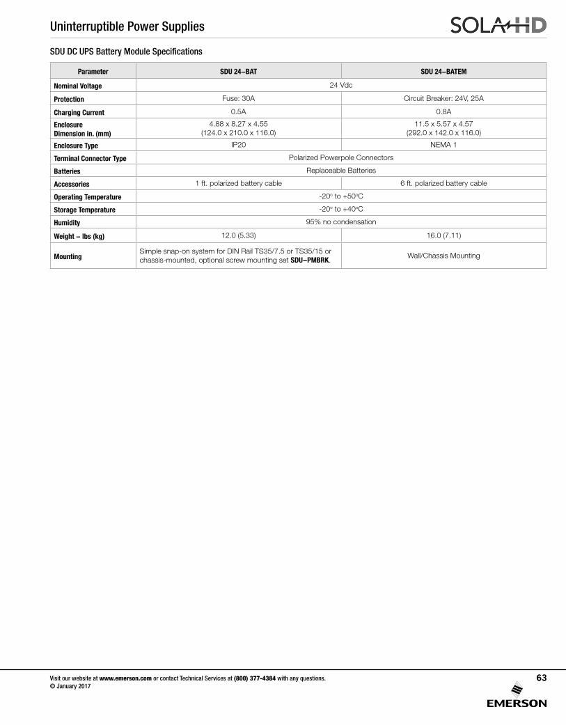
Uninterruptible Power Supplies
Parameter SDU 24-BAT SDU 24-BATEM
Nominal Voltage 24 Vdc
Protection Fuse: 30A Circuit Breaker: 24V, 25A
Charging Current 0.5A 0.8A
Enclosure Dimension in. (mm)
4.88 x 8.27 x 4.55 (124.0 x 210.0 x 116.0)
11.5 x 5.57 x 4.57 (292.0 x 142.0 x 116.0)
Enclosure Type IP20 NEMA 1
Terminal Connector Type Polarized Powerpole Connectors
Batteries Replaceable Batteries
Accessories 1 ft. polarized battery cable 6 ft. polarized battery cable
Operating Temperature -20o to +50oC
Storage Temperature -20o to +40oC
Humidity 95% no condensation
Weight - lbs (kg) 12.0 (5.33) 16.0 (7.11)
MountingSimple snap-on system for DIN Rail TS35/7.5 or TS35/15 or chassis-mounted, optional screw mounting set SDU-PMBRK.
Wall/Chassis Mounting
SDU DC UPS Battery Module Specifications
Visit our website at www.emerson.com or contact Technical Services at (800) 377-4384 with any questions. © January 2017
63
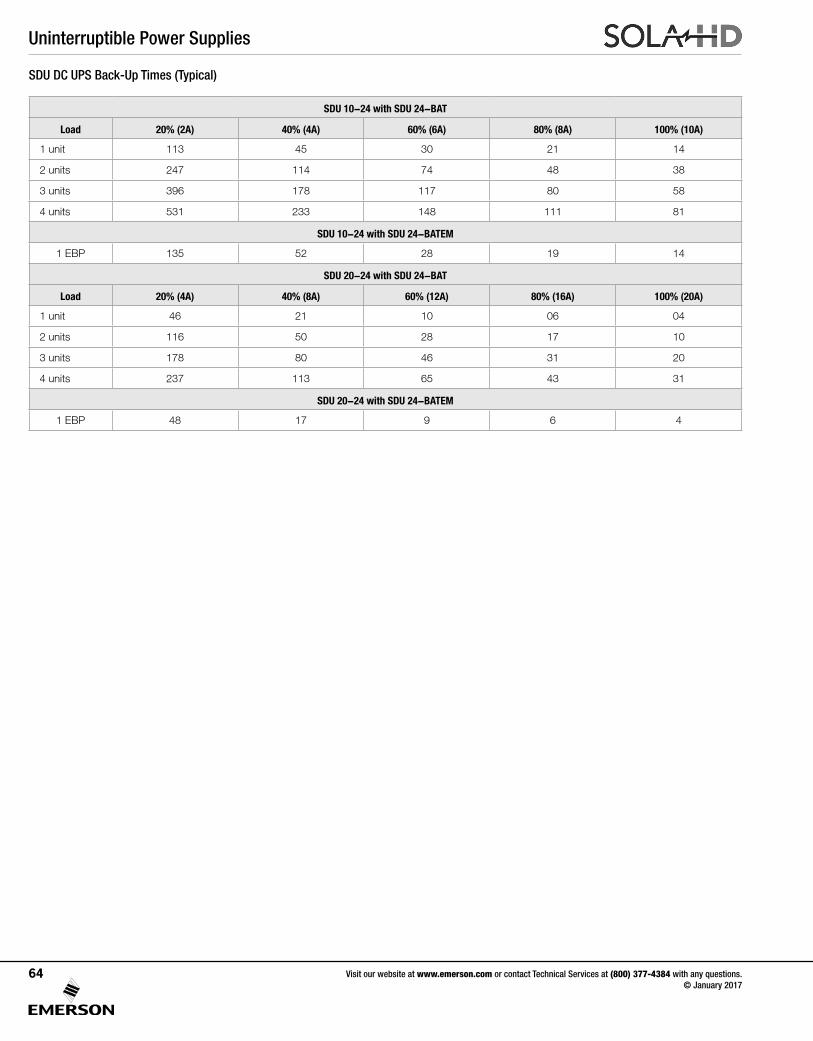
Uninterruptible Power Supplies
SDU 10-24 with SDU 24-BAT
Load 20% (2A) 40% (4A) 60% (6A) 80% (8A) 100% (10A)
1 unit 113 45 30 21 14
2 units 247 114 74 48 38
3 units 396 178 117 80 58
4 units 531 233 148 111 81
SDU 10-24 with SDU 24-BATEM
1 EBP 135 52 28 19 14
SDU 20-24 with SDU 24-BAT
Load 20% (4A) 40% (8A) 60% (12A) 80% (16A) 100% (20A)
1 unit 46 21 10 06 04
2 units 116 50 28 17 10
3 units 178 80 46 31 20
4 units 237 113 65 43 31
SDU 20-24 with SDU 24-BATEM
1 EBP 48 17 9 6 4
SDU DC UPS Back-Up Times (Typical)
Visit our website at www.emerson.com or contact Technical Services at (800) 377-4384 with any questions. © January 2017
64
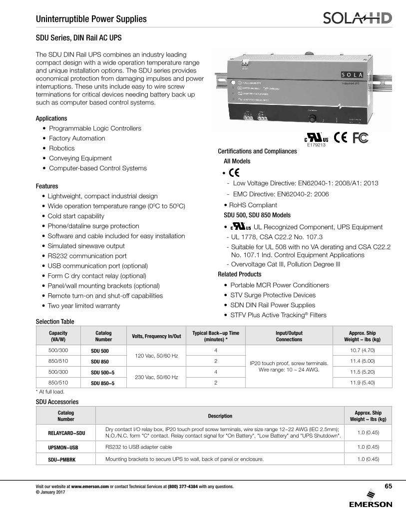
Uninterruptible Power Supplies
Visit our website at www.emerson.com or contact Technical Services at (800) 377-4384 with any questions. © January 2017
65
The SDU DIN Rail UPS combines an industry leading compact design with a wide operation temperature range and unique installation options. The SDU series provides economical protection from damaging impulses and power interruptions. These units include easy to wire screw terminations for critical devices needing battery back up such as computer based control systems.
Applications
• Programmable Logic Controllers
• Factory Automation
• Robotics
• Conveying Equipment
• Computer-based Control Systems
Features
• Lightweight, compact industrial design
• Wide operation temperature range (00C to 500C)
• Cold start capability
• Phone/dataline surge protection
• Software and cable included for easy installation
• Simulated sinewave output
• RS232 communication port
• USB communication port (optional)
• Form C dry contact relay (optional)
• Panel/wall mounting brackets (optional)
• Remote turn-on and shut-off capabilities
• Two year limited warranty
SDU Series, DIN Rail AC UPS
Selection Table
Certifications and Compliances
All Models
•
- Low Voltage Directive: EN62040-1: 2008/A1: 2013
- EMC Directive: EN62040-2: 2006
• RoHS Compliant
SDU 500, SDU 850 Models
• UL 60950 E137632
CUL/CSA-C22.2No. 234-M90
UL Recognized Component, UPS Equipment
- UL 1778, CSA C22.2 No. 107.3
- Suitable for UL 508 with no VA derating and CSA C22.2 No. 107.1 Ind. Control Equipment Applications
- Overvoltage Cat III, Pollution Degree III
Related Products
• Portable MCR Power Conditioners
• STV Surge Protective Devices
• SDN DIN Rail Power Supplies
• STFV Plus Active Tracking® Filters
SDU Accessories
Capacity (VA/W)
Catalog Number
Volts, Frequency In/OutTypical Back-up Time
(minutes) *Input/Output Connections
Approx. Ship Weight - lbs (kg)
500/300 SDU 500120 Vac, 50/60 Hz
4
IP20 touch proof, screw terminals. Wire range: 10 ~ 24 AWG.
10.7 (4.70)
850/510 SDU 850 2 11.4 (5.00)
500/300 SDU 500-5230 Vac, 50/60 Hz
4 11.5 (5.20)
850/510 SDU 850-5 2 11.9 (5.40)
E179213
* At full load.
Catalog Number
DescriptionApprox. Ship
Weight - lbs (kg)
RELAYCARD-SDUDry contact I/O relay box, IP20 touch proof screw terminals, wire size range 12~22 AWG (IEC 2.5mm); N.O./N.C. form "C" contact. Relay contact signal for "On Battery", "Low Battery" and "UPS Shutdown".
1.0 (0.45)
UPSMON-USB RS232 to USB adapter cable 1.0 (0.45)
SDU-PMBRK Mounting brackets to secure UPS to wall, back of panel or enclosure. 1.0 (0.45)
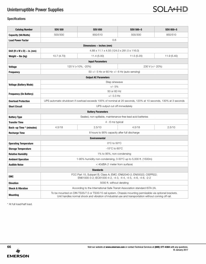
Uninterruptible Power Supplies
Visit our website at www.emerson.com or contact Technical Services at (800) 377-4384 with any questions. © January 2017
66
Specifications
Catalog Number SDU 500 SDU 850 SDU 500-5 SDU 850-5
Capacity (VA/Watts) 500/300 850/510 500/300 850/510
Load Power Factor 0.6
Dimensions - inches (mm)
Unit (H x W x D) - in. (mm) 4.88 x 11.1 x 4.55 (124.0 x 281.0 x 116.0)
Weight - lbs (kg) 10.7 (4.70) 11.4 (5.00) 11.5 (5.20) 11.9 (5.40)
Input Parameters
Voltage 120 V (+10%, -20%) 230 V (+/- 20%)
Frequency 50 +/- 5 Hz or 60 Hz +/- 6 Hz (auto sensing)
Output AC Parameters
Voltage (Battery Mode)Step sinewave
+/- 5%
Frequency (On Battery)50 or 60 Hz
+/- 0.3 Hz
Overload Protection UPS automatic shutdown if overload exceeds 105% of nominal at 20 seconds, 120% at 10 seconds, 130% at 3 seconds
Short Circuit UPS output cut off immediately
Battery Parameters
Battery Type Sealed, non-spillable, maintenance-free lead acid batteries
Transfer Time 4 - 6 ms typical
Back-up Time * (minutes) 4.5/18 2.5/10 4.5/18 2.5/10
Recharge Time 8 hours to 90% capacity after full discharge
Environmental
Operating Temperature 0°C to 50°C
Storage Temperature -15°C to 60°C
Relative Humidity 1% to 95%, non-condensing
Ambient Operation 1-95% humidity non-condensing, 0-50°C up to 5,000 ft. (1500m)
Audible Noise < 40dBA (1 meter from surface)
Standards
EMCFCC Part 15, Subpart B, Class A; EMC: EN62040-2; EN55022; CISPR22;
EN61000-3-2; IEC61000-4-2, -4-3, -4-4, -4-5, -4-6, -4-8, -2-2
Elevation 5000 ft. without derating
Shock & Vibration According to the International Safe Transit Association standard ISTA 2A.
MountingTo be mounted on DIN TS35/7.5 or TS35/15 rail system. Chassis mounting permissible via optional brackets.
Unit handles normal shock and vibration of industrial use and transportation without coming off rail.
* At full load/half load.
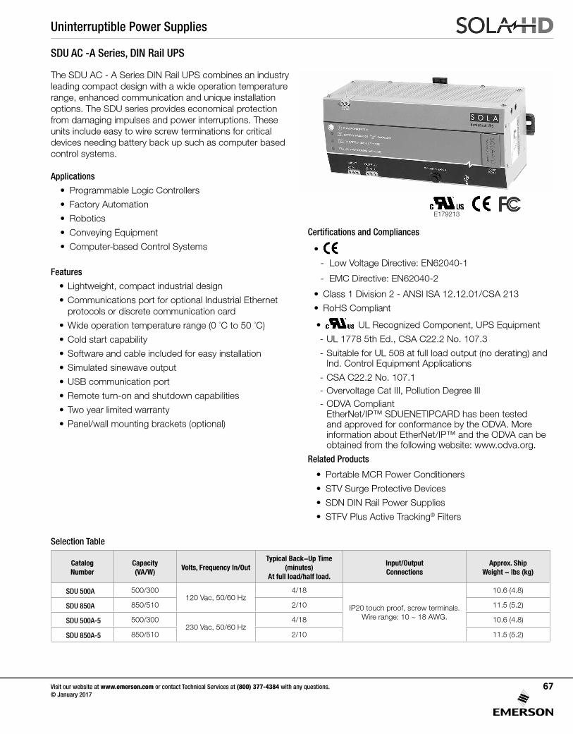
Uninterruptible Power Supplies
Visit our website at www.emerson.com or contact Technical Services at (800) 377-4384 with any questions. © January 2017
67
The SDU AC - A Series DIN Rail UPS combines an industry leading compact design with a wide operation temperature range, enhanced communication and unique installation options. The SDU series provides economical protection from damaging impulses and power interruptions. These units include easy to wire screw terminations for critical devices needing battery back up such as computer based control systems.
Applications
• Programmable Logic Controllers
• Factory Automation
• Robotics
• Conveying Equipment
• Computer-based Control Systems
Features
• Lightweight, compact industrial design
• Communications port for optional Industrial Ethernet protocols or discrete communication card
• Wide operation temperature range (0 °C to 50 °C)
• Cold start capability
• Software and cable included for easy installation
• Simulated sinewave output
• USB communication port
• Remote turn-on and shutdown capabilities
• Two year limited warranty
• Panel/wall mounting brackets (optional)
SDU AC -A Series, DIN Rail UPS
Selection Table
Certifications and Compliances
•
- Low Voltage Directive: EN62040-1
- EMC Directive: EN62040-2
• Class 1 Division 2 - ANSI ISA 12.12.01/CSA 213
• RoHS Compliant
• UL 60950 E137632
CUL/CSA-C22.2No. 234-M90
UL Recognized Component, UPS Equipment
- UL 1778 5th Ed., CSA C22.2 No. 107.3
- Suitable for UL 508 at full load output (no derating) and Ind. Control Equipment Applications
- CSA C22.2 No. 107.1- Overvoltage Cat III, Pollution Degree III- ODVA Compliant
EtherNet/IP™ SDUENETIPCARD has been tested and approved for conformance by the ODVA. More information about EtherNet/IP™ and the ODVA can be obtained from the following website: www.odva.org.
Related Products
• Portable MCR Power Conditioners
• STV Surge Protective Devices
• SDN DIN Rail Power Supplies
• STFV Plus Active Tracking® Filters
Catalog Number
Capacity (VA/W)
Volts, Frequency In/OutTypical Back-Up Time
(minutes) At full load/half load.
Input/Output Connections
Approx. Ship Weight - lbs (kg)
SDU 500A 500/300120 Vac, 50/60 Hz
4/18
IP20 touch proof, screw terminals. Wire range: 10 ~ 18 AWG.
10.6 (4.8)
SDU 850A 850/510 2/10 11.5 (5.2)
SDU 500A-5 500/300230 Vac, 50/60 Hz
4/18 10.6 (4.8)
SDU 850A-5 850/510 2/10 11.5 (5.2)
E179213
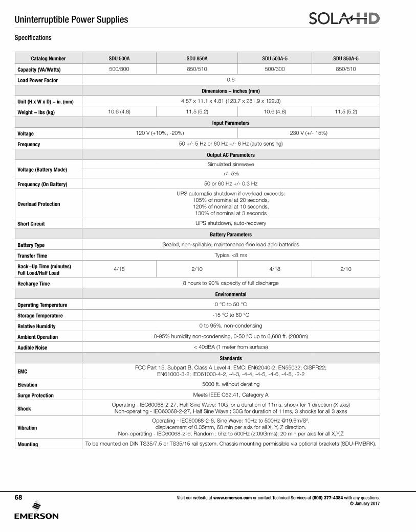
Uninterruptible Power Supplies
Visit our website at www.emerson.com or contact Technical Services at (800) 377-4384 with any questions. © January 2017
68
Specifications
Catalog Number SDU 500A SDU 850A SDU 500A-5 SDU 850A-5
Capacity (VA/Watts) 500/300 850/510 500/300 850/510
Load Power Factor 0.6
Dimensions - inches (mm)
Unit (H x W x D) - in. (mm) 4.87 x 11.1 x 4.81 (123.7 x 281.9 x 122.3)
Weight - lbs (kg) 10.6 (4.8) 11.5 (5.2) 10.6 (4.8) 11.5 (5.2)
Input Parameters
Voltage 120 V (+10%, -20%) 230 V (+/- 15%)
Frequency 50 +/- 5 Hz or 60 Hz +/- 6 Hz (auto sensing)
Output AC Parameters
Voltage (Battery Mode)Simulated sinewave
+/- 5%
Frequency (On Battery) 50 or 60 Hz +/- 0.3 Hz
Overload Protection
UPS automatic shutdown if overload exceeds:105% of nominal at 20 seconds,120% of nominal at 10 seconds,130% of nominal at 3 seconds
Short Circuit UPS shutdown, auto-recovery
Battery Parameters
Battery Type Sealed, non-spillable, maintenance-free lead acid batteries
Transfer Time Typical <8 ms
Back-Up Time (minutes) Full Load/Half Load
4/18 2/10 4/18 2/10
Recharge Time 8 hours to 90% capacity of full discharge
Environmental
Operating Temperature 0 °C to 50 °C
Storage Temperature -15 °C to 60 °C
Relative Humidity 0 to 95%, non-condensing
Ambient Operation 0-95% humidity non-condensing, 0-50 °C up to 6,600 ft. (2000m)
Audible Noise < 40dBA (1 meter from surface)
Standards
EMCFCC Part 15, Subpart B, Class A Level 4; EMC: EN62040-2; EN55032; CISPR22;
EN61000-3-2; IEC61000-4-2, -4-3, -4-4, -4-5, -4-6, -4-8, -2-2
Elevation 5000 ft. without derating
Surge Protection Meets IEEE C62.41, Category A
ShockOperating - IEC60068-2-27, Half Sine Wave: 10G for a duration of 11ms, shock for 1 direction (X axis)Non-operating - IEC60068-2-27, Half Sine Wave : 30G for duration of 11ms, 3 shocks for all 3 axes
VibrationOperating - IEC60068-2-6, Sine Wave: 10Hz to 500Hz @19.6m/S²,
displacement of 0.35mm, 60 min per axis for all X, Y, Z direction.Non-operating - IEC60068-2-6, Random : 5hz to 500Hz (2.09Grms); 20 min per axis for all X,Y,Z
Mounting To be mounted on DIN TS35/7.5 or TS35/15 rail system. Chassis mounting permissible via optional brackets (SDU-PMBRK).
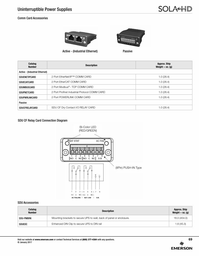
Uninterruptible Power Supplies
Visit our website at www.emerson.com or contact Technical Services at (800) 377-4384 with any questions. © January 2017
69
SDU Accessories
Comm Card Accessories
Catalog Number
DescriptionApprox. Ship
Weight - oz. (g)
SDU-PMBRK Mounting brackets to secure UPS to wall, back of panel or enclosure. 16.0 (454.0)
SDUEDC Enhanced DIN Clip to secure UPS to DIN rail 1.6 (45.3)
Catalog Number
DescriptionApprox. Ship
Weight - oz. (g)
Active - (Industrial Ethernet)
SDUENETIPCARD 2 Port EtherNet/IP™ COMM CARD 1.0 (28.4)
SDUECATCARD 2 Port EtherCAT COMM CARD 1.0 (28.4)
SDUMBUSCARD 2 Port Modbus® - TCP COMM CARD 1.0 (28.4)
SDUPNETCARD 2 Port Profinet Industrial Protocol COMM CARD 1.0 (28.4)
SDUPWRLNKCARD 2 Port POWERLINK COMM CARD 1.0 (28.4)
Passive
SDUCFRELAYCARD SDU CF Dry Contact I/O RELAY CARD 1.0 (28.4)
SDU CF Relay Card Connection Diagram
(8Pin) PUSH-IN Type
Bi-Color LED (RED/GREEN)
Active - (Industrial Ethernet) Passive
1 2 3 4 5 6 87
CNC
A RULIAF C E WOL TAB .B.S
|
|
|
CNC
|
|
|
_+
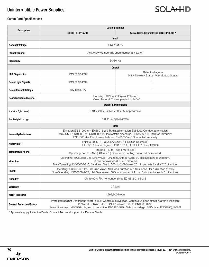
Uninterruptible Power Supplies
Visit our website at www.emerson.com or contact Technical Services at (800) 377-4384 with any questions. © January 2017
70
Comm Card Specifications
DescriptionCatalog Number
SDUCFRELAYCARD Active Cards (Example: SDUENETIPCARD) *
Input
Nominal Voltage +3.3 V ±5 %
Standby Signal Active low via normally open momentary switch
Frequency 50/60 Hz
Output
LED Diagnostics Refer to diagramRefer to diagram
NS = Network Status, MS=Module Status
Relay Logic Signals Refer to diagram —
Relay Contact Ratings 60V peak, 1A —
Case/Enclosure MaterialHousing: LCP(Liquid Crystal Polymer)Color: Natural, Thermoplastic,UL 94 V-0
Weight & Dimensions
H x W x D, in. (mm) 0.91 x 2.0 x 2.2 (23 x 50 x 55) approximate
Net Weight, oz. (g) 1.0 (28.4) approximate
EMC
Immunity/EmissionsEmission EN 61000-6-4 EN55016-2-3 Radiated emission EN55022 Conducted emission
Immunity EN 61000-6-2 EN61000-4-2 Electrostatic discharge, EN61000-4-3 Radiated immunity.EN61000-4-4 Fast transients/burst, EN61000-4-6 Conducted immunity
Approvals *EN/IEC 60950-1 ; UL/CSA 60950-1 Pollution Degree 3 ;UL 508 Pollution Degree 3 CSA 107.1; EU ROHS2,China ROHS2
Temperature °F (°C)Storage: -40 to +185 (-40 to +85)
Operating: -40 to +158 (-40 to +70) Convection cooling; no forced air required.
VibrationOperating: IEC60068-2-6, Sine Wave: 10Hz to 500Hz @19.6m/S², displacement of 0.35mm,
60 min per axis for all X, Y, Z direction. Non-Operating: IEC60068-2-6, Random : 5hz to 500Hz (2.09Grms); 20 min per axis for all X,Y,Z direction.
ShockOperating: IEC60068-2-27, Half Sine Wave: 10G for a duration of 11ms, shock for 1 direction (X axis).
Non-Operating: IEC60068-2-27, Half Sine Wave : 50G for duration of 11ms, 3 shocks for each 3 directions.
Humidity 0% to 90% RH, noncondensing; IEC 68-2-2, 68-2-3
Warranty 2 Years
MTBF (bellcore) 1,968,800 Hours
General Protection/SafetyProtected against Continuous short -circuit, Continuous overload, Continuous open circuit. Galvanic Isolation:
I/P to O/P: 3KVac, I/P to GND: 1.5KVac, O/P to GND: 0.5KVacProtection class 1 (IEC536), degree of protection IP20 (IEC 529) Safe low voltage: SELV (acc. EN60950); ROHS
* Approvals apply for ActiveCards. Contact Technical support for Passive Cards.
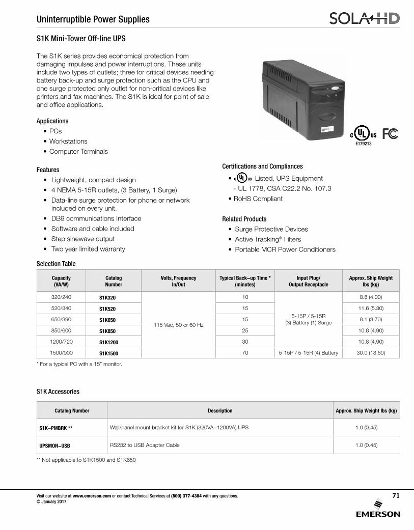
Uninterruptible Power Supplies
Visit our website at www.emerson.com or contact Technical Services at (800) 377-4384 with any questions. © January 2017
71
S1K Mini-Tower Off-line UPS
The S1K series provides economical protection from damaging impulses and power interruptions. These units include two types of outlets; three for critical devices needing battery back-up and surge protection such as the CPU and one surge protected only outlet for non-critical devices like printers and fax machines. The S1K is ideal for point of sale and office applications.
Applications
• PCs
• Workstations
• Computer Terminals
Features
• Lightweight, compact design
• 4 NEMA 5-15R outlets, (3 Battery, 1 Surge)
• Data-line surge protection for phone or network included on every unit.
• DB9 communications Interface
• Software and cable included
• Step sinewave output
• Two year limited warranty
Selection Table
Capacity (VA/W)
Catalog Number
Volts, FrequencyIn/Out
Typical Back-up Time *(minutes)
Input Plug/Output Receptacle
Approx. Ship Weight lbs (kg)
320/240 S1K320
115 Vac, 50 or 60 Hz
10
5-15P / 5-15R(3) Battery (1) Surge
8.8 (4.00)
520/340 S1K520 15 11.6 (5.30)
650/390 S1K650 15 8.1 (3.70)
850/600 S1K850 25 10.8 (4.90)
1200/720 S1K1200 30 10.8 (4.90)
1500/900 S1K1500 70 5-15P / 5-15R (4) Battery 30.0 (13.60)
Certifications and Compliances
• Listed, UPS Equipment
- UL 1778, CSA C22.2 No. 107.3
• RoHS Compliant
Related Products
• Surge Protective Devices
• Active Tracking® Filters
• Portable MCR Power Conditioners
* For a typical PC with a 15” monitor.
Catalog Number Description Approx. Ship Weight lbs (kg)
S1K-PMBRK ** Wall/panel mount bracket kit for S1K (320VA~1200VA) UPS 1.0 (0.45)
UPSMON-USB RS232 to USB Adapter Cable 1.0 (0.45)
S1K Accessories
** Not applicable to S1K1500 and S1K650
E179213
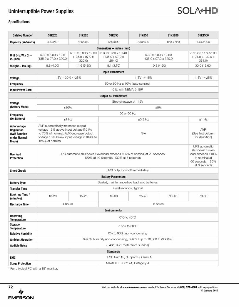
Uninterruptible Power Supplies
Visit our website at www.emerson.com or contact Technical Services at (800) 377-4384 with any questions. © January 2017
72
Catalog Number S1K320 S1K520 S1K650 S1K850 S1K1200 S1K1500
Capacity (VA/Watts) 320/240 520/340 650/390 850/600 1200/720 1440/900
Dimensions - inches (mm)
Unit (H x W x D) - in. (mm)
5.30 x 3.80 x 12.6(135.0 x 97.0 x 320.0)
5.30 x 3.80 x 12.60(135.0 x 97.0 x
320.0)
5.30 x 3.80 x 10.40(135.0 x 97.0 x
264.0)
5.30 x 3.80 x 12.60(135.0 x 97.0 x 320.0)
7.50 x 5.11 x 15.00(191.0 x 130.0 x
381.0)
Weight - lbs (kg) 8.8 (4.00) 11.6 (5.30) 8.1 (3.70) 10.8 (4.90) 30.0 (13.60)
Input Parameters
Voltage 115V + 20% / -25% 115V +/-15% 115V +/-25%
Frequency 50 or 60 Hz ± 10% (auto sensing)
Input Power Cord 6 ft. with NEMA 5-15P
Output AC Parameters
Voltage (Battery Mode)
Step sinewave at 115V
±10% ±5%
Frequency (On Battery)
50 or 60 Hz
±1 Hz ±0.3 Hz ±1 Hz
Auto Voltage Regulation (AVR function under Normal Mode)
AVR automatically increases output voltage 15% above input voltage if 91% to 75% of nominal. AVR decrease output voltage 13% below input voltage if 109% to 125% of nominal
N/AAVR
(See first column for definition)
Overload Protection
UPS automatic shutdown if overload exceeds 105% of nominal at 20 seconds, 120% at 10 seconds, 130% at 3 seconds
UPS automatic shutdown if over-
load exceeds 110% of nominal at
60 seconds, 130% at 3 seconds
Short Circuit UPS output cut off immediately
Battery Parameters
Battery Type Sealed, maintenance-free lead acid batteries
Transfer Time 4 milliseconds, Typical
Back-up Time * (minutes)
10-20 15-25 15-30 25-40 30-45 70-80
Recharge Time 4 hours 6 hours
Environmental
Operating Temperature
0°C to 40°C
Storage Temperature
-15°C to 50°C
Relative Humidity 0% to 90%, non-condensing
Ambient Operation 0-95% humidity non-condensing, 0-40°C up to 10,000 ft. (3000m)
Audible Noise < 40dBA (1 meter from surface)
Standards
EMC FCC Part 15, Subpart B, Class A
Surge Protection Meets IEEE C62.41, Category A
Specifications
* For a typical PC with a 15” monitor.
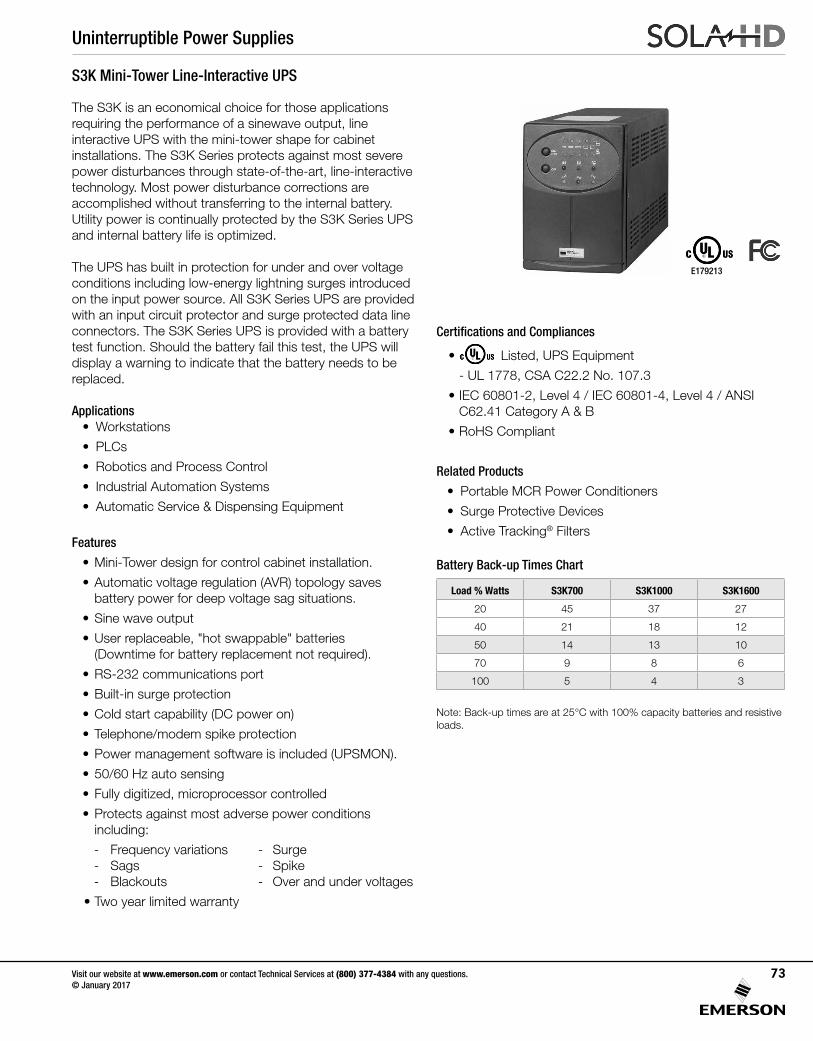
Uninterruptible Power Supplies
Visit our website at www.emerson.com or contact Technical Services at (800) 377-4384 with any questions. © January 2017
73
Battery Back-up Times Chart
Load % Watts S3K700 S3K1000 S3K1600
20 45 37 27
40 21 18 12
50 14 13 10
70 9 8 6
100 5 4 3
Note: Back-up times are at 25°C with 100% capacity batteries and resistive loads.
S3K Mini-Tower Line-Interactive UPS
The S3K is an economical choice for those applications requiring the performance of a sinewave output, line interactive UPS with the mini-tower shape for cabinet installations. The S3K Series protects against most severe power disturbances through state-of-the-art, line-interactive technology. Most power disturbance corrections are accomplished without transferring to the internal battery. Utility power is continually protected by the S3K Series UPS and internal battery life is optimized.
The UPS has built in protection for under and over voltage conditions including low-energy lightning surges introduced on the input power source. All S3K Series UPS are provided with an input circuit protector and surge protected data line connectors. The S3K Series UPS is provided with a battery test function. Should the battery fail this test, the UPS will display a warning to indicate that the battery needs to be replaced.
Applications• Workstations
• PLCs
• Robotics and Process Control
• Industrial Automation Systems
• Automatic Service & Dispensing Equipment
Features
• Mini-Tower design for control cabinet installation.
• Automatic voltage regulation (AVR) topology saves battery power for deep voltage sag situations.
• Sine wave output
• User replaceable, "hot swappable" batteries (Downtime for battery replacement not required).
• RS-232 communications port
• Built-in surge protection
• Cold start capability (DC power on)
• Telephone/modem spike protection
• Power management software is included (UPSMON).
• 50/60 Hz auto sensing
• Fully digitized, microprocessor controlled
• Protects against most adverse power conditions including:
- Frequency variations - Surge - Sags - Spike - Blackouts - Over and under voltages
• Two year limited warranty
Certifications and Compliances
• Listed, UPS Equipment
- UL 1778, CSA C22.2 No. 107.3
• IEC 60801-2, Level 4 / IEC 60801-4, Level 4 / ANSI C62.41 Category A & B
• RoHS Compliant
Related Products
• Portable MCR Power Conditioners
• Surge Protective Devices
• Active Tracking® Filters
E179213
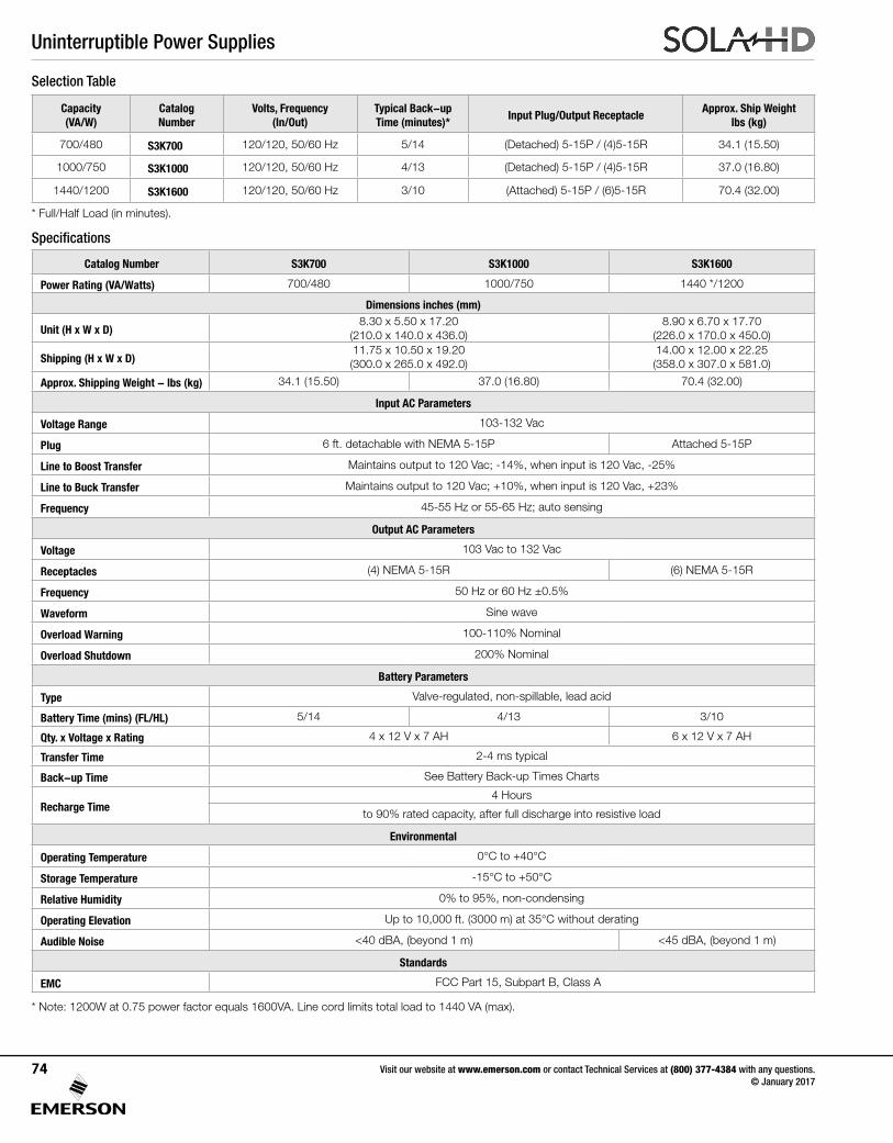
Uninterruptible Power Supplies
Visit our website at www.emerson.com or contact Technical Services at (800) 377-4384 with any questions. © January 2017
74
* Full/Half Load (in minutes).
Selection Table
Capacity (VA/W)
Catalog Number
Volts, Frequency (In/Out)
Typical Back-up Time (minutes)*
Input Plug/Output ReceptacleApprox. Ship Weight
lbs (kg)
700/480 S3K700 120/120, 50/60 Hz 5/14 (Detached) 5-15P / (4)5-15R 34.1 (15.50)
1000/750 S3K1000 120/120, 50/60 Hz 4/13 (Detached) 5-15P / (4)5-15R 37.0 (16.80)
1440/1200 S3K1600 120/120, 50/60 Hz 3/10 (Attached) 5-15P / (6)5-15R 70.4 (32.00)
Specifications
Catalog Number S3K700 S3K1000 S3K1600
Power Rating (VA/Watts) 700/480 1000/750 1440 */1200
Dimensions inches (mm)
Unit (H x W x D)8.30 x 5.50 x 17.20
(210.0 x 140.0 x 436.0)8.90 x 6.70 x 17.70
(226.0 x 170.0 x 450.0)
Shipping (H x W x D)11.75 x 10.50 x 19.20 (300.0 x 265.0 x 492.0)
14.00 x 12.00 x 22.25 (358.0 x 307.0 x 581.0)
Approx. Shipping Weight - lbs (kg) 34.1 (15.50) 37.0 (16.80) 70.4 (32.00)
Input AC Parameters
Voltage Range 103-132 Vac
Plug 6 ft. detachable with NEMA 5-15P Attached 5-15P
Line to Boost Transfer Maintains output to 120 Vac; -14%, when input is 120 Vac, -25%
Line to Buck Transfer Maintains output to 120 Vac; +10%, when input is 120 Vac, +23%
Frequency 45-55 Hz or 55-65 Hz; auto sensing
Output AC Parameters
Voltage 103 Vac to 132 Vac
Receptacles (4) NEMA 5-15R (6) NEMA 5-15R
Frequency 50 Hz or 60 Hz ±0.5%
Waveform Sine wave
Overload Warning 100-110% Nominal
Overload Shutdown 200% Nominal
Battery Parameters
Type Valve-regulated, non-spillable, lead acid
Battery Time (mins) (FL/HL) 5/14 4/13 3/10
Qty. x Voltage x Rating 4 x 12 V x 7 AH 6 x 12 V x 7 AH
Transfer Time 2-4 ms typical
Back-up Time See Battery Back-up Times Charts
Recharge Time4 Hours
to 90% rated capacity, after full discharge into resistive load
Environmental
Operating Temperature 0°C to +40°C
Storage Temperature -15°C to +50°C
Relative Humidity 0% to 95%, non-condensing
Operating Elevation Up to 10,000 ft. (3000 m) at 35°C without derating
Audible Noise <40 dBA, (beyond 1 m) <45 dBA, (beyond 1 m)
Standards
EMC FCC Part 15, Subpart B, Class A
* Note: 1200W at 0.75 power factor equals 1600VA. Line cord limits total load to 1440 VA (max).
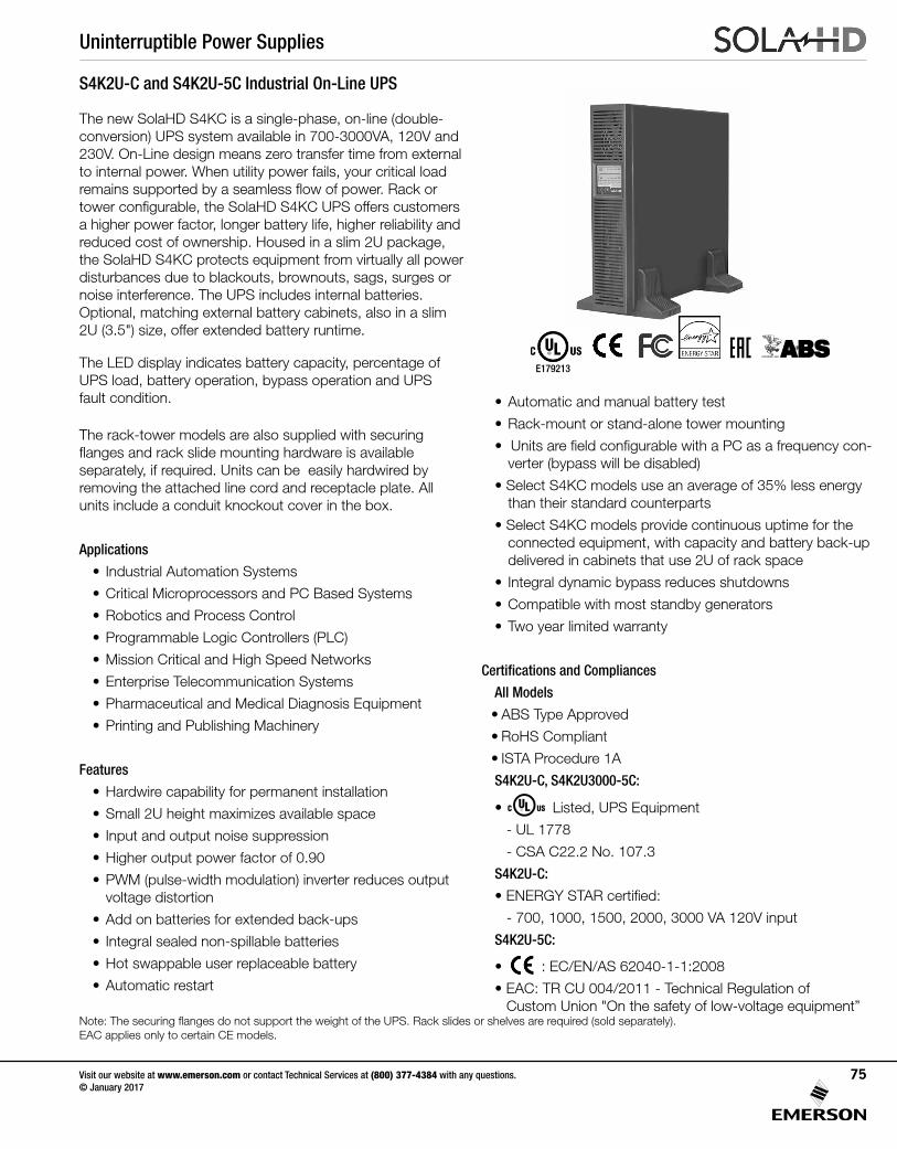
Uninterruptible Power Supplies
Visit our website at www.emerson.com or contact Technical Services at (800) 377-4384 with any questions. © January 2017
75
S4K2U-C and S4K2U-5C Industrial On-Line UPS
The new SolaHD S4KC is a single-phase, on-line (double-conversion) UPS system available in 700-3000VA, 120V and 230V. On-Line design means zero transfer time from external to internal power. When utility power fails, your critical load remains supported by a seamless flow of power. Rack or tower configurable, the SolaHD S4KC UPS offers customers a higher power factor, longer battery life, higher reliability and reduced cost of ownership. Housed in a slim 2U package, the SolaHD S4KC protects equipment from virtually all power disturbances due to blackouts, brownouts, sags, surges or noise interference. The UPS includes internal batteries. Optional, matching external battery cabinets, also in a slim 2U (3.5") size, offer extended battery runtime.
The LED display indicates battery capacity, percentage of UPS load, battery operation, bypass operation and UPS fault condition.
The rack-tower models are also supplied with securing flanges and rack slide mounting hardware is available separately, if required. Units can be easily hardwired by removing the attached line cord and receptacle plate. All units include a conduit knockout cover in the box.
Applications
• Industrial Automation Systems
• Critical Microprocessors and PC Based Systems
• Robotics and Process Control
• Programmable Logic Controllers (PLC)
• Mission Critical and High Speed Networks
• Enterprise Telecommunication Systems
• Pharmaceutical and Medical Diagnosis Equipment
• Printing and Publishing Machinery
Features
• Hardwire capability for permanent installation
• Small 2U height maximizes available space
• Input and output noise suppression
• Higher output power factor of 0.90
• PWM (pulse-width modulation) inverter reduces output voltage distortion
• Add on batteries for extended back-ups
• Integral sealed non-spillable batteries
• Hot swappable user replaceable battery
• Automatic restart
• Automatic and manual battery test
• Rack-mount or stand-alone tower mounting
• Units are field configurable with a PC as a frequency con-verter (bypass will be disabled)
• Select S4KC models use an average of 35% less energy than their standard counterparts
• Select S4KC models provide continuous uptime for the connected equipment, with capacity and battery back-up delivered in cabinets that use 2U of rack space
• Integral dynamic bypass reduces shutdowns
• Compatible with most standby generators
• Two year limited warranty
Certifications and Compliances
All Models
• ABS Type Approved
• RoHS Compliant
• ISTA Procedure 1A
S4K2U-C, S4K2U3000-5C:
• Listed, UPS Equipment
- UL 1778
- CSA C22.2 No. 107.3
S4K2U-C:
• ENERGY STAR certified:
- 700, 1000, 1500, 2000, 3000 VA 120V input
S4K2U-5C:
• : EC/EN/AS 62040-1-1:2008
• EAC: TR CU 004/2011 - Technical Regulation of Custom Union "On the safety of low-voltage equipment”
E179213
ENPC
Note: The securing flanges do not support the weight of the UPS. Rack slides or shelves are required (sold separately).EAC applies only to certain CE models.
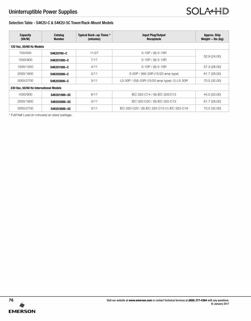
Uninterruptible Power Supplies
Visit our website at www.emerson.com or contact Technical Services at (800) 377-4384 with any questions. © January 2017
76
Selection Table - S4K2U-C & S4K2U-5C Tower/Rack-Mount Models
* Full/Half Load (in minutes) at rated wattage.
Capacity (VA/W)
Catalog Number
Typical Back-up Times * (minutes)
Input Plug/Output Receptacle
Approx. Ship Weight - lbs (kg)
120 Vac, 50/60 Hz Models
700/630 S4K2U700-C 11/27 5-15P / (6) 5-15R52.9 (24.00)
1000/900 S4K2U1000-C 7/17 5-15P / (6) 5-15R
1500/1350 S4K2U1500-C 4/11 5-15P / (6) 5-15R 57.3 (26.00)
2000/1800 S4K2U2000-C 3/11 5-20P / (6)5-20R (15/20 amp type) 61.7 (28.00)
3000/2700 S4K2U3000-C 3/11 L5-30P / (5)5-20R (15/20 amp type): (1) L5-30R 70.5 (32.00)
230 Vac, 50/60 Hz International Models
1000/900 S4K2U1000-5C 6/17 IEC 320-C14 / (6) IEC 320/C13 44.0 (20.00)
2000/1800 S4K2U2000-5C 3/11 IEC 320-C20 / (6) IEC 320-C13 61.7 (28.00)
3000/2700 S4K2U3000-5C 3/11 IEC 320-C20 / (6) IEC 320-C13 (1) IEC 320-C19 70.5 (32.00)
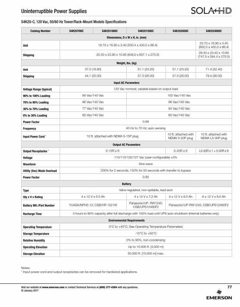
Uninterruptible Power Supplies
Visit our website at www.emerson.com or contact Technical Services at (800) 377-4384 with any questions. © January 2017
77
S4K2U-C, 120 Vac, 50/60 Hz Tower/Rack-Mount Models Specifications
Catalog Number S4K2U700C S4K2U1000C S4K2U1500C S4K2U2000C S4K2U3000C
Dimensions, D x W x H, in. (mm)
Unit 19.70 x 16.90 x 3.40 (500.4 x 430.0 x 86.4)23.70 x 16.90 x 3.40(602.0 x 430.0 x 86.4)
Shipping 25.50 x 23.90 x 10.60 (648.0 x 607.1 x 270.0)29.40 x 23.40 x 10.60(747.0 x 594.4 x 270.0)
Weight, lbs. (kg)
Unit 37.0 (16.80) 51.1 (23.20) 51.1 (23.20) 71.4 (32.40)
Shipping 44.1 (20.00) 57.3 (26.00) 57.3 (26.00) 79.4 (36.00)
Input AC Parameters
Voltage Range (typical) 120 Vac nominal; variable based on output load
90% to 100% Loading 90 Vac/140 Vac 102 Vac/140 Vac
70% to 90% Loading 86 Vac/140 Vac 96 Vac/140 Vac
30% to 70% Loading 77 Vac/140 Vac 84 Vac/140 Vac
0% to 30% Loading 60 Vac/140 Vac 60 Vac/140 Vac
Power Factor 0.99
Frequency 40 Hz to 70 Hz; auto sensing
Input Power Cord * 10 ft. attached with NEMA 5-15P plug10 ft. attached with NEMA 5-20P plug
10 ft. attached with NEMA L5-30P plug
Output AC Parameters
Output Receptacles * 5-15R x 6 5-20R x 6 L5-30R x 1 + 5-20R x 6
Voltage 110/115/120/127 Vac (user-configurable) ±3%
Waveform Sine wave
Utility (Vac) Mode Overload 200% for 2 seconds; 150% for 50 seconds with transfer to bypass
Power Factor 0.90
Battery
Type Valve-regulated, non-spillable, lead acid
Qty x V x Rating 4 x 12 V x 5.0 Ah 4 x 12 V x 7.2 Ah 4 x 12 V x 9.0 Ah 6 x 12 V x 9.0 Ah
Battery Mfr./Part Number YUASA/NPH5-12; CSB/HR 1221WPanasonic/UP- RW1245;
CSB/UPS12460F2Panasonic/UP-RW1245; CSB/UPS12460F2
Recharge Time 3 hours to 90% capacity after full discharge with 100% load until UPS auto shutdown (internal batteries only)
Environmental Requirements
Operating Temperature 0°C to +40°C; See Operating Temperature Parameters
Storage Temperature -15°C to +50°C
Relative Humidity 0% to 95%, non-condensing
Operating Elevation Up to 10,000 ft. [3,000 m]
Storage Elevation 50,000 ft. [15,000 m] max.
Notes:* Input power cord and output receptacles can be removed for hardwired applications.
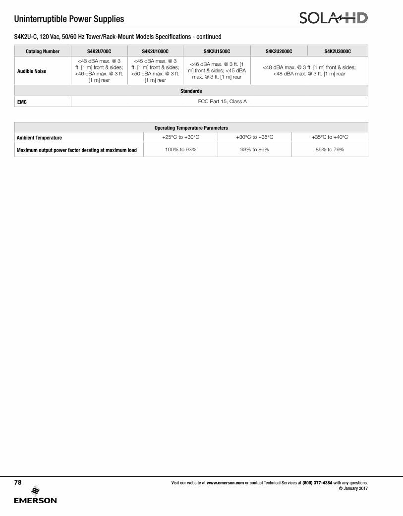
Uninterruptible Power Supplies
Visit our website at www.emerson.com or contact Technical Services at (800) 377-4384 with any questions. © January 2017
78
S4K2U-C, 120 Vac, 50/60 Hz Tower/Rack-Mount Models Specifications - continued
Catalog Number S4K2U700C S4K2U1000C S4K2U1500C S4K2U2000C S4K2U3000C
Audible Noise
<43 dBA max. @ 3 ft. [1 m] front & sides; <46 dBA max. @ 3 ft.
[1 m] rear
<45 dBA max. @ 3 ft. [1 m] front & sides; <50 dBA max. @ 3 ft.
[1 m] rear
<46 dBA max. @ 3 ft. [1 m] front & sides; <45 dBA
max. @ 3 ft. [1 m] rear
<48 dBA max. @ 3 ft. [1 m] front & sides; <48 dBA max. @ 3 ft. [1 m] rear
Standards
EMC FCC Part 15, Class A
Operating Temperature Parameters
Ambient Temperature +25°C to +30°C +30°C to +35°C +35°C to +40°C
Maximum output power factor derating at maximum load 100% to 93% 93% to 86% 86% to 79%
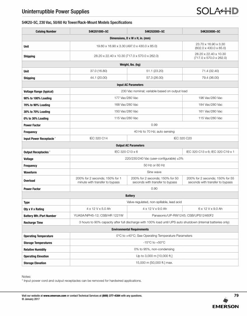
Uninterruptible Power Supplies
Visit our website at www.emerson.com or contact Technical Services at (800) 377-4384 with any questions. © January 2017
79
S4K2U-5C, 230 Vac, 50/60 Hz Tower/Rack-Mount Models Specifications
Catalog Number S4K2U1000-5C S4K2U2000-5C S4K2U3000-5C
Dimensions, D x W x H, in. (mm)
Unit 19.60 x 16.90 x 3.30 (497.0 x 430.0 x 85.0)23.70 x 16.90 x 3.30 (602.0 x 430.0 x 85.0)
Shipping 28.20 x 22.40 x 10.30 (717.0 x 570.0 x 262.0)28.20 x 22.40 x 10.30 (717.0 x 570.0 x 262.0)
Weight, lbs. (kg)
Unit 37.0 (16.80) 51.1 (23.20) 71.4 (32.40)
Shipping 44.1 (20.00) 57.3 (26.00) 79.4 (36.00)
Input AC Parameters
Voltage Range (typical) 230 Vac nominal; variable based on output load
90% to 100% Loading 177 Vac/280 Vac 196 Vac/280 Vac
70% to 90% Loading 168 Vac/280 Vac 184 Vac/280 Vac
30% to 70% Loading 150 Vac/280 Vac 161 Vac/280 Vac
0% to 30% Loading 115 Vac/280 Vac 115 Vac/280 Vac
Power Factor 0.99
Frequency 40 Hz to 70 Hz; auto sensing
Input Power Receptacle * IEC 320 C14 IEC 320 C20
Output AC Parameters
Output Receptacles * IEC 320 C13 x 6 IEC 320 C13 x 6; IEC 320 C19 x 1
Voltage 220/230/240 Vac (user-configurable) ±3%
Frequency 50 Hz or 60 Hz
Waveform Sine wave
Overload200% for 2 seconds; 150% for 1
minute with transfer to bypass200% for 2 seconds; 150% for 50 seconds with transfer to bypass
200% for 2 seconds; 150% for 55 seconds with transfer to bypass
Power Factor 0.90
Battery
Type Valve-regulated, non-spillable, lead acid
Qty x V x Rating 4 x 12 V x 5.0 Ah 4 x 12 V x 9.0 Ah 6 x 12 V x 9.0 Ah
Battery Mfr./Part Number YUASA/NPH5-12; CSB/HR 1221W Panasonic/UP-RW1245; CSB/UPS12460F2
Recharge Time 3 hours to 90% capacity after full discharge with 100% load until UPS auto shutdown (internal batteries only)
Environmental Requirements
Operating Temperature 0°C to +40°C; See Operating Temperature Parameters
Storage Temperatures -15°C to +50°C
Relative Humidity 0% to 95%, non-condensing
Operating Elevation Up to 3,000 m [10,000 ft.]
Storage Elevation 15,000 m [50,000 ft.] max.
Notes:* Input power cord and output receptacles can be removed for hardwired applications.
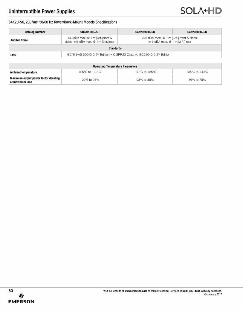
Uninterruptible Power Supplies
Visit our website at www.emerson.com or contact Technical Services at (800) 377-4384 with any questions. © January 2017
80
S4K2U-5C, 230 Vac, 50/60 Hz Tower/Rack-Mount Models Specifications
Catalog Number S4K2U1000-5C S4K2U2000-5C S4K2U3000-5C
Audible Noise<43 dBA max. @ 1 m [3 ft.] front &
sides; <46 dBA max. @ 1 m [3 ft.] rear<48 dBA max. @ 1 m [3 ft.] front & sides;
<48 dBA max. @ 1 m [3 ft.] rear
Standards
EMC IEC/EN/AS 62040-2 2nd Edition = CISPR22 Class A; IEC62040-2 2nd Edition
Operating Temperature Parameters
Ambient temperature +25°C to +30°C +30°C to +35°C +35°C to +40°C
Maximum output power factor derating at maximum load
100% to 93% 93% to 86% 86% to 79%
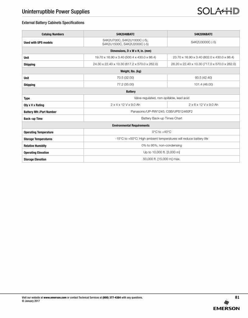
Uninterruptible Power Supplies
Visit our website at www.emerson.com or contact Technical Services at (800) 377-4384 with any questions. © January 2017
81
External Battery Cabinets Specifications
Catalog Numbers S4K2U48BATC S4K2U96BATC
Used with UPS modelsS4K2U700C, S4K2U1000C (-5), S4K2U1500C, S4K2U2000C (-5)
S4K2U3000C (-5)
Dimensions, D x W x H, in. (mm)
Unit 19.70 x 16.90 x 3.40 (500.4 x 430.0 x 86.4) 23.70 x 16.90 x 3.40 (602.0 x 430.0 x 86.4)
Shipping 24.30 x 22.40 x 10.30 (617.2 x 570.0 x 262.0) 28.20 x 22.40 x 10.30 (717.0 x 570.0 x 262.0)
Weight, lbs. (kg)
Unit 70.5 (32.00) 93.5 (42.40)
Shipping 77.2 (35.00) 101.4 (46.00)
Battery
Type Valve-regulated, non-spillable, lead acid
Qty x V x Rating 2 x 4 x 12 V x 9.0 Ah 2 x 6 x 12 V x 9.0 Ah
Battery Mfr./Part Number Panasonic/UP-RW1245; CSB/UPS12460F2
Back-up Time Battery Back-up Times Chart
Environmental Requirements
Operating Temperature 0°C to +40°C
Storage Temperatures -15°C to +50°C; High ambient temperatures will reduce battery life
Relative Humidity 0% to 95%, non-condensing
Operating Elevation Up to 10,000 ft. [3,000 m]
Storage Elevation 50,000 ft. [15,000 m] max.
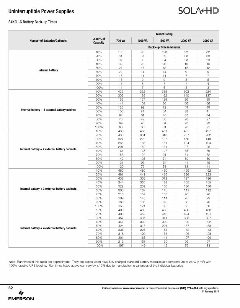
Uninterruptible Power Supplies
Visit our website at www.emerson.com or contact Technical Services at (800) 377-4384 with any questions. © January 2017
82
Number of Batteries/CabinetsLoad % of Capacity
Model Rating
700 VA 1000 VA 1500 VA 2000 VA 3000 VA
Back-up Time in Minutes
Internal battery
10% 105 90 123 92 8220% 61 37 52 38 3830% 37 30 34 23 2340% 32 23 23 16 1650% 27 17 18 12 1260% 22 14 14 9 970% 18 11 11 7 780% 15 9 9 5 590% 13 8 7 4 4100% 11 7 6 3 3
Internal battery + 1 external battery cabinet
10% 426 332 335 303 22420% 302 165 162 140 13730% 163 137 129 96 9540% 144 108 96 66 6650% 125 92 72 49 4960% 106 74 54 38 4170% 94 61 46 33 3480% 78 49 38 28 2790% 69 40 34 23 23100% 60 38 31 20 21
Internal battery + 2 external battery cabinets
10% 480 456 451 431 42720% 433 331 318 207 20230% 327 222 187 150 14940% 265 166 151 124 12450% 201 152 131 97 9860% 164 137 107 75 7670% 153 122 91 61 6280% 142 105 74 50 5090% 131 95 64 41 45100% 120 79 53 38 41
Internal battery + 3 external battery cabinets
10% 480 480 480 455 45220% 461 441 426 326 32330% 438 336 312 197 19640% 344 305 198 155 15550% 322 209 160 136 13660% 300 167 145 111 11270% 213 157 130 96 9880% 189 146 111 78 7990% 163 135 99 68 70100% 155 124 83 56 60
Internal battery + 4 external battery cabinets
10% 480 480 480 480 46620% 480 459 446 424 42130% 457 435 341 308 30740% 441 339 309 192 19250% 424 316 204 157 15860% 336 221 164 142 14370% 318 199 153 126 12880% 301 166 141 107 10990% 213 158 130 95 97100% 197 149 112 79 81
Note: Run times in this table are approximate. They are based upon new, fully charged standard battery modules at a temperature of 25°C (77°F) with 100% resistive UPS loading. Run times listed above can vary by +/-5% due to manufacturing variances of the individual batteries
S4K2U-C Battery Back-up Times
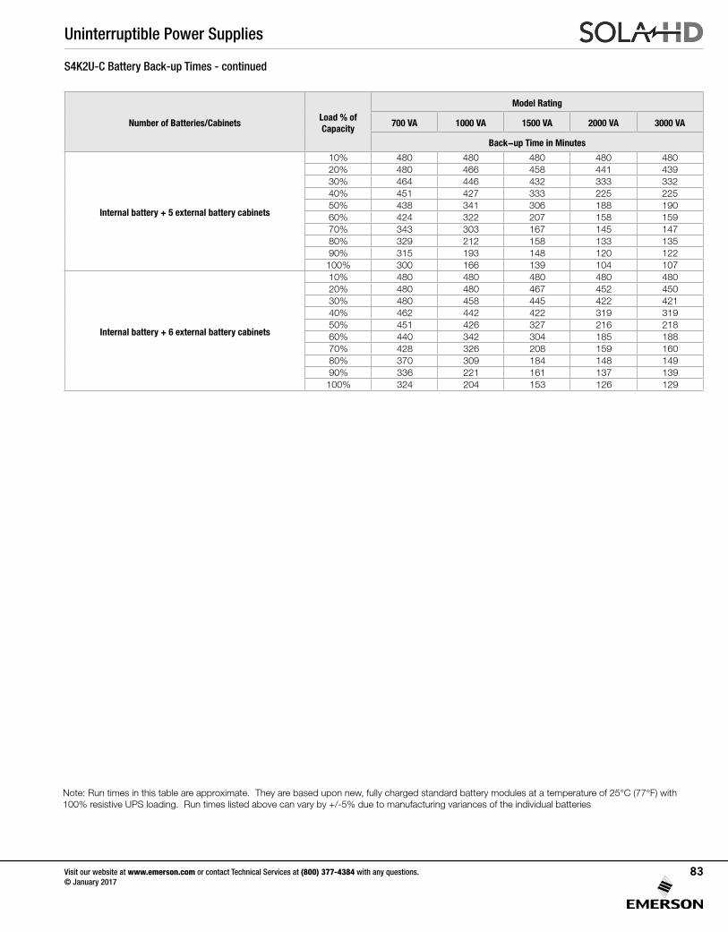
Uninterruptible Power Supplies
Visit our website at www.emerson.com or contact Technical Services at (800) 377-4384 with any questions. © January 2017
83
Number of Batteries/CabinetsLoad % of Capacity
Model Rating
700 VA 1000 VA 1500 VA 2000 VA 3000 VA
Back-up Time in Minutes
Internal battery + 5 external battery cabinets
10% 480 480 480 480 48020% 480 466 458 441 43930% 464 446 432 333 33240% 451 427 333 225 22550% 438 341 306 188 19060% 424 322 207 158 15970% 343 303 167 145 14780% 329 212 158 133 13590% 315 193 148 120 122100% 300 166 139 104 107
Internal battery + 6 external battery cabinets
10% 480 480 480 480 48020% 480 480 467 452 45030% 480 458 445 422 42140% 462 442 422 319 31950% 451 426 327 216 21860% 440 342 304 185 18870% 428 326 208 159 16080% 370 309 184 148 14990% 336 221 161 137 139100% 324 204 153 126 129
S4K2U-C Battery Back-up Times - continued
Note: Run times in this table are approximate. They are based upon new, fully charged standard battery modules at a temperature of 25°C (77°F) with 100% resistive UPS loading. Run times listed above can vary by +/-5% due to manufacturing variances of the individual batteries
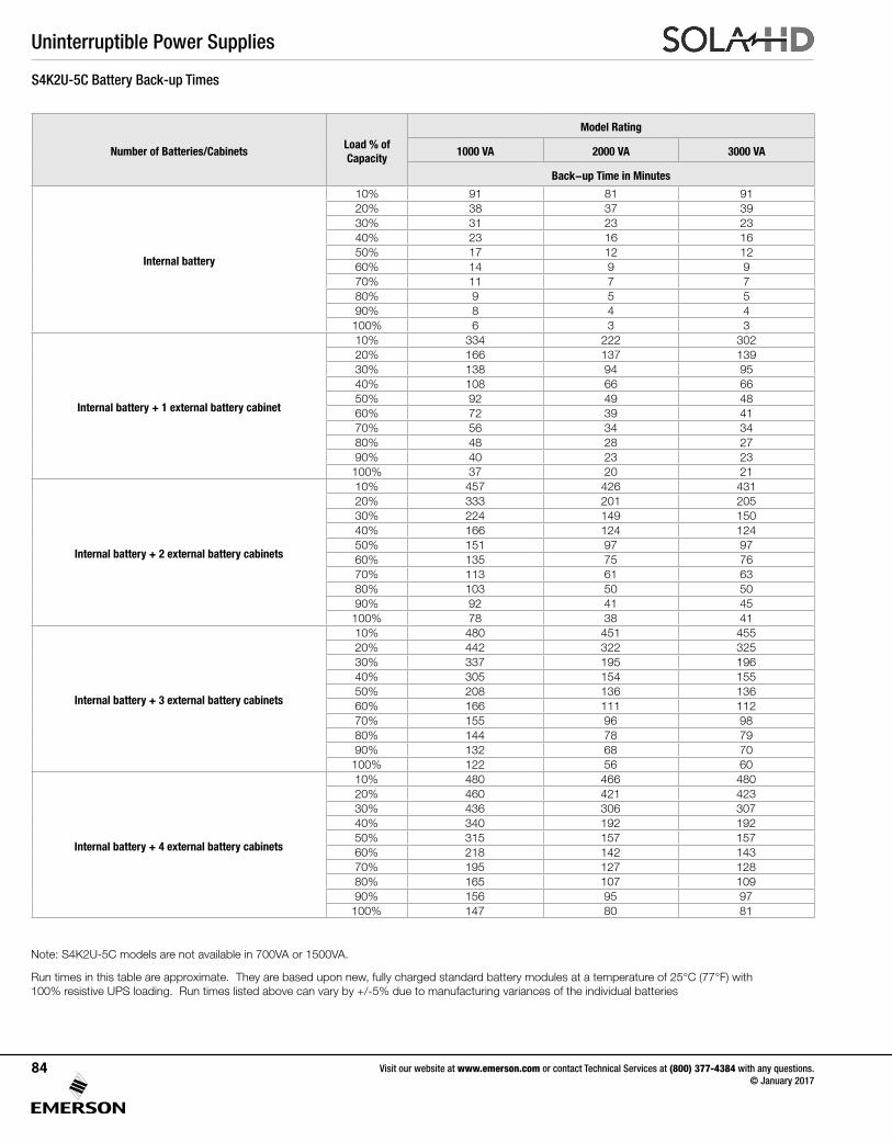
Uninterruptible Power Supplies
Visit our website at www.emerson.com or contact Technical Services at (800) 377-4384 with any questions. © January 2017
84
Number of Batteries/CabinetsLoad % of Capacity
Model Rating
1000 VA 2000 VA 3000 VA
Back-up Time in Minutes
Internal battery
10% 91 81 9120% 38 37 3930% 31 23 2340% 23 16 1650% 17 12 1260% 14 9 970% 11 7 780% 9 5 590% 8 4 4
100% 6 3 3
Internal battery + 1 external battery cabinet
10% 334 222 30220% 166 137 13930% 138 94 9540% 108 66 6650% 92 49 4860% 72 39 4170% 56 34 3480% 48 28 2790% 40 23 23
100% 37 20 21
Internal battery + 2 external battery cabinets
10% 457 426 43120% 333 201 20530% 224 149 15040% 166 124 12450% 151 97 9760% 135 75 7670% 113 61 6380% 103 50 5090% 92 41 45
100% 78 38 41
Internal battery + 3 external battery cabinets
10% 480 451 45520% 442 322 32530% 337 195 19640% 305 154 15550% 208 136 13660% 166 111 11270% 155 96 9880% 144 78 7990% 132 68 70
100% 122 56 60
Internal battery + 4 external battery cabinets
10% 480 466 48020% 460 421 42330% 436 306 30740% 340 192 19250% 315 157 15760% 218 142 14370% 195 127 12880% 165 107 10990% 156 95 97
100% 147 80 81
Note: S4K2U-5C models are not available in 700VA or 1500VA.
Run times in this table are approximate. They are based upon new, fully charged standard battery modules at a temperature of 25°C (77°F) with 100% resistive UPS loading. Run times listed above can vary by +/-5% due to manufacturing variances of the individual batteries
S4K2U-5C Battery Back-up Times
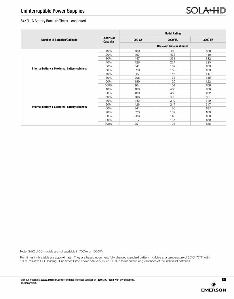
Uninterruptible Power Supplies
Visit our website at www.emerson.com or contact Technical Services at (800) 377-4384 with any questions. © January 2017
85
Number of Batteries/CabinetsLoad % of Capacity
Model Rating
1000 VA 2000 VA 3000 VA
Back-up Time in Minutes
Internal battery + 5 external battery cabinets
10% 480 480 48020% 467 438 44030% 447 331 33240% 428 224 22550% 341 189 18960% 320 158 15970% 227 146 14780% 208 133 13590% 189 120 122
100% 164 104 106
Internal battery + 6 external battery cabinets
10% 480 480 48020% 480 450 45230% 458 420 42140% 442 319 31950% 426 217 21760% 341 186 18770% 323 159 16080% 306 148 15090% 217 137 139
100% 201 126 128
S4K2U-C Battery Back-up Times - continued
Note: S4K2U-5C models are not available in 700VA or 1500VA.
Run times in this table are approximate. They are based upon new, fully charged standard battery modules at a temperature of 25°C (77°F) with 100% resistive UPS loading. Run times listed above can vary by +/-5% due to manufacturing variances of the individual batteries
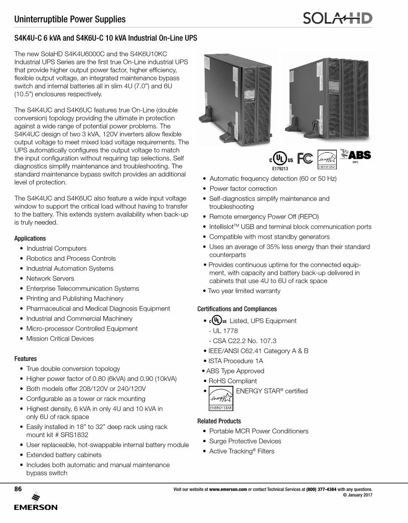
Uninterruptible Power Supplies
Visit our website at www.emerson.com or contact Technical Services at (800) 377-4384 with any questions. © January 2017
86
S4K4U-C 6 kVA and S4K6U-C 10 kVA Industrial On-Line UPS
The new SolaHD S4K4U6000C and the S4K6U10KC Industrial UPS Series are the first true On-Line industrial UPS that provide higher output power factor, higher efficiency, flexible output voltage, an integrated maintenance bypass switch and internal batteries all in slim 4U (7.0”) and 6U (10.5") enclosures respectively.
The S4K4UC and S4K6UC features true On-Line (double conversion) topology providing the ultimate in protection against a wide range of potential power problems. The S4K4UC design of two 3 kVA, 120V inverters allow flexible output voltage to meet mixed load voltage requirements. The UPS automatically configures the output voltage to match the input configuration without requiring tap selections. Self diagnostics simplify maintenance and troubleshooting. The standard maintenance bypass switch provides an additional level of protection.
The S4K4UC and S4K6UC also feature a wide input voltage window to support the critical load without having to transfer to the battery. This extends system availability when back-up is truly needed.
Applications
• Industrial Computers
• Robotics and Process Controls
• Industrial Automation Systems
• Network Servers
• Enterprise Telecommunication Systems
• Printing and Publishing Machinery
• Pharmaceutical and Medical Diagnosis Equipment
• Industrial and Commercial Machinery
• Micro-processor Controlled Equipment
• Mission Critical Devices
Features
• True double conversion topology
• Higher power factor of 0.80 (6kVA) and 0.90 (10kVA)
• Both models offer 208/120V or 240/120V
• Configurable as a tower or rack mounting
• Highest density, 6 kVA in only 4U and 10 kVA in only 6U of rack space
• Easily installed in 18” to 32” deep rack using rack mount kit # SRS1832
• User replaceable, hot-swappable internal battery module
• Extended battery cabinets
• Includes both automatic and manual maintenance bypass switch
• Automatic frequency detection (60 or 50 Hz)
• Power factor correction
• Self-diagnostics simplify maintenance and troubleshooting
• Remote emergency Power Off (REPO)
• IntellislotTM USB and terminal block communication ports
• Compatible with most standby generators
• Uses an average of 35% less energy than their standard counterparts
• Provides continuous uptime for the connected equip-ment, with capacity and battery back-up delivered in cabinets that use 4U to 6U of rack space
• Two year limited warranty
Certifications and Compliances
• Listed, UPS Equipment
- UL 1778
- CSA C22.2 No. 107.3
• IEEE/ANSI C62.41 Category A & B
• ISTA Procedure 1A
• ABS Type Approved
• RoHS Compliant
• ENERGY STAR® certified
Related Products
• Portable MCR Power Conditioners
• Surge Protective Devices
• Active Tracking® Filters
E179213
ENPC
Uninterruptible Power Supplies
Visit our website at www.emerson.com or contact Technical Services at (800) 377-4384 with any questions. © January 2017
87
S4K 6 and 10 kVA Specifications
Table 1: UPS Specifications
ParametersModel Number
S4K4U6000C S4K6U10KC
Rating 4800 W/6000 VA 9000 W/10000 VA
Dimensions, W x D x H, in. (mm)
Unit 6.80 x 26.10 x 16.90 (173.0 x 662.0 x 430.0)10.30 x 26.50 x 16.90 (261.0 x 672.0 x 430.0)
Shipping 13.20 x 33.10 x 26.10 (336.0 x 842.0 x 662.0)16.70 x 32.80 x 24.10 (424.0 x 832.0 x 612.0)
Weight, lbs. (kg)
Unit 56.2 (25.50) 78.3 (35.50)
Shipping 70.5 (32.00) 92.6 (42.00)
Input AC Parameters
Nominal Operating Frequency 50 or 60 Hz (Factory default is 60 Hz)
Factory Default Vac 120/208 Vac @ 120°
L1–L2 Factory Default Input Phase Angle 120°C
Allowable Input Phase Angle120, 180, 240 degrees; auto-sensing on application of alternating current
(Restrictions for L–N voltage other than 120 Vac)
Factory Default L1–N, L2–N Vac 120 Vac nominal
User Configurable L1–N, L2–N Vac 100/110/115/120/127 Vac (Can be modified with configuration program)
Input Frequency w/o Battery Operation 40–70 Hz
Input Power Connection Hardwire terminal block 3W + G (L–L–N–G)
L1–N, L2–N Maximum Allowable Vac 150 Vac
Output AC Parameters
Factory Default Vac 120/208 Vac @ 120°C
L1–L2 Factory Default Output Phase Angle 120°C
Allowable Output Phase Angle 120, 180, 240 degrees; auto-sensing on initial application of input alternating current
Factory Default L1–N, L2–N Vac 120 Vac nominal
User Configurable L1–N, L2–N Vac 100/110/115/120/127 Vac, ± 2%
L1-N, L2-N Overload Rating
105% to 130% 1 minute
131% to 150% 10 seconds
151% to 200% 1 second
>200% (impact load) At least 5 cycles
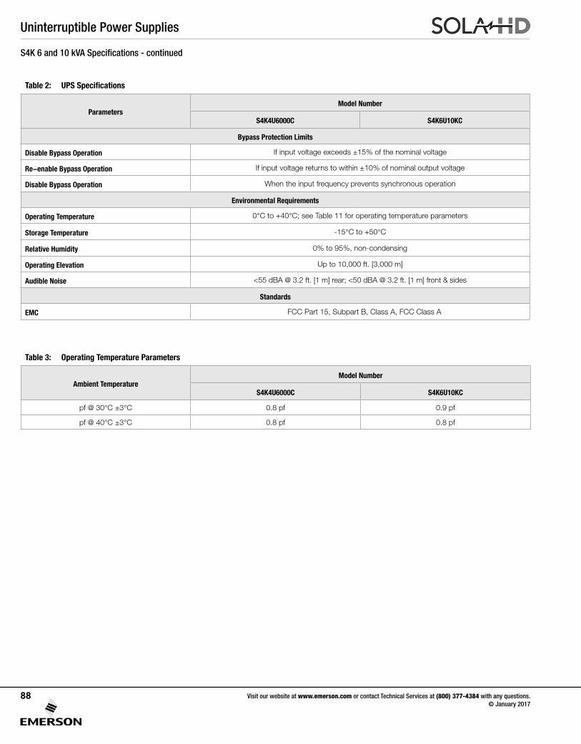
Uninterruptible Power Supplies
Visit our website at www.emerson.com or contact Technical Services at (800) 377-4384 with any questions. © January 2017
88
S4K 6 and 10 kVA Specifications - continued
Table 2: UPS Specifications
ParametersModel Number
S4K4U6000C S4K6U10KC
Bypass Protection Limits
Disable Bypass Operation If input voltage exceeds ±15% of the nominal voltage
Re-enable Bypass Operation If input voltage returns to within ±10% of nominal output voltage
Disable Bypass Operation When the input frequency prevents synchronous operation
Environmental Requirements
Operating Temperature 0°C to +40°C; see Table 11 for operating temperature parameters
Storage Temperature -15°C to +50°C
Relative Humidity 0% to 95%, non-condensing
Operating Elevation Up to 10,000 ft. [3,000 m]
Audible Noise <55 dBA @ 3.2 ft. [1 m] rear; <50 dBA @ 3.2 ft. [1 m] front & sides
Standards
EMC FCC Part 15, Subpart B, Class A, FCC Class A
Table 3: Operating Temperature Parameters
Ambient TemperatureModel Number
S4K4U6000C S4K6U10KC
pf @ 30°C ±3°C 0.8 pf 0.9 pf
pf @ 40°C ±3°C 0.8 pf 0.8 pf
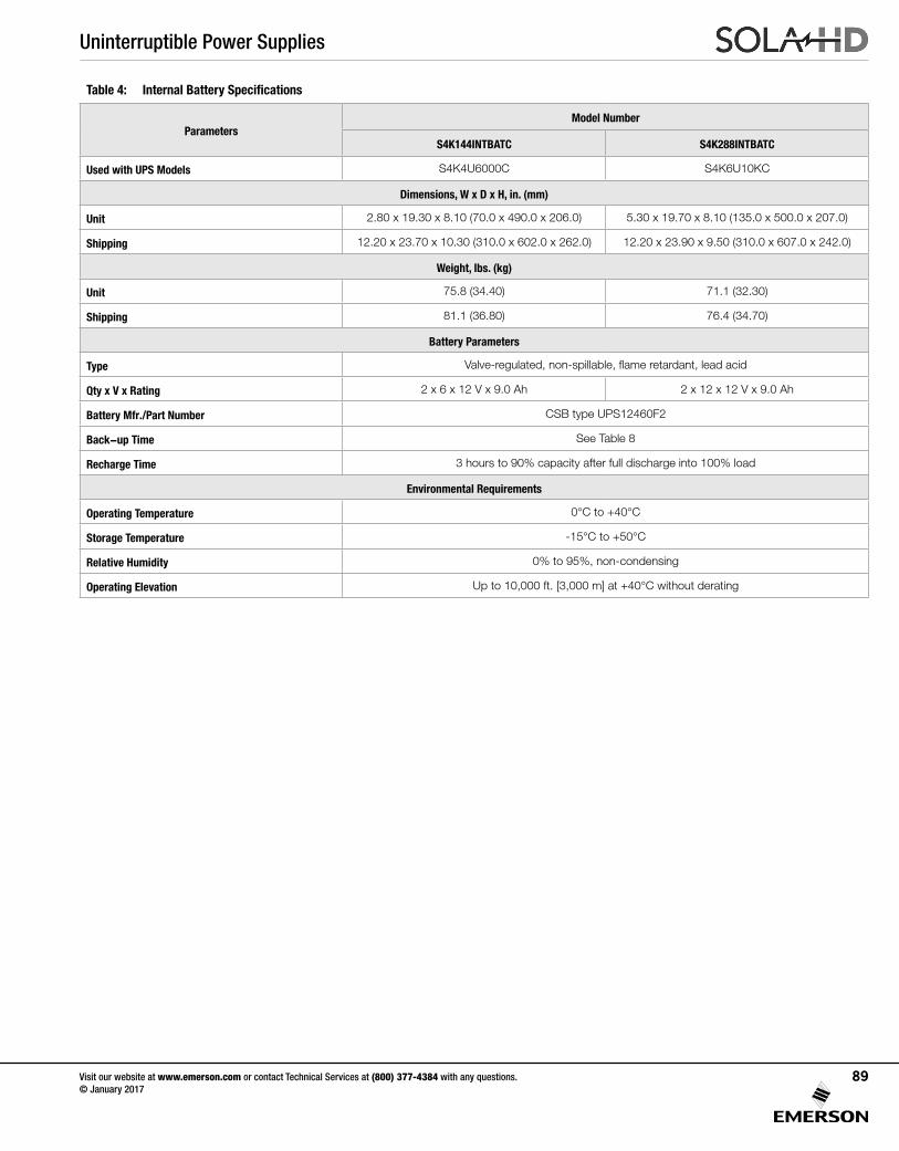
Uninterruptible Power Supplies
Visit our website at www.emerson.com or contact Technical Services at (800) 377-4384 with any questions. © January 2017
89
Table 4: Internal Battery Specifications
ParametersModel Number
S4K144INTBATC S4K288INTBATC
Used with UPS Models S4K4U6000C S4K6U10KC
Dimensions, W x D x H, in. (mm)
Unit 2.80 x 19.30 x 8.10 (70.0 x 490.0 x 206.0) 5.30 x 19.70 x 8.10 (135.0 x 500.0 x 207.0)
Shipping 12.20 x 23.70 x 10.30 (310.0 x 602.0 x 262.0) 12.20 x 23.90 x 9.50 (310.0 x 607.0 x 242.0)
Weight, lbs. (kg)
Unit 75.8 (34.40) 71.1 (32.30)
Shipping 81.1 (36.80) 76.4 (34.70)
Battery Parameters
Type Valve-regulated, non-spillable, flame retardant, lead acid
Qty x V x Rating 2 x 6 x 12 V x 9.0 Ah 2 x 12 x 12 V x 9.0 Ah
Battery Mfr./Part Number CSB type UPS12460F2
Back-up Time See Table 8
Recharge Time 3 hours to 90% capacity after full discharge into 100% load
Environmental Requirements
Operating Temperature 0°C to +40°C
Storage Temperature -15°C to +50°C
Relative Humidity 0% to 95%, non-condensing
Operating Elevation Up to 10,000 ft. [3,000 m] at +40°C without derating
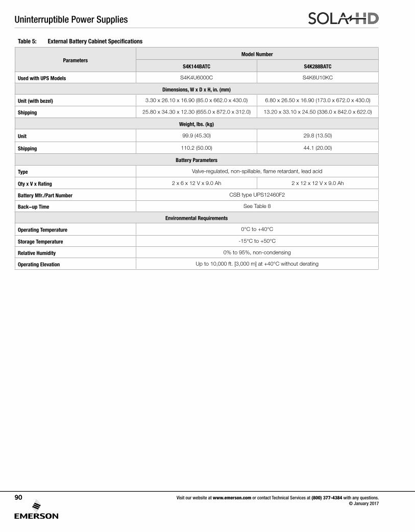
Uninterruptible Power Supplies
Visit our website at www.emerson.com or contact Technical Services at (800) 377-4384 with any questions. © January 2017
90
Table 5: External Battery Cabinet Specifications
ParametersModel Number
S4K144BATC S4K288BATC
Used with UPS Models S4K4U6000C S4K6U10KC
Dimensions, W x D x H, in. (mm)
Unit (with bezel) 3.30 x 26.10 x 16.90 (85.0 x 662.0 x 430.0) 6.80 x 26.50 x 16.90 (173.0 x 672.0 x 430.0)
Shipping 25.80 x 34.30 x 12.30 (655.0 x 872.0 x 312.0) 13.20 x 33.10 x 24.50 (336.0 x 842.0 x 622.0)
Weight, lbs. (kg)
Unit 99.9 (45.30) 29.8 (13.50)
Shipping 110.2 (50.00) 44.1 (20.00)
Battery Parameters
Type Valve-regulated, non-spillable, flame retardant, lead acid
Qty x V x Rating 2 x 6 x 12 V x 9.0 Ah 2 x 12 x 12 V x 9.0 Ah
Battery Mfr./Part Number CSB type UPS12460F2
Back-up Time See Table 8
Environmental Requirements
Operating Temperature 0°C to +40°C
Storage Temperature -15°C to +50°C
Relative Humidity 0% to 95%, non-condensing
Operating Elevation Up to 10,000 ft. [3,000 m] at +40°C without derating
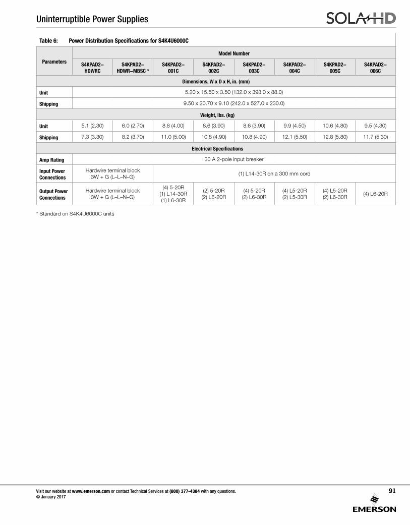
Uninterruptible Power Supplies
Visit our website at www.emerson.com or contact Technical Services at (800) 377-4384 with any questions. © January 2017
91
Table 6: Power Distribution Specifications for S4K4U6000C
Parameters
Model Number
S4KPAD2- HDWRC
S4KPAD2- HDWR-MBSC *
S4KPAD2- 001C
S4KPAD2- 002C
S4KPAD2- 003C
S4KPAD2- 004C
S4KPAD2- 005C
S4KPAD2- 006C
Dimensions, W x D x H, in. (mm)
Unit 5.20 x 15.50 x 3.50 (132.0 x 393.0 x 88.0)
Shipping 9.50 x 20.70 x 9.10 (242.0 x 527.0 x 230.0)
Weight, lbs. (kg)
Unit 5.1 (2.30) 6.0 (2.70) 8.8 (4.00) 8.6 (3.90) 8.6 (3.90) 9.9 (4.50) 10.6 (4.80) 9.5 (4.30)
Shipping 7.3 (3.30) 8.2 (3.70) 11.0 (5.00) 10.8 (4.90) 10.8 (4.90) 12.1 (5.50) 12.8 (5.80) 11.7 (5.30)
Electrical Specifications
Amp Rating 30 A 2-pole input breaker
Input Power Connections
Hardwire terminal block3W + G (L–L–N–G)
(1) L14-30R on a 300 mm cord
Output Power Connections
Hardwire terminal block3W + G (L–L–N–G)
(4) 5-20R(1) L14-30R(1) L6-30R
(2) 5-20R(2) L6-20R
(4) 5-20R(2) L6-30R
(4) L5-20R(2) L5-30R
(4) L5-20R(2) L6-30R
(4) L6-20R
* Standard on S4K4U6000C units
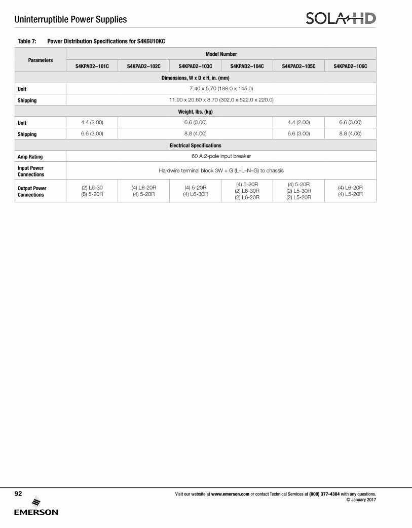
Uninterruptible Power Supplies
Visit our website at www.emerson.com or contact Technical Services at (800) 377-4384 with any questions. © January 2017
92
Table 7: Power Distribution Specifications for S4K6U10KC
ParametersModel Number
S4KPAD2-101C S4KPAD2-102C S4KPAD2-103C S4KPAD2-104C S4KPAD2-105C S4KPAD2-106C
Dimensions, W x D x H, in. (mm)
Unit 7.40 x 5.70 (188.0 x 145.0)
Shipping 11.90 x 20.60 x 8.70 (302.0 x 522.0 x 220.0)
Weight, lbs. (kg)
Unit 4.4 (2.00) 6.6 (3.00) 4.4 (2.00) 6.6 (3.00)
Shipping 6.6 (3.00) 8.8 (4.00) 6.6 (3.00) 8.8 (4.00)
Electrical Specifications
Amp Rating 60 A 2-pole input breaker
Input Power Connections
Hardwire terminal block 3W + G (L–L–N–G) to chassis
Output Power Connections
(2) L6-30(8) 5-20R
(4) L6-20R(4) 5-20R
(4) 5-20R(4) L6-30R
(4) 5-20R(2) L6-30R(2) L6-20R
(4) 5-20R(2) L5-30R(2) L5-20R
(4) L6-20R(4) L5-20R
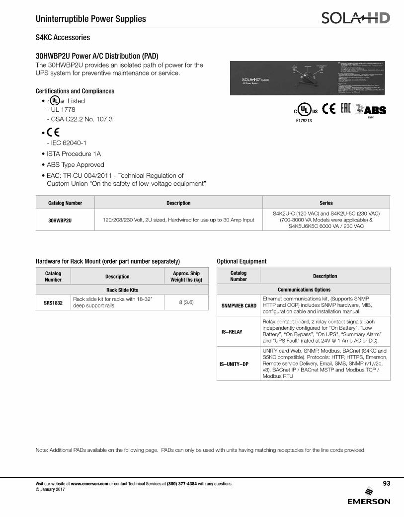
Uninterruptible Power Supplies
Visit our website at www.emerson.com or contact Technical Services at (800) 377-4384 with any questions. © January 2017
93
Hardware for Rack Mount (order part number separately)
The 30HWBP2U provides an isolated path of power for the UPS system for preventive maintenance or service.
Note: Additional PADs available on the following page. PADs can only be used with units having matching receptacles for the line cords provided.
30HWBP2U Power A/C Distribution (PAD)
Catalog Number
DescriptionApprox. Ship
Weight lbs (kg)
Rack Slide Kits
SRS1832Rack slide kit for racks with 18-32” deep support rails.
8 (3.6)
Catalog Number Description Series
30HWBP2U 120/208/230 Volt, 2U sized, Hardwired for use up to 30 Amp InputS4K2U-C (120 VAC) and S4K2U-5C (230 VAC)
(700-3000 VA Models were applicable) & S4K5U6K5C 6000 VA / 230 VAC
Catalog Number
Description
Communications Options
SNMPWEB CARDEthernet communications kit, (Supports SNMP, HTTP and OCP) includes SNMP hardware, MIB, configuration cable and installation manual.
IS-RELAY
Relay contact board, 2 relay contact signals each independently configured for “On Battery”, “Low Battery”, “On Bypass”, "On UPS", “Summary Alarm” and “UPS Fault” (rated at 24V @ 1 Amp AC or DC).
IS-UNITY-DP
UNITY card Web, SNMP, Modbus, BACnet (S4KC and S5KC compatible). Protocols: HTTP, HTTPS, Emerson, Remote service Delivery, Email, SMS, SNMP (v1,v2c, v3), BACnet IP / BACnet MSTP and Modbus TCP / Modbus RTU
Optional Equipment
S4KC Accessories
Certifications and Compliances
• Listed - UL 1778- CSA C22.2 No. 107.3
•
- IEC 62040-1
• ISTA Procedure 1A
• ABS Type Approved
• EAC: TR CU 004/2011 - Technical Regulation of Custom Union "On the safety of low-voltage equipment”
E179213ENPC
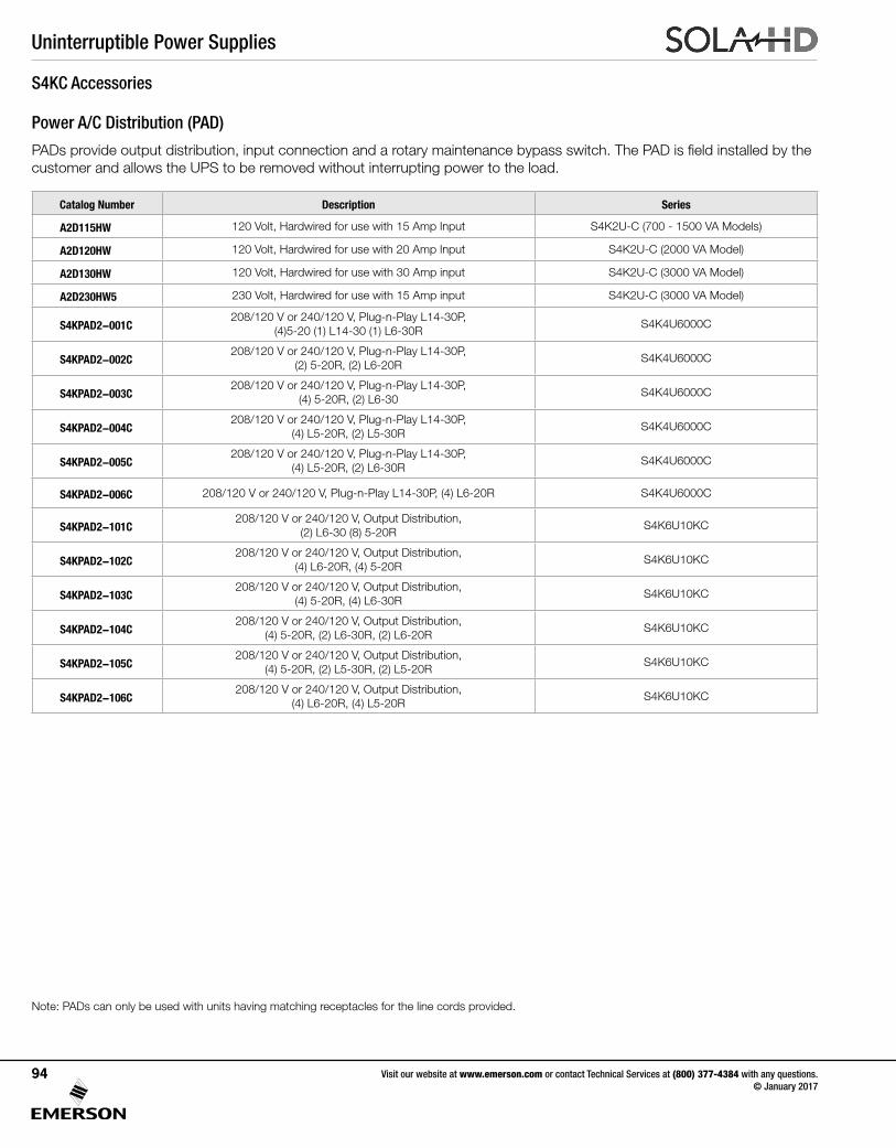
Uninterruptible Power Supplies
Visit our website at www.emerson.com or contact Technical Services at (800) 377-4384 with any questions. © January 2017
94
Power A/C Distribution (PAD)
S4KC Accessories
Catalog Number Description Series
A2D115HW 120 Volt, Hardwired for use with 15 Amp Input S4K2U-C (700 - 1500 VA Models)
A2D120HW 120 Volt, Hardwired for use with 20 Amp Input S4K2U-C (2000 VA Model)
A2D130HW 120 Volt, Hardwired for use with 30 Amp input S4K2U-C (3000 VA Model)
A2D230HW5 230 Volt, Hardwired for use with 15 Amp input S4K2U-C (3000 VA Model)
S4KPAD2-001C208/120 V or 240/120 V, Plug-n-Play L14-30P,
(4)5-20 (1) L14-30 (1) L6-30RS4K4U6000C
S4KPAD2-002C208/120 V or 240/120 V, Plug-n-Play L14-30P,
(2) 5-20R, (2) L6-20RS4K4U6000C
S4KPAD2-003C208/120 V or 240/120 V, Plug-n-Play L14-30P,
(4) 5-20R, (2) L6-30S4K4U6000C
S4KPAD2-004C208/120 V or 240/120 V, Plug-n-Play L14-30P,
(4) L5-20R, (2) L5-30RS4K4U6000C
S4KPAD2-005C208/120 V or 240/120 V, Plug-n-Play L14-30P,
(4) L5-20R, (2) L6-30RS4K4U6000C
S4KPAD2-006C 208/120 V or 240/120 V, Plug-n-Play L14-30P, (4) L6-20R S4K4U6000C
S4KPAD2-101C208/120 V or 240/120 V, Output Distribution,
(2) L6-30 (8) 5-20RS4K6U10KC
S4KPAD2-102C208/120 V or 240/120 V, Output Distribution,
(4) L6-20R, (4) 5-20RS4K6U10KC
S4KPAD2-103C208/120 V or 240/120 V, Output Distribution,
(4) 5-20R, (4) L6-30RS4K6U10KC
S4KPAD2-104C208/120 V or 240/120 V, Output Distribution,
(4) 5-20R, (2) L6-30R, (2) L6-20RS4K6U10KC
S4KPAD2-105C208/120 V or 240/120 V, Output Distribution,
(4) 5-20R, (2) L5-30R, (2) L5-20RS4K6U10KC
S4KPAD2-106C208/120 V or 240/120 V, Output Distribution,
(4) L6-20R, (4) L5-20RS4K6U10KC
Note: PADs can only be used with units having matching receptacles for the line cords provided.
PADs provide output distribution, input connection and a rotary maintenance bypass switch. The PAD is field installed by the customer and allows the UPS to be removed without interrupting power to the load.
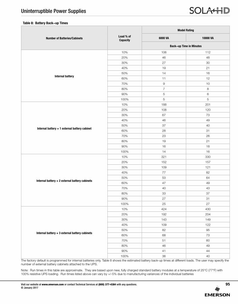
Uninterruptible Power Supplies
Visit our website at www.emerson.com or contact Technical Services at (800) 377-4384 with any questions. © January 2017
95
Table 8: Battery Back-up Times
Number of Batteries/CabinetsLoad % of Capacity
Model Rating
6000 VA 10000 VA
Back-up Time in Minutes
Internal battery
10% 106 112
20% 46 48
30% 27 30
40% 19 21
50% 14 16
60% 11 12
70% 9 10
80% 7 8
90% 5 6
100% 5 5
Internal battery + 1 external battery cabinet
10% 188 201
20% 108 120
30% 67 73
40% 46 49
50% 37 40
60% 28 31
70% 23 26
80% 19 21
90% 16 18
100% 14 16
Internal battery + 2 external battery cabinets
10% 321 330
20% 152 157
30% 109 121
40% 77 82
50% 53 64
60% 47 49
70% 40 43
80% 33 37
90% 27 31
100% 25 27
Internal battery + 3 external battery cabinets
10% 424 430
20% 192 204
30% 143 149
40% 109 122
50% 82 95
60% 68 73
70% 51 60
80% 46 49
90% 41 44
100% 36 40The factory default is programmed for internal batteries only. Table 8 shows the estimated battery back-up times at different loads. The user may specify the number of external battery cabinets attached to the UPS.
Note: Run times in this table are approximate. They are based upon new, fully charged standard battery modules at a temperature of 25°C (77°F) with 100% resistive UPS loading. Run times listed above can vary by +/-5% due to manufacturing variances of the individual batteries
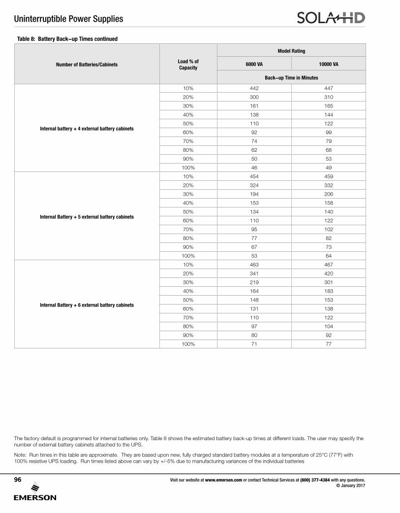
Uninterruptible Power Supplies
Visit our website at www.emerson.com or contact Technical Services at (800) 377-4384 with any questions. © January 2017
96
The factory default is programmed for internal batteries only. Table 8 shows the estimated battery back-up times at different loads. The user may specify the number of external battery cabinets attached to the UPS.
Note: Run times in this table are approximate. They are based upon new, fully charged standard battery modules at a temperature of 25°C (77°F) with 100% resistive UPS loading. Run times listed above can vary by +/-5% due to manufacturing variances of the individual batteries
Table 8: Battery Back-up Times continued
Number of Batteries/CabinetsLoad % of Capacity
Model Rating
6000 VA 10000 VA
Back-up Time in Minutes
Internal battery + 4 external battery cabinets
10% 442 447
20% 300 310
30% 161 165
40% 138 144
50% 110 122
60% 92 99
70% 74 79
80% 62 68
90% 50 53
100% 46 49
Internal Battery + 5 external battery cabinets
10% 454 459
20% 324 332
30% 194 206
40% 153 158
50% 134 140
60% 110 122
70% 95 102
80% 77 82
90% 67 73
100% 53 64
Internal Battery + 6 external battery cabinets
10% 463 467
20% 341 420
30% 219 301
40% 164 183
50% 148 153
60% 131 138
70% 110 122
80% 97 104
90% 80 92
100% 71 77
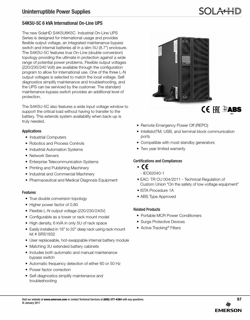
Uninterruptible Power Supplies
Visit our website at www.emerson.com or contact Technical Services at (800) 377-4384 with any questions. © January 2017
97
S4K5U-5C 6 kVA International On-Line UPS
The new SolaHD S4K5U6K5C Industrial On-Line UPS Series is designed for international usage and provides flexible output voltage, an integrated maintenance bypass switch and internal batteries all in a slim 5U (8.7”) enclosure.The S4K5U-5C features true On-Line (double conversion) topology providing the ultimate in protection against a wide range of potential power problems. Flexible output voltages (220/230/240 Volt) are available through the configuration program to allow for international use. One of the three L-N output voltages is selected to match the local voltage. Self diagnostics simplify maintenance and troubleshooting, and the UPS can be serviced by the customer. The standard maintenance bypass switch provides an additional level of protection.
The S4K5U-5C also features a wide input voltage window to support the critical load without having to transfer to the battery. This extends system availability when back-up is truly needed.
Applications
• Industrial Computers
• Robotics and Process Controls
• Industrial Automation Systems
• Network Servers
• Enterprise Telecommunication Systems
• Printing and Publishing Machinery
• Industrial and Commercial Machinery
• Pharmaceutical and Medical Diagnosis Equipment
Features
• True double conversion topology
• Higher power factor of 0.80
• Flexible L-N output voltage (220/230/240V)
• Configurable as a tower or rack mount model
• High density, 6 kVA in only 5U of rack space
• Easily installed in 18” to 32” deep rack using rack mount kit # SRS1832
• User replaceable, hot-swappable internal battery module
• Matching 3U extended battery cabinets
• Includes both automatic and manual maintenance bypass switch
• Automatic frequency detection of either 60 or 50 Hz
• Power factor correction
• Self-diagnostics simplify maintenance and troubleshooting
• Remote Emergency Power Off (REPO)
• IntellislotTM, USB, and terminal block communication ports
• Compatible with most standby generators
• Two year limited warranty
Certifications and Compliances
•
- IEC62040-1
• EAC: TR CU 004/2011 - Technical Regulation of Custom Union "On the safety of low-voltage equipment”
• ISTA Procedure 1A
• ABS Type Approved
Related Products
• Portable MCR Power Conditioners
• Surge Protective Devices
• Active Tracking® Filters
ENPC
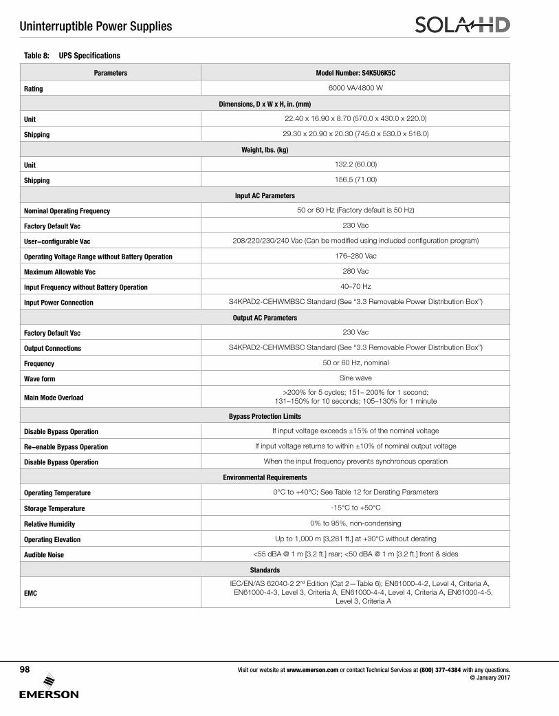
Uninterruptible Power Supplies
Visit our website at www.emerson.com or contact Technical Services at (800) 377-4384 with any questions. © January 2017
98
Table 8: UPS Specifications
Parameters Model Number: S4K5U6K5C
Rating 6000 VA/4800 W
Dimensions, D x W x H, in. (mm)
Unit 22.40 x 16.90 x 8.70 (570.0 x 430.0 x 220.0)
Shipping 29.30 x 20.90 x 20.30 (745.0 x 530.0 x 516.0)
Weight, lbs. (kg)
Unit 132.2 (60.00)
Shipping 156.5 (71.00)
Input AC Parameters
Nominal Operating Frequency 50 or 60 Hz (Factory default is 50 Hz)
Factory Default Vac 230 Vac
User-configurable Vac 208/220/230/240 Vac (Can be modified using included configuration program)
Operating Voltage Range without Battery Operation 176–280 Vac
Maximum Allowable Vac 280 Vac
Input Frequency without Battery Operation 40–70 Hz
Input Power Connection S4KPAD2-CEHWMBSC Standard (See “3.3 Removable Power Distribution Box”)
Output AC Parameters
Factory Default Vac 230 Vac
Output Connections S4KPAD2-CEHWMBSC Standard (See “3.3 Removable Power Distribution Box”)
Frequency 50 or 60 Hz, nominal
Wave form Sine wave
Main Mode Overload>200% for 5 cycles; 151– 200% for 1 second;
131–150% for 10 seconds; 105–130% for 1 minute
Bypass Protection Limits
Disable Bypass Operation If input voltage exceeds ±15% of the nominal voltage
Re-enable Bypass Operation If input voltage returns to within ±10% of nominal output voltage
Disable Bypass Operation When the input frequency prevents synchronous operation
Environmental Requirements
Operating Temperature 0°C to +40°C; See Table 12 for Derating Parameters
Storage Temperature -15°C to +50°C
Relative Humidity 0% to 95%, non-condensing
Operating Elevation Up to 1,000 m [3,281 ft.] at +30°C without derating
Audible Noise <55 dBA @ 1 m [3.2 ft.] rear; <50 dBA @ 1 m [3.2 ft.] front & sides
Standards
EMCIEC/EN/AS 62040-2 2nd Edition (Cat 2—Table 6); EN61000-4-2, Level 4, Criteria A, EN61000-4-3, Level 3, Criteria A, EN61000-4-4, Level 4, Criteria A, EN61000-4-5,
Level 3, Criteria A
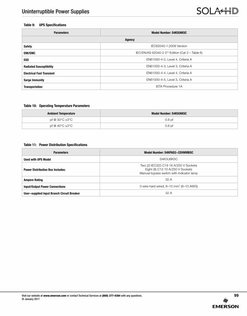
Uninterruptible Power Supplies
Visit our website at www.emerson.com or contact Technical Services at (800) 377-4384 with any questions. © January 2017
99
Table 9: UPS Specifications
Parameters Model Number: S4K5U6K5C
Agency
Safety IEC62040-1:2008 Version
EMI/EMC IEC/EN/AS 62040-2 2nd Edition (Cat 2—Table 6)
ESD EN61000-4-2, Level 4, Criteria A
Radiated Susceptibility EN61000-4-3, Level 3, Criteria A
Electrical Fast Transient EN61000-4-4, Level 4, Criteria A
Surge Immunity EN61000-4-5, Level 3, Criteria A
Transportation ISTA Procedure 1A
Table 10: Operating Temperature Parameters
Ambient Temperature Model Number: S4K5U6K5C
pf @ 30°C ±3°C 0.8 pf
pf @ 40°C ±3°C 0.8 pf
Table 11: Power Distribution Specifications
Parameters Model Number: S4KPAD2-CEHWMBSC
Used with UPS Model S4K5U6K5C
Power Distribution Box Includes:Two (2) IEC320 C19 16 A/250 V Sockets
Eight (8) C13 10 A/250 V SocketsManual bypass switch with indicator lamp
Ampere Rating 32 A
Input/Output Power Connections 3-wire hard wired, 6–10 mm2 (8–10 AWG)
User-supplied Input Branch Circuit Breaker 32 A
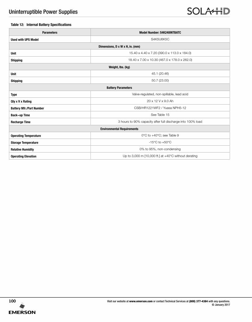
Uninterruptible Power Supplies
Visit our website at www.emerson.com or contact Technical Services at (800) 377-4384 with any questions. © January 2017
100
Table 12: Internal Battery Specifications
Parameters Model Number: S4K240INTBATC
Used with UPS Model S4K5U6K5C
Dimensions, D x W x H, in. (mm)
Unit 15.40 x 4.40 x 7.20 (390.0 x 113.0 x 184.0)
Shipping 18.40 x 7.00 x 10.30 (467.0 x 178.0 x 262.0)
Weight, lbs. (kg)
Unit 45.1 (20.46)
Shipping 50.7 (23.00)
Battery Parameters
Type Valve-regulated, non-spillable, lead acid
Qty x V x Rating 20 x 12 V x 9.0 Ah
Battery Mfr./Part Number CSB/HR1221WF2 / Yuasa NPH5-12
Back-up Time See Table 15
Recharge Time 3 hours to 90% capacity after full discharge into 100% load
Environmental Requirements
Operating Temperature 0°C to +40°C; see Table 9
Storage Temperature -15°C to +50°C
Relative Humidity 0% to 95%, non-condensing
Operating Elevation Up to 3,000 m [10,000 ft.] at +40°C without derating
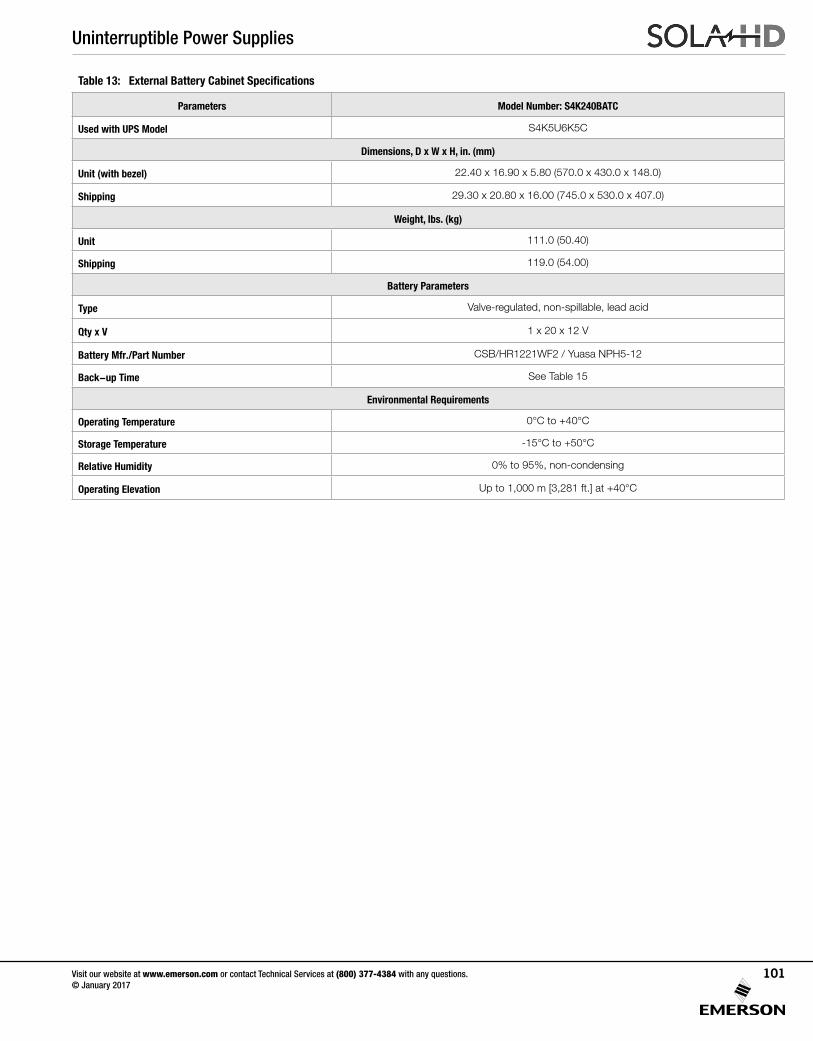
Uninterruptible Power Supplies
Visit our website at www.emerson.com or contact Technical Services at (800) 377-4384 with any questions. © January 2017
101
Table 13: External Battery Cabinet Specifications
Parameters Model Number: S4K240BATC
Used with UPS Model S4K5U6K5C
Dimensions, D x W x H, in. (mm)
Unit (with bezel) 22.40 x 16.90 x 5.80 (570.0 x 430.0 x 148.0)
Shipping 29.30 x 20.80 x 16.00 (745.0 x 530.0 x 407.0)
Weight, lbs. (kg)
Unit 111.0 (50.40)
Shipping 119.0 (54.00)
Battery Parameters
Type Valve-regulated, non-spillable, lead acid
Qty x V 1 x 20 x 12 V
Battery Mfr./Part Number CSB/HR1221WF2 / Yuasa NPH5-12
Back-up Time See Table 15
Environmental Requirements
Operating Temperature 0°C to +40°C
Storage Temperature -15°C to +50°C
Relative Humidity 0% to 95%, non-condensing
Operating Elevation Up to 1,000 m [3,281 ft.] at +40°C
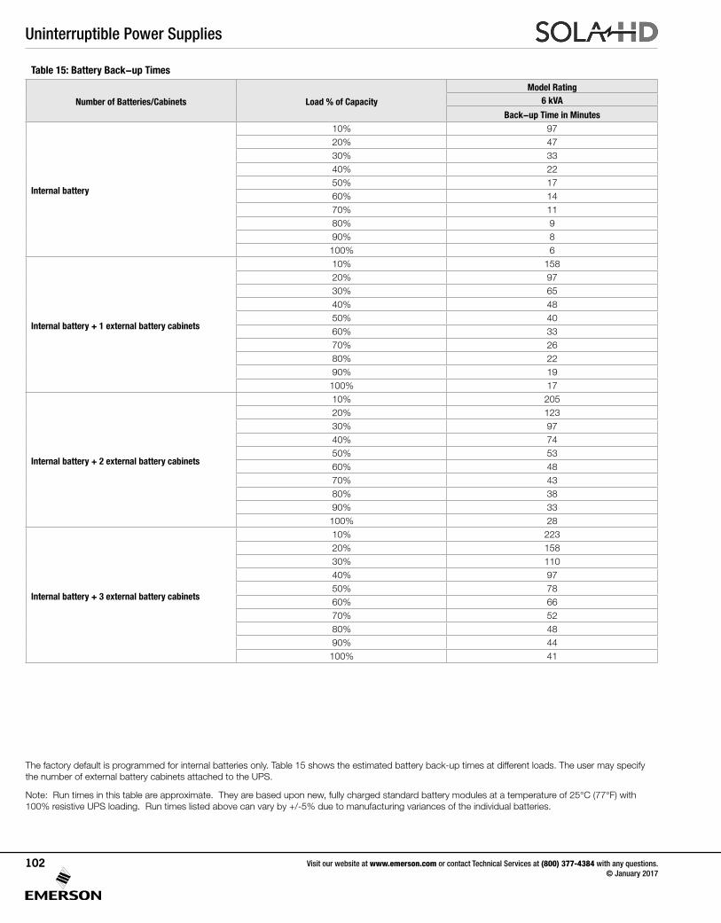
Uninterruptible Power Supplies
Visit our website at www.emerson.com or contact Technical Services at (800) 377-4384 with any questions. © January 2017
102
Table 15: Battery Back-up Times
Number of Batteries/Cabinets Load % of Capacity
Model Rating6 kVA
Back-up Time in Minutes
Internal battery
10% 9720% 4730% 3340% 2250% 1760% 1470% 1180% 990% 8100% 6
Internal battery + 1 external battery cabinets
10% 15820% 9730% 6540% 4850% 4060% 3370% 2680% 2290% 19100% 17
Internal battery + 2 external battery cabinets
10% 20520% 12330% 9740% 7450% 5360% 4870% 4380% 3890% 33100% 28
Internal battery + 3 external battery cabinets
10% 22320% 15830% 11040% 9750% 7860% 6670% 5280% 4890% 44100% 41
The factory default is programmed for internal batteries only. Table 15 shows the estimated battery back-up times at different loads. The user may specify the number of external battery cabinets attached to the UPS.
Note: Run times in this table are approximate. They are based upon new, fully charged standard battery modules at a temperature of 25°C (77°F) with 100% resistive UPS loading. Run times listed above can vary by +/-5% due to manufacturing variances of the individual batteries.
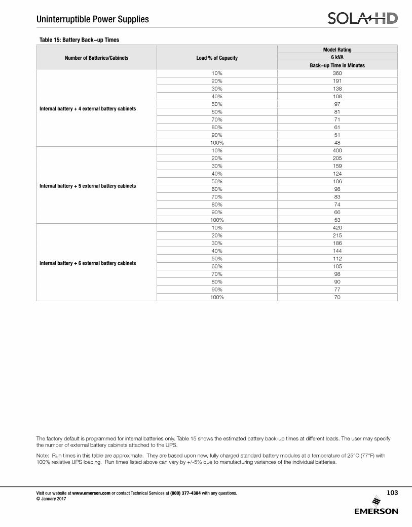
Uninterruptible Power Supplies
Visit our website at www.emerson.com or contact Technical Services at (800) 377-4384 with any questions. © January 2017
103
Table 15: Battery Back-up Times
Number of Batteries/Cabinets Load % of Capacity
Model Rating6 kVA
Back-up Time in Minutes
Internal battery + 4 external battery cabinets
10% 36020% 19130% 13840% 10850% 9760% 8170% 7180% 6190% 51100% 48
Internal battery + 5 external battery cabinets
10% 40020% 20530% 15940% 12450% 10660% 9870% 8380% 7490% 66100% 53
Internal battery + 6 external battery cabinets
10% 42020% 21530% 18640% 14450% 11260% 10570% 9880% 9090% 77100% 70
The factory default is programmed for internal batteries only. Table 15 shows the estimated battery back-up times at different loads. The user may specify the number of external battery cabinets attached to the UPS.
Note: Run times in this table are approximate. They are based upon new, fully charged standard battery modules at a temperature of 25°C (77°F) with 100% resistive UPS loading. Run times listed above can vary by +/-5% due to manufacturing variances of the individual batteries.
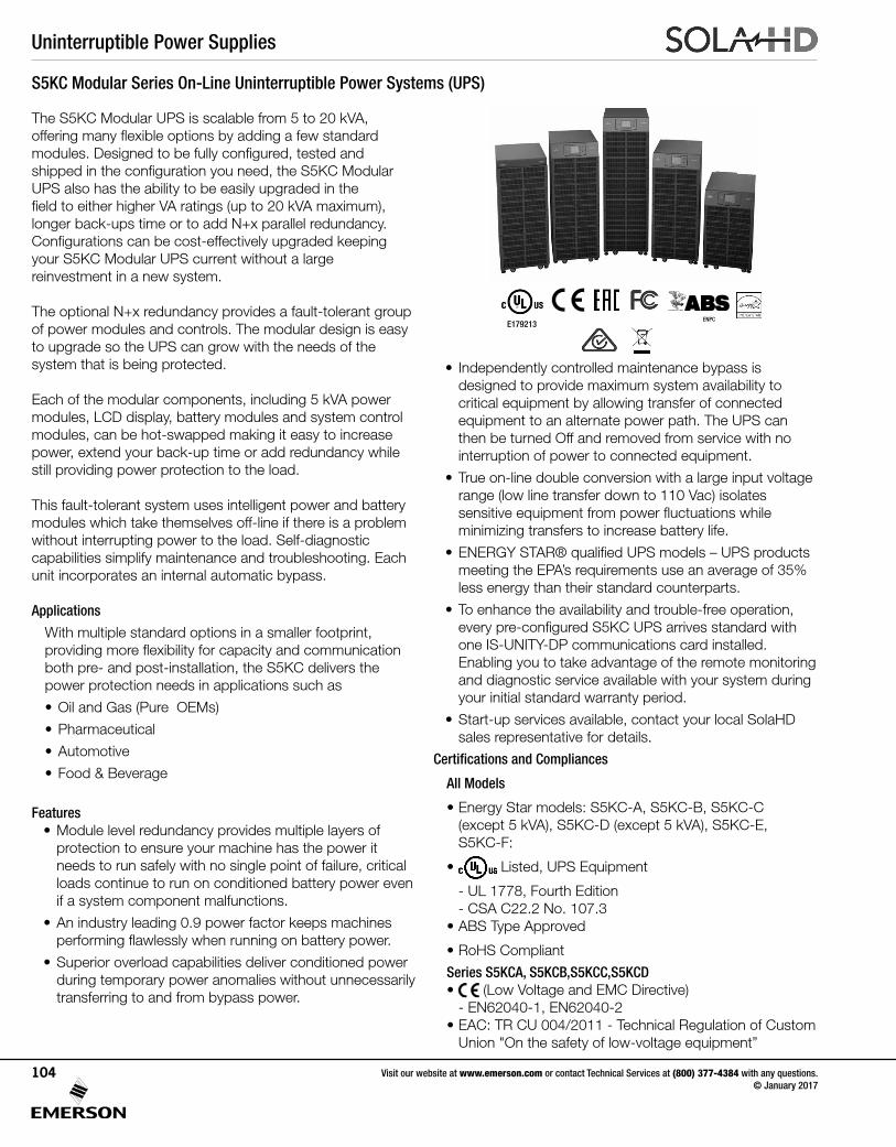
Uninterruptible Power Supplies
Visit our website at www.emerson.com or contact Technical Services at (800) 377-4384 with any questions. © January 2017
104
The S5KC Modular UPS is scalable from 5 to 20 kVA, offering many flexible options by adding a few standard modules. Designed to be fully configured, tested and shipped in the configuration you need, the S5KC Modular UPS also has the ability to be easily upgraded in the field to either higher VA ratings (up to 20 kVA maximum), longer back-ups time or to add N+x parallel redundancy. Configurations can be cost-effectively upgraded keeping your S5KC Modular UPS current without a large reinvestment in a new system.
The optional N+x redundancy provides a fault-tolerant groupof power modules and controls. The modular design is easyto upgrade so the UPS can grow with the needs of thesystem that is being protected.
Each of the modular components, including 5 kVA powermodules, LCD display, battery modules and system control modules, can be hot-swapped making it easy to increase power, extend your back-up time or add redundancy while still providing power protection to the load.
This fault-tolerant system uses intelligent power and batterymodules which take themselves off-line if there is a problemwithout interrupting power to the load. Self-diagnosticcapabilities simplify maintenance and troubleshooting. Eachunit incorporates an internal automatic bypass.
Applications
With multiple standard options in a smaller footprint, providing more flexibility for capacity and communication both pre- and post-installation, the S5KC delivers the power protection needs in applications such as
• Oil and Gas (Pure OEMs)
• Pharmaceutical
• Automotive
• Food & Beverage
Features• Module level redundancy provides multiple layers of
protection to ensure your machine has the power it needs to run safely with no single point of failure, critical loads continue to run on conditioned battery power even if a system component malfunctions.
• An industry leading 0.9 power factor keeps machines performing flawlessly when running on battery power.
• Superior overload capabilities deliver conditioned power during temporary power anomalies without unnecessarily transferring to and from bypass power.
S5KC Modular Series On-Line Uninterruptible Power Systems (UPS)
• Independently controlled maintenance bypass is designed to provide maximum system availability to critical equipment by allowing transfer of connected equipment to an alternate power path. The UPS can then be turned Off and removed from service with no interruption of power to connected equipment.
• True on-line double conversion with a large input voltage range (low line transfer down to 110 Vac) isolates sensitive equipment from power fluctuations while minimizing transfers to increase battery life.
• ENERGY STAR® qualified UPS models – UPS products meeting the EPA’s requirements use an average of 35% less energy than their standard counterparts.
• To enhance the availability and trouble-free operation, every pre-configured S5KC UPS arrives standard with one IS-UNITY-DP communications card installed. Enabling you to take advantage of the remote monitoring and diagnostic service available with your system during your initial standard warranty period.
• Start-up services available, contact your local SolaHD sales representative for details.
Certifications and Compliances
All Models
• Energy Star models: S5KC-A, S5KC-B, S5KC-C (except 5 kVA), S5KC-D (except 5 kVA), S5KC-E, S5KC-F:
• Listed, UPS Equipment
- UL 1778, Fourth Edition - CSA C22.2 No. 107.3
• ABS Type Approved
• RoHS Compliant
Series S5KCA, S5KCB,S5KCC,S5KCD• (Low Voltage and EMC Directive) - EN62040-1, EN62040-2• EAC: TR CU 004/2011 - Technical Regulation of Custom
Union "On the safety of low-voltage equipment”
E179213ENPC
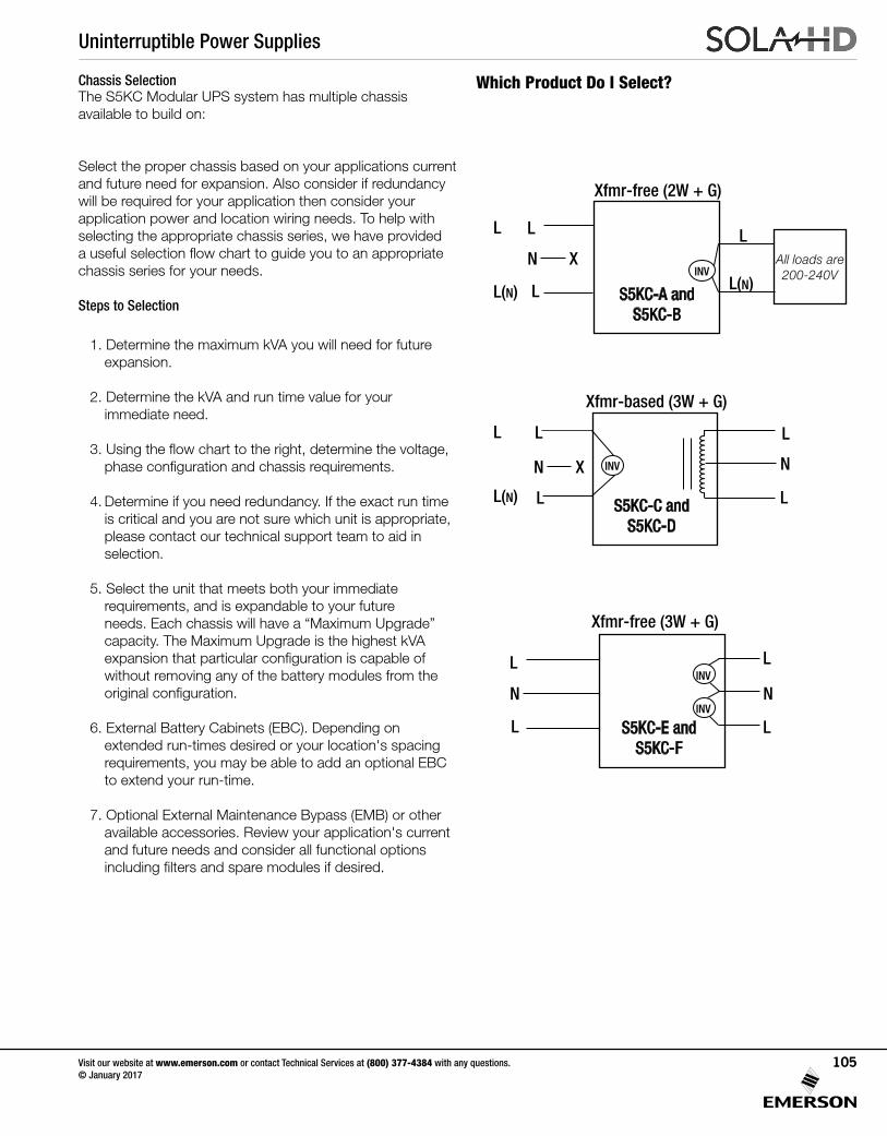
Uninterruptible Power Supplies
Visit our website at www.emerson.com or contact Technical Services at (800) 377-4384 with any questions. © January 2017
105
Chassis SelectionThe S5KC Modular UPS system has multiple chassis available to build on:
Select the proper chassis based on your applications current and future need for expansion. Also consider if redundancy will be required for your application then consider your application power and location wiring needs. To help with selecting the appropriate chassis series, we have provided a useful selection flow chart to guide you to an appropriate chassis series for your needs.
Steps to Selection
1. Determine the maximum kVA you will need for future expansion.
2. Determine the kVA and run time value for your immediate need.
3. Using the flow chart to the right, determine the voltage, phase configuration and chassis requirements.
4. Determine if you need redundancy. If the exact run time is critical and you are not sure which unit is appropriate, please contact our technical support team to aid in selection.
5. Select the unit that meets both your immediaterequirements, and is expandable to your futureneeds. Each chassis will have a “Maximum Upgrade” capacity. The Maximum Upgrade is the highest kVA expansion that particular configuration is capable of without removing any of the battery modules from the original configuration.
6. External Battery Cabinets (EBC). Depending on extended run-times desired or your location's spacing requirements, you may be able to add an optional EBC to extend your run-time.
7. Optional External Maintenance Bypass (EMB) or other available accessories. Review your application's current and future needs and consider all functional options including filters and spare modules if desired.
Which Product Do I Select?
Xfmr-free (2W + G)
Xfmr-free (3W + G)
S5KC-A and S5KC-B
S5KC-E and S5KC-F
INV
INV
INV
L
N
L
L
L
L(N)
LAll loads are 200-240V
L
L(N)
L
L(N)
L
L
N X
N X
L
L
N
INV
S5KC-C and S5KC-D
N
L
L
Xfmr-based (3W + G)
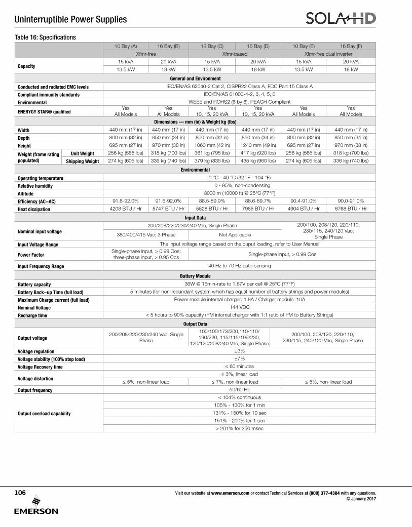
Uninterruptible Power Supplies
Visit our website at www.emerson.com or contact Technical Services at (800) 377-4384 with any questions. © January 2017
106
Table 16: Specifications10 Bay (A) 16 Bay (B) 12 Bay (C) 16 Bay (D) 10 Bay (E) 16 Bay (F)
Xfmr-free Xfmr-based Xfmr-free dual inverter
Capacity15 kVA 20 kVA 15 kVA 20 kVA 15 kVA 20 kVA
13.5 kW 18 kW 13.5 kW 18 kW 13.5 kW 18 kW
General and Environment
Conducted and radiated EMC levels IEC/EN/AS 62040-2 Cat 2, CISPR22 Class A, FCC Part 15 Class A
Compliant immunity standards IEC/EN/AS 61000-4-2, 3, 4, 5, 6
Environmental WEEE and ROHS2 (6 by 6), REACH Compliant
ENERYGY STAR® qualifiedYes
All ModelsYes
All ModelsYes
10, 15, 20 kVAYes
10, 15, 20 kVAYes
All ModelsYes
All Models
Dimensions — mm (in) & Weight kg (lbs)
Width 440 mm (17 in) 440 mm (17 in) 440 mm (17 in) 440 mm (17 in) 440 mm (17 in) 440 mm (17 in)
Depth 800 mm (32 in) 850 mm (34 in) 800 mm (32 in) 850 mm (34 in) 800 mm (32 in) 850 mm (34 in)
Height 695 mm (27 in) 970 mm (38 in) 1060 mm (42 in) 1240 mm (49 in) 695 mm (27 in) 970 mm (38 in)
Weight (frame rating populated)
Unit Weight 256 kg (565 lbs) 318 kg (700 lbs) 361 kg (795 lbs) 417 kg (920 lbs) 256 kg (565 lbs) 318 kg (700 lbs)
Shipping Weight 274 kg (605 lbs) 336 kg (740 lbs) 379 kg (835 lbs) 435 kg (960 lbs) 274 kg (605 lbs) 336 kg (740 lbs)
Environmental
Operating temperature 0 °C - 40 °C (32 °F - 104 °F)
Relative humidity 0 - 95%, non-condensing
Altitude 3000 m (10000 ft) @ 25°C (77°F)
Efficiency (AC-AC) 91.8-92.0% 91.6-92.0% 88.5-89.9% 88.6-89.7% 90.4-91.0% 90.0-91.0%
Heat dissipation 4208 BTU / Hr 5747 BTU / Hr 5528 BTU / Hr 7965 BTU / Hr 4904 BTU / Hr 6768 BTU / Hr
Input Data
Nominal input voltage200/208/220/230/240 Vac; Single Phase 200/100, 208/120, 220/110,
230/115, 240/120 Vac;Single Phase380/400/415 Vac; 3 Phase Not Applicable
Input Voltage Range The input voltage range based on the ouput loading, refer to User Manual
Power FactorSingle-phase input, > 0.99 Cos;three-phase input, > 0.95 Cos
Single-phase input, > 0.99 Cos
Input Frequency Range 40 Hz to 70 Hz auto-sensing
Battery Module
Battery capacity 36W @ 15min-rate to 1.67V per cell @ 25°C (77°F)
Battery Back-up Time (full load) 5 minutes (for non-redundant system which has equal number of battery strings and power modules)
Maximum Charge current (full load) Power module internal charger: 1.8A / Charger module: 10A
Nominal Voltage 144 VDC
Recharge time < 5 hours to 90% capacity (PM internal charger with 1:1 ratio of PM to Battery Strings)
Output Data
Output voltage200/208/220/230/240 Vac; Single
Phase
100/100/173/200,110/110/190/220, 115/115/199/230,
120/120/208/240 Vac; Single Phase
200/100, 208/120, 220/110,230/115, 240/120 Vac; Single Phase
Voltage regulation ±3%
Voltage stability (100% step load) ±7%
Voltage Recovery time ≤ 60 minutes
Voltage distortion≤ 3%, linear load
≤ 5%, non-linear load ≤ 7%, non-linear load ≤ 5%, non-linear load
Output frequency 50/60 Hz
Output overload capability
< 104% continuous
105% - 130% for 1 min
131% - 150% for 10 sec
151% - 200% for 1 sec
> 201% for 250 msec
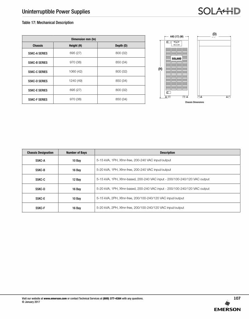
Uninterruptible Power Supplies
Visit our website at www.emerson.com or contact Technical Services at (800) 377-4384 with any questions. © January 2017
107
Table 17: Mechanical Description
Dimension mm (In)
Chassis Height (H) Depth (D)
S5KC-A SERIES 695 (27) 800 (32)
S5KC-B SERIES 970 (38) 850 (34)
S5KC-C SERIES 1060 (42) 800 (32)
S5KC-D SERIES 1240 (49) 850 (34)
S5KC-E SERIES 695 (27) 800 (32)
S5KC-F SERIES 970 (38) 850 (34)
Chassis Designation Number of Bays Description
S5KC-A 10 Bay 5-15 kVA, 1PH, Xfmr-free, 200-240 VAC input/output
S5KC-B 16 Bay 5-20 kVA, 1PH, Xfmr-free, 200-240 VAC input/output
S5KC-C 12 Bay 5-15 kVA, 1PH, Xfmr-based, 200-240 VAC input - 200/100-240/120 VAC output
S5KC-D 16 Bay 5-20 kVA, 1PH, Xfmr-based, 200-240 VAC input - 200/100-240/120 VAC output
S5KC-E 10 Bay 5-15 kVA, 2PH, Xfmr-free, 200/100-240/120 VAC input/output
S5KC-F 16 Bay 5-20 kVA, 2PH, Xfmr-free, 200/100-240/120 VAC input/output
SOLAHD
(H)
440 (17) (W)(D)
Chassis Dimensions
Uninterruptible Power Supplies
Visit our website at www.emerson.com or contact Technical Services at (800) 377-4384 with any questions. © January 2017
108
The S5KC UPS is a true online double-conversion system, having the following operating modes:
• Normal Mode• Back-up Mode• Auto Restart Mode• Bypass Mode
Normal ModeThe power module rectifiers derive power from a utility AC source and supply regulated DC power to the inverter. The module’s inverter regenerates precise AC power to supply the connected equipment. The battery charger is in the power module and maintains a float-charge on the batteries of the UPS; additionally, the optional charger module (S5KCCHRGRMOD) can also charge the batteries to maintain a quicker recharge time for long back-up time applications.
Back-up ModeWhen AC utility fails, the connected equipment is supplied power by the inverter, which obtains energy from the battery modules. The output power will not be interrupted during the failure or restoration of the AC utility/mains source.
Auto Restart ModeAfter a power outage and complete battery discharge, and once AC utility is restored, the UPS will automatically restart and resume supplying power to connected equipment. This feature is enabled at the factory, but can be disabled by the user. The user can also program two auto restart delay settingsfrom the LCD:
• Battery capacity level (%)• Countdown timer
Bypass ModeThe bypass provides an alternate path for power to the connected equipment and operates in the following manner:
• Automatic: In the event of an internal fault or should the inverter overload capacity be exceeded, the UPS performs an automatic transfer of the connected equipment from the inverter to the bypass source.• Manual: Should the UPS need to be taken out of service for limited maintenance or repair, manual activation of the bypass will cause an immediate transfer of the equipment from the inverter to the bypass source.
S5KC Operating Modes
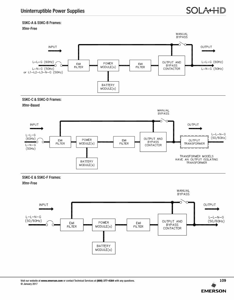
Uninterruptible Power Supplies
Visit our website at www.emerson.com or contact Technical Services at (800) 377-4384 with any questions. © January 2017
109
S5KC-A & S5KC-B Frames:
Xfmr-Free
S5KC-C & S5KC-D Frames:
Xfmr-Based
S5KC-E & S5KC-F Frames:
Xfmr-Free
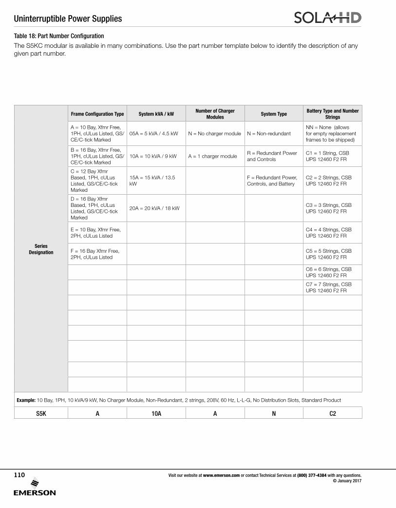
Uninterruptible Power Supplies
Visit our website at www.emerson.com or contact Technical Services at (800) 377-4384 with any questions. © January 2017
110
Series Designation
Frame Configuration Type System kVA / kWNumber of Charger
ModulesSystem Type
Battery Type and Number Strings
Output Voltage/Frequency/Wiring
Distribution Slot 1 Distribution Slot 2 Product Type
A = 10 Bay, Xfmr Free, 1PH, cULus Listed, GS/CE/C-tick Marked
05A = 5 kVA / 4.5 kW N = No charger module N = Non-redundantNN = None (allows for empty replacement frames to be shipped)
A = 200V, 60Hz, L-L-G N = None N = None C = Standard product
B = 16 Bay, Xfmr Free, 1PH, cULus Listed, GS/CE/C-tick Marked
10A = 10 kVA / 9 kW A = 1 charger moduleR = Redundant Power and Controls
C1 = 1 String, CSB UPS 12460 F2 FR
B = 220V, 60Hz, L-L-G1 = (2) L6-30R, (8) 5-15/20R [PD2-101]
1 = (2) L6-30R, (8) 5-15/20R [PD2-101]
C = 12 Bay Xfmr Based, 1PH, cULus Listed, GS/CE/C-tick Marked
15A = 15 kVA / 13.5 kW
F = Redundant Power, Controls, and Battery
C2 = 2 Strings, CSB UPS 12460 F2 FR
C = 208V, 60Hz, L-L-G2 = (4) L6-20R, (4) 5-15/20R [PD2-102]
2 = (4) L6-20R, (4) 5-15/20R [PD2-102]
D = 16 Bay Xfmr Based, 1PH, cULus Listed, GS/CE/C-tick Marked
20A = 20 kVA / 18 kWC3 = 3 Strings, CSB UPS 12460 F2 FR
D = 240V, 60Hz, L-L-G3 = (4) L6-30R, (4) 5-15/20R [PD2-103]
3 = (4) L6-30R, (4) 5-15/20R [PD2-103]
E = 10 Bay, Xfmr Free, 2PH, cULus Listed
C4 = 4 Strings, CSB UPS 12460 F2 FR
E = 200/100V, 60Hz, L-L-N-G
4 = (2) L6-30R, (2) L6-20R, (4) 5-15/20R [PD2-104]
4 = (2) L6-30R, (2) L6-20R, (4) 5-15/20R [PD2-104]
F = 16 Bay Xfmr Free, 2PH, cULus Listed
C5 = 5 Strings, CSB UPS 12460 F2 FR
F = 220/110V, 60Hz, L-L-N-G
5 = (2) L5-30R, (2) L5-20R, (4) 5-15/20R [PD2-105]
5 = (2) L5-30R, (2) L5-20R, (4) 5-15/20R [PD2-105]
C6 = 6 Strings, CSB UPS 12460 F2 FR
G = 208/120V, 60Hz, L-L-N-G
6 = (4) L6-20R, (4) L5-20R [PD2-106]
6 = (4) L6-20R, (4) L5-20R [PD2-106]
C7 = 7 Strings, CSB UPS 12460 F2 FR
H = 240/120V, 60Hz, L-L-N-G
7 = (4) L5-20R, (4) 5-15/20R [PD2-107]
7 = (4) L5-20R, (4) 5-15/20R [PD2-107]
J = 220/127V, 60Hz, L-L-N-G
8 = (2) L6-30R, (2) L6-20R [PD2-108]
8 = (2) L6-30R, (2) L6-20R [PD2-108]
9 = (2) L14-30R [PD2-109]
9 = (2) L14-30R [PD2-109]
A = (4) IEC320-C19, (4) IEC320-C13 [PD2-200]
A = (4) IEC320-C19, (4) IEC320-C13 [PD2-200]
B = (2) IEC320-C19, (8) IEC320-C13 [PD2-201]
B = (2) IEC320-C19, (8) IEC320-C13 [PD2-201]
C = (12) IEC320-C13 [PD2-202]
C = (12) IEC320-C13 [PD2-202]
D = (2) IEC309-32A, (4) IEC320-C13 [PD2-204]
D = (2) IEC309-32A, (4) IEC320-C13 [PD2-204]
Example: 10 Bay, 1PH, 10 kVA/9 kW, No Charger Module, Non-Redundant, 2 strings, 208V, 60 Hz, L-L-G, No Distribution Slots, Standard Product
S5K A 10A A N C2 C N N C
Table 18: Part Number Configuration
The S5KC modular is available in many combinations. Use the part number template below to identify the description of any given part number.
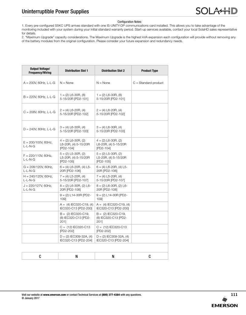
Uninterruptible Power Supplies
Visit our website at www.emerson.com or contact Technical Services at (800) 377-4384 with any questions. © January 2017
111
Series Designation
Frame Configuration Type System kVA / kWNumber of Charger
ModulesSystem Type
Battery Type and Number Strings
Output Voltage/Frequency/Wiring
Distribution Slot 1 Distribution Slot 2 Product Type
A = 10 Bay, Xfmr Free, 1PH, cULus Listed, GS/CE/C-tick Marked
05A = 5 kVA / 4.5 kW N = No charger module N = Non-redundantNN = None (allows for empty replacement frames to be shipped)
A = 200V, 60Hz, L-L-G N = None N = None C = Standard product
B = 16 Bay, Xfmr Free, 1PH, cULus Listed, GS/CE/C-tick Marked
10A = 10 kVA / 9 kW A = 1 charger moduleR = Redundant Power and Controls
C1 = 1 String, CSB UPS 12460 F2 FR
B = 220V, 60Hz, L-L-G1 = (2) L6-30R, (8) 5-15/20R [PD2-101]
1 = (2) L6-30R, (8) 5-15/20R [PD2-101]
C = 12 Bay Xfmr Based, 1PH, cULus Listed, GS/CE/C-tick Marked
15A = 15 kVA / 13.5 kW
F = Redundant Power, Controls, and Battery
C2 = 2 Strings, CSB UPS 12460 F2 FR
C = 208V, 60Hz, L-L-G2 = (4) L6-20R, (4) 5-15/20R [PD2-102]
2 = (4) L6-20R, (4) 5-15/20R [PD2-102]
D = 16 Bay Xfmr Based, 1PH, cULus Listed, GS/CE/C-tick Marked
20A = 20 kVA / 18 kWC3 = 3 Strings, CSB UPS 12460 F2 FR
D = 240V, 60Hz, L-L-G3 = (4) L6-30R, (4) 5-15/20R [PD2-103]
3 = (4) L6-30R, (4) 5-15/20R [PD2-103]
E = 10 Bay, Xfmr Free, 2PH, cULus Listed
C4 = 4 Strings, CSB UPS 12460 F2 FR
E = 200/100V, 60Hz, L-L-N-G
4 = (2) L6-30R, (2) L6-20R, (4) 5-15/20R [PD2-104]
4 = (2) L6-30R, (2) L6-20R, (4) 5-15/20R [PD2-104]
F = 16 Bay Xfmr Free, 2PH, cULus Listed
C5 = 5 Strings, CSB UPS 12460 F2 FR
F = 220/110V, 60Hz, L-L-N-G
5 = (2) L5-30R, (2) L5-20R, (4) 5-15/20R [PD2-105]
5 = (2) L5-30R, (2) L5-20R, (4) 5-15/20R [PD2-105]
C6 = 6 Strings, CSB UPS 12460 F2 FR
G = 208/120V, 60Hz, L-L-N-G
6 = (4) L6-20R, (4) L5-20R [PD2-106]
6 = (4) L6-20R, (4) L5-20R [PD2-106]
C7 = 7 Strings, CSB UPS 12460 F2 FR
H = 240/120V, 60Hz, L-L-N-G
7 = (4) L5-20R, (4) 5-15/20R [PD2-107]
7 = (4) L5-20R, (4) 5-15/20R [PD2-107]
J = 220/127V, 60Hz, L-L-N-G
8 = (2) L6-30R, (2) L6-20R [PD2-108]
8 = (2) L6-30R, (2) L6-20R [PD2-108]
9 = (2) L14-30R [PD2-109]
9 = (2) L14-30R [PD2-109]
A = (4) IEC320-C19, (4) IEC320-C13 [PD2-200]
A = (4) IEC320-C19, (4) IEC320-C13 [PD2-200]
B = (2) IEC320-C19, (8) IEC320-C13 [PD2-201]
B = (2) IEC320-C19, (8) IEC320-C13 [PD2-201]
C = (12) IEC320-C13 [PD2-202]
C = (12) IEC320-C13 [PD2-202]
D = (2) IEC309-32A, (4) IEC320-C13 [PD2-204]
D = (2) IEC309-32A, (4) IEC320-C13 [PD2-204]
Example: 10 Bay, 1PH, 10 kVA/9 kW, No Charger Module, Non-Redundant, 2 strings, 208V, 60 Hz, L-L-G, No Distribution Slots, Standard Product
S5K A 10A A N C2 C N N C
Configuration Notes:1. Every pre-configured S5KC UPS arrives standard with one IS-UNITY-DP communications card installed. This allows you to take advantage of the monitoring included with your system during your initial standard warranty period. Start-up services available, contact your local SolaHD sales representative for details.2. “Maximum Upgrade” capacity considerations. The Maximum Upgrade is the highest kVA expansion each configuration will provide without removing any of the battery modules from the original configuration. Please consider your future expansion and redundancy needs.
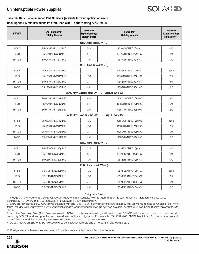
Uninterruptible Power Supplies
Visit our website at www.emerson.com or contact Technical Services at (800) 377-4384 with any questions. © January 2017
112
kVA/kWNon-RedundantCatalog Number
Available Expansion Bays(Total/Power)
RedundantCatalog Number
Available Expansion Bays(Total/Power)
S5KA Xfmr-Free (2W + G)
5/4.5 S5KA05ANNC1CNNC 7/2 S5KA05ANRC1CNNC 6/2
10/9 S5KA10ANNC2CNNC 5/1 S5KA10ANRC2CNNC 3/1
15/13.5 S5KA15ANNC3CNNC 1/0 S5KA15ANRC3CNNC 0/0
S5KB Xfmr-Free (2W + G)
5/4.5 S5KB05ANNC1CNNC 13/3 S5KB05ANRC1CNNC 12/3
10/9 S5KB10ANNC2CNNC 10/2 S5KB10ANRC2CNNC 9/2
15/13.5 S5KB15ANNC3CNNC 7/1 S5KB15ANRC3CNNC 6/1
20/18 S5KB20ANNC4CNNC 4/0 S5KB20ANRC4CNNC 3/0
S5KC Xfmr-Based (Input: 2W + G, Output: 3W + G)
5/4.5 S5KC05ANNC1GNNC 9/2 S5KC05ANRC1GNNC 8/2
10/9 S5KC10ANNC2GNNC 6/1 S5KC10ANRC2GNNC 5/1
15/13.5 S5KC15ANNC3GNNC 3/0 S5KC15ANRC3GNNC 2/0
S5KD Xfmr-Based (Input: 2W + G, Output: 3W + G)
5/4.5 S5KD05ANNC1GNNC 13/3 S5KD05ANRC1GNNC 12/3
10/9 S5KD10ANNC2GNNC 10/2 S5KD10ANRC2GNNC 9/2
15/13.5 S5KD15ANNC3GNNC 7/1 S5KD15ANRC3GNNC 6/1
20/18 S5KD20ANNC4GNNC 4/0 S5KD20ANRC4GNNC 3/0
S5KE Xfmr-Free (3W + G)
5/4.5 S5KE05ANNC1GNNC 7/2 S5KE05ANRC1GNNC 6/2
10/9 S5KE10ANNC2GNNC 5/1 S5KE10ANRC2GNNC 3/1
15/13.5 S5KE15ANNC3GNNC 1/0 S5KE15ANRC3GNNC 0/0
S5KF Xfmr-Free (3W + G)
5/4.5 S5KF05ANNC1GNNC 13/3 S5KF05ANRC1GNNC 12/3
10/9 S5KF10ANNC2GNNC 10/2 S5KF10ANRC2GNNC 9/2
15/13.5 S5KF15ANNC3GNNC 7/1 S5KF15ANRC3GNNC 6/1
20/18 S5KF20ANNC4GNNC 4/0 S5KF20ANRC4GNNC 3/0
Table 19: Basic Recommended Part Numbers (scalable for your application needs)
Back-up time: 5 minutes minimum at full load with 1-battery string per 5 kVA
Configuration Notes:1. Voltage Options: Additional Output Voltage Configurations are available. Refer to Table 16 and 18, part number configuration template table.Example: D = 240V, 60Hz, L-L-G ; S5KC05ANN1DNNC is a 240V configuration.2. Every pre-configured S5KC UPS arrives standard with one IS-UNITY-DP communications card installed. This allows you to take advantage of the moni-toring included with your system during your initial standard warranty period. Start-up services available, contact your local SolaHD sales representative for details.3. Available Expansion Bays (Total/Power) equals the TOTAL available expansion bays still available and POWER is the number of bays that can be used for remaining POWER modules up to the maximum allowed for that configuration. For example: S5KA05ANNC1CNNC, has 7 total, 2 power so you can add either 6 battery modules, 1 charging module or 6 battery modules and 2 power modules.4. Do you require an EBC or MBC? Please refer to configuration table 20 and 21 to build an appropriate part.
Configurations with run-times in excess of 5 minutes are available, contact Technical Services.
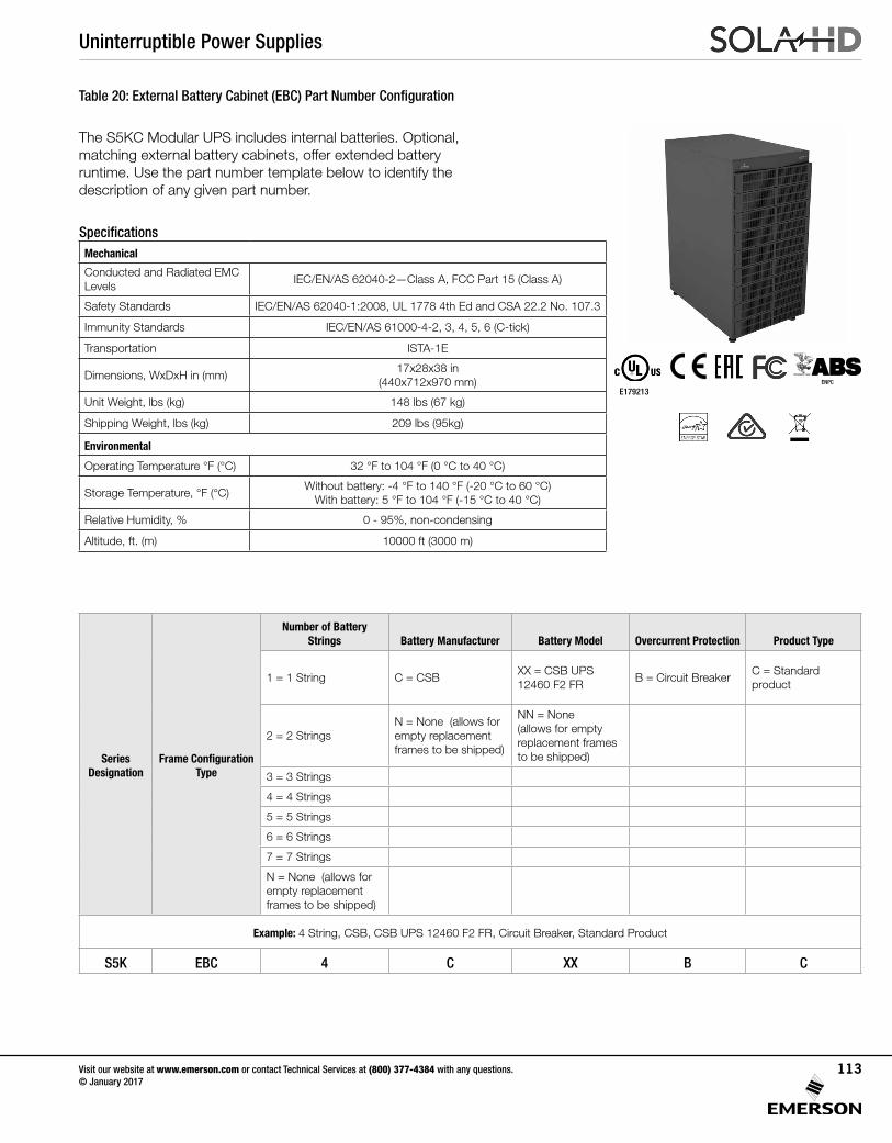
Uninterruptible Power Supplies
Visit our website at www.emerson.com or contact Technical Services at (800) 377-4384 with any questions. © January 2017
113
Table 20: External Battery Cabinet (EBC) Part Number Configuration
Series Designation
Frame Configuration Type
Number of Battery Strings Battery Manufacturer Battery Model Overcurrent Protection Product Type
1 = 1 String C = CSBXX = CSB UPS 12460 F2 FR
B = Circuit BreakerC = Standard product
2 = 2 StringsN = None (allows for empty replacement frames to be shipped)
NN = None (allows for empty replacement frames to be shipped)
3 = 3 Strings
4 = 4 Strings
5 = 5 Strings
6 = 6 Strings
7 = 7 Strings
N = None (allows for empty replacement frames to be shipped)
Example: 4 String, CSB, CSB UPS 12460 F2 FR, Circuit Breaker, Standard Product
S5K EBC 4 C XX B C
The S5KC Modular UPS includes internal batteries. Optional, matching external battery cabinets, offer extended battery runtime. Use the part number template below to identify the description of any given part number.
SpecificationsMechanical
Conducted and Radiated EMC Levels
IEC/EN/AS 62040-2—Class A, FCC Part 15 (Class A)
Safety Standards IEC/EN/AS 62040-1:2008, UL 1778 4th Ed and CSA 22.2 No. 107.3
Immunity Standards IEC/EN/AS 61000-4-2, 3, 4, 5, 6 (C-tick)
Transportation ISTA-1E
Dimensions, WxDxH in (mm)17x28x38 in
(440x712x970 mm)
Unit Weight, lbs (kg) 148 lbs (67 kg)
Shipping Weight, lbs (kg) 209 lbs (95kg)
Environmental
Operating Temperature °F (°C) 32 °F to 104 °F (0 °C to 40 °C)
Storage Temperature, °F (°C)Without battery: -4 °F to 140 °F (-20 °C to 60 °C)
With battery: 5 °F to 104 °F (-15 °C to 40 °C)
Relative Humidity, % 0 - 95%, non-condensing
Altitude, ft. (m) 10000 ft (3000 m)
E179213ENPC
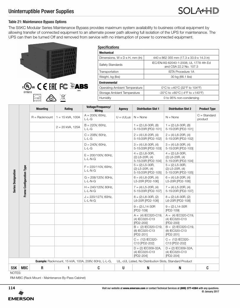
Uninterruptible Power Supplies
Visit our website at www.emerson.com or contact Technical Services at (800) 377-4384 with any questions. © January 2017
114
Table 21: Maintenance Bypass Options
The S5KC Modular Series Maintenance Bypass provides maximum system availability to business critical equipment by allowing transfer of connected equipment to an alternate power path allowing full isolation of the UPS for maintenance. The UPS can then be turned Off and removed from service with no interruption of power to connected equipment.
Serie
s De
sign
atio
n
Fram
e Co
nfig
urat
ion
Type
Mounting RatingVoltage/Frequency/
WiringAgency Distribution Slot 1 Distribution Slot 2 Product Type
R = Rackmount 1 = 15 kVA, 100AA = 200V, 60Hz, L-L-G
U = cULus N = None N = NoneC = Standard product
2 = 20 kVA, 125AB = 220V, 60Hz, L-L-G
1 = (2) L6-30R, (8) 5-15/20R [PD2-101]
1 = (2) L6-30R, (8) 5-15/20R [PD2-101]
C = 208V, 60Hz, L-L-G
2 = (4) L6-20R, (4) 5-15/20R [PD2-102]
2 = (4) L6-20R, (4) 5-15/20R [PD2-102]
D = 240V, 60Hz, L-L-G
3 = (4) L6-30R, (4) 5-15/20R [PD2-103]
3 = (4) L6-30R, (4) 5-15/20R [PD2-103]
E = 200/100V, 60Hz, L-L-N-G
4 = (2) L6-30R, (2) L6-20R, (4) 5-15/20R [PD2-104]
4 = (2) L6-30R, (2) L6-20R, (4) 5-15/20R [PD2-104]
F = 220/110V, 60Hz, L-L-N-G
5 = (2) L5-30R, (2) L5-20R, (4) 5-15/20R [PD2-105]
5 = (2) L5-30R, (2) L5-20R, (4) 5-15/20R [PD2-105]
G = 208/120V, 60Hz, L-L-N-G
6 = (4) L6-20R, (4) L5-20R [PD2-106]
6 = (4) L6-20R, (4) L5-20R [PD2-106]
H = 240/120V, 60Hz, L-L-N-G
7 = (4) L5-20R, (4) 5-15/20R [PD2-107]
7 = (4) L5-20R, (4) 5-15/20R [PD2-107]
J = 220/127V, 60Hz, L-L-N-G
8 = (2) L6-30R, (2) L6-20R [PD2-108]
8 = (2) L6-30R, (2) L6-20R [PD2-108]
9 = (2) L14-30R [PD2-109]
9 = (2) L14-30R [PD2-109]
A = (4) IEC320-C19, (4) IEC320-C13 [PD2-200]
A = (4) IEC320-C19, (4) IEC320-C13 [PD2-200]
B = (2) IEC320-C19, (8) IEC320-C13 [PD2-201]
B = (2) IEC320-C19, (8) IEC320-C13 [PD2-201]
C = (12) IEC320-C13 [PD2-202]
C = (12) IEC320-C13 [PD2-202]
D = (2) IEC309-32A, (4) IEC320-C13 [PD2-204]
D = (2) IEC309-32A, (4) IEC320-C13 [PD2-204]
Example: Rackmount, 15 kVA, 100A, 208V, 60Hz, L-L-G, UL, cUL Listed, No Distribution Slots, Standard Product
S5K MBC R 1 C U N N CNOTES:
RM-MBC (Rack Mount - Maintenance By-Pass Cabinet)
SpecificationsMechanical
Dimensions, W x D x H, mm (In) 440 x 862 355 mm (17.3 x 33.9 x 14.3 in)
Safety StandardsIEC/EN/AS 62040-1:2008, UL 1778 4th Ed
and CSA 22.2 No. 107.3
Transportation ISTA Procedure 1A
Weight, kg (lbs) 30 kg (66.1 lbs)
Environmental
Operating Ambient Temperature 0°C to +40°C (32°F to 104°F)
Storage Ambient Temperature -20°C to +60°C (-4°F to +140°F)
Humidity 0 to 95% non-condensing
E179213ENPC
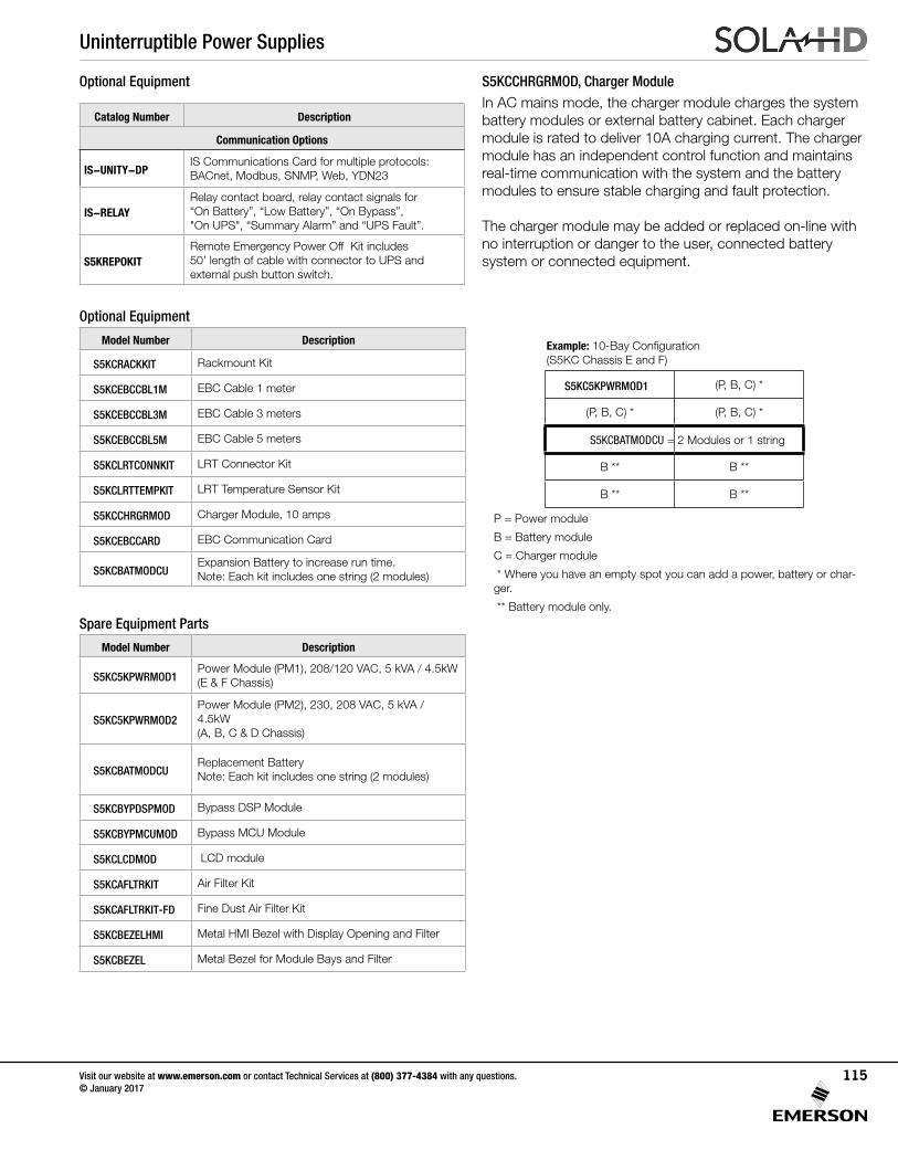
Uninterruptible Power Supplies
Visit our website at www.emerson.com or contact Technical Services at (800) 377-4384 with any questions. © January 2017
115
Optional Equipment S5KCCHRGRMOD, Charger Module
Catalog Number Description
Communication Options
IS-UNITY-DPIS Communications Card for multiple protocols: BACnet, Modbus, SNMP, Web, YDN23
IS-RELAYRelay contact board, relay contact signals for “On Battery”, “Low Battery”, “On Bypass”, "On UPS", “Summary Alarm” and “UPS Fault”.
S5KREPOKITRemote Emergency Power Off Kit includes 50’ length of cable with connector to UPS and external push button switch.
Model Number Description
S5KCRACKKIT Rackmount Kit
S5KCEBCCBL1M EBC Cable 1 meter
S5KCEBCCBL3M EBC Cable 3 meters
S5KCEBCCBL5M EBC Cable 5 meters
S5KCLRTCONNKIT LRT Connector Kit
S5KCLRTTEMPKIT LRT Temperature Sensor Kit
S5KCCHRGRMOD Charger Module, 10 amps
S5KCEBCCARD EBC Communication Card
S5KCBATMODCUExpansion Battery to increase run time.Note: Each kit includes one string (2 modules)
Optional Equipment
Model Number Description
S5KC5KPWRMOD1Power Module (PM1), 208/120 VAC, 5 kVA / 4.5kW(E & F Chassis)
S5KC5KPWRMOD2Power Module (PM2), 230, 208 VAC, 5 kVA / 4.5kW(A, B, C & D Chassis)
S5KCBATMODCUReplacement BatteryNote: Each kit includes one string (2 modules)
S5KCBYPDSPMOD Bypass DSP Module
S5KCBYPMCUMOD Bypass MCU Module
S5KCLCDMOD LCD module
S5KCAFLTRKIT Air Filter Kit
S5KCAFLTRKIT-FD Fine Dust Air Filter Kit
S5KCBEZELHMI Metal HMI Bezel with Display Opening and Filter
S5KCBEZEL Metal Bezel for Module Bays and Filter
Spare Equipment Parts
S5KC5KPWRMOD1 (P, B, C) *
(P, B, C) * (P, B, C) *
B ** B **
B ** B **
Example: 10-Bay Configuration (S5KC Chassis E and F)
P = Power module
B = Battery module
C = Charger module
* Where you have an empty spot you can add a power, battery or char-ger.
** Battery module only.
In AC mains mode, the charger module charges the system battery modules or external battery cabinet. Each charger module is rated to deliver 10A charging current. The charger module has an independent control function and maintains real-time communication with the system and the battery modules to ensure stable charging and fault protection.
The charger module may be added or replaced on-line with no interruption or danger to the user, connected battery system or connected equipment.
S5KCBATMODCU = 2 Modules or 1 string
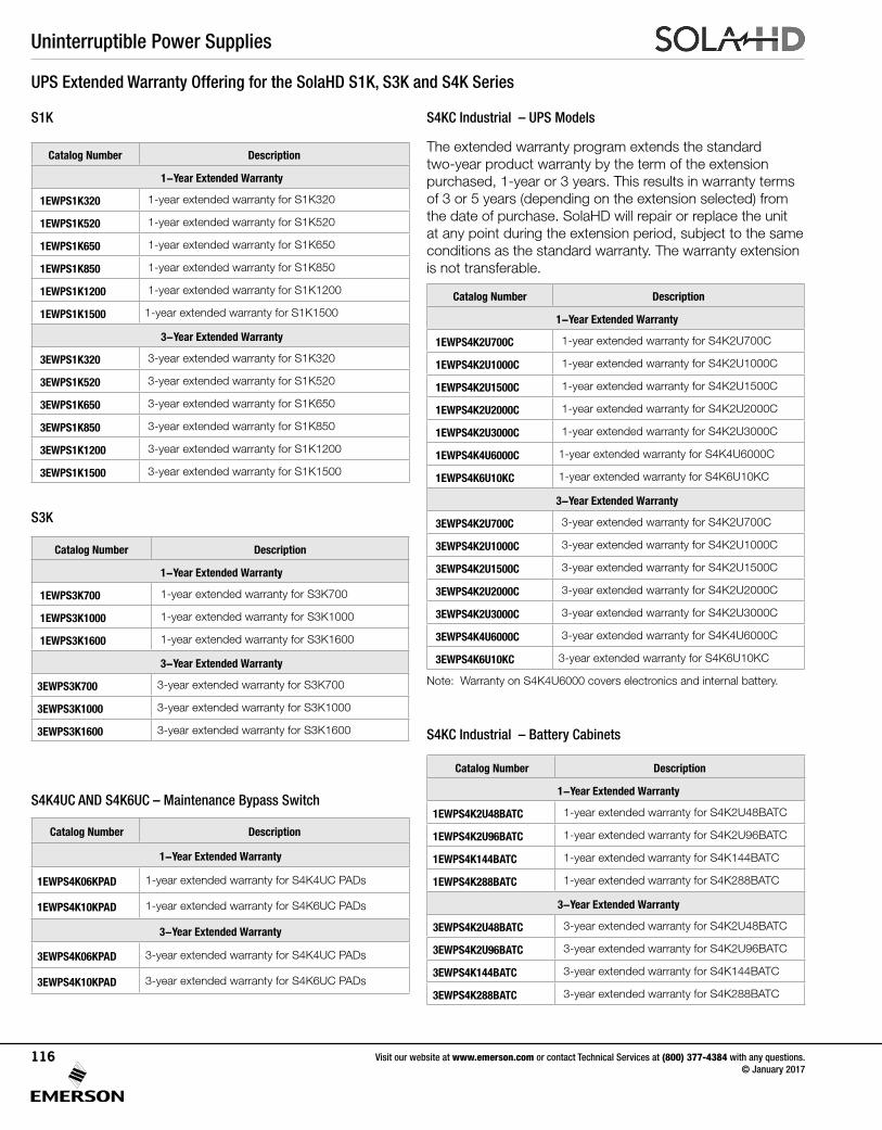
Uninterruptible Power Supplies
Visit our website at www.emerson.com or contact Technical Services at (800) 377-4384 with any questions. © January 2017
116
UPS Extended Warranty Offering for the SolaHD S1K, S3K and S4K Series
S3K
Catalog Number Description
1-Year Extended Warranty
1EWPS3K700 1-year extended warranty for S3K700
1EWPS3K1000 1-year extended warranty for S3K1000
1EWPS3K1600 1-year extended warranty for S3K1600
3-Year Extended Warranty
3EWPS3K700 3-year extended warranty for S3K700
3EWPS3K1000 3-year extended warranty for S3K1000
3EWPS3K1600 3-year extended warranty for S3K1600
S1K
Catalog Number Description
1-Year Extended Warranty
1EWPS1K320 1-year extended warranty for S1K320
1EWPS1K520 1-year extended warranty for S1K520
1EWPS1K650 1-year extended warranty for S1K650
1EWPS1K850 1-year extended warranty for S1K850
1EWPS1K1200 1-year extended warranty for S1K1200
1EWPS1K1500 1-year extended warranty for S1K1500
3-Year Extended Warranty
3EWPS1K320 3-year extended warranty for S1K320
3EWPS1K520 3-year extended warranty for S1K520
3EWPS1K650 3-year extended warranty for S1K650
3EWPS1K850 3-year extended warranty for S1K850
3EWPS1K1200 3-year extended warranty for S1K1200
3EWPS1K1500 3-year extended warranty for S1K1500
S4K4UC AND S4K6UC – Maintenance Bypass Switch
S4KC Industrial – UPS Models
Catalog Number Description
1-Year Extended Warranty
1EWPS4K2U700C 1-year extended warranty for S4K2U700C
1EWPS4K2U1000C 1-year extended warranty for S4K2U1000C
1EWPS4K2U1500C 1-year extended warranty for S4K2U1500C
1EWPS4K2U2000C 1-year extended warranty for S4K2U2000C
1EWPS4K2U3000C 1-year extended warranty for S4K2U3000C
1EWPS4K4U6000C 1-year extended warranty for S4K4U6000C
1EWPS4K6U10KC 1-year extended warranty for S4K6U10KC
3-Year Extended Warranty
3EWPS4K2U700C 3-year extended warranty for S4K2U700C
3EWPS4K2U1000C 3-year extended warranty for S4K2U1000C
3EWPS4K2U1500C 3-year extended warranty for S4K2U1500C
3EWPS4K2U2000C 3-year extended warranty for S4K2U2000C
3EWPS4K2U3000C 3-year extended warranty for S4K2U3000C
3EWPS4K4U6000C 3-year extended warranty for S4K4U6000C
3EWPS4K6U10KC 3-year extended warranty for S4K6U10KC
Note: Warranty on S4K4U6000 covers electronics and internal battery.
The extended warranty program extends the standard two-year product warranty by the term of the extension purchased, 1-year or 3 years. This results in warranty terms of 3 or 5 years (depending on the extension selected) from the date of purchase. SolaHD will repair or replace the unit at any point during the extension period, subject to the same conditions as the standard warranty. The warranty extension is not transferable.
S4KC Industrial – Battery Cabinets
Catalog Number Description
1-Year Extended Warranty
1EWPS4K2U48BATC 1-year extended warranty for S4K2U48BATC
1EWPS4K2U96BATC 1-year extended warranty for S4K2U96BATC
1EWPS4K144BATC 1-year extended warranty for S4K144BATC
1EWPS4K288BATC 1-year extended warranty for S4K288BATC
3-Year Extended Warranty
3EWPS4K2U48BATC 3-year extended warranty for S4K2U48BATC
3EWPS4K2U96BATC 3-year extended warranty for S4K2U96BATC
3EWPS4K144BATC 3-year extended warranty for S4K144BATC
3EWPS4K288BATC 3-year extended warranty for S4K288BATC
Catalog Number Description
1-Year Extended Warranty
1EWPS4K06KPAD 1-year extended warranty for S4K4UC PADs
1EWPS4K10KPAD 1-year extended warranty for S4K6UC PADs
3-Year Extended Warranty
3EWPS4K06KPAD 3-year extended warranty for S4K4UC PADs
3EWPS4K10KPAD 3-year extended warranty for S4K6UC PADs
Uninterruptible Power Supplies
Visit our website at www.emerson.com or contact Technical Services at (800) 377-4384 with any questions. © January 2017
117
Field Service Programs for the S4K4UC/6UC Industrial and S5KC Series
These programs are for Domestic coverage (valid only within the continental United States and Canada); additional travel expenses may be billed to customers with site locations more than 150 miles from a major metropolitan area.
S4K4UC/6UC Industrial Start-Up Programs
Start-Up includes one site trip within the contiguous 48 states by a factory trained technician. Any additional trips by the customer service engineer as a result of the site not being ready for start-up may result in additional costs to the customer. The site trip includes the following services for one UPS module:
• Rack construction, installation or re-configuration with UPS accessories.
• Installation includes mounting and start-up of new UPS and internal batteries (excludes hard-wired applications).
• Services performed by factory trained technician.
• Services performed 24x7, excluding national holidays within the 48 contiguous states.
S5KC Modular Start-Up Programs
Start-up services should be ordered as a separate line item at the time of purchase. S5KC Series UPS sold with start-up Services are provided with a 2 year parts and labor warranty. Please refer to the following information for a menu of start-up options and please choose the appropriate start-up service required. If start-up is not ordered and performed, please note that this will reduce your warranty period to two years of parts and, 90 days labor.
A separate Preventative Maintenance Only plan is available in addition to the standard Start-Up plan.
Service Programs - S4K4UC/6UC and S5KC Series
Preferred service level options include 6-hour on-site response, 24x7 within 150 miles of nearest service centers. 24x7 emergency service includes parts (including internal batteries), labor, and travel. Also includes one (1) Preventive Maintenance (PM) visit per year, scheduled at the customer’s convenience (24x7).
Essential service level options include 6-hour on-site response, 24x7 within 150 miles of nearest service centers. 24x7 emergency service includes parts (including internal batteries), labor, and travel. Also includes one (1) Preventive Maintenance (PM) visit per year, scheduled by the customer for M-F 8AM-5PM.
Basic service level options include 6-hour on-site response, 24x7 within 150 miles of nearest service centers. 24x7 emergency service includes parts (excluding internal batteries), labor, and travel. Preventive Maintenance (PM) not included and is not available if the Basic Service plan is selected.
Uninterruptible Power Supplies
Visit our website at www.emerson.com or contact Technical Services at (800) 377-4384 with any questions. © January 2017
118
Field Service Programs for the S4K4UC, S4K6UC Industrial and S5KC Series
Catalog Number Description
Domestic Only (7-Days/Week, 24 Hrs/Day)
SUS4K061U7 6 kVA Start-Up
SUS4K101U7 10 kVA Start-Up
Preferred Service (w/ 1 PM)
Catalog Number Equipment
MUUS4K06PR1 S4K4U6000C
MEUS4KBATPR1 S4K144BATC & S4K288BATC
MUUS4K10PR1 S4K6U10KC
S4K4UC and S4K6UC Industrial Start-Up Programs S5KC Start-Up Services
S4K4UC and S4K6UC Industrial Service Programs
1 PM Only (7-Days/Week, 24 Hrs/Day)
Catalog Number Equipment
MS4K061PM24 S4K4U6000C
MS4KBAT1PM24 S4K144BATC & S4K288BATC
MUUS4K10PM24 S4K6U10KC
1 PM Only (Mon-Fri, 8 am - 5 pm)
Catalog Number Equipment
MS4K061PM85 S4K4U6000C
MS4KBAT1PM85 S4K144BATC & S4K288BATC
MUUS4K10PM85 S4K6U10KC
Catalog Number Equipment
SUS5KCXXMF S5KC Start-Up Monday-Friday 8-5
SUS5KCXX24 S5KC Start-Up 7x24
SUPS5KCXXMFS5KC Start-Up Plus M-F 8-5 w/1PM over initial warranty period
SUPS5KCXX24S5KC Start-Up Plus 7x24 w/1PM over initial warranty period
Basic Service (PM not available)
Catalog Number Equipment
MUUS4K06BA0 S4K4U6000C
MEUS4KBATBA0 S4K144BATC & S4K288BATC
MUUS4K10BAO S4K6U10KC
Essential Service (w/ 1 PM)
Catalog Number Equipment
MUUS4K06ES1 S4K4U6000C
MEUS4KBATES1 S4K144BATC & S4K288BATC
MUUS4K10ES1 S4K6U10KC
Catalog Number Service Program
MUUS5KCXPRYY Preferred Service
MUUS5KCXESYY Essential Service
MUUS5KCXBAYY Basic Service
MS5KC1PM24PM Only (7-Days/Week, 24 Hrs/Day) for all configurations
S5KC Modular Service Programs
Contact Technical Services to obtain the catalog number for any of the Preferred, Essential or Basic Services (catalog number depends on the S5KC configuration).
X = Number of Power/Charger Modules (#1 through #6)
YY = Number of Battery Modules (#01 through #07)
Note: Service programs are valid for one year.
PM = Preventative Maintenance
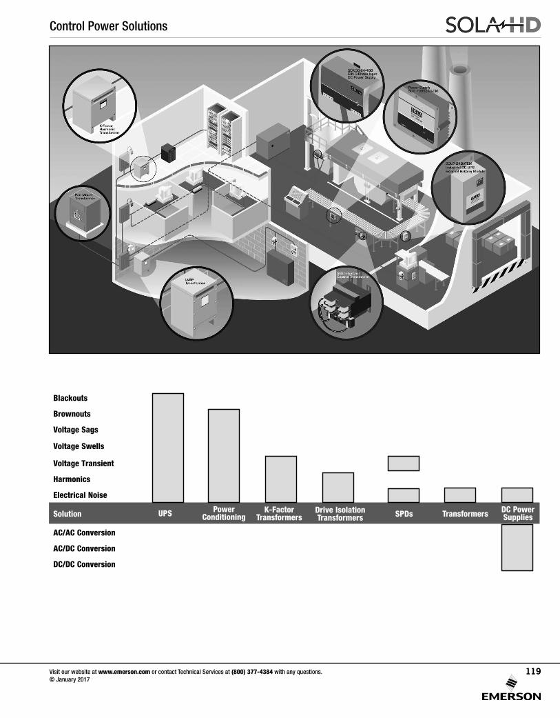
Control Power Solutions
Blackouts
Brownouts
Voltage Sags
Voltage Swells
Voltage Transient
Harmonics
Electrical Noise
Solution
AC/AC Conversion
AC/DC Conversion
DC/DC Conversion
UPS PowerConditioning
Drive IsolationTransformers SPDs DC Power
SuppliesK-Factor
Transformers Transformers
Visit our website at www.emerson.com or contact Technical Services at (800) 377-4384 with any questions. © January 2017
119

DC Power Supply Selection Worksheet .................................... 122
DIN Rail Selection Tables .......................................................... 123
DIN Rail
SDN-C Series (Single and Three Phase Units, 120-960 Watts) . 124
SDN-P™ Series (Single Phase Units, 60–240 Watts) ................ 132
SDN™ Redundant Series ......................................................... 127
SDN-C Redundancy Modules ................................................... 141
SDP™ Low Power Series ......................................................... 144
SVL Essential DIN Rail Series .................................................... 147
SCP Series (30 Watt; Single, Dual & Triple) ............................... 152
SCD Series (Encapsulated, Industrial DC to DC Converter) ....... 154
Linears
Silver Line SL Series (Single and Multi-Output Linears) .............. 156
Other
IP67 SCP-X Extreme Environment ............................................ 160
GL Series, Single and Multi-Output Switchers........................... 163
SHP High Power Modulars ........................................................171
Power Supplies
Visit our website at www.emerson.com or contact Technical Services at (800) 377-4384 with any questions. © January 2017
120
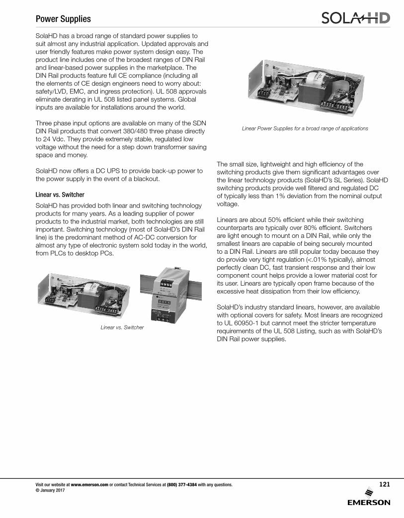
SolaHD has a broad range of standard power supplies to suit almost any industrial application. Updated approvals and user friendly features make power system design easy. The product line includes one of the broadest ranges of DIN Rail and linear-based power supplies in the marketplace. The DIN Rail products feature full CE compliance (including all the elements of CE design engineers need to worry about: safety/LVD, EMC, and ingress protection). UL 508 approvals eliminate derating in UL 508 listed panel systems. Global inputs are available for installations around the world.
Three phase input options are available on many of the SDN DIN Rail products that convert 380/480 three phase directly to 24 Vdc. They provide extremely stable, regulated low voltage without the need for a step down transformer saving space and money.
SolaHD now offers a DC UPS to provide back-up power to the power supply in the event of a blackout.
Linear vs. Switcher
SolaHD has provided both linear and switching technology products for many years. As a leading supplier of power products to the industrial market, both technologies are still important. Switching technology (most of SolaHD’s DIN Rail line) is the predominant method of AC-DC conversion for almost any type of electronic system sold today in the world, from PLCs to desktop PCs.
The small size, lightweight and high efficiency of the switching products give them significant advantages over the linear technology products (SolaHD’s SL Series). SolaHD switching products provide well filtered and regulated DC of typically less than 1% deviation from the nominal output voltage.
Linears are about 50% efficient while their switching counterparts are typically over 80% efficient. Switchers are light enough to mount on a DIN Rail, while only the smallest linears are capable of being securely mounted to a DIN Rail. Linears are still popular today because they do provide very tight regulation (<.01% typically), almost perfectly clean DC, fast transient response and their low component count helps provide a lower material cost for its user. Linears are typically open frame because of the excessive heat dissipation from their low efficiency. SolaHD’s industry standard linears, however, are available with optional covers for safety. Most linears are recognized to UL 60950-1 but cannot meet the stricter temperature requirements of the UL 508 Listing, such as with SolaHD’s DIN Rail power supplies.
Linear vs. Switcher
Linear Power Supplies for a broad range of applications
Power Supplies
Visit our website at www.emerson.com or contact Technical Services at (800) 377-4384 with any questions. © January 2017
121
DC Power Supply Selection Worksheet
Power supplies can be selected by following the directions below. Enter your power requirements and a list of matching power supplies will list. You can also manually select a power supply by following the directions below:
1) Gather the required information.
• Input voltage and frequency?
• Wattage needed?
• Number of outputs?
• Voltage of each output?
• Amperage of each output?
• Don’t forget to take into account the peak loading of each output.
• Battery Back-up?
2) Calculate the power (wattage) of the DC power supply you need. If more than one output is required,
do the following calculation:
• Multiply the Voltage times the amperage of each output to calculate the wattage of each output. Next, add together the wattage of each output to get the total wattage for the supply.
3) Determine which models from the Power Supply Selection Chart (on the next page) meet all of the
required specifications.
4) Reference www.solahd.com for the latest specifications sheets.
5) Check the mounting style, connections and physical size of the power supply to ensure its suitability for the
intended application.
6) Check for applicable safety approvals for the country and application the power supply will be used in.
Selection Worksheet
Output:_______ Vdc x _______ Amps = ________ Watts
_______ Vdc x _______ Amps = ________ Watts
_______ Vdc x _______ Amps = ________ Watts
_______ Vdc x _______ Amps = ________ Watts
_______ Vdc x _______ Amps = ________ Watts
_______ Vdc x _______ Amps = ________ Watts
_______ Vdc x _______ Amps = ________ Watts
_______ Vdc x _______ Amps = ________ Watts
Add Watts from each output to calculate
Total Watts = ________
Physical Dimensions:
_______H x _______W x _______D
Mounting:
_______ DIN Rail
_______ Chassis
_______ Other
Other required features or options:
If you have filled out this form and cannot find the appropriate power supply, e-mail this information to the
Technical Services group:[email protected]
Power Supplies
Visit our website at www.emerson.com or contact Technical Services at (800) 377-4384 with any questions. © January 2017
122
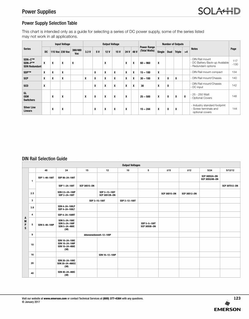
Power Supply Selection Table
This chart is intended only as a guide for selecting a series of DC power supply, some of the series listed may not work in all applications.
Series
Input Voltage Output VoltagePower Range (Total Watts)
Number of Outputs
Notes PageDC 115 Vac 230 Vac
380/480 Vac
3.3 V 5 V 12 V 15 V 24 V 48 V Single Dual Triple >4
SDN-C™ SDN-P™ SDN Redundant
X X X X X X X 60 - 960 X- DIN Rail mount - DC Battery Back-up Available- Redundant options
117 -130
SDP™ X X X X X X X X 15 - 100 X - DIN Rail mount compact 134
SCP X X X X X X X X X 30 - 100 X X X - DIN Rail mount/Chassis 140
SCD X X X X X X 30 X X- DIN Rail mount/Chassis - DC input
142
GL OEM Switchers
X X X X X X X 25 - 500 X X X X- 25 - 250 Watt- Optional Covers
148
Silver LineLinears
X X X X X X 15 - 244 X X X- Industry standard footprint- Screw terminals and optional covers
144
DIN Rail Selection GuideOutput Voltages
AMPS
48 24 15 12 10 5 ±15 ±12 5/24 5/12/12
1SDP 1-48-100T SDP 06-24-100T
SCP 30D524-DN SCP 30S524B-DN
SDP 1-24-100T SCP 30S15-DN SCP 30T512-DN
2.5 SDN 2.5-24-100PSDP 2-24-100T
SDP 2-12-100T SCP 30S12B-DN
SCP 30D15-DN SCP 30D12-DN
3 SDP 3-15-100T SDP 2-12-100T
3.8 SDN 4-24-100LPSDP 4-24-100LT
4 SDP 4-24-100RT
5 SDN 5-48-100P
SDN 5-24-100CSDN 5-24-100PSDN 5-24-480C
(3Ø)
SDP 5-5-100TSCP 30S5B-DN
9 ddwwwwdwww9-12-100P
10SDN 10-24-100CSDN 10-24-100PSDN 10-24-480C
(3Ø)
16 SDN 16-12-100P
20SDN 20-24-100C
SDN 20-24-480CC (3Ø)
40 SDN 40-24-480C (3Ø)
Power Supplies
Visit our website at www.emerson.com or contact Technical Services at (800) 377-4384 with any questions. © January 2017
123
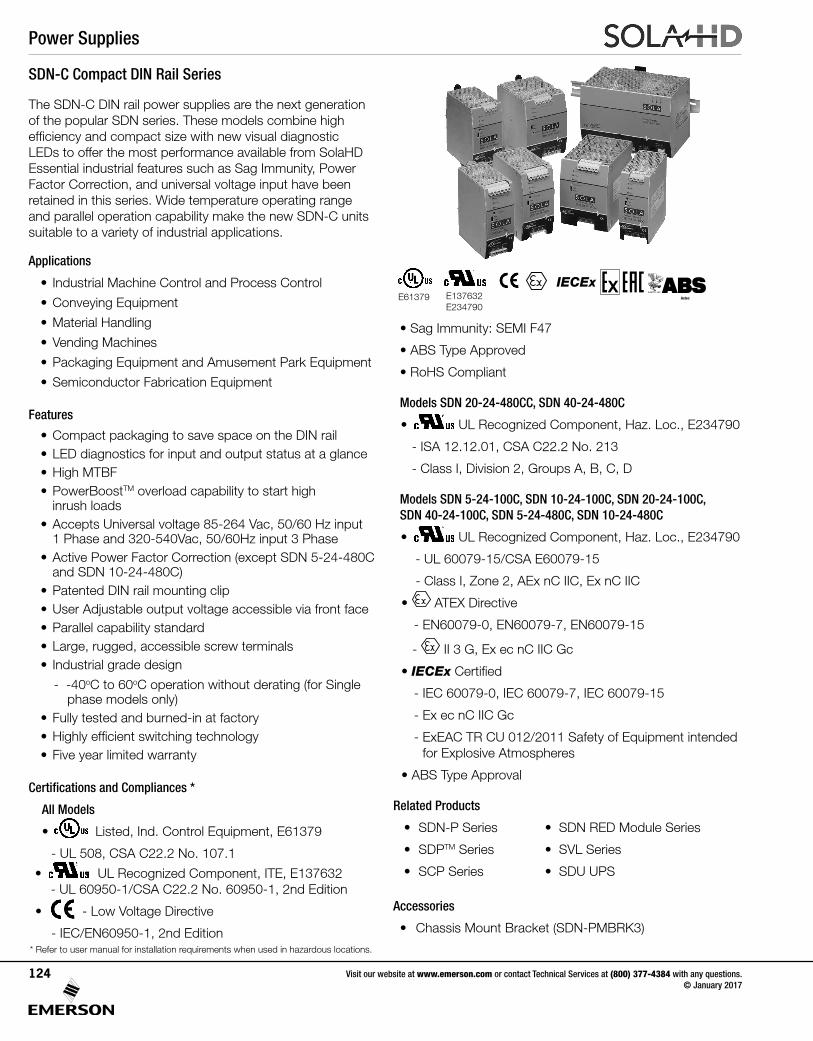
The SDN-C DIN rail power supplies are the next generation of the popular SDN series. These models combine high efficiency and compact size with new visual diagnostic LEDs to offer the most performance available from SolaHD Essential industrial features such as Sag Immunity, Power Factor Correction, and universal voltage input have been retained in this series. Wide temperature operating range and parallel operation capability make the new SDN-C units suitable to a variety of industrial applications.
Applications
• Industrial Machine Control and Process Control
• Conveying Equipment
• Material Handling
• Vending Machines
• Packaging Equipment and Amusement Park Equipment
• Semiconductor Fabrication Equipment
Features
• Compact packaging to save space on the DIN rail • LED diagnostics for input and output status at a glance • High MTBF• PowerBoostTM overload capability to start high
inrush loads• Accepts Universal voltage 85-264 Vac, 50/60 Hz input
1 Phase and 320-540Vac, 50/60Hz input 3 Phase• Active Power Factor Correction (except SDN 5-24-480C
and SDN 10-24-480C)• Patented DIN rail mounting clip• User Adjustable output voltage accessible via front face• Parallel capability standard• Large, rugged, accessible screw terminals• Industrial grade design
- -40oC to 60oC operation without derating (for Single phase models only)
• Fully tested and burned-in at factory• Highly efficient switching technology• Five year limited warranty
Certifications and Compliances *
All Models
• UL 508 Listed
IND. CONT. EQ.E61379
Listed, Ind. Control Equipment, E61379
- UL 508, CSA C22.2 No. 107.1
• UL 60950 E137632
CUL/CSA-C22.2No. 234-M90
UL Recognized Component, ITE, E137632 - UL 60950-1/CSA C22.2 No. 60950-1, 2nd Edition
• EMC andLow Volt. Directive
- Low Voltage Directive
- IEC/EN60950-1, 2nd Edition
SDN-C Compact DIN Rail Series
• Sag Immunity: SEMI F47
• ABS Type Approved
• RoHS Compliant
Models SDN 20-24-480CC, SDN 40-24-480C
• UL 60950 E137632
CUL/CSA-C22.2No. 234-M90
UL Recognized Component, Haz. Loc., E234790
- ISA 12.12.01, CSA C22.2 No. 213
- Class I, Division 2, Groups A, B, C, D
Models SDN 5-24-100C, SDN 10-24-100C, SDN 20-24-100C, SDN 40-24-100C, SDN 5-24-480C, SDN 10-24-480C
• UL 60950 E137632
CUL/CSA-C22.2No. 234-M90
UL Recognized Component, Haz. Loc., E234790
- UL 60079-15/CSA E60079-15
- Class I, Zone 2, AEx nC IIC, Ex nC IIC
• ATEX Directive
- EN60079-0, EN60079-7, EN60079-15
- II 3 G, Ex ec nC IIC Gc
• IECEx Certified
- IEC 60079-0, IEC 60079-7, IEC 60079-15
- Ex ec nC IIC Gc
- ExEAC TR CU 012/2011 Safety of Equipment intended for Explosive Atmospheres
• ABS Type Approval
Related Products
• SDN-P Series • SDN RED Module Series
• SDPTM Series • SVL Series
• SCP Series • SDU UPS
Accessories
• Chassis Mount Bracket (SDN-PMBRK3)
UL 508 ListedIND. CONT. EQ.
E61379
UL 60950 E137632
CUL/CSA-C22.2No. 234-M90
E61379 E137632E234790
* Refer to user manual for installation requirements when used in hazardous locations.
EMC andLow Volt. Directive
IECExAstec
Power Supplies
Visit our website at www.emerson.com or contact Technical Services at (800) 377-4384 with any questions. © January 2017
124
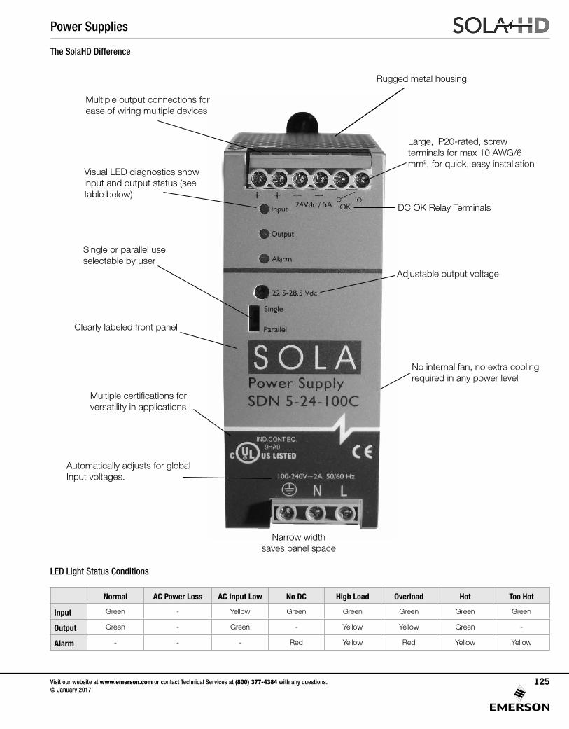
Rugged metal housing
The SolaHD Difference
Large, IP20-rated, screw terminals for max 10 AWG/6 mm2, for quick, easy installation
Multiple output connections for ease of wiring multiple devices
Single or parallel use selectable by user
Clearly labeled front panel
Multiple certifications for versatility in applications
Automatically adjusts for global Input voltages.
Narrow width saves panel space
No internal fan, no extra cooling required in any power level
Adjustable output voltage
DC OK Relay Terminals
Visual LED diagnostics show input and output status (see table below)
LED Light Status Conditions
Normal AC Power Loss AC Input Low No DC High Load Overload Hot Too Hot
Input Green - Yellow Green Green Green Green Green
Output Green - Green - Yellow Yellow Green -
Alarm - - - Red Yellow Red Yellow Yellow
Power Supplies
Visit our website at www.emerson.com or contact Technical Services at (800) 377-4384 with any questions. © January 2017
125
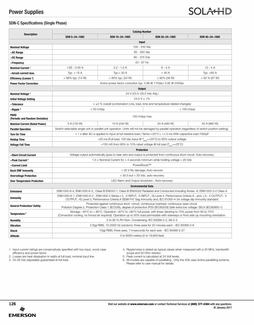
DescriptionCatalog Number
SDN 5-24-100C SDN 10-24-100C SDN 20-24-100C SDN 40-24-100C
Input
Nominal Voltage 100 - 240 Vac
-AC Range 85 - 264 Vac
-DC Range 90 - 375 Vdc
-Frequency 43 - 67 Hz
Nominal Current 1 1.65 - 0.55 A 3.2 - 1.0 A 6 - 3 A 12 - 4 A
-Inrush current max. Typ. < 15 A Typ.< 30 A < 40 A Typ. <60 A
Efficiency (Losses 2) > 88% typ. (14 W) > 90% typ. (24 W) > 92% (38 W) > 93 % (67 W)
Power Factor Correction Active power factor correction typ. 0.98 @ 115Vac/ 0.92 @ 230Vac
Output
Nominal Voltage 3 24 V (23.5~28.5 Vdc Adj.)
Initial Voltage Setting 24.5 V ± 1%
-Tolerance < ±2 % overall (combination Line, load, time and temperature related changes)
-Ripple 4 < 50 mVpp < 100 mVpp
PARD (Periodic and Random Deviation)
100 mVpp max
Nominal Current (Rated Power) 5 A (120 W) 10 A (240 W) 20 A (480 W) 40 A (960 W)
Parallel Operation Switch selectable single unit or parallel unit operation. Units will not be damaged by parallel operation (regardless of switch position setting).
Turn On Time < 1 s after AC is applied to input at full resistive load ( Tamb=+25°C ). <1.5 ms With capacitive load 7000μF
Holdup Time >20 ms (Full load, 100 Vac Input @ Tamb=+25°C) to 95% output voltage
Voltage Fall Time <150 mS from 95% to 10% rated voltage @ full load (Tamb=+25°C)
Protection
-Short Circuit Current Voltage output automatically goes to near zero and output is protected from continuous short circuit. Auto-recovery.
-Peak Current 5 1.5 × Nominal Current for > 4 seconds minimum while holding voltage > 20 Vdc
-Current Limit PowerBoost™
Back EMF Immunity < 35 V No damage, Auto-recover
Overvoltage Protection > 30.5 but < 33 Vdc, auto recovery
Over Temperature Protection LED Alarm and Output shutdown , Auto-recovery
Environmental Data
Emissions EN61000-6-4, EN61000-6-3,, Class B EN55011, Class B EN55022 Radiated and Conducted including Annex. A, EN61000-3-2 Class A
ImmunityEN61000-6-1, EN61000-6-2 , EN61000-4 Series (-2, -4 INPUT, -5 INPUT ,-8) Level 4, Performance Criteria A , and, (-3,- 4 OUTPUT,- 5
OUTPUT, -6) Level 3, Performance Criteria A SEMI F47 Sag Immunity and, IEC 61000-4-34 voltage dip immunity standard
General Protection/ SafetyProtected against continuous short -circuit, continuous overload, continuous open circuit.
Pollution Degree 2, Protection Class 1 (IEC536), degree of protection IP20 (IEC60529) Safe extra low voltage: SELV (IEC60950-1)
Temperature 6Storage: -40°C to + 85°C, Operation -40°C to +60°C full power, with linear derating to 75% power from 60 to 70oC
(Convection cooling, no forced air required). Operation up to 50% load permissible with sideways or front side up mounting orientation.
Humidity 5 to 95 % RH Non- Condensing; IEC 60068-2-2, 68-2-3
Vibration 2.5(g) RMS, 10-2000 Hz (random); three axes for 20 minutes each - IEC 60068-2-6
Shock 10(g) RMS, three axes, 11mseconds for each axis - IEC 60068-2-27
Altitude 0 to 6000 meters (0 to 19,600 feet)
SDN-C Specifications (Single Phase)
1. Input current ratings are conservatively specified with low input, worst case efficiency and power factor.
2. Losses are heat dissipation in watts at full load, nominal input line.3. 24-28 Vdc adjustable guaranteed at full load.
4. Ripple/noise is stated as typical values when measured with a 20 MHz, bandwidth scope and 50 Ohm resistor.
5. Peak current is calculated at 24 Volt levels.6. All models are capable of paralleling . Only the 40A uses Active paralleling scheme.
Please refer to user manual for details.
Power Supplies
Visit our website at www.emerson.com or contact Technical Services at (800) 377-4384 with any questions. © January 2017
126
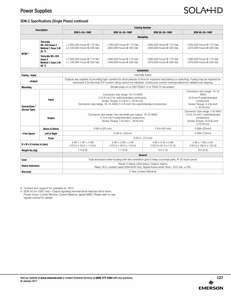
SDN-C Specifications (Single Phase) continued
DescriptionCatalog Number
SDN 5-24-100C SDN 10-24-100C SDN 20-24-100C SDN 40-24-100C
Reliability
MTBF 8
Telcordia SR-332 Issue 2Method 1 Case 3 @ 25 °C
>1,800,000 hours @ 115 Vac>2,100,000 hours @ 230 Vac
> 550,000 hours @ 115 Vac>650,000 hours @ 230 Vac
>800,000 hours @ 115 Vac>850,000 hours @ 230 Vac
>550,000 hours @ 115 Vac>570,000 hours @ 230 Vac
Telcordia SR-332 Issue 2Method 1 Case 3 @ 40 °C
>1,000,000 hours @ 115 Vac>1,100,000 hours @ 230 Vac
>300,000 hours @ 115 Vac>400,000 hours @ 230 Vac
>500,000 hours @ 115 Vac>570,000 hours @ 230 Vac
>360,000 hours @ 115 Vac>370,000 hours @ 230 Vac
Installation
Fusing -Input Internally fused
-OutputOutputs are capable of providing high currents for short periods of time for inductive load startup or switching. Fusing may be required for
wire/loads if 2x Nominal O/P current rating cannot be tolerated. Continuous current overload allows for reliable fuse tripping.
Mounting Simple snap-on to DIN TS35/7.5 or TS35/15 rail system.
Connections 9
(Screw Type)
Input
Connector size range: 16-10 AWG(1.5-6 mm2) for solid/stranded conductors.
Screw Torque: 4.4 lb-in (~ 50 N-cm).Connector size range: 16-10 AWG (1.5-6 mm2) for solid/stranded conductors.
Connector size range: 13-10 AWG
(3-6 mm2) solid/stranded conductors.
Screw Torque: 4.4 lb-inch (~ 50 N-cm).
OutputConnector size range: Two terminals per output, 16-10 AWG
(1.5-6 mm2) solid/stranded conductors. Screw Torque: 7 lb-inch (~ 80 N-cm)
Connector size range: 7–6 AWG (10.6–13 mm2 ) solid/stranded
conductors. Screw Torque: 15.6 lb-inch
(176 N-cm)
-Free Space
Above & Below 0.98 in (25 mm) 1.6 in (40 mm) 0.98in (25mm)
Left & Right 0.39 in. (10mm) 0.59in (15mm)
Front 0.59 in. (15 mm)
H x W x D inches in (mm)4.85 × 1.97 × 4.36
(123.0 × 50.0 × 110.0)4.85 × 2.36 × 4.36
(123.0 × 60.0 × 110.0)4.85 x 3.42 x 4.98
(123.0 x 87.0 x 127.0)4.85 x 7.09 x 4.81
(123.0 x 180.0 x 122.0)
Weight lbs (kg) 1.3 (0.6) 1.7 (0.8) 3.0 (1.4) 6.0 (2.8)
General
Case Fully enclosed metal housing with fine ventilation grid to keep out small parts. IP 20 touch proof
Status IndicatorsVisual: 3 status LEDs (Input, Output, Alarm)
Relay: N.O. contact rated 200mA/50 Vdc, Signal Active when Vout> 18.5 Vdc +/-5%
Warranty 5 Year Limited Warranty
8. Contact tech support for operation at -40oC. 9. SDN 40-24-100C only = Output signaling terminal block features (Shut down,
Power Good, Current Monitor, Current Balance, signal GND). Please refer to user signals manual for details.
Power Supplies
Visit our website at www.emerson.com or contact Technical Services at (800) 377-4384 with any questions. © January 2017
127
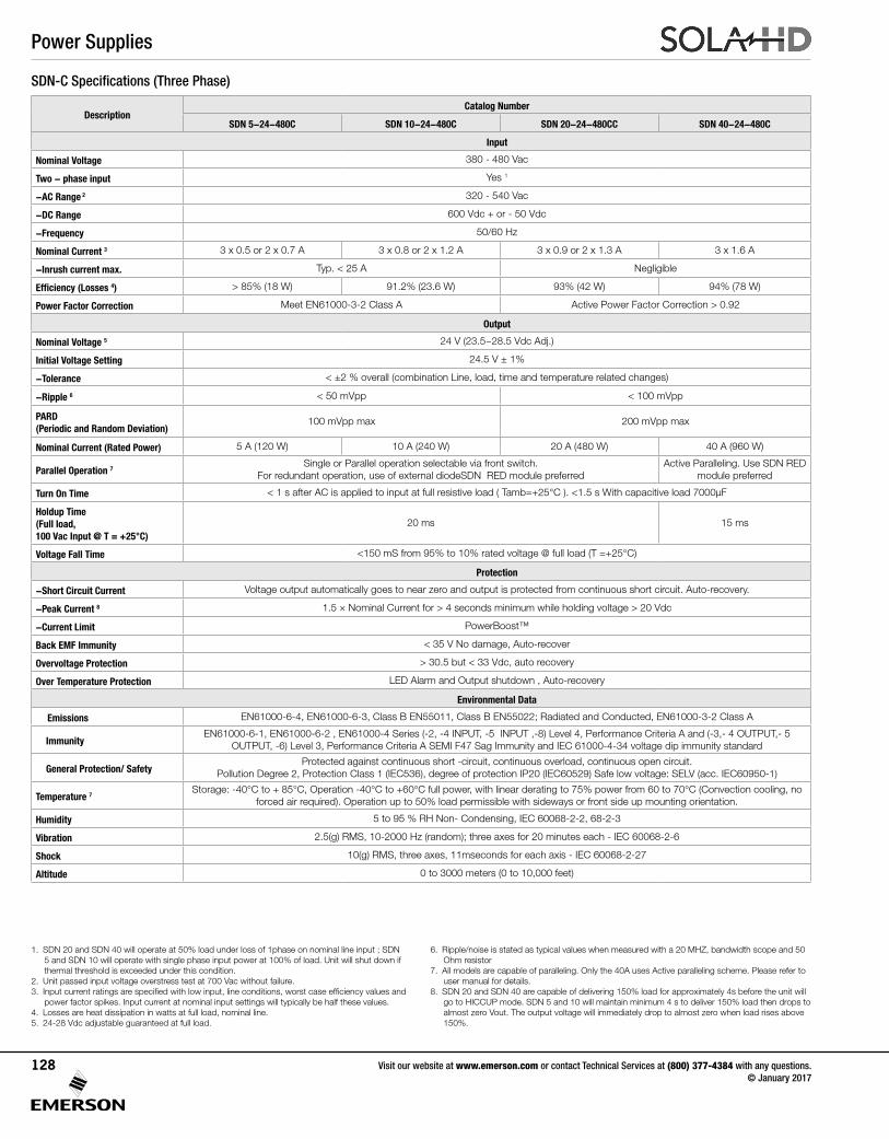
SDN-C Specifications (Three Phase)
1. SDN 20 and SDN 40 will operate at 50% load under loss of 1phase on nominal line input ; SDN 5 and SDN 10 will operate with single phase input power at 100% of load. Unit will shut down if thermal threshold is exceeded under this condition.
2. Unit passed input voltage overstress test at 700 Vac without failure.3. Input current ratings are specified with low input, line conditions, worst case efficiency values and
power factor spikes. Input current at nominal input settings will typically be half these values.4. Losses are heat dissipation in watts at full load, nominal line.5. 24-28 Vdc adjustable guaranteed at full load.
6. Ripple/noise is stated as typical values when measured with a 20 MHZ, bandwidth scope and 50 Ohm resistor
7. All models are capable of paralleling. Only the 40A uses Active paralleling scheme. Please refer to user manual for details.
8. SDN 20 and SDN 40 are capable of delivering 150% load for approximately 4s before the unit will go to HICCUP mode. SDN 5 and 10 will maintain minimum 4 s to deliver 150% load then drops to almost zero Vout. The output voltage will immediately drop to almost zero when load rises above 150%.
DescriptionCatalog Number
SDN 5-24-480C SDN 10-24-480C SDN 20-24-480CC SDN 40-24-480C
Input
Nominal Voltage 380 - 480 Vac
Two - phase input Yes 1
-AC Range 2 320 - 540 Vac
-DC Range 600 Vdc + or - 50 Vdc
-Frequency 50/60 Hz
Nominal Current 3 3 x 0.5 or 2 x 0.7 A 3 x 0.8 or 2 x 1.2 A 3 x 0.9 or 2 x 1.3 A 3 x 1.6 A
-Inrush current max. Typ. < 25 A Negligible
Efficiency (Losses 4) > 85% (18 W) 91.2% (23.6 W) 93% (42 W) 94% (78 W)
Power Factor Correction Meet EN61000-3-2 Class A Active Power Factor Correction > 0.92
Output
Nominal Voltage 5 24 V (23.5~28.5 Vdc Adj.)
Initial Voltage Setting 24.5 V ± 1%
-Tolerance < ±2 % overall (combination Line, load, time and temperature related changes)
-Ripple 6 < 50 mVpp < 100 mVpp
PARD (Periodic and Random Deviation)
100 mVpp max 200 mVpp max
Nominal Current (Rated Power) 5 A (120 W) 10 A (240 W) 20 A (480 W) 40 A (960 W)
Parallel Operation 7Single or Parallel operation selectable via front switch.
For redundant operation, use of external diodeSDN RED module preferredActive Paralleling. Use SDN RED
module preferred
Turn On Time < 1 s after AC is applied to input at full resistive load ( Tamb=+25°C ). <1.5 s With capacitive load 7000μF
Holdup Time (Full load, 100 Vac Input @ T = +25°C)
20 ms 15 ms
Voltage Fall Time <150 mS from 95% to 10% rated voltage @ full load (T =+25°C)
Protection
-Short Circuit Current Voltage output automatically goes to near zero and output is protected from continuous short circuit. Auto-recovery.
-Peak Current 8 1.5 × Nominal Current for > 4 seconds minimum while holding voltage > 20 Vdc
-Current Limit PowerBoost™
Back EMF Immunity < 35 V No damage, Auto-recover
Overvoltage Protection > 30.5 but < 33 Vdc, auto recovery
Over Temperature Protection LED Alarm and Output shutdown , Auto-recovery
Environmental Data
Emissions EN61000-6-4, EN61000-6-3, Class B EN55011, Class B EN55022; Radiated and Conducted, EN61000-3-2 Class A
ImmunityEN61000-6-1, EN61000-6-2 , EN61000-4 Series (-2, -4 INPUT, -5 INPUT ,-8) Level 4, Performance Criteria A and (-3,- 4 OUTPUT,- 5
OUTPUT, -6) Level 3, Performance Criteria A SEMI F47 Sag Immunity and IEC 61000-4-34 voltage dip immunity standard
General Protection/ SafetyProtected against continuous short -circuit, continuous overload, continuous open circuit.
Pollution Degree 2, Protection Class 1 (IEC536), degree of protection IP20 (IEC60529) Safe low voltage: SELV (acc. IEC60950-1)
Temperature 7Storage: -40°C to + 85°C, Operation -40°C to +60°C full power, with linear derating to 75% power from 60 to 70°C (Convection cooling, no
forced air required). Operation up to 50% load permissible with sideways or front side up mounting orientation.
Humidity 5 to 95 % RH Non- Condensing, IEC 60068-2-2, 68-2-3
Vibration 2.5(g) RMS, 10-2000 Hz (random); three axes for 20 minutes each - IEC 60068-2-6
Shock 10(g) RMS, three axes, 11mseconds for each axis - IEC 60068-2-27
Altitude 0 to 3000 meters (0 to 10,000 feet)
Power Supplies
Visit our website at www.emerson.com or contact Technical Services at (800) 377-4384 with any questions. © January 2017
128
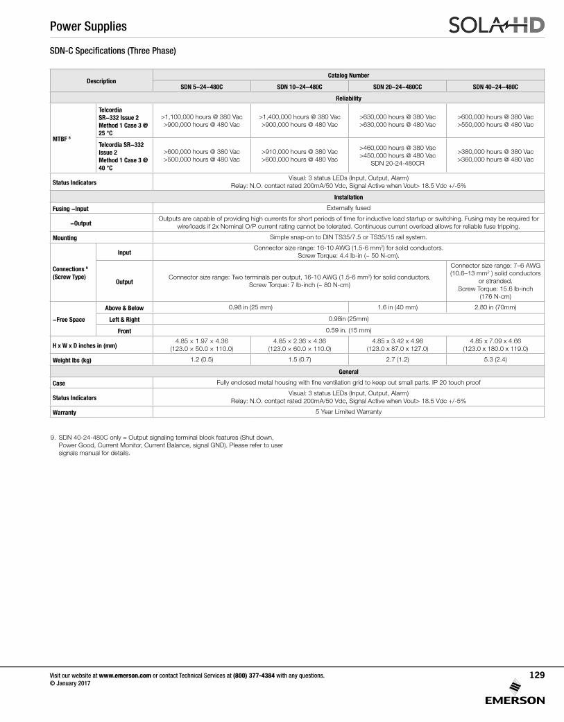
SDN-C Specifications (Three Phase)
DescriptionCatalog Number
SDN 5-24-480C SDN 10-24-480C SDN 20-24-480CC SDN 40-24-480C
Reliability
MTBF 8
Telcordia SR-332 Issue 2Method 1 Case 3 @ 25 °C
>1,100,000 hours @ 380 Vac>900,000 hours @ 480 Vac
>1,400,000 hours @ 380 Vac>900,000 hours @ 480 Vac
>630,000 hours @ 380 Vac>630,000 hours @ 480 Vac
>600,000 hours @ 380 Vac>550,000 hours @ 480 Vac
Telcordia SR-332 Issue 2Method 1 Case 3 @ 40 °C
>600,000 hours @ 380 Vac>500,000 hours @ 480 Vac
>910,000 hours @ 380 Vac>600,000 hours @ 480 Vac
>460,000 hours @ 380 Vac>450,000 hours @ 480 Vac
SDN 20-24-480CR
>380,000 hours @ 380 Vac>360,000 hours @ 480 Vac
Status IndicatorsVisual: 3 status LEDs (Input, Output, Alarm)
Relay: N.O. contact rated 200mA/50 Vdc, Signal Active when Vout> 18.5 Vdc +/-5%
Installation
Fusing -Input Externally fused
-OutputOutputs are capable of providing high currents for short periods of time for inductive load startup or switching. Fusing may be required for
wire/loads if 2x Nominal O/P current rating cannot be tolerated. Continuous current overload allows for reliable fuse tripping.
Mounting Simple snap-on to DIN TS35/7.5 or TS35/15 rail system.
Connections 9
(Screw Type)
InputConnector size range: 16-10 AWG (1.5-6 mm2) for solid conductors.
Screw Torque: 4.4 lb-in (~ 50 N-cm).
OutputConnector size range: Two terminals per output, 16-10 AWG (1.5-6 mm2) for solid conductors.
Screw Torque: 7 lb-inch (~ 80 N-cm)
Connector size range: 7–6 AWG (10.6–13 mm2 ) solid conductors
or stranded. Screw Torque: 15.6 lb-inch
(176 N-cm)
-Free Space
Above & Below 0.98 in (25 mm) 1.6 in (40 mm) 2.80 in (70mm)
Left & Right 0.98in (25mm)
Front 0.59 in. (15 mm)
H x W x D inches in (mm)4.85 × 1.97 × 4.36
(123.0 × 50.0 × 110.0)4.85 × 2.36 × 4.36
(123.0 × 60.0 × 110.0)4.85 x 3.42 x 4.98
(123.0 x 87.0 x 127.0)4.85 x 7.09 x 4.66
(123.0 x 180.0 x 119.0)
Weight lbs (kg) 1.2 (0.5) 1.5 (0.7) 2.7 (1.2) 5.3 (2.4)
General
Case Fully enclosed metal housing with fine ventilation grid to keep out small parts. IP 20 touch proof
Status IndicatorsVisual: 3 status LEDs (Input, Output, Alarm)
Relay: N.O. contact rated 200mA/50 Vdc, Signal Active when Vout> 18.5 Vdc +/-5%
Warranty 5 Year Limited Warranty
9. SDN 40-24-480C only = Output signaling terminal block features (Shut down, Power Good, Current Monitor, Current Balance, signal GND). Please refer to user signals manual for details.
Power Supplies
Visit our website at www.emerson.com or contact Technical Services at (800) 377-4384 with any questions. © January 2017
129
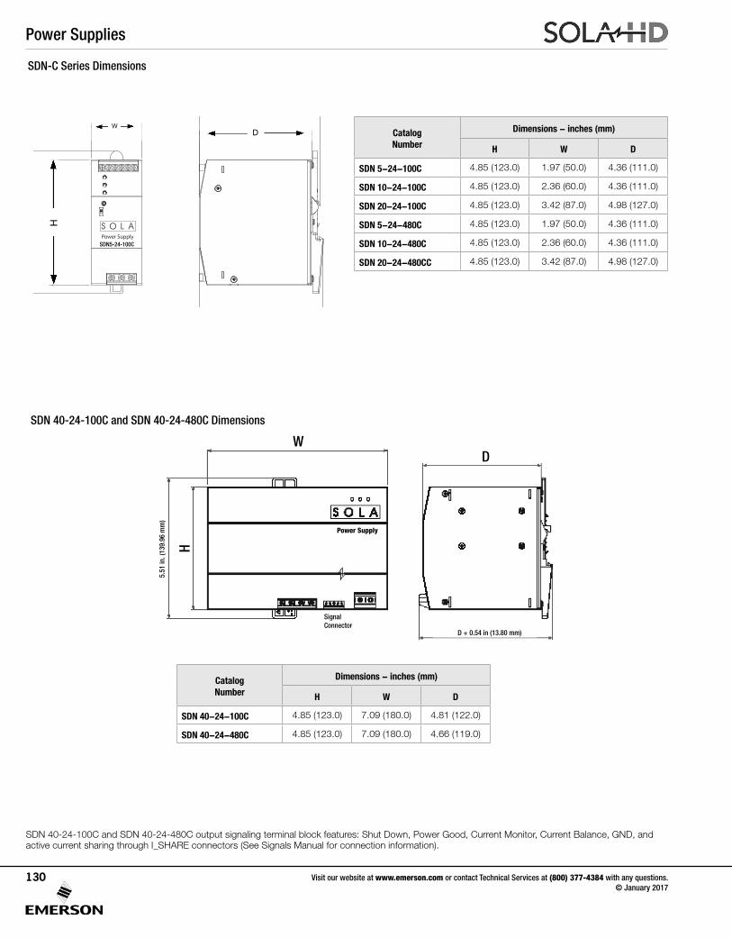
SDN-C Series Dimensions
SDN 40-24-100C and SDN 40-24-480C Dimensions
Catalog Number
Dimensions - inches (mm)
H W D
SDN 5-24-100C 4.85 (123.0) 1.97 (50.0) 4.36 (111.0)
SDN 10-24-100C 4.85 (123.0) 2.36 (60.0) 4.36 (111.0)
SDN 20-24-100C 4.85 (123.0) 3.42 (87.0) 4.98 (127.0)
SDN 5-24-480C 4.85 (123.0) 1.97 (50.0) 4.36 (111.0)
SDN 10-24-480C 4.85 (123.0) 2.36 (60.0) 4.36 (111.0)
SDN 20-24-480CC 4.85 (123.0) 3.42 (87.0) 4.98 (127.0)
Catalog Number
Dimensions - inches (mm)
H W D
SDN 40-24-100C 4.85 (123.0) 7.09 (180.0) 4.81 (122.0)
SDN 40-24-480C 4.85 (123.0) 7.09 (180.0) 4.66 (119.0)
Power Supply
W D
D + 0.54 in (13.80 mm)
H
5.51
in. (
139.
96 m
m)
Signal Connector
SDN 40-24-100C and SDN 40-24-480C output signaling terminal block features: Shut Down, Power Good, Current Monitor, Current Balance, GND, and active current sharing through I_SHARE connectors (See Signals Manual for connection information).
Power Supply
4.85
in. [
123.
3 m
m]
1.97 in.[50.0 mm] 4.36 in. [110.8 mm]
5.51
in. [
140.
0 m
m]
4.68 in. [118.8 mm]
4.78 in. [121.6 mm]
H
WD
SDN5-24-100C
Power Supplies
Visit our website at www.emerson.com or contact Technical Services at (800) 377-4384 with any questions. © January 2017
130
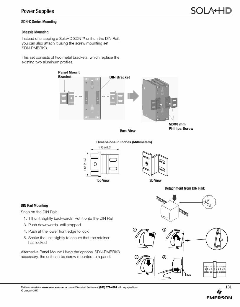
SDN-C Series Mounting
DIN Rail Mounting
Snap on the DIN Rail:
1. Tilt unit slightly backwards. Put it onto the DIN Rail
3. Push downwards until stopped
4. Push at the lower front edge to lock
5. Shake the unit slightly to ensure that the retainer has locked
Alternative Panel Mount: Using the optional SDN-PMBRK3 accessory, the unit can be screw mounted to a panel.
Chassis Mounting
Instead of snapping a SolaHD SDN™ unit on the DIN Rail, you can also attach it using the screw mounting set SDN-PMBRK3.
This set consists of two metal brackets, which replace the existing two aluminum profiles.
Back View
Detachment from DIN Rail:
Power Supply Accessories
SDN-PMBRK3Panel Mount Brackets Installation Manual
P/N: A272-289 REV. 1 (07/16)©2016 Appleton Grp LLC d/b/a Appleton GroupAll rights reserved. Specificationssubject to change without notice.
Dimensions in Inches (Millimeters)
1. Remove the M3X6 mm Phillips Screws and C-Insert from the DIN Brackets.
This set consists of two panel mount brackets, which replace the existing two DIN mounting brackets at the back of the unit.
FOR USE WITH:
CHASSIS MOUNTING
SDN 5-24-100CSDN 10-24-100CSDN 40-24-100CSDN 10-24-480CSDN 2X20RED
DIN Bracket
2. Retain and slide back the two DIN brackets to use as a guide for the installation of the panel mount brackets.
3. Push and slide the panel mount brackets on the top of DIN bracket and secure with M3X10 mm Phillips Screw and lock washer (use 7kgf torque).
Two M3x10 mm phillips screwsTwo bracketsTwo M3 lock washers
Four 8-32 x 1/2” screws for mounting unit to panelFour 8-32 flat washers
INCLUDED:
NOT INCLUDED:
C-Insert
M3X6 mmPhillips Screw
DIN Bracket
Panel Mount Brackets Installation
7 983472 00651
1.93 (49.0)
Top View 3D View
1.65
(41.
9)
CAUTION:Risk of Electric Shock and Personal Injury
Ensure unit is disconnected from all power sources prior to replacing brackets.
Panel Mount Bracket DIN Bracket
Lock washers
M3X10 mmPhillips Screw
Power Supply Accessories
SDN-PMBRK3Panel Mount Brackets Installation Manual
P/N: A272-289 REV. 1 (07/16)©2016 Appleton Grp LLC d/b/a Appleton GroupAll rights reserved. Specificationssubject to change without notice.
Dimensions in Inches (Millimeters)
1. Remove the M3X6 mm Phillips Screws, shoulder screw, plastic slide, spring and C-Insert from the DIN Brackets.
This set consists of two panel mount brackets, which replace the existing two DIN mounting brackets at the back of the unit.
FOR USE WITH:
CHASSIS MOUNTING
SDN 5-24-100CSDN 10-24-100CSDN 40-24-100CSDN 10-24-480CSDN 2X20RED
DIN Bracket
2. Retain and slide back the two DIN brackets to use as a guide for the installation of the panel mount brackets.
3. Push and slide the panel mount brackets on the top of DIN bracket and secure with M3X8 mm Phillips Screw and lock washer (use 7kgf torque).
Two M3x8 mm phillips screwsTwo bracketsTwo lock washers
Four 8-32 x 1/2” screws for mounting unit to panelFour 8-32 flat washers
INCLUDED:
NOT INCLUDED:
C-InsertSpring
Plastic slide
Shoulder screw
M3X6 mmPhillips Screw
DIN Bracket
Panel Mount Brackets Installation
7 983472 00651
Top View 3D View
CAUTION:Risk of Electric Shock and Personal Injury
Ensure unit is disconnected from all power sources prior to replacing brackets.
Panel Mount Bracket DIN Bracket
M3X8 mmPhillips Screw 1.
65 (4
1.9)
0.87 (22.1)
0.60
(15.
2)
1.47 (37.3)
Top View 3D View
Power Supplies
Visit our website at www.emerson.com or contact Technical Services at (800) 377-4384 with any questions. © January 2017
131
SDN-P DIN Rail Series
The SDN DIN Rail power supplies provide industry leading performance. Sag Immunity, transient suppression and noise tolerant, the SDN series ensures compatibility in demanding applications. Power factor correction to meet European directives, hazardous location approvals and optional redundant accessories allow the SDN series to be used in a wide variety of applications. Wide operation temperature range, high tolerance to shock and vibration and reliable design make the SDN series the preferred choice of users.
Applications
• Industrial/Machine Control
• Process Control
• Conveying Equipment
• Material Handling
• Vending Machines
• Packaging Equipment
• DeviceNetTM
• Amusement Park Equipment
• Semiconductor Fabrication Equipment
Features
• Power Factor Correction (per EN61000-3-2)
• Auto Select 115/230 Vac, 50/60 Hz Input
• Improved metal mounting clip
• DC OK Signal
• Adjustable Voltage
• Parallel Capability standard on all units
• Industrial grade design
- -10°C to 60°C operation without derating. Indefinite short circuit, overvoltage and overtemperature protection.
- Powers high inrush loads without shutdown or foldback
- Rugged metal case and DIN connector
• Narrow width on rail for space critical applications
• User-friendly front panel
- Large, rugged, accessible, multiple connection screw terminations
- Easy installation
• 12 Vdc and 48 Vdc single phase models available
• Highly efficient >90% switching technology
• High MTBF and reliability
Accessories
• SDN-C Redundant Modules
• Chassis Mount Bracket (SDN-PMBRK2)
Certifications and Compliances *
All Models
• UL 508 Listed
IND. CONT. EQ.E61379
Listed, Ind. Control Equipment, E61379
- UL 508, CSA C22.2 No. 107.1•
UL 60950 E137632
CUL/CSA-C22.2No. 234-M90
UL Recognized Component, ITE, E137632- UL 60950-1/CSA C22.2 No. 60950-1, 2nd Edition
• UL 60950 E137632
CUL/CSA-C22.2No. 234-M90
UL Recognized Component, Haz. Loc., E234790
- ISA 12.12.01, CSA C22.2 No. 213- Class I, Division 2, Groups A, B, C, D
• - Low Voltage Directive
- IEC/EN60950-1, 2nd Edition• Sag Immunity: SEMI F47
• RoHS Compliant
Models SDN 2.5-24-100P, SDN 4-24-100LP
• Class 2 per UL 1310, CSA C22.2 No. 223
Related Products
• SVL Series
• SDP™ Series
• SCP Series
• SCL Series
• SDU UPS
UL 508 ListedIND. CONT. EQ.
E61379
UL 60950 E137632
CUL/CSA-C22.2No. 234-M90
EMC andLow Volt. Directive
E61379 E137632E234790
* Refer to user manual for installation requirements when used in hazardous locations.
Power Supplies
Visit our website at www.emerson.com or contact Technical Services at (800) 377-4384 with any questions. © January 2017
132
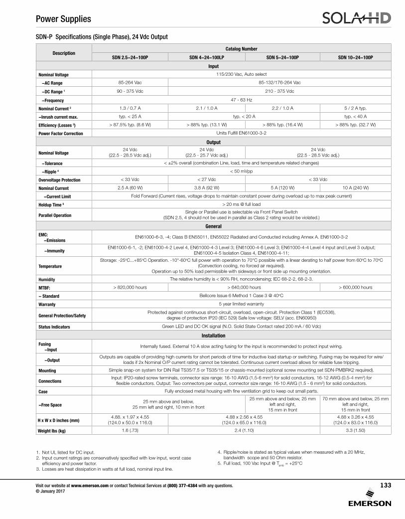
SDN-P Specifications (Single Phase), 24 Vdc Output
DescriptionCatalog Number
SDN 2.5-24-100P SDN 4-24-100LP SDN 5-24-100P SDN 10-24-100P
Input
Nominal Voltage 115/230 Vac, Auto select
-AC Range 85-264 Vac 85-132/176-264 Vac
-DC Range 1 90 - 375 Vdc 210 - 375 Vdc
-Frequency 47 - 63 Hz
Nominal Current 2 1.3 / 0.7 A 2.1 / 1.0 A 2.2 / 1.0 A 5 / 2 A typ.
-Inrush current max. typ. < 25 A typ. < 20 A typ. < 40 A
Efficiency (Losses 3) > 87.5% typ. (8.6 W) > 88% typ. (13.1 W) > 88% typ. (16.4 W) > 88% typ. (32.7 W)
Power Factor Correction Units Fulfill EN61000-3-2
Output
Nominal Voltage24 Vdc
(22.5 - 28.5 Vdc adj.)24 Vdc
(22.5 - 25.7 Vdc adj.)24 Vdc
(22.5 - 28.5 Vdc adj.)
-Tolerance < ±2% overall (combination Line, load, time and temperature related changes)
-Ripple 4 < 50 mVpp
Overvoltage Protection < 33 Vdc < 27 Vdc < 33 Vdc
Nominal Current 2.5 A (60 W) 3.8 A (92 W) 5 A (120 W) 10 A (240 W)
-Current Limit Fold Forward (Current rises, voltage drops to maintain constant power during overload up to max peak current)
Holdup Time 5 > 20 ms @ full load
Parallel OperationSingle or Parallel use is selectable via Front Panel Switch
(SDN 2.5, 4 should not be used in parallel as Class 2 rating would be violated.)
General
EMC: -Emissions
EN61000-6-3, -4; Class B EN55011, EN55022 Radiated and Conducted including Annex A. EN61000-3-2
-ImmunityEN61000-6-1, -2; EN61000-4-2 Level 4, EN61000-4-3 Level 3; EN61000-4-6 Level 3; EN61000-4-4 Level 4 input and Level 3 output;
EN61000-4-5 Isolation Class 4, EN61000-4-11;
TemperatureStorage: -25oC...+85oC Operation. -10°-60oC full power with operation to 70°C possible with a linear derating to half power from 60oC to 70oC
(Convection cooling, no forced air required). Operation up to 50% load permissible with sideways or front side up mounting orientation.
Humidity The relative humidity is < 90% RH, noncondensing; IEC 68-2-2, 68-2-3.
MTBF: > 820,000 hours > 640,000 hours > 600,000 hours
- Standard Bellcore Issue 6 Method 1 Case 3 @ 40oC
Warranty 5 year limited warranty
General Protection/SafetyProtected against continuous short-circuit, overload, open-circuit. Protection Class 1 (IEC536),
degree of protection IP20 (IEC 529) Safe low voltage: SELV (acc. EN60950)
Status Indicators Green LED and DC OK signal (N.O. Solid State Contact rated 200 mA / 60 Vdc)
Installation
Fusing-Input
Internally fused. External 10 A slow acting fusing for the input is recommended to protect input wiring.
-OutputOutputs are capable of providing high currents for short periods of time for inductive load startup or switching. Fusing may be required for wire/
loads if 2x Nominal O/P current rating cannot be tolerated. Continuous current overload allows for reliable fuse tripping.
Mounting Simple snap-on system for DIN Rail TS35/7.5 or TS35/15 or chassis-mounted (optional screw mounting set SDN-PMBRK2 required).
ConnectionsInput: IP20-rated screw terminals, connector size range: 16-10 AWG (1.5-6 mm2) for solid conductors. 16-12 AWG (0.5-4 mm2) for
flexible conductors. Output: Two connectors per output, connector size range: 16-10 AWG (1.5 - 6 mm2) for solid conductors.
Case Fully enclosed metal housing with fine ventilation grid to keep out small parts.
-Free Space 25 mm above and below,
25 mm left and right, 10 mm in front
25 mm above and below, 25 mm left and right,
15 mm in front
70 mm above and below, 25 mm left and right,
15 mm in front
H x W x D inches (mm)4.88. x 1.97 x 4.55
(124.0 x 50.0 x 116.0)4.88 x 2.56 x 4.55
(124.0 x 65.0 x 116.0)4.88 x 3.26 x 4.55
(124.0 x 83.0 x 116.0)
Weight lbs (kg) 1.6 (.73) 2.4 (1.10) 3.3 (1.50)
1. Not UL listed for DC input.2. Input current ratings are conservatively specified with low input, worst case
efficiency and power factor. 3. Losses are heat dissipation in watts at full load, nominal input line.
4. Ripple/noise is stated as typical values when measured with a 20 MHz, bandwidth scope and 50 Ohm resistor.
5. Full load, 100 Vac Input @ Tamb = +25°C
Power Supplies
Visit our website at www.emerson.com or contact Technical Services at (800) 377-4384 with any questions. © January 2017
133
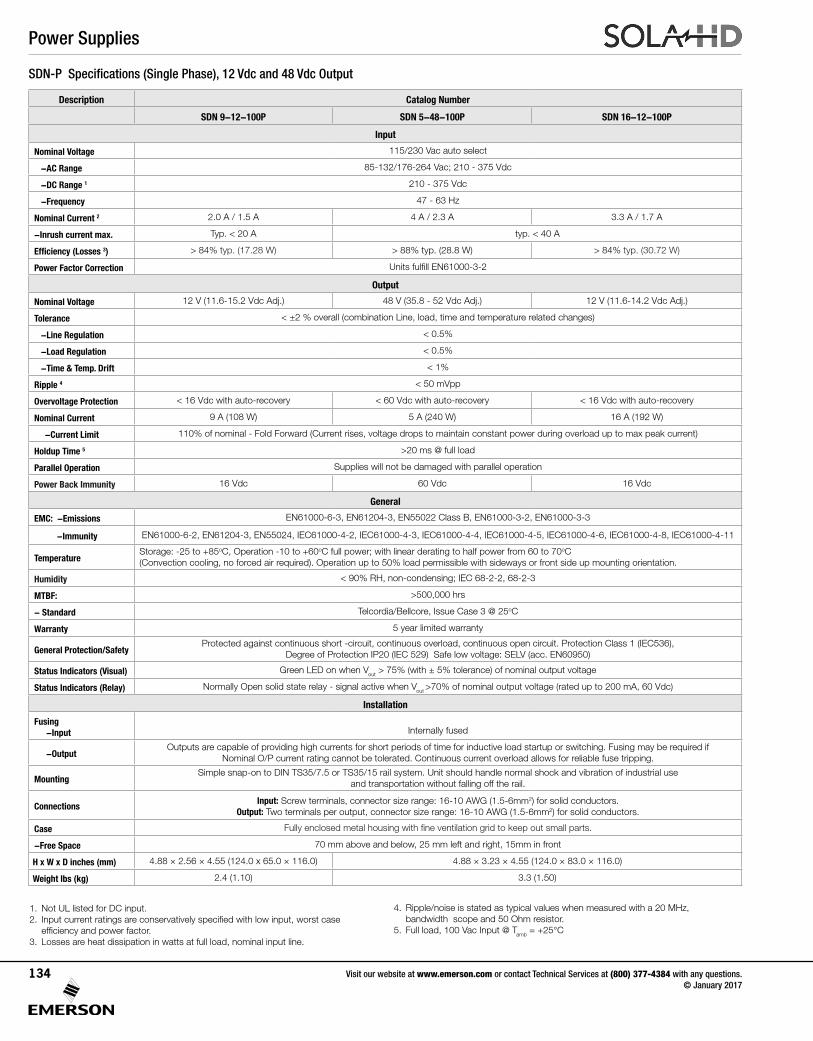
SDN-P Specifications (Single Phase), 12 Vdc and 48 Vdc Output
Description Catalog Number
SDN 9-12-100P SDN 5-48-100P SDN 16-12-100P
Input
Nominal Voltage 115/230 Vac auto select
-AC Range 85-132/176-264 Vac; 210 - 375 Vdc
-DC Range 1 210 - 375 Vdc
-Frequency 47 - 63 Hz
Nominal Current 2 2.0 A / 1.5 A 4 A / 2.3 A 3.3 A / 1.7 A
-Inrush current max. Typ. < 20 A typ. < 40 A
Efficiency (Losses 3) > 84% typ. (17.28 W) > 88% typ. (28.8 W) > 84% typ. (30.72 W)
Power Factor Correction Units fulfill EN61000-3-2
Output
Nominal Voltage 12 V (11.6-15.2 Vdc Adj.) 48 V (35.8 - 52 Vdc Adj.) 12 V (11.6-14.2 Vdc Adj.)
Tolerance < ±2 % overall (combination Line, load, time and temperature related changes)
-Line Regulation < 0.5%
-Load Regulation < 0.5%
-Time & Temp. Drift < 1%
Ripple 4 < 50 mVpp
Overvoltage Protection < 16 Vdc with auto-recovery < 60 Vdc with auto-recovery < 16 Vdc with auto-recovery
Nominal Current 9 A (108 W) 5 A (240 W) 16 A (192 W)
-Current Limit 110% of nominal - Fold Forward (Current rises, voltage drops to maintain constant power during overload up to max peak current)
Holdup Time 5 >20 ms @ full load
Parallel Operation Supplies will not be damaged with parallel operation
Power Back Immunity 16 Vdc 60 Vdc 16 Vdc
General
EMC: -Emissions EN61000-6-3, EN61204-3, EN55022 Class B, EN61000-3-2, EN61000-3-3
-Immunity EN61000-6-2, EN61204-3, EN55024, IEC61000-4-2, IEC61000-4-3, IEC61000-4-4, IEC61000-4-5, IEC61000-4-6, IEC61000-4-8, IEC61000-4-11
TemperatureStorage: -25 to +85oC, Operation -10 to +60oC full power; with linear derating to half power from 60 to 70oC (Convection cooling, no forced air required). Operation up to 50% load permissible with sideways or front side up mounting orientation.
Humidity < 90% RH, non-condensing; IEC 68-2-2, 68-2-3
MTBF: >500,000 hrs
- Standard Telcordia/Bellcore, Issue Case 3 @ 25oC
Warranty 5 year limited warranty
General Protection/SafetyProtected against continuous short -circuit, continuous overload, continuous open circuit. Protection Class 1 (IEC536),
Degree of Protection IP20 (IEC 529) Safe low voltage: SELV (acc. EN60950)
Status Indicators (Visual) Green LED on when Vout > 75% (with ± 5% tolerance) of nominal output voltage
Status Indicators (Relay) Normally Open solid state relay - signal active when Vout >70% of nominal output voltage (rated up to 200 mA, 60 Vdc)
Installation
Fusing-Input
Internally fused
-OutputOutputs are capable of providing high currents for short periods of time for inductive load startup or switching. Fusing may be required if
Nominal O/P current rating cannot be tolerated. Continuous current overload allows for reliable fuse tripping.
MountingSimple snap-on to DIN TS35/7.5 or TS35/15 rail system. Unit should handle normal shock and vibration of industrial use
and transportation without falling off the rail.
ConnectionsInput: Screw terminals, connector size range: 16-10 AWG (1.5-6mm2) for solid conductors.
Output: Two terminals per output, connector size range: 16-10 AWG (1.5-6mm2) for solid conductors.
Case Fully enclosed metal housing with fine ventilation grid to keep out small parts.
-Free Space 70 mm above and below, 25 mm left and right, 15mm in front
H x W x D inches (mm) 4.88 × 2.56 × 4.55 (124.0 x 65.0 × 116.0) 4.88 × 3.23 × 4.55 (124.0 × 83.0 × 116.0)
Weight lbs (kg) 2.4 (1.10) 3.3 (1.50)
1. Not UL listed for DC input.2. Input current ratings are conservatively specified with low input, worst case
efficiency and power factor. 3. Losses are heat dissipation in watts at full load, nominal input line.
4. Ripple/noise is stated as typical values when measured with a 20 MHz, bandwidth scope and 50 Ohm resistor.
5. Full load, 100 Vac Input @ Tamb = +25°C
Power Supplies
Visit our website at www.emerson.com or contact Technical Services at (800) 377-4384 with any questions. © January 2017
134
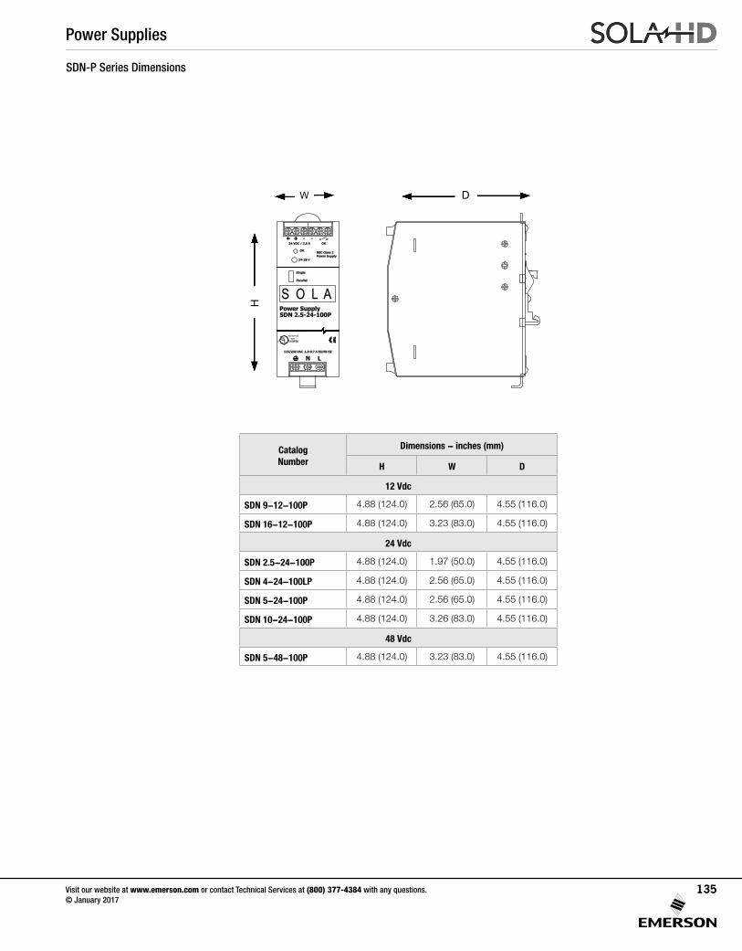
24-28 V
115/230 VAC 1.3-0.7 A 50/60 HZ
���� ���� ��
US LISTED
Power SupplySDN 2.5-24-100P
S O L AParallel
Single
C����
LU
LN
24 VDC / 2.5 A+ +
NEC Class 2Power Supply
OK
- -OK
SDN-P Series Dimensions
W D
H
Catalog Number
Dimensions - inches (mm)
H W D
12 Vdc
SDN 9-12-100P 4.88 (124.0) 2.56 (65.0) 4.55 (116.0)
SDN 16-12-100P 4.88 (124.0) 3.23 (83.0) 4.55 (116.0)
24 Vdc
SDN 2.5-24-100P 4.88 (124.0) 1.97 (50.0) 4.55 (116.0)
SDN 4-24-100LP 4.88 (124.0) 2.56 (65.0) 4.55 (116.0)
SDN 5-24-100P 4.88 (124.0) 2.56 (65.0) 4.55 (116.0)
SDN 10-24-100P 4.88 (124.0) 3.26 (83.0) 4.55 (116.0)
48 Vdc
SDN 5-48-100P 4.88 (124.0) 3.23 (83.0) 4.55 (116.0)
Power Supplies
Visit our website at www.emerson.com or contact Technical Services at (800) 377-4384 with any questions. © January 2017
135
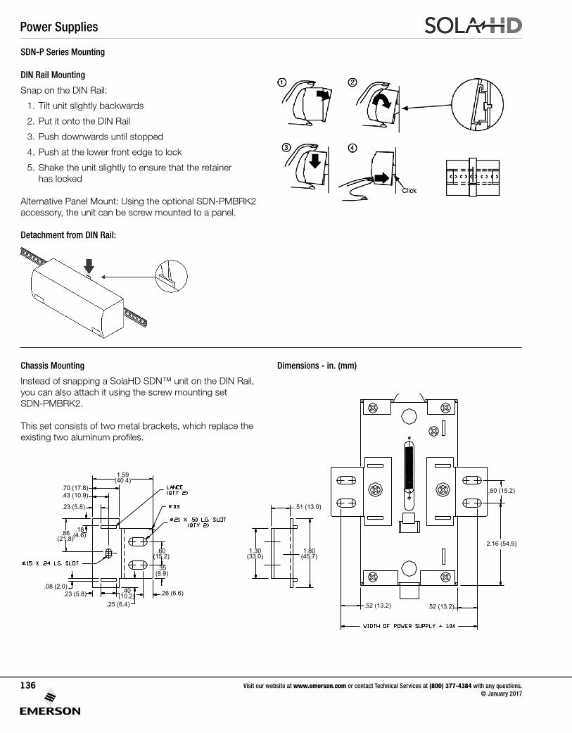
SDN-P Series Mounting
DIN Rail Mounting
Snap on the DIN Rail:
1. Tilt unit slightly backwards
2. Put it onto the DIN Rail
3. Push downwards until stopped
4. Push at the lower front edge to lock
5. Shake the unit slightly to ensure that the retainer has locked
Alternative Panel Mount: Using the optional SDN-PMBRK2 accessory, the unit can be screw mounted to a panel.
Detachment from DIN Rail:
Chassis Mounting
Instead of snapping a SolaHD SDN™ unit on the DIN Rail, you can also attach it using the screw mounting set SDN-PMBRK2.
This set consists of two metal brackets, which replace the existing two aluminum profiles.
Dimensions - in. (mm)
1.59(40.4)
.18(4.6).86
(21.8)
.40(10.2)
.60(15.2)
1.30(33.0)
1.80(45.7)
.35(8.9)
.70 (17.8)
.51 (13.0)
.43 (10.9)
.23 (5.8)
.08 (2.0).23 (5.8)
.25 (6.4)
.26 (6.6)
.52 (13.2) .52 (13.2)
2.16 (54.9)
.60 (15.2)
Power Supplies
Visit our website at www.emerson.com or contact Technical Services at (800) 377-4384 with any questions. © January 2017
136
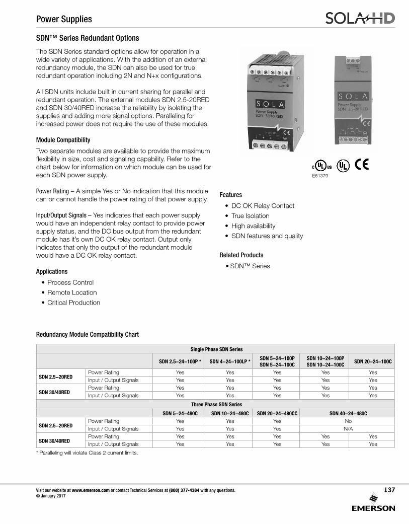
SDN™ Series Redundant Options
The SDN Series standard options allow for operation in a wide variety of applications. With the addition of an external redundancy module, the SDN can also be used for true redundant operation including 2N and N+x configurations.
All SDN units include built in current sharing for parallel and redundant operation. The external modules SDN 2.5-20RED and SDN 30/40RED increase the reliability by isolating the supplies and adding more signal options. Paralleling for increased power does not require the use of these modules.
Module Compatibility
Two separate modules are available to provide the maximum flexibility in size, cost and signaling capability. Refer to the chart below for information on which module can be used for each SDN power supply.
Power Rating – A simple Yes or No indication that this module can or cannot handle the power rating of that power supply.
Input/Output Signals – Yes indicates that each power supply would have an independent relay contact to provide power supply status, and the DC bus output from the redundant module has it’s own DC OK relay contact. Output only indicates that only the output of the redundant module would have a DC OK relay contact.
Applications
• Process Control
• Remote Location
• Critical Production
Features
• DC OK Relay Contact
• True Isolation
• High availability
• SDN features and quality
Related Products
• SDN™ Series
Redundancy Module Compatibility Chart
Single Phase SDN Series
SDN 2.5-24-100P * SDN 4-24-100LP *SDN 5-24-100PSDN 5-24-100C
SDN 10-24-100PSDN 10-24-100C
SDN 20-24-100C
SDN 2.5-20REDPower Rating Yes Yes Yes Yes YesInput / Output Signals Yes Yes Yes Yes Yes
SDN 30/40REDPower Rating Yes Yes Yes Yes YesInput / Output Signals Yes Yes Yes Yes Yes
Three Phase SDN Series
SDN 5-24-480C SDN 10-24-480C SDN 20-24-480CC SDN 40-24-480C
SDN 2.5-20REDPower Rating Yes Yes Yes NoInput / Output Signals Yes Yes Yes N/A
SDN 30/40REDPower Rating Yes Yes Yes Yes YesInput / Output Signals Yes Yes Yes Yes Yes
* Paralleling will violate Class 2 current limits.
E61379
Power Supplies
Visit our website at www.emerson.com or contact Technical Services at (800) 377-4384 with any questions. © January 2017
137
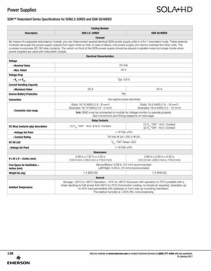
SDN™ Redundant Series Specifications for SDN2.5-20RED and SDN 30/40RED
Catalog Number
Description SDN 2.5-20RED SDN 30/40RED
ConceptBy means of a separate redundancy module, you can interconnect several identical SDN power supply units in a N+1 redundant mode. These external modules decouple the power supply outputs from each other so that, in case of failure, one power supply unit cannot overload the other units. The modules incorporate DC OK relay contacts. The switch on front of the SDN power supply should be placed in parallel mode (not single mode) when power supplies are used with redundant module.
Electrical Characteristics
Voltage
-Nominal Value 24 Vdc
-Max. Rated 35 V
Voltage Drop
-Vin -> VoutTyp. 0.6 V
Current Handling Capacity
-Maximum Value 20 A 40 A
Inverse Battery Protection Yes
Connection Via captive screw terminals
-Connector size range
Solid: 16-10 AWG (1.5 - 6 mm2) Stranded: 16-12 AWG (1.5 - 4 mm2)
Solid: 16-5 AWG (1.5 - 16 mm2) Stranded: 16-8 AWG (1.5 - 10 mm2)
Note: GND must be connected to module for voltage monitor to operate properly. See Connectors and Wiring diagrams on next page.
Relay Contacts
DC Okay Contacts (qty) description (1) Vout “OK” - N.O. & N.C. Contact(1) Vout “OK” - N.O. Contact(2) Vin “OK” - N.O. Contact
-Voltage Set Point > 18 Vdc ±5%
-Contact Rating 30 Vdc @ 2A / 250 V @ 2A
DC OK LED Vout “OK” Green LED
-Voltage Set Point > 18 Vdc ±5%
Dimensions
H x W x D - inches (mm)4.88 in x 1.97 in x 4.55 in
(124.0 mm x 50.0 mm x 116.0 mm)4.88 in x 2.56 in x 4.55 in
(124.0 mm x 65.0 mm x 116.0 mm)
Free Space for Ventilation - inches (mm)
Above/Below: 0.39 in. (10 mm) recommended Left/Right: 0.39 in. (10 mm) recommended
Weight lbs (kg) 1.4 (625.00) 1.4 (646.00)
General
Ambient Temperature
Storage: -25°C to +85°C Operation: -10°C to +60°C full power with operation to 70°C possible with a linear derating to half power from 60°C to 70°C (Convection cooling, no forced air required). Operation up
to 50% load permissible with sideways or front side up mounting orientation. The relative humidity is < 90% RH, noncondensing.
Power Supplies
Visit our website at www.emerson.com or contact Technical Services at (800) 377-4384 with any questions. © January 2017
138
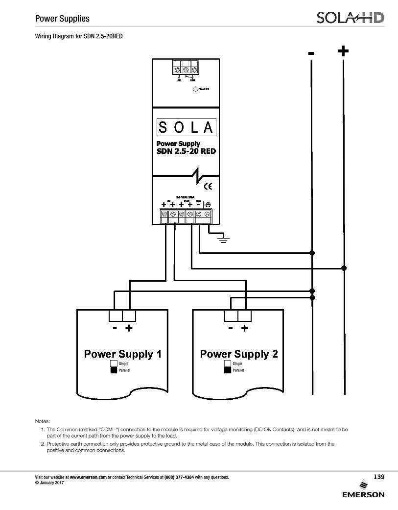
Wiring Diagram for SDN 2.5-20RED
Single
Parallel
Single
Parallel
Notes:
1. The Common (marked “COM -“) connection to the module is required for voltage monitoring (DC OK Contacts), and is not meant to be part of the current path from the power supply to the load.
2. Protective earth connection only provides protective ground to the metal case of the module. This connection is isolated from the positive and common connections.
Power Supplies
Visit our website at www.emerson.com or contact Technical Services at (800) 377-4384 with any questions. © January 2017
139
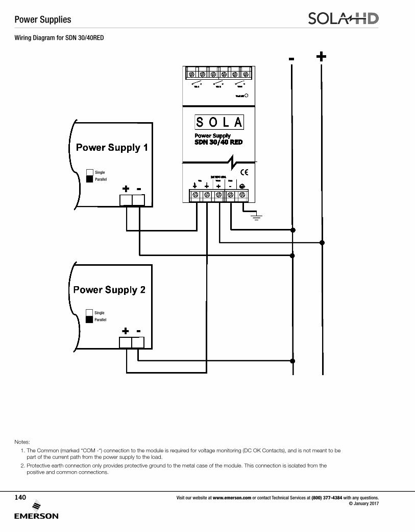
Wiring Diagram for SDN 30/40RED
Notes:
1. The Common (marked “COM -“) connection to the module is required for voltage monitoring (DC OK Contacts), and is not meant to be part of the current path from the power supply to the load.
2. Protective earth connection only provides protective ground to the metal case of the module. This connection is isolated from the positive and common connections.
Single
Parallel
Single
Parallel
Power Supplies
Visit our website at www.emerson.com or contact Technical Services at (800) 377-4384 with any questions. © January 2017
140
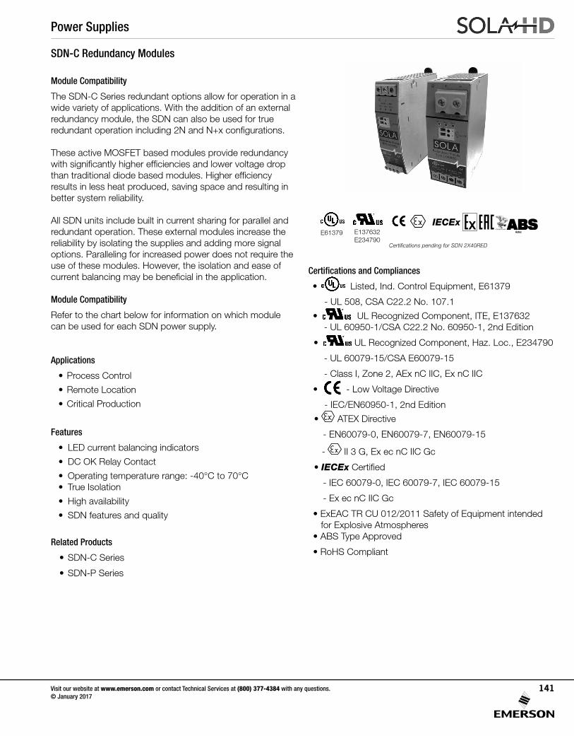
SDN-C Redundancy Modules
Module Compatibility
The SDN-C Series redundant options allow for operation in a wide variety of applications. With the addition of an external redundancy module, the SDN can also be used for true redundant operation including 2N and N+x configurations.
These active MOSFET based modules provide redundancy with significantly higher efficiencies and lower voltage drop than traditional diode based modules. Higher efficiency results in less heat produced, saving space and resulting in better system reliability.
All SDN units include built in current sharing for parallel and redundant operation. These external modules increase the reliability by isolating the supplies and adding more signal options. Paralleling for increased power does not require the use of these modules. However, the isolation and ease of current balancing may be beneficial in the application.
Module Compatibility
Refer to the chart below for information on which module can be used for each SDN power supply.
Applications
• Process Control
• Remote Location
• Critical Production
Features
• LED current balancing indicators
• DC OK Relay Contact
• Operating temperature range: -40°C to 70°C• True Isolation
• High availability
• SDN features and quality
Related Products
• SDN-C Series
• SDN-P Series
Certifications and Compliances
• UL 508 Listed
IND. CONT. EQ.E61379
Listed, Ind. Control Equipment, E61379
- UL 508, CSA C22.2 No. 107.1
• UL 60950 E137632
CUL/CSA-C22.2No. 234-M90
UL Recognized Component, ITE, E137632 - UL 60950-1/CSA C22.2 No. 60950-1, 2nd Edition
• UL 60950 E137632
CUL/CSA-C22.2No. 234-M90
UL Recognized Component, Haz. Loc., E234790
- UL 60079-15/CSA E60079-15
- Class I, Zone 2, AEx nC IIC, Ex nC IIC
• EMC andLow Volt. Directive
- Low Voltage Directive
- IEC/EN60950-1, 2nd Edition
• ATEX Directive
- EN60079-0, EN60079-7, EN60079-15
- II 3 G, Ex ec nC IIC Gc
• IECEx Certified
- IEC 60079-0, IEC 60079-7, IEC 60079-15
- Ex ec nC IIC Gc
• ExEAC TR CU 012/2011 Safety of Equipment intended for Explosive Atmospheres• ABS Type Approved
• RoHS Compliant
UL 508 ListedIND. CONT. EQ.
E61379
UL 60950 E137632
CUL/CSA-C22.2No. 234-M90
E61379 E137632E234790
EMC andLow Volt. Directive
IECExAstec
Certifications pending for SDN 2X40RED
Power Supplies
Visit our website at www.emerson.com or contact Technical Services at (800) 377-4384 with any questions. © January 2017
141
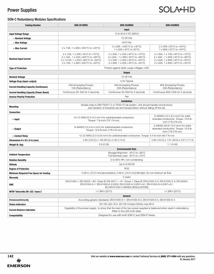
SDN-C Redundancy Modules Specifications
Catalog Number SDN 2X10RED SDN 2X20RED SDN 2X40RED
Input
Input Voltage Range 10.8-30.8 V DC (SELV)
- Nominal Voltage 12-28 Vdc
- Max Voltage 30.8 Vdc
- Max Current 2 x 13A, 1 x 26A (-40C°C to +40°C)2 x 26A (-40C°C to +40°C)
1 x 52A (-40°C to 40°C)2 x 45A (-25°C to +40°C) 1 x 90A (-25°C to +40°C)
Nominal Input Current
2 x 10A, 1 x 20A (-40°C to +70°C)2 x 12A , 1 x 24A (-40C°C to +60°C)2 x 12.5A, 1 x 25A (-40C°C to +50°C)2 x 13A, 1 x 26A (-40C°C to +40°C)
2 x 20A, 1 x 40A (-40°C to +70°C)2 x 24A , 1 x 48A (-40°C to +60°C)2 x 25A, 1 x 50A (-40°C to +50°C)2 x 26A, 1 x 52A (-40°C to +40°C)
2 x 35A, 1 x 70A (-40°C to +70°C) 2 x 40A , 1 x 80A (-40°C to +60°C)2 x 50A, 1 x 80A (-40°C to +50°C)2 x 52A, 1 x 80A (-40°C to +40°C)
Type of Protection Protect against static surge voltages >30V
Output
Nominal Voltage 12-28 Vdc
Voltage Drop (input-output) 0.2V Typical
Current Handling Capacity (Continuous)20A (Increasing Power);
10A (Redundancy)40A (Increasing Power);
20A (Redundancy)80A (Increasing Power);
40A (Redundancy)
Current Handling Capacity (Power Boost) Continuous 26; 50A for 5 seconds Continuous 40; 65A for 5 seconds Continuous 80A;120A for 5 seconds
Inverse Polarity Protection Yes
Installation
MountingSimple snap to DIN TS35/7.5 or TS35/15 rail system. Unit should handle normal shock
and vibration of industrial use and transportation without falling off the rail.
Connection
- Input10–12 AWG (5.3–3.3 mm2) for solid/stranded conductors.
Torque: 7 lb-inch (79.1 N-cm).
6–8AWG (13.3–8.4 mm2) for solid/stranded conductors. Torque: 15.6 lb-
inch (176.3 N-cm)
- Output6–8AWG (13.3–8.4 mm2) for solid/stranded conductors.
Torque: 15.6 lb-inch (176.3 N-cm)
2–6AWG (33.6–13.3 mm2) for solid/stranded conductors. Torque: 15.6 lb-
inch (176.3 N-cm).
- Contact Relay 12-22 AWG (3.3-0.33 mm2) for solid/stranded conductors. Torque: 4.4 lb-inch (49.7 N-cm)
Dimensions H x W x D in (mm) 4.85 (123.2) x 1.38 (35.0) x 4.46 (113.3) 4.85 (123.2) x 1.81 (46.0) x 4.61 (117.0)
Weight lb. (kg) 0.8 (0.36) 1.1 (0.48)
Environmental Data
Ambient TemperatureStorage/Shipment: -40°C to +85°C Full Nominal Load: -40°C to +70°C
Relative Humidity 0 to 95% RH, non-condensing
Altitude Up to 6,000 M
Degree of Protection IP20
Minimum Required Free Space for Cooling 0.39 in. [10.0 mm] above/below, 0.39 in. [10.0 mm] left/right. Do not obstruct air flow.
Warranty 5 years
EMCEN 61326-1; EN 55022 +AC: Class B; EN 55011 + A1: Group 1 Class B; EN 61000-3-2; EN 61000-3-3; EN 55024;
EN 61000-6-1; EN 61000-6-2:2005; EN 61000-6-3:2007+A1; EN 61000-6-4:2007+A1; IEC/EN 61000-4 SERIES REGULATIONS
MTBF Telecordia SR-322 Issue 2 >1.3M h (25°C) >1.2M h (25°C)
General
Emissions/Immunity According generic standards: EN 61000-6-1, EN 61000-6-2, EN 61000-6-3, EN 61000-6-4
Status Indicators DC OK LED, N.O. DC OK Contact 60Vdc max @1A
Current Balance IndicationCapability of the power supply to show that the load of the two power supplies is balanced when used in redundancy.
Refer to the LED truth table.
Compatability Designed for use with both SDN-C and SDN-P Series
Power Supplies
Visit our website at www.emerson.com or contact Technical Services at (800) 377-4384 with any questions. © January 2017
142
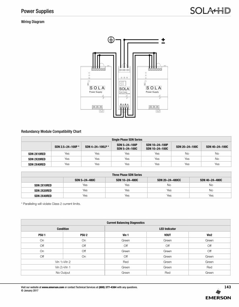
Wiring Diagram
Current Balancing Diagnostics
Condition LED Indicator
PSU 1 PSU 2 Vin 1 VOUT Vin2
On On Green Green Green
Off Off Off Off Off
On Off Green Green Off
Off On Off Green Green
Vin 1>Vin 2 Red Green Green
Vin 2>Vin 1 Green Green Red
No Output Green Red Green
SOLAPower SupplyRedundancy Module
S O L APower Supply
S O L APower Supply
+-
+- + -
Redundancy Module Compatibility Chart
Single Phase SDN Series
SDN 2.5-24-100P * SDN 4-24-100LP *SDN 5-24-100PSDN 5-24-100C
SDN 10-24-100PSDN 10-24-100C
SDN 20-24-100C SDN 40-24-100C
SDN 2X10RED Yes Yes Yes Yes No No
SDN 2X20RED Yes Yes Yes Yes Yes No
SDN 2X40RED Yes Yes Yes Yes Yes Yes
Three Phase SDN Series
SDN 5-24-480C SDN 10-24-480C SDN 20-24-480CC SDN 40-24-480C
SDN 2X10RED Yes Yes No No
SDN 2X20RED Yes Yes Yes No
SDN 2X40RED Yes Yes Yes Yes
* Paralleling will violate Class 2 current limits.
Power Supplies
Visit our website at www.emerson.com or contact Technical Services at (800) 377-4384 with any questions. © January 2017
143
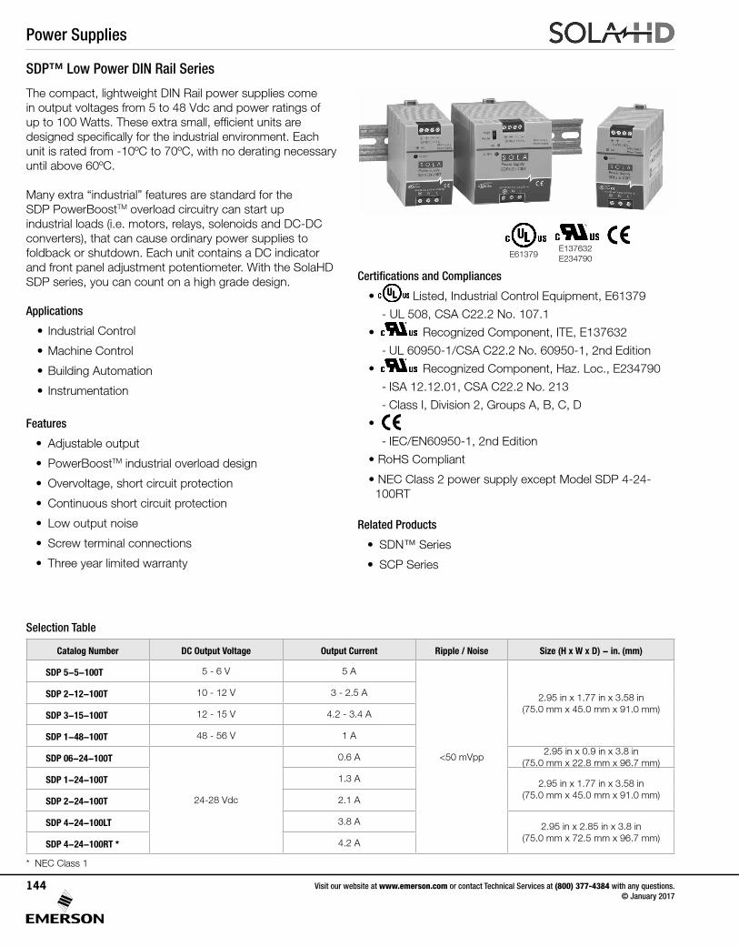
SDP™ Low Power DIN Rail Series
The compact, lightweight DIN Rail power supplies come in output voltages from 5 to 48 Vdc and power ratings of up to 100 Watts. These extra small, efficient units are designed specifically for the industrial environment. Each unit is rated from -10ºC to 70ºC, with no derating necessary until above 60ºC.
Many extra “industrial” features are standard for the SDP PowerBoostTM overload circuitry can start up industrial loads (i.e. motors, relays, solenoids and DC-DC converters), that can cause ordinary power supplies to foldback or shutdown. Each unit contains a DC indicator and front panel adjustment potentiometer. With the SolaHD SDP series, you can count on a high grade design.
Applications
• Industrial Control
• Machine Control
• Building Automation
• Instrumentation
Features
• Adjustable output
• PowerBoostTM industrial overload design
• Overvoltage, short circuit protection
• Continuous short circuit protection
• Low output noise
• Screw terminal connections
• Three year limited warranty
Certifications and Compliances
• Listed, Industrial Control Equipment, E61379
- UL 508, CSA C22.2 No. 107.1
• UL 60950 E137632
CUL/CSA-C22.2No. 234-M90
Recognized Component, ITE, E137632
- UL 60950-1/CSA C22.2 No. 60950-1, 2nd Edition
• UL 60950 E137632
CUL/CSA-C22.2No. 234-M90
Recognized Component, Haz. Loc., E234790
- ISA 12.12.01, CSA C22.2 No. 213
- Class I, Division 2, Groups A, B, C, D
•
- IEC/EN60950-1, 2nd Edition
• RoHS Compliant
• NEC Class 2 power supply except Model SDP 4-24- 100RT
Related Products
• SDN™ Series
• SCP Series
Selection Table
Catalog Number DC Output Voltage Output Current Ripple / Noise Size (H x W x D) - in. (mm)
SDP 5-5-100T 5 - 6 V 5 A
<50 mVpp
2.95 in x 1.77 in x 3.58 in(75.0 mm x 45.0 mm x 91.0 mm)
SDP 2-12-100T 10 - 12 V 3 - 2.5 A
SDP 3-15-100T 12 - 15 V 4.2 - 3.4 A
SDP 1-48-100T 48 - 56 V 1 A
SDP 06-24-100T
24-28 Vdc
0.6 A2.95 in x 0.9 in x 3.8 in
(75.0 mm x 22.8 mm x 96.7 mm)
SDP 1-24-100T 1.3 A 2.95 in x 1.77 in x 3.58 in(75.0 mm x 45.0 mm x 91.0 mm)
SDP 2-24-100T 2.1 A
SDP 4-24-100LT 3.8 A 2.95 in x 2.85 in x 3.8 in(75.0 mm x 72.5 mm x 96.7 mm)
SDP 4-24-100RT * 4.2 A
* NEC Class 1
E61379E137632E234790
Power Supplies
Visit our website at www.emerson.com or contact Technical Services at (800) 377-4384 with any questions. © January 2017
144
SDP™ Series Specifications (24 V models)
DescriptionCatalog Number
SDP 06-24-100T SDP 1-24-100T SDP 2-24-100T SDP 4-24-100LT SDP 4-24-100RT
Input
Input Voltage 1 85-264 Vac, 90-375 Vdc 85-132 / 176-264 Vac, 210-375 Vdc
Input Frequency 47-63 Hz
Input Current 0.4 A / 0.25 A 0.7 A / 0.4 A 1.1 A / 0.7 A 1.8 A / 1.0 A 2.2 A / 1.2 A
External Fusing Not required. Unit provides internal fuse (T3A, not accessible)
Hold-Up Time > 25 ms
Efficiency > 80% typ. > 83% typ. > 86% typ. > 88% typ.
Losses < 3.75 W typ. < 6.1 W typ. < 8.1 W typ. < 12 W typ.
Output
Output Voltage 24 V (22.5 - 28.5 Vdc Adj.) 24 V (24 - 25.7 Vdc Adj.) 24 V (22.5 - 28.5 Vdc Adj.)
Voltage Regulation Static 0.5% Vout, dynamic + 2% Vout overall\
Ripple/Noise 2 < 50 mVpp
Overvoltage Protection (OVP) > 30 Vdc, but < 33 Vdc, auto recovery> 26 Vdc, but < 27.2 Vdc, auto recovery
> 30 Vdc, but < 33 Vdc, auto recovery
Output Noise Suppression
Radiated EMI values below EN61000-6-2
Rated Continuous Loading
0.63 A @ 24 Vdc / 0.54 A @ 28 Vdc
1.3 A @ 24 Vdc / 1.1 A @ 28 Vdc
2.1 A @ 24 Vdc / 1.8 A @ 28 Vdc
3.8 A @ 24.5 Vdc4.2 A @ 24.5 Vdc /
3.6 A @ 28 Vdc
Overload Behavior Continuous operation at overload/short-circuit: up to 1.5 x Nominal Current Continuous
Protection Unit is continuously protected against short-circuit, overload and open-circuit.
Power Back Immunity 35 V
Installation
Status Indicators Green LED on, when Vout “OK”.
Case & MountingMolded plastic housing using UL 94 approved flameproof material rating 94V-2.
Simple snap-on to DIN TS35/7.5 or TS35/15 rail system.
Dimensions
H x W x D - inches (mm)2.95 x 0.90 x 3.80
(75.0 x 22.8 x 96.7)2.95 x 1.77 x 3.58 (75.0 x 45.0 x 91.0)
2.95 x 2.85 x 3.80(75.0 x 72.5 x 96.7)
Weight - lbs (kg) 0.4 lbs (0.18 kg) 0.5 lbs (0.23 kg) 0.7 lbs (0.32 kg)
Mounting Orientation Standard: Vertical; Optional: Horizontal or on top (Contact Technical Services).
Ventilation/Cooling •Free space for cooling
Normal convection, no fan required; Above/below: 25 mm recommended.
Connection •Connector size range
Input: screw terminals, connector size range: 20-12AWG (1.5 - 6 mm2) for solid or stranded conductors.
General
Electromagnetic Emissions (EMC)
EN61000-6-3 (Includes EN61000-6-4) Class B (EN 55022) incl. Annex A
Electromagnetic Immunity (EMI)
EN61000-6-2 (Includes EN61000-6-1) (EN55024) Criterion A: no derogation of performance
TemperatureStorage: -25°C to +85°C Operation: -10° to +60°C full power with linear derating to half power from 60°C to 70°C.
(Convection cooling, no forced air required).
MTBF > 500,000 hours according to Telcordia/Bellcore Document SR-332, Issue 1
Humidity Up to 90% RH, noncondensing; IEC 68-2-2, 68-2-3
Safe Low Voltage SELV (acc. EN60950)
Protection Class/Voltage IP20 (IEC529), Protection Class 1 (IEC536)
Warranty 3 year limited warranty
Notes:
1. Not UL listed for DC input. 2. Ripple/noise is stated as typical values when measured with a 20 MHz, bandwidth scope and 50 ohm resistor.
Power Supplies
Visit our website at www.emerson.com or contact Technical Services at (800) 377-4384 with any questions. © January 2017
145
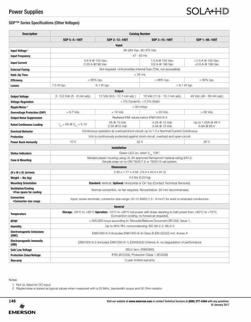
SDP™ Series Specifications (Other Voltages)
Description Catalog Number
SDP 5-5-100T SDP 2-12-100T SDP 3-15-100T SDP 1-48-100T
Input
Input Voltage 1 85-264 Vac, 90-375 Vdc
Input Frequency 47 - 63 Hz
Input Current 0.6 A @ 102 Vac; 0.33 A @196 Vac
1.0 A @ 102 Vac; 0.6 A @ 196 Vac
<1.0 A @ 100 Vac; <0.6 A @ 196 Vac
External Fusing Not required. Unit provides internal fuse (T3A, not accessible)
Hold-Up Time > 25 ms
Efficiency > 80% typ. > 86% typ. > 90% typ.
Losses 7.5 W typ. 8.1 W typ. < 8.1 W typ.
Output
Output Voltage 5 - 5.5 Vdc (5 - 6 min adj.) 12 Vdc (9.9 - 12.1 min adj. ) 15 Vdc (11.9 - 15.1 min adj.) 48 Vdc (48 - 56 min adj.)
Voltage Regulation < 2% Dynamic; < 0.5% Static
Ripple/Noise 2 < 50 mVpp
Overvoltage Protection (OVP) > 6.7 Vdc > 18 Vdc > 20 Vdc > 56 Vdc
Output Noise Suppression Radiated EMI values below EN61000-6-2
Rated Continuous Loading lout = 5A @ Vout = 5.1V 3A @ 10 Vdc2.5A @12 Vdc
4.2A @ 12 Vdc 3.4A @ 15 Vdc
Up to 1.05A @ 48 V 0.9A @ 56 V
Overload Behavior Continuous operation at overload/short-circuit: up to 1.5 x Nominal Current Continuous
Protection Unit is continuously protected against short-circuit, overload and open-circuit.
Power Back Immunity 10 V 22 V 80 V
Installation
Status Indicators Green LED on, when Vout “OK”.
Case & MountingMolded plastic housing using UL 94 approved flameproof material rating 94V-2.
Simple snap-on to DIN TS35/7.5 or TS35/15 rail system.
Dimensions
(H x W x D) (in/mm) 2.95 x 1.77 x 3.58 (75.0 x 45.0 x 91.0)
Weight - lbs (kg) 0.5 lbs (0.23 kg)
Mounting Orientation Standard: Vertical; Optional: Horizontal or On Top (Contact Technical Services).
Ventilation/Cooling •Free space for cooling
Normal convection, no fan required; Above/below: 25 mm recommended.
Connection •Connector size range
Input: screw terminals, connector size range: 20-12 AWG (1.5 - 6 mm2) for solid or stranded conductors.
General
TemperatureStorage: -25°C to +85°C Operation: -10°C to +60°C full power with linear derating to half power from +60°C to +70°C.
(Convection cooling, no forced air required).
MTBF > 500,000 hours according to Telcordia/Bellcore Document SR-332, Issue 1.
Humidity Up to 90% RH, noncondensing; IEC 68-2-2, 68-2-3
Electromagnetic Emissions (EMC)
EN61000-6-3 (Includes EN61000-6-4) Class B (EN 55022) incl. Annex A
Electromagnetic Immunity (EMI)
EN61000-6-2 (Includes EN61000-6-1) (EN55024) Criterion A: no degradation of performance
Safe Low Voltage SELV (acc. EN60950)
Protection Class/Voltage IP20 (IEC529), Protection Class 1 (IEC536)
Warranty 3 year limited warranty
Notes:
1. Not UL listed for DC input.2. Ripple/noise is stated as typical values when measured with a 20 MHz, bandwidth scope and 50 Ohm resistor.
Power Supplies
Visit our website at www.emerson.com or contact Technical Services at (800) 377-4384 with any questions. © January 2017
146
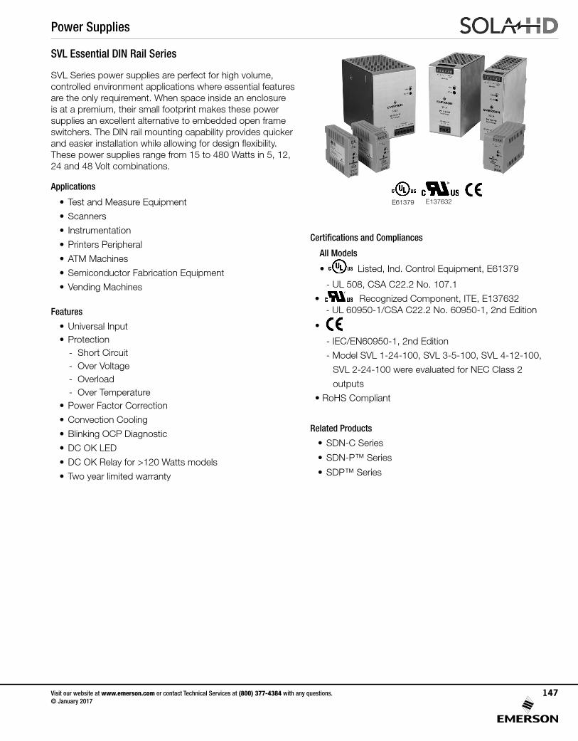
SVL Series power supplies are perfect for high volume, controlled environment applications where essential features are the only requirement. When space inside an enclosure is at a premium, their small footprint makes these power supplies an excellent alternative to embedded open frame switchers. The DIN rail mounting capability provides quicker and easier installation while allowing for design flexibility.These power supplies range from 15 to 480 Watts in 5, 12, 24 and 48 Volt combinations.
Applications
• Test and Measure Equipment
• Scanners
• Instrumentation
• Printers Peripheral
• ATM Machines
• Semiconductor Fabrication Equipment
• Vending Machines
Features
• Universal Input• Protection - Short Circuit - Over Voltage - Overload - Over Temperature• Power Factor Correction
• Convection Cooling
• Blinking OCP Diagnostic
• DC OK LED
• DC OK Relay for >120 Watts models
• Two year limited warranty
SVL Essential DIN Rail Series
Certifications and Compliances
All Models
• UL 508 Listed
IND. CONT. EQ.E61379
Listed, Ind. Control Equipment, E61379
- UL 508, CSA C22.2 No. 107.1
• UL 60950 E137632
CUL/CSA-C22.2No. 234-M90
Recognized Component, ITE, E137632 - UL 60950-1/CSA C22.2 No. 60950-1, 2nd Edition
• EMC andLow Volt. Directive- IEC/EN60950-1, 2nd Edition
- Model SVL 1-24-100, SVL 3-5-100, SVL 4-12-100,
SVL 2-24-100 were evaluated for NEC Class 2
outputs
• RoHS Compliant
Related Products
• SDN-C Series
• SDN-P™ Series
• SDP™ Series
UL 508 ListedIND. CONT. EQ.
E61379
UL 60950 E137632
CUL/CSA-C22.2No. 234-M90
E61379 E137632 EMC andLow Volt. Directive
Power Supplies
Visit our website at www.emerson.com or contact Technical Services at (800) 377-4384 with any questions. © January 2017
147
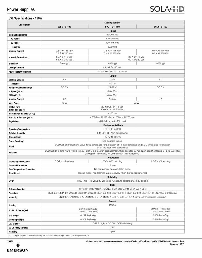
SVL Specifications <120W
DescriptionCatalog Number
SVL 3-5-100 SVL 1-24-100 SVL 6-5-100
Input
Input Voltage Range 85-264 Vac
- AC Range 100–240 Vac
- DC Range1 120-375 Vdc
- Frequency 50/60 Hz
Nominal Current 0.5 A @ 115 Vac0.3 A @ 230 Vac
0.8 A @ 115 Vac0.4 A @ 230 Vac
0.9 A @ 115 Vac 0.5 A @ 230 Vac
- Inrush Current max, 35 A @ 115 Vac65 A @ 230 Vac
35 A @ 115 Vac60 A @ 230 Vac
Efficiency 79% typ 88% typ 80% typ
Leakage Current <1 mA @ 240 Vac
Power Factor Correction Meets EN61000-3-2 Class A
Output
Nominal Voltage 5 V 24 V 5 V
- Tolerance +/-2%
Voltage Adjustable Range 5-5.5 V 24-28 V 5-5.5 V
- Ripple (25 °C) <75 mVp-p
PARD (25 °C) <75 mVp-p
Nominal Current 3 A 1.25 A 6 A
Max. Power 15 W 30 W
Holdup Time at full load (25 °C)
20 ms typ. @ 115 Vac 100 ms typ. @ 230 Vac
Rise Time at full load (25 °C) <100 ms
Start Up at full load (25 °C) <3000 ms @ 115 Vac, <1500 ms @ 230 Vac
Regulation <0.5% Line and <1% Load
Environmental Data
Operating Temperature -20 °C to +70 °C
Relative Humidity 5 to 95% RH Non-condensing
Storage temp -40 °C to +85 °C
Power Derating2 See derating tables.
ShockIEC60068-2-27: half sine wave 10 G, single axis for a duration of 11 ms operational and 50 G three axes for duration
of 11 ms each non-operational
VibrationIEC60068-2-6: sine wave; 10 Hz to 500 Hz at 2 g, 0.35 mm displacement, three axes for 60 min each operational and 5 Hz to 500 Hz at
2.09 grms, three axes for 20 min each non-operational
Protections
Overvoltage Protection 6.3-7.4 V, Latching 30-34.8 V, Latching 6.3-7.4 V, Latching
Overload Protection Hiccup
Over Temperature Protection No component damage, latch mode
Short Circuit Hiccup mode, non-latching (auto-recovery when the fault is removed)
Reliability
MTBF >350 khrs (115 Vac/230 Vac @ 25 °C) acc. to Telcordia SR-332 issue 3
EMC
Galvanic Isolation I/P to O/P: 3 K Vac; I/P to GND: 1.5 K Vac; O/P to GND: 0.5 K Vac
Emissions EN55022 (CISPR22) Class B, EN55011 Class B, EN61000-6-3, EN61000-6-4, EN61000-3-3, EN61204-3, EN61000-3-2 Class A
Immunity EN55024, EN61000-6-1, EN61000-6-2 (EN61000-4-2, 3, 4, 5, 6, 8, 11, 12) Level 3, Performance Criteria A
General
Housing Plastic
H x W x D in (mm)svl2.95 x 0.82 x 3.52(75.0 x 21.0 x 89.5)
2.95 x 1.18 x 3.52 (75.0 x 30.0 x 89.5)
Unit Weight 0.242 lb (110 g) 0.368 lb (167 g)
Shipping Weight 0.309 lb (140 g) 0.419 lb (190 g)
LED Signals GREEN light = DC OK , OCP = blinking
DC OK Relay Contact No
Warranty 2 year
1. DC input range is not listed in safety file it is only to confirm product functional performance.
Power Supplies
Visit our website at www.emerson.com or contact Technical Services at (800) 377-4384 with any questions. © January 2017
148
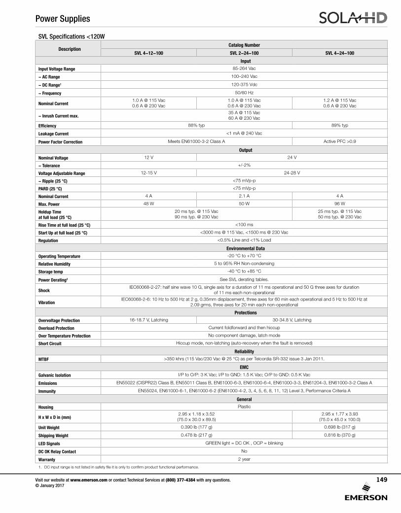
SVL Specifications <120W
DescriptionCatalog Number
SVL 4-12-100 SVL 2-24-100 SVL 4-24-100
Input
Input Voltage Range 85-264 Vac
- AC Range 100–240 Vac
- DC Range1 120-375 Vdc
- Frequency 50/60 Hz
Nominal Current1.0 A @ 115 Vac 0.6 A @ 230 Vac
1.0 A @ 115 Vac 0.6 A @ 230 Vac
1.2 A @ 115 Vac 0.6 A @ 230 Vac
- Inrush Current max.35 A @ 115 Vac60 A @ 230 Vac
Efficiency 88% typ 89% typ
Leakage Current <1 mA @ 240 Vac
Power Factor Correction Meets EN61000-3-2 Class A Active PFC >0.9
Output
Nominal Voltage 12 V 24 V
- Tolerance +/-2%
Voltage Adjustable Range 12-15 V 24-28 V
- Ripple (25 °C) <75 mVp-p
PARD (25 °C) <75 mVp-p
Nominal Current 4 A 2.1 A 4 A
Max. Power 48 W 50 W 96 W
Holdup Time at full load (25 °C)
20 ms typ. @ 115 Vac90 ms typ. @ 230 Vac
25 ms typ. @ 115 Vac 50 ms typ. @ 230 Vac
Rise Time at full load (25 °C) <100 ms
Start Up at full load (25 °C) <3000 ms @ 115 Vac, <1500 ms @ 230 Vac
Regulation <0.5% Line and <1% Load
Environmental Data
Operating Temperature -20 °C to +70 °C
Relative Humidity 5 to 95% RH Non-condensing
Storage temp -40 °C to +85 °C
Power Derating2 See SVL derating tables.
ShockIEC60068-2-27: half sine wave 10 G, single axis for a duration of 11 ms operational and 50 G three axes for duration
of 11 ms each non-operational
VibrationIEC60068-2-6: 10 Hz to 500 Hz at 2 g, 0.35mm displacement, three axes for 60 min each operational and 5 Hz to 500 Hz at
2.09 grms, three axes for 20 min each non-operational
Protections
Overvoltage Protection 16-18.7 V, Latching 30-34.8 V, Latching
Overload Protection Current foldforward and then hiccup
Over Temperature Protection No component damage, latch mode
Short Circuit Hiccup mode, non-latching (auto-recovery when the fault is removed)
Reliability
MTBF >350 khrs (115 Vac/230 Vac @ 25 °C) as per Telcordia SR-332 issue 3 Jan 2011.
EMC
Galvanic Isolation I/P to O/P: 3 K Vac; I/P to GND: 1.5 K Vac; O/P to GND: 0.5 K Vac
Emissions EN55022 (CISPR22) Class B, EN55011 Class B, EN61000-6-3, EN61000-6-4, EN61000-3-3, EN61204-3, EN61000-3-2 Class A
Immunity EN55024, EN61000-6-1, EN61000-6-2 (EN61000-4-2, 3, 4, 5, 6, 8, 11, 12) Level 3, Performance Criteria A
General
Housing Plastic
H x W x D in (mm)2.95 x 1.18 x 3.52 (75.0 x 30.0 x 89.5)
2.95 x 1.77 x 3.93(75.0 x 45.0 x 100.0)
Unit Weight 0.390 lb (177 g) 0.698 lb (317 g)
Shipping Weight 0.478 lb (217 g) 0.816 lb (370 g)
LED Signals GREEN light = DC OK , OCP = blinking
DC OK Relay Contact No
Warranty 2 year
1. DC input range is not listed in safety file it is only to confirm product functional performance.
Power Supplies
Visit our website at www.emerson.com or contact Technical Services at (800) 377-4384 with any questions. © January 2017
149
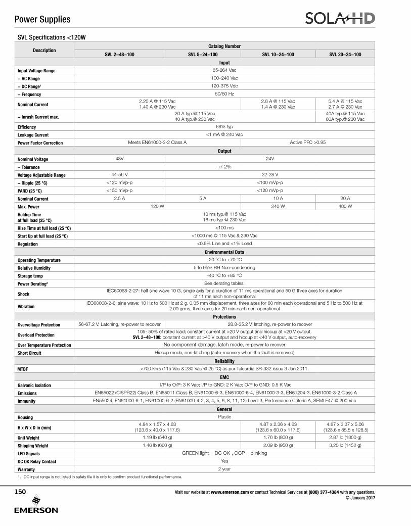
SVL Specifications <120W
DescriptionCatalog Number
SVL 2-48-100 SVL 5-24-100 SVL 10-24-100 SVL 20-24-100
Input
Input Voltage Range 85-264 Vac
- AC Range 100–240 Vac
- DC Range1 120-375 Vdc
- Frequency 50/60 Hz
Nominal Current2.20 A @ 115 Vac1.40 A @ 230 Vac
2.8 A @ 115 Vac1.4 A @ 230 Vac
5.4 A @ 115 Vac2.7 A @ 230 Vac
- Inrush Current max.20 A typ.@ 115 Vac40 A typ.@ 230 Vac
40A typ.@ 115 Vac80A typ.@ 230 Vac
Efficiency 88% typ
Leakage Current <1 mA @ 240 Vac
Power Factor Correction Meets EN61000-3-2 Class A Active PFC >0.95
Output
Nominal Voltage 48V 24V
- Tolerance +/-2%
Voltage Adjustable Range 44-56 V 22-28 V
- Ripple (25 °C) <120 mVp-p <100 mVp-p
PARD (25 °C) <150 mVp-p <120 mVp-p
Nominal Current 2.5 A 5 A 10 A 20 A
Max. Power 120 W 240 W 480 W
Holdup Time at full load (25 °C)
10 ms typ.@ 115 Vac16 ms typ @ 230 Vac
Rise Time at full load (25 °C) <100 ms
Start Up at full load (25 °C) <1000 ms @ 115 Vac & 230 Vac
Regulation <0.5% Line and <1% Load
Environmental Data
Operating Temperature -20 °C to +70 °C
Relative Humidity 5 to 95% RH Non-condensing
Storage temp -40 °C to +85 °C
Power Derating2 See derating tables.
ShockIEC60068-2-27: half sine wave 10 G, single axis for a duration of 11 ms operational and 50 G three axes for duration
of 11 ms each non-operational
VibrationIEC60068-2-6: sine wave; 10 Hz to 500 Hz at 2 g, 0.35 mm displacement, three axes for 60 min each operational and 5 Hz to 500 Hz at
2.09 grms, three axes for 20 min each non-operational
Protections
Overvoltage Protection 56-67.2 V, Latching, re-power to recover 28.8-35.2 V, latching, re-power to recover
Overload Protection105- 50% of rated load; constant current at >20 V output and hiccup at <20 V output.
SVL 2-48-100: constant current at >40 V output and hiccup at <40 V output, auto-recovery
Over Temperature Protection No component damage, latch mode, re-power to recover
Short Circuit Hiccup mode, non-latching (auto-recovery when the fault is removed)
Reliability
MTBF >700 khrs (115 Vac & 230 Vac @ 25 °C) as per Telcordia SR-332 issue 3 Jan 2011.
EMC
Galvanic Isolation I/P to O/P: 3 K Vac; I/P to GND: 2 K Vac; O/P to GND: 0.5 K Vac
Emissions EN55022 (CISPR22) Class B, EN55011 Class B, EN61000-6-3, EN61000-6-4, EN61000-3-3, EN61204-3, EN61000-3-2 Class A
Immunity EN55024, EN61000-6-1, EN61000-6-2 (EN61000-4-2, 3, 4, 5, 6, 8, 11, 12) Level 3, Performance Criteria A, SEMI F47 @ 200 Vac
General
Housing Plastic
H x W x D in (mm)4.84 x 1.57 x 4.63
(123.6 x 40.0 x 117.6)4.87 x 2.36 x 4.63
(123.6 x 60.0 x 117.6)4.87 x 3.37 x 5.06
(123.6 x 85.5 x 128.5)
Unit Weight 1.19 lb (540 g) 1.76 lb (800 g) 2.87 lb (1300 g)
Shipping Weight 1.46 lb (660 g) 2.09 lb (950 g) 3.20 lb (1452 g)
LED Signals GREEN light = DC OK , OCP = blinking
DC OK Relay Contact Yes
Warranty 2 year
1. DC input range is not listed in safety file it is only to confirm product functional performance.
Power Supplies
Visit our website at www.emerson.com or contact Technical Services at (800) 377-4384 with any questions. © January 2017
150
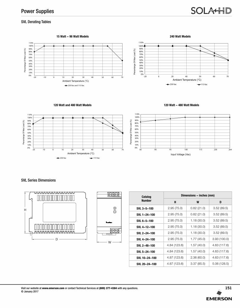
SVL Series Dimensions
Catalog Number
Dimensions - inches (mm)
H W D
SVL 3-5-100 2.95 (75.0) 0.82 (21.0) 3.52 (89.5)
SVL 1-24-100 2.95 (75.0) 0.82 (21.0) 3.52 (89.5)
SVL 6-5-100 2.95 (75.0) 1.18 (30.0) 3.52 (89.5)
SVL 4-12-100 2.95 (75.0) 1.18 (30.0) 3.52 (89.5)
SVL 2-24-100 2.95 (75.0) 1.18 (30.0) 3.52 (89.5)
SVL 4-24-100 2.95 (75.0) 1.77 (45.0) 3.93 (100.0)
SVL 2-48-100 4.84 (123.6) 1.57 (40.0) 4.63 (117.6)
SVL 5-24-100 4.84 (123.6) 1.57 (40.0) 4.63 (117.6)
SVL 10-24-100 4.87 (123.6) 2.36 (60.0) 4.63 (117.6)
SVL 20-24-100 4.87 (123.6) 3.37 (85.5) 5.06 (128.5)
H
DW
SVL Derating Tables
15 Watt - 96 Watt Models
120 Watt and 480 Watt Models 120 Watt - 480 Watt Models
240 Watt Models
Ambient Temperature (°C)
Perc
enta
nge
Of M
ax L
oad
(%)
-20 -10 0 10
230 Vac and 115 Vac
20 30 40 6050 700%10%
20%
30%40%
50%
60%
70%80%90%
100%110%
Ambient Temperature (°C)
Perc
enta
nge
Of M
ax L
oad
(%)
Power Derating Curve For PSU
-20 0
230 Vac 115 Vac
20 40 6050 700%
10%
20%30%40%50%60%70%80%90%
100%
110%
Ambient Temperature (°C)
Perc
enta
nge
Of M
ax L
oad
(%)
-20 -10 0 10
230 Vac 115 Vac
20 30 40 6050 700%10%
20%
30%40%
50%
60%
70%80%90%
100%110%
Input Voltage (Vac)
Perc
enta
nge
Of M
ax L
oad
(%)
85 90 95 100 115 230 2640%10%
20%
30%40%
50%
60%
70%80%90%
100%110%
Power Supplies
Visit our website at www.emerson.com or contact Technical Services at (800) 377-4384 with any questions. © January 2017
151
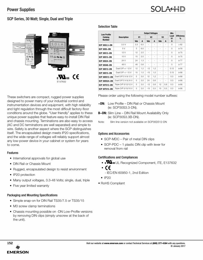
SCP Series, 30 Watt; Single, Dual and Triple
These switchers are compact, rugged power supplies designed to power many of your industrial control and instrumentation devices and equipment, with high reliability and tight regulation through the most difficult factory-floor conditions around the globe. “User friendly” applies to these unique power supplies that feature easy-to-install DIN Rail and chassis mounting. Terminations are also easy to access (AC and DC terminations are well separated) and simple to wire. Safety is another aspect where the SCP distinguishes itself. The encapsulated design meets IP20 specifications, and the wide range of voltages will reliably support almost any low-power device in your cabinet or system for years to come.
Features
• International approvals for global use
• DIN Rail or Chassis Mount
• Rugged, encapsulated design to resist environment
• IP20 protection
• Many output voltages, 3.3-48 Volts; single, dual, triple
• Five year limited warranty
Packaging and Mounting Specifications
• Simple snap-on for DIN Rail TS35/7.5 or TS35/15
• M3 screw clamp terminations
• Chassis mounting possible on -DN Low-Profile versions by removing DIN clips (simply unscrew at the back of the unit).
Selection Table
Options and Accessories
• SCP-MDC – Pair of metal DIN clips
• SCP-PDC – 1 plastic DIN clip with lever for removal from rail
Certifications and Compliances
• UL 60950 E137632
CUL/CSA-C22.2No. 234-M90
UL Recognized Component, ITE, E137632
•
- IEC/EN 60950-1, 2nd Edition
• IP20
• RoHS Compliant
Please order using the following model number suffixes:
-DN: Low Profile – DIN Rail or Chassis Mount (ie: SCP30S3.3-DN).
B-DN: Slim Line – DIN Rail Mount Availability Only (ie: SCP30S3.3B-DN). Note: Slim line version not available on SCP30D512-DN
Low Profile Catalog Number
Description
Output Voltages MinLoadV1A
Efficiency %
V1 V2 V3
Vdc A Vdc A Vdc A
SCP 30S3.3-DN 3.3 V 3.3 6.0 - - - - 0 ≥ 62
SCP 30S5-DN 5 V 5 6.0 - - - - 0 ≥ 70
SCP 30S12-DN 12 V 12 2.5 - - - - 0 ≥ 75
SCP 30S15-DN 15 V 15 2.0 - - - - 0 ≥ 75
SCP 30S24-DN 24 V 24 1.3 - - - - 0 ≥ 77
SCP 30S48-DN 48 V 48 0.6 - - - - 0 ≥ 77
SCP 30D12-DN Dual O/P +/- 12 V 12 1.2 -12 1.2 - - 0.12 ≥ 68
SCP 30D15-DN Dual O/P +/- 15 V 15 1.0 -15 1.0 - - 0.15 ≥ 68
SCP 30D512-DN Dual O/P 5 V & 12 V 5 3.0 12 1.2 - - 0.3 ≥ 68
SCP 30D524-DN Dual O/P 5 V & 24 V 5 3.0 24 0.6 - - 0.3 ≥ 68
SCP 30T512-DN Triple O/P 5/12/12 V 5 3.0 -12 0.6 12 0.6 0.3 ≥ 68
SCP 30T515-DN Triple O/P 5/15/15 V 5 3.0 -15 0.5 15 0.5 0.3 ≥ 68
E137632
Power Supplies
Visit our website at www.emerson.com or contact Technical Services at (800) 377-4384 with any questions. © January 2017
152
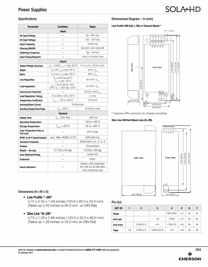
Specifications Dimensional Diagram – in (mm)
Low Profile DIN Rail (-DN) or Chassis Mount *Parameter Condition Value
Input
AC Input Voltage — 85 - 264 Vac
DC Input Voltage — 100 - 375 Vdc
Input Frequency — 50/60 HZ
Filtering EMI/RFI — EN 55011/B, 55022/B
Switching Frequency — Typ. 100 kHz
Input Fusing Required — Use 2.0 A Slow Fuse
Output
Output Voltage Accuracy Vin = 230V, Iout = max, 25°C V1 ≤ ±1%, V2/3 ≤ ±3%
Ripple Vin=min, Iout=max, 25°C ≤1%, Vout
Noise Vin=min, Iout=max, 25°C ≤2%, Vout
Line RegulationVin=min/max 25°CIout = max, 25°C
≤+0.5%, Vout
Load RegulationIout = 10 to 90 to 10%,
25°C Vin = 230 Vac, 25°C≤+0.5%, Vout
Overcurrent Protection — 105 to 130% Inom
Load Regulation Timing 10 to 90 to 10%, 25°C <4 ms
Temperature Coefficient Tamb = -25 to +65°C 0.01%/K
Overload/Short Circuit Continuous
Derating Single/Dual/Triple Tamb >50°C 2/3/5%/K max
General
Holdup Time Vin =230 Vac >50 ms
Operating Temperature -25 to +65°C
Storage Temperature Tamb = 25°C 45 to +85°C
Case Temperature Rise at Full Load
— 45 K max
MTBF at 25°C (input/output) acc. MIL-HDBK-217F 800,000 hrs
Transient Protection — EN61000-4-2, 3, 4, 5
Cooling — Convection
Weight - lbs (kg) 0.7 lbs (.34 kg) 0.8 lbs (.38 kg)
Case Material/Potting — UL94-VO
Protection — IP20
Visual Indicators —Green LED indicates DC OK for B-DN Slim
Line versions only
Dimensions (H x W x D)
• Low Profile “-DN” 4.72 x 2.55 x 1.29 inches (120.0 x 65.0 x 33.0 mm) (Takes up 2.55 inches or 65.0 mm on DIN Rail)
• Slim Line “B-DN” 4.72 x 1.29 x 2.68 inches ( 120.0 x 33.0 x 68.0 mm) (Takes up 1.29 inches or 33.0 mm on DIN Rail)
Pin-Out
SCP 30 1 2 3 4 5 6 7
Single RETURN +V1 IN IN
Dual sym -V2 COM +V1 IN IN
Dual asym COM (V1) +V1 COM V3 +V3 IN IN
Triple -V2 COM (V1) COM (V2/3) +V1 +V3 IN IN
* Unscrew DIN connector for chassis mounting.
5 4 3 2 1
6 7
Side
View
Front View
4.16
(10
6.0)
4.51
(11
5.0)
2.26
(57
.5)
1.29 (33.0)
(4.5
).1
8
D = .16 (4.2)
2.08 (53.0)
.24
(6.0)
2.55 (65.0)
4.71
(12
0.0)
Slim Line DIN Rail Mount only (B-DN)
1 2 3 4 5
6 7
Side View Front View
3.53
(90
.0)
4.00
(10
2.0)
4.43
(11
3.0)
2.67 (68.0) 1.37 (35.0)
Power Supplies
Visit our website at www.emerson.com or contact Technical Services at (800) 377-4384 with any questions. © January 2017
153
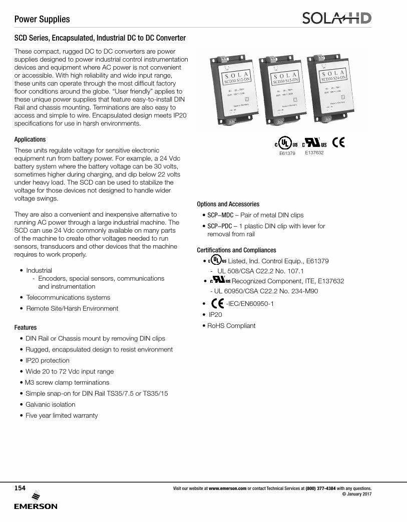
SCD Series, Encapsulated, Industrial DC to DC Converter
These compact, rugged DC to DC converters are power supplies designed to power industrial control instrumentation devices and equipment where AC power is not convenient or accessible. With high reliability and wide input range, these units can operate through the most difficult factory floor conditions around the globe. “User friendly” applies to these unique power supplies that feature easy-to-install DIN Rail and chassis mounting. Terminations are also easy to access and simple to wire. Encapsulated design meets IP20 specifications for use in harsh environments.
Applications
These units regulate voltage for sensitive electronic equipment run from battery power. For example, a 24 Vdc battery system where the battery voltage can be 30 volts, sometimes higher during charging, and dip below 22 volts under heavy load. The SCD can be used to stabilize the voltage for those devices not designed to handle wider voltage swings.
They are also a convenient and inexpensive alternative to running AC power through a large industrial machine. The SCD can use 24 Vdc commonly available on many parts of the machine to create other voltages needed to run sensors, transducers and other devices that the machine requires to work properly.
• Industrial - Encoders, special sensors, communications and instrumentation
• Telecommunications systems
• Remote Site/Harsh Environment
Features
• DIN Rail or Chassis mount by removing DIN clips
• Rugged, encapsulated design to resist environment
• IP20 protection
• Wide 20 to 72 Vdc input range
• M3 screw clamp terminations
• Simple snap-on for DIN Rail TS35/7.5 or TS35/15
• Galvanic isolation
• Five year limited warranty
Options and Accessories
• SCP-MDC – Pair of metal DIN clips
• SCP-PDC – 1 plastic DIN clip with lever for removal from rail
Certifications and Compliances
• Listed, Ind. Control Equip., E61379
- UL 508/CSA C22.2 No. 107.1
• UL 60950 E137632
CUL/CSA-C22.2No. 234-M90
Recognized Component, ITE, E137632
- UL 60950/CSA C22.2 No. 234-M90
• -IEC/EN60950-1
• IP20
• RoHS Compliant
E61379 E137632
Power Supplies
Visit our website at www.emerson.com or contact Technical Services at (800) 377-4384 with any questions. © January 2017
154
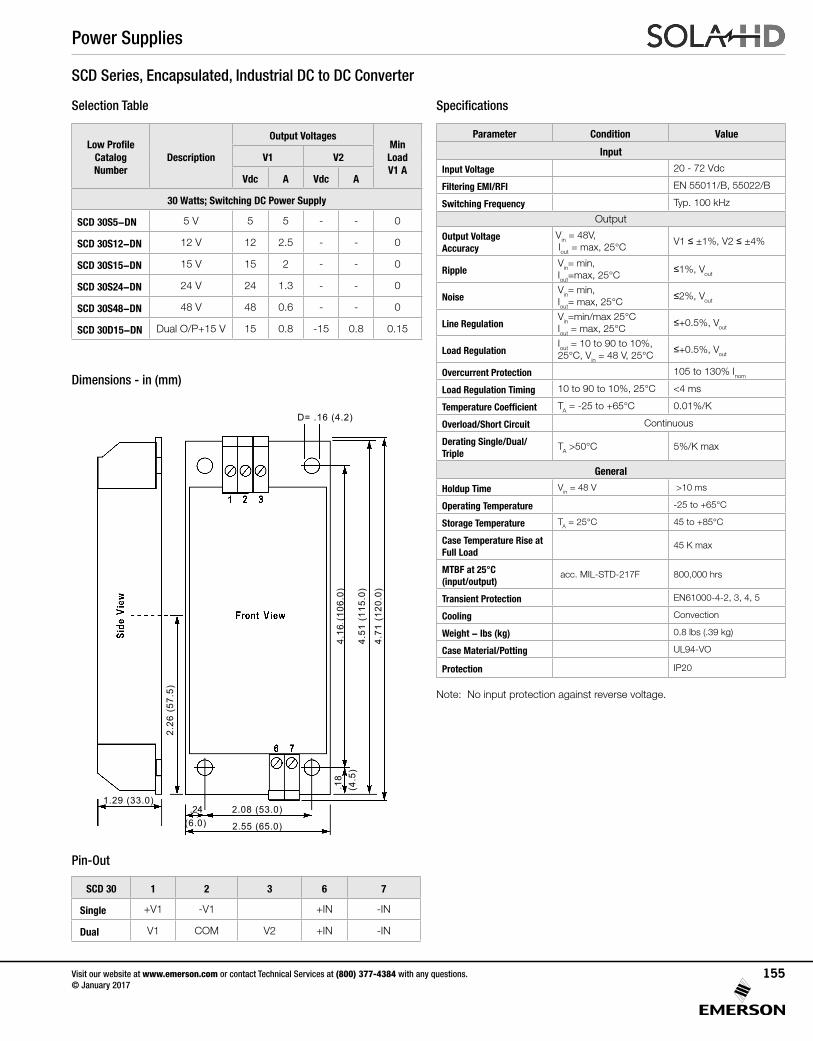
SCD Series, Encapsulated, Industrial DC to DC Converter
Selection Table
Low ProfileCatalog Number
Description
Output VoltagesMin Load V1 A
V1 V2
Vdc A Vdc A
30 Watts; Switching DC Power Supply
SCD 30S5-DN 5 V 5 5 - - 0
SCD 30S12-DN 12 V 12 2.5 - - 0
SCD 30S15-DN 15 V 15 2 - - 0
SCD 30S24-DN 24 V 24 1.3 - - 0
SCD 30S48-DN 48 V 48 0.6 - - 0
SCD 30D15-DN Dual O/P+15 V 15 0.8 -15 0.8 0.15
Dimensions - in (mm)
4.16
(10
6.0)
4.51
(11
5.0)
2.26
(57
.5)
1.29 (33.0)
D= .16 (4.2)
(4.5
)
2.08 (53.0)(6.0) 2.55 (65.0)
4.71
(12
0.0)
.24
.18
Pin-Out
SCD 30 1 2 3 6 7
Single +V1 -V1 +IN -IN
Dual V1 COM V2 +IN -IN
Specifications
Parameter Condition Value
Input
Input Voltage 20 - 72 Vdc
Filtering EMI/RFI EN 55011/B, 55022/B
Switching Frequency Typ. 100 kHz
Output
Output Voltage Accuracy
Vin = 48V, Iout = max, 25°C
V1 ≤ ±1%, V2 ≤ ±4%
RippleVin= min, Iout=max, 25°C
≤1%, Vout
NoiseVin= min, Iout= max, 25°C
≤2%, Vout
Line RegulationVin=min/max 25°CIout = max, 25°C
≤+0.5%, Vout
Load RegulationIout = 10 to 90 to 10%, 25°C, Vin = 48 V, 25°C
≤+0.5%, Vout
Overcurrent Protection 105 to 130% Inom
Load Regulation Timing 10 to 90 to 10%, 25°C <4 ms
Temperature Coefficient TA = -25 to +65°C 0.01%/K
Overload/Short Circuit Continuous
Derating Single/Dual/Triple
TA >50°C 5%/K max
General
Holdup Time Vin = 48 V >10 ms
Operating Temperature -25 to +65°C
Storage Temperature TA = 25°C 45 to +85°C
Case Temperature Rise at Full Load
45 K max
MTBF at 25°C (input/output)
acc. MIL-STD-217F 800,000 hrs
Transient Protection EN61000-4-2, 3, 4, 5
Cooling Convection
Weight - lbs (kg) 0.8 lbs (.39 kg)
Case Material/Potting UL94-VO
Protection IP20
Note: No input protection against reverse voltage.
Power Supplies
Visit our website at www.emerson.com or contact Technical Services at (800) 377-4384 with any questions. © January 2017
155
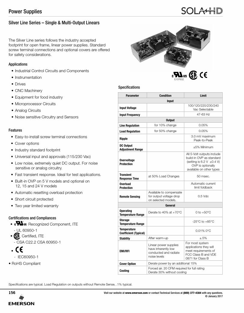
Silver Line Series – Single & Multi-Output Linears
The Silver Line series follows the industry accepted footprint for open frame, linear power supplies. Standard screw terminal connections and optional covers are offered for safety considerations.
Applications
• Industrial Control Circuits and Components
• Instrumentation
• Drives
• CNC Machinery
• Equipment for food industry
• Microprocessor Circuits
• Analog Circuits
• Noise sensitive Circuitry and Sensors
Features
• Easy-to-install screw terminal connections
• Cover options
• Industry standard footprint
• Universal input and approvals (115/230 Vac)
• Low noise, extremely quiet DC output. For noise sensitive or analog circuitry.
• Fast transient response. Ideal for test applications.
• Built-in OVP on 5 V models and optional on 12, 15 and 24 V models
• Automatic resetting overload protection
• Short circuit protected
• Two year limited warranty
Certifications and Compliances
• UL 60950 E137632
CUL/CSA-C22.2No. 234-M90
Recognized Component, ITE
- UL 60950-1 • Certified, ITE
- CSA C22.2 CSA 60950-1
•
- IEC60950-1
• RoHS Compliant
E137632
Specifications
Specifications are typical. Load Regulation on outputs without Remote Sense, .1% typical.
Parameter Condition Limit
Input
Input Voltage100/120/220/230/240
Vac Selectable
Input Frequency 47-63 Hz
Output
Line Regulation for 10% change 0.05%
Load Regulation for 50% change 0.05%
Ripple3.0 mV maximum
Peak-to-Peak
DC Output Adjustment Range
±5% Minimum
Overvoltage Protection
All 5-Volt outputs include build-in OVP as standard (setting is 6.2 V ±0.4 V)
OVP is optionally available on other types
Transient Response Time
at 50% Load Changes 50 msec.
Overload Protection
Automatic current limit foldback
Remote SensingAvailable to compensate for output voltage drop on selected models.
0.5 Vdc
General
Operating Temperature Range
Derate to 40% at +70°C 0 to +50°C
Storage Temperature Range
-25°C to +85°C
Temperature Coefficient (Typical)
0.01% 0°C
Stability After warm-up ±.5%
EMI/RFI
Linear power supplies have inherently low conducted and radiate noise levels
For most system applications they will meet requirements of FCC Class B and VDE 0871 for Class B
Cover Option Derate power by an additional 15%
CoolingForced air. 20 CFM required for full rating Derate 30% without cooling
Power Supplies
Visit our website at www.emerson.com or contact Technical Services at (800) 377-4384 with any questions. © January 2017
156
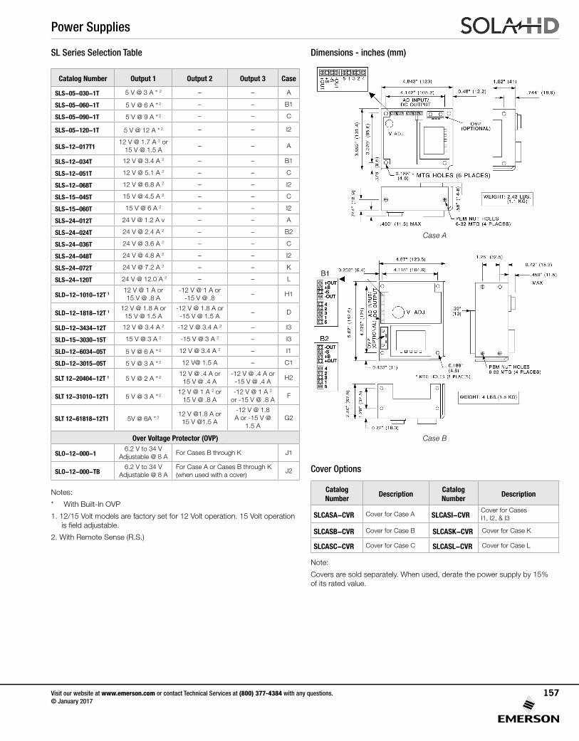
SL Series Selection Table
Catalog Number Output 1 Output 2 Output 3 Case
SLS-05-030-1T 5 V @ 3 A * 2 – – A
SLS-05-060-1T 5 V @ 6 A * 2 – – B1
SLS-05-090-1T 5 V @ 9 A * 2 – – C
SLS-05-120-1T 5 V @ 12 A * 2 – – I2
SLS-12-017T1 12 V @ 1.7 A 2 or
15 V @ 1.5 A– – A
SLS-12-034T 12 V @ 3.4 A 2 – – B1
SLS-12-051T 12 V @ 5.1 A 2 – – C
SLS-12-068T 12 V @ 6.8 A 2 – – I2
SLS-15-045T 15 V @ 4.5 A 2 – – C
SLS-15-060T 15 V @ 6 A 2 – – I2
SLS-24-012T 24 V @ 1.2 A v – – A
SLS-24-024T 24 V @ 2.4 A 2 – – B2
SLS-24-036T 24 V @ 3.6 A 2 – – C
SLS-24-048T 24 V @ 4.8 A 2 – – I2
SLS-24-072T 24 V @ 7.2 A 2 – – K
SLS-24-120T 24 V @ 12.0 A 2 – – L
SLD-12-1010-12T 112 V @ 1 A or 15 V @ .8 A
-12 V @ 1 A or -15 V @ .8
– H1
SLD-12-1818-12T 112 V @ 1.8 A or
15 V @ 1.5 A-12 V @ 1.8 A or
-15 V @ 1.5 A– D
SLD-12-3434-12T 12 V @ 3.4 A 2 -12 V @ 3.4 A 2 – I3
SLD-15-3030-15T 15 V @ 3 A 2 -15 V @ 3 A 2 – I3
SLD-12-6034-05T 5 V @ 6 A * 2 12 V @ 3.4 A 2 – I1
SLD-12-3015-05T 5 V @ 3 A * 2 12 V@ 1.5 A – C1
SLT 12-20404-12T 1 5 V @ 2 A * 2 12 V @ .4 A or
15 V @ .4 A-12 V @ .4 A or
-15 V @ .4 AH2
SLT 12-31010-12T1 5 V @ 3 A * 212 V @ 1 A 2 or
15 V @ .8 A-12 V @ 1 A 2
or -15 V @ .8 AF
SLT 12-61818-12T1 5V @ 6A * 2 12 V @1.8 A or
15 V @1.5 A
-12 V @ 1.8 A or -15 V @
1.5 AG2
Over Voltage Protector (OVP)
SLO-12-000-16.2 V to 34 V
Adjustable @ 8 AFor Cases B through K J1
SLO-12-000-TB6.2 V to 34 V
Adjustable @ 8 AFor Case A or Cases B through K (when used with a cover)
J2
Notes:
* With Built-In OVP
1. 12/15 Volt models are factory set for 12 Volt operation. 15 Volt operation is field adjustable.
2. With Remote Sense (R.S.)
Dimensions - inches (mm)
Case A
Case B
Cover Options
Note:
Covers are sold separately. When used, derate the power supply by 15% of its rated value.
Catalog Number
DescriptionCatalog Number
Description
SLCASA-CVR Cover for Case A SLCASI-CVRCover for Cases I1, I2, & I3
SLCASB-CVR Cover for Case B SLCASK-CVR Cover for Case K
SLCASC-CVR Cover for Case C SLCASL-CVR Cover for Case L
Power Supplies
Visit our website at www.emerson.com or contact Technical Services at (800) 377-4384 with any questions. © January 2017
157
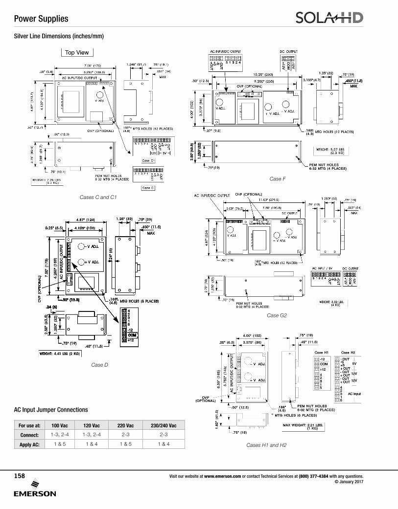
Silver Line Dimensions (inches/mm)
AC Input Jumper Connections
For use at: 100 Vac 120 Vac 220 Vac 230/240 Vac
Connect: 1-3, 2-4 1-3, 2-4 2-3 2-3
Apply AC: 1 & 5 1 & 4 1 & 5 1 & 4
Cases C and C1
Case F
Case D
Case G2
Cases H1 and H2
Power Supplies
Visit our website at www.emerson.com or contact Technical Services at (800) 377-4384 with any questions. © January 2017
158
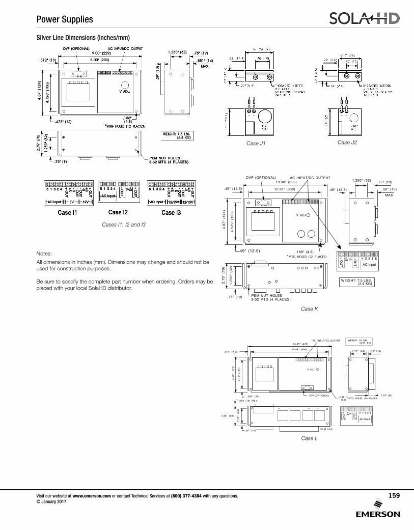
Cases I1, I2 and I3
Case J1 Case J2
Case K
OVP (OPTIONAL)
12.99" (330).49" (12.5)
13.98" (355)AC INPUT/DC OUTPUT
°MTG HOLES (12 PLACES)
.49" (12.5) .188" (4.8)
.75" (19)
4.8
7"
(12
4)
2.7
5"
(70
)
1.2
50
"(3
2)
4.1
25
"(1
05
)
1.250" (32)
.49" (12.5)
.75" (19)
MAX
.59" (15)
V ADJ.
WEIGHT: 7.5 LBS.(3.4 KG)
+S+O
UT
-S -O
UT
4 12 3 5
AC Input
PEM NUT HOLES8-32 MTG (4 PLACES)
15.98" (406). 375" (9.53)
16.85" (428)AC INPUT/DC OUTPUT
°MTG HOLES (16 PLACES). 394" (10) . 236”
(6.0)
. 39” (10)
4.9
2"
(12
5)
2.5
2"
(64
)
3.46" (88)
4.1
3”
(10
5)
2.52” (64) . 55" (14)
V ADJ.
-S 41 235
-O
UT
+S
+O
UT
AC Input
OVP (OPTIONAL) 1.34" (34)
WEIGHT: 19 LBS.(8.55 KG)
Heat Sink
. 630 (16) Ma x.
Case L
Notes:
All dimensions in inches (mm). Dimensions may change and should not be used for construction purposes.
Be sure to specify the complete part number when ordering. Orders may be placed with your local SolaHD distributor.
Silver Line Dimensions (inches/mm)
Power Supplies
Visit our website at www.emerson.com or contact Technical Services at (800) 377-4384 with any questions. © January 2017
159
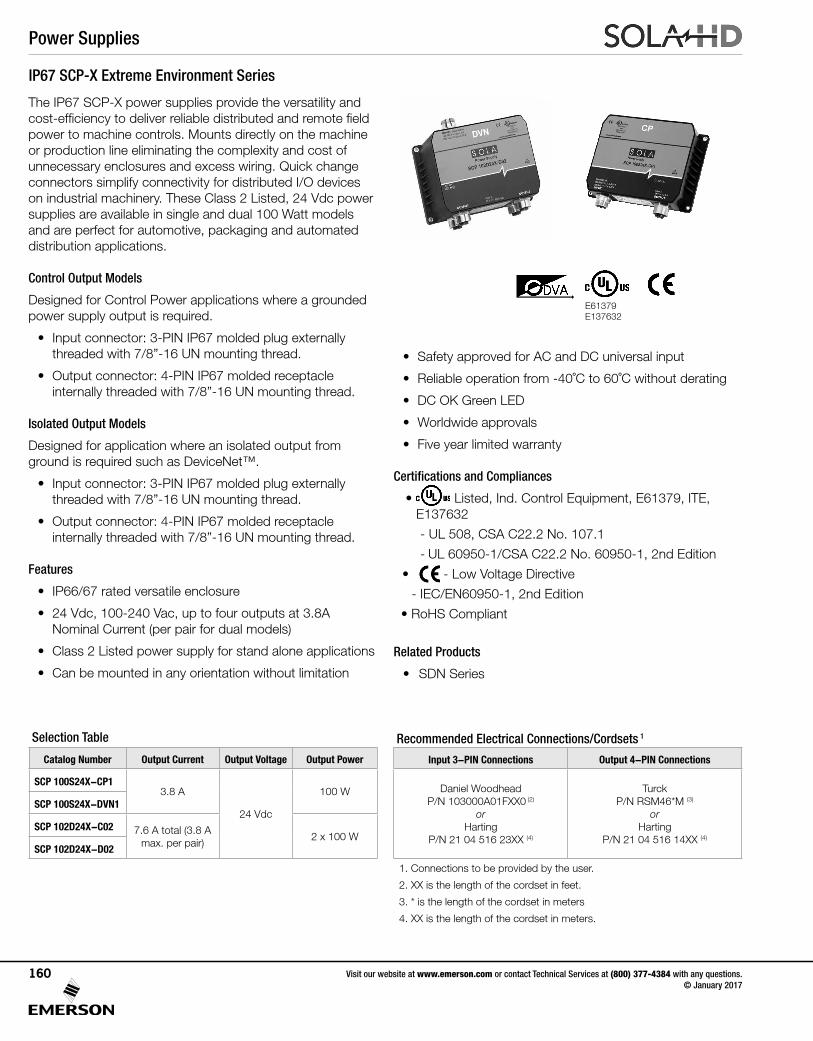
IP67 SCP-X Extreme Environment Series
The IP67 SCP-X power supplies provide the versatility and cost-efficiency to deliver reliable distributed and remote field power to machine controls. Mounts directly on the machine or production line eliminating the complexity and cost of unnecessary enclosures and excess wiring. Quick change connectors simplify connectivity for distributed I/O devices on industrial machinery. These Class 2 Listed, 24 Vdc power supplies are available in single and dual 100 Watt models and are perfect for automotive, packaging and automated distribution applications.
Control Output Models
Designed for Control Power applications where a grounded power supply output is required.
• Input connector: 3-PIN IP67 molded plug externally threaded with 7/8”-16 UN mounting thread.
• Output connector: 4-PIN IP67 molded receptacle internally threaded with 7/8”-16 UN mounting thread.
Isolated Output Models
Designed for application where an isolated output from ground is required such as DeviceNet™.
• Input connector: 3-PIN IP67 molded plug externally threaded with 7/8”-16 UN mounting thread.
• Output connector: 4-PIN IP67 molded receptacle internally threaded with 7/8”-16 UN mounting thread.
Features
• IP66/67 rated versatile enclosure
• 24 Vdc, 100-240 Vac, up to four outputs at 3.8A Nominal Current (per pair for dual models)
• Class 2 Listed power supply for stand alone applications
• Can be mounted in any orientation without limitation
• Safety approved for AC and DC universal input
• Reliable operation from -40˚C to 60˚C without derating
• DC OK Green LED
• Worldwide approvals
• Five year limited warranty
Certifications and Compliances
• Listed, Ind. Control Equipment, E61379, ITE, E137632
- UL 508, CSA C22.2 No. 107.1
- UL 60950-1/CSA C22.2 No. 60950-1, 2nd Edition
• - Low Voltage Directive
- IEC/EN60950-1, 2nd Edition
• RoHS Compliant
Related Products
• SDN Series
E61379 E137632
Recommended Electrical Connections/Cordsets 1
Input 3-PIN Connections Output 4-PIN Connections
Daniel Woodhead P/N 103000A01FXX0 (2)
orHarting
P/N 21 04 516 23XX (4)
Turck P/N RSM46*M (3)
or Harting
P/N 21 04 516 14XX (4)
1. Connections to be provided by the user.
2. XX is the length of the cordset in feet.
3. * is the length of the cordset in meters
4. XX is the length of the cordset in meters.
Selection Table
Catalog Number Output Current Output Voltage Output Power
SCP 100S24X-CP13.8 A
24 Vdc
100 WSCP 100S24X-DVN1
SCP 102D24X-C02 7.6 A total (3.8 A max. per pair)
2 x 100 WSCP 102D24X-D02
Power Supplies
Visit our website at www.emerson.com or contact Technical Services at (800) 377-4384 with any questions. © January 2017
160
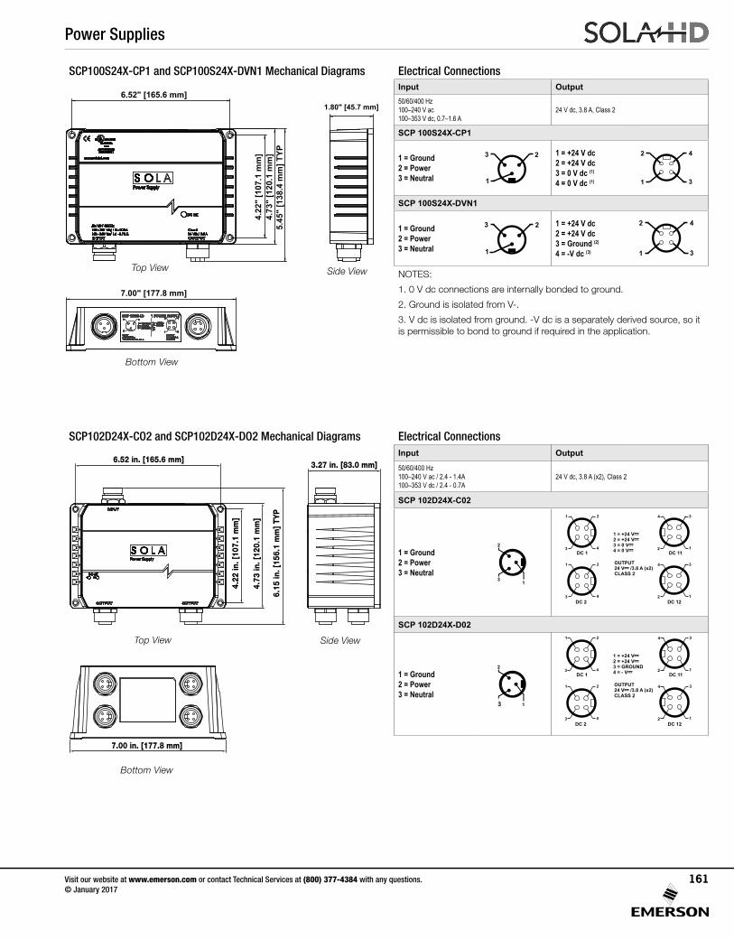
SCP100S24X-CP1 and SCP100S24X-DVN1 Mechanical Diagrams Electrical Connections
Top View Side View
Bottom View
1.80" [45.7 mm]
7.00" [177.8 mm]
6.52" [165.6 mm]
4.22
" [1
07.1
mm
]4.
73"
[120
.1 m
m]
5.45
" [1
38.4
mm
] TYP
Input Output50/60/400 Hz100–240 V ac100–353 V dc, 0.7–1.6 A
24 V dc, 3.8 A, Class 2
SCP 100S24X-CP1
1 = Ground2 = Power3 = Neutral
3
1
2 1 = +24 V dc2 = +24 V dc3 = 0 V dc (1)
4 = 0 V dc (1)
2
3
4
1
SCP 100S24X-DVN1
1 = Ground2 = Power3 = Neutral
3
1
2 1 = +24 V dc2 = +24 V dc3 = Ground (2)
4 = -V dc (3)
2
3
4
1
NOTES:
1. 0 V dc connections are internally bonded to ground.
2. Ground is isolated from V-.
3. V dc is isolated from ground. -V dc is a separately derived source, so it is permissible to bond to ground if required in the application.
SCP102D24X-CO2 and SCP102D24X-DO2 Mechanical Diagrams Electrical Connections
6.15
in. [
156.
1 m
m] T
YP
4.73
in. [
120.
1 m
m]
4.22
in. [
107.
1 m
m]
6.52 in. [165.6 mm]3.27 in. [83.0 mm]
7.00 in. [177.8 mm]
Bottom View
Top View Side View
Input Output50/60/400 Hz100–240 V ac / 2.4 - 1.4A100–353 V dc / 2.4 - 0.7A
24 V dc, 3.8 A (x2), Class 2
SCP 102D24X-C02
1 = Ground2 = Power3 = Neutral
1 = Ground2 = Power3 = Neutral
INPUT50/60/400 Hz100–240 V ac / 2.4–1.4 A100–353 V dc / 2.4–0.7 A
OUTPUT24 V--- /3.8 A (x2)CLASS 2
1 = +24 V---2 = +24 V---3 = 4 = 0 V---
0 V---
21
3 4
21
3 4
DC 1
DC 2
34
2 1
34
2 1
DC 11
DC 12
SCP 102D24X-D02
1 = Ground2 = Power3 = Neutral
1 = Ground2 = Power3 = Neutral
INPUT50/60/400 Hz100–240 V ac / 2.4–1.4 A100–353 V dc / 2.4–0.7 A
3
OUTPUT24 V--- /3.8 A (x2)CLASS 2
1 = +24 V---2 = +24 V---3 = GROUND4 = - V---
21
3 4
21
3 4
DC 1
DC 2
34
2 1
34
2 1
DC 11
DC 12
Power Supplies
Visit our website at www.emerson.com or contact Technical Services at (800) 377-4384 with any questions. © January 2017
161
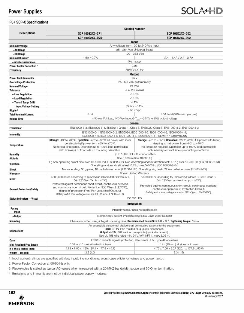
DescriptionsCatalog Number
SCP 100S24X-CP1 SCP 102D24X-C02SCP 100S24X-DVN1 SCP 102D24X-D02
Input Nominal Voltage Any voltage from 100 to 240 Vac Input
-AC Range 85 - 264 Vac Universal Input-DC Range 100 - 353 Vdc
Nominal Current 1 1.6A / 0.7A 2.4 - 1.4A / 2.4 - 0.7A-Inrush current max. Typ. <30A
Power Factor Correction 2 0.95 Frequency 50/60/400 Hz
Output Power Back Immunity 35 V
Overvoltage Protection 25-25.5 Vdc, autorecovery
Nominal Voltage 24 Vdc
Tolerance < +/-2% overall
- Line Regulation < 0.5%
- Load Regulation < 0.5%
- Time & Temp. Drift < 1%
Input Voltage Setting 24.5 V +/-1%
Ripple 3 < 50 mVpp
Total Nominal Current 3.8A 7.6A Total (3.8A max. per pair)
Holdup Time > 50 ms (Full load, 100 Vac Input @ Tamb=+25oC) to 95% output voltage
General
Emissions 4 EN61000-6-3, EN61000-6-4, EN55011 Group 1, Class B, EN55022 Class B, EN61000-3-2, EN61000-3-3
Immunity 4EN61000-6-1, EN61000-6-2, EN55024, IEC61000-4-2, IEC61000-4-3, IEC61000-4-4, IEC61000-4-5, IEC61000-4-6, IEC61000-4-8, IEC61000-4-11, SEMI F47 Sag Immunity
Temperature
Storage: -40o to +85oC, Operation: -40o to +60oC full power with linear derating to half power from +60o to +70oC.
No forced air required. Operation up to 100% load permissible with sideways or front side up mounting orientation.
Storage: -40o to +85oC, Operation: -25o to +60oC full power with linear derating to half power from +60o to +70oC.
No forced air required. Operation up to 100% load permissible with sideways or front side up mounting orientation.
Humidity Up to 100% RH with condensation
Altitude 0 to 3,000 m (0 to 10,000 ft.)
Vibration1 g non-operating swept sine over 10–500 Hz (IEC 60068-2-6). Non-operating random vibration test: 1.87 g over 10–500 Hz (IEC 60068-2-64).
Operating random vibration test: 0.15 g over 5–100 Hz (IEC 60068-2-64)
Shock Non-operating: 30 g peak, 18 ms half-sine pulse (IEC 68-2-27). Operating: 4 g peak, 22 ms half-sine pulse (IEC 68-2-27)
Warranty 5 Year Limited Warranty
MTBF>800,000 hours according to Telcoredia/Bellcore SR-332 Issue 1,
(Vin 120 Vac, Tamb = 40°C)>800,000 hr. according to Telcoredia/Bellcore SR-332 Issue 3,
(Vin 120 Vac, ambient temp. = 40°C)
General Protection/Safety
Protected against continuous short-circuit, continuous overload, and continuous open circuit. Protection NEC Class 2 (IEC536),
degree of protection IP66/IP67 versatile (IEC60529). Safety extra low voltage circuits: SELV (acc. EN60950-1).
Protected against continuous short-circuit, continuous overload, continuous open circuit. Protection Class 1.
Safety extra low voltage circuits: SELV (acc. EN60950).
Status Indicators - Visual DC OK LED
InstallationFusing
-InputInternally fused, fuses not replaceable
-Output Electronically current limited to meet NEC Class 2 per UL1310
Mounting Chassis mounted using integral mounting tabs. Recommended Screw Size: M4 x 0.7. Tightening Torque: 1N-m
Connections
An accessible disconnect device shall be installed external to the equipment. Input: 3-PIN IP67 molded plug (quick disconnect).
Output: 4-PIN IP67 molded receptacle (quick disconnect). Use UL 758 wire rated min. 24 V, VW-1/FT-1, max. 3.05 m.
Case IP66/67 versatile ingress protection; also meets UL50 Type 4X enclosure
Min. Required Free Space 0.39 in. (10 mm) all sides but base 1 in. (25 mm) all sides but base
H x W x D inches (mm) 4.73 x 7.00 x 1.80 (120.1 x 177.8 x 45.7) 4.73 x 7.00 x 3.27 (120.1 x 177.8 x 83.0)
Weight - lbs (kg) 2.2 (1.0) 3.3 (1.5)
1. Input current ratings are specified with low input, line conditions, worst case efficiency values and power factor.
2. Power Factor Correction at 50/60 Hz only.
3. Ripple/noise is stated as typical AC values when measured with a 20 MHZ bandwidth scope and 50 Ohm termination.
4. Emissions and immunity are met by individual power supply modules.
IP67 SCP-X Specifications
Power Supplies
Visit our website at www.emerson.com or contact Technical Services at (800) 377-4384 with any questions. © January 2017
162
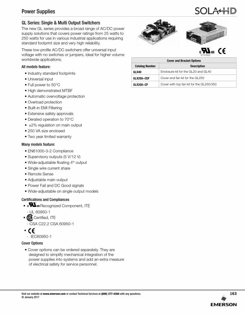
GL Series: Single & Multi Output SwitchersThe new GL series provides a broad range of AC/DC power supply solutions that covers power ratings from 25 watts to 250 watts for use in various industrial applications requiring standard footprint size and very high reliability.
These low-profile AC/DC switchers offer universal input voltage with no switches or jumpers, ideal for higher volume worldwide applications.
All models feature:
• Industry standard footprints• Universal input• Full power to 50°C• High demonstrated MTBF• Automatic overvoltage protection• Overload protection• Built-in EMI Filtering• Extensive safety approvals• Derated operation to 70°C• ±2% regulation on main output• 250 VA size enclosed• Two year limited warranty
Many models feature:
• EN61000-3-2 Compliance• Supervisory outputs (5 V/12 V)• Wide-adjustable floating 4th output• Single wire current share• Remote Sense• Adjustable main output• Power Fail and DC Good signals• Wide-adjustable on single output models
Certifications and Compliances
• UL 60950 E137632
CUL/CSA-C22.2No. 234-M90
Recognized Component, ITE
- UL 60950-1 • Certified, ITE
- CSA C22.2 CSA 60950-1
•
- IEC60950-1
Cover Options
• Cover options can be ordered separately. They are designed to simplify mechanical integration of the power supplies into systems and add an extra measure of electrical safety for service personnel.
Cover and Bracket Options
Catalog Number Description
GLX40 Enclosure kit for the GL20 and GL40
GLX250-CEF Cover end fan kit for the GL250
GLX250-CF Cover with top fan kit for the GL250/350
E137632
Power Supplies
Visit our website at www.emerson.com or contact Technical Services at (800) 377-4384 with any questions. © January 2017
163
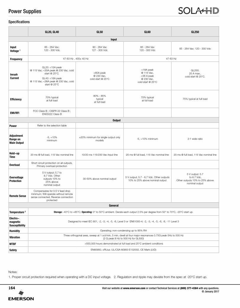
Notes:
1. Proper circuit protection required when operating with a DC input voltage. 2. Regulation and ripple may deviate from the spec at -20°C start up.
GL20, GL40 GL50 GL60 GL250
Input
Input Voltage 1
85 - 264 Vac; 120 - 300 Vdc
90 - 264 Vac 127 - 300 Vdc
85 - 264 Vac 120 - 300 Vdc
85 - 264 Vac; 120 - 300 Vdc
Frequency 47-63 Hz , 400± 40 Hz 47-63 Hz
Inrush Current
GL20: <15A peak @ 115 Vac; <30A peak @ 230 Vac, cold
start @ 25°C.
GL40: <18A peak @ 115 Vac; <36A peak @ 230 Vac, cold
start @ 25°C
<60A peak @ 230 Vac,
cold start @ 25°C
<18A peak @ 115 Vac, <36 A peak @ 230 Vac,
cold start @ 25°C
GL250: 20 A max.,
cold start @ 25°C.
Efficiency70% typical at full load
80% - 85% typical
at full load
70% typical at full load
75% typical at full load
EMI/RFIFCC Class B ; CISPR 22 Class B ;
EN55022 Class B
Output
Power Refer to the selection table
Adjustment Range on Main Output
-5, +10% minimum
±20% minimum for single output only models
-5, +10% minimum 2:1 wide ratio
Hold-up Time
20 ms @ full load, 115 Vac nominal line 10/20 ms 115/230 Vac Input line 20 ms @ full load, 115 Vac nominal line 20 ms @ full load, 115 Vac nominal line
Overload Short circuit protection on all outputs.
Primary overload protection
Overvoltage Protection
5 V output; 5.7 to 6.7 Vdc. Other outputs 10% to
25% abovenominal output
30-50% above nominal output5 V output; 5.7 - 6.7 Vdc. Other outputs
10% to 25% above nominal output
5 V output: 5.7 to 6.7 Vdc.
Other outputs 10% to 25% abovenominal output
Remote Sense
Compensates for 0.5 V lead drop minimum; Will operate without remote sense connected, Reverse connection
protected
General
Temperature 2 Storage: -40°C to +85°C; Operating: 0° to 50°C ambient. Derate each output 2.5% per degree from 50° to 70°C, -20°C start up.
Electro-magnetic Susceptibility
Designed to meet IEC 801, -2, -3, -4, -5, -6, Level 3 or EN61000-4; -2, -3, -4, -5, -6, -8, -11 Level 3
Humidity Operating; non-condensing up to 95% RH
VibrationThree orthogonal axes, sweep at 1 oct/min, 5 min. dwell at four major resonances 0.75G peak 5Hz to 500 Hz
(2 G peak 8 Hz to 500 Hz for GL500)
MTBF >550,000 hours demonstrated at full load and 25°C ambient conditions
Safety EN60950, cRUus: UL/CSA 60950 E132002, CE Mark (LVD)
Specifications
Power Supplies
Visit our website at www.emerson.com or contact Technical Services at (800) 377-4384 with any questions. © January 2017
164
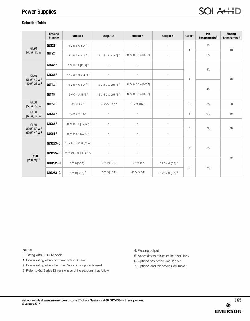
Catalog Number
Output 1 Output 2 Output 3 Output 4 Case 3 Pin Assignments 3
Mating Connectors 3
GL20 [40 W] 25 W
GLS22 5 V @ 5 A [8 A] 4 - - -
1
1A
1BGLT22
5 V @ 3 A [4 A] 5 12 V @ 1.5 A [2 A] 5 -12 V @ 0.5 A [0.7 A] - 2A
GL40 [55 W] 40 W 1
[40 W] 25 W 2
GLS42 4 5 V @ 8 A [11 A] 4 - - -
1
3A
1B
GLS43 4 12 V @ 3.3 A [4.5] 4 - - -
GLT42 4 5 V @ 4 A [5 A] 5 12 V @ 2 A [2.5 A] 5 -12 V @ 0.5 A [0.7 A] -
4A
GLT45 4 5 V @ 4 A [5 A] 5 15 V @ 2 A [2.5 A] 5 -15 V @ 0.5 A [0.7 A] -
GL50[50 W] 50 W
GLT54 4 5 V @ 8 A 5 24 V @ 1.5 A 5 12 V @ 0.5 A - 2 5A 2B
GL50 [60 W] 60 W
GLS55 4 24 V @ 2.5 A 4 - - - 3 6A 2B
GL60[80 W] 60 W 1
[60 W] 40 W 2
GLS63 4 12 V @ 5 A [6.7 A] 4 - - -
4 7A 3B
GLS64 4 15 V @ 4 A [5.3 A] 4 - - -
GL250[250 W] 6 7
GLS253-C 12 V (6-12 V) @ [21 A] - - -
5 8A
4B
GLS255-C 24 V (24-48) @ [10.4 A] - - -
GLQ252-C 5 V @ [35 A] 7 12 V @ [10 A] -12 V @ [6 A] ±5-25 V @ [6 A] 4
6 9A
GLQ253-C 5 V @ [35 A] 7 15 V @ [10 A] -15 V @ [6A] ±5-25 V @ [6 A] 4
Selection Table
Notes:
[ ] Rating with 30 CFM of air
1. Power rating when no cover option is used
2. Power rating when the cover/enclosure option is used
3. Refer to GL Series Dimensions and the sections that follow
4. Floating output
5. Approximate minimum loading: 10%
6. Optional fan cover, See Table 1
7. Optional end fan cover, See Table 1
Power Supplies
Visit our website at www.emerson.com or contact Technical Services at (800) 377-4384 with any questions. © January 2017
165
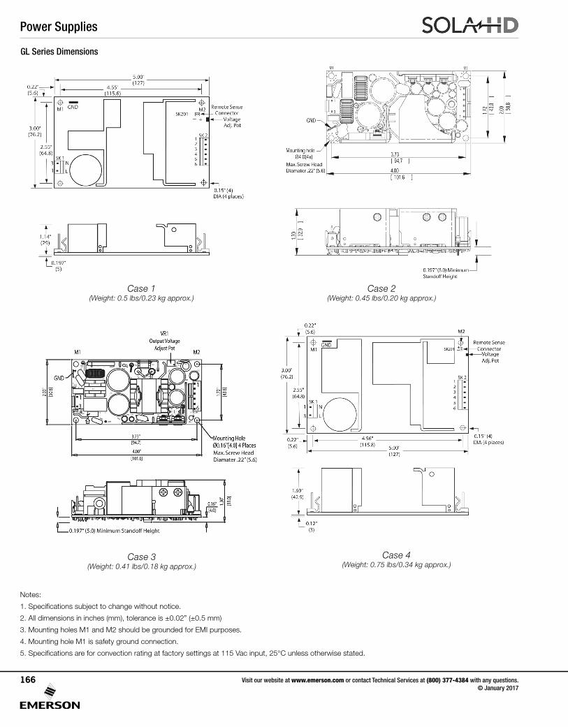
GL Series Dimensions
Notes:
1. Specifications subject to change without notice.
2. All dimensions in inches (mm), tolerance is ±0.02” (±0.5 mm)
3. Mounting holes M1 and M2 should be grounded for EMI purposes.
4. Mounting hole M1 is safety ground connection.
5. Specifications are for convection rating at factory settings at 115 Vac input, 25°C unless otherwise stated.
Case 1 (Weight: 0.5 lbs/0.23 kg approx.)
Case 2(Weight: 0.45 lbs/0.20 kg approx.)
Case 3 (Weight: 0.41 lbs/0.18 kg approx.)
Case 4 (Weight: 0.75 lbs/0.34 kg approx.)
Power Supplies
Visit our website at www.emerson.com or contact Technical Services at (800) 377-4384 with any questions. © January 2017
166
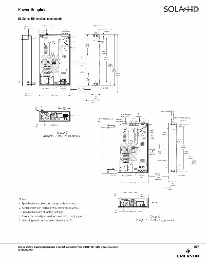
Notes:
1. Specifications subject to change without notice.
2. All dimensions in inches (mm), tolerance is ±0.02” .
3. Specifications are at factory settings.
4. To enable normally closed remote inhibit, cut jumper J1.
5. Mounting maximum insertion depth is 0.12”.
5.0 (127.0)2.0
(50.8)
1.18 (30.0)
9.0(228.6)
6.64(168.6)
3.42 (87.0).79(20)
��3
��1
12345678
3 2 1
��5��� ���
������������� ��1
��
� ���.
��4���
�6�32 (4 ������)
5.46(138.6)
8.52(216.4)
�3 (4 ������)
3.68(93.6)
3.15(80)
2.17(55)
3.0(76.2)
.55(14)
1.30(33.0)
��������(���)
����� ���� ���
�������� (����) �����
���� ����
10.32(262.0)
��7���
�� �����
10.0
10.0�3
�6�32 ��� (2 ������)
�310.0
�6�32 ��� (2 ������)
.24 (6.1)
6�32 (2 ������)���� ������
6�32 (3 ������)
Case 5(Weight: 2.6 lbs/1.19 kg approx.)
Case 6(Weight: 3.1 lbs/1.41 kg approx.)
5.0 (127.0)2.0
(50.8)
1.18 (30.0)
9.0(228.6)
6.64(168.6)
3.42 (87.0).79(20)
SK3
SK1
12345678
3 2 1
SK5+ve -ve
TerminalBlock TB1
O/P AD
J.
SK4FAN
#6-32 UNC (8 places)
5.46(138.6)
8.52(216.4)
M3 (8 places)
3.68(93.6)
3.15(80)
2.17(55)
3.0(76.2)
.55(14)
1.30(33.0)
Optional(-CF)
Cover with Fan
Optional (-CEF) Cover
with fans
10.32(262.0)
SK7FAN
AC Inlet
10.0
10.0
10.0M3
#6-32 UNC (2 places)
#6-32 UNC (2 places)
#6-3
2 (2
pla
ces)
M3
(2 p
lace
s)
4th O/P AD
J.
.24 (6.1)
6-32 (2 places)Main Output
6-32 (3 places)
SK2
6 5 4 3 2 1
M3(6 places)
M3
GL Series Dimensions (continued)
Power Supplies
Visit our website at www.emerson.com or contact Technical Services at (800) 377-4384 with any questions. © January 2017
167
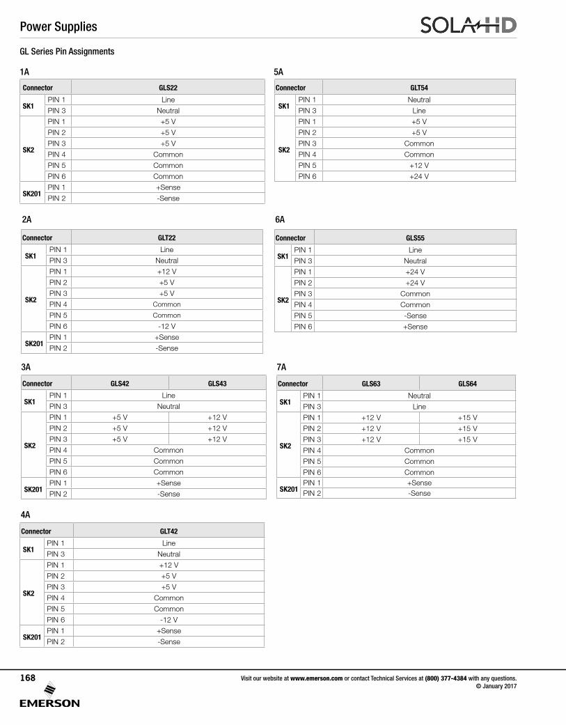
6A
7A
Connector GLS55
SK1PIN 1 Line
PIN 3 Neutral
SK2
PIN 1 +24 V
PIN 2 +24 V
PIN 3 Common
PIN 4 Common
PIN 5 -Sense
PIN 6 +Sense
Connector GLS63 GLS64
SK1PIN 1 Neutral
PIN 3 Line
SK2
PIN 1 +12 V +15 V
PIN 2 +12 V +15 V
PIN 3 +12 V +15 V
PIN 4 Common
PIN 5 Common
PIN 6 Common
SK201PIN 1 +SensePIN 2 -Sense
2A
3A
4A
Connector GLS22
SK1PIN 1 Line
PIN 3 Neutral
SK2
PIN 1 +5 V
PIN 2 +5 V
PIN 3 +5 V
PIN 4 Common
PIN 5 Common
PIN 6 Common
SK201PIN 1 +Sense
PIN 2 -Sense
Connector GLT22
SK1PIN 1 Line
PIN 3 Neutral
SK2
PIN 1 +12 V
PIN 2 +5 V
PIN 3 +5 V
PIN 4 Common
PIN 5 Common
PIN 6 -12 V
SK201PIN 1 +Sense
PIN 2 -Sense
Connector GLS42 GLS43
SK1PIN 1 Line
PIN 3 Neutral
SK2
PIN 1 +5 V +12 V
PIN 2 +5 V +12 V
PIN 3 +5 V +12 V
PIN 4 Common
PIN 5 Common
PIN 6 Common
SK201PIN 1 +Sense
PIN 2 -Sense
Connector GLT54
SK1PIN 1 Neutral
PIN 3 Line
SK2
PIN 1 +5 V
PIN 2 +5 V
PIN 3 Common
PIN 4 Common
PIN 5 +12 V
PIN 6 +24 V
GL Series Pin Assignments
Connector GLT42
SK1PIN 1 Line
PIN 3 Neutral
SK2
PIN 1 +12 V
PIN 2 +5 V
PIN 3 +5 V
PIN 4 Common
PIN 5 Common
PIN 6 -12 V
SK201PIN 1 +Sense
PIN 2 -Sense
1A 5A
Power Supplies
Visit our website at www.emerson.com or contact Technical Services at (800) 377-4384 with any questions. © January 2017
168
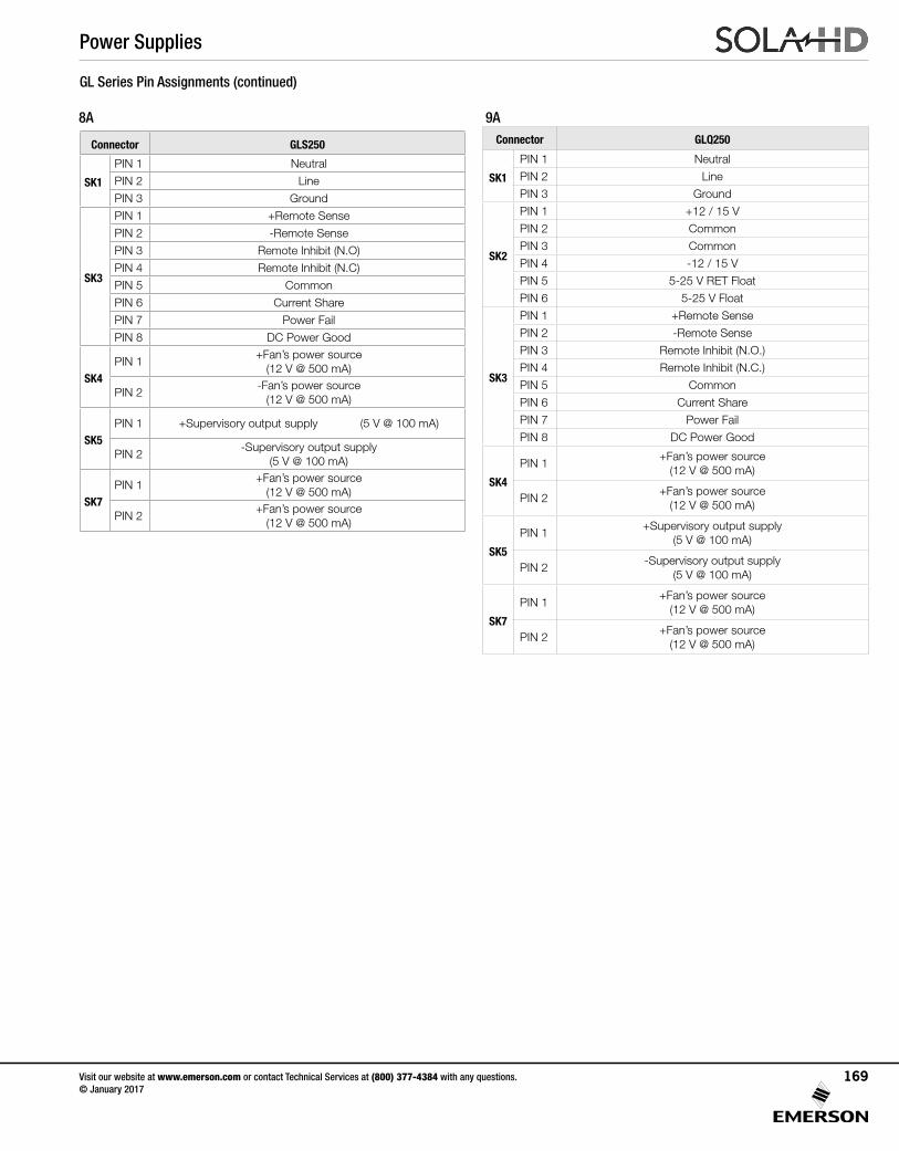
GL Series Pin Assignments (continued)
Connector GLS250
SK1
PIN 1 Neutral
PIN 2 Line
PIN 3 Ground
SK3
PIN 1 +Remote Sense
PIN 2 -Remote Sense
PIN 3 Remote Inhibit (N.O)
PIN 4 Remote Inhibit (N.C)
PIN 5 Common
PIN 6 Current Share
PIN 7 Power Fail
PIN 8 DC Power Good
SK4PIN 1
+Fan’s power source (12 V @ 500 mA)
PIN 2-Fan’s power source
(12 V @ 500 mA)
SK5PIN 1 +Supervisory output supply (5 V @ 100 mA)
PIN 2-Supervisory output supply
(5 V @ 100 mA)
SK7PIN 1
+Fan’s power source (12 V @ 500 mA)
PIN 2+Fan’s power source
(12 V @ 500 mA)
Connector GLQ250
SK1
PIN 1 Neutral
PIN 2 Line
PIN 3 Ground
SK2
PIN 1 +12 / 15 V
PIN 2 Common
PIN 3 Common
PIN 4 -12 / 15 V
PIN 5 5-25 V RET Float
PIN 6 5-25 V Float
SK3
PIN 1 +Remote Sense
PIN 2 -Remote Sense
PIN 3 Remote Inhibit (N.O.)
PIN 4 Remote Inhibit (N.C.)
PIN 5 Common
PIN 6 Current Share
PIN 7 Power Fail
PIN 8 DC Power Good
SK4
PIN 1+Fan’s power source
(12 V @ 500 mA)
PIN 2+Fan’s power source
(12 V @ 500 mA)
SK5
PIN 1+Supervisory output supply
(5 V @ 100 mA)
PIN 2-Supervisory output supply
(5 V @ 100 mA)
SK7
PIN 1+Fan’s power source
(12 V @ 500 mA)
PIN 2+Fan’s power source
(12 V @ 500 mA)
8A 9A
Power Supplies
Visit our website at www.emerson.com or contact Technical Services at (800) 377-4384 with any questions. © January 2017
169
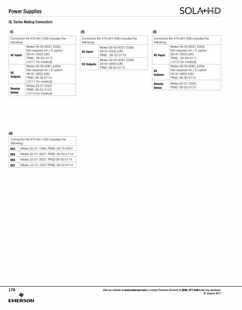
1B 2B
Connector Kit #70-841-006 includes the following:
AC Input:
Molex 09-50-8031 (USA) Not required for (-T) option09-91-0300 (UK)PINS: 08-52-0113(-0111 for medical)
DC Outputs:
Molex 09-50-8061 (USA) Not required for (-T) option09-91-0600 (UK)PINS: 08-52-0113(-0111 for medical)
Remote Sense:
Molex 22-01-2025PINS: 08-52-0123(-0114 for medical)
Connector Kit #70-841-006 includes the following:
AC Input:Molex 09-50-8031 (USA) 09-91-0300 (UK)PINS: 08-52-0113
DC Outputs:Molex 09-50-8061 (USA) 09-91-0600 (UK)PINS: 08-52-0113
GL Series Mating Connectors
3B
Connector Kit #70-841-006 includes the following:
AC Input:
Molex 09-50-8031 (USA) Not required for (-T) option09-91-0300 (UK)PINS: 08-58-0111(-0113 for medical)
DC Outputs:
Molex 09-50-8061 (USA) Not required for (-T) option09-91-0600 (UK)PINS: 08-58-0113
Remote Sense:
Molex 22-01-2025PINS: 08-52-0113
4BConnector Kit #70-841-005 includes the following:
SK3 Molex 22-01-1084; PINS: 08-70-0057
SK4 Molex 22-01-3027; PINS: 08-50-0114
SK5 Molex 22-01-3027; PINS:08-50-0114
SK7 Molex: 22-01-3027 PINS: 08-50-0114
Power Supplies
Visit our website at www.emerson.com or contact Technical Services at (800) 377-4384 with any questions. © January 2017
170
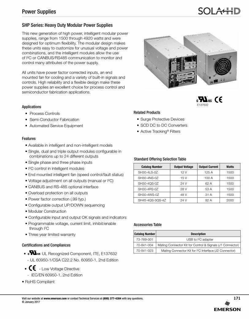
SHP Series: Heavy Duty Modular Power Supplies
This new generation of high power, intelligent modular power supplies, range from 1500 through 4920 watts and were designed for optimum flexibility. The modular design makes these units easy to customize for unusual voltage and power combinations, and the intelligent modules allow the use of I2C or CANBUS/RS485 communication to monitor and control many attributes of the power supply.
All units have power factor corrected inputs, an endmounted fan for cooling and a variety of built-in signals andcontrols. High reliability and a flexible design make these power supplies an excellent choice for process control and semiconductor fabrication applications.
Applications
• Process Controls
• Semi-Conductor Fabrication
• Automated Service Equipment
Features
• Available in intelligent and non-intelligent models
• Single, dual and triple output modules configurable in combinations up to 24 different outputs
• Single phase and three phase inputs
• I2C control in intelligent modules
• End mounted intelligent fan (speed control/fault status)
• Voltage adjustment on all outputs (manual or I2C)
• CANBUS and RS-485 optional interface
• Overload protection on all outputs
• Power factor correction (.99 typ.)
• Configurable output UP/DOWN sequencing
• Modular Construction
• Configurable input and output OK signals and indicators
• Programmable voltage, current limit, inhibit/enable through I2C
• Three year limited warranty
Certifications and Compliances
• UL 60950 E137632
CUL/CSA-C22.2No. 234-M90
UL Recognized Component, ITE, E137632
- UL 60950-1/CSA C22.2 No. 60950-1, 2nd Edition
• - Low Voltage Directive
- IEC/EN 60950-1, 2nd Edition
• RoHS Compliant
Related Products
• Surge Protective Devices
• SCD DC to DC Converters
• Active Tracking® Filters
E137632
Catalog Number Output Voltage Output Current Watts
SH30-4LS-0Z 12 V 125 A 1500
SH30-4NS-0Z 15 V 100 A 1500
SH30-4QS-0Z 24 V 62 A 1500
SH30-4RS-0Z 28 V 53 A 1500
SH30-4WS-0Z 48 V 31 A 1500
SH45-4QS-3QS-4Z 24 V 92 A 2000
Catalog Number Description
73-769-001 USB to I2C adapter
70-841-004 Mating Connector Kit for Control & Signals (J1 Connector)
70-841-023 Mating Connector Kit for I2C Interface (J2 Connector)
Standard Offering Selection Table
Accessories Table
Power Supplies
Visit our website at www.emerson.com or contact Technical Services at (800) 377-4384 with any questions. © January 2017
171
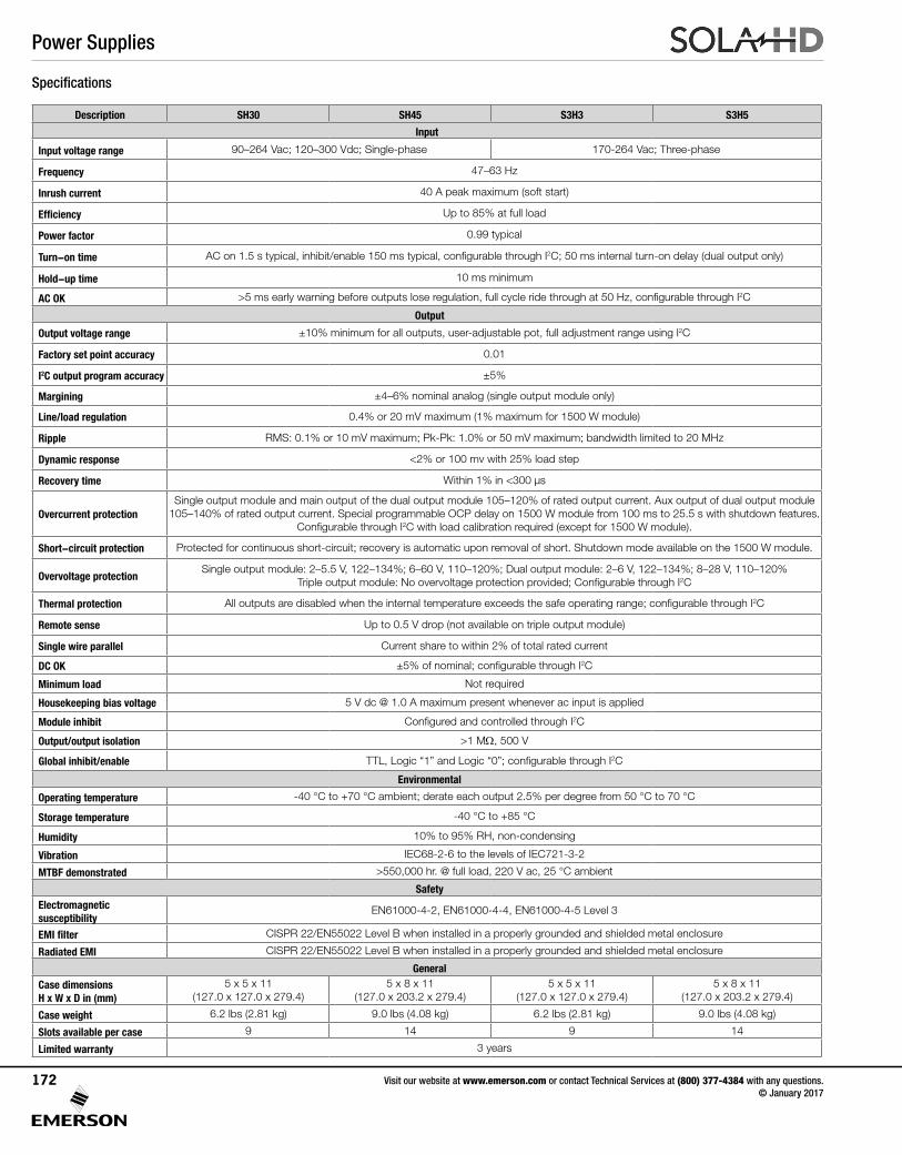
Specifications
Description SH30 SH45 S3H3 S3H5
Input
Input voltage range 90–264 Vac; 120–300 Vdc; Single-phase 170-264 Vac; Three-phase
Frequency 47–63 Hz
Inrush current 40 A peak maximum (soft start)
Efficiency Up to 85% at full load
Power factor 0.99 typical
Turn-on time AC on 1.5 s typical, inhibit/enable 150 ms typical, configurable through I2C; 50 ms internal turn-on delay (dual output only)
Hold-up time 10 ms minimum
AC OK >5 ms early warning before outputs lose regulation, full cycle ride through at 50 Hz, configurable through I2C
Output
Output voltage range ±10% minimum for all outputs, user-adjustable pot, full adjustment range using I2C
Factory set point accuracy 0.01
I2C output program accuracy ±5%
Margining ±4–6% nominal analog (single output module only)
Line/load regulation 0.4% or 20 mV maximum (1% maximum for 1500 W module)
Ripple RMS: 0.1% or 10 mV maximum; Pk-Pk: 1.0% or 50 mV maximum; bandwidth limited to 20 MHz
Dynamic response <2% or 100 mv with 25% load step
Recovery time Within 1% in <300 μs
Overcurrent protectionSingle output module and main output of the dual output module 105–120% of rated output current. Aux output of dual output module
105–140% of rated output current. Special programmable OCP delay on 1500 W module from 100 ms to 25.5 s with shutdown features. Configurable through I2C with load calibration required (except for 1500 W module).
Short-circuit protection Protected for continuous short-circuit; recovery is automatic upon removal of short. Shutdown mode available on the 1500 W module.
Overvoltage protectionSingle output module: 2–5.5 V, 122–134%; 6–60 V, 110–120%; Dual output module: 2–6 V, 122–134%; 8–28 V, 110–120%
Triple output module: No overvoltage protection provided; Configurable through I2C
Thermal protection All outputs are disabled when the internal temperature exceeds the safe operating range; configurable through I2C
Remote sense Up to 0.5 V drop (not available on triple output module)
Single wire parallel Current share to within 2% of total rated current
DC OK ±5% of nominal; configurable through I2C
Minimum load Not required
Housekeeping bias voltage 5 V dc @ 1.0 A maximum present whenever ac input is applied
Module inhibit Configured and controlled through I2C
Output/output isolation >1 MΩ, 500 V
Global inhibit/enable TTL, Logic “1” and Logic “0”; configurable through I2C
Environmental
Operating temperature -40 °C to +70 °C ambient; derate each output 2.5% per degree from 50 °C to 70 °C
Storage temperature -40 °C to +85 °C
Humidity 10% to 95% RH, non-condensing
Vibration IEC68-2-6 to the levels of IEC721-3-2
MTBF demonstrated >550,000 hr. @ full load, 220 V ac, 25 °C ambient
SafetyElectromagnetic susceptibility
EN61000-4-2, EN61000-4-4, EN61000-4-5 Level 3
EMI filter CISPR 22/EN55022 Level B when installed in a properly grounded and shielded metal enclosure
Radiated EMI CISPR 22/EN55022 Level B when installed in a properly grounded and shielded metal enclosure
GeneralCase dimensions H x W x D in (mm)
5 x 5 x 11 (127.0 x 127.0 x 279.4)
5 x 8 x 11 (127.0 x 203.2 x 279.4)
5 x 5 x 11 (127.0 x 127.0 x 279.4)
5 x 8 x 11 (127.0 x 203.2 x 279.4)
Case weight 6.2 lbs (2.81 kg) 9.0 lbs (4.08 kg) 6.2 lbs (2.81 kg) 9.0 lbs (4.08 kg)
Slots available per case 9 14 9 14
Limited warranty 3 years
Power Supplies
Visit our website at www.emerson.com or contact Technical Services at (800) 377-4384 with any questions. © January 2017
172
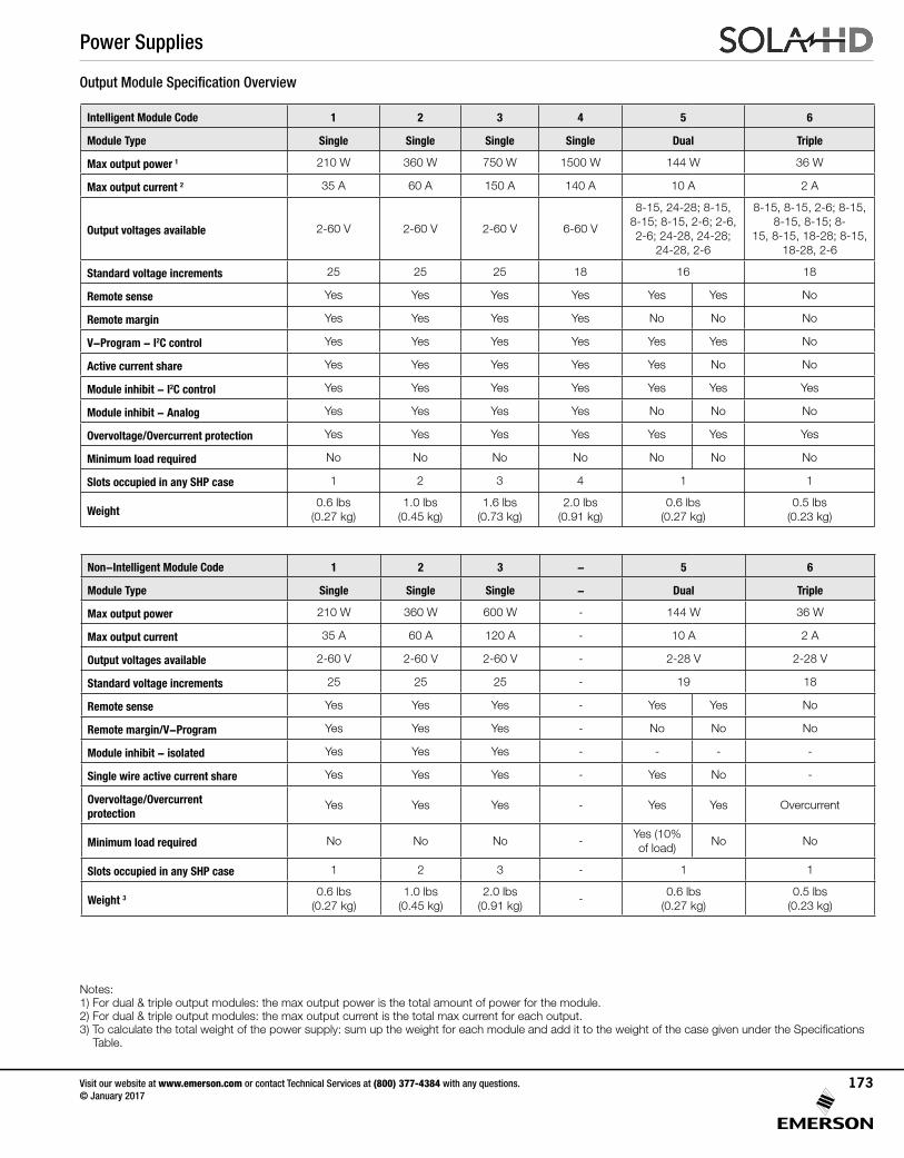
Description SH30 SH45 S3H3 S3H5
Input
Input voltage range 90–264 Vac; 120–300 Vdc; Single-phase 170-264 Vac; Three-phase
Frequency 47–63 Hz
Inrush current 40 A peak maximum (soft start)
Efficiency Up to 85% at full load
Power factor 0.99 typical
Turn-on time AC on 1.5 s typical, inhibit/enable 150 ms typical, configurable through I2C; 50 ms internal turn-on delay (dual output only)
Hold-up time 10 ms minimum
AC OK >5 ms early warning before outputs lose regulation, full cycle ride through at 50 Hz, configurable through I2C
Output
Output voltage range ±10% minimum for all outputs, user-adjustable pot, full adjustment range using I2C
Factory set point accuracy 0.01
I2C output program accuracy ±5%
Margining ±4–6% nominal analog (single output module only)
Line/load regulation 0.4% or 20 mV maximum (1% maximum for 1500 W module)
Ripple RMS: 0.1% or 10 mV maximum; Pk-Pk: 1.0% or 50 mV maximum; bandwidth limited to 20 MHz
Dynamic response <2% or 100 mv with 25% load step
Recovery time Within 1% in <300 μs
Overcurrent protectionSingle output module and main output of the dual output module 105–120% of rated output current. Aux output of dual output module
105–140% of rated output current. Special programmable OCP delay on 1500 W module from 100 ms to 25.5 s with shutdown features. Configurable through I2C with load calibration required (except for 1500 W module).
Short-circuit protection Protected for continuous short-circuit; recovery is automatic upon removal of short. Shutdown mode available on the 1500 W module.
Overvoltage protectionSingle output module: 2–5.5 V, 122–134%; 6–60 V, 110–120%; Dual output module: 2–6 V, 122–134%; 8–28 V, 110–120%
Triple output module: No overvoltage protection provided; Configurable through I2C
Thermal protection All outputs are disabled when the internal temperature exceeds the safe operating range; configurable through I2C
Remote sense Up to 0.5 V drop (not available on triple output module)
Single wire parallel Current share to within 2% of total rated current
DC OK ±5% of nominal; configurable through I2C
Minimum load Not required
Housekeeping bias voltage 5 V dc @ 1.0 A maximum present whenever ac input is applied
Module inhibit Configured and controlled through I2C
Output/output isolation >1 MΩ, 500 V
Global inhibit/enable TTL, Logic “1” and Logic “0”; configurable through I2C
Environmental
Operating temperature -40 °C to +70 °C ambient; derate each output 2.5% per degree from 50 °C to 70 °C
Storage temperature -40 °C to +85 °C
Humidity 10% to 95% RH, non-condensing
Vibration IEC68-2-6 to the levels of IEC721-3-2
MTBF demonstrated >550,000 hr. @ full load, 220 V ac, 25 °C ambient
SafetyElectromagnetic susceptibility
EN61000-4-2, EN61000-4-4, EN61000-4-5 Level 3
EMI filter CISPR 22/EN55022 Level B when installed in a properly grounded and shielded metal enclosure
Radiated EMI CISPR 22/EN55022 Level B when installed in a properly grounded and shielded metal enclosure
GeneralCase dimensions H x W x D in (mm)
5 x 5 x 11 (127.0 x 127.0 x 279.4)
5 x 8 x 11 (127.0 x 203.2 x 279.4)
5 x 5 x 11 (127.0 x 127.0 x 279.4)
5 x 8 x 11 (127.0 x 203.2 x 279.4)
Case weight 6.2 lbs (2.81 kg) 9.0 lbs (4.08 kg) 6.2 lbs (2.81 kg) 9.0 lbs (4.08 kg)
Slots available per case 9 14 9 14
Limited warranty 3 years
Intelligent Module Code 1 2 3 4 5 6
Module Type Single Single Single Single Dual Triple
Max output power 1 210 W 360 W 750 W 1500 W 144 W 36 W
Max output current 2 35 A 60 A 150 A 140 A 10 A 2 A
Output voltages available 2-60 V 2-60 V 2-60 V 6-60 V
8-15, 24-28; 8-15, 8-15; 8-15, 2-6; 2-6, 2-6; 24-28, 24-28;
24-28, 2-6
8-15, 8-15, 2-6; 8-15, 8-15, 8-15; 8-
15, 8-15, 18-28; 8-15, 18-28, 2-6
Standard voltage increments 25 25 25 18 16 18
Remote sense Yes Yes Yes Yes Yes Yes No
Remote margin Yes Yes Yes Yes No No No
V-Program - I2C control Yes Yes Yes Yes Yes Yes No
Active current share Yes Yes Yes Yes Yes No No
Module inhibit - I2C control Yes Yes Yes Yes Yes Yes Yes
Module inhibit - Analog Yes Yes Yes Yes No No No
Overvoltage/Overcurrent protection Yes Yes Yes Yes Yes Yes Yes
Minimum load required No No No No No No No
Slots occupied in any SHP case 1 2 3 4 1 1
Weight0.6 lbs
(0.27 kg)1.0 lbs
(0.45 kg)1.6 lbs
(0.73 kg)2.0 lbs
(0.91 kg)0.6 lbs
(0.27 kg)0.5 lbs
(0.23 kg)
Non-Intelligent Module Code 1 2 3 - 5 6
Module Type Single Single Single - Dual Triple
Max output power 210 W 360 W 600 W - 144 W 36 W
Max output current 35 A 60 A 120 A - 10 A 2 A
Output voltages available 2-60 V 2-60 V 2-60 V - 2-28 V 2-28 V
Standard voltage increments 25 25 25 - 19 18
Remote sense Yes Yes Yes - Yes Yes No
Remote margin/V-Program Yes Yes Yes - No No No
Module inhibit - isolated Yes Yes Yes - - - -
Single wire active current share Yes Yes Yes - Yes No -
Overvoltage/Overcurrent protection
Yes Yes Yes - Yes Yes Overcurrent
Minimum load required No No No -Yes (10% of load)
No No
Slots occupied in any SHP case 1 2 3 - 1 1
Weight 30.6 lbs
(0.27 kg)1.0 lbs
(0.45 kg)2.0 lbs
(0.91 kg)-
0.6 lbs (0.27 kg)
0.5 lbs (0.23 kg)
Output Module Specification Overview
Notes: 1) For dual & triple output modules: the max output power is the total amount of power for the module. 2) For dual & triple output modules: the max output current is the total max current for each output.3) To calculate the total weight of the power supply: sum up the weight for each module and add it to the weight of the case given under the Specifications Table.
Power Supplies
Visit our website at www.emerson.com or contact Technical Services at (800) 377-4384 with any questions. © January 2017
173
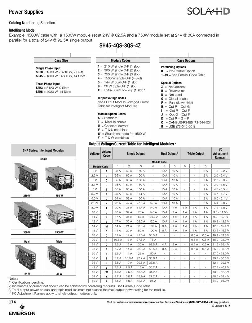
Catalog Numbering Selection
Intelligent ModelExample: 4500W case with: a 1500W module set at 24V @ 62.5A and a 750W module set at 24V @ 30A connected in parallel for a total of 24V @ 92.5A single output.
Output Voltage/Current Table for Intelligent Modules 2
VoltageVoltage
CodeSingle Output Dual Output 3 Triple Output
I2CAdjustment
Ranges 4
Module Code
Module Code 1 2 3 4 5 5 6 6 6
2 V A 35 A 60 A 150 A - 10 A 10 A - - 2 A 1.8 - 2.2 V
2.2 V B 35 A 60 A 150 A - 10 A 10 A - - 2 A 2.0 - 2.4 V
3 V C 35 A 60 A 150 A - 10 A 10 A - - 2 A 2.7 - 3.3 V
3.3 V D 35 A 60 A 150 A - 10 A 10 A - - 2 A 3.0 - 3.6 V
5 V E 35 A 60 A 150 A - 10 A 10 A - - 2 A 4.5 - 5.5 V
5.2 V F 35 A 60 A 144 A - 10 A 10 A - - 2 A 4.7 - 5.7 V
5.5 V G 34 A 58 A 136 A - 10 A 10 A - - 2 A 5.0 - 6.1 V
6.0 V H 23 A 42 A 97.5 A 140 A 10 A 10 A - - 2 A 5.4 - 6.6 V
8.0 V I 20 A 36 A 84.4 A 140 A 10 A 4 A 1 A 1 A 1 A 7.2 - 8.8 V
10 V J 18 A 32 A 75 A 140 A 10 A 4 A 1 A 1 A 1 A 9.0 - 11.0 V
11 V K 17 A 31 A 68 A 136.3 A 10 A 4 A 1 A 1 A 1 A 9.9 - 12.1 V
12 V L 17 A 30 A 62.5 A 125 A 10 A 4 A 1 A 1 A 1 A 10.8 - 13.2 V
14 V M 14 A 21 A 53.5 A 107 A 9 A 4 A 1 A 1 A 1 A 12.6 - 15.4 V
15 V N 14 A 20 A 50 A 100 A 8 A 4 A 1 A 1 A 1 A 13.5 - 16.5 V
18 V O 11 A 19 A 41.6 A 83.3 A - - - 0.5 A 0.5 A 16.2 - 19.8 V
20 V P 10.5 A 18 A 37.5 A 75 A - - - 0.5 A 0.5 A 18.0 - 22.0 V
24 V Q 8.5 A 15 A 30 A 62.5 A 4 A 2 A - 0.5 A 0.5 A 21.6 - 26.4 V
28 V R 6.7 A 11 A 26.8 A 53.5 A 3 A 2 A - 0.5 A 0.5 A 25.2 - 30.8 V
30 V S 6.5 A 11 A 25 A 50 A - - - - - 27.0 - 33.0 V
33 V T 6.2 A 10.9 A 22.7 A 35.8 A - - - - - 29.7 - 36.3 V
36 V U 5.8 A 10 A 20.8 A 35.8 A - - - - - 32.4 - 39.6 V
42 V V 4.2 A 7.5 A 16 A 35.7 A - - - - - 37.8 - 46.2 V
48 V W 4.0 A 7.5 A 15.6 A 31.2 A - - - - - 43.2 - 52.8 V
54 V X 3.7 A 6.0 A 13.9 A 27.7 A - - - - - 48.6 - 59.4 V
60 V Y 3.5 A 6.0 A 12.5 A 25 A - - - - - 54.0 - 66.0 V
SHP Series: Intelligent Modules
Single
210 W 750 W
360 W 1500 W
Dual Triple
144 W 36 W
Notes: 1) Certifications pending.2) Increments of current not shown can be achieved by paralleling modules. See Parallel Code Table. 3) Total output power on dual and triple modules must not exceed the max output power rating for the module.4) I2C Adjustment Ranges apply to single output modules only.
SH45-4QS-3QS-4Z
Case Size Module Codes Case Options
Single Phase InputSH30 = 1500 W - 3210 W, 9 SlotsSH45 = 1800 W - 4500 W, 14 Slots
Three Phase InputS3H3 = 3120 W, 9 SlotsS3H5 = 4920 W, 14 Slots
1 = 210 W single O/P (1 slot)2 = 360 W single O/P (2 slot)3 = 750 W single O/P (3 slot)4 = 1500 W single O/P (4 Slot)5 = 144 W dual O/P (1 slot)6 = 36 W triple O/P (1 slot)X = Extra 30mS hold-up (1 slot) 1
Output Voltage CodesSee Output Module Voltage/Current Table for Intelligent Modules
Module Option CodesS = StandardT = Module enableU = Constant currentV = T & U combinedW = Shutdown mode for 1500 WY = T & W combined
Paralleling Options0 = No Parallel Option1-19 = See Parallel Code Table
Special OptionsZ = No OptionsR = Reverse airN = Not usedG = Global enableF = Fan Idle w/inhibitH = Opt R + Opt GI = Opt R + Opt FJ = Opt G + Opt FK = Opt R + G + FC = CANBUS/RS485 (73-544-001)B = USB (73-546-001)
Power Supplies
Visit our website at www.emerson.com or contact Technical Services at (800) 377-4384 with any questions. © January 2017
174
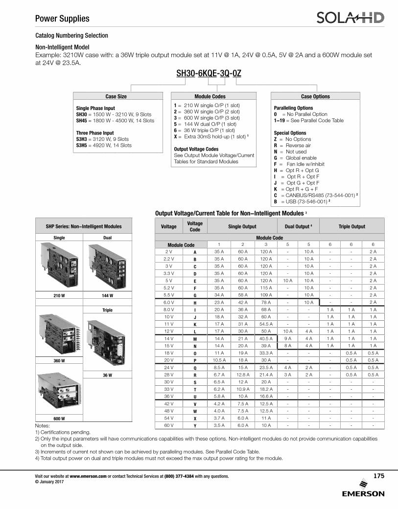
Output Voltage/Current Table for Non-Intelligent Modules 3
VoltageVoltage
CodeSingle Output Dual Output 4 Triple Output
Module CodeModule Code 1 2 3 5 5 6 6 6
2 V A 35 A 60 A 120 A - 10 A - - 2 A
2.2 V B 35 A 60 A 120 A - 10 A - - 2 A
3 V C 35 A 60 A 120 A - 10 A - - 2 A
3.3 V D 35 A 60 A 120 A - 10 A - - 2 A
5 V E 35 A 60 A 120 A 10 A 10 A - - 2 A
5.2 V F 35 A 60 A 115 A - 10 A - - 2 A
5.5 V G 34 A 58 A 109 A - 10 A - - 2 A
6.0 V H 23 A 42 A 78 A - 10 A - - 2 A
8.0 V I 20 A 36 A 68 A - - 1 A 1 A 1 A
10 V J 18 A 32 A 60 A - - 1 A 1 A 1 A
11 V K 17 A 31 A 54.5 A - - 1 A 1 A 1 A
12 V L 17 A 30 A 50 A 10 A 4 A 1 A 1 A 1 A
14 V M 14 A 21 A 40.5 A 9 A 4 A 1 A 1 A 1 A
15 V N 14 A 20 A 39 A 8 A 4 A 1 A 1 A 1 A
18 V O 11 A 19 A 33.3 A - - - 0.5 A 0.5 A
20 V P 10.5 A 18 A 30 A - - - 0.5 A 0.5 A
24 V Q 8.5 A 15 A 23.5 A 4 A 2 A - 0.5 A 0.5 A
28 V R 6.7 A 12.8 A 21.4 A 3 A 2 A - 0.5 A 0.5 A
30 V S 6.5 A 12 A 20 A - - - - -
33 V T 6.2 A 10.9 A 18.2 A - - - - -
36 V U 5.8 A 10 A 16.6 A - - - - -
42 V V 4.2 A 7.5 A 12.5 A - - - - -
48 V W 4.0 A 7.5 A 12.5 A - - - - -
54 V X 3.7 A 6.0 A 11 A - - - - -
60 V Y 3.5 A 6.0 A 10 A - - - - -
SHP Series: Non-Intelligent Modules
Single Dual
210 W 144 W
Triple
360 W
36 W
600 W
Notes: 1) Certifications pending.2) Only the input parameters will have communications capabilities with these options. Non-intelligent modules do not provide communication capabilities on the output side. 3) Increments of current not shown can be achieved by paralleling modules. See Parallel Code Table. 4) Total output power on dual and triple modules must not exceed the max output power rating for the module.
Catalog Numbering Selection
Non-Intelligent ModelExample: 3210W case with: a 36W triple output module set at 11V @ 1A, 24V @ 0.5A, 5V @ 2A and a 600W module set at 24V @ 23.5A.
SH30-6KQE-3Q-0Z
Case Size Module Codes Case Options
Single Phase InputSH30 = 1500 W - 3210 W, 9 SlotsSH45 = 1800 W - 4500 W, 14 Slots
Three Phase InputS3H3 = 3120 W, 9 SlotsS3H5 = 4920 W, 14 Slots
1 = 210 W single O/P (1 slot)2 = 360 W single O/P (2 slot)3 = 600 W single O/P (3 slot)5 = 144 W dual O/P (1 slot)6 = 36 W triple O/P (1 slot)X = Extra 30mS hold-up (1 slot) 1
Output Voltage CodesSee Output Module Voltage/Current Tables for Standard Modules
Paralleling Options0 = No Parallel Option1-19 = See Parallel Code Table
Special OptionsZ = No OptionsR = Reverse airN = Not usedG = Global enableF = Fan Idle w/inhibitH = Opt R + Opt GI = Opt R + Opt FJ = Opt G + Opt FK = Opt R + G + FC = CANBUS/RS485 (73-544-001) 2
B = USB (73-546-001) 2
Power Supplies
Visit our website at www.emerson.com or contact Technical Services at (800) 377-4384 with any questions. © January 2017
175
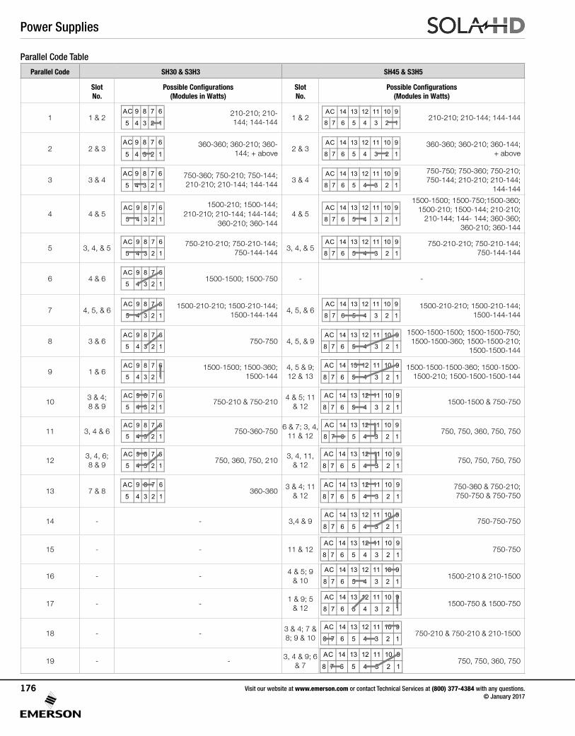
Parallel Code Table
Parallel Code SH30 & S3H3 SH45 & S3H5
Slot No.
Possible Configurations (Modules in Watts)
Slot No.
Possible Configurations (Modules in Watts)
1 1 & 2AC 9 8 7 6
5 4 3 2 1 210-210; 210-
144; 144-1441 & 2
14 13 12 11 10 9
8 7 6 5 4 3 2 1
AC210-210; 210-144; 144-144
2 2 & 3AC 9 8 7 6
5 4 3 2 1 360-360; 360-210; 360-
144; + above2 & 3
14 13 12 11 10 9
8 7 6 5 4 3 2 1
AC 360-360; 360-210; 360-144; + above
3 3 & 4AC 9 8 7 6
5 4 3 2 1750-360; 750-210; 750-144; 210-210; 210-144; 144-144
3 & 414 13 12 11 10 9
8 7 6 5 4 3 2 1
AC 750-750; 750-360; 750-210; 750-144; 210-210; 210-144;
144-144
4 4 & 5AC 9 8 7 6
5 4 3 2 1
1500-210; 1500-144; 210-210; 210-144; 144-144;
360-210; 360-1444 & 5
14 13 12 11 10 9
8 7 6 5 4 3 2 1
AC1500-1500; 1500-750;1500-360;
1500-210; 1500-144; 210-210; 210-144; 144- 144; 360-360;
360-210; 360-144
5 3, 4, & 5AC 9 8 7 6
5 4 3 2 1750-210-210; 750-210-144;
750-144-1443, 4, & 5
14 13 12 11 10 9
8 7 6 5 4 3 2 1
AC 750-210-210; 750-210-144; 750-144-144
6 4 & 6AC 9 8 7 6
5 4 3 2 11500-1500; 1500-750 - -
7 4, 5, & 6AC 9 8 7 6
5 4 3 2 11500-210-210; 1500-210-144;
1500-144-1444, 5, & 6
14 13 12 11 10 9
8 7 6 5 4 3 2 1
AC 1500-210-210; 1500-210-144; 1500-144-144
8 3 & 6 AC 9 8 7 6
5 4 3 2 1750-750 4, 5, & 9
14 13 12 11 10 9
8 7 6 5 4 3 2 1
AC 1500-1500-1500; 1500-1500-750; 1500-1500-360; 1500-1500-210;
1500-1500-144
9 1 & 6 AC 9 8 7 6
5 4 3 2 11500-1500; 1500-360;
1500-1444, 5 & 9; 12 & 13
14 13 12 11 10 9
8 7 6 5 4 3 2 1
AC 1500-1500-1500-360; 1500-1500-1500-210; 1500-1500-1500-144
103 & 4; 8 & 9
AC 9 8 7 6
5 4 3 2 1750-210 & 750-210
4 & 5; 11 & 12
14 13 12 11 10 9
8 7 6 5 4 3 2 1
AC1500-1500 & 750-750
11 3, 4 & 6AC 9 8 7 6
5 4 3 2 1750-360-750
6 & 7; 3, 4, 11 & 12
14 13 12 11 10 9
8 7 6 5 4 3 2 1
AC750, 750, 360, 750, 750
123, 4, 6; 8 & 9
AC 9 8 7 6
5 4 3 2 1750, 360, 750, 210
3, 4, 11, & 12
14 13 12 11 10 9
8 7 6 5 4 3 2 1
AC750, 750, 750, 750
13 7 & 8AC 9 8 7 6
5 4 3 2 1360-360
3 & 4; 11 & 12
14 13 12 11 10 9
8 7 6 5 4 3 2 1
AC 750-360 & 750-210; 750-750 & 750-750
14 - - 3,4 & 914 13 12 11 10 9
8 7 6 5 4 3 2 1
AC750-750-750
15 - - 11 & 1214 13 12 11 10 9
8 7 6 5 4 3 2 1
AC750-750
16 - -4 & 5; 9
& 10
14 13 12 11 10 9
8 7 6 5 4 3 2 1
AC1500-210 & 210-1500
17 - -1 & 9; 5
& 12
14 13 12 11 10 9
8 7 6 5 4 3 2 1
AC1500-750 & 1500-750
18 - -3 & 4; 7 & 8; 9 & 10
14 13 12 11 10 9
8 7 6 5 4 3 2 1
AC750-210 & 750-210 & 210-1500
19 - -3, 4 & 9; 6
& 7
14 13 12 11 10 9
8 7 6 5 4 3 2 1
AC750, 750, 360, 750
Power Supplies
Visit our website at www.emerson.com or contact Technical Services at (800) 377-4384 with any questions. © January 2017
176
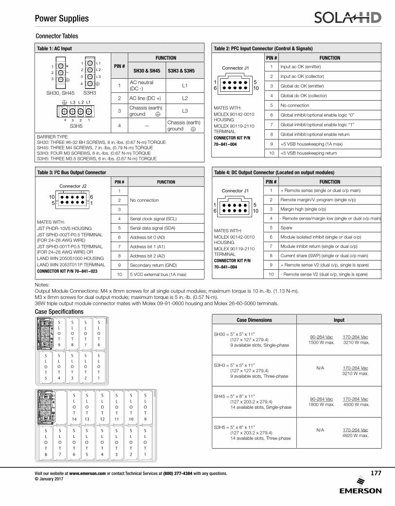
Notes: Output Module Connections: M4 x 8mm screws for all single output modules; maximum torque is 10 in.-lb. (1.13 N-m). M3 x 8mm screws for dual output module; maximum torque is 5 in.-lb. (0.57 N-m). 36W triple output module connector mates with Molex 09-91-0600 housing and Molex 26-60-5060 terminals.
123
~N
123
~N
Table 1: AC Input
PIN #
FUNCTION
SH30 & SH45 S3H3 & S3H5
1AC neutral(DC -)
L1
2 AC line (DC +) L2
3 Chassis (earth) ground
L3
4 — Chassis (earth) ground
BARRIER TYPE SH30: THREE #6-32 BH SCREWS, 6 in.-lbs. (0.67 N-m) TORQUE SH45: THREE M4 SCREWS, 7 in.-lbs. (0.79 N-m) TORQUE S3H3: FOUR M3 SCREWS, 6 in.-lbs. (0.67 N-m) TORQUE S3H5: THREE M3.5 SCREWS, 6 in.-lbs. (0.67 N-m) TORQUE
1
2
3~ N
1
1
2
2
3
3
4
4
L
L
L
L L L
SH30, SH45 S3H3
S3H5
Table 2: PFC Input Connector (Control & Signals)
61
105
Connector J1
MATES WITH:MOLEX 90142-0010 HOUSINGMOLEX 90119-2110 TERMINALCONNECTOR KIT P/N 70-841-004
PIN # FUNCTION
1 Input ac OK (emitter)
2 Input ac OK (collector)
3 Global dc OK (emitter)
4 Global dc OK (collector)
5 No connection
6 Global inhibit/optional enable logic “0”
7 Global inhibit/optional enable logic “1”
8 Global inhibit/optional enable return
9 +5 VSB housekeeping (1A max)
10 +5 VSB housekeeping return
Table 4: DC Output Connector (Located on output modules)
61
105
Connector J1
MATES WITH:MOLEX 90142-0010 HOUSINGMOLEX 90119-2110 TERMINALCONNECTOR KIT P/N 70-841-004
PIN # FUNCTION
1 + Remote sense (single or dual o/p main)
2 Remote margin/V. program (single o/p)
3 Margin high (single o/p)
4 - Remote sense/margin low (single or dual o/p main)
5 Spare
6 Module isolated inhibit (single or dual o/p)
7 Module inhibit return (single or dual o/p)
8 Current share (SWP) (single or dual o/p main)
9 + Remote sense V2 (dual o/p, single is spare)
10 - Remote sense V2 (dual o/p, single is spare)
Case Specifications
Connector Tables
InputSH30 = 5” x 5” x 11” 90-264 Vac 170-264 Vac (127 x 127 x 279.4) 1500 W max. 3210 W max. 9 available slots
S3H3 = 5” x 5” x 11” N/A 170-264 Vac (127 x 127 x 279.4) 3210 W max. 9 available slots 3-phase only
InputSH45 = 5” x 8” x 11” 90-264 Vac 170-264 Vac (127 x 203.2 x 279.4) 1800 W max. 4500 W max. 14 available slots
S3H5 = 5” x 8” x 11” N/A 170-264 Vac (127 x 203.2 x 279.4) 4920 W max. 14 available slots
SLOT
9
SLOT
7
SLOT
8
SLOT
6
SLOT
4
SLOT
2
SLOT
3
SLOT
1
SLOT
5
SLOT
13
SLOT
14
SLOT
12
SLOT
11
SLOT
10
SLOT
9
SLOT
7
SLOT
5
SLOT
6
SLOT
4
SLOT
3
SLOT
2
SLOT
1
SLOT
8
Case Dimensions Input
SH30 = 5” x 5” x 11” (127 x 127 x 279.4) 9 available slots, Single-phase
90-264 Vac 170-264 Vac1500 W max. 3210 W max.
S3H3 = 5” x 5” x 11” (127 x 127 x 279.4) 9 available slots, Three-phase
N/A 170-264 Vac 3210 W max.
SH45 = 5” x 8” x 11” (127 x 203.2 x 279.4) 14 available slots, Single-phase
90-264 Vac 170-264 Vac1800 W max. 4500 W max.
S3H5 = 5” x 8” x 11” (127 x 203.2 x 279.4) 14 available slots, Three-phase
N/A 170-264 Vac 4920 W max.
Table 3: I2C Bus Output Connector
Connector J2
105
61
MATES WITH:JST PHDR-10VS HOUSINGJST SPHD-002T-P0.5 TERMINAL (FOR 24–28 AWG WIRE)JST SPHD-001T-P0.5 TERMINAL (FOR 24–28 AWG WIRE) ORLAND WIN 2050S1000 HOUSINGLAND WIN 2053T011P TERMINALCONNECTOR KIT P/N 70-841-023
PIN # FUNCTION
1
No connection2
3
4 Serial clock signal (SCL)
5 Serial data signal (SDA)
6 Address bit 0 (A0)
7 Address bit 1 (A1)
8 Address bit 2 (A2)
9 Secondary return (GND)
10 5 VCC external bus (1A max)
Power Supplies
Visit our website at www.emerson.com or contact Technical Services at (800) 377-4384 with any questions. © January 2017
177
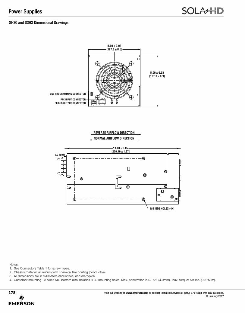
SH30 and S3H3 Dimensional Drawings
11.00 ± 0.05[279.40 ± 1.27]
5.00 ± 0.02[127.0 ± 0.5]
5.00 ± 0.03[127.0 ± 0.9]
I2C BUS OUTPUT CONNECTORPFC INPUT CONNECTOR
USB PROGRAMMING CONNECTOR
M4 MTG HOLES (4X)
REVERSE AIRFLOW DIRECTION
NORMAL AIRFLOW DIRECTION
ACOK
DCOK10 6J2
5 1
1 5J1
6 10
AC INPUT
11.00 ± 0.05[279.40 ± 1.27]
5.00 ± 0.02[127.0 ± 0.5]
5.00 ± 0.03[127.0 ± 0.9]
I2C BUS OUTPUT CONNECTORPFC INPUT CONNECTOR
USB PROGRAMMING CONNECTOR
M4 MTG HOLES (4X)
REVERSE AIRFLOW DIRECTION
NORMAL AIRFLOW DIRECTION
ACOK
DCOK10 6J2
5 1
1 5J1
6 10
AC INPUT
Notes: 1. See Connectors Table 1 for screw types. 2. Chassis material: aluminum with chemical film coating (conductive). 3. All dimensions are in millimeters and inches, and are typical. 4. Customer mounting - 3 sides M4, bottom also includes 8-32 mounting holes. Max. penetration is 0.155” (4.0mm). Max. torque: 5in-lbs. (0.57N-m).
Power Supplies
Visit our website at www.emerson.com or contact Technical Services at (800) 377-4384 with any questions. © January 2017
178
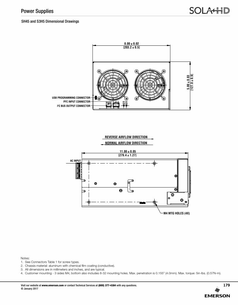
SH45 and S3H5 Dimensional Drawings
11.00 ± 0.05[279.4 ± 1.27]
0.26[6.7] REF
8.00 ± 0.02[203.2 ± 0.5]
1.15[29.1]
6.75[171.5]
0.64[16.2]
0.75[19.1]
6.75[171.5]
B
A
A
AB
B
B
ACOK
DCOK
10 6J2
5 1
1 5J1
6 10I2C BUS OUTPUT CONNECTOR
PFC INPUT CONNECTORUSB PROGRAMMING CONNECTOR
REVERSE AIRFLOW DIRECTION
NORMAL AIRFLOW DIRECTION
M4 MTG HOLES (4X)
#8-32 MTG HOLES(5X) MARKED “A”
M4 MTG HOLES (5X) MARKED “B”
5.00
± 0
.03
[127
.0 ±
0.9
]
AC INPUT
A
B A
0.57[14.4]
6.82
[173
.3]
5.88
[149
.4]
0.5[12.7]
7.00
[177
.8]
Notes: 1. See Connectors Table 1 for screw types. 2. Chassis material: aluminum with chemical film coating (conductive). 3. All dimensions are in millimeters and inches, and are typical. 4. Customer mounting - 3 sides M4, bottom also includes 8-32 mounting holes. Max. penetration is 0.155” (4.0mm). Max. torque: 5in-lbs. (0.57N-m).
Power Supplies
Visit our website at www.emerson.com or contact Technical Services at (800) 377-4384 with any questions. © January 2017
179
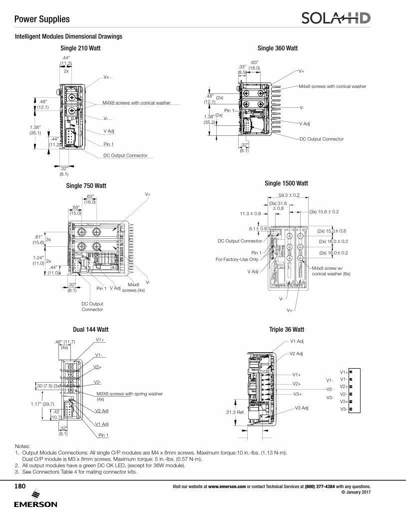
Intelligent Modules Dimensional Drawings
Single 360 Watt
Dual 144 Watt Triple 36 Watt
Single 750 Watt Single 1500 Watt
Notes: 1. Output Module Connections: All single O/P modules are M4 x 8mm screws. Maximum torque:10 in.-lbs. (1.13 N-m). Dual O/P module is M3 x 8mm screws. Maximum torque: 5 in.-lbs. (0.57 N-m). 2. All output modules have a green DC OK LED, (except for 36W module). 3. See Connectors Table 4 for mating connector kits.
21.3 Ref.
V1 Adj
V2 Adj
V3 Adj
V1+ V1+
V1- V1-
V2-V2-
V3-
V3-
V2+ V2+
V3+
V3+
Pin 1
V Adj
V-
V+
59.3 0.2+
11.3 0.8+
8.1 0.8+
(3x) 31.6 0.8+
(2x) 15.0 0.8+
(2x) 16.0 0.2+
(3x) 15.6 0.2+
(2x) 16.0 0.2+
DC Output Connector
M4x8 screw w/ conical washer (6x)
For Factory-Use Only
.63” (16.0)
.32” (8.1)
.44” (11.0)
.61” (15.6)
.59” (15.0)
1.24” (11.0)
V+
V-Pin 1 V Adj
2x
2x
DC Output Connector
M4x8 screws (4x)
Single 210 Watt.44”
(11.2)
.32” (8.1)
.48” (12.1)
1.38” (35.1)
2x
V Adj
Pin 1
V+
V-
M4X8 screws with conical washer
DC Output Connector
"44.)4.11(
.44” (11.2)
.48” (12.1)
.32” (8.1)
.63” (16.0).33”
(8.5)
1.38” (35.2)
V+
V-
V Adj
Pin 1
DC Output Connector
M4x8 screws with conical washer
(2x)
(2x)
.32” (8.1)
.46” (11.7) (4x)
1.17” (29.7)
.30 (7.5) (3x)
.42 (10.7)
(4x)
V1 Adj
V2 Adj
Pin 1
V1+
V1-
V2-
V2+
M3X8 screws with spring washer
Power Supplies
Visit our website at www.emerson.com or contact Technical Services at (800) 377-4384 with any questions. © January 2017
180
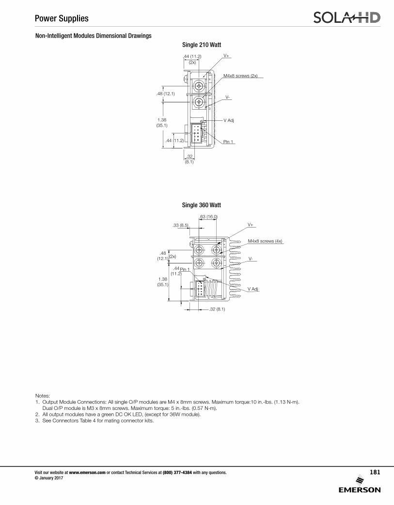
Single 210 Watt
Single 360 Watt
Non-Intelligent Modules Dimensional Drawings
.48 (12.1)
.44 (11.2)
.44 (11.2)
1.38 (35.1)
.32 (8.1)
(2x)
V+
M4x8 screws (2x)
V Adj
Pin 1
V-
(2x)
Pin 1
V Adj
M4x8 screws (4x)
V-
V+
.63 (16.0)
.33 (8.5)
.32 (8.1)
.48 (12.1)
1.38 (35.1)
.44 (11.2)
Notes: 1. Output Module Connections: All single O/P modules are M4 x 8mm screws. Maximum torque:10 in.-lbs. (1.13 N-m). Dual O/P module is M3 x 8mm screws. Maximum torque: 5 in.-lbs. (0.57 N-m). 2. All output modules have a green DC OK LED, (except for 36W module). 3. See Connectors Table 4 for mating connector kits.
Power Supplies
Visit our website at www.emerson.com or contact Technical Services at (800) 377-4384 with any questions. © January 2017
181
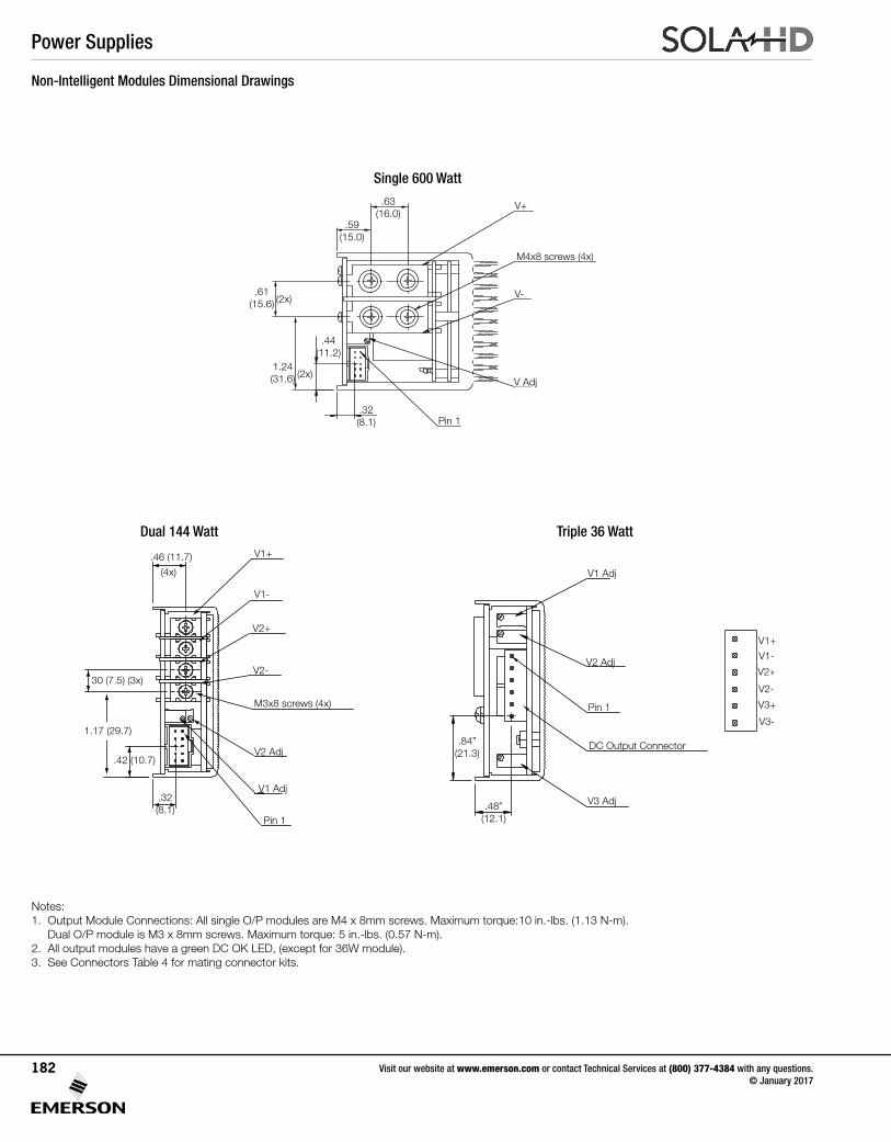
Non-Intelligent Modules Dimensional Drawings
Notes: 1. Output Module Connections: All single O/P modules are M4 x 8mm screws. Maximum torque:10 in.-lbs. (1.13 N-m). Dual O/P module is M3 x 8mm screws. Maximum torque: 5 in.-lbs. (0.57 N-m). 2. All output modules have a green DC OK LED, (except for 36W module). 3. See Connectors Table 4 for mating connector kits.
Dual 144 Watt Triple 36 Watt
Single 600 Watt
V+
V-(2x)
(2x)
.63 (16.0)
.44 (11.2)
.61 (15.6)
1.24 (31.6)
.32 (8.1)
.59 (15.0)
M4x8 screws (4x)
Pin 1
V Adj
30 (7.5) (3x)
.46 (11.7)
(4x)
Pin 1
V1 Adj
V2 Adj
M3x8 screws (4x)
V1+
V1-
V2+
V2-
.42 (10.7)
1.17 (29.7)
.32 (8.1)
Pin 1
V1 Adj
V2 Adj
V1+
V1-
V2-
V3-
V2+
V3+
.48” (12.1)
.84” (21.3)
V3 Adj
DC Output Connector
Power Supplies
Visit our website at www.emerson.com or contact Technical Services at (800) 377-4384 with any questions. © January 2017
182
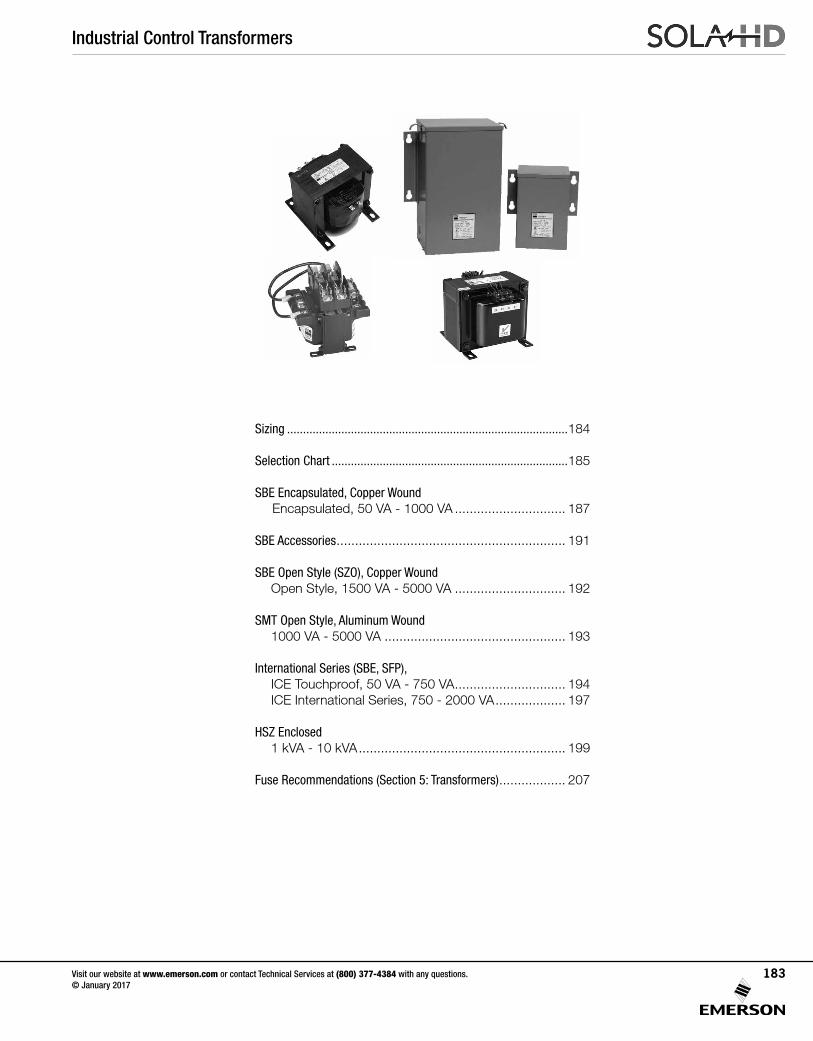
Industrial Control Transformers
Visit our website at www.emerson.com or contact Technical Services at (800) 377-4384 with any questions. © January 2017
183
Sizing ........................................................................................184
Selection Chart ..........................................................................185
SBE Encapsulated, Copper Wound Encapsulated, 50 VA - 1000 VA .............................. 187
SBE Accessories .............................................................. 191
SBE Open Style (SZO), Copper Wound Open Style, 1500 VA - 5000 VA .............................. 192
SMT Open Style, Aluminum Wound 1000 VA - 5000 VA ................................................. 193
International Series (SBE, SFP),ICE Touchproof, 50 VA - 750 VA .............................. 194ICE International Series, 750 - 2000 VA ................... 197
HSZ Enclosed 1 kVA - 10 kVA ........................................................ 199
Fuse Recommendations (Section 5: Transformers) .................. 207
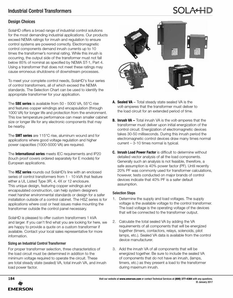
Industrial Control Transformers
Visit our website at www.emerson.com or contact Technical Services at (800) 377-4384 with any questions. © January 2017
184
Design Choices
SolaHD offers a broad range of industrial control solutions for the most demanding industrial applications. Our products exceed NEMA ratings for inrush and regulation to ensure control systems are powered correctly. Electromagnetic control components demand inrush currents up to 10 times the transformer’s nominal rating. While this inrush is occurring, the output side of the transformer must not fall below 85% of nominal as specified by NEMA ST-1, Part 4. Using a transformer that does not meet these ratings may cause erroneous shutdowns of downstream processes.
To meet your complete control needs, SolaHD's four series of control transformers, all of which exceed the NEMA standards. The Selection Chart can be used to identify the appropriate transformer for your application. The SBE series is available from 50 - 5000 VA, 55°C rise and features copper windings and encapsulation (through 1000 VA) for longer life and protection from the environment. This low temperature performance can mean smaller cabinet size or longer life for any electronic components that may be nearby.
The SMT series are 115°C rise, aluminum wound and for applications where good voltage regulation and higher power capacities (1000-5000 VA) are required.
The International series meets IEC requirements and IP20 (touch proof covers ordered separately for E models) for European applications.
The HSZ series rounds out SolaHD’s line with an enclosed series of control transformers from 1 - 10 kVA that feature either a UL Listed Type 3R, 4, 4X or 12 enclosure. This unique design, featuring copper windings and encapsulated construction, can help system designers meet harsher environmental standards or design for a safer installation outside of a control cabinet. The HSZ series is for applications where cost or heat issues make mounting the transformer outside the control panel necessary.
SolaHD is pleased to offer custom transformers 1 kVA and larger. If you can't find what you are looking for here, we are happy to provide a quote on a custom transformer if available. Contact your local sales representative for more information.
A. Sealed VA - Total steady state sealed VA is the volt-amperes that the transformer must deliver to the load circuit for an extended period of time.
B. Inrush VA - Total inrush VA is the volt-amperes that the transformer must deliver upon initial energization of the control circuit. Energization of electromagnetic devices takes 30-50 milliseconds. During this inrush period the electromagnetic control devices draw many times normal current – 3-10 times normal is typical.
C. Inrush Load Power Factor is difficult to determine without detailed vector analysis of all the load components. Generally such an analysis is not feasible, therefore, a safe assumption is 40% power factor (PF). Until recently 20% PF was commonly used for transformer calculations, however, tests conducted on major brands of control devices indicate that 40% PF is a safer default assumption.
Sizing an Industrial Control Transformer
For proper transformer selection, three characteristics of the load circuit must be determined in addition to the minimum voltage required to operate the circuit. These are total steady state (sealed) VA, total inrush VA, and inrush load power factor.
Selection Steps
1. Determine the supply and load voltages. The supply voltage is the available voltage to the control transformer. The load voltage is the operating voltage of the devices that will be connected to the transformer output.
2. Calculate the total sealed VA by adding the VA requirements of all components that will be energized together (timers, contactors, relays, solenoids, pilot lamps, etc.). Sealed VA data is available from the control device manufacturer.
3. Add the inrush VA of all components that will be energized together. Be sure to include the sealed VA of components that do not have an inrush, (lamps, timers, etc.) as they present a load to the transformer during maximum inrush.
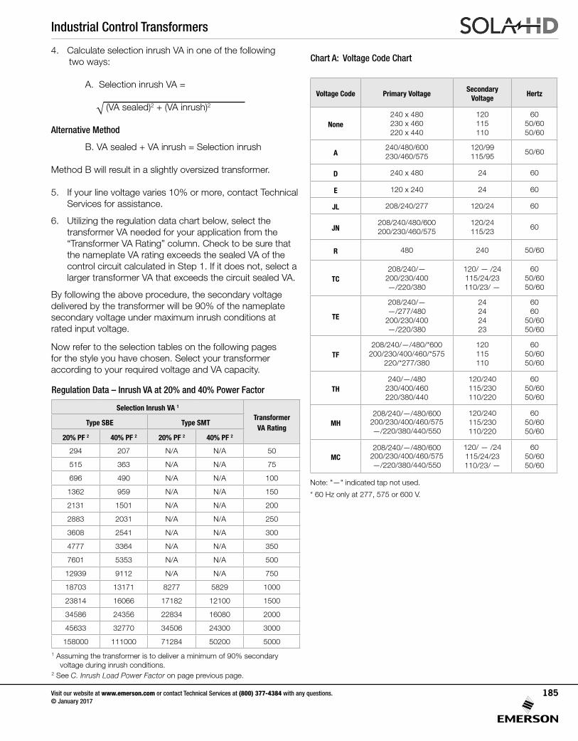
Industrial Control Transformers
Visit our website at www.emerson.com or contact Technical Services at (800) 377-4384 with any questions. © January 2017
185
√
Chart A: Voltage Code Chart
Note: "—" indicated tap not used.
* 60 Hz only at 277, 575 or 600 V.
Voltage Code Primary Voltage Secondary
Voltage Hertz
None240 x 480230 x 460220 x 440
120 115 110
60 50/60 50/60
A240/480/600 230/460/575
120/99 115/95
50/60
D 240 x 480 24 60
E 120 x 240 24 60
JL 208/240/277 120/24 60
JN208/240/480/600 200/230/460/575
120/24 115/23
60
R 480 240 50/60
TC208/240/—
200/230/400 —/220/380
120/ — /24 115/24/23 110/23/ —
6050/6050/60
TE
208/240/——/277/480
200/230/400—/220/380
24 24 24 23
6060
50/6050/60
TF208/240/—/480/*600
200/230/400/460/*575220/*277/380
120 115 110
6050/6050/60
TH240/—/480
230/400/460220/380/440
120/240 115/230 110/220
6050/6050/60
MH208/240/—/480/600
200/230/400/460/575 —/220/380/440/550
120/240 115/230 110/220
6050/6050/60
MC208/240/—/480/600
200/230/400/460/575 —/220/380/440/550
120/ — /24 115/24/23 110/23/ —
6050/6050/60
1 Assuming the transformer is to deliver a minimum of 90% secondary voltage during inrush conditions. 2 See C. Inrush Load Power Factor on page previous page.
Selection Inrush VA 1
TransformerVA Rating
Type SBE Type SMT
20% PF 2 40% PF 2 20% PF 2 40% PF 2
294 207 N/A N/A 50
515 363 N/A N/A 75
696 490 N/A N/A 100
1362 959 N/A N/A 150
2131 1501 N/A N/A 200
2883 2031 N/A N/A 250
3608 2541 N/A N/A 300
4777 3364 N/A N/A 350
7601 5353 N/A N/A 500
12939 9112 N/A N/A 750
18703 13171 8277 5829 1000
23814 16066 17182 12100 1500
34586 24356 22834 16080 2000
45633 32770 34506 24300 3000
158000 111000 71284 50200 5000
Regulation Data – Inrush VA at 20% and 40% Power Factor
4. Calculate selection inrush VA in one of the following two ways:
A. Selection inrush VA =
(VA sealed)2 + (VA inrush)2
Alternative Method
B. VA sealed + VA inrush = Selection inrush
Method B will result in a slightly oversized transformer.
5. If your line voltage varies 10% or more, contact Technical Services for assistance.
6. Utilizing the regulation data chart below, select the transformer VA needed for your application from the “Transformer VA Rating” column. Check to be sure that the nameplate VA rating exceeds the sealed VA of the control circuit calculated in Step 1. If it does not, select a larger transformer VA that exceeds the circuit sealed VA.
By following the above procedure, the secondary voltage delivered by the transformer will be 90% of the nameplate secondary voltage under maximum inrush conditions at rated input voltage.
Now refer to the selection tables on the following pages for the style you have chosen. Select your transformer according to your required voltage and VA capacity.
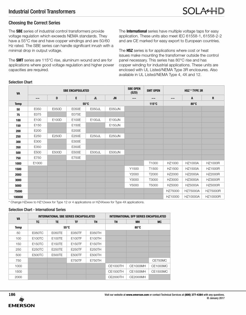
Industrial Control Transformers
Visit our website at www.emerson.com or contact Technical Services at (800) 377-4384 with any questions. © January 2017
186
Choosing the Correct Series
The SBE series of industrial control transformers provide voltage regulation which exceeds NEMA standards. They have a 55°C rise and have copper windings and are 50/60 Hz rated. The SBE series can handle significant inrush with a minimal drop in output voltage.
The SMT series are 115°C rise, aluminum wound and are for applications where good voltage regulation and higher power capacities are required.
Selection Chart
The International series have multiple voltage taps for easy application. These units also meet IEC 61558-1, 61558-2-2 and are CE marked for easy export to European countries.
The HSZ series is for applications where cost or heat issues make mounting the transformer outside the control panel necessary. This series has 80°C rise and has copper winding for industrial applications. These units are enclosed with UL Listed/NEMA Type 3R enclosures. Also available in UL Listed/NEMA Type 4, 4X and 12.
VASBE ENCAPSULATED
SBE OPEN (SZO)
SMT OPEN HSZ * TYPE 3R
-- D E JL JN -- -- -- A R
Temp 55°C 115°C 80°C
50 E050 E050D E050E E050JL E050JN
75 E075 E075E
100 E100 E100D E100E E100JL E100JN
150 E150 E150E E150JN
200 E200 E200E
250 E250 E250D E250E E250JL E250JN
300 E300 E300E
350 E350 E350E
500 E500 E500D E500E E500JL E500JN
750 E750 E750E
1000 E1000 T1000 HZ1000 HZ1000A HZ1000R
1500 Y1500 T1500 HZ1500 HZ1500A HZ1500R
2000 Y2000 T2000 HZ2000 HZ2000A HZ2000R
3000 Y3000 T3000 HZ3000 HZ3000A HZ3000R
5000 Y5000 T5000 HZ5000 HZ5000A HZ5000R
75000 HZ75000 HZ75000A HZ75000R
100000 HZ10000 HZ10000A HZ10000R
* Change HZxxxx to HZ12xxxx for Type 12 or 4 applications or HZ4Xxxxx for Type 4X applications.
VAINTERNATIONAL SBE SERIES ENCAPSULATED INTERNATIONAL SFP SERIES ENCAPSULATED
TC TE TF TH TH MH MC
Temp 55°C 80°C
50 E050TC E050TE E050TF E050TH
100 E100TC E100TE E100TF E100TH
150 E150TC E150TE E150TF E150TH
250 E250TC E250TE E250TF E250TH
500 E500TC E500TE E500TF E500TH
750 E750TF E750TH CE750MC
1000 CE1000TH CE1000MH CE1000MC
1500 CE1500TH CE1500MH CE1500MC
2000 CE2000TH CE2000MH
Selection Chart - International Series
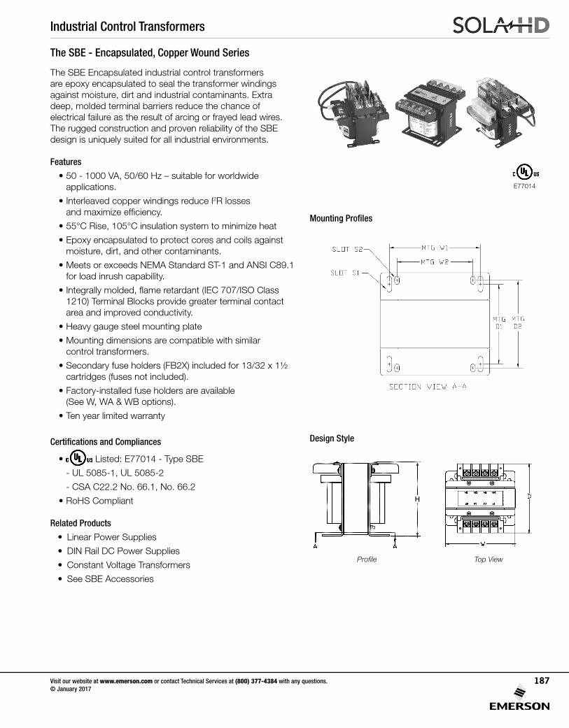
Industrial Control Transformers
Visit our website at www.emerson.com or contact Technical Services at (800) 377-4384 with any questions. © January 2017
187
The SBE Encapsulated industrial control transformers are epoxy encapsulated to seal the transformer windings against moisture, dirt and industrial contaminants. Extra deep, molded terminal barriers reduce the chance of electrical failure as the result of arcing or frayed lead wires. The rugged construction and proven reliability of the SBE design is uniquely suited for all industrial environments.
Features
• 50 - 1000 VA, 50/60 Hz – suitable for worldwide applications.
• Interleaved copper windings reduce I2R losses and maximize efficiency.
• 55°C Rise, 105°C insulation system to minimize heat
• Epoxy encapsulated to protect cores and coils against moisture, dirt, and other contaminants.
• Meets or exceeds NEMA Standard ST-1 and ANSI C89.1 for load inrush capability.
• Integrally molded, flame retardant (IEC 707/ISO Class 1210) Terminal Blocks provide greater terminal contact area and improved conductivity.
• Heavy gauge steel mounting plate
• Mounting dimensions are compatible with similar control transformers.
• Secondary fuse holders (FB2X) included for 13/32 x 1½ cartridges (fuses not included).
• Factory-installed fuse holders are available (See W, WA & WB options).
• Ten year limited warranty
Certifications and Compliances
• Listed: E77014 - Type SBE
- UL 5085-1, UL 5085-2
- CSA C22.2 No. 66.1, No. 66.2
• RoHS Compliant
Related Products
• Linear Power Supplies
• DIN Rail DC Power Supplies
• Constant Voltage Transformers
• See SBE Accessories
The SBE - Encapsulated, Copper Wound Series
Mounting Profiles
Design Style
Profile Top View
E77014
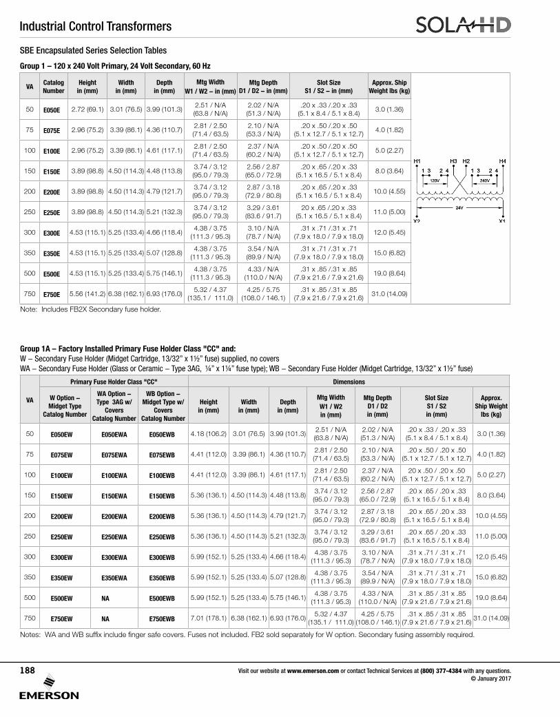
Industrial Control Transformers
Visit our website at www.emerson.com or contact Technical Services at (800) 377-4384 with any questions. © January 2017
188
SBE Encapsulated Series Selection Tables
Group 1 – 120 x 240 Volt Primary, 24 Volt Secondary, 60 Hz
VACatalog Number
Height in (mm)
Width in (mm)
Depth in (mm)
Mtg Width W1 / W2 - in (mm)
Mtg Depth D1 / D2 - in (mm)
Slot SizeS1 / S2 - in (mm)
Approx. Ship Weight lbs (kg)
50 E050E 2.72 (69.1) 3.01 (76.5) 3.99 (101.3)2.51 / N/A(63.8 / N/A)
2.02 / N/A(51.3 / N/A)
.20 x .33 /.20 x .33(5.1 x 8.4 / 5.1 x 8.4)
3.0 (1.36)
75 E075E 2.96 (75.2) 3.39 (86.1) 4.36 (110.7)2.81 / 2.50(71.4 / 63.5)
2.10 / N/A(53.3 / N/A)
.20 x .50 /.20 x .50(5.1 x 12.7 / 5.1 x 12.7)
4.0 (1.82)
100 E100E 2.96 (75.2) 3.39 (86.1) 4.61 (117.1)2.81 / 2.50(71.4 / 63.5)
2.37 / N/A(60.2 / N/A)
.20 x .50 /.20 x .50(5.1 x 12.7 / 5.1 x 12.7)
5.0 (2.27)
150 E150E 3.89 (98.8) 4.50 (114.3) 4.48 (113.8)3.74 / 3.12(95.0 / 79.3)
2.56 / 2.87(65.0 / 72.9)
.20 x .65 /.20 x .33(5.1 x 16.5 / 5.1 x 8.4)
8.0 (3.64)
200 E200E 3.89 (98.8) 4.50 (114.3) 4.79 (121.7)3.74 / 3.12(95.0 / 79.3)
2.87 / 3.18(72.9 / 80.8)
.20 x .65 /.20 x .33(5.1 x 16.5 / 5.1 x 8.4)
10.0 (4.55)
250 E250E 3.89 (98.8) 4.50 (114.3) 5.21 (132.3)3.74 / 3.12(95.0 / 79.3)
3.29 / 3.61(83.6 / 91.7)
20 x .65 /.20 x .33(5.1 x 16.5 / 5.1 x 8.4)
11.0 (5.00)
300 E300E 4.53 (115.1) 5.25 (133.4) 4.66 (118.4)4.38 / 3.75
(111.3 / 95.3)3.10 / N/A(78.7 / N/A)
.31 x .71 /.31 x .71(7.9 x 18.0 / 7.9 x 18.0)
12.0 (5.45)
350 E350E 4.53 (115.1) 5.25 (133.4) 5.07 (128.8)4.38 / 3.75
(111.3 / 95.3)3.54 / N/A(89.9 / N/A)
.31 x .71 /.31 x .71(7.9 x 18.0 / 7.9 x 18.0)
15.0 (6.82)
500 E500E 4.53 (115.1) 5.25 (133.4) 5.75 (146.1)4.38 / 3.75
(111.3 / 95.3)4.33 / N/A
(110.0 / N/A).31 x .85 /.31 x .85
(7.9 x 21.6 / 7.9 x 21.6)19.0 (8.64)
750 E750E 5.56 (141.2) 6.38 (162.1) 6.93 (176.0)5.32 / 4.37
(135.1 / 111.0)4.25 / 5.75
(108.0 / 146.1).31 x .85 /.31 x .85
(7.9 x 21.6 / 7.9 x 21.6)31.0 (14.09)
Group 1A – Factory Installed Primary Fuse Holder Class "CC" and:W - Secondary Fuse Holder (Midget Cartridge, 13/32” x 1½” fuse) supplied, no coversWA - Secondary Fuse Holder (Glass or Ceramic - Type 3AG, ¼” x 1¼” fuse type); WB - Secondary Fuse Holder (Midget Cartridge, 13/32” x 1½” fuse)
VA
Primary Fuse Holder Class "CC" Dimensions
W Option - Midget Type
Catalog Number
WA Option - Type 3AG w/
CoversCatalog Number
WB Option - Midget Type w/
CoversCatalog Number
Height in (mm)
Width in (mm)
Depth in (mm)
Mtg Width W1 / W2in (mm)
Mtg Depth D1 / D2in (mm)
Slot SizeS1 / S2in (mm)
Approx. Ship Weight
lbs (kg)
50 E050EW E050EWA E050EWB 4.18 (106.2) 3.01 (76.5) 3.99 (101.3)2.51 / N/A(63.8 / N/A)
2.02 / N/A(51.3 / N/A)
.20 x .33 / .20 x .33(5.1 x 8.4 / 5.1 x 8.4)
3.0 (1.36)
75 E075EW E075EWA E075EWB 4.41 (112.0) 3.39 (86.1) 4.36 (110.7)2.81 / 2.50(71.4 / 63.5)
2.10 / N/A(53.3 / N/A)
.20 x .50 / .20 x .50(5.1 x 12.7 / 5.1 x 12.7)
4.0 (1.82)
100 E100EW E100EWA E100EWB 4.41 (112.0) 3.39 (86.1) 4.61 (117.1)2.81 / 2.50(71.4 / 63.5)
2.37 / N/A(60.2 / N/A)
20 x .50 / .20 x .50(5.1 x 12.7 / 5.1 x 12.7)
5.0 (2.27)
150 E150EW E150EWA E150EWB 5.36 (136.1) 4.50 (114.3) 4.48 (113.8)3.74 / 3.12(95.0 / 79.3)
2.56 / 2.87(65.0 / 72.9)
.20 x .65 / .20 x .33(5.1 x 16.5 / 5.1 x 8.4)
8.0 (3.64)
200 E200EW E200EWA E200EWB 5.36 (136.1) 4.50 (114.3) 4.79 (121.7)3.74 / 3.12(95.0 / 79.3)
2.87 / 3.18(72.9 / 80.8)
.20 x .65 / .20 x .33(5.1 x 16.5 / 5.1 x 8.4)
10.0 (4.55)
250 E250EW E250EWA E250EWB 5.36 (136.1) 4.50 (114.3) 5.21 (132.3)3.74 / 3.12(95.0 / 79.3)
3.29 / 3.61(83.6 / 91.7)
.20 x .65 / .20 x .33(5.1 x 16.5 / 5.1 x 8.4)
11.0 (5.00)
300 E300EW E300EWA E300EWB 5.99 (152.1) 5.25 (133.4) 4.66 (118.4)4.38 / 3.75
(111.3 / 95.3)3.10 / N/A(78.7 / N/A)
.31 x .71 / .31 x .71(7.9 x 18.0 / 7.9 x 18.0)
12.0 (5.45)
350 E350EW E350EWA E350EWB 5.99 (152.1) 5.25 (133.4) 5.07 (128.8)4.38 / 3.75
(111.3 / 95.3)3.54 / N/A(89.9 / N/A)
.31 x .71 / .31 x .71(7.9 x 18.0 / 7.9 x 18.0)
15.0 (6.82)
500 E500EW NA E500EWB 5.99 (152.1) 5.25 (133.4) 5.75 (146.1)4.38 / 3.75
(111.3 / 95.3)4.33 / N/A
(110.0 / N/A).31 x .85 / .31 x .85
(7.9 x 21.6 / 7.9 x 21.6)19.0 (8.64)
750 E750EW NA E750EWB 7.01 (178.1) 6.38 (162.1) 6.93 (176.0)5.32 / 4.37
(135.1 / 111.0)4.25 / 5.75
(108.0 / 146.1).31 x .85 / .31 x .85
(7.9 x 21.6 / 7.9 x 21.6)31.0 (14.09)
Notes: WA and WB suffix include finger safe covers. Fuses not included. FB2 sold separately for W option. Secondary fusing assembly required.
Note: Includes FB2X Secondary fuse holder.
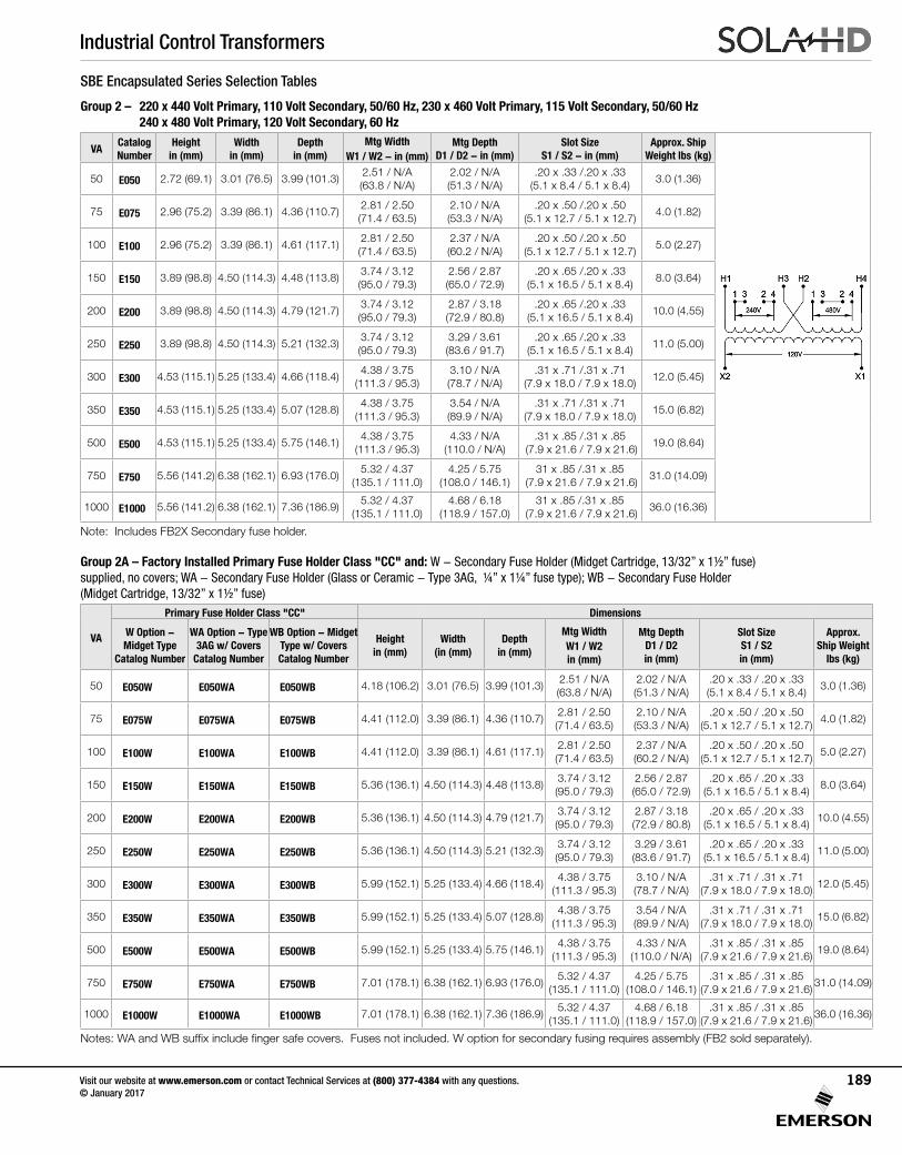
Industrial Control Transformers
Visit our website at www.emerson.com or contact Technical Services at (800) 377-4384 with any questions. © January 2017
189
SBE Encapsulated Series Selection Tables
Group 2 – 220 x 440 Volt Primary, 110 Volt Secondary, 50/60 Hz, 230 x 460 Volt Primary, 115 Volt Secondary, 50/60 Hz 240 x 480 Volt Primary, 120 Volt Secondary, 60 Hz
VACatalog Number
Height in (mm)
Width in (mm)
Depth in (mm)
Mtg Width W1 / W2 - in (mm)
Mtg Depth D1 / D2 - in (mm)
Slot SizeS1 / S2 - in (mm)
Approx. Ship Weight lbs (kg)
50 E050 2.72 (69.1) 3.01 (76.5) 3.99 (101.3)2.51 / N/A(63.8 / N/A)
2.02 / N/A(51.3 / N/A)
.20 x .33 /.20 x .33(5.1 x 8.4 / 5.1 x 8.4)
3.0 (1.36)
75 E075 2.96 (75.2) 3.39 (86.1) 4.36 (110.7)2.81 / 2.50(71.4 / 63.5)
2.10 / N/A(53.3 / N/A)
.20 x .50 /.20 x .50(5.1 x 12.7 / 5.1 x 12.7)
4.0 (1.82)
100 E100 2.96 (75.2) 3.39 (86.1) 4.61 (117.1)2.81 / 2.50(71.4 / 63.5)
2.37 / N/A(60.2 / N/A)
.20 x .50 /.20 x .50(5.1 x 12.7 / 5.1 x 12.7)
5.0 (2.27)
150 E150 3.89 (98.8) 4.50 (114.3) 4.48 (113.8)3.74 / 3.12(95.0 / 79.3)
2.56 / 2.87(65.0 / 72.9)
.20 x .65 /.20 x .33 (5.1 x 16.5 / 5.1 x 8.4)
8.0 (3.64)
200 E200 3.89 (98.8) 4.50 (114.3) 4.79 (121.7)3.74 / 3.12(95.0 / 79.3)
2.87 / 3.18(72.9 / 80.8)
.20 x .65 /.20 x .33 (5.1 x 16.5 / 5.1 x 8.4)
10.0 (4.55)
250 E250 3.89 (98.8) 4.50 (114.3) 5.21 (132.3)3.74 / 3.12(95.0 / 79.3)
3.29 / 3.61(83.6 / 91.7)
.20 x .65 /.20 x .33 (5.1 x 16.5 / 5.1 x 8.4)
11.0 (5.00)
300 E300 4.53 (115.1) 5.25 (133.4) 4.66 (118.4)4.38 / 3.75
(111.3 / 95.3)3.10 / N/A(78.7 / N/A)
.31 x .71 /.31 x .71(7.9 x 18.0 / 7.9 x 18.0)
12.0 (5.45)
350 E350 4.53 (115.1) 5.25 (133.4) 5.07 (128.8)4.38 / 3.75
(111.3 / 95.3)3.54 / N/A(89.9 / N/A)
.31 x .71 /.31 x .71(7.9 x 18.0 / 7.9 x 18.0)
15.0 (6.82)
500 E500 4.53 (115.1) 5.25 (133.4) 5.75 (146.1)4.38 / 3.75
(111.3 / 95.3)4.33 / N/A
(110.0 / N/A).31 x .85 /.31 x .85
(7.9 x 21.6 / 7.9 x 21.6)19.0 (8.64)
750 E750 5.56 (141.2) 6.38 (162.1) 6.93 (176.0)5.32 / 4.37
(135.1 / 111.0)4.25 / 5.75
(108.0 / 146.1)31 x .85 /.31 x .85
(7.9 x 21.6 / 7.9 x 21.6)31.0 (14.09)
1000 E1000 5.56 (141.2) 6.38 (162.1) 7.36 (186.9)5.32 / 4.37
(135.1 / 111.0)4.68 / 6.18
(118.9 / 157.0)31 x .85 /.31 x .85
(7.9 x 21.6 / 7.9 x 21.6)36.0 (16.36)
Note: Includes FB2X Secondary fuse holder.
Group 2A – Factory Installed Primary Fuse Holder Class "CC" and: W - Secondary Fuse Holder (Midget Cartridge, 13/32” x 1½” fuse) supplied, no covers; WA - Secondary Fuse Holder (Glass or Ceramic - Type 3AG, ¼” x 1¼” fuse type); WB - Secondary Fuse Holder (Midget Cartridge, 13/32” x 1½” fuse)
VA
Primary Fuse Holder Class "CC" Dimensions
W Option - Midget Type
Catalog Number
WA Option - Type 3AG w/ Covers
Catalog Number
WB Option - Midget Type w/ CoversCatalog Number
Height in (mm)
Width (in (mm)
Depth in (mm)
Mtg Width W1 / W2in (mm)
Mtg Depth D1 / D2in (mm)
Slot SizeS1 / S2in (mm)
Approx. Ship Weight
lbs (kg)
50 E050W E050WA E050WB 4.18 (106.2) 3.01 (76.5) 3.99 (101.3)2.51 / N/A(63.8 / N/A)
2.02 / N/A(51.3 / N/A)
.20 x .33 / .20 x .33(5.1 x 8.4 / 5.1 x 8.4)
3.0 (1.36)
75 E075W E075WA E075WB 4.41 (112.0) 3.39 (86.1) 4.36 (110.7)2.81 / 2.50(71.4 / 63.5)
2.10 / N/A(53.3 / N/A)
.20 x .50 / .20 x .50(5.1 x 12.7 / 5.1 x 12.7)
4.0 (1.82)
100 E100W E100WA E100WB 4.41 (112.0) 3.39 (86.1) 4.61 (117.1)2.81 / 2.50(71.4 / 63.5)
2.37 / N/A(60.2 / N/A)
.20 x .50 / .20 x .50(5.1 x 12.7 / 5.1 x 12.7)
5.0 (2.27)
150 E150W E150WA E150WB 5.36 (136.1) 4.50 (114.3) 4.48 (113.8)3.74 / 3.12(95.0 / 79.3)
2.56 / 2.87(65.0 / 72.9)
.20 x .65 / .20 x .33(5.1 x 16.5 / 5.1 x 8.4)
8.0 (3.64)
200 E200W E200WA E200WB 5.36 (136.1) 4.50 (114.3) 4.79 (121.7)3.74 / 3.12(95.0 / 79.3)
2.87 / 3.18(72.9 / 80.8)
.20 x .65 / .20 x .33(5.1 x 16.5 / 5.1 x 8.4)
10.0 (4.55)
250 E250W E250WA E250WB 5.36 (136.1) 4.50 (114.3) 5.21 (132.3)3.74 / 3.12(95.0 / 79.3)
3.29 / 3.61(83.6 / 91.7)
.20 x .65 / .20 x .33(5.1 x 16.5 / 5.1 x 8.4)
11.0 (5.00)
300 E300W E300WA E300WB 5.99 (152.1) 5.25 (133.4) 4.66 (118.4)4.38 / 3.75
(111.3 / 95.3)3.10 / N/A(78.7 / N/A)
.31 x .71 / .31 x .71(7.9 x 18.0 / 7.9 x 18.0)
12.0 (5.45)
350 E350W E350WA E350WB 5.99 (152.1) 5.25 (133.4) 5.07 (128.8)4.38 / 3.75
(111.3 / 95.3)3.54 / N/A(89.9 / N/A)
.31 x .71 / .31 x .71(7.9 x 18.0 / 7.9 x 18.0)
15.0 (6.82)
500 E500W E500WA E500WB 5.99 (152.1) 5.25 (133.4) 5.75 (146.1)4.38 / 3.75
(111.3 / 95.3)4.33 / N/A
(110.0 / N/A).31 x .85 / .31 x .85
(7.9 x 21.6 / 7.9 x 21.6)19.0 (8.64)
750 E750W E750WA E750WB 7.01 (178.1) 6.38 (162.1) 6.93 (176.0)5.32 / 4.37
(135.1 / 111.0)4.25 / 5.75
(108.0 / 146.1).31 x .85 / .31 x .85
(7.9 x 21.6 / 7.9 x 21.6)31.0 (14.09)
1000 E1000W E1000WA E1000WB 7.01 (178.1) 6.38 (162.1) 7.36 (186.9)5.32 / 4.37
(135.1 / 111.0)4.68 / 6.18
(118.9 / 157.0).31 x .85 / .31 x .85
(7.9 x 21.6 / 7.9 x 21.6)36.0 (16.36)
Notes: WA and WB suffix include finger safe covers. Fuses not included. W option for secondary fusing requires assembly (FB2 sold separately).
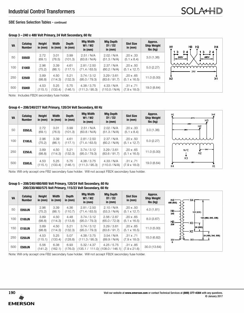
Industrial Control Transformers
Visit our website at www.emerson.com or contact Technical Services at (800) 377-4384 with any questions. © January 2017
190
SBE Series Selection Tables - continued
Group 3 – 240 x 480 Volt Primary, 24 Volt Secondary, 60 Hz
VACatalog Number
Height in (mm)
Width in (mm)
Depth in (mm)
Mtg Width W1 / W2in (mm)
Mtg Depth D1 / D2in (mm)
Slot Size in (mm)
Approx. Ship Weight
lbs (kg)
50 E050D2.72 (69.1)
3.01 (76.5)
3.99 (101.3)
2.51 / N/A(63.8 / N/A)
2.02 / N/A(51.3 / N/A)
.20 x .33 (5.1 x 8.4)
3.0 (1.36)
100 E100D2.96 (75.2)
3.39 (86.1)
4.61 (117.1)
2.81 / 2.50(71.4 / 63.5)
2.37 / N/A(60.2 / N/A)
.20 x .50 (5.1 x 12.7)
5.0 (2.27)
250 E250D3.89 (98.8)
4.50 (114.3)
5.21 (132.3)
3.74 / 3.12(95.0 / 79.3)
3.29 / 3.61(83.6 / 91.7)
.20 x .65 (5.1 x 16.5)
11.0 (5.00)
500 E500D4.53
(115.1)5.25
(133.4)5.75
(146.1)4.38 / 3.75
(111.3 / 95.3)4.33 / N/A
(110.0 / N/A).31 x .71
(7.9 x 18.0)19.0 (8.64)
Note: Includes FB2X secondary fuse holder.
Group 4 – 208/240/277 Volt Primary, 120/24 Volt Secondary, 60 Hz
VACatalog Number
Height in (mm)
Width in (mm)
Depth in (mm)
Mtg Width W1 / W2in (mm)
Mtg Depth D1 / D2in (mm)
Slot Size in (mm)
Approx. Ship Weight
lbs (kg)
50 E050JL2.72 (69.1)
3.01 (76.5)
3.99 (101.3)
2.51 / N/A(63.8 / N/A)
2.02 / N/A(51.3 / N/A)
.20 x .33 (5.1 x 8.4)
3.0 (1.36)
100 E100JL2.96 (75.2)
3.39 (86.1)
4.61 (117.1)
2.81 / 2.50(71.4 / 63.5)
2.37 / N/A(60.2 / N/A)
.20 x .50 (5.1 x 12.7)
5.0 (2.27)
250 E250JL3.89 (98.8)
4.50 (114.3)
5.21 (132.3)
3.74 / 3.12(95.0 / 79.3)
3.29 / 3.61(83.6 / 91.7)
.20 x .65 (5.1 x 16.5)
11.0 (5.00)
500 E500JL4.53
(115.1)5.25
(133.4)5.75
(146.1)4.38 / 3.75
(111.3 / 95.3)4.33 / N/A
(110.0 / N/A).31 x .71
(7.9 x 18.0)19.0 (8.64)
Note: Will only accept one FB2 secondary fuse holder. Will not accept FB2X secondary fuse holder.
Group 5 – 208/240/480/600 Volt Primary, 120/24 Volt Secondary, 60 Hz 200/230/460/575 Volt Primary, 115/23 Volt Secondary, 60 Hz
VACatalog Number
Height in (mm)
Width in (mm)
Depth in (mm)
Mtg Width W1 / W2in (mm)
Mtg Depth D1 / D2in (mm)
Slot Size in (mm)
Approx. Ship Weight
lbs (kg)
50 E050JN2.96 (75.2)
3.39 (86.1)
4.36 (110.7)
2.81 / 2.50(71.4 / 63.5)
2.10 / N/A(53.3 / N/A)
.20 x .50 (5.1 x 12.7)
4.0 (1.81)
100 E100JN3.89 (98.8)
4.50 (114.3)
4.48(113.8)
3.74 / 3.12(95.0 / 79.3)
2.56 / 2.87(65.0 / 72.9)
.20 x .65 (5.1 x 16.5)
8.0 (3.67)
150 E150JN3.89 (98.8)
4.50 (114.3)
5.21 (132.3)
3.74 / 3.12(95.0 / 79.3)
3.29 / 3.61(83.6 / 91.7)
.20 x .65 (5.1 x 16.5)
11.0 (5.00)
250 E250JN4.53
(115.1)5.25
(133.4)5.07
(128.8)4.38 / 3.75
(111.3 / 95.3)3.54 / N/A(89.9 / N/A)
.31 x .71 (7.9 x 18.0)
15.0 (6.82)
500 E500JN5.56
(141.2)6.38
(162.1)6.93
(176.0)5.32 / 4.37
(135.1 / 111.0)4.25 / 5.75
(108.0 / 146.1).31 x .85
(7.9 x 21.6)30.0 (13.64)
Note: Will only accept one FB2 secondary fuse holder. Will not accept FB2X secondary fuse holder.
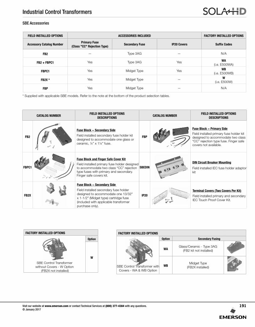
Industrial Control Transformers
Visit our website at www.emerson.com or contact Technical Services at (800) 377-4384 with any questions. © January 2017
191
SBE Accessories
* Supplied with applicable SBE models. Refer to the note at the bottom of the product selection tables.
FIELD INSTALLED OPTIONS ACCESSORIES INCLUDED FACTORY INSTALLED OPTIONS
Accessory Catalog NumberPrimary Fuse
(Class "CC" Rejection Type) Secondary Fuse IP20 Covers Suffix Codes
FB2 — Type 3AG — N/A
FB2 + FBPC1 Yes Type 3AG Yes WA (i.e. E500WA)
FBPC1 Yes Midget Type Yes WB (i.e. E500WB)
FB2X * Yes Midget Type — W (i.e. E500W)
FBP Yes Midget Type — N/A
CATALOG NUMBERFIELD INSTALLED OPTIONS
DESCRIPTIONSCATALOG NUMBER
FIELD INSTALLED OPTIONS DESCRIPTIONS
FB2
Fuse Block - Secondary Side
Field installed secondary fuse holder kit designed to accommodate one glass or ceramic, ¼” x 1¼” fuse.
FBP
Fuse Block - Primary Side
Field installed primary fuse holder kit designed to accommodate two class “CC” rejection type fuse. Finger safe covers not available.
FBPC1
Fuse Block and Finger Safe Cover Kit
Field installed primary fuse holder designed to accommodate two class “CC” rejection type fuses with primary and secondary. Finger safe covers kit.
SBEDINDIN Circuit Breaker Mounting Field installed IEC fuse holder adaptor kit
FB2X
Fuse Block - Secondary Side
Field installed secondary fuse holder designed to accommodate one 13/32" x 1-1/2" (Midget type) cartridge fuse (included with applicable transformer purchase only).
IP20Terminal Covers (Two Covers Per Kit)
Field installed primary and secondary IEC Touch Proof Cover Kit.
FACTORY INSTALLED OPTIONS
Option Secondary Fusing
WAGlass/Ceramic - Type 3AG
(FB2 kit not installed)
WBMidget Type
(FB2X installed)SBE Control Transformer with Covers - WA & WB Option
FACTORY INSTALLED OPTIONS
Option
W
SBE Control Transformer without Covers - W Option
(FB2X not installed)
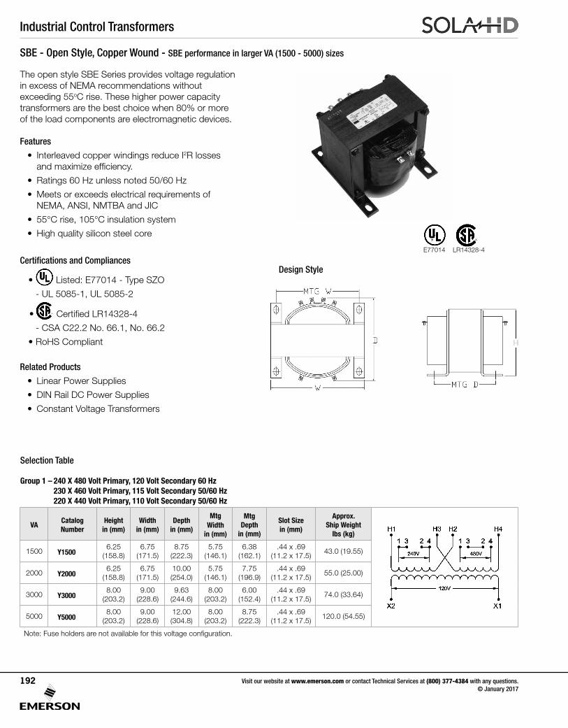
Industrial Control Transformers
Visit our website at www.emerson.com or contact Technical Services at (800) 377-4384 with any questions. © January 2017
192
SBE - Open Style, Copper Wound - SBE performance in larger VA (1500 - 5000) sizes
The open style SBE Series provides voltage regulation in excess of NEMA recommendations without exceeding 55oC rise. These higher power capacity transformers are the best choice when 80% or more of the load components are electromagnetic devices.
Features
• Interleaved copper windings reduce I2R losses and maximize efficiency.
• Ratings 60 Hz unless noted 50/60 Hz
• Meets or exceeds electrical requirements of NEMA, ANSI, NMTBA and JIC
• 55°C rise, 105°C insulation system
• High quality silicon steel core
Certifications and Compliances
• Listed: E77014 - Type SZO
- UL 5085-1, UL 5085-2
• Certified LR14328-4
- CSA C22.2 No. 66.1, No. 66.2
• RoHS Compliant
Related Products
• Linear Power Supplies
• DIN Rail DC Power Supplies
• Constant Voltage Transformers
Selection Table
Group 1 – 240 X 480 Volt Primary, 120 Volt Secondary 60 Hz 230 X 460 Volt Primary, 115 Volt Secondary 50/60 Hz 220 X 440 Volt Primary, 110 Volt Secondary 50/60 Hz
VACatalog Number
Height in (mm)
Width in (mm)
Depth in (mm)
Mtg Width
in (mm)
Mtg Depth
in (mm)
Slot Size in (mm)
Approx. Ship Weight
lbs (kg)
1500 Y15006.25
(158.8)6.75
(171.5)8.75
(222.3)5.75
(146.1)6.38
(162.1).44 x .69
(11.2 x 17.5)43.0 (19.55)
2000 Y20006.25
(158.8)6.75
(171.5)10.00(254.0)
5.75(146.1)
7.75(196.9)
.44 x .69(11.2 x 17.5)
55.0 (25.00)
3000 Y30008.00
(203.2)9.00
(228.6)9.63
(244.6)8.00
(203.2)6.00
(152.4).44 x .69
(11.2 x 17.5)74.0 (33.64)
5000 Y50008.00
(203.2)9.00
(228.6)12.00(304.8)
8.00 (203.2)
8.75(222.3)
.44 x .69(11.2 x 17.5)
120.0 (54.55)
Note: Fuse holders are not available for this voltage configuration.
Design Style
E77014 LR14328-4
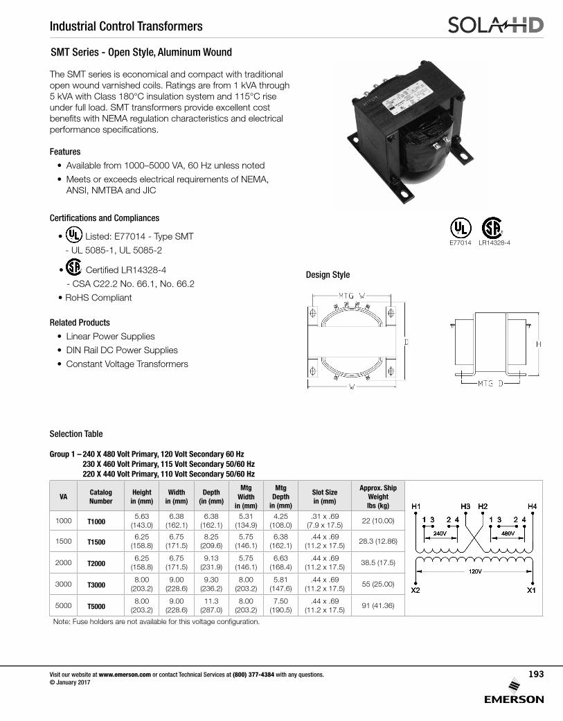
Industrial Control Transformers
Visit our website at www.emerson.com or contact Technical Services at (800) 377-4384 with any questions. © January 2017
193
SMT Series - Open Style, Aluminum Wound
The SMT series is economical and compact with traditional open wound varnished coils. Ratings are from 1 kVA through 5 kVA with Class 180°C insulation system and 115°C rise under full load. SMT transformers provide excellent cost benefits with NEMA regulation characteristics and electrical performance specifications.
Features
• Available from 1000–5000 VA, 60 Hz unless noted
• Meets or exceeds electrical requirements of NEMA, ANSI, NMTBA and JIC
Certifications and Compliances
• Listed: E77014 - Type SMT
- UL 5085-1, UL 5085-2
• Certified LR14328-4
- CSA C22.2 No. 66.1, No. 66.2
• RoHS Compliant
Related Products
• Linear Power Supplies
• DIN Rail DC Power Supplies
• Constant Voltage Transformers
Selection Table
Group 1 – 240 X 480 Volt Primary, 120 Volt Secondary 60 Hz 230 X 460 Volt Primary, 115 Volt Secondary 50/60 Hz 220 X 440 Volt Primary, 110 Volt Secondary 50/60 Hz
VACatalog Number
Height in (mm)
Width in (mm)
Depth (in (mm)
Mtg Width
in (mm)
Mtg Depth
in (mm)
Slot Size in (mm)
Approx. Ship Weight lbs (kg)
1000 T10005.63
(143.0)6.38
(162.1)6.38
(162.1)5.31
(134.9)4.25
(108.0).31 x .69
(7.9 x 17.5)22 (10.00)
1500 T15006.25
(158.8)6.75
(171.5)8.25
(209.6)5.75
(146.1)6.38
(162.1).44 x .69
(11.2 x 17.5)28.3 (12.86)
2000 T20006.25
(158.8)6.75
(171.5)9.13
(231.9)5.75
(146.1)6.63
(168.4).44 x .69
(11.2 x 17.5)38.5 (17.5)
3000 T30008.00
(203.2)9.00
(228.6)9.30
(236.2)8.00
(203.2)5.81
(147.6).44 x .69
(11.2 x 17.5)55 (25.00)
5000 T50008.00
(203.2)9.00
(228.6)11.3
(287.0)8.00
(203.2)7.50
(190.5).44 x .69
(11.2 x 17.5)91 (41.36)
Note: Fuse holders are not available for this voltage configuration.
Design Style
E77014 LR14328-4
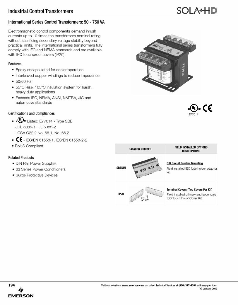
Industrial Control Transformers
Visit our website at www.emerson.com or contact Technical Services at (800) 377-4384 with any questions. © January 2017
194
International Series Control Transformers: 50 - 750 VA
Electromagnetic control components demand inrush currents up to 10 times the transformers nominal rating without sacrificing secondary voltage stability beyond practical limits. The International series transformers fully comply with IEC and NEMA standards and are available with IEC touchproof covers (IP20).
Features
• Epoxy encapsulated for cooler operation
• Interleaved copper windings to reduce impedence
• 50/60 Hz
• 55°C Rise, 105°C insulation system for harsh, heavy duty applications
• Exceeds IEC, NEMA, ANSI, NMTBA, JIC and automotive standards
Certifications and Compliances
• Listed: E77014 - Type SBE
- UL 5085-1, UL 5085-2
- CSA C22.2 No. 66.1, No. 66.2
• - IEC/EN 61558-1, IEC/EN 61558-2-2
• RoHS Compliant
Related Products
• DIN Rail Power Supplies
• 63 Series Power Conditioners
• Surge Protective Devices
E77014
CATALOG NUMBERFIELD INSTALLED OPTIONS
DESCRIPTIONS
SBEDINDIN Circuit Breaker Mounting Field installed IEC fuse holder adaptor kit
IP20Terminal Covers (Two Covers Per Kit)
Field installed primary and secondary IEC Touch Proof Cover Kit.
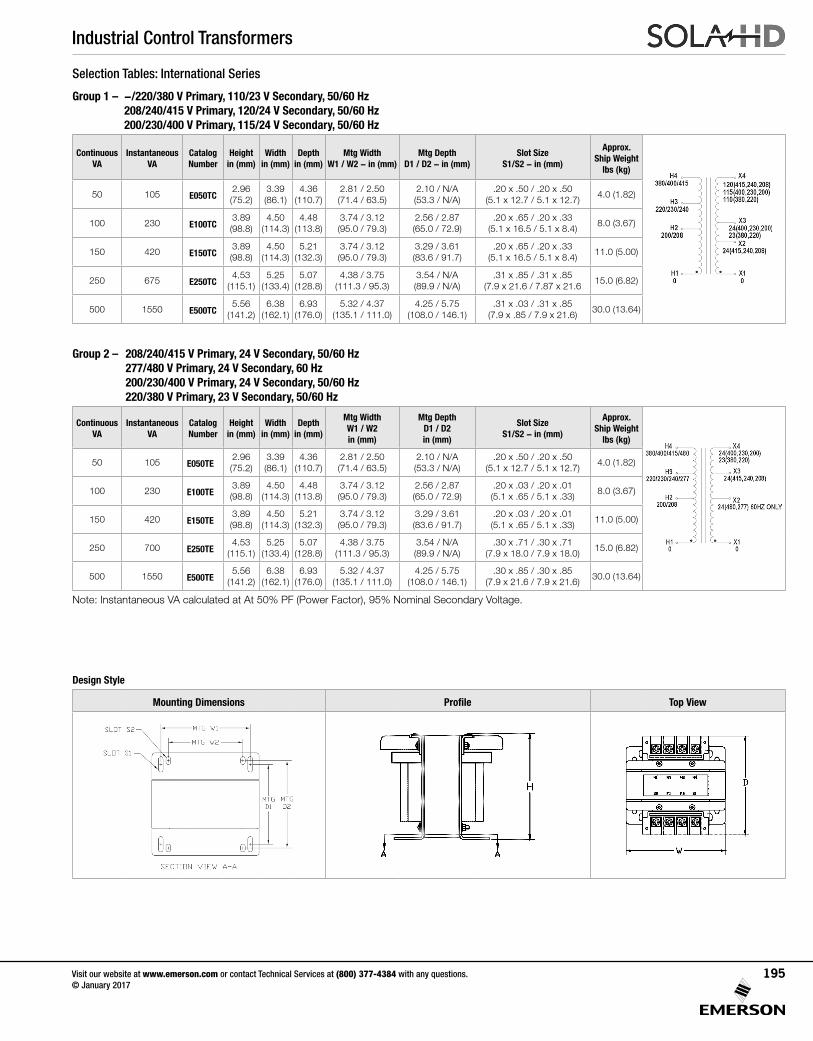
Industrial Control Transformers
Visit our website at www.emerson.com or contact Technical Services at (800) 377-4384 with any questions. © January 2017
195
Selection Tables: International Series
Group 1 – -/220/380 V Primary, 110/23 V Secondary, 50/60 Hz 208/240/415 V Primary, 120/24 V Secondary, 50/60 Hz 200/230/400 V Primary, 115/24 V Secondary, 50/60 Hz
Continuous VA
Instantaneous VA
Catalog Number
Height in (mm)
Width in (mm)
Depth in (mm)
Mtg Width W1 / W2 - in (mm)
Mtg Depth D1 / D2 - in (mm)
Slot SizeS1/S2 - in (mm)
Approx. Ship Weight
lbs (kg)
50 105 E050TC2.96 (75.2)
3.39 (86.1)
4.36 (110.7)
2.81 / 2.50(71.4 / 63.5)
2.10 / N/A(53.3 / N/A)
.20 x .50 / .20 x .50(5.1 x 12.7 / 5.1 x 12.7)
4.0 (1.82)
100 230 E100TC3.89 (98.8)
4.50 (114.3)
4.48(113.8)
3.74 / 3.12(95.0 / 79.3)
2.56 / 2.87(65.0 / 72.9)
.20 x .65 / .20 x .33(5.1 x 16.5 / 5.1 x 8.4)
8.0 (3.67)
150 420 E150TC3.89 (98.8)
4.50 (114.3)
5.21 (132.3)
3.74 / 3.12(95.0 / 79.3)
3.29 / 3.61(83.6 / 91.7)
.20 x .65 / .20 x .33(5.1 x 16.5 / 5.1 x 8.4)
11.0 (5.00)
250 675 E250TC4.53
(115.1)5.25
(133.4)5.07
(128.8)4.38 / 3.75
(111.3 / 95.3)3.54 / N/A(89.9 / N/A)
.31 x .85 / .31 x .85(7.9 x 21.6 / 7.87 x 21.6
15.0 (6.82)
500 1550 E500TC5.56
(141.2)6.38
(162.1)6.93
(176.0)5.32 / 4.37
(135.1 / 111.0)4.25 / 5.75
(108.0 / 146.1).31 x .03 / .31 x .85
(7.9 x .85 / 7.9 x 21.6)30.0 (13.64)
Group 2 – 208/240/415 V Primary, 24 V Secondary, 50/60 Hz 277/480 V Primary, 24 V Secondary, 60 Hz 200/230/400 V Primary, 24 V Secondary, 50/60 Hz 220/380 V Primary, 23 V Secondary, 50/60 Hz
Continuous VA
Instantaneous VA
Catalog Number
Height in (mm)
Width in (mm)
Depth in (mm)
Mtg Width W1 / W2in (mm)
Mtg Depth D1 / D2 in (mm)
Slot SizeS1/S2 - in (mm)
Approx. Ship Weight
lbs (kg)
50 105 E050TE2.96 (75.2)
3.39 (86.1)
4.36 (110.7)
2.81 / 2.50(71.4 / 63.5)
2.10 / N/A(53.3 / N/A)
.20 x .50 / .20 x .50(5.1 x 12.7 / 5.1 x 12.7)
4.0 (1.82)
100 230 E100TE3.89 (98.8)
4.50 (114.3)
4.48(113.8)
3.74 / 3.12(95.0 / 79.3)
2.56 / 2.87(65.0 / 72.9)
.20 x .03 / .20 x .01(5.1 x .65 / 5.1 x .33)
8.0 (3.67)
150 420 E150TE3.89 (98.8)
4.50 (114.3)
5.21 (132.3)
3.74 / 3.12(95.0 / 79.3)
3.29 / 3.61(83.6 / 91.7)
.20 x .03 / .20 x .01(5.1 x .65 / 5.1 x .33)
11.0 (5.00)
250 700 E250TE4.53
(115.1)5.25
(133.4)5.07
(128.8)4.38 / 3.75
(111.3 / 95.3)3.54 / N/A(89.9 / N/A)
.30 x .71 / .30 x .71(7.9 x 18.0 / 7.9 x 18.0)
15.0 (6.82)
500 1550 E500TE5.56
(141.2)6.38
(162.1)6.93
(176.0)5.32 / 4.37
(135.1 / 111.0)4.25 / 5.75
(108.0 / 146.1).30 x .85 / .30 x .85
(7.9 x 21.6 / 7.9 x 21.6)30.0 (13.64)
Note: Instantaneous VA calculated at At 50% PF (Power Factor), 95% Nominal Secondary Voltage.
Design Style
Mounting Dimensions Profile Top View
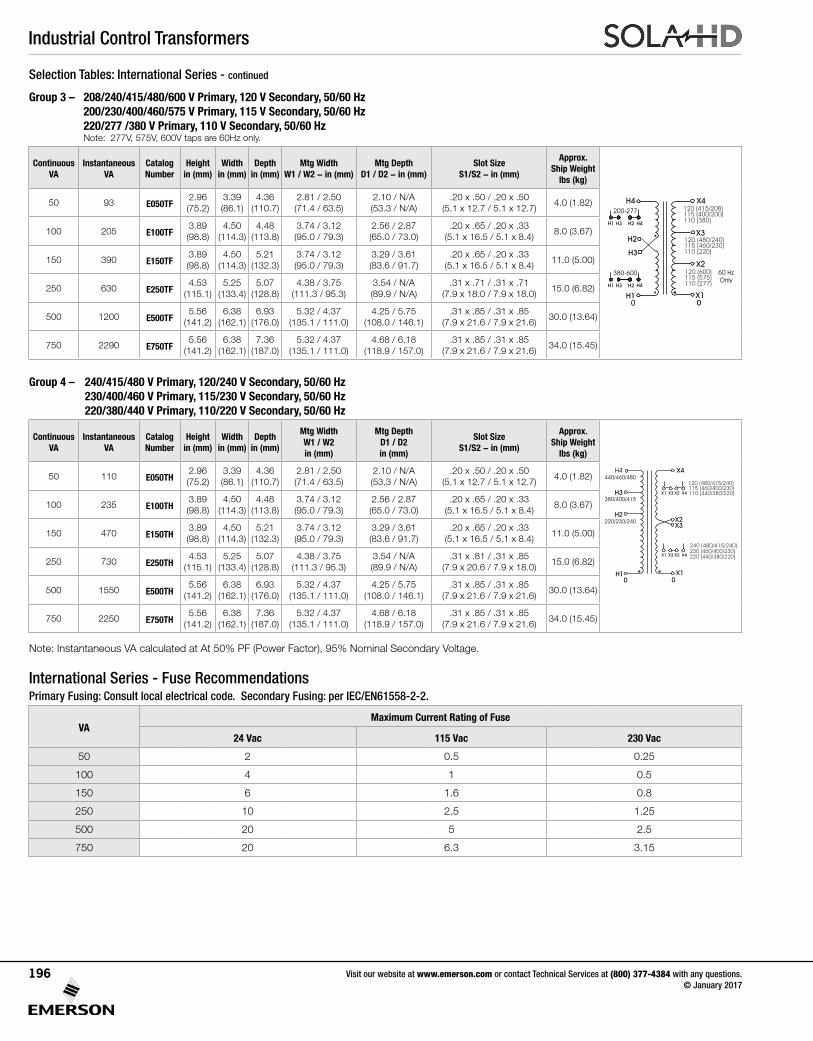
Industrial Control Transformers
Visit our website at www.emerson.com or contact Technical Services at (800) 377-4384 with any questions. © January 2017
196
Selection Tables: International Series - continued
Group 3 – 208/240/415/480/600 V Primary, 120 V Secondary, 50/60 Hz 200/230/400/460/575 V Primary, 115 V Secondary, 50/60 Hz 220/277 /380 V Primary, 110 V Secondary, 50/60 Hz
Note: 277V, 575V, 600V taps are 60Hz only.
Continuous VA
Instantaneous VA
Catalog Number
Height in (mm)
Width in (mm)
Depth in (mm)
Mtg Width W1 / W2 - in (mm)
Mtg Depth D1 / D2 - in (mm)
Slot SizeS1/S2 - in (mm)
Approx. Ship Weight
lbs (kg)
H4
H3
X2
H1050/60 Hz
X3
X4
120 (415/208)115 (400/200)110 (380)
H2
X1
120 (480/240)115 (460/230)110 (220)
120 (600)115 (575)110 (277)
200-277
H3H1 H2 H4
380-600
H3H1 H2 H4
60 Hz
Only
0
50 93 E050TF2.96 (75.2)
3.39 (86.1)
4.36 (110.7)
2.81 / 2.50(71.4 / 63.5)
2.10 / N/A(53.3 / N/A)
.20 x .50 / .20 x .50(5.1 x 12.7 / 5.1 x 12.7)
4.0 (1.82)
100 205 E100TF3.89 (98.8)
4.50 (114.3)
4.48(113.8)
3.74 / 3.12(95.0 / 79.3)
2.56 / 2.87(65.0 / 73.0)
.20 x .65 / .20 x .33(5.1 x 16.5 / 5.1 x 8.4)
8.0 (3.67)
150 390 E150TF3.89 (98.8)
4.50 (114.3)
5.21 (132.3)
3.74 / 3.12(95.0 / 79.3)
3.29 / 3.61(83.6 / 91.7)
.20 x .65 / .20 x .33(5.1 x 16.5 / 5.1 x 8.4)
11.0 (5.00)
250 630 E250TF4.53
(115.1)5.25
(133.4)5.07
(128.8)4.38 / 3.75
(111.3 / 95.3)3.54 / N/A(89.9 / N/A)
.31 x .71 / .31 x .71(7.9 x 18.0 / 7.9 x 18.0)
15.0 (6.82)
500 1200 E500TF5.56
(141.2)6.38
(162.1)6.93
(176.0)5.32 / 4.37
(135.1 / 111.0)4.25 / 5.75
(108.0 / 146.1).31 x .85 / .31 x .85
(7.9 x 21.6 / 7.9 x 21.6)30.0 (13.64)
750 2290 E750TF5.56
(141.2)6.38
(162.1)7.36
(187.0)5.32 / 4.37
(135.1 / 111.0)4.68 / 6.18
(118.9 / 157.0).31 x .85 / .31 x .85
(7.9 x 21.6 / 7.9 x 21.6)34.0 (15.45)
Group 4 – 240/415/480 V Primary, 120/240 V Secondary, 50/60 Hz 230/400/460 V Primary, 115/230 V Secondary, 50/60 Hz 220/380/440 V Primary, 110/220 V Secondary, 50/60 Hz
Continuous VA
Instantaneous VA
Catalog Number
Height in (mm)
Width in (mm)
Depth in (mm)
Mtg Width W1 / W2in (mm)
Mtg Depth D1 / D2 in (mm)
Slot SizeS1/S2 - in (mm)
Approx. Ship Weight
lbs (kg)
440/460/480
H4
H3
H2
380/400/415
220/230/240
H1
0 050/60 Hz
X3
X4
230 (460/400/230)240 (480/415/240)
220 (440/380/220)
120 (480/415/240)115 (460/400/230)110 (440/380/220)X3X1 X2 X4
X3X1 X2 X4
X2
X1
50 110 E050TH2.96 (75.2)
3.39 (86.1)
4.36 (110.7)
2.81 / 2.50(71.4 / 63.5)
2.10 / N/A(53.3 / N/A)
.20 x .50 / .20 x .50(5.1 x 12.7 / 5.1 x 12.7)
4.0 (1.82)
100 235 E100TH3.89 (98.8)
4.50 (114.3)
4.48(113.8)
3.74 / 3.12(95.0 / 79.3)
2.56 / 2.87(65.0 / 73.0)
.20 x .65 / .20 x .33(5.1 x 16.5 / 5.1 x 8.4)
8.0 (3.67)
150 470 E150TH3.89 (98.8)
4.50 (114.3)
5.21 (132.3)
3.74 / 3.12(95.0 / 79.3)
3.29 / 3.61(83.6 / 91.7)
.20 x .65 / .20 x .33(5.1 x 16.5 / 5.1 x 8.4)
11.0 (5.00)
250 730 E250TH4.53
(115.1)5.25
(133.4)5.07
(128.8)4.38 / 3.75
(111.3 / 95.3)3.54 / N/A(89.9 / N/A)
.31 x .81 / .31 x .85(7.9 x 20.6 / 7.9 x 18.0)
15.0 (6.82)
500 1550 E500TH5.56
(141.2)6.38
(162.1)6.93
(176.0)5.32 / 4.37
(135.1 / 111.0)4.25 / 5.75
(108.0 / 146.1).31 x .85 / .31 x .85
(7.9 x 21.6 / 7.9 x 21.6)30.0 (13.64)
750 2250 E750TH5.56
(141.2)6.38
(162.1)7.36
(187.0)5.32 / 4.37
(135.1 / 111.0)4.68 / 6.18
(118.9 / 157.0).31 x .85 / .31 x .85
(7.9 x 21.6 / 7.9 x 21.6)34.0 (15.45)
Note: Instantaneous VA calculated at At 50% PF (Power Factor), 95% Nominal Secondary Voltage.
International Series - Fuse RecommendationsPrimary Fusing: Consult local electrical code. Secondary Fusing: per IEC/EN61558-2-2.
VAMaximum Current Rating of Fuse
24 Vac 115 Vac 230 Vac
50 2 0.5 0.25
100 4 1 0.5
150 6 1.6 0.8
250 10 2.5 1.25
500 20 5 2.5
750 20 6.3 3.15
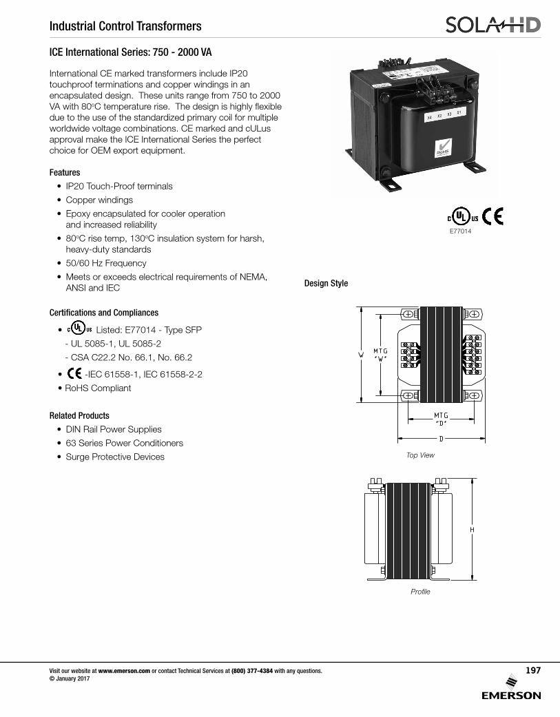
Industrial Control Transformers
Visit our website at www.emerson.com or contact Technical Services at (800) 377-4384 with any questions. © January 2017
197
ICE International Series: 750 - 2000 VA
International CE marked transformers include IP20 touchproof terminations and copper windings in an encapsulated design. These units range from 750 to 2000 VA with 80oC temperature rise. The design is highly flexible due to the use of the standardized primary coil for multiple worldwide voltage combinations. CE marked and cULus approval make the ICE International Series the perfect choice for OEM export equipment.
Features
• IP20 Touch-Proof terminals
• Copper windings
• Epoxy encapsulated for cooler operation and increased reliability
• 80oC rise temp, 130oC insulation system for harsh, heavy-duty standards
• 50/60 Hz Frequency
• Meets or exceeds electrical requirements of NEMA, ANSI and IEC
Certifications and Compliances
• Listed: E77014 - Type SFP
- UL 5085-1, UL 5085-2
- CSA C22.2 No. 66.1, No. 66.2
• -IEC 61558-1, IEC 61558-2-2
• RoHS Compliant
Related Products
• DIN Rail Power Supplies
• 63 Series Power Conditioners
• Surge Protective Devices
Design Style
Top View
Profile
E77014
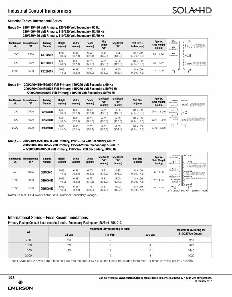
Industrial Control Transformers
Visit our website at www.emerson.com or contact Technical Services at (800) 377-4384 with any questions. © January 2017
198
Selection Tables: International Series
Group 5 – 240/415/480 Volt Primary, 120/240 Volt Secondary, 60 Hz 230/400/460 Volt Primary, 115/230 Volt Secondary, 50/60 Hz 220/380/440 Volt Primary, 110/220 Volt Secondary, 50/60 Hz
Continuous VA
Instantaneous VA
Catalog Number
Height in (mm)
Width in (mm)
Depth in (mm)
Mtg Width "W"
Mtg Depth "D"
Slot Size -inches (mm)
Approx. Ship Weight
lbs (kg)
440/460/480
H4
H3
H2
380/400/415
220/230/240
H1
0 050/60 Hz
X3
X4
230 (460/400/230)240 (480/415/240)
220 (440/380/220)
120 (480/415/240)115 (460/400/230)110 (440/380/220)X3X1 X2 X4
X3X1 X2 X4
X2
X1
1000 2500 CE1000TH5.63
(143.0)6.38
(162.1)6.00
(152.4)5.31
(135.0)4.25
(108.0).31 x .69
(7.9 x 17.5)25 (11.36)
1500 4200 CE1500TH5.63
(143.0)6.38
(162.1)6.75
(171.5)5.31
(135.0)5.00
(127.0).31 x .69
(7.9 x 17.5)32 (14.55)
2000 5500 CE2000TH5.63
(143.0)6.38
(162.1)7.75
(196.9)5.31
(135.0)6.00
(152.4).31 x .69
(7.9 x 17.5)37 (16.82)
Group 6 – 208/240/415/480/600 Volt Primary, 120/240 Volt Secondary, 60 Hz 200/230/400/460/575 Volt Primary, 115/230 Volt Secondary, 50/60 Hz - /220/380/440/550 Volt Primary, 110/220 Volt Secondary, 50/60 Hz
Continuous VA
Instantaneous VA
Catalog Number
Height in (mm)
Width in (mm)
Depth in (mm)
Mtg Width "W"
in (mm)
Mtg Depth "D"
in (mm)
Slot Sizein (mm)
Approx. Ship Weight
lbs (kg)440/460/480
550/575/600
H6
H4
H3
H5
380/400/415
220/230/240
H1
0 050/60 Hz
X3
X4
230 (575/460/400/230/200)240 (600/480/415/240/208)
220 (550/440/380/220/ - )
120 (600/480/415/240/208)115 (575/460/400/230/200)110 (550/440/380/220/ - )X3X1 X2 X4
X3X1 X2 X4
X2
X1
1000 2500 CE1000MH5.63
(143.0)6.38
(162.1)6.00
(152.4)5.31
(135.0)4.25
(108.0).31 x .69
(7.9 x 17.5)25.0 (11.36)
1500 4200 CE1500MH5.63
(143.0)6.38
(162.1)6.75
(171.5)5.31
(135.0)5.00
(127.0).31 x .69
(7.9 x 17.5)32.0 (14.55)
2000 5500 CE2000MH5.63
(143.0)6.38
(162.1)7.75
(196.9)5.31
(135.0)6.00
(152.4).31 x .69
(7.9 x 17.5)37.0 (16.82)
Group 7 – 208/240/415/480/600 Volt Primary, 120/ - /24 Volt Secondary, 60 Hz 200/230/400/460/575 Volt Primary, 115/24/23 Volt Secondary, 50/60 Hz - /220/380/440/550 Volt Primary, 110/23/- Volt Secondary, 50/60 Hz
Continuous VA
Instantaneous VA *
Catalog Number
Height in (mm)
Width in (mm)
Depth in (mm)
Mtg Width "W"
in (mm)
Mtg Depth "D"
in (mm)
Slot Sizein (mm)
Approx. Ship Weight
lbs (kg) 440/460/480
550/575/600
H6
H4
H3
H5
380/400/415
220/230/240
-200/208
H2
H10 050/60 Hz
X1
X2
X3
X6NC
X424 (575/460/400/230/200)
X5
24 (600/480/415/240/208)
23 (550/440/380/220/ - )
120 (600/480/415/240/208)115 (575/460/400/230/200)110 (550/440/380/220/ - )
750 1875 CE750MC5.63
(143.0)6.38
(162.1)6.00
(152.4)5.31
(135.0)4.25
(108.0).31 x .69
(7.9 x 17.5)25 (11.36)
1000 3000 CE1000MC5.63
(143.0)6.38
(162.1)6.75
(171.5)5.31
(135.0)5.00
(127.0).31 x .69
(7.9 x 17.5)32 (14.55)
1500 4500 CE1500MC5.63
(143.0)6.38
(162.1)7.75
(196.9)5.31
(135.0)6.00
(152.4).31 x .69
(7.9 x 17.5)37 (16.82)
Notes: At 50% PF (Power Factor), 95% Nominal Secondary Voltage.
International Series - Fuse RecommendationsPrimary Fusing: Consult local electrical code. Secondary Fusing: per IEC/EN61558-2-2.
VAMaximum Current Rating of Fuse Maximum VA Rating for
110/220Vac Output *24 Vac 115 Vac 230 Vac
750 20 6 - 720
1000 20 8 4 960
1500 20 12 6 1440
2000 - 16 8 1920
* For 110Vac and 220Vac output taps only, de-rate the output by 4% so the fuse is not loaded more than 1.1 times its rating per IEC 615558.
24V output 500 VA maximum load.
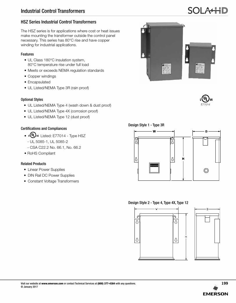
Industrial Control Transformers
Visit our website at www.emerson.com or contact Technical Services at (800) 377-4384 with any questions. © January 2017
199
The HSZ series is for applications where cost or heat issues make mounting the transformer outside the control panel necessary. This series has 80°C rise and have copper winding for industrial applications.
Features
• UL Class 180°C insulation system, 80°C temperature rise under full load
• Meets or exceeds NEMA regulation standards
• Copper windings
• Encapsulated
• UL Listed/NEMA Type 3R (rain proof)
Optional Styles
• UL Listed/NEMA Type 4 (wash down & dust proof)
• UL Listed/NEMA Type 4X (corrosion proof)
• UL Listed/NEMA Type 12 (dust proof)
Certifications and Compliances
• Listed: E77014 - Type HSZ
- UL 5085-1, UL 5085-2
- CSA C22.2 No. 66.1, No. 66.2
• RoHS Compliant
Related Products
• Linear Power Supplies
• DIN Rail DC Power Supplies
• Constant Voltage Transformers
HSZ Series Industrial Control Transformers
Design Style 1 - Type 3R
Design Style 2 - Type 4, Type 4X, Type 12
E77014
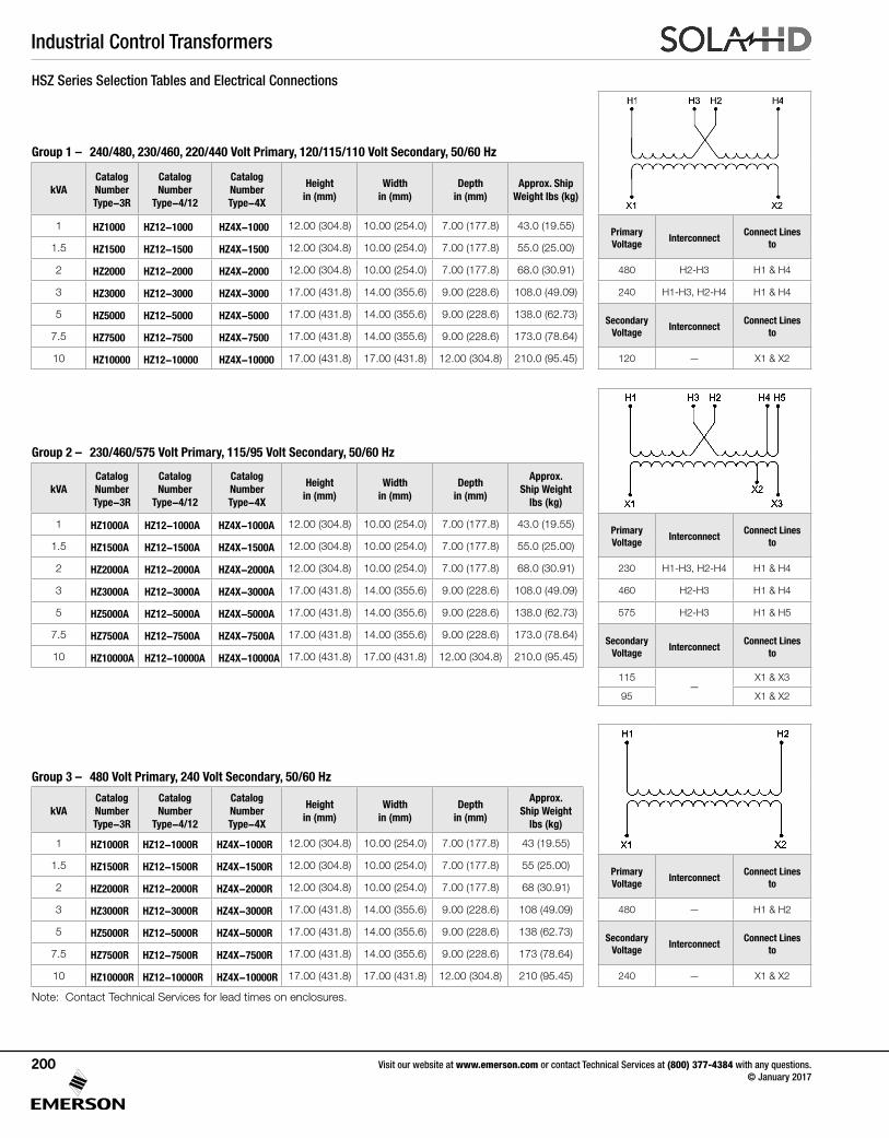
Industrial Control Transformers
Visit our website at www.emerson.com or contact Technical Services at (800) 377-4384 with any questions. © January 2017
200
HSZ Series Selection Tables and Electrical Connections
Group 1 – 240/480, 230/460, 220/440 Volt Primary, 120/115/110 Volt Secondary, 50/60 Hz
kVACatalog Number Type-3R
Catalog Number
Type-4/12
Catalog Number Type-4X
Height in (mm)
Width in (mm)
Depth in (mm)
Approx. Ship Weight lbs (kg)
1 HZ1000 HZ12-1000 HZ4X-1000 12.00 (304.8) 10.00 (254.0) 7.00 (177.8) 43.0 (19.55) Primary Voltage
InterconnectConnect Lines
to1.5 HZ1500 HZ12-1500 HZ4X-1500 12.00 (304.8) 10.00 (254.0) 7.00 (177.8) 55.0 (25.00)
2 HZ2000 HZ12-2000 HZ4X-2000 12.00 (304.8) 10.00 (254.0) 7.00 (177.8) 68.0 (30.91) 480 H2-H3 H1 & H4
3 HZ3000 HZ12-3000 HZ4X-3000 17.00 (431.8) 14.00 (355.6) 9.00 (228.6) 108.0 (49.09) 240 H1-H3, H2-H4 H1 & H4
5 HZ5000 HZ12-5000 HZ4X-5000 17.00 (431.8) 14.00 (355.6) 9.00 (228.6) 138.0 (62.73) Secondary Voltage
InterconnectConnect Lines
to7.5 HZ7500 HZ12-7500 HZ4X-7500 17.00 (431.8) 14.00 (355.6) 9.00 (228.6) 173.0 (78.64)
10 HZ10000 HZ12-10000 HZ4X-10000 17.00 (431.8) 17.00 (431.8) 12.00 (304.8) 210.0 (95.45) 120 — X1 & X2
Group 2 – 230/460/575 Volt Primary, 115/95 Volt Secondary, 50/60 Hz
kVACatalog Number Type-3R
Catalog Number
Type-4/12
Catalog Number Type-4X
Height in (mm)
Width in (mm)
Depth in (mm)
Approx. Ship Weight
lbs (kg)
1 HZ1000A HZ12-1000A HZ4X-1000A 12.00 (304.8) 10.00 (254.0) 7.00 (177.8) 43.0 (19.55) Primary Voltage
InterconnectConnect Lines
to1.5 HZ1500A HZ12-1500A HZ4X-1500A 12.00 (304.8) 10.00 (254.0) 7.00 (177.8) 55.0 (25.00)
2 HZ2000A HZ12-2000A HZ4X-2000A 12.00 (304.8) 10.00 (254.0) 7.00 (177.8) 68.0 (30.91) 230 H1-H3, H2-H4 H1 & H4
3 HZ3000A HZ12-3000A HZ4X-3000A 17.00 (431.8) 14.00 (355.6) 9.00 (228.6) 108.0 (49.09) 460 H2-H3 H1 & H4
5 HZ5000A HZ12-5000A HZ4X-5000A 17.00 (431.8) 14.00 (355.6) 9.00 (228.6) 138.0 (62.73) 575 H2-H3 H1 & H5
7.5 HZ7500A HZ12-7500A HZ4X-7500A 17.00 (431.8) 14.00 (355.6) 9.00 (228.6) 173.0 (78.64) Secondary Voltage
InterconnectConnect Lines
to10 HZ10000A HZ12-10000A HZ4X-10000A 17.00 (431.8) 17.00 (431.8) 12.00 (304.8) 210.0 (95.45)
115—
X1 & X3
95 X1 & X2
Group 3 – 480 Volt Primary, 240 Volt Secondary, 50/60 Hz
kVACatalog NumberType-3R
Catalog Number
Type-4/12
Catalog NumberType-4X
Height in (mm)
Width in (mm)
Depth in (mm)
Approx. Ship Weight
lbs (kg)
1 HZ1000R HZ12-1000R HZ4X-1000R 12.00 (304.8) 10.00 (254.0) 7.00 (177.8) 43 (19.55)
1.5 HZ1500R HZ12-1500R HZ4X-1500R 12.00 (304.8) 10.00 (254.0) 7.00 (177.8) 55 (25.00) Primary Voltage
InterconnectConnect Lines
to2 HZ2000R HZ12-2000R HZ4X-2000R 12.00 (304.8) 10.00 (254.0) 7.00 (177.8) 68 (30.91)
3 HZ3000R HZ12-3000R HZ4X-3000R 17.00 (431.8) 14.00 (355.6) 9.00 (228.6) 108 (49.09) 480 — H1 & H2
5 HZ5000R HZ12-5000R HZ4X-5000R 17.00 (431.8) 14.00 (355.6) 9.00 (228.6) 138 (62.73) Secondary Voltage
InterconnectConnect Lines
to7.5 HZ7500R HZ12-7500R HZ4X-7500R 17.00 (431.8) 14.00 (355.6) 9.00 (228.6) 173 (78.64)
10 HZ10000R HZ12-10000R HZ4X-10000R 17.00 (431.8) 17.00 (431.8) 12.00 (304.8) 210 (95.45) 240 — X1 & X2
Note: Contact Technical Services for lead times on enclosures.
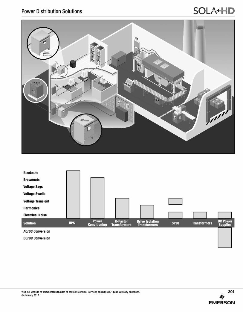
Power Distribution Solutions
Visit our website at www.emerson.com or contact Technical Services at (800) 377-4384 with any questions. © January 2017
201
Blackouts
Brownouts
Voltage Sags
Voltage Swells
Voltage Transient
Harmonics
Electrical Noise
Solution
AC/DC Conversion
DC/DC Conversion
UPS PowerConditioning
Drive IsolationTransformers SPDs DC Power
SuppliesK-Factor
Transformers Transformers
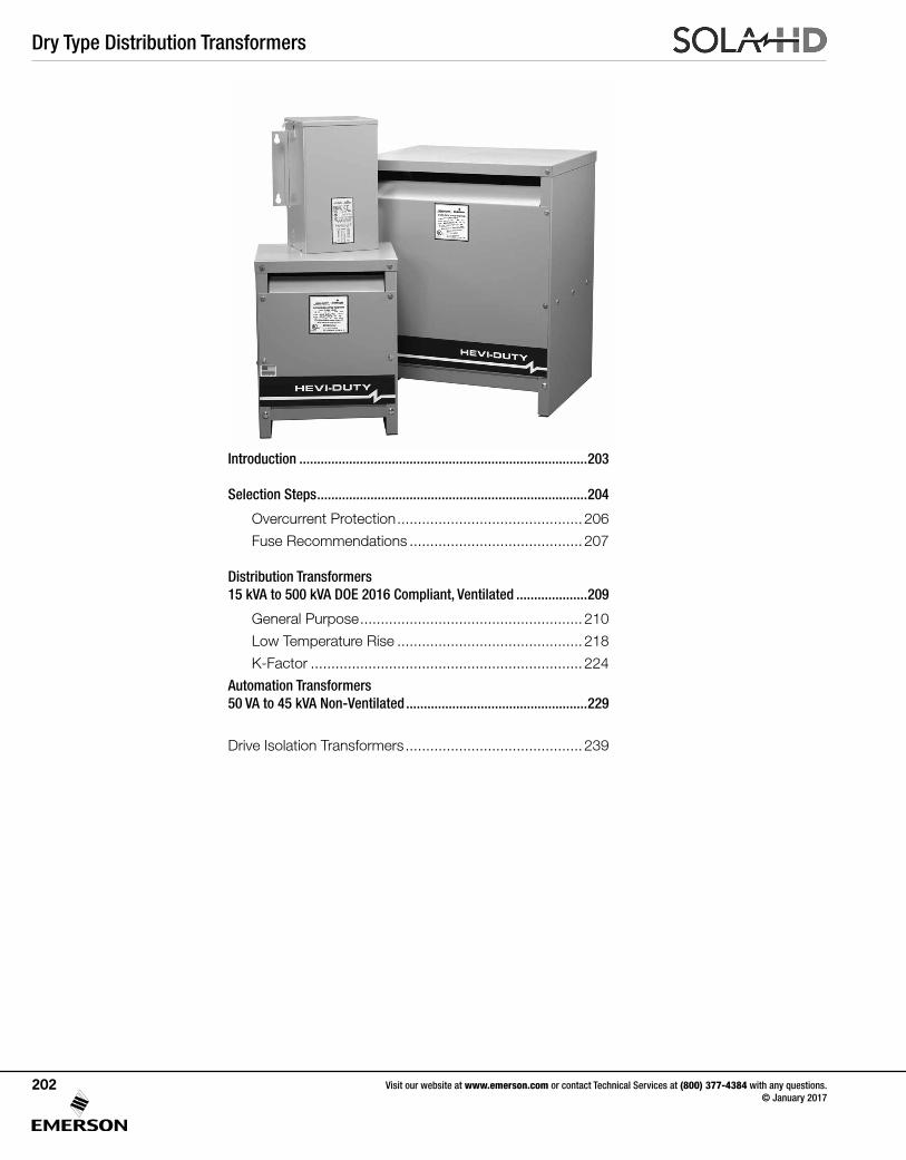
Dry Type Distribution Transformers
Visit our website at www.emerson.com or contact Technical Services at (800) 377-4384 with any questions. © January 2017
202
Introduction .................................................................................203
Selection Steps ............................................................................204
Overcurrent Protection .............................................206
Fuse Recommendations ..........................................207
Distribution Transformers 15 kVA to 500 kVA DOE 2016 Compliant, Ventilated ....................209
General Purpose ......................................................210
Low Temperature Rise .............................................218
K-Factor ..................................................................224
Automation Transformers 50 VA to 45 kVA Non-Ventilated ...................................................229
Drive Isolation Transformers ...........................................239
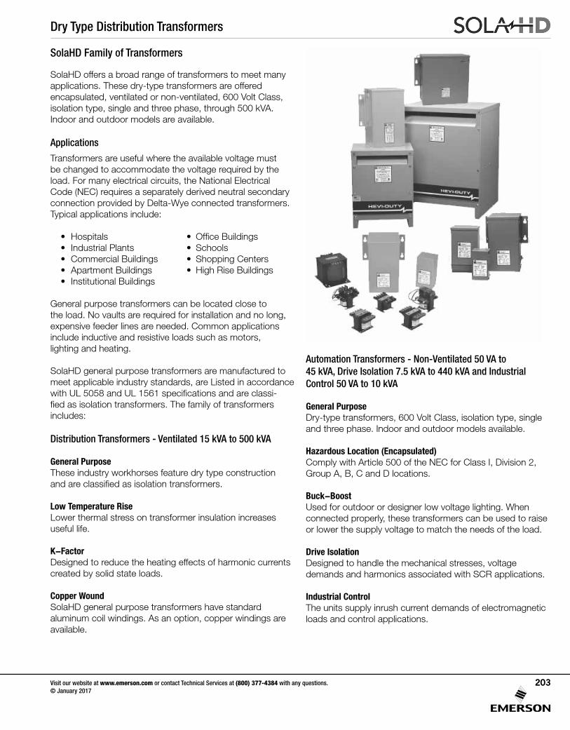
Dry Type Distribution Transformers
Visit our website at www.emerson.com or contact Technical Services at (800) 377-4384 with any questions. © January 2017
203
SolaHD offers a broad range of transformers to meet many applications. These dry-type transformers are offered encapsulated, ventilated or non-ventilated, 600 Volt Class, isolation type, single and three phase, through 500 kVA. Indoor and outdoor models are available.
Applications
Transformers are useful where the available voltage must be changed to accommodate the voltage required by the load. For many electrical circuits, the National Electrical Code (NEC) requires a separately derived neutral secondary connection provided by Delta-Wye connected transformers. Typical applications include:
• Hospitals • OfficeBuildings• Industrial Plants • Schools• CommercialBuildings • ShoppingCenters• ApartmentBuildings • HighRiseBuildings• InstitutionalBuildings
General purpose transformers can be located close to the load. No vaults are required for installation and no long, expensive feeder lines are needed. Common applications include inductive and resistive loads such as motors, lighting and heating.
SolaHD general purpose transformers are manufactured to meet applicable industry standards, are Listed in accordance withUL5058andUL1561specificationsandareclassi-fiedasisolationtransformers.The family of transformers includes:
Distribution Transformers - Ventilated 15 kVA to 500 kVA
General Purpose These industry workhorses feature dry type construction andareclassifiedasisolationtransformers.
Low Temperature RiseLower thermal stress on transformer insulation increases useful life.
K-FactorDesigned to reduce the heating effects of harmonic currents created by solid state loads.
Copper Wound SolaHD general purpose transformers have standard aluminum coil windings. As an option, copper windings are available.
SolaHD Family of Transformers
Automation Transformers - Non-Ventilated 50 VA to 45 kVA, Drive Isolation 7.5 kVA to 440 kVA and Industrial Control 50 VA to 10 kVA
General Purpose Dry-type transformers, 600 Volt Class, isolation type, single and three phase. Indoor and outdoor models available.
Hazardous Location (Encapsulated)Comply with Article 500 of the NEC for Class I, Division 2, GroupA,B,CandDlocations.
Buck-BoostUsed for outdoor or designer low voltage lighting. When connected properly, these transformers can be used to raise or lower the supply voltage to match the needs of the load.
Drive IsolationDesigned to handle the mechanical stresses, voltage demands and harmonics associated with SCR applications.
Industrial ControlThe units supply inrush current demands of electromagnetic loads and control applications.
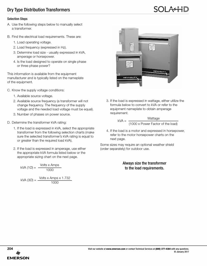
Dry Type Distribution Transformers
Visit our website at www.emerson.com or contact Technical Services at (800) 377-4384 with any questions. © January 2017
204
3. If the load is expressed in wattage, either utilize the formula below to convert to kVA or refer to the equipment nameplate to obtain amperage requirement.
4. If the load is a motor and expressed in horsepower, refer to the motor horsepower charts on the next page.
Some sizes may require an optional weather shield (order separately) for outdoor use.
Always size the transformer to the load requirements. kVA (1Ø) =
Volts x Amps1000
kVA (3Ø) =Volts x Amps x 1.732
1000
Selection Steps
A. Use the following steps below to manually select a transformer.
B.Findtheelectricalloadrequirements.Theseare:
1. Load operating voltage.
2. Load frequency (expressed in Hz).
3. Determine load size - usually expressed in kVA, amperage or horsepower.
4. Is the load designed to operate on single phase or three phase power?
This information is available from the equipment manufacturer and is typically listed on the nameplate of the equipment.
C. Know the supply voltage conditions:
1. Available source voltage.
2. Available source frequency (a transformer will not change frequency. The frequency of the supply voltage and the needed load voltage must be equal).
3. Number of phases on power source.
D. Determine the transformer kVA rating:
1. If the load is expressed in kVA, select the appropriate transformer from the following selection charts (make sure the selected transformer’s kVA rating is equal to or greater than the required load kVA).
2. If the load is expressed in amperage, use either the appropriate kVA formula listed below or the appropriate sizing chart on the next page.
kVA =Wattage
(1000 x Power Factor of the load)
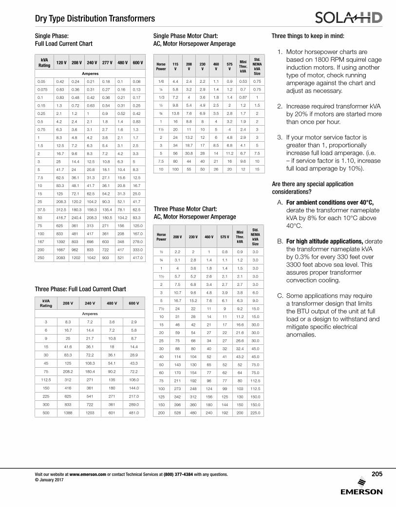
Dry Type Distribution Transformers
Visit our website at www.emerson.com or contact Technical Services at (800) 377-4384 with any questions. © January 2017
205
1. Motor horsepower charts are based on 1800 RPM squirrel cage induction motors. If using another type of motor, check running amperage against the chart and adjust as necessary.
2. Increase required transformer kVA by 20% if motors are started more than once per hour.
3. If your motor service factor is greater than 1, proportionally increase full load amperage. (i.e. – if service factor is 1.10, increase full load amperage by 10%).
Are there any special application considerations?
A. For ambient conditions over 40°C, derate the transformer nameplate kVA by 8% for each 10°C above 40°C.
B. For high altitude applications, derate the transformer nameplate kVA by 0.3% for every 330 feet over 3300 feet above sea level. This assures proper transformer convection cooling.
C. Some applications may require a transformer design that limits theBTUoutputoftheunitatfullload or a design to withstand and mitigatespecificelectrical anomalies.
Single Phase: Full Load Current Chart
Three Phase: Full Load Current Chart
Three Phase Motor Chart:AC, Motor Horsepower Amperage
Single Phase Motor Chart: AC, Motor Horsepower Amperage
Three things to keep in mind:
kVA Rating
120 V 208 V 240 V 277 V 480 V 600 V
Amperes
0.05 0.42 0.24 0.21 0.18 0.1 0.08
0.075 0.63 0.36 0.31 0.27 0.16 0.13
0.1 0.83 0.48 0.42 0.36 0.21 0.17
0.15 1.3 0.72 0.63 0.54 0.31 0.25
0.25 2.1 1.2 1 0.9 0.52 0.42
0.5 4.2 2.4 2.1 1.8 1.4 0.83
0.75 6.3 3.6 3.1 2.7 1.6 1.3
1 8.3 4.8 4.2 3.6 2.1 1.7
1.5 12.5 7.2 6.3 5.4 3.1 2.5
2 16.7 9.6 8.3 7.2 4.2 3.3
3 25 14.4 12.5 10.8 6.3 5
5 41.7 24 20.8 18.1 10.4 8.3
7.5 62.5 36.1 31.3 27.1 15.6 12.5
10 83.3 48.1 41.7 36.1 20.8 16.7
15 125 72.1 62.5 54.2 31.3 25.0
25 208.3 120.2 104.2 90.3 52.1 41.7
37.5 312.5 180.3 156.3 135.4 78.1 62.5
50 416.7 240.4 208.3 180.5 104.2 83.3
75 625 361 313 271 156 125.0
100 833 481 417 361 208 167.0
167 1392 803 696 603 348 278.0
200 1667 962 833 722 417 333.0
250 2083 1202 1042 903 521 417.0
kVA Rating 208 V 240 V 480 V 600 V
Amperes
3 8.3 7.2 3.6 2.9
6 16.7 14.4 7.2 5.8
9 25 21.7 10.8 8.7
15 41.6 36.1 18 14.4
30 83.3 72.2 36.1 28.9
45 125 108.3 54.1 43.3
75 208.2 180.4 90.2 72.2
112.5 312 271 135 108.0
150 416 361 180 144.0
225 625 541 271 217.0
300 833 722 361 289.0
500 1388 1203 601 481.0
Horse Power
115 V
208 V
230 V
460 V
575 V
Mini Tfmr. kVA
Std. NEMA kVA Size
1/6 4.4 2.4 2.2 1.1 0.9 0.53 0.75
¼ 5.8 3.2 2.9 1.4 1.2 0.7 0.75
1/3 7.2 4 3.6 1.8 1.4 0.87 1
½ 9.8 5.4 4.9 2.5 2 1.2 1.5
¾ 13.8 7.6 6.9 3.5 2.8 1.7 2
1 16 8.8 8 4 3.2 1.9 2
1½ 20 11 10 5 4 2.4 3
2 24 13.2 12 6 4.8 2.9 3
3 34 18.7 17 8.5 6.8 4.1 5
5 56 30.8 28 14 11.2 6.7 7.5
7.5 80 44 40 21 16 9.6 10
10 100 55 50 26 20 12 15
Horse Power
208 V 230 V 460 V 575 VMini Tfmr.kVA
Std. NEMAkVASize
½ 2.2 2 1 0.8 0.9 3.0
¾ 3.1 2.8 1.4 1.1 1.2 3.0
1 4 3.6 1.8 1.4 1.5 3.0
1½ 5.7 5.2 2.6 2.1 2.1 3.0
2 7.5 6.8 3.4 2.7 2.7 3.0
3 10.7 9.6 4.8 3.9 3.8 6.0
5 16.7 15.2 7.6 6.1 6.3 9.0
7½ 24 22 11 9 9.2 15.0
10 31 28 14 11 11.2 15.0
15 46 42 21 17 16.6 30.0
20 59 54 27 22 21.6 30.0
25 75 68 34 27 26.6 30.0
30 88 80 40 32 32.4 45.0
40 114 104 52 41 43.2 45.0
50 143 130 65 52 52 75.0
60 170 154 77 62 64 75.0
75 211 192 96 77 80 112.5
100 273 248 124 99 103 112.5
125 342 312 156 125 130 150.0
150 396 360 180 144 150 150.0
200 528 480 240 192 200 225.0
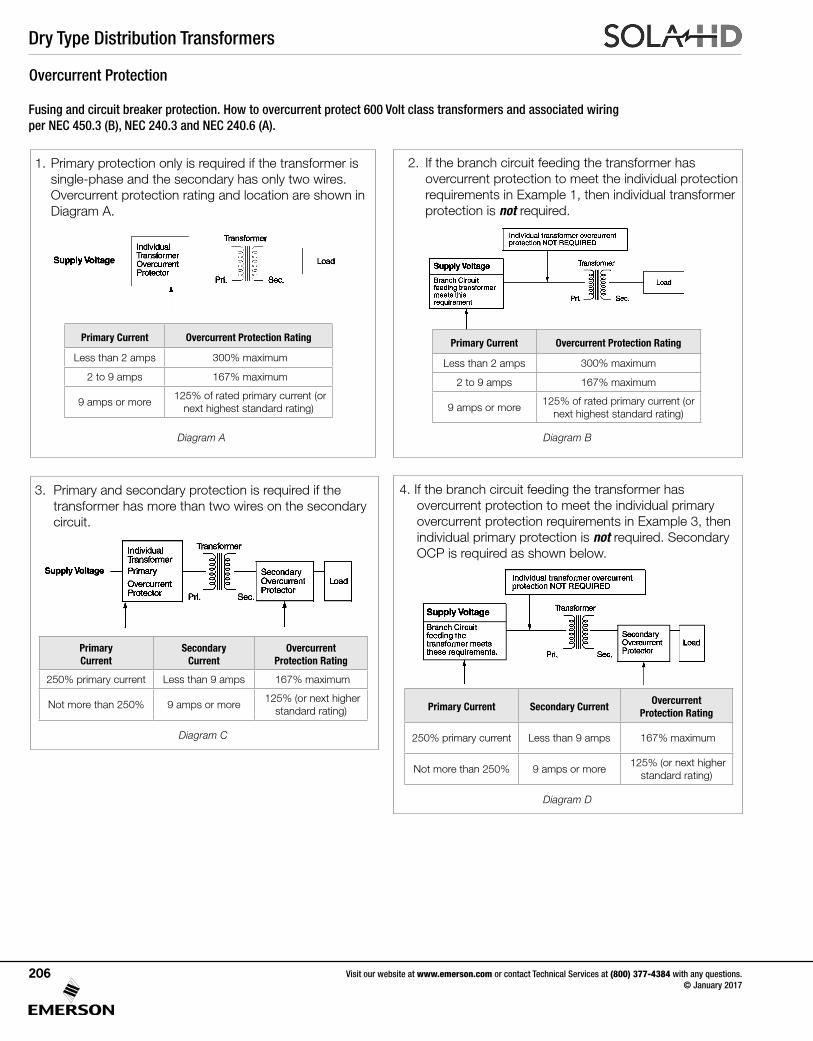
Dry Type Distribution Transformers
Visit our website at www.emerson.com or contact Technical Services at (800) 377-4384 with any questions. © January 2017
206
Overcurrent Protection
Fusing and circuit breaker protection. How to overcurrent protect 600 Volt class transformers and associated wiring per NEC 450.3 (B), NEC 240.3 and NEC 240.6 (A).
1. Primary protection only is required if the transformer is single-phase and the secondary has only two wires.
Overcurrent protection rating and location are shown in Diagram A.
Diagram A
2. If the branch circuit feeding the transformer has overcurrent protection to meet the individual protection requirements in Example 1, then individual transformer protection is not required.
Diagram B
3. Primary and secondary protection is required if the transformer has more than two wires on the secondary circuit.
Diagram C
4. If the branch circuit feeding the transformer has overcurrent protection to meet the individual primary overcurrent protection requirements in Example 3, then individual primary protection is not required. Secondary OCP is required as shown below.
Diagram D
Primary Current Overcurrent Protection Rating
Less than 2 amps 300% maximum
2 to 9 amps 167% maximum
9 amps or more 125% of rated primary current (or
next highest standard rating)
Primary Current Overcurrent Protection Rating
Less than 2 amps 300% maximum
2 to 9 amps 167% maximum
9 amps or more125% of rated primary current (or
next highest standard rating)
Primary Current
Secondary Current
Overcurrent Protection Rating
250% primary current Less than 9 amps 167% maximum
Not more than 250% 9 amps or more 125% (or next higher
standard rating) Primary Current Secondary CurrentOvercurrent
Protection Rating
250% primary current Less than 9 amps 167% maximum
Not more than 250% 9 amps or more 125% (or next higher
standard rating)
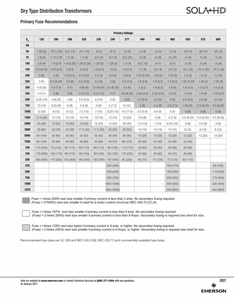
Dry Type Distribution Transformers
Visit our website at www.emerson.com or contact Technical Services at (800) 377-4384 with any questions. © January 2017
207
Fuse = I times 125% next size higher if primary current is 9 amp. or higher. No secondary fusing required.(Fuse) = (I times 250%) next size smaller if primary current is 9 Amps. or higher. Secondary fusing is required see chart for size.
Fuse = I times 167% next size smaller if primary current is less than 9 amp. No secondary fusing required.(Fuse) = (I times 250%) next size smaller if primary current is less than 9 Amps. Secondary fusing is required see chart for size.
Fuse = I times 300% next size smaller if primary current is less than 2 amp. No secondary fusing required.(Fuse) = (I*500%) next size smaller if used for a motor control circuit per NEC 430.72 (C) (4).
Primary Fuse Recommendations
RecommendedfusesizesperUL508andNEC450.3(B),NEC430.72andcommerciallyavailabletypefuses.
Primary Voltage
Vin 120 200 208 220 230 240 277 440 460 480 550 575 600
VA
50 1.25 (2) .75 (1.25) .6 (1.13) .6 (1.13) .6 (1) .6 (1) .5 (.8) .3 (.5) .3 (.5) .3 (.5) .25 (.4) .25 (.4) .25 (.4)
75 1.8 (3) 1.13 (1.8) 1 (1.8) 1 (1.6) .8 (1.6) .8 (1.5) .8 (1.25) .5 (.8) .4 (.8) .4 (.75) .4 (.6) .3 (.6) .3 (.6)
100 2.5 (4) 1.5 (2.5) 1.4 (2.25) 1.25 (2.25) 1.25 (2) 1.25 (2) 1 (1.8) .6 (1.13) .6 (1) .6 (1) .5 (.8) .5 (.8) .5 (.8)
150 3.5 (6.25) 2.25 (3.5) 2 (3.5) 2 (3.2) 1.8 (3.2) 1.8 (3) 1.6 (2.5) 1 (1.6) .8 (1.6) .8 (1.5) .8 (1.25) .75 (1.25) .75 (1.25)
200 5 (8) 3 (5) 2.8 (4.5) 2.5 (4.5) 2.5 (4) 2.5 (4) 2 (3.5) 1.25 (2.25) 1.25 (2) 1.25 (2) 1 (1.8) 1 (1.5) 1 (1.6)
250 3 (5) 3.5 (6.25) 3.5 (6) 3.2 (5.6) 3.2 (5) 3 (5) 2.5 (4.5) 1.6 (2.8) 1.6 (2.5) 1.5 (2.5) 1.25 (2.25) 1.25 (2) 1.25 (2)
300 4 (6.25) 4.5 (7.5) 4 (7) 4 (6.25) 3.5 (6.25) 3.5 (6.25) 3.2 (5) 2 (3.2) 1.8 (3.2) 1.8 (3) 1.6 (2.5) 1.5 (2.5) 1.5 (2.5)
350 4.5 (7) 5 (8) 5 (8) 4.5 (7.5) 4.5 (7.5) 4 (7) 3.5 (6.25) 2.25 (3.5) 2.25 (3.5) 2 (3.5) 1.8 (3) 1.8 (3) 1.75 (2.5)
500 6.25 (10) 4 (6.25) 4 (6) 3.5 (5.6) 3.5 (5) 3 (5) 5 (9) 3.2 (5.6) 3.2 (5) 3 (5) 2.5 (4.5) 2.5 (4) 2.5 (4)
750 10 (15) 6.25 (9) 6 (9) 5.6 (8) 5 (8) 5 (7.5) 8 (12) 5 (8) 4.5 (8) 4.5 (7.5) 4 (6.25) 3.5 (6.25) 3.5 (6.25)
1000 12 (20) 8 (12) 8 (12) 7.5 (10) 7 (10) 6.25 (10) 10 (17.5) 3.5 (5.6) 3.6 (5) 3 (5) 5 (9) 5 (8) 5 (8)
1500 17.5 (30) 12 (15) 12 (15) 10 (15) 10 (15) 10 (15) 15 (25) 5.6 (8) 5 (8) 5 (7.5) 4.5 (6.25) 4.5 (6.25) 4.5 (6.25)
2000 25 (40) 15 (25) 15 (20) 15 (20) 12 (20) 12 (20) 20 (35) 7.5 (10) 7 (10) 6.25 (10) 6 (9) 5.6 (8) 5 (8)
3000 35 (60) 20 (35) 20 (35) 17.5 (30) 17.5 (30) 20 (30) 35 (50) 10 (15) 10 (15) 10 (15) 9 (12) 8 (12) 8 (12)
5000 60 (100) 35 (60) 30 (60) 30 (50) 30 (50) 30 (50) 60 (90) 15 (25) 15 (25) 15 (25) 12 (20) 12 (20) 12 (20)
7500 80 (150) 50 (90) 45 (90) 45 (80) 45 (80) 40 (70) 90 (125) 25 (40) 25 (40) 20 (35) 20 (30)
10K 110 (200) 70 (125) 60 (110) 60 (110) 60 (110) 60 (100) 110 (175) 30 (50) 30 (50) 30 (50) 25 (45)
15K 175 (300) 100 (175) 90 (175) 90 (150) 90 (150) 80 (150) 175 (250) 45 (80) 45 (80) 40 (70) 35 (60)
25K 300 (500) 175 (300) 150 (300) 150 (250) 150 (250) 150 (250) 90 (250) 60 (70) 70 (125) 70 (125) 60 (110)
37K 200 (350) 100 (175) 80 (150)
50K 300 (500) 150 (250) 110 (200)
75K 400 (750) 200 (350) 175 (300)
100K 600 (1000) 300 (500) 225 (400)
167K 900 (1600) 450 (850) 350 (650)
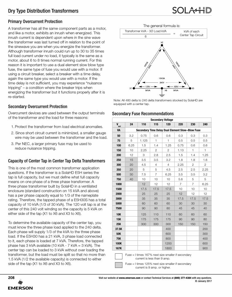
Dry Type Distribution Transformers
Visit our website at www.emerson.com or contact Technical Services at (800) 377-4384 with any questions. © January 2017
208
Secondary Fuse RecommendationsSecondary Voltage
VOUT
24 110 115 120 220 230 240
VA Secondary Time Delay Dual Element Slow-Blow Fuse
50 3.2 0.75 0.6 0.6 0.3 0.3 0.3
75 5 1.125 1 1 0.5 0.5 0.5
100 6.25 1.5 1.4 1.25 0.75 0.6 0.6
150 10 2.25 2 2 1.13 1 1
200 12 3 2.8 2.5 1.5 1.4 1.25
250 15 3.5 3.5 3.2 1.8 1.8 1.6
300 20 4.5 4 4 2.25 2 2
350 20 5 5 4.5 2.5 2.5 2.25
500 30 7.5 7 6.25 3.5 3.5 3.2
750 40 10 10 10 5.6 5 5
1000 12 12 12 7 7 6.25
1500 17.5 17.5 17.5 10 10 10
2000 25 25 25 12 12 12
3000 35 35 35 17.5 17.5 17.5
5000 60 60 60 30 30 30
7500 90 90 80 45 45 40
10K 125 110 110 60 60 60
15K 175 175 175 90 90 80
25K 300 300 300 150 150 150
37.5K 400 200
50K 600 300
75K 800 400
100K 1200 600
167K 1800 900
Fuse = I times 167% next size smaller if secondary current is less than 9 amp.
Fuse = I times 125% next size smaller if secondary current is 9 amp. or higher.
A transformer has all the same component parts as a motor, and like a motor, exhibits an inrush when energized. This inrush current is dependent upon where in the sine wave the transformer was last turned off in relation to the point of the sinewave you are when you energize the transformer. Although transformer inrush could run up to 30 to 35 times full load current under no load, it typically is the same as a motor, about 6 to 8 times normal running current. For this reason it is important to use a dual element slow blow type fuse, the same type of fuse you would use with a motor. If using a circuit breaker, select a breaker with a time delay, again the same type you would use with a motor. If the timedelayisnotsufficient,youmayexperience“nuisancetripping” – a condition where the breaker trips when energizing the transformer but it functions properly after it is re-started.
Secondary Overcurrent ProtectionOvercurrent devices are used between the output terminals of the transformer and the load for three reasons:
1. Protect the transformer from load electrical anomalies.
2. Since short circuit current is minimized, a smaller gauge wire may be used between the transformer and the load.
3. Per NEC, a larger primary fuse may be used to reduce nuisance tripping.
This is one of the most common transformer application questions. If the transformer is a SolaHD E5H series the tapisfullcapacity,butwemustdefinewhatfullcapacitymeans on one phase of a three phase transformer. A three phase transformer built by SolaHD in a ventilated enclosure (standard construction on 15 kVA and above) has a per phase capacity equal to 1/3 of the nameplate rating. Therefore, the tapped phase of a E5H30S has a total capacity of 10 kVA (1/3 of 30 kVA). The 120 volt tap is at the center of this 240 volt winding so the capacity is 5 kVA on either side of the tap (X1 to X6 and X3 to X6).
To determine the available capacity of the center tap, you must know the three phase load applied to the 240 delta. Each phase will supply 1/3 of the kVA to the three phase load. If the E5H30 has a 21 kVA, 3 phase load connected to it, each phase is loaded at 7 kVA. Therefore, the tapped phase has 3 kVA available (10 kVA - 7 kVA = 3 kVA). The center tap can be loaded to 3 kVA without over loading the transformer, but the load must be split so that no more than 1.5 kVA (1/2 the available capacity) is connected to either side of the tap (X1 to X6 and X3 to X6).
Primary Overcurrent Protection
Capacity of Center Tap in Center Tap Delta Transformers
The general formula is:
Note: All 480 delta to 240 delta transformers stocked by SolaHD are equipped with a center tap.
Transformer kVA - 3Ø Load kVA
6=
kVA of eachCenter Tap Circuit
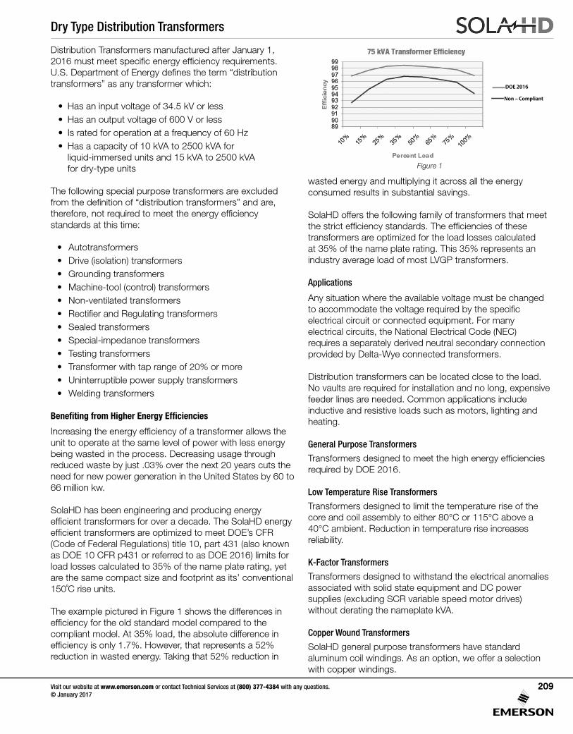
Dry Type Distribution Transformers
Visit our website at www.emerson.com or contact Technical Services at (800) 377-4384 with any questions. © January 2017
209
Figure 1
Distribution Transformers manufactured after January 1, 2016mustmeetspecificenergyefficiencyrequirements.U.S.DepartmentofEnergydefinestheterm“distributiontransformers” as any transformer which:
• Has an input voltage of 34.5 kV or less• Has an output voltage of 600 V or less• Is rated for operation at a frequency of 60 Hz • Has a capacity of 10 kVA to 2500 kVA for
liquid-immersed units and 15 kVA to 2500 kVA for dry-type units
The following special purpose transformers are excluded fromthedefinitionof“distributiontransformers”andare,therefore,notrequiredtomeettheenergyefficiencystandards at this time:
• Autotransformers• Drive (isolation) transformers• Grounding transformers• Machine-tool (control) transformers• Non-ventilated transformers•RectifierandRegulatingtransformers• Sealed transformers• Special-impedance transformers• Testing transformers• Transformer with tap range of 20% or more• Uninterruptible power supply transformers• Welding transformers
Benefiting from Higher Energy Efficiencies
Increasingtheenergyefficiencyofatransformerallowstheunit to operate at the same level of power with less energy being wasted in the process. Decreasing usage through reduced waste by just .03% over the next 20 years cuts the need for new power generation in the United States by 60 to 66 million kw.
SolaHD has been engineering and producing energy efficienttransformersforoveradecade.TheSolaHDenergyefficienttransformersareoptimizedtomeetDOE’sCFR(Code of Federal Regulations) title 10, part 431 (also known as DOE 10 CFR p431 or referred to as DOE 2016) limits for load losses calculated to 35% of the name plate rating, yet are the same compact size and footprint as its’ conventional 150˚Criseunits.
The example pictured in Figure 1 shows the differences in efficiencyfortheoldstandardmodelcomparedtothe compliant model. At 35% load, the absolute difference in efficiencyisonly1.7%.However,thatrepresentsa52%reduction in wasted energy. Taking that 52% reduction in
wasted energy and multiplying it across all the energy consumed results in substantial savings.
SolaHD offers the following family of transformers that meet thestrictefficiencystandards.Theefficienciesofthesetransformers are optimized for the load losses calculated at 35% of the name plate rating. This 35% represents an industry average load of most LVGP transformers.
Applications
Any situation where the available voltage must be changed toaccommodatethevoltagerequiredbythespecific electrical circuit or connected equipment. For many electrical circuits, the National Electrical Code (NEC) requires a separately derived neutral secondary connection provided by Delta-Wye connected transformers.
Distribution transformers can be located close to the load. No vaults are required for installation and no long, expensive feeder lines are needed. Common applications include inductive and resistive loads such as motors, lighting and heating.
General Purpose Transformers
Transformersdesignedtomeetthehighenergyefficienciesrequired by DOE 2016.
Low Temperature Rise Transformers
Transformers designed to limit the temperature rise of the core and coil assembly to either 80°C or 115°C above a 40°C ambient. Reduction in temperature rise increases reliability.
K-Factor Transformers
Transformers designed to withstand the electrical anomalies associated with solid state equipment and DC power supplies (excluding SCR variable speed motor drives) without derating the nameplate kVA.
Copper Wound Transformers
SolaHD general purpose transformers have standard aluminum coil windings. As an option, we offer a selection with copper windings.
DOE 2016
Non – Compliant
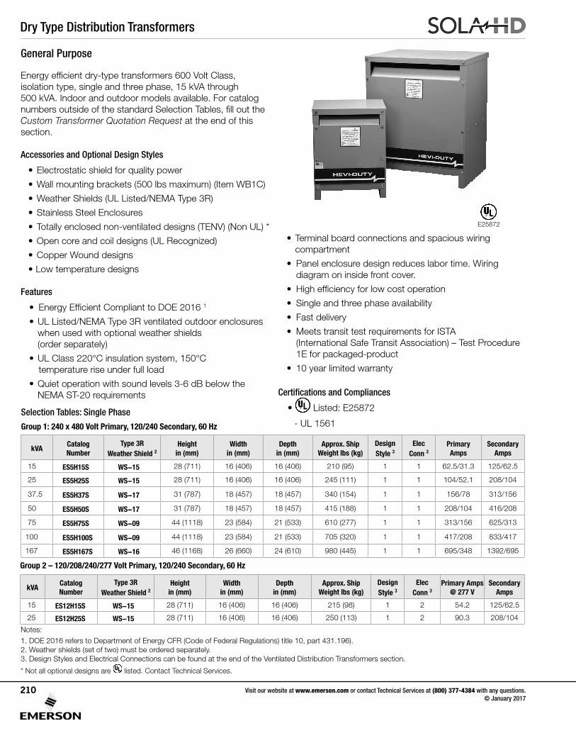
Dry Type Distribution Transformers
Visit our website at www.emerson.com or contact Technical Services at (800) 377-4384 with any questions. © January 2017
210
kVACatalog Number
Type 3R Weather Shield 2
Height in (mm)
Width in (mm)
Depth in (mm)
Approx. Ship Weight lbs (kg)
DesignStyle 3
Elec Conn 3
Primary Amps@ 277 V
Secondary Amps
15 ES12H15S WS-15 28 (711) 16 (406) 16 (406) 215 (98) 1 2 54.2 125/62.5
25 ES12H25S WS-15 28 (711) 16 (406) 16 (406) 250 (113) 1 2 90.3 208/104
Energyefficientdry-typetransformers600VoltClass, isolation type, single and three phase, 15 kVA through 500 kVA. Indoor and outdoor models available. For catalog numbersoutsideofthestandardSelectionTables,fillouttheCustom Transformer Quotation Request at the end of this section.
Accessories and Optional Design Styles
• Electrostatic shield for quality power
•Wallmountingbrackets(500lbsmaximum)(ItemWB1C)
• Weather Shields (UL Listed/NEMA Type 3R)
• Stainless Steel Enclosures
• Totally enclosed non-ventilated designs (TENV) (Non UL) *
• Open core and coil designs (UL Recognized)
• Copper Wound designs
• Low temperature designs
Features
• EnergyEfficientComplianttoDOE20161
• UL Listed/NEMA Type 3R ventilated outdoor enclosures when used with optional weather shields (order separately)
• UL Class 220°C insulation system, 150°C temperature rise under full load
•Quietoperationwithsoundlevels3-6dBbelowtheNEMA ST-20 requirements
• Terminal board connections and spacious wiring compartment
• Panel enclosure design reduces labor time. Wiring diagram on inside front cover.
• Highefficiencyforlowcostoperation
• Single and three phase availability
• Fast delivery
• Meets transit test requirements for ISTA (International Safe Transit Association) – Test Procedure 1E for packaged-product
• 10 year limited warranty
Certifications and Compliances
• Listed: E25872
- UL 1561 Selection Tables: Single Phase
Group 1: 240 x 480 Volt Primary, 120/240 Secondary, 60 Hz
kVACatalog Number
Type 3R Weather Shield 2
Height in (mm)
Width in (mm)
Depth in (mm)
Approx. Ship Weight lbs (kg)
DesignStyle 3
Elec Conn 3
Primary Amps
Secondary Amps
15 ES5H15S WS-15 28 (711) 16 (406) 16 (406) 210 (95) 1 1 62.5/31.3 125/62.5
25 ES5H25S WS-15 28 (711) 16 (406) 16 (406) 245 (111) 1 1 104/52.1 208/104
37.5 ES5H37S WS-17 31 (787) 18 (457) 18 (457) 340 (154) 1 1 156/78 313/156
50 ES5H50S WS-17 31 (787) 18 (457) 18 (457) 415 (188) 1 1 208/104 416/208
75 ES5H75S WS-09 44 (1118) 23 (584) 21 (533) 610 (277) 1 1 313/156 625/313
100 ES5H100S WS-09 44 (1118) 23 (584) 21 (533) 705 (320) 1 1 417/208 833/417
167 ES5H167S WS-16 46 (1168) 26 (660) 24 (610) 980 (445) 1 1 695/348 1392/695
Notes:1. DOE 2016 refers to Department of Energy CFR (Code of Federal Regulations) title 10, part 431.196). 2. Weather shields (set of two) must be ordered separately. 3. Design Styles and Electrical Connections can be found at the end of the Ventilated Distribution Transformers section.
Group 2 – 120/208/240/277 Volt Primary, 120/240 Secondary, 60 Hz
General Purpose
* Not all optional designs are listed. Contact Technical Services.
E25872
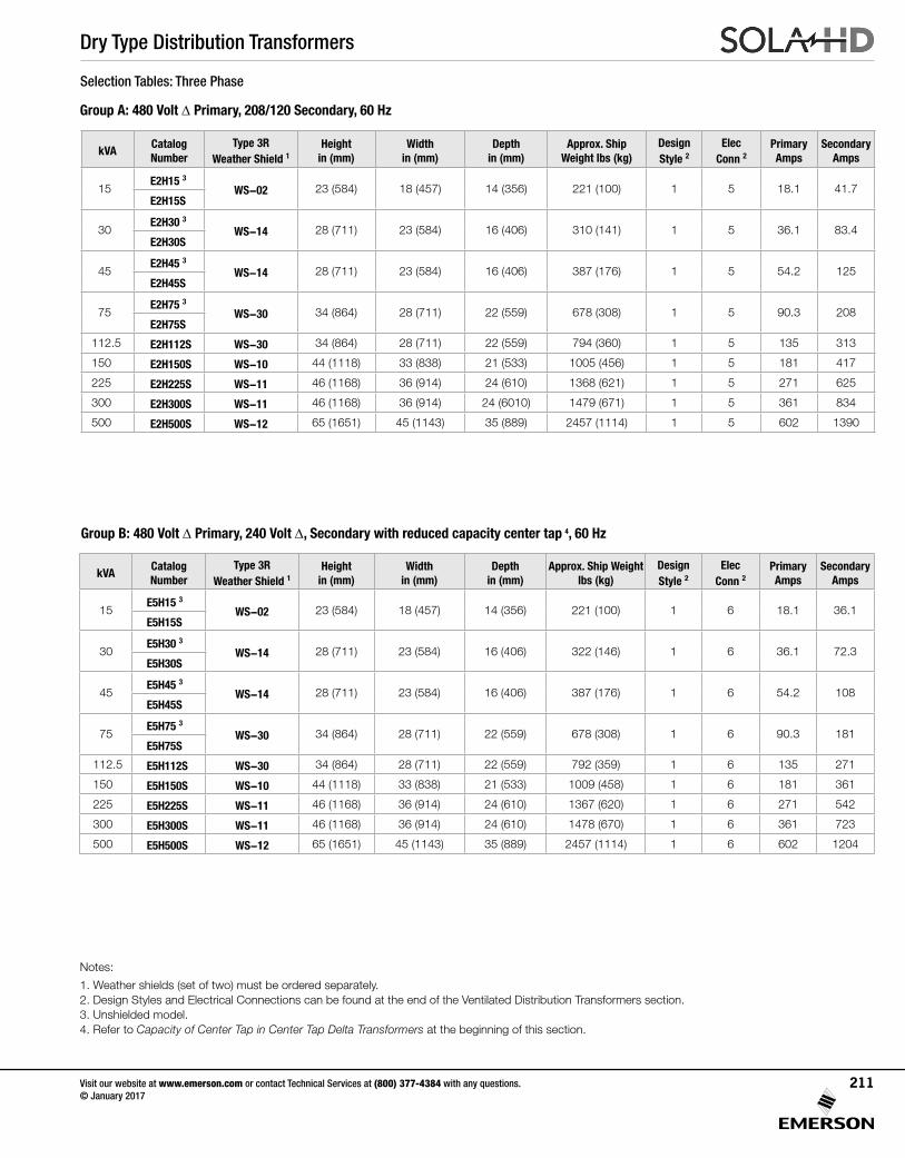
Dry Type Distribution Transformers
Visit our website at www.emerson.com or contact Technical Services at (800) 377-4384 with any questions. © January 2017
211
Group A: 480 Volt Δ Primary, 208/120 Secondary, 60 Hz
Selection Tables: Three Phase
Group B: 480 Volt Δ Primary, 240 Volt Δ, Secondary with reduced capacity center tap 4, 60 Hz
Notes:
1. Weather shields (set of two) must be ordered separately. 2. Design Styles and Electrical Connections can be found at the end of the Ventilated Distribution Transformers section.3. Unshielded model. 4. Refer to Capacity of Center Tap in Center Tap Delta Transformers at the beginning of this section.
kVACatalog Number
Type 3R Weather Shield 1
Height in (mm)
Width in (mm)
Depth in (mm)
Approx. Ship Weight lbs (kg)
DesignStyle 2
Elec Conn 2
Primary Amps
Secondary Amps
15E2H15 3
WS-02 23 (584) 18 (457) 14 (356) 221 (100) 1 5 18.1 41.7E2H15S
30E2H30 3
WS-14 28 (711) 23 (584) 16 (406) 310 (141) 1 5 36.1 83.4E2H30S
45E2H45 3
WS-14 28 (711) 23 (584) 16 (406) 387 (176) 1 5 54.2 125E2H45S
75E2H75 3
WS-30 34 (864) 28 (711) 22 (559) 678 (308) 1 5 90.3 208E2H75S
112.5 E2H112S WS-30 34 (864) 28 (711) 22 (559) 794 (360) 1 5 135 313
150 E2H150S WS-10 44 (1118) 33 (838) 21 (533) 1005 (456) 1 5 181 417
225 E2H225S WS-11 46 (1168) 36 (914) 24 (610) 1368 (621) 1 5 271 625
300 E2H300S WS-11 46 (1168) 36 (914) 24 (6010) 1479 (671) 1 5 361 834
500 E2H500S WS-12 65 (1651) 45 (1143) 35 (889) 2457 (1114) 1 5 602 1390
kVACatalog Number
Type 3R Weather Shield 1
Height in (mm)
Width in (mm)
Depth in (mm)
Approx. Ship Weight lbs (kg)
DesignStyle 2
Elec Conn 2
Primary Amps
Secondary Amps
15E5H15 3
WS-02 23 (584) 18 (457) 14 (356) 221 (100) 1 6 18.1 36.1E5H15S
30E5H30 3
WS-14 28 (711) 23 (584) 16 (406) 322 (146) 1 6 36.1 72.3E5H30S
45E5H45 3
WS-14 28 (711) 23 (584) 16 (406) 387 (176) 1 6 54.2 108E5H45S
75E5H75 3
WS-30 34 (864) 28 (711) 22 (559) 678 (308) 1 6 90.3 181E5H75S
112.5 E5H112S WS-30 34 (864) 28 (711) 22 (559) 792 (359) 1 6 135 271
150 E5H150S WS-10 44 (1118) 33 (838) 21 (533) 1009 (458) 1 6 181 361
225 E5H225S WS-11 46 (1168) 36 (914) 24 (610) 1367 (620) 1 6 271 542
300 E5H300S WS-11 46 (1168) 36 (914) 24 (610) 1478 (670) 1 6 361 723
500 E5H500S WS-12 65 (1651) 45 (1143) 35 (889) 2457 (1114) 1 6 602 1204
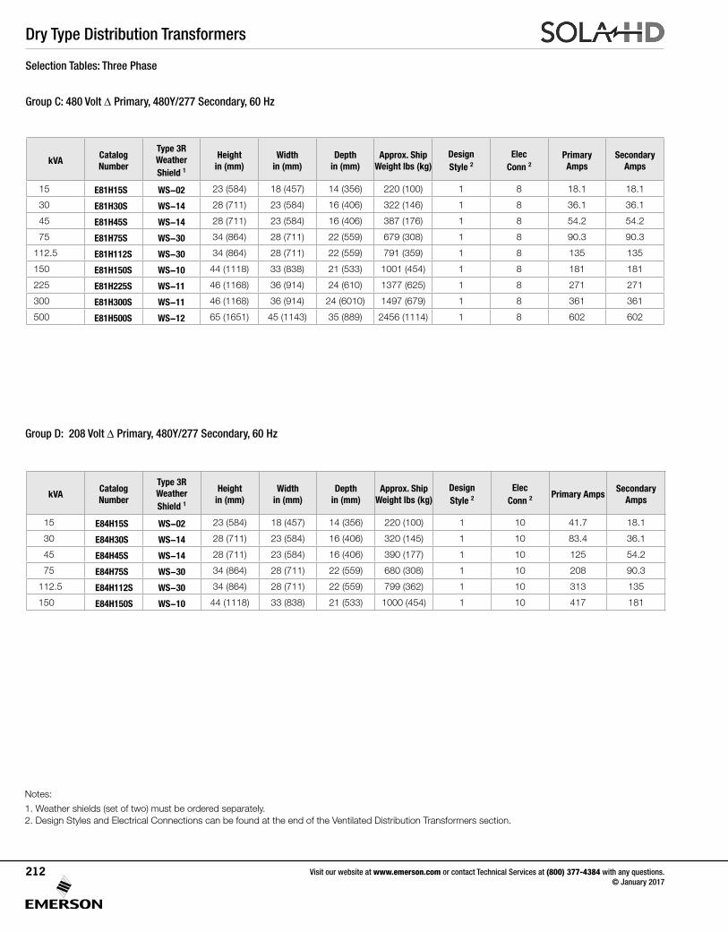
Dry Type Distribution Transformers
Visit our website at www.emerson.com or contact Technical Services at (800) 377-4384 with any questions. © January 2017
212
Selection Tables: Three Phase
Notes:
1. Weather shields (set of two) must be ordered separately.2. Design Styles and Electrical Connections can be found at the end of the Ventilated Distribution Transformers section.
Group C: 480 Volt Δ Primary, 480Y/277 Secondary, 60 Hz
Group D: 208 Volt Δ Primary, 480Y/277 Secondary, 60 Hz
kVACatalog Number
Type 3R Weather Shield 1
Height in (mm)
Width in (mm)
Depth in (mm)
Approx. Ship Weight lbs (kg)
Design Style 2
Elec Conn 2
Primary Amps
Secondary Amps
15 E81H15S WS-02 23 (584) 18 (457) 14 (356) 220 (100) 1 8 18.1 18.1
30 E81H30S WS-14 28 (711) 23 (584) 16 (406) 322 (146) 1 8 36.1 36.1
45 E81H45S WS-14 28 (711) 23 (584) 16 (406) 387 (176) 1 8 54.2 54.2
75 E81H75S WS-30 34 (864) 28 (711) 22 (559) 679 (308) 1 8 90.3 90.3
112.5 E81H112S WS-30 34 (864) 28 (711) 22 (559) 791 (359) 1 8 135 135
150 E81H150S WS-10 44 (1118) 33 (838) 21 (533) 1001 (454) 1 8 181 181
225 E81H225S WS-11 46 (1168) 36 (914) 24 (610) 1377 (625) 1 8 271 271
300 E81H300S WS-11 46 (1168) 36 (914) 24 (6010) 1497 (679) 1 8 361 361
500 E81H500S WS-12 65 (1651) 45 (1143) 35 (889) 2456 (1114) 1 8 602 602
kVACatalog Number
Type 3R Weather Shield 1
Height in (mm)
Width in (mm)
Depth in (mm)
Approx. Ship Weight lbs (kg)
DesignStyle 2
Elec Conn 2
Primary AmpsSecondary
Amps
15 E84H15S WS-02 23 (584) 18 (457) 14 (356) 220 (100) 1 10 41.7 18.1
30 E84H30S WS-14 28 (711) 23 (584) 16 (406) 320 (145) 1 10 83.4 36.1
45 E84H45S WS-14 28 (711) 23 (584) 16 (406) 390 (177) 1 10 125 54.2
75 E84H75S WS-30 34 (864) 28 (711) 22 (559) 680 (308) 1 10 208 90.3
112.5 E84H112S WS-30 34 (864) 28 (711) 22 (559) 799 (362) 1 10 313 135
150 E84H150S WS-10 44 (1118) 33 (838) 21 (533) 1000 (454) 1 10 417 181
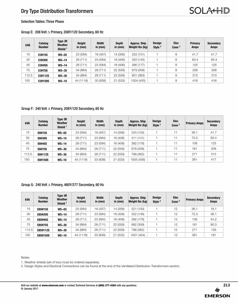
Dry Type Distribution Transformers
Visit our website at www.emerson.com or contact Technical Services at (800) 377-4384 with any questions. © January 2017
213
Selection Tables: Three Phase
Group G: 240 Volt Δ Primary, 480Y/277 Secondary, 60 Hz
Group E: 208 Volt Δ Primary, 208Y/120 Secondary, 60 Hz
Group F: 240 Volt Δ Primary, 208Y/120 Secondary, 60 Hz
Notes:
1. Weather shields (set of two) must be ordered separately. 2. Design Styles and Electrical Connections can be found at the end of the Ventilated Distribution Transformers section.
kVACatalog Number
Type 3R Weather Shield 1
Height in (mm)
Width in (mm)
Depth in (mm)
Approx. Ship Weight lbs (kg)
Design Style 2
Elec Conn 2
Primary Amps
Secondary Amps
15 E3H15S WS-02 23 (584) 18 (457) 14 (356) 222 (101) 1 9 41.7 41.7
30 E3H30S WS-14 28 (711) 23 (584) 16 (406) 320 (145) 1 9 83.4 83.4
45 E3H45S WS-14 28 (711) 23 (584) 16 (406) 390 (177) 1 9 125 125
75 E3H75S WS-30 34 (864) 28 (711) 22 (559) 679 (308) 1 9 208 208
112.5 E3H112S WS-30 34 (864) 28 (711) 22 (559) 801 (363) 1 9 313 313
150 E3H150S WS-10 44 (1118) 33 (838) 21 (533) 1004 (455) 1 9 416 416
kVACatalog Number
Type 3R Weather Shield 1
Height in (mm)
Width in (mm)
Depth in (mm)
Approx. Ship Weight lbs (kg)
DesignStyle 2
Elec Conn 2
Primary AmpsSecondary
Amps
15 E6H15S WS-02 23 (584) 18 (457) 14 (356) 220 (100) 1 11 36.1 41.7
30 E6H30S WS-14 28 (711) 23 (584) 16 (406) 311 (141) 1 11 72.3 83.4
45 E6H45S WS-14 28 (711) 23 (584) 16 (406) 392 (178) 1 11 108 125
75 E6H75S WS-30 34 (864) 28 (711) 22 (559) 678 (308) 1 11 181 208
112.5 E6H112S WS-30 34 (864) 28 (711) 22 (559) 799 (362) 1 11 271 313
150 E6H150S WS-10 44 (1118) 33 (838) 21 (533) 1005 (456) 1 11 361 417
kVACatalog Number
Type 3R Weather Shield 1
Height in (mm)
Width in (mm)
Depth in (mm)
Approx. Ship Weight lbs (kg)
DesignStyle 2
Elec Conn 2
Primary AmpsSecondary
Amps
15 E85H15S WS-02 23 (584) 18 (457) 14 (356) 221 (100) 1 12 36.1 18.1
30 E85H30S WS-14 28 (711) 23 (584) 16 (406) 322 (146) 1 12 72.3 36.1
45 E85H45S WS-14 28 (711) 23 (584) 16 (406) 392 (178) 1 12 108 54.2
75 E85H75S WS-30 34 (864) 28 (711) 22 (559) 682 (309) 1 12 181 90.3
112.5 E85H112S WS-30 34 (864) 28 (711) 22 (559) 798 (362) 1 12 271 135
150 E85H150S WS-10 44 (1118) 33 (838) 21 (533) 1001 (454) 1 12 361 181
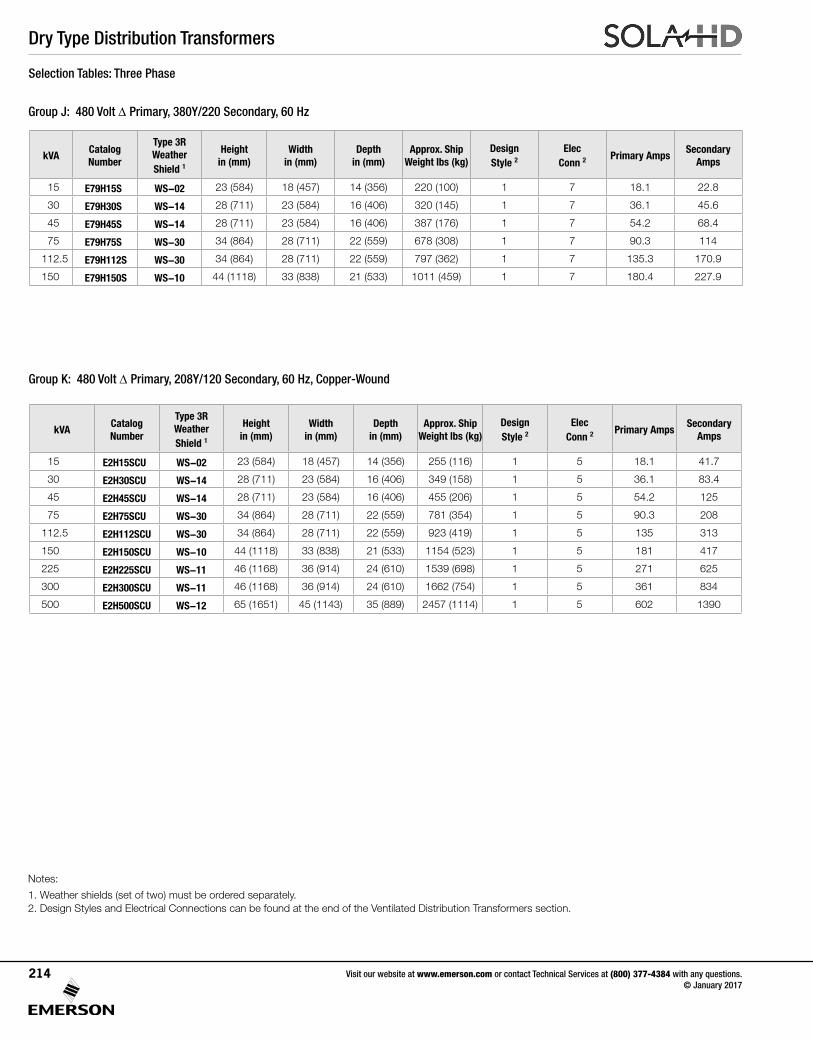
Dry Type Distribution Transformers
Visit our website at www.emerson.com or contact Technical Services at (800) 377-4384 with any questions. © January 2017
214
Group K: 480 Volt Δ Primary, 208Y/120 Secondary, 60 Hz, Copper-Wound
Group J: 480 Volt Δ Primary, 380Y/220 Secondary, 60 Hz
Selection Tables: Three Phase
Notes:
1. Weather shields (set of two) must be ordered separately.2. Design Styles and Electrical Connections can be found at the end of the Ventilated Distribution Transformers section.
kVACatalog Number
Type 3R Weather Shield 1
Height in (mm)
Width in (mm)
Depth in (mm)
Approx. Ship Weight lbs (kg)
Design Style 2
Elec Conn 2
Primary AmpsSecondary
Amps
15 E79H15S WS-02 23 (584) 18 (457) 14 (356) 220 (100) 1 7 18.1 22.8
30 E79H30S WS-14 28 (711) 23 (584) 16 (406) 320 (145) 1 7 36.1 45.6
45 E79H45S WS-14 28 (711) 23 (584) 16 (406) 387 (176) 1 7 54.2 68.4
75 E79H75S WS-30 34 (864) 28 (711) 22 (559) 678 (308) 1 7 90.3 114
112.5 E79H112S WS-30 34 (864) 28 (711) 22 (559) 797 (362) 1 7 135.3 170.9
150 E79H150S WS-10 44 (1118) 33 (838) 21 (533) 1011 (459) 1 7 180.4 227.9
kVACatalog Number
Type 3R Weather Shield 1
Height in (mm)
Width in (mm)
Depth in (mm)
Approx. Ship Weight lbs (kg)
Design Style 2
Elec Conn 2
Primary AmpsSecondary
Amps
15 E2H15SCU WS-02 23 (584) 18 (457) 14 (356) 255 (116) 1 5 18.1 41.7
30 E2H30SCU WS-14 28 (711) 23 (584) 16 (406) 349 (158) 1 5 36.1 83.4
45 E2H45SCU WS-14 28 (711) 23 (584) 16 (406) 455 (206) 1 5 54.2 125
75 E2H75SCU WS-30 34 (864) 28 (711) 22 (559) 781 (354) 1 5 90.3 208
112.5 E2H112SCU WS-30 34 (864) 28 (711) 22 (559) 923 (419) 1 5 135 313
150 E2H150SCU WS-10 44 (1118) 33 (838) 21 (533) 1154 (523) 1 5 181 417
225 E2H225SCU WS-11 46 (1168) 36 (914) 24 (610) 1539 (698) 1 5 271 625
300 E2H300SCU WS-11 46 (1168) 36 (914) 24 (610) 1662 (754) 1 5 361 834
500 E2H500SCU WS-12 65 (1651) 45 (1143) 35 (889) 2457 (1114) 1 5 602 1390

Dry Type Distribution Transformers
120/208/240/277 Volt Primary, 120/240 Volt Secondary Taps: None
Primary Voltage InterconnectConnect Lines To
277 1 to 2 H1 & H2
240 3 to 4 H1 & H2
208 5 to 6 H1 & H2
120H1 to 4 H2 to 3
H1 & H2
Secondary Voltage
InterconnectConnect Lines To
240 X2 to X3 X1 & X4
120-0-120X2 to X3 X2 to
X1-X2-X4
120X1 to X3 X2 to X4
X1 & X4
ES12 Series
240 x 480 Volt Primary, 120/240 Volt Secondary Taps: 2, 2½%FCAN;4,2½%FCBN
Primary Voltage InterconnectConnect Lines To
504 1 to 2 H1 & H2
492 2 to 3 H1 & H2
480 3 to 4 H1 & H2
468 4 to 5 H1 & H2
456 5 to 6 H1 & H2
444 6 to 7 H1 & H2
432 7 to 8 H1 & H2
252 H1 to 2 H2 to 1 H1 & H2
240 H1 to 4 H2 to 3 H1 & H2
228 H1 to 6 H2 to 5 H1 & H2
216 H1 to 8 H2 to 7 H1 & H2
Secondary Voltage
InterconnectConnect Lines To
240 X2 to X3 X1 & X4
120-0-120 X2 to X3 X2 to X1-X2-X4
120 X1 to X3 X2 to X4 X1 & X4
ES5 Series
1 2
7
H1 H2
SHIELD
5 3 1 2 4 6 8
X1 X3 X2 X4
H1 H2
35 1 2 4 6
SHIELD
X1 X3 X2 X4
Design Style
Style 1 - Ventilated
W D
H
Electrical Connections (Single Phase)
Visit our website at www.emerson.com or contact Technical Services at (800) 377-4384 with any questions. © January 2017
215
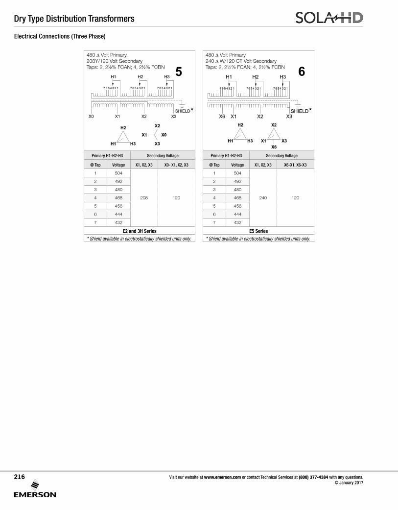
Dry Type Distribution Transformers
480 Δ Volt Primary, 240 Δ W/120 CT Volt Secondary Taps:2,2½%FCAN;4,2½%FCBN
Primary H1-H2-H3 Secondary Voltage
@ Tap Voltage X1, X2, X3 X6-X1, X6-X3
1 504
240 120
2 492
3 480
4 468
5 456
6 444
7 432
E5 Series
* Shield available in electrostatically shielded units only.
480 Δ Volt Primary, 208Y/120 Volt Secondary Taps: 2, 2½% FCAN; 4, 2½%FCBN
Primary H1-H2-H3 Secondary Voltage
@ Tap Voltage X1, X2, X3 X0- X1, X2, X3
1 504
208 120
2 492
3 480
4 468
5 456
6 444
7 432
E2 and 3H Series
* Shield available in electrostatically shielded units only.
5 6
H1 H3
H2
X1
X6
X3
X2
H1 H2 H3
7 6 5 4 3 2 1 7 6 5 4 3 2 1 7 6 5 4 3 2 1
X6
SHIELD
X1 X3X2
*X1 X2 X3
7 6 5 4 3 2 1 7 6 5 4 3 2 1 7 6 5 4 3 2 1
X0
SHIELD
H1 H3H2
H1 H3
H2
X1
X2
X3
X0
*
Electrical Connections (Three Phase)
Visit our website at www.emerson.com or contact Technical Services at (800) 377-4384 with any questions. © January 2017
216

Dry Type Distribution Transformers
208 Δ Volt Primary 208Y/120 Volt Secondary Taps:2,2½%FCAN;4,2½%FCBN
Primary H1-H2-H3 Secondary Voltage
@ Tap Voltage X1, X2, X3 X0- X1, X2, X3
1 218
208 120
2 213
3 208
4 203
5 198
6 192
7 187
E3 Series
208 Δ Volt Primary480Y/277 Volt Secondary Taps:2,2½%FCAN;4,2½%FCBN
Primary X1-X2-X3 Secondary Voltage
@ Tap Voltage H1-H2-H3 H0-H1, H2, H3
1 218
480 277
2 213
3 208
4 203
5 198
6 192
7 187
E84 Series
480 Δ Volt Primary 480Y/277 Volt Secondary Taps:2,2½%FCAN;4,2½%FCBN
Primary H1-H2-H3 Secondary Voltage
@ Tap Voltage X1, X2, X3 X0- X1, X2, X3
1 504
480 277
2 492
3 480
4 468
5 456
6 444
7 432
E81 Series
8480 Δ Volt Primary 380/220 Volt Secondary Taps:2,2½%FCAN;4,2½%FCBN
Primary H1-H2-H3 Secondary Voltage
@ Tap Voltage X1, X2, X3 X0- X1, X2, X3
1 504
380 220
2 492
3 480
4 468
5 456
6 444
7 432
E79 Series
7
H1 H3
H2
X1
X2
X3
X0
X1 X2 X3
7 6 5 4 3 2 1 7 6 5 4 3 2 1 7 6 5 4 3 2 1
X0
SHIELD
H1 H3H2
240 Δ Volt Primary 480Y/277 Volt Secondary Taps:2,2½%FCAN;4,2½%FCBN
Primary X1-X2-X3 Secondary Voltage
@ Tap Voltage H1, H2, H3 H0- H1, H2, H3
1 252
480 277
2 246
3 240
4 234
5 228
6 222
7 216
E85 Series
240 Δ Volt Primary208Y/120 Volt Secondary Taps:2,2½%FCAN;4,2½%FCBN
Primary H1-H2-H3 Secondary Voltage
@ Tap Voltage X1, X2, X3 X0- X1, X2, X3
1 252
208 120
2 246
3 240
4 234
5 228
6 222
7 216
E6 Series
9
10
H1 H2 H3
7 6 5 4 3 2 1 7 6 5 4 3 2 1 7 6 5 4 3 2 1
H0
SHIELD
X1 X3X2
X1 X3
X2
H1
H2
H3
H0
H1 H3
H2
X1
X2
X3
X0
X1 X2 X3
7 6 5 4 3 2 1 7 6 5 4 3 2 1 7 6 5 4 3 2 1
X0
SHIELD
H1 H3H2
X1 X2 X3
7 6 5 4 3 2 1 7 6 5 4 3 2 1 7 6 5 4 3 2 1
X0
SHIELD
H1 H3H2
H1 H3
H2
X1
X2
X3
X0
Electrical Connections (Three Phase) cont.
11
X1 X3
X2
H1
H2
H3
H0
H1 H2 H3
7 6 5 4 3 2 1 7 6 5 4 3 2 1 7 6 5 4 3 2 1
H0
SHIELD
X1 X3X2
12
X1 X2 X3
7 6 5 4 3 2 1 7 6 5 4 3 2 1 7 6 5 4 3 2 1
X0
SHIELD
H1 H3H2
H1 H3
H2
X1
X2
X3
X0
Visit our website at www.emerson.com or contact Technical Services at (800) 377-4384 with any questions. © January 2017
217
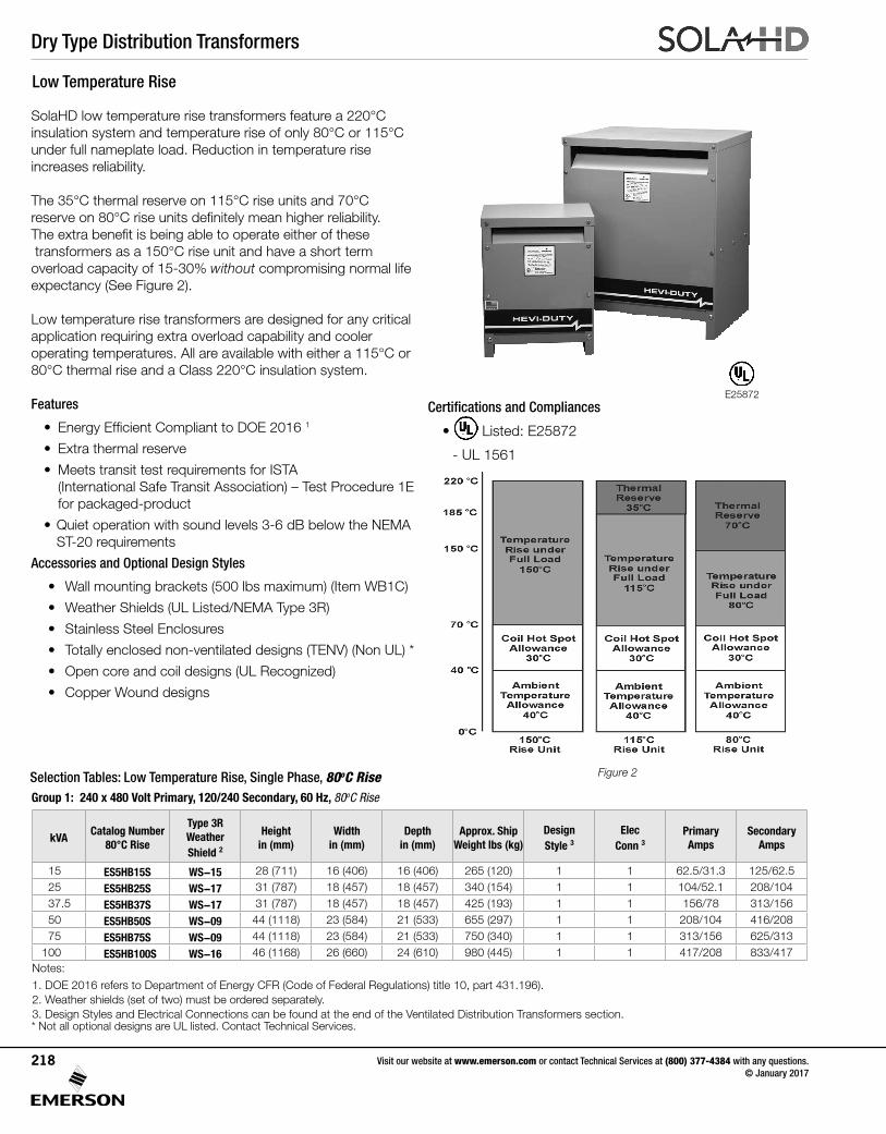
Dry Type Distribution Transformers
Visit our website at www.emerson.com or contact Technical Services at (800) 377-4384 with any questions. © January 2017
218
Figure 2
SolaHD low temperature rise transformers feature a 220°C insulation system and temperature rise of only 80°C or 115°C under full nameplate load. Reduction in temperature rise increases reliability.
The 35°C thermal reserve on 115°C rise units and 70°C reserveon80°Criseunitsdefinitelymeanhigherreliability. Theextrabenefitisbeingabletooperateeitherofthese transformers as a 150°C rise unit and have a short term overload capacity of 15-30% without compromising normal life expectancy (See Figure 2).
Low temperature rise transformers are designed for any critical application requiring extra overload capability and cooler operating temperatures. All are available with either a 115°C or 80°C thermal rise and a Class 220°C insulation system.
Features
• EnergyEfficientComplianttoDOE20161
• Extra thermal reserve
• Meets transit test requirements for ISTA (International Safe Transit Association) – Test Procedure 1E for packaged-product
•Quietoperationwithsoundlevels3-6dBbelowtheNEMAST-20 requirements
Accessories and Optional Design Styles
•Wallmountingbrackets(500lbsmaximum)(ItemWB1C)
• Weather Shields (UL Listed/NEMA Type 3R)
• Stainless Steel Enclosures
• Totally enclosed non-ventilated designs (TENV) (Non UL) *
• Open core and coil designs (UL Recognized)
• Copper Wound designs
* Not all optional designs are UL listed. Contact Technical Services.
Low Temperature Rise
Group 1: 240 x 480 Volt Primary, 120/240 Secondary, 60 Hz, 80oC Rise
E25872
Notes:1. DOE 2016 refers to Department of Energy CFR (Code of Federal Regulations) title 10, part 431.196). 2. Weather shields (set of two) must be ordered separately. 3. Design Styles and Electrical Connections can be found at the end of the Ventilated Distribution Transformers section.
Selection Tables: Low Temperature Rise, Single Phase, 80oC Rise
kVACatalog Number
80°C Rise
Type 3R Weather Shield 2
Height in (mm)
Width in (mm)
Depth in (mm)
Approx. Ship Weight lbs (kg)
DesignStyle 3
Elec Conn 3
Primary Amps
Secondary Amps
15 ES5HB15S WS-15 28 (711) 16 (406) 16 (406) 265 (120) 1 1 62.5/31.3 125/62.525 ES5HB25S WS-17 31 (787) 18 (457) 18 (457) 340 (154) 1 1 104/52.1 208/104 37.5 ES5HB37S WS-17 31 (787) 18 (457) 18 (457) 425 (193) 1 1 156/78 313/15650 ES5HB50S WS-09 44 (1118) 23 (584) 21 (533) 655 (297) 1 1 208/104 416/20875 ES5HB75S WS-09 44 (1118) 23 (584) 21 (533) 750 (340) 1 1 313/156 625/313
100 ES5HB100S WS-16 46 (1168) 26 (660) 24 (610) 980 (445) 1 1 417/208 833/417
Certifications and Compliances
• Listed: E25872
- UL 1561
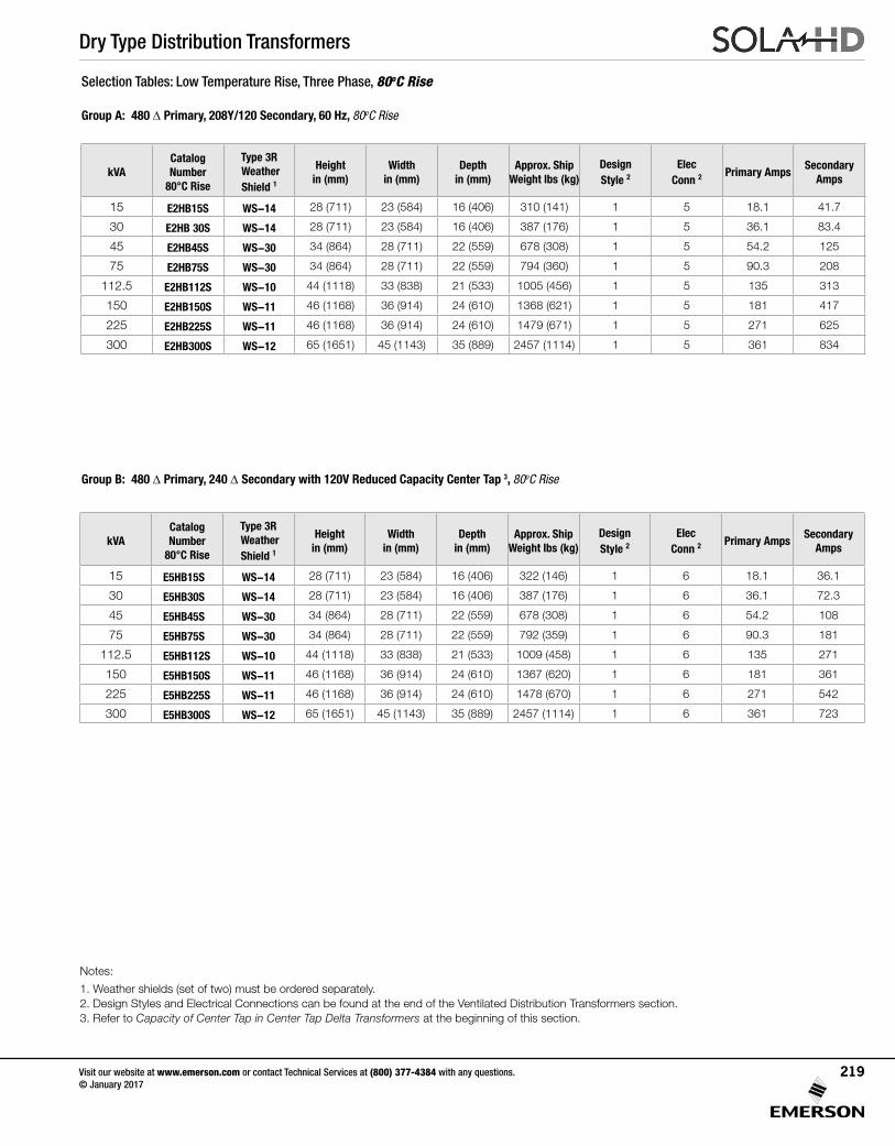
Dry Type Distribution Transformers
Visit our website at www.emerson.com or contact Technical Services at (800) 377-4384 with any questions. © January 2017
219
Selection Tables: Low Temperature Rise, Three Phase, 80oC Rise
Group A: 480 Δ Primary, 208Y/120 Secondary, 60 Hz, 80oC Rise
Notes:
1. Weather shields (set of two) must be ordered separately. 2. Design Styles and Electrical Connections can be found at the end of the Ventilated Distribution Transformers section. 3. Refer to Capacity of Center Tap in Center Tap Delta Transformers at the beginning of this section.
Group B: 480 Δ Primary, 240 Δ Secondary with 120V Reduced Capacity Center Tap 3, 80oC Rise
kVACatalog Number
80°C Rise
Type 3R Weather Shield 1
Height in (mm)
Width in (mm)
Depth in (mm)
Approx. Ship Weight lbs (kg)
DesignStyle 2
Elec Conn 2
Primary AmpsSecondary
Amps
15 E2HB15S WS-14 28 (711) 23 (584) 16 (406) 310 (141) 1 5 18.1 41.7
30 E2HB 30S WS-14 28 (711) 23 (584) 16 (406) 387 (176) 1 5 36.1 83.4
45 E2HB45S WS-30 34 (864) 28 (711) 22 (559) 678 (308) 1 5 54.2 125
75 E2HB75S WS-30 34 (864) 28 (711) 22 (559) 794 (360) 1 5 90.3 208
112.5 E2HB112S WS-10 44 (1118) 33 (838) 21 (533) 1005 (456) 1 5 135 313
150 E2HB150S WS-11 46 (1168) 36 (914) 24 (610) 1368 (621) 1 5 181 417
225 E2HB225S WS-11 46 (1168) 36 (914) 24 (610) 1479 (671) 1 5 271 625
300 E2HB300S WS-12 65 (1651) 45 (1143) 35 (889) 2457 (1114) 1 5 361 834
kVACatalog Number
80°C Rise
Type 3R Weather Shield 1
Height in (mm)
Width in (mm)
Depth in (mm)
Approx. Ship Weight lbs (kg)
DesignStyle 2
Elec Conn 2
Primary AmpsSecondary
Amps
15 E5HB15S WS-14 28 (711) 23 (584) 16 (406) 322 (146) 1 6 18.1 36.1
30 E5HB30S WS-14 28 (711) 23 (584) 16 (406) 387 (176) 1 6 36.1 72.3
45 E5HB45S WS-30 34 (864) 28 (711) 22 (559) 678 (308) 1 6 54.2 108
75 E5HB75S WS-30 34 (864) 28 (711) 22 (559) 792 (359) 1 6 90.3 181
112.5 E5HB112S WS-10 44 (1118) 33 (838) 21 (533) 1009 (458) 1 6 135 271
150 E5HB150S WS-11 46 (1168) 36 (914) 24 (610) 1367 (620) 1 6 181 361
225 E5HB225S WS-11 46 (1168) 36 (914) 24 (610) 1478 (670) 1 6 271 542
300 E5HB300S WS-12 65 (1651) 45 (1143) 35 (889) 2457 (1114) 1 6 361 723
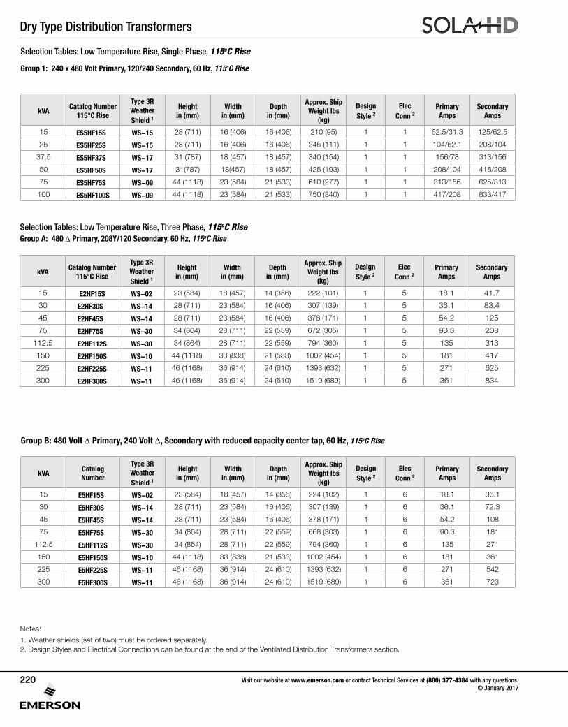
Dry Type Distribution Transformers
Visit our website at www.emerson.com or contact Technical Services at (800) 377-4384 with any questions. © January 2017
220
Selection Tables: Low Temperature Rise, Single Phase, 115oC Rise
Group 1: 240 x 480 Volt Primary, 120/240 Secondary, 60 Hz, 115oC Rise
Selection Tables: Low Temperature Rise, Three Phase, 115oC RiseGroup A: 480 Δ Primary, 208Y/120 Secondary, 60 Hz, 115oC Rise
Group B: 480 Volt Δ Primary, 240 Volt Δ, Secondary with reduced capacity center tap, 60 Hz, 115oC Rise
Notes:
1. Weather shields (set of two) must be ordered separately. 2. Design Styles and Electrical Connections can be found at the end of the Ventilated Distribution Transformers section.
kVACatalog Number
115°C Rise
Type 3R Weather Shield 1
Height in (mm)
Width in (mm)
Depth in (mm)
Approx. Ship Weight lbs
(kg)
DesignStyle 2
Elec Conn 2
Primary Amps
Secondary Amps
15 ES5HF15S WS-15 28 (711) 16 (406) 16 (406) 210 (95) 1 1 62.5/31.3 125/62.5
25 ES5HF25S WS-15 28 (711) 16 (406) 16 (406) 245 (111) 1 1 104/52.1 208/104
37.5 ES5HF37S WS-17 31 (787) 18 (457) 18 (457) 340 (154) 1 1 156/78 313/156
50 ES5HF50S WS-17 31(787) 18(457) 18 (457) 425 (193) 1 1 208/104 416/208
75 ES5HF75S WS-09 44 (1118) 23 (584) 21 (533) 610 (277) 1 1 313/156 625/313
100 ES5HF100S WS-09 44 (1118) 23 (584) 21 (533) 750 (340) 1 1 417/208 833/417
kVACatalog Number
115°C Rise
Type 3R Weather Shield 1
Height in (mm)
Width in (mm)
Depth in (mm)
Approx. Ship Weight lbs
(kg)
DesignStyle 2
Elec Conn 2
Primary Amps
Secondary Amps
15 E2HF15S WS-02 23 (584) 18 (457) 14 (356) 222 (101) 1 5 18.1 41.7
30 E2HF30S WS-14 28 (711) 23 (584) 16 (406) 307 (139) 1 5 36.1 83.4
45 E2HF45S WS-14 28 (711) 23 (584) 16 (406) 378 (171) 1 5 54.2 125
75 E2HF75S WS-30 34 (864) 28 (711) 22 (559) 672 (305) 1 5 90.3 208
112.5 E2HF112S WS-30 34 (864) 28 (711) 22 (559) 794 (360) 1 5 135 313
150 E2HF150S WS-10 44 (1118) 33 (838) 21 (533) 1002 (454) 1 5 181 417
225 E2HF225S WS-11 46 (1168) 36 (914) 24 (610) 1393 (632) 1 5 271 625
300 E2HF300S WS-11 46 (1168) 36 (914) 24 (610) 1519 (689) 1 5 361 834
kVACatalog Number
Type 3R Weather Shield 1
Height in (mm)
Width in (mm)
Depth in (mm)
Approx. Ship Weight lbs
(kg)
DesignStyle 2
Elec Conn 2
Primary Amps
Secondary Amps
15 E5HF15S WS-02 23 (584) 18 (457) 14 (356) 224 (102) 1 6 18.1 36.1
30 E5HF30S WS-14 28 (711) 23 (584) 16 (406) 307 (139) 1 6 36.1 72.3
45 E5HF45S WS-14 28 (711) 23 (584) 16 (406) 378 (171) 1 6 54.2 108
75 E5HF75S WS-30 34 (864) 28 (711) 22 (559) 668 (303) 1 6 90.3 181
112.5 E5HF112S WS-30 34 (864) 28 (711) 22 (559) 794 (360) 1 6 135 271
150 E5HF150S WS-10 44 (1118) 33 (838) 21 (533) 1002 (454) 1 6 181 361
225 E5HF225S WS-11 46 (1168) 36 (914) 24 (610) 1393 (632) 1 6 271 542
300 E5HF300S WS-11 46 (1168) 36 (914) 24 (610) 1519 (689) 1 6 361 723
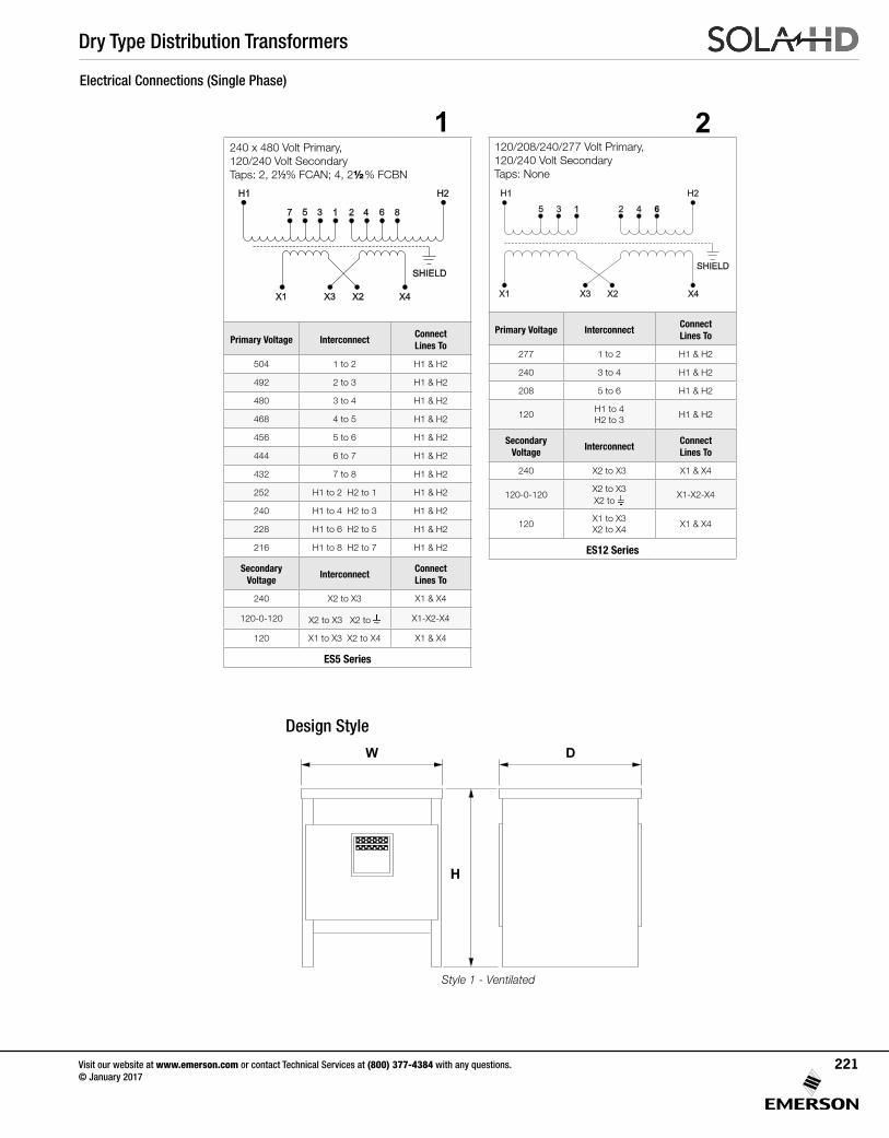
Dry Type Distribution Transformers
120/208/240/277 Volt Primary, 120/240 Volt Secondary Taps: None
Primary Voltage InterconnectConnect Lines To
277 1 to 2 H1 & H2
240 3 to 4 H1 & H2
208 5 to 6 H1 & H2
120H1 to 4 H2 to 3
H1 & H2
Secondary Voltage
InterconnectConnect Lines To
240 X2 to X3 X1 & X4
120-0-120X2 to X3 X2 to
X1-X2-X4
120X1 to X3 X2 to X4
X1 & X4
ES12 Series
240 x 480 Volt Primary, 120/240 Volt Secondary Taps: 2, 2½% FCAN; 4, 2½%FCBN
Primary Voltage InterconnectConnect Lines To
504 1 to 2 H1 & H2
492 2 to 3 H1 & H2
480 3 to 4 H1 & H2
468 4 to 5 H1 & H2
456 5 to 6 H1 & H2
444 6 to 7 H1 & H2
432 7 to 8 H1 & H2
252 H1 to 2 H2 to 1 H1 & H2
240 H1 to 4 H2 to 3 H1 & H2
228 H1 to 6 H2 to 5 H1 & H2
216 H1 to 8 H2 to 7 H1 & H2
Secondary Voltage
InterconnectConnect Lines To
240 X2 to X3 X1 & X4
120-0-120 X2 to X3 X2 to X1-X2-X4
120 X1 to X3 X2 to X4 X1 & X4
ES5 Series
1 2
7
H1 H2
SHIELD
5 3 1 2 4 6 8
X1 X3 X2 X4
H1 H2
35 1 2 4 6
SHIELD
X1 X3 X2 X4
Design Style
Style 1 - Ventilated
W D
H
Electrical Connections (Single Phase)
Visit our website at www.emerson.com or contact Technical Services at (800) 377-4384 with any questions. © January 2017
221

Dry Type Distribution Transformers
480 Δ Volt Primary, 240 Δ W/120 CT Volt Secondary Taps:2,2½%FCAN;4,2½%FCBN
Primary H1-H2-H3 Secondary Voltage
@ Tap Voltage X1, X2, X3 X6-X1, X6-X3
1 504
240 120
2 492
3 480
4 468
5 456
6 444
7 432
E5 Series
* Shield available in electrostatically shielded units only.
480 Δ Volt Primary, 208Y/120 Volt Secondary Taps: 2, 2½% FCAN; 4, 2½%FCBN
Primary H1-H2-H3 Secondary Voltage
@ Tap Voltage X1, X2, X3 X0- X1, X2, X3
1 504
208 120
2 492
3 480
4 468
5 456
6 444
7 432
E2 and 3H Series
* Shield available in electrostatically shielded units only.
5 6
H1 H3
H2
X1
X6
X3
X2
H1 H2 H3
7 6 5 4 3 2 1 7 6 5 4 3 2 1 7 6 5 4 3 2 1
X6
SHIELD
X1 X3X2
*X1 X2 X3
7 6 5 4 3 2 1 7 6 5 4 3 2 1 7 6 5 4 3 2 1
X0
SHIELD
H1 H3H2
H1 H3
H2
X1
X2
X3
X0
*
Electrical Connections (Three Phase)
Visit our website at www.emerson.com or contact Technical Services at (800) 377-4384 with any questions. © January 2017
222
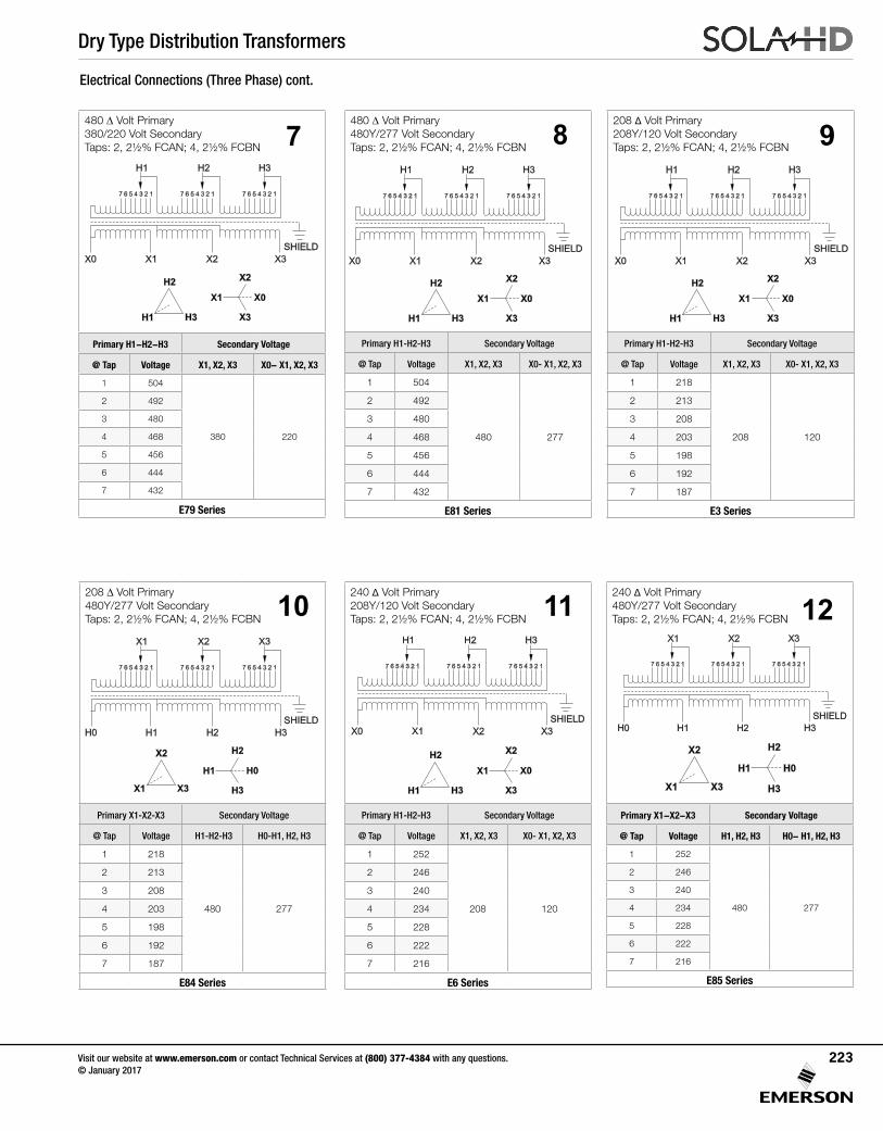
Dry Type Distribution Transformers
208 Δ Volt Primary 208Y/120 Volt Secondary Taps:2,2½%FCAN;4,2½%FCBN
Primary H1-H2-H3 Secondary Voltage
@ Tap Voltage X1, X2, X3 X0- X1, X2, X3
1 218
208 120
2 213
3 208
4 203
5 198
6 192
7 187
E3 Series
208 Δ Volt Primary480Y/277 Volt Secondary Taps:2,2½%FCAN;4,2½%FCBN
Primary X1-X2-X3 Secondary Voltage
@ Tap Voltage H1-H2-H3 H0-H1, H2, H3
1 218
480 277
2 213
3 208
4 203
5 198
6 192
7 187
E84 Series
480 Δ Volt Primary 480Y/277 Volt Secondary Taps:2,2½%FCAN;4,2½%FCBN
Primary H1-H2-H3 Secondary Voltage
@ Tap Voltage X1, X2, X3 X0- X1, X2, X3
1 504
480 277
2 492
3 480
4 468
5 456
6 444
7 432
E81 Series
8480 Δ Volt Primary 380/220 Volt Secondary Taps:2,2½%FCAN;4,2½%FCBN
Primary H1-H2-H3 Secondary Voltage
@ Tap Voltage X1, X2, X3 X0- X1, X2, X3
1 504
380 220
2 492
3 480
4 468
5 456
6 444
7 432
E79 Series
7
H1 H3
H2
X1
X2
X3
X0
X1 X2 X3
7 6 5 4 3 2 1 7 6 5 4 3 2 1 7 6 5 4 3 2 1
X0
SHIELD
H1 H3H2
240 Δ Volt Primary 480Y/277 Volt Secondary Taps:2,2½%FCAN;4,2½%FCBN
Primary X1-X2-X3 Secondary Voltage
@ Tap Voltage H1, H2, H3 H0- H1, H2, H3
1 252
480 277
2 246
3 240
4 234
5 228
6 222
7 216
E85 Series
240 Δ Volt Primary208Y/120 Volt Secondary Taps:2,2½%FCAN;4,2½%FCBN
Primary H1-H2-H3 Secondary Voltage
@ Tap Voltage X1, X2, X3 X0- X1, X2, X3
1 252
208 120
2 246
3 240
4 234
5 228
6 222
7 216
E6 Series
9
10
H1 H2 H3
7 6 5 4 3 2 1 7 6 5 4 3 2 1 7 6 5 4 3 2 1
H0
SHIELD
X1 X3X2
X1 X3
X2
H1
H2
H3
H0
H1 H3
H2
X1
X2
X3
X0
X1 X2 X3
7 6 5 4 3 2 1 7 6 5 4 3 2 1 7 6 5 4 3 2 1
X0
SHIELD
H1 H3H2
X1 X2 X3
7 6 5 4 3 2 1 7 6 5 4 3 2 1 7 6 5 4 3 2 1
X0
SHIELD
H1 H3H2
H1 H3
H2
X1
X2
X3
X0
Electrical Connections (Three Phase) cont.
11
X1 X3
X2
H1
H2
H3
H0
H1 H2 H3
7 6 5 4 3 2 1 7 6 5 4 3 2 1 7 6 5 4 3 2 1
H0
SHIELD
X1 X3X2
12
X1 X2 X3
7 6 5 4 3 2 1 7 6 5 4 3 2 1 7 6 5 4 3 2 1
X0
SHIELD
H1 H3H2
H1 H3
H2
X1
X2
X3
X0
Visit our website at www.emerson.com or contact Technical Services at (800) 377-4384 with any questions. © January 2017
223
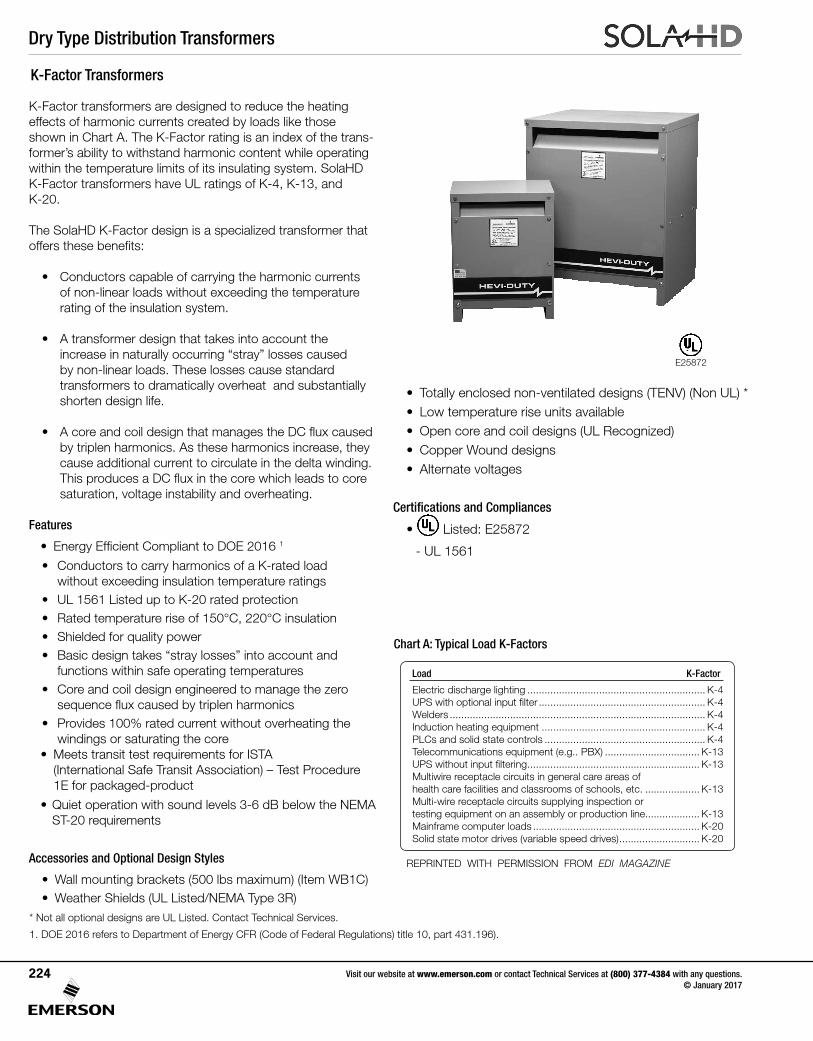
Dry Type Distribution Transformers
K-Factor transformers are designed to reduce the heating effects of harmonic currents created by loads like those shown in Chart A. The K-Factor rating is an index of the trans-former’s ability to withstand harmonic content while operating within the temperature limits of its insulating system. SolaHD K-Factor transformers have UL ratings of K-4, K-13, and K-20.
The SolaHD K-Factor design is a specialized transformer that offersthesebenefits:
• Conductors capable of carrying the harmonic currents of non-linear loads without exceeding the temperature rating of the insulation system.
• A transformer design that takes into account the increaseinnaturallyoccurring“stray”lossescaused
by non-linear loads. These losses cause standard transformers to dramatically overheat and substantially shorten design life.
• AcoreandcoildesignthatmanagestheDCfluxcausedby triplen harmonics. As these harmonics increase, they cause additional current to circulate in the delta winding. ThisproducesaDCfluxinthecorewhichleadstocoresaturation, voltage instability and overheating.
Features
• EnergyEfficientComplianttoDOE20161
• Conductors to carry harmonics of a K-rated load without exceeding insulation temperature ratings
• UL 1561 Listed up to K-20 rated protection• Rated temperature rise of 150°C, 220°C insulation• Shielded for quality power• Basicdesigntakes“straylosses”intoaccountand
functions within safe operating temperatures• Core and coil design engineered to manage the zero
sequencefluxcausedbytriplenharmonics• Provides 100% rated current without overheating the
windings or saturating the core• Meets transit test requirements for ISTA
(International Safe Transit Association) – Test Procedure 1E for packaged-product
•Quietoperationwithsoundlevels3-6dBbelowtheNEMAST-20 requirements
Accessories and Optional Design Styles
•Wallmountingbrackets(500lbsmaximum)(ItemWB1C)• Weather Shields (UL Listed/NEMA Type 3R)
Chart A: Typical Load K-Factors
Load K-Factor
Electric discharge lighting .............................................................. K-4UPSwithoptionalinputfilter .......................................................... K-4Welders ......................................................................................... K-4Induction heating equipment ......................................................... K-4PLCs and solid state controls ........................................................ K-4Telecommunicationsequipment(e.g..PBX) ................................. K-13UPSwithoutinputfiltering ............................................................ K-13Multiwire receptacle circuits in general care areas of health care facilities and classrooms of schools, etc. ................... K-13Multi-wire receptacle circuits supplying inspection or testing equipment on an assembly or production line................... K-13Mainframe computer loads .......................................................... K-20Solid state motor drives (variable speed drives) ............................ K-20
REPRINTED WITH PERMISSION FROM EDI MAGAZINE
K-Factor Transformers
• Totally enclosed non-ventilated designs (TENV) (Non UL) *• Low temperature rise units available• Open core and coil designs (UL Recognized)• Copper Wound designs• Alternate voltages
Certifications and Compliances
• Listed: E25872
- UL 1561
* Not all optional designs are UL Listed. Contact Technical Services.
1. DOE 2016 refers to Department of Energy CFR (Code of Federal Regulations) title 10, part 431.196).
E25872
Visit our website at www.emerson.com or contact Technical Services at (800) 377-4384 with any questions. © January 2017
224
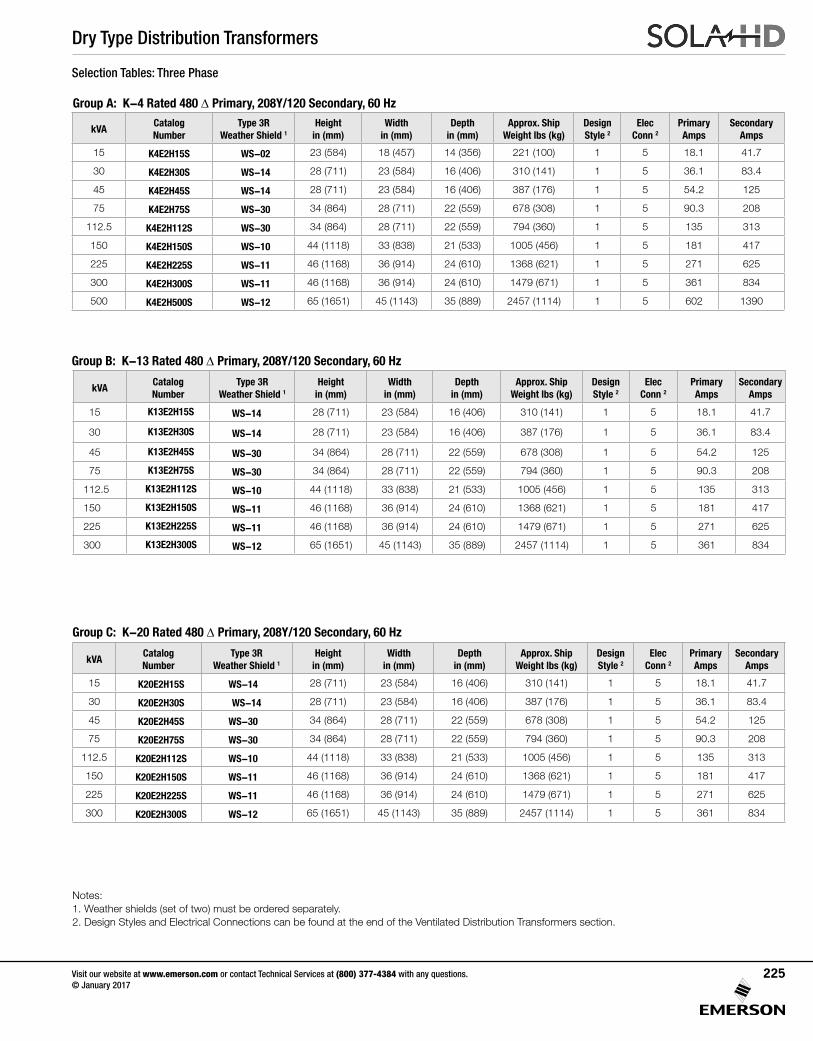
Dry Type Distribution Transformers
Group B: K-13 Rated 480 Δ Primary, 208Y/120 Secondary, 60 Hz
Group A: K-4 Rated 480 Δ Primary, 208Y/120 Secondary, 60 Hz
Selection Tables: Three Phase
kVACatalog Number
Type 3R Weather Shield 1
Height in (mm)
Width in (mm)
Depth in (mm)
Approx. Ship Weight lbs (kg)
DesignStyle 2
Elec Conn 2
Primary Amps
Secondary Amps
15 K4E2H15S WS-02 23 (584) 18 (457) 14 (356) 221 (100) 1 5 18.1 41.7
30 K4E2H30S WS-14 28 (711) 23 (584) 16 (406) 310 (141) 1 5 36.1 83.4
45 K4E2H45S WS-14 28 (711) 23 (584) 16 (406) 387 (176) 1 5 54.2 125
75 K4E2H75S WS-30 34 (864) 28 (711) 22 (559) 678 (308) 1 5 90.3 208
112.5 K4E2H112S WS-30 34 (864) 28 (711) 22 (559) 794 (360) 1 5 135 313
150 K4E2H150S WS-10 44 (1118) 33 (838) 21 (533) 1005 (456) 1 5 181 417
225 K4E2H225S WS-11 46 (1168) 36 (914) 24 (610) 1368 (621) 1 5 271 625
300 K4E2H300S WS-11 46 (1168) 36 (914) 24 (610) 1479 (671) 1 5 361 834
500 K4E2H500S WS-12 65 (1651) 45 (1143) 35 (889) 2457 (1114) 1 5 602 1390
kVACatalog Number
Type 3R Weather Shield 1
Height in (mm)
Width in (mm)
Depth in (mm)
Approx. Ship Weight lbs (kg)
DesignStyle 2
Elec Conn 2
Primary Amps
Secondary Amps
15 K13E2H15S WS-14 28 (711) 23 (584) 16 (406) 310 (141) 1 5 18.1 41.7
30 K13E2H30S WS-14 28 (711) 23 (584) 16 (406) 387 (176) 1 5 36.1 83.4
45 K13E2H45S WS-30 34 (864) 28 (711) 22 (559) 678 (308) 1 5 54.2 125
75 K13E2H75S WS-30 34 (864) 28 (711) 22 (559) 794 (360) 1 5 90.3 208
112.5 K13E2H112S WS-10 44 (1118) 33 (838) 21 (533) 1005 (456) 1 5 135 313
150 K13E2H150S WS-11 46 (1168) 36 (914) 24 (610) 1368 (621) 1 5 181 417
225 K13E2H225S WS-11 46 (1168) 36 (914) 24 (610) 1479 (671) 1 5 271 625
300 K13E2H300S WS-12 65 (1651) 45 (1143) 35 (889) 2457 (1114) 1 5 361 834
Group C: K-20 Rated 480 Δ Primary, 208Y/120 Secondary, 60 Hz
kVACatalog Number
Type 3R Weather Shield 1
Height in (mm)
Width in (mm)
Depth in (mm)
Approx. Ship Weight lbs (kg)
DesignStyle 2
Elec Conn 2
Primary Amps
Secondary Amps
15 K20E2H15S WS-14 28 (711) 23 (584) 16 (406) 310 (141) 1 5 18.1 41.7
30 K20E2H30S WS-14 28 (711) 23 (584) 16 (406) 387 (176) 1 5 36.1 83.4
45 K20E2H45S WS-30 34 (864) 28 (711) 22 (559) 678 (308) 1 5 54.2 125
75 K20E2H75S WS-30 34 (864) 28 (711) 22 (559) 794 (360) 1 5 90.3 208
112.5 K20E2H112S WS-10 44 (1118) 33 (838) 21 (533) 1005 (456) 1 5 135 313
150 K20E2H150S WS-11 46 (1168) 36 (914) 24 (610) 1368 (621) 1 5 181 417
225 K20E2H225S WS-11 46 (1168) 36 (914) 24 (610) 1479 (671) 1 5 271 625
300 K20E2H300S WS-12 65 (1651) 45 (1143) 35 (889) 2457 (1114) 1 5 361 834
Visit our website at www.emerson.com or contact Technical Services at (800) 377-4384 with any questions. © January 2017
225
Notes: 1. Weather shields (set of two) must be ordered separately. 2. Design Styles and Electrical Connections can be found at the end of the Ventilated Distribution Transformers section.

Dry Type Distribution Transformers
120/208/240/277 Volt Primary, 120/240 Volt Secondary Taps: None
Primary Voltage InterconnectConnect Lines To
277 1 to 2 H1 & H2
240 3 to 4 H1 & H2
208 5 to 6 H1 & H2
120H1 to 4 H2 to 3
H1 & H2
Secondary Voltage
InterconnectConnect Lines To
240 X2 to X3 X1 & X4
120-0-120X2 to X3 X2 to
X1-X2-X4
120X1 to X3 X2 to X4
X1 & X4
ES12 Series
240 x 480 Volt Primary, 120/240 Volt Secondary Taps: 2, 2½%FCAN;4,2½%FCBN
Primary Voltage InterconnectConnect Lines To
504 1 to 2 H1 & H2
492 2 to 3 H1 & H2
480 3 to 4 H1 & H2
468 4 to 5 H1 & H2
456 5 to 6 H1 & H2
444 6 to 7 H1 & H2
432 7 to 8 H1 & H2
252 H1 to 2 H2 to 1 H1 & H2
240 H1 to 4 H2 to 3 H1 & H2
228 H1 to 6 H2 to 5 H1 & H2
216 H1 to 8 H2 to 7 H1 & H2
Secondary Voltage
InterconnectConnect Lines To
240 X2 to X3 X1 & X4
120-0-120 X2 to X3 X2 to X1-X2-X4
120 X1 to X3 X2 to X4 X1 & X4
ES5 Series
1 2
7
H1 H2
SHIELD
5 3 1 2 4 6 8
X1 X3 X2 X4
H1 H2
35 1 2 4 6
SHIELD
X1 X3 X2 X4
Visit our website at www.emerson.com or contact Technical Services at (800) 377-4384 with any questions. © January 2017
226
Design Style
Style 1 - Ventilated
W D
H
Electrical Connections (Single Phase)
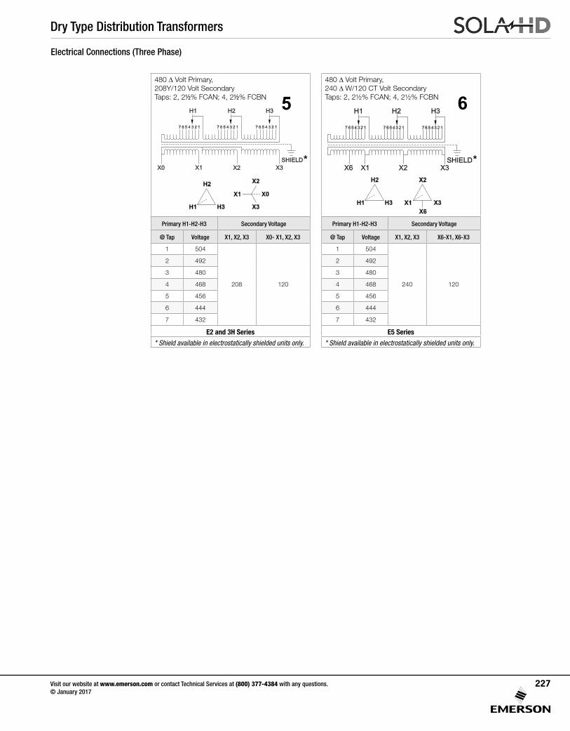
Dry Type Distribution Transformers
480 Δ Volt Primary, 240 Δ W/120 CT Volt Secondary Taps:2,2½%FCAN;4,2½%FCBN
Primary H1-H2-H3 Secondary Voltage
@ Tap Voltage X1, X2, X3 X6-X1, X6-X3
1 504
240 120
2 492
3 480
4 468
5 456
6 444
7 432
E5 Series
* Shield available in electrostatically shielded units only.
480 Δ Volt Primary, 208Y/120 Volt Secondary Taps: 2, 2½% FCAN; 4, 2½%FCBN
Primary H1-H2-H3 Secondary Voltage
@ Tap Voltage X1, X2, X3 X0- X1, X2, X3
1 504
208 120
2 492
3 480
4 468
5 456
6 444
7 432
E2 and 3H Series
* Shield available in electrostatically shielded units only.
5 6
H1 H3
H2
X1
X6
X3
X2
H1 H2 H3
7 6 5 4 3 2 1 7 6 5 4 3 2 1 7 6 5 4 3 2 1
X6
SHIELD
X1 X3X2
*X1 X2 X3
7 6 5 4 3 2 1 7 6 5 4 3 2 1 7 6 5 4 3 2 1
X0
SHIELD
H1 H3H2
H1 H3
H2
X1
X2
X3
X0
*
Visit our website at www.emerson.com or contact Technical Services at (800) 377-4384 with any questions. © January 2017
227
Electrical Connections (Three Phase)
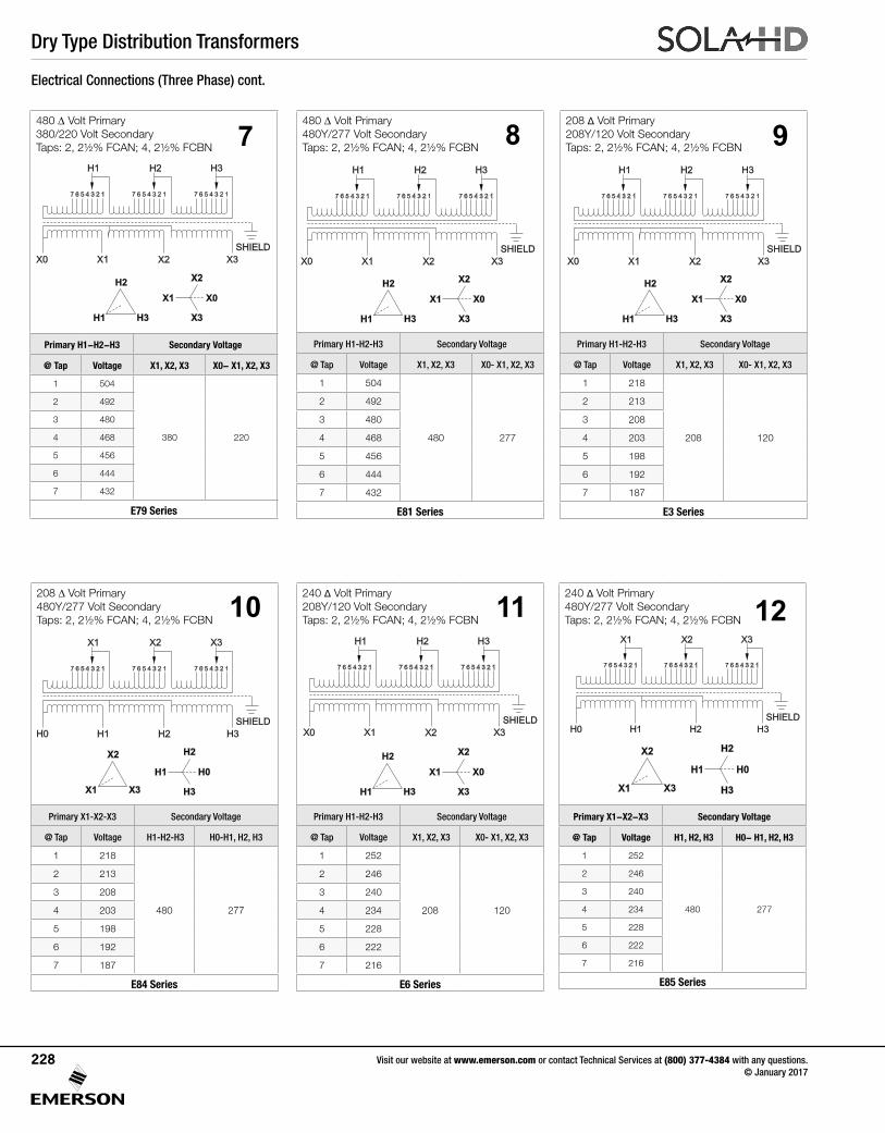
Dry Type Distribution Transformers
208 Δ Volt Primary 208Y/120 Volt Secondary Taps:2,2½%FCAN;4,2½%FCBN
Primary H1-H2-H3 Secondary Voltage
@ Tap Voltage X1, X2, X3 X0- X1, X2, X3
1 218
208 120
2 213
3 208
4 203
5 198
6 192
7 187
E3 Series
208 Δ Volt Primary480Y/277 Volt Secondary Taps:2,2½%FCAN;4,2½%FCBN
Primary X1-X2-X3 Secondary Voltage
@ Tap Voltage H1-H2-H3 H0-H1, H2, H3
1 218
480 277
2 213
3 208
4 203
5 198
6 192
7 187
E84 Series
480 Δ Volt Primary 480Y/277 Volt Secondary Taps:2,2½%FCAN;4,2½%FCBN
Primary H1-H2-H3 Secondary Voltage
@ Tap Voltage X1, X2, X3 X0- X1, X2, X3
1 504
480 277
2 492
3 480
4 468
5 456
6 444
7 432
E81 Series
8480 Δ Volt Primary 380/220 Volt Secondary Taps:2,2½%FCAN;4,2½%FCBN
Primary H1-H2-H3 Secondary Voltage
@ Tap Voltage X1, X2, X3 X0- X1, X2, X3
1 504
380 220
2 492
3 480
4 468
5 456
6 444
7 432
E79 Series
7
H1 H3
H2
X1
X2
X3
X0
X1 X2 X3
7 6 5 4 3 2 1 7 6 5 4 3 2 1 7 6 5 4 3 2 1
X0
SHIELD
H1 H3H2
240 Δ Volt Primary 480Y/277 Volt Secondary Taps:2,2½%FCAN;4,2½%FCBN
Primary X1-X2-X3 Secondary Voltage
@ Tap Voltage H1, H2, H3 H0- H1, H2, H3
1 252
480 277
2 246
3 240
4 234
5 228
6 222
7 216
E85 Series
240 Δ Volt Primary208Y/120 Volt Secondary Taps:2,2½%FCAN;4,2½%FCBN
Primary H1-H2-H3 Secondary Voltage
@ Tap Voltage X1, X2, X3 X0- X1, X2, X3
1 252
208 120
2 246
3 240
4 234
5 228
6 222
7 216
E6 Series
Visit our website at www.emerson.com or contact Technical Services at (800) 377-4384 with any questions. © January 2017
228
9
10
H1 H2 H3
7 6 5 4 3 2 1 7 6 5 4 3 2 1 7 6 5 4 3 2 1
H0
SHIELD
X1 X3X2
X1 X3
X2
H1
H2
H3
H0
H1 H3
H2
X1
X2
X3
X0
X1 X2 X3
7 6 5 4 3 2 1 7 6 5 4 3 2 1 7 6 5 4 3 2 1
X0
SHIELD
H1 H3H2
X1 X2 X3
7 6 5 4 3 2 1 7 6 5 4 3 2 1 7 6 5 4 3 2 1
X0
SHIELD
H1 H3H2
H1 H3
H2
X1
X2
X3
X0
Electrical Connections (Three Phase) cont.
11
X1 X3
X2
H1
H2
H3
H0
H1 H2 H3
7 6 5 4 3 2 1 7 6 5 4 3 2 1 7 6 5 4 3 2 1
H0
SHIELD
X1 X3X2
12
X1 X2 X3
7 6 5 4 3 2 1 7 6 5 4 3 2 1 7 6 5 4 3 2 1
X0
SHIELD
H1 H3H2
H1 H3
H2
X1
X2
X3
X0
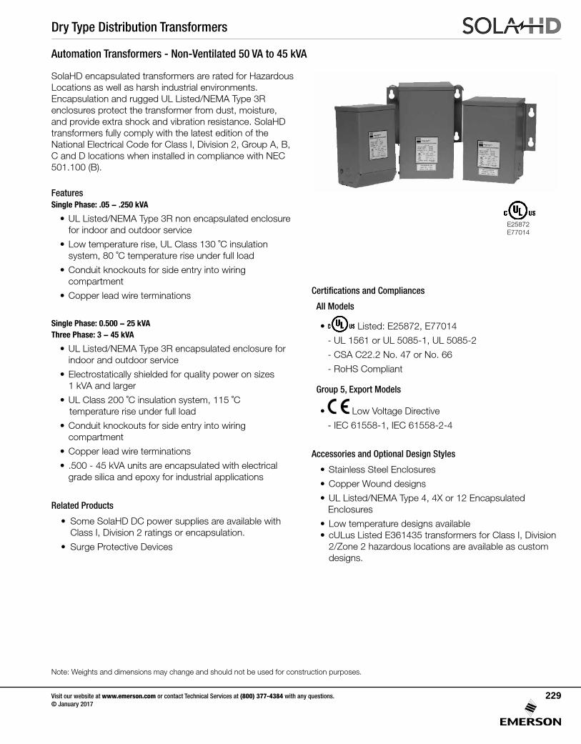
Dry Type Distribution Transformers
Note: Weights and dimensions may change and should not be used for construction purposes.
Visit our website at www.emerson.com or contact Technical Services at (800) 377-4384 with any questions. © January 2017
229
Automation Transformers - Non-Ventilated 50 VA to 45 kVA
SolaHD encapsulated transformers are rated for Hazardous Locations as well as harsh industrial environments. Encapsulation and rugged UL Listed/NEMA Type 3R enclosures protect the transformer from dust, moisture, and provide extra shock and vibration resistance. SolaHD transformers fully comply with the latest edition of the NationalElectricalCodeforClassI,Division2,GroupA,B,C and D locations when installed in compliance with NEC 501.100(B).
FeaturesSingle Phase: .05 - .250 kVA
• UL Listed/NEMA Type 3R non encapsulated enclosure for indoor and outdoor service
• Low temperature rise, UL Class 130 ˚C insulation system, 80 ˚C temperature rise under full load
• Conduit knockouts for side entry into wiring compartment
• Copper lead wire terminations
Single Phase: 0.500 - 25 kVAThree Phase: 3 - 45 kVA
• UL Listed/NEMA Type 3R encapsulated enclosure for indoor and outdoor service
• Electrostatically shielded for quality power on sizes 1 kVA and larger
• UL Class 200 ˚C insulation system, 115 ˚C temperature rise under full load
• Conduit knockouts for side entry into wiring compartment
• Copper lead wire terminations
• .500 - 45 kVA units are encapsulated with electrical grade silica and epoxy for industrial applications
Related Products
• Some SolaHD DC power supplies are available with Class I, Division 2 ratings or encapsulation.
• Surge Protective Devices
Certifications and Compliances
All Models
• Listed: E25872, E77014
- UL 1561 or UL 5085-1, UL 5085-2
- CSA C22.2 No. 47 or No. 66
- RoHS Compliant
Group 5, Export Models
• Low Voltage Directive
- IEC 61558-1, IEC 61558-2-4
Accessories and Optional Design Styles
• Stainless Steel Enclosures
• Copper Wound designs
• UL Listed/NEMA Type 4, 4X or 12 Encapsulated Enclosures
• Low temperature designs available• cULus Listed E361435 transformers for Class I, Division
2/Zone 2 hazardous locations are available as custom designs.
E25872E77014
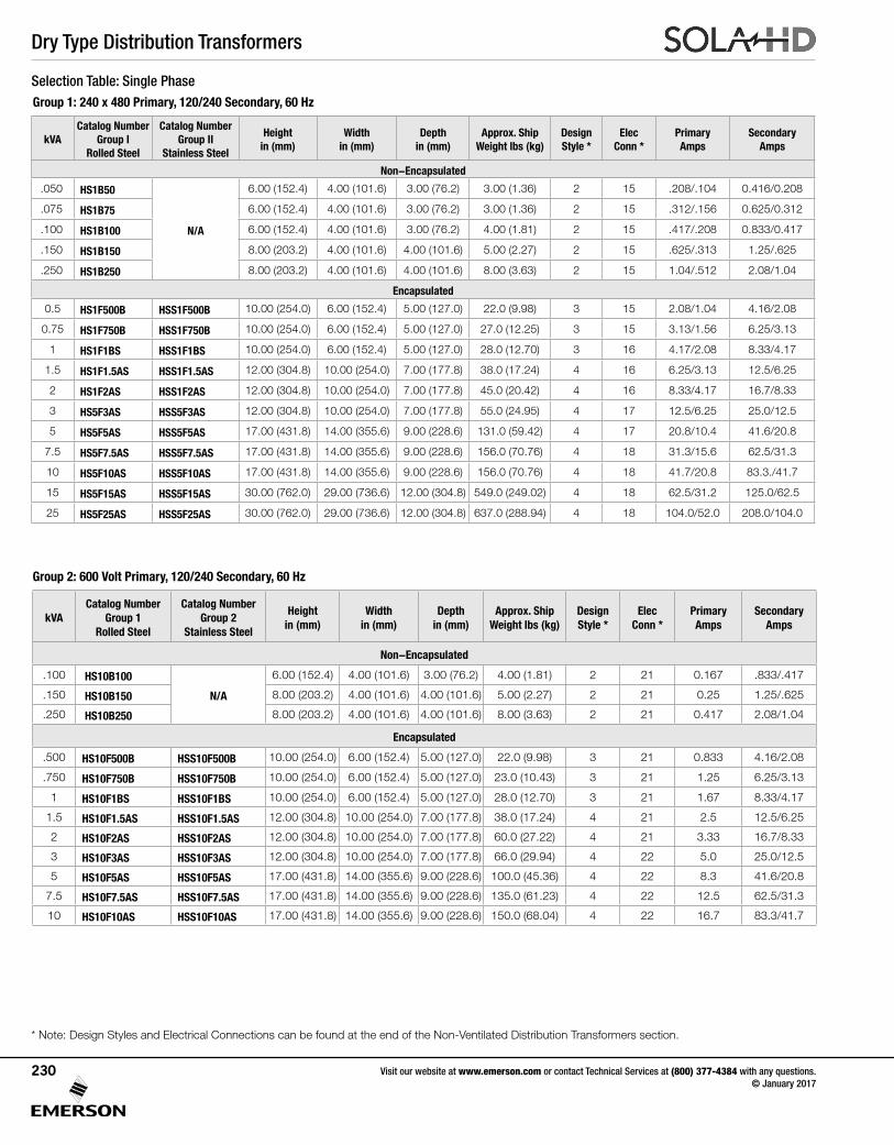
Dry Type Distribution Transformers
Visit our website at www.emerson.com or contact Technical Services at (800) 377-4384 with any questions. © January 2017
230
Selection Table: Single Phase
Group 2: 600 Volt Primary, 120/240 Secondary, 60 Hz
kVACatalog Number
Group 1Rolled Steel
Catalog Number Group 2
Stainless Steel
Height in (mm)
Width in (mm)
Depth in (mm)
Approx. Ship Weight lbs (kg)
Design Style *
Elec Conn *
Primary Amps
Secondary Amps
Non-Encapsulated
.100 HS10B100
N/A
6.00 (152.4) 4.00 (101.6) 3.00 (76.2) 4.00 (1.81) 2 21 0.167 .833/.417
.150 HS10B150 8.00 (203.2) 4.00 (101.6) 4.00 (101.6) 5.00 (2.27) 2 21 0.25 1.25/.625
.250 HS10B250 8.00 (203.2) 4.00 (101.6) 4.00 (101.6) 8.00 (3.63) 2 21 0.417 2.08/1.04
Encapsulated
.500 HS10F500B HSS10F500B 10.00 (254.0) 6.00 (152.4) 5.00 (127.0) 22.0 (9.98) 3 21 0.833 4.16/2.08
.750 HS10F750B HSS10F750B 10.00 (254.0) 6.00 (152.4) 5.00 (127.0) 23.0 (10.43) 3 21 1.25 6.25/3.13
1 HS10F1BS HSS10F1BS 10.00 (254.0) 6.00 (152.4) 5.00 (127.0) 28.0 (12.70) 3 21 1.67 8.33/4.17
1.5 HS10F1.5AS HSS10F1.5AS 12.00 (304.8) 10.00 (254.0) 7.00 (177.8) 38.0 (17.24) 4 21 2.5 12.5/6.25
2 HS10F2AS HSS10F2AS 12.00 (304.8) 10.00 (254.0) 7.00 (177.8) 60.0 (27.22) 4 21 3.33 16.7/8.33
3 HS10F3AS HSS10F3AS 12.00 (304.8) 10.00 (254.0) 7.00 (177.8) 66.0 (29.94) 4 22 5.0 25.0/12.5
5 HS10F5AS HSS10F5AS 17.00 (431.8) 14.00 (355.6) 9.00 (228.6) 100.0 (45.36) 4 22 8.3 41.6/20.8
7.5 HS10F7.5AS HSS10F7.5AS 17.00 (431.8) 14.00 (355.6) 9.00 (228.6) 135.0 (61.23) 4 22 12.5 62.5/31.3
10 HS10F10AS HSS10F10AS 17.00 (431.8) 14.00 (355.6) 9.00 (228.6) 150.0 (68.04) 4 22 16.7 83.3/41.7
* Note: Design Styles and Electrical Connections can be found at the end of the Non-Ventilated Distribution Transformers section.
kVACatalog Number
Group I Rolled Steel
Catalog Number Group II
Stainless Steel
Height in (mm)
Width in (mm)
Depth in (mm)
Approx. Ship Weight lbs (kg)
DesignStyle *
Elec Conn *
Primary Amps
Secondary Amps
Non-Encapsulated
.050 HS1B50
N/A
6.00 (152.4) 4.00 (101.6) 3.00 (76.2) 3.00 (1.36) 2 15 .208/.104 0.416/0.208
.075 HS1B75 6.00 (152.4) 4.00 (101.6) 3.00 (76.2) 3.00 (1.36) 2 15 .312/.156 0.625/0.312
.100 HS1B100 6.00 (152.4) 4.00 (101.6) 3.00 (76.2) 4.00 (1.81) 2 15 .417/.208 0.833/0.417
.150 HS1B150 8.00 (203.2) 4.00 (101.6) 4.00 (101.6) 5.00 (2.27) 2 15 .625/.313 1.25/.625
.250 HS1B250 8.00 (203.2) 4.00 (101.6) 4.00 (101.6) 8.00 (3.63) 2 15 1.04/.512 2.08/1.04
Encapsulated
0.5 HS1F500B HSS1F500B 10.00 (254.0) 6.00 (152.4) 5.00 (127.0) 22.0 (9.98) 3 15 2.08/1.04 4.16/2.08
0.75 HS1F750B HSS1F750B 10.00 (254.0) 6.00 (152.4) 5.00 (127.0) 27.0 (12.25) 3 15 3.13/1.56 6.25/3.13
1 HS1F1BS HSS1F1BS 10.00 (254.0) 6.00 (152.4) 5.00 (127.0) 28.0 (12.70) 3 16 4.17/2.08 8.33/4.17
1.5 HS1F1.5AS HSS1F1.5AS 12.00 (304.8) 10.00 (254.0) 7.00 (177.8) 38.0 (17.24) 4 16 6.25/3.13 12.5/6.25
2 HS1F2AS HSS1F2AS 12.00 (304.8) 10.00 (254.0) 7.00 (177.8) 45.0 (20.42) 4 16 8.33/4.17 16.7/8.33
3 HS5F3AS HSS5F3AS 12.00 (304.8) 10.00 (254.0) 7.00 (177.8) 55.0 (24.95) 4 17 12.5/6.25 25.0/12.5
5 HS5F5AS HSS5F5AS 17.00 (431.8) 14.00 (355.6) 9.00 (228.6) 131.0 (59.42) 4 17 20.8/10.4 41.6/20.8
7.5 HS5F7.5AS HSS5F7.5AS 17.00 (431.8) 14.00 (355.6) 9.00 (228.6) 156.0 (70.76) 4 18 31.3/15.6 62.5/31.3
10 HS5F10AS HSS5F10AS 17.00 (431.8) 14.00 (355.6) 9.00 (228.6) 156.0 (70.76) 4 18 41.7/20.8 83.3./41.7
15 HS5F15AS HSS5F15AS 30.00 (762.0) 29.00 (736.6) 12.00 (304.8) 549.0 (249.02) 4 18 62.5/31.2 125.0/62.5
25 HS5F25AS HSS5F25AS 30.00 (762.0) 29.00 (736.6) 12.00 (304.8) 637.0 (288.94) 4 18 104.0/52.0 208.0/104.0
Group 1: 240 x 480 Primary, 120/240 Secondary, 60 Hz
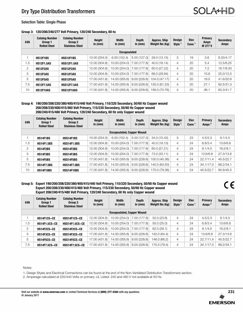
Dry Type Distribution Transformers
Visit our website at www.emerson.com or contact Technical Services at (800) 377-4384 with any questions. © January 2017
231
Selection Table: Single Phase
Group 3: 120/208/240/277 Volt Primary, 120/240 Secondary, 60 Hz
kVACatalog Number
Group 1Rolled Steel
Catalog Number Group 2
Stainless Steel
Height in (mm)
Width in (mm)
Depth in (mm)
Approx. Ship Weight lbs (kg)
Design Style 1
ElecConn 1
Primary Amps
@ 277 V
Secondary Amps
Encapsulated
1 HS12F1BS HSS12F1BS 10.00 (254.0) 6.00 (152.4) 5.00 (127.0) 29.0 (13.15) 3 19 3.6 8.33/4.17
1.5 HS12F1.5AS HSS12F1.5AS 12.00 (304.8) 10.00 (254.0) 7.00 (177.8) 40.0 (18.14) 4 20 5.4 12.5/6.25
2 HS12F2AS HSS12F2AS 12.00 (304.8) 10.00 (254.0) 7.00 (177.8) 60.0 (27.22) 4 20 7.2 16.7/8.33
3 HS12F3AS HSS12F3AS 12.00 (304.8) 10.00 (254.0) 7.00 (177.8) 66.0 (29.94) 4 20 10.8 25.0/12.5
5 HS12F5AS HSS12F5AS 17.00 (431.8) 14.00 (355.6) 9.00 (228.6) 104.0 (47.17) 4 20 18.0 41.6/20.8
7.5 HS12F7.5AS HSS12F7.5AS 17.00 (431.8) 14.00 (355.6) 9.00 (228.6) 135.0 (61.23) 4 20 27.1 62.5/31.3
10 HS12F10AS HSS12F10AS 17.00 (431.8) 14.00 (355.6) 9.00 (228.6) 156.0 (70.76) 4 20 36.1 83.3/41.7
Group 4: 190/200/208/220/380/400/415/440 Volt Primary, 110/220 Secondary, 50/60 Hz Copper wound 200/208/230/400/415/460 Volt Primary, 115/230 Secondary, 50/60 Hz Copper wound 208/240/415/480 Volt Primary, 120/240 Secondary, 60 Hz only Copper wound
kVACatalog Number
Group 1Rolled Steel
Catalog Number Group 2
Stainless Steel
Height in (mm)
Width in (mm)
Depth in (mm)
Approx. Ship Weight lbs (kg)
Design Style 1
ElecConn 1
Primary Amps 2
Secondary Amps
Encapsulated, Copper Wound
1 HS14F1BS HSS14F1BS 10.00 (254.0) 6.00 (152.4) 5.00 (127.0) 34.0 (15.42) 3 23 4.5/2.3 9.1/4.5
1.5 HS14F1.5BS HSS14F1.5BS 12.00 (304.8) 10.00 (254.0) 7.00 (177.8) 40.0 (18.13) 4 24 6.8/3.4 13.6/6.8
2 HS14F2BS HSS14F2BS 12.00 (304.8) 10.00 (254.0) 7.00 (177.8) 60.0 (27.21) 4 24 9.1/4.5 18.2/9.1
3 HS14F3BS HSS14F3BS 12.00 (304.8) 10.00 (254.0) 7.00 (177.8) 73.0 (33.11) 4 24 13.6/6.8 27.3/13.6
5 HS14F5BS HSS14F5BS 17.00 (431.8) 14.00 (355.6) 9.00 (228.6) 100.0 (45.36) 4 24 22.7/11.4 45.5/22.7
7.5 HS14F7.5BS HSS14F7.5BS 17.00 (431.8) 14.00 (355.6) 9.00 (228.6) 140.0 (63.50) 4 24 34.1/17.0 68.2/34.1
10 HS14F10BS HSS14F10BS 17.00 (431.8) 14.00 (355.6) 9.00 (228.6) 175.0 (79.38) 4 24 45.5/22.7 90.9/45.5
Group 5: Export 190/200/208/220/380/400/415/440 Volt Primary, 110/220 Secondary, 50/60 Hz Copper wound Export 200/208/230/400/415/460 Volt Primary, 115/230 Secondary, 50/60 Hz Copper wound Export 208/240/415/480 Volt Primary, 120/240 Secondary, 60 Hz only Copper wound
kVACatalog Number
Group 1Rolled Steel
Catalog Number Group 2
Stainless Steel
Height in (mm)
Width in (mm)
Depth in (mm)
Approx. Ship Weight lbs (kg)
Design Style 1
ElecConn 1
Primary Amps 2
Secondary Amps
Encapsulated, Copper Wound
1 HS14F1CS-CE HSS14F1CS-CE 12.00 (304.8) 10.00 (254.0) 7.00 (177.8) 52.0 (23.6) 4 24 4.5/2.3 9.1/4.5
1.5 HS14F1.5CS-CE HSS14F1.5CS-CE 12.00 (304.8) 10.00 (254.0) 7.00 (177.8) 55.0 (25.0) 4 24 6.8/3.4 13.6/6.8
2 HS14F2CS-CE HSS14F2CS-CE 12.00 (304.8) 10.00 (254.0) 7.00 (177.8) 62.0 (28.1) 4 24 9.1/4.5 18.2/9.1
3 HS14F3CS-CE HSS14F3CS-CE 17.00 (431.8) 14.00 (355.6) 9.00 (228.6) 142.0 (64.4) 4 24 13.6/6.8 27.3/13.6
5 HS14F5CS-CE HSS14F5CS-CE 17.00 (431.8) 14.00 (355.6) 9.00 (228.6) 146.0 (66.2) 4 24 22.7/11.4 45.5/22.7
7.5 HS14F7.5CS-CE HSS14F7.5CS-CE 17.00 (431.8) 14.00 (355.6) 9.00 (228.6) 175.0 (79.4) 4 24 34.1/17.0 68.2/34.1
Notes:
1. Design Styles and Electrical Connections can be found at the end of the Non-Ventilated Distribution Transformers section. 2. Amperage calculated at 220/440 Volts on primary. UL Listed. 240 and 480 V not available at 50 Hz.
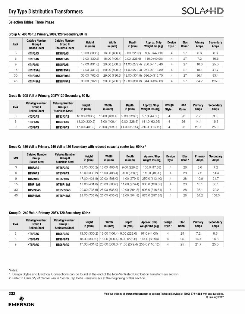
Dry Type Distribution Transformers
Group A: 480 Volt Δ Primary, 208Y/120 Secondary, 60 Hz
kVACatalog Number
Group I Rolled Steel
Catalog Number Group II
Stainless Steel
Height in (mm)
Width in (mm)
Depth in (mm)
Approx. Ship Weight lbs (kg)
DesignStyle 1
Elec Conn 1
Primary Amps
Secondary Amps
3 HT1F3AS HTS1F3AS 13.00 (330.2) 16.00 (406.4) 9.00 (228.6) 105.0 (47.63) 4 27 3.6 8.3
6 HT1F6AS HTS1F6AS 13.00 (330.2) 16.00 (406.4) 9.00 (228.6) 110.0 (49.90) 4 27 7.2 16.6
9 HT1F9AS HTS1F9AS 17.00 (431.8) 20.00 (508.0) 11.00 (279.4) 250.0 (113.40) 4 27 10.8 25.0
15 HT1F15AS HTS1F15AS 17.00 (431.8) 20.00 (508.0) 11.00 (279.4) 261.0 (118.39) 4 27 18.1 41.7
30 HT1F30AS HTS1F30AS 30.00 (762.0) 29.00 (736.6) 12.00 (304.8) 696.0 (315.70) 4 27 36.1 83.4
45 HT1F45AS HTS1F45AS 30.00 (762.0) 29.00 (736.6) 12.00 (304.8) 844.0 (382.83) 4 27 54.2 125.0
Visit our website at www.emerson.com or contact Technical Services at (800) 377-4384 with any questions. © January 2017
232
Group C: 480 Volt Δ Primary, 240 Volt Δ 120 Secondary with reduced capacity center tap, 60 Hz 2
kVACatalog Number
Group I Rolled Steel
Catalog Number Group II
Stainless Steel
Height in (mm)
Width in (mm)
Depth in (mm)
Approx. Ship Weight lbs (kg)
DesignStyle 1
Elec Conn 1
Primary Amps
Secondary Amps
3 HT5F3AS HTS5F3AS 13.00 (330.2) 16.00 (406.4) 9.00 (228.6) 105.0 (47.63) 4 28 3.6 7.2
6 HT5F6AS HTS5F6AS 13.00 (330.2) 16.00 (406.4) 9.00 (228.6) 110.0 (49.90) 4 28 7.2 14.4
9 HT5F9AS HTS5F9AS 17.00 (431.8) 20.00 (508.0) 11.00 (279.4) 250.0 (113.40) 4 28 10.8 21.7
15 HT5F15AS HTS5F15AS 17.00 (431.8) 20.00 (508.0) 11.00 (279.4) 305.0 (138.35) 4 28 18.1 36.1
30 HT5F30AS HTS5F30AS 29.00 (736.6) 25.00 (635.0) 12.00 (304.8) 698.0 (316.61) 4 28 36.1 72.2
45 HT5F45AS HTS5F45AS 29.00 (736.6) 25.00 (635.0) 12.00 (304.8) 876.0 (397.35) 4 28 54.2 108.3
Notes: 1. Design Styles and Electrical Connections can be found at the end of the Non-Ventilated Distribution Transformers section. 2. Refer to Capacity of Center Tap in Center Tap Delta Transformers at the beginning of this section.
Group D: 240 Volt Δ Primary, 208Y/120 Secondary, 60 Hz
kVACatalog Number
Group I Rolled Steel
Catalog NumberGroup II
Stainless Steel
Height in (mm)
Width in (mm)
Depth in (mm)
Approx. Ship Weight lbs (kg)
Design Style 1
Elec Conn 1
Primary Amps
Secondary Amps
3 HT6F3AS HTS6F3AS 13.00 (330.2) 16.00 (406.4) 9.00 (228.6) 97.0 (44.00) 4 25 7.2 8.3
6 HT6F6AS HTS6F6AS 13.00 (330.2) 16.00 (406.4) 9.00 (228.6) 141.0 (63.96) 4 25 14.4 16.6
9 HT6F9AS HTS6F9AS 17.00 (431.8) 20.00 (508.0) 11.00 (279.4) 256.0 (116.12) 4 25 21.7 25.0
Selection Tables: Three Phase
Group B: 208 Volt Δ Primary, 208Y/120 Secondary, 60 Hz
kVACatalog Number
Group I Rolled Steel
Catalog Number Group II
Stainless Steel
Height in (mm)
Width in (mm)
Depth in (mm)
Approx. Ship Weight lbs (kg)
Design Style 1
Elec Conn 1
Primary Amps
Secondary Amps
3 HT3F3AS HTS3F3AS 13.00 (330.2) 16.00 (406.4) 9.00 (228.6) 97.0 (44.00) 4 26 7.2 8.3
6 HT3F6AS HTS3F6AS 13.00 (330.2) 16.00 (406.4) 9.00 (228.6) 141.0 (63.96) 4 26 14.4 16.6
9 HT3F9AS HTS3F9AS 17.00 (431.8) 20.00 (508.0) 11.00 (279.4) 256.0 (116.12) 4 26 21.7 25.0
Dry Type Distribution Transformers
Visit our website at www.emerson.com or contact Technical Services at (800) 377-4384 with any questions. © January 2017
233
Group E: 480 Volt Δ Primary, 380Y/220 Secondary, 60 Hz
kVACatalog Number
Group I Rolled Steel
Catalog NumberGroup II
Stainless Steel
Height in (mm)
Width in (mm)
Depth in (mm)
Approx. Ship Weight lbs (kg)
Design Style *
Elec Conn *
Primary Amps
Secondary Amps
3 HT79F3AS HTS79F3AS 13.00 (330.2) 16.00 (406.4) 9.00 (228.6) 121.0 (54.88) 4 29 3.6 4.6
6 HT79F6AS HTS79F6AS 13.00 (330.2) 16.00 (406.4) 9.00 (228.6) 141.0 (63.96) 4 29 7.2 9.1
9 HT79F9AS HTS79F9AS 17.00 (431.8) 20.00 (508.0) 11.00 (279.4) 255.0 (115.7) 4 29 10.8 13.6
Selection Tables: Three Phase
Group F: 600 Volt Δ Primary, 208Y/120 Secondary, 60 Hz
kVACatalog Number
Group I Rolled Steel
Catalog NumberGroup II
Stainless Steel
Height in (mm)
Width in (mm)
Depth in (mm)
Approx. Ship Weight lbs (kg)
Design Style *
Elec Conn *
Primary Amps
Secondary Amps
3 HT7F3AS HTS7F3AS 13.00 (330.2) 16.00 (406.4) 9.00 (228.6) 116.0 (52.62) 4 30 2.9 8.3
6 HT7F6AS HTS7F6AS 13.00 (330.2) 16.00 (406.4) 9.00 (228.6) 145.0 (65.77) 4 30 5.8 16.6
9 HT7F9AS HTS7F9AS 17.00 (431.8) 20.00 (508.0) 11.00 (279.4) 225.0 (115.67) 4 30 8.7 25.0
Group G: 208 Volt Δ Primary, 480Y/277 Secondary, 60 Hz
kVACatalog Number
Group I Rolled Steel
Catalog Number Group II
Stainless Steel
Height in (mm)
Width in (mm)
Depth in (mm)
Ship Weight Approx. (lbs)
DesignStyle *
Elec Conn *
Primary Amps
Secondary Amps
3 HT84F3AS HTS84F3AS 13.00 (330.2) 16.00 (406.4) 9.00 (228.6) 97.0 (44.00) 4 31 8.3 3.6
6 HT84F6AS HTS84F6AS 13.00 (330.2) 16.00 (406.4) 9.00 (228.6) 141.0 (63.96) 4 31 16.6 7.2
9 HT84F9AS HTS84F9AS 17.00 (431.8) 20.00 (508.0) 11.00 (279.4) 256.0 (116.12) 4 31 25.0 10.8
Group H: 240 Volt Δ Primary, 480Y/277 Secondary, 60 Hz
kVACatalog Number
Group I Rolled Steel
Catalog Number Group II
Stainless Steel
Height in (mm)
Width in (mm)
Depth in (mm)
Ship Weight Approx. (lbs)
DesignStyle *
Elec Conn *
Primary Amps
Secondary Amps
3 HT85F3AS HTS85F3AS 13.00 (330.2) 16.00 (406.4) 9.00 (228.6) 97.0 (44.00) 4 32 7.2 3.6
6 HT85F6AS HTS85F6AS 13.00 (330.2) 16.00 (406.4) 9.00 (228.6) 141.0 (63.96) 4 32 14.4 7.2
9 HT85F9AS HTS85F9AS 17.00 (431.8) 20.00 (508.0) 11.00 (279.4) 256.0 (116.12) 4 32 21.6 10.8
* Notes: Design Styles and Electrical Connections can be found at the end of the Non-Ventilated Distribution Transformers section.
Dry Type Distribution Transformers
Visit our website at www.emerson.com or contact Technical Services at (800) 377-4384 with any questions. © January 2017
234
Style 3 - Encapsulated Style 4 - Encapsulated
Style 2 - Non-Encapsulated
Customized Enclosures - Contact Technical Services
Style 5 - Encapsulated
Available for all encapsulated kVA sizes (For Type 4, 12 and 4X)
Design Styles
W D
H
W D
H
Dry Type Distribution Transformers
Visit our website at www.emerson.com or contact Technical Services at (800) 377-4384 with any questions. © January 2017
235
Primary Voltage Interconnect Connect Lines to
277 H2 to H3 H1 & H6
240 H2 to H3 H1 & H5
208 H2 to H3 H1 & H4
120H1 to H3H2 to H5
H1 & H5
Secondary Voltage Interconnect Connect Lines to
240 X2 to X3 X1 & X4
120-0-120X2 to X3X2 to
X1-X2-X4
120X1 to X3X2 to X4
X1 & X4
HS12 Series (1 kVA only)
Primary Voltage Interconnect Connect Lines to
277 H4 to H5 H1 & H8
240 H3 to H6 H1 & H8
208 H2 to H7 H1 & H8
120H1 to H6H3 to H8
H1 & H8
Secondary Voltage Interconnect Connect Lines to
240 X2 to X3 X1 & X4
120-0-120X2 to X3X2 to
X1-X2-X4
120X1 to X3X2 to X4
X1 & X4
HS12 Series
Primary Voltage Interconnect Connect Lines to
504 H4 to H5 H1 & H8
492 H3 to H5 H1 & H8
480 H3 to H6 H1 & H8
468 H2 to H6 H1 & H8
456 H2 to H7 H1 & H8
252H1 to H5 H4 to H8
H1 & H8
240H1 to H6H3 to H8
H1 & H8
228H1 to H7H2 to H8
H1 & H8
Secondary Voltage Interconnect Connect Lines to
240 X2 to X3 X1 & X4
120-0-120X2 to X3X2 to
X1-X2-X4
120X1 to X3X2 to X4
X1 & X4
HS5 Series
Primary Voltage Interconnect Connect Lines to
480 H2 to H3 H1 & H4
240H1 to H3 H2 to H4
H1 & H4
Secondary Voltage Interconnect Connect Lines to
240 X2 to X3 X1 & X4
120-0-120X2 to X3X2 to
X1-X2-X4
120X1 to X3 X2 to X4
X1 & X4
HS1 Series
Primary Voltage Interconnect Connect Lines to
504 H5 to H6 H1 & H10
492 H4 to H6 H1 & H10
480 H4 to H7 H1 & H10
468 H3 to H7 H1 & H10
456 H3 to H8 H1 & H10
444 H2 to H8 H1 & H10
432 H2 to H9 H1 & H10
252H1 to H6H5 to H10
H1 & H10
240H1 to H7H4 to H10
H1 & H10
228H1 to H8H3 to H10
H1 & H10
216H1 to H9H2 to H10
H1 & H10
Secondary Voltage Interconnect Connect Lines to
240 X2 to X3 X1 & X4
120-0-120X2 to X3X2 to
X1-X2-X4
120X1 to X3X2 to X4
X1 & X4
HS5 Series
Primary Voltage Interconnect Connect Lines to
480 H2 to H3 H1 & H4
240H1 to H3 H2 to H4
H1 & H4
Secondary Voltage Interconnect Connect Lines to
240 X2 to X3 X1 & X4
120-0-120X2 to X3X2 to
X1-X2-X4
120X1 to X3 X2 to X4
X1 & X4
HS1 Series
Electrical Connections (Single Phase)
240 X 480 Volt Primary 120/240 Volt Secondary Taps: None
15 17240 X 480 Volt Primary 120/240 Volt Secondary Taps: None
240 X 480 Volt Primary 120/240 Volt Secondary Taps:2,2½%FCAN&FCBN
240 X 480 Volt Primary, 120/240 Volt Secondary Taps: 2, 2½% FCAN; 4, 2½% FCBN
18
16
120/208/240/277 Volt Primary 120/240 Volt Secondary Taps: None
19
120/208/240/277 Volt Primary 120/240 Volt Secondary Taps: None
20
Note:
Connect the electrostatic shield to the equipment ground (green) or to both the equipment ground and thesystemground(white).Specificationsaresubjecttochangewithoutnotice.
= Earth Ground
H1 H2H3 H4
X1 X3 X2 X4
SHIELD
H1 H2 H3 H4 H5 H6H7 H8
SHIELD
X1 X3 X2 X4
H1 H2H3 H4
X1 X3 X2 X4
H1 H2 H3 H4 H5 H6 H7 H8 H9 H10
SHIELD
X1 X3 X2 X4
H1 H2H3 H4 H5 H6
SHIELD
X1 X3 X2 X4
H1 H2 H3 H4 H5 H6 H7 H8
SHIELD
X1 X3 X2 X4
Dry Type Distribution Transformers
Visit our website at www.emerson.com or contact Technical Services at (800) 377-4384 with any questions. © January 2017
236
600 Volt Primary, 120/240 Volt Secondary Taps: None 21
X1 X3 X2 X4
H1 H2
Primary Voltage Interconnect Connect Lines to
600 H1 & H2
Secondary Voltage Interconnect Connect Lines to
240 X2 to X3 X1 & X4
120-0-120X2 to X3X2 to m
X1, X2 & X4
120X1 to X3X2 to X4
X1 & X4
HS10 Series
190/200/208/220/380/400/415/440 Volt Pri. 110/220 Volt SecondaryTaps: None 24
H1 H2 H3 H4 H5 H6 H7 H8 H9 H10
SHIELD
X1 X3 X2 X4
Primary Voltage Interconnect Connect Lines to
440/460/480 H5 to H6 H1 & H10
415 H4 to H7 H1 & H10
400/415 H3 to H8 H1 & H10
380/400 H2 to H9 H1 & H10
220/230/240H1 to H6, H5 to H10
H1 & H10
208H1 to H7, H4 to H10
H1 & H10
200/208H1 to H8, H3 to H10
H1 & H10
190/200/208H1 to H9H2 to H10
H1 & H10
Secondary Voltage Interconnect Connect Lines to
220/230/240 X2 to X3 X1 & X4
110,220/115,230/120,240
X2 to X3X2 to X1, X2 & X4
110/115/120X1 to X3X2 to X4
X1 & X4
HS14 Series
Primary Voltage Interconnect Connect Lines to
440/460/480 H5 to H6 H1 & H10
415 H4 to H6 H1 & H9
400/415 H3 to H6 H1 & H8
380/400 H2 to H6 H1 & H7
220/230/240H1 to H6
H5 to H10H1 & H10
208H1 to H6H4 to H9
H1 & H9
200/208H1 to H6H3 to H8
H1 & H8
190/200/208H1 to H6H2 to H7
H1 & H7
Secondary Voltage Interconnect Connect Lines to
220/230/240 X2 to X3 X1 & X4
110,220/115,230/120,240
X2 to X3X2 to
X1, X2 & X4
110/115/120X1 to X3X2 to X4
X1 & X4
HS14F1BS
Primary Voltage Interconnect Connect Lines to
600 H3 to H4 H1 & H6
570 H2 to H4 H1 & H6
540 H2 to H5 H1 & H6
Secondary Voltage Interconnect Connect Lines to
240 X2 to X3 X1 & X4
120-0-120X2 to X3X2 to
X1-X2-X4
120X1 to X3X2 to X4
X1 & X4
HS10 Series
600 Volt Primary 120/240 Volt Secondary Taps:2,5%FCBN
Electrical Connections (Single Phase)
190/200/208/220/380/400/415/440 Volt Pri.110/220 Volt Secondary Taps: None
Note: 1 through 2 kVA units have electrostatic shielding.
Note:
Connect the electrostatic shield to the equipment ground (green) or to both the equipment ground and thesystemground(white).Specificationsaresubjecttochangewithoutnotice.
= Earth Ground
2322H1 H2 H3 H4 H5 H6
SHIELD
X1 X3 X2 X4
H1 H6H2 H7H3 H8H4 H9H5 H10
SHIELD
X1 X3 X2 X4
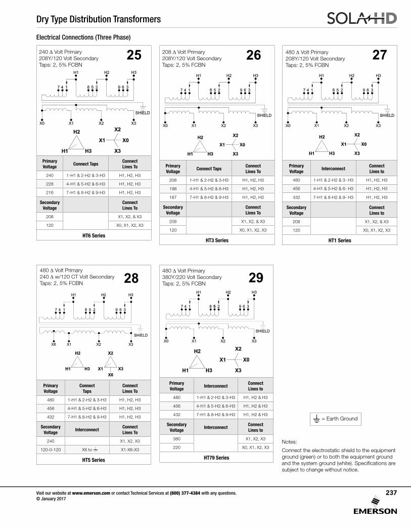
Dry Type Distribution Transformers
Visit our website at www.emerson.com or contact Technical Services at (800) 377-4384 with any questions. © January 2017
237
Primary Voltage
InterconnectConnect Lines to
480 1-H1 & 2-H2 & 3-H3 H1, H2 & H3
456 4-H1 & 5-H2 & 6-H3 H1, H2 & H3
432 7-H1 & 8-H2 & 9-H3 H1, H2 & H3
Secondary Voltage
InterconnectConnect Lines to
380 X1, X2, X3
220 X0, X1, X2, X3
HT79 Series
Primary Voltage
Connect Taps
Connect Lines To
480 1-H1 & 2-H2 & 3-H3 H1, H2, H3
456 4-H1 & 5-H2 & 6-H3 H1, H2, H3
432 7-H1 & 8-H2 & 9-H3 H1, H2, H3
Secondary Voltage
InterconnectConnect Lines To
240 X1, X2, X3
120-0-120 X6 to X1-X6-X3
HT5 Series
Primary Voltage
InterconnectConnect Lines to
480 1-H1 & 2-H2 & 3- H3 H1, H2, H3
456 4-H1 & 5-H2 & 6- H3 H1, H2, H3
432 7-H1 & 8-H2 & 9- H3 H1, H2, H3
Secondary Voltage
Connect Lines to
208 X1, X2, & X3
120 X0, X1, X2, X3
HT1 Series
480 Δ Volt Primary 208Y/120 Volt Secondary Taps:2,5%FCBN
27
Electrical Connections (Three Phase)
480 Δ Volt Primary 240 Δ w/120 CT Volt Secondary Taps:2,5%FCBN 28
480 Δ Volt Primary 380Y/220 Volt Secondary Taps:2,5%FCBN 29
Primary Voltage
Connect TapsConnect Lines To
208 1-H1 & 2-H2 & 3-H3 H1, H2, H3
198 4-H1 & 5-H2 & 6-H3 H1, H2, H3
187 7-H1 & 8-H2 & 9-H3 H1, H2, H3
Secondary Voltage
Connect Lines To
208 X1, X2, & X3
120 X0, X1, X2, X3
HT3 Series
208 Δ Volt Primary 208Y/120 Volt Secondary Taps:2,5%FCBN
26 27
Notes:
Connect the electrostatic shield to the equipment ground (green) or to both the equipment ground andthesystemground(white).Specificationsaresubject to change without notice.
= Earth Ground
X1 X2 X3X0
SHIELD
H1 H3H2
4 5 61 2 37 8 9
H1 H3
H2
X1
X2
X3
X0
X1 X2 X3X0
SHIELD
H1 H3H2
4 5 61 2 37 8 9
H1 H3
H2
X1
X2
X3
X0
X1 X2 X3X0
SHIELD
H1 H3H2
4 5 61 2 37 8 9
H1 H3
H2
X1
X2
X3
X0
X1 X2 X3X6
SHIELD
H1 H3H2
4 5 61 2 37 8 9
H1 H3
H2
X1
X6
X3
X2
Primary Voltage
Connect TapsConnect Lines To
240 1-H1 & 2-H2 & 3-H3 H1, H2, H3
228 4-H1 & 5-H2 & 6-H3 H1, H2, H3
216 7-H1 & 8-H2 & 9-H3 H1, H2, H3
Secondary Voltage
Connect Lines To
208 X1, X2, & X3
120 X0, X1, X2, X3
HT6 Series
240 Δ Volt Primary 208Y/120 Volt Secondary Taps:2,5%FCBN
25
X1 X2 X3X0
SHIELD
H1 H3H2
4 5 61 2 37 8 9
H1 H3
H2
X1
X2
X3
X0
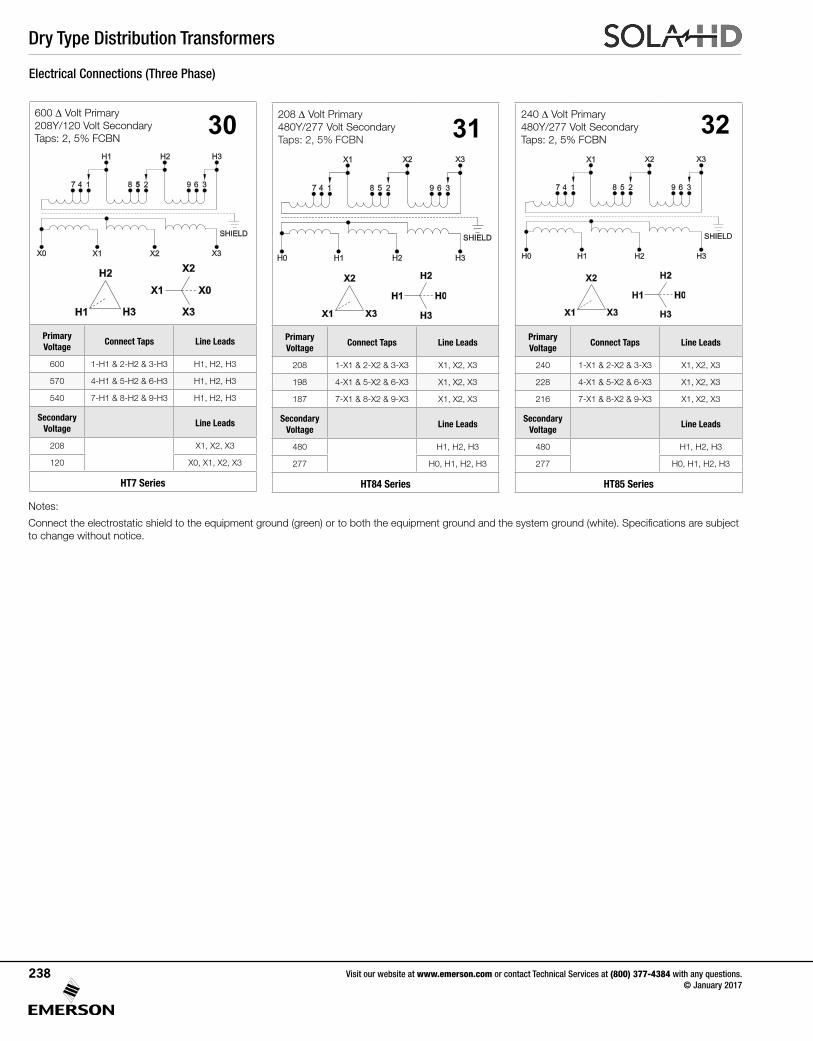
Dry Type Distribution Transformers
Visit our website at www.emerson.com or contact Technical Services at (800) 377-4384 with any questions. © January 2017
238
Electrical Connections (Three Phase)
Primary Voltage
Connect Taps Line Leads
208 1-X1 & 2-X2 & 3-X3 X1, X2, X3
198 4-X1 & 5-X2 & 6-X3 X1, X2, X3
187 7-X1 & 8-X2 & 9-X3 X1, X2, X3
Secondary Voltage
Line Leads
480 H1, H2, H3
277 H0, H1, H2, H3
HT84 Series
208 Δ Volt Primary 480Y/277 Volt Secondary Taps:2,5%FCBN 31
Primary Voltage
Connect Taps Line Leads
240 1-X1 & 2-X2 & 3-X3 X1, X2, X3
228 4-X1 & 5-X2 & 6-X3 X1, X2, X3
216 7-X1 & 8-X2 & 9-X3 X1, X2, X3
Secondary Voltage
Line Leads
480 H1, H2, H3
277 H0, H1, H2, H3
HT85 Series
32
Notes:
Connecttheelectrostaticshieldtotheequipmentground(green)ortoboththeequipmentgroundandthesystemground(white).Specificationsaresubjectto change without notice.
240 Δ Volt Primary 480Y/277 Volt Secondary Taps:2,5%FCBN
H1 H2 H3H0
SHIELD
X1 X3X2
4 5 61 2 37 8 9
X1 X3
X2
H1
H2
H3
H0
H1 H2 H3H0
SHIELD
X1 X3X2
4 5 61 2 37 8 9
X1 X3
X2
H1
H2
H3
H0
Primary Voltage
Connect Taps Line Leads
600 1-H1 & 2-H2 & 3-H3 H1, H2, H3
570 4-H1 & 5-H2 & 6-H3 H1, H2, H3
540 7-H1 & 8-H2 & 9-H3 H1, H2, H3
Secondary Voltage
Line Leads
208 X1, X2, X3
120 X0, X1, X2, X3
HT7 Series
600 Δ Volt Primary 208Y/120 Volt Secondary Taps:2,5%FCBN
30
X1 X2 X3X0
SHIELD
H1 H3H2
4 5 61 2 37 8 9
H1 H3
H2
X1
X2
X3
X0
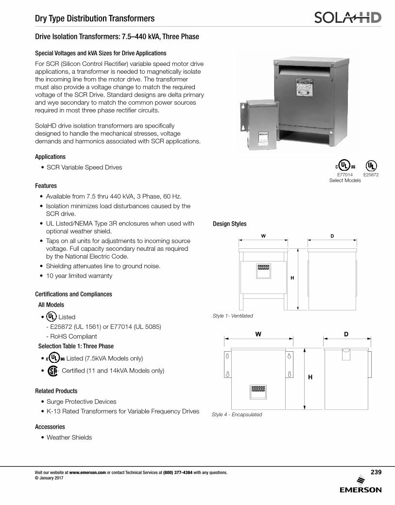
Dry Type Distribution Transformers
Visit our website at www.emerson.com or contact Technical Services at (800) 377-4384 with any questions. © January 2017
239
Drive Isolation Transformers: 7.5–440 kVA, Three Phase
Special Voltages and kVA Sizes for Drive Applications
ForSCR(SiliconControlRectifier)variablespeedmotordriveapplications, a transformer is needed to magnetically isolate the incoming line from the motor drive. The transformer must also provide a voltage change to match the required voltage of the SCR Drive. Standard designs are delta primary and wye secondary to match the common power sources requiredinmostthreephaserectifiercircuits.
SolaHDdriveisolationtransformersarespecifically designed to handle the mechanical stresses, voltage demands and harmonics associated with SCR applications.
Applications
• SCR Variable Speed Drives
Features
• Available from 7.5 thru 440 kVA, 3 Phase, 60 Hz.
• Isolation minimizes load disturbances caused by the SCR drive.
• UL Listed/NEMA Type 3R enclosures when used with optional weather shield.
• Taps on all units for adjustments to incoming source voltage. Full capacity secondary neutral as required by the National Electric Code.
• Shielding attenuates line to ground noise.
• 10 year limited warranty
Certifications and Compliances
All Models
• Listed
- E25872 (UL 1561) or E77014 (UL 5085)
- RoHS Compliant
Selection Table 1: Three Phase
• Listed (7.5kVA Models only)
• Certified(11and14kVAModels only)
Related Products
• Surge Protective Devices
• K-13 Rated Transformers for Variable Frequency Drives
Accessories
• Weather Shields
Design Styles
Style 4 - Encapsulated
Style 1- Ventilated
E25872E77014
W D
H
Select Models
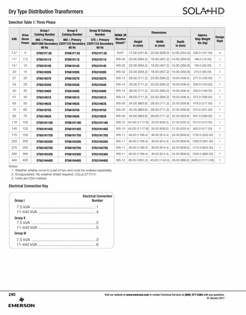
Dry Type Distribution Transformers
Visit our website at www.emerson.com or contact Technical Services at (800) 377-4384 with any questions. © January 2017
240
Selection Table 1: Three Phase
Electrical Connection Key
Notes: 1. Weather shields come in a set of two and must be ordered separately. 2. Encapsulated. No weather shield required. cULus E77014. 3. Units are CSA marked.
kVADrive Horse Power
Group I Catalog Number
Group II Catalog Number
Group III Catalog Number NEMA 3R
Weather Shield(1)
DimensionsApprox.
Ship Weight lbs (kg)
Design Style460 Δ Primary
460Y/266 Secondary 60 Hz
460 Δ Primary 230Y/133 Secondary
60 Hz
575 Δ Primary 230Y/133 Secondary
60 Hz
Height in (mm)
Width in (mm)
Depth in (mm)
7.5 2 5 DT651F7.5S DT661F7.5S DT631F7.5S N/A(2) 17.00 (431.8) 20.00 (508.0) 10.00 (254.0) 236.0 (107.00) 4
113 7.5 DT651H11S DT661H11S DT631H11S WS-02 23.00 (584.2) 18.00 (457.2) 14.00 (355.6) 166.0 (72.00) 1
14 3 10 DT651H14S DT661H14S DT631H14S WS-02 23.00 (584.2) 18.00 (457.2) 14.00 (355.6) 180.0 (82.00) 1
20 15 DT651H20S DT661H20S DT631H20S WS-02 23.00 (584.2) 18.00 (457.2) 14.00 (355.6) 210.0 (95.00) 1
27 20 DT651H27S DT661H27S DT631H27S WS-14 28.00 (711.2) 23.00 (584.2) 16.00 (406.4) 277.0 (126.00) 1
34 25 DT651H34S DT661H34S DT631H34S WS-14 28.00 (711.2) 23.00 (584.2) 16.00 (406.4) 309.0 (140.00) 1
40 30 DT651H40S DT661H40S DT631H40S WS-14 28.00 (711.2) 23.00 (584.2) 16.00 (406.4) 329.0 (149.00) 1
51 40 DT651H51S DT661H51S DT631H51S WS-14 28.00 (711.2) 23.00 (584.2) 16.00 (406.4) 372.0 (169.00) 1
63 50 DT651H63S DT661H63S DT631H63S WS-30 34.00 (863.6) 28.00 (711.2) 22.00 (558.8) 479.0 (217.00) 1
75 60 DT651H75S DT661H75S DT631H75S WS-30 34.00 (863.6) 28.00 (711.2) 22.00 (558.8) 510.0 (231.00) 1
93 75 DT651H93S DT661H93S DT631H93S WS-30 34.00 (863.6) 28.00 (711.2) 22.00 (558.8) 637.0 (289.00) 1
118 100 DT651H118S DT661H118S DT631H118S WS-10 44.00 (1117.6) 33.00 (838.2) 21.00 (533.4) 910.0 (413.00) 1
145 125 DT651H145S DT661H145S DT631H145S WS-10 44.00 (1117.6) 33.00 (838.2) 21.00 (533.4) 920.0 (417.00) 1
175 150 DT651H175S DT661H175S DT631H175S WS-11 46.00 (1168.4) 36.00 (914.4) 24.00 (609.6) 1150.0 (522.00) 1
220 200 DT651H220S DT661H220S DT631H220S WS-11 46.00 (1168.4) 36.00 (914.4) 24.00 (609.6) 1280.0 (581.00) 1
275 250 DT651H275S DT661H275S DT631H275S WS-11 46.00 (1168.4) 36.00 (914.4) 24.00 (609.6) 1415.0 (642.00) 1
330 300 DT651H330S DT661H330S DT631H330S WS-11 46.00 (1168.4) 36.00 (914.4) 24.00 (609.6) 1525.0 (692.00) 1
440 400 DT651H440S DT661H440S DT631H440S WS-12 65.00 (1651.0) 45.00 (1143.0) 35.00 (889.0) 2450.0 (1111.00) 1
Electrical ConnectionGroup I Number
7.5 kVA ......................................................... 1 11-440 kVA ................................................... 4
Group II 7.5 kVA ......................................................... 2 11-440 kVA ................................................... 5
Group III
7.5 kVA ......................................................... 3 11-440 kVA ................................................... 6
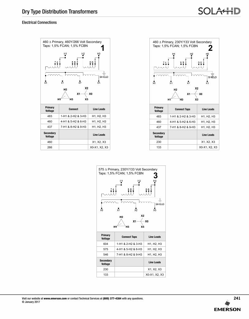
Dry Type Distribution Transformers
Visit our website at www.emerson.com or contact Technical Services at (800) 377-4384 with any questions. © January 2017
241
Primary Voltage
Connect Taps Line Leads
483 1-H1 & 2-H2 & 3-H3 H1, H2, H3
460 4-H1 & 5-H2 & 6-H3 H1, H2, H3
437 7-H1 & 8-H2 & 9-H3 H1, H2, H3
Secondary Voltage
Line Leads
230 X1, X2, X3
133 X0-X1, X2, X3
Primary Voltage
Connect Line Leads
483 1-H1 & 2-H2 & 3-H3 H1, H2, H3
460 4-H1 & 5-H2 & 6-H3 H1, H2, H3
437 7-H1 & 8-H2 & 9-H3 H1, H2, H3
Secondary Voltage
Line Leads
460 X1, X2, X3
266 X0-X1, X2, X3
Electrical Connections
460 Δ Primary, 460Y/266 Volt SecondaryTaps: 1,5% FCAN; 1,5% FCBN
460 Δ Primary, 230Y/133 Volt SecondaryTaps: 1,5% FCAN; 1,5% FCBN1 2
3
Primary Voltage
Connect Taps Line Leads
604 1-H1 & 2-H2 & 3-H3 H1, H2, H3
575 4-H1 & 5-H2 & 6-H3 H1, H2, H3
546 7-H1 & 8-H2 & 9-H3 H1, H2, H3
Secondary Voltage
Line Leads
230 X1, X2, X3
133 X0-X1, X2, X3
575 Δ Primary, 230Y/133 Volt SecondaryTaps: 1,5% FCAN; 1,5% FCBN
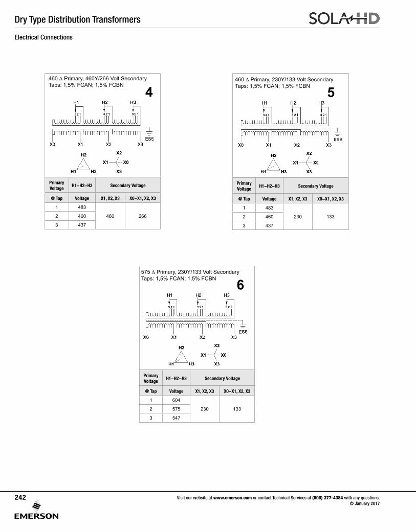
Dry Type Distribution Transformers
Visit our website at www.emerson.com or contact Technical Services at (800) 377-4384 with any questions. © January 2017
242
Primary Voltage
H1-H2-H3 Secondary Voltage
@ Tap Voltage X1, X2, X3 X0-X1, X2, X3
1 483
460 2662 460
3 437
Primary Voltage
H1-H2-H3 Secondary Voltage
@ Tap Voltage X1, X2, X3 X0-X1, X2, X3
1 483
230 1332 460
3 437
Primary Voltage
H1-H2-H3 Secondary Voltage
@ Tap Voltage X1, X2, X3 X0-X1, X2, X3
1 604
230 1332 575
3 547
460 Δ Primary, 230Y/133 Volt SecondaryTaps: 1,5% FCAN; 1,5% FCBN
575 Δ Primary, 230Y/133 Volt SecondaryTaps: 1,5% FCAN; 1,5% FCBN 6
5460 Δ Primary, 460Y/266 Volt SecondaryTaps: 1,5% FCAN; 1,5% FCBN
4
Electrical Connections
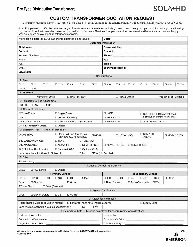
Dry Type Distribution Transformers
Visit our website at www.emerson.com or contact Technical Services at (800) 377-4384 with any questions. © January 2017
243
CUSTOM TRANSFORMER QUOTATION REQUESTInformation is required prior to quotation being issued | Email this form to [email protected] or fax to (800) 538-6545.
SolaHD is pleased to offer the broadest range of transformers on the market including many custom designs. If you can't find what you are looking for, please fill out the information below and submit to our Technical Services Group at [email protected]. We are happy to provide a quote on a custom transformer if available.
Information in bold is REQUIRED prior to quotation being issued. Date:
Customer Information
Distributor: _____________________________________________________________ Representative: _________________________________________________________
Contact: ________________________________________________________________ Contact: ________________________________________________________________
Account Number: ______________________________________________________ Phone: ___________________________________________________________________
Phone: __________________________________________________________________ Fax: _____________________________________________________________________
Fax: _____________________________________________________________________ Email: ___________________________________________________________________
Email: ___________________________________________________________________ Job/Project Name: ______________________________________________________
City/State: ______________________________________________________________
1: Specifications
1A: Size
15 25 30 37.5 45 50 75 100 112.5 150 167 225 300 500
kVA VA
1B: Quantity
_______________ Number of Units One Time Buy Annual Usage _______________ Frequency of Purchase
1C: Temperature Rise (Check One)
80°C 115°C 150°C
1C: Check all that apply
Three Phase Single Phase LVGP DOE 2016 (≥15kVA ventilated distribution transformers only) 50 Hz 60 Hz (Standard) K-Factor 13
Copper Windings Aluminum Windings (Standard) K-Factor 20 SCR Drive Isolation
No Electrostatic Shield Other: _____________________________________________________________
1D: Enclosure Type — Check all that apply
VENTILATED: Open Coil (Top Terminated Standard (UL Recognized) NEMA 1 NEMA 1 (SS) NEMA 3R
(WSXX) NEMA 3R (SS)
ENCLOSED (NON-UL): TENV TENV (SS)
ENCAPSULATED: NEMA 3R NEMA 3R (SS) NEMA 4/12 (SS) NEMA 4X (SS)
(SS) Stainless Steel Grade: Standard (304) Optional (316)
Hazardous Location Class 1, Division 2: No Yes (UL Certified)
1E: Other
Please specify _________________________________________________________________________________________________________________________________
3: Industrial Control Transformers
ICE HSZ Series Other: ______________________________________________________________________________________________________
4: Primary Voltage 5: Secondary Voltage
120 208 240 480 600 Other: _________ 120 208 240 480 600 Other: _________
Taps: Standard: _________________ Other: _________ If Three-Phase: Delta (Standard) Wye
If Three-Phase: Delta (Standard)
6: Agency Certification
UL CSA or cULus CE Other: ____________________
7: Additional Information
Please quote a Catalog or Design Number : Similar to (must note changes above): _______________________ Exactly Like: _________________________
Does this request pertain to a bid specification?: No Yes
8: Competitive Data — Must be completed for special pricing considerations
End User/Contractor: ___________________________________________________ Competition: __________________________________________________________
Competitor's Part Number : _____________________________________________ Competitor's Price : ____________________________________________________
Target End User's Price : _________________________________________________ Distributor Margin: _____________________________________________________
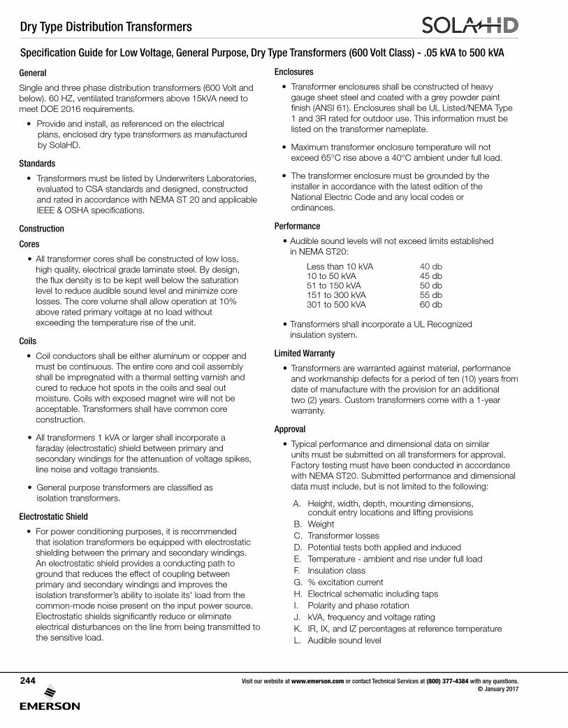
Dry Type Distribution Transformers
Visit our website at www.emerson.com or contact Technical Services at (800) 377-4384 with any questions. © January 2017
244
General
Single and three phase distribution transformers (600 Volt and below). 60 HZ, ventilated transformers above 15kVA need to meet DOE 2016 requirements.
• Provide and install, as referenced on the electrical plans, enclosed dry type transformers as manufactured by SolaHD.
Standards
• Transformers must be listed by Underwriters Laboratories, evaluated to CSA standards and designed, constructed and rated in accordance with NEMA ST 20 and applicable IEEE&OSHAspecifications.
Construction
Cores
• All transformer cores shall be constructed of low loss, highquality,electricalgradelaminatesteel.Bydesign, thefluxdensityistobekeptwellbelowthesaturation level to reduce audible sound level and minimize core losses. The core volume shall allow operation at 10% above rated primary voltage at no load without exceeding the temperature rise of the unit.
Coils
• Coil conductors shall be either aluminum or copper and must be continuous. The entire core and coil assembly shall be impregnated with a thermal setting varnish and cured to reduce hot spots in the coils and seal out moisture. Coils with exposed magnet wire will not be acceptable. Transformers shall have common core construction.
• All transformers 1 kVA or larger shall incorporate a faraday (electrostatic) shield between primary and secondary windings for the attenuation of voltage spikes, line noise and voltage transients.
• Generalpurposetransformersareclassifiedas isolation transformers.
Electrostatic Shield
• For power conditioning purposes, it is recommended that isolation transformers be equipped with electrostatic shielding between the primary and secondary windings. An electrostatic shield provides a conducting path to ground that reduces the effect of coupling between primary and secondary windings and improves the isolation transformer’s ability to isolate its' load from the common-mode noise present on the input power source. Electrostaticshieldssignificantlyreduceoreliminateelectrical disturbances on the line from being transmitted to the sensitive load.
Enclosures
• Transformer enclosures shall be constructed of heavy gauge sheet steel and coated with a grey powder paint finish(ANSI61).EnclosuresshallbeULListed/NEMAType 1 and 3R rated for outdoor use. This information must be listed on the transformer nameplate.
• Maximum transformer enclosure temperature will not exceed 65°C rise above a 40°C ambient under full load.
• The transformer enclosure must be grounded by the installer in accordance with the latest edition of the National Electric Code and any local codes or ordinances.
Performance
• Audible sound levels will not exceed limits established in NEMA ST20:
• Transformers shall incorporate a UL Recognized insulation system.
Limited Warranty
• Transformers are warranted against material, performance and workmanship defects for a period of ten (10) years from date of manufacture with the provision for an additional two (2) years. Custom transformers come with a 1-year warranty.
Approval
• Typical performance and dimensional data on similar units must be submitted on all transformers for approval. Factory testing must have been conducted in accordance with NEMA ST20. Submitted performance and dimensional data must include, but is not limited to the following:
A. Height, width, depth, mounting dimensions, conduit entry locations and lifting provisionsB.WeightC. Transformer lossesD. Potential tests both applied and inducedE. Temperature - ambient and rise under full loadF. Insulation classG. % excitation currentH. Electrical schematic including tapsI. Polarity and phase rotationJ. kVA, frequency and voltage ratingK. IR, IX, and IZ percentages at reference temperatureL. Audible sound level
Specification Guide for Low Voltage, General Purpose, Dry Type Transformers (600 Volt Class) - .05 kVA to 500 kVA
Less than 10 kVA 40 db10 to 50 kVA 45 db51 to 150 kVA 50 db151 to 300 kVA 55 db301 to 500 kVA 60 db
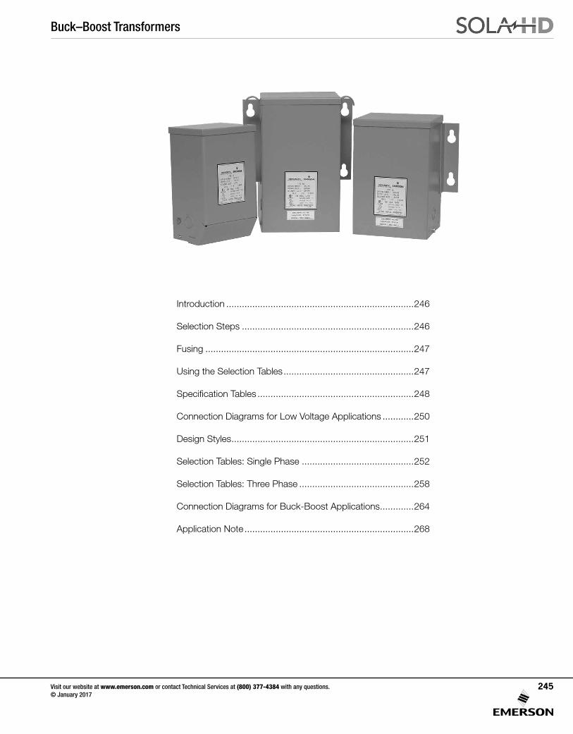
Buck–Boost Transformers
Visit our website at www.emerson.com or contact Technical Services at (800) 377-4384 with any questions. © January 2017
245
Introduction ........................................................................246
Selection Steps ..................................................................246
Fusing ................................................................................247
Using the Selection Tables ..................................................247
Specification Tables ............................................................248
Connection Diagrams for Low Voltage Applications ............250
Design Styles ......................................................................251
Selection Tables: Single Phase ...........................................252
Selection Tables: Three Phase ............................................258
Connection Diagrams for Buck-Boost Applications .............264
Application Note .................................................................268
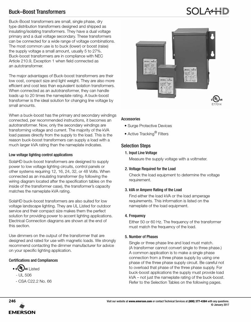
Buck–Boost Transformers
Visit our website at www.emerson.com or contact Technical Services at (800) 377-4384 with any questions. © January 2017
246
Accessories
• Surge Protective Devices
• Active Tracking® Filters
Selection Steps1. Input Line Voltage
Measure the supply voltage with a voltmeter.
2. Voltage Required for the Load
Check the load equipment to determine the voltage requirement.
3. kVA or Ampere Rating of the Load
Find either the load kVA or the load amperage requirements. This information is listed on the nameplate of the load equipment.
4. Frequency
Either 50 or 60 Hz. The frequency of the transformer must match the frequency of the load.
5. Number of Phases
Single or three phase line and load must match. (A transformer cannot convert single to three phase.) A common application is to make a single phase connection from a three phase supply by using one phase of the three phase supply circuit. Be careful not to overload that phase of the three phase supply. For buck-boost applications the supply must provide load kVA – not just the nameplate rating of the buck-boost. Refer to the Selection Tables on the following pages.
Buck-Boost transformers are small, single phase, dry type distribution transformers designed and shipped as insulating/isolating transformers. They have a dual voltage primary and a dual voltage secondary. These transformers can be connected for a wide range of voltage combinations. The most common use is to buck (lower) or boost (raise) the supply voltage a small amount, usually 5 to 27%. Buck-boost transformers are in compliance with NEC Article 210.9, Exception 1 when field connected as an autotransformer.
The major advantages of Buck-boost transformers are their low cost, compact size and light weight. They are also more efficient and cost less than equivalent isolation transformers. When connected as an autotransformer, they can handle loads up to 20 times the nameplate rating. A buck-boost transformer is the ideal solution for changing line voltage by small amounts.
When a buck-boost has the primary and secondary windings connected, per recommended instructions, it becomes an autotransformer. Now, only the secondary windings are transforming voltage and current. The majority of the kVA load passes directly from the supply to the load. This is the reason buck-boost transformers can supply a load with a much larger kVA rating than the nameplate indicates.
Low voltage lighting control applications
SolaHD buck-boost transformers are designed to supply power to low voltage lighting circuits, control panels or other systems requiring 12, 16, 24, 32, or 48 Volts. When connected as an insulating transformer (by following the wiring diagram located after the specification tables on the inside of the transformer case), the transformer’s capacity matches the nameplate kVA rating.
SolaHD buck-boost transformers are also suited for low voltage landscape lighting. They are UL Listed for outdoor service and their compact size makes them the perfect solution for providing power to accent lighting applications. Electrical Connection diagrams are shown at the end of this section.
Use dimmers on the output of the transformer that are designed and rated for use with magnetic loads. We strongly recommend contacting the dimmer manufacturer for advice on your specific lighting application.
Certifications and Compliances
• Listed
- UL 506
- CSA C22.2 No. 66
E77014
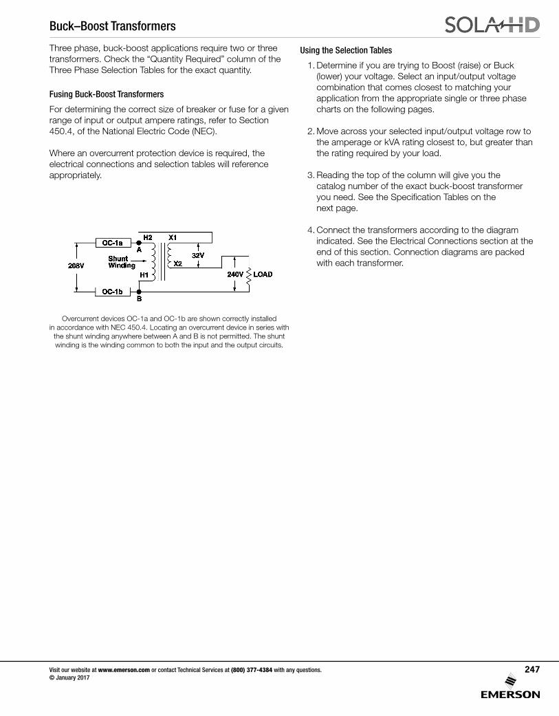
Buck–Boost Transformers
Visit our website at www.emerson.com or contact Technical Services at (800) 377-4384 with any questions. © January 2017
247
Using the Selection Tables
1. Determine if you are trying to Boost (raise) or Buck (lower) your voltage. Select an input/output voltage combination that comes closest to matching your application from the appropriate single or three phase charts on the following pages.
2. Move across your selected input/output voltage row to the amperage or kVA rating closest to, but greater than the rating required by your load.
3. Reading the top of the column will give you the catalog number of the exact buck-boost transformer
you need. See the Specification Tables on the next page.
4. Connect the transformers according to the diagram indicated. See the Electrical Connections section at the
end of this section. Connection diagrams are packed with each transformer.
Three phase, buck-boost applications require two or three transformers. Check the “Quantity Required” column of the Three Phase Selection Tables for the exact quantity.
Fusing Buck-Boost Transformers
For determining the correct size of breaker or fuse for a given range of input or output ampere ratings, refer to Section 450.4, of the National Electric Code (NEC).
Where an overcurrent protection device is required, the electrical connections and selection tables will reference appropriately.
Overcurrent devices OC-1a and OC-1b are shown correctly installed in accordance with NEC 450.4. Locating an overcurrent device in series with
the shunt winding anywhere between A and B is not permitted. The shunt winding is the winding common to both the input and the output circuits.
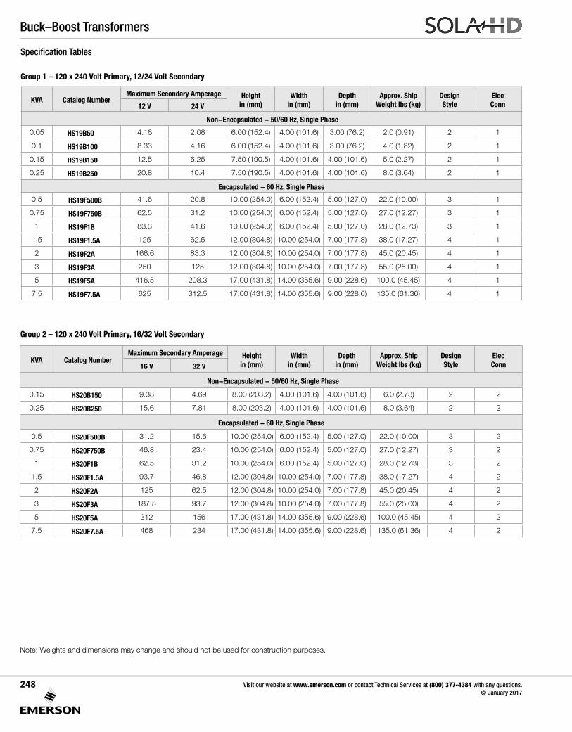
Buck–Boost Transformers
Visit our website at www.emerson.com or contact Technical Services at (800) 377-4384 with any questions. © January 2017
248
Group 2 – 120 x 240 Volt Primary, 16/32 Volt Secondary
Note: Weights and dimensions may change and should not be used for construction purposes.
Specification Tables
Group 1 – 120 x 240 Volt Primary, 12/24 Volt Secondary
KVA Catalog NumberMaximum Secondary Amperage Height
in (mm)Width
in (mm)Depth
in (mm)Approx. Ship
Weight lbs (kg)Design Style
Elec Conn12 V 24 V
Non-Encapsulated - 50/60 Hz, Single Phase
0.05 HS19B50 4.16 2.08 6.00 (152.4) 4.00 (101.6) 3.00 (76.2) 2.0 (0.91) 2 1
0.1 HS19B100 8.33 4.16 6.00 (152.4) 4.00 (101.6) 3.00 (76.2) 4.0 (1.82) 2 1
0.15 HS19B150 12.5 6.25 7.50 (190.5) 4.00 (101.6) 4.00 (101.6) 5.0 (2.27) 2 1
0.25 HS19B250 20.8 10.4 7.50 (190.5) 4.00 (101.6) 4.00 (101.6) 8.0 (3.64) 2 1
Encapsulated - 60 Hz, Single Phase
0.5 HS19F500B 41.6 20.8 10.00 (254.0) 6.00 (152.4) 5.00 (127.0) 22.0 (10.00) 3 1
0.75 HS19F750B 62.5 31.2 10.00 (254.0) 6.00 (152.4) 5.00 (127.0) 27.0 (12.27) 3 1
1 HS19F1B 83.3 41.6 10.00 (254.0) 6.00 (152.4) 5.00 (127.0) 28.0 (12.73) 3 1
1.5 HS19F1.5A 125 62.5 12.00 (304.8) 10.00 (254.0) 7.00 (177.8) 38.0 (17.27) 4 1
2 HS19F2A 166.6 83.3 12.00 (304.8) 10.00 (254.0) 7.00 (177.8) 45.0 (20.45) 4 1
3 HS19F3A 250 125 12.00 (304.8) 10.00 (254.0) 7.00 (177.8) 55.0 (25.00) 4 1
5 HS19F5A 416.5 208.3 17.00 (431.8) 14.00 (355.6) 9.00 (228.6) 100.0 (45.45) 4 1
7.5 HS19F7.5A 625 312.5 17.00 (431.8) 14.00 (355.6) 9.00 (228.6) 135.0 (61.36) 4 1
KVA Catalog NumberMaximum Secondary Amperage Height
in (mm)Width
in (mm)Depth
in (mm)Approx. Ship
Weight lbs (kg)Design Style
Elec Conn16 V 32 V
Non-Encapsulated - 50/60 Hz, Single Phase
0.15 HS20B150 9.38 4.69 8.00 (203.2) 4.00 (101.6) 4.00 (101.6) 6.0 (2.73) 2 2
0.25 HS20B250 15.6 7.81 8.00 (203.2) 4.00 (101.6) 4.00 (101.6) 8.0 (3.64) 2 2
Encapsulated - 60 Hz, Single Phase
0.5 HS20F500B 31.2 15.6 10.00 (254.0) 6.00 (152.4) 5.00 (127.0) 22.0 (10.00) 3 2
0.75 HS20F750B 46.8 23.4 10.00 (254.0) 6.00 (152.4) 5.00 (127.0) 27.0 (12.27) 3 2
1 HS20F1B 62.5 31.2 10.00 (254.0) 6.00 (152.4) 5.00 (127.0) 28.0 (12.73) 3 2
1.5 HS20F1.5A 93.7 46.8 12.00 (304.8) 10.00 (254.0) 7.00 (177.8) 38.0 (17.27) 4 2
2 HS20F2A 125 62.5 12.00 (304.8) 10.00 (254.0) 7.00 (177.8) 45.0 (20.45) 4 2
3 HS20F3A 187.5 93.7 12.00 (304.8) 10.00 (254.0) 7.00 (177.8) 55.0 (25.00) 4 2
5 HS20F5A 312 156 17.00 (431.8) 14.00 (355.6) 9.00 (228.6) 100.0 (45.45) 4 2
7.5 HS20F7.5A 468 234 17.00 (431.8) 14.00 (355.6) 9.00 (228.6) 135.0 (61.36) 4 2
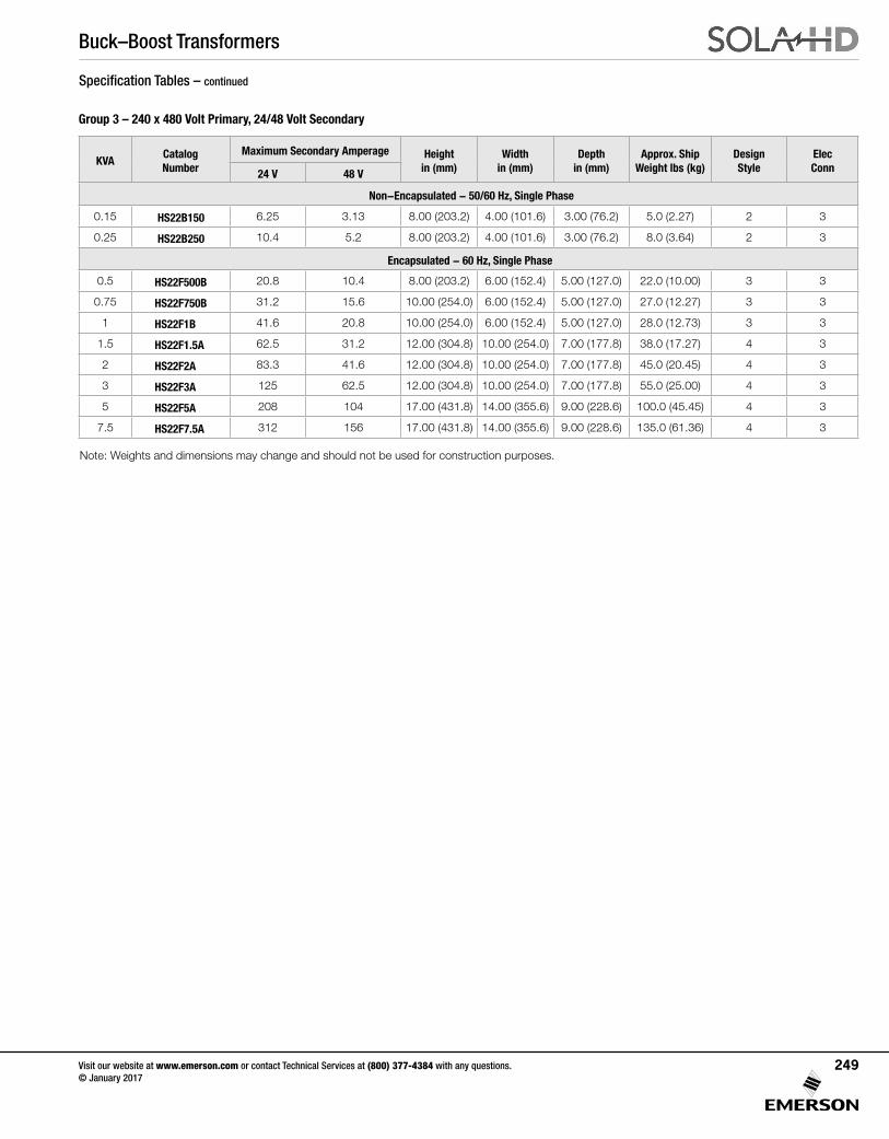
Buck–Boost Transformers
Visit our website at www.emerson.com or contact Technical Services at (800) 377-4384 with any questions. © January 2017
249
Group 3 – 240 x 480 Volt Primary, 24/48 Volt Secondary
Specification Tables – continued
KVACatalog Number
Maximum Secondary Amperage Height in (mm)
Width in (mm)
Depth in (mm)
Approx. Ship Weight lbs (kg)
Design Style
Elec Conn24 V 48 V
Non-Encapsulated - 50/60 Hz, Single Phase
0.15 HS22B150 6.25 3.13 8.00 (203.2) 4.00 (101.6) 3.00 (76.2) 5.0 (2.27) 2 3
0.25 HS22B250 10.4 5.2 8.00 (203.2) 4.00 (101.6) 3.00 (76.2) 8.0 (3.64) 2 3
Encapsulated - 60 Hz, Single Phase
0.5 HS22F500B 20.8 10.4 8.00 (203.2) 6.00 (152.4) 5.00 (127.0) 22.0 (10.00) 3 3
0.75 HS22F750B 31.2 15.6 10.00 (254.0) 6.00 (152.4) 5.00 (127.0) 27.0 (12.27) 3 3
1 HS22F1B 41.6 20.8 10.00 (254.0) 6.00 (152.4) 5.00 (127.0) 28.0 (12.73) 3 3
1.5 HS22F1.5A 62.5 31.2 12.00 (304.8) 10.00 (254.0) 7.00 (177.8) 38.0 (17.27) 4 3
2 HS22F2A 83.3 41.6 12.00 (304.8) 10.00 (254.0) 7.00 (177.8) 45.0 (20.45) 4 3
3 HS22F3A 125 62.5 12.00 (304.8) 10.00 (254.0) 7.00 (177.8) 55.0 (25.00) 4 3
5 HS22F5A 208 104 17.00 (431.8) 14.00 (355.6) 9.00 (228.6) 100.0 (45.45) 4 3
7.5 HS22F7.5A 312 156 17.00 (431.8) 14.00 (355.6) 9.00 (228.6) 135.0 (61.36) 4 3
Note: Weights and dimensions may change and should not be used for construction purposes.
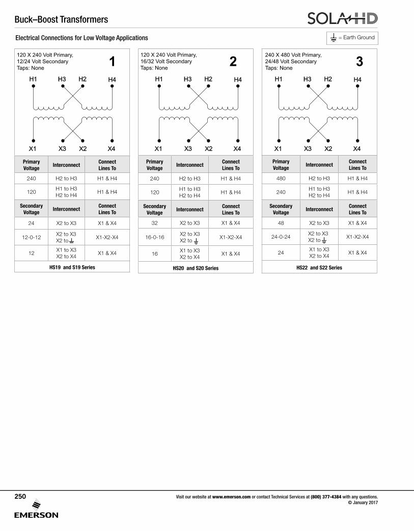
Buck–Boost Transformers
Visit our website at www.emerson.com or contact Technical Services at (800) 377-4384 with any questions. © January 2017
250
Primary Voltage
InterconnectConnect Lines To
480 H2 to H3 H1 & H4
240H1 to H3 H2 to H4
H1 & H4
SecondaryVoltage
InterconnectConnect Lines To
48 X2 to X3 X1 & X4
24-0-24X2 to X3X2 to
X1-X2-X4
24X1 to X3 X2 to X4
X1 & X4
HS22 and S22 Series
Primary Voltage
InterconnectConnect Lines To
240 H2 to H3 H1 & H4
120H1 to H3 H2 to H4
H1 & H4
Secondary Voltage
InterconnectConnect Lines To
24 X2 to X3 X1 & X4
12-0-12X2 to X3 X2 to
X1-X2-X4
12X1 to X3X2 to X4
X1 & X4
HS19 and S19 Series
Primary Voltage
InterconnectConnect Lines To
240 H2 to H3 H1 & H4
120H1 to H3H2 to H4
H1 & H4
SecondaryVoltage
InterconnectConnect Lines To
32 X2 to X3 X1 & X4
16-0-16X2 to X3X2 to
X1-X2-X4
16X1 to X3X2 to X4
X1 & X4
HS20 and S20 Series
Electrical Connections for Low Voltage Applications
120 X 240 Volt Primary, 12/24 Volt Secondary Taps: None
120 X 240 Volt Primary, 16/32 Volt Secondary Taps: None
240 X 480 Volt Primary, 24/48 Volt Secondary Taps: None
1 2 3
= Earth Ground
H1 H2H3 H4
X1 X3 X2 X4
H1 H2H3 H4
X1 X3 X2 X4
H1 H2H3 H4
X1 X3 X2 X4
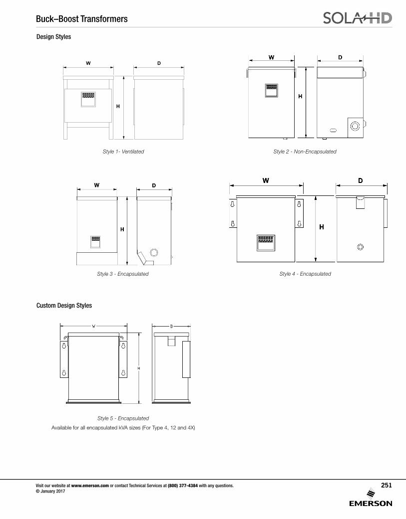
Buck–Boost Transformers
Visit our website at www.emerson.com or contact Technical Services at (800) 377-4384 with any questions. © January 2017
251
Design Styles
Style 4 - EncapsulatedStyle 3 - Encapsulated
Style 2 - Non-Encapsulated
Style 5 - Encapsulated
Available for all encapsulated kVA sizes (For Type 4, 12 and 4X)
Custom Design Styles
Style 1- Ventilated
W D
H
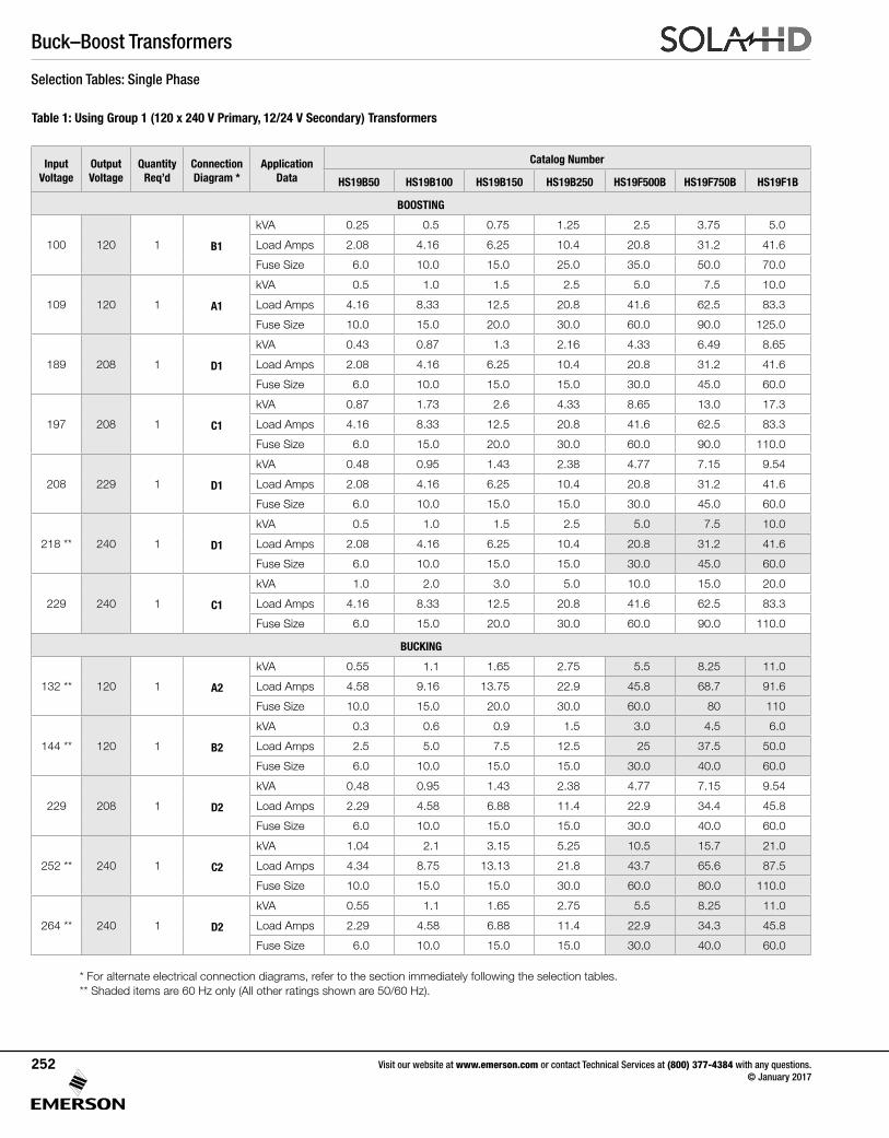
Buck–Boost Transformers
Visit our website at www.emerson.com or contact Technical Services at (800) 377-4384 with any questions. © January 2017
252
Selection Tables: Single Phase
Table 1: Using Group 1 (120 x 240 V Primary, 12/24 V Secondary) Transformers
* For alternate electrical connection diagrams, refer to the section immediately following the selection tables. ** Shaded items are 60 Hz only (All other ratings shown are 50/60 Hz).
Input Voltage
Output Voltage
Quantity Req’d
Connection Diagram *
Application Data
Catalog Number
HS19B50 HS19B100 HS19B150 HS19B250 HS19F500B HS19F750B HS19F1B
BOOSTING
100 120 1 B1
kVA 0.25 0.5 0.75 1.25 2.5 3.75 5.0
Load Amps 2.08 4.16 6.25 10.4 20.8 31.2 41.6
Fuse Size 6.0 10.0 15.0 25.0 35.0 50.0 70.0
109 120 1 A1
kVA 0.5 1.0 1.5 2.5 5.0 7.5 10.0
Load Amps 4.16 8.33 12.5 20.8 41.6 62.5 83.3
Fuse Size 10.0 15.0 20.0 30.0 60.0 90.0 125.0
189 208 1 D1
kVA 0.43 0.87 1.3 2.16 4.33 6.49 8.65
Load Amps 2.08 4.16 6.25 10.4 20.8 31.2 41.6
Fuse Size 6.0 10.0 15.0 15.0 30.0 45.0 60.0
197 208 1 C1
kVA 0.87 1.73 2.6 4.33 8.65 13.0 17.3
Load Amps 4.16 8.33 12.5 20.8 41.6 62.5 83.3
Fuse Size 6.0 15.0 20.0 30.0 60.0 90.0 110.0
208 229 1 D1
kVA 0.48 0.95 1.43 2.38 4.77 7.15 9.54
Load Amps 2.08 4.16 6.25 10.4 20.8 31.2 41.6
Fuse Size 6.0 10.0 15.0 15.0 30.0 45.0 60.0
218 ** 240 1 D1
kVA 0.5 1.0 1.5 2.5 5.0 7.5 10.0
Load Amps 2.08 4.16 6.25 10.4 20.8 31.2 41.6
Fuse Size 6.0 10.0 15.0 15.0 30.0 45.0 60.0
229 240 1 C1
kVA 1.0 2.0 3.0 5.0 10.0 15.0 20.0
Load Amps 4.16 8.33 12.5 20.8 41.6 62.5 83.3
Fuse Size 6.0 15.0 20.0 30.0 60.0 90.0 110.0
BUCKING
132 ** 120 1 A2
kVA 0.55 1.1 1.65 2.75 5.5 8.25 11.0
Load Amps 4.58 9.16 13.75 22.9 45.8 68.7 91.6
Fuse Size 10.0 15.0 20.0 30.0 60.0 80 110
144 ** 120 1 B2
kVA 0.3 0.6 0.9 1.5 3.0 4.5 6.0
Load Amps 2.5 5.0 7.5 12.5 25 37.5 50.0
Fuse Size 6.0 10.0 15.0 15.0 30.0 40.0 60.0
229 208 1 D2
kVA 0.48 0.95 1.43 2.38 4.77 7.15 9.54
Load Amps 2.29 4.58 6.88 11.4 22.9 34.4 45.8
Fuse Size 6.0 10.0 15.0 15.0 30.0 40.0 60.0
252 ** 240 1 C2
kVA 1.04 2.1 3.15 5.25 10.5 15.7 21.0
Load Amps 4.34 8.75 13.13 21.8 43.7 65.6 87.5
Fuse Size 10.0 15.0 15.0 30.0 60.0 80.0 110.0
264 ** 240 1 D2
kVA 0.55 1.1 1.65 2.75 5.5 8.25 11.0
Load Amps 2.29 4.58 6.88 11.4 22.9 34.3 45.8
Fuse Size 6.0 10.0 15.0 15.0 30.0 40.0 60.0
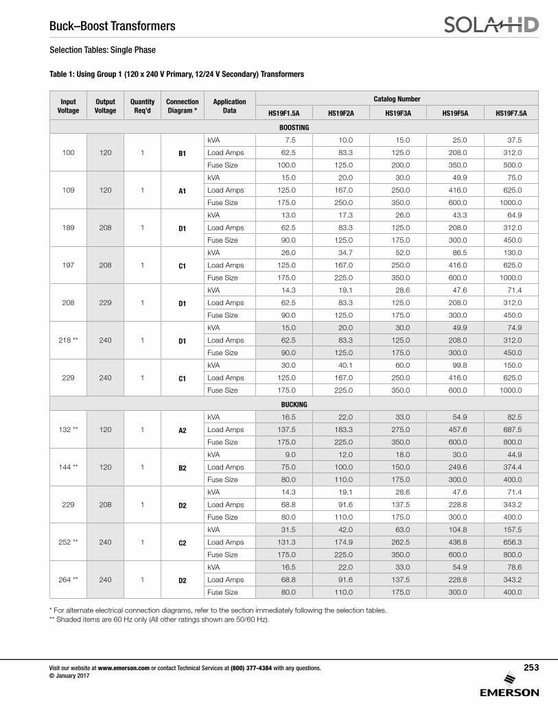
Buck–Boost Transformers
Visit our website at www.emerson.com or contact Technical Services at (800) 377-4384 with any questions. © January 2017
253
Selection Tables: Single Phase
Table 1: Using Group 1 (120 x 240 V Primary, 12/24 V Secondary) Transformers
* For alternate electrical connection diagrams, refer to the section immediately following the selection tables. ** Shaded items are 60 Hz only (All other ratings shown are 50/60 Hz).
Input Voltage
Output Voltage
Quantity Req’d
Connection Diagram *
Application Data
Catalog Number
HS19F1.5A HS19F2A HS19F3A HS19F5A HS19F7.5A
BOOSTING
100 120 1 B1
kVA 7.5 10.0 15.0 25.0 37.5
Load Amps 62.5 83.3 125.0 208.0 312.0
Fuse Size 100.0 125.0 200.0 350.0 500.0
109 120 1 A1
kVA 15.0 20.0 30.0 49.9 75.0
Load Amps 125.0 167.0 250.0 416.0 625.0
Fuse Size 175.0 250.0 350.0 600.0 1000.0
189 208 1 D1
kVA 13.0 17.3 26.0 43.3 64.9
Load Amps 62.5 83.3 125.0 208.0 312.0
Fuse Size 90.0 125.0 175.0 300.0 450.0
197 208 1 C1
kVA 26.0 34.7 52.0 86.5 130.0
Load Amps 125.0 167.0 250.0 416.0 625.0
Fuse Size 175.0 225.0 350.0 600.0 1000.0
208 229 1 D1
kVA 14.3 19.1 28.6 47.6 71.4
Load Amps 62.5 83.3 125.0 208.0 312.0
Fuse Size 90.0 125.0 175.0 300.0 450.0
218 ** 240 1 D1
kVA 15.0 20.0 30.0 49.9 74.9
Load Amps 62.5 83.3 125.0 208.0 312.0
Fuse Size 90.0 125.0 175.0 300.0 450.0
229 240 1 C1
kVA 30.0 40.1 60.0 99.8 150.0
Load Amps 125.0 167.0 250.0 416.0 625.0
Fuse Size 175.0 225.0 350.0 600.0 1000.0
BUCKING
132 ** 120 1 A2
kVA 16.5 22.0 33.0 54.9 82.5
Load Amps 137.5 183.3 275.0 457.6 687.5
Fuse Size 175.0 225.0 350.0 600.0 800.0
144 ** 120 1 B2
kVA 9.0 12.0 18.0 30.0 44.9
Load Amps 75.0 100.0 150.0 249.6 374.4
Fuse Size 80.0 110.0 175.0 300.0 400.0
229 208 1 D2
kVA 14.3 19.1 28.6 47.6 71.4
Load Amps 68.8 91.6 137.5 228.8 343.2
Fuse Size 80.0 110.0 175.0 300.0 400.0
252 ** 240 1 C2
kVA 31.5 42.0 63.0 104.8 157.5
Load Amps 131.3 174.9 262.5 436.8 656.3
Fuse Size 175.0 225.0 350.0 600.0 800.0
264 ** 240 1 D2
kVA 16.5 22.0 33.0 54.9 78.6
Load Amps 68.8 91.6 137.5 228.8 343.2
Fuse Size 80.0 110.0 175.0 300.0 400.0
* For alternate electrical connection diagrams, refer to the section immediately following the selection tables. ** Shaded items are 60 Hz only (All other ratings shown are 50/60 Hz).

Buck–Boost Transformers
Visit our website at www.emerson.com or contact Technical Services at (800) 377-4384 with any questions. © January 2017
254
Selection Tables: Single Phase
Table 2: Using Group 2 (120 x 240 V Primary, 16/32 V Secondary) Transformers
* For alternate electrical connection diagrams, refer to the section immediately following the selection tables. ** Shaded items are 60 Hz only (All other ratings shown are 50/60 Hz).
Input Voltage
Output Voltage
Quantity Req’d
Connection Diagram *
Application Data
Catalog Number
HS20B150 HS20B250 HS20F500B HS20F750B HS20F1B
BOOSTING
95 120 1 B1
kVA 0.6 0.9 1.9 2.8 3.8
Load Amps 4.7 7.8 15.6 23.4 31.2
Fuse Size 10.0 15.0 25.0 40.0 50.0
106 120 1 A1
kVA 1.1 1.9 3.7 5.6 7.5
Load Amps 9.4 15.6 31.2 46.8 62.5
Fuse Size 15.0 25.0 45.0 70.0 90.0
183 208 1 D1
kVA 1.0 1.6 3.2 4.9 6.5
Load Amps 4.7 7.8 15.6 23.4 31.2
Fuse Size 10.0 15.0 25.0 35.0 45.0
195 208 1 C1
kVA 2.0 3.2 6.5 9.7 13.0
Load Amps 9.4 15.6 31.2 46.8 62.5
Fuse Size 15.0 25.0 45.0 70.0 90.0
208 236 1 D1
kVA 1.1 1.8 3.7 5.5 7.4
Load Amps 4.7 7.8 15.6 23.4 31.2
Fuse Size 10.0 15.0 25.0 40.0 50.0
225 240 1 C1
kVA 2.3 3.7 7.5 11.2 15.0
Load Amps 9.4 15.6 31.2 46.8 62.5
Fuse Size 15.0 25.0 45.0 70.0 90.0
240 ** 272 1 D1
kVA 1.3 2.1 4.2 6.4 8.5
Load Amps 4.7 7.8 15.6 23.4 31.2
Fuse Size 10.0 15.0 25.0 35.0 45.0
BUCKING
136 ** 120 1 A2
kVA 1.3 2.1 4.2 6.4 8.5
Load Amps 10.6 17.7 35.4 53.2 70.8
Fuse Size 15.0 20.0 40.0 60.0 80.0
152 ** 120 1 B2
kVA 0.7 1.2 2.4 3.6 4.7
Load Amps 6.0 9.9 19.8 29.6 39.5
Fuse Size 10.0 15.0 20.0 30.0 40.0
236 208 1 D2
kVA 1.1 1.8 3.7 5.5 7.4
Load Amps 5.3 8.9 17.7 26.5 35.4
Fuse Size 6.0 15.0 20.0 30.0 40.0
256 ** 240 1 C2
kVA 2.4 4.0 8.0 12.0 16.0
Load Amps 10.0 16.6 33.3 50.0 66.7
Fuse Size 15.0 20.0 40.0 60.0 80.0
272 ** 240 1 D2
kVA 1.3 2.1 4.2 6.4 8.5
Load Amps 5.3 8.8 17.7 26.5 35.4
Fuse Size 10.0 15.0 20.0 30.0 40.0
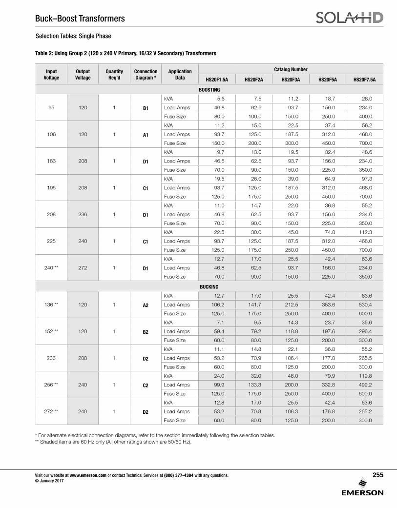
Buck–Boost Transformers
Visit our website at www.emerson.com or contact Technical Services at (800) 377-4384 with any questions. © January 2017
255
Selection Tables: Single Phase
Table 2: Using Group 2 (120 x 240 V Primary, 16/32 V Secondary) Transformers
* For alternate electrical connection diagrams, refer to the section immediately following the selection tables. ** Shaded items are 60 Hz only (All other ratings shown are 50/60 Hz).
Input Voltage
Output Voltage
Quantity Req’d
Connection Diagram *
Application Data
Catalog Number
HS20F1.5A HS20F2A HS20F3A HS20F5A HS20F7.5A
BOOSTING
95 120 1 B1
kVA 5.6 7.5 11.2 18.7 28.0
Load Amps 46.8 62.5 93.7 156.0 234.0
Fuse Size 80.0 100.0 150.0 250.0 400.0
106 120 1 A1
kVA 11.2 15.0 22.5 37.4 56.2
Load Amps 93.7 125.0 187.5 312.0 468.0
Fuse Size 150.0 200.0 300.0 450.0 700.0
183 208 1 D1
kVA 9.7 13.0 19.5 32.4 48.6
Load Amps 46.8 62.5 93.7 156.0 234.0
Fuse Size 70.0 90.0 150.0 225.0 350.0
195 208 1 C1
kVA 19.5 26.0 39.0 64.9 97.3
Load Amps 93.7 125.0 187.5 312.0 468.0
Fuse Size 125.0 175.0 250.0 450.0 700.0
208 236 1 D1
kVA 11.0 14.7 22.0 36.8 55.2
Load Amps 46.8 62.5 93.7 156.0 234.0
Fuse Size 70.0 90.0 150.0 225.0 350.0
225 240 1 C1
kVA 22.5 30.0 45.0 74.8 112.3
Load Amps 93.7 125.0 187.5 312.0 468.0
Fuse Size 125.0 175.0 250.0 450.0 700.0
240 ** 272 1 D1
kVA 12.7 17.0 25.5 42.4 63.6
Load Amps 46.8 62.5 93.7 156.0 234.0
Fuse Size 70.0 90.0 150.0 225.0 350.0
BUCKING
136 ** 120 1 A2
kVA 12.7 17.0 25.5 42.4 63.6
Load Amps 106.2 141.7 212.5 353.6 530.4
Fuse Size 125.0 175.0 250.0 400.0 600.0
152 ** 120 1 B2
kVA 7.1 9.5 14.3 23.7 35.6
Load Amps 59.4 79.2 118.8 197.6 296.4
Fuse Size 60.0 80.0 125.0 200.0 300.0
236 208 1 D2
kVA 11.1 14.8 22.1 36.8 55.2
Load Amps 53.2 70.9 106.4 177.0 265.5
Fuse Size 60.0 80.0 125.0 200.0 300.0
256 ** 240 1 C2
kVA 24.0 32.0 48.0 79.9 119.8
Load Amps 99.9 133.3 200.0 332.8 499.2
Fuse Size 125.0 175.0 250.0 400.0 600.0
272 ** 240 1 D2
kVA 12.8 17.0 25.5 42.4 63.6
Load Amps 53.2 70.8 106.3 176.8 265.2
Fuse Size 60.0 80.0 125.0 200.0 300.0
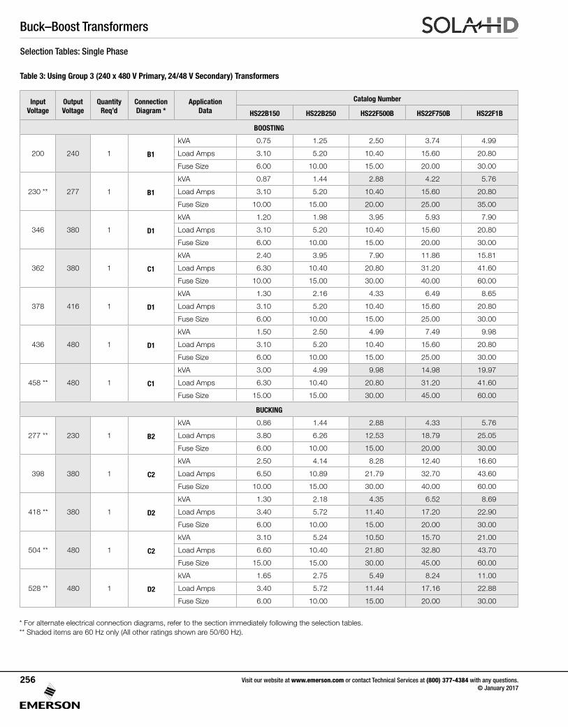
Buck–Boost Transformers
Visit our website at www.emerson.com or contact Technical Services at (800) 377-4384 with any questions. © January 2017
256
Selection Tables: Single Phase
Table 3: Using Group 3 (240 x 480 V Primary, 24/48 V Secondary) Transformers
* For alternate electrical connection diagrams, refer to the section immediately following the selection tables. ** Shaded items are 60 Hz only (All other ratings shown are 50/60 Hz).
Input Voltage
Output Voltage
Quantity Req’d
Connection Diagram *
Application Data
Catalog Number
HS22B150 HS22B250 HS22F500B HS22F750B HS22F1B
BOOSTING
200 240 1 B1
kVA 0.75 1.25 2.50 3.74 4.99
Load Amps 3.10 5.20 10.40 15.60 20.80
Fuse Size 6.00 10.00 15.00 20.00 30.00
230 ** 277 1 B1
kVA 0.87 1.44 2.88 4.22 5.76
Load Amps 3.10 5.20 10.40 15.60 20.80
Fuse Size 10.00 15.00 20.00 25.00 35.00
346 380 1 D1
kVA 1.20 1.98 3.95 5.93 7.90
Load Amps 3.10 5.20 10.40 15.60 20.80
Fuse Size 6.00 10.00 15.00 20.00 30.00
362 380 1 C1
kVA 2.40 3.95 7.90 11.86 15.81
Load Amps 6.30 10.40 20.80 31.20 41.60
Fuse Size 10.00 15.00 30.00 40.00 60.00
378 416 1 D1
kVA 1.30 2.16 4.33 6.49 8.65
Load Amps 3.10 5.20 10.40 15.60 20.80
Fuse Size 6.00 10.00 15.00 25.00 30.00
436 480 1 D1
kVA 1.50 2.50 4.99 7.49 9.98
Load Amps 3.10 5.20 10.40 15.60 20.80
Fuse Size 6.00 10.00 15.00 25.00 30.00
458 ** 480 1 C1
kVA 3.00 4.99 9.98 14.98 19.97
Load Amps 6.30 10.40 20.80 31.20 41.60
Fuse Size 15.00 15.00 30.00 45.00 60.00
BUCKING
277 ** 230 1 B2
kVA 0.86 1.44 2.88 4.33 5.76
Load Amps 3.80 6.26 12.53 18.79 25.05
Fuse Size 6.00 10.00 15.00 20.00 30.00
398 380 1 C2
kVA 2.50 4.14 8.28 12.40 16.60
Load Amps 6.50 10.89 21.79 32.70 43.60
Fuse Size 10.00 15.00 30.00 40.00 60.00
418 ** 380 1 D2
kVA 1.30 2.18 4.35 6.52 8.69
Load Amps 3.40 5.72 11.40 17.20 22.90
Fuse Size 6.00 10.00 15.00 20.00 30.00
504 ** 480 1 C2
kVA 3.10 5.24 10.50 15.70 21.00
Load Amps 6.60 10.40 21.80 32.80 43.70
Fuse Size 15.00 15.00 30.00 45.00 60.00
528 ** 480 1 D2
kVA 1.65 2.75 5.49 8.24 11.00
Load Amps 3.40 5.72 11.44 17.16 22.88
Fuse Size 6.00 10.00 15.00 20.00 30.00
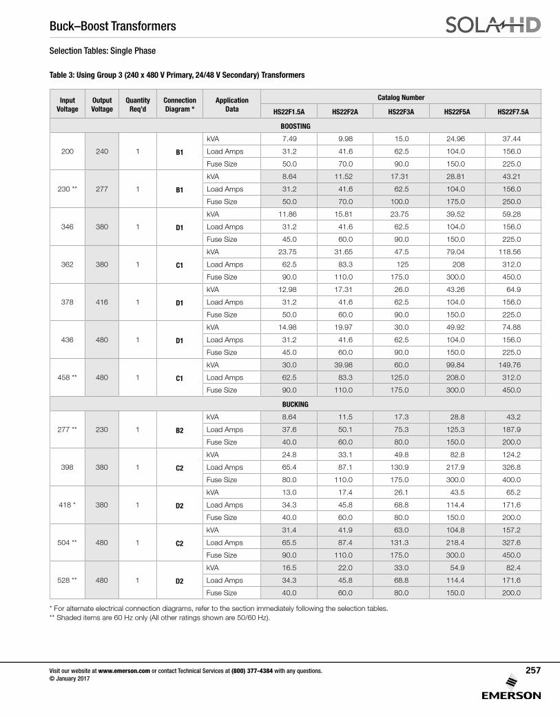
Buck–Boost Transformers
Visit our website at www.emerson.com or contact Technical Services at (800) 377-4384 with any questions. © January 2017
257
Selection Tables: Single Phase
Table 3: Using Group 3 (240 x 480 V Primary, 24/48 V Secondary) Transformers
* For alternate electrical connection diagrams, refer to the section immediately following the selection tables. ** Shaded items are 60 Hz only (All other ratings shown are 50/60 Hz).
Input Voltage
Output Voltage
Quantity Req’d
Connection Diagram *
Application Data
Catalog Number
HS22F1.5A HS22F2A HS22F3A HS22F5A HS22F7.5A
BOOSTING
200 240 1 B1
kVA 7.49 9.98 15.0 24.96 37.44
Load Amps 31.2 41.6 62.5 104.0 156.0
Fuse Size 50.0 70.0 90.0 150.0 225.0
230 ** 277 1 B1
kVA 8.64 11.52 17.31 28.81 43.21
Load Amps 31.2 41.6 62.5 104.0 156.0
Fuse Size 50.0 70.0 100.0 175.0 250.0
346 380 1 D1
kVA 11.86 15.81 23.75 39.52 59.28
Load Amps 31.2 41.6 62.5 104.0 156.0
Fuse Size 45.0 60.0 90.0 150.0 225.0
362 380 1 C1
kVA 23.75 31.65 47.5 79.04 118.56
Load Amps 62.5 83.3 125 208 312.0
Fuse Size 90.0 110.0 175.0 300.0 450.0
378 416 1 D1
kVA 12.98 17.31 26.0 43.26 64.9
Load Amps 31.2 41.6 62.5 104.0 156.0
Fuse Size 50.0 60.0 90.0 150.0 225.0
436 480 1 D1
kVA 14.98 19.97 30.0 49.92 74.88
Load Amps 31.2 41.6 62.5 104.0 156.0
Fuse Size 45.0 60.0 90.0 150.0 225.0
458 ** 480 1 C1
kVA 30.0 39.98 60.0 99.84 149.76
Load Amps 62.5 83.3 125.0 208.0 312.0
Fuse Size 90.0 110.0 175.0 300.0 450.0
BUCKING
277 ** 230 1 B2
kVA 8.64 11.5 17.3 28.8 43.2
Load Amps 37.6 50.1 75.3 125.3 187.9
Fuse Size 40.0 60.0 80.0 150.0 200.0
398 380 1 C2
kVA 24.8 33.1 49.8 82.8 124.2
Load Amps 65.4 87.1 130.9 217.9 326.8
Fuse Size 80.0 110.0 175.0 300.0 400.0
418 * 380 1 D2
kVA 13.0 17.4 26.1 43.5 65.2
Load Amps 34.3 45.8 68.8 114.4 171.6
Fuse Size 40.0 60.0 80.0 150.0 200.0
504 ** 480 1 C2
kVA 31.4 41.9 63.0 104.8 157.2
Load Amps 65.5 87.4 131.3 218.4 327.6
Fuse Size 90.0 110.0 175.0 300.0 450.0
528 ** 480 1 D2
kVA 16.5 22.0 33.0 54.9 82.4
Load Amps 34.3 45.8 68.8 114.4 171.6
Fuse Size 40.0 60.0 80.0 150.0 200.0
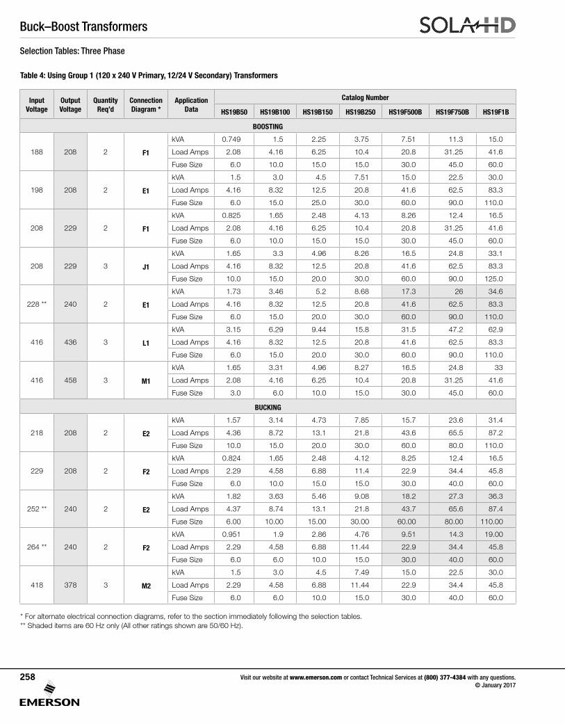
Buck–Boost Transformers
Visit our website at www.emerson.com or contact Technical Services at (800) 377-4384 with any questions. © January 2017
258
Selection Tables: Three Phase
Table 4: Using Group 1 (120 x 240 V Primary, 12/24 V Secondary) Transformers
* For alternate electrical connection diagrams, refer to the section immediately following the selection tables. ** Shaded items are 60 Hz only (All other ratings shown are 50/60 Hz).
Input Voltage
Output Voltage
Quantity Req’d
Connection Diagram *
Application Data
Catalog Number
HS19B50 HS19B100 HS19B150 HS19B250 HS19F500B HS19F750B HS19F1B
BOOSTING
188 208 2 F1
kVA 0.749 1.5 2.25 3.75 7.51 11.3 15.0
Load Amps 2.08 4.16 6.25 10.4 20.8 31.25 41.6
Fuse Size 6.0 10.0 15.0 15.0 30.0 45.0 60.0
198 208 2 E1
kVA 1.5 3.0 4.5 7.51 15.0 22.5 30.0
Load Amps 4.16 8.32 12.5 20.8 41.6 62.5 83.3
Fuse Size 6.0 15.0 25.0 30.0 60.0 90.0 110.0
208 229 2 F1
kVA 0.825 1.65 2.48 4.13 8.26 12.4 16.5
Load Amps 2.08 4.16 6.25 10.4 20.8 31.25 41.6
Fuse Size 6.0 10.0 15.0 15.0 30.0 45.0 60.0
208 229 3 J1
kVA 1.65 3.3 4.96 8.26 16.5 24.8 33.1
Load Amps 4.16 8.32 12.5 20.8 41.6 62.5 83.3
Fuse Size 10.0 15.0 20.0 30.0 60.0 90.0 125.0
228 ** 240 2 E1
kVA 1.73 3.46 5.2 8.68 17.3 26 34.6
Load Amps 4.16 8.32 12.5 20.8 41.6 62.5 83.3
Fuse Size 6.0 15.0 20.0 30.0 60.0 90.0 110.0
416 436 3 L1
kVA 3.15 6.29 9.44 15.8 31.5 47.2 62.9
Load Amps 4.16 8.32 12.5 20.8 41.6 62.5 83.3
Fuse Size 6.0 15.0 20.0 30.0 60.0 90.0 110.0
416 458 3 M1
kVA 1.65 3.31 4.96 8.27 16.5 24.8 33
Load Amps 2.08 4.16 6.25 10.4 20.8 31.25 41.6
Fuse Size 3.0 6.0 10.0 15.0 30.0 45.0 60.0
BUCKING
218 208 2 E2
kVA 1.57 3.14 4.73 7.85 15.7 23.6 31.4
Load Amps 4.36 8.72 13.1 21.8 43.6 65.5 87.2
Fuse Size 10.0 15.0 20.0 30.0 60.0 80.0 110.0
229 208 2 F2
kVA 0.824 1.65 2.48 4.12 8.25 12.4 16.5
Load Amps 2.29 4.58 6.88 11.4 22.9 34.4 45.8
Fuse Size 6.0 10.0 15.0 15.0 30.0 40.0 60.0
252 ** 240 2 E2
kVA 1.82 3.63 5.46 9.08 18.2 27.3 36.3
Load Amps 4.37 8.74 13.1 21.8 43.7 65.6 87.4
Fuse Size 6.00 10.00 15.00 30.00 60.00 80.00 110.00
264 ** 240 2 F2
kVA 0.951 1.9 2.86 4.76 9.51 14.3 19.00
Load Amps 2.29 4.58 6.88 11.44 22.9 34.4 45.8
Fuse Size 6.0 6.0 10.0 15.0 30.0 40.0 60.0
418 378 3 M2
kVA 1.5 3.0 4.5 7.49 15.0 22.5 30.0
Load Amps 2.29 4.58 6.88 11.44 22.9 34.4 45.8
Fuse Size 6.0 6.0 10.0 15.0 30.0 40.0 60.0
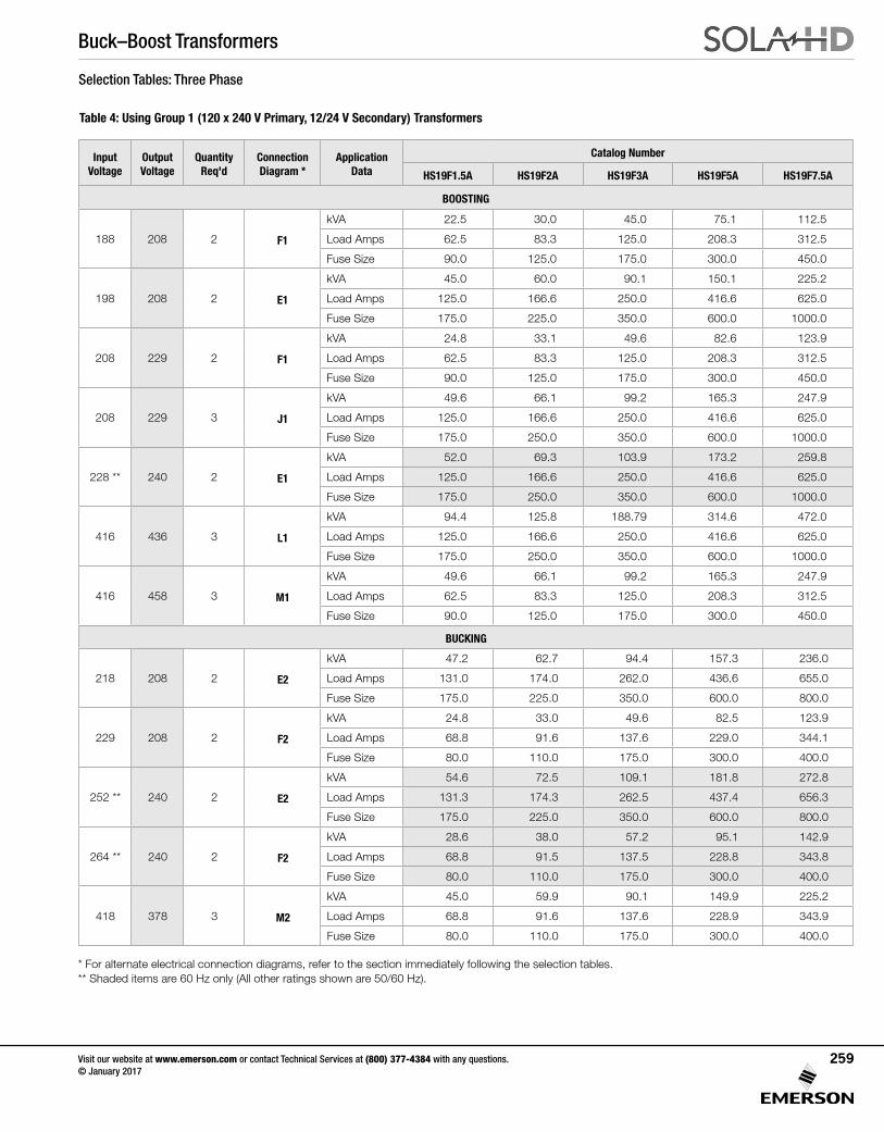
Buck–Boost Transformers
Visit our website at www.emerson.com or contact Technical Services at (800) 377-4384 with any questions. © January 2017
259
Selection Tables: Three Phase
Table 4: Using Group 1 (120 x 240 V Primary, 12/24 V Secondary) Transformers
* For alternate electrical connection diagrams, refer to the section immediately following the selection tables. ** Shaded items are 60 Hz only (All other ratings shown are 50/60 Hz).
Input Voltage
Output Voltage
Quantity Req'd
Connection Diagram *
Application Data
Catalog Number
HS19F1.5A HS19F2A HS19F3A HS19F5A HS19F7.5A
BOOSTING
188 208 2 F1
kVA 22.5 30.0 45.0 75.1 112.5
Load Amps 62.5 83.3 125.0 208.3 312.5
Fuse Size 90.0 125.0 175.0 300.0 450.0
198 208 2 E1
kVA 45.0 60.0 90.1 150.1 225.2
Load Amps 125.0 166.6 250.0 416.6 625.0
Fuse Size 175.0 225.0 350.0 600.0 1000.0
208 229 2 F1
kVA 24.8 33.1 49.6 82.6 123.9
Load Amps 62.5 83.3 125.0 208.3 312.5
Fuse Size 90.0 125.0 175.0 300.0 450.0
208 229 3 J1
kVA 49.6 66.1 99.2 165.3 247.9
Load Amps 125.0 166.6 250.0 416.6 625.0
Fuse Size 175.0 250.0 350.0 600.0 1000.0
228 ** 240 2 E1
kVA 52.0 69.3 103.9 173.2 259.8
Load Amps 125.0 166.6 250.0 416.6 625.0
Fuse Size 175.0 250.0 350.0 600.0 1000.0
416 436 3 L1
kVA 94.4 125.8 188.79 314.6 472.0
Load Amps 125.0 166.6 250.0 416.6 625.0
Fuse Size 175.0 250.0 350.0 600.0 1000.0
416 458 3 M1
kVA 49.6 66.1 99.2 165.3 247.9
Load Amps 62.5 83.3 125.0 208.3 312.5
Fuse Size 90.0 125.0 175.0 300.0 450.0
BUCKING
218 208 2 E2
kVA 47.2 62.7 94.4 157.3 236.0
Load Amps 131.0 174.0 262.0 436.6 655.0
Fuse Size 175.0 225.0 350.0 600.0 800.0
229 208 2 F2
kVA 24.8 33.0 49.6 82.5 123.9
Load Amps 68.8 91.6 137.6 229.0 344.1
Fuse Size 80.0 110.0 175.0 300.0 400.0
252 ** 240 2 E2
kVA 54.6 72.5 109.1 181.8 272.8
Load Amps 131.3 174.3 262.5 437.4 656.3
Fuse Size 175.0 225.0 350.0 600.0 800.0
264 ** 240 2 F2
kVA 28.6 38.0 57.2 95.1 142.9
Load Amps 68.8 91.5 137.5 228.8 343.8
Fuse Size 80.0 110.0 175.0 300.0 400.0
418 378 3 M2
kVA 45.0 59.9 90.1 149.9 225.2
Load Amps 68.8 91.6 137.6 228.9 343.9
Fuse Size 80.0 110.0 175.0 300.0 400.0
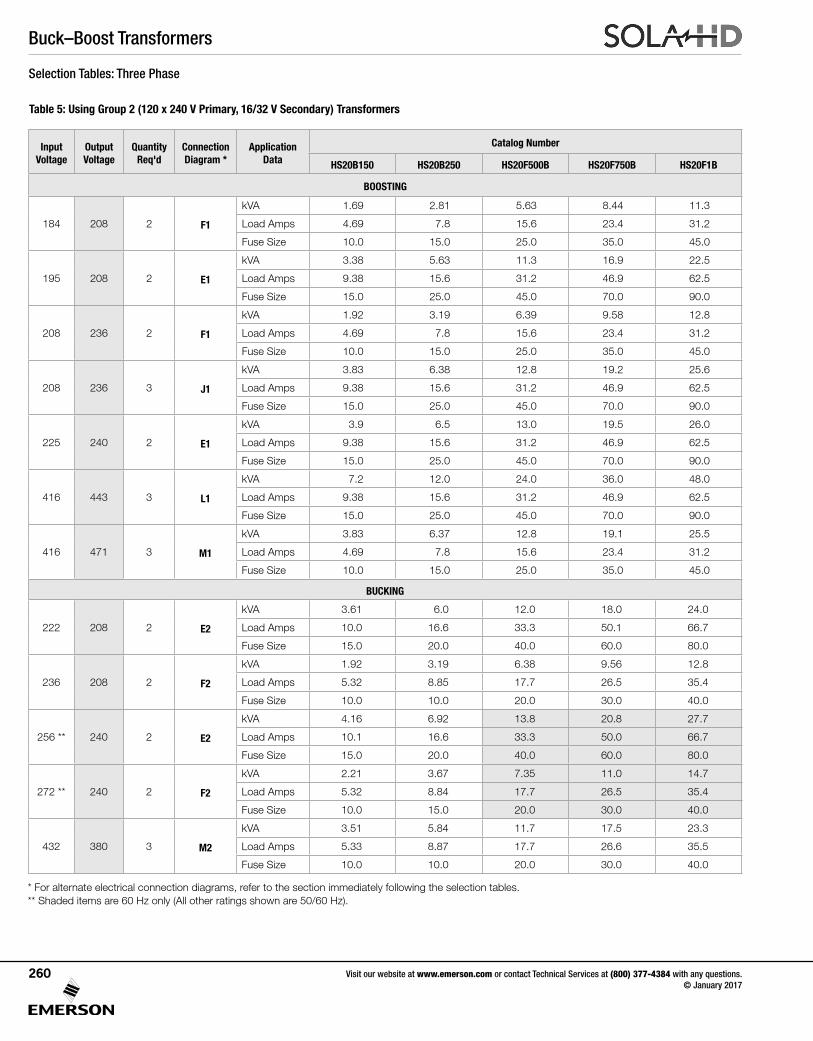
Buck–Boost Transformers
Visit our website at www.emerson.com or contact Technical Services at (800) 377-4384 with any questions. © January 2017
260
Selection Tables: Three Phase
Table 5: Using Group 2 (120 x 240 V Primary, 16/32 V Secondary) Transformers
* For alternate electrical connection diagrams, refer to the section immediately following the selection tables. ** Shaded items are 60 Hz only (All other ratings shown are 50/60 Hz).
Input Voltage
Output Voltage
Quantity Req'd
Connection Diagram *
Application Data
Catalog Number
HS20B150 HS20B250 HS20F500B HS20F750B HS20F1B
BOOSTING
184 208 2 F1
kVA 1.69 2.81 5.63 8.44 11.3
Load Amps 4.69 7.8 15.6 23.4 31.2
Fuse Size 10.0 15.0 25.0 35.0 45.0
195 208 2 E1
kVA 3.38 5.63 11.3 16.9 22.5
Load Amps 9.38 15.6 31.2 46.9 62.5
Fuse Size 15.0 25.0 45.0 70.0 90.0
208 236 2 F1
kVA 1.92 3.19 6.39 9.58 12.8
Load Amps 4.69 7.8 15.6 23.4 31.2
Fuse Size 10.0 15.0 25.0 35.0 45.0
208 236 3 J1
kVA 3.83 6.38 12.8 19.2 25.6
Load Amps 9.38 15.6 31.2 46.9 62.5
Fuse Size 15.0 25.0 45.0 70.0 90.0
225 240 2 E1
kVA 3.9 6.5 13.0 19.5 26.0
Load Amps 9.38 15.6 31.2 46.9 62.5
Fuse Size 15.0 25.0 45.0 70.0 90.0
416 443 3 L1
kVA 7.2 12.0 24.0 36.0 48.0
Load Amps 9.38 15.6 31.2 46.9 62.5
Fuse Size 15.0 25.0 45.0 70.0 90.0
416 471 3 M1
kVA 3.83 6.37 12.8 19.1 25.5
Load Amps 4.69 7.8 15.6 23.4 31.2
Fuse Size 10.0 15.0 25.0 35.0 45.0
BUCKING
222 208 2 E2
kVA 3.61 6.0 12.0 18.0 24.0
Load Amps 10.0 16.6 33.3 50.1 66.7
Fuse Size 15.0 20.0 40.0 60.0 80.0
236 208 2 F2
kVA 1.92 3.19 6.38 9.56 12.8
Load Amps 5.32 8.85 17.7 26.5 35.4
Fuse Size 10.0 10.0 20.0 30.0 40.0
256 ** 240 2 E2
kVA 4.16 6.92 13.8 20.8 27.7
Load Amps 10.1 16.6 33.3 50.0 66.7
Fuse Size 15.0 20.0 40.0 60.0 80.0
272 ** 240 2 F2
kVA 2.21 3.67 7.35 11.0 14.7
Load Amps 5.32 8.84 17.7 26.5 35.4
Fuse Size 10.0 15.0 20.0 30.0 40.0
432 380 3 M2
kVA 3.51 5.84 11.7 17.5 23.3
Load Amps 5.33 8.87 17.7 26.6 35.5
Fuse Size 10.0 10.0 20.0 30.0 40.0
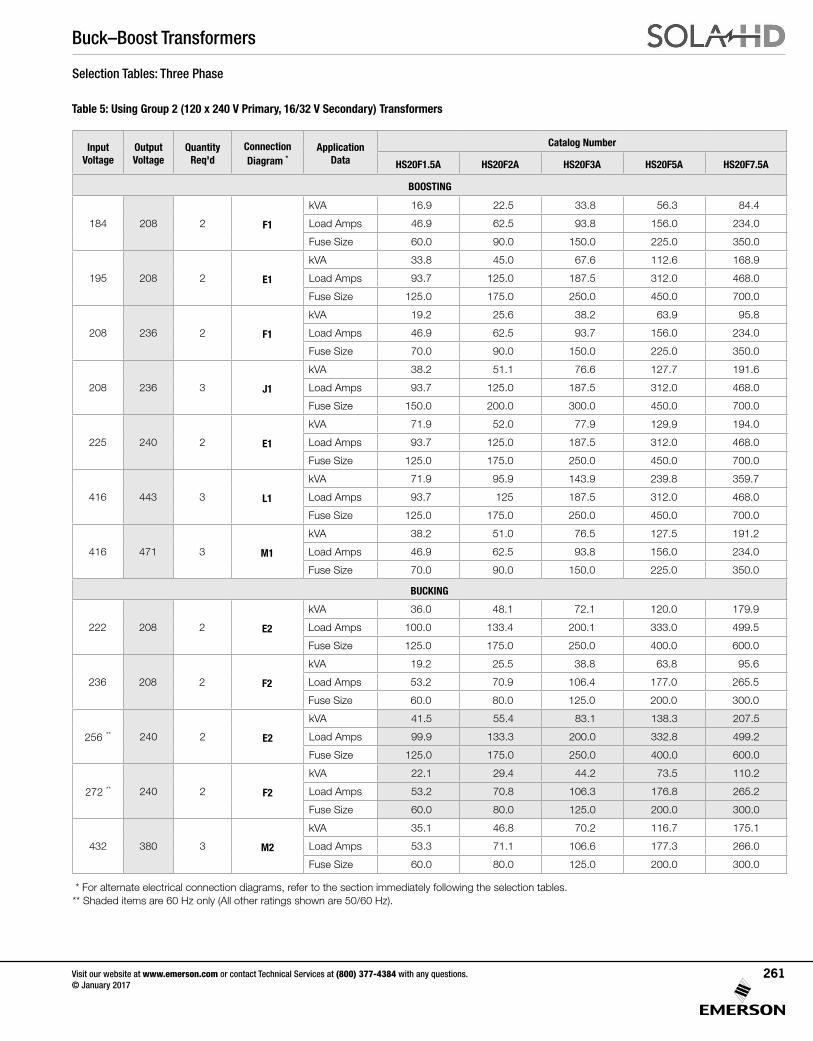
Buck–Boost Transformers
Visit our website at www.emerson.com or contact Technical Services at (800) 377-4384 with any questions. © January 2017
261
Selection Tables: Three Phase
Table 5: Using Group 2 (120 x 240 V Primary, 16/32 V Secondary) Transformers
Input Voltage
Output Voltage
Quantity Req'd
Connection Diagram *
Application Data
Catalog Number
HS20F1.5A HS20F2A HS20F3A HS20F5A HS20F7.5A
BOOSTING
184 208 2 F1
kVA 16.9 22.5 33.8 56.3 84.4
Load Amps 46.9 62.5 93.8 156.0 234.0
Fuse Size 60.0 90.0 150.0 225.0 350.0
195 208 2 E1
kVA 33.8 45.0 67.6 112.6 168.9
Load Amps 93.7 125.0 187.5 312.0 468.0
Fuse Size 125.0 175.0 250.0 450.0 700.0
208 236 2 F1
kVA 19.2 25.6 38.2 63.9 95.8
Load Amps 46.9 62.5 93.7 156.0 234.0
Fuse Size 70.0 90.0 150.0 225.0 350.0
208 236 3 J1
kVA 38.2 51.1 76.6 127.7 191.6
Load Amps 93.7 125.0 187.5 312.0 468.0
Fuse Size 150.0 200.0 300.0 450.0 700.0
225 240 2 E1
kVA 71.9 52.0 77.9 129.9 194.0
Load Amps 93.7 125.0 187.5 312.0 468.0
Fuse Size 125.0 175.0 250.0 450.0 700.0
416 443 3 L1
kVA 71.9 95.9 143.9 239.8 359.7
Load Amps 93.7 125 187.5 312.0 468.0
Fuse Size 125.0 175.0 250.0 450.0 700.0
416 471 3 M1
kVA 38.2 51.0 76.5 127.5 191.2
Load Amps 46.9 62.5 93.8 156.0 234.0
Fuse Size 70.0 90.0 150.0 225.0 350.0
BUCKING
222 208 2 E2
kVA 36.0 48.1 72.1 120.0 179.9
Load Amps 100.0 133.4 200.1 333.0 499.5
Fuse Size 125.0 175.0 250.0 400.0 600.0
236 208 2 F2
kVA 19.2 25.5 38.8 63.8 95.6
Load Amps 53.2 70.9 106.4 177.0 265.5
Fuse Size 60.0 80.0 125.0 200.0 300.0
256 ** 240 2 E2
kVA 41.5 55.4 83.1 138.3 207.5
Load Amps 99.9 133.3 200.0 332.8 499.2
Fuse Size 125.0 175.0 250.0 400.0 600.0
272 ** 240 2 F2
kVA 22.1 29.4 44.2 73.5 110.2
Load Amps 53.2 70.8 106.3 176.8 265.2
Fuse Size 60.0 80.0 125.0 200.0 300.0
432 380 3 M2
kVA 35.1 46.8 70.2 116.7 175.1
Load Amps 53.3 71.1 106.6 177.3 266.0
Fuse Size 60.0 80.0 125.0 200.0 300.0
* For alternate electrical connection diagrams, refer to the section immediately following the selection tables. ** Shaded items are 60 Hz only (All other ratings shown are 50/60 Hz).
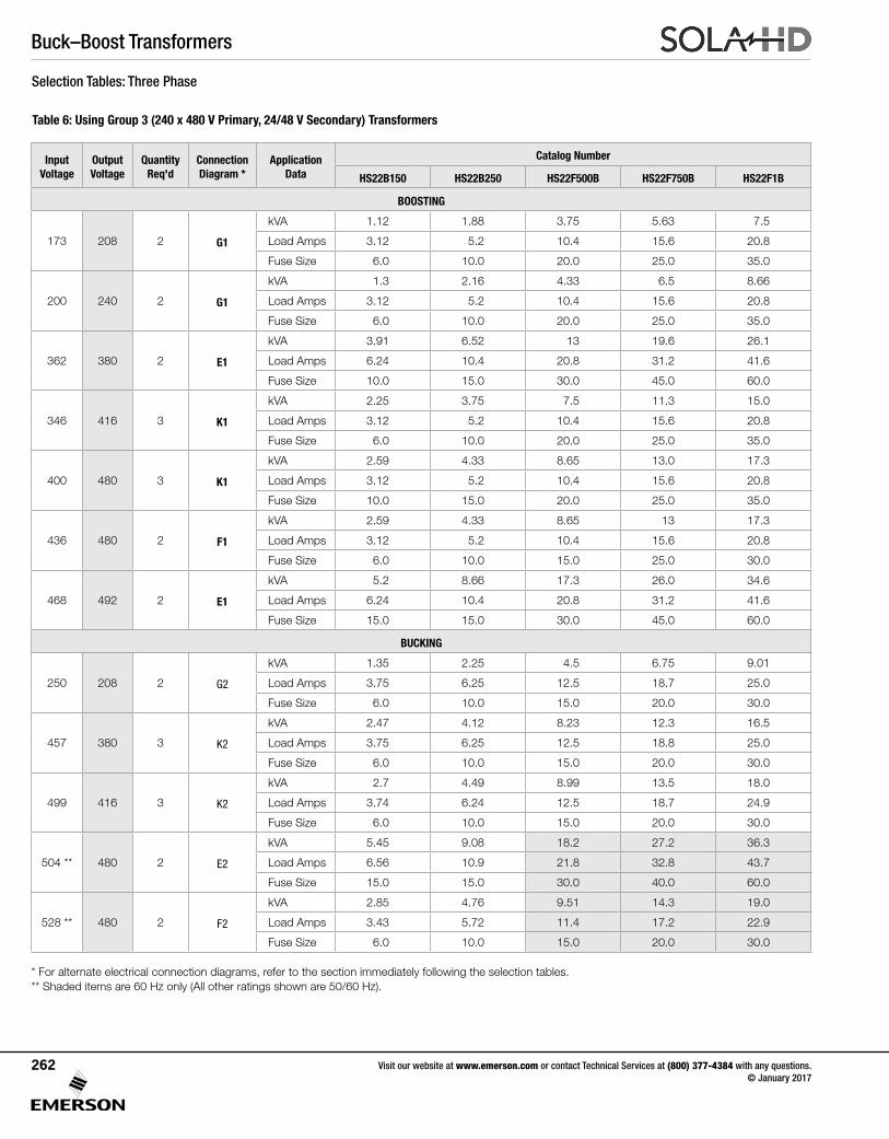
Buck–Boost Transformers
Visit our website at www.emerson.com or contact Technical Services at (800) 377-4384 with any questions. © January 2017
262
Selection Tables: Three Phase
Table 6: Using Group 3 (240 x 480 V Primary, 24/48 V Secondary) Transformers
Input Voltage
Output Voltage
Quantity Req'd
Connection Diagram *
Application Data
Catalog Number
HS22B150 HS22B250 HS22F500B HS22F750B HS22F1B
BOOSTING
173 208 2 G1
kVA 1.12 1.88 3.75 5.63 7.5
Load Amps 3.12 5.2 10.4 15.6 20.8
Fuse Size 6.0 10.0 20.0 25.0 35.0
200 240 2 G1
kVA 1.3 2.16 4.33 6.5 8.66
Load Amps 3.12 5.2 10.4 15.6 20.8
Fuse Size 6.0 10.0 20.0 25.0 35.0
362 380 2 E1
kVA 3.91 6.52 13 19.6 26.1
Load Amps 6.24 10.4 20.8 31.2 41.6
Fuse Size 10.0 15.0 30.0 45.0 60.0
346 416 3 K1
kVA 2.25 3.75 7.5 11.3 15.0
Load Amps 3.12 5.2 10.4 15.6 20.8
Fuse Size 6.0 10.0 20.0 25.0 35.0
400 480 3 K1
kVA 2.59 4.33 8.65 13.0 17.3
Load Amps 3.12 5.2 10.4 15.6 20.8
Fuse Size 10.0 15.0 20.0 25.0 35.0
436 480 2 F1
kVA 2.59 4.33 8.65 13 17.3
Load Amps 3.12 5.2 10.4 15.6 20.8
Fuse Size 6.0 10.0 15.0 25.0 30.0
468 492 2 E1
kVA 5.2 8.66 17.3 26.0 34.6
Load Amps 6.24 10.4 20.8 31.2 41.6
Fuse Size 15.0 15.0 30.0 45.0 60.0
BUCKING
250 208 2 G2
kVA 1.35 2.25 4.5 6.75 9.01
Load Amps 3.75 6.25 12.5 18.7 25.0
Fuse Size 6.0 10.0 15.0 20.0 30.0
457 380 3 K2
kVA 2.47 4.12 8.23 12.3 16.5
Load Amps 3.75 6.25 12.5 18.8 25.0
Fuse Size 6.0 10.0 15.0 20.0 30.0
499 416 3 K2
kVA 2.7 4.49 8.99 13.5 18.0
Load Amps 3.74 6.24 12.5 18.7 24.9
Fuse Size 6.0 10.0 15.0 20.0 30.0
504 ** 480 2 E2
kVA 5.45 9.08 18.2 27.2 36.3
Load Amps 6.56 10.9 21.8 32.8 43.7
Fuse Size 15.0 15.0 30.0 40.0 60.0
528 ** 480 2 F2
kVA 2.85 4.76 9.51 14.3 19.0
Load Amps 3.43 5.72 11.4 17.2 22.9
Fuse Size 6.0 10.0 15.0 20.0 30.0
* For alternate electrical connection diagrams, refer to the section immediately following the selection tables.** Shaded items are 60 Hz only (All other ratings shown are 50/60 Hz).
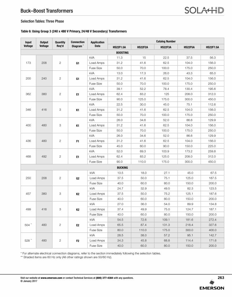
Buck–Boost Transformers
Visit our website at www.emerson.com or contact Technical Services at (800) 377-4384 with any questions. © January 2017
263
Selection Tables: Three Phase
Table 6: Using Group 3 (240 x 480 V Primary, 24/48 V Secondary) Transformers
Input Voltage
Output Voltage
Quantity Req'd
Connection Diagram *
Application Data
Catalog Number
HS22F1.5A HS22F2A HS22F3A HS22F5A HS22F7.5A
BOOSTING
173 208 2 G1
kVA 11.3 15 22.5 37.5 56.3
Load Amps 31.2 41.6 62.5 104.0 156.0
Fuse Size 50.0 70.0 100.0 175.0 250.0
200 240 2 G1
kVA 13.0 17.3 26.0 43.3 65.0
Load Amps 31.2 41.6 62.5 104.0 156.0
Fuse Size 50.0 70.0 100.0 175.0 250.0
362 380 2 E1
kVA 39.1 52.2 78.4 130.4 195.6
Load Amps 62.4 83.2 125 208.0 312.0
Fuse Size 90.0 125.0 175.0 300.0 450.0
346 416 3 K1
kVA 22.5 30.0 45.0 75.1 112.6
Load Amps 31.2 41.6 62.5 104.0 156.0
Fuse Size 50.0 70.0 100.0 175.0 250.0
400 480 3 K1
kVA 26.0 34.6 52.0 86.6 129.9
Load Amps 31.2 41.6 62.5 104.0 156.0
Fuse Size 50.0 70.0 100.0 175.0 250.0
436 480 2 F1
kVA 26.0 34.6 52.0 86.6 129.9
Load Amps 31.2 41.6 62.5 104.0 156.0
Fuse Size 45.0 60.0 90.0 150.0 225.0
468 492 2 E1
kVA 52.0 69.3 103.9 173.2 259.8
Load Amps 62.4 83.2 125.0 208.0 312.0
Fuse Size 90.0 110.0 175.0 300.0 450.0
BUCKING
250 208 2 G2
kVA 13.5 18.0 27.1 45.0 67.5
Load Amps 37.5 50.0 75.1 125.0 187.5
Fuse Size 40.0 60.0 80.0 150.0 200.0
457 380 3 K2
kVA 24.7 32.9 49.5 82.3 123.5
Load Amps 37.5 50.0 75.2 125.1 187.6
Fuse Size 40.0 60.0 80.0 150.0 200.0
499 416 3 K2
kVA 27.0 36.0 54.0 89.9 134.8
Load Amps 37.4 49.9 75.0 124.7 187.1
Fuse Size 40.0 60.0 80.0 150.0 200.0
504 ** 480 2 E2
kVA 54.5 72.6 109.1 181.6 272.4
Load Amps 65.5 87.4 131.3 218.4 327.6
Fuse Size 80.0 110.0 175.0 300.0 400.0
528 ** 480 2 F2
kVA 28.5 38.0 57.2 95.1 142.7
Load Amps 34.3 45.8 68.8 114.4 171.6
Fuse Size 40.0 60.0 80.0 150.0 200.0
* For alternate electrical connection diagrams, refer to the section immediately following the selection tables.** Shaded items are 60 Hz only (All other ratings shown are 50/60 Hz).
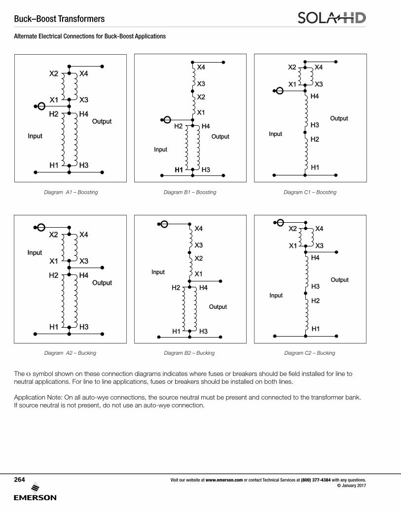
Buck–Boost Transformers
Visit our website at www.emerson.com or contact Technical Services at (800) 377-4384 with any questions. © January 2017
264
The O symbol shown on these connection diagrams indicates where fuses or breakers should be field installed for line to neutral applications. For line to line applications, fuses or breakers should be installed on both lines.
Application Note: On all auto-wye connections, the source neutral must be present and connected to the transformer bank. If source neutral is not present, do not use an auto-wye connection.
Alternate Electrical Connections for Buck-Boost Applications
Diagram A1 – Boosting Diagram B1 – Boosting Diagram C1 – Boosting
Diagram A2 – Bucking Diagram B2 – Bucking Diagram C2 – Bucking
Output
Input
H1
X1
H2
X2
H4
X4
H3
X3
Output
H2 H4
Input
H1 H3
X1
X2
X4
X3
Output
H2
H4
Input
H1
H3
X1
X2 X4
X3
Output
Input
H1
X1
H2
X2
H4
X4
H3
X3
Output
H2 H4
Input
H1 H3
X1
X2
X4
X3
Output
H2
H4
Input
H1
H3
X1
X2 X4
X3
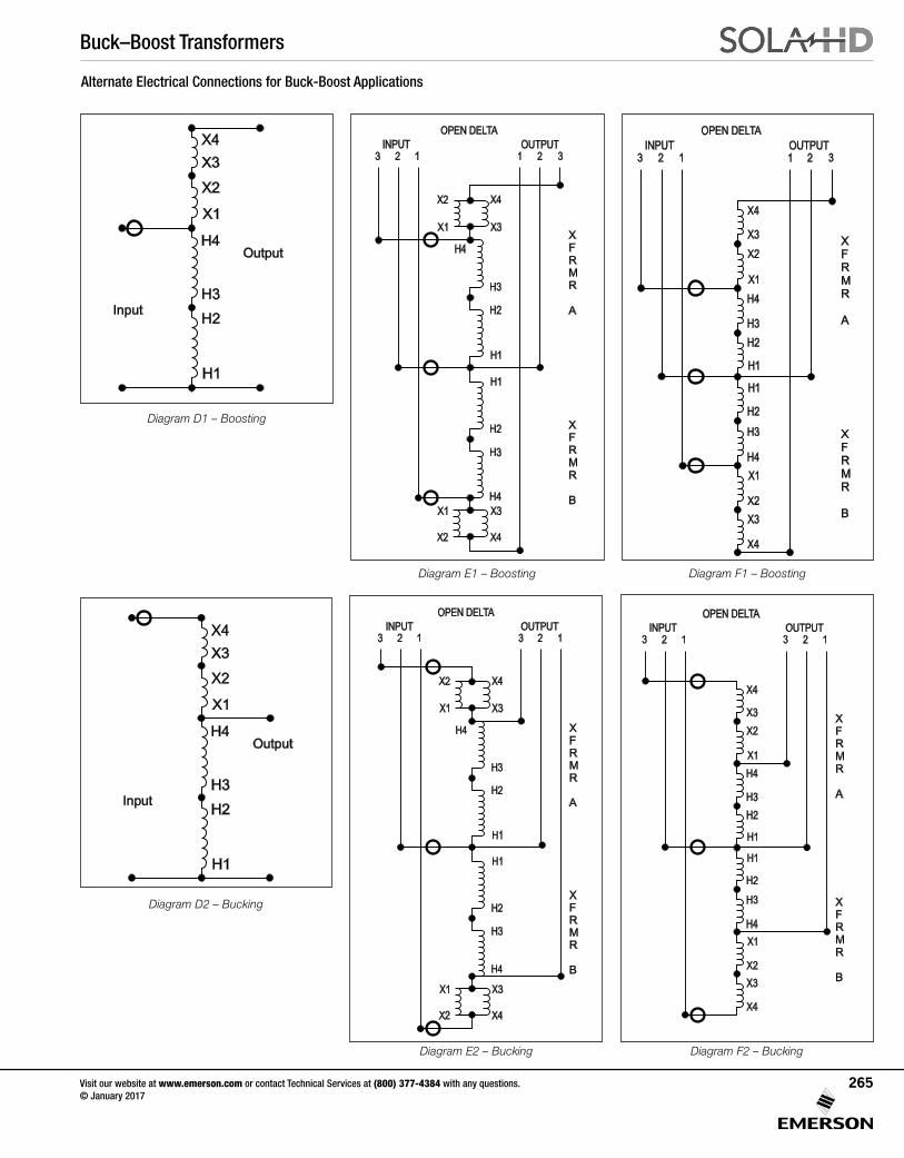
Buck–Boost Transformers
Visit our website at www.emerson.com or contact Technical Services at (800) 377-4384 with any questions. © January 2017
265
Alternate Electrical Connections for Buck-Boost Applications
Diagram F2 – Bucking
Diagram D1 – Boosting
Diagram E1 – Boosting Diagram F1 – Boosting
Diagram D2 – Bucking
Diagram E2 – Bucking
Output
H2
H4
Input
H1
H3
X1
X2
X4
X3
X
F
R
M
R
A
X
F
R
M
R
B
X1
X1
X2
X2
X4
X4
X3
X3
H1
H1
H2
H2
H4
H4
H3
H3
OUTPUT
OPEN DELTA
INPUT
1 2 3123
X
F
R
M
R
A
X
F
R
M
R
B
OUTPUT
OPEN DELTA
INPUT
123 1 2 3
X1
X1
X2
X2
X4
X4
X3
X3
H1
H1
H2
H2
H4
H4
H3
H3
Output
H2
H4
Input
H1
H3
X1
X2
X4
X3
X
F
R
M
R
A
X
F
R
M
R
B
OPEN DELTA
OUTPUT
1231
INPUT
23
X1
X1
X2
X2
X4
X4
X3
X3
H1
H1
H2
H2
H4
H4
H3
H3
X
F
R
M
R
A
X
F
R
M
R
B
OUTPUT
OPEN DELTA
INPUT
123 123
X1
X1
X2
X2
X4
X4
X3
X3
H1
H1
H2
H2
H4
H4
H3
H3
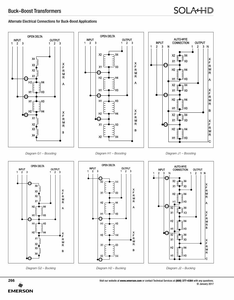
Buck–Boost Transformers
Visit our website at www.emerson.com or contact Technical Services at (800) 377-4384 with any questions. © January 2017
266
Alternate Electrical Connections for Buck-Boost Applications
Diagram J2 – Bucking
Diagram G1 – Boosting Diagram H1 – Boosting Diagram J1 – Boosting
Diagram G2 – Bucking Diagram H2 – Bucking
X
F
R
M
R
A
X
F
R
M
R
B
OUTPUT
OPEN DELTA
INPUT
1 2 31 2 3
H4
H4
H3
H3
X1
X1
X2
X2
X4
X4
X3
X3
H1
H1
H2
H2
X
F
R
M
R
A
X
F
R
M
R
B
OUTPUT
OPEN DELTA
INPUT
1 2 31 2 3
H4
H4
H3
H3
X1
X1
X2
X2
X4
X4
X3
X3
H1
H1
H2
H2
X
F
R
M
R
A
X
F
R
M
R
B
OUTPUT
OPEN DELTA
INPUT
1 2 31 2 3
H4
H4
H3
H3
X1
X1
X2
X2
X4
X4
X3
X3
H1
H1
H2
H2
X
F
R
M
R
A
X
F
R
M
R
B
X
F
R
M
R
C
OUTPUT
AUTO-WYE
CONNECTIONINPUT
1 2 3 N 1 2 3 N
H4
H4
H4
H3
H3
H3
X1
X1
X1
X2
X2
X2
X4
X4
X4
X3
X3
X3
H1
H1
H1
H2
H2
H2
X
F
R
M
R
A
X
F
R
M
R
B
OUTPUT
OPEN DELTA
INPUT
1 2 31 2 3
H4
H4
H3
H3
X1
X1
X2
X2
X4
X4
X3
X3
H1
H1
H2
H2
H4
H4
H3
H3
X1
X2 X4
X3
H1
H1
H2
H2
OUTPUT
AUTO-WYE
CONNECTIONINPUT
1 2 3 N 1 2 3 N
H4
H3
X1
X1
X2
X2
X4
X4
X3
X3
H1
H2
X
F
R
M
R
A
X
F
R
M
R
B
X
F
R
M
R
C
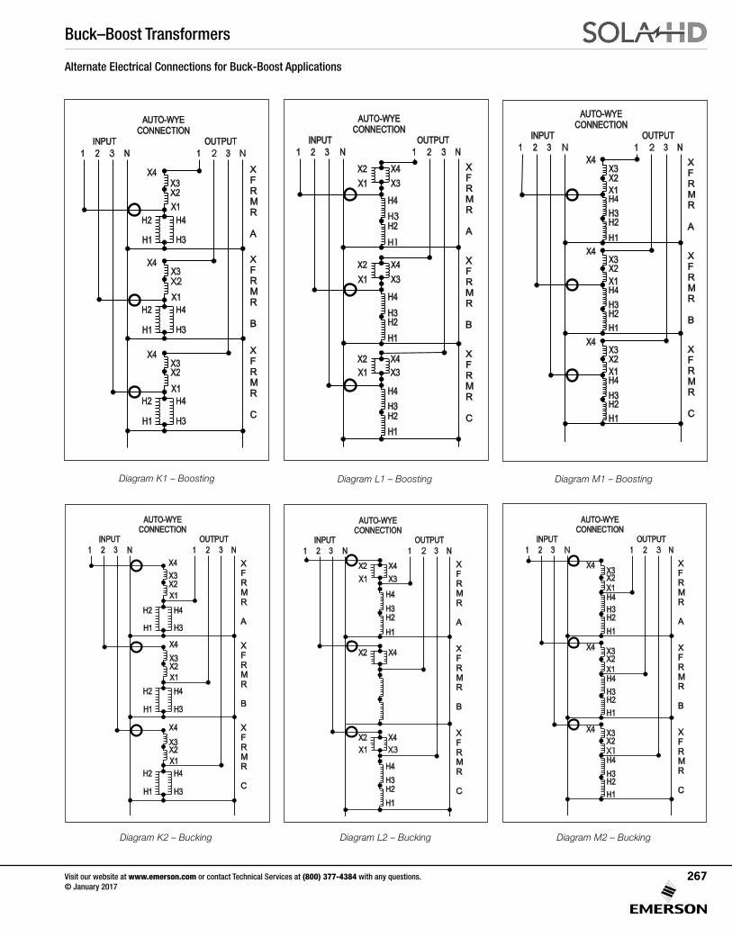
Buck–Boost Transformers
Visit our website at www.emerson.com or contact Technical Services at (800) 377-4384 with any questions. © January 2017
267
Alternate Electrical Connections for Buck-Boost Applications
Diagram M2 – Bucking
Diagram K1 – Boosting Diagram L1 – Boosting Diagram M1 – Boosting
Diagram K2 – Bucking Diagram L2 – Bucking
H4
H4
H3
H3
X1
X2
X3
H1
H1
H2
H2
AUTO-WYE
CONNECTION
INPUT
1 2 3 N
OUTPUT
1 2 3 N
H4
H3
X1
X1
X2
X2
X4
X4
X4
X3
X3
H1
H2
X
F
R
M
R
A
X
F
R
M
R
B
X
F
R
M
R
C
H4
H4
H3
H3
X1
X2X3
H1
H1
H2
H2
AUTO-WYE
CONNECTION
INPUT
1 2 3 N
OUTPUT
1 2 3 N
H4
H3
X1
X1
X2
X2
X4
X4
X4
X3
X3
H1
H2
X
F
R
M
R
A
X
F
R
M
R
B
X
F
R
M
R
C
H4
H4
H3
H3
X1
X2
X3
H1
H1
H2
H2
AUTO-WYE
CONNECTION
INPUT
1 2 3 N
OUTPUT
1 2 3 N
H4
H3
X1
X1
X2
X2
X4
X4
X4
X3
X3
H1
H2
X
F
R
M
R
A
X
F
R
M
R
B
X
F
R
M
R
C
H4
H4
H3
H3
X1
X2
X3
H1
H1
H2
H2
AUTO-WYE
CONNECTION
INPUT
1 2 3 N
OUTPUT
1 2 3 N
H4
H3
X1
X1
X2
X2
X4
X4
X4
X3
X3
H1
H2
X
F
R
M
R
A
X
F
R
M
R
B
X
F
R
M
R
C
H4
H3
X1
X2
X3
H1
H2
AUTO-WYE
CONNECTION
INPUT
1 2 3 N
OUTPUT
1 2 3 N
H4
H3
X1
X2
X2
X4
X4
X4
X3
H1
H2
X
F
R
M
R
A
X
F
R
M
R
B
X
F
R
M
R
C
H4
H4
H3
H3
X1X2X3
H1
H1
H2
H2
AUTO-WYE
CONNECTION
INPUT
1 2 3 N
OUTPUT
1 2 3 N
H4
H3
X1
X1
X2
X2
X4
X4
X4
X3
X3
H1
H2
X
F
R
M
R
A
X
F
R
M
R
B
X
F
R
M
R
C

Buck–Boost Transformers
Visit our website at www.emerson.com or contact Technical Services at (800) 377-4384 with any questions. © January 2017
268
Application Note
Application Limitations with Buck-Boost Transformers
1. A Buck-Boost transformer cannot be used to develop a three phase, four wire wye circuit from a three phase, three wire delta circuit.
A delta to wye connection does not supply enough current carrying capability to provide for unbalanced currents flowing in the neutral wire of the four wire circuit. The neutral created is not stable and under load will not deliver desired line to neutral voltages. This connection would also be in violation of the National Electric Code, Article 210.9.
2. Buck-Boost transformers cannot be used in a closed delta connection.
A closed delta requires more kVA capacity than a wye or an open delta connection, plus phase shifting comes into play on the output side.
3. Buck-Boost transformers should not be used to correct for voltage drop on a long circuit run where the load fluctuates.
Voltage drop varies with the load and buck-boost trans-formers are connected for a specific voltage change. If a buck-boost transformer was used to correct voltage drop during peak loading conditions, high voltages may result under light load conditions. This could be equally detrimental to the load and possibly pose safety hazards.
4. Buck-Boost transformers cannot be used to create a 240/120 Volt, single phase service from a 208Y/120 Volt three phase supply.
Two problems that would occur:
A. Two neutrals would exist on the same circuit. Since neutrals must be grounded according to the National Electric Code, a short circuit would be created.
B. Unbalanced line to output neutral voltages would be created; one line would read 120 Volts, the other 130+ Volts.
What is a Buck-Boost transformer and why is it used?
Isolation transformers have separate primary and secondary windings, electrically insulated and isolated from one another. With a relatively high voltage primary (typically 120, 240 or 480 Volts) and a relatively low voltage secondary (typically 12, 16, 24, 32 or 48 Volts), buck-boost transformers are designed to be field connected as autotransformers. These are transformers with one continuous winding, a portion of which is jointly shared between the input and the output. No electrical isolation is present in an autotransformer.
Buck-Boost transformers have two major uses:
1. When field connected as an autotransformer, they can be used to Buck (lower) or Boost (raise) available line voltage in the range of 5 to 27% and at a kVA rating many times that listed on the transformer nameplate.
2. When left as an isolation transformer, they can be used to supply power to low voltage circuits at the nameplate rating listed.
The importance of altering available line voltage.
Electrical equipment is designed to operate at maximum efficiency at a specific standard supply voltage. Your voltage may not be at the standard supply voltage level. Causes can be proximity to a large utility transformer, losses in the line voltage due to loads on that circuit, or a difference between the standard supply voltage available and the standard supply voltage needed to run the equipment.
Normally the problem is having low voltage available. Low voltage on a circuit, even as little as 5% lower can cause a decrease in incandescent light output, and a decrease in resistive heat output. With motors low voltage can cause a decrease in motor torque, an increase in motor amperage requirements, an increase in motor temperature and decrease in motor life expectancy.

Notes
Visit our website at www.emerson.com or contact Technical Services at (800) 377-4384 with any questions. © January 2017
269
Notes
Visit our website at www.emerson.com or contact Technical Services at (800) 377-4384 with any questions. © January 2017
270
Notes
Visit our website at www.emerson.com or contact Technical Services at (800) 377-4384 with any questions. © January 2017
271

Notes
Visit our website at www.emerson.com or contact Technical Services at (800) 377-4384 with any questions. © January 2017
272

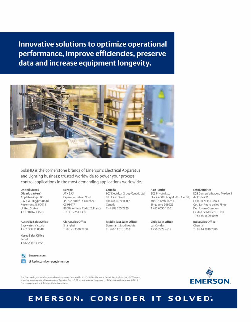
SolaHD is the cornerstone brands of Emerson's Electrical Apparatus and Lighting business; trusted worldwide to power your process control applications in the most demanding applications worldwide.
The Emerson logo is a trademark and service mark of Emerson Electric Co. © 2016 Emerson Electric Co. Appleton and O-Z/Gedney brand logos are registered trademarks of Appleton Grp LLC. All other marks are the property of their respective owners. © 2016 Emerson Automation Solutions. All rights reserved.
Emerson.com
LinkedIn.com/company/emerson
United States (Headquarters) Appleton Grp LLC9377 W. Higgins RoadRosemont, IL 60018United StatesT +1 800 621 1506
Australia Sales OfficeBayswater, Victoria T +61 3 9721 0348
Europe ATX SASEspace Industriel Nord35, rue André Durouchez, CS 9801780084 Amiens Cedex 2, FranceT +33 3 2254 1390
China Sales OfficeShanghai T +86 21 3338 7000
CanadaEGS Electrical Group Canada Ltd.99 Union StreetElmira ON, N3B 3L7CanadaT +1 888 765 2226
Middle East Sales OfficeDammam, Saudi ArabiaT +966 13 510 3702
Chile Sales OfficeLas CondesT +56 2928 4819
India Sales OfficeChennaiT +91 44 3919 7300
Korea Sales OfficeSeoulT +82 2 3483 1555
Asia Pacific EGS Private Ltd.Block 4008, Ang Mo Kio Ave 10, #04-16 TechPlace 1, Singapore 569625 T +65 6556 1100
Latin America EGS Comercializadora Mexico S de RL de CVCalle 10 N°145 Piso 3Col. San Pedro de los PinosDel. Álvaro ObregonCiudad de México. 01180T +52 55 5809 5049
Innovative solutions to optimize operational performance, improve efficiencies, preserve data and increase equipment longevity.
SolaHDA complete selection of power conditioners, surge protection, uninterruptible power supplies, power supplies and transformers.
Total Power Quality Solutions for System Reliability
SolaH
D Total Pow
er Qu
ality Solu
tion
s for System
Reliability