catalog aventics series as5 - emerson
TRANSCRIPT
Series AS5
AVENTICS™ Series AS5
Page 2 | AVENTICS
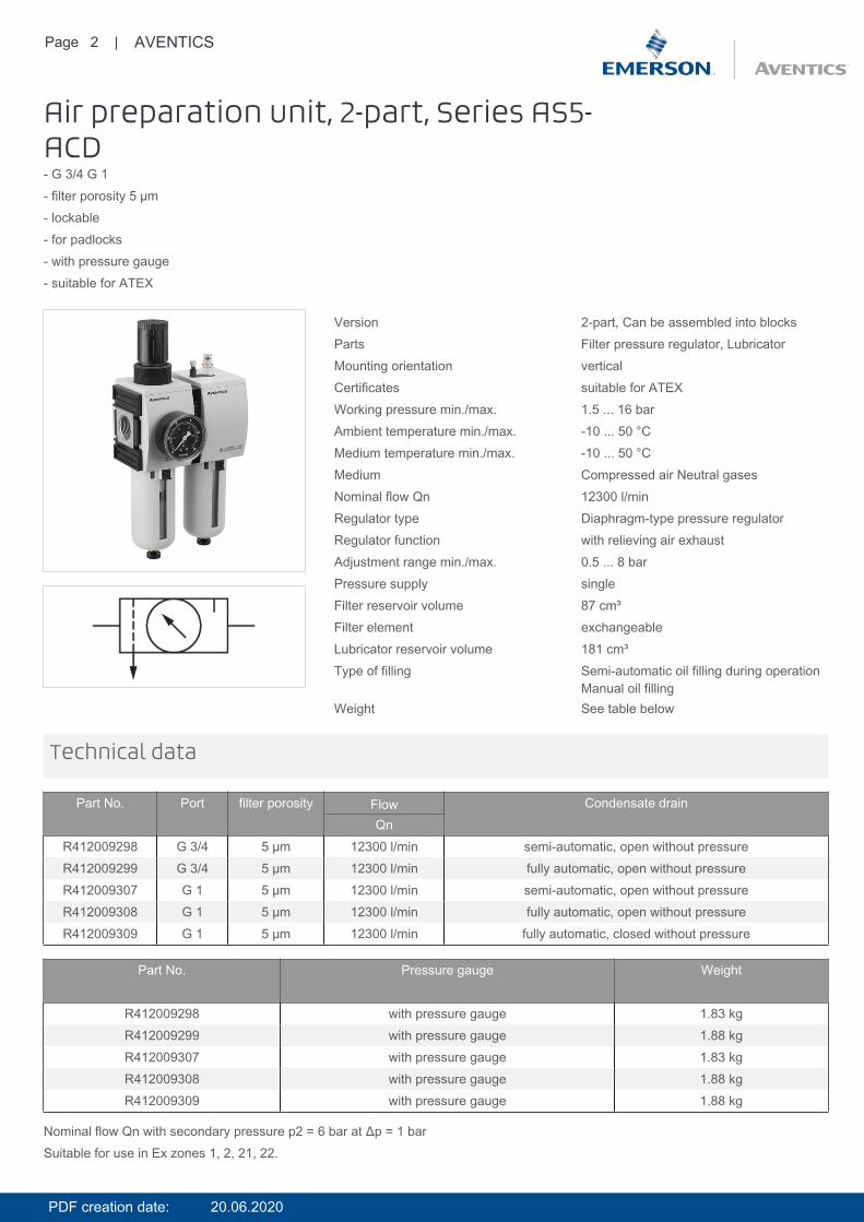
Air preparation unit, 2-part, Series AS5-ACD- G 3/4 G 1- filter porosity 5 µm- lockable- for padlocks- with pressure gauge- suitable for ATEX
Version 2-part, Can be assembled into blocksParts Filter pressure regulator, LubricatorMounting orientation verticalCertificates suitable for ATEXWorking pressure min./max. 1.5 ... 16 barAmbient temperature min./max. -10 ... 50 °CMedium temperature min./max. -10 ... 50 °CMedium Compressed air Neutral gasesNominal flow Qn 12300 l/minRegulator type Diaphragm-type pressure regulatorRegulator function with relieving air exhaustAdjustment range min./max. 0.5 ... 8 barPressure supply singleFilter reservoir volume 87 cm³Filter element exchangeableLubricator reservoir volume 181 cm³Type of filling Semi-automatic oil filling during operation
Manual oil fillingWeight See table below
Technical data
Part No. Port filter porosity Flow Condensate drainQn
R412009298 G 3/4 5 µm 12300 l/min semi-automatic, open without pressureR412009299 G 3/4 5 µm 12300 l/min fully automatic, open without pressureR412009307 G 1 5 µm 12300 l/min semi-automatic, open without pressureR412009308 G 1 5 µm 12300 l/min fully automatic, open without pressureR412009309 G 1 5 µm 12300 l/min fully automatic, closed without pressure
Part No. Pressure gauge Weight
R412009298 with pressure gauge 1.83 kgR412009299 with pressure gauge 1.88 kgR412009307 with pressure gauge 1.83 kgR412009308 with pressure gauge 1.88 kgR412009309 with pressure gauge 1.88 kg
Nominal flow Qn with secondary pressure p2 = 6 bar at Δp = 1 barSuitable for use in Ex zones 1, 2, 21, 22.
PDF creation date: 20.06.2020
Page 3 | AVENTICS
The pressure dew point must be at least 15 °C under ambient and medium temperature and may not exceed 3 °C .Note: Polycarbonate reservoirs are susceptible to solvents, supplementary information can be found at "Customer information".Suitable for use in Ex zones 1, 2, 21, 22.A change in the flow direction (from air supply on the left to air supply on the right) occurs by rotating installation by 180° about thevertical axis. Please see the operating instructions for further details.Also suitable for separation of fluid oil or water due to the design.
Max. achievable compressed air class acc. to ISO 8573-1:2010 6 : 7 : -
Technical information
Technical information
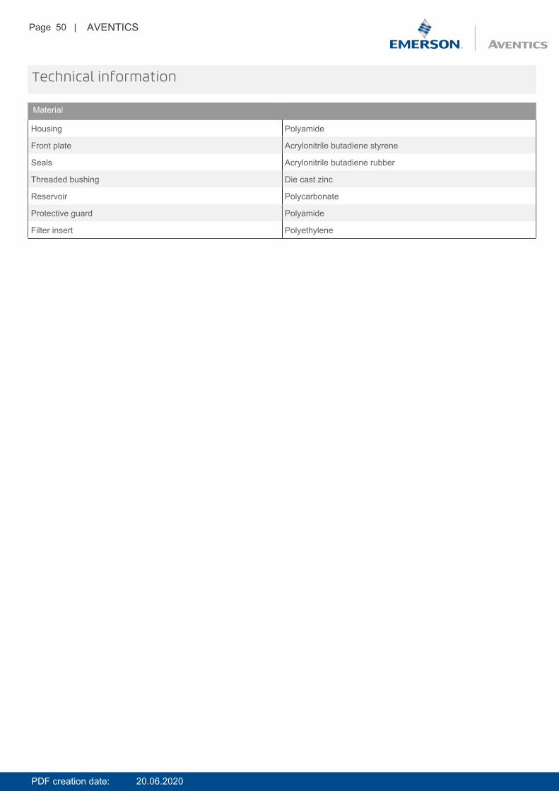
Material
Housing Polyamide
Front plate Acrylonitrile butadiene styrene
Seals Acrylonitrile butadiene rubber
Threaded bushing Die cast zinc
Reservoir Polycarbonate
Protective guard Polyamide
Filter insert Polyethylene
PDF creation date: 20.06.2020

Page 4 | AVENTICS
Dimensions
Dimensions
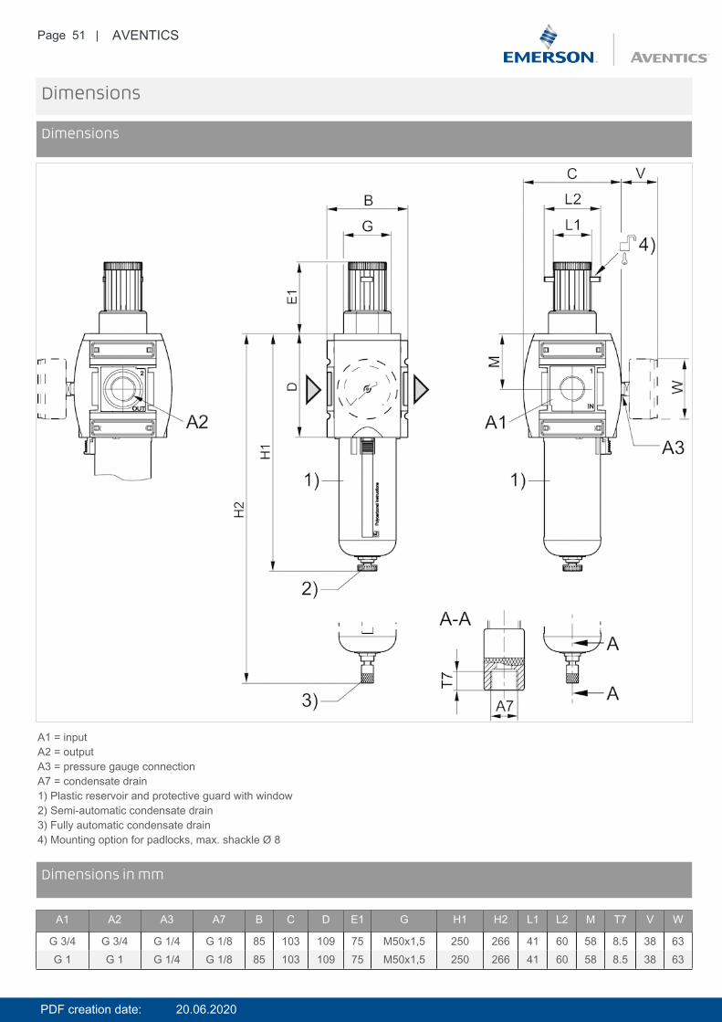
A1 = inputA2 = outputA3 = pressure gauge connectionA7 = condensate drain1) Plastic reservoir and protective guard with window2) Semi-automatic condensate drain3) Fully automatic condensate drain4) Port for semi-automatic oil filling5) Mounting option for padlocks, max. shackle Ø 8
DimensionsDimensions in mm
A1 A2 A3 A7 A8 B C D E1 E2 G H1 H2 H3 L1 L2 M T7 V W
G 3/4 G 3/4 G 1/4 G 1/8 G 1/8 170 103 109 75 30.5 M50x1,5 250 266 239 41 60 58 8.5 38 63G 1 G 1 G 1/4 G 1/8 G 1/8 170 103 109 75 30.5 M50x1,5 250 266 239 41 60 58 8.5 38 63
PDF creation date: 20.06.2020
Page 5 | AVENTICS
Diagrams
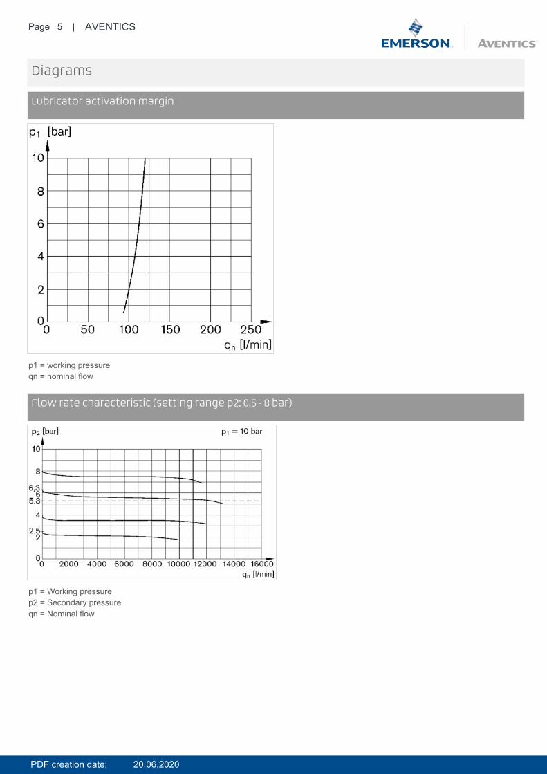
Lubricator activation margin
p1 = working pressureqn = nominal flow
DiagramsFlow rate characteristic (setting range p2: 0.5 - 8 bar)
p1 = Working pressurep2 = Secondary pressureqn = Nominal flow
PDF creation date: 20.06.2020

Page 6 | AVENTICS
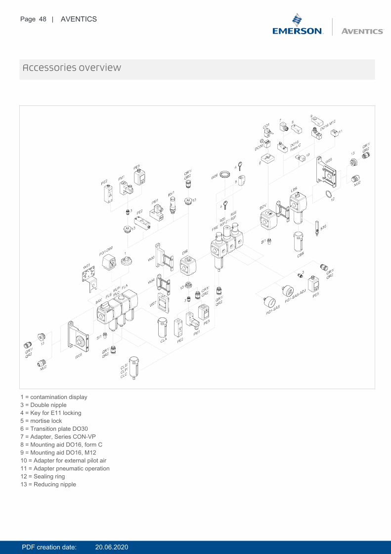
Accessories overview
1 = contamination display3 = Double nipple4 = Key for E11 locking5 = mortise lock6 = Transition plate DO307 = Adapter, Series CON-VP8 = Mounting aid DO16, form C9 = Mounting aid DO16, M1210 = Adapter for external pilot air11 = Adapter pneumatic operation12 = Sealing ring13 = Reducing nipple
PDF creation date: 20.06.2020
Page 7 | AVENTICS
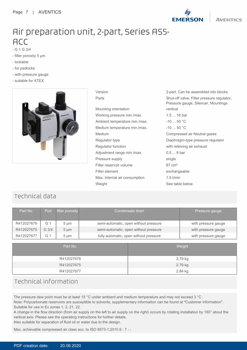
Air preparation unit, 2-part, Series AS5-ACC- G 1 G 3/4- filter porosity 5 µm- lockable- for padlocks- with pressure gauge- suitable for ATEX
Version 2-part, Can be assembled into blocksParts Shut-off valve, Filter pressure regulator,
Pressure gauge, Silencer, MountingsMounting orientation verticalWorking pressure min./max. 1.5 ... 16 barAmbient temperature min./max. -10 ... 50 °CMedium temperature min./max. -10 ... 50 °CMedium Compressed air Neutral gasesRegulator type Diaphragm-type pressure regulatorRegulator function with relieving air exhaustAdjustment range min./max. 0.5 ... 8 barPressure supply singleFilter reservoir volume 87 cm³Filter element exchangeableMax. Internal air consumption 1.5 l/minWeight See table below
Technical data
Part No. Port filter porosity Condensate drain Pressure gauge
R412027676 G 1 5 µm semi-automatic, open without pressure with pressure gaugeR412027675 G 3/4 5 µm semi-automatic, open without pressure with pressure gaugeR412027677 G 1 5 µm fully automatic, open without pressure with pressure gauge
Part No. Weight
R412027676 2.79 kgR412027675 2.79 kgR412027677 2.84 kg
The pressure dew point must be at least 15 °C under ambient and medium temperature and may not exceed 3 °C .Note: Polycarbonate reservoirs are susceptible to solvents, supplementary information can be found at "Customer information".Suitable for use in Ex zones 1, 2, 21, 22.A change in the flow direction (from air supply on the left to air supply on the right) occurs by rotating installation by 180° about thevertical axis. Please see the operating instructions for further details.Also suitable for separation of fluid oil or water due to the design.
Max. achievable compressed air class acc. to ISO 8573-1:2010 6 : 7 : -
Technical information
PDF creation date: 20.06.2020
Page 8 | AVENTICS
Technical information
Material
Housing Polyamide
Front plate Acrylonitrile butadiene styrene
Seals Acrylonitrile butadiene rubber
Threaded bushing Die cast zinc
Reservoir Polycarbonate
Protective guard Polyamide
Filter insert Polyethylene
Dimensions
Dimensions
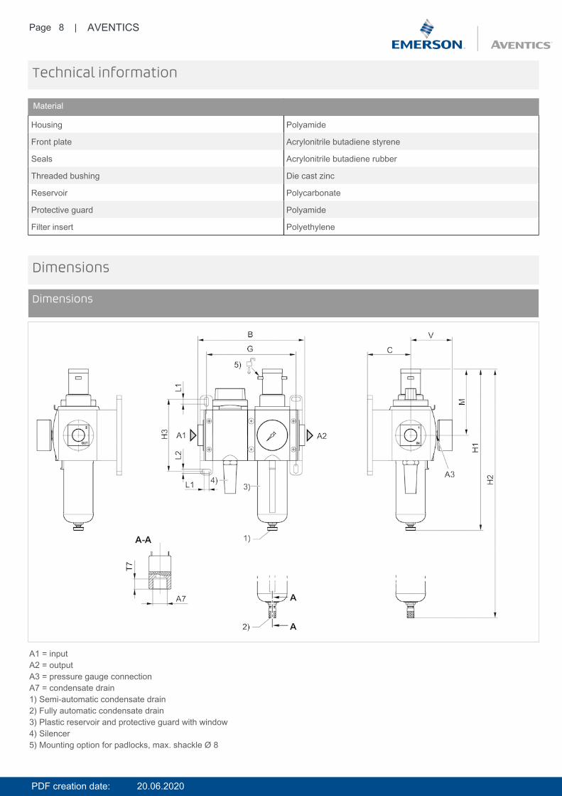
A1 = inputA2 = outputA3 = pressure gauge connectionA7 = condensate drain1) Semi-automatic condensate drain2) Fully automatic condensate drain3) Plastic reservoir and protective guard with window4) Silencer5) Mounting option for padlocks, max. shackle Ø 8
PDF creation date: 20.06.2020
Page 9 | AVENTICS
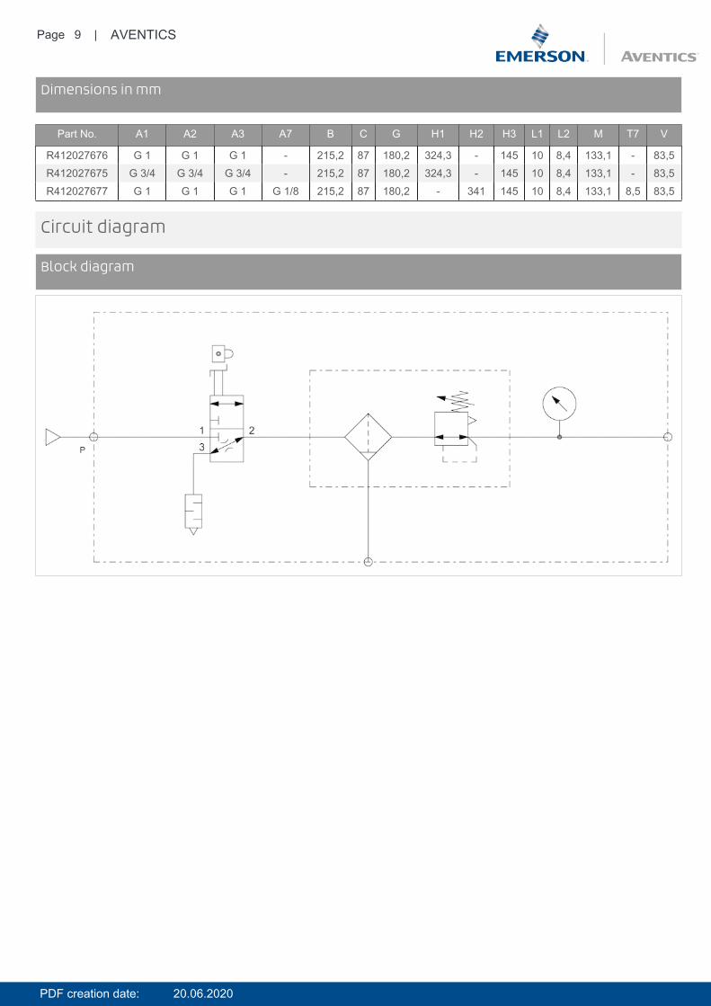
DimensionsDimensions in mm
Part No. A1 A2 A3 A7 B C G H1 H2 H3 L1 L2 M T7 V
R412027676 G 1 G 1 G 1 - 215,2 87 180,2 324,3 - 145 10 8,4 133,1 - 83,5R412027675 G 3/4 G 3/4 G 3/4 - 215,2 87 180,2 324,3 - 145 10 8,4 133,1 - 83,5R412027677 G 1 G 1 G 1 G 1/8 215,2 87 180,2 - 341 145 10 8,4 133,1 8,5 83,5
Circuit diagram
Block diagram
PDF creation date: 20.06.2020

Page 10 | AVENTICS
Accessories overview
1 = contamination display3 = Double nipple4 = Key for E11 locking5 = mortise lock6 = Transition plate DO307 = Adapter, Series CON-VP8 = Mounting aid DO16, form C9 = Mounting aid DO16, M1210 = Adapter for external pilot air11 = Adapter pneumatic operation12 = Sealing ring13 = Reducing nipple
PDF creation date: 20.06.2020
Page 11 | AVENTICS
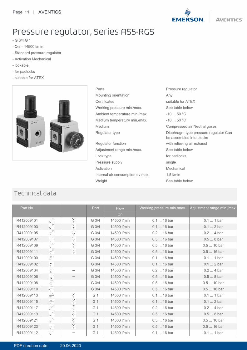
Pressure regulator, Series AS5-RGS- G 3/4 G 1- Qn = 14500 l/min- Standard pressure regulator- Activation Mechanical- lockable- for padlocks- suitable for ATEX
Parts Pressure regulatorMounting orientation AnyCertificates suitable for ATEXWorking pressure min./max. See table belowAmbient temperature min./max. -10 ... 50 °CMedium temperature min./max. -10 ... 50 °CMedium Compressed air Neutral gasesRegulator type Diaphragm-type pressure regulator Can
be assembled into blocksRegulator function with relieving air exhaustAdjustment range min./max. See table belowLock type for padlocksPressure supply singleActivation MechanicalInternal air consumption qv max. 1.5 l/minWeight See table below
Technical data
Part No. Port Flow Working pressure min./max. Adjustment range min./max.Qn
R412009101 G 3/4 14500 l/min 0.1 ... 16 bar 0.1 ... 1 barR412009103 G 3/4 14500 l/min 0.1 ... 16 bar 0.1 ... 2 barR412009105 G 3/4 14500 l/min 0.2 ... 16 bar 0.2 ... 4 barR412009107 G 3/4 14500 l/min 0.5 ... 16 bar 0.5 ... 8 barR412009109 G 3/4 14500 l/min 0.5 ... 16 bar 0.5 ... 10 barR412009111 G 3/4 14500 l/min 0.5 ... 16 bar 0.5 ... 16 barR412009100 G 3/4 14500 l/min 0.1 ... 16 bar 0.1 ... 1 barR412009102 G 3/4 14500 l/min 0.1 ... 16 bar 0.1 ... 2 barR412009104 G 3/4 14500 l/min 0.2 ... 16 bar 0.2 ... 4 barR412009106 G 3/4 14500 l/min 0.5 ... 16 bar 0.5 ... 8 barR412009108 G 3/4 14500 l/min 0.5 ... 16 bar 0.5 ... 10 barR412009110 G 3/4 14500 l/min 0.5 ... 16 bar 0.5 ... 16 barR412009113 G 1 14500 l/min 0.1 ... 16 bar 0.1 ... 1 barR412009115 G 1 14500 l/min 0.1 ... 16 bar 0.1 ... 2 barR412009117 G 1 14500 l/min 0.2 ... 16 bar 0.2 ... 4 barR412009119 G 1 14500 l/min 0.5 ... 16 bar 0.5 ... 8 barR412009121 G 1 14500 l/min 0.5 ... 16 bar 0.5 ... 10 barR412009123 G 1 14500 l/min 0.5 ... 16 bar 0.5 ... 16 barR412009112 G 1 14500 l/min 0.1 ... 16 bar 0.1 ... 1 bar
PDF creation date: 20.06.2020
Page 12 | AVENTICS
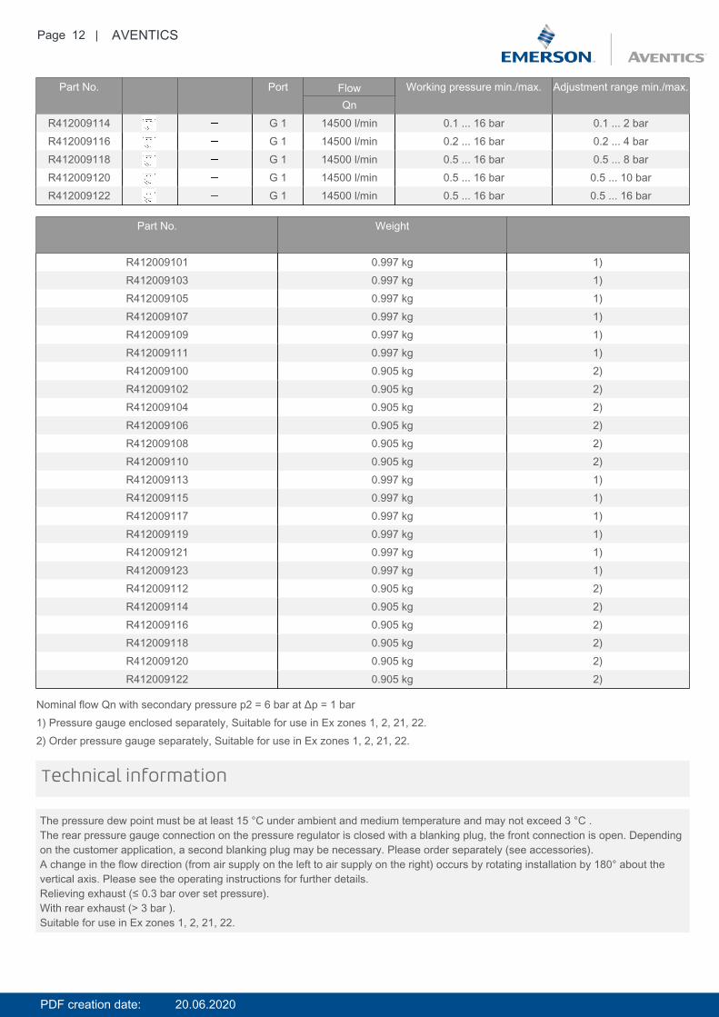
Part No. Port Flow Working pressure min./max. Adjustment range min./max.Qn
R412009114 G 1 14500 l/min 0.1 ... 16 bar 0.1 ... 2 barR412009116 G 1 14500 l/min 0.2 ... 16 bar 0.2 ... 4 barR412009118 G 1 14500 l/min 0.5 ... 16 bar 0.5 ... 8 barR412009120 G 1 14500 l/min 0.5 ... 16 bar 0.5 ... 10 barR412009122 G 1 14500 l/min 0.5 ... 16 bar 0.5 ... 16 bar
Part No. Weight
R412009101 0.997 kg 1)R412009103 0.997 kg 1)R412009105 0.997 kg 1)R412009107 0.997 kg 1)R412009109 0.997 kg 1)R412009111 0.997 kg 1)R412009100 0.905 kg 2)R412009102 0.905 kg 2)R412009104 0.905 kg 2)R412009106 0.905 kg 2)R412009108 0.905 kg 2)R412009110 0.905 kg 2)R412009113 0.997 kg 1)R412009115 0.997 kg 1)R412009117 0.997 kg 1)R412009119 0.997 kg 1)R412009121 0.997 kg 1)R412009123 0.997 kg 1)R412009112 0.905 kg 2)R412009114 0.905 kg 2)R412009116 0.905 kg 2)R412009118 0.905 kg 2)R412009120 0.905 kg 2)R412009122 0.905 kg 2)
Nominal flow Qn with secondary pressure p2 = 6 bar at Δp = 1 bar1) Pressure gauge enclosed separately, Suitable for use in Ex zones 1, 2, 21, 22.2) Order pressure gauge separately, Suitable for use in Ex zones 1, 2, 21, 22.
The pressure dew point must be at least 15 °C under ambient and medium temperature and may not exceed 3 °C .The rear pressure gauge connection on the pressure regulator is closed with a blanking plug, the front connection is open. Dependingon the customer application, a second blanking plug may be necessary. Please order separately (see accessories).A change in the flow direction (from air supply on the left to air supply on the right) occurs by rotating installation by 180° about thevertical axis. Please see the operating instructions for further details.Relieving exhaust (≤ 0.3 bar over set pressure).With rear exhaust (> 3 bar ).Suitable for use in Ex zones 1, 2, 21, 22.
Technical information
PDF creation date: 20.06.2020
Page 13 | AVENTICS
Technical information
Material
Housing Polyamide
Front plate Acrylonitrile butadiene styrene
Seals Acrylonitrile butadiene rubber
Threaded bushing Die cast zinc
Dimensions
Dimensions
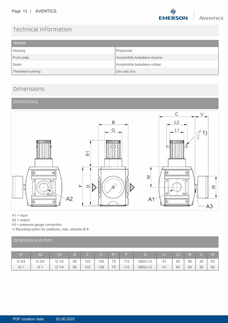
A1 = inputA2 = outputA3 = pressure gauge connection1) Mounting option for padlocks, max. shackle Ø 8
DimensionsDimensions in mm
A1 A2 A3 B C D E1 F G L1 L2 M V W
G 3/4 G 3/4 G 1/4 85 103 109 75 112 M50x1,5 41 60 58 38 63G 1 G 1 G 1/4 85 103 109 75 112 M50x1,5 41 60 58 38 63
PDF creation date: 20.06.2020

Page 14 | AVENTICS
Diagrams
Pressure characteristics curve
p1 = working pressurep2 = secondary pressureqn = nominal flow* starting point
DiagramsFlow rate characteristic (setting range p2: 0.5 - 8 bar)
p1 = working pressurep2 = secondary pressureqn = nominal flow
PDF creation date: 20.06.2020

Page 15 | AVENTICS
Accessories overview
1 = contamination display3 = Double nipple4 = Key for E11 locking5 = mortise lock6 = Transition plate DO307 = Adapter, Series CON-VP8 = Mounting aid DO16, form C9 = Mounting aid DO16, M1210 = Adapter for external pilot air11 = Adapter pneumatic operation12 = Sealing ring13 = Reducing nipple
PDF creation date: 20.06.2020
Page 16 | AVENTICS
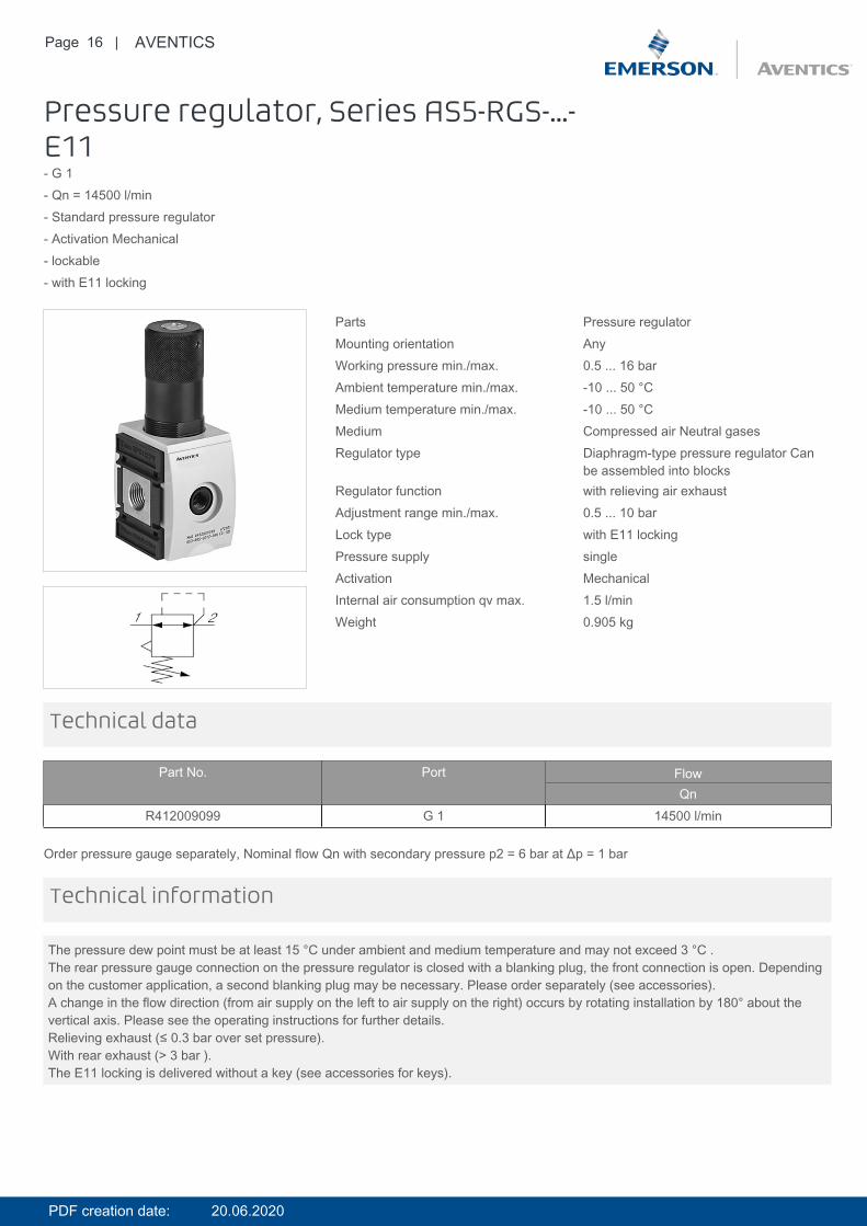
Pressure regulator, Series AS5-RGS-...-E11- G 1- Qn = 14500 l/min- Standard pressure regulator- Activation Mechanical- lockable- with E11 locking
Parts Pressure regulatorMounting orientation AnyWorking pressure min./max. 0.5 ... 16 barAmbient temperature min./max. -10 ... 50 °CMedium temperature min./max. -10 ... 50 °CMedium Compressed air Neutral gasesRegulator type Diaphragm-type pressure regulator Can
be assembled into blocksRegulator function with relieving air exhaustAdjustment range min./max. 0.5 ... 10 barLock type with E11 lockingPressure supply singleActivation MechanicalInternal air consumption qv max. 1.5 l/minWeight 0.905 kg
Technical data
Part No. Port FlowQn
R412009099 G 1 14500 l/min
Order pressure gauge separately, Nominal flow Qn with secondary pressure p2 = 6 bar at Δp = 1 bar
The pressure dew point must be at least 15 °C under ambient and medium temperature and may not exceed 3 °C .The rear pressure gauge connection on the pressure regulator is closed with a blanking plug, the front connection is open. Dependingon the customer application, a second blanking plug may be necessary. Please order separately (see accessories).A change in the flow direction (from air supply on the left to air supply on the right) occurs by rotating installation by 180° about thevertical axis. Please see the operating instructions for further details.Relieving exhaust (≤ 0.3 bar over set pressure).With rear exhaust (> 3 bar ).The E11 locking is delivered without a key (see accessories for keys).
Technical information
PDF creation date: 20.06.2020
Page 17 | AVENTICS
Technical information
Material
Housing Polyamide
Front plate Acrylonitrile butadiene styrene
Seals Acrylonitrile butadiene rubber
Threaded bushing Die cast zinc
Dimensions
Dimensions
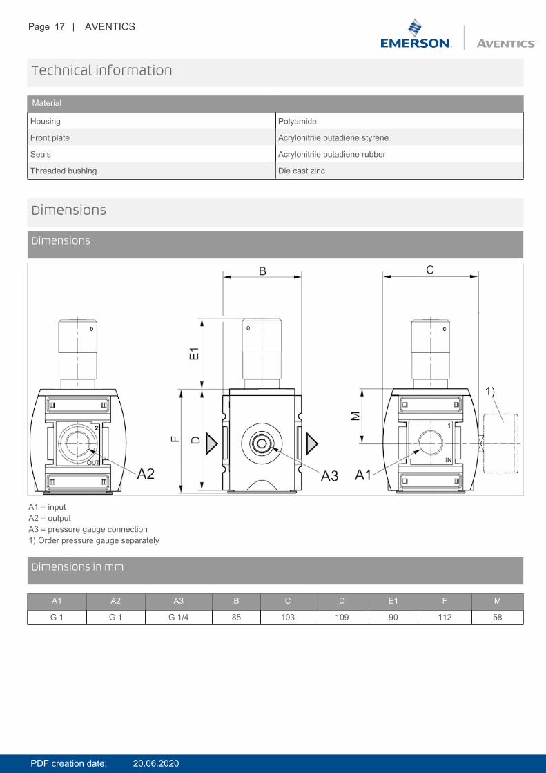
A1 = inputA2 = outputA3 = pressure gauge connection1) Order pressure gauge separately
DimensionsDimensions in mm
A1 A2 A3 B C D E1 F M
G 1 G 1 G 1/4 85 103 109 90 112 58
PDF creation date: 20.06.2020
Page 18 | AVENTICS
Diagrams
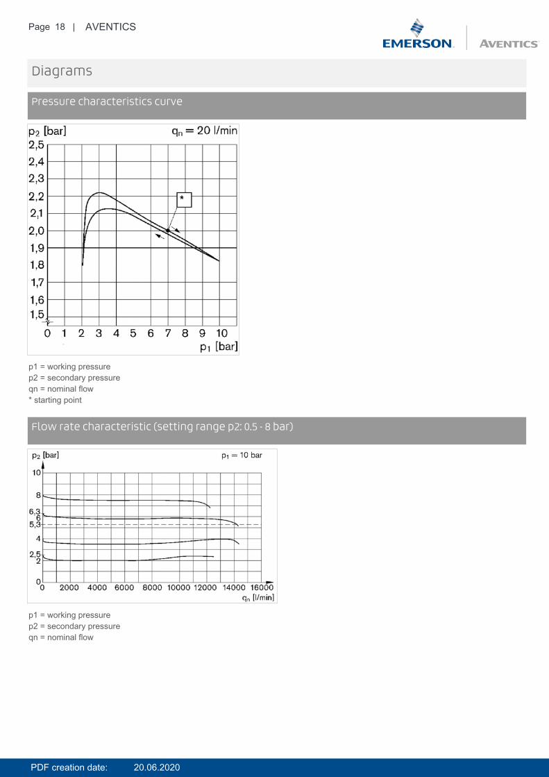
Pressure characteristics curve
p1 = working pressurep2 = secondary pressureqn = nominal flow* starting point
DiagramsFlow rate characteristic (setting range p2: 0.5 - 8 bar)
p1 = working pressurep2 = secondary pressureqn = nominal flow
PDF creation date: 20.06.2020

Page 19 | AVENTICS
Accessories overview
1 = contamination display3 = Double nipple4 = Key for E11 locking5 = mortise lock6 = Transition plate DO307 = Adapter, Series CON-VP8 = Mounting aid DO16, form C9 = Mounting aid DO16, M1210 = Adapter for external pilot air11 = Adapter pneumatic operation12 = Sealing ring13 = Reducing nipple
PDF creation date: 20.06.2020
Page 20 | AVENTICS
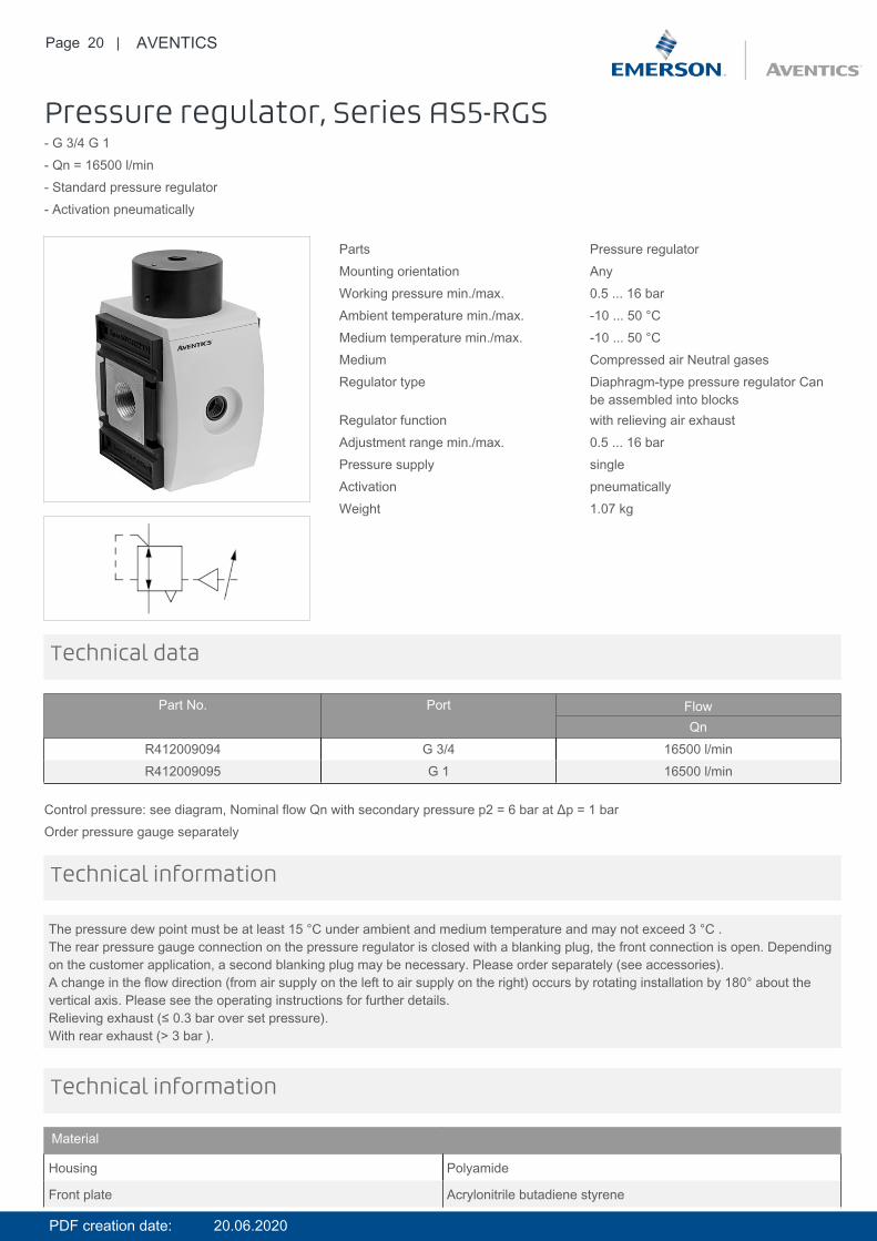
Pressure regulator, Series AS5-RGS- G 3/4 G 1- Qn = 16500 l/min- Standard pressure regulator- Activation pneumatically
Parts Pressure regulatorMounting orientation AnyWorking pressure min./max. 0.5 ... 16 barAmbient temperature min./max. -10 ... 50 °CMedium temperature min./max. -10 ... 50 °CMedium Compressed air Neutral gasesRegulator type Diaphragm-type pressure regulator Can
be assembled into blocksRegulator function with relieving air exhaustAdjustment range min./max. 0.5 ... 16 barPressure supply singleActivation pneumaticallyWeight 1.07 kg
Technical data
Part No. Port FlowQn
R412009094 G 3/4 16500 l/minR412009095 G 1 16500 l/min
Control pressure: see diagram, Nominal flow Qn with secondary pressure p2 = 6 bar at Δp = 1 barOrder pressure gauge separately
The pressure dew point must be at least 15 °C under ambient and medium temperature and may not exceed 3 °C .The rear pressure gauge connection on the pressure regulator is closed with a blanking plug, the front connection is open. Dependingon the customer application, a second blanking plug may be necessary. Please order separately (see accessories).A change in the flow direction (from air supply on the left to air supply on the right) occurs by rotating installation by 180° about thevertical axis. Please see the operating instructions for further details.Relieving exhaust (≤ 0.3 bar over set pressure).With rear exhaust (> 3 bar ).
Technical information
Technical information
Material
Housing Polyamide
Front plate Acrylonitrile butadiene styrene
PDF creation date: 20.06.2020
Page 21 | AVENTICS
Material
Seals Acrylonitrile butadiene rubber
Threaded bushing Die cast zinc
Dimensions
Dimensions
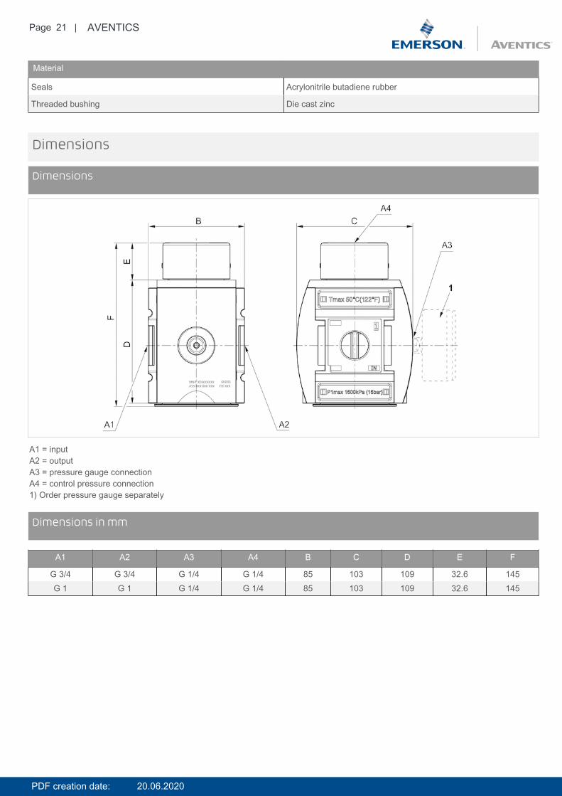
A1 = inputA2 = outputA3 = pressure gauge connectionA4 = control pressure connection1) Order pressure gauge separately
DimensionsDimensions in mm
A1 A2 A3 A4 B C D E F
G 3/4 G 3/4 G 1/4 G 1/4 85 103 109 32.6 145G 1 G 1 G 1/4 G 1/4 85 103 109 32.6 145
PDF creation date: 20.06.2020
Page 22 | AVENTICS
Diagrams
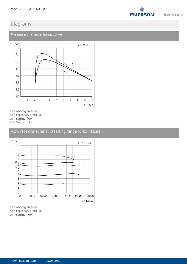
Pressure characteristics curve
p1 = working pressurep2 = secondary pressureqn = nominal flow1) = Starting point
DiagramsFlow rate characteristic (setting range p2: 0.5 - 8 bar)
p1 = working pressurep2 = secondary pressureqn = nominal flow
PDF creation date: 20.06.2020
Page 23 | AVENTICS
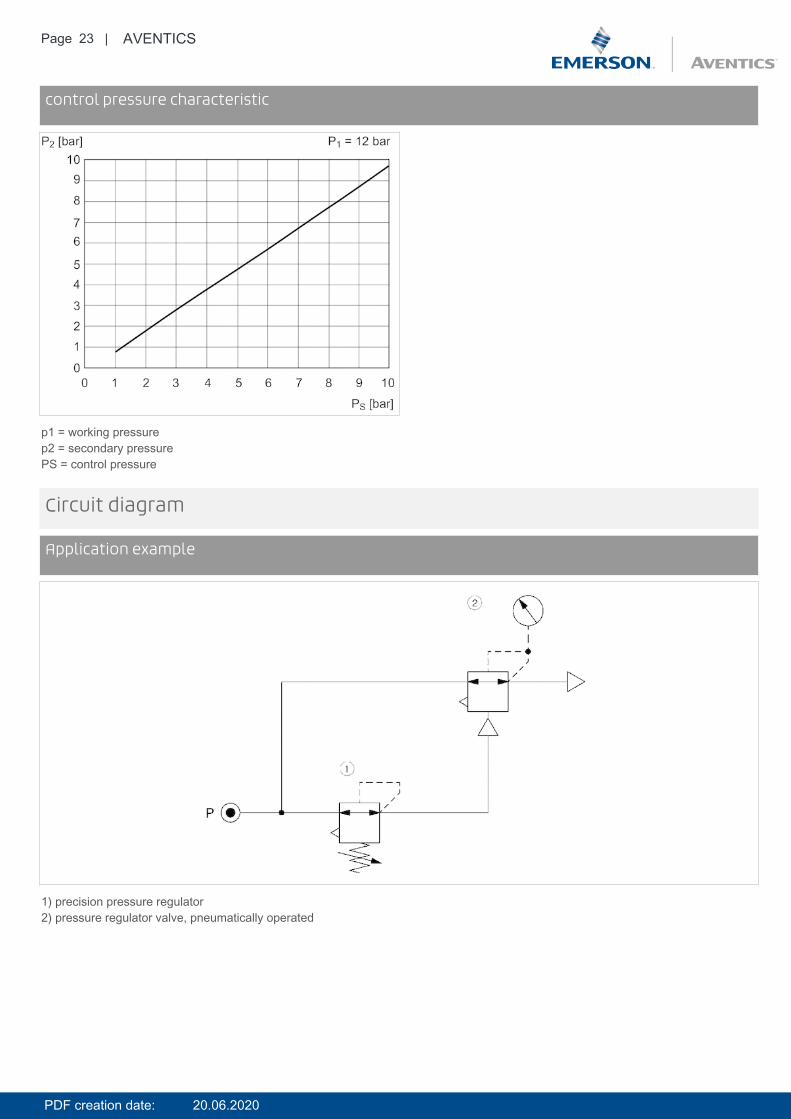
Diagramscontrol pressure characteristic
p1 = working pressurep2 = secondary pressurePS = control pressure
Circuit diagram
Application example
1) precision pressure regulator2) pressure regulator valve, pneumatically operated
PDF creation date: 20.06.2020

Page 24 | AVENTICS
Accessories overview
1 = contamination display3 = Double nipple4 = Key for E11 locking5 = mortise lock6 = Transition plate DO307 = Adapter, Series CON-VP8 = Mounting aid DO16, form C9 = Mounting aid DO16, M1210 = Adapter for external pilot air11 = Adapter pneumatic operation12 = Sealing ring13 = Reducing nipple
PDF creation date: 20.06.2020

Page 25 | AVENTICS
E/P pressure regulator, Series EV18- Pressure supply, right, Display: display- Qn = 16500 l/min- Compressed air connection output G 1 G 3/4- Electr. connection M12, 5-pin, A-coded- serial control IO-Link- Pilot valves
Version Poppet valveWorking pressure max 11 barAmbient temperature min./max. 0 ... 50 °CMedium temperature min./max. 0 ... 50 °CMax. particle size 50 µmOil content of compressed air 0 ... 5 mg/m³Nominal flow Qn 16500 l/minDC operating voltage 24 VVoltage tolerance DC -20% / +30%Hysteresis 0.12 barPermissible ripple 5%Max. power consumption 220 mAWeight 2.15 kg
Technical data
Part No. Pressure setting rangemin./max.
Compressed air connectionInput
R414011411 0 ... 10 bar G 1R414011412 0 ... 10 bar G 1R414011414 0 ... 10 bar G 1R414011417 0 ... 10 bar G 3/4R414011418 0 ... 10 bar G 3/4R414011420 0 ... 10 bar G 3/4
Part No. Compressed air connection Nominal input value Actual output value serial controlOutput Min./max. Min./max.
R414011411 G 1 0 ... 10 V 0 ... 10 V -R414011412 G 1 4 ... 20 mA 4 ... 20 mA -R414011414 G 1 - - IO-LinkR414011417 G 3/4 0 ... 10 V 0 ... 10 V -R414011418 G 3/4 4 ... 20 mA 4 ... 20 mA -R414011420 G 3/4 - - IO-Link
Technical information
PDF creation date: 20.06.2020
Page 26 | AVENTICS
The min. control pressure must be adhered to, since otherwise faulty switching and valve failure may result!The pressure dew point must be at least 15 °C under ambient and medium temperature and may not exceed 3 °C .The oil content of compressed air must remain constant during the life cycle.Use only the approved oils from AVENTICS. Further information can be found in the “Technical information” document (available inthe MediaCentre).
Power outage: maintain pressure
Technical information
Material
Housing Polyamide
Base plate Aluminum
Seals Nitrile butadiene rubber
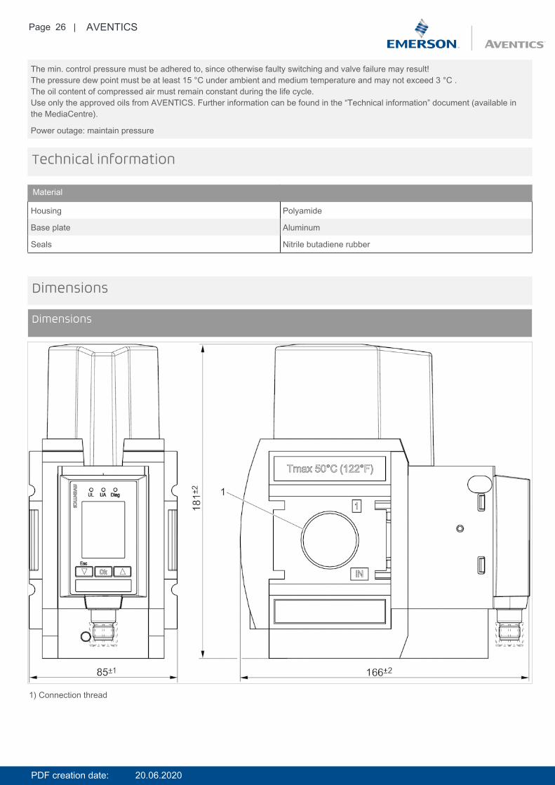
Dimensions
Dimensions
1) Connection thread
PDF creation date: 20.06.2020

Page 27 | AVENTICS
DimensionsPressure supply, right
PDF creation date: 20.06.2020
Page 28 | AVENTICS
Diagrams
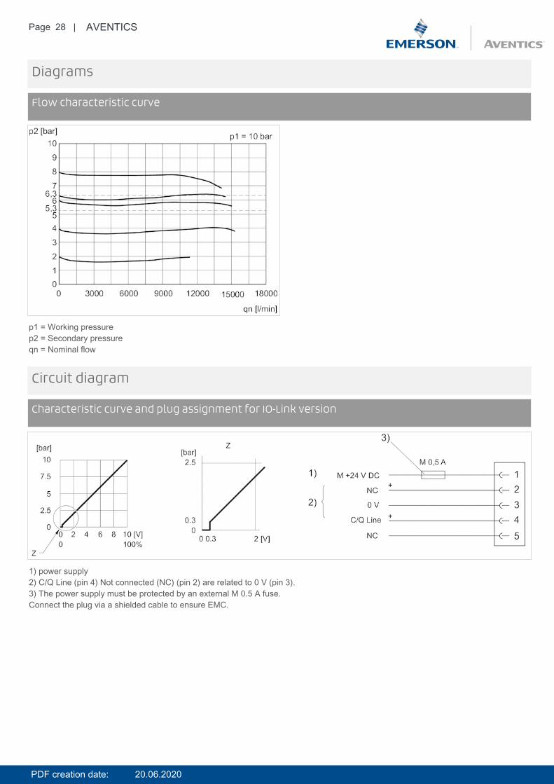
Flow characteristic curve
p1 = Working pressurep2 = Secondary pressureqn = Nominal flow
Circuit diagram
Characteristic curve and plug assignment for IO-Link version
1) power supply2) C/Q Line (pin 4) Not connected (NC) (pin 2) are related to 0 V (pin 3).3) The power supply must be protected by an external M 0.5 A fuse.Connect the plug via a shielded cable to ensure EMC.
PDF creation date: 20.06.2020
Page 29 | AVENTICS
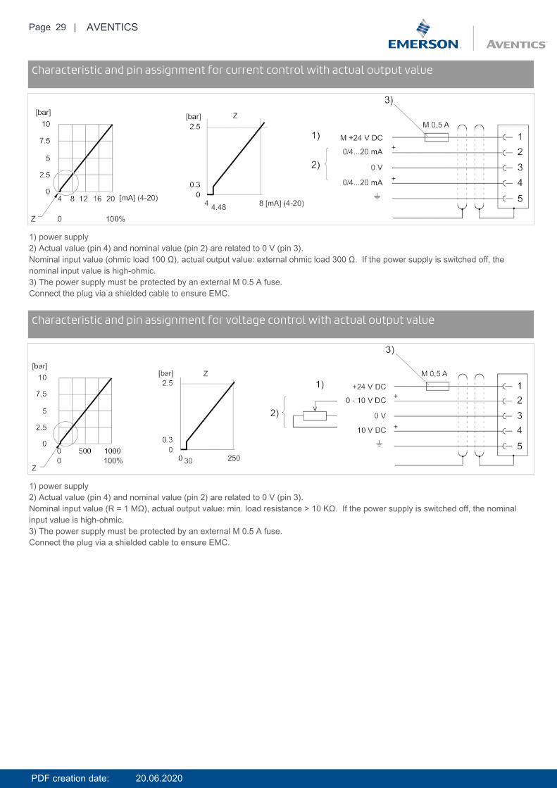
Circuit diagramCharacteristic and pin assignment for current control with actual output value
1) power supply2) Actual value (pin 4) and nominal value (pin 2) are related to 0 V (pin 3).Nominal input value (ohmic load 100 Ω), actual output value: external ohmic load 300 Ω. If the power supply is switched off, thenominal input value is high-ohmic.3) The power supply must be protected by an external M 0.5 A fuse.Connect the plug via a shielded cable to ensure EMC.
Circuit diagramCharacteristic and pin assignment for voltage control with actual output value
1) power supply2) Actual value (pin 4) and nominal value (pin 2) are related to 0 V (pin 3).Nominal input value (R = 1 MΩ), actual output value: min. load resistance > 10 KΩ. If the power supply is switched off, the nominalinput value is high-ohmic.3) The power supply must be protected by an external M 0.5 A fuse.Connect the plug via a shielded cable to ensure EMC.
PDF creation date: 20.06.2020
Page 30 | AVENTICS
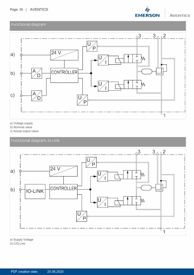
Circuit diagramFunctional diagram
a) Voltage supplyb) Nominal valuec) Actual output value
Circuit diagramFunctional diagram, IO-Link
a) Supply Voltageb) C/Q Line
PDF creation date: 20.06.2020

Page 31 | AVENTICS
Pin assignments
Plug assignment
1) 24 V DC2) Nominal input value3) GND4) Actual output value5) Ground
PDF creation date: 20.06.2020
Page 32 | AVENTICS
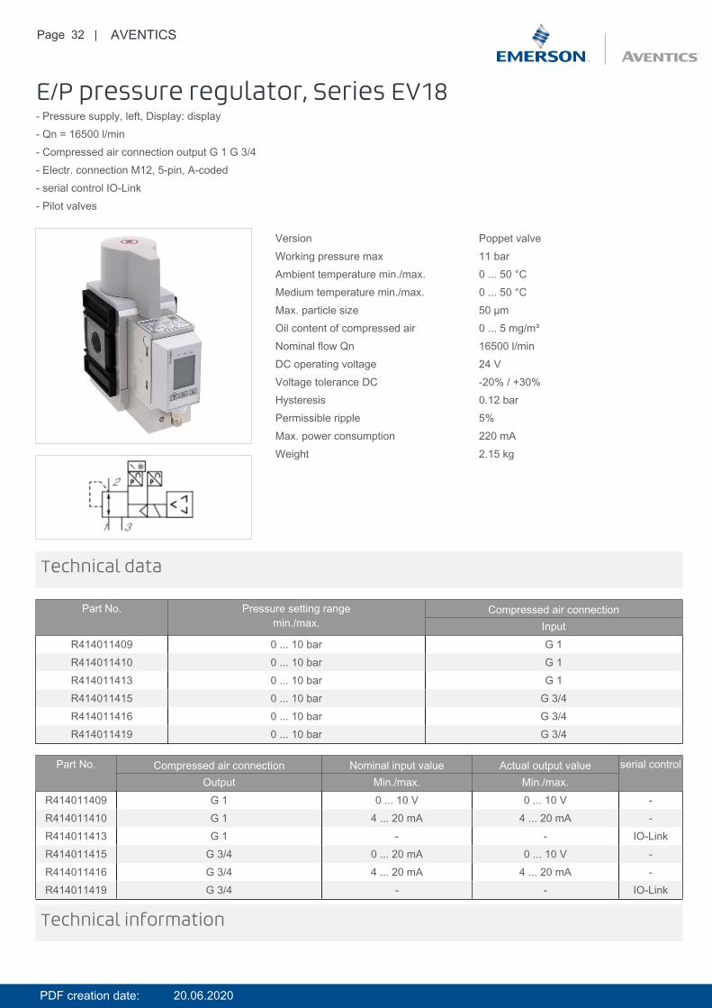
E/P pressure regulator, Series EV18- Pressure supply, left, Display: display- Qn = 16500 l/min- Compressed air connection output G 1 G 3/4- Electr. connection M12, 5-pin, A-coded- serial control IO-Link- Pilot valves
Version Poppet valveWorking pressure max 11 barAmbient temperature min./max. 0 ... 50 °CMedium temperature min./max. 0 ... 50 °CMax. particle size 50 µmOil content of compressed air 0 ... 5 mg/m³Nominal flow Qn 16500 l/minDC operating voltage 24 VVoltage tolerance DC -20% / +30%Hysteresis 0.12 barPermissible ripple 5%Max. power consumption 220 mAWeight 2.15 kg
Technical data
Part No. Pressure setting rangemin./max.
Compressed air connectionInput
R414011409 0 ... 10 bar G 1R414011410 0 ... 10 bar G 1R414011413 0 ... 10 bar G 1R414011415 0 ... 10 bar G 3/4R414011416 0 ... 10 bar G 3/4R414011419 0 ... 10 bar G 3/4
Part No. Compressed air connection Nominal input value Actual output value serial controlOutput Min./max. Min./max.
R414011409 G 1 0 ... 10 V 0 ... 10 V -R414011410 G 1 4 ... 20 mA 4 ... 20 mA -R414011413 G 1 - - IO-LinkR414011415 G 3/4 0 ... 20 mA 0 ... 10 V -R414011416 G 3/4 4 ... 20 mA 4 ... 20 mA -R414011419 G 3/4 - - IO-Link
Technical information
PDF creation date: 20.06.2020

Page 33 | AVENTICS
The min. control pressure must be adhered to, since otherwise faulty switching and valve failure may result!The pressure dew point must be at least 15 °C under ambient and medium temperature and may not exceed 3 °C .The oil content of compressed air must remain constant during the life cycle.Use only the approved oils from AVENTICS. Further information can be found in the “Technical information” document (available inthe MediaCentre).
Power outage: maintain pressure
Technical information
Material
Housing Polyamide
Base plate Aluminum
Seals Nitrile butadiene rubber
Dimensions
Dimensions
1) Connection thread
PDF creation date: 20.06.2020
Page 34 | AVENTICS
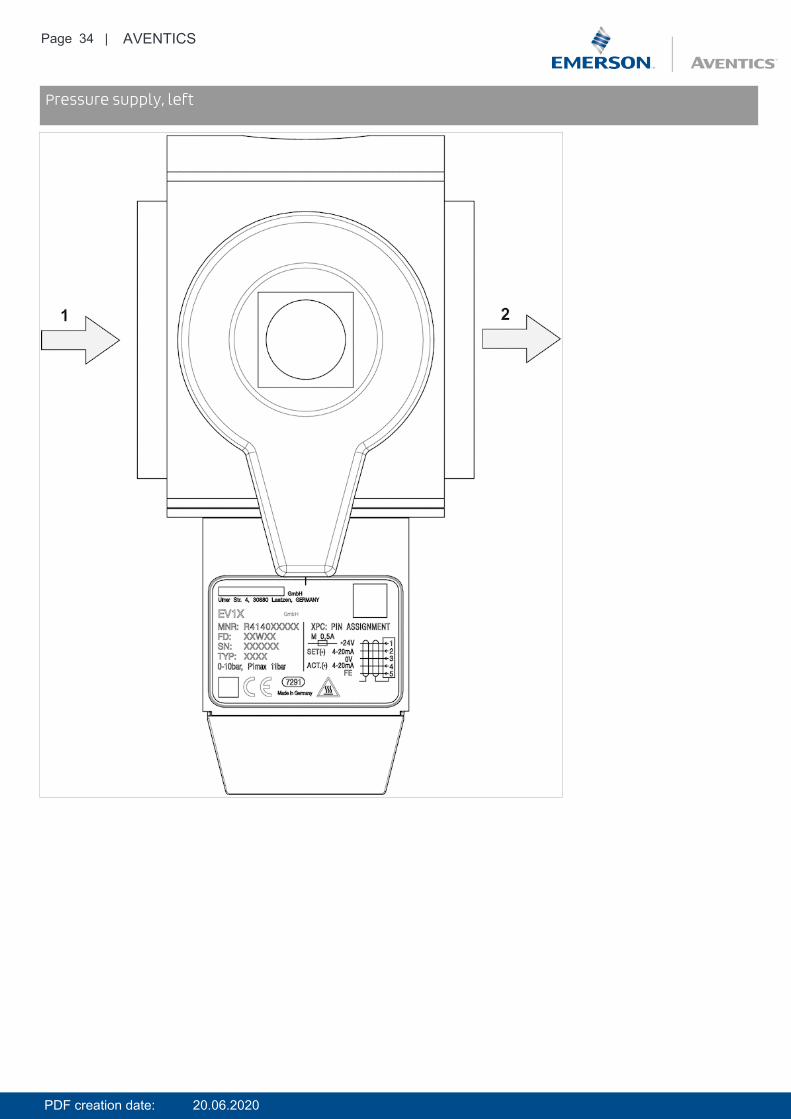
DimensionsPressure supply, left
PDF creation date: 20.06.2020

Page 35 | AVENTICS
Diagrams
Flow characteristic curve
p1 = Working pressurep2 = Secondary pressureqn = Nominal flow
Circuit diagram
Characteristic curve and plug assignment for IO-Link version
1) power supply2) C/Q Line (pin 4) Not connected (NC) (pin 2) are related to 0 V (pin 3).3) The power supply must be protected by an external M 0.5 A fuse.Connect the plug via a shielded cable to ensure EMC.
PDF creation date: 20.06.2020

Page 36 | AVENTICS
Circuit diagramCharacteristic and pin assignment for current control with actual output value
1) power supply2) Actual value (pin 4) and nominal value (pin 2) are related to 0 V (pin 3).Nominal input value (ohmic load 100 Ω), actual output value: external ohmic load 300 Ω. If the power supply is switched off, thenominal input value is high-ohmic.3) The power supply must be protected by an external M 0.5 A fuse.Connect the plug via a shielded cable to ensure EMC.
Circuit diagramCharacteristic and pin assignment for voltage control with actual output value
1) power supply2) Actual value (pin 4) and nominal value (pin 2) are related to 0 V (pin 3).Nominal input value (R = 1 MΩ), actual output value: min. load resistance > 10 KΩ. If the power supply is switched off, the nominalinput value is high-ohmic.3) The power supply must be protected by an external M 0.5 A fuse.Connect the plug via a shielded cable to ensure EMC.
PDF creation date: 20.06.2020

Page 37 | AVENTICS
Circuit diagramFunctional diagram
a) Voltage supplyb) Nominal valuec) Actual output value
Circuit diagramFunctional diagram, IO-Link
a) Supply Voltageb) C/Q Line
PDF creation date: 20.06.2020
Page 38 | AVENTICS
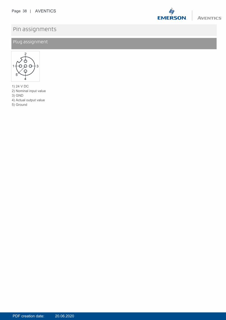
Pin assignments
Plug assignment
1) 24 V DC2) Nominal input value3) GND4) Actual output value5) Ground
PDF creation date: 20.06.2020
Page 39 | AVENTICS
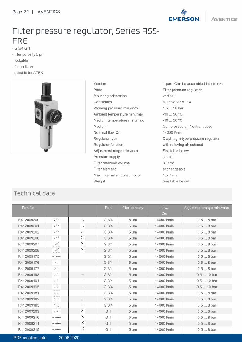
Filter pressure regulator, Series AS5-FRE- G 3/4 G 1- filter porosity 5 µm- lockable- for padlocks- suitable for ATEX
Version 1-part, Can be assembled into blocksParts Filter pressure regulatorMounting orientation verticalCertificates suitable for ATEXWorking pressure min./max. 1.5 ... 16 barAmbient temperature min./max. -10 ... 50 °CMedium temperature min./max. -10 ... 50 °CMedium Compressed air Neutral gasesNominal flow Qn 14000 l/minRegulator type Diaphragm-type pressure regulatorRegulator function with relieving air exhaustAdjustment range min./max. See table belowPressure supply singleFilter reservoir volume 87 cm³Filter element exchangeableMax. Internal air consumption 1.5 l/minWeight See table below
Technical data
Part No. Port filter porosity Flow Adjustment range min./max.Qn
R412009200 G 3/4 5 µm 14000 l/min 0.5 ... 8 barR412009201 G 3/4 5 µm 14000 l/min 0.5 ... 8 barR412009202 G 3/4 5 µm 14000 l/min 0.5 ... 8 barR412009206 G 3/4 5 µm 14000 l/min 0.5 ... 8 barR412009207 G 3/4 5 µm 14000 l/min 0.5 ... 8 barR412009208 G 3/4 5 µm 14000 l/min 0.5 ... 8 barR412009175 G 3/4 5 µm 14000 l/min 0.5 ... 8 barR412009176 G 3/4 5 µm 14000 l/min 0.5 ... 8 barR412009177 G 3/4 5 µm 14000 l/min 0.5 ... 8 barR412009193 G 3/4 5 µm 14000 l/min 0.5 ... 10 barR412009194 G 3/4 5 µm 14000 l/min 0.5 ... 10 barR412009195 G 3/4 5 µm 14000 l/min 0.5 ... 10 barR412009181 G 3/4 5 µm 14000 l/min 0.5 ... 8 barR412009182 G 3/4 5 µm 14000 l/min 0.5 ... 8 barR412009183 G 3/4 5 µm 14000 l/min 0.5 ... 8 barR412009209 G 1 5 µm 14000 l/min 0.5 ... 8 barR412009210 G 1 5 µm 14000 l/min 0.5 ... 8 barR412009211 G 1 5 µm 14000 l/min 0.5 ... 8 barR412009215 G 1 5 µm 14000 l/min 0.5 ... 8 bar
PDF creation date: 20.06.2020
Page 40 | AVENTICS
Part No. Port filter porosity Flow Adjustment range min./max.Qn
R412009216 G 1 5 µm 14000 l/min 0.5 ... 8 barR412009217 G 1 5 µm 14000 l/min 0.5 ... 8 barR412009184 G 1 5 µm 14000 l/min 0.5 ... 8 barR412009185 G 1 5 µm 14000 l/min 0.5 ... 8 barR412009186 G 1 5 µm 14000 l/min 0.5 ... 8 barR412009190 G 1 5 µm 14000 l/min 0.5 ... 8 barR412009191 G 1 5 µm 14000 l/min 0.5 ... 8 barR412009192 G 1 5 µm 14000 l/min 0.5 ... 8 barR412009196 G 1 5 µm 14000 l/min 0.5 ... 10 barR412009197 G 1 5 µm 14000 l/min 0.5 ... 10 barR412009198 G 1 5 µm 14000 l/min 0.5 ... 10 bar
Part No. Condensate drain Pressure gauge Reservoir
R412009200 semi-automatic, open without pressure with pressure gauge PolycarbonateR412009201 fully automatic, open without pressure with pressure gauge PolycarbonateR412009202 fully automatic, closed without pressure with pressure gauge PolycarbonateR412009206 semi-automatic, open without pressure with pressure gauge Die cast zincR412009207 fully automatic, open without pressure with pressure gauge Die cast zincR412009208 fully automatic, closed without pressure with pressure gauge Die cast zincR412009175 semi-automatic, open without pressure - PolycarbonateR412009176 fully automatic, open without pressure - PolycarbonateR412009177 fully automatic, closed without pressure - PolycarbonateR412009193 semi-automatic, open without pressure - PolycarbonateR412009194 fully automatic, open without pressure - PolycarbonateR412009195 fully automatic, closed without pressure - PolycarbonateR412009181 semi-automatic, open without pressure - Die cast zincR412009182 fully automatic, open without pressure - Die cast zincR412009183 fully automatic, closed without pressure - Die cast zincR412009209 semi-automatic, open without pressure with pressure gauge PolycarbonateR412009210 fully automatic, open without pressure with pressure gauge PolycarbonateR412009211 fully automatic, closed without pressure with pressure gauge PolycarbonateR412009215 semi-automatic, open without pressure with pressure gauge Die cast zincR412009216 fully automatic, open without pressure with pressure gauge Die cast zincR412009217 fully automatic, closed without pressure with pressure gauge Die cast zincR412009184 semi-automatic, open without pressure - PolycarbonateR412009185 fully automatic, open without pressure - PolycarbonateR412009186 fully automatic, closed without pressure - PolycarbonateR412009190 semi-automatic, open without pressure - Die cast zincR412009191 fully automatic, open without pressure - Die cast zincR412009192 fully automatic, closed without pressure - Die cast zincR412009196 semi-automatic, open without pressure - PolycarbonateR412009197 fully automatic, open without pressure - PolycarbonateR412009198 fully automatic, closed without pressure - Polycarbonate
Part No. Protective guard Weight
R412009200 Polyamide 1.08 kg 1)R412009201 Polyamide 1.13 kg 1)
PDF creation date: 20.06.2020
Page 41 | AVENTICS
Part No. Protective guard Weight
R412009202 Polyamide 1.13 kg 1)R412009206 - 1.57 kg 1)R412009207 - 1.62 kg 1)R412009208 - 1.62 kg 1)R412009175 Polyamide 0.99 kg 2)R412009176 Polyamide 1.04 kg 2)R412009177 Polyamide 1.04 kg 2)R412009193 Polyamide 0.99 kg 2)R412009194 Polyamide 1.04 kg 2)R412009195 Polyamide 1.04 kg 2)R412009181 - 1.48 kg 2)R412009182 - 1.53 kg 2)R412009183 - 1.53 kg 2)R412009209 Polyamide 1.08 kg 1)R412009210 Polyamide 1.13 kg 1)R412009211 Polyamide 1.13 kg 1)R412009215 - 1.57 kg 1)R412009216 - 1.62 kg 1)R412009217 - 1.62 kg 1)R412009184 Polyamide 0.99 kg 2)R412009185 Polyamide 1.04 kg 2)R412009186 Polyamide 1.04 kg 2)R412009190 - 1.48 kg 2)R412009191 - 1.53 kg 2)R412009192 - 1.53 kg 2)R412009196 Polyamide 0.99 kg 2)R412009197 Polyamide 1.04 kg 2)R412009198 Polyamide 1.04 kg 2)
Nominal flow Qn with secondary pressure p2 = 6 bar at Δp = 1 bar1) Pressure gauge enclosed separately, Suitable for use in Ex zones 1, 2, 21, 22.2) Order pressure gauge separately, Suitable for use in Ex zones 1, 2, 21, 22.
The pressure dew point must be at least 15 °C under ambient and medium temperature and may not exceed 3 °C .Note: Polycarbonate reservoirs are susceptible to solvents, supplementary information can be found at "Customer information".Suitable for use in Ex zones 1, 2, 21, 22.A change in the flow direction (from air supply on the left to air supply on the right) occurs by rotating installation by 180° about thevertical axis. Please see the operating instructions for further details.Also suitable for separation of fluid oil or water due to the design.
Max. achievable compressed air class acc. to ISO 8573-1:2010 6 : 7 : -
Technical information
Technical information
Material
Housing Polyamide
Front plate Acrylonitrile butadiene styrene
PDF creation date: 20.06.2020
Page 42 | AVENTICS
Material
Seals Acrylonitrile butadiene rubber
Threaded bushing Die cast zinc
Reservoir Polycarbonate Die cast zinc
Protective guard Polyamide
Filter insert Polyethylene
Dimensions
Dimensions
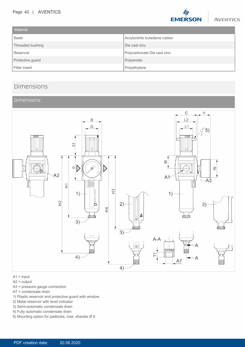
A1 = inputA2 = outputA3 = pressure gauge connectionA7 = condensate drain1) Plastic reservoir and protective guard with window2) Metal reservoir with level indicator3) Semi-automatic condensate drain4) Fully automatic condensate drain5) Mounting option for padlocks, max. shackle Ø 8
PDF creation date: 20.06.2020
Page 43 | AVENTICS
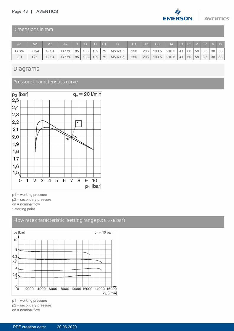
DimensionsDimensions in mm
A1 A2 A3 A7 B C D E1 G H1 H2 H3 H4 L1 L2 M T7 V W
G 3/4 G 3/4 G 1/4 G 1/8 85 103 109 75 M50x1,5 250 206 193.5 210.5 41 60 58 8.5 38 63G 1 G 1 G 1/4 G 1/8 85 103 109 75 M50x1,5 250 206 193.5 210.5 41 60 58 8.5 38 63
Diagrams
Pressure characteristics curve
p1 = working pressurep2 = secondary pressureqn = nominal flow* starting point
DiagramsFlow rate characteristic (setting range p2: 0.5 - 8 bar)
p1 = working pressurep2 = secondary pressureqn = nominal flow
PDF creation date: 20.06.2020

Page 44 | AVENTICS
Accessories overview
1 = contamination display3 = Double nipple4 = Key for E11 locking5 = mortise lock6 = Transition plate DO307 = Adapter, Series CON-VP8 = Mounting aid DO16, form C9 = Mounting aid DO16, M1210 = Adapter for external pilot air11 = Adapter pneumatic operation12 = Sealing ring13 = Reducing nipple
PDF creation date: 20.06.2020
Page 45 | AVENTICS
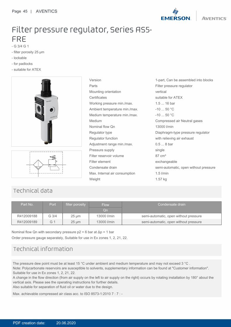
Filter pressure regulator, Series AS5-FRE- G 3/4 G 1- filter porosity 25 µm- lockable- for padlocks- suitable for ATEX
Version 1-part, Can be assembled into blocksParts Filter pressure regulatorMounting orientation verticalCertificates suitable for ATEXWorking pressure min./max. 1.5 ... 16 barAmbient temperature min./max. -10 ... 50 °CMedium temperature min./max. -10 ... 50 °CMedium Compressed air Neutral gasesNominal flow Qn 13000 l/minRegulator type Diaphragm-type pressure regulatorRegulator function with relieving air exhaustAdjustment range min./max. 0.5 ... 8 barPressure supply singleFilter reservoir volume 87 cm³Filter element exchangeableCondensate drain semi-automatic, open without pressureMax. Internal air consumption 1.5 l/minWeight 1.57 kg
Technical data
Part No. Port filter porosity Flow Condensate drainQn
R412009188 G 3/4 25 µm 13000 l/min semi-automatic, open without pressureR412009189 G 1 25 µm 13000 l/min semi-automatic, open without pressure
Nominal flow Qn with secondary pressure p2 = 6 bar at Δp = 1 barOrder pressure gauge separately, Suitable for use in Ex zones 1, 2, 21, 22.
The pressure dew point must be at least 15 °C under ambient and medium temperature and may not exceed 3 °C .Note: Polycarbonate reservoirs are susceptible to solvents, supplementary information can be found at "Customer information".Suitable for use in Ex zones 1, 2, 21, 22.A change in the flow direction (from air supply on the left to air supply on the right) occurs by rotating installation by 180° about thevertical axis. Please see the operating instructions for further details.Also suitable for separation of fluid oil or water due to the design.
Max. achievable compressed air class acc. to ISO 8573-1:2010 7 : 7 : -
Technical information
PDF creation date: 20.06.2020
Page 46 | AVENTICS
Technical information
Material
Housing Polyamide
Front plate Acrylonitrile butadiene styrene
Seals Acrylonitrile butadiene rubber
Threaded bushing Die cast zinc
Reservoir Die cast zinc
Protective guard Polyamide
Filter insert Polyethylene
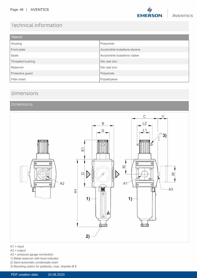
Dimensions
Dimensions
A1 = inputA2 = outputA3 = pressure gauge connection1) Metal reservoir with level indicator2) Semi-automatic condensate drain3) Mounting option for padlocks, max. shackle Ø 8
PDF creation date: 20.06.2020
Page 47 | AVENTICS
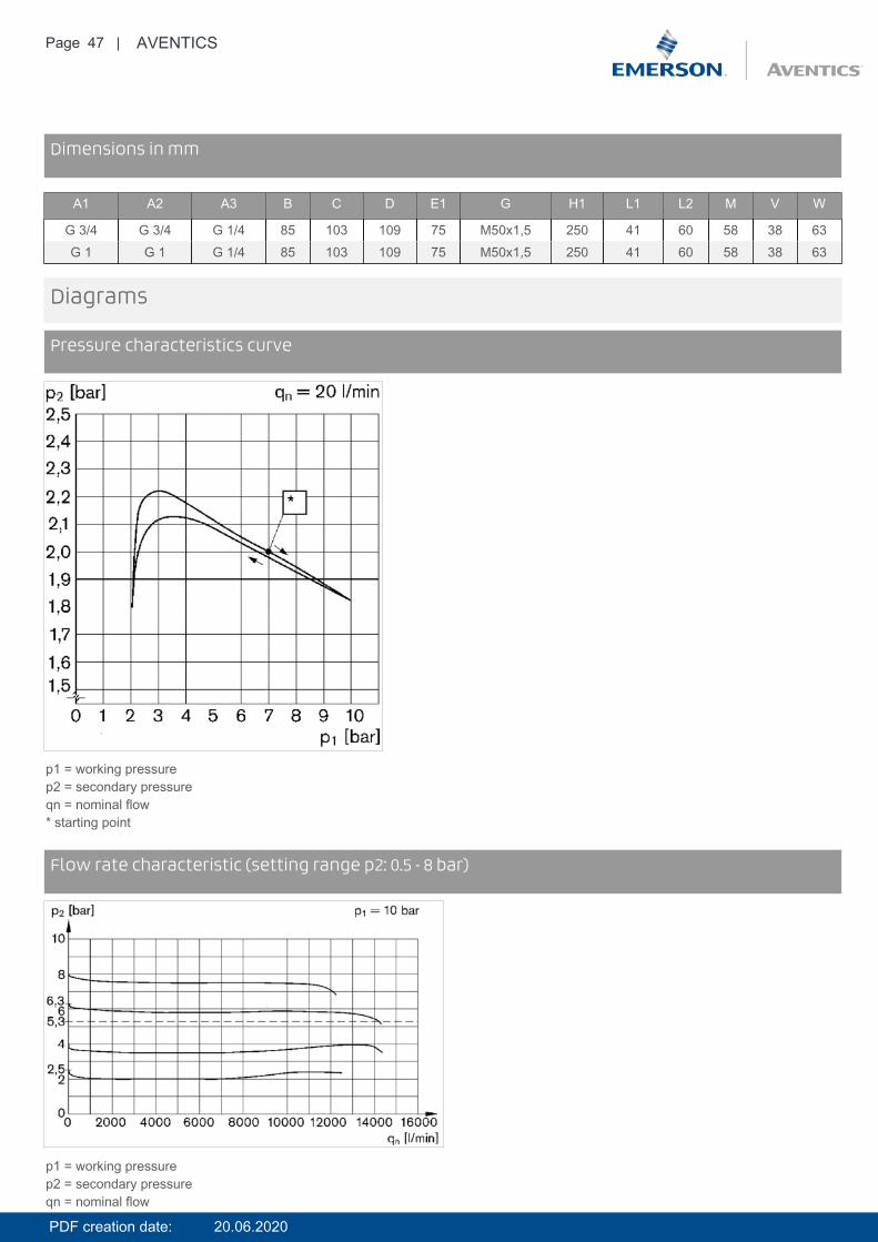
DimensionsDimensions in mm
A1 A2 A3 B C D E1 G H1 L1 L2 M V W
G 3/4 G 3/4 G 1/4 85 103 109 75 M50x1,5 250 41 60 58 38 63G 1 G 1 G 1/4 85 103 109 75 M50x1,5 250 41 60 58 38 63
Diagrams
Pressure characteristics curve
p1 = working pressurep2 = secondary pressureqn = nominal flow* starting point
DiagramsFlow rate characteristic (setting range p2: 0.5 - 8 bar)
p1 = working pressurep2 = secondary pressureqn = nominal flow
PDF creation date: 20.06.2020
Page 48 | AVENTICS
Accessories overview
1 = contamination display3 = Double nipple4 = Key for E11 locking5 = mortise lock6 = Transition plate DO307 = Adapter, Series CON-VP8 = Mounting aid DO16, form C9 = Mounting aid DO16, M1210 = Adapter for external pilot air11 = Adapter pneumatic operation12 = Sealing ring13 = Reducing nipple
PDF creation date: 20.06.2020

Page 49 | AVENTICS
Filter pressure regulator, Series AS5-FRE- G 3/4 G 1- filter porosity 40 µm- lockable- for padlocks- suitable for ATEX
Version 1-part, Can be assembled into blocksParts Filter pressure regulatorMounting orientation verticalCertificates suitable for ATEXWorking pressure min./max. 1.5 ... 16 barAmbient temperature min./max. -10 ... 50 °CMedium temperature min./max. -10 ... 50 °CMedium Compressed air Neutral gasesNominal flow Qn 14000 l/minRegulator type Diaphragm-type pressure regulatorRegulator function with relieving air exhaustAdjustment range min./max. 0.5 ... 10 barPressure supply singleFilter reservoir volume 87 cm³Filter element exchangeableMax. Internal air consumption 1.5 l/minWeight See table below
Technical data
Part No. Port filter porosity Flow Condensate drain WeightQn
R412009218 G 3/4 40 µm 14000 l/min semi-automatic, open without pressure 0.99 kgR412009219 G 3/4 40 µm 14000 l/min fully automatic, open without pressure 1.04 kgR412009220 G 3/4 40 µm 14000 l/min fully automatic, closed without pressure 1.04 kgR412009221 G 1 40 µm 14000 l/min semi-automatic, open without pressure 0.99 kgR412009222 G 1 40 µm 14000 l/min fully automatic, open without pressure 1.04 kgR412009223 G 1 40 µm 14000 l/min fully automatic, closed without pressure 1.04 kg
Nominal flow Qn with secondary pressure p2 = 6 bar at Δp = 1 barOrder pressure gauge separately, Suitable for use in Ex zones 1, 2, 21, 22.
The pressure dew point must be at least 15 °C under ambient and medium temperature and may not exceed 3 °C .Note: Polycarbonate reservoirs are susceptible to solvents, supplementary information can be found at "Customer information".Suitable for use in Ex zones 1, 2, 21, 22.A change in the flow direction (from air supply on the left to air supply on the right) occurs by rotating installation by 180° about thevertical axis. Please see the operating instructions for further details.Also suitable for separation of fluid oil or water due to the design.
Max. achievable compressed air class acc. to ISO 8573-1:2010 7 : 7 : -
Technical information
PDF creation date: 20.06.2020
Page 50 | AVENTICS
Technical information
Material
Housing Polyamide
Front plate Acrylonitrile butadiene styrene
Seals Acrylonitrile butadiene rubber
Threaded bushing Die cast zinc
Reservoir Polycarbonate
Protective guard Polyamide
Filter insert Polyethylene
PDF creation date: 20.06.2020
Page 51 | AVENTICS
Dimensions
Dimensions
A1 = inputA2 = outputA3 = pressure gauge connectionA7 = condensate drain1) Plastic reservoir and protective guard with window2) Semi-automatic condensate drain3) Fully automatic condensate drain4) Mounting option for padlocks, max. shackle Ø 8
DimensionsDimensions in mm
A1 A2 A3 A7 B C D E1 G H1 H2 L1 L2 M T7 V W
G 3/4 G 3/4 G 1/4 G 1/8 85 103 109 75 M50x1,5 250 266 41 60 58 8.5 38 63G 1 G 1 G 1/4 G 1/8 85 103 109 75 M50x1,5 250 266 41 60 58 8.5 38 63
PDF creation date: 20.06.2020

Page 52 | AVENTICS
Diagrams
Pressure characteristics curve
p1 = working pressurep2 = secondary pressureqn = nominal flow* starting point
DiagramsFlow rate characteristic (setting range p2: 0.5 - 8 bar)
p1 = working pressurep2 = secondary pressureqn = nominal flow
PDF creation date: 20.06.2020

Page 53 | AVENTICS
Accessories overview
1 = contamination display3 = Double nipple4 = Key for E11 locking5 = mortise lock6 = Transition plate DO307 = Adapter, Series CON-VP8 = Mounting aid DO16, form C9 = Mounting aid DO16, M1210 = Adapter for external pilot air11 = Adapter pneumatic operation12 = Sealing ring13 = Reducing nipple
PDF creation date: 20.06.2020
Page 54 | AVENTICS
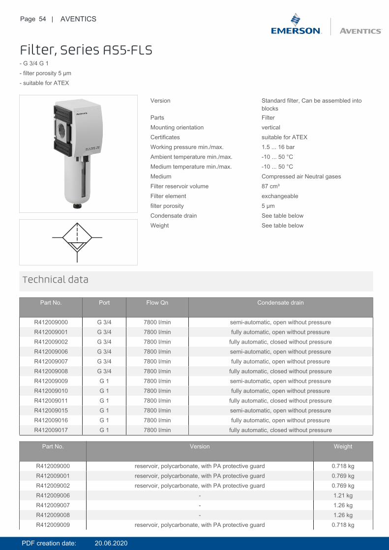
Filter, Series AS5-FLS- G 3/4 G 1- filter porosity 5 µm- suitable for ATEX
Version Standard filter, Can be assembled intoblocks
Parts FilterMounting orientation verticalCertificates suitable for ATEXWorking pressure min./max. 1.5 ... 16 barAmbient temperature min./max. -10 ... 50 °CMedium temperature min./max. -10 ... 50 °CMedium Compressed air Neutral gasesFilter reservoir volume 87 cm³Filter element exchangeablefilter porosity 5 µmCondensate drain See table belowWeight See table below
Technical data
Part No. Port Flow Qn Condensate drain
R412009000 G 3/4 7800 l/min semi-automatic, open without pressureR412009001 G 3/4 7800 l/min fully automatic, open without pressureR412009002 G 3/4 7800 l/min fully automatic, closed without pressureR412009006 G 3/4 7800 l/min semi-automatic, open without pressureR412009007 G 3/4 7800 l/min fully automatic, open without pressureR412009008 G 3/4 7800 l/min fully automatic, closed without pressureR412009009 G 1 7800 l/min semi-automatic, open without pressureR412009010 G 1 7800 l/min fully automatic, open without pressureR412009011 G 1 7800 l/min fully automatic, closed without pressureR412009015 G 1 7800 l/min semi-automatic, open without pressureR412009016 G 1 7800 l/min fully automatic, open without pressureR412009017 G 1 7800 l/min fully automatic, closed without pressure
Part No. Version Weight
R412009000 reservoir, polycarbonate, with PA protective guard 0.718 kgR412009001 reservoir, polycarbonate, with PA protective guard 0.769 kgR412009002 reservoir, polycarbonate, with PA protective guard 0.769 kgR412009006 - 1.21 kgR412009007 - 1.26 kgR412009008 - 1.26 kgR412009009 reservoir, polycarbonate, with PA protective guard 0.718 kg
PDF creation date: 20.06.2020
Page 55 | AVENTICS
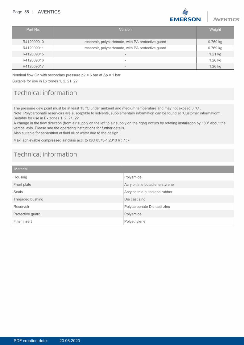
Part No. Version Weight
R412009010 reservoir, polycarbonate, with PA protective guard 0.769 kgR412009011 reservoir, polycarbonate, with PA protective guard 0.769 kgR412009015 - 1.21 kgR412009016 - 1.26 kgR412009017 - 1.26 kg
Nominal flow Qn with secondary pressure p2 = 6 bar at Δp = 1 barSuitable for use in Ex zones 1, 2, 21, 22.
The pressure dew point must be at least 15 °C under ambient and medium temperature and may not exceed 3 °C .Note: Polycarbonate reservoirs are susceptible to solvents, supplementary information can be found at "Customer information".Suitable for use in Ex zones 1, 2, 21, 22.A change in the flow direction (from air supply on the left to air supply on the right) occurs by rotating installation by 180° about thevertical axis. Please see the operating instructions for further details.Also suitable for separation of fluid oil or water due to the design.
Max. achievable compressed air class acc. to ISO 8573-1:2010 6 : 7 : -
Technical information
Technical information
Material
Housing Polyamide
Front plate Acrylonitrile butadiene styrene
Seals Acrylonitrile butadiene rubber
Threaded bushing Die cast zinc
Reservoir Polycarbonate Die cast zinc
Protective guard Polyamide
Filter insert Polyethylene
PDF creation date: 20.06.2020
Page 56 | AVENTICS
Dimensions
Dimensions
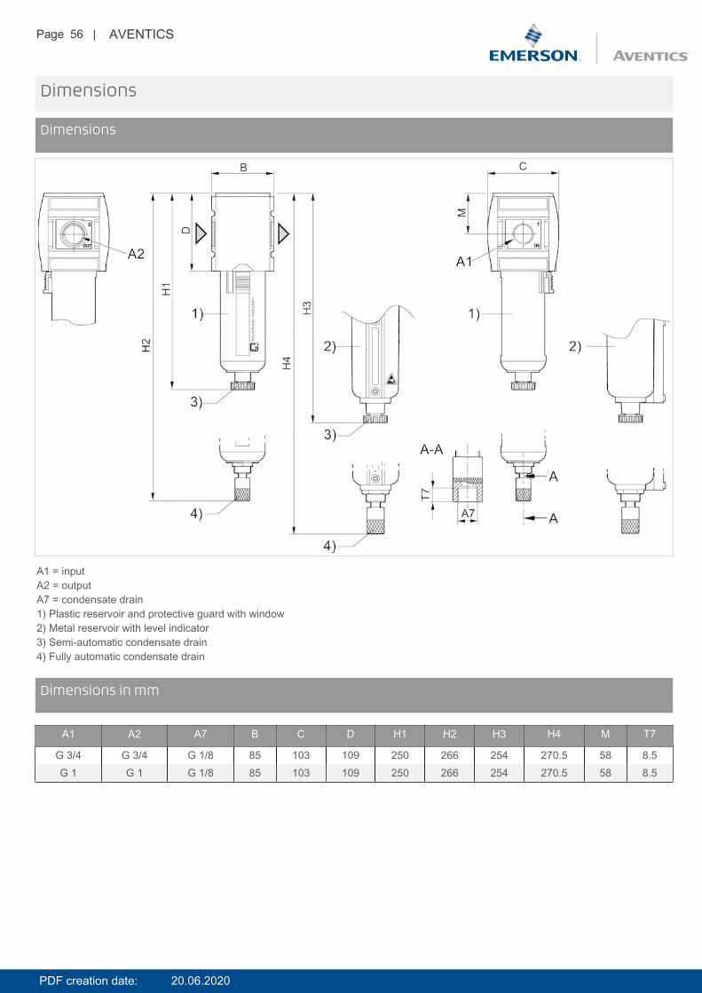
A1 = inputA2 = outputA7 = condensate drain1) Plastic reservoir and protective guard with window2) Metal reservoir with level indicator3) Semi-automatic condensate drain4) Fully automatic condensate drain
DimensionsDimensions in mm
A1 A2 A7 B C D H1 H2 H3 H4 M T7
G 3/4 G 3/4 G 1/8 85 103 109 250 266 254 270.5 58 8.5G 1 G 1 G 1/8 85 103 109 250 266 254 270.5 58 8.5
PDF creation date: 20.06.2020
Page 57 | AVENTICS
Diagrams
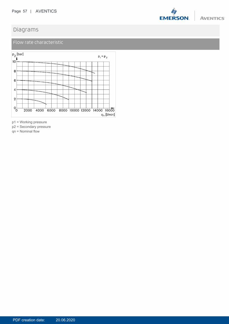
Flow rate characteristic
p1 = Working pressurep2 = Secondary pressureqn = Nominal flow
PDF creation date: 20.06.2020

Page 58 | AVENTICS
Accessories overview
1 = contamination display3 = Double nipple4 = Key for E11 locking5 = mortise lock6 = Transition plate DO307 = Adapter, Series CON-VP8 = Mounting aid DO16, form C9 = Mounting aid DO16, M1210 = Adapter for external pilot air11 = Adapter pneumatic operation12 = Sealing ring13 = Reducing nipple
PDF creation date: 20.06.2020
Page 59 | AVENTICS
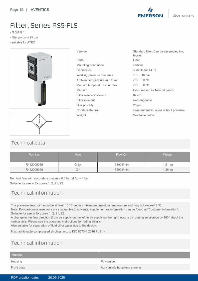
Filter, Series AS5-FLS- G 3/4 G 1- filter porosity 25 µm- suitable for ATEX
Version Standard filter, Can be assembled intoblocks
Parts FilterMounting orientation verticalCertificates suitable for ATEXWorking pressure min./max. 1.5 ... 16 barAmbient temperature min./max. -10 ... 50 °CMedium temperature min./max. -10 ... 50 °CMedium Compressed air Neutral gasesFilter reservoir volume 87 cm³Filter element exchangeablefilter porosity 25 µmCondensate drain semi-automatic, open without pressureWeight See table below
Technical data
Part No. Port Flow Qn Weight
R412009089 G 3/4 7800 l/min 1.21 kgR412009090 G 1 7800 l/min 1.26 kg
Nominal flow with secondary pressure 6.3 bar at Δp = 1 barSuitable for use in Ex zones 1, 2, 21, 22.
The pressure dew point must be at least 15 °C under ambient and medium temperature and may not exceed 3 °C .Note: Polycarbonate reservoirs are susceptible to solvents, supplementary information can be found at "Customer information".Suitable for use in Ex zones 1, 2, 21, 22.A change in the flow direction (from air supply on the left to air supply on the right) occurs by rotating installation by 180° about thevertical axis. Please see the operating instructions for further details.Also suitable for separation of fluid oil or water due to the design.
Max. achievable compressed air class acc. to ISO 8573-1:2010 7 : 7 : -
Technical information
Technical information
Material
Housing Polyamide
Front plate Acrylonitrile butadiene styrene
PDF creation date: 20.06.2020
Page 60 | AVENTICS
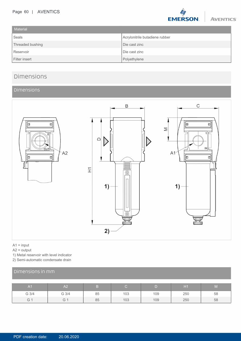
Material
Seals Acrylonitrile butadiene rubber
Threaded bushing Die cast zinc
Reservoir Die cast zinc
Filter insert Polyethylene
Dimensions
Dimensions
A1 = inputA2 = output1) Metal reservoir with level indicator2) Semi-automatic condensate drain
DimensionsDimensions in mm
A1 A2 B C D H1 M
G 3/4 G 3/4 85 103 109 250 58G 1 G 1 85 103 109 250 58
PDF creation date: 20.06.2020

Page 61 | AVENTICS
Diagrams
Flow rate characteristic
p1 = Working pressurep2 = Secondary pressureqn = Nominal flow
PDF creation date: 20.06.2020
Page 62 | AVENTICS
Accessories overview
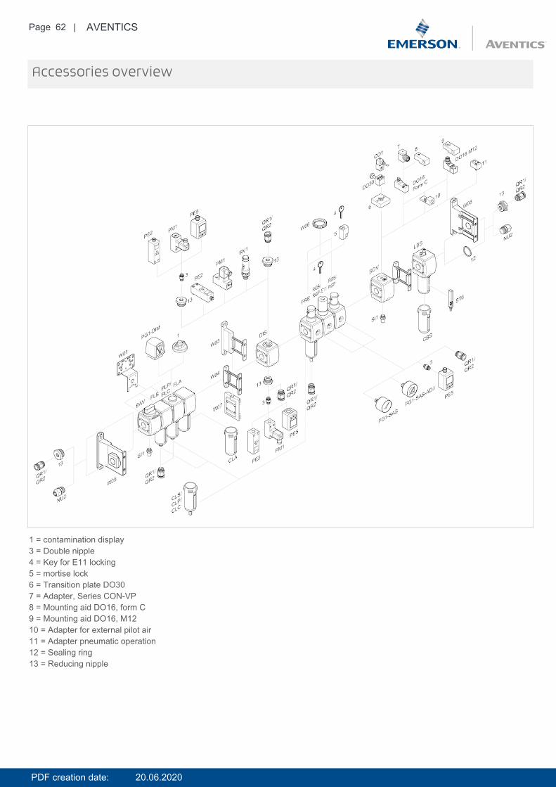
1 = contamination display3 = Double nipple4 = Key for E11 locking5 = mortise lock6 = Transition plate DO307 = Adapter, Series CON-VP8 = Mounting aid DO16, form C9 = Mounting aid DO16, M1210 = Adapter for external pilot air11 = Adapter pneumatic operation12 = Sealing ring13 = Reducing nipple
PDF creation date: 20.06.2020
Page 63 | AVENTICS
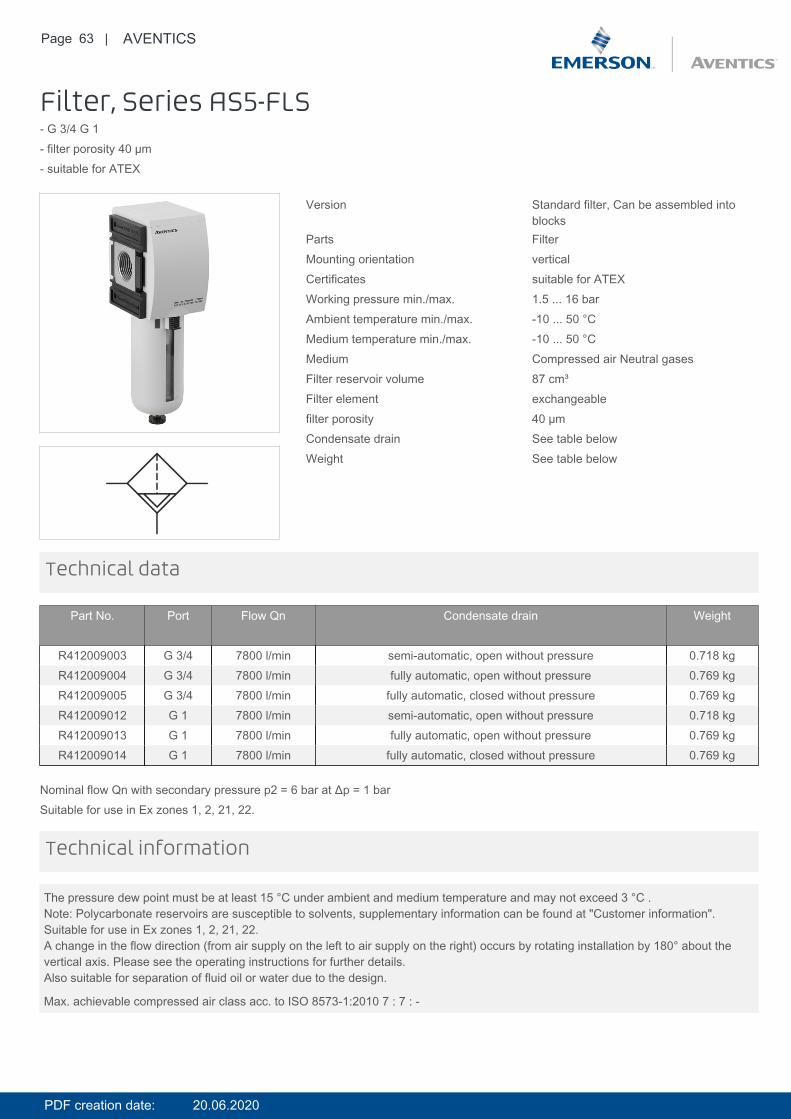
Filter, Series AS5-FLS- G 3/4 G 1- filter porosity 40 µm- suitable for ATEX
Version Standard filter, Can be assembled intoblocks
Parts FilterMounting orientation verticalCertificates suitable for ATEXWorking pressure min./max. 1.5 ... 16 barAmbient temperature min./max. -10 ... 50 °CMedium temperature min./max. -10 ... 50 °CMedium Compressed air Neutral gasesFilter reservoir volume 87 cm³Filter element exchangeablefilter porosity 40 µmCondensate drain See table belowWeight See table below
Technical data
Part No. Port Flow Qn Condensate drain Weight
R412009003 G 3/4 7800 l/min semi-automatic, open without pressure 0.718 kgR412009004 G 3/4 7800 l/min fully automatic, open without pressure 0.769 kgR412009005 G 3/4 7800 l/min fully automatic, closed without pressure 0.769 kgR412009012 G 1 7800 l/min semi-automatic, open without pressure 0.718 kgR412009013 G 1 7800 l/min fully automatic, open without pressure 0.769 kgR412009014 G 1 7800 l/min fully automatic, closed without pressure 0.769 kg
Nominal flow Qn with secondary pressure p2 = 6 bar at Δp = 1 barSuitable for use in Ex zones 1, 2, 21, 22.
The pressure dew point must be at least 15 °C under ambient and medium temperature and may not exceed 3 °C .Note: Polycarbonate reservoirs are susceptible to solvents, supplementary information can be found at "Customer information".Suitable for use in Ex zones 1, 2, 21, 22.A change in the flow direction (from air supply on the left to air supply on the right) occurs by rotating installation by 180° about thevertical axis. Please see the operating instructions for further details.Also suitable for separation of fluid oil or water due to the design.
Max. achievable compressed air class acc. to ISO 8573-1:2010 7 : 7 : -
Technical information
PDF creation date: 20.06.2020
Page 64 | AVENTICS
Technical information
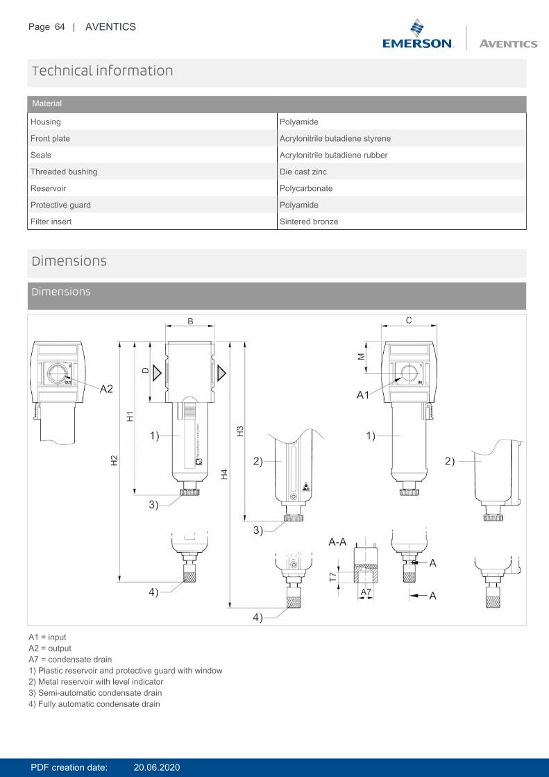
Material
Housing Polyamide
Front plate Acrylonitrile butadiene styrene
Seals Acrylonitrile butadiene rubber
Threaded bushing Die cast zinc
Reservoir Polycarbonate
Protective guard Polyamide
Filter insert Sintered bronze
Dimensions
Dimensions
A1 = inputA2 = outputA7 = condensate drain1) Plastic reservoir and protective guard with window2) Metal reservoir with level indicator3) Semi-automatic condensate drain4) Fully automatic condensate drain
PDF creation date: 20.06.2020
Page 65 | AVENTICS
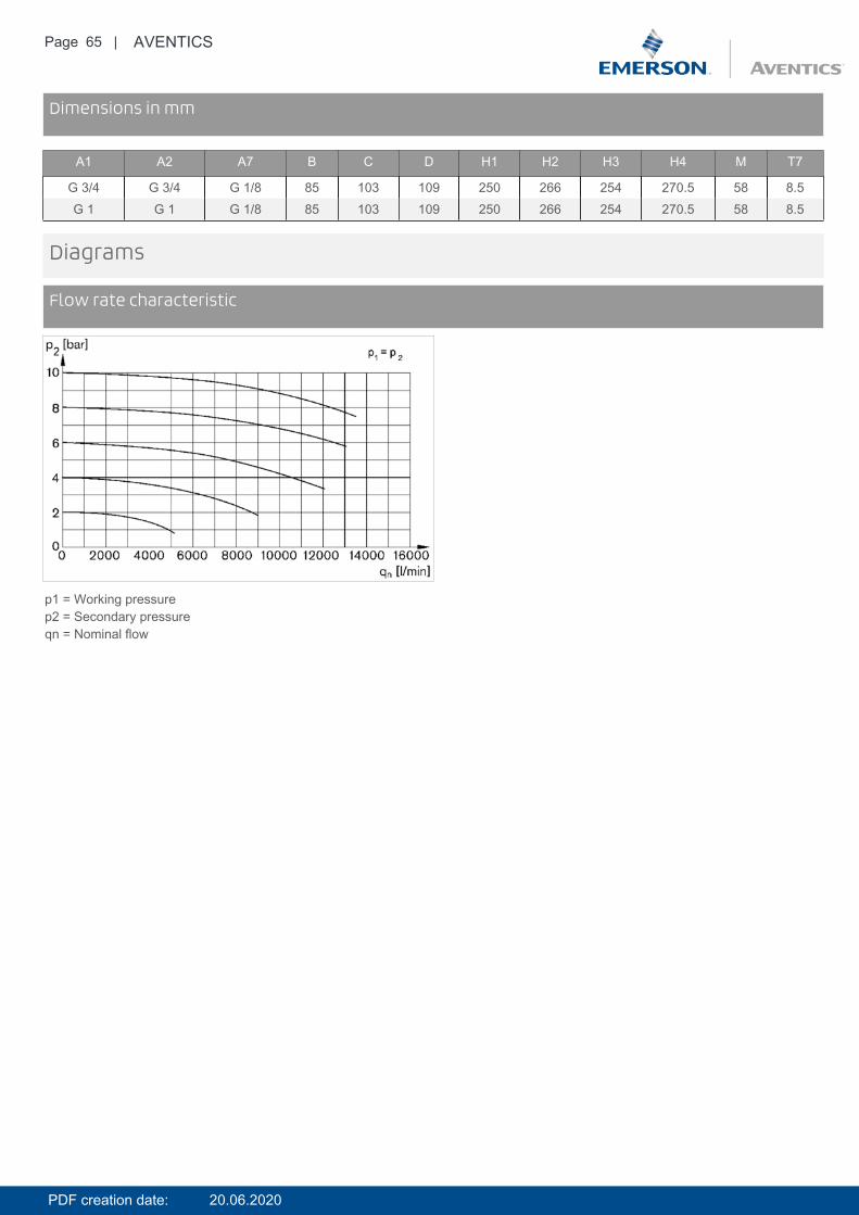
DimensionsDimensions in mm
A1 A2 A7 B C D H1 H2 H3 H4 M T7
G 3/4 G 3/4 G 1/8 85 103 109 250 266 254 270.5 58 8.5G 1 G 1 G 1/8 85 103 109 250 266 254 270.5 58 8.5
Diagrams
Flow rate characteristic
p1 = Working pressurep2 = Secondary pressureqn = Nominal flow
PDF creation date: 20.06.2020

Page 66 | AVENTICS
Accessories overview
1 = contamination display3 = Double nipple4 = Key for E11 locking5 = mortise lock6 = Transition plate DO307 = Adapter, Series CON-VP8 = Mounting aid DO16, form C9 = Mounting aid DO16, M1210 = Adapter for external pilot air11 = Adapter pneumatic operation12 = Sealing ring13 = Reducing nipple
PDF creation date: 20.06.2020
Page 67 | AVENTICS
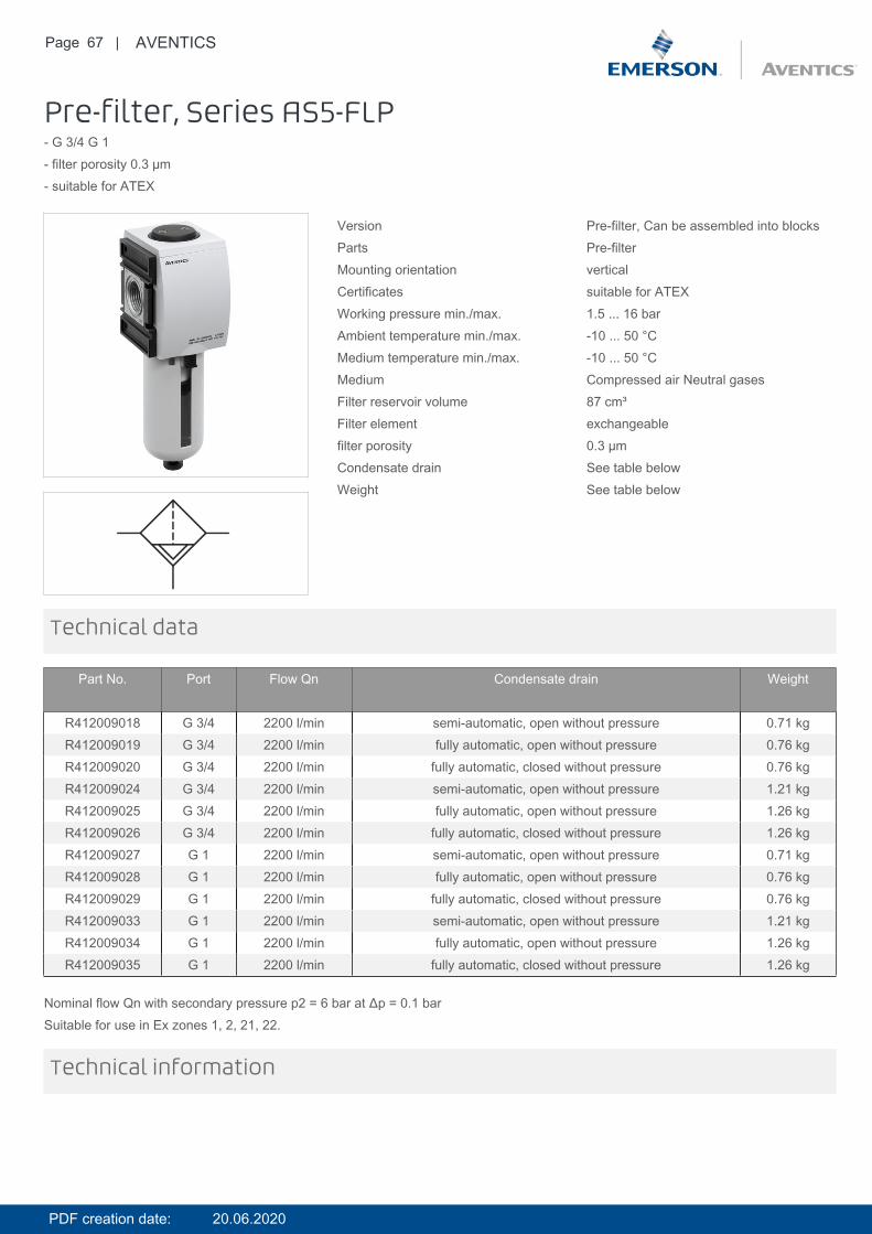
Pre-filter, Series AS5-FLP- G 3/4 G 1- filter porosity 0.3 µm- suitable for ATEX
Version Pre-filter, Can be assembled into blocksParts Pre-filterMounting orientation verticalCertificates suitable for ATEXWorking pressure min./max. 1.5 ... 16 barAmbient temperature min./max. -10 ... 50 °CMedium temperature min./max. -10 ... 50 °CMedium Compressed air Neutral gasesFilter reservoir volume 87 cm³Filter element exchangeablefilter porosity 0.3 µmCondensate drain See table belowWeight See table below
Technical data
Part No. Port Flow Qn Condensate drain Weight
R412009018 G 3/4 2200 l/min semi-automatic, open without pressure 0.71 kgR412009019 G 3/4 2200 l/min fully automatic, open without pressure 0.76 kgR412009020 G 3/4 2200 l/min fully automatic, closed without pressure 0.76 kgR412009024 G 3/4 2200 l/min semi-automatic, open without pressure 1.21 kgR412009025 G 3/4 2200 l/min fully automatic, open without pressure 1.26 kgR412009026 G 3/4 2200 l/min fully automatic, closed without pressure 1.26 kgR412009027 G 1 2200 l/min semi-automatic, open without pressure 0.71 kgR412009028 G 1 2200 l/min fully automatic, open without pressure 0.76 kgR412009029 G 1 2200 l/min fully automatic, closed without pressure 0.76 kgR412009033 G 1 2200 l/min semi-automatic, open without pressure 1.21 kgR412009034 G 1 2200 l/min fully automatic, open without pressure 1.26 kgR412009035 G 1 2200 l/min fully automatic, closed without pressure 1.26 kg
Nominal flow Qn with secondary pressure p2 = 6 bar at Δp = 0.1 barSuitable for use in Ex zones 1, 2, 21, 22.
Technical information
PDF creation date: 20.06.2020
Page 68 | AVENTICS
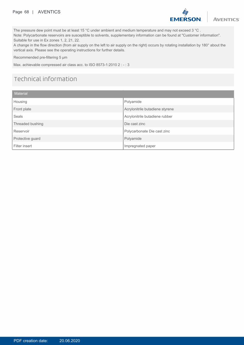
The pressure dew point must be at least 15 °C under ambient and medium temperature and may not exceed 3 °C .Note: Polycarbonate reservoirs are susceptible to solvents, supplementary information can be found at "Customer information".Suitable for use in Ex zones 1, 2, 21, 22.A change in the flow direction (from air supply on the left to air supply on the right) occurs by rotating installation by 180° about thevertical axis. Please see the operating instructions for further details.
Recommended pre-filtering 5 µm
Max. achievable compressed air class acc. to ISO 8573-1:2010 2 : - : 3
Technical information
Material
Housing Polyamide
Front plate Acrylonitrile butadiene styrene
Seals Acrylonitrile butadiene rubber
Threaded bushing Die cast zinc
Reservoir Polycarbonate Die cast zinc
Protective guard Polyamide
Filter insert Impregnated paper
PDF creation date: 20.06.2020
Page 69 | AVENTICS
Dimensions
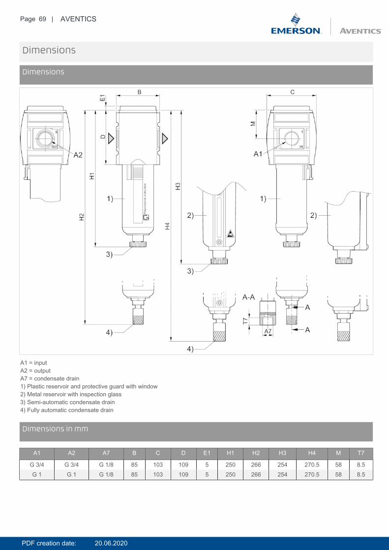
Dimensions
A1 = inputA2 = outputA7 = condensate drain1) Plastic reservoir and protective guard with window2) Metal reservoir with inspection glass3) Semi-automatic condensate drain4) Fully automatic condensate drain
DimensionsDimensions in mm
A1 A2 A7 B C D E1 H1 H2 H3 H4 M T7
G 3/4 G 3/4 G 1/8 85 103 109 5 250 266 254 270.5 58 8.5G 1 G 1 G 1/8 85 103 109 5 250 266 254 270.5 58 8.5
PDF creation date: 20.06.2020
Page 70 | AVENTICS
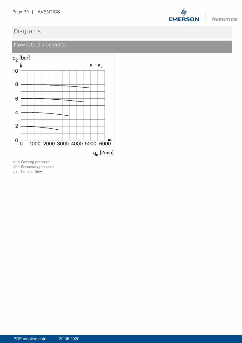
Diagrams
Flow rate characteristic
p1 = Working pressurep2 = Secondary pressureqn = Nominal flow
PDF creation date: 20.06.2020
Page 71 | AVENTICS
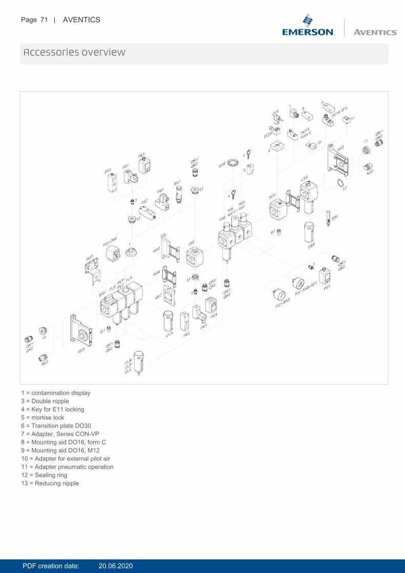
Accessories overview
1 = contamination display3 = Double nipple4 = Key for E11 locking5 = mortise lock6 = Transition plate DO307 = Adapter, Series CON-VP8 = Mounting aid DO16, form C9 = Mounting aid DO16, M1210 = Adapter for external pilot air11 = Adapter pneumatic operation12 = Sealing ring13 = Reducing nipple
PDF creation date: 20.06.2020
Page 72 | AVENTICS
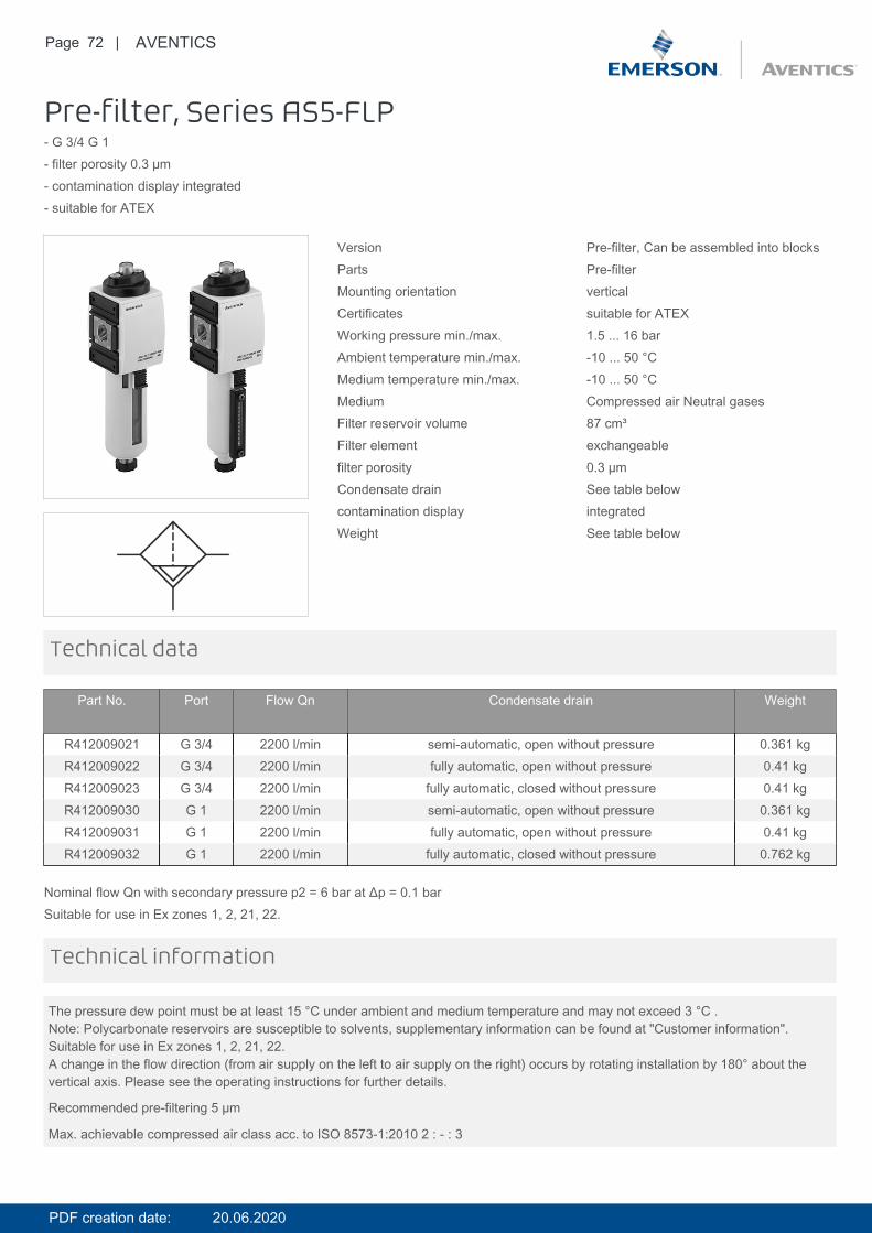
Pre-filter, Series AS5-FLP- G 3/4 G 1- filter porosity 0.3 µm- contamination display integrated- suitable for ATEX
Version Pre-filter, Can be assembled into blocksParts Pre-filterMounting orientation verticalCertificates suitable for ATEXWorking pressure min./max. 1.5 ... 16 barAmbient temperature min./max. -10 ... 50 °CMedium temperature min./max. -10 ... 50 °CMedium Compressed air Neutral gasesFilter reservoir volume 87 cm³Filter element exchangeablefilter porosity 0.3 µmCondensate drain See table belowcontamination display integratedWeight See table below
Technical data
Part No. Port Flow Qn Condensate drain Weight
R412009021 G 3/4 2200 l/min semi-automatic, open without pressure 0.361 kgR412009022 G 3/4 2200 l/min fully automatic, open without pressure 0.41 kgR412009023 G 3/4 2200 l/min fully automatic, closed without pressure 0.41 kgR412009030 G 1 2200 l/min semi-automatic, open without pressure 0.361 kgR412009031 G 1 2200 l/min fully automatic, open without pressure 0.41 kgR412009032 G 1 2200 l/min fully automatic, closed without pressure 0.762 kg
Nominal flow Qn with secondary pressure p2 = 6 bar at Δp = 0.1 barSuitable for use in Ex zones 1, 2, 21, 22.
The pressure dew point must be at least 15 °C under ambient and medium temperature and may not exceed 3 °C .Note: Polycarbonate reservoirs are susceptible to solvents, supplementary information can be found at "Customer information".Suitable for use in Ex zones 1, 2, 21, 22.A change in the flow direction (from air supply on the left to air supply on the right) occurs by rotating installation by 180° about thevertical axis. Please see the operating instructions for further details.
Recommended pre-filtering 5 µm
Max. achievable compressed air class acc. to ISO 8573-1:2010 2 : - : 3
Technical information
PDF creation date: 20.06.2020
Page 73 | AVENTICS
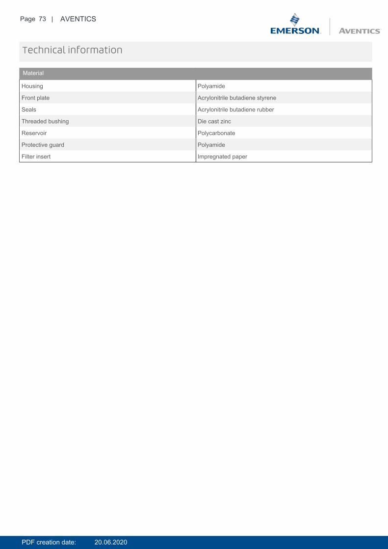
Technical information
Material
Housing Polyamide
Front plate Acrylonitrile butadiene styrene
Seals Acrylonitrile butadiene rubber
Threaded bushing Die cast zinc
Reservoir Polycarbonate
Protective guard Polyamide
Filter insert Impregnated paper
PDF creation date: 20.06.2020
Page 74 | AVENTICS
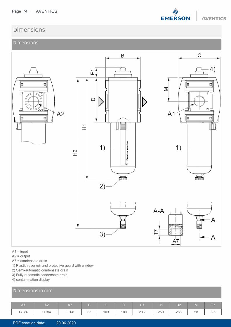
Dimensions
Dimensions
A1 = inputA2 = outputA7 = condensate drain1) Plastic reservoir and protective guard with window2) Semi-automatic condensate drain3) Fully automatic condensate drain4) contamination display
DimensionsDimensions in mm
A1 A2 A7 B C D E1 H1 H2 M T7
G 3/4 G 3/4 G 1/8 85 103 109 23.7 250 266 58 8.5
PDF creation date: 20.06.2020
Page 75 | AVENTICS
A1 A2 A7 B C D E1 H1 H2 M T7
G 1 G 1 G 1/8 85 103 109 23.7 250 266 58 8.5
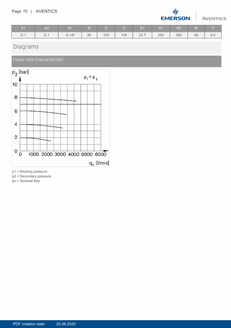
Diagrams
Flow rate characteristic
p1 = Working pressurep2 = Secondary pressureqn = Nominal flow
PDF creation date: 20.06.2020

Page 76 | AVENTICS
Accessories overview
1 = contamination display3 = Double nipple4 = Key for E11 locking5 = mortise lock6 = Transition plate DO307 = Adapter, Series CON-VP8 = Mounting aid DO16, form C9 = Mounting aid DO16, M1210 = Adapter for external pilot air11 = Adapter pneumatic operation12 = Sealing ring13 = Reducing nipple
PDF creation date: 20.06.2020
Page 77 | AVENTICS
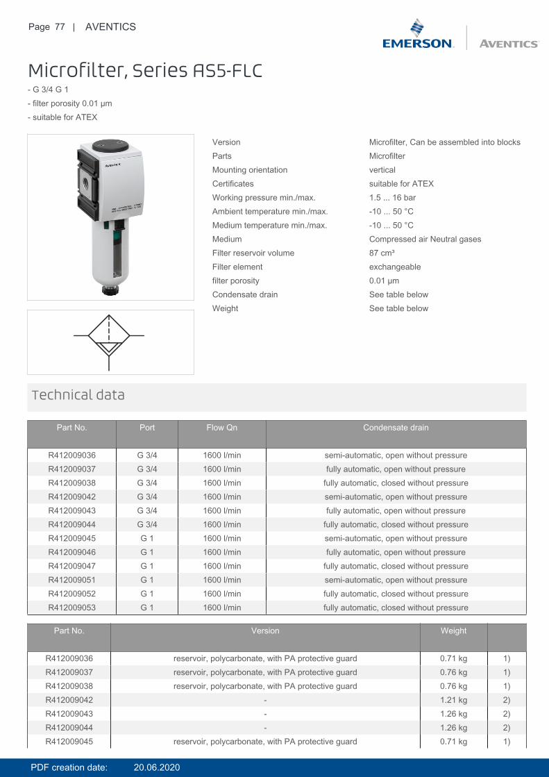
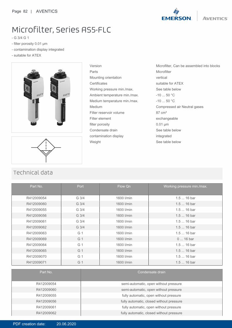
Microfilter, Series AS5-FLC- G 3/4 G 1- filter porosity 0.01 µm- suitable for ATEX
Version Microfilter, Can be assembled into blocksParts MicrofilterMounting orientation verticalCertificates suitable for ATEXWorking pressure min./max. 1.5 ... 16 barAmbient temperature min./max. -10 ... 50 °CMedium temperature min./max. -10 ... 50 °CMedium Compressed air Neutral gasesFilter reservoir volume 87 cm³Filter element exchangeablefilter porosity 0.01 µmCondensate drain See table belowWeight See table below
Technical data
Part No. Port Flow Qn Condensate drain
R412009036 G 3/4 1600 l/min semi-automatic, open without pressureR412009037 G 3/4 1600 l/min fully automatic, open without pressureR412009038 G 3/4 1600 l/min fully automatic, closed without pressureR412009042 G 3/4 1600 l/min semi-automatic, open without pressureR412009043 G 3/4 1600 l/min fully automatic, open without pressureR412009044 G 3/4 1600 l/min fully automatic, closed without pressureR412009045 G 1 1600 l/min semi-automatic, open without pressureR412009046 G 1 1600 l/min fully automatic, open without pressureR412009047 G 1 1600 l/min fully automatic, closed without pressureR412009051 G 1 1600 l/min semi-automatic, open without pressureR412009052 G 1 1600 l/min fully automatic, closed without pressureR412009053 G 1 1600 l/min fully automatic, closed without pressure
Part No. Version Weight
R412009036 reservoir, polycarbonate, with PA protective guard 0.71 kg 1)R412009037 reservoir, polycarbonate, with PA protective guard 0.76 kg 1)R412009038 reservoir, polycarbonate, with PA protective guard 0.76 kg 1)R412009042 - 1.21 kg 2)R412009043 - 1.26 kg 2)R412009044 - 1.26 kg 2)R412009045 reservoir, polycarbonate, with PA protective guard 0.71 kg 1)
PDF creation date: 20.06.2020
Page 78 | AVENTICS
Part No. Version Weight
R412009046 reservoir, polycarbonate, with PA protective guard 0.76 kg 1)R412009047 reservoir, polycarbonate, with PA protective guard 0.76 kg 1)R412009051 - 1.21 kg 2)R412009052 - 1.26 kg 2)R412009053 - 1.26 kg 2)
Nominal flow Qn with secondary pressure p2 = 6 bar at Δp = 0.1 bar1) Suitable for use in Ex zones 1, 2, 21, 22.2) Reservoir with level indicator, Suitable for use in Ex zones 1, 2, 21, 22.
The pressure dew point must be at least 15 °C under ambient and medium temperature and may not exceed 3 °C .Note: Polycarbonate reservoirs are susceptible to solvents, supplementary information can be found at "Customer information".Suitable for use in Ex zones 1, 2, 21, 22.A change in the flow direction (from air supply on the left to air supply on the right) occurs by rotating installation by 180° about thevertical axis. Please see the operating instructions for further details.
Recommended pre-filtering 0.3 µm
Max. achievable compressed air class acc. to ISO 8573-1:2010 1 : - : 2
Technical information
Technical information
Material
Housing Polyamide
Front plate Acrylonitrile butadiene styrene
Seals Acrylonitrile butadiene rubber
Threaded bushing Die cast zinc
Reservoir Polycarbonate Die cast zinc
Protective guard Polyamide
Filter insert Borosilicate glass fiber
PDF creation date: 20.06.2020
Page 79 | AVENTICS
Dimensions
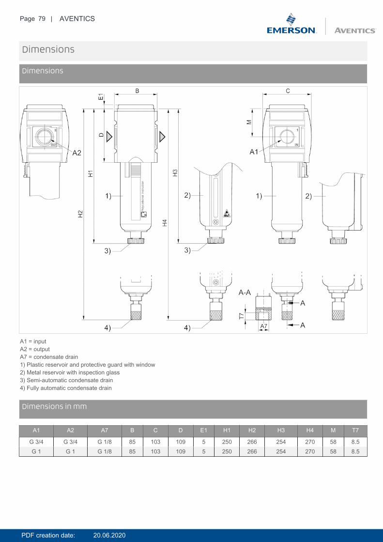
Dimensions
A1 = inputA2 = outputA7 = condensate drain1) Plastic reservoir and protective guard with window2) Metal reservoir with inspection glass3) Semi-automatic condensate drain4) Fully automatic condensate drain
DimensionsDimensions in mm
A1 A2 A7 B C D E1 H1 H2 H3 H4 M T7
G 3/4 G 3/4 G 1/8 85 103 109 5 250 266 254 270 58 8.5G 1 G 1 G 1/8 85 103 109 5 250 266 254 270 58 8.5
PDF creation date: 20.06.2020

Page 80 | AVENTICS
Diagrams
Flow rate characteristic
p1 = Working pressurep2 = Secondary pressureqn = Nominal flow
PDF creation date: 20.06.2020

Page 81 | AVENTICS
Accessories overview
1 = contamination display3 = Double nipple4 = Key for E11 locking5 = mortise lock6 = Transition plate DO307 = Adapter, Series CON-VP8 = Mounting aid DO16, form C9 = Mounting aid DO16, M1210 = Adapter for external pilot air11 = Adapter pneumatic operation12 = Sealing ring13 = Reducing nipple
PDF creation date: 20.06.2020
Page 82 | AVENTICS
Microfilter, Series AS5-FLC- G 3/4 G 1- filter porosity 0.01 µm- contamination display integrated- suitable for ATEX
Version Microfilter, Can be assembled into blocksParts MicrofilterMounting orientation verticalCertificates suitable for ATEXWorking pressure min./max. See table belowAmbient temperature min./max. -10 ... 50 °CMedium temperature min./max. -10 ... 50 °CMedium Compressed air Neutral gasesFilter reservoir volume 87 cm³Filter element exchangeablefilter porosity 0.01 µmCondensate drain See table belowcontamination display integratedWeight See table below
Technical data
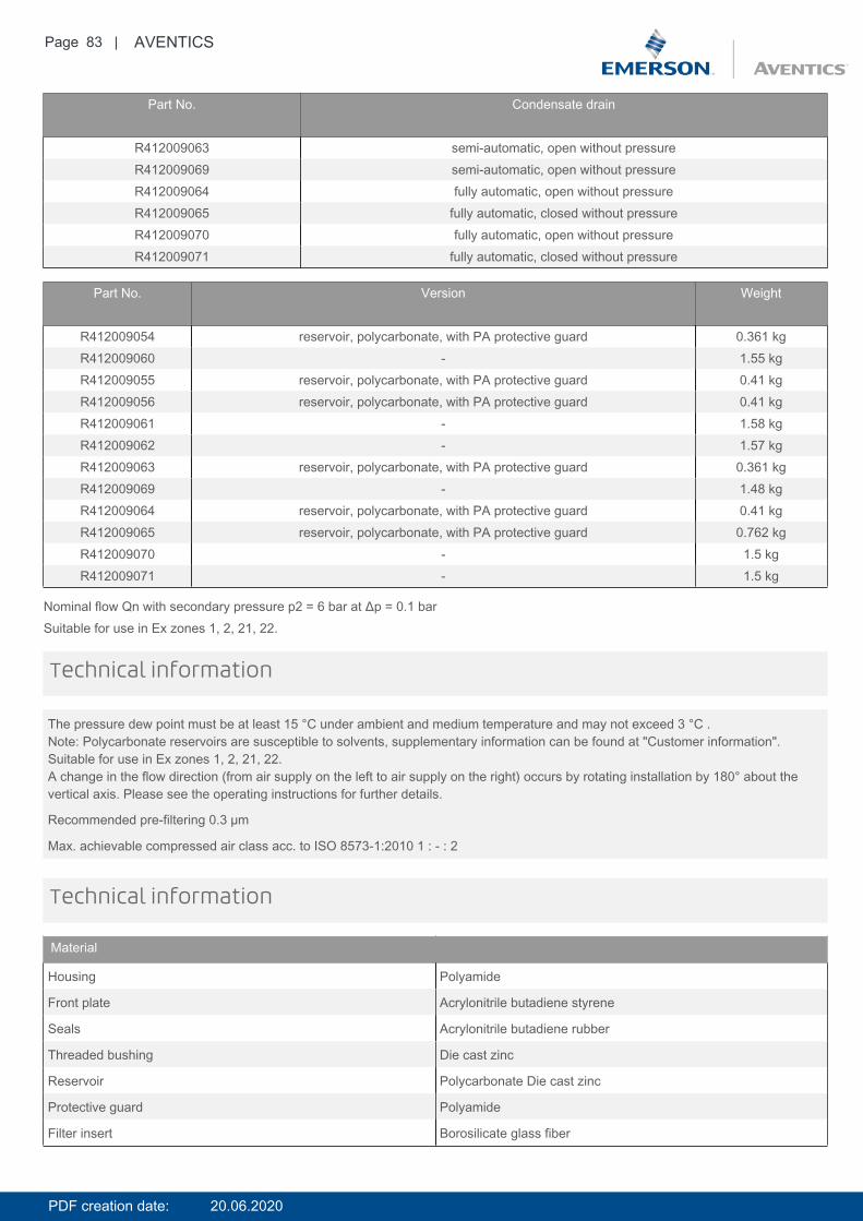
Part No. Port Flow Qn Working pressure min./max.
R412009054 G 3/4 1600 l/min 1.5 ... 16 barR412009060 G 3/4 1600 l/min 1.5 ... 16 barR412009055 G 3/4 1600 l/min 1.5 ... 16 barR412009056 G 3/4 1600 l/min 1.5 ... 16 barR412009061 G 3/4 1600 l/min 1.5 ... 16 barR412009062 G 3/4 1600 l/min 1.5 ... 16 barR412009063 G 1 1600 l/min 1.5 ... 16 barR412009069 G 1 1600 l/min 0 ... 16 barR412009064 G 1 1600 l/min 1.5 ... 16 barR412009065 G 1 1600 l/min 1.5 ... 16 barR412009070 G 1 1600 l/min 1.5 ... 16 barR412009071 G 1 1600 l/min 1.5 ... 16 bar
Part No. Condensate drain
R412009054 semi-automatic, open without pressureR412009060 semi-automatic, open without pressureR412009055 fully automatic, open without pressureR412009056 fully automatic, closed without pressureR412009061 fully automatic, open without pressureR412009062 fully automatic, closed without pressure
PDF creation date: 20.06.2020
Page 83 | AVENTICS
Part No. Condensate drain
R412009063 semi-automatic, open without pressureR412009069 semi-automatic, open without pressureR412009064 fully automatic, open without pressureR412009065 fully automatic, closed without pressureR412009070 fully automatic, open without pressureR412009071 fully automatic, closed without pressure
Part No. Version Weight
R412009054 reservoir, polycarbonate, with PA protective guard 0.361 kgR412009060 - 1.55 kgR412009055 reservoir, polycarbonate, with PA protective guard 0.41 kgR412009056 reservoir, polycarbonate, with PA protective guard 0.41 kgR412009061 - 1.58 kgR412009062 - 1.57 kgR412009063 reservoir, polycarbonate, with PA protective guard 0.361 kgR412009069 - 1.48 kgR412009064 reservoir, polycarbonate, with PA protective guard 0.41 kgR412009065 reservoir, polycarbonate, with PA protective guard 0.762 kgR412009070 - 1.5 kgR412009071 - 1.5 kg
Nominal flow Qn with secondary pressure p2 = 6 bar at Δp = 0.1 barSuitable for use in Ex zones 1, 2, 21, 22.
The pressure dew point must be at least 15 °C under ambient and medium temperature and may not exceed 3 °C .Note: Polycarbonate reservoirs are susceptible to solvents, supplementary information can be found at "Customer information".Suitable for use in Ex zones 1, 2, 21, 22.A change in the flow direction (from air supply on the left to air supply on the right) occurs by rotating installation by 180° about thevertical axis. Please see the operating instructions for further details.
Recommended pre-filtering 0.3 µm
Max. achievable compressed air class acc. to ISO 8573-1:2010 1 : - : 2
Technical information
Technical information
Material
Housing Polyamide
Front plate Acrylonitrile butadiene styrene
Seals Acrylonitrile butadiene rubber
Threaded bushing Die cast zinc
Reservoir Polycarbonate Die cast zinc
Protective guard Polyamide
Filter insert Borosilicate glass fiber
PDF creation date: 20.06.2020
Page 84 | AVENTICS
Dimensions
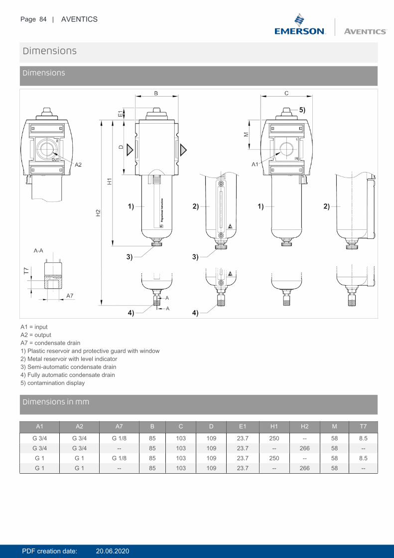
Dimensions
A1 = inputA2 = outputA7 = condensate drain1) Plastic reservoir and protective guard with window2) Metal reservoir with level indicator3) Semi-automatic condensate drain4) Fully automatic condensate drain5) contamination display
DimensionsDimensions in mm
A1 A2 A7 B C D E1 H1 H2 M T7
G 3/4 G 3/4 G 1/8 85 103 109 23.7 250 -- 58 8.5G 3/4 G 3/4 -- 85 103 109 23.7 -- 266 58 --G 1 G 1 G 1/8 85 103 109 23.7 250 -- 58 8.5G 1 G 1 -- 85 103 109 23.7 -- 266 58 --
PDF creation date: 20.06.2020

Page 85 | AVENTICS
Diagrams
Flow rate characteristic
p1 = Working pressurep2 = Secondary pressureqn = Nominal flow
PDF creation date: 20.06.2020

Page 86 | AVENTICS
Accessories overview
1 = contamination display3 = Double nipple4 = Key for E11 locking5 = mortise lock6 = Transition plate DO307 = Adapter, Series CON-VP8 = Mounting aid DO16, form C9 = Mounting aid DO16, M1210 = Adapter for external pilot air11 = Adapter pneumatic operation12 = Sealing ring13 = Reducing nipple
PDF creation date: 20.06.2020
Page 87 | AVENTICS
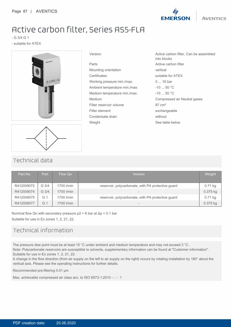
Active carbon filter, Series AS5-FLA- G 3/4 G 1- suitable for ATEX
Version Active carbon filter, Can be assembledinto blocks
Parts Active carbon filterMounting orientation verticalCertificates suitable for ATEXWorking pressure min./max. 0 ... 16 barAmbient temperature min./max. -10 ... 50 °CMedium temperature min./max. -10 ... 50 °CMedium Compressed air Neutral gasesFilter reservoir volume 87 cm³Filter element exchangeableCondensate drain withoutWeight See table below
Technical data
Part No. Port Flow Qn Version Weight
R412009072 G 3/4 1700 l/min reservoir, polycarbonate, with PA protective guard 0.71 kgR412009074 G 3/4 1700 l/min - 0.375 kgR412009075 G 1 1700 l/min reservoir, polycarbonate, with PA protective guard 0.71 kgR412009077 G 1 1700 l/min - 0.375 kg
Nominal flow Qn with secondary pressure p2 = 6 bar at Δp = 0.1 barSuitable for use in Ex zones 1, 2, 21, 22.
The pressure dew point must be at least 15 °C under ambient and medium temperature and may not exceed 3 °C .Note: Polycarbonate reservoirs are susceptible to solvents, supplementary information can be found at "Customer information".Suitable for use in Ex zones 1, 2, 21, 22.A change in the flow direction (from air supply on the left to air supply on the right) occurs by rotating installation by 180° about thevertical axis. Please see the operating instructions for further details.
Recommended pre-filtering 0.01 µm
Max. achievable compressed air class acc. to ISO 8573-1:2010 - : - : 1
Technical information
PDF creation date: 20.06.2020
Page 88 | AVENTICS
Technical information
Material
Housing Polyamide
Front plate Acrylonitrile butadiene styrene
Seals Acrylonitrile butadiene rubber
Threaded bushing Die cast zinc
Reservoir Polycarbonate Die cast zinc
Protective guard Polyamide
Filter insert Active carbon
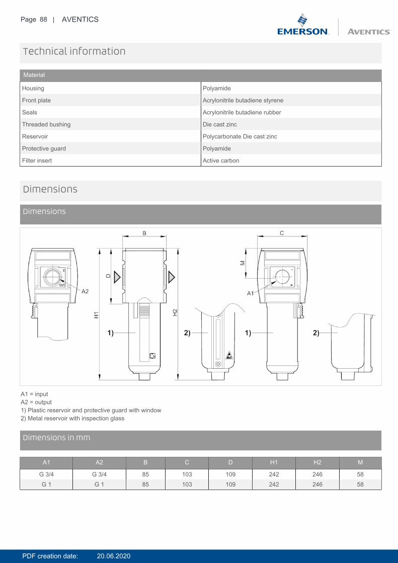
Dimensions
Dimensions
A1 = inputA2 = output1) Plastic reservoir and protective guard with window2) Metal reservoir with inspection glass
DimensionsDimensions in mm
A1 A2 B C D H1 H2 M
G 3/4 G 3/4 85 103 109 242 246 58G 1 G 1 85 103 109 242 246 58
PDF creation date: 20.06.2020
Page 89 | AVENTICS
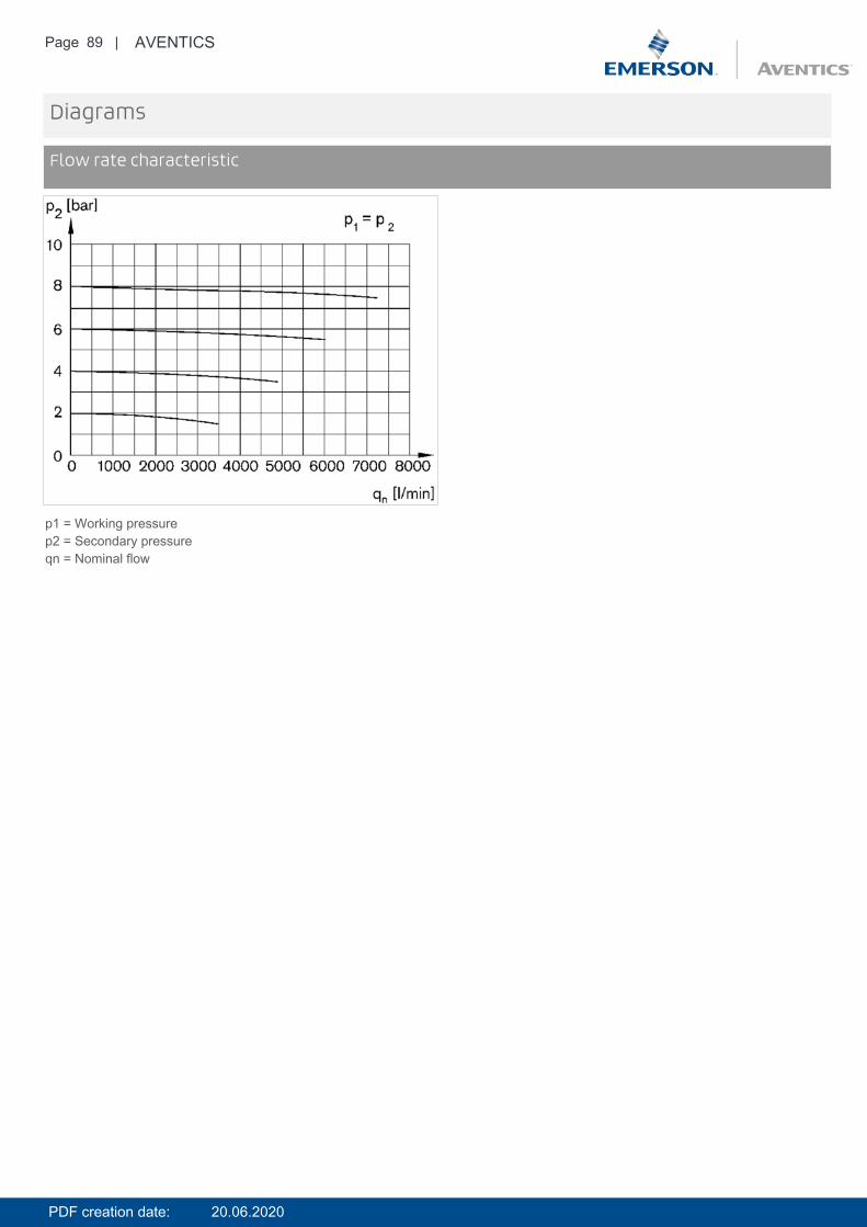
Diagrams
Flow rate characteristic
p1 = Working pressurep2 = Secondary pressureqn = Nominal flow
PDF creation date: 20.06.2020

Page 90 | AVENTICS
Accessories overview
1 = contamination display3 = Double nipple4 = Key for E11 locking5 = mortise lock6 = Transition plate DO307 = Adapter, Series CON-VP8 = Mounting aid DO16, form C9 = Mounting aid DO16, M1210 = Adapter for external pilot air11 = Adapter pneumatic operation12 = Sealing ring13 = Reducing nipple
PDF creation date: 20.06.2020

Page 91 | AVENTICS
Flow sensor, IO-Link, Series AF2- 2 analog outputs, 2 switch outputs, 1 frequency output, 1 pulse output, IO-Link, With mounting- Qn min. 22 l/min- Qn max. 6490 l/min- Electrical connection Plug, M12x1, 5-pin
Certificates CE declaration of conformity RoHS UL(Underwriters Laboratories)
Working pressure min./max. 0 ... 16 barAmbient temperature min./max. -20 ... 60 °CMedium temperature min./max. -20 ... 60 °CMedium Compressed air Argon Nitrogen Helium
Carbon dioxidefilter porosity 5 µmDisplay OLEDFlow display unit l/sec, l/min, m³/min, m³/h, ft³/s, m³/minPressure display unit bar, psiTemperature display unit °C, °FDC operating voltage min. 17 V DCDC operating voltage max. 30 V DCMax. power consumption *) 175 mAResponse time 10 msProtection class IP65, IP67 according to IEC 60529Short circuit resistance short circuit resistantShock resistance max. 30 g, 11 msVibration resistance 1 g (10 - 2000 Hz) IEC 60068 - 2-6Reproducibility ± 1.5% of the measured valueWeight 2.82 kg*) Current consumption without load
Technical data
Part No. for series Compressed airconnection
Nominal flow Qn Nominal flow Qn Nominal flow QnMin., standard Max., standard Min., extended
R412026836 AS5 G 1 22 l/min 4326 l/min 4326 l/min
Part No. Nominal flow QnMax., extended
R412026836 6490 l/min
Standard measurement range for flow measurement: compressed air 0.5 ... 100 m/s, extended measurement range: compressed air>100 ... 150 m/s, in accordance with ISO 8778, Flow display range: 0 ... 12980 l/min
Technical information
PDF creation date: 20.06.2020
Page 92 | AVENTICS
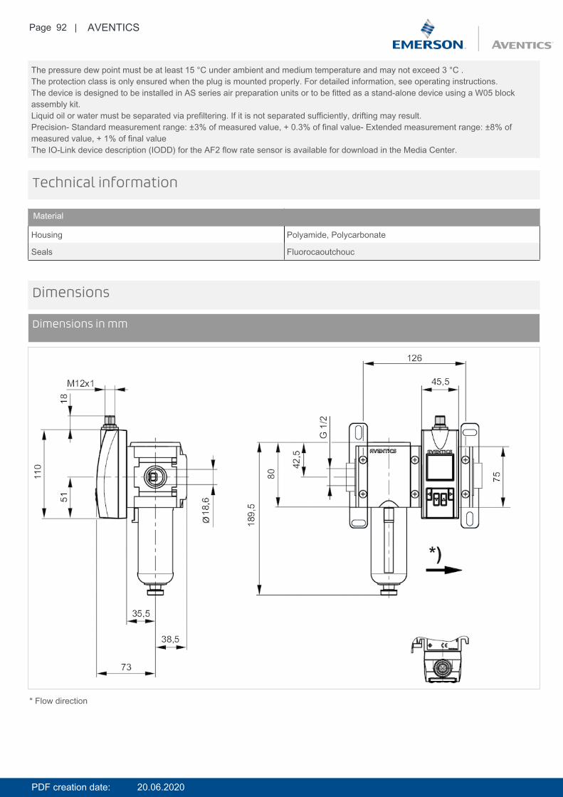
The pressure dew point must be at least 15 °C under ambient and medium temperature and may not exceed 3 °C .The protection class is only ensured when the plug is mounted properly. For detailed information, see operating instructions.The device is designed to be installed in AS series air preparation units or to be fitted as a stand-alone device using a W05 blockassembly kit.Liquid oil or water must be separated via prefiltering. If it is not separated sufficiently, drifting may result.Precision- Standard measurement range: ±3% of measured value, + 0.3% of final value- Extended measurement range: ±8% ofmeasured value, + 1% of final valueThe IO-Link device description (IODD) for the AF2 flow rate sensor is available for download in the Media Center.
Technical information
Material
Housing Polyamide, Polycarbonate
Seals Fluorocaoutchouc
Dimensions
Dimensions in mm
* Flow direction
PDF creation date: 20.06.2020
Page 93 | AVENTICS
Pin assignments
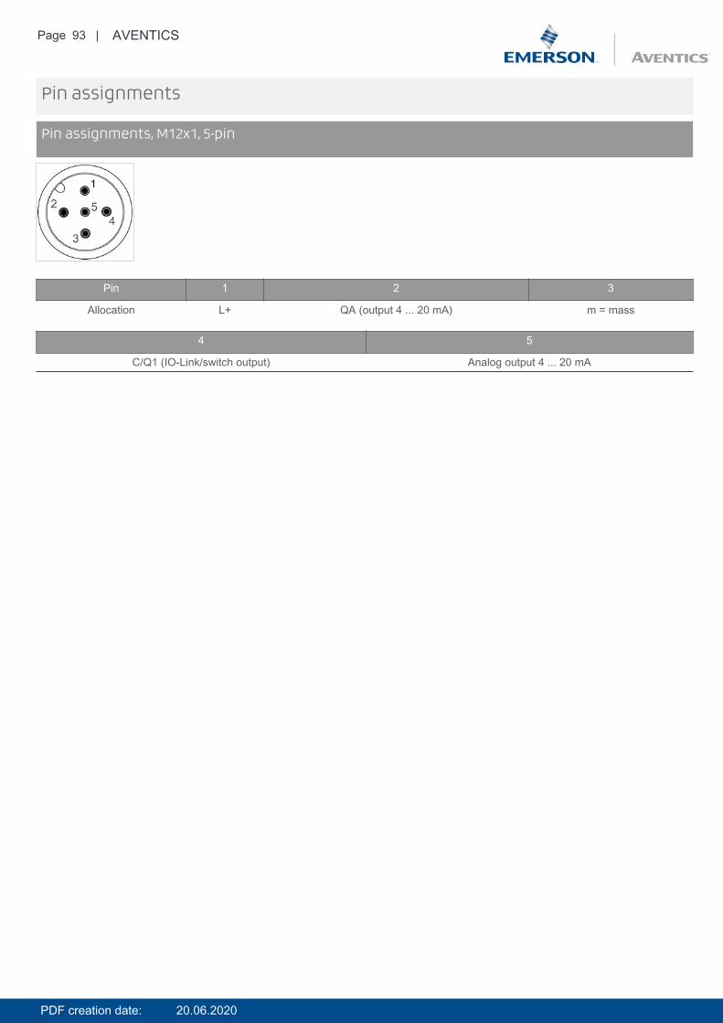
Pin assignments, M12x1, 5-pin
Pin 1 2 3
Allocation L+ QA (output 4 ... 20 mA) m = mass
4 5
C/Q1 (IO-Link/switch output) Analog output 4 ... 20 mA
PDF creation date: 20.06.2020
Page 94 | AVENTICS
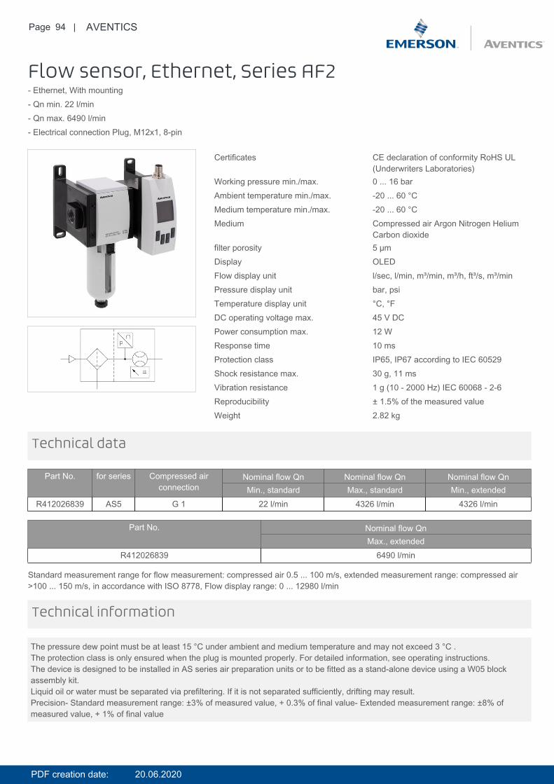
Flow sensor, Ethernet, Series AF2- Ethernet, With mounting- Qn min. 22 l/min- Qn max. 6490 l/min- Electrical connection Plug, M12x1, 8-pin
Certificates CE declaration of conformity RoHS UL(Underwriters Laboratories)
Working pressure min./max. 0 ... 16 barAmbient temperature min./max. -20 ... 60 °CMedium temperature min./max. -20 ... 60 °CMedium Compressed air Argon Nitrogen Helium
Carbon dioxidefilter porosity 5 µmDisplay OLEDFlow display unit l/sec, l/min, m³/min, m³/h, ft³/s, m³/minPressure display unit bar, psiTemperature display unit °C, °FDC operating voltage max. 45 V DCPower consumption max. 12 WResponse time 10 msProtection class IP65, IP67 according to IEC 60529Shock resistance max. 30 g, 11 msVibration resistance 1 g (10 - 2000 Hz) IEC 60068 - 2-6Reproducibility ± 1.5% of the measured valueWeight 2.82 kg
Technical data
Part No. for series Compressed airconnection
Nominal flow Qn Nominal flow Qn Nominal flow QnMin., standard Max., standard Min., extended
R412026839 AS5 G 1 22 l/min 4326 l/min 4326 l/min
Part No. Nominal flow QnMax., extended
R412026839 6490 l/min
Standard measurement range for flow measurement: compressed air 0.5 ... 100 m/s, extended measurement range: compressed air>100 ... 150 m/s, in accordance with ISO 8778, Flow display range: 0 ... 12980 l/min
The pressure dew point must be at least 15 °C under ambient and medium temperature and may not exceed 3 °C .The protection class is only ensured when the plug is mounted properly. For detailed information, see operating instructions.The device is designed to be installed in AS series air preparation units or to be fitted as a stand-alone device using a W05 blockassembly kit.Liquid oil or water must be separated via prefiltering. If it is not separated sufficiently, drifting may result.Precision- Standard measurement range: ±3% of measured value, + 0.3% of final value- Extended measurement range: ±8% ofmeasured value, + 1% of final value
Technical information
PDF creation date: 20.06.2020
Page 95 | AVENTICS
Technical information
Material
Housing Polyamide, Polycarbonate
Seals Fluorocaoutchouc
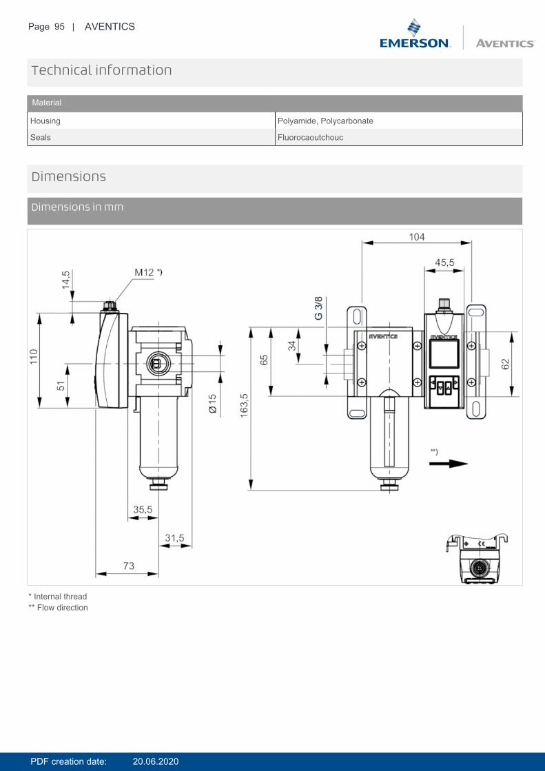
Dimensions
Dimensions in mm
* Internal thread** Flow direction
PDF creation date: 20.06.2020

Page 96 | AVENTICS
Pin assignments
Pin assignments, M12, X-coded
Pin 1 2 3 4 7 8 5
Color WH / OG OG WH / GN GN WH / BU BU WH / BNFunction TX(+) + POE TX(-) + POE RX(+) - POE RX(-) - POE POE+ POE+ POE-
6
BNPOE-
PDF creation date: 20.06.2020
Page 97 | AVENTICS
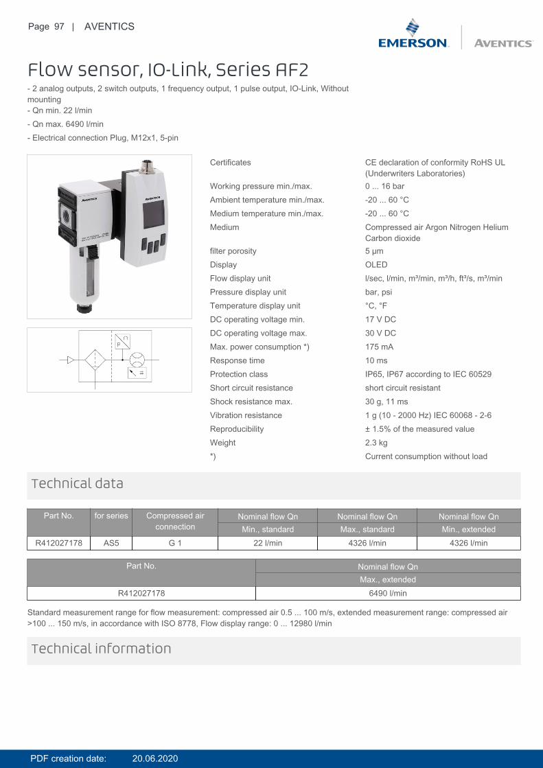
Flow sensor, IO-Link, Series AF2- 2 analog outputs, 2 switch outputs, 1 frequency output, 1 pulse output, IO-Link, Withoutmounting- Qn min. 22 l/min- Qn max. 6490 l/min- Electrical connection Plug, M12x1, 5-pin
Certificates CE declaration of conformity RoHS UL(Underwriters Laboratories)
Working pressure min./max. 0 ... 16 barAmbient temperature min./max. -20 ... 60 °CMedium temperature min./max. -20 ... 60 °CMedium Compressed air Argon Nitrogen Helium
Carbon dioxidefilter porosity 5 µmDisplay OLEDFlow display unit l/sec, l/min, m³/min, m³/h, ft³/s, m³/minPressure display unit bar, psiTemperature display unit °C, °FDC operating voltage min. 17 V DCDC operating voltage max. 30 V DCMax. power consumption *) 175 mAResponse time 10 msProtection class IP65, IP67 according to IEC 60529Short circuit resistance short circuit resistantShock resistance max. 30 g, 11 msVibration resistance 1 g (10 - 2000 Hz) IEC 60068 - 2-6Reproducibility ± 1.5% of the measured valueWeight 2.3 kg*) Current consumption without load
Technical data
Part No. for series Compressed airconnection
Nominal flow Qn Nominal flow Qn Nominal flow QnMin., standard Max., standard Min., extended
R412027178 AS5 G 1 22 l/min 4326 l/min 4326 l/min
Part No. Nominal flow QnMax., extended
R412027178 6490 l/min
Standard measurement range for flow measurement: compressed air 0.5 ... 100 m/s, extended measurement range: compressed air>100 ... 150 m/s, in accordance with ISO 8778, Flow display range: 0 ... 12980 l/min
Technical information
PDF creation date: 20.06.2020
Page 98 | AVENTICS
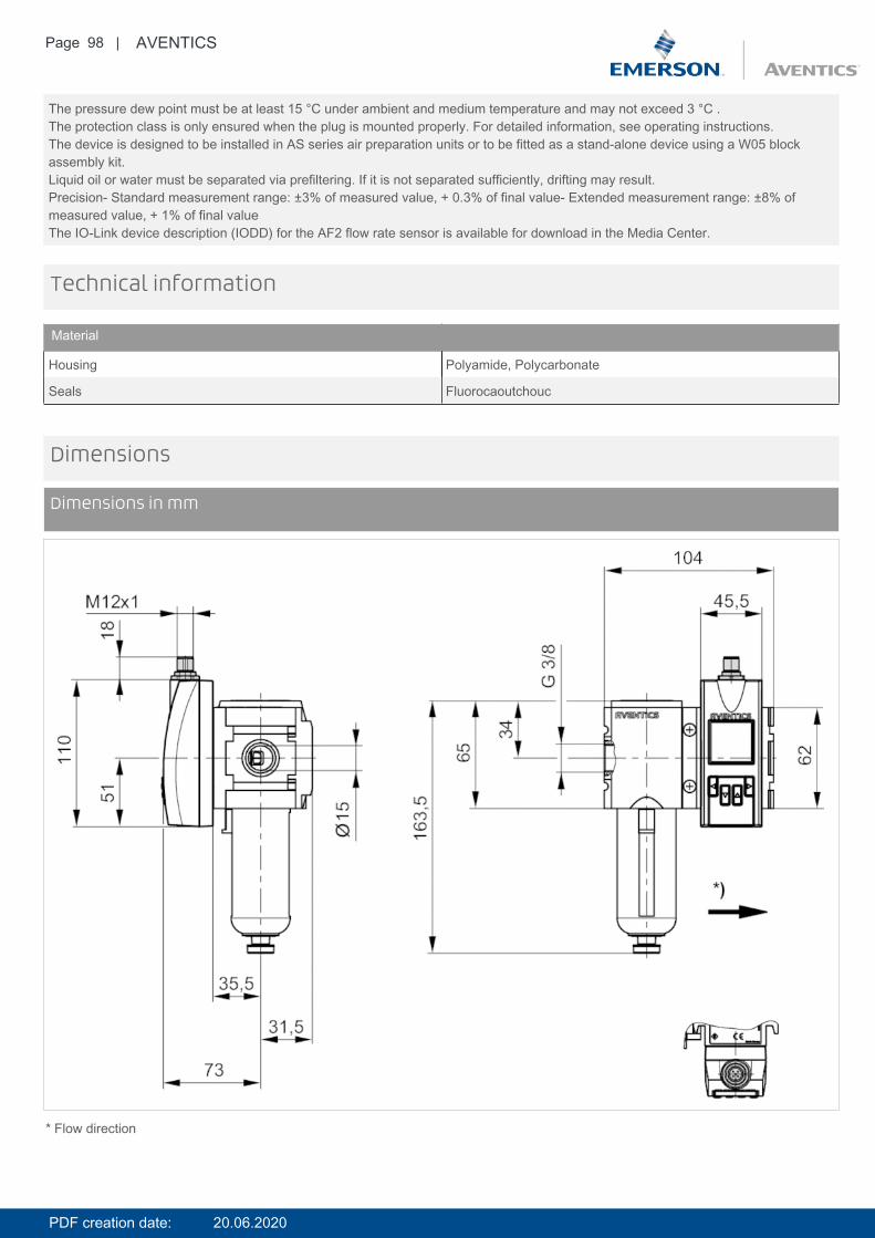
The pressure dew point must be at least 15 °C under ambient and medium temperature and may not exceed 3 °C .The protection class is only ensured when the plug is mounted properly. For detailed information, see operating instructions.The device is designed to be installed in AS series air preparation units or to be fitted as a stand-alone device using a W05 blockassembly kit.Liquid oil or water must be separated via prefiltering. If it is not separated sufficiently, drifting may result.Precision- Standard measurement range: ±3% of measured value, + 0.3% of final value- Extended measurement range: ±8% ofmeasured value, + 1% of final valueThe IO-Link device description (IODD) for the AF2 flow rate sensor is available for download in the Media Center.
Technical information
Material
Housing Polyamide, Polycarbonate
Seals Fluorocaoutchouc
Dimensions
Dimensions in mm
* Flow direction
PDF creation date: 20.06.2020

Page 99 | AVENTICS
Pin assignments
Pin assignments, M12x1, 5-pin
Pin 1 2 3
Allocation L+ QA (output 4 ... 20 mA) m = mass
4 5
C/Q1 (IO-Link/switch output) Analog output 4 ... 20 mA
PDF creation date: 20.06.2020
Page 100 | AVENTICS
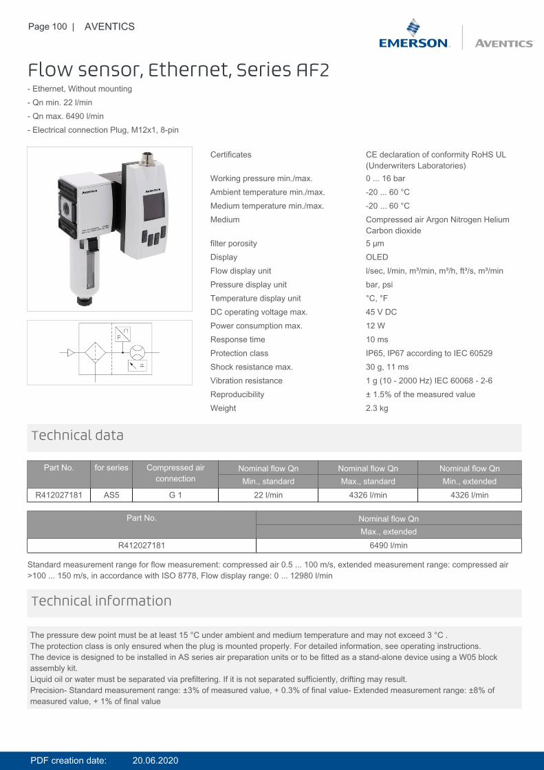
Flow sensor, Ethernet, Series AF2- Ethernet, Without mounting- Qn min. 22 l/min- Qn max. 6490 l/min- Electrical connection Plug, M12x1, 8-pin
Certificates CE declaration of conformity RoHS UL(Underwriters Laboratories)
Working pressure min./max. 0 ... 16 barAmbient temperature min./max. -20 ... 60 °CMedium temperature min./max. -20 ... 60 °CMedium Compressed air Argon Nitrogen Helium
Carbon dioxidefilter porosity 5 µmDisplay OLEDFlow display unit l/sec, l/min, m³/min, m³/h, ft³/s, m³/minPressure display unit bar, psiTemperature display unit °C, °FDC operating voltage max. 45 V DCPower consumption max. 12 WResponse time 10 msProtection class IP65, IP67 according to IEC 60529Shock resistance max. 30 g, 11 msVibration resistance 1 g (10 - 2000 Hz) IEC 60068 - 2-6Reproducibility ± 1.5% of the measured valueWeight 2.3 kg
Technical data
Part No. for series Compressed airconnection
Nominal flow Qn Nominal flow Qn Nominal flow QnMin., standard Max., standard Min., extended
R412027181 AS5 G 1 22 l/min 4326 l/min 4326 l/min
Part No. Nominal flow QnMax., extended
R412027181 6490 l/min
Standard measurement range for flow measurement: compressed air 0.5 ... 100 m/s, extended measurement range: compressed air>100 ... 150 m/s, in accordance with ISO 8778, Flow display range: 0 ... 12980 l/min
The pressure dew point must be at least 15 °C under ambient and medium temperature and may not exceed 3 °C .The protection class is only ensured when the plug is mounted properly. For detailed information, see operating instructions.The device is designed to be installed in AS series air preparation units or to be fitted as a stand-alone device using a W05 blockassembly kit.Liquid oil or water must be separated via prefiltering. If it is not separated sufficiently, drifting may result.Precision- Standard measurement range: ±3% of measured value, + 0.3% of final value- Extended measurement range: ±8% ofmeasured value, + 1% of final value
Technical information
PDF creation date: 20.06.2020

Page 101 | AVENTICS
Technical information
Material
Housing Polyamide, Polycarbonate
Seals Fluorocaoutchouc
Dimensions
Dimensions in mm
* Internal thread** Flow direction
PDF creation date: 20.06.2020
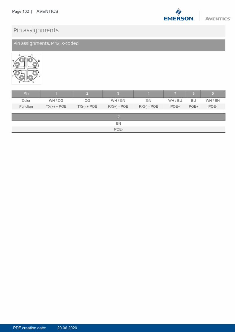
Page 102 | AVENTICS
Pin assignments
Pin assignments, M12, X-coded
Pin 1 2 3 4 7 8 5
Color WH / OG OG WH / GN GN WH / BU BU WH / BNFunction TX(+) + POE TX(-) + POE RX(+) - POE RX(-) - POE POE+ POE+ POE-
6
BNPOE-
PDF creation date: 20.06.2020
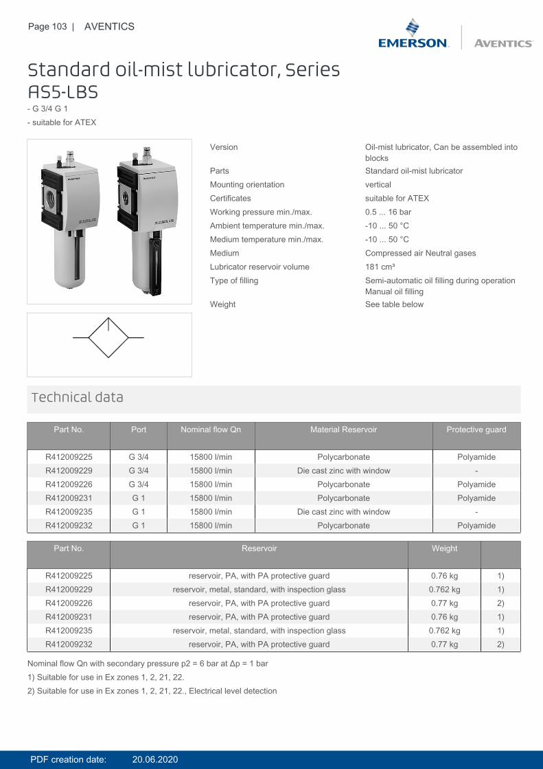
Page 103 | AVENTICS
Standard oil-mist lubricator, SeriesAS5-LBS- G 3/4 G 1- suitable for ATEX
Version Oil-mist lubricator, Can be assembled intoblocks
Parts Standard oil-mist lubricatorMounting orientation verticalCertificates suitable for ATEXWorking pressure min./max. 0.5 ... 16 barAmbient temperature min./max. -10 ... 50 °CMedium temperature min./max. -10 ... 50 °CMedium Compressed air Neutral gasesLubricator reservoir volume 181 cm³Type of filling Semi-automatic oil filling during operation
Manual oil fillingWeight See table below
Technical data
Part No. Port Nominal flow Qn Material Reservoir Protective guard
R412009225 G 3/4 15800 l/min Polycarbonate PolyamideR412009229 G 3/4 15800 l/min Die cast zinc with window -R412009226 G 3/4 15800 l/min Polycarbonate PolyamideR412009231 G 1 15800 l/min Polycarbonate PolyamideR412009235 G 1 15800 l/min Die cast zinc with window -R412009232 G 1 15800 l/min Polycarbonate Polyamide
Part No. Reservoir Weight
R412009225 reservoir, PA, with PA protective guard 0.76 kg 1)R412009229 reservoir, metal, standard, with inspection glass 0.762 kg 1)R412009226 reservoir, PA, with PA protective guard 0.77 kg 2)R412009231 reservoir, PA, with PA protective guard 0.76 kg 1)R412009235 reservoir, metal, standard, with inspection glass 0.762 kg 1)R412009232 reservoir, PA, with PA protective guard 0.77 kg 2)
Nominal flow Qn with secondary pressure p2 = 6 bar at Δp = 1 bar1) Suitable for use in Ex zones 1, 2, 21, 22.2) Suitable for use in Ex zones 1, 2, 21, 22., Electrical level detection
PDF creation date: 20.06.2020
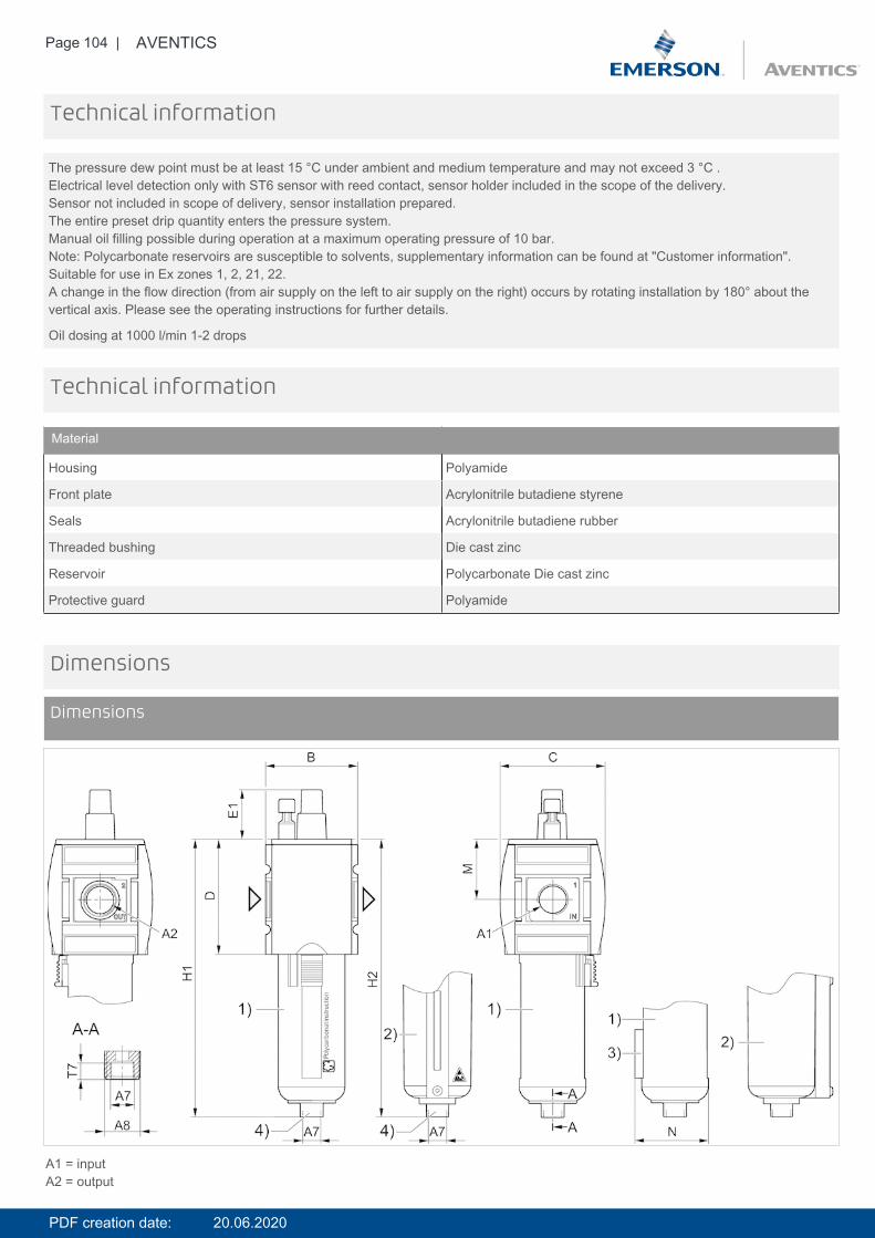
Page 104 | AVENTICS
The pressure dew point must be at least 15 °C under ambient and medium temperature and may not exceed 3 °C .Electrical level detection only with ST6 sensor with reed contact, sensor holder included in the scope of the delivery.Sensor not included in scope of delivery, sensor installation prepared.The entire preset drip quantity enters the pressure system.Manual oil filling possible during operation at a maximum operating pressure of 10 bar.Note: Polycarbonate reservoirs are susceptible to solvents, supplementary information can be found at "Customer information".Suitable for use in Ex zones 1, 2, 21, 22.A change in the flow direction (from air supply on the left to air supply on the right) occurs by rotating installation by 180° about thevertical axis. Please see the operating instructions for further details.
Oil dosing at 1000 l/min 1-2 drops
Technical information
Technical information
Material
Housing Polyamide
Front plate Acrylonitrile butadiene styrene
Seals Acrylonitrile butadiene rubber
Threaded bushing Die cast zinc
Reservoir Polycarbonate Die cast zinc
Protective guard Polyamide
Dimensions
Dimensions
A1 = inputA2 = output
PDF creation date: 20.06.2020
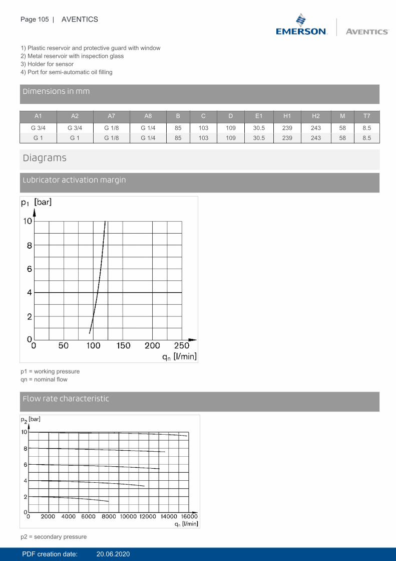
Page 105 | AVENTICS
1) Plastic reservoir and protective guard with window2) Metal reservoir with inspection glass3) Holder for sensor4) Port for semi-automatic oil filling
DimensionsDimensions in mm
A1 A2 A7 A8 B C D E1 H1 H2 M T7
G 3/4 G 3/4 G 1/8 G 1/4 85 103 109 30.5 239 243 58 8.5G 1 G 1 G 1/8 G 1/4 85 103 109 30.5 239 243 58 8.5
Diagrams
Lubricator activation margin
p1 = working pressureqn = nominal flow
DiagramsFlow rate characteristic
p2 = secondary pressure
PDF creation date: 20.06.2020

Page 106 | AVENTICS
qn = nominal flow
Accessories overview
1 = contamination display3 = Double nipple4 = Key for E11 locking5 = mortise lock6 = Transition plate DO307 = Adapter, Series CON-VP8 = Mounting aid DO16, form C9 = Mounting aid DO16, M1210 = Adapter for external pilot air11 = Adapter pneumatic operation12 = Sealing ring13 = Reducing nipple
PDF creation date: 20.06.2020
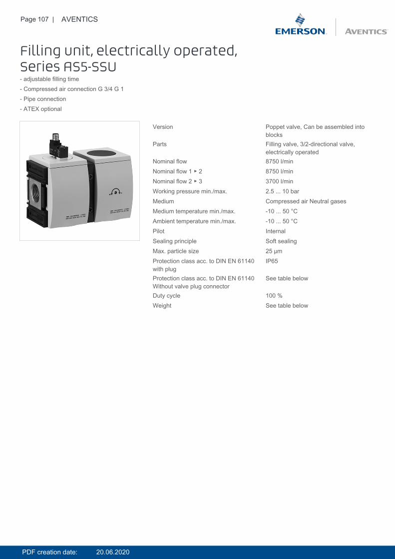
Page 107 | AVENTICS
Filling unit, electrically operated,Series AS5-SSU- adjustable filling time- Compressed air connection G 3/4 G 1- Pipe connection- ATEX optional
Version Poppet valve, Can be assembled intoblocks
Parts Filling valve, 3/2-directional valve,electrically operated
Nominal flow 8750 l/minNominal flow 1 ▶ 2 8750 l/minNominal flow 2 ▶ 3 3700 l/minWorking pressure min./max. 2.5 ... 10 barMedium Compressed air Neutral gasesMedium temperature min./max. -10 ... 50 °CAmbient temperature min./max. -10 ... 50 °CPilot InternalSealing principle Soft sealingMax. particle size 25 µmProtection class acc. to DIN EN 61140with plug
IP65
Protection class acc. to DIN EN 61140Without valve plug connector
See table below
Duty cycle 100 %Weight See table below
PDF creation date: 20.06.2020
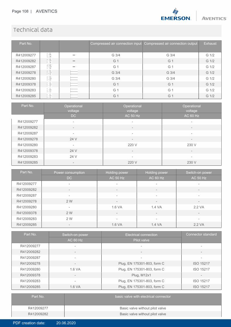
Page 108 | AVENTICS
Technical data
Part No. Compressed air connection input Compressed air connection output Exhaust
R412009277 G 3/4 G 3/4 G 1/2R412009282 G 1 G 1 G 1/2R412009287 G 1 G 1 G 1/2R412009278 G 3/4 G 3/4 G 1/2R412009280 G 3/4 G 3/4 G 1/2R412009378 G 1 G 1 G 1/2R412009283 G 1 G 1 G 1/2R412009285 G 1 G 1 G 1/2
Part No. Operationalvoltage
Operationalvoltage
Operationalvoltage
DC AC 50 Hz AC 60 HzR412009277 - - -R412009282 - - -R412009287 - - -R412009278 24 V - -R412009280 - 220 V 230 VR412009378 24 V - -R412009283 24 V - -R412009285 - 220 V 230 V
Part No. Power consumption Holding power Holding power Switch-on powerDC AC 50 Hz AC 60 Hz AC 50 Hz
R412009277 - - - -R412009282 - - - -R412009287 - - - -R412009278 2 W - - -R412009280 - 1.6 VA 1.4 VA 2.2 VAR412009378 2 W - - -R412009283 2 W - - -R412009285 - 1.6 VA 1.4 VA 2.2 VA
Part No. Switch-on power Electrical connection Connector standardAC 60 Hz Pilot valve
R412009277 - - -R412009282 - - -R412009287 - - -R412009278 - Plug, EN 175301-803, form C ISO 15217R412009280 1.6 VA Plug, EN 175301-803, form C ISO 15217R412009378 - Plug, M12x1 -R412009283 - Plug, EN 175301-803, form C ISO 15217R412009285 1.6 VA Plug, EN 175301-803, form C ISO 15217
Part No. basic valve with electrical connector
R412009277 Basic valve without pilot valveR412009282 Basic valve without pilot valve
PDF creation date: 20.06.2020
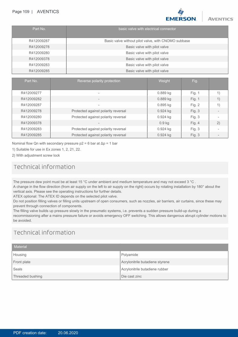
Page 109 | AVENTICS
Part No. basic valve with electrical connector
R412009287 Basic valve without pilot valve, with CNOMO subbaseR412009278 Basic valve with pilot valveR412009280 Basic valve with pilot valveR412009378 Basic valve with pilot valveR412009283 Basic valve with pilot valveR412009285 Basic valve with pilot valve
Part No. Reverse polarity protection Weight Fig.
R412009277 - 0.889 kg Fig. 1 1)R412009282 - 0.889 kg Fig. 1 1)R412009287 - 0.895 kg Fig. 2 1)R412009278 Protected against polarity reversal 0.924 kg Fig. 3 -R412009280 Protected against polarity reversal 0.924 kg Fig. 3 -R412009378 - 0.9 kg Fig. 4 2)R412009283 Protected against polarity reversal 0.924 kg Fig. 3 -R412009285 Protected against polarity reversal 0.924 kg Fig. 3 -
Nominal flow Qn with secondary pressure p2 = 6 bar at Δp = 1 bar1) Suitable for use in Ex zones 1, 2, 21, 22.2) With adjustment screw lock
The pressure dew point must be at least 15 °C under ambient and medium temperature and may not exceed 3 °C .A change in the flow direction (from air supply on the left to air supply on the right) occurs by rotating installation by 180° about thevertical axis. Please see the operating instructions for further details.ATEX optional: The ATEX ID depends on the selected pilot valve.Do not position filling valves or filling units upstream of open consumers, such as nozzles, air barriers, air curtains, since these mayprevent through connection of components.The filling valve builds up pressure slowly in the pneumatic systems, i.e. prevents a sudden pressure build-up during arecommissioning after a mains pressure failure or avoids emergency OFF switching. This allows dangerous abrupt cylinder motions tobe avoided.
Technical information
Technical information
Material
Housing Polyamide
Front plate Acrylonitrile butadiene styrene
Seals Acrylonitrile butadiene rubber
Threaded bushing Die cast zinc
PDF creation date: 20.06.2020
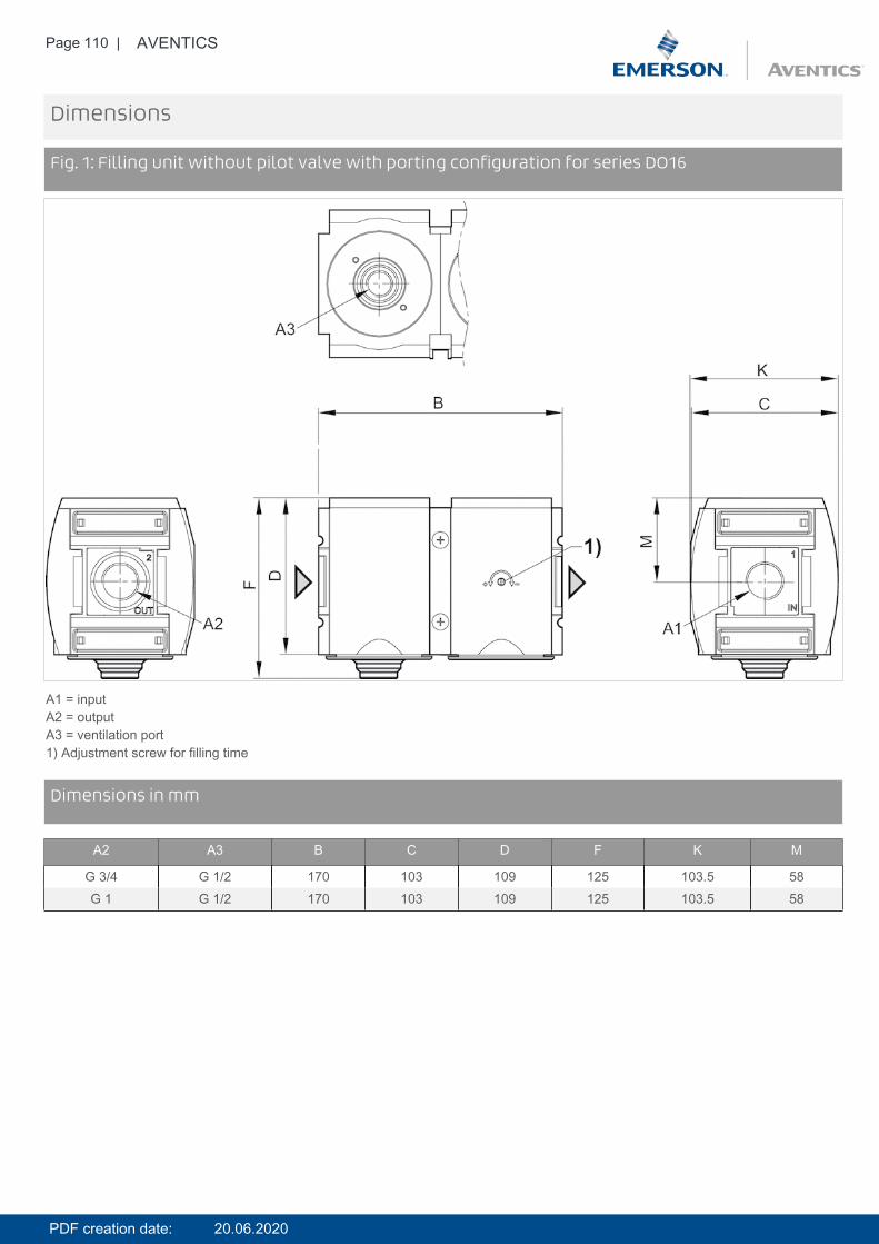
Page 110 | AVENTICS
Dimensions
Fig. 1: Filling unit without pilot valve with porting configuration for series DO16
A1 = inputA2 = outputA3 = ventilation port1) Adjustment screw for filling time
DimensionsDimensions in mm
A2 A3 B C D F K M
G 3/4 G 1/2 170 103 109 125 103.5 58G 1 G 1/2 170 103 109 125 103.5 58
PDF creation date: 20.06.2020
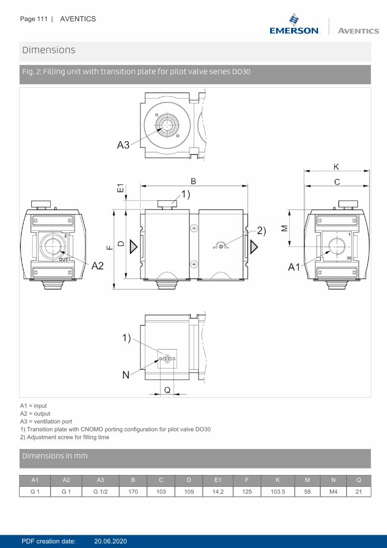
Page 111 | AVENTICS
Dimensions
Fig. 2: Filling unit with transition plate for pilot valve series DO30
A1 = inputA2 = outputA3 = ventilation port1) Transition plate with CNOMO porting configuration for pilot valve DO302) Adjustment screw for filling time
DimensionsDimensions in mm
A1 A2 A3 B C D E1 F K M N Q
G 1 G 1 G 1/2 170 103 109 14.2 125 103.5 58 M4 21
PDF creation date: 20.06.2020
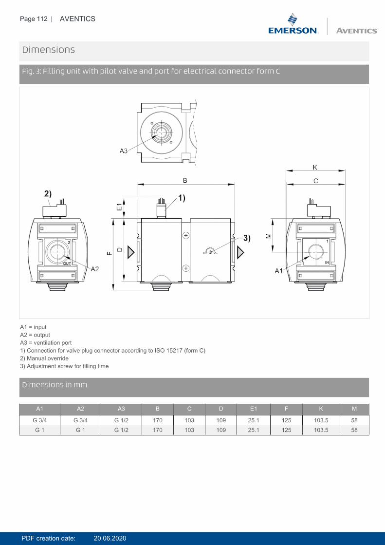
Page 112 | AVENTICS
Dimensions
Fig. 3: Filling unit with pilot valve and port for electrical connector form C
A1 = inputA2 = outputA3 = ventilation port1) Connection for valve plug connector according to ISO 15217 (form C)2) Manual override3) Adjustment screw for filling time
DimensionsDimensions in mm
A1 A2 A3 B C D E1 F K M
G 3/4 G 3/4 G 1/2 170 103 109 25.1 125 103.5 58G 1 G 1 G 1/2 170 103 109 25.1 125 103.5 58
PDF creation date: 20.06.2020
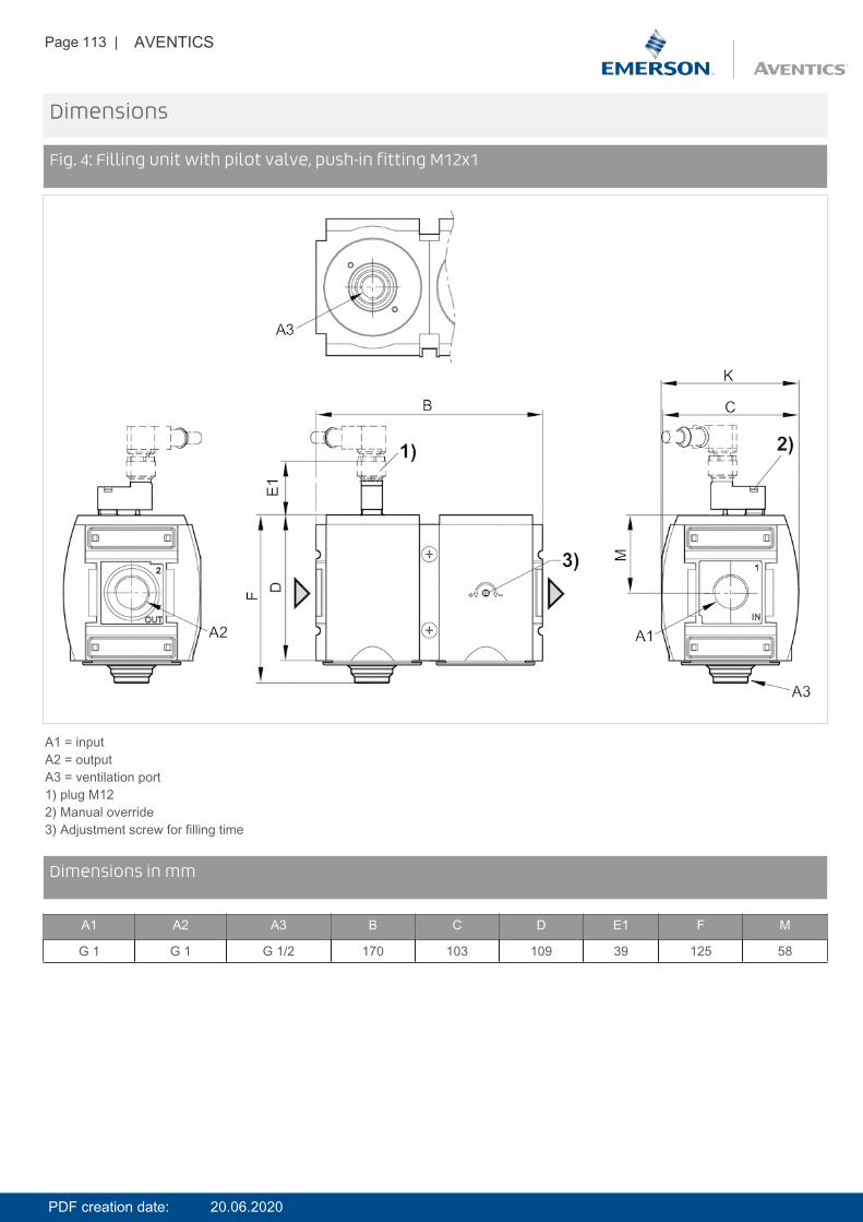
Page 113 | AVENTICS
Dimensions
Fig. 4: Filling unit with pilot valve, push-in fitting M12x1
A1 = inputA2 = outputA3 = ventilation port1) plug M122) Manual override3) Adjustment screw for filling time
DimensionsDimensions in mm
A1 A2 A3 B C D E1 F M
G 1 G 1 G 1/2 170 103 109 39 125 58
PDF creation date: 20.06.2020
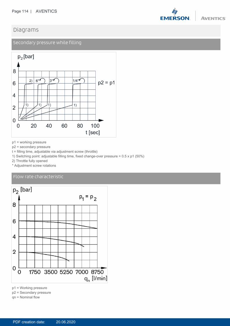
Page 114 | AVENTICS
Diagrams
Secondary pressure while filling
p1 = working pressurep2 = secondary pressuret = filling time, adjustable via adjustment screw (throttle)1) Switching point: adjustable filling time, fixed change-over pressure ≈ 0.5 x p1 (50%)2) Throttle fully opened* Adjustment screw rotations
DiagramsFlow rate characteristic
p1 = Working pressurep2 = Secondary pressureqn = Nominal flow
PDF creation date: 20.06.2020

Page 115 | AVENTICS
Pin assignments
Pin assignment M12x1
3: +/-4: +/-
Accessories overview
1 = contamination display3 = Double nipple4 = Key for E11 locking5 = mortise lock
PDF creation date: 20.06.2020

Page 116 | AVENTICS
6 = Transition plate DO307 = Adapter, Series CON-VP8 = Mounting aid DO16, form C9 = Mounting aid DO16, M1210 = Adapter for external pilot air11 = Adapter pneumatic operation12 = Sealing ring13 = Reducing nipple
PDF creation date: 20.06.2020
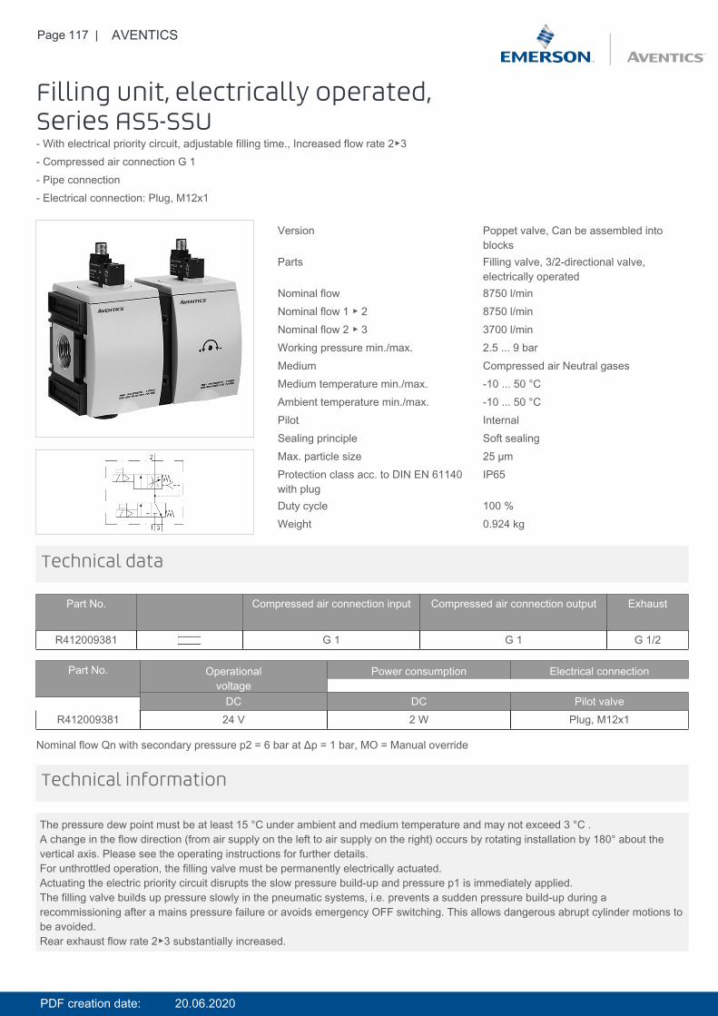
Page 117 | AVENTICS
Filling unit, electrically operated,Series AS5-SSU- With electrical priority circuit, adjustable filling time., Increased flow rate 2▶3- Compressed air connection G 1- Pipe connection- Electrical connection: Plug, M12x1
Version Poppet valve, Can be assembled intoblocks
Parts Filling valve, 3/2-directional valve,electrically operated
Nominal flow 8750 l/minNominal flow 1 ▶ 2 8750 l/minNominal flow 2 ▶ 3 3700 l/minWorking pressure min./max. 2.5 ... 9 barMedium Compressed air Neutral gasesMedium temperature min./max. -10 ... 50 °CAmbient temperature min./max. -10 ... 50 °CPilot InternalSealing principle Soft sealingMax. particle size 25 µmProtection class acc. to DIN EN 61140with plug
IP65
Duty cycle 100 %Weight 0.924 kg
Technical data
Part No. Compressed air connection input Compressed air connection output Exhaust
R412009381 G 1 G 1 G 1/2
Part No. Operationalvoltage
Power consumption Electrical connection
DC DC Pilot valveR412009381 24 V 2 W Plug, M12x1
Nominal flow Qn with secondary pressure p2 = 6 bar at Δp = 1 bar, MO = Manual override
The pressure dew point must be at least 15 °C under ambient and medium temperature and may not exceed 3 °C .A change in the flow direction (from air supply on the left to air supply on the right) occurs by rotating installation by 180° about thevertical axis. Please see the operating instructions for further details.For unthrottled operation, the filling valve must be permanently electrically actuated.Actuating the electric priority circuit disrupts the slow pressure build-up and pressure p1 is immediately applied.The filling valve builds up pressure slowly in the pneumatic systems, i.e. prevents a sudden pressure build-up during arecommissioning after a mains pressure failure or avoids emergency OFF switching. This allows dangerous abrupt cylinder motions tobe avoided.Rear exhaust flow rate 2▶3 substantially increased.
Technical information
PDF creation date: 20.06.2020
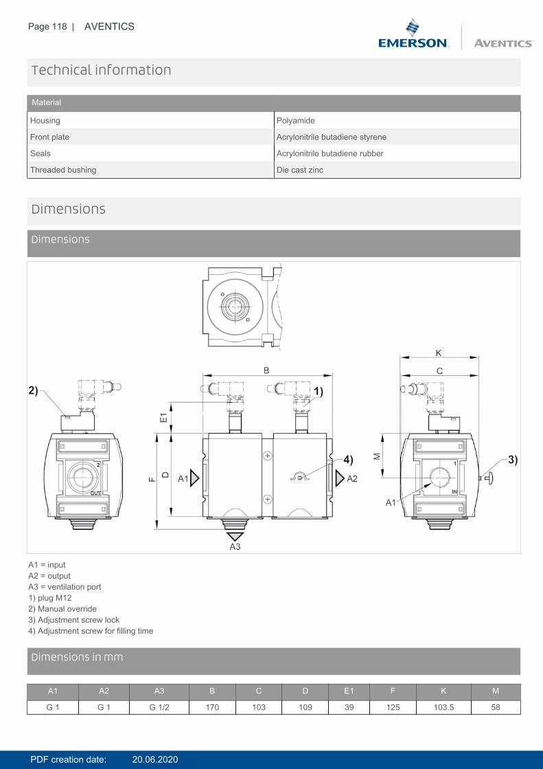
Page 118 | AVENTICS
Technical information
Material
Housing Polyamide
Front plate Acrylonitrile butadiene styrene
Seals Acrylonitrile butadiene rubber
Threaded bushing Die cast zinc
Dimensions
Dimensions
A1 = inputA2 = outputA3 = ventilation port1) plug M122) Manual override3) Adjustment screw lock4) Adjustment screw for filling time
DimensionsDimensions in mm
A1 A2 A3 B C D E1 F K M
G 1 G 1 G 1/2 170 103 109 39 125 103.5 58
PDF creation date: 20.06.2020
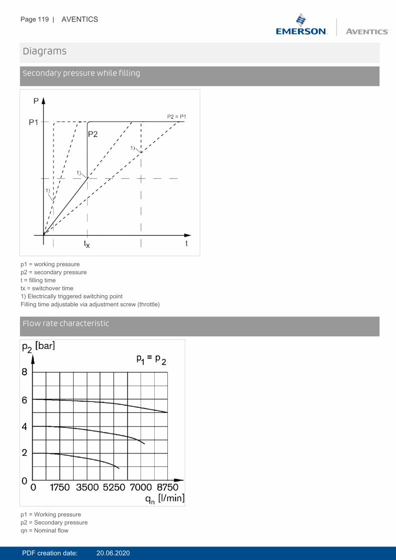
Page 119 | AVENTICS
Diagrams
Secondary pressure while filling
p1 = working pressurep2 = secondary pressuret = filling timetx = switchover time1) Electrically triggered switching pointFilling time adjustable via adjustment screw (throttle)
DiagramsFlow rate characteristic
p1 = Working pressurep2 = Secondary pressureqn = Nominal flow
PDF creation date: 20.06.2020
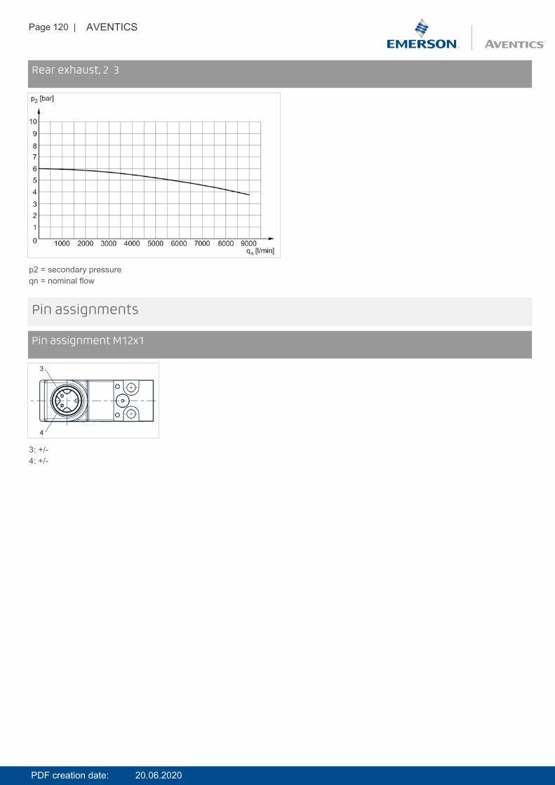
Page 120 | AVENTICS
DiagramsRear exhaust, 2 3
p2 = secondary pressureqn = nominal flow
Pin assignments
Pin assignment M12x1
3: +/-4: +/-
PDF creation date: 20.06.2020

Page 121 | AVENTICS
Accessories overview
1 = contamination display3 = Double nipple4 = Key for E11 locking5 = mortise lock6 = Transition plate DO307 = Adapter, Series CON-VP8 = Mounting aid DO16, form C9 = Mounting aid DO16, M1210 = Adapter for external pilot air11 = Adapter pneumatic operation12 = Sealing ring13 = Reducing nipple
PDF creation date: 20.06.2020
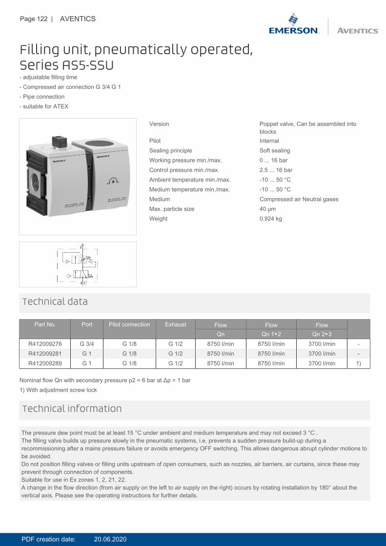
Page 122 | AVENTICS
Filling unit, pneumatically operated,Series AS5-SSU- adjustable filling time- Compressed air connection G 3/4 G 1- Pipe connection- suitable for ATEX
Version Poppet valve, Can be assembled intoblocks
Pilot InternalSealing principle Soft sealingWorking pressure min./max. 0 ... 16 barControl pressure min./max. 2.5 ... 16 barAmbient temperature min./max. -10 ... 50 °CMedium temperature min./max. -10 ... 50 °CMedium Compressed air Neutral gasesMax. particle size 40 µmWeight 0.924 kg
Technical data
Part No. Port Pilot connection Exhaust Flow Flow FlowQn Qn 1▶2 Qn 2▶3
R412009276 G 3/4 G 1/8 G 1/2 8750 l/min 8750 l/min 3700 l/min -R412009281 G 1 G 1/8 G 1/2 8750 l/min 8750 l/min 3700 l/min -R412009289 G 1 G 1/8 G 1/2 8750 l/min 8750 l/min 3700 l/min 1)
Nominal flow Qn with secondary pressure p2 = 6 bar at Δp = 1 bar1) With adjustment screw lock
The pressure dew point must be at least 15 °C under ambient and medium temperature and may not exceed 3 °C .The filling valve builds up pressure slowly in the pneumatic systems, i.e. prevents a sudden pressure build-up during arecommissioning after a mains pressure failure or avoids emergency OFF switching. This allows dangerous abrupt cylinder motions tobe avoided.Do not position filling valves or filling units upstream of open consumers, such as nozzles, air barriers, air curtains, since these mayprevent through connection of components.Suitable for use in Ex zones 1, 2, 21, 22.A change in the flow direction (from air supply on the left to air supply on the right) occurs by rotating installation by 180° about thevertical axis. Please see the operating instructions for further details.
Technical information
PDF creation date: 20.06.2020
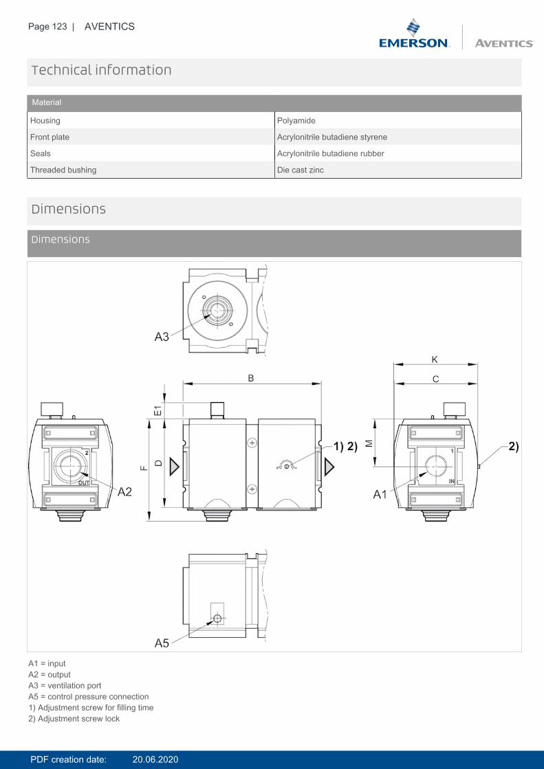
Page 123 | AVENTICS
Technical information
Material
Housing Polyamide
Front plate Acrylonitrile butadiene styrene
Seals Acrylonitrile butadiene rubber
Threaded bushing Die cast zinc
Dimensions
Dimensions
A1 = inputA2 = outputA3 = ventilation portA5 = control pressure connection1) Adjustment screw for filling time2) Adjustment screw lock
PDF creation date: 20.06.2020
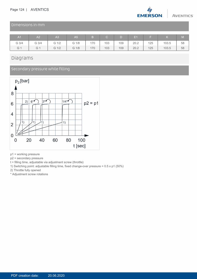
Page 124 | AVENTICS
DimensionsDimensions in mm
A1 A2 A3 A5 B C D E1 F K M
G 3/4 G 3/4 G 1/2 G 1/8 170 103 109 20.2 125 103.5 58G 1 G 1 G 1/2 G 1/8 170 103 109 20.2 125 103.5 58
Diagrams
Secondary pressure while filling
p1 = working pressurep2 = secondary pressuret = filling time, adjustable via adjustment screw (throttle)1) Switching point: adjustable filling time, fixed change-over pressure ≈ 0.5 x p1 (50%)2) Throttle fully opened* Adjustment screw rotations
PDF creation date: 20.06.2020
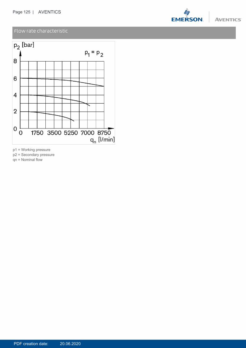
Page 125 | AVENTICS
DiagramsFlow rate characteristic
p1 = Working pressurep2 = Secondary pressureqn = Nominal flow
PDF creation date: 20.06.2020

Page 126 | AVENTICS
Accessories overview
1 = contamination display3 = Double nipple4 = Key for E11 locking5 = mortise lock6 = Transition plate DO307 = Adapter, Series CON-VP8 = Mounting aid DO16, form C9 = Mounting aid DO16, M1210 = Adapter for external pilot air11 = Adapter pneumatic operation12 = Sealing ring13 = Reducing nipple
PDF creation date: 20.06.2020
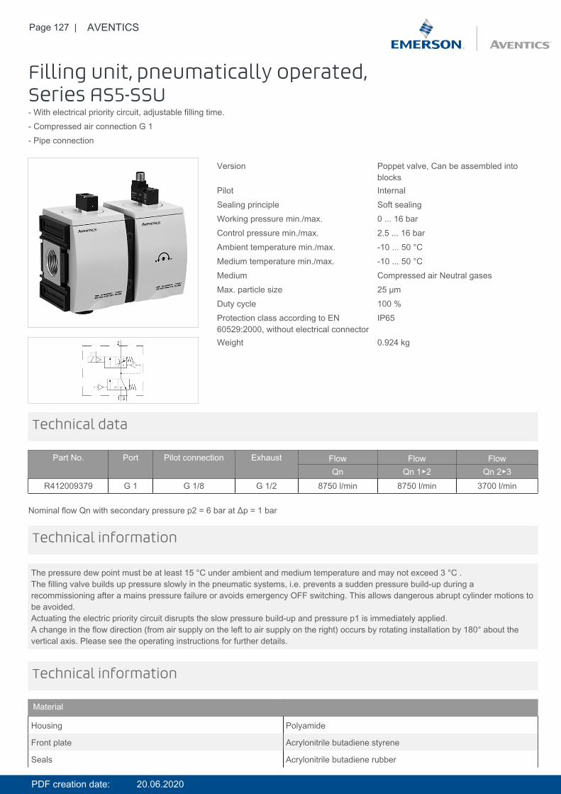
Page 127 | AVENTICS
Filling unit, pneumatically operated,Series AS5-SSU- With electrical priority circuit, adjustable filling time.- Compressed air connection G 1- Pipe connection
Version Poppet valve, Can be assembled intoblocks
Pilot InternalSealing principle Soft sealingWorking pressure min./max. 0 ... 16 barControl pressure min./max. 2.5 ... 16 barAmbient temperature min./max. -10 ... 50 °CMedium temperature min./max. -10 ... 50 °CMedium Compressed air Neutral gasesMax. particle size 25 µmDuty cycle 100 %Protection class according to EN60529:2000, without electrical connector
IP65
Weight 0.924 kg
Technical data
Part No. Port Pilot connection Exhaust Flow Flow FlowQn Qn 1▶2 Qn 2▶3
R412009379 G 1 G 1/8 G 1/2 8750 l/min 8750 l/min 3700 l/min
Nominal flow Qn with secondary pressure p2 = 6 bar at Δp = 1 bar
The pressure dew point must be at least 15 °C under ambient and medium temperature and may not exceed 3 °C .The filling valve builds up pressure slowly in the pneumatic systems, i.e. prevents a sudden pressure build-up during arecommissioning after a mains pressure failure or avoids emergency OFF switching. This allows dangerous abrupt cylinder motions tobe avoided.Actuating the electric priority circuit disrupts the slow pressure build-up and pressure p1 is immediately applied.A change in the flow direction (from air supply on the left to air supply on the right) occurs by rotating installation by 180° about thevertical axis. Please see the operating instructions for further details.
Technical information
Technical information
Material
Housing Polyamide
Front plate Acrylonitrile butadiene styrene
Seals Acrylonitrile butadiene rubber
PDF creation date: 20.06.2020
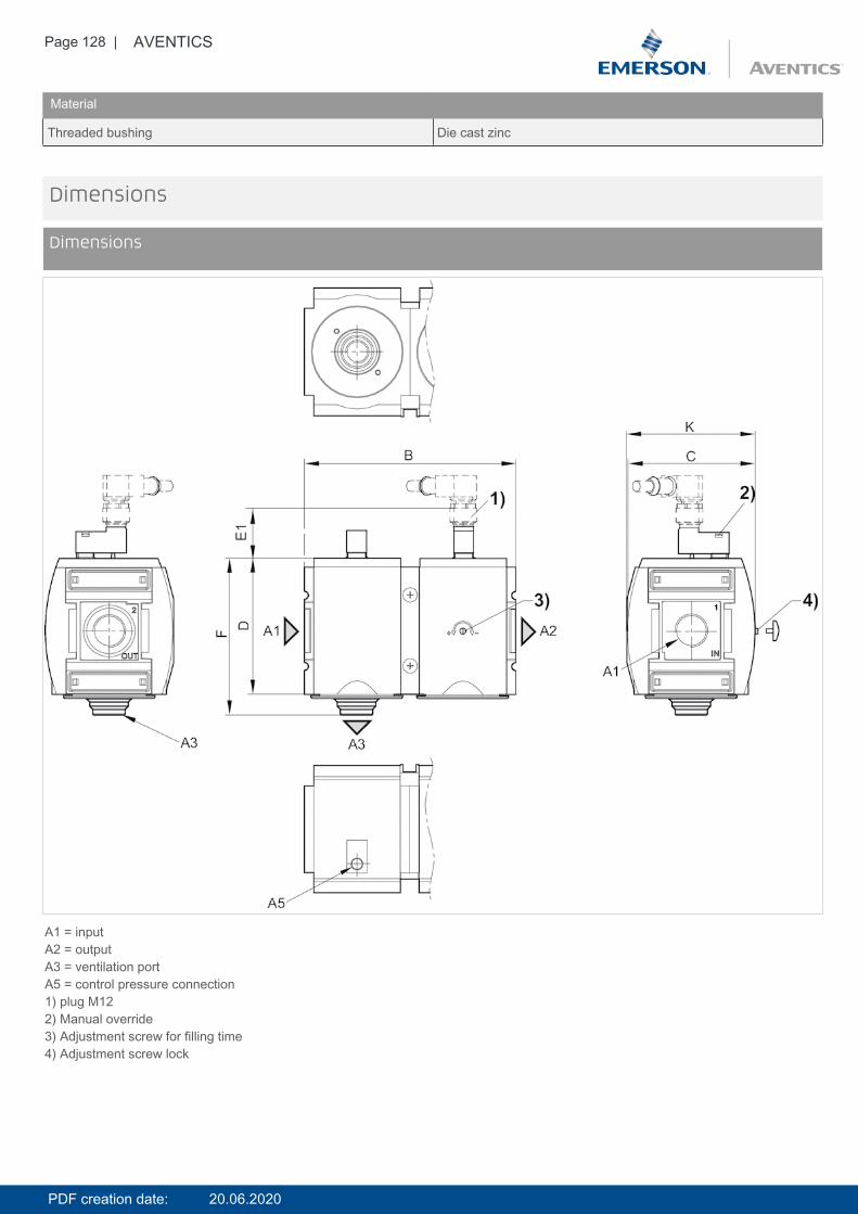
Page 128 | AVENTICS
Material
Threaded bushing Die cast zinc
Dimensions
Dimensions
A1 = inputA2 = outputA3 = ventilation portA5 = control pressure connection1) plug M122) Manual override3) Adjustment screw for filling time4) Adjustment screw lock
PDF creation date: 20.06.2020
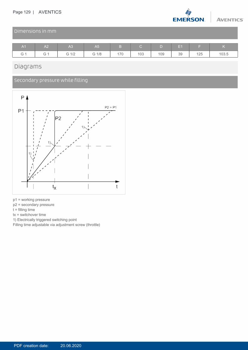
Page 129 | AVENTICS
DimensionsDimensions in mm
A1 A2 A3 A5 B C D E1 F K
G 1 G 1 G 1/2 G 1/8 170 103 109 39 125 103.5
Diagrams
Secondary pressure while filling
p1 = working pressurep2 = secondary pressuret = filling timetx = switchover time1) Electrically triggered switching pointFilling time adjustable via adjustment screw (throttle)
PDF creation date: 20.06.2020
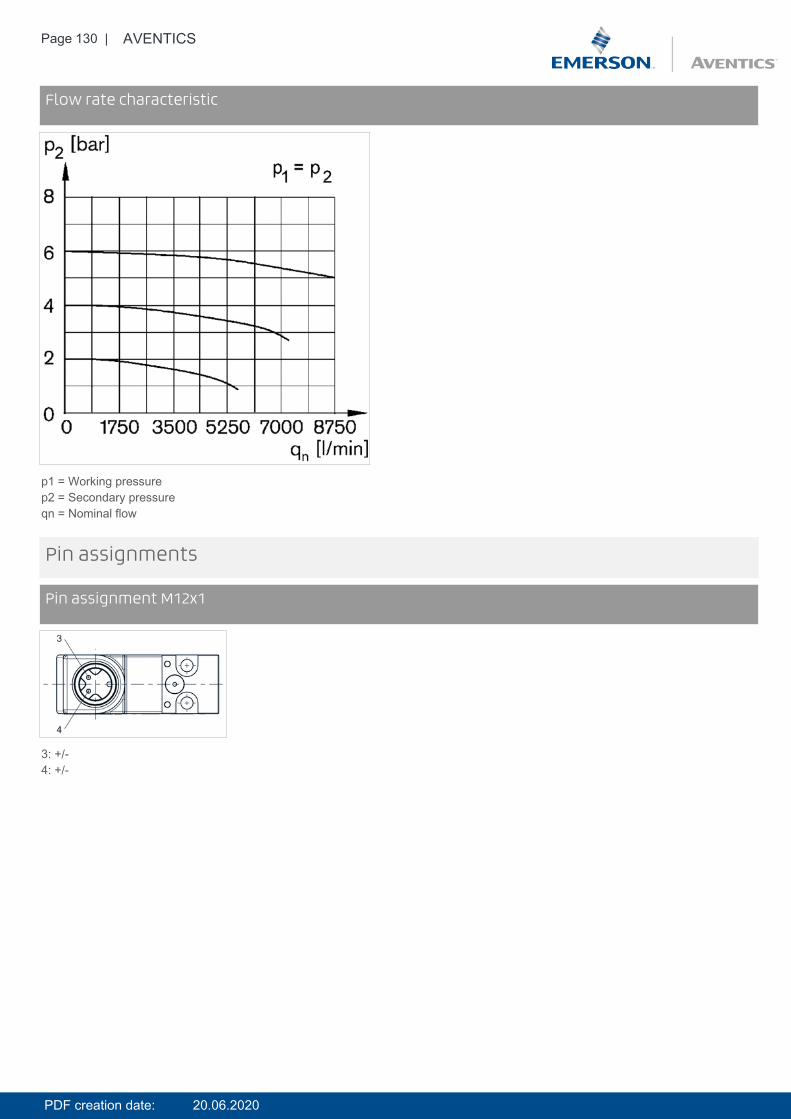
Page 130 | AVENTICS
DiagramsFlow rate characteristic
p1 = Working pressurep2 = Secondary pressureqn = Nominal flow
Pin assignments
Pin assignment M12x1
3: +/-4: +/-
PDF creation date: 20.06.2020

Page 131 | AVENTICS
Accessories overview
1 = contamination display3 = Double nipple4 = Key for E11 locking5 = mortise lock6 = Transition plate DO307 = Adapter, Series CON-VP8 = Mounting aid DO16, form C9 = Mounting aid DO16, M1210 = Adapter for external pilot air11 = Adapter pneumatic operation12 = Sealing ring13 = Reducing nipple
PDF creation date: 20.06.2020
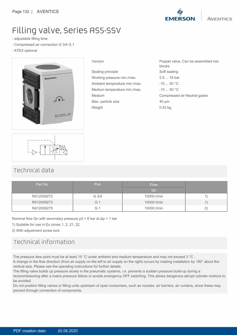
Page 132 | AVENTICS
Filling valve, Series AS5-SSV- adjustable filling time- Compressed air connection G 3/4 G 1- ATEX optional
Version Poppet valve, Can be assembled intoblocks
Sealing principle Soft sealingWorking pressure min./max. 2.5 ... 16 barAmbient temperature min./max. -10 ... 50 °CMedium temperature min./max. -10 ... 50 °CMedium Compressed air Neutral gasesMax. particle size 40 µmWeight 0.43 kg
Technical data
Part No. Port FlowQn
R412009272 G 3/4 10000 l/min 1)R412009273 G 1 10000 l/min 1)R412009275 G 1 10000 l/min 2)
Nominal flow Qn with secondary pressure p2 = 6 bar at Δp = 1 bar1) Suitable for use in Ex zones 1, 2, 21, 22.2) With adjustment screw lock
The pressure dew point must be at least 15 °C under ambient and medium temperature and may not exceed 3 °C .A change in the flow direction (from air supply on the left to air supply on the right) occurs by rotating installation by 180° about thevertical axis. Please see the operating instructions for further details.The filling valve builds up pressure slowly in the pneumatic systems, i.e. prevents a sudden pressure build-up during arecommissioning after a mains pressure failure or avoids emergency OFF switching. This allows dangerous abrupt cylinder motions tobe avoided.Do not position filling valves or filling units upstream of open consumers, such as nozzles, air barriers, air curtains, since these mayprevent through connection of components.
Technical information
PDF creation date: 20.06.2020
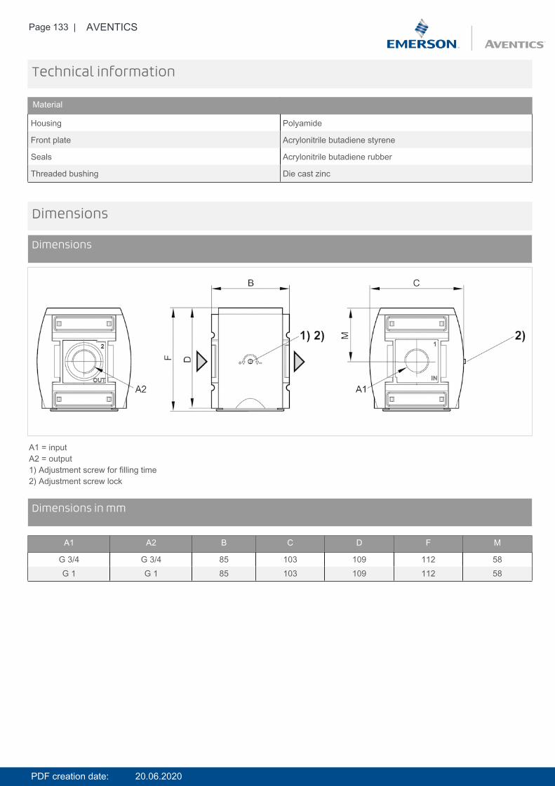
Page 133 | AVENTICS
Technical information
Material
Housing Polyamide
Front plate Acrylonitrile butadiene styrene
Seals Acrylonitrile butadiene rubber
Threaded bushing Die cast zinc
Dimensions
Dimensions
A1 = inputA2 = output1) Adjustment screw for filling time2) Adjustment screw lock
DimensionsDimensions in mm
A1 A2 B C D F M
G 3/4 G 3/4 85 103 109 112 58G 1 G 1 85 103 109 112 58
PDF creation date: 20.06.2020
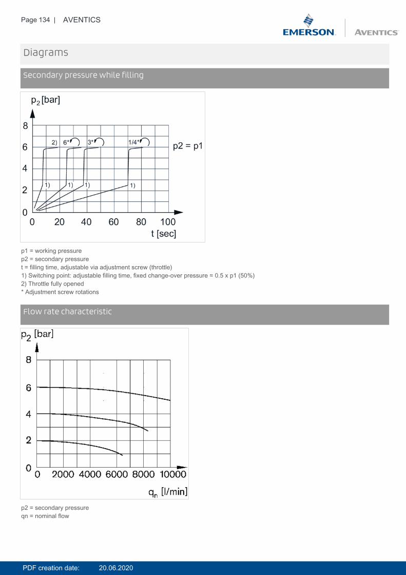
Page 134 | AVENTICS
Diagrams
Secondary pressure while filling
p1 = working pressurep2 = secondary pressuret = filling time, adjustable via adjustment screw (throttle)1) Switching point: adjustable filling time, fixed change-over pressure ≈ 0.5 x p1 (50%)2) Throttle fully opened* Adjustment screw rotations
DiagramsFlow rate characteristic
p2 = secondary pressureqn = nominal flow
PDF creation date: 20.06.2020

Page 135 | AVENTICS
Accessories overview
1 = contamination display3 = Double nipple4 = Key for E11 locking5 = mortise lock6 = Transition plate DO307 = Adapter, Series CON-VP8 = Mounting aid DO16, form C9 = Mounting aid DO16, M1210 = Adapter for external pilot air11 = Adapter pneumatic operation12 = Sealing ring13 = Reducing nipple
PDF creation date: 20.06.2020
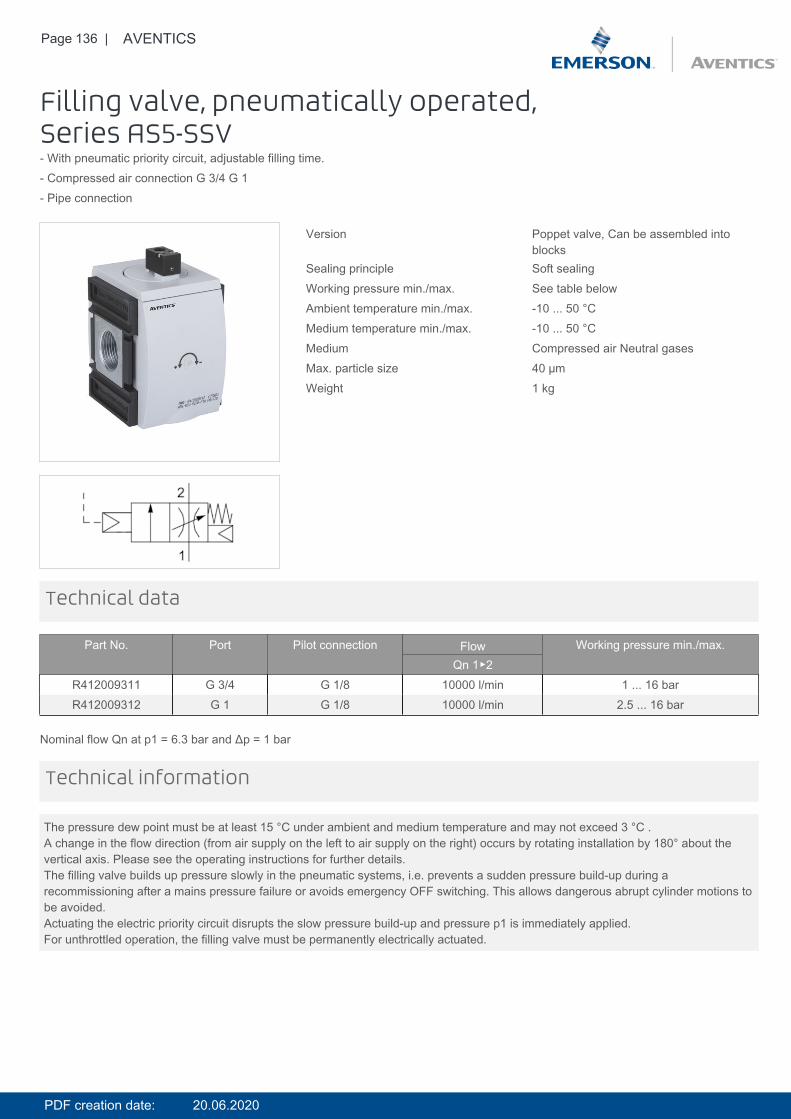
Page 136 | AVENTICS
Filling valve, pneumatically operated,Series AS5-SSV- With pneumatic priority circuit, adjustable filling time.- Compressed air connection G 3/4 G 1- Pipe connection
Version Poppet valve, Can be assembled intoblocks
Sealing principle Soft sealingWorking pressure min./max. See table belowAmbient temperature min./max. -10 ... 50 °CMedium temperature min./max. -10 ... 50 °CMedium Compressed air Neutral gasesMax. particle size 40 µmWeight 1 kg
Technical data
Part No. Port Pilot connection Flow Working pressure min./max.Qn 1▶2
R412009311 G 3/4 G 1/8 10000 l/min 1 ... 16 barR412009312 G 1 G 1/8 10000 l/min 2.5 ... 16 bar
Nominal flow Qn at p1 = 6.3 bar and Δp = 1 bar
The pressure dew point must be at least 15 °C under ambient and medium temperature and may not exceed 3 °C .A change in the flow direction (from air supply on the left to air supply on the right) occurs by rotating installation by 180° about thevertical axis. Please see the operating instructions for further details.The filling valve builds up pressure slowly in the pneumatic systems, i.e. prevents a sudden pressure build-up during arecommissioning after a mains pressure failure or avoids emergency OFF switching. This allows dangerous abrupt cylinder motions tobe avoided.Actuating the electric priority circuit disrupts the slow pressure build-up and pressure p1 is immediately applied.For unthrottled operation, the filling valve must be permanently electrically actuated.
Technical information
PDF creation date: 20.06.2020
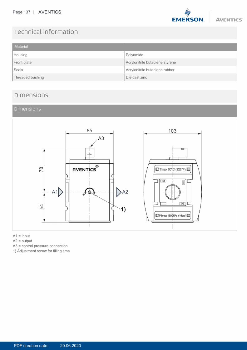
Page 137 | AVENTICS
Technical information
Material
Housing Polyamide
Front plate Acrylonitrile butadiene styrene
Seals Acrylonitrile butadiene rubber
Threaded bushing Die cast zinc
Dimensions
Dimensions
A1 = inputA2 = outputA3 = control pressure connection1) Adjustment screw for filling time
PDF creation date: 20.06.2020
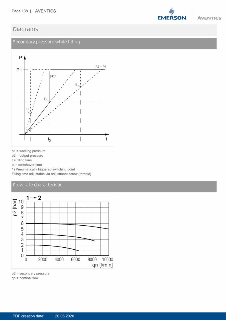
Page 138 | AVENTICS
Diagrams
Secondary pressure while filling
p1 = working pressurep2 = output pressuret = filling timetx = switchover time1) Pneumatically triggered switching pointFilling time adjustable via adjustment screw (throttle)
DiagramsFlow rate characteristic
p2 = secondary pressureqn = nominal flow
PDF creation date: 20.06.2020

Page 139 | AVENTICS
Accessories overview
1 = contamination display3 = Double nipple4 = Key for E11 locking5 = mortise lock6 = Transition plate DO307 = Adapter, Series CON-VP8 = Mounting aid DO16, form C9 = Mounting aid DO16, M1210 = Adapter for external pilot air11 = Adapter pneumatic operation12 = Sealing ring13 = Reducing nipple
PDF creation date: 20.06.2020
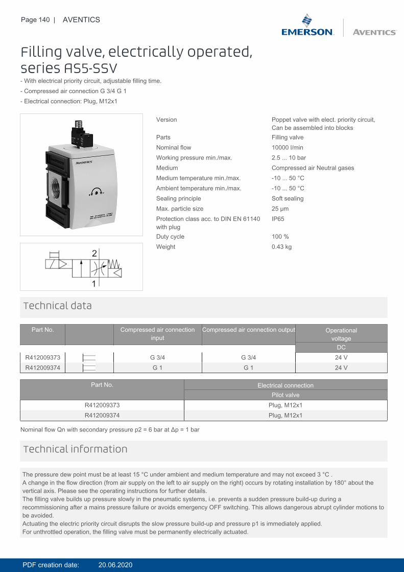
Page 140 | AVENTICS
Filling valve, electrically operated,series AS5-SSV- With electrical priority circuit, adjustable filling time.- Compressed air connection G 3/4 G 1- Electrical connection: Plug, M12x1
Version Poppet valve with elect. priority circuit,Can be assembled into blocks
Parts Filling valveNominal flow 10000 l/minWorking pressure min./max. 2.5 ... 10 barMedium Compressed air Neutral gasesMedium temperature min./max. -10 ... 50 °CAmbient temperature min./max. -10 ... 50 °CSealing principle Soft sealingMax. particle size 25 µmProtection class acc. to DIN EN 61140with plug
IP65
Duty cycle 100 %Weight 0.43 kg
Technical data
Part No. Compressed air connectioninput
Compressed air connection output Operationalvoltage
DCR412009373 G 3/4 G 3/4 24 VR412009374 G 1 G 1 24 V
Part No. Electrical connectionPilot valve
R412009373 Plug, M12x1R412009374 Plug, M12x1
Nominal flow Qn with secondary pressure p2 = 6 bar at Δp = 1 bar
The pressure dew point must be at least 15 °C under ambient and medium temperature and may not exceed 3 °C .A change in the flow direction (from air supply on the left to air supply on the right) occurs by rotating installation by 180° about thevertical axis. Please see the operating instructions for further details.The filling valve builds up pressure slowly in the pneumatic systems, i.e. prevents a sudden pressure build-up during arecommissioning after a mains pressure failure or avoids emergency OFF switching. This allows dangerous abrupt cylinder motions tobe avoided.Actuating the electric priority circuit disrupts the slow pressure build-up and pressure p1 is immediately applied.For unthrottled operation, the filling valve must be permanently electrically actuated.
Technical information
PDF creation date: 20.06.2020
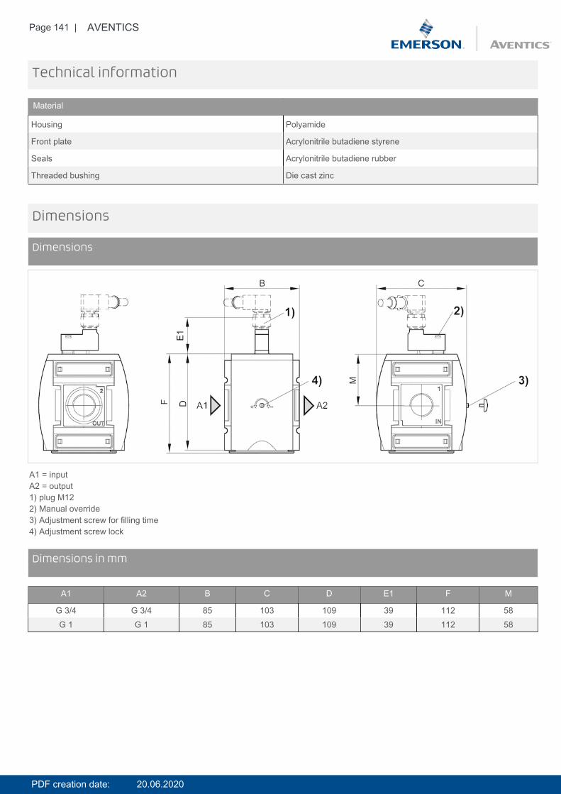
Page 141 | AVENTICS
Technical information
Material
Housing Polyamide
Front plate Acrylonitrile butadiene styrene
Seals Acrylonitrile butadiene rubber
Threaded bushing Die cast zinc
Dimensions
Dimensions
A1 = inputA2 = output1) plug M122) Manual override3) Adjustment screw for filling time4) Adjustment screw lock
DimensionsDimensions in mm
A1 A2 B C D E1 F M
G 3/4 G 3/4 85 103 109 39 112 58G 1 G 1 85 103 109 39 112 58
PDF creation date: 20.06.2020
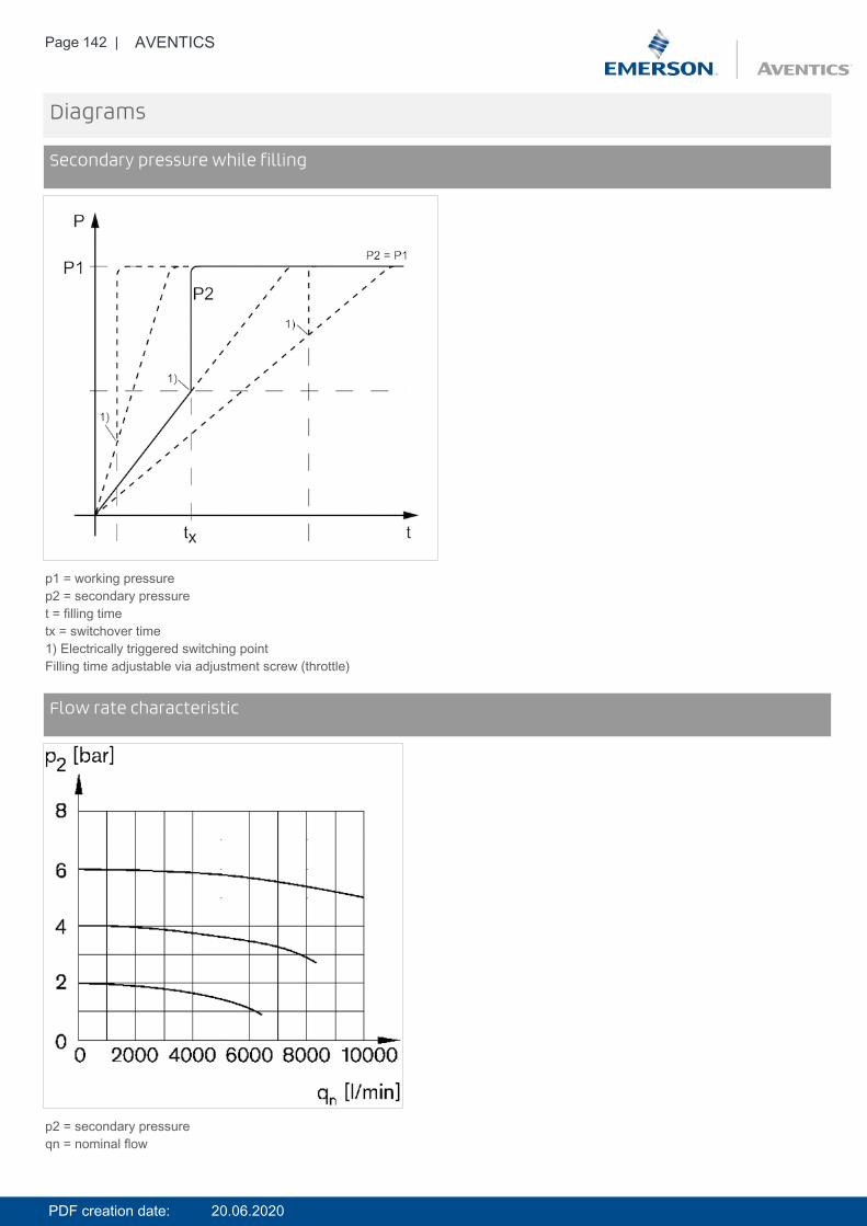
Page 142 | AVENTICS
Diagrams
Secondary pressure while filling
p1 = working pressurep2 = secondary pressuret = filling timetx = switchover time1) Electrically triggered switching pointFilling time adjustable via adjustment screw (throttle)
DiagramsFlow rate characteristic
p2 = secondary pressureqn = nominal flow
PDF creation date: 20.06.2020

Page 143 | AVENTICS
Pin assignments
Pin assignment M12x1
3: +/-4: +/-
Accessories overview
1 = contamination display3 = Double nipple4 = Key for E11 locking5 = mortise lock
PDF creation date: 20.06.2020

Page 144 | AVENTICS
6 = Transition plate DO307 = Adapter, Series CON-VP8 = Mounting aid DO16, form C9 = Mounting aid DO16, M1210 = Adapter for external pilot air11 = Adapter pneumatic operation12 = Sealing ring13 = Reducing nipple
PDF creation date: 20.06.2020
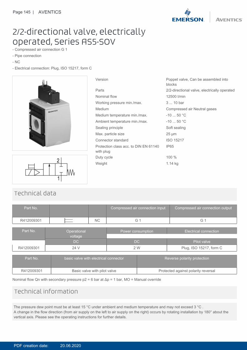
Page 145 | AVENTICS
2/2-directional valve, electricallyoperated, Series AS5-SOV- Compressed air connection G 1- Pipe connection- NC- Electrical connection: Plug, ISO 15217, form C
Version Poppet valve, Can be assembled intoblocks
Parts 2/2-directional valve, electrically operatedNominal flow 12500 l/minWorking pressure min./max. 3 ... 10 barMedium Compressed air Neutral gasesMedium temperature min./max. -10 ... 50 °CAmbient temperature min./max. -10 ... 50 °CSealing principle Soft sealingMax. particle size 25 µmConnector standard ISO 15217Protection class acc. to DIN EN 61140with plug
IP65
Duty cycle 100 %Weight 1.14 kg
Technical data
Part No. Compressed air connection input Compressed air connection output
R412009301 NC G 1 G 1
Part No. Operationalvoltage
Power consumption Electrical connection
DC DC Pilot valveR412009301 24 V 2 W Plug, ISO 15217, form C
Part No. basic valve with electrical connector Reverse polarity protection
R412009301 Basic valve with pilot valve Protected against polarity reversal
Nominal flow Qn with secondary pressure p2 = 6 bar at Δp = 1 bar, MO = Manual override
The pressure dew point must be at least 15 °C under ambient and medium temperature and may not exceed 3 °C .A change in the flow direction (from air supply on the left to air supply on the right) occurs by rotating installation by 180° about thevertical axis. Please see the operating instructions for further details.
Technical information
PDF creation date: 20.06.2020
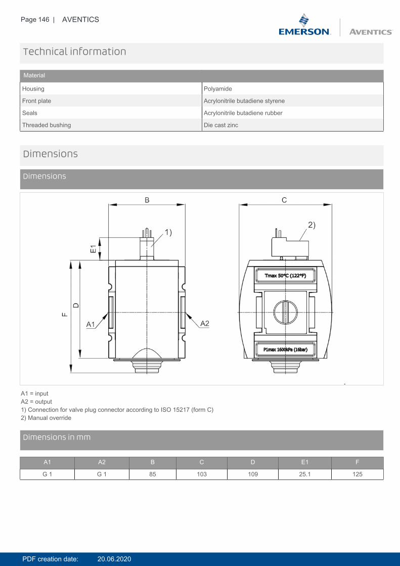
Page 146 | AVENTICS
Technical information
Material
Housing Polyamide
Front plate Acrylonitrile butadiene styrene
Seals Acrylonitrile butadiene rubber
Threaded bushing Die cast zinc
Dimensions
Dimensions
A1 = inputA2 = output1) Connection for valve plug connector according to ISO 15217 (form C)2) Manual override
DimensionsDimensions in mm
A1 A2 B C D E1 F
G 1 G 1 85 103 109 25.1 125
PDF creation date: 20.06.2020
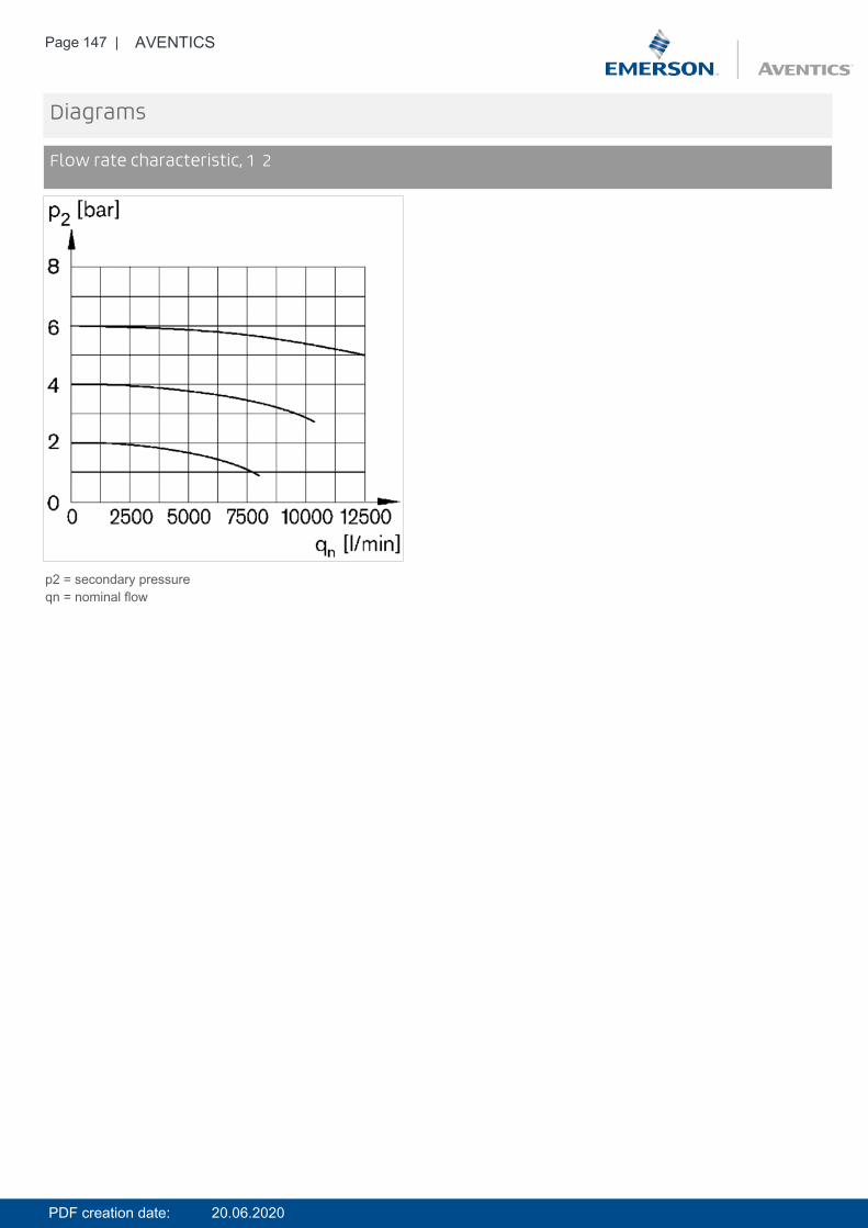
Page 147 | AVENTICS
Diagrams
Flow rate characteristic, 1 2
p2 = secondary pressureqn = nominal flow
PDF creation date: 20.06.2020

Page 148 | AVENTICS
Accessories overview
1 = contamination display3 = Double nipple4 = Key for E11 locking5 = mortise lock6 = Transition plate DO307 = Adapter, Series CON-VP8 = Mounting aid DO16, form C9 = Mounting aid DO16, M1210 = Adapter for external pilot air11 = Adapter pneumatic operation12 = Sealing ring13 = Reducing nipple
PDF creation date: 20.06.2020
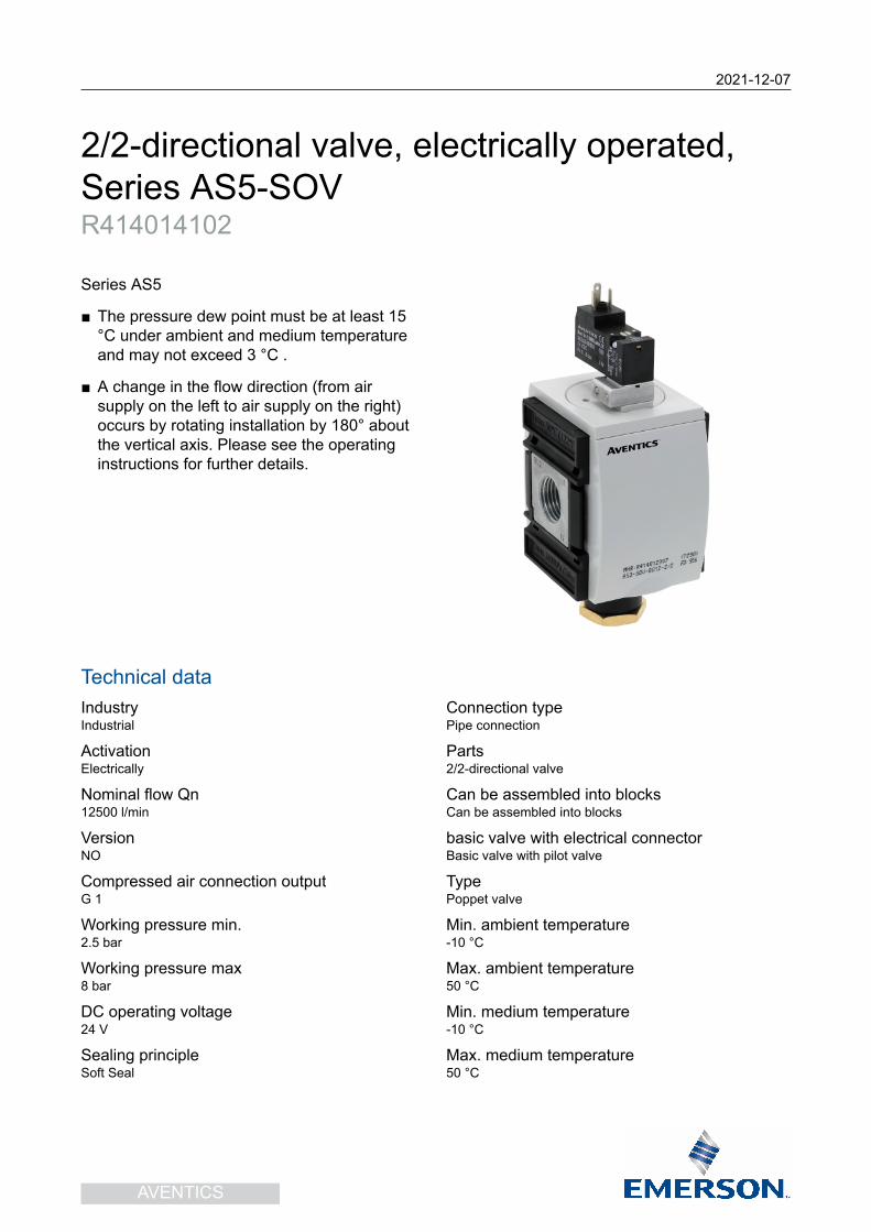
2021-12-07
2/2-directional valve, electrically operated,Series AS5-SOVR414014102
Series AS5
■ The pressure dew point must be at least 15°C under ambient and medium temperatureand may not exceed 3 °C .
■ A change in the flow direction (from airsupply on the left to air supply on the right)occurs by rotating installation by 180° aboutthe vertical axis. Please see the operatinginstructions for further details.
Technical dataIndustryIndustrial
ActivationElectrically
Nominal flow Qn12500 l/min
VersionNO
Compressed air connection outputG 1
Working pressure min.2.5 bar
Working pressure max8 bar
DC operating voltage24 V
Sealing principleSoft Seal
Connection typePipe connection
Parts2/2-directional valve
Can be assembled into blocksCan be assembled into blocks
basic valve with electrical connectorBasic valve with pilot valve
TypePoppet valve
Min. ambient temperature-10 °C
Max. ambient temperature50 °C
Min. medium temperature-10 °C
Max. medium temperature50 °C
AVENTICS
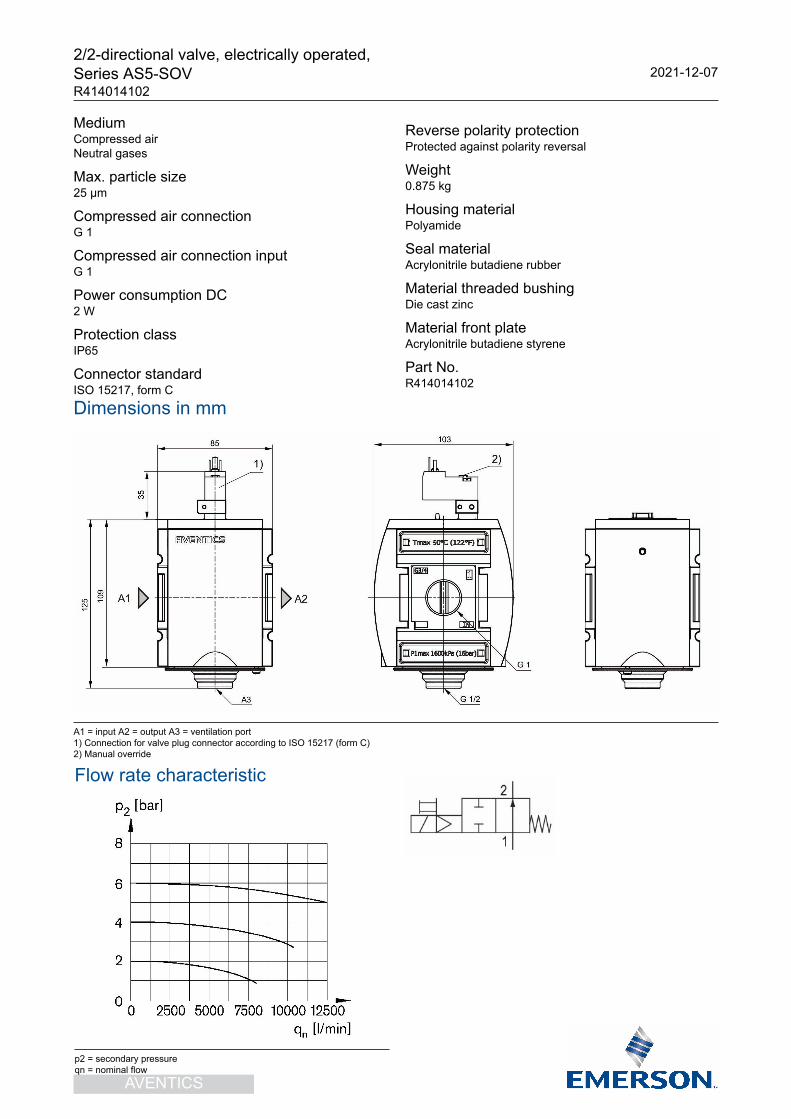
2/2-directional valve, electrically operated,Series AS5-SOVR414014102
2021-12-07
MediumCompressed airNeutral gases
Max. particle size25 µm
Compressed air connectionG 1
Compressed air connection inputG 1
Power consumption DC2 W
Protection classIP65
Connector standardISO 15217, form C
Reverse polarity protectionProtected against polarity reversal
Weight0.875 kg
Housing materialPolyamide
Seal materialAcrylonitrile butadiene rubber
Material threaded bushingDie cast zinc
Material front plateAcrylonitrile butadiene styrene
Part No.R414014102
Dimensions in mm
A1 = input A2 = output A3 = ventilation port1) Connection for valve plug connector according to ISO 15217 (form C)2) Manual override
AVENTICS
Flow rate characteristic
p2 = secondary pressureqn = nominal flow
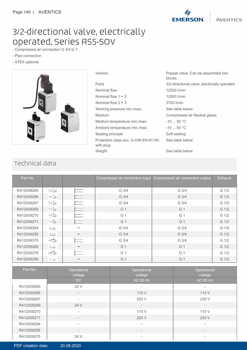
Page 149 | AVENTICS
3/2-directional valve, electricallyoperated, Series AS5-SOV- Compressed air connection G 3/4 G 1- Pipe connection- ATEX optional
Version Poppet valve, Can be assembled intoblocks
Parts 3/2-directional valve, electrically operatedNominal flow 12500 l/minNominal flow 1 ▶ 2 12500 l/minNominal flow 2 ▶ 3 3700 l/minWorking pressure min./max. See table belowMedium Compressed air Neutral gasesMedium temperature min./max. -10 ... 50 °CAmbient temperature min./max. -10 ... 50 °CSealing principle Soft sealingProtection class acc. to DIN EN 61140with plug
See table below
Weight See table below
Technical data
Part No. Compressed air connection input Compressed air connection output Exhaust
R412009265 G 3/4 G 3/4 G 1/2R412009266 G 3/4 G 3/4 G 1/2R412009267 G 3/4 G 3/4 G 1/2R412009269 G 1 G 1 G 1/2R412009270 G 1 G 1 G 1/2R412009271 G 1 G 1 G 1/2R412009264 G 3/4 G 3/4 G 1/2R412009258 G 3/4 G 3/4 G 1/2R412009375 G 3/4 G 3/4 G 1/2R412009268 G 1 G 1 G 1/2R412009376 G 1 G 1 G 1/2R412009259 G 1 G 1 G 1/2
Part No. Operationalvoltage
Operationalvoltage
Operationalvoltage
DC AC 50 Hz AC 60 HzR412009265 24 V - -R412009266 - 110 V 110 VR412009267 - 220 V 230 VR412009269 24 V - -R412009270 - 110 V 110 VR412009271 - 220 V 230 VR412009264 - - -R412009258 - - -R412009375 24 V - -
PDF creation date: 20.06.2020
Page 150 | AVENTICS
Part No. Operationalvoltage
Operationalvoltage
Operationalvoltage
DC AC 50 Hz AC 60 HzR412009268 - - -R412009376 24 V - -R412009259 - - -
Part No. Power consumption Holding power Holding power Switch-on powerDC AC 50 Hz AC 60 Hz AC 50 Hz
R412009265 2 W - - -R412009266 - 1.6 VA 1.4 VA 2.2 VAR412009267 - 1.6 VA 1.4 VA 2.2 VAR412009269 2 W - - -R412009270 - 1.6 VA 1.4 VA 2.2 VAR412009271 - 1.6 VA 1.4 VA 2.2 VAR412009264 - - - -R412009258 - - - -R412009375 2 W - - -R412009268 - - - -R412009376 2 W - - -R412009259 - - - -
Part No. Switch-on power Working pressure min./max. Protection class Electrical connectionAC 60 Hz Pilot valve
R412009265 - 2.5 ... 10 bar IP65 Plug, ISO 15217, form CR412009266 1.6 VA 2.5 ... 10 bar IP65 Plug, ISO 15217, form CR412009267 1.6 VA 2.5 ... 10 bar IP65 Plug, ISO 15217, form CR412009269 - 2.5 ... 10 bar IP65 Plug, ISO 15217, form CR412009270 1.6 VA 2.5 ... 10 bar IP65 Plug, ISO 15217, form CR412009271 1.6 VA 2.5 ... 10 bar IP65 Plug, ISO 15217, form CR412009264 - 2.5 ... 16 bar - -R412009258 - 2.5 ... 16 bar - -R412009375 - 2.5 ... 10 bar IP65 Plug, M12x1R412009268 - 2.5 ... 16 bar - -R412009376 - 2.5 ... 10 bar IP65 Plug, M12x1R412009259 - 2.5 ... 16 bar - -
Part No. Connector standard basic valve with electrical connector
R412009265 ISO 15217 Basic valve with pilot valveR412009266 ISO 15217 Basic valve with pilot valveR412009267 ISO 15217 Basic valve with pilot valveR412009269 ISO 15217 Basic valve with pilot valveR412009270 ISO 15217 Basic valve with pilot valveR412009271 ISO 15217 Basic valve with pilot valveR412009264 - Basic valve without pilot valveR412009258 - Basic valve without pilot valve, with CNOMO subbaseR412009375 - Basic valve with pilot valveR412009268 - Basic valve without pilot valveR412009376 - Basic valve with pilot valveR412009259 - Basic valve without pilot valve, with CNOMO subbase
PDF creation date: 20.06.2020
Page 151 | AVENTICS
Part No. Reverse polarity protection Weight Fig.
R412009265 Protected against polarity reversal 0.677 kg Fig. 3 -R412009266 Protected against polarity reversal 0.677 kg Fig. 3 -R412009267 Protected against polarity reversal 0.677 kg Fig. 3 -R412009269 Protected against polarity reversal 0.677 kg Fig. 3 -R412009270 Protected against polarity reversal 0.677 kg Fig. 3 -R412009271 Protected against polarity reversal 0.677 kg Fig. 3 -R412009264 - 0.641 kg Fig. 1 1)R412009258 - 0.62 kg Fig. 2 1)R412009375 - 0.65 kg Fig. 4 -R412009268 - 0.641 kg Fig. 1 1)R412009376 - 0.65 kg Fig. 4 -R412009259 - 0.62 kg Fig. 2 1)
Nominal flow Qn with secondary pressure p2 = 6 bar at Δp = 1 bar, MO = Manual override1) Suitable for use in Ex zones 1, 2, 21, 22.
The pressure dew point must be at least 15 °C under ambient and medium temperature and may not exceed 3 °C .A change in the flow direction (from air supply on the left to air supply on the right) occurs by rotating installation by 180° about thevertical axis. Please see the operating instructions for further details.ATEX optional: The ATEX ID depends on the selected pilot valve.
Technical information
Technical information
Material
Housing Polyamide
Front plate Acrylonitrile butadiene styrene
Seals Acrylonitrile butadiene rubber
Threaded bushing Die cast zinc
PDF creation date: 20.06.2020
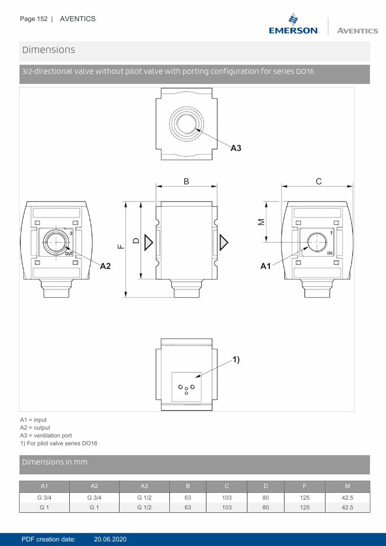
Page 152 | AVENTICS
Dimensions
3/2-directional valve without pilot valve with porting configuration for series DO16
A1 = inputA2 = outputA3 = ventilation port1) For pilot valve series DO16
DimensionsDimensions in mm
A1 A2 A3 B C D F M
G 3/4 G 3/4 G 1/2 63 103 80 125 42.5G 1 G 1 G 1/2 63 103 80 125 42.5
PDF creation date: 20.06.2020
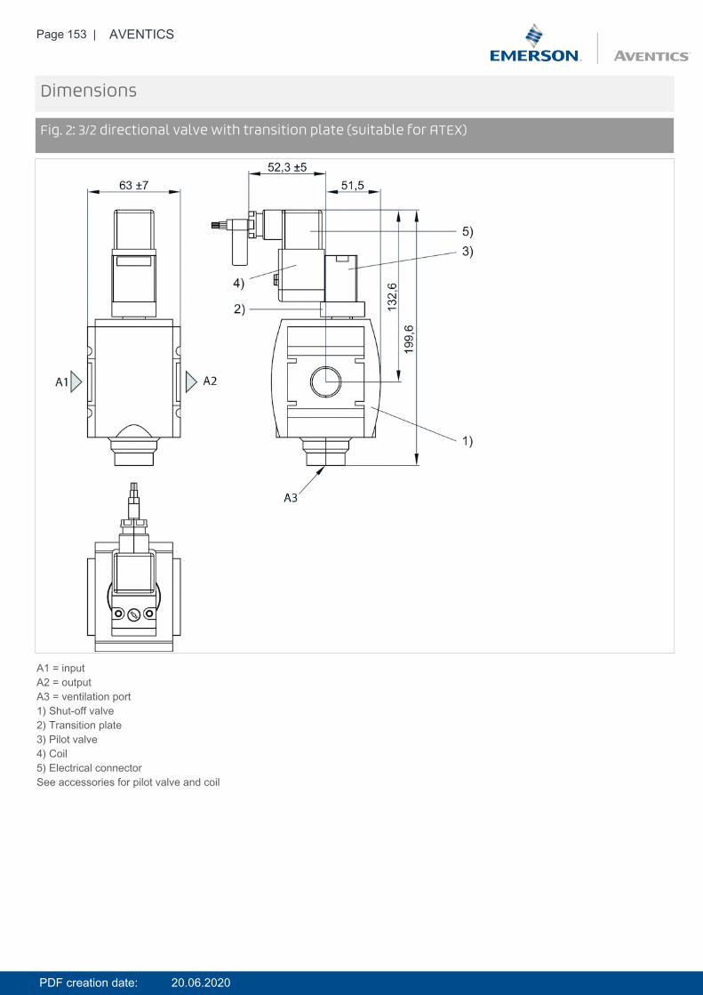
Page 153 | AVENTICS
Dimensions
Fig. 2: 3/2 directional valve with transition plate (suitable for ATEX)
A1 = inputA2 = outputA3 = ventilation port1) Shut-off valve2) Transition plate3) Pilot valve4) Coil5) Electrical connectorSee accessories for pilot valve and coil
PDF creation date: 20.06.2020
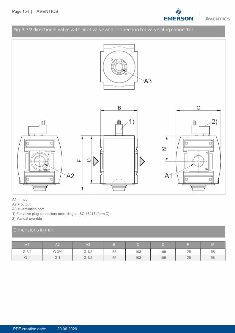
Page 154 | AVENTICS
DimensionsFig. 3: 3/2 directional valve with pilot valve and connection for valve plug connector
A1 = inputA2 = outputA3 = ventilation port1) For valve plug connectors according to ISO 15217 (form C)2) Manual override
DimensionsDimensions in mm
A1 A2 A3 B C D F M
G 3/4 G 3/4 G 1/2 85 103 109 125 58G 1 G 1 G 1/2 85 103 109 125 58
PDF creation date: 20.06.2020
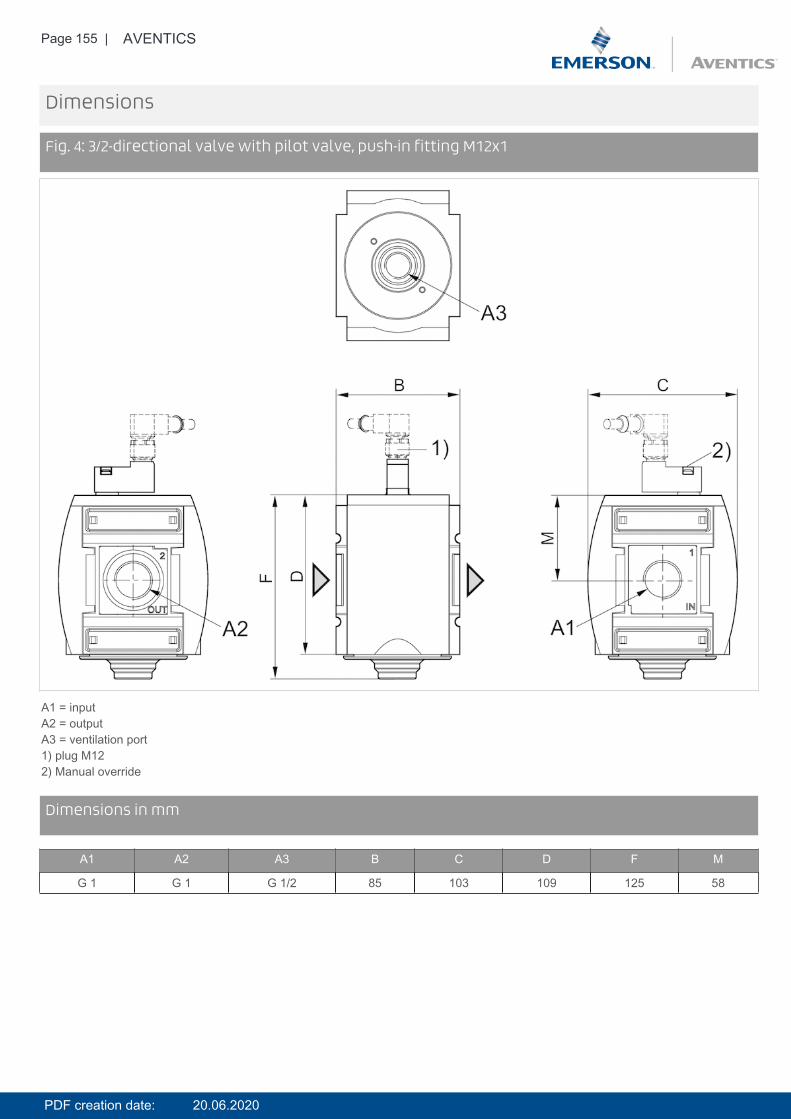
Page 155 | AVENTICS
Dimensions
Fig. 4: 3/2-directional valve with pilot valve, push-in fitting M12x1
A1 = inputA2 = outputA3 = ventilation port1) plug M122) Manual override
DimensionsDimensions in mm
A1 A2 A3 B C D F M
G 1 G 1 G 1/2 85 103 109 125 58
PDF creation date: 20.06.2020
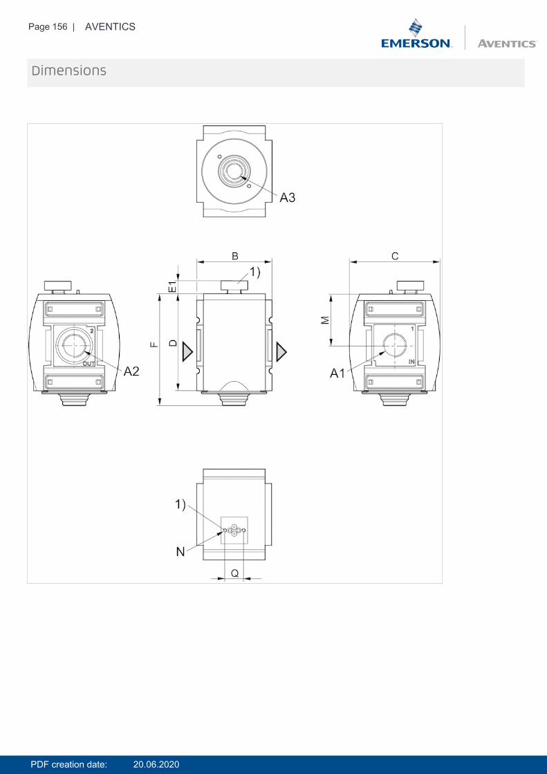
Page 156 | AVENTICS
Dimensions
PDF creation date: 20.06.2020
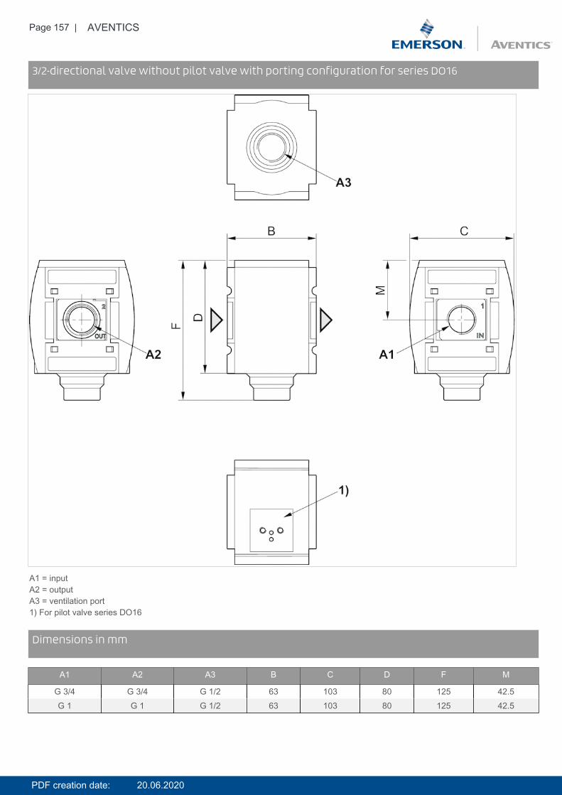
Page 157 | AVENTICS
Dimensions3/2-directional valve without pilot valve with porting configuration for series DO16
A1 = inputA2 = outputA3 = ventilation port1) For pilot valve series DO16
DimensionsDimensions in mm
A1 A2 A3 B C D F M
G 3/4 G 3/4 G 1/2 63 103 80 125 42.5G 1 G 1 G 1/2 63 103 80 125 42.5
PDF creation date: 20.06.2020

Page 158 | AVENTICS
Dimensions
Fig. 2: 3/2 directional valve with transition plate (suitable for ATEX)
A1 = inputA2 = outputA3 = ventilation port1) Shut-off valve2) Transition plate3) Pilot valve4) Coil5) Electrical connectorSee accessories for pilot valve and coil
PDF creation date: 20.06.2020

Page 159 | AVENTICS
DimensionsFig. 3: 3/2 directional valve with pilot valve and connection for valve plug connector
A1 = inputA2 = outputA3 = ventilation port1) For valve plug connectors according to ISO 15217 (form C)2) Manual override
DimensionsDimensions in mm
A1 A2 A3 B C D F M
G 3/4 G 3/4 G 1/2 85 103 109 125 58G 1 G 1 G 1/2 85 103 109 125 58
PDF creation date: 20.06.2020

Page 160 | AVENTICS
Dimensions
Fig. 4: 3/2-directional valve with pilot valve, push-in fitting M12x1
A1 = inputA2 = outputA3 = ventilation port1) plug M122) Manual override
DimensionsDimensions in mm
A1 A2 A3 B C D F M
G 1 G 1 G 1/2 85 103 109 125 58
PDF creation date: 20.06.2020

Page 161 | AVENTICS
Diagrams
Flow rate characteristic, 1 2
p2 = secondary pressureqn = nominal flow
DiagramsRear exhaust, 2 3
p2 = secondary pressureqn = nominal flow
PDF creation date: 20.06.2020
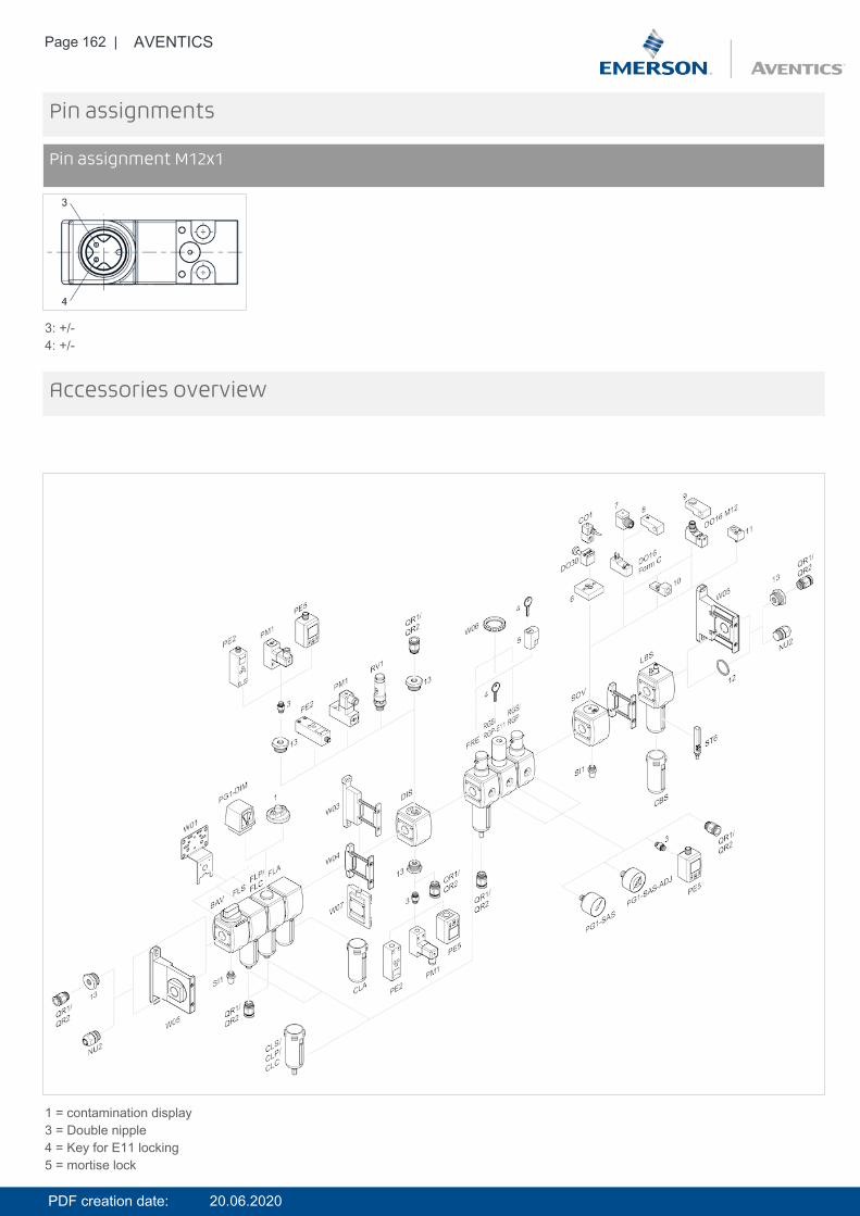
Page 162 | AVENTICS
Pin assignments
Pin assignment M12x1
3: +/-4: +/-
Accessories overview
1 = contamination display3 = Double nipple4 = Key for E11 locking5 = mortise lock
PDF creation date: 20.06.2020

Page 163 | AVENTICS
6 = Transition plate DO307 = Adapter, Series CON-VP8 = Mounting aid DO16, form C9 = Mounting aid DO16, M1210 = Adapter for external pilot air11 = Adapter pneumatic operation12 = Sealing ring13 = Reducing nipple
PDF creation date: 20.06.2020
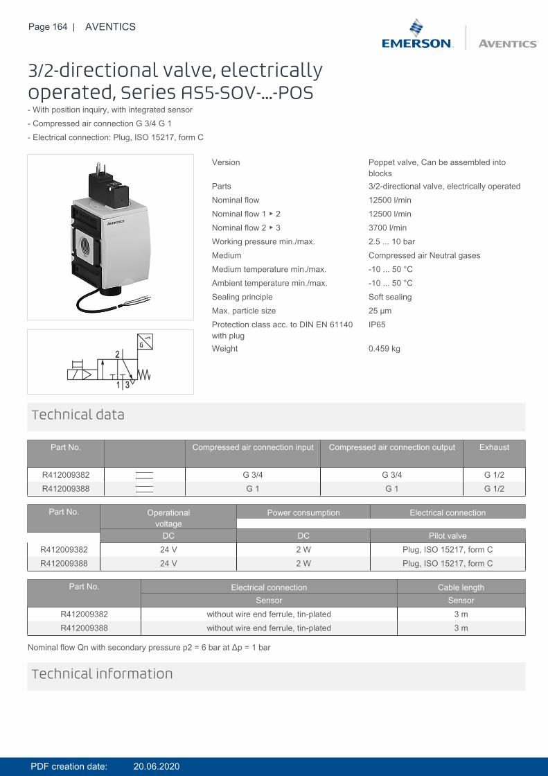
Page 164 | AVENTICS
3/2-directional valve, electricallyoperated, Series AS5-SOV-...-POS- With position inquiry, with integrated sensor- Compressed air connection G 3/4 G 1- Electrical connection: Plug, ISO 15217, form C
Version Poppet valve, Can be assembled intoblocks
Parts 3/2-directional valve, electrically operatedNominal flow 12500 l/minNominal flow 1 ▶ 2 12500 l/minNominal flow 2 ▶ 3 3700 l/minWorking pressure min./max. 2.5 ... 10 barMedium Compressed air Neutral gasesMedium temperature min./max. -10 ... 50 °CAmbient temperature min./max. -10 ... 50 °CSealing principle Soft sealingMax. particle size 25 µmProtection class acc. to DIN EN 61140with plug
IP65
Weight 0.459 kg
Technical data
Part No. Compressed air connection input Compressed air connection output Exhaust
R412009382 G 3/4 G 3/4 G 1/2R412009388 G 1 G 1 G 1/2
Part No. Operationalvoltage
Power consumption Electrical connection
DC DC Pilot valveR412009382 24 V 2 W Plug, ISO 15217, form CR412009388 24 V 2 W Plug, ISO 15217, form C
Part No. Electrical connection Cable lengthSensor Sensor
R412009382 without wire end ferrule, tin-plated 3 mR412009388 without wire end ferrule, tin-plated 3 m
Nominal flow Qn with secondary pressure p2 = 6 bar at Δp = 1 bar
Technical information
PDF creation date: 20.06.2020
Page 165 | AVENTICS
The pressure dew point must be at least 15 °C under ambient and medium temperature and may not exceed 3 °C .A change in the flow direction (from air supply on the left to air supply on the right) occurs by rotating installation by 180° about thevertical axis. Please see the operating instructions for further details.The sensor signal is visible on the front of the cover.Electronic sensor R412003658 included in scope of delivery (assembled).For sensor connection, see the selection table.An ST6 sensor (contactless) is used to detect the switching position in the non-actuated state (position: exhaust).
Technical information
Material
Housing Polyamide
Front plate Acrylonitrile butadiene styrene
Seals Acrylonitrile butadiene rubber
Threaded bushing Die cast zinc
PDF creation date: 20.06.2020
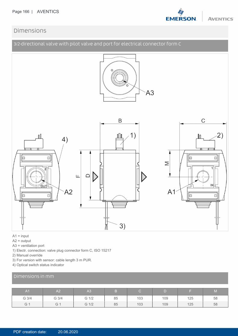
Page 166 | AVENTICS
Dimensions
3/2-directional valve with pilot valve and port for electrical connector form C
A1 = inputA2 = outputA3 = ventilation port1) Electr. connection: valve plug connector form C, ISO 152172) Manual override3) For version with sensor: cable length 3 m PUR.4) Optical switch status indicator
DimensionsDimensions in mm
A1 A2 A3 B C D F M
G 3/4 G 3/4 G 1/2 85 103 109 125 58G 1 G 1 G 1/2 85 103 109 125 58
PDF creation date: 20.06.2020

Page 167 | AVENTICS
Diagrams
Flow rate characteristic, 1 2
p2 = secondary pressureqn = nominal flow
DiagramsRear exhaust, 2 3
p2 = secondary pressureqn = nominal flow
PDF creation date: 20.06.2020
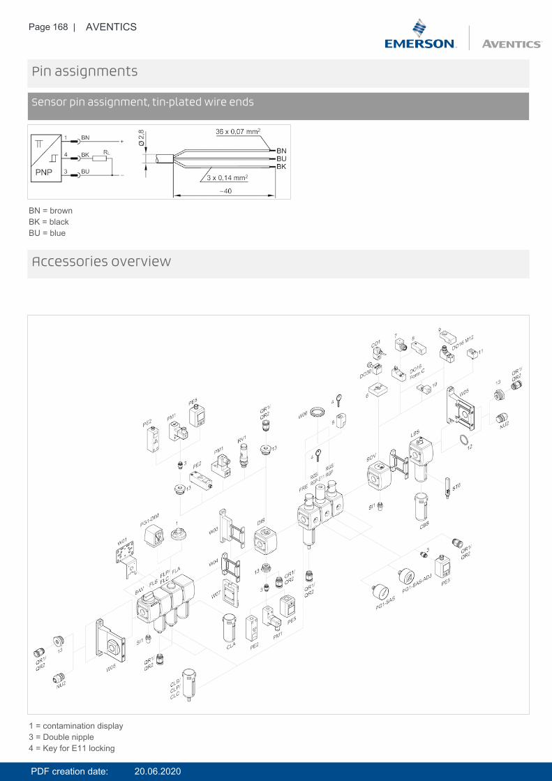
Page 168 | AVENTICS
Pin assignments
Sensor pin assignment, tin-plated wire ends
BN = brownBK = blackBU = blue
Accessories overview
1 = contamination display3 = Double nipple4 = Key for E11 locking
PDF creation date: 20.06.2020

Page 169 | AVENTICS
5 = mortise lock6 = Transition plate DO307 = Adapter, Series CON-VP8 = Mounting aid DO16, form C9 = Mounting aid DO16, M1210 = Adapter for external pilot air11 = Adapter pneumatic operation12 = Sealing ring13 = Reducing nipple
PDF creation date: 20.06.2020
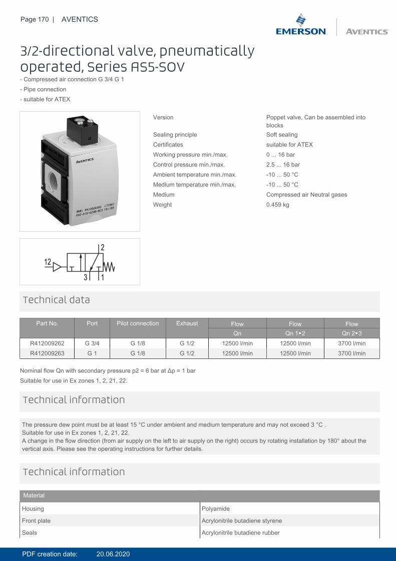
Page 170 | AVENTICS
3/2-directional valve, pneumaticallyoperated, Series AS5-SOV- Compressed air connection G 3/4 G 1- Pipe connection- suitable for ATEX
Version Poppet valve, Can be assembled intoblocks
Sealing principle Soft sealingCertificates suitable for ATEXWorking pressure min./max. 0 ... 16 barControl pressure min./max. 2.5 ... 16 barAmbient temperature min./max. -10 ... 50 °CMedium temperature min./max. -10 ... 50 °CMedium Compressed air Neutral gasesWeight 0.459 kg
Technical data
Part No. Port Pilot connection Exhaust Flow Flow FlowQn Qn 1▶2 Qn 2▶3
R412009262 G 3/4 G 1/8 G 1/2 12500 l/min 12500 l/min 3700 l/minR412009263 G 1 G 1/8 G 1/2 12500 l/min 12500 l/min 3700 l/min
Nominal flow Qn with secondary pressure p2 = 6 bar at Δp = 1 barSuitable for use in Ex zones 1, 2, 21, 22.
The pressure dew point must be at least 15 °C under ambient and medium temperature and may not exceed 3 °C .Suitable for use in Ex zones 1, 2, 21, 22.A change in the flow direction (from air supply on the left to air supply on the right) occurs by rotating installation by 180° about thevertical axis. Please see the operating instructions for further details.
Technical information
Technical information
Material
Housing Polyamide
Front plate Acrylonitrile butadiene styrene
Seals Acrylonitrile butadiene rubber
PDF creation date: 20.06.2020
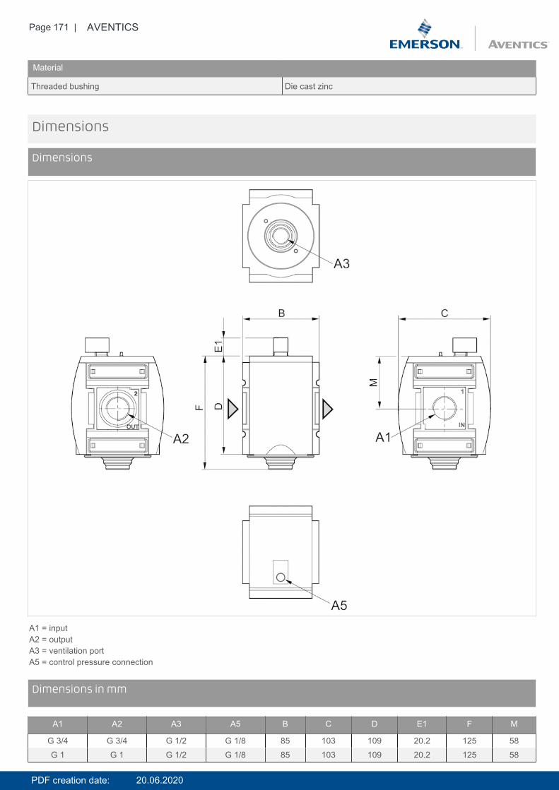
Page 171 | AVENTICS
Material
Threaded bushing Die cast zinc
Dimensions
Dimensions
A1 = inputA2 = outputA3 = ventilation portA5 = control pressure connection
DimensionsDimensions in mm
A1 A2 A3 A5 B C D E1 F M
G 3/4 G 3/4 G 1/2 G 1/8 85 103 109 20.2 125 58G 1 G 1 G 1/2 G 1/8 85 103 109 20.2 125 58
PDF creation date: 20.06.2020
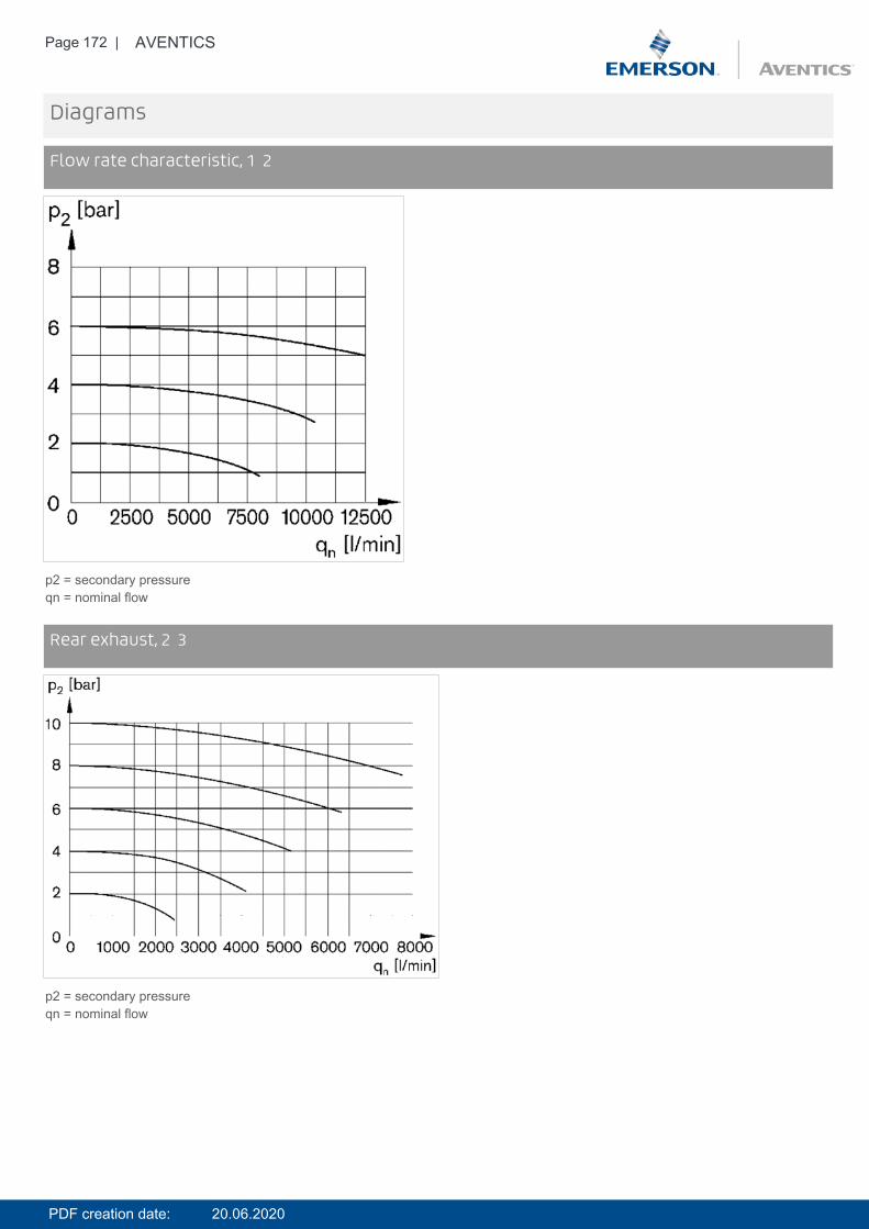
Page 172 | AVENTICS
Diagrams
Flow rate characteristic, 1 2
p2 = secondary pressureqn = nominal flow
DiagramsRear exhaust, 2 3
p2 = secondary pressureqn = nominal flow
PDF creation date: 20.06.2020
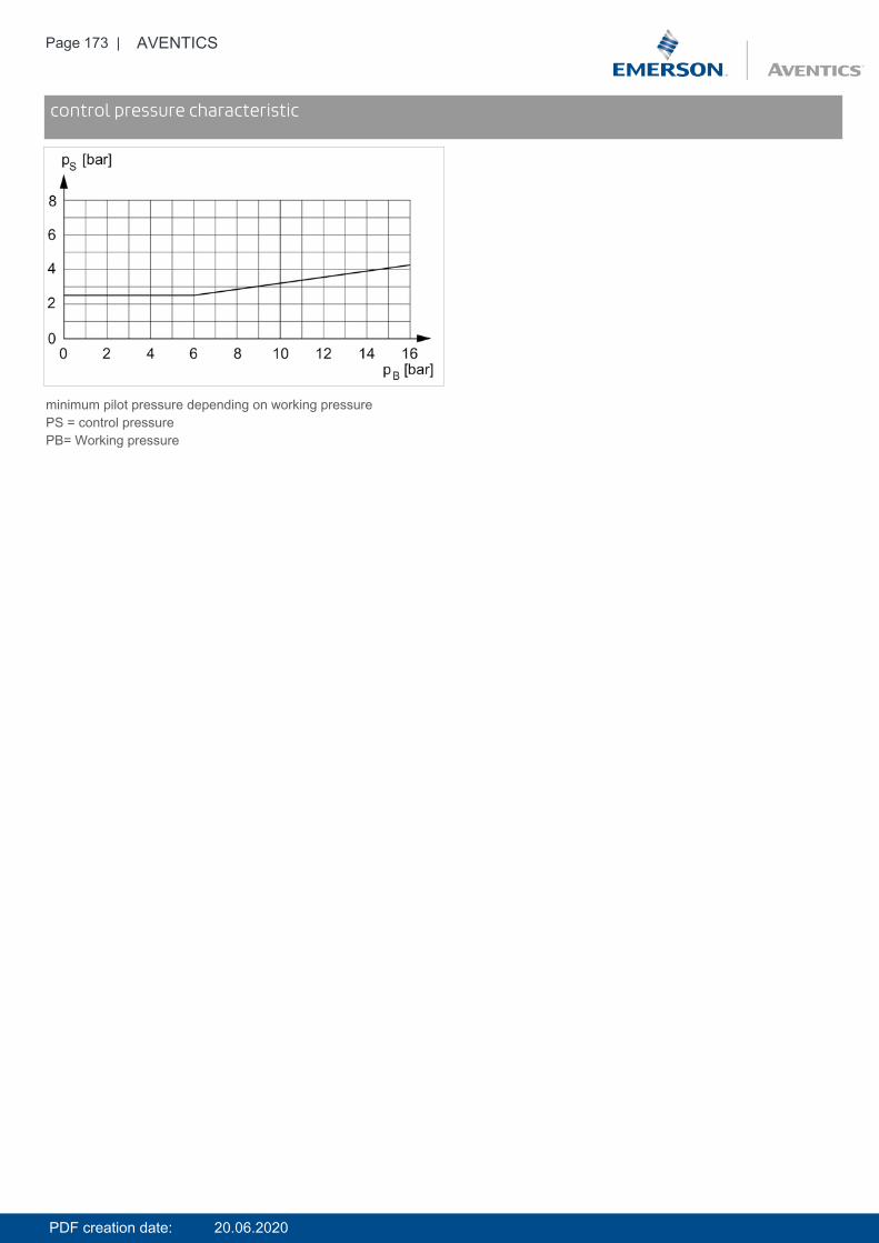
Page 173 | AVENTICS
Diagramscontrol pressure characteristic
minimum pilot pressure depending on working pressurePS = control pressurePB= Working pressure
PDF creation date: 20.06.2020

Page 174 | AVENTICS
Accessories overview
1 = contamination display3 = Double nipple4 = Key for E11 locking5 = mortise lock6 = Transition plate DO307 = Adapter, Series CON-VP8 = Mounting aid DO16, form C9 = Mounting aid DO16, M1210 = Adapter for external pilot air11 = Adapter pneumatic operation12 = Sealing ring13 = Reducing nipple
PDF creation date: 20.06.2020
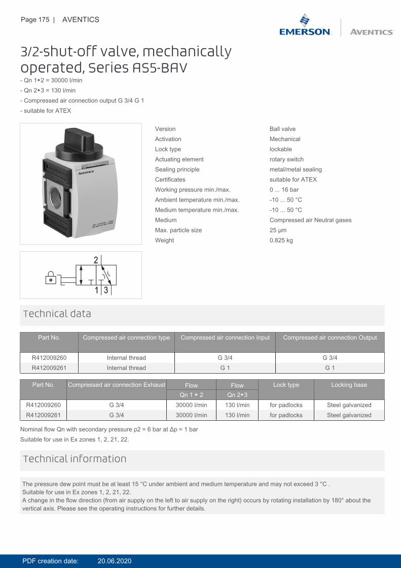
Page 175 | AVENTICS
3/2-shut-off valve, mechanicallyoperated, Series AS5-BAV- Qn 1▶2 = 30000 l/min- Qn 2▶3 = 130 l/min- Compressed air connection output G 3/4 G 1- suitable for ATEX
Version Ball valveActivation MechanicalLock type lockableActuating element rotary switchSealing principle metal/metal sealingCertificates suitable for ATEXWorking pressure min./max. 0 ... 16 barAmbient temperature min./max. -10 ... 50 °CMedium temperature min./max. -10 ... 50 °CMedium Compressed air Neutral gasesMax. particle size 25 µmWeight 0.825 kg
Technical data
Part No. Compressed air connection type Compressed air connection Input Compressed air connection Output
R412009260 Internal thread G 3/4 G 3/4R412009261 Internal thread G 1 G 1
Part No. Compressed air connection Exhaust Flow Flow Lock type Locking baseQn 1 ▶ 2 Qn 2▶3
R412009260 G 3/4 30000 l/min 130 l/min for padlocks Steel galvanizedR412009261 G 3/4 30000 l/min 130 l/min for padlocks Steel galvanized
Nominal flow Qn with secondary pressure p2 = 6 bar at Δp = 1 barSuitable for use in Ex zones 1, 2, 21, 22.
The pressure dew point must be at least 15 °C under ambient and medium temperature and may not exceed 3 °C .Suitable for use in Ex zones 1, 2, 21, 22.A change in the flow direction (from air supply on the left to air supply on the right) occurs by rotating installation by 180° about thevertical axis. Please see the operating instructions for further details.
Technical information
PDF creation date: 20.06.2020
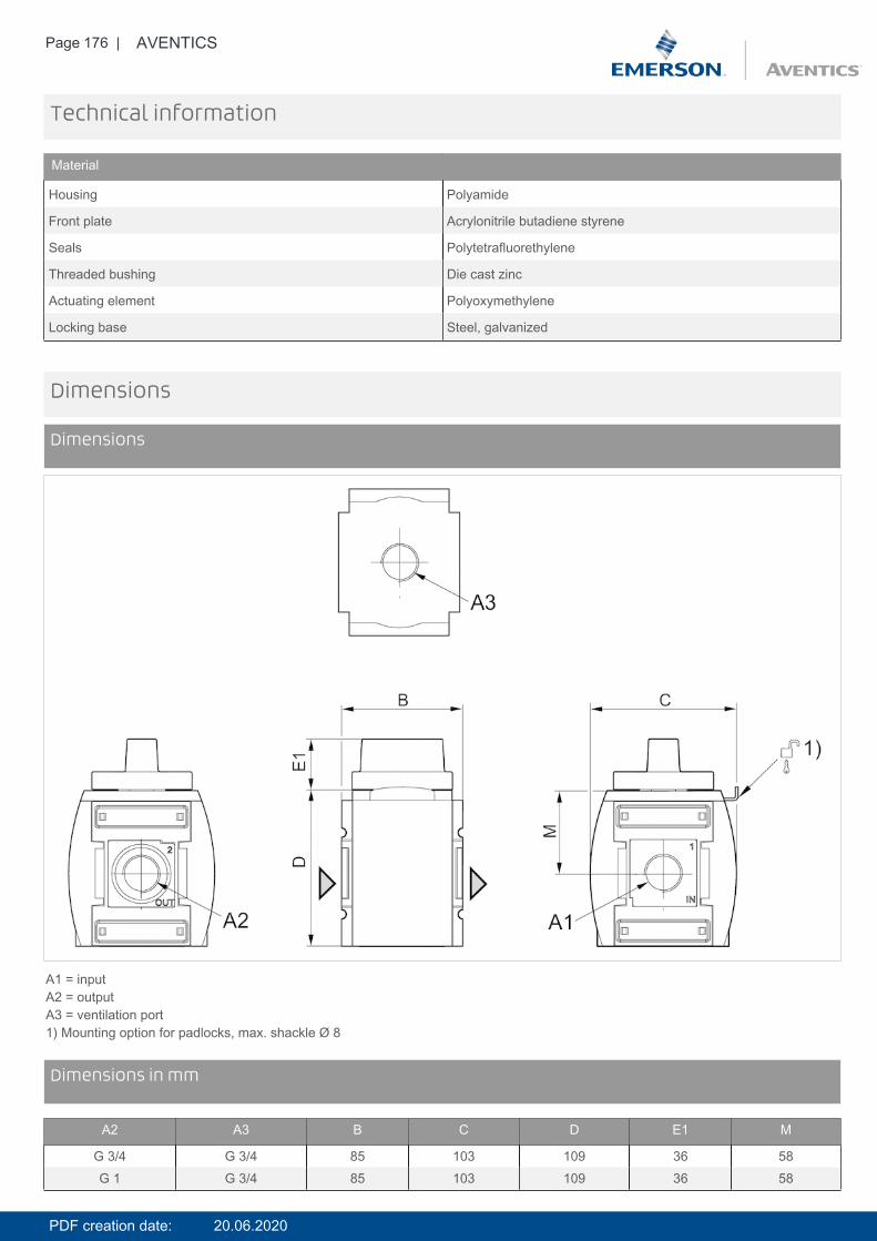
Page 176 | AVENTICS
Technical information
Material
Housing Polyamide
Front plate Acrylonitrile butadiene styrene
Seals Polytetrafluorethylene
Threaded bushing Die cast zinc
Actuating element Polyoxymethylene
Locking base Steel, galvanized
Dimensions
Dimensions
A1 = inputA2 = outputA3 = ventilation port1) Mounting option for padlocks, max. shackle Ø 8
DimensionsDimensions in mm
A2 A3 B C D E1 M
G 3/4 G 3/4 85 103 109 36 58G 1 G 3/4 85 103 109 36 58
PDF creation date: 20.06.2020
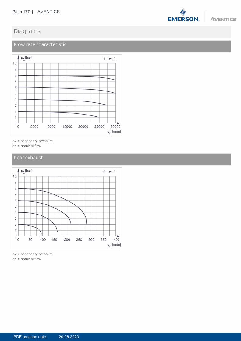
Page 177 | AVENTICS
Diagrams
Flow rate characteristic
p2 = secondary pressureqn = nominal flow
DiagramsRear exhaust
p2 = secondary pressureqn = nominal flow
PDF creation date: 20.06.2020

Page 178 | AVENTICS
Accessories overview
1 = contamination display3 = Double nipple4 = Key for E11 locking5 = mortise lock6 = Transition plate DO307 = Adapter, Series CON-VP8 = Mounting aid DO16, form C9 = Mounting aid DO16, M1210 = Adapter for external pilot air11 = Adapter pneumatic operation12 = Sealing ring13 = Reducing nipple
PDF creation date: 20.06.2020
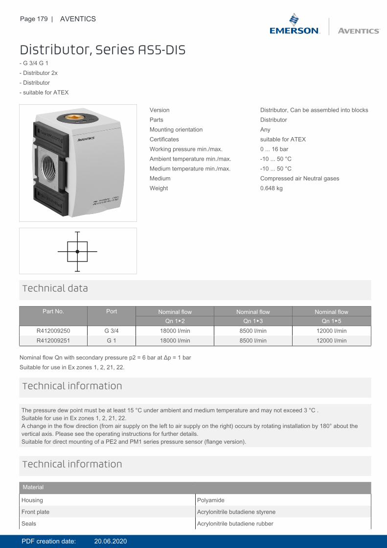
Page 179 | AVENTICS
Distributor, Series AS5-DIS- G 3/4 G 1- Distributor 2x- Distributor- suitable for ATEX
Version Distributor, Can be assembled into blocksParts DistributorMounting orientation AnyCertificates suitable for ATEXWorking pressure min./max. 0 ... 16 barAmbient temperature min./max. -10 ... 50 °CMedium temperature min./max. -10 ... 50 °CMedium Compressed air Neutral gasesWeight 0.648 kg
Technical data
Part No. Port Nominal flow Nominal flow Nominal flowQn 1▶2 Qn 1▶3 Qn 1▶5
R412009250 G 3/4 18000 l/min 8500 l/min 12000 l/minR412009251 G 1 18000 l/min 8500 l/min 12000 l/min
Nominal flow Qn with secondary pressure p2 = 6 bar at Δp = 1 barSuitable for use in Ex zones 1, 2, 21, 22.
The pressure dew point must be at least 15 °C under ambient and medium temperature and may not exceed 3 °C .Suitable for use in Ex zones 1, 2, 21, 22.A change in the flow direction (from air supply on the left to air supply on the right) occurs by rotating installation by 180° about thevertical axis. Please see the operating instructions for further details.Suitable for direct mounting of a PE2 and PM1 series pressure sensor (flange version).
Technical information
Technical information
Material
Housing Polyamide
Front plate Acrylonitrile butadiene styrene
Seals Acrylonitrile butadiene rubber
PDF creation date: 20.06.2020
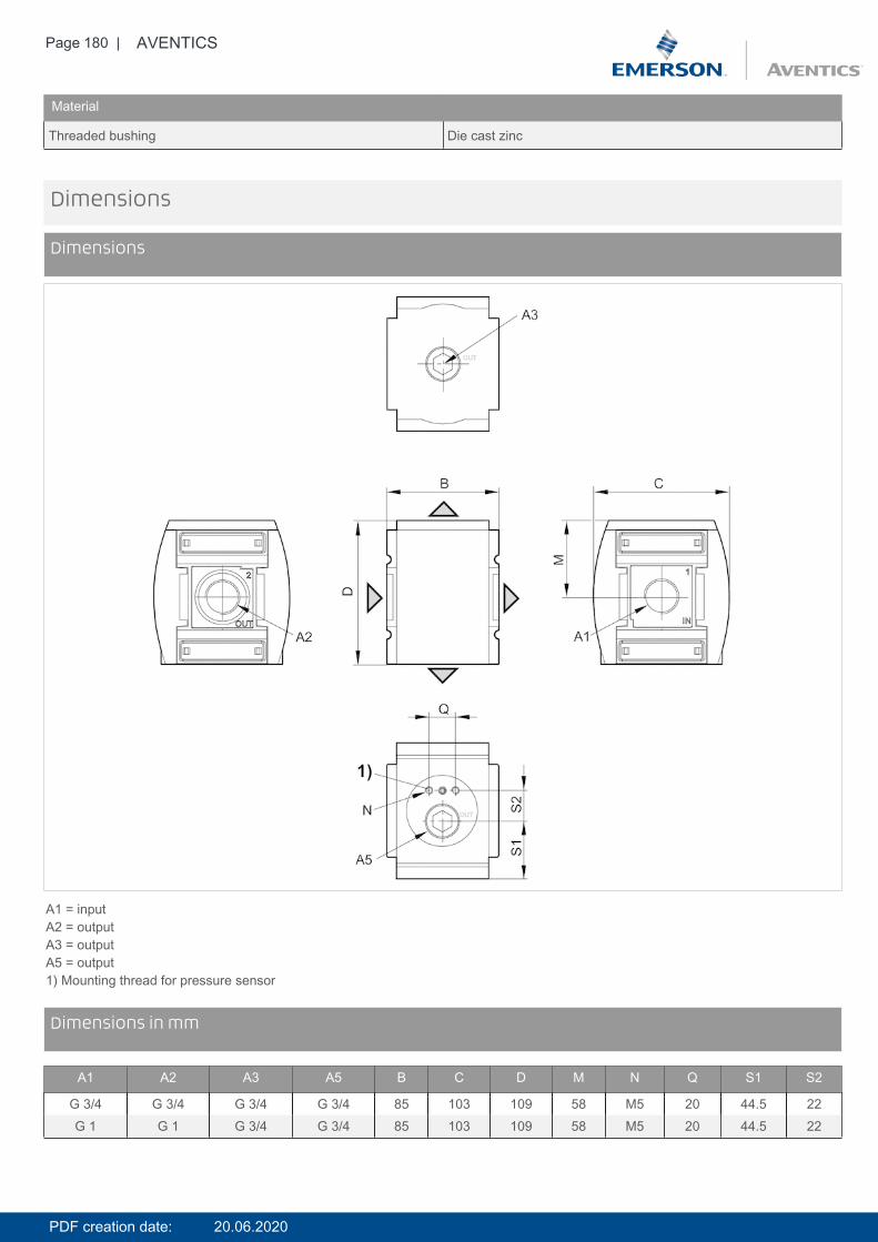
Page 180 | AVENTICS
Material
Threaded bushing Die cast zinc
Dimensions
Dimensions
A1 = inputA2 = outputA3 = outputA5 = output1) Mounting thread for pressure sensor
DimensionsDimensions in mm
A1 A2 A3 A5 B C D M N Q S1 S2
G 3/4 G 3/4 G 3/4 G 3/4 85 103 109 58 M5 20 44.5 22G 1 G 1 G 3/4 G 3/4 85 103 109 58 M5 20 44.5 22
PDF creation date: 20.06.2020

Page 181 | AVENTICS
Accessories overview
1 = contamination display3 = Double nipple4 = Key for E11 locking5 = mortise lock6 = Transition plate DO307 = Adapter, Series CON-VP8 = Mounting aid DO16, form C9 = Mounting aid DO16, M1210 = Adapter for external pilot air11 = Adapter pneumatic operation12 = Sealing ring13 = Reducing nipple
PDF creation date: 20.06.2020
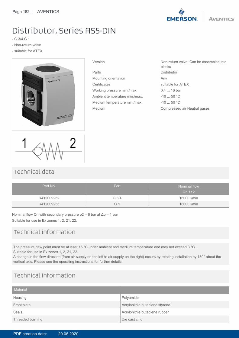
Page 182 | AVENTICS
Distributor, Series AS5-DIN- G 3/4 G 1- Non-return valve- suitable for ATEX
Version Non-return valve, Can be assembled intoblocks
Parts DistributorMounting orientation AnyCertificates suitable for ATEXWorking pressure min./max. 0.4 ... 16 barAmbient temperature min./max. -10 ... 50 °CMedium temperature min./max. -10 ... 50 °CMedium Compressed air Neutral gases
Technical data
Part No. Port Nominal flowQn 1▶2
R412009252 G 3/4 16000 l/minR412009253 G 1 16000 l/min
Nominal flow Qn with secondary pressure p2 = 6 bar at Δp = 1 barSuitable for use in Ex zones 1, 2, 21, 22.
The pressure dew point must be at least 15 °C under ambient and medium temperature and may not exceed 3 °C .Suitable for use in Ex zones 1, 2, 21, 22.A change in the flow direction (from air supply on the left to air supply on the right) occurs by rotating installation by 180° about thevertical axis. Please see the operating instructions for further details.
Technical information
Technical information
Material
Housing Polyamide
Front plate Acrylonitrile butadiene styrene
Seals Acrylonitrile butadiene rubber
Threaded bushing Die cast zinc
PDF creation date: 20.06.2020
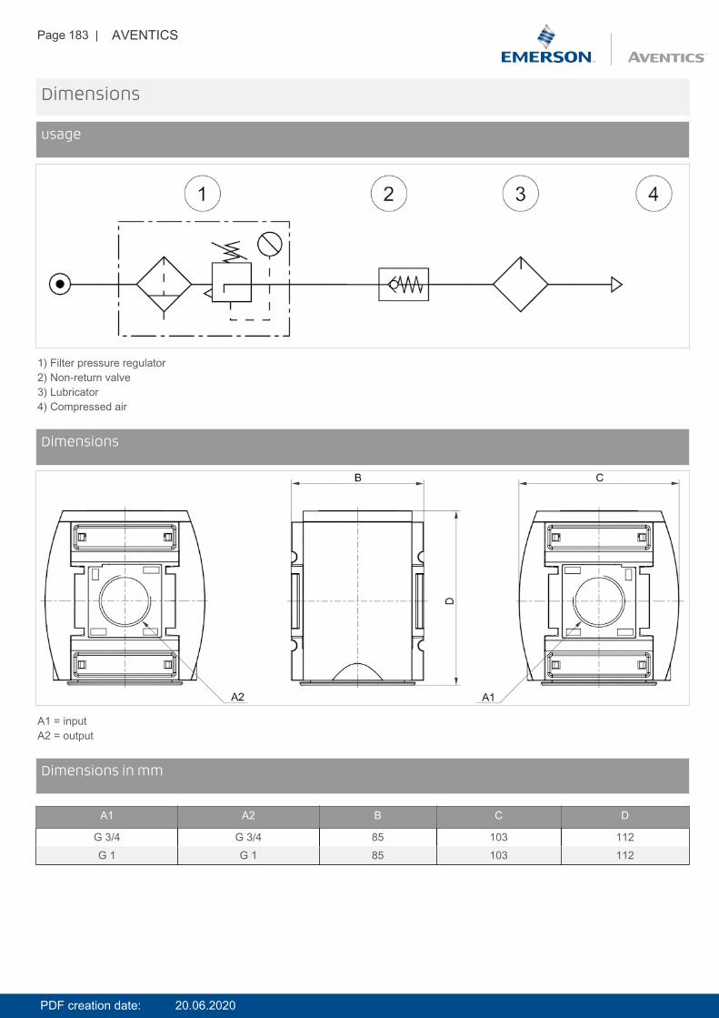
Page 183 | AVENTICS
Dimensions
usage
1) Filter pressure regulator2) Non-return valve3) Lubricator4) Compressed air
DimensionsDimensions
A1 = inputA2 = output
DimensionsDimensions in mm
A1 A2 B C D
G 3/4 G 3/4 85 103 112G 1 G 1 85 103 112
PDF creation date: 20.06.2020
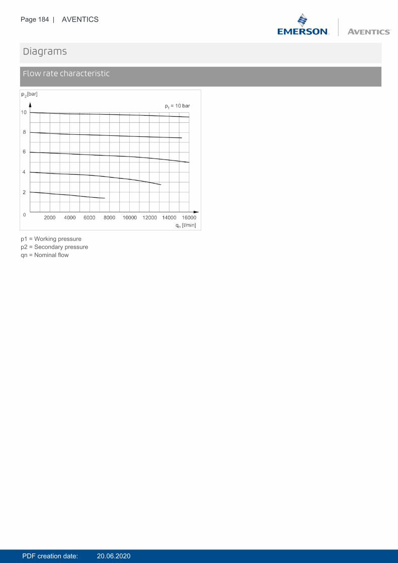
Page 184 | AVENTICS
Diagrams
Flow rate characteristic
p1 = Working pressurep2 = Secondary pressureqn = Nominal flow
PDF creation date: 20.06.2020

Page 185 | AVENTICS
Accessories overview
1 = contamination display3 = Double nipple4 = Key for E11 locking5 = mortise lock6 = Transition plate DO307 = Adapter, Series CON-VP8 = Mounting aid DO16, form C9 = Mounting aid DO16, M1210 = Adapter for external pilot air11 = Adapter pneumatic operation12 = Sealing ring13 = Reducing nipple
PDF creation date: 20.06.2020
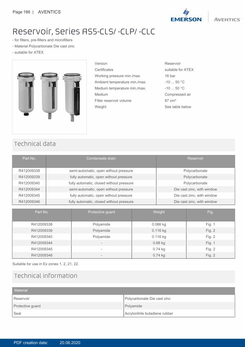
Page 186 | AVENTICS
Reservoir, Series AS5-CLS/ -CLP/ -CLC- for filters, pre-filters and microfilters- Material Polycarbonate Die cast zinc- suitable for ATEX
Version ReservoirCertificates suitable for ATEXWorking pressure min./max. 16 barAmbient temperature min./max. -10 ... 50 °CMedium temperature min./max. -10 ... 50 °CMedium Compressed airFilter reservoir volume 87 cm³Weight See table below
Technical data
Part No. Condensate drain Reservoir
R412009338 semi-automatic, open without pressure PolycarbonateR412009339 fully automatic, open without pressure PolycarbonateR412009340 fully automatic, closed without pressure PolycarbonateR412009344 semi-automatic, open without pressure Die cast zinc, with windowR412009345 fully automatic, open without pressure Die cast zinc, with windowR412009346 fully automatic, closed without pressure Die cast zinc, with window
Part No. Protective guard Weight Fig.
R412009338 Polyamide 0.086 kg Fig. 1R412009339 Polyamide 0.116 kg Fig. 2R412009340 Polyamide 0.116 kg Fig. 2R412009344 - 0.68 kg Fig. 1R412009345 - 0.74 kg Fig. 2R412009346 - 0.74 kg Fig. 2
Suitable for use in Ex zones 1, 2, 21, 22.
Technical information
Material
Reservoir Polycarbonate Die cast zinc
Protective guard Polyamide
Seal Acrylonitrile butadiene rubber
PDF creation date: 20.06.2020
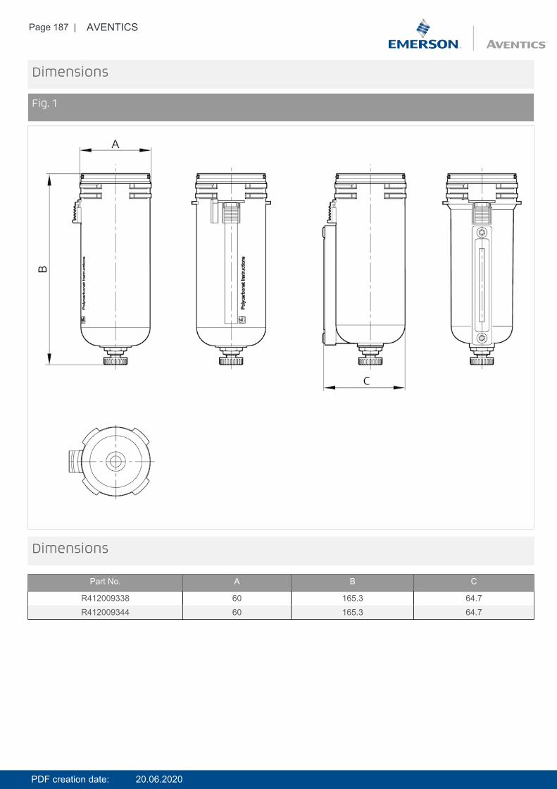
Page 187 | AVENTICS
Dimensions
Fig. 1
Dimensions
Part No. A B C
R412009338 60 165.3 64.7R412009344 60 165.3 64.7
PDF creation date: 20.06.2020
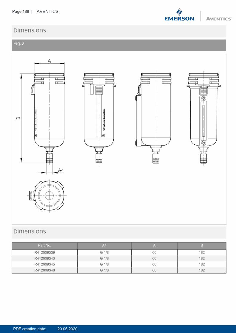
Page 188 | AVENTICS
Dimensions
Fig. 2
Dimensions
Part No. A4 A B
R412009339 G 1/8 60 182R412009340 G 1/8 60 182R412009345 G 1/8 60 182R412009346 G 1/8 60 182
PDF creation date: 20.06.2020
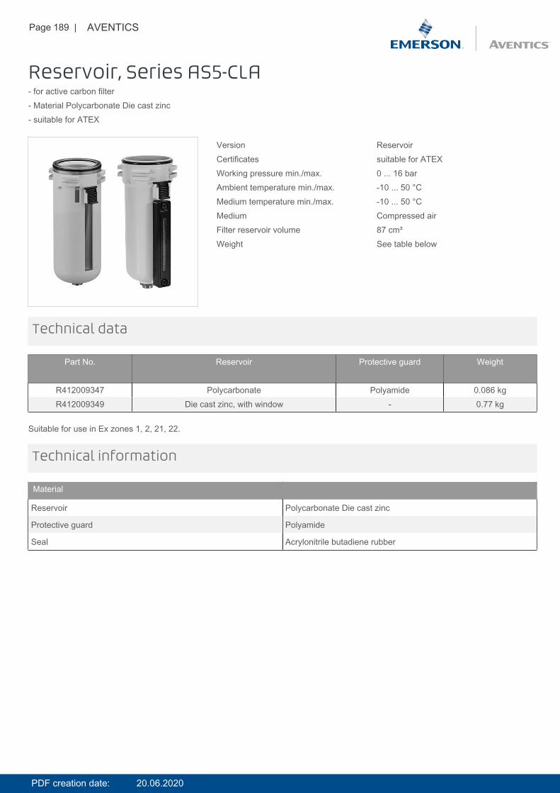
Page 189 | AVENTICS
Reservoir, Series AS5-CLA- for active carbon filter- Material Polycarbonate Die cast zinc- suitable for ATEX
Version ReservoirCertificates suitable for ATEXWorking pressure min./max. 0 ... 16 barAmbient temperature min./max. -10 ... 50 °CMedium temperature min./max. -10 ... 50 °CMedium Compressed airFilter reservoir volume 87 cm³Weight See table below
Technical data
Part No. Reservoir Protective guard Weight
R412009347 Polycarbonate Polyamide 0.086 kgR412009349 Die cast zinc, with window - 0.77 kg
Suitable for use in Ex zones 1, 2, 21, 22.
Technical information
Material
Reservoir Polycarbonate Die cast zinc
Protective guard Polyamide
Seal Acrylonitrile butadiene rubber
PDF creation date: 20.06.2020
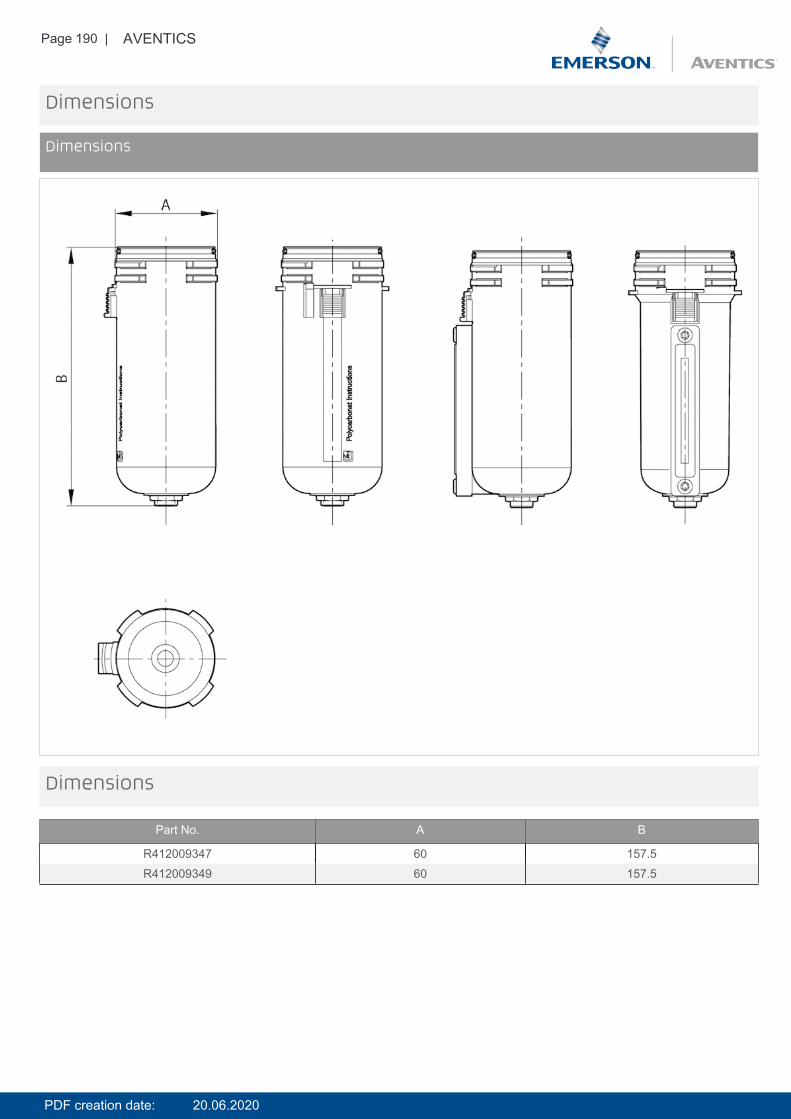
Page 190 | AVENTICS
Dimensions
Dimensions
Dimensions
Part No. A B
R412009347 60 157.5R412009349 60 157.5
PDF creation date: 20.06.2020

Page 191 | AVENTICS
Reservoir, Series AS5-CBS- for lubricator- Material Polycarbonate Die cast zinc- suitable for ATEX
Version ReservoirCertificates suitable for ATEXWorking pressure min./max. 0 ... 16 barAmbient temperature min./max. -10 ... 50 °CMedium temperature min./max. -10 ... 50 °CMedium Compressed air OilLubricator reservoir volume 181 cm³Weight See table below
Technical data
Part No. Electrical level indicator Reservoir Protective guard Weight
R412009351 with external query Polycarbonate Polyamide 0.086 kgR412009352 - Polycarbonate Polyamide 0.335 kgR412009358 - Die cast zinc, with window - 0.68 kg
Suitable for use in Ex zones 1, 2, 21, 22.
Technical information
Material
Reservoir Polycarbonate Die cast zinc
Protective guard Polyamide
Seal Acrylonitrile butadiene rubber
PDF creation date: 20.06.2020

Page 192 | AVENTICS
Dimensions
Dimensions
Dimensions
Part No. A B
R412009351 60 154.8R412009352 60 154.8R412009358 60 154.8
PDF creation date: 20.06.2020
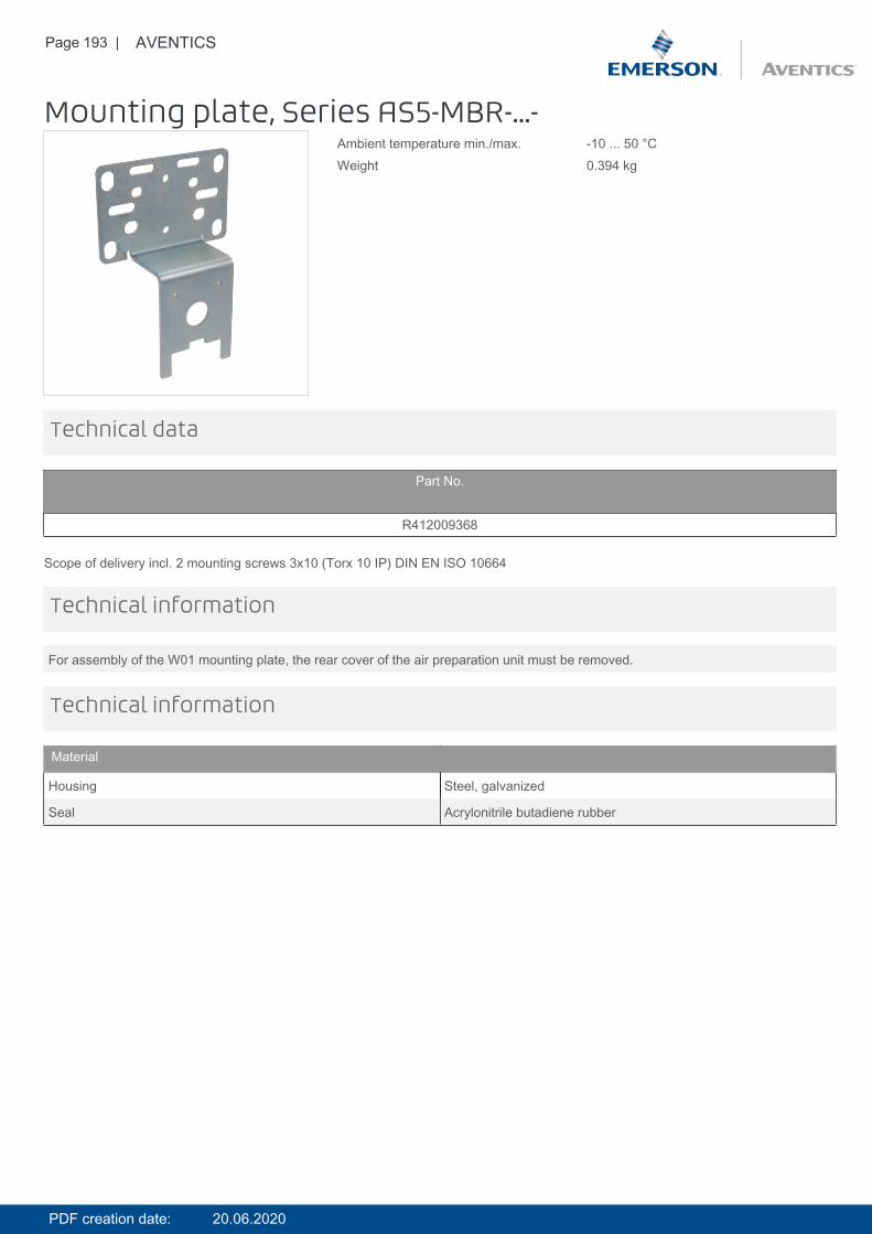
Page 193 | AVENTICS
Mounting plate, Series AS5-MBR-...-Ambient temperature min./max. -10 ... 50 °CWeight 0.394 kg
Technical data
Part No.
R412009368
Scope of delivery incl. 2 mounting screws 3x10 (Torx 10 IP) DIN EN ISO 10664
For assembly of the W01 mounting plate, the rear cover of the air preparation unit must be removed.
Technical information
Technical information
Material
Housing Steel, galvanized
Seal Acrylonitrile butadiene rubber
PDF creation date: 20.06.2020
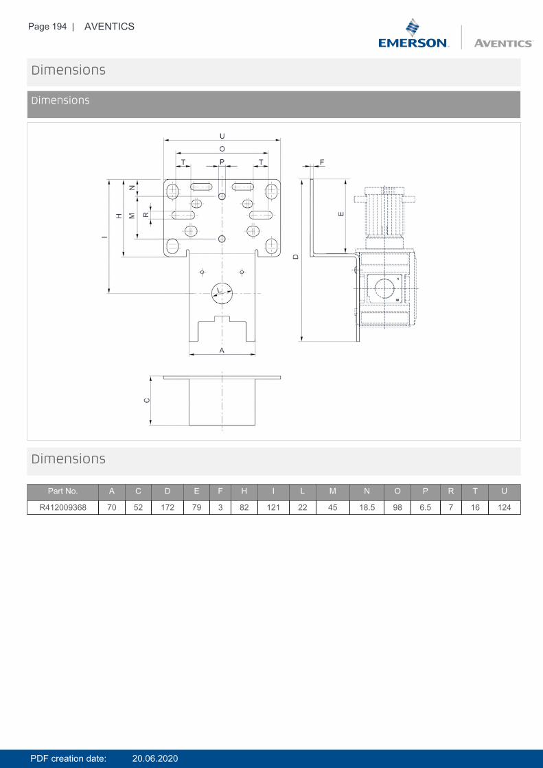
Page 194 | AVENTICS
Dimensions
Dimensions
Dimensions
Part No. A C D E F H I L M N O P R T U
R412009368 70 52 172 79 3 82 121 22 45 18.5 98 6.5 7 16 124
PDF creation date: 20.06.2020
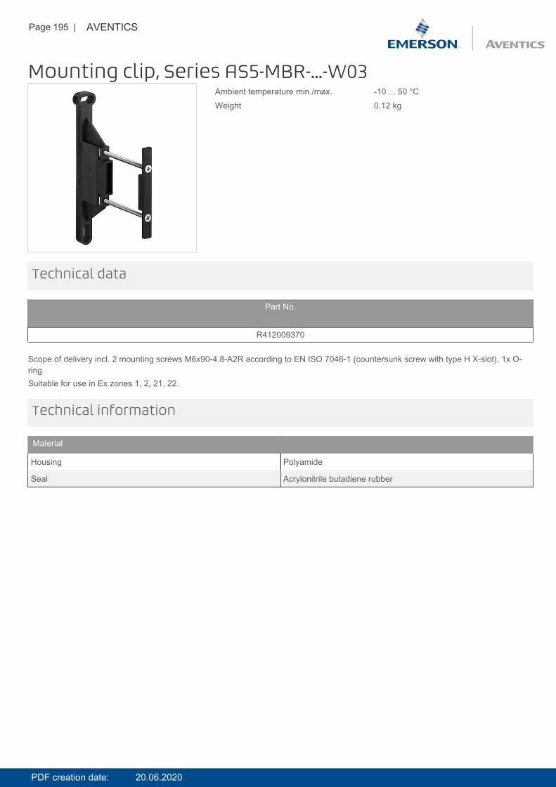
Page 195 | AVENTICS
Mounting clip, Series AS5-MBR-...-W03Ambient temperature min./max. -10 ... 50 °CWeight 0.12 kg
Technical data
Part No.
R412009370
Scope of delivery incl. 2 mounting screws M6x90-4.8-A2R according to EN ISO 7046-1 (countersunk screw with type H X-slot), 1x O-ringSuitable for use in Ex zones 1, 2, 21, 22.
Technical information
Material
Housing Polyamide
Seal Acrylonitrile butadiene rubber
PDF creation date: 20.06.2020
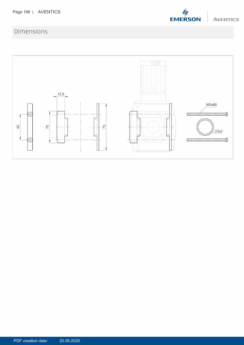
Page 196 | AVENTICS
Dimensions
PDF creation date: 20.06.2020
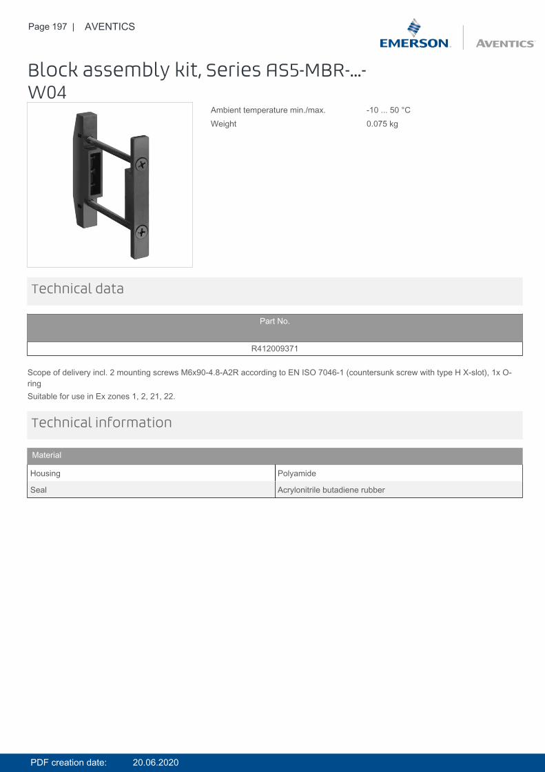
Page 197 | AVENTICS
Block assembly kit, Series AS5-MBR-...-W04
Ambient temperature min./max. -10 ... 50 °CWeight 0.075 kg
Technical data
Part No.
R412009371
Scope of delivery incl. 2 mounting screws M6x90-4.8-A2R according to EN ISO 7046-1 (countersunk screw with type H X-slot), 1x O-ringSuitable for use in Ex zones 1, 2, 21, 22.
Technical information
Material
Housing Polyamide
Seal Acrylonitrile butadiene rubber
PDF creation date: 20.06.2020
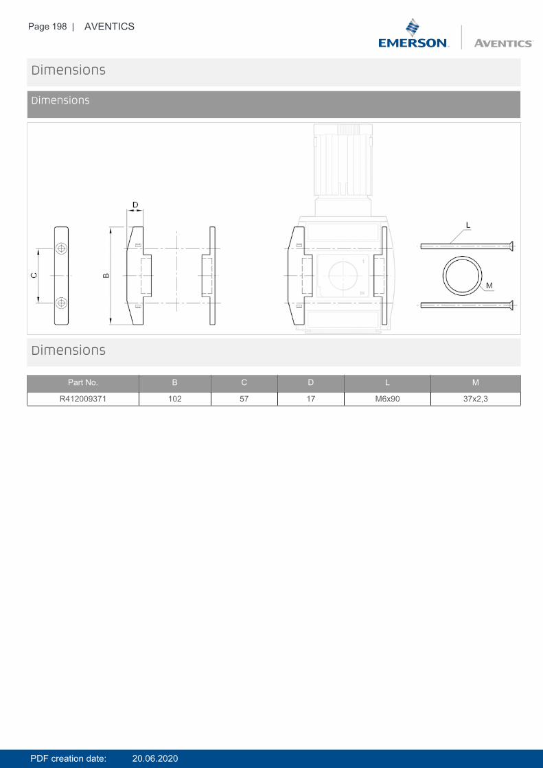
Page 198 | AVENTICS
Dimensions
Dimensions
Dimensions
Part No. B C D L M
R412009371 102 57 17 M6x90 37x2,3
PDF creation date: 20.06.2020
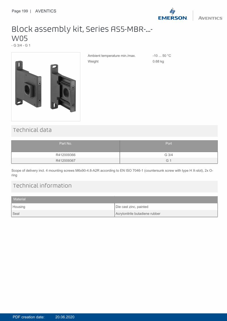
Page 199 | AVENTICS
Block assembly kit, Series AS5-MBR-...-W05- G 3/4 - G 1
Ambient temperature min./max. -10 ... 50 °CWeight 0.68 kg
Technical data
Part No. Port
R412009366 G 3/4R412009367 G 1
Scope of delivery incl. 4 mounting screws M6x90-4.8-A2R according to EN ISO 7046-1 (countersunk screw with type H X-slot), 2x O-ring
Technical information
Material
Housing Die cast zinc, painted
Seal Acrylonitrile butadiene rubber
PDF creation date: 20.06.2020
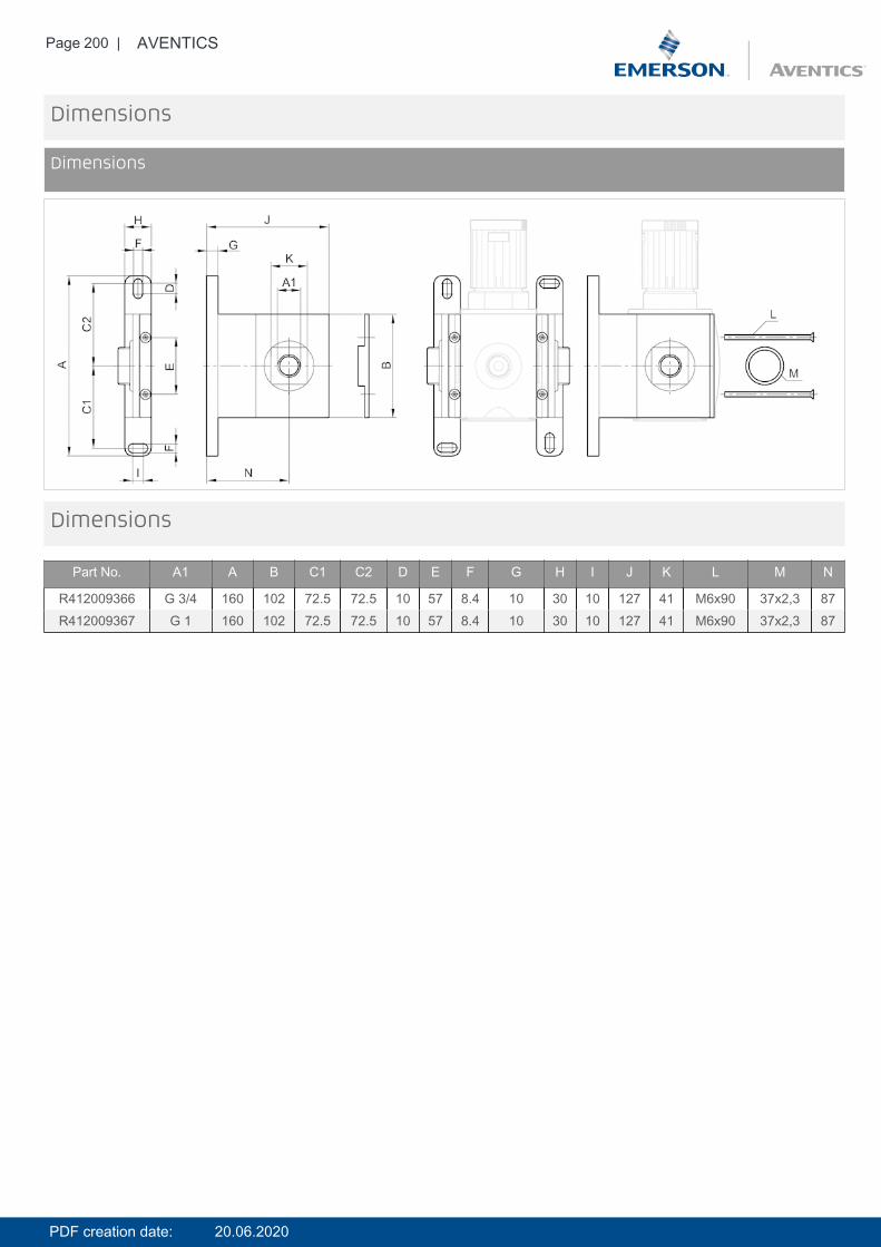
Page 200 | AVENTICS
Dimensions
Dimensions
Dimensions
Part No. A1 A B C1 C2 D E F G H I J K L M N
R412009366 G 3/4 160 102 72.5 72.5 10 57 8.4 10 30 10 127 41 M6x90 37x2,3 87R412009367 G 1 160 102 72.5 72.5 10 57 8.4 10 30 10 127 41 M6x90 37x2,3 87
PDF creation date: 20.06.2020
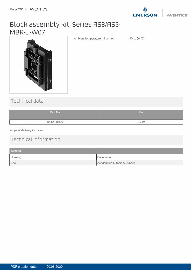
Page 201 | AVENTICS
Block assembly kit, Series AS3/AS5-MBR-...-W07
Ambient temperature min./max. -10 ... 50 °C
Technical data
Part No. Port
R412010122 G 1/4
scope of delivery incl. seal
Technical information
Material
Housing Polyamide
Seal Acrylonitrile butadiene rubber
PDF creation date: 20.06.2020
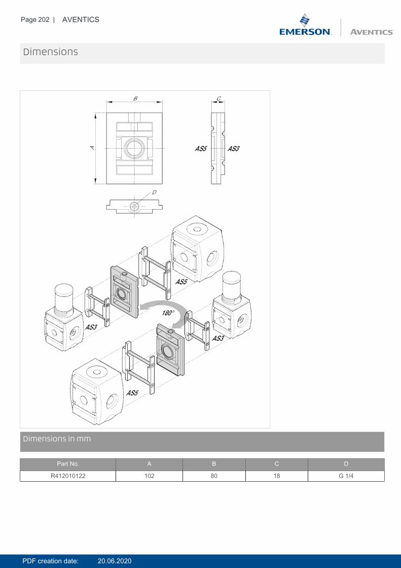
Page 202 | AVENTICS
Dimensions
DimensionsDimensions in mm
Part No. A B C D
R412010122 102 80 18 G 1/4
PDF creation date: 20.06.2020
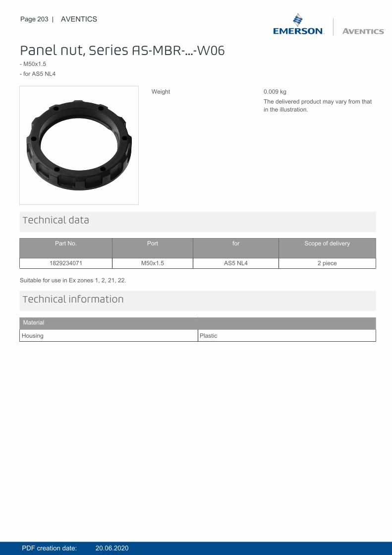
Page 203 | AVENTICS
Panel nut, Series AS-MBR-...-W06- M50x1.5- for AS5 NL4
Weight 0.009 kgThe delivered product may vary from thatin the illustration.
Technical data
Part No. Port for Scope of delivery
1829234071 M50x1.5 AS5 NL4 2 piece
Suitable for use in Ex zones 1, 2, 21, 22.
Technical information
Material
Housing Plastic
PDF creation date: 20.06.2020
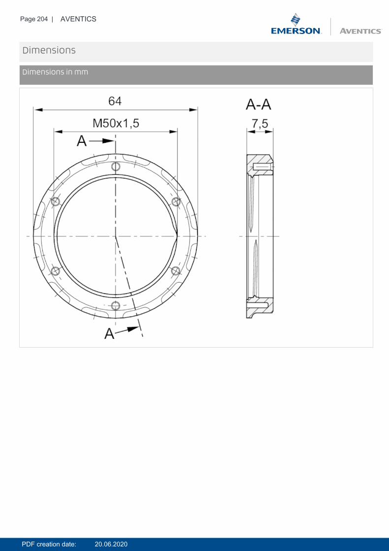
Page 204 | AVENTICS
Dimensions
Dimensions in mm
PDF creation date: 20.06.2020
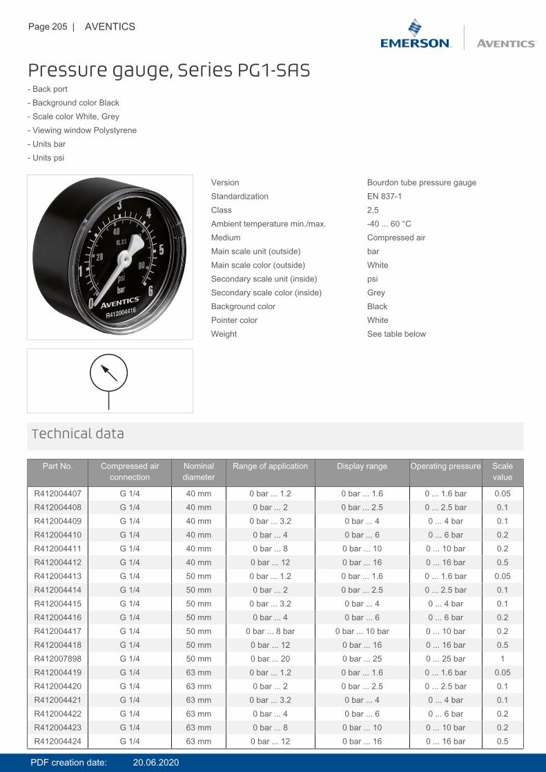
Page 205 | AVENTICS
Pressure gauge, Series PG1-SAS- Back port- Background color Black- Scale color White, Grey- Viewing window Polystyrene- Units bar- Units psi
Version Bourdon tube pressure gaugeStandardization EN 837-1Class 2,5Ambient temperature min./max. -40 ... 60 °CMedium Compressed airMain scale unit (outside) barMain scale color (outside) WhiteSecondary scale unit (inside) psiSecondary scale color (inside) GreyBackground color BlackPointer color WhiteWeight See table below
Technical data
Part No. Compressed airconnection
Nominaldiameter
Range of application Display range Operating pressure Scalevalue
R412004407 G 1/4 40 mm 0 bar ... 1.2 0 bar ... 1.6 0 ... 1.6 bar 0.05R412004408 G 1/4 40 mm 0 bar ... 2 0 bar ... 2.5 0 ... 2.5 bar 0.1R412004409 G 1/4 40 mm 0 bar ... 3.2 0 bar ... 4 0 ... 4 bar 0.1R412004410 G 1/4 40 mm 0 bar ... 4 0 bar ... 6 0 ... 6 bar 0.2R412004411 G 1/4 40 mm 0 bar ... 8 0 bar ... 10 0 ... 10 bar 0.2R412004412 G 1/4 40 mm 0 bar ... 12 0 bar ... 16 0 ... 16 bar 0.5R412004413 G 1/4 50 mm 0 bar ... 1.2 0 bar ... 1.6 0 ... 1.6 bar 0.05R412004414 G 1/4 50 mm 0 bar ... 2 0 bar ... 2.5 0 ... 2.5 bar 0.1R412004415 G 1/4 50 mm 0 bar ... 3.2 0 bar ... 4 0 ... 4 bar 0.1R412004416 G 1/4 50 mm 0 bar ... 4 0 bar ... 6 0 ... 6 bar 0.2R412004417 G 1/4 50 mm 0 bar ... 8 bar 0 bar ... 10 bar 0 ... 10 bar 0.2R412004418 G 1/4 50 mm 0 bar ... 12 0 bar ... 16 0 ... 16 bar 0.5R412007898 G 1/4 50 mm 0 bar ... 20 0 bar ... 25 0 ... 25 bar 1R412004419 G 1/4 63 mm 0 bar ... 1.2 0 bar ... 1.6 0 ... 1.6 bar 0.05R412004420 G 1/4 63 mm 0 bar ... 2 0 bar ... 2.5 0 ... 2.5 bar 0.1R412004421 G 1/4 63 mm 0 bar ... 3.2 0 bar ... 4 0 ... 4 bar 0.1R412004422 G 1/4 63 mm 0 bar ... 4 0 bar ... 6 0 ... 6 bar 0.2R412004423 G 1/4 63 mm 0 bar ... 8 0 bar ... 10 0 ... 10 bar 0.2R412004424 G 1/4 63 mm 0 bar ... 12 0 bar ... 16 0 ... 16 bar 0.5
PDF creation date: 20.06.2020
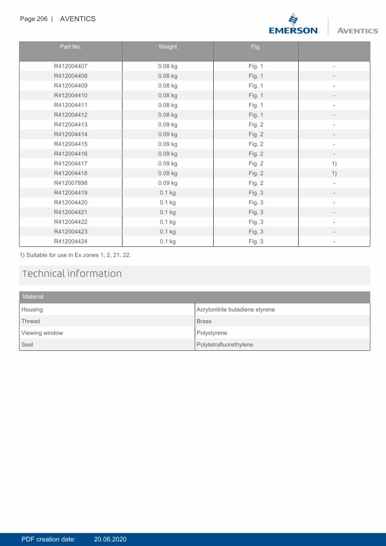
Page 206 | AVENTICS
Part No. Weight Fig.
R412004407 0.08 kg Fig. 1 -R412004408 0.08 kg Fig. 1 -R412004409 0.08 kg Fig. 1 -R412004410 0.08 kg Fig. 1 -R412004411 0.08 kg Fig. 1 -R412004412 0.08 kg Fig. 1 -R412004413 0.09 kg Fig. 2 -R412004414 0.09 kg Fig. 2 -R412004415 0.09 kg Fig. 2 -R412004416 0.09 kg Fig. 2 -R412004417 0.09 kg Fig. 2 1)R412004418 0.09 kg Fig. 2 1)R412007898 0.09 kg Fig. 2 -R412004419 0.1 kg Fig. 3 -R412004420 0.1 kg Fig. 3 -R412004421 0.1 kg Fig. 3 -R412004422 0.1 kg Fig. 3 -R412004423 0.1 kg Fig. 3 -R412004424 0.1 kg Fig. 3 -
1) Suitable for use in Ex zones 1, 2, 21, 22.
Technical information
Material
Housing Acrylonitrile butadiene styrene
Thread Brass
Viewing window Polystyrene
Seal Polytetrafluorethylene
PDF creation date: 20.06.2020
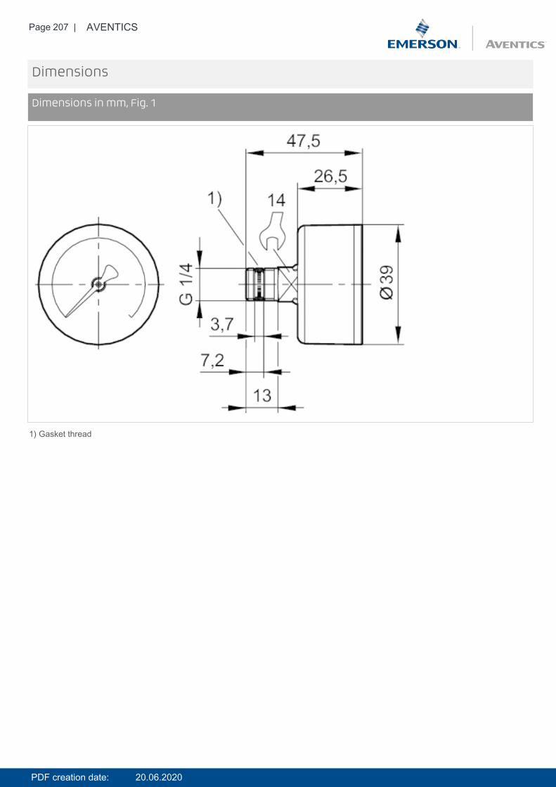
Page 207 | AVENTICS
Dimensions
Dimensions in mm, Fig. 1
1) Gasket thread
PDF creation date: 20.06.2020
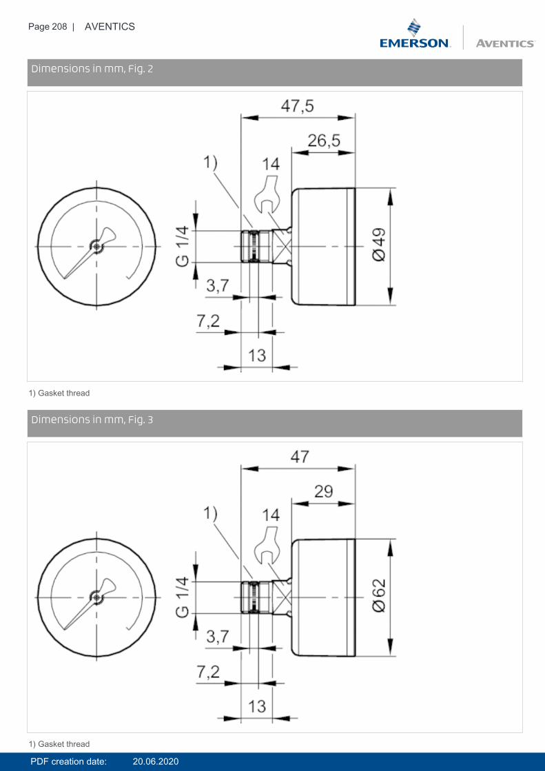
Page 208 | AVENTICS
DimensionsDimensions in mm, Fig. 2
1) Gasket thread
DimensionsDimensions in mm, Fig. 3
1) Gasket thread
PDF creation date: 20.06.2020

Page 209 | AVENTICS
PDF creation date: 20.06.2020
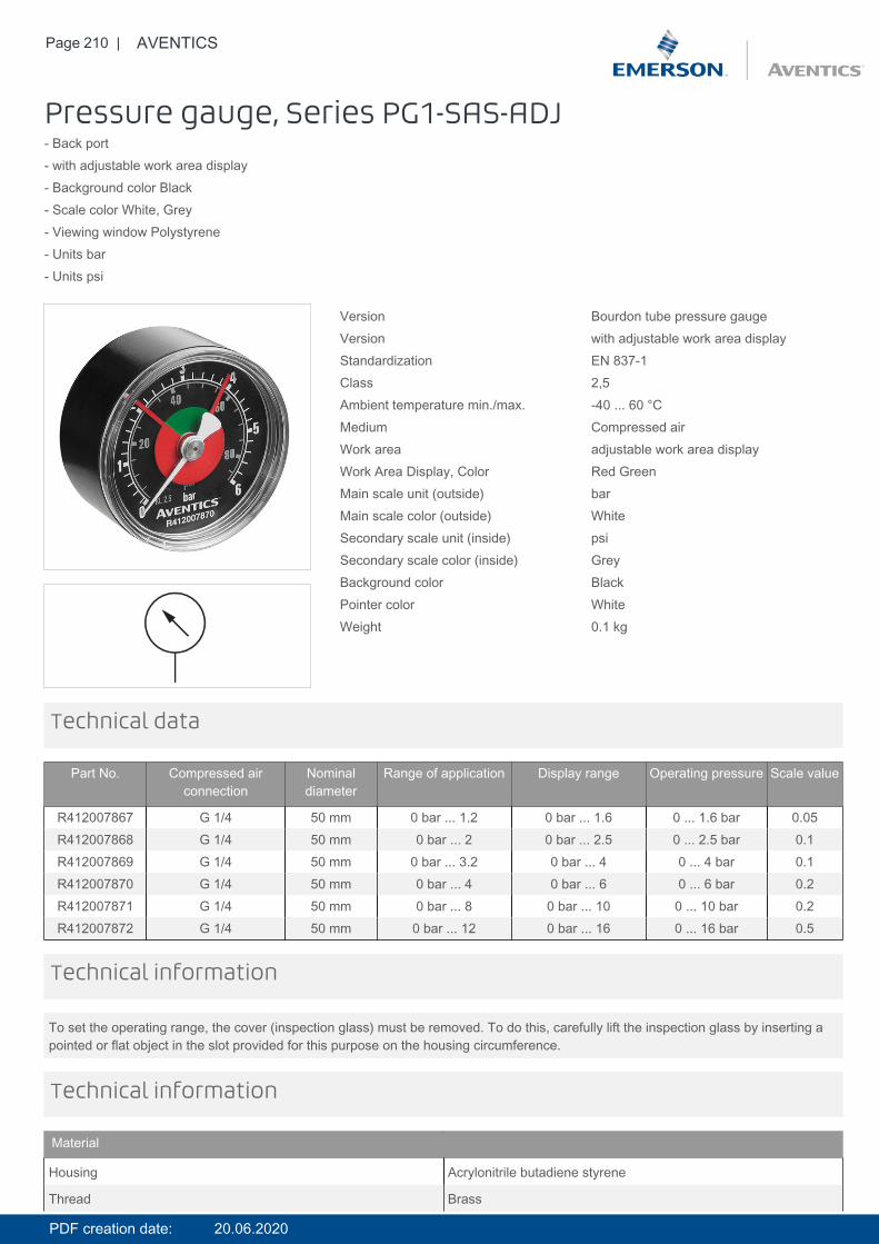
Page 210 | AVENTICS
Pressure gauge, Series PG1-SAS-ADJ- Back port- with adjustable work area display- Background color Black- Scale color White, Grey- Viewing window Polystyrene- Units bar- Units psi
Version Bourdon tube pressure gaugeVersion with adjustable work area displayStandardization EN 837-1Class 2,5Ambient temperature min./max. -40 ... 60 °CMedium Compressed airWork area adjustable work area displayWork Area Display, Color Red GreenMain scale unit (outside) barMain scale color (outside) WhiteSecondary scale unit (inside) psiSecondary scale color (inside) GreyBackground color BlackPointer color WhiteWeight 0.1 kg
Technical data
Part No. Compressed airconnection
Nominaldiameter
Range of application Display range Operating pressure Scale value
R412007867 G 1/4 50 mm 0 bar ... 1.2 0 bar ... 1.6 0 ... 1.6 bar 0.05R412007868 G 1/4 50 mm 0 bar ... 2 0 bar ... 2.5 0 ... 2.5 bar 0.1R412007869 G 1/4 50 mm 0 bar ... 3.2 0 bar ... 4 0 ... 4 bar 0.1R412007870 G 1/4 50 mm 0 bar ... 4 0 bar ... 6 0 ... 6 bar 0.2R412007871 G 1/4 50 mm 0 bar ... 8 0 bar ... 10 0 ... 10 bar 0.2R412007872 G 1/4 50 mm 0 bar ... 12 0 bar ... 16 0 ... 16 bar 0.5
To set the operating range, the cover (inspection glass) must be removed. To do this, carefully lift the inspection glass by inserting apointed or flat object in the slot provided for this purpose on the housing circumference.
Technical information
Technical information
Material
Housing Acrylonitrile butadiene styrene
Thread Brass
PDF creation date: 20.06.2020
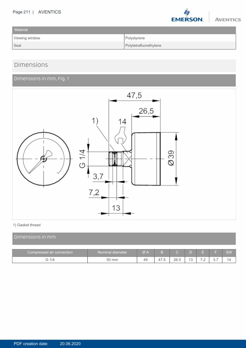
Page 211 | AVENTICS
Material
Viewing window Polystyrene
Seal Polytetrafluorethylene
Dimensions
Dimensions in mm, Fig. 1
1) Gasket thread
DimensionsDimensions in mm
Compressed air connection Nominal diameter Ø A B C D E F SW
G 1/4 50 mm 49 47.5 26.5 13 7.2 3.7 14
PDF creation date: 20.06.2020
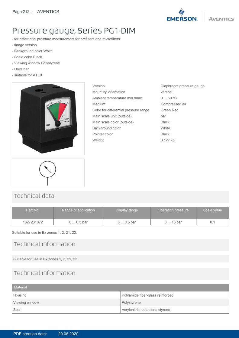
Page 212 | AVENTICS
Pressure gauge, Series PG1-DIM- for differential pressure measurement for prefilters and microfilters- flange version- Background color White- Scale color Black- Viewing window Polystyrene- Units bar- suitable for ATEX
Version Diaphragm pressure gaugeMounting orientation verticalAmbient temperature min./max. 0 ... 60 °CMedium Compressed airColor for differential pressure range Green RedMain scale unit (outside) barMain scale color (outside) BlackBackground color WhitePointer color BlackWeight 0.127 kg
Technical data
Part No. Range of application Display range Operating pressure Scale value
1827231072 0 ... 0.5 bar 0 ... 0.5 bar 0 ... 16 bar 0.1
Suitable for use in Ex zones 1, 2, 21, 22.
Suitable for use in Ex zones 1, 2, 21, 22.
Technical information
Technical information
Material
Housing Polyamide fiber-glass reinforced
Viewing window Polystyrene
Seal Acrylonitrile butadiene styrene
PDF creation date: 20.06.2020
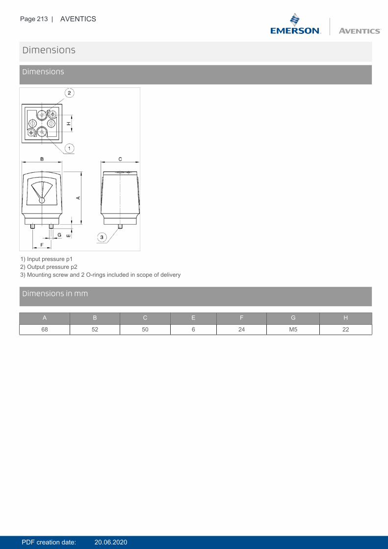
Page 213 | AVENTICS
Dimensions
Dimensions
1) Input pressure p12) Output pressure p23) Mounting screw and 2 O-rings included in scope of delivery
DimensionsDimensions in mm
A B C E F G H
68 52 50 6 24 M5 22
PDF creation date: 20.06.2020
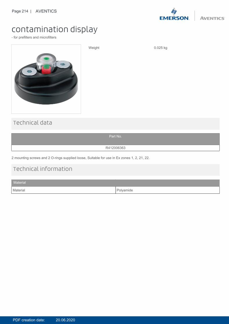
Page 214 | AVENTICS
contamination display- for prefilters and microfilters
Weight 0.025 kg
Technical data
Part No.
R412006363
2 mounting screws and 2 O-rings supplied loose, Suitable for use in Ex zones 1, 2, 21, 22.
Technical information
Material
Material Polyamide
PDF creation date: 20.06.2020
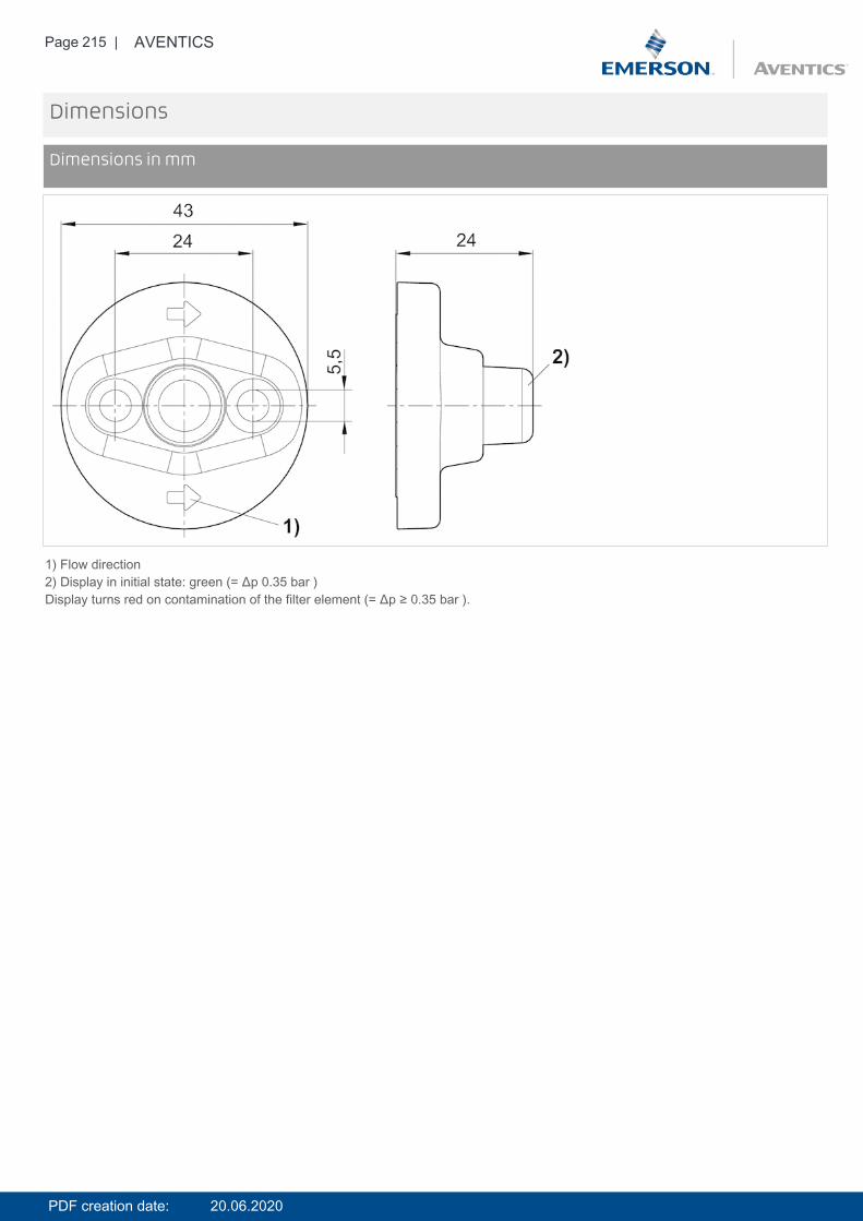
Page 215 | AVENTICS
Dimensions
Dimensions in mm
1) Flow direction2) Display in initial state: green (= Δp 0.35 bar )Display turns red on contamination of the filter element (= Δp ≥ 0.35 bar ).
PDF creation date: 20.06.2020
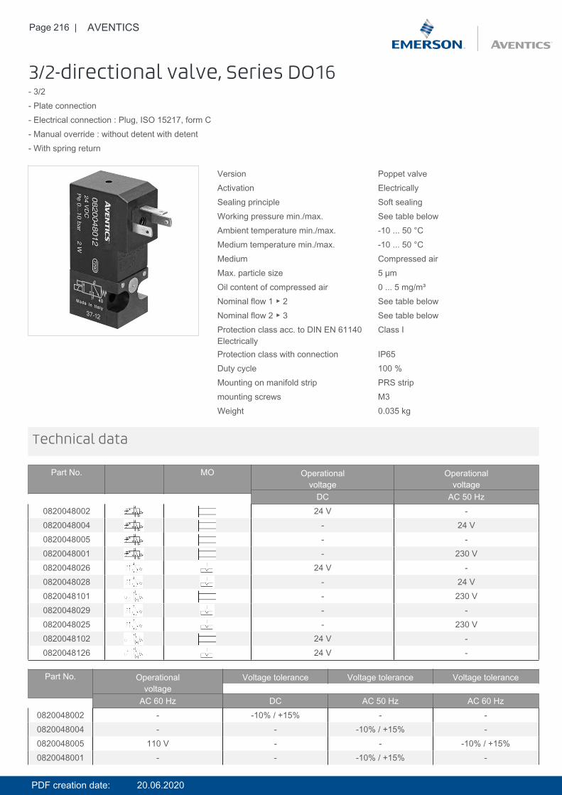
Page 216 | AVENTICS
3/2-directional valve, Series DO16- 3/2- Plate connection- Electrical connection : Plug, ISO 15217, form C- Manual override : without detent with detent- With spring return
Version Poppet valveActivation ElectricallySealing principle Soft sealingWorking pressure min./max. See table belowAmbient temperature min./max. -10 ... 50 °CMedium temperature min./max. -10 ... 50 °CMedium Compressed airMax. particle size 5 µmOil content of compressed air 0 ... 5 mg/m³Nominal flow 1 ▶ 2 See table belowNominal flow 2 ▶ 3 See table belowProtection class acc. to DIN EN 61140Electrically
Class I
Protection class with connection IP65Duty cycle 100 %Mounting on manifold strip PRS stripmounting screws M3Weight 0.035 kg
Technical data
Part No. MO Operationalvoltage
Operationalvoltage
DC AC 50 Hz0820048002 24 V -0820048004 - 24 V0820048005 - -0820048001 - 230 V0820048026 24 V -0820048028 - 24 V0820048101 - 230 V0820048029 - -0820048025 - 230 V0820048102 24 V -0820048126 24 V -
Part No. Operationalvoltage
Voltage tolerance Voltage tolerance Voltage tolerance
AC 60 Hz DC AC 50 Hz AC 60 Hz0820048002 - -10% / +15% - -0820048004 - - -10% / +15% -0820048005 110 V - - -10% / +15%0820048001 - - -10% / +15% -
PDF creation date: 20.06.2020
Page 217 | AVENTICS
Part No. Operationalvoltage
Voltage tolerance Voltage tolerance Voltage tolerance
AC 60 Hz DC AC 50 Hz AC 60 Hz0820048026 - -10% / +15% - -0820048028 - - -10% / +15% -0820048101 - - -10% / +15% -0820048029 110 V - - -10% / +15%0820048025 - - -10% / +15% -0820048102 - -10% / +15% - -0820048126 - -10% / +15% - -
Part No. Power consumption Holding power Holding power Switch-on powerDC AC 50 Hz AC 60 Hz AC 50 Hz
0820048002 2 W - - -0820048004 - 1.6 VA - 2.2 VA0820048005 - - 1.4 VA -0820048001 - 1.6 VA - 2.2 VA0820048026 2 W - - -0820048028 - 1.6 VA - 2.2 VA0820048101 - 1.6 VA - 2.2 VA0820048029 - - 1.4 VA -0820048025 - 1.6 VA - 2.2 VA0820048102 2 W - - -0820048126 2 W - - -
Part No. Switch-on power Nominal flow 1 ▶ 2 Nominal flow 2 ▶ 3 Working pressure min./max.AC 60 Hz
0820048002 - 25 l/min 36 l/min 0 ... 10 bar0820048004 - 25 l/min 36 l/min 0 ... 10 bar0820048005 2 VA 25 l/min 36 l/min 0 ... 10 bar0820048001 - 25 l/min 36 l/min 0 ... 10 bar0820048026 - 25 l/min 36 l/min 0 ... 10 bar0820048028 - 25 l/min 36 l/min 0 ... 10 bar0820048101 - 16 l/min 19 l/min 0 ... 6 bar0820048029 2 VA 25 l/min 36 l/min 0 ... 10 bar0820048025 - 25 l/min 36 l/min 0 ... 10 bar0820048102 - 20 l/min 26 l/min 0 ... 8 bar0820048126 - 20 l/min 26 l/min 0 ... 8 bar
Nominal flow Qn at 6 bar and Δp = 1 bar, MO = Manual override
The min. control pressure must be adhered to, since otherwise faulty switching and valve failure may result!The pressure dew point must be at least 15 °C under ambient and medium temperature and may not exceed 3 °C .The oil content of compressed air must remain constant during the life cycle.Use only the approved oils from AVENTICS. Further information can be found in the “Technical information” document (available inthe MediaCentre).
Technical information
PDF creation date: 20.06.2020
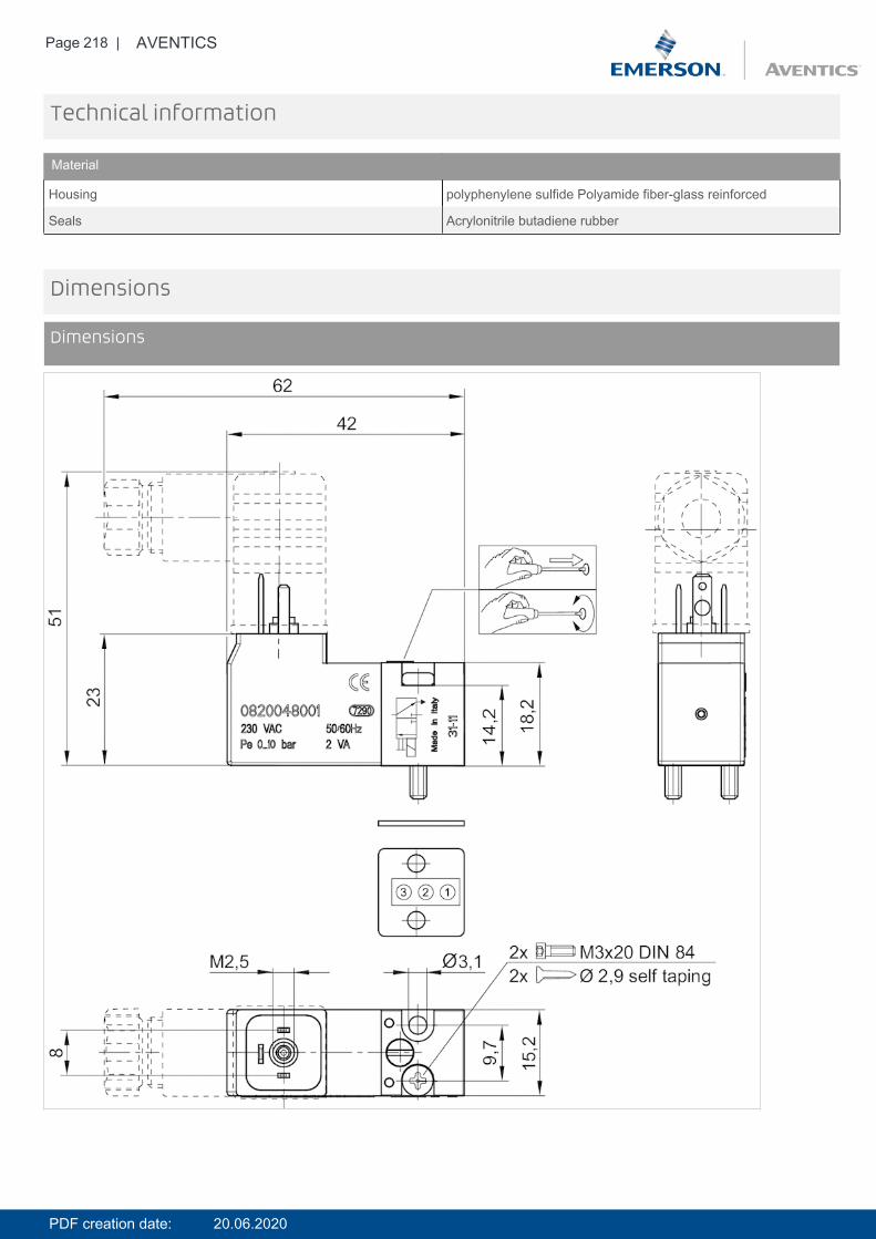
Page 218 | AVENTICS
Technical information
Material
Housing polyphenylene sulfide Polyamide fiber-glass reinforced
Seals Acrylonitrile butadiene rubber
Dimensions
Dimensions
PDF creation date: 20.06.2020
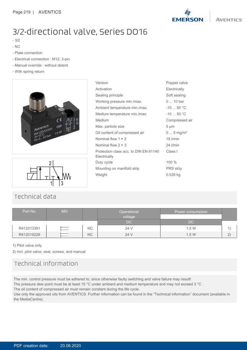
Page 219 | AVENTICS
3/2-directional valve, Series DO16- 3/2- NC- Plate connection- Electrical connection : M12, 3-pin- Manual override : without detent- With spring return
Version Poppet valveActivation ElectricallySealing principle Soft sealingWorking pressure min./max. 0 ... 10 barAmbient temperature min./max. -10 ... 50 °CMedium temperature min./max. -10 ... 50 °CMedium Compressed airMax. particle size 5 µmOil content of compressed air 0 ... 5 mg/m³Nominal flow 1 ▶ 2 18 l/minNominal flow 2 ▶ 3 24 l/minProtection class acc. to DIN EN 61140Electrically
Class I
Duty cycle 100 %Mounting on manifold strip PRS stripWeight 0.035 kg
Technical data
Part No. MO Operationalvoltage
Power consumption
DC DCR412013391 NC 24 V 1.5 W 1)R412019226 NC 24 V 1.5 W 2)
1) Pilot valve only2) Incl. pilot valve, seal, screws, and manual
The min. control pressure must be adhered to, since otherwise faulty switching and valve failure may result!The pressure dew point must be at least 15 °C under ambient and medium temperature and may not exceed 3 °C .The oil content of compressed air must remain constant during the life cycle.Use only the approved oils from AVENTICS. Further information can be found in the “Technical information” document (available inthe MediaCentre).
Technical information
PDF creation date: 20.06.2020
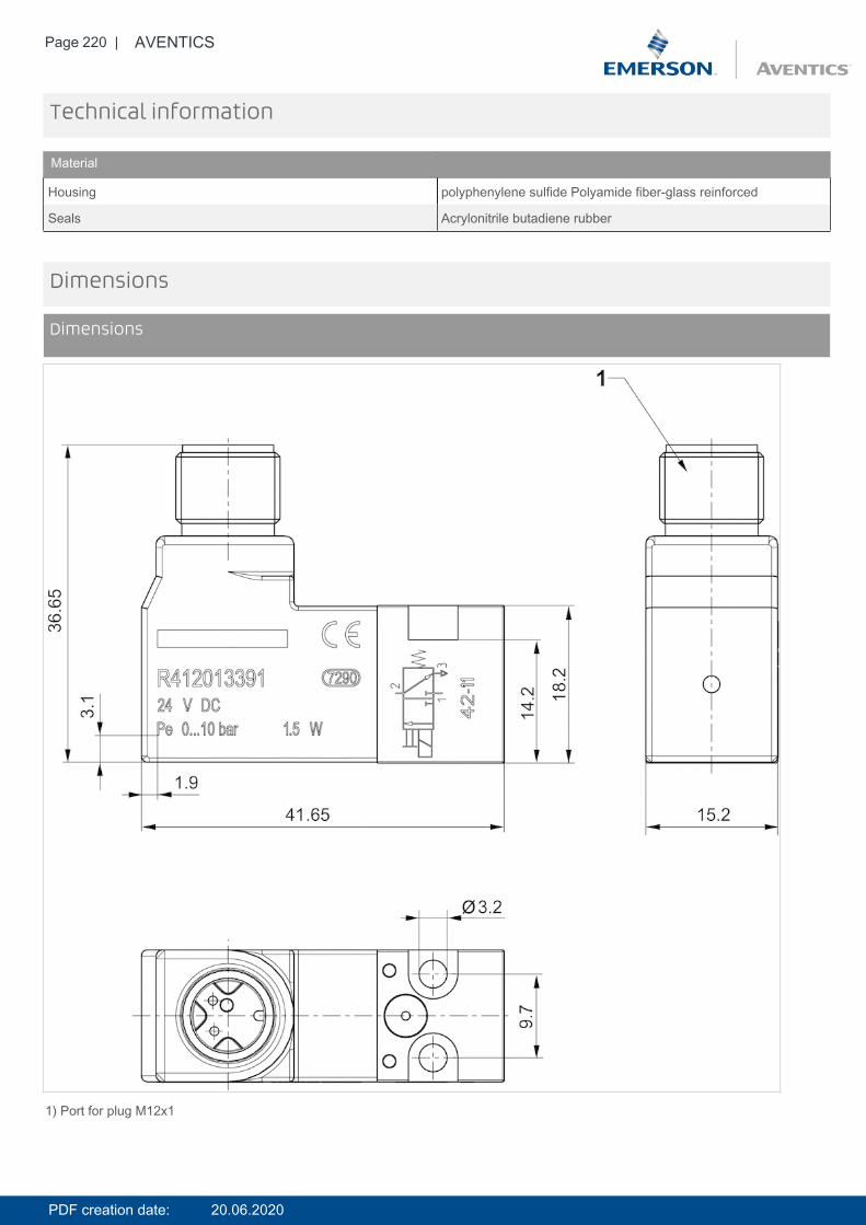
Page 220 | AVENTICS
Technical information
Material
Housing polyphenylene sulfide Polyamide fiber-glass reinforced
Seals Acrylonitrile butadiene rubber
Dimensions
Dimensions
1) Port for plug M12x1
PDF creation date: 20.06.2020
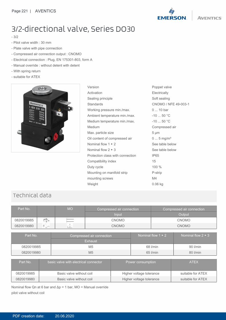
Page 221 | AVENTICS
3/2-directional valve, Series DO30- 3/2- Pilot valve width : 30 mm- Plate valve with pipe connection- Compressed air connection output : CNOMO- Electrical connection : Plug, EN 175301-803, form A- Manual override : without detent with detent- With spring return- suitable for ATEX
Version Poppet valveActivation ElectricallySealing principle Soft sealingStandards CNOMO / NFE 49-003-1Working pressure min./max. 0 ... 10 barAmbient temperature min./max. -10 ... 50 °CMedium temperature min./max. -10 ... 50 °CMedium Compressed airMax. particle size 5 µmOil content of compressed air 0 ... 5 mg/m³Nominal flow 1 ▶ 2 See table belowNominal flow 2 ▶ 3 See table belowProtection class with connection IP65Compatibility index 15Duty cycle 100 %Mounting on manifold strip P-stripmounting screws M4Weight 0.06 kg
Technical data
Part No. MO Compressed air connection Compressed air connectionInput Output
0820019985 CNOMO CNOMO0820019980 CNOMO CNOMO
Part No. Compressed air connection Nominal flow 1 ▶ 2 Nominal flow 2 ▶ 3Exhaust
0820019985 M5 68 l/min 90 l/min0820019980 M5 65 l/min 80 l/min
Part No. basic valve with electrical connector Power consumption ATEX
0820019985 Basic valve without coil Higher voltage tolerance suitable for ATEX0820019980 Basic valve without coil Higher voltage tolerance suitable for ATEX
Nominal flow Qn at 6 bar and Δp = 1 bar, MO = Manual overridepilot valve without coil
PDF creation date: 20.06.2020
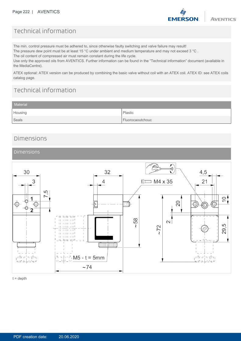
Page 222 | AVENTICS
The min. control pressure must be adhered to, since otherwise faulty switching and valve failure may result!The pressure dew point must be at least 15 °C under ambient and medium temperature and may not exceed 3 °C .The oil content of compressed air must remain constant during the life cycle.Use only the approved oils from AVENTICS. Further information can be found in the “Technical information” document (available inthe MediaCentre).
ATEX optional: ATEX version can be produced by combining the basic valve without coil with an ATEX coil. ATEX ID: see ATEX coilscatalog page.
Technical information
Technical information
Material
Housing Plastic
Seals Fluorocaoutchouc
Dimensions
Dimensions
t = depth
PDF creation date: 20.06.2020
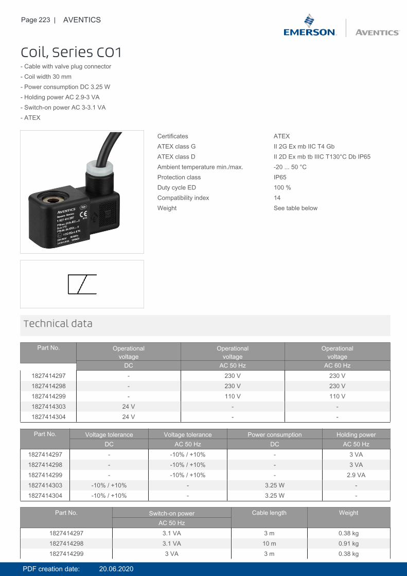
Page 223 | AVENTICS
Coil, Series CO1- Cable with valve plug connector- Coil width 30 mm- Power consumption DC 3.25 W- Holding power AC 2.9-3 VA- Switch-on power AC 3-3.1 VA- ATEX
Certificates ATEXATEX class G II 2G Ex mb IIC T4 GbATEX class D II 2D Ex mb tb IIIC T130°C Db IP65Ambient temperature min./max. -20 ... 50 °CProtection class IP65Duty cycle ED 100 %Compatibility index 14Weight See table below
Technical data
Part No. Operationalvoltage
Operationalvoltage
Operationalvoltage
DC AC 50 Hz AC 60 Hz1827414297 - 230 V 230 V1827414298 - 230 V 230 V1827414299 - 110 V 110 V1827414303 24 V - -1827414304 24 V - -
Part No. Voltage tolerance Voltage tolerance Power consumption Holding powerDC AC 50 Hz DC AC 50 Hz
1827414297 - -10% / +10% - 3 VA1827414298 - -10% / +10% - 3 VA1827414299 - -10% / +10% - 2.9 VA1827414303 -10% / +10% - 3.25 W -1827414304 -10% / +10% - 3.25 W -
Part No. Switch-on power Cable length WeightAC 50 Hz
1827414297 3.1 VA 3 m 0.38 kg1827414298 3.1 VA 10 m 0.91 kg1827414299 3 VA 3 m 0.38 kg
PDF creation date: 20.06.2020
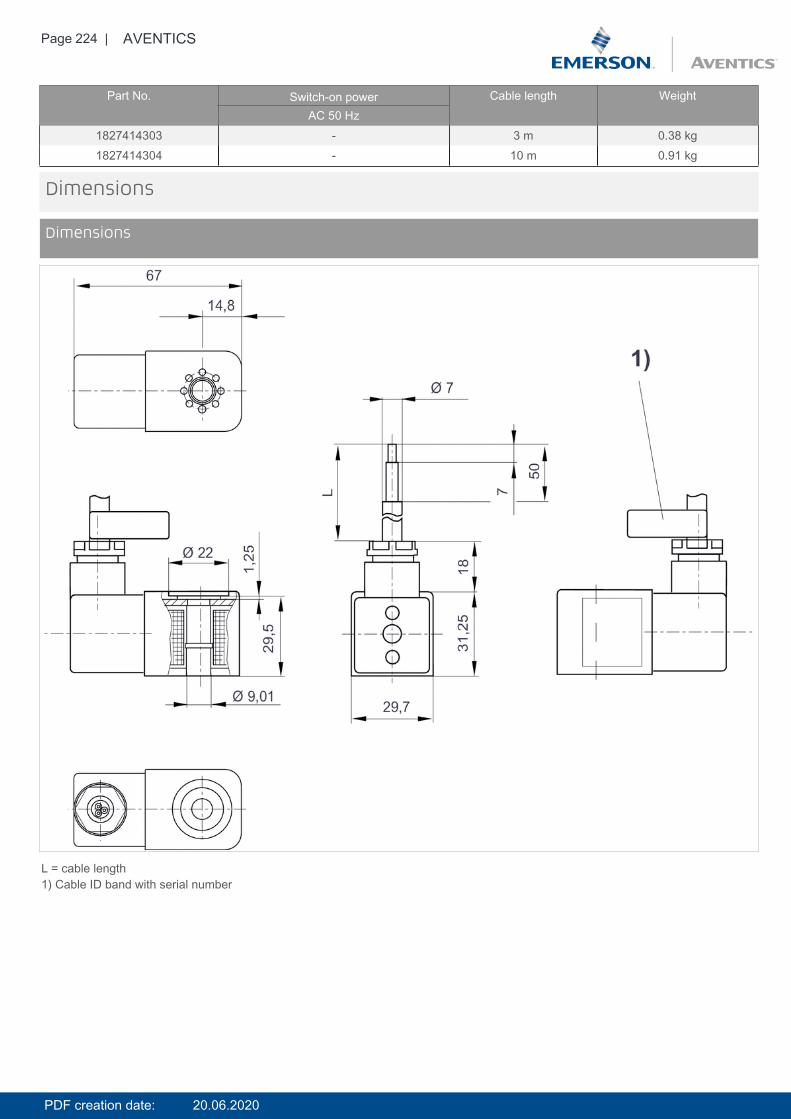
Page 224 | AVENTICS
Part No. Switch-on power Cable length WeightAC 50 Hz
1827414303 - 3 m 0.38 kg1827414304 - 10 m 0.91 kg
Dimensions
Dimensions
L = cable length1) Cable ID band with serial number
PDF creation date: 20.06.2020
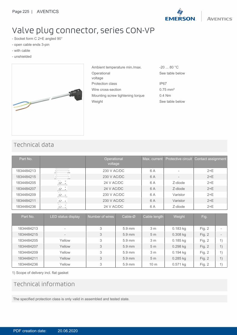
Page 225 | AVENTICS
Valve plug connector, series CON-VP- Socket form C 2+E angled 90°- open cable ends 3-pin- with cable- unshielded
Ambient temperature min./max. -20 ... 80 °COperationalvoltage
See table below
Protection class IP67Wire cross-section 0.75 mm²Mounting screw tightening torque 0.4 NmWeight See table below
Technical data
Part No. Operationalvoltage
Max. current Protective circuit Contact assignment
1834484213 230 V AC/DC 6 A - 2+E1834484215 230 V AC/DC 6 A - 2+E1834484205 24 V AC/DC 6 A Z-diode 2+E1834484207 24 V AC/DC 6 A Z-diode 2+E1834484209 230 V AC/DC 6 A Varistor 2+E1834484211 230 V AC/DC 6 A Varistor 2+E1834484236 24 V AC/DC 6 A Z-diode 2+E
Part No. LED status display Number of wires Cable-Ø Cable length Weight Fig.
1834484213 - 3 5.9 mm 3 m 0.183 kg Fig. 2 -1834484215 - 3 5.9 mm 5 m 0.308 kg Fig. 2 -1834484205 Yellow 3 5.9 mm 3 m 0.185 kg Fig. 2 1)1834484207 Yellow 3 5.9 mm 5 m 0.298 kg Fig. 2 1)1834484209 Yellow 3 5.9 mm 3 m 0.194 kg Fig. 2 1)1834484211 Yellow 3 5.9 mm 5 m 0.285 kg Fig. 2 1)1834484236 Yellow 3 5.9 mm 10 m 0.571 kg Fig. 2 1)
1) Scope of delivery incl. flat gasket
The specified protection class is only valid in assembled and tested state.
Technical information
PDF creation date: 20.06.2020
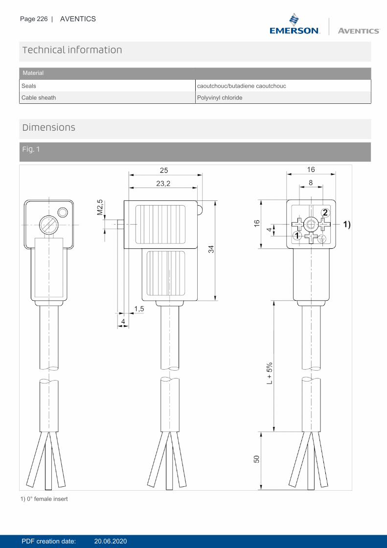
Page 226 | AVENTICS
Technical information
Material
Seals caoutchouc/butadiene caoutchouc
Cable sheath Polyvinyl chloride
Dimensions
Fig. 1
1) 0° female insert
PDF creation date: 20.06.2020
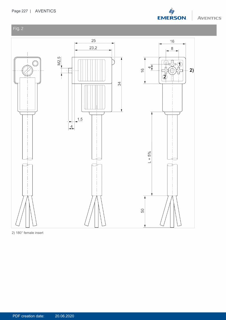
Page 227 | AVENTICS
DimensionsFig. 2
2) 180° female insert
PDF creation date: 20.06.2020
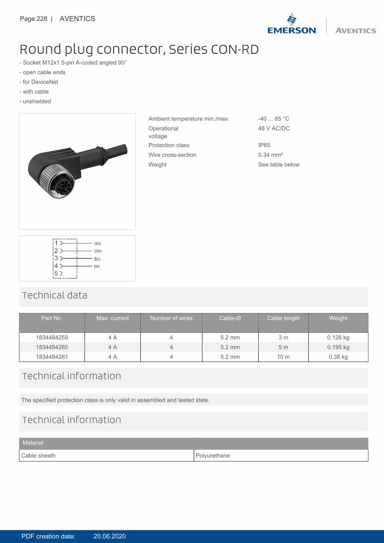
Page 228 | AVENTICS
Round plug connector, Series CON-RD- Socket M12x1 5-pin A-coded angled 90°- open cable ends- for DeviceNet- with cable- unshielded
Ambient temperature min./max. -40 ... 85 °COperationalvoltage
48 V AC/DC
Protection class IP65Wire cross-section 0.34 mm²Weight See table below
Technical data
Part No. Max. current Number of wires Cable-Ø Cable length Weight
1834484259 4 A 4 5.2 mm 3 m 0.126 kg1834484260 4 A 4 5.2 mm 5 m 0.195 kg1834484261 4 A 4 5.2 mm 10 m 0.38 kg
The specified protection class is only valid in assembled and tested state.
Technical information
Technical information
Material
Cable sheath Polyurethane
PDF creation date: 20.06.2020
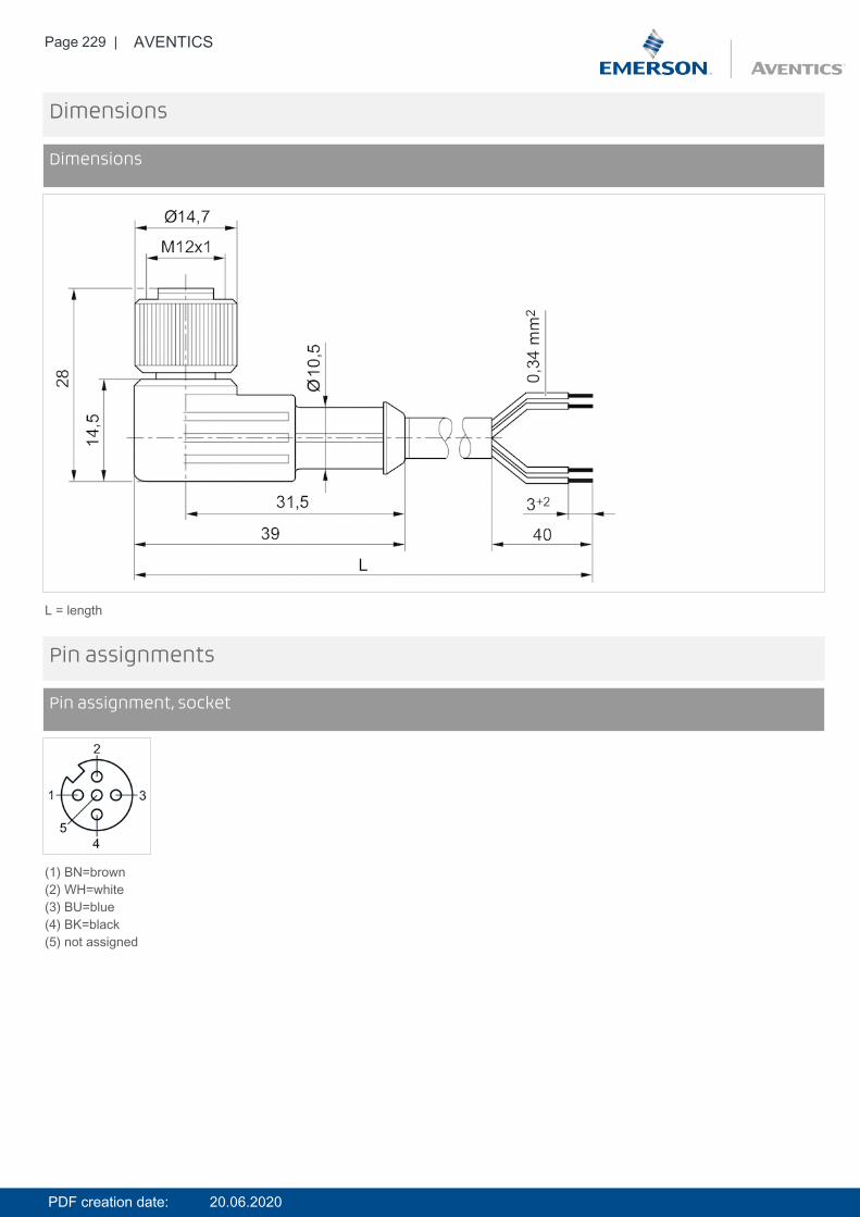
Page 229 | AVENTICS
Dimensions
Dimensions
L = length
Pin assignments
Pin assignment, socket
(1) BN=brown(2) WH=white(3) BU=blue(4) BK=black(5) not assigned
PDF creation date: 20.06.2020
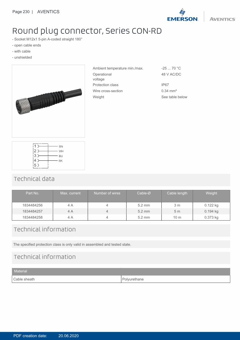
Page 230 | AVENTICS
Round plug connector, Series CON-RD- Socket M12x1 5-pin A-coded straight 180°- open cable ends- with cable- unshielded
Ambient temperature min./max. -25 ... 70 °COperationalvoltage
48 V AC/DC
Protection class IP67Wire cross-section 0.34 mm²Weight See table below
Technical data
Part No. Max. current Number of wires Cable-Ø Cable length Weight
1834484256 4 A 4 5.2 mm 3 m 0.122 kg1834484257 4 A 4 5.2 mm 5 m 0.194 kg1834484258 4 A 4 5.2 mm 10 m 0.373 kg
The specified protection class is only valid in assembled and tested state.
Technical information
Technical information
Material
Cable sheath Polyurethane
PDF creation date: 20.06.2020
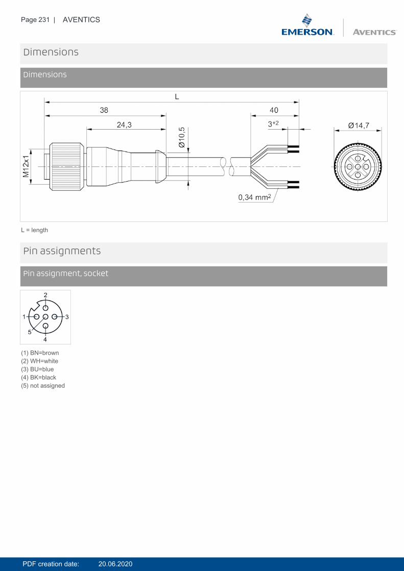
Page 231 | AVENTICS
Dimensions
Dimensions
L = length
Pin assignments
Pin assignment, socket
(1) BN=brown(2) WH=white(3) BU=blue(4) BK=black(5) not assigned
PDF creation date: 20.06.2020
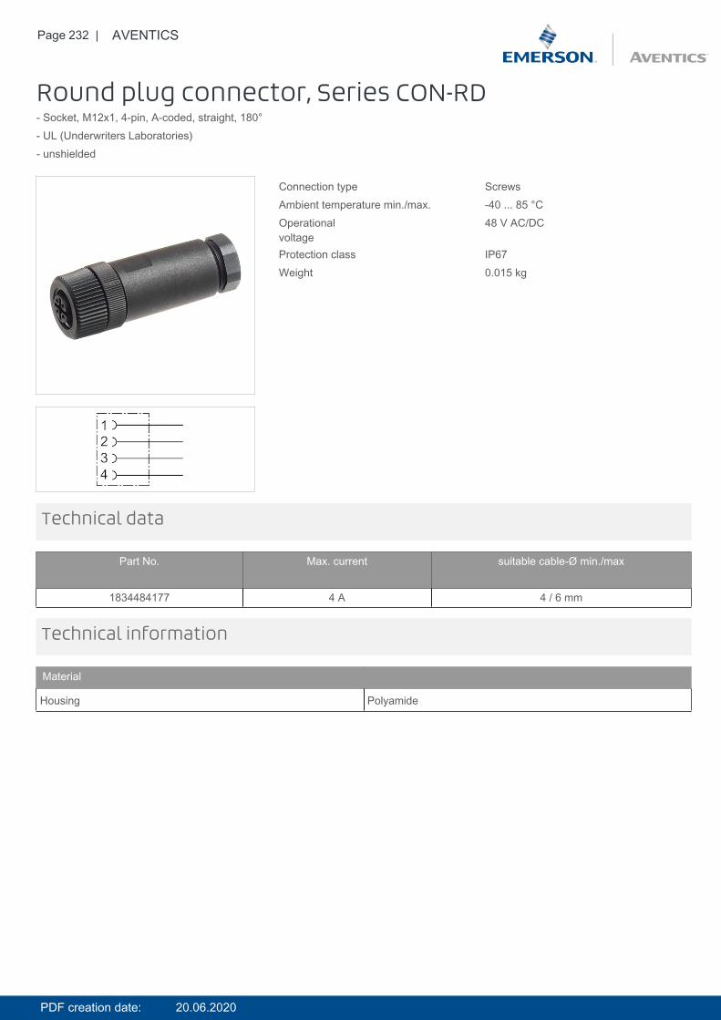
Page 232 | AVENTICS
Round plug connector, Series CON-RD- Socket, M12x1, 4-pin, A-coded, straight, 180°- UL (Underwriters Laboratories)- unshielded
Connection type ScrewsAmbient temperature min./max. -40 ... 85 °COperationalvoltage
48 V AC/DC
Protection class IP67Weight 0.015 kg
Technical data
Part No. Max. current suitable cable-Ø min./max
1834484177 4 A 4 / 6 mm
Technical information
Material
Housing Polyamide
PDF creation date: 20.06.2020
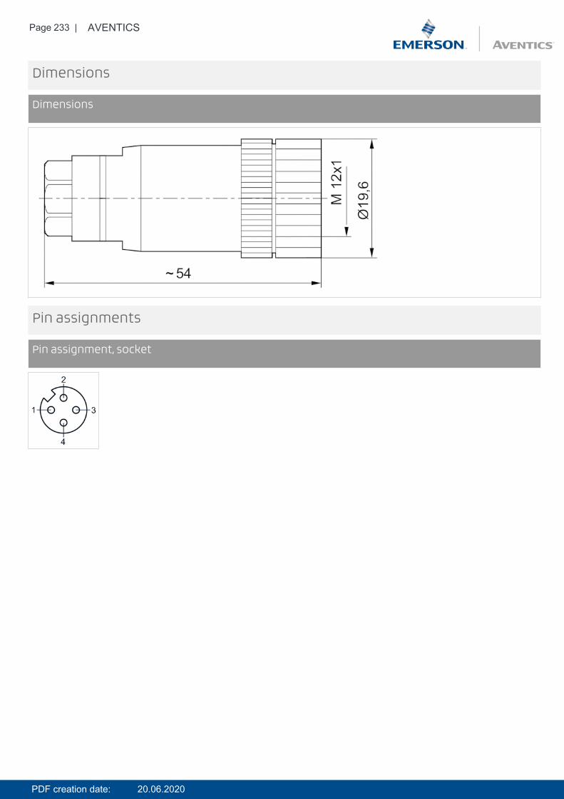
Page 233 | AVENTICS
Dimensions
Dimensions
Pin assignments
Pin assignment, socket
PDF creation date: 20.06.2020
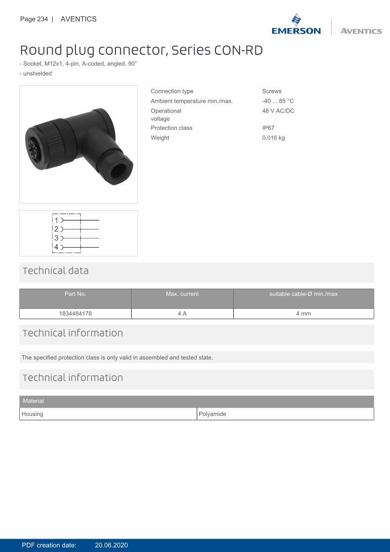
Page 234 | AVENTICS
Round plug connector, Series CON-RD- Socket, M12x1, 4-pin, A-coded, angled, 90°- unshielded
Connection type ScrewsAmbient temperature min./max. -40 ... 85 °COperationalvoltage
48 V AC/DC
Protection class IP67Weight 0.016 kg
Technical data
Part No. Max. current suitable cable-Ø min./max
1834484178 4 A 4 mm
The specified protection class is only valid in assembled and tested state.
Technical information
Technical information
Material
Housing Polyamide
PDF creation date: 20.06.2020
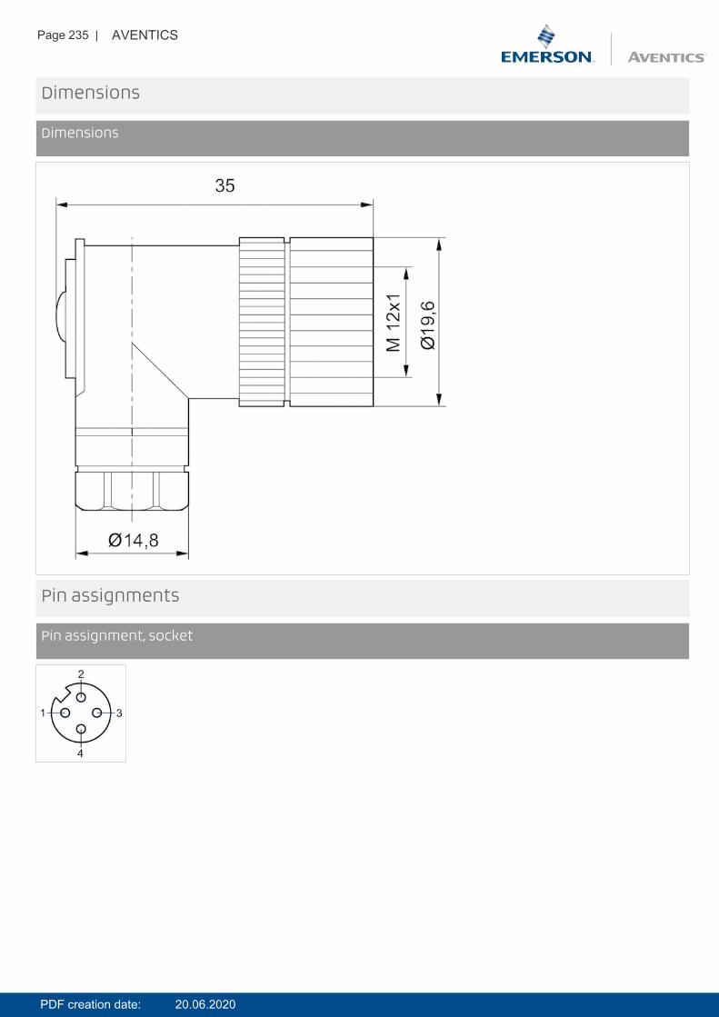
Page 235 | AVENTICS
Dimensions
Dimensions
Pin assignments
Pin assignment, socket
PDF creation date: 20.06.2020
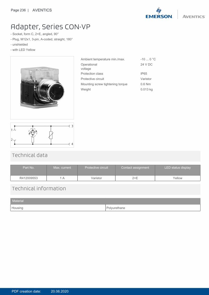
Page 236 | AVENTICS
Adapter, Series CON-VP- Socket, form C, 2+E, angled, 90°- Plug, M12x1, 3-pin, A-coded, straight, 180°- unshielded- with LED Yellow
Ambient temperature min./max. -10 ... 0 °COperationalvoltage
24 V DC
Protection class IP65Protective circuit VaristorMounting screw tightening torque 0.6 NmWeight 0.013 kg
Technical data
Part No. Max. current Protective circuit Contact assignment LED status display
R412009553 1 A Varistor 2+E Yellow
Technical information
Material
Housing Polyurethane
PDF creation date: 20.06.2020
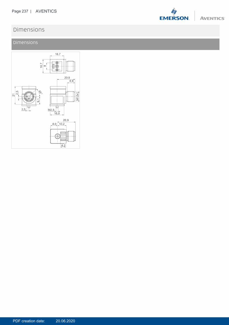
Page 237 | AVENTICS
Dimensions
Dimensions
PDF creation date: 20.06.2020
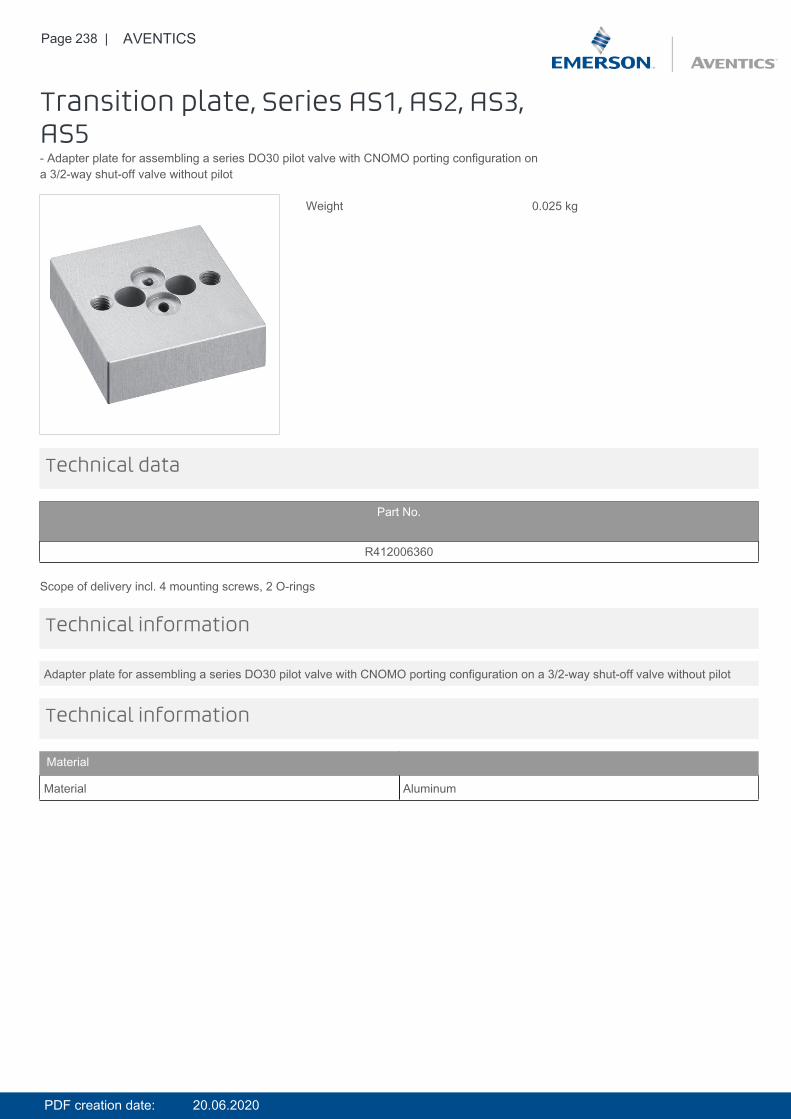
Page 238 | AVENTICS
Transition plate, Series AS1, AS2, AS3,AS5- Adapter plate for assembling a series DO30 pilot valve with CNOMO porting configuration ona 3/2-way shut-off valve without pilot
Weight 0.025 kg
Technical data
Part No.
R412006360
Scope of delivery incl. 4 mounting screws, 2 O-rings
Adapter plate for assembling a series DO30 pilot valve with CNOMO porting configuration on a 3/2-way shut-off valve without pilot
Technical information
Technical information
Material
Material Aluminum
PDF creation date: 20.06.2020
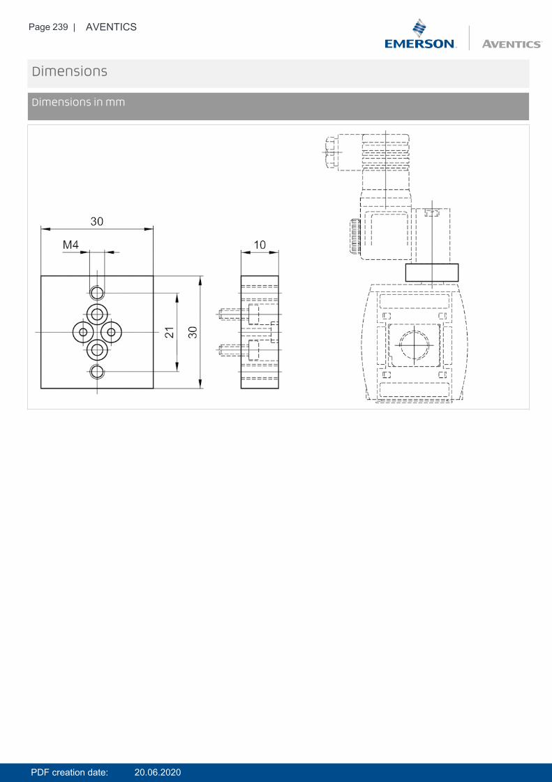
Page 239 | AVENTICS
Dimensions
Dimensions in mm
PDF creation date: 20.06.2020
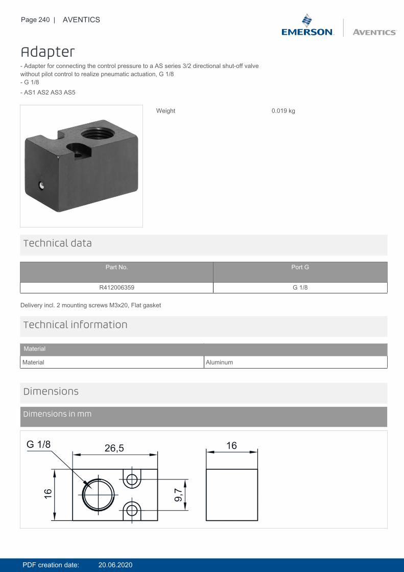
Page 240 | AVENTICS
Adapter- Adapter for connecting the control pressure to a AS series 3/2 directional shut-off valvewithout pilot control to realize pneumatic actuation, G 1/8- G 1/8- AS1 AS2 AS3 AS5
Weight 0.019 kg
Technical data
Part No. Port G
R412006359 G 1/8
Delivery incl. 2 mounting screws M3x20, Flat gasket
Technical information
Material
Material Aluminum
Dimensions
Dimensions in mm
PDF creation date: 20.06.2020
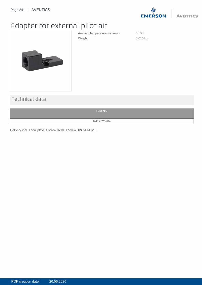
Page 241 | AVENTICS
Adapter for external pilot airAmbient temperature min./max. 50 °CWeight 0.015 kg
Technical data
Part No.
R412025904
Delivery incl. 1 seal plate, 1 screw 3x10, 1 screw DIN 84-M3x18
PDF creation date: 20.06.2020
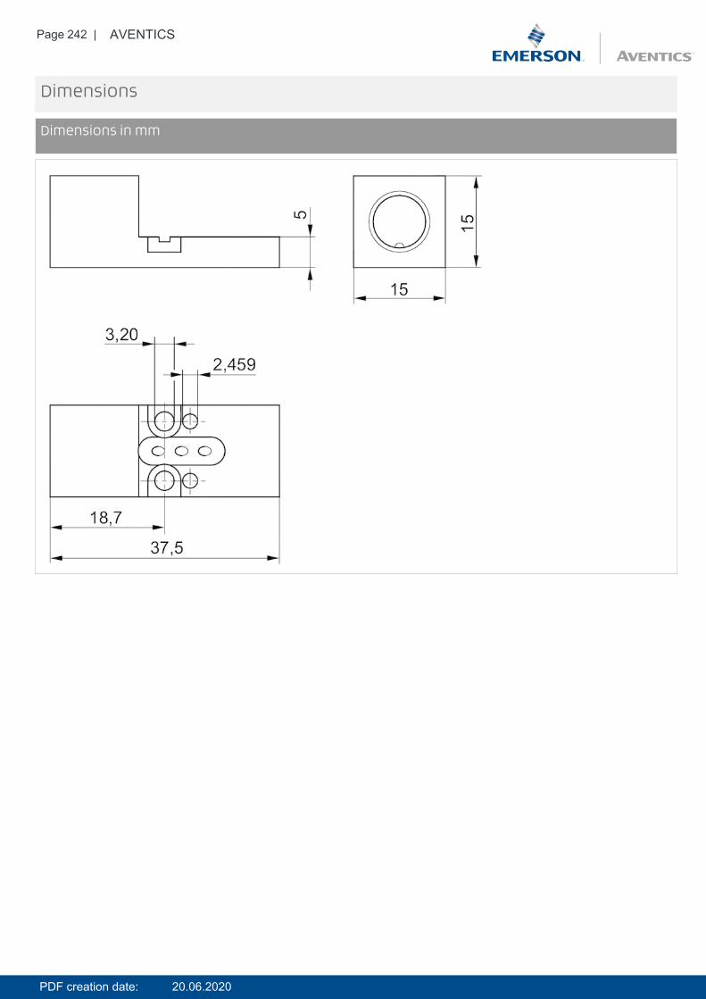
Page 242 | AVENTICS
Dimensions
Dimensions in mm
PDF creation date: 20.06.2020
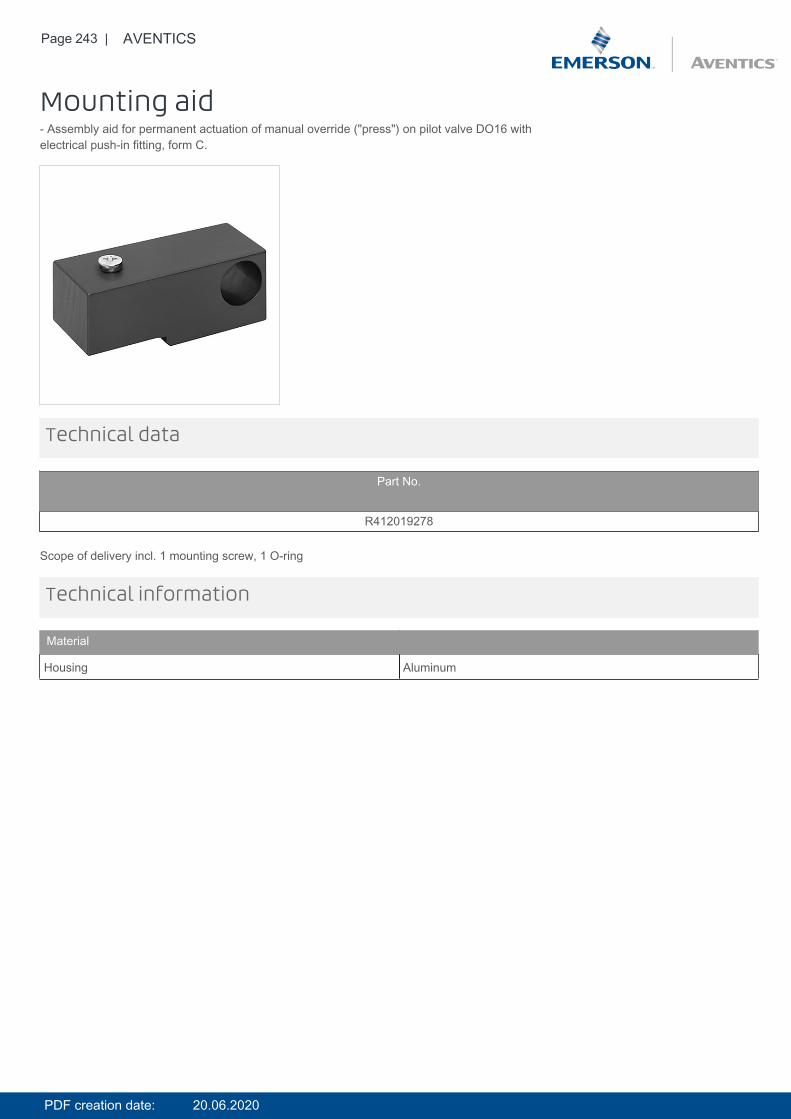
Page 243 | AVENTICS
Mounting aid- Assembly aid for permanent actuation of manual override ("press") on pilot valve DO16 withelectrical push-in fitting, form C.
Technical data
Part No.
R412019278
Scope of delivery incl. 1 mounting screw, 1 O-ring
Technical information
Material
Housing Aluminum
PDF creation date: 20.06.2020
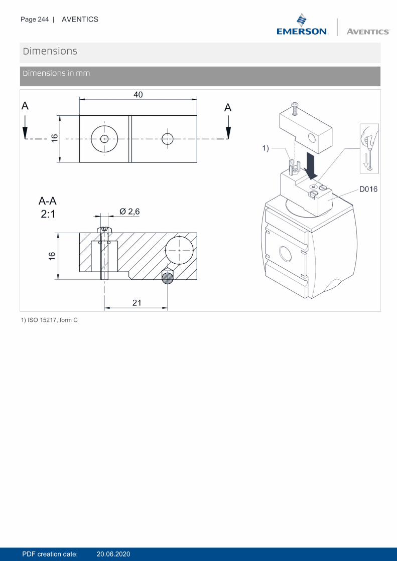
Page 244 | AVENTICS
Dimensions
Dimensions in mm
1) ISO 15217, form C
PDF creation date: 20.06.2020
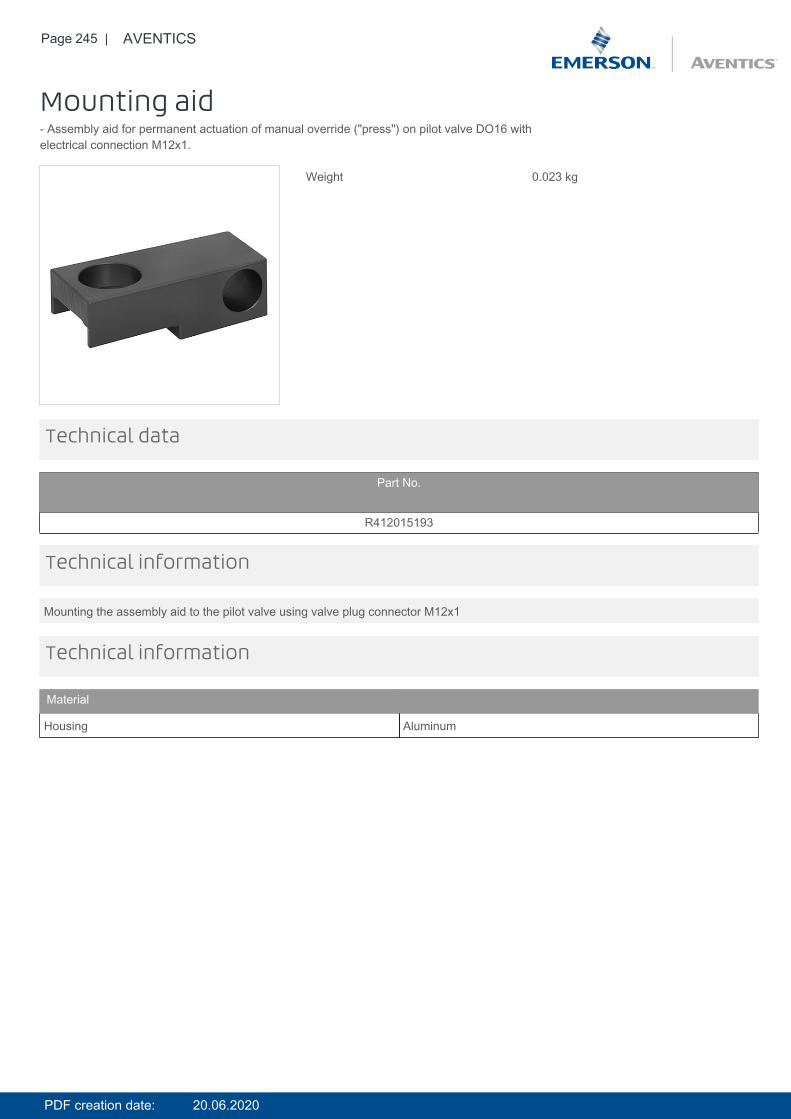
Page 245 | AVENTICS
Mounting aid- Assembly aid for permanent actuation of manual override ("press") on pilot valve DO16 withelectrical connection M12x1.
Weight 0.023 kg
Technical data
Part No.
R412015193
Mounting the assembly aid to the pilot valve using valve plug connector M12x1
Technical information
Technical information
Material
Housing Aluminum
PDF creation date: 20.06.2020
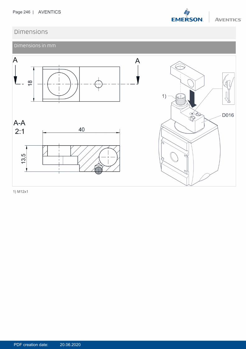
Page 246 | AVENTICS
Dimensions
Dimensions in mm
1) M12x1
PDF creation date: 20.06.2020
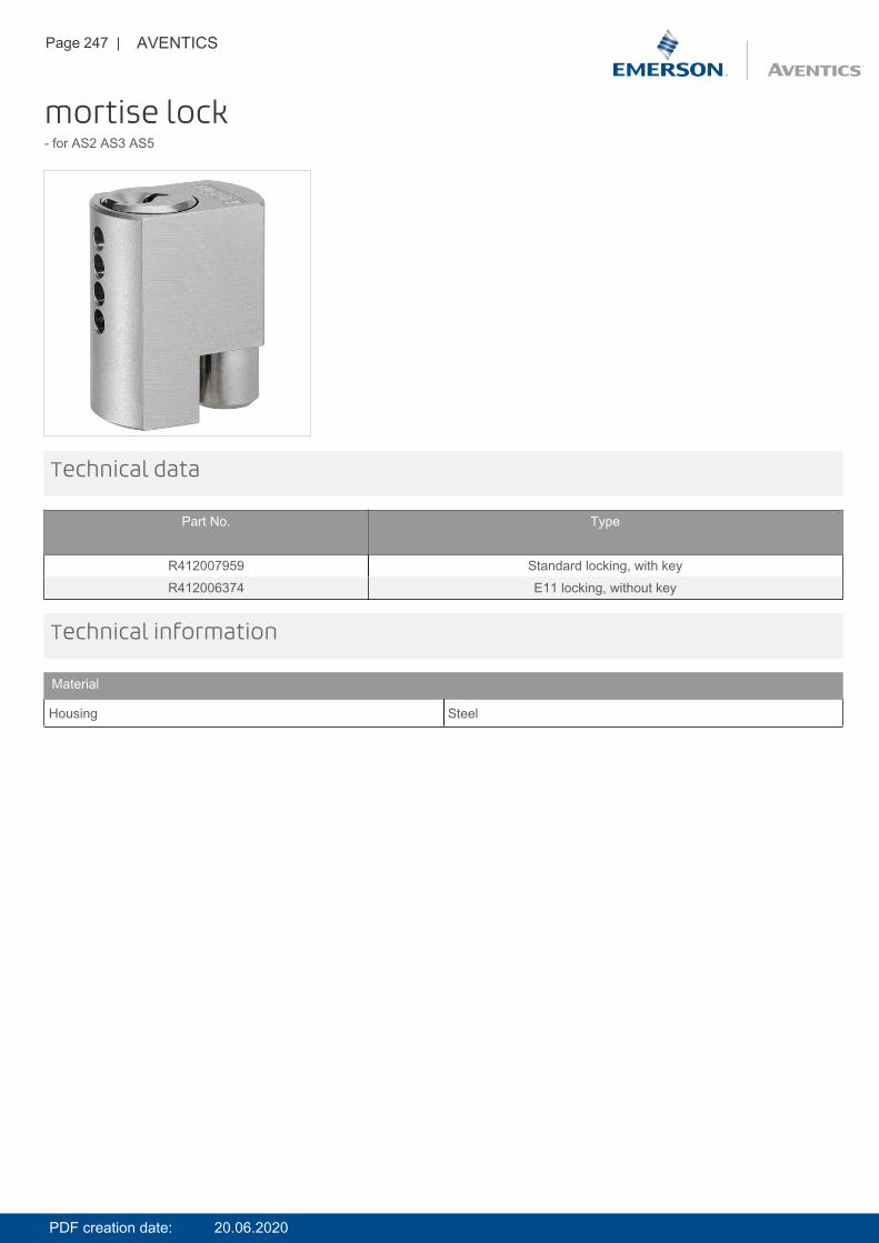
Page 247 | AVENTICS
mortise lock- for AS2 AS3 AS5
Technical data
Part No. Type
R412007959 Standard locking, with keyR412006374 E11 locking, without key
Technical information
Material
Housing Steel
PDF creation date: 20.06.2020
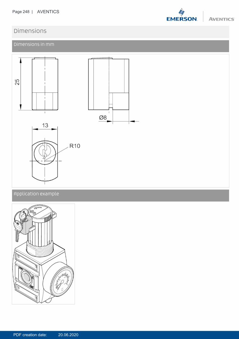
Page 248 | AVENTICS
Dimensions
Dimensions in mm
DimensionsApplication example
PDF creation date: 20.06.2020
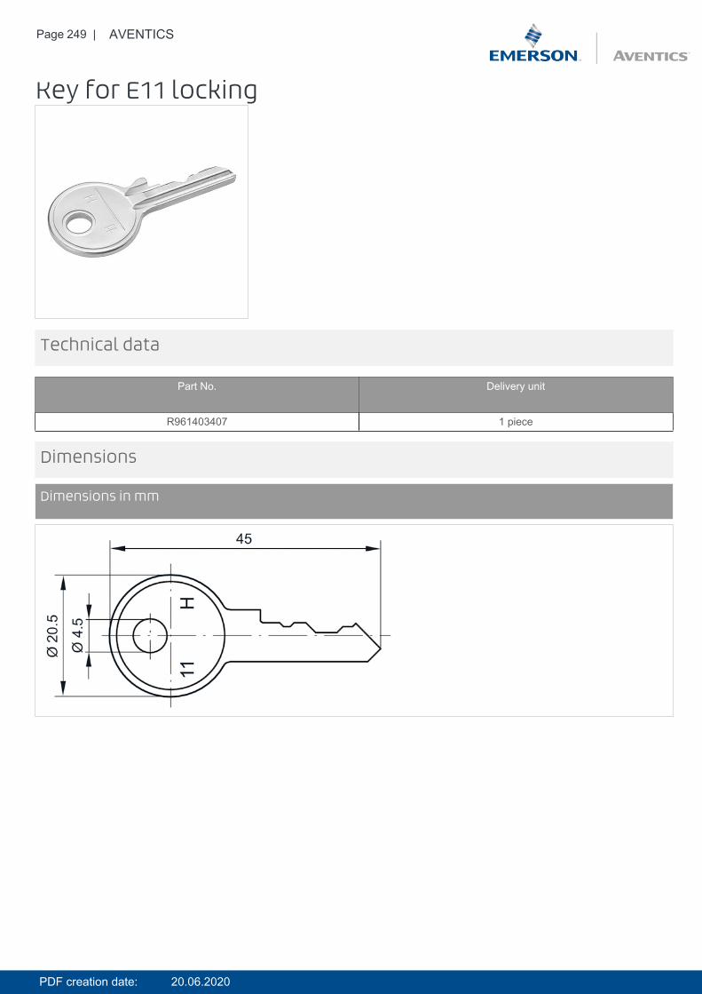
Page 249 | AVENTICS
Key for E11 locking
Technical data
Part No. Delivery unit
R961403407 1 piece
Dimensions
Dimensions in mm
PDF creation date: 20.06.2020
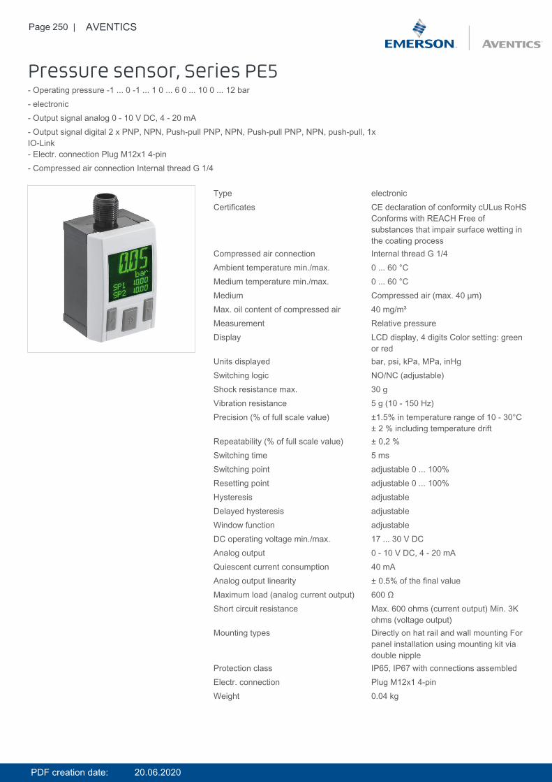
Page 250 | AVENTICS
Pressure sensor, Series PE5- Operating pressure -1 ... 0 -1 ... 1 0 ... 6 0 ... 10 0 ... 12 bar- electronic- Output signal analog 0 - 10 V DC, 4 - 20 mA- Output signal digital 2 x PNP, NPN, Push-pull PNP, NPN, Push-pull PNP, NPN, push-pull, 1xIO-Link- Electr. connection Plug M12x1 4-pin- Compressed air connection Internal thread G 1/4
Type electronicCertificates CE declaration of conformity cULus RoHS
Conforms with REACH Free ofsubstances that impair surface wetting inthe coating process
Compressed air connection Internal thread G 1/4Ambient temperature min./max. 0 ... 60 °CMedium temperature min./max. 0 ... 60 °CMedium Compressed air (max. 40 μm)Max. oil content of compressed air 40 mg/m³Measurement Relative pressureDisplay LCD display, 4 digits Color setting: green
or redUnits displayed bar, psi, kPa, MPa, inHgSwitching logic NO/NC (adjustable)Shock resistance max. 30 gVibration resistance 5 g (10 - 150 Hz)Precision (% of full scale value) ±1.5% in temperature range of 10 - 30°C
± 2 % including temperature driftRepeatability (% of full scale value) ± 0,2 %Switching time 5 msSwitching point adjustable 0 ... 100%Resetting point adjustable 0 ... 100%Hysteresis adjustableDelayed hysteresis adjustableWindow function adjustableDC operating voltage min./max. 17 ... 30 V DCAnalog output 0 - 10 V DC, 4 - 20 mAQuiescent current consumption 40 mAAnalog output linearity ± 0.5% of the final valueMaximum load (analog current output) 600 ΩShort circuit resistance Max. 600 ohms (current output) Min. 3K
ohms (voltage output)Mounting types Directly on hat rail and wall mounting For
panel installation using mounting kit viadouble nipple
Protection class IP65, IP67 with connections assembledElectr. connection Plug M12x1 4-pinWeight 0.04 kg
PDF creation date: 20.06.2020
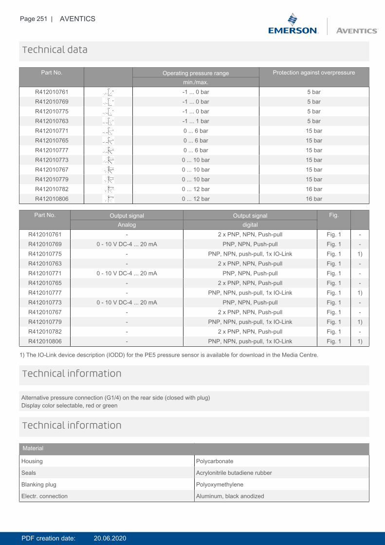
Page 251 | AVENTICS
Technical data
Part No. Operating pressure range Protection against overpressuremin./max.
R412010761 -1 ... 0 bar 5 barR412010769 -1 ... 0 bar 5 barR412010775 -1 ... 0 bar 5 barR412010763 -1 ... 1 bar 5 barR412010771 0 ... 6 bar 15 barR412010765 0 ... 6 bar 15 barR412010777 0 ... 6 bar 15 barR412010773 0 ... 10 bar 15 barR412010767 0 ... 10 bar 15 barR412010779 0 ... 10 bar 15 barR412010782 0 ... 12 bar 16 barR412010806 0 ... 12 bar 16 bar
Part No. Output signal Output signal Fig.Analog digital
R412010761 - 2 x PNP, NPN, Push-pull Fig. 1 -R412010769 0 - 10 V DC-4 ... 20 mA PNP, NPN, Push-pull Fig. 1 -R412010775 - PNP, NPN, push-pull, 1x IO-Link Fig. 1 1)R412010763 - 2 x PNP, NPN, Push-pull Fig. 1 -R412010771 0 - 10 V DC-4 ... 20 mA PNP, NPN, Push-pull Fig. 1 -R412010765 - 2 x PNP, NPN, Push-pull Fig. 1 -R412010777 - PNP, NPN, push-pull, 1x IO-Link Fig. 1 1)R412010773 0 - 10 V DC-4 ... 20 mA PNP, NPN, Push-pull Fig. 1 -R412010767 - 2 x PNP, NPN, Push-pull Fig. 1 -R412010779 - PNP, NPN, push-pull, 1x IO-Link Fig. 1 1)R412010782 - 2 x PNP, NPN, Push-pull Fig. 1 -R412010806 - PNP, NPN, push-pull, 1x IO-Link Fig. 1 1)
1) The IO-Link device description (IODD) for the PE5 pressure sensor is available for download in the Media Centre.
Alternative pressure connection (G1/4) on the rear side (closed with plug)Display color selectable, red or green
Technical information
Technical information
Material
Housing Polycarbonate
Seals Acrylonitrile butadiene rubber
Blanking plug Polyoxymethylene
Electr. connection Aluminum, black anodized
PDF creation date: 20.06.2020
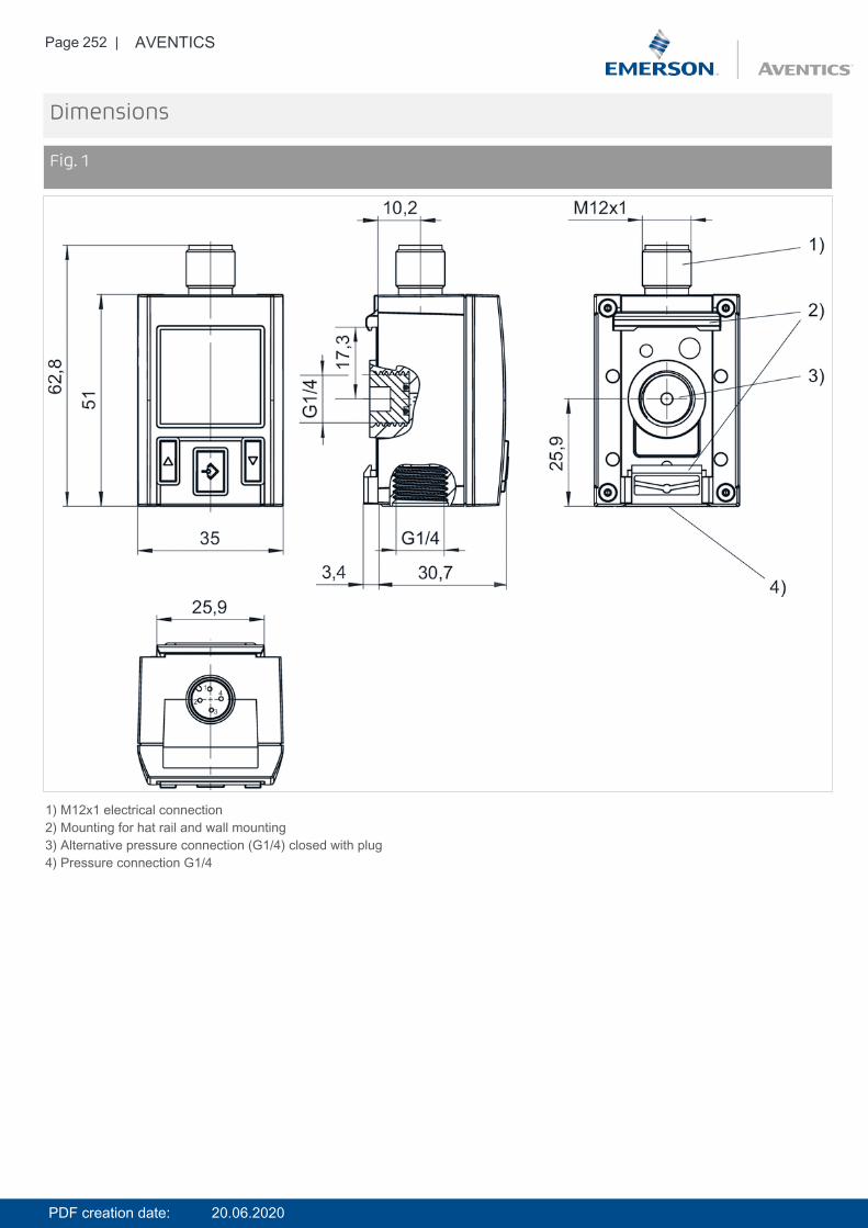
Page 252 | AVENTICS
Dimensions
Fig. 1
1) M12x1 electrical connection2) Mounting for hat rail and wall mounting3) Alternative pressure connection (G1/4) closed with plug4) Pressure connection G1/4
PDF creation date: 20.06.2020
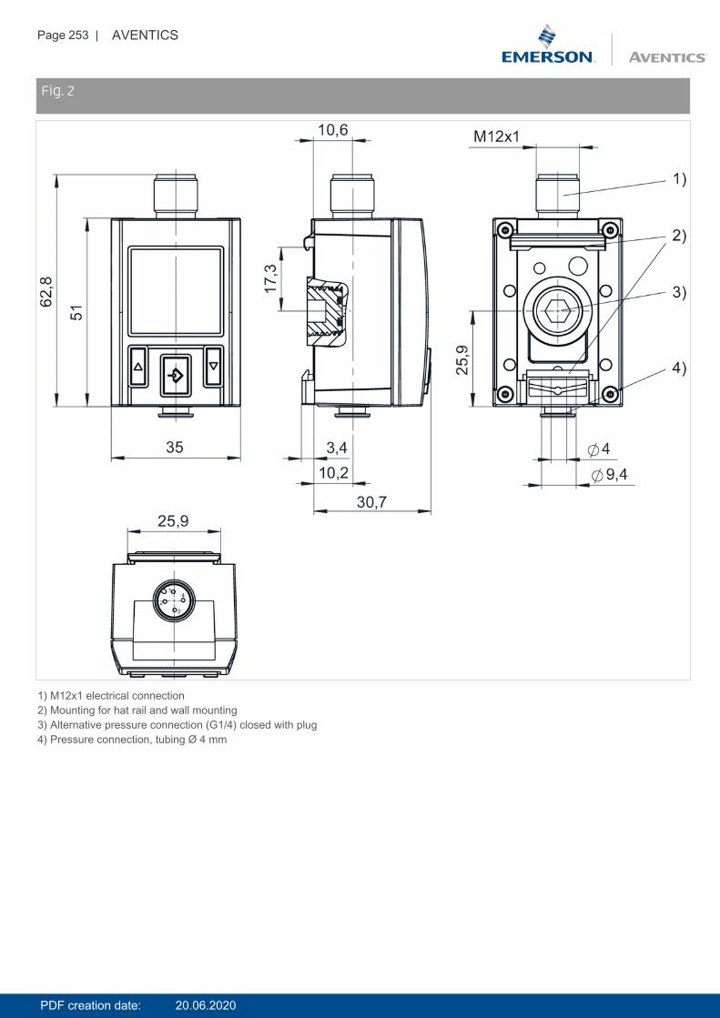
Page 253 | AVENTICS
DimensionsFig. 2
1) M12x1 electrical connection2) Mounting for hat rail and wall mounting3) Alternative pressure connection (G1/4) closed with plug4) Pressure connection, tubing Ø 4 mm
PDF creation date: 20.06.2020
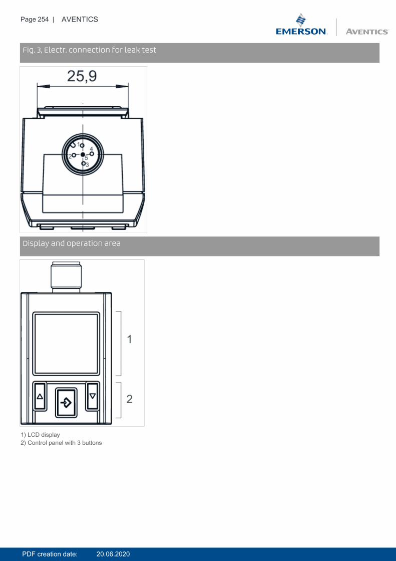
Page 254 | AVENTICS
DimensionsFig. 3, Electr. connection for leak test
DimensionsDisplay and operation area
1) LCD display2) Control panel with 3 buttons
PDF creation date: 20.06.2020
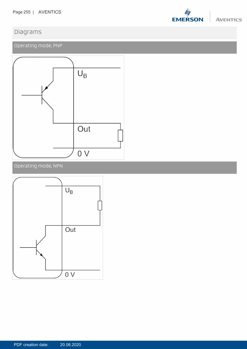
Page 255 | AVENTICS
Diagrams
Operating mode, PNP
DiagramsOperating mode, NPN
PDF creation date: 20.06.2020
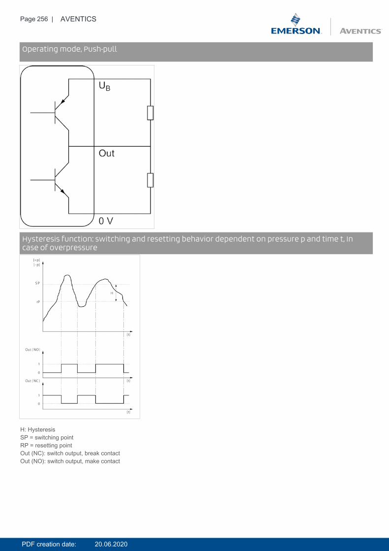
Page 256 | AVENTICS
DiagramsOperating mode, Push-pull
DiagramsHysteresis function: switching and resetting behavior dependent on pressure p and time t, Incase of overpressure
H: HysteresisSP = switching pointRP = resetting pointOut (NC): switch output, break contactOut (NO): switch output, make contact
PDF creation date: 20.06.2020
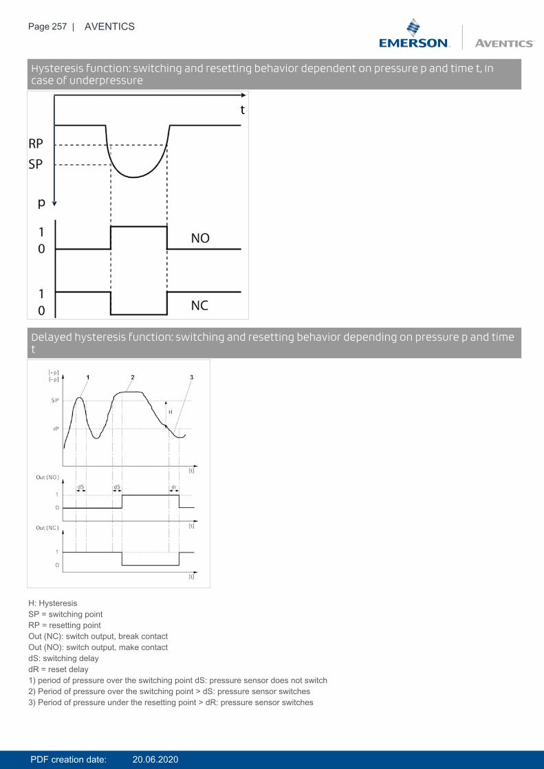
Page 257 | AVENTICS
DiagramsHysteresis function: switching and resetting behavior dependent on pressure p and time t, Incase of underpressure
DiagramsDelayed hysteresis function: switching and resetting behavior depending on pressure p and timet
H: HysteresisSP = switching pointRP = resetting pointOut (NC): switch output, break contactOut (NO): switch output, make contactdS: switching delaydR = reset delay1) period of pressure over the switching point dS: pressure sensor does not switch2) Period of pressure over the switching point > dS: pressure sensor switches3) Period of pressure under the resetting point > dR: pressure sensor switches
PDF creation date: 20.06.2020
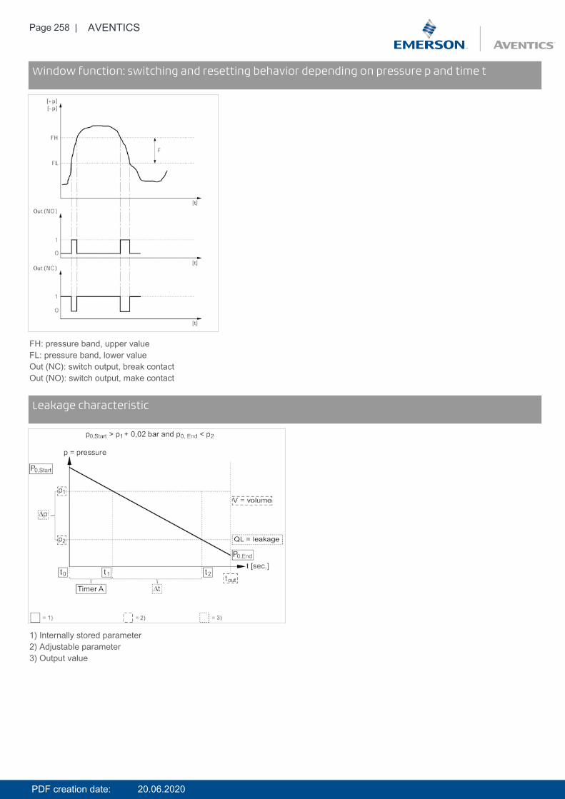
Page 258 | AVENTICS
DiagramsWindow function: switching and resetting behavior depending on pressure p and time t
FH: pressure band, upper valueFL: pressure band, lower valueOut (NC): switch output, break contactOut (NO): switch output, make contact
DiagramsLeakage characteristic
1) Internally stored parameter2) Adjustable parameter3) Output value
PDF creation date: 20.06.2020
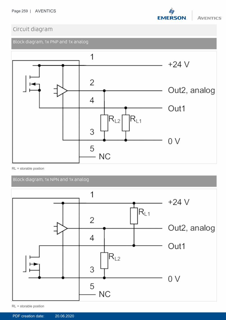
Page 259 | AVENTICS
Circuit diagram
Block diagram, 1x PNP and 1x analog
RL = storable postion
Circuit diagramBlock diagram, 1x NPN and 1x analog
RL = storable postion
PDF creation date: 20.06.2020
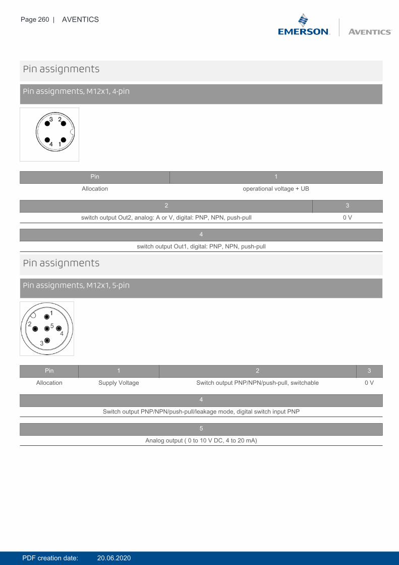
Page 260 | AVENTICS
Pin assignments
Pin assignments, M12x1, 4-pin
Pin 1
Allocation operational voltage + UB
2 3
switch output Out2, analog: A or V, digital: PNP, NPN, push-pull 0 V
4
switch output Out1, digital: PNP, NPN, push-pull
Pin assignments
Pin assignments, M12x1, 5-pin
Pin 1 2 3
Allocation Supply Voltage Switch output PNP/NPN/push-pull, switchable 0 V
4
Switch output PNP/NPN/push-pull/leakage mode, digital switch input PNP
5
Analog output ( 0 to 10 V DC, 4 to 20 mA)
PDF creation date: 20.06.2020
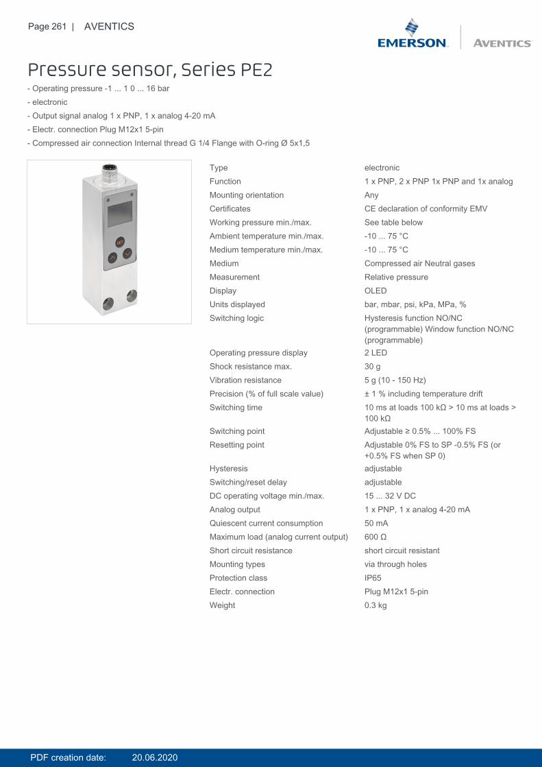
Page 261 | AVENTICS
Pressure sensor, Series PE2- Operating pressure -1 ... 1 0 ... 16 bar- electronic- Output signal analog 1 x PNP, 1 x analog 4-20 mA- Electr. connection Plug M12x1 5-pin- Compressed air connection Internal thread G 1/4 Flange with O-ring Ø 5x1,5
Type electronicFunction 1 x PNP, 2 x PNP 1x PNP and 1x analogMounting orientation AnyCertificates CE declaration of conformity EMVWorking pressure min./max. See table belowAmbient temperature min./max. -10 ... 75 °CMedium temperature min./max. -10 ... 75 °CMedium Compressed air Neutral gasesMeasurement Relative pressureDisplay OLEDUnits displayed bar, mbar, psi, kPa, MPa, %Switching logic Hysteresis function NO/NC
(programmable) Window function NO/NC(programmable)
Operating pressure display 2 LEDShock resistance max. 30 gVibration resistance 5 g (10 - 150 Hz)Precision (% of full scale value) ± 1 % including temperature driftSwitching time 10 ms at loads 100 kΩ > 10 ms at loads >
100 kΩSwitching point Adjustable ≥ 0.5% ... 100% FSResetting point Adjustable 0% FS to SP -0.5% FS (or
+0.5% FS when SP 0)Hysteresis adjustableSwitching/reset delay adjustableDC operating voltage min./max. 15 ... 32 V DCAnalog output 1 x PNP, 1 x analog 4-20 mAQuiescent current consumption 50 mAMaximum load (analog current output) 600 ΩShort circuit resistance short circuit resistantMounting types via through holesProtection class IP65Electr. connection Plug M12x1 5-pinWeight 0.3 kg
PDF creation date: 20.06.2020
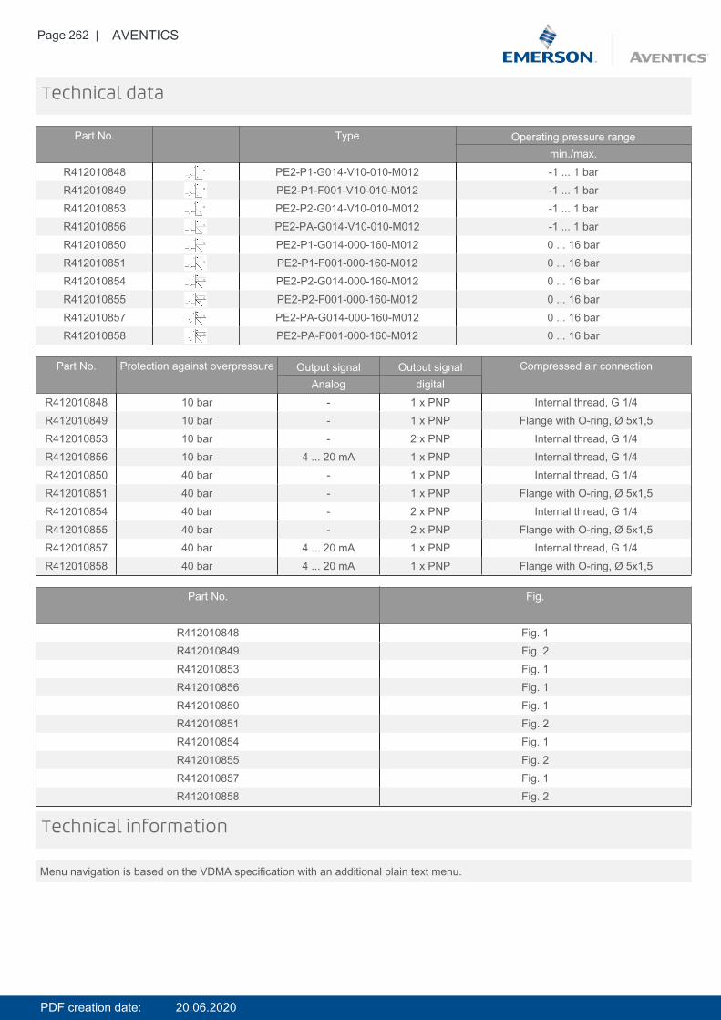
Page 262 | AVENTICS
Technical data
Part No. Type Operating pressure rangemin./max.
R412010848 PE2-P1-G014-V10-010-M012 -1 ... 1 barR412010849 PE2-P1-F001-V10-010-M012 -1 ... 1 barR412010853 PE2-P2-G014-V10-010-M012 -1 ... 1 barR412010856 PE2-PA-G014-V10-010-M012 -1 ... 1 barR412010850 PE2-P1-G014-000-160-M012 0 ... 16 barR412010851 PE2-P1-F001-000-160-M012 0 ... 16 barR412010854 PE2-P2-G014-000-160-M012 0 ... 16 barR412010855 PE2-P2-F001-000-160-M012 0 ... 16 barR412010857 PE2-PA-G014-000-160-M012 0 ... 16 barR412010858 PE2-PA-F001-000-160-M012 0 ... 16 bar
Part No. Protection against overpressure Output signal Output signal Compressed air connectionAnalog digital
R412010848 10 bar - 1 x PNP Internal thread, G 1/4R412010849 10 bar - 1 x PNP Flange with O-ring, Ø 5x1,5R412010853 10 bar - 2 x PNP Internal thread, G 1/4R412010856 10 bar 4 ... 20 mA 1 x PNP Internal thread, G 1/4R412010850 40 bar - 1 x PNP Internal thread, G 1/4R412010851 40 bar - 1 x PNP Flange with O-ring, Ø 5x1,5R412010854 40 bar - 2 x PNP Internal thread, G 1/4R412010855 40 bar - 2 x PNP Flange with O-ring, Ø 5x1,5R412010857 40 bar 4 ... 20 mA 1 x PNP Internal thread, G 1/4R412010858 40 bar 4 ... 20 mA 1 x PNP Flange with O-ring, Ø 5x1,5
Part No. Fig.
R412010848 Fig. 1R412010849 Fig. 2R412010853 Fig. 1R412010856 Fig. 1R412010850 Fig. 1R412010851 Fig. 2R412010854 Fig. 1R412010855 Fig. 2R412010857 Fig. 1R412010858 Fig. 2
Menu navigation is based on the VDMA specification with an additional plain text menu.
Technical information
PDF creation date: 20.06.2020
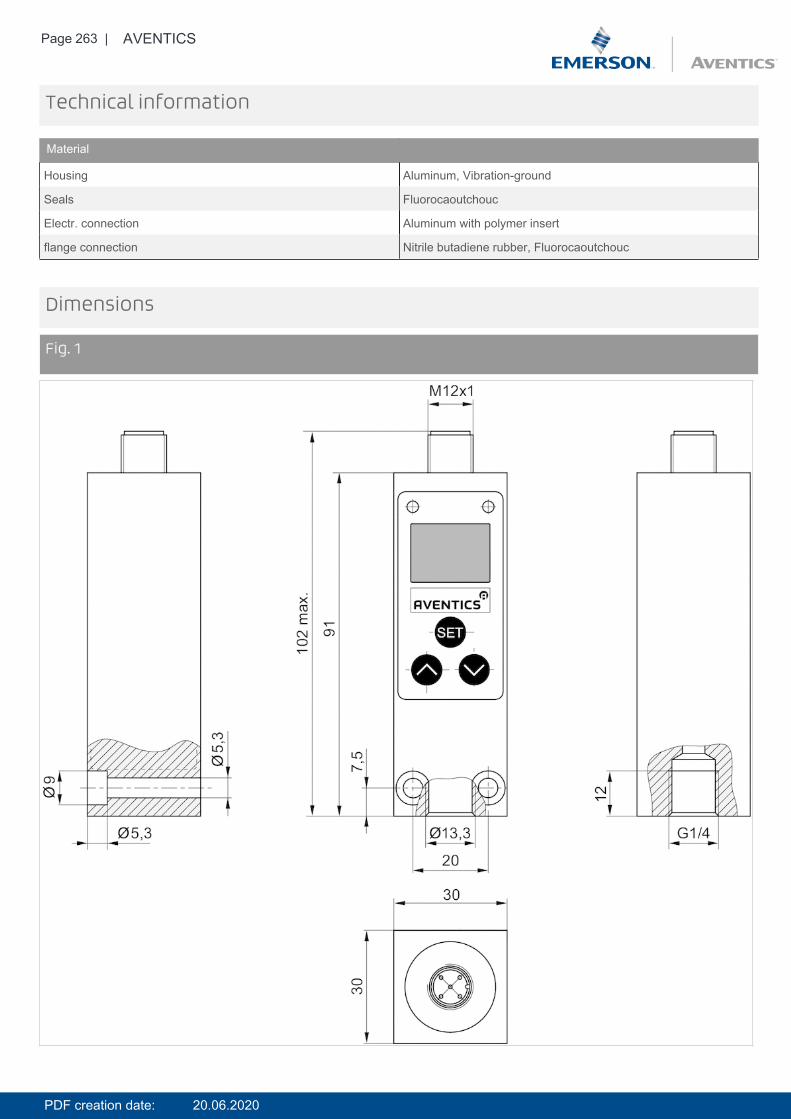
Page 263 | AVENTICS
Technical information
Material
Housing Aluminum, Vibration-ground
Seals Fluorocaoutchouc
Electr. connection Aluminum with polymer insert
flange connection Nitrile butadiene rubber, Fluorocaoutchouc
Dimensions
Fig. 1
PDF creation date: 20.06.2020
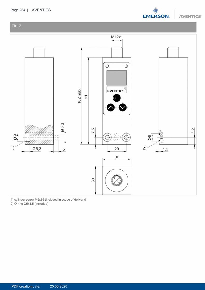
Page 264 | AVENTICS
DimensionsFig. 2
1) cylinder screw M5x35 (included in scope of delivery)2) O-ring Ø5x1,5 (included)
PDF creation date: 20.06.2020
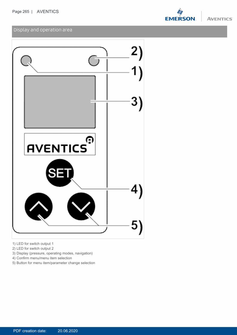
Page 265 | AVENTICS
DimensionsDisplay and operation area
1) LED for switch output 12) LED for switch output 23) Display (pressure, operating modes, navigation)4) Confirm menu/menu item selection5) Button for menu item/parameter change selection
PDF creation date: 20.06.2020
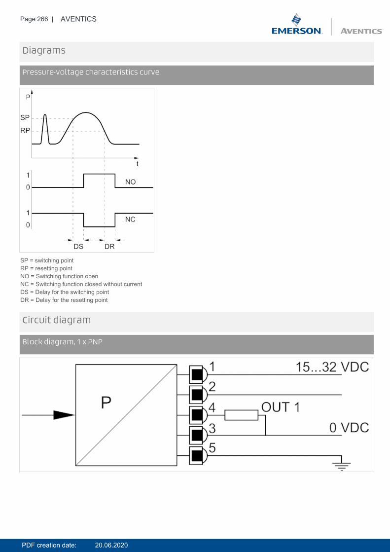
Page 266 | AVENTICS
Diagrams
Pressure-voltage characteristics curve
SP = switching pointRP = resetting pointNO = Switching function openNC = Switching function closed without currentDS = Delay for the switching pointDR = Delay for the resetting point
Circuit diagram
Block diagram, 1 x PNP
PDF creation date: 20.06.2020
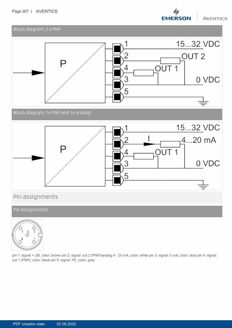
Page 267 | AVENTICS
Circuit diagramBlock diagram, 2 x PNP
Circuit diagramBlock diagram, 1x PNP and 1x analog
Pin assignments
Pin assignments
pin 1: signal + UB, color: brown pin 2: signal: out 2 (PNP)/analog 4 - 20 mA, color: white pin 3: signal: 0 volt, color: blue pin 4: signal:out 1 (PNP), color: black pin 5: signal: FE, color: gray
PDF creation date: 20.06.2020
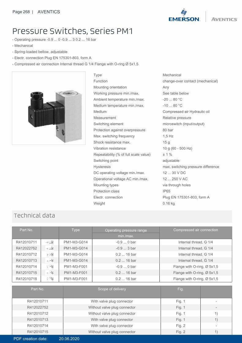
Page 268 | AVENTICS
Pressure Switches, Series PM1- Operating pressure -0.9 ... 0 -0.9 ... 3 0.2 ... 16 bar- Mechanical- Spring-loaded bellow, adjustable- Electr. connection Plug EN 175301-803, form A- Compressed air connection Internal thread G 1/4 Flange with O-ring Ø 5x1,5
Type MechanicalFunction change-over contact (mechanical)Mounting orientation AnyWorking pressure min./max. See table belowAmbient temperature min./max. -20 ... 80 °CMedium temperature min./max. -10 ... 80 °CMedium Compressed air Hydraulic oilMeasurement Relative pressureSwitching element microswitch (input/output)Protection against overpressure 80 barMax. switching frequency 1,5 HzShock resistance max. 15 gVibration resistance 10 g (60 - 500 Hz)Repeatability (% of full scale value) ± 1 %Switching point adjustableHysteresis max. switching pressure differenceDC operating voltage min./max. 12 ... 30 V DCOperational voltage AC min./max. 12 ... 250 V ACMounting types via through holesProtection class IP65Electr. connection Plug EN 175301-803, form AWeight 0.16 kg
Technical data
Part No. Type Operating pressure range Compressed air connectionmin./max.
R412010711 PM1-M3-G014 -0.9 ... 0 bar Internal thread, G 1/4R412022752 PM1-M3-G014 -0.9 ... 3 bar Internal thread, G 1/4R412010712 PM1-M3-G014 0.2 ... 16 bar Internal thread, G 1/4R412010713 PM1-M3-G014 0.2 ... 16 bar Internal thread, G 1/4R412010714 PM1-M3-F001 -0.9 ... 0 bar Flange with O-ring, Ø 5x1,5R412010715 PM1-M3-F001 0.2 ... 16 bar Flange with O-ring, Ø 5x1,5R412010718 PM1-M3-F001 0.2 ... 16 bar Flange with O-ring, Ø 5x1,5
Part No. Scope of delivery Fig.
R412010711 With valve plug connector Fig. 1 -R412022752 Without valve plug connector Fig. 1 -R412010712 Without valve plug connector Fig. 1 1)R412010713 With valve plug connector Fig. 1 1)R412010714 With valve plug connector Fig. 2 -R412010715 Without valve plug connector Fig. 2 1)
PDF creation date: 20.06.2020
Page 269 | AVENTICS
Part No. Scope of delivery Fig.
R412010718 With valve plug connector Fig. 2 1)
1) Min. switching pressure range 0.2 bar falling/0.5 bar rising
Switching function increasing pressure: contact switches from 1-2 to 1-3.Switching function decreasing pressure: contact switches from 1-3 to 1-2.Notice:Too-high currents can damage contacts. Inductive or capacitive loads must be equipped with appropriate spark-quenching!The microswitch has silver-plated contacts.Please observe the pin assignment when selecting plug connectors.
Technical information
Technical information
Material
Housing Aluminum
Seals Acrylonitrile butadiene rubber
Electr. connection Brass, nickel-plated
PDF creation date: 20.06.2020
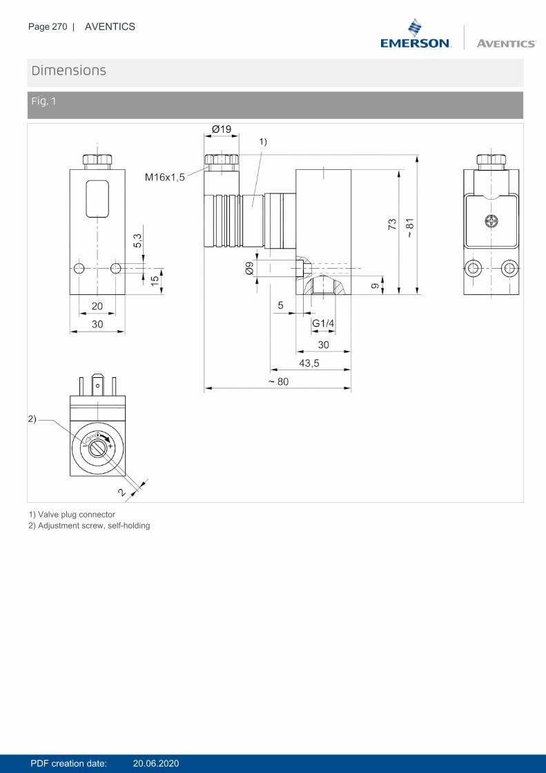
Page 270 | AVENTICS
Dimensions
Fig. 1
1) Valve plug connector2) Adjustment screw, self-holding
PDF creation date: 20.06.2020
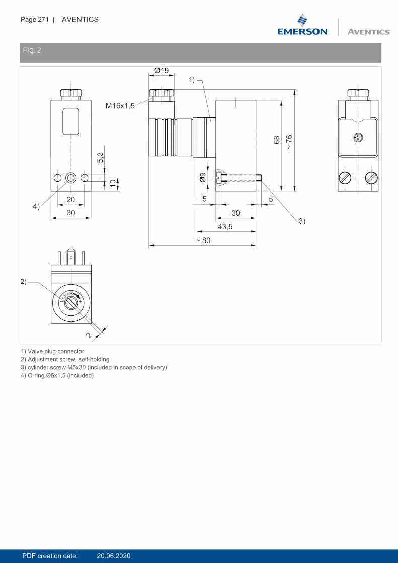
Page 271 | AVENTICS
DimensionsFig. 2
1) Valve plug connector2) Adjustment screw, self-holding3) cylinder screw M5x30 (included in scope of delivery)4) O-ring Ø5x1,5 (included)
PDF creation date: 20.06.2020

Page 272 | AVENTICS
Diagrams
differential switching pressure characteristic curve (-0,9 – 0 bar)
A) p1 (-), min.B) p1 (-), max.p1 (+) = upper switching pressure with increasing pressurep1 (-) = lower switching pressure with decreasing pressure
Diagramsdifferential switching pressure characteristic curve (0,2 - 16 bar)
A) p1 (-), min.B) p1 (-), max.p1 (+) = upper switching pressure with increasing pressurep1 (-) = lower switching pressure with decreasing pressureΔ p1 = max. operating pressure difference or hysteresisExample:
PDF creation date: 20.06.2020
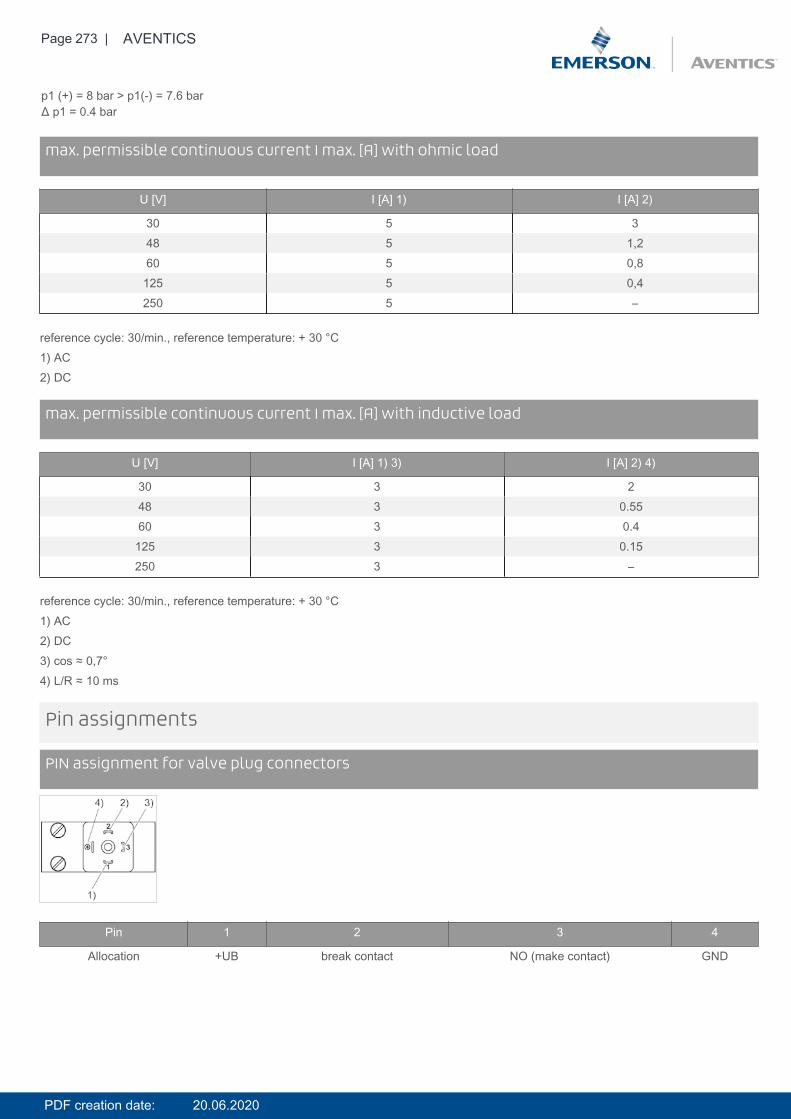
Page 273 | AVENTICS
p1 (+) = 8 bar > p1(-) = 7.6 barΔ p1 = 0.4 bar
Diagramsmax. permissible continuous current I max. [A] with ohmic load
U [V] I [A] 1) I [A] 2)
30 5 348 5 1,260 5 0,8
125 5 0,4250 5 –
reference cycle: 30/min., reference temperature: + 30 °C1) AC2) DC
Diagramsmax. permissible continuous current I max. [A] with inductive load
U [V] I [A] 1) 3) I [A] 2) 4)
30 3 248 3 0.5560 3 0.4
125 3 0.15250 3 –
reference cycle: 30/min., reference temperature: + 30 °C1) AC2) DC3) cos ≈ 0,7°4) L/R ≈ 10 ms
Pin assignments
PIN assignment for valve plug connectors
Pin 1 2 3 4
Allocation +UB break contact NO (make contact) GND
PDF creation date: 20.06.2020
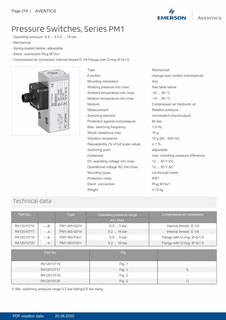
Page 274 | AVENTICS
Pressure Switches, Series PM1- Operating pressure -0.9 ... 0 0.2 ... 16 bar- Mechanical- Spring-loaded bellow, adjustable- Electr. connection Plug M12x1- Compressed air connection Internal thread G 1/4 Flange with O-ring Ø 5x1,5
Type MechanicalFunction change-over contact (mechanical)Mounting orientation AnyWorking pressure min./max. See table belowAmbient temperature min./max. -20 ... 80 °CMedium temperature min./max. -10 ... 80 °CMedium Compressed air Hydraulic oilMeasurement Relative pressureSwitching element microswitch (input/output)Protection against overpressure 80 barMax. switching frequency 1,5 HzShock resistance max. 15 gVibration resistance 10 g (60 - 500 Hz)Repeatability (% of full scale value) ± 1 %Switching point adjustableHysteresis max. switching pressure differenceDC operating voltage min./max. 12 ... 30 V DCOperational voltage AC min./max. 12 ... 30 V ACMounting types via through holesProtection class IP67Electr. connection Plug M12x1Weight 0.15 kg
Technical data
Part No. Type Operating pressure range Compressed air connectionmin./max.
R412010716 PM1-M3-G014 -0.9 ... 0 bar Internal thread, G 1/4R412010717 PM1-M3-G014 0.2 ... 16 bar Internal thread, G 1/4R412010719 PM1-M3-F001 -0.9 ... 0 bar Flange with O-ring, Ø 5x1,5R412010720 PM1-M3-F001 0.2 ... 16 bar Flange with O-ring, Ø 5x1,5
Part No. Fig.
R412010716 Fig. 1 -R412010717 Fig. 1 1)R412010719 Fig. 2 -R412010720 Fig. 2 1)
1) Min. switching pressure range 0.2 bar falling/0.5 bar rising
PDF creation date: 20.06.2020
Page 275 | AVENTICS
Switching function increasing pressure: contact switches from 1-2 to 1-3.Switching function decreasing pressure: contact switches from 1-3 to 1-2.Notice:Too-high currents can damage contacts. Inductive or capacitive loads must be equipped with appropriate spark-quenching!The microswitch has silver-plated contacts.
Technical information
Technical information
Material
Housing Aluminum
Seals Acrylonitrile butadiene rubber
Electr. connection Brass, nickel-plated
PDF creation date: 20.06.2020
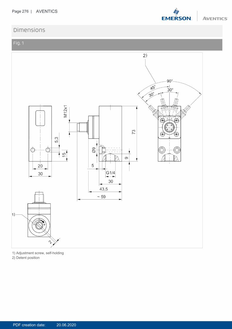
Page 276 | AVENTICS
Dimensions
Fig. 1
1) Adjustment screw, self-holding2) Detent position
PDF creation date: 20.06.2020
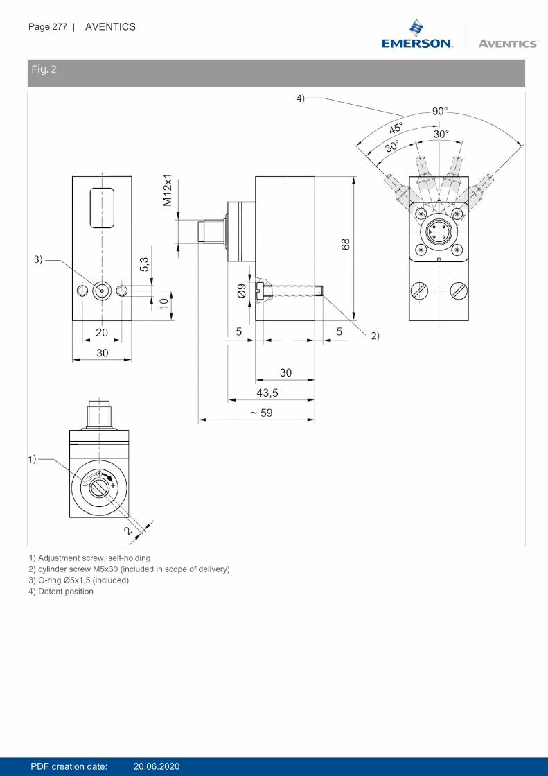
Page 277 | AVENTICS
DimensionsFig. 2
1) Adjustment screw, self-holding2) cylinder screw M5x30 (included in scope of delivery)3) O-ring Ø5x1,5 (included)4) Detent position
PDF creation date: 20.06.2020
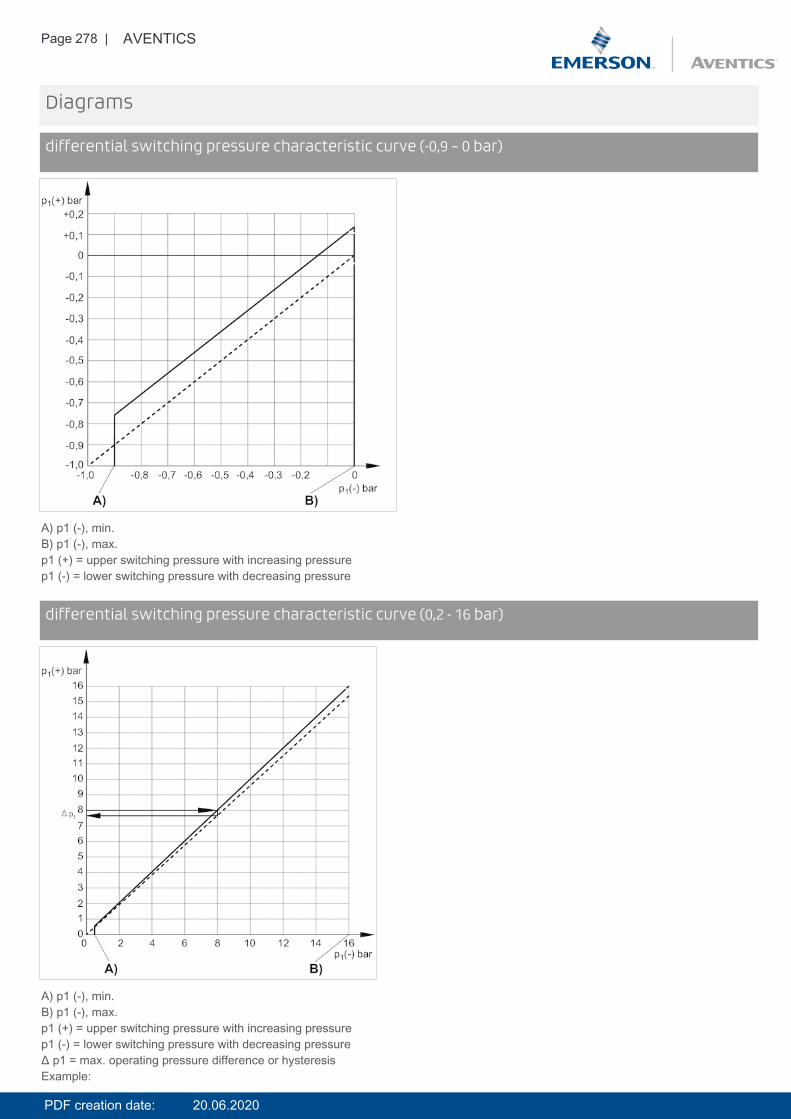
Page 278 | AVENTICS
Diagrams
differential switching pressure characteristic curve (-0,9 – 0 bar)
A) p1 (-), min.B) p1 (-), max.p1 (+) = upper switching pressure with increasing pressurep1 (-) = lower switching pressure with decreasing pressure
Diagramsdifferential switching pressure characteristic curve (0,2 - 16 bar)
A) p1 (-), min.B) p1 (-), max.p1 (+) = upper switching pressure with increasing pressurep1 (-) = lower switching pressure with decreasing pressureΔ p1 = max. operating pressure difference or hysteresisExample:
PDF creation date: 20.06.2020
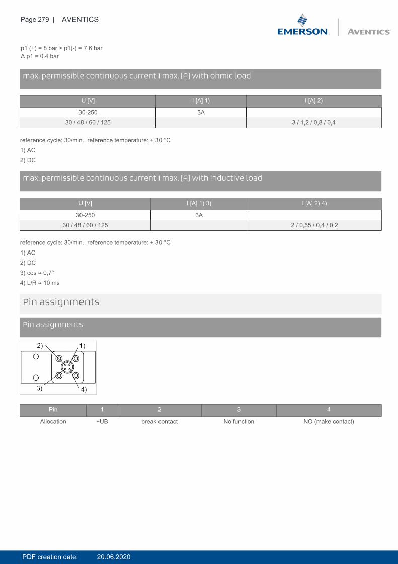
Page 279 | AVENTICS
p1 (+) = 8 bar > p1(-) = 7.6 barΔ p1 = 0.4 bar
Diagramsmax. permissible continuous current I max. [A] with ohmic load
U [V] I [A] 1) I [A] 2)
30-250 3A30 / 48 / 60 / 125 3 / 1,2 / 0,8 / 0,4
reference cycle: 30/min., reference temperature: + 30 °C1) AC2) DC
Diagramsmax. permissible continuous current I max. [A] with inductive load
U [V] I [A] 1) 3) I [A] 2) 4)
30-250 3A30 / 48 / 60 / 125 2 / 0,55 / 0,4 / 0,2
reference cycle: 30/min., reference temperature: + 30 °C1) AC2) DC3) cos ≈ 0,7°4) L/R ≈ 10 ms
Pin assignments
Pin assignments
Pin 1 2 3 4
Allocation +UB break contact No function NO (make contact)
PDF creation date: 20.06.2020
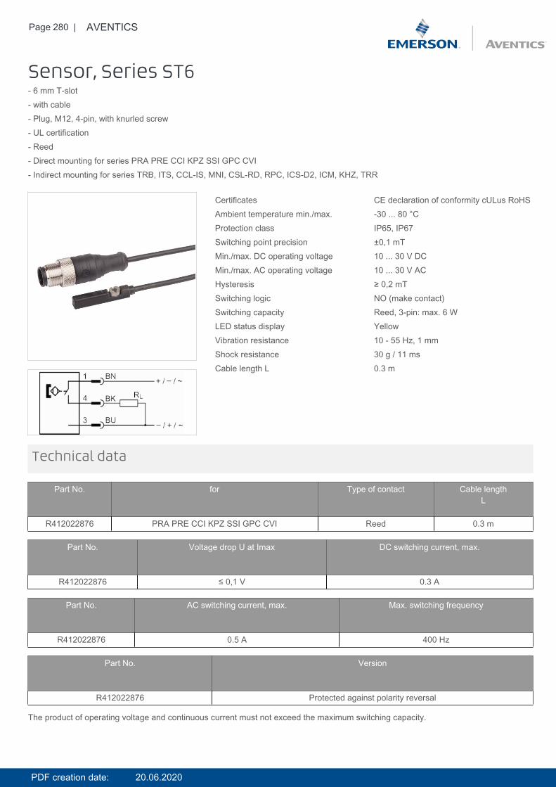
Page 280 | AVENTICS
Sensor, Series ST6- 6 mm T-slot- with cable- Plug, M12, 4-pin, with knurled screw- UL certification- Reed- Direct mounting for series PRA PRE CCI KPZ SSI GPC CVI- Indirect mounting for series TRB, ITS, CCL-IS, MNI, CSL-RD, RPC, ICS-D2, ICM, KHZ, TRR
Certificates CE declaration of conformity cULus RoHSAmbient temperature min./max. -30 ... 80 °CProtection class IP65, IP67Switching point precision ±0,1 mTMin./max. DC operating voltage 10 ... 30 V DCMin./max. AC operating voltage 10 ... 30 V ACHysteresis ≥ 0,2 mTSwitching logic NO (make contact)Switching capacity Reed, 3-pin: max. 6 WLED status display YellowVibration resistance 10 - 55 Hz, 1 mmShock resistance 30 g / 11 msCable length L 0.3 m
Technical data
Part No. for Type of contact Cable lengthL
R412022876 PRA PRE CCI KPZ SSI GPC CVI Reed 0.3 m
Part No. Voltage drop U at Imax DC switching current, max.
R412022876 ≤ 0,1 V 0.3 A
Part No. AC switching current, max. Max. switching frequency
R412022876 0.5 A 400 Hz
Part No. Version
R412022876 Protected against polarity reversal
The product of operating voltage and continuous current must not exceed the maximum switching capacity.
PDF creation date: 20.06.2020
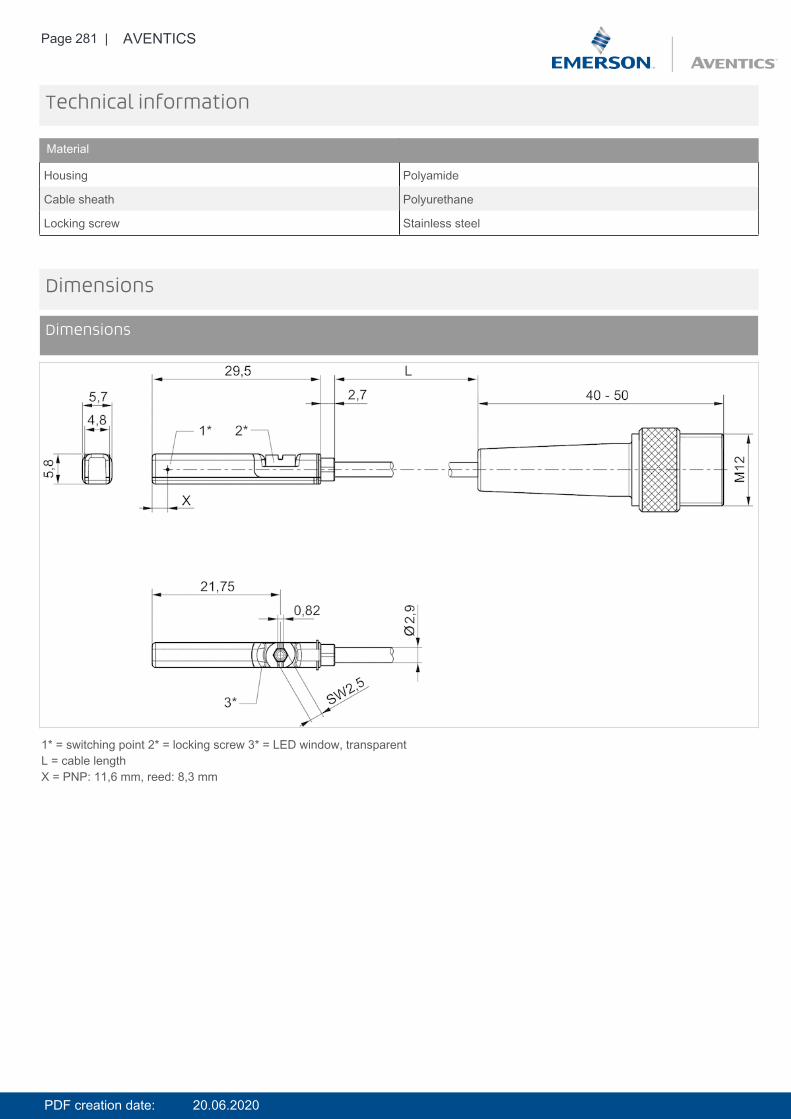
Page 281 | AVENTICS
Technical information
Material
Housing Polyamide
Cable sheath Polyurethane
Locking screw Stainless steel
Dimensions
Dimensions
1* = switching point 2* = locking screw 3* = LED window, transparentL = cable lengthX = PNP: 11,6 mm, reed: 8,3 mm
PDF creation date: 20.06.2020
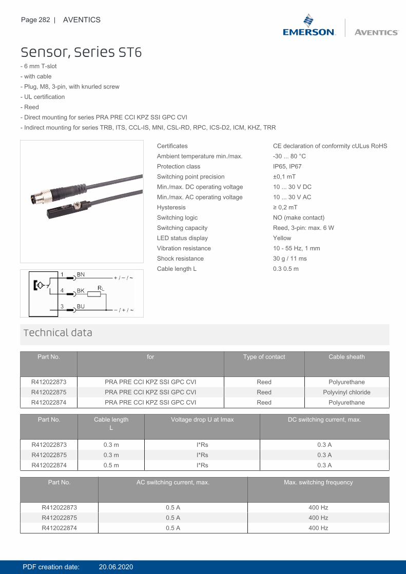
Page 282 | AVENTICS
Sensor, Series ST6- 6 mm T-slot- with cable- Plug, M8, 3-pin, with knurled screw- UL certification- Reed- Direct mounting for series PRA PRE CCI KPZ SSI GPC CVI- Indirect mounting for series TRB, ITS, CCL-IS, MNI, CSL-RD, RPC, ICS-D2, ICM, KHZ, TRR
Certificates CE declaration of conformity cULus RoHSAmbient temperature min./max. -30 ... 80 °CProtection class IP65, IP67Switching point precision ±0,1 mTMin./max. DC operating voltage 10 ... 30 V DCMin./max. AC operating voltage 10 ... 30 V ACHysteresis ≥ 0,2 mTSwitching logic NO (make contact)Switching capacity Reed, 3-pin: max. 6 WLED status display YellowVibration resistance 10 - 55 Hz, 1 mmShock resistance 30 g / 11 msCable length L 0.3 0.5 m
Technical data
Part No. for Type of contact Cable sheath
R412022873 PRA PRE CCI KPZ SSI GPC CVI Reed PolyurethaneR412022875 PRA PRE CCI KPZ SSI GPC CVI Reed Polyvinyl chlorideR412022874 PRA PRE CCI KPZ SSI GPC CVI Reed Polyurethane
Part No. Cable lengthL
Voltage drop U at Imax DC switching current, max.
R412022873 0.3 m I*Rs 0.3 AR412022875 0.3 m I*Rs 0.3 AR412022874 0.5 m I*Rs 0.3 A
Part No. AC switching current, max. Max. switching frequency
R412022873 0.5 A 400 HzR412022875 0.5 A 400 HzR412022874 0.5 A 400 Hz
PDF creation date: 20.06.2020
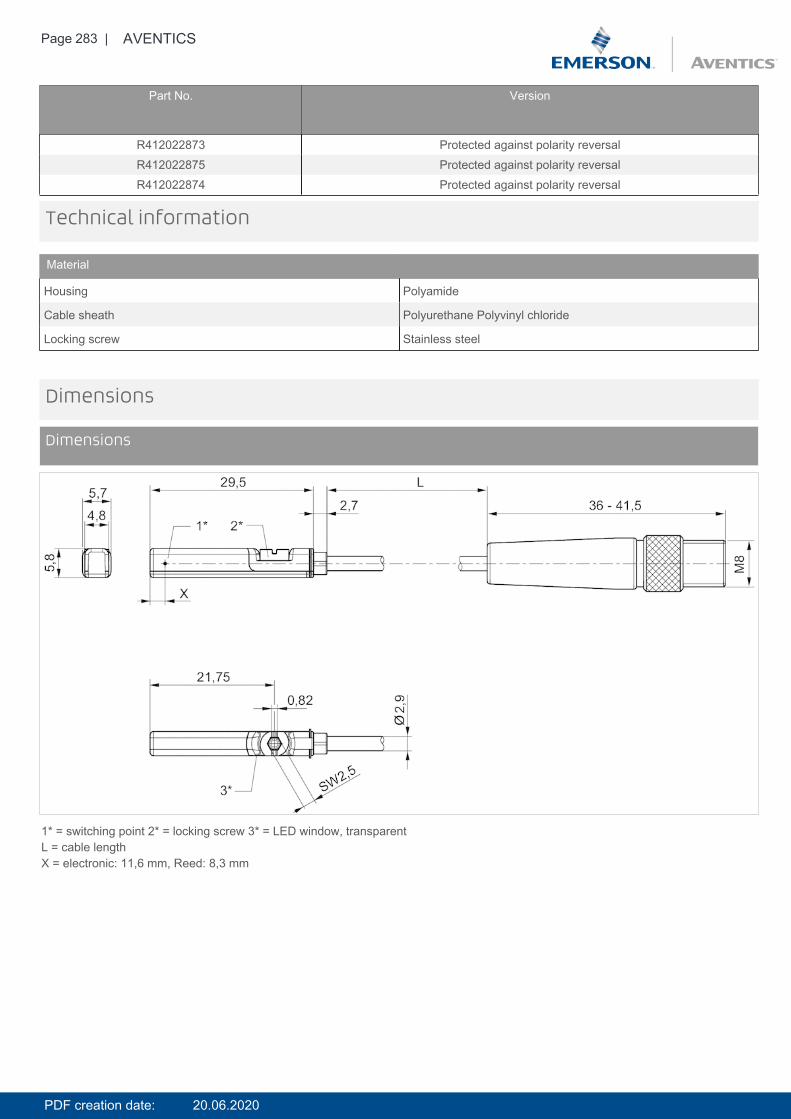
Page 283 | AVENTICS
Part No. Version
R412022873 Protected against polarity reversalR412022875 Protected against polarity reversalR412022874 Protected against polarity reversal
Technical information
Material
Housing Polyamide
Cable sheath Polyurethane Polyvinyl chloride
Locking screw Stainless steel
Dimensions
Dimensions
1* = switching point 2* = locking screw 3* = LED window, transparentL = cable lengthX = electronic: 11,6 mm, Reed: 8,3 mm
PDF creation date: 20.06.2020
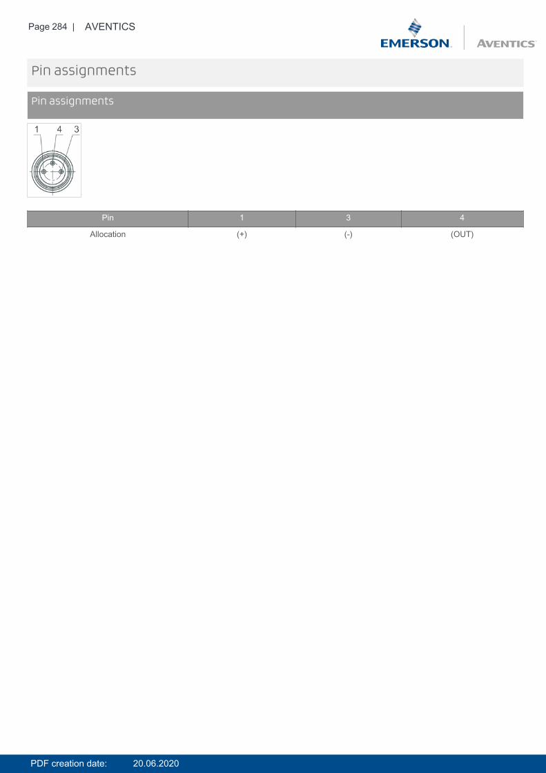
Page 284 | AVENTICS
Pin assignments
Pin assignments
Pin 1 3 4
Allocation (+) (-) (OUT)
PDF creation date: 20.06.2020
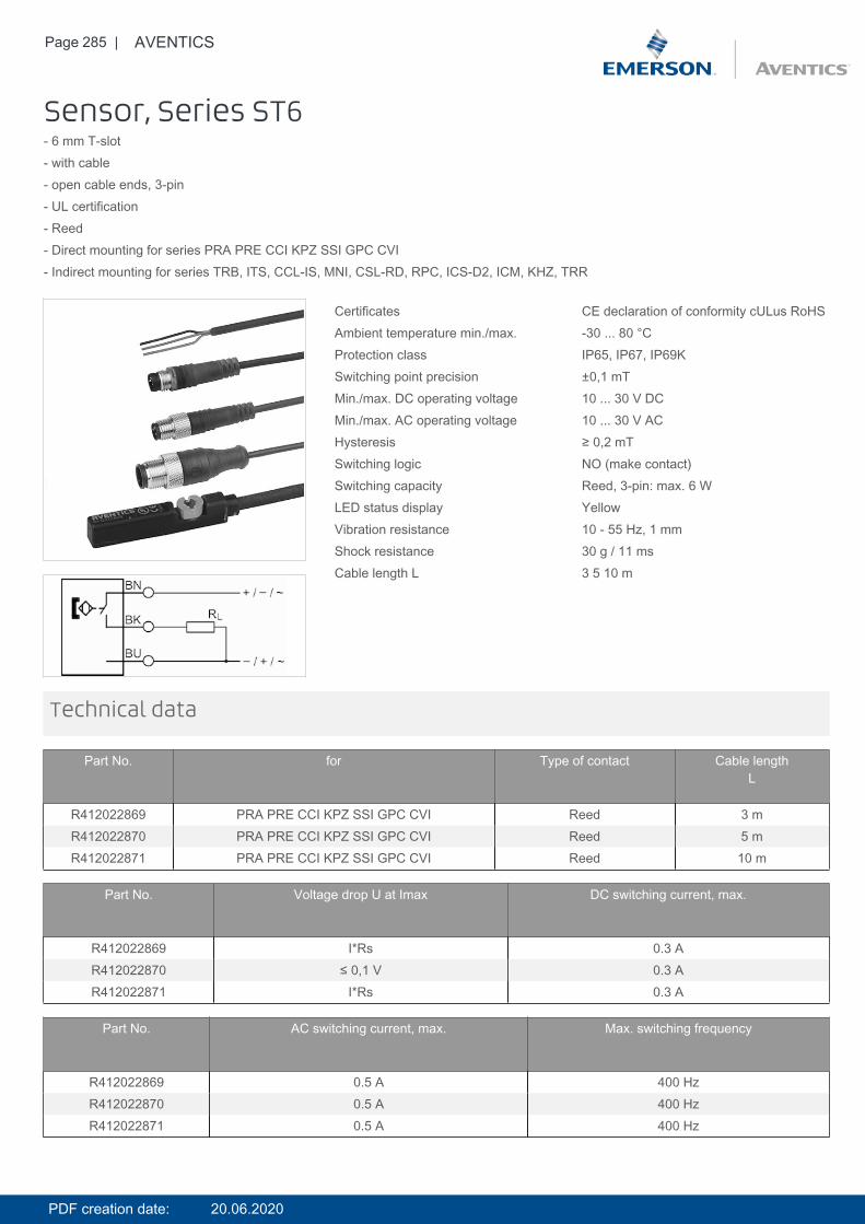
Page 285 | AVENTICS
Sensor, Series ST6- 6 mm T-slot- with cable- open cable ends, 3-pin- UL certification- Reed- Direct mounting for series PRA PRE CCI KPZ SSI GPC CVI- Indirect mounting for series TRB, ITS, CCL-IS, MNI, CSL-RD, RPC, ICS-D2, ICM, KHZ, TRR
Certificates CE declaration of conformity cULus RoHSAmbient temperature min./max. -30 ... 80 °CProtection class IP65, IP67, IP69KSwitching point precision ±0,1 mTMin./max. DC operating voltage 10 ... 30 V DCMin./max. AC operating voltage 10 ... 30 V ACHysteresis ≥ 0,2 mTSwitching logic NO (make contact)Switching capacity Reed, 3-pin: max. 6 WLED status display YellowVibration resistance 10 - 55 Hz, 1 mmShock resistance 30 g / 11 msCable length L 3 5 10 m
Technical data
Part No. for Type of contact Cable lengthL
R412022869 PRA PRE CCI KPZ SSI GPC CVI Reed 3 mR412022870 PRA PRE CCI KPZ SSI GPC CVI Reed 5 mR412022871 PRA PRE CCI KPZ SSI GPC CVI Reed 10 m
Part No. Voltage drop U at Imax DC switching current, max.
R412022869 I*Rs 0.3 AR412022870 ≤ 0,1 V 0.3 AR412022871 I*Rs 0.3 A
Part No. AC switching current, max. Max. switching frequency
R412022869 0.5 A 400 HzR412022870 0.5 A 400 HzR412022871 0.5 A 400 Hz
PDF creation date: 20.06.2020
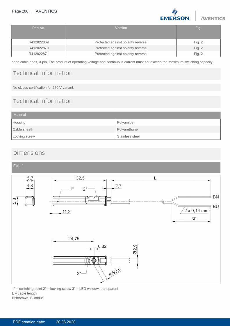
Page 286 | AVENTICS
Part No. Version Fig.
R412022869 Protected against polarity reversal Fig. 2R412022870 Protected against polarity reversal Fig. 2R412022871 Protected against polarity reversal Fig. 2
open cable ends, 3-pin, The product of operating voltage and continuous current must not exceed the maximum switching capacity.
No cULus certification for 230 V variant.
Technical information
Technical information
Material
Housing Polyamide
Cable sheath Polyurethane
Locking screw Stainless steel
Dimensions
Fig. 1
1* = switching point 2* = locking screw 3* = LED window, transparentL = cable lengthBN=brown, BU=blue
PDF creation date: 20.06.2020
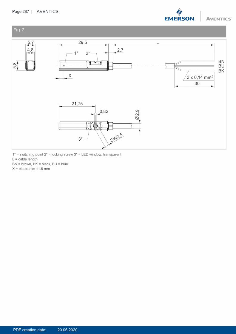
Page 287 | AVENTICS
DimensionsFig. 2
1* = switching point 2* = locking screw 3* = LED window, transparentL = cable lengthBN = brown, BK = black, BU = blueX = electronic: 11.6 mm
PDF creation date: 20.06.2020
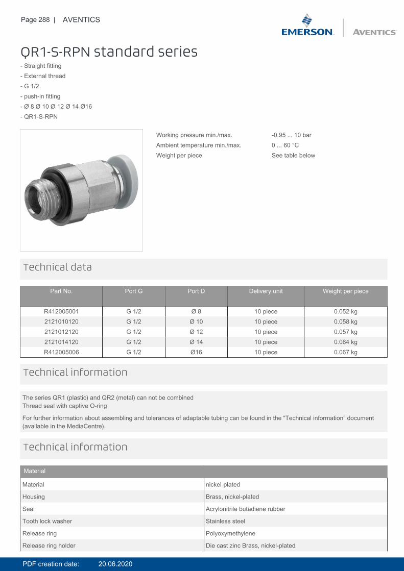
Page 288 | AVENTICS
QR1-S-RPN standard series- Straight fitting- External thread- G 1/2- push-in fitting- Ø 8 Ø 10 Ø 12 Ø 14 Ø16- QR1-S-RPN
Working pressure min./max. -0.95 ... 10 barAmbient temperature min./max. 0 ... 60 °CWeight per piece See table below
Technical data
Part No. Port G Port D Delivery unit Weight per piece
R412005001 G 1/2 Ø 8 10 piece 0.052 kg2121010120 G 1/2 Ø 10 10 piece 0.058 kg2121012120 G 1/2 Ø 12 10 piece 0.057 kg2121014120 G 1/2 Ø 14 10 piece 0.064 kgR412005006 G 1/2 Ø16 10 piece 0.067 kg
The series QR1 (plastic) and QR2 (metal) can not be combinedThread seal with captive O-ring
For further information about assembling and tolerances of adaptable tubing can be found in the “Technical information” document(available in the MediaCentre).
Technical information
Technical information
Material
Material nickel-plated
Housing Brass, nickel-plated
Seal Acrylonitrile butadiene rubber
Tooth lock washer Stainless steel
Release ring Polyoxymethylene
Release ring holder Die cast zinc Brass, nickel-plated
PDF creation date: 20.06.2020
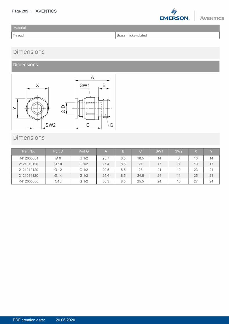
Page 289 | AVENTICS
Material
Thread Brass, nickel-plated
Dimensions
Dimensions
Dimensions
Part No. Port D Port G A B C SW1 SW2 X Y
R412005001 Ø 8 G 1/2 25.7 8.5 18.5 14 6 16 142121010120 Ø 10 G 1/2 27.4 8.5 21 17 8 19 172121012120 Ø 12 G 1/2 29.5 8.5 23 21 10 23 212121014120 Ø 14 G 1/2 25.6 8.5 24.6 24 11 25 23R412005006 Ø16 G 1/2 36.3 8.5 25.5 24 10 27 24
PDF creation date: 20.06.2020
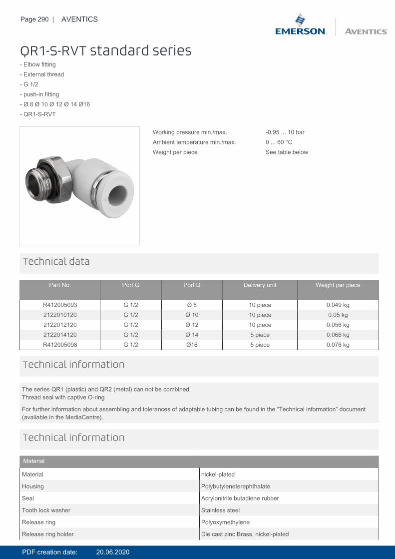
Page 290 | AVENTICS
QR1-S-RVT standard series- Elbow fitting- External thread- G 1/2- push-in fitting- Ø 8 Ø 10 Ø 12 Ø 14 Ø16- QR1-S-RVT
Working pressure min./max. -0.95 ... 10 barAmbient temperature min./max. 0 ... 60 °CWeight per piece See table below
Technical data
Part No. Port G Port D Delivery unit Weight per piece
R412005093 G 1/2 Ø 8 10 piece 0.049 kg2122010120 G 1/2 Ø 10 10 piece 0.05 kg2122012120 G 1/2 Ø 12 10 piece 0.056 kg2122014120 G 1/2 Ø 14 5 piece 0.066 kgR412005098 G 1/2 Ø16 5 piece 0.076 kg
The series QR1 (plastic) and QR2 (metal) can not be combinedThread seal with captive O-ring
For further information about assembling and tolerances of adaptable tubing can be found in the “Technical information” document(available in the MediaCentre).
Technical information
Technical information
Material
Material nickel-plated
Housing Polybutyleneterephthalate
Seal Acrylonitrile butadiene rubber
Tooth lock washer Stainless steel
Release ring Polyoxymethylene
Release ring holder Die cast zinc Brass, nickel-plated
PDF creation date: 20.06.2020
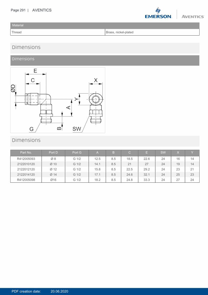
Page 291 | AVENTICS
Material
Thread Brass, nickel-plated
Dimensions
Dimensions
Dimensions
Part No. Port D Port G A B C E SW X Y
R412005093 Ø 8 G 1/2 12.5 8.5 18.5 22.6 24 16 142122010120 Ø 10 G 1/2 14.1 8.5 21 27 24 19 142122012120 Ø 12 G 1/2 15.8 8.5 22.5 29.2 24 23 212122014120 Ø 14 G 1/2 17.1 8.5 24.6 32.1 24 25 23R412005098 Ø16 G 1/2 18.2 8.5 24.8 33.3 24 27 24
PDF creation date: 20.06.2020
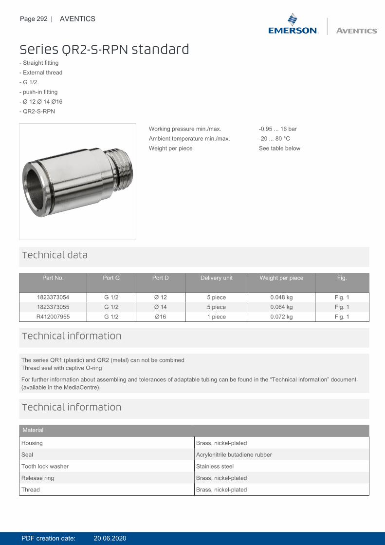
Page 292 | AVENTICS
Series QR2-S-RPN standard- Straight fitting- External thread- G 1/2- push-in fitting- Ø 12 Ø 14 Ø16- QR2-S-RPN
Working pressure min./max. -0.95 ... 16 barAmbient temperature min./max. -20 ... 80 °CWeight per piece See table below
Technical data
Part No. Port G Port D Delivery unit Weight per piece Fig.
1823373054 G 1/2 Ø 12 5 piece 0.048 kg Fig. 11823373055 G 1/2 Ø 14 5 piece 0.064 kg Fig. 1R412007955 G 1/2 Ø16 1 piece 0.072 kg Fig. 1
The series QR1 (plastic) and QR2 (metal) can not be combinedThread seal with captive O-ring
For further information about assembling and tolerances of adaptable tubing can be found in the “Technical information” document(available in the MediaCentre).
Technical information
Technical information
Material
Housing Brass, nickel-plated
Seal Acrylonitrile butadiene rubber
Tooth lock washer Stainless steel
Release ring Brass, nickel-plated
Thread Brass, nickel-plated
PDF creation date: 20.06.2020
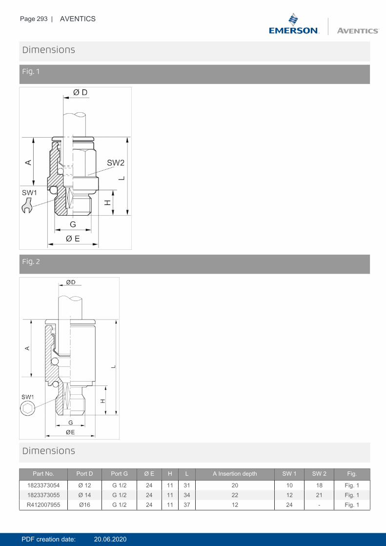
Page 293 | AVENTICS
Dimensions
Fig. 1
DimensionsFig. 2
Dimensions
Part No. Port D Port G Ø E H L A Insertion depth SW 1 SW 2 Fig.
1823373054 Ø 12 G 1/2 24 11 31 20 10 18 Fig. 11823373055 Ø 14 G 1/2 24 11 34 22 12 21 Fig. 1R412007955 Ø16 G 1/2 24 11 37 12 24 - Fig. 1
PDF creation date: 20.06.2020
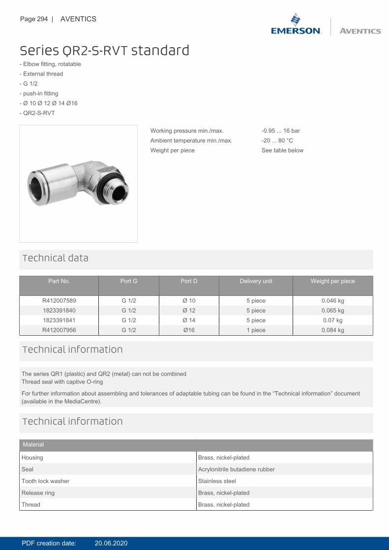
Page 294 | AVENTICS
Series QR2-S-RVT standard- Elbow fitting, rotatable- External thread- G 1/2- push-in fitting- Ø 10 Ø 12 Ø 14 Ø16- QR2-S-RVT
Working pressure min./max. -0.95 ... 16 barAmbient temperature min./max. -20 ... 80 °CWeight per piece See table below
Technical data
Part No. Port G Port D Delivery unit Weight per piece
R412007589 G 1/2 Ø 10 5 piece 0.046 kg1823391840 G 1/2 Ø 12 5 piece 0.065 kg1823391841 G 1/2 Ø 14 5 piece 0.07 kgR412007956 G 1/2 Ø16 1 piece 0.084 kg
The series QR1 (plastic) and QR2 (metal) can not be combinedThread seal with captive O-ring
For further information about assembling and tolerances of adaptable tubing can be found in the “Technical information” document(available in the MediaCentre).
Technical information
Technical information
Material
Housing Brass, nickel-plated
Seal Acrylonitrile butadiene rubber
Tooth lock washer Stainless steel
Release ring Brass, nickel-plated
Thread Brass, nickel-plated
PDF creation date: 20.06.2020
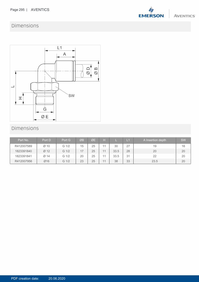
Page 295 | AVENTICS
Dimensions
Dimensions
Part No. Port D Port G ØB ØE H L L1 A Insertion depth SW
R412007589 Ø 10 G 1/2 15 25 11 30 27 19 161823391840 Ø 12 G 1/2 17 25 11 33.5 28 20 201823391841 Ø 14 G 1/2 20 25 11 33.5 31 22 20R412007956 Ø16 G 1/2 23 25 11 38 33 23.5 20
PDF creation date: 20.06.2020
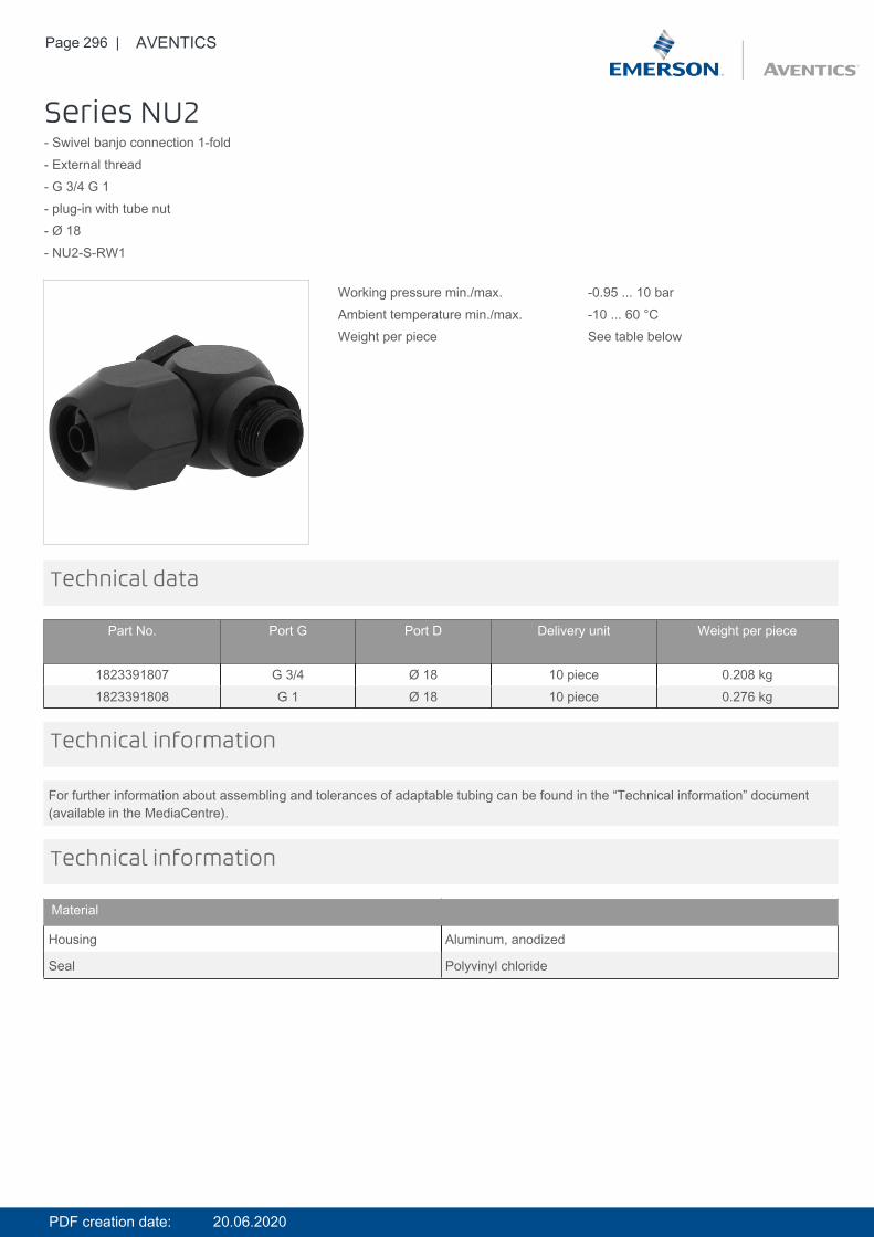
Page 296 | AVENTICS
Series NU2- Swivel banjo connection 1-fold- External thread- G 3/4 G 1- plug-in with tube nut- Ø 18- NU2-S-RW1
Working pressure min./max. -0.95 ... 10 barAmbient temperature min./max. -10 ... 60 °CWeight per piece See table below
Technical data
Part No. Port G Port D Delivery unit Weight per piece
1823391807 G 3/4 Ø 18 10 piece 0.208 kg1823391808 G 1 Ø 18 10 piece 0.276 kg
For further information about assembling and tolerances of adaptable tubing can be found in the “Technical information” document(available in the MediaCentre).
Technical information
Technical information
Material
Housing Aluminum, anodized
Seal Polyvinyl chloride
PDF creation date: 20.06.2020
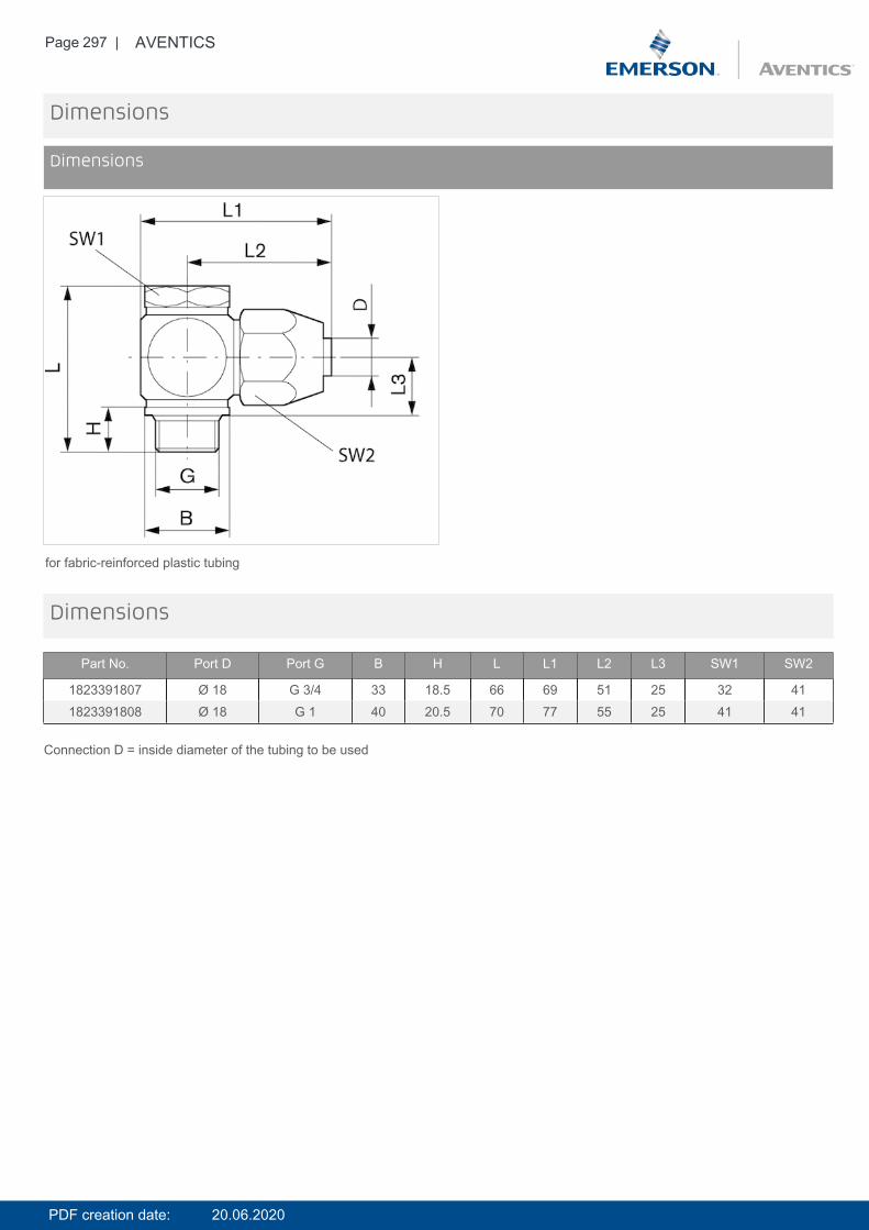
Page 297 | AVENTICS
Dimensions
Dimensions
for fabric-reinforced plastic tubing
Dimensions
Part No. Port D Port G B H L L1 L2 L3 SW1 SW2
1823391807 Ø 18 G 3/4 33 18.5 66 69 51 25 32 411823391808 Ø 18 G 1 40 20.5 70 77 55 25 41 41
Connection D = inside diameter of the tubing to be used
PDF creation date: 20.06.2020
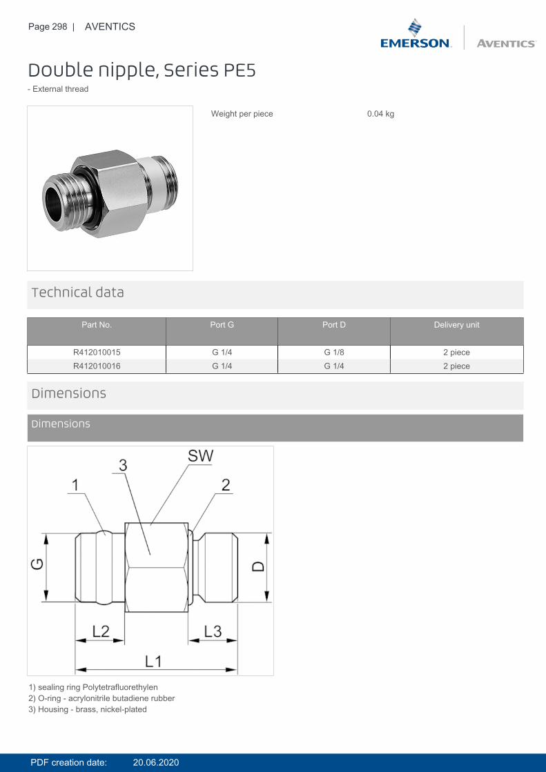
Page 298 | AVENTICS
Double nipple, Series PE5- External thread
Weight per piece 0.04 kg
Technical data
Part No. Port G Port D Delivery unit
R412010015 G 1/4 G 1/8 2 pieceR412010016 G 1/4 G 1/4 2 piece
Dimensions
Dimensions
1) sealing ring Polytetrafluorethylen2) O-ring - acrylonitrile butadiene rubber3) Housing - brass, nickel-plated
PDF creation date: 20.06.2020
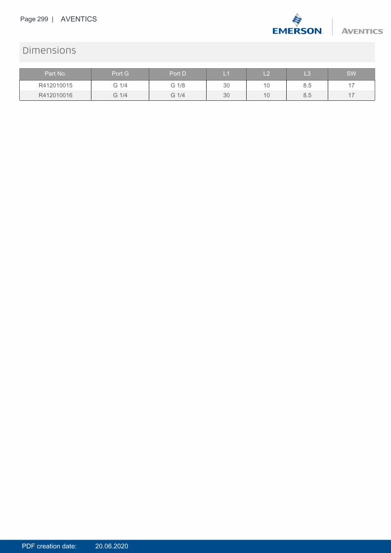
Page 299 | AVENTICS
Dimensions
Part No. Port G Port D L1 L2 L3 SW
R412010015 G 1/4 G 1/8 30 10 8.5 17R412010016 G 1/4 G 1/4 30 10 8.5 17
PDF creation date: 20.06.2020
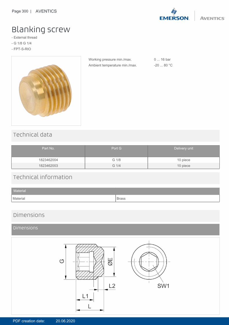
Page 300 | AVENTICS
Blanking screw- External thread- G 1/8 G 1/4- FPT-S-RIO
Working pressure min./max. 0 ... 16 barAmbient temperature min./max. -20 ... 80 °C
Technical data
Part No. Port G Delivery unit
1823462004 G 1/8 10 piece1823462003 G 1/4 10 piece
Technical information
Material
Material Brass
Dimensions
Dimensions
PDF creation date: 20.06.2020

Page 301 | AVENTICS
DimensionsDimensions in mm
Port G ØE L L1 L2 SW1
G 1/8 8 8 5 2 5G 1/4 11 11 7 3.5 6
PDF creation date: 20.06.2020
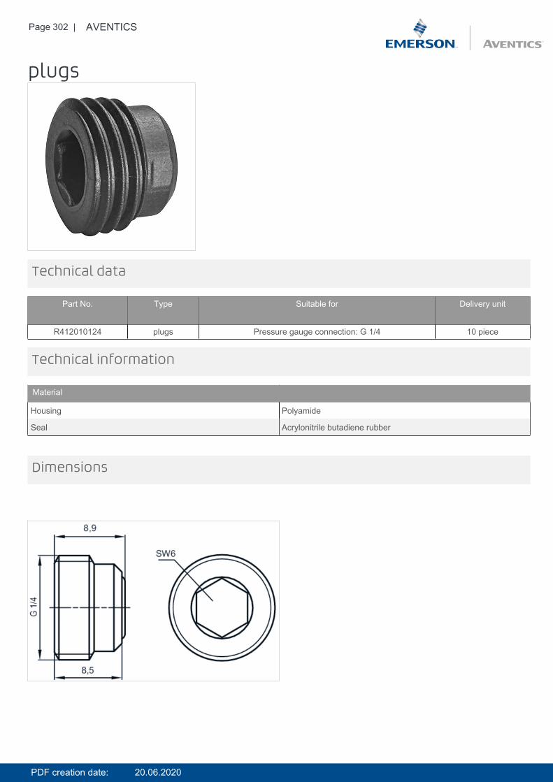
Page 302 | AVENTICS
plugs
Technical data
Part No. Type Suitable for Delivery unit
R412010124 plugs Pressure gauge connection: G 1/4 10 piece
Technical information
Material
Housing Polyamide
Seal Acrylonitrile butadiene rubber
Dimensions
PDF creation date: 20.06.2020
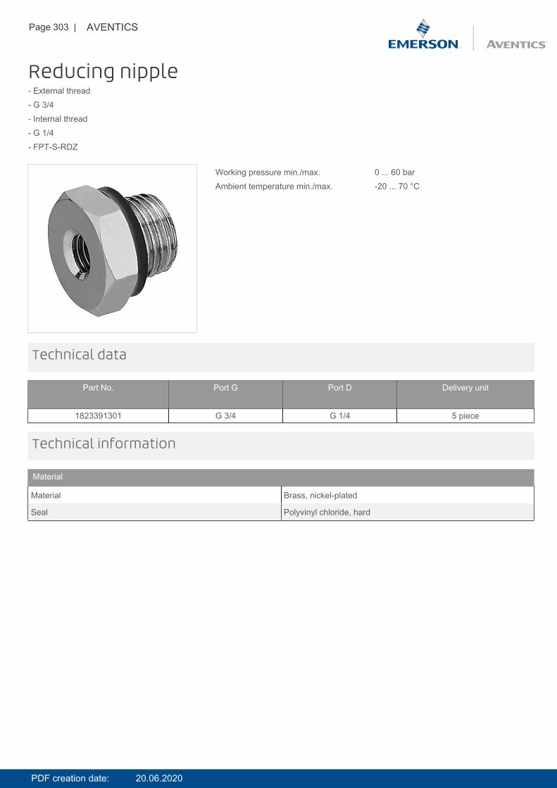
Page 303 | AVENTICS
Reducing nipple- External thread- G 3/4- Internal thread- G 1/4- FPT-S-RDZ
Working pressure min./max. 0 ... 60 barAmbient temperature min./max. -20 ... 70 °C
Technical data
Part No. Port G Port D Delivery unit
1823391301 G 3/4 G 1/4 5 piece
Technical information
Material
Material Brass, nickel-plated
Seal Polyvinyl chloride, hard
PDF creation date: 20.06.2020
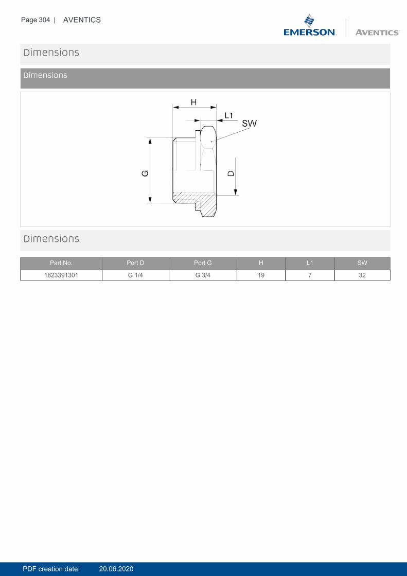
Page 304 | AVENTICS
Dimensions
Dimensions
Dimensions
Part No. Port D Port G H L1 SW
1823391301 G 1/4 G 3/4 19 7 32
PDF creation date: 20.06.2020
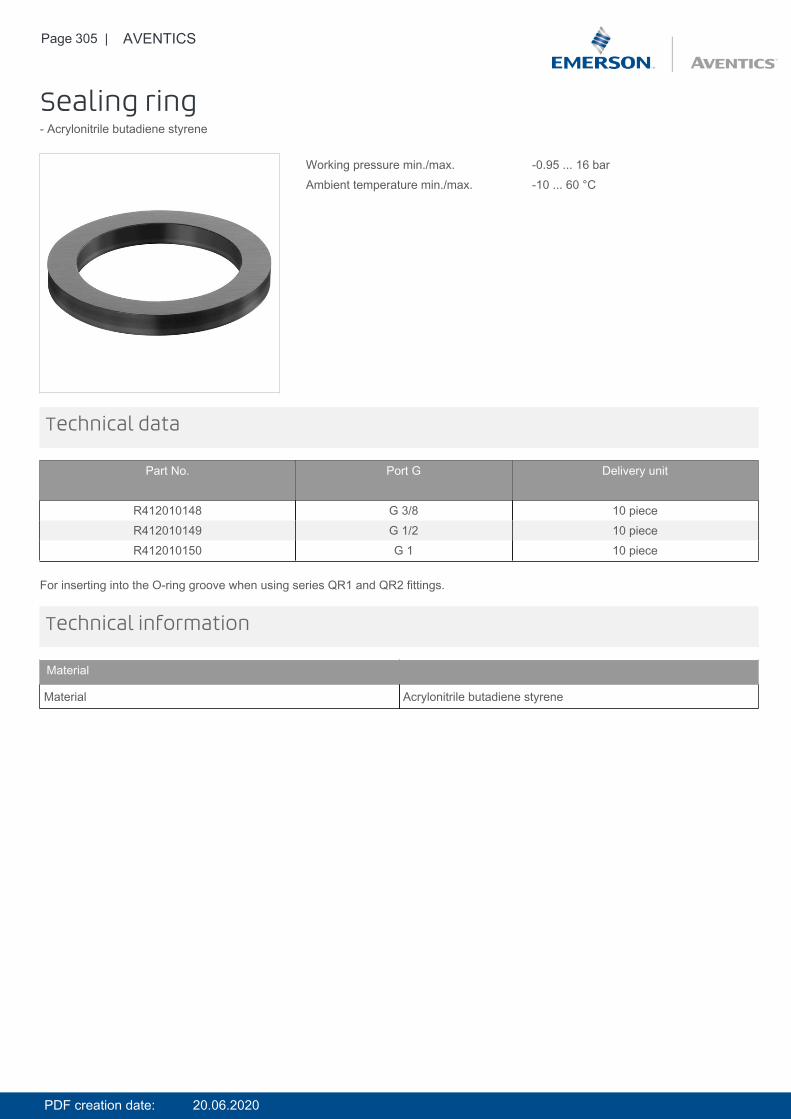
Page 305 | AVENTICS
Sealing ring- Acrylonitrile butadiene styrene
Working pressure min./max. -0.95 ... 16 barAmbient temperature min./max. -10 ... 60 °C
Technical data
Part No. Port G Delivery unit
R412010148 G 3/8 10 pieceR412010149 G 1/2 10 pieceR412010150 G 1 10 piece
For inserting into the O-ring groove when using series QR1 and QR2 fittings.
Technical information
Material
Material Acrylonitrile butadiene styrene
PDF creation date: 20.06.2020
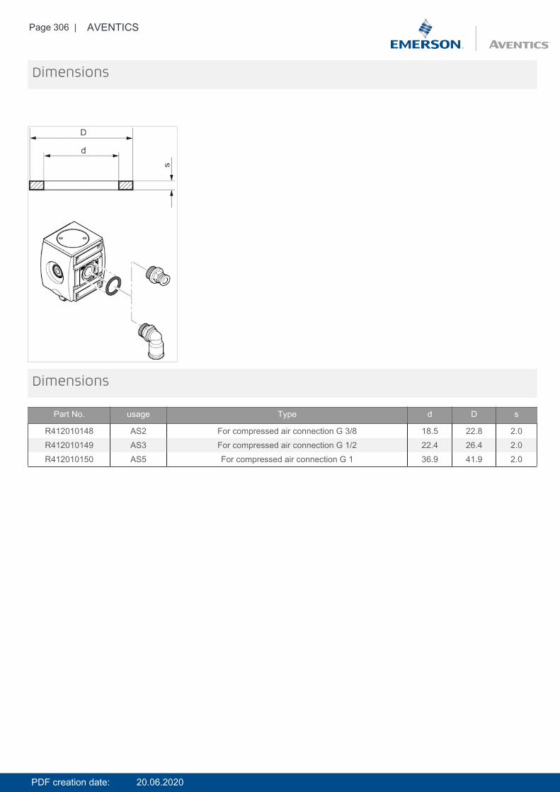
Page 306 | AVENTICS
Dimensions
Dimensions
Part No. usage Type d D s
R412010148 AS2 For compressed air connection G 3/8 18.5 22.8 2.0R412010149 AS3 For compressed air connection G 1/2 22.4 26.4 2.0R412010150 AS5 For compressed air connection G 1 36.9 41.9 2.0
PDF creation date: 20.06.2020
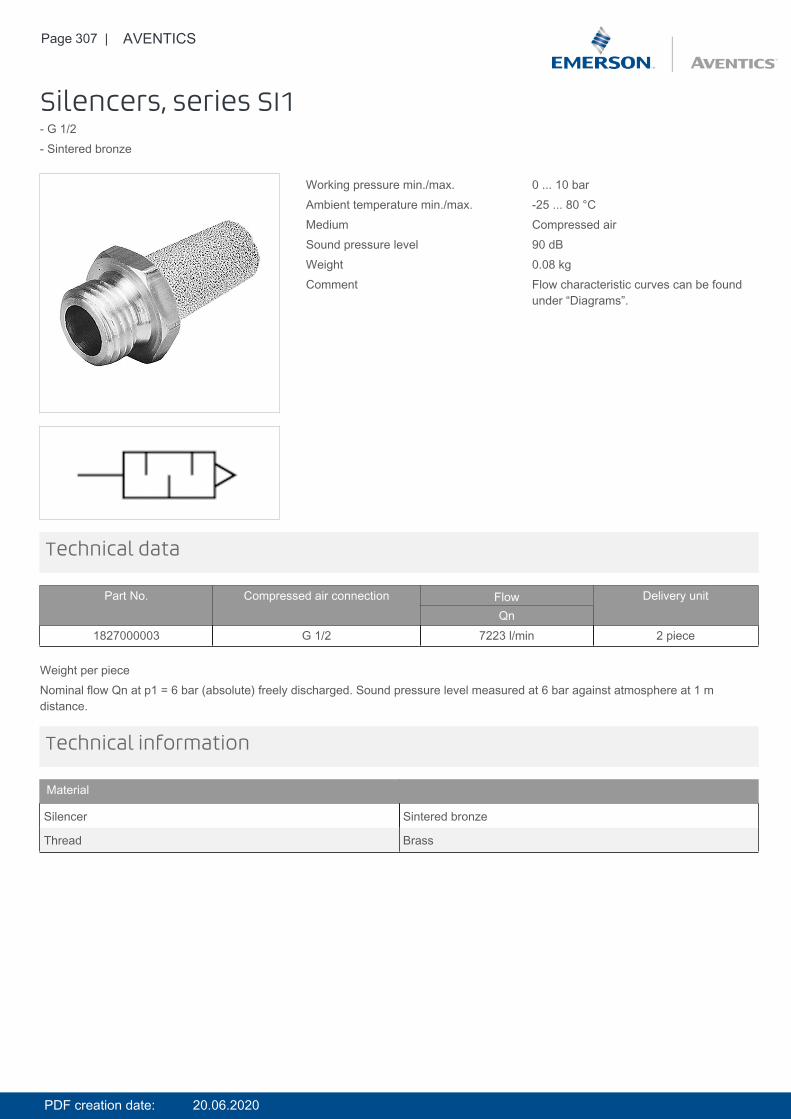
Page 307 | AVENTICS
Silencers, series SI1- G 1/2- Sintered bronze
Working pressure min./max. 0 ... 10 barAmbient temperature min./max. -25 ... 80 °CMedium Compressed airSound pressure level 90 dBWeight 0.08 kgComment Flow characteristic curves can be found
under “Diagrams”.
Technical data
Part No. Compressed air connection Flow Delivery unitQn
1827000003 G 1/2 7223 l/min 2 piece
Weight per pieceNominal flow Qn at p1 = 6 bar (absolute) freely discharged. Sound pressure level measured at 6 bar against atmosphere at 1 mdistance.
Technical information
Material
Silencer Sintered bronze
Thread Brass
PDF creation date: 20.06.2020
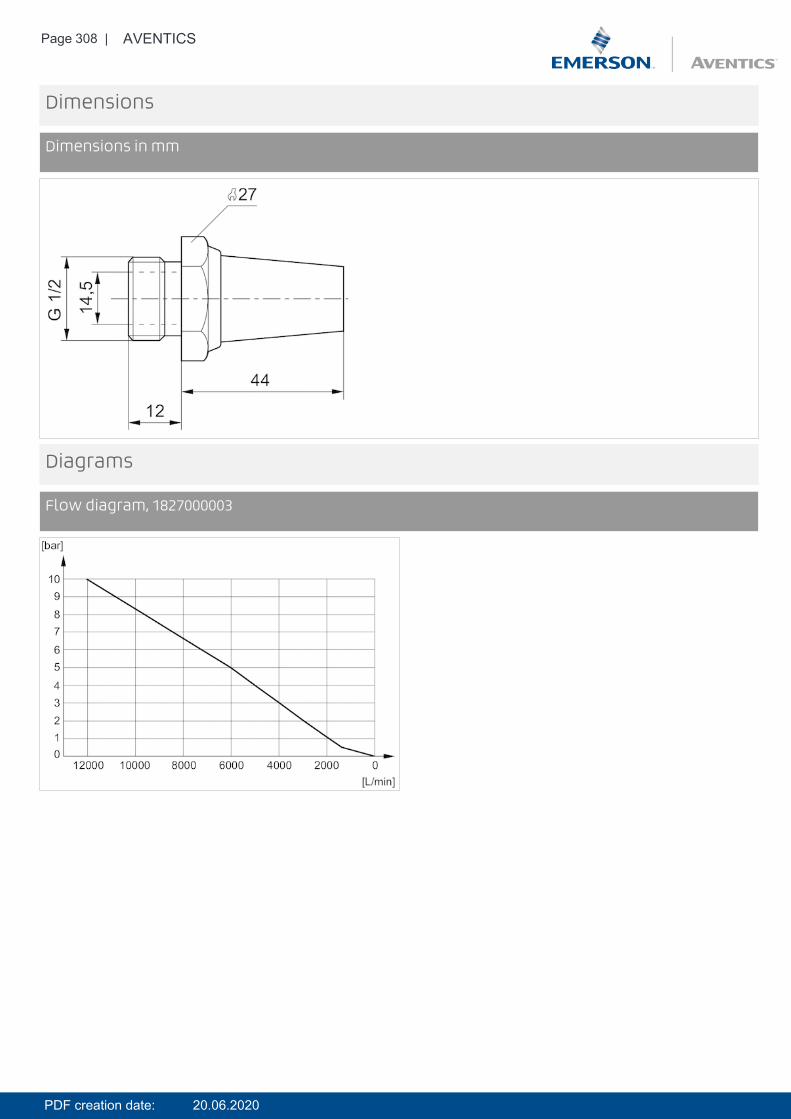
Page 308 | AVENTICS
Dimensions
Dimensions in mm
Diagrams
Flow diagram, 1827000003
PDF creation date: 20.06.2020

Page 309 | AVENTICS
Silencers, series SI1- G 3/4- Sintered bronze
Working pressure min./max. 0 ... 10 barAmbient temperature min./max. -25 ... 80 °CMedium Compressed airSound pressure level 92 dBWeight 0.13 kgComment Flow characteristic curves can be found
under “Diagrams”.
Technical data
Part No. Compressed air connection Flow Delivery unitQn
1827000004 G 3/4 8394 l/min 1 piece
Weight per pieceNominal flow Qn at p1 = 6 bar (absolute) freely discharged. Sound pressure level measured at 6 bar against atmosphere at 1 mdistance.
Technical information
Material
Silencer Sintered bronze
Thread Brass
PDF creation date: 20.06.2020
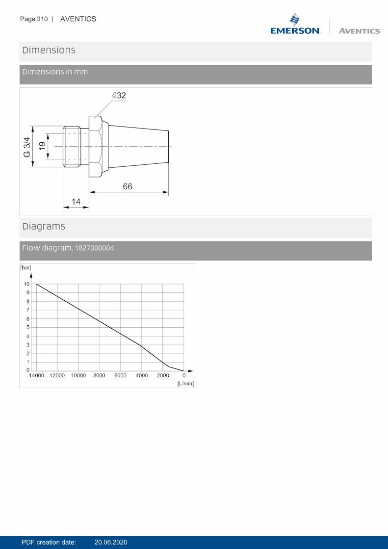
Page 310 | AVENTICS
Dimensions
Dimensions in mm
Diagrams
Flow diagram, 1827000004
PDF creation date: 20.06.2020
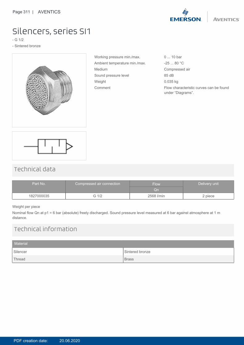
Page 311 | AVENTICS
Silencers, series SI1- G 1/2- Sintered bronze
Working pressure min./max. 0 ... 10 barAmbient temperature min./max. -25 ... 80 °CMedium Compressed airSound pressure level 85 dBWeight 0.035 kgComment Flow characteristic curves can be found
under “Diagrams”.
Technical data
Part No. Compressed air connection Flow Delivery unitQn
1827000035 G 1/2 2568 l/min 2 piece
Weight per pieceNominal flow Qn at p1 = 6 bar (absolute) freely discharged. Sound pressure level measured at 6 bar against atmosphere at 1 mdistance.
Technical information
Material
Silencer Sintered bronze
Thread Brass
PDF creation date: 20.06.2020
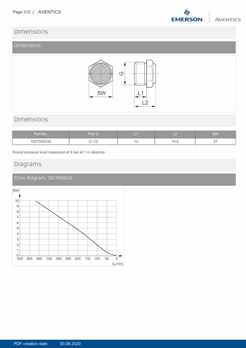
Page 312 | AVENTICS
Dimensions
Dimensions
Dimensions
Part No. Port G L1 L2 SW
1827000035 G 1/2 12 19.5 27
Sound pressure level measured at 6 bar at 1 m distance
Diagrams
Flow diagram, 1827000032
PDF creation date: 20.06.2020

Page 313 | AVENTICS
DiagramsFlow diagram, 1827000031
DiagramsFlow diagram, 1827000033
DiagramsFlow diagram, 1827000034
PDF creation date: 20.06.2020

Page 314 | AVENTICS
DiagramsFlow diagram, 1827000035
DiagramsFlow diagram, 8145003400
DiagramsFlow diagram, 8145001000
PDF creation date: 20.06.2020
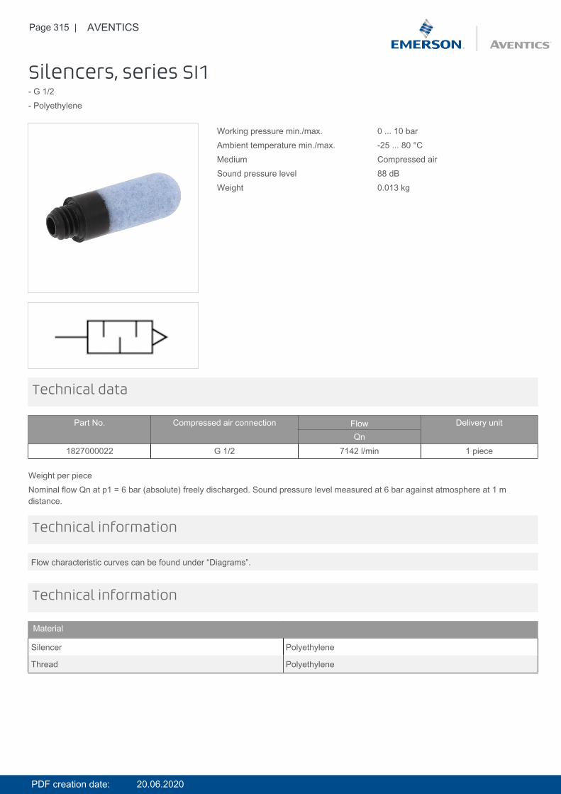
Page 315 | AVENTICS
Silencers, series SI1- G 1/2- Polyethylene
Working pressure min./max. 0 ... 10 barAmbient temperature min./max. -25 ... 80 °CMedium Compressed airSound pressure level 88 dBWeight 0.013 kg
Technical data
Part No. Compressed air connection Flow Delivery unitQn
1827000022 G 1/2 7142 l/min 1 piece
Weight per pieceNominal flow Qn at p1 = 6 bar (absolute) freely discharged. Sound pressure level measured at 6 bar against atmosphere at 1 mdistance.
Flow characteristic curves can be found under “Diagrams”.
Technical information
Technical information
Material
Silencer Polyethylene
Thread Polyethylene
PDF creation date: 20.06.2020
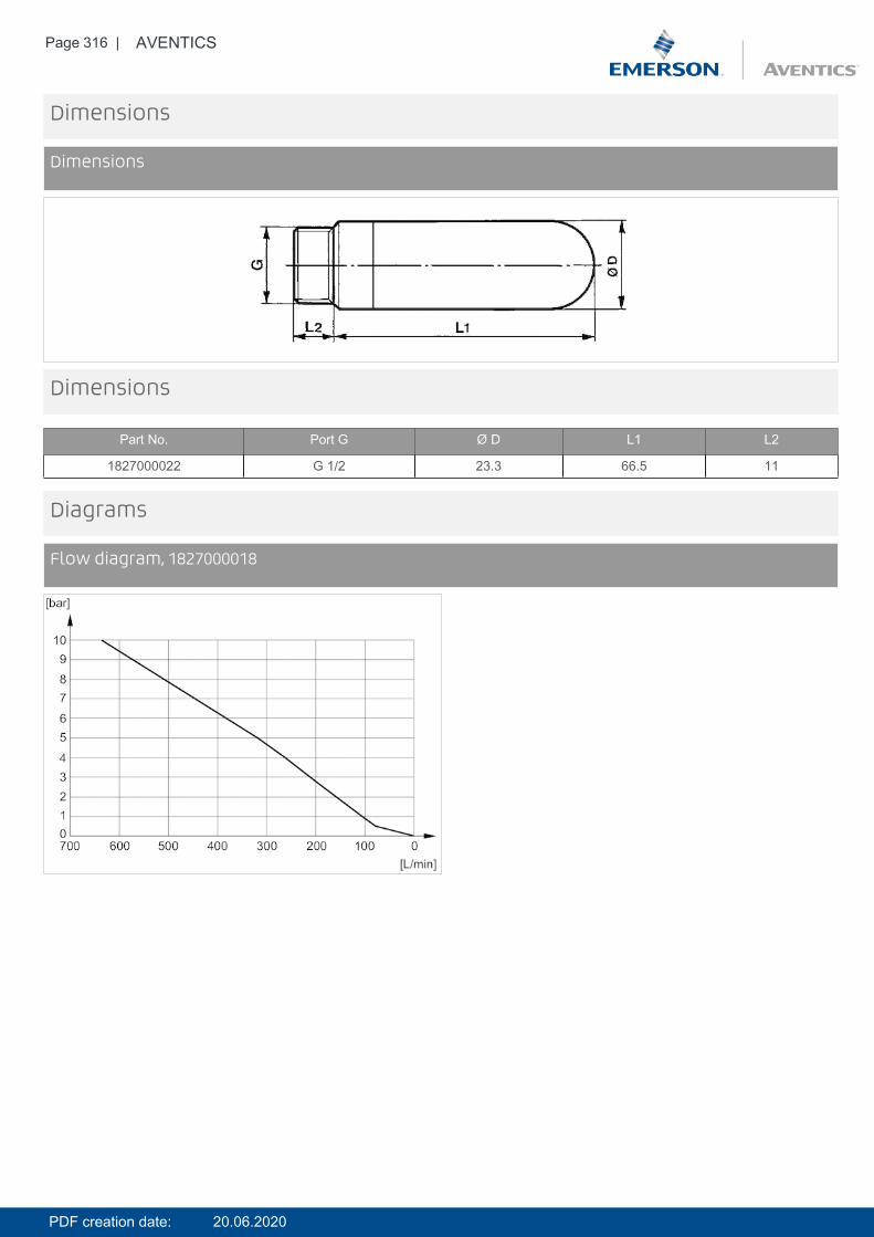
Page 316 | AVENTICS
Dimensions
Dimensions
Dimensions
Part No. Port G Ø D L1 L2
1827000022 G 1/2 23.3 66.5 11
Diagrams
Flow diagram, 1827000018
PDF creation date: 20.06.2020
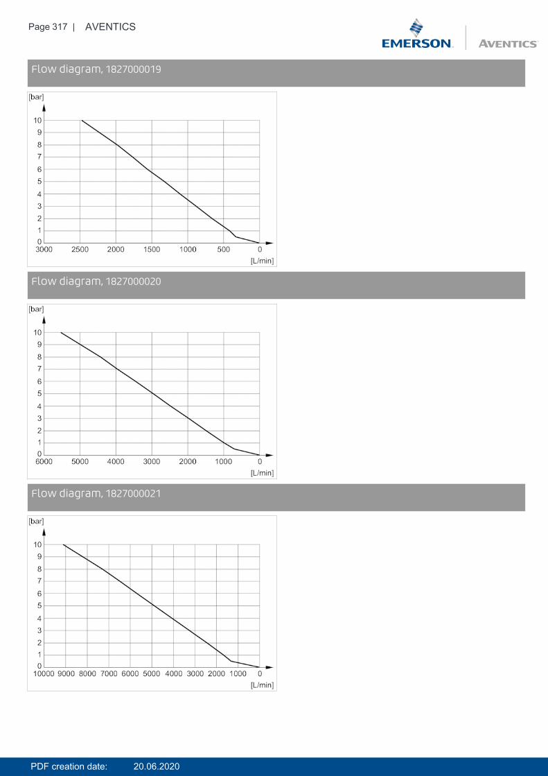
Page 317 | AVENTICS
DiagramsFlow diagram, 1827000019
DiagramsFlow diagram, 1827000020
DiagramsFlow diagram, 1827000021
PDF creation date: 20.06.2020
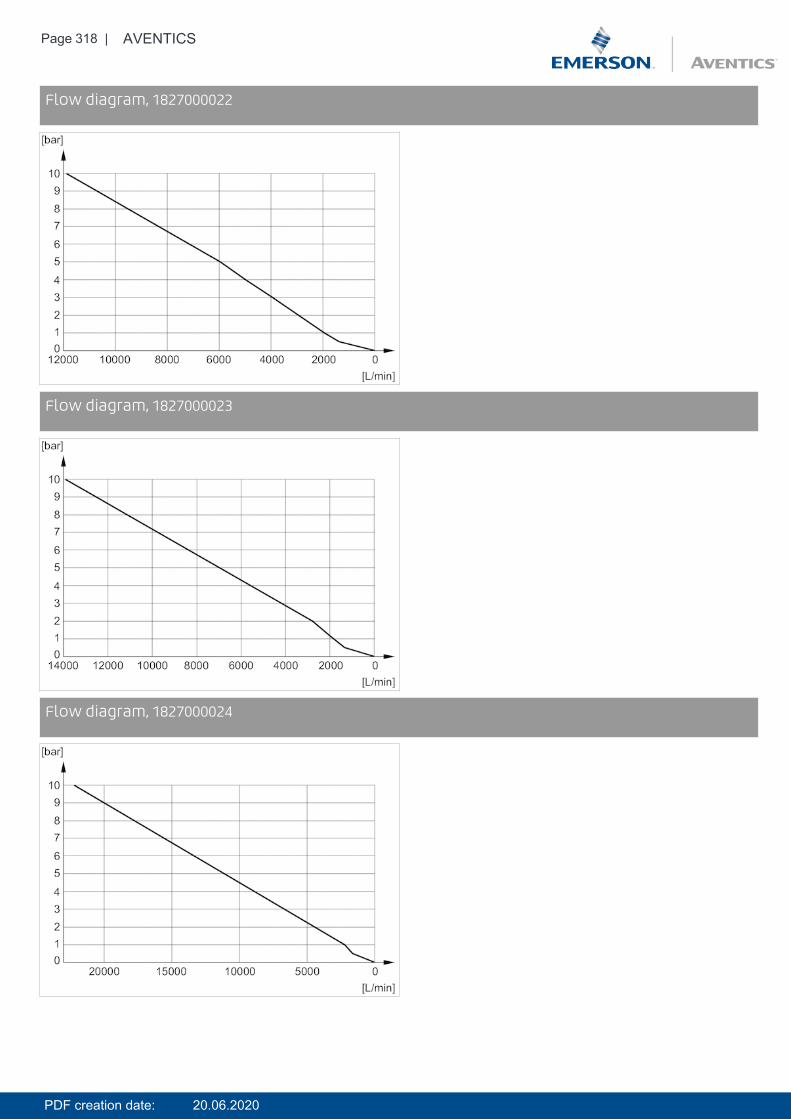
Page 318 | AVENTICS
DiagramsFlow diagram, 1827000022
DiagramsFlow diagram, 1827000023
DiagramsFlow diagram, 1827000024
PDF creation date: 20.06.2020
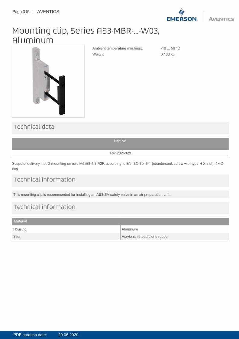
Page 319 | AVENTICS
Mounting clip, Series AS3-MBR-...-W03,Aluminum
Ambient temperature min./max. -10 ... 50 °CWeight 0.133 kg
Technical data
Part No.
R412026828
Scope of delivery incl. 2 mounting screws M5x68-4.8-A2R according to EN ISO 7046-1 (countersunk screw with type H X-slot), 1x O-ring
This mounting clip is recommended for installing an AS3-SV safety valve in an air preparation unit.
Technical information
Technical information
Material
Housing Aluminum
Seal Acrylonitrile butadiene rubber
PDF creation date: 20.06.2020
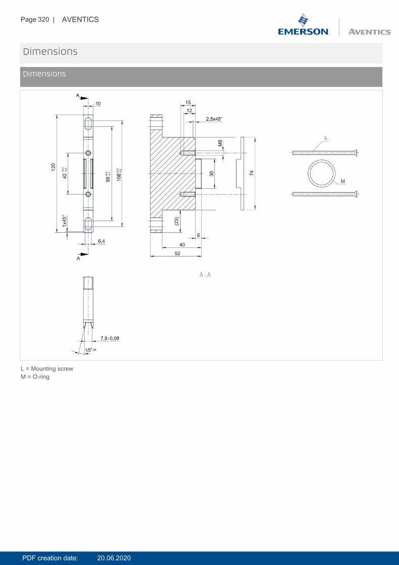
Page 320 | AVENTICS
Dimensions
Dimensions
L = Mounting screwM = O-ring
PDF creation date: 20.06.2020

Page 321 | AVENTICS
Block assembly kit, Series AS3-MBR-...-W05- G 3/8 - G 1/2
Ambient temperature min./max. -10 ... 50 °CWeight 0.825 kg
Technical data
Part No. Port
R412007366 G 3/8R412007367 G 1/2
Scope of delivery incl. 4 mounting screws M5x68-4.8-A2R according to EN ISO 7046-1 (countersunk screw with type H X-slot), 2x O-ring
Technical information
Material
Housing Die cast zinc, painted
Seal Acrylonitrile butadiene rubber
PDF creation date: 20.06.2020

Page 322 | AVENTICS
Dimensions
Dimensions
Dimensions
Part No. A1 A B C1 C2 D E F G H I J K L M N
R412007366 G 3/8 120 75 54 54 8 42 6.4 7 20 8 102.5 30 M5x68 23x2 72R412007367 G 1/2 120 75 54 54 8 42 6.4 7 20 8 102.5 30 M5x68 23x2 72
PDF creation date: 20.06.2020
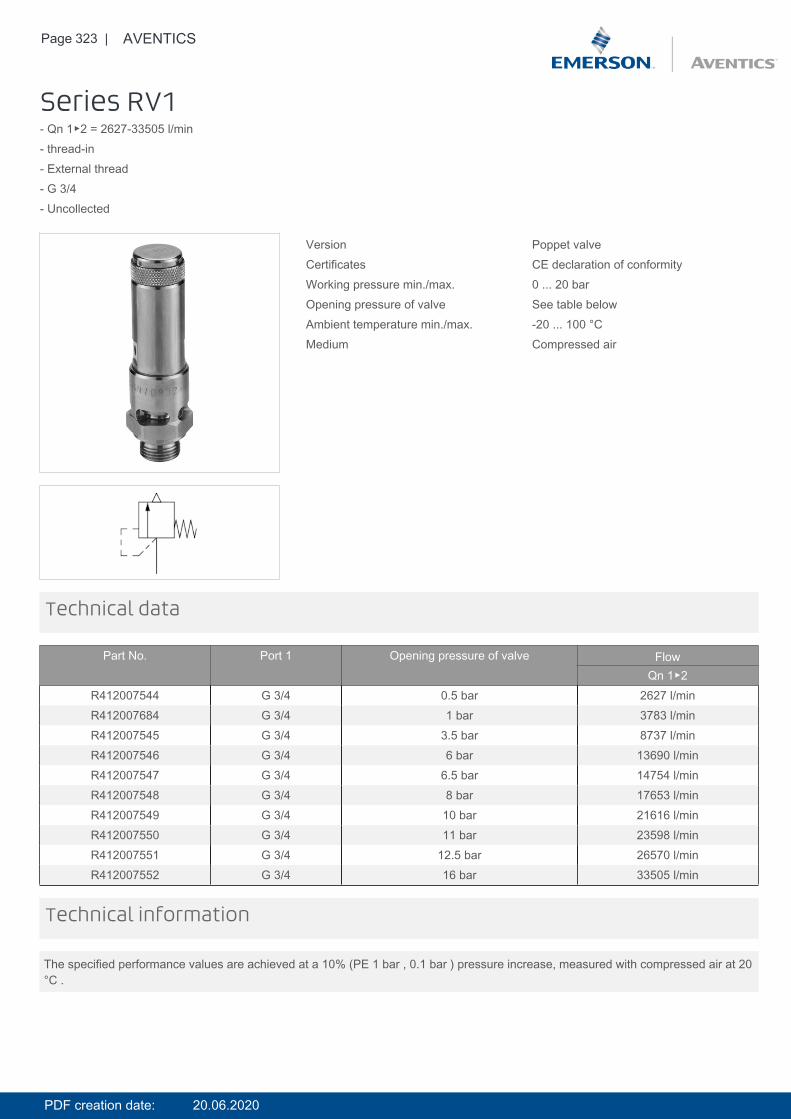
Page 323 | AVENTICS
Series RV1- Qn 1▶2 = 2627-33505 l/min- thread-in- External thread- G 3/4- Uncollected
Version Poppet valveCertificates CE declaration of conformityWorking pressure min./max. 0 ... 20 barOpening pressure of valve See table belowAmbient temperature min./max. -20 ... 100 °CMedium Compressed air
Technical data
Part No. Port 1 Opening pressure of valve FlowQn 1▶2
R412007544 G 3/4 0.5 bar 2627 l/minR412007684 G 3/4 1 bar 3783 l/minR412007545 G 3/4 3.5 bar 8737 l/minR412007546 G 3/4 6 bar 13690 l/minR412007547 G 3/4 6.5 bar 14754 l/minR412007548 G 3/4 8 bar 17653 l/minR412007549 G 3/4 10 bar 21616 l/minR412007550 G 3/4 11 bar 23598 l/minR412007551 G 3/4 12.5 bar 26570 l/minR412007552 G 3/4 16 bar 33505 l/min
The specified performance values are achieved at a 10% (PE 1 bar , 0.1 bar ) pressure increase, measured with compressed air at 20°C .
Technical information
PDF creation date: 20.06.2020
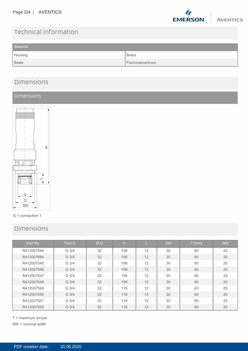
Page 324 | AVENTICS
Technical information
Material
Housing Brass
Seals Fluorocaoutchouc
Dimensions
Dimensions
G = connection 1
Dimensions
Part No. Port G Ø D H L SW T [Nm] NW
R412007544 G 3/4 32 106 12 30 60 20R412007684 G 3/4 32 106 12 30 60 20R412007545 G 3/4 32 106 12 30 60 20R412007546 G 3/4 32 106 12 30 60 20R412007547 G 3/4 32 106 12 30 60 20R412007548 G 3/4 32 106 12 30 60 20R412007549 G 3/4 32 116 12 30 60 20R412007550 G 3/4 32 116 12 30 60 20R412007551 G 3/4 32 116 12 30 60 20R412007552 G 3/4 32 116 12 30 60 20
T = maximum torqueNW = nominal width
PDF creation date: 20.06.2020
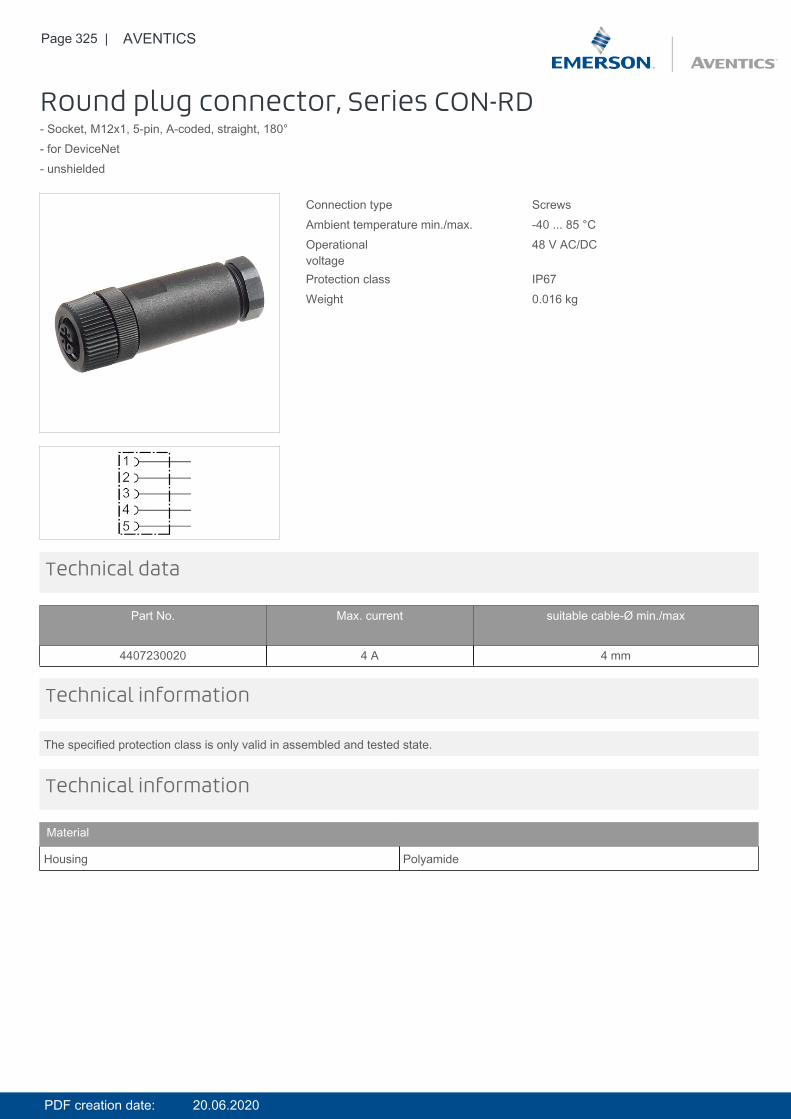
Page 325 | AVENTICS
Round plug connector, Series CON-RD- Socket, M12x1, 5-pin, A-coded, straight, 180°- for DeviceNet- unshielded
Connection type ScrewsAmbient temperature min./max. -40 ... 85 °COperationalvoltage
48 V AC/DC
Protection class IP67Weight 0.016 kg
Technical data
Part No. Max. current suitable cable-Ø min./max
4407230020 4 A 4 mm
The specified protection class is only valid in assembled and tested state.
Technical information
Technical information
Material
Housing Polyamide
PDF creation date: 20.06.2020
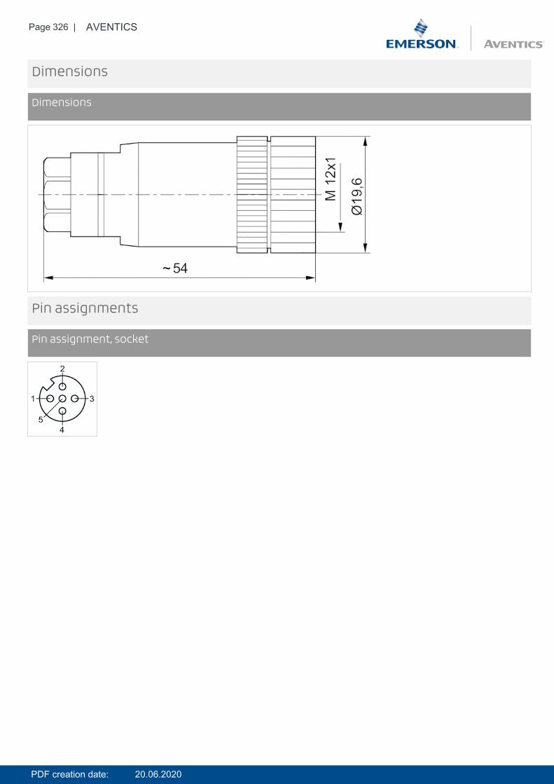
Page 326 | AVENTICS
Dimensions
Dimensions
Pin assignments
Pin assignment, socket
PDF creation date: 20.06.2020

Page 327 | AVENTICS
Round plug connector, Series CON-RD- Socket, M12x1, 5-pin, A-coded, angled, 90°- for CANopen- UL (Underwriters Laboratories)- shielded
Connection type ScrewsAmbient temperature min./max. -40 ... 85 °COperationalvoltage
48 V AC/DC
Protection class IP67Weight 0.072 kg
Technical data
Part No. Max. current suitable cable-Ø min./max
1824484029 4 A 6 / 8 mm
The specified protection class is only valid in assembled and tested state.
Technical information
Technical information
Material
Housing Die cast zinc
PDF creation date: 20.06.2020

Page 328 | AVENTICS
Dimensions
Dimensions
Pin assignments
Pin assignment, socket
PDF creation date: 20.06.2020
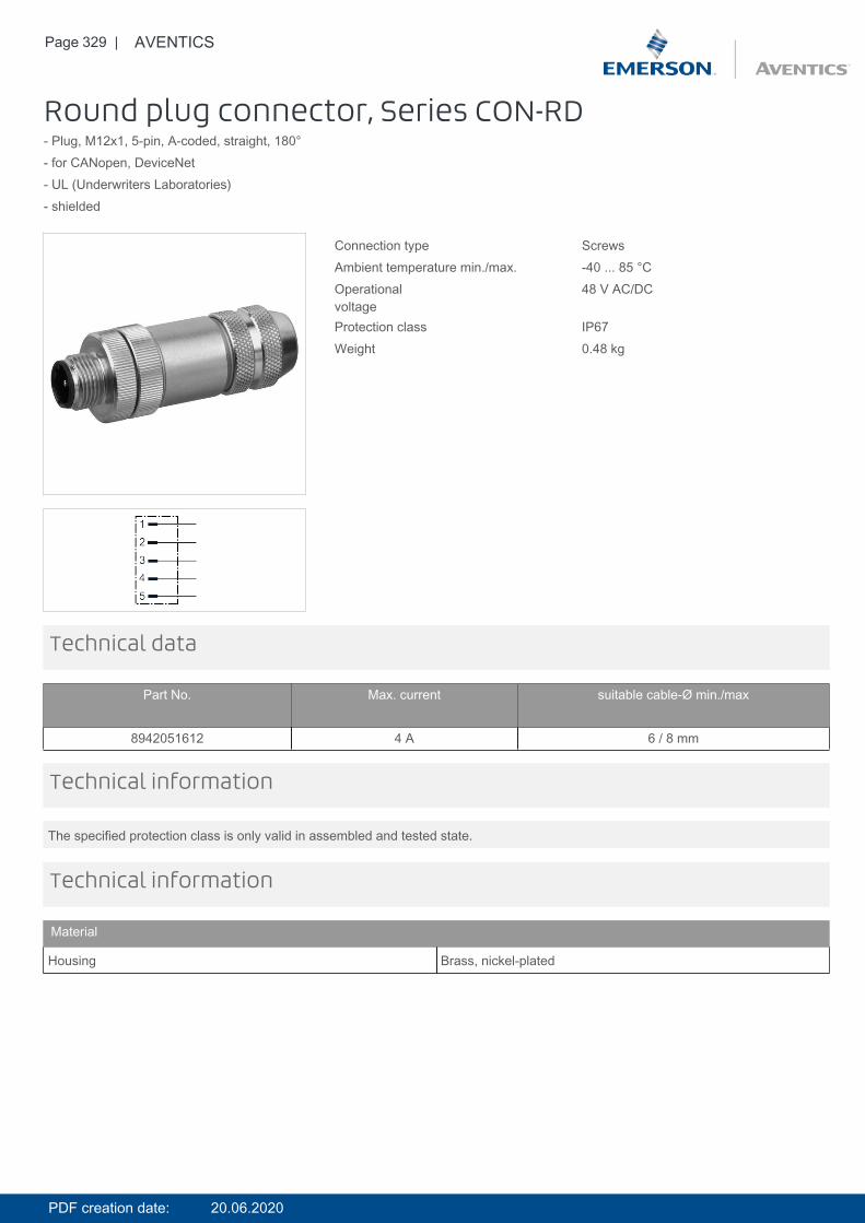
Page 329 | AVENTICS
Round plug connector, Series CON-RD- Plug, M12x1, 5-pin, A-coded, straight, 180°- for CANopen, DeviceNet- UL (Underwriters Laboratories)- shielded
Connection type ScrewsAmbient temperature min./max. -40 ... 85 °COperationalvoltage
48 V AC/DC
Protection class IP67Weight 0.48 kg
Technical data
Part No. Max. current suitable cable-Ø min./max
8942051612 4 A 6 / 8 mm
The specified protection class is only valid in assembled and tested state.
Technical information
Technical information
Material
Housing Brass, nickel-plated
PDF creation date: 20.06.2020
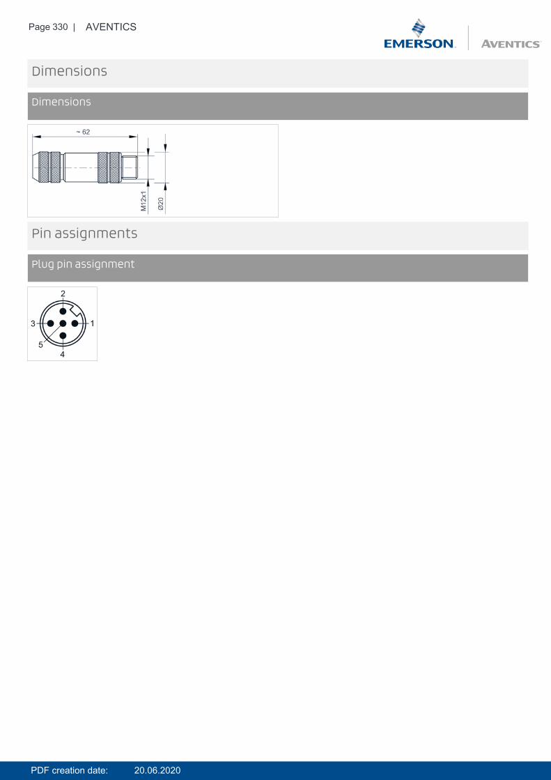
Page 330 | AVENTICS
Dimensions
Dimensions
Pin assignments
Plug pin assignment
PDF creation date: 20.06.2020
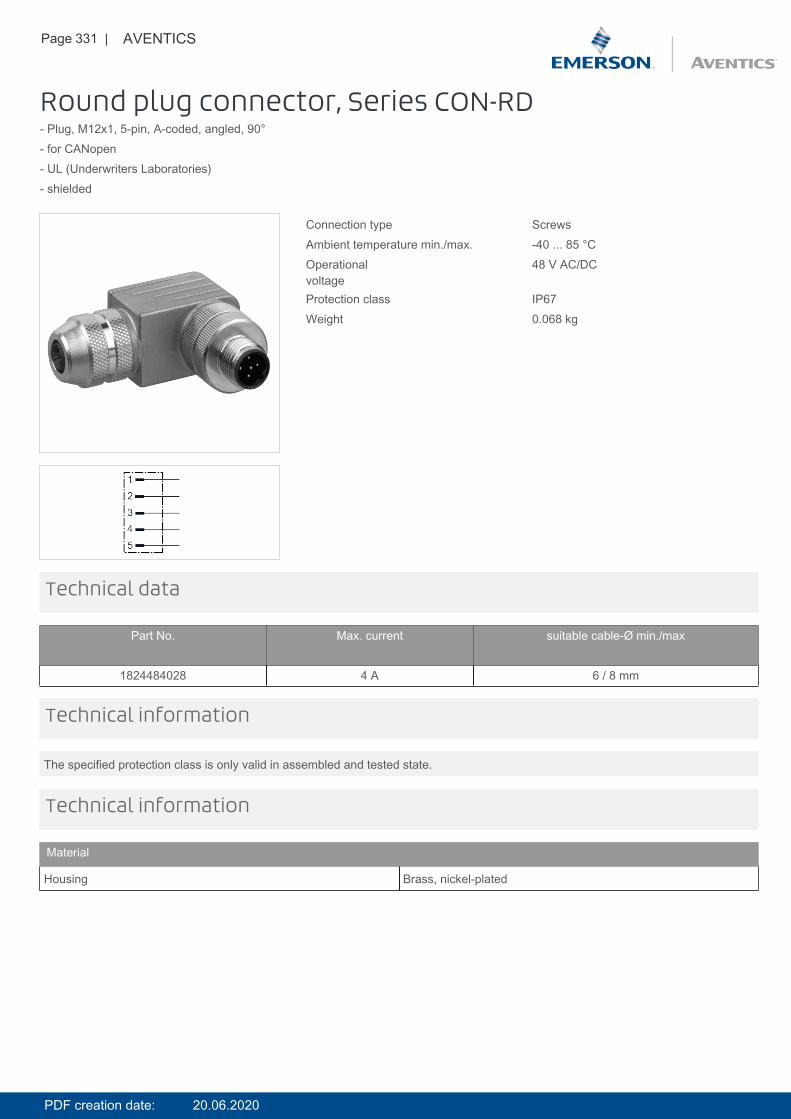
Page 331 | AVENTICS
Round plug connector, Series CON-RD- Plug, M12x1, 5-pin, A-coded, angled, 90°- for CANopen- UL (Underwriters Laboratories)- shielded
Connection type ScrewsAmbient temperature min./max. -40 ... 85 °COperationalvoltage
48 V AC/DC
Protection class IP67Weight 0.068 kg
Technical data
Part No. Max. current suitable cable-Ø min./max
1824484028 4 A 6 / 8 mm
The specified protection class is only valid in assembled and tested state.
Technical information
Technical information
Material
Housing Brass, nickel-plated
PDF creation date: 20.06.2020
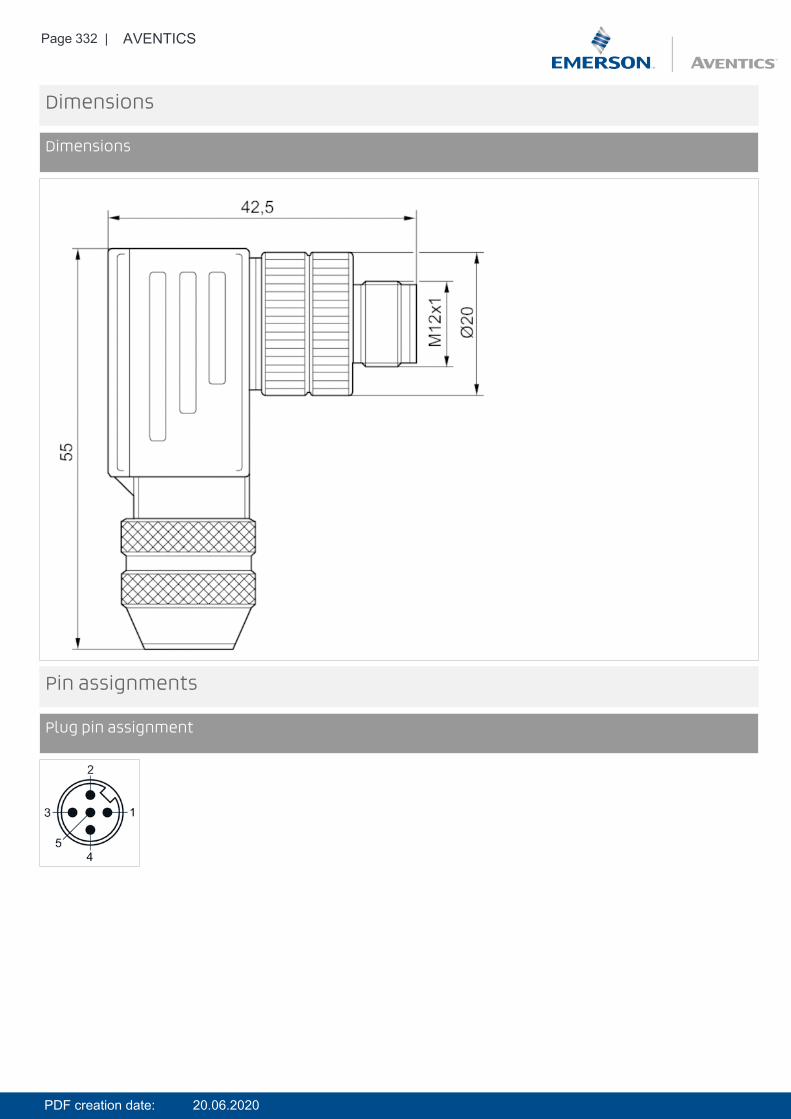
Page 332 | AVENTICS
Dimensions
Dimensions
Pin assignments
Plug pin assignment
PDF creation date: 20.06.2020
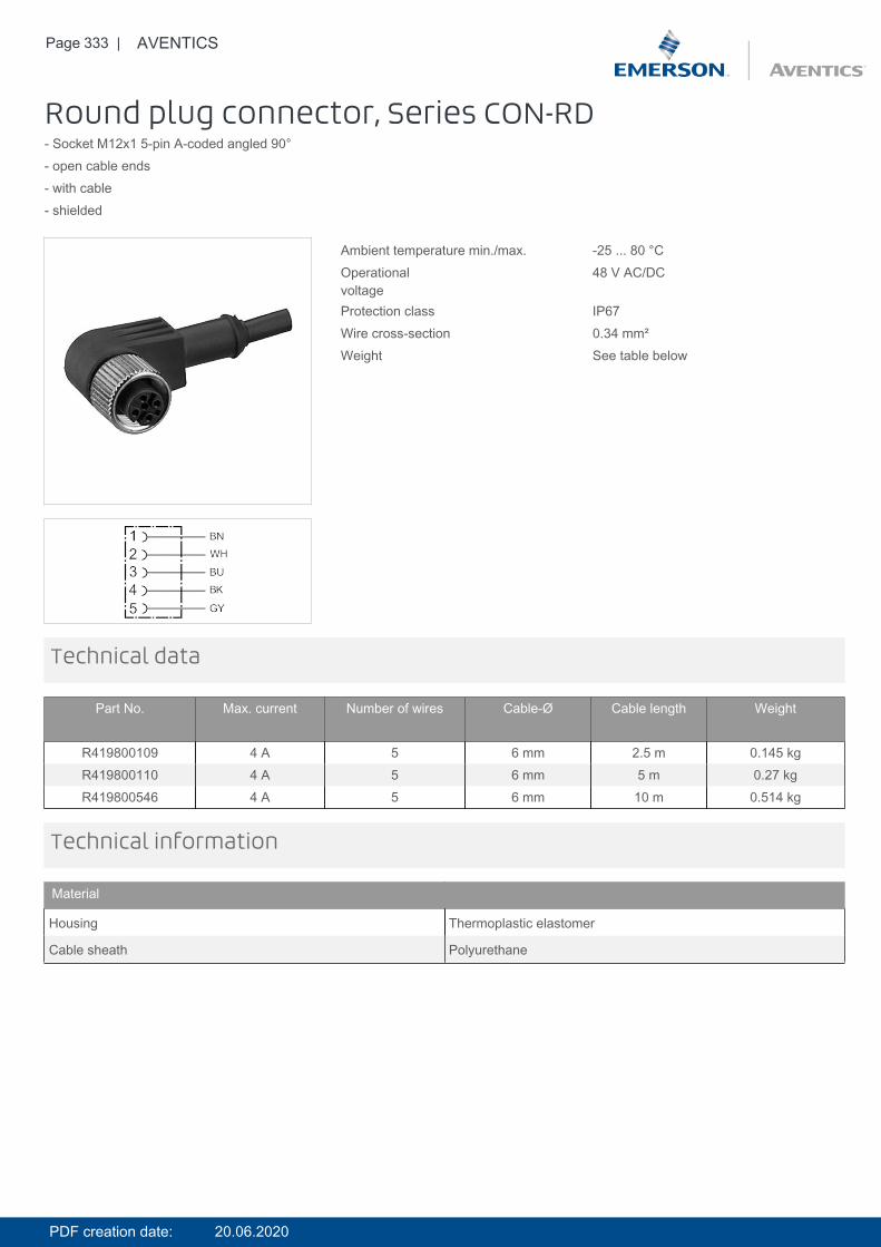
Page 333 | AVENTICS
Round plug connector, Series CON-RD- Socket M12x1 5-pin A-coded angled 90°- open cable ends- with cable- shielded
Ambient temperature min./max. -25 ... 80 °COperationalvoltage
48 V AC/DC
Protection class IP67Wire cross-section 0.34 mm²Weight See table below
Technical data
Part No. Max. current Number of wires Cable-Ø Cable length Weight
R419800109 4 A 5 6 mm 2.5 m 0.145 kgR419800110 4 A 5 6 mm 5 m 0.27 kgR419800546 4 A 5 6 mm 10 m 0.514 kg
Technical information
Material
Housing Thermoplastic elastomer
Cable sheath Polyurethane
PDF creation date: 20.06.2020

Page 334 | AVENTICS
Dimensions
Dimensions
L = length
Pin assignments
Pin assignment, socket
(1) BN=brown(2) WH=white3) BU=blue(4) BK=black(5) GY=grey
PDF creation date: 20.06.2020
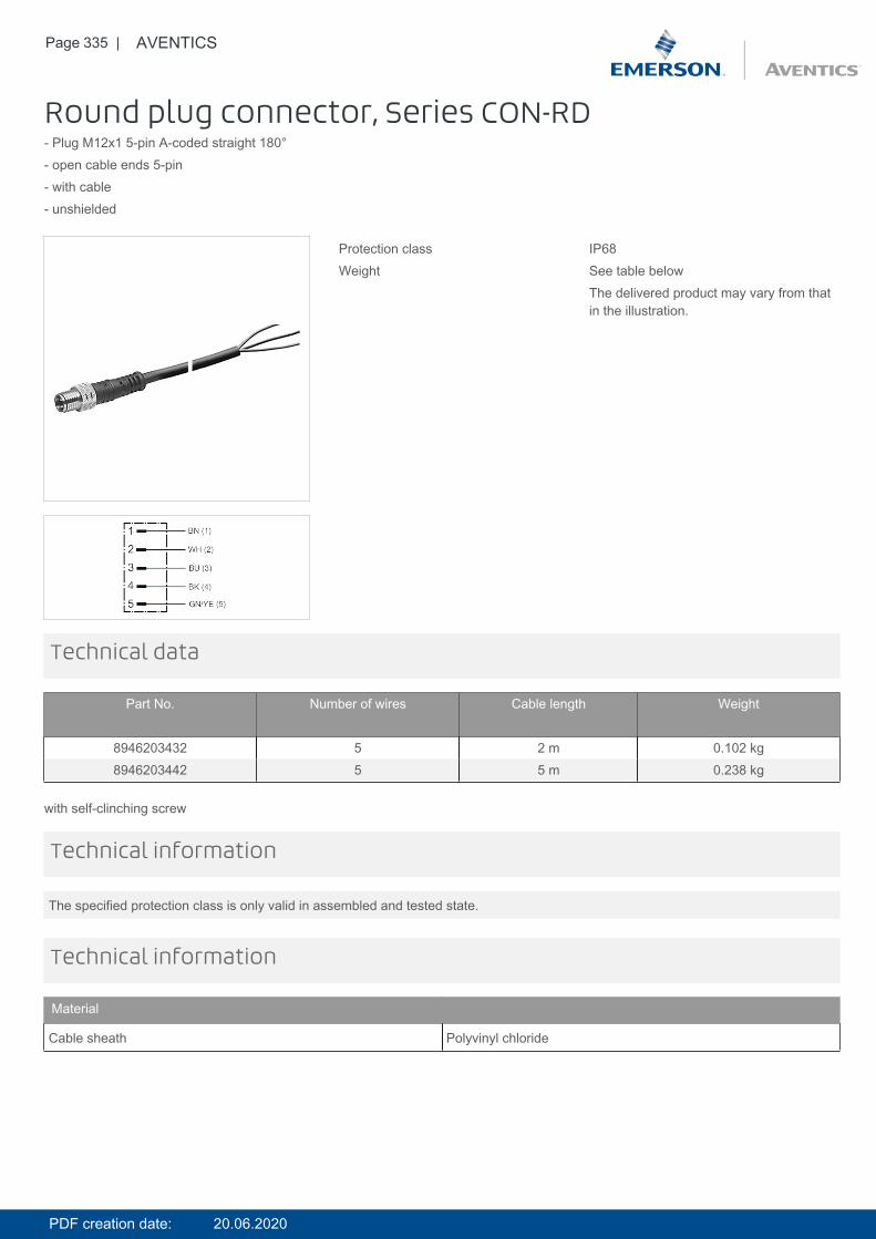
Page 335 | AVENTICS
Round plug connector, Series CON-RD- Plug M12x1 5-pin A-coded straight 180°- open cable ends 5-pin- with cable- unshielded
Protection class IP68Weight See table below
The delivered product may vary from thatin the illustration.
Technical data
Part No. Number of wires Cable length Weight
8946203432 5 2 m 0.102 kg8946203442 5 5 m 0.238 kg
with self-clinching screw
The specified protection class is only valid in assembled and tested state.
Technical information
Technical information
Material
Cable sheath Polyvinyl chloride
PDF creation date: 20.06.2020
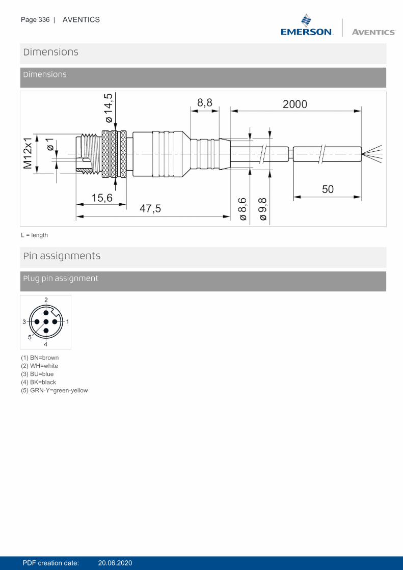
Page 336 | AVENTICS
Dimensions
Dimensions
L = length
Pin assignments
Plug pin assignment
(1) BN=brown(2) WH=white(3) BU=blue(4) BK=black(5) GRN-Y=green-yellow
PDF creation date: 20.06.2020
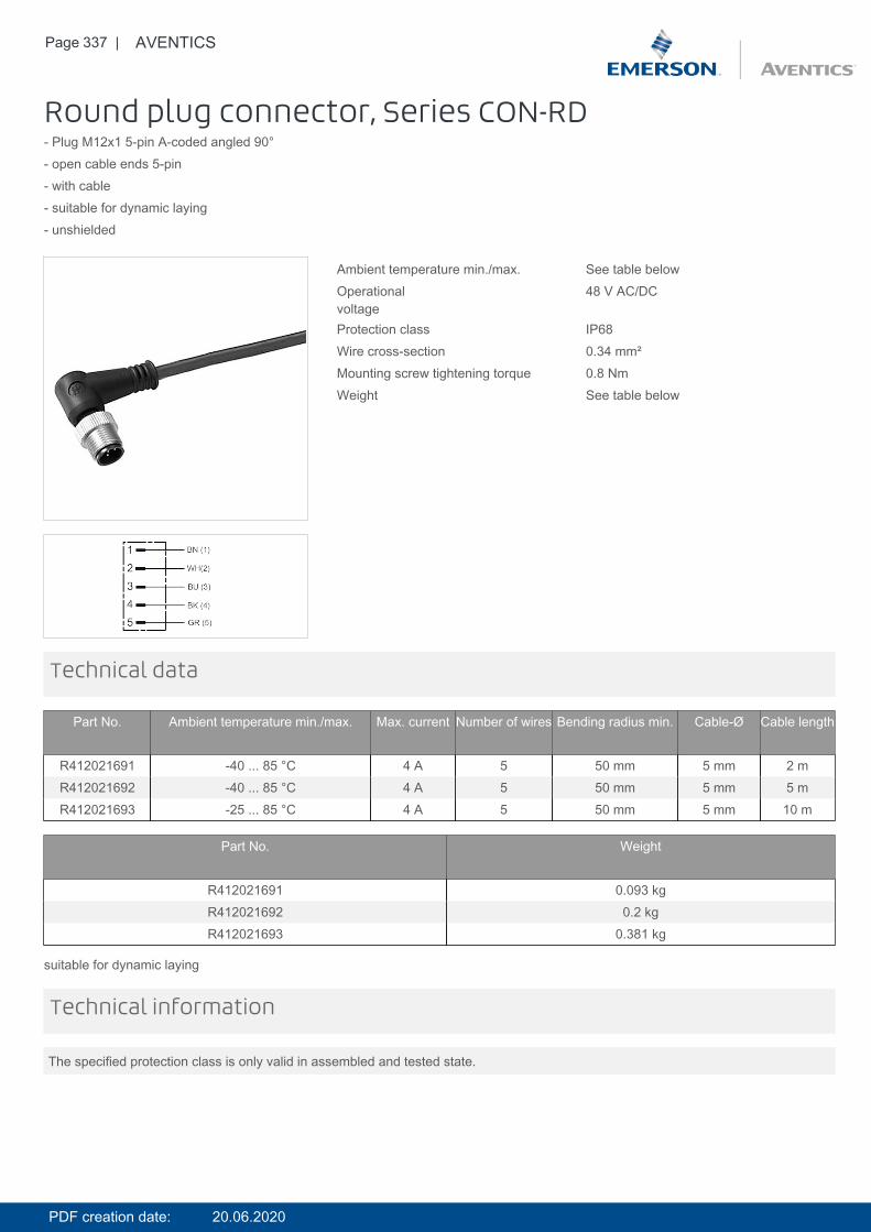
Page 337 | AVENTICS
Round plug connector, Series CON-RD- Plug M12x1 5-pin A-coded angled 90°- open cable ends 5-pin- with cable- suitable for dynamic laying- unshielded
Ambient temperature min./max. See table belowOperationalvoltage
48 V AC/DC
Protection class IP68Wire cross-section 0.34 mm²Mounting screw tightening torque 0.8 NmWeight See table below
Technical data
Part No. Ambient temperature min./max. Max. current Number of wires Bending radius min. Cable-Ø Cable length
R412021691 -40 ... 85 °C 4 A 5 50 mm 5 mm 2 mR412021692 -40 ... 85 °C 4 A 5 50 mm 5 mm 5 mR412021693 -25 ... 85 °C 4 A 5 50 mm 5 mm 10 m
Part No. Weight
R412021691 0.093 kgR412021692 0.2 kgR412021693 0.381 kg
suitable for dynamic laying
The specified protection class is only valid in assembled and tested state.
Technical information
PDF creation date: 20.06.2020
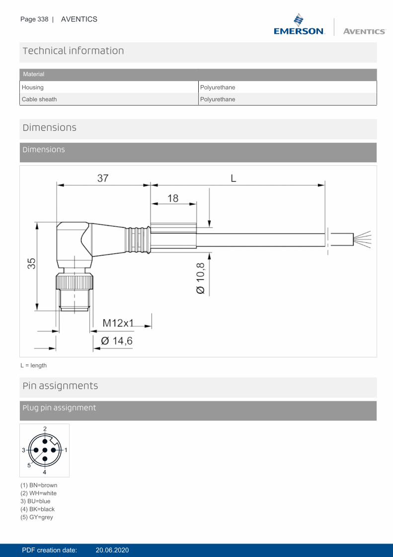
Page 338 | AVENTICS
Technical information
Material
Housing Polyurethane
Cable sheath Polyurethane
Dimensions
Dimensions
L = length
Pin assignments
Plug pin assignment
(1) BN=brown(2) WH=white3) BU=blue(4) BK=black(5) GY=grey
PDF creation date: 20.06.2020
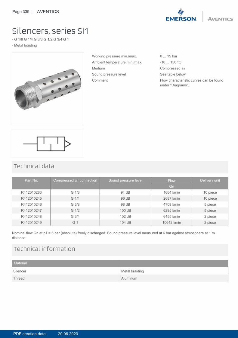
Page 339 | AVENTICS
Silencers, series SI1- G 1/8 G 1/4 G 3/8 G 1/2 G 3/4 G 1- Metal braiding
Working pressure min./max. 0 ... 15 barAmbient temperature min./max. -10 ... 150 °CMedium Compressed airSound pressure level See table belowComment Flow characteristic curves can be found
under “Diagrams”.
Technical data
Part No. Compressed air connection Sound pressure level Flow Delivery unitQn
R412010283 G 1/8 94 dB 1664 l/min 10 pieceR412010245 G 1/4 96 dB 2687 l/min 10 pieceR412010246 G 3/8 98 dB 4709 l/min 5 pieceR412010247 G 1/2 100 dB 6285 l/min 5 pieceR412010248 G 3/4 102 dB 6455 l/min 2 pieceR412010249 G 1 104 dB 10642 l/min 2 piece
Nominal flow Qn at p1 = 6 bar (absolute) freely discharged. Sound pressure level measured at 6 bar against atmosphere at 1 mdistance.
Technical information
Material
Silencer Metal braiding
Thread Aluminum
PDF creation date: 20.06.2020
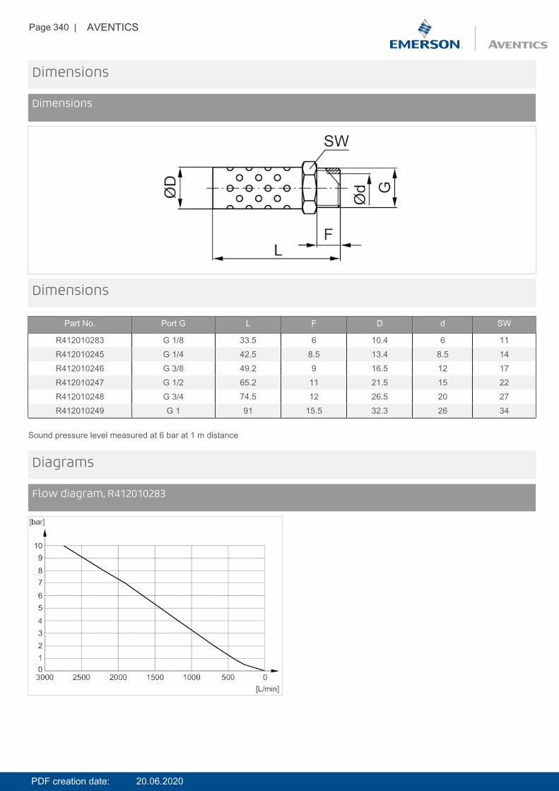
Page 340 | AVENTICS
Dimensions
Dimensions
Dimensions
Part No. Port G L F D d SW
R412010283 G 1/8 33.5 6 10.4 6 11R412010245 G 1/4 42.5 8.5 13.4 8.5 14R412010246 G 3/8 49.2 9 16.5 12 17R412010247 G 1/2 65.2 11 21.5 15 22R412010248 G 3/4 74.5 12 26.5 20 27R412010249 G 1 91 15.5 32.3 26 34
Sound pressure level measured at 6 bar at 1 m distance
Diagrams
Flow diagram, R412010283
PDF creation date: 20.06.2020
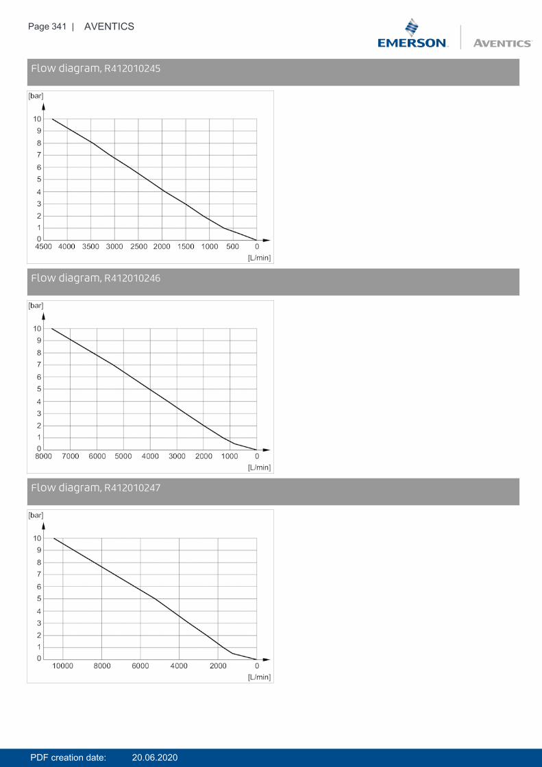
Page 341 | AVENTICS
DiagramsFlow diagram, R412010245
DiagramsFlow diagram, R412010246
DiagramsFlow diagram, R412010247
PDF creation date: 20.06.2020
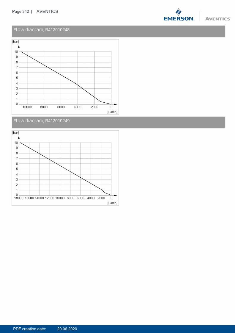
Page 342 | AVENTICS
DiagramsFlow diagram, R412010248
DiagramsFlow diagram, R412010249
PDF creation date: 20.06.2020

Page 343 | AVENTICS
Round plug connector, Series CON-RD- Socket M12x1 5-pin A-coded angled 90°- open cable ends- with cable- shielded
Ambient temperature min./max. -25 ... 80 °COperationalvoltage
48 V AC/DC
Protection class IP67Wire cross-section 0.34 mm²Weight See table below
Technical data
Part No. Max. current Number of wires Cable-Ø Cable length Weight
R419800109 4 A 5 6 mm 2.5 m 0.145 kgR419800110 4 A 5 6 mm 5 m 0.27 kgR419800546 4 A 5 6 mm 10 m 0.514 kg
Technical information
Material
Housing Thermoplastic elastomer
Cable sheath Polyurethane
PDF creation date: 20.06.2020
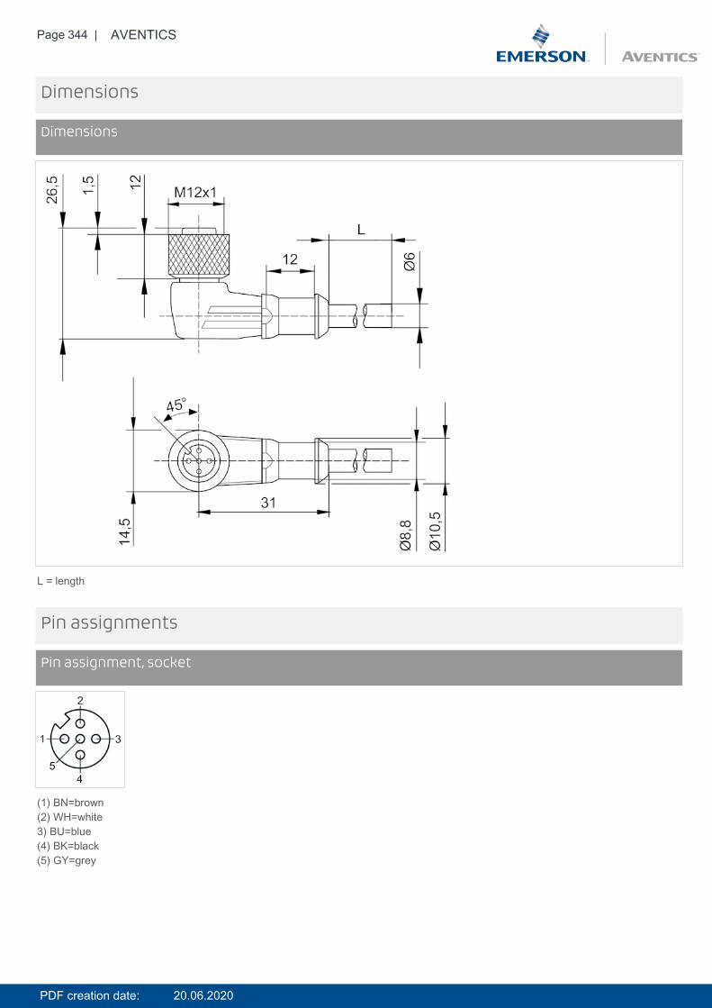
Page 344 | AVENTICS
Dimensions
Dimensions
L = length
Pin assignments
Pin assignment, socket
(1) BN=brown(2) WH=white3) BU=blue(4) BK=black(5) GY=grey
PDF creation date: 20.06.2020
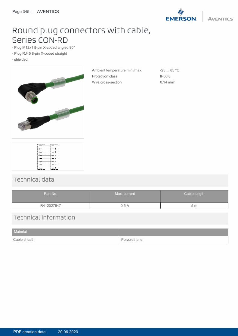
Page 345 | AVENTICS
Round plug connectors with cable,Series CON-RD- Plug M12x1 8-pin X-coded angled 90°- Plug RJ45 8-pin X-coded straight- shielded
Ambient temperature min./max. -25 ... 85 °CProtection class IP66KWire cross-section 0.14 mm²
Technical data
Part No. Max. current Cable length
R412027647 0.5 A 5 m
Technical information
Material
Cable sheath Polyurethane
PDF creation date: 20.06.2020
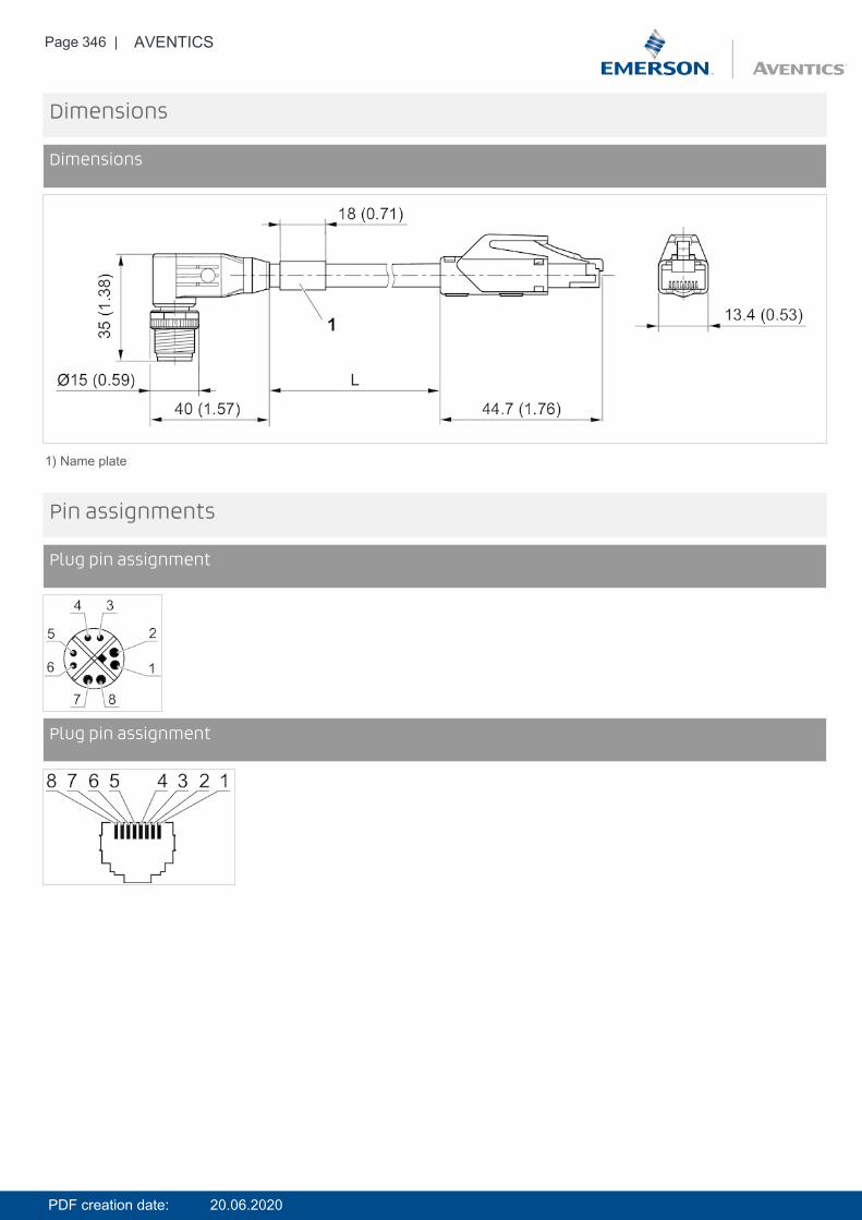
Page 346 | AVENTICS
Dimensions
Dimensions
1) Name plate
Pin assignments
Plug pin assignment
Pin assignmentsPlug pin assignment
PDF creation date: 20.06.2020

Page 347 | AVENTICS
Round plug connector, Series CON-RD- Socket M12x1 5-pin A-coded angled 90°- open cable ends- with cable- shielded
Ambient temperature min./max. -25 ... 80 °COperationalvoltage
48 V AC/DC
Protection class IP67Wire cross-section 0.34 mm²Weight See table below
Technical data
Part No. Max. current Number of wires Cable-Ø Cable length Weight
R419800109 4 A 5 6 mm 2.5 m 0.145 kgR419800110 4 A 5 6 mm 5 m 0.27 kgR419800546 4 A 5 6 mm 10 m 0.514 kg
Technical information
Material
Housing Thermoplastic elastomer
Cable sheath Polyurethane
PDF creation date: 20.06.2020

Page 348 | AVENTICS
Dimensions
Dimensions
L = length
Pin assignments
Pin assignment, socket
(1) BN=brown(2) WH=white3) BU=blue(4) BK=black(5) GY=grey
PDF creation date: 20.06.2020
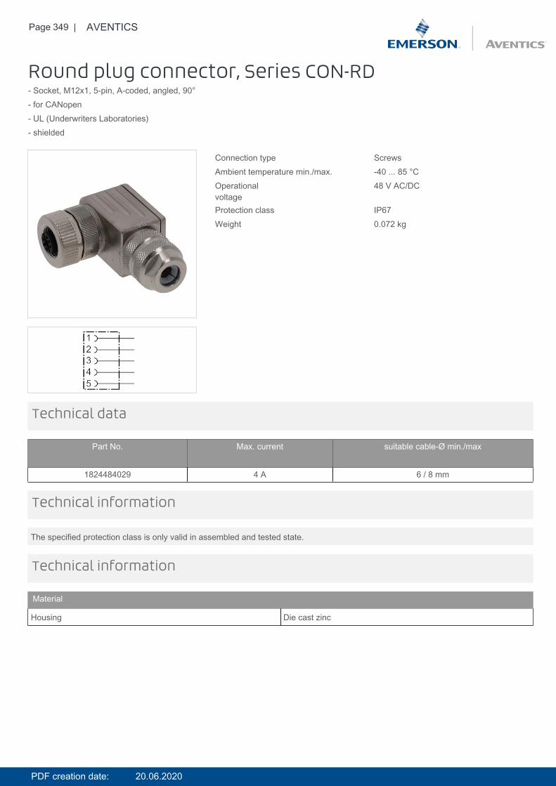
Page 349 | AVENTICS
Round plug connector, Series CON-RD- Socket, M12x1, 5-pin, A-coded, angled, 90°- for CANopen- UL (Underwriters Laboratories)- shielded
Connection type ScrewsAmbient temperature min./max. -40 ... 85 °COperationalvoltage
48 V AC/DC
Protection class IP67Weight 0.072 kg
Technical data
Part No. Max. current suitable cable-Ø min./max
1824484029 4 A 6 / 8 mm
The specified protection class is only valid in assembled and tested state.
Technical information
Technical information
Material
Housing Die cast zinc
PDF creation date: 20.06.2020
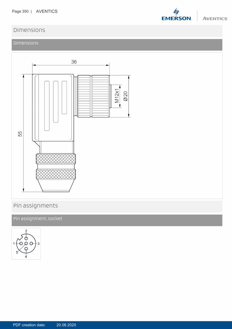
Page 350 | AVENTICS
Dimensions
Dimensions
Pin assignments
Pin assignment, socket
PDF creation date: 20.06.2020
Efficient pneumatic solutions, our program:cylinders and drives, valves and valve systems,air supply management
Visit us: Emerson.com/Aventics
Your local contact: Emerson.com/contactus
Emerson.com
Facebook.com/EmersonAutomationSolutions
LinkedIn.com/company/Emerson-Automation-Solutions
Twitter.com/EMR_Automation
An example configuration is depicted on the title page. The delivered product may thus vary from that in the illustration. Subject to change. ThisDocument, as well as the data, specifications and other information set forth in it, are the exclusive property of AVENTICS GmbH. It may not bereproduced or given to third parties without its consent. Only use the AVENTICS products shown in industrial applications. Read the productdocumentation completely and carefully before using the product. Observe the applicable regulations and laws of the respective country. Whenintegrating the product into applications, note the system manufacturer’s specifications for safe use of the product. The data specified only servetodescribe the product. No statements concerning a certain condition or suitability for a certain application can be derived from our information.The information given does not release the user from the obligation of own judgment and verification. It must be remembered that the products aresubject to a natural process of wear and aging.
The Emerson logo is a trademark and service mark of Emerson Electric Co. Brand logotype are registered trademarks of oneof the Emerson family of companies. All other marks are the property of their respective owners. © 2017 Emerson Electric Co.All rights reserved.2019-03