fm transmitter developer guide
TRANSCRIPT
FM Transmitter Developer Guide
1
Table of Contents Overview....……………………………….……………………………………… 2 Equipment…………………………....………………………………………….. 3 Parts…………………………………....………………………………………… 4 Block Diagram…………………………………………………………………… 6 Schematic…………………………………….………………………………….. 7 PCB…………………………………………….……………………………….... 8 Assembly…………………………………….…………………………………... 9 Testing………...………………………….………………………………….…. 10 Enclosure……………………………………………………………………….. 11 Summary………………………………....…………………………………….. 12
2
Introduction
A frequency modulation transmitter, better known as an FM transmitter, takes an
input, usually music, and transmits it to a receiver to be broadcasted. Think of a car
radio. The music station is playing music miles away from where the subject is, but the
car radio is able to play that same music at the same time due to FM frequencies. To
break it down further, first, a sine wave is produced that contains music or some kind of
sound. It is then transmitted by altering the frequency signals so that it matches a carrier
frequency. To do so, the signal goes through an amplification and an oscillator. The
carrier frequency is then picked up by a receiver, normally an antenna. Finally, the
sound being carried as a sine wave is broadcasted to whatever it is playing it from.
Building a simple FM transmitter is quite simple. Everything is documented in this guide
to build a simple FM transmitter. This FM transmitter will be able to transmit within the
FM range of 88MHz to 108MHz.
3
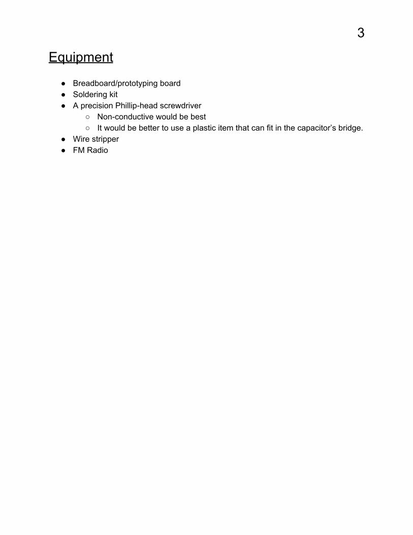
Equipment
● Breadboard/prototyping board ● Soldering kit ● A precision Phillip-head screwdriver
○ Non-conductive would be best ○ It would be better to use a plastic item that can fit in the capacitor’s bridge.
● Wire stripper ● FM Radio
4
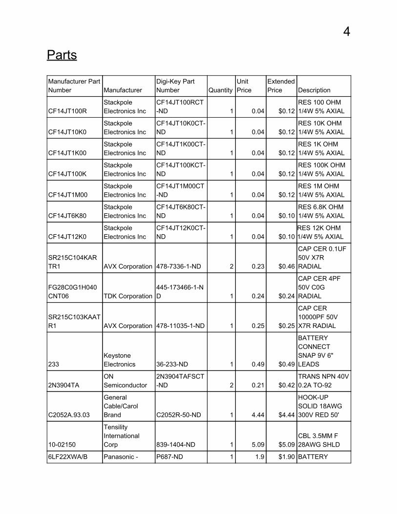
Parts Manufacturer Part Number Manufacturer
Digi-Key Part Number Quantity
Unit Price
Extended Price Description
CF14JT100R Stackpole Electronics Inc
CF14JT100RCT-ND 1 0.04 $0.12
RES 100 OHM 1/4W 5% AXIAL
CF14JT10K0 Stackpole Electronics Inc
CF14JT10K0CT-ND 1 0.04 $0.12
RES 10K OHM 1/4W 5% AXIAL
CF14JT1K00 Stackpole Electronics Inc
CF14JT1K00CT-ND 1 0.04 $0.12
RES 1K OHM 1/4W 5% AXIAL
CF14JT100K Stackpole Electronics Inc
CF14JT100KCT-ND 1 0.04 $0.12
RES 100K OHM 1/4W 5% AXIAL
CF14JT1M00 Stackpole Electronics Inc
CF14JT1M00CT-ND 1 0.04 $0.12
RES 1M OHM 1/4W 5% AXIAL
CF14JT6K80 Stackpole Electronics Inc
CF14JT6K80CT-ND 1 0.04 $0.10
RES 6.8K OHM 1/4W 5% AXIAL
CF14JT12K0 Stackpole Electronics Inc
CF14JT12K0CT-ND 1 0.04 $0.10
RES 12K OHM 1/4W 5% AXIAL
SR215C104KARTR1 AVX Corporation 478-7336-1-ND 2 0.23 $0.46
CAP CER 0.1UF 50V X7R RADIAL
FG28C0G1H040CNT06 TDK Corporation
445-173466-1-ND 1 0.24 $0.24
CAP CER 4PF 50V C0G RADIAL
SR215C103KAATR1 AVX Corporation 478-11035-1-ND 1 0.25 $0.25
CAP CER 10000PF 50V X7R RADIAL
233 Keystone Electronics 36-233-ND 1 0.49 $0.49
BATTERY CONNECT SNAP 9V 6" LEADS
2N3904TA ON Semiconductor
2N3904TAFSCT-ND 2 0.21 $0.42
TRANS NPN 40V 0.2A TO-92
C2052A.93.03
General Cable/Carol Brand C2052R-50-ND 1 4.44 $4.44
HOOK-UP SOLID 18AWG 300V RED 50'
10-02150
Tensility International Corp 839-1404-ND 1 5.09 $5.09
CBL 3.5MM F 28AWG SHLD
6LF22XWA/B Panasonic - P687-ND 1 1.9 $1.90 BATTERY
5
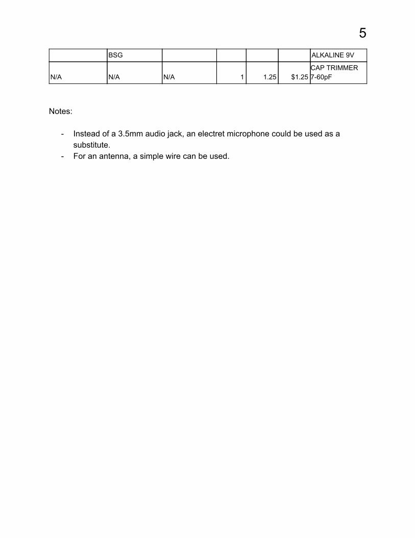
BSG ALKALINE 9V
N/A N/A N/A 1 1.25 $1.25 CAP TRIMMER 7-60pF
Notes:
- Instead of a 3.5mm audio jack, an electret microphone could be used as a substitute.
- For an antenna, a simple wire can be used.
6
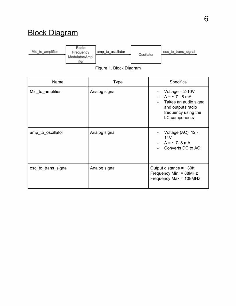
Block Diagram
Figure 1. Block Diagram
Name Type Specifics
Mic_to_amplifier Analog signal - Voltage = 2-10V - A = ~ 7 - 8 mA - Takes an audio signal
and outputs radio frequency using the LC components
amp_to_oscillator Analog signal - Voltage (AC): 12 - 14V
- A = ~ 7- 8 mA - Converts DC to AC
osc_to_trans_signal Analog signal Output distance = ~30ft Frequency Min. = 88MHz Frequency Max = 108MHz
7
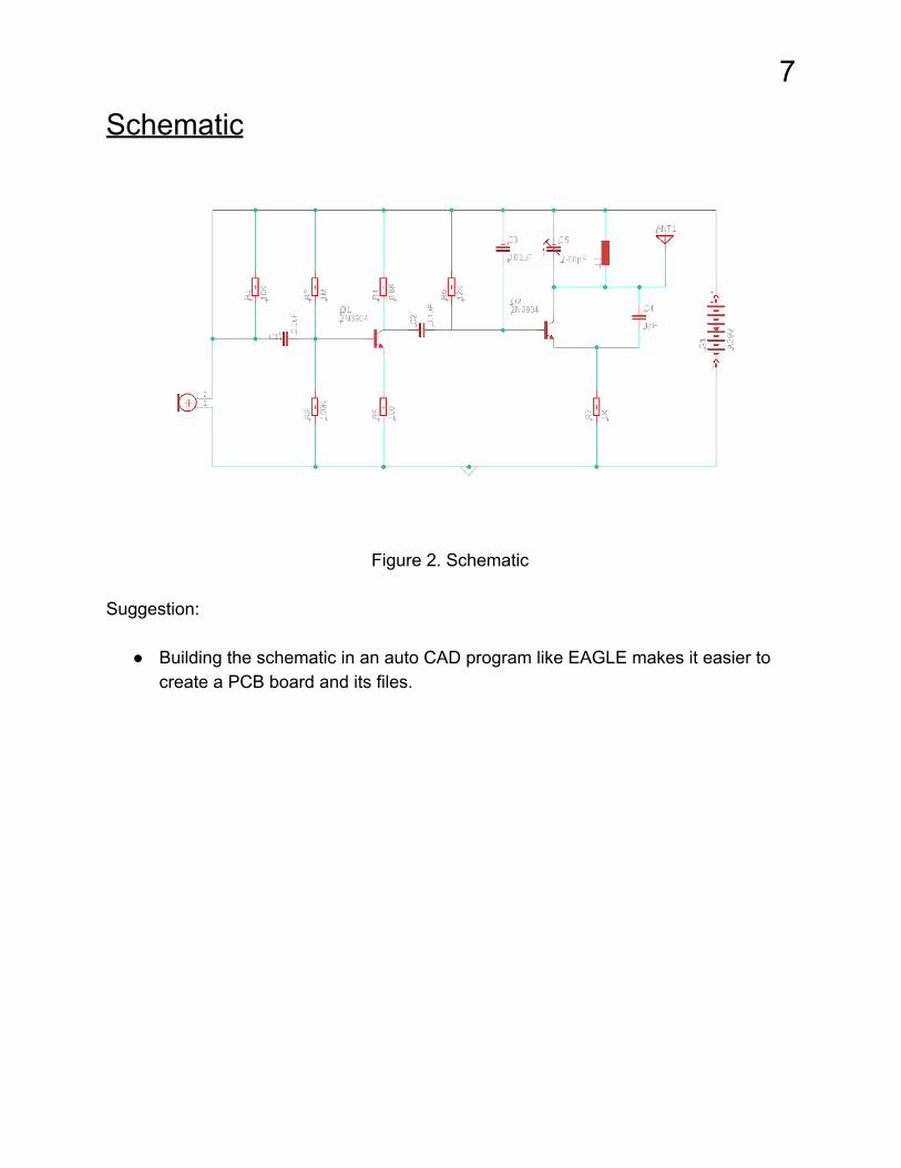
Schematic
Figure 2. Schematic
Suggestion:
● Building the schematic in an auto CAD program like EAGLE makes it easier to create a PCB board and its files.
8
PCB
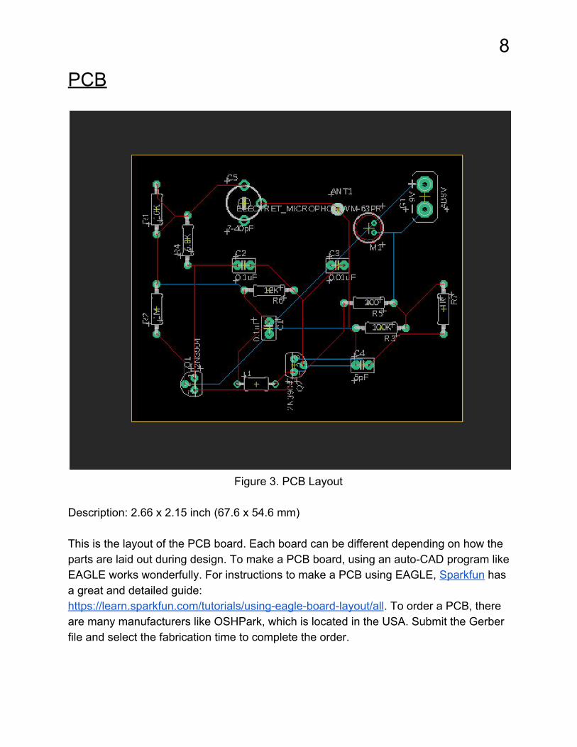
Figure 3. PCB Layout
Description: 2.66 x 2.15 inch (67.6 x 54.6 mm) This is the layout of the PCB board. Each board can be different depending on how the parts are laid out during design. To make a PCB board, using an auto-CAD program like EAGLE works wonderfully. For instructions to make a PCB using EAGLE, Sparkfun has a great and detailed guide: https://learn.sparkfun.com/tutorials/using-eagle-board-layout/all. To order a PCB, there are many manufacturers like OSHPark, which is located in the USA. Submit the Gerber file and select the fabrication time to complete the order.

9
Assembly
1. Start with a prototyping board like a breadboard. Making a prototype will allow for adjustments to be made before making a final product. Many of the resistors and capacitors in this project could be replaced with other values if the exact values cannot be found.
2. To create the coil, use a 18AWG wire. Strip about seven to eight inches of the wire. Make a ¼ inch diameter coil with about eight to nine turns. Using a pencil or a pen will suffice in making the coil. To adjust the number of turns or to use a different wire, this website is quite helpful: http://electronics-diy.com/calculators.php
3. Now that all the parts are ready to go, assemble the circuit using the schematic. 4. Test the circuit. The instructions for testing are on the next page. 5. If satisfied with what is being produced, continue onto making a PCB board.
Notes:
- Only two legs of the trimmer capacitor will be used, the stator and the rotor. Essentially, the middle leg and one of the side legs. The capacitor is not polarized, it doesn’t matter where each leg is connected.
- If using a female audio jack like the one listed in the parts, the left and right wires will have to be shorted together. Solder resistors to each of the wires and then connect the two of the same valued resistors on the other end to short it. The value of the resistors could range from 1k ohm to 47k ohm. The shorted end will be the part that connects to R1 and C1.
- If using an electret microphone, one of the legs will be grounded. Use a DMM to figure out which leg it is.
- The antenna should be at least seven inches. The longer the antenna, the transmission will be able to reach at a longer distance.
10
Testing
To test the FM transmitter, connect the audio source to the audio jack or start
playing music near the microphone. On the radio, tune to an empty station. Using the
precision Phillip head screwdriver, turn the trimmer capacitor slowly until the music can
be heard. This may take some time due to having to go through the whole range of
frequencies. Another way to test it would be to set the trimmer capacitor and tune the
radio until music can be heard. The only problem with this could be that the transmitter
could be set on a station that is occupied or could possibly be out of range.
The sound from the radio may not be the clearest, but the music should be
heard. There are a lot of factors that go into how clear the sound is coming from the
radio. The transmitter may be fighting with another station to get through the radio. The
antenna may not be consistent. There could be a lot of interference between the
transmitter and the radio. Using a regular precision Phillip head screwdriver can also
interfere with the frequencies. It is best to use a non-conductive screwdriver or
something plastic to turn the capacitor. Play around with the parts. The sound could
come out clearer or the signal could be stronger.
11
Enclosure
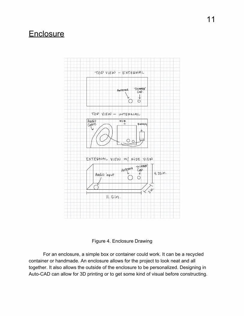
Figure 4. Enclosure Drawing
For an enclosure, a simple box or container could work. It can be a recycled
container or handmade. An enclosure allows for the project to look neat and all together. It also allows the outside of the enclosure to be personalized. Designing in Auto-CAD can allow for 3D printing or to get some kind of visual before constructing.

12
Summary
Overall, this is a great DIY project. It uses simple and basic parts. Many parts
could be recycled from other electronics. There could be adjustments to improve the
signal. The transmitter could be used in a number of ways. If using an electret
microphone, it could be used as a communication device for those who are near each
other, like a walkie talkie. Make two of these transmitters, get a radio for each person,
and it can be a fun time. The possibilities are endless. Happy tinkering!