overcurrent protection of feeder using numerical relay
TRANSCRIPT
© 2018, IJCSE All Rights Reserved 192
International Journal of Computer Sciences and Engineering Open Access
Research Paper Vol.-6, Issue-6, June 2018 E-ISSN: 2347-2693
Overcurrent Protection of Feeder Using Numerical Relay
A. Kamani
1*, J. Satapara
2, T. Patel
3
1 Dept. of Electrical Engineering, Indus Institute of Technology and Engineering, Indus University, Ahmedabad, India
2 Dept. of Electrical Engineering, Indus Institute of Technology and Engineering, Indus University, Ahmedabad, India
3 Dept. of Electrical Engineering, Indus Institute of Technology and Engineering, Indus University, Ahmedabad, India
*Corresponding Author: [email protected] Tel.: 8511527090
Available online at: www.ijcseonline.org
Accepted: 07/Jun/2018, Published: 30/Jun/2018
Abstract— Short circuits occur in power systems when equipment insulation fails, due to system overvoltages caused by
lightning or switching surges, to insulation contamination, or to other mechanical and natural causes. Careful design, operation,
and maintenance can minimize the occurrence of short circuits but cannot eliminate them. Such short-circuit currents (for
balanced and unbalanced faults) can be several orders of magnitude larger than normal operating currents and, if allowed to
persist, may cause insulation damage, conductor melting, fire, and explosion. Windings and busbars may also suffer
mechanical damage due to high magnetic forces during faults. Clearly, faults must be quickly removed from a power system.
Hence, proposed journal deals with removal of fault by sensing overcurrent element using Numerical Relay REF615, meant for
Feeder Protection. Along with Overcurrent Protection few more protection schemes such as CB Failure Protection and Trip
Circuit Supervision (TCS) are also described here. Moreover, Relay Status can also be detected i.e., whether healthy or
unhealthy. When we say that system has to be protected against fault, then it means to disconnect faulty part from healthy one
by opening CB of corresponding feeder section. In case of CB failure i.e., when Main CB (downstream CB) fails to operate,
Backup CB (upstream CB) must be operated after predefined time interval.
Keywords— Circuit Breaker, Fault, Feeder, IEC 61850, Network, Overcurrent, Protection, REF615, Relay, Substation.
I. INTRODUCTION
Protection systems have three basic components:
1. Instrument transformers
2. Relays
3. Circuit breakers
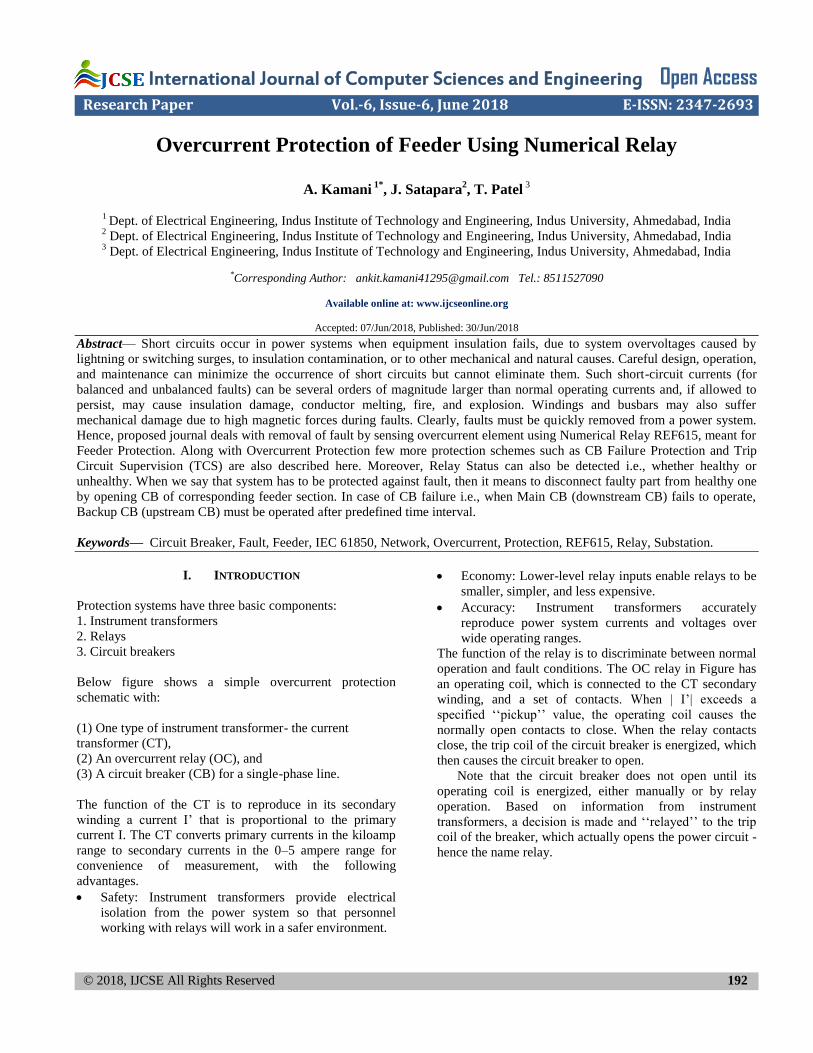
Below figure shows a simple overcurrent protection
schematic with:
(1) One type of instrument transformer- the current
transformer (CT),
(2) An overcurrent relay (OC), and
(3) A circuit breaker (CB) for a single-phase line.
The function of the CT is to reproduce in its secondary
winding a current I‘ that is proportional to the primary
current I. The CT converts primary currents in the kiloamp
range to secondary currents in the 0–5 ampere range for
convenience of measurement, with the following
advantages.
Safety: Instrument transformers provide electrical
isolation from the power system so that personnel
working with relays will work in a safer environment.
Economy: Lower-level relay inputs enable relays to be
smaller, simpler, and less expensive.
Accuracy: Instrument transformers accurately
reproduce power system currents and voltages over
wide operating ranges.
The function of the relay is to discriminate between normal
operation and fault conditions. The OC relay in Figure has
an operating coil, which is connected to the CT secondary
winding, and a set of contacts. When | I‘| exceeds a
specified ‗‗pickup‘‘ value, the operating coil causes the
normally open contacts to close. When the relay contacts
close, the trip coil of the circuit breaker is energized, which
then causes the circuit breaker to open.
Note that the circuit breaker does not open until its
operating coil is energized, either manually or by relay
operation. Based on information from instrument
transformers, a decision is made and ‗‗relayed‘‘ to the trip
coil of the breaker, which actually opens the power circuit -
hence the name relay.
International Journal of Computer Sciences and Engineering Vol.6(6), Jun 2018, E-ISSN: 2347-2693
© 2018, IJCSE All Rights Reserved 193
Figure 1. Overcurrent Protection Schematics
In order to fulfil the requirement of protection with the
requirement of profitable operation, any protection system
is required to satisfy the 5-S principles listed below:
- Security
- Sensitivity
- Speed
- Selectivity
- Stability
II. RELAY TECHNOLOGY
In this section, the author describes the previous research
works in the form of title, problem statement, objectives,
not repeat the information discussed in Introduction. The
electromechanical relay in all of its different forms has
been replaced successively by static, digital and numerical
relays, each change bringing with it reductions in size and
improvements in functionality. Reliability levels have also
been maintained or even improved and availability
significantly increased due to techniques not available with
older relay types.
Electromechanical Relays: - These relays were the earliest
forms of relay used for protection of Power System. They
work on principle of mechanical force causing an operation
of relay.
Static Relays: - These relays don‘t have moving parts. The
design of static relays is based on the use of Analog
Electronics instead of coils and magnets to create relay
characteristics.
Digital Relays: - To implement the relay functions, Analog
Circuits used in static relays are replaced with
Microprocessors and Microcontrollers in digital relays.
Numerical Relays: - These relays can be viewed as
natural developments of digital relays as a result of
advances in technology. These relays use DSP processor as
a computational hardware, together with the associated
software tools.
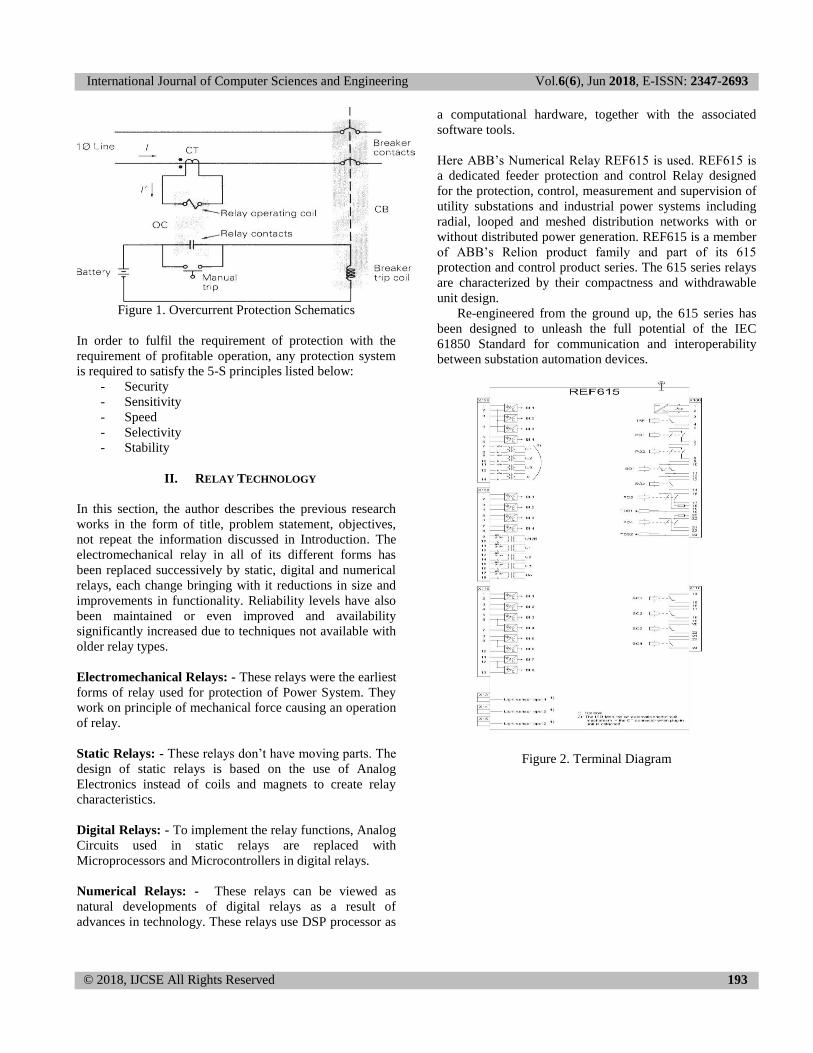
Here ABB‘s Numerical Relay REF615 is used. REF615 is
a dedicated feeder protection and control Relay designed
for the protection, control, measurement and supervision of
utility substations and industrial power systems including
radial, looped and meshed distribution networks with or
without distributed power generation. REF615 is a member
of ABB‘s Relion product family and part of its 615
protection and control product series. The 615 series relays
are characterized by their compactness and withdrawable
unit design.
Re-engineered from the ground up, the 615 series has
been designed to unleash the full potential of the IEC
61850 Standard for communication and interoperability
between substation automation devices.
Figure 2. Terminal Diagram
International Journal of Computer Sciences and Engineering Vol.6(6), Jun 2018, E-ISSN: 2347-2693
© 2018, IJCSE All Rights Reserved 194
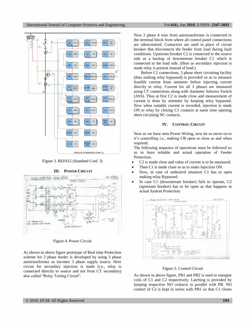
Figure 3. REF615 (Standard Conf. J)
III. POWER CIRCUIT
Figure 4. Power Circuit
As shown in above figure prototype of Real time Protection
scheme for 3 phase feeder is developed by using 3 phase
autotransformer as incomer 3 phase supply source. Here
circuit for secondary injection is made (i.e., relay is
connected directly to source and not from CT secondary)
also called ―Relay Testing Circuit‖.
Now 3 phase 4 wire from autotransformer is connected to
the terminal block from where all control panel connections
are taken/started. Contactors are used in place of circuit
breaker that disconnects the feeder from load during fault
conditions. Upstream breaker C2 is connected to the source
side as a backup of downstream breaker C1 which is
connected to the load side. (Here as secondary injection is
made relay is present instead of load.)
Before C1 connections, 3 phase short circuiting facility
(thus making relay bypassed) is provided so as to measure
feasible current from ammeter before injecting current
directly to relay. Current for all 3 phases are measured
using CT connections along with Ammeter Selector Switch
(ASS). Thus at first C2 is made close and measurement of
current is done by ammeter by keeping relay bypassed.
Now when suitable current is recorded, injection is made
ON to relay by closing C1 contacts at same time opening
short circuiting NC contacts.
IV. CONTROL CIRCUIT
Now as we have seen Power Wiring, now let us move on to
it‘s controlling i.e., making CB open or close as and when
required.
The following sequence of operations must be followed so
as to have reliable and actual operation of Feeder
Protection.
C2 is made close and value of current is to be measured.
Then C1 is made close so as to make Injection ON.
Now, in case of undesired situation C1 has to open
making relay Bypassed.
In case C1 (downstream breaker) fails to operate, C2
(upstream breaker) has to be open as that happens in
actual System Protection.
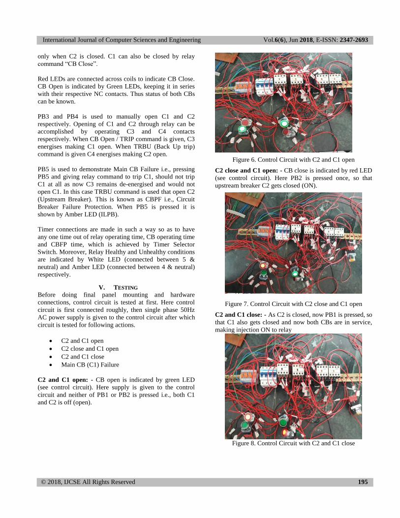
Figure 5. Control Circuit
As shown in above figure, PB1 and PB2 is used to energise
coils of C1 and C2 respectively. Latching is provided by
keeping respective NO contacts in parallel with PB. NO
contact of C2 is kept in series with PB1 so that C1 closes
International Journal of Computer Sciences and Engineering Vol.6(6), Jun 2018, E-ISSN: 2347-2693
© 2018, IJCSE All Rights Reserved 195
only when C2 is closed. C1 can also be closed by relay
command ―CB Close‖.
Red LEDs are connected across coils to indicate CB Close.
CB Open is indicated by Green LEDs, keeping it in series
with their respective NC contacts. Thus status of both CBs
can be known.
PB3 and PB4 is used to manually open C1 and C2
respectively. Opening of C1 and C2 through relay can be
accomplished by operating C3 and C4 contacts
respectively. When CB Open / TRIP command is given, C3
energises making C1 open. When TRBU (Back Up trip)
command is given C4 energises making C2 open.
PB5 is used to demonstrate Main CB Failure i.e., pressing
PB5 and giving relay command to trip C1, should not trip
C1 at all as now C3 remains de-energised and would not
open C1. In this case TRBU command is used that open C2
(Upstream Breaker). This is known as CBPF i.e., Circuit
Breaker Failure Protection. When PB5 is pressed it is
shown by Amber LED (ILPB).
Timer connections are made in such a way so as to have
any one time out of relay operating time, CB operating time
and CBFP time, which is achieved by Timer Selector
Switch. Moreover, Relay Healthy and Unhealthy conditions
are indicated by White LED (connected between 5 &
neutral) and Amber LED (connected between 4 & neutral)
respectively.
V. TESTING Before doing final panel mounting and hardware
connections, control circuit is tested at first. Here control
circuit is first connected roughly, then single phase 50Hz
AC power supply is given to the control circuit after which
circuit is tested for following actions.
C2 and C1 open
C2 close and C1 open
C2 and C1 close
Main CB (C1) Failure
C2 and C1 open: - CB open is indicated by green LED
(see control circuit). Here supply is given to the control
circuit and neither of PB1 or PB2 is pressed i.e., both C1
and C2 is off (open).
Figure 6. Control Circuit with C2 and C1 open
C2 close and C1 open: - CB close is indicated by red LED
(see control circuit). Here PB2 is pressed once, so that
upstream breaker C2 gets closed (ON).
Figure 7. Control Circuit with C2 close and C1 open
C2 and C1 close: - As C2 is closed, now PB1 is pressed, so
that C1 also gets closed and now both CBs are in service,
making injection ON to relay
Figure 8. Control Circuit with C2 and C1 close
International Journal of Computer Sciences and Engineering Vol.6(6), Jun 2018, E-ISSN: 2347-2693
© 2018, IJCSE All Rights Reserved 196
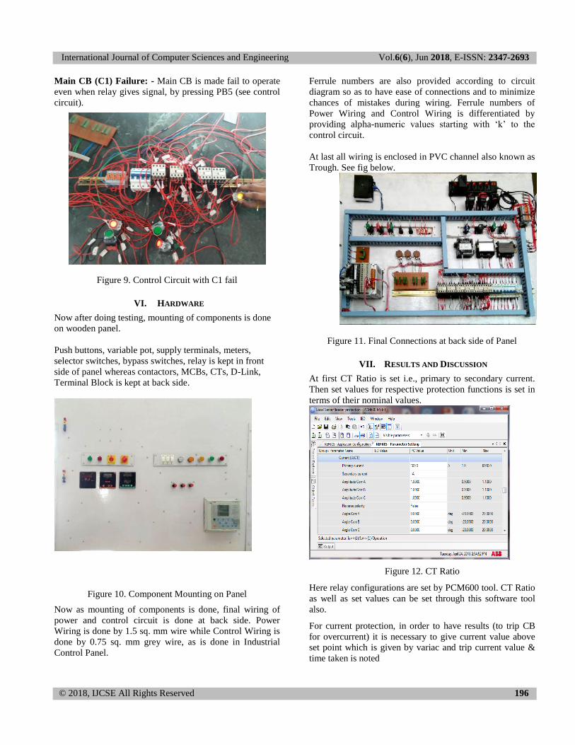
Main CB (C1) Failure: - Main CB is made fail to operate
even when relay gives signal, by pressing PB5 (see control
circuit).
Figure 9. Control Circuit with C1 fail
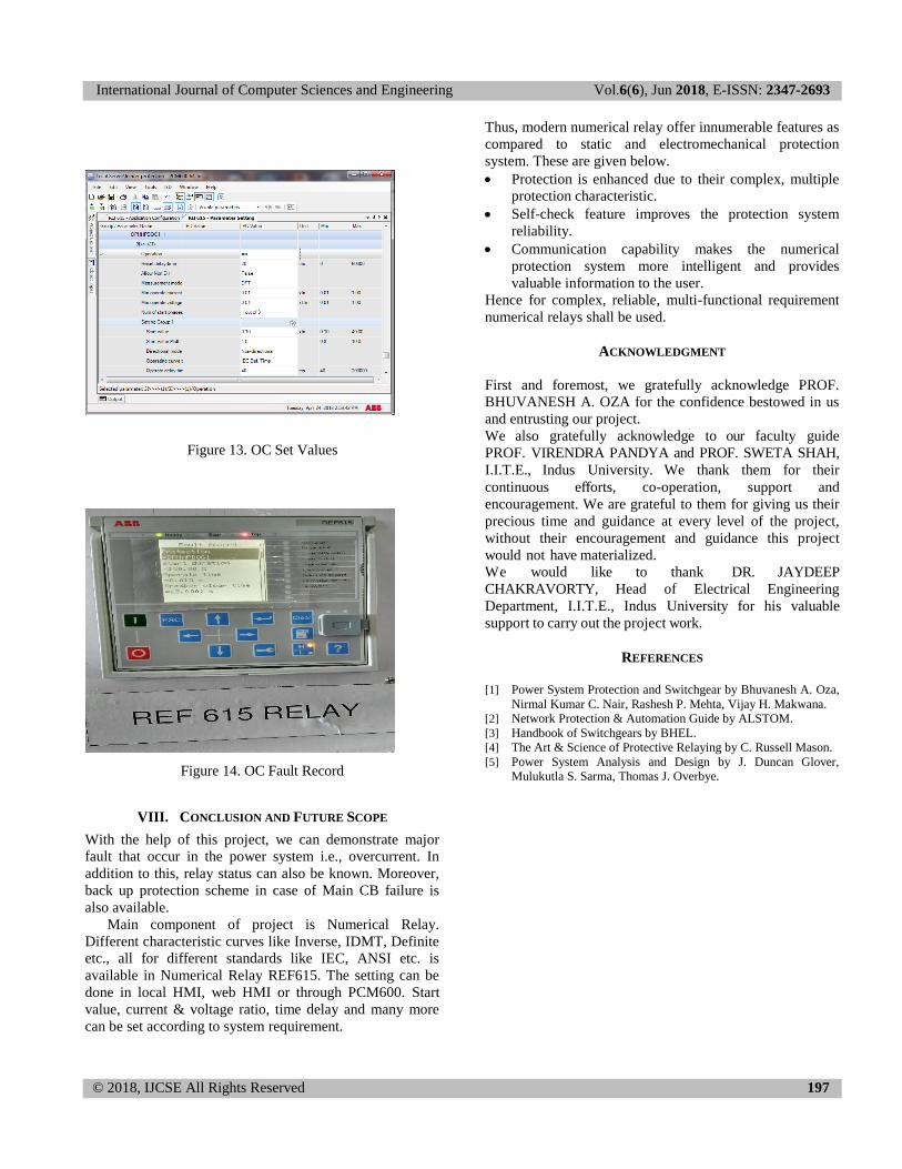
VI. HARDWARE
Now after doing testing, mounting of components is done
on wooden panel.
Push buttons, variable pot, supply terminals, meters,
selector switches, bypass switches, relay is kept in front
side of panel whereas contactors, MCBs, CTs, D-Link,
Terminal Block is kept at back side.
Figure 10. Component Mounting on Panel
Now as mounting of components is done, final wiring of
power and control circuit is done at back side. Power
Wiring is done by 1.5 sq. mm wire while Control Wiring is
done by 0.75 sq. mm grey wire, as is done in Industrial
Control Panel.
Ferrule numbers are also provided according to circuit
diagram so as to have ease of connections and to minimize
chances of mistakes during wiring. Ferrule numbers of
Power Wiring and Control Wiring is differentiated by
providing alpha-numeric values starting with ‗k‘ to the
control circuit.
At last all wiring is enclosed in PVC channel also known as
Trough. See fig below.
Figure 11. Final Connections at back side of Panel
VII. RESULTS AND DISCUSSION
At first CT Ratio is set i.e., primary to secondary current.
Then set values for respective protection functions is set in
terms of their nominal values.
Figure 12. CT Ratio
Here relay configurations are set by PCM600 tool. CT Ratio
as well as set values can be set through this software tool
also.
For current protection, in order to have results (to trip CB
for overcurrent) it is necessary to give current value above
set point which is given by variac and trip current value &
time taken is noted
International Journal of Computer Sciences and Engineering Vol.6(6), Jun 2018, E-ISSN: 2347-2693
© 2018, IJCSE All Rights Reserved 197
Figure 13. OC Set Values
Figure 14. OC Fault Record
VIII. CONCLUSION AND FUTURE SCOPE
With the help of this project, we can demonstrate major
fault that occur in the power system i.e., overcurrent. In
addition to this, relay status can also be known. Moreover,
back up protection scheme in case of Main CB failure is
also available.
Main component of project is Numerical Relay.
Different characteristic curves like Inverse, IDMT, Definite
etc., all for different standards like IEC, ANSI etc. is
available in Numerical Relay REF615. The setting can be
done in local HMI, web HMI or through PCM600. Start
value, current & voltage ratio, time delay and many more
can be set according to system requirement.
Thus, modern numerical relay offer innumerable features as
compared to static and electromechanical protection
system. These are given below.
Protection is enhanced due to their complex, multiple
protection characteristic.
Self-check feature improves the protection system
reliability.
Communication capability makes the numerical
protection system more intelligent and provides
valuable information to the user.
Hence for complex, reliable, multi-functional requirement
numerical relays shall be used.
ACKNOWLEDGMENT
First and foremost, we gratefully acknowledge PROF.
BHUVANESH A. OZA for the confidence bestowed in us
and entrusting our project.
We also gratefully acknowledge to our faculty guide
PROF. VIRENDRA PANDYA and PROF. SWETA SHAH,
I.I.T.E., Indus University. We thank them for their
continuous efforts, co-operation, support and
encouragement. We are grateful to them for giving us their
precious time and guidance at every level of the project,
without their encouragement and guidance this project
would not have materialized.
We would like to thank DR. JAYDEEP
CHAKRAVORTY, Head of Electrical Engineering
Department, I.I.T.E., Indus University for his valuable
support to carry out the project work.
REFERENCES
[1] Power System Protection and Switchgear by Bhuvanesh A. Oza,
Nirmal Kumar C. Nair, Rashesh P. Mehta, Vijay H. Makwana.
[2] Network Protection & Automation Guide by ALSTOM.
[3] Handbook of Switchgears by BHEL.
[4] The Art & Science of Protective Relaying by C. Russell Mason.
[5] Power System Analysis and Design by J. Duncan Glover,
Mulukutla S. Sarma, Thomas J. Overbye.