overcurrent protection fundamentals - littelfuse
TRANSCRIPT

Overcurrent Protection FundamentalsAn excerpt from the POWR-SPEED® Fuses Application Guide
SECTION 3.0
1 Littelfuse.com© 2021 Littelfuse, Inc.
POWR-SPEED® FusesOvercurrent Protection Fundamentals
TABLE OF CONTENTS INTRODUCTION ................................................................................................................................................. 2 3.1 Overcurrent Condition ................................................................................................................................ 2 3.2 Overcurrent Types ...................................................................................................................................... 2 3.3 Protection of Power Semiconductor Devices .............................................................................................. 2 3.4 What Are High-Speed Fuses? ..................................................................................................................... 3 3.5 High-Speed Fuse Construction ................................................................................................................... 4 3.6 High-Speed Fuse Styles ............................................................................................................................ 4 3.7 Fuse Operation ........................................................................................................................................... 6 3.8 High-Speed Fuse Performance Characteristics ........................................................................................... 7 3.8.1 Time Current Curve……………………………………………………………... .............................................. 7 3.8.2 Peak Let-Thru Curve………………………………………………………… ..................................................10 3.8.3 Total Clearing I2t Correction Factor Curve………………………………………………………… ..................13 3.8.4 Peak Arc Voltage Curve……………………………………………………… ................................................15 3.8.5 Temperature Derating Curve .............................................................................................................16 3.8.6 Watt Loss Correction Factor Curve ...................................................................................................17
For more insights, download the full POWR-SPEED Fuses Application Guide at Littelfuse.com/powr-speed-application-guide
2 Littelfuse.com© 2021 Littelfuse, Inc.
POWR-SPEED® FusesOvercurrent Protection Fundamentals
Understanding the protection requirements and selecting the right fuse for your application can be an overwhelming, time-consuming process even for a seasoned power electronics design engineer. An important part of developing quality overcurrent protection is understanding system needs and overcurrent protective device fundamentals.
This document, which is excerpted from the POWR-SPEED Fuses Application Guide, reviews the fundamentals of overcurrent protection, construction, end operating characteristic of high-speed fuses. Download complete, 52-page POWR-SPEED Fuses Application Guide at Littelfuse.com/powr-speed-application-guide for an in-depth look at high-speed fuse protection.
3.1 Overcurrent ConditionAn overcurrent is any current larger than what the equipment, conductor, or device is rated to carry under specified conditions. Unless removed in time, even moderate overcurrents can quickly overheat system components, which in turn, can damage insulation, conductors, and equipment. Large overcurrents may melt conductors and vaporize insulation.
Very high currents produce magnetic forces that can bend and twist bus bars. These high currents can pull cables from their terminals and crack insulators and spacers. Uncontrolled overcurrents can result in fires, explosions, or the releasing of poisonous fumes. This not only damages electrical systems and equipment, but may cause injury or death to personnel nearby.
3.2 Overcurrent TypesTher are two types of overcurrent fault conditions:
§ Overload fault condition
§ Short-circuit fault condition
Overload Fault Condition: Defined as an overcurrent that is confined to the normal current path, which if allowed to persist in the circuit, will cause damage to equipment and/or any connected wiring.
Overcurrent protective devices must disconnect circuits and equipment experiencing continuous overloads before any overheating occurs. Even moderate insulation overheating can seriously reduce the life of the components and/or equipment involved.
Typically, overcurrents less than 600% of the rated current of the device or application are termed as an overload fault current. Overload conditions often arise in applications when temporary surge currents persist in the system due to mechanical obstruction or jammed equipment conditions.
Short-Circuit Fault Condition: An overcurrent that flows outside its normal current path in the circuit is a short-circuit fault condition. A short-circuit fault is most commonly caused by an insulation breakdown or a faulty connection.
When a short-circuit fault occurs, the current bypasses the normal load and takes a shorter path, hence the term short-circuit. Short-circuit faults are typically divided into three categories: bolted faults, arcing faults and ground faults. Each type of short-circuit is defined in the Terms & Definitions section.
Typically, overcurrents greater than 600% of the rated current of the device or application are termed as a short-circuit fault current. Short-circuit conditions often arise in applications due to occurrences such as accidents, human error, dropped tools, misapplication, or insulation breakdown.
3.3. Protection of Power Semiconductor DevicesPower semiconductors combine high-power handling and fast switching capability in a small package size. These devices generate excessive heat during their normal operation and have low thermal withstand capacity. Additionally, any reduction in size impacts the devices ability to withstand overcurrent and overvoltage. This causes the device to require additional arrangements such as heat sinks and/or forced air/liquid cooling to dissipate the heat and help them run cool.

3 Littelfuse.com© 2021 Littelfuse, Inc.
POWR-SPEED® FusesOvercurrent Protection Fundamentals
Performance of power semiconductor devices, Figure 6, are also greatly affected by the various stresses they handle during their operation such as electrical, mechanical, thermal, and environmental. When these stress levels exceed their withstanding limits, the devices tend to fail.
Thermal stress caused by various application conditions is identified as the major factor for semiconductor failure and can result in catastrophic conditions such as case rupture, fire, and explosion which can obviously cause extensive damage.
High-speed fuses have proven to be the protection devices that offer the proper level of protection to these sensitive power semiconductor devices.
3.4 What Are High-Speed Fuses?High-speed fuses are thermal, current-controlled devices used for semiconductor electrical circuit protection. They have a specially designed element profile and body construction to offer all the necessary short-circuit characteristics required for protection of semiconductor devices such as low energy let-through (l2t), low peak currents (lPEAK), low arc voltage and high heat dissipation.
This type of fuse consists of one or more current carrying elements that are enclosed within a chamber. The chamber is fitted with contacts (also known as blade/end-bells or terminations) so that the fuse may be readily inserted into or removed from an electrical circuit. Unlike general industrial fuses, high-speed fuses do not have intentional time-delay features.
Sometimes referred to as a rectifier fuse, ultra-fast acting fuse, ultra-quick fuse, very fast-acting fuse, or semiconductor fuse, these overcurrent protection devices are known as high-speed fuses.
High-speed fuses are classified into two broad categories: full range high-speed fuses and partial range high-speed fuses. The IEC 60269 standard classifies fuse operating characteristics by utilization category, represented in the form of a two-letter alphabetical symbol/code (e.g. gG, aR, gR, aM, etc.)
Full Range High-Speed Fuses: Fuses in this category offer protection to both overload and short-circuit overcurrent conditions and have an assigned utilization category symbol gR. The first letter ‘g’ denotes full range protection while the second letter ‘R’ denotes semiconductor device application.
Partial Range High-Speed Fuses: Fuses in this category offer protection to only short-circuit overcurrent condition and have an assigned utilization category symbol aR. In this case, the first letter "a" denotes partial range protection while the second letter ‘R’ denotes semiconductor device application.
Figure 6. Power semiconductor device
IEEE/ANSIIECIEEE/ANSI
Figure 7. Representation of a fuse in an electrical circuit across various international standards
4 Littelfuse.com© 2021 Littelfuse, Inc.
POWR-SPEED® FusesOvercurrent Protection Fundamentals
3.5 High-Speed Fuse ConstructionThe design and construction of high-speed fuses are unique as is their size and terminations. This is done to avoid misapplication of these fuses to any other general industrial applications in the field. Superior grade materials are used for high-speed fuse construction and are described below.
Element: High-speed fuses contain one or more current sensitive elements. Each element has a reduced cross section at one or more points. The reduced cross sections provide a measured resistance in each element.
The resistance of each element and the number of elements used in each fuse typically determines the current rating of the fuse. High-speed fuses contain elements made of silver, silver-plated copper, copper or other suitable materials.
Body Material: The most common body material used in high-speed fuses is glass-reinforced melamine and high grade ceramics. Glass-melamine is strong and break resistant, whereas ceramic has higher heat dissipation and temperature withstand capabilities.
Mounting Terminals: Typical high-speed fuse terminals consist of a copper alloy material. Some lower ampere ratings are drawn-brass to provide proper stress relief. Terminals of these fuses are also typically plated to reduce corrosion and to provide low-resistance connections.
Filler Material: High-speed fuses contain filler, which is primarily used to help extinguish arcing that occurs during current interruption. High grade quartz silica crystal filler material is used which contributes to the fuse’s current-limiting ability. Additionally, fillers aid with heat balance within the fuse while providing stability to the elements. This stability allows for smaller element cross sections to be used which, improves short-circuit performance.
3.6 High-Speed Fuse StylesHigh-speed fuse styles are broadly classified based on dimension, mounting, and origin. The most common styles are:
§ North American Traditional Round Body
§ Square Body
§ Cylindrical or Ferrule
§ British Standard (BS88) Bolted
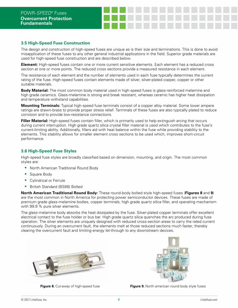
North American Traditional Round Body: These round-body bolted style high-speed fuses (Figures 8 and 9) are the most common in North America for protecting power semiconductor devices. These fuses are made of premium grade glass-melamine bodies, copper terminals, high grade quartz silica filler, and operating mechanism with 99.9 % pure silver elements.
The glass-melamine body absorbs the heat dissipated by the fuse. Silver-plated copper terminals offer excellent electrical contact to the fuse holder or bus bar. High grade quartz silica quenches the arc produced during fuse operation. The silver elements are uniquely designed with reduced cross-section areas to carry the rated current continuously. During an overcurrent fault, the elements melt at those reduced sections much faster, thereby clearing the overcurrent fault and limiting energy let-through to any downstream devices.
Figure 9. North american round body style fusesFigure 8. Cut-away of high-speed fuse
5 Littelfuse.com© 2021 Littelfuse, Inc.
POWR-SPEED® FusesOvercurrent Protection Fundamentals
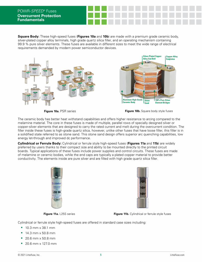
The ceramic body has better heat withstand capabilities and offers higher resistance to arcing compared to the melamine material. The core in these fuses is made of multiple, parallel rows of specially designed silver or copper-silver elements that are designed to carry the rated current and melt during the overcurrent condition. The filler inside these fuses is high-grade quartz silica, however, unlike other fuses that have loose filler, this filler is in a solidified state referred to as stone sand. This stone sand design offers superior arc quenching capabilities, low energy let-through and improved dc performance.
Cylindrical or Ferrule Body: Cylindrical or ferrule style high-speed fuses (Figures 11a and 11b) are widely preferred by users thanks to their compact size and ability to be mounted directly to the printed circuit boards. Typical applications of these fuses include power supplies and control circuits. These fuses are made of melamine or ceramic bodies, while the end caps are typically a plated copper material to provide better conductivity. The elements inside are pure silver and are filled with high grade quartz silica filler.
Cylindrical or ferrule style high-speed fuses are offered in standard case sizes including:
§ 10.3 mm x 38.1 mm
§ 14.3 mm x 50.8 mm
§ 20.6 mm x 50.8 mm
§ 20.6 mm x 127.0 mm
Square Body: These high-speed fuses (Figures 10a and 10b) are made with a premium grade ceramic body, silver-plated copper alloy terminals, high grade quartz silica filler, and an operating mechanism containing 99.9 % pure silver elements. These fuses are available in different sizes to meet the wide range of electrical requirements demanded by modern power semiconductor devices.
Figure 10b. Square body style fuses
▲▲
▲▲▲
Silver-Plated Copper Alloy End Bell
Copper Alloy Endplates
Aluminum High-Grade Ceramic Body
100% Pure Silver Element Bridges
Stone Sand
Figure 10a. PSR series
Figure 11b. Cylindrical or ferrule style fusesFigure 11a. L25S series
6 Littelfuse.com© 2021 Littelfuse, Inc.
POWR-SPEED® FusesOvercurrent Protection Fundamentals
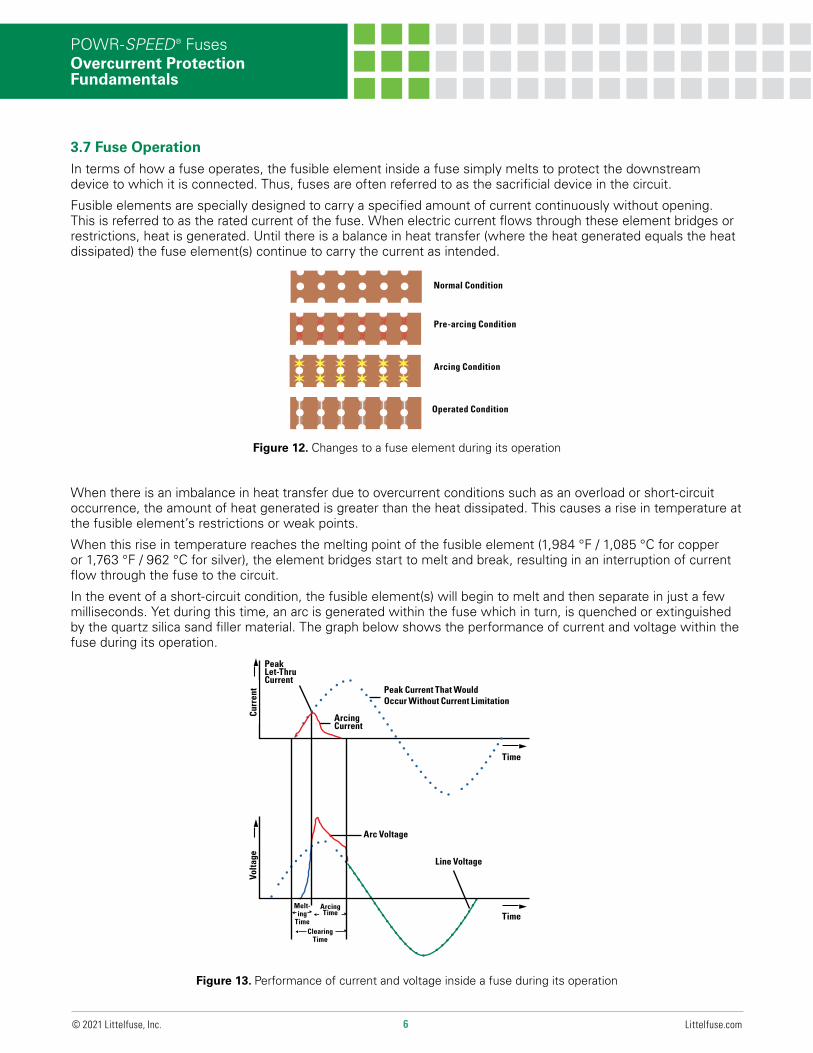
3.7 Fuse OperationIn terms of how a fuse operates, the fusible element inside a fuse simply melts to protect the downstream device to which it is connected. Thus, fuses are often referred to as the sacrificial device in the circuit.
Fusible elements are specially designed to carry a specified amount of current continuously without opening. This is referred to as the rated current of the fuse. When electric current flows through these element bridges or restrictions, heat is generated. Until there is a balance in heat transfer (where the heat generated equals the heat dissipated) the fuse element(s) continue to carry the current as intended.
When there is an imbalance in heat transfer due to overcurrent conditions such as an overload or short-circuit occurrence, the amount of heat generated is greater than the heat dissipated. This causes a rise in temperature at the fusible element’s restrictions or weak points.
When this rise in temperature reaches the melting point of the fusible element (1,984 °F / 1,085 °C for copper or 1,763 °F / 962 °C for silver), the element bridges start to melt and break, resulting in an interruption of current flow through the fuse to the circuit.
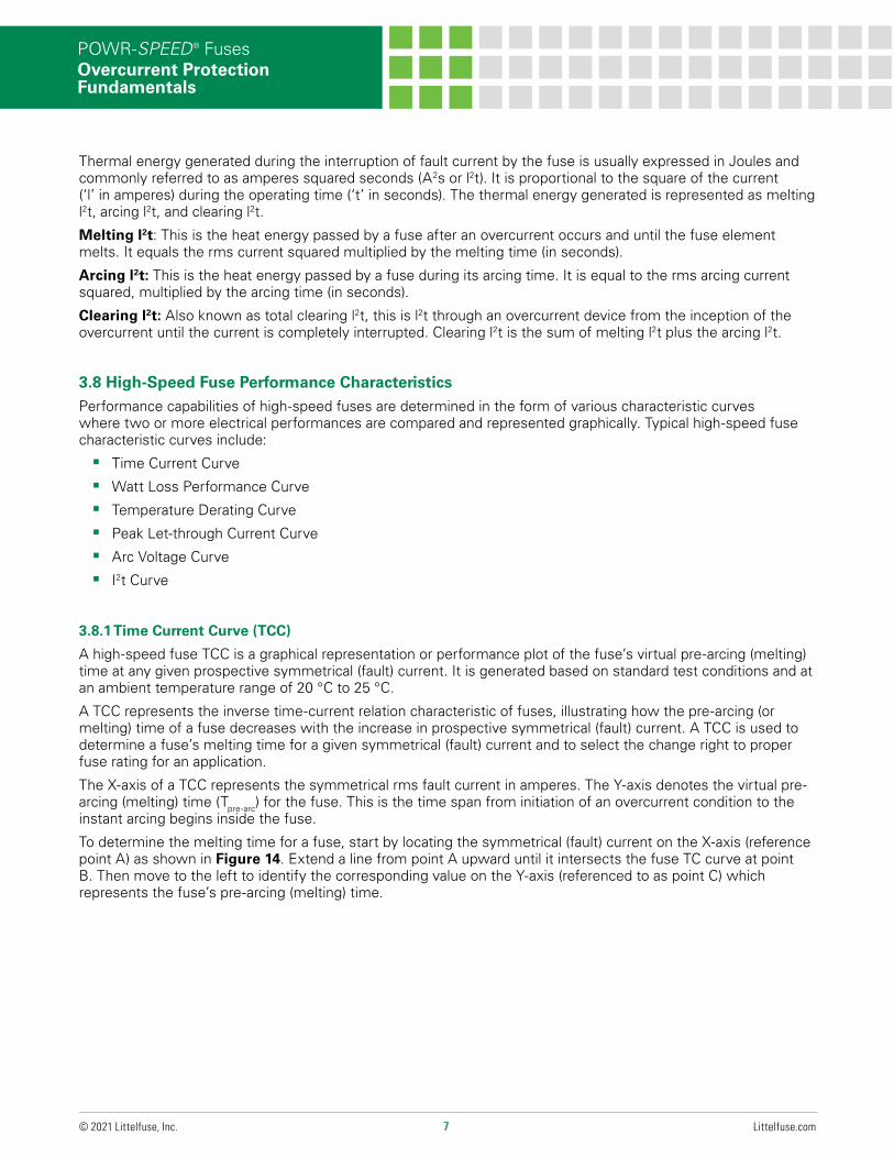
In the event of a short-circuit condition, the fusible element(s) will begin to melt and then separate in just a few milliseconds. Yet during this time, an arc is generated within the fuse which in turn, is quenched or extinguished by the quartz silica sand filler material. The graph below shows the performance of current and voltage within the fuse during its operation.
Figure 12. Changes to a fuse element during its operation
Normal Condition
Pre-arcing Condition
Arcing Condition
Operated Condition
✶✶
✶✶
✶✶
✶✶
✶✶
✶✶
Figure 13. Performance of current and voltage inside a fuse during its operation
Clearing Time
Peak Current That Would Occur Without Current Limitation
Peak Let-Thru Current
Arcing Current
Arc Voltage
Line Voltage
Time
Time
Volta
ge
◄
▲
▲▲▲
▲
◄
◄
◄
Melt-ing
Time
Arcing Time
▲
▲
Curr
ent
7 Littelfuse.com© 2021 Littelfuse, Inc.
POWR-SPEED® FusesOvercurrent Protection Fundamentals
Thermal energy generated during the interruption of fault current by the fuse is usually expressed in Joules and commonly referred to as amperes squared seconds (A2s or l2t). It is proportional to the square of the current (‘l’ in amperes) during the operating time (‘t’ in seconds). The thermal energy generated is represented as melting l2t, arcing l2t, and clearing l2t.
Melting l2t: This is the heat energy passed by a fuse after an overcurrent occurs and until the fuse element melts. It equals the rms current squared multiplied by the melting time (in seconds).
Arcing l2t: This is the heat energy passed by a fuse during its arcing time. It is equal to the rms arcing current squared, multiplied by the arcing time (in seconds).
Clearing l2t: Also known as total clearing l2t, this is l2t through an overcurrent device from the inception of the overcurrent until the current is completely interrupted. Clearing l2t is the sum of melting l2t plus the arcing l2t.
3.8 High-Speed Fuse Performance CharacteristicsPerformance capabilities of high-speed fuses are determined in the form of various characteristic curves where two or more electrical performances are compared and represented graphically. Typical high-speed fuse characteristic curves include:
§ Time Current Curve
§ Watt Loss Performance Curve
§ Temperature Derating Curve
§ Peak Let-through Current Curve
§ Arc Voltage Curve
§ I2t Curve
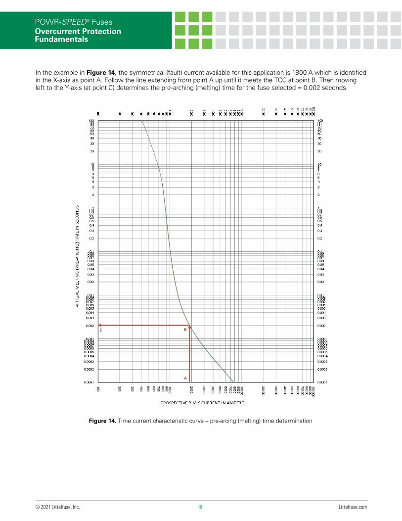
3.8.1 Time Current Curve (TCC)
A high-speed fuse TCC is a graphical representation or performance plot of the fuse’s virtual pre-arcing (melting) time at any given prospective symmetrical (fault) current. It is generated based on standard test conditions and at an ambient temperature range of 20 °C to 25 °C.
A TCC represents the inverse time-current relation characteristic of fuses, illustrating how the pre-arcing (or melting) time of a fuse decreases with the increase in prospective symmetrical (fault) current. A TCC is used to determine a fuse’s melting time for a given symmetrical (fault) current and to select the change right to proper fuse rating for an application.
The X-axis of a TCC represents the symmetrical rms fault current in amperes. The Y-axis denotes the virtual pre-arcing (melting) time (Tpre-arc) for the fuse. This is the time span from initiation of an overcurrent condition to the instant arcing begins inside the fuse.
To determine the melting time for a fuse, start by locating the symmetrical (fault) current on the X-axis (reference point A) as shown in Figure 14. Extend a line from point A upward until it intersects the fuse TC curve at point B. Then move to the left to identify the corresponding value on the Y-axis (referenced to as point C) which represents the fuse’s pre-arcing (melting) time.
8 Littelfuse.com© 2021 Littelfuse, Inc.
POWR-SPEED® FusesOvercurrent Protection Fundamentals
Figure 14. Time current characteristic curve – pre-arcing (melting) time determination
Page 13: Figure 14: High-Speed Applications Guide
B
A
C
In the example in Figure 14, the symmetrical (fault) current available for this application is 1800 A which is identified in the X-axis as point A. Follow the line extending from point A up until it meets the TCC at point B. Then moving left to the Y-axis (at point C) determines the pre-arching (melting) time for the fuse selected = 0.002 seconds.
9 Littelfuse.com© 2021 Littelfuse, Inc.
POWR-SPEED® FusesOvercurrent Protection Fundamentals
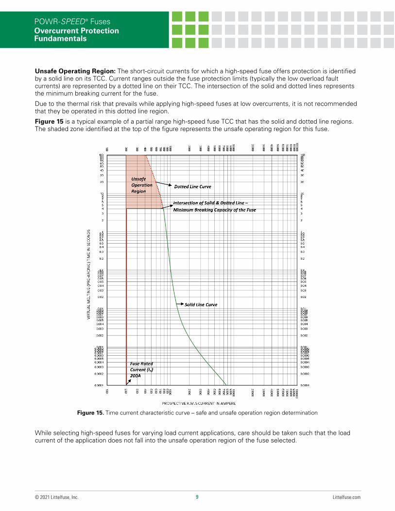
Unsafe Operating Region: The short-circuit currents for which a high-speed fuse offers protection is identified by a solid line on its TCC. Current ranges outside the fuse protection limits (typically the low overload fault currents) are represented by a dotted line on their TCC. The intersection of the solid and dotted lines represents the minimum breaking current for the fuse.
Due to the thermal risk that prevails while applying high-speed fuses at low overcurrents, it is not recommended that they be operated in this dotted line region.
Figure 15 is a typical example of a partial range high-speed fuse TCC that has the solid and dotted line regions. The shaded zone identified at the top of the figure represents the unsafe operating region for this fuse.
While selecting high-speed fuses for varying load current applications, care should be taken such that the load current of the application does not fall into the unsafe operation region of the fuse selected.
Figure 15. Time current characteristic curve – safe and unsafe operation region determination
Solid Line Curve
Fuse Rated Current (In) 200A
Intersection of Dotted & Solid Line – Minimum Breaking Capacity of the Fuse
Unsafe Operation Region of Fuse
Dotted Line CurveUnsafe Operation Region
◄
◄
◄
◄
10 Littelfuse.com© 2021 Littelfuse, Inc.
POWR-SPEED® FusesOvercurrent Protection Fundamentals
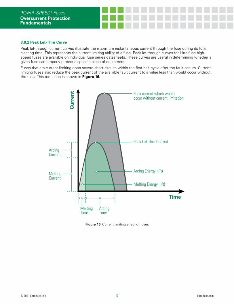
3.8.2 Peak Let-Thru Curve
Peak let-through current curves illustrate the maximum instantaneous current through the fuse during its total clearing time. This represents the current limiting ability of a fuse. Peak let-through curves for Littelfuse high-speed fuses are available on individual fuse series datasheets. These curves are useful in determining whether a given fuse can properly protect a specific piece of equipment.
Fuses that are current-limiting open severe short-circuits within the first half-cycle after the fault occurs. Current-limiting fuses also reduce the peak current of the available fault current to a value less than would occur without the fuse. This reduction is shown in Figure 16.
Figure 16. Current limiting effect of fuses
Cu
rren
t
Time
Peak Let-Thru Current
Peak current which would occur without current limitation
Arcing Energy (I2t)
Melting Energy (I2t)
Melting Time
ArcingTime
ArcingCurrent
Melting Current
11 Littelfuse.com© 2021 Littelfuse, Inc.
POWR-SPEED® FusesOvercurrent Protection Fundamentals
Figure 17. Peak let-through curves
100,00090,00080,00070,00060,000
50,000
40,000
30,000
20,000
10,0009,0008,0007,0006,000
5,000
4,000
3,000
2,000
100,00090,00080,00070,00060,000
50,000
40,000
30,000
20,000
10,0009,0008,0007,0006,000
5,000
4,000
3,000
2,000
200,
000
100,
000
90,0
0080
,000
70,0
0060
,000
50,0
0040
,000
30,0
00
20,0
00
10,0
009,
000
8,00
07,
000
6,00
05,
000
4,00
0
3,00
0
2,00
0
1,00
090
080
070
060
050
040
0
300
200
100
PE
AK
LE
T-TH
RU
IN A
MP
ER
ES
800A -
600A -
400A -
200A -
100A -
60A -
B
1,000900800700600
500
400
300
200
100
1,000900800700600
500
400
300
200
100
200,
000
100,
000
90,0
0080
,000
70,0
0060
,000
50,0
0040
,000
30,0
00
20,0
00
10,0
009,
000
8,00
07,
000
6,00
05,
000
4,00
0
3,00
0
2,00
0
1,00
090
080
070
060
050
040
0
300
200
100
AVAILABLE FAULT CURRENTSYMMETRICAL R.M.S. AMPERES
BASIS FOR DATA:
TEST VOLTAGE: TIME CONSTANT/POWER FACTOR: FUSE CATALOG NUMBER:
DRAWN BY:DATE:REVISION:DRAWING NO.: SHEET PEAK LET-THRU CHARACTERISTIC CURVES
LITTELFUSE, INC.CHICAGO, IL. USA
LLL
10/13/2015
B2 OF 8
FCC05-L50QS
L50QS 60A - 800A
A
- DATA GENERATED IN EXCEL -
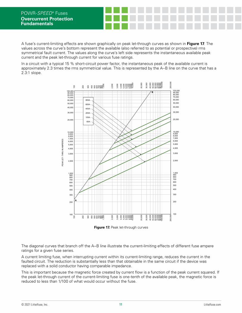
A fuse’s current-limiting effects are shown graphically on peak let-through curves as shown in Figure 17. The values across the curve’s bottom represent the available (also referred to as potential or prospective) rms symmetrical fault current. The values along the curve’s left side represents the instantaneous available peak current and the peak let-through current for various fuse ratings.
In a circuit with a typical 15 % short-circuit power factor, the instantaneous peak of the available current is approximately 2.3 times the rms symmetrical value. This is represented by the A–B line on the curve that has a 2.3:1 slope.
The diagonal curves that branch off the A–B line illustrate the current-limiting effects of different fuse ampere ratings for a given fuse series.
A current limiting fuse, when interrupting current within its current-limiting range, reduces the current in the faulted circuit. The reduction is substantially less than that obtainable in the same circuit if the device was replaced with a solid conductor having comparable impedance.
This is important because the magnetic force created by current flow is a function of the peak current squared. If the peak let-through current of the current-limiting fuse is one-tenth of the available peak, the magnetic force is reduced to less than 1/100 of what would occur without the fuse.

12 Littelfuse.com© 2021 Littelfuse, Inc.
POWR-SPEED® FusesOvercurrent Protection Fundamentals
Using the Peak Let-Through Charts (“Up-Over-and-Down”): Refer to Figure 18. For a given available fault-current of 100,000 rms amperes, determine whether a 600 A, 500 V L50QS series fuse can sufficiently protect equipment that has a 22,000 A short-circuit rating.
Start by locating the 100,000 A available fault-current on the bottom of the curve (point A1) and follow this value upwards to the intersection with the 600 A fuse curve (point B1). Next, follow the point horizontally to the left to intersect with the A-B line (point C1). Finally, read down to the bottom of the curve (point D1) to read a value of approximately 8,000 A (let-through current).
Based on the analysis, the selected fuse has reduced the 100,000 A available current to an apparent or equivalent 8,000 A. This fuse can now be used to safely protect the connected piece of equipment in this application and its 22,000 A short-circuit rating.
Figure 18. L50QS series peak let-through curve
100,00090,00080,00070,00060,000
50,000
40,000
30,000
20,000
10,0009,0008,0007,0006,000
5,000
4,000
3,000
2,000
100,00090,00080,00070,00060,000
50,000
40,000
30,000
20,000
10,0009,0008,0007,0006,000
5,000
4,000
3,000
2,000
200,
000
100,
000
90,0
0080
,000
70,0
0060
,000
50,0
0040
,000
30,0
00
20,0
00
10,0
009,
000
8,00
07,
000
6,00
05,
000
4,00
0
3,00
0
2,00
0
1,00
090
080
070
060
050
040
0
300
200
100
PE
AK
LE
T-TH
RU
IN A
MP
ER
ES
800A -
600A -
400A -
200A -
100A -
60A -
B
B1C1
1,000900800700600
500
400
300
200
100
1,000900800700600
500
400
300
200
100
200,
000
100,
000
90,0
0080
,000
70,0
0060
,000
50,0
0040
,000
30,0
00
20,0
00
10,0
009,
000
8,00
07,
000
6,00
05,
000
4,00
0
3,00
0
2,00
0
1,00
090
080
070
060
050
040
0
300
200
100
AVAILABLE FAULT CURRENTSYMMETRICAL R.M.S. AMPERES
BASIS FOR DATA:
TEST VOLTAGE: TIME CONSTANT/POWER FACTOR: FUSE CATALOG NUMBER:
DRAWN BY:DATE:REVISION:DRAWING NO.: SHEET PEAK LET-THRU CHARACTERISTIC CURVES
LITTELFUSE, INC.CHICAGO, IL. USA
LLL
10/13/2015
C2 OF 8
FCC05-L50QS
L50QS 60A - 800A
A
A1D1
- DATA GENERATED IN EXCEL -
13 Littelfuse.com© 2021 Littelfuse, Inc.
POWR-SPEED® FusesOvercurrent Protection Fundamentals
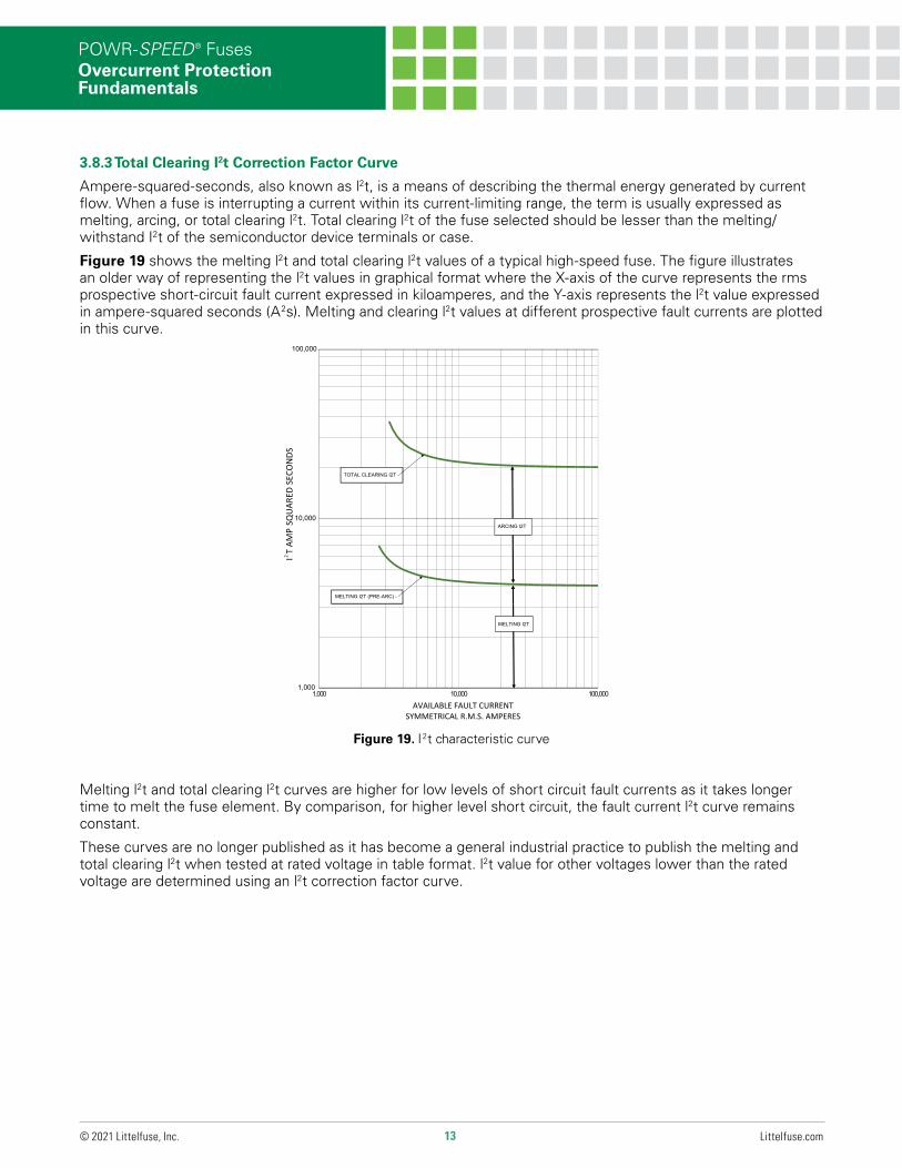
3.8.3 Total Clearing I2t Correction Factor Curve
Ampere-squared-seconds, also known as l2t, is a means of describing the thermal energy generated by current flow. When a fuse is interrupting a current within its current-limiting range, the term is usually expressed as melting, arcing, or total clearing l2t. Total clearing l2t of the fuse selected should be lesser than the melting/withstand I2t of the semiconductor device terminals or case.
Figure 19 shows the melting l2t and total clearing l2t values of a typical high-speed fuse. The figure illustrates an older way of representing the l2t values in graphical format where the X-axis of the curve represents the rms prospective short-circuit fault current expressed in kiloamperes, and the Y-axis represents the l2t value expressed in ampere-squared seconds (A2s). Melting and clearing l2t values at different prospective fault currents are plotted in this curve.
Melting l2t and total clearing l2t curves are higher for low levels of short circuit fault currents as it takes longer time to melt the fuse element. By comparison, for higher level short circuit, the fault current l2t curve remains constant.
These curves are no longer published as it has become a general industrial practice to publish the melting and total clearing l2t when tested at rated voltage in table format. l2t value for other voltages lower than the rated voltage are determined using an l2t correction factor curve.
100,000
TOTAL CLEARING I2T -ECO
ND
S
10,000ARCING I2T
I T
AM
P S
QU
ARE
D S
MELTING I2T (PRE-ARC) -
MELTING I2T
1,000000,001000,01000,1
AVAILABLE FAULT CURRENTSYMMETRICAL R.M.S. AMPERES
2
Figure 19. I 2 t characteristic curve
14 Littelfuse.com© 2021 Littelfuse, Inc.
POWR-SPEED® FusesOvercurrent Protection Fundamentals
1
0.9
1
0.9
700
600
500
400
300
200
100
0.8
0.7
0.6
0.8
0.7
0.6
0.5
0.4
0.5
0.4TOR
0.3 0.3
OSS
CO
RREC
TIO
N F
ACT
35A - 800A -
0.2 0.2
WA
TTS
LO
0.1 0.1
700
600
500
400
300
200
100
OPERATING VOLTAGE IN VOLT
A
B C
•
• •
◄
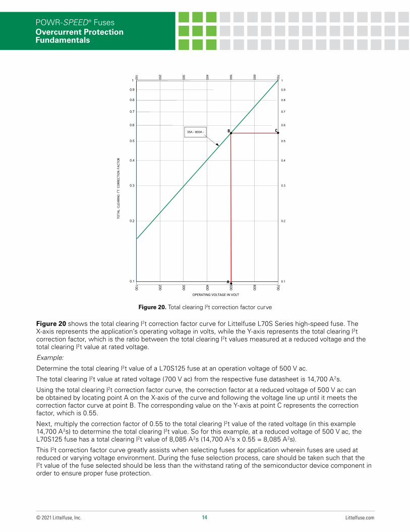
Figure 20. Total clearing l2t correction factor curve
Figure 20 shows the total clearing l2t correction factor curve for Littelfuse L70S Series high-speed fuse. The X-axis represents the application’s operating voltage in volts, while the Y-axis represents the total clearing l2t correction factor, which is the ratio between the total clearing l2t values measured at a reduced voltage and the total clearing l2t value at rated voltage.
Example:
Determine the total clearing l2t value of a L70S125 fuse at an operation voltage of 500 V ac.
The total clearing l2t value at rated voltage (700 V ac) from the respective fuse datasheet is 14,700 A2s.
Using the total clearing l2t correction factor curve, the correction factor at a reduced voltage of 500 V ac can be obtained by locating point A on the X-axis of the curve and following the voltage line up until it meets the correction factor curve at point B. The corresponding value on the Y-axis at point C represents the correction factor, which is 0.55.
Next, multiply the correction factor of 0.55 to the total clearing l2t value of the rated voltage (in this example 14,700 A2s) to determine the total clearing l2t value. So for this example, at a reduced voltage of 500 V ac, the L70S125 fuse has a total clearing l2t value of 8,085 A2s (14,700 A2s x 0.55 = 8,085 A2s).
This l2t correction factor curve greatly assists when selecting fuses for application wherein fuses are used at reduced or varying voltage environment. During the fuse selection process, care should be taken such that the l2t value of the fuse selected should be less than the withstand rating of the semiconductor device component in order to ensure proper fuse protection.
TOT
AL C
LEAR
ING
I2 T C
ORRE
CTIO
N FA
CTOR
15 Littelfuse.com© 2021 Littelfuse, Inc.
POWR-SPEED® FusesOvercurrent Protection Fundamentals
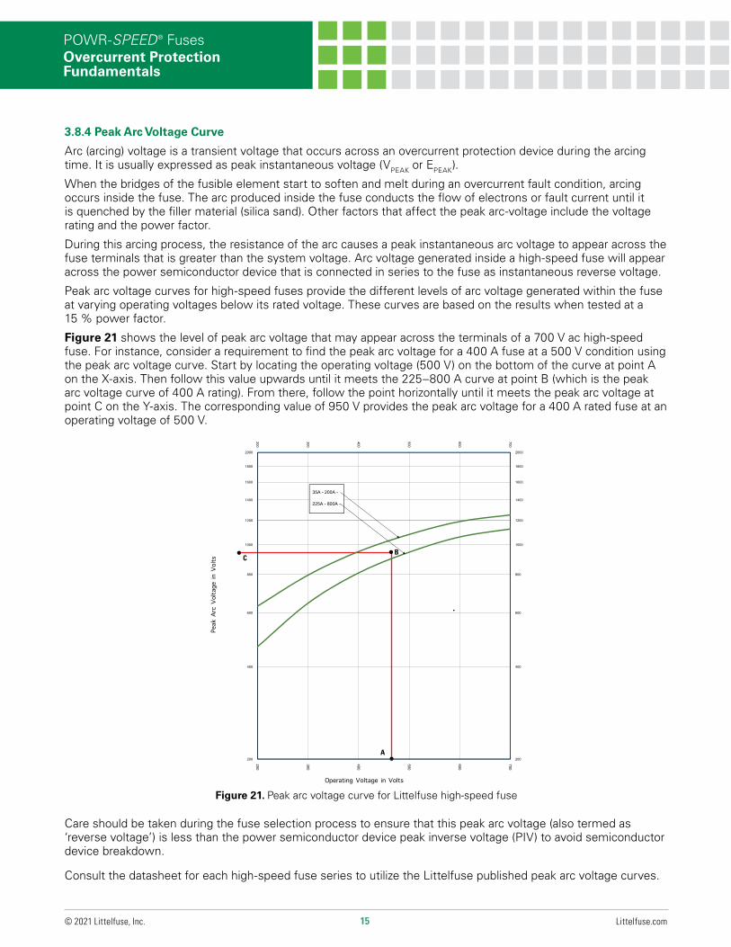
3.8.4 Peak Arc Voltage Curve
Arc (arcing) voltage is a transient voltage that occurs across an overcurrent protection device during the arcing time. It is usually expressed as peak instantaneous voltage (VPEAK or EPEAK).
When the bridges of the fusible element start to soften and melt during an overcurrent fault condition, arcing occurs inside the fuse. The arc produced inside the fuse conducts the flow of electrons or fault current until it is quenched by the filler material (silica sand). Other factors that affect the peak arc-voltage include the voltage rating and the power factor.
During this arcing process, the resistance of the arc causes a peak instantaneous arc voltage to appear across the fuse terminals that is greater than the system voltage. Arc voltage generated inside a high-speed fuse will appear across the power semiconductor device that is connected in series to the fuse as instantaneous reverse voltage.
Peak arc voltage curves for high-speed fuses provide the different levels of arc voltage generated within the fuse at varying operating voltages below its rated voltage. These curves are based on the results when tested at a 15 % power factor.
Figure 21 shows the level of peak arc voltage that may appear across the terminals of a 700 V ac high-speed fuse. For instance, consider a requirement to find the peak arc voltage for a 400 A fuse at a 500 V condition using the peak arc voltage curve. Start by locating the operating voltage (500 V) on the bottom of the curve at point A on the X-axis. Then follow this value upwards until it meets the 225–800 A curve at point B (which is the peak arc voltage curve of 400 A rating). From there, follow the point horizontally until it meets the peak arc voltage at point C on the Y-axis. The corresponding value of 950 V provides the peak arc voltage for a 400 A rated fuse at an operating voltage of 500 V.
Figure 21. Peak arc voltage curve for Littelfuse high-speed fuse
Operating Voltage in Volts
Peak
Arc V
olta
ge in
Volts
A
BC
•
•
•
2000
1800
2000
1800
700
600
500
400
300
200
1600
1400
1200
1600
1400
1200
35A - 200A -
225A - 800A -
1000
800
1000
800
t
600 600
Peak
Arc
Vol
tage
in V
olt
400 400
P
200 200
700
600
500
400
300
200
Operating Voltage in Volt
Care should be taken during the fuse selection process to ensure that this peak arc voltage (also termed as ‘reverse voltage’) is less than the power semiconductor device peak inverse voltage (PIV) to avoid semiconductor device breakdown.
Consult the datasheet for each high-speed fuse series to utilize the Littelfuse published peak arc voltage curves.
16 Littelfuse.com© 2021 Littelfuse, Inc.
POWR-SPEED® FusesOvercurrent Protection Fundamentals
PER
CEN
T O
F U
PRAT
ING
PERCEN
0
10%
0
10%
30%
20%
20%
AMBIENT TEMPERATURE
NT O
F DOW
NRATIN
G
50%100°C212°F
80°C176°F
60°C140°F
40°C104°F
20°C68°F
-20°C-4°F
-40°C-40°F
30%
120°C248°F
0°C32°F
40%
70°CA1
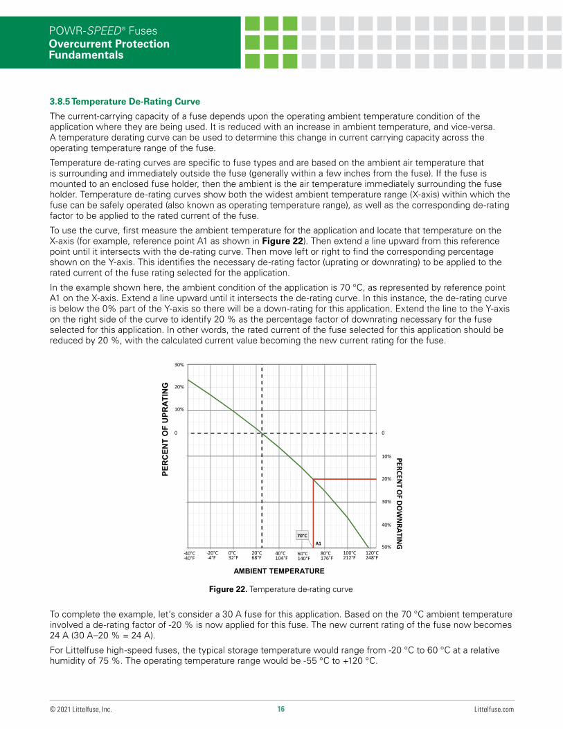
3.8.5 Temperature De-Rating Curve
The current-carrying capacity of a fuse depends upon the operating ambient temperature condition of the application where they are being used. It is reduced with an increase in ambient temperature, and vice-versa. A temperature derating curve can be used to determine this change in current carrying capacity across the operating temperature range of the fuse.
Temperature de-rating curves are specific to fuse types and are based on the ambient air temperature that is surrounding and immediately outside the fuse (generally within a few inches from the fuse). If the fuse is mounted to an enclosed fuse holder, then the ambient is the air temperature immediately surrounding the fuse holder. Temperature de-rating curves show both the widest ambient temperature range (X-axis) within which the fuse can be safely operated (also known as operating temperature range), as well as the corresponding de-rating factor to be applied to the rated current of the fuse.
To use the curve, first measure the ambient temperature for the application and locate that temperature on the X-axis (for example, reference point A1 as shown in Figure 22). Then extend a line upward from this reference point until it intersects with the de-rating curve. Then move left or right to find the corresponding percentage shown on the Y-axis. This identifies the necessary de-rating factor (uprating or downrating) to be applied to the rated current of the fuse rating selected for the application.
In the example shown here, the ambient condition of the application is 70 °C, as represented by reference point A1 on the X-axis. Extend a line upward until it intersects the de-rating curve. In this instance, the de-rating curve is below the 0% part of the Y-axis so there will be a down-rating for this application. Extend the line to the Y-axis on the right side of the curve to identify 20 % as the percentage factor of downrating necessary for the fuse selected for this application. In other words, the rated current of the fuse selected for this application should be reduced by 20 %, with the calculated current value becoming the new current rating for the fuse.
Figure 22. Temperature de-rating curve
To complete the example, let’s consider a 30 A fuse for this application. Based on the 70 °C ambient temperature involved a de-rating factor of -20 % is now applied for this fuse. The new current rating of the fuse now becomes 24 A (30 A–20 % = 24 A).
For Littelfuse high-speed fuses, the typical storage temperature would range from -20 °C to 60 °C at a relative humidity of 75 %. The operating temperature range would be -55 °C to +120 °C.
17 Littelfuse.com© 2021 Littelfuse, Inc.
POWR-SPEED® FusesOvercurrent Protection Fundamentals
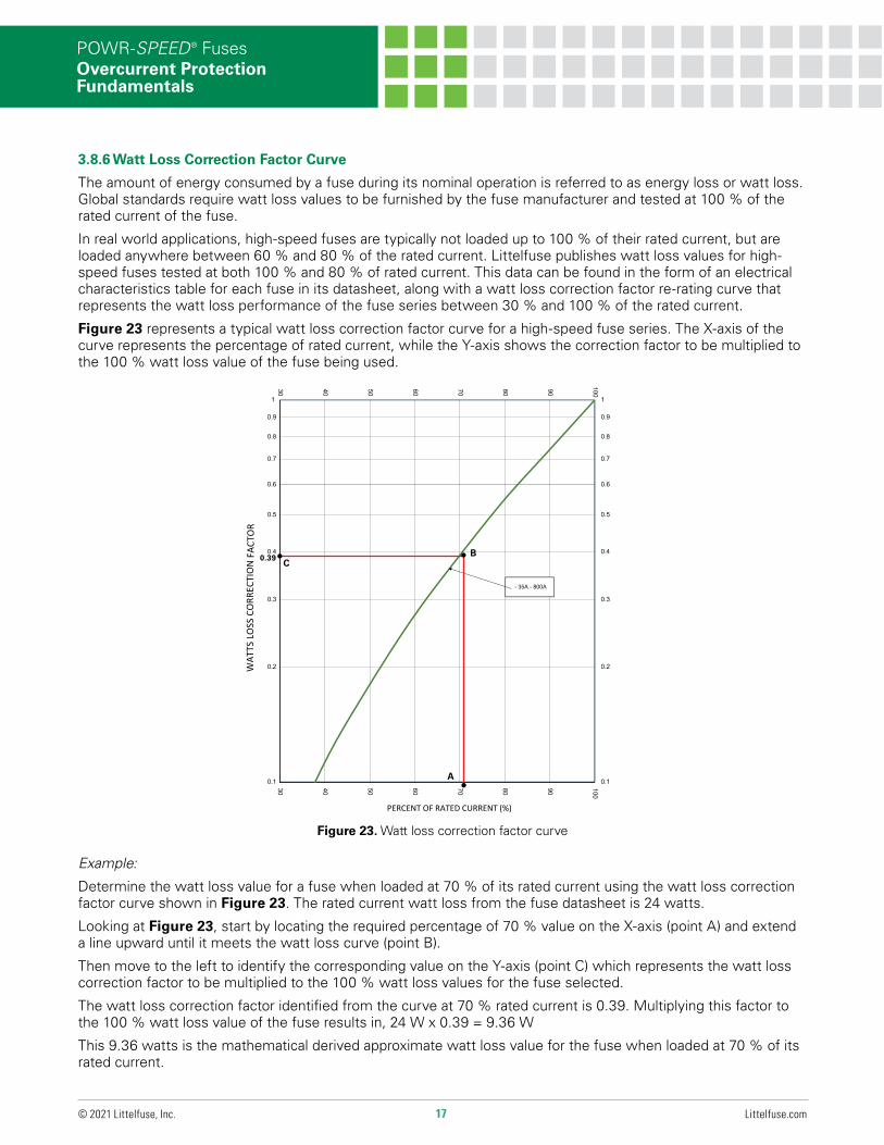
3.8.6 Watt Loss Correction Factor Curve
The amount of energy consumed by a fuse during its nominal operation is referred to as energy loss or watt loss. Global standards require watt loss values to be furnished by the fuse manufacturer and tested at 100 % of the rated current of the fuse.
In real world applications, high-speed fuses are typically not loaded up to 100 % of their rated current, but are loaded anywhere between 60 % and 80 % of the rated current. Littelfuse publishes watt loss values for high-speed fuses tested at both 100 % and 80 % of rated current. This data can be found in the form of an electrical characteristics table for each fuse in its datasheet, along with a watt loss correction factor re-rating curve that represents the watt loss performance of the fuse series between 30 % and 100 % of the rated current.
Figure 23 represents a typical watt loss correction factor curve for a high-speed fuse series. The X-axis of the curve represents the percentage of rated current, while the Y-axis shows the correction factor to be multiplied to the 100 % watt loss value of the fuse being used.
Figure 23. Watt loss correction factor curve
1
0.9
1
0.9
100
90807060504030
0.8
0.7
0.6
0.8
0.7
0.6
0.5
0.4
0.5
0.4
0.3 0.3
O SS CO
RREC
TIO
N FA
CTO
RT
- 35A - 800A
0.2 0.2WA
TTS
LO
0.1 0.1
100
90807060504030
PERCENT OF RATED CURRENT (%)
0.39
A
BC• •
•
Example:
Determine the watt loss value for a fuse when loaded at 70 % of its rated current using the watt loss correction factor curve shown in Figure 23. The rated current watt loss from the fuse datasheet is 24 watts.
Looking at Figure 23, start by locating the required percentage of 70 % value on the X-axis (point A) and extend a line upward until it meets the watt loss curve (point B).
Then move to the left to identify the corresponding value on the Y-axis (point C) which represents the watt loss correction factor to be multiplied to the 100 % watt loss values for the fuse selected.
The watt loss correction factor identified from the curve at 70 % rated current is 0.39. Multiplying this factor to the 100 % watt loss value of the fuse results in, 24 W x 0.39 = 9.36 W
This 9.36 watts is the mathematical derived approximate watt loss value for the fuse when loaded at 70 % of its rated current.
18 Littelfuse.com© 2021 Littelfuse, Inc.
POWR-SPEED® FusesOvercurrent Protection Fundamentals
DISCLAIMERThe purpose of this Technical Applications Guide is to promote a better understanding of high-speed fuses, power semiconductor devices and their common application details within circuit design. These high-speed fuses being considered are current sensitive devices designed to serve as the intentional weak link in the electrical circuit. Their function is to provide protection of power semiconductor components, or of complete circuits, by reliably operating under current overload conditions.
Application guidelines and product data mentioned in this guide is intended for technical reference only. Fuse parameters and application concepts should be well understood to properly select a fuse for a given application. Application testing is strongly recommended and should be used to verify fuse performance in the circuit/application.
Littelfuse products are not designed for, and shall not be used for, any purpose (including, without limitation, automotive, military, aerospace, medical, life-saving, life-sustaining or nuclear facility applications, devices intended for surgical implant into the body, or any other application in which the failure or lack of desired operation of the product may result in personal injury, death, or property damage) other than those expressly set forth in applicable Littelfuse product documentation. Warranties granted by Littelfuse shall be deemed void for products used for any purpose not expressly set forth in applicable Littelfuse documentation. Littelfuse shall not be liable for any claims or damages arising out of products used in applications not expressly intended by Littelfuse as set forth in applicable Littelfuse documentation. The sale and use of Littelfuse products is subject to Littelfuse Terms and Conditions of Sale, unless otherwise agreed by Littelfuse.
For more information visit Littelfuse.com/Product-Disclaimer
Littelfuse reserves the right to make changes in product design, processes, manufacturing location and literature information without notice. For additional questions, contact Littelfuse Technical Services Group at 1-800-TEC-FUSE or [email protected].