installation manual - image relay
TRANSCRIPT
1
INSTALLATION MANUALSAFERA Siro IN-line stove guard
Power control units:PCU6.3-FPCU6.3-PPCU5.1-UPCU5.1-P
20909 V4.6.0 ENG SIRO IN-LINE
32
CONTENTS
1. Preparations
2. Installation
3. Troubleshooting
4. Optional: Installing the Water Leakage Sensor
Follow these instructions carefully and pay particular attention to the instructions marked in the following way:
ѥ WARNING
Follow instructions marked with a war-ning accurately to prevent injury to per-sons and damage to property.
⚐ ATTENTION
Follow instructions marked with a note carefully to prevent damage to property.
ѧ HINT
Hints give you useful advices on using the appliance.
WARNINGS
ѥ WARNING
Read user and installation manual before using or installing the appliance.
Install and check the application accor-ding to the instructions. SAFERA is not liable for any damages or expenses caused by inappropriate installation.
Check that the Stove Guard is compatible with the cooker (see section 1.1).
If the network cable is damaged, it must be replaced by the service personnel of the manufacturer or their representative to avoid hazards.
All electrical connections must be carried out by a qualified electrician.
⚐ ATTENTION
If the appliance was stored in a cold spa-ce, it must be allowed to warm up to room temperature before connecting it to elec-tric network.
1. PREPARATIONS
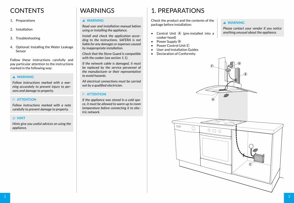
Check the product and the contents of the package before installation:
• Central Unit Ⓐ (pre-installed into a cooker hood)
• Power Supply Ⓓ• Power Control Unit Ⓒ• User and Installation Guides• Declaration of Conformity
ѥ WARNING
Please contact your vendor if you notice anything unusual about the appliance.
Ⓒ
Ⓐ
Ⓓ
Ⓔ
Ⓕ
54
8
9 13
724
5 6
Install the cooker hood with Central Unit Ⓐ according to the dimensions:
⚐ ATTENTION
The Central Unit Ⓐ is plugged into the wall socket with its own power supply Ⓓ.
ѥ WARNING
The extinguishing area is approx. 60 cm in diameter, when the installation height is in accordance with the table. The installa-tion height has an effect on the size of the extinguishing area and the extinguishing capacity.
With extinguisher:
Cooker width Inst. height
Max. 60 cm 45 - 55 cm
Without extinguisher:
Cooker width Inst. height
Max. 60 cm 45 - 75 cm
60 - 90 cm 60 - 75 cm
WidthAlign the Central Unit ±15 mm with the centre of the cooktop.
DepthAlign the Central Unit ±100 mm with the centre of the cooktop.
1.1 CompatibilitySAFERA Stove Guard is compatible with most electrical cookers, hobs and ovens meant for household use:
• Traditional cast-iron cookers and hobs• Ceramic cookers and hobs• Induction cookers and hobs• Cookers and hobs equipped with a ti-
mer, afterheat indicator, child proof lock or integrated switch-off system
SAFERA Siro is compatible with cookers no wider than 90 cm, see Installation step 1/6.
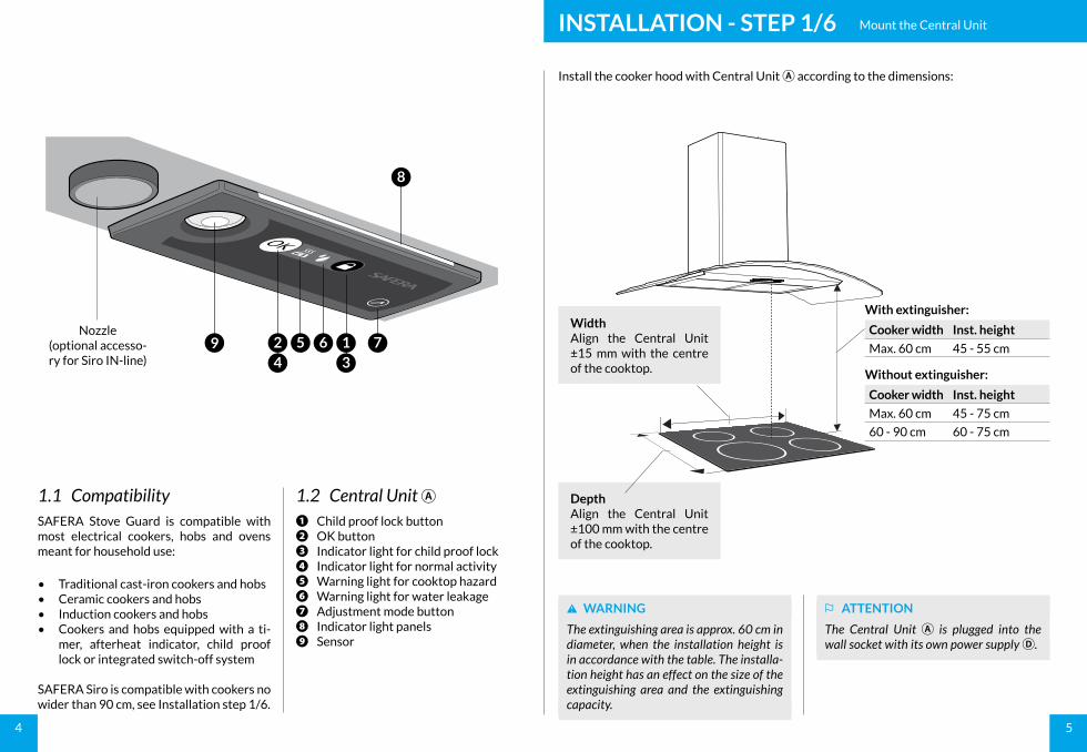
1.2 Central Unit Ⓐ❶ Child proof lock button❷ OK button❸ Indicator light for child proof lock❹ Indicator light for normal activity❺ Warning light for cooktop hazard❻ Warning light for water leakage❼ Adjustment mode button❽ Indicator light panels❾ Sensor
Nozzle(optional accesso-ry for Siro IN-line)
INSTALLATION - STEP 1/6 Mount the Central Unit
76
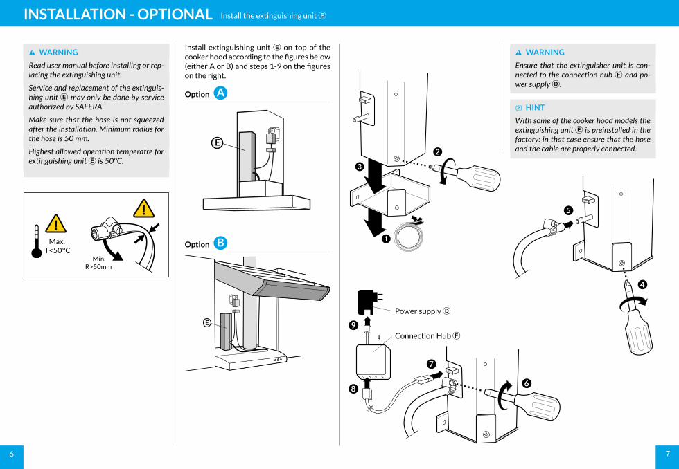
Install extinguishing unit Ⓔ on top of the cooker hood according to the figures below (either A or B) and steps 1-9 on the figures on the right.
Option
Option
ѥ WARNING
Ensure that the extinguisher unit is con-nected to the connection hub Ⓕ and po-wer supply Ⓓ.
ѧ HINT
With some of the cooker hood models the extinguishing unit Ⓔ is preinstalled in the factory: in that case ensure that the hose and the cable are properly connected.
ѥ WARNING
Read user manual before installing or rep-lacing the extinguishing unit.
Service and replacement of the extinguis-hing unit Ⓔ may only be done by service authorized by SAFERA.
Make sure that the hose is not squeezed after the installation. Minimum radius for the hose is 50 mm.
Highest allowed operation temperatre for extinguishing unit Ⓔ is 50°C.
Max.T<50°C
Min.R>50mm
E
E
A
B 1
2
3
5
4
6
7
8
9Connection Hub Ⓕ
Power supply Ⓓ
INSTALLATION - OPTIONAL Install the extinguishing unit Ⓔ
98
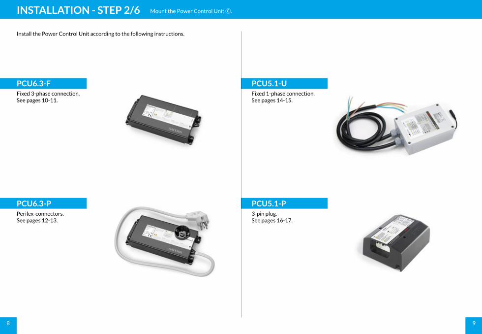
Install the Power Control Unit according to the following instructions.
INSTALLATION - STEP 2/6 Mount the Power Control Unit Ⓒ.
PCU5.1-UFixed 1-phase connection.See pages 14-15.
PCU6.3-PPerilex-connectors.See pages 12-13.
PCU6.3-FFixed 3-phase connection.See pages 10-11.
PCU5.1-P3-pin plug.See pages 16-17.
1110
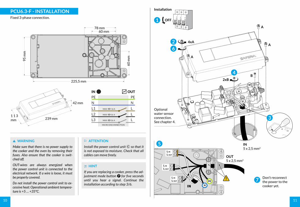
ѧ HINT
If you are replacing a cooker, press the ad-justment mode button ❼ for five seconds until you hear a signal. Continue the installation according to step 3/6.
ѥ WARNING
Make sure that there is no power supply to the cooker and the oven by removing their fuses. Also ensure that the cooker is swit-ched off.
OUT-wires are always energized when the power control unit is connected to the electrical network. If a wire is loose, it must be properly covered.
Do not install the power control onit to ex-cessive heat: Operational ambient tempera-ture is +5 … +35°C.
⚐ ATTENTION
Install the power control unit Ⓒ so that it is not exposed to moisture. Check that all cables can move freely.
InstallationPCU6.3-F - INSTALLATIONFixed 3-phase connection.
42 mm
239 mm1 1 3 mm
7
225,5 mm
78 mm60 mm
60
mm
95
mm
OUTIN
OUT5 x 2,5 mm2
5
N
PE
L OUT
L IN
L OUT
L IN
L OUT
L IN
Optional water sensor connection.See chapter 4.
2
6
4
3
4xA
A
A
A
B2xB
IN5 x 2,5 mm2
IN
Don’t reconnect the power to the cooker yet.
OFF1
1312
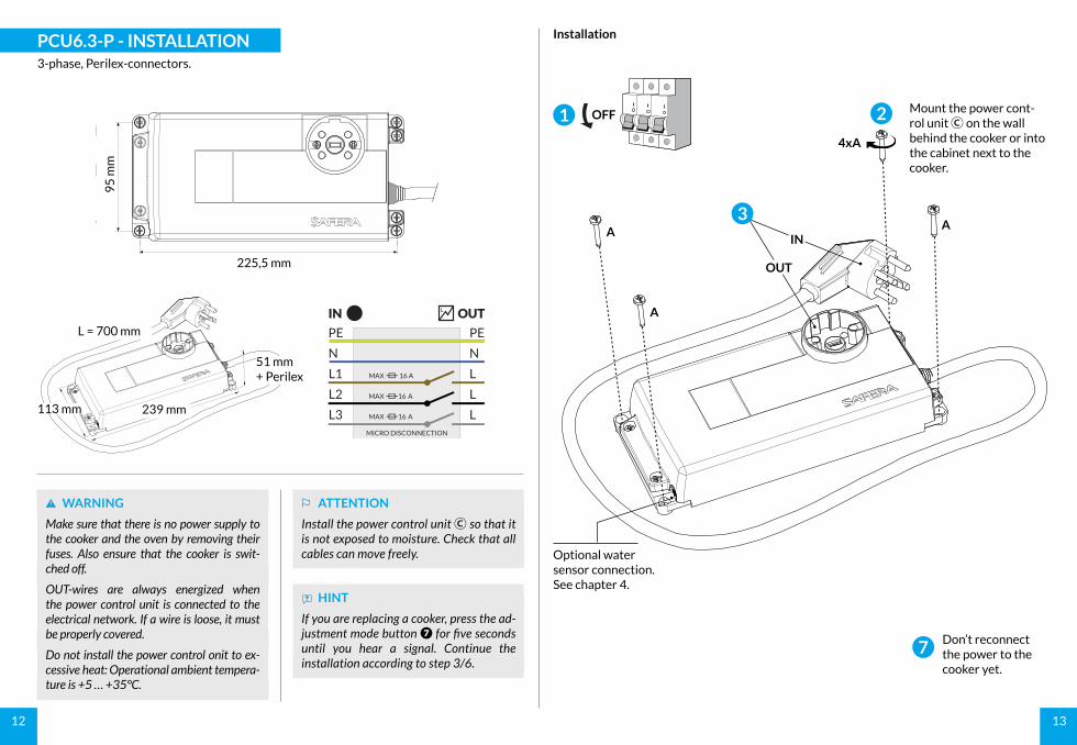
7Don’t reconnect the power to the cooker yet.
ѧ HINT
If you are replacing a cooker, press the ad-justment mode button ❼ for five seconds until you hear a signal. Continue the installation according to step 3/6.
ѥ WARNING
Make sure that there is no power supply to the cooker and the oven by removing their fuses. Also ensure that the cooker is swit-ched off.
OUT-wires are always energized when the power control unit is connected to the electrical network. If a wire is loose, it must be properly covered.
Do not install the power control onit to ex-cessive heat: Operational ambient tempera-ture is +5 … +35°C.
⚐ ATTENTION
Install the power control unit Ⓒ so that it is not exposed to moisture. Check that all cables can move freely.
InstallationPCU6.3-P - INSTALLATION3-phase, Perilex-connectors.
225,5 mm
95
mm
OUTINL = 700 mm
51 mm+ Perilex
239 mm113 mm
Optional water sensor connection.See chapter 4.
A
Mount the power cont-rol unit Ⓒ on the wall behind the cooker or into the cabinet next to the cooker.
2
4xA
A
A3
OUT
IN
OFF1
1514
ѥ WARNING
Make sure that there is no power supply to the cooker and the oven by removing their fuses. Also ensure that the cooker is swit-ched off.
OUT-wires are always energized when the power control unit is connected to the electrical network. If a wire is loose, it must be properly covered.
Do not install the Power Control Unit to ex-cessive heat: Operational ambient tempera-ture is +5 … +40°C.
⚐ ATTENTION
Install the power control unit Ⓒ so that it is not exposed to moisture. Check that all cables can move freely.
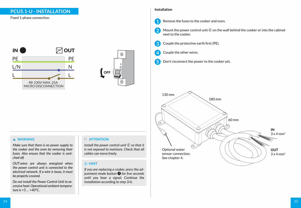
IN3 x 4 mm2
OUT3 x 4 mm2
180 mm
60 mm
130 mm
Optional water sensor connection. See chapter 4.
Remove the fuses to the cooker and oven.
Mount the power control unit Ⓒ on the wall behind the cooker or into the cabinet next to the cooker.
Couple the protective earth first (PE).
Couple the other wires.
Don’t reconnect the power to the cooker yet.
InstallationPCU5.1-U - INSTALLATIONFixed 1-phase connection.
OFF
OUTIN
PE
L/N
L
PE
N
L 230V MAX. 25A
MICRO DISCONNECTION
ѧ HINT
If you are replacing a cooker, press the ad-justment mode button ❼ for five seconds until you hear a signal. Continue the installation according to step 3/6.
3
4
5
2
1
1716
PE
L
L
N/L
L/N
4
PE5 6
2
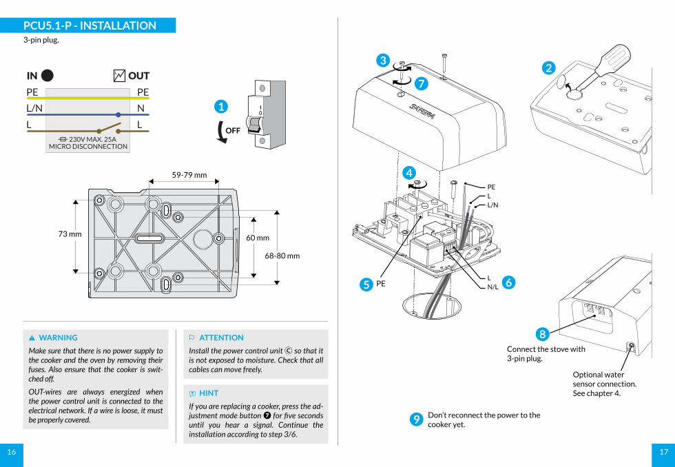
9 Don’t reconnect the power to the cooker yet.
Optional water sensor connection.See chapter 4.
Connect the stove with 3-pin plug.
8
PCU5.1-P - INSTALLATION3-pin plug.
59-79 mm
73 mm 60 mm
68-80 mm
ѥ WARNING
Make sure that there is no power supply to the cooker and the oven by removing their fuses. Also ensure that the cooker is swit-ched off.
OUT-wires are always energized when the power control unit is connected to the electrical network. If a wire is loose, it must be properly covered.
⚐ ATTENTION
Install the power control unit Ⓒ so that it is not exposed to moisture. Check that all cables can move freely.
OFF
OUTIN
PE
L/N
L
PE
N
L 230V MAX. 25A
MICRO DISCONNECTION
1
ѧ HINT
If you are replacing a cooker, press the ad-justment mode button ❼ for five seconds until you hear a signal. Continue the installation according to step 3/6.
3
7
1918
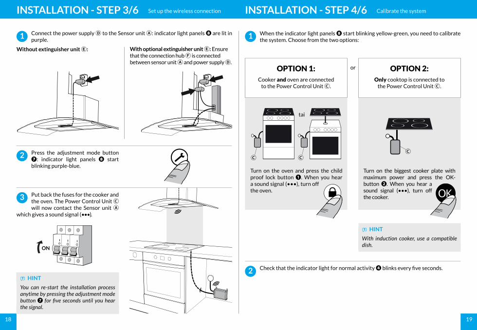
Connect the power supply Ⓓ to the Sensor unit Ⓐ: indicator light panels ❽ are lit in purple.
Press the adjustment mode button ❼: indicator light panels ❽ start blinking purple-blue.
2
1
Without extinguisher unit Ⓔ: With optional extinguisher unit Ⓔ: Ensure that the connection hub Ⓕ is connected between sensor unit Ⓐ and power supply Ⓓ.
When the indicator light panels ❽ start blinking yellow-green, you need to calibrate the system. Choose from the two options:
Check that the indicator light for normal activity ❹ blinks every five seconds.
OPTION 1:Cooker and oven are connected
to the Power Control Unit Ⓒ.
1
2
OPTION 2:Only cooktop is connected to
the Power Control Unit Ⓒ.
Turn on the biggest cooker plate with maximum power and press the OK-button ❷. When you hear a sound signal (•••), turn off the cooker.
ѧ HINT
With induction cooker, use a compatible dish.
Turn on the oven and press the child proof lock button ❶. When you hear a sound signal (•••), turn off the oven.
ⒸⒸⒸ
tai
or
Put back the fuses for the cooker and the oven. The Power Control Unit Ⓒ will now contact the Sensor unit Ⓐ
which gives a sound signal (•••).
3
ѧ HINT
You can re-start the installation process anytime by pressing the adjustment mode button ❼ for five seconds until you hear the signal.
ON
INSTALLATION - STEP 3/6 Set up the wireless connection INSTALLATION - STEP 4/6 Calibrate the system
2120
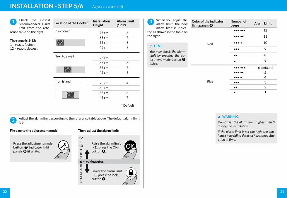
Adjust the alarm limit according to the reference table above. The default alarm limit is 6.
First, go to the adjustment mode:
2
Check the closest recommended alarm limit from the refe-
rence table on the right.
The range is 1-12:1 = reacts fastest12 = reacts slowest
Then, adjust the alarm limit:
Lower the alarm limit (-1): press the lock button ❶.
Raise the alarm limit (+1): press the OK-button ❷.
= vakioasetus
1
Press the adjustment mode button ❼: indicator light panels ❽ lit white.
121110987654321
INSTALLATION - STEP 5/6 Adjust the alarm limit
When you adjust the alarm limit, the new alarm limit is indica-
ted as shown in the table on the right.
3
ѥ WARNING
Do not set the alarm limit higher than 9 during the installation.
If the alarm limit is set too high, the app-liance may fail to detect a hazardous situ-ation in time.
ѧ HINT
You may check the alarm limit by pressing the ad-justment mode button ❼ twice.
Location of the CookerInstallation Height
Alarm Limit (1-12)
In a corner 75 cm 6*
65 cm 7
55 cm 8
45 cm 9
Next to a wall 75 cm 5
65 cm 6*
55 cm 7
45 cm 8
In an island 75 cm 4
65 cm 5
55 cm 6*
45 cm 7
* Default
Color of the indicator light panels ❽
Number of beeps
Alarm Limit
Red
••• ••• 12
••• •• 11
••• • 10
••• 9
•• 8
• 7
Blue
••• ••• 6 (default)
••• •• 5
••• • 4
••• 3
•• 2
• 1
2322
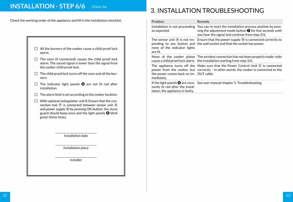
Check the working order of the appliance and fill in the installation checklist:
≅ All the burners of the cooker cause a child proof lock alarm.
≅ The oven (if connected) causes the child proof lock alarm. The sound signal is lower than the signal from the cooker child proof lock.
≅ The child proof lock turns off the oven and all the bur-ners.
≅ The indicator light panels ❽ are not lit red after installation.
≅ The alarm limit is set according to the cooker location.
≅ With optional extinguisher unit Ⓔ: Ensure that the con-nection hub Ⓕ is connected between sensor unit Ⓐ and power supply Ⓓ by pressing OK-button: the stove guard should beep once and the light panels ❽ blink green three times.
_______________________________Installation date
_______________________________Installation place
_______________________________Installer
INSTALLATION - STEP 6/6 Check-list
3. INSTALLATION TROUBLESHOOTING
Problem Remedy
Installation is not proceeding as expected.
You can re-start the installation process anytime by pres-sing the adjustment mode button ❼ for five seconds until you hear the signal and continue from step 3/6.
The sensor unit Ⓐ is not res-ponding to any button and none of the indicator lights are lit.
Ensure that the power supply Ⓓ is connected correctly to the wall socket and that the socket has power.
None of the cooker plates cause a child proof lock alarm.
The wireless connection has not been properly made: redo the installation starting from step 3/6.
The appliance turns off the power from the cooker, but the power comes back on im-mediately.
Make sure that the Power Control Unit Ⓒ is connected correctly – in other words, the cooker is connected to the OUT cable.
If the light panels ❽ are cons-tantly lit red after the instal-lation, the appliance is faulty.
See user manual chapter 5. Troubleshooting
24
4. INSTALLING THE WATER LEAKAGE SENSOR (optional)
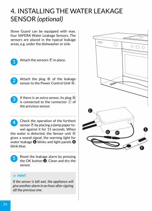
Stove Guard can be equipped with max. four SAFERA Water Leakage Sensors. The sensors are placed in the typical leakage areas, e.g. under the dishwasher or sink.
Attach the sensors Ⓕ in place.1
ѧ HINT
If the sensor is left wet, the appliance will give another alarm in an hour after signing off the previous one.
Attach the plug Ⓖ of the leakage sensor to the Power Control Unit Ⓗ.
2
If there is an extra sensor, its plug Ⓖ is connected to the connector Ⓘ of the previous sensor.
3
Check the operation of the furthest sensor Ⓕ by placing a damp paper to-wel against it for 15 seconds. When
the water is detected, the Sensor unit Ⓐ gives a sound signal, the warning light for water leakage ❻ blinks and light panels ❽ blink blue.
4
Reset the leakage alarm by pressing the OK button ❷. Clean and dry the sensor.
5
C
G HI
F