osiris tunable imager and spectrograph: instrument status
TRANSCRIPT

OSIRIS tunable imager and spectrograph for the GTC. Instrumentstatus.
Jordi Cepaa,b
, Marta Aguiara, Jonathan Bland-Hawthorn
c, Francisco Cobos
d, Santiago Correa
a,
Carlos Espejod, Ana Belén Fragoso
a, Javier Fuentes
a, José Vicente Gigante
a, Jesús González
d,
Victor González-Escaleraa, José Ignacio González-Serrano
e, Enrique Joven
a, José Carlos López
a,
Carmelo Militellof, Lorenzo Peraza
a, Angeles Pérez
a, Jaime Pérez
a, Jose Luis Rasilla
a, Beatriz
Sánchezd, Carlos Tejada
d
aInstituto de Astrofísica de Canarias, c/Vía Láctea s/n, E-38200 La Laguna, Tenerife, Spain
bDepartamento de Astrofísica, Facultad de Física, Universidad de La Laguna, E-38071 La Laguna,
Tenerife, SpaincAnglo-Australian Observatory, P.O. Box 296, 167 Vimiera Road, Epping, NSW 2121, AustraliadInstituto de Astronomía, Universidad Nacional Autónoma de México, Apartado Postal 70-264,
México, D.F., México 04510eInstituto de Física de Cantabria (CSIC-Universidad de Cantabria), E-39005 Santander, Spain
fAcústica y Vibraciones, Departamento de Física Fundamental y Experimental, Facultad de Física,
Universidad de La Laguna, E-38071 La Laguna, Tenerife, Spain
ABSTRACT
OSIRIS (Optical System for Imaging and low Resolution Integrated Spectroscopy) is the optical Day One instrumentfor the 10.4m Spanish telescope GTC to be installed in the Observatorio del Roque de Los Muchachos (La Palma,Spain). This instrument, operational in mid-2004, covers from 360 up to 1000 nm. OSIRIS observing modes includedirect imaging with tunable and conventional filters, long slit and multiple object spectroscopy and fastspectrophotometry. The OSIRIS wide field of view, high efficiency and the new observing modes (tunable imaging andfast spectrophotometry) for 8-10m class telescopes will provide GTC with a powerful tool for their scientificexploitation. The present paper provides an updated overview of the instrument development, of some of the scientificprojects that will be tackled with OSIRIS and of the general requirements driving the optical and mechanical design.
Keywords: Tunable imaging, fast spectrophotometry, Fabry-Pèrot interferometers, multiple object spectroscopy, GTC
1. INTRODUCTION
The OSIRIS project began in 1998 as a result of an Announcement of Opportunity for GTC Day One instruments issuedby GRANTECAN, the company in charge of GTC construction. OSIRIS was selected in 1999 as the optical GTC DayOne instrument, and the engineering team was completed and starting to work in the final instrument concept in mid-2000.
OSIRIS is a joint endeavour of the Instituto de Astrofísica de Canarias (IAC) and Instituto de Astronomía of theUniversidad Nacional Autónoma de México (IA-UNAM). The latter is in charge of the optical design, the manufactureof some camera lenses and management of external contracts for the rest of camera lenses, coatings and camera barreland focusing system. The IAC has the overall instrument responsibility and is in charge of all the other tasks
(instrument structure, mask loader, collimator and folder mirror, wheels, TF, filters, grisms, camera specifications,cryostat, control of TF, detector and instrument, pipeline, etc).
GRANTECAN, the Spanish Plan NACIONAL DE I+D+I (National Plan for Research, Development and TechnologicalInnovation) and the IAC finance the instrument OSIRIS.
1.1 Instrument procurement
The general philosophy for instrument procurement is to develop within OSIRIS institutions the system and subsystemsspecifications, the instrument error budgets and the subsystems design up to Preliminary Design level. The subsystemsDetailed Design and Fabrication, including tests, is contracted to external companies by the IAC. This procedure allowsoptimizing the available engineering resources within IAC and IA-UNAM, while decreasing the whole project duration.There are several exceptions to this guideline:
• The fabrication of part of camera lenses by IA-UNAM
• The Masks and mask loader that are fully designed and manufactured at the IAC
• The instrument structure, that will be developed to Detailed Design level by the IAC to avoid interface definitionby the rest of the subsystems to be attached to the structure
• The detector control (IAC)
• The instrument control (IAC)
• The instrument AIV & Commissioning (IAC and IA-UNAM)
1.2 Instrument update
The instrument concept was changed in June 2000 as the result of a Preliminary Design Review. According to thereview results, and mainly to be able to meet the delivery date, it was decided to simplify the instrument concept. Theinitial proposal to use VPHs as dispersive elements together with an articulated camera (for maximal spectroscopicperformance and resolution) was discarded. The use of standard grisms with a fixed camera was adopted. Thissimplification limited the maximum spectral resolution of OSIRIS from 5000 to 2500. However, apart from schedulefulfilling, some very good benefits were also gained with this decision.
A review of the new instrument concept in April 2001 yield some changes to the design, mainly: the collimatorcontrolling image movement instead of the folder mirror, a mask loader mechanism more simplified and faster and thecamera barrel concept redesign.
Since then, several other improvements have been incorporated to the instrument:
• Optimization of the instrument structure
• Decoupling collimator support from instrument structure
• Compensating temperature variations (plate scale & image quality) by passively moving one camera doublet
• Avoiding changes of temperature gradients by fully enclosing the instrument and filling it with overpresurized dryair
• Lowering the intermediate resolution R=1500 to 1300 to increase wavelength range to cover most important opticalspectral lines
• Including very low resolution (R=250) grisms for Nod&Shuffling spectroscopy1

In the following sections an overview of the current status of the instrument according to these changes andimprovements is provided.
2. INSTRUMENT OVERVIEW
2.1 Scientific drivers
Many instruments for 8-10mts telescopes are conceived as “redshift machines”. The main scientific motivation forOSIRIS is to be a “Star Formation Machine”, unique to provide an homogenous and consistent mapping of starformation indicators in nearby and back to the furthest observable galaxies with GTC. In particular, the main originalscientific drivers for the OSIRIS instrument are the studies of:
1. The evolution of the star formation in the Universe: Star formation in galaxies as a function of the redshift is aclassical topic and one main objective of several current projects of instruments for large telescopes both, groundbased and aboard satellites. These projects are mainly aimed to moderately large redshifted galaxies, via the NIRstudy of the redshifted optical emission lines, or to high redshifts by means of the FIR SEDs and lines. Objectivesof highest priority for OSIRIS are two main areas left relatively untouched by these other programs: star formationrates in field and cluster galaxies at intermediate redshifts, and the UV emission spectra of large redshift galaxies.
2. The star formation in nearby galaxies: A well known and studied topic, using either a full optical spectra of afew HII regions, or a few lines of all HII regions through narrow band images in nearby galaxies. Studies based onfull spectra of all star forming regions in a galaxy are a relatively unexplored fields to be exploited by OSIRIS.Also, 2D maps of faint lines such as iron ones or of lines within the OH sky forest such as [OI] at 630.0 nm or[SIII] at 906.9 and 953.2 nm, are prime targets for OSIRIS.
3. The stellar populations in nearby galaxies: Stellar absorption spectra provide an independent and differentlyweighted indicator of SF history than emission nebular lines. This field, widely developed in relatively smalltelescopes and currently pursued by 8-10m class telescopes, is an area were important contributions are expected,using specially tuned spectral indicators for age, abundances and IMF determinations, based on absorption linesand synthesis techniques. OSIRIS tunable filters will allow galaxy 2D mapping of these spectral indicators.Together with the nebular study of star formation in nearby galaxies, OSIRIS plans to make a consistent connectionamong the observations of local, intermediate and distant galaxies.
Several more astronomical projects covering an ample variety of fields, can be consulted in other OSIRIS documents atthe OSIRIS web page http://www.iac.es/project/OSIRIS/.
2.2 General instrument requirements
2.2.1 Observing modes
To achieve the scientific objectives outlined above it is necessary to conceive an instrument fulfilling the followingrequirements:
• Optimized to observe spectral emission lines
• Able to observe spectral lines at arbitrary wavelengths
• Able to flux calibrate the spectral lines observed
Flux calibration is an extremely important feature, for example, to estimate and reliably compare star formation rates ofdifferent objects. While multi-object spectroscopy (MOS) allows observation of spectral lines at almost anywavelength, flux calibration of MOS spectra is very difficult to achieve (slit and atmospheric refraction loses) and moreuncertain than images through narrow band filters. Narrow band imaging has the additional advantage of sampling anextended field at once, which is fundamental to observe simultaneously the multiple and extended targets (galaxies andclusters) defined by the scientific objectives, with the payoff disadvantage of observing a single particular line at a time.
This is not a severe limitation since star formation rates and other studies employ usually one or two lines mostly, andsince spectra of very distant objects show a limited number of lines in their spectra. The most severe limitation is theneed of a large quantity of narrow band filters to cover for a wide number of different lines at a wide redshift range.Tunable filters1 (TF) were selected for OSIRIS as an excellent choice to obtain the above three desirable features whileovercoming the main limitations of MOS and narrow band imaging. Then,
• Tunable imaging is the main OSIRIS observing mode, and drives the instrument design.
• Long slit and MOS spectroscopic modes are also provided (with a lower priority) by OSIRIS, to open theinstrument to a larger and broader astronomical programs, and to nicely complement tunable imaging.
• Fast modes (photometry and spectroscopy) are also incorporated. Being modes of third priority, their requirementsare limited not to compromise the instrument design.
2.2.2 Instrument location
Given the availability schedule of the GTC foci (only Nasmyth foci will be available at Day One) the OSIRIS designmust then consider installation in a Nasmyth focus. However, OSIRIS is being designed for a final destination at theCassegrain focus. OSIRIS will then benefit from the higher efficiency of the Cassegrain configuration. Also, since mostfuture instruments are unlikely to fit within the small Cassegrain envelope, at the same time will ease off the GTCschedule strategy for the likely more demanded Nasmyth instrumentation, while favoring a more intensive and longterm use of OSIRIS.
2.2 Main OSIRIS characteristics
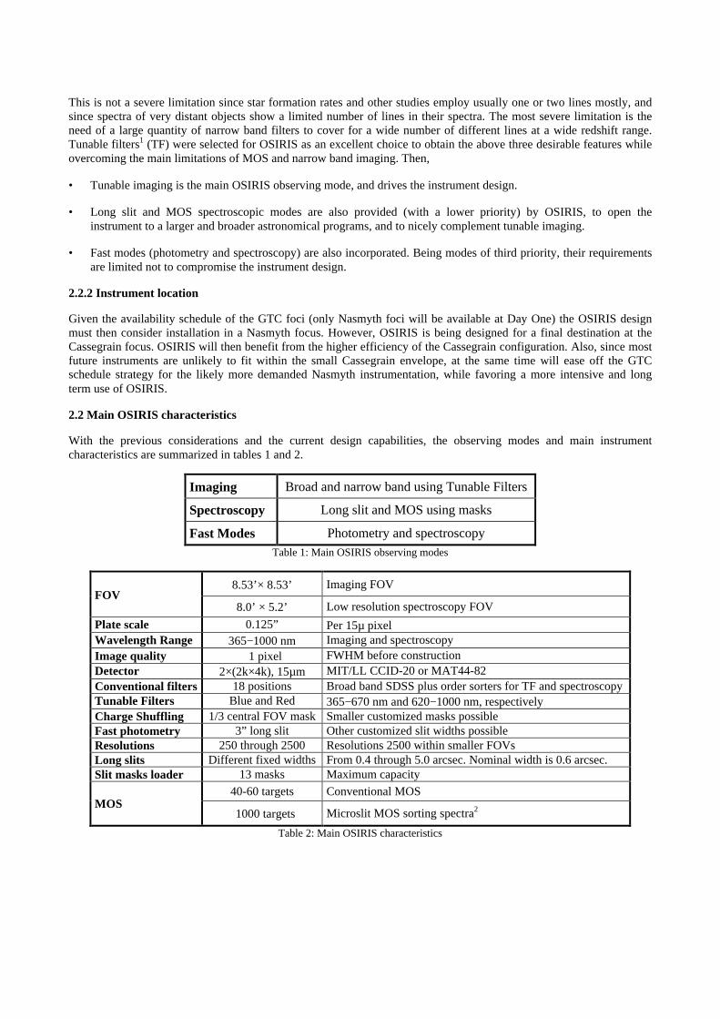
With the previous considerations and the current design capabilities, the observing modes and main instrumentcharacteristics are summarized in tables 1 and 2.
Imaging Broad and narrow band using Tunable Filters
Spectroscopy Long slit and MOS using masks
Fast Modes Photometry and spectroscopyTable 1: Main OSIRIS observing modes
8.53’× 8.53’ Imaging FOVFOV
8.0’ × 5.2’ Low resolution spectroscopy FOV
Plate scale 0.125” Per 15µ pixelWavelength Range 365−1000 nm Imaging and spectroscopyImage quality ∼1 pixel FWHM before constructionDetector 2×(2k×4k), 15µm MIT/LL CCID-20 or MAT44-82Conventional filters 18 positions Broad band SDSS plus order sorters for TF and spectroscopyTunable Filters Blue and Red 365−670 nm and 620−1000 nm, respectivelyCharge Shuffling 1/3 central FOV mask Smaller customized masks possibleFast photometry 3” long slit Other customized slit widths possibleResolutions 250 through 2500 Resolutions 2500 within smaller FOVsLong slits Different fixed widths From 0.4 through 5.0 arcsec. Nominal width is 0.6 arcsec.Slit masks loader 13 masks Maximum capacity
40-60 targets Conventional MOSMOS
∼1000 targets Microslit MOS sorting spectra2
Table 2: Main OSIRIS characteristics
3. OPTICS
3.1 Optical design
The optical design is based in a reflective collimator plus refractive camera, with a flat mirror in between to fold thelight path in order to fit the Cassegrain envelope. It has been driven by the following stringent high level requirements:
• To maximize imaging FOV and to alleviate etalon coating inhomogeneities, the tunable filters are to be placed atthe instrument pupil. Then the maximum pupil diameter is limited by the clear aperture of currently commerciallyavailable high quality TFs, such that throughput is not compromised by TF vignetting losses. As a consequence avery small pupil (about 10 cm or less) relative to most instruments of the 8-10m class telescopes is required. Thismakes the optical design of OSIRIS a very unique and challenging one.
• For the OSIRIS scientific drivers a large FOV is important, even at the possible expense of a marginal loss inthroughput, since for large targets (like clusters of galaxies and extended sources) slightly longer exposures aremore efficient than mosaic observations. The initial goal was initially set to 8’×8’ to match the telescopeunvignetted FOV.
• The focal reducer must provide enough space in the collimated beam (pupil space) to accommodate two TF, severalgrisms and their necessary filters and calibration masks.
• A red optimized design (beyond 400 nm up to the longest possible wavelength of ~1000nm) for observingredshifted emission lines, but keeping enough blue sensitivity to observe [OII] λ372.7 nm at zero redshift (starformation in nearby galaxies) and U imaging (365 nm, for stellar population studies). The possibility to implementtwo cameras (one blue optimized and another red optimized) was initially considered but rejected latter on to keepwithin cost and time budgets.
• A very good image quality for a good exploitation of the telescope and site characteristics.
• A pixel size of the order of at least 1/5 (goal 1/10) of the PSF for a good sampling to re-centre images withoutsignificant spatial degradation. Detector readout noise is not an issue because TF imaging is practically sky limited.Also, small pixel sizes alleviate cosmic ray rejection since cosmic ray hits can be better distinguished from pointlike objects. This is an important issue mainly for thick devices such as the detectors selected for OSIRIS (both theMIT/LL or the MAT options).
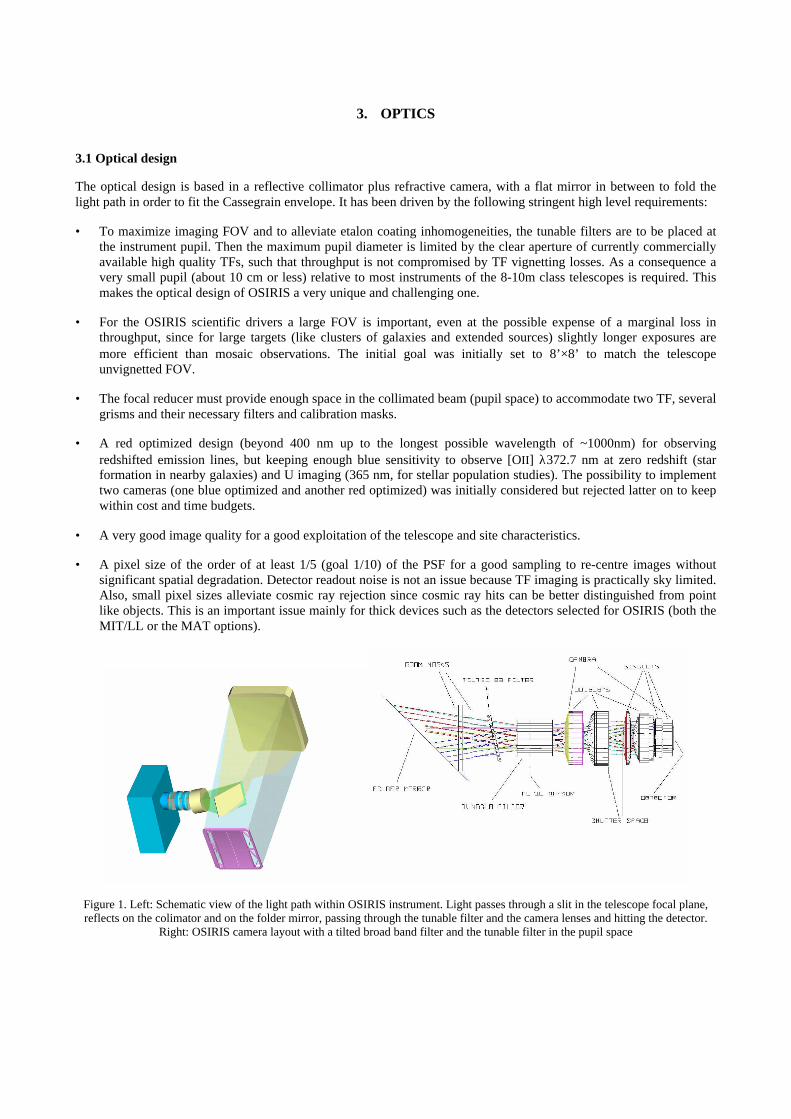
Figure 1. Left: Schematic view of the light path within OSIRIS instrument. Light passes through a slit in the telescope focal plane,reflects on the colimator and on the folder mirror, passing through the tunable filter and the camera lenses and hitting the detector.
Right: OSIRIS camera layout with a tilted broad band filter and the tunable filter in the pupil space
The current optical design3, shown in Figure 1, fulfills these requirements.
It can be shown that temperature changes degrade beyond requirements the image quality and plate scale under theexpected ambient temperature variations of about 1.8°C/hour. This is mostly due to the thermal response of therefraction indices of the OSIRIS glasses and not so much due to thickness or curvature radii variations. After a detailedthermal analysis4 the motion (of a few microns per °C) of the first camera singlet, as a sole compensator, practicallyeliminates thermal influences on both image quality and plate scale.
3.2 Dispersive and selective optics
3.2.1 Imaging
The set of broad band filters will include a SDSS set, including the z filter, plus order sorters for TFs and grisms. Allthese filters are tilted to avoid their ghosts on the detector.
Due to coating designs, two tunable filters are needed to cover the full OSIRIS wavelength range. Both have beendesigned to match blue and red resolutions with relatively high contrasts and overlapping at the Hα line at zeroredshift5. To minimize ghost images the TF shall be wedged, and the external surface of the plates AR coated. It isrequired that the tuned TF wavelength shall be stable during one hour with a variation lower than 1/10 of the FWHM atany wavelength and mode and that it shall be maintained within this range during at least one hour of observation. Thisincludes tuning accuracy, tuning resolution, RMS stability and temperature variations.
The order sorters to select the TF orders are requested to fulfill the following requirements:
• Allow distinguishing Hα from [NII] λ658.4 nm
• Avoiding strong sky emission lines whenever possible
• Overlapping in wavelength when contiguous
• With higher priority for observing:
- The zero redshift lines: Hα, Hβ, Hγ, Hδ, [OI] at 630.0 nm [OII] at 372.7 nm, [OIII] at 436.3, 495.9 and 500.7nm, [NII] at 658.4, [SII] at 671.7 and 673.1 nm, [SIII] at 906.9 nm, the 400.0 nm break, CH 430.0 nm, [FeI]438.3, 527.0 and 533.5 nm, Mgb 517.0 nm and CaT.
- The redshifted Hα, Hβ, [OII] 372.7 nm and [OIII] 500.7 nm
3.2.2 Spectroscopy
The long slit nominal width has been chosen to match the best GTC plus best site plus best instrument image. As ageneral requirement the number of grisms at every resolution shall cover the OSIRIS spectral range. The resolutionschosen are:
• The lowest one (R=250), to shorten the spectral increasing the MOS multiplexing capability of OSIRIS2.
• The intermediate one (R=1300) allowing to observe from [OII] at 372.7 nm through [NII] at 658.4 nm, and fromHα through [SIII] at 953.2 nm, in a single exposure
• The higher ones (R=2500) for studying a particular spectral line.
A more detailed description of OSIRIS grisms is given in this volume.
4. MECHANICS
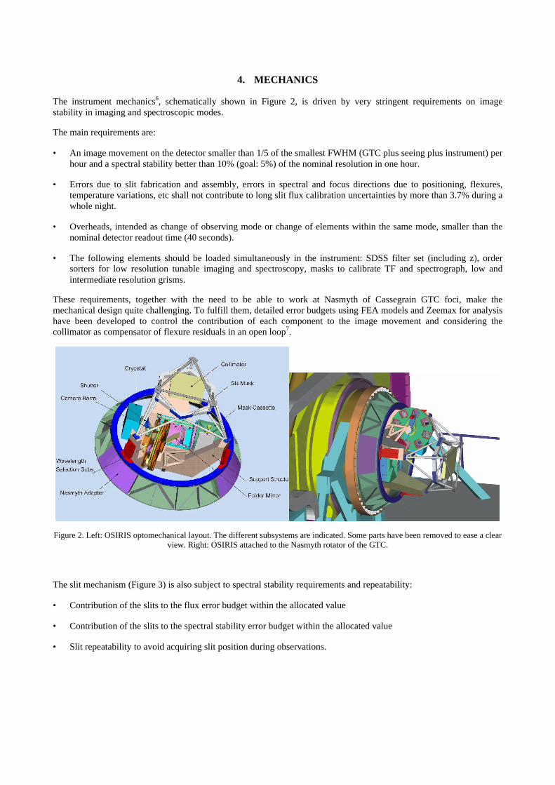
The instrument mechanics6, schematically shown in Figure 2, is driven by very stringent requirements on imagestability in imaging and spectroscopic modes.
The main requirements are:
• An image movement on the detector smaller than 1/5 of the smallest FWHM (GTC plus seeing plus instrument) perhour and a spectral stability better than 10% (goal: 5%) of the nominal resolution in one hour.
• Errors due to slit fabrication and assembly, errors in spectral and focus directions due to positioning, flexures,temperature variations, etc shall not contribute to long slit flux calibration uncertainties by more than 3.7% during awhole night.
• Overheads, intended as change of observing mode or change of elements within the same mode, smaller than thenominal detector readout time (40 seconds).
• The following elements should be loaded simultaneously in the instrument: SDSS filter set (including z), ordersorters for low resolution tunable imaging and spectroscopy, masks to calibrate TF and spectrograph, low andintermediate resolution grisms.
These requirements, together with the need to be able to work at Nasmyth of Cassegrain GTC foci, make themechanical design quite challenging. To fulfill them, detailed error budgets using FEA models and Zeemax for analysishave been developed to control the contribution of each component to the image movement and considering thecollimator as compensator of flexure residuals in an open loop7.
Figure 2. Left: OSIRIS optomechanical layout. The different subsystems are indicated. Some parts have been removed to ease a clearview. Right: OSIRIS attached to the Nasmyth rotator of the GTC.
The slit mechanism (Figure 3) is also subject to spectral stability requirements and repeatability:
• Contribution of the slits to the flux error budget within the allocated value
• Contribution of the slits to the spectral stability error budget within the allocated value
• Slit repeatability to avoid acquiring slit position during observations.
• A number of masks adequate to carry on a long slit, a MOS, or a long slit plus a MOS observing programs (thuseasing queue observations) during the same night without changing masks
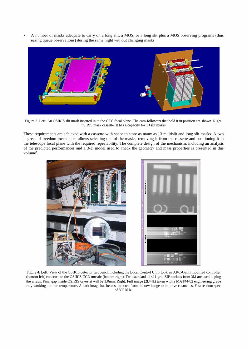
Figure 3. Left: An OSIRIS slit mask inserted in to the GTC focal plane. The cam-followers that hold it in position are shown. Right:OSIRIS mask cassette. It has a capacity for 13 slit masks.
These requirements are achieved with a cassette with space to store as many as 13 multislit and long slit masks. A twodegrees-of-freedom mechanism allows selecting one of the masks, removing it from the cassette and positioning it inthe telescope focal plane with the required repeatability. The complete design of the mechanism, including an analysisof the predicted performances and a 3-D model used to check the geometry and mass properties is presented in thisvolume8.
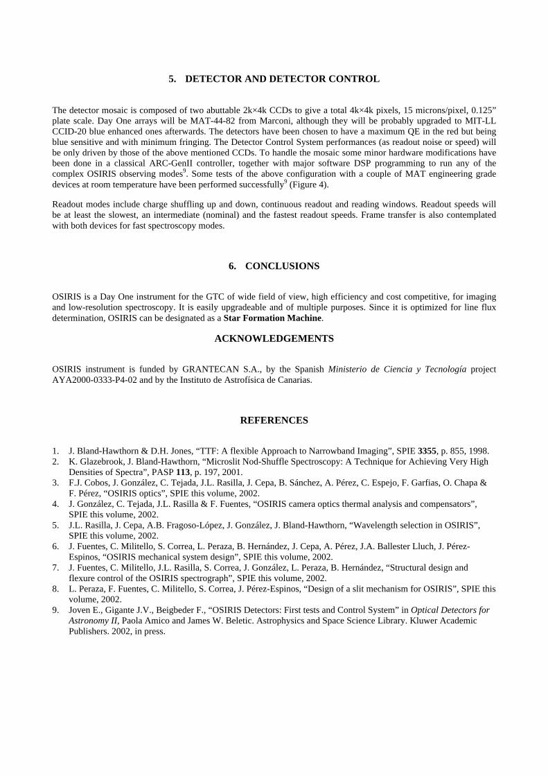
Figure 4. Left: View of the OSIRIS detector test bench including the Local Control Unit (top), an ARC-GenII modified controller(bottom left) conected to the OSIRIS CCD mosaic (bottom right). Two standard 11×11 grid ZIP sockets from 3M are used to plugthe arrays. Final gap inside OSIRIS cryostat will be 1.0mm. Right: Full image (2k×4k) taken with a MAT44-82 engineering grade
array working at room temperature. A dark image has been subtracted from the raw image to improve cosmetics. Fast readout speedof 800 kHz.
5. DETECTOR AND DETECTOR CONTROL
The detector mosaic is composed of two abuttable 2k×4k CCDs to give a total 4k×4k pixels, 15 microns/pixel, 0.125”plate scale. Day One arrays will be MAT-44-82 from Marconi, although they will be probably upgraded to MIT-LLCCID-20 blue enhanced ones afterwards. The detectors have been chosen to have a maximum QE in the red but beingblue sensitive and with minimum fringing. The Detector Control System performances (as readout noise or speed) willbe only driven by those of the above mentioned CCDs. To handle the mosaic some minor hardware modifications havebeen done in a classical ARC-GenII controller, together with major software DSP programming to run any of thecomplex OSIRIS observing modes9. Some tests of the above configuration with a couple of MAT engineering gradedevices at room temperature have been performed successfully9 (Figure 4).
Readout modes include charge shuffling up and down, continuous readout and reading windows. Readout speeds willbe at least the slowest, an intermediate (nominal) and the fastest readout speeds. Frame transfer is also contemplatedwith both devices for fast spectroscopy modes.
6. CONCLUSIONS
OSIRIS is a Day One instrument for the GTC of wide field of view, high efficiency and cost competitive, for imagingand low-resolution spectroscopy. It is easily upgradeable and of multiple purposes. Since it is optimized for line fluxdetermination, OSIRIS can be designated as a Star Formation Machine.
ACKNOWLEDGEMENTS
OSIRIS instrument is funded by GRANTECAN S.A., by the Spanish Ministerio de Ciencia y Tecnología projectAYA2000-0333-P4-02 and by the Instituto de Astrofísica de Canarias.
REFERENCES
1. J. Bland-Hawthorn & D.H. Jones, “TTF: A flexible Approach to Narrowband Imaging”, SPIE 3355, p. 855, 1998.2. K. Glazebrook, J. Bland-Hawthorn, “Microslit Nod-Shuffle Spectroscopy: A Technique for Achieving Very High
Densities of Spectra”, PASP 113, p. 197, 2001.3. F.J. Cobos, J. González, C. Tejada, J.L. Rasilla, J. Cepa, B. Sánchez, A. Pérez, C. Espejo, F. Garfias, O. Chapa &
F. Pérez, “OSIRIS optics”, SPIE this volume, 2002.4. J. González, C. Tejada, J.L. Rasilla & F. Fuentes, “OSIRIS camera optics thermal analysis and compensators”,
SPIE this volume, 2002.5. J.L. Rasilla, J. Cepa, A.B. Fragoso-López, J. González, J. Bland-Hawthorn, “Wavelength selection in OSIRIS”,
SPIE this volume, 2002.6. J. Fuentes, C. Militello, S. Correa, L. Peraza, B. Hernández, J. Cepa, A. Pérez, J.A. Ballester Lluch, J. Pérez-
Espinos, “OSIRIS mechanical system design”, SPIE this volume, 2002.7. J. Fuentes, C. Militello, J.L. Rasilla, S. Correa, J. González, L. Peraza, B. Hernández, “Structural design and
flexure control of the OSIRIS spectrograph”, SPIE this volume, 2002.8. L. Peraza, F. Fuentes, C. Militello, S. Correa, J. Pérez-Espinos, “Design of a slit mechanism for OSIRIS”, SPIE this
volume, 2002.9. Joven E., Gigante J.V., Beigbeder F., “OSIRIS Detectors: First tests and Control System” in Optical Detectors for
Astronomy II, Paola Amico and James W. Beletic. Astrophysics and Space Science Library. Kluwer AcademicPublishers. 2002, in press.