ordinance no. 20100624-146 - austintexas.gov
TRANSCRIPT
ORDINANCE NO. 20100624-146
AN ORDINANCE REPEALING AND REPLACING ARTICLE 6 OF CITY CODECHAPTER 25-12 TO ADOPT THE 2009 UNIFORM PLUMBING CODE ANDLOCAL AMENDMENTS.
BE IT ORDAINED BY THE CITY COUNCIL OF THE CITY OF AUSTIN:
PART 1. City Code Chapter 25-12 is amended to repeal Article 6 (Plumbing Code) andreplace it with a new Article 6 to read as follows:
ARTICLE 6. PLUMBING CODE
§ 25-12-151 PLUMBING CODE.
(A) The Uniform Plumbing Code, 2009 edition, published by the InternationalAssociation of Plumbing and Mechanical Officials (2009 Uniform PlumbingCode) is adopted and incorporated into this section, including all appendicesexcept Appendices F and K, with deletions and amendments in Subsection(B) and Section 25-12-153 (Local Amendments to the Plumbing Code).
(B) The following provisions of the 2009 Plumbing Code are deleted. Allsubsections contained within a deleted section or subsection are also deleted,even if not specifically listed below.
101.4.1.3 101.5.3 103.1.1
103.1.2 103.1.3 103.3.4
103.4 Table 1-1 313.7
320.0 402.2 402.3
411.2 Table 5-1 501.0
507.1.1 508.4 509.4
601.1 601.2.2 Table 6-2
603.1 603.3.4 603.4.6.1
603.4.12 608.2 704.3
707.4 710.3.3 712.0
713.4 713.6 715.1
723.0 801.3 804.1
Page 1 of 59
807.4
Table 10-2
1009.2
1012.0
1014.2
1014.3.7
1017.0
1101.3
1101.6
1104.3
1204.3.1
1205.2
1213.0
Table 12-6
1507.1
905.3
Table 10-3
1010.0
1013.0
1014.3.3
1015.0
Table 11-3
1101.4
1101.9
1106.3
1204.3.2
1209.5.3.2
1214.0
Chapter 13
Chapter 16 Part II
909.0
1007.0
1011.0
1014.1
1014.3.6
1016.0
1101.1
1101.5
1101.10
1109.0
1204.4
1211.3.2
Table 12-5
1501.1
(C) The city clerk shall file a copy of the 2009 Plumbing Code with the officialordinances of the City.
25-12-152 CITATIONS TO THE PLUMBING CODE.
In the City Code, "Plumbing Code" means the 2009 Plumbing Code adopted by Section25-12-151 (Plumbing Code), as amended by Section 25-12-153 (Local Amendments tothe Plumbing Code).
25-12-153 LOCAL AMENDMENTS TO THE PLUMBING CODE.
The following provisions are local amendments to the 2009 Plumbing Code. Eachprovision in this section is a substitute for the identically numbered provision deleted bySection 25-12-151(8) (Plumbing Code) or is an addition to the 2009 Plumbing Code.
101.4.1.3 Existing Construction. No provision of this Code shall be deemed to require achange in any portion of a plumbing or drainage system or any other work regulated bythis Code in or on an existing building or lot when such work was installed and ismaintained in accordance with law in effect before the effective date of this Code, exceptwhen any such plumbing or drainage system or other work regulated by this Code is
Page 2 of 59
determined by the Authority Having Jurisdiction to be dangerous, unsafe, unsanitary, or anuisance and a menace to life, health, or property, or where retrofit is required by Chapter6-4, Article 1 (Plumbing Fixture Retrofit) of the City Code.
101.5.3 Existing Installation. Plumbing systems lawfully in existence at the time of theadoption of this Code may have their use, maintenance, or repair continued if the use,maintenance, or repair is in accordance with the original design and location and nohazard to life, health, or property has been created by such plumbing system unlessretrofit is required by Chapter 6-4, Article 1 (Plumbing Fixture Retrofit) of the City Code.
103.1.1 Permits Required. It shall be unlawful for any person, firm, or corporation tomake any installation, alteration, repair, replacement, or to remodel any plumbing systemregulated by this code except as permitted in section 103.1.2, or to cause the same to bedone without first obtaining a separate plumbing permit for each separate building,structure, or on-site plumbing or non-potable water reuse system.
103.1.1.1 Persons Authorized to Obtain Permits. A master plumber licensed by theState of Texas and registered with the City may obtain permits required by this Code.
Exception: A permit may be issued to an unlicensed person for plumbing workthat under state law may be done by an unlicensed person.
103.1.2 Exempt Work. A plumbing permit is not required for the following:
103.1.2.1 The stopping of leaks in drains, soil pipe, waste pipe or vent pipe, provided,however, that the removal or replacement of a defective concealed trap, drain pipe, soilpipe, waste pipe or vent pipe is new work and a permit shall be procured and inspectionmade as provided in this Code.
103.1.2.2 The clearing of stoppages, the repair of leaks in pipes, valves or fixtures, or theremoval and reinstallation of water closets, if the repairs do not involve or require thereplacement or rearrangement of valve, pipes, or fixtures. The installation or replacement,of backflow prevention assemblies, or devices are not exempt from plumbing permit andplumbing licensing requirements.
103.1.2.3 Repairs or replacement of fixtures and replacement of traps, continuous wastepiping, water shut-off valves, faucets, are exempt from permit requirements if the work isperformed in accordance with the requirements of the Plumbing Code, and does notinvolve other city departments or inspections from other trades. Exemption from thepermit requirements of this Code is not authorization for the work to be done in violationof this Code or other laws or ordinances of the City.
103.1.3 Homestead Permit. A person who is not licensed to perform plumbing workmay perform plumbing work within a residence and on property owned by the person ifthe requirements of this section are met.
(1) The residence is the person's homestead.
Page 3 of 59
(2) The work does not include plumbing work that involves natural gas orliquefied petroleum plumbing systems.
(3) The residence is the person's principal residence.
(4) The person has not secured a homestead permit for another residence withinthe prior 12 month period.
(5) The person must have owned and occupied the property as of January 1 ofthe tax year in which the person applies for a homestead permit.
(6) A person must obtain a homestead permit and pay required permit feesbefore beginning any electrical, mechanical, or plumbing work. A personmust apply for a homestead permit in person and must file an affidavitstating that the location at which the work is to be done is the person'shomestead.
(7) A person who has obtained a homestead permit may not allow or cause anyperson to perform plumbing work under the permit. The building officialmay suspend or revoke a homestead permit if work done under the permit isperformed by anyone other than the person who obtained the permit.
(8) A person may not transfer a permit to another person.
(9) A person performing plumbing work under a homestead permit shall presenta picture identification to verify that the person is authorized to performwork under the homestead permit, when requested by the building official orhis designee.
(10) A homestead permit shall not be issued for plumbing work on a mobile,modular or manufactured home unless the homeowner owns the land onwhich the mobile, modular or manufactured home is located. A homesteadpermit shall not be issued if the mobile, modular or manufactured home islocated in a mobile home park, mobile home community or othercommercial premises.
(11) A homestead permit shall not be issued for any auxiliary water system.
103.1.3.4. Registered Industrial Plant Program. A licensed plumber may perform thefollowing plumbing installations in a Registered Industrial Plant, as defined by this Codeand the Building Code:
Installation, repair, and replacement of fixtures, traps, shut-off valves, waterdistribution piping, drains, building waste piping, vent stacks and water heaterswith a capacity of 100 gallons or less and a rating of 75,000 BTU or less, providedthe work does not require approval of the Austin Travis County HealthDepartment, the City of Austin Water Utility, or the Texas Department ofLicensing and Regulation.
Page 4 of 59
No plan review fee or permit fee shall be required if records are maintained in accordancewith the registered industrial plant program established in the Building Code.
103.1.4 Licensing. Every person who enters into a contract for the installation or repairof plumbing systems covered by this Code for which a permit is required shall complywith licensing regulation of the State of Texas.
103.1.4.1 Registration of Plumbers. A plumber shall register with the City beforeperforming any work regulated by this Code.
103.1.4.2 Landscape Irrigation. A person licensed by the Texas Commission onEnvironmental Quality to install irrigation systems shall register with the City. Aplumbing permit shall be purchased before installing landscape irrigation or a yardsprinkler system. A registration fee is required when a license is presented for initialregistration, after a license suspension, or after license expiration. A new fee shall not berequired for a renewal of a license before expiration.
103.1.5 Special Inspections Program. The building official may establish by rule aninspection program of plumbing components identified in this section in buildings withinthe zoning jurisdiction of the City and outside of the zoning jurisdiction under agreementwith a municipal utility district or where the City provides water or wastewater service ofthe City. Under the program the building official shall inspect work performed under oneout of five of the applications submitted. The special inspection program applies to thereplacement of existing:
(1) water heaters not exceeding 100 gallons or 75,000 BTU's; and
(2) backflow devices.
103.2.1.7 Application for a permit shall contain the name of the master plumber licensedby the State of Texas Board of Plumbing Examiners, and registered with the City.
103.3.4.1 Permit Expiration and Reactivation. Requirements for permit expirationand reactivation, including an enhanced fee for expired permits, are set forth in Chapter25-12, Article 13 (Administration of Technical Codes').
103.4 Fees.
103.4.1 Permit and Plan Review Fees. Permit and plan review fees shall be establishedunder separate ordinance by action of the City Council.
103.9 Solar Heating Systems. A solar water heater or a solar recreational andtherapeutic water-heating system shall be installed in accordance with the requirementsof this Code and the Solar Code. A public solar recreational and therapeutic water heatingsystem shall be installed in accordance with the requirements of this Code, the SolarCode, and the Health Authority.
Page 5 of 59
104.0 Private Sewage Systems. The Austin Water Utility regulates private sewagedisposal systems covered by this Code, Regulations regarding on-site sewage facilitiesare found in Chapter 15-5 of the City Code.
105.0 Mechanical, Plumbing and Solar Board. Regulations regarding the Mechanical,Plumbing and Solar Board are found in Chapter 2-1 of the City Code.
106.0 Qualified Inspectors. An inspector who performs inspections under this code mustmeet the following qualifications.
106.1 Plumbing/Mechanical Inspector Supervisor.
(1) The Plumbing/Mechanical Inspection Supervisor must:
(a) be an employee of the City;
(b) maintain a current plumbing inspector license issued by the TexasState Board of Plumbing Examiners;
(c) maintain a current certification as a mechanical and plumbinginspector under the certification program established by theInternational Code Conference or International Association ofPlumbing and Mechanical Officials; and
(d) have at least ten years of experience as a licensed master plumber orequivalent experience as a City or state licensed air conditioning andrefrigeration contractor, at least three years of which must be in aresponsible supervisory capacity.
(2) Five years of inspection experience may be substituted for five years of craftexperience required in Subsection l(d) above.
106.2 A plumbing inspector must:
(1) be an employee of the City;
(2) maintain a current plumbing inspector license issued by the Texas StateBoard of Plumbing Examiners;
(3) maintain a current certification as a plumbing inspector under thecertification program established by the International Code Conference orthe International Association of Plumbing and Mechanical Officials; and
(4) have a least five years of experience as a state licensed master or journeymanplumber, one year of which must be in a responsible supervisory capacity.
106.3 A person hired by the City as a commercial plumbing inspector after the effectivedate of this Code must become certified through the certification program established bythe International Code Conference or the International Association of Plumbing andMechanical Officials not later than one year after the date of employment.
Page 6 of 59
218.1 Definition of "plumbing system." The following definition supercedes thedefinition included in Section 218 of the Uniform Plumbing Code, which applies to allother defined terms:
Plumbing System: includes all potable water, building supply, and distributionpipes; all plumbing fixtures and traps; all drainage and vent pipes; and all buildingdrains and building sewers, including their respective joints and connections,devices, receptors, and appurtenances within the property lines of the premises andshall include potable water piping, nonpotable water reuse systems, irrigationsystems, potable water treating or using equipment, medical gas and medicalvacuum systems, liquid and fuel gas piping, and water heaters and vents for same.
220.1 Definition of "Restricted Use Restroom." The following definition supplementsthe definitions in Section 220.0:
Restricted Use Restrooms: A restricted use restroom is a restroom that isimmediately accessible only through one or more single occupant offices and thatare located on a floor where adequate public restroom facilities are also available.A restricted use restroom is not a public restroom for purposes of this Code.
222.1 Definition of "Trap, Deep Seal P-trap." The following definition supplementsthe definitions in Section 222.0:
Trap, Deep Seal P-trap. A fixture trap having a water seal of at least four inches,but not more than twice the diameter of the trap arm, and not to exceed twelve (12)inches. A trap shall set true with respect to its water seal, and, where necessary, itshall be protected from freezing.
305.2.1 Sewage System Connection Required. The drainage system of every house orbuilding shall be separately and independently connected to a public sewage disposalsystem if any part of the lot or tract that contains the house or building is within 100 feetin horizontal distance (measured on the closest practicable access route) of a publicsewage disposal system. Connection to a public sewage disposal system is not required ifany one of the following applies:
(1) The property owner has received a written denial of service from the owneror governing body of the public sewage disposal system.
(2) The property owner has received a written determination from the AustinWater Utility that it is not feasible for the building to be connected to thepublic sewage disposal system.
(3) The property is served by an existing private sewage facility and the AustinWater Utility has determined that the private sewage facility may continue tobe used based on factors such as the type of facility served, the age,condition, and capacity of the private sewage facility, and the availability ofrecords regarding the system, changes to the system, or the generating unit.
Page 7 of 59
(4) A composting toilet serves the property; and the Austin Water Utility hasapproved the disposal of liquid wastes in a private on-site sewage facility.
313.7 Piping penetrations of fire resistance rated walls; partitions, floors, floor/ceilingassemblies, roof/ceiling assemblies, or shaft enclosures shall be protected in accordancewith the requirements of the Building Code.
320.0 Medical Gas and Vacuum Systems. The installation of any medical gas andvacuum system used in conjunction with human health care purposes shall comply withall requirements of the current edition of the National Fire Protection Association(NFPA) 99C, entitled "Medical Gas and Vacuum Systems''. The latest edition of theANSI/ASSE Series 6000 titled "Professional Qualifications Standards for Medical GasSystems Installers, Inspectors, Verifiers, Maintenance Personnel and Instructors" shallalso be applicable except that which conflicts with the Texas State Board of PlumbingExaminers Plumbing License Law requirements. Medical gas installations for Non-Human Use shall conform to section 1304.0 in its entirety.
321.0 Requirements for Flood Plain Areas.
321.1 Definitions.
(1) Regulatory Flood Datum (RFD) means an established plane of referencefrom which elevations and depth of flooding may be determined for specificlocations of the flood plain in accordance with the Building Code.
(2) W-l spaces means spaces that must remain completely dry during floodingto the RFD. Walls must be impermeable to water and water vapor inaccordance with the Building Code.
(3) W-2 spaces means spaces that remain essentially dry during flooding to theRFD. Walls must be impermeable to water, but may pass some water vaporor seep slightly in accordance with the Building Code.
321.2 For the purpose of this section, plumbing systems shall include sanitary and stormdrainage, sanitary facilities, water supply, and storm water disposal systems.
321.3 Sanitary sewers and storm drainage systems that have openings below the RFDshall be provided with automatic backwater valves or other automatic backflow devicesthat are installed in each discharge line passing through a building exterior wall. In W-lspaces, manually operated shut-off valves that can be operated from a location above theRFD shall also be installed on the lines to serve as supplementary safety provisions forpreventing backflow if the automatic backflow device fails.
321.4 If the dryness of a space depends on sump pump systems, all interior storm waterdrainage or seepage, appliance drainage, and under slab drain tile systems shall bedirectly connected to a sump pump and discharged at an elevation of five feet above theRFD.
Page 8 of 59
321.5 Septic tanks and disposal beds are not permitted in the 25-year flood hazard area.In other areas within the flood hazard areas, the use of septic tanks and disposal beds forsewage disposal is subject to the approval of Austin Water Utility.
321.6 Potable water supply systems that are located in the flood hazard area shall bedesigned and installed in a manner that prevents contamination from floodwaters up tothe RFD.
321.7 Approved backflow preventers or devices shall be installed on main water servicelines to building entry locations to protect the system from backflow or back siphonage ofwaters or other contaminants in the event of a line break. Devices shall be installed ataccessible locations and shall be maintained in accordance with this Code.
321.8 Establishment of Flood Hazard Areas. Flood hazard areas are established toinclude the following:
(1) The flood hazard areas identified by the Federal Emergency ManagementAgency in a scientific and engineering report entitled, "The FloodInsurance Study for Austin, Texas," dated September 26, 2008, withaccompanying Flood Insurance Rate Maps and Flood Boundary-Floodway Maps (FIRM and FBFM) and related supporting data alongwith any amendments or revisions thereto are hereby adopted byreference and declared to be a part of this section.
(2) The 100-year and 25-year floodplains based on projected frilldevelopment as specified in the Austin City Code and Drainage CriteriaManual are adopted by reference and declared to be part of this section.
322.0 Elevator Sump Pumps. Pumps and associated piping and materials required forelevators installed under the rules of the Texas Administrative Code, Title 16, Part 4,Chapter 74 shall also comply with sections 322.1 thru 322.4.
322.1 Acceptable Discharge Location. Pumps shall discharge to the storm systemoutside the building, detention pond or other location approved by the Authority HavingJurisdiction.
322.2 Discharge Piping. Piping shall be a minimum of one and a half inch (1 Vz") NPS.Piping shall be independent and not connect to the storm or sub-soil piping within thebuilding. Discharge piping shall conform to section 710.4 of this code. If an elevatorsump pump is located below the 100 year flood plain its piping shall rise above the 100year flood plain elevation before connecting to a gravity drainage system. Piping shall belabeled as required in section 610.2.2 of this code.
322.3 Materials. Piping materials for elevator sump pump piping shall be of galvanizedsteel, galvanized wrought iron, copper or other material approved by the AuthorityHaving Jurisdiction.
Page 9 of 59
322.4 Sample Port. A sample port shall be installed outside the building on privateproperty or other locations approved by the Authority Having Jurisdiction. Acceptablesample ports include single riser two way cleanouts, open grate catch basins or otherapproved fittings/receptors with the ability to visually see the flow line and retrievesamples.
402.2 Water Closets. Effective May 1st, 2010, water closets, including flush tank,flushometer tank, and flushometer valve operated, shall have an average consumption ofa maximum of 1.28 gallons of water per flush.
402.3 Urinal Flushometer. New installation of a flushometer valve shall have amaximum discharge of (1/2) one-half gallon per flush.
402.3.1 Nonwater Urinals. Nonwater urinals shall be listed and comply with theapplicable standards referenced in Table 14-1. Nonwater urinals shall have a barrierliquid sealant to maintain a trap seal. Nonwater urinals shall permit the uninhibited flowof waste through the urinal to the sanitary drainage system. Nonwater urinals shall becleaned and maintained in accordance with the manufacturer's instructions afterinstallation. Where nonwater urinals are installed they shall have a water distribution linerough-in to the urinal location to allow for the installation of an approved backflowprevention device in the event of a retrofit. Nonwater urinals that are determined by theAuthority Having Jurisdiction to have been maintained contrary to the manufacturer'sinstructions, and determined to be a health hazard or detrimental to public health andsafety shall be retrofitted by a flushometer type urinal complying with Section 402.3. TheBuilding Official shall establish the timeline for a retrofit if public health iscompromised.
402.7 Compliance with State Water Conservation Standards. Water savingperformance standards for all plumbing fixtures must comply with ANSI A112.18.l-Plumbing Fixtures (Flow Capacity) and Chapter 372 of the Health and Safety Code of theState of Texas, whichever is more restrictive.
408.1.1 Water Closet Enclosure. Each water closet that will be used by the public oremployees shall be separated by walls or partitions and a door to maintain privacy.
Exception: Water closet enclosures shall not be required in single occupant toiletfacilities which contain a lockable door.
408.4.6 Fixtures, brackets and flanges shall be set on finished walls and floors.
Exception: Water closets in carpeted bathrooms.
Table 4-1.1 Minimum Plumbing Facilities for Certain Occupancies. Table 4-1.1includes the minimum fixture requirements for the following types of occupancies:
(1) Office or Public Buildings for Employee Use (5000 square feet, or less)
Page 10 of 59
(2) Retail or Wholesale
(3) Exercise and Health Spas
(4) Restaurants, Pubs and Lounges (4500 square feet, or less).
(5) Libraries
(6) Workshops
(7) Warehouses
Page 11 of 59
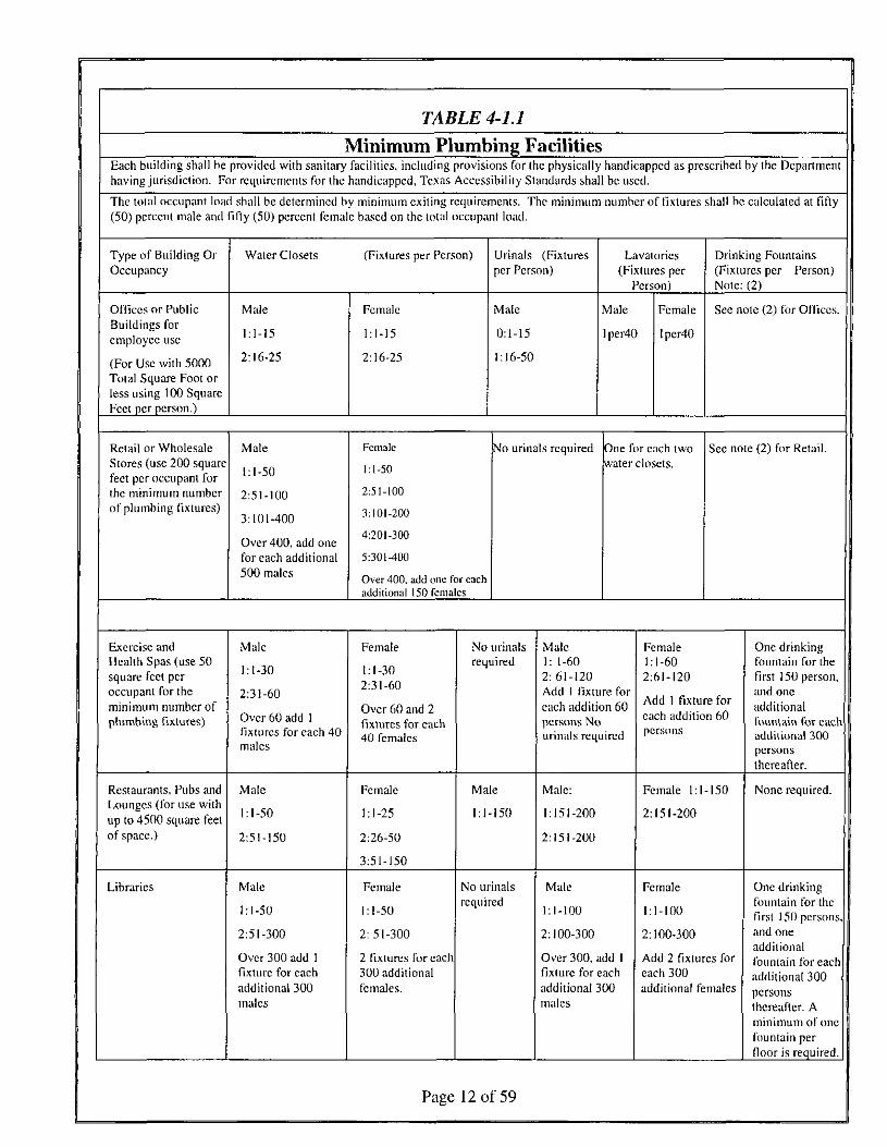
TABLE 4-1.1
Minimum Plumbing FacilitiesEach building shall be provided with sanitary facilities, including provisions for the physically handicapped as prescribed by the Departmenthaving jurisdiction. For requirements for the handicapped, Texas Accessibility Standards shall be used.
The totul occupant load shall be determined by minimum exiling requirements. The minimum number of fixtures shall be calculated at fifty(50) percent male and fifty (50) percent female based on the total occupant load.
Type of Building OrOccupancy
Water Closets (Fixtures per Person) Urinals (Fixturesper Person)
Lavatories(Fixtures per
Person)
Drinking Fountains(Fixtures per Person)Note: (2)
Offices or PublicBuildings foremployee use
(For Use with 5000Total Square Foot orless using 100 SquareFeet pcipcrson.)
Male
1:1-15
2:16-25
Female
1:1-15
2:16-25
Male
0:1-15
1:16-50
Male
Iper40
Female
Iper40
See note (2) for Offices.
Retail or WholesaleStores (use 200 squarefeet per occupant forthe minimum numberof p lumbing fixtures)
Male
1:1-50
2:51-100
3:101-400
Over 400, add onefor each additional500 males
Female
1:1-50
2:51-100
3:101-200
4:201-300
5:301-400
Over 400, add one for eachadditional 150 females
N'o urinals required One for each twowater closets.
See note (2) for Retail.
Exercise andHealth Spas (use 50square feet peroccupant for theminimum number ofplumbing fixtures)
Male
1:1-30
2:31-60
Over 60 add 1fixtures for each 40males
Female
1:1-302:31-60
Over 60 and 2fixtures for each40 females
No urinalsrequired
Male1: 1-602:61-120Add I fixture foreach addition 60persons Nourinals required
Female1:1-602:61-120
Add I fixture foreach addition 60persons
One drinkingfountain for thefirst 150 person,and oneadditionalfountain for eachadditional 300personsthereafter.
Restaurants, Pubs andLounges (for use withup to 4500 square feetof space.)
Male
1:1 -50
2:51-150
Female
1:1-25
2:26-50
3:51-150
Male
1:1-150
Male:
1:151-200
2:151-200
Female 1:1-150
2:151-200
None required.
Libraries Male
1:1-50
2:51-300
Over 300 add 1fixture for eachadditional 300males
Female
1:1-50
2:51-300
2 Fixtures for each300 additionalfemales.
No urinalsrequired
Male
1:1-100
2:100-300
Over 300, add Ifixture for eachadditional 300males
Female
1:1-100
2:100-300
Add 2 fixtures foreach 300additional females
One drinkingfountain for thefirst 150 persons,and oneadditionalfountain for eachadditional 300personsthereafter. Aminimum of onefountain perfloor is required.
Page 12 of 59
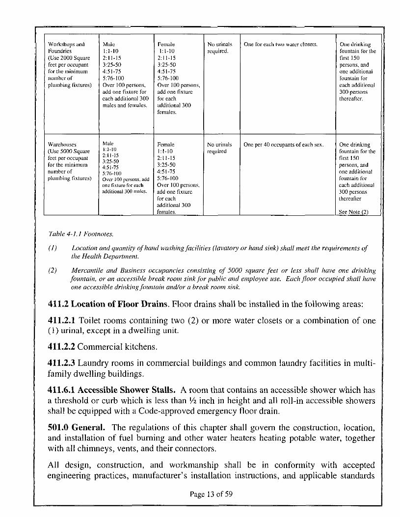
Workshops andFoundries(Use 2000 Squarefeet per occupantfor the minimumnumber ofplumbing fixtures)
Warehouses(Use 5000 Squarefeet per occupantfor the minimumnumber ofplumbing fixtures)
Male1:1-102 : 1 1 - 1 53:25-504:51-755:76-100Over 100 persons,add one fixture foreach additional 300males and females.
Male1:1-102:1 1-153:25-504:51-755:76-100Over 1 00 persons, addone fixture for eachadditional 300 males.
Female1:1-10
2:11-153:25-504:51-755:76-100Over 100 persons,add one fixturefor eachadditional 300females.
Female1:1-102:11-153:25-504:51-755:76-100Over 100 persons.add one fixiurcfor eachadditional 300females.
No urinalsrequired.
No urinalsrequired
One for eaeh Iwo water closets.
One per 40 occupants of each sex.
One drinkingfountain for thefirst 150persons, andone additionalfountain foreach additional300 personsthereafter.
One drinkingfountain for thefirst 150persons, andone additionalfountain foreach additional300 personsthereafter
See Note (2)
Table 4-1,1 Footnotes.
(1) Location and quantity of hand washing facilities (lavatory or hand sink) shall meet the requirements ofthe Health Department.
(2) Mercantile and Business occupancies consisting of 5000 square feet or less shall have one drinkingfountain, or an accessible break room sink for public and employee use. Each floor occupied shall haveone accessible drinking fountain and/or a break room sink.
411.2 Location of Floor Drains. Floor drains shall be installed in the following areas:
411.2.1 Toilet rooms containing two (2) or more water closets or a combination of one(1) urinal, except in a dwelling unit.
411.2.2 Commercial kitchens.
411.2.3 Laundry rooms in commercial buildings and common laundry facilities in multi-family dwelling buildings.
411.6.1 Accessible Shower Stalls. A room that contains an accessible shower which hasa threshold or curb which is less than !/2 inch in height and all roll-in accessible showersshall be equipped with a Code-approved emergency floor drain.
501.0 General. The regulations of this chapter shall govern the construction, location,and installation of fuel burning and other water heaters heating potable water, togetherwith all chimneys, vents, and their connectors.
All design, construction, and workmanship shall be in conformity with acceptedengineering practices, manufacturer's installation instructions, and applicable standards
Page 13 of 59
and shall be of such character as to secure the results sought to be obtained by this Code.No water heater shall be hereinafter installed which does not comply in all respects withthe type and model of each size thereof approved by the Administrative Authority. A listof accepted gas equipment standards is included in Table 14-1.
501.1 Water Heater Location. The total developed length of water piping from theoutlet of the water heater to the inlet of the furthest fixture served by the water pipingmay not be greater than 70 feet, unless the water heater is installed with a gravity flowdesign system or a mechanical pump to provide continuous hot water to the fixture orwith additional water heaters.
501.1.2 Compliance with the Energy Code Required. Water heaters installed after theeffective date of this Code in sites served by the City's Electric Utility shall comply withthe Energy Code. All replacement electrical equipment must comply with the EnergyCode.
507.1.1. Air for combustion, ventilation, and dilution of flue gases for gas utilizationappliances installed in buildings shall be obtained by application of one (1) of themethods covered in Sections 507.2.1 through 507.7. Gas utilization appliances of otherthan natural draft and Category I vented appliances shall be provided with combustion,ventilation, and dilution air in accordance with the appliance manufacturer's instructions.Where infiltration does not provide the necessary air, outdoor air shall be introduced inaccordance with methods covered in Sections 507.4 through 507.7. [NFPA 54:9.3.1.1]
Exception No. 1: This provision shall not apply to direct-vent appliances.
Exception No. 2: Type 1 clothes dryers that are provided with make-up air inaccordance with section NFPA 54:10.4.3.
Exception No. 3: Outside air shall not be obtained by any means that violates theCity adopted energy code.
507.1.1.1 Clothes Dryer. A device used to dry wet laundry by means of heat derivedfrom the combustion of fuel gases. [NFPA 54.3.3.18]
5.7.1.1.2 Clothes Dryer, Type 1. Primarily used in family living environment. May ormay not be coin-operated for public use. [NFPA 54.3.3.18.1]
5.7.1.1.3 Exhausting to the Outdoors. Type 1 and Type 2 clothes dryers shall beexhausted to the outside air. [NFPA 54:10.4.2]
5.7.1.1.4 Provisions for Make-Up Air. Make-up air shall be provided for Type 1clothes dryers in accordance with the manufacturer's installation instructions. [NFPA54:10.4.3.1]
Page 14 of 59
508.4 Protection From Damage. When a water heater is located in an attic or furredspace where damage may occur from a leaking water heater, a watertight pan ofcorrosion resistant materials shall be installed beneath the water heater with a minimumthree-quarter (3/4) inch diameter drain to an approved location. The water heater panshall have a depth of two (2) inches and have a diameter that is two (2) inches larger thanthe water heater.
509.4 Appliances in Attics. An attic in which a water heater is installed shall bedesigned to support the weight of the water heater, A water heater installation shall beaccessible for inspection, repair, or replacement. The appliance space shall be providedwith an opening or doorway of sufficient size to remove the water heater. The opening ordoorway must be at least twenty-four (24) inches in width and three (3) inches higherthan the water heater to be installed. The access shall be continuous and shall beaccomplished by one or more of the methods described in this section:
509.4.1 By an opening or door, the passageway not less than twenty-four (24) inches inwidth and large enough to permit removal of the water heater, but not less than thirty (30)inches in height. Stairways and ramps that lead to or are a part of the passageway shallcomply with the Building Code.
509.4.2 For an attic, roof, mezzanine, or platform that is more than eight (8) feet aboveground level or floor level, by a stairway or ladder permanently fastened to the building.The ladder or stairway may not be more than eighteen (18) feet in length betweenlandings and not less than fourteen (14) inches in width. The ladder shall have rungsspaced not more than fourteen (14) inches center to center and not less than six (6) inchesfrom the face of the wall. Each stile shall extend thirty (30) inches above the surface to bereached or as high as possible if height is limited. Permanent ladders for water heateraccesses are not required at parapets or walls less than thirty (30) inches in height.
Exception: Permanent ladders or platforms are not required for electric waterheaters with a capacity of seventeen (17) gallons or less.
509.4.3 By a trap door or opening and passageway not less than thirty (30) inches bythirty (30) inches in size, but in no case smaller than the water heater. The unobstructedpassageway shall be continuous from the trap door or opening to the water heater. Thecatwalk shall be level and free of any obstruction to allow safe removal of the waterheater. The trap door or opening shall be located not more than twenty (20) feet from thewater heater.
509.4.4 Lighting and Convenience Outlet. A permanent 120-volt receptacle outlet and alighting fixture shall be installed near the water heater. The switch controlling the lightingfixture shall be located at the entrance to the passageway.
601.1 Plumbing Fixture Water Required. Except where not deemed necessary forsafety or sanitation by the Authority Having Jurisdiction, each plumbing fixture shall beprovided with an adequate supply of potable running water piped thereto in an approved
Page 15 of 59
manner, so arranged as to flush and keep it in a clean and sanitary condition withoutdanger of backflow or cross-connection. Water closets and urinals shall be flushed bymeans of an approved flush tank or flushometer valve. In areas where an auxiliary watersystem is available, structures may be provided with auxiliary water for indoor use toprovide non-potable water to water closets, urinals and trap primers as regulated by thewater utility and Chapter 16 of this Code.
601.1.1 Hot and Cold Water Required. In occupancies where plumbing fixtures areinstalled for private use, hot and cold potable water shall be required for bathing,washing, laundry, cooking purposes, dishwashing, or maintenance. In occupancies whereplumbing fixtures are installed for public use, hot water shall be required for bathing andwashing puiposes. This requirement shall not supersede the requirements for individualtemperature control limitations for public lavatories, bathtubs, whirlpool bathtubs andshower control valves, nor shall it supersede the requirements for hot water by the HealthAuthority.
Exception: A permitted composting toilet approved by the Austin Water Utilityserves the property.
601.1.2 Water System Connection Required. The water system of every house orbuilding shall be separately and independently connected to a state licensed publicpotable water system if any part of the lot or tract that contains the house or building iswithin 100 feet in horizontal distance (measured on the closest practicable access route)of the public water system. Connection to the public water system is not required if anyof the following apply:
(1) The property owner has received a written denial of service from the owneror governing body of the public water system.
(2) The property owner has received a written determination from the waterutility that it is not feasible for the building to be connected to the potablewater system.
(3) The property is served by an existing private potable water system and thewater utility has determined that the private potable water system maycontinue to be used based on factors such as the type of facility served, theage, condition, and capacity of the private potable water system, and theavailability of records regarding the system, changes to the system, or thesystem demand.
601.1.3 If a state licensed public potable water system is unavailable within the fullpurpose jurisdiction of the City of Austin, then any alternative source used for potablewater shall be installed per the provisions of this code. Rain water collection systemsutilized for potable water shall comply with the latest edition of the Texas Manual onRainwater Harvesting by the Texas Water Development Board and any other applicablestate laws.
Page 16 of 59
601.2.2 Color and Information. Each system shall be identified with a colored pipe orband and coded with paints, wraps and materials compatible with the piping.
Except as required by Chapter 16, non-potable water systems shall have a yellowbackground with black uppercase lettering, with the words "CAUTION: NONPOTABLEWATER, DO NOT DRINK." Each nonpotable system shall be identified to designate theliquid being conveyed, and the direction of normal flow shall be clearly shown. Theminimum size of the letters and length of the color field shall conform to Table 6-1.
The background color and required information shall be indicated every twenty(20) feet (6,096mm) but not less than once per room, and shall be visible from the floorlevel.
Page 17 of 59
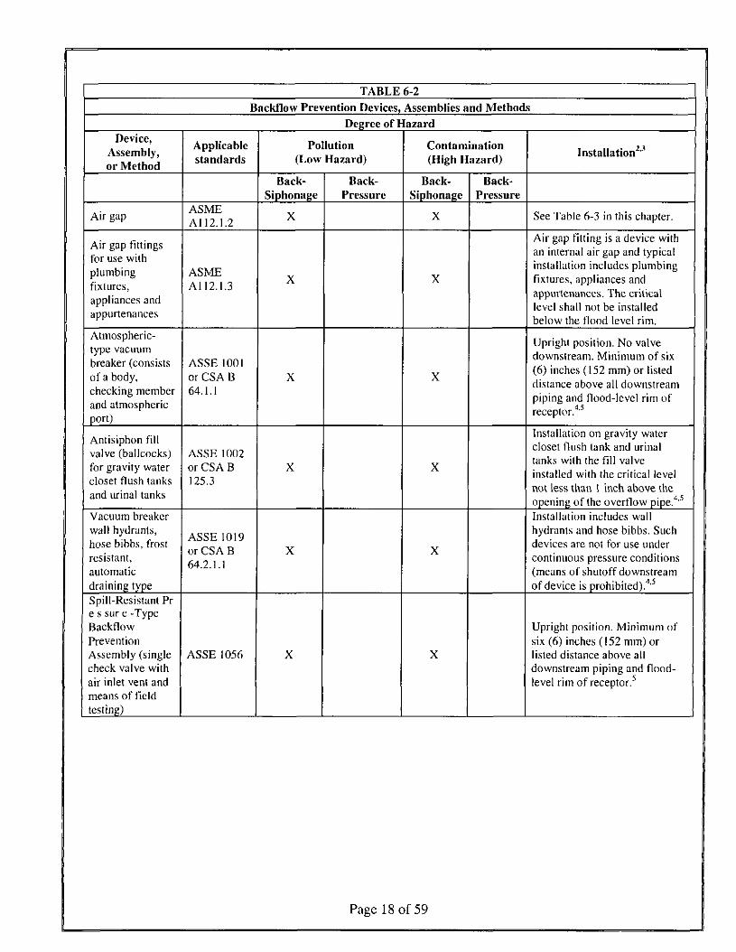
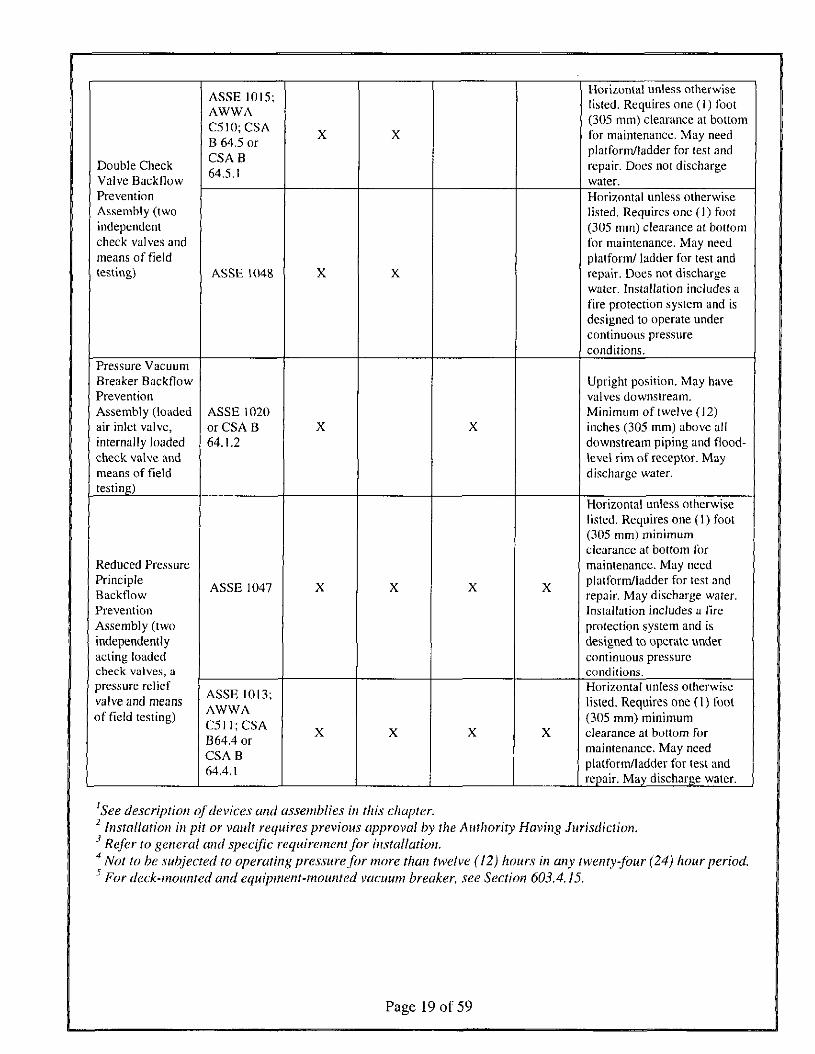
TABLE 6-2
Backflow Prevention Devices, Assemblies and MethodsDegree of Hazard
Assembly,or Method
Air gap
Air gap fittings
plumbingfixtures,appliances andappurtenances
Atmospheric-
breaker (consistsof a body,checking memberand atmosphericport)
Antisiphon fil lvalve (ballcocks)for gravity watercloset flush tanksand urinal tanks
Vacuum breakerwall hydrants,hose bibbs, irostresistant,automaticdraining typeSpill-Resistant Pre s sur e -TypeBackflowPreventionAssembly (singlecheck valve withair inlet vent andmeans of fieldtesting)
Applicablestandards
ASMEA112.1.2
ASMEAl 12.1.3
ASSE 1001or CSA B64.1.1
ASSE 1002or CSA B125.3
ASSE 1019
642 1 1
ASSE 1056
Pollution(Low Hazard)
Back-Siphonage
X
X
X
X
X
Back-Pressurc
Contamination(High Hazard)
Back-Siphonage
X
X
X
X
X
Back-Pressure
Installation2"'
See Table 6-3 in this chapter.
Air gap fitting is a device withan internal air gap and typicalinstallation includes plumbingfixtures, appliances andappurtenances. The criticallevel shall not be installedbelow the flood level rim.
Upright position. No valvedownstream. Minimum of six(6) inches (152 mm) or listeddistance above all downstreampiping and flood-level rim of
4 ^
Installation on gravity watercloset flush tank and urinaltanks wilh the fill valveinstalled with the critical levelnot less than I inch above theopening of the overflow pipe.4'5
Installation includes wallhydrants and hose bibbs. Suchdevices are not for use undercontinuous pressure conditions(means of shutoff downstreamof device is prohibited).4'5
Upright position. Minimum ofsix (6) inches (152 mm) orlisted distance above alldownstream piping and flood-level rim of receptor.
Page 18 of 59
Double CheckValve BackflowPreventionAssembly (twoindependentcheck valves andmeans of fieldtesting)
Pressure VacuumBreaker BackflowPreventionAssembly (loadedair inlet valve,internally loadedcheck valve andmeans of fieldtesting)
Reduced PressurePrincipleBackflowPreventionAssembly (twoindependentlyacting loadedcheck valves, apressure reliefvalve and meansof field testing)
ASSE 1015;AWWAC510; CSAB 64 1 orU \J^,^f \Jl
CSA B64.5.1
ASSE 1048
ASSE 1020or CSA B64.1.2
ASSE 1047
ASSE 1013;AWWAf\. TT T* 1\.
C5 1 1 ; CSAB64.4 orCSAB64.4.1
X
X
X
X
X
X
X
X
X
X
X
X
X
X
Horizontal unless otherwiselisted. Requires one ( 1 ) foot(305 mm) clearance at bottomfor maintenance. May needplatform/ladder for test andrepair. Does not dischargewater.Horizontal unless otherwiselisted. Requires one (1) foot(305 mm) clearance at bottomfor maintenance. May needplatform/ ladder for test andrepair. Does not dischargewater. Installation includes afire protection system and isdesigned to operate undercontinuous pressureconditions.
Upright position. May havevalves downstream.Min imum of twelve (12)inches (305 mm) above alldownstream piping and flood-level rim of receptor. Maydischarge water.
Horizontal unless otherwiselisted. Requires one (1) foot(305 mm) minimumclearance at bottom formaintenance. May needplatform/ladder for test andrepair. May discharge water.Installation includes a fireprotection system and isdesigned to operate undercontinuous pressureconditions.Horizontal unless otherwiselisted. Requires one (1) foot(305 mm) minimumclearance at bottom formaintenance. May needplatform/ladder for test andrepair. May discharge water.
See description of devices and assemblies in this chapter.2 Installation in pit or vault requires previous approval by the Authority Having Jurisdiction.
Refer to general and specific requirement for installation.4 Not to be subjected to operating pressure for more than twelve (12) hours in any twenty-four (24) hour period.5 For deck-mounted and equipment-mounted vacuum breaker, see Section 603.4.15.
Page 19 of 59
603.1 Approval of Devices or Assemblies. Before any device or assembly is installedfor the prevention of backflow, it shall have first been approved by the Authority HavingJurisdiction. Devices or assemblies shall be tested for conformity with recognizedstandards or other standards acceptable to the Authority Having Jurisdiction. Backflowdevices and assemblies shall comply with Chapter 15-1 of the City Code.
Devices or assemblies installed in a potable water supply system for protection againstbackflow shall be maintained in good working condition by the person or persons havingcontrol of such devices or assemblies. Such devices or assemblies shall be tested at thetime of installation, repair, or relocation and on a schedule conforming to that of Chapter15-1 of the City Code. If found to be defective or inoperative, the device or assemblyshall be repaired or replaced. No device or assembly shall be removed from use orrelocated or other device or assembly substituted, without the approval of the AuthorityHaving Jurisdiction.
Testing shall be performed by a state licensed back-flow assembly tester registered withthe City.
603.3.4 Backflow Prevention Assembly Installation Standards. Backflow preventionassemblies shall be installed as outlined in Austin Water Utilities Criteria Manual.
603.4.6.1 Potable water supplies to "non-health hazard" irrigation systems shall beprotected with a DCVA. Potable water supplies to "health hazard" irrigation systems,those having pumps or connections for pumping equipment, or chemical injection oraspiration or provisions for chemical injection or aspiration, or septic or auxiliary wateruse on site shall be protected from backflow by an RPZ or air gap as required by theAuthority Having Jurisdiction.
603.4.12 A separate backflow prevention assembly or device shall be installed on eachhigh hazard appurtenance or fixture in high hazard situations where the water or productis intended for contact with humans either directly (consumption, bathing, medical uses,dental chairs, pharmaceuticals, etc.) or indirectly (sterilizers, autoclaves, washing dishesor bottles, canning, etc.).
Exception: Potable water supply to carbonators shall be protected by a listedreduced pressure principal backflow preventer as approved by the AuthorityHaving Jurisdiction for the specific use. A single RPZ may be installed formultiple carbonators that are located in the same immediate physical area if allwater piping from backflow preventer to carbonator is exposed. Copper pipingdownstream of backflow protection for carbonators is prohibited.
603.4.12.1 A single backflow prevention assembly or device may be installed formultiple high hazard appurtenances or fixtures where no human contact is intended. Eachwater line downstream of the backflow protection shall be properly labeled as requiredfor non-potable water.
Page 20 of 59
603.4.12.2 A single backflow prevention assembly or device may be installed in lowhazard situations serving multiple like low hazards that are located in the same immediatephysical area if all piping downstream of the backflow protection is exposed.
608.2 Excessive Water Pressure. If local static water pressure is in excess of sixty-five(65) pounds per square inch, an approved pressure regulator preceded by an adequatestrainer shall be installed and the static pressure reduced to sixty-five (65) pounds persquare inch or less. Pressure regulator(s) equal to or exceeding one and one-half (1-1/2)inches shall not require a strainer. Such regulator(s) shall control the pressure to all wateroutlets in the building unless otherwise approved by the Authority Having Jurisdiction.Each such regulator and strainer shall be accessibly located above ground or in a vaultequipped with a properly sized and sloped bore-sighted drain to daylight, shall beprotected from freezing, and shall have the strainer readily accessible for cleaningwithout removing the regulator or strainer body or disconnecting the supply piping. Pipesize determinations shall be based on eighty (80) percent of the reduced pressure whenusing Table 6-6 (Fixture Unit Table for Determining Water Pipe and Meter Sizes). Anapproved expansion tank shall be installed in the cold water distribution pipingdownstream of each such regulator to prevent excessive pressure from developing due tothermal expansion and to maintain the pressure setting of the regulator. The expansiontank shall be properly sized and installed in accordance with the manufacturer'sinstructions and listing. Systems designed by registered engineers shall be permitted touse approved pressure relief valves in lieu of expansion tanks provided such relief valveshave a maximum pressure relief setting of one-hundred (100) pounds per square inch(698 kPa) or less.
609.1.1 Freeze Protection. The following list of plumbing installations is acceptablemethods of providing freeze protection:
(1) Shutoff Valves - Property owner shutoff valves located in the ground at thewater meter shall meet American Water Works Association standards.
(2) Insulated Exterior Walls - If the wall member is six (6) inches or greater innominal width, the piping may be placed on the conditioned side of the wallinsulation and no additional pipe insulation is required.
(3) If the exterior wall is less than six inches nominal width, the piping shall beinsulated with material that has an R-value of at least four (4). The waterpiping and the pipe insulation shall be placed on the conditioned side of thewall.
(4) Uninsulated Exterior Walls, Attics and Crawl Spaces - All water pipinginstalled in uninsulated exterior walls and unconditioned crawl spaces shallbe protected by pipe Insulation with a minimum R-value of four (4). Allwater piping installed in unconditioned attics. Above the building insulationshall be protected with pipe insulation having an R-value of at least four (4).
Page 21 of 59
(5) Exterior Hose Bibs - Exterior hose bibs shall be of the self-draining andfrost-resistant with an integral backflow preventer. Standard hose bibs shallbe protected by adding pipe insulation with an R-value of a least four (4) upto the edge or wall flange of the hose bib.
609.1.2 Pipe Insulation wall thickness for domestic hot water run outs and circulationshall be in accordance with the energy code.
609.11 Private Fire Lines. Private fire lines shall be installed in accordance with thelatest standards of the National Fire Protection Association (NFPA) 24 Standard for theInstallation of Private Fire Service Mains and their Appurtenances, as adopted by theAustin Fire Department Fire Protection Criteria Manual. Private fire lines shall adhere toNFPA 25 Standard for the Inspection, Testing, and Maintenance of Water-Based FireProtection Systems as required by the Austin Fire Department.
612.0 Plumbing for Multi-family Sub-meters. Each newly constructed multi-familyhousing unit and each newly constructed residential unit in a mixed-use facility, shallhave a single cold water stub out supplying all fixtures in each dwelling unit supplied bythe master meter. A City meter or privately-owned water meter shall be installed for eachnewly constructed unit at the time of construction. Each stub out shall have a shut offvalve immediately ahead of the private meter location. The meter shall have a clearanceof at least four (4) inches on all sides. The location of the private meter installation mustbe accessible for reading, testing, replacement, and inspection of the private meter.
Exceptions:
The following developments are not required to comply with this section:
(1) a condominium development
(2) a development that has a centralized hot water system
613.0 Cooling Towers. New and replaced cooling tower installations must includemakeup and blowdown meter, conductivity controllers, overflow alarms, drifteliminators, and a minimum of 5 cycles of concentration.
614.0 Landscape Irrigation. Landscape irrigation shall conform to the rules set forth inChapter 344, Title 30 of The Texas Administrative Code, Texas Commission onEnvironmental Quality rules and sections 614.1 through 614.3 of this code.
Definitions:
Hydrozoning is the practice of grouping sprinkler heads into zones with similarvegetation, soil types, slopes, and sunlight availability.
Isolation valve is a valve used for isolating all or part of the irrigation system forrepairs, maintenance, or winter shut-down.
Page 22 of 59
614.1 Requirements for New Commercial and Multi-family Landscape Irrigation.
A new commercial and multi-family irrigation system must be designed and installed sothat:
(1) the system does not include spray irrigation on areas less than six (6) feetwide (such as medians, buffer strips, and parking lot islands);
(2) above-ground irrigation emission devices are set back at least six (6) inchesfrom impervious surfaces;
(3) the irrigation system has a master valve;
(4) circuit remote control valves have adjustable flow controls;
(5) serviceable in-head check valves are adjacent to paved areas where elevationdifferences may cause low head drainage;
(6) the irrigation system has a City-approved weather based controller;
(7) an automatic rain shut-off device shuts off the irrigation systemautomatically after not more than a one-half inch (1/2") rainfall;
(8) zone valves and circuits are separated based on hydrozoning (plant waterrequirements).
614.2 Requirements for One and Two Family Dwelling Landscape Irrigation.
New irrigation systems for one-and two-family dwellings must be designed and installedso that:
(1) the system does not include spray irrigation on areas less than six (6) feetwide (such as medians, buffer strips, and parking lot islands);
(2) above-ground irrigation emission devices are set back at least six (6) inchesfrom impervious surfaces;
(3) the irrigation system has a master valve and must be installed on thedischarge side of the backflow prevention device;
(4) a working soil moisture sensor or an automatic rain shut-off device shuts offthe irrigation system automatically after not more than a one-half inch (3/2")rainfall; and
(5) zone valves and circuits are separated based on hydrozoning (plant waterrequirements).
Page 23 of 59
614.3 Inspection.
At the time of final plumbing inspection the irrigation installer shall provide to the city:
(1) a water budget including:
(a) a chart containing zone numbers, precipitation rate, and gallons perminute; and
(b) the location of the emergency irrigation system shut-off valve.
(2) a report on the form provided by the Austin Water Utility Departmentcertifying compliance with Section 614.1 (Requirements for NewCommercial and Multi-family Landscape irrigation) or Section 614.2(Requirements for One and Two Family Dwelling Landscape Irrigation);and
(3) proof that a laminated copy of the water budget is permanently installedinside the irrigation controller door.
615.0 Food waste and garbage disposal unit installations shall be prohibited inrestaurants, cafeterias, and other commercial and institutional kitchens and foodpreparation facilities.
704.3 Fixture Connections. Pot sinks, scullery sinks, and dishwashing sinks, silverwaresinks, commercial dishwashing machines, silverware-washing machines, and othersimilar fixtures shall be connected indirectly to the drainage system.
707.4 Each horizontal drainage pipe shall be provided with a cleanout at its upperterminal, and each run of piping, that is more than one-hundred (100) feet (30,480 mm) intotal developed length, shall be provided with a cleanout for each one-hundred (100) feet(30,480 mm), or fraction thereof, in length of such piping. An additional cleanout shallbe provided in a drainage line for each aggregate horizontal change of directionexceeding 135 degrees (2.36 rad).
Exceptions:
(1) Cleanouts shall be permitted to be omitted on a horizontal drain line less thanfive (5) feet (1,524 mm) in length unless such line is serving sinks or urinals.
(2) Cleanouts shall be permitted to be omitted on any horizontal drainage pipeinstalled on a slope of 72 degrees (1.26 rad) or less from the vertical angle(one-fifth (1/5) bend).
(3) Excepting the building drain and its horizontal branches, a cleanout shall notbe required on any pipe or piping that is above the floor level of the lowestfloor of the building.
Page 24 of 59
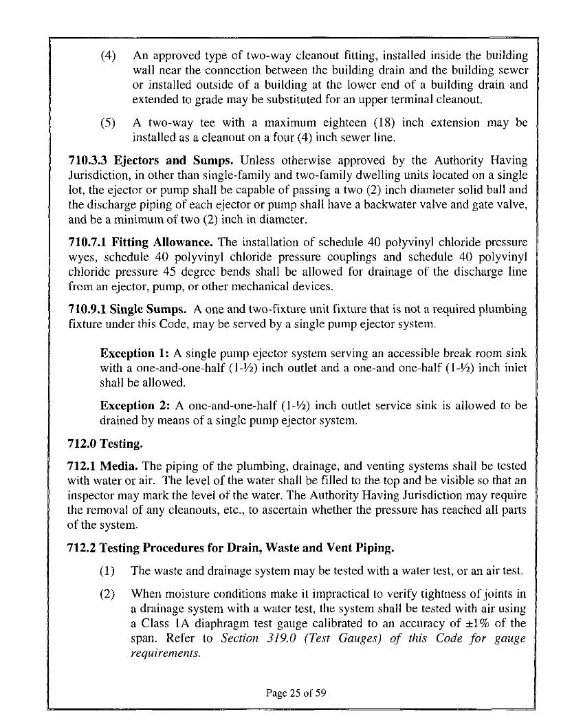
(4) An approved type of two-way cleanout fitting, installed inside the buildingwall near the connection between the building drain and the building seweror installed outside of a building at the lower end of a building drain andextended to grade may be substituted for an upper terminal cleanout.
(5) A two-way tee with a maximum eighteen (18) inch extension may beinstalled as a cleanout on a four (4) inch sewer line.
710.3.3 Ejectors and Sumps. Unless otherwise approved by the Authority HavingJurisdiction, in other than single-family and two-family dwelling units located on a singlelot, the ejector or pump shall be capable of passing a two (2) inch diameter solid ball andthe discharge piping of each ejector or pump shall have a backwater valve and gate valve,and be a minimum of two (2) inch in diameter.
710.7.1 Fitting Allowance. The installation of schedule 40 polyvinyl chloride pressurewyes, schedule 40 polyvinyl chloride pressure couplings and schedule 40 polyvinylchloride pressure 45 degree bends shall be allowed for drainage of the discharge linefrom an ejector, pump, or other mechanical devices.
710.9.1 Single Sumps. A one and two-fixture unit fixture that is not a required plumbingfixture under this Code, may be served by a single pump ejector system.
Exception 1: A single pump ejector system serving an accessible break room sinkwith a one-and-one-half (l-!/2) inch outlet and a one-and one-half (\-l/2) inch inletshall be allowed.
Exception 2: A one-and-one-half (l-'/2) inch outlet service sink is allowed to bedrained by means of a single pump ejector system.
712.0 Testing.
712.1 Media. The piping of the plumbing, drainage, and venting systems shall be testedwith water or air. The level of the water shall be filled to the top and be visible so that aninspector may mark the level of the water. The Authority Having Jurisdiction may requirethe removal of any cleanouts, etc., to ascertain whether the pressure has reached all partsof the system.
712.2 Testing Procedures for Drain, Waste and Vent Piping.
(1) The waste and drainage system may be tested with a water test, or an air test.
(2) When moisture conditions make it impractical to verify tightness of joints ina drainage system with a water test, the system shall be tested with air usinga Class IA diaphragm test gauge calibrated to an accuracy of ±1% of thespan. Refer to Section 319.0 (Test Gauges) of this Code for gaugerequirements.
Page 25 of 59
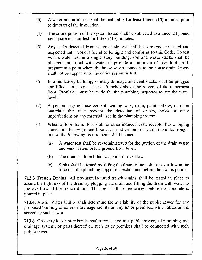
(3) A water and or air test shall be maintained at least fifteen (15) minutes priorto the start of the inspection.
(4) The entire portion of the system tested shall be subjected to a three (3) poundper square inch air test for fifteen (15) minutes.
(5) Any leaks detected from water or air test shall be corrected, re-tested andinspected until work is found to be tight and conforms to this Code. To testwith a water test in a single story building, soil and waste stacks shall beplugged and filled with water to provide a minimum of five foot head-pressure at a point where the house sewer connects to the house drain. Risersshall not be capped until the entire system is full.
(6) In a multistory building, sanitary drainage and vent stacks shall be pluggedand filled to a point at least 6 inches above the re-vent of the uppermostfloor. Provision must be made for the plumbing inspector to see the waterlevel.
(7) A person may not use cement, sealing wax, resin, paint, tallow, or othermaterials that may prevent the detection of cracks, holes or otherimperfections on any material used in the plumbing system.
(8) When a floor drain, floor sink, or other indirect waste receptor has a pipingconnection below ground floor level that was not tested on the initial rough-in test, the following requirements shall be met:
(a) A water test shall be re-administered for the portion of the drain wasteand vent system below ground floor level.
(b) The drain shall be filled to a point of overflow.
(c) Sinks shall be tested by filling the drain to the point of overflow at thetime that the plumbing copper inspection and before the slab is poured.
712.3 Trench Drains. All pre-manufactured trench drains shall be tested in place toassure the tightness of the drain by plugging the drain and filling the drain with water tothe overflow of the trench drain. This test shall be performed before the concrete ispoured in place.
713.4. Austin Water Utility shall determine the availability of the public sewer for anyproposed building or exterior drainage facility on any lot or premises, which abuts and isserved by such sewer.
713.6 On every lot or premises hereafter connected to a public sewer, all plumbing anddrainage systems or parts thereof on such lot or premises shall be connected with suchpublic sewer.
Page 26 of 59
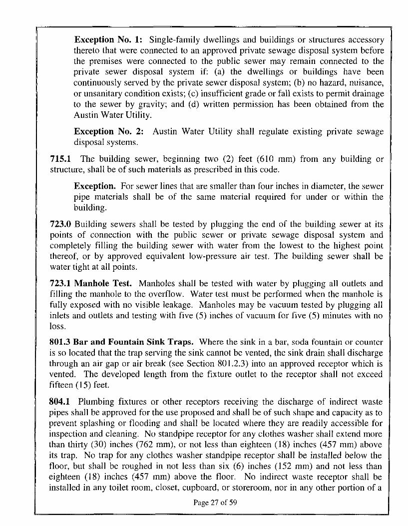
Exception No. 1: Single-family dwellings and buildings or structures accessorythereto that were connected to an approved private sewage disposal system beforethe premises were connected to the public sewer may remain connected to theprivate sewer disposal system if: (a) the dwellings or buildings have beencontinuously served by the private sewer disposal system; (b) no hazard, nuisance,or unsanitary condition exists; (c) insufficient grade or fall exists to permit drainageto the sewer by gravity; and (d) written permission has been obtained from theAustin Water Utility.
Exception No. 2: Austin Water Utility shall regulate existing private sewagedisposal systems.
715.1 The building sewer, beginning two (2) feet (610 mm) from any building orstructure, shall be of such materials as prescribed in this code.
Exception. For sewer lines that are smaller than four inches in diameter, the sewerpipe materials shall be of the same material required for under or within thebuilding.
723.0 Building sewers shall be tested by plugging the end of the building sewer at itspoints of connection with the public sewer or private sewage disposal system andcompletely filling the building sewer with water from the lowest to the highest pointthereof, or by approved equivalent low-pressure air test. The building sewer shall bewater tight at all points.
723.1 Manhole Test. Manholes shall be tested with water by plugging all outlets andfilling the manhole to the overflow. Water test must be performed when the manhole isfully exposed with no visible leakage. Manholes may be vacuum tested by plugging allinlets and outlets and testing with five (5) inches of vacuum for five (5) minutes with noloss.
801.3 Bar and Fountain Sink Traps. Where the sink in a bar, soda fountain or counteris so located that the trap serving the sink cannot be vented, the sink drain shall dischargethrough an air gap or air break (see Section 801.2.3) into an approved receptor which isvented. The developed length from the fixture outlet to the receptor shall not exceedfifteen (15) feet.
804.1 Plumbing fixtures or other receptors receiving the discharge of indirect wastepipes shall be approved for the use proposed and shall be of such shape and capacity as toprevent splashing or flooding and shall be located where they are readily accessible forinspection and cleaning. No standpipe receptor for any clothes washer shall extend morethan thirty (30) inches (762 mm), or not less than eighteen (18) inches (457 mm) aboveits trap. No trap for any clothes washer standpipe receptor shall be installed below thefloor, but shall be roughed in not less than six (6) inches (152 mm) and not less thaneighteen (18) inches (457 mm) above the floor. No indirect waste receptor shall beinstalled in any toilet room, closet, cupboard, or storeroom, nor in any other portion of a
Page 27 of 59
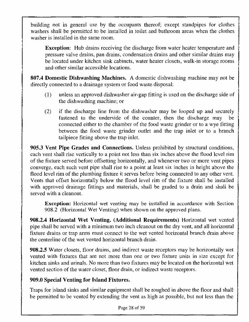
building not in general use by the occupants thereof; except standpipes for clotheswashers shall be permitted to be installed in toilet and bathroom areas when the clotheswasher is installed in the same room.
Exception: Hub drains receiving the discharge from water heater temperature andpressure valve drains, pan drains, condensation drains and other similar drains maybe located under kitchen sink cabinets, water heater closets, walk-in storage roomsand other similar accessible locations.
807.4 Domestic Dishwashing Machines. A domestic dishwashing machine may not bedirectly connected to a drainage system or food waste disposal:
(1) unless an approved dishwasher air-gap fitting is used on the discharge side ofthe dishwashing machine; or
(2) if the discharge line from the dishwasher may be looped up and securelyfastened to the underside of the counter, then the discharge may beconnected either to the chamber of the food waste grinder or to a wye fittingbetween the food waste grinder outlet and the trap inlet or to a branchtailpiece fitting above the trap inlet.
905.3 Vent Pipe Grades and Connections. Unless prohibited by structural conditions,each vent shall rise vertically to a point not less than six inches above the flood level rimof the fixture served before offsetting horizontally, and whenever two or more vent pipesconverge, each such vent pipe shall rise to a point at least six inches in height above theflood level rim of the plumbing fixture it serves before being connected to any other vent.Vents that offset horizontally below the flood level rim of the fixture shall be installedwith approved drainage fittings and materials, shall be graded to a drain and shall beserved with a cleanout.
Exception: Horizontal wet venting may be installed in accordance with Section908.2 (Horizontal Wet Venting) when shown on the approved plans.
908.2.4 Horizontal Wet Venting. (Additional Requirements) Horizontal wet ventedpipe shall be served with a minimum two inch cleanout on the dry vent, and all horizontalfixture drains or trap arms must connect to the wet vented horizontal branch drain abovethe centerline of the wet vented horizontal branch drain.
908.2.5 Water closets, floor drains, and indirect waste receptors may be horizontally wetvented with fixtures that are not more than one or two fixture units in size except forkitchen sinks and urinals. No more than two fixtures may be located on the horizontal wetvented section of the water closet, floor drain, or indirect waste receptors.
909.0 Special Venting for Island Fixtures.
Traps for island sinks and similar equipment shall be roughed in above the floor and shallbe permitted to be vented by extending the vent as high as possible, but not less than the
Page 28 of 59
drainboard height and then returning it downward and connecting it to the horizontal sinkdrain immediately downstream from the vertical fixture drain. The return vent shall beconnected to the horizontal drain through a wye branch fitting and shall, in addition, beprovided with a foot vent taken off the vertical fixture vent by means of a wye branchimmediately below the floor and extending to the nearest partition and then through theroof to the open air, or shall be permitted to be connected to other vents at a point not lessthan six (6) inches (152 mm) above the flood-level rim of the fixtures served. Drainagefittings shall be used on all parts of the vent below the floor level, and a slope of not lessthan one-fourth (1/4) inch per foot (20.8 mm/tn) back to the drain shall be maintained.The return bend used under the drainboard shall be a one (1) piece fitting or an assemblyof a 45 degree (0.79 rad), a 90 degree (1.6 rad), and a 45 degree (0.79 rad) elbow in theorder named. Pipe sizing shall be as elsewhere required in this code. The island sinkdrain, upstream of the returned vent, shall serve no other fixtures. An accessible cleanoutshall be installed in the vertical portion of the foot vent.
Exception: Deep seal P-traps may be installed under the floor of island fixtures ifthe trap and trap vent are at least two inches in diameter and the trap vent is locatedin the nearest partition wall. The vent riser shall contain a cleanout and the ventshall continue through the roof to open air. The vent shall take off no more thanthree feet downstream from the trap being served. Pipe sizing for island fixturesshall be in accordance with this Code.
1007.0 Trap Seal Protection. Floor drains or similar traps directly connected to thedrainage system and subject to infrequent use shall be protected with a trap seal primer,except where not deemed necessary for safety or sanitation by the Authority HavingJurisdiction. When structurally feasible, traps for floor drains and similar fixtures shall beprimed by methods utilizing gravity flow wastewater from acceptable plumbing fixtures.Fixtures used for grease or food particle wasting shall not be used for trap seal priming.Trap seal primers shall be accessible for maintenance.
1009.2 Approval. Austin Water Utility shall approve the size, design, type, and locationof each interceptor or separator. Except as otherwise specifically permitted in the CityCode, no wastes other than those requiring treatment or separation, shall be dischargedinto any interceptor. A grease, sand, or other gravity interceptor shall be field tested byapplying a minimum of a one-inch (1") water column above the lid seal of theinterceptor.
Exception: Interceptors or separators on a septic system must meet requirementsestablished by the Health Authority.
1010.0 Slaughterhouses, Packing Establishments, etc. Every fish, fowl, and animalslaughterhouse or establishment; every fish, fowl, and meat packing or curingestablishment; every soap factory, tallow-rendering, fat-rendering, and hide-curingestablishment shall be connected to and shall drain or discharge into an approved greaseinterceptor (clarifier) or other pretreatment system as necessary to comply with the
Page 29 of 59
requirements in Chapter 15-10 of the City Code and as authorized by Austin WaterUtility.
1011.0 Minimum Requirements for Auto Wash Racks. Every private or public washrack and / or floor or slab used for cleaning machinery or machine parts shall beadequately protected against storm or surface water and shall drain or discharge into anapproved mud box and then into an interceptor (clarifier) of an approved design.Additional pretreatment shall be required if the effluent quality does not meet Citystandards.
1011.2 Car Wash Equipment. New installation of car wash equipment except for selfservice (spray wand) type systems shall be sleeved or piped under the slab toaccommodate future reuse equipment that can be easily installed underground and run toan area where a water reclaim system would be anticipated to be installed. The sleeve orpiping shall extend approximately 24 inches past the exterior wall from the car washequipment room and 18 inches from the interior wall. Both ends of the sleeve or pipingshall be equipped with a cleanout extended to grade.
1011.2.1 Automatic commercial vehicle wash conveyor washes shall be limited to 40gallons of water use or less per vehicle.
1011.2.2 In-bay passenger vehicle washes are limited to 55 gallons of water use or lessper vehicle.
1011.2.3 Large Vehicle (bus or large truck) washes are limited to 75 gallons of water useor less per vehicle.
1011.2.4 Hand wash nozzles shall not use more than 3 gallons per minute.
1012.0 Commercial and Industrial Laundries. Laundry equipment in commercial andindustrial buildings shall discharge into an interceptor or other pretreatment system asnecessary to comply with the requirements in Chapter 15-10 of the City Code and asauthorized by Austin Water Utility.
1013.0 Bottling Establishments. Bottling plants shall discharge their process wastesinto an interceptor or other pretreatment system that will provide for the separation ofbroken glass or other solids, before discharging liquid wastes into the drainage system,and as necessary to comply with the requirements in Chapter 15-10 of the City Code andas authorized by the Austin Water Utility.
1014.1 When pretreatment is required, an approved type grease interceptor complyingwith Austin Water Utility regulations shall be installed in the waste discharge leadingfrom sinks, drains, and other fixtures or equipment. Grease interceptors are required incommercial or institutional food preparation facilities, including, food processors,bakeries, restaurants, cafeterias, schools, hospitals, retirement homes, assisted livingcenters, grocery stores, or other commercial or institutional food preparation facilitieswhere grease may be introduced into the drainage or sewage system in quantities that can
Page 30 of 59
effect line stoppage or hinder sewage treatment or private sewage disposal. Acombination of hydromechanical, gravity grease interceptors and engineered systemsmay be allowed in certain cases when space or existing physical constraints of existingbuildings necessitate such installations in order to meet this code and upon approval bythe Austin Water Utility. A grease interceptor is not required for one-and-two-familydwelling units. Water closets, urinals, and other plumbing fixtures conveying humanwaste shall not drain into or through the grease interceptor.
1014.1.1 Each fixture discharging into a grease interceptor shall be individually trappedand vented in an approved manner.
1014.1.2 All grease interceptors shall be maintained in efficient operating condition byperiodic removal of the accumulated grease and latent material. No such collected greaseshall be introduced into any drainage piping or public or private sewer. If the AuthorityHaving Jurisdiction determines that a grease interceptor is not being properly cleaned ormaintained, the Authority Having Jurisdiction shall have the authority to mandate theinstallation of additional equipment or devices and to mandate a maintenance program.
1014.1.3 Food Waste Disposal Units and Dishwashers. Food waste and garbagedisposal unit installations in restaurants, cafeterias, and other commercial andinstitutional kitchens and food preparation facilities are prohibited by Section 615,0 ofthis code. Food waste and garbage disposal units that were installed in restaurants,cafeterias, and other commercial and institutional kitchens and food preparation facilitiesprior to this prohibition shall be connected to or discharge into a grease interceptor.Unless specifically exempted by the Austin Water Utility, dishwashers in commercial orinstitutional food preparation facilities shall be connected to or discharge into a greaseinterceptor.
1014.2 Hydromechanical Grease Interceptors. Hydromechanical grease interceptorsor separators shall be of a size, standard, design, type, and installed in a locationapproved by the Austin Water Utility.
1014.3.3 Design.
1014.3.3.1 Gravity Interceptors shall be constructed in accordance with the designapproved by the Austin Water Utility.
1014.3.6 Sizing Criteria.
1014.3.6.1 Sizing. The size and volume of the interceptor shall be determined accordingto the Austin Water Utility's interceptor sizing criteria.
1014.3.7 Abandoned and Discontinued Use Gravity Grease Interceptors. Greaseinterceptors that have been abandoned or discontinued from use shall be pumped andfilled as required for abandoned sewers and sewage disposal facilities in Section 722.0.
1015.0 Fats, Oils, and Greases (FOG) Pretreatment and Disposal System.
Page 31 of 59
1015.1 Purpose. The purpose of this section is to provide the necessary criteria for thesizing, application, and installation of FOG pretreatment and disposal systems designatedas a pretreatment or discharge water quality compliance strategy in accordance with therequirements in this code and Chapter 15-10 of the City Code.
1015.2 Scope. FOG pretreatment and disposal systems shall be considered engineeredsystems and shall comply with the requirements of Section 301.4 of this code andChapter 15-10 of the City Code.
1015.3 Components, Materials, and Equipment. FOG pretreatment and disposalsystems, including all components, materials, and equipment necessary for the properfunction of the system, shall comply with Sections 301.1.3 or 301.2 of this code andChapter 15-10 of the City Code.
1015.4 Sizing Application and Installation. FOG pretreatment and disposal systemsshall be engineered, sized, and installed in accordance with the manufacturers'specifications and as specified in ASME Al 12.14.6, as listed in Chapter 14, Table 14-1of this code and Chapter 15-10 of the City Code.
1015.5 Performance. FOG pretreatment and disposal systems shall be tested andcertified as listed in Chapter 14, Table 14-1 of this code, and other national consensusstandards applicable to FOG disposal systems as discharging an effluent not to exceed thestandards and requirements in Chapter 15-10 of the City Code.
1016.0 Sand Interceptors.
1016.1 Where Required.
1016.1.1 When pretreatment is required, an approved type sand interceptor complyingwith Austin Water Utility regulations shall be installed in the waste discharge leadingfrom a fixture or drain containing solids or semi-solids heavier than water that would beharmful to a drainage system, cause a stoppage within the system, or as otherwiserequired by Chapter 15-10 of the City Code. Multiple floor drains shall be permitted todischarge into one sand interceptor. Additional pretreatment shall be required if theeffluent quality does not meet City standards.
1016.1.2 Sand interceptors are required whenever the Austin Water Utility deems itnecessary to have a sand interceptor to protect the drainage system.
1016.2 Construction and Size. Sand Interceptors shall be constructed in accordance withthe design approved by the Austin Water Utility.
1016.3 Separate Use. Sand and similar interceptors for every solid shall be so designedand located as to be readily accessible for cleaning, shall have a water seal of not lessthan six (6) inches (152 mm), and shall be vented.
Page 32 of 59
1017.0 Petroleum-Based Oil and Flammable Liquid Interceptors and Pretreatment.
Any operation that generates a discharge that contains petroleum-based oily, flammable,or both types of wastes shall be required to install and maintain an interceptor, hold haultank, or other pretreatment system in accordance with the requirements in Chapter 15-10of the City Code and as authorized by the Austin Water Utility. The interceptor or otherpretreatment system, tanks, and pumps installed shall be accessible and shall be vented tothe atmosphere in a Code approved manner.
1101.1 Where Required. Roofs and courtyards shall be drained into a separate stormsewer system or to some other place of disposal, satisfactory to the authority havingjurisdiction. For one and two family dwellings, storm water may be discharged on flatareas such as streets or lawns so long as the storm water shall flow away from thebuilding and away from adjoining property and shall not create a nuisance.
1101.3 Materials for Rainwater Piping. Rainwater piping placed within the interior of abuilding or run within a vent or shaft shall be of cast iron, galvanized steel, wrought iron,brass, copper, lead, Schedule 40 ABS, Schedule 40 PVC, DWV, stainless steel 304 or316L (stainless steel 304 pipe and fittings shall not be installed underground and shall bekept not less than six (6) inches (152 mm) above ground), or other approved materials,and changes in direction shall conform to the requirements of Section 706.0. ABS andPVC, DWV piping installations shall be installed in accordance with IS. #5 and IS. #9.Fire stopping for ABS and PVC shall comply with the Building Code. Except forindividual single-family dwelling units, materials exposed within ducts or plenums shallhave a flame-spread index of a maximum of twenty-five (25) and a smoke-developedindex of a maximum of fifty (50), when tested in accordance with the Test for Surface-Burning Characteristics of the Building Materials (see the Building Code standardsbased on ASTM E84 and UL 723.).
1101.5 Subsoil Drains. When required by the Authority Having Jurisdiction, subsoildrains shall be provided around the perimeter of buildings having basements, cellars, orcrawl spaces or floors below grade. Such subsoil drains may be positioned inside oroutside of the footing, shall be of perforated, or open jointed approved drain tile or pipenot less than three (3) inches (80 mm) in diameter, and shall be laid in gravel, slag,crushed rock, approved three-quarter (3/4) inch (19.1 mm) crushed recycled glassaggregate, or other approved porous material with a minimum of four (4) inches (102mm) surrounding the pipe on all sides. Filter media shall be provided for exterior subsoilpiping.
1106.5 Sizing of Rain Piping. Sizing of rainwater piping is based upon maximum offive inches (5") of rainfall per hour falling upon a given roof area in square feet. Fiveinches per hour shall be used for sizing both primary rainwater systems and overflow oremergency rainwater systems.
1108.3 Window Areaway Drains. Window areaway drains must terminate to anapproved location as approved by the Authority Having Jurisdiction. Window areaways
Page 33 of 59
not exceeding ten (10) square feet in area may discharge to the subsoil drain through atwo (2) inch discharge pipe. However, areaways exceeding ten (10) square feet in areashall be drained to an approved storm drainage system.
1109.2 Methods of Testing Storm Drainage Systems. Except for outside leaders andperforated or open jointed drain tile, the piping of storm drain systems shall be testedupon completion of the rough piping installation by water or air, and proven tight. TheAuthority Having Jurisdiction may require the removal of any cleanout plugs to ascertainif the pressure has reached all parts of the system. Either of the following test methodsshall be used:
1109.2.1 Test Procedures for Material other than Polyvinyl Chloride (PVC)Drainage Piping. This section applies to material other than PVC drainage piping (forexample, cast iron).
(1) The storm drainage system may be tested with a water test, or an air test.
(2) When utilizing a water test, the level of the water shall be visible so that aninspector may mark the level of the water unless the system is filled to thepoint of overflow.
(3) A water and or air test shall be maintained at least fifteen (15) minutes priorto the start of the inspection.
(4) If tested with air, the entire portion of the system tested shall be subjected toa five (5) pound per square inch air test for fifteen (15) minutes.
(5) When moisture or wet conditions make it impractical to verify tightness ofjoints in a drainage system with a water test, the system shall be tested withair using a Class 1A diaphragm test gauge calibrated to an accuracy of ±1%of the span. Refer to Section 319.0 (Test Gauges) of this Code for gaugerequirements.
(6) To test with a water test in a single story building, storm water system stacksshall be plugged and completely filled with water to provide a minimum often (10) foot head-pressure at the highest portion of the system being tested,or to a point of roof drain overflow.
(7) In a multistory building storm water system stacks shall be plugged andfilled to a point of overflow at the roof drain, or in sectional test. The roofdrainage system shall be tested with a minimum of a ten (10) foot head ofwater or a five (5) pound per square inch air test for fifteen (15) minutes.
(8) Any leaks detected from water or air test shall be corrected, re-tested andinspected until work is found to be tight and conforms to this Code.
Page 34 of 59
(9) A person may not use cement, sealing wax, resin, paint, tallow, or othermaterials that may prevent the detection of cracks, holes or otherimperfections on any material used in the plumbing system.
1109.2.2 Testing Procedures for Plastic Roof Drainage Piping.
(1) A PVC drainage system shall be tested utilizing water or air.
(2) The level of the water shall be visible so that an inspector may mark the levelof the water.
(3) To test with a water test in a single story building, storm water system stacksshall be plugged and completely filled with water to provide a minimum often (10) foot head-pressure at the highest portion of the system being tested,or to a point of roof drain overflow.
(4) In a multistory building the storm water system stacks shall be plugged andfilled to a point of overflow at the roof drain, or a sectional test of the roofdrainage system shall be allowable when tested with a minimum of a ten (10)foot head of water, or a three (3) pound per square inch air test for fifteen(15) minutes.
(5) When moisture or wet conditions make it impracticable to verify tightness ofjoints in a drainage system with a water test, the system shall be tested withair using a Class 1A diaphragm test gauge calibrated to an accuracy of ±1%of the span. Refer to Section 319.0 this Code for gauge requirements.
(6) A water and or air test shall be maintained at least fifteen (15) minutes priorto the start of the inspection.
(7) The entire portion of the system tested shall be subjected to a three (3) poundper square inch air test for fifteen (15) minutes.
(8) Any leaks detected from a water or air test shall be corrected, re-tested andinspected until work is found to be tight and conforms to this Code.
(9) A person may not use cement, sealing wax, resin, paint, tallow, or othermaterials that may prevent the detection of cracks, holes or otherimperfections on any material used in the plumbing system.
1204.3.1 Top Out Inspection. This inspection shall be made after all piping authorizedby the permit has been installed, before the portions of the piping that are to be coveredor concealed are concealed, and before any fixture, appliance or shutoff valve has beenattached to the pipe.
(1) Low Pressure Gas Test. This inspection shall include an air, carbondioxide, or nitrogen pressure test. The test pressure for gas piping may not beless than fifteen (15) pounds per square inch gauge pressure. Test pressures
Page 35 of 59
shall be held for at least fifteen (15) minutes with no perceptible drop inpressure or for a longer time if determined necessary by the BuildingOfficial. A Bourdon tube ("Spring") gage may be utilized for this test. Referto Code Section 319.0 (Test Gauges) of this Code for gauge requirements.
(2) Medium Pressure Gas Test. For welded piping and for piping that carriesgas at pressures of more than fourteen (14) inches water column pressure, thetest pressure may not be less than sixty (60) pounds per square inch and shallbe continued for a length of time satisfactory to the Building Official, but inno case for less than thirty (30) minutes. These tests shall be made using air,carbon dioxide, or nitrogen pressure only, and shall be made in the presenceof the inspector. All necessary apparatus for conducting tests shall befurnished by the permittee. Test pressures shall be held for at least fifteen(15) minutes with no perceptible drop in pressure or for a longer time ifdetermined necessary by the Building Official. A Bourdon tube ("Spring")gage may be utilized for this test. Refer to Code Section 319.0 (Test Gauges)of this Code for gauge requirements.
1204.3.2 Final Gas Inspection. The final test on the gas piping shall be made after thewater heaters, floor furnaces, and gas appliance shutoff valves have been installed.Whenever changes or extensions are made to any existing gas piping from a point whereno gas stop valve has been provided in the original gas system, the responsible plumberor responsible person shall prepare the entire system for inspection and testing.
(1) Low Pressure Final Gas Test. A low-pressure gas distribution system shallbe tested with a minimum of five (5) pounds of air, carbon dioxide, ornitrogen_pressure for ten (10) minutes using a Class 1A diaphragm test gaugecalibrated to an accuracy of ± 1 % of the span. Refer to Section 319.0 of thisCode for gauge requirements.
(2) Medium Pressure Final Gas Test. A medium pressure gas distributionsystem shall be tested with a ten (10) pound per square inch test for the entiremedium pressure gas system using a Class 1A diaphragm test gaugecalibrated to an accuracy of ±1% of the span. The test shall hold tight for atleast 30 minutes. Refer to Code Section 319.0 of this Code for gaugerequirements.
(3) The permittee shall notify the plumbing inspector when the system is readyfor final inspection and arrange for the buildings to be unlocked for theinspector to enter the buildings.
(4) The testing equipment and labor necessary for making the required tests andinspections shall be furnished by the permittee.
Page 36 of 59
1204.4 Pulled Meters, Gas Repair, and Remodeling.
1204.4.1 Definitions.
Pulled Gas Meter. A pulled meter is an active gas system that has been terminated bythe gas supplier due to a code violation that will require a permit and inspection by theCity to verify that the system meets the requirements of the Code before restoring gasservice to the customer. Refer to the pulled gas meter procedures in Section 1204.4.2(Pulled Natural Gas Meter Inspection Criteria).
1204.4.2 Pulled Natural Gas Meter Inspection Criteria. The following requirementsmust be met before the inspector may authorize a final inspection on a plumbing permit:
(1) Pulled Meter Testing Pressure Requirements.
(a) Low Pressure Test. A five (5) pound per square inch test shall bemade on the entire low-pressure natural gas system using a Class 1Adiaphragm test gauge calibrated to an accuracy of ±1% of the span.The test shall hold tight for at least fifteen (15) minutes. Refer toSection 319.0 (Test Gauges) of this Code for gauge requirements.
(b) Medium Pressure Test. A ten (10) pound per square inch test isrequired for the entire medium pressure gas system using a Class 1Adiaphragm test gauge calibrated to an accuracy of ±1% of the span.The test shall hold tight for at least 30 minutes. Refer to Section 319.0(Test Gauges) of this Code for gauge requirements.
(2) All natural gas piping, valves, connectors, and appliances that have beeninstalled under a pulled meter plumbing permit must meet current PlumbingCode and Mechanical Code standards.
(3) Existing gas valves no longer in use shall be capped if an adequate numberof outlets are available to provide a temperature of 70 degrees three feetabove the floor in habitable rooms. All existing valves that leak shall bereplaced with listed valves and connectors.
(4) All rubber hose gas connectors shall be replaced with listed connectors.
(5) Existing single wall vent piping for gas appliances and water heaters may beretained if all of the following conditions are met:
(a) the vent is properly sized for the application serviced;
(b) the vent is properly connected for the appliance;
(c) the vent is not rusted or deteriorated; and
(d) the vent terminates above the roofline; and the vent has a minimumtwo-inch clearance from combustibles at all points.
Page 37 of 59
(6) Existing water heaters must have operable temperature and pressure reliefvalves and properly sized relief lines (where practical). If water heaters lackan opening for a properly sized temperature and pressure relief valve, apressure relief valve shall be installed on the hot water side of the waterheater.
(7) All natural gas appliances shall be provided with combustion air inaccordance with the product listing. If no combustion air is provided for anexisting gas appliance, properly sized louvers in doors or ducts shall beplaced in proper locations.
(8) Except for enclosed water heaters located in existing closets with weather-stripped tight fitting doors, all existing or replacement gas water heaterslocated in garages shall be at least 18 inches above the finished floor levelunless the water heater is listed to be located at finished floor level and isprotected from damage in accordance with the code. Water heaters located intight fitting closets must obtain combustion air from approved locations.
(9) Battery operated smoke detectors shall be installed within three foot of theentrance of each sleeping room of the dwelling units.
1211.2.1.1 Piping. All exposed gas piping shall be kept at least six (6) inches abovegrade or structure. The term "building or structure" shall include structures such asporches and steps, whether covered or uncovered, breeze ways, roofed porte-cocheres,roofed patios, carports, covered walls, covered driveways, and structures of similarappearance.
1211.3.2 Connections. Pipe connections such as elbows, tees, and couplings shall beused.
(1) Where gas piping is to be concealed and where unions are necessary, rightand left nipples and couplings shall be used.
(2) Ground-joint unions may be used at exposed fixture, appliance, or equipmentconnections and in exposed exterior locations immediately on the dischargeside of a building shutoff valve.
Heavy duty flanged type unions may be used in special cases, when first approved by theAdministrative Authority. Bushings shall not be used in concealed locations.
Exception: Unions for emergency hood fire suppression systems, shut-off valvesand regulators may be installed in accessible locations.
1213.0 Liquified Petroleum Gas Systems. In addition to requirements of Texas StateBoard of Plumbing Examiners requirements for plumbing licenses, other regulatoryauthorities, including the State of Texas Railroad Commission and the Fire Department,may require additional certifications or licenses for the installation of gas piping and
Page 3 8 of 59
appurtenances. These ceitifications may include certified welder, certified installer offactory designed gas piping systems, and certified or licensed LP Gas piping installer. Oncompletion of the installation, alteration, repair, or testing of the gas piping system, theinstaller shall identify all piping installations requiring such certified or licensedpersonnel. The installer shall attach to the end of the piping nearest the service entrance; adecal or tag of metal or other permanent material indicating the following information:
(1) The installer's name;
(2) The license and/or certification number; and
(3) The date the piping was installed, altered, repaired or tested.
1213.1 Liquified Petroleum Approval. The City of Austin Fire Department shallapprove the Liquified Petroleum gas container size, location and service line to thebuilding.
1214.0 Detection of Leaks and Defects.
1214.1 The piping system shall withstand the test pressure specified without showing anyevidence of leakage or other defects. Any reduction of test pressures as indicated bypressure gauges shall be deemed to indicate the presence of a leak unless such reductioncan be readily attributed to some other cause.
1214.2 The leakage shall be located by means of an approved gas detector, a non-corrosive leak detection fluid, or other approved leak detection methods. Matches,candles, open flames, or other methods that provide a source of ignition shall not be used.
1218.0 Multiple Buildings on a single lot. A business or apartment complex with morethan one building on a single lot or one master gas meter serving a single lot must secureseparate permits for each building (for example, and apartment complex with 20 separatebuildings will need 20 separate permits).
(1) Buildings with multiple meters must have each meter identified.
(2) Existing life-safety conditions that are unsafe and that violate this Code shallbe corrected before a gas plumbing system is approved.
(3) Existing conditions created by installations made under prior regulations thatdo not create life-safety hazards may remain.
1301.0 Medical Gas and Vacuum Piping Systems. The Medical Gas Installer shallpresent a copy of his Medical Gas Endorsement to the Plumbing Inspector before the firstinspection.
1302.0 Medical Gas Plan Review and Permits. Plans shall be submitted for review of anew or revised medical gas system. An engineer licensed with the State of Texas shalldesign plans for medical gas systems installed for human uses. After approval of themedical gas plan, a master plumber licensed by the State of Texas with a current medical
Page 39 of 59
gas endorsement shall secure a medical gas permit. This permit shall be for all medicalgas installations and alterations of a medical gas system
1303.0 Liquid Ring Surgical and Dental Vacuum Pump Installations. Liquid ringsurgical and dental vacuum pump installations are prohibited in the City's jurisdiction.
1304.0 Medical Gas For Non-Human Uses.
1304.1 Piping Materials For Field-Installed Medical Gas And Vacuum Systems ForNon-Human Uses.
(1) Hard drawn seamless copper tube:
(a) ASTM B 88, Standard Specification for Seamless Copper WaterTube, copper tube (K,L,M)
(b) ASTM B 280, Standard Specification for Seamless Copper Tubingfor Air Conditioning and Refrigeration Field Service, copper ACRtube
(c) ASTM B 819, Standard Specification for Seamless Copper Tube forMedical Gas Systems, copper medical gas tubing (K or L)
(2) Stainless steel tube
Exception: Piping for field installed vacuum systems for non-human use may be installed with schedule 40polyvinylchloride (PVC).
1304.2 Testing Requirements.
1304.2.1 The test pressure for positive-pressure gas piping installed in medical gassystems for non-human uses shall be 1.5 times the system working pressure, but not lessthan a gauge pressure of 1035 kpa (150 psi).
1304.2.2 The test pressure for copper vacuum systems installed for non-human uses shallbe a gauge pressure of 105 kpa (15 psi).
1304.2.3 Piping for field installed vacuum systems using PVC pipe and fittings for non-human uses shall be subjected to a vacuum of not less than 485mm (19in.) gauge HgV,using either the vacuum source equipment or a test pump.
1508.0 Conflicts. If there is a conflict between the Plumbing Code, Fire Code orBuilding Code regarding firestop protection, the most stringent code requirement shallprevail.
1600.0 The provisions of Chapter 16 are strictly voluntary and optional. The AuthorityHaving Jurisdiction shall not require the installation of a gray-water, reclaimed water orany other auxiliary water system. However if a gray-water, reclaimed water or auxiliarywater system is installed, it shall comply with the requirements of Chapter 16.
Page 40 of 59
Part II
1613.0 Commercial, Institutional and Industrial Gray-water Systems.
(1) The provisions of Part II of this chapter shall apply to the installation,construction, alteration, and repair of gray-water systems for commercial,institutional and industrial properties intended to supply uses such as waterclosets, urinals, trap primers for floor drains, floor sinks, irrigation, industrialprocesses, water features and other uses approved by the Authority HavingJurisdiction. Potable water supplied as makeup water in these systems shallbe protected against back-pressure and back-siphonage in accordance withSections 602.0 and 603.0 and Table 16-3. If gray-water systems are utilizedon the premises, all potable supplies shall be provided with appropriatebackflow protection, as required by the Authority Having Jurisdiction andTable 16-3.
(2) No commercial construction permit for any gray-water system shall beissued until complete plumbing plans, with appropriate data satisfactory tothe Authority Having Jurisdiction, have been submitted and approved. Nochanges or connections shall be made to either the gray-water system or thepotable water system within any site containing a gray-water system withoutapproval by the Authority Having Jurisdiction.
(3) Before a building may be occupied on a site using gray water, the installershall perform the initial cross-connection testing and inspection inaccordance with section 1620.0 of this code and in accordance with Section2.3.6 Cross Connection Inspections and Testing of Auxiliary Water Use Sitesof the City of Austin Utilities Criteria Manual, with direction and oversightof the Authority Having Jurisdiction and other authorities havingjurisdiction. The test shall be ruled successful by the Authority HavingJurisdiction before final approval is granted.
(4) A gray-water system for commercial applications shall be designed by aperson registered or licensed to perform plumbing design work.
1614.0 Definitions.
Gray water for Industrial, Commercial or Institutional properties. Wastewater frombathtubs, showers, bathroom wash basins, clotheswashers, laundry tubs and other clearwater wastes approved by the Authority Having Jurisdiction that has been treated to:
BOD5orCBOD5mg/l
Turbidity 3NTU
Fecal coliform 20CFU/100ml (geometric mean)
Fecal coliform (not to exceed) 75CFU/100ml (single grab sample)Page 41 of 59
1615.0 Permit. It shall be unlawful for any person to construct, install, alter, or cause tobe constructed, installed, or altered any gray-water system within a building or on apremises without first obtaining a permit to do such work from the Authority HavingJurisdiction.
1616.0 Drawings and Specifications. The Authority Having Jurisdiction shall bepermitted to require any or all of the following information to be included with or in theplot plan before a permit is issued for a gray-water system.
(1) A plot plan drawn to scale and completely dimensioned, showing lot linesand structures, location of present and proposed potable water supplies andmeters, water wells, streams, gray-water and/or auxiliary supply andsystems, reclaimed water supply and meters, drain lines, locations of privatesewage disposal systems and 100 percent expansion areas or building sewerconnected to the public sewer.
(2) Details of construction including riser diagrams or isometrics and a fulldescription of the complete installation, including installation methods,construction, and materials as required by the Authority Having Jurisdiction.To the extent permitted by structural conditions, gray-water risers within thetoilet room, including appurtenances such as air/vacuum relief valves,pressure reducing valves, etc., shall be installed in the opposite end of theroom containing the served fixtures from the potable water risers or oppositewalls, as applicable. To the extent permitted by structural conditions, gray-water headers and branches off risers shall not be run in the same wall orceiling cavity of the toilet room where potable water piping is run.
(3) Detailed initial and annual or periodic testing requirements as outlinedelsewhere in this chapter.
1617.0 Pipe Material/Pipe Identification. Gray-water systems shall comply withSections 1617.1 and 1617.2.
1617.1 Pipe Materials. Gray-water pipe, valves and fittings shall conform to therequirements of Sections 604.0, 605.0 and 606.0.
1617.2 Color and Information. Gray-water systems shall have a purple backgroundwith black uppercase lettering with the words "CAUTION: NONPOTABLE GRAYWATER, DO NOT DRINK." The minimum size of the letters and length of the colorfield shall conform to Table 6-1. Where used, a colored identification band shall beindicated every five (5) feet (6,096 mm) not less than once per room, and shall be visiblefrom the floor level. Marking is not required for pipe manufactured with purple colorintegral to the pipe and marked with black uppercase lettering to read "CAUTION:NONPOTABLE RECLAIMED WATER, DO NOT DRINK" in intervals not to exceedfive (5) feet (1,524 mm). All valves, except fixture supply control valves shall be
Page 42 of 59
equipped with a locking feature. All mechanical equipment that is appurtenant to thegray-water system shall be painted purple.
1618.0 Installation.
(1) Hose bibbs shall not be allowed on a gray-water piping system.
(2) The gray-water system and the potable water system within the buildingshall be provided with the required appurtenances (valves, air/vacuum reliefvalves, etc.) to allow for deactivation or drainage as required for crossconnection test in Section 1620.0.
(3) Gray-water pipes shall not be run or laid in the same trench as potable waterpipes. A ten (10) foot (3,048 mm) horizontal separation shall be maintainedbetween pressurized, buried gray water and potable water piping. Buriedpotable water pipes crossing pressurized gray-water pipes shall be laid notless than twelve (12) inches (305 mm) above the gray-water pipes. Gray-water pipes laid in the same trench or crossing building sewer or drainagepiping shall be installed in compliance with Sections 609.0 and 720.0 of thiscode. Gray-water pipes shall be protected similar to potable water pipes.
1618.1 Specific Installation Requirements for Commercial, Institutional andIndustrial Gray-water Systems.
(1) All drain, waste and vent piping associated with gray-water systems shall beinstalled in full compliance with this code.
(2) Gray water shall be collected in an approved reservoir constructed ofdurable, nonabsorbent and corrosion-resistant materials. The reservoir shallbe a closed and gas-tight vessel. Access openings shall be provided to allowinspection and cleaning of the reservoir interior. The holding capacity of thereservoir shall be a minimum of twice the volume of water required to meetthe daily flushing requirements of the fixtures supplied with gray water.
(3) Gray-water storage tanks shall be permitted to be installed above or belowgrade.
(a) Above Grade. Above grade storage tanks shall be of an opaquematerial, approved for above-ground use in direct sunlight or shall beprotected from direct sunlight. Tanks shall be installed in an accessiblelocation to allow for inspection and cleaning. The tank shall beinstalled on a foundation or platform that is constructed toaccommodate all loads in accordance with the building code.
(b) Below Grade. Auxiliary water storage tanks installed below gradeshall be structurally designed to withstand all anticipated earth or otherloads. All holding tank covers shall be capable of supporting an earth
Page 43 of 59
load of not less than three hundred (300) pounds per square foot'j
(1464.6 kg/m ) when the tank is designed for underground installation.Below grade auxiliary water tanks installed underground shall beprovided with manholes. The manhole opening shall be located aminimum of 4 inches above finished grade. The surrounding gradeshall be sloped away from the manhole. Underground tanks shall besecured to prevent the tank from floating out of the ground whenempty.
(4) gray water entering the reservoir shall pass through an approved filter suchas a media, sand or diatomaceous earth filter.
(5) gray water shall be disinfected by an approved method that employs one ormore disinfectants such as chlorine, iodine or ozone.
(6) Devices and equipment used to treat gray water to maintain the minimumwater quality requirements determined by the Authority Having Jurisdictionshall be listed or labeled (third-party certified) by a listing agency (accreditedconformity assessment body) and approved for the intended application.
(7) Potable water shall be supplied as a source of makeup water for the gray-water system if the system is utilized for water closet and urinal flushing.The potable water supply shall be protected against back flow in accordancewith Section 603. There shall be a full-open valve on the makeup watersupply line to the reservoir.
(8) The collection reservoir shall be equipped with an overflow pipe of the samediameter as the influent pipe for the gray water.
(9) A drain shall be located at the lowest point of the collection reservoir. Thedrain shall be the same diameter as the overflow pipe required by (H) andshall be provided with a full-open valve.
(10) The reservoir shall be provided with a vent sized in accordance with Chapter9 based on the size of the reservoir influent pipe. If the reservoir is indirectlywasted to the sanitary sewer then the vent pipe must be independent thru theroof and cannot be combined with sanitary connected vent pipes.
1618.2 Pumps. All pumps serving auxiliary water systems shall be listed. All pumpssupplying water to water closets, urinals, trap primers shall be capable of delivering aminimum (15) pounds per square inch (103.4 kPa) residual pressure at the highest andmost remote outlet served. Where the water pressure in auxiliary water supply systemwithin the building exceeds (65) pounds per square inch (552 kPa), a pressure reducingvalve reducing the pressure to (65) pounds per square inch (552 kPa) or less to all wateroutlets in the building shall be installed in accordance with the plumbing code.
Page 44 of 59
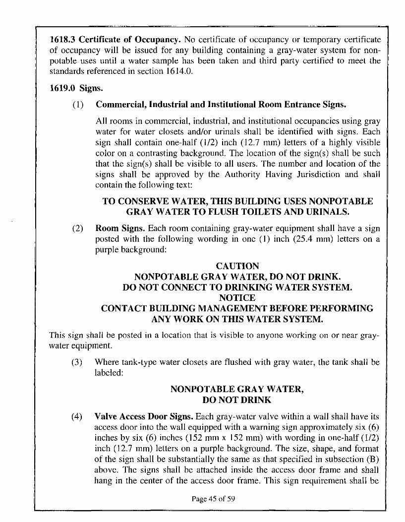
1618.3 Certificate of Occupancy. No certificate of occupancy or temporary certificateof occupancy will be issued for any building containing a gray-water system for non-potable uses until a water sample has been taken and third party certified to meet thestandards referenced in section 1614.0.
1619.0 Signs.
(1) Commercial, Industrial and Institutional Room Entrance Signs.
All rooms in commercial, industrial, and institutional occupancies using graywater for water closets and/or urinals shall be identified with signs. Eachsign shall contain one-half (1/2) inch (12.7 mm) letters of a highly visiblecolor on a contrasting background. The location of the sign(s) shall be suchthat the sign(s) shall be visible to all users. The number and location of thesigns shall be approved by the Authority Having Jurisdiction and shallcontain the following text:
TO CONSERVE WATER, THIS BUILDING USES NONPOTABLEGRAY WATER TO FLUSH TOILETS AND URINALS.
(2) Room Signs. Each room containing gray-water equipment shall have a signposted with the following wording in one (1) inch (25.4 mm) letters on apurple background:
CAUTIONNONPOTABLE GRAY WATER, DO NOT DRINK.
DO NOT CONNECT TO DRINKING WATER SYSTEM.NOTICE
CONTACT BUILDING MANAGEMENT BEFORE PERFORMINGANY WORK ON THIS WATER SYSTEM.
This sign shall be posted in a location that is visible to anyone working on or near gray-water equipment.
(3) Where tank-type water closets are flushed with gray water, the tank shall belabeled:
NONPOTABLE GRAY WATER,DO NOT DRINK
(4) Valve Access Door Signs. Each gray-water valve within a wall shall have itsaccess door into the wall equipped with a warning sign approximately six (6)inches by six (6) inches (152 mm x 152 mm) with wording in one-half (1/2)inch (12.7 mm) letters on a purple background. The size, shape, and formatof the sign shall be substantially the same as that specified in subsection (B)above. The signs shall be attached inside the access door frame and shallhang in the center of the access door frame. This sign requirement shall be
Page 45 of 59
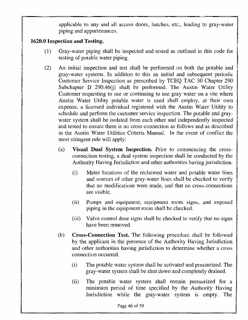
applicable to any and all access doors, hatches, etc., leading to gray-waterpiping and appurtenances.
1620.0 Inspection and Testing.
(1) Gray-water piping shall be inspected and tested as outlined in this code fortesting of potable water piping.
(2) An initial inspection and test shall be performed on both the potable andgray-water systems. In addition to this an initial and subsequent periodicCustomer Service Inspection as prescribed by TCEQ TAG 30 Chapter 290Subchapter D 290.46(j) shall be performed. The Austin Water UtilityCustomer requesting to use or continuing to use gray water on a site whereAustin Water Utility potable water is used shall employ, at their ownexpense, a licensed individual registered with the Austin Water Utility toschedule and perform the customer service inspection. The potable and gray-water system shall be isolated from each other and independently inspectedand tested to ensure there is no cross-connection as follows and as describedin the Austin Water Utilities Criteria Manual. In the event of conflict themost stringent rule will apply:
(a) Visual Dual System Inspection. Prior to commencing the cross-connection testing, a dual system inspection shall be conducted by theAuthority Having Jurisdiction and other authorities having jurisdiction.
(i) Meter locations of the reclaimed water and potable water linesand sources of other gray-water lines shall be checked to verifythat no modifications were made, and that no cross-connectionsare visible.
(ii) Pumps and equipment, equipment room signs, and exposedpiping in the equipment room shall be checked.
(iii) Valve control door signs shall be checked to verify that no signshave been removed.
(b) Cross-Connection Test. The following procedure shall be followedby the applicant in the presence of the Authority Having Jurisdictionand other authorities having jurisdiction to determine whether a crossconnection occurred.
(i) The potable water system shall be activated and pressurized. Thegray-water system shall be shut down and completely drained.
(ii) The potable water system shall remain pressurized for aminimum period of time specified by the Authority HavingJurisdiction while the gray-water system is empty. The
Page 46 of 59
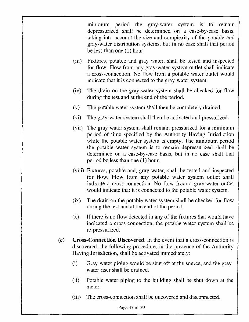
minimum period the gray-water system is to remaindepressurized shall be determined on a case-by-case basis,taking into account the size and complexity of the potable andgray-water distribution systems, but in no case shall that periodbe less than one (1) hour.
(iii) Fixtures, potable and gray water, shall be tested and inspectedfor flow. Flow from any gray-water system outlet shall indicatea cross-connection. No flow from a potable water outlet wouldindicate that it is connected to the gray-water system.
(iv) The drain on the gray-water system shall be checked for flowduring the test and at the end of the period.
(v) The potable water system shall then be completely drained.
(vi) The gray-water system shall then be activated and pressurized.
(vii) The gray-water system shall remain pressurized for a minimumperiod of time specified by the Authority Having Jurisdictionwhile the potable water system is empty. The minimum periodthe potable water system is to remain depressurized shall bedetermined on a case-by-case basis, but in no case shall thatperiod be less than one (1) hour.
(viii) Fixtures, potable and, gray water, shall be tested and inspectedfor flow. Flow from any potable water system outlet shallindicate a cross-connection. No flow from a gray-water outletwould indicate that it is connected to the potable water system.
(ix) The drain on the potable water system shall be checked for flowduring the test and at the end of the period,
(x) If there is no flow detected in any of the fixtures that would haveindicated a cross-connection, the potable water system shall bere-pressurized.
(c) Cross-Connection Discovered. In the event that a cross-connection isdiscovered, the following procedure, in the presence of the AuthorityHaving Jurisdiction, shall be activated immediately:
(i) Gray-water piping would be shut off at the source, and the gray-water riser shall be drained.
(ii) Potable water piping to the building shall be shut down at themeter.
(iii) The cross-connection shall be uncovered and disconnected.
Page 47 of 59
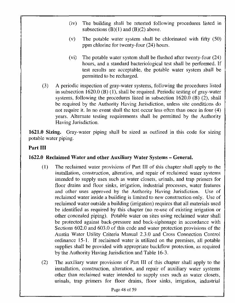
(iv) The building shall be retested following procedures listed insubsections (B)(l) and (B)(2) above.
(v) The potable water system shall be chlorinated with fifty (50)ppm chlorine for twenty-four (24) hours.
(vi) The potable water system shall be flushed after twenty-four (24)hours, and a standard bacteriological test shall be performed. Iftest results are acceptable, the potable water system shall bepermitted to be recharged.
(3) A periodic inspection of gray-water systems, following the procedures listedin subsection 1620.0 (B) (1), shall be required. Periodic testing of gray-watersystems, following the procedures listed in subsection 1620.0 (B) (2), shallbe required by the Authority Having Jurisdiction, unless site conditions donot require it. In no event shall the test occur less often than once in four (4)years. Alternate testing requirements shall be permitted by the AuthorityHaving Jurisdiction.
1621.0 Sizing. Gray-water piping shall be sized as outlined in this code for sizingpotable water piping.
Part III
1622.0 Reclaimed Water and other Auxiliary Water Systems - General.
(1) The reclaimed water provisions of Part III of this chapter shall apply to theinstallation, construction, alteration, and repair of reclaimed water systemsintended to supply uses such as water closets, urinals, and trap primers forfloor drains and floor sinks, irrigation, industrial processes, water featuresand other uses approved by the Authority Having Jurisdiction. Use ofreclaimed water inside a building is limited to new construction only. Use ofreclaimed water outside a building (irrigation) requires that all materials usedbe identified as required by this chapter (no re-use of existing irrigation orother concealed piping). Potable water on sites using reclaimed water shallbe protected against back-pressure and back-siphonage in accordance withSections 602.0 and 603.0 of this code and water protection provisions of theAustin Water Utility Criteria Manual 2.3.0 and Cross Connection Controlordinance 15-1. If reclaimed water is utilized on the premises, all potablesupplies shall be provided with appropriate backflow protection, as requiredby the Authority Having Jurisdiction and Table 16-3.
(2) The auxiliary water provisions of Part III of this chapter shall apply to theinstallation, construction, alteration, and repair of auxiliary water systemsother than reclaimed water intended to supply uses such as water closets,urinals, trap primers for floor drains, floor sinks, irrigation, industrial
Page 48 of 59
processes, water features and other uses approved by the Authority HavingJurisdiction. Potable water supplied as makeup water in these systems shallbe protected against back-pressure and back-siphonage in accordance withSections 602.0 and 603.0 and Table 16-3. If auxiliary water systems areutilized on the premises, all potable supplies shall be provided withappropriate backflow protection, as required by the Authority HavingJurisdiction and Table 16-3. If a property is connected to Austin WaterUtility's public potable water supply and has a rainwater harvesting systemor other auxiliary water system for indoor use, the property must haveappropriate cross-connection safeguards and the rainwater harvesting systemor auxiliary water system may be used only for non-potable indoor purposes.
(3) No commercial construction permit for any reclaimed water or otherauxiliary water system shall be issued until complete plumbing plans, withappropriate data satisfactory to the Authority Having Jurisdiction, have beensubmitted and approved. Residential plan review is not required and theproject will be inspected as a "field inspect" project. No changes orconnections shall be made to either the reclaimed water or other auxiliarywater system or the potable water system within any site containing areclaimed water or other auxiliary water system without approval by theAuthority Having Jurisdiction.
(4) Before a building may be occupied on a site using reclaimed water or otherauxiliary water, the installer shall perform the initial cross-connection testingand inspection in accordance with Section 1629.0 of this code and inaccordance with Section 2.3.6 Cross Connection Inspections and Testing ofAuxiliary Water Use Sites of the City of Austin Utilities Criteria Manual,with direction and oversight of the Authority Having Jurisdiction and otherauthorities having jurisdiction. The test shall be ruled successful by theAuthority Having Jurisdiction before final approval is granted.
(5) A reclaimed water or other auxiliary water system shall be designed by aperson registered or licensed to perform plumbing design work forcommercial applications.
1623.0 Definitions.
(1) Reclaimed Water - Nonpotable water that meets or as a result of treatment,meets federal requirements for its intended uses. The level of treatment andquality of the reclaimed water shall be approved by the TCEQ and theAuthority Having Jurisdiction.
(2) Auxiliary Water- any pressurized water supply on or available to thepremises other than the Austin Water Utility's approved public potable watersupply. These auxiliary waters may include water from another waterpurveyor's public water supply or any natural source(s) , including without
Page 49 of 59
limitation, rain, a well, lake, spring, river, stream, harbor, and so forth; orground water, surface water, ponded water for detention, retention or re-irrigation, or used waters, reclaimed water, recycled water, air conditioningcondensate, or industrial fluids but does not include forced sewer mains orany pumped sewage that is piped to City of Austin sewer or on site sewagefacility system.
1624.0 Permit. It shall be unlawful for any person to construct, install, alter, or cause tobe constructed, installed, or altered any reclaimed water or other auxiliary water systemwithin a building or on a premises without first obtaining a permit to do such work fromthe Authority Having Jurisdiction. No Homeowner/Homestead Plumbing Permits will beissued for installation of auxiliary water systems.
1625.0 Drawings and Specifications. The Authority Having Jurisdiction shall bepermitted to require any or all of the following information to be included with or in theplot plan before a permit is issued for a reclaimed water or other auxiliary water system.Residential One and Two Family Dwelling auxiliary water systems are exempt from planreview.
(1) A plot plan drawn to scale and completely dimensioned, showing lot linesand structures, location of present and proposed potable water supplies andmeters, water wells, streams, auxiliary water supply and systems, reclaimedwater supply and meters, drain lines, locations of private sewage disposalsystems and 100 percent expansion areas or building sewer connected to thepublic sewer.
(2) Details of construction including riser diagrams or isometrics and a fulldescription of the complete installation, including installation methods,construction, and materials as required by the Authority Having Jurisdiction.To the extent permitted by structural conditions, reclaimed water and otherauxiliary water risers within the toilet room, including appurtenances such asair/vacuum relief valves, pressure reducing valves, etc., shall be installed inthe opposite end of the room containing the served fixtures from the potablewater risers or opposite walls, as applicable. To the extent permitted bystructural conditions, reclaimed and other auxiliary water headers andbranches off risers shall not be run in the same wall or ceiling cavity of thetoilet room where potable water piping is run.
(3) Detailed initial and annual or periodic testing requirements as outlinedelsewhere in this chapter.
1626.0 Pipe Material/Pipe Identification. Reclaimed and other auxiliary water systemsshall comply with Sections 1626.1 and 1626.2.
1626.1 Pipe Materials. Reclaimed water and other auxiliary water pipe, valves andfittings shall conform to the requirements of Sections 604.0, 605.0 and 606.0.
Page 50 of 59
1626.2 Color and Information. Reclaimed water systems shall have a purplebackground with black uppercase lettering with the words "CAUTION: NONPOTABLERECLAIMED WATER, DO NOT DRINK." The minimum size of the letters and lengthof the color field shall conform to Table 6-1. Where used, a colored identification bandshall be indicated every five (5) feet (6,096 mm) not less than once per room, and shall bevisible from the floor level. Marking is not required for pipe manufactured with purplecolor integral to the pipe and marked with black uppercase lettering to read "CAUTION:NONPOTABLE RECLAIMED WATER, DO NOT DRINK" in intervals not to exceedfive (5) feet (1,524 mm). All valves, except fixture supply control valves shall beequipped with a locking feature. All mechanical equipment that is appurtenant to thereclaimed water system shall be painted purple. Piping for auxiliary waters other thanreclaimed water (rainwater, well, lake, stream, river, pond, etc.) installed below groundshall have a purple background with the words "CAUTION: NONPOTABLE WATER,DO NOT DRINK" in black uppercase lettering. The minimum size of the letters andlength of the color field shall conform to Table 6-1. Where used, a colored identificationband shall be indicated every five (5) feet (6,096 mm). Marking is not required for pipemanufactured with purple color integral to the pipe and marked with black uppercaselettering to read "CAUTION: NONPOTABLE WATER, DO NOT DRINK" in intervalsnot to exceed five (5) feet (1,524 mm).Piping for auxiliary waters other than reclaimedwater (rainwater, well, lake, stream, river, pond, etc.) installed above ground shall belabeled as non-potable per section 601.2.2.
1627.0 Installation.
(1) Hose bibbs shall not be allowed on reclaimed water or other auxiliary waterpiping systems.
(2) The reclaimed water or other auxiliary water system and the potable watersystem within the building shall be provided with the required appurtenances(valves, air/vacuum relief valves, etc.) to allow for deactivation or drainageas required for cross connection test in Section 1629.0.
(3) Reclaimed water or other auxiliary water pipes shall not be run or laid in thesame trench as potable water pipes. A ten (10) foot (3,048 mm) horizontalseparation shall be maintained between pressurized, buried reclaimed wateror other auxiliary water and potable water piping. Buried potable water pipescrossing pressurized reclaimed water or other auxiliary water pipes shall belaid not less than twelve (12) inches (305 mm) above the reclaimed water orother auxiliary water pipes. Reclaimed water or other auxiliary water pipeslaid in the same trench or crossing building sewer or drainage piping shall beinstalled in compliance with Sections 609.0 and 720.0 of this code.Reclaimed water or other auxiliary water pipes shall be protected similar topotable water pipes.
Page 51 of 59
1627.1 Specific Installation Requirements for Auxiliary Water Systems other thanReclaimed Water.
1627.1.1 Auxiliary Water Storage Tanks. Auxiliary water storage tanks shall beconstructed and installed in accordance with Sections 1627.1.1.1 through 1627.1.1.7.
1627.1.1.1 Construction. Auxiliary water storage tanks shall be constructed of solid,durable materials not subject to excessive corrosion or decay and shall be watertight.Storage tanks shall be approved by the Authority Having Jurisdiction, provided suchtanks comply with approved applicable standards.
1627.1.1.2 Location. Auxiliary water storage tanks shall be permitted to be installedabove or below grade.
1627.1.1.3 Above Grade. Above grade storage tanks shall be of an opaque material,approved for above-ground use in direct sunlight or shall be protected from directsunlight. Tanks shall be installed in an accessible location to allow for inspection andcleaning. The tank shall be installed on a foundation or platform that is constructed toaccommodate all loads in accordance with the building code.
1627.1.1.4 Below Grade. Auxiliary water storage tanks installed below grade shall bestructurally designed to withstand all anticipated earth or other loads. All holding tankcovers shall be capable of supporting an earth load of not less than three hundred (300)
•~\
pounds per square foot (1464.6 kg/m ) when the tank is designed for undergroundinstallation. Below grade auxiliary water tanks installed underground shall be providedwith manholes. The manhole opening shall be located a minimum of 4 inches abovefinished grade. The surrounding grade shall be sloped away from the manhole.Underground tanks shall be secured to prevent the tank from floating out of the groundwhen empty.
1627.1.1.5 Drainage and Overflow. Auxiliary water storage tanks shall be providedwith a means of draining and cleaning. The overflow drain shall not be equipped with ashutoff valve. The overflow outlet shall discharge as required by the plumbing code.Where discharging is to the storm or other drainage or collection system, the overflowdrain shall be protected from backflow of the storm or other drainage or collection systemby a backwater valve or other approved method.
1627.1.1.5.1 Overflow Outlet Size. The overflow outlet shall be sized to accommodatethe flow of the auxiliary water entering the tank and not less than the aggregate cross-sectional area of all inflow pipes.
1627.1.1.6 Opening and Access Protection.
1627.1.1.6.1 Animals and Insects. All auxiliary water tank openings shall be protectedto prevent the entrance of insects, birds and rodents into the tank with a screen havingopenings no greater than 1/32 inches (0.8 mm).
Page 52 of 59
1627.1.1.6.2 Human Access. Auxiliary water tank access openings 12 inches (305 mm)in diameter and larger shall be secured to prevent tampering and unintended entry byeither a lockable device or other approved method.
1627.1.1.6.3 Exposure to Sunlight. Auxiliary water tank openings shall not be exposedto direct sunlight.
1627.1.1.7 Marking. Auxiliary water tanks shall be permanently marked with thecapacity and the language: "NONPOTABLE AUXILIARY WATER." Where openingsare provided to allow a person to enter the tank, the opening shall be marked with thefollowing language:
"DANGER - CONFINED SPACE"
1627.1.2 Pumps. All pumps serving auxiliary water systems shall be listed. All pumpssupplying water to water closets, urinals, trap primers shall be capable of delivering aminimum (15) pounds per square inch (103.4 kPa) residual pressure at the highest andmost remote outlet served. Where the water pressure in auxiliary water supply systemwithin the building exceeds (65) pounds per square inch (552 kPa), a pressure reducingvalve reducing the pressure to (65) pounds per square inch (552 kPa) or less to all wateroutlets in the building shall be installed in accordance with the plumbing code.
1627.1.3 Water Quality Devices and Equipment. Devices and equipment used to treatauxiliary water to maintain the minimum water quality requirements determined by theAuthority Having Jurisdiction shall be listed or labeled (third-party certified) by a listingagency (accredited conformity assessment body) and approved for the intendedapplication.
1627.1.4 Auxiliary water for non-potable uses inside a building shall meet the followingstandards for treatment:
BOD 5 or CBOD 5mg/l
Turbidity 3NTU
Fecal coliform 20CFU/100ml (geometric mean)
Fecal coliform (not to exceed) 75CFU/100ml (single grab sample)
1627.2 Certificate of Occupancy. No certificate of occupancy or temporary certificateof occupancy will be issued for any building containing a auxiliary water system for non-potable uses until a water sample has been taken and third party certified to meet thestandards referenced in section 1627.1.4.
1628.0 Signs.
(1) Commercial, Industrial and institutional Room Entrance Signs.
Page 53 of 59
All rooms in commercial, industrial, and institutional occupancies usingreclaimed water or other auxiliary water for water closets and/or urinals shallbe identified with signs. Each sign shall contain one-half (1/2) inch (12.7mm) letters of a highly visible color on a contrasting background. Thelocation of the sign(s) shall be such that the sign(s) shall be visible to allusers. The number and location of the signs shall be approved by theAuthority Having Jurisdiction and shall contain the following text:
TO CONSERVE WATER, THIS BUILDING USES NONPOTABLERECLAIMED WATER TO FLUSH TOILETS AND URINALS.
(2) Room Signs. Each room containing reclaimed water or other auxiliary waterequipment shall have a sign posted with the following wording in one (1)inch (25.4 mm) letters on a purple background:
CAUTIONNONPOTABLE RECLAIMED WATER, DO NOT DRINK.DO NOT CONNECT TO DRINKING WATER SYSTEM.
NOTICECONTACT BUILDING MANAGEMENT BEFORE PERFORMING
ANY WORK ON THIS WATER SYSTEM.
This sign shall be posted in a location that is visible to anyone working onor near reclaimed water or other auxiliary water equipment.
(3) Where tank-type water closets are flushed with reclaimed water or otherauxiliary water, the tank shall be labeled:
NONPOTABLE RECLAIMED WATER,DO NOT DRINK
(4) Valve Access Door Signs. Each reclaimed water or other auxiliary watervalve within a wall shall have its access door into the wall equipped with awarning sign approximately six (6) inches by six (6) inches (152 mm x 152mm) with wording in one-half (1/2) inch (12.7 mm) letters on a purplebackground. The size, shape, and format of the sign shall be substantially thesame as that specified in subsection (B) above. The signs shall be attachedinside the access door frame and shall hang in the center of the access doorframe. This sign requirement shall be applicable to any and all access doors,hatches, etc., leading to reclaimed water or other auxiliary water piping andappurtenances.
(5) Auxiliary Waters other than reclaimed water (rainwater, well, river, stream,lake, etc) are not required to have the word "Reclaimed" in their signage.
Page 54 of 59
1629.0 Inspection and Testing.
(1) Reclaimed water and other auxiliary water piping shall be inspected andtested as outlined in this code for testing of potable water piping.
(2) An initial inspection and test shall be performed on both the potable andreclaimed water or other auxiliary water systems. In addition to this an initialand subsequent periodic Customer Service Inspection as prescribed byTCEQ 30 TAG Chapter 290, Subchapter D 290.46Q) shall be performed. TheAustin Water Utility Customer requesting to use or continuing to usereclaimed water or other auxiliary water on a site where Austin Water Utilitypotable water is used shall employ, at their own expense, a licensedindividual registered with the Austin Water Utility to schedule and performthe customer service inspection. The potable and reclaimed water or otherauxiliary water system shall be isolated from each other and independentlyinspected and tested to ensure there is no cross-connection as follows and asdescribed in the Austin Water Utilities Criteria Manual. In the event ofconflict the most stringent rule will apply.
(a) Visual Dual System Inspection. Prior to commencing the cross-connection testing, a dual system inspection shall be conducted by theAuthority Having Jurisdiction and other authorities having jurisdiction.
(i) Meter locations of the reclaimed water and potable water linesand sources of other auxiliary water lines shall be checked toverify that no modifications were made, and that no cross-connections are visible.
(ii) Pumps and equipment, equipment room signs, and exposedpiping in the equipment room shall be checked.
(iii) Valve control door signs shall be checked to verify that no signshave been removed.
(b) Cross-Connection Test. The following procedure shall be followedby the applicant in the presence of the Authority Having Jurisdictionand other authorities having jurisdiction to determine whether a crossconnection occurred.
(i) The potable water system shall be activated and pressurized. Thereclaimed water or other auxiliary water system shall be shutdown and completely drained.
(ii) The potable water system shall remain pressurized for aminimum period of time specified by the Authority HavingJurisdiction while the reclaimed water or other auxiliary watersystem(s) is(are) empty. The minimum period the reclaimed
Page 55 of 59
water or other auxiliary water system is to remain depressurizedshall be determined on a case-by-case basis, taking into accountthe size and complexity of the potable and reclaimed water orother auxiliary water distribution systems, but in no case shallthat period be less than one (1) hour.
(iii) Fixtures, potable and reclaimed water or other auxiliary, shall betested and inspected for flow. Flow from any reclaimed water orother auxiliary water system outlet shall indicate a cross-connection. No flow from a potable water outlet would indicatethat it is connected to the reclaimed water or other auxiliarywater system.
(iv) The drain on the reclaimed water or other auxiliary water systemshall be checked for flow during the test and at the end of theperiod.
(v) The potable water system shall then be completely drained.
(vi) The reclaimed water or other auxiliary water system shall thenbe activated and pressurized.
(vii) The reclaimed water or other auxiliary water system shallremain pressurized for a minimum period of time specified bythe Authority Having Jurisdiction while the potable watersystem is empty. The minimum period the potable water systemis to remain depressurized shall be determined on a case-by-casebasis, but in no case shall that period be less than one (1) hour.
(viii) Fixtures, potable and Declaimed water or other auxiliary, shallbe tested and inspected for flow. Flow from any potable watersystem outlet shall indicate a cross-connection. No flow from areclaimed water or other auxiliary water outlet would indicatethat it is connected to the potable water system.
(ix) The drain on the potable water system shall be checked for flowduring the test and at the end of the period.
(x) If there is no flow detected in any of the fixtures that would haveindicated a cross-connection, the potable water system shall bere-pressurized.
(c) Cross-Connection Discovered. In the event that a cross-connection isdiscovered, the following procedure, in the presence of the AuthorityHaving Jurisdiction, shall be activated immediately:
Page 56 of 59
(i) Reclaimed water piping to the building shall be shut down at themeter, and the reclaimed water riser shall be drained. Otherauxiliary water piping would be shut off at the source, and theauxiliary water riser shall be drained.
(ii) Potable water piping to the building shall be shut down at themeter.
(iii) The cross-connection shall be uncovered and disconnected.
(iv) The building shall be retested following procedures listed insubsections (B)(l) and (B)(2) above.
(v) The potable water system shall be chlorinated with fifty (50)ppm chlorine for twenty-four (24) hours.
(vi) The potable water system shall be flushed after twenty-four (24)hours, and a standard bacteriological test shall be performed. Iftest results are acceptable, the potable water system shall bepermitted to be recharged.
(3) An annual inspection of the reclaimed water system and periodic inspectionof other auxiliary water systems, following the procedures listed insubsection 1629.0 (B)(l), shall be required. Annual cross-connection testingof reclaimed water and periodic testing of other auxiliary water systems,following the procedures listed in subsection 1629.0 (B)(2), shall be requiredby the Authority Having Jurisdiction, unless site conditions do not require it.In no event shall the test occur less often than once in four (4) years.Alternate testing requirements shall be permitted by the Authority HavingJurisdiction.
1630.0 Sizing. Reclaimed water and other auxiliary water piping shall be sized asoutlined in this code for sizing potable water piping.
Page 57 of 59
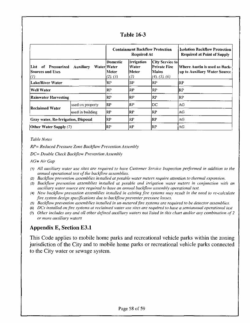
Table 16-3
List of PressurizedSources and Uses(D
Auxiliary Water
Lake/River Water
Well Water
Rainwater Harvesting
Reclaimed Waterused on property
used in building
Gray water, Re-Irrigation, Disposal
Other Water Supply (7)
Containment Backflow ProtectionRequired At
DomesticWaterMeter(2). (3)RP
RP
RP
RP
RP
RP
RP
IrrigationWaterMeter(3)RP
RP
RP
RP
RP
RP
RP
City Service toPrivate FireMains(4), (5), (6)
RP
RP
RP
DC
RP
RP
RP
Isolation Backflow ProtectionRequired at Point of Supply
Where Austin is used as Back-up to Auxiliary Water Source
RP
RP
RP
AG
AG
AG
AG
Table Notes
RP- Reduced Pressure Zone Back/low Prevention Assembly
DC= Double Check Back/low Prevention Assembly
AG= Air Gap
(1) All auxiliary water use sites are required to have Customer Service Inspection performed in addition to theannual operational test of the back/low assemblies.
(2) Backflow prevention assemblies installed at potable water meters require attention to thermal expansion.(3) Back/low prevention assemblies installed at potable and irrigation water meters in conjunction with an
auxiliary water source are required to have an annual backflow assembly operational test.New backflow prevention assemblies installed in existing fire systems may result in the need to re-calculate(4)
(5)(6)(7)
fire system design specifications due to backflow preventer pressure losses.Backflow prevention assemblies installed in un-metered fire systems are required to be detector assemblies.DCs installed on fire systems at reclaimed water use sites are required to have a semiannual operational testOther includes any and all other defined auxiliary wafers not listed in this chart and/or any combination of 2or more auxiliary waters
Appendix E, Section E3.1
This Code applies to mobile home parks and recreational vehicle parks within the zoningjurisdiction of the City and to mobile home parks or recreational vehicle parks connectedto the City water or sewage system.
Page 5 8 of 59
PART 2. This ordinance takes effect on October 1, 2010.
PASSED AND APPROVED
June 24 .2010 §
APPRO ATTEST:.aren
Acting City Attorney
ff ing wellMayor
Shirley Al. GentryCity Clerk
Page 59 of 59