sun rigging 146 - evapco
TRANSCRIPT
Rigging andAssembly Instructions
SUNINDUCED DRAFT COOLING TOWERS
Visit EVAPCO’s Website at: http://www.evapco.com
EVAPCO...SPECIALISTS IN HEAT TRANSFER PRODUCTS AND SERVICES.
EVAPCO, Inc. — World Headquarters & Research/Development Center
EVAPCO, Inc. • P.O. Box 1300 • Westminster, MD 21158 USAPHONE: 410-756-2600 • FAX: 410-756-6450 • E-MAIL: [email protected]
EVAPCO, Inc. World HeadquartersP.O. Box 1300Westminster, MD 21158 USAPhone: 410-756-2600 Fax: 410-756-6450E-mail: [email protected]
EVAPCO Asia/Pacific
EVAPCO Asia/Pacific Headquarters1159 Luoning Rd. Baoshan Industrial ZoneShanghai, P. R. China, Postal Code: 200949Phone: (86) 21-6687-7786Fax: (86) 21-6687-7008E-mail: [email protected]
EVAPCO Europe
EVAPCO Europe BVBAEuropean HeadquartersIndustrieterrein Oost 40103700 Tongeren, BelgiumPhone: (32) 12-395029Fax: (32) 12-238527E-mail: [email protected]
EVAPCO East5151 Allendale LaneTaneytown, MD 21787 USAPhone: 410-756-2600Fax: 410-756-6450E-mail: [email protected]
EVAPCO Midwest1723 York RoadGreenup, IL 62428 USAPhone: 217-923-3431Fax: 217-923-3300E-mail: [email protected]
EVAPCO West1900 West Almond AvenueMadera, CA 93637 USAPhone: 559-673-2207Fax: 559-673-2378E-mail: [email protected]
EVAPCO Iowa925 Quality DriveLake View, IA 51450 USAPhone: 712-657-3223Fax: 712-657-3226
EVAPCO IowaSales & Engineering215 1st Street, NEP.O. Box 88Medford, MN 55049 USAPhone: 507-446-8005Fax: 507-446-8239E-mail: [email protected]
EVAPCO Northwest5775 S.W. Jean Road, Suite 104Lake Oswego, Oregon 97035 USAPhone: 503-639-2137Fax: 503-639-1800
EVAPCO Newton701 East Jourdan StreetNewton, IL 62448 USAPhone: 618-783-3433Fax: 618-783-3499E-mail: [email protected]
EVAPCO-BLCT Dry Cooling, Inc.981 US Highway 22 WestBridgewater, New Jersey 08807 USA Phone: 1-908-379-2665E-mail: [email protected]
Refrigeration Valves & Systems CorporationA wholly owned subsidiary of EVAPCO, Inc.1520 Crosswind Dr.Bryan, TX 77808 USAPhone: 979-778-0095Fax: 979-778-0030E-mail: [email protected]
EvapTech, Inc.A wholly owned subsidiary of EVAPCO, Inc.8331 Nieman RoadLenexa, KS 66214 USAPhone: 913-322-5165Fax: 913-322-5166E-mail: [email protected]
Tower Components, Inc.A wholly owned subsidiary of EVAPCO, Inc.5960 US HWY 64ERamseur, NC 27316Phone: 336-824-2102Fax: 336-824-2190E-mail: [email protected]
EVAPCO Europe, S.r.l.Via Ciro Menotti 10I-20017 Passirana di RhoMilan, ItalyPhone: (39) 02-939-9041Fax: (39) 02-935-00840E-mail: [email protected]
EVAPCO Europe, S.r.l.Via Dosso 223020 Piateda Sondrio, Italy
EVAPCO Europe GmbHInsterburger Straße 1840670 Meerbusch, GermanyPhone: (49) 2159-69560Fax: (49) 2159-695611E-mail: [email protected]
Flex coil a/sA wholly owned subsidiary of EVAPCO, Inc.Knøsgårdvej 115DK-9440 Aabybro DenmarkPhone: (45) 9824 4999Fax: (45) 9824 4990E-mail: [email protected]
EVAPCO S.A. (Pty.) Ltd.A licensed manufacturer of EVAPCO, Inc.18 Quality RoadIsando 1600Republic of South AfricaPhone: (27) 11-392-6630Fax: (27) 11-392-6615E-mail: [email protected]
Evap Egypt Engineering Industries Co.A licensed manufacturer of EVAPCO, Inc.5 El Nasr RoadNasr City, Cairo, EgyptPhone: 2 02 24022866 /2 02 24044997Fax: 2 02 24044667/2 02 24044668E-mail: [email protected] / [email protected]
EVAPCO (Shanghai) Refrigeration Equipment Co., Ltd.1159 Luoning Rd., Baoshan Industrial ZoneShanghai, P.R. China, Postal Code: 200949Phone: (86) 21-6687-7786Fax: (86) 21-6687-7008E-mail: [email protected]
Beijing EVAPCO Refrigeration Equipment Co., Ltd.No. 13 Yanxi Avenue, Yanqi DevelopmentZoneHuai Rou CountyBeijing, P.R. ChinaPostal code 101407Phone: (86) 10 6166-7238Fax: (86) 10 6166-7395E-mail: [email protected]
EVAPCO Australia (Pty.) Ltd.34-42 Melbourne RoadP.O. Box 436Riverstone, N.S.W. Australia 2765Phone: (61) 2 9627-3322Fax: (61) 2 9627-1715E-mail: [email protected]
EVAPCO Composites Sdn. BhdNo. 70 (Lot 1289) Jalan Industri 2/3Rawang Integrated Industrial ParkRawang, Selangor, 48000 MalaysiaPhone: 60 3 6092-2209Fax: 60 3 6092-2210
EvapTech Asia Pacific Sdn. BhdA wholly owned subsidiary of EvapTech, Inc.B-6-1, IOI BoulevardJalan Kenari 5, Bandar Puchong Jaya47170 Puchong, Selangor Darul EhsanMalaysiaPhone: (60-3) 8070-7255Fax: (60-3) 8070-5731E-mail: [email protected]
EVAPCO North America
EVAPCO Products are Manufactured Wordwide
Bulletin 146
2
SUN Induced Draft Cooling Towers
Introduction
Thank you for purchasing your EVAPCO cooling tower. This manual will provide instructions for installation of the cooling tower. Ifany questions arise during the installation, please contact your local EVAPCO representative or us directly at our worldheadquarters location.
International Building Code Provisions
The International Building Code (IBC) is a comprehensive set of regulations addressing the structural design and installationrequirements for building systems – including HVAC and industrial refrigeration equipment. As of June 2008, all 50 states plusWashington D.C. have adopted the International Building Code. The code provisions require that evaporative cooling equipmentand all other components permanently installed on a structure must meet the same seismic design criteria as the building. TheSUN Series of Open Cooling Towers are IBC 2009 compliant up to 1g with standard construction.
All items attached to the Evapco SUN cooling tower must be independently reviewed and isolated to meet applicable wind andseismic loads. This includes piping, ductwork, conduit, and electrical connections. These items must be flexibly attached to theEvapco unit so as not to transmit additional loads to the equipment as a result of seismic or wind forces.
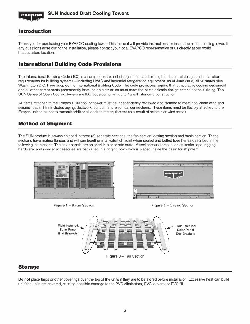
Method of Shipment
The SUN product is always shipped in three (3) separate sections; the fan section, casing section and basin section. Thesesections have mating flanges and will join together in a watertight joint when sealed and bolted together as described in thefollowing instructions. The solar panels are shipped in a separate crate. Miscellaneous items, such as sealer tape, rigginghardware, and smaller accessories are packaged in a rigging box which is placed inside the basin for shipment.
Storage
Do not place tarps or other coverings over the top of the units if they are to be stored before installation. Excessive heat can buildup if the units are covered, causing possible damage to the PVC eliminators, PVC louvers, or PVC fill.
Figure 1 – Basin Section Figure 2 – Casing Section
Figure 3 – Fan Section
Field InstalledSolar Panel
End Brackets
Field InstalledSolar Panel
End Brackets
3
SUN Induced Draft Cooling Towers
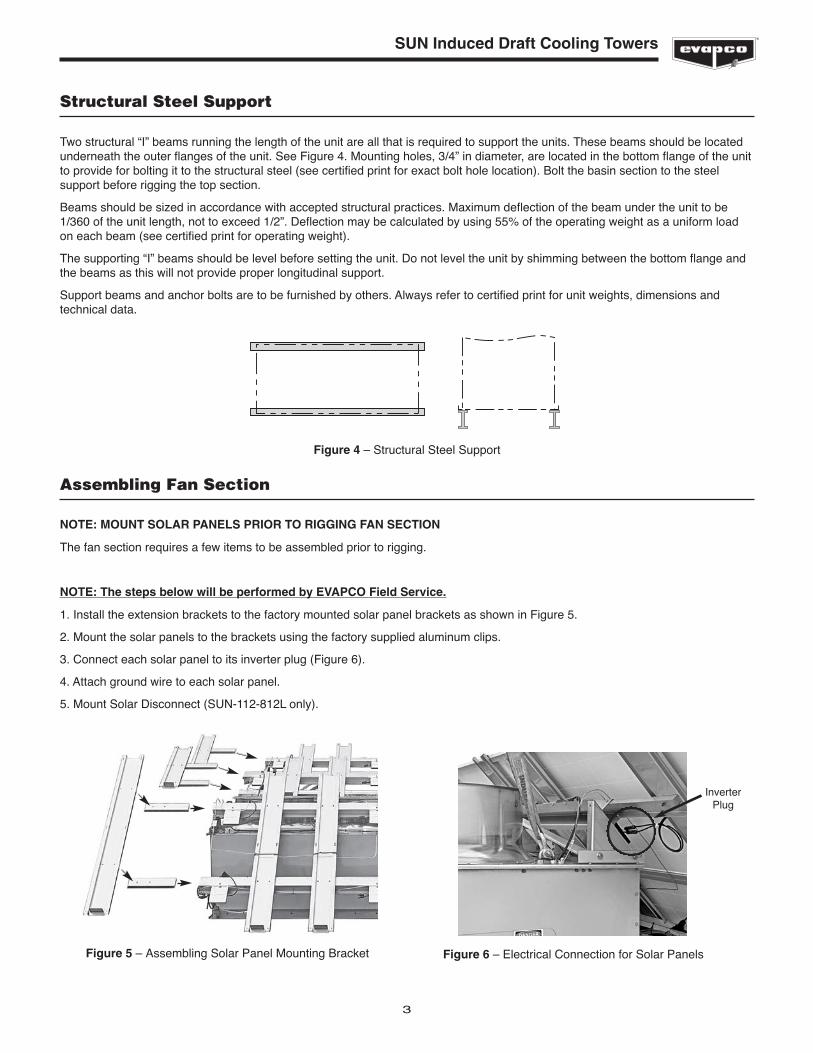
Structural Steel Support
Two structural “I” beams running the length of the unit are all that is required to support the units. These beams should be locatedunderneath the outer flanges of the unit. See Figure 4. Mounting holes, 3/4” in diameter, are located in the bottom flange of the unitto provide for bolting it to the structural steel (see certified print for exact bolt hole location). Bolt the basin section to the steelsupport before rigging the top section.
Beams should be sized in accordance with accepted structural practices. Maximum deflection of the beam under the unit to be1/360 of the unit length, not to exceed 1/2”. Deflection may be calculated by using 55% of the operating weight as a uniform loadon each beam (see certified print for operating weight).
The supporting “I” beams should be level before setting the unit. Do not level the unit by shimming between the bottom flange andthe beams as this will not provide proper longitudinal support.
Support beams and anchor bolts are to be furnished by others. Always refer to certified print for unit weights, dimensions andtechnical data.
Figure 4 – Structural Steel Support
Assembling Fan Section
NOTE: MOUNT SOLAR PANELS PRIOR TO RIGGING FAN SECTION
The fan section requires a few items to be assembled prior to rigging.
NOTE: The steps below will be performed by EVAPCO Field Service.
1. Install the extension brackets to the factory mounted solar panel brackets as shown in Figure 5.
2. Mount the solar panels to the brackets using the factory supplied aluminum clips.
3. Connect each solar panel to its inverter plug (Figure 6).
4. Attach ground wire to each solar panel.
5. Mount Solar Disconnect (SUN-112-812L only).
Figure 5 – Assembling Solar Panel Mounting Bracket Figure 6 – Electrical Connection for Solar Panels
InverterPlug
4
SUN Induced Draft Cooling Towers
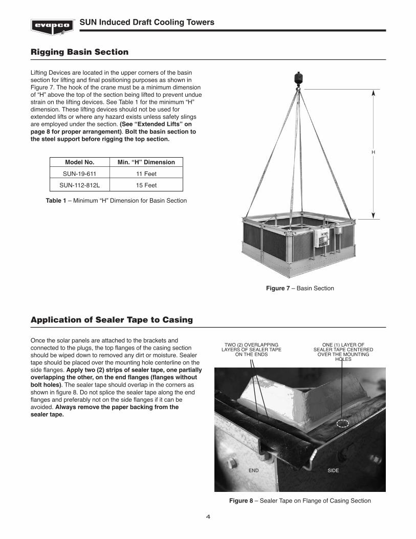
Rigging Basin Section
Lifting Devices are located in the upper corners of the basinsection for lifting and final positioning purposes as shown inFigure 7. The hook of the crane must be a minimum dimensionof “H” above the top of the section being lifted to prevent unduestrain on the lifting devices. See Table 1 for the minimum “H”dimension. These lifting devices should not be used forextended lifts or where any hazard exists unless safety slingsare employed under the section. (See “Extended Lifts” onpage 8 for proper arrangement). Bolt the basin section tothe steel support before rigging the top section.
Application of Sealer Tape to Casing
Once the solar panels are attached to the brackets andconnected to the plugs, the top flanges of the casing sectionshould be wiped down to removed any dirt or moisture. Sealertape should be placed over the mounting hole centerline on theside flanges. Apply two (2) strips of sealer tape, one partiallyoverlapping the other, on the end flanges (flanges withoutbolt holes). The sealer tape should overlap in the corners asshown in figure 8. Do not splice the sealer tape along the endflanges and preferably not on the side flanges if it can beavoided. Always remove the paper backing from the sealer tape.
Figure 7 – Basin Section
Model No. Min. “H” Dimension
SUN-19-611 11 Feet
SUN-112-812L 15 Feet
Table 1 – Minimum “H” Dimension for Basin Section
H
Figure 8 – Sealer Tape on Flange of Casing Section
TWO (2) OVERLAPPINGLAYERS OF SEALER TAPE
ON THE ENDS
ONE (1) LAYER OFSEALER TAPE CENTERED
OVER THE MOUNTINGHOLES
END SIDE
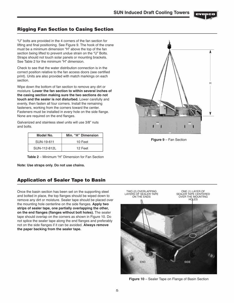
Application of Sealer Tape to Basin
Once the basin section has been set on the supporting steeland bolted in place, the top flanges should be wiped down toremove any dirt or moisture. Sealer tape should be placed overthe mounting hole centerline on the side flanges. Apply twostrips of sealer tape, one partially overlapping the other,on the end flanges (flanges without bolt holes). The sealertape should overlap on the corners as shown in Figure 10. Donot splice the sealer tape along the end flanges and preferablynot on the side flanges if it can be avoided. Always removethe paper backing from the sealer tape.
SUN Induced Draft Cooling Towers
5
Rigging Fan Section to Casing Section
“U” bolts are provided in the 4 corners of the fan section forlifting and final positioning. See Figure 9. The hook of the cranemust be a minimum dimension “H” above the top of the fansection being lifted to prevent undue strain on the “U” Bolts.Straps should not touch solar panels or mounting brackets.See Table 2 for the minimum “H” dimension.
Check to see that the water distribution connection is in thecorrect position relative to the fan access doors (see certifiedprint). Units are also provided with match markings on eachsection.
Wipe down the bottom of fan section to remove any dirt ormoisture. Lower the fan section to within several inches ofthe casing section making sure the two sections do nottouch and the sealer is not disturbed. Lower carefully andevenly, then fasten all four corners. Install the remainingfasteners, working from the corners toward the center.Fasteners must be installed in every hole on the side flange.None are required on the end flanges.
Galvanized and stainless steel units will use 3/8” nuts and bolts.
Figure 9 – Fan SectionModel No. Min. “H” Dimension
SUN-19-611 10 Feet
SUN-112-812L 12 Feet
Table 2 – Minimum “H” Dimension for Fan Section
H
Figure 10 – Sealer Tape on Flange of Basin Section
Note: Use straps only. Do not use chains.
TWO (2) OVERLAPPINGLAYERS OF SEALER TAPE
ON THE ENDS
ONE (1) LAYER OFSEALER TAPE CENTERED
OVER THE MOUNTINGHOLES
END SIDE
6
SUN Induced Draft Cooling Towers
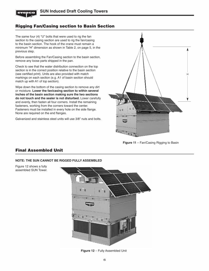
Rigging Fan/Casing section to Basin Section
The same four (4) “U” bolts that were used to rig the fansection to the casing section are used to rig the fan/casing to the basin section. The hook of the crane must remain aminimum “H” dimension as shown in Table 2, on page 5, in the previous step.
Before assembling the Fan/Casing section to the basin section,remove any loose parts shipped in the pan.
Check to see that the water distribution connection on the topsection is in the correct position relative to the basin section(see certified print). Units are also provided with matchmarkings on each section (e.g. A1 of basin section shouldmatch up with A1 of top section).
Wipe down the bottom of the casing section to remove any dirtor moisture. Lower the fan/casing section to within severalinches of the basin section making sure the two sectionsdo not touch and the sealer is not disturbed. Lower carefullyand evenly, then fasten all four corners. Install the remainingfasteners, working from the corners toward the center.Fasteners must be installed in every hole on the side flange.None are required on the end flanges.
Galvanized and stainless steel units will use 3/8” nuts and bolts.
Figure 11 – Fan/Casing Rigging to Basin
H
Final Assembled Unit
NOTE: THE SUN CANNOT BE RIGGED FULLY ASSEMBLED
Figure 12 shows a fullyassembled SUN Tower.
Figure 12 – Fully Assembled Unit
7
SUN Induced Draft Cooling Towers
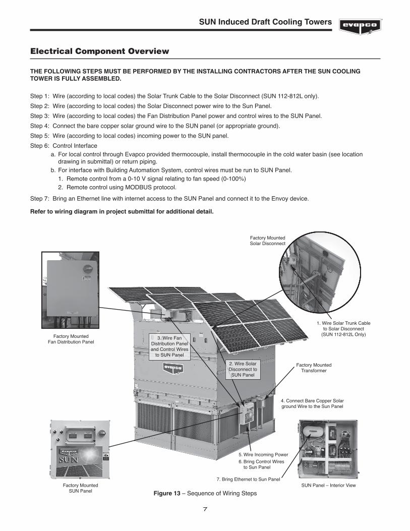
Figure 13 – Sequence of Wiring Steps
Factory Mounted Fan Distribution Panel
Factory Mounted SUN Panel
SUN Panel – Interior View
Factory Mounted Solar Disconnect
1. Wire Solar Trunk Cableto Solar Disconnect
(SUN 112-812L Only)
2. Wire SolarDisconnect to SUN Panel
3. Wire FanDistribution Paneland Control Wires
to SUN Panel
4. Connect Bare Copper Solarground Wire to the Sun Panel
5. Wire Incoming Power
6. Bring Control Wiresto Sun Panel
7. Bring Ethernet to Sun Panel
Electrical Component Overview
THE FOLLOWING STEPS MUST BE PERFORMED BY THE INSTALLING CONTRACTORS AFTER THE SUN COOLINGTOWER IS FULLY ASSEMBLED.
Step 1: Wire (according to local codes) the Solar Trunk Cable to the Solar Disconnect (SUN 112-812L only).
Step 2: Wire (according to local codes) the Solar Disconnect power wire to the Sun Panel.
Step 3: Wire (according to local codes) the Fan Distribution Panel power and control wires to the SUN Panel.
Step 4: Connect the bare copper solar ground wire to the SUN panel (or appropriate ground).
Step 5: Wire (according to local codes) incoming power to the SUN panel.
Step 6: Control Interfacea. For local control through Evapco provided thermocouple, install thermocouple in the cold water basin (see location
drawing in submittal) or return piping.b. For interface with Building Automation System, control wires must be run to SUN Panel.
1. Remote control from a 0-10 V signal relating to fan speed (0-100%)2. Remote control using MODBUS protocol.
Step 7: Bring an Ethernet line with internet access to the SUN Panel and connect it to the Envoy device.
Refer to wiring diagram in project submittal for additional detail.
Factory MountedTransformer
8
SUN Induced Draft Cooling Towers
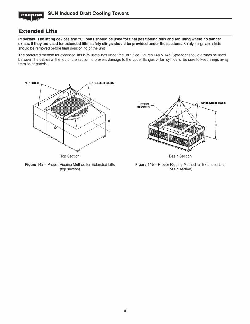
Extended LiftsImportant: The lifting devices and “U” bolts should be used for final positioning only and for lifting where no dangerexists. If they are used for extended lifts, safety slings should be provided under the sections. Safety slings and skidsshould be removed before final positioning of the unit.
The preferred method for extended lifts is to use slings under the unit. See Figures 14a & 14b. Spreader should always be usedbetween the cables at the top of the section to prevent damage to the upper flanges or fan cylinders. Be sure to keep slings awayfrom solar panels.
Figure 14b – Proper Rigging Method for Extended Lifts (basin section)
Figure 14a – Proper Rigging Method for Extended Lifts (top section)
Basin SectionTop Section
9
SUN Induced Draft Cooling Towers
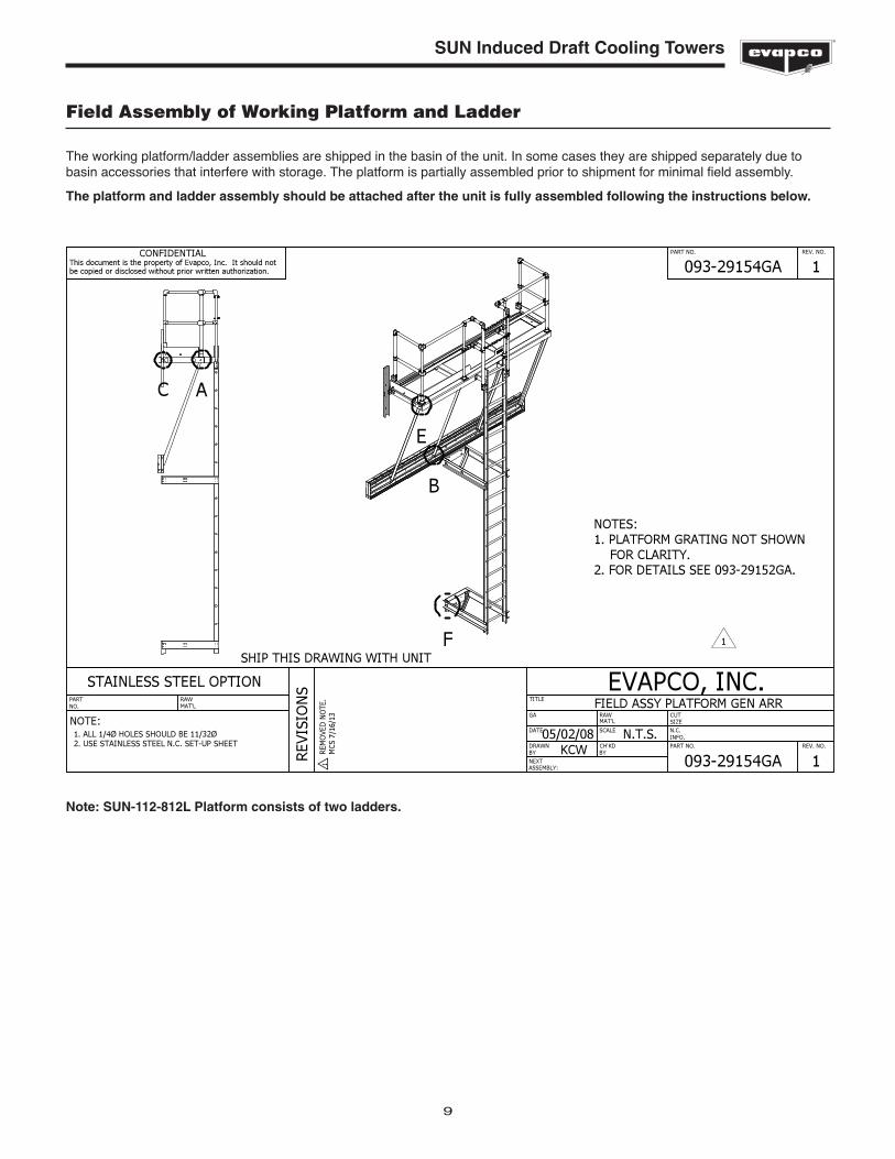
Field Assembly of Working Platform and Ladder
The working platform/ladder assemblies are shipped in the basin of the unit. In some cases they are shipped separately due tobasin accessories that interfere with storage. The platform is partially assembled prior to shipment for minimal field assembly.
The platform and ladder assembly should be attached after the unit is fully assembled following the instructions below.
�����
���
��
�� �
�� ��
������� ������
����������������������
������� ������
����
���
��
����
����
����
����
��
���������
�����
�� �������
�����
�����������
���
������
������������� !�"#$%&'()� !�)�'�*+#*'+),�#-��./*$#���($���)�!�#%0"�(#)1'�$#* '"�#+�" !$0#!'"�2 )�#%)�*+ #+�2+ ))'(�/%)�#+ 3/) #(
�����4�����4567����������������4458979���������������������������:��������
������������ ���� ��������
������4������������������������� ����������������9����������������;<8:9<4=9��
��������������������������
;=5;95;> �����
;<8:9<4=6�� 4
;<8:9<4=6�� 4
���
���
��
���
�
���?
54@5
48
�4
4
�
� �
�
�
Note: SUN-112-812L Platform consists of two ladders.
10
SUN Induced Draft Cooling Towers
General Information - Start-up & Maintenance Start-up Details Shipping Chocks and Debris
Remove any chocks that have been placed inside the unit for shipping purposes. Clean all debris from the pan prior to start-up.Close and secure all access doors.
Bleed-off Line
Make sure a bleed line and valve are installed on the pump discharge side of the system piping to a convenient drain. The bleed-offvalve should be open.
TITLE
CUT
N.C.
DRAWN
RAWGA
PART NO. REV NO.
STAINLESS STEEL OPTION
PART NO. REV. NO.
REVI
SIO
NS
PARTNO.
NEXT
SIZE
INFO.
BY
ASSEMBLY:
MAT’L
MAT’LRAW
NOTE:
EVAPCO, INC.
DATE
CH’KDBY
CONFIDENTIALThis document is the property of Evapco, Inc. It should notbe copied or disclosed without prior written authorization.
SCALE1. ALL 1/4Ø HOLES SHOULD BE 11/32Ø2. USE STAINLESS STEEL N.C. SET9UP SHEET
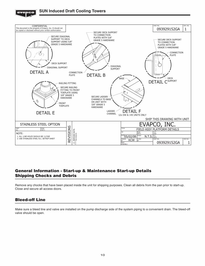
DETAIL A
SECURE DIAGONALSUPPORT TO DECKSUPPORT USING 5/8"GRADE 5 HARDWARE
DECK SUPPORT
DIAGONAL SUPPORT
SHIP THIS DRAWING WITH UNIT
DETAIL BCONNECTIONPLATE
DIAGONALSUPPORT
SECURE DECK SUPPORTTO CONNECTIONPLATES WITH 5/8"GRADE 5 HARDWARE
DETAIL E
RAILING FITTING
SECURE RAILINGFITTING TO FRONTTOEPLATE USING3/8" GRADE 5HARDWARE
FRONTTOEPLATE
FIELD ASSY PLATFORM DETAILS
05/02/08 N.T.S.KCW
093929152GA 1
093929152GA 1
REM
OVE
D N
OTE
.TL
S 4/
3/13
SECURE LADDERCHANNELS TO BASEON UNIT WITH3/8" GRADE 5HARDWARE
BASE
LADDERCHANNEL
DETAIL F12x DW & 14X UNITS ONLY
SECURE DECK SUPPORTTO CONNECTIONPLATES WITH 5/8"GRADE 5 HARDWARE
DECKSUPPORT
CONNECTIONPLATE
DETAIL C
1
11
SUN Induced Draft Cooling Towers
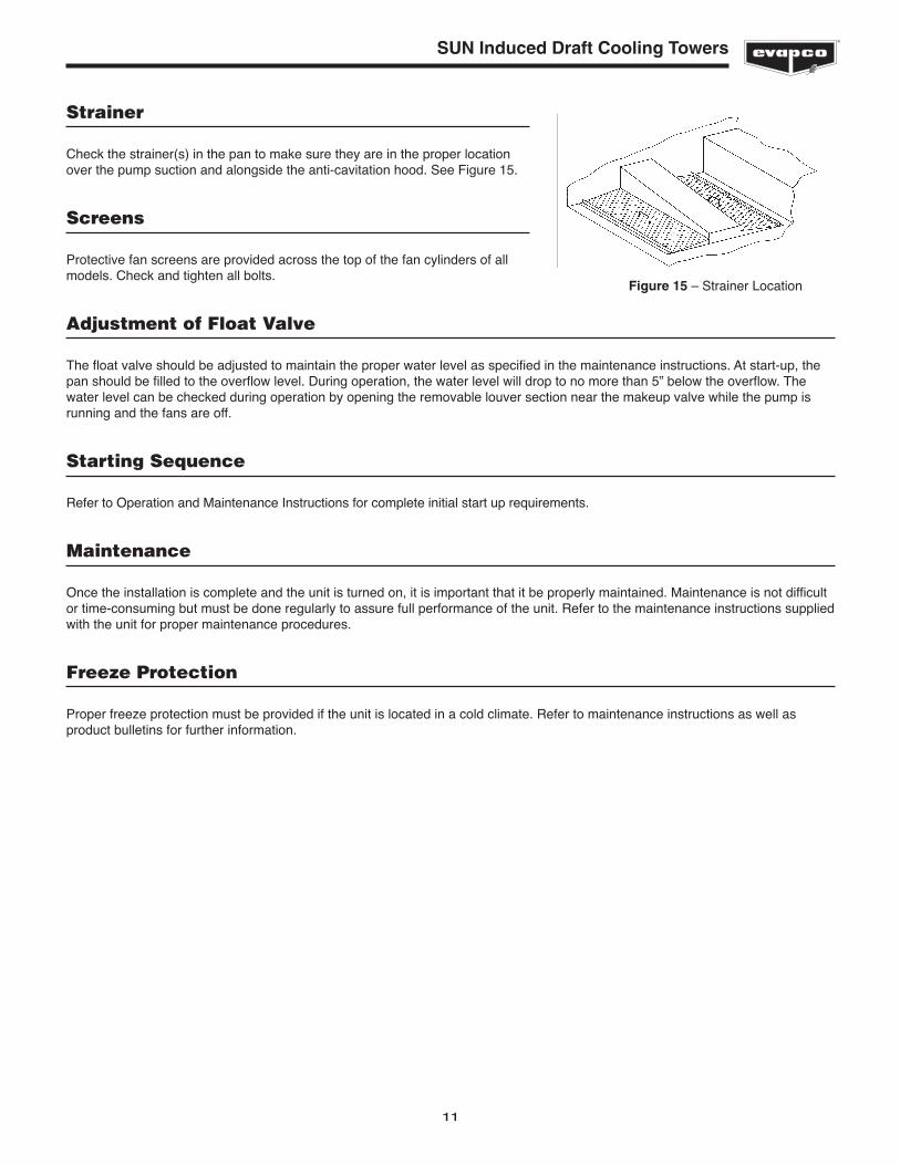
Strainer
Check the strainer(s) in the pan to make sure they are in the proper locationover the pump suction and alongside the anti-cavitation hood. See Figure 15.
Screens
Protective fan screens are provided across the top of the fan cylinders of allmodels. Check and tighten all bolts.
Adjustment of Float Valve
The float valve should be adjusted to maintain the proper water level as specified in the maintenance instructions. At start-up, thepan should be filled to the overflow level. During operation, the water level will drop to no more than 5” below the overflow. Thewater level can be checked during operation by opening the removable louver section near the makeup valve while the pump isrunning and the fans are off.
Starting Sequence
Refer to Operation and Maintenance Instructions for complete initial start up requirements.
Maintenance
Once the installation is complete and the unit is turned on, it is important that it be properly maintained. Maintenance is not difficultor time-consuming but must be done regularly to assure full performance of the unit. Refer to the maintenance instructions suppliedwith the unit for proper maintenance procedures.
Freeze Protection
Proper freeze protection must be provided if the unit is located in a cold climate. Refer to maintenance instructions as well asproduct bulletins for further information.
Figure 15 – Strainer Location

EVAPCO, Inc. • P.O. Box 1300 • Westminster, MD 21158 USAPHONE: 410-756-2600 • FAX: 410-756-6450 • E-MAIL: [email protected]
©2014 EVAPCO, Inc.
Printed on recycled paperusing soy-based ink