chain & rigging attachments - dillon supply
TRANSCRIPT
SHACKLES
CHAIN
SLINGS
HOOKS
TIE-DOWNS
BINDERS
WIRE ROPE ATTACHMENTS
HOIST RINGS
CLAMPS
C O L U M B U S M c K I N N O N C O R P O R A T I O N
CHAIN &RIGGINGATTACHMENTS
THE GlobAl lEAdER IN PRovIdING PRoduCTS, APPlICATIoN KNowlEdGE ANd TRAINING To HElP CuSToMERS lIfT, PoSITIoN, oR SECuRE MATERIAlS EASIly ANd SAfEly.
Columbus McKinnon Corporation has a rich tradition of providing quality products and services to meet the needs of users in a variety of industries around the globe which continues with an expanded line of chain and attachments by CM. Used by professional riggers, maintenance workers, plant engineers and safety specialists to lift, pull, and secure loads, the broad product offering allows users to select the proper product for everyday use or for those challenging, unique applications which arise during the course of a project.
Our broad product offering is one advantage CM has over the competition, complemented by:
A thoroughly trained and knowledgeable technical sales force providing expertise on applications, regulations, training requirements, and product features and benefits.
A global network of authorized distributors providing inventory, technical support, service after the sale, and consultation regarding specific needs.
Knowledgeable customer service representatives addressing an array of issues related to shipments, product selection, specifications, and auxiliary items.
World-class, global manufacturing facilities performing product testing which exceeds the standards outlined by industry regulations.
An engineering team working to improve existing products, while developing unique and innovative new products.
Training programs dedicated specifically to rigging products, as well as broad-based programs to cover all aspects of lifting and positioning.
The ONLY manufacturer of rigging products that is also a LEADER in the design and manufacturing of hoists, overhead cranes, and related products.
More than 130 years of experience in providing products and services that exceed the expectations of customers.
THE GlobAl lEAdERIN PRovIdING PRoduCTS, APPlICATIoN KNowlEdGEANd TRAINING To HElP CuSToMERS lIfT, PoT, PoT SITIoN, oR SECuRE MATERIAlS EASI EASI E ly ANd SAd SAd S fEly.
Columbus McKinnon Corporation has a rich tradition of providing quality products and services to meet the needs of users in a variety of industries around the globe which continues with an expanded line of chain and attachments by CM. Used by professional riggers, maintenance workers, plant engineers and safety specialists to lift, pull, and secure loads, the broad product offering allows users to select the proper product for everyday use or for those challenging, unique applications which arise during the course of a project.
Our broad product offering is one advantage CM has over the competition, complemented by:
A thoroughly trained and knowledgeable technical sales force providing expertise on applications, regulations, training requirements, and product features and benefits.
A global network of authorized distributors providing inventory, technical support, service after the sale, and consultation regarding specific needs.
Knowledgeable customer service representatives addressing an array of issues related to shipments, product selection, specifications, and auxiliary items.
World-class, global manufacturing facilities performing product testing which exceeds the standards outlined by industry regulations.
An engineering team working to improve existing products, while developing unique and innovative new products.
Training programs dedicated specifically to rigging products, as well as broad-based programs to cover all aspects of lifting and positioning.
The ONLY manufacturer of rigging products that is also a LEADER in the design and manufacturing of hoists, overhead cranes, and related products.
More than 130 years of experience in providing products and services that exceed the expectations of customers.
Columbus McKinnon Corporation has a rich tradition, spanning more than 141 years, of providing quality material handling products and services to meet the needs of users in a variety of industries around the globe. Professional riggers, maintenance workers, plant engineers and safety specialists rely on the CM line of chain and attachments to lift, pull and secure loads in a variety of applications. We continue to innovate and expand our rigging portfolio to meet industry needs and give customers the products they need for their unique and challenging applications.
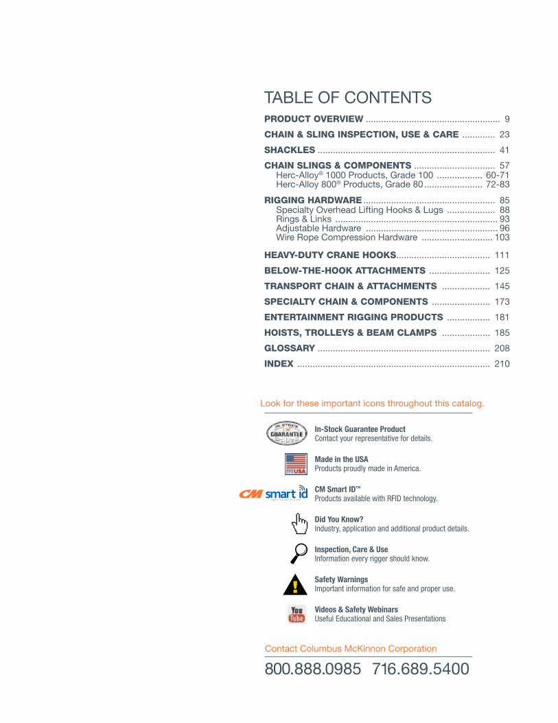
TABLE OF CONTENTS
Look for these important icons throughout this catalog.
In-Stock Guarantee Product Contact your representative for details.
Made in the USA Products proudly made in America.
CM Smart IDTM Products available with RFID technology.
Inspection, Care & Use Information every rigger should know.
Safety Warnings Important information for safe and proper use.!
Did You Know? Industry, application and additional product details.
Videos & Safety Webinars Useful Educational and Sales Presentations
800.888.0985 716.689.5400Contact Columbus McKinnon Corporation
PRODUCT OVERVIEW ..................................................... 9
CHAIN & SLING INSPECTION, USE & CARE ............. 23
SHACKLES ...................................................................... 41
CHAIN SLINGS & COMPONENTS ................................ 57 Herc-Alloy® 1000 Products, Grade 100 .................. 60-71 Herc-Alloy 800® Products, Grade 80 ....................... 72-83
RIGGING HARDWARE .................................................... 85 Specialty Overhead Lifting Hooks & Lugs ................... 88 Rings & Links ................................................................ 93 Adjustable Hardware .................................................... 96 Wire Rope Compression Hardware ............................ 103
HEAVY-DUTY CRANE HOOKS ..................................... 111
BELOW-THE-HOOK ATTACHMENTS ........................ 125
TRANSPORT CHAIN & ATTACHMENTS ................... 145
SPECIALTY CHAIN & COMPONENTS ....................... 173
ENTERTAINMENT RIGGING PRODUCTS ................. 181
HOISTS, TROLLEYS & BEAM CLAMPS ................... 185
GLOSSARY .................................................................... 208
INDEX ............................................................................ 210
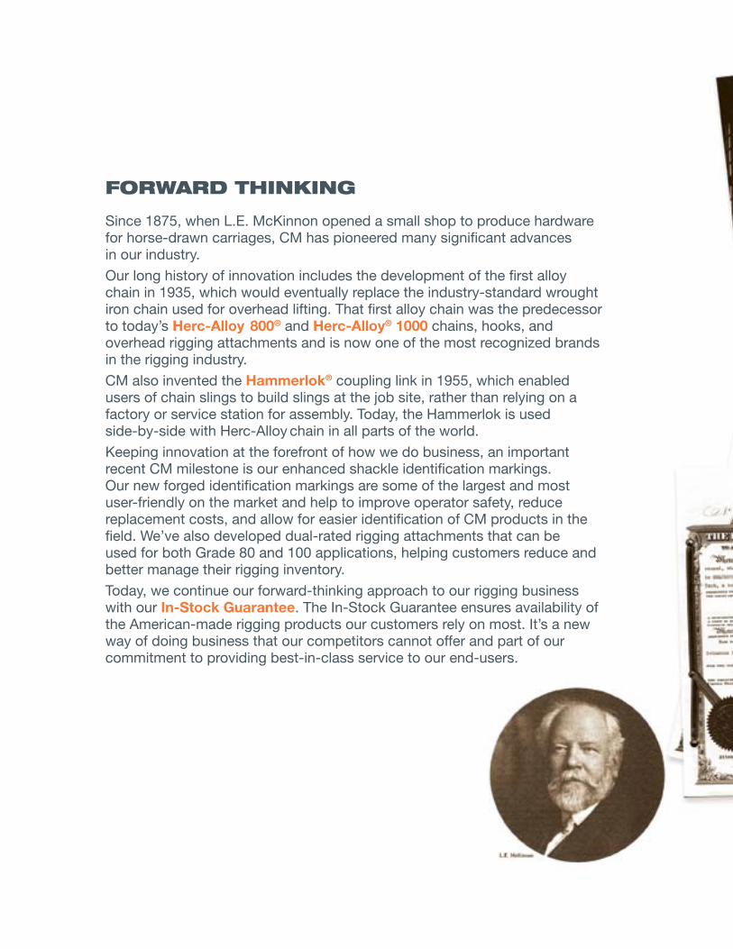
foRwARd THINKING
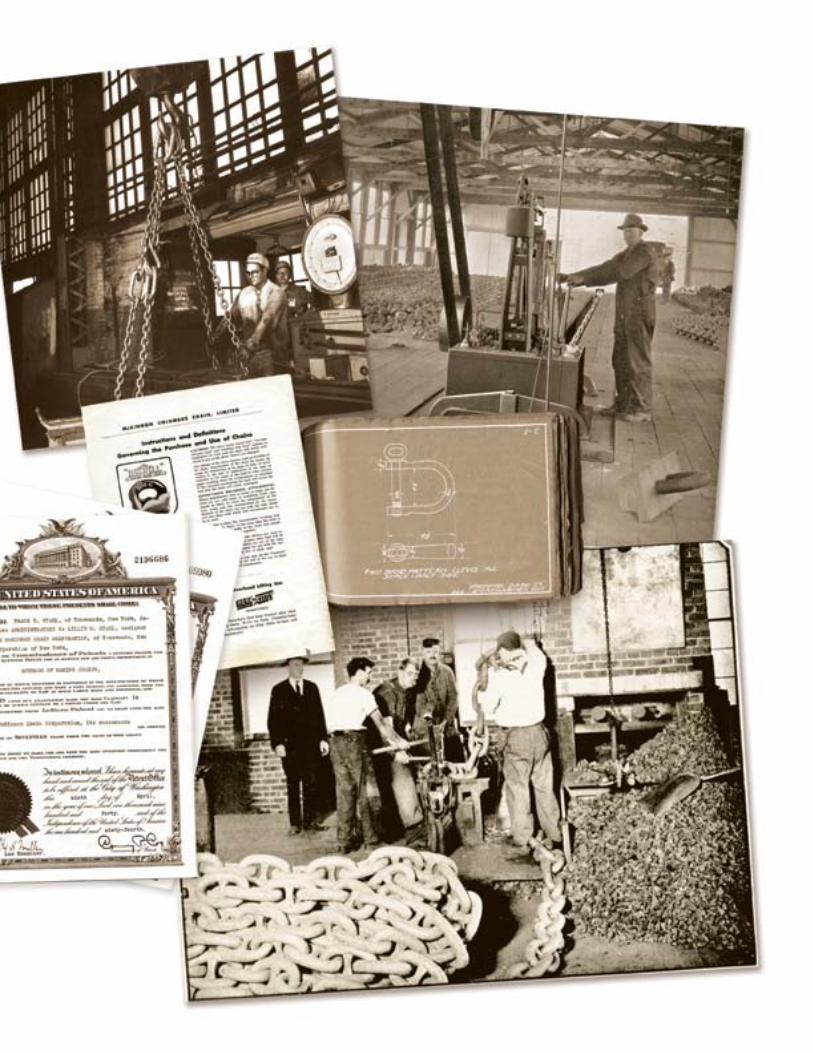
Since 1875, when L.E. McKinnon opened a small shop to produce hardware for horse-drawn carriages, CM has pioneered many significant advances in our industry.
Our long history of innovation includes the development of the first alloy chain in 1935, which would eventually replace the industry-standard wrought iron chain used for overhead lifting. That first alloy chain was the predecessor to today’s Herc-Alloy 800® and Herc-Alloy® 1000 chains, hooks, and overhead rigging attachments and is now one of the most recognized brands in the rigging industry.
CM also invented the Hammerlok® coupling link in 1955, which enabled users of chain slings to build slings at the job site, rather than relying on a factory or service station for assembly. Today, the Hammerlok is used side-by-side with Herc-Alloy chain in all parts of the world.
Keeping innovation at the forefront of how we do business, an important recent CM milestone is our enhanced shackle identification markings. Our new forged identification markings are some of the largest and most user-friendly on the market and help to improve operator safety, reduce replacement costs, and allow for easier identification of CM products in the field. We’ve also developed dual-rated rigging attachments that can be used for both Grade 80 and 100 applications, helping customers reduce and better manage their rigging inventory.
Today, we continue our forward-thinking approach to our rigging business with our In-Stock Guarantee. The In-Stock Guarantee ensures availability of the American-made rigging products our customers rely on most. It’s a new way of doing business that our competitors cannot offer and part of our commitment to providing best-in-class service to our end-users.
buy wITH CoNfIdENCECM is Proud to be Compliant with the “Buy American Act”
We know that American-made products are important to our customers. That’s why CM manufactures the majority of its chain and rigging attachments at our two Tennessee facilities. We also manufacture many of our hoists here in America as well.
Dating back to 1933, the Buy American Act requires end products for supplies or construction material to be manufactured domestically. For a product to comply with this Act, it is required that more than half the cost of its components is derived from U.S.-made components.
CM is proud to comply with the Buy American Act and is happy to supply a Certificate of Compliance upon request.
SERvICING CuSToMERS ARouNd THE GlobEIn today’s global economy, Columbus McKinnon is ready to meet the needs of customers anywhere in the world.
We rely on our world-class global manufacturing facilities to produce best-in-class material handling products as well as perform product testing that exceeds standards outlined by industry regulations. To quickly and efficiently meet customer demands, we have also strategically positioned our warehouses to ensure our products are available to the customer when they need them.
Our material handling knowledge and expertise surpasses the competition. Our dedicated team of engineers, trainers and sales representatives continually work with customers to solve tough application problems and better understand their needs to fuel future product development.
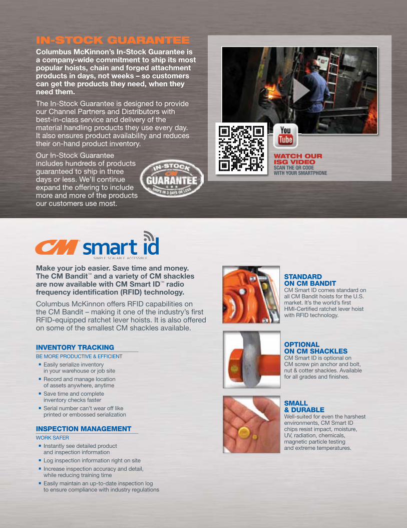
Make your job easier. Save time and money. The CM Bandit™ and a variety of CM shackles are now available with CM Smart ID™ radio frequency identification (RFID) technology.
Columbus McKinnon offers RFID capabilities on the CM Bandit – making it one of the industry’s first RFID-equipped ratchet lever hoists. It is also offered on some of the smallest CM shackles available.
IN-SToCK GuARANTEEColumbus McKinnon’s In-Stock Guarantee is a company-wide commitment to ship its most popular hoists, chain and forged attachment products in days, not weeks – so customers can get the products they need, when they need them.
The In-Stock Guarantee is designed to provide our Channel Partners and Distributors with best-in-class service and delivery of the material handling products they use every day. It also ensures product availability and reduces their on-hand product inventory.
Our In-Stock Guarantee includes hundreds of products guaranteed to ship in three days or less. We’ll continue expand the offering to include more and more of the products our customers use most.
INVENTORY TRACKINGBE MORE PRODUCTIvE & EFFICIENT
n Easily serialize inventory in your warehouse or job site
n Record and manage location of assets anywhere, anytime
n Save time and complete inventory checks faster
n Serial number can’t wear off like printed or embossed serialization
INSPECTION MANAGEMENTWORK SAFER
n Instantly see detailed product and inspection information
n Log inspection information right on siten Increase inspection accuracy and detail,
while reducing training timen Easily maintain an up-to-date inspection log
to ensure compliance with industry regulations
STANDARD ON CM BANDIT CM Smart ID comes standard on all CM Bandit hoists for the U.S. market. It’s the world’s first HMI-Certified ratchet lever hoist with RFID technology.
OPTIONAL ON CM SHACKLES CM Smart ID is optional on CM screw pin anchor and bolt, nut & cotter shackles. Available for all grades and finishes.
SMALL & DURABLE Well-suited for even the harshest environments, CM Smart ID chips resist impact, moisture, Uv, radiation, chemicals, magnetic particle testing and extreme temperatures.
wATCH ouR ISG vIdEoSCAN THE qR CODE WITH YOUR SMARTPHONE
PRoduCT ovERvIEwFrom CM Chain and Chain Slings to Plate Clamps and Cady® Lifters, our broad product offering is complemented by an unmatched wealth of knowledge and expertise that far surpasses our competition. This includes:
A thoroughly trained and knowledgeable technical sales force that provides expertise on applications, regulations, training requirements and product features and benefits.
A global network of authorized distributors that provide inventory, technical support, service after the sale, and consultation regarding specific needs.
Knowledgeable customer service representatives to help customers with shipment information, product selection, specifications and auxiliary items.
An engineering team constantly working to improve existing products, while developing unique and innovative new products.
Training programs dedicated specifically to rigging products, as well as broad-based programs to cover all aspects of lifting and positioning.
The unique ability to not only manufacture high-quality rigging products, but also lead the industry in the design and manufacture of hoists, overhead cranes, and related products.
10 WWW.CMWORKS.COMCHAIN & RIGGING ATTACHMENTS (CMRP-6)
PHONE: 800.888.0985
PRODUCT OVERVIEW
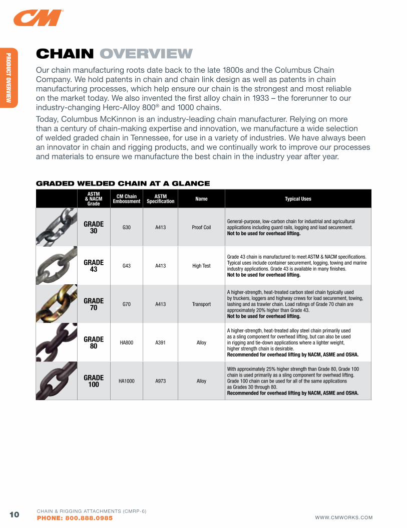
CHAIN ovERvIEwOur chain manufacturing roots date back to the late 1800s and the Columbus Chain Company. We hold patents in chain and chain link design as well as patents in chain manufacturing processes, which help ensure our chain is the strongest and most reliable on the market today. We also invented the first alloy chain in 1933 – the forerunner to our industry-changing Herc-Alloy 800® and 1000 chains.
Today, Columbus McKinnon is an industry-leading chain manufacturer. Relying on more than a century of chain-making expertise and innovation, we manufacture a wide selection of welded graded chain in Tennessee, for use in a variety of industries. We have always been an innovator in chain and rigging products, and we continually work to improve our processes and materials to ensure we manufacture the best chain in the industry year after year.
ASTM & NACM Grade
CM Chain Embossment
ASTM Specification Name Typical Uses
GRADE 30 G30 A413 Proof Coil
General-purpose, low-carbon chain for industrial and agricultural applications including guard rails, logging and load securement. Not to be used for overhead lifting.
GRADE 43 G43 A413 High Test
Grade 43 chain is manufactured to meet ASTM & NACM specifications. Typical uses include container securement, logging, towing and marine industry applications. Grade 43 is available in many finishes.Not to be used for overhead lifting.
GRADE 70 G70 A413 Transport
A higher-strength, heat-treated carbon steel chain typically used by truckers, loggers and highway crews for load securement, towing, lashing and as trawler chain. Load ratings of Grade 70 chain are approximately 20% higher than Grade 43.Not to be used for overhead lifting.
GRADE 80 HA800 A391 Alloy
A higher-strength, heat-treated alloy steel chain primarily used as a sling component for overhead lifting, but can also be used in rigging and tie-down applications where a lighter weight, higher strength chain is desirable. Recommended for overhead lifting by NACM, ASME and OSHA.
GRADE 100 HA1000 A973 Alloy
With approximately 25% higher strength than Grade 80, Grade 100 chain is used primarily as a sling component for overhead lifting. Grade 100 chain can be used for all of the same applications as Grades 30 through 80. Recommended for overhead lifting by NACM, ASME and OSHA.
GRAdEd wEldEd CHAIN AT A GlANCE
11WWW.CMWORKS.COMCHAIN & RIGGING ATTACHMENTS (CMRP-6)
PHONE: 800.888.0985
PROD
UCT
OVER
VIEW
GRAdE 30
Chain Size(in.)
Wire Diameter Nominal
(in.)
Inside Length
Nominal(in.)
Inside Width Nominal
(in.)
Weight Per 100 ft
(lbs.)
Working Load Limit(lbs.)
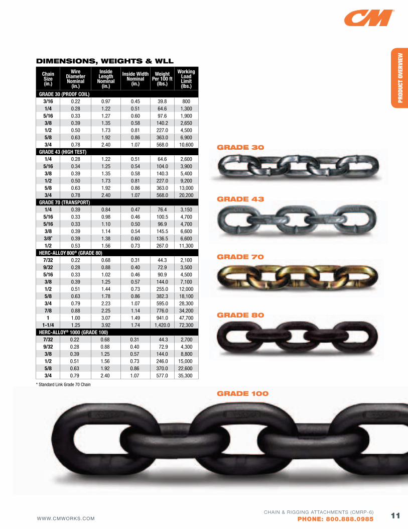
GRADE 30 (PROOf COIL)3/16 0.22 0.97 0.45 39.8 8001/4 0.28 1.22 0.51 64.6 1,3005/16 0.33 1.27 0.60 97.6 1,9003/8 0.39 1.35 0.58 140.2 2,6501/2 0.50 1.73 0.81 227.0 4,5005/8 0.63 1.92 0.86 363.0 6,9003/4 0.78 2.40 1.07 568.0 10,600
GRADE 43 (HIGH TEST)1/4 0.28 1.22 0.51 64.6 2,6005/16 0.34 1.25 0.54 104.0 3,9003/8 0.39 1.35 0.58 140.3 5,4001/2 0.50 1.73 0.81 227.0 9,2005/8 0.63 1.92 0.86 363.0 13,0003/4 0.78 2.40 1.07 568.0 20,200
GRADE 70 (TRANSPORT)1/4 0.39 0.84 0.47 76.4 3,1505/16 0.33 0.98 0.46 100.5 4,7005/16 0.33 1.10 0.50 96.9 4,7003/8 0.39 1.14 0.54 145.5 6,6003/8* 0.39 1.38 0.60 136.5 6,6001/2 0.53 1.56 0.73 267.0 11,300
HERC-ALLOY 800® (GRADE 80)7/32 0.22 0.68 0.31 44.3 2,1009/32 0.28 0.88 0.40 72.9 3,5005/16 0.33 1.02 0.46 90.9 4,5003/8 0.39 1.25 0.57 144.0 7,1001/2 0.51 1.44 0.73 255.0 12,0005/8 0.63 1.78 0.86 382.3 18,1003/4 0.79 2.23 1.07 595.0 28,3007/8 0.88 2.25 1.14 776.0 34,2001 1.00 3.07 1.49 941.0 47,700
1-1/4 1.25 3.92 1.74 1,420.0 72,300HERC-ALLOY® 1000 (GRADE 100)
7/32 0.22 0.68 0.31 44.3 2,7009/32 0.28 0.88 0.40 72.9 4,3003/8 0.39 1.25 0.57 144.0 8,8001/2 0.51 1.56 0.73 246.0 15,0005/8 0.63 1.92 0.86 370.0 22,6003/4 0.79 2.40 1.07 577.0 35,300
dIMENSIoNS, wEIGHTS & wll
GRAdE 30
GRAdE 43
GRAdE 70
GRAdE 80
GRAdE 100* Standard Link Grade 70 Chain
12 WWW.CMWORKS.COMCHAIN & RIGGING ATTACHMENTS (CMRP-6)
PHONE: 800.888.0985
PRODUCT OVERVIEW
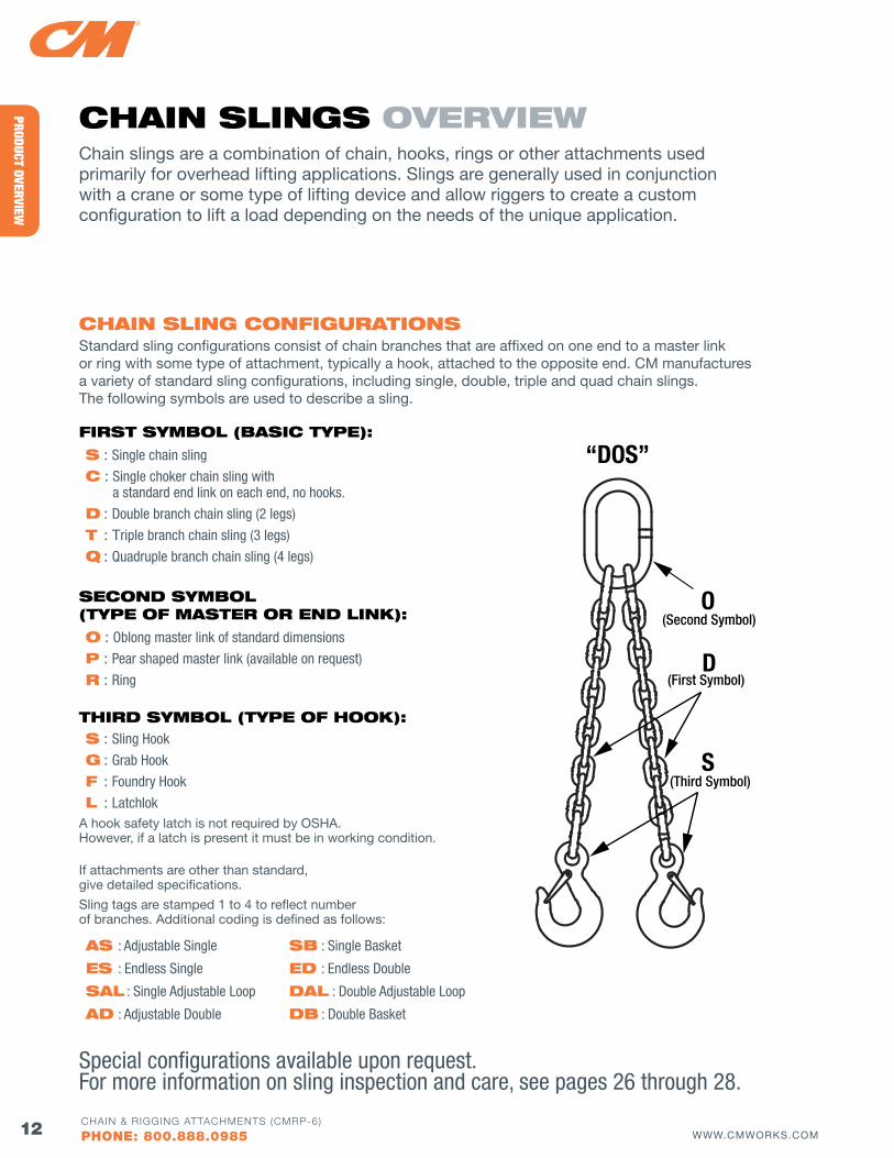
CHAIN SlING CoNfIGuRATIoNSStandard sling configurations consist of chain branches that are affixed on one end to a master link or ring with some type of attachment, typically a hook, attached to the opposite end. CM manufactures a variety of standard sling configurations, including single, double, triple and quad chain slings. The following symbols are used to describe a sling.
CHAIN SlINGS ovERvIEwChain slings are a combination of chain, hooks, rings or other attachments used primarily for overhead lifting applications. Slings are generally used in conjunction with a crane or some type of lifting device and allow riggers to create a custom configuration to lift a load depending on the needs of the unique application.
fIRST SyMbol (bASIC TyPE):
S : Single chain sling
C : Single choker chain sling with a standard end link on each end, no hooks.
d : Double branch chain sling (2 legs)
T : Triple branch chain sling (3 legs)
Q : Quadruple branch chain sling (4 legs)
SECoNd SyMbol (TyPE of MASTER oR ENd lINK):
o : Oblong master link of standard dimensions
P : Pear shaped master link (available on request)
R : Ring
THIRd SyMbol (TyPE of HooK):S : Sling Hook
G : Grab Hook
f : Foundry Hook
l : LatchlokA hook safety latch is not required by OSHA. However, if a latch is present it must be in working condition.
AS : Adjustable Single
ES : Endless Single
SAl : Single Adjustable Loop
Ad : Adjustable Double
Sb : Single Basket
Ed : Endless Double
dAl : Double Adjustable Loop
db : Double Basket
O (Second Symbol)
D (First Symbol)
S (Third Symbol)
“DOS”
If attachments are other than standard, give detailed specifications.
Sling tags are stamped 1 to 4 to reflect number of branches. Additional coding is defined as follows:
Special configurations available upon request.For more information on sling inspection and care, see pages 26 through 28.

13WWW.CMWORKS.COMCHAIN & RIGGING ATTACHMENTS (CMRP-6)
PHONE: 800.888.0985
PROD
UCT
OVER
VIEW
STANdARd TyPES of CM CHAIN SlINGS
SAfETy NoTE A quad branch chain sling, especially when used on a load of rigid structure, is usually not sustaining the load evenly on each of its four branches. The maximum working load limits are therefore set at the same values as triple branch chain slings of equal quality and size with branches used at same angle of inclination.
TRIPlE CHAIN SlINGS : TYPE T
QuAdRuPlE CHAIN SlINGS : TYPE Q
SINGlE CHAIN SlINGS : TYPE S & C
doublE CHAIN SlINGS : TYPE D
SlING Id TAGS
CM sling configurations come with an affixed metal identification tag that includes:s Sling sizes Sling reachsWorking load limit (all slings must be rated by their weakest component)
s Serial numbersManufacturer name (CM) and grade of slings Number of branches
Permanently affixed sling ID tags are required per ASME B30.9 and OSHA 1910.184. To order replacement sling ID tags, contact customer service. For additional information see pages 33, 63 & 75.
14 WWW.CMWORKS.COMCHAIN & RIGGING ATTACHMENTS (CMRP-6)
PHONE: 800.888.0985
PRODUCT OVERVIEW
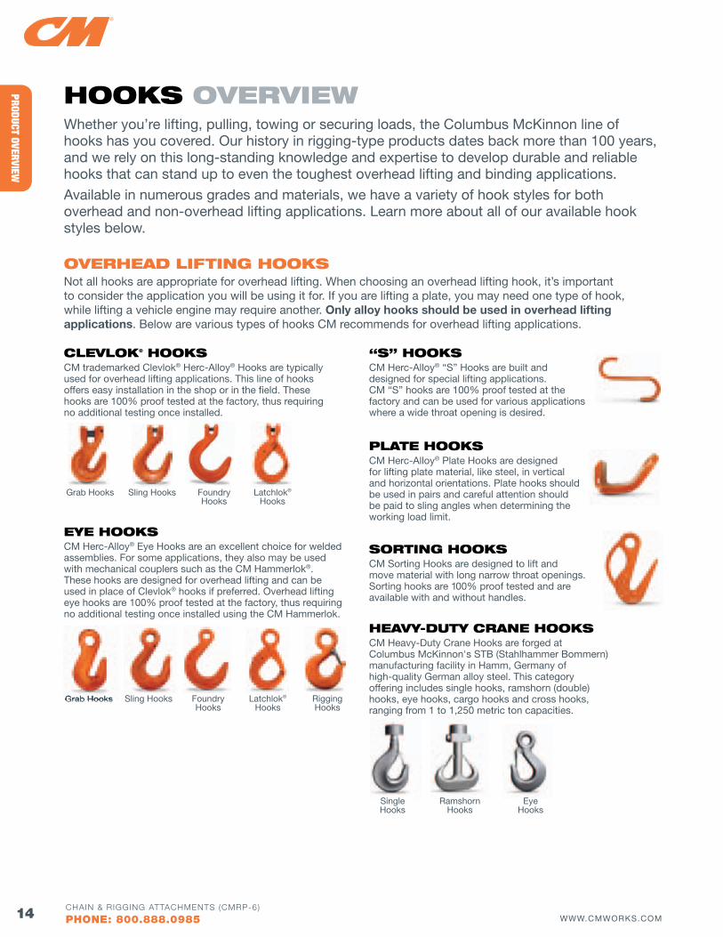
ClEvloK® HooKSCM trademarked Clevlok® Herc-Alloy® Hooks are typically used for overhead lifting applications. This line of hooks offers easy installation in the shop or in the field. These hooks are 100% proof tested at the factory, thus requiring no additional testing once installed.
EyE HooKSCM Herc-Alloy® Eye Hooks are an excellent choice for welded assemblies. For some applications, they also may be used with mechanical couplers such as the CM Hammerlok®. These hooks are designed for overhead lifting and can be used in place of Clevlok® hooks if preferred. Overhead lifting eye hooks are 100% proof tested at the factory, thus requiring no additional testing once installed using the CM Hammerlok.
“S” HooKSCM Herc-Alloy® “S” Hooks are built and designed for special lifting applications. CM “S” hooks are 100% proof tested at the factory and can be used for various applications where a wide throat opening is desired.
PlATE HooKSCM Herc-Alloy® Plate Hooks are designed for lifting plate material, like steel, in vertical and horizontal orientations. Plate hooks should be used in pairs and careful attention should be paid to sling angles when determining the working load limit.
SoRTING HooKSCM Sorting Hooks are designed to lift and move material with long narrow throat openings. Sorting hooks are 100% proof tested and are available with and without handles.
HEAvy-duTy CRANE HooKSCM Heavy-Duty Crane Hooks are forged at Columbus McKinnon's STB (Stahlhammer Bommern) manufacturing facility in Hamm, Germany of high-quality German alloy steel. This category offering includes single hooks, ramshorn (double) hooks, eye hooks, cargo hooks and cross hooks, ranging from 1 to 1,250 metric ton capacities.
ovERHEAd lIfTING HooKSNot all hooks are appropriate for overhead lifting. When choosing an overhead lifting hook, it’s important to consider the application you will be using it for. If you are lifting a plate, you may need one type of hook, while lifting a vehicle engine may require another. Only alloy hooks should be used in overhead lifting applications. Below are various types of hooks CM recommends for overhead lifting applications.
HooKS ovERvIEwWhether you’re lifting, pulling, towing or securing loads, the Columbus McKinnon line of hooks has you covered. Our history in rigging-type products dates back more than 100 years, and we rely on this long-standing knowledge and expertise to develop durable and reliable hooks that can stand up to even the toughest overhead lifting and binding applications.
Available in numerous grades and materials, we have a variety of hook styles for both overhead and non-overhead lifting applications. Learn more about all of our available hook styles below.
Grab Hooks
Grab Hooks
Single Hooks
Sling Hooks
Ramshorn Hooks
Foundry Hooks
Eye Hooks
Latchlok® Hooks
Rigging Hooks
Sling Hooks Latchlok® Hooks
Foundry Hooks
Grab Hooks
15WWW.CMWORKS.COMCHAIN & RIGGING ATTACHMENTS (CMRP-6)
PHONE: 800.888.0985
PROD
UCT
OVER
VIEW
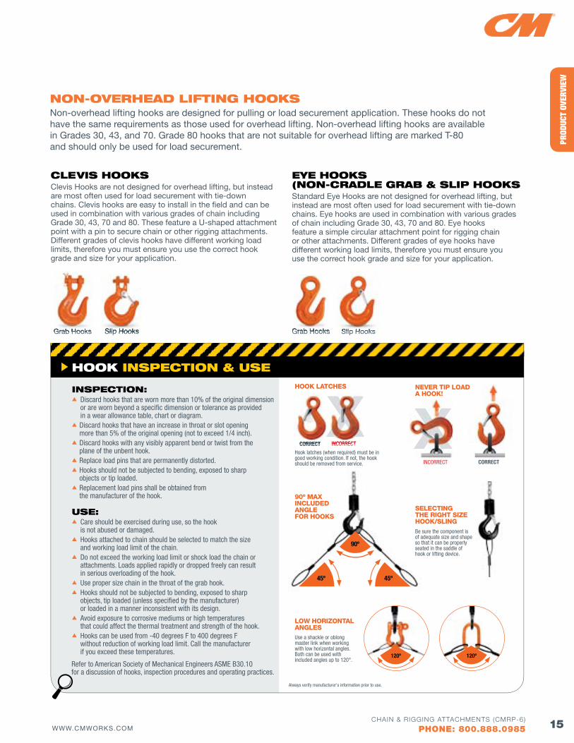
NoN-ovERHEAd lIfTING HooKSNon-overhead lifting hooks are designed for pulling or load securement application. These hooks do not have the same requirements as those used for overhead lifting. Non-overhead lifting hooks are available in Grades 30, 43, and 70. Grade 80 hooks that are not suitable for overhead lifting are marked T-80 and should only be used for load securement.
Be sure the component is of adequate size and shape so that it can be properly seated in the saddle of hook or lifting device.
SELECTING THE RIGHT SIZE HOOK/SLING
LOW HORIZONTAL ANGLES
NEVER TIP LOAD A HOOK!
CORRECTINCORRECT
HOOK LATCHES
CORRECT INCORRECT
Hook latches (when required) must be in good working condition. If not, the hook should be removed from service.
45º 45º
90º
Always verify manufacturer's information prior to use.
HooK INSPECTIoN & uSE
INSPECTIoN:s Discard hooks that are worn more than 10% of the original dimension or are worn beyond a specific dimension or tolerance as provided in a wear allowance table, chart or diagram.sDiscard hooks that have an increase in throat or slot opening more than 5% of the original opening (not to exceed 1/4 inch).sDiscard hooks with any visibly apparent bend or twist from the plane of the unbent hook.sReplace load pins that are permanently distorted.sHooks should not be subjected to bending, exposed to sharp objects or tip loaded.sReplacement load pins shall be obtained from the manufacturer of the hook.
uSE:s Care should be exercised during use, so the hook is not abused or damaged.s Hooks attached to chain should be selected to match the size and working load limit of the chain.s Do not exceed the working load limit or shock load the chain or attachments. Loads applied rapidly or dropped freely can result in serious overloading of the hook.s Use proper size chain in the throat of the grab hook.s Hooks should not be subjected to bending, exposed to sharp objects, tip loaded (unless specified by the manufacturer) or loaded in a manner inconsistent with its design.s Avoid exposure to corrosive mediums or high temperatures that could affect the thermal treatment and strength of the hook.s Hooks can be used from -40 degrees F to 400 degrees F without reduction of working load limit. Call the manufacturer if you exceed these temperatures.
ClEvIS HooKSClevis Hooks are not designed for overhead lifting, but instead are most often used for load securement with tie-down chains. Clevis hooks are easy to install in the field and can be used in combination with various grades of chain including Grade 30, 43, 70 and 80. These feature a U-shaped attachment point with a pin to secure chain or other rigging attachments. Different grades of clevis hooks have different working load limits, therefore you must ensure you use the correct hook grade and size for your application.
EyE HooKS (NoN-CRAdlE GRAb & SlIP HooKSStandard Eye Hooks are not designed for overhead lifting, but instead are most often used for load securement with tie-down chains. Eye hooks are used in combination with various grades of chain including Grade 30, 43, 70 and 80. Eye hooks feature a simple circular attachment point for rigging chain or other attachments. Different grades of eye hooks have different working load limits, therefore you must ensure you use the correct hook grade and size for your application.
Grab Hooks Slip Hooks Grab Hooks Slip Hooks
Refer to American Society of Mechanical Engineers ASME B30.10 for a discussion of hooks, inspection procedures and operating practices.
Slip HooksGrab Hooks Slip HooksGrab Hooks
Use a shackle or oblong master link when working with low horizontal angles. Both can be used with included angles up to 120°.
120º 120º
90º MAX INCLUDED ANGLE fOR HOOKS
CORRECT INCORRECT
XX X
16 WWW.CMWORKS.COMCHAIN & RIGGING ATTACHMENTS (CMRP-6)
PHONE: 800.888.0985
PRODUCT OVERVIEW
ovERHEAd lIfTING RINGS & lINKS
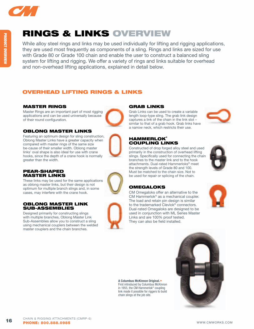
RINGS & lINKS ovERvIEwWhile alloy steel rings and links may be used individually for lifting and rigging applications, they are used most frequently as components of a sling. Rings and links are sized for use with Grade 80 or Grade 100 chain and enable the user to construct a balanced sling system for lifting and rigging. We offer a variety of rings and links suitable for overhead and non-overhead lifting applications, explained in detail below.
MASTER RINGSMaster Rings are an important part of most rigging applications and can be used universally because of their round configuration.
obloNG MASTER lINKSFeaturing an optimum design for sling construction, Oblong Master Links have a greater capacity when compared with master rings of the same size be-cause of their smaller width. Oblong master links’ oval shape is also ideal for use with crane hooks, since the depth of a crane hook is normally greater than the width.
PEAR-SHAPEd MASTER lINKSThese links may be used for the same applications as oblong master links, but their design is not optimum for multiple branch slings and, in some cases, may interfere with the crane hook.
obloNG MASTER lINK Sub-ASSEMblIESDesigned primarily for constructing slings with multiple branches, Oblong Master Link Sub-Assemblies allow you to construct a sling using mechanical couplers between the welded master couplers and the chain branches.
GRAb lINKSGrab Links can be used to create a variable length loop-type sling. The grab link design captures a link of the chain in the link slot – similar to that of a grab hook. Grab links have a narrow neck, which restricts their use.
HAMMERloK® CouPlING lINKSConstructed of drop forged alloy steel and used primarily in the construction of overhead lifting slings. Specifically used for connecting the chain branches to the master link and to the hook attachments. Dual-rated Hammerloks® meet the strength levels of Grade 80 and 100. Must be matched to the chain size. Not to be used for repair or splicing of the chain.
oMEGAloKSCM Omegaloks offer an alternative to the CM Hammerlok® as a mechanical coupler. The load and retain pin design is similar to the trademarked Clevlok® connectors. Dual-rated Omegaloks are designed to be used in conjunction with ML Series Master Links and are 100% proof tested. They can also be field installed.
A Columbus McKinnon Original. First introduced by Columbus McKinnon in 1955, the CM Hammerlok® coupling link made it possible for riggers to build chain slings at the job site.
17WWW.CMWORKS.COMCHAIN & RIGGING ATTACHMENTS (CMRP-6)
PHONE: 800.888.0985
PROD
UCT
OVER
VIEW
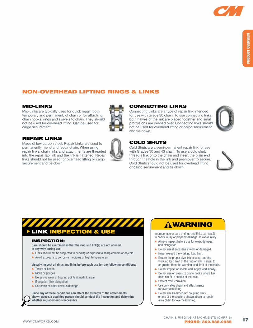
NoN-ovERHEAd lIfTING RINGS & lINKS
MId-lINKSMid-Links are typically used for quick repair, both temporary and permanent, of chain or for attaching chain hooks, rings and swivels to chain. They should not be used for overhead lifting. Can be used for cargo securement.
REPAIR lINKSMade of low carbon steel, Repair Links are used to permanently mend and repair chain. When using repair links, chain links and attachments are threaded into the repair lap link and the link is flattened. Repair links should not be used for overhead lifting or cargo securement and tie-down.
CoNNECTING lINKSConnecting Links are a type of repair link intended for use with Grade 30 chain. To use connecting links, both halves of the link are placed together and small protrusions are peened over. Connecting links should not be used for overhead lifting or cargo securement and tie-down.
Cold SHuTSCold Shuts are a semi-permanent repair link for use with Grades 30 and 43 chain. To use a cold shut, thread a link onto the chain and insert the plain end through the hole in the link and peen over to secure. Cold Shuts should not be used for overhead lifting or cargo securement and tie-down.
lINK INSPECTIoN & uSE
INSPECTIoN:Care should be exercised so that the ring and link(s) are not abused in any way during use.s Links should not be subjected to bending or exposed to sharp corners or objects.s Avoid exposure to corrosive mediums or high temperatures.
Visually inspect all rings and links before each use for the following conditions:s Twists or bendss Nicks or gougess Excessive wear at bearing points (innerlink area) s Elongation (link elongation)s Corrosion or other obvious damage
Since any of these conditions can affect the strength of the attachments shown above, a qualified person should conduct the inspection and determine whether replacement is necessary.
Improper use or care of rings and links can result in bodily injury or property damage. To avoid injury:s Always inspect before use for wear, damage,
and elongation.s Do not use if excessively worn or damaged.s Never exceed the working load limit.s Ensure the proper size link is used, and the
working load limit of the ring or link is equal to or greater than the working load limit of the chain.
s Do not impact or shock load. Apply load slowly.s Do not use on oversize crane hooks where link
does not fit in saddle of the hook.s Protect from corrosion.s Use only alloy chain and attachments for overhead lifting.s Do not use Hammerlok® coupling links or any of the couplers shown above to repair alloy chain for overhead lifting.
18 WWW.CMWORKS.COMCHAIN & RIGGING ATTACHMENTS (CMRP-6)
PHONE: 800.888.0985
PRODUCT OVERVIEW
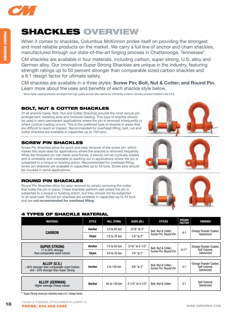
SHACKlES ovERvIEwWhen it comes to shackles, Columbus McKinnon prides itself on providing the strongest and most reliable products on the market. We carry a full line of anchor and chain shackles, manufactured through our state-of-the-art forging process in Chattanooga, Tennessee*.
CM shackles are available in four materials, including carbon, super strong, U.S. alloy and German alloy. Our innovative Super Strong Shackles are unique in the industry, featuring strength ratings up to 50 percent stronger than comparable sized carbon shackles and a 6:1 design factor for ultimate safety.
CM shackles are available in a three styles: Screw Pin; Bolt, Nut & Cotter; and Round Pin. Learn more about the uses and benefits of each shackle style below.
MATERIAL STYLE WLL (TONS) SIzES (IN.) STYLES DESIGN fACTOR fINISHES
CARBONAnchor 1/3 to 85 ton 3/16" to 3"
Bolt, Nut & Cotter;Screw Pin; Round Pin 6:1 Orange Powder Coated,
GalvanizedChain 1/2 to 35 ton 1/4" to 2"
SUPER STRONG 17 to 50% stronger
than comparable-sized Carbon
Anchor 1/2 to 55 ton 3/16" to 2-1/2"Bolt, Nut & Cotter;Screw Pin; Round Pin 6:1**
Orange Powder Coated, Self Colored, GalvanizedChain 3/4 to 35 ton 1/4" to 2"
ALLOY (U.S.) ~50% stronger than comparable-sized Carbon
and ~25% stronger than Super StrongAnchor 2 to 120 ton 3/8" to 3" Bolt, Nut & Cotter;
Screw Pin; Round Pin 5:1Orange Powder Coated,
Self Colored, Galvanized
ALLOY (GERMAN)Higher average Charpy values
Anchor 85 to 150 ton 2-1/2" to 3-1/2" Bolt, Nut & Cotter 5:1 Self Colored, Galvanized
4 TyPES of SHACKlE MATERIAl
bolT, NuT & CoTTER SHACKlESOf all shackle types, Bolt, Nut and Cotter Shackles provide the most secure pin arrangement, resisting axial and torsional loading. This type of shackle should be used in semi-permanent applications where the pin is removed infrequently or where cyclical loading occurs. This is the preferred type of shackle in areas that are difficult to reach or inspect. Recommended for overhead lifting, bolt, nut and cotter shackles are available in capacities up to 150 tons.
SCREw PIN SHACKlESScrew Pin Shackles allow for quick and easy removal of the screw pin, which makes this style ideal for applications where the shackle is removed frequently. While the threaded pin can resist axial forces, it should not be cyclically loaded and is unreliable and vulnerable to backing out in applications where the pin is subjected to a torque or twisting action. Recommended for overhead lifting, screw pin shackles are available in capacities up to 43 tons. Screw pins should be moused in some applications.
RouNd PIN SHACKlESRound Pin Shackles allow for easy removal by simply removing the cotter that holds the pin in place. These shackles perform well where the pin is subjected to a torque or twisting action, but they should not be subjected to an axial load. Round pin shackles are available in capacities up to 43 tons and are not recommended for overhead lifting.
** Super Strong round pin shackles have a 5:1 design factor.
* Some higher-capacity shackles are forged from high-quality German alloy steel at our STB facility in Hamm, Germany and then finished in the U.S.A.
19WWW.CMWORKS.COMCHAIN & RIGGING ATTACHMENTS (CMRP-6)
PHONE: 800.888.0985
PROD
UCT
OVER
VIEWwIRE RoPE ATTACHMENTS ovERvIEw
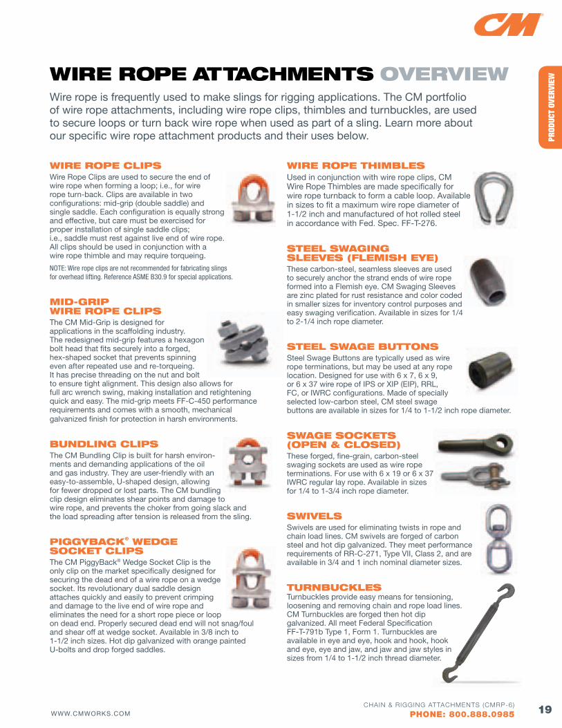
Wire rope is frequently used to make slings for rigging applications. The CM portfolio of wire rope attachments, including wire rope clips, thimbles and turnbuckles, are used to secure loops or turn back wire rope when used as part of a sling. Learn more about our specific wire rope attachment products and their uses below.
wIRE RoPE ClIPS Wire Rope Clips are used to secure the end of wire rope when forming a loop; i.e., for wire rope turn-back. Clips are available in two configurations: mid-grip (double saddle) and single saddle. Each configuration is equally strong and effective, but care must be exercised for proper installation of single saddle clips; i.e., saddle must rest against live end of wire rope. All clips should be used in conjunction with a wire rope thimble and may require torqueing.
NOTE: Wire rope clips are not recommended for fabricating slings for overhead lifting. Reference ASME B30.9 for special applications.
MId-GRIP wIRE RoPE ClIPSThe CM Mid-Grip is designed for applications in the scaffolding industry. The redesigned mid-grip features a hexagon bolt head that fits securely into a forged, hex-shaped socket that prevents spinning even after repeated use and re-torqueing. It has precise threading on the nut and bolt to ensure tight alignment. This design also allows for full arc wrench swing, making installation and retightening quick and easy. The mid-grip meets FF-C-450 performance requirements and comes with a smooth, mechanical galvanized finish for protection in harsh environments.
buNdlING ClIPS The CM Bundling Clip is built for harsh environ-ments and demanding applications of the oil and gas industry. They are user-friendly with an easy-to-assemble, U-shaped design, allowing for fewer dropped or lost parts. The CM bundling clip design eliminates shear points and damage to wire rope, and prevents the choker from going slack and the load spreading after tension is released from the sling.
PIGGybACK® wEdGE SoCKET ClIPS The CM PiggyBack® Wedge Socket Clip is the only clip on the market specifically designed for securing the dead end of a wire rope on a wedge socket. Its revolutionary dual saddle design attaches quickly and easily to prevent crimping and damage to the live end of wire rope and eliminates the need for a short rope piece or loop on dead end. Properly secured dead end will not snag/foul and shear off at wedge socket. Available in 3/8 inch to 1-1/2 inch sizes. Hot dip galvanized with orange painted U-bolts and drop forged saddles.
wIRE RoPE THIMblES Used in conjunction with wire rope clips, CM Wire Rope Thimbles are made specifically for wire rope turnback to form a cable loop. Available in sizes to fit a maximum wire rope diameter of 1-1/2 inch and manufactured of hot rolled steel in accordance with Fed. Spec. FF-T-276.
STEEl SwAGING SlEEvES (flEMISH EyE) These carbon-steel, seamless sleeves are used to securely anchor the strand ends of wire rope formed into a Flemish eye. CM Swaging Sleeves are zinc plated for rust resistance and color coded in smaller sizes for inventory control purposes and easy swaging verification. Available in sizes for 1/4 to 2-1/4 inch rope diameter.
STEEl SwAGE buTToNS Steel Swage Buttons are typically used as wire rope terminations, but may be used at any rope location. Designed for use with 6 x 7, 6 x 9, or 6 x 37 wire rope of IPS or XIP (EIP), RRL, FC, or IWRC configurations. Made of specially selected low-carbon steel, CM steel swage buttons are available in sizes for 1/4 to 1-1/2 inch rope diameter.
SwAGE SoCKETS (oPEN & CloSEd) These forged, fine-grain, carbon-steel swaging sockets are used as wire rope terminations. For use with 6 x 19 or 6 x 37 IWRC regular lay rope. Available in sizes for 1/4 to 1-3/4 inch rope diameter.
SwIvElS Swivels are used for eliminating twists in rope and chain load lines. CM swivels are forged of carbon steel and hot dip galvanized. They meet performance requirements of RR-C-271, Type vII, Class 2, and are available in 3/4 and 1 inch nominal diameter sizes.
TuRNbuCKlES Turnbuckles provide easy means for tensioning, loosening and removing chain and rope load lines. CM Turnbuckles are forged then hot dip galvanized. All meet Federal Specification FF-T-791b Type 1, Form 1. Turnbuckles are available in eye and eye, hook and hook, hook and eye, eye and jaw, and jaw and jaw styles in sizes from 1/4 to 1-1/2 inch thread diameter.
20 WWW.CMWORKS.COMCHAIN & RIGGING ATTACHMENTS (CMRP-6)
PHONE: 800.888.0985
PRODUCT OVERVIEW
loAd SECuREMENT ovERvIEwLoad securement, also known as tie-down or load binding, can be a complex rigging application that often has strict specifications and regulations. CM offers a number of load securement products, including load binders, binder chain assemblies and tie-down hooks, that help you safely secure loads for transport as well as meet federal, state and Commerical vehicle Safety Alliance (CvSA) regulations. Our load securement products comply with the National Association of Chain Manufacturers (NACM) Welded Steel Chain specifications and the American Society of Testing and Materials (ASTM) specifications. They are also designed to meet applicable Federal Motor Carrier Safety Administration (FMCSA) rules for cargo securement.
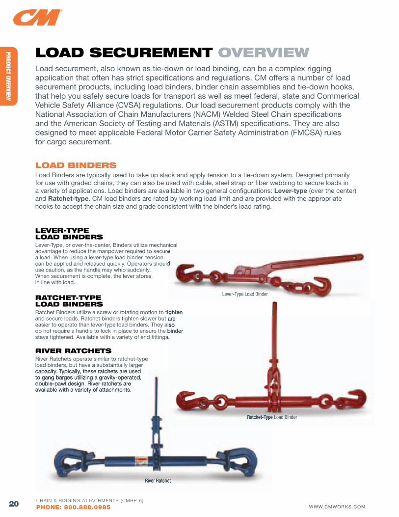
loAd bINdERSLoad Binders are typically used to take up slack and apply tension to a tie-down system. Designed primarily for use with graded chains, they can also be used with cable, steel strap or fiber webbing to secure loads in a variety of applications. Load binders are available in two general configurations: Lever-type (over the center) and Ratchet-type. CM load binders are rated by working load limit and are provided with the appropriate hooks to accept the chain size and grade consistent with the binder’s load rating.
lEvER-TyPE loAd bINdERSLever-Type, or over-the-center, Binders utilize mechanical advantage to reduce the manpower required to secure a load. When using a lever-type load binder, tension can be applied and released quickly. Operators should use caution, as the handle may whip suddenly. When securement is complete, the lever stores in line with load.
RATCHET-TyPE loAd bINdERSRatchet Binders utilize a screw or rotating motion to tighten and secure loads. Ratchet binders tighten slower but are easier to operate than lever-type load binders. They also do not require a handle to lock in place to ensure the binder stays tightened. Available with a variety of end fittings.
RIvER RATCHETSRiver Ratchets operate similar to ratchet-type load binders, but have a substantially larger capacity. Typically, these ratchets are used to gang barges utilizing a gravity-operated, double-pawl design. River ratchets are available with a variety of attachments.
Ratchet Binders utilize a screw or rotating motion to tighten and secure loads. Ratchet binders tighten slower but are easier to operate than lever-type load binders. They also do not require a handle to lock in place to ensure the binder stays tightened. Available with a variety of end fittings.
advantage to reduce the manpower required to secure
can be applied and released quickly. Operators should
Ratchet Binders utilize a screw or rotating motion to tighten
Lever-Type Load Binder
Ratchet-Type Load Binder
River Ratchet
capacity. Typically, these ratchets are used to gang barges utilizing a gravity-operated, double-pawl design. River ratchets are available with a variety of attachments.
Ratchet-Type Load Binder
River Ratchet
21WWW.CMWORKS.COMCHAIN & RIGGING ATTACHMENTS (CMRP-6)
PHONE: 800.888.0985
PROD
UCT
OVER
VIEW
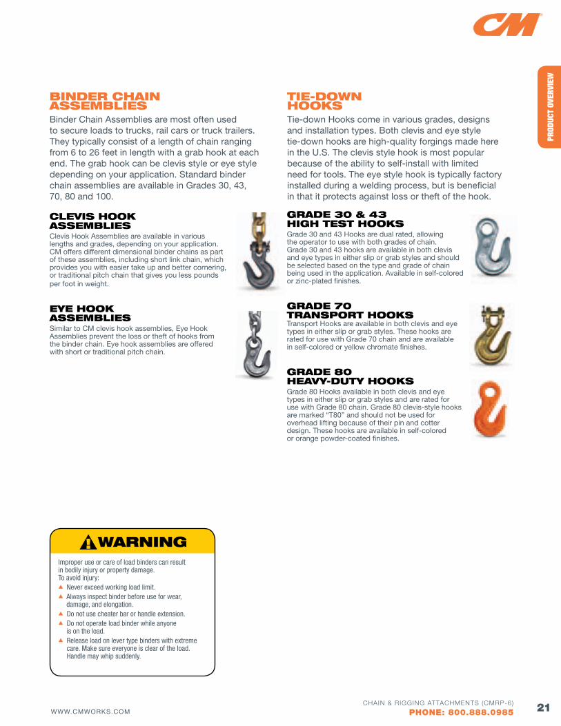
ClEvIS HooK ASSEMblIES Clevis Hook Assemblies are available in various lengths and grades, depending on your application. CM offers different dimensional binder chains as part of these assemblies, including short link chain, which provides you with easier take up and better cornering, or traditional pitch chain that gives you less pounds per foot in weight.
EyE HooK ASSEMblIESSimilar to CM clevis hook assemblies, Eye Hook Assemblies prevent the loss or theft of hooks from the binder chain. Eye hook assemblies are offered with short or traditional pitch chain.
bINdER CHAIN ASSEMblIES Binder Chain Assemblies are most often used to secure loads to trucks, rail cars or truck trailers. They typically consist of a length of chain ranging from 6 to 26 feet in length with a grab hook at each end. The grab hook can be clevis style or eye style depending on your application. Standard binder chain assemblies are available in Grades 30, 43, 70, 80 and 100.
Improper use or care of load binders can result in bodily injury or property damage. To avoid injury:s Never exceed working load limit.s Always inspect binder before use for wear,
damage, and elongation.s Do not use cheater bar or handle extension.s Do not operate load binder while anyone
is on the load.s Release load on lever type binders with extreme
care. Make sure everyone is clear of the load. Handle may whip suddenly.
GRAdE 30 & 43 HIGH TEST HooKSGrade 30 and 43 Hooks are dual rated, allowing the operator to use with both grades of chain. Grade 30 and 43 hooks are available in both clevis and eye types in either slip or grab styles and should be selected based on the type and grade of chain being used in the application. Available in self-colored or zinc-plated finishes.
GRAdE 70 TRANSPoRT HooKS Transport Hooks are available in both clevis and eye types in either slip or grab styles. These hooks are rated for use with Grade 70 chain and are available in self-colored or yellow chromate finishes.
GRAdE 80 HEAvy-duTy HooKS Grade 80 Hooks available in both clevis and eye types in either slip or grab styles and are rated for use with Grade 80 chain. Grade 80 clevis-style hooks are marked “T80” and should not be used for overhead lifting because of their pin and cotter design. These hooks are available in self-colored or orange powder-coated finishes.
TIE-dowN HooKS Tie-down Hooks come in various grades, designs and installation types. Both clevis and eye style tie-down hooks are high-quality forgings made here in the U.S. The clevis style hook is most popular because of the ability to self-install with limited need for tools. The eye style hook is typically factory installed during a welding process, but is beneficial in that it protects against loss or theft of the hook.
22 WWW.CMWORKS.COMCHAIN & RIGGING ATTACHMENTS (CMRP-6)
PHONE: 800.888.0985
PRODUCT OVERVIEW
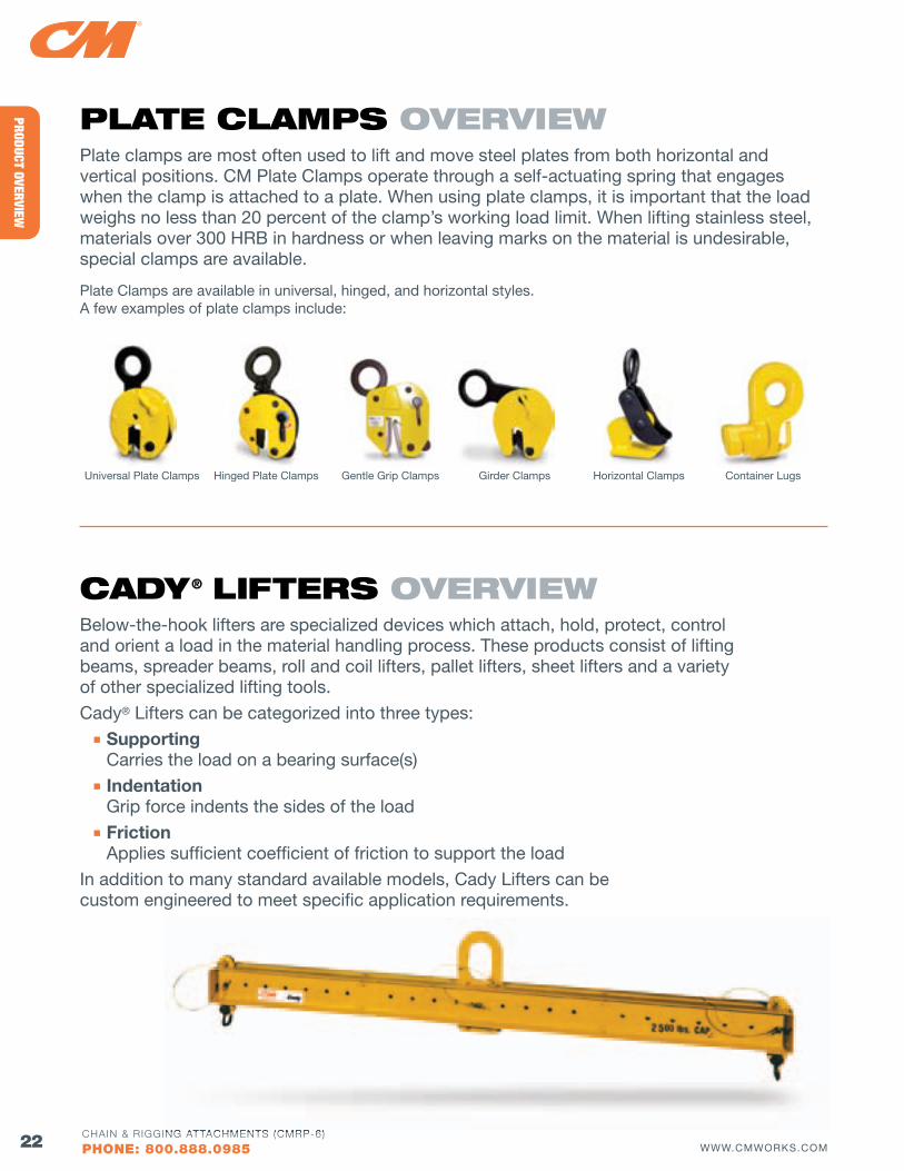
PlATE ClAMPS ovERvIEwPlate clamps are most often used to lift and move steel plates from both horizontal and vertical positions. CM Plate Clamps operate through a self-actuating spring that engages when the clamp is attached to a plate. When using plate clamps, it is important that the load weighs no less than 20 percent of the clamp’s working load limit. When lifting stainless steel, materials over 300 HRB in hardness or when leaving marks on the material is undesirable, special clamps are available.
Plate Clamps are available in universal, hinged, and horizontal styles. A few examples of plate clamps include:
Universal Plate Clamps Hinged Plate Clamps Gentle Grip Clamps Girder Clamps Horizontal Clamps Container Lugs
CAdy® lIfTERS ovERvIEwBelow-the-hook lifters are specialized devices which attach, hold, protect, control and orient a load in the material handling process. These products consist of lifting beams, spreader beams, roll and coil lifters, pallet lifters, sheet lifters and a variety of other specialized lifting tools.
Cady® Lifters can be categorized into three types: n Supporting Carries the load on a bearing surface(s) n Indentation Grip force indents the sides of the load n Friction Applies sufficient coefficient of friction to support the load
In addition to many standard available models, Cady Lifters can be custom engineered to meet specific application requirements.
CHAIN & RIGGING ATTACHMENTS (CMRP-6)
CHAIN & SlING INSPECTIoN, uSE & CARE Warnings .......................................................................... 25
CHAIN & CHAIN SlINGS General Inspection ........................................................... 26
In-Depth Inspection ................................................... 26-28
General Care & Use ......................................................... 28
CHAIN Selection & Working Load Limits ..................................... 29
CHAIN SlINGS Selection & Working Load Limits ............................... 30-32
wIRE RoPE SlINGS Working Load Limits .................................................. 34-35
SyNTHETIC SlINGS Web Sling Working Load Limits ....................................... 36
Round Sling Working Load Limits ................................... 37
TRAINING Rigging Training ............................................................... 38
CMCO University™ ........................................................... 39
Columbus McKinnon Corporation assumes no responsibility for the misuse or misapplication of any of its products. Products are provided with the express understanding that the purchaser and/or user are thoroughly familiar with the correct application and proper use of such rigging products. Warnings and definitions are provided as an aid to the user in understanding the correct application and proper use of the product. Chain and rigging products should not be used by personnel unless they are properly trained and/or certified for that application
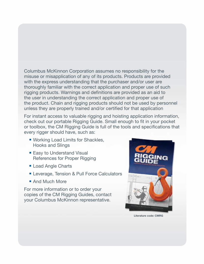
For instant access to valuable rigging and hoisting application information, check out our portable Rigging Guide. Small enough to fit in your pocket or toolbox, the CM Rigging Guide is full of the tools and specifications that every rigger should have, such as: nWorking Load Limits for Shackles, Hooks and Slings nEasy to Understand visual References for Proper Rigging nLoad Angle Charts nLeverage, Tension & Pull Force Calculators nAnd Much More
For more information or to order your copies of the CM Rigging Guides, contact your Columbus McKinnon representative.
Literature code: CMRG
25WWW.CMWORKS.COMCHAIN & RIGGING ATTACHMENTS (CMRP-6)
PHONE: 800.888.0985
CHAI
N &
SLI
NG
INSP
ECTI
ON, U
SE &
CAR
E
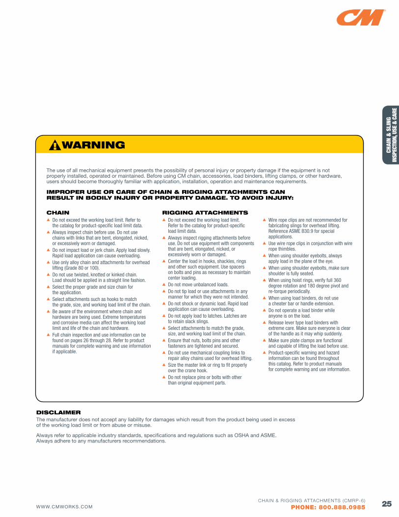
s Do not exceed the working load limit. Refer to the catalog for product-specific load limit data.s Always inspect chain before use. Do not use chains with links that are bent, elongated, nicked, or excessively worn or damaged. s Do not impact load or jerk chain. Apply load slowly. Rapid load application can cause overloading.s Use only alloy chain and attachments for overhead lifting (Grade 80 or 100).s Do not use twisted, knotted or kinked chain. Load should be applied in a straight line fashion. s Select the proper grade and size chain for
the application.s Select attachments such as hooks to match the grade, size, and working load limit of the chain.s Be aware of the environment where chain and hardware are being used. Extreme temperatures and corrosive media can affect the working load limit and life of the chain and hardware.s Full chain inspection and use information can be found on pages 26 through 28. Refer to product
manuals for complete warning and use information if applicable.
CHAINs Do not exceed the working load limit. Refer to the catalog for product-specific load limit data.s Always inspect rigging attachments before use. Do not use equipment with components that are bent, elongated, nicked, or excessively worn or damaged. s Center the load in hooks, shackles, rings and other such equipment. Use spacers on bolts and pins as necessary to maintain center loading. s Do not move unbalanced loads.s Do not tip load or use attachments in any manner for which they were not intended.s Do not shock or dynamic load. Rapid load application can cause overloading. s Do not apply load to latches. Latches are
to retain slack slings.s Select attachments to match the grade, size, and working load limit of the chain.s Ensure that nuts, bolts pins and other fasteners are tightened and secured. s Do not use mechanical coupling links to repair alloy chains used for overhead lifting.s Size the master link or ring to fit properly
over the crane hook.s Do not replace pins or bolts with other than original equipment parts.
s Wire rope clips are not recommended for fabricating slings for overhead lifting. Reference ASME B30.9 for special applications.
s Use wire rope clips in conjunction with wire rope thimbles.s When using shoulder eyebolts, always apply load in the plane of the eye.s When using shoulder eyebolts, make sure shoulder is fully seated.s When using hoist rings, verify full 360
degree rotation and 180 degree pivot and re-torque periodically.
s When using load binders, do not use a cheater bar or handle extension.s Do not operate a load binder while anyone is on the load.s Release lever type load binders with extreme care. Make sure everyone is clear of the handle as it may whip suddenly.s Make sure plate clamps are functional and capable of lifting the load before use. s Product-specific warning and hazard information can be found throughout this catalog. Refer to product manuals for complete warning and use information.
RIGGING ATTACHMENTS
The use of all mechanical equipment presents the possibility of personal injury or property damage if the equipment is not properly installed, operated or maintained. Before using CM chain, accessories, load binders, lifting clamps, or other hardware, users should become thoroughly familiar with application, installation, operation and maintenance requirements.
IMPRoPER uSE oR CARE of CHAIN & RIGGING ATTACHMENTS CAN RESulT IN bodIly INjuRy oR PRoPERTy dAMAGE. To AvoId INjuRy:
dISClAIMER The manufacturer does not accept any liability for damages which result from the product being used in excess of the working load limit or from abuse or misuse.
Always refer to applicable industry standards, specifications and regulations such as OSHA and ASME. Always adhere to any manufacturers recommendations.
26 WWW.CMWORKS.COMCHAIN & RIGGING ATTACHMENTS (CMRP-6)
PHONE: 800.888.0985
CHAIN & SLING
INSPECTION, USE & CARE
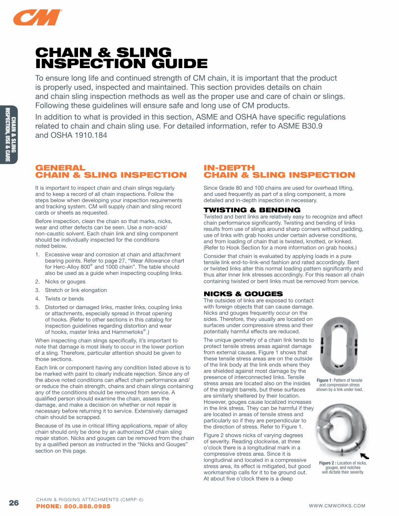
figure 1: Pattern of tensile and compression stress
shown by a link under load.
To ensure long life and continued strength of CM chain, it is important that the product is properly used, inspected and maintained. This section provides details on chain and chain sling inspection methods as well as the proper use and care of chain or slings. Following these guidelines will ensure safe and long use of CM products.
In addition to what is provided in this section, ASME and OSHA have specific regulations related to chain and chain sling use. For detailed information, refer to ASME B30.9 and OSHA 1910.184
GENERAl CHAIN & SlING INSPECTIoN
It is important to inspect chain and chain slings regularly and to keep a record of all chain inspections. Follow the steps below when developing your inspection requirements and tracking system. CM will supply chain and sling record cards or sheets as requested.
Before inspection, clean the chain so that marks, nicks, wear and other defects can be seen. Use a non-acid/ non-caustic solvent. Each chain link and sling component should be individually inspected for the conditions noted below.
1. Excessive wear and corrosion at chain and attachment bearing points. Refer to page 27, “Wear Allowance chart for Herc-Alloy 800® and 1000 chain”. The table should also be used as a guide when inspecting coupling links.
2. Nicks or gouges
3. Stretch or link elongation
4. Twists or bends
5. Distorted or damaged links, master links, coupling links or attachments, especially spread in throat opening of hooks. (Refer to other sections in this catalog for inspection guidelines regarding distortion and wear of hooks, master links and Hammerloks®.)
When inspecting chain slings specifically, it’s important to note that damage is most likely to occur in the lower portion of a sling. Therefore, particular attention should be given to those sections.
Each link or component having any condition listed above is to be marked with paint to clearly indicate rejection. Since any of the above noted conditions can affect chain performance and/or reduce the chain strength, chains and chain slings containing any of the conditions should be removed from service. A qualified person should examine the chain, assess the damage, and make a decision on whether or not repair is necessary before returning it to service. Extensively damaged chain should be scrapped.
Because of its use in critical lifting applications, repair of alloy chain should only be done by an authorized CM chain sling repair station. Nicks and gouges can be removed from the chain by a qualified person as instructed in the “Nicks and Gouges” section on this page.
IN-dEPTH CHAIN & SlING INSPECTIoN
Since Grade 80 and 100 chains are used for overhead lifting, and used frequently as part of a sling component, a more detailed and in-depth inspection in necessary.
TwISTING & bENdINGTwisted and bent links are relatively easy to recognize and affect chain performance significantly. Twisting and bending of links results from use of slings around sharp corners without padding, use of links with grab hooks under certain adverse conditions, and from loading of chain that is twisted, knotted, or kinked. (Refer to Hook Section for a more information on grab hooks.)
Consider that chain is evaluated by applying loads in a pure tensile link end-to-link-end fashion and rated accordingly. Bent or twisted links alter this normal loading pattern significantly and thus alter inner link stresses accordingly. For this reason all chain containing twisted or bent links must be removed from service.
NICKS & GouGESThe outsides of links are exposed to contact with foreign objects that can cause damage. Nicks and gouges frequently occur on the sides. Therefore, they usually are located on surfaces under compressive stress and their potentially harmful effects are reduced.
The unique geometry of a chain link tends to protect tensile stress areas against damage from external causes. Figure 1 shows that these tensile stress areas are on the outside of the link body at the link ends where they are shielded against most damage by the presence of interconnected links. Tensile stress areas are located also on the insides of the straight barrels, but these surfaces are similarly sheltered by their location. However, gouges cause localized increases in the link stress. They can be harmful if they are located in areas of tensile stress and particularly so if they are perpendicular to the direction of stress. Refer to Figure 1.
Figure 2 shows nicks of varying degrees of severity. Reading clockwise, at three o’clock there is a longitudinal mark in a compressive stress area. Since it is longitudinal and located in a compressive stress area, its effect is mitigated, but good workmanship calls for it to be ground out. At about five o’clock there is a deep
figure 2 : Location of nicks, gouges, and notches
will dictate their severity.
CHAIN & SlING INSPECTIoN GuIdE
27WWW.CMWORKS.COMCHAIN & RIGGING ATTACHMENTS (CMRP-6)
PHONE: 800.888.0985
CHAI
N &
SLI
NG
INSP
ECTI
ON, U
SE &
CAR
E
transverse nick in an area of high shear stress. A similar nick is located at six o’clock in the zone of maximum tensile stress. Both of these can create a potentially dangerous escalation of the local stress and must be filed out. A nick that was located at eight o’clock has been filed out properly. Although the final cross section is smaller, the link is stronger because the stress riser effect of the notch has been removed. The remaining cross section can now be evaluated for acceptability by measuring it and applying the criterion for worn chain. See “Wear Allowances Table” below.
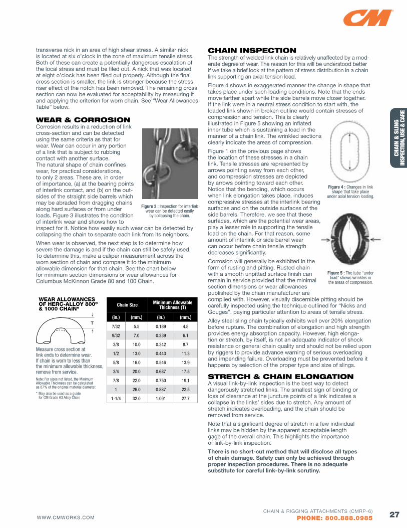
wEAR & CoRRoSIoNCorrosion results in a reduction of link cross-section and can be detected using the same criteria as that for wear. Wear can occur in any portion of a link that is subject to rubbing contact with another surface. The natural shape of chain confines wear, for practical considerations, to only 2 areas. These are, in order of importance, (a) at the bearing points of interlink contact, and (b) on the out-sides of the straight side barrels which may be abraded from dragging chains along hard surfaces or from under loads. Figure 3 illustrates the condition of interlink wear and shows how to inspect for it. Notice how easily such wear can be detected by collapsing the chain to separate each link from its neighbors.
When wear is observed, the next step is to determine how severe the damage is and if the chain can still be safely used. To determine this, make a caliper measurement across the worn section of chain and compare it to the minimum allowable dimension for that chain. See the chart below for minimum section dimensions or wear allowances for Columbus McKinnon Grade 80 and 100 Chain.
CHAIN INSPECTIoNThe strength of welded link chain is relatively unaffected by a mod-erate degree of wear. The reason for this will be understood better if we take a brief look at the pattern of stress distribution in a chain link supporting an axial tension load.
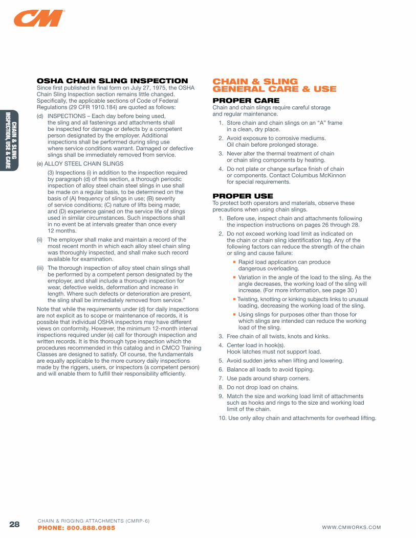
Figure 4 shows in exaggerated manner the change in shape that takes place under such loading conditions. Note that the ends move farther apart while the side barrels move closer together. If the link were in a neutral stress condition to start with, the loaded link shown in broken outline would contain stresses of compression and tension. This is clearly illustrated in Figure 5 showing an inflated inner tube which is sustaining a load in the manner of a chain link. The wrinkled sections clearly indicate the areas of compression.
Figure 1 on the previous page shows the location of these stresses in a chain link. Tensile stresses are represented by arrows pointing away from each other, and compression stresses are depicted by arrows pointing toward each other. Notice that the bending, which occurs when link elongation takes place, induces compressive stresses at the interlink bearing surfaces and on the outside surfaces of the side barrels. Therefore, we see that these surfaces, which are the potential wear areas, play a lesser role in supporting the tensile load on the chain. For that reason, some amount of interlink or side barrel wear can occur before chain tensile strength decreases significantly.
Corrosion will generally be exhibited in the form of rusting and pitting. Rusted chain with a smooth unpitted surface finish can remain in service provided that the minimal section dimensions or wear allowances published by the chain manufacturer are complied with. However, visually discernible pitting should be carefully inspected using the technique outlined for “Nicks and Gouges”, paying particular attention to areas of tensile stress.
Alloy steel sling chain typically exhibits well over 20% elongation before rupture. The combination of elongation and high strength provides energy absorption capacity. However, high elonga-tion or stretch, by itself, is not an adequate indicator of shock resistance or general chain quality and should not be relied upon by riggers to provide advance warning of serious overloading and impending failure. Overloading must be prevented before it happens by selection of the proper type and size of slings.
STRETCH & CHAIN EloNGATIoN A visual link-by-link inspection is the best way to detect dangerously stretched links. The smallest sign of binding or loss of clearance at the juncture points of a link indicates a collapse in the links’ sides due to stretch. Any amount of stretch indicates overloading, and the chain should be removed from service.
Note that a significant degree of stretch in a few individual links may be hidden by the apparent acceptable length gage of the overall chain. This highlights the importance of link-by-link inspection.
There is no short-cut method that will disclose all types of chain damage. Safety can only be achieved through proper inspection procedures. There is no adequate substitute for careful link-by-link scrutiny.
figure 3 : Inspection for interlink wear can be detected easily
by collapsing the chain.
WEAR ALLOWANCES Of HERC-ALLOY 800® & 1000 CHAIN*
Chain Size Minimum Allowable Thickness (T)
(in.) (mm.) (in.) (mm.)
7/32 5.5 0.189 4.8
9/32 7.0 0.239 6.1
3/8 10.0 0.342 8.7
1/2 13.0 0.443 11.3
5/8 16.0 0.546 13.9
3/4 20.0 0.687 17.5
7/8 22.0 0.750 19.1
1 26.0 0.887 22.5
1-1/4 32.0 1.091 27.7
Measure cross section at link ends to determine wear. If chain is worn to less than the minimum allowable thickness, remove from service.
T
Note: For sizes not listed, the Minimum Allowable Thickness can be calculated as 87% of the original material diameter.
* May also be used as a guide for CM Grade 63 Alloy Chain
figure 4 : Changes in link shape that take place
under axial tension loading.
figure 5 : The tube “under load” shows wrinkles in
the areas of compression.
28 WWW.CMWORKS.COMCHAIN & RIGGING ATTACHMENTS (CMRP-6)
PHONE: 800.888.0985
CHAIN & SLING
INSPECTION, USE & CARE
oSHA CHAIN SlING INSPECTIoNSince first published in final form on July 27, 1975, the OSHA Chain Sling Inspection section remains little changed. Specifically, the applicable sections of Code of Federal Regulations (29 CFR 1910.184) are quoted as follows:
(d) INSPECTIONS – Each day before being used, the sling and all fastenings and attachments shall be inspected for damage or defects by a competent person designated by the employer. Additional inspections shall be performed during sling use where service conditions warrant. Damaged or defective slings shall be immediately removed from service.
(e) ALLOY STEEL CHAIN SLINGS
(3) Inspections (i) in addition to the inspection required by paragraph (d) of this section, a thorough periodic inspection of alloy steel chain steel slings in use shall be made on a regular basis, to be determined on the basis of (A) frequency of slings in use; (B) severity of service conditions; (C) nature of lifts being made; and (D) experience gained on the service life of slings used in similar circumstances. Such inspections shall in no event be at intervals greater than once every 12 months.
(ii) The employer shall make and maintain a record of the most recent month in which each alloy steel chain sling was thoroughly inspected, and shall make such record available for examination.
(iii) The thorough inspection of alloy steel chain slings shall be performed by a competent person designated by the employer, and shall include a thorough inspection for wear, defective welds, deformation and increase in length. Where such defects or deterioration are present, the sling shall be immediately removed from service.”
Note that while the requirements under (d) for daily inspections are not explicit as to scope or maintenance of records, it is possible that individual OSHA inspectors may have different views on conformity. However, the minimum 12-month interval inspections required under (e) call for thorough inspection and written records. It is this thorough type inspection which the procedures recommended in this catalog and in CMCO Training Classes are designed to satisfy. Of course, the fundamentals are equally applicable to the more cursory daily inspections made by the riggers, users, or inspectors (a competent person) and will enable them to fulfill their responsibility efficiently.
CHAIN & SlING GENERAl CARE & uSEPRoPER CARE Chain and chain slings require careful storage and regular maintenance.
1. Store chain and chain slings on an “A” frame in a clean, dry place.
2. Avoid exposure to corrosive mediums. Oil chain before prolonged storage.
3. Never alter the thermal treatment of chain or chain sling components by heating.
4. Do not plate or change surface finish of chain or components. Contact Columbus McKinnon for special requirements.
PRoPER uSETo protect both operators and materials, observe these precautions when using chain slings.
1. Before use, inspect chain and attachments following the inspection instructions on pages 26 through 28.
2. Do not exceed working load limit as indicated on the chain or chain sling identification tag. Any of the following factors can reduce the strength of the chain or sling and cause failure:
n Rapid load application can produce dangerous overloading.
n variation in the angle of the load to the sling. As the angle decreases, the working load of the sling will increase. (For more information, see page 30 )
n Twisting, knotting or kinking subjects links to unusual loading, decreasing the working load of the sling.
n Using slings for purposes other than those for which slings are intended can reduce the working load of the sling.
3. Free chain of all twists, knots and kinks.
4. Center load in hook(s). Hook latches must not support load.
5. Avoid sudden jerks when lifting and lowering.
6. Balance all loads to avoid tipping.
7. Use pads around sharp corners.
8. Do not drop load on chains.
9. Match the size and working load limit of attachments such as hooks and rings to the size and working load limit of the chain.
10. Use only alloy chain and attachments for overhead lifting.
29WWW.CMWORKS.COMCHAIN & RIGGING ATTACHMENTS (CMRP-6)
PHONE: 800.888.0985
CHAI
N &
SLI
NG
INSP
ECTI
ON, U
SE &
CAR
E
TradeDiameter
(in)
NACM Working Load Limits (lbs.)
Grade 30
Grade 43
Grade 70
Grade 80
Grade 100
1/8 400 — — — —
3/16 800 — — 2,100 2,700
7/32 — — — 2,100 2,700
1/4 1,300 2,600 3,150 — —
9/32 — — — 3,500 4,300
5/16 1,900 3,900 4,700 4,500 5,700
3/8 2,650 5,400 6,600 7,100 8,800
7/16 3,700 7,200 8,750 — —
1/2 4,500 9,200 11,300 12,000 15,000
5/8 6,900 13,000 15,800 18,100 22,600
3/4 10,600 20,200 24,700 28,300 35,300
7/8 12,800 24,500 — 34,200 42,700
1 17,900 — — 47,700 —
1-1/4 — — — 72,300 —
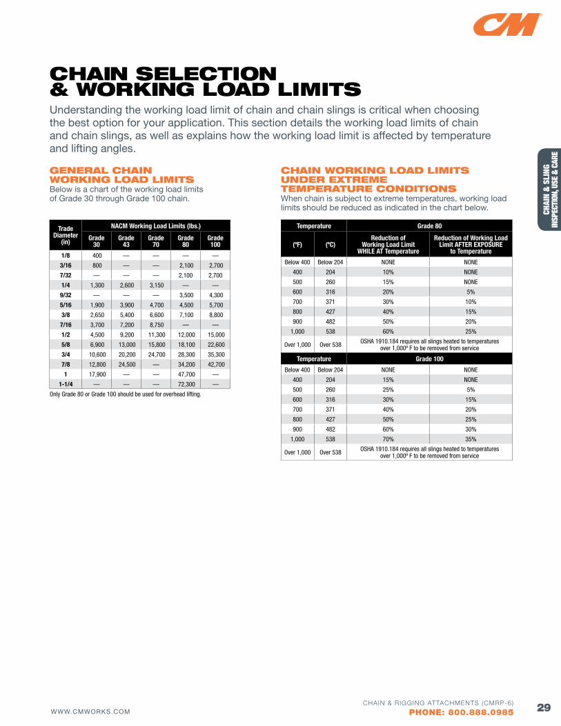
Only Grade 80 or Grade 100 should be used for overhead lifting.
CHAIN woRKING loAd lIMITS uNdER EXTREME TEMPERATuRE CoNdITIoNSWhen chain is subject to extreme temperatures, working load limits should be reduced as indicated in the chart below.
Temperature Grade 80
(ºf) (ºC)Reduction of
Working Load Limit WHILE AT Temperature
Reduction of Working Load Limit AfTER EXPOSURE
to Temperature
Below 400 Below 204 NONE NONE
400 204 10% NONE
500 260 15% NONE
600 316 20% 5%
700 371 30% 10%
800 427 40% 15%
900 482 50% 20%
1,000 538 60% 25%
Over 1,000 Over 538 OSHA 1910.184 requires all slings heated to temperatures over 1,000º F to be removed from service
Temperature Grade 100
Below 400 Below 204 NONE NONE
400 204 15% NONE
500 260 25% 5%
600 316 30% 15%
700 371 40% 20%
800 427 50% 25%
900 482 60% 30%
1,000 538 70% 35%
Over 1,000 Over 538 OSHA 1910.184 requires all slings heated to temperatures over 1,000º F to be removed from service
GENERAl CHAIN woRKING loAd lIMITSBelow is a chart of the working load limits of Grade 30 through Grade 100 chain.
Understanding the working load limit of chain and chain slings is critical when choosing the best option for your application. This section details the working load limits of chain and chain slings, as well as explains how the working load limit is affected by temperature and lifting angles.
CHAIN SElECTIoN & woRKING loAd lIMITS
30 WWW.CMWORKS.COMCHAIN & RIGGING ATTACHMENTS (CMRP-6)
PHONE: 800.888.0985
CHAIN & SLING
INSPECTION, USE & CARE
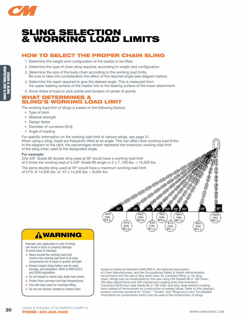
How To SElECT THE PRoPER CHAIN SlING1. Determine the weight and configuration of the load(s) to be lifted.
2. Determine the type of chain sling required, according to weight and configuration.
3. Determine the size of the body chain according to the working load limits. Be sure to take into consideration the effect of the required angle (see diagram below).
4. Determine the reach required to give the desired angle. This is measured from the upper bearing surface of the master link to the bearing surface of the lower attachment.
5. Know share of load on pick points and location of center of gravity.
wHAT dETERMINES A SlING’S woRKING loAd lIMITThe working load limit of slings is based on the following factors:n Type of hitch
n Material strength n Design factor n Diameter of curvature (D/d) n Angle of loading
For specific information on the working load limit of various slings, see page 31. When using a sling, loads are frequently lifted at an angle. This can affect their working load limits. In the diagram to the right, the percentages shown represent the maximum working load limit of the sling when used at the designated angle.
For example: One 3/8" Grade 80 double sling used at 90˚ would have a working load limit of 2 times the working load of a 3/8" Grade 80 single or 2 x 7, 100 lbs. = 14,200 lbs.
The same double sling used at 35º would have a maximum working load limit of 57% of 14,200 lbs. or .57 x 14,200 lbs. = 8,094 lbs.
Improper use, application or care of slings can result in injury or property damage. To avoid injury or damage:s Never exceed the working load limit.
Confirm the working load limit of all sling components are of equal or greater strength.
s Always inspect slings before use for wear, damage, and elongation. Refer to ANSI B30.9 and OSHA regulations.
s Do not impact or shock load. Apply load slowly.s Protect from corrosion and high temperatures.s Use with alloy chain for overhead lifting.s Do not use twisted, knotted or kinked chain.
American National Standard ANSI B30.9, the National Association of Chain Manufacturers, and the Occupational Safety & Health Administration recommend only the use of alloy steel chain for overhead lifting i.e. for sling chain. Slings may be constructed by the user using CM Grades 80 or 100 Chain, CM alloy attachments and CM mechanical coupling links (Hammerloks®). Columbus McKinnon uses Grade 80 or 100 chain and alloy steel welded coupling links instead of Hammerloks for construction of welded slings. Refer to this catalog’s product overview sections for “Chain,” “Hooks” and “Rings and Links” for detailed information on components which may be used in the construction of slings.
SlING SElECTIoN & woRKING loAd lIMITS
31WWW.CMWORKS.COMCHAIN & RIGGING ATTACHMENTS (CMRP-6)
PHONE: 800.888.0985
CHAI
N &
SLI
NG
INSP
ECTI
ON, U
SE &
CAR
E
SINGLE LEG(VERTICAL)
DOUBLE(2 LEGS)
TRIPLE(3 LEGS)
QUADRUPLE(4 LEGS)
BASKETTYPE
DOUBLEBASKET TYPE
SINGLE LEG(CHOKER)
Chain Size(in.)
Working Load Limits for Sling Types Show Above
Single(1 leg)
SingleChoker Double (2 legs) Triple (3 legs) quad (4 legs) Single
BasketDouble Basket
Single Endless
Double Endless*
90º(lbs.)
90º(lbs.)
60º(lbs.)
45º(lbs.)
30º(lbs.)
60º(lbs.)
45º(lbs.)
30º(lbs.)
60º(lbs.)
45º(lbs.)
30º(lbs.)
60º(lbs.)
60º(lbs.)
90º(lbs.)
60º(lbs.)
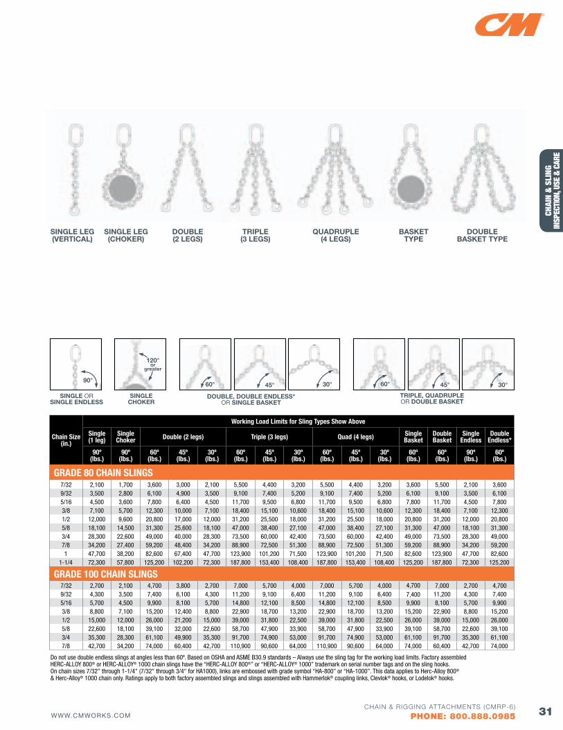
GRADE 80 CHAIN SLINGS7/32 2,100 1,700 3,600 3,000 2,100 5,500 4,400 3,200 5,500 4,400 3,200 3,600 5,500 2,100 3,6009/32 3,500 2,800 6,100 4,900 3,500 9,100 7,400 5,200 9,100 7,400 5,200 6,100 9,100 3,500 6,1005/16 4,500 3,600 7,800 6,400 4,500 11,700 9,500 6,800 11,700 9,500 6,800 7,800 11,700 4,500 7,8003/8 7,100 5,700 12,300 10,000 7,100 18,400 15,100 10,600 18,400 15,100 10,600 12,300 18,400 7,100 12,3001/2 12,000 9,600 20,800 17,000 12,000 31,200 25,500 18,000 31,200 25,500 18,000 20,800 31,200 12,000 20,8005/8 18,100 14,500 31,300 25,600 18,100 47,000 38,400 27,100 47,000 38,400 27,100 31,300 47,000 18,100 31,3003/4 28,300 22,600 49,000 40,000 28,300 73,500 60,000 42,400 73,500 60,000 42,400 49,000 73,500 28,300 49,0007/8 34,200 27,400 59,200 48,400 34,200 88,900 72,500 51,300 88,900 72,500 51,300 59,200 88,900 34,200 59,2001 47,700 38,200 82,600 67,400 47,700 123,900 101,200 71,500 123,900 101,200 71,500 82,600 123,900 47,700 82,600
1-1/4 72,300 57,800 125,200 102,200 72,300 187,800 153,400 108,400 187,800 153,400 108,400 125,200 187,800 72,300 125,200
GRADE 100 CHAIN SLINGS7/32 2,700 2,100 4,700 3,800 2,700 7,000 5,700 4,000 7,000 5,700 4,000 4,700 7,000 2,700 4,700 9/32 4,300 3,500 7,400 6,100 4,300 11,200 9,100 6,400 11,200 9,100 6,400 7,400 11,200 4,300 7,400 5/16 5,700 4,500 9,900 8,100 5,700 14,800 12,100 8,500 14,800 12,100 8,500 9,900 8,100 5,700 9,9003/8 8,800 7,100 15,200 12,400 8,800 22,900 18,700 13,200 22,900 18,700 13,200 15,200 22,900 8,800 15,200 1/2 15,000 12,000 26,000 21,200 15,000 39,000 31,800 22,500 39,000 31,800 22,500 26,000 39,000 15,000 26,000 5/8 22,600 18,100 39,100 32,000 22,600 58,700 47,900 33,900 58,700 47,900 33,900 39,100 58,700 22,600 39,100 3/4 35,300 28,300 61,100 49,900 35,300 91,700 74,900 53,000 91,700 74,900 53,000 61,100 91,700 35,300 61,100 7/8 42,700 34,200 74,000 60,400 42,700 110,900 90,600 64,000 110,900 90,600 64,000 74,000 60,400 42,700 74,000
SINGLE ORSINGLE ENDLESS
90°
120°or
greater
30°60° 45°
DOUBLE, DOUBLE ENDLESS* OR SINGLE BASKET
60° 45° 30°
TRIPLE, QUADRUPLE OR DOUBLE BASKET
SINGLE CHOKER
Do not use double endless slings at angles less than 60º. Based on OSHA and ASME B30.9 standards – Always use the sling tag for the working load limits. Factory assembled HERC-ALLOY 800® or HERC-ALLOY® 1000 chain slings have the “HERC-ALLOY 800®” or “HERC-ALLOY® 1000” trademark on serial number tags and on the sling hooks. On chain sizes 7/32" through 1-1/4" (7/32" through 3/4" for HA1000), links are embossed with grade symbol “HA-800” or “HA-1000”. This data applies to Herc-Alloy 800® & Herc-Alloy® 1000 chain only. Ratings apply to both factory assembled slings and slings assembled with Hammerlok® coupling links, Clevlok® hooks, or Lodelok® hooks.
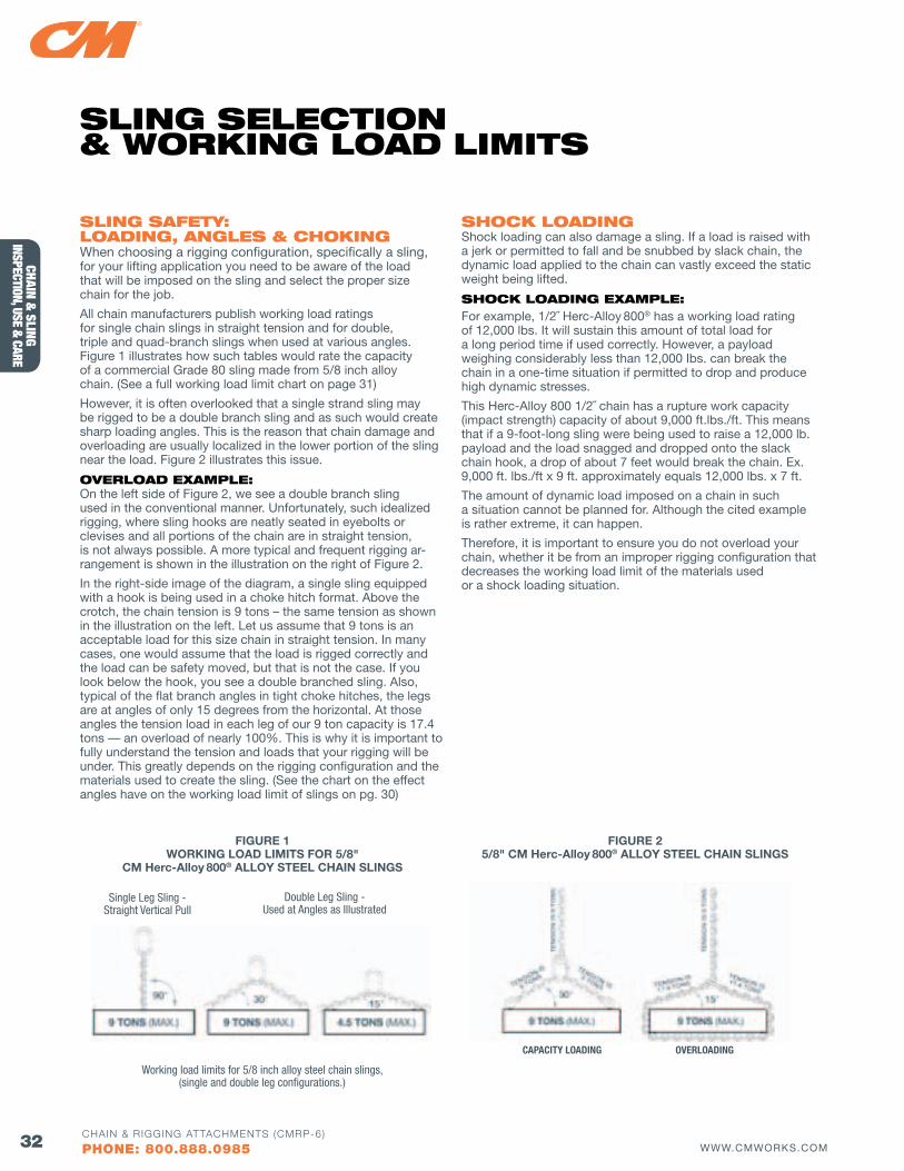
32 WWW.CMWORKS.COMCHAIN & RIGGING ATTACHMENTS (CMRP-6)
PHONE: 800.888.0985
CHAIN & SLING
INSPECTION, USE & CARE
SlING SAfETy: loAdING, ANGlES & CHoKINGWhen choosing a rigging configuration, specifically a sling, for your lifting application you need to be aware of the load that will be imposed on the sling and select the proper size chain for the job.
All chain manufacturers publish working load ratings for single chain slings in straight tension and for double, triple and quad-branch slings when used at various angles. Figure 1 illustrates how such tables would rate the capacity of a commercial Grade 80 sling made from 5/8 inch alloy chain. (See a full working load limit chart on page 31)
However, it is often overlooked that a single strand sling may be rigged to be a double branch sling and as such would create sharp loading angles. This is the reason that chain damage and overloading are usually localized in the lower portion of the sling near the load. Figure 2 illustrates this issue.
ovERloAd EXAMPlE: On the left side of Figure 2, we see a double branch sling used in the conventional manner. Unfortunately, such idealized rigging, where sling hooks are neatly seated in eyebolts or clevises and all portions of the chain are in straight tension, is not always possible. A more typical and frequent rigging ar-rangement is shown in the illustration on the right of Figure 2.
In the right-side image of the diagram, a single sling equipped with a hook is being used in a choke hitch format. Above the crotch, the chain tension is 9 tons – the same tension as shown in the illustration on the left. Let us assume that 9 tons is an acceptable load for this size chain in straight tension. In many cases, one would assume that the load is rigged correctly and the load can be safety moved, but that is not the case. If you look below the hook, you see a double branched sling. Also, typical of the flat branch angles in tight choke hitches, the legs are at angles of only 15 degrees from the horizontal. At those angles the tension load in each leg of our 9 ton capacity is 17.4 tons — an overload of nearly 100%. This is why it is important to fully understand the tension and loads that your rigging will be under. This greatly depends on the rigging configuration and the materials used to create the sling. (See the chart on the effect angles have on the working load limit of slings on pg. 30)
SHoCK loAdINGShock loading can also damage a sling. If a load is raised with a jerk or permitted to fall and be snubbed by slack chain, the dynamic load applied to the chain can vastly exceed the static weight being lifted.
SHoCK loAdING EXAMPlE:For example, 1/2˝ Herc-Alloy 800® has a working load rating of 12,000 lbs. It will sustain this amount of total load for a long period time if used correctly. However, a payload weighing considerably less than 12,000 Ibs. can break the chain in a one-time situation if permitted to drop and produce high dynamic stresses.
This Herc-Alloy 800 1/2˝ chain has a rupture work capacity (impact strength) capacity of about 9,000 ft.lbs./ft. This means that if a 9-foot-long sling were being used to raise a 12,000 lb. payload and the load snagged and dropped onto the slack chain hook, a drop of about 7 feet would break the chain. Ex. 9,000 ft. lbs./ft x 9 ft. approximately equals 12,000 lbs. x 7 ft.
The amount of dynamic load imposed on a chain in such a situation cannot be planned for. Although the cited example is rather extreme, it can happen.
Therefore, it is important to ensure you do not overload your chain, whether it be from an improper rigging configuration that decreases the working load limit of the materials used or a shock loading situation.
Double Leg Sling - Used at Angles as Illustrated
Single Leg Sling - Straight Vertical Pull
Working load limits for 5/8 inch alloy steel chain slings, (single and double leg configurations.)
FIGURE 1WORKING LOAD LIMITS FOR 5/8"
CM Herc-Alloy 800® ALLOY STEEL CHAIN SLINGS
SlING SElECTIoN & woRKING loAd lIMITS
FIGURE 25/8" CM Herc-Alloy 800® ALLOY STEEL CHAIN SLINGS
CAPACITY LOADING OVERLOADING
33WWW.CMWORKS.COMCHAIN & RIGGING ATTACHMENTS (CMRP-6)
PHONE: 800.888.0985
CHAI
N &
SLI
NG
INSP
ECTI
ON, U
SE &
CAR
E
vISIT ouR bloG AT bloG.CMwoRKS.CoM foR GREAT ARTIClES oN RIGGING PRoduCTS & SAfETy ToPICS lIKE THIS:
Who is responsible for putting tags on chain slings? Can I retag my chain slings with missing tags, and do I have to load test a sling after I retag it?It is the sling manufacturer’s responsibility to put ID tags on chain slings. The sling manufacturer is a person or company assembling or fabricating sling components into their final form. The sling manufacturer and the manufacturer of the sling materials may or may not be identical. An end user who buys components and assembles them mechanically is the sling manufacturer. If the user does not know who the sling manufacturer is because the old tag fell off and went missing, then a decision needs to be made. It’s the user’s or rigger’s responsibility to maintain the tag and be sure it remains legible. A rigger cannot use a sling without a tag or when a tag is illegible or missing information.
For retagging, the user would need to start their own serial number for documentation purposes. In doing so, this user would become the “sling manufacturer.” This can only be done if the user is properly trained and deemed competent. Per OSHA, a person who tags a sling must be a competent person designated by the employer. ASME B30.9 states: replacement of the sling identification shall be considered a repair. Slings shall be repaired only by the sling manufacturer or a qualified person. A repair shall be marked to identify the repairing agency. To be considered competent and or qualified, the user should have some inspection experience and complete a rigging gear inspection course from a reputable training organization.
If the user feels they are not competent to properly inspect and retag the sling, they would need to send the sling out to a rigging house with a competent person for inspection and retagging. That rigging house now becomes the “sling manufacturer.” Tags must have information per OSHA 1910.184(e) Alloy steel chain slings. Key OSHA and ASME standards regarding this include:
OSHA 1910.184(E)(1) SLING IDENTIFICATION Alloy steel chain slings shall have permanently affixed durable identification stating size, grade, rated capacity, and reach.
ASME B30.9: SECTION 9-1.7: Sling Identification 9-1.7.1 Identification Requirements
Each sling shall be marked to show:
(a) name or trademark of manufacturer
(b) grade
(c) nominal chain size
(d) number of legs
(e) rated loads for the type(s) of hitch(es) used and the angle upon which it is based
(f) serial number
(g) reach
A load test is not required if a sling is made up of individual load-tested components from the component manufacturer. If the sling is always found in acceptable condition per ASME B30.9, OSHA 1910.184 and manufacturers’ recommendations, then the sling can remain in service without ever needing another load test performed.
for additional information on Sling ID tags, see pages 13, 63 & 75.
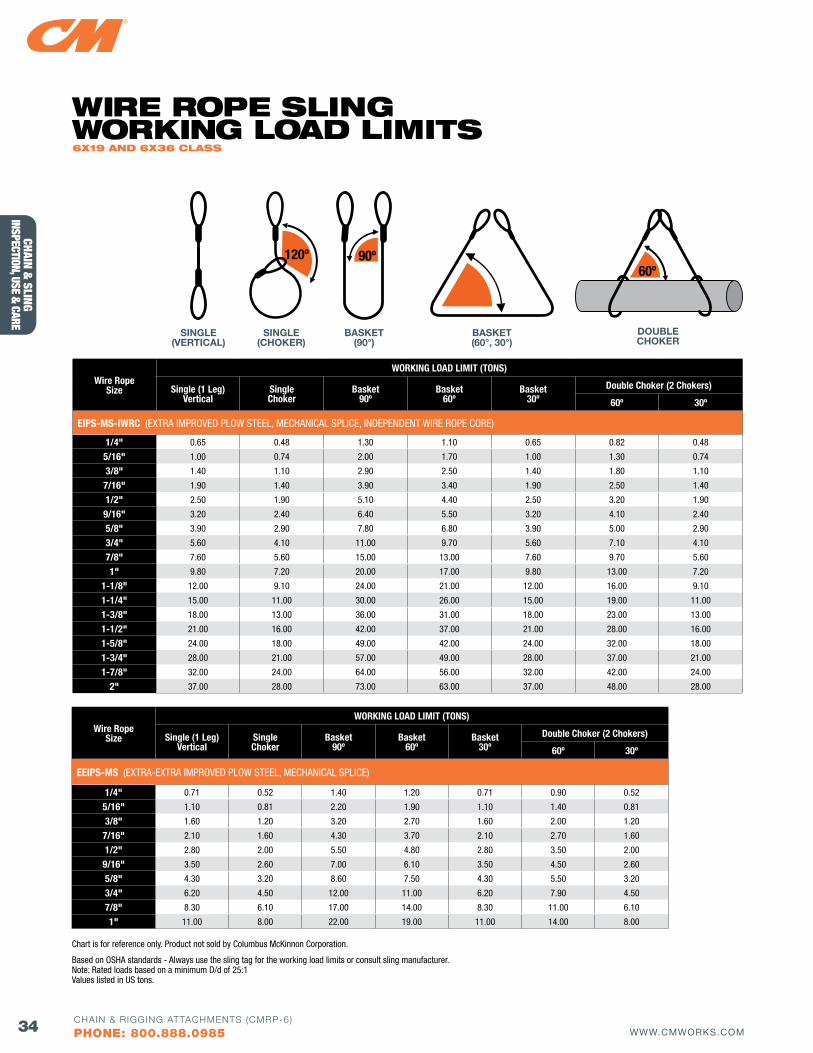
34 WWW.CMWORKS.COMCHAIN & RIGGING ATTACHMENTS (CMRP-6)
PHONE: 800.888.0985
CHAIN & SLING
INSPECTION, USE & CARE
Wire RopeSize
WORKING LOAD LIMIT (TONS)
Single (1 Leg)Vertical
SingleChoker
Basket90º
Basket60º
Basket30º
Double Choker (2 Chokers)
60º 30º
EIPS-MS-IWRC (EXTRA IMPROVED PLOW STEEL, MECHANICAL SPLICE, INDEPENDENT WIRE ROPE CORE)
1/4" 0.65 0.48 1.30 1.10 0.65 0.82 0.48
5/16" 1.00 0.74 2.00 1.70 1.00 1.30 0.74
3/8" 1.40 1.10 2.90 2.50 1.40 1.80 1.10
7/16" 1.90 1.40 3.90 3.40 1.90 2.50 1.40
1/2" 2.50 1.90 5.10 4.40 2.50 3.20 1.90
9/16" 3.20 2.40 6.40 5.50 3.20 4.10 2.40
5/8" 3.90 2.90 7.80 6.80 3.90 5.00 2.90
3/4" 5.60 4.10 11.00 9.70 5.60 7.10 4.10
7/8" 7.60 5.60 15.00 13.00 7.60 9.70 5.60
1" 9.80 7.20 20.00 17.00 9.80 13.00 7.20
1-1/8" 12.00 9.10 24.00 21.00 12.00 16.00 9.10
1-1/4" 15.00 11.00 30.00 26.00 15.00 19.00 11.00
1-3/8" 18.00 13.00 36.00 31.00 18.00 23.00 13.00
1-1/2" 21.00 16.00 42.00 37.00 21.00 28.00 16.00
1-5/8" 24.00 18.00 49.00 42.00 24.00 32.00 18.00
1-3/4" 28.00 21.00 57.00 49.00 28.00 37.00 21.00
1-7/8" 32.00 24.00 64.00 56.00 32.00 42.00 24.00
2" 37.00 28.00 73.00 63.00 37.00 48.00 28.00
Wire RopeSize
WORKING LOAD LIMIT (TONS)
Single (1 Leg)Vertical
SingleChoker
Basket90º
Basket60º
Basket30º
Double Choker (2 Chokers)
60º 30º
EEIPS-MS (EXTRA-EXTRA IMPROVED PLOW STEEL, MECHANICAL SPLICE)
1/4" 0.71 0.52 1.40 1.20 0.71 0.90 0.52
5/16" 1.10 0.81 2.20 1.90 1.10 1.40 0.81
3/8" 1.60 1.20 3.20 2.70 1.60 2.00 1.20
7/16" 2.10 1.60 4.30 3.70 2.10 2.70 1.60
1/2" 2.80 2.00 5.50 4.80 2.80 3.50 2.00
9/16" 3.50 2.60 7.00 6.10 3.50 4.50 2.60
5/8" 4.30 3.20 8.60 7.50 4.30 5.50 3.20
3/4" 6.20 4.50 12.00 11.00 6.20 7.90 4.50
7/8" 8.30 6.10 17.00 14.00 8.30 11.00 6.10
1" 11.00 8.00 22.00 19.00 11.00 14.00 8.00
Chart is for reference only. Product not sold by Columbus McKinnon Corporation.
Based on OSHA standards - Always use the sling tag for the working load limits or consult sling manufacturer. Note: Rated loads based on a minimum D/d of 25:1 Values listed in US tons.
SINGLE(VERTICAL)
BASKET(90°)
BASKET(60°, 30°)
DOUBLECHOKER
SINGLE(CHOKER)
60º120º 90º
wIRE RoPE SlING woRKING loAd lIMITS 6X19 ANd 6X36 ClASS
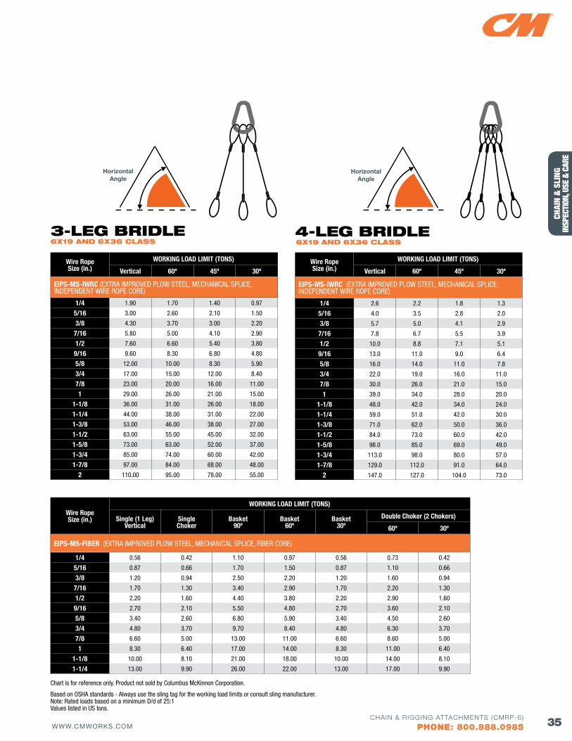
35WWW.CMWORKS.COMCHAIN & RIGGING ATTACHMENTS (CMRP-6)
PHONE: 800.888.0985
CHAI
N &
SLI
NG
INSP
ECTI
ON, U
SE &
CAR
E
Wire RopeSize (in.)
WORKING LOAD LIMIT (TONS)
Vertical 60º 45º 30º
EIPS-MS-IWRC (EXTRA IMPROVED PLOW STEEL, MECHANICAL SPLICE, INDEPENDENT WIRE ROPE CORE)
1/4 1.90 1.70 1.40 0.97
5/16 3.00 2.60 2.10 1.50
3/8 4.30 3.70 3.00 2.20
7/16 5.80 5.00 4.10 2.90
1/2 7.60 6.60 5.40 3.80
9/16 9.60 8.30 6.80 4.80
5/8 12.00 10.00 8.30 5.90
3/4 17.00 15.00 12.00 8.40
7/8 23.00 20.00 16.00 11.00
1 29.00 26.00 21.00 15.00
1-1/8 36.00 31.00 26.00 18.00
1-1/4 44.00 38.00 31.00 22.00
1-3/8 53.00 46.00 38.00 27.00
1-1/2 63.00 55.00 45.00 32.00
1-5/8 73.00 63.00 52.00 37.00
1-3/4 85.00 74.00 60.00 42.00
1-7/8 97.00 84.00 68.00 48.00
2 110.00 95.00 78.00 55.00
6X19 ANd 6X36 ClASS3-lEG bRIdlE
Wire RopeSize (in.)
WORKING LOAD LIMIT (TONS)
Vertical 60º 45º 30º
EIPS-MS-IWRC (EXTRA IMPROVED PLOW STEEL, MECHANICAL SPLICE, INDEPENDENT WIRE ROPE CORE)
1/4 2.6 2.2 1.8 1.3
5/16 4.0 3.5 2.8 2.0
3/8 5.7 5.0 4.1 2.9
7/16 7.8 6.7 5.5 3.9
1/2 10.0 8.8 7.1 5.1
9/16 13.0 11.0 9.0 6.4
5/8 16.0 14.0 11.0 7.8
3/4 22.0 19.0 16.0 11.0
7/8 30.0 26.0 21.0 15.0
1 39.0 34.0 28.0 20.0
1-1/8 48.0 42.0 34.0 24.0
1-1/4 59.0 51.0 42.0 30.0
1-3/8 71.0 62.0 50.0 36.0
1-1/2 84.0 73.0 60.0 42.0
1-5/8 98.0 85.0 69.0 49.0
1-3/4 113.0 98.0 80.0 57.0
1-7/8 129.0 112.0 91.0 64.0
2 147.0 127.0 104.0 73.0
6X19 ANd 6X36 ClASS4-lEG bRIdlE
Wire RopeSize (in.)
WORKING LOAD LIMIT (TONS)
Single (1 Leg)Vertical
SingleChoker
Basket90º
Basket60º
Basket30º
Double Choker (2 Chokers)
60º 30º
EIPS-MS-fIBER (EXTRA IMPROVED PLOW STEEL, MECHANICAL SPLICE, FIBER CORE)
1/4 0.56 0.42 1.10 0.97 0.56 0.73 0.42
5/16 0.87 0.66 1.70 1.50 0.87 1.10 0.66
3/8 1.20 0.94 2.50 2.20 1.20 1.60 0.94
7/16 1.70 1.30 3.40 2.90 1.70 2.20 1.30
1/2 2.20 1.60 4.40 3.80 2.20 2.90 1.60
9/16 2.70 2.10 5.50 4.80 2.70 3.60 2.10
5/8 3.40 2.60 6.80 5.90 3.40 4.50 2.60
3/4 4.80 3.70 9.70 8.40 4.80 6.30 3.70
7/8 6.60 5.00 13.00 11.00 6.60 8.60 5.00
1 8.30 6.40 17.00 14.00 8.30 11.00 6.40
1-1/8 10.00 8.10 21.00 18.00 10.00 14.00 8.10
1-1/4 13.00 9.90 26.00 22.00 13.00 17.00 9.90
Chart is for reference only. Product not sold by Columbus McKinnon Corporation.
Based on OSHA standards - Always use the sling tag for the working load limits or consult sling manufacturer. Note: Rated loads based on a minimum D/d of 25:1 Values listed in US tons.
HorizontalAngle
HorizontalAngle
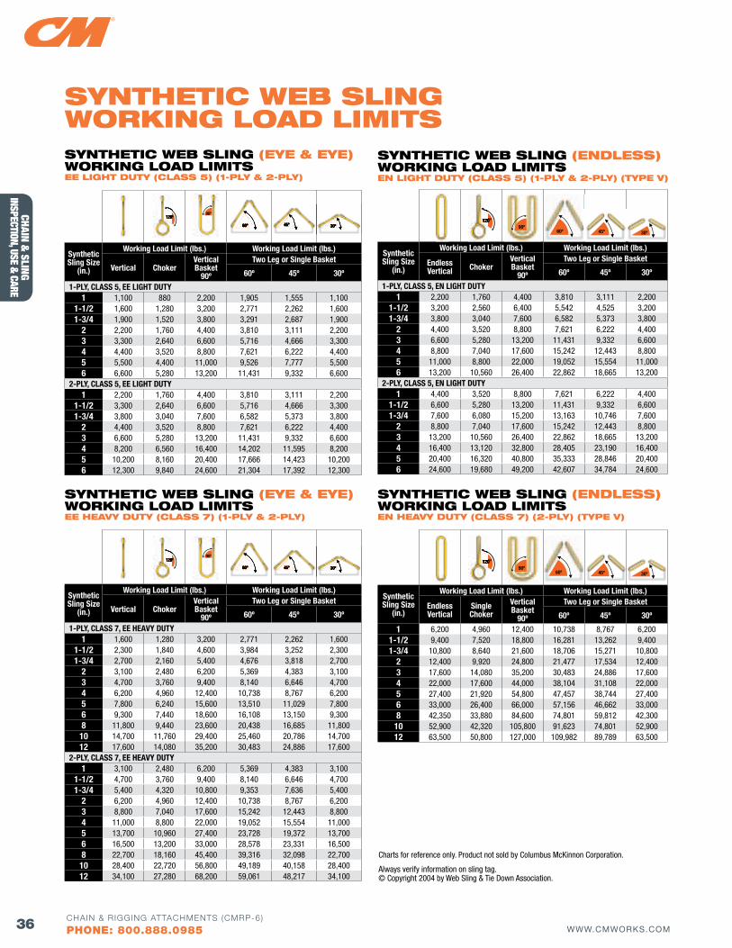
36 WWW.CMWORKS.COMCHAIN & RIGGING ATTACHMENTS (CMRP-6)
PHONE: 800.888.0985
CHAIN & SLING
INSPECTION, USE & CARE
Synthetic Sling Size
(in.)
Working Load Limit (lbs.) Working Load Limit (lbs.)
Endless Vertical Choker
Vertical Basket
90º
Two Leg or Single Basket
60º 45º 30º
1-PLY, CLASS 5, EN LIGHT DUTY1 2,200 1,760 4,400 3,810 3,111 2,200
1-1/2 3,200 2,560 6,400 5,542 4,525 3,2001-3/4 3,800 3,040 7,600 6,582 5,373 3,800
2 4,400 3,520 8,800 7,621 6,222 4,4003 6,600 5,280 13,200 11,431 9,332 6,6004 8,800 7,040 17,600 15,242 12,443 8,8005 11,000 8,800 22,000 19,052 15,554 11,0006 13,200 10,560 26,400 22,862 18,665 13,200
2-PLY, CLASS 5, EN LIGHT DUTY1 4,400 3,520 8,800 7,621 6,222 4,400
1-1/2 6,600 5,280 13,200 11,431 9,332 6,6001-3/4 7,600 6,080 15,200 13,163 10,746 7,600
2 8,800 7,040 17,600 15,242 12,443 8,8003 13,200 10,560 26,400 22,862 18,665 13,2004 16,400 13,120 32,800 28,405 23,190 16,4005 20,400 16,320 40,800 35,333 28,846 20,4006 24,600 19,680 49,200 42,607 34,784 24,600
120º120º120º90º
60º 45º 30º
SyNTHETIC wEb SlING (ENdlESS) woRKING loAd lIMITS EN lIGHT duTy (ClASS 5) (1-Ply & 2-Ply) (TyPE v)
120º120º120º90º
60º 45º 30º
Synthetic Sling Size
(in.)
Working Load Limit (lbs.) Working Load Limit (lbs.)
Endless Vertical
SingleChoker
Vertical Basket
90º
Two Leg or Single Basket
60º 45º 30º
1 6,200 4,960 12,400 10,738 8,767 6,2001-1/2 9,400 7,520 18,800 16,281 13,262 9,4001-3/4 10,800 8,640 21,600 18,706 15,271 10,800
2 12,400 9,920 24,800 21,477 17,534 12,4003 17,600 14,080 35,200 30,483 24,886 17,6004 22,000 17,600 44,000 38,104 31,108 22,0005 27,400 21,920 54,800 47,457 38,744 27,4006 33,000 26,400 66,000 57,156 46,662 33,0008 42,350 33,880 84,600 74,801 59,812 42,30010 52,900 42,320 105,800 91,623 74,801 52,90012 63,500 50,800 127,000 109,982 89,789 63,500
Charts for reference only. Product not sold by Columbus McKinnon Corporation.
Always verify information on sling tag. © Copyright 2004 by Web Sling & Tie Down Association.
SyNTHETIC wEb SlING (ENdlESS) woRKING loAd lIMITS EN HEAvy duTy (ClASS 7) (2-Ply) (TyPE v)
SyNTHETIC wEb SlING woRKING loAd lIMITS
Synthetic Sling Size
(in.)
Working Load Limit (lbs.) Working Load Limit (lbs.)
Vertical ChokerVertical Basket
90º
Two Leg or Single Basket
60º 45º 30º
1-PLY, CLASS 5, EE LIGHT DUTY1 1,100 880 2,200 1,905 1,555 1,100
1-1/2 1,600 1,280 3,200 2,771 2,262 1,6001-3/4 1,900 1,520 3,800 3,291 2,687 1,900
2 2,200 1,760 4,400 3,810 3,111 2,2003 3,300 2,640 6,600 5,716 4,666 3,3004 4,400 3,520 8,800 7,621 6,222 4,4005 5,500 4,400 11,000 9,526 7,777 5,5006 6,600 5,280 13,200 11,431 9,332 6,600
2-PLY, CLASS 5, EE LIGHT DUTY1 2,200 1,760 4,400 3,810 3,111 2,200
1-1/2 3,300 2,640 6,600 5,716 4,666 3,3001-3/4 3,800 3,040 7,600 6,582 5,373 3,800
2 4,400 3,520 8,800 7,621 6,222 4,4003 6,600 5,280 13,200 11,431 9,332 6,6004 8,200 6,560 16,400 14,202 11,595 8,2005 10,200 8,160 20,400 17,666 14,423 10,2006 12,300 9,840 24,600 21,304 17,392 12,300
Synthetic Sling Size
(in.)
Working Load Limit (lbs.) Working Load Limit (lbs.)
Vertical ChokerVertical Basket
90º
Two Leg or Single Basket
60º 45º 30º
1-PLY, CLASS 7, EE HEAVY DUTY1 1,600 1,280 3,200 2,771 2,262 1,600
1-1/2 2,300 1,840 4,600 3,984 3,252 2,3001-3/4 2,700 2,160 5,400 4,676 3,818 2,700
2 3,100 2,480 6,200 5,369 4,383 3,1003 4,700 3,760 9,400 8,140 6,646 4,7004 6,200 4,960 12,400 10,738 8,767 6,2005 7,800 6,240 15,600 13,510 11,029 7,8006 9,300 7,440 18,600 16,108 13,150 9,3008 11,800 9,440 23,600 20,438 16,685 11,800
10 14,700 11,760 29,400 25,460 20,786 14,70012 17,600 14,080 35,200 30,483 24,886 17,600
2-PLY, CLASS 7, EE HEAVY DUTY1 3,100 2,480 6,200 5,369 4,383 3,100
1-1/2 4,700 3,760 9,400 8,140 6,646 4,7001-3/4 5,400 4,320 10,800 9,353 7,636 5,400
2 6,200 4,960 12,400 10,738 8,767 6,2003 8,800 7,040 17,600 15,242 12,443 8,8004 11,000 8,800 22,000 19,052 15,554 11,0005 13,700 10,960 27,400 23,728 19,372 13,7006 16,500 13,200 33,000 28,578 23,331 16,5008 22,700 18,160 45,400 39,316 32,098 22,700
10 28,400 22,720 56,800 49,189 40,158 28,40012 34,100 27,280 68,200 59,061 48,217 34,100
SyNTHETIC wEb SlING (EyE & EyE) woRKING loAd lIMITS EE lIGHT duTy (ClASS 5) (1-Ply & 2-Ply)
SyNTHETIC wEb SlING (EyE & EyE) woRKING loAd lIMITS EE HEAvy duTy (ClASS 7) (1-Ply & 2-Ply)
120º120º120º
120º120º120º
90º
90º
60º60º60º
60º60º60º
45º45º45º
45º45º45º
30º30º30º
30º30º30º
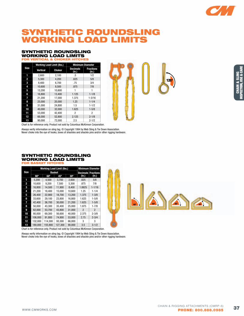
37WWW.CMWORKS.COMCHAIN & RIGGING ATTACHMENTS (CMRP-6)
PHONE: 800.888.0985
CHAI
N &
SLI
NG
INSP
ECTI
ON, U
SE &
CAR
E
SizeWorking Load Limit (lbs.) Minimum Diameter
Basket Decimals (in.)
fractions (in.)90º 60º 45º 30º
1 5,200 4,500 3,700 2,600 .625 5/82 10,600 9,200 7,500 5,300 .875 7/83 16,800 14,500 11,900 8,400 1.0625 1-1/164 21,200 18,400 15,000 10,600 1.25 1-1/45 26,400 22,900 18,700 13,200 1.375 1-3/86 33,600 29,100 23,800 16,800 1.625 1-5/87 42,400 36,700 30,000 21,200 1.625 1-5/88 50,000 43,300 35,400 25,000 1.875 1-7/89 62,000 53,700 43,800 31,000 2 210 80,000 69,300 56,600 40,000 2.375 2-3/811 106,000 91,800 74,900 53,000 2.75 2-3/412 132,000 114,300 93,300 66,000 3 313 180,000 155,900 127,300 90,000 3.5 3-1/2
60º 45º 30º90º
Chart is for reference only. Product not sold by Columbus McKinnon Corporation.
Always verify information on sling tag. © Copyright 1994 by Web Sling & Tie Down Association. Never choke into the eye of hooks, bows of shackles and shackle pins and/or other rigging hardware.
SyNTHETIC RouNdSlING woRKING loAd lIMITS foR bASKET HITCHES
Chart is for reference only. Product not sold by Columbus McKinnon Corporation.
Always verify information on sling tag. © Copyright 1994 by Web Sling & Tie Down Association. Never choke into the eye of hooks, bows of shackles and shackle pins and/or other rigging hardware.
SizeWorking Load Limit (lbs.) Minimum Diameter
Vertical Choker Decimals(in.)
fractions(in.)
1 2,600 2,100 .5 1/22 5,300 4,200 .625 5/83 8,400 6,700 .75 3/44 10,600 8,500 .875 7/85 13,200 10,600 1 16 16,800 13,400 1.125 1-1/87 21,200 17,000 1.375 1-3/168 25,000 20,000 1.25 1-1/49 31,000 24,800 1.5 1-1/210 40,000 32,000 1.625 1-5/811 53,000 42,400 2 212 66,000 52,800 2.125 2-1/813 90,000 72,000 2.5 2-1/2
120º120º120º
SyNTHETIC RouNdSlING woRKING loAd lIMITS foR vERTICAl & CHoKER HITCHES
SyNTHETIC RouNdSlING woRKING loAd lIMITS
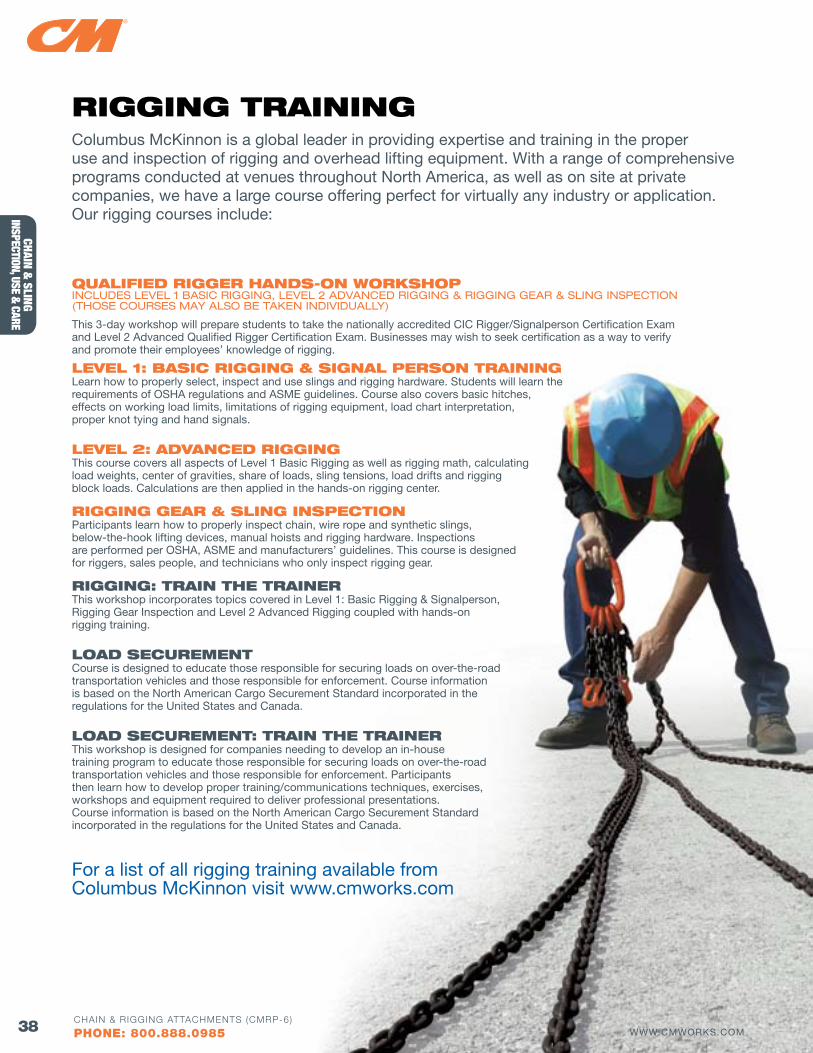
38 WWW.CMWORKS.COMCHAIN & RIGGING ATTACHMENTS (CMRP-6)
PHONE: 800.888.0985
CHAIN & SLING
INSPECTION, USE & CARE
QuAlIfIEd RIGGER HANdS-oN woRKSHoP INCLUDES LEVEL 1 BASIC RIGGING, LEVEL 2 ADVANCED RIGGING & RIGGING GEAR & SLING INSPECTION (THOSE COURSES MAY ALSO BE TAKEN INDIVIDUALLY)
This 3-day workshop will prepare students to take the nationally accredited CIC Rigger/Signalperson Certification Exam and Level 2 Advanced Qualified Rigger Certification Exam. Businesses may wish to seek certification as a way to verify and promote their employees’ knowledge of rigging.
lEvEl 1: bASIC RIGGING & SIGNAl PERSoN TRAININGLearn how to properly select, inspect and use slings and rigging hardware. Students will learn the requirements of OSHA regulations and ASME guidelines. Course also covers basic hitches, effects on working load limits, limitations of rigging equipment, load chart interpretation, proper knot tying and hand signals.
lEvEl 2: AdvANCEd RIGGINGThis course covers all aspects of Level 1 Basic Rigging as well as rigging math, calculating load weights, center of gravities, share of loads, sling tensions, load drifts and rigging block loads. Calculations are then applied in the hands-on rigging center.
RIGGING GEAR & SlING INSPECTIoNParticipants learn how to properly inspect chain, wire rope and synthetic slings, below-the-hook lifting devices, manual hoists and rigging hardware. Inspections are performed per OSHA, ASME and manufacturers’ guidelines. This course is designed for riggers, sales people, and technicians who only inspect rigging gear.
RIGGING: TRAIN THE TRAINERThis workshop incorporates topics covered in Level 1: Basic Rigging & Signalperson, Rigging Gear Inspection and Level 2 Advanced Rigging coupled with hands-on rigging training.
loAd SECuREMENTCourse is designed to educate those responsible for securing loads on over-the-road transportation vehicles and those responsible for enforcement. Course information is based on the North American Cargo Securement Standard incorporated in the regulations for the United States and Canada.
loAd SECuREMENT: TRAIN THE TRAINERThis workshop is designed for companies needing to develop an in-house training program to educate those responsible for securing loads on over-the-road transportation vehicles and those responsible for enforcement. Participants then learn how to develop proper training/communications techniques, exercises, workshops and equipment required to deliver professional presentations. Course information is based on the North American Cargo Securement Standard incorporated in the regulations for the United States and Canada.
For a list of all rigging training available from Columbus McKinnon visit www.cmworks.com
RIGGING TRAININGColumbus McKinnon is a global leader in providing expertise and training in the proper use and inspection of rigging and overhead lifting equipment. With a range of comprehensive programs conducted at venues throughout North America, as well as on site at private companies, we have a large course offering perfect for virtually any industry or application. Our rigging courses include:
WWW.CMWORKS.COMCHAIN & RIGGING ATTACHMENTS (CMRP-6)
PHONE: 800.888.0985
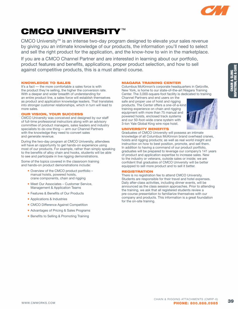
39WWW.CMWORKS.COMCHAIN & RIGGING ATTACHMENTS (CMRP-6)
PHONE: 800.888.0985
CHAI
N &
SLI
NG
INSP
ECTI
ON, U
SE &
CAR
E
CMCo uNIvERSITy ™CMCO University™ is an intense two-day program designed to elevate your sales revenue by giving you an intimate knowledge of our products, the information you’ll need to select and sell the right product for the application, and the know-how to win in the marketplace.
If you are a CMCO Channel Partner and are interested in learning about our portfolio, product features and benefits, applications, proper product selection, and how to sell against competitive products, this is a must attend course.
KNowlEdGE To SAlES It’s a fact — the more comfortable a sales force is with the product they’re selling, the higher the conversion rate. With a deeper and wider breadth of understanding for an entire product line, a sales force will establish themselves as product and application knowledge leaders. That translates into stronger customer relationships, which in turn will lead to more sales.
ouR vISIoN, youR SuCCESS CMCO University was conceived and designed by our staff of full-time professional instructors along with an advisory committee of product managers, sales leaders and industry specialists to do one thing — arm our Channel Partners with the knowledge they need to convert sales and generate revenue.
During the two-day program at CMCO University, attendees will have an opportunity to get hands-on experience using most of our products. For example, rather than simply speaking to the benefits of alloy chain and hooks, students will be able to see and participate in live rigging demonstrations.
Some of the topics covered in the classroom training and hands-on product demonstrations include:
Overview of the CMCO product portfolio – manual hoists, powered hoists, crane components, chain and rigging
Meet Our Associates – Customer Service, Management & Application Teams
Features & Benefits of Our Products
Applications & Industries
CMCO Difference Against Competition
Advantages of Pricing & Sales Programs
Benefits to Selling & Promoting Training
NIAGARA TRAINING CENTER Columbus McKinnon’s corporate headquarters in Getzville, New York, is home to our state-of-the-art Niagara Training Center. The 3,000-square-foot facility is dedicated to training Channel Partners and end users on the safe and proper use of hoist and rigging products. The Center offers a one-of-a-kind training experience on chain and rigging equipment with more than 75 manual and powered hoists, enclosed track systems and our 50-foot-wide crane system with 3-ton Yale Global King wire rope hoist.
uNIvERSITy bENEfITS Graduates of CMCO University will possess an intimate knowledge of all Columbus McKinnon brand overhead cranes, hoists and rigging products; as well as real world insight and instruction on how to best position, promote, and sell them. In addition to having a command of our product portfolio, graduates will be prepared to leverage our company’s 141 years of product and application expertise to increase sales. New to the industry or veterans, outside sales or inside; we are confident that graduates of CMCO University will be better equipped to sell more product and to sell it better.
REGISTRATIoN There is no registration fee to attend CMCO University. Students are responsible for their travel and hotel expenses. Daily after-class activities, including dinner events, will be announced as the class session approaches. Prior to attending the training, we ask that all registered students review a pre-course presentation to familiarize themselves with our company and products. This information is a great foundation for the on-site training.
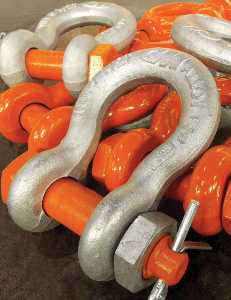
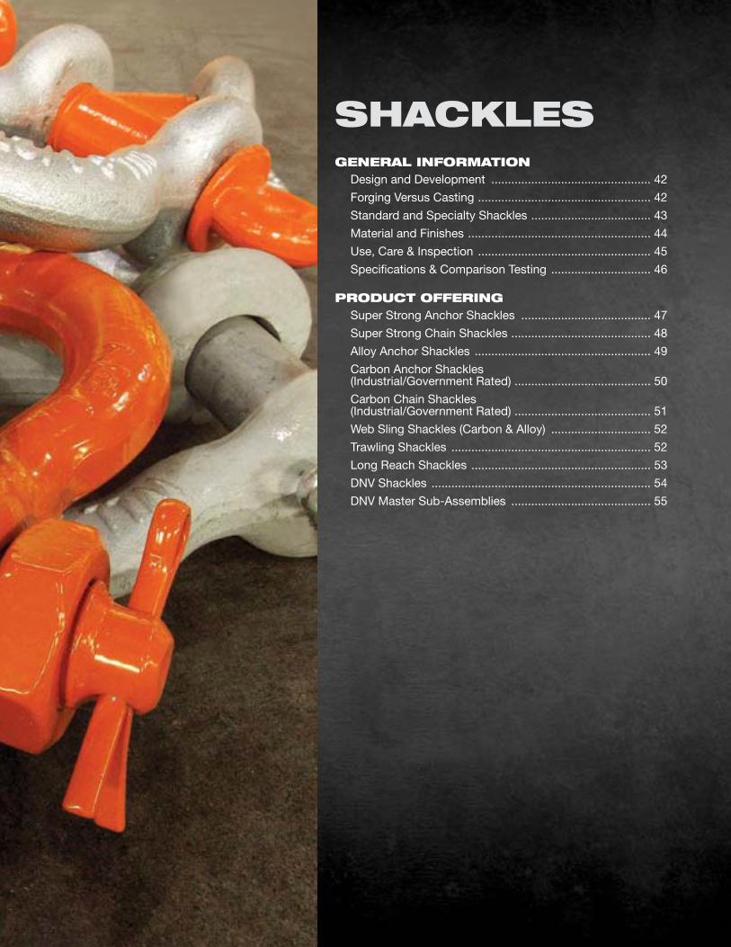
GENERAl INfoRMATIoN Design and Development ................................................ 42
Forging versus Casting .................................................... 42
Standard and Specialty Shackles .................................... 43
Material and Finishes ....................................................... 44
Use, Care & Inspection .................................................... 45
Specifications & Comparison Testing .............................. 46
PRoduCT offERING Super Strong Anchor Shackles ....................................... 47
Super Strong Chain Shackles .......................................... 48
Alloy Anchor Shackles ..................................................... 49
Carbon Anchor Shackles (Industrial/Government Rated) ......................................... 50
Carbon Chain Shackles (Industrial/Government Rated) ......................................... 51
Web Sling Shackles (Carbon & Alloy) .............................. 52
Trawling Shackles ............................................................ 52
Long Reach Shackles ...................................................... 53
DNv Shackles .................................................................. 54
DNv Master Sub-Assemblies .......................................... 55
SHACKlES
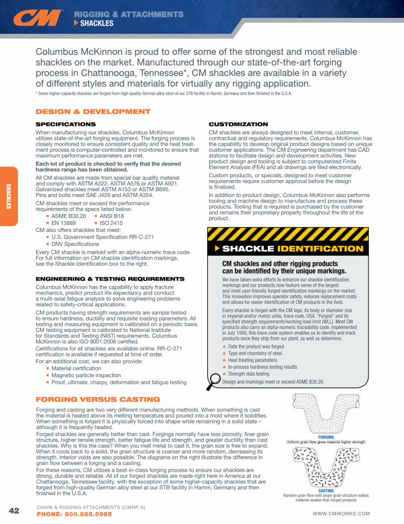
RIGGING & ATTACHMENTS
42 WWW.CMWORKS.COM
SHACKLES
CHAIN & RIGGING ATTACHMENTS (CMRP-6)
PHONE: 800.888.0985
SHACKLES
SPECIfICATIoNS
When manufacturing our shackles, Columbus McKinnon utilizes state-of-the-art forging equipment. The forging process is closely monitored to ensure consistent quality and the heat treat-ment process is computer-controlled and monitored to ensure that maximum performance parameters are met.
Each lot of product is checked to verify that the desired hardness range has been obtained.All CM shackles are made from special bar quality material and comply with ASTM A322, ASTM A576 or ASTM A921. Galvanized shackles meet ASTM A153 or ASTM B695. Pins and bolts meet SAE J429 and ASTM A354.
CM shackles meet or exceed the performance requirements of the specs listed below:
n ASME B30.26 n ANSI B18 n EN 13889 n ISO 2415CM also offers shackles that meet: n U.S. Government Specification RR-C-271 n DNv Specifications
Every CM shackle is marked with an alpha-numeric trace code. For full information on CM shackle identification markings, see the Shackle Identification box to the right.
ENGINEERING & TESTING REQuIREMENTS
Columbus McKinnon has the capability to apply fracture mechanics, predict product life expectancy and conduct a multi-axial fatigue analysis to solve engineering problems related to safety-critical applications.
CM products having strength requirements are sample tested to ensure hardness, ductility and requisite loading parameters. All testing and measuring equipment is calibrated on a periodic basis. CM testing equipment is calibrated to National Institute for Standards and Testing (NIST) requirements. Columbus McKinnon is also ISO 9001:2008 certified.Certifications for all shackles are available online. RR-C-271 certification is available if requested at time of order.For an additional cost, we can also provide: n Material certification n Magnetic particle inspection n Proof, ultimate, charpy, deformation and fatigue testing
CuSToMIZATIoN
CM shackles are always designed to meet internal, customer, contractual and regulatory requirements. Columbus McKinnon has the capability to develop original product designs based on unique customer applications. The CM Engineering department has CAD stations to facilitate design and development activities. New product design and tooling is subject to computerized Finite Element Analysis (FEA) and all drawings are filed electronically.
Custom products, or specials, designed to meet customer requirements require customer approval before the design is finalized.
In addition to product design, Columbus McKinnon also performs tooling and machine design to manufacture and process these products. Tooling that is required is purchased by the customer and remains their proprietary property throughout the life of the product.
dESIGN & dEvEloPMENT
Columbus McKinnon is proud to offer some of the strongest and most reliable shackles on the market. Manufactured through our state-of-the-art forging process in Chattanooga, Tennessee*, CM shackles are available in a variety of different styles and materials for virtually any rigging application.
foRGING vERSuS CASTINGForging and casting are two very different manufacturing methods. When something is cast the material is heated above its melting temperature and poured into a mold where it solidifies. When something is forged it is physically forced into shape while remaining in a solid state – although it is frequently heated.Forged shackles are generally better than cast. Forgings normally have less porosity, finer grain structure, higher tensile strength, better fatigue life and strength, and greater ductility than cast shackles. Why is this the case? When you melt metal to cast it, the grain size is free to expand. When it cools back to a solid, the grain structure is coarser and more random, decreasing its strength. Interior voids are also possible. The diagrams on the right illustrate the difference in grain flow between a forging and a casting.For these reasons, CM utilizes a best-in-class forging process to ensure our shackles are strong, durable and reliable. All of our forged shackles are made right here in America at our Chattanooga, Tennessee facility, with the exception of some higher-capacity shackles that are forged from high-quality German alloy steel at our STB facility in Hamm, Germany and then finished in the U.S.A.
SHACKlE IdENTIfICATIoN
CM shackles and other rigging products can be identified by their unique markings.We have taken extra efforts to enhance our shackle identification markings and our products now feature some of the largest and most user-friendly forged identification markings on the market. This innovation improves operator safety, reduces replacement costs and allows for easier identification of CM products in the field.
Every shackle is forged with the CM logo, its body or diameter size in imperial and/or metric units, trace code, USA, “Forged” and its specified strength requirements/working load limit (WLL). Most CM products also carry an alpha-numeric traceability code. Implemented in July 1980, this trace code system enables us to identify and track products once they ship from our plant, as well as determine:s Date the product was forgeds Type and chemistry of steels Heat treating parameterss In-process hardness testing resultss Strength data testing
Design and markings meet or exceed ASME B30.26
fORGING Uniform grain flow gives material higher strength
CASTING Random grain flow with larger grain structure makes
material weaker than forged products
* Some higher-capacity shackles are forged from high-quality German alloy steel at our STB facility in Hamm, Germany and then finished in the U.S.A.
Uniform grain flow gives material higher strength
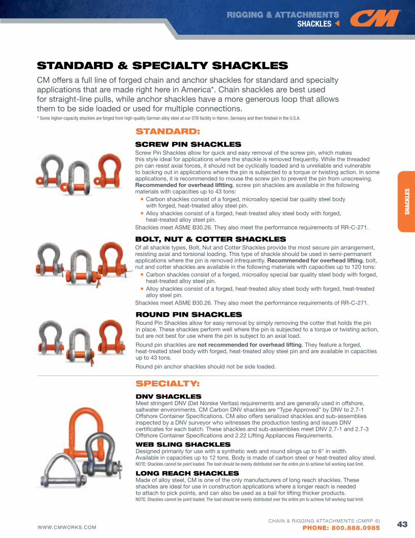
RIGGING & ATTACHMENTS
43WWW.CMWORKS.COM
SHACKLES
CHAIN & RIGGING ATTACHMENTS (CMRP-6)
PHONE: 800.888.0985
SHAC
KLES
CM offers a full line of forged chain and anchor shackles for standard and specialty applications that are made right here in America*. Chain shackles are best used for straight-line pulls, while anchor shackles have a more generous loop that allows them to be side loaded or used for multiple connections.
STANdARd & SPECIAlTy SHACKlES
bolT, NuT & CoTTER SHACKlESOf all shackle types, Bolt, Nut and Cotter Shackles provide the most secure pin arrangement, resisting axial and torsional loading. This type of shackle should be used in semi-permanent applications where the pin is removed infrequently. Recommended for overhead lifting, bolt, nut and cotter shackles are available in the following materials with capacities up to 120 tons: n Carbon shackles consist of a forged, microalloy special bar quality steel body with forged,
heat-treated alloy steel pin. n Alloy shackles consist of a forged, heat-treated alloy steel body with forged, heat-treated
alloy steel pin.Shackles meet ASME B30.26. They also meet the performance requirements of RR-C-271.
RouNd PIN SHACKlESRound Pin Shackles allow for easy removal by simply removing the cotter that holds the pin in place. These shackles perform well where the pin is subjected to a torque or twisting action, but are not best for use where the pin is subject to an axial load.
Round pin shackles are not recommended for overhead lifting. They feature a forged, heat-treated steel body with forged, heat-treated alloy steel pin and are available in capacities up to 43 tons.
Round pin anchor shackles should not be side loaded.
dNv SHACKlES Meet stringent DNv (Det Norske veritas) requirements and are generally used in offshore, saltwater environments. CM Carbon DNv shackles are “Type Approved” by DNv to 2.7-1 Offshore Container Specifications. CM also offers serialized shackles and sub-assemblies inspected by a DNv surveyor who witnesses the production testing and issues DNv certificates for each batch. These shackles and sub-assemblies meet DNv 2.7-1 and 2.7-3 Offshore Container Specifications and 2.22 Lifting Appliances Requirements.
wEb SlING SHACKlES Designed primarily for use with a synthetic web and round slings up to 6" in width. Available in capacities up to 12 tons. Body is made of carbon steel or heat-treated alloy steel.NOTE: Shackles cannot be point loaded. The load should be evenly distributed over the entire pin to achieve full working load limit.
loNG REACH SHACKlES Made of alloy steel, CM is one of the only manufacturers of long reach shackles. These shackles are ideal for use in construction applications where a longer reach is needed to attach to pick points, and can also be used as a bail for lifting thicker products. NOTE: Shackles cannot be point loaded. The load should be evenly distributed over the entire pin to achieve full working load limit.
SCREw PIN SHACKlESScrew Pin Shackles allow for quick and easy removal of the screw pin, which makes this style ideal for applications where the shackle is removed frequently. While the threaded pin can resist axial forces, it should not be cyclically loaded and is unreliable and vulnerable to backing out in applications where the pin is subjected to a torque or twisting action. In some applications, it is recommended to mouse the screw pin to prevent the pin from unscrewing. Recommended for overhead liftting, screw pin shackles are available in the following materials with capacities up to 43 tons: n Carbon shackles consist of a forged, microalloy special bar quality steel body
with forged, heat-treated alloy steel pin. n Alloy shackles consist of a forged, heat-treated alloy steel body with forged,
heat-treated alloy steel pin.Shackles meet ASME B30.26. They also meet the performance requirements of RR-C-271.
SPECIAlTy:
STANdARd:
* Some higher-capacity shackles are forged from high-quality German alloy steel at our STB facility in Hamm, Germany and then finished in the U.S.A.
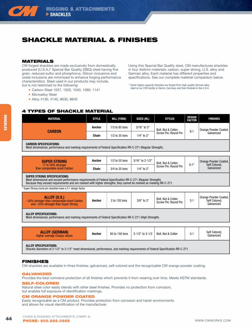
RIGGING & ATTACHMENTS
44 WWW.CMWORKS.COM
SHACKLES
CHAIN & RIGGING ATTACHMENTS (CMRP-6)
PHONE: 800.888.0985
SHACKLES
CM forged shackles are made exclusively from domestically produced (U.S.A.)* Special Bar Quality (SBQ) steel having fine grain, reduced sulfur and phosphorus. Silicon inclusions and oxide inclusions are minimized to enhance forging performance characteristics. Steel used in our products may include, but is not restricted to the following: n Carbon Steel 1037, 1020, 1040, 1080, 1141 n Microalloy Steel n Alloy 4130, 4140, 8630, 8640
Using this Special Bar Quality steel, CM manufactures shackles in four distinct materials: carbon, super strong, U.S. alloy and German alloy. Each material has different properties and specifications. See our complete material comparison below.
fINISHESCM shackles are available in three finishes: galvanized, self-colored and the recognizable CM orange powder coating.
GAlvANIZEd Provides the best corrosive protection of all finishes which prevents it from wearing over time. Meets ASTM standards.
SElf-ColoREd Natural steel color easily blends with other steel finishes. Provides no protection from corrosion, but enables full exposure of identification markings.
CM oRANGE PowdER CoATEd Easily recognizable as a CM product. Provides protection from corrosion and harsh environments and allows for visual identification of the manufacturer.
MATERIAL STYLE WLL (TONS) SIzES (IN.) STYLES DESIGN fACTOR fINISHES
CARBONAnchor 1/3 to 85 tons 3/16" to 3"
Bolt, Nut & Cotter;Screw Pin; Round Pin 6:1 Orange Powder Coated,
GalvanizedChain 1/2 to 35 tons 1/4" to 2"
CARBON SPECIfICATIONS:Meet dimensional, performance and marking requirements of Federal Specification RR-C-271 (Regular Strength).
SUPER STRONG 17 to 50% stronger
than comparable-sized Carbon
Anchor 1/2 to 55 tons 3/16" to 2-1/2"Bolt, Nut & Cotter;Screw Pin; Round Pin 6:1*
Orange Powder Coated, Self Colored, GalvanizedChain 3/4 to 35 tons 1/4" to 2"
SUPER STRONG SPECIfICATIONS:Meet dimensional and exceed performance requirements of Federal Specification RR-C-271 (Regular Strength). Because they exceed requirements and are marked with higher strengths, they cannot be marked as meeting RR-C-271.
ALLOY (U.S.) ~50% stronger than comparable-sized Carbon
and ~25% stronger than Super StrongAnchor 2 to 120 tons 3/8" to 3" Bolt, Nut & Cotter;
Screw Pin; Round Pin 5:1Orange Powder Coated,
Self Colored, Galvanized
ALLOY SPECIfICATIONS:Meet dimensional, performance and marking requirements of Federal Specification RR-C-271 (High Strength).
ALLOY (GERMAN)Higher average Charpy values
Anchor 85 to 150 tons 2-1/2" to 3-1/2 Bolt, Nut & Cotter 5:1 Self Colored, Galvanized
ALLOY SPECIfICATIONS:Shackle diameters of 2-1/2" to 3-1/2" meet dimensional, performance, and marking requirements of Federal Specification RR-C-271.
4 TyPES of SHACKlE MATERIAl
MATERIAlS
SHACKlE MATERIAl & fINISHES
* Super Strong round pin shackles have a 5:1 design factor.
* Some higher-capacity shackles are forged from high-quality German alloy steel at our STB facility in Hamm, Germany and then finished in the U.S.A.
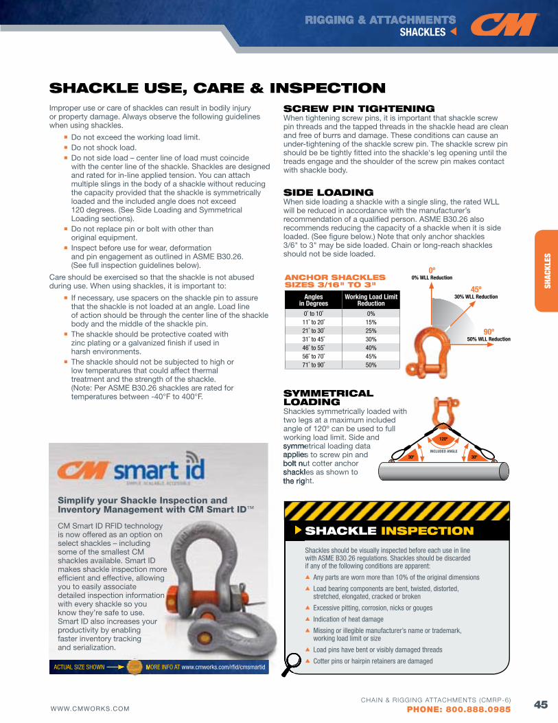
RIGGING & ATTACHMENTS
45WWW.CMWORKS.COM
SHACKLES
CHAIN & RIGGING ATTACHMENTS (CMRP-6)
PHONE: 800.888.0985
SHAC
KLES
SHACKlE INSPECTIoN
Shackles should be visually inspected before each use in line with ASME B30.26 regulations. Shackles should be discarded if any of the following conditions are apparent:
s Any parts are worn more than 10% of the original dimensions
s Load bearing components are bent, twisted, distorted, stretched, elongated, cracked or broken
s Excessive pitting, corrosion, nicks or gouges
s Indication of heat damage
s Missing or illegible manufacturer’s name or trademark, working load limit or size
s Load pins have bent or visibly damaged threads
s Cotter pins or hairpin retainers are damaged
SCREw PIN TIGHTENINGWhen tightening screw pins, it is important that shackle screw pin threads and the tapped threads in the shackle head are clean and free of burrs and damage. These conditions can cause an under-tightening of the shackle screw pin. The shackle screw pin should be be tightly fitted into the shackle's leg opening until the treads engage and the shoulder of the screw pin makes contact with shackle body.
SIdE loAdINGWhen side loading a shackle with a single sling, the rated WLL will be reduced in accordance with the manufacturer’s recommendation of a qualified person. ASME B30.26 also recommends reducing the capacity of a shackle when it is side loaded. (See figure below.) Note that only anchor shackles 3/6" to 3" may be side loaded. Chain or long-reach shackles should not be side loaded.
SyMMETRICAl loAdINGShackles symmetrically loaded with two legs at a maximum included angle of 120º can be used to full working load limit. Side and symmetrical loading data applies to screw pin and bolt nut cotter anchor shackles as shown to the right.
Improper use or care of shackles can result in bodily injury or property damage. Always observe the following guidelines when using shackles.
n Do not exceed the working load limit. n Do not shock load. n Do not side load – center line of load must coincide with the center line of the shackle. Shackles are designed and rated for in-line applied tension. You can attach multiple slings in the body of a shackle without reducing the capacity provided that the shackle is symmetrically loaded and the included angle does not exceed 120 degrees. (See Side Loading and Symmetrical Loading sections). n Do not replace pin or bolt with other than original equipment. n Inspect before use for wear, deformation and pin engagement as outlined in ASME B30.26. (See full inspection guidelines below).
Care should be exercised so that the shackle is not abused during use. When using shackles, it is important to:
n If necessary, use spacers on the shackle pin to assure that the shackle is not loaded at an angle. Load line of action should be through the center line of the shackle body and the middle of the shackle pin. n The shackle should be protective coated with
zinc plating or a galvanized finish if used in harsh environments.
n The shackle should not be subjected to high or low temperatures that could affect thermal treatment and the strength of the shackle. (Note: Per ASME B30.26 shackles are rated for temperatures between -40°F to 400°F.
SHACKlE uSE, CARE & INSPECTIoN
Angles in Degrees
Working Load Limit Reduction
0˚ to 10˚ 0%11˚ to 20˚ 15%21˚ to 30˚ 25%31˚ to 45˚ 30%46˚ to 55˚ 40%56˚ to 70˚ 45%71˚ to 90˚ 50%
ANCHoR SHACKlES SIZES 3/16" To 3"
30ºINCLUDED ANGLE
30º
120º
0º0% WLL Reduction
45º30% WLL Reduction
90º50% WLL Reduction
symmetrical loading data applies to screw pin and bolt nut cotter anchor shackles as shown to the right.
Simplify your Shackle Inspection and Inventory Management with CM Smart ID™
CM Smart ID RFID technology is now offered as an option on select shackles – including some of the smallest CM shackles available. Smart ID makes shackle inspection more efficient and effective, allowing you to easily associate detailed inspection information with every shackle so you know they’re safe to use. Smart ID also increases your productivity by enabling faster inventory tracking and serialization.
ACTUAL SIzE SHOWN MORE INFO AT www.cmworks.com/rfid/cmsmartidMORE INFO AT
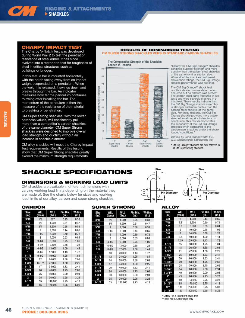
RIGGING & ATTACHMENTS
46 WWW.CMWORKS.COM
SHACKLES
CHAIN & RIGGING ATTACHMENTS (CMRP-6)
PHONE: 800.888.0985
SHACKLES
SizeSize
W
Pin DiameterPin Diameter
W
dIMENSIoNS & woRKING loAd lIMITS CM shackles are available in different dimensions with varying working load limits depending on the material they are made of. See the charts below for sizes and working load limits of our alloy, carbon and super strong shackles.
AlloyCARboN SuPER STRoNG
SHACKlE SPECIfICATIoNS
CHARPy IMPACT TESTThe Charpy v-Notch Test was developed during World War 2 to test the penetration resistance of steel armor. It has since evolved into a method to test for toughness of steel in critical structures such as buildings or bridges.
In this test, a bar is mounted horizontally with the notch facing away from an impact weight suspended on a pendulum. When the weight is released, it swings down and breaks through the bar. An indicator measures how far the pendulum continues to swing after breaking the bar. The momentum of the pendulum is then the measure of the resistance of the material to breaking or penetration.
CM Super Strong shackles, with the lower hardness values, will consistently pull more than a competitor’s carbon shackles of the same diameter. CM Super Strong shackles were designed to improve overall load strength and ductility without an increase in shackle diameter.
CM alloy shackles will meet the Charpy Impact Test requirements. Results of this testing show that CM Super Strong shackles greatly exceed the minimum strength requirements.
“Clearly the CM Big Orange®* shackles exhibited superior strength and more ductility than the carbon steel shackles of the same nominal section size. While all of the shackles performed above their ratings, the CM Big Orange shackle performance was superior.
The CM Big Orange®* shock test results indicated severe deformation occurred but no fracture was present. The carbon steel parts fractured in two tests and were severely cracked in a third test. These results indicate that the CM Big Orange shackle assembly is stronger and more ductile than the carbon steel shackle of the same size. For these reasons, the CM Big Orange shackle provides more exten-sive deformation prior to fracture. In conclusion, this test demonstrates the superiority of the CM Big Orange shackles when compared to the carbon steel shackles under the shock loaded conditions.”
Verified by John Bloodsworth, P.E. Q.C. Metallurgical Laboratory, Inc.
* CM Big Orange® shackles are now referred to as CM Super Strong shackles.
RESulTS of CoMPARISoN TESTING CM SUPER STRONG SHACKLES VERSUS STANDARD CARBON SHACKLES
The Comparative Strength of the Shackles Loaded in Tension
Appl
ied
Load
in P
ound
s (T
hous
ands
)
90
80
70
60
50
40
30
20
10
01/2"
Super StrongShackle
1/2"CarbonShackle
3/4"Super Strong
Shackle
3/4"CarbonShackle
Size(in.)
WLL(tons)
WLL(lbs.)
Pin Dia.(in.)
W dim.(in.)
3/16 1/2 1,000 0.25 0.381/4 3/4 1,500 0.31 0.475/16 1 2,000 0.38 0.533/8 1-1/2 3,000 0.44 0.667/16 2 4,000 0.50 0.721/2 3 6,000 0.63 0.845/8 4-1/2 9,000 0.75 1.063/4 6-1/2 13,000 0.88 1.287/8 8-1/2 17,000 1.00 1.441 10 20,000 1.13 1.72
1-1/8 12 24,000 1.25 1.841-1/4 14 28,000 1.38 2.031-3/8 17 34,000 1.50 2.251-1/2 20 40,000 1.63 2.411-5/8 24 48,000 1.75 2.661-3/4 30 60,000 2.00 2.94
2 35 70,000 2.25 3.282-1/2 55 110,000 2.75 4.13
* Screw Pin & Round Pin style only ** Bolt, Nut & Cotter style only
Size(in.)
WLL(tons)
WLL(lbs.)
Pin Dia.(in.)
W dim.(in.)
3/8 2 4,000 0.44 0.667/16 2.6 5,200 0.50 0.721/2 3.3 6,600 0.63 0.845/8 5 10,000 0.75 1.063/4 7 14,000 0.88 1.287/8 9.5 19,000 1.00 1.441 12.5 25,000 1.13 1.72
1-1/8 15 30,000 1.25 1.841-1/4 18 36,000 1.38 2.031-3/8 21 42,000 1.50 2.251-1/2* 25 50,000 1.63 2.411-1/2** 30 60,000 1.63 2.411-5/8* 29 58,000 1.75 2.661-5/8** 35 70,000 1.75 2.661-3/4* 34 68,000 2.00 2.941-3/4** 40 80,000 2.00 2.94
2* 43 86,000 2.25 3.282** 50 100,000 2.25 3.28
2-1/2** 85 170,000 2.75 4.133** 110 220,000 3.25 5.00
3-1/2** 150 300,000 3.75 5.25
Size(in.)
WLL(tons)
WLL(lbs.)
Pin Dia.(in.)
W dim.(in.)
3/16 1/3 667 0.25 0.381/4 1/2 1,000 0.31 0.475/16 3/4 1,500 0.38 0.533/8 1 2,000 0.44 0.667/16 1-1/2 3,000 0.50 0.721/2 2 4,000 0.63 0.845/8 3-1/4 6,500 0.75 1.063/4 4-3/4 9,500 0.88 1.287/8 6-1/2 13,000 1.00 1.441 8-1/2 17,000 1.13 1.72
1-1/8 9-1/2 19,000 1.25 1.841-1/4 12 24,000 1.38 2.031-3/8 13-1/2 27,000 1.50 2.251-1/2 17 34,000 1.63 2.411-5/8 20 40,000 1.75 2.661-3/4 25 50,000 2.00 2.94
2 35 70,000 2.25 3.282-1/2 55 110,000 2.75 4.13
3 85 170,000 3.25 5.00
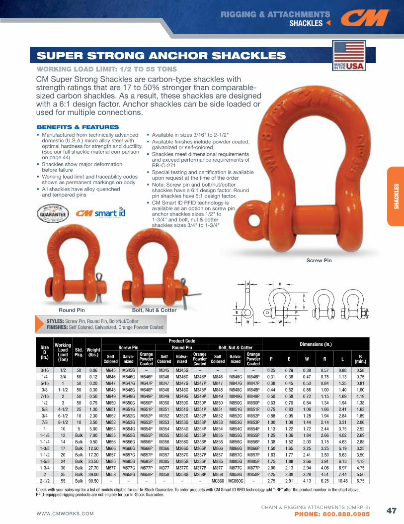
RIGGING & ATTACHMENTS
47WWW.CMWORKS.COM
SHACKLES
CHAIN & RIGGING ATTACHMENTS (CMRP-6)
PHONE: 800.888.0985
SHAC
KLES
SuPER STRoNG ANCHoR SHACKlES
Bolt, Nut & Cotter
Screw Pin
Round Pin
Manufactured from technically advanced domestic (U.S.A.) micro alloy steel with optimal hardness for strength and ductility. (See our full shackle material comparison on page 44)
Shackles show major deformation before failure
Working load limit and traceability codes shown as permanent markings on body
All shackles have alloy quenched and tempered pins
Available in sizes 3/16" to 2-1/2" Available finishes include powder coated,
galvanized or self-colored Shackles meet dimensional requirements
and exceed performance requirements of RR-C-271
Special testing and certification is available upon request at the time of the order
Note: Screw pin and bolt/nut/cotter shackles have a 6:1 design factor. Round pin shackles have 5:1 design factor.
CM Smart ID RFID technology is available as an option on screw pin anchor shackles sizes 1/2" to 1-3/4" and bolt, nut & cotter shackles sizes 3/4" to 1-3/4"
bENEfITS & fEATuRES
WORKING LOAD LIMIT: 1/2 TO 55 TONS
SizeD
(in.)
Working Load Limit(Ton)
Std.Pkg.
Weight(lbs.)
Product CodeDimensions (in.)
Screw Pin Round Pin Bolt, Nut & Cotter
Self Colored
Galva-nized
Orange Powder Coated
Self Colored
Galva-nized
Orange Powder Coated
Self Colored
Galva-nized
Orange Powder Coated
P E W R L B (min.)
3/16 1/2 50 0.06 M645 M645G – M345 M345G – – – – 0.25 0.29 0.38 0.57 0.88 0.581/4 3/4 50 0.12 M646 M646G M646P M346 M346G M346P M846 M846G M846P 0.31 0.36 0.47 0.75 1.13 0.755/16 1 50 0.20 M647 M647G M647P M347 M347G M347P M847 M847G M847P 0.38 0.45 0.53 0.84 1.25 0.813/8 1-1/2 50 0.30 M648 M648G M648P M348 M348G M348P M848 M848G M848P 0.44 0.52 0.66 1.00 1.40 1.007/16 2 50 0.50 M649 M649G M649P M349 M349G M349P M849 M849G M849P 0.50 0.58 0.72 1.15 1.69 1.191/2 3 50 0.75 M650 M650G M650P M350 M350G M350P M850 M850G M850P 0.63 0.70 0.84 1.34 1.94 1.385/8 4-1/2 25 1.30 M651 M651G M651P M351 M351G M351P M851 M851G M851P 0.75 0.83 1.06 1.66 2.41 1.633/4 6-1/2 10 2.30 M652 M652G M652P M352 M352G M352P M852 M852G M852P 0.88 0.95 1.28 1.94 2.84 1.897/8 8-1/2 10 3.50 M653 M653G M653P M353 M353G M353P M853 M853G M853P 1.00 1.09 1.44 2.14 3.31 2.061 10 5 5.00 M654 M654G M654P M354 M354G M354P M854 M854G M854P 1.13 1.22 1.72 2.44 3.75 2.52
1-1/8 12 Bulk 7.00 M655 M655G M655P M355 M355G M355P M855 M855G M855P 1.25 1.36 1.84 2.66 4.02 2.691-1/4 14 Bulk 9.50 M656 M656G M656P M356 M356G M356P M856 M856G M856P 1.38 1.52 2.03 3.15 4.63 2.881-3/8 17 Bulk 12.50 M666 M666G M666P M366 M366G M366P M866 M866G M866P 1.50 1.65 2.25 3.25 5.19 3.251-1/2 20 Bulk 17.20 M657 M657G M657P M357 M357G M357P M857 M857G M857P 1.63 1.77 2.41 3.50 5.63 3.501-5/8 24 Bulk 23.50 M685 M685G M685P M385 M385G M385P M885 M885G M885P 1.75 1.88 2.66 3.91 6.13 4.131-3/4 30 Bulk 27.70 M677 M677G M677P M377 M377G M377P M877 M877G M877P 2.00 2.13 2.94 4.06 6.97 4.75
2 35 Bulk 39.00 M658 M658G M658P M358 M358G M358P M858 M858G M858P 2.25 2.38 3.28 4.51 7.44 5.502-1/2 55 Bulk 90.50 – – – – – – MC860 MC860G – 2.75 2.91 4.13 6.25 10.48 6.75
STYLES: Screw Pin, Round Pin, Bolt/Nut/CotterFINISHES: Self Colored, Galvanized, Orange Powder Coated
CM Super Strong Shackles are carbon-type shackles with strength ratings that are 17 to 50% stronger than comparable-sized carbon shackles. As a result, these shackles are designed with a 6:1 design factor. Anchor shackles can be side loaded or used for multiple connections.
E
D B
R W
L
PE
D B
R W
L
PE
D B
R W
L
P
Check with your sales rep for a list of models eligible for our In-Stock Guarantee. To order products with CM Smart ID RFID technology add “-RF” after the product number in the chart above. RFID-equipped rigging products are not eligible for our In-Stock Guarantee.
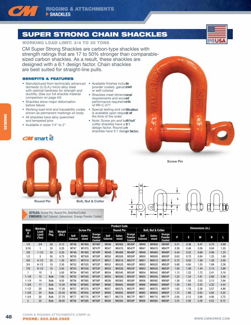
RIGGING & ATTACHMENTS
48 WWW.CMWORKS.COM
SHACKLES
CHAIN & RIGGING ATTACHMENTS (CMRP-6)
PHONE: 800.888.0985
SHACKLES
Manufactured from technically advanced domestic (U.S.A.) micro alloy steel with optimal hardness for strength and ductility. (See our full shackle material comparison on page 44)
Shackles show major deformation before failure
Working load limit and traceability codes shown as permanent markings on body
All shackles have alloy quenched and tempered pins
Available in sizes 1/4" to 2"
Available finishes include powder coated, galvanized or self-colored
Shackles meet dimensional requirements and exceed performance requirements of RR-C-271
Special testing and certification is available upon request at the time of the order
Note: Screw pin and bolt/nut/ cotter shackles have a 6:1 design factor. Round pin shackles have 5:1 design factor.
bENEfITS & fEATuRES
SizeD
(in.)
Working Load Limit(Ton)
Std.Pkg.
Weight(lbs.)
Product CodeDimensions (in.)
Screw Pin Round Pin Bolt, Nut & Cotter
Self Colored
Galva-nized
Orange Powder Coated
Self Colored
Galva-nized
Orange Powder Coated
Self Colored
Galva-nized
Orange Powder Coated
P E W R L
1/4 3/4 50 0.12 M746 M746G M746P M546 M546G M546P M946 M946G M946P 0.31 0.36 0.47 0.75 0.885/16 1 50 0.20 M747 M747G M747P M547 M547G M547P M947 M947G M947P 0.38 0.46 0.56 0.84 1.033/8 1-1/2 50 0.30 M748 M748G M748P M548 M548G M548P M948 M948G M948P 0.44 0.52 0.66 0.99 1.251/2 3 50 0.75 M750 M750G M750P M550 M550G M550P M950 M950G M950P 0.63 0.70 0.84 1.25 1.695/8 4-1/2 25 1.30 M751 M751G M751P M551 M551G M551P M951 M951G M951P 0.75 0.83 1.09 1.58 2.003/4 6-1/2 10 2.30 M752 M752G M752P M552 M552G M552P M952 M952G M952P 0.88 0.95 1.25 1.89 2.387/8 8-1/2 10 3.50 M753 M753G M753P M553 M553G M553P M953 M953G M953P 1.00 1.09 1.44 2.14 2.881 10 5 5.00 M754 M754G M754P M554 M554G M554P M954 M954G M954P 1.13 1.22 1.72 2.41 3.19
1-1/8 12 Bulk 7.00 M755 M755G M755P M555 M555G M555P M955 M955G M955P 1.25 1.34 1.81 2.69 3.561-1/4 14 Bulk 9.50 M756 M756G M756P M556 M556G M556P M956 M956G M956P 1.38 1.50 2.03 3.13 3.941-3/8 17 Bulk 12.50 M766 M766G M766P M566 M566G M566P M966 M966G M966P 1.50 1.63 2.25 3.32 4.441-1/2 20 Bulk 17.20 M757 M757G M757P M557 M557G M557P M957 M957G M957P 1.63 1.78 2.38 3.57 4.881-5/8 24 Bulk 23.50 M785 M785G M785P M585 M585G M585P M985 M985G M985P 1.75 1.88 2.63 3.94 5.251-3/4 30 Bulk 27.70 M777 M777G M777P M577 M577G M577P M977 M977G M977P 2.00 2.13 2.88 4.06 5.75
2 35 Bulk 39.00 M758 M758G M758P M558 M558G M558P M958 M958G M958P 2.25 2.38 3.28 4.53 6.75
E
D
R W
L
P
SuPER STRoNG CHAIN SHACKlESWORKING LOAD LIMIT: 3/4 TO 35 TONS
STYLES: Screw Pin, Round Pin, Bolt/Nut/CotterFINISHES: Self Colored, Galvanized, Orange Powder Coated
Available finishes include powder coated, galvanized
Shackles meet dimensional requirements and exceed performance requirements
Special testing and certification is available upon request at
Note: Screw pin and bolt/nut/cotter shackles have a 6:1 design factor. Round pin shackles have 5:1 design factor.
Bolt, Nut & Cotter
Screw Pin
Round Pin
CM Super Strong Shackles are carbon-type shackles with strength ratings that are 17 to 50% stronger than comparable-sized carbon shackles. As a result, these shackles are designed with a 6:1 design factor. Chain shackles are best suited for straight-line pulls.
E
D
R W
L
PE
D
R W
L
P
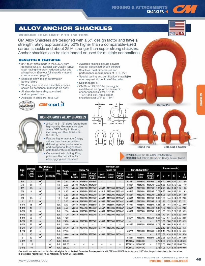
RIGGING & ATTACHMENTS
49WWW.CMWORKS.COM
SHACKLES
CHAIN & RIGGING ATTACHMENTS (CMRP-6)
PHONE: 800.888.0985
SHAC
KLES
CM Alloy Shackles are designed with a 5:1 design factor and have a strength rating approximately 50% higher than a comparable-sized carbon shackle and about 25% stronger than super strong shackles. Anchor shackles can be side loaded or used for multiple connections.
Alloy ANCHoR SHACKlES
3/8" to 2" sizes made in the U.S.A. from domestic (U.S.A.) Special Bar Quality (SBQ) steel having fine grain, reduced sulfur and phosphorus. (See our full shackle material comparison on page 8)
Shackles show major deformation before failure
Working load limit and traceability codes shown as permanent markings on body
All shackles have alloy quenched and tempered pins
Available in sizes 3/8" to 3-1/2"
Available finishes include powder coated, galvanized or self-colored
Shackles meet dimensional and performance requirements of RR-C-271
Special testing and certification is available upon request at the time of the order
Design factor 5:1 CM Smart ID RFID technology is
available as an option on screw pin anchor shackles sizes 1/2" to 1-3/4" and bolt, nut & cotter shackles sizes 3/4" to 1-3/4"
bENEfITS & fEATuRES
WORKING LOAD LIMIT: 2 TO 150 TONS
SizeD
(in.)
Working Load Limit(Ton)
Alloy Material Origin
Std.Pkg.
Weight(lbs.)
Product CodeDimensions (in.)
Screw Pin Round Pin Bolt, Nut & Cotter
U.S.A Germany Self Colored
Galva-nized
Orange Powder Coated
Self Colored
Galva-nized
Orange Powder Coated
Self Colored
Galva-nized
Orange Powder Coated
P E W R L B min
3/8 2 50 0.30 M648A M648AG M648AP – – – M848A M848AG M848AP 0.44 0.52 0.66 1.00 1.40 1.007/16 2.6 50 0.50 M649A M649AG M649AP – – – M849A M849AG M849AP 0.50 0.58 0.72 1.15 1.69 1.191/2 3.3 50 0.75 M650A M650AG M650AP M350A M350AG M350AP M850A M850AG M850AP 0.63 0.70 0.84 1.34 1.94 1.385/8 5 25 1.30 M651A M651AG M651AP M351A M351AG M351AP M851A M851AG M851AP 0.75 0.83 1.06 1.66 2.41 1.633/4 7 10 2.30 M652A M652AG M652AP M352A M352AG M352AP M852A M852AG M852AP 0.88 0.95 1.28 1.94 2.84 1.897/8 9.5 10 3.50 M653A M653AG M653AP M353A M353AG M353AP M853A M853AG M853AP 1.00 1.09 1.44 2.14 3.31 2.061 12.5 5 5.00 M654A M654AG M654AP M354A M354AG M354AP M854A M854AG M854AP 1.13 1.22 1.72 2.44 3.75 2.52
1-1/8 15 Bulk 7.00 M655A M655AG M655AP M355A M355AG M355AP M855A M855AG M855AP 1.25 1.36 1.84 2.66 4.02 2.691-1/4 18 Bulk 9.50 M656A M656AG M656AP M356A M356AG M356AP M856A M856AG M856AP 1.38 1.52 2.03 3.15 4.63 2.881-3/8 21 Bulk 12.50 M666A M666AG M666AP M366A M366AG M366AP M866A M866AG M866AP 1.50 1.65 2.25 3.25 5.19 3.251-1/2 25 Bulk 17.20 M657A M657AG M657AP M357A M357AG M357AP – – – 1.63 1.77 2.41 3.50 5.63 3.501-1/2 30 Bulk 17.20 – – – – – – M857A M857AG M857AP 1.63 1.77 2.41 3.50 5.63 3.501-5/8 29 Bulk 23.50 M685A M685AG M685AP M385A M385AG M385AP – – – 1.75 1.88 2.66 3.91 6.13 4.131-5/8 35 Bulk 23.50 – – – – – – M885A M885AG M885AP 1.75 1.88 2.66 3.91 6.13 4.131-3/4 34 Bulk 27.70 M677A M677AG M677AP M377A M377AG M377AP – – – 2.00 2.13 2.94 4.06 6.97 4.751-3/4 40 Bulk 27.70 – – – – – – M877A M877AG M877AP 2.00 2.13 2.94 4.06 6.97 4.75
2 43 Bulk 39.00 M658A M658AG M658AP M358A M358AG M358AP – – – 2.25 2.38 3.28 4.51 7.44 5.502 50 Bulk 39.00 – – – – – – M858A M858AG M858AP 2.25 2.38 3.28 4.51 7.44 5.50
2-1/2 85 Bulk 109.00 – – – – – – MC860A MC860AG – 2.75 2.99 4.13 6.13 10.48 6.75 3 110 Bulk 148.00 – – – – – – MC862A MC862AG – 3.25 3.53 5.00 6.56 13.00 7.38
3-1/2 150 Bulk 265.00 – – – – – – MC864A MC864AG – 3.75 4.06 5.25 8.38 15.00 9.00
CM Alloy Shackles are designed with a 5:1 design factor and have a strength rating approximately 50% higher than a comparable-sized carbon shackle and about 25% stronger than super strong shackles. Anchor shackles can be side loaded or used for multiple connections.
Special testing and certification is available
Screw Pin
Bolt, Nut & CotterRound Pin
E
D B
R W
L
P
E
D B
R W
L
PE
D B
R W
L
P
STYLES: Screw Pin, Round Pin, Bolt/Nut/CotterFINISHES: Self Colored, Galvanized, Orange Powder Coated
Check with your sales rep for a list of models eligible for our In-Stock Guarantee. To order products with CM Smart ID RFID technology add “-RF” after the product number in the chart above. RFID-equipped rigging products are not eligible for our In-Stock Guarantee.
HIGH-CAPACITY ALLOY SHACKLESHIGH-CAPACITY ALLOY SHACKLES
2-1/2" to 3-1/2" sizes forged from high-quality German alloy steel at our STB facility in Hamm, Germany and then finished in the U.S.A.
Feature higher average Charpy values than the competition, delivering better performance and exceptional toughness in cold temperature applications.
Convenient articulating lifting points on the bolt allow for easy rigging and transport.
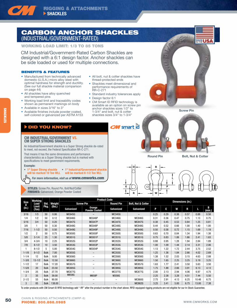
RIGGING & ATTACHMENTS
50 WWW.CMWORKS.COM
SHACKLES
CHAIN & RIGGING ATTACHMENTS (CMRP-6)
PHONE: 800.888.0985
SHACKLES
CARboN ANCHoR SHACKlES (INDUSTRIAL/GOVERNMENT-RATED)
Manufactured from technically advanced domestic (U.S.A.) micro alloy steel with optimal hardness for strength and ductility. (See our full shackle material comparison on page 44)
All shackles have alloy quenched and tempered pins
Working load limit and traceability codes shown as permanent markings on body
Available in sizes 3/16" to 3" Available finishes include powder coated,
self-colored or galvanized per ASTM A153
All bolt, nut & cotter shackles have thread-protected ends
Shackles meet dimensional and performance requirements of RR-C-271
Standard industry tolerances apply Design factor 6:1 CM Smart ID RFID technology is
available as an option on screw pin anchor shackles sizes 1/2" to 1-3/4" and bolt, nut & cotter shackles sizes 3/4" to 1-3/4"
bENEfITS & fEATuRES
WORKING LOAD LIMIT: 1/3 TO 85 TONS
SizeD
(in.)
Working Load Limit(Ton)
Std.Pkg.
Weight(lbs.)
Product CodeDimensions (in.)
Screw Pin Round Pin Bolt, Nut & Cotter
Galvanized Orange Powder Coated Galvanized Galvanized P E W R L B
(min.)3/16 1/3 50 0.06 MC645G – MC345G – 0.25 0.29 0.38 0.57 0.88 0.581/4 1/2 50 0.12 MC646G MC646P MC346G MC846G 0.31 0.36 0.47 0.75 1.13 0.755/16 3/4 50 0.20 MC647G MC647P MC347G MC847G 0.38 0.45 0.53 0.84 1.25 0.813/8 1 50 0.30 MC648G MC648P MC348G MC848G 0.44 0.52 0.66 1.00 1.40 1.007/16 1-1/2 50 0.50 MC649G MC649P MC349G MC849G 0.50 0.58 0.72 1.15 1.69 1.191/2 2 50 0.75 MC650G MC650P MC350G MC850G 0.63 0.70 0.84 1.34 1.94 1.385/8 3-1/4 25 1.30 MC651G MC651P MC351G MC851G 0.75 0.83 1.06 1.66 2.41 1.633/4 4-3/4 10 2.25 MC652G MC652P MC352G MC852G 0.88 0.95 1.28 1.94 2.84 1.897/8 6-1/2 10 3.50 MC653G MC653P MC353G MC853G 1.00 1.09 1.44 2.14 3.31 2.061 8-1/2 5 5.00 MC654G MC654P MC354G MC854G 1.13 1.22 1.72 2.44 3.75 2.52
1-1/8 9-1/2 Bulk 7.00 MC655G – MC355G MC855G 1.25 1.36 1.84 2.66 4.02 2.691-1/4 12 Bulk 9.00 MC656G – MC356G MC856G 1.38 1.52 2.03 3.15 4.63 2.881-3/8 13-1/2 Bulk 12.50 MC666G – MC366G MC866G 1.50 1.65 2.25 3.25 5.19 3.251-1/2 17 Bulk 17.20 MC657G – MC357G MC857G 1.63 1.77 2.41 3.50 5.63 3.501-5/8 20 Bulk 23.50 MC685G – MC385G MC885G 1.75 1.88 2.66 3.91 6.13 4.131-3/4 25 Bulk 27.70 MC677G – MC377G MC877G 2.00 2.13 2.94 4.06 6.97 4.75
2 35 Bulk 39.00 M658G M658P M358G – 2.25 2.38 3.28 4.51 7.44 5.502-1/2 55 Bulk 90.00 – – – MC860G 2.75 2.91 4.13 6.25 10.48 6.75
3 85 Bulk 138.00 – – – MC862G 3.25 3.41 5.00 6.75 13.00 7.38
Bolt, Nut & Cotter
Screw Pin
Round Pin
For more information, visit us at www.cmworks.com
An Industrial/Government shackle is a Super Strong shackle de-rated to meet, not exceed, the Federal Specification RR-C-271.
That means it has the same dimensions and performance characteristics as a Super Strong shackle but is marked with specifications to meet government requirements.
Example: 1" Super Strong shackle
will be marked 10 Ton WLL 1" Industrial/Government shackle
will be marked 8-1/2 Ton WLL
CM INDUSTRIAL/GOVERNMENT VS. CM SUPER STRONG SHACKLES
dId you KNow?
CM Industrial/Government-Rated Carbon Shackles are designed with a 6:1 design factor. Anchor shackles can be side loaded or used for multiple connections.
E
D B
R W
L
PE
D B
R W
L
PE
D B
R W
L
PSTYLES: Screw Pin, Round Pin, Bolt/Nut/CotterFINISHES: Galvanized, Orange Powder Coated
To order products with CM Smart ID RFID technology add “-RF” after the product number in the chart above. RFID-equipped rigging products are not eligible for our In-Stock Guarantee.
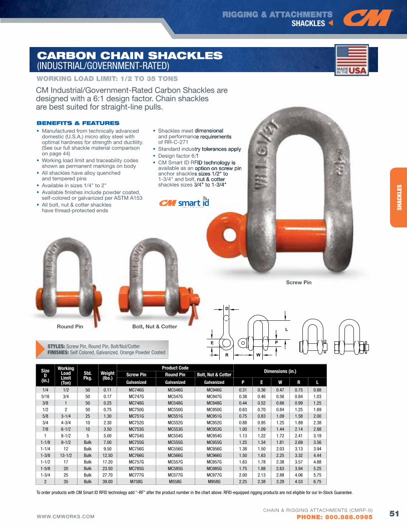
RIGGING & ATTACHMENTS
51WWW.CMWORKS.COM
SHACKLES
CHAIN & RIGGING ATTACHMENTS (CMRP-6)
PHONE: 800.888.0985
SHAC
KLES
CARboN CHAIN SHACKlES (INDUSTRIAL/GOVERNMENT-RATED)
Manufactured from technically advanced domestic (U.S.A.) micro alloy steel with optimal hardness for strength and ductility. (See our full shackle material comparison on page 44)
Working load limit and traceability codes shown as permanent markings on body
All shackles have alloy quenched and tempered pins
Available in sizes 1/4" to 2" Available finishes include powder coated,
self-colored or galvanized per ASTM A153 All bolt, nut & cotter shackles
have thread-protected ends
Shackles meet dimensional and performance requirements of RR-C-271
Standard industry tolerances apply Design factor 6:1 CM Smart ID RFID technology is
available as an option on screw pin anchor shackles sizes 1/2" to 1-3/4" and bolt, nut & cotter shackles sizes 3/4" to 1-3/4"
bENEfITS & fEATuRES
WORKING LOAD LIMIT: 1/2 TO 35 TONS
SizeD
(in.)
Working Load Limit(Ton)
Std.Pkg.
Weight(lbs.)
Product CodeDimensions (in.)
Screw Pin Round Pin Bolt, Nut & Cotter
Galvanized Galvanized Galvanized P E W R L
1/4 1/2 50 0.11 MC746G MC546G MC946G 0.31 0.36 0.47 0.75 0.885/16 3/4 50 0.17 MC747G MC547G MC947G 0.38 0.46 0.56 0.84 1.033/8 1 50 0.25 MC748G MC548G MC948G 0.44 0.52 0.66 0.99 1.251/2 2 50 0.75 MC750G MC550G MC950G 0.63 0.70 0.84 1.25 1.695/8 3-1/4 25 1.30 MC751G MC551G MC951G 0.75 0.83 1.09 1.58 2.003/4 4-3/4 10 2.30 MC752G MC552G MC952G 0.88 0.95 1.25 1.89 2.387/8 6-1/2 10 3.50 MC753G MC553G MC953G 1.00 1.09 1.44 2.14 2.881 8-1/2 5 5.00 MC754G MC554G MC954G 1.13 1.22 1.72 2.41 3.19
1-1/8 9-1/2 Bulk 7.00 MC755G MC555G MC955G 1.25 1.34 1.81 2.69 3.561-1/4 12 Bulk 9.50 MC756G MC556G MC956G 1.38 1.50 2.03 3.13 3.941-3/8 13-1/2 Bulk 12.50 MC766G MC566G MC966G 1.50 1.63 2.25 3.32 4.441-1/2 17 Bulk 17.20 MC757G MC557G MC957G 1.63 1.78 2.38 3.57 4.881-5/8 20 Bulk 23.50 MC785G MC585G MC985G 1.75 1.88 2.63 3.94 5.251-3/4 25 Bulk 27.70 MC777G MC577G MC977G 2.00 2.13 2.88 4.06 5.75
2 35 Bulk 39.00 M758G M558G M958G 2.25 2.38 3.28 4.53 6.75
Shackles meet dimensional and performance requirements
Standard industry tolerances applyDesign factor 6:1CM Smart ID RFID technology is available as an option on screw pin anchor shackles sizes 1/2" to 1-3/4" and bolt, nut & cotter shackles sizes 3/4" to 1-3/4"
Bolt, Nut & Cotter
Screw Pin
Round Pin
CM Industrial/Government-Rated Carbon Shackles are designed with a 6:1 design factor. Chain shackles are best suited for straight-line pulls.
E
D
R W
L
PE
D
R W
L
PE
D
R W
L
PSTYLES: Screw Pin, Round Pin, Bolt/Nut/CotterFINISHES: Self Colored, Galvanized, Orange Powder Coated
To order products with CM Smart ID RFID technology add “-RF” after the product number in the chart above. RFID-equipped rigging products are not eligible for our In-Stock Guarantee.
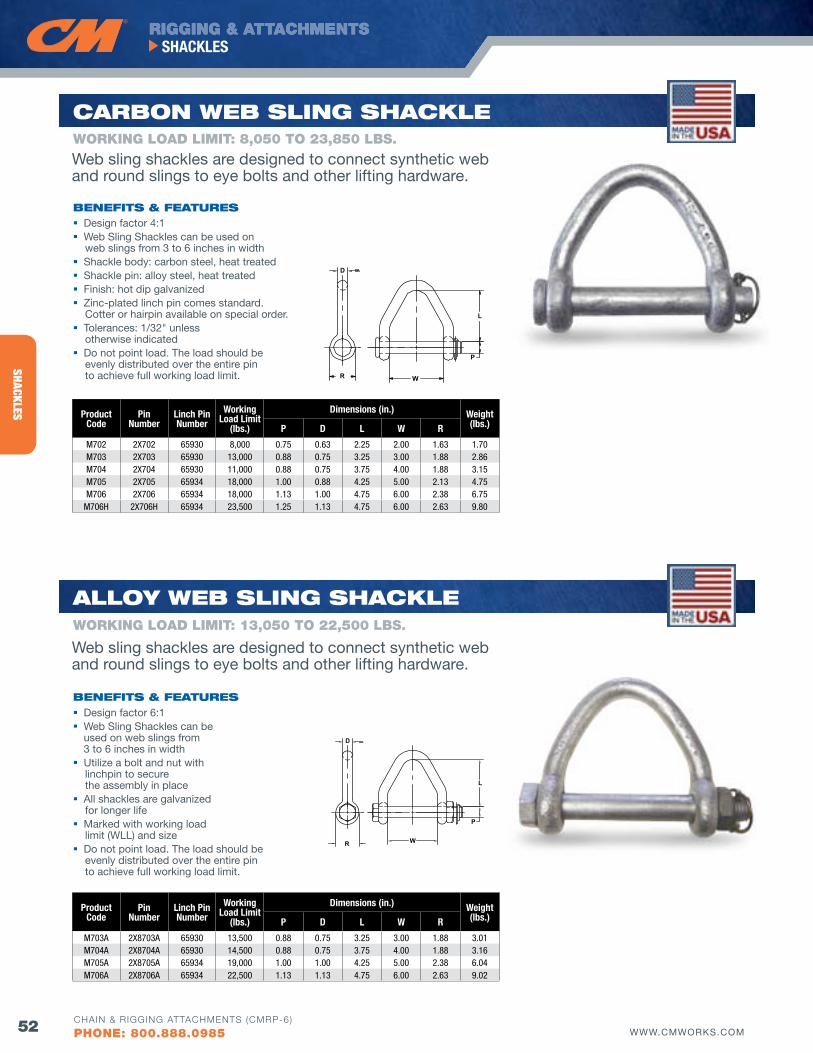
RIGGING & ATTACHMENTS
52 WWW.CMWORKS.COM
SHACKLES
CHAIN & RIGGING ATTACHMENTS (CMRP-6)
PHONE: 800.888.0985
SHACKLES
D
R W
P
L
Product Code
Pin Number
Linch Pin Number
Working Load Limit
(lbs.)
Dimensions (in.) Weight(lbs.)P D L W R
M703A 2X8703A 65930 13,500 0.88 0.75 3.25 3.00 1.88 3.01 M704A 2X8704A 65930 14,500 0.88 0.75 3.75 4.00 1.88 3.16 M705A 2X8705A 65934 19,000 1.00 1.00 4.25 5.00 2.38 6.04 M706A 2X8706A 65934 22,500 1.13 1.13 4.75 6.00 2.63 9.02
D
R W
P
L
Product Code
Pin Number
Linch Pin Number
Working Load Limit
(lbs.)
Dimensions (in.) Weight(lbs.)P D L W R
M702 2X702 65930 8,000 0.75 0.63 2.25 2.00 1.63 1.70 M703 2X703 65930 13,000 0.88 0.75 3.25 3.00 1.88 2.86 M704 2X704 65930 11,000 0.88 0.75 3.75 4.00 1.88 3.15 M705 2X705 65934 18,000 1.00 0.88 4.25 5.00 2.13 4.75 M706 2X706 65934 18,000 1.13 1.00 4.75 6.00 2.38 6.75
M706H 2X706H 65934 23,500 1.25 1.13 4.75 6.00 2.63 9.80
CARboN wEb SlING SHACKlE
Design factor 4:1 Web Sling Shackles can be used on
web slings from 3 to 6 inches in width Shackle body: carbon steel, heat treated Shackle pin: alloy steel, heat treated Finish: hot dip galvanized Zinc-plated linch pin comes standard.
Cotter or hairpin available on special order. Tolerances: 1/32" unless
otherwise indicated Do not point load. The load should be
evenly distributed over the entire pin to achieve full working load limit.
bENEfITS & fEATuRES
Alloy wEb SlING SHACKlE
Design factor 6:1 Web Sling Shackles can be
used on web slings from 3 to 6 inches in width
Utilize a bolt and nut with linchpin to secure the assembly in place
All shackles are galvanized for longer life
Marked with working load limit (WLL) and size
Do not point load. The load should be evenly distributed over the entire pin to achieve full working load limit.
bENEfITS & fEATuRES
WORKING LOAD LIMIT: 13,050 TO 22,500 LbS.
WORKING LOAD LIMIT: 8,050 TO 23,850 LbS.
Web sling shackles are designed to connect synthetic web and round slings to eye bolts and other lifting hardware.
Web sling shackles are designed to connect synthetic web and round slings to eye bolts and other lifting hardware.
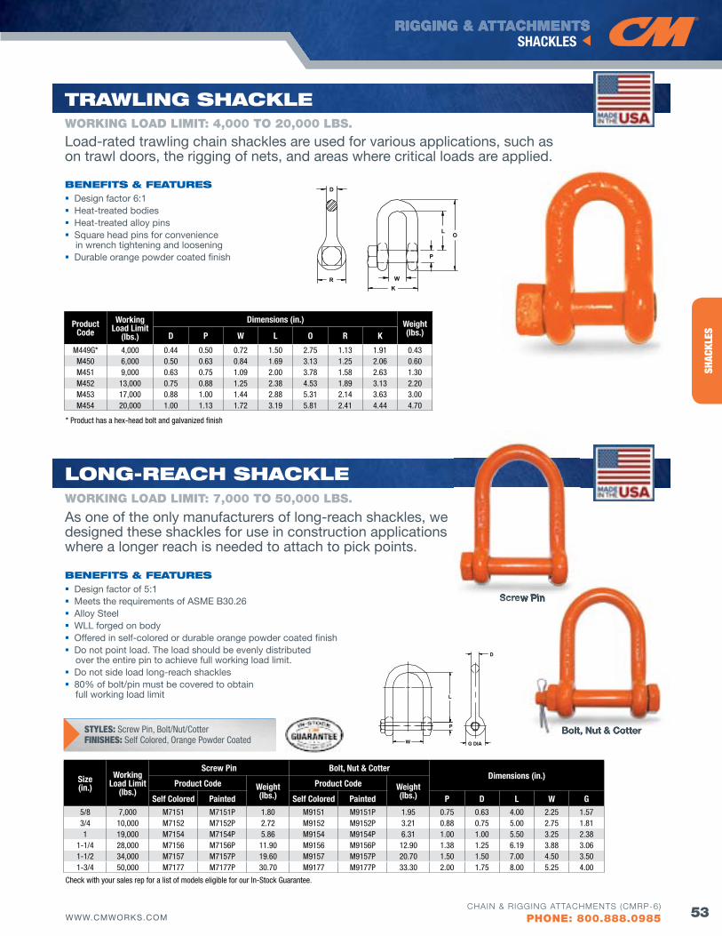
RIGGING & ATTACHMENTS
53WWW.CMWORKS.COM
SHACKLES
CHAIN & RIGGING ATTACHMENTS (CMRP-6)
PHONE: 800.888.0985
SHAC
KLES
L
P
W
D
G DIA
Size(in.)
Working Load Limit
(lbs.)
Screw Pin Bolt, Nut & CotterDimensions (in.)
Product Code Weight (lbs.)
Product Code Weight (lbs.)Self Colored Painted Self Colored Painted P D L W G
5/8 7,000 M7151 M7151P 1.80 M9151 M9151P 1.95 0.75 0.63 4.00 2.25 1.57 3/4 10,000 M7152 M7152P 2.72 M9152 M9152P 3.21 0.88 0.75 5.00 2.75 1.81 1 19,000 M7154 M7154P 5.86 M9154 M9154P 6.31 1.00 1.00 5.50 3.25 2.38
1-1/4 28,000 M7156 M7156P 11.90 M9156 M9156P 12.90 1.38 1.25 6.19 3.88 3.06 1-1/2 34,000 M7157 M7157P 19.60 M9157 M9157P 20.70 1.50 1.50 7.00 4.50 3.50 1-3/4 50,000 M7177 M7177P 30.70 M9177 M9177P 33.30 2.00 1.75 8.00 5.25 4.00
R
D
KW
OL
P
Product Code
Working Load Limit
(lbs.)
Dimensions (in.) Weight(lbs.)D P W L O R K
M449G* 4,000 0.44 0.50 0.72 1.50 2.75 1.13 1.91 0.43 M450 6,000 0.50 0.63 0.84 1.69 3.13 1.25 2.06 0.60 M451 9,000 0.63 0.75 1.09 2.00 3.78 1.58 2.63 1.30 M452 13,000 0.75 0.88 1.25 2.38 4.53 1.89 3.13 2.20 M453 17,000 0.88 1.00 1.44 2.88 5.31 2.14 3.63 3.00 M454 20,000 1.00 1.13 1.72 3.19 5.81 2.41 4.44 4.70
TRAwlING SHACKlE
Design factor 6:1 Heat-treated bodies Heat-treated alloy pins Square head pins for convenience
in wrench tightening and loosening Durable orange powder coated finish
bENEfITS & fEATuRES
WORKING LOAD LIMIT: 4,000 TO 20,000 LbS.
Load-rated trawling chain shackles are used for various applications, such as on trawl doors, the rigging of nets, and areas where critical loads are applied.
As one of the only manufacturers of long-reach shackles, we designed these shackles for use in construction applications where a longer reach is needed to attach to pick points.
* Product has a hex-head bolt and galvanized finish
Check with your sales rep for a list of models eligible for our In-Stock Guarantee.
loNG-REACH SHACKlE
Design factor of 5:1 Meets the requirements of ASME B30.26 Alloy Steel WLL forged on body Offered in self-colored or durable orange powder coated finish Do not point load. The load should be evenly distributed
over the entire pin to achieve full working load limit. Do not side load long-reach shackles 80% of bolt/pin must be covered to obtain
full working load limit
bENEfITS & fEATuRES
WORKING LOAD LIMIT: 7,000 TO 50,000 LbS.
Bolt, Nut & Cotter
Screw Pin
Bolt, Nut & Cotter
Screw PinScrew PinScrew Pin
STYLES: Screw Pin, Bolt/Nut/CotterFINISHES: Self Colored, Orange Powder Coated
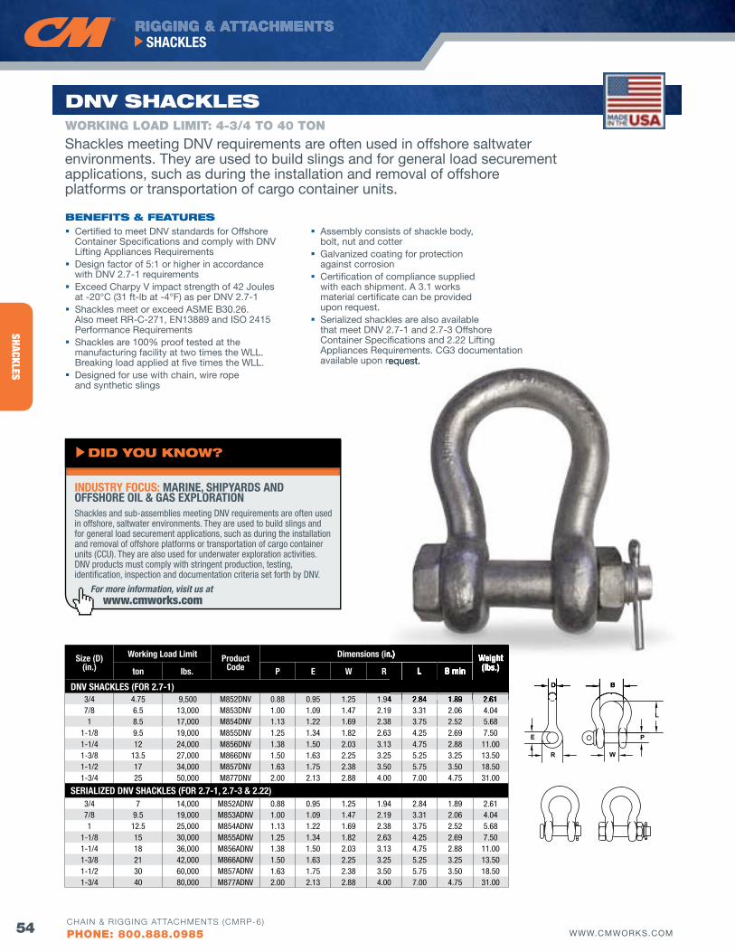
RIGGING & ATTACHMENTS
54 WWW.CMWORKS.COM
SHACKLES
CHAIN & RIGGING ATTACHMENTS (CMRP-6)
PHONE: 800.888.0985
SHACKLES
Size (D)(in.)
Working Load Limit ProductCode
Dimensions (in.) Weight(lbs.)ton lbs. P E W R L B min
DNV SHACKLES (fOR 2.7-1)3/4 4.75 9,500 M852DNV 0.88 0.95 1.25 1.94 2.84 1.89 2.617/8 6.5 13,000 M853DNV 1.00 1.09 1.47 2.19 3.31 2.06 4.041 8.5 17,000 M854DNV 1.13 1.22 1.69 2.38 3.75 2.52 5.68
1-1/8 9.5 19,000 M855DNV 1.25 1.34 1.82 2.63 4.25 2.69 7.501-1/4 12 24,000 M856DNV 1.38 1.50 2.03 3.13 4.75 2.88 11.001-3/8 13.5 27,000 M866DNV 1.50 1.63 2.25 3.25 5.25 3.25 13.501-1/2 17 34,000 M857DNV 1.63 1.75 2.38 3.50 5.75 3.50 18.501-3/4 25 50,000 M877DNV 2.00 2.13 2.88 4.00 7.00 4.75 31.00
SERIALIzED DNV SHACKLES (fOR 2.7-1, 2.7-3 & 2.22)3/4 7 14,000 M852ADNV 0.88 0.95 1.25 1.94 2.84 1.89 2.617/8 9.5 19,000 M853ADNV 1.00 1.09 1.47 2.19 3.31 2.06 4.041 12.5 25,000 M854ADNV 1.13 1.22 1.69 2.38 3.75 2.52 5.68
1-1/8 15 30,000 M855ADNV 1.25 1.34 1.82 2.63 4.25 2.69 7.501-1/4 18 36,000 M856ADNV 1.38 1.50 2.03 3.13 4.75 2.88 11.001-3/8 21 42,000 M866ADNV 1.50 1.63 2.25 3.25 5.25 3.25 13.501-1/2 30 60,000 M857ADNV 1.63 1.75 2.38 3.50 5.75 3.50 18.501-3/4 40 80,000 M877ADNV 2.00 2.13 2.88 4.00 7.00 4.75 31.00
E
D B
R W
L
P
dNv SHACKlES
Certified to meet DNv standards for Offshore Container Specifications and comply with DNv Lifting Appliances Requirements
Design factor of 5:1 or higher in accordance with DNv 2.7-1 requirements
Exceed Charpy v impact strength of 42 Joules at -20°C (31 ft-lb at -4°F) as per DNv 2.7-1
Shackles meet or exceed ASME B30.26. Also meet RR-C-271, EN13889 and ISO 2415 Performance Requirements
Shackles are 100% proof tested at the manufacturing facility at two times the WLL. Breaking load applied at five times the WLL.
Designed for use with chain, wire rope and synthetic slings
bENEfITS & fEATuRES
WORKING LOAD LIMIT: 4-3/4 TO 40 TON
Assembly consists of shackle body, bolt, nut and cotter
Galvanized coating for protection against corrosion
Certification of compliance supplied with each shipment. A 3.1 works material certificate can be provided upon request.
Serialized shackles are also available that meet DNv 2.7-1 and 2.7-3 Offshore Container Specifications and 2.22 Lifting Appliances Requirements. CG3 documentation available upon request.
Dimensions (in.) Weight(lbs.)L B min
1.94 2.84 1.89 2.61
D BD BD BD BD B
available upon request.
For more information, visit us at www.cmworks.com
Shackles and sub-assemblies meeting DNV requirements are often used in offshore, saltwater environments. They are used to build slings and for general load securement applications, such as during the installation and removal of offshore platforms or transportation of cargo container units (CCU). They are also used for underwater exploration activities. DNV products must comply with stringent production, testing, identification, inspection and documentation criteria set forth by DNV.
INDUSTRY fOCUS: MARINE, SHIPYARDS AND OffSHORE OIL & GAS EXPLORATION
dId you KNow?
Shackles meeting DNv requirements are often used in offshore saltwater environments. They are used to build slings and for general load securement applications, such as during the installation and removal of offshore platforms or transportation of cargo container units.
E
D B
R W
L
P
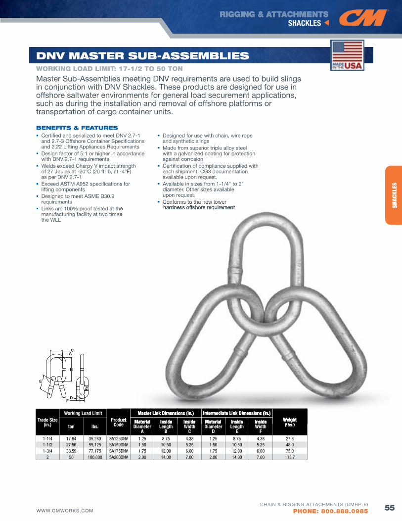
RIGGING & ATTACHMENTS
55WWW.CMWORKS.COM
SHACKLES
CHAIN & RIGGING ATTACHMENTS (CMRP-6)
PHONE: 800.888.0985
SHAC
KLES
Trade Size(in.)
Working Load LimitProduct
Code
Master Link Dimensions (in.) Intermediate Link Dimensions (in.)Weight(lbs.)ton lbs.
Material Diameter
A
Inside Length
B
Inside Width
C
Material Diameter
D
Inside Length
E
Inside Width
f1-1/4 17.64 35,280 SA125DNV 1.25 8.75 4.38 1.25 8.75 4.38 27.81-1/2 27.56 55,125 SA150DNV 1.50 10.50 5.25 1.50 10.50 5.25 48.01-3/4 38.59 77,175 SA175DNV 1.75 12.00 6.00 1.75 12.00 6.00 75.0
2 50 100,000 SA200DNV 2.00 14.00 7.00 2.00 14.00 7.00 113.7
dNv MASTER Sub-ASSEMblIES
Certified and serialized to meet DNv 2.7-1 and 2.7-3 Offshore Container Specifications and 2.22 Lifting Appliances Requirements
Design factor of 5:1 or higher in accordance with DNv 2.7-1 requirements
Welds exceed Charpy v impact strength of 27 Joules at -20ºC (20 ft-lb, at -4ºF) as per DNv 2.7-1
Exceed ASTM A952 specifications for lifting components
Designed to meet ASME B30.9 requirements
Links are 100% proof tested at the manufacturing facility at two times the WLL
Designed for use with chain, wire rope and synthetic slings
Made from superior triple alloy steel with a galvanized coating for protection against corrosion
Certification of compliance supplied with each shipment. CG3 documentation available upon request.
Available in sizes from 1-1/4" to 2" diameter. Other sizes available upon request.
Conforms to the new lower hardness offshore requirement
bENEfITS & fEATuRES
WORKING LOAD LIMIT: 17-1/2 TO 50 TON
Flat
A
B
C
D
E
F
Master Sub-Assemblies meeting DNv requirements are used to build slings in conjunction with DNv Shackles. These products are designed for use in offshore saltwater environments for general load securement applications, such as during the installation and removal of offshore platforms or transportation of cargo container units.
SHAC
KLES
ProductCode
Master Link Dimensions (in.) Intermediate Link Dimensions (in.)Weight(lbs.)Material Inside Inside Material Inside Inside
Links are 100% proof tested at the manufacturing facility at two times
Conforms to the new lower hardness offshore requirement
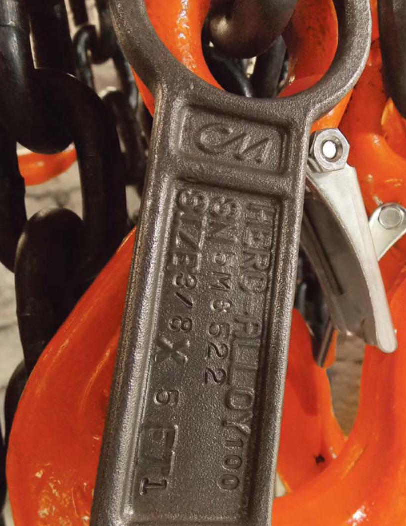
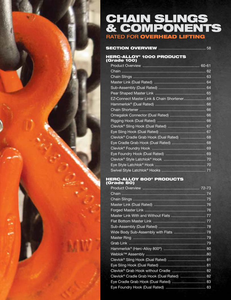
RATED FOR ovERHEAd lIfTING
SECTIoN ovERvIEw ............................................. 58
HERC-Alloy® 1000 PRoduCTS (Grade 100) Product Overview ...................................................... 60-61
Chain ................................................................................ 62
Chain Slings ..................................................................... 63
Master Link (Dual Rated) ................................................. 64
Sub-Assembly (Dual Rated) ............................................. 64
Pear Shaped Master Link ................................................ 65
EZ•Connect Master Link & Chain Shortener ......................65
Hammerlok® (Dual Rated) ................................................ 66
Chain Shortener ............................................................... 66
Omegalok Connector (Dual Rated) .................................. 66
Rigging Hook (Dual Rated) .............................................. 66
Clevlok® Sling Hook (Dual Rated) .................................... 67
Eye Sling Hook (Dual Rated) ............................................ 67
Clevlok® Cradle Grab Hook (Dual Rated) ........................ 68
Eye Cradle Grab Hook (Dual Rated) ................................ 68
Clevlok® Foundry Hook ................................................... 69
Eye Foundry Hook (Dual Rated) ...................................... 69
Clevlok® Style Latchlok® Hook ........................................ 70
Eye Style Latchlok® Hook ................................................ 70
Swivel Style Latchlok® Hooks .......................................... 71
HERC-Alloy 800® PRoduCTS (Grade 80) Product Overview ...................................................... 72-73
Chain ................................................................................ 74
Chain Slings ..................................................................... 75
Master Link (Dual Rated) ................................................. 76
Forged Master Link .......................................................... 76
Master Link With and Without Flats ................................. 77
Flat Bottom Master Link .................................................. 77
Sub-Assembly (Dual Rated) ............................................. 78
Wide Body Sub-Assembly with Flats .............................. 78
Master Ring ..................................................................... 79
Grab Link ......................................................................... 79
Hammerlok® (Herc-Alloy 800®) ........................................ 80
Weblok™ Assembly ..........................................................80
Clevlok® Sling Hook (Dual Rated) .................................... 81
Eye Sling Hook (Dual Rated) ............................................ 81
Clevlok® Grab Hook without Cradle ................................ 82
Clevlok® Cradle Grab Hook (Dual Rated) ........................ 82
Eye Cradle Grab Hook (Dual Rated) ................................ 83
Eye Foundry Hook (Dual Rated) ...................................... 83
CHAIN SlINGS & CoMPoNENTS
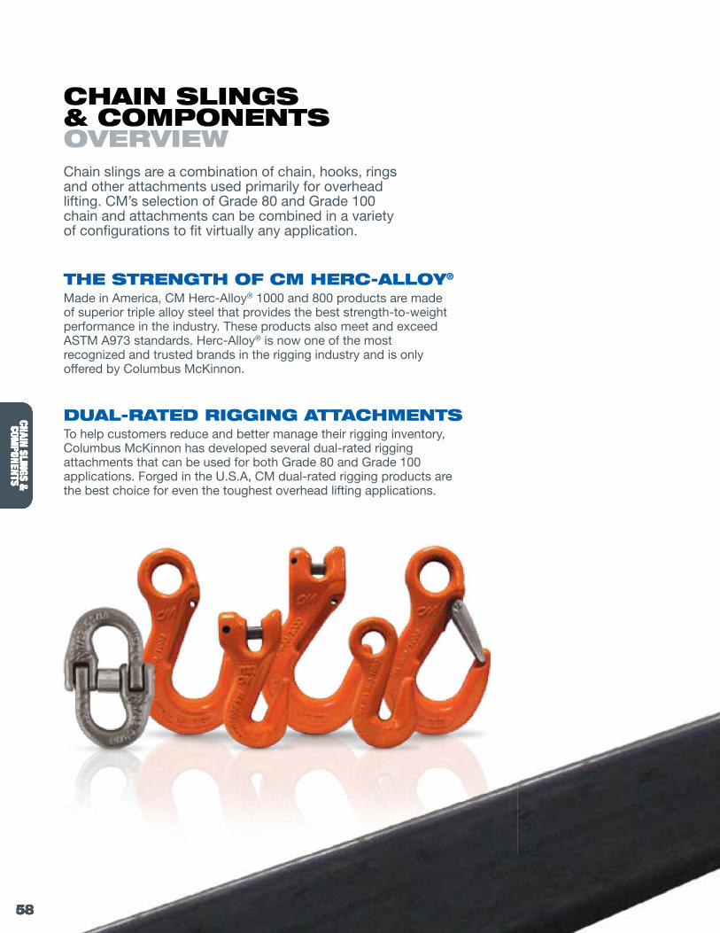
58 WWW.CMWORKS.COM
CHAIN SLINGS & COMPONENTS
CHAIN & RIGGING ATTACHMENTS (CMRP-6)
PHONE: 800.888.0985
CHAIN SLINGS &COM
PONENTS
RIGGING & ATTACHMENTS
58
CHAIN SLINGS & COMPONENTS
CHAIN SLINGS &COM
PONENTS
Chain slings are a combination of chain, hooks, rings and other attachments used primarily for overhead lifting. CM’s selection of Grade 80 and Grade 100 chain and attachments can be combined in a variety of configurations to fit virtually any application.
THE STRENGTH of CM HERC-Alloy®
Made in America, CM Herc-Alloy® 1000 and 800 products are made of superior triple alloy steel that provides the best strength-to-weight performance in the industry. These products also meet and exceed ASTM A973 standards. Herc-Alloy® is now one of the most recognized and trusted brands in the rigging industry and is only offered by Columbus McKinnon.
duAl-RATEd RIGGING ATTACHMENTS To help customers reduce and better manage their rigging inventory, Columbus McKinnon has developed several dual-rated rigging attachments that can be used for both Grade 80 and Grade 100 applications. Forged in the U.S.A, CM dual-rated rigging products are the best choice for even the toughest overhead lifting applications.
CHAIN SlINGS & CoMPoNENTS ovERvIEw
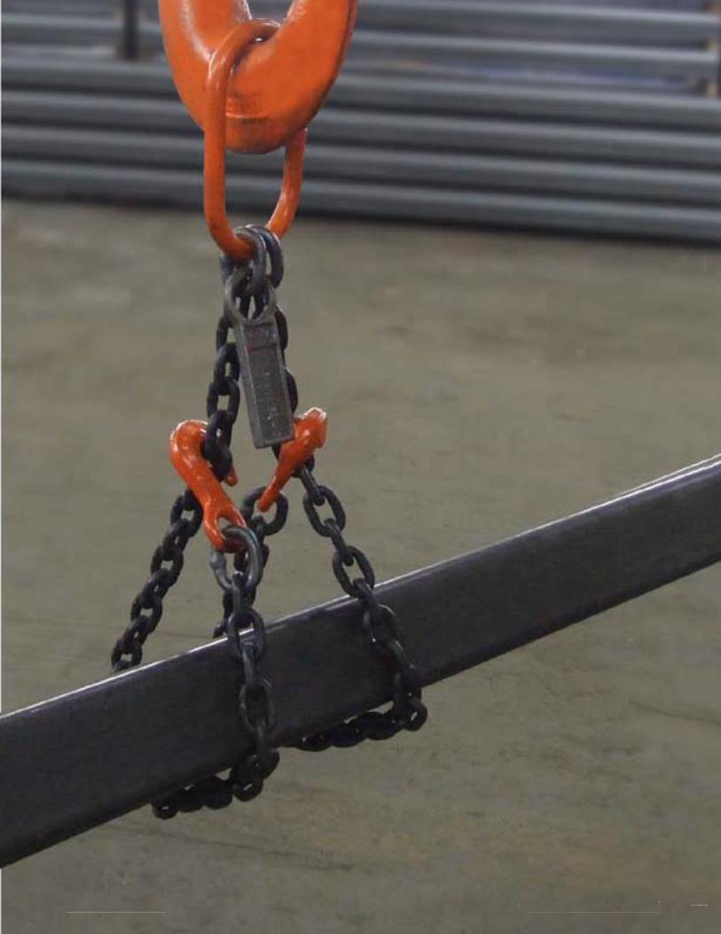
59WWW.CMWORKS.COM
CHAIN SLINGS & COMPONENTS
CHAIN & RIGGING ATTACHMENTS (CMRP-6)
PHONE: 800.888.0985
HERC
-ALL
OY® 1
000
CHAI
N SL
INGS
&CO
MPO
NENT
S
59WWW.CMWORKS.COMCHAIN & RIGGING ATTACHMENTS (CMRP-6)
PHONE: 800.888.0985
CHAI
N SL
INGS
&CO
MPO
NENT
S
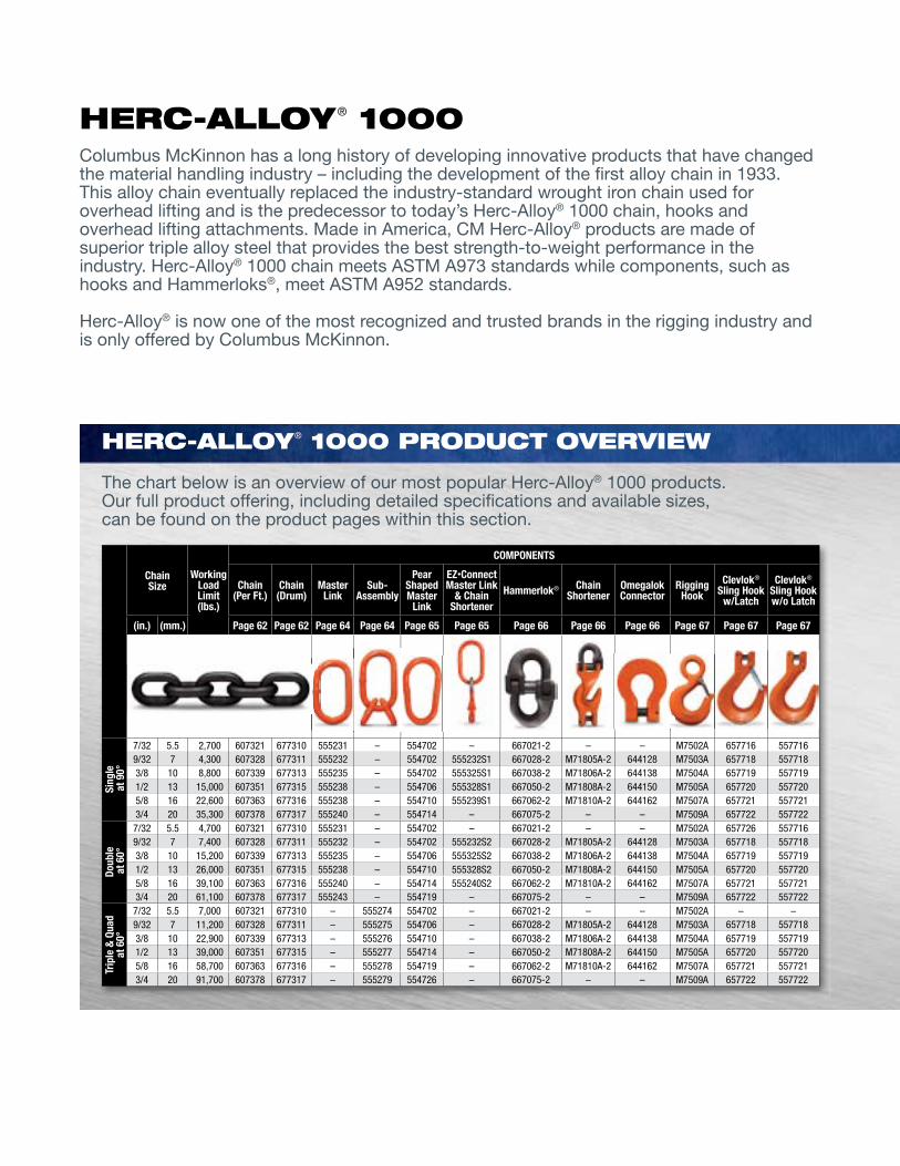
RIGGING & ATTACHMENTS
60 WWW.CMWORKS.COM
CHAIN SLINGS & COMPONENTS HERC-ALLOY® 1000 (GRADE 100)
CHAIN & RIGGING ATTACHMENTS (CMRP-6)
PHONE: 800.888.0985
CHAIN SLINGS &
COMPONENTS
Columbus McKinnon has a long history of developing innovative products that have changed the material handling industry – including the development of the first alloy chain in 1933. This alloy chain eventually replaced the industry-standard wrought iron chain used for overhead lifting and is the predecessor to today’s Herc-Alloy® 1000 chain, hooks and overhead lifting attachments. Made in America, CM Herc-Alloy® products are made of superior triple alloy steel that provides the best strength-to-weight performance in the industry. Herc-Alloy® 1000 chain meets ASTM A973 standards while components, such as hooks and Hammerloks®, meet ASTM A952 standards.
Herc-Alloy® is now one of the most recognized and trusted brands in the rigging industry and is only offered by Columbus McKinnon.
The chart below is an overview of our most popular Herc-Alloy® 1000 products. Our full product offering, including detailed specifications and available sizes, can be found on the product pages within this section.
HERC-Alloy® 1000 PRoduCT ovERvIEw
ChainSize
Working Load Limit(lbs.)
COMPONENTS
Chain (Per ft.)
Chain (Drum)
Master Link
Sub- Assembly
Pear Shaped Master
Link
Ez•Connect Master Link
& Chain Shortener
Hammerlok® Chain Shortener
Omegalok Connector
Rigging Hook
Clevlok® Sling Hook
w/Latch
Clevlok® Sling Hookw/o Latch
(in.) (mm.) Page 62 Page 62 Page 64 Page 64 Page 65 Page 65 Page 66 Page 66 Page 66 Page 67 Page 67 Page 67
Sing
le
at 9
0°
7/32 5.5 2,700 607321 677310 555231 – 554702 – 667021-2 – – M7502A 657716 5577169/32 7 4,300 607328 677311 555232 – 554702 555232S1 667028-2 M71805A-2 644128 M7503A 657718 5577183/8 10 8,800 607339 677313 555235 – 554702 555325S1 667038-2 M71806A-2 644138 M7504A 657719 5577191/2 13 15,000 607351 677315 555238 – 554706 555328S1 667050-2 M71808A-2 644150 M7505A 657720 5577205/8 16 22,600 607363 677316 555238 – 554710 555239S1 667062-2 M71810A-2 644162 M7507A 657721 5577213/4 20 35,300 607378 677317 555240 – 554714 – 667075-2 – – M7509A 657722 557722
Doub
le
at 6
0°
7/32 5.5 4,700 607321 677310 555231 – 554702 – 667021-2 – – M7502A 657726 5577169/32 7 7,400 607328 677311 555232 – 554702 555232S2 667028-2 M71805A-2 644128 M7503A 657718 5577183/8 10 15,200 607339 677313 555235 – 554706 555325S2 667038-2 M71806A-2 644138 M7504A 657719 5577191/2 13 26,000 607351 677315 555238 – 554710 555328S2 667050-2 M71808A-2 644150 M7505A 657720 5577205/8 16 39,100 607363 677316 555240 – 554714 555240S2 667062-2 M71810A-2 644162 M7507A 657721 5577213/4 20 61,100 607378 677317 555243 – 554719 – 667075-2 – – M7509A 657722 557722
Trip
le &
qua
d
at 6
0°
7/32 5.5 7,000 607321 677310 – 555274 554702 – 667021-2 – – M7502A – –9/32 7 11,200 607328 677311 – 555275 554706 – 667028-2 M71805A-2 644128 M7503A 657718 5577183/8 10 22,900 607339 677313 – 555276 554710 – 667038-2 M71806A-2 644138 M7504A 657719 5577191/2 13 39,000 607351 677315 – 555277 554714 – 667050-2 M71808A-2 644150 M7505A 657720 5577205/8 16 58,700 607363 677316 – 555278 554719 – 667062-2 M71810A-2 644162 M7507A 657721 5577213/4 20 91,700 607378 677317 – 555279 554726 – 667075-2 – – M7509A 657722 557722
HERC-Alloy® 1000
–
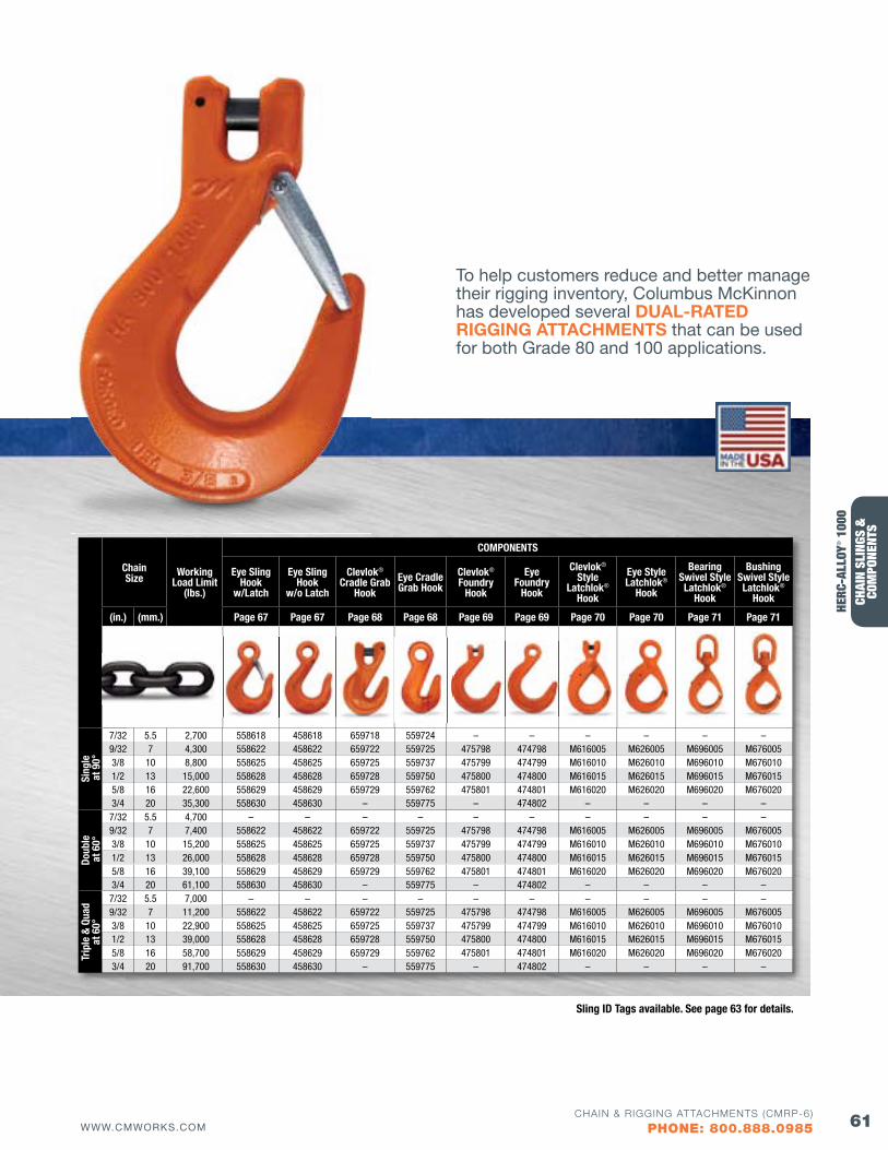
61WWW.CMWORKS.COMCHAIN & RIGGING ATTACHMENTS (CMRP-6)
PHONE: 800.888.0985
CHAI
N SL
INGS
&
COM
PONE
NTS
CHAIN SLINGS & COMPONENTS HERC-ALLOY® 1000 (GRADE 100)
Chain Size Working
Load Limit(lbs.)
COMPONENTS
Eye Sling Hook
w/Latch
Eye Sling Hook
w/o Latch
Clevlok® Cradle Grab
HookEye Cradle Grab Hook
Clevlok® foundry
Hook
Eye foundry
Hook
Clevlok® Style
Latchlok® Hook
Eye Style Latchlok®
Hook
Bearing Swivel StyleLatchlok®
Hook
BushingSwivel StyleLatchlok®
Hook
(in.) (mm.) Page 67 Page 67 Page 68 Page 68 Page 69 Page 69 Page 70 Page 70 Page 71 Page 71
Sing
le
at 9
0°
7/32 5.5 2,700 558618 458618 659718 559724 – – – – – –9/32 7 4,300 558622 458622 659722 559725 475798 474798 M616005 M626005 M696005 M6760053/8 10 8,800 558625 458625 659725 559737 475799 474799 M616010 M626010 M696010 M6760101/2 13 15,000 558628 458628 659728 559750 475800 474800 M616015 M626015 M696015 M6760155/8 16 22,600 558629 458629 659729 559762 475801 474801 M616020 M626020 M696020 M6760203/4 20 35,300 558630 458630 – 559775 – 474802 – – – –
Doub
le
at 6
0°
7/32 5.5 4,700 – – – – – – – – – –9/32 7 7,400 558622 458622 659722 559725 475798 474798 M616005 M626005 M696005 M6760053/8 10 15,200 558625 458625 659725 559737 475799 474799 M616010 M626010 M696010 M6760101/2 13 26,000 558628 458628 659728 559750 475800 474800 M616015 M626015 M696015 M6760155/8 16 39,100 558629 458629 659729 559762 475801 474801 M616020 M626020 M696020 M6760203/4 20 61,100 558630 458630 – 559775 – 474802 – – – –
Trip
le &
qua
d
at 6
0°
7/32 5.5 7,000 – – – – – – – – – –9/32 7 11,200 558622 458622 659722 559725 475798 474798 M616005 M626005 M696005 M6760053/8 10 22,900 558625 458625 659725 559737 475799 474799 M616010 M626010 M696010 M6760101/2 13 39,000 558628 458628 659728 559750 475800 474800 M616015 M626015 M696015 M6760155/8 16 58,700 558629 458629 659729 559762 475801 474801 M616020 M626020 M696020 M6760203/4 20 91,700 558630 458630 – 559775 – 474802 – – – –
To help customers reduce and better manage their rigging inventory, Columbus McKinnon has developed several DUAL-RATED RIGGING ATTACHMENTS that can be used for both Grade 80 and 100 applications.
HERC
-ALL
OY® 1
000
Sling ID Tags available. See page 63 for details.
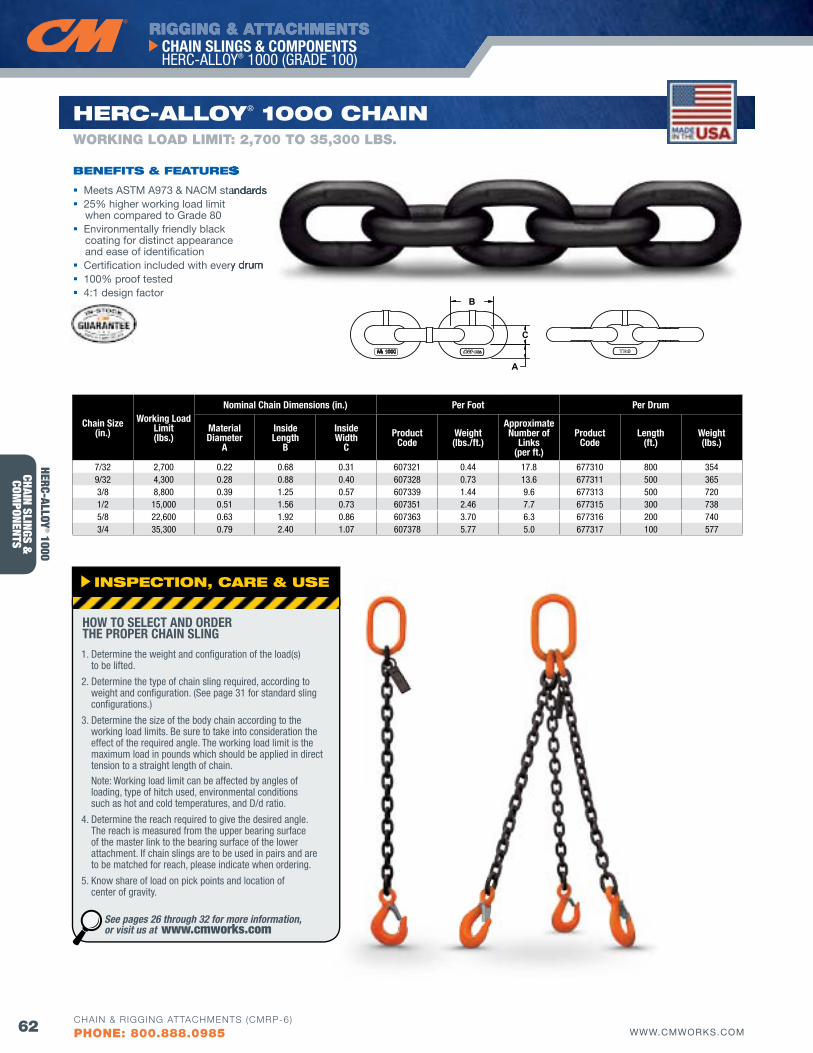
RIGGING & ATTACHMENTS
62 WWW.CMWORKS.COM
CHAIN SLINGS & COMPONENTS HERC-ALLOY® 1000 (GRADE 100)
CHAIN & RIGGING ATTACHMENTS (CMRP-6)
PHONE: 800.888.0985
CHAIN SLINGS &
COMPONENTS
A
B
C1000
Chain Size(in.)
Working Load Limit(lbs.)
Nominal Chain Dimensions (in.) Per foot Per Drum
Material Diameter
A
Inside Length
B
Inside Width
CProduct
CodeWeight(lbs./ft.)
Approximate Number of
Links(per ft.)
Product Code
Length(ft.)
Weight(lbs.)
7/32 2,700 0.22 0.68 0.31 607321 0.44 17.8 677310 800 3549/32 4,300 0.28 0.88 0.40 607328 0.73 13.6 677311 500 3653/8 8,800 0.39 1.25 0.57 607339 1.44 9.6 677313 500 7201/2 15,000 0.51 1.56 0.73 607351 2.46 7.7 677315 300 7385/8 22,600 0.63 1.92 0.86 607363 3.70 6.3 677316 200 7403/4 35,300 0.79 2.40 1.07 607378 5.77 5.0 677317 100 577
HERC-Alloy® 1000 CHAIN
Meets ASTM A973 & NACM standards 25% higher working load limit
when compared to Grade 80 Environmentally friendly black
coating for distinct appearance and ease of identification
Certification included with every drum 100% proof tested 4:1 design factor
bENEfITS & fEATuRES
WORKING LOAD LIMIT: 2,700 TO 35,300 LbS.
Meets ASTM A973 & NACM standards
Certification included with every drum
RES
INSPECTIoN, CARE & uSE
1. Determine the weight and configuration of the load(s) to be lifted.
2. Determine the type of chain sling required, according to weight and configuration. (See page 31 for standard sling configurations.)
3. Determine the size of the body chain according to the working load limits. Be sure to take into consideration the effect of the required angle. The working load limit is the maximum load in pounds which should be applied in direct tension to a straight length of chain. Note: Working load limit can be affected by angles of loading, type of hitch used, environmental conditions such as hot and cold temperatures, and D/d ratio.
4. Determine the reach required to give the desired angle. The reach is measured from the upper bearing surface of the master link to the bearing surface of the lower attachment. If chain slings are to be used in pairs and are to be matched for reach, please indicate when ordering.
5. Know share of load on pick points and location of center of gravity.
HOW TO SELECT AND ORDER THE PROPER CHAIN SLING
See pages 26 through 32 for more information, or visit us at www.cmworks.com
HERC-ALLOY® 1000
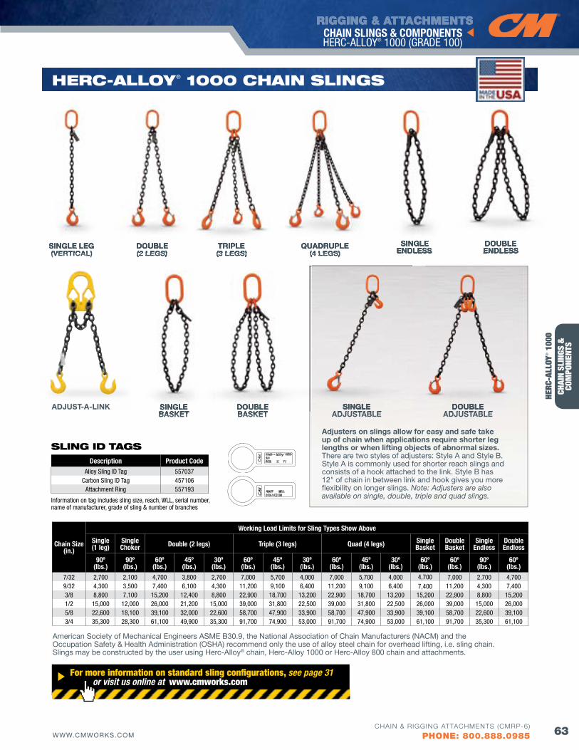
RIGGING & ATTACHMENTS
63WWW.CMWORKS.COMCHAIN & RIGGING ATTACHMENTS (CMRP-6)
PHONE: 800.888.0985
CHAI
N SL
INGS
&
COM
PONE
NTS
CHAIN SLINGS & COMPONENTS HERC-ALLOY® 1000 (GRADE 100)
HERC-Alloy® 1000 CHAIN SlINGS
Chain Size(in.)
Working Load Limits for Sling Types Show Above
Single(1 leg)
Single Choker Double (2 legs) Triple (3 legs) quad (4 legs) Single
BasketDouble Basket
Single Endless
Double Endless
90º(lbs.)
90º(lbs.)
60º(lbs.)
45º(lbs.)
30º(lbs.)
60º(lbs.)
45º(lbs.)
30º(lbs.)
60º(lbs.)
45º(lbs.)
30º(lbs.)
60º(lbs.)
60º(lbs.)
90º(lbs.)
60º(lbs.)
7/32 2,700 2,100 4,700 3,800 2,700 7,000 5,700 4,000 7,000 5,700 4,000 4,700 7,000 2,700 4,700 9/32 4,300 3,500 7,400 6,100 4,300 11,200 9,100 6,400 11,200 9,100 6,400 7,400 11,200 4,300 7,400 3/8 8,800 7,100 15,200 12,400 8,800 22,900 18,700 13,200 22,900 18,700 13,200 15,200 22,900 8,800 15,200 1/2 15,000 12,000 26,000 21,200 15,000 39,000 31,800 22,500 39,000 31,800 22,500 26,000 39,000 15,000 26,000 5/8 22,600 18,100 39,100 32,000 22,600 58,700 47,900 33,900 58,700 47,900 33,900 39,100 58,700 22,600 39,100 3/4 35,300 28,300 61,100 49,900 35,300 91,700 74,900 53,000 91,700 74,900 53,000 61,100 91,700 35,300 61,100
American Society of Mechanical Engineers ASME B30.9, the National Association of Chain Manufacturers (NACM) and the Occupation Safety & Health Administration (OSHA) recommend only the use of alloy steel chain for overhead lifting, i.e. sling chain. Slings may be constructed by the user using Herc-Alloy® chain, Herc-Alloy 1000 or Herc-Alloy 800 chain and attachments.
For more information on standard sling configurations, see page 31 or visit us online at www.cmworks.com
SINGLE LEG(VERTICAL)
DOUBLE(2 LEGS)
TRIPLE(3 LEGS)
QUADRUPLE(4 LEGS)
DOUBLE BASKET
DOUBLE ENDLESS
SINGLEBASKET
ADJUST-A-LINK
Adjusters on slings allow for easy and safe take up of chain when applications require shorter leg lengths or when lifting objects of abnormal sizes. There are two styles of adjusters: Style A and Style B. Style A is commonly used for shorter reach slings and consists of a hook attached to the link. Style B has 12" of chain in between link and hook gives you more flexibility on longer slings. Note: Adjusters are also available on single, double, triple and quad slings.
SINGLEADJUSTABLE
DOUBLEADJUSTABLE
SINGLEENDLESS
SINGLE LEG(VERTICAL)
DOUBLE(2 LEGS) (4 LEGS)
SINGLEADJUSTABLE
DOUBLEADJUSTABLE
(2 LEGS)
SINGLEBASKET
(3 LEGS) (4 LEGS)
DOUBLEBASKET
(4 LEGS)SINGLE
ENDLESSDOUBLE ENDLESS
TRIPLE(3 LEGS)
QUADRUPLE(4 LEGS)
HERC
-ALL
OY® 1
000
Description Product CodeAlloy Sling ID Tag 557037
Carbon Sling ID Tag 457106Attachment Ring 557193
Information on tag includes sling size, reach, WLL, serial number, name of manufacturer, grade of sling & number of branches
SlING Id TAGS
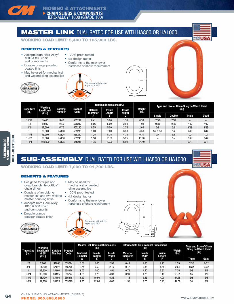
RIGGING & ATTACHMENTS
64 WWW.CMWORKS.COM
CHAIN SLINGS & COMPONENTS HERC-ALLOY® 1000 (GRADE 100)
CHAIN & RIGGING ATTACHMENTS (CMRP-6)
PHONE: 800.888.0985
CHAIN SLINGS &
COMPONENTS
Trade Size(in.)
Working Load Limit
at 60º(lbs.)
CatalogNumber
Product Code
Master Link Nominal Dimensions (in.)
Intermediate Link Nominal Dimensions (in.)
Weight(lbs.)
Type and Size of Chain Sling on Which Used
(in.)Material Diameter
A
Inside Length
B
InsideWidth
C
Material Diameter
D
InsideWidth
E
Inside Length
f Triple quad
1/2 7,000 SA050 555274 0.56 5.00 2.50 0.44 1.06 1.75 1.35 7/32 7/32 3/4 11,200 SA075 555275 0.75 5.50 2.75 0.47 0.88 1.56 2.64 9/32 9/32 1 22,900 SA100 555276 1.00 7.00 3.50 0.78 1.50 2.63 7.25 3/8 3/8
1-1/4 39,000 SA125 555277 1.25 8.75 4.38 0.91 1.75 3.13 13.51 1/2 1/2 1-1/2 58,700 SA150 555278 1.50 10.50 5.25 1.13 2.25 4.00 24.28 5/8 5/8 1-3/4 91,700 SA175 555279 1.75 12.00 6.00 1.50 2.75 5.25 44.58 3/4 3/4
A
B
C
DE
F
Trade Size(in.)
Working Load Limit
(lbs.)CatalogNumber
Product Code
Nominal Dimensions (in.)Weight(lbs.)
Type and Size of Chain Sling on Which Used(in.)Material
DiameterA
InsideLength
B
InsideWidth
C Single Double Triple quad
13/32 5,400 HA40 555231 0.41 3.00 1.50 0.33 7/32 7/32 – –1/2 8,600 HA50 555232 0.56 5.00 2.50 1.02 9/32 9/32 7/32 7/323/4 17,600 HA75 555235 0.75 5.50 2.75 2.08 3/8 3/8 9/32 9/321 30,000 HA100 555238 1.00 7.00 3.50 4.59 1/2 & 5/8 1/2 3/8 3/8
1-1/4 45,200 HA125 555240 1.25 8.75 4.38 9.31 3/4 5/8 1/2 1/21-1/2 70,600 HA150 555243 1.50 10.50 5.25 15.60 – 3/4 5/8 5/81-3/4 105,900 HA175 555246 1.75 12.00 6.00 24.40 – – 3/4 3/4
A
B
C
MASTER lINK DUAL RATED FOR USE WITH HA800 OR HA1000
Accepts both Herc-Alloy® 1000 & 800 chain and components
Durable orange powder coated finish
May be used for mechanical and welded sling assemblies
bENEfITS & fEATuRES
WORKING LOAD LIMIT: 5,400 TO 105,900 LbS.
Sub-ASSEMbly DUAL RATED FOR USE WITH HA800 OR HA1000
Designed for triple and quad branch Herc-Alloy® chain slings
Consists of an oblong master link and two welded master coupling links
Accepts both Herc-Alloy 1000 & 800 chain and components
Durable orange powder coated finish
bENEfITS & fEATuRES
WORKING LOAD LIMIT: 7,000 TO 91,700 LbS.
May be used for mechanical or welded sling assemblies
100% proof tested 4:1 design factor Conforms to the new lower
hardness offshore requirement
100% proof tested 4:1 design factor Conforms to the new lower
hardness offshore requirement
120º
Can be used with included angles up to 120°
HERC-ALLOY® 1000
120º
Can be used with included angles up to 120°
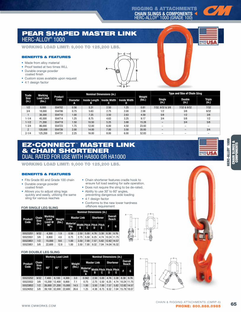
RIGGING & ATTACHMENTS
65WWW.CMWORKS.COMCHAIN & RIGGING ATTACHMENTS (CMRP-6)
PHONE: 800.888.0985
CHAI
N SL
INGS
&
COM
PONE
NTS
CHAIN SLINGS & COMPONENTS HERC-ALLOY® 1000 (GRADE 100)
Trade Size(in.)
Working Load Limit
(lbs.)Product
Code
Nominal Dimensions (in.)Weight(lbs.)
Type and Size of Chain Sling
Single(in.)
Double(in.)
Triple(in.)
DiameterA
Inside LengthB
Inside WidthC
Inside WidthD
1/2 9,000 554702 0.56 5.31 2.50 1.25 0.81 7/32, 9/32 & 3/8 7/32 & 9/32 7/323/4 18,000 554706 0.75 5.63 2.75 2.00 2.08 1/2 3/8 9/321 30,300 554710 1.00 7.25 3.50 2.63 4.59 5/8 1/2 3/8
1-1/4 45,500 554714 1.25 8.75 4.63 3.25 9.17 3/4 5/8 1/21-1/2 71,200 554719 1.50 10.50 5.25 3.88 15.28 – 3/4 5/81-3/4 86,000 554723 1.75 12.00 6.00 4.50 23.93 – – –
2 120,000 554726 2.00 14.00 7.00 3.50 35.93 – – 3/42-1/4 125,200 554731 2.25 16.00 8.00 6.00 52.83 – – –
B
C
A
D
Made from alloy material Proof tested at two times WLL Durable orange powder
coated finish Custom sizes available upon request 4:1 design factor
bENEfITS & fEATuRES
WORKING LOAD LIMIT: 9,000 TO 125,200 LbS.
HERC
-ALL
OY® 1
000
PEAR SHAPEd MASTER lINKHERC-ALLOY® 1000
Type and Size of Chain Sling
Fits Grade 80 and Grade 100 chain Durable orange powder
coated finish Allows you to adjust sling legs
quickly and easily, utilizing the same sling for various reaches
Chain shortener features cradle hook to ensure full load seating for safe operation.
Does not require the sling to be de-rated. Ability to use 30˚ to 60˚ angles,
preventing dangerous side loading 4:1 design factor Conforms to the new lower hardness
offshore requirement
bENEfITS & fEATuRES
WORKING LOAD LIMIT: 9,000 TO 125,200 LbS.
EZ•CONNECT TM MASTER lINK & CHAIN SHoRTENER DUAL RATED FOR USE WITH HA800 OR HA1000
Product Code
Chain Size (in.)
Working Load
Limit @ 90°
Weight (lbs.)
Nominal Dimensions (in.)
Master Link Shortener Overall Reach
Material Dia. A
Width B
Pitch C
Pitch D
Pitch E f G
555232S1 9/32 4,300 1.9 0.56 2.50 5.00 4.76 3.38 8.38 9.76555235S1 3/8 8,800 4.6 0.75 2.75 5.50 6.25 4.74 10.24 11.75555238S1 1/2 15,000 9.6 1.00 3.50 7.00 7.57 5.82 12.82 14.57555239S1 5/8 22,600 12.8 1.00 3.50 7.00 9.32 7.04 14.04 16.32
Product Code
Chain Size (in.)
Working Load Limit
Weight (lbs.)
Nominal Dimensions (in.)
60° 45° 30°
Master Link Shortener Overall Reach
Material Dia. A
Width B
Pitch C
Pitch D
PItch E f G
555232S2 9/32 7,400 6,100 4,300 3.0 0.562 2.50 5.00 4.76 3.38 8.38 9.76555235S2 3/8 15,200 12,400 8,800 7.1 0.75 2.75 5.50 6.25 4.74 10.24 11.75555238S2 1/2 26,000 21,200 15,000 14.5 1.00 3.50 7.00 7.57 5.82 12.82 14.57555240S2 5/8 39,100 32,000 22,600 26.6 1.25 4.38 8.75 9.32 7.04 15.79 18.07
FOR SINGLE LEG SLING
FOR DOUBLE LEG SLING
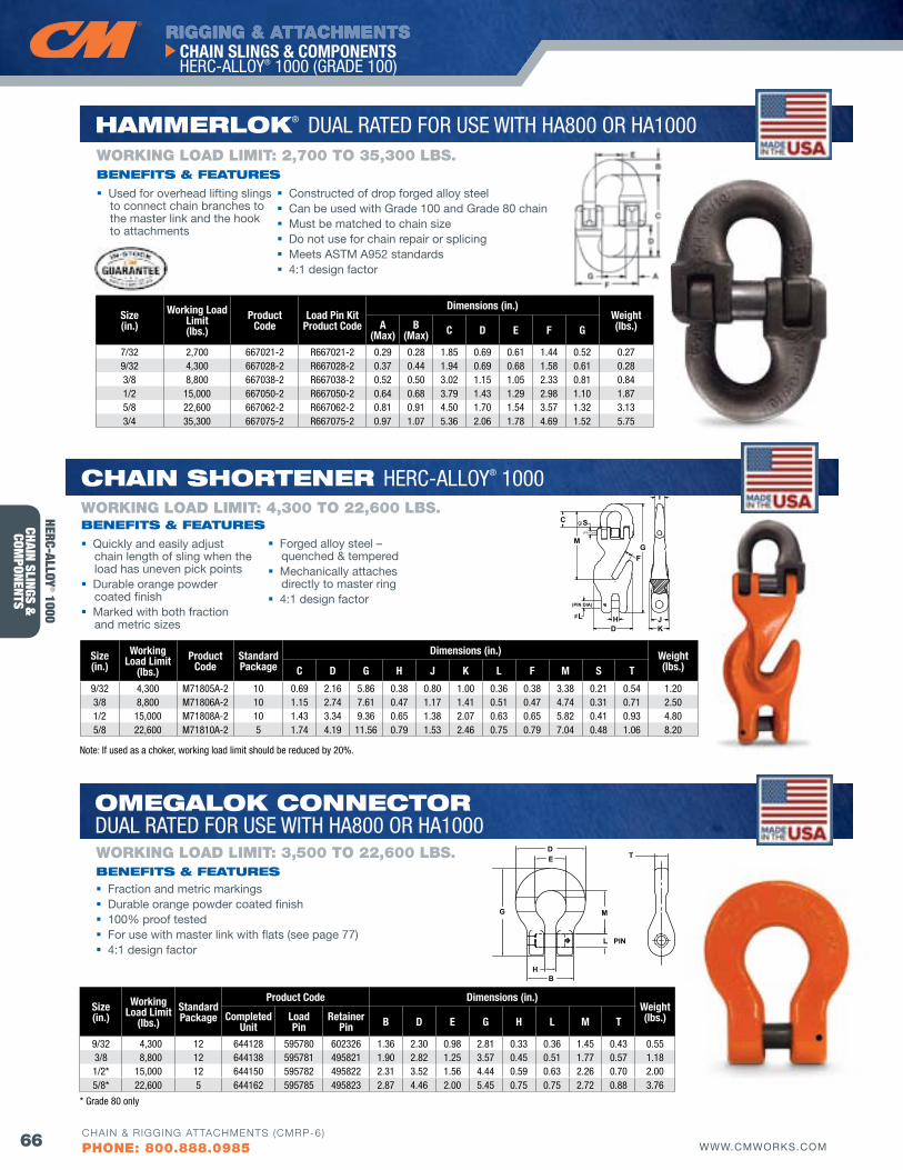
RIGGING & ATTACHMENTS
66 WWW.CMWORKS.COM
CHAIN SLINGS & COMPONENTS HERC-ALLOY® 1000 (GRADE 100)
CHAIN & RIGGING ATTACHMENTS (CMRP-6)
PHONE: 800.888.0985
CHAIN SLINGS &
COMPONENTS
D
FG
M
K
(PIN DIA)
(PIN DIA)
HL
S
J
T
C
Size(in.)
Working Load Limit
(lbs.)Product
CodeStandard Package
Dimensions (in.) Weight(lbs.)C D G H J K L f M S T
9/32 4,300 M71805A-2 10 0.69 2.16 5.86 0.38 0.80 1.00 0.36 0.38 3.38 0.21 0.54 1.20 3/8 8,800 M71806A-2 10 1.15 2.74 7.61 0.47 1.17 1.41 0.51 0.47 4.74 0.31 0.71 2.50 1/2 15,000 M71808A-2 10 1.43 3.34 9.36 0.65 1.38 2.07 0.63 0.65 5.82 0.41 0.93 4.80 5/8 22,600 M71810A-2 5 1.74 4.19 11.56 0.79 1.53 2.46 0.75 0.79 7.04 0.48 1.06 8.20
CHAIN SHoRTENER HERC-ALLOY® 1000
Quickly and easily adjust chain length of sling when the load has uneven pick points
Durable orange powder coated finish
Marked with both fraction and metric sizes
Forged alloy steel – quenched & tempered
Mechanically attaches directly to master ring
4:1 design factor
bENEfITS & fEATuRESWORKING LOAD LIMIT: 4,300 TO 22,600 LbS.
Note: If used as a choker, working load limit should be reduced by 20%.
HERC-ALLOY® 1000
Size(in.)
Working Load Limit(lbs.)
Product Code
Load Pin Kit Product Code
Dimensions (in.)Weight(lbs.)A
(Max)B
(Max) C D E f G
7/32 2,700 667021-2 R667021-2 0.29 0.28 1.85 0.69 0.61 1.44 0.52 0.279/32 4,300 667028-2 R667028-2 0.37 0.44 1.94 0.69 0.68 1.58 0.61 0.283/8 8,800 667038-2 R667038-2 0.52 0.50 3.02 1.15 1.05 2.33 0.81 0.841/2 15,000 667050-2 R667050-2 0.64 0.68 3.79 1.43 1.29 2.98 1.10 1.875/8 22,600 667062-2 R667062-2 0.81 0.91 4.50 1.70 1.54 3.57 1.32 3.133/4 35,300 667075-2 R667075-2 0.97 1.07 5.36 2.06 1.78 4.69 1.52 5.75
Used for overhead lifting slings to connect chain branches to the master link and the hook to attachments
Constructed of drop forged alloy steel Can be used with Grade 100 and Grade 80 chain Must be matched to chain size Do not use for chain repair or splicing Meets ASTM A952 standards 4:1 design factor
bENEfITS & fEATuRES
WORKING LOAD LIMIT: 2,700 TO 35,300 LbS.
HAMMERloK® DUAL RATED FOR USE WITH HA800 OR HA1000
Size(in.)
Working Load Limit
(lbs.)StandardPackage
Product Code Dimensions (in.)Weight(lbs.)Completed
UnitLoad Pin
Retainer Pin B D E G H L M T
9/32 4,300 12 644128 595780 602326 1.36 2.30 0.98 2.81 0.33 0.36 1.45 0.43 0.55 3/8 8,800 12 644138 595781 495821 1.90 2.82 1.25 3.57 0.45 0.51 1.77 0.57 1.181/2* 15,000 12 644150 595782 495822 2.31 3.52 1.56 4.44 0.59 0.63 2.26 0.70 2.005/8* 22,600 5 644162 595785 495823 2.87 4.46 2.00 5.45 0.75 0.75 2.72 0.88 3.76
L PIN
M
BH
TDE
G
Fraction and metric markings Durable orange powder coated finish 100% proof tested For use with master link with flats (see page 77) 4:1 design factor
bENEfITS & fEATuRESWORKING LOAD LIMIT: 3,500 TO 22,600 LbS.
oMEGAloK CoNNECToRDUAL RATED FOR USE WITH HA800 OR HA1000
* Grade 80 only
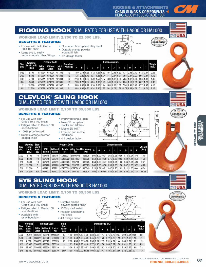
RIGGING & ATTACHMENTS
67WWW.CMWORKS.COMCHAIN & RIGGING ATTACHMENTS (CMRP-6)
PHONE: 800.888.0985
CHAI
N SL
INGS
&
COM
PONE
NTS
CHAIN SLINGS & COMPONENTS HERC-ALLOY® 1000 (GRADE 100)
EyE SlING HooK DUAL RATED FOR USE WITH HA800 OR HA1000
B
N
G
K
D
E
P
M
I
O
LH
S
Size(in.)
Working Load Limit(lbs.)
Product Code Stan-dard
Pack-age
Dimensions (in.)Weight(lbs.)With
LatchWithoutLatch
LatchKit B D E G H I K L M N O P S
7/32 2,700 558618 458618 4X458321 10 1.50 3.04 1.30 5.06 0.38 0.66 1.47 0.75 3.75 0.97 0.99 0.94 0.99 0.89/32 4,300 558622 458622 595523 10 1.65 3.48 1.50 5.25 0.45 0.75 1.75 0.72 3.75 1.19 1.21 1.05 1.10 1.13/8 8,800 558625 458625 595525 10 2.06 4.33 1.88 6.66 0.58 0.97 2.19 0.91 4.77 1.44 1.46 1.31 1.29 1.91/2 15,000 558628 458628 595528 5 2.63 5.50 2.25 8.16 0.77 1.10 2.56 1.09 5.67 1.78 1.91 1.68 1.63 4.55/8 22,600 558629 458629 595529 5 3.06 6.23 2.63 9.63 0.89 1.46 2.62 1.31 6.50 2.03 2.20 2.23 1.69 7.33/4 35,300 558630 458630 595530 Bulk 3.50 7.82 3.00 11.38 1.00 1.69 3.47 1.50 7.81 2.50 2.82 2.58 2.31 11.4
ClEvloK® SlING HooK DUAL RATED FOR USE WITH HA800 OR HA1000
For use with both Grade 80 & 100 chain
Fatigue rated to Grade 100 specifications
100% proof tested Durable orange powder
coated finish
Improved forged latch New CE compliant
hooks and latches Meets EN 1677 Fraction and metric
markings 4:1 design factor
bENEfITS & fEATuRES
WORKING LOAD LIMIT: 2,700 TO 35,300 LbS.
For use with both Grade 80 & 100 chain
Fatigue rated to Grade 100 specifications
Available with or without latch
Durable orange powder coated finish
100% proof tested Fraction and metric
markings 4:1 design factor
bENEfITS & fEATuRES
WORKING LOAD LIMIT: 2,700 TO 35,300 LbS.
CA
B
L R
K
G
H KD
TF
O
J
P
Size(in.)
Working Load Limit
(lbs.)
Product CodeStandard Package
Dimensions (in.)Weight(lbs.)With
LatchWithoutLatch
LatchKit A B C D f G H J K L O P R T
7/32 2,700 M7502A M7402A 4X1302 10 1.50 0.74 0.38 3.12 1.25 0.87 1.01 0.93 0.63 4.37 0.93 2.13 3.12 0.87 0.66 9/32 4,300 M7503A M7403A 4X1303 10 1.75 0.86 0.45 3.37 1.38 0.94 1.11 0.97 0.71 5.04 0.97 2.27 3.66 0.97 1.12 5/16 5,700 M7504A M7404A 4X1304 10 2.13 1.10 0.52 3.79 1.50 1.07 1.23 1.02 0.88 5.65 1.02 2.56 4.08 1.03 1.46 3/8 8,800 M7505A M7405A 4X1305 10 2.50 1.23 0.64 4.24 1.63 1.26 1.43 1.19 0.94 6.54 1.16 2.85 4.67 1.21 2.42 1/2 15,000 M7507A M7407A 4X1307 5 3.08 1.55 0.77 5.10 2.00 1.44 1.63 1.50 1.38 7.98 1.41 3.47 5.77 1.47 4.10 5/8 22,600 M7509A M7409A 4X1309 5 3.88 1.98 0.95 6.24 2.50 1.82 2.01 1.78 1.68 10.07 1.69 4.59 7.31 1.71 8.16
RIGGING HooK DUAL RATED FOR USE WITH HA800 OR HA1000
For use with both Grade 80 & 100 chain
Large eye to easily accommodate other fittings
Quenched & tempered alloy steel Durable orange powder
coated finish 5:1 design factor
bENEfITS & fEATuRES
WORKING LOAD LIMIT: 2,700 TO 22,600 LbS.
HERC
-ALL
OY® 1
000
Size(in.)
Working Load Limit(lbs.)
Stan-dard
Pack-age
Product Code Dimensions (in.)Weight(lbs.)With
LatchWithout Latch
Latch Kit
Alloy Load Pin
RetainingPin D G H I L M O P R
7/32 2,700 10 657716 557716 4X455321 SP595778 495826 3.05 5.00 0.31 0.66 0.28 0.96 1.13 0.94 3.45 1.109/32 4,300 10 657718 557718 4X455322 595780SP 495825 3.53 5.55 0.38 0.75 0.36 0.83 1.32 1.11 3.75 1.20 3/8 8,800 10 657719 557719 4X455325 595781 495825 4.54 6.93 0.47 1.00 0.51 1.06 1.34 1.51 4.58 2.21 1/2 15,000 5 657720 557720 4X455328 595782 495823 5.48 8.28 0.58 1.33 0.63 1.38 1.87 1.55 5.59 4.22 5/8 22,600 5 657721 557721 4X455329 SP595783P 495849 6.20 9.61 0.71 1.47 0.75 1.69 2.11 1.83 6.44 6.64 3/4 35,300 Bulk 657722 557722 4X455330 595786 495824 7.63 11.79 0.88 1.88 0.94 2.09 2.55 2.51 7.74 11.22
M (MIN)
R G
M (MIN)
D
P
R
P
G
D I
O
L
H H
L
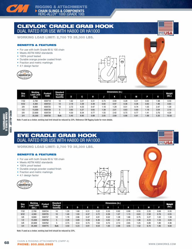
RIGGING & ATTACHMENTS
68 WWW.CMWORKS.COM
CHAIN SLINGS & COMPONENTS HERC-ALLOY® 1000 (GRADE 100)
CHAIN & RIGGING ATTACHMENTS (CMRP-6)
PHONE: 800.888.0985
CHAIN SLINGS &
COMPONENTS
B
H
GK
E
P
D
M
L
I
H
M
G
R
L
P
D
J
K
Size(in.)
Working Load Limit
(lbs.)Product
CodeStandard Packagequantity
Dimensions (in.)Weight(lbs.)D G H J K L M P R
7/32 2,700 659718 10 1.62 3.21 0.31 0.75 0.94 0.28 0.31 0.62 1.98 0.509/32 4,300 659722 10 2.18 3.39 0.38 0.82 0.97 0.36 0.38 0.82 1.86 0.633/8 8,800 659725 10 2.72 4.33 0.47 1.18 1.29 0.51 0.74 1.03 2.47 1.301/2 15,000 659728 5 3.65 5.27 0.65 1.39 2.01 0.63 0.60 1.19 3.04 2.105/8 22,600 659729 5 4.50 6.54 0.77 1.55 2.42 0.75 0.77 1.41 3.76 4.203/4 35,300 659730 Bulk 5.40 8.80 0.88 2.05 2.69 0.88 0.91 1.89 5.30 10.50
Size(in.)
Working Load Limit
(lbs.)Product
CodeStandard Packagequantity
Dimensions (in.) Weight(lbs.)B D E G H I K L M P
7/32 2,700 559724 10 1.20 1.68 0.31 3.22 0.33 0.92 0.99 0.55 2.20 0.69 0.359/32 4,300 559725 10 1.40 1.93 0.37 3.72 0.39 1.07 1.15 0.63 2.58 0.76 0.55 3/8 8,800 559737 10 1.78 2.86 0.47 4.81 0.52 1.38 1.66 0.75 3.27 1.02 1.39 1/2 15,000 559750 5 2.28 3.69 0.59 6.36 0.63 1.81 2.15 1.06 4.23 1.53 3.05 5/8 22,600 559762 5 2.75 4.53 0.75 7.62 0.75 2.13 2.65 1.25 5.06 1.80 4.36 3/4 35,300 559775 Bulk 3.50 5.23 0.91 9.54 1.00 2.88 3.55 1.52 6.70 1.85 9.00
EyE CRAdlE GRAb HooK DUAL RATED FOR USE WITH HA800 OR HA1000
ClEvloK® CRAdlE GRAb HooK DUAL RATED FOR USE WITH HA800 OR HA1000
For use with both Grade 80 & 100 chain Meets ASTM A952 standards 100% proof tested Durable orange powder coated finish Fraction and metric markings 4:1 design factor
bENEfITS & fEATuRES
WORKING LOAD LIMIT: 2,700 TO 35,300 LbS.
For use with both Grade 80 & 100 chain Meets ASTM A952 standards 100% proof tested Durable orange powder coated finish Fraction and metric markings 4:1 design factor
bENEfITS & fEATuRES
WORKING LOAD LIMIT: 2,700 TO 35,300 LbS.
Weight
Note: If used as a choker, working load limit should be reduced by 20%. Reference CM Rigging Guide for more details.
Note: If used as a choker, working load limit should be reduced by 20%.
HERC-ALLOY® 1000
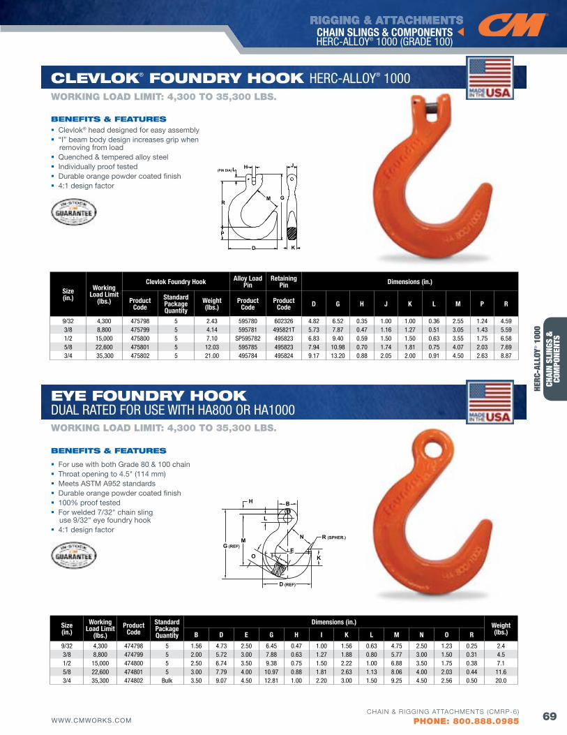
RIGGING & ATTACHMENTS
69WWW.CMWORKS.COMCHAIN & RIGGING ATTACHMENTS (CMRP-6)
PHONE: 800.888.0985
CHAI
N SL
INGS
&
COM
PONE
NTS
CHAIN SLINGS & COMPONENTS HERC-ALLOY® 1000 (GRADE 100)
H B
L
N R (SPHER.)
KE
D (REF)
O
G (REF)M
I
M
J
K
(PIN DIA)L
D
H
RG
P
Size(in.)
Working Load Limit
(lbs.)Product
CodeStandard Packagequantity
Dimensions (in.) Weight(lbs.)B D E G H I K L M N O R
9/32 4,300 474798 5 1.56 4.73 2.50 6.45 0.47 1.00 1.56 0.63 4.75 2.50 1.23 0.25 2.43/8 8,800 474799 5 2.00 5.72 3.00 7.88 0.63 1.27 1.88 0.80 5.77 3.00 1.50 0.31 4.51/2 15,000 474800 5 2.50 6.74 3.50 9.38 0.75 1.50 2.22 1.00 6.88 3.50 1.75 0.38 7.15/8 22,600 474801 5 3.00 7.79 4.00 10.97 0.88 1.81 2.63 1.13 8.06 4.00 2.03 0.44 11.63/4 35,300 474802 Bulk 3.50 9.07 4.50 12.81 1.00 2.20 3.00 1.50 9.25 4.50 2.56 0.50 20.0
Size(in.)
Working Load Limit
(lbs.)
Clevlok foundry Hook Alloy Load Pin
Retaining Pin Dimensions (in.)
Product Code
Standard Packagequantity
Weight(lbs.)
Product Code
Product Code D G H J K L M P R
9/32 4,300 475798 5 2.43 595780 602326 4.82 6.52 0.35 1.00 1.00 0.36 2.55 1.24 4.59 3/8 8,800 475799 5 4.14 595781 495821T 5.73 7.87 0.47 1.16 1.27 0.51 3.05 1.43 5.59 1/2 15,000 475800 5 7.10 SP595782 495823 6.83 9.40 0.59 1.50 1.50 0.63 3.55 1.75 6.58 5/8 22,600 475801 5 12.03 595785 495823 7.94 10.98 0.70 1.74 1.81 0.75 4.07 2.03 7.69 3/4 35,300 475802 5 21.00 495784 495824 9.17 13.20 0.88 2.05 2.00 0.91 4.50 2.63 8.87
ClEvloK® fouNdRy HooK HERC-ALLOY® 1000
Clevlok® head designed for easy assembly “I” beam body design increases grip when
removing from load Quenched & tempered alloy steel Individually proof tested Durable orange powder coated finish 4:1 design factor
bENEfITS & fEATuRES
WORKING LOAD LIMIT: 4,300 TO 35,300 LbS.
EyE fouNdRy HooK DUAL RATED FOR USE WITH HA800 OR HA1000
For use with both Grade 80 & 100 chain Throat opening to 4.5" (114 mm) Meets ASTM A952 standards Durable orange powder coated finish 100% proof tested For welded 7/32" chain sling
use 9/32" eye foundry hook 4:1 design factor
bENEfITS & fEATuRES
WORKING LOAD LIMIT: 4,300 TO 35,300 LbS.
HERC
-ALL
OY® 1
000
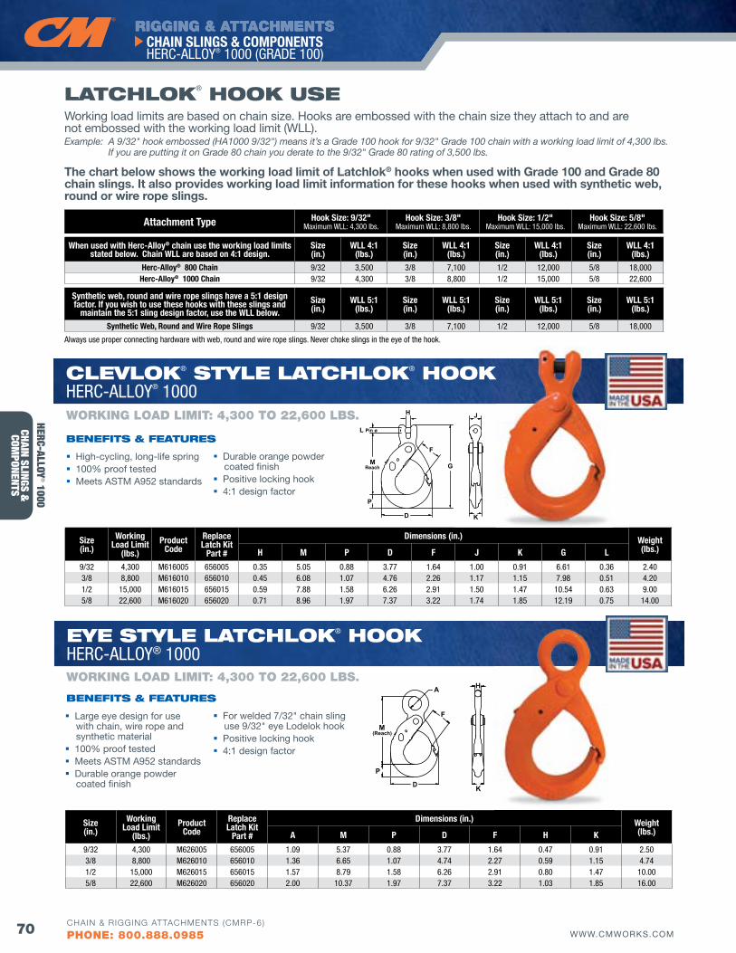
RIGGING & ATTACHMENTS
70 WWW.CMWORKS.COM
CHAIN SLINGS & COMPONENTS HERC-ALLOY® 1000 (GRADE 100)
CHAIN & RIGGING ATTACHMENTS (CMRP-6)
PHONE: 800.888.0985
CHAIN SLINGS &
COMPONENTS
ClEvloK® STylE lATCHloK® HooKHERC-ALLOY® 1000
EyE STylE lATCHloK® HooKHERC-ALLOY® 1000
A H
KD
F
P
M(Reach)
H
L Pin ø
MReach
P
D
G
F
J
K
Size(in.)
Working Load Limit
(lbs.)Product
CodeReplace Latch Kit
Part #
Dimensions (in.) Weight(lbs.)A M P D f H K
9/32 4,300 M626005 656005 1.09 5.37 0.88 3.77 1.64 0.47 0.91 2.50 3/8 8,800 M626010 656010 1.36 6.65 1.07 4.74 2.27 0.59 1.15 4.741/2 15,000 M626015 656015 1.57 8.79 1.58 6.26 2.91 0.80 1.47 10.00 5/8 22,600 M626020 656020 2.00 10.37 1.97 7.37 3.22 1.03 1.85 16.00
Size(in.)
Working Load Limit
(lbs.)Product
CodeReplace Latch Kit
Part #
Dimensions (in.) Weight(lbs.)H M P D f J K G L
9/32 4,300 M616005 656005 0.35 5.05 0.88 3.77 1.64 1.00 0.91 6.61 0.36 2.40 3/8 8,800 M616010 656010 0.45 6.08 1.07 4.76 2.26 1.17 1.15 7.98 0.51 4.20 1/2 15,000 M616015 656015 0.59 7.88 1.58 6.26 2.91 1.50 1.47 10.54 0.63 9.00 5/8 22,600 M616020 656020 0.71 8.96 1.97 7.37 3.22 1.74 1.85 12.19 0.75 14.00
High-cycling, long-life spring 100% proof tested Meets ASTM A952 standards
Durable orange powder coated finish
Positive locking hook 4:1 design factor
bENEfITS & fEATuRES
WORKING LOAD LIMIT: 4,300 TO 22,600 LbS.
Large eye design for use with chain, wire rope and synthetic material
100% proof tested Meets ASTM A952 standards Durable orange powder
coated finish
For welded 7/32" chain sling use 9/32" eye Lodelok hook
Positive locking hook 4:1 design factor
bENEfITS & fEATuRES
WORKING LOAD LIMIT: 4,300 TO 22,600 LbS.
lATCHloK® HooK uSE
Attachment Type Hook Size: 9/32" Maximum WLL: 4,300 lbs.
Hook Size: 3/8" Maximum WLL: 8,800 lbs.
Hook Size: 1/2" Maximum WLL: 15,000 lbs.
Hook Size: 5/8" Maximum WLL: 22,600 lbs.
When used with Herc-Alloy® chain use the working load limits stated below. Chain WLL are based on 4:1 design.
Size(in.)
WLL 4:1(lbs.)
Size(in.)
WLL 4:1(lbs.)
Size(in.)
WLL 4:1(lbs.)
Size(in.)
WLL 4:1(lbs.)
Herc-Alloy® 800 Chain 9/32 3,500 3/8 7,100 1/2 12,000 5/8 18,000Herc-Alloy® 1000 Chain 9/32 4,300 3/8 8,800 1/2 15,000 5/8 22,600
Synthetic web, round and wire rope slings have a 5:1 designfactor. If you wish to use these hooks with these slings and
maintain the 5:1 sling design factor, use the WLL below.Size(in.)
WLL 5:1(lbs.)
Size(in.)
WLL 5:1(lbs.)
Size(in.)
WLL 5:1(lbs.)
Size(in.)
WLL 5:1(lbs.)
Synthetic Web, Round and Wire Rope Slings 9/32 3,500 3/8 7,100 1/2 12,000 5/8 18,000
Working load limits are based on chain size. Hooks are embossed with the chain size they attach to and are not embossed with the working load limit (WLL). Example: A 9/32" hook embossed (HA1000 9/32") means it’s a Grade 100 hook for 9/32" Grade 100 chain with a working load limit of 4,300 lbs.
If you are putting it on Grade 80 chain you derate to the 9/32" Grade 80 rating of 3,500 lbs.
The chart below shows the working load limit of Latchlok® hooks when used with Grade 100 and Grade 80 chain slings. It also provides working load limit information for these hooks when used with synthetic web, round or wire rope slings.
Always use proper connecting hardware with web, round and wire rope slings. Never choke slings in the eye of the hook.
A H
KD
F
P
M(Reach)
H
L Pin ø
MReach
P
D
G
F
J
K
HERC-ALLOY® 1000
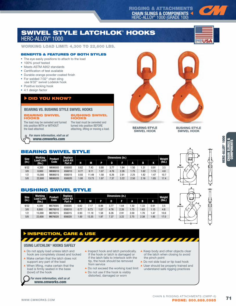
RIGGING & ATTACHMENTS
71WWW.CMWORKS.COMCHAIN & RIGGING ATTACHMENTS (CMRP-6)
PHONE: 800.888.0985
CHAI
N SL
INGS
&
COM
PONE
NTS
CHAIN SLINGS & COMPONENTS HERC-ALLOY® 1000 (GRADE 100)
Size(in.)
Working Load Limit
(lbs.)Product
CodeReplace Latch Kit
Part #
Dimensions (in.) Weight(lbs.)H M P D f A B K
9/32 4,300 M676005 656005 0.62 7.17 0.88 3.77 1.64 1.50 1.33 0.91 3.53/8 8,800 M676010 656010 0.77 8.73 1.07 4.76 2.26 1.75 1.63 1.15 4.81/2 15,000 M676015 656015 0.93 11.18 1.58 6.26 2.91 2.00 1.76 1.47 10.65/8 22,600 M676020 656020 1.00 13.35 1.97 7.37 3.22 2.75 2.38 1.85 17.0
A H
KD
F
P
M(Reach)
B
Size(in.)
Working Load Limit
(lbs.)Product
CodeReplace Latch Kit
Part #
Dimensions (in.) Weight(lbs.)H M P D f A B K
9/32 4,300 M696005 656005 0.62 7.43 0.88 3.77 1.64 1.50 1.31 0.91 3.53/8 8,800 M696010 656010 0.77 9.11 1.07 4.76 2.26 1.75 1.62 1.15 4.81/2 15,000 M696015 656015 0.93 11.49 1.58 6.26 2.91 2.25 1.82 1.47 10.75/8 22,600 M696020 656020 1.00 13.73 1.97 7.37 3.22 2.50 2.16 1.85 17.4
WORKING LOAD LIMIT: 4,300 TO 22,600 LbS.
SwIvEl STylE lATCHloK® HooKS HERC-ALLOY® 1000
bEARING SwIvEl STylE
buSHING SwIvEl STylE
A H
KD
F
P
M(Reach)
B
A H
KD
F
P
M(Reach)
B
The eye easily positions to attach to the load 100% proof tested Meets ASTM A952 standards Certification of test available Durable orange powder coated finish For welded 7/32" chain sling
use 9/32" swivel Lodelok hook Positive locking hook 4:1 design factor
bENEfITS & fEATuRES of boTH STylES
BEARING STYLESWIVEL HOOK
BUSHING STYLESWIVEL HOOK
BEARING STYLE
For more information, visit us at www.cmworks.com
bEARING SwIvEl HooKSThe load may be swiveled and turned into position WITH or WITHOUT the load attached.
buSHING SwIvEl HooKSThe load must be swiveled and turned into position BEFORE attaching, lifting or moving a load.
BEARING VS. BUSHING STYLE SWIVEL HOOKS
dId you KNow?
INSPECTIoN, CARE & uSE
s Do not apply load unless latch and hook are completely closed and locked
s Make certain that the latch does not support any part of the load
s When lifting, make certain that the load is firmly seated in the base (bowl) of the hook
s Inspect hook and latch periodically. If the hook or latch is damaged or if the latch fails to interlock with the tip, the hook should be removed from service
s Do not exceed the working load limits Do not use if the hook is visibly
distorted, damaged or worn
s Keep body and other objects clear of the latch when closing to avoid the pinch point
s Do not side load or tip load hooks User should be properly trained and
understand safe rigging practices
USING LATCHLOK® HOOKS SAfELY
For more information, visit us at www.cmworks.com
HERC
-ALL
OY® 1
000
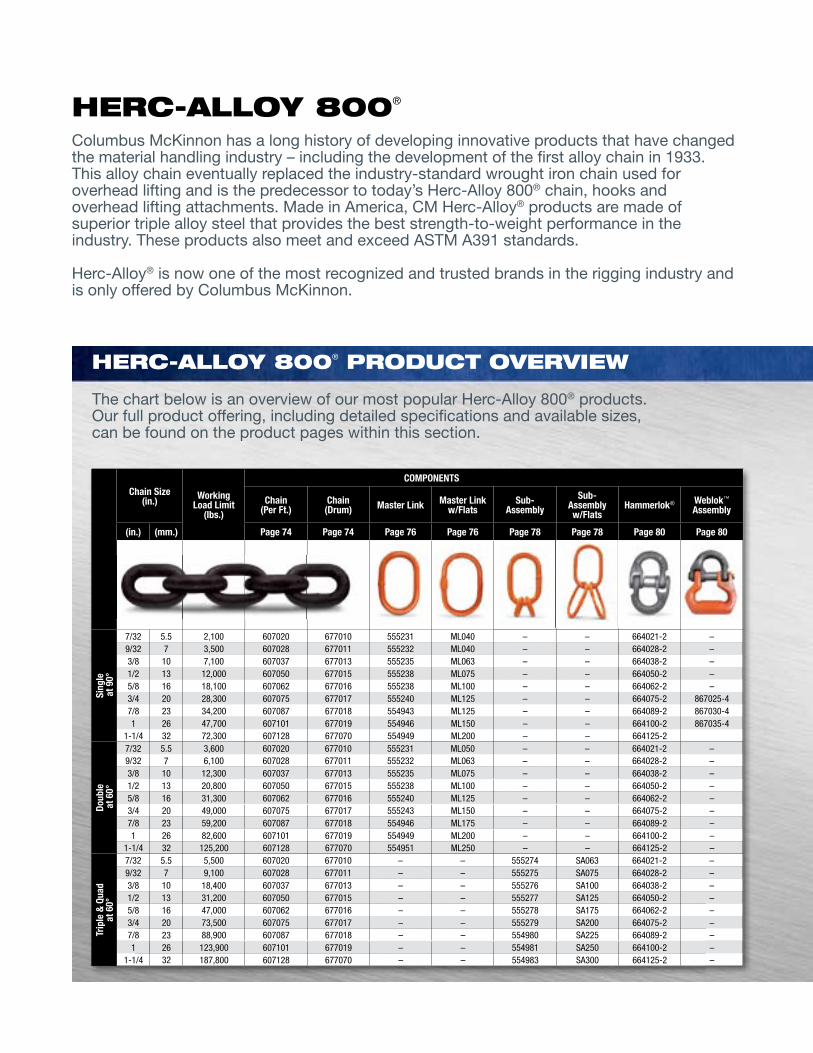
RIGGING & ATTACHMENTS
72 WWW.CMWORKS.COM
CHAIN SLINGS & COMPONENTS HERC-ALLOY 800® (GRADE 80)
CHAIN & RIGGING ATTACHMENTS (CMRP-6)
PHONE: 800.888.0985
CHAIN SLINGS &
COMPONENTS
Chain Size(in.) Working
Load Limit(lbs.)
COMPONENTS
Chain (Per ft.)
Chain (Drum) Master Link Master Link
w/flatsSub-
AssemblySub-
Assembly w/flats
Hammerlok® Weblok™
Assembly
(in.) (mm.) Page 74 Page 74 Page 76 Page 76 Page 78 Page 78 Page 80 Page 80
Sing
le
at 9
0°
7/32 5.5 2,100 607020 677010 555231 ML040 – – 664021-2 –9/32 7 3,500 607028 677011 555232 ML040 – – 664028-2 –3/8 10 7,100 607037 677013 555235 ML063 – – 664038-2 –1/2 13 12,000 607050 677015 555238 ML075 – – 664050-2 –5/8 16 18,100 607062 677016 555238 ML100 – – 664062-2 –3/4 20 28,300 607075 677017 555240 ML125 – – 664075-2 867025-47/8 23 34,200 607087 677018 554943 ML125 – – 664089-2 867030-41 26 47,700 607101 677019 554946 ML150 – – 664100-2 867035-4
1-1/4 32 72,300 607128 677070 554949 ML200 – – 664125-2
Doub
le
at 6
0°
7/32 5.5 3,600 607020 677010 555231 ML050 – – 664021-2 –9/32 7 6,100 607028 677011 555232 ML063 – – 664028-2 –3/8 10 12,300 607037 677013 555235 ML075 – – 664038-2 –1/2 13 20,800 607050 677015 555238 ML100 – – 664050-2 –5/8 16 31,300 607062 677016 555240 ML125 – – 664062-2 –3/4 20 49,000 607075 677017 555243 ML150 – – 664075-2 –7/8 23 59,200 607087 677018 554946 ML175 – – 664089-2 –1 26 82,600 607101 677019 554949 ML200 – – 664100-2 –
1-1/4 32 125,200 607128 677070 554951 ML250 – – 664125-2 –
Trip
le &
qua
d
at 6
0°
7/32 5.5 5,500 607020 677010 – – 555274 SA063 664021-2 –9/32 7 9,100 607028 677011 – – 555275 SA075 664028-2 –3/8 10 18,400 607037 677013 – – 555276 SA100 664038-2 –1/2 13 31,200 607050 677015 – – 555277 SA125 664050-2 –5/8 16 47,000 607062 677016 – – 555278 SA175 664062-2 –3/4 20 73,500 607075 677017 – – 555279 SA200 664075-2 –7/8 23 88,900 607087 677018 – – 554980 SA225 664089-2 –1 26 123,900 607101 677019 – – 554981 SA250 664100-2 –
1-1/4 32 187,800 607128 677070 – – 554983 SA300 664125-2 –
HERC-Alloy 800® PRoduCT ovERvIEw
The chart below is an overview of our most popular Herc-Alloy 800® products. Our full product offering, including detailed specifications and available sizes, can be found on the product pages within this section.
Columbus McKinnon has a long history of developing innovative products that have changed the material handling industry – including the development of the first alloy chain in 1933. This alloy chain eventually replaced the industry-standard wrought iron chain used for overhead lifting and is the predecessor to today’s Herc-Alloy 800® chain, hooks and overhead lifting attachments. Made in America, CM Herc-Alloy® products are made of superior triple alloy steel that provides the best strength-to-weight performance in the industry. These products also meet and exceed ASTM A391 standards.
Herc-Alloy® is now one of the most recognized and trusted brands in the rigging industry and is only offered by Columbus McKinnon.
HERC-Alloy 800®
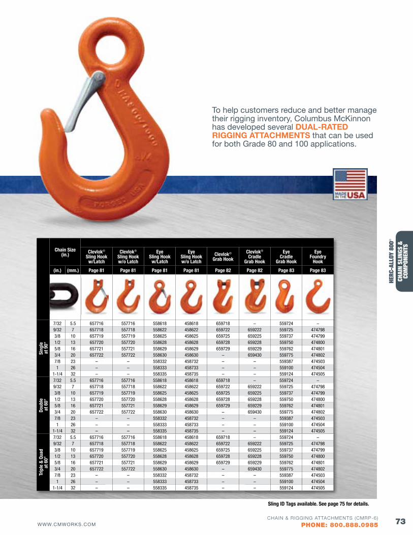
73WWW.CMWORKS.COMCHAIN & RIGGING ATTACHMENTS (CMRP-6)
PHONE: 800.888.0985
CHAIN SLINGS & COMPONENTS HERC-ALLOY 800® (GRADE 80)
CHAI
N SL
INGS
&
COM
PONE
NTS
Chain Size(in.) Clevlok®
Sling Hook w/Latch
Clevlok® Sling Hook w/o Latch
Eye Sling Hook
w/Latch
Eye Sling Hook w/o Latch
Clevlok® Grab Hook
Clevlok® Cradle
Grab Hook
Eye Cradle
Grab Hook
Eye foundry
Hook
(in.) (mm.) Page 81 Page 81 Page 81 Page 81 Page 82 Page 82 Page 83 Page 83
Sing
le
at 9
0°
7/32 5.5 657716 557716 558618 458618 659718 – 559724 –9/32 7 657718 557718 558622 458622 659722 659222 559725 4747983/8 10 657719 557719 558625 458625 659725 659225 559737 4747991/2 13 657720 557720 558628 458628 659728 659228 559750 4748005/8 16 657721 557721 558629 458629 659729 659229 559762 4748013/4 20 657722 557722 558630 458630 – 659430 559775 4748027/8 23 – – 558332 458732 – – 559387 4745031 26 – – 558333 458733 – – 559100 474504
1-1/4 32 – – 558335 458735 – – 559124 474505
Doub
le
at 6
0°
7/32 5.5 657716 557716 558618 458618 659718 – 559724 –9/32 7 657718 557718 558622 458622 659722 659222 559725 4747983/8 10 657719 557719 558625 458625 659725 659225 559737 4747991/2 13 657720 557720 558628 458628 659728 659228 559750 4748005/8 16 657721 557721 558629 458629 659729 659229 559762 4748013/4 20 657722 557722 558630 458630 – 659430 559775 4748027/8 23 – – 558332 458732 – – 559387 4745031 26 – – 558333 458733 – – 559100 474504
1-1/4 32 – – 558335 458735 – – 559124 474505
Trip
le &
qua
d
at 6
0°
7/32 5.5 657716 557716 558618 458618 659718 – 559724 –9/32 7 657718 557718 558622 458622 659722 659222 559725 4747983/8 10 657719 557719 558625 458625 659725 659225 559737 4747991/2 13 657720 557720 558628 458628 659728 659228 559750 4748005/8 16 657721 557721 558629 458629 659729 659229 559762 4748013/4 20 657722 557722 558630 458630 – 659430 559775 4748027/8 23 – – 558332 458732 – – 559387 4745031 26 – – 558333 458733 – – 559100 474504
1-1/4 32 – – 558335 458735 – – 559124 474505
To help customers reduce and better manage their rigging inventory, Columbus McKinnon has developed several DUAL-RATED RIGGING ATTACHMENTS that can be used for both Grade 80 and 100 applications.
HERC
-ALL
OY 8
00®
Sling ID Tags available. See page 75 for details.
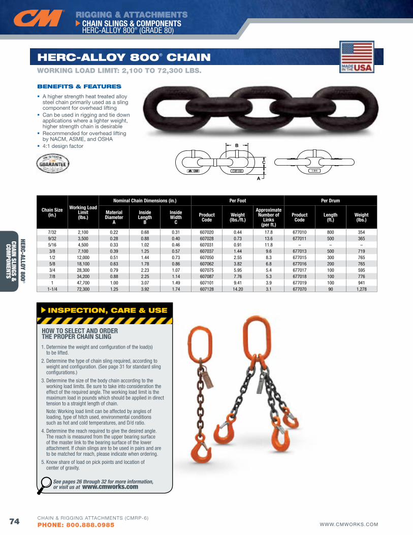
RIGGING & ATTACHMENTS
74 WWW.CMWORKS.COM
CHAIN SLINGS & COMPONENTS HERC-ALLOY 800® (GRADE 80)
CHAIN & RIGGING ATTACHMENTS (CMRP-6)
PHONE: 800.888.0985
CHAIN SLINGS &
COMPONENTS
HERC-Alloy 800® CHAIN
A higher strength heat treated alloy steel chain primarily used as a sling component for overhead lifting
Can be used in rigging and tie down applications where a lighter weight, higher strength chain is desirable
Recommended for overhead lifting by NACM, ASME, and OSHA
4:1 design factor
bENEfITS & fEATuRES
Chain Size(in.)
Working Load Limit(lbs.)
Nominal Chain Dimensions (in.) Per foot Per Drum
Material Diameter
A
Inside Length
B
Inside Width
CProduct
CodeWeight(lbs./ft.)
Approximate Number of
Links(per ft.)
Product Code
Length(ft.)
Weight(lbs.)
7/32 2,100 0.22 0.68 0.31 607020 0.44 17.8 677010 800 3549/32 3,500 0.28 0.88 0.40 607028 0.73 13.6 677011 500 3655/16 4,500 0.33 1.02 0.46 607031 0.91 11.8 – – –3/8 7,100 0.39 1.25 0.57 607037 1.44 9.6 677013 500 7191/2 12,000 0.51 1.44 0.73 607050 2.55 8.3 677015 300 7655/8 18,100 0.63 1.78 0.86 607062 3.82 6.8 677016 200 7653/4 28,300 0.79 2.23 1.07 607075 5.95 5.4 677017 100 5957/8 34,200 0.88 2.25 1.14 607087 7.76 5.3 677018 100 7761 47,700 1.00 3.07 1.49 607101 9.41 3.9 677019 100 941
1-1/4 72,300 1.25 3.92 1.74 607128 14.20 3.1 677070 90 1,278
A
B
C1000
WORKING LOAD LIMIT: 2,100 TO 72,300 LbS.
INSPECTIoN, CARE & uSE
1. Determine the weight and configuration of the load(s) to be lifted.
2. Determine the type of chain sling required, according to weight and configuration. (See page 31 for standard sling configurations.)
3. Determine the size of the body chain according to the working load limits. Be sure to take into consideration the effect of the required angle. The working load limit is the maximum load in pounds which should be applied in direct tension to a straight length of chain. Note: Working load limit can be affected by angles of loading, type of hitch used, environmental conditions such as hot and cold temperatures, and D/d ratio.
4. Determine the reach required to give the desired angle. The reach is measured from the upper bearing surface of the master link to the bearing surface of the lower attachment. If chain slings are to be used in pairs and are to be matched for reach, please indicate when ordering.
5. Know share of load on pick points and location of center of gravity.
HOW TO SELECT AND ORDER THE PROPER CHAIN SLING
See pages 26 through 32 for more information, or visit us at www.cmworks.com
HERC-ALLOY 800®
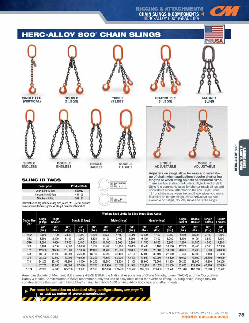
RIGGING & ATTACHMENTS
75WWW.CMWORKS.COMCHAIN & RIGGING ATTACHMENTS (CMRP-6)
PHONE: 800.888.0985
CHAIN SLINGS & COMPONENTS HERC-ALLOY 800® (GRADE 80)
CHAI
N SL
INGS
&
COM
PONE
NTS
Adjusters on slings allow for easy and safe take up of chain when applications require shorter leg lengths or when lifting objects of abnormal sizes. There are two styles of adjusters: Style A and Style B. Style A is commonly used for shorter reach slings and consists of a hook attached to the link. Style B has 12" of chain in between link and hook gives you more flexibility on longer slings. Note: Adjusters are also available on single, double, triple and quad slings.
SINGLE LEG(VERTICAL)
DOUBLE(2 LEGS)
TRIPLE(3 LEGS)
QUADRUPLE(4 LEGS)
DOUBLE BASKET
SINGLEBASKET
SINGLEADJUSTABLE
DOUBLEADJUSTABLE
MAGNETSLING
HERC-Alloy 800® CHAIN SlINGS
DOUBLE ENDLESS
SINGLEENDLESS
Chain Size(in.)
Working Load Limits for Sling Types Show Above
Single(1 leg)
SingleChoker Double (2 legs) Triple (3 legs) quad (4 legs) Single
BasketDouble Basket
Single Endless
Double Endless
90º(lbs.)
90º(lbs.)
60º(lbs.)
45º(lbs.)
30º(lbs.)
60º(lbs.)
45º(lbs.)
30º(lbs.)
60º(lbs.)
45º(lbs.)
30º(lbs.)
60º(lbs.)
60º(lbs.)
90º(lbs.)
60º(lbs.)
7/32 2,100 1,700 3,600 3,000 2,100 5,500 4,400 3,200 5,500 4,400 3,200 3,600 5,500 2,100 3,6009/32 3,500 2,800 6,100 4,900 3,500 9,100 7,400 5,200 9,100 7,400 5,200 6,100 9,100 3,500 6,1005/16 4,500 3,600 7,800 6,400 4,500 11,700 9,500 6,800 11,700 9,500 6,800 7,800 11,700 4,500 7,8003/8 7,100 5,700 12,300 10,000 7,100 18,400 15,100 10,600 18,400 15,100 10,600 12,300 18,400 7,100 12,3001/2 12,000 9,600 20,800 17,000 12,000 31,200 25,500 18,000 31,200 25,500 18,000 20,800 31,200 12,000 20,8005/8 18,100 14,500 31,300 25,600 18,100 47,000 38,400 27,100 47,000 38,400 27,100 31,300 47,000 18,100 31,3003/4 28,300 22,600 49,000 40,000 28,300 73,500 60,000 42,400 73,500 60,000 42,400 49,000 73,500 28,300 49,0007/8 34,200 27,400 59,200 48,400 34,200 88,900 72,500 51,300 88,900 72,500 51,300 59,200 88,900 34,200 59,2001 47,700 38,200 82,600 67,400 47,700 123,900 101,200 71,500 123,900 101,200 71,500 82,600 123,900 47,700 82,600
1-1/4 72,300 57,800 125,200 102,200 72,300 187,800 153,400 108,400 187,800 153,400 108,400 125,200 187,800 72,300 125,200
Description Product CodeAlloy Sling ID Tag 557037
Carbon Sling ID Tag 457106Attachment Ring 557193
Information on tag includes sling size, reach, WLL, serial number, name of manufacturer, grade of sling & number of branches
American Society of Mechanical Engineers ASME B30.9, the National Association of Chain Manufacturers (NACM) and the Occupation Safety & Health Administration (OSHA) recommend only the use of alloy steel chain for overhead lifting, i.e. sling chain. Slings may be constructed by the user using Herc-Alloy® chain, Herc-Alloy 1000 or Herc-Alloy 800 chain and attachments.
SINGLE LEG(VERTICAL)
DOUBLE TRIPLE QUADRUPLE MAGNETSLING
For more information on standard sling configurations, see page 31 or visit us online at www.cmworks.com
HERC
-ALL
OY 8
00®
SlING Id TAGS
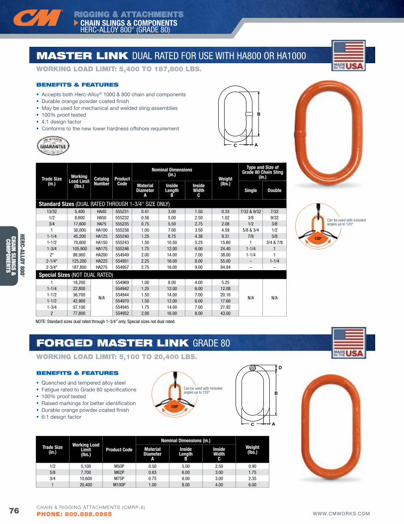
RIGGING & ATTACHMENTS
76 WWW.CMWORKS.COM
CHAIN SLINGS & COMPONENTS HERC-ALLOY 800® (GRADE 80)
CHAIN & RIGGING ATTACHMENTS (CMRP-6)
PHONE: 800.888.0985
CHAIN SLINGS &
COMPONENTS
Trade Size(in.)
Working Load Limit(lbs.)
Product Code
Nominal Dimensions (in.)Weight(lbs.)Material
DiameterA
Inside Length
B
Inside Width
C 1/2 5,100 M50P 0.50 5.00 2.50 0.905/8 7,700 M62P 0.63 6.00 3.00 1.753/4 10,600 M75P 0.75 6.00 3.00 2.351 20,400 M100P 1.00 8.00 4.00 6.00
A
B
C
D
Trade Size(in.)
Working Load Limit
(lbs.)Catalog Number
Product Code
Nominal Dimensions (in.)
Weight(lbs.)
Type and Size of Grade 80 Chain Sling
(in.)
Material Diameter
A
InsideLength
B
InsideWidth
CSingle Double
Standard Sizes (DUAL RATED THROUGH 1-3/4" SIzE ONLY)13/32 5,400 HA40 555231 0.41 3.00 1.50 0.33 7/32 & 9/32 7/32
1/2 8,600 HA50 555232 0.56 5.00 2.50 1.02 3/8 9/32 3/4 17,600 HA75 555235 0.75 5.50 2.75 2.08 1/2 3/8 1 30,000 HA100 555238 1.00 7.00 3.50 4.59 5/8 & 3/4 1/2
1-1/4 45,200 HA125 555240 1.25 8.75 4.38 9.31 7/8 5/8 1-1/2 70,600 HA150 555243 1.50 10.50 5.25 15.60 1 3/4 & 7/81-3/4 105,900 HA175 555246 1.75 12.00 6.00 24.40 1-1/4 1
2* 88,900 HA200 554949 2.00 14.00 7.00 38.00 1-1/4 1 2-1/4* 125,200 HA225 554951 2.25 16.00 8.00 55.00 – 1-1/4 2-3/4* 187,800 HA275 554957 2.75 16.00 9.00 84.84 – –
Special Sizes (NOT DUAL RATED)1 18,200
N/A
554969 1.00 8.00 4.00 5.25
N/A N/A
1-1/4 22,800 554942 1.25 12.00 6.00 12.081-1/2 36,700 554944 1.50 14.00 7.00 20.161-1/2 42,900 554970 1.50 12.00 6.00 17.601-3/4 57,100 554945 1.75 14.00 7.00 27.92
2 77,800 554952 2.00 16.00 8.00 43.00
A
B
C
Accepts both Herc-Alloy® 1000 & 800 chain and components Durable orange powder coated finish May be used for mechanical and welded sling assemblies 100% proof tested 4:1 design factor Conforms to the new lower hardness offshore requirement
bENEfITS & fEATuRES
WORKING LOAD LIMIT: 5,400 TO 187,800 LbS.
foRGEd MASTER lINK GRADE 80
MASTER lINK DUAL RATED FOR USE WITH HA800 OR HA1000
Quenched and tempered alloy steel Fatigue rated to Grade 80 specifications 100% proof tested Raised markings for better identification Durable orange powder coated finish 6:1 design factor
NOTE: Standard sizes dual rated through 1-3/4" only. Special sizes not dual rated.
bENEfITS & fEATuRES
WORKING LOAD LIMIT: 5,100 TO 20,400 LbS.
HERC-ALLOY 800®
120º
Can be used with included angles up to 120°
120º
Can be used with included angles up to 120°
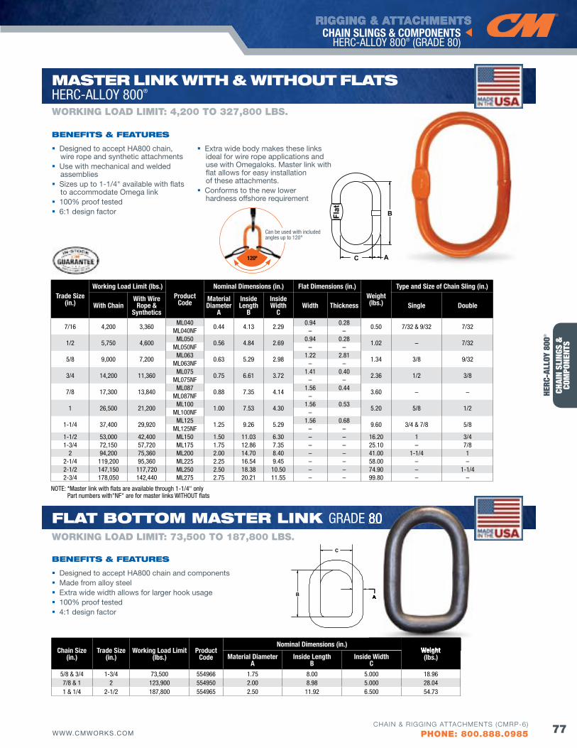
RIGGING & ATTACHMENTS
77WWW.CMWORKS.COMCHAIN & RIGGING ATTACHMENTS (CMRP-6)
PHONE: 800.888.0985
CHAIN SLINGS & COMPONENTS HERC-ALLOY 800® (GRADE 80)
CHAI
N SL
INGS
&
COM
PONE
NTS
Chain Size(in.)
Trade Size(in.)
Working Load Limit(lbs.)
Product Code
Nominal Dimensions (in.)Weight(lbs.)Material Diameter
AInside Length
BInside Width
C5/8 & 3/4 1-3/4 73,500 554966 1.75 8.00 5.000 18.96 7/8 & 1 2 123,900 554950 2.00 8.98 5.000 28.04 1 & 1/4 2-1/2 187,800 554965 2.50 11.92 6.500 54.73
AB
C
Trade Size(in.)
Working Load Limit (lbs.)Product
Code
Nominal Dimensions (in.) flat Dimensions (in.)Weight(lbs.)
Type and Size of Chain Sling (in.)
With ChainWith Wire
Rope & Synthetics
Material Diameter
A
Inside Length
B
Inside Width
CWidth Thickness Single Double
7/16 4,200 3,360ML040
0.44 4.13 2.290.94 0.28
0.50 7/32 & 9/32 7/32ML040NF – –
1/2 5,750 4,600ML050
0.56 4.84 2.690.94 0.28
1.02 – 7/32ML050NF – –
5/8 9,000 7,200ML063
0.63 5.29 2.981.22 2.81
1.34 3/8 9/32ML063NF – –
3/4 14,200 11,360ML075
0.75 6.61 3.721.41 0.40
2.36 1/2 3/8ML075NF – –
7/8 17,300 13,840ML087
0.88 7.35 4.141.56 0.44
3.60 – –ML087NF –
1 26,500 21,200ML100
1.00 7.53 4.301.56 0.53
5.20 5/8 1/2ML100NF –
1-1/4 37,400 29,920ML125
1.25 9.26 5.291.56 0.68
9.60 3/4 & 7/8 5/8ML125NF – –
1-1/2 53,000 42,400 ML150 1.50 11.03 6.30 – – 16.20 1 3/41-3/4 72,150 57,720 ML175 1.75 12.86 7.35 – – 25.10 – 7/8
2 94,200 75,360 ML200 2.00 14.70 8.40 – – 41.00 1-1/4 12-1/4 119,200 95,360 ML225 2.25 16.54 9.45 – – 58.00 – –2-1/2 147,150 117,720 ML250 2.50 18.38 10.50 – – 74.90 – 1-1/42-3/4 178,050 142,440 ML275 2.75 20.21 11.55 – – 99.80 – –
A
B
C
Flat
Designed to accept HA800 chain, wire rope and synthetic attachments
Use with mechanical and welded assemblies
Sizes up to 1-1/4" available with flats to accommodate Omega link
100% proof tested 6:1 design factor
Extra wide body makes these links ideal for wire rope applications and use with Omegaloks. Master link with flat allows for easy installation of these attachments.
Conforms to the new lower hardness offshore requirement
bENEfITS & fEATuRES
WORKING LOAD LIMIT: 4,200 TO 327,800 LbS.
flAT boTToM MASTER lINK GRADE 80
MASTER lINK wITH & wITHouT flATS HERC-ALLOY 800®
Designed to accept HA800 chain and components Made from alloy steel Extra wide width allows for larger hook usage 100% proof tested 4:1 design factor
bENEfITS & fEATuRES
WORKING LOAD LIMIT: 73,500 TO 187,800 LbS.
Weight
A
80
NOTE: *Master link with flats are available through 1-1/4" only Part numbers with"NF" are for master links WITHOUT flats
HERC
-ALL
OY 8
00®
120º
Can be used with included angles up to 120°
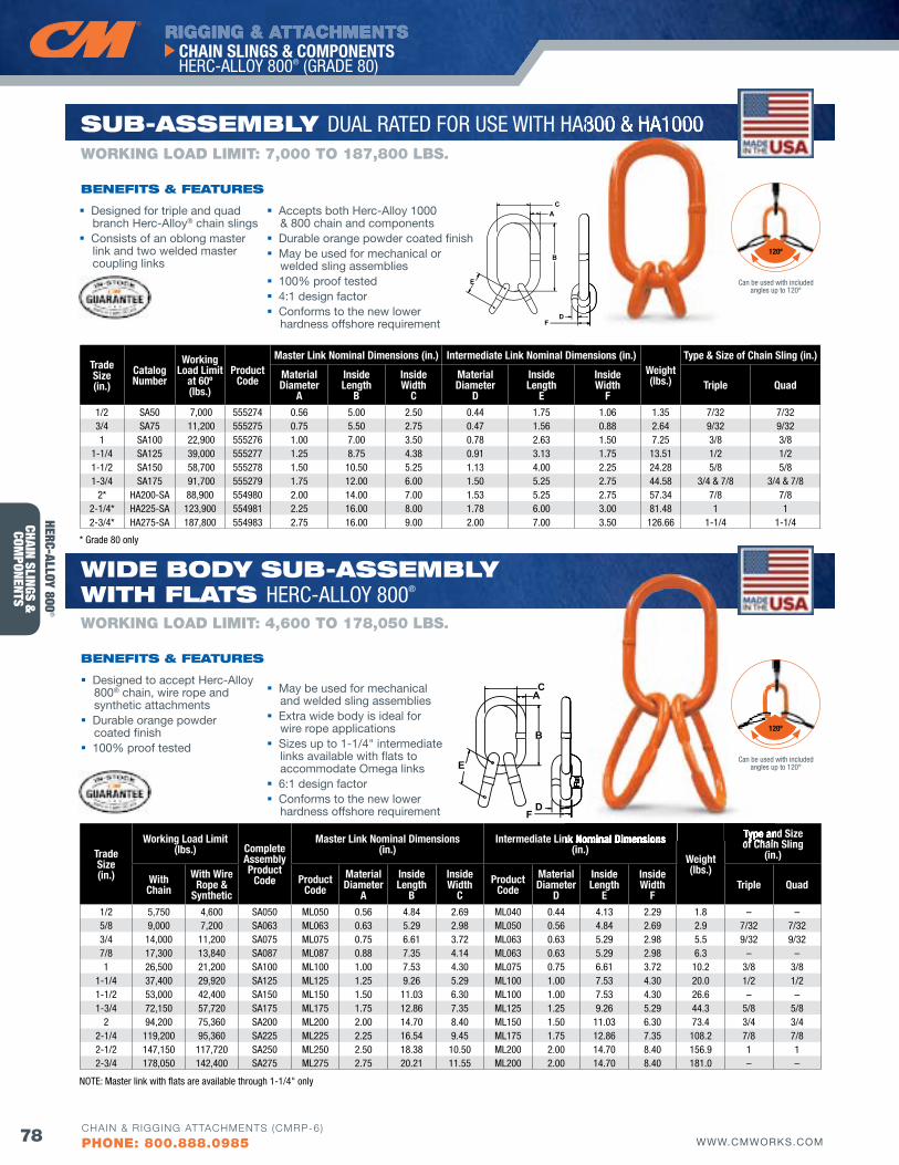
RIGGING & ATTACHMENTS
78 WWW.CMWORKS.COM
CHAIN SLINGS & COMPONENTS HERC-ALLOY 800® (GRADE 80)
CHAIN & RIGGING ATTACHMENTS (CMRP-6)
PHONE: 800.888.0985
CHAIN SLINGS &
COMPONENTS
Flat
A
B
C
D
E
F
A
B
C
D
E
F
Trade Size(in.)
Working Load Limit(lbs.) Complete
Assembly Product
Code
Master Link Nominal Dimensions (in.)
Intermediate Link Nominal Dimensions (in.)
Weight(lbs.)
Type and Size of Chain Sling
(in.)
With Chain
With Wire Rope &
SyntheticProduct
CodeMaterial Diameter
A
Inside Length
B
Inside Width
CProduct
CodeMaterial Diameter
D
Inside Length
E
Inside Width
fTriple quad
1/2 5,750 4,600 SA050 ML050 0.56 4.84 2.69 ML040 0.44 4.13 2.29 1.8 – –5/8 9,000 7,200 SA063 ML063 0.63 5.29 2.98 ML050 0.56 4.84 2.69 2.9 7/32 7/323/4 14,000 11,200 SA075 ML075 0.75 6.61 3.72 ML063 0.63 5.29 2.98 5.5 9/32 9/327/8 17,300 13,840 SA087 ML087 0.88 7.35 4.14 ML063 0.63 5.29 2.98 6.3 – –1 26,500 21,200 SA100 ML100 1.00 7.53 4.30 ML075 0.75 6.61 3.72 10.2 3/8 3/8
1-1/4 37,400 29,920 SA125 ML125 1.25 9.26 5.29 ML100 1.00 7.53 4.30 20.0 1/2 1/21-1/2 53,000 42,400 SA150 ML150 1.50 11.03 6.30 ML100 1.00 7.53 4.30 26.6 – –1-3/4 72,150 57,720 SA175 ML175 1.75 12.86 7.35 ML125 1.25 9.26 5.29 44.3 5/8 5/8
2 94,200 75,360 SA200 ML200 2.00 14.70 8.40 ML150 1.50 11.03 6.30 73.4 3/4 3/42-1/4 119,200 95,360 SA225 ML225 2.25 16.54 9.45 ML175 1.75 12.86 7.35 108.2 7/8 7/82-1/2 147,150 117,720 SA250 ML250 2.50 18.38 10.50 ML200 2.00 14.70 8.40 156.9 1 12-3/4 178,050 142,400 SA275 ML275 2.75 20.21 11.55 ML200 2.00 14.70 8.40 181.0 – –
Trade Size(in.)
Catalog Number
Working Load Limit
at 60º(lbs.)
Product Code
Master Link Nominal Dimensions (in.) Intermediate Link Nominal Dimensions (in.)Weight(lbs.)
Type & Size of Chain Sling (in.)
Material Diameter
A
Inside Length
B
InsideWidth
C
Material Diameter
D
InsideLength
E
InsideWidth
fTriple quad
1/2 SA50 7,000 555274 0.56 5.00 2.50 0.44 1.75 1.06 1.35 7/32 7/323/4 SA75 11,200 555275 0.75 5.50 2.75 0.47 1.56 0.88 2.64 9/32 9/321 SA100 22,900 555276 1.00 7.00 3.50 0.78 2.63 1.50 7.25 3/8 3/8
1-1/4 SA125 39,000 555277 1.25 8.75 4.38 0.91 3.13 1.75 13.51 1/2 1/21-1/2 SA150 58,700 555278 1.50 10.50 5.25 1.13 4.00 2.25 24.28 5/8 5/81-3/4 SA175 91,700 555279 1.75 12.00 6.00 1.50 5.25 2.75 44.58 3/4 & 7/8 3/4 & 7/8
2* HA200-SA 88,900 554980 2.00 14.00 7.00 1.53 5.25 2.75 57.34 7/8 7/82-1/4* HA225-SA 123,900 554981 2.25 16.00 8.00 1.78 6.00 3.00 81.48 1 12-3/4* HA275-SA 187,800 554983 2.75 16.00 9.00 2.00 7.00 3.50 126.66 1-1/4 1-1/4
Designed for triple and quad branch Herc-Alloy® chain slings
Consists of an oblong master link and two welded master coupling links
Accepts both Herc-Alloy 1000 & 800 chain and components
Durable orange powder coated finish May be used for mechanical or
welded sling assemblies 100% proof tested 4:1 design factor Conforms to the new lower
hardness offshore requirement
May be used for mechanical and welded sling assemblies
Extra wide body is ideal for wire rope applications
Sizes up to 1-1/4" intermediate links available with flats to accommodate Omega links
6:1 design factor Conforms to the new lower
hardness offshore requirement
bENEfITS & fEATuRES
WORKING LOAD LIMIT: 7,000 TO 187,800 LbS.
wIdE body Sub-ASSEMbly wITH flATS HERC-ALLOY 800®
Sub-ASSEMbly DUAL RATED FOR USE WITH HA800 & HA1000
Designed to accept Herc-Alloy 800® chain, wire rope and synthetic attachments
Durable orange powder coated finish
100% proof tested
bENEfITS & fEATuRES
WORKING LOAD LIMIT: 4,600 TO 178,050 LbS.
Flat
Intermediate Link Nominal Dimensions Type and Size of Chain Sling
HA800 & HA1000
* Grade 80 only
NOTE: Master link with flats are available through 1-1/4" only
HERC-ALLOY 800®
120º
120º
Can be used with included angles up to 120°
Can be used with included angles up to 120°
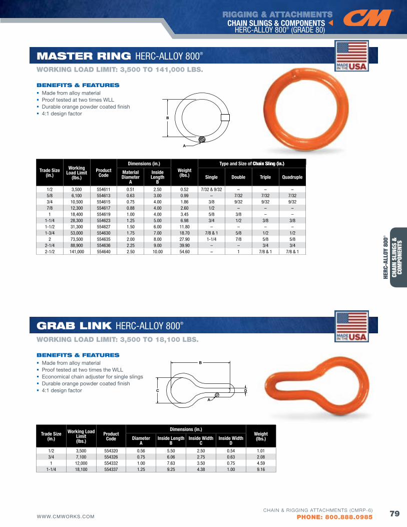
RIGGING & ATTACHMENTS
79WWW.CMWORKS.COMCHAIN & RIGGING ATTACHMENTS (CMRP-6)
PHONE: 800.888.0985
CHAIN SLINGS & COMPONENTS HERC-ALLOY 800® (GRADE 80)
CHAI
N SL
INGS
&
COM
PONE
NTS
Trade Size(in.)
Working Load Limit(lbs.)
ProductCode
Dimensions (in.)Weight(lbs.)Diameter
AInside Length
BInside Width
CInside Width
D
1/2 3,500 554320 0.56 5.50 2.50 0.54 1.013/4 7,100 554326 0.75 6.06 2.75 0.63 2.08 1 12,000 554332 1.00 7.63 3.50 0.75 4.59
1-1/4 18,100 554337 1.25 9.25 4.38 1.00 9.16
B
C D
A
Trade Size(in.)
Working Load Limit
(lbs.)Product
Code
Dimensions (in.)Weight(lbs.)
Type and Size of Chain Sling (in.)
Material Diameter
A
InsideLength
B Single Double Triple quadruple
1/2 3,500 554611 0.51 2.50 0.52 7/32 & 9/32 – – –5/8 6,100 554613 0.63 3.00 0.99 – 7/32 7/32 7/323/4 10,500 554615 0.75 4.00 1.86 3/8 9/32 9/32 9/327/8 12,300 554617 0.88 4.00 2.60 1/2 – – –1 18,400 554619 1.00 4.00 3.45 5/8 3/8 – –
1-1/4 28,300 554623 1.25 5.00 6.98 3/4 1/2 3/8 3/81-1/2 31,300 554627 1.50 6.00 11.80 – – – –1-3/4 53,000 554630 1.75 7.00 18.70 7/8 & 1 5/8 1/2 1/2
2 73,500 554635 2.00 8.00 27.90 1-1/4 7/8 5/8 5/82-1/4 88,900 554636 2.25 9.00 39.90 – – 3/4 3/42-1/2 141,000 554640 2.50 10.00 54.60 – 1 7/8 & 1 7/8 & 1
A
B
Made from alloy material Proof tested at two times WLL Durable orange powder coated finish 4:1 design factor
bENEfITS & fEATuRES
WORKING LOAD LIMIT: 3,500 TO 141,000 LbS.
MASTER RING HERC-ALLOY 800®
GRAb lINK HERC-ALLOY 800®
Made from alloy material Proof tested at two times the WLL Economical chain adjuster for single slings Durable orange powder coated finish 4:1 design factor
bENEfITS & fEATuRES
WORKING LOAD LIMIT: 3,500 TO 18,100 LbS.
Type and Size of Chain Sling (in.)
HERC
-ALL
OY 8
00®
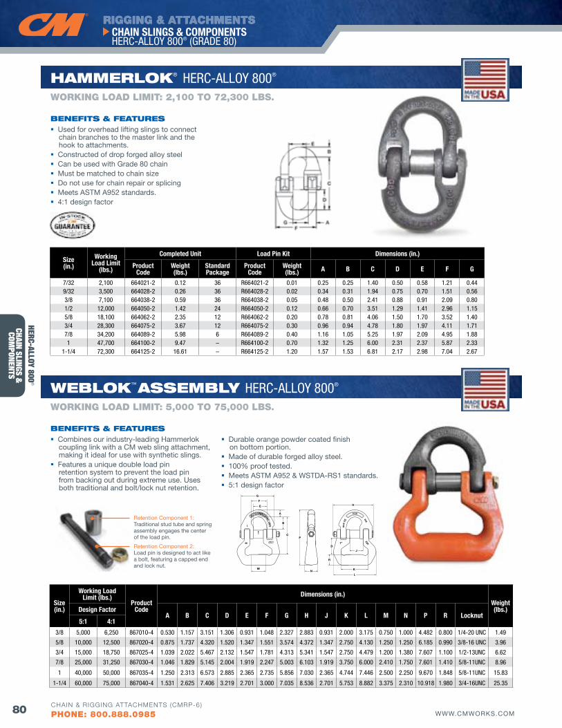
RIGGING & ATTACHMENTS
80 WWW.CMWORKS.COM
CHAIN SLINGS & COMPONENTS HERC-ALLOY 800® (GRADE 80)
CHAIN & RIGGING ATTACHMENTS (CMRP-6)
PHONE: 800.888.0985
CHAIN SLINGS &
COMPONENTS
Size(in.)
Working Load Limit
(lbs.)
Completed Unit Load Pin Kit Dimensions (in.)
Product Code
Weight (lbs.)
Standard Package
Product Code
Weight (lbs.) A B C D E f G
7/32 2,100 664021-2 0.12 36 R664021-2 0.01 0.25 0.25 1.40 0.50 0.58 1.21 0.449/32 3,500 664028-2 0.26 36 R664028-2 0.02 0.34 0.31 1.94 0.75 0.70 1.51 0.563/8 7,100 664038-2 0.59 36 R664038-2 0.05 0.48 0.50 2.41 0.88 0.91 2.09 0.801/2 12,000 664050-2 1.42 24 R664050-2 0.12 0.66 0.70 3.51 1.29 1.41 2.96 1.155/8 18,100 664062-2 2.35 12 R664062-2 0.20 0.78 0.81 4.06 1.50 1.70 3.52 1.403/4 28,300 664075-2 3.67 12 R664075-2 0.30 0.96 0.94 4.78 1.80 1.97 4.11 1.717/8 34,200 664089-2 5.98 6 R664089-2 0.40 1.16 1.05 5.25 1.97 2.09 4.95 1.881 47,700 664100-2 9.47 – R664100-2 0.70 1.32 1.25 6.00 2.31 2.37 5.87 2.33
1-1/4 72,300 664125-2 16.61 – R664125-2 1.20 1.57 1.53 6.81 2.17 2.98 7.04 2.67
HAMMERloK® HERC-ALLOY 800®
wEbloK™ ASSEMbly HERC-ALLOY 800®
Used for overhead lifting slings to connect chain branches to the master link and the hook to attachments.
Constructed of drop forged alloy steel Can be used with Grade 80 chain Must be matched to chain size Do not use for chain repair or splicing Meets ASTM A952 standards. 4:1 design factor
Combines our industry-leading Hammerlok coupling link with a CM web sling attachment, making it ideal for use with synthetic slings.
Features a unique double load pin retention system to prevent the load pin from backing out during extreme use. Uses both traditional and bolt/lock nut retention.
Durable orange powder coated finish on bottom portion.
Made of durable forged alloy steel. 100% proof tested. Meets ASTM A952 & WSTDA-RS1 standards. 5:1 design factor
bENEfITS & fEATuRES
bENEfITS & fEATuRES
WORKING LOAD LIMIT: 2,100 TO 72,300 LbS.
WORKING LOAD LIMIT: 5,000 TO 75,000 LbS.
HERC-ALLOY 800®
Size (in.)
Working Load Limit (lbs.)
Product Code
Dimensions (in.)Weight (lbs.)Design factor
A B C D E f G H J K L M N P R Locknut5:1 4:1
3/8 5,000 6,250 867010-4 0.530 1.157 3.151 1.306 0.931 1.048 2.327 2.883 0.931 2.000 3.175 0.750 1.000 4.482 0.800 1/4-20 UNC 1.49
5/8 10,000 12,500 867020-4 0.875 1.737 4.320 1.520 1.347 1.551 3.574 4.372 1.347 2.750 4.130 1.250 1.250 6.185 0.990 3/8-16 UNC 3.96
3/4 15,000 18,750 867025-4 1.039 2.022 5.467 2.132 1.547 1.781 4.313 5.341 1.547 2.750 4.479 1.200 1.380 7.607 1.100 1/2-13UNC 6.62
7/8 25,000 31,250 867030-4 1.046 1.829 5.145 2.004 1.919 2.247 5.003 6.103 1.919 3.750 6.000 2.410 1.750 7.601 1.410 5/8-11UNC 8.96
1 40,000 50,000 867035-4 1.250 2.313 6.573 2.885 2.365 2.735 5.856 7.030 2.365 4.744 7.446 2.500 2.250 9.670 1.848 5/8-11UNC 15.83
1-1/4 60,000 75,000 867040-4 1.531 2.625 7.406 3.219 2.701 3.000 7.035 8.536 2.701 5.753 8.882 3.375 2.310 10.918 1.980 3/4-16UNC 25.35
M
C
D
A
B
R
L
KN
P
J
HE
F
G
Retention Component 1: Traditional stud tube and spring assembly engages the center of the load pin.
Retention Component 2: Load pin is designed to act like a bolt, featuring a capped end and lock nut.
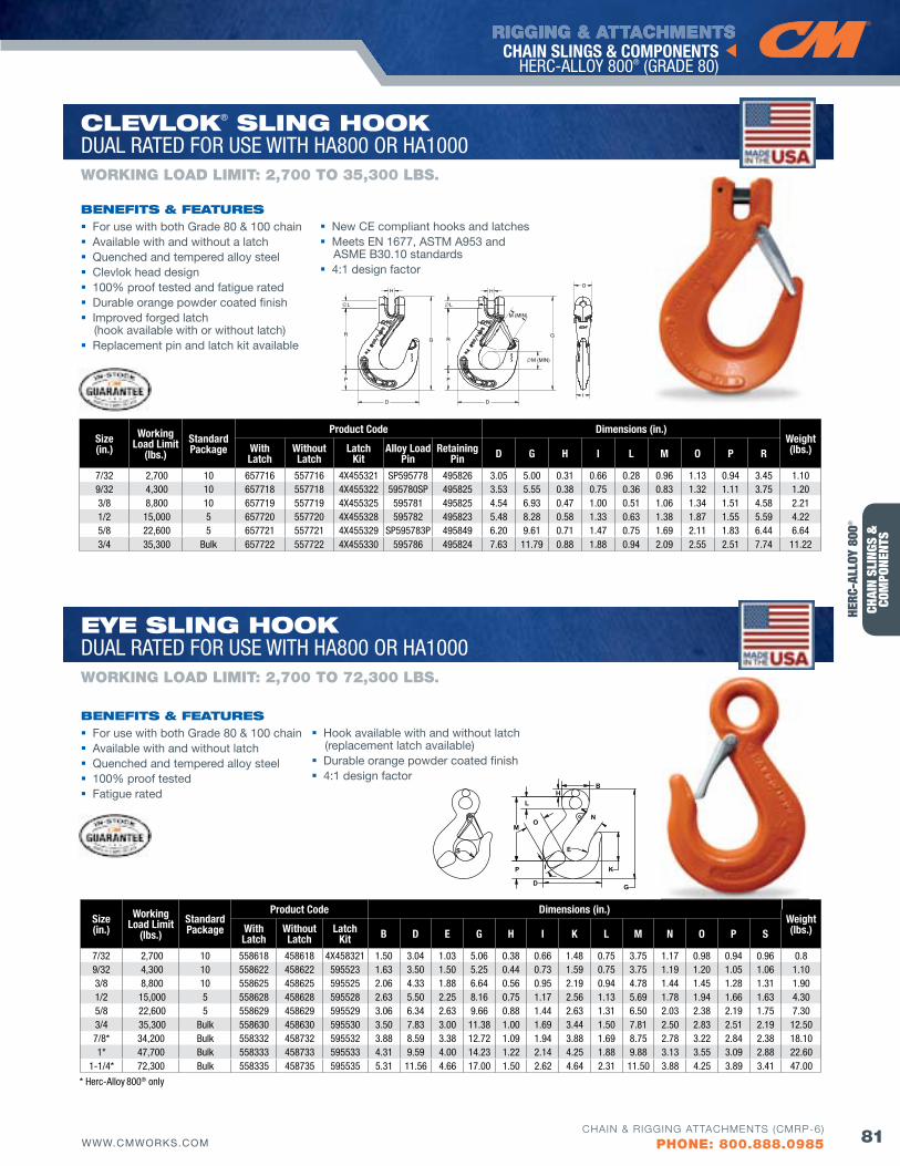
RIGGING & ATTACHMENTS
81WWW.CMWORKS.COMCHAIN & RIGGING ATTACHMENTS (CMRP-6)
PHONE: 800.888.0985
CHAIN SLINGS & COMPONENTS HERC-ALLOY 800® (GRADE 80)
CHAI
N SL
INGS
&
COM
PONE
NTS
Size(in.)
Working Load Limit
(lbs.)StandardPackage
Product Code Dimensions (in.)Weight(lbs.)With
LatchWithout Latch
Latch Kit B D E G H I K L M N O P S
7/32 2,700 10 558618 458618 4X458321 1.50 3.04 1.03 5.06 0.38 0.66 1.48 0.75 3.75 1.17 0.98 0.94 0.96 0.89/32 4,300 10 558622 458622 595523 1.63 3.50 1.50 5.25 0.44 0.73 1.59 0.75 3.75 1.19 1.20 1.05 1.06 1.103/8 8,800 10 558625 458625 595525 2.06 4.33 1.88 6.64 0.56 0.95 2.19 0.94 4.78 1.44 1.45 1.28 1.31 1.901/2 15,000 5 558628 458628 595528 2.63 5.50 2.25 8.16 0.75 1.17 2.56 1.13 5.69 1.78 1.94 1.66 1.63 4.305/8 22,600 5 558629 458629 595529 3.06 6.34 2.63 9.66 0.88 1.44 2.63 1.31 6.50 2.03 2.38 2.19 1.75 7.303/4 35,300 Bulk 558630 458630 595530 3.50 7.83 3.00 11.38 1.00 1.69 3.44 1.50 7.81 2.50 2.83 2.51 2.19 12.507/8* 34,200 Bulk 558332 458732 595532 3.88 8.59 3.38 12.72 1.09 1.94 3.88 1.69 8.75 2.78 3.22 2.84 2.38 18.101* 47,700 Bulk 558333 458733 595533 4.31 9.59 4.00 14.23 1.22 2.14 4.25 1.88 9.88 3.13 3.55 3.09 2.88 22.60
1-1/4* 72,300 Bulk 558335 458735 595535 5.31 11.56 4.66 17.00 1.50 2.62 4.64 2.31 11.50 3.88 4.25 3.89 3.41 47.00
B
N
G
K
D
E
P
M
I
O
LH
S
For use with both Grade 80 & 100 chain Available with and without a latch Quenched and tempered alloy steel Clevlok head design 100% proof tested and fatigue rated Durable orange powder coated finish Improved forged latch
(hook available with or without latch) Replacement pin and latch kit available
New CE compliant hooks and latches Meets EN 1677, ASTM A953 and
ASME B30.10 standards 4:1 design factor
bENEfITS & fEATuRES
WORKING LOAD LIMIT: 2,700 TO 35,300 LbS.
ClEvloK® SlING HooK DUAL RATED FOR USE WITH HA800 OR HA1000
EyE SlING HooK DUAL RATED FOR USE WITH HA800 OR HA1000
For use with both Grade 80 & 100 chain Available with and without latch Quenched and tempered alloy steel 100% proof tested Fatigue rated
Hook available with and without latch (replacement latch available)
Durable orange powder coated finish 4:1 design factor
bENEfITS & fEATuRES
WORKING LOAD LIMIT: 2,700 TO 72,300 LbS.
Size(in.)
Working Load Limit
(lbs.)Standard Package
Product Code Dimensions (in.)Weight(lbs.)With
LatchWithout Latch
Latch Kit
Alloy Load Pin
RetainingPin D G H I L M O P R
7/32 2,700 10 657716 557716 4X455321 SP595778 495826 3.05 5.00 0.31 0.66 0.28 0.96 1.13 0.94 3.45 1.109/32 4,300 10 657718 557718 4X455322 595780SP 495825 3.53 5.55 0.38 0.75 0.36 0.83 1.32 1.11 3.75 1.20 3/8 8,800 10 657719 557719 4X455325 595781 495825 4.54 6.93 0.47 1.00 0.51 1.06 1.34 1.51 4.58 2.21 1/2 15,000 5 657720 557720 4X455328 595782 495823 5.48 8.28 0.58 1.33 0.63 1.38 1.87 1.55 5.59 4.22 5/8 22,600 5 657721 557721 4X455329 SP595783P 495849 6.20 9.61 0.71 1.47 0.75 1.69 2.11 1.83 6.44 6.64 3/4 35,300 Bulk 657722 557722 4X455330 595786 495824 7.63 11.79 0.88 1.88 0.94 2.09 2.55 2.51 7.74 11.22
* Herc-Alloy 800® only
HERC
-ALL
OY 8
00®
M (MIN)
R G
M (MIN)
D
P
R
P
G
D I
O
L
H H
L
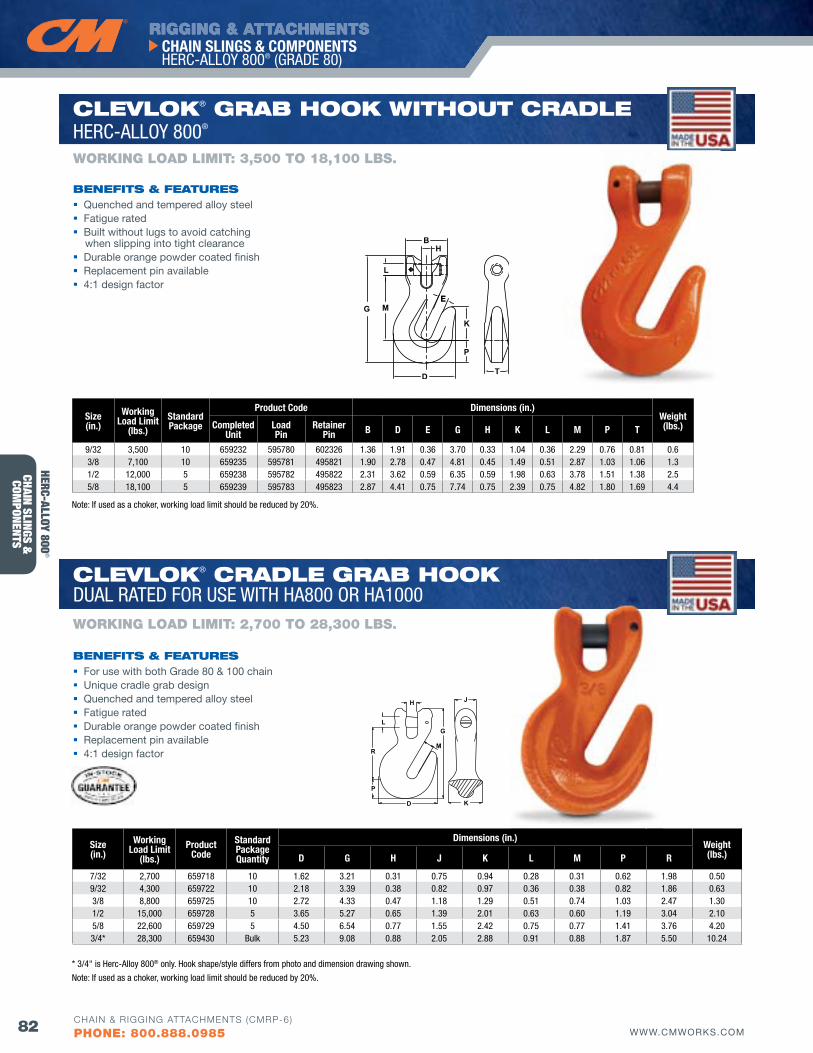
RIGGING & ATTACHMENTS
82 WWW.CMWORKS.COM
CHAIN SLINGS & COMPONENTS HERC-ALLOY 800® (GRADE 80)
CHAIN & RIGGING ATTACHMENTS (CMRP-6)
PHONE: 800.888.0985
CHAIN SLINGS &
COMPONENTS
B
P
H
E
K
D
EMG
L
T
Quenched and tempered alloy steel Fatigue rated Built without lugs to avoid catching
when slipping into tight clearance Durable orange powder coated finish Replacement pin available 4:1 design factor
bENEfITS & fEATuRES
WORKING LOAD LIMIT: 3,500 TO 18,100 LbS.
ClEvloK® GRAb HooK wITHouT CRAdlE HERC-ALLOY 800®
ClEvloK® CRAdlE GRAb HooK DUAL RATED FOR USE WITH HA800 OR HA1000
For use with both Grade 80 & 100 chain Unique cradle grab design Quenched and tempered alloy steel Fatigue rated Durable orange powder coated finish Replacement pin available 4:1 design factor
bENEfITS & fEATuRES
WORKING LOAD LIMIT: 2,700 TO 28,300 LbS.
Size(in.)
Working Load Limit
(lbs.)StandardPackage
Product Code Dimensions (in.)Weight(lbs.)Completed
UnitLoad Pin
Retainer Pin B D E G H K L M P T
9/32 3,500 10 659232 595780 602326 1.36 1.91 0.36 3.70 0.33 1.04 0.36 2.29 0.76 0.81 0.63/8 7,100 10 659235 595781 495821 1.90 2.78 0.47 4.81 0.45 1.49 0.51 2.87 1.03 1.06 1.3 1/2 12,000 5 659238 595782 495822 2.31 3.62 0.59 6.35 0.59 1.98 0.63 3.78 1.51 1.38 2.5 5/8 18,100 5 659239 595783 495823 2.87 4.41 0.75 7.74 0.75 2.39 0.75 4.82 1.80 1.69 4.4
Note: If used as a choker, working load limit should be reduced by 20%.
* 3/4" is Herc-Alloy 800® only. Hook shape/style differs from photo and dimension drawing shown.
H
M
G
R
L
P
D
J
K
Size(in.)
Working Load Limit
(lbs.)Product
CodeStandard Packagequantity
Dimensions (in.)Weight(lbs.)D G H J K L M P R
7/32 2,700 659718 10 1.62 3.21 0.31 0.75 0.94 0.28 0.31 0.62 1.98 0.509/32 4,300 659722 10 2.18 3.39 0.38 0.82 0.97 0.36 0.38 0.82 1.86 0.633/8 8,800 659725 10 2.72 4.33 0.47 1.18 1.29 0.51 0.74 1.03 2.47 1.301/2 15,000 659728 5 3.65 5.27 0.65 1.39 2.01 0.63 0.60 1.19 3.04 2.105/8 22,600 659729 5 4.50 6.54 0.77 1.55 2.42 0.75 0.77 1.41 3.76 4.203/4* 28,300 659430 Bulk 5.23 9.08 0.88 2.05 2.88 0.91 0.88 1.87 5.50 10.24
Note: If used as a choker, working load limit should be reduced by 20%.
HERC-ALLOY 800®
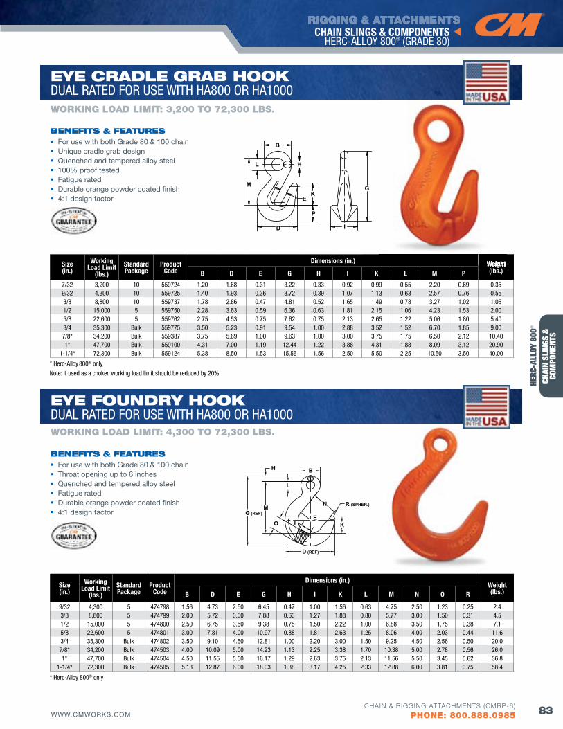
RIGGING & ATTACHMENTS
83WWW.CMWORKS.COMCHAIN & RIGGING ATTACHMENTS (CMRP-6)
PHONE: 800.888.0985
CHAIN SLINGS & COMPONENTS HERC-ALLOY 800® (GRADE 80)
CHAI
N SL
INGS
&
COM
PONE
NTS
Size(in.)
Working Load Limit
(lbs.)StandardPackage
Product Code
Dimensions (in.)Weight(lbs.)B D E G H I K L M N O R
9/32 4,300 5 474798 1.56 4.73 2.50 6.45 0.47 1.00 1.56 0.63 4.75 2.50 1.23 0.25 2.43/8 8,800 5 474799 2.00 5.72 3.00 7.88 0.63 1.27 1.88 0.80 5.77 3.00 1.50 0.31 4.51/2 15,000 5 474800 2.50 6.75 3.50 9.38 0.75 1.50 2.22 1.00 6.88 3.50 1.75 0.38 7.15/8 22,600 5 474801 3.00 7.81 4.00 10.97 0.88 1.81 2.63 1.25 8.06 4.00 2.03 0.44 11.63/4 35,300 Bulk 474802 3.50 9.10 4.50 12.81 1.00 2.20 3.00 1.50 9.25 4.50 2.56 0.50 20.07/8* 34,200 Bulk 474503 4.00 10.09 5.00 14.23 1.13 2.25 3.38 1.70 10.38 5.00 2.78 0.56 26.01* 47,700 Bulk 474504 4.50 11.55 5.50 16.17 1.29 2.63 3.75 2.13 11.56 5.50 3.45 0.62 36.8
1-1/4* 72,300 Bulk 474505 5.13 12.87 6.00 18.03 1.38 3.17 4.25 2.33 12.88 6.00 3.81 0.75 58.4
H B
L
N R (SPHER.)
KE
D (REF)
O
G (REF)M
I
Size(in.)
Working Load Limit
(lbs.)StandardPackage
Product Code
Dimensions (in.) Weight(lbs.)B D E G H I K L M P
7/32 3,200 10 559724 1.20 1.68 0.31 3.22 0.33 0.92 0.99 0.55 2.20 0.69 0.359/32 4,300 10 559725 1.40 1.93 0.36 3.72 0.39 1.07 1.13 0.63 2.57 0.76 0.553/8 8,800 10 559737 1.78 2.86 0.47 4.81 0.52 1.65 1.49 0.78 3.27 1.02 1.061/2 15,000 5 559750 2.28 3.63 0.59 6.36 0.63 1.81 2.15 1.06 4.23 1.53 2.005/8 22,600 5 559762 2.75 4.53 0.75 7.62 0.75 2.13 2.65 1.22 5.06 1.80 5.403/4 35,300 Bulk 559775 3.50 5.23 0.91 9.54 1.00 2.88 3.52 1.52 6.70 1.85 9.007/8* 34,200 Bulk 559387 3.75 5.69 1.00 9.63 1.00 3.00 3.75 1.75 6.50 2.12 10.401* 47,700 Bulk 559100 4.31 7.00 1.19 12.44 1.22 3.88 4.31 1.88 8.09 3.12 20.90
1-1/4* 72,300 Bulk 559124 5.38 8.50 1.53 15.56 1.56 2.50 5.50 2.25 10.50 3.50 40.00
B
H
GK
E
P
D
M
L
I
For use with both Grade 80 & 100 chain Unique cradle grab design Quenched and tempered alloy steel 100% proof tested Fatigue rated Durable orange powder coated finish 4:1 design factor
bENEfITS & fEATuRES
WORKING LOAD LIMIT: 3,200 TO 72,300 LbS.
EyE CRAdlE GRAb HooK DUAL RATED FOR USE WITH HA800 OR HA1000
EyE fouNdRy HooK DUAL RATED FOR USE WITH HA800 OR HA1000
For use with both Grade 80 & 100 chain Throat opening up to 6 inches Quenched and tempered alloy steel Fatigue rated Durable orange powder coated finish 4:1 design factor
bENEfITS & fEATuRES
WORKING LOAD LIMIT: 4,300 TO 72,300 LbS.
* Herc-Alloy 800® only
* Herc-Alloy 800® only
Weight
Note: If used as a choker, working load limit should be reduced by 20%.
HERC
-ALL
OY 8
00®
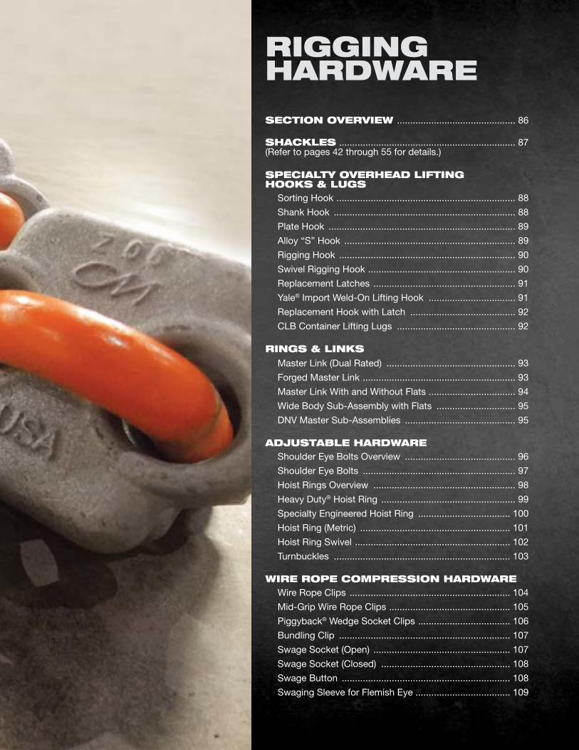
SECTIoN ovERvIEw ............................................. 86
SHACKlES ................................................................... 87 (Refer to pages 42 through 55 for details.)
SPECIAlTy ovERHEAd lIfTING HooKS & luGS Sorting Hook .................................................................... 88
Shank Hook ..................................................................... 88
Plate Hook ....................................................................... 89
Alloy “S” Hook ................................................................. 89
Rigging Hook ................................................................... 90
Swivel Rigging Hook ........................................................ 90
Replacement Latches ...................................................... 91
Yale® Import Weld-On Lifting Hook ................................. 91
Replacement Hook with Latch ........................................ 92
CLB Container Lifting Lugs ............................................. 92
RINGS & lINKS Master Link (Dual Rated) ................................................. 93
Forged Master Link .......................................................... 93
Master Link With and Without Flats ................................. 94
Wide Body Sub-Assembly with Flats .............................. 95
DNv Master Sub-Assemblies .......................................... 95
AdjuSTAblE HARdwARE Shoulder Eye Bolts Overview .......................................... 96
Shoulder Eye Bolts .......................................................... 97
Hoist Rings Overview ...................................................... 98
Heavy Duty® Hoist Ring ................................................... 99
Specialty Engineered Hoist Ring ................................... 100
Hoist Ring (Metric) ......................................................... 101
Hoist Ring Swivel ........................................................... 102
Turnbuckles ................................................................... 103
wIRE RoPE CoMPRESSIoN HARdwARE Wire Rope Clips ............................................................. 104
Mid-Grip Wire Rope Clips .............................................. 105
Piggyback® Wedge Socket Clips ................................... 106
Bundling Clip ................................................................. 107
Swage Socket (Open) .................................................... 107
Swage Socket (Closed) ................................................. 108
Swage Button ................................................................ 108
Swaging Sleeve for Flemish Eye .................................... 109
RIGGINGHARdwARE
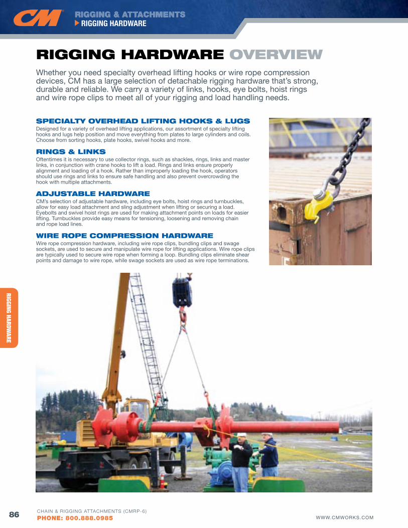
RIGGING HARDWARE
RIGGING & ATTACHMENTSRIGGING HARDWARE
86 WWW.CMWORKS.COMCHAIN & RIGGING ATTACHMENTS (CMRP-6)
PHONE: 800.888.0985
Whether you need specialty overhead lifting hooks or wire rope compression devices, CM has a large selection of detachable rigging hardware that’s strong, durable and reliable. We carry a variety of links, hooks, eye bolts, hoist rings and wire rope clips to meet all of your rigging and load handling needs.
SPECIAlTy ovERHEAd lIfTING HooKS & luGSDesigned for a variety of overhead lifting applications, our assortment of specialty lifting hooks and lugs help position and move everything from plates to large cylinders and coils. Choose from sorting hooks, plate hooks, swivel hooks and more.
RINGS & lINKSOftentimes it is necessary to use collector rings, such as shackles, rings, links and master links, in conjunction with crane hooks to lift a load. Rings and links ensure properly alignment and loading of a hook. Rather than improperly loading the hook, operators should use rings and links to ensure safe handling and also prevent overcrowding the hook with multiple attachments.
AdjuSTAblE HARdwARE CM’s selection of adjustable hardware, including eye bolts, hoist rings and turnbuckles, allow for easy load attachment and sling adjustment when lifting or securing a load. Eyebolts and swivel hoist rings are used for making attachment points on loads for easier lifting. Turnbuckles provide easy means for tensioning, loosening and removing chain and rope load lines.
wIRE RoPE CoMPRESSIoN HARdwARE Wire rope compression hardware, including wire rope clips, bundling clips and swage sockets, are used to secure and manipulate wire rope for lifting applications. Wire rope clips are typically used to secure wire rope when forming a loop. Bundling clips eliminate shear points and damage to wire rope, while swage sockets are used as wire rope terminations.
RIGGING HARdwARE ovERvIEw
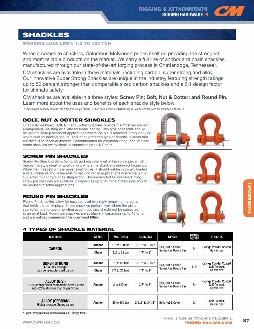
HERC
-ALL
OY® 8
00RI
GGIN
G HA
RDW
ARE
RIGGING & ATTACHMENTSRIGGING HARDWARE
87WWW.CMWORKS.COMCHAIN & RIGGING ATTACHMENTS (CMRP-6)
PHONE: 800.888.0985
WORKING LOAD LIMIT: 1/3 TO 120 TON
SHACKlES
When it comes to shackles, Columbus McKinnon prides itself on providing the strongest and most reliable products on the market. We carry a full line of anchor and chain shackles, manufactured through our state-of-the-art forging process in Chattanooga, Tennessee*.
CM shackles are available in three materials, including carbon, super strong and alloy. Our innovative Super Strong Shackles are unique in the industry, featuring strength ratings up to 50 percent stronger than comparable sized carbon shackles and a 6:1 design factor for ultimate safety.
CM shackles are available in a three styles: Screw Pin; Bolt, Nut & Cotter; and Round Pin. Learn more about the uses and benefits of each shackle style below.
MATERIAL STYLE WLL (TONS) SIzES (IN.) STYLES DESIGN fACTOR fINISHES
CARBONAnchor 1/3 to 120 ton 3/16" to 3-1/2"
Bolt, Nut & Cotter;Screw Pin; Round Pin 6:1 Orange Powder Coated,
GalvanizedChain 1/2 to 35 ton 1/4" to 2"
SUPER STRONG 17 to 50% stronger
than comparable-sized Carbon
Anchor 1/2 to 55 tons 3/16" to 2-1/2"Bolt, Nut & Cotter;Screw Pin; Round Pin 6:1*
Orange Powder Coated, Self Colored, GalvanizedChain 3/4 to 35 tons 1/4" to 2"
ALLOY (U.S.) ~50% stronger than comparable-sized Carbon
and ~25% stronger than Super StrongAnchor 2 to 120 ton 3/8" to 3" Bolt, Nut & Cotter;
Screw Pin; Round Pin 5:1Orange Powder Coated,
Self Colored, Galvanized
ALLOY (GERMAN)Higher average Charpy values
Anchor 85 to 150 ton 2-1/2" to 3-1/2" Bolt, Nut & Cotter 5:1 Self Colored, Galvanized
4 TyPES of SHACKlE MATERIAl
bolT, NuT & CoTTER SHACKlESOf all shackle types, Bolt, Nut and Cotter Shackles provide the most secure pin arrangement, resisting axial and torsional loading. This type of shackle should be used in semi-permanent applications where the pin is removed infrequently or where cyclical loading occurs. This is the preferred type of shackle in areas that are difficult to reach or inspect. Recommended for overhead lifting, bolt, nut and cotter shackles are available in capacities up to 120 tons.
SCREw PIN SHACKlESScrew Pin Shackles allow for quick and easy removal of the screw pin, which makes this style ideal for applications where the shackle is removed frequently. While the threaded pin can resist axial forces, it should not be cyclically loaded and is unreliable and vulnerable to backing out in applications where the pin is subjected to a torque or twisting action. Recommended for overhead lifting, screw pin shackles are available in capacities up to 43 tons. Screw pins should be moused in some applications.
RouNd PIN SHACKlESRound Pin Shackles allow for easy removal by simply removing the cotter that holds the pin in place. These shackles perform well where the pin is subjected to a torque or twisting action, but they should not be subjected to an axial load. Round pin shackles are available in capacities up to 43 tons and are not recommended for overhead lifting.
* Super Strong round pin shackles have a 5:1 design factor.
* Some higher-capacity shackles are forged from high-quality German alloy steel at our STB facility in Hamm, Germany and then finished in the U.S.A.
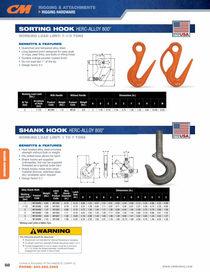
RIGGING HARDWARE
RIGGING & ATTACHMENTSRIGGING HARDWARE
88 WWW.CMWORKS.COMCHAIN & RIGGING ATTACHMENTS (CMRP-6)
PHONE: 800.888.0985
Alloy Shank HookWeight(lbs.)
LatchKit
ProductCode
Max Shank
Diameter(in.)
LatchHole(in.)
Dimensions (in.)
Working Load Limit*
(ton)Product
Code D f G H J K L O P R X Y z
1 M1302AV 0.65 4X1302 0.72 0.14 3.09 1.25 0.87 1.01 0.91 0.63 5.44 0.88 2.12 2.35 0.66 2.22 0.69 1-1/2 M1303AV 0.80 4X1303 0.79 0.19 3.37 1.38 0.94 1.11 0.97 0.71 5.92 0.91 2.27 2.59 0.73 2.39 0.80
2 M1304AV 1.47 4X1304 0.86 0.18 3.75 1.50 1.04 1.21 1.06 0.88 6.45 1.00 2.58 2.75 0.79 2.66 1.00 3 M1305AV 1.85 4X1305 1.11 0.18 4.23 1.63 1.25 1.43 1.17 0.94 7.42 1.16 2.84 3.16 0.96 3.01 1.035 M1307AV 4.04 4X1307 1.30 0.20 5.16 2.00 1.44 1.63 1.48 1.38 8.80 1.41 3.52 3.85 1.24 3.52 1.277 M1309AV 7.25 4X1309 1.56 0.20 6.24 2.50 1.82 2.01 1.78 1.68 10.72 1.69 4.59 4.70 1.49 4.02 1.56
L
F
D
J w/o Latch
P
Z
Y
R
G
X
H
O
T
K
K
Z
Working Load Limit(lbs.) With Handle Without Handle Dimensions (in.)
At Tip(ton)
At bottom of Hook
(ton)Product
CodeWeight(lbs.)
Product Code
Weight(lbs.) A B C D E f G H I M
2 7-1/2 M129H 7.0 M129 6.8 3 1.44 0.78 7.34 3.75 1.28 1.25 3.93 10.09 6.58
IH
C
E
G
F
D
B
MA
Quenched and tempered alloy steel Long tapered point designed for easy grab
in rings, pear links, eye bolts or lifting holes Durable orange powder coated finish Do not load last 1" of the tip Design factor 5:1
bENEfITS & fEATuRES
WORKING LOAD LIMIT: 7-1/2 TONS
SoRTING HooK HERC-ALLOY 800®
SHANK HooK HERC-ALLOY 800®
Heat treated alloy steel provides strength without bulk or weight
Pre-drilled boss allows for latch Shank hooks are supplied
unthreaded, but can be supplied threaded as a special order item
Shank hooks made from other material (bronze, stainless steel, etc.) available upon request
Design factor 5:1
bENEfITS & fEATuRES
WORKING LOAD LIMIT: 1 TO 7 TONS
K
The following should be observed: s Shanks are not intended for internal threading or swaging.
s To obtain maximum strength threads should be class 1 or 2.
s Thread engagement in nut or object must be a minimum of 1-1/2 times the thread diameter. Insufficient thread engagement can result in loss of load.
* Working Load Limits in Metric Tons.
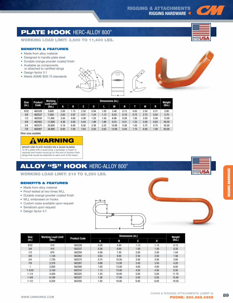
HERC
-ALL
OY® 8
00RI
GGIN
G HA
RDW
ARE
RIGGING & ATTACHMENTSRIGGING HARDWARE
89WWW.CMWORKS.COMCHAIN & RIGGING ATTACHMENTS (CMRP-6)
PHONE: 800.888.0985
Size(in.)
Working Load Limit(lbs.) Product Code
Dimensions (in.) Weight(lbs.)A B C D
9/32 210 562228 0.28 4.50 1.13 1.13 0.153/8 410 562237 0.38 6.00 1.50 1.50 0.351/2 870 562250 0.56 7.50 2.00 2.00 1.045/8 1,120 562262 0.63 9.00 2.50 2.50 1.563/4 1,730 562275 0.75 10.50 3.00 3.00 2.607/8 2,370 562287 0.88 12.00 3.50 3.50 4.201 2,920 562300 1.00 13.00 4.00 4.00 6.00
1-5/32 3,150 562310 1.13 15.00 4.50 4.50 9.301-1/4 4,450 562325 1.25 16.00 5.00 5.00 11.701-3/8 6,100 562337 1.38 17.00 5.50 5.50 15.401-1/2 6,250 562350 1.50 18.00 6.00 6.00 19.50
B
CA
C
D
R
R
R
W
M
B
L
NA
C
D
T
Size(in.)
Product Code
Working Load Limit
(lbs.)
Dimensions (in.) Weight(lbs.)A B C D L M N T W R
9/32 462528 3,600 2.00 1.75 2.50 0.94 1.00 3.48 0.13 0.63 2.50 0.31 2.80 3/8 462537 7,050 2.63 2.97 4.31 1.24 1.13 6.53 0.19 0.75 2.75 0.50 5.70 1/2 462550 11,400 3.50 4.00 4.38 1.50 1.50 6.98 0.28 1.00 3.50 0.50 13.00 5/8 462562 17,800 4.38 5.00 5.44 1.88 1.88 9.25 0.31 1.25 5.00 0.63 26.503/4 462575 25,600 5.19 6.00 6.50 2.38 2.25 10.88 0.38 1.50 5.75 0.75 42.007/8 462587 34,900 6.00 7.00 7.63 2.50 2.63 13.06 0.44 1.75 6.00 1.00 65.00
Made from alloy material Designed to handle plate steel Durable orange powder coated finish Available as components
or attached to certified slings Design factor 5:1 Meets ASME B30.10 standards
bENEfITS & fEATuRES
WORKING LOAD LIMIT: 3,600 TO 11,400 LbS.
PlATE HooK HERC-ALLOY 800®
Alloy “S” HooK HERC-ALLOY 800®
Made from alloy material Proof tested at two times WLL Durable orange powder coated finish WLL embossed on hooks Custom sizes available upon request Serialized upon request Design factor 4:1
Other sizes available
bENEfITS & fEATuRES
WORKING LOAD LIMIT: 210 TO 6,250 LbS.
NEVER USE PLATE HOOKS ON A QUAD SLINGS. To lift a plate with a quad sling, a spreader or beam is required and hooks would go on the end of double chain slings that would be attached to each end of the beam.
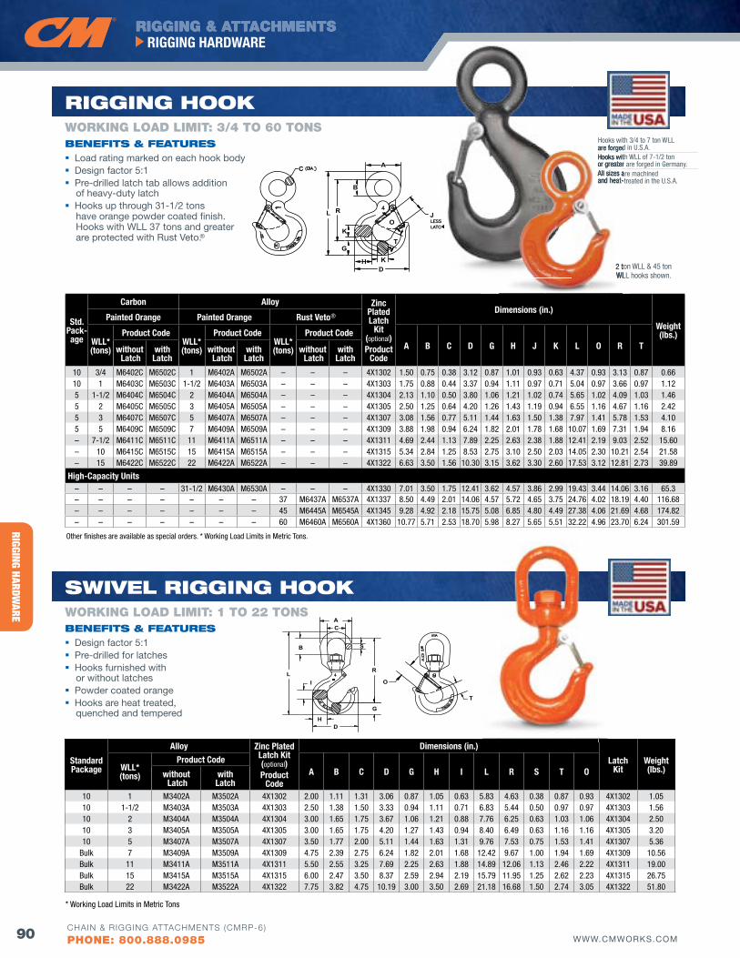
RIGGING HARDWARE
RIGGING & ATTACHMENTSRIGGING HARDWARE
90 WWW.CMWORKS.COMCHAIN & RIGGING ATTACHMENTS (CMRP-6)
PHONE: 800.888.0985
C
LR
B
A
I
G
H
S
D
T
O
SwIvEl RIGGING HooK
bENEfITS & fEATuRES Design factor 5:1 Pre-drilled for latches Hooks furnished with
or without latches Powder coated orange Hooks are heat treated,
quenched and tempered
WORKING LOAD LIMIT: 1 TO 22 TONS
StandardPackage
Alloy zinc Plated Latch Kit (optional)Product
Code
Dimensions (in.)
LatchKit
Weight(lbs.)WLL*
(tons)
Product CodeA B C D G H I L R S T Owithout
LatchwithLatch
10 1 M3402A M3502A 4X1302 2.00 1.11 1.31 3.06 0.87 1.05 0.63 5.83 4.63 0.38 0.87 0.93 4X1302 1.0510 1-1/2 M3403A M3503A 4X1303 2.50 1.38 1.50 3.33 0.94 1.11 0.71 6.83 5.44 0.50 0.97 0.97 4X1303 1.5610 2 M3404A M3504A 4X1304 3.00 1.65 1.75 3.67 1.06 1.21 0.88 7.76 6.25 0.63 1.03 1.06 4X1304 2.5010 3 M3405A M3505A 4X1305 3.00 1.65 1.75 4.20 1.27 1.43 0.94 8.40 6.49 0.63 1.16 1.16 4X1305 3.2010 5 M3407A M3507A 4X1307 3.50 1.77 2.00 5.11 1.44 1.63 1.31 9.76 7.53 0.75 1.53 1.41 4X1307 5.36
Bulk 7 M3409A M3509A 4X1309 4.75 2.39 2.75 6.24 1.82 2.01 1.68 12.42 9.67 1.00 1.94 1.69 4X1309 10.56Bulk 11 M3411A M3511A 4X1311 5.50 2.55 3.25 7.69 2.25 2.63 1.88 14.89 12.06 1.13 2.46 2.22 4X1311 19.00Bulk 15 M3415A M3515A 4X1315 6.00 2.47 3.50 8.37 2.59 2.94 2.19 15.79 11.95 1.25 2.62 2.23 4X1315 26.75Bulk 22 M3422A M3522A 4X1322 7.75 3.82 4.75 10.19 3.00 3.50 2.69 21.18 16.68 1.50 2.74 3.05 4X1322 51.80
* Working Load Limits in Metric Tons
C
L R
B
A
K
G
H KD
T
OJ
RIGGING HooK
bENEfITS & fEATuRES Load rating marked on each hook body Design factor 5:1 Pre-drilled latch tab allows addition
of heavy-duty latch Hooks up through 31-1/2 tons
have orange powder coated finish. Hooks with WLL 37 tons and greater are protected with Rust veto.®
WORKING LOAD LIMIT: 3/4 TO 60 TONS
Other finishes are available as special orders. * Working Load Limits in Metric Tons.
Std.Pack-age
Carbon Alloy zinc Plated Latch
Kit (optional)Product
Code
Dimensions (in.)
Weight(lbs.)
Painted Orange Painted Orange Rust Veto®
WLL*(tons)
Product CodeWLL*(tons)
Product CodeWLL*(tons)
Product CodeA B C D G H J K L O R Twithout
LatchwithLatch
without Latch
withLatch
without Latch
withLatch
10 3/4 M6402C M6502C 1 M6402A M6502A – – – 4X1302 1.50 0.75 0.38 3.12 0.87 1.01 0.93 0.63 4.37 0.93 3.13 0.87 0.6610 1 M6403C M6503C 1-1/2 M6403A M6503A – – – 4X1303 1.75 0.88 0.44 3.37 0.94 1.11 0.97 0.71 5.04 0.97 3.66 0.97 1.125 1-1/2 M6404C M6504C 2 M6404A M6504A – – – 4X1304 2.13 1.10 0.50 3.80 1.06 1.21 1.02 0.74 5.65 1.02 4.09 1.03 1.465 2 M6405C M6505C 3 M6405A M6505A – – – 4X1305 2.50 1.25 0.64 4.20 1.26 1.43 1.19 0.94 6.55 1.16 4.67 1.16 2.425 3 M6407C M6507C 5 M6407A M6507A – – – 4X1307 3.08 1.56 0.77 5.11 1.44 1.63 1.50 1.38 7.97 1.41 5.78 1.53 4.105 5 M6409C M6509C 7 M6409A M6509A – – – 4X1309 3.88 1.98 0.94 6.24 1.82 2.01 1.78 1.68 10.07 1.69 7.31 1.94 8.16– 7-1/2 M6411C M6511C 11 M6411A M6511A – – – 4X1311 4.69 2.44 1.13 7.89 2.25 2.63 2.38 1.88 12.41 2.19 9.03 2.52 15.60– 10 M6415C M6515C 15 M6415A M6515A – – – 4X1315 5.34 2.84 1.25 8.53 2.75 3.10 2.50 2.03 14.05 2.30 10.21 2.54 21.58– 15 M6422C M6522C 22 M6422A M6522A – – – 4X1322 6.63 3.50 1.56 10.30 3.15 3.62 3.30 2.60 17.53 3.12 12.81 2.73 39.89
High-Capacity Units– – – – 31-1/2 M6430A M6530A – – – 4X1330 7.01 3.50 1.75 12.41 3.62 4.57 3.86 2.99 19.43 3.44 14.06 3.16 65.3– – – – – – – 37 M6437A M6537A 4X1337 8.50 4.49 2.01 14.06 4.57 5.72 4.65 3.75 24.76 4.02 18.19 4.40 116.68– – – – – – – 45 M6445A M6545A 4X1345 9.28 4.92 2.18 15.75 5.08 6.85 4.80 4.49 27.38 4.06 21.69 4.68 174.82– – – – – – – 60 M6460A M6560A 4X1360 10.77 5.71 2.53 18.70 5.98 8.27 5.65 5.51 32.22 4.96 23.70 6.24 301.59
Hooks with 3/4 to 7 ton WLL are forged in U.S.A.Hooks with WLL of 7-1/2 ton or greater are forged in Germany.All sizes are machined and heat-treated in the U.S.A.
2 ton WLL & 45 ton WLL hooks shown.
are forged in U.S.A.Hooks with WLL of 7-1/2 ton or greater are forged in Germany.All sizes are machined and heat-treated in the U.S.A.
2 ton WLL & 45 ton WLL hooks shown.
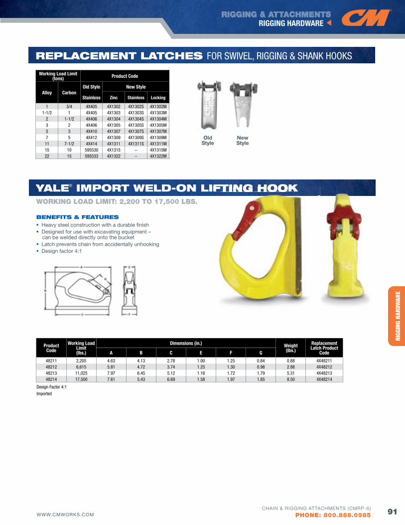
HERC
-ALL
OY® 8
00RI
GGIN
G HA
RDW
ARE
RIGGING & ATTACHMENTSRIGGING HARDWARE
91WWW.CMWORKS.COMCHAIN & RIGGING ATTACHMENTS (CMRP-6)
PHONE: 800.888.0985
REPlACEMENT lATCHES FOR SWIVEL, RIGGING & SHANK HOOKS
Working Load Limit(tons) Product Code
Alloy CarbonOld Style New Style
Stainless zinc Stainless Locking
1 3/4 4X405 4X1302 4X1302S 4X1302M1-1/2 1 4X405 4X1303 4X1303S 4X1303M
2 1-1/2 4X406 4X1304 4X1304S 4X1304M3 2 4X406 4X1305 4X1305S 4X1305M5 3 4X410 4X1307 4X1307S 4X1307M7 5 4X412 4X1309 4X1309S 4X1309M11 7-1/2 4X414 4X1311 4X1311S 4X1311M15 10 595530 4X1315 – 4X1315M22 15 595533 4X1322 – 4X1322M
Old Style
New Style
Product Code
Working Load Limit(lbs.)
Dimensions (in.) Weight(lbs.)
Replacement Latch Product
CodeA B C E f G
48211 2,205 4.63 4.13 2.78 1.00 1.25 0.84 0.88 4X4821148212 6,615 5.81 4.72 3.74 1.25 1.30 0.98 2.88 4X4821248213 11,025 7.97 6.45 5.12 1.16 1.72 1.79 5.31 4X4821348214 17,500 7.61 5.43 6.69 1.58 1.97 1.85 8.50 4X48214
Design Factor 4:1
Imported
yAlE® IMPoRT wEld-oN lIfTING HooKlIfTING HooK
bENEfITS & fEATuRES Heavy steel construction with a durable finish Designed for use with excavating equipment –
can be welded directly onto the bucket Latch prevents chain from accidentally unhooking Design factor 4:1
WORKING LOAD LIMIT: 2,200 TO 17,500 LbS.
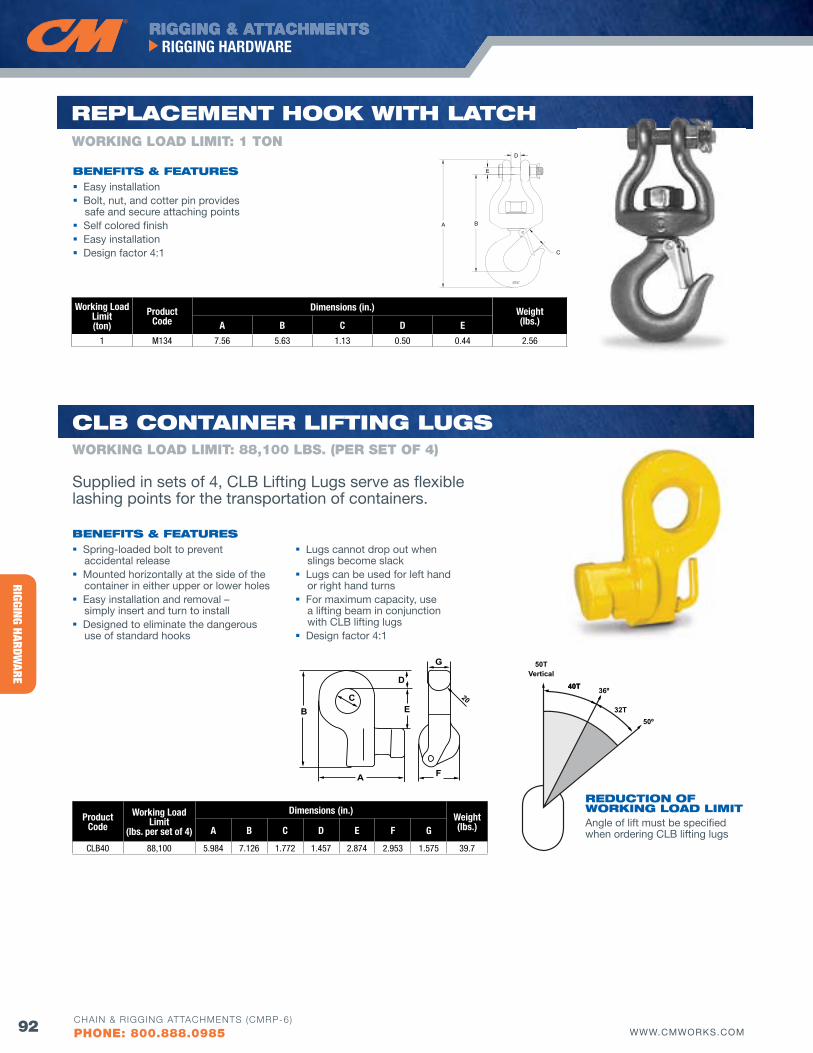
RIGGING HARDWARE
RIGGING & ATTACHMENTSRIGGING HARDWARE
92 WWW.CMWORKS.COMCHAIN & RIGGING ATTACHMENTS (CMRP-6)
PHONE: 800.888.0985
Working Load Limit(ton)
Product Code
Dimensions (in.) Weight(lbs.)A B C D E
1 M134 7.56 5.63 1.13 0.50 0.44 2.56
REPlACEMENT HooK wITH lATCHWORKING LOAD LIMIT: 1 TON
A B
C
D
EbENEfITS & fEATuRES Easy installation Bolt, nut, and cotter pin provides
safe and secure attaching points Self colored finish Easy installation Design factor 4:1
ProductCode
Working Load Limit
(lbs. per set of 4)
Dimensions (in.)Weight(lbs.)A B C D E f G
CLB40 88,100 5.984 7.126 1.772 1.457 2.874 2.953 1.575 39.7
E
A F
BC
D
G
20
Clb CoNTAINER lIfTING luGS
bENEfITS & fEATuRES
REduCTIoN of woRKING loAd lIMITAngle of lift must be specified when ordering CLB lifting lugs
Spring-loaded bolt to prevent accidental release
Mounted horizontally at the side of the container in either upper or lower holes
Easy installation and removal – simply insert and turn to install
Designed to eliminate the dangerous use of standard hooks
Lugs cannot drop out when slings become slack
Lugs can be used for left hand or right hand turns
For maximum capacity, use a lifting beam in conjunction with CLB lifting lugs
Design factor 4:1
WORKING LOAD LIMIT: 88,100 LbS. (PER SET Of 4)
Supplied in sets of 4, CLB Lifting Lugs serve as flexible lashing points for the transportation of containers.
40T40T
32T
36º
50º
50TVertical
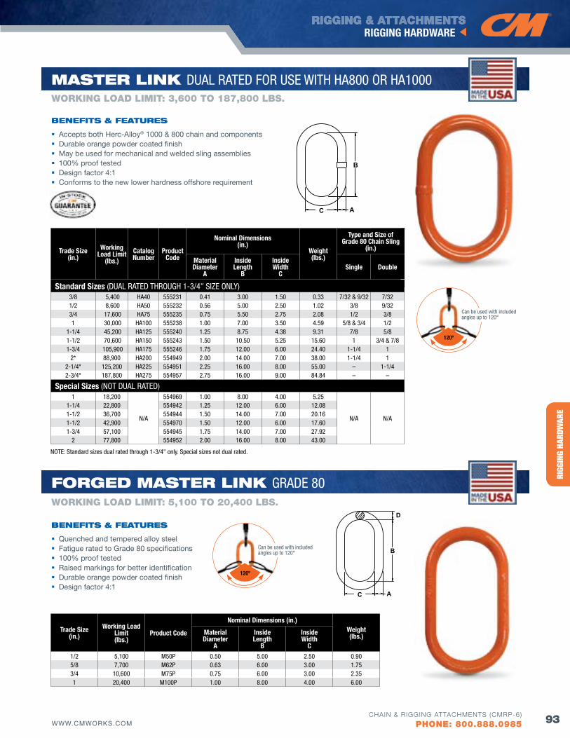
HERC
-ALL
OY® 8
00RI
GGIN
G HA
RDW
ARE
RIGGING & ATTACHMENTSRIGGING HARDWARE
93WWW.CMWORKS.COMCHAIN & RIGGING ATTACHMENTS (CMRP-6)
PHONE: 800.888.0985
Trade Size(in.)
Working Load Limit
(lbs.)Catalog Number
Product Code
Nominal Dimensions (in.)
Weight(lbs.)
Type and Size of Grade 80 Chain Sling
(in.)
Material Diameter
A
InsideLength
B
InsideWidth
CSingle Double
Standard Sizes (DUAL RATED THROUGH 1-3/4" SIzE ONLY)3/8 5,400 HA40 555231 0.41 3.00 1.50 0.33 7/32 & 9/32 7/32 1/2 8,600 HA50 555232 0.56 5.00 2.50 1.02 3/8 9/32 3/4 17,600 HA75 555235 0.75 5.50 2.75 2.08 1/2 3/8 1 30,000 HA100 555238 1.00 7.00 3.50 4.59 5/8 & 3/4 1/2
1-1/4 45,200 HA125 555240 1.25 8.75 4.38 9.31 7/8 5/8 1-1/2 70,600 HA150 555243 1.50 10.50 5.25 15.60 1 3/4 & 7/81-3/4 105,900 HA175 555246 1.75 12.00 6.00 24.40 1-1/4 1
2* 88,900 HA200 554949 2.00 14.00 7.00 38.00 1-1/4 1 2-1/4* 125,200 HA225 554951 2.25 16.00 8.00 55.00 – 1-1/4 2-3/4* 187,800 HA275 554957 2.75 16.00 9.00 84.84 – –
Special Sizes (NOT DUAL RATED)1 18,200
N/A
554969 1.00 8.00 4.00 5.25
N/A N/A
1-1/4 22,800 554942 1.25 12.00 6.00 12.081-1/2 36,700 554944 1.50 14.00 7.00 20.161-1/2 42,900 554970 1.50 12.00 6.00 17.601-3/4 57,100 554945 1.75 14.00 7.00 27.92
2 77,800 554952 2.00 16.00 8.00 43.00
A
B
C
Accepts both Herc-Alloy® 1000 & 800 chain and components Durable orange powder coated finish May be used for mechanical and welded sling assemblies 100% proof tested Design factor 4:1 Conforms to the new lower hardness offshore requirement
bENEfITS & fEATuRES
WORKING LOAD LIMIT: 3,600 TO 187,800 LbS.
MASTER lINK DUAL RATED FOR USE WITH HA800 OR HA1000
NOTE: Standard sizes dual rated through 1-3/4" only. Special sizes not dual rated.
Trade Size(in.)
Working Load Limit(lbs.)
Product Code
Nominal Dimensions (in.)Weight(lbs.)Material
DiameterA
Inside Length
B
Inside Width
C 1/2 5,100 M50P 0.50 5.00 2.50 0.905/8 7,700 M62P 0.63 6.00 3.00 1.753/4 10,600 M75P 0.75 6.00 3.00 2.351 20,400 M100P 1.00 8.00 4.00 6.00
A
B
C
D
foRGEd MASTER lINK GRADE 80
Quenched and tempered alloy steel Fatigue rated to Grade 80 specifications 100% proof tested Raised markings for better identification Durable orange powder coated finish Design factor 4:1
bENEfITS & fEATuRES
WORKING LOAD LIMIT: 5,100 TO 20,400 LbS.
120º
Can be used with included angles up to 120°
120º
Can be used with included angles up to 120°
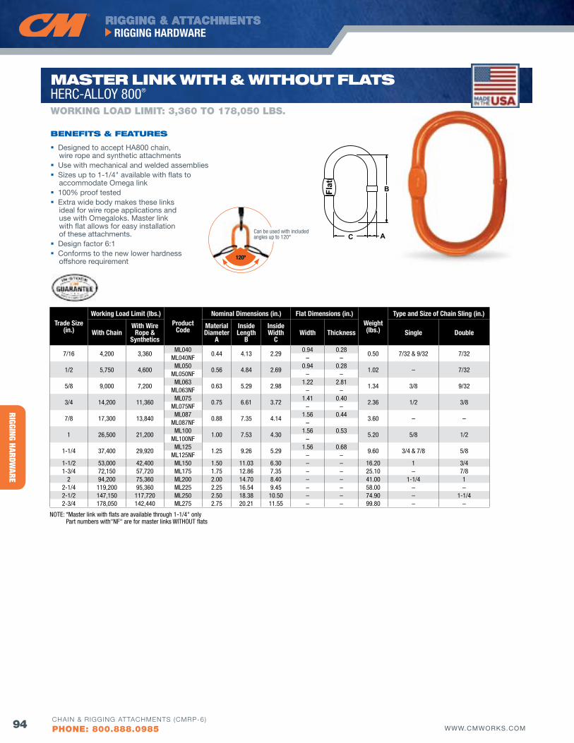
RIGGING HARDWARE
RIGGING & ATTACHMENTSRIGGING HARDWARE
94 WWW.CMWORKS.COMCHAIN & RIGGING ATTACHMENTS (CMRP-6)
PHONE: 800.888.0985
Trade Size(in.)
Working Load Limit (lbs.)Product
Code
Nominal Dimensions (in.) flat Dimensions (in.)Weight(lbs.)
Type and Size of Chain Sling (in.)
With ChainWith Wire
Rope & Synthetics
Material Diameter
A
Inside Length
B
Inside Width
CWidth Thickness Single Double
7/16 4,200 3,360ML040
0.44 4.13 2.290.94 0.28
0.50 7/32 & 9/32 7/32ML040NF – –
1/2 5,750 4,600ML050
0.56 4.84 2.690.94 0.28
1.02 – 7/32ML050NF – –
5/8 9,000 7,200ML063
0.63 5.29 2.981.22 2.81
1.34 3/8 9/32ML063NF – –
3/4 14,200 11,360ML075
0.75 6.61 3.721.41 0.40
2.36 1/2 3/8ML075NF – –
7/8 17,300 13,840ML087
0.88 7.35 4.141.56 0.44
3.60 – –ML087NF –
1 26,500 21,200ML100
1.00 7.53 4.301.56 0.53
5.20 5/8 1/2ML100NF –
1-1/4 37,400 29,920ML125
1.25 9.26 5.291.56 0.68
9.60 3/4 & 7/8 5/8ML125NF – –
1-1/2 53,000 42,400 ML150 1.50 11.03 6.30 – – 16.20 1 3/41-3/4 72,150 57,720 ML175 1.75 12.86 7.35 – – 25.10 – 7/8
2 94,200 75,360 ML200 2.00 14.70 8.40 – – 41.00 1-1/4 12-1/4 119,200 95,360 ML225 2.25 16.54 9.45 – – 58.00 – –2-1/2 147,150 117,720 ML250 2.50 18.38 10.50 – – 74.90 – 1-1/42-3/4 178,050 142,440 ML275 2.75 20.21 11.55 – – 99.80 – –
A
B
C
Flat
Designed to accept HA800 chain, wire rope and synthetic attachments
Use with mechanical and welded assemblies Sizes up to 1-1/4" available with flats to
accommodate Omega link 100% proof tested Extra wide body makes these links
ideal for wire rope applications and use with Omegaloks. Master link with flat allows for easy installation of these attachments.
Design factor 6:1 Conforms to the new lower hardness
offshore requirement
bENEfITS & fEATuRES
WORKING LOAD LIMIT: 3,360 TO 178,050 LbS.
MASTER lINK wITH & wITHouT flATS HERC-ALLOY 800®
NOTE: *Master link with flats are available through 1-1/4" only Part numbers with"NF" are for master links WITHOUT flats
120º
Can be used with included angles up to 120°
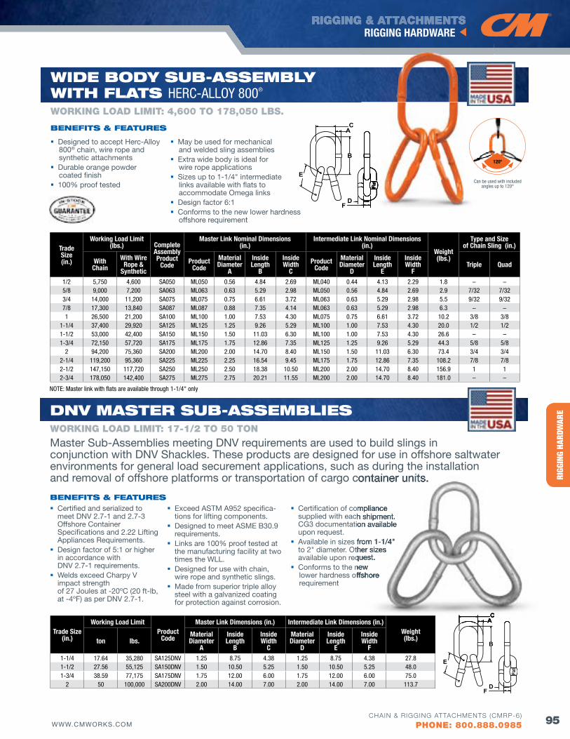
HERC
-ALL
OY® 8
00RI
GGIN
G HA
RDW
ARE
RIGGING & ATTACHMENTSRIGGING HARDWARE
95WWW.CMWORKS.COMCHAIN & RIGGING ATTACHMENTS (CMRP-6)
PHONE: 800.888.0985
Flat
A
B
C
D
E
F
Trade Size(in.)
Working Load Limit(lbs.) Complete
Assembly Product
Code
Master Link Nominal Dimensions (in.)
Intermediate Link Nominal Dimensions (in.)
Weight(lbs.)
Type and Size of Chain Sling (in.)
With Chain
With Wire Rope &
SyntheticProduct
CodeMaterial Diameter
A
Inside Length
B
Inside Width
CProduct
CodeMaterial Diameter
D
Inside Length
E
Inside Width
fTriple quad
1/2 5,750 4,600 SA050 ML050 0.56 4.84 2.69 ML040 0.44 4.13 2.29 1.8 – –5/8 9,000 7,200 SA063 ML063 0.63 5.29 2.98 ML050 0.56 4.84 2.69 2.9 7/32 7/323/4 14,000 11,200 SA075 ML075 0.75 6.61 3.72 ML063 0.63 5.29 2.98 5.5 9/32 9/327/8 17,300 13,840 SA087 ML087 0.88 7.35 4.14 ML063 0.63 5.29 2.98 6.3 – –1 26,500 21,200 SA100 ML100 1.00 7.53 4.30 ML075 0.75 6.61 3.72 10.2 3/8 3/8
1-1/4 37,400 29,920 SA125 ML125 1.25 9.26 5.29 ML100 1.00 7.53 4.30 20.0 1/2 1/21-1/2 53,000 42,400 SA150 ML150 1.50 11.03 6.30 ML100 1.00 7.53 4.30 26.6 – –1-3/4 72,150 57,720 SA175 ML175 1.75 12.86 7.35 ML125 1.25 9.26 5.29 44.3 5/8 5/8
2 94,200 75,360 SA200 ML200 2.00 14.70 8.40 ML150 1.50 11.03 6.30 73.4 3/4 3/42-1/4 119,200 95,360 SA225 ML225 2.25 16.54 9.45 ML175 1.75 12.86 7.35 108.2 7/8 7/82-1/2 147,150 117,720 SA250 ML250 2.50 18.38 10.50 ML200 2.00 14.70 8.40 156.9 1 12-3/4 178,050 142,400 SA275 ML275 2.75 20.21 11.55 ML200 2.00 14.70 8.40 181.0 – –
May be used for mechanical and welded sling assemblies
Extra wide body is ideal for wire rope applications
Sizes up to 1-1/4" intermediate links available with flats to accommodate Omega links
Design factor 6:1 Conforms to the new lower hardness
offshore requirement
wIdE body Sub-ASSEMbly wITH flATS HERC-ALLOY 800®
Designed to accept Herc-Alloy
800® chain, wire rope and synthetic attachments
Durable orange powder coated finish
100% proof tested
bENEfITS & fEATuRES
WORKING LOAD LIMIT: 4,600 TO 178,050 LbS.
Flat
NOTE: Master link with flats are available through 1-1/4" only
dNv MASTER Sub-ASSEMblIES
Certified and serialized to meet DNv 2.7-1 and 2.7-3 Offshore Container Specifications and 2.22 Lifting Appliances Requirements.
Design factor of 5:1 or higher in accordance with DNv 2.7-1 requirements.
Welds exceed Charpy v impact strength of 27 Joules at -20ºC (20 ft-lb, at -4ºF) as per DNv 2.7-1.
bENEfITS & fEATuRES
WORKING LOAD LIMIT: 17-1/2 TO 50 TON
Exceed ASTM A952 specifica-tions for lifting components.
Designed to meet ASME B30.9 requirements.
Links are 100% proof tested at the manufacturing facility at two times the WLL.
Designed for use with chain, wire rope and synthetic slings.
Made from superior triple alloy steel with a galvanized coating for protection against corrosion.
Certification of compliance supplied with each shipment. CG3 documentation available upon request.
Available in sizes from 1-1/4" to 2" diameter. Other sizes available upon request.
Conforms to the new lower hardness offshore requirement
Flat
A
B
C
D
E
F
Master Sub-Assemblies meeting DNv requirements are used to build slings in conjunction with DNv Shackles. These products are designed for use in offshore saltwater environments for general load securement applications, such as during the installation and removal of offshore platforms or transportation of cargo container units.
Certification of compliance supplied with each shipment. CG3 documentation available
Available in sizes from 1-1/4" to 2" diameter. Other sizes available upon request.Conforms to the new lower hardness offshore
AAC
and removal of offshore platforms or transportation of cargo container units.
Trade Size(in.)
Working Load LimitProduct
Code
Master Link Dimensions (in.) Intermediate Link Dimensions (in.)Weight(lbs.)ton lbs.
Material Diameter
A
Inside Length
B
Inside Width
C
Material Diameter
D
Inside Length
E
Inside Width
f1-1/4 17.64 35,280 SA125DNV 1.25 8.75 4.38 1.25 8.75 4.38 27.81-1/2 27.56 55,125 SA150DNV 1.50 10.50 5.25 1.50 10.50 5.25 48.01-3/4 38.59 77,175 SA175DNV 1.75 12.00 6.00 1.75 12.00 6.00 75.0
2 50 100,000 SA200DNV 2.00 14.00 7.00 2.00 14.00 7.00 113.7
120º
Can be used with included angles up to 120°
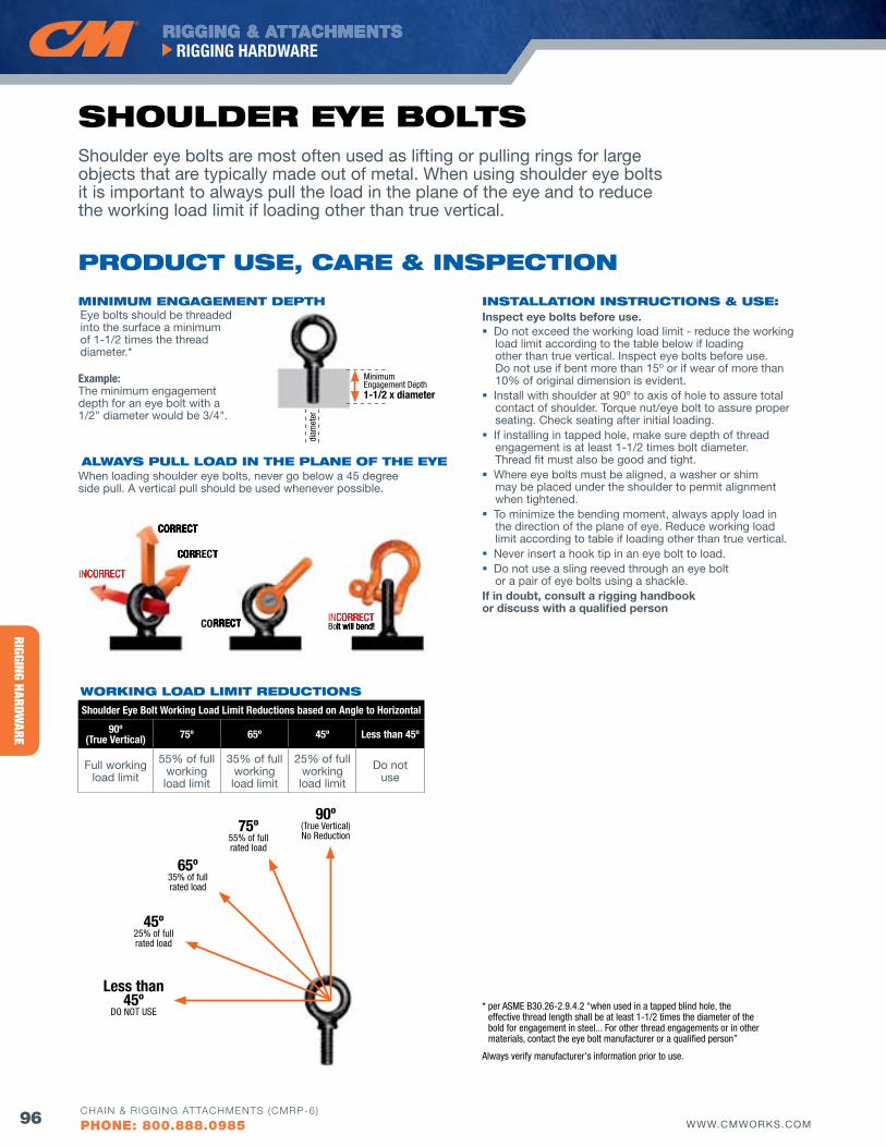
RIGGING HARDWARE
RIGGING & ATTACHMENTSRIGGING HARDWARE
96 WWW.CMWORKS.COMCHAIN & RIGGING ATTACHMENTS (CMRP-6)
PHONE: 800.888.0985
INSTAllATIoN INSTRuCTIoNS & uSE: Inspect eye bolts before use. Do not exceed the working load limit - reduce the working
load limit according to the table below if loading other than true vertical. Inspect eye bolts before use. Do not use if bent more than 15º or if wear of more than 10% of original dimension is evident.
Install with shoulder at 90º to axis of hole to assure total contact of shoulder. Torque nut/eye bolt to assure proper seating. Check seating after initial loading.
If installing in tapped hole, make sure depth of thread engagement is at least 1-1/2 times bolt diameter. Thread fit must also be good and tight.
Where eye bolts must be aligned, a washer or shim may be placed under the shoulder to permit alignment when tightened.
To minimize the bending moment, always apply load in the direction of the plane of eye. Reduce working load limit according to table if loading other than true vertical.
Never insert a hook tip in an eye bolt to load. Do not use a sling reeved through an eye bolt
or a pair of eye bolts using a shackle.If in doubt, consult a rigging handbook or discuss with a qualified person
Shoulder Eye Bolt Working Load Limit Reductions based on Angle to Horizontal
90º (True Vertical) 75º 65º 45º Less than 45º
Full working load limit
55% of full working load limit
35% of full working load limit
25% of full working load limit
Do not use
45º 25% of full rated load
65º 35% of full rated load
75º 55% of full rated load
90º (True Vertical) No Reduction
Less than 45º
DO NOT USE
Shoulder eye bolts are most often used as lifting or pulling rings for large objects that are typically made out of metal. When using shoulder eye bolts it is important to always pull the load in the plane of the eye and to reduce the working load limit if loading other than true vertical.
PRoduCT uSE, CARE & INSPECTIoN
SHouldER EyE bolTS
AlwAyS Pull loAd IN THE PlANE of THE EyE
woRKING loAd lIMIT REduCTIoNS
MINIMuM ENGAGEMENT dEPTH
Example: The minimum engagement depth for an eye bolt with a 1/2" diameter would be 3/4".
When loading shoulder eye bolts, never go below a 45 degree side pull. A vertical pull should be used whenever possible.
Minimum Engagement Depth 1-1/2 x diameter
diam
eter
Eye bolts should be threaded into the surface a minimum of 1-1/2 times the thread diameter.*
CORRECT
CORRECT
CORRECT INCORRECTBolt will bend!
INCORRECT
* per ASME B30.26-2.9.4.2 “when used in a tapped blind hole, the effective thread length shall be at least 1-1/2 times the diameter of the bold for engagement in steel... For other thread engagements or in other materials, contact the eye bolt manufacturer or a qualified person”
Always verify manufacturer's information prior to use.
CORRECT
CORRECT
INCORRECT
CORRECT
CORRECT INCORRECTBolt will bend!
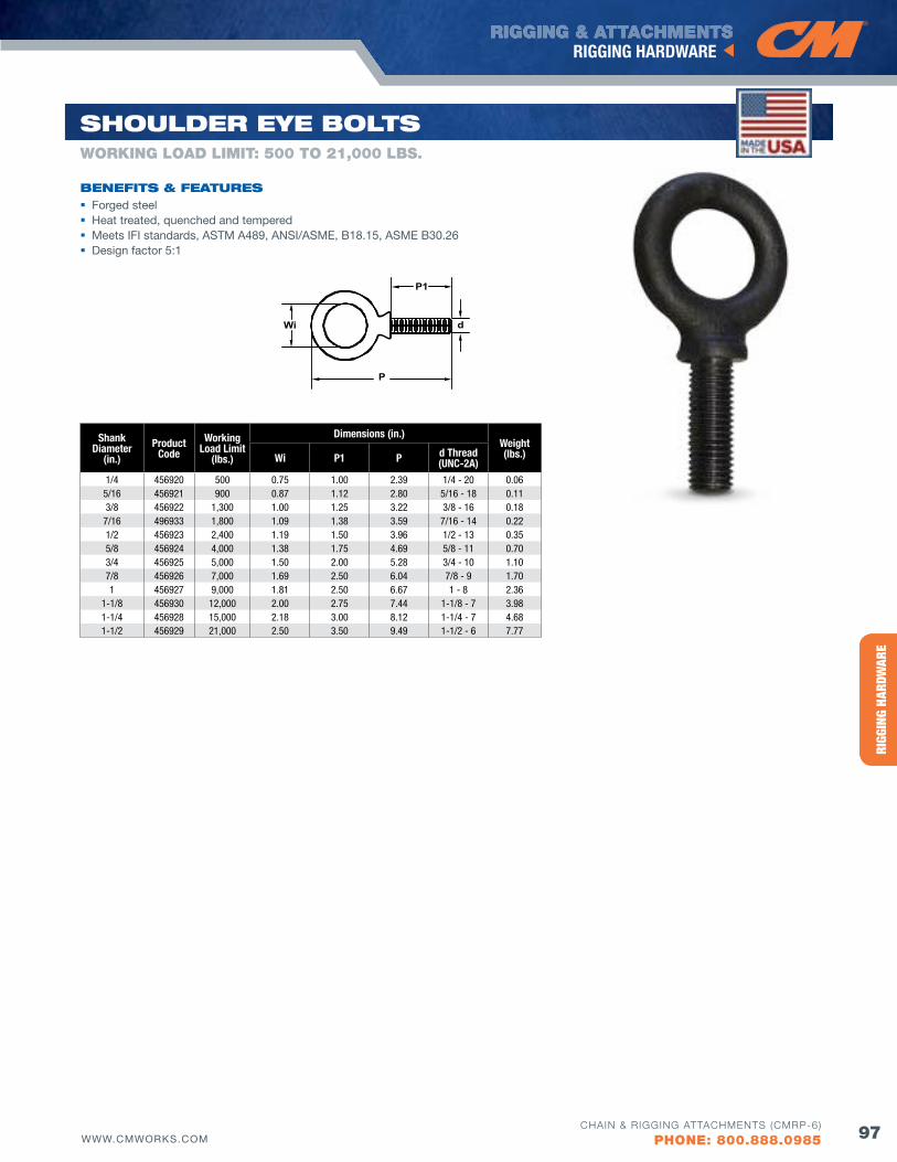
HERC
-ALL
OY® 8
00RI
GGIN
G HA
RDW
ARE
RIGGING & ATTACHMENTSRIGGING HARDWARE
97WWW.CMWORKS.COMCHAIN & RIGGING ATTACHMENTS (CMRP-6)
PHONE: 800.888.0985
Wi
P
P1
d
Shank Diameter
(in.)Product
CodeWorking
Load Limit(lbs.)
Dimensions (in.)Weight(lbs.)Wi P1 P d Thread
(UNC-2A)1/4 456920 500 0.75 1.00 2.39 1/4 - 20 0.06
5/16 456921 900 0.87 1.12 2.80 5/16 - 18 0.113/8 456922 1,300 1.00 1.25 3.22 3/8 - 16 0.18
7/16 496933 1,800 1.09 1.38 3.59 7/16 - 14 0.221/2 456923 2,400 1.19 1.50 3.96 1/2 - 13 0.355/8 456924 4,000 1.38 1.75 4.69 5/8 - 11 0.703/4 456925 5,000 1.50 2.00 5.28 3/4 - 10 1.107/8 456926 7,000 1.69 2.50 6.04 7/8 - 9 1.701 456927 9,000 1.81 2.50 6.67 1 - 8 2.36
1-1/8 456930 12,000 2.00 2.75 7.44 1-1/8 - 7 3.981-1/4 456928 15,000 2.18 3.00 8.12 1-1/4 - 7 4.681-1/2 456929 21,000 2.50 3.50 9.49 1-1/2 - 6 7.77
bENEfITS & fEATuRES Forged steel Heat treated, quenched and tempered Meets IFI standards, ASTM A489, ANSI/ASME, B18.15, ASME B30.26 Design factor 5:1
WORKING LOAD LIMIT: 500 TO 21,000 LbS.
SHouldER EyE bolTS
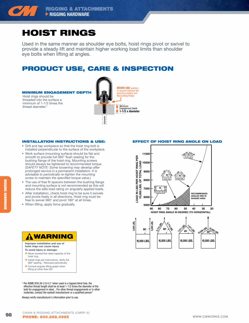
RIGGING HARDWARE
RIGGING & ATTACHMENTSRIGGING HARDWARE
98 WWW.CMWORKS.COMCHAIN & RIGGING ATTACHMENTS (CMRP-6)
PHONE: 800.888.0985
Used in the same manner as shoulder eye bolts, hoist rings pivot or swivel to provide a steady lift and maintain higher working load limits than shoulder eye bolts when lifting at angles.
PRoduCT uSE, CARE & INSPECTIoN
HoIST RINGS
MINIMuM ENGAGEMENT dEPTHHoist rings should be threaded into the surface a minimum of 1-1/2 times the thread diameter.*
Improper installation and use of hoist rings can cause injuryTo avoid injury or damage:s Never exceed the rated capacity of the
hoist ring.s Install rings per instructions. verify full
360º seating - Retorque periodically.s Consult angular lifting graph when
lifting at other than 90º.
10,000 LBS.
10,000 LBS.
10,000 LBS.
10,000 LBS. 10,000 LBS. 10,000 LBS. 10,000 LBS.
5,00
0 LB
S.
5,00
0 LB
S.
5,774
LBS.
5,774 LBS. 7,071
LBS.
5,774
LBS.
5,00
0 LB
S.
5,00
0 LB
S.
7,071
LBS.
10,000 LBS. 10,000 LBS.
7,071 LBS.
5,774 LBS.
7,071 LBS.
10,000 LBS. 10,000 LBS.
10,000 LBS.
HOIST RING ANGLE IN DEGREE ( TO HORIZONTAL)
RECOMMENDEDANGLES ARE INSHADED AREA
EFFECT OF HOIST RING ANGLE ON LOAD
11000
10000
9000
8000
7000
6000
500090 80 70 60 50 40 30 20
LOA
D IN
LB
S P
ER
HO
IST
RIN
G P
ER
1
0,00
0 LB
S. O
F T
OTA
L LO
AD
900 600
450 300900
600 450
300
10,000 LBS.
10,000 LBS.
10,000 LBS.
10,000 LBS. 10,000 LBS. 10,000 LBS. 10,000 LBS.
5,00
0 LB
S.
5,00
0 LB
S.
5,774
LBS.
5,774 LBS. 7,071
LBS.
5,774
LBS.
5,00
0 LB
S.
5,00
0 LB
S.
7,071
LBS.
10,000 LBS. 10,000 LBS.
7,071 LBS.
5,774 LBS.
7,071 LBS.
10,000 LBS. 10,000 LBS.
10,000 LBS.
HOIST RING ANGLE IN DEGREE ( TO HORIZONTAL)
RECOMMENDEDANGLES ARE INSHADED AREA
EFFECT OF HOIST RING ANGLE ON LOAD
11000
10000
9000
8000
7000
6000
500090 80 70 60 50 40 30 20
LOA
D IN
LB
S P
ER
HO
IST
RIN
G P
ER
1
0,00
0 LB
S. O
F T
OTA
L LO
AD
900 600
450 300900
600 450
300
EffECT of HoIST RING ANGlE oN loAdINSTAllATIoN INSTRuCTIoNS & uSE: Drill and tap workpiece so that the hoist ring bolt is
installed perpendicular to the surface of the workpiece. Work surface (mounting surface) should be flat and
smooth to provide full 360° flush seating for the bushing flange of the hoist ring. Mounting screws should always be tightened to recommended torque. (SAFETY NOTE: Some loosening may develop after prolonged service in a permanent installation. It is advisable to periodically re-tighten the mounting screw to maintain the specified torque value.)
The use of free fit spacers between the bushing flange and mounting surface is not recommended as this will reduce the safe load rating on angularly applied loads.
After installation, check hoist ring to be sure it swivels and pivots freely in all directions. Hoist ring must be free to swivel 360° and pivot 180° at all times.
When lifting, apply force gradually.
NEVER USE washers or spacers between the mounting surface and the bushing flange
Minimum Engagement Depth 1-1/2 x diameter
diam
eter
* Per ASME B30.26-2.9.4.2 “when used in a tapped blind hole, the effective thread length shall be at least 1-1/2 times the diameter of the bold for engagement in steel... For other thread engagements or in other materials, contact the eyebolt manufacturer or a qualified person”
Always verify manufacturer's information prior to use.
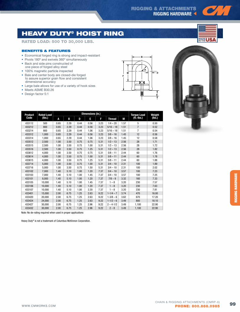
HERC
-ALL
OY® 8
00RI
GGIN
G HA
RDW
ARE
RIGGING & ATTACHMENTSRIGGING HARDWARE
99WWW.CMWORKS.COMCHAIN & RIGGING ATTACHMENTS (CMRP-6)
PHONE: 800.888.0985
B
AD
E
MF
ProductCode
Rated Load(lbs.)
Dimensions (in.) Torque Load(ft.-lbs.)
Weight(lbs.)A B D E f Thread M
433112 500 0.65 2.29 0.44 0.56 3.23 1/4 – 20 1.57 5 0.50433212 800 0.65 2.29 0.44 0.56 3.23 5/16 – 18 1.51 7 0.52433214 800 0.65 2.29 0.44 1.06 3.23 5/16 – 18 1.51 7 0.54433312 1,000 0.65 2.29 0.44 0.56 3.23 3/8 – 16 1.45 12 0.56433314 1,000 0.65 2.29 0.44 1.06 3.23 3/8 – 16 1.45 12 0.58433512 2,500 1.00 3.50 0.75 0.75 5.31 1/2 – 13 2.56 28 1.71433515 2,500 1.00 3.50 0.75 1.00 5.31 1/2 – 13 2.56 28 1.72433516 2,500 1.00 3.50 0.75 1.25 5.31 1/2 – 13 2.56 28 1.82433612 4,000 1.00 3.50 0.75 0.75 5.31 5/8 – 11 2.44 60 1.76433614 4,000 1.00 3.50 0.75 1.00 5.31 5/8 – 11 2.44 60 1.78433615 4,000 1.00 3.50 0.75 1.25 5.31 5/8 – 11 2.44 60 1.88433714 5,000 1.00 3.50 0.75 1.00 5.31 3/4 – 10 2.31 100 1.89433716 5,000 1.00 3.50 0.75 1.50 5.31 3/4 – 10 2.31 100 2.02433102 7,000 1.40 5.10 1.00 1.20 7.37 3/4 – 10 3.57 100 7.23433103 7,000 1.40 5.10 1.00 1.45 7.37 3/4 – 10 3.57 100 7.25433101 8,000 1.40 5.10 1.00 1.20 7.37 7/8 – 9 3.32 160 7.33433105 10,000 1.40 5.10 1.00 1.45 7.37 1 – 8 3.20 230 7.57433106 10,000 1.40 5.10 1.00 1.20 7.37 1 – 8 3.20 230 7.63433107 10,000 1.40 5.10 1.00 2.20 7.37 1 – 8 3.20 230 7.81433401 15,000 2.00 6.75 1.25 2.63 9.22 1-1/4 – 7 3.74 470 16.00433420 20,000 2.00 6.75 1.25 2.63 9.22 1-3/8 – 6 3.62 670 17.20433424 24,000 2.00 6.75 1.25 2.63 9.22 1-1/2 – 6 3.49 800 18.10433427 30,000 2.00 6.75 1.25 2.96 9.22 2 – 4-1/2 3.49 1,100 22.90433432 30,000 2.00 6.75 1.25 2.96 9.22 2 – 8 3.49 1,100 22.90
HEAvy duTy® HoIST RING
bENEfITS & fEATuRES Economical forged ring is strong and impact-resistant Pivots 180º and swivels 360º simultaneously Back and side pins constructed of
one piece of forged alloy steel 100% magnetic particle inspected Bale and center body are closed-die forged
to assure superior grain flow and consistent dimensional accuracy
Large bale allows for use of a variety of hook sizes Meets ASME B30.26 Design factor 5:1
RATED LOAD: 500 TO 30,000 LbS.
Heavy Duty® is not a trademark of Columbus McKinnon Corporation.
Note: No de-rating required when used in proper applications
EffECT of HoIST RING ANGlE oN loAd
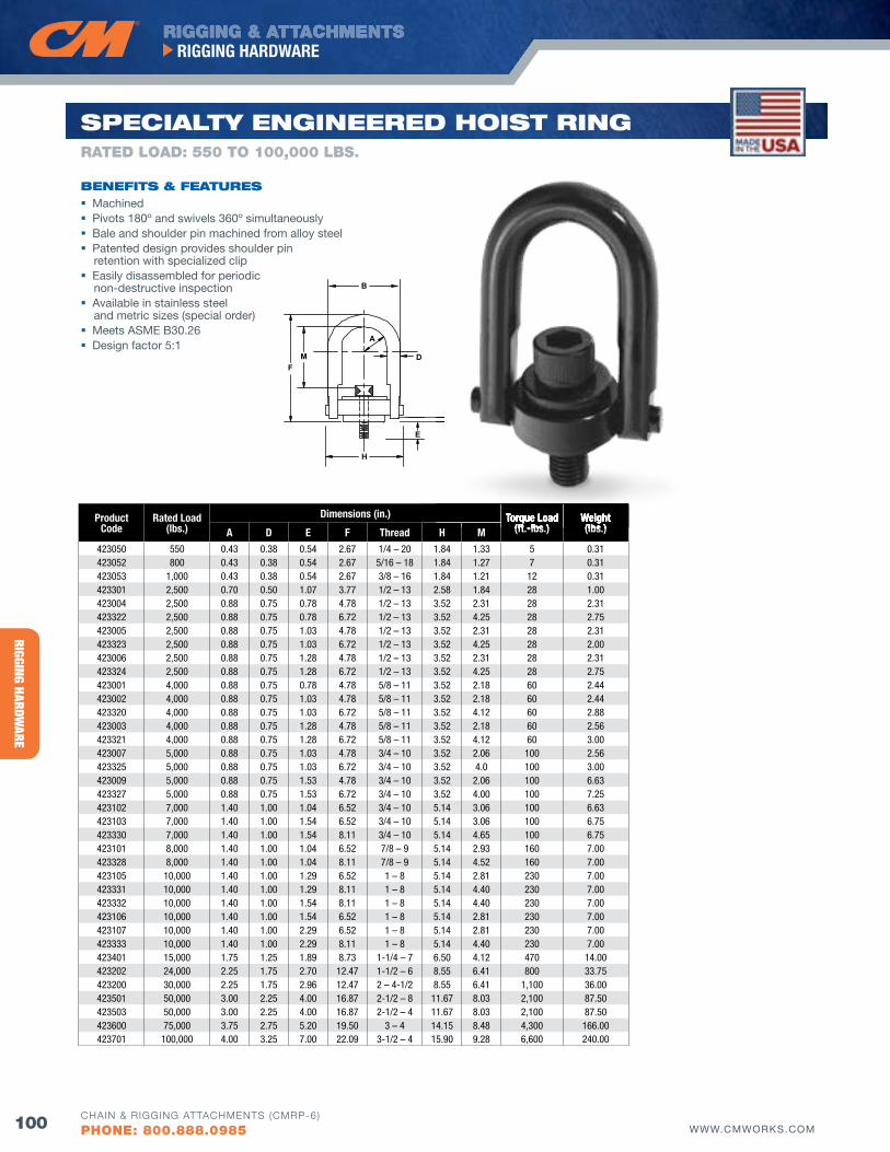
RIGGING HARDWARE
RIGGING & ATTACHMENTSRIGGING HARDWARE
100 WWW.CMWORKS.COMCHAIN & RIGGING ATTACHMENTS (CMRP-6)
PHONE: 800.888.0985
D
A
B
E
H
FM
ProductCode
Rated Load(lbs.)
Dimensions (in.) Torque Load(ft.-lbs.)
Weight(lbs.)A D E f Thread H M
423050 550 0.43 0.38 0.54 2.67 1/4 – 20 1.84 1.33 5 0.31423052 800 0.43 0.38 0.54 2.67 5/16 – 18 1.84 1.27 7 0.31423053 1,000 0.43 0.38 0.54 2.67 3/8 – 16 1.84 1.21 12 0.31423301 2,500 0.70 0.50 1.07 3.77 1/2 – 13 2.58 1.84 28 1.00423004 2,500 0.88 0.75 0.78 4.78 1/2 – 13 3.52 2.31 28 2.31423322 2,500 0.88 0.75 0.78 6.72 1/2 – 13 3.52 4.25 28 2.75423005 2,500 0.88 0.75 1.03 4.78 1/2 – 13 3.52 2.31 28 2.31423323 2,500 0.88 0.75 1.03 6.72 1/2 – 13 3.52 4.25 28 2.00423006 2,500 0.88 0.75 1.28 4.78 1/2 – 13 3.52 2.31 28 2.31423324 2,500 0.88 0.75 1.28 6.72 1/2 – 13 3.52 4.25 28 2.75423001 4,000 0.88 0.75 0.78 4.78 5/8 – 11 3.52 2.18 60 2.44423002 4,000 0.88 0.75 1.03 4.78 5/8 – 11 3.52 2.18 60 2.44423320 4,000 0.88 0.75 1.03 6.72 5/8 – 11 3.52 4.12 60 2.88423003 4,000 0.88 0.75 1.28 4.78 5/8 – 11 3.52 2.18 60 2.56423321 4,000 0.88 0.75 1.28 6.72 5/8 – 11 3.52 4.12 60 3.00423007 5,000 0.88 0.75 1.03 4.78 3/4 – 10 3.52 2.06 100 2.56423325 5,000 0.88 0.75 1.03 6.72 3/4 – 10 3.52 4.0 100 3.00423009 5,000 0.88 0.75 1.53 4.78 3/4 – 10 3.52 2.06 100 6.63423327 5,000 0.88 0.75 1.53 6.72 3/4 – 10 3.52 4.00 100 7.25423102 7,000 1.40 1.00 1.04 6.52 3/4 – 10 5.14 3.06 100 6.63423103 7,000 1.40 1.00 1.54 6.52 3/4 – 10 5.14 3.06 100 6.75423330 7,000 1.40 1.00 1.54 8.11 3/4 – 10 5.14 4.65 100 6.75423101 8,000 1.40 1.00 1.04 6.52 7/8 – 9 5.14 2.93 160 7.00423328 8,000 1.40 1.00 1.04 8.11 7/8 – 9 5.14 4.52 160 7.00423105 10,000 1.40 1.00 1.29 6.52 1 – 8 5.14 2.81 230 7.00423331 10,000 1.40 1.00 1.29 8.11 1 – 8 5.14 4.40 230 7.00423332 10,000 1.40 1.00 1.54 8.11 1 – 8 5.14 4.40 230 7.00423106 10,000 1.40 1.00 1.54 6.52 1 – 8 5.14 2.81 230 7.00423107 10,000 1.40 1.00 2.29 6.52 1 – 8 5.14 2.81 230 7.00423333 10,000 1.40 1.00 2.29 8.11 1 – 8 5.14 4.40 230 7.00423401 15,000 1.75 1.25 1.89 8.73 1-1/4 – 7 6.50 4.12 470 14.00423202 24,000 2.25 1.75 2.70 12.47 1-1/2 – 6 8.55 6.41 800 33.75423200 30,000 2.25 1.75 2.96 12.47 2 – 4-1/2 8.55 6.41 1,100 36.00423501 50,000 3.00 2.25 4.00 16.87 2-1/2 – 8 11.67 8.03 2,100 87.50423503 50,000 3.00 2.25 4.00 16.87 2-1/2 – 4 11.67 8.03 2,100 87.50423600 75,000 3.75 2.75 5.20 19.50 3 – 4 14.15 8.48 4,300 166.00423701 100,000 4.00 3.25 7.00 22.09 3-1/2 – 4 15.90 9.28 6,600 240.00
SPECIAlTy ENGINEEREd HoIST RING
bENEfITS & fEATuRES Machined Pivots 180º and swivels 360º simultaneously Bale and shoulder pin machined from alloy steel Patented design provides shoulder pin
retention with specialized clip Easily disassembled for periodic
non-destructive inspection Available in stainless steel
and metric sizes (special order) Meets ASME B30.26 Design factor 5:1
RATED LOAD: 550 TO 100,000 LbS.
Torque Load(ft.-lbs.)
Weight(lbs.)
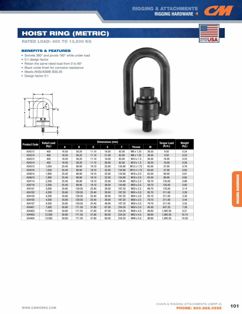
HERC
-ALL
OY® 8
00RI
GGIN
G HA
RDW
ARE
RIGGING & ATTACHMENTSRIGGING HARDWARE
101WWW.CMWORKS.COMCHAIN & RIGGING ATTACHMENTS (CMRP-6)
PHONE: 800.888.0985
B
AD
E
MF
Product Code Rated Load(kg.)
Dimensions (mm) Torque Load(N.m.)
Weight(kg.)A B D E f Thread M
434212 400 16.50 58.20 11.10 16.00 82.00 M8 x 1.25 38.50 9.50 0.24434214 400 16.50 58.20 11.10 21.00 82.00 M8 x 1.25 38.50 9.50 0.25434312 450 16.50 58.20 11.10 16.00 82.00 M10 x 1.5 36.50 16.00 0.25434314 450 16.50 58.20 11.10 26.00 82.00 M10 x 1.5 36.50 16.00 0.26434515 1,050 25.40 88.90 19.10 25.00 134.90 M12 x 1.75 65.00 37.00 0.78434516 1,050 25.40 88.90 19.10 32.00 134.90 M12 x 1.75 65.00 37.00 0.83434614 1,900 25.40 88.90 19.10 25.00 134.90 M16 x 2.0 62.00 80.00 0.81434615 1,900 25.40 88.90 19.10 32.00 134.90 M16 x 2.0 62.00 80.00 0.85434714 2,200 25.40 88.90 19.10 25.00 134.90 M20 x 2.5 58.70 135.00 0.86434716 2,200 25.40 88.90 19.10 38.00 134.90 M20 x 2.5 58.70 135.00 0.92434101 3,000 35.60 129.50 25.40 28.00 187.20 M20 x 2.5 89.70 135.00 3.14434102 4,200 35.60 129.50 25.40 28.00 187.20 M24 x 3.0 85.70 311.00 3.29434103 4,200 35.60 129.50 25.40 38.00 187.20 M24 x 3.0 85.70 311.00 3.30434105 4,500 35.60 129.50 25.40 38.00 187.20 M30 x 3.5 79.70 311.00 3.44434107 4,500 35.60 129.50 25.40 48.00 187.20 M30 x 3.5 79.70 311.00 3.55434401 7,000 50.80 171.50 31.80 67.00 234.20 M30 x 3.5 95.00 637.20 7.26434402 11,000 50.80 171.50 31.80 67.00 234.20 M36 x 4.0 88.60 1,085.50 8.21434403 12,500 50.80 171.50 31.80 80.00 234.20 M42 x 4.5 88.60 1,085.50 10.14434404 13,500 50.80 171.50 31.80 80.00 234.20 M48 x 5.0 88.60 1,085.50 10.59
HoIST RING (METRIC)RATED LOAD: 400 TO 13,500 KG
bENEfITS & fEATuRES Swivels 360° and pivots 180° while under load 5:1 design factor Retain the same rated load from 0 to 90° Black oxide finish for corrosion resistance Meets ANSI/ASME B30.26 Design factor 5:1
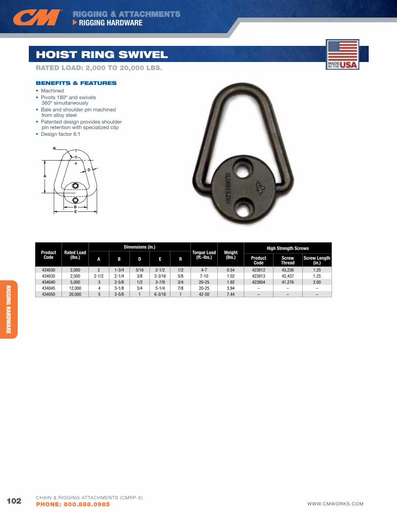
RIGGING HARDWARE
RIGGING & ATTACHMENTSRIGGING HARDWARE
102 WWW.CMWORKS.COMCHAIN & RIGGING ATTACHMENTS (CMRP-6)
PHONE: 800.888.0985
D
R
A
BE
ProductCode
Rated Load(lbs.)
Dimensions (in.)Torque Load
(ft.-lbs.)Weight(lbs.)
High Strength Screws
A B D E R Product Code
Screw Thread
Screw Length(in.)
434030 2,000 2 1-3/4 5/16 2-1/2 1/2 4-7 0.54 423812 43,236 1.25 434035 2,500 2-1/2 2-1/4 3/8 3-3/16 5/8 7-10 1.02 423813 42,437 1.25 434040 5,000 3 2-5/8 1/2 3-7/8 3/4 20-25 1.92 423804 41,276 2.00 434045 12,000 4 3-1/8 3/4 5-1/4 7/8 20-25 3.94 – – –434050 20,000 5 3-5/8 1 6-3/16 1 42-50 7.44 – – –
HoIST RING SwIvEl
bENEfITS & fEATuRES Machined Pivots 180º and swivels
360º simultaneously Bale and shoulder pin machined
from alloy steel Patented design provides shoulder
pin retention with specialized clip Design factor 6:1
RATED LOAD: 2,000 TO 20,000 LbS.
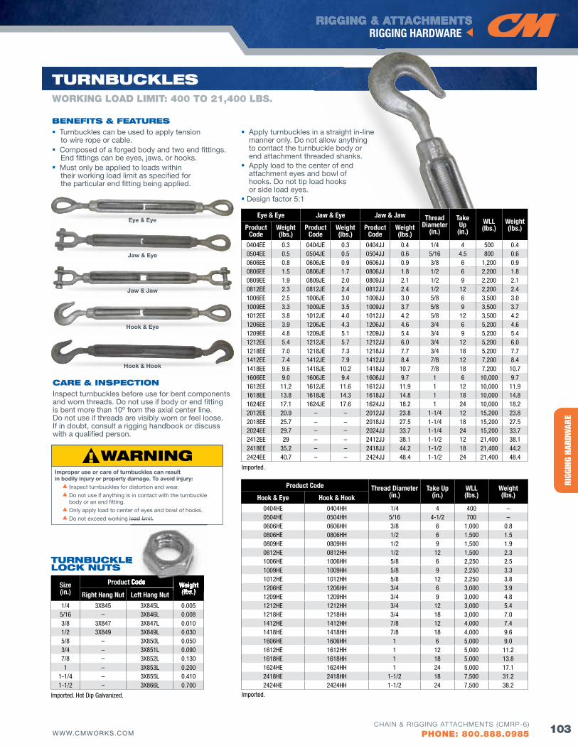
HERC
-ALL
OY® 8
00RI
GGIN
G HA
RDW
ARE
RIGGING & ATTACHMENTSRIGGING HARDWARE
103WWW.CMWORKS.COMCHAIN & RIGGING ATTACHMENTS (CMRP-6)
PHONE: 800.888.0985
TuRNbuCKlES
Product Code Thread Diameter(in.)
Take Up(in.)
WLL(lbs.)
Weight(lbs.)Hook & Eye Hook & Hook
0404HE 0404HH 1/4 4 400 –0504HE 0504HH 5/16 4-1/2 700 –0606HE 0606HH 3/8 6 1,000 0.80806HE 0806HH 1/2 6 1,500 1.50809HE 0809HH 1/2 9 1,500 1.90812HE 0812HH 1/2 12 1,500 2.31006HE 1006HH 5/8 6 2,250 2.51009HE 1009HH 5/8 9 2,250 3.31012HE 1012HH 5/8 12 2,250 3.81206HE 1206HH 3/4 6 3,000 3.91209HE 1209HH 3/4 9 3,000 4.81212HE 1212HH 3/4 12 3,000 5.41218HE 1218HH 3/4 18 3,000 7.01412HE 1412HH 7/8 12 4,000 7.41418HE 1418HH 7/8 18 4,000 9.61606HE 1606HH 1 6 5,000 9.01612HE 1612HH 1 12 5,000 11.21618HE 1618HH 1 18 5,000 13.81624HE 1624HH 1 24 5,000 17.12418HE 2418HH 1-1/2 18 7,500 31.22424HE 2424HH 1-1/2 24 7,500 38.2
Size(in.)
Product Code Weight(lbs.)Right Hang Nut Left Hang Nut
1/4 3X845 3X845L 0.0055/16 – 3X846L 0.0083/8 3X847 3X847L 0.0101/2 3X849 3X849L 0.0305/8 – 3X850L 0.0503/4 – 3X851L 0.0907/8 – 3X852L 0.1301 – 3X853L 0.200
1-1/4 – 3X855L 0.4101-1/2 – 3X866L 0.700
Eye & Eye Jaw & Eye Jaw & Jaw Thread Diameter
(in.)
TakeUp
(in.)WLL(lbs.)
Weight(lbs.)Product
CodeWeight(lbs.)
Product Code
Weight(lbs.)
Product Code
Weight(lbs.)
0404EE 0.3 0404JE 0.3 0404JJ 0.4 1/4 4 500 0.40504EE 0.5 0504JE 0.5 0504JJ 0.6 5/16 4.5 800 0.60606EE 0.8 0606JE 0.9 0606JJ 0.9 3/8 6 1,200 0.90806EE 1.5 0806JE 1.7 0806JJ 1.8 1/2 6 2,200 1.80809EE 1.9 0809JE 2.0 0809JJ 2.1 1/2 9 2,200 2.10812EE 2.3 0812JE 2.4 0812JJ 2.4 1/2 12 2,200 2.41006EE 2.5 1006JE 3.0 1006JJ 3.0 5/8 6 3,500 3.01009EE 3.3 1009JE 3.5 1009JJ 3.7 5/8 9 3,500 3.71012EE 3.8 1012JE 4.0 1012JJ 4.2 5/8 12 3,500 4.21206EE 3.9 1206JE 4.3 1206JJ 4.6 3/4 6 5,200 4.61209EE 4.8 1209JE 5.1 1209JJ 5.4 3/4 9 5,200 5.41212EE 5.4 1212JE 5.7 1212JJ 6.0 3/4 12 5,200 6.01218EE 7.0 1218JE 7.3 1218JJ 7.7 3/4 18 5,200 7.71412EE 7.4 1412JE 7.9 1412JJ 8.4 7/8 12 7,200 8.41418EE 9.6 1418JE 10.2 1418JJ 10.7 7/8 18 7,200 10.71606EE 9.0 1606JE 9.4 1606JJ 9.7 1 6 10,000 9.71612EE 11.2 1612JE 11.6 1612JJ 11.9 1 12 10,000 11.91618EE 13.8 1618JE 14.3 1618JJ 14.8 1 18 10,000 14.81624EE 17.1 1624JE 17.6 1624JJ 18.2 1 24 10,000 18.22012EE 20.9 – – 2012JJ 23.8 1-1/4 12 15,200 23.82018EE 25.7 – – 2018JJ 27.5 1-1/4 18 15,200 27.52024EE 29.7 – – 2024JJ 33.7 1-1/4 24 15,200 33.72412EE 29 – – 2412JJ 38.1 1-1/2 12 21,400 38.12418EE 35.2 – – 2418JJ 44.2 1-1/2 18 21,400 44.22424EE 40.7 – – 2424JJ 48.4 1-1/2 24 21,400 48.4
WORKING LOAD LIMIT: 400 TO 21,400 LbS.
bENEfITS & fEATuRES Turnbuckles can be used to apply tension
to wire rope or cable. Composed of a forged body and two end fittings.
End fittings can be eyes, jaws, or hooks. Must only be applied to loads within
their working load limit as specified for the particular end fitting being applied.
Apply turnbuckles in a straight in-line manner only. Do not allow anything to contact the turnbuckle body or end attachment threaded shanks.
Apply load to the center of end attachment eyes and bowl of hooks. Do not tip load hooks or side load eyes.
Design factor 5:1
CARE & INSPECTIoNInspect turnbuckles before use for bent components and worn threads. Do not use if body or end fitting is bent more than 10º from the axial center line. Do not use if threads are visibly worn or feel loose. If in doubt, consult a rigging handbook or discuss with a qualified person.
Imported. Hot Dip Galvanized. Imported.
Imported.
Hook & Hook
Eye & Eye
Jaw & Eye
Jaw & Jaw
Hook & Eye
Improper use or care of turnbuckles can result in bodily injury or property damage. To avoid injury: s Inspect turnbuckles for distortion and wear.
s Do not use if anything is in contact with the turnbuckle body or an end fitting.
s Only apply load to center of eyes and bowl of hooks.
s Do not exceed working load limit.
TuRNbuCKlE loCK NuTS
Product Code Weight(lbs.)
Do not exceed working load limit.
E
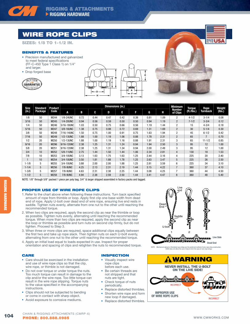
RIGGING HARDWARE
RIGGING & ATTACHMENTSRIGGING HARDWARE
104 WWW.CMWORKS.COMCHAIN & RIGGING ATTACHMENTS (CMRP-6)
PHONE: 800.888.0985
Precision manufactured and galvanized to meet federal specifications (FF-C-450 Type 1 Class 1) on 1/4" and larger.
Drop forged base
PRoPER uSE of wIRE RoPE ClIPS1. Refer to the chart above when following these instructions. Turn back specified
amount of rope from thimble or loop. Apply first clip one base width from dead end of rope. Apply U-bolt over dead end of wire rope, ensuring live end rests in saddle. Tighten nuts evenly, alternate from one nut to the other until reaching the recommended torque.
2. When two clips are required, apply the second clip as near the thimble or loop as possible. Tighten nuts evenly, alternating until reaching the recommended torque. When more than two clips are required, apply the second clip as near the loop or thimble as possible and turn nuts on second clip firmly, but do not tighten. Proceed to Step 3.
3. When three or more clips are required, space additional clips equally between the first two and take up rope slack. Then tighten nuts on each U-bolt evenly, alternating from one nut to the other until reaching the recommended torque.
4. Apply an initial load equal to loads expected in use. Inspect for proper orientation and spacing of clips and retighten the nuts to recommended torque.
wIRE RoPE ClIPS
CARE Care should be exercised in the installation
and use of wire rope clips so that the clip, wire rope, or thimble is not damaged.
Do not over torque or under torque the nuts. Too much torque can result in damage to the clip and/or the wire rope. Too little torque can result in the wire rope slipping. Torque nuts to the value specified in the accompanying instructions.
Clips should not be subjected to bending or come in contact with sharp object.
Avoid exposure to corrosive mediums.
B
C
E
FGH
D A
Size(in.)
StandardPackage
Product Code
Dimensions (in.) Minimum Number of Clips
Torque(ft./lbs.)
Rope Turnback
Weight(lbs.)A B C D E f G H
1/8 50 M244 1/8-24UNC 0.72 0.44 0.47 0.42 0.38 0.81 1.09 2 4-1/2 3-1/4 0.083/16 50 M245 1/4-20UNC 0.94 0.56 0.59 0.50 0.50 0.94 1.19 2 7-1/2 3-3/4 0.121/4 50 M246 5/16-18UNC 1.03 0.50 0.75 0.66 0.56 1.19 1.44 2 15 4-3/4 0.18
5/16 50 M247 3/8-16UNC 1.38 0.75 0.88 0.72 0.69 1.31 1.69 2 30 5-1/4 0.303/8 50 M248 7/16-14UNC 1.50 0.75 1.00 0.91 0.75 1.63 1.94 2 45 6-1/2 0.42
7/16 50 M249 1/2-13UNC 1.88 1.00 1.19 1.06 0.88 1.78 2.31 2 65 7 0.701/2 20 M250 1/2-13UNC 1.88 1.00 1.19 1.16 0.88 1.91 2.31 3 65 11-1/2 0.85
9/16 20 M296 9/16-12UNC 2.38 1.25 1.31 1.24 0.94 1.94 2.50 3 95 12 1.005/8 20 M251 9/16-12UNC 2.38 1.25 1.31 1.34 0.94 2.00 2.49 3 95 12 1.003/4 10 M252 5/8-11UNC 2.75 1.44 1.50 1.44 1.06 2.34 2.81 4 130 18 1.537/8 10 M253 3/4-10UNC 3.13 1.63 1.75 1.63 1.25 2.44 3.16 4 225 20 2.401 10 M254 3/4-10UNC 3.50 1.81 1.88 1.78 1.25 2.63 3.47 5 225 26 2.50
1-1/8 5 M255 3/4-10UNC 3.88 2.00 2.00 1.88 1.25 2.81 3.59 6 225 34 3.101-1/4 5 M256 7/8-9UNC 4.25 2.13 2.31 2.19 1.44 3.15 4.22 7 360 37 4.101-3/8 5 M257 7/8-9UNC 4.63 2.31 2.38 2.25 1.44 3.08 4.25 7 360 44 4.501-1/2 5 M258 7/8-9UNC 4.94 2.38 2.59 2.50 1.44 3.41 4.47 8 360 48 5.40
INSPECTIoN visually inspect wire
rope clips before each use.
Be certain threads are not stripped and that nuts are tight.
Check torque of nuts periodically.
Replace distorted thimbles. Shorten wire rope and form
new loop if damaged. Replace distorted thimbles.
bENEfITS & fEATuRES
NOTE: 1/8" through 5/8" packed 1 piece per poly bag. 3/4" & larger shipped assembled in factory packs and tagged.
SIZES: 1/8 TO 1-1/2 IN.
Liveend
Saddle
U-bolt
DeadEnd
1 2 3
Dead End
Live Side
NOTE: Mechanical spliced or flemished eyes slings are the preferred method of wire rope sling construction. OSHA does not allow the use of clips to form the eyes of wire rope slings.
Liveend
Saddle
U-bolt
DeadEnd
1 2 3
INCORRECT
INCORRECT
IMPROPER USE Of WIRE ROPE CLIPS
NEVER INSTALL THE U-BOLT ON THE LIVE SIDE!
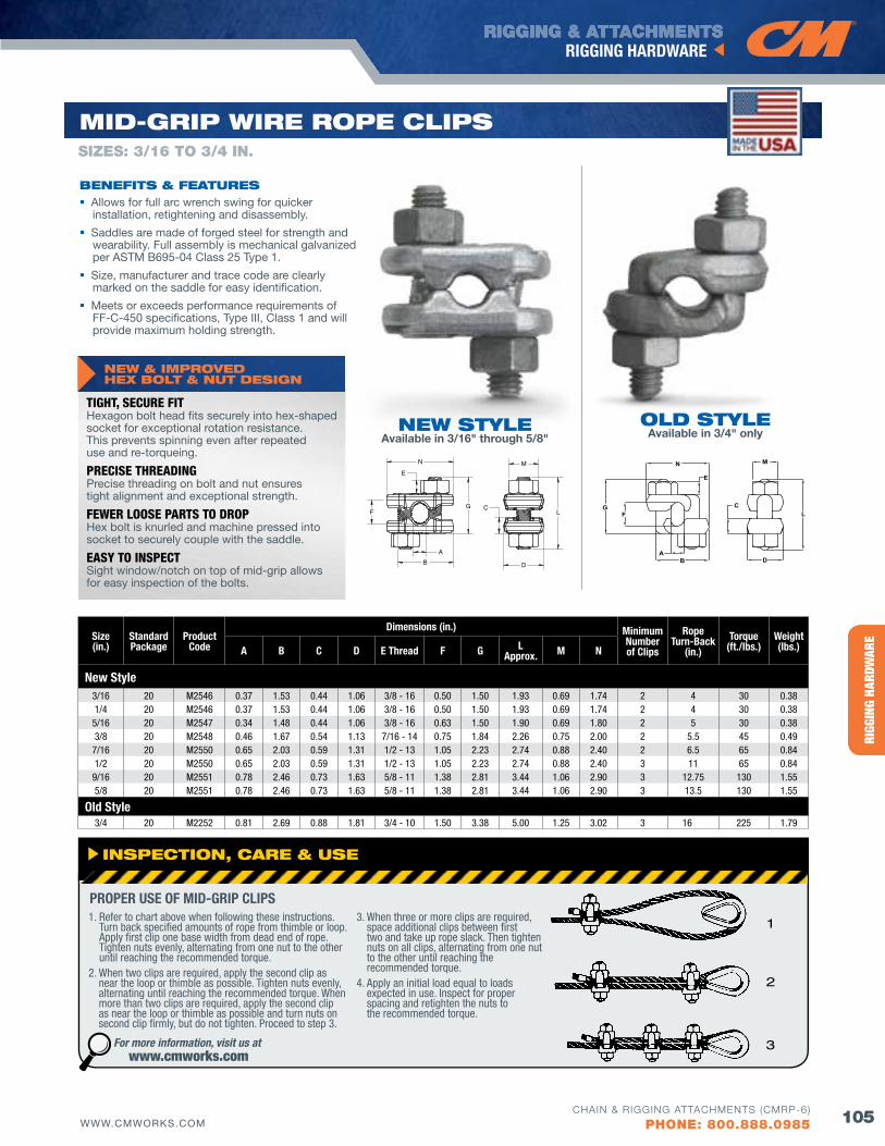
HERC
-ALL
OY® 8
00RI
GGIN
G HA
RDW
ARE
RIGGING & ATTACHMENTSRIGGING HARDWARE
105WWW.CMWORKS.COMCHAIN & RIGGING ATTACHMENTS (CMRP-6)
PHONE: 800.888.0985
INSPECTIoN, CARE & uSE
1. Refer to chart above when following these instructions. Turn back specified amounts of rope from thimble or loop. Apply first clip one base width from dead end of rope. Tighten nuts evenly, alternating from one nut to the other until reaching the recommended torque.
2. When two clips are required, apply the second clip as near the loop or thimble as possible. Tighten nuts evenly, alternating until reaching the recommended torque. When more than two clips are required, apply the second clip as near the loop or thimble as possible and turn nuts on second clip firmly, but do not tighten. Proceed to step 3.
3. When three or more clips are required, space additional clips between first two and take up rope slack. Then tighten nuts on all clips, alternating from one nut to the other until reaching the recommended torque.
4. Apply an initial load equal to loads expected in use. Inspect for proper spacing and retighten the nuts to the recommended torque.
PROPER USE Of MID-GRIP CLIPS
For more information, visit us at www.cmworks.com
Size(in.)
StandardPackage
Product Code
Dimensions (in.) Minimum Number of Clips
Rope Turn-Back
(in.)Torque
(ft./lbs.)Weight(lbs.)A B C D E Thread f G L
Approx. M N
New Style3/16 20 M2546 0.37 1.53 0.44 1.06 3/8 - 16 0.50 1.50 1.93 0.69 1.74 2 4 30 0.381/4 20 M2546 0.37 1.53 0.44 1.06 3/8 - 16 0.50 1.50 1.93 0.69 1.74 2 4 30 0.385/16 20 M2547 0.34 1.48 0.44 1.06 3/8 - 16 0.63 1.50 1.90 0.69 1.80 2 5 30 0.383/8 20 M2548 0.46 1.67 0.54 1.13 7/16 - 14 0.75 1.84 2.26 0.75 2.00 2 5.5 45 0.497/16 20 M2550 0.65 2.03 0.59 1.31 1/2 - 13 1.05 2.23 2.74 0.88 2.40 2 6.5 65 0.841/2 20 M2550 0.65 2.03 0.59 1.31 1/2 - 13 1.05 2.23 2.74 0.88 2.40 3 11 65 0.849/16 20 M2551 0.78 2.46 0.73 1.63 5/8 - 11 1.38 2.81 3.44 1.06 2.90 3 12.75 130 1.555/8 20 M2551 0.78 2.46 0.73 1.63 5/8 - 11 1.38 2.81 3.44 1.06 2.90 3 13.5 130 1.55
Old Style3/4 20 M2252 0.81 2.69 0.88 1.81 3/4 - 10 1.50 3.38 5.00 1.25 3.02 3 16 225 1.79
1
2
3
MId-GRIP wIRE RoPE ClIPS
bENEfITS & fEATuRES Allows for full arc wrench swing for quicker
installation, retightening and disassembly.
Saddles are made of forged steel for strength and wearability. Full assembly is mechanical galvanized per ASTM B695-04 Class 25 Type 1.
Size, manufacturer and trace code are clearly marked on the saddle for easy identification.
Meets or exceeds performance requirements of FF-C-450 specifications, Type III, Class 1 and will provide maximum holding strength.
NEw STylEAvailable in 3/16" through 5/8"
old STylEAvailable in 3/4" only
B
C
D
L
MN
E
A
FG
B
C
D
L
MN
E
A
FG
NEw & IMPRovEd HEX bolT & NuT dESIGN
TIGHT, SECURE FITHexagon bolt head fits securely into hex-shaped socket for exceptional rotation resistance. This prevents spinning even after repeated use and re-torqueing.
PRECISE THREADINGPrecise threading on bolt and nut ensures tight alignment and exceptional strength.
FEWER LOOSE PARTS TO DROPHex bolt is knurled and machine pressed into socket to securely couple with the saddle.
EASY TO INSPECTSight window/notch on top of mid-grip allows for easy inspection of the bolts.
SIZES: 3/16 TO 3/4 IN.
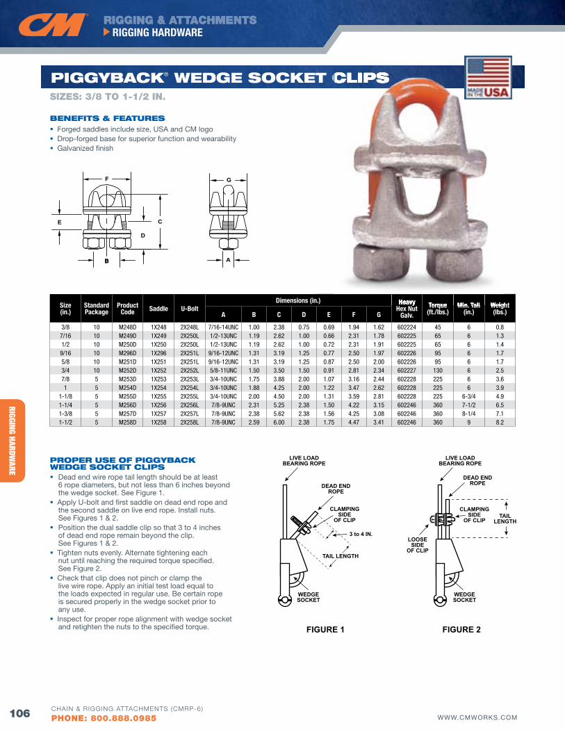
RIGGING HARDWARE
RIGGING & ATTACHMENTSRIGGING HARDWARE
106 WWW.CMWORKS.COMCHAIN & RIGGING ATTACHMENTS (CMRP-6)
PHONE: 800.888.0985
Forged saddles include size, USA and CM logo Drop-forged base for superior function and wearability Galvanized finish
B A
D
C
GF
B
E
Size(in.)
StandardPackage
Product Code Saddle U-Bolt
Dimensions (in.) Heavy Hex Nut
Galv.Torque
(ft./lbs.)Min. Tail
(in.)Weight(lbs.)A B C D E f G
3/8 10 M248D 1X248 2X248L 7/16-14UNC 1.00 2.38 0.75 0.69 1.94 1.62 602224 45 6 0.8 7/16 10 M249D 1X249 2X250L 1/2-13UNC 1.19 2.62 1.00 0.66 2.31 1.78 602225 65 6 1.3 1/2 10 M250D 1X250 2X250L 1/2-13UNC 1.19 2.62 1.00 0.72 2.31 1.91 602225 65 6 1.4
9/16 10 M296D 1X296 2X251L 9/16-12UNC 1.31 3.19 1.25 0.77 2.50 1.97 602226 95 6 1.7 5/8 10 M251D 1X251 2X251L 9/16-12UNC 1.31 3.19 1.25 0.87 2.50 2.00 602226 95 6 1.7 3/4 10 M252D 1X252 2X252L 5/8-11UNC 1.50 3.50 1.50 0.91 2.81 2.34 602227 130 6 2.5 7/8 5 M253D 1X253 2X253L 3/4-10UNC 1.75 3.88 2.00 1.07 3.16 2.44 602228 225 6 3.6 1 5 M254D 1X254 2X254L 3/4-10UNC 1.88 4.25 2.00 1.22 3.47 2.62 602228 225 6 3.9
1-1/8 5 M255D 1X255 2X255L 3/4-10UNC 2.00 4.50 2.00 1.31 3.59 2.81 602228 225 6-3/4 4.9 1-1/4 5 M256D 1X256 2X256L 7/8-9UNC 2.31 5.25 2.38 1.50 4.22 3.15 602246 360 7-1/2 6.5 1-3/8 5 M257D 1X257 2X257L 7/8-9UNC 2.38 5.62 2.38 1.56 4.25 3.08 602246 360 8-1/4 7.1 1-1/2 5 M258D 1X258 2X258L 7/8-9UNC 2.59 6.00 2.38 1.75 4.47 3.41 602246 360 9 8.2
PRoPER uSE of PIGGybACK wEdGE SoCKET ClIPS Dead end wire rope tail length should be at least
6 rope diameters, but not less than 6 inches beyond the wedge socket. See Figure 1.
Apply U-bolt and first saddle on dead end rope and the second saddle on live end rope. Install nuts. See Figures 1 & 2.
Position the dual saddle clip so that 3 to 4 inches of dead end rope remain beyond the clip. See Figures 1 & 2.
Tighten nuts evenly. Alternate tightening each nut until reaching the required torque specified. See Figure 2.
Check that clip does not pinch or clamp the live wire rope. Apply an initial test load equal to the loads expected in regular use. Be certain rope is secured properly in the wedge socket prior to any use.
Inspect for proper rope alignment with wedge socket and retighten the nuts to the specified torque.
PIGGybACK® wEdGE SoCKET ClIPS
FIGURE 2
LIVE LOADBEARING ROPE
DEAD ENDROPE
CLAMPINGSIDE
OF CLIPTAIL
LENGTH
WEDGESOCKET
LOOSESIDE
OF CLIP
FIGURE 1
LIVE LOADBEARING ROPE
DEAD ENDROPE
CLAMPINGSIDE
OF CLIP
TAIL LENGTH
WEDGESOCKET
3 to 4 IN.
Heavy Torque Min. Tail Weight
ClIPS
bENEfITS & fEATuRES
SIZES: 3/8 TO 1-1/2 IN.
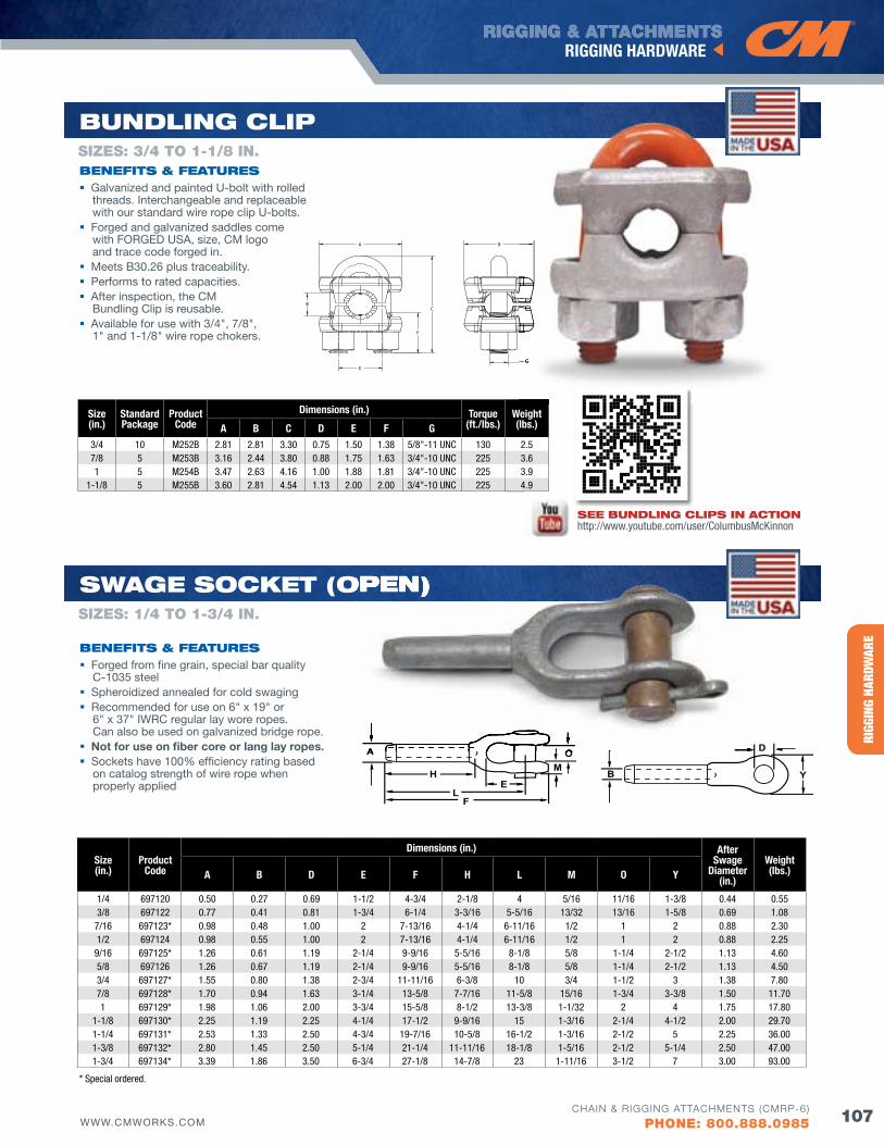
HERC
-ALL
OY® 8
00RI
GGIN
G HA
RDW
ARE
RIGGING & ATTACHMENTSRIGGING HARDWARE
107WWW.CMWORKS.COMCHAIN & RIGGING ATTACHMENTS (CMRP-6)
PHONE: 800.888.0985
SIZES: 3/4 TO 1-1/8 IN.
buNdlING ClIP
bENEfITS & fEATuRES Galvanized and painted U-bolt with rolled
threads. Interchangeable and replaceable with our standard wire rope clip U-bolts.
Forged and galvanized saddles come with FORGED USA, size, CM logo and trace code forged in.
Meets B30.26 plus traceability. Performs to rated capacities. After inspection, the CM
Bundling Clip is reusable. Available for use with 3/4", 7/8",
1" and 1-1/8" wire rope chokers.
Size(in.)
StandardPackage
Product Code
Dimensions (in.) Torque(ft./lbs.)
Weight(lbs.)A B C D E f G
3/4 10 M252B 2.81 2.81 3.30 0.75 1.50 1.38 5/8"-11 UNC 130 2.57/8 5 M253B 3.16 2.44 3.80 0.88 1.75 1.63 3/4"-10 UNC 225 3.61 5 M254B 3.47 2.63 4.16 1.00 1.88 1.81 3/4"-10 UNC 225 3.9
1-1/8 5 M255B 3.60 2.81 4.54 1.13 2.00 2.00 3/4"-10 UNC 225 4.9
G
A B
CB
F
E
G
SEE buNdlING ClIPS IN ACTIoN http://www.youtube.com/user/ColumbusMcKinnon
B
A
H
L
D
Y
F
OM
E
Size(in.)
Product Code
Dimensions (in.) After Swage
Diameter(in.)
Weight(lbs.)A B D E f H L M O Y
1/4 697120 0.50 0.27 0.69 1-1/2 4-3/4 2-1/8 4 5/16 11/16 1-3/8 0.44 0.55 3/8 697122 0.77 0.41 0.81 1-3/4 6-1/4 3-3/16 5-5/16 13/32 13/16 1-5/8 0.69 1.08
7/16 697123* 0.98 0.48 1.00 2 7-13/16 4-1/4 6-11/16 1/2 1 2 0.88 2.30 1/2 697124 0.98 0.55 1.00 2 7-13/16 4-1/4 6-11/16 1/2 1 2 0.88 2.25
9/16 697125* 1.26 0.61 1.19 2-1/4 9-9/16 5-5/16 8-1/8 5/8 1-1/4 2-1/2 1.13 4.60 5/8 697126 1.26 0.67 1.19 2-1/4 9-9/16 5-5/16 8-1/8 5/8 1-1/4 2-1/2 1.13 4.50 3/4 697127* 1.55 0.80 1.38 2-3/4 11-11/16 6-3/8 10 3/4 1-1/2 3 1.38 7.80 7/8 697128* 1.70 0.94 1.63 3-1/4 13-5/8 7-7/16 11-5/8 15/16 1-3/4 3-3/8 1.50 11.70 1 697129* 1.98 1.06 2.00 3-3/4 15-5/8 8-1/2 13-3/8 1-1/32 2 4 1.75 17.80
1-1/8 697130* 2.25 1.19 2.25 4-1/4 17-1/2 9-9/16 15 1-3/16 2-1/4 4-1/2 2.00 29.70 1-1/4 697131* 2.53 1.33 2.50 4-3/4 19-7/16 10-5/8 16-1/2 1-3/16 2-1/2 5 2.25 36.00 1-3/8 697132* 2.80 1.45 2.50 5-1/4 21-1/4 11-11/16 18-1/8 1-5/16 2-1/2 5-1/4 2.50 47.00 1-3/4 697134* 3.39 1.86 3.50 6-3/4 27-1/8 14-7/8 23 1-11/16 3-1/2 7 3.00 93.00
SwAGE SoCKET (oPEN)
bENEfITS & fEATuRES Forged from fine grain, special bar quality
C-1035 steel Spheroidized annealed for cold swaging Recommended for use on 6" x 19" or
6" x 37" IWRC regular lay wore ropes. Can also be used on galvanized bridge rope.
Not for use on fiber core or lang lay ropes. Sockets have 100% efficiency rating based
on catalog strength of wire rope when properly applied
A O
oPEN)SIZES: 1/4 TO 1-3/4 IN.
* Special ordered.
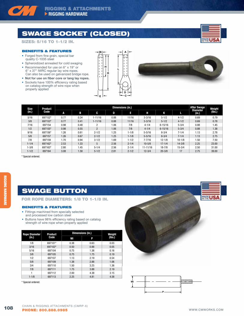
RIGGING HARDWARE
RIGGING & ATTACHMENTSRIGGING HARDWARE
108 WWW.CMWORKS.COMCHAIN & RIGGING ATTACHMENTS (CMRP-6)
PHONE: 800.888.0985
B A
H
K
E
L
DC
Size(in.)
ProductCode
Dimensions (in.) After Swage Diameter
(in.)Weight(lbs.)A B C D E H K L
5/16 697152* 0.77 0.34 1-11/16 0.88 11/16 3-3/16 5-1/2 4-1/2 0.69 0.79 3/8 697153* 0.77 0.41 1-11/16 0.88 11/16 3-3/16 5-1/2 4-1/2 0.69 0.78
7/16 697154 0.98 0.48 2 1.06 7/8 4-1/4 6-15/16 5-3/4 0.88 1.45 1/2 697155* 0.98 0.55 2 1.06 7/8 4-1/4 6-15/16 5-3/4 0.88 1.38
9/16 697156* 1.26 0.61 2-1/2 1.25 1-1/8 5-5/16 8-3/4 7-1/4 1.13 2.78 5/8 697157 1.26 0.67 2-1/2 1.25 1-1/8 5-5/16 8-3/4 7-1/4 1.13 2.75 7/8 697159 1.70 0.94 3-1/2 1.69 1-1/2 7-7/16 12-1/8 10-1/8 1.50 7.50
1-1/4 697162* 2.53 1.33 5 2.56 2-1/4 10-5/8 17-1/4 14-3/8 2.25 23.00 1-3/8 697163* 2.80 1.45 5-1/4 2.56 2-1/4 11-11/16 18-7/8 15-3/4 2.50 31.00 1-1/2 697164 3.08 1.58 5-1/2 2.81 2-1/2 12-3/4 20-3/8 17 2.75 39.00
P
Wi
Rope Diameter(in.)
ProductCode
Dimensions (in.) Weight(lbs.)Wi P
1/8 697101* 0.38 0.63 0.033/16 697102* 0.50 0.88 0.055/16 697104 0.75 1.38 0.163/8 697105 0.75 1.75 0.191/2 697107 1.13 2.19 0.545/8 697109 1.38 2.88 1.063/4 697110 1.50 3.25 1.367/8 697111 1.75 3.88 2.191 697112 2.00 4.38 3.15
1-1/8 697113 2.25 4.81 4.58
SwAGE buTToN
bENEfITS & fEATuRES Fittings machined from specially selected
and processed low carbon steel Buttons have 98% efficiency rating based on catalog
strength of wire rope when properly applied
SwAGE SoCKET (CloSEd)
bENEfITS & fEATuRES Forged from fine grain, special bar
quality C-1035 steel Spheroidized annealed for cold swaging Recommended for use on 6" x 19" or
6" x 37" IWRC regular lay wire ropes. Can also be used on galvanized bridge rope.
Not for use on fiber core or lang lay ropes. Sockets have 100% efficiency rating based
on catalog strength of wire rope when properly applied
fOR ROPE DIAMETERS: 1/8 TO 1-1/8 IN.
SIZES: 5/16 TO 1-1/2 IN.
* Special ordered.
* Special ordered.
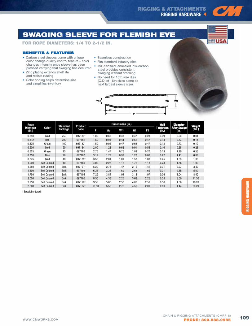
HERC
-ALL
OY® 8
00RI
GGIN
G HA
RDW
ARE
RIGGING & ATTACHMENTSRIGGING HARDWARE
109WWW.CMWORKS.COMCHAIN & RIGGING ATTACHMENTS (CMRP-6)
PHONE: 800.888.0985
Rope Diameter
(in.)Color Standard
PackageProduct
Code
Dimensions (in.) Wall Thickness
(in.)
Diameter After Swage
(in.)Weight(lbs.)P Wo Wi1 Wi P1
0.250 Gold 250 697180* 1.00 0.66 0.33 0.47 0.28 0.09 0.50 0.040.312 Red 200 697181 1.50 0.91 0.44 0.61 0.47 0.14 0.73 0.140.375 Green 100 697182* 1.50 0.91 0.47 0.66 0.47 0.13 0.73 0.120.500 Gold 50 697184* 2.00 1.22 0.63 0.91 0.59 0.16 0.98 0.280.625 Green 25 697186 2.75 1.47 0.75 1.09 0.70 0.19 1.20 0.560.750 Blue 20 697187 3.19 1.72 0.92 1.28 0.86 0.22 1.41 0.880.875 Gold 10 697188* 3.56 2.01 1.01 1.53 1.00 0.25 1.63 1.381.000 Self Colored 10 697189 4.00 2.28 1.16 1.72 1.13 0.28 1.88 1.901.250 Self Colored Bulk 697191* 5.20 2.78 1.47 2.16 1.41 0.31 2.27 3.401.500 Self Colored Bulk 697193 6.25 3.25 1.69 2.63 1.69 0.31 2.65 5.001.750 Self Colored Bulk 697194 7.25 3.84 1.94 3.13 1.97 0.36 3.04 8.402.000 Self Colored Bulk 697195 8.50 4.38 2.25 3.63 2.25 0.38 3.50 11.302.250 Self Colored Bulk 697196* 9.56 5.03 2.50 4.03 2.53 0.50 4.06 19.202.500 Self Colored Bulk 697197* 10.50 5.50 2.75 4.50 2.81 0.50 4.44 23.20
PP1
Wi1 Wi Wo
SwAGING SlEEvE foR flEMISH EyE
bENEfITS & fEATuRES Seamless construction Fits standard industry dies Mill-certified, annealed low-carbon
steel provides consistent swaging without cracking
No need for 16th size dies (O.D. of 16th sizes same as next largest sleeve size).
Carbon steel sleeves come with unique color change quality control feature – color changes intensity once sleeve has been pressed verifying that swaging has occurred
Zinc plating extends shelf life and resists rusting
Color coding helps determine size and simplifies inventory
Wall Thickness
Diameter After Swage Weight
(lbs.)
Wi Wo
EyEfOR ROPE DIAMETERS: 1/4 TO 2-1/2 IN.
* Special ordered.
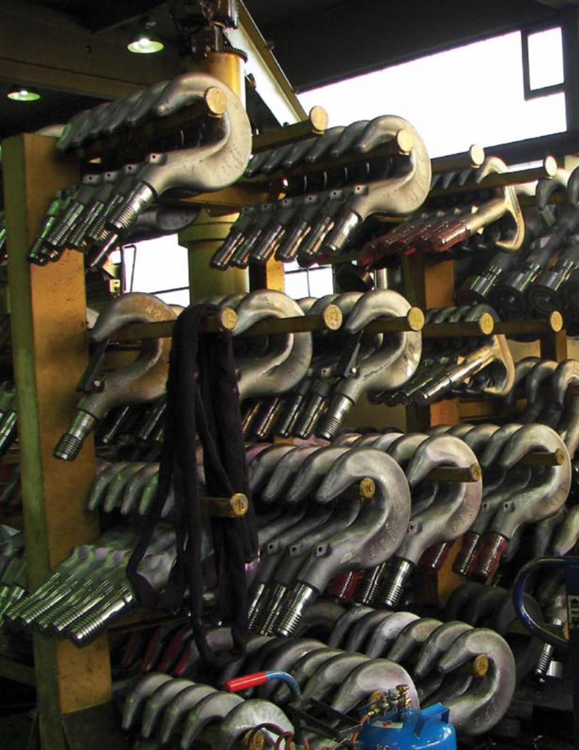
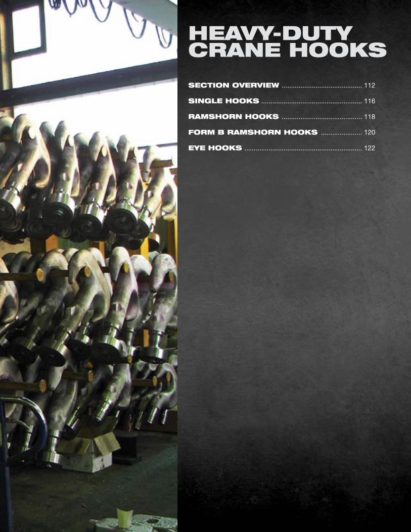
SECTIoN ovERvIEw ........................................... 112
SINGlE HooKS ...................................................... 116
RAMSHoRN HooKS ........................................... 118
foRM b RAMSHoRN HooKS ...................... 120
EyE HooKS ............................................................... 122
HEAvy-duTyCRANE HooKS
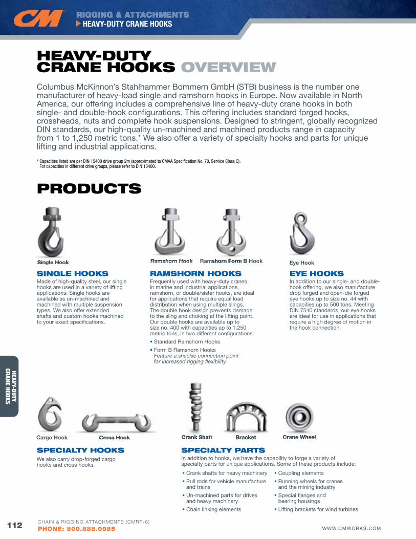
HEAVY-DUTYCRANE HOOKS
RIGGING & ATTACHMENTSHEAVY-DUTY CRANE HOOKS
112 WWW.CMWORKS.COMCHAIN & RIGGING ATTACHMENTS (CMRP-6)
PHONE: 800.888.0985
Columbus McKinnon’s Stahlhammer Bommern GmbH (STB) business is the number one manufacturer of heavy-load single and ramshorn hooks in Europe. Now available in North America, our offering includes a comprehensive line of heavy-duty crane hooks in both single- and double-hook configurations. This offering includes standard forged hooks, crossheads, nuts and complete hook suspensions. Designed to stringent, globally recognized DIN standards, our high-quality un-machined and machined products range in capacity from 1 to 1,250 metric tons.* We also offer a variety of specialty hooks and parts for unique lifting and industrial applications.
* Capacities listed are per DIN 15400 drive group 2m (approximated to CMAA Specification No. 70, Service Class C). For capacities in different drive groups, please refer to DIN 15400.
PRoduCTS
SINGlE HooKSMade of high-quality steel, our single hooks are used in a variety of lifting applications. Single hooks are available as un-machined and machined with multiple suspension types. We also offer extended shafts and custom hooks machined to your exact specifications.
EyE HooKSIn addition to our single- and double-hook offering, we also manufacture drop forged and open-die forged eye hooks up to size no. 44 with capacities up to 500 tons. Meeting DIN 7540 standards, our eye hooks are ideal for use in applications that require a high degree of motion in the hook connection.
RAMSHoRN HooKSFrequently used with heavy-duty cranes in marine and industrial applications, ramshorn, or double/sister hooks, are ideal for applications that require equal load distribution when using multiple slings. The double hook design prevents damage to the sling and choking at the lifting point. Our double hooks are available up to size no. 400 with capacities up to 1,250 metric tons, in two different configurations:
Standard Ramshorn Hooks
Form B Ramshorn Hooks Feature a shackle connection point for increased rigging flexibility.
SPECIAlTy PARTSIn addition to hooks, we have the capability to forge a variety of specialty parts for unique applications. Some of these products include:
SPECIAlTy HooKSWe also carry drop-forged cargo hooks and cross hooks.
HEAvy-duTy CRANE HooKS ovERvIEw
Crank shafts for heavy machinery
Pull rods for vehicle manufacture and trains
Un-machined parts for drives and heavy machinery
Chain linking elements
Coupling elements
Running wheels for cranes and the mining industry
Special flanges and bearing housings
Lifting brackets for wind turbines
Single HookSingle Hook Ramshorn HookRamshorn Hook Ramshorn Form B HookRamshorn Form B Hook
Cargo Hook Cross HookCross Hook BracketBracket Crane WheelCrane WheelCrank ShaftCrank Shaft
Eye Hook
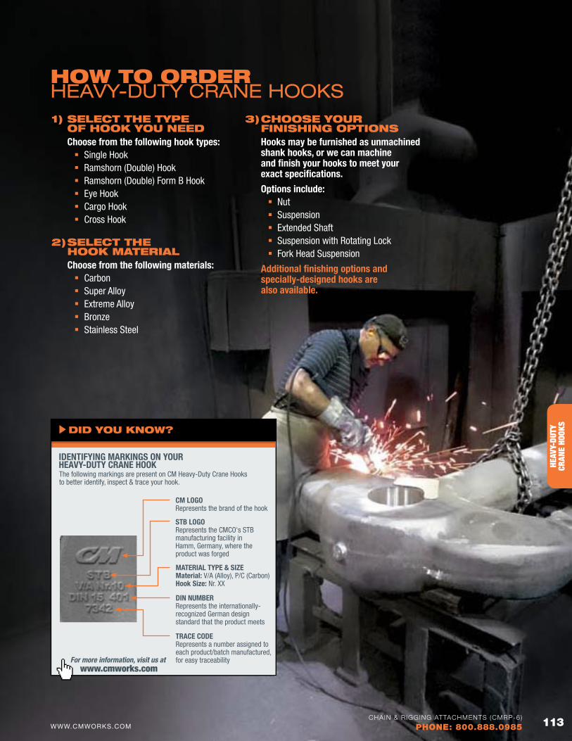
HERC
-ALL
OY® 8
00HE
AVY-
DUTY
CRAN
E HO
OKS
HEAVY-DUTY CRANE HOOKS
113WWW.CMWORKS.COMCHAIN & RIGGING ATTACHMENTS (CMRP-6)
PHONE: 800.888.0985
How To oRdERHEAVY-DUTY CRANE HOOKS
For more information, visit us at www.cmworks.com
IDENTIfYING MARKINGS ON YOUR HEAVY-DUTY CRANE HOOK
dId you KNow?
CM LOGO Represents the brand of the hook
STB LOGO Represents the CMCO's STB manufacturing facility in Hamm, Germany, where the product was forged
MATERIAL TYPE & SIzE Material: V/A (Alloy), P/C (Carbon) Hook Size: Nr. XX
DIN NUMBER Represents the internationally- recognized German design standard that the product meets
TRACE CODE Represents a number assigned to each product/batch manufactured, for easy traceability
The following markings are present on CM Heavy-Duty Crane Hooks to better identify, inspect & trace your hook.
1) SElECT THE TyPE of HooK you NEEd
Choose from the following hook types: Single Hook Ramshorn (Double) Hook Ramshorn (Double) Form B Hook Eye Hook Cargo Hook Cross Hook
2) SElECT THE HooK MATERIAl
Choose from the following materials: Carbon Super Alloy Extreme Alloy Bronze Stainless Steel
3) CHooSE youR fINISHING oPTIoNS
Hooks may be furnished as unmachined shank hooks, or we can machine and finish your hooks to meet your exact specifications.
Options include: Nut Suspension Extended Shaft Suspension with Rotating Lock Fork Head Suspension
Additional finishing options and specially-designed hooks are also available.
HERC
-ALL
OY® 8
00HE
AVY-
DUTY
CRAN
E HO
OKS
113WWW.CMWORKS.COMCHAIN & RIGGING ATTACHMENTS (CMRP-6)
PHONE: 800.888.0985
HEAVY-DUTYCRANE HOOKS
RIGGING & ATTACHMENTSHEAVY-DUTY CRANE HOOKS
114 WWW.CMWORKS.COMCHAIN & RIGGING ATTACHMENTS (CMRP-6)
PHONE: 800.888.0985
MATERIAlS To create a great product, you have to start with the best materials. To accomplish this, we’ve partnered with one of the leading steel suppliers in Europe to develop what we feel is the highest quality steel available. Our involvement in the earliest stages of our raw material development allows us to determine our material specifications, reducing variations in chemical makeup and helping to ensure consistency in the quality of the products we produce.
ouR PRoduCTS ARE AvAIlAblE IN fIvE MATERIAlS:
1. CARBON Design Factor 6:1 Strength Class P Depending on size, we offer two grades
of fine-grain carbon steel: StE355N (similar to ASTM A572 Grade 50) StE420N (similar to ASTM A255 Grade D)
2. SUPER ALLOY Design Factor 5:1 Strength Class v
Heat-treatable steel: 34CrNiMo6 (similar to SAE/AISI 4340)
3. EXTREME ALLOY Need a stronger material? Available upon request is our extreme
alloy material with a minimum Charpy v-notch impact value of 42 joule at -40°C and a maximum value of 52 joule at - 50°C.
Design Factor 5:1 Strength Class W (per EN 13001-3-5 standard) Heat-treatable steel
4. BRONZE Design Factor 6:1
5. STAINLESS STEEL Design Factor 6:1
All of our products are quenched and tempered. Our products are also pre-formed. This promotes grain flow, which provides strength and durability for products under high dynamic stress – like our heavy-duty crane hooks and specially machined parts.
For more information, visit us at www.cmworks.com
DIN stands for “Deutsches Institut für Normung”, meaning “German Institute for Standardization”. Founded in 1917, DIN is the organization responsible for standardization in Germany and is the German ISO member body. Today, there are approximately 30,000 DIN standards covering nearly every field of technology, including crane hooks.
WHAT IS DIN?
dId you KNow? AdvANTAGESAll of Columbus McKinnon’s heavy-duty crane hooks and specialty parts are made in house at our 82,000 square foot facility in Hamm, Germany.
With our own forging, machining and tool-making capabilities, we are able to turn pre-formed steel billets into finished, geometrically complex products quickly and efficiently while ensuring the highest levels of quality. For closed-die forgings, we rely on a hammer forge with pre-forming presses that give us flexibility in the forging process and allow for a shorter set-up time and running-in period. For larger hooks, we use state-of-the-art, open-die forging technology. We also use modular dies that reduce tool costs for smaller quantities of individually designed hooks.
For easy identification, we forge a traceability code along with STB and CM logos into every product.
CAPAbIlITIESWe manufacture many of our products through a combination of open-die forging and drop forging processes.
DROP fORGING We primarily focus on drop-forging technologies for standard and geometrically complex parts due to the cost savings it provides for larger production runs.
We use drop forging to produce single hooks up to size no. 63 and 250 metric ton capacities, as well as ramshorn hooks up to size no. 125 and 500 metric ton capacities.
OPEN-DIE fORGING Our open-die forging capabilities enable us to produce large, heavy-duty hooks that not only meet our customers’ unique requirements but DIN specifications as well. Our open-die forging capabilities allow us to manufacture hooks with any shaft length and is typically used for a single specialized product or products with small production runs.
We utilize modular dies that allow us to forge different hook shapes using the same die by simply changing the insert.
We use open-die forging to produce single hooks ranging in size from no. 80 to no. 400, and no. 160 to no. 400 for ramshorn hooks.
COMBINING CAPABILITIES For forgings with longer shaft lengths, we frequently combine our drop forging and open-die forging capabilities to produce a single product. This allows us to produce geometrically complex engineered products with longer shaft lengths.
MACHINING CAPABILITIES We can machine any type of hook suspension required, including cross heads and nuts.
IN-HOUSE TOOL SHOP Our in-house tool shop gives us the ability to design and produce our own dies, allowing for quick turnaround of specialty forgings and custom products. We are also able to repair and replace parts on our existing dies without relying on an external supplier.
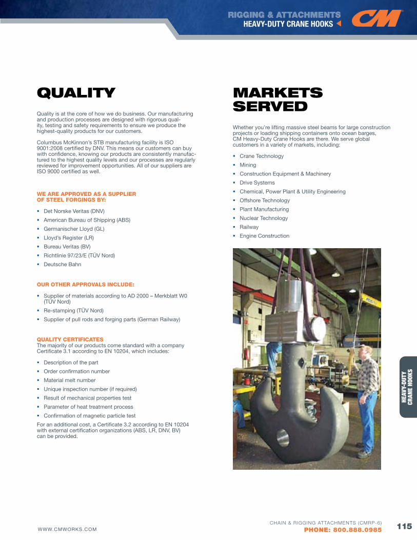
HERC
-ALL
OY® 8
00HE
AVY-
DUTY
CRAN
E HO
OKS
RIGGING & ATTACHMENTSHEAVY-DUTY CRANE HOOKS
115WWW.CMWORKS.COMCHAIN & RIGGING ATTACHMENTS (CMRP-6)
PHONE: 800.888.0985
QuAlITyQuality is at the core of how we do business. Our manufacturing and production processes are designed with rigorous qual-ity, testing and safety requirements to ensure we produce the highest-quality products for our customers.
Columbus McKinnon’s STB manufacturing facility is ISO 9001:2008 certified by DNv. This means our customers can buy with confidence, knowing our products are consistently manufac-tured to the highest quality levels and our processes are regularly reviewed for improvement opportunities. All of our suppliers are ISO 9000 certified as well.
WE ARE APPROVED AS A SUPPLIER Of STEEL fORGINGS BY:
Det Norske veritas (DNv)
American Bureau of Shipping (ABS)
Germanischer Lloyd (GL)
Lloyd’s Register (LR)
Bureau veritas (Bv)
Richtlinie 97/23/E (TÜv Nord)
Deutsche Bahn
OUR OTHER APPROVALS INCLUDE:
Supplier of materials according to AD 2000 – Merkblatt W0 (TÜv Nord)
Re-stamping (TÜv Nord)
Supplier of pull rods and forging parts (German Railway)
QUALITY CERTIfICATES The majority of our products come standard with a company Certificate 3.1 according to EN 10204, which includes:
Description of the part
Order confirmation number
Material melt number
Unique inspection number (if required)
Result of mechanical properties test
Parameter of heat treatment process
Confirmation of magnetic particle test
For an additional cost, a Certificate 3.2 according to EN 10204 with external certification organizations (ABS, LR, DNv, Bv) can be provided.
MARKETS SERvEdWhether you’re lifting massive steel beams for large construction projects or loading shipping containers onto ocean barges, CM Heavy-Duty Crane Hooks are there. We serve global customers in a variety of markets, including:
Crane Technology
Mining
Construction Equipment & Machinery
Drive Systems
Chemical, Power Plant & Utility Engineering
Offshore Technology
Plant Manufacturing
Nuclear Technology
Railway
Engine Construction
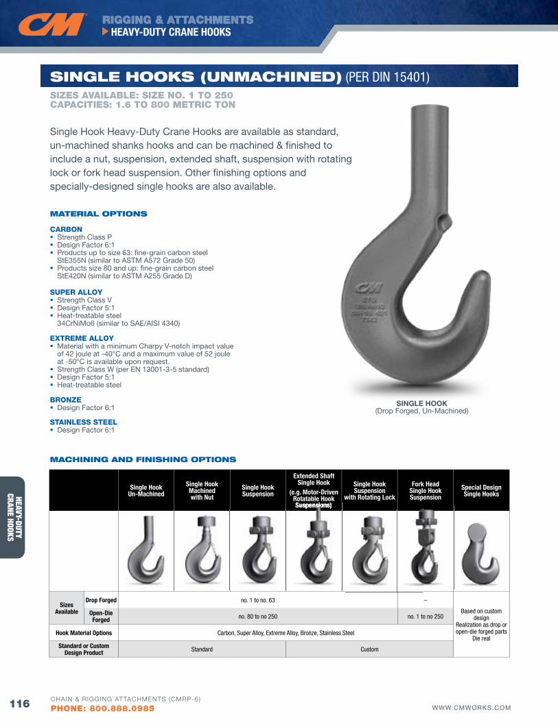
HEAVY-DUTYCRANE HOOKS
RIGGING & ATTACHMENTSHEAVY-DUTY CRANE HOOKS
116 WWW.CMWORKS.COMCHAIN & RIGGING ATTACHMENTS (CMRP-6)
PHONE: 800.888.0985
CARBON Strength Class P Design Factor 6:1 Products up to size 63: fine-grain carbon steel
StE355N (similar to ASTM A572 Grade 50) Products size 80 and up: fine-grain carbon steel
StE420N (similar to ASTM A255 Grade D)
SUPER ALLOY Strength Class v Design Factor 5:1 Heat-treatable steel
34CrNiMo6 (similar to SAE/AISI 4340)
EXTREME ALLOY Material with a minimum Charpy v-notch impact value
of 42 joule at -40°C and a maximum value of 52 joule at -50°C is available upon request.
Strength Class W (per EN 13001-3-5 standard) Design Factor 5:1 Heat-treatable steel
BRONZE Design Factor 6:1
STAINLESS STEEL Design Factor 6:1
MATERIAl oPTIoNS
SIZES AVAILAbLE: SIZE NO. 1 TO 250CAPACITIES: 1.6 TO 800 METRIC TON
SINGlE HooKS (uNMACHINEd) (PER DIN 15401)
Single HookUn-Machined
Single HookMachinedwith Nut
Single HookSuspension
Extended ShaftSingle Hook
(e.g. Motor-Driven Rotatable Hook Suspensions)
Single Hook Suspension
with Rotating Lock
fork HeadSingle HookSuspension
Special DesignSingle Hooks
Sizes Available
Drop forged no. 1 to no. 63 –
Based on custom design
Realization as drop or open-die forged parts
Die real
Open-Die forged no. 80 to no 250 no. 1 to no 250
Hook Material Options Carbon, Super Alloy, Extreme Alloy, Bronze, Stainless Steel
Standard or Custom Design Product Standard Custom
Suspensions)
MACHINING ANd fINISHING oPTIoNS
Single Hook Heavy-Duty Crane Hooks are available as standard, un-machined shanks hooks and can be machined & finished to include a nut, suspension, extended shaft, suspension with rotating lock or fork head suspension. Other finishing options and specially-designed single hooks are also available.
SINGLE HOOK(Drop Forged, Un-Machined)
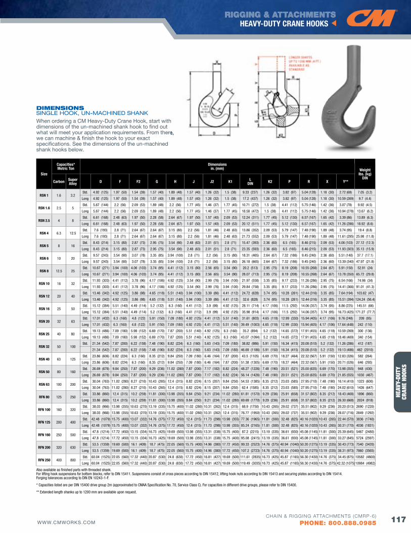
HERC
-ALL
OY® 8
00HE
AVY-
DUTY
CRAN
E HO
OKS
RIGGING & ATTACHMENTSHEAVY-DUTY CRANE HOOKS
117WWW.CMWORKS.COMCHAIN & RIGGING ATTACHMENTS (CMRP-6)
PHONE: 800.888.0985
Size
Capacities*Metric Ton
Dimensions in. (mm) Weight
lbs. (kg) DIN
Carbon Super Alloy D f f2 G H J J2 K1 L
DIN K2 P R X Y**
RSN 1 1.6 3.2Std. 4.92 (125) 1.97 (50) 1.54 (39) 1.57 (40) 1.89 (48) 1.57 (40) 1.26 (32) 1.5 (38) 9.33 (237) 1.26 (32) 3.82 (97) 5.04 (128) 1.18 (30) 2.72 (69) 7.05 (3.2)
Long 4.92 (125) 1.97 (50) 1.54 (39) 1.57 (40) 1.89 (48) 1.57 (40) 1.26 (32) 1.5 (38) 17.2 (437) 1.26 (32) 3.82 (97) 5.04 (128) 1.18 (30) 10.59 (269) 9.7 (4.4)
RSN 1.6 2.5 5Std. 5.67 (144) 2.2 (56) 2.09 (53) 1.89 (48) 2.2 (56) 1.77 (45) 1.46 (37) 1.77 (45) 10.71 (272) 1.5 (38) 4.41 (112) 5.75 (146) 1.42 (36) 3.07 (78) 9.92 (4.5)
Long 5.67 (144) 2.2 (56) 2.09 (53) 1.89 (48) 2.2 (56) 1.77 (45) 1.46 (37) 1.77 (45) 18.58 (472) 1.5 (38) 4.41 (112) 5.75 (146) 1.42 (36) 10.94 (278) 13.67 (6.2)
RSN 2.5 4 8Std. 6.61 (168) 2.48 (63) 1.97 (50) 2.28 (58) 2.64 (67) 1.97 (50) 1.57 (40) 2.09 (53) 12.24 (311) 1.77 (45) 5.12 (130) 6.57 (167) 1.65 (42) 3.39 (86) 13.89 (6.3)
Long 6.61 (168) 2.48 (63) 1.97 (50) 2.28 (58) 2.64 (67) 1.97 (50) 1.57 (40) 2.09 (53) 20.12 (511) 1.77 (45) 5.12 (130) 6.57 (167) 1.65 (42) 11.26 (286) 18.92 (8.6)
RSN 4 6.3 12.5Std. 7.6 (193) 2.8 (71) 2.64 (67) 2.64 (67) 3.15 (80) 2.2 (56) 1.81 (46) 2.48 (63) 13.86 (352) 2.09 (53) 5.79 (147) 7.48 (190) 1.89 (48) 3.74 (95) 19.4 (8.8)
Long 7.6 (193) 2.8 (71) 2.64 (67) 2.64 (67) 3.15 (80) 2.2 (56) 1.81 (46) 2.48 (63) 21.73 (552) 2.09 (53) 5.79 (147) 7.48 (190) 1.89 (48) 11.61 (295) 25.98 (11.8)
RSN 5 8 16Std. 8.43 (214) 3.15 (80) 2.87 (73) 2.95 (75) 3.54 (90) 2.48 (63) 2.01 (51) 2.8 (71) 15.47 (393) 2.36 (60) 6.5 (165) 8.46 (215) 2.09 (53) 4.06 (103) 27.12 (12.3)
Long 8.43 (214) 3.15 (80) 2.87 (73) 2.95 (75) 3.54 (90) 2.48 (63) 2.01 (51) 2.8 (71) 23.35 (593) 2.36 (60) 6.5 (165) 8.46 (215) 2.09 (53) 11.93 (303) 35.13 (15.9)
RSN 6 10 20Std. 9.57 (243) 3.54 (90) 3.07 (78) 3.35 (85) 3.94 (100) 2.8 (71) 2.2 (56) 3.15 (80) 18.31 (465) 2.64 (67) 7.32 (186) 9.45 (240) 2.36 (60) 5.51 (140) 37.7 (17.1)
Long 9.57 (243) 3.54 (90) 3.07 (78) 3.35 (85) 3.94 (100) 2.8 (71) 2.2 (56) 3.15 (80) 26.18 (665) 2.64 (67) 7.32 (186) 9.45 (240) 2.36 (60) 13.39 (340) 47.97 (21.8)
RSN 8 12.5 25Std. 10.67 (271) 3.94 (100) 4.06 (103) 3.74 (95) 4.41 (112) 3.15 (80) 2.56 (65) 3.54 (90) 20.2 (513) 2.95 (75) 8.19 (208) 10.55 (268) 2.64 (67) 5.91 (150) 52.91 (24)
Long 10.67 (271) 3.94 (100) 4.06 (103) 3.74 (95) 4.41 (112) 3.15 (80) 2.56 (65) 3.54 (90) 28.07 (713) 2.95 (75) 8.19 (208) 10.55 (268) 2.64 (67) 13.78 (350) 65.72 (29.8)
RSN 10 16 32Std. 11.93 (303) 4.41 (112) 3.78 (96) 4.17 (106) 4.92 (125) 3.54 (90) 2.99 (76) 3.94 (100) 21.97 (558) 3.35 (85) 9.17 (233) 11.26 (286) 2.95 (75) 6.54 (166) 74.96 (34)
Long 11.93 (303) 4.41 (112) 3.78 (96) 4.17 (106) 4.92 (125) 3.54 (90) 2.99 (76) 3.94 (100) 29.84 (758) 3.35 (85) 9.17 (233) 11.26 (286) 2.95 (75) 14.41 (366) 91.01 (41.3)
RSN 12 20 40Std. 13.46 (342) 4.92 (125) 3.86 (98) 4.65 (118) 5.51 (140) 3.94 (100) 3.39 (86) 4.41 (112) 24.72 (628) 3.74 (95) 10.28 (261) 12.44 (316) 3.35 (85) 7.64 (194) 103.62 (47)
Long 13.46 (342) 4.92 (125) 3.86 (98) 4.65 (118) 5.51 (140) 3.94 (100) 3.39 (86) 4.41 (112) 32.6 (828) 3.74 (95) 10.28 (261) 12.44 (316) 3.35 (85) 15.51 (394) 124.24 (56.4)
RSN 16 25 50Std. 15.12 (384) 5.51 (140) 4.49 (114) 5.2 (132) 6.3 (160) 4.41 (112) 3.9 (99) 4.92 (125) 28.11 (714) 4.17 (106) 11.5 (292) 14.06 (357) 3.74 (95) 8.86 (225) 145.51 (66)
Long 15.12 (384) 5.51 (140) 4.49 (114) 5.2 (132) 6.3 (160) 4.41 (112) 3.9 (99) 4.92 (125) 35.98 (914) 4.17 (106) 11.5 (292) 14.06 (357) 3.74 (95) 16.73 (425) 171.27 (77.7)
RSN 20 32 63Std. 17.01 (432) 6.3 (160) 4.8 (122) 5.91 (150) 7.09 (180) 4.92 (125) 4.41 (112) 5.51 (140) 31.61 (803) 4.65 (118) 12.99 (330) 15.94 (405) 4.17 (106) 9.76 (248) 209 (95)
Long 17.01 (432) 6.3 (160) 4.8 (122) 5.91 (150) 7.09 (180) 4.92 (125) 4.41 (112) 5.51 (140) 39.49 (1003) 4.65 (118) 12.99 (330) 15.94 (405) 4.17 (106) 17.64 (448) 242 (110)
RSN 25 40 80Std. 19.13 (486) 7.09 (180) 5.98 (152) 6.69 (170) 7.87 (200) 5.51 (140) 4.92 (125) 6.3 (160) 35.2 (894) 5.2 (132) 14.65 (372) 17.91 (455) 4.65 (118) 10.59 (269) 300 (136)
Long 19.13 (486) 7.09 (180) 5.98 (152) 6.69 (170) 7.87 (200) 5.51 (140) 4.92 (125) 6.3 (160) 43.07 (1094) 5.2 (132) 14.65 (372) 17.91 (455) 4.65 (118) 18.46 (469) 340 (154)
RSN 32 50 100Std. 21.34 (542) 7.87 (200) 6.22 (158) 7.48 (190) 8.82 (224) 6.3 (160) 5.63 (143) 7.09 (180) 38.82 (986) 5.91 (150) 16.34 (415) 20.08 (510) 5.2 (132) 11.26 (286) 412 (187)
21.34 (542) 7.87 (200) 6.22 (158) 7.48 (190) 8.82 (224) 6.3 (160) 5.63 (143) 7.09 (180) 46.69 (1186) 5.91 (150) 16.34 (415) 20.08 (510) 5.2 (132) 19.13 (486) 462 (2010)
RSN 40 63 125Std. 23.86 (606) 8.82 (224) 6.3 (160) 8.35 (212) 9.84 (250) 7.09 (180) 6.46 (164) 7.87 (200) 43.5 (1105) 6.69 (170) 18.27 (464) 22.32 (567) 5.91 (150) 12.83 (326) 582 (264)
Long 23.86 (606) 8.82 (224) 6.3 (160) 8.35 (212) 9.84 (250) 7.09 (180) 6.46 (164) 7.87 (200) 51.38 (1305) 6.69 (170) 18.27 (464) 22.32 (567) 5.91 (150) 20.71 (526) 646 (293)
RSN 50 80 160Std. 26.69 (678) 9.84 (250) 7.87 (200) 9.29 (236) 11.02 (280) 7.87 (200) 7.17 (182) 8.82 (224) 48.27 (1226) 7.48 (190) 20.51 (521) 25.00 (635) 6.69 (170) 13.98 (355) 948 (430)
Long 26.69 (678) 9.84 (250) 7.87 (200) 9.29 (236) 11.02 (280) 7.87 (200) 7.17 (182) 8.82 (224) 56.14 (1426) 7.48 (190) 20.51 (521) 25.00 (635) 6.69 (170) 21.85 (555) 1030 (467)
RSN 63 100 200Std. 30.04 (763) 11.02 (280) 8.27 (210) 10.43 (265) 12.4 (315) 8.82 (224) 8.15 (207) 9.84 (250) 54.53 (1385) 8.35 (212) 23.03 (585) 27.95 (710) 7.48 (190) 16.14 (410) 1323 (600)
Long 30.04 (763) 11.02 (280) 8.27 (210) 10.43 (265) 12.4 (315) 8.82 (224) 8.15 (207) 9.84 (250) 62.4 (1585) 8.35 (212) 23.03 (585) 27.95 (710) 7.48 (190) 24.02 (610) 1426 (647)
RfN 80 125 250Std. 33.86 (860) 12.4 (315) 10.2 (259) 11.81 (300) 13.98 (355) 9.84 (250) 9.21 (234) 11.02 (280) 61.81 (1570) 9.29 (236) 25.91 (658) 31.57 (802) 8.35 (212) 18.43 (468) 1896 (860)
Long 33.86 (860) 12.4 (315) 10.2 (259) 11.81 (300) 13.98 (355) 9.84 (250) 9.21 (234) 11.02 (280) 69.69 (1770) 9.29 (236) 25.91 (658) 31.57 (802) 8.35 (212) 26.30 (668) 2024 (918)
RfN 100 160 320Std. 38.03 (966) 13.98 (355) 10.63 (270) 13.19 (335) 15.75 (400) 11.02 (280) 10.31 (262) 12.4 (315) 68.9 (1750) 10.43 (265) 29.02 (737) 35.51 (902) 9.29 (236) 20.20 (513) 2690 (1220)
Long 38.03 (966) 13.98 (355) 10.63 (270) 13.19 (335) 15.75 (400) 11.02 (280) 10.31 (262) 12.4 (315) 76.77 (1950) 10.43 (265) 29.02 (737) 35.51 (902) 9.29 (236) 28.07 (716) 2849 (1292)
RfN 125 200 400Std. 42.48 (1079) 15.75 (400) 13.07 (332) 14.76 (375) 17.72 (450) 12.4 (315) 11.73 (298) 13.98 (355) 77.36 (1965) 11.81 (300) 32.48 (825) 40.16 (1020) 10.43 (265) 22.44 (570) 3836 (1740)
Long 42.48 (1079) 15.75 (400) 13.07 (332) 14.76 (375) 17.72 (450) 12.4 (315) 11.73 (298) 13.98 (355) 85.24 (2165) 11.81 (300) 32.48 (825) 40.16 (1020) 10.43 (265) 30.31 (770) 4036 (1831)
RfN 160 250 500Std. 47.8 (1214) 17.72 (450) 13.15 (334) 16.73 (425) 19.69 (500) 13.98 (355) 13.31 (338) 15.75 (400) 87.2 (2215) 13.19 (335) 36.61 (930) 45.08 (1145) 11.81 (300) 25.39 (645) 5467 (2480)
Long 47.8 (1214) 17.72 (450) 13.15 (334) 16.73 (425) 19.69 (500) 13.98 (355) 13.31 (338) 15.75 (400) 95.08 (2415) 13.19 (335) 36.61 (930) 45.08 (1145) 11.81 (300) 33.27 (845) 5724 (2597)
RfN 200 320 630Std. 53.5 (1359) 19.69 (500) 16.1 (409) 18.7 (475) 22.05 (560) 15.75 (400) 14.96 (380) 17.72 (450) 99.33 (2523) 14.76 (375) 40.94 (1040) 50.20 (1275) 13.19 (335) 30.43 (773) 7540 (3420)
Long 53.5 (1359) 19.69 (500) 16.1 (409) 18.7 (475) 22.05 (560) 15.75 (400) 14.96 (380) 17.72 (450) 107.2 (2723) 14.76 (375) 40.94 (1040) 50.20 (1275) 13.19 (335) 38.31 (973) 7860 (3565)
RfN 250 400 800Std. 60.04 (1525) 22.05 (560) 17.32 (440) 20.87 (530) 24.8 (630) 17.72 (450) 16.81 (427) 19.69 (500) 111.61 (2835) 16.73 (425) 45.87 (1165) 56.30 (1430) 14.76 (375) 34.45 (875) 10582 (4800)
Long 60.04 (1525) 22.05 (560) 17.32 (440) 20.87 (530) 24.8 (630) 17.72 (450) 16.81 (427) 19.69 (500) 119.49 (3035) 16.73 (425) 45.87 (1165) 56.30 (1430) 14.76 (375) 42.32 (1075) 10984 (4982)
Also available as finished parts with threaded shank. For lifting hook suspensions for bottom blocks, refer to DIN 15411. Suspensions consist of cross pieces according to DIN 15412, lifting hook nuts according to DIN 15413 and securing plates according to DIN 15414. Forging tolerances according to DIN EN 10243-1-F.
* Capacities listed are per DIN 15400 drive group 2m (approximated to CMAA Specification No. 70, Service Class C). For capacities in different drive groups, please refer to DIN 15400.
** Extended length shanks up to 1200 mm are available upon request.
dIMENSIoNS SINGLE HOOK, UN-MACHINED SHANKWhen ordering a CM Heavy-Duty Crane Hook, start with dimensions of the un-machined shank hook to find out what will meet your application requirements. From there, we can machine & finish the hook to your exact specifications. See the dimensions of the un-machined shank hooks below.
what will meet your application requirements. From there,
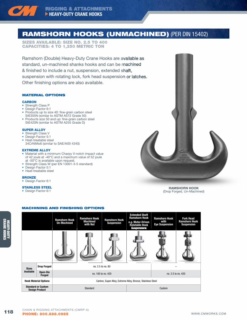
HEAVY-DUTYCRANE HOOKS
RIGGING & ATTACHMENTSHEAVY-DUTY CRANE HOOKS
118 WWW.CMWORKS.COMCHAIN & RIGGING ATTACHMENTS (CMRP-6)
PHONE: 800.888.0985
SIZES AVAILAbLE: SIZE NO. 2.5 TO 400CAPACITIES: 4 TO 1,250 METRIC TON
RAMSHoRN HooKS (uNMACHINEd) (PER DIN 15402)
CARBON Strength Class P Design Factor 6:1 Products up to size 40: fine-grain carbon steel
StE355N (similar to ASTM A572 Grade 50) Products size 50 and up: fine-grain carbon steel
StE420N (similar to ASTM A255 Grade D)
SUPER ALLOY Strength Class v Design Factor 5:1 Heat-treatable steel
34CrNiMo6 (similar to SAE/AISI 4340)
EXTREME ALLOY Material with a minimum Charpy v-notch impact value
of 42 joule at -40°C and a maximum value of 52 joule at -50°C is available upon request.
Strength Class W (per EN 13001-3-5 standard) Design Factor 5:1 Heat-treatable steel
BRONZE Design Factor 6:1
STAINLESS STEEL Design Factor 6:1
MATERIAl oPTIoNS
Ramshorn (Double) Heavy-Duty Crane Hooks are available as standard, un-machined shanks hooks and can be machined & finished to include a nut, suspension, extended shaft, suspension with rotating lock, fork head suspension or latches. Other finishing options are also available.
Ramshorn HookUn-Machined
Ramshorn HookMachinedwith Nut
Ramshorn HookSuspension
Extended ShaftRamshorn Hook
e.g. Motor-Driven Rotatable Hook
Suspensions
Ramshorn Hookwith
Eye Suspension
fork HeadRamshorn Hook
Suspension
Sizes Available
Drop forged no. 2.5 to no. 80 –
Open-Die forged no. 100 to no. 420 no. 2.5 to no. 420
Hook Material Options Carbon, Super Alloy, Extreme Alloy, Bronze, Stainless Steel
Standard or Custom Design Product Standard Custom
Suspensions
MACHINING ANd fINISHING oPTIoNS
Ramshorn (Double) Heavy-Duty Crane Hooks are available as standard, un-machined shanks hooks and can be machined & finished to include a nut, suspension, extended shaft, suspension with rotating lock, fork head suspension or latches.
RAMSHORN HOOK(Drop Forged, Un-Machined)

HERC
-ALL
OY® 8
00HE
AVY-
DUTY
CRAN
E HO
OKS
RIGGING & ATTACHMENTSHEAVY-DUTY CRANE HOOKS
119WWW.CMWORKS.COMCHAIN & RIGGING ATTACHMENTS (CMRP-6)
PHONE: 800.888.0985
Size
Capacities*Metric Ton
Dimensions in. (mm) Weight
lbs. (kg)DIN
Carbon Super Alloy D f f2 G J J2 K L P R X Y**
RSN 2.5 4 8Std. 8.19 (208) 1.97 (50) 1.65 (42) 1.97 (50) 1.57 (40) 1.26 (32) 1.57 (40) 11.81 (300) 4.53 (115) 4.41 (112) 1.65 (42) 5.43 (138) 15.21 (6.9)
Long 8.19 (208) 1.97 (50) 1.65 (42) 1.97 (50) 1.57 (40) 1.26 (32) 1.57 (40) 19.69 (500) 4.53 (115) 4.41 (112) 1.65 (42) 13.31 (338) 20.06 (9.1)
RSN 4 6.3 12.5Std. 9.37 (238) 2.2 (56) 1.77 (45) 2.36 (60) 1.77 (45) 1.38 (35) 1.89 (48) 13.39 (340) 5.24 (133) 4.88 (124) 1.89 (48) 6.14 (156) 21.38 (9.7)
Long 9.37 (238) 2.2 (56) 1.77 (45) 2.36 (60) 1.77 (45) 1.38 (35) 1.89 (48) 21.26 (540) 5.24 (133) 4.88 (124) 1.89 (48) 14.02 (356) 27.56 (12.5)
RSN 5 8 16Std. 10.47 (266) 2.48 (63) 2.36 (60) 2.64 (67) 1.97 (50) 1.61 (41) 2.09 (53) 14.92 (379) 5.87 (149) 5.63 (143) 2.09 (53) 6.65 (169) 29.54 (13.4)
Long 10.47 (266) 2.48 (63) 2.36 (60) 2.64 (67) 1.97 (50) 1.61 (41) 2.09 (53) 22.8 (579) 5.87 (149) 5.63 (143) 2.09 (53) 14.53 (369) 37.26 (16.9)
RSN 6 10 20Std. 11.85 (301) 2.8 (71) 2.64 (67) 2.95 (75) 2.2 (56) 1.77 (45) 2.36 (60) 17.72 (450) 6.57 (167) 6.3 (160) 2.36 (60) 8.46 (215) 37.04 (16.8)
Long 11.85 (301) 2.8 (71) 2.64 (67) 2.95 (75) 2.2 (56) 1.77 (45) 2.36 (60) 25.59 (650) 6.57 (167) 6.3 (160) 2.36 (60) 16.34 (415) 46.74 (21.2)
RSN 8 12.5 25Std. 13.27 (337) 3.15 (80) 2.87 (73) 3.35 (85) 2.48 (63) 1.93 (49) 2.64 (67) 19.69 (500) 7.4 (188) 7.17 (182) 2.64 (67) 9.17 (233) 55.78 (25.3)
Long 13.27 (337) 3.15 (80) 2.87 (73) 3.35 (85) 2.48 (63) 1.93 (49) 2.64 (67) 27.56 (700) 7.4 (188) 7.17 (182) 2.64 (67) 17.05 (433) 67.9 (30.8)
RSN 10 16 32Std. 14.84 (377) 3.54 (90) 3.31 (84) 3.74 (95) 2.8 (71) 2.2 (56) 2.95 (75) 21.46 (545) 8.31 (211) 7.56 (192) 2.95 (75) 10.16 (258) 78.26 (35.5)
Long 14.84 (377) 3.54 (90) 3.31 (84) 3.74 (95) 2.8 (71) 2.2 (56) 2.95 (75) 29.33 (745) 8.31 (211) 7.56 (192) 2.95 (75) 18.03 (458) 93.48 (42.4)
RSN 12 20 40Std. 16.57 (421) 3.94 (100) 3.46 (88) 4.17 (106) 3.15 (80) 2.4 (61) 3.35 (85) 24.25 (616) 9.29 (236) 8.27 (210) 3.35 (85) 11.81 (300) 109.13 (49.5)
Long 16.57 (421) 3.94 (100) 3.46 (88) 4.17 (106) 3.15 (80) 2.4 (61) 3.35 (85) 32.13 (816) 9.29 (236) 8.27 (210) 3.35 (85) 19.69 (500) 128.75 (58.4)
RSN 16 25 50Std. 18.54 (471) 4.41 (112) 3.39 (86) 4.65 (118) 3.54 (90) 2.72 (69) 3.74 (95) 27.48 (698) 10.39 (264) 9.33 (237) 3.74 (95) 13.5 (343) 154 (69.7)
Long 18.54 (471) 4.41 (112) 3.39 (86) 4.65 (118) 3.54 (90) 2.72 (69) 3.74 (95) 35.35 (898) 10.39 (264) 9.33 (237) 3.74 (95) 21.38 (543) 178 (80.8)
RSN 20 32 63Std. 20.91 (531) 4.92 (125) 4.02 (102) 5.2 (132) 3.94 (100) 3.11 (79) 4.17 (106) 30.79 (782) 11.61 (295) 10.43 (265) 4.17 (106) 15.16 (385) 215 (97.5)
Long 20.91 (531) 4.92 (125) 4.02 (102) 5.2 (132) 3.94 (100) 3.11 (79) 4.17 (106) 38.66 (982) 11.61 (295) 10.43 (265) 4.17 (106) 23.03 (585) 246 (111.4)
RSN 25 40 80Std. 23.54 (598) 5.51 (140) 4.33 (110) 5.91 (150) 4.41 (112) 3.43 (87) 4.65 (118) 34.06 (865) 13.07 (332) 12.4 (315) 4.65 (118) 15.75 (400) 298 (135)
Long 23.54 (598) 5.51 (140) 4.33 (110) 5.91 (150) 4.41 (112) 3.43 (87) 4.65 (118) 41.93 (1065) 13.07 (332) 12.4 (315) 4.65 (118) 23.62 (600) 336 (152.2)
RSN 32 50 100Std. 26.46 (672) 6.3 (160) 5.2 (132) 6.69 (170) 4.92 (125) 3.94 (100) 5.2 (132) 37.8 (960) 14.76 (375) 13.19 (335) 5.2 (132) 17.91 (455) 425 (193)
Long 26.46 (672) 6.3 (160) 5.2 (132) 6.69 (170) 4.92 (125) 3.94 (100) 5.2 (132) 45.67 (1160) 14.76 (375) 13.19 (335) 5.2 (132) 25.79 (655) 473 (214.5)
RSN 40 63 125Std. 29.69 (754) 7.09 (180) 5.43 (138) 7.48 (190) 5.51 (140) 4.41 (112) 5.91 (150) 42.32 (1075) 16.54 (420) 14.76 (375) 5.91 (150) 20.08 (510) 617 (280)
Long 29.69 (754) 7.09 (180) 5.43 (138) 7.48 (190) 5.51 (140) 4.41 (112) 5.91 (150) 50.2 (1275) 16.54 (420) 14.76 (375) 5.91 (150) 27.95 (710) 678 (307.7)
RSN 50 80 160Std. 33.15 (842) 7.87 (200) 7.24 (184) 8.35 (212) 6.3 (160) 5.28 (134) 6.69 (170) 46.34 (1177) 18.58 (472) 16.54 (420) 6.69 (170) 21.46 (545) 829 (376)
Long 33.15 (842) 7.87 (200) 7.24 (184) 8.35 (212) 6.3 (160) 5.28 (134) 6.69 (170) 54.21 (1377) 18.58 (472) 16.54 (420) 6.69 (170) 29.33 (745) 907 (411.6)
RSN 63 100 200Std. 37.17 (944) 8.82 (224) 7.13 (181) 9.29 (236) 7.09 (180) 5.91 (150) 7.48 (190) 52.2 (1326) 20.79 (528) 18.11 (460) 7.48 (190) 24.8 (630) 1250 (567)
Long 37.17 (944) 8.82 (224) 7.13 (181) 9.29 (236) 7.09 (180) 5.91 (150) 7.48 (190) 60.08 (1526) 20.79 (528) 18.11 (460) 7.48 (190) 32.68 (830) 1348 (611.5)
RSN 80 125 250Std. 41.81 (1062) 9.84 (250) 7.2 (183) 10.43 (265) 7.87 (200) 6.65 (169) 8.35 (212) 59.06 (1500) 23.23 (590) 20.28 (515) 8.35 (212) 28.35 (720) 1673 (759)
Long 41.81 (1062) 9.84 (250) 7.2 (183) 10.43 (265) 7.87 (200) 6.65 (169) 8.35 (212) 66.93 (1700) 23.23 (590) 20.28 (515) 8.35 (212) 36.22 (920) 1795 (814.4)
RSN 100 160 320Std. 46.69 (1186) 11.02 (280) 9.65 (245) 11.81 (300) 8.82 (224) 7.68 (195) 9.29 (236) 65.94 (1675) 26.14 (664) 22.64 (575) 9.29 (236) 31.5 (800) 2337 (1060)
Long 46.69 (1186) 11.02 (280) 9.65 (245) 11.81 (300) 8.82 (224) 7.68 (195) 9.29 (236) 73.82 (1875) 26.14 (664) 22.64 (575) 9.29 (236) 39.37 (1000) 2488 (1128.7)
RfN 125 200 400Std. 52.36 (1330) 12.4 (315) 9.33 (237) 13.19 (335) 9.84 (250) 8.46 (215) 10.43 (265) 74.21 (1885) 29.25 (743) 25.39 (645) 10.43 (265) 35.63 (905) 3287 (1491)
Long 52.36 (1330) 12.4 (315) 9.33 (237) 13.19 (335) 9.84 (250) 8.46 (215) 10.43 (265) 82.09 (2085) 29.25 (743) 25.39 (645) 10.43 (265) 43.5 (1105) 3478 (1577.6)
RfN 160 250 500Std. 59.25 (1505) 13.98 (355) 9.65 (245) 14.76 (375) 11.02 (280) 9.57 (243) 11.81 (300) 83.46 (2120) 32.8 (833) 28.54 (725) 11.81 (300) 40.16 (1020) 4663 (2115)
Long 59.25 (1505) 13.98 (355) 9.65 (245) 14.76 (375) 11.02 (280) 9.57 (243) 11.81 (300) 91.34 (2320) 32.8 (833) 28.54 (725) 11.81 (300) 48.03 (1220) 4907 (2226)
RfN 200 320 630Std. 66.34 (1685) 15.75 (400) 12.72 (323) 16.73 (425) 12.4 (315) 10.94 (278) 13.19 (335) 95.39 (2423) 37.01 (940) 31.5 (800) 13.19 (335) 47.17 (1198) 6647 (3015)
Long 66.34 (1685) 15.75 (400) 12.72 (323) 16.73 (425) 12.4 (315) 10.94 (278) 13.19 (335) 103.27 (2623) 37.01 (940) 31.5 (800) 13.19 (335) 55.04 (1398) 6952 (3153.4)
RfN 250 400 800Std. 74.21 (1885) 17.72 (450) 13.9 (353) 18.7 (475) 13.98 (355) 12.44 (316) 14.76 (375) 107.28 (2725) 41.54 (1055) 34.45 (875) 14.76 (375) 54.13 (1375) 9409 (4268)
Long 74.21 (1885) 17.72 (450) 13.9 (353) 18.7 (475) 13.98 (355) 12.44 (316) 14.76 (375) 115.16 (2925) 41.54 (1055) 34.45 (875) 14.76 (375) 62.01 (1575) 9792 (4441.4)
RfN 320 500 1000Std. 83.66 (2125) 19.69 (500) 15.16 (385) 20.87 (530) 15.75 (400) 14.21 (361) 16.73 (425) 121.26 (3080) 46.46 (1180) 37.4 (950) 16.73 (425) 62.99 (1600) 14231 (6455)
Long 83.66 (2125) 19.69 (500) 15.16 (385) 20.87 (530) 15.75 (400) 14.21 (361) 16.73 (425) 129.13 (3280) 46.46 (1180) 37.4 (950) 16.73 (425) 70.87 (1800) 14722 (6677.7)
RfN 400 630 1250Std. 93.5 (2375) 22.05 (560) 17.13 (435) 23.62 (600) 17.72 (450) 16.06 (408) 18.7 (475) 137.6 (3495) 52.36 (1330) 41.14 (1045) 18.7 (475) 72.83 (1850) 17857 (8100)
Long 93.5 (2375) 22.05 (560) 17.13 (435) 23.62 (600) 17.72 (450) 16.06 (408) 18.7 (475) 145.47 (3695) 52.36 (1330) 41.14 (1045) 18.7 (475) 80.71 (2050) 18471 (8378.2)
Also available as finished parts with threaded shank. For lifting hook suspensions for bottom blocks, refer to DIN 15411. Suspensions consist of cross pieces according to DIN 15412, lifting hook nuts according to DIN 15413 and securing plates according to DIN 15414. Forging tolerances according to DIN EN 10243-1-F.
* Capacities listed are per DIN 15400 drive group 2m (approximated to CMAA Specification No. 70, Service Class C). For capacities in different drive groups, please refer to DIN 15400.
** Extended length shanks up to 1200 mm are available upon request.
dIMENSIoNS RAMSHORN HOOK, UN-MACHINED SHANKWhen ordering a CM Heavy-Duty Crane Hook, start with dimensions of the un-machined shank hook to find out what will meet your application requirements. From there, we can machine & finish the hook to your exact specifications. See the dimensions of the un-machined shank hooks below.
When ordering a CM Heavy-Duty Crane Hook, start with dimensions of the un-machined shank hook to find out what will meet your application requirements. From there,
specifications. See the dimensions of the un-machined
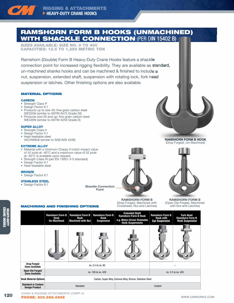
HEAVY-DUTYCRANE HOOKS
RIGGING & ATTACHMENTSHEAVY-DUTY CRANE HOOKS
120 WWW.CMWORKS.COMCHAIN & RIGGING ATTACHMENTS (CMRP-6)
PHONE: 800.888.0985
Ramshorn form BHook
Un-Machined
Ramshorn form BHook
Machined with Nut
Ramshorn form BHook
Suspension
Extended ShaftRamshorn form B Hook
e.g. Motor-Driven Rotatable Hook Suspensions
Ramshorn form B Hook with
Eye Suspension
fork HeadRamshorn form B Hook Suspension
Drop forgedSizes Available no. 2.5 to no. 80 –
Open-Die forged Sizes Available no. 100 to no. 420 no. 2.5 to no. 420
Hook Material Options Carbon, Super Alloy, Extreme Alloy, Bronze, Stainless Steel
Standard or Custom Design Product Standard Custom
Eye Suspension Hook Suspension
CARBON Strength Class P Design Factor 6:1 Products up to size 40: fine-grain carbon steel
StE355N (similar to ASTM A572 Grade 50) Products size 50 and up: fine-grain carbon steel
StE420N (similar to ASTM A255 Grade D)
SUPER ALLOY Strength Class v Design Factor 5:1 Heat-treatable steel
34CrNiMo6 (similar to SAE/AISI 4340)
EXTREME ALLOY Material with a minimum Charpy v-notch impact value
of 42 joule at -40°C and a maximum value of 52 joule at -50°C is available upon request.
Strength Class W (per EN 13001-3-5 standard) Design Factor 5:1 Heat-treatable steel
BRONZE Design Factor 6:1
STAINLESS STEEL Design Factor 6:1
MATERIAl oPTIoNS
Ramshorn (Double) Form B Heavy-Duty Crane Hooks feature a shackle connection point for increased rigging flexibility. They are available as standard, un-machined shanks hooks and can be machined & finished to include a nut, suspension, extended shaft, suspension with rotating lock, fork head suspension or latches. Other finishing options are also available.
RAMSHORN FORM B(Open Die Forged, Machined
with Nut and Latches)
RAMSHORN FORM B(Drop Forged, Machined with Crosshead, Nut and Latches)
Shackle Connection Point
SIZES AVAILAbLE: SIZE NO. 8 TO 400CAPACITIES: 12.5 TO 1,250 METRIC TON
RAMSHoRN foRM b HooKS (uNMACHINEd)wITH SHACKlE CoNNECTIoN (PER DIN 15402 B)
MACHINING ANd fINISHING oPTIoNS
RAMSHORN FORM B HOOK(Drop Forged, Un-Machined)
Ramshorn (Double) Form B Heavy-Duty Crane Hooks feature a shackle connection point for increased rigging flexibility. They are available as standard, un-machined shanks hooks and can be machined & finished to include a nut, suspension, extended shaft, suspension with rotating lock, fork head
) (PER DIN 15402 B)
RAMSHORN FORM B HOOK
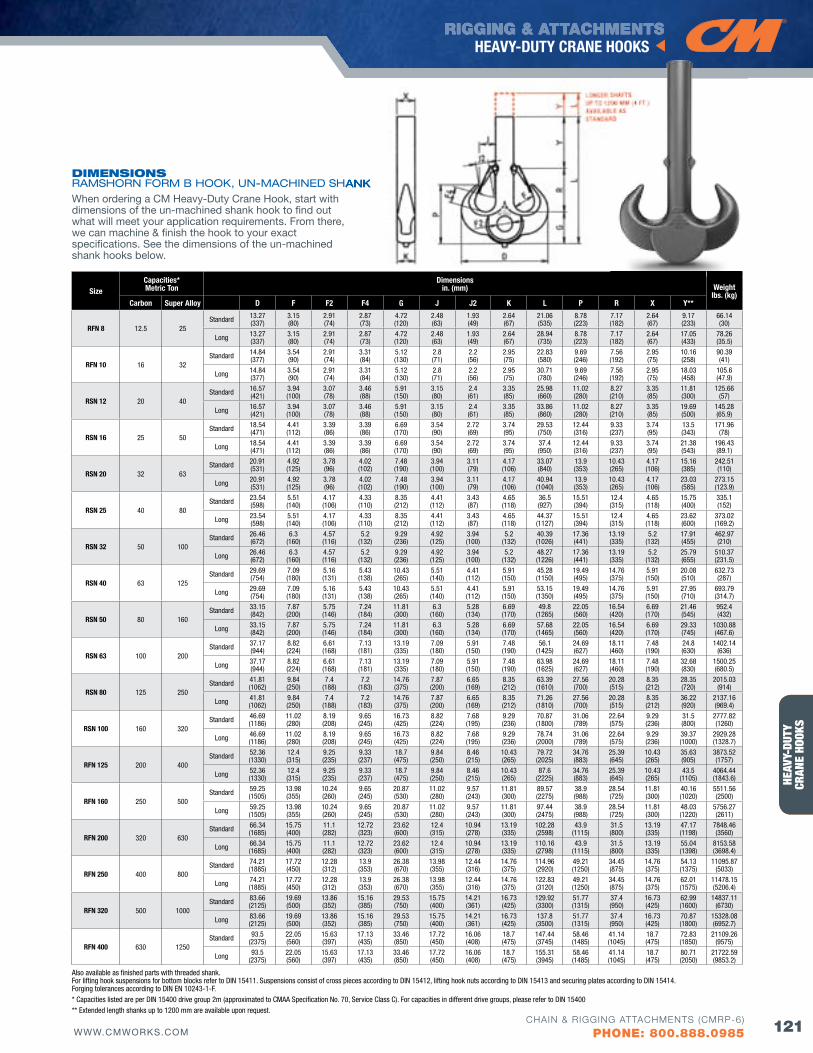
HERC
-ALL
OY® 8
00HE
AVY-
DUTY
CRAN
E HO
OKS
RIGGING & ATTACHMENTSHEAVY-DUTY CRANE HOOKS
121WWW.CMWORKS.COMCHAIN & RIGGING ATTACHMENTS (CMRP-6)
PHONE: 800.888.0985
SizeCapacities*Metric Ton
Dimensions in. (mm) Weight
lbs. (kg)Carbon Super Alloy D f f2 f4 G J J2 K L P R X Y**
RfN 8 12.5 25Standard 13.27
(337)3.15 (80)
2.91 (74)
2.87 (73)
4.72 (120)
2.48 (63)
1.93 (49)
2.64 (67)
21.06 (535)
8.78 (223)
7.17 (182)
2.64 (67)
9.17 (233)
66.14 (30)
Long 13.27 (337)
3.15 (80)
2.91 (74)
2.87 (73)
4.72 (120)
2.48 (63)
1.93 (49)
2.64 (67)
28.94 (735)
8.78 (223)
7.17 (182)
2.64 (67)
17.05 (433)
78.26 (35.5)
RfN 10 16 32Standard 14.84
(377)3.54 (90)
2.91 (74)
3.31 (84)
5.12 (130)
2.8 (71)
2.2 (56)
2.95 (75)
22.83 (580)
9.69 (246)
7.56 (192)
2.95 (75)
10.16 (258)
90.39 (41)
Long 14.84 (377)
3.54 (90)
2.91 (74)
3.31 (84)
5.12 (130)
2.8 (71)
2.2 (56)
2.95 (75)
30.71 (780)
9.69 (246)
7.56 (192)
2.95 (75)
18.03 (458)
105.6 (47.9)
RSN 12 20 40Standard 16.57
(421)3.94 (100)
3.07 (78)
3.46 (88)
5.91 (150)
3.15 (80)
2.4 (61)
3.35 (85)
25.98 (660)
11.02 (280)
8.27 (210)
3.35 (85)
11.81 (300)
125.66 (57)
Long 16.57 (421)
3.94 (100)
3.07 (78)
3.46 (88)
5.91 (150)
3.15 (80)
2.4 (61)
3.35 (85)
33.86 (860)
11.02 (280)
8.27 (210)
3.35 (85)
19.69 (500)
145.28 (65.9)
RSN 16 25 50Standard 18.54
(471)4.41 (112)
3.39 (86)
3.39 (86)
6.69 (170)
3.54 (90)
2.72 (69)
3.74 (95)
29.53 (750)
12.44 (316)
9.33 (237)
3.74 (95)
13.5 (343)
171.96 (78)
Long 18.54 (471)
4.41 (112)
3.39 (86)
3.39 (86)
6.69 (170)
3.54 (90)
2.72 (69)
3.74 (95)
37.4 (950)
12.44 (316)
9.33 (237)
3.74 (95)
21.38 (543)
196.43 (89.1)
RSN 20 32 63Standard 20.91
(531)4.92 (125)
3.78 (96)
4.02 (102)
7.48 (190)
3.94 (100)
3.11 (79)
4.17 (106)
33.07 (840)
13.9 (353)
10.43 (265)
4.17 (106)
15.16 (385)
242.51 (110)
Long 20.91 (531)
4.92 (125)
3.78 (96)
4.02 (102)
7.48 (190)
3.94 (100)
3.11 (79)
4.17 (106)
40.94 (1040)
13.9 (353)
10.43 (265)
4.17 (106)
23.03 (585)
273.15 (123.9)
RSN 25 40 80Standard 23.54
(598)5.51 (140)
4.17 (106)
4.33 (110)
8.35 (212)
4.41 (112)
3.43 (87)
4.65 (118)
36.5 (927)
15.51 (394)
12.4 (315)
4.65 (118)
15.75 (400)
335.1 (152)
Long 23.54 (598)
5.51 (140)
4.17 (106)
4.33 (110)
8.35 (212)
4.41 (112)
3.43 (87)
4.65 (118)
44.37 (1127)
15.51 (394)
12.4 (315)
4.65 (118)
23.62 (600)
373.02 (169.2)
RSN 32 50 100Standard 26.46
(672)6.3
(160)4.57 (116)
5.2 (132)
9.29 (236)
4.92 (125)
3.94 (100)
5.2 (132)
40.39 (1026)
17.36 (441)
13.19 (335)
5.2 (132)
17.91 (455)
462.97 (210)
Long 26.46 (672)
6.3 (160)
4.57 (116)
5.2 (132)
9.29 (236)
4.92 (125)
3.94 (100)
5.2 (132)
48.27 (1226)
17.36 (441)
13.19 (335)
5.2 (132)
25.79 (655)
510.37 (231.5)
RSN 40 63 125Standard 29.69
(754)7.09 (180)
5.16 (131)
5.43 (138)
10.43 (265)
5.51 (140)
4.41 (112)
5.91 (150)
45.28 (1150)
19.49 (495)
14.76 (375)
5.91 (150)
20.08 (510)
632.73 (287)
Long 29.69 (754)
7.09 (180)
5.16 (131)
5.43 (138)
10.43 (265)
5.51 (140)
4.41 (112)
5.91 (150)
53.15 (1350)
19.49 (495)
14.76 (375)
5.91 (150)
27.95 (710)
693.79 (314.7)
RSN 50 80 160Standard 33.15
(842)7.87 (200)
5.75 (146)
7.24 (184)
11.81 (300)
6.3 (160)
5.28 (134)
6.69 (170)
49.8 (1265)
22.05 (560)
16.54 (420)
6.69 (170)
21.46 (545)
952.4 (432)
Long 33.15 (842)
7.87 (200)
5.75 (146)
7.24 (184)
11.81 (300)
6.3 (160)
5.28 (134)
6.69 (170)
57.68 (1465)
22.05 (560)
16.54 (420)
6.69 (170)
29.33 (745)
1030.88 (467.6)
RSN 63 100 200Standard 37.17
(944)8.82 (224)
6.61 (168)
7.13 (181)
13.19 (335)
7.09 (180)
5.91 (150)
7.48 (190)
56.1 (1425)
24.69 (627)
18.11 (460)
7.48 (190)
24.8 (630)
1402.14 (636)
Long 37.17 (944)
8.82 (224)
6.61 (168)
7.13 (181)
13.19 (335)
7.09 (180)
5.91 (150)
7.48 (190)
63.98 (1625)
24.69 (627)
18.11 (460)
7.48 (190)
32.68 (830)
1500.25 (680.5)
RSN 80 125 250Standard 41.81
(1062)9.84 (250)
7.4 (188)
7.2 (183)
14.76 (375)
7.87 (200)
6.65 (169)
8.35 (212)
63.39 (1610)
27.56 (700)
20.28 (515)
8.35 (212)
28.35 (720)
2015.03 (914)
Long 41.81 (1062)
9.84 (250)
7.4 (188)
7.2 (183)
14.76 (375)
7.87 (200)
6.65 (169)
8.35 (212)
71.26 (1810)
27.56 (700)
20.28 (515)
8.35 (212)
36.22 (920)
2137.16 (969.4)
RSN 100 160 320Standard 46.69
(1186)11.02 (280)
8.19 (208)
9.65 (245)
16.73 (425)
8.82 (224)
7.68 (195)
9.29 (236)
70.87 (1800)
31.06 (789)
22.64 (575)
9.29 (236)
31.5 (800)
2777.82 (1260)
Long 46.69 (1186)
11.02 (280)
8.19 (208)
9.65 (245)
16.73 (425)
8.82 (224)
7.68 (195)
9.29 (236)
78.74 (2000)
31.06 (789)
22.64 (575)
9.29 (236)
39.37 (1000)
2929.28 (1328.7)
RfN 125 200 400Standard 52.36
(1330)12.4 (315)
9.25 (235)
9.33 (237)
18.7 (475)
9.84 (250)
8.46 (215)
10.43 (265)
79.72 (2025)
34.76 (883)
25.39 (645)
10.43 (265)
35.63 (905)
3873.52 (1757)
Long 52.36 (1330)
12.4 (315)
9.25 (235)
9.33 (237)
18.7 (475)
9.84 (250)
8.46 (215)
10.43 (265)
87.6 (2225)
34.76 (883)
25.39 (645)
10.43 (265)
43.5 (1105)
4064.44 (1843.6)
RfN 160 250 500Standard 59.25
(1505)13.98 (355)
10.24 (260)
9.65 (245)
20.87 (530)
11.02 (280)
9.57 (243)
11.81 (300)
89.57 (2275)
38.9 (988)
28.54 (725)
11.81 (300)
40.16 (1020)
5511.56 (2500)
Long 59.25 (1505)
13.98 (355)
10.24 (260)
9.65 (245)
20.87 (530)
11.02 (280)
9.57 (243)
11.81 (300)
97.44 (2475)
38.9 (988)
28.54 (725)
11.81 (300)
48.03 (1220)
5756.27 (2611)
RfN 200 320 630Standard 66.34
(1685)15.75 (400)
11.1 (282)
12.72 (323)
23.62 (600)
12.4 (315)
10.94 (278)
13.19 (335)
102.28 (2598)
43.9 (1115)
31.5 (800)
13.19 (335)
47.17 (1198)
7848.46 (3560)
Long 66.34 (1685)
15.75 (400)
11.1 (282)
12.72 (323)
23.62 (600)
12.4 (315)
10.94 (278)
13.19 (335)
110.16 (2798)
43.9 (1115)
31.5 (800)
13.19 (335)
55.04 (1398)
8153.58 (3698.4)
RfN 250 400 800Standard 74.21
(1885)17.72 (450)
12.28 (312)
13.9 (353)
26.38 (670)
13.98 (355)
12.44 (316)
14.76 (375)
114.96 (2920)
49.21 (1250)
34.45 (875)
14.76 (375)
54.13 (1375)
11095.87 (5033)
Long 74.21 (1885)
17.72 (450)
12.28 (312)
13.9 (353)
26.38 (670)
13.98 (355)
12.44 (316)
14.76 (375)
122.83 (3120)
49.21 (1250)
34.45 (875)
14.76 (375)
62.01 (1575)
11478.15 (5206.4)
RfN 320 500 1000Standard 83.66
(2125)19.69 (500)
13.86 (352)
15.16 (385)
29.53 (750)
15.75 (400)
14.21 (361)
16.73 (425)
129.92 (3300)
51.77 (1315)
37.4 (950)
16.73 (425)
62.99 (1600)
14837.11 (6730)
Long 83.66 (2125)
19.69 (500)
13.86 (352)
15.16 (385)
29.53 (750)
15.75 (400)
14.21 (361)
16.73 (425)
137.8 (3500)
51.77 (1315)
37.4 (950)
16.73 (425)
70.87 (1800)
15328.08 (6952.7)
RfN 400 630 1250Standard 93.5
(2375)22.05 (560)
15.63 (397)
17.13 (435)
33.46 (850)
17.72 (450)
16.06 (408)
18.7 (475)
147.44 (3745)
58.46 (1485)
41.14 (1045)
18.7 (475)
72.83 (1850)
21109.26 (9575)
Long 93.5 (2375)
22.05 (560)
15.63 (397)
17.13 (435)
33.46 (850)
17.72 (450)
16.06 (408)
18.7 (475)
155.31 (3945)
58.46 (1485)
41.14 (1045)
18.7 (475)
80.71 (2050)
21722.59 (9853.2)
Also available as finished parts with threaded shank. For lifting hook suspensions for bottom blocks refer to DIN 15411. Suspensions consist of cross pieces according to DIN 15412, lifting hook nuts according to DIN 15413 and securing plates according to DIN 15414. Forging tolerances according to DIN EN 10243-1-F.* Capacities listed are per DIN 15400 drive group 2m (approximated to CMAA Specification No. 70, Service Class C). For capacities in different drive groups, please refer to DIN 15400** Extended length shanks up to 1200 mm are available upon request.
dIMENSIoNS RAMSHORN FORM B HOOK, UN-MACHINED SHANKWhen ordering a CM Heavy-Duty Crane Hook, start with dimensions of the un-machined shank hook to find out what will meet your application requirements. From there, we can machine & finish the hook to your exact specifications. See the dimensions of the un-machined shank hooks below.
RAMSHORN FORM B HOOK, UN-MACHINED SHANK
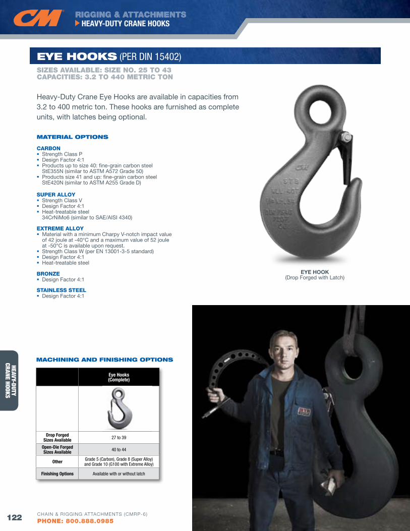
HEAVY-DUTYCRANE HOOKS
RIGGING & ATTACHMENTSHEAVY-DUTY CRANE HOOKS
122 WWW.CMWORKS.COMCHAIN & RIGGING ATTACHMENTS (CMRP-6)
PHONE: 800.888.0985
SIZES AVAILAbLE: SIZE NO. 25 TO 43CAPACITIES: 3.2 TO 440 METRIC TON
EyE HooKS (PER DIN 15402)
CARBON Strength Class P Design Factor 4:1 Products up to size 40: fine-grain carbon steel
StE355N (similar to ASTM A572 Grade 50) Products size 41 and up: fine-grain carbon steel
StE420N (similar to ASTM A255 Grade D)
SUPER ALLOY Strength Class v Design Factor 4:1 Heat-treatable steel
34CrNiMo6 (similar to SAE/AISI 4340)
EXTREME ALLOY Material with a minimum Charpy v-notch impact value
of 42 joule at -40°C and a maximum value of 52 joule at -50°C is available upon request.
Strength Class W (per EN 13001-3-5 standard) Design Factor 4:1 Heat-treatable steel
BRONZE Design Factor 4:1
STAINLESS STEEL Design Factor 4:1
MATERIAl oPTIoNS
Heavy-Duty Crane Eye Hooks are available in capacities from 3.2 to 400 metric ton. These hooks are furnished as complete units, with latches being optional.
EYE HOOK(Drop Forged with Latch)
Eye Hooks(Complete)
Drop forgedSizes Available 27 to 39
Open-Die forgedSizes Available 40 to 44
Other Grade 5 (Carbon), Grade 8 (Super Alloy)and Grade 10 (G100 with Extreme Alloy)
finishing Options Available with or without latch
MACHINING ANd fINISHING oPTIoNS
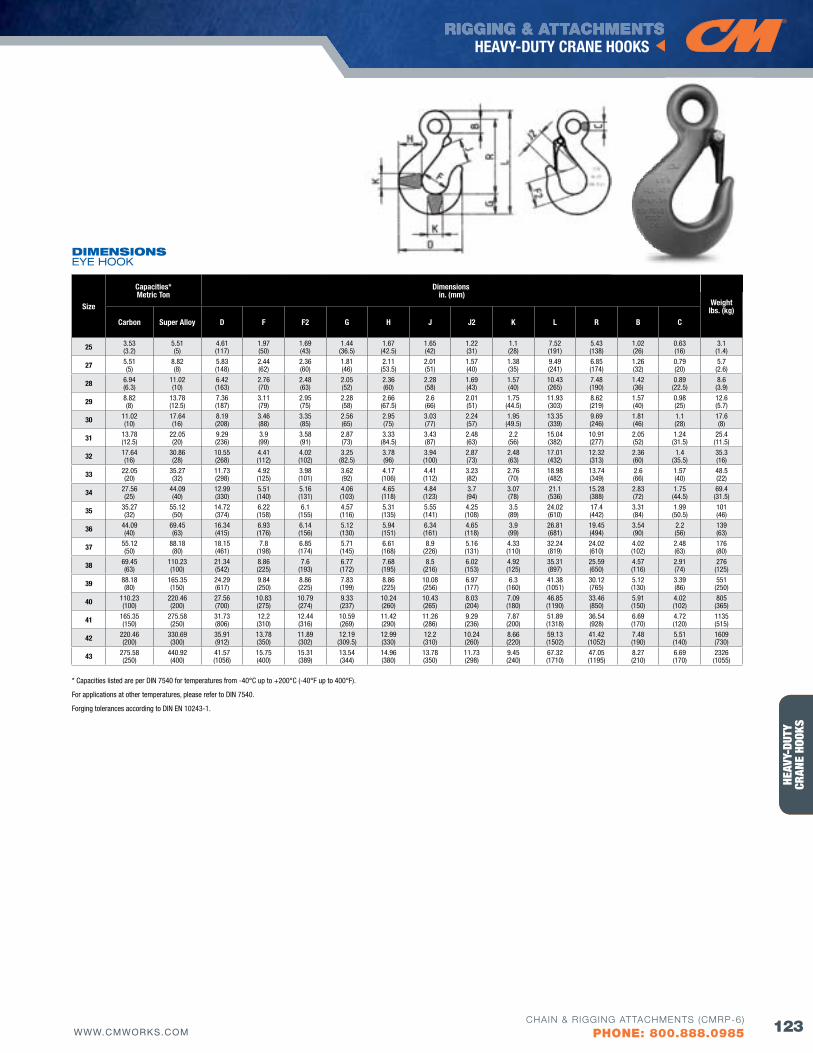
HERC
-ALL
OY® 8
00HE
AVY-
DUTY
CRAN
E HO
OKS
RIGGING & ATTACHMENTSHEAVY-DUTY CRANE HOOKS
123WWW.CMWORKS.COMCHAIN & RIGGING ATTACHMENTS (CMRP-6)
PHONE: 800.888.0985
Size
Capacities*Metric Ton
Dimensions in. (mm)
Weightlbs. (kg)
Carbon Super Alloy D f f2 G H J J2 K L R B C
25 3.53 (3.2)
5.51 (5)
4.61 (117)
1.97 (50)
1.69 (43)
1.44 (36.5)
1.67 (42.5)
1.65 (42)
1.22 (31)
1.1 (28)
7.52 (191)
5.43 (138)
1.02 (26)
0.63 (16)
3.1 (1.4)
27 5.51 (5)
8.82 (8)
5.83 (148)
2.44 (62)
2.36 (60)
1.81 (46)
2.11 (53.5)
2.01 (51)
1.57 (40)
1.38 (35)
9.49 (241)
6.85 (174)
1.26 (32)
0.79 (20)
5.7 (2.6)
28 6.94 (6.3)
11.02 (10)
6.42 (163)
2.76 (70)
2.48 (63)
2.05 (52)
2.36 (60)
2.28 (58)
1.69 (43)
1.57 (40)
10.43 (265)
7.48 (190)
1.42 (36)
0.89 (22.5)
8.6 (3.9)
29 8.82 (8)
13.78 (12.5)
7.36 (187)
3.11 (79)
2.95 (75)
2.28 (58)
2.66 (67.5)
2.6 (66)
2.01 (51)
1.75 (44.5)
11.93 (303)
8.62 (219)
1.57 (40)
0.98 (25)
12.6 (5.7)
30 11.02 (10)
17.64 (16)
8.19 (208)
3.46 (88)
3.35 (85)
2.56 (65)
2.95 (75)
3.03 (77)
2.24 (57)
1.95 (49.5)
13.35 (339)
9.69 (246)
1.81 (46)
1.1 (28)
17.6 (8)
31 13.78 (12.5)
22.05 (20)
9.29 (236)
3.9 (99)
3.58 (91)
2.87 (73)
3.33 (84.5)
3.43 (87)
2.48 (63)
2.2 (56)
15.04 (382)
10.91 (277)
2.05 (52)
1.24 (31.5)
25.4 (11.5)
32 17.64 (16)
30.86 (28)
10.55 (268)
4.41 (112)
4.02 (102)
3.25 (82.5)
3.78 (96)
3.94 (100)
2.87 (73)
2.48 (63)
17.01 (432)
12.32 (313)
2.36 (60)
1.4 (35.5)
35.3 (16)
33 22.05 (20)
35.27 (32)
11.73 (298)
4.92 (125)
3.98 (101)
3.62 (92)
4.17 (106)
4.41 (112)
3.23 (82)
2.76 (70)
18.98 (482)
13.74 (349)
2.6 (66)
1.57 (40)
48.5 (22)
34 27.56 (25)
44.09 (40)
12.99 (330)
5.51 (140)
5.16 (131)
4.06 (103)
4.65 (118)
4.84 (123)
3.7 (94)
3.07 (78)
21.1 (536)
15.28 (388)
2.83 (72)
1.75 (44.5)
69.4 (31.5)
35 35.27 (32)
55.12 (50)
14.72 (374)
6.22 (158)
6.1 (155)
4.57 (116)
5.31 (135)
5.55 (141)
4.25 (108)
3.5 (89)
24.02 (610)
17.4 (442)
3.31 (84)
1.99 (50.5)
101 (46)
36 44.09 (40)
69.45 (63)
16.34 (415)
6.93 (176)
6.14 (156)
5.12 (130)
5.94 (151)
6.34 (161)
4.65 (118)
3.9 (99)
26.81 (681)
19.45 (494)
3.54 (90)
2.2 (56)
139 (63)
37 55.12 (50)
88.18 (80)
18.15 (461)
7.8 (198)
6.85 (174)
5.71 (145)
6.61 (168)
8.9 (226)
5.16 (131)
4.33 (110)
32.24 (819)
24.02 (610)
4.02 (102)
2.48 (63)
176 (80)
38 69.45 (63)
110.23 (100)
21.34 (542)
8.86 (225)
7.6 (193)
6.77 (172)
7.68 (195)
8.5 (216)
6.02 (153)
4.92 (125)
35.31 (897)
25.59 (650)
4.57 (116)
2.91 (74)
276 (125)
39 88.18 (80)
165.35 (150)
24.29 (617)
9.84 (250)
8.86 (225)
7.83 (199)
8.86 (225)
10.08 (256)
6.97 (177)
6.3 (160)
41.38 (1051)
30.12 (765)
5.12 (130)
3.39 (86)
551 (250)
40 110.23 (100)
220.46 (200)
27.56 (700)
10.83 (275)
10.79 (274)
9.33 (237)
10.24 (260)
10.43 (265)
8.03 (204)
7.09 (180)
46.85 (1190)
33.46 (850)
5.91 (150)
4.02 (102)
805 (365)
41 165.35 (150)
275.58 (250)
31.73 (806)
12.2 (310)
12.44 (316)
10.59 (269)
11.42 (290)
11.26 (286)
9.29 (236)
7.87 (200)
51.89 (1318)
36.54 (928)
6.69 (170)
4.72 (120)
1135 (515)
42 220.46 (200)
330.69 (300)
35.91 (912)
13.78 (350)
11.89 (302)
12.19 (309.5)
12.99 (330)
12.2 (310)
10.24 (260)
8.66 (220)
59.13 (1502)
41.42 (1052)
7.48 (190)
5.51 (140)
1609 (730)
43 275.58 (250)
440.92 (400)
41.57 (1056)
15.75 (400)
15.31 (389)
13.54 (344)
14.96 (380)
13.78 (350)
11.73 (298)
9.45 (240)
67.32 (1710)
47.05 (1195)
8.27 (210)
6.69 (170)
2326 (1055)
* Capacities listed are per DIN 7540 for temperatures from -40°C up to +200°C (-40°F up to 400°F).
For applications at other temperatures, please refer to DIN 7540.
Forging tolerances according to DIN EN 10243-1.
dIMENSIoNS EYE HOOK
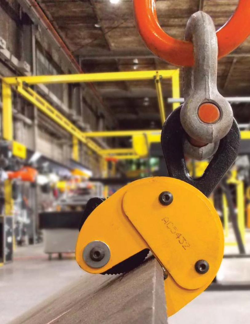
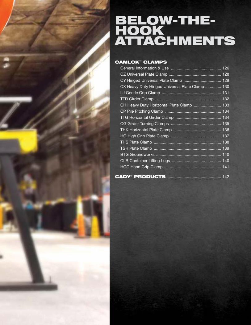
CAMloK™ ClAMPS General Information & Use ............................................ 126
CZ Universal Plate Clamp .............................................. 128
CY Hinged Universal Plate Clamp ................................. 129
CX Heavy Duty Hinged Universal Plate Clamp .............. 130
LJ Gentle Grip Clamp .................................................... 131
TTR Girder Clamp .......................................................... 132
CH Heavy Duty Horizontal Plate Clamp ........................ 133
CP Pile Pitching Clamp ................................................. 134
TTG Horizontal Girder Clamp ........................................ 134
CG Girder Turning Clamps ............................................ 135
THK Horizontal Plate Clamp .......................................... 136
HG High Grip Plate Clamp ............................................. 137
THS Plate Clamp ........................................................... 138
TSH Plate Clamp ........................................................... 139
BTG Groundworks ......................................................... 140
CLB Container Lifting Lugs ........................................... 140
HGC Hand Grip Clamp .................................................. 141
CAdy® PRoduCTS ............................................... 142
bElow-THE- HooK ATTACHMENTS
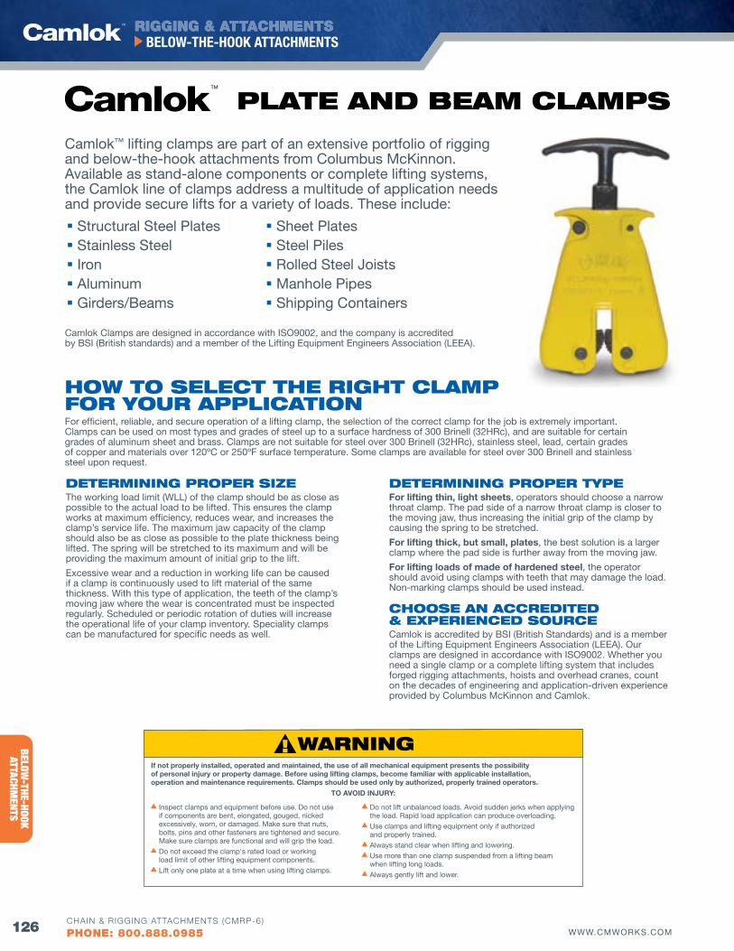
RIGGING & ATTACHMENTS
126 WWW.CMWORKS.COM
BELOW-THE-HOOK ATTACHMENTS
CHAIN & RIGGING ATTACHMENTS (CMRP-6)
PHONE: 800.888.0985
BELOW-THE-HOOK
ATTACHMENTS
Camlok Clamps are designed in accordance with ISO9002, and the company is accredited by BSI (British standards) and a member of the Lifting Equipment Engineers Association (LEEA).
Camlok™ lifting clamps are part of an extensive portfolio of rigging and below-the-hook attachments from Columbus McKinnon. Available as stand-alone components or complete lifting systems, the Camlok line of clamps address a multitude of application needs and provide secure lifts for a variety of loads. These include:
Structural Steel Plates Stainless Steel Iron Aluminum Girders/Beams
Sheet Plates Steel Piles Rolled Steel Joists Manhole Pipes Shipping Containers
PlATE ANd bEAM ClAMPS
How To SElECT THE RIGHT ClAMP foR youR APPlICATIoNFor efficient, reliable, and secure operation of a lifting clamp, the selection of the correct clamp for the job is extremely important. Clamps can be used on most types and grades of steel up to a surface hardness of 300 Brinell (32HRc), and are suitable for certain grades of aluminum sheet and brass. Clamps are not suitable for steel over 300 Brinell (32HRc), stainless steel, lead, certain grades of copper and materials over 120ºC or 250ºF surface temperature. Some clamps are available for steel over 300 Brinell and stainless steel upon request.
dETERMINING PRoPER SIZEThe working load limit (WLL) of the clamp should be as close as possible to the actual load to be lifted. This ensures the clamp works at maximum efficiency, reduces wear, and increases the clamp’s service life. The maximum jaw capacity of the clamp should also be as close as possible to the plate thickness being lifted. The spring will be stretched to its maximum and will be providing the maximum amount of initial grip to the lift.
Excessive wear and a reduction in working life can be caused if a clamp is continuously used to lift material of the same thickness. With this type of application, the teeth of the clamp’s moving jaw where the wear is concentrated must be inspected regularly. Scheduled or periodic rotation of duties will increase the operational life of your clamp inventory. Speciality clamps can be manufactured for specific needs as well.
dETERMINING PRoPER TyPEFor lifting thin, light sheets, operators should choose a narrow throat clamp. The pad side of a narrow throat clamp is closer to the moving jaw, thus increasing the initial grip of the clamp by causing the spring to be stretched.
For lifting thick, but small, plates, the best solution is a larger clamp where the pad side is further away from the moving jaw.
For lifting loads of made of hardened steel, the operator should avoid using clamps with teeth that may damage the load. Non-marking clamps should be used instead.
CHooSE AN ACCREdITEd & EXPERIENCEd SouRCECamlok is accredited by BSI (British Standards) and is a member of the Lifting Equipment Engineers Association (LEEA). Our clamps are designed in accordance with ISO9002. Whether you need a single clamp or a complete lifting system that includes forged rigging attachments, hoists and overhead cranes, count on the decades of engineering and application-driven experience provided by Columbus McKinnon and Camlok.
If not properly installed, operated and maintained, the use of all mechanical equipment presents the possibility of personal injury or property damage. Before using lifting clamps, become familiar with applicable installation, operation and maintenance requirements. Clamps should be used only by authorized, properly trained operators.
s Inspect clamps and equipment before use. Do not use if components are bent, elongated, gouged, nicked excessively, worn, or damaged. Make sure that nuts, bolts, pins and other fasteners are tightened and secure. Make sure clamps are functional and will grip the load.
s Do not exceed the clamp's rated load or working load limit of other lifting equipment components.
s Lift only one plate at a time when using lifting clamps.
s Do not lift unbalanced loads. Avoid sudden jerks when applying the load. Rapid load application can produce overloading.
s Use clamps and lifting equipment only if authorized and properly trained.
s Always stand clear when lifting and lowering.s Use more than one clamp suspended from a lifting beam
when lifting long loads.s Always gently lift and lower.
TO AVOID INJURY:
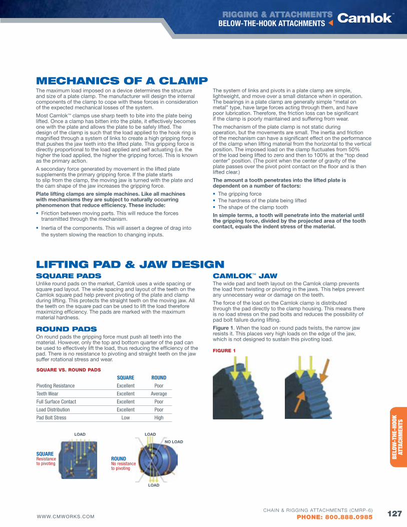
RIGGING & ATTACHMENTS
127WWW.CMWORKS.COM
BELOW-THE-HOOK ATTACHMENTS
CHAIN & RIGGING ATTACHMENTS (CMRP-6)
PHONE: 800.888.0985
ENTE
RTAI
NMEN
TRI
GGIN
G PR
ODUC
TSBE
LOW
-THE
-HOO
K AT
TACH
MEN
TS
PlATE ANd bEAM ClAMPS
The maximum load imposed on a device determines the structure and size of a plate clamp. The manufacturer will design the internal components of the clamp to cope with these forces in consideration of the expected mechanical losses of the system.
Most Camlok™ clamps use sharp teeth to bite into the plate being lifted. Once a clamp has bitten into the plate, it effectively becomes one with the plate and allows the plate to be safely lifted. The design of the clamp is such that the load applied to the hook ring is magnified through a system of links to create a high gripping force that pushes the jaw teeth into the lifted plate. This gripping force is directly proportional to the load applied and self actuating (i.e. the higher the load applied, the higher the gripping force). This is known as the primary action.
A secondary force generated by movement in the lifted plate supplements the primary gripping force. If the plate starts to slip from the clamp, the moving jaw is turned with the plate and the cam shape of the jaw increases the gripping force.
Plate lifting clamps are simple machines. Like all machines with mechanisms they are subject to naturally occurring phenomenon that reduce efficiency. These include:
Friction between moving parts. This will reduce the forces transmitted through the mechanism.
Inertia of the components. This will assert a degree of drag into the system slowing the reaction to changing inputs.
The system of links and pivots in a plate clamp are simple, lightweight, and move over a small distance when in operation. The bearings in a plate clamp are generally simple “metal on metal” type, have large forces acting through them, and have poor lubrication. Therefore, the friction loss can be significant if the clamp is poorly maintained and suffering from wear.
The mechanism of the plate clamp is not static during operation, but the movements are small. The inertia and friction of the mechanism can have a significant effect on the performance of the clamp when lifting material from the horizontal to the vertical position. The imposed load on the clamp fluctuates from 50% of the load being lifted to zero and then to 100% at the “top dead center” position. (The point when the center of gravity of the plate passes over the pivot point contact on the floor and is then lifted clear.)
The amount a tooth penetrates into the lifted plate is dependent on a number of factors:
The gripping force The hardness of the plate being lifted The shape of the clamp tooth
In simple terms, a tooth will penetrate into the material until the gripping force, divided by the projected area of the tooth contact, equals the indent stress of the material.
lIfTING PAd & jAw dESIGNSQuARE PAdSUnlike round pads on the market, Camlok uses a wide spacing or square pad layout. The wide spacing and layout of the teeth on the Camlok square pad help prevent pivoting of the plate and clamp during lifting. This protects the straight teeth on the moving jaw. All the teeth on the square pad can be used to lift the load therefore maximizing efficiency. The pads are marked with the maximum material hardness.
RouNd PAdSOn round pads the gripping force must push all teeth into the material. However, only the top and bottom quarter of the pad can be used to effectively lift the load, thus reducing the efficiency of the pad. There is no resistance to pivoting and straight teeth on the jaw suffer rotational stress and wear.
CAMloK™ jAwThe wide pad and teeth layout on the Camlok clamp prevents the load from twisting or pivoting in the jaws. This helps prevent any unnecessary wear or damage on the teeth.
The force of the load on the Camlok clamp is distributed through the pad directly to the clamp housing. This means there is no load stress on the pad bolts and reduces the possibility of pad bolt failure during lifting.
Figure 1. When the load on round pads twists, the narrow jaw resists it. This places very high loads on the edge of the jaw, which is not designed to sustain this pivoting load.
LOAD
LOAD
NO LOAD
ROUNDNo resistance to pivoting
LOAD
SqUARE Resistance to pivoting
SQUARE VS. ROUND PADS
SqUARE ROUND
Pivoting Resistance Excellent Poor
Teeth Wear Excellent Average
Full Surface Contact Excellent Poor
Load Distribution Excellent Poor
Pad Bolt Stress Low High
fIGURE 1
MECHANICS of A ClAMP
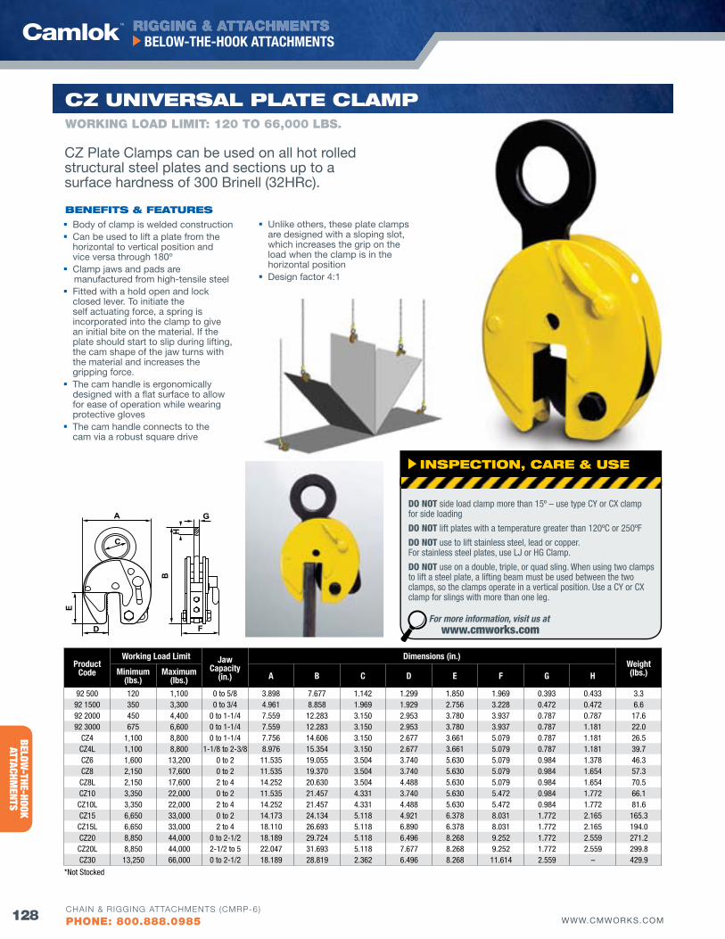
RIGGING & ATTACHMENTS
128 WWW.CMWORKS.COM
BELOW-THE-HOOK ATTACHMENTS
CHAIN & RIGGING ATTACHMENTS (CMRP-6)
PHONE: 800.888.0985
BELOW-THE-HOOK
ATTACHMENTS
E
A
D F
B
C
G
H
ProductCode
Working Load Limit Jaw Capacity
(in.)
Dimensions (in.)Weight(lbs.)Minimum
(lbs.)Maximum
(lbs.) A B C D E f G H
92 500 120 1,100 0 to 5/8 3.898 7.677 1.142 1.299 1.850 1.969 0.393 0.433 3.3 92 1500 350 3,300 0 to 3/4 4.961 8.858 1.969 1.929 2.756 3.228 0.472 0.472 6.6 92 2000 450 4,400 0 to 1-1/4 7.559 12.283 3.150 2.953 3.780 3.937 0.787 0.787 17.6 92 3000 675 6,600 0 to 1-1/4 7.559 12.283 3.150 2.953 3.780 3.937 0.787 1.181 22.0
Cz4 1,100 8,800 0 to 1-1/4 7.756 14.606 3.150 2.677 3.661 5.079 0.787 1.181 26.5 Cz4L 1,100 8,800 1-1/8 to 2-3/8 8.976 15.354 3.150 2.677 3.661 5.079 0.787 1.181 39.7 Cz6 1,600 13,200 0 to 2 11.535 19.055 3.504 3.740 5.630 5.079 0.984 1.378 46.3 Cz8 2,150 17,600 0 to 2 11.535 19.370 3.504 3.740 5.630 5.079 0.984 1.654 57.3 Cz8L 2,150 17,600 2 to 4 14.252 20.630 3.504 4.488 5.630 5.079 0.984 1.654 70.5 Cz10 3,350 22,000 0 to 2 11.535 21.457 4.331 3.740 5.630 5.472 0.984 1.772 66.1 Cz10L 3,350 22,000 2 to 4 14.252 21.457 4.331 4.488 5.630 5.472 0.984 1.772 81.6 Cz15 6,650 33,000 0 to 2 14.173 24.134 5.118 4.921 6.378 8.031 1.772 2.165 165.3 Cz15L 6,650 33,000 2 to 4 18.110 26.693 5.118 6.890 6.378 8.031 1.772 2.165 194.0 Cz20 8,850 44,000 0 to 2-1/2 18.189 29.724 5.118 6.496 8.268 9.252 1.772 2.559 271.2 Cz20L 8,850 44,000 2-1/2 to 5 22.047 31.693 5.118 7.677 8.268 9.252 1.772 2.559 299.8 Cz30 13,250 66,000 0 to 2-1/2 18.189 28.819 2.362 6.496 8.268 11.614 2.559 – 429.9
*Not Stocked
CZ uNIvERSAl PlATE ClAMP
Body of clamp is welded construction Can be used to lift a plate from the
horizontal to vertical position and vice versa through 180º
Clamp jaws and pads are manufactured from high-tensile steel
Fitted with a hold open and lock closed lever. To initiate the self actuating force, a spring is incorporated into the clamp to give an initial bite on the material. If the plate should start to slip during lifting, the cam shape of the jaw turns with the material and increases the gripping force.
The cam handle is ergonomically designed with a flat surface to allow for ease of operation while wearing protective gloves
The cam handle connects to the cam via a robust square drive
Unlike others, these plate clamps are designed with a sloping slot, which increases the grip on the load when the clamp is in the horizontal position
Design factor 4:1
WORKING LOAD LIMIT: 120 TO 66,000 LbS.
CZ Plate Clamps can be used on all hot rolled structural steel plates and sections up to a surface hardness of 300 Brinell (32HRc).
bENEfITS & fEATuRES
INSPECTIoN, CARE & uSE
DO NOT side load clamp more than 15º – use type CY or CX clamp for side loading
DO NOT lift plates with a temperature greater than 120ºC or 250ºF
DO NOT use to lift stainless steel, lead or copper. For stainless steel plates, use LJ or HG Clamp.
DO NOT use on a double, triple, or quad sling. When using two clamps to lift a steel plate, a lifting beam must be used between the two clamps, so the clamps operate in a vertical position. Use a CY or CX clamp for slings with more than one leg.
For more information, visit us at www.cmworks.com
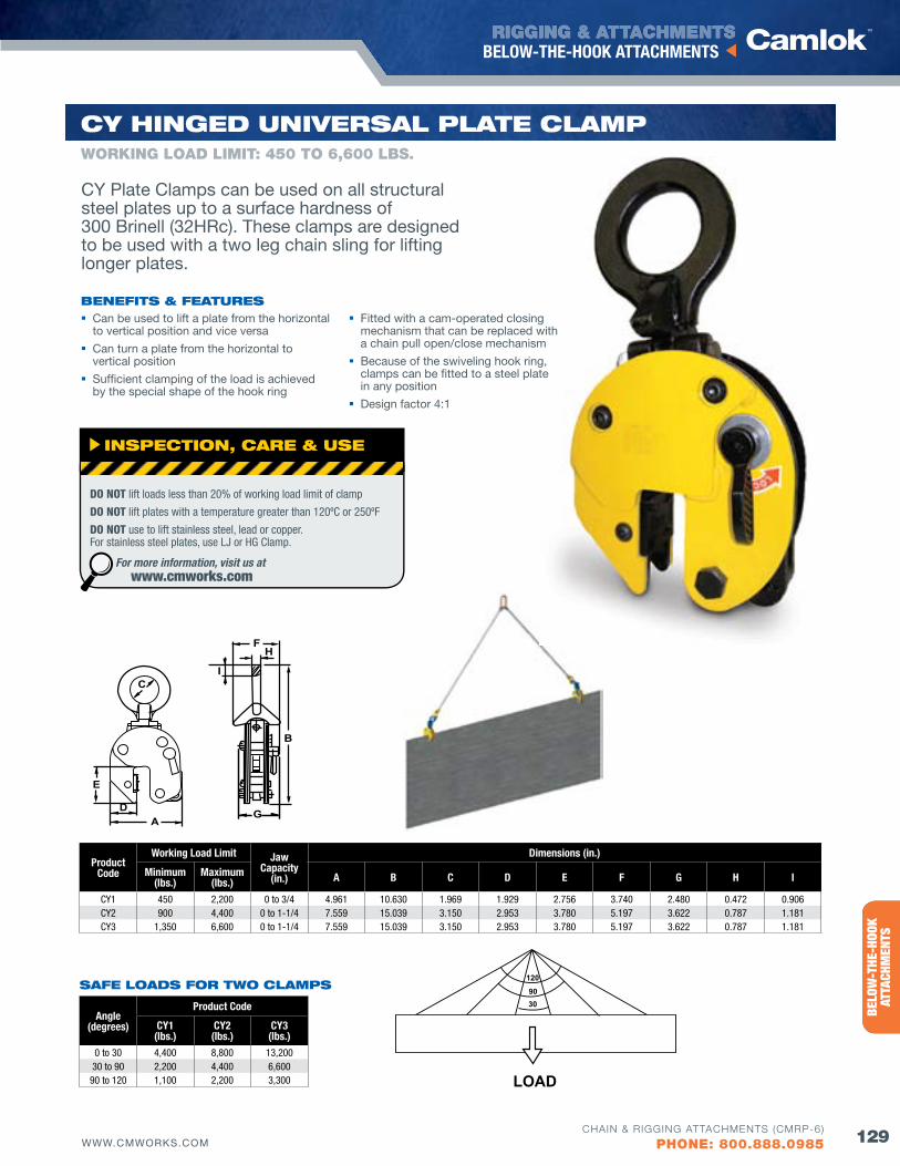
RIGGING & ATTACHMENTS
129WWW.CMWORKS.COM
BELOW-THE-HOOK ATTACHMENTS
CHAIN & RIGGING ATTACHMENTS (CMRP-6)
PHONE: 800.888.0985
ENTE
RTAI
NMEN
TRI
GGIN
G PR
ODUC
TSBE
LOW
-THE
-HOO
K AT
TACH
MEN
TS
SAfE loAdS foR Two ClAMPS
Angle(degrees)
Product Code
CY1(lbs.)
CY2(lbs.)
CY3(lbs.)
0 to 30 4,400 8,800 13,20030 to 90 2,200 4,400 6,600
90 to 120 1,100 2,200 3,300
120
9030
LOAD
E
AD G
B
C
FH
I
ProductCode
Working Load Limit Jaw Capacity
(in.)
Dimensions (in.)
Minimum(lbs.)
Maximum(lbs.) A B C D E f G H I
CY1 450 2,200 0 to 3/4 4.961 10.630 1.969 1.929 2.756 3.740 2.480 0.472 0.906CY2 900 4,400 0 to 1-1/4 7.559 15.039 3.150 2.953 3.780 5.197 3.622 0.787 1.181CY3 1,350 6,600 0 to 1-1/4 7.559 15.039 3.150 2.953 3.780 5.197 3.622 0.787 1.181
Cy HINGEd uNIvERSAl PlATE ClAMP
bENEfITS & fEATuRES Can be used to lift a plate from the horizontal
to vertical position and vice versa
Can turn a plate from the horizontal to vertical position
Sufficient clamping of the load is achieved by the special shape of the hook ring
Fitted with a cam-operated closing mechanism that can be replaced with a chain pull open/close mechanism
Because of the swiveling hook ring, clamps can be fitted to a steel plate in any position
Design factor 4:1
WORKING LOAD LIMIT: 450 TO 6,600 LbS.
CY Plate Clamps can be used on all structural steel plates up to a surface hardness of 300 Brinell (32HRc). These clamps are designed to be used with a two leg chain sling for lifting longer plates.
INSPECTIoN, CARE & uSE
DO NOT lift loads less than 20% of working load limit of clamp
DO NOT lift plates with a temperature greater than 120ºC or 250ºF
DO NOT use to lift stainless steel, lead or copper. For stainless steel plates, use LJ or HG Clamp.
For more information, visit us at www.cmworks.com
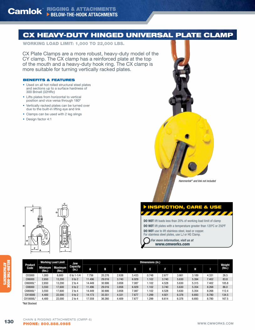
RIGGING & ATTACHMENTS
130 WWW.CMWORKS.COM
BELOW-THE-HOOK ATTACHMENTS
CHAIN & RIGGING ATTACHMENTS (CMRP-6)
PHONE: 800.888.0985
BELOW-THE-HOOK
ATTACHMENTS
E
A
D
F
BG
H
C
I
ProductCode
Working Load Limit Jaw Capacity
(in.)
Dimensions (in.)Weight(lbs.)Minimum
(lbs.)Maximum
(lbs.) A B C D E f G H I
CX3000 1,000 6,600 0 to 1-1/4 7.756 20.276 2.638 5.433 0.748 2.677 3.661 3.189 4.331 26.5CX6000 2,650 13,200 0 to 2 11.496 29.016 3.740 6.929 1.102 3.740 5.630 5.394 7.402 83.8
CX6000L* 2,650 13,200 2 to 4 14.449 30.906 3.858 7.087 1.102 4.528 5.630 5.315 7.402 105.8CX8000 3,550 17,600 0 to 2 11.496 29.016 3.858 6.929 1.102 3.740 5.630 5.354 8.268 86.0
CX8000L* 3,550 17,600 2 to 4 14.449 30.906 3.858 7.087 1.102 4.528 5.630 5.354 8.268 112.4CX10000 4,400 22,000 0 to 2 14.173 35.551 4.331 7.677 1.299 4.921 6.378 6.693 8.780 134.5
CX10000L* 4,400 22,000 2 to 4 17.559 36.260 4.409 7.677 1.299 6.614 6.378 6.693 8.780 167.5
*Not Stocked
Hammerlok® and link not included
CX HEAvy-duTy HINGEd uNIvERSAl PlATE ClAMP
bENEfITS & fEATuRES Used on all hot rolled structural steel plates
and sections up to a surface hardness of 300 Brinell (32HRc)
Lifts plates from horizontal to vertical position and vice versa through 180º
vertically racked plates can be turned over due to the built-in lifting eye and link
Clamps can be used with 2 leg slings
Design factor 4:1
WORKING LOAD LIMIT: 1,000 TO 22,000 LbS.
CX Plate Clamps are a more robust, heavy-duty model of the CY clamp. The CX clamp has a reinforced plate at the top of the mouth and a heavy-duty hook ring. The CX clamp is more suitable for turning vertically racked plates.
INSPECTIoN, CARE & uSE
DO NOT lift loads less than 20% of working load limit of clamp
DO NOT lift plates with a temperature greater than 120ºC or 250ºF
DO NOT use to lift stainless steel, lead or copper. For stainless steel plates, use LJ or HG Clamp.
For more information, visit us at www.cmworks.com
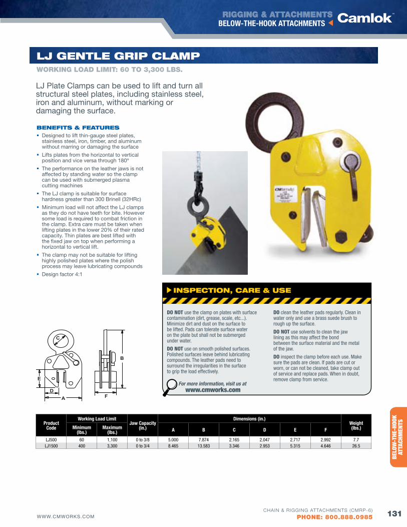
RIGGING & ATTACHMENTS
131WWW.CMWORKS.COM
BELOW-THE-HOOK ATTACHMENTS
CHAIN & RIGGING ATTACHMENTS (CMRP-6)
PHONE: 800.888.0985
ENTE
RTAI
NMEN
TRI
GGIN
G PR
ODUC
TSBE
LOW
-THE
-HOO
K AT
TACH
MEN
TS
E
AD
F
B
C
ProductCode
Working Load LimitJaw Capacity
(in.)
Dimensions (in.)Weight(lbs.)Minimum
(lbs.)Maximum
(lbs.) A B C D E f
LJ500 60 1,100 0 to 3/8 5.000 7.874 2.165 2.047 2.717 2.992 7.7LJ1500 400 3,300 0 to 3/4 8.465 13.583 3.346 2.953 5.315 4.646 26.5
lj GENTlE GRIP ClAMP
bENEfITS & fEATuRES Designed to lift thin-gauge steel plates,
stainless steel, iron, timber, and aluminum without marring or damaging the surface
Lifts plates from the horizontal to vertical position and vice versa through 180º
The performance on the leather jaws is not affected by standing water so the clamp can be used with submerged plasma cutting machines
The LJ clamp is suitable for surface hardness greater than 300 Brinell (32HRc)
Minimum load will not affect the LJ clamps as they do not have teeth for bite. However some load is required to combat friction in the clamp. Extra care must be taken when lifting plates in the lower 20% of their rated capacity. Thin plates are best lifted with the fixed jaw on top when performing a horizontal to vertical lift.
The clamp may not be suitable for lifting highly polished plates where the polish process may leave lubricating compounds
Design factor 4:1
WORKING LOAD LIMIT: 60 TO 3,300 LbS.
LJ Plate Clamps can be used to lift and turn all structural steel plates, including stainless steel, iron and aluminum, without marking or damaging the surface.
INSPECTIoN, CARE & uSE
DO NOT use the clamp on plates with surface contamination (dirt, grease, scale, etc...). Minimize dirt and dust on the surface to be lifted. Pads can tolerate surface water on the plate but shall not be submerged under water.
DO NOT use on smooth polished surfaces. Polished surfaces leave behind lubricating compounds. The leather pads need to surround the irregularities in the surface to grip the load effectively.
DO clean the leather pads regularly. Clean in water only and use a brass suede brush to rough up the surface.
DO NOT use solvents to clean the jaw lining as this may affect the bond between the surface material and the metal of the jaw.
DO inspect the clamp before each use. Make sure the pads are clean. If pads are cut or worn, or can not be cleaned, take clamp out of service and replace pads. When in doubt, remove clamp from service.
For more information, visit us at www.cmworks.com
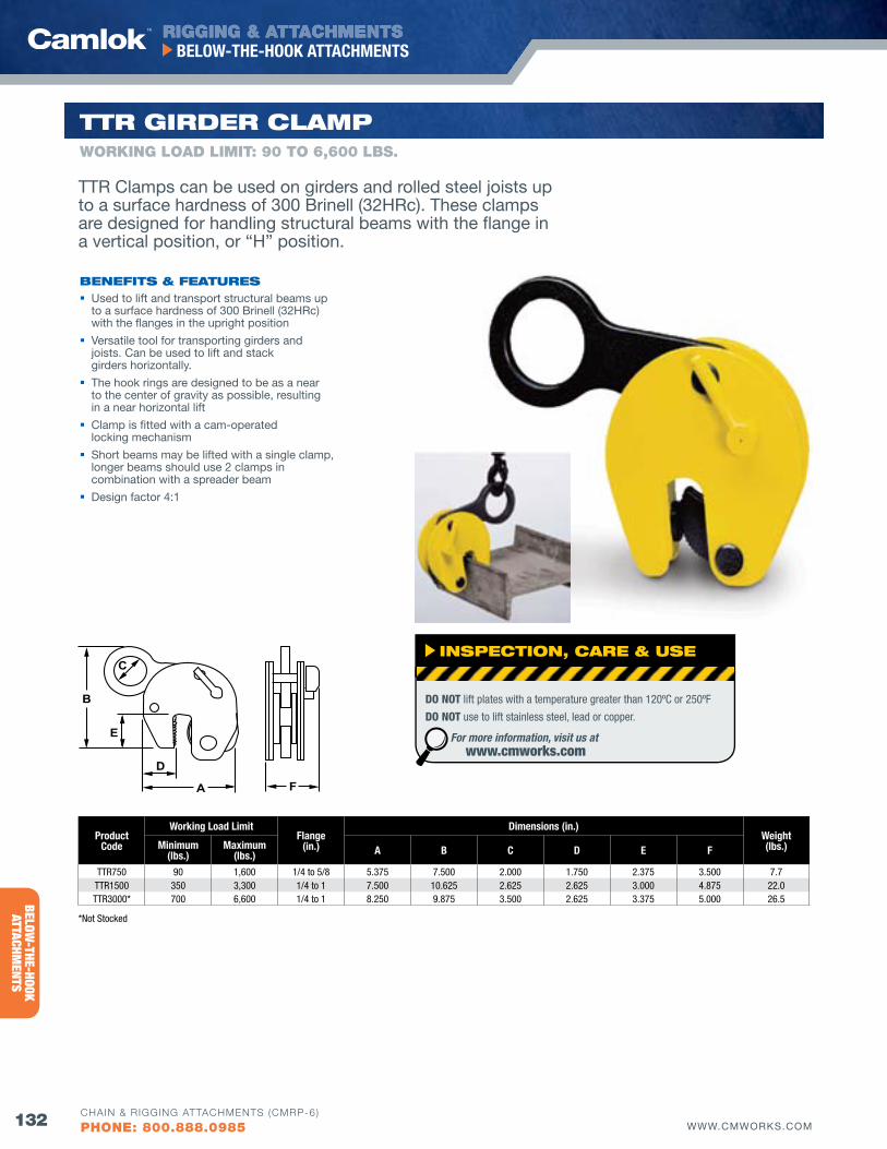
RIGGING & ATTACHMENTS
132 WWW.CMWORKS.COM
BELOW-THE-HOOK ATTACHMENTS
CHAIN & RIGGING ATTACHMENTS (CMRP-6)
PHONE: 800.888.0985
BELOW-THE-HOOK
ATTACHMENTS
*Not Stocked
E
A
D
F
B
C
ProductCode
Working Load Limitflange
(in.)
Dimensions (in.)Weight(lbs.)Minimum
(lbs.)Maximum
(lbs.) A B C D E f
TTR750 90 1,600 1/4 to 5/8 5.375 7.500 2.000 1.750 2.375 3.500 7.7TTR1500 350 3,300 1/4 to 1 7.500 10.625 2.625 2.625 3.000 4.875 22.0TTR3000* 700 6,600 1/4 to 1 8.250 9.875 3.500 2.625 3.375 5.000 26.5
*Not Stocked
TTR GIRdER ClAMPWORKING LOAD LIMIT: 90 TO 6,600 LbS.
bENEfITS & fEATuRES Used to lift and transport structural beams up
to a surface hardness of 300 Brinell (32HRc) with the flanges in the upright position
versatile tool for transporting girders and joists. Can be used to lift and stack girders horizontally.
The hook rings are designed to be as a near to the center of gravity as possible, resulting in a near horizontal lift
Clamp is fitted with a cam-operated locking mechanism
Short beams may be lifted with a single clamp, longer beams should use 2 clamps in combination with a spreader beam
Design factor 4:1
TTR Clamps can be used on girders and rolled steel joists up to a surface hardness of 300 Brinell (32HRc). These clamps are designed for handling structural beams with the flange in a vertical position, or “H” position.
INSPECTIoN, CARE & uSE
DO NOT lift plates with a temperature greater than 120ºC or 250ºF
DO NOT use to lift stainless steel, lead or copper.
For more information, visit us at www.cmworks.com
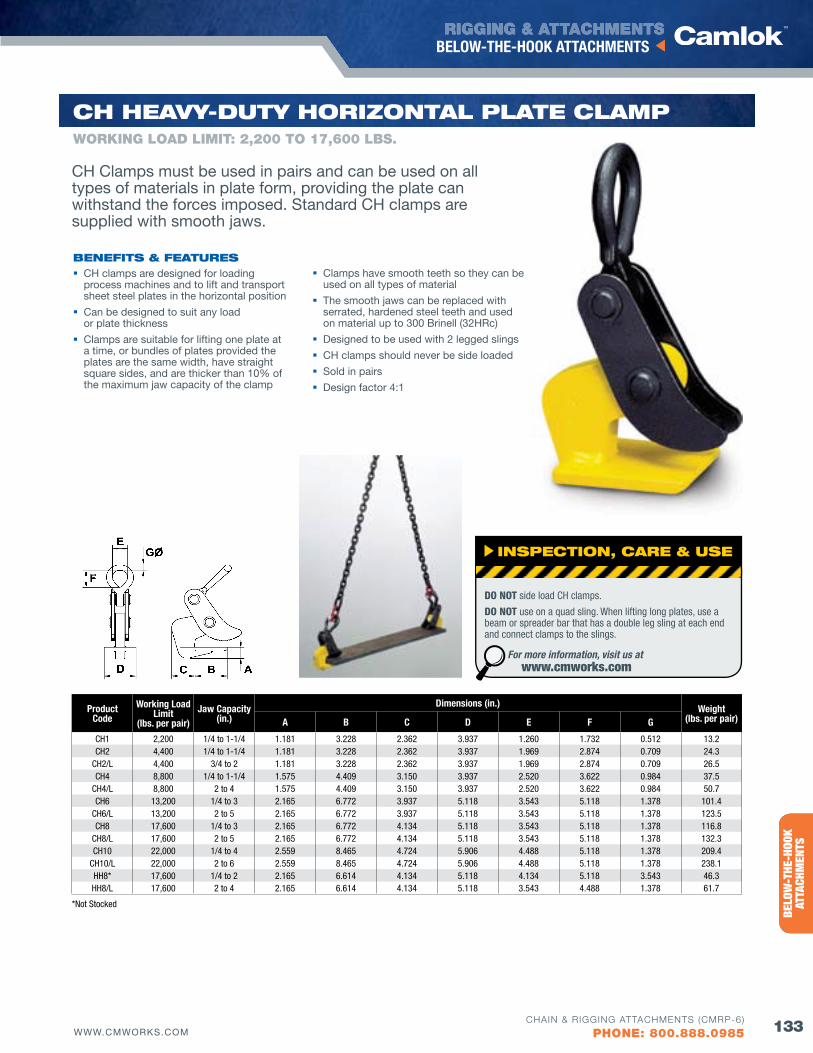
RIGGING & ATTACHMENTS
133WWW.CMWORKS.COM
BELOW-THE-HOOK ATTACHMENTS
CHAIN & RIGGING ATTACHMENTS (CMRP-6)
PHONE: 800.888.0985
ENTE
RTAI
NMEN
TRI
GGIN
G PR
ODUC
TSBE
LOW
-THE
-HOO
K AT
TACH
MEN
TS
ProductCode
Working Load Limit
(lbs. per pair)Jaw Capacity
(in.)
Dimensions (in.) Weight(lbs. per pair)A B C D E f G
CH1 2,200 1/4 to 1-1/4 1.181 3.228 2.362 3.937 1.260 1.732 0.512 13.2CH2 4,400 1/4 to 1-1/4 1.181 3.228 2.362 3.937 1.969 2.874 0.709 24.3
CH2/L 4,400 3/4 to 2 1.181 3.228 2.362 3.937 1.969 2.874 0.709 26.5CH4 8,800 1/4 to 1-1/4 1.575 4.409 3.150 3.937 2.520 3.622 0.984 37.5
CH4/L 8,800 2 to 4 1.575 4.409 3.150 3.937 2.520 3.622 0.984 50.7CH6 13,200 1/4 to 3 2.165 6.772 3.937 5.118 3.543 5.118 1.378 101.4
CH6/L 13,200 2 to 5 2.165 6.772 3.937 5.118 3.543 5.118 1.378 123.5CH8 17,600 1/4 to 3 2.165 6.772 4.134 5.118 3.543 5.118 1.378 116.8
CH8/L 17,600 2 to 5 2.165 6.772 4.134 5.118 3.543 5.118 1.378 132.3CH10 22,000 1/4 to 4 2.559 8.465 4.724 5.906 4.488 5.118 1.378 209.4
CH10/L 22,000 2 to 6 2.559 8.465 4.724 5.906 4.488 5.118 1.378 238.1HH8* 17,600 1/4 to 2 2.165 6.614 4.134 5.118 4.134 5.118 3.543 46.3HH8/L 17,600 2 to 4 2.165 6.614 4.134 5.118 3.543 4.488 1.378 61.7
CH HEAvy-duTy HoRIZoNTAl PlATE ClAMP
bENEfITS & fEATuRES CH clamps are designed for loading
process machines and to lift and transport sheet steel plates in the horizontal position
Can be designed to suit any load or plate thickness
Clamps are suitable for lifting one plate at a time, or bundles of plates provided the plates are the same width, have straight square sides, and are thicker than 10% of the maximum jaw capacity of the clamp
WORKING LOAD LIMIT: 2,200 TO 17,600 LbS.
CH Clamps must be used in pairs and can be used on all types of materials in plate form, providing the plate can withstand the forces imposed. Standard CH clamps are supplied with smooth jaws.
Clamps have smooth teeth so they can be used on all types of material
The smooth jaws can be replaced with serrated, hardened steel teeth and used on material up to 300 Brinell (32HRc)
Designed to be used with 2 legged slings
CH clamps should never be side loaded
Sold in pairs
Design factor 4:1
*Not Stocked
INSPECTIoN, CARE & uSE
DO NOT side load CH clamps.
DO NOT use on a quad sling. When lifting long plates, use a beam or spreader bar that has a double leg sling at each end and connect clamps to the slings.
For more information, visit us at www.cmworks.com
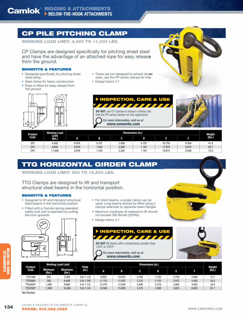
RIGGING & ATTACHMENTS
134 WWW.CMWORKS.COM
BELOW-THE-HOOK ATTACHMENTS
CHAIN & RIGGING ATTACHMENTS (CMRP-6)
PHONE: 800.888.0985
BELOW-THE-HOOK
ATTACHMENTS
E
A
D
F
B
C
ProductCode
Working Load Limit(lbs.)
Dimensions (in.) Weight(lbs.)A B C D E f
CP2 4,400 8.976 0.787 2.000 0.787 16.750 8.500 41.9CP3 6,600 8.976 1.024 2.500 1.181 17.875 8.875 50.7CP5 11,000 8.976 1.378 3.250 1.181 19.875 9.500 72.8
CP PIlE PITCHING ClAMP
bENEfITS & fEATuRES Designed specifically for pitching sheet
steel piling Ideal clamp for heavy construction Rope is fitted for easy release from
the ground
These are not designed to extract driven piles, use the PP series clamps for this
Design factor 4:1
WORKING LOAD LIMIT: 4,400 TO 11,000 LbS.
EA
D
F
B
C
ProductCode
Working Load LimitPlate(in.)
Dimensions (in.)Weight(lbs.)Minimum
(lbs.)Maximum
(lbs.) A B C D E f
TTG1500 200 3,300 0 to 1-1/8 9.000 10.875 3.750 1.750 2.750 4.000 12.1TTG3000 350 6,600 0 to 1-3/8 11.125 11.625 3.125 2.125 2.875 4.500 24.3TTG4500* 1,000 9,900 0 to 1-1/2 12.375 13.250 3.500 2.375 3.000 4.625 32.0TTG7500* 1,650 16,500 0 to 1-3/4 14.500 15.000 4.375 2.500 3.625 6.625 61.7
*Not Stocked
TTG HoRIZoNTAl GIRdER ClAMP
bENEfITS & fEATuRES Designed to lift and transport structural
steel beams in the horizontal position
Fitted with a Camlok spring-operated safety lock and is operated by pulling the lock upwards
WORKING LOAD LIMIT: 200 TO 16,500 LbS.
CP Clamps are designed specifically for pitching sheet steel and have the advantage of an attached rope for easy release from the ground.
TTG Clamps are designed to lift and transport structural steel beams in the horizontal position.
For short beams, a single clamp can be used. Long beams should be lifted using 2 clamps attached to opposite beam flanges
Maximum hardness of material to lift should not exceed 300 Brinell (32HRc)
Design factor 4:1
INSPECTIoN, CARE & uSE
DO NOT lift plates with a temperature greater than 120ºC or 250ºF
For more information, visit us at www.cmworks.com
INSPECTIoN, CARE & uSE
DO NOT use CP Clamps to extract a driven pile. Use the PP series clamps for this application.
For more information, visit us at www.cmworks.com
These are not designed to extract driven piles, use the PP series clamps for this
and have the advantage of an attached rope for easy release
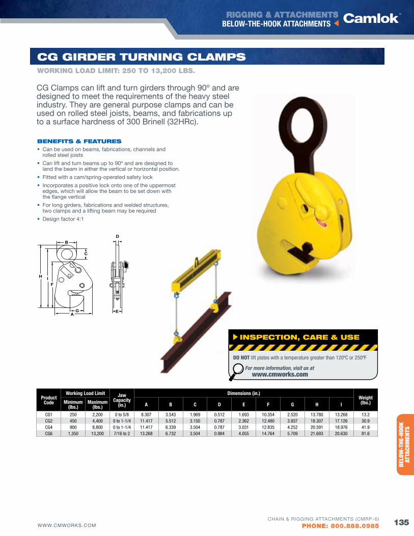
RIGGING & ATTACHMENTS
135WWW.CMWORKS.COM
BELOW-THE-HOOK ATTACHMENTS
CHAIN & RIGGING ATTACHMENTS (CMRP-6)
PHONE: 800.888.0985
ENTE
RTAI
NMEN
TRI
GGIN
G PR
ODUC
TSBE
LOW
-THE
-HOO
K AT
TACH
MEN
TS
CG Clamps can lift and turn girders through 90º and are designed to meet the requirements of the heavy steel industry. They are general purpose clamps and can be used on rolled steel joists, beams, and fabrications up to a surface hardness of 300 Brinell (32HRc).
EA
D
F
B
G
H
C
I
ProductCode
Working Load Limit Jaw Capacity
(in.)
Dimensions (in.)Weight(lbs.)Minimum
(lbs.)Maximum
(lbs.) A B C D E f G H I
CG1 250 2,200 0 to 5/8 8.307 3.543 1.969 0.512 1.693 10.354 2.520 13.780 13.268 13.2 CG2 450 4,400 0 to 1-1/4 11.417 5.512 3.150 0.787 2.362 12.480 3.937 18.307 17.126 30.9 CG4 900 8,800 0 to 1-1/4 11.417 6.339 3.504 0.787 3.031 12.835 4.252 20.591 18.976 41.9 CG6 1,350 13,200 7/16 to 2 13.268 6.732 3.504 0.984 4.055 14.764 5.709 21.693 20.630 81.6
CG GIRdER TuRNING ClAMPS
bENEfITS & fEATuRES Can be used on beams, fabrications, channels and
rolled steel joists
Can lift and turn beams up to 90º and are designed to land the beam in either the vertical or horizontal position.
Fitted with a cam/spring-operated safety lock
Incorporates a positive lock onto one of the uppermost edges, which will allow the beam to be set down with the flange vertical
For long girders, fabrications and welded structures, two clamps and a lifting beam may be required
Design factor 4:1
WORKING LOAD LIMIT: 250 TO 13,200 LbS.
INSPECTIoN, CARE & uSE
DO NOT lift plates with a temperature greater than 120ºC or 250ºF
For more information, visit us at www.cmworks.com
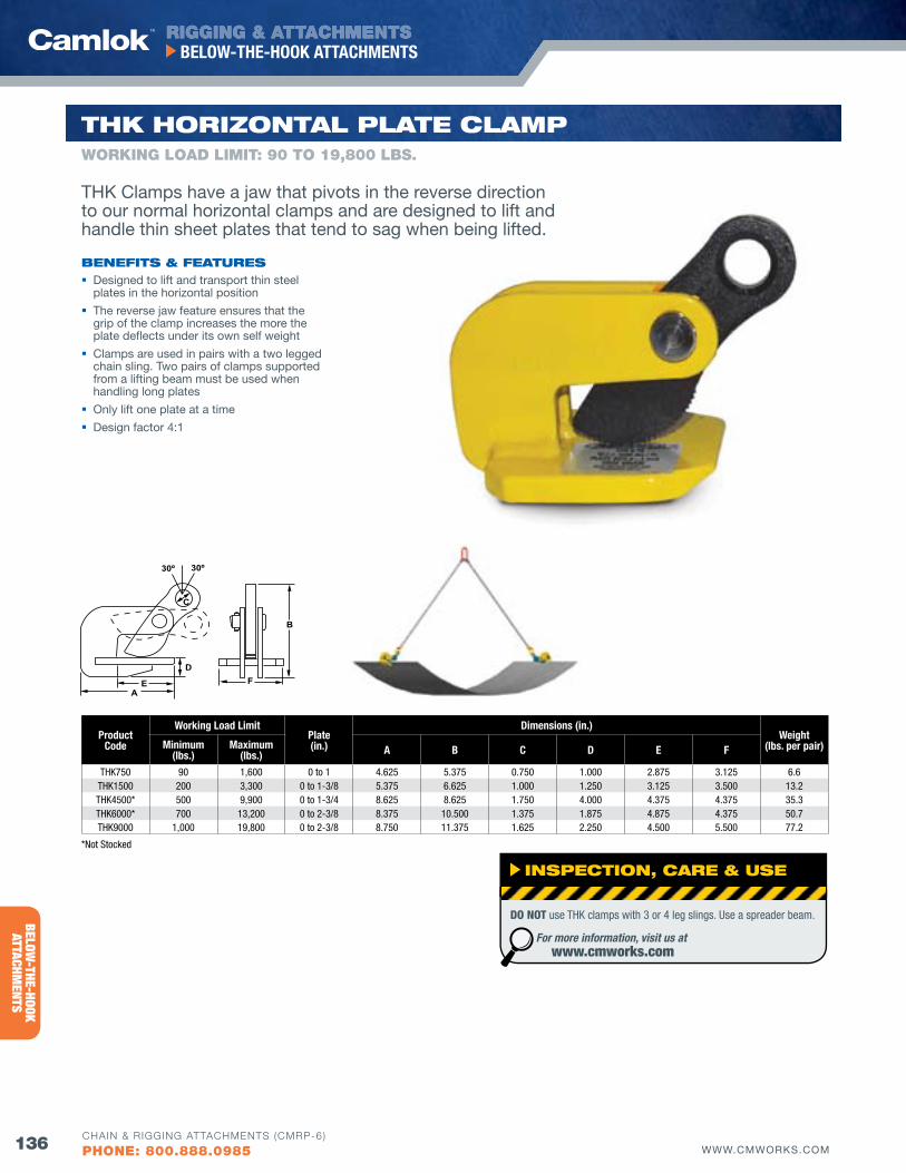
RIGGING & ATTACHMENTS
136 WWW.CMWORKS.COM
BELOW-THE-HOOK ATTACHMENTS
CHAIN & RIGGING ATTACHMENTS (CMRP-6)
PHONE: 800.888.0985
BELOW-THE-HOOK
ATTACHMENTS
EA
DF
B
C
30º 30º
ProductCode
Working Load LimitPlate(in.)
Dimensions (in.)Weight
(lbs. per pair)Minimum(lbs.)
Maximum(lbs.) A B C D E f
THK750 90 1,600 0 to 1 4.625 5.375 0.750 1.000 2.875 3.125 6.6 THK1500 200 3,300 0 to 1-3/8 5.375 6.625 1.000 1.250 3.125 3.500 13.2 THK4500* 500 9,900 0 to 1-3/4 8.625 8.625 1.750 4.000 4.375 4.375 35.3 THK6000* 700 13,200 0 to 2-3/8 8.375 10.500 1.375 1.875 4.875 4.375 50.7 THK9000 1,000 19,800 0 to 2-3/8 8.750 11.375 1.625 2.250 4.500 5.500 77.2
*Not Stocked
THK HoRIZoNTAl PlATE ClAMPWORKING LOAD LIMIT: 90 TO 19,800 LbS.
bENEfITS & fEATuRES Designed to lift and transport thin steel
plates in the horizontal position
The reverse jaw feature ensures that the grip of the clamp increases the more the plate deflects under its own self weight
Clamps are used in pairs with a two legged chain sling. Two pairs of clamps supported from a lifting beam must be used when handling long plates
Only lift one plate at a time
Design factor 4:1
THK Clamps have a jaw that pivots in the reverse direction to our normal horizontal clamps and are designed to lift and handle thin sheet plates that tend to sag when being lifted.
INSPECTIoN, CARE & uSE
DO NOT use THK clamps with 3 or 4 leg slings. Use a spreader beam.
For more information, visit us at www.cmworks.com
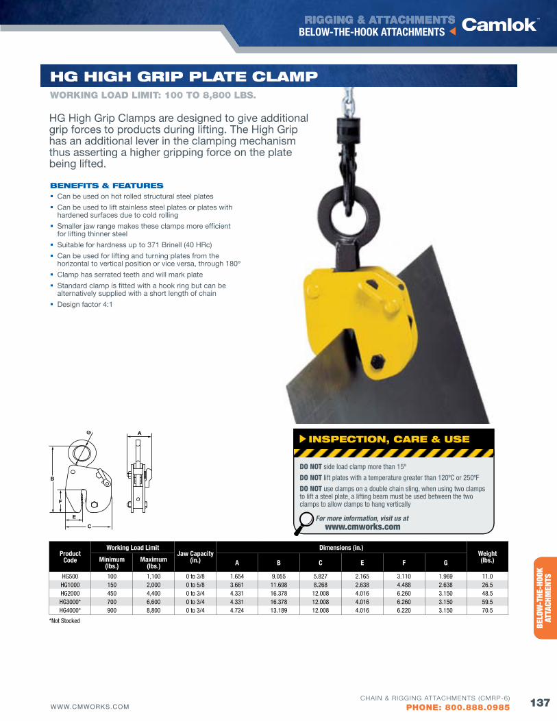
RIGGING & ATTACHMENTS
137WWW.CMWORKS.COM
BELOW-THE-HOOK ATTACHMENTS
CHAIN & RIGGING ATTACHMENTS (CMRP-6)
PHONE: 800.888.0985
ENTE
RTAI
NMEN
TRI
GGIN
G PR
ODUC
TSBE
LOW
-THE
-HOO
K AT
TACH
MEN
TS
*Not Stocked
A
F
B
G
C
E
ProductCode
Working Load LimitJaw Capacity
(in.)
Dimensions (in.)Weight(lbs.)Minimum
(lbs.)Maximum
(lbs.) A B C E f G
HG500 100 1,100 0 to 3/8 1.654 9.055 5.827 2.165 3.110 1.969 11.0HG1000 150 2,000 0 to 5/8 3.661 11.698 8.268 2.638 4.488 2.638 26.5HG2000 450 4,400 0 to 3/4 4.331 16.378 12.008 4.016 6.260 3.150 48.5HG3000* 700 6,600 0 to 3/4 4.331 16.378 12.008 4.016 6.260 3.150 59.5HG4000* 900 8,800 0 to 3/4 4.724 13.189 12.008 4.016 6.220 3.150 70.5
HG HIGH GRIP PlATE ClAMP
bENEfITS & fEATuRES Can be used on hot rolled structural steel plates
Can be used to lift stainless steel plates or plates with hardened surfaces due to cold rolling
Smaller jaw range makes these clamps more efficient for lifting thinner steel
Suitable for hardness up to 371 Brinell (40 HRc)
Can be used for lifting and turning plates from the horizontal to vertical position or vice versa, through 180º
Clamp has serrated teeth and will mark plate
Standard clamp is fitted with a hook ring but can be alternatively supplied with a short length of chain
Design factor 4:1
WORKING LOAD LIMIT: 100 TO 8,800 LbS.
HG High Grip Clamps are designed to give additional grip forces to products during lifting. The High Grip has an additional lever in the clamping mechanism thus asserting a higher gripping force on the plate being lifted.
INSPECTIoN, CARE & uSE
DO NOT side load clamp more than 15º
DO NOT lift plates with a temperature greater than 120ºC or 250ºF
DO NOT use clamps on a double chain sling, when using two clamps to lift a steel plate, a lifting beam must be used between the two clamps to allow clamps to hang vertically
For more information, visit us at www.cmworks.com
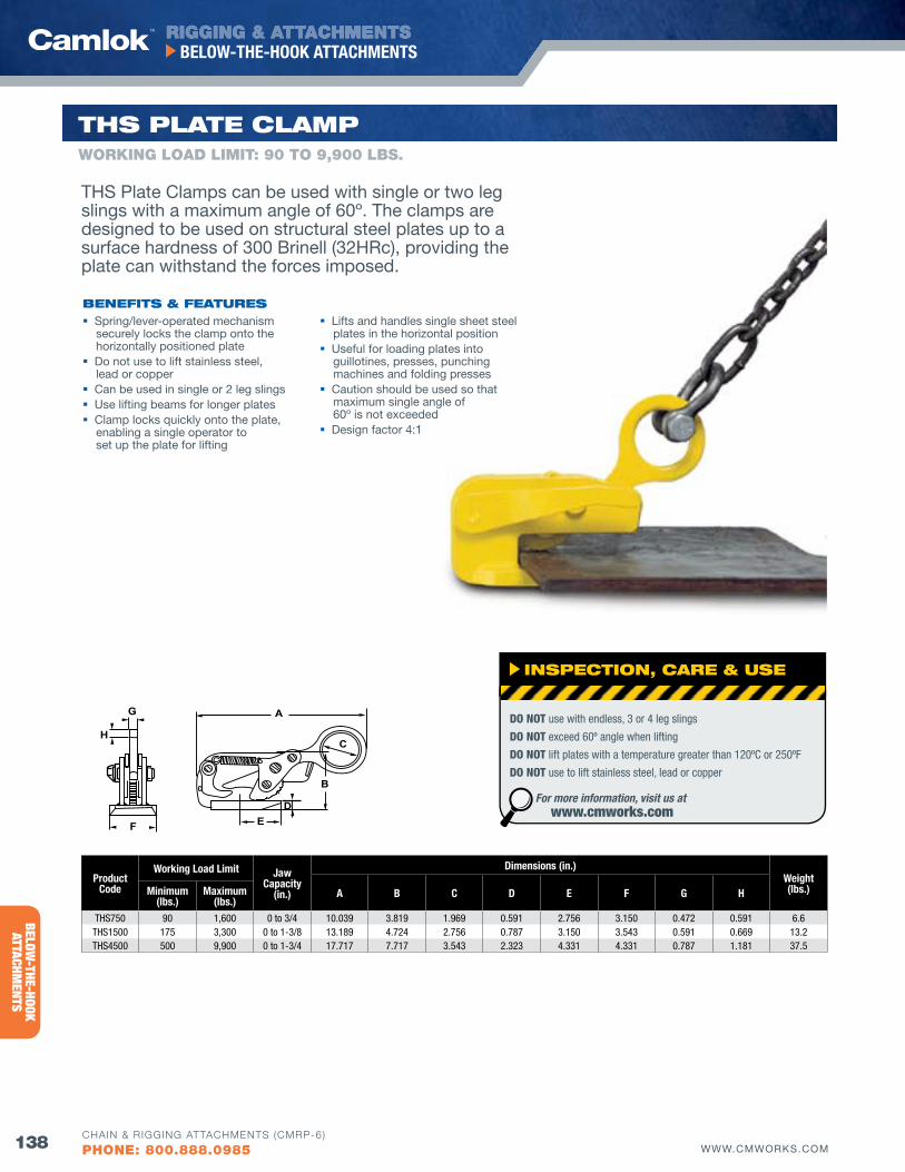
RIGGING & ATTACHMENTS
138 WWW.CMWORKS.COM
BELOW-THE-HOOK ATTACHMENTS
CHAIN & RIGGING ATTACHMENTS (CMRP-6)
PHONE: 800.888.0985
BELOW-THE-HOOK
ATTACHMENTS
ProductCode
Working Load Limit Jaw Capacity
(in.)
Dimensions (in.)Weight(lbs.)A B C D E f G HMinimum
(lbs.)Maximum
(lbs.)THS750 90 1,600 0 to 3/4 10.039 3.819 1.969 0.591 2.756 3.150 0.472 0.591 6.6THS1500 175 3,300 0 to 1-3/8 13.189 4.724 2.756 0.787 3.150 3.543 0.591 0.669 13.2THS4500 500 9,900 0 to 1-3/4 17.717 7.717 3.543 2.323 4.331 4.331 0.787 1.181 37.5
E
A
DF
B
G
HC
E
A
DF
B
G
HC
THS PlATE ClAMP
bENEfITS & fEATuRES Spring/lever-operated mechanism
securely locks the clamp onto the horizontally positioned plate
Do not use to lift stainless steel, lead or copper
Can be used in single or 2 leg slings Use lifting beams for longer plates Clamp locks quickly onto the plate,
enabling a single operator to set up the plate for lifting
Lifts and handles single sheet steel plates in the horizontal position
Useful for loading plates into guillotines, presses, punching machines and folding presses
Caution should be used so that maximum single angle of 60º is not exceeded
Design factor 4:1
WORKING LOAD LIMIT: 90 TO 9,900 LbS.
THS Plate Clamps can be used with single or two leg slings with a maximum angle of 60º. The clamps are designed to be used on structural steel plates up to a surface hardness of 300 Brinell (32HRc), providing the plate can withstand the forces imposed.
INSPECTIoN, CARE & uSE
DO NOT use with endless, 3 or 4 leg slings
DO NOT exceed 60º angle when lifting
DO NOT lift plates with a temperature greater than 120ºC or 250ºF
DO NOT use to lift stainless steel, lead or copper
For more information, visit us at www.cmworks.com
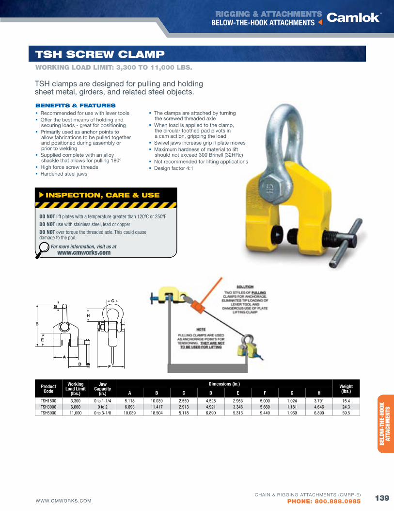
RIGGING & ATTACHMENTS
139WWW.CMWORKS.COM
BELOW-THE-HOOK ATTACHMENTS
CHAIN & RIGGING ATTACHMENTS (CMRP-6)
PHONE: 800.888.0985
ENTE
RTAI
NMEN
TRI
GGIN
G PR
ODUC
TSBE
LOW
-THE
-HOO
K AT
TACH
MEN
TSProduct
CodeWorking
Load Limit(lbs.)
Jaw Capacity
(in.)
Dimensions (in.) Weight(lbs.)A B C D E f G H
TSH1500 3,300 0 to 1-1/4 5.118 10.039 2.559 4.528 2.953 5.000 1.024 3.701 15.4TSH3000 6,600 0 to 2 6.693 11.417 2.913 4.921 3.346 5.669 1.181 4.646 24.3TSH5000 11,000 0 to 3-1/8 10.039 18.504 5.118 6.890 5.315 9.449 1.969 6.890 59.5
A
F
B
GC
E
H
D
TSH SCREw ClAMP
bENEfITS & fEATuRES Recommended for use with lever tools Offer the best means of holding and
securing loads - great for positioning Primarily used as anchor points to
allow fabrications to be pulled together and positioned during assembly or prior to welding
Supplied complete with an alloy shackle that allows for pulling 180º
High force screw threads Hardened steel jaws
The clamps are attached by turning the screwed threaded axle
When load is applied to the clamp, the circular toothed pad pivots in a cam action, gripping the load
Swivel jaws increase grip if plate moves Maximum hardness of material to lift
should not exceed 300 Brinell (32HRc) Not recommended for lifting applications Design factor 4:1
WORKING LOAD LIMIT: 3,300 TO 11,000 LbS.
TSH clamps are designed for pulling and holding sheet metal, girders, and related steel objects.
INSPECTIoN, CARE & uSE
DO NOT lift plates with a temperature greater than 120ºC or 250ºF
DO NOT use with stainless steel, lead or copper
DO NOT over torque the threaded axle. This could cause damage to the pad.
For more information, visit us at www.cmworks.com
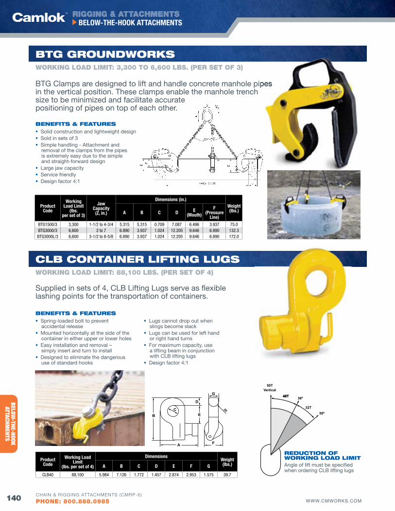
RIGGING & ATTACHMENTS
140 WWW.CMWORKS.COM
BELOW-THE-HOOK ATTACHMENTS
CHAIN & RIGGING ATTACHMENTS (CMRP-6)
PHONE: 800.888.0985
BELOW-THE-HOOK
ATTACHMENTS
ProductCode
Working Load Limit
(lbs. per set of 4)
DimensionsWeight(lbs.)A B C D E f G
CLB40 88,100 5.984 7.126 1.772 1.457 2.874 2.953 1.575 39.7
E
A F
BC
D
G
20
ProductCode
WorkingLoad Limit
(lbs. per set of 3)
JawCapacity(z, in.)
Dimensions (in.)Weight(lbs.)A B C D E
(Mouth)f
(Pressure Line)
BTG1500/3 3,300 1-1/2 to 4-3/4 5.315 5.315 0.709 7.087 6.496 3.937 75.0BTG3000/3 6,600 2 to 7 6.890 3.937 1.024 12.205 9.646 6.890 132.3BTG3000L/3 6,600 3-1/2 to 8-5/8 6.890 3.937 1.024 12.205 9.646 6.890 172.0
Clb CoNTAINER lIfTING luGS
bENEfITS & fEATuRES
REduCTIoN of woRKING loAd lIMITAngle of lift must be specified when ordering CLB lifting lugs
Spring-loaded bolt to prevent accidental release
Mounted horizontally at the side of the container in either upper or lower holes
Easy installation and removal – simply insert and turn to install
Designed to eliminate the dangerous use of standard hooks
Lugs cannot drop out when slings become slack
Lugs can be used for left hand or right hand turns
For maximum capacity, use a lifting beam in conjunction with CLB lifting lugs
Design factor 4:1
WORKING LOAD LIMIT: 88,100 LbS. (PER SET Of 4)
bTG GRouNdwoRKS
bENEfITS & fEATuRES Solid construction and lightweight design Sold in sets of 3 Simple handling - Attachment and
removal of the clamps from the pipes is extremely easy due to the simple and straight-forward design
Large jaw capacity Service friendly Design factor 4:1
WORKING LOAD LIMIT: 3,300 TO 6,600 LbS. (PER SET Of 3)
BTG Clamps are designed to lift and handle concrete manhole pipes in the vertical position. These clamps enable the manhole trench size to be minimized and facilitate accurate positioning of pipes on top of each other.
Supplied in sets of 4, CLB Lifting Lugs serve as flexible lashing points for the transportation of containers.
BTG Clamps are designed to lift and handle concrete manhole pipes
40T40T
32T
36º
50º
50TVertical
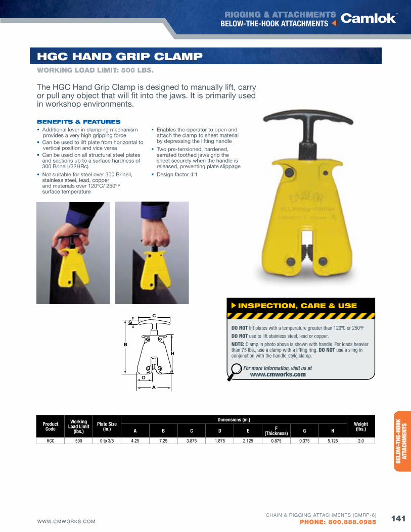
RIGGING & ATTACHMENTS
141WWW.CMWORKS.COM
BELOW-THE-HOOK ATTACHMENTS
CHAIN & RIGGING ATTACHMENTS (CMRP-6)
PHONE: 800.888.0985
ENTE
RTAI
NMEN
TRI
GGIN
G PR
ODUC
TSBE
LOW
-THE
-HOO
K AT
TACH
MEN
TSProductCode
Working Load Limit
(lbs.)Plate Size
(in.)
Dimensions (in.)Weight(lbs.)A B C D E f
(Thickness) G H
HGC 500 0 to 3/8 4.25 7.25 3.875 1.875 2.125 0.875 0.375 5.125 2.0
HGC HANd GRIP ClAMP
bENEfITS & fEATuRES Additional lever in clamping mechanism
provides a very high gripping force Can be used to lift plate from horizontal to
vertical position and vice versa Can be used on all structural steel plates
and sections up to a surface hardness of 300 Brinell (32HRc)
Not suitable for steel over 300 Brinell, stainless steel, lead, copper and materials over 120ºC/ 250ºF surface temperature
Enables the operator to open and attach the clamp to sheet material by depressing the lifting handle
Two pre-tensioned, hardened, serrated toothed jaws grip the sheet securely when the handle is released, preventing plate slippage
Design factor 4:1
WORKING LOAD LIMIT: 500 LbS.
B
GC
H
A
D
F = Thickness
The HGC Hand Grip Clamp is designed to manually lift, carry or pull any object that will fit into the jaws. It is primarily used in workshop environments.
INSPECTIoN, CARE & uSE
DO NOT lift plates with a temperature greater than 120ºC or 250ºF
DO NOT use to lift stainless steel, lead or copper.
NOTE: Clamp in photo above is shown with handle. For loads heavier than 75 lbs., use a clamp with a lifting ring. DO NOT use a sling in conjunction with the handle-style clamp.
For more information, visit us at www.cmworks.com
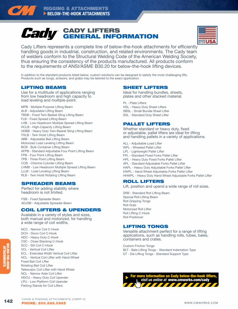
RIGGING & ATTACHMENTS
142 WWW.CMWORKS.COM
BELOW-THE-HOOK ATTACHMENTS
CHAIN & RIGGING ATTACHMENTS (CMRP-6)
PHONE: 800.888.0985
BELOW-THE-HOOK
ATTACHMENTS
Cady Lifters represents a complete line of below-the-hook attachments for efficiently handling goods in industrial, construction, and related environments. The Cady team of welders conform to the Structural Welding Code of the American Welding Society, thus ensuring the consistency of the products manufactured. All products conform to the requirements of ANSI/ASME B30.20 for below-the-hook lifting devices.
In addition to the standard products listed below, custom solutions can be designed to satisfy the most challenging lifts. Products such as tongs, scissors, and grabs may be tailored to the exact application.
lIfTING bEAMSUse for a multitude of applications ranging from low headroom and high capacity to load leveling and multiple-point.
MPB - Multiple Purpose Lifting BeamALB - Adjustable Lifting BeamTBSB - Fixed Twin Basket Sling Lifting BeamFLB - Fixed Spread Lifting BeamLHB - Low Headroom Multiple Spread Lifting BeamHCLB - High-Capacity Lifting BeamHDBB - Heavy Duty Twin Basket Sling Lifting BeamTHLB - Twin Hoist Lifting BeamABB - Adjustable Bail Lifting BeamMotorized Load Leveling Lifting BeamBCB - Bulk Container Lifting BeamAFPB - Standard Adjustable Four Point Lifting BeamFPB - Four Point Lifting BeamTPB - Three Point Lifting BeamCCB - Chlorine Cylinder Lifting BeamLHMB - Low Headroom Multiple Spread Lifting BeamLLLB - Load Leveling Lifting BeamRLB - Twin Hoist Rotating Lifting Beam
Roll lIfTERSLift, position and upend a wide range of roll sizes.
SRB - Standard Roll Lifting BeamSpecial Roll LIfting BeamRoll Gripping TongsRoll GrabMotorized Roll LIfterRoll LIfting C-HookRoll Positioner
SHEET lIfTERS Ideal for handling bundles, sheets, plates and other stacked material.
PL - Plate LiftersHSL - Heavy Duty Sheet LiftersSBSL - Small Bundle Sheet LifterSSL - Standard Duty Sheet Lifter
PAllET lIfTERS Whether standard or heavy duty, fixed or adjustable, pallet lifters are ideal for lifting and handling pallets in a variety of applications.
ALL - Adjustable Load LifterWPL - Wheeled Pallet LifterLPL - Lightweight Pallet LifterFPL - Standard Fixed Forks Pallet LifterHPL - Heavy Duty Fixed Forks Pallet LifterAPL - Standard Adjustable Forks Pallet LifterHAPL - Heavy Duty Adjustable Forks Pallet LifterHWPL - Hand Wheel Adjustable Forks Pallet LifterHHWPL - Heavy Duty Hand Wheel Adjustable Forks Pallet Lifter
SPREAdER bEAMSPerfect for adding stability where headroom is not limited.
FSB - Fixed Spreader BeamADJSB - Adjustable Spreader Beam
lIfTING ToNGSversatile attachment perfect for a range of lifting applications, such as handling rolls, tubes, bales, containers and crates.
Custom Friction TongsBLT - Bale Lifting Tongs - Standard Indentation TypeDT - Die Lifting Tongs - Standard Support Type
CoIl lIfTERS & uPENdERSAvailable in a variety of styles and sizes, both manual and motorized, for handling a wide range of coil widths.
NCC - Narrow Coil C-HookDCH - Dixon Coil C-HookHDC - Heavy Duty C-HookCSC - Close Stacking C-HookSCC - Slit Coil C-HookvCL - vertical Coil LIfterECL - Extended Width vertical Coil LIfterHCL - vertical Coil LIfter with Hand WheelFixed Bail Coil LifterRotating Bail Coil LifterTelescopic Coil Lifter with Hand WheelNCL - Narrow Aisle Coil LifterHDCU - Heavy Duty Coil UpenderLPU - Low Platform Coil UpenderParking Stands for Coil Lifters
CAdy lIfTERS GENERAl INfoRMATIoN
For more information on Cady below-the-hook lifters, visit us online at www.cmworks.com/cady
®
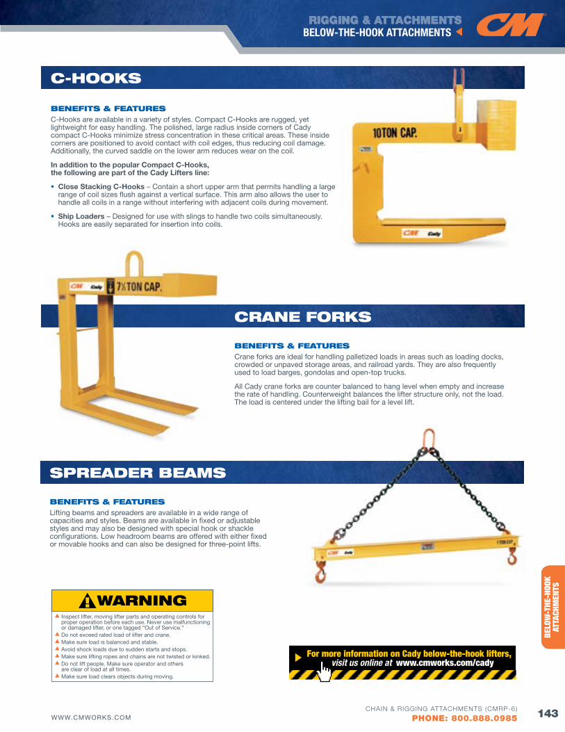
RIGGING & ATTACHMENTS
143WWW.CMWORKS.COM
BELOW-THE-HOOK ATTACHMENTS
CHAIN & RIGGING ATTACHMENTS (CMRP-6)
PHONE: 800.888.0985
ENTE
RTAI
NMEN
TRI
GGIN
G PR
ODUC
TSBE
LOW
-THE
-HOO
K AT
TACH
MEN
TS
CRANE foRKS
bENEfITS & fEATuRESCrane forks are ideal for handling palletized loads in areas such as loading docks, crowded or unpaved storage areas, and railroad yards. They are also frequently used to load barges, gondolas and open-top trucks.
All Cady crane forks are counter balanced to hang level when empty and increase the rate of handling. Counterweight balances the lifter structure only, not the load. The load is centered under the lifting bail for a level lift.
C-HooKS
bENEfITS & fEATuRESC-Hooks are available in a variety of styles. Compact C-Hooks are rugged, yet lightweight for easy handling. The polished, large radius inside corners of Cady compact C-Hooks minimize stress concentration in these critical areas. These inside corners are positioned to avoid contact with coil edges, thus reducing coil damage. Additionally, the curved saddle on the lower arm reduces wear on the coil.
In addition to the popular Compact C-Hooks, the following are part of the Cady Lifters line:
Close Stacking C-Hooks – Contain a short upper arm that permits handling a large range of coil sizes flush against a vertical surface. This arm also allows the user to handle all coils in a range without interfering with adjacent coils during movement.
Ship Loaders – Designed for use with slings to handle two coils simultaneously. Hooks are easily separated for insertion into coils.
SPREAdER bEAMS
bENEfITS & fEATuRESLifting beams and spreaders are available in a wide range of capacities and styles. Beams are available in fixed or adjustable styles and may also be designed with special hook or shackle configurations. Low headroom beams are offered with either fixed or movable hooks and can also be designed for three-point lifts.
For more information on Cady below-the-hook lifters, visit us online at www.cmworks.com/cady
s Inspect lifter, moving lifter parts and operating controls for proper operation before each use. Never use malfunctioning or damaged lifter, or one tagged “Out of Service.”
s Do not exceed rated load of lifter and crane.s Make sure load is balanced and stable.s Avoid shock loads due to sudden starts and stops.s Make sure lifting ropes and chains are not twisted or kinked.s Do not lift people. Make sure operator and others
are clear of load at all times.s Make sure load clears objects during moving.
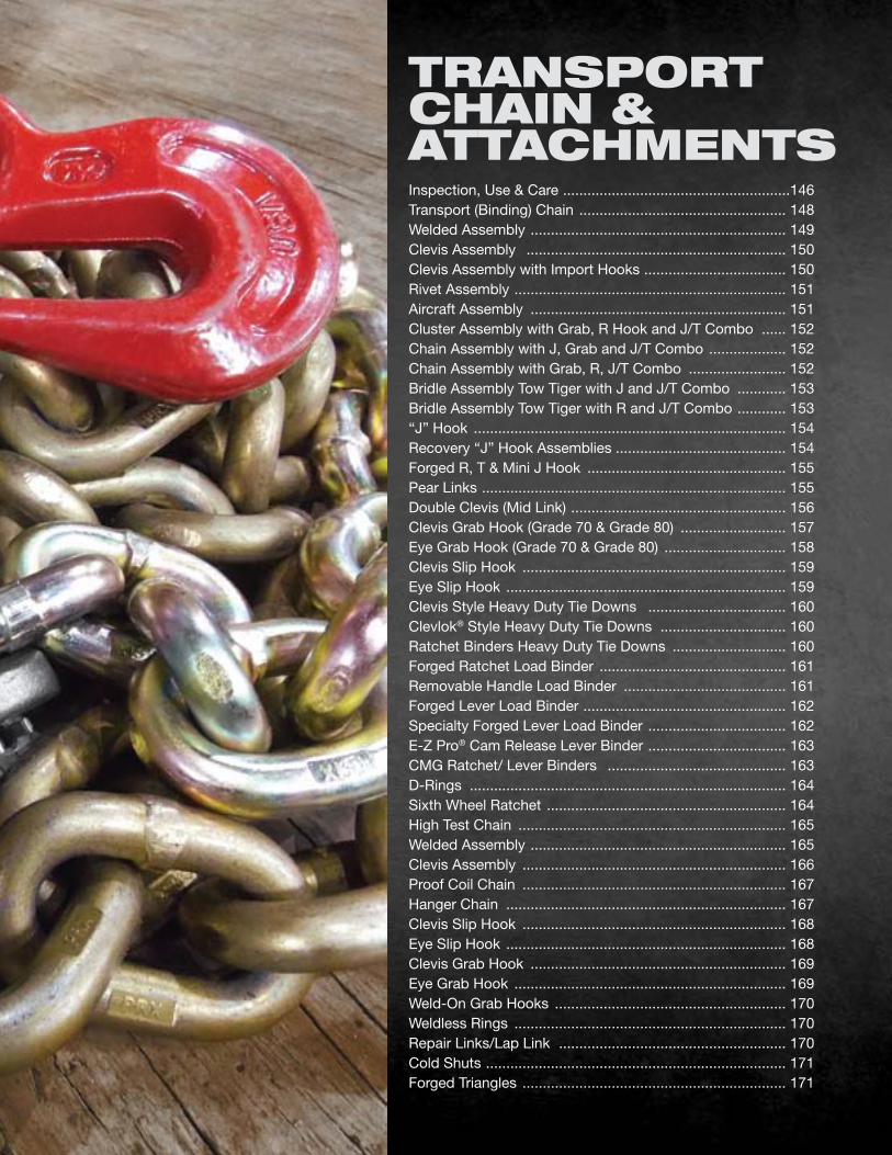
Inspection, Use & Care ........................................................146 Transport (Binding) Chain ................................................... 148Welded Assembly ............................................................... 149Clevis Assembly ................................................................ 150Clevis Assembly with Import Hooks ................................... 150Rivet Assembly ................................................................... 151Aircraft Assembly ............................................................... 151Cluster Assembly with Grab, R Hook and J/T Combo ...... 152Chain Assembly with J, Grab and J/T Combo ................... 152Chain Assembly with Grab, R, J/T Combo ........................ 152Bridle Assembly Tow Tiger with J and J/T Combo ............ 153Bridle Assembly Tow Tiger with R and J/T Combo ............ 153“J” Hook ............................................................................. 154Recovery “J” Hook Assemblies .......................................... 154Forged R, T & Mini J Hook ................................................. 155Pear Links ........................................................................... 155Double Clevis (Mid Link) ..................................................... 156Clevis Grab Hook (Grade 70 & Grade 80) .......................... 157Eye Grab Hook (Grade 70 & Grade 80) .............................. 158Clevis Slip Hook ................................................................. 159Eye Slip Hook ..................................................................... 159Clevis Style Heavy Duty Tie Downs .................................. 160Clevlok® Style Heavy Duty Tie Downs ............................... 160Ratchet Binders Heavy Duty Tie Downs ............................ 160Forged Ratchet Load Binder .............................................. 161Removable Handle Load Binder ........................................ 161Forged Lever Load Binder .................................................. 162Specialty Forged Lever Load Binder .................................. 162E-Z Pro® Cam Release Lever Binder .................................. 163CMG Ratchet/ Lever Binders ............................................ 163D-Rings .............................................................................. 164Sixth Wheel Ratchet ........................................................... 164High Test Chain .................................................................. 165Welded Assembly ............................................................... 165Clevis Assembly ................................................................. 166Proof Coil Chain ................................................................. 167Hanger Chain ..................................................................... 167Clevis Slip Hook ................................................................. 168Eye Slip Hook ..................................................................... 168Clevis Grab Hook ............................................................... 169Eye Grab Hook ................................................................... 169Weld-On Grab Hooks ......................................................... 170Weldless Rings ................................................................... 170Repair Links/Lap Link ........................................................ 170Cold Shuts .......................................................................... 171Forged Triangles ................................................................. 171
TRANSPoRT CHAIN & ATTACHMENTS
RIGGING & ATTACHMENTS
146 WWW.CMWORKS.COM
TRANSPORTATION CHAIN & ATTACHMENTS
CHAIN & RIGGING ATTACHMENTS (CMRP-6)
PHONE: 800.888.0985
TRANSPORT CHAIN &
ATTACHMENTS
Columbus McKinnon and our Tennessee-based Dixie Industries are leaders in innovation for the towing and transportation industries. We are the premier manufacturer of American-made chain and forged attachments for the towing industry. We are proud to not only offer towing products, but a full line of chain and hardware for the heavy-duty trucking industry.
loAd bINdER uSE, INSPECTIoN & CAREuSE 1. Always follow safe work practices and take precautions
in use of binders. Particular attention is called to the following sections of D.O.T. Federal Motor Carrier Safety Regulations: S392.9 (relating to safe loading); S393.100 (relating to protection against shifting or falling cargo); and S393.102 (relating to securement systems).
2. Never exceed working load limit shown on the binder. Hand effort will tighten binder to working load limit.
3. Always inspect the load binder before use. See the load binder inspection section below.
4. Always position the load binder so the handle goes downward when securing or tightening the load.
5. Operate only by hand from a firm standing position.
6. Do not operate load binder while anyone is on the load.
7. Do not use a cheater bar or handle extension. Extensions can dangerously overload the binder system and may result in serious injury. Use a ratchet-type binder if sufficient leverage is difficult to develop.
8. Make certain that the lever of the lever-type binder is over center and locked. Always secure the handle in the locked position with a positive retaining method. The handle must be secured since there is a possibility of relaxation of the load, which may result in the lever moving from the locked-over-center position to relaxed mode, resulting in loss of tension in the system.
9. Release handle/load with extreme care. Make sure everyone is clear. Lever binder handle can snap back over center. Use open palm under handle and push up.
10. Tighten binders before moving and frequently recheck and retighten.
CARE Care should be exercised during use so that the binder is not abused or damaged.
1. The binder or hooks should not be subjected to bending or sharp objects. Loading should be in a straight line.
2. Avoid exposure to corrosive mediums. Lubricate periodically.
INSPECTIoN Inspect binder prior to each use for damage, distortion, cracks, nicks, or wear.
1. Bending of any feature in any plane of more than 10 degrees is cause for removal of the unit from service. Any distortion indicates overloading or misuse.
2. Distorted or elongated connecting links indicate overloading or misuse and is also cause for removal of the unit from service.
3. If wear of connecting link ends is more than 10% of the original stock, remove unit from service.
4. On lever-type binders inspect yoke periodically for distortion and make certain it is seated on the pins.
5. Deep nicks and gouges should be smoothed out to relief stress concentrations providing that the material removed does not exceed 10% of the total material.
6. If distortion, cracks, nicks, or wear affect more than 10% of the stock, discard the unit.
TRANSPoRTATIoN
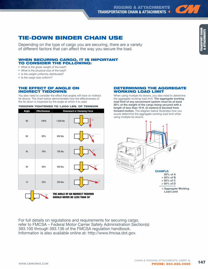
RIGGING & ATTACHMENTS
147WWW.CMWORKS.COM
TRANSPORTATION CHAIN & ATTACHMENTS
CHAIN & RIGGING ATTACHMENTS (CMRP-6)
PHONE: 800.888.0985
TRAN
SPOR
T CH
AIN
&
ATT
ACHM
ENTS
Depending on the type of cargo you are securing, there are a variety of different factors that can affect the way you secure the load.
wHEN SECuRING CARGo, IT IS IMPoRTANT To CoNSIdER THE followING: What is the gross weight of the load? What is the physical size of the load? Is the weight uniformly distributed? Is the cargo size uniform?
For full details on regulations and requirements for securing cargo, refer to FMCSA – Federal Motor Carrier Safety Administration Section(s) 393.100 through 393.136 of the FMCSA regulation handbook. Information is also available online at: http://www.fmcsa.dot.gov.
TIE-dowN bINdER CHAIN uSE
dETERMINING THE AGGREGATE woRKING loAd lIMIT When using multiple tie downs, you also need to determine the aggregate working load limit. The aggregate working load limit of any securement system must be at least 50% of the weight of the cargo being secured with a length of less than 10 ft. (3 meters) & blocked from forward motion. The diagram below illustrates how you would determine the aggregate working load limit when using multiple tie downs.
THE EffECT of ANGlE oN INdIRECT TIEdowNSYou also need to consider the effect that angles will have on indirect tie downs. The chart below demonstrates how the effectiveness of the tie down is impacted by the angle at which it is used.
TIEdowN TIGHTENEd To 1,000 lbS. of TENSIoN
THE aNgLE oF aN INdIrECT TIEdowN SHouLd NEvEr bE LESS THaN 30˚
Angle Effectiveness Downward or Clamping force
90 100% 1,000 lbs
60 85% 850 lbs.
45 70% 700 lbs.
30 50% 500 lbs.
15 25% 250 lbs.
90˚
60˚
45˚
30˚
30˚
15˚
AC
B D
50% of A+ 50% of B+ 50% of C+ 50% of D
EXAMPLE:
= Aggregate Working Load Limit
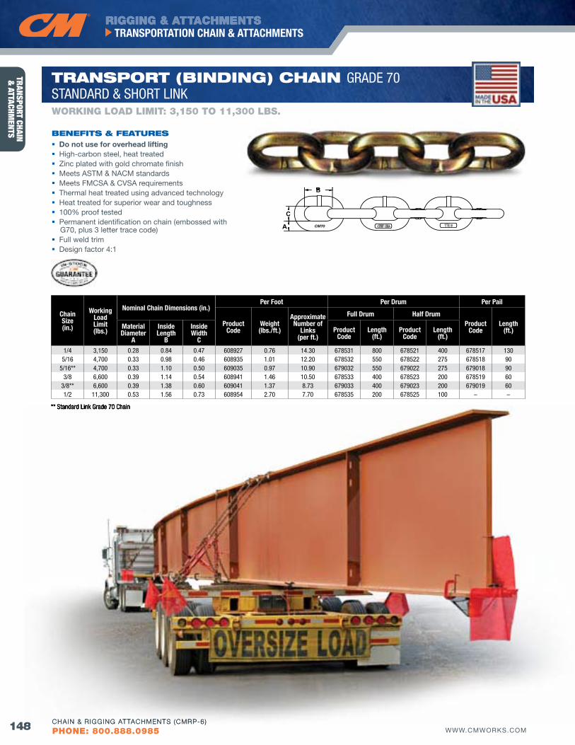
RIGGING & ATTACHMENTS
148 WWW.CMWORKS.COM
TRANSPORTATION CHAIN & ATTACHMENTS
CHAIN & RIGGING ATTACHMENTS (CMRP-6)
PHONE: 800.888.0985
TRANSPORT CHAIN &
ATTACHMENTS
B
C
A CM70
Chain Size(in.)
Working Load Limit(lbs.)
Nominal Chain Dimensions (in.)Per foot Per Drum Per Pail
Product Code
Weight(lbs./ft.)
Approximate Number of
Links(per ft.)
full Drum Half DrumProduct
CodeLength
(ft.)Material Diameter
A
Inside Length
B
Inside Width
CProduct
CodeLength
(ft.)Product
CodeLength
(ft.)
1/4 3,150 0.28 0.84 0.47 608927 0.76 14.30 678531 800 678521 400 678517 1305/16 4,700 0.33 0.98 0.46 608935 1.01 12.20 678532 550 678522 275 678518 90
5/16** 4,700 0.33 1.10 0.50 609035 0.97 10.90 679032 550 679022 275 679018 903/8 6,600 0.39 1.14 0.54 608941 1.46 10.50 678533 400 678523 200 678519 60
3/8** 6,600 0.39 1.38 0.60 609041 1.37 8.73 679033 400 679023 200 679019 601/2 11,300 0.53 1.56 0.73 608954 2.70 7.70 678535 200 678525 100 – –
Do not use for overhead lifting High-carbon steel, heat treated Zinc plated with gold chromate finish Meets ASTM & NACM standards Meets FMCSA & CvSA requirements Thermal heat treated using advanced technology Heat treated for superior wear and toughness 100% proof tested Permanent identification on chain (embossed with
G70, plus 3 letter trace code) Full weld trim Design factor 4:1
bENEfITS & fEATuRES
WORKING LOAD LIMIT: 3,150 TO 11,300 LbS.
TRANSPoRT (bINdING) CHAIN GRADE 70STANDARD & SHORT LINK
** Standard Link Grade 70 Chain
B
148 CHAIN & RIGGING ATTACHMENTS (CMRP-6)
** Standard Link Grade 70 Chain
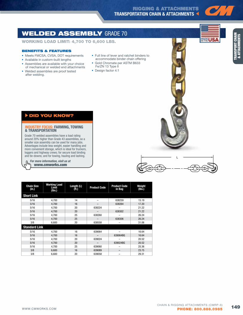
RIGGING & ATTACHMENTS
149WWW.CMWORKS.COM
TRANSPORTATION CHAIN & ATTACHMENTS
CHAIN & RIGGING ATTACHMENTS (CMRP-6)
PHONE: 800.888.0985
TRAN
SPOR
T CH
AIN
&
ATT
ACHM
ENTS
Chain Size(in.)
Working Load Limit(lbs.)
Length (L)(ft.) Product Code Product Code
in BagWeight(lbs.)
Short Link5/16 4,700 14 – 638259 15.195/16 4,700 16 – 638264 17.205/16 4,700 20 638224 – 21.225/16 4,700 20 – 638302 21.225/16 4,700 25 638260 – 26.245/16 4,700 25 – 638306 26.243/8 6,600 20 638558 – 31.06
Standard Link5/16 4,700 16 639064 – 16.645/16 4,700 16 – 639064BG 16.645/16 4,700 20 639024 – 20.525/16 4,700 20 – 639024BG 20.525/16 4,700 25 639060 – 25.363/8 6,600 16 639089 – 23.753/8 6,600 20 639058 – 29.31
L
Meets FMCSA, CvSA, DOT requirements Available in custom-built lengths Assemblies are available with your choice
of mechanical or welded end attachments Welded assemblies are proof tested
after welding.
bENEfITS & fEATuRES
WORKING LOAD LIMIT: 4,700 TO 6,600 LbS.
wEldEd ASSEMbly GRADE 70
Full line of lever and ratchet binders to accommodate binder chain offering
Gold Chromate per ASTM B633 Fe/ZN 13 Type II
Design factor 4:1
For more information, visit us at www.cmworks.com
Grade 70 welded assemblies have a load rating around 20% higher than Grade 43 assemblies, so a smaller size assembly can be used for many jobs. Advantages include less weight, easier handling and more convenient storage, which is ideal for truckers, loggers and highway crews; for secure load binding and tie-downs; and for towing, hauling and lashing.
INDUSTRY fOCUS: fARMING, TOWING & TRANSPORTATION
dId you KNow?
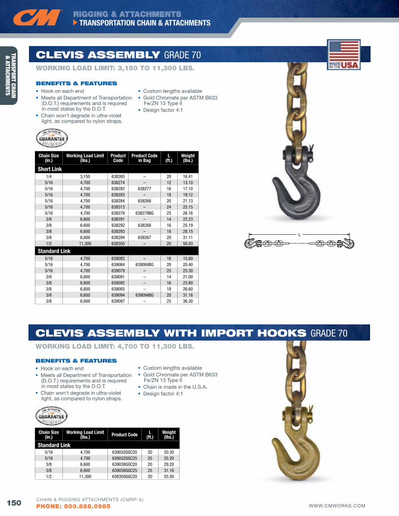
RIGGING & ATTACHMENTS
150 WWW.CMWORKS.COM
TRANSPORTATION CHAIN & ATTACHMENTS
CHAIN & RIGGING ATTACHMENTS (CMRP-6)
PHONE: 800.888.0985
TRANSPORT CHAIN &
ATTACHMENTS
L
Chain Size(in.)
Working Load Limit(lbs.)
Product Code
Product Code in Bag
L(ft.)
Weight(lbs.)
Short Link1/4 3,150 638265 – 20 16.41
5/16 4,700 638274 – 12 13.105/16 4,700 638282 638277 16 17.105/16 4,700 638283 – 18 19.125/16 4,700 638284 638266 20 21.135/16 4,700 638313 – 24 25.155/16 4,700 638279 638279BG 25 26.163/8 6,600 638291 – 14 22.233/8 6,600 638292 638268 16 25.193/8 6,600 638293 – 18 28.153/8 6,600 638294 638267 20 31.111/2 11,300 638350 – 20 56.93
Standard Link5/16 4,700 639082 – 16 15.605/16 4,700 639084 639084BG 20 20.405/16 4,700 639079 – 25 25.303/8 6,600 639091 – 14 21.003/8 6,600 639092 – 16 23.803/8 6,600 639093 – 18 26.603/8 6,600 639094 639094BG 20 31.163/8 6,600 639097 – 25 36.30
Chain Size(in.)
Working Load Limit(lbs.) Product Code L
(ft.)Weight(lbs.)
Standard Link5/16 4,700 639032GGC20 20 20.305/16 4,700 639032GGC25 25 25.203/8 6,600 639038GGC20 20 29.203/8 6,600 639038GGC25 25 31.161/2 11,300 638350GGC20 20 55.50
Hook on each end Meets all Department of Transportation
(D.O.T.) requirements and is required in most states by the D.O.T.
Chain won't degrade in ultra-violet light, as compared to nylon straps.
Custom lengths available Gold Chromate per ASTM B633
Fe/ZN 13 Type II Design factor 4:1
Custom lengths available Gold Chromate per ASTM B633
Fe/ZN 13 Type II Chain is made in the U.S.A. Design factor 4:1
Hook on each end Meets all Department of Transportation
(D.O.T.) requirements and is required in most states by the D.O.T.
Chain won't degrade in ultra-violet light, as compared to nylon straps.
bENEfITS & fEATuRES
bENEfITS & fEATuRES
WORKING LOAD LIMIT: 3,150 TO 11,300 LbS.
WORKING LOAD LIMIT: 4,700 TO 11,300 LbS.
ClEvIS ASSEMbly GRADE 70
ClEvIS ASSEMbly wITH IMPoRT HooKS GRADE 70

RIGGING & ATTACHMENTS
151WWW.CMWORKS.COM
TRANSPORTATION CHAIN & ATTACHMENTS
CHAIN & RIGGING ATTACHMENTS (CMRP-6)
PHONE: 800.888.0985
TRAN
SPOR
T CH
AIN
&
ATT
ACHM
ENTS
Chain Size(in.)
Working Load Limit(lbs.) Product Code L
(ft.)Weight(lbs.)
Short Link5/16 4,700 638281CRV 14 15.105/16 4,700 638282CRV 16 17.105/16 4,700 638283CRV 18 19.105/16 4,700 638284CRV 20 21.103/8 6,600 638291CRV 14 22.223/8 6,600 638292CRV 16 25.183/8 6,600 638293CRV 18 28.143/8 6,600 638294CRV 20 31.10
Standard Link5/16 4,700 639084CRV 20 20.435/16 4,700 639079CRV 25 25.273/8 6,600 639094CRV 20 29.33
L
Riveted hooks prevent loss or theft of hooks
Gold Chromate per ASTM B633 Fe/ZN 13 Type II Design factor 4:1
Meets MIL-DTL-6458E- Type I specifications 100% proof tested in accordance
to MIL spec standards Gold chromate finish per ASTM B633 Fe/ZN 13 Type II Individually packaged assemblies available upon request Design factor 4:1
bENEfITS & fEATuRES
bENEfITS & fEATuRES
RIvET ASSEMbly GRADE 70WORKING LOAD LIMIT: 4,700 TO 6,600 LbS.
L
Chain Size(in.)
Minimum Break Strength
(lbs.)Product Code L
(ft.)Weight(lbs.)
9/32 14,100 627728 9 7.17
MINIMuM bREAK STRENGTH: 14,100 LbS.
AIRCRAfT ASSEMbly
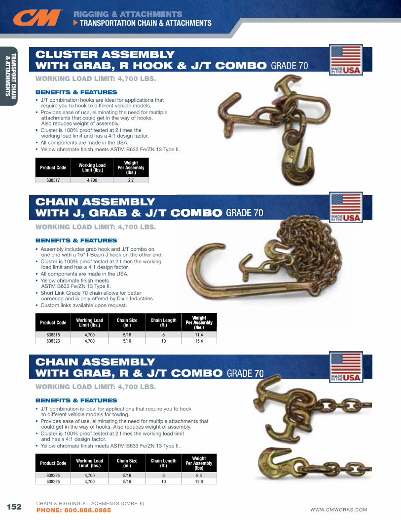
RIGGING & ATTACHMENTS
152 WWW.CMWORKS.COM
TRANSPORTATION CHAIN & ATTACHMENTS
CHAIN & RIGGING ATTACHMENTS (CMRP-6)
PHONE: 800.888.0985
TRANSPORT CHAIN &
ATTACHMENTS
Product Code Working Load Limit (lbs.)
Chain Size (in.)
Chain Length (ft.)
Weight Per Assembly
(lbs)
638324 4,700 5/16 6 8.8638325 4,700 5/16 10 12.8
Product Code Working Load Limit (lbs.)
Chain Size (in.)
Chain Length (ft.)
Weight Per Assembly
(lbs.)
638318 4,700 5/16 6 11.4638323 4,700 5/16 10 15.4
Product Code Working Load Limit (lbs.)
Weight Per Assembly
(lbs.)
638317 4,700 2.7
J/T combination hooks are ideal for applications that require you to hook to different vehicle models.
Provides ease of use, eliminating the need for multiple attachments that could get in the way of hooks. Also reduces weight of assembly.
Cluster is 100% proof tested at 2 times the working load limit and has a 4:1 design factor.
All components are made in the USA. Yellow chromate finish meets ASTM B633 Fe/ZN 13 Type II.
Assembly includes grab hook and J/T combo on one end with a 15" I-Beam J hook on the other end.
Cluster is 100% proof tested at 2 times the working load limit and has a 4:1 design factor.
All components are made in the USA. Yellow chromate finish meets
ASTM B633 Fe/ZN 13 Type II. Short Link Grade 70 chain allows for better
cornering and is only offered by Dixie Industries. Custom links available upon request.
WORKING LOAD LIMIT: 4,700 LbS.
CluSTER ASSEMbly wITH GRAb, R HooK & j/T CoMbo GRADE 70
J/T combination is ideal for applications that require you to hook to different vehicle models for towing.
Provides ease of use, eliminating the need for multiple attachments that could get in the way of hooks. Also reduces weight of assembly.
Cluster is 100% proof tested at 2 times the working load limit and has a 4:1 design factor.
Yellow chromate finish meets ASTM B633 Fe/ZN 13 Type II.
WORKING LOAD LIMIT: 4,700 LbS.
CHAIN ASSEMbly wITH j, GRAb & j/T CoMbo GRADE 70
WORKING LOAD LIMIT: 4,700 LbS.
CHAIN ASSEMbly wITH GRAb, R & j/T CoMbo GRADE 70GRADE 70
WeightPer Assembly
(lbs.)
/T CoMbo GRADE 70
bENEfITS & fEATuRES
bENEfITS & fEATuRES
bENEfITS & fEATuRES
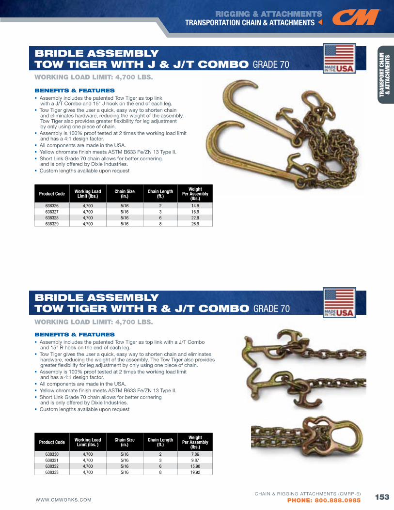
RIGGING & ATTACHMENTS
153WWW.CMWORKS.COM
TRANSPORTATION CHAIN & ATTACHMENTS
CHAIN & RIGGING ATTACHMENTS (CMRP-6)
PHONE: 800.888.0985
TRAN
SPOR
T CH
AIN
&
ATT
ACHM
ENTS
bENEfITS & fEATuRES
bENEfITS & fEATuRES
WORKING LOAD LIMIT: 4,700 LbS.
bRIdlE ASSEMbly Tow TIGER wITH j & j/T CoMbo GRADE 70
Product Code Working Load Limit (lbs. )
Chain Size (in.)
Chain Length (ft.)
Weight Per Assembly
(lbs.)
638330 4,700 5/16 2 7.86638331 4,700 5/16 3 9.87638332 4,700 5/16 6 15.90638333 4,700 5/16 8 19.92
Assembly includes the patented Tow Tiger as top link with a J/T Combo and 15" R hook on the end of each leg.
Tow Tiger gives the user a quick, easy way to shorten chain and eliminates hardware, reducing the weight of the assembly. The Tow Tiger also provides greater flexibility for leg adjustment by only using one piece of chain.
Assembly is 100% proof tested at 2 times the working load limit and has a 4:1 design factor.
All components are made in the USA. Yellow chromate finish meets ASTM B633 Fe/ZN 13 Type II. Short Link Grade 70 chain allows for better cornering
and is only offered by Dixie Industries. Custom lengths available upon request
WORKING LOAD LIMIT: 4,700 LbS.
bRIdlE ASSEMbly Tow TIGER wITH R & j/T CoMbo GRADE 70
Product Code Working Load Limit (lbs.)
Chain Size (in.)
Chain Length (ft.)
Weight Per Assembly
(lbs.)
638326 4,700 5/16 2 14.9638327 4,700 5/16 3 16.9638328 4,700 5/16 6 22.9638329 4,700 5/16 8 26.9
Assembly includes the patented Tow Tiger as top link with a J/T Combo and 15" J hook on the end of each leg.
Tow Tiger gives the user a quick, easy way to shorten chain and eliminates hardware, reducing the weight of the assembly. Tow Tiger also provides greater flexibility for leg adjustment by only using one piece of chain.
Assembly is 100% proof tested at 2 times the working load limit and has a 4:1 design factor.
All components are made in the USA. Yellow chromate finish meets ASTM B633 Fe/ZN 13 Type II. Short Link Grade 70 chain allows for better cornering
and is only offered by Dixie Industries. Custom lengths available upon request
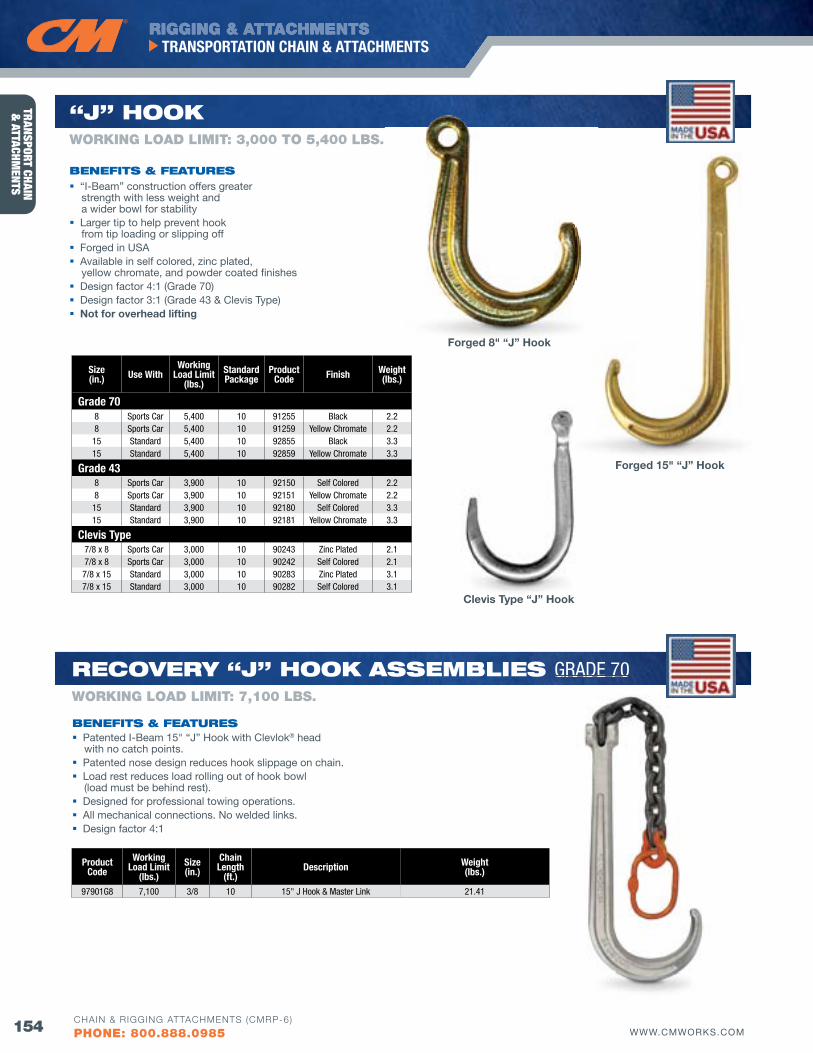
RIGGING & ATTACHMENTS
154 WWW.CMWORKS.COM
TRANSPORTATION CHAIN & ATTACHMENTS
CHAIN & RIGGING ATTACHMENTS (CMRP-6)
PHONE: 800.888.0985
TRANSPORT CHAIN &
ATTACHMENTS
Size(in.) Use With
Working Load Limit
(lbs.)StandardPackage
Product Code finish Weight
(lbs.)
Grade 708 Sports Car 5,400 10 91255 Black 2.28 Sports Car 5,400 10 91259 Yellow Chromate 2.2
15 Standard 5,400 10 92855 Black 3.315 Standard 5,400 10 92859 Yellow Chromate 3.3
Grade 438 Sports Car 3,900 10 92150 Self Colored 2.28 Sports Car 3,900 10 92151 Yellow Chromate 2.2
15 Standard 3,900 10 92180 Self Colored 3.315 Standard 3,900 10 92181 Yellow Chromate 3.3
Clevis Type7/8 x 8 Sports Car 3,000 10 90243 zinc Plated 2.17/8 x 8 Sports Car 3,000 10 90242 Self Colored 2.1
7/8 x 15 Standard 3,000 10 90283 zinc Plated 3.17/8 x 15 Standard 3,000 10 90282 Self Colored 3.1
WORKING LOAD LIMIT: 3,000 TO 5,400 LbS.
“j” HooK
“I-Beam” construction offers greater strength with less weight and a wider bowl for stability
Larger tip to help prevent hook from tip loading or slipping off
Forged in USA Available in self colored, zinc plated,
yellow chromate, and powder coated finishes Design factor 4:1 (Grade 70) Design factor 3:1 (Grade 43 & Clevis Type) Not for overhead lifting
bENEfITS & fEATuRES
Clevis Type “J” Hook
Forged 15" “J” Hook
Forged 8" “J” Hook
Product Code
Working Load Limit
(lbs.)Size(in.)
Chain Length
(ft.)Description Weight
(lbs.)
97901G8 7,100 3/8 10 15" J Hook & Master Link 21.41
WORKING LOAD LIMIT: 7,100 LbS.
RECovERy “j” HooK ASSEMblIES GRADE 70
bENEfITS & fEATuRES Patented I-Beam 15" “J” Hook with Clevlok® head
with no catch points. Patented nose design reduces hook slippage on chain. Load rest reduces load rolling out of hook bowl
(load must be behind rest). Designed for professional towing operations. All mechanical connections. No welded links. Design factor 4:1
GRADE 70
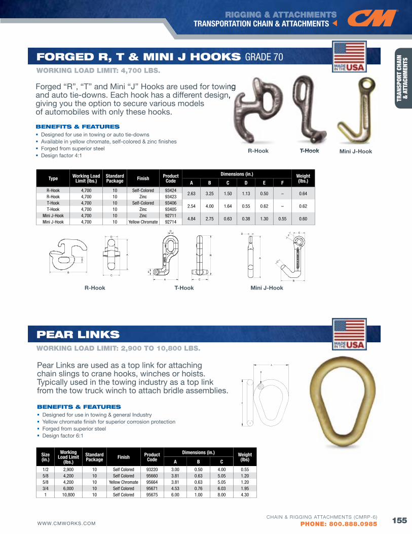
RIGGING & ATTACHMENTS
155WWW.CMWORKS.COM
TRANSPORTATION CHAIN & ATTACHMENTS
CHAIN & RIGGING ATTACHMENTS (CMRP-6)
PHONE: 800.888.0985
TRAN
SPOR
T CH
AIN
&
ATT
ACHM
ENTS
bENEfITS & fEATuRES Designed for use in towing or auto tie-downs Available in yellow chromate, self-colored & zinc finishes Forged from superior steel Design factor 4:1
Forged “R”, “T” and Mini “J” Hooks are used for towing and auto tie-downs. Each hook has a different design, giving you the option to secure various models of automobiles with only these hooks.
Type Working Load Limit (lbs.)
StandardPackage finish Product
CodeDimensions (in.) Weight
(lbs.)A B C D E fR-Hook 4,700 10 Self-Colored 93424
2.63 3.25 1.50 1.13 0.50 – 0.64R-Hook 4,700 10 zinc 93423T-Hook 4,700 10 Self-Colored 93406
2.54 4.00 1.64 0.55 0.62 – 0.62T-Hook 4,700 10 zinc 93405
Mini J-Hook 4,700 10 zinc 927114.84 2.75 0.63 0.38 1.30 0.55 0.60
Mini J-Hook 4,700 10 Yellow Chromate 92714
WORKING LOAD LIMIT: 4,700 LbS.
foRGEd R, T & MINI j HooKS GRADE 70
Forged “R”, “T” and Mini “J” Hooks are used for towing and auto tie-downs. Each hook has a different design,
R-Hook
R-Hook
Mini J-Hook
Mini J-HookT-Hook
T-HookT-Hook
A
BC
D
E
A
B
C
D
E
F
A
B
C
D E
A
BC
D
E
A
B
C
D
E
F
A
B
C
D E
A
BC
D
E
A
B
C
D
E
F
A
B
C
D E
A
BC
D
E
A
B
C
D
E
F
A
B
C
D E
Size(in.)
Working Load Limit
(lbs.)StandardPackage finish Product
CodeDimensions (in.) Weight
(lbs)A B C
1/2 2,900 10 Self Colored 93220 3.00 0.50 4.00 0.555/8 4,200 10 Self Colored 95660 3.81 0.63 5.05 1.205/8 4,200 10 Yellow Chromate 95664 3.81 0.63 5.05 1.203/4 6,000 10 Self Colored 95671 4.53 0.76 6.03 1.951 10,800 10 Self Colored 95675 6.00 1.00 8.00 4.30
WORKING LOAD LIMIT: 2,900 TO 10,800 LbS.
PEAR lINKS
bENEfITS & fEATuRES Designed for use in towing & general Industry Yellow chromate finish for superior corrosion protection Forged from superior steel Design factor 6:1
Pear Links are used as a top link for attaching chain slings to crane hooks, winches or hoists. Typically used in the towing industry as a top link from the tow truck winch to attach bridle assemblies.
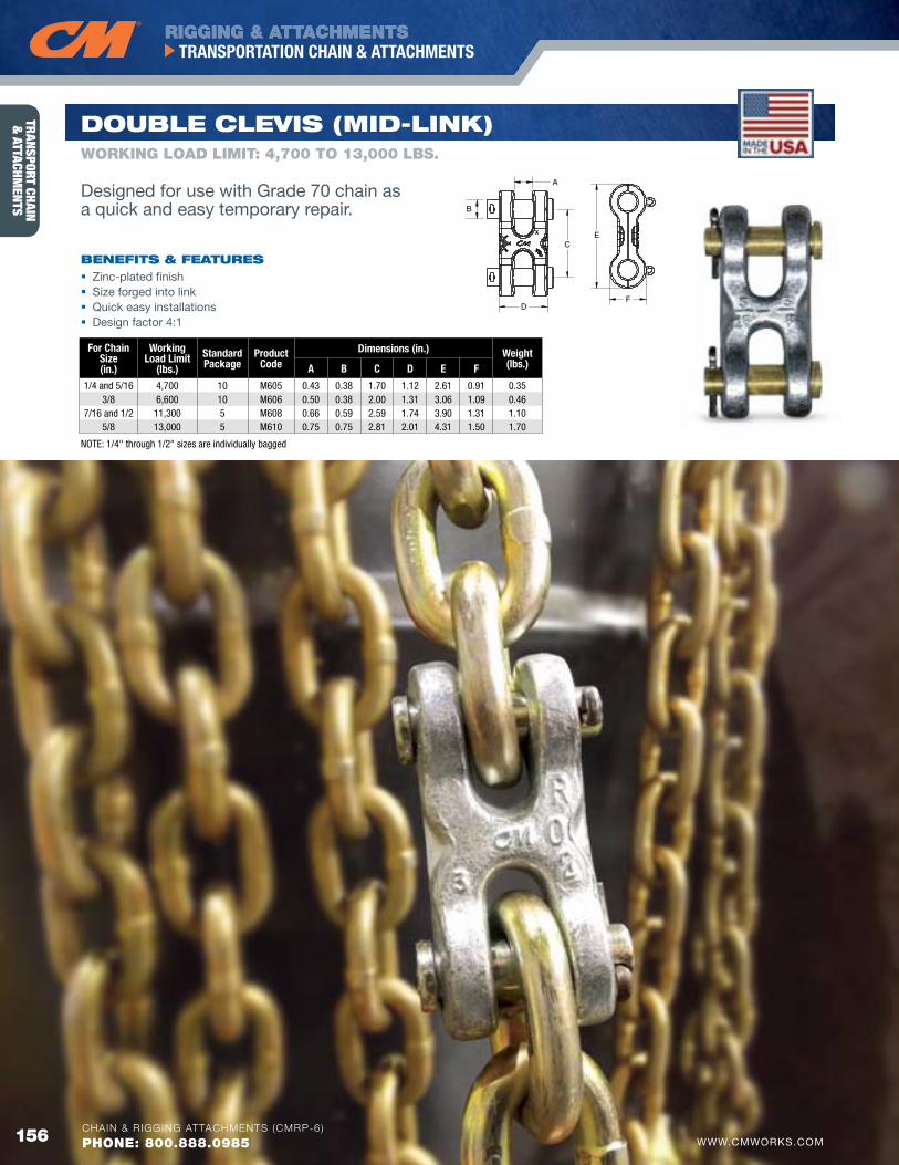
RIGGING & ATTACHMENTS
156 WWW.CMWORKS.COM
TRANSPORTATION CHAIN & ATTACHMENTS
CHAIN & RIGGING ATTACHMENTS (CMRP-6)
PHONE: 800.888.0985
TRANSPORT CHAIN &
ATTACHMENTS
for Chain Size(in.)
WorkingLoad Limit
(lbs.)Standard Package
ProductCode
Dimensions (in.) Weight(lbs.)A B C D E f
1/4 and 5/16 4,700 10 M605 0.43 0.38 1.70 1.12 2.61 0.91 0.353/8 6,600 10 M606 0.50 0.38 2.00 1.31 3.06 1.09 0.46
7/16 and 1/2 11,300 5 M608 0.66 0.59 2.59 1.74 3.90 1.31 1.105/8 13,000 5 M610 0.75 0.75 2.81 2.01 4.31 1.50 1.70
doublE ClEvIS (MId-lINK)
bENEfITS & fEATuRES Zinc-plated finish Size forged into link Quick easy installations Design factor 4:1
NOTE: 1/4" through 1/2" sizes are individually bagged
WORKING LOAD LIMIT: 4,700 TO 13,000 LbS.
Designed for use with Grade 70 chain as a quick and easy temporary repair.
156 WWW.CMWORKS.COMCHAIN & RIGGING ATTACHMENTS (CMRP-6)
PHONE: 800.888.0985
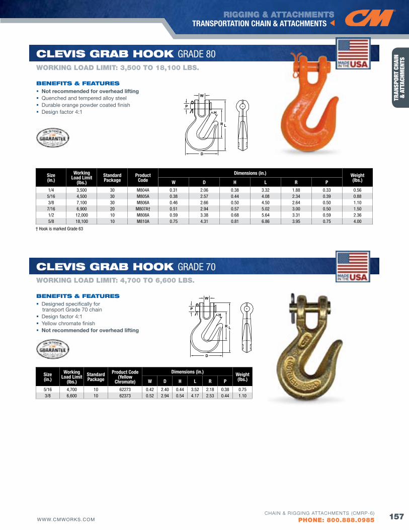
RIGGING & ATTACHMENTS
157WWW.CMWORKS.COM
TRANSPORTATION CHAIN & ATTACHMENTS
CHAIN & RIGGING ATTACHMENTS (CMRP-6)
PHONE: 800.888.0985
TRAN
SPOR
T CH
AIN
&
ATT
ACHM
ENTS
Size(in.)
Working Load Limit
(lbs.)Standard Package
Product Code
Dimensions (in.) Weight(lbs.)W D H L R P
1/4 3,500 30 M804A 0.31 2.06 0.38 3.32 1.88 0.33 0.56 5/16 4,500 30 M805A 0.38 2.57 0.44 4.08 2.34 0.39 0.88 3/8 7,100 30 M806A 0.46 2.66 0.50 4.50 2.64 0.50 1.10 7/16 6,900 20 M807A† 0.51 2.94 0.57 5.02 3.00 0.50 1.50 1/2 12,000 10 M808A 0.59 3.38 0.68 5.64 3.31 0.59 2.36 5/8 18,100 10 M810A 0.75 4.31 0.81 6.86 3.95 0.75 4.00
ClEvIS GRAb HooK GRADE 80
Not recommended for overhead lifting Quenched and tempered alloy steel Durable orange powder coated finish Design factor 4:1
bENEfITS & fEATuRES
WORKING LOAD LIMIT: 3,500 TO 18,100 LbS.
W
L
H
R
D
P
† Hook is marked Grade 63
W
L
H
R
D
P
Size(in.)
Working Load Limit
(lbs.)StandardPackage
Product Code(Yellow
Chromate)
Dimensions (in.) Weight(lbs.)W D H L R P
5/16 4,700 10 62273 0.42 2.40 0.44 3.52 2.18 0.38 0.753/8 6,600 10 62373 0.52 2.94 0.54 4.17 2.53 0.44 1.10
Designed specifically for transport Grade 70 chain
Design factor 4:1 Yellow chromate finish Not recommended for overhead lifting
bENEfITS & fEATuRES
WORKING LOAD LIMIT: 4,700 TO 6,600 LbS.
ClEvIS GRAb HooK GRADE 70
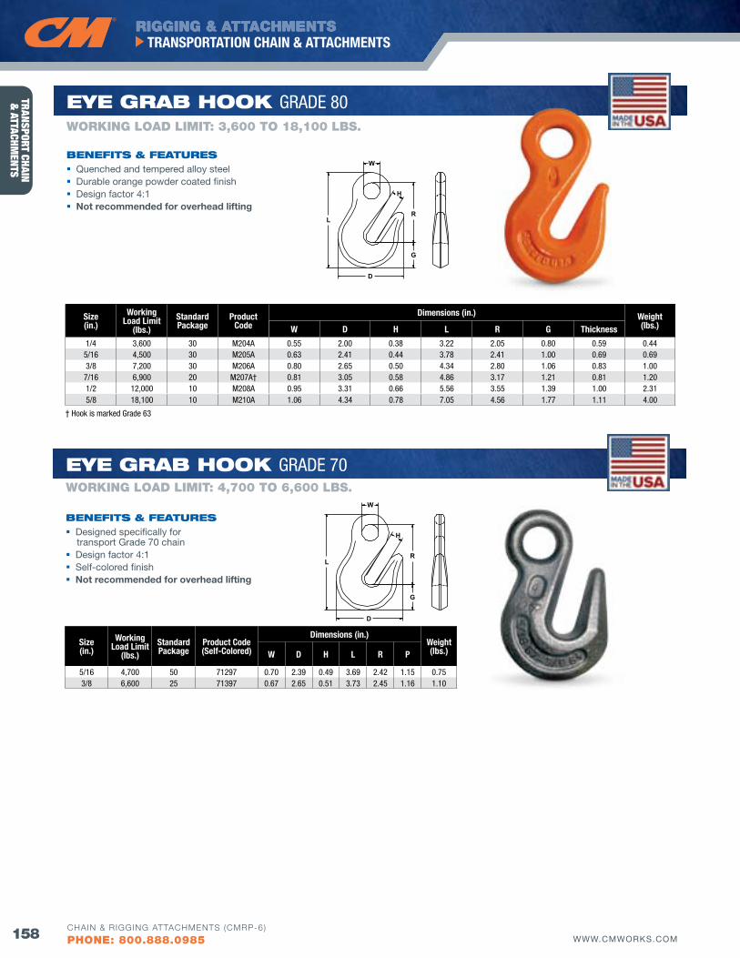
RIGGING & ATTACHMENTS
158 WWW.CMWORKS.COM
TRANSPORTATION CHAIN & ATTACHMENTS
CHAIN & RIGGING ATTACHMENTS (CMRP-6)
PHONE: 800.888.0985
TRANSPORT CHAIN &
ATTACHMENTS
Size(in.)
Working Load Limit
(lbs.)StandardPackage
ProductCode
Dimensions (in.) Weight(lbs.)W D H L R G Thickness
1/4 3,600 30 M204A 0.55 2.00 0.38 3.22 2.05 0.80 0.59 0.445/16 4,500 30 M205A 0.63 2.41 0.44 3.78 2.41 1.00 0.69 0.693/8 7,200 30 M206A 0.80 2.65 0.50 4.34 2.80 1.06 0.83 1.007/16 6,900 20 M207A† 0.81 3.05 0.58 4.86 3.17 1.21 0.81 1.201/2 12,000 10 M208A 0.95 3.31 0.66 5.56 3.55 1.39 1.00 2.315/8 18,100 10 M210A 1.06 4.34 0.78 7.05 4.56 1.77 1.11 4.00
Quenched and tempered alloy steel Durable orange powder coated finish Design factor 4:1 Not recommended for overhead lifting
bENEfITS & fEATuRES
WORKING LOAD LIMIT: 3,600 TO 18,100 LbS.
EyE GRAb HooK GRADE 80
H
L
W
D
G
R
† Hook is marked Grade 63
H
L
W
D
G
R
Size(in.)
Working Load Limit
(lbs.)StandardPackage
Product Code(Self-Colored)
Dimensions (in.)Weight(lbs.)W D H L R P
5/16 4,700 50 71297 0.70 2.39 0.49 3.69 2.42 1.15 0.753/8 6,600 25 71397 0.67 2.65 0.51 3.73 2.45 1.16 1.10
Designed specifically for transport Grade 70 chain
Design factor 4:1 Self-colored finish Not recommended for overhead lifting
bENEfITS & fEATuRES
WORKING LOAD LIMIT: 4,700 TO 6,600 LbS.
EyE GRAb HooK GRADE 70
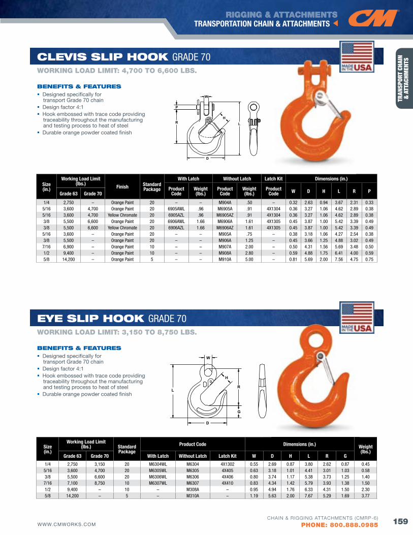
RIGGING & ATTACHMENTS
159WWW.CMWORKS.COM
TRANSPORTATION CHAIN & ATTACHMENTS
CHAIN & RIGGING ATTACHMENTS (CMRP-6)
PHONE: 800.888.0985
TRAN
SPOR
T CH
AIN
&
ATT
ACHM
ENTS
HL
D
W
P
R
Size(in.)
Working Load Limit(lbs.)
finish StandardPackage
With Latch Without Latch Latch Kit Dimensions (in.)
Product Code
Weight (lbs.)
Product Code
Weight (lbs.)
Product Code W D H L R PGrade 63 Grade 70
1/4 2,750 – Orange Paint 20 – – M904A .50 – 0.32 2.63 0.94 3.67 2.31 0.335/16 3,600 4,700 Orange Paint 20 6905AWL .96 M6905A .91 4X1304 0.36 3.27 1.06 4.62 2.89 0.385/16 3,600 4,700 Yellow Chromate 20 6905AzL .96 M6905Az .91 4X1304 0.36 3.27 1.06 4.62 2.89 0.383/8 5,500 6,600 Orange Paint 20 6906AWL 1.66 M6906A 1.61 4X1305 0.45 3.87 1.00 5.42 3.39 0.493/8 5,500 6,600 Yellow Chromate 20 6906AzL 1.66 M6906Az 1.61 4X1305 0.45 3.87 1.00 5.42 3.39 0.49
5/16 3,600 – Orange Paint 20 – – M905A .75 – 0.38 3.18 1.06 4.27 2.54 0.383/8 5,500 – Orange Paint 20 – – M906A 1.25 – 0.45 3.66 1.25 4.88 3.02 0.49
7/16 6,900 – Orange Paint 10 – – M907A 2.00 – 0.50 4.31 1.56 5.69 3.48 0.501/2 9,400 – Orange Paint 10 – – M908A 2.80 – 0.59 4.88 1.75 6.41 4.00 0.595/8 14,200 – Orange Paint 5 – – M910A 5.00 – 0.81 5.69 2.00 7.56 4.75 0.75
Designed specifically for transport Grade 70 chain
Design factor 4:1 Hook embossed with trace code providing
traceability throughout the manufacturing and testing process to heat of steel
Durable orange powder coated finish
bENEfITS & fEATuRES
WORKING LOAD LIMIT: 4,700 TO 6,600 LbS.
ClEvIS SlIP HooK GRADE 70
H
L
W
D
G
R
Size(in.)
Working Load Limit(lbs.) Standard
PackageProduct Code Dimensions (in.) Weight
(lbs.)Grade 63 Grade 70 With Latch Without Latch Latch Kit W D H L R G
1/4 2,750 3,150 20 M6304WL M6304 4X1302 0.55 2.69 0.87 3.80 2.62 0.87 0.455/16 3,600 4,700 20 M6305WL M6305 4X405 0.63 3.18 1.01 4.41 3.01 1.03 0.583/8 5,500 6,600 20 M6306WL M6306 4X406 0.80 3.74 1.17 5.38 3.73 1.25 1.40
7/16 7,100 8,750 10 M6307WL M6307 4X410 0.83 4.34 1.42 5.79 3.93 1.38 1.501/2 9,400 – 10 – M308A – 0.95 4.94 1.76 6.33 4.31 1.50 2.305/8 14,200 – 5 – M310A – 1.19 5.63 2.00 7.67 5.29 1.69 3.77
WORKING LOAD LIMIT: 3,150 TO 8,750 LbS.
EyE SlIP HooK GRADE 70
Designed specifically for transport Grade 70 chain
Design factor 4:1 Hook embossed with trace code providing
traceability throughout the manufacturing and testing process to heat of steel
Durable orange powder coated finish
bENEfITS & fEATuRES
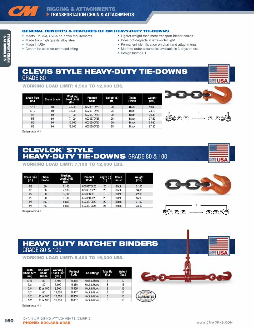
RIGGING & ATTACHMENTS
160 WWW.CMWORKS.COM
TRANSPORTATION CHAIN & ATTACHMENTS
CHAIN & RIGGING ATTACHMENTS (CMRP-6)
PHONE: 800.888.0985
TRANSPORT CHAIN &
ATTACHMENTS
Chain Size(in.)
Chain Grade
Working Load Limit
(lbs.)Product
CodeLength (L)
(ft.)Chainfinish
Weight(lbs.)
3/8 80 7,100 607037CL20 20 Black 31.003/8 80 7,100 607037CL25 25 Black 38.001/2 80 12,000 607050CL15 15 Black 42.001/2 80 12,000 607050CL20 20 Black 55.003/8 100 8,800 607337CL20 20 Black 31.003/8 100 8,800 607337CL25 25 Black 38.50 L
With Chain Size
(in.)
Use With Chain Grade
Working Load Limit
(lbs.)Product
Code End fittings Take Up(in.)
Weight(lbs.)
5/16 80 5,400 48365 Hook & Hook 8 123/8 80 7,100 48360 Hook & Hook 8 133/8 80 or 100 9,200 48366 Hook & Hook 8 131/2 80 13,000 48367 Hook & Hook 8 161/2 80 or 100 15,000 48358 Hook & Hook 8 161/2 80 or 100 16,000 48387 Hook & Hook 8 16
L
Chain Size(in.) Chain Grade
Working Load Limit
(lbs.)Product
CodeLength (L)
(ft.)Chainfinish
Weight(lbs.)
5/16 80 4,500 607031CV20 20 Black 19.605/16 80 4,500 607031CV25 25 Black 24.103/8 80 7,100 607037CV20 20 Black 30.303/8 80 7,100 607037CV25 25 Black 37.501/2 80 12,000 607050CV20 20 Black 54.601/2 80 12,000 607050CV25 25 Black 67.30
Meets FMCSA, CvSA tie-down requirements Made from high quality alloy steel Made in USA Cannot be used for overhead lifting
GENERAl bENEfITS & fEATuRES of CM HEAvy-duTy TIE-dowNS
WORKING LOAD LIMIT: 4,500 TO 12,000 LbS.
ClEvIS STylE HEAvy-duTy TIE-dowNS GRADE 80
ClEvloK® STylE HEAvy-duTy TIE-dowNS GRADE 80 & 100WORKING LOAD LIMIT: 7,100 TO 12,000 LbS.
Lighter weight than most transport binder chains Does not degrade in ultra-violet light Permanent identification on chain and attachments Made to order assemblies available in 3 days or less Design factor 4:1
HEAvy duTy RATCHET bINdERS GRADE 80 & 100WORKING LOAD LIMIT: 5,400 TO 16,000 LbS.
dERS
Design factor 4:1
Design factor 4:1
Design factor 4:1
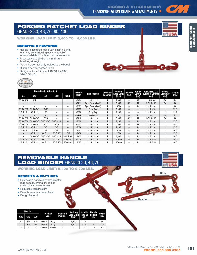
RIGGING & ATTACHMENTS
161WWW.CMWORKS.COM
TRANSPORTATION CHAIN & ATTACHMENTS
CHAIN & RIGGING ATTACHMENTS (CMRP-6)
PHONE: 800.888.0985
TRAN
SPOR
T CH
AIN
&
ATT
ACHM
ENTS
Chain Grade & Size (in.) Product
Code End fittings Standard Package
Working Load Limit
(lbs.)Take Up
(in.)Handle Length
(in.)
Barrel Size O.D. (Diam. x Length)
(in.)
Screw Diameter
(in.)Weight(lbs.)G30 G43 G70 G80 G100
3/16 & 1/4 1/4 – – – 48364 Hook / Hook 4 2,600 4 12 1-5/16 x 6 5/8 5.4 – – – 48811 Eye / Eye (no hook) 4 5,400 8.5 12 1-5/16 x 10 3/4 8.6– – – – – 48363 Eye / Eye (no hook) 4 13,000 8 14 1-1/2 x 10 1 9.8
5/16 & 3/8 5/16 & 3/8 5/16 – – 46565 Body Only 4 5,400 8 – 1-1/2 x 10 1 11.03/8 & 1/2 3/8 & 1/2 3/8 – – 46566 Body Only 4 9,200 8 – 1-1/2 x 10 1 11.7
– – – – – 46565H Handle Only 4 – – 14 – – 4.35/16 & 3/8 5/16 & 3/8 5/16 – – 48810 Hook / Hook 4 5,400 8.5 12 1-5/16 x 10 3/4 8.65/16 & 3/8 5/16 & 3/8 5/16 & 3/8 5/16 & 3/8 – 48360 Hook / Hook 4 7,100 8 14 1-1/2 x 10 1 13.05/16 & 3/8 5/16 & 3/8 5/16 5/16 – 48365 Hook / Hook 4 5,400 8 14 1-1/2 x 10 1 12.03/8 & 1/2 3/8 & 1/2 3/8 3/8 – 48366 Hook / Hook 4 9,200 8 14 1-1/2 x 10 1 13.01/2 & 5/8 1/2 & 5/8 1/2 1/2 – 48367 Hook / Hook 4 13,000 8 14 1-1/2 x 10 1 16.0
– 3/8 & 1/2 3/8 & 1/2 3/8 & 1/2 3/8 48458 Hook / Hook 4 12,000 8 14 1-1/2 x 10 1 13.0– 5/16 & 3/8 5/16 & 3/8 5/16 & 3/8 5/16 & 3/8 48455 Hook / Hook 4 8,800 8 14 1-1/2 x 10 1 16.0
3/8 & 1/2 3/8 & 1/2 3/8 & 1/2 3/8 & 1/2 3/8 & 1/2 48358 Hook / Hook 4 15,000 8 14 1-1/2 X 10 1 16.03/8 & 1/2 3/8 & 1/2 3/8 & 1/2 3/8 & 1/2 3/8 & 1/2 48387 Hook / Hook 4 16,000 8 14 1-1/2 X 10 1 16.0
Handle is designed loose using self-locking, one-way bolts allowing easy removal of unwanted debris such as mud, snow or ice
Proof tested to 50% of the minimum breaking strength
Gears are permanently welded to the barrel Durable powder coated finish Design factor 4:1 (Except 48358 & 48387,
which are 3:1)
bENEfITS & fEATuRES
WORKING LOAD LIMIT: 2,600 TO 16,000 LbS.
foRGEd RATCHET loAd bINdER GRADES 30, 43, 70, 80, 100
bINdER
Size (in.)Product
CodeStandardPackage
Working Load Limit
(lbs.)
Handle Take Up
(in.)
Handle Length
(in.)Weight(lbs.)G30 G43 G70
3/8 3/8 5/16 46565 Body 4 5,400 8.00 – 7.41/2 1/2 3/8 46566 Body 4 9,200 8.00 – 11.7– – – 46565H Handle 4 – – 14 4.3
WORKING LOAD LIMIT: 5,400 TO 9,200 LbS.
REMovAblE HANdlE loAd bINdER GRADES 30, 43, 70
Removable handle provides greater load security by making it less likely for load to be stolen
Reduces overall weight Durable powder coated finish Design factor 4:1
bENEfITS & fEATuRES
Handle
Body
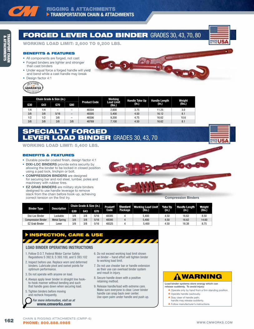
RIGGING & ATTACHMENTS
162 WWW.CMWORKS.COM
TRANSPORTATION CHAIN & ATTACHMENTS
CHAIN & RIGGING ATTACHMENTS (CMRP-6)
PHONE: 800.888.0985
TRANSPORT CHAIN &
ATTACHMENTS
Load binder systems store energy which can release suddenly. To avoid injury: s Operate only by hand from a firm standing position.
s Operate handle cautiously.
s Stay clear of handle path; handle may release suddenly.
s Follow manufacturer's instructions.
Chain Grade & Size (in.) Product Code
Working Load Limit
(lbs.)Handle Take Up
(in.)Handle Length
(in.)Weight(lbs.)G30 G43 G70 G80
1/4 1/4 – – 48304 2,600 3.75 11.25 3.03/8 3/8 5/16 – 48305 5,400 4.50 16.12 8.11/2 1/2 3/8 – 48306 9,200 4.75 16.62 10.63/8 3/8 3/8 3/8 48769 7,100 4.50 16.62 8.1
All components are forged, not cast Forged binders are lighter and stronger
than cast binders Under equal force a forged handle will yield
and bend while a cast handle may break Design factor 4:1
bENEfITS & fEATuRES
WORKING LOAD LIMIT: 2,600 TO 9,200 LbS.
foRGEd lEvER loAd bINdER GRADES 30, 43, 70, 80
Under equal force a forged handle will yield
9,200
Binder Type DescriptionChain Grade & Size (in.) Product
CodeStandard Package
Working Load Limit(lbs.)
Take Up(in.)
Handle Length(in.)
Weight(lbs.)G30 G43 G70
Dixi-Loc Binder Lockable 3/8 3/8 5/16 48385 4 5,400 4.50 16.62 8.50Compression Binder Metal Spring 3/8 3/8 5/16 48395 4 5,400 4.50 16.62 14.60
Ez Grab Binder Lever 3/8 3/8 5/16 48325 4 5,400 4.50 18.38 8.75
Durable powder coated finish, design factor 4:1 DIXI-LOC BINDERS provide extra security by
allowing the binder to be locked in closed position using a pad lock, linchpin or bolt.
COMPRESSION BINDERS are designed for securing bar and rod steel, lumber, poles and machinery with rubber tires.
EZ GRAB BINDERS are military style binders designed to use handle leverage to remove slack from the chain before hook-up, achieving correct tension on the first try.
bENEfITS & fEATuRES
WORKING LOAD LIMIT: 5,400 LbS.
SPECIAlTy foRGEd lEvER loAd bINdER GRADES 30, 43, 70
Product Standard Working Load Limit Take Up Handle Length Weight
Compression Binders
INSPECTIoN, CARE & uSE
1. Follow D.O.T. Federal Motor Carrier Safety Regulations S 392.9, S 393.100, and S 393.102
2. Inspect before use. Replace worn and deformed binders. Lubricate pivot and swivel points for optimum performance.
3. Do not operate with anyone on load.
4. Always apply lever binder in straight line hook- to-hook manner without bending and such that handle goes down when securing load.
5. Tighten binders before moving and recheck frequently.
6. Do not exceed working load limit shown on binder – hand effort will tighten binder to working load limit.
7. Do not use cheater bar or handle extension as their use can overload binder system and result in injury.
8. Secure handle down with a positive retaining method.
9. Release handle/load with extreme care. Make sure everyone is clear. Lever binder handle can snap back over center. Use open palm under handle and push up.
LOAD BINDER OPERATING INSTRUCTIONS
For more information, visit us at www.cmworks.com
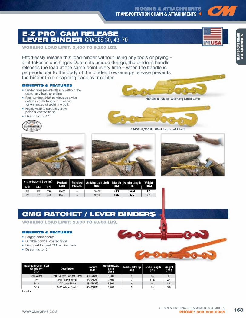
RIGGING & ATTACHMENTS
163WWW.CMWORKS.COM
TRANSPORTATION CHAIN & ATTACHMENTS
CHAIN & RIGGING ATTACHMENTS (CMRP-6)
PHONE: 800.888.0985
TRAN
SPOR
T CH
AIN
&
ATT
ACHM
ENTS
Chain Grade & Size (in.) Product Code
Standard Package
Working Load Limit(lbs.)
Take Up(in.)
Handle Length(in.)
Weight(lbs.)G30 G43 G70
3/8 3/8 5/16 48405 4 5,400 4.75 16.62 9.01/2 1/2 3/8 48406 4 9,200 4.75 16.62 9.8
48405: 5,400 lb. Working Load Limit
48406: 9,200 lb. Working Load Limit
Effortlessly release this load binder without using any tools or prying – all it takes is one finger. Due to its unique design, the binder’s handle releases the load at the same point every time – when the handle is perpendicular to the body of the binder. Low-energy release prevents the binder from snapping back over center.
Binder releases effortlessly without the use of any tools or prying
Free turning, 360º continuous swivel action in both tongue and clevis for enhanced straight line pull.
Highly visible, durable yellow powder coated finish
Design factor 4:1
bENEfITS & fEATuRES
WORKING LOAD LIMIT: 5,400 TO 9,200 LbS.
E-Z PRo® CAM RElEASElEvER bINdER GRADES 30, 43, 70
Maximum Chain Size (Grade 70)
(in.)Description Product
CodeWorking Load
Limit(lbs.)
Handle Take Up(in.)
Handle Length(in.)
Weight(lbs.)
5/16 & 3/8 5/16" & 3/8" Ratchet Binder 48362CMG 8,800 8 14 131/4 5/16” Lever Binder 48304CMG 2,600 3 11.5 3.45/16 3/8” Lever Binder 48305CMG 6,600 4 16 8.85/16 3/8” Indirect Binder 48405CMG 5,400 8 15 9.0
Forged components Durable powder coated finish Designed to meet CM requirements Design factor 3:1
Imported
bENEfITS & fEATuRES
WORKING LOAD LIMIT: 2,600 TO 8,800 LbS.
CMG RATCHET / lEvER bINdERS
(in.) (in.) (lbs.)
4.75 16.62 9.04.75 16.62 9.8
S.
ER bINdERS
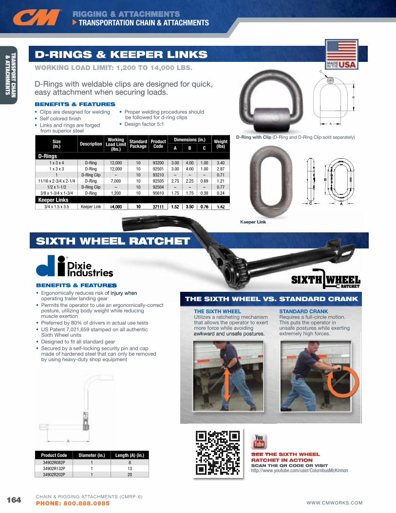
RIGGING & ATTACHMENTS
164 WWW.CMWORKS.COM
TRANSPORTATION CHAIN & ATTACHMENTS
CHAIN & RIGGING ATTACHMENTS (CMRP-6)
PHONE: 800.888.0985
TRANSPORT CHAIN &
ATTACHMENTS
Product Code Diameter (in.) Length (A) (in.)34902R082P 1 834902R132P 1 1334902R202P 1 20
Ergonomically reduces risk of injury when operating trailer landing gear
Permits the operator to use an ergonomically-correct posture, utilizing body weight while reducing muscle exertion
Preferred by 80% of drivers in actual use tests US Patent 7,021,659 stamped on all authentic
Sixth Wheel units Designed to fit all standard gear Secured by a self-locking security pin and cap
made of hardened steel that can only be removed by using heavy-duty shop equipment
bENEfITS & fEATuRES
SIXTH wHEEl RATCHET
Size(in.) Description
Working Load Limit
(lbs.)
StandardPackage
Product Code
Dimensions (in.) Weight (lbs)A B C
D-Rings1 x 3 x 4 D-Ring 12,000 10 93200 3.00 4.00 1.00 3.401 x 3 x 3 D-Ring 12,000 10 92501 3.00 4.00 1.00 2.87
1 D-Ring Clip – 10 93210 – – – 0.7111/16 x 2-3/4 x 2-1/4 D-Ring 7,000 10 92505 2.75 2.25 0.69 1.21
1/2 x 1-1/2 D-Ring Clip – 10 92504 – – – 0.773/8 x 1-3/4 x 1-3/4 D-Ring 1,200 10 95610 1.75 1.75 0.38 0.24
Keeper Links3/4 x 1.5 x 3.5 Keeper Link 14,000 10 37111 1.52 3.50 0.76 1.42
WORKING LOAD LIMIT: 1,200 TO 14,000 LbS.
d-RINGS & KEEPER lINKS
bENEfITS & fEATuRES Clips are designed for welding Self colored finish Links and rings are forged
from superior steel
Proper welding procedures should be followed for d-ring clips
Design factor 5:1
D-Rings with weldable clips are designed for quick, easy attachment when securing loads.
Ergonomically reduces risk of injury when operating trailer landing gear
RES
HEEl RATCHET
14,000 10 37111 1.52 3.50 0.76 1.42
STANDARD CRANK Requires a full-circle motion. This puts the operator in unsafe postures while exerting extremely high forces.
THE SIXTH WHEELUtilizes a ratcheting mechanism that allows the operator to exert more force while avoiding awkward and unsafe postures.more force while avoiding awkward and unsafe postures.awkward and unsafe postures.
THE SIXTH wHEEl vS. STANdARd CRANK
SEE THE SIXTH wHEEl RATCHET IN ACTIoNSCAN THE QR CodE oR vISIThttp://www.youtube.com/user/ColumbusMcKinnon
SEE TH
D-Ring with Clip (D-Ring and D-Ring Clip sold separately)
Keeper Link
C
B
A
Keeper Link
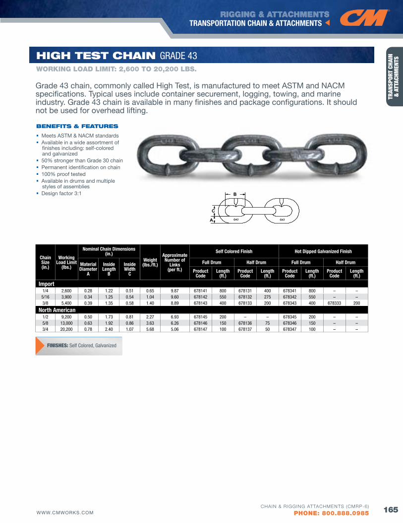
RIGGING & ATTACHMENTS
165WWW.CMWORKS.COM
TRANSPORTATION CHAIN & ATTACHMENTS
CHAIN & RIGGING ATTACHMENTS (CMRP-6)
PHONE: 800.888.0985
TRAN
SPOR
T CH
AIN
&
ATT
ACHM
ENTS
Grade 43 chain, commonly called High Test, is manufactured to meet ASTM and NACM specifications. Typical uses include container securement, logging, towing, and marine industry. Grade 43 chain is available in many finishes and package configurations. It should not be used for overhead lifting.
B
C
A
Chain Size(in.)
Working Load Limit
(lbs.)
Nominal Chain Dimensions (in.)
Weight(lbs./ft.)
Approximate Number of
Links(per ft.)
Self Colored finish Hot Dipped Galvanized finish
Material Diameter
A
Inside Length
B
Inside Width
C
full Drum Half Drum full Drum Half Drum
ProductCode
Length(ft.)
ProductCode
Length(ft.)
ProductCode
Length(ft.)
ProductCode
Length(ft.)
Import1/4 2,600 0.28 1.22 0.51 0.65 9.87 678141 800 678131 400 678341 800 – –
5/16 3,900 0.34 1.25 0.54 1.04 9.60 678142 550 678132 275 678342 550 – –3/8 5,400 0.39 1.35 0.58 1.40 8.89 678143 400 678133 200 678343 400 678333 200
North American1/2 9,200 0.50 1.73 0.81 2.27 6.93 678145 200 – – 678345 200 – –5/8 13,000 0.63 1.92 0.86 3.63 6.26 678146 150 678136 75 678346 150 – –3/4 20,200 0.78 2.40 1.07 5.68 5.06 678147 100 678137 50 678347 100 – –
Meets ASTM & NACM standards Available in a wide assortment of
finishes including: self-colored and galvanized
50% stronger than Grade 30 chain Permanent identification on chain 100% proof tested Available in drums and multiple
styles of assemblies Design factor 3:1
bENEfITS & fEATuRES
WORKING LOAD LIMIT: 2,600 TO 20,200 LbS.
HIGH TEST CHAIN GRADE 43
FINISHES: Self Colored, Galvanized
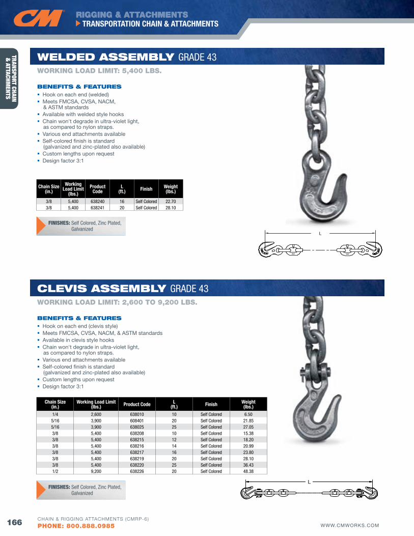
RIGGING & ATTACHMENTS
166 WWW.CMWORKS.COM
TRANSPORTATION CHAIN & ATTACHMENTS
CHAIN & RIGGING ATTACHMENTS (CMRP-6)
PHONE: 800.888.0985
TRANSPORT CHAIN &
ATTACHMENTS
L
L
Chain Size(in.)
Working Load Limit(lbs.) Product Code L
(ft.) finish Weight(lbs.)
1/4 2,600 638010 10 Self Colored 6.505/16 3,900 608401 20 Self Colored 21.855/16 3,900 638025 25 Self Colored 27.053/8 5,400 638208 10 Self Colored 15.383/8 5,400 638215 12 Self Colored 18.203/8 5,400 638216 14 Self Colored 20.993/8 5,400 638217 16 Self Colored 23.803/8 5,400 638219 20 Self Colored 28.103/8 5,400 638220 25 Self Colored 36.431/2 9,200 638226 20 Self Colored 48.38
Chain Size(in.)
Working Load Limit
(lbs.)Product
CodeL
(ft.) finish Weight(lbs.)
3/8 5,400 638240 16 Self Colored 22.703/8 5,400 638241 20 Self Colored 28.10
Hook on each end (clevis style) Meets FMCSA, CvSA, NACM, & ASTM standards Available in clevis style hooks Chain won't degrade in ultra-violet light,
as compared to nylon straps. various end attachments available Self-colored finish is standard
(galvanized and zinc-plated also available) Custom lengths upon request Design factor 3:1
bENEfITS & fEATuRES
WORKING LOAD LIMIT: 2,600 TO 9,200 LbS.
ClEvIS ASSEMbly GRADE 43
Hook on each end (welded) Meets FMCSA, CvSA, NACM,
& ASTM standards Available with welded style hooks Chain won't degrade in ultra-violet light,
as compared to nylon straps. various end attachments available Self-colored finish is standard
(galvanized and zinc-plated also available) Custom lengths upon request Design factor 3:1
bENEfITS & fEATuRES
WORKING LOAD LIMIT: 5,400 LbS.
wEldEd ASSEMbly GRADE 43
FINISHES: Self Colored, zinc Plated, Galvanized
FINISHES: Self Colored, zinc Plated, Galvanized
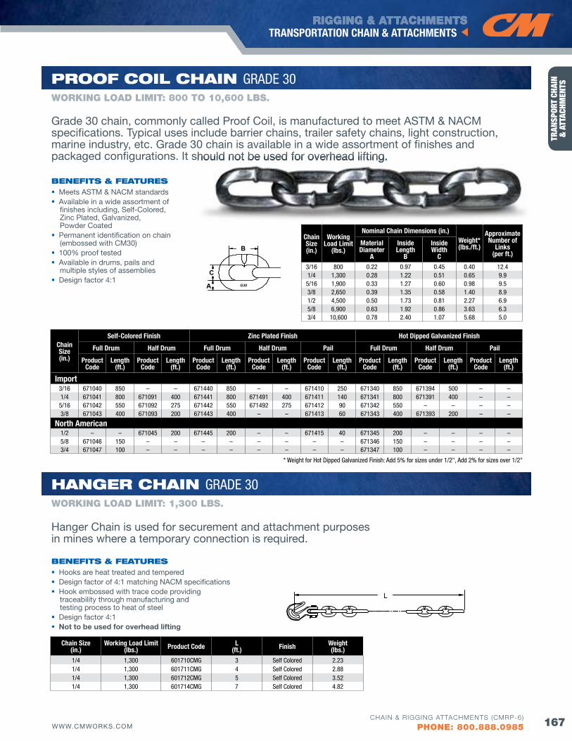
RIGGING & ATTACHMENTS
167WWW.CMWORKS.COM
TRANSPORTATION CHAIN & ATTACHMENTS
CHAIN & RIGGING ATTACHMENTS (CMRP-6)
PHONE: 800.888.0985
TRAN
SPOR
T CH
AIN
&
ATT
ACHM
ENTS
L
B
C
A
Chain Size(in.)
Working Load Limit
(lbs.)
Nominal Chain Dimensions (in.)Weight*(lbs./ft.)
Approximate Number of
Links(per ft.)
Material Diameter
A
Inside Length
B
Inside Width
C3/16 800 0.22 0.97 0.45 0.40 12.41/4 1,300 0.28 1.22 0.51 0.65 9.95/16 1,900 0.33 1.27 0.60 0.98 9.53/8 2,650 0.39 1.35 0.58 1.40 8.91/2 4,500 0.50 1.73 0.81 2.27 6.95/8 6,900 0.63 1.92 0.86 3.63 6.33/4 10,600 0.78 2.40 1.07 5.68 5.0
Chain Size(in.)
Working Load Limit(lbs.) Product Code L
(ft.) finish Weight(lbs.)
1/4 1,300 601710CMG 3 Self Colored 2.231/4 1,300 601711CMG 4 Self Colored 2.881/4 1,300 601712CMG 5 Self Colored 3.521/4 1,300 601714CMG 7 Self Colored 4.82
Chain Size(in.)
Self-Colored finish zinc Plated finish Hot Dipped Galvanized finish
full Drum Half Drum full Drum Half Drum Pail full Drum Half Drum Pail
Product Code
Length(ft.)
Product Code
Length(ft.)
Product Code
Length(ft.)
Product Code
Length(ft.)
Product Code
Length(ft.)
Product Code
Length(ft.)
Product Code
Length(ft.)
Product Code
Length(ft.)
Import3/16 671040 850 – – 671440 850 – – 671410 250 671340 850 671394 500 – –1/4 671041 800 671091 400 671441 800 671491 400 671411 140 671341 800 671391 400 – –5/16 671042 550 671092 275 671442 550 671492 275 671412 90 671342 550 – – – –3/8 671043 400 671093 200 671443 400 – – 671413 60 671343 400 671393 200 – –
North American1/2 – – 671045 200 671445 200 – – 671415 40 671345 200 – – – –5/8 671046 150 – – – – – – – – 671346 150 – – – –3/4 671047 100 – – – – – – – – 671347 100 – – – –
Hooks are heat treated and tempered Design factor of 4:1 matching NACM specifications Hook embossed with trace code providing
traceability through manufacturing and testing process to heat of steel
Design factor 4:1 Not to be used for overhead lifting
bENEfITS & fEATuRES
WORKING LOAD LIMIT: 1,300 LbS.
HANGER CHAIN GRADE 30
Grade 30 chain, commonly called Proof Coil, is manufactured to meet ASTM & NACM specifications. Typical uses include barrier chains, trailer safety chains, light construction, marine industry, etc. Grade 30 chain is available in a wide assortment of finishes and packaged configurations. It should not be used for overhead lifting.
Hanger Chain is used for securement and attachment purposes in mines where a temporary connection is required.
bENEfITS & fEATuRES
WORKING LOAD LIMIT: 800 TO 10,600 LbS.
PRoof CoIl CHAIN GRADE 30
Meets ASTM & NACM standards Available in a wide assortment of
finishes including, Self-Colored, Zinc Plated, Galvanized, Powder Coated
Permanent identification on chain (embossed with CM30)
100% proof tested Available in drums, pails and
multiple styles of assemblies Design factor 4:1
packaged configurations. It should not be used for overhead lifting.
* Weight for Hot Dipped Galvanized Finish: Add 5% for sizes under 1/2", Add 2% for sizes over 1/2"
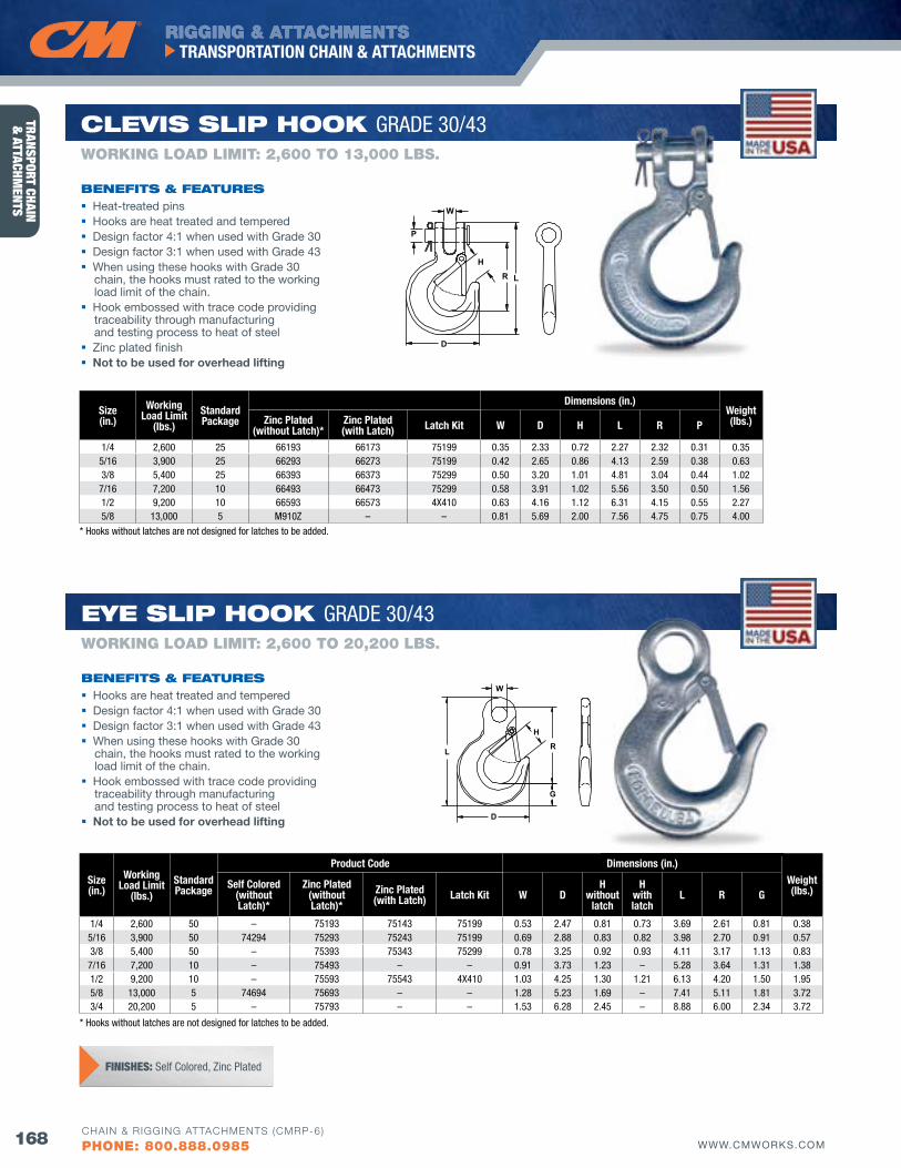
RIGGING & ATTACHMENTS
168 WWW.CMWORKS.COM
TRANSPORTATION CHAIN & ATTACHMENTS
CHAIN & RIGGING ATTACHMENTS (CMRP-6)
PHONE: 800.888.0985
TRANSPORT CHAIN &
ATTACHMENTS
H
L
W
R
D
P
Size(in.)
Working Load Limit
(lbs.)StandardPackage
Dimensions (in.)Weight(lbs.)zinc Plated
(without Latch)*zinc Plated (with Latch) Latch Kit W D H L R P
1/4 2,600 25 66193 66173 75199 0.35 2.33 0.72 2.27 2.32 0.31 0.355/16 3,900 25 66293 66273 75199 0.42 2.65 0.86 4.13 2.59 0.38 0.633/8 5,400 25 66393 66373 75299 0.50 3.20 1.01 4.81 3.04 0.44 1.02
7/16 7,200 10 66493 66473 75299 0.58 3.91 1.02 5.56 3.50 0.50 1.561/2 9,200 10 66593 66573 4X410 0.63 4.16 1.12 6.31 4.15 0.55 2.275/8 13,000 5 M910z – – 0.81 5.69 2.00 7.56 4.75 0.75 4.00
Size(in.)
Working Load Limit
(lbs.)StandardPackage
Product Code Dimensions (in.)
Weight(lbs.)Self Colored
(without Latch)*
zinc Plated(without Latch)*
zinc Plated (with Latch) Latch Kit W D
Hwithout
latch
Hwithlatch
L R G
1/4 2,600 50 – 75193 75143 75199 0.53 2.47 0.81 0.73 3.69 2.61 0.81 0.385/16 3,900 50 74294 75293 75243 75199 0.69 2.88 0.83 0.82 3.98 2.70 0.91 0.573/8 5,400 50 – 75393 75343 75299 0.78 3.25 0.92 0.93 4.11 3.17 1.13 0.83
7/16 7,200 10 – 75493 – – 0.91 3.73 1.23 – 5.28 3.64 1.31 1.381/2 9,200 10 – 75593 75543 4X410 1.03 4.25 1.30 1.21 6.13 4.20 1.50 1.955/8 13,000 5 74694 75693 – – 1.28 5.23 1.69 – 7.41 5.11 1.81 3.723/4 20,200 5 – 75793 – – 1.53 6.28 2.45 – 8.88 6.00 2.34 3.72
bENEfITS & fEATuRES
WORKING LOAD LIMIT: 2,600 TO 13,000 LbS.
ClEvIS SlIP HooK GRADE 30/43
Heat-treated pins Hooks are heat treated and tempered Design factor 4:1 when used with Grade 30 Design factor 3:1 when used with Grade 43 When using these hooks with Grade 30
chain, the hooks must rated to the working load limit of the chain.
Hook embossed with trace code providing traceability through manufacturing and testing process to heat of steel
Zinc plated finish Not to be used for overhead lifting
FINISHES: Self Colored, zinc Plated
H
L
W
R
D
G
Hooks are heat treated and tempered Design factor 4:1 when used with Grade 30 Design factor 3:1 when used with Grade 43 When using these hooks with Grade 30
chain, the hooks must rated to the working load limit of the chain.
Hook embossed with trace code providing traceability through manufacturing and testing process to heat of steel
Not to be used for overhead lifting
bENEfITS & fEATuRES
WORKING LOAD LIMIT: 2,600 TO 20,200 LbS.
EyE SlIP HooK GRADE 30/43
* Hooks without latches are not designed for latches to be added.
* Hooks without latches are not designed for latches to be added.
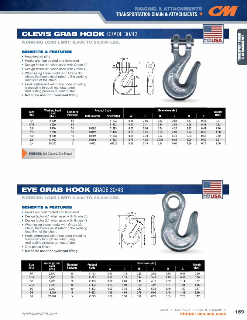
RIGGING & ATTACHMENTS
169WWW.CMWORKS.COM
TRANSPORTATION CHAIN & ATTACHMENTS
CHAIN & RIGGING ATTACHMENTS (CMRP-6)
PHONE: 800.888.0985
TRAN
SPOR
T CH
AIN
&
ATT
ACHM
ENTS
H
L
W
R
D
P
Size(in.)
Working Load Limit(lbs.)
StandardPackage
Product Code Dimensions (in.) Weight(lbs.)Self Colored zinc Plated W D H L R P
1/4 2,600 50 – 61193 0.36 2.05 0.37 2.88 1.57 0.31 0.375/16 3,900 50 – 61293 0.42 2.41 0.44 3.52 1.98 0.38 0.633/8 5,400 50 60392 61393 0.50 2.94 0.54 4.20 2.23 0.44 1.107/16 7,200 10 60492 61493 0.58 3.25 0.59 4.93 2.94 0.50 1.601/2 9,200 10 60592 61593 0.66 3.70 0.67 5.43 2.93 0.55 2.425/8 13,000 10 60692 61693 0.75 4.25 0.781 6.88 4.00 0.69 3.613/4 20,200 5 M812 M812z 0.88 5.19 0.94 8.00 4.56 0.75 7.00
Size(in.)
Working Load Limit(lbs.)
StandardPackage
ProductCode
Dimensions (in.) Weight(lbs.)W D H L R G
1/4 2,600 50 71193 0.47 1.78 0.35 2.85 1.78 0.81 0.30 5/16 3,900 50 71293 0.61 2.19 0.44 3.47 2.19 0.98 0.56 3/8 5,400 50 71393 0.82 2.86 0.49 4.13 2.69 1.14 0.87
7/16 7,200 10 71493 0.83 2.99 0.59 4.97 3.21 1.34 1.45 1/2 9,200 10 71593 0.93 3.34 0.67 5.38 3.40 1.50 2.17 5/8 13,000 5 71693 1.16 4.63 0.76 6.95 4.49 1.88 3.89 3/4 20,200 5 71793 1.38 5.50 0.98 8.28 5.35 2.28 6.12
H
L
W
R
D
G
bENEfITS & fEATuRES
WORKING LOAD LIMIT: 2,600 TO 20,200 LbS.
EyE GRAb HooK GRADE 30/43
bENEfITS & fEATuRES
WORKING LOAD LIMIT: 2,600 TO 20,200 LbS.
ClEvIS GRAb HooK GRADE 30/43
Heat-treated pins Hooks are heat treated and tempered Design factor 4:1 when used with Grade 30 Design factor 3:1 when used with Grade 43 When using these hooks with Grade 30
chain, the hooks must rated to the working load limit of the chain.
Hook embossed with trace code providing traceability through manufacturing and testing process to heat of steel
Not to be used for overhead lifting
Hooks are heat treated and tempered Design factor 4:1 when used with Grade 30 Design factor 3:1 when used with Grade 43 When using these hooks with Grade 30
chain, the hooks must rated to the working load limit of the chain.
Hook embossed with trace code providing traceability through manufacturing and testing process to heat of steel
Zinc plated finish Not to be used for overhead lifting
Dimensions (in.)
FINISHES: Self Colored, zinc Plated
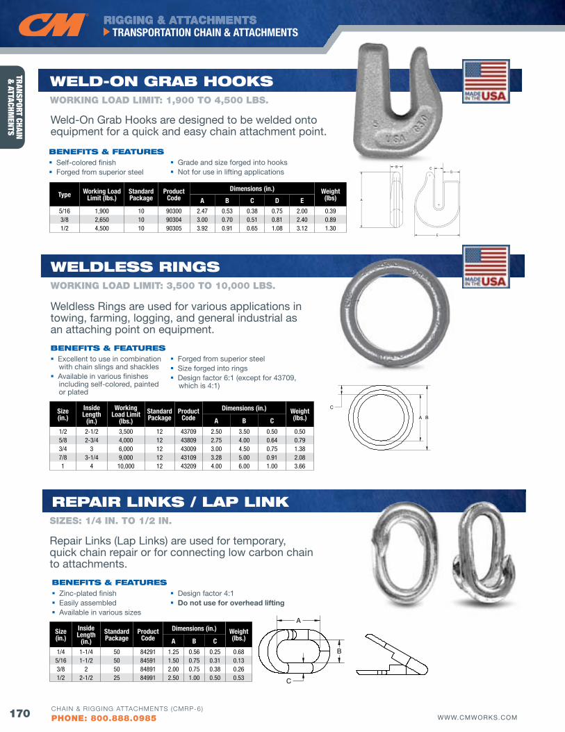
RIGGING & ATTACHMENTS
170 WWW.CMWORKS.COM
TRANSPORTATION CHAIN & ATTACHMENTS
CHAIN & RIGGING ATTACHMENTS (CMRP-6)
PHONE: 800.888.0985
TRANSPORT CHAIN &
ATTACHMENTS
bENEfITS & fEATuRES Self-colored finish Forged from superior steel
Grade and size forged into hooks Not for use in lifting applications
Type Working Load Limit (lbs.)
StandardPackage
Product Code
Dimensions (in.) Weight (lbs)A B C D E
5/16 1,900 10 90300 2.47 0.53 0.38 0.75 2.00 0.393/8 2,650 10 90304 3.00 0.70 0.51 0.81 2.40 0.891/2 4,500 10 90305 3.92 0.91 0.65 1.08 3.12 1.30
WORKING LOAD LIMIT: 1,900 TO 4,500 LbS.
wEld-oN GRAb HooKS
Size(in.)
InsideLength
(in.)
WorkingLoad Limit
(lbs.)Standard Package
Product Code
Dimensions (in.) Weight(lbs.)A B C
1/2 2-1/2 3,500 12 43709 2.50 3.50 0.50 0.505/8 2-3/4 4,000 12 43809 2.75 4.00 0.64 0.793/4 3 6,000 12 43009 3.00 4.50 0.75 1.387/8 3-1/4 9,000 12 43109 3.28 5.00 0.91 2.081 4 10,000 12 43209 4.00 6.00 1.00 3.66
wEldlESS RINGS
bENEfITS & fEATuRES Excellent to use in combination
with chain slings and shackles Available in various finishes
including self-colored, painted or plated
Forged from superior steel Size forged into rings Design factor 6:1 (except for 43709,
which is 4:1)
WORKING LOAD LIMIT: 3,500 TO 10,000 LbS.
Weldless Rings are used for various applications in towing, farming, logging, and general industrial as an attaching point on equipment.
Weld-On Grab Hooks are designed to be welded onto equipment for a quick and easy chain attachment point.
Size(in.)
InsideLength
(in.)Standard Package
ProductCode
Dimensions (in.) Weight(lbs.)A B C
1/4 1-1/4 50 84291 1.25 0.56 0.25 0.685/16 1-1/2 50 84591 1.50 0.75 0.31 0.133/8 2 50 84891 2.00 0.75 0.38 0.261/2 2-1/2 25 84991 2.50 1.00 0.50 0.53
REPAIR lINKS / lAP lINK
bENEfITS & fEATuRES Zinc-plated finish Easily assembled Available in various sizes
Design factor 4:1 Do not use for overhead lifting
SIZES: 1/4 IN. TO 1/2 IN.
Repair Links (Lap Links) are used for temporary, quick chain repair or for connecting low carbon chain to attachments.
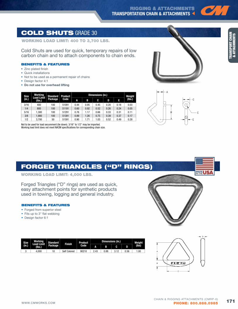
RIGGING & ATTACHMENTS
171WWW.CMWORKS.COM
TRANSPORTATION CHAIN & ATTACHMENTS
CHAIN & RIGGING ATTACHMENTS (CMRP-6)
PHONE: 800.888.0985
TRAN
SPOR
T CH
AIN
&
ATT
ACHM
ENTS
Size(in.)
WorkingLoad Limit
(lbs.)Standard Package
ProductCode
Dimensions (in.) Weight(lbs.)A B C D E
3/16 400 100 51091 0.44 0.95 0.45 0.20 0.18 0.031/4 800 100 51191 0.60 0.92 0.52 0.26 0.24 0.05
5/16 1,300 100 51291 0.76 1.17 0.66 0.33 0.31 0.113/8 1,900 100 51391 0.89 1.26 0.75 0.39 0.37 0.171/2 3,700 50 51591 0.90 1.71 1.03 0.52 0.49 0.28
Cold SHuTS GRADE 30
bENEfITS & fEATuRES Zinc plated finish Quick installations Not to be used as a permanent repair of chains Design factor 4:1 Do not use for overhead lifting
Not to be used for load securement (tie down). 3/16" to 1/2" may be imported. Working load limit does not meet NACM specifications for corresponding chain size.
WORKING LOAD LIMIT: 400 TO 3,700 LbS.
Cold Shuts are used for quick, temporary repairs of low carbon chain and to attach components to chain ends.
Size(in.)
Working Load Limit
(lbs.)StandardPackage finish Product
CodeDimensions (in.) Weight
(lbs)A B C D
3 4,000 10 Self Colored 90210 2.43 0.88 3.12 0.56 1.00
WORKING LOAD LIMIT: 4,000 LbS.
foRGEd TRIANGlES (“d” RINGS)
bENEfITS & fEATuRES Forged from superior steel Fits up to 3" flat webbing Design factor 6:1
Forged Triangles (“D” rings) are used as quick, easy attachment points for synthetic products used in towing, logging and general industry.
RINGS)
Winch Line/Tail Chain ..........................................................174
Straight Link Machine Chain ...............................................174
Straight Link Coil Chain .......................................................174
Sash Chain ..........................................................................175
Buoy Chain ..........................................................................175
Cast Drive Sprocket ............................................................176
Drive Sprocket - Replaceable Teeth ....................................176
Long Wall Mining Chain .......................................................177
Padless Shackle Connectors ..............................................178
Special Chain Connector ....................................................179
Grinding Mill Liner Bolts .....................................................179
SPECIAlTy CHAIN &CoMPoNENTS
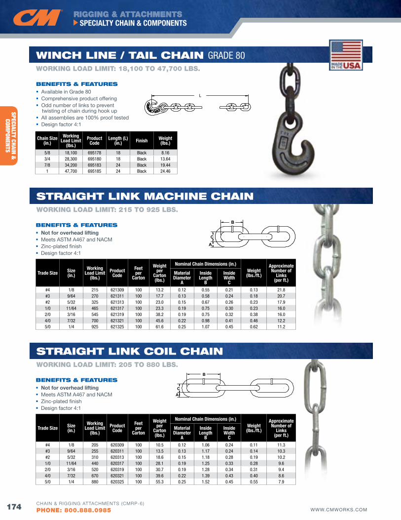
RIGGING & ATTACHMENTS
174 WWW.CMWORKS.COM
SPECIALTY CHAIN & COMPONENTS
CHAIN & RIGGING ATTACHMENTS (CMRP-6)
PHONE: 800.888.0985
SPECIALTY CHAIN &
COMPONENTS
L
Chain Size(in.)
Working Load Limit
(lbs.)Product
CodeLength (L)
(in.) finish Weight(lbs.)
5/8 18,100 695178 18 Black 8.163/4 28,300 695180 18 Black 13.647/8 34,200 695183 24 Black 19.441 47,700 695185 24 Black 24.46
bENEfITS & fEATuRES
bENEfITS & fEATuRES
bENEfITS & fEATuRES
WORKING LOAD LIMIT: 18,100 TO 47,700 LbS.
wINCH lINE / TAIl CHAIN GRADE 80
Available in Grade 80 Comprehensive product offering Odd number of links to prevent
twisting of chain during hook up All assemblies are 100% proof tested Design factor 4:1
Not for overhead lifting Meets ASTM A467 and NACM Zinc-plated finish Design factor 4:1
Not for overhead lifting Meets ASTM A467 and NACM Zinc-plated finish Design factor 4:1
B
CA
Trade Size Size(in.)
Working Load Limit
(lbs.)Product
Codefeetper
Carton
Weight per
Carton(lbs.)
Nominal Chain Dimensions (in.)Weight(lbs./ft.)
Approximate Number of
Links(per ft.)
Material Diameter
A
Inside Length
B
Inside Width
C#4 1/8 215 621309 100 13.2 0.12 0.55 0.21 0.13 21.8#3 9/64 270 621311 100 17.7 0.13 0.58 0.24 0.18 20.7#2 5/32 325 621313 100 23.0 0.15 0.67 0.26 0.23 17.91/0 11/64 465 621317 100 23.3 0.19 0.75 0.30 0.23 16.02/0 3/16 545 621319 100 38.2 0.19 0.75 0.32 0.38 16.04/0 7/32 700 621321 100 45.6 0.22 0.98 0.41 0.46 12.25/0 1/4 925 621325 100 61.6 0.25 1.07 0.45 0.62 11.2
Trade Size Size(in.)
Working Load Limit
(lbs.)Product
Codefeetper
Carton
Weight per
Carton(lbs.)
Nominal Chain Dimensions (in.)Weight(lbs./ft.)
Approximate Number of
Links(per ft.)
Material Diameter
A
Inside Length
B
Inside Width
C#4 1/8 205 620309 100 10.5 0.12 1.06 0.24 0.11 11.3#3 9/64 255 620311 100 13.5 0.13 1.17 0.24 0.14 10.3#2 5/32 310 620313 100 18.6 0.15 1.18 0.28 0.19 10.21/0 11/64 440 620317 100 28.1 0.19 1.25 0.33 0.28 9.62/0 3/16 520 620319 100 30.7 0.19 1.28 0.34 0.31 9.44/0 7/32 670 620321 100 39.6 0.22 1.39 0.43 0.40 8.65/0 1/4 880 620325 100 55.3 0.25 1.52 0.45 0.55 7.9
WORKING LOAD LIMIT: 205 TO 880 LbS.
STRAIGHT lINK CoIl CHAIN
WORKING LOAD LIMIT: 215 TO 925 LbS.
STRAIGHT lINK MACHINE CHAIN
B
CA
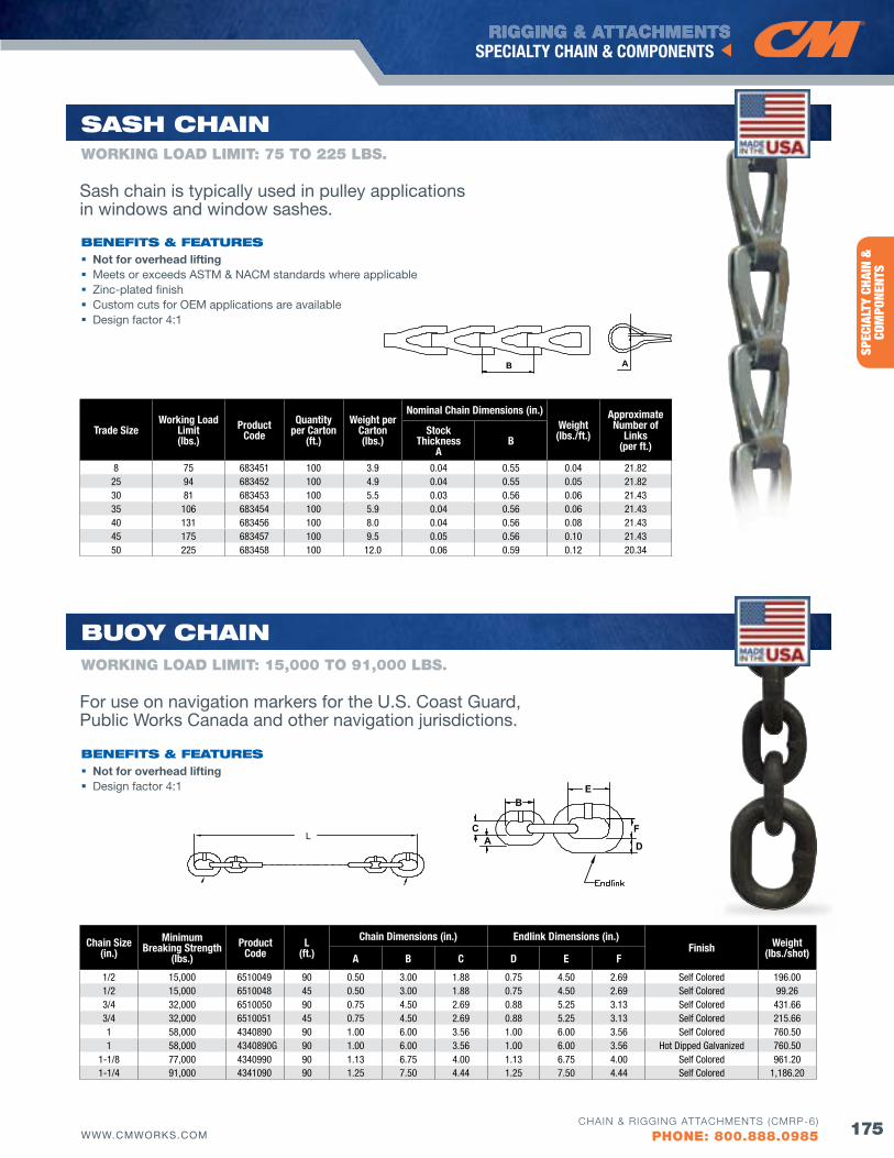
RIGGING & ATTACHMENTS
175WWW.CMWORKS.COM
SPECIALTY CHAIN & COMPONENTS
CHAIN & RIGGING ATTACHMENTS (CMRP-6)
PHONE: 800.888.0985
SPEC
IALT
Y CH
AIN
&
COM
PONE
NTS
B A
L
Chain Size(in.)
Minimum Breaking Strength
(lbs.)Product
CodeL
(ft.)
Chain Dimensions (in.) Endlink Dimensions (in.)finish Weight
(lbs./shot)A B C D E f
1/2 15,000 6510049 90 0.50 3.00 1.88 0.75 4.50 2.69 Self Colored 196.001/2 15,000 6510048 45 0.50 3.00 1.88 0.75 4.50 2.69 Self Colored 99.263/4 32,000 6510050 90 0.75 4.50 2.69 0.88 5.25 3.13 Self Colored 431.663/4 32,000 6510051 45 0.75 4.50 2.69 0.88 5.25 3.13 Self Colored 215.661 58,000 4340890 90 1.00 6.00 3.56 1.00 6.00 3.56 Self Colored 760.501 58,000 4340890G 90 1.00 6.00 3.56 1.00 6.00 3.56 Hot Dipped Galvanized 760.50
1-1/8 77,000 4340990 90 1.13 6.75 4.00 1.13 6.75 4.00 Self Colored 961.201-1/4 91,000 4341090 90 1.25 7.50 4.44 1.25 7.50 4.44 Self Colored 1,186.20
Trade SizeWorking Load
Limit(lbs.)
Product Code
quantity per Carton
(ft.)
Weight per Carton(lbs.)
Nominal Chain Dimensions (in.)Weight(lbs./ft.)
Approximate Number of
Links(per ft.)
Stock Thickness
AB
8 75 683451 100 3.9 0.04 0.55 0.04 21.8225 94 683452 100 4.9 0.04 0.55 0.05 21.8230 81 683453 100 5.5 0.03 0.56 0.06 21.4335 106 683454 100 5.9 0.04 0.56 0.06 21.4340 131 683456 100 8.0 0.04 0.56 0.08 21.4345 175 683457 100 9.5 0.05 0.56 0.10 21.4350 225 683458 100 12.0 0.06 0.59 0.12 20.34
B
CA
E
F
D
buoy CHAIN
bENEfITS & fEATuRES
bENEfITS & fEATuRES
WORKING LOAD LIMIT: 75 TO 225 LbS.
SASH CHAIN
Sash chain is typically used in pulley applications in windows and window sashes.
For use on navigation markers for the U.S. Coast Guard, Public Works Canada and other navigation jurisdictions.
Not for overhead lifting Meets or exceeds ASTM & NACM standards where applicable Zinc-plated finish Custom cuts for OEM applications are available Design factor 4:1
Not for overhead lifting Design factor 4:1
WORKING LOAD LIMIT: 15,000 TO 91,000 LbS.
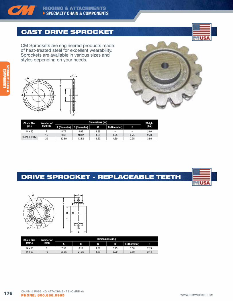
RIGGING & ATTACHMENTS
176 WWW.CMWORKS.COM
SPECIALTY CHAIN & COMPONENTS
CHAIN & RIGGING ATTACHMENTS (CMRP-6)
PHONE: 800.888.0985
SPECIALTY CHAIN &
COMPONENTS
CM Sprockets are engineered products made of heat-treated steel for excellent wearability. Sprockets are available in various sizes and styles depending on your needs.
A C
B
D
EF
Chain Size(mm.)
Number of Teeth
Dimensions (in.)
A B C D E (Diameter) f14 x 50 6 7.52 8.19 1.69 3.25 3.50 2.1914 x 50 16 20.05 21.35 1.69 6.00 3.50 2.44
dRIvE SPRoCKET - REPlACEAblE TEETH
Chain Size(in.)
Number of Pockets
Dimensions (in.) Weight(lbs.)A (Diameter) B (Diameter) C D (Diameter) E
14 x 50 7 8.77 9.62 1.88 – – 23.0
0.375 x 1.01215 9.66 10.32 1.50 4.25 2.75 25.020 12.89 13.52 1.50 4.50 2.75 38.0
AC
B
D
E
dRIvE SPRoCKETSCAST dRIvE SPRoCKET
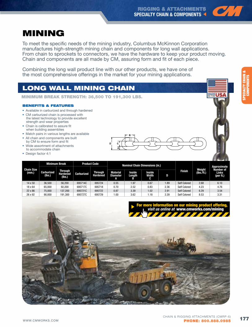
RIGGING & ATTACHMENTS
177WWW.CMWORKS.COM
SPECIALTY CHAIN & COMPONENTS
CHAIN & RIGGING ATTACHMENTS (CMRP-6)
PHONE: 800.888.0985
SPEC
IALT
Y CH
AIN
&
COM
PONE
NTS
B
C
A
D
To meet the specific needs of the mining industry, Columbus McKinnon Corporation manufactures high-strength mining chain and components for long wall applications. From chain to sprockets to connectors, we have the hardware to keep your product moving. Chain and components are all made by CM, assuring form and fit of each piece.
Combining the long wall product line with our other products, we have one of the most comprehensive offerings in the market for your mining applications.
Chain Size(mm.)
Minimum Break Product Code Nominal Chain Dimensions (in.)
finish Weight(lbs./ft.)
Approximate Number of
Links(per ft.)
Carburized(lbs.)
Through Hardened
(lbs.)Carburized Through
HardenedMaterial Diameter
A
Inside Length
B
Inside Width
CD
14 x 50 36,500 56,200 695714C 695724 0.55 1.97 0.67 1.89 Self Colored 2.68 6.1018 x 64 65,000 92,200 695717C 695718 0.70 2.52 0.83 2.36 Self Colored 4.23 4.7622 x 86 75,000 137,200 695721C 695722 0.87 3.39 1.02 2.91 Self Colored 6.29 3.5426 x 92 90,000 191,300 695727C 695729 1.00 3.62 1.18 3.39 Self Colored 8.53 3.31
bENEfITS & fEATuRES Available in carburized and through hardened CM carburized chain is processed with
the latest technology to provide excellent strength and wear properties
Chain is calibrated to assure fit when building assemblies
Match pairs in various lengths are available All chain and components are built
by CM to ensure form and fit Wide assortment of attachments
to accommodate chain Design factor 4:1
MINING
For more information on our mining product offering, visit us online at www.cmworks.com/mining
loNG wAll MINING CHAINMINIMuM bREAK STRENGTH: 36,500 TO 191,300 LbS.
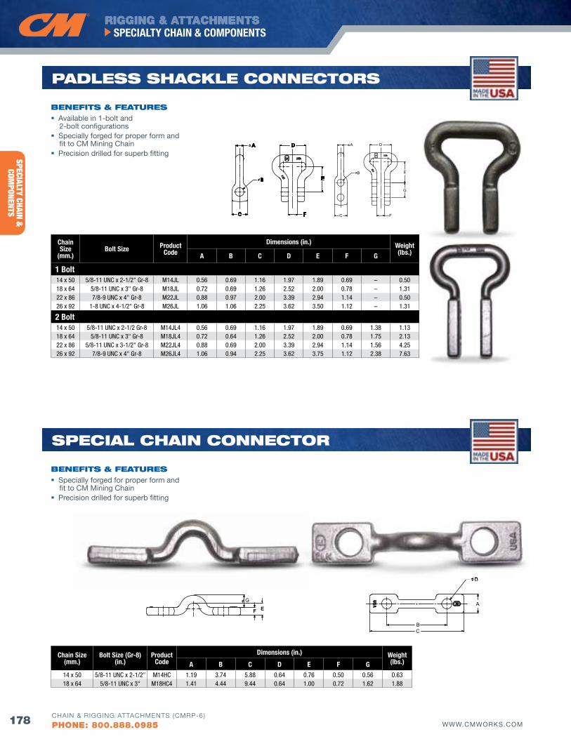
RIGGING & ATTACHMENTS
178 WWW.CMWORKS.COM
SPECIALTY CHAIN & COMPONENTS
CHAIN & RIGGING ATTACHMENTS (CMRP-6)
PHONE: 800.888.0985
SPECIALTY CHAIN &
COMPONENTS
bENEfITS & fEATuRES Available in 1-bolt and
2-bolt configurations Specially forged for proper form and
fit to CM Mining Chain Precision drilled for superb fitting
Chain Size(mm.)
Bolt Size (Gr-8)(in.)
Product Code
Dimensions (in.) Weight(lbs.)A B C D E f G
14 x 50 5/8-11 UNC x 2-1/2" M14HC 1.19 3.74 5.88 0.64 0.76 0.50 0.56 0.6318 x 64 5/8-11 UNC x 3" M18HC4 1.41 4.44 9.44 0.64 1.00 0.72 1.62 1.88
C
A
B E
F
D
C
A
B E
D
F
G
Chain Size
(mm.)Bolt Size Product
Code
Dimensions (in.) Weight(lbs.)A B C D E f G
1 Bolt14 x 50 5/8-11 UNC x 2-1/2" Gr-8 M14JL 0.56 0.69 1.16 1.97 1.89 0.69 – 0.5018 x 64 5/8-11 UNC x 3" Gr-8 M18JL 0.72 0.69 1.26 2.52 2.00 0.78 – 1.3122 x 86 7/8-9 UNC x 4" Gr-8 M22JL 0.88 0.97 2.00 3.39 2.94 1.14 – 0.5026 x 92 1-8 UNC x 4-1/2" Gr-8 M26JL 1.06 1.06 2.25 3.62 3.50 1.12 – 1.31
2 Bolt14 x 50 5/8-11 UNC x 2-1/2 Gr-8 M14JL4 0.56 0.69 1.16 1.97 1.89 0.69 1.38 1.1318 x 64 5/8-11 UNC x 3" Gr-8 M18JL4 0.72 0.64 1.26 2.52 2.00 0.78 1.75 2.1322 x 86 5/8-11 UNC x 3-1/2" Gr-8 M22JL4 0.88 0.69 2.00 3.39 2.94 1.14 1.56 4.2526 x 92 7/8-9 UNC x 4" Gr-8 M26JL4 1.06 0.94 2.25 3.62 3.75 1.12 2.38 7.63
SPECIAl CHAIN CoNNECToR
D
B
A
C
GEF
PAdlESS SHACKlE CoNNECToRS
bENEfITS & fEATuRES Specially forged for proper form and
fit to CM Mining Chain Precision drilled for superb fitting
D
B
A
C
GEF
D
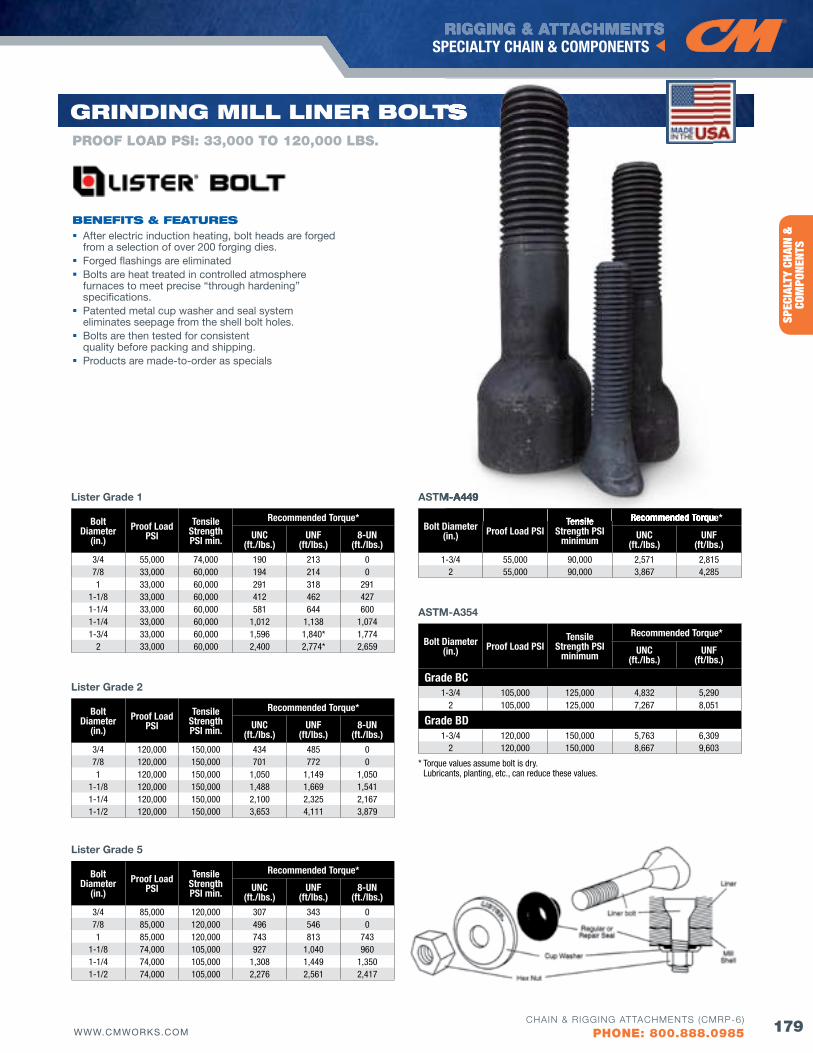
RIGGING & ATTACHMENTS
179WWW.CMWORKS.COM
SPECIALTY CHAIN & COMPONENTS
CHAIN & RIGGING ATTACHMENTS (CMRP-6)
PHONE: 800.888.0985
SPEC
IALT
Y CH
AIN
&
COM
PONE
NTS
Bolt Diameter
(in.)Proof Load
PSITensile
Strength PSI min.
Recommended Torque*
UNC(ft./lbs.)
UNf(ft/lbs.)
8-UN(ft./lbs.)
3/4 55,000 74,000 190 213 07/8 33,000 60,000 194 214 01 33,000 60,000 291 318 291
1-1/8 33,000 60,000 412 462 4271-1/4 33,000 60,000 581 644 6001-1/4 33,000 60,000 1,012 1,138 1,0741-3/4 33,000 60,000 1,596 1,840* 1,774
2 33,000 60,000 2,400 2,774* 2,659
Lister Grade 1
Bolt Diameter
(in.)Proof Load
PSITensile
Strength PSI min.
Recommended Torque*
UNC(ft./lbs.)
UNf(ft/lbs.)
8-UN(ft./lbs.)
3/4 85,000 120,000 307 343 07/8 85,000 120,000 496 546 01 85,000 120,000 743 813 743
1-1/8 74,000 105,000 927 1,040 9601-1/4 74,000 105,000 1,308 1,449 1,3501-1/2 74,000 105,000 2,276 2,561 2,417
Lister Grade 5
Bolt Diameter
(in.)Proof Load
PSITensile
Strength PSI min.
Recommended Torque*
UNC(ft./lbs.)
UNf(ft/lbs.)
8-UN(ft./lbs.)
3/4 120,000 150,000 434 485 07/8 120,000 150,000 701 772 01 120,000 150,000 1,050 1,149 1,050
1-1/8 120,000 150,000 1,488 1,669 1,5411-1/4 120,000 150,000 2,100 2,325 2,1671-1/2 120,000 150,000 3,653 4,111 3,879
Lister Grade 2
bENEfITS & fEATuRES
PROOf LOAD PSI: 33,000 TO 120,000 LbS.
GRINdING MIll lINER bolTS
After electric induction heating, bolt heads are forged from a selection of over 200 forging dies.
Forged flashings are eliminated Bolts are heat treated in controlled atmosphere
furnaces to meet precise “through hardening” specifications.
Patented metal cup washer and seal system eliminates seepage from the shell bolt holes.
Bolts are then tested for consistent quality before packing and shipping.
Products are made-to-order as specials
Bolt Diameter(in.) Proof Load PSI
Tensile Strength PSI
minimum
Recommended Torque*
UNC(ft./lbs.)
UNf(ft/lbs.)
1-3/4 55,000 90,000 2,571 2,8152 55,000 90,000 3,867 4,285
ASTM-A449
Bolt Diameter(in.) Proof Load PSI
Tensile Strength PSI
minimum
Recommended Torque*
UNC(ft./lbs.)
UNf(ft/lbs.)
Grade BC1-3/4 105,000 125,000 4,832 5,290
2 105,000 125,000 7,267 8,051
Grade BD1-3/4 120,000 150,000 5,763 6,309
2 120,000 150,000 8,667 9,603
ASTM-A354
* Torque values assume bolt is dry. Lubricants, planting, etc., can reduce these values.
TS
Tensile Recommended Torque*
ASTM-A449
RIGGING & ATTACHMENTS
180 WWW.CMWORKS.COM
ENTERTAINMENT RIGGING PRODUCTS
CHAIN & RIGGING ATTACHMENTS (CMRP-6)
PHONE: 800.888.0985
ENTERTAINMENT
RIGGING PRODUCTS
RIGGING & ATTACHMENTS
181WWW.CMWORKS.COM
ENTERTAINMENT RIGGING PRODUCTS
CHAIN & RIGGING ATTACHMENTS (CMRP-6)
PHONE: 800.888.0985
WIR
E RO
PEAT
TACH
MEN
TSEN
TERT
AINM
ENT
RIGG
ING
PROD
UCTS
S.T.A.C. Chain .....................................................................182
S.T.A.C. Chain Sets ............................................................182
Theatrical Shackles .............................................................183
ENTERTAINMENTRIGGINGPRoduCTS
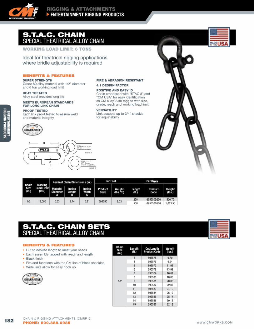
RIGGING & ATTACHMENTS
182 WWW.CMWORKS.COM
ENTERTAINMENT RIGGING PRODUCTS
CHAIN & RIGGING ATTACHMENTS (CMRP-6)
PHONE: 800.888.0985
ENTERTAINMENT
RIGGING PRODUCTS
Chain Size(in.)
Working Load Limit
(lbs.)
Nominal Chain Dimensions (in.) Per foot Per Drum
Product Code
Weight(lbs./ft.)
Length(ft.)
Product Code
Weight(lbs.)
Material Diameter
A
Inside Length
B
Inside Width
C
1/2 12,000 0.53 3.74 0.91 695550 2.03250 695550D250 506.75500 695550D500 1,013.50
Chain Size(in.)
Length(ft.)
Cut LengthProduct Code
Weight(lbs.)
1/2
3 695575 6.704 695576 9.945 695577 11.966 695578 13.997 695579 16.018 695580 18.039 695581 20.0510 695582 22.0711 695583 24.1012 695584 26.1213 695585 28.1414 695586 30.1615 695587 32.18
SUPER STRENGTHGrade 80 alloy material with 1/2" diameter and 6 ton working load limit
HEAT TREATEDAlloy steel provides long life
MEETS EUROPEAN STANDARDS fOR LONG LINK CHAIN
PROOf TESTEDEach link proof tested to assure weld and material integrity
fIRE & ABRASION RESISTANT
4:1 DESIGN fACTOR
POSITIVE AND EASY IDChain embossed with “STAC 8” and “CM USA” for easy identification as CM alloy. Also tagged with size, grade, reach and working load limit.
VERSATILITYLink accepts up to 3/4" shackle for adjustability
bENEfITS & fEATuRES
WORKING LOAD LIMIT: 6 TONS
S.T.A.C. CHAINSPECIAL THEATRICAL ALLOY CHAIN
S.T.A.C. CHAIN SETSSPECIAL THEATRICAL ALLOY CHAIN
Per Drum
Ideal for theatrical rigging applicationswhere bridle adjustability is required
Cut to desired length to meet your needs Each assembly tagged with reach and length Black finish Fits and functions with the CM line of black shackles Wide links allow for easy hook up
bENEfITS & fEATuRES
STAC 8
B
C
A
S.T.A.C.GRADE SPECIAL ALLOYSIZE 12.7COLUMBUS McKINNON
REACH ........... FT.LEGS 1WLL 6000 KgAT 90˚ TO HORIZONTAL
SIDE A
SIDE b
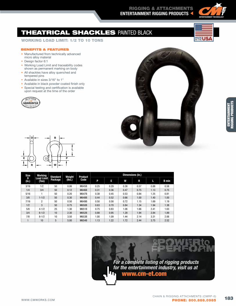
RIGGING & ATTACHMENTS
183WWW.CMWORKS.COM
ENTERTAINMENT RIGGING PRODUCTS
CHAIN & RIGGING ATTACHMENTS (CMRP-6)
PHONE: 800.888.0985
WIR
E RO
PEAT
TACH
MEN
TSEN
TERT
AINM
ENT
RIGG
ING
PROD
UCTS
bENEfITS & fEATuRES
E
D B
R W
L
P
THEATRICAl SHACKlES PAINTED BLACK
Manufactured from technically advanced micro alloy material
Design factor 6:1 Working Load Limit and traceability codes
shown as permanent marking on body All shackles have alloy quenched and
tempered pins Available in sizes 3/16" to 1" Available in black powder coated finish only Special testing and certification is available
upon request at the time of the order
WORKING LOAD LIMIT: 1/2 TO 10 TONS
SizeD
(in.)
Working Load Limit
(Ton)StandardPackage
Weight(lbs.)
Product Code
Dimensions (in.)
P E W R L B min
3/16 1/2 50 0.06 M645B 0.25 0.29 0.38 0.57 0.88 0.581/4 3/4 50 0.12 M646B 0.31 0.36 0.47 0.75 1.13 0.75
5/16 1 50 0.20 M647B 0.38 0.45 0.53 0.84 1.25 0.813/8 1-1/2 50 0.30 M648B 0.44 0.52 0.66 1.00 1.40 1.00
7/16 2 50 0.50 M649B 0.50 0.58 0.72 1.15 1.69 1.191/2 3 50 0.75 M650B 0.63 0.70 0.84 1.34 1.94 1.385/8 4-1/2 25 1.30 M651B 0.75 0.83 1.06 1.66 2.41 1.633/4 6-1/2 10 2.30 M652B 0.88 0.95 1.28 1.94 2.84 1.897/8 8-1/2 10 3.50 M653B 1.00 1.09 1.44 2.14 3.31 2.061 10 5 5.00 M654B 1.13 1.22 1.72 2.44 3.75 2.52
For a complete listing of rigging products for the entertainment industry, visit us at www.cm-et.com
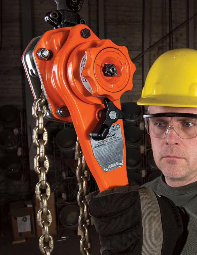

ElECTRIC HoIST ModEl CoMPARISoN ............................... 186-187
AIR HoIST ModEl CoMPARISoN ....................................... 189
lEvER HoIST ModEl CoMPARISoN ............................... 190-191
HANd CHAIN HoIST ModEl CoMPARISoN ............................... 192-193
RATCHET lEvER HoISTS CM Tornado 360° ................................................... 194-197
CM Bandit .............................................................. 198-201
HANd CHAIN HoISTS CM Hurricane 360˚ ............................................... 202-203
ClAMPS CTP Adjustable Trolley Clamp ....................................... 204
CM Beam Clamp ........................................................... 205
Screwlok Beam Clamp with Shackle ............................. 206
SC Series Twin Beam Clamp ......................................... 207
ProduCT SHowCaSEHoISTS, TRollEyS & bEAM ClAMPS
To see our full line of hoists, trolleys & beam clamps, visit us online at www.cmworks.com

ElECTRIC HoISTSMODEL COMPARISON
SHoPSTarElectric Chain Hoist
SHoPSTar vSElectric Chain Hoist
vaLuSTarElectric Chain Hoist
JLCElectric Chain Hoist
LodESTar Electric Chain Hoist
ECElectric Chain Hoist
186 WWW.CMWORKS.COMCHAIN & RIGGING ATTACHMENTS (CMRP-6)
PHONE: 800.888.0985
CAPACITY Speed (fpm) Reeving Speed (fpm) Reeving Speed (fpm) Reeving Speed (fpm) Reeving Speed (fpm) Reeving Speed (fpm) Reeving250 lb. 16, 24, 40 1300 lb. 16, 24, 40 1
500 lb. 8, 12, 16, 20, 24 1 & 2
3/8 ton600 lb. 8,12, 20 23/4 ton1,000 lb. 6, 8, 12 21/8 ton 32 1 32, 60 11/4 ton 16 1 16, 32 1 16, 32, 64 1 16, 32 11/2 ton 16 1 16, 32 1 9, 16, 32 1 8, 16, 32, 64 1 & 2
1 ton 8, 16 1 & 2 16 1 4, 8, 12, 16, 32, 48 1 & 2 8, 16, 32 1 & 2
2 ton 8 2 8 2 6, 8, 16, 24 1 & 2 8, 16 1 & 2
3 ton 5, 10, 16 2 & 3 5-1/2, 11 3
4 ton 8, 12 2
5 ton 5, 8 3
6 ton7-1/2 ton9 ton10 ton12 ton15 ton
STANDARD fEATURESTotal Enclosed Non-Vented Motor Standard Standard Standard Standard Standard
Total Enclosed fan Cooled Motor N/A N/A N/A ED Model Only N/A
Vane Motor N/AAdjustable Up/Down Limits N/A N/A Standard Standard Standard
Paddle Limits N/A N/A N/A N/A N/AWeather Proofing N/A N/A Weather-Resistant Cover Weather-Resistant Cover Standard
Load Chain Std. Unplated/Optional Plated Unplated Std. Unplated/Optional
PlatedStd. Unplated/Optional
Plated Standard zinc Plated
Chain Container Optional Optional Standard up to 20' Single Chain Optional Standard Fabric Bag
Powder Coat finish Standard Standard N/A N/A Standard
Variable frequency Drive Versions
N/A N/A Standard Offering Standard Offering Standard Offering
Two-Speed Version N/A N/A Standard Offering Standard Offering Standard Offering
Certification CUL N/A CSA CSA CSA/US, TUV, CE, RoHSMotor Brake DC AC Caliper Style AC Friction Disc AC Friction Disc DC Electric, Double OptionMechanical Load Brake N/A N/A N/A Standard N/A
Spark-Resistant features N/A N/A N/A N/A N/A
Upper Suspension Included Included Included Included Rigid Hook StandardOverload Clutch Standard Standard Standard Standard Standard Out of Load PathMetric Rated Standard Standard Optional Optional StandardSuspension Option Hook and Lug Hook and Lug Hook and Lug Hook and Lug Hook and LugWarranty Lifetime 1 Year Lifetime Lifetime Lifetime
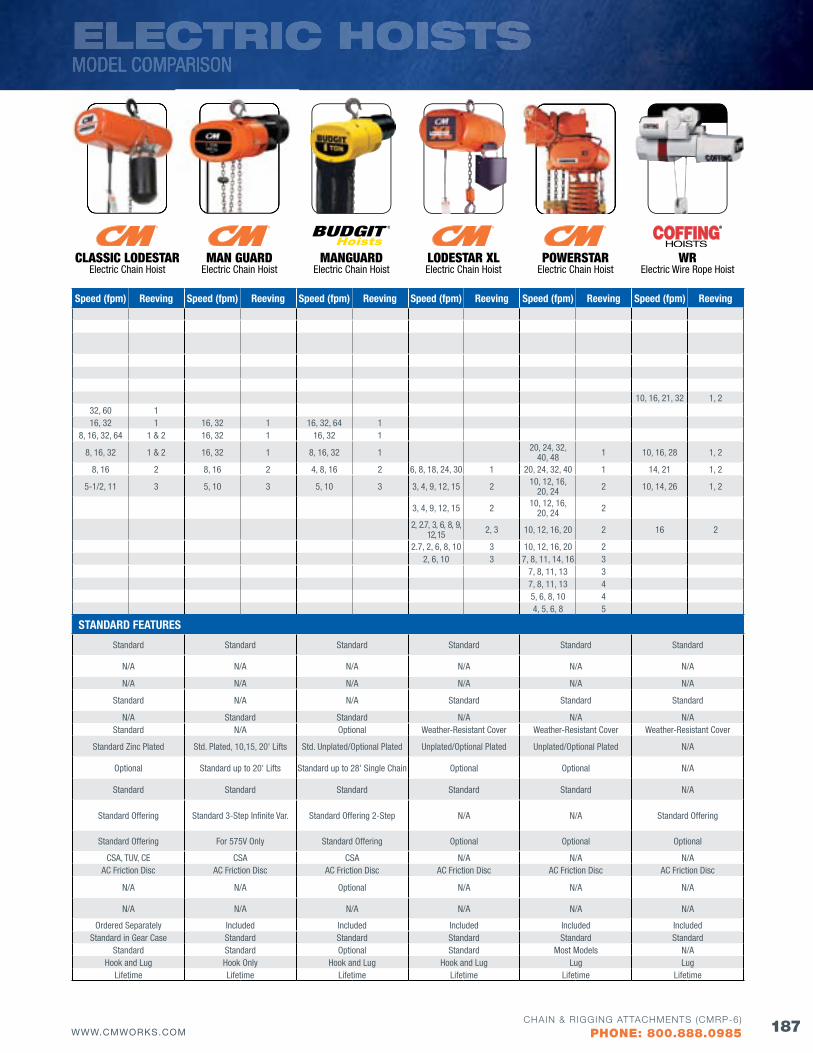
ELECTRIC HOISTSMODEL COMPARISON
MaN guardElectric Chain Hoist
CLaSSIC LodESTarElectric Chain Hoist
MaNguardElectric Chain Hoist
LodESTar XLElectric Chain Hoist
wrElectric Wire Rope Hoist
PowErSTarElectric Chain Hoist
187WWW.CMWORKS.COMCHAIN & RIGGING ATTACHMENTS (CMRP-6)
PHONE: 800.888.0985
Speed (fpm) Reeving Speed (fpm) Reeving Speed (fpm) Reeving Speed (fpm) Reeving Speed (fpm) Reeving Speed (fpm) Reeving
10, 16, 21, 32 1, 232, 60 116, 32 1 16, 32 1 16, 32, 64 1
8, 16, 32, 64 1 & 2 16, 32 1 16, 32 1
8, 16, 32 1 & 2 16, 32 1 8, 16, 32 1 20, 24, 32, 40, 48 1 10, 16, 28 1, 2
8, 16 2 8, 16 2 4, 8, 16 2 6, 8, 18, 24, 30 1 20, 24, 32, 40 1 14, 21 1, 2
5-1/2, 11 3 5, 10 3 5, 10 3 3, 4, 9, 12, 15 2 10, 12, 16, 20, 24 2 10, 14, 26 1, 2
3, 4, 9, 12, 15 2 10, 12, 16, 20, 24 2
2, 2.7, 3, 6, 8, 9, 12, 15 2, 3 10, 12, 16, 20 2 16 2
2.7, 2, 6, 8, 10 3 10, 12, 16, 20 22, 6, 10 3 7, 8, 11, 14, 16 3
7, 8, 11, 13 37, 8, 11, 13 45, 6, 8, 10 44, 5, 6, 8 5
STANDARD fEATURES
Standard Standard Standard Standard Standard Standard
N/A N/A N/A N/A N/A N/A
N/A N/A N/A N/A N/A N/A
Standard N/A N/A Standard Standard Standard
N/A Standard Standard N/A N/A N/AStandard N/A Optional Weather-Resistant Cover Weather-Resistant Cover Weather-Resistant Cover
Standard zinc Plated Std. Plated, 10,15, 20' Lifts Std. Unplated/Optional Plated Unplated/Optional Plated Unplated/Optional Plated N/A
Optional Standard up to 20' Lifts Standard up to 28' Single Chain Optional Optional N/A
Standard Standard Standard Standard Standard N/A
Standard Offering Standard 3-Step Infinite Var. Standard Offering 2-Step N/A N/A Standard Offering
Standard Offering For 575V Only Standard Offering Optional Optional Optional
CSA, TUV, CE CSA CSA N/A N/A N/AAC Friction Disc AC Friction Disc AC Friction Disc AC Friction Disc AC Friction Disc AC Friction Disc
N/A N/A Optional N/A N/A N/A
N/A N/A N/A N/A N/A N/A
Ordered Separately Included Included Included Included IncludedStandard in Gear Case Standard Standard Standard Standard Standard
Standard Standard Optional Standard Most Models N/AHook and Lug Hook Only Hook and Lug Hook and Lug Lug Lug
Lifetime Lifetime Lifetime Lifetime Lifetime Lifetime
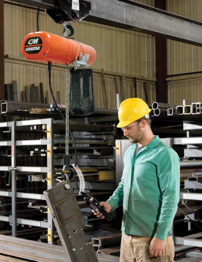
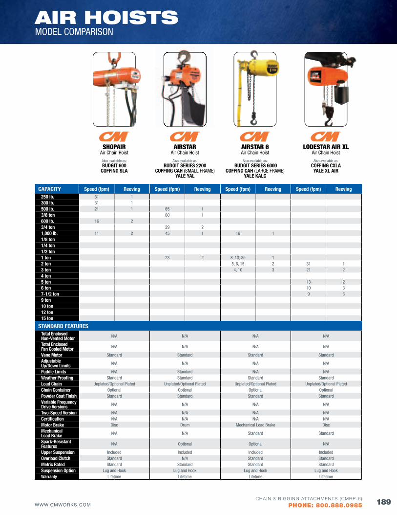
AIR HoISTSMODEL COMPARISON
189WWW.CMWORKS.COMCHAIN & RIGGING ATTACHMENTS (CMRP-6)
PHONE: 800.888.0985
CAPACITY Speed (fpm) Reeving Speed (fpm) Reeving Speed (fpm) Reeving Speed (fpm) Reeving250 lb. 31 1300 lb. 31 1500 lb. 21 1 65 13/8 ton 60 1600 lb. 16 23/4 ton 29 21,000 lb. 11 2 45 1 16 11/8 ton1/4 ton1/2 ton1 ton 23 2 8, 13, 30 12 ton 5, 6, 15 2 31 13 ton 4, 10 3 21 24 ton5 ton 13 26 ton 10 37-1/2 ton 9 39 ton10 ton12 ton15 ton
STANDARD fEATURESTotal Enclosed Non-Vented Motor N/A N/A N/A N/A
Total Enclosed fan Cooled Motor N/A N/A N/A N/A
Vane Motor Standard Standard Standard StandardAdjustable Up/Down Limits N/A N/A N/A N/A
Paddle Limits N/A Standard N/A N/AWeather Proofing Standard Standard Standard StandardLoad Chain Unplated/Optional Plated Unplated/Optional Plated Unplated/Optional Plated Unplated/Optional PlatedChain Container Optional Optional Optional OptionalPowder Coat finish Standard Standard Standard StandardVariable frequency Drive Versions N/A N/A N/A N/A
Two-Speed Version N/A N/A N/A N/ACertification N/A N/A N/A N/AMotor Brake Disc Drum Mechanical Load Brake DiscMechanical Load Brake N/A N/A Standard Standard
Spark-Resistant features N/A Optional Optional N/A
Upper Suspension Included Included Included IncludedOverload Clutch Standard N/A Standard StandardMetric Rated Standard Standard Standard StandardSuspension Option Lug and Hook Lug and Hook Lug and Hook Lug and HookWarranty Lifetime Lifetime Lifetime Lifetime
SHoPaIr Air Chain Hoist
Also available as:BUDGIT 600
COffING SLA
aIrSTar Air Chain Hoist
Also available as:BUDGIT SERIES 2200
COffING CAH (SMALL FRAME)YALE YAL
aIrSTar 6 Air Chain Hoist
Also available as: BUDGIT SERIES 6000
COffING CAH (LARGE FRAME)YALE KALC
LodESTar aIr XLAir Chain Hoist
Also available as:COffING CXLAYALE XL AIR
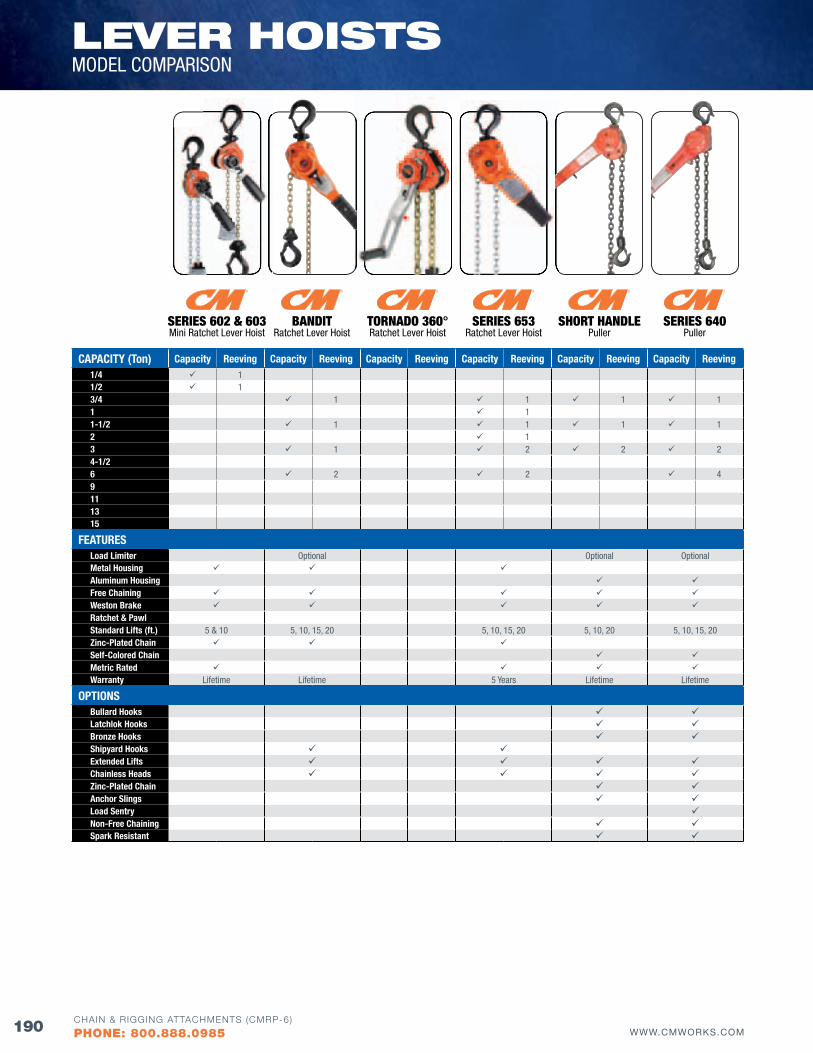
CAPACITY (Ton) Capacity Reeving Capacity Reeving Capacity Reeving Capacity Reeving Capacity Reeving Capacity Reeving1/4 11/2 13/4 1 1 1 11 11-1/2 1 1 1 12 13 1 2 2 24-1/26 2 2 49111315
fEATURESLoad Limiter Optional Optional OptionalMetal Housing Aluminum Housing free Chaining Weston Brake Ratchet & PawlStandard Lifts (ft.) 5 & 10 5, 10, 15, 20 5, 10, 15, 20 5, 10, 20 5, 10, 15, 20zinc-Plated Chain Self-Colored Chain Metric Rated Warranty Lifetime Lifetime 5 Years Lifetime Lifetime
OPTIONSBullard Hooks Latchlok Hooks Bronze Hooks Shipyard Hooks Extended Lifts Chainless Heads zinc-Plated Chain Anchor Slings Load Sentry Non-free Chaining Spark Resistant
lEvER HoISTSMODEL COMPARISON
SErIES 602 & 603Mini Ratchet Lever Hoist
baNdITRatchet Lever Hoist
TorNado 360°Ratchet Lever Hoist
SErIES 653Ratchet Lever Hoist
SErIES 640Puller
SHorT HaNdLEPuller
190 WWW.CMWORKS.COMCHAIN & RIGGING ATTACHMENTS (CMRP-6)
PHONE: 800.888.0985
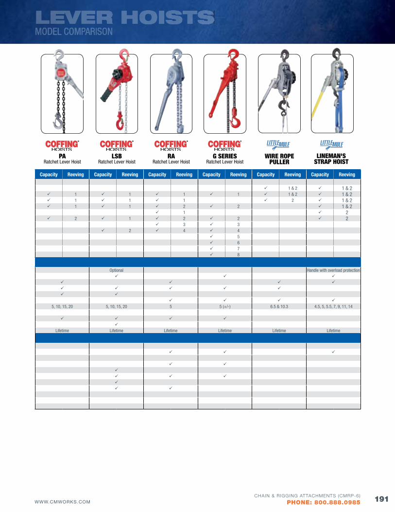
Capacity Reeving Capacity Reeving Capacity Reeving Capacity Reeving Capacity Reeving Capacity Reeving
1 & 2 1 & 2 1 1 1 1 1 & 2 1 & 2 1 1 1 2 1 & 2 1 1 2 2 1 & 2
1 2 2 1 2 2 2
3 3 2 4 4
5 6 7 8
Optional Handle with overload protection
5, 10, 15, 20 5, 10, 15, 20 5 5 (+/-) 6.5 & 10.3 4.5, 5, 5.5, 7, 9, 11, 14
Lifetime Lifetime Lifetime Lifetime Lifetime Lifetime
LEVER HOISTSMODEL COMPARISON
LSbRatchet Lever Hoist
PaRatchet Lever Hoist
raRatchet Lever Hoist
g SErIESRatchet Lever Hoist
LINEMaN'S STraP HoIST
wIrE roPEPuLLEr
191WWW.CMWORKS.COMCHAIN & RIGGING ATTACHMENTS (CMRP-6)
PHONE: 800.888.0985
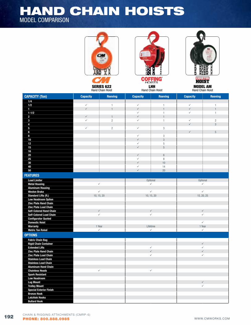
HANd CHAIN HoISTSMODEL COMPARISON
CAPACITY (Ton) Capacity Reeving Capacity Reeving Capacity Reeving1/41/2 1 1 11 1 1 11-1/2 1 12 1 13 2 1 24 35 2 36 58 310 312 515 51620 625 830 1040 1450 20
fEATURESLoad Limiter Optional OptionalMetal Housing Aluminum Housing Weston Brake Standard Lifts (ft.) 10, 15, 20 10, 15, 20 15, 20, 25Low Headroom Option zinc Plate Hand Chain zinc Plate Load Chain Self-Colored Hand Chain Self-Colored Load Chain Configurator quoted Domestic Hoist Warranty 1 Year Lifetime 1 YearMetric Ton Rated
OPTIONSfabric Chain Bag Rigid Chain Container Extended Lifts zinc Plate Hand Chain zinc Plate Load Chain Stainless Load Chain Stainless Load Chain Aluminum Hand Chain Chainless Heads Spark Resistant Low Headroom Lug Mount Trolley Mount Special Exterior finish Bronze Hook Latchlok Hooks Bullard Hook
SErIES 622Hand Chain Hoist
LHHHand Chain Hoist
ModEL aMHand Chain Hoist
192 WWW.CMWORKS.COMCHAIN & RIGGING ATTACHMENTS (CMRP-6)
PHONE: 800.888.0985
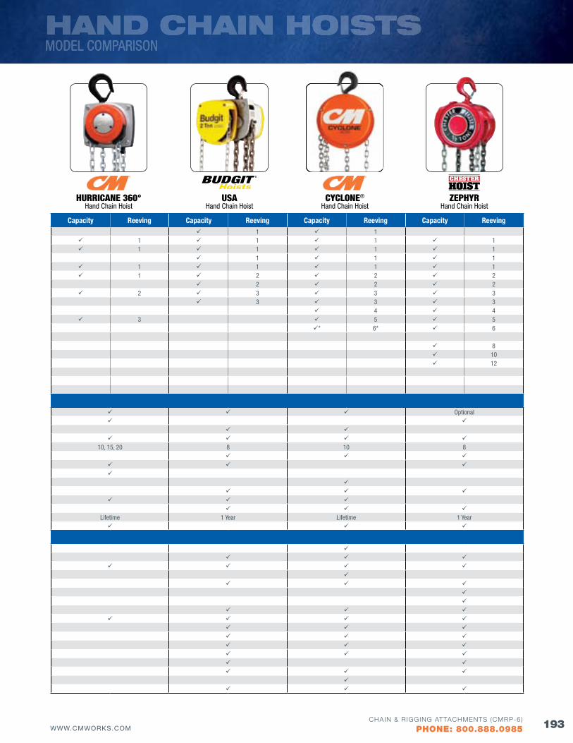
HAND CHAIN HOISTSMODEL COMPARISON
Capacity Reeving Capacity Reeving Capacity Reeving Capacity Reeving 1 1
1 1 1 1 1 1 1 1
1 1 1 1 1 1 1 1 2 2 2
2 2 2 2 3 3 3
3 3 3 4 4
3 5 5* 6* 6
8 10 12
Optional
10, 15, 20 8 10 8
Lifetime 1 Year Lifetime 1 Year
CYCLoNE®
Hand Chain HoistHurrICaNE 360°
Hand Chain HoistZEPHYr
Hand Chain HoistuSa
Hand Chain Hoist
193WWW.CMWORKS.COMCHAIN & RIGGING ATTACHMENTS (CMRP-6)
PHONE: 800.888.0985
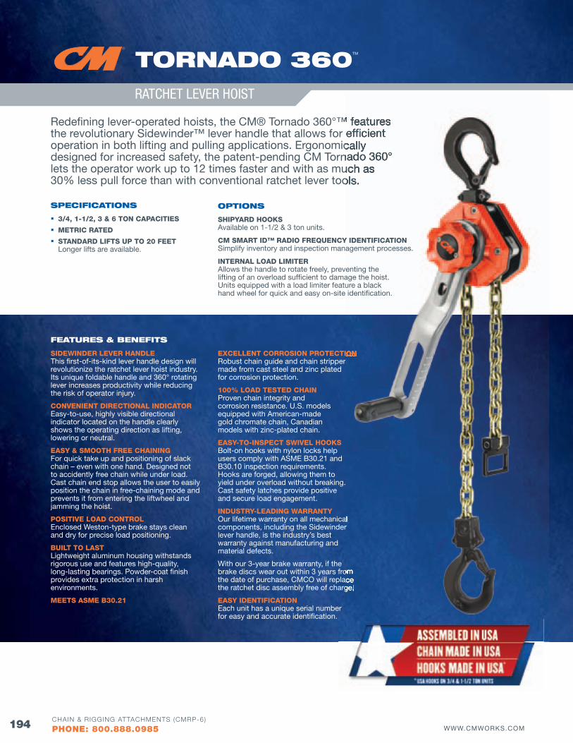
HOISTS, TROLLEYS &
BEAM CLAM
PS
194 WWW.CMWORKS.COMCHAIN & RIGGING ATTACHMENTS (CMRP-6)
PHONE: 800.888.0985
ToRNAdo 360TM
RATCHET LEVER HOIST
Redefining lever-operated hoists, the CM® Tornado 360°™ features the revolutionary Sidewinder™ lever handle that allows for efficient operation in both lifting and pulling applications. Ergonomically designed for increased safety, the patent-pending CM Tornado 360° lets the operator work up to 12 times faster and with as much as 30% less pull force than with conventional ratchet lever tools.
SPECIfICATIoNS
3/4, 1-1/2, 3 & 6 TON CAPACITIES
METRIC RATED
STANDARD LIfTS UP TO 20 fEET Longer lifts are available.
fEATuRES & bENEfITS
SIDEWINDER LEVER HANDLE This first-of-its-kind lever handle design will revolutionize the ratchet lever hoist industry. Its unique foldable handle and 360° rotating lever increases productivity while reducing the risk of operator injury.
CONVENIENT DIRECTIONAL INDICATOR Easy-to-use, highly visible directional indicator located on the handle clearly shows the operating direction as lifting, lowering or neutral.
EASY & SMOOTH fREE CHAINING For quick take up and positioning of slack chain – even with one hand. Designed not to accidently free chain while under load. Cast chain end stop allows the user to easily position the chain in free-chaining mode and prevents it from entering the liftwheel and jamming the hoist.
POSITIVE LOAD CONTROL Enclosed Weston-type brake stays clean and dry for precise load positioning.
BUILT TO LAST Lightweight aluminum housing withstands rigorous use and features high-quality, long-lasting bearings. Powder-coat finish provides extra protection in harsh environments.
MEETS ASME B30.21
EXCELLENT CORROSION PROTECTION Robust chain guide and chain stripper made from cast steel and zinc plated for corrosion protection.
100% LOAD TESTED CHAIN Proven chain integrity and corrosion resistance. U.S. models equipped with American-made gold chromate chain, Canadian models with zinc-plated chain.
EASY-TO-INSPECT SWIVEL HOOKS Bolt-on hooks with nylon locks help users comply with ASME B30.21 and B30.10 inspection requirements. Hooks are forged, allowing them to yield under overload without breaking. Cast safety latches provide positive and secure load engagement.
INDUSTRY-LEADING WARRANTY Our lifetime warranty on all mechanical components, including the Sidewinder lever handle, is the industry’s best warranty against manufacturing and material defects.
With our 3-year brake warranty, if the brake discs wear out within 3 years from the date of purchase, CMCO will replace the ratchet disc assembly free of charge.
EASY IDENTIfICATION Each unit has a unique serial number for easy and accurate identification.
Redefining lever-operated hoists, the CM® Tornado 360°™ features the revolutionary Sidewinder™ lever handle that allows for efficient operation in both lifting and pulling applications. Ergonomically designed for increased safety, the patent-pending CM Tornado 360° lets the operator work up to 12 times faster and with as much as 30% less pull force than with conventional ratchet lever tools.
EXCELLENT CORROSION PROTECTION
yield under overload without breaking.
Our lifetime warranty on all mechanical components, including the Sidewinder
brake discs wear out within 3 years from the date of purchase, CMCO will replace the ratchet disc assembly free of charge.
oPTIoNS
SHIPYARD HOOKSAvailable on 1-1/2 & 3 ton units.
CM SMART ID™ RADIO fREQUENCY IDENTIfICATIONSimplify inventory and inspection management processes.
INTERNAL LOAD LIMITERAllows the handle to rotate freely, preventing the lifting of an overload sufficient to damage the hoist. Units equipped with a load limiter feature a black hand wheel for quick and easy on-site identification.
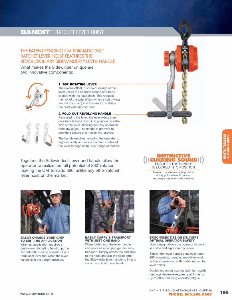
BELO
W T
HE H
OOK
HOIS
TS, T
ROLL
EYS
&
BEA
M C
LAM
PS
195WWW.CMWORKS.COMCHAIN & RIGGING ATTACHMENTS (CMRP-6)
PHONE: 800.888.0985
bANdIT TM RATCHET LEVER HOIST
195WWW.CMWORKS.COMCHAIN & RIGGING ATTACHMENTS (CMRP-6)
PHONE: 800.888.0985
The paTenT-pending CM Tornado 360˚ raTCheT lever hoisT feaTures The revoluTionary sidewinder™ lever handle. What makes the Sidewinder unique are two innovative components:
1. 360˚ ROTATING LEVERThe unique offset, or curved, design of the lever keeps the operator’s hand and body aligned with the load chain. This reduces the risk of the twist effect (when a hoist twists around the chain) and the need to stabilize the hoist with another hand.
2. fOLD-OUT REVOLVING HANDLERecessed in the lever, the heavy-duty steel core handle folds down into position on either side of the lever, allowing for easy operation from any angle. The handle is grooved to provide a secure grip – even with gloves.
The handle revolves, allowing the operator to ergonomically and easily maintain control of the lever through its full 360˚ range of motion.
Together, the Sidewinder’s lever and handle allow the operator to realize the full potential of 360˚ rotation, making the CM Tornado 360˚ unlike any other ratchet lever hoist on the market.
Distinctive clicking sounD
ENSURES THE HANDLE IS LOCKED INTO POSITIONTo return handle to upright position,
simply pull the handle outward and snap into place inside the lever.
EASILY CHANGE YOUR GRIP TO SUIT THE APPLICATIONWhen an application requires a customary ratcheting hand grip, the Tornado 360˚ can be operated like a traditional lever tool when the lever handle is in the upright position.
EASILY CARRY & TRANSPORT WITH JUST ONE HANDWhen folded out, the lever handle can serve as a carrying grip for easy transport. Simply attach the end stop to the hook and slip the hook onto the Sidewinder lever handle to lift and carry the unit with one hand.
ERGONOMIC DESIGN DELIVERS OPTIMAL OPERATOR SAfETYHoist design allows the operator to work in a safe and ergonomic position.
Sidewinder lever handle enables smooth 360˚ operation, reducing repetitive wrist action experienced with traditional ratchet lever hoists.
Double reduction gearing and high-quality bearings decrease required pull force by up to 30%, reducing operator fatigue.
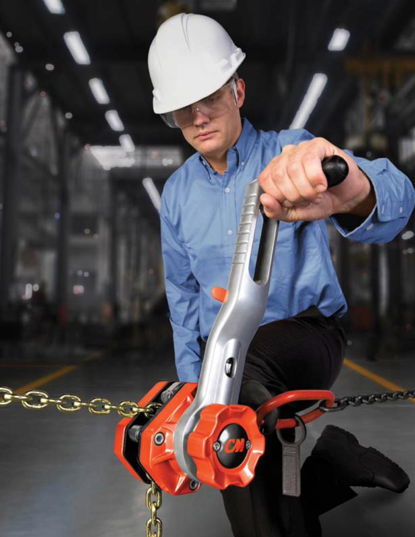
HOISTS, TROLLEYS &
BEAM CLAM
PS
196 WWW.CMWORKS.COMCHAIN & RIGGING ATTACHMENTS (CMRP-6)
PHONE: 800.888.0985
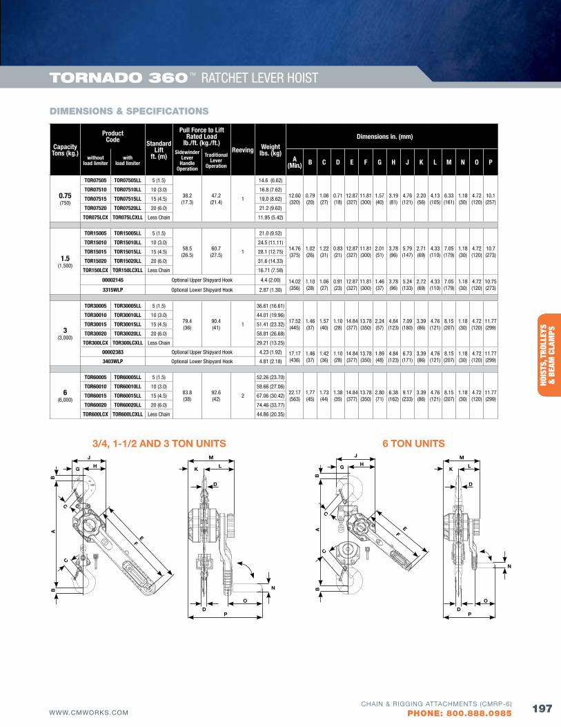
BELO
W T
HE H
OOK
HOIS
TS, T
ROLL
EYS
&
BEA
M C
LAM
PS
197WWW.CMWORKS.COMCHAIN & RIGGING ATTACHMENTS (CMRP-6)
PHONE: 800.888.0985
Capacity Tons (kg.)
ProductCode Standard
Lift ft. (m)
Pull force to Lift Rated Load
lb./ft. (kg./ft.)Reeving Weight
lbs. (kg)
Dimensions in. (mm)
without load limiter
with load limiter
Sidewinder Lever
Handle Operation
Traditional Lever
OperationA
(Min.) B C D E f G H J K L M N O P
0.75(750)
TOR07505 TOR07505LL 5 (1.5)
38.2(17.3)
47.2(21.4)
1
14.6 (6.62)
12.60 (320)
0.79 (20)
1.06 (27)
0.71 (18)
12.87 (327)
11.81 (300)
1.57 (40)
3.19 (81)
4.76 (121)
2.20 (56)
4.13 (105)
6.33 (161)
1.18 (30)
4.72 (120)
10.1 (257)
TOR07510 TOR07510LL 10 (3.0) 16.8 (7.62)
TOR07515 TOR07515LL 15 (4.5) 19.0 (8.62)
TOR07520 TOR07520LL 20 (6.0) 21.2 (9.62)
TOR075LCX TOR075LCXLL Less Chain 11.95 (5.42)
1.5(1,500)
TOR15005 TOR15005LL 5 (1.5)
58.5(26.5)
60.7(27.5)
1
21.0 (9.52)
14.76 (375)
1.02 (26)
1.22 (31)
0.83 (21)
12.87 (327)
11.81 (300)
2.01 (51)
3.78 (96)
5.79 (147)
2.71 (69)
4.33 (110)
7.05 (179)
1.18 (30)
4.72 (120)
10.7 (273)
TOR15010 TOR15010LL 10 (3.0) 24.5 (11.11)
TOR15015 TOR15015LL 15 (4.5) 28.1 (12.75)
TOR15020 TOR15020LL 20 (6.0) 31.6 (14.33)
TOR150LCX TOR150LCXLL Less Chain 16.71 (7.58)
00002145 Optional Upper Shipyard Hook 4.4 (2.00) 14.02(356)
1.10(28)
1.06(27)
0.91(23)
12.87(327)
11.81(300)
1.46(37)
3.78(96)
5.24(133)
2.72(69)
4.33(110)
7.05(179)
1.18(30)
4.72(120)
10.75(273)3315WLP Optional Lower Shipyard Hook 2.87 (1.30)
3(3,000)
TOR30005 TOR30005LL 5 (1.5)
79.4(36)
90.4(41)
1
36.61 (16.61)
17.52(445)
1.46(37)
1.57(40)
1.10(28)
14.84(377)
13.78(350)
2.24(57)
4.84(123)
7.09(180)
3.39(86)
4.76(121)
8.15(207)
1.18(30)
4.72(120)
11.77(299)
TOR30010 TOR30010LL 10 (3.0) 44.01 (19.96)
TOR30015 TOR30015LL 15 (4.5) 51.41 (23.32)
TOR30020 TOR30020LL 20 (6.0) 58.81 (26.68)
TOR300LCX TOR300LCXLL Less Chain 29.21 (13.25)
00002383 Optional Upper Shipyard Hook 4.23 (1.92) 17.17(436)
1.46(37)
1.42(36)
1.10(28)
14.84(377)
13.78(350)
1.89(48)
4.84(123)
6.73(171)
3.39(86)
4.76(121)
8.15(207)
1.18(30)
4.72(120)
11.77(299)3403WLP Optional Lower Shipyard Hook 4.81 (2.18)
6(6,000)
TOR60005 TOR60005LL 5 (1.5)
83.8(38)
92.6(42)
2
52.26 (23.70)
22.17(563)
1.77(45)
1.73(44)
1.38(35)
14.84(377)
13.78(350)
2.80(71)
6.38(162)
9.17(233)
3.39(86)
4.76(121)
8.15(207)
1.18(30)
4.72(120)
11.77(299)
TOR60010 TOR60010LL 10 (3.0) 59.66 (27.06)
TOR60015 TOR60015LL 15 (4.5) 67.06 (30.42)
TOR60020 TOR60020LL 20 (6.0) 74.46 (33.77)
TOR600LCX TOR600LCXLL Less Chain 44.86 (20.35)
DIMENSIONS & SPECIfICATIONS
3/4, 1-1/2 AND 3 TON UNITSM
D
O
N
D
LK
P
J
H
EF
G
BB
A
C
C
6 TON UNITSM
D
O
N
D
LK
P
C
J
H
EF
G
BB
A
C
ToRNAdo 360 TM RATCHET LEVER HOIST
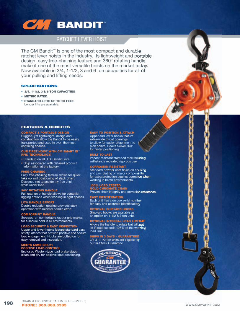
HOISTS, TROLLEYS &
BEAM CLAM
PS
198 WWW.CMWORKS.COMCHAIN & RIGGING ATTACHMENTS (CMRP-6)
PHONE: 800.888.0985
bANdIT TM
RATCHET LEVER HOIST
The CM Bandit™ is one of the most compact and durable ratchet lever hoists in the industry. Its lightweight and portable design, easy free-chaining feature and 360° rotating handle make it one of the most versatile hoists on the market today. Now available in 3/4, 1-1/2, 3 and 6 ton capacities for all of your pulling and lifting needs.
SPECIfICATIoNS
3/4, 1-1/2, 3 & 6 TON CAPACITIES
METRIC RATED.
STANDARD LIfTS UP TO 20 fEET. Longer lifts are available.
fEATuRES & bENEfITS
COMPACT & PORTABLE DESIGN Rugged, yet lightweight, design and construction allow the Bandit to be easily transported and used in even the most confining spaces.
OUR fIRST HOIST WITH CM SMART ID™ RfID TECHNOLOGY!
Standard on all U.S. Bandit units Chip associated with detailed product
information at the factory
fREE-CHAINING Easy free-chaining feature allows for quick take up and positioning of slack chain. Designed not to accidently free chain while under load.
360° ROTATING HANDLE Full rotation of handle allows for versatile rigging options when working in tight spaces.
LOW HANDLE EffORT Double reduction gearing provides easy operation with minimal handle effort.
COMfORT-fIT HANDLE Screwed-on comfortable rubber grip makes for a secure hold in all environments.
LOAD SECURITY & EASY INSPECTION Upper and lower hooks feature standard cast safety latches that provide positive and secure load engagement. Hooks are bolted on for easy removal and inspection.
MEETS ASME B30.21 POSITIVE LOAD CONTROL Enclosed Weston-type load brake stays clean and dry for positive load positioning.
EASY TO POSITION & ATTACH Upper and lower hooks feature extra-wide throat openings to allow for easier attachment to pick points. Hooks swivel 360° for faster positioning.
BUILT TO LAST Impact-resistant stamped steel housing withstands repeated rigorous use.
CORROSION RESISTANT Standard powder coat finish on housing and zinc plating on major components for extra protection against corrosion when working in harsh environments.
100% LOAD TESTED GOLD CHROMATE CHAIN Proven chain integrity and corrosion resistance.
EASY IDENTIfICATION Each unit has a unique serial number for easy and accurate identification.
OPTIONAL SHIPYARD HOOKS Shipyard hooks are available as an option on 1-1/2 & 3 ton units.
OPTIONAL INTERNAL LOAD LIMITER Allows the handle to rotate but will not lift if load exceeds 125% of the working load limit.
SHIPS IN 3 DAYS – GUARANTEED 3/4 & 1-1/2 ton units are eligible for our In-Stock Guarantee.
is one of the most compact and durable ratchet lever hoists in the industry. Its lightweight and portable design, easy free-chaining feature and 360° rotating handle make it one of the most versatile hoists on the market today. Now available in 3/4, 1-1/2, 3 and 6 ton capacities for all of
Impact-resistant stamped steel housing
Standard powder coat finish on housing and zinc plating on major components for extra protection against corrosion when
Proven chain integrity and corrosion resistance.
Each unit has a unique serial number for easy and accurate identification.
OPTIONAL INTERNAL LOAD LIMITERAllows the handle to rotate but will not lift if load exceeds 125% of the working
SHIPS IN 3 DAYS – GUARANTEED3/4 & 1-1/2 ton units are eligible for
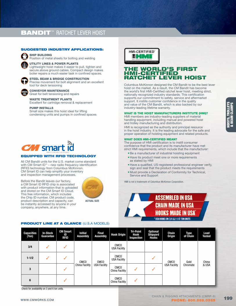
BELO
W T
HE H
OOK
HOIS
TS, T
ROLL
EYS
&
BEA
M C
LAM
PS
199WWW.CMWORKS.COMCHAIN & RIGGING ATTACHMENTS (CMRP-6)
PHONE: 800.888.0985
bANdIT TM RATCHET LEVER HOIST
SuGGESTEd INduSTRy APPlICATIoNS:
SHIP BUILDING Position of metal sheets for bolting and welding
UTILITY LINES & POWER PLANTSLightweight hoist makes it easier to pull, tighten and secure above ground cables. Compact design makes boiler repairs a much easier task in confined spaces.
STEEL BEAM & BRIDGE CONSTRUCTIONPrecise movement for bolt alignment and an excellent tool for deck tensioning
CONVEYOR MAINTENANCE Great for belt tensioning and repairs
WASTE TREATMENT PLANTSExcellent for cartridge removal & replacement
PUMP INSTALLSSmall size makes this hoist ideal for lifting condensing units and pumps in confined spaces
BELO
W T
HE H
OOK
HOIS
TS, T
ROLL
EYS
&
BEA
M C
LAM
PS
Columbus McKinnon designed the CM Bandit to be the best lever hoist on the market. As a result, the CM Bandit has become the world’s first HMI-Certified ratchet lever hoist, meeting strict, nationally recognized industry standards. This certification supports our commitment to safety, service and aftermarket support. It instills customer confidence in the quality and value of the CM Bandit, which is also backed by our industry-leading lifetime warranty.
WHAT IS THE HOIST MANUfACTURERS INSTITUTE (HMI)?HMI members are industry-leading suppliers of material handling equipment, including manual and powered hoist and trolley manufacturing and distribution. HMI is recognized as the authority and principal resource in the hoist industry. It is the leading advocate for the safe and proper operation of hoisting equipment and related products.
WHAT DOES HMI-CERTIfIED MEAN?The purpose of HMI certification is to instill consumer confidence that the product and its manufacturer have met strict HMI requirements, which include that the manufacturer: n Be a manufacturer of industrial hoisting equipment n Have its product meet one or more requirements
as stated by HMI n Have a qualified, US-registered professional engineer verify,
sign and seal that the product meets the requirements n Must provide a Declaration of Conformity for Technical,
Service and Support
Capacities (Ton)
In-Stock Guarantee
CM Smart ID
RfID
Initial Assembly
final Assembly Hook Origin
Tri-Point Hook
Inspection
Optional Shipyard
Hooks
Chain Origin
Type of Chain
Load Tested
3/4 3 3
CMCO China Facility
CMCO USA Facility
CMCO USA Facility
CMCO USA Facility
Gold Chromate
China & USA
1-1/2 3 3 CMCO USA Facility 3
3 3 CMCO China Facility 3 3
6 3 CMCO China Facility 3
PRoduCT lINE AT A GlANCE (U.S.A MODELS)
EQuIPPEd wITH RfId TECHNoloGy
All CM Bandit units for the U.S. market come standard with CM Smart ID™ – new radio frequency identification (RFID) technology from Columbus McKinnon. CM Smart ID can help simplify your inventory and inspection management processes.
Before the Bandit leaves our factory, a CM Smart ID RFID chip is associated with product information that is uploaded and stored on the CM Smart ID Cloud. This free information, which includes the Chip ID number, CM product code, product description and capacity, can be instantly accessed by anyone in your company, anywhere, at any time.
ACTUAL SIzE
Check for availability on 3 and 6 ton units.
HMI is not a trademark of Columbus McKinnon Corporation.
199WWW.CMWORKS.COMCHAIN & RIGGING ATTACHMENTS (CMRP-6)
PHONE: 800.888.0985
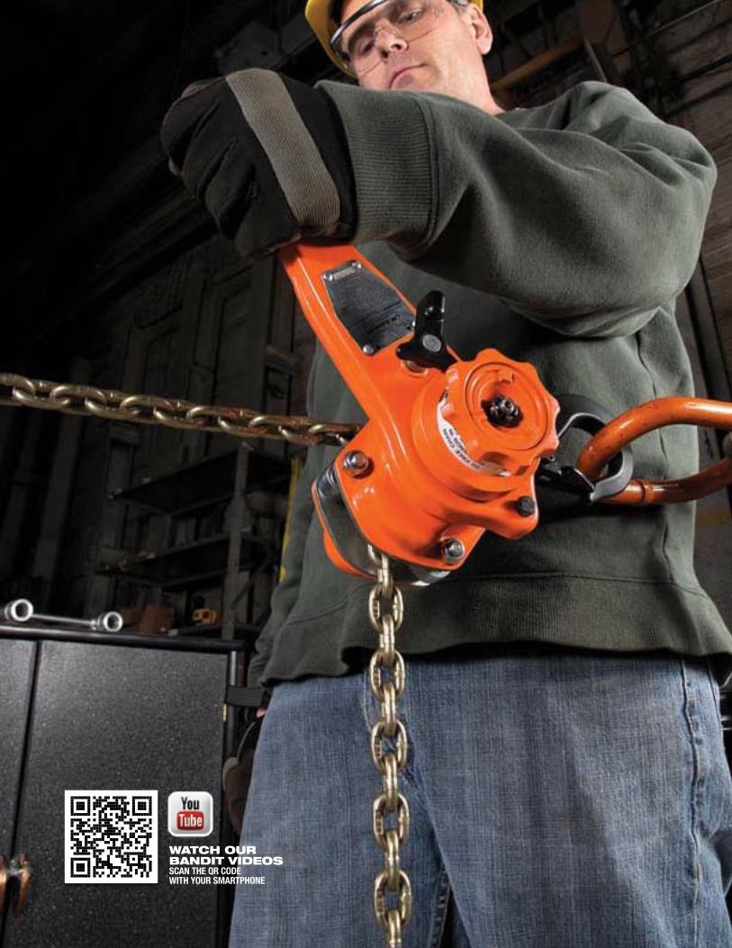
HOISTS, TROLLEYS &
BEAM CLAM
PS
200 WWW.CMWORKS.COMCHAIN & RIGGING ATTACHMENTS (CMRP-6)
PHONE: 800.888.0985
wATCH ouR bANdIT vIdEoSSCAN THE qR CODE WITH YOUR SMARTPHONE
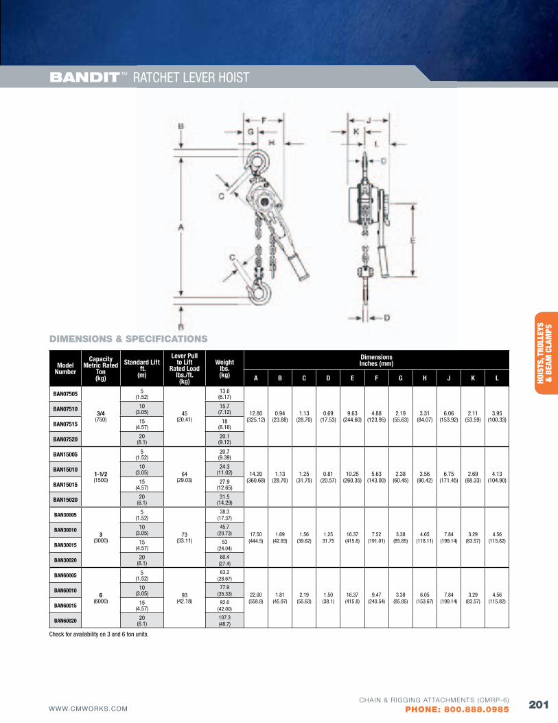
BELO
W T
HE H
OOK
HOIS
TS, T
ROLL
EYS
&
BEA
M C
LAM
PS
201WWW.CMWORKS.COMCHAIN & RIGGING ATTACHMENTS (CMRP-6)
PHONE: 800.888.0985
bANdIT TM RATCHET LEVER HOIST
DIMENSIONS & SPECIfICATIONS
Model Number
Capacity Metric Rated
Ton (kg)
Standard Lift ft. (m)
Lever Pull to Lift
Rated Load lbs./ft. (kg)
Weight lbs. (kg)
Dimensions Inches (mm)
A B C D E f G H J K L
BAN07505
3/4 (750)
5 (1.52)
45 (20.41)
13.6 (6.17)
12.80 (325.12)
0.94(23.88)
1.13 (28.70)
0.69 (17.53)
9.63 (244.60)
4.88 (123.95)
2.19 (55.63)
3.31 (84.07)
6.06 (153.92)
2.11 (53.59)
3.95 (100.33)
BAN07510 10 (3.05)
15.7 (7.12)
BAN07515 15 (4.57)
18 (8.16)
BAN07520 20 (6.1)
20.1 (9.12)
BAN15005
1-1/2 (1500)
5 (1.52)
64 (29.03)
20.7 (9.39)
14.20 (360.68)
1.13 (28.70)
1.25 (31.75)
0.81 (20.57)
10.25 (260.35)
5.63 (143.00)
2.38 (60.45)
3.56 (90.42)
6.75 (171.45)
2.69 (68.33)
4.13 (104.90)
BAN15010 10 (3.05)
24.3 (11.02)
BAN15015 15 (4.57)
27.9 (12.65)
BAN15020 20 (6.1)
31.5 (14.29)
BAN30005
3 (3000)
5 (1.52)
73 (33.11)
38.3(17.37)
17.50(444.5)
1.69(42.93)
1.56(39.62)
1.2531.75
16.37(415.8)
7.52(191.01)
3.38(85.85)
4.65(118.11)
7.84(199.14)
3.29(83.57)
4.56(115.82)
BAN30010 10 (3.05)
45.7(20.73)
BAN30015 15 (4.57)
53(24.04)
BAN30020 20 (6.1)
60.4(27.4)
BAN60005
6 (6000)
5 (1.52)
93 (42.18)
63.2 (28.67)
22.00(558.8)
1.81(45.97)
2.19(55.63)
1.50(38.1)
16.37(415.8)
9.47(240.54)
3.38(85.85)
6.05(153.67)
7.84(199.14)
3.29(83.57)
4.56(115.82)
BAN60010 10 (3.05)
77.9 (35.33)
BAN60015 15 (4.57)
92.6 (42.00)
BAN60020 20 (6.1)
107.3 (48.7)
Check for availability on 3 and 6 ton units.
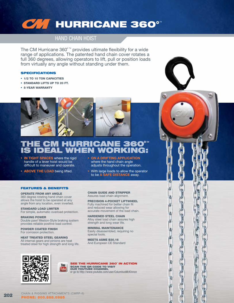
HOISTS, TROLLEYS &
BEAM CLAM
PS
202 WWW.CMWORKS.COMCHAIN & RIGGING ATTACHMENTS (CMRP-6)
PHONE: 800.888.0985
HuRRICANE 360°TM
HAND CHAIN HOIST
The CM Hurricane 360˚ TM provides ultimate flexibility for a wide range of applications. The patented hand chain cover rotates a full 360 degrees, allowing operators to lift, pull or position loads from virtually any angle without standing under them.
SPECIfICATIoNS
1/2 TO 10 TON CAPACITIES
STANDARD LIfTS UP TO 20 fT.
5-YEAR WARRANTY
fEATuRES & bENEfITS
OPERATE fROM ANY ANGLE360 degree rotating hand chain cover allows the hoist to be operated at any angle from any location, even inverted.
STANDARD LOAD LIMITERFor simple, automatic overload protection.
BRAKING POWERDouble pawl Weston-Style braking system provides reliable positive load control.
POWDER COATED fINISHFor corrosion protection.
HEAT TREATED STEEL GEARINGAll internal gears and pinions are heat treated steel for high strength and long life.
CHAIN GUIDE AND STRIPPERAssures load chain alignment.
PRECISION 4-POCKET LIfTWHEELFully machined for better chain fit and reduced wear allowing for accurate movement of the load chain.
HARDENED STEEL CHAINAlloy steel load chain assures high strength and long wear life.
MINIMAL MAINTENANCEEasily disassembled, requiring no special tools.
MEETS ASME B30.16And European CE Standard
The CM hurriCane 360Cane 360C ˚ TM
is ideal when working: IN TIGHT SPACES where the rigid
handle of a lever hoist would be difficult to maneuver and operate.
ABOVE THE LOAD being lifted.
ON A DRIFTING APPLICATION where the hand chain angle adjusts throughout the operation.
With large loads to allow the operator to be A SAFE DISTANCE away.
SEE THE HuRRICANE 360˚ IN ACTIoNSCAN THE QR CodE To vISIT ouR youTubE CHANNElor go to http://www.youtube.com/user/ColumbusMcKinnon
202 CHAIN & RIGGING ATTACHMENTS (CMRP-6)
PHONE: 800.888.0985
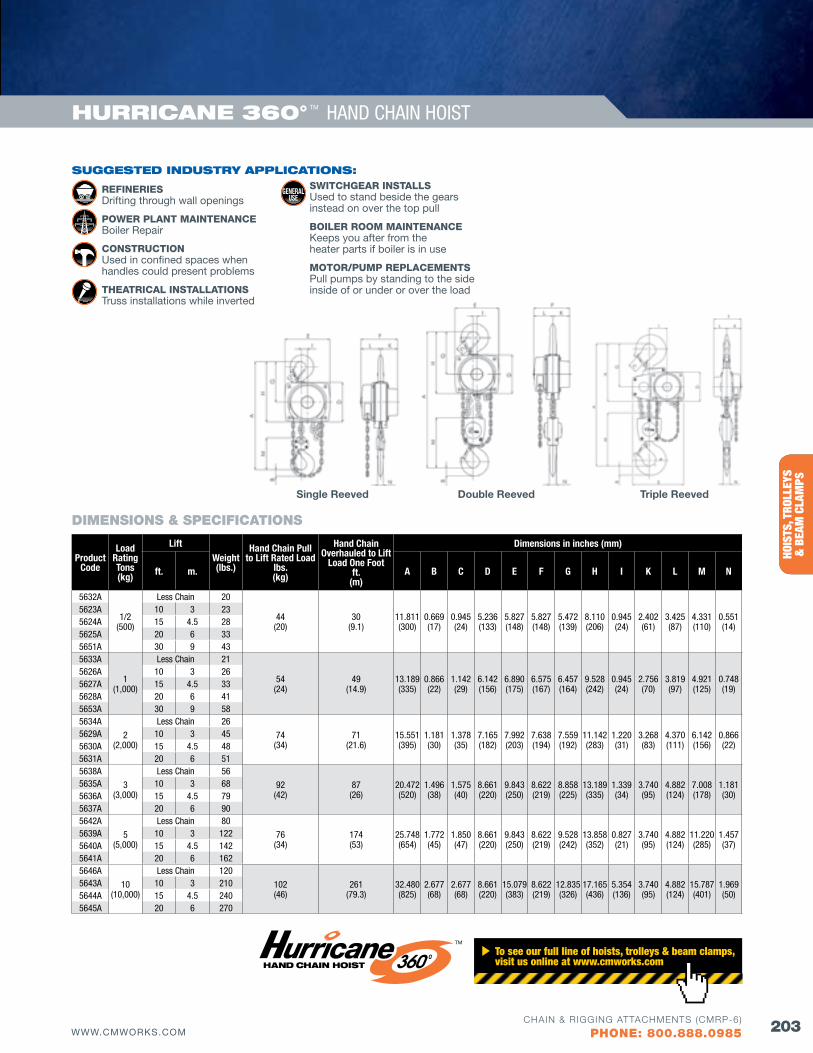
BELO
W T
HE H
OOK
HOIS
TS, T
ROLL
EYS
&
BEA
M C
LAM
PS
203WWW.CMWORKS.COMCHAIN & RIGGING ATTACHMENTS (CMRP-6)
PHONE: 800.888.0985
HuRRICANE 360° TM HAND CHAIN HOIST
Product Code
Load Rating Tons(kg)
LiftWeight(lbs.)
Hand Chain Pull to Lift Rated Load
lbs.(kg)
Hand Chain Overhauled to Lift
Load One footft.
(m)
Dimensions in inches (mm)
ft. m. A B C D E f G H I K L M N
5632A
1/2(500)
Less Chain 20
44(20)
30(9.1)
11.811(300)
0.669(17)
0.945(24)
5.236(133)
5.827(148)
5.827(148)
5.472(139)
8.110(206)
0.945(24)
2.402(61)
3.425(87)
4.331(110)
0.551(14)
5623A 10 3 235624A 15 4.5 285625A 20 6 335651A 30 9 435633A
1(1,000)
Less Chain 21
54(24)
49(14.9)
13.189(335)
0.866(22)
1.142(29)
6.142(156)
6.890(175)
6.575(167)
6.457(164)
9.528(242)
0.945(24)
2.756(70)
3.819(97)
4.921(125)
0.748(19)
5626A 10 3 265627A 15 4.5 335628A 20 6 415653A 30 9 585634A
2(2,000)
Less Chain 26
74(34)
71(21.6)
15.551(395)
1.181(30)
1.378(35)
7.165(182)
7.992(203)
7.638(194)
7.559(192)
11.142(283)
1.220(31)
3.268(83)
4.370(111)
6.142(156)
0.866(22)
5629A 10 3 455630A 15 4.5 485631A 20 6 515638A
3(3,000)
Less Chain 56
92(42)
87(26)
20.472(520)
1.496(38)
1.575(40)
8.661(220)
9.843(250)
8.622(219)
8.858(225)
13.189(335)
1.339(34)
3.740(95)
4.882(124)
7.008(178)
1.181(30)
5635A 10 3 685636A 15 4.5 795637A 20 6 905642A
5(5,000)
Less Chain 80
76(34)
174(53)
25.748(654)
1.772(45)
1.850(47)
8.661(220)
9.843(250)
8.622(219)
9.528(242)
13.858(352)
0.827(21)
3.740(95)
4.882(124)
11.220(285)
1.457(37)
5639A 10 3 1225640A 15 4.5 1425641A 20 6 1625646A
10(10,000)
Less Chain 120
102(46)
261(79.3)
32.480(825)
2.677(68)
2.677(68)
8.661(220)
15.079(383)
8.622(219)
12.835(326)
17.165(436)
5.354(136)
3.740(95)
4.882(124)
15.787(401)
1.969(50)
5643A 10 3 2105644A 15 4.5 2405645A 20 6 270
DIMENSIONS & SPECIfICATIONS
Double Reeved Triple ReevedSingle Reeved
SuGGESTEd INduSTRy APPlICATIoNS:
REfINERIESDrifting through wall openings
POWER PLANT MAINTENANCEBoiler Repair
CONSTRUCTIONUsed in confined spaces when handles could present problems
THEATRICAL INSTALLATIONSTruss installations while inverted
SWITCHGEAR INSTALLSUsed to stand beside the gears instead on over the top pull
BOILER ROOM MAINTENANCEKeeps you after from the heater parts if boiler is in use
MOTOR/PUMP REPLACEMENTSPull pumps by standing to the side inside of or under or over the load
To see our full line of hoists, trolleys & beam clamps, visit us online at www.cmworks.com
TM
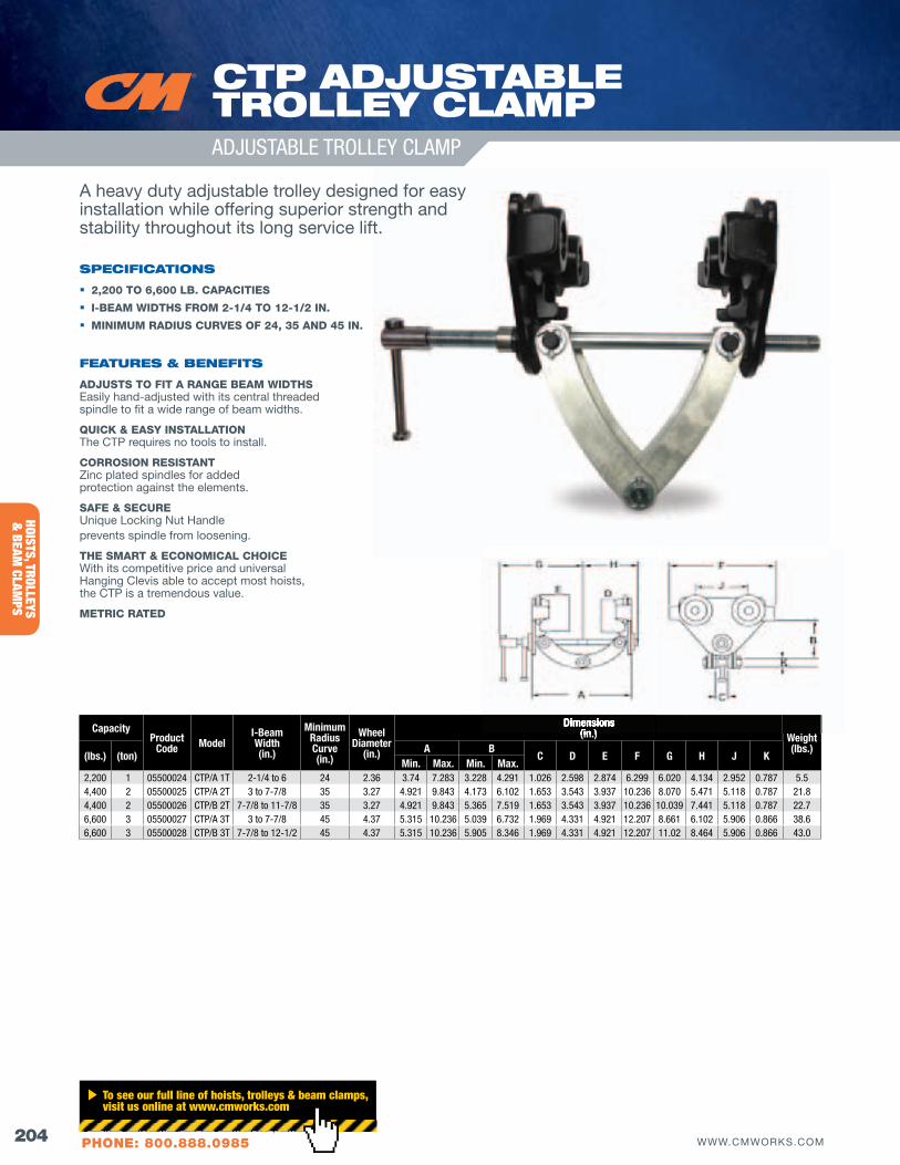
HOISTS, TROLLEYS &
BEAM CLAM
PS
204 WWW.CMWORKS.COMCHAIN & RIGGING ATTACHMENTS (CMRP-6)
PHONE: 800.888.0985
CapacityProduct
Code ModelI-BeamWidth(in.)
Minimum Radius Curve(in.)
Wheel Diameter
(in.)
Dimensions(in.) Weight
(lbs.)(lbs.) (ton)
A BC D E f G H J K
Min. Max. Min. Max.2,200 1 05500024 CTP/A 1T 2-1/4 to 6 24 2.36 3.74 7.283 3.228 4.291 1.026 2.598 2.874 6.299 6.020 4.134 2.952 0.787 5.54,400 2 05500025 CTP/A 2T 3 to 7-7/8 35 3.27 4.921 9.843 4.173 6.102 1.653 3.543 3.937 10.236 8.070 5.471 5.118 0.787 21.84,400 2 05500026 CTP/B 2T 7-7/8 to 11-7/8 35 3.27 4.921 9.843 5.365 7.519 1.653 3.543 3.937 10.236 10.039 7.441 5.118 0.787 22.76,600 3 05500027 CTP/A 3T 3 to 7-7/8 45 4.37 5.315 10.236 5.039 6.732 1.969 4.331 4.921 12.207 8.661 6.102 5.906 0.866 38.66,600 3 05500028 CTP/B 3T 7-7/8 to 12-1/2 45 4.37 5.315 10.236 5.905 8.346 1.969 4.331 4.921 12.207 11.02 8.464 5.906 0.866 43.0
CTP AdjuSTAblE TRollEy ClAMPADJUSTABLE TROLLEY CLAMP
A heavy duty adjustable trolley designed for easy installation while offering superior strength and stability throughout its long service lift.
SPECIfICATIoNS
2,200 TO 6,600 LB. CAPACITIES
I-BEAM WIDTHS fROM 2-1/4 TO 12-1/2 IN.
MINIMUM RADIUS CURVES Of 24, 35 AND 45 IN.
fEATuRES & bENEfITS
ADJUSTS TO fIT A RANGE BEAM WIDTHSEasily hand-adjusted with its central threaded spindle to fit a wide range of beam widths.
QUICK & EASY INSTALLATIONThe CTP requires no tools to install.
CORROSION RESISTANTZinc plated spindles for added protection against the elements.
SAfE & SECUREUnique Locking Nut Handleprevents spindle from loosening.
THE SMART & ECONOMICAL CHOICEWith its competitive price and universal Hanging Clevis able to accept most hoists, the CTP is a tremendous value.
METRIC RATED
Dimensions(in.)
CHAIN & RIGGING ATTACHMENTS (CMRP-6)
To see our full line of hoists, trolleys & beam clamps, visit us online at www.cmworks.com
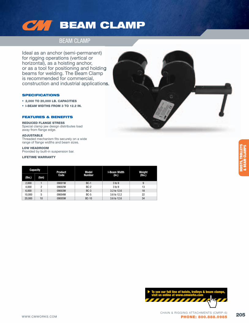
BELO
W T
HE H
OOK
HOIS
TS, T
ROLL
EYS
&
BEA
M C
LAM
PS
205WWW.CMWORKS.COMCHAIN & RIGGING ATTACHMENTS (CMRP-6)
PHONE: 800.888.0985
Ideal as an anchor (semi-permanent) for rigging operations (vertical or horizontal), as a hoisting anchor, or as a tool for positioning and holding beams for welding. The Beam Clamp is recommended for commercial, construction and industrial applications.
SPECIfICATIoNS
2,000 TO 20,000 LB. CAPACITIES
I-BEAM WIDTHS fROM 3 TO 12.2 IN.
fEATuRES & bENEfITS
REDUCED fLANGE STRESSSpecial clamp jaw design distributes load away from flange edge.
ADJUSTABLEThreaded mechanism fits securely on a wide range of flange widths and beam sizes.
LOW HEADROOMProvided by built-in suspension bar.
LIfETIME WARRANTY
bEAM ClAMP
BEAM CLAMP
CapacityProduct
CodeModel
NumberI-Beam Width
(in.)Weight(lbs.)
(lbs.) (ton)
2,000 1 09001W BC-1 3 to 9 94,000 2 09002W BC-2 3 to 9 136,000 3 09003W BC-3 3.2 to 12.6 18
10,000 5 09004W BC-5 3.6 to 12.2 2220,000 10 09005W BC-10 3.6 to 12.6 34
or as a tool for positioning and holding
construction and industrial applications.
To see our full line of hoists, trolleys & beam clamps, visit us online at www.cmworks.com
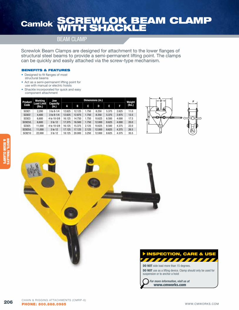
206 WWW.CMWORKS.COMCHAIN & RIGGING ATTACHMENTS (CMRP-6)
PHONE: 800.888.0985
HOISTS, TROLLEYS &
BEAM CLAM
PS
Screwlok Beam Clamps are designed for attachment to the lower flanges of structural steel beams to provide a semi-permanent lifting point. The clamps can be quickly and easily attached via the screw-type mechanism.
EB
AD F
C
ProductCode
Working Load Limit
(lbs.)
Jaw Capacity
(in.)
Dimensions (in.)Weight(lbs.)A B C D E f
SC921 2,200 3 to 8-1/4 12.625 12.125 1.750 8.250 5.375 2.625 11.0SC922 4,400 3 to 8-1/4 12.625 12.875 1.750 8.250 5.375 2.875 13.5SC923 6,600 4 to 10-5/8 16.125 14.750 1.750 10.625 6.500 4.000 17.5
SC923/L 6,600 3 to 12 17.375 16.500 1.750 12.000 8.625 4.000 20.0SC925 11,000 4 to 10-5/8 16.125 15.375 2.125 10.625 8.500 4.375 22.0
SC925/L 11,000 3 to 12 17.125 17.125 2.125 12.000 8.625 4.375 26.5SC9210 22,000 3 to 12 18.125 20.000 3.250 12.000 8.625 4.375 35.5
SCREwloK bEAM ClAMP wITH SHACKlE
bENEfITS & fEATuRES Designed to fit flanges of most
structural beams Act as a semi-permanent lifting point for
use with manual or electric hoists Shackle incorporated for quick and easy
component attachment
INSPECTIoN, CARE & uSE
DO NOT side load more than 15 degrees.
DO NOT use as a lifting device. Clamp should only be used for suspension or to anchor a hoist
For more information, visit us at www.cmworks.com
BEAM CLAMP
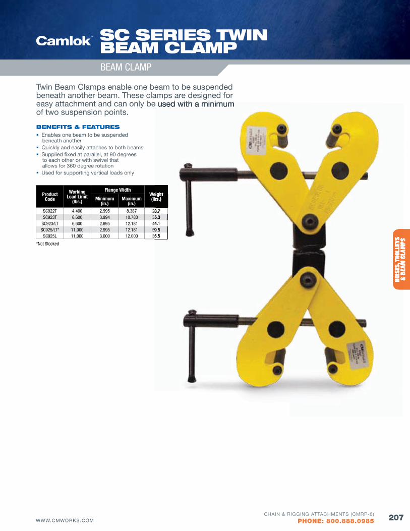
207WWW.CMWORKS.COMCHAIN & RIGGING ATTACHMENTS (CMRP-6)
PHONE: 800.888.0985
BELO
W T
HE H
OOK
HOIS
TS, T
ROLL
EYS
&
BEA
M C
LAM
PS
Twin Beam Clamps enable one beam to be suspended beneath another beam. These clamps are designed for easy attachment and can only be used with a minimum of two suspension points.
*Not Stocked
ProductCode
Working Load Limit
(lbs.)
flange WidthWeight(lbs.)Minimum
(in.)Maximum
(in.)SC922T 4,400 2.995 8.387 28.7 SC923T 6,600 3.994 10.783 35.3
SC923/LT 6,600 2.995 12.181 44.1 SC925/LT* 11,000 2.995 12.181 59.5
SC925L 11,000 3.000 12.000 35.5
bENEfITS & fEATuRES Enables one beam to be suspended
beneath another Quickly and easily attaches to both beams Supplied fixed at parallel, at 90 degrees
to each other or with swivel that allows for 360 degree rotation
Used for supporting vertical loads only
SC SERIES TwIN bEAM ClAMPBEAM CLAMP
HOIS
TS, T
ROLL
EYS
& B
EAM
CLA
MPS
easy attachment and can only be used with a minimum
Weight(lbs.)
28.7 35.3 44.1 59.535.5
208 WWW.CMWORKS.COMCHAIN & RIGGING ATTACHMENTS (CMRP-6)
PHONE: 800.888.0985
ACRPAssociation of Crane & Rigging Professionals 28175 Haggerty Road, Novi, MI 48377(800) 690-3921
ANSI Refers to American National Standards Institute Specifications published by ANSI 1899 L Street, NW, 11th Floor Washington, DC, 20036(202) 293-8020.
ASME The American Society of Mechanical Engineers Two Park Avenue, New York, NY 10016-5990(800) 843-2763.
ASTM Refers to American Society of Testing and Materials Specifications published by ASTM100 Barr Harbor Dr., West Conshohocken, PA 19428(610) 832-9500
AwEAAmerican Wind Energy Association 1501 M St. NW, Suite 1000, Washington, DC 20005(202) 383-2500
AwRfAssociated Wire Rope FabricatorsP.O. Box 748, Walled Lake, MI 48390(800) 444-2973
CvSA Commercial vehicle Safety Alliance 6303 Ivy Lane, Suite 310, Greenbelt, MD 20770-6319(301) 830-6143
doT Department of Transportation 1200 New Jersey Ave, SE, Washington, DC 20590(202) 366-4000
ISoInternational Organization for Standardization ISO Central Secretariat: Geneva Switzerland
NACM Refers to National Association of Chain Manufacturers Specifications published by NACMPost Office Box 89014, Tucson, AZ 85752-9014(520) 886-0695
oSHA Occupational Safety & Health Administration U.S. Department of Labor200 Constitution Avenue, Washington, D.C. 20210(800) 321-6742.
SC&RASpecialized Carriers & Rigging Association 5870 Trinity Parkway, Suite 200, Centreville, vA 20120 (703) 698-0291
wSTdAWeb Sling & Tie Down Association(443) 640-1070.
ANGlE of loAdING The acute angle between the horizontal and the leg of the rigging referred to as the horizontal angle.
bASKET HITCHRigging a sling in which the sling is passed around the load and both loop eyes or end fittings are attached to the hoist, crane or lifting device.
bRIdlE SlING Sling composed of multiple legs with a fitting that attaches to the lifting hook.
CHoKER HITCH A type of rigging hitch in which the sling is passed around the load then through one loop eye or other end fitting, with the other loop eye or end fitting attached to the hoist, crane or lifting device. This method will reduce the lifting capacity of a sling.
ClEvIS A U-shaped fitting with holes in each end through which a pin or bolt is run.
CoMPETENT PERSoNAs defined by OSHA, this is someone who is capable of identifying existing and predictable hazards in the surroundings or working conditions which are unsanitary, hazardous, or dangerous to employees, and who has authorization to take prompt corrective measures to eliminate them.
CouPlING lINK An alloy steel welded coupling link used as an intermediate link to join alloy steel chain to master links.
dATE CodE (AlSo KNow AS TRACE CodE) A series of letters, numbers or both embossed on products that identifies its manufacturing history.
dESIGN fACToR (SAfETy fACToR) An industry term usually computed by dividing breaking strength by the catalog working load limit andgenerally expressed as a ratio – for example 4:1.
EloNGATIoN A test performed on products to determine the amount of stretch prior to fracture. This is typically stated as a percentage.
loAd The total superimposed weight or force to be overcome by the hoisting and rigging equipment.
MASTER lINKForged or welded steel link used to support all legs of an alloy-steel chain or wire rope sling.
MECHANICAl CouPlING lINK A non-welded, mechanically closed steel link used to attach master links, hooks, and other attachments to alloy steel chain.
MESSENGER SlING A short, standard eye-eye wire rope sling often used to connect between a crane hook and another wire rope sling or bridle.
MINIMuM bREAK foRCE oR MbS The minimum force at which the product has been tested during manufacture that includes testing to break when a constantly increasing force is applied in direct tension. This test is a manufacturer’s attribute acceptance test and SHALL NOT be used as criteria for service and design purposes.
GLOSSARY
oRGANIZATIoNS INduSTRy TERMS
209WWW.CMWORKS.COMCHAIN & RIGGING ATTACHMENTS (CMRP-6)
PHONE: 800.888.0985
ovERHEAd lIfTING The process of lifting that would elevate a freely suspended load to such a position that dropping the load would present a possibility of bodily injury or property damage.
ovERloAd A static or dynamic load in excess of the “Working load Limit.”
PRoof loAd The load applied during a manufacturing proof test.
PRoof TEST oR PRoof foRCE The minimum tensile force applied to a product under a constantly increasing force in direct tension during manufacturing. These tests are manufacturing integrity tests and SHALL NOT be used as criteria for service and design purposes.
QuAlIfIEd PERSoN As defined by OSHA, this is someone who by possession of a recognized degree, certificate, or professional standing, or who by extensive knowledge, training, and experience, has success-fully demonstrated his/her ability to solve or resolve problems relating to the subject matter, the work, or the project.
RATEd loAd (CAPACITy) The maximum load designated by the manufacturer for which a crane, hoist, rigging, or other lifting device is designed and built. Can also be expressed as WLL, SWLL or Capacity.
REACH The effective length of an alloy steel chain sling measured from the top bearing surface of the upper terminal component to the bottom bearing surface of the lower terminal component.
SAfE woRKING loAd lIMIT oR Swll The maximum rated capacity that shall be applied in direct tension to an undamaged straight-line product.
SHoCK loAdING Any condition of rapid lift sudden shifting of load or arrest of a falling load.
SlINGS An assembly made of chain, wire rope or synthetic material with or without end fittings that connects to a lifting mechanism at the top and lower portion supports the load.
TRACE CodE A series of letters, numbers or both embossed on products that identifies its manufacturing history.
TEST loAd A load that is periodically applied to hoisting equipment to ensure that it has the ability to safely handle the rated capacity of the equipment. The test load ranges from 100 to 125 percent of the rated load capacity.
vERTICAl HITCH A method of supporting a load by a single, vertical part or leg of the sling.
woRKING loAd lIMIT (wll) The working load limit of a chain is the maximum load in pounds that should ever be applied to a chain, even when the chain is new and the load is applied in direct tension to a straight length of chain.
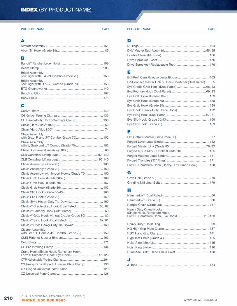
210 WWW.CMWORKS.COMCHAIN & RIGGING ATTACHMENTS (CMRP-6)
PHONE: 800.888.0985
AAircraft Assembly .................................................................. 151
Alloy “S” Hook (Grade 80) ....................................................... 89
bBandit™ Ratchet Lever Hoist ................................................. 198
Beam Clamp .......................................................................... 205
Bridle Assembly Tow Tiger with J & J/T Combo (Grade 70) ............................ 153
Bridle Assembly Tow Tiger with R & J/T Combo (Grade 70) ............................ 153
BTG Groundworks ................................................................. 140
Bundling Clip ......................................................................... 107
Buoy Chain ............................................................................ 175
CCady® Lifters ......................................................................... 142
CG Girder Turning Clamps .................................................... 135
CH Heavy-Duty Horizontal Plate Clamp ............................... 133
Chain (Herc-Alloy® 1000) ......................................................... 62
Chain (Herc-Alloy 800®) ........................................................... 74
Chain Assembly with Grab, R and J/T Combo (Grade 70)............................... 152
Chain Assembly with J, Grab and J/T Combo (Grade 70) ............................... 152
Chain Shortener (Herc-Alloy 1000) .......................................... 66
CLB Container Lifting Lugs ............................................. 92, 140
CLB Container Lifting Lugs .............................................. 92 140
Clevis Assembly (Grade 43) .................................................. 166
Clevis Assembly (Grade 70) .................................................. 150
Clevis Assembly with Import Hooks (Grade 70) .................... 150
Clevis Grab Hook (Grade 30/43) ........................................... 169
Clevis Grab Hook (Grade 70) ................................................ 157
Clevis Grab Hook (Grade 80) ................................................ 157
Clevis Slip Hook (Grade 30/43) ............................................. 168
Clevis Slip Hook (Grade 70) .................................................. 159
Clevis Style Heavy-Duty Tie-Downs ...................................... 160
Clevlok® Cradle Grab Hook (Dual Rated) .......................... 68, 82
Clevlok® Foundry Hook (Dual Rated) ...................................... 69
Clevlok® Grab Hook without Cradle (Grade 80) ...................... 82
Clevlok® Sling Hook (Dual Rated) ...................................... 67, 81
Clevlok® Style Heavy-Duty Tie-Downs .................................. 160
Cluster Assembly with Grab, R Hook & J/T Combo (Grade 70) ......................... 152
CMG Ratchet & Lever Binders .............................................. 163
Cold Shuts ............................................................................. 171
CP Pile Pitching Clamp ......................................................... 134
Crane Hook (Single Hook, Ramshorn Hook, Form B Ramshorn Hook, Eye Hook) ..............................116-123
CTP Adjustable Trolley Clamp ............................................... 204
CX Heavy Duty Hinged Universal Plate Clamp ..................... 130
CY Hinged Universal Plate Clamp ......................................... 129
CZ Universal Plate Clamp ..................................................... 128
DD-Rings ................................................................................. 164
DNv Master Sub-Assembly ............................................... 55, 95
Double Clevis (Mid-Link) ....................................................... 156
Drive Sprocket - Cast ............................................................ 176
Drive Sprocket - Replaceable Teeth ...................................... 176
EE-Z Pro® Cam Release Lever Binder ..................................... 163
EZ•Connect Master Link & Chain Shortener (Dual Rated) ...... 65
Eye Cradle Grab Hook (Dual Rated) .................................. 68, 83
Eye Foundry Hook (Dual Rated) ........................................ 69, 83
Eye Grab Hook (Grade 30/43) ............................................... 169
Eye Grab Hook (Grade 70) .................................................... 158
Eye Grab Hook (Grade 80) .................................................... 158
Eye Hook (Heavy-Duty Crane Hook) ..................................... 122
Eye Sling Hook (Dual Rated) ............................................. 67, 81
Eye Slip Hook (Grade 30/43) ................................................. 168
Eye Slip Hook (Grade 70) ...................................................... 159
fFlat Bottom Master Link (Grade 80) ........................................ 77
Forged Lever Load Binder ..................................................... 162
Forged Master Link (Grade 80) .......................................... 76, 93
Forged R, T & Mini J Hooks (Grade 70) ................................. 155
Forged Ratchet Load Binder ................................................. 161
Forged Triangles (“D” Rings) ................................................. 171
Form B Ramshorn Hook (Heavy-Duty Crane Hook) ............. 120
GGrab Link (Grade 80) ............................................................... 79
Grinding Mill Liner Bolts ........................................................ 179
HHammerlok® (Dual Rated) ........................................................ 66
Hammerlok® (Grade 80) ........................................................... 80
Hanger Chain (Grade 30) ....................................................... 167
Heavy Duty Crane Hooks (Single Hook, Ramshorn Hook, Form B Ramshorn Hook, Eye Hook) ..............................116-123
Heavy Duty® Hoist Ring ........................................................... 99
HG High Grip Plate Clamp .................................................... 137
HGC Hand Grip Clamp .......................................................... 141
High Test Chain (Grade 43) ................................................... 165
Hoist Ring (Metric) ................................................................. 115
Hoist Ring Swivel .................................................................. 116
Hurricane 360°™ Hand Chain Hoist ....................................... 198
JJ Hook ................................................................................... 154
INDEX (BY PRODUCT NAME)
PAGEPRODUCT NAME PAGEPRODUCT NAME
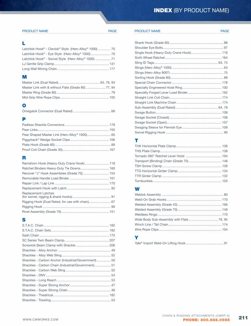
211WWW.CMWORKS.COMCHAIN & RIGGING ATTACHMENTS (CMRP-6)
PHONE: 800.888.0985
LLatchlok Hook® - Clevlok® Style (Herc-Alloy® 1000) .............. 70
Latchlok Hook® - Eye Style (Herc-Alloy® 1000) ...................... 70
Latchlok Hook® - Swivel Style (Herc-Alloy® 1000) ................. 71
LJ Gentle Grip Clamp ............................................................ 131
Long Wall Mining Chain ......................................................... 177
MMaster Link (Dual Rated) ............................................. 64, 76, 93
Master Link with & without Flats (Grade 80) ..................... 77, 94
Master Ring (Grade 80) ........................................................... 79
Mid-Grip Wire Rope Clips ..................................................... 105
OOmegalok Connector (Dual Rated) ......................................... 66
PPadless Shackle Connectors ................................................ 178
Pear Links .............................................................................. 155
Pear Shaped Master Link (Herc-Alloy® 1000) .......................... 65
Piggyback® Wedge Socket Clips .......................................... 106
Plate Hook (Grade 80) ............................................................. 89
Proof Coil Chain (Grade 30)................................................... 167
RRamshorn Hook (Heavy-Duty Crane Hook) .......................... 118
Ratchet Binders Heavy-Duty Tie Downs ............................... 160
Recover “J” Hook Assemblies (Grade 70)............................. 154
Removable Handle Load Binder ........................................... 161
Repair Link / Lap Link ........................................................... 170
Replacement Hook with Latch ................................................ 92
Replacement Latches (for swivel, rigging & shank hooks) .......................................... 91
Rigging Hook (Dual Rated, for use with chain) ........................ 67
Rigging Hook .......................................................................... 90
Rivet Assembly (Grade 70) .................................................... 151
SS.T.A.C. Chain ....................................................................... 182
S.T.A.C. Chain Sets ............................................................... 182
Sash Chain ............................................................................ 175
SC Series Twin Beam Clamp................................................. 207
Screwlok Beam Clamp with Shackle .................................... 206
Shackles - Alloy Anchor .......................................................... 49
Shackles - Alloy Web Sling ...................................................... 52
Shackles - Carbon Anchor (Industrial/Government) ............... 50
Shackles - Carbon Chain (Industrial/Government) .................. 51
Shackles - Carbon Web Sling ................................................. 52
Shackles - DNv ....................................................................... 54
Shackles - Long Reach ........................................................... 53
Shackles - Super Strong Anchor ............................................. 47
Shackles - Super Strong Chain ............................................... 48
Shackles - Theatrical ............................................................. 182
Shackles - Trawling ................................................................. 53
Shank Hook (Grade 80) ........................................................... 88
Shoulder Eye Bolts .................................................................. 97
Single Hook (Heavy-Duty Crane Hook) ................................. 116
Sixth Wheel Ratchet .............................................................. 164
Sling ID Tags ...................................................................... 63, 75
Slings (Herc-Alloy® 1000) ........................................................ 63
Slings (Herc-Alloy 800®) .......................................................... 75
Sorting Hook (Grade 80) .......................................................... 88
Special Chain Connector ...................................................... 178
Specialty Engineered Hoist Ring ........................................... 100
Specialty Forged Lever Load Binder ..................................... 162
Straight Link Coil Chain ......................................................... 174
Straight Link Machine Chain ................................................. 174
Sub-Assembly (Dual Rated) .............................................. 64, 78
Swage Button ........................................................................ 108
Swage Socket (Closed) ......................................................... 108
Swage Socket (Open) ............................................................ 107
Swaging Sleeve for Flemish Eye ........................................... 109
Swivel Rigging Hook ............................................................... 90
TTHK Horizontal Plate Clamp.................................................. 136
THS Plate Clamp ................................................................... 138
Tornado 360° Ratchet Lever Hoist ....................................... 194
Transport (Binding) Chain (Grade 70) .................................... 148
TSH Screw Clamp ................................................................. 139
TTG Horizontal Girder Clamp ................................................ 134
TTR Girder Clamp ................................................................. 132
Turnbuckles ........................................................................... 103
WWeblok Assembly ................................................................... 80
Weld-On Grab Hooks ............................................................ 170
Welded Assembly (Grade 43) ................................................ 166
Welded Assembly (Grade 70) ................................................ 149
Weldless Rings ...................................................................... 170
Wide Body Sub-Assembly with Flats ................................ 78, 95
Winch Line / Tail Chain .......................................................... 174
Wire Rope Clips ..................................................................... 104
YYale® Import Weld-On Lifting Hook ......................................... 91
INDEX (BY PRODUCT NAME)
PAGEPRODUCT NAME PAGEPRODUCT NAME
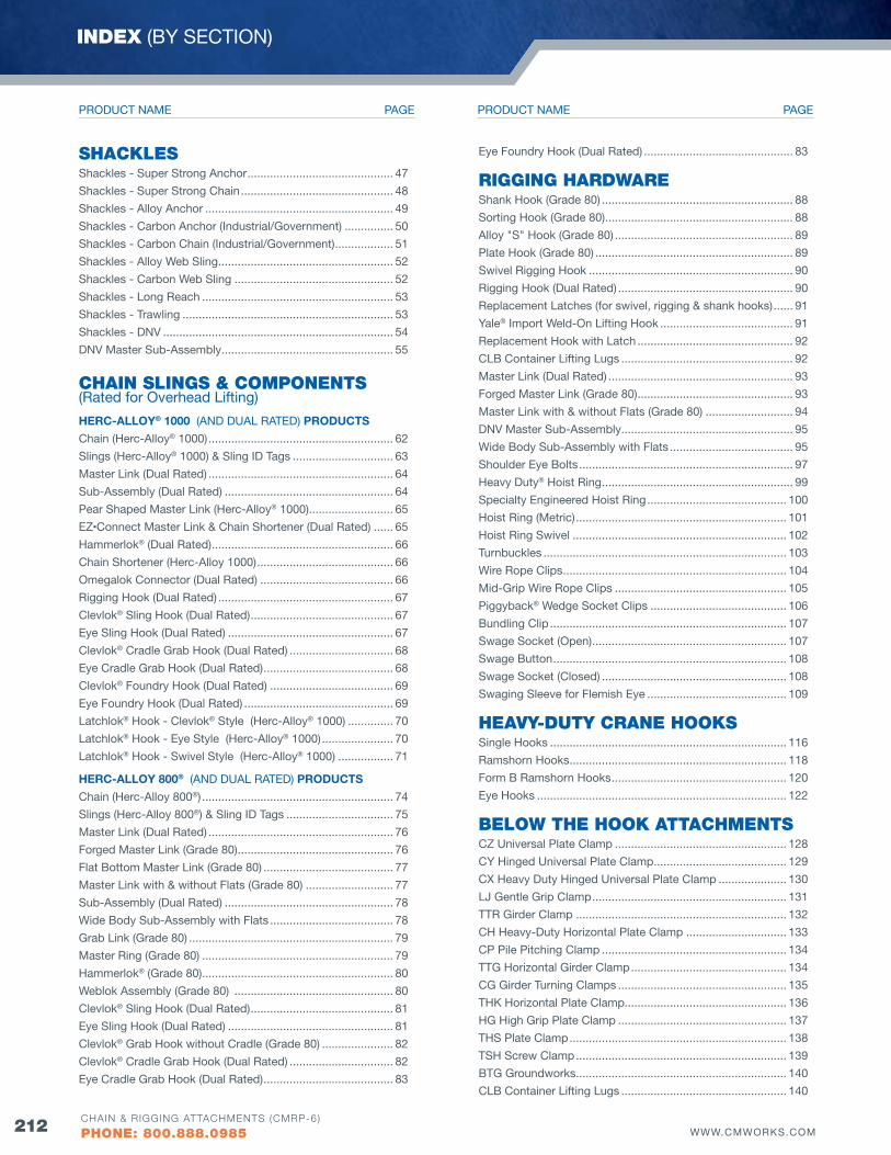
212 WWW.CMWORKS.COMCHAIN & RIGGING ATTACHMENTS (CMRP-6)
PHONE: 800.888.0985
SHACKLESShackles - Super Strong Anchor ............................................. 47
Shackles - Super Strong Chain ............................................... 48
Shackles - Alloy Anchor .......................................................... 49
Shackles - Carbon Anchor (Industrial/Government) ............... 50
Shackles - Carbon Chain (Industrial/Government) .................. 51
Shackles - Alloy Web Sling ...................................................... 52
Shackles - Carbon Web Sling ................................................. 52
Shackles - Long Reach ........................................................... 53
Shackles - Trawling ................................................................. 53
Shackles - DNv ....................................................................... 54
DNv Master Sub-Assembly ..................................................... 55
CHAIN SLINGS & COMPONENTS (Rated for Overhead Lifting)
HERC-ALLOY® 1000 (AND DUAL RATED) PRODUCTS
Chain (Herc-Alloy® 1000) ......................................................... 62
Slings (Herc-Alloy® 1000) & Sling ID Tags ............................... 63
Master Link (Dual Rated) ......................................................... 64
Sub-Assembly (Dual Rated) .................................................... 64
Pear Shaped Master Link (Herc-Alloy® 1000) .......................... 65
EZ•Connect Master Link & Chain Shortener (Dual Rated) ...... 65
Hammerlok® (Dual Rated) ........................................................ 66
Chain Shortener (Herc-Alloy 1000) .......................................... 66
Omegalok Connector (Dual Rated) ......................................... 66
Rigging Hook (Dual Rated) ...................................................... 67
Clevlok® Sling Hook (Dual Rated) ............................................ 67
Eye Sling Hook (Dual Rated) ................................................... 67
Clevlok® Cradle Grab Hook (Dual Rated) ................................ 68
Eye Cradle Grab Hook (Dual Rated) ........................................ 68
Clevlok® Foundry Hook (Dual Rated) ...................................... 69
Eye Foundry Hook (Dual Rated) .............................................. 69
Latchlok® Hook - Clevlok® Style (Herc-Alloy® 1000) .............. 70
Latchlok® Hook - Eye Style (Herc-Alloy® 1000) ...................... 70
Latchlok® Hook - Swivel Style (Herc-Alloy® 1000) ................. 71
HERC-ALLOY 800® (AND DUAL RATED) PRODUCTS
Chain (Herc-Alloy 800®) ........................................................... 74
Slings (Herc-Alloy 800®) & Sling ID Tags ................................. 75
Master Link (Dual Rated) ......................................................... 76
Forged Master Link (Grade 80) ................................................ 76
Flat Bottom Master Link (Grade 80) ........................................ 77
Master Link with & without Flats (Grade 80) ........................... 77
Sub-Assembly (Dual Rated) .................................................... 78
Wide Body Sub-Assembly with Flats ...................................... 78
Grab Link (Grade 80) ............................................................... 79
Master Ring (Grade 80) ........................................................... 79
Hammerlok® (Grade 80) ........................................................... 80
Weblok Assembly (Grade 80) ................................................. 80
Clevlok® Sling Hook (Dual Rated) ............................................ 81
Eye Sling Hook (Dual Rated) ................................................... 81
Clevlok® Grab Hook without Cradle (Grade 80) ...................... 82
Clevlok® Cradle Grab Hook (Dual Rated) ................................ 82
Eye Cradle Grab Hook (Dual Rated) ........................................ 83
Eye Foundry Hook (Dual Rated) .............................................. 83
RIGGING HARDWAREShank Hook (Grade 80) ........................................................... 88
Sorting Hook (Grade 80) .......................................................... 88
Alloy "S" Hook (Grade 80) ....................................................... 89
Plate Hook (Grade 80) ............................................................. 89
Swivel Rigging Hook ............................................................... 90
Rigging Hook (Dual Rated) ...................................................... 90
Replacement Latches (for swivel, rigging & shank hooks) ...... 91
Yale® Import Weld-On Lifting Hook ......................................... 91
Replacement Hook with Latch ................................................ 92
CLB Container Lifting Lugs ..................................................... 92
Master Link (Dual Rated) ......................................................... 93
Forged Master Link (Grade 80) ................................................ 93
Master Link with & without Flats (Grade 80) ........................... 94
DNv Master Sub-Assembly ..................................................... 95
Wide Body Sub-Assembly with Flats ...................................... 95
Shoulder Eye Bolts .................................................................. 97
Heavy Duty® Hoist Ring ........................................................... 99
Specialty Engineered Hoist Ring ........................................... 100
Hoist Ring (Metric) ................................................................. 101
Hoist Ring Swivel .................................................................. 102
Turnbuckles ........................................................................... 103
Wire Rope Clips ..................................................................... 104
Mid-Grip Wire Rope Clips ..................................................... 105
Piggyback® Wedge Socket Clips .......................................... 106
Bundling Clip ......................................................................... 107
Swage Socket (Open) ............................................................ 107
Swage Button ........................................................................ 108
Swage Socket (Closed) ......................................................... 108
Swaging Sleeve for Flemish Eye ........................................... 109
HEAVY-DuTY CRANE HOOKSSingle Hooks ......................................................................... 116
Ramshorn Hooks ................................................................... 118
Form B Ramshorn Hooks ...................................................... 120
Eye Hooks ............................................................................. 122
bELOW THE HOOK ATTACHMENTSCZ Universal Plate Clamp ..................................................... 128
CY Hinged Universal Plate Clamp ......................................... 129
CX Heavy Duty Hinged Universal Plate Clamp ..................... 130
LJ Gentle Grip Clamp ............................................................ 131
TTR Girder Clamp ................................................................. 132
CH Heavy-Duty Horizontal Plate Clamp ............................... 133
CP Pile Pitching Clamp ......................................................... 134
TTG Horizontal Girder Clamp ................................................ 134
CG Girder Turning Clamps .................................................... 135
THK Horizontal Plate Clamp.................................................. 136
HG High Grip Plate Clamp .................................................... 137
THS Plate Clamp ................................................................... 138
TSH Screw Clamp ................................................................. 139
BTG Groundworks ................................................................. 140
CLB Container Lifting Lugs ................................................... 140
INDEX (BY SECTION)
PAGEPRODUCT NAME PAGEPRODUCT NAME
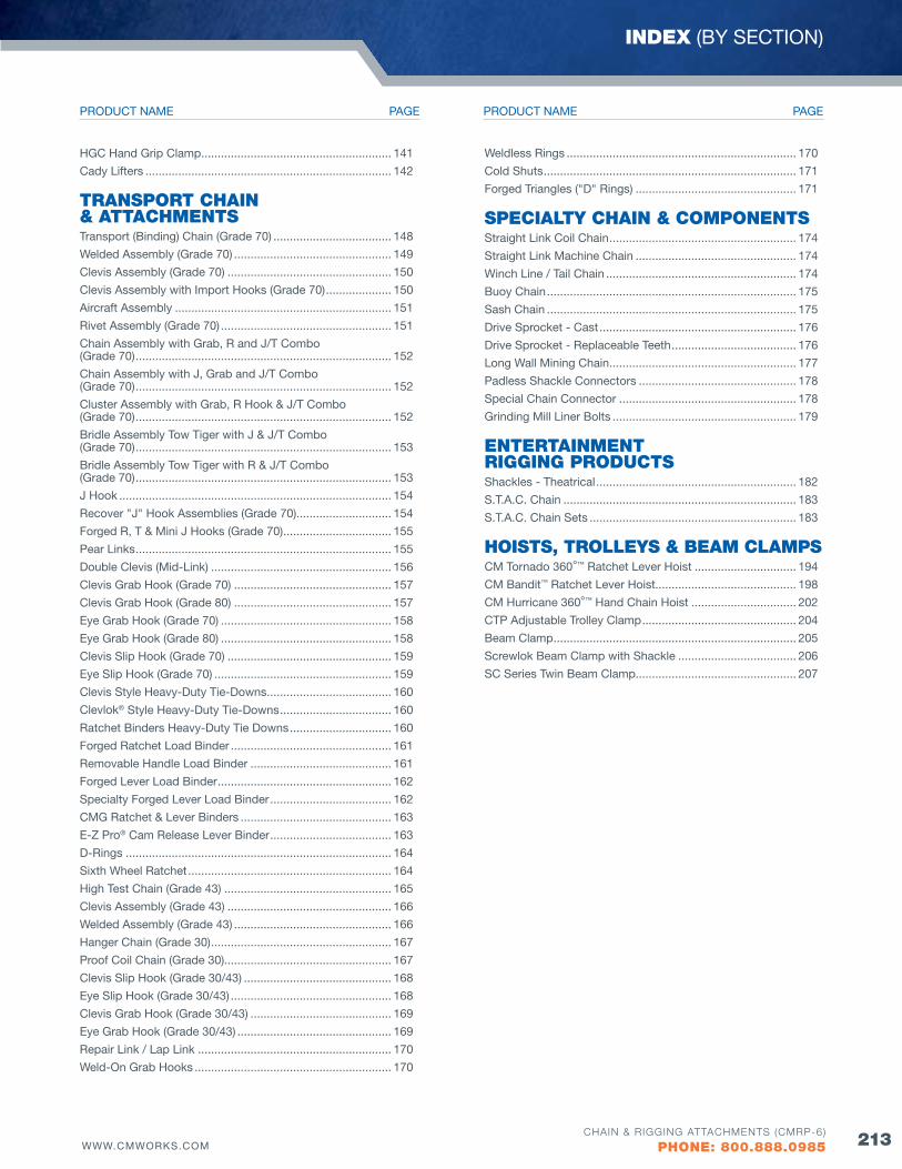
213WWW.CMWORKS.COMCHAIN & RIGGING ATTACHMENTS (CMRP-6)
PHONE: 800.888.0985
HGC Hand Grip Clamp .......................................................... 141
Cady Lifters ........................................................................... 142
TRANSPORT CHAIN & ATTACHMENTSTransport (Binding) Chain (Grade 70) .................................... 148
Welded Assembly (Grade 70) ................................................ 149
Clevis Assembly (Grade 70) .................................................. 150
Clevis Assembly with Import Hooks (Grade 70) .................... 150
Aircraft Assembly .................................................................. 151
Rivet Assembly (Grade 70) .................................................... 151
Chain Assembly with Grab, R and J/T Combo (Grade 70) .............................................................................. 152
Chain Assembly with J, Grab and J/T Combo (Grade 70) .............................................................................. 152
Cluster Assembly with Grab, R Hook & J/T Combo (Grade 70) .............................................................................. 152
Bridle Assembly Tow Tiger with J & J/T Combo (Grade 70) .............................................................................. 153
Bridle Assembly Tow Tiger with R & J/T Combo (Grade 70) .............................................................................. 153
J Hook ................................................................................... 154
Recover "J" Hook Assemblies (Grade 70)............................. 154
Forged R, T & Mini J Hooks (Grade 70) ................................. 155
Pear Links .............................................................................. 155
Double Clevis (Mid-Link) ....................................................... 156
Clevis Grab Hook (Grade 70) ................................................ 157
Clevis Grab Hook (Grade 80) ................................................ 157
Eye Grab Hook (Grade 70) .................................................... 158
Eye Grab Hook (Grade 80) .................................................... 158
Clevis Slip Hook (Grade 70) .................................................. 159
Eye Slip Hook (Grade 70) ...................................................... 159
Clevis Style Heavy-Duty Tie-Downs ...................................... 160
Clevlok® Style Heavy-Duty Tie-Downs .................................. 160
Ratchet Binders Heavy-Duty Tie Downs ............................... 160
Forged Ratchet Load Binder ................................................. 161
Removable Handle Load Binder ........................................... 161
Forged Lever Load Binder ..................................................... 162
Specialty Forged Lever Load Binder ..................................... 162
CMG Ratchet & Lever Binders .............................................. 163
E-Z Pro® Cam Release Lever Binder ..................................... 163
D-Rings ................................................................................. 164
Sixth Wheel Ratchet .............................................................. 164
High Test Chain (Grade 43) ................................................... 165
Clevis Assembly (Grade 43) .................................................. 166
Welded Assembly (Grade 43) ................................................ 166
Hanger Chain (Grade 30) ....................................................... 167
Proof Coil Chain (Grade 30)................................................... 167
Clevis Slip Hook (Grade 30/43) ............................................. 168
Eye Slip Hook (Grade 30/43) ................................................. 168
Clevis Grab Hook (Grade 30/43) ........................................... 169
Eye Grab Hook (Grade 30/43) ............................................... 169
Repair Link / Lap Link ........................................................... 170
Weld-On Grab Hooks ............................................................ 170
Weldless Rings ...................................................................... 170
Cold Shuts ............................................................................. 171
Forged Triangles ("D" Rings) ................................................. 171
SPECIALTY CHAIN & COMPONENTSStraight Link Coil Chain ......................................................... 174
Straight Link Machine Chain ................................................. 174
Winch Line / Tail Chain .......................................................... 174
Buoy Chain ............................................................................ 175
Sash Chain ............................................................................ 175
Drive Sprocket - Cast ............................................................ 176
Drive Sprocket - Replaceable Teeth ...................................... 176
Long Wall Mining Chain ......................................................... 177
Padless Shackle Connectors ................................................ 178
Special Chain Connector ...................................................... 178
Grinding Mill Liner Bolts ........................................................ 179
ENTERTAINMENT RIGGING PRODuCTSShackles - Theatrical ............................................................. 182
S.T.A.C. Chain ....................................................................... 183
S.T.A.C. Chain Sets ............................................................... 183
HOISTS, TROLLEYS & bEAM CLAMPSCM Tornado 360°™ Ratchet Lever Hoist ............................... 194
CM Bandit™ Ratchet Lever Hoist........................................... 198
CM Hurricane 360°™ Hand Chain Hoist ................................ 202
CTP Adjustable Trolley Clamp ............................................... 204
Beam Clamp .......................................................................... 205
Screwlok Beam Clamp with Shackle .................................... 206
SC Series Twin Beam Clamp................................................. 207
INDEX (BY SECTION)
PAGEPRODUCT NAME PAGEPRODUCT NAME
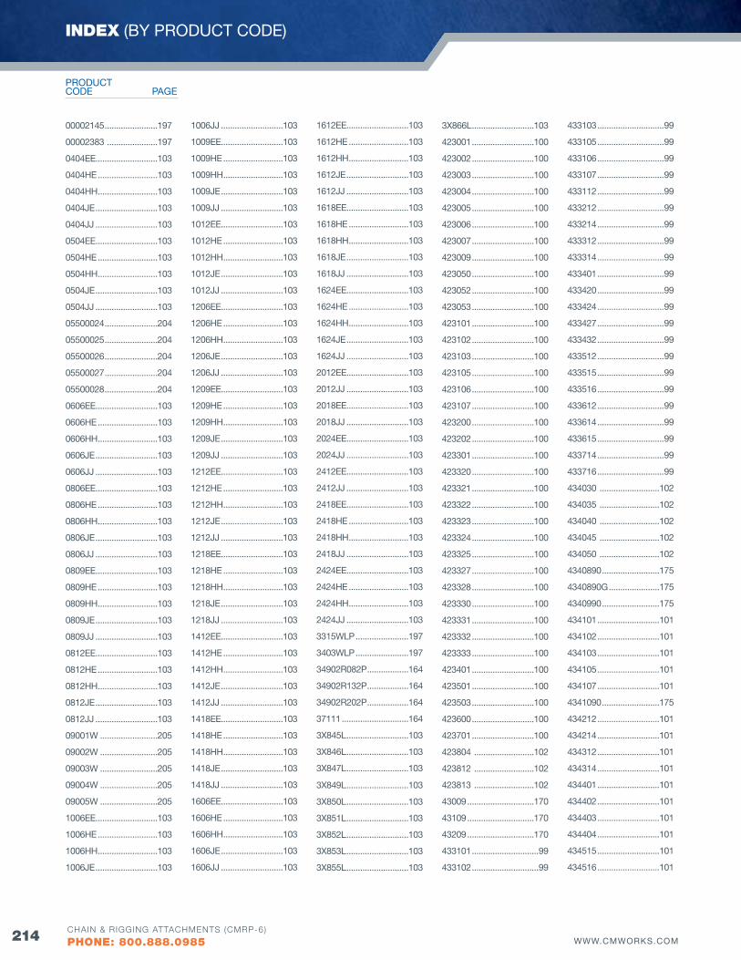
214 WWW.CMWORKS.COMCHAIN & RIGGING ATTACHMENTS (CMRP-6)
PHONE: 800.888.0985
00002145 .......................197
00002383 ......................197
0404EE...........................103
0404HE ..........................103
0404HH ..........................103
0404JE ...........................103
0404JJ ...........................103
0504EE...........................103
0504HE ..........................103
0504HH ..........................103
0504JE ...........................103
0504JJ ...........................103
05500024 .......................204
05500025 .......................204
05500026 .......................204
05500027 .......................204
05500028 .......................204
0606EE...........................103
0606HE ..........................103
0606HH ..........................103
0606JE ...........................103
0606JJ ...........................103
0806EE...........................103
0806HE ..........................103
0806HH ..........................103
0806JE ...........................103
0806JJ ...........................103
0809EE...........................103
0809HE ..........................103
0809HH ..........................103
0809JE ...........................103
0809JJ ...........................103
0812EE...........................103
0812HE ..........................103
0812HH ..........................103
0812JE ...........................103
0812JJ ...........................103
09001W .........................205
09002W .........................205
09003W .........................205
09004W .........................205
09005W .........................205
1006EE...........................103
1006HE ..........................103
1006HH ..........................103
1006JE ...........................103
1006JJ ...........................103
1009EE...........................103
1009HE ..........................103
1009HH ..........................103
1009JE ...........................103
1009JJ ...........................103
1012EE...........................103
1012HE ..........................103
1012HH ..........................103
1012JE ...........................103
1012JJ ...........................103
1206EE...........................103
1206HE ..........................103
1206HH ..........................103
1206JE ...........................103
1206JJ ...........................103
1209EE...........................103
1209HE ..........................103
1209HH ..........................103
1209JE ...........................103
1209JJ ...........................103
1212EE...........................103
1212HE ..........................103
1212HH ..........................103
1212JE ...........................103
1212JJ ...........................103
1218EE...........................103
1218HE ..........................103
1218HH ..........................103
1218JE ...........................103
1218JJ ...........................103
1412EE...........................103
1412HE ..........................103
1412HH ..........................103
1412JE ...........................103
1412JJ ...........................103
1418EE...........................103
1418HE ..........................103
1418HH ..........................103
1418JE ...........................103
1418JJ ...........................103
1606EE...........................103
1606HE ..........................103
1606HH ..........................103
1606JE ...........................103
1606JJ ...........................103
1612EE...........................103
1612HE ..........................103
1612HH ..........................103
1612JE ...........................103
1612JJ ...........................103
1618EE...........................103
1618HE ..........................103
1618HH ..........................103
1618JE ...........................103
1618JJ ...........................103
1624EE...........................103
1624HE ..........................103
1624HH ..........................103
1624JE ...........................103
1624JJ ...........................103
2012EE...........................103
2012JJ ...........................103
2018EE...........................103
2018JJ ...........................103
2024EE...........................103
2024JJ ...........................103
2412EE...........................103
2412JJ ...........................103
2418EE...........................103
2418HE ..........................103
2418HH ..........................103
2418JJ ...........................103
2424EE...........................103
2424HE ..........................103
2424HH ..........................103
2424JJ ...........................103
3315WLP .......................197
3403WLP .......................197
34902R082P ..................164
34902R132P ..................164
34902R202P ..................164
37111 .............................164
3X845L ...........................103
3X846L ...........................103
3X847L ...........................103
3X849L ...........................103
3X850L ...........................103
3X851L ...........................103
3X852L ...........................103
3X853L ...........................103
3X855L ...........................103
3X866L ...........................103
423001 ...........................100
423002 ...........................100
423003 ...........................100
423004 ...........................100
423005 ...........................100
423006 ...........................100
423007 ...........................100
423009 ...........................100
423050 ...........................100
423052 ...........................100
423053 ...........................100
423101 ...........................100
423102 ...........................100
423103 ...........................100
423105 ...........................100
423106 ...........................100
423107 ...........................100
423200 ...........................100
423202 ...........................100
423301 ...........................100
423320 ...........................100
423321 ...........................100
423322 ...........................100
423323 ...........................100
423324 ...........................100
423325 ...........................100
423327 ...........................100
423328 ...........................100
423330 ...........................100
423331 ...........................100
423332 ...........................100
423333 ...........................100
423401 ...........................100
423501 ...........................100
423503 ...........................100
423600 ...........................100
423701 ...........................100
423804 ..........................102
423812 ..........................102
423813 ..........................102
43009 .............................170
43109 .............................170
43209 .............................170
433101 .............................99
433102 .............................99
433103 .............................99
433105 .............................99
433106 .............................99
433107 .............................99
433112 .............................99
433212 .............................99
433214 .............................99
433312 .............................99
433314 .............................99
433401 .............................99
433420 .............................99
433424 .............................99
433427 .............................99
433432 .............................99
433512 .............................99
433515 .............................99
433516 .............................99
433612 .............................99
433614 .............................99
433615 .............................99
433714 .............................99
433716 .............................99
434030 ..........................102
434035 ..........................102
434040 ..........................102
434045 ..........................102
434050 ..........................102
4340890 .........................175
4340890G ......................175
4340990 .........................175
434101 ...........................101
434102 ...........................101
434103 ...........................101
434105 ...........................101
434107 ...........................101
4341090 .........................175
434212 ...........................101
434214 ...........................101
434312 ...........................101
434314 ...........................101
434401 ...........................101
434402 ...........................101
434403 ...........................101
434404 ...........................101
434515 ...........................101
434516 ...........................101
INDEX (BY PRODUCT CODE)
PAGECODEPRODUCT
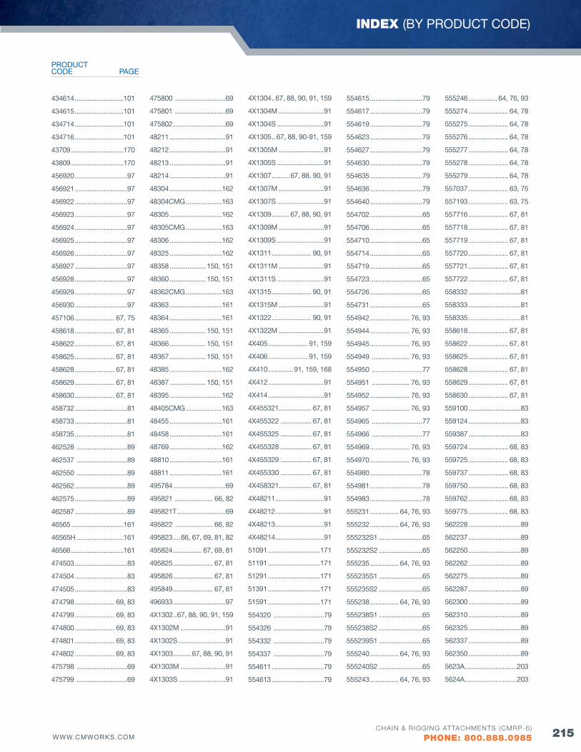
215WWW.CMWORKS.COMCHAIN & RIGGING ATTACHMENTS (CMRP-6)
PHONE: 800.888.0985
INDEX (BY PRODUCT CODE)
434614 ...........................101
434615 ...........................101
434714 ...........................101
434716 ...........................101
43709 .............................170
43809 .............................170
456920 .............................97
456921 .............................97
456922 .............................97
456923 .............................97
456924 .............................97
456925 .............................97
456926 .............................97
456927 .............................97
456928 .............................97
456929 .............................97
456930 .............................97
457106 ...................... 67, 75
458618 ...................... 67, 81
458622 ...................... 67, 81
458625 ...................... 67, 81
458628 ...................... 67, 81
458629 ...................... 67, 81
458630 ...................... 67, 81
458732 .............................81
458733 .............................81
458735 .............................81
462528 ............................89
462537 ............................89
462550 ............................89
462562 .............................89
462575 .............................89
462587 .............................89
46565 .............................161
46565H ..........................161
46566 .............................161
474503 .............................83
474504 .............................83
474505 .............................83
474798 ...................... 69, 83
474799 ...................... 69, 83
474800 ...................... 69, 83
474801 ...................... 69, 83
474802 ...................... 69, 83
475798 ............................69
475799 ............................69
475800 ............................69
475801 ............................69
475802 .............................69
48211 ...............................91
48212 ...............................91
48213 ...............................91
48214 ...............................91
48304 .............................162
48304CMG ....................163
48305 .............................162
48305CMG ....................163
48306 .............................162
48325 .............................162
48358 .................... 150, 151
48360 .................... 150, 151
48362CMG ....................163
48363 .............................161
48364 .............................161
48365 .................... 150, 151
48366 .................... 150, 151
48367 .................... 150, 151
48385 .............................162
48387 .................... 150, 151
48395 .............................162
48405CMG ....................163
48455 .............................161
48458 .............................161
48769 .............................162
48810 .............................161
48811 .............................161
495784 .............................69
495821 ..................... 66, 82
495821T ...........................69
495822 ..................... 66, 82
495823 ....66, 67, 69, 81, 82
495824 ................ 67, 69, 81
495825 ...................... 67, 81
495826 ...................... 67, 81
495849 ...................... 67, 81
496933 .............................97
4X1302 ..67, 88, 90, 91, 159
4X1302M .........................91
4X1302S ..........................91
4X1303 ..........67, 88, 90, 91
4X1303M .........................91
4X1303S ..........................91
4X1304 ..67, 88, 90, 91, 159
4X1304M .........................91
4X1304S ..........................91
4X1305 .. 67, 88, 90-91, 159
4X1305M .........................91
4X1305S ..........................91
4X1307 ..........67, 88, 90, 91
4X1307M .........................91
4X1307S ..........................91
4X1309 ..........67, 88, 90, 91
4X1309M .........................91
4X1309S ..........................91
4X1311 ...................... 90, 91
4X1311M .........................91
4X1311S ..........................91
4X1315 ...................... 90, 91
4X1315M .........................91
4X1322 ...................... 90, 91
4X1322M .........................91
4X405 ...................... 91, 159
4X406 ...................... 91, 159
4X410 ..............91, 159, 168
4X412 ...............................91
4X414 ...............................91
4X455321.................. 67, 81
4X455322 ................. 67, 81
4X455325 ................. 67, 81
4X455328 ................. 67, 81
4X455329 ................. 67, 81
4X455330 ................. 67, 81
4X458321.................. 67, 81
4X48211 ...........................91
4X48212 ...........................91
4X48213 ...........................91
4X48214 ...........................91
51091 .............................171
51191 .............................171
51291 .............................171
51391 .............................171
51591 .............................171
554320 ............................79
554326 ............................79
554332 ............................79
554337 ............................79
554611 .............................79
554613 .............................79
554615 .............................79
554617 .............................79
554619 .............................79
554623 .............................79
554627 .............................79
554630 .............................79
554635 .............................79
554636 .............................79
554640 .............................79
554702 .............................65
554706 .............................65
554710 .............................65
554714 .............................65
554719 .............................65
554723 .............................65
554726 .............................65
554731 .............................65
554942 ...................... 76, 93
554944 ...................... 76, 93
554945 ...................... 76, 93
554949 ..................... 76, 93
554950 ............................77
554951 ..................... 76, 93
554952 ...................... 76, 93
554957 ..................... 76, 93
554965 ............................77
554966 ............................77
554969 ...................... 76, 93
554970 ...................... 76, 93
554980 .............................78
554981 .............................78
554983 .............................78
555231 ................ 64, 76, 93
555232 ................ 64, 76, 93
555232S1 ........................65
555232S2 ........................65
555235 ................ 64, 76, 93
555235S1 ........................65
555235S2 ........................65
555238 ................ 64, 76, 93
555238S1 ........................65
555238S2 ........................65
555239S1 ........................65
555240 ................ 64, 76, 93
555240S2 ........................65
555243 ................ 64, 76, 93
555246 ................ 64, 76, 93
555274 ...................... 64, 78
555275 ...................... 64, 78
555276 ...................... 64, 78
555277 ...................... 64, 78
555278 ...................... 64, 78
555279 ...................... 64, 78
557037 ...................... 63, 75
557193 ...................... 63, 75
557716 ...................... 67, 81
557718 ...................... 67, 81
557719 ...................... 67, 81
557720 ...................... 67, 81
557721 ...................... 67, 81
557722 ...................... 67, 81
558332 .............................81
558333 .............................81
558335 .............................81
558618 ...................... 67, 81
558622 ...................... 67, 81
558625 ...................... 67, 81
558628 ...................... 67, 81
558629 ...................... 67, 81
558630 ...................... 67, 81
559100 .............................83
559124 .............................83
559387 .............................83
559724 ...................... 68, 83
559725 ...................... 68, 83
559737 ...................... 68, 83
559750 ...................... 68, 83
559762 ...................... 68, 83
559775 ...................... 68, 83
562228 .............................89
562237 .............................89
562250 .............................89
562262 .............................89
562275 .............................89
562287 .............................89
562300 .............................89
562310 .............................89
562325 .............................89
562337 .............................89
562350 .............................89
5623A .............................203
5624A .............................203
PAGECODEPRODUCT
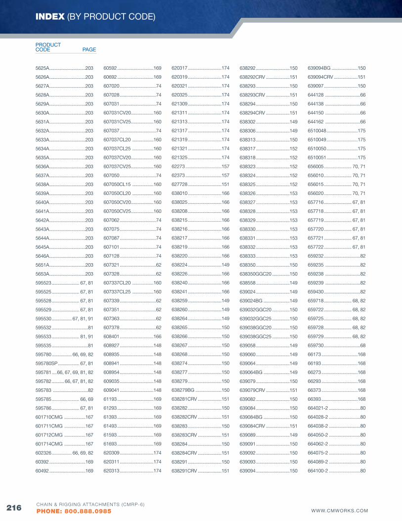
216 WWW.CMWORKS.COMCHAIN & RIGGING ATTACHMENTS (CMRP-6)
PHONE: 800.888.0985
5625A .............................203
5626A .............................203
5627A .............................203
5628A .............................203
5629A .............................203
5630A .............................203
5631A .............................203
5632A .............................203
5633A .............................203
5634A .............................203
5635A .............................203
5636A .............................203
5637A .............................203
5638A .............................203
5639A .............................203
5640A .............................203
5641A .............................203
5642A .............................203
5643A .............................203
5644A .............................203
5645A .............................203
5646A .............................203
5651A .............................203
5653A .............................203
595523 ...................... 67, 81
595525 ...................... 67, 81
595528 ...................... 67, 81
595529 ...................... 67, 81
595530 ................ 67, 81, 91
595532 .............................81
595533 ...................... 81, 91
595535 .............................81
595780 ................ 66, 69, 82
595780SP ................. 67, 81
595781 ....66, 67, 69, 81, 82
595782 ..........66, 67, 81, 82
595783 ............................82
595785 ...................... 66, 69
595786 ...................... 67, 81
601710CMG .................167
601711CMG .................167
601712CMG .................167
601714CMG .................167
602326 ................ 66, 69, 82
60392 .............................169
60492 .............................169
60592 .............................169
60692 .............................169
607020 .............................74
607028 .............................74
607031 .............................74
607031Cv20 ..................160
607031Cv25 ..................160
607037 .............................74
607037CL20 .................160
607037CL25 .................160
607037Cv20 ..................160
607037Cv25 ..................160
607050 .............................74
607050CL15 .................160
607050CL20 .................160
607050Cv20 ..................160
607050Cv25 ..................160
607062 .............................74
607075 .............................74
607087 .............................74
607101 .............................74
607128 .............................74
607321 .............................62
607328 .............................62
607337CL20 .................160
607337CL25 .................160
607339 .............................62
607351 .............................62
607363 .............................62
607378 .............................62
608401 ...........................166
608927 ...........................148
608935 ...........................148
608941 ...........................148
608954 ...........................148
609035 ...........................148
609041 ...........................148
61193 .............................169
61293 .............................169
61393 .............................169
61493 .............................169
61593 .............................169
61693 .............................169
620309 ...........................174
620311 ...........................174
620313 ...........................174
620317 ...........................174
620319 ...........................174
620321 ...........................174
620325 ...........................174
621309 ...........................174
621311 ...........................174
621313 ...........................174
621317 ...........................174
621319 ...........................174
621321 ...........................174
621325 ...........................174
62273 .............................157
62373 .............................157
627728 ...........................151
638010 ...........................166
638025 ...........................166
638208 ...........................166
638215 ...........................166
638216 ...........................166
638217 ...........................166
638219 ...........................166
638220 ...........................166
638224 ...........................149
638226 ...........................166
638240 ...........................166
638241 ...........................166
638259 ...........................149
638260 ...........................149
638264 ...........................149
638265 ...........................150
638266 ...........................150
638267 ...........................150
638268 ...........................150
638274 ...........................150
638277 ...........................150
638279 ...........................150
638279BG .....................150
638281CRv ...................151
638282 ...........................150
638282CRv ...................151
638283 ...........................150
638283CRv ...................151
638284 ...........................150
638284CRv ...................151
638291 ...........................150
638291CRv ...................151
638292 ...........................150
638292CRv ...................151
638293 ...........................150
638293CRv ...................151
638294 ...........................150
638294CRv ...................151
638302 ...........................149
638306 ...........................149
638313 ...........................150
638317 ...........................152
638318 ...........................152
638323 ...........................152
638324 ...........................152
638325 ...........................152
638326 ...........................153
638327 ...........................153
638328 ...........................153
638329 ...........................153
638330 ...........................153
638331 ...........................153
638332 ...........................153
638333 ...........................153
638350 ...........................150
638350GGC20 ..............150
638558 ...........................149
639024 ...........................149
639024BG .....................149
639032GGC20 ..............150
639032GGC25 ..............150
639038GGC20 ..............150
639038GGC25 ..............150
639058 ...........................149
639060 ...........................149
639064 ...........................149
639064BG .....................149
639079 ...........................150
639079CRv ...................151
639082 ...........................150
639084 ...........................150
639084BG .....................150
639084CRv ...................151
639089 ...........................149
639091 ...........................150
639092 ...........................150
639093 ...........................150
639094 ...........................150
639094BG .....................150
639094CRv ...................151
639097 ...........................150
644128 ............................66
644138 ............................66
644150 ............................66
644162 ............................66
6510048 .........................175
6510049 .........................175
6510050 .........................175
6510051 .........................175
656005 ...................... 70, 71
656010 ...................... 70, 71
656015 ...................... 70, 71
656020 ...................... 70, 71
657716 ...................... 67, 81
657718 ...................... 67, 81
657719 ...................... 67, 81
657720 ...................... 67, 81
657721 ...................... 67, 81
657722 ...................... 67, 81
659232 .............................82
659235 ............................82
659238 ............................82
659239 ............................82
659430 .............................82
659718 ...................... 68, 82
659722 ...................... 68, 82
659725 ...................... 68, 82
659728 ...................... 68, 82
659729 ...................... 68, 82
659730 .............................68
66173 .............................168
66193 .............................168
66273 .............................168
66293 .............................168
66373 .............................168
66393 .............................168
664021-2 .........................80
664028-2 .........................80
664038-2 .........................80
664050-2 .........................80
664062-2 .........................80
664075-2 .........................80
664089-2 .........................80
664100-2 .........................80
INDEX (BY PRODUCT CODE)
PAGECODEPRODUCT
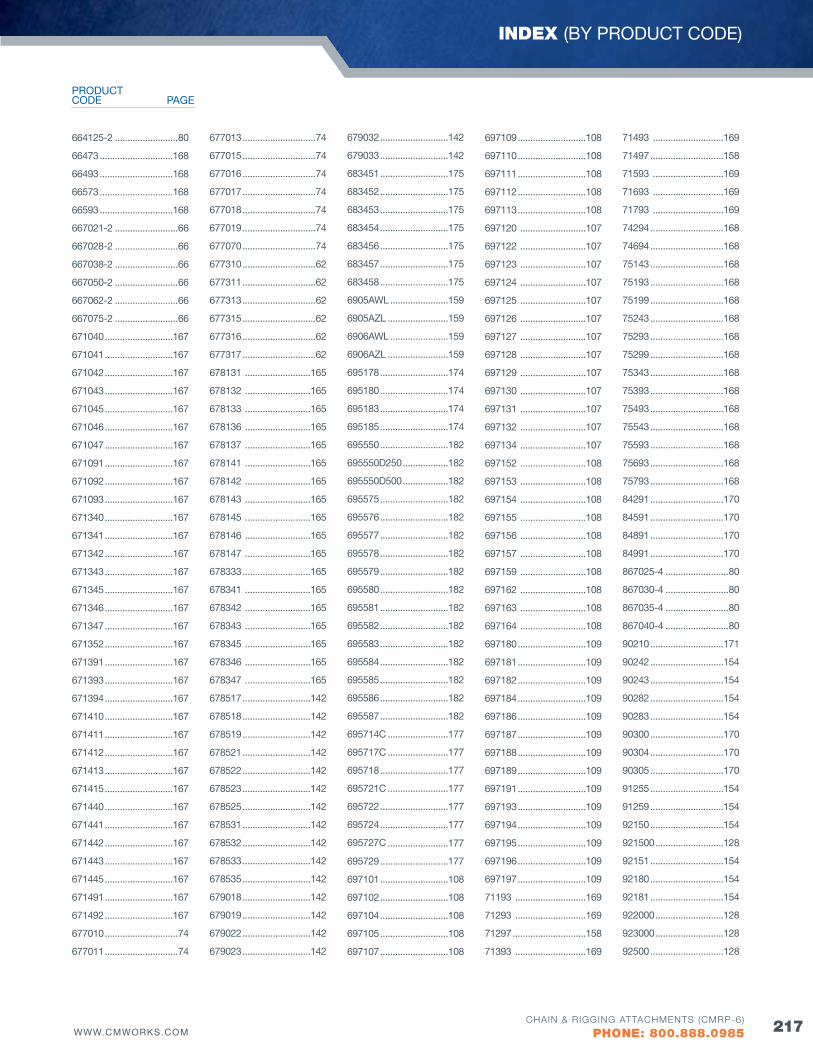
217WWW.CMWORKS.COMCHAIN & RIGGING ATTACHMENTS (CMRP-6)
PHONE: 800.888.0985
INDEX (BY PRODUCT CODE)
664125-2 .........................80
66473 .............................168
66493 .............................168
66573 .............................168
66593 .............................168
667021-2 .........................66
667028-2 .........................66
667038-2 .........................66
667050-2 .........................66
667062-2 .........................66
667075-2 .........................66
671040 ...........................167
671041 ...........................167
671042 ...........................167
671043 ...........................167
671045 ...........................167
671046 ...........................167
671047 ...........................167
671091 ...........................167
671092 ...........................167
671093 ...........................167
671340 ...........................167
671341 ...........................167
671342 ...........................167
671343 ...........................167
671345 ...........................167
671346 ...........................167
671347 ...........................167
671352 ...........................167
671391 ...........................167
671393 ...........................167
671394 ...........................167
671410 ...........................167
671411 ...........................167
671412 ...........................167
671413 ...........................167
671415 ...........................167
671440 ...........................167
671441 ...........................167
671442 ...........................167
671443 ...........................167
671445 ...........................167
671491 ...........................167
671492 ...........................167
677010 .............................74
677011 .............................74
677013 .............................74
677015 .............................74
677016 .............................74
677017 .............................74
677018 .............................74
677019 .............................74
677070 .............................74
677310 .............................62
677311 .............................62
677313 .............................62
677315 .............................62
677316 .............................62
677317 .............................62
678131 ..........................165
678132 ..........................165
678133 ..........................165
678136 ..........................165
678137 ..........................165
678141 ..........................165
678142 ..........................165
678143 ..........................165
678145 ..........................165
678146 ..........................165
678147 ..........................165
678333 ...........................165
678341 ..........................165
678342 ..........................165
678343 ..........................165
678345 ..........................165
678346 ..........................165
678347 ..........................165
678517 ...........................142
678518 ...........................142
678519 ...........................142
678521 ...........................142
678522 ...........................142
678523 ...........................142
678525 ...........................142
678531 ...........................142
678532 ...........................142
678533 ...........................142
678535 ...........................142
679018 ...........................142
679019 ...........................142
679022 ...........................142
679023 ...........................142
679032 ...........................142
679033 ...........................142
683451 ...........................175
683452 ...........................175
683453 ...........................175
683454 ...........................175
683456 ...........................175
683457 ...........................175
683458 ...........................175
6905AWL .......................159
6905AZL ........................159
6906AWL .......................159
6906AZL ........................159
695178 ...........................174
695180 ...........................174
695183 ...........................174
695185 ...........................174
695550 ...........................182
695550D250 ..................182
695550D500 ..................182
695575 ...........................182
695576 ...........................182
695577 ...........................182
695578 ...........................182
695579 ...........................182
695580 ...........................182
695581 ...........................182
695582 ...........................182
695583 ...........................182
695584 ...........................182
695585 ...........................182
695586 ...........................182
695587 ...........................182
695714C ........................177
695717C ........................177
695718 ...........................177
695721C ........................177
695722 ...........................177
695724 ...........................177
695727C ........................177
695729 ...........................177
697101 ...........................108
697102 ...........................108
697104 ...........................108
697105 ...........................108
697107 ...........................108
697109 ...........................108
697110 ...........................108
697111 ...........................108
697112 ...........................108
697113 ...........................108
697120 ..........................107
697122 ..........................107
697123 ..........................107
697124 ..........................107
697125 ..........................107
697126 ..........................107
697127 ..........................107
697128 ..........................107
697129 ..........................107
697130 ..........................107
697131 ..........................107
697132 ..........................107
697134 ..........................107
697152 ..........................108
697153 ..........................108
697154 ..........................108
697155 ..........................108
697156 ..........................108
697157 ..........................108
697159 ..........................108
697162 ..........................108
697163 ..........................108
697164 ..........................108
697180 ...........................109
697181 ...........................109
697182 ...........................109
697184 ...........................109
697186 ...........................109
697187 ...........................109
697188 ...........................109
697189 ...........................109
697191 ...........................109
697193 ...........................109
697194 ...........................109
697195 ...........................109
697196 ...........................109
697197 ...........................109
71193 ............................169
71293 ............................169
71297 .............................158
71393 ............................169
71493 ............................169
71497 .............................158
71593 ............................169
71693 ............................169
71793 ............................169
74294 .............................168
74694 .............................168
75143 .............................168
75193 .............................168
75199 .............................168
75243 .............................168
75293 .............................168
75299 .............................168
75343 .............................168
75393 .............................168
75493 .............................168
75543 .............................168
75593 .............................168
75693 .............................168
75793 .............................168
84291 .............................170
84591 .............................170
84891 .............................170
84991 .............................170
867025-4 .........................80
867030-4 .........................80
867035-4 .........................80
867040-4 .........................80
90210 .............................171
90242 .............................154
90243 .............................154
90282 .............................154
90283 .............................154
90300 .............................170
90304 .............................170
90305 .............................170
91255 .............................154
91259 .............................154
92150 .............................154
921500 ...........................128
92151 .............................154
92180 .............................154
92181 .............................154
922000 ...........................128
923000 ...........................128
92500 .............................128
PAGECODEPRODUCT
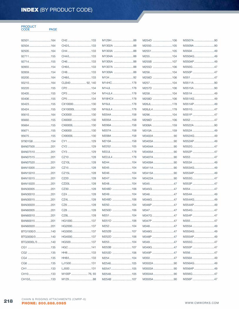
218 WWW.CMWORKS.COMCHAIN & RIGGING ATTACHMENTS (CMRP-6)
PHONE: 800.888.0985
92501 .............................164
92504 .............................164
92505 .............................164
92711 .............................155
92714 .............................155
92855 .............................154
92859 .............................154
93200 .............................164
93210 .............................164
93220 .............................155
93405 .............................155
93406 .............................155
93423 .............................155
93424 .............................155
95610 .............................164
95660 .............................155
95664 .............................155
95671 .............................155
95675 .............................155
97901G8 ........................154
BAN07505 .....................201
BAN07510 .....................201
BAN07515 .....................201
BAN07520 .....................201
BAN15005 .....................201
BAN15010 .....................201
BAN15015 .....................201
BAN15020 .....................201
BAN30005 .....................201
BAN30010 .....................201
BAN30015 .....................201
BAN30020 .....................201
BAN60005 .....................201
BAN60010 .....................201
BAN60015 .....................201
BAN60020 .....................201
BTG1500/3 ....................140
BTG3000/3 ....................140
BTG3000L/3 ..................140
CG1 ...............................135
CG2 ...............................135
CG4 ...............................135
CG6 ...............................135
CH1 ................................133
CH10 ..............................133
CH10/L...........................133
CH2 ................................133
CH2/L .............................133
CH4 ................................133
CH4/L .............................133
CH6 ................................133
CH6/L .............................133
CH8 ................................133
CH8/L .............................133
CLB40 ..................... 92, 140
CP2 ................................134
CP3 ................................134
CP5 ................................134
CX10000 ........................130
CX10000L ......................130
CX3000 ..........................130
CX6000 ..........................130
CX6000L ........................130
CX8000 ..........................130
CX8000L ........................130
CY1 ................................129
CY2 ................................129
CY3 ................................129
CZ10 ..............................128
CZ10L ............................128
CZ15 ..............................128
CZ15L ............................128
CZ20 ..............................128
CZ20L ............................128
CZ30 ..............................128
CZ4 ................................128
CZ4L ..............................128
CZ6 ................................128
CZ8 ................................128
CZ8L ..............................128
HG1000..........................137
HG2000..........................137
HG3000..........................137
HG4000..........................137
HG500 ............................137
HGC ...............................141
HH8 ................................133
HH8/L .............................133
LJ1500 ...........................131
LJ500 .............................131
M100P ...................... 76, 93
M129 ................................88
M129H .............................88
M1302A ..........................88
M1303A ..........................88
M1304A ..........................88
M1305A ..........................88
M1307A ..........................88
M1309A ..........................88
M134 ................................92
M14HC...........................178
M14JL ............................178
M14JL4 ..........................178
M18HC4 ........................178
M18JL ............................178
M18JL4 ..........................178
M204A ...........................158
M205A ...........................158
M206A ...........................158
M207A ...........................158
M208A ...........................158
M210A ...........................158
M2252 ............................105
M22JL ............................178
M22JL4 ..........................178
M244 ..............................104
M245 ..............................104
M246 ..............................104
M247 ..............................104
M248 ..............................104
M248D ..........................106
M249 ..............................104
M249D ..........................106
M250 ..............................104
M250D ..........................106
M251 ..............................104
M251D ..........................106
M252 ..............................104
M252B ..........................107
M252D ..........................106
M253 ..............................104
M253B ..........................107
M253D ..........................106
M254 ..............................104
M2546 ............................105
M2547 ............................105
M2548 ............................105
M254B ..........................107
M254D ..........................106
M2550 ............................105
M2551 ............................105
M255 ..............................104
M255B ..........................107
M255D ..........................106
M256 ..............................104
M256D ..........................106
M257 ..............................104
M257D ..........................106
M258 ..............................104
M258D ..........................106
M26JL ............................178
M26JL4 ..........................178
M296 ..............................104
M296D ..........................106
M308A ...........................159
M310A ...........................159
M3402A ...........................90
M3403A ...........................90
M3404A ...........................90
M3405A ...........................90
M3407A ...........................90
M3409A ...........................90
M3411A ...........................90
M3415A ...........................90
M3422A ...........................90
M345 ................................47
M345G .............................47
M346 ................................47
M346G .............................47
M346P .............................47
M347 ................................47
M347G .............................47
M347P .............................47
M348 ................................47
M348G .............................47
M348P .............................47
M349 ................................47
M349G .............................47
M349P .............................47
M350 ................................47
M3502A ...........................90
M3503A ...........................90
M3504A ...........................90
M3505A ...........................90
M3507A ...........................90
M3509A ...........................90
M350A .............................49
M350AG...........................49
M350AP ...........................49
M350G .............................47
M350P .............................47
M351 ................................47
M3511A ...........................90
M3515A ...........................90
M351A .............................49
M351AG...........................49
M351AP ...........................49
M351G .............................47
M351P .............................47
M352 ................................47
M3522A ...........................90
M352A .............................49
M352AG...........................49
M352AP ...........................49
M352G .............................47
M352P .............................47
M353 ................................47
M353A .............................49
M353AG...........................49
M353AP ...........................49
M353G .............................47
M353P .............................47
M354 ................................47
M354A .............................49
M354AG...........................49
M354AP ...........................49
M354G .............................47
M354P .............................47
M355 ................................47
M355A .............................49
M355AG...........................49
M355AP ...........................49
M355G .............................47
M355P .............................47
M356 ................................47
M356A .............................49
M356AG...........................49
M356AP ...........................49
M356G .............................47
M356P .............................47
INDEX (BY PRODUCT CODE)
PAGECODEPRODUCT

219WWW.CMWORKS.COMCHAIN & RIGGING ATTACHMENTS (CMRP-6)
PHONE: 800.888.0985
INDEX (BY PRODUCT CODE)
M357 ................................47
M357A .............................49
M357AG...........................49
M357AP ...........................49
M357G .............................47
M357P .............................47
M358 ......................... 47, 50
M358A .............................49
M358AG...........................49
M358AP ...........................49
M358G ...................... 47, 50
M358P .............................47
M366 ................................47
M366A .............................49
M366AG...........................49
M366AP ...........................49
M366G .............................47
M366P .............................47
M377 ................................47
M377A .............................49
M377AG...........................49
M377AP ...........................49
M377G .............................47
M377P .............................47
M385 ................................47
M385A .............................49
M385AG...........................49
M385AP ...........................49
M385G .............................47
M385P .............................47
M449G* ............................53
M450 ................................53
M451 ................................53
M452 ................................53
M453 ................................53
M454 ................................53
M50P......................... 76, 93
M546 ................................48
M546G .............................48
M546P .............................48
M547 ................................48
M547G .............................48
M547P .............................48
M548 ................................48
M548G .............................48
M548P .............................48
M550 ................................48
M550G .............................48
M550P .............................48
M551 ................................48
M551G .............................48
M551P .............................48
M552 ................................48
M552G .............................48
M552P .............................48
M553 ................................48
M553G .............................48
M553P .............................48
M554 ................................48
M554G .............................48
M554P .............................48
M555 ................................48
M555G .............................48
M555P .............................48
M556 ................................48
M556G .............................48
M556P .............................48
M557 ................................48
M557G .............................48
M557P .............................48
M558 ......................... 48, 51
M558G ...................... 48, 51
M558P .............................48
M558P .............................48
M566 ................................48
M566G .............................48
M566P .............................48
M577 ................................48
M577G .............................48
M577P .............................48
M585 ................................48
M585G .............................48
M585P .............................48
M605 ..............................156
M606 ..............................156
M608 ..............................156
M610 ..............................156
M616005 .........................70
M616010 .........................70
M616015 .........................70
M616020 .........................70
M626005 .........................70
M626010 .........................70
M626015 .........................70
M626020 .........................70
M62P......................... 76, 93
M6304 ............................159
M6304WL ......................159
M6305 ............................159
M6305WL ......................159
M6306 ............................159
M6306WL ......................159
M6307 ............................159
M6307WL ......................159
M6402A ...........................90
M6402C ...........................90
M6403A ...........................90
M6403C ...........................90
M6404A ...........................90
M6404C ...........................90
M6405A ...........................90
M6405C ...........................90
M6407A ...........................90
M6407C ...........................90
M6409A ...........................90
M6409C ...........................90
M6411A ...........................90
M6411C ...........................90
M6415A ...........................90
M6415C ...........................90
M6422A ...........................90
M6422C ...........................90
M645 ................................47
M645B ...........................183
M645G .............................47
M646 ................................47
M646B ...........................183
M646G .............................47
M646P .............................47
M647 ................................47
M647B ...........................183
M647G .............................47
M647P .............................47
M648 ................................47
M648A .............................49
M648AG...........................49
M648AP ...........................49
M648B ...........................183
M648G .............................47
M648P .............................47
M649 ................................47
M649A .............................49
M649AG...........................49
M649AP ...........................49
M649B ...........................183
M649G .............................47
M649P .............................47
M650 ................................47
M6502A ...........................90
M6502C ...........................90
M6503A ...........................90
M6503C ...........................90
M6504A ...........................90
M6504C ...........................90
M6505A ...........................90
M6505C ...........................90
M6507A ...........................90
M6507C ...........................90
M6509A ...........................90
M6509C ...........................90
M650A .............................49
M650AG...........................49
M650AP ...........................49
M650B ...........................183
M650G .............................47
M650P .............................47
M651 ................................47
M6511A ...........................90
M6511C ...........................90
M6515A ...........................90
M6515C ...........................90
M651A .............................49
M651AG...........................49
M651AP ...........................49
M651B ...........................183
M651G .............................47
M651P .............................47
M652 ................................47
M6522A ...........................90
M6522C ...........................90
M652A .............................49
M652AG...........................49
M652AP ...........................49
M652B ...........................183
M652G .............................47
M652P .............................47
M653 ................................47
M653A .............................49
M653AG...........................49
M653AP ...........................49
M653B ...........................183
M653G .............................47
M653P .............................47
M654 ................................47
M654A .............................49
M654AG...........................49
M654AP ...........................49
M654B ...........................183
M654G .............................47
M654P .............................47
M655 ................................47
M655A .............................49
M655AG...........................49
M655AP ...........................49
M655G .............................47
M655P .............................47
M656 ................................47
M656A .............................49
M656AG...........................49
M656AP ...........................49
M656G .............................47
M656P .............................47
M657 ................................47
M657A .............................49
M657AG...........................49
M657AP ...........................49
M657G .............................47
M657P .............................47
M658 ......................... 47, 50
M658A .............................49
M658AG...........................49
M658AP ...........................49
M658G ...................... 47, 50
M658P ...................... 47, 50
M666 ................................47
M666A .............................49
M666AG...........................49
M666AP ...........................49
M666G .............................47
M666P .............................47
PAGECODEPRODUCT
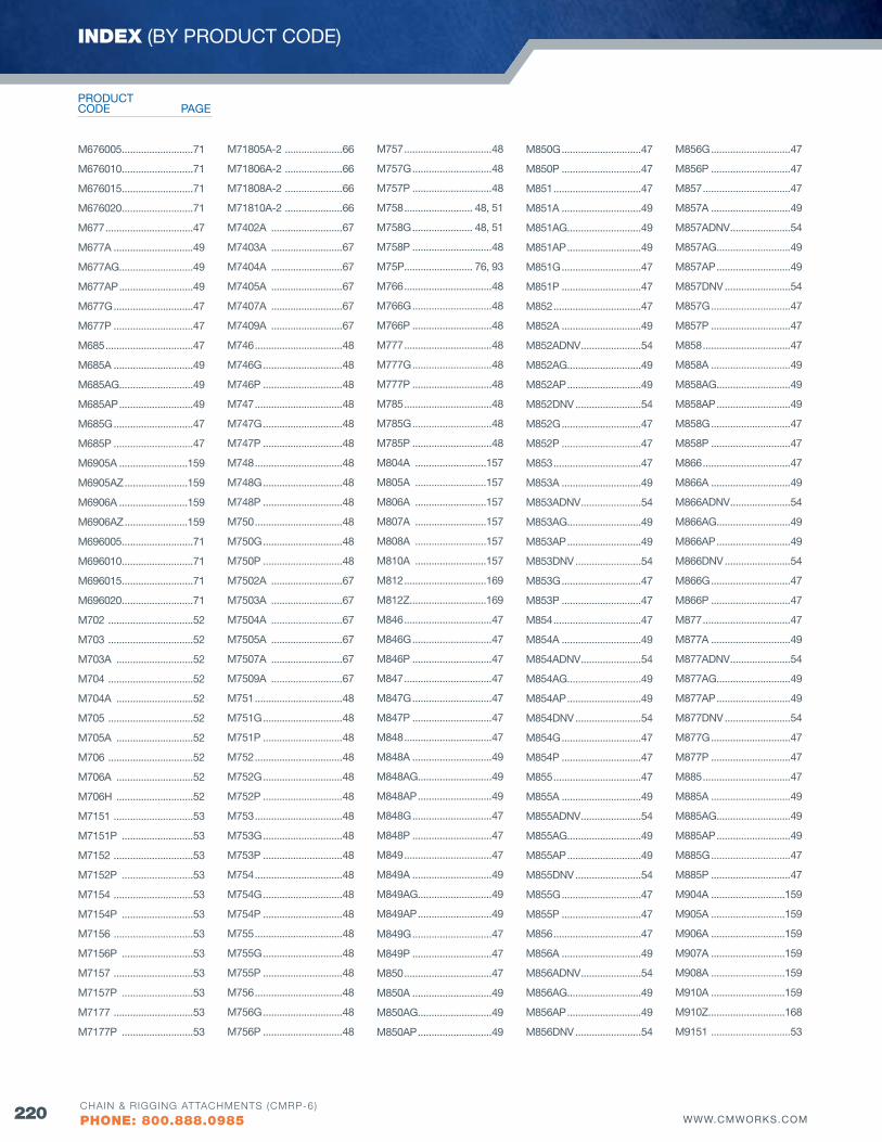
220 WWW.CMWORKS.COMCHAIN & RIGGING ATTACHMENTS (CMRP-6)
PHONE: 800.888.0985
M676005 ..........................71
M676010 ..........................71
M676015 ..........................71
M676020 ..........................71
M677 ................................47
M677A .............................49
M677AG...........................49
M677AP ...........................49
M677G .............................47
M677P .............................47
M685 ................................47
M685A .............................49
M685AG...........................49
M685AP ...........................49
M685G .............................47
M685P .............................47
M6905A .........................159
M6905AZ .......................159
M6906A .........................159
M6906AZ .......................159
M696005 ..........................71
M696010 ..........................71
M696015 ..........................71
M696020 ..........................71
M702 ...............................52
M703 ...............................52
M703A ............................52
M704 ...............................52
M704A ............................52
M705 ...............................52
M705A ............................52
M706 ...............................52
M706A ............................52
M706H ............................52
M7151 .............................53
M7151P ..........................53
M7152 .............................53
M7152P ..........................53
M7154 .............................53
M7154P ..........................53
M7156 .............................53
M7156P ..........................53
M7157 .............................53
M7157P ..........................53
M7177 .............................53
M7177P ..........................53
M71805A-2 .....................66
M71806A-2 .....................66
M71808A-2 .....................66
M71810A-2 .....................66
M7402A ..........................67
M7403A ..........................67
M7404A ..........................67
M7405A ..........................67
M7407A ..........................67
M7409A ..........................67
M746 ................................48
M746G .............................48
M746P .............................48
M747 ................................48
M747G .............................48
M747P .............................48
M748 ................................48
M748G .............................48
M748P .............................48
M750 ................................48
M750G .............................48
M750P .............................48
M7502A ..........................67
M7503A ..........................67
M7504A ..........................67
M7505A ..........................67
M7507A ..........................67
M7509A ..........................67
M751 ................................48
M751G .............................48
M751P .............................48
M752 ................................48
M752G .............................48
M752P .............................48
M753 ................................48
M753G .............................48
M753P .............................48
M754 ................................48
M754G .............................48
M754P .............................48
M755 ................................48
M755G .............................48
M755P .............................48
M756 ................................48
M756G .............................48
M756P .............................48
M757 ................................48
M757G .............................48
M757P .............................48
M758 ......................... 48, 51
M758G ...................... 48, 51
M758P .............................48
M75P......................... 76, 93
M766 ................................48
M766G .............................48
M766P .............................48
M777 ................................48
M777G .............................48
M777P .............................48
M785 ................................48
M785G .............................48
M785P .............................48
M804A ..........................157
M805A ..........................157
M806A ..........................157
M807A ..........................157
M808A ..........................157
M810A ..........................157
M812 ..............................169
M812Z ............................169
M846 ................................47
M846G .............................47
M846P .............................47
M847 ................................47
M847G .............................47
M847P .............................47
M848 ................................47
M848A .............................49
M848AG...........................49
M848AP ...........................49
M848G .............................47
M848P .............................47
M849 ................................47
M849A .............................49
M849AG...........................49
M849AP ...........................49
M849G .............................47
M849P .............................47
M850 ................................47
M850A .............................49
M850AG...........................49
M850AP ...........................49
M850G .............................47
M850P .............................47
M851 ................................47
M851A .............................49
M851AG...........................49
M851AP ...........................49
M851G .............................47
M851P .............................47
M852 ................................47
M852A .............................49
M852ADNv ......................54
M852AG...........................49
M852AP ...........................49
M852DNv ........................54
M852G .............................47
M852P .............................47
M853 ................................47
M853A .............................49
M853ADNv ......................54
M853AG...........................49
M853AP ...........................49
M853DNv ........................54
M853G .............................47
M853P .............................47
M854 ................................47
M854A .............................49
M854ADNv ......................54
M854AG...........................49
M854AP ...........................49
M854DNv ........................54
M854G .............................47
M854P .............................47
M855 ................................47
M855A .............................49
M855ADNv ......................54
M855AG...........................49
M855AP ...........................49
M855DNv ........................54
M855G .............................47
M855P .............................47
M856 ................................47
M856A .............................49
M856ADNv ......................54
M856AG...........................49
M856AP ...........................49
M856DNv ........................54
M856G .............................47
M856P .............................47
M857 ................................47
M857A .............................49
M857ADNv ......................54
M857AG...........................49
M857AP ...........................49
M857DNv ........................54
M857G .............................47
M857P .............................47
M858 ................................47
M858A .............................49
M858AG...........................49
M858AP ...........................49
M858G .............................47
M858P .............................47
M866 ................................47
M866A .............................49
M866ADNv ......................54
M866AG...........................49
M866AP ...........................49
M866DNv ........................54
M866G .............................47
M866P .............................47
M877 ................................47
M877A .............................49
M877ADNv ......................54
M877AG...........................49
M877AP ...........................49
M877DNv ........................54
M877G .............................47
M877P .............................47
M885 ................................47
M885A .............................49
M885AG...........................49
M885AP ...........................49
M885G .............................47
M885P .............................47
M904A ...........................159
M905A ...........................159
M906A ...........................159
M907A ...........................159
M908A ...........................159
M910A ...........................159
M910Z ............................168
M9151 .............................53
INDEX (BY PRODUCT CODE)
PAGECODEPRODUCT
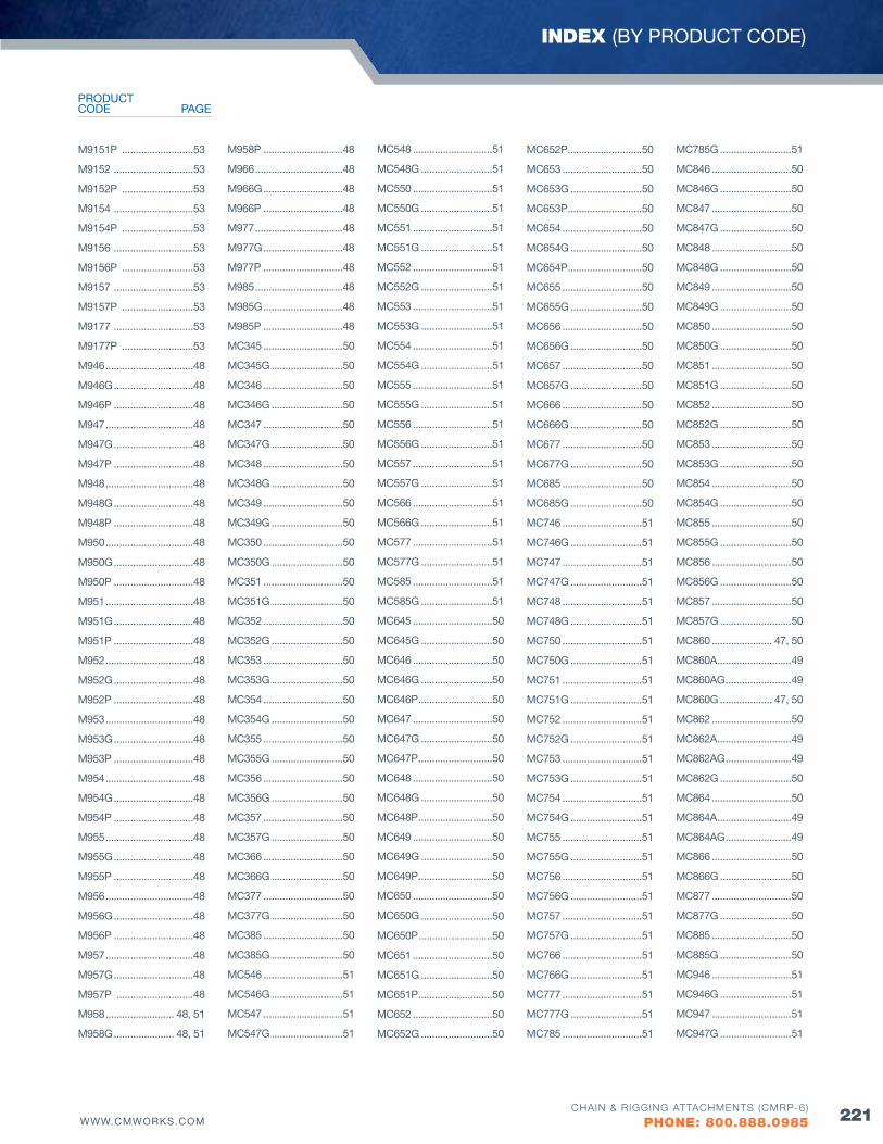
221WWW.CMWORKS.COMCHAIN & RIGGING ATTACHMENTS (CMRP-6)
PHONE: 800.888.0985
INDEX (BY PRODUCT CODE)
M9151P ..........................53
M9152 .............................53
M9152P ..........................53
M9154 .............................53
M9154P ..........................53
M9156 .............................53
M9156P ..........................53
M9157 .............................53
M9157P ..........................53
M9177 .............................53
M9177P ..........................53
M946 ................................48
M946G .............................48
M946P .............................48
M947 ................................48
M947G .............................48
M947P .............................48
M948 ................................48
M948G .............................48
M948P .............................48
M950 ................................48
M950G .............................48
M950P .............................48
M951 ................................48
M951G .............................48
M951P .............................48
M952 ................................48
M952G .............................48
M952P .............................48
M953 ................................48
M953G .............................48
M953P .............................48
M954 ................................48
M954G .............................48
M954P .............................48
M955 ................................48
M955G .............................48
M955P .............................48
M956 ................................48
M956G .............................48
M956P .............................48
M957 ................................48
M957G .............................48
M957P ............................48
M958 ......................... 48, 51
M958G ...................... 48, 51
M958P .............................48
M966 ................................48
M966G .............................48
M966P .............................48
M977 ................................48
M977G .............................48
M977P .............................48
M985 ................................48
M985G .............................48
M985P .............................48
MC345 .............................50
MC345G ..........................50
MC346 .............................50
MC346G ..........................50
MC347 .............................50
MC347G ..........................50
MC348 .............................50
MC348G ..........................50
MC349 .............................50
MC349G ..........................50
MC350 .............................50
MC350G ..........................50
MC351 .............................50
MC351G ..........................50
MC352 .............................50
MC352G ..........................50
MC353 .............................50
MC353G ..........................50
MC354 .............................50
MC354G ..........................50
MC355 .............................50
MC355G ..........................50
MC356 .............................50
MC356G ..........................50
MC357 .............................50
MC357G ..........................50
MC366 .............................50
MC366G ..........................50
MC377 .............................50
MC377G ..........................50
MC385 .............................50
MC385G ..........................50
MC546 .............................51
MC546G ..........................51
MC547 .............................51
MC547G ..........................51
MC548 .............................51
MC548G ..........................51
MC550 .............................51
MC550G ..........................51
MC551 .............................51
MC551G ..........................51
MC552 .............................51
MC552G ..........................51
MC553 .............................51
MC553G ..........................51
MC554 .............................51
MC554G ..........................51
MC555 .............................51
MC555G ..........................51
MC556 .............................51
MC556G ..........................51
MC557 .............................51
MC557G ..........................51
MC566 .............................51
MC566G ..........................51
MC577 .............................51
MC577G ..........................51
MC585 .............................51
MC585G ..........................51
MC645 .............................50
MC645G ..........................50
MC646 .............................50
MC646G ..........................50
MC646P ...........................50
MC647 .............................50
MC647G ..........................50
MC647P ...........................50
MC648 .............................50
MC648G ..........................50
MC648P ...........................50
MC649 .............................50
MC649G ..........................50
MC649P ...........................50
MC650 .............................50
MC650G ..........................50
MC650P ...........................50
MC651 .............................50
MC651G ..........................50
MC651P ...........................50
MC652 .............................50
MC652G ..........................50
MC652P ...........................50
MC653 .............................50
MC653G ..........................50
MC653P ...........................50
MC654 .............................50
MC654G ..........................50
MC654P ...........................50
MC655 .............................50
MC655G ..........................50
MC656 .............................50
MC656G ..........................50
MC657 .............................50
MC657G ..........................50
MC666 .............................50
MC666G ..........................50
MC677 .............................50
MC677G ..........................50
MC685 .............................50
MC685G ..........................50
MC746 .............................51
MC746G ..........................51
MC747 .............................51
MC747G ..........................51
MC748 .............................51
MC748G ..........................51
MC750 .............................51
MC750G ..........................51
MC751 .............................51
MC751G ..........................51
MC752 .............................51
MC752G ..........................51
MC753 .............................51
MC753G ..........................51
MC754 .............................51
MC754G ..........................51
MC755 .............................51
MC755G ..........................51
MC756 .............................51
MC756G ..........................51
MC757 .............................51
MC757G ..........................51
MC766 .............................51
MC766G ..........................51
MC777 .............................51
MC777G ..........................51
MC785 .............................51
MC785G ..........................51
MC846 .............................50
MC846G ..........................50
MC847 .............................50
MC847G ..........................50
MC848 .............................50
MC848G ..........................50
MC849 .............................50
MC849G ..........................50
MC850 .............................50
MC850G ..........................50
MC851 .............................50
MC851G ..........................50
MC852 .............................50
MC852G ..........................50
MC853 .............................50
MC853G ..........................50
MC854 .............................50
MC854G ..........................50
MC855 .............................50
MC855G ..........................50
MC856 .............................50
MC856G ..........................50
MC857 .............................50
MC857G ..........................50
MC860 ...................... 47, 50
MC860A ...........................49
MC860AG ........................49
MC860G ................... 47, 50
MC862 .............................50
MC862A ...........................49
MC862AG ........................49
MC862G ..........................50
MC864 .............................50
MC864A ...........................49
MC864AG ........................49
MC866 .............................50
MC866G ..........................50
MC877 .............................50
MC877G ..........................50
MC885 .............................50
MC885G ..........................50
MC946 .............................51
MC946G ..........................51
MC947 .............................51
MC947G ..........................51
PAGECODEPRODUCT
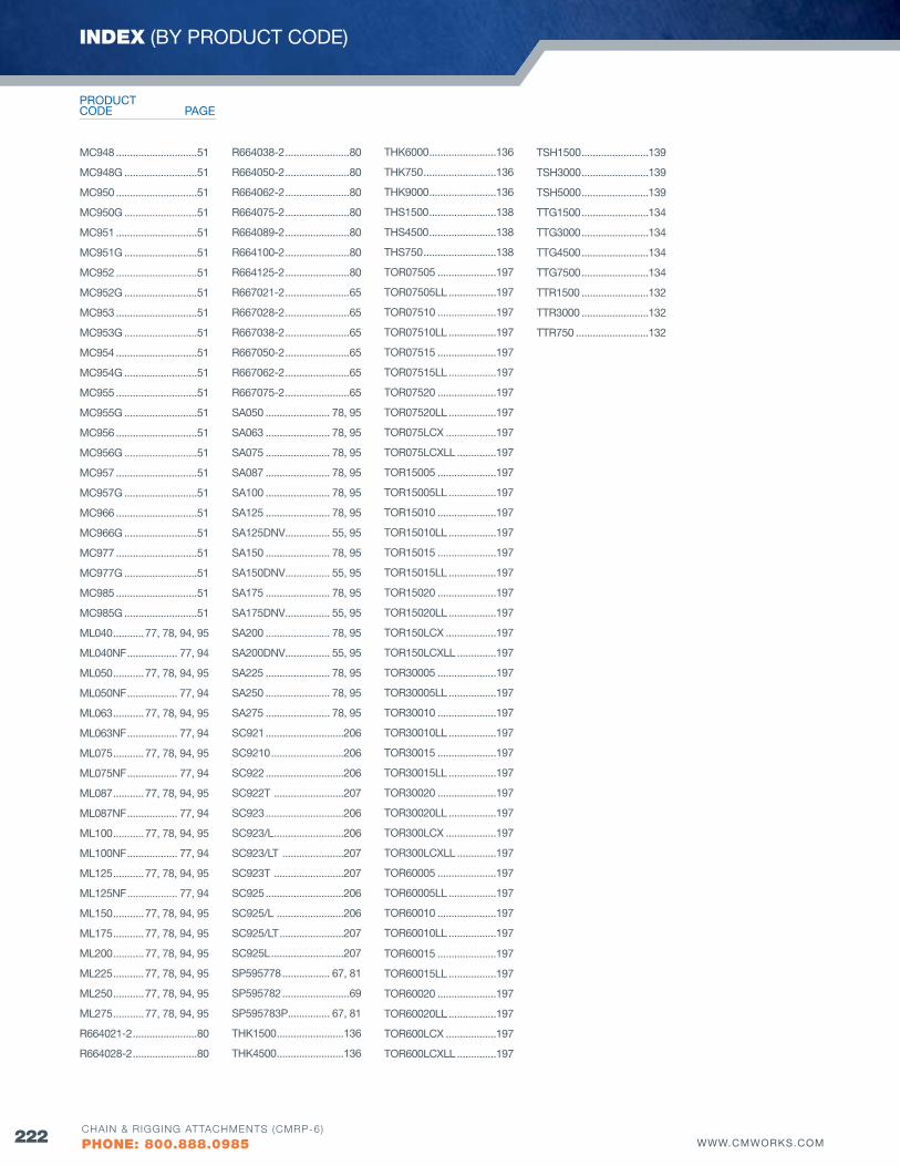
222 WWW.CMWORKS.COMCHAIN & RIGGING ATTACHMENTS (CMRP-6)
PHONE: 800.888.0985
MC948 .............................51
MC948G ..........................51
MC950 .............................51
MC950G ..........................51
MC951 .............................51
MC951G ..........................51
MC952 .............................51
MC952G ..........................51
MC953 .............................51
MC953G ..........................51
MC954 .............................51
MC954G ..........................51
MC955 .............................51
MC955G ..........................51
MC956 .............................51
MC956G ..........................51
MC957 .............................51
MC957G ..........................51
MC966 .............................51
MC966G ..........................51
MC977 .............................51
MC977G ..........................51
MC985 .............................51
MC985G ..........................51
ML040 ...........77, 78, 94, 95
ML040NF .................. 77, 94
ML050 ...........77, 78, 94, 95
ML050NF .................. 77, 94
ML063 ...........77, 78, 94, 95
ML063NF .................. 77, 94
ML075 ...........77, 78, 94, 95
ML075NF .................. 77, 94
ML087 ...........77, 78, 94, 95
ML087NF .................. 77, 94
ML100 ...........77, 78, 94, 95
ML100NF .................. 77, 94
ML125 ...........77, 78, 94, 95
ML125NF .................. 77, 94
ML150 ...........77, 78, 94, 95
ML175 ...........77, 78, 94, 95
ML200 ...........77, 78, 94, 95
ML225 ...........77, 78, 94, 95
ML250 ...........77, 78, 94, 95
ML275 ...........77, 78, 94, 95
R664021-2 .......................80
R664028-2 .......................80
R664038-2 .......................80
R664050-2 .......................80
R664062-2 .......................80
R664075-2 .......................80
R664089-2 .......................80
R664100-2 .......................80
R664125-2 .......................80
R667021-2 .......................65
R667028-2 .......................65
R667038-2 .......................65
R667050-2 .......................65
R667062-2 .......................65
R667075-2 .......................65
SA050 ....................... 78, 95
SA063 ....................... 78, 95
SA075 ....................... 78, 95
SA087 ....................... 78, 95
SA100 ....................... 78, 95
SA125 ....................... 78, 95
SA125DNv ................ 55, 95
SA150 ....................... 78, 95
SA150DNv ................ 55, 95
SA175 ....................... 78, 95
SA175DNv ................ 55, 95
SA200 ....................... 78, 95
SA200DNv ................ 55, 95
SA225 ....................... 78, 95
SA250 ....................... 78, 95
SA275 ....................... 78, 95
SC921 ............................206
SC9210 ..........................206
SC922 ............................206
SC922T .........................207
SC923 ............................206
SC923/L .........................206
SC923/LT ......................207
SC923T .........................207
SC925 ............................206
SC925/L ........................206
SC925/LT .......................207
SC925L ..........................207
SP595778 ................. 67, 81
SP595782 ........................69
SP595783P ............... 67, 81
THK1500 ........................136
THK4500 ........................136
THK6000 ........................136
THK750 ..........................136
THK9000 ........................136
THS1500 ........................138
THS4500 ........................138
THS750 ..........................138
TOR07505 .....................197
TOR07505LL .................197
TOR07510 .....................197
TOR07510LL .................197
TOR07515 .....................197
TOR07515LL .................197
TOR07520 .....................197
TOR07520LL .................197
TOR075LCX ..................197
TOR075LCXLL ..............197
TOR15005 .....................197
TOR15005LL .................197
TOR15010 .....................197
TOR15010LL .................197
TOR15015 .....................197
TOR15015LL .................197
TOR15020 .....................197
TOR15020LL .................197
TOR150LCX ..................197
TOR150LCXLL ..............197
TOR30005 .....................197
TOR30005LL .................197
TOR30010 .....................197
TOR30010LL .................197
TOR30015 .....................197
TOR30015LL .................197
TOR30020 .....................197
TOR30020LL .................197
TOR300LCX ..................197
TOR300LCXLL ..............197
TOR60005 .....................197
TOR60005LL .................197
TOR60010 .....................197
TOR60010LL .................197
TOR60015 .....................197
TOR60015LL .................197
TOR60020 .....................197
TOR60020LL .................197
TOR600LCX ..................197
TOR600LCXLL ..............197
TSH1500 ........................139
TSH3000 ........................139
TSH5000 ........................139
TTG1500 ........................134
TTG3000 ........................134
TTG4500 ........................134
TTG7500 ........................134
TTR1500 ........................132
TTR3000 ........................132
TTR750 ..........................132
INDEX (BY PRODUCT CODE)
PAGECODEPRODUCT
223WWW.CMWORKS.COMCHAIN & RIGGING ATTACHMENTS (CMRP-6)
PHONE: 800.888.0985
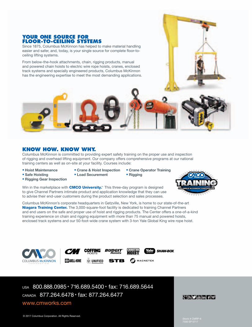
© 2017 Columbus Corporation. All Rights Reserved. Stock # CMRP-67500 EP 0717
YouR one souRce FoR FlooR-to-ceiling sYsteMsSince 1875, Columbus McKinnon has helped to make material handling easier and safer, and, today, is your single source for complete floor-to- ceiling lifting systems.
From below-the-hook attachments, chain, rigging products, manual and powered chain hoists to electric wire rope hoists, cranes, enclosed track systems and specially engineered products, Columbus McKinnon has the engineering expertise to meet the most demanding applications.
knoW HoW. knoW WHY. Columbus McKinnon is committed to providing expert safety training on the proper use and inspection of rigging and overhead lifting equipment. Our company offers comprehensive programs at our national training centers as well as on-site at your facility. Courses include:
Hoist Maintenance Crane & Hoist Inspection Crane Operator Training Safe Hoisting Load Securement Rigging Rigging Gear Inspection
Win in the marketplace with CMCO University.™ This three-day program is designed to give Channel Partners intimate product and application knowledge that they can use to advise their end-user customers during the product selection and sales processes.
Columbus McKinnon’s corporate headquarters in Getzville, New York, is home to our state-of-the-art Niagara Training Center. The 3,000-square-foot facility is dedicated to training Channel Partners and end users on the safe and proper use of hoist and rigging products. The Center offers a one-of-a-kind training experience on chain and rigging equipment with more than 75 manual and powered hoists, enclosed track systems and our 50-foot-wide crane system with 3-ton Yale Global King wire rope hoist.
USA 800.888.0985 • 716.689.5400 • fax: 716.689.5644 CANADA 877.264.6478 • fax: 877.264.6477 www.cmworks.com