operators, maintenance, and parts manual boss model 25 ahbi
TRANSCRIPT
BOSS MODEL 25 AHBIPTO AIR COMPRESSOR
OPERATORS, MAINTENANCEAND PARTS MANUAL
P/N: 302118
2 P/N: 302118
OPERATORS, MAINTENANCE, AND PARTS MANUALBOSS MODEL 25 AHBI
TABLE OF CONTENTS
Operation & Maintenance Section
Specifications ................................................................................................................ 3 - 4
Safety .......................................................................................................................... 5 - 10
Compressor Terminology .................................................................................................. 11
Description of Components ..................................................................................... 12 - 15
Inspection, Lubrication, and Maintenance .............................................................. 16 - 23
Troubleshooting ....................................................................................................... 24 - 26
Compressor Operation............................................................................................. 27 - 28
Parts and Illustration Section ................................................................................. 29 - 42
24 Volt Option ............................................................................................................ 43-44
Recommended Spare Parts .............................................................................................. 45
Service Questionnaire ..................................................................................................... 46
Instructional Procedures For Installation ................................................................. 47-50
Warranty Section
Warranty Information ............................................................................................... 51 - 55
3 P/N: 302118
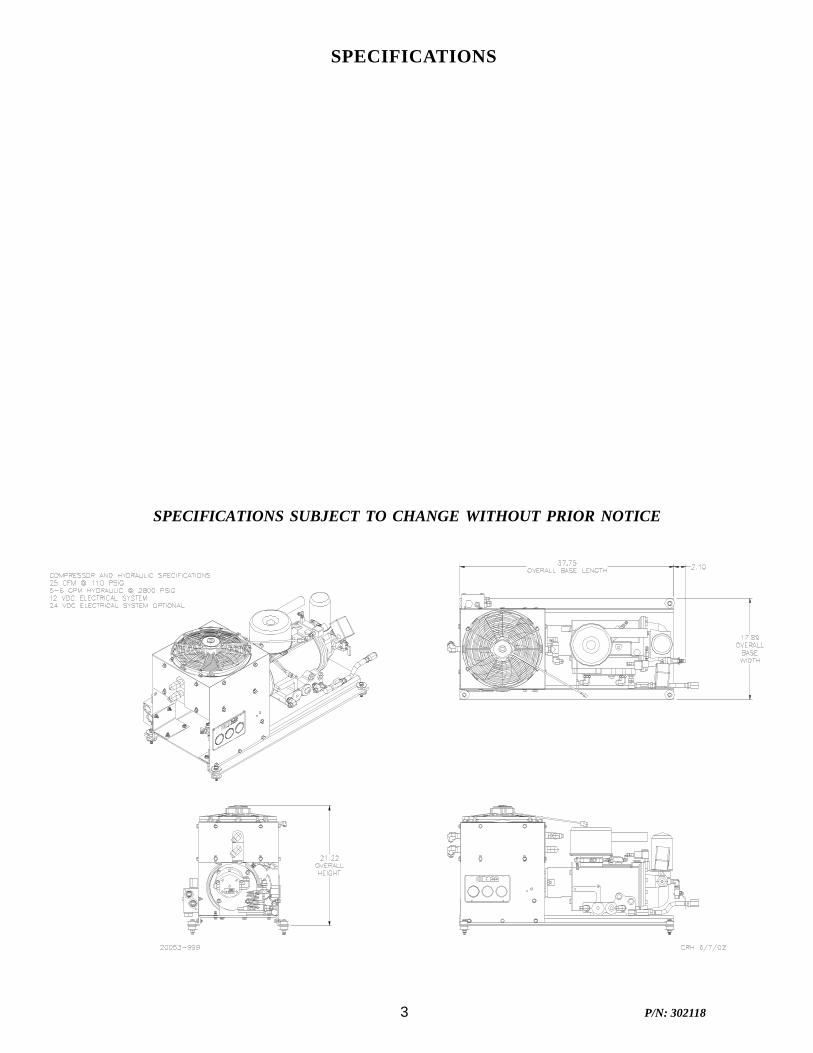
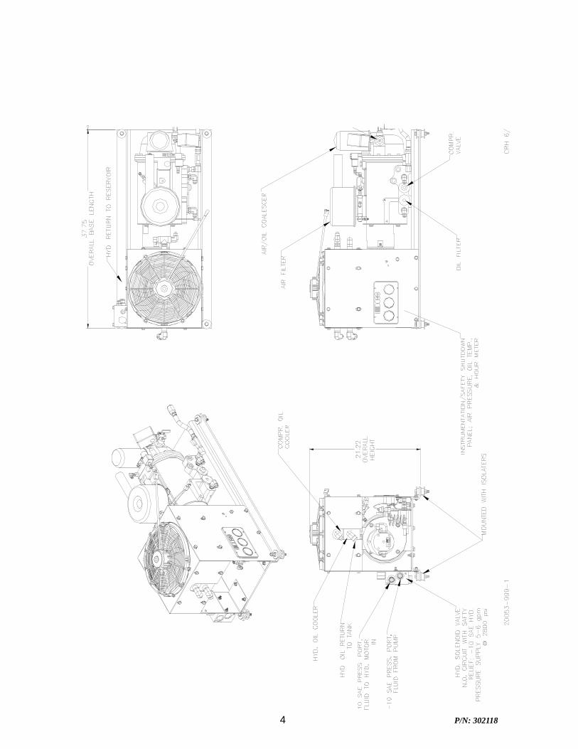
SPECIFICATIONS
SPECIFICATIONS SUBJECT TO CHANGE WITHOUT PRIOR NOTICE
4 P/N: 302118
5 P/N: 302118
SAFETY
WARNING
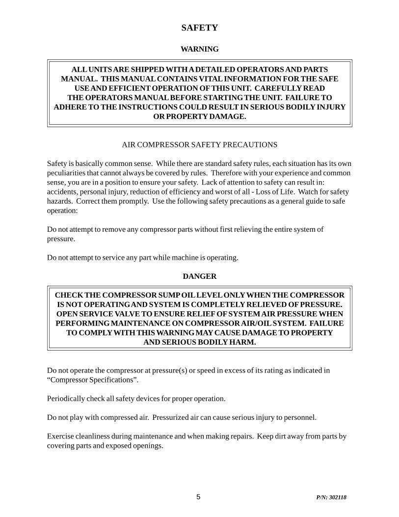
ALL UNITS ARE SHIPPED WITH A DETAILED OPERATORS AND PARTSMANUAL. THIS MANUAL CONTAINS VITAL INFORMATION FOR THE SAFE
USE AND EFFICIENT OPERATION OF THIS UNIT. CAREFULLY READTHE OPERATORS MANUAL BEFORE STARTING THE UNIT. FAILURE TO
ADHERE TO THE INSTRUCTIONS COULD RESULT IN SERIOUS BODILY INJURYOR PROPERTY DAMAGE.
AIR COMPRESSOR SAFETY PRECAUTIONS
Safety is basically common sense. While there are standard safety rules, each situation has its ownpeculiarities that cannot always be covered by rules. Therefore with your experience and commonsense, you are in a position to ensure your safety. Lack of attention to safety can result in:accidents, personal injury, reduction of efficiency and worst of all - Loss of Life. Watch for safetyhazards. Correct them promptly. Use the following safety precautions as a general guide to safeoperation:
Do not attempt to remove any compressor parts without first relieving the entire system ofpressure.
Do not attempt to service any part while machine is operating.
DANGER
CHECK THE COMPRESSOR SUMP OIL LEVEL ONLY WHEN THE COMPRESSORIS NOT OPERATING AND SYSTEM IS COMPLETELY RELIEVED OF PRESSURE.OPEN SERVICE VALVE TO ENSURE RELIEF OF SYSTEM AIR PRESSURE WHENPERFORMING MAINTENANCE ON COMPRESSOR AIR/OIL SYSTEM. FAILURE
TO COMPLY WITH THIS WARNING MAY CAUSE DAMAGE TO PROPERTYAND SERIOUS BODILY HARM.
Do not operate the compressor at pressure(s) or speed in excess of its rating as indicated in“Compressor Specifications”.
Periodically check all safety devices for proper operation.
Do not play with compressed air. Pressurized air can cause serious injury to personnel.
Exercise cleanliness during maintenance and when making repairs. Keep dirt away from parts bycovering parts and exposed openings.
6 P/N: 302118
SAFETY
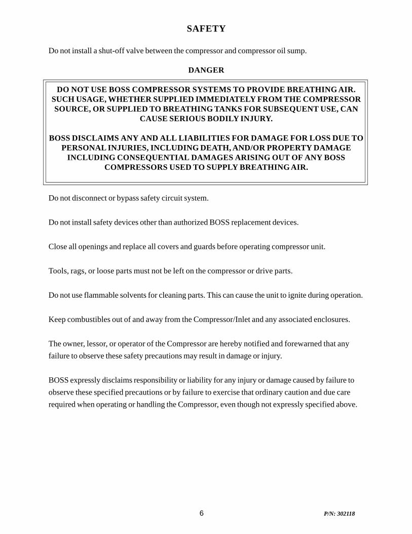
Do not install a shut-off valve between the compressor and compressor oil sump.
DANGER
DO NOT USE BOSS COMPRESSOR SYSTEMS TO PROVIDE BREATHING AIR.SUCH USAGE, WHETHER SUPPLIED IMMEDIATELY FROM THE COMPRESSORSOURCE, OR SUPPLIED TO BREATHING TANKS FOR SUBSEQUENT USE, CAN
CAUSE SERIOUS BODILY INJURY.
BOSS DISCLAIMS ANY AND ALL LIABILITIES FOR DAMAGE FOR LOSS DUE TOPERSONAL INJURIES, INCLUDING DEATH, AND/OR PROPERTY DAMAGE
INCLUDING CONSEQUENTIAL DAMAGES ARISING OUT OF ANY BOSSCOMPRESSORS USED TO SUPPLY BREATHING AIR.
Do not disconnect or bypass safety circuit system.
Do not install safety devices other than authorized BOSS replacement devices.
Close all openings and replace all covers and guards before operating compressor unit.
Tools, rags, or loose parts must not be left on the compressor or drive parts.
Do not use flammable solvents for cleaning parts. This can cause the unit to ignite during operation.
Keep combustibles out of and away from the Compressor/Inlet and any associated enclosures.
The owner, lessor, or operator of the Compressor are hereby notified and forewarned that anyfailure to observe these safety precautions may result in damage or injury.
BOSS expressly disclaims responsibility or liability for any injury or damage caused by failure toobserve these specified precautions or by failure to exercise that ordinary caution and due carerequired when operating or handling the Compressor, even though not expressly specified above.
7 P/N: 302118
SAFETY
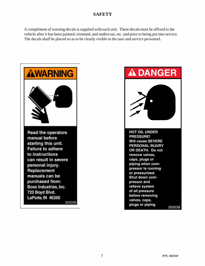
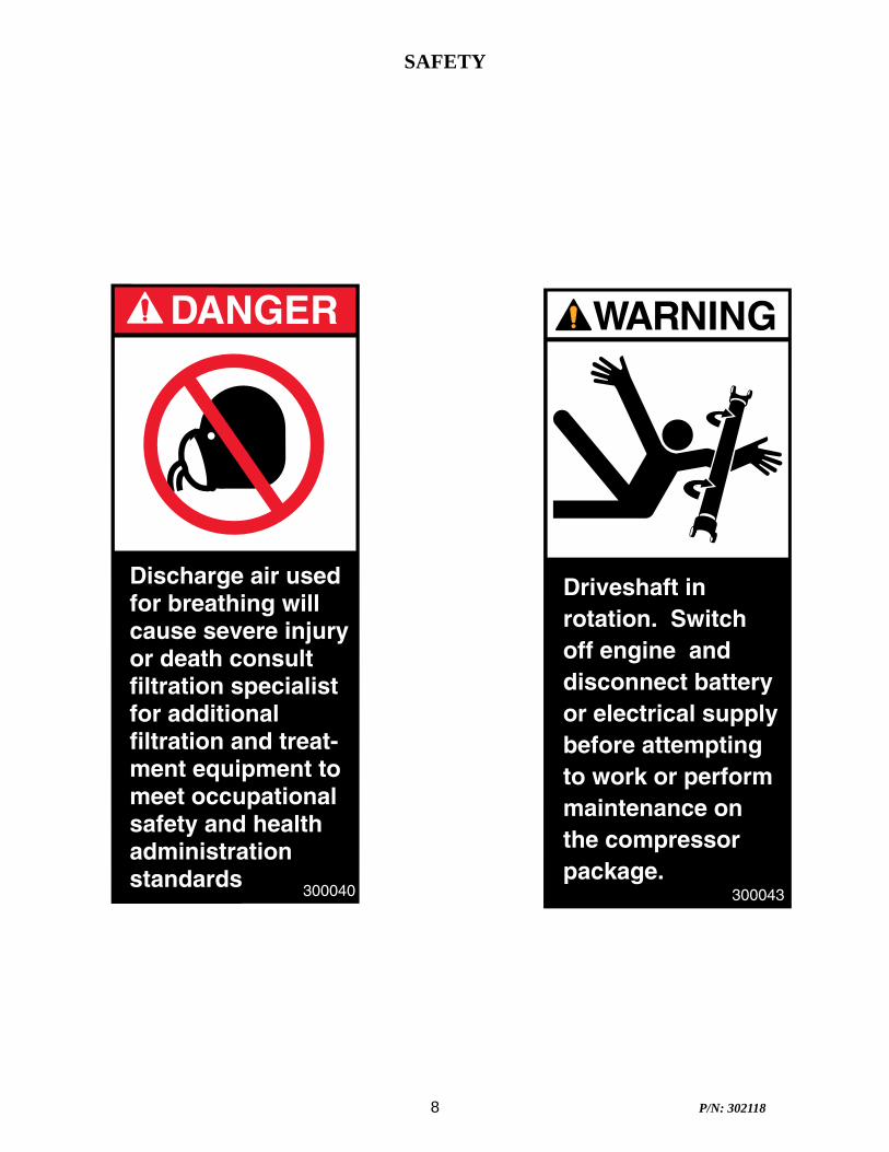
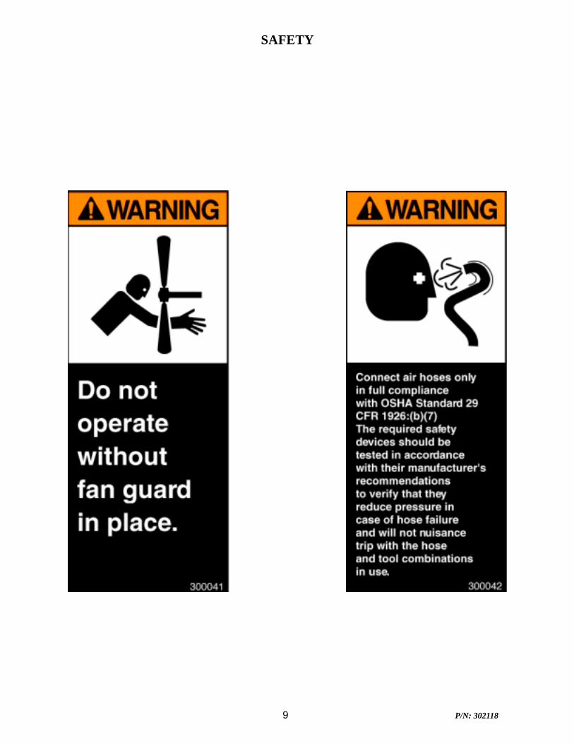
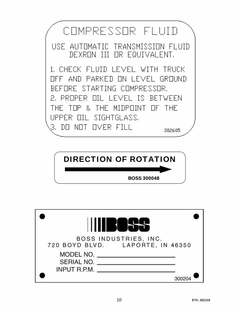
A compliment of warning decals is supplied with each unit. These decals must be affixed to thevehicle after it has been painted, trimmed, and undercoat, etc. and prior to being put into service.The decals shall be placed so as to be clearly visible to the user and service personnel.
8 P/N: 302118
SAFETY
9 P/N: 302118
SAFETY
10 P/N: 302118
DIRECTION OF ROTATION
BOSS 300048
11 P/N: 302118
COMPRESSOR TERMINOLOGY
AIR/OIL COALESCER - Performs second stage separation of oil from compressed air feedingair tools. Sometimes referred to as the separator element.
CFM - Refers to the volume of compressed air being produced, expressed as cubic feet of air perminute.
COMPRESSOR LUBRICANT - DEXTRON III ATF.
GPM - Refers to the amount of gallons per minute of hydraulic fluid flowing through the pump.
OIL SUMP - The first stage of oil separation from compressed air. Also serves as reservoir areafor compressor lubricant and sometimes referred to as the receiver tank.
PSI - Refers to the operating pressure the system is set up at, expressed as pounds per squareinch.
SAFETY VALVE - A valve located on the oil sump which opens in case of excessive pressure.Sometimes referred to as the pop-off or pressure relief valve.
12 P/N: 302118
DESCRIPTION OF COMPONENTS
COMPRESSOR ASSEMBLY
The BOSS hydraulic drive compressor assembly is a positive displacement, oil flooded, rotaryscrew type unit employing one stage of compression to achieve the desired pressure. Componentsinclude a housing (stator), two screws (rotors), bearings, and bearing supports. Power from thehydraulic motor shaft is transferred to the male rotor through a drive coupling. The female rotor isdriven by the male rotor. There are five lobes on the male rotor while the female rotor has sixroots.
PRINCIPLES OF OPERATION
In operation, two helical grooved rotors mesh to compress air. Inlet air is trapped as the malelobes roll down the female grooves, pushing trapped air along, compressing it until it reaches thedischarge port in the end of the stator and delivers smooth-flowing, pulse-free air to the receiver.
During the compression cycle, oil is injected into the compressor and serves these purposes:
1. Lubricates the rotating parts and bearings.2. Serves as a cooling agent for the compressed air.3. Seals the running clearances.
LUBRICATION SYSTEM
Oil from the compressor at discharge pressure, is directed into it’s integral housing, through thethermal valve and filter, and then out of the integral housing to the oil cooling system, and then backto the side of the compressor stator, where it is injected into the compressor. At the same time oilis directed internally to the bearings and shaft seal of the compressor.
OIL SUMP
Compressed, oil-laden air enters the sump from the compressor. As the oil-laden air enters thesump, most of the oil is separated from the air as it passes through a series of baffles and de-fusionplates. The oil accumulates at the bottom of the sump for recirculation. However, some smalldroplets of oil remain suspended in the air and are passed on to the Coalescer.
13 P/N: 302118
DESCRIPTION OF COMPONENTS
SAFETY VALVE
The pop safety valve is set at 218 PSI (15 BAR) and is located at the top of the air/oil sump.This valve acts as a backup to protect the system from excessive pressure that might resultfrom a malfunction.
AIR/OIL COALESCER
The coalescer is self-contained within a spin-on housing. When air is demanded at the service line,it passes through the coalescer which efficiently provides the final stage of oil separation. Whenmounting/installing the unit, leave clearance for removal.
OIL RETURN LINE
The oil that is removed by the coalescer accumulates and is returned through an internal oil returnline leading to the compressor.
MINIMUM PRESSURE VALVE
The minimum pressure valve is located at the outlet of the coalescer head and serves to maintain aminimum discharge pressure of approximately 75 PSIG in operation, which is required toassure adequate compressor lubrication pressure.
OIL FILTER
The compressor oil filter is a removable and cleanable screen built into the side of the compressorhousing. Screen replacement may be necessary after several cleanings.
COMPRESSOR OIL AND HYDRAULIC OIL COOLING SYSTEMS
The compressor cooling system consists of a combination hydraulic cooler and compressor coolermounted on the common frame. Compressor oil temperature is controlled by a thermal valvelocated down stream of the oil filter. The thermal valve maintains the compressor oil temperatureat approximately 185ºF. Air is drawn through the hydraulic cooler, then the compressor coolerout the top of the package. Allow for adequate clearance at the top (12”) for the air to exit.Also, the package location should not be subjected to above ambient air temperatures.
14 P/N: 302118
DESCRIPTION OF COMPONENTS
INSTRUMENTATION
The BOSS hydraulic drive compressor unit incorporates a gauge panel that monitors temperature,pressure and hours of operation.
HOURMETER
The hourmeter records the total number of operating hours. It serves as a guide in following therecommended inspection and maintenance schedule. The hourmeter will only run when there is pressurein the system.
COMPRESSOR DISCHARGE AIR/OIL TEMPERATURE SWICHGAUGE
This swichgauge indicates compressor air discharge temperature. The swichgauge ensures safetyshutdown in case of excessive operating temperatures, preventing compressor damage, by stoppinghydraulic flow to the compressor motor.
ELECTRICAL AND SAFETY SYSTEM
The BOSS compressor’s standard electrical system consists of:-Gauge panel with a temperature swichgauge, hourmeter and discharge pressure swichgauge.-Compressor and hydraulic oil cooler fan assembly and relay.-Compressor after cooler/oil cooler fan assembly with relay.-N.O. hourmeter pressure switch.-N.C. blowdown pressure switch.-12VDC N.O. hydraulic solenoid and relay.-Switch relay for customer equipment interface during compressor operation.
15 P/N: 302118
DESCRIPTION OF COMPONENTS
AUTOMATIC BLOW DOWN VALVE
There is one blow down valve in the compressor system. It is located at the intake valve and willautomatically bleed the sump to zero pressure when the compressor is disengaged. Blow downtime interval takes between 45 and 60 seconds.
CONTROL SYSTEM
The prime component of the compressor control system is the compressor inlet valve. The controlsystem is designed to match air supply to air demand and to prevent excessive discharge pressurewhen compressor is at idle. Control of air delivery is accomplished by the inlet valve regulationand modulation as directed by the discharge pressure regulator.
DISCHARGE PRESSURE REGULATOR VALVE
This valve, located on the compressor discharge housing is used to set the desired dischargepressure within the operating pressure range. Turning the regulator screw clockwise increases theworking pressure, a counterclockwise movement of the screw reduces the working pressure. Thissystem has a maximum operating pressure of 150 psi.
NOTE: Most air tools operating pressure range is between 90 and 125 psi. Operatingabove the tools recommended pressures will decrease the life of the tool. Higheroperating pressure can also over torque nut and bolts fatiguing the fastener and matingparts. Strictly adhere to tool operating pressures and torque standards set forth by thetool manufacturer and the specifications of the equipment that work is being performedon.
INLET VALVE
The compressor inlet valve is a piston operated disc valve that regulates the inlet opening to controlcapacity and serving as a check valve at shutdown.
16 P/N: 302118
INSPECTION, LUBRICATION, AND MAINTENANCE
This section contains instructions for performing the inspection, lubrication, and maintenanceprocedures required to maintain the compressor in proper operating condition. The importance ofperforming the maintenance described herein cannot be over emphasized.
The periodic maintenance procedures to be performed on the equipment covered by this manualare listed below. It should be understood that the intervals between inspections specified aremaximum interval. More frequent inspections should be made if the unit is operating in a dustyenvironment, in high ambient temperature, or in other unusual conditions. A planned program ofperiodic inspection and maintenance will help avoided premature failure and costly repairs. Dailyvisual inspections should become a routine.
The LUBRICATION AND MAINTENANCE CHART lists serviceable items on this compressorpackage. The items are listed according to their frequency of maintenance, followed by thoseitems which need only “As Required” maintenance.
The maintenance time intervals are expressed in hours. The hourmeter shows thetotal number of hours your compressor has run. Use the hourmeter readings for determining yourmaintenance schedules. Perform the maintenance at multiple intervals of the hours shown. Forexample, when the hourmeter shows “100” on the dial, all items listed under “EVERY 10 HOURS”should be serviced for the tenth time, and all items under “EVERY 50 HOURS” should beserviced for the second time, and so on.
DANGER
COMPRESSOR MUST BE SHUT DOWN AND COMPLETELY RELIEVED OFPRESSURE PRIOR TO CHECKING FLUID LEVELS. OPEN SERVICE VALVE TO
ENSURE RELIEF OF SYSTEM AIR PRESSURE. FAILURE TO COMPLY WITH THISWARNING MAY CAUSE DAMAGE TO PROPERTY AND SERIOUS BODILY HARM.

17 P/N: 302118
LUBRICATION AND MAINTENANCE CHART
NOTE: Compressor oil and filter is to be changed after the first 50 hours of operation. After this,normal intervals are to be followed.
18 P/N: 302118
LUBRICANT RECOMMENDATIONS
WARNING
IT IS IMPORTANT THAT THE COMPRESSOR OIL BE OF A RECOMMENDEDTYPE AND THAT THIS OIL AS WELL AS THE AIR FILTER, OIL FILTER, AND
COALESCER ELEMENTS BE INSPECTED AND REPLACED AS STATED IN THISMANUAL.
THE COMBINATION OF A COALESCER ELEMENT LOADED WITH DIRT ANDOXIDIZED OIL PRODUCTS TOGETHER WITH INCREASED AIR VELOCITY AS ARESULT OF THIS CLOGGED CONDITION MAY PRODUCE A CRITICAL POINT
WHILE THE MACHINE IS IN OPERATION WHERE IGNITION CAN TAKE PLACEAND COULD CAUSE A FIRE IN THE OIL SUMP.
FAILURE TO COMPLY WITH THIS WARNING MAY CAUSE DAMAGE TOPROPERTY AND SERIOUS BODILY HARM.
The following are general characteristics for a rotary screw lubricant. Due to the impossibility ofestablishing limits on all physical and chemical properties of lubricants which can affect theirperformance in the compressor over a broad range of environmental influences, the responsibilityfor recommending and consistently furnishing a suitable heavy duty lubricant must rest with theindividual supplier if they choose not to use the recommended BOSS rotary screw lubricant. Thelubricant supplier’s recommendation must, therefore, be based upon not only the following generalcharacteristics, but also upon his own knowledge of the suitability of the recommended lubricant inhelical screw type air compressors operating in the particular environment involved.
CAUTION
MIXING DIFFERENT TYPES OR BRANDS OF LUBRICANTS IS NOTRECOMMENDED DUE TO THE POSSIBILITY OF A DILUTION OF THE ADDITIVES
OR A REACTION BETWEEN ADDITIVES OF DIFFERENT TYPES.
19 P/N: 302118
LUBRICANT RECOMMENDATIONS
LUBRICANT CHARACTERISTICS
1. Flash point 400°F minimum.2. Pour point -40°F.3. Contains rust and corrosion inhibitors.4. Contains foam suppressors.5. Contains oxidation stabilizer.
NOTE
DUE TO ENVIRONMENTAL FACTORS THE USEFUL LIFE OF ALL “EXTENDEDLIFE” LUBRICANTS MAY BE SHORTER THAN QUOTED BY THE LUBRICANT
SUPPLIER. BOSS ENCOURAGES THE USER TO CLOSELY MONITOR THELUBRICANT CONDITION AND TO PARTICIPATE IN AN OIL ANALYSIS
PROGRAM WITH THE SUPPLIER.
NOTE
NO LUBRICANT, HOWEVER GOOD AND/OR EXPENSIVE, CAN REPLACEPROPER MAINTENANCE AND ATTENTION. SELECT AND USE IT WISELY.
20 P/N: 302118
MAINTENANCE
If some of the maintenance intervals in the schedule outlined in this manual seem to be rather short,it should be considered that one hour’s operation of a compressor is equal to about 40 road mileson an engine. Thus, eight hours operation is equal to 320 road miles, 250 hours is equal to 10,000road miles, etc.
COMPRESSOR OIL SUMP FILL, LEVEL, AND DRAIN
Before adding or changing compressor oil make sure that the compressor is completely relieved ofpressure. Oil is added at the fill cap on the side of the compressor body. A drain valve/hoseassembly is provided at the bottom of the compressor body. The proper oil level, when unit is shutdown and has had time to settle between the top and the midpoint of the upper oil sightglass. Thetruck must be level when checking the oil. DO NOT OVERFILL. The oil sump capacity is givenin “Compressor Specifications”.
DANGER
DO NOT ATTEMPT TO DRAIN CONDENSATE, REMOVE THE OIL LEVEL FILLPLUG, OR BREAK ANY CONNECTION IN THE AIR OR OIL SYSTEM WITHOUT
SHUTTING OFF COMPRESSOR AND MANUALLY RELIEVING PRESSURE FROMTHE SUMP. FAILURE TO COMPLY WITH THIS WARNING MAY CAUSE DAMAGE
TO PROPERTY AND SERIOUS BODILY HARM.
AIR INTAKE FILTER
The air intake filter is a heavy-duty dry type high efficiency filter designed to protect thecompressor from dust and foreign objects. Optional two-stage available.
Optional filter is equipped with an evacuator cup for continuous dust ejection while operating andwhen stopped.
Frequency of maintenance of the filter depends on dust conditions at the operating site. The filterelement must be serviced when clogged (maximum pressure drop for proper operation is 15”of water). The filter is equipped with a pressure drop indicator, and the element should bechanged based on it’s reading first and then by the maintenance intervals outlined.
21 P/N: 302118
MAINTENANCE
AIR/OIL COALESCER
The air/oil coalescer employs an element permanently housed within a spin-on canister. This is asingle piece unit that requires replacement when it fails to remove the oil from the discharge air, orpressure drop across it exceeds 15 PSI. Dirty oil clogs the element and increases the pressuredrop across it.
To replace element proceed as follows:
1. Shutdown compressor and wait for complete blow down (zero pressure).2. Turn element counterclockwise for removal (viewing element from bottom).3. Apply a film of fluid directly to seal on the new element.4. Rotate element clockwise by hand until element contacts seal (viewing element from
bottom).5. Rotate element approximately one more turn clockwise with band wrench near the top
of element.6. Run system and check for leaks.
WARNING
DO NOT SUBSTITUTE ELEMENT. USE ONLY A GENUINE BOSS REPLACEMENTELEMENT. THIS ELEMENT IS RATED AT 200 PSI WORKING PRESSURE. USE OF
ANY OTHER ELEMENT MAY BE HAZARDOUS AND COULD IMPAIR THEPERFORMANCE AND RELIABILITY OF THE COMPRESSOR, POSSIBLY VOIDING
THE WARRANTY AND/OR RESULTING IN DAMAGE TO PROPERTY ANDSERIOUS BODILY HARM.
COALERSCER OIL RETURN
This originates at the bottom of the air/oil coalescer and flows through a special recoverypipe and venturi nozzle. If the coalerscer starts to fill with oil there is a good chance theventuri or pipe has been plugged. Consult factory for cleaning instructions.
22 P/N: 302118
MAINTENANCE
OIL FILTER
The compressor oil filter is a spin-on, throw away type.
To replace filter proceed as follows:1. Make sure system pressure is relieved.2. Unscrew with 14 mm allen wrench.3. Remove oil filter from housing.4. Remove gasket and clean or replace the screen.5. Reinsert filter and gasket into housing and tighten with 14 mm allen wrench.6. Add oil, re-tighten filler cap.7. Check for leaks in operation.
WARNING
DO NOT SUBSTITUTE ELEMENT. USE ONLY A GENUINE BOSS REPLACEMENTELEMENT. USE OF ANY OTHER ELEMENT MAY BE HAZARDOUS AND COULD
IMPAIR THE PERFORMANCE AND RELIABILITY OF THE COMPRESSOR,POSSIBLY VOIDING THE WARRANTY AND/OR RESULTING IN DAMAGE TO
PROPERTY AND SERIOUS BODILY HARM.
HYDRAULIC OIL COOLER AND COMPRESSOR OIL COOLER COMBINATION
The interior of the oil cooler should be cleaned when the pressure drop across it at full flowexceeds 25 PSI. The following procedure has been recommended by the vendor who supplies thecooler:
1. Remove cooler.2. Circulate a suitable solvent to dissolve and remove varnish and sludge.3. Flush generously with compressor lubricant (compressor oil cooler section only, use
hydraulic oil to flush the hydraulic cooler portion on the combo cooler).4. Once the coolers are reinstalled, fill the compressor and hydraulic systems with the
proper fluids to their appropriate levels.
23 P/N: 302118
MAINTENANCE
SHAFT SEAL
SHAFT SEAL INSTALLATION INSTRUCTIONS:
1. Remove hydraulic motor, drive coupling and adapter housing from face of compressor.
2. Remove coupling hub from compressor shaft.
3. Remove 4 screws from shaft seal cover and press seal out.
4. Pull seal wear sleeve off shaft with puller.
5. Clean shaft surface removing all burrs from shaft where the wear sleeve gets installed.
6. Press new wear sleeve on to shaft. Oil heating new wear sleeve to 212°F approximatelyaids in the installation of this ring.
7. Press new seal into housing with seal assembly tool, until contact with snapring.
8. Temporarily install new seal installation cone over shaft to protect seal during reinstallation.
9. Reinstall cover.
10. Reverse steps 2 then 1.
24 P/N: 302118
TROUBLESHOOTING
This section contains instructions for troubleshooting the equipment following a malfunction.
The troubleshooting procedures to be performed on the equipment are listed below. Eachsymptom of trouble for a component or system is followed by a list of probable causes of thetrouble and suggested procedures to be followed to identify the cause.
In general, the procedures listed should be performed in the order in which they are listed, althoughthe order may be varied if the need is indicated by conditions under which the trouble occurred. Inany event, the procedures which can be performed in the least amount of time and with the leastamount of removal or disassembly of parts, should be performed first.
UNPLANNED SHUTDOWNWhen the operation of the machine has been interrupted by an unexplained shutdown, check thefollowing:
1. Check the fuel level and truck dash gauges and indications for possible engineproblems.
2. Check the compressor discharge temperature/switchgauge. If the latching relay circuitis tripped the 12VDC solenoid will loose power and divert hydraulic oil back to thereservoir. The compressor blowdown pressure switch and the temperature switchgaugewill not allow power to the hydraulic solenoid until the air has blown down and thetemperature has dropped into it’s normal operating range and the push button has beenre-set. Take compressor in for service once a high temperature shutdown hasoccurred. Failure to do so will void your warranty.
3. Check that the compressor oil is at proper level.4. Check oil cooler for dirt, slush, ice on the fins, or any other obstructions to the cooling
air flow.5. Make a thorough external check for any cause of shutdown such as broken hose,
broken oil lines, loose or broken wire, etc.
25 P/N: 302118
TROUBLESHOOTING
IMPROPER DISCHARGE PRESSURE
1. If discharge pressure is too low, check the following:
A. Too much air demand. (Air tools require more air than what the compressor canproduce, air tools are free wheeling without resistance.)
B. Service valve wide open to atmosphere.C. Leaks in service line.D. Restricted compressor inlet air filter.E. Faulty control system operation (i.e. regulator is sending a signal to close inlet valve at
all times.)
2. If discharge pressure is too high, safety valve blows, or system shuts down on high pressure,check the following:
A. Faulty discharge pressure swichgauge.B. Coalescer plugged up.C. Faulty safety valve.D. Faulty regulator ( regulator air pressure signal is not getting to inlet valve)
3. Sump relief valve activates:
A. Inlet valve leaking or open
B. Faulty regulator
SUMP PRESSURE DOES NOT BLOW DOWN
If after the compressor is shutdown, pressure does not automatically blow down, check for:
1. Automatic blow down valve may be inoperative.2. Blockage in air line from side of inlet valve to blow down valve pilot port 1.3. Blow down valve orifice is clogged.
OIL CONSUMPTION
Abnormal oil consumption or oil in service line, check for the following:
1. Over filling of oil sump.2. Leaking oil lines or oil cooler.3. Plugged oil return line: check nozzle beneath the sightglass.4. Defective coalescer element.5. Compressor shaft seal leakage.6. Discharge pressure below 65 PSI or above 175 PSI.
26 P/N: 302118
TROUBLESHOOTING
COALESCER PLUGGING
If the coalescer element has to be replaced frequently because it is plugging up, it is an indicationthat foreign material may be entering the compressor inlet or the compressor oil is breaking down.
Compressor oil can break down prematurely for a number or reasons.(1) Extreme operating temperature, (2) negligence in draining condensate from oil sump, (3) usingthe improper type of oil, (4) dirty oil, (5) oil return nozzle plugged.
The complete air inlet system should be checked for leaks.
HIGH COMPRESSOR DISCHARGE TEMPERATURE
1. Check compressor oil level. Add oil if required (see Section for oil specifications).2. Check thermal valve operation.3. Clean outside of oil cooler.4. Clean oil system (cooler) internally.5. Check fan relay harness.

27 P/N: 302118
COMPRESSOR OPERATION
Before starting the compressor, read this section thoroughly. Familiarize yourself with the controls andindicators, their purpose, location, and use.
28 P/N: 302118
COMPRESSOR OPERATION
OPERATING CONDITIONS
The following conditions should exist for maximum performance of the compressor. The truckshould be as close to level as possible when operating. The compressor will operate on a 15degree sideward and lengthwise tilt without any adverse problems. Operation in ambient tempera-tures above 100°F (38°C) may experience high temperature shutdown.
NOTE
IF THE COMPRESSOR IS BEING USED TO POWER SANDBLASTING EQUIPMENT, ORAN AIR STORAGE TANK, USE A CHECK VALVE DIRECTLY AFTER THE MINIMUM
PRESSURE VALVE TO PREVENT BACKFLOW INTO THE SUMP. THIS CHECK VALVESHOULD HAVE A MAXIMUM PRESSURE DROP RATING OF 2 PSIG (13.78kPa)
OPERATING AND A CAPACITY RATING EQUAL TO THE COMPRESSOR.
NOTE
THE COMPRESSOR SERVICE VALVE SHOULD BE RELOCATED TO THE HOSE REELINLET OR BE THE CUSTOMERS AIR CONNECTION PORT WHEN A HOSE REEL ISNOT USED. TYPICAL PLUMBING FROM MINIMUM PRESSURE ORIFICE SHOULDFLOW IN THE FOLLOWING ORDER:
1. MINIMUM PRESSURE VALVE.2. CHECK VALVE.3. AIR TANK (WHEN USED).4. MOISTURE TRAP/GAUGE/OILER COMBINATION (WHEN USED).5. HOSE REEL (WHEN USED).
29 P/N: 302118
PARTS AND
ILLUSTRATION
SECTION

30 P/N: 302118
This page intentionally left blank.
31 P/N: 302118
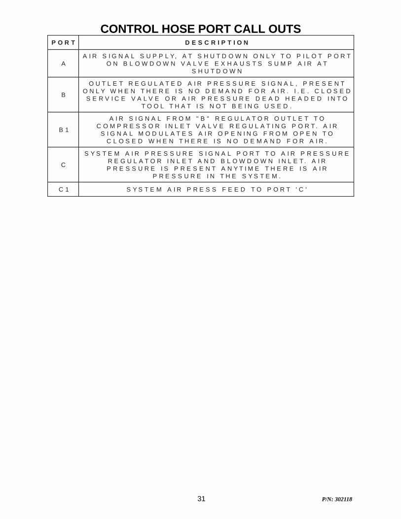
TROP NOITPIRCSED
ATROPTOLIPOTYLNONWODTUHSTA,YLPPUSLANGISRIA
TARIAPMUSSTSUAHXEEVLAVNWODWOLBNONWODTUHS
B
TNESERP,LANGISERUSSERPRIADETALUGERTELTUODESOLC.E.I.RIAROFDNAMEDONSIEREHTNEHWYLNO
OTNIDEDAEHDAEDERUSSERPRIAROEVLAVECIVRES.DESUGNIEBTONSITAHTLOOT
1B
OTTELTUOROTALUGER"B"MORFLANGISRIARIA.TROPGNITALUGEREVLAVTELNIROSSERPMOC
OTNEPOMORFGNINEPORIASETALUDOMLANGIS.RIAROFDNAMEDONSIEREHTNEHWDESOLC
C
ERUSSERPRIAOTTROPLANGISERUSSERPRIAMETSYSRIA.TELNINWODWOLBDNATELNIROTALUGERRIASIEREHTEMITYNATNESERPSIERUSSERP
.METSYSEHTNIERUSSERP
1C 'C'TROPOTDEEFSSERPRIAMETSYS
CONTROL HOSE PORT CALL OUTS

32 P/N: 302118
33 P/N: 302118
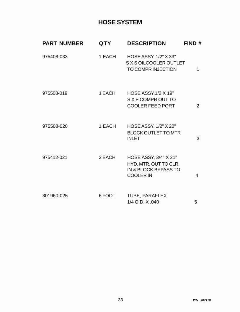
HOSE SYSTEM
PART NUMBER QTY DESCRIPTION FIND #
975408-033 1 EACH HOSE ASSY, 1/2” X 33”S X S OILCOOLER OUTLETTO COMPR INJECTION 1
975508-019 1 EACH HOSE ASSY,1/2 X 19”S X E COMPR OUT TOCOOLER FEED PORT 2
975508-020 1 EACH HOSE ASSY, 1/2” X 20”BLOCK OUTLET TO MTRINLET 3
975412-021 2 EACH HOSE ASSY, 3/4” X 21”HYD. MTR. OUT TO CLR.IN & BLOCK BYPASS TOCOOLER IN 4
301960-025 6 FOOT TUBE, PARAFLEX1/4 O.D. X .040 5
34 P/N: 302118
35 P/N: 302118
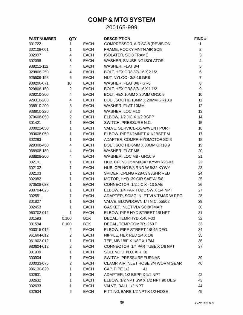
COMP & MTG SYSTEM200165-999
PART NUMBER QTY DESCRIPTION FIND #301722 1 EACH COMPRESSOR, AIR SCI8 (REVISION 1302108-001 1 EACH FRAME, ROCKY MNTN AIR SCI8 2302097 4 EACH ISOLATER, SCI8 FRAME 3302098 8 EACH WASHER, SNUBBING ISOLATOR 4938212-112 4 EACH WASHER, FLAT 3/4 5929806-250 4 EACH BOLT, HEX GR8 3/8-16 X 2 1/2 6925506-198 6 EACH NUT, NYLOC - 3/8-16 GR8 7938206-071 10 EACH WASHER, FLAT 3/8 - GR8 8929806-150 2 EACH BOLT, HEX GR8 3/8-16 X 1 1/2 9929210-300 4 EACH BOLT, HEX 10MM X 30MM GR10.9 10929310-200 4 EACH BOLT, SOC HD 10MM X 20MM GR10.9 11938910-200 8 EACH WASHER, FLAT 10MM 12938810-220 8 EACH WASHER, LOC M10 13970608-050 2 EACH ELBOW, 1/2 JIC X 1/2 BSPP 14301421 1 EACH SWITCH, PRESSURE N.C. 15300022-050 1 EACH VALVE, SERVICE-1/2 W/VENT PORT 16983608-050 1 EACH ELBOW, PIPE1/2MNPT X 1/2BSPT M 17302283 1 EACH ADAPTER, COMPR-HYDMOTOR SCI8 18929308-450 4 EACH BOLT, SOC HD 8MM X 30MM GR10.9 19938908-180 4 EACH WASHER, FLAT M8 20938808-200 4 EACH WASHER, LOC M8 - GR10.9 21302101 1 EACH HUB, CPLNG 25MMX8X7 KYWYR28-03 22302102 1 EACH HUB, CPLNG 5/8 RND W 5/32 KYWY 23302103 1 EACH SPIDER, CPLNG R28-03 98SHR RED 24302082 1 EACH MOTOR, HYD .39 CIR SAE”A” 5/8 25970508-088 1 EACH CONNECTOR, 1/2 JIC X - 10 SAE 26980704-025 1 EACH ELBOW, 1/4 PAR TUBE SW X 1/4 NPT 27302551 1 EACH ADAPTER, SCI8G INLET VLV TMAR W REG 28301827 1 EACH VALVE, BLOWDOWN 1/4 N.C. 55502 29302453 1 EACH GASKET, INLET VLV SCI8/TMAR 30960702-012 1 EACH ELBOW, PIPE HYD STREET 1/8 NPT 31301593 0.100 BOX DECAL, TEMP.HYD.-140 F30 32301594 0.100 BOX DECAL, TEMP.COMPR.-250 F 33903315-012 2 EACH ELBOW, PIPE STREET 1/8 45 DEG. 34961604-012 2 EACH NIPPLE, HEX RED 1/4 X 1/8 35961902-012 1 EACH TEE, MB 1/8F X 1/8F X 1/8M 36980604-012 2 EACH CONNECTOR, 1/4 PAR TUBE X 1/8 NPT 37301939 1 EACH SOLENOID, N.O. AIR 38300904 1 EACH SWITCH, PRESSURE FURNAS 39300033-075 2 EACH CLAMP, AIR INLET HOSE 3/4 WORM GEAR 40906130-020 1 EACH CAP, PIPE 1/2 41302631 1 EACH ADAPTER, 1/2 BSPP X 1/2 NPT 42302632 1 EACH ELBOW, 1/2 NPT SW X 1/2 NPT 90 DEG. 43302633 1 EACH VALVE, BALL 1/2 NPT 44302634 2 EACH FITTING, BARB 1/2 NPT X 1/2 HOSE 45
36 P/N: 302118
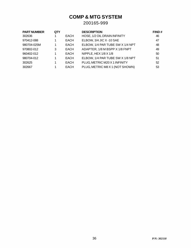
COMP & MTG SYSTEM200165-999
PART NUMBER QTY DESCRIPTION FIND #302636 1 EACH HOSE, 1/2 OIL DRAIN INFINITY 46970412-088 1 EACH ELBOW, 3/4 JIC X -10 SAE 47980704-025M 1 EACH ELBOW, 1/4 PAR TUBE SW X 1/4 NPT 48970802-012 3 EACH ADAPTER, 1/8 M BSPP X 1/8 FNPT 49960402-012 1 EACH NIPPLE, HEX 1/8 X 1/8 50980704-012 1 EACH ELBOW, 1/4 PAR TUBE SW X 1/8 NPT 51302625 1 EACH PLUG, METRIC M20 X 1 INFINITY 52302667 1 EACH PLUG, METRIC M8 X 1 (NOT SHOWN) 53
37 P/N: 302118
38 P/N: 302118
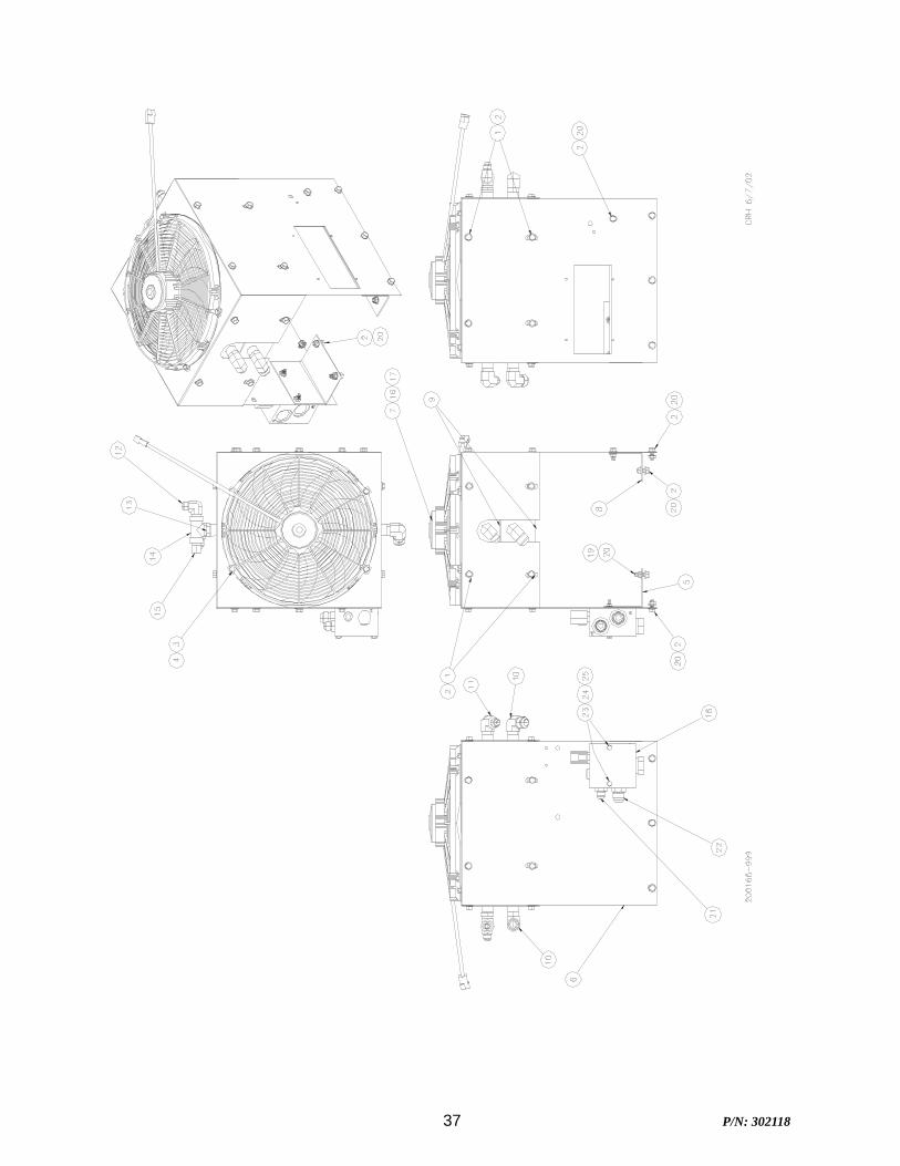
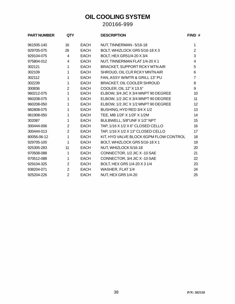
OIL COOLING SYSTEM200166-999
PART NUMBER QTY DESCRIPTION FIND #
961505-140 16 EACH NUT, TINNERMAN - 5/16-18 1929705-075 26 EACH BOLT, WHIZLOCK GR5 5/16-18 X 3 2929104-075 4 EACH BOLT, HEX GR51/4-20 X 3/4 3975804-012 4 EACH NUT, TINNERMAN FLAT 1/4-20 X 1 4302121 1 EACH BRACKET, SUPPORT RCKY MTN AIR 5302109 1 EACH SHROUD, OIL CLR RCKY MNTN AIR 6302112 1 EACH FAN, ASSY W/MTR & GRILL 13” PU 7302239 1 EACH BRACKET, OIL COOLER SHROUD 8300836 2 EACH COOLER, OIL 12” X 13.5” 9960212-075 1 EACH ELBOW, 3/4 JIC X 3/4 MNPT 90 DEGREE 10960208-075 1 EACH ELBOW, 1/2 JIC X 3/4 MNPT 90 DEGREE 11960208-050 1 EACH ELBOW, 1/2 JIC X 1/2 MNPT 90 DEGREE 12982808-075 1 EACH BUSHING, HYD RED 3/4 X 1/2 13961908-050 1 EACH TEE, MB 1/2F X 1/2F X 1/2M 14302087 1 EACH BULBWELL, 5/8”UNF X 1/2” NPT 15300444-006 2 EACH TAP, 1/16 X 1/2 X 6” CLOSED CELLO 16300444-013 2 EACH TAP, 1/16 X 1/2 X 13” CLOSED CELLO 1780056-06-12 1 EACH KIT, HYD VALVE BLOCK 6GPM FLOW CONTROL 18929705-100 1 EACH BOLT, WHIZLOCK GR5 5/16-18 X 1 19925305-283 11 EACH NUT, WHIZLOCK 5/16-18 20970508-088 1 EACH CONNECTOR, 1/2 JIC X -10 SAE 21970512-088 1 EACH CONNECTOR, 3/4 JIC X -10 SAE 22929104-325 2 EACH BOLT, HEX GR5 1/4-20 X 3 1/4 23938204-071 2 EACH WASHER, FLAT 1/4 24925204-226 2 EACH NUT, HEX GR5 1/4-20 25
39 P/N: 302118
40 P/N: 302118
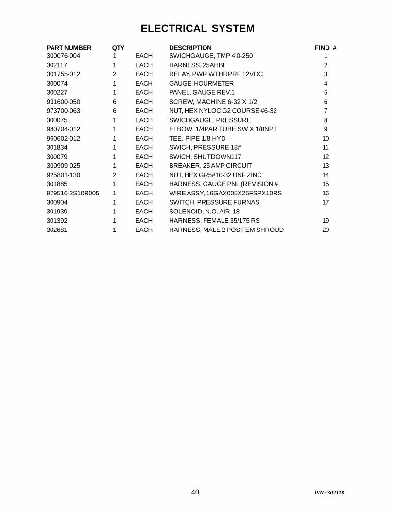
ELECTRICAL SYSTEM
PART NUMBER QTY DESCRIPTION FIND #300076-004 1 EACH SWICHGAUGE, TMP 4’0-250 1302117 1 EACH HARNESS, 25AHBI 2301755-012 2 EACH RELAY, PWR WTHRPRF 12VDC 3300074 1 EACH GAUGE, HOURMETER 4300227 1 EACH PANEL, GAUGE REV.1 5931600-050 6 EACH SCREW, MACHINE 6-32 X 1/2 6973700-063 6 EACH NUT, HEX NYLOC G2 COURSE #6-32 7300075 1 EACH SWICHGAUGE, PRESSURE 8980704-012 1 EACH ELBOW, 1/4PAR TUBE SW X 1/8NPT 9960602-012 1 EACH TEE, PIPE 1/8 HYD 10301834 1 EACH SWICH, PRESSURE 18# 11300079 1 EACH SWICH, SHUTDOWN117 12300909-025 1 EACH BREAKER, 25 AMP CIRCUIT 13925801-130 2 EACH NUT, HEX GR5#10-32 UNF ZINC 14301885 1 EACH HARNESS, GAUGE PNL (REVISION # 15979516-2S10R005 1 EACH WIRE ASSY, 16GAX005X25FSPX10RS 16300904 1 EACH SWITCH, PRESSURE FURNAS 17301939 1 EACH SOLENOID, N.O. AIR 18301392 1 EACH HARNESS, FEMALE 35/175 RS 19302681 1 EACH HARNESS, MALE 2 POS FEM SHROUD 20
41 P/N: 302118
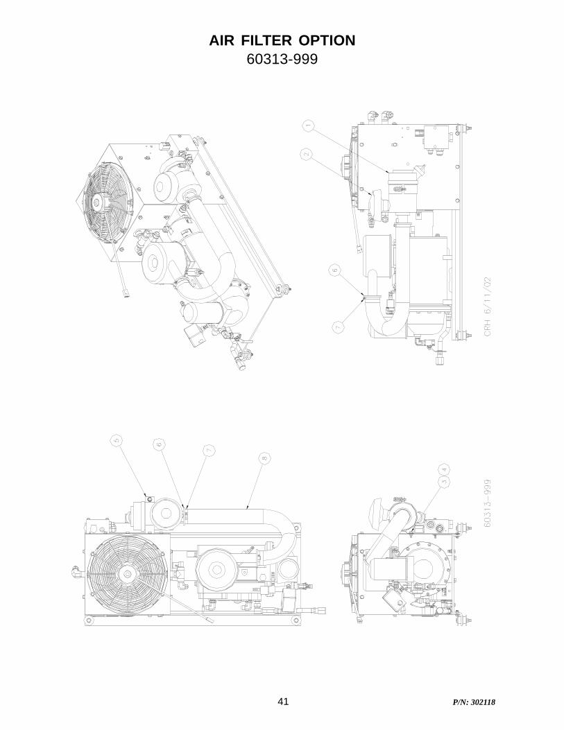
AIR FILTER OPTION60313-999
42 P/N: 302118
AIR FILTER OPTION60313-999
PART NUMBER QTY DESCRIPTION FIND #300918 1 EACH ASSY, AIR FILTER - 4.8 1300857 1 EACH CAP, AIR FILTER 4.8 2925305-283 1 EACH NUT, WHIZLOCK 5/16-18 3929705-075 1 EACH BOLT, WHIZLOCK GR5 5/16-18 X 3/4 4300855 1 EACH BAND, AIR FILTER MTG. 4.8 5301397 2 EACH INSERT, RUBBER 2 1/2 X 1 3/4 6301786-250 2 EACH CLAMP, AIR FILTER 2 1/2 IN KFLEX 7301785-250 2 1/2 FOOT HOSE, AIR INLET 2 1/2 I.D. KFLEX 8
43 P/N: 302118
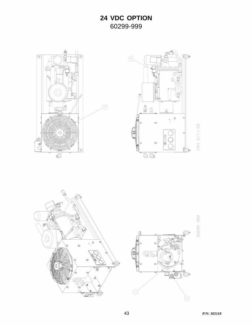
24 VDC OPTION60299-999
44 P/N: 302118
24 VDC OPTION60299-999
PART NUMBER QTY DESCRIPTION FIND #301755-024 2 EACH RELAY, PWR WTHRPRF 24VDC 180056-06-24 1 EACH KIT, HYD VALVE BLOCK 6GPM 12V FLOW CONTROL 2302643 1 EACH FAN, ASSY W/MTR & GRILL 13" PULLER 24VDC 3301939-024 1 EACH SOLENOID, N.O. AIR 24VDC 4301755-012 -2 EACH RELAY, PWR WTHRPRF 12VDC80056-06-12 -1 EACH KIT, HYD VALVE BLOCK 6GPM FLOW CONTROL302112 -1 EACH FAN, ASSY W/MTR & GRILL 13" PULLER 24VDC301939 -1 EACH SOLENOID, N.O. AIR

45 P/N: 302118
RECOMMENDED SPARE PARTS LIST
46 P/N: 302118
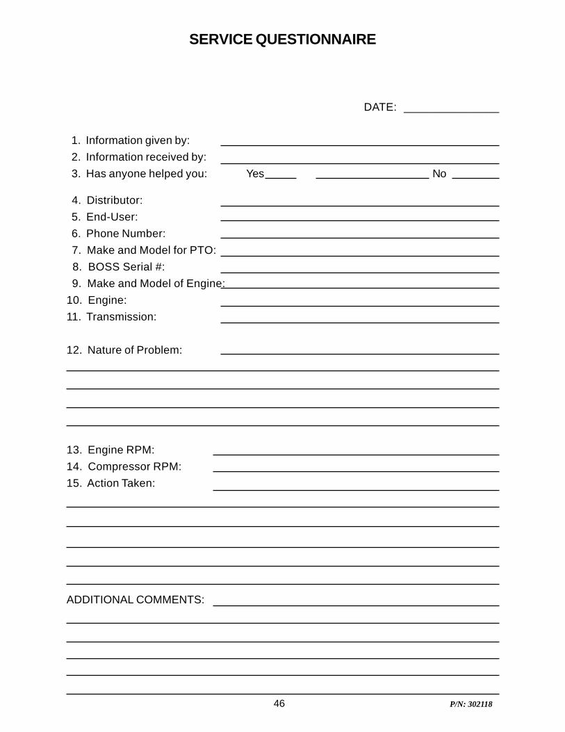
DATE: _______________
1. Information given by: 2. Information received by: 3. Has anyone helped you: Yes No
4. Distributor: 5. End-User: 6. Phone Number: 7. Make and Model for PTO: 8. BOSS Serial #: 9. Make and Model of Engine:10. Engine:11. Transmission:
12. Nature of Problem:
13. Engine RPM:14. Compressor RPM:15. Action Taken:
ADDITIONAL COMMENTS:
SERVICE QUESTIONNAIRE
47 P/N: 302118
Instructional Procedures for the Installation of BOSSINDUSTRIES 25 AHBI Geared Rotary Screw Air
Compressor
This air compressor should be installed only by those who have been trained and delegated to doso and who have read and understand both the operators’ manual and the installation manual.Failure to follow the instructions, procedures, and safety precautions in this manual may result inaccidents and injuries.
Install, use, and operate this air compressor only in full compliance with all pertinent O.S.H.A.requirements and all pertinent Federal, State, and Local codes or requirements and with BOSSINDUSTRIES, Inc. instructions.
Do not modify this compressor except with written factory approval.
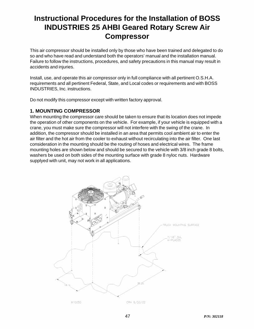
1. MOUNTING COMPRESSORWhen mounting the compressor care should be taken to ensure that its location does not impedethe operation of other components on the vehicle. For example, if your vehicle is equipped with acrane, you must make sure the compressor will not interfere with the swing of the crane. Inaddition, the compressor should be installed in an area that permits cool ambient air to enter theair filter and the hot air from the cooler to exhaust without recirculating into the air filter. One lastconsideration in the mounting should be the routing of hoses and electrical wires. The framemounting holes are shown below and should be secured to the vehicle with 3/8 inch grade 8 bolts,washers be used on both sides of the mounting surface with grade 8 nyloc nuts. Hardwaresupplyed with unit, may not work in all applications.
48 P/N: 302118
INSTRUCTIONAL PROCEDURES2. INSTALLING THE WIRING & CONNECTING THE HYDRAULIC HOSES
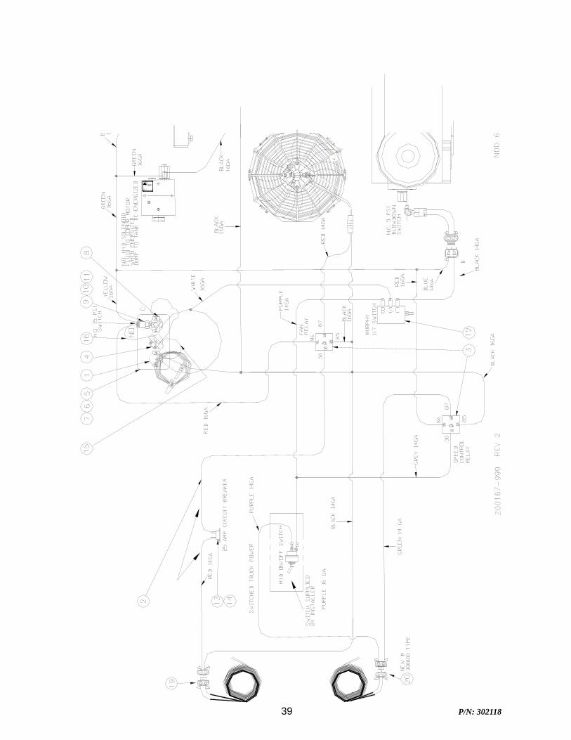
This unit is shipped from the factory with all necessary internal wiring installed. The only remain-ing wiring necessary is the wiring needed to interface your vehicle/power source with the Bosscompressor. (Please refer to drawing 200167-999 on page 40) The unit is shipped with 4 loosewires, they need to be connected as follows:
1. Connect red wire to switched 12 vdc power. (or 24 VDC if you have this option)2. The green wire should be spliced into the 12 vdc switched feed
for the hydraulic systems solenoid. (or 24 VDC if you have this option)3. Connect black wire to ground.4. The purple wire is used to activate an electronic
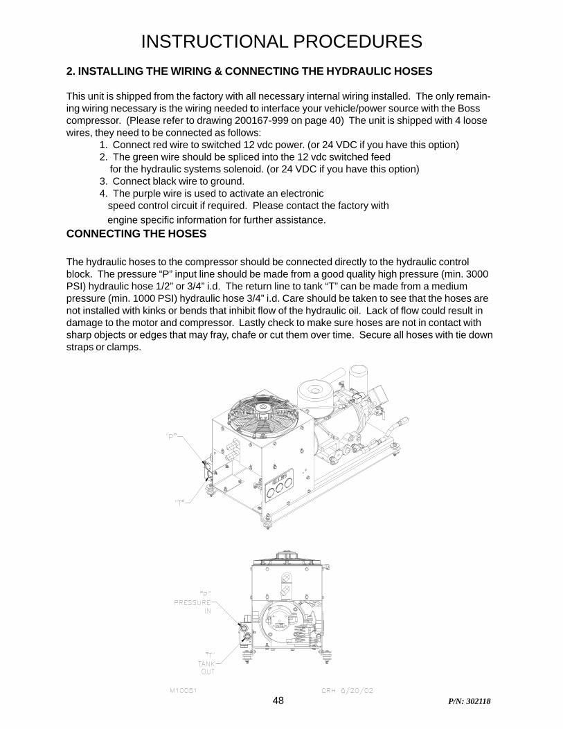
speed control circuit if required. Please contact the factory with engine specific information for further assistance.CONNECTING THE HOSES
The hydraulic hoses to the compressor should be connected directly to the hydraulic controlblock. The pressure “P” input line should be made from a good quality high pressure (min. 3000PSI) hydraulic hose 1/2” or 3/4” i.d. The return line to tank “T” can be made from a mediumpressure (min. 1000 PSI) hydraulic hose 3/4” i.d. Care should be taken to see that the hoses arenot installed with kinks or bends that inhibit flow of the hydraulic oil. Lack of flow could result indamage to the motor and compressor. Lastly check to make sure hoses are not in contact withsharp objects or edges that may fray, chafe or cut them over time. Secure all hoses with tie downstraps or clamps.
49 P/N: 302118
3. PRE-START-UP INSPECTION CHECKS
This inspection should be done prior to removing truck from bay. Final testing of the system,including checking for leaks, is to be done outside.ALL TRUCKS SHOULD BE ROAD TESTED PRIOR TO STARTING INSTALLATION TO ISOLATE ANY
PREVIOUS TRUCK PROBLEMS.I. Check sales order to verify that all compressor related items originally ordered have been
installed or are ready to ship with the truck. This would include any special filters, oils,hoses, options, etc.
II. Vacuum all areas that have metal or plastic shavings. Wipe all fingerprints off unit andvehicle.
III. Apply decals to proper location. Make sure that the area is cleaned prior to applyingdecals. All decals should have a professional appearance upon application.
IV. Check all assemblies, clamps, fittings, drivelines, angles, nuts, and bolts to ensure theyare properly tied and secured to the vehicle. This is a very critical area of inspection. Thevehicle should not be moved until this inspection has been completed.
V. Record all serial numbers for this installation.A. Vehicle V.I.N.B. Hydraulic Pump DataC. Air-End Serial NumberD. BOSS INDUSTRIES Serial NumberE. Receiver Tank Serial NumberF. Note any special applications relating to specific installations.
VI. Check all fluid levels (position the unit on a level surface so that proper amount of fluidscan be added).
A. Fuel to provide for three hours of operation.B. Transmission fluid and PTO box.C. Compressor.
Check the compressor oil sump level (see lubricant section of the operator and parts section for type of lubricant to use). 1. Add oil if needed. 2. Additional oil may need to be added after test. 3. Top off oil level to half the sightglass when finished with the test.
D. Any other applicable fluids.
4. INITIAL START-UP AND TEST
A. Start power source and allow for warm-up.B. Read the operation section in the operator and parts manual carefully before proceeding onto
the initial start-up.
INSTRUCTIONAL PROCEDURES
50 P/N: 302118
C. Engage hydraulic system. A direction of rotation arrow is attached to the compressor packageabove the hydraulic coupling. The coupling/hub must be rotating in the direction the arrow ispointing. If for any reason this arrow has been removed the correct compressor rotation isclockwise when looking directly at the compressor shaft. Check the direction of rotation byquickly engaging and then disengaging the compressor.
CAUTIONDO NOT RUN THE COMPRESSOR IN A REVERSE ROTATION FOR PERIODS LONGER THAN 5
SECONDS. CONTINUED OPERATION IN THIS MANNER WILL RESULT IN EXTENSIVE COMPRES-SOR UNIT DAMAGE.
The safety shutdown switch should be wired in series with the solenoid thatopens the flow of the hydraulic oil to the compressor drive motor. In cases ofhigh temperature and/or pressure, the closing of the valve will stop the com-pressor operation. Refer to page 39.
Safety circuit testing for 25 AHBI
Safety circuit testing can be done in the following manner. Start the truck.Engage the compressor. Take a screwdriver and touch the 1/16” allen headscrew on the face of the temperature gauge and simultaneously touch theoutside ring on the face of the gauge. This should shut off the power to thesolenoid of the hydraulics. Push the button in on the shutdown switch to reset.Repeat the test with the pressure gauge if solenoid does not stop flow to com-pressor, check wiring.
INSTRUCTIONAL PROCEDURES
51 P/N: 302118
WARRANTY
SECTION
52 P/N: 302118
BOSS Industries, Inc. warrants that this Rotary Screw Compressor unit conforms toapplicable drawings and specifications approved in writing by BOSS. The unit assemblywill be free from defects in material and workmanship for a period of two (2) years from thedate of initial operation or thirty (30) months from the date of shipment, whichever periodfirst expires. All other components and parts of BOSS manufacture, will be free fromdefects in material and workmanship for a period of one (1) year from the date of initialoperation or eighteen (18) months from the date of shipment, whichever period first expires.If within such period BOSS receives from the Buyer written notice of and alleged defect inor nonconformance of the unit, all other components and parts of BOSS manufacture and ifin the judgment of BOSS these items do not conform or are found to be defective inmaterial of workmanship, BOSS will at its option either, (a) furnish a Service Representativeto correct defective workmanship, or (b) upon return of the item F.O.B. BOSS originalshipping point, repair or replace the item or issue credit for the replacement item ordered byBuyer, (Defective material must be returned within thirty (30) days of return shippinginstructions from BOSS. Failure to do so within specified time will result in forfeiture ofclaim), or (c) refund the full purchase price for the item without interest. Factory installedunits will also include warranty on installation for a period of one (1) year. This warrantydoes not cover damage caused by accident, misuse or negligence. If the compressor unitis disassembled the warranty is void. BOSS’s sole responsibility and Buyer’s exclusiveremedy hereunder is limited to such repair, replacement, or repayment of the purchaseprice. Parts not of BOSS manufacture are warranted only to the extent that they arewarranted by the original manufacture. BOSS shall have no responsibility for any cost orexpense incurred by Buyer from inability of BOSS to repair under said warranty when suchinability is beyond the control of BOSS or caused solely by Buyer.
There are no other warranties, express, statutory or implied, including thoseof merchantability and of fitness of purpose; nor any affirmation of fact orrepresentation which extends beyond the description of the face hereof.
This warranty shall be void and BOSS shall have no responsibility to repair, replace, orrepay the purchase price of defective or damaged parts or components resulting directly orindirectly from the use of repair or replacement parts not of BOSS manufacture or approvedby BOSS or from Buyer’s failure to store, install, maintain, and operate the compressoraccording to the recommendations contained in the Operating and Parts Manual and goodengineering practice. The total responsibility of BOSS for claims, losses, liabilities ordamages, whether in contract or tort, arising out of or related to its products shall notexceed the purchase price. In no event shall BOSS be liable for any special, indirect,incidental or consequential damages of any charter, including, but not limited to, loss of useof productive facilities or equipment, loss of profits, property damage, expenses incurred inreliance on the performance of BOSS, or lost production, whether suffered by Buyer or anythird party.
BOSS Industries, Inc.
720 Boyd Boulevard
LaPorte, IN 46352
WARRANTY
53 P/N: 302118
As claims, policies and procedure are governed by the terms of the BOSS Industries,Inc. warranty, it is necessary to outline some of the more important provisions.
The BOSS warranty applies only to new and unused products which, after shipmentfrom the factory, have not been altered, changed, repaired or mistreated in any mannerwhatsoever. Normal maintenance items such as lubricants and filters are notwarrantable items.
Parts not of BOSS manufacture are warranted only to the extent they are warranted bythe original manufacturer.
Damage resulting from abuse, neglect, misapplication or overloading of a machine,accessory or part is not covered under warranty.
Deterioration or wear occasioned by chemical and/or abrasive action or excessiveheat shall not constitute defects.
Parts replacement and/or correction of defective workmanship will normally be handledby BOSS or their authorized distributor.
Failure to file a detailed warranty claim/service report for each occurrence of materialdefect of defective workmanship will cause warranty claim to be rejected.
Defective material must be returned within 30 days of receipt of shipping instructions.Failure to do so within specified time will result in forfeiture of claim.
The distributor is responsible for the initial investigation and write up of the warrantyclaim.
Distributor shall be allowed no more than 30 days from date of repair to file a warrantyclaim/service report.
Warranty for failure of BOSS replacement parts covers the net cost of the party only, notlabor and mileage.
The BOSS warranty does not cover diagnostic calls and travel. That is time spenttraveling to the machine to analyze the problem and returning with the proper tools andparts to correct the problem.
BOSS will deduct from allowable credits for excess freight caused by sender failing tofollow return shipping instructions.
Distributors or end-users automatically deducting the value of a warranty claim fromoutstanding balances due and payable to BOSS prior to receiving written notificationof BOSS approval of the warranty claim may be subject to forfeiture of the entire claim.
SUMMARY OF MAIN WARRANTY PROVISIONS
54 P/N: 302118
The warranty policy and procedures outlined here within are detailed to provide the claimantwith the information necessary when filing a warranty claim, and enabling BOSS the abilityto best serve it’s customers.
WARRANTY CLAIMS - GENERAL
An approved claim depends on the following provision:
1. A warranty claim/service report # must be issued by BOSS. (See filing procedures).2. Failed part must be returned within 30 days, freight prepaid, with receipt of warranty
claim/service report.3. Part is definitely defective.4. Workmanship is definitely defective.5. Machine is within warranty period.6. Machine has been operating within design conditions.
Claims made by distributors must be verified by distributor prior to contracting BOSS.
WARRANTY CLAIMS - FILING PROCEDURES
1. Initiate through purchase order for warranty part or request for credit.2. Warranty Claims/Service Report will accompany replacement part. When returning
failed part to the factory for warranty credit, fill out all information requested on WarrantyClaims/Service Report when it is returned to you with replacement part.
3. BOSS will confirm disposition of failed part within 30 days, and or request additionalinformation.
4. Claim acceptance or denial will result in release of a credit or confirmation letter ofdenial.
5. BOSS will consider each claim on it’s own merit and reserves the right to accept orreject claim request. In case of air-ends, these will be returned to the manufacturer fortheir analysis/input.
6. Send Warranty Claim/Service Report request to:
BOSS Industries, Inc.
720 Boyd Boulevard
LaPorte, IN 46350
WARRANTY INTRODUCTION
55 P/N: 302118
Parts returned to the factory must be properly packaged to prevent damage during shipment.Damage to a part as a result of improper handling or packing could be cause for claimsdisallowance of credit. When addressing the package for shipment, the following information mustbe on the outside of or tagged clearly to package.
1. Return Goods Authorization.2. Distributor or end-users return address.3. Correct factory address.4. Warranty Claim/Service Report #.5. Number of packages pertaining to each claim.
NOTE: Our warranty requires that all defective parts be returned to BOSS freight prepaid.Items sent without RGA number will not be accepted.
DAMAGE IN TRANSIT
Do not return damaged merchandise to BOSS Industries, Inc. please follow claim procedure.
1. Loss in transit:
The merchandise in our kit or provided in our factory installations has been thoroughly inspected orcarefully installed and tested before leaving our plant. However, regardless of the care taken at thefactory, there is a possibility that damage may occur in shipment. For this reason, it isrecommended that the unit be carefully inspected for evidence of possible damage or malfunctionduring the first few hours of operation. Responsibility for the safe delivery of the kit or factoryinstalled unit was assumed by the carrier at the time of shipment. Therefore, claims for loss ordamage to the contents of the kit or factory installed unit should be made upon the carrier.
2. Concealed loss or damage:
Concealed loss or damage means loss or damage which does not become apparent until the kit isunpacked or the factory installed unit is run by the end-user. The contents of the kit or factoryinstalled unit may be damaged due to rough handling while in route to its destination, even thoughthe kit or factory installed unit shows no external damage. When the damage is discovered uponunpacking, make a written request for inspection by the carrier agent within fifteen days of deliverydate. Then file a claim with the carrier since such damage is the carrier’s responsibility.
WARRANTY CLAIMS - PREPARATION OF PART RETURN