purchased parts / spare parts list m3.7 - cloudinary
TRANSCRIPT

PURCHASED PARTS / SPARE PARTS LIST
M3.7
ProfiTurn 35000 4500/350-23 x 20000 840D-1
13.0222 13.04.2011 T. Hebel
WALDRICH SIEGEN Werkzeugmaschinen GmbH Postfach 1320 57299 Burbach Telefon: +49 2736 493-02 Telefax: +49 2736 493-559 www.waldrich-siegen.de

2 13.0222
Copyright
WALDRICH SIEGEN© Copying of this document, and giving it to others and the use or communication of the contents thereof, are forbidden without express authority. Offenders are liable to the payment of damages. All rights are reserved in the event of the grant of a patent or the registration of a utility model or design. We would be pleased to receive any improvement suggestions you may have regarding this manual.
Original operating instructions Rev. Name Date Chapter Reason Of Modification

Contents
This operation manual consists of
BOOK M1 OPERATION MANUAL
BOOK M2 PROGRAMMING MANUAL
BOOK M3 PURCHASED PARTS / SPARE PART LIST
BOOK M4 DRAWINGS
BOOK E1 ELECTRICAL DIAGRAMS
BOOK E2 SOFTWARE LICENSES / MANUFACTURER-DOCUMENTATION
BOOK E3 PLC SOFTWARE LISTING

Contents

Table of Contents PURCHASED PARTS
Item QNTY UM S/N / Part Name Dimension Material Norm SP Manufacturer10 1 pce 13-02220 TURNING LATHE DH 4500/350 - 23 x 20000-1 bgf190 1 pce 13-02220-00100 HEADSTOCK HOUSING bgf90 2 pce 7-0051512 VENTILATION FILTER M 33X1.5 NO. 4100462112 bgf,v1,t Mann & Hummel200 1 pce 13-02220-00120 MAIN SPINDLE AND BEARING bgf470 3 pce 556105 DIGITAL DISPLAY HDA 5500-3-1-DC-000 v3,spi,t HYDAC INTERNATIONAL230 1 pce 13-02220-00125 DRIVE COUPLING WITH BRAKE bgf70 1 pce 506328 DISC BRAKE SB 17-1200 PI v3,t,bgf Pintsch-Bubenzer240 1 pce 13-02220-00130 GEAR STEP SWITCHING bgf80 1 pce 550157 HYDRAULIC-DIFF CYLINDER RD 100/50 x 320 v3,t,spi Hänchen260 1 pce 13-02220-00151 HYDRAULIC AND LUBRICATION AGGREGATE bgf20 1 pce 6203277 HYDRAULICS & LUBRICATION 630 LITERS t,spi,bgf Kuwega130 1 pce 514962 DUPLEX-FILTER PI 3730-15 t,spi,bgf Mahle 140 4 pce 525059 FILTER ELEMENT PI 3230 SMX VST 10 v1,bgf,t Mahle 190 1 pce 542401 DUPLEX FILTER PI 2130-069 t,spi,bgf Mahle 200 4 pce 519859 FILTER ELEMENT PI 3130 SMX 10 v1,bgf,t Mahle 250 1 pce 542283 DUPLEX FILTER PI 2105-069 t,spi,bgf Mahle 260 4 pce 509909 FILTER ELEMENT PI 3105 SMX 10 v1,t,bgf Mahle 270 1 pce 13-02220-00155 OIL COOLER bgf20 1 pce 554827 PLATE HEAT EXCHANGER PK-90-121-I-G11/2 bgf,v3,t Newcool GmbH280 1 pce 13-02220-00165 SPINDLE POSITIONING bgf60 1 pce 7-0051510 AERATION-FILTER M 26 X 1,5 NO. 4100262102 bgf,v1,t Mann & Hummel380 1 pce 519339 HYDRAULIC DIFF. CYLINDER 122 10103-01/32/16/55 v3,t,bgf Hänchen310 1 pce 13-02220-00187 OPERATING PLATFORM bgf240 1 pce 6203306 SAFETY SOLENOID INTERLOCK AZM 190-02/01rk v2,spi,bgf,t Schmersal250 1 pce 6203309 ACTUATOR AZM 190-B3/2x15 spi,v3,t Schmersal320 1 pce 13-02220-00190 FACE PLATE bgf80 4 pce 549983 CLAMPING SPINDLE MSP 200 v4,t,bgf Jakob90 4 pce 549984 CLAMPING SPINDLE MSP 200 v4,t,bgf Jakob330 1 pce 13-02220-00197 CLAMPING SPINDLE QUICK ADJUSTMENT bgf20 2 pce 2554230 HIGH TORQUE SCREWER LMP51 HR004-20 bgf,v3,t Atlas Copco340 1 pce 13-02220-00198 FACE PLATE PROTECTION DRIVE PNEUMATICAL bgf130 1 pce 554240 DOUBLE THRUST CYLINDER DGP-40-1485-PPV-A bgf,v3,t Festo140 1 pce 555766 SAFETY SENSOR CSS 14-34-S-D-M-ST v2,spi,bgf,t Schmersal150 1 pce 555769 ACTUATOR CST 34-S-1 v2,spi,bgf,t Schmersal390 1 pce 13-02220-00240 TELESCOPING COVERING CARRIAGE BED bgf20 1 pce 550099 TELESKOPABDECKUNG LINKS t,bgf Kabelschlepp30 1 pce 550100 TELESKOPABDECKUNG RECHTS t,bgf Kabelschlepp420 1 pce 13-02220-00300 CUNTERSTAY bgf90 1 pce 556329 HYDRAULIC-CYLINDRE HMZ250.63/40 v3,t,bgf AHP Merkle210 6 pce 527120 SPRING TENSION CYLINDER ZSF 35000 v3,t,bgf Optima280 1 pce 556363 SPUR WHEEL BACK-GEARED MO RF77DV112M4-VS t,spi,bgf,v3 SEW Eurodrive421 1 pce 13-02220-00310 CUNTERSTAY HYDRAULICS + LUBRICATION bgf30 1 pce 2555021 COMPACT-PUMP-UNIT HC48DT/5,6 t,spi,bgf,v1 Hawe410 1 pce 2524380 GEAR PUMP UNIT MFE 5/BW 3 v3,t,spi,bgf Willy Vogel430 1 pce 13-02220-00320 SENSOR MECHANISM AT QUILL bgf330 1 pce 6204888 POSITION SENSOR capaNCDT6300 v3,spi,bgf,t Micro-Epsilon450 1 pce 13-02220-00350 PICKUP-STATION COUTERSTAY bgf90 1 pce 6204215 HYDRAULIC DIFF. CYLINDER RD 50/30 X 1325 STROKE v3,t,bgf Hänchen
S/N 13-02220 April 2011 1 / 3

Item QNTY UM S/N / Part Name Dimension Material Norm SP Manufacturer470 1 pce 13-02220-00408 DRIVE X-AXIS bgf50 1 pce 551630 PLANETARY GEAR SEW PSF921/M EPH10/24/19 v1,bgf,t SEW Eurodrive480 1 pce 13-02220-00410 DRIVE Z-AXIS bgf10 2 pce 550090 PLANETARY GEAR v1,bgf,t Wittenstein Alpha490 1 pce 13-02220-00440 UPPER CARRIAGE,R.H. bgf300 4 pce 506135 SPRING LOADED CYLINDER ZSF 10000 special design v3,t,bgf Optima390 1 pce 507459 HYDRAULIC MOTOR TYPE: OMP 100 v3,t,bgf Sauer Danfoss500 1 pce 13-02220-00442 TOOL CARRIER CARRIAGE R.H. bgf250 1 pce 506367 HYDRAULIC MOTOR OMR 160, 151-021300 v3,bgf,t Sauer Danfoss520 1 pce 13-02220-00460 HYDROSTATIC CARRIAGE, R.H. bgf50 1 pce 553878 LUBRICATION UNIT 400 LITERS t,spi,bgf Kuwega60 2 pce 599109 FILTER ELEMENT PI 8511 Drg 100 v1,bgf,t Mahle 70 2 pce 599108 FILTER ELEMENT PI 1011 MIC 25 v1,bgf,t Mahle 160 1 pce 542283 DUPLEX FILTER PI 2105-069 t,spi,bgf Mahle 170 4 pce 503855 FILTER ELEMENT PI 1105 MIC 10 v1,bgf,t Mahle 300 2 pce 524707 20-CIRCUIT-GEAR PUMP ZM 2202/S7; 480V 60HZ v3,t,spi,bgf SKF (Willy Vogel)480 1 pce 524707 20-CIRCUIT-GEAR PUMP ZM 2202/S7; 480V 60HZ v3,t,spi,bgf SKF (Willy Vogel)530 1 pce 13-02220-00470 HYDRAULIC INSTALLATION CARRIAGE, R.H. bgf30 1 pce 554755 COMPACT PUMP ASSEMBLY MP54A-H3,6-Z12,3 v3,t,spi,bgf Hawe600 1 pce 13-02220-00490 MIST-TYPE COOLING DEVICE bgf30 1 pce 6203676 MINIMAL QUANTITY LUBRICATION bgf,t,v1 Schmidt Microdosiertechnik620 1 pce 13-02220-00492 TELESCOPING COVERING FRONT / REAR, R.H. bgf40 1 pce 554692 TELESCOPING COVER, FRONT v2,t,bgf Kabelschlepp280 1 pce 554693 TELESCOPING COVER, REAR v2,t,bgf Kabelschlepp640 1 pce 13-02220-00495 OPERATING PLATFORM TOP CARRIAGE, R.H. bgf180 2 pce 550263 HYDRAULIC-DIFF-CYLINDER RD 50/36 X 1900 HUB v3,t,bgf AHP Merkle665 1 pce 13-02220-00499 SPLASH GUARD CARRIAGE bgf1270 2 pce 6203352 SAFETY SOLENOID INTERLOCK CET1-AX-LRA-00-50X-SA v2,t,spi,bgf Euchner 1280 2 pce 6203353 ACTUATER CET CET-A-BWK-50X v2,t,spi,bgf Euchner 1450 1 pce 6203364 ACTUATER P-W 059227 t,spi,bgf,v3 Euchner 1460 1 pce 6203363 SAFETY SWITCH TP TP3-4141A024M v2,t,spi,bgf Euchner 680 1 pce 13-02220-00620 BOTTOM PART OF STEADY REST STEADY RESTS 1 AND 2 bgf260 8 pce 500659 SPRING LOADED CYLINDER ZSF 10000 v3,t,bgf Optima300 1 pce 556362 SPUR WHEEL BACK-GEARED MOTOR RF77DV112M4-VS t,spi,bgf,v3 SEW Eurodrive305 1 pce 6205470 SPUR WHEEL BACK-GEARED MOTOR RF77DV112M4-VS t,spi,bgf,v3 SEW Eurodrive560 2 pce 552423 HYDRAULIC CYLINDRE Rd 450x370 v3,bgf,t Hydraulik & Hubgeräte GmbH710 1 pce 13-02220-00625 HYDROSTATIC, STEADY REST bgf450 2 pce 6203431 MOTOR PUMP COMBINATION 1PLA66DE10R-L-S-3,0kW t,spi,bgf Abitek GmbH500 2 pce 519796 DUPLEX FILTER PI 2145-069 t,spi,bgf Mahle 510 8 pce 522384 FILTER ELEMENT PI 4145 SMX 25 v1,bgf,t Mahle 710 2 pce 6203433 PUMP AGGREGATE H 09 037 M 00 v3,bgf,spi,t Hawe730 2 pce 6203434 PUMP AGGREGATE H 09 038 M 00 v3,bgf,spi,t Hawe1360 2 pce 543284 2-CIRCUIT GEAR PUMP UNIT M 205 v3,t,spi,bgf SKF (Willy Vogel)1590 2 pce 8-7308250 GEAR PUMP UNIT MFE 5 v3,t,spi,bgf SKF (Willy Vogel)1790 2 pce 8-7308245 GEAR PUMP UNIT MF5 HTN:106106 v3,t,spi,bgf SKF (Willy Vogel)720 1 pce 13-02220-00626 OIL COOLER DK - H 48 - V (2X) bgf20 2 pce 554986 PLATE HEAT EXCHANGER PK-70M-85-I-G11/2 bgf,t Newcool GmbH730 1 pce 13-02220-00627 HYDRAULIC, STEADY REST bgf30 2 pce 6203473 PUMP AGGREGATE t,spi,bgf,v1 Parker Hannifin90 2 pce 6203474 DUPLEX FILTER Pi 47010-015 t,spi,bgf Mahle Filtersys100 8 pce 6203481 FILTER ELEMENT Pi 73010 DN Sm-x vst 10 v1,bgf,t Mahle Filtersys
S/N 13-02220 April 2011 2 / 3

Item QNTY UM S/N / Part Name Dimension Material Norm SP Manufacturer770 1 pce 13-02220-00865 CRANE FOR CLAMPING JAWS bgf20 1 pce 6202778 SLEWING CRANE AS 5,0-2,0 spi,bgf,t Vetter820 1 pce 13-02220-00920 COMPRESSED AIR SUPPLY bgf60 1 pce 542054 MAINTENANCE UNIT 531 030 MSB6-AGE:J1:M1-WP v4,t,bgf Festo830 1 pce 13-02220-00925 COOLING UNIT VACUUM ROTATION FILTER bgf10 1 pce 556386 COOLANT FILTRATION t Knoll860 1 pce 13-02220-00961 ACCESSORIES FOR MAINTENANCE bgf10 1 pce 6203638 OIL PUMP 226400 B t SKF20 1 pce 2500601 PUMP HOLDER 226402 bgf,t SKF880 1 pce 13-02220-00970 CHIP CONVEYOR20 1 pce 556300 CHIP CONVEYOR t Knoll20 1 pce 13-02221 ELECTRICAL EQUIPMENT bgf10 1 pce 13-02221-00001 MAIN MOTORS bgf10 1 pce 555753 DC-MOTOR 1GG7352-5NC40-1WV1-Z v4,t,spi,bgf Siemens20 1 pce 556258 AC-MOTOR 1FT6136-6AC71-4DG1 v4,t,spi,bgf Siemens30 2 pce 556257 AC-MOTOR 1FT6108-8AC71-4DL3 v4,t,spi,bgf Siemens40 1 pce 6000154 AC-MOTOR 1FT6136-6AC71-1DG0 t,v4 Siemens50 1 pce 6203931 AC-MOTOR 1FK7105-5AF71-1AG3 t,spi,v4,bgf Siemens40 1 pce 13-02221-00180 ROT. ENCODER F. MAIN SPINDLE bgf10 1 pce 532799 INCREMENTAL ANGLE ENCODER ROD 880 - 36000 increment t,spi,bgf,v4 Heidenhain45 1 pce 13-02221-00300 ROT. ENCODER F. COUNTERSTAY bgf10 1 pce 533895 ROTARY ENCODER ROQ 524 t,spi,bgf,v4 Heidenhain50 1 pce 13-02221-00472 MEASURIND DEVICE Z-AXIS bgf10 1 pce 550114 LENGTH GAUGE SET LB382C;ML=23,240mm v3,t,spi,bgf Heidenhain60 1 pce 13-02221-00473 MEASURIND DEVICE X-AXIS CARRIAGE bgf10 1 pce 556185 LENGTH GAUGE SET LC183;ML=02,440mm v3,t,spi,bgf Heidenhain80 1 pce 13-02221-00720 CONTROL 480V±10%;60Hz±1%;TNC bgf3020 3 pce 6201099 DOC.HMI-ADVANCED MANUAL 840DSL;01/08 6FC5398-2AP10-3BA0;ENGLIS t Siemens3030 3 pce 6201471 DOC.PROGRAMMING BASICS 840DSL;01/08 6FC5398-1BP10-3BA0;ENGLIS t Siemens3040 3 pce 6201467 DOC.DISPO+PROGRAMMING 840DSL;01/08 6FC5398-2BP10-3BA0;ENGLIS t Siemens3050 3 pce 6201591 DOK.SINAMICS 840DSL;01/08 6FC5398-6BP10-3BA0;ENGLIS t Siemens3060 3 pce 6201593 DOC.PROGRAMMING CYCLES 840DSL;01/08 6FC5398-3BP20-1BA0;ENGLIS t Siemens
EXPLANATORY NOTES:
- The parts in this list are sorted by machine-components (e.g. headstock; tailstock; carriage …)
- The print-out documents are sorted in alphabetical order
S/N 13-02220 April 2011 3 / 3


M.../ME.../MF.../ Gear Pump, Ring Gear Pump, MFE.../ZM.../ Vane Pump and Multi-Circuit 143-012-... Pump Units Operating Manual Version 2


Contents Page 1
EN
Imprint The operating manual is an integral part of the scope supply of a pump unit type M... / ME... / MF... / MFE... / ZM... / 143-012-... The operating manual has been edited in conformity with applicable standards and rules for technical documentation. © Copyright SKF LUBRICATION SYSTEMS GERMANY AG reserves the right to make changes to adapt to technical improvement. Reprinting or copying even of parts of this operating manual requires the permission of SKF LUBRICATION SYSTEMS GERMANY AG. Editor Dipl.-Ing. S. Schlenzka
Contents Information Concerning the EC Declaration of Conformity and the Manufacturer´s Declaration ................ 2 Notes Concerning this Manual ............ 3 Applications ......................................... 3 Safety Instructions............................... 4 Transport, Delivery, Storage................ 5 Lubricants ............................................ 5 Design Versions ................................... 5 Function................................................ 8
Supply pump units for piston feeder systems ........................................................... 8 Supply pump units for Oil circulation Systems........................................................... 8 Multi-circuit gear pump units for hydrostatic bearings........................................................... 8
Installation ........................................... 8 Set-up .............................................................. 8 Connecting the lubrication lines..................... 8 Electrical Connection...................................... 9
First Operation ................................... 10 Maintenance....................................... 10 Failures............................................... 12 Decommissioning............................... 14
Temporary Shut-Down.................................. 14 Final Taking out of Service ........................... 14
Service................................................ 14

Information Concerning the EC Declaration of Conformity and the Manufacturer´s Declaration Page 2
EN
For the product designated below: Gear pump, ring gear pump, vane pump and multi-circuit pump units Series: M... / ME... / MF... / MFE... / ZM…/ 143-012-… we herewith certify that it conforms to the pertinent safety requirements set forth in the following Council Directive(s) for the harmonisation of the laws of the Member States... Electromagnetic compatibility 89/336/EEC Electrical equipment designed for use
within certain voltage limits (low voltage directive) 73/23/EEC
Notes (a) This declaration certifies the conformity with
the directives listed, but does not entail an express assurance of properties.
(b) The safety instructions in the documentation accompanying the product must be observed.
(c) Taking into operation of the certified products is not allowed until evidence has been provided that the machinery, vehicle or similar item, into which the product is integrated, conforms to the regulations and requirements set forth by the applicable directives.
(d) The operation of the products on non-standard line voltage as well as non-adherence to the installation instructions can affect the EMC properties and electrical safety.
We further declare that the above mentioned product: is meant for integration into a machine / for
connection to other machinery according to the EC - Machinery Directive 98/37/EC, Annex II B. Taking into service is not admissible until evidence has been provided that the machine in which this part is installed or to which this part is connected, conforms to the regulations set forth in the EC directive 98/37/EC.
with reference to the EC directive 97/23/EC concerning apparatus subjected to pressure this product must only be used as intended and according to the notes in the documentation. Especially observe the following:
SKF products must not be used in conjunction with fluids, group I (hazardous fluids), according to the definition of article 2 paragraph 2 of the directive 67/548/EC dtd. June 27th, 1967; and are not approved for application with such.
None of the products manufactured by SKF are approved for application in connection with gases, liquefied gases, gases dissolved under pressure, steams or fluids that will reach a steam pressure of more than 0.5 bar above the normal atmospheric pressure (1013 mbar) in the admissible application temperature range. Provided they are used as intended, the products supplied by us will not reach the limit values set forth in article 3, paragraph 1, numbers 1.1 to 1.3 and paragraph 2 of the directive 97/23/EC. Therefore they do not come under the requirements set forth in annex I of that directive. Therefore, they are not marked with the CE mark concerning the directive 97/23/EC. They are classified by us to come under article 3 paragraph 3 of the directive. SKF products must only be used as intended. Use or taking into operation of the products in areas with potentially explosive atmospheres according to the ATEX directive 94/9/EC is not allowed, regardless of whether these entail gaseous atmospheres or dusty atmospheres.
If required, you may request the declaration of conformity or manufacturer´s declaration for this product from our central contact address.
Information Concerning the EC Declaration of Conformity and the Manufacturer´s Declaration

Notes Concerning this Manual Page 3
EN
Notes Concerning this Manual SKF pump units type M... / ME... / MF... / MFE... / ZM... / 143-012-... have been made to comply with the generally recognised technical standards and the corresponding rules for work safety and accident prevention. Still hazards may be involved in their use, which can lead to injury of operators or other persons or damage to the machine or other property. To ensure trouble-free operation and prevent hazards, we kindly ask you to read the present manual carefully and observe the notes contained in it. Use the table of contents to locate the desired information promptly and successfully. Please take note of the symbol shown below. It calls attention to special situations:
Text marked with this sign alerts to special hazards or work that must be performed with caution.
Note that this manual is an integral part of the unit and that it must be passed on to the new owner upon sale.
Applications
All products of SKF LUBRICATION SYSTEMS GERMANY AG may be used only as intended and according to the information set forth in the respective operating manual. We expressly emphasise that dangerous materials of any type, especially materials which are classified as dangerous according to EC directive 67/548/EEC article 2, paragraph 2, may be stored and transported and/or distributed with SKF products only after consulting SKF Lubrication Systems Germany AG and receiving their written consent. None of the products manufactured by SKF are approved for application in connection with hot gases, liquefied gases, gases liquefied under pressure, steams or fluids that will reach a steam pressure of more than 0.5 bar above the normal atmospheric pressure (1013 mbar) at the maximum admissible temperature.
Unless expressly stated for a specific product, products made by SKF must nut be used in areas with potentially explosive atmospheres.
SKF pump units type M... / ME... / MF... / MFE... / ZM... / 143-012-... are meant to supply lubricants to central lubrication systems and hydrostatic bearings. Other or use beyond this purpose is considered unintended. SKF will not accept liability for damages resulting from such unintended use.
Only media released for use in connection with the pump unit may be supplied. Unsuitable media could lead to unit failure and might cause severe property damage and personal injury.
Further notes concerning lubricants are found in chapter “Lubricants”, page 5. A list of approved lubricants is found on the Internet at www.skf.com/schmierung. SKF will not warrant for damages resulting from use of lubricants other than those approved by SKF.

Safety Instructions Page 4
EN
Safety Instructions Please observe the following safety instructions to ensure trouble-free functioning of the pump unit and prevent damage. Use the pump units only in technically perfect condition for the intended use. Be aware of hazards and observe the operating manual. Especially errors that could affect safety must be resolved without delay. To do so, turn to a SKF service station (see chapter Service). The safety mechanisms, if provided for, must not be damaged, dismantled, or in any way made inoperable, nor must they be replaced by parts which have not been expressly approved by SKF. The installation, electrical connection and all interventions such as repairs, component replacement, etc. may be carried out only by adequately qualified and instructed personnel.
If the pump unit is installed improperly, substantial property damage or injury of persons may be the consequence.
Qualified personnel has been trained, instructed and specifically ordered by the owner to perform the work. Due to their training and experience, these persons are familiar with the applicable standards, regulations, accident prevention rules and operating conditions. They are authorised to perform the respective tasks and capable of identifying and avoiding possible hazards. The definition of what is a trained specialist and the prohibition of use by unqualified personnel are set forth in DIN VDE 0105 or IEC 364. The pump unit and the central lubrication system must be disconnected from the electric voltage supply before undertaking any work on it, e.g. cleaning, refilling with lubricant, etc.
DANGER, FATAL INJURY Repair work must only be performed after a trained specialist has disconnected the pump unit from power.
DANGER, FATAL INJURY Work on systems which have not been disconnected from power supply can lead to injury of persons.
The central lubrication system connected to the pump unit may be pressurised. Before extension work, changes, repairs etc. it must be depressurised.
Working on systems under pressure can lead to personal injury.
When working on central lubrication systems with piston feeders, note that the delivery plungers of the piston feeders could be under spring pressure. Be sure to take appropriate precautions. Unauthorised modifications to the pump unit and the use of unauthorised spare parts and aids are prohibited and void the warranty. Worn-out systems must be made inoperable and disposed of properly.
Transport, Delivery, Storage Page 5
EN
Transport, Delivery, Storage The pump units are packed according to market standards in conformity with the regulations of the respective country of destination and DIN ISO 9001. Transport packages must be labelled with the note “Do not throw!”. There are no limitations for transport by surface, air or sea. Upon receiving the package, please check the items for possible damage, and ensure the package is complete by checking the supply papers. Keep the packaging material until any and all problems have been clarified. SKF pump units type M... / ME... / MF... / MFE... / ZM... / 143-012-... are supplied with oil conservation. However there is a possibility that the preservative might resinify if a unit is in storage for a long period of time. This is especially the case if the unit is stored at higher temperatures or exposed to UV rays. It may be necessary to clean the pump unit with a commercially available non-aggressive cleaning agent before installation. In general, the pump should be stored in a dry and dust-free environment. The storage temperatures are listed in the specifications.
Lubricants The lubricants listed in Table 1 may be used in connection with SKF pump units, type M... / ME... / MF... / MFE... / ZM... / 143-012-... The oils and basic oils may be of mineral or synthetic origin and may be rapidly biodegradable. Use of additives depends on the operating conditions. Note that the properties of some lubricants may lie within the limit values indicated, but these may not be suitable for use with central lubrication systems because of some other properties. For instance, synthetic lubricants may be incompatible with elastomeres. SKF offers to test lubricants for compatibility with central lubrication systems. Avail yourself of the advice of SKF employees. Keep in mind that lubricants are generally considered environmentally hazardous and combustible substances and that their transport, storage and processing require that special safety measures be taken. Also observe the safety datasheet of the respective lubricant.
Design Versions SKF pump units type M... / ME... / MF... / MFE... / ZM... / 143-012-... are available in the versions listed in Table 1. Special versions can be supplied upon consultation with our technical advisors. For technical details please refer to the information in the ordering documents or the customer drawing. In Table 1 the most important specifications of SKF standard units are listed. Further specifications can be extracted from the SKF leaflet 1-1204.

Design Versions Page 6
EN
Table 1. Designs
Type series Pump type Relief valve Separate reservoir
To be installed to reservoir
Number of supply circuits
Suction height Supply volume in l/min
Admissible viscosity range for operation in mm²/s*
M 1 – M 5 Gear – yes – 1 500 0.1 – 0.5 20 – 2000
MF 1 - MF 5 Gear – – yes 1 500 0.1 – 0.5 20 – 2000
ME 1 - ME 5 Gear yes yes – 1 500 0.1 – 0.5 20 – 2000
MFE 1 - MFE 5 Gear yes – yes 1 500 0.1 – 0.5 20 – 2000
FLMF 12 - 24 Vane cell – – yes 1 3000/1000 1.2 / 2.4 20 – 850
FLM 12 - 24 Vane cell – yes yes 1 3000/1000 1.2 / 2.4 20 – 850
M 201 Gear – yes – 2 500 2 x 0.1 20 – 1000
M 202 Gear – yes – 2 500 2 x 0.2 20 – 1500
M 205 Gear – yes – 2 500 2 x 0.5 20 – 500
MF 201 Gear – – yes 2 500 2 x 0.1 20 – 1000
MF 202 Gear – – yes 2 500 2 x 0.2 20 – 1500
MF 205 Gear – – yes 2 500 2 x 0.5 20 – 500
ZM 12 - ZM 25 Gear – yes – 1 500-1000 1.2 / 2.5 20 – 2000
143 012 1.. Ring gear – yes 1 1000 0.85 – 19.0 20 – 1000
143 012 2.. Ring gear – – yes 1 1000 0.85 – 19.0 20 – 1000
ZM 212-21 Gear – yes – 2 500 2 x 1.2 20 – 2000
ZM 212-31 Gear – – yes 2 500 2 x 1.2 20 – 2000
ZM 502 Gear – yes – 5 500 5 x 0.2 20 – 1000
ZM 502-3 Gear – – yes 5 500 5 x 0.2 20 – 1000
ZM 505 Gear – yes – 5 500 5 x 0.45 20 – 500
ZM 505-3 Gear – – yes 5 500 5 x 0.45 20 – 500
ZM 1002 Gear – yes – 10 500 10 x 0.2 20 – 1000
ZM 1002-3 Gear – – yes 10 500 10 x 0.2 20 – 1000
* admissible viscosity range for operation depends on counter pressure and flow volume

Design Versions Page 7
EN
Table 1 continued. Designs
Type series Pump type Relief valve Separate reservoir
To be installed to reservoir
Number of supply circuits
Suction height Supply volume in l/min
Admissible viscosity range for operation in mm²/s*
ZM 1005 Gear - yes - 10 500 10 x 0.45 20 – 250
ZM 1005-3 Gear - - yes 10 500 10 x 0.45 20 – 250
ZM 1025 Gear - yes - 10 500 5 x 0.2 / 5 x 0.45 20 – 500
ZM 1025-3 Gear - - yes 10 500 5 x 0.2 / 5 x 0.45 20 – 500
ZM 2101 - ZM 2104 Gear - yes - 20 - 20 x 0.015 20 x 0.03 20 x 0.05 20 x 0.1
20 – 1000
ZM 1035 Gear - yes - 10 500 10 x 0.45 20 – 500
ZM 2201 – ZM 2203 Gear - yes - 20 500 20 x 0.025 – 20 x 0.05
20 - 500
* admissible viscosity range for operation depends on counter pressure and flow volume

Function Page 8
EN
Function
Supply pump units for piston feeder systems
The gear pump draws in lubricant from a separate reservoir or a reservoir installed to the pump unit and pumps it through an integrated pressure limiting and relief valve to the piston feeders of the system. The lubricant pressure ensures that the lubricant separately metered in the feeders is supplied to the lubricating points; if prelubrication distributors are installed this occurs simultaneous with power-up of the pump; if post-lubrication distributors are installed it occurs after pressure relieving. When the pump is shut off, the integrated relief valve reduces the pressure in the lubrication system, and thereby in the feeders, to approx. 0.5 bar. This allows to shift the lubricant in the metering chambers of the distributors to the respective supply chambers. The feeders are then ready to operate again. The runtime of the pump motor must be set in a way to ensure that all distributors in the system are supplied with lubricant. In large systems it is therefore recommended to install a pressure switch at the end of the system to ensure lubricant supply to all distributors.
In smaller systems, the pressure switch may be installed immediately downstream of the pump, however, a pump dwell time should then be set to ensure safe filling of the system. Supply pump units for Oil circulation Systems
All gear pump and ring gear pump units without integrated relief valve can be used as supply pumps in oil circulation systems. They draw in the lubricant from a separate reservoir or reservoir installed to the pump unit and supply it to the system, in which the volume is distributed to the individual lubrication points by throttle pipes, throttle feeders or progressive feeders. Multi-circuit gear pump units for hydrostatic bearings
Pump units with four, five ....or even 20 circuits are used to supply hydrostatic bearings with oil. A separate lubrication circuit is required for each pocket.
Installation
Set-up
Prior to set-up of the pump unit, the packing material and any transport safety devices (e. g. plugs etc.) should be removed. The pump unit should be installed in a location that is protected from moisture and vibration, but should be readily accessible to ensure all further installation tasks can be performed easily. The filling level of the lubricant reservoir and all other visual indicators must be clearly visible. Connecting the lubrication lines
When connecting the lines, be sure that no forces are conducted to the pump unit. When installing armatures, be sure to observe the installation instructions of the respective manufacturers. All accessory parts must be capable of containing the possible maximum pressure in the lubrication system. Pump units without integrated pressure relief valve must be secured by a separate valve. The admissible maximum pressure can be read off at the nameplate of the pump unit.

Installation Page 9
EN
The main lubricant line must be dimensioned to contain the maximum pressure and supply volume. It should ascend along its entire path from the pump unit upward, and it should be possible to vent it at its highest point. Lubricant distributors at the end of the lubrication system should be installed with the lubrication point lines pointing upward. If feeders must be installed below the main line, then never put them at the end of the main line. Types ME and M For pump units type ME and M with separate lubricant reservoir three lines must be installed: 1. Intake line from lubricant reservoir to
connection S. (This connection is located directly at the pump)
2. Relief and return line from connection R1 to the lubricant reservoir.
3. Pressure line to the system, from connection P.
Types MF and MFE For the unit types MF and MFE mounted directly to the lubricant reservoir, only the pressure line must be connected to connection P. The pump units should be installed in vertical position preferably, however, horizontal installation is possible. If the unit is to be installed in horizontal position below the oil level, a special sealed pump unit must be employed.
Types 143-012-... and ZM Ring gear pump units, type 143-012-... as well as gear pump units type ZM must not be installed below the oil level if they are flanged to the lubricant reservoir in horizontal position, because their intermediate flange is not sealed. In these cases the pump unit must be installed separately from the lubricant reservoir and the connection between the reservoir and the intake of the pump must be achieved by means of a pipe. The height difference between the lubricant reservoir and the pump must not exceed max. 1000 mm. On multi-circuit pump units, type ZM, pressure connections not used must not be plugged. The oil pumped through these connections must be conducted back to the lubricant reservoir. Electrical Connection
The pump unit must be connected electrically by qualified, trained specialists that have been authorised by the owner to do so. If the pump unit is installed improperly, substantial property damage or injury of persons may be the consequence.
When connecting the pump unit be sure to check that the sense of rotation of the pump motor is correct. It is indicated on the pump housing by an arrow.
The supply voltage on site must agree with the information on the nameplate. The correct fusing of the circuit must be checked. Use only original fuses with the required current value. If other fuses are used, damage to property or personal injury may be the consequence.

First Operation Page 10
EN
First Operation Only media suited to the unit type may be supplied. Unsuitable media could lead to pump unit failure and might cause severe property damage and personal injury.
Ensure that the pump unit and all its connections are firmly in place before the first operation. Fill the lubricant reservoir with bubble-free lubricant through the integrated filter screen, then operate the pump until lubricant drools from all lubricating points. The venting is furthered by: opening the ends of the main line, until
lubricant comes out bubble-free. filling of longer lubricant lines before they are
connected to the system, especially the lines to feeder stages with low volumes.
Maintenance Maintenance work may be carried out only by qualified and trained specialists instructed to do so.
Maintenance work may only be carried out on pump units that have been properly disconnected from power by trained specialists. Working on units with reservoir that have not been disconnected from power could lead to personal injury.
The central lubrication system may be subjected to pressure. Before extension work, changes, repairs etc. it must be depressurised.
SKF pump units, type M... / ME... / MF... / MFE... / ZM... / 143-012-... are virtually maintenance-free. However, to ensure proper function and prevent hazards from coming up, you should observe the following points: Regularly check the lubricant filling level in the lubricant reservoir and top up lubricant via the integrated filter screen if required. Use only clean standard lubricants; their viscosity must meet the specifications.
Regularly check the pump units as well as all lines, hoses and unions for signs of exterior damage or leakage. The strainer in the filling hole should be checked regularly for contamination and, if necessary, cleaned or replaced. Defects found must be remedied properly before re-start of the pump unit. If necessary, the compact unit can be cleaned with mild, material-safe (non-alkaline, no soap) cleaning agents. For safety reasons we recommend to separate the pump unit from the power supply before. If possible, leave hoses and cables connected while cleaning and close any openings to prevent cleaning agents from entering the interior. Interior cleaning is not necessary in normal operation and if compatible lubricants are used. If an unsuitable or dirty lubricant has been used, the interior of the lubricant reservoir must be cleaned. Please contact us if this situation arises.
Any further work must exclusively be performed by SKF service technicians.

Maintenance Page 11
EN
SKF LUBRICATION SYSTEMS GERMANY AG assumes no liability for damages which accrue from improper maintenance work on the unit with reservoir.

Failures Page 12
EN
Failures All interventions such as repairs, component replacement, etc. may be carried out only by properly qualified and instructed personnel.
DANGER, FATAL INJURY Repair work must only be performed after a trained specialist has disconnected the unit from power. Working on units that have not been disconnected from power may lead to personal injury.
The central lubrication system may be subjected to pressure. Before extension work, changes, repairs etc. it must be depressurised.
Use only original SKF spare parts. Unauthorised modifications to the single-piston pump and the use of unauthorised spare parts and aids are prohibited and void the warranty.
Table 2 provides an overview of possible failures and their causes.
You should contact us if the problem can not be rectified by taking the measures described here.
Table 2. Error analysis and remedy
Problem Possible cause Remedy
No operating voltage applied to motor.
Have an electrician do the following:
Check supply connection. Check power plug or power cable and correctly
connect it. Check operating voltage at the motor. Check fuse.
Before any other work switch off power supply to the unit!
Pump motor does not run upon power up of the operating voltage an
Pump blocked Remove pump, turn manually. If it runs hard, replace the pump.
Manually turn the motor shaft. If it runs hard, replace the motor.
Wrong lubricant (see Specifications)
Replace lubricant in entire system, remove all old lubricant before and dispose of it properly.
Pressure too high, pressure relief valve jammed or defective
Check pressure relief valve; replace if necessary.
Pump or motor blocked Clean pump or turn unit in for repair.
Motor runs hard at too low speed
Ambient temperature too low Increase temperature.
Before any other work switch off power supply to the unit! Pump does not supply lubricant, no pressure build-up Pressure limiting valve does
not close Check pressure limiting valve for correct
opening pressure adjustment and contamination or damage.
If the opening pressure is falsely adjusted on a permanently adjusted valve or if the valve is damaged, replace the valve. Use only original SKF spare parts.
Clean the valve if it is contaminated.

Failures Page 13
EN
Table 2 continued. Error analysis and remedy
Problem Possible cause Remedy
Air in the main line Vent the line.
Line broken Repair the line.
Relief valve does not close
Replace the relief valve.
Wrong lubricant, viscosity too low (see Specifications)
Replace lubricant in entire system, remove all old lubricant before and dispose of it properly.
Insufficient filling level Refill lubricant.
Before any other work switch off power supply to the unit!
Pump or pump motor defective
Replace, turn pump or unit in for repair.
No pressure is built up in the main line.
Motor does not run, runs hard
See failure “Motor runs hard”.
No pressure is built up in the main line, feeders do not move.
Relief valve jammed (contaminated)
Clean or replace the relief valve.

Decommissioning Page 14
EN
Decommissioning
Temporary Shut-Down
For temporary shut-down of the pump unit, separate it from the central lubrication system and the electric power supply. For long-term shut-down we recommend to pump empty the lubricant reservoir. Comply with the instructions in the chapter “Transport and Storage” if the pump unit is to be decommissioned for a longer period. Final Taking out of Service
If you want to put the pump unit out of service permanently, please comply with the legal regulations for disposal of contaminated components. The pump unit can also be taken back by SKF for disposal, provided the costs are covered.
Service Please contact our sales offices or our international representatives if you have any questions or problems. You can find a list with current addresses on the Internet at: www.skf.com/schmierung

Service Page 15
EN


Notes
EN

Notes
EN

Notes
EN

Notes
EN


SKF Lubrication Systems Germany AG Motzener Straße 35/37 12277 Berlin Postfach: 970444, 12704 Berlin Telefon: (++49) 30-7 20 02-0 Fax: (++49) 30-7 20 02-111 E-Mail: [email protected] WWW: www.skf.com/schmierung 951-130-176 24th April 2009

Instructions for useMode d’emploiBedienungsanleitungInstrucciones de usoManuale d’instruzioniBruksanvisning
GebruiksaanwijzingInstrucções de utilização
BrugervejledningKäyttöohje
O‰ËÁ›Â˜ ¯Ú‹Û˘
SKF 226400Oil Injector
MP518-LR.P65 07-11-2002, 16:011

2 SKF-TMEB 1
MP518-LR.P65 07-11-2002, 16:012

SKF-TMEB 1 3
Ned
erlands
Eng
lishFrançais
Deutsch
Esp
añol
ItalianoS
venskaP
ortug
uêsD
anskS
uom
iE
ÏÏËÓÈο
Français 10
Deutsch 16
Español 22
Italiano 28
Svenska 34
Nederlands 40
Português 46
Dansk 52
Suomi 58
EÏÏËÓÈο 64
English 4
MP518-LR.P65 07-11-2002, 16:013

4 SKF 226400Oil Injector
TABLE OF CONTENTS
EU-DECLARATION OF CONFORMITY FOR MACHINERY 5
SAFETY RECOMMENDATIONS 6
1. DESCRIPTION 7
2. TECHNICAL DATA 7
3. OPERATING INSTRUCTIONS 8
4. MAINTENANCE 94.1 Replacing the oil 94.2 Cleanliness 94.3 Replacement parts 94.4 Accessories 9
MP518-LR.P65 07-11-2002, 16:024

SKF 226400 5Oil Injector
Eng
lishEU-DECLARATION OF CONFORMITY FOR MACHINERY
We, SKF Maintenance Products,Kelvinbaan 16, 3439 MT NIEUWEGEIN, The Netherlands,declare that this
OIL INJECTOR226400
is designed and manufactured in accordance with the Directiveby the Council of the European Communities of 14 June 1989,amended 20 June 1991, 14 June 1993 and 22 July 1993,on the approximation of the laws of the Member States relating tomachinery.
The Netherlands, 1 September 2002
Magnus RydinManager Product Development and Quality
MP518-LR.P65 07-11-2002, 16:025

6 SKF 226400Oil Injector
SAFETY RECOMMENDATIONS
As high pressures constitute a potential safety risk, the followinginstructions must be considered:• The equipment should only be operated by trained personnel.• Always follow the operating instructions.• Check the injector and all accessories carefully before use.
Never use even slightly damaged components.• Make sure all air has been removed from the hydraulic
system, before pressurizing the injector.• Always use a pressure gauge.• Always prevent the workpiece/tool from being projected upon
sudden release of pressure (e.g. by use of retaining nut).• Never use the equipment above the stated maximum pressure.• Do not extend the handle in order to reduce the required
force to reach maximum pressure. Use hand pressure only.• Never use the injector together with accessories which are
rated below the maximum pressure of the injector.• Use protective goggles.• Never modify the unit.• Use original parts only.• Only use clean, recommended hydraulic oils
(e.g. SKF LHMF 300, LHDF 900 or similar).• In case of any uncertainties as regards the use of the injector,
contact SKF.
MP518-LR.P65 07-11-2002, 16:026

SKF 226400 7Oil Injector
Eng
lish
1. DESCRIPTION
The 226400 has a maximum pressure of 300 MPa (43,500 psi) anddelivers a volume per stroke of 0.23 cm3 (0.014 in3). The oil injector hasa most varied usage when applying the SKF oil injection method.Mounting and dismounting bearings, couplings and gearwheels areonly a few examples. The injector is supplied complete with repair kit728383. Everything is packed in a sturdy case.
2. TECHNICAL DATA
Maximum pressure 300 MPa (43,500 psi)Volume per stroke 0.23 cm3 (0.014 in3)Oil container capacity 200 cm3 (12.2 in3)Oil outlet G 3/4, external threadMin. oil viscosity 300 mm2/s (1,400 SUS) at operating
temperatureWeight 2.2 kg (4.8 lb)Designation 226400
Note: For applications where 400 MPa (58,000 psi) is required aspecial model designation 226400/400 MPa is available.
MP518-LR.P65 07-11-2002, 16:027

8 SKF 226400Oil Injector
3. OPERATING INSTRUCTIONS
a) When the oil container (8) is to be charged, the nozzle is immersedin oil and the piston retracted using the handle. The nozzle is thenpointed upwards and the valve ball retaining the oil depressedslightly to permit any air to escape. The oil container can be refilledwithout releasing the hydraulic pressure. For mounting bearingswith the SKF Oil Injection Method, or by means of an hydraulic nut,it is recommended to use an oil with a viscosity of approximately300 mm2/s (1,400 SUS) at the operating temperature. For dismountingbearings, we recommend to use an oil with a viscosity of approx900 mm2/s (4,100 SUS) at operating temperature.
b) The injector has to be firmly screwed into the application.c) Open the release valve (6) and screw the full oil container in
position. The oil container should be screwed lightly to the injector.Too much force may break the filter nipple.
d) Make a few strokes with the lever until clean oil, free of air bubbles,issues between the injector body and the forked lever. The releasevalve is then tightened.
e) Continue pumping until necessary pressure is reached for yourapplication. Maximum pressure is 300 MPa (43,500 psi).
f) Open the release valve, allowing superfluous oil to escape freely.Unscrew the oil container a few turns. This will prevent oil to escapefrom the container.
MP518-LR.P65 07-11-2002, 16:028

SKF 226400 9Oil Injector
Eng
lish
4. MAINTENANCE
4.1 Replacing the oilWhen replacing the oil or after maintenance, make sure no air istrapped in the hydraulic system. This should be checked beforepressurizing the injector. Only use clean, recommended hydraulic oils.
4.2 CleanlinessKeep the injector clean from dirt and metal particles in order to avoidexcessive wear.
4.3 Replacement parts
Designation Description728383 Repair kit (1-5)909792 Valve screw (6)1077597 Oil filter nipple (7)920100 B Oil container (8)920100 B-1 O-ring container (9)920100 B-2 Connection nipple (10)
4.4 Accessories
Designation DescriptionLHMF 300/5 Mounting fluid (5 litre, 300 mm2/s at 20 °C)LHDF 900/5 Dismounting fluid (5 litre, 900 mm2/s at 20 °C)
MP518-LR.P65 07-11-2002, 16:029

10 SKF 226400Injecteur d’huile
TABLE DES MATIÈRES
EU-DECLARATION DE CONFORMITE POUR L’OUTILLAGE 11
RECOMMANDATIONS DE SÉCURITÉ 12
1. DESCRIPTION 13
2. SPÉCIFICATIONS TECHNIQUES 13
3. MODE D’EMPLOI 14
4. MAINTENANCE 154.1 Vidange d’huile 154.2 Propreté 154.3 Pièces de rechange 154.4 Accessoires 15
MP518-LR.P65 07-11-2002, 16:0210

SKF 226400 11Injecteur d’huile
Français
EU-DECLARATION DE CONFORMITE POUR L’OUTILLAGE
Nous soussignés, SKF Maintenance Products,Kelvinbaan 16, 3439 MT NIEUWEGEIN, The Netherlands,déclarons que:
INJECTEUR D’HUILE226400
sont fabriqués en conformité avec la directive du conseil de laCommunauté Européenne du 14 juin 1989, amendé le20 juin 1991, 14 juin 1993 et le 22 juillet 1993, à l’exceptiond’éventuelles réglementations ou restrictions locales des étatsmembres concernant l’outillage.
Hollande, le 1 septembre 2002
Magnus RydinChef de Produit Développement et Qualité
MP518-LR.P65 07-11-2002, 16:0211

12 SKF 226400Injecteur d’huile
RECOMMANDATIONS DE SÉCURITÉ
Les hautes pressions constituant un danger potentiel, lesinstructions suivantes doivent être prises en considération:• L’équipement devra être utilisé par une personne expérimentée.• Toujours suivre les instructions d’utilisation.• Vérifier soigneusement la pompe et tous les accessoires
avant utilisation. Ne jamais utiliser des composantsendommagés, même légèrement.
• S’assurer que l’air a été totalement évacué du systèmehydraulique, avant de mettre la pompe sous pression.
• Utiliser toujours un manomètre.• Afin d’éviter l’expulsion totale de la pièce à démonter il faut
toujours placer une pièce en butée (un écrou par exemple).• Ne jamais utiliser l’équipement au-dessus de la pression
maximal indiquée.• Ne jamais régler les soupapes de sûreté pour fonctionner à
des pressions supérieures à la pression maximale d’utilisation.• Ne pas prolonger la poignée de manoeuvre afin de réduire
l’effort nécessaire pour atteindre la pression maximale. Utiliserseulement la pression manuelle.
• Ne jamais utiliser la pompe avec des accessoires qui sontprévus pour des pressions inférieures à la pression maximalede la pompe.
• Utiliser des lunettes de protection.• Ne jamais modifier la pièce.• Utiliser seulement des pièces d’origine.• Utiliser seulement des huiles hydrauliques propres et
recommandées (par exemple: SKF LHMF 300, LHDF 900 ouéquivalent)
• Pour toute incertitude quant à l’utilisation de la pompeveuillez consulter SKF.
MP518-LR.P65 07-11-2002, 16:0212

SKF 226400 13Injecteur d’huile
Français
1. DESCRIPTION
L’injecteur d’huile 226400 possède une pression maximale de 300MPa (43 500 psi) et délivre un volume de 0,23 cm3 par course.L’injecteur d’huile est destiné à un usage extrêmement varié lorsqu’onmet en oeuvre la méthode SKF d’injection d’huile. Montage etdémontage des roulements, raccords et roues d’engrenage sontquelques exemples. Cet injecteur est fourni complet avec un kit deréparation 728383. L’ensemble est emballé dans un coffret robuste.
2. SPÉCIFICATIONS TECHNIQUES
Pression maximale 300 MPa (43.500 psi)Volume par course 0,23 cm3
Capacité du réservoir d’huile 200 cm3
Sortie d’huile G 3/4, filetage externeViscosité minimale de l’huile 300 mm2/s (1.400 SUS) à température
de servicePoids 2,2 kgDésignation 226400
N.B. Un modèle spécial 226400/400 MPa est disponible pour lesdispositifs nécessitant 400 MPa (58.000 psi).
MP518-LR.P65 07-11-2002, 16:0213

14 SKF 226400Injecteur d’huile
3. MODE D’EMPLOI
a) Pour remplir le réservoir d’huile (8), vous devez immerger la busedans l’huile puis tirer sur le piston au moyen de la poignée.Puis pointez la buse vers le haut afin que la bille de valve qui retientl’huile s’abaisse légèrement pour permettre à l’air éventuellementprésent de s’échapper. On peut remplir de nouveau le réservoird’huile sans relâcher la pression hydraulique. Pour le montage deroulements avec la méthode SKF d’injection d’huile ou au moyend’un écrou hydraulique, il est recommandé d’utiliser une huile dontla viscosité est d’environ 300 mm2/s à température de service.Pour le démontage de roulements, nous recommandons l’emploid’une huile ayant une viscosité d’environ 900 mm2/s à températurede service.
b) L’injecteur doit être solidement vissé dans le dispositif.c) Ouvrez la soupape de sûreté (6) puis vissez le réservoir d’huile rempli
pour le mettre en place. Le réservoir d’huile doit être légèrement vissésur l’injecteur. Une force excessive peut casser l’embout du filtre.
d) Procédez à quelques courses de piston à l’aide de la poignée, jusqu’àce que de l’huile propre et sans bulles d’air apparaisse entre le corpsde l’injecteur et le levier à fourche. Puis serrez la soupape de sûreté.
e) Continuez à pomper jusqu’à ce que vous obteniez la pressionnécessaire à votre dispositif. La pression maximale est de 300 MPa(43.500 psi).
f) Ouvrez la soupape de sûreté pour permettre à l’huile de s’échapperlibrement. Dévissez le réservoir d’huile de quelques tours. Celaempêche l’huile de s’échapper du réservoir.
MP518-LR.P65 07-11-2002, 16:0214

SKF 226400 15Injecteur d’huile
Français
4. MAINTENANCE
4.1 Vidange d’huileLors de la vidange d’huile ou après la maintenance, assurez-vous quel’air n’a pas été retenu dans le système hydraulique. Cela doit êtrevérifié avant de mettre l’injecteur sous pression. Utilisez exclusivementdes huiles recommandées et propres.
4.2 PropretéAfin d’éviter son usure excessive, veillez à ce que l’injecteur soit à l’abride la saleté et des particules métalliques.
4.3 Pièces de rechange
Désignation Description728383 Kit de réparation (1-5)909792 Vis de soupape (6)1077597 Embout du filtre d’huile (7)920100 B Réservoir d’huile (8)920100 B-1 Joint torique du réservoir (9)920100 B-2 Embout de raccordement (10)
4.4 Accessoires
Désignation DescriptionLHMF 300/5 Liquide de montage (5 litres, 300 mm2/s à 20 °C)LHDF 900/5 Liquide de démontage (5 litres, 900 mm2/s à 20 °C)
MP518-LR.P65 07-11-2002, 16:0315

16 SKF 226400Hochdruckpumpen
INHALTSANGABE
CE KONFORMITÄTSERKLÄRUNG 17
SICHERHEITSHINWEISE 18
1. BESCHREIBUNG 19
2. TECHNISCHE DATEN 19
3. BETRIEBSANLEITUNG 20
4. WARTUNG 214.1 Ölwechsel 214.2 Sauberkeit 214.3 Ersatzteile 214.4 Zubehörteile 21
MP518-LR.P65 07-11-2002, 16:0316

SKF 226400 17Hochdruckpumpen
Deutsch
CE KONFORMITÄTSERKLÄRUNG
Die SKF Maintenance Products,Kelvinbaan 16, 3439 MT NIEUWEGEIN, Niederlande,erklärt, daß die
HOCHDRUCKPUMPEN226400
konstruiert und hergestellt wurde in Übereinstimmung mit derRichtlinie 89/392/EWG vom 14.06.1989, ergänzt am 20.06.1991,14.06.1993 und 22.07.1993 zur Angleichung der Vorschriften fürMaschinen der Mitgliedsstaaten.
Mijdrecht, den 01.08.2002
Magnus RydinLeiter Produktentwicklung und Qualität
MP518-LR.P65 07-11-2002, 16:0317

18 SKF 226400Hochdruckpumpen
SICHERHEITSHINWEISE
Da Flüssigkeiten unter hohem Druck ein Sicherheitsrisikodarstellen und gefährliche Verletzungen verursachen können,sind die folgenden Sicherheitshinweise zu beachten:• Das Gerät darf nur von geschultem Personal bedient werden.• Stets die Gebrauchsanweisung/Betriebsanleitung beachten.• Vor Inbetriebnahme sind der Ölinjektor/die Hochdruckpumpe/
das Druckölgerät und alle Zubehörteile sorgfältig zuüberprüfen. Beschädigte Teile, auch mit nur geringfügigenBeschädigungen, dürfen keinesfalls verwendet werden.
• Vor dem Druckaufbau im Ölinjektor/in der Hochdruckpumpe/im Druckölgerät muß das Hydrauliksystem vollständigentlüftet werden.
• Nie ohne Manometer arbeiten.• Wenn sich das zu demontierende Bauteil oder Werkzeug
gelöst hat, besteht die Gefahr, daß es schlagartig von seinemSitz herunterschießt. Daher Bauteil/Werkzeug immer sichern,beispielsweise mit einer Sicherungsmutter.
• Das Gerät nie mit höherem Druck als dem angegebenenMaximaldruck beaufschlagen.
• Auf keinen Fall den Handgriff verlängern, um denHöchstdruck mit weniger Kraftaufwand zu erreichen.Der Druck muß manuell aufgebaut werden.
• Den Ölinjektor/die Hochdruckpumpe/das Druckölgerätniemals mit Zubehörteilen betreiben, die nicht für denHöchstdruck des Ölinjektors/der Hochdruckpumpe/desDruckölgerätes ausgelegt sind.
• Immer Schutzbrille tragen.• Auf keinen Fall Veränderungen am Gerät vornehmen.• Nur Original-Ersatzteile verwenden.• Nur saubere Drucköle nach SKF Empfehlung verwenden
(z.B. SKF LHMF 300, SKF LHDF 900, o.ä.)• Wenn Sie Fragen zur Benutzung des Ölinjektors/der
Hochdruckpumpe/des Druckölgerätes haben oderUnsicherheit vorliegt, wenden Sie sich bitte an SKF.
MP518-LR.P65 07-11-2002, 16:0318

SKF 226400 19Hochdruckpumpen
Deutsch
1. BESCHREIBUNG
Der 226400 bietet einen Höchstdruck von 300 MPa und pro Hub einVolumen von 0,23 cm3. Der Ölinjektor erschließt mit dem Öleinspritz-verfahren von SKF vielfältige Anwendungsmöglichkeiten.Ein- und Ausbau von Lagern, Kupplungen und Getrieberädern sind nureinige Beispiele. Der Injektor wird vollständig mit dem Reparatursatz728383 geliefert. Alles zusammen wird solide verpackt.
2. TECHNISCHE DATEN
Höchstdruck 300 MPaVolumen pro Hub 0,23 cm3
Fassungsvermögen des Ölbehälters 200 cm3
Ölablaß G 3/4, AußengewindeMindestviskosität des Öls 300 mm2/s bei BetriebstemperaturGewicht 2,2 kgBezeichnung 226400
Hinweis: Für Einsatzbereiche von 400 MPa steht eine besondereModellbezeichnung 226400/400 MPa zur Verfügung.
MP518-LR.P65 07-11-2002, 16:0319

20 SKF 226400Hochdruckpumpen
3. BETRIEBSANLEITUNG
a) Beim Füllen des Ölbehälters (8) wird die Düse in Öl getaucht undder Kolben mit Hilfe des Griffs zurückgezogen. Dann wird die Düsenach oben gerichtet und die Ventilkugel, die das Öl zurückhält,leicht gedrückt, damit eventuell vorhandene Luft entweichen kann.Der Ölbehälter kann ohne Ablassen des Hydraulikdrucks aufgefülltwerden. Zur Montage von Lagern mit Hilfe des SKF-Öleinspitzverfahrens oder der Hydraulikmutter empfiehlt es sich, Ölmit einer Viskosität von rund 300 mm2/s bei Betriebstemperatur zuverwenden. Zur Demontage von Lagern empfehlen wir dieVerwendung von Öl mit einer Viskosität von rund 900 mm2/s beiBetriebstemperatur.
b) Der Injektor muß fest auf die Anwendung geschraubt werden.c) Öffnen Sie das Löseventil (6) und schrauben Sie den vollen
Ölbehäter in Position. Der Ölbehälter sollte leicht auf den Injektorgeschraubt werden. Durch zu großen Kraftaufwand könnte derFilternippel brechen.
d) Bewegen Sie den Hebel einige Male, bis sauberes Öl ohneLuftblasen zwischen dem Injektorgehäuse und dem gabelförmigenHebel austritt. Das Löseventil wird dann geschlossen.
e) Pumpen Sie weiter, bis der erforderliche Druck für Ihre Anwendungerreicht ist. Der Höchstdruck beträgt 300 MPa.
f) Öffnen Sie das Löseventil, damit überflüssiges Öl ungehindertentweichen kann. Lösen Sie den Ölbehälter mit einigen Drehungen.Auf diese Weise entweicht kein Öl aus dem Behälter.
MP518-LR.P65 07-11-2002, 16:0320

SKF 226400 21Hochdruckpumpen
Deutsch
4. WARTUNG
4.1 ÖlwechselBeim Ölwechsel oder nach der Wartung überzeugen Sie sich davon,daß das Hydrauliksystem frei von Öl ist. Überprüfen Sie das vor demDruckaufbau im Injektor. Verwenden Sie nur saubere, empfohleneHydrauliköle.
4.2 SauberkeitHalten Sie den Injektor frei von Schmutz oder Metallpartikeln, umübermäßigen Verschleiß zu verhüten.
4.3 Ersatzteile
Bezeichnung Beschreibung728383 Reparatursatz (1-5)909792 Ventilschraube (6)1077597 Ölfilternippel (7)920100 B Ölbehälter (8)920100 B-1 O-Ring Behälter (9)920100 B-2 Kupplungsnippel (10)
4.4 Zubehörteile
Bezeichnung BeschreibungLHMF 300/5 Montageflüssigkeit (5 Liter, 300 mm2/s bei 20 °C)LHDF 900/5 Demontageflüssigkeit (5 Liter, 900 mm2/s bei 20 °C)
MP518-LR.P65 07-11-2002, 16:0321

22 SKF 226400Inyectores de Aceite
ÍNDICE
DECLARACION DE LA UE SOBRE CONFORMIDADDE LA MAQUINARIA 23
RECOMENDACIONES DE SEGURIDAD 24
1. DESCRIPCIÓN 25
2. DATOS TÉCNICOS 25
3. INSTRUCCIONES DE FUNCIONAMIENTO 26
4. MANTENIMIENTO 274.1 Cambio de aceite 274.2 Limpieza 274.3 Piezas de repuesto 274.4 Accesorios 27
MP518-LR.P65 07-11-2002, 16:0322

SKF 226400 23Inyectores de Aceite
Esp
añol
DECLARACION DE LA UE SOBRE CONFORMIDADDE LA MAQUINARIA
Nosotros, SKF Maintenance Products,Kelvinbaan 16, 3439 MT NIEUWEGEIN, The Netherlands,Declaramos que
INYECTORES DE ACEITE226400
han sido diseñados y fabricados de acuerdo con la Directiva delConsejo de las Comunidades Europeas del 14 de Junio de 1989,enmiendas del 20 de Junio de 1991, 14 de Junio de 1993 y22 de Julio de 1993, en aproximación de las leyes de los EstadosMiembros con relación a maquinaria.
Holanda, 1 de Septiembre de 2002
Magnus RydinJefe de Desarrollo de Producto y Calidad
MP518-LR.P65 07-11-2002, 16:0323

24 SKF 226400Inyectores de Aceite
RECOMENDACIONES DE SEGURIDAD
Como las altas presiones constituyen un riesgo potencial para laseguridad, las siguientes instrucciones deben ser consideradas:• Los equipos sólo deberían ser manipulados por personal
entrenado.• Siga siempre las instrucciones de funcionamiento.• Compruebe cuidadosamente el inyector y todos los
accesorios antes de usarlos. No use nunca componentesdañados, ni siquiera ligeramente dañados.
• Asegúrese de que todo el aire ha sido eliminado del sistemahidráulico antes de dar presión con el inyector.
• Use siempre un manómetro.• Téngase siempre en cuenta que la pieza de trabajo/
herramienta puede salir súbitamente proyectada al estarsometida a alta presión (use una tuerca tope o de retención).
• No use nunca el equipo con presiones superiores a laspresiones máximas establecidas.
• No alargue la barra de accionamiento con objeto de lograr unmayor brazo de palanca tratando de lograr mayor facilidad enla impulsión. Accione la palanca simplemente con la mano.
• No use nunca el inyector junto con accesorios tarados apresiones inferiores a la presión de trabajo del inyector.
• Use guantes protectores.• No modifique nunca el equipo.• Use sólamente recambios y piezas originales.• Use sólamente aceites hidráulicos recomendados y límpios
(por ejemplo, SKF LHMF 300, LHDF 900 o similar).• En caso de duda en relación con el uso del inyector, contacte
con SKF.
MP518-LR.P65 07-11-2002, 16:0324

SKF 226400 25Inyectores de Aceite
Esp
añol
1. DESCRIPCIÓN
La 226400 impulsa una presión máxima de 300 MPa y suministra unvolumen por carrera de 0,23 cm3. El inyector de aceite tiene un usomuy variado cuando se aplica el método de inyección de aceite SKF.Montaje y desmontaje de rodamientos, racores y ruedas de engranajesson sólo unos pocos ejemplos. El inyector se suministra completo conkit de reparación 728383. Todo está embalado en una caja resistente.
2. DATOS TÉCNICOS
Presión máxima 300 MPaVolumen por carrera 0,23 cm3
Capacidad del depósito de aceite 200 cm3
Salida de aceite G 3/4, rosca externaViscosidad del aceite min. 300 mm2/s a temperatura de
funcionamientoPeso 2,2 kgDesignación 226400
Nota: Para aplicaciones en que se necesita 400 MPa está disponibleun modelo especial de designación 226400/400 MPa.
MP518-LR.P65 07-11-2002, 16:0425

26 SKF 226400Inyectores de Aceite
3. INSTRUCCIONES DE FUNCIONAMIENTO
a) Cuando se deba cargar el depósito de aceite (8), se sumerge latobera en aceite y se retrae el émbolo con el mango. Entonces latobera apunta hacia arriba y la bola de la válvula que retiene elaceite está presionada ligeramente para no permitir que escape elaire. El depósito de aceite se puede rellenar sin soltar la presiónhidráulica. Para el montaje de los rodamientos con el Método deinyección de aceite SKF, o por medio de una tuerca hidráulica, serecomienda utilizar un aceite con una viscosidad de aproximadamente300 mm2/s a temperatura de funcionamiento. Para desmontar losrodamientos, recomendamos un aceite con una viscosidad deaprox. 900 mm2/s a temperatura de funcionamiento.
b) El inyector tiene que ser enroscado con firmeza en la aplicación.c) Abra la válvula de descarga (6) y enrosque el depósito de aceite lleno
en su sitio. El depósito de aceite debe ser enroscado con suavidad alinyector. Demasiada fuerza puede romper la boquilla del filtro.
d) Haga algunas impulsiones con la palanca hasta que el aceite limpio,sin burbujas de aire, fluya entre el cuerpo del inyector y la palancaahorquillada. Luego se aprieta la válvula de descarga.
e) Continúe bombeando hasta que se haya alcanzado la presiónnecesaria para su aplicación. La presión máxima es de 300 MPa.
f) Abra la válvula de descarga, permitiendo que escape libremente elaceite superfluo. Desenrosque el depósito de aceite unas vueltas.Esto evitará que el aceite salga del depósito.
MP518-LR.P65 07-11-2002, 16:0426

SKF 226400 27Inyectores de Aceite
Esp
añol
4. MANTENIMIENTO
4.1 Cambio de aceiteCuando cambie el aceite o después del mantenimiento, asegúrese deque no queda aire en el sistema hidráulico. Esto se debe comprobarantes de presurizar el inyector. Utilice solamente los aceites hidráulicosrecomendados limpios.
4.2 LimpiezaMantenga el inyector limpio de suciedad y partículas de metal paraevitar el desgaste excesivo.
4.3 Piezas de repuesto
Designación Descripción728383 Kit de reparación (1-5)909792 Tornillo de válvula (6)1077597 Boquilla de filtro de aceite (7)920100 B Depósito de aceite (8)920100 B-1 Depósito de junta tórica (9)920100 B-2 Boquilla de conexión (10)
4.4 Accesorios
Designación DescripciónLHMF 300/5 Aceite de montaje (5 litros, 300 mm2/s a 20 °C)LHDF 900/5 Aceite de desmontaje (5 litros, 900 mm2/s a 20 °C)
MP518-LR.P65 07-11-2002, 16:0427
28 SKF 226400Iniettori d’olio
INDICE
DICHIARAZIONE EUROPEA DI CONFORMITA’DEL MACCHINARIO 29
NORME DI SICUREZZA 30
1. DESCRIZIONE 31
2. DATI TECNICI 31
3. ISTRUZIONI PER L’USO 32
4. MANUTENZIONE 334.1 Cambio olio 334.2 Pulitura 334.3 Ricambi 334.4 Accessori 33
MP518-LR.P65 07-11-2002, 16:0428

SKF 226400 29Iniettori d’olio
Italiano
DICHIARAZIONE EUROPEA DI CONFORMITA’DEL MACCHINARIO
Noi, SKF Maintenance Products,Kelvinbaan 16, 3439 MT NIEUWEGEIN, Olanda,dichiariamo che gli
INIETTORI D’OLIO226400
sono progettati e realizzati in conformità con la Direttiva delConsiglio della Comunità Europea del 14 giugno 1989, emendatail 20 giugno 1991, 14 giugno 1993 e 22 luglio 1993 sulla basedelle leggi degli Stati Membri relativi al macchinario.
Olanda, 1º Settembre 2002
Magnus RydinResponsabile qualità e sviluppo prodotto
MP518-LR.P65 07-11-2002, 16:0429

30 SKF 226400Iniettori d’olio
NORME DI SICUREZZA
Siccome le alte pressioni possono costituire un potenzialepericolo, si seguano in proposito le seguenti precauzioni:• L’attrezzatura deve essere utilizzata solamente da personale
qualificato.• Seguire sempre le istruzioni per l’uso.• Controllare attentamente l’iniettore e tutti gli accessori prima
di farne uso. Evitare l’utilizzo anche in caso di modestidanneggiamenti.
• Assicurarsi che tutta l’aria sia stata eliminata dal circuitoidraulico prima di utilizzare l’iniettore.
• Utilizzare sempre un manometro.• E’ sempre necessario prevedere un sistema di arresto (es:
una ghiera di bloccaggio) per evitare che il particolaremeccanico venga proiettato violentemente verso l’esterno almomento del distacco.
• Non utilizzare mai l’attrezzatura oltre le pressioni massimeconsentite.
• Non utilizzare prolunghe sulla leva per ridurre lo sforzonecessario al raggiungimento della pressione massima.
• Non utilizzare mai l’iniettore con accessori che non siano ingrado di sopportare la pressione massima dell iniettore stesso.
• Indossare occhiali protettivi.• Non apportare modifiche all’attrezzatura.• Utillizzare esclusivamente ricambi originali.• Utilizzare solamente oli idraulici puliti (es. SKF LHMF 300,
LHDF 900 o similari).• In caso di qualsiasi incertezza nell’utilizzo dell’iniettore,
contattare la SKF.
MP518-LR.P65 07-11-2002, 16:0430

SKF 226400 31Iniettori d’olio
Italiano
1. DESCRIZIONE
Il modello 226400 ha una pressione massima di 300 MPa con unvolume di iniezione di 0,23 cm3 per corsa. L’iniettore d’olio abbinato almetodo di iniezione SKF si presta a svariati tipi di impiego, quali adesempio il montaggio e lo smontaggio di cuscinetti, giunti e ruotedentate. L’iniettore è fornito completo di kit di riparazione 728383.Il tutto è inserito in una robusta valigetta.
2. DATI TECNICI
Pressione massima 300 MPaVolume iniettato per corsa 0,23 cm3
Capacità del serbatoio olio 200 cm3
Foro uscita olio Filettatura esterna G 3/4Viscosità minima olio 300 mm2/s alla temperatura di esercizioPeso 2,2 kgDenominazione 226400
Nota: Per le applicazioni che necessitano di una pressione massima di400 MPa, è disponibile il modello speciale 226400/400 Mpa.
MP518-LR.P65 07-11-2002, 16:0431
32 SKF 226400Iniettori d’olio
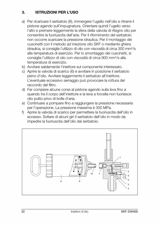
3. ISTRUZIONI PER L’USO
a) Per ricaricare il serbatoio (8), immergere l’ugello nell’olio e ritrarre ilpistone agendo sull’impugnatura. Orientare quindi l’ugello versol’alto e premere leggermente la sfera della valvola di ritegno olio perconsentire la fuoriuscita dell’aria. Per il rifornimento del serbatoionon occorre scaricare la pressione idraulica. Per il montaggio deicuscinetti con il metodo ad iniezione olio SKF o mediante ghieraidraulica, si consiglia l’utilizzo di olio con viscosità di circa 300 mm2/salla temperatura di esercizio. Per lo smontaggio dei cuscinetti, siconsiglia l’utilizzo di olio con viscosità di circa 900 mm2/s allatemperatura di esercizio.
b) Avvitare saldamente l’iniettore sul componente interessato.c) Aprire la valvola di scarico (6) e avvitare in posizione il serbatoio
pieno d’olio. Avvitare leggermente il serbatoio all’iniettore.L’eventuale eccessivo serraggio può provocare la rottura delraccordo del filtro.
d) Far compiere alcune corse al pistone agendo sulla leva fino aquando tra il corpo dell’iniettore e la leva a forcella non fuoriesceolio pulito privo di bolle d’aria.
e) Continuare a pompare fino a raggiungere la pressione necessariaper l’operazione. La pressione massima è 300 MPa.
f) Aprire la valvola di scarico per permettere la fuoriuscita dell’olio ineccesso. Svitare di alcuni giri il serbatoio dell’olio in modo daimpedire la fuoriuscita dell’olio dal serbatoio.
MP518-LR.P65 07-11-2002, 16:0432

SKF 226400 33Iniettori d’olio
Italiano
4. MANUTENZIONE
4.1 Cambio olioIn occasione del cambio dell’olio o al termine degli interventi dimanutenzione, accertarsi che non rimanga aria nell’impianto idraulico.Questa verifica deve essere effettuata prima di pressurizzare l’iniettore.Utilizzare solo gli oli idraulici prescritti e non contaminati.
4.2 PulituraEliminare l’eventuale polvere o residui metallici dall’iniettore per evitarnel’usura precoce.
4.3 Ricambi
Appellativo Descrizione728383 Kit di riparazione (1-5)909792 Vite della valvola (6)1077597 Raccordo filtro olio (7)920100 B Serbatoio olio (8)920100 B-1 O-ring serbatoio (9)920100 B-2 Raccordo di collegamento (10)
4.4 Accessori
Appellativo DescrizioneLHMF 300/5 Olio per montaggio (5 litri, 300 mm2/s a 20 °C)LHDF 900/5 Olio per smontaggio (5 litri, 900 mm2/s a 20 °C)
MP518-LR.P65 07-11-2002, 16:0433

Oljeinjektor34 SKF 226400
INNEHÅLLSFÖRTECKNING
EU-FÖRSÄKRAN OM ÖVERENSSTÄMMELSEFÖR MASKINER 35
SÄKERHETSREKOMMENDATIONER 36
1. BESKRIVNING 37
2. TEKNISKA DATA 37
3. BRUKSANVISNING 38
4. UNDERHÅLL 394.1 Oljebyte 394.2 Renlighet 394.3 Reservdelar 394.4 Tillbehör 39
MP518-LR.P65 07-11-2002, 16:0434

OljeinjektorSKF 226400 35
Svenska
EU-FÖRSÄKRAN OM ÖVERENSSTÄMMELSEFÖR MASKINER
Vi, SKF Maintenance Products,Kelvinbaan 16, 3439 MT NIEUWEGEIN, The Netherlands,försäkrar att
OLJEINJEKTOR226400
är konstruerad och tillverkad i enlighet med EuropeiskaGemenskapernas Råds direktiv av 14 juni 1989 (89/392/EEC),kompletterade med tilläggen 20 juni 1991 (91/368/EEC),14 juni 1993 (93/44/EEC) och 22 juli 1993 (93/68/EEC) omtillnärmning av medlemstaternas lagstiftning om maskiner.
The Netherlands, 1 september 2002
Magnus RydinChef Produktutveckling och Kvalitet
MP518-LR.P65 07-11-2002, 16:0435

Oljeinjektor36 SKF 226400
SÄKERHETSREKOMMENDATIONER
Eftersom höga tryck utgör en potentiell säkerhetsrisk, måsteföljande instruktioner följas:• Utrustningen skall endast handhas av utbildad personal.• Följ alltid bruksanvisningarna.• Kontrollera injektorn och samtliga tillbehör noggrant före
användandet. Använd aldrig, inte ens lindrigt, skadadekomponenter.
• Tillförsäkra att all luft har avlägsnats från hydraulsystemet,innan injektorn trycksätts.
• Använd alltid en manometer.• Skydda alltid arbetsstycket/verktyget från att plötsligt skjutas
av vid demontering (t.ex. med en mothållsmutter).• Använd aldrig utrustningen över angivet maximalt tryck.• Handtaget får inte förlängas för att minska den erforderliga
kraft som krävs för att uppnå maximalt tryck. Använd enbarthandkraft.
• Använd aldrig pumpen tillsammans med tillbehör som ärklassade för lägre tryck än injektorns maximala tryck.
• Använd skyddsglasögon.• Modifiera aldrig enheten.• Använd endast originaldelar.• Använd endast ren, rekommenderad olja (t.ex. SKF LHMF 300,
LHDF 900 eller motsvarande).
MP518-LR.P65 07-11-2002, 16:0536

OljeinjektorSKF 226400 37
Svenska
1. BESKRIVNING
Oljeinjektor 226400 kan ge ett maximmalt tryck på 300 MPa och ger0,23 cm3 per slag. Oljeinjektorn har en mycket brettanvändningsområde vid utnyttjande av SKFs tryckoljemetod. Monteringoch demontering av lager, kopplingar och kugghjul är endast ett fåtalexempel. Injektorn levereras komplett med reparationssats 728383.Alltsammans är förpackat i en robust väska.
2. TEKNISKA DATA
Maximalt tryck 300 MPaVolym per slag 0,23 cm3
Oljebehållarens volym 200 cm3
Anslutning G 3/4, utvändig gängaMin. oljeviskositet 300 mm2/s vid arbetstemperaturenVikt 2,2 kgBeteckning 226400
Obs: För förband med tryck upp till 400 MPa finns en specialmodellmed beteckning 226400/400 MPa.
MP518-LR.P65 07-11-2002, 16:0537

Oljeinjektor38 SKF 226400
3. BRUKSANVISNING
a) För att fylla oljebehållaren (8) sänks munstycket ner i ett kärl medolja. Kolven dras sakta ut med handtaget så att oljan sugs in ibehållaren. För att eliminera eventuell luft i behållaren, hålls den uppoch ner,varefter ventilkulan trycks in tills ren olja kommer ut.Oljebehållaren kan fyllas utan att det hydrauliska trycket avlastas.För montering av lager och andra komponenter med SKFstryckoljemetod rekommenderas olja med en viskositet på ca300 mm2/s vid arbetstemperaturen. För demontering av lagerrekommenderas olja med en viskositet på ca 900 mm2/s vidarbetstemperaturen.
b) Injektorn måste skruvas in stadigt i arbetsstycket.c) Öppna avlastningsventilen (6) och skruva in den fyllda oljebehållaren
i injektorn. Oljebehållaren ska ansättas lätt i injektorn. För stor kraftkan få filternippeln att brista.
d) Pumpa några slag med handtaget tills ren olja, utan luftbubblor,kommer ut mellan injektorkroppen och gaffelhandtaget.Stäng sedan avlastningsventilen.
e) Fortsätt pumpa tills tillräckligt tryck uppnås för det aktuellaarbetsstycket. Maximitrycket är 300 MPa.
f) Öppna avlastningsventilen så att trycket sjunker och överflödig oljakan strömma ut. Skruva loss oljebehållaren ett par varv.Detta hindrar olja från att läcka ut ur behållaren.
MP518-LR.P65 07-11-2002, 16:0538

OljeinjektorSKF 226400 39
Svenska
4. UNDERHÅLL
4.1 OljebyteVid påfyllning av ny olja efter underhåll är det viktigt att ingen luft finnskvar i hydraulsystemet. Detta måste kontrolleras innan injektorn sättsunder tryck. Använd endast rena, rekommenderade hydrauloljor.
4.2 RenlighetHåll injektorn fri från smuts och metallpartiklar för att undvika onormaltslitage.
4.3 Reservdelar
Beteckning Beskrivning728383 Reparationssats (1-5)909792 Ventilskruv (6)1077597 Filternippel (7)920100 B Oljemagasin (8)920100 B-1 O-ring till magasin (9)920100 B-2 Nippel till magasin (10)
4.4 Tillbehör
Beteckning BeskrivningLHMF 300/5 Monteringsolja (5 liter, 300 mm2/s vid 20 °C)LHDF 900/5 Demonteringsolja (5 liter, 900 mm2/s vid 20 °C)
MP518-LR.P65 07-11-2002, 16:0539

Olie-injector40 SKF 226400
INHOUDSOPGAVE
EUROPESE CONFORMITEITSVERKLARING 41
VEILIGHEIDSVOORSCHRIFTEN 42
1. BESCHRIJVING 43
2. TECHNISCHE GEGEVENS 43
3. BEDIENINGSINSTRUCTIES 44
4. ONDERHOUD 454.1 Olie vervangen 454.2 Reinheid 454.3 Vervangende onderdelen 454.4 Accessoires 45
MP518-LR.P65 07-11-2002, 16:0540

Olie-injectorSKF 226400 41
Ned
erlands
EUROPESE CONFORMITEITSVERKLARING
SKF Maintenance Products,Kelvinbaan 16, 3439 MT NIEUWEGEIN, Nederland,verklaart dat de
OLIE INJECTOR226400
is ontwikkeld en geproduceerd in overeenstemming met derichtlijnen van de raad van de Europese Gemeenschap van14 juni 1989, gewijzigd per 20 juni 1991, 14 juni 1993 en22 juli 1993, conform de wetgeving van de Lidstaten betreffendemachines.
Nederland, 1 september 2002
Magnus RydinManager Produktontwikkeling en Kwaliteit
MP518-LR.P65 07-11-2002, 16:0541
Olie-injector42 SKF 226400
VEILIGHEIDSVOORSCHRIFTEN
De volgende veiligheidsvoorschriften dienen in acht te wordengenomen omdat de hoge hydraulische drukken mogelijkerwijsgevaarlijk kunnen zijn.• Het gereedschap dient uitsluitend door goed getraind
personeel bediend te worden.• Volg altijd de gebruiksaanwijzing.• Controleer de injector en alle accessoires nauwkeurig voor
gebruik. Gebruik nooit beschadigde onderdelen.• Zorg ervoor dat alle lucht uit het hydraulische systeem is voor
de injector onder druk gebracht wordt.• Gebruik altijd een manometer.• Zorg ervoor dat het werkstuk/gereedschap niet weg kan
springen door gebruik te maken van een borgmoer op de as.• Gebruik het gereedschap nooit boven de toegestane
maximale werkdruk.• Verleng nooit de hendel om de benodigde kracht te
verminderen. Gebruik uitsluitend handkracht.• Gebruik nooit accessoires welke een lagere maximale druk
hebben dan de injector.• Gebruik een veiligheidsbril.• Wijzig het gereedschap nooit.• Gebruik uitsluitend originele onderdelen.• Gebruik uitsluitend schone, aanbevolen hydraulisch oliën
(SKF LHMF 300, LHDF 900 of gelijkwaardig).• Indien U vragen heeft met betrekking tot het gebruik van de
injector, gelieve contact op te nemen met SKF.
MP518-LR.P65 07-11-2002, 16:0542

Olie-injectorSKF 226400 43
Ned
erlands
1. BESCHRIJVING
De 226400 heeft een maximale druk van 300 MPa en levert per slageen volume van 0,23 cm3. De olie-injector kan op zeer verschillendemanieren worden gebruikt bij toepassing van de SKF olie-injectiemethode.Het monteren en demonteren van lagers, koppelingen en tandwielenzijn slechts een paar voorbeelden. De injector wordt compleet metreparatieset 728383 geleverd. Dit alles is verpakt in een stevige koffer.
2. TECHNISCHE GEGEVENS
Maximale druk 300 MPaVolume per slag 0,23 cm3
Inhoud oliereservoir 200 cm3
Olie-uitlaat G 3/4, uitwendige schroefdraadMinimale olieviscositeit 300 mm2/s bij bedrijfstemperatuurGewicht 2,2 kgAanduiding 226400
Opmerking: Voor toepassingen waarbij 400 MPa is vereist is eenspeciale injector 226400/400 MPA beschikbaar.
MP518-LR.P65 07-11-2002, 16:0543

Olie-injector44 SKF 226400
3. BEDIENINGSINSTRUCTIES
a) Om het oliereservoir (8) te vullen wordt de tuit in olie gedompeld enwordt de zuiger met behulp van de hendel teruggetrokken. De tuitwordt vervolgens omhoog gericht en de kogel die de olietegenhoudt wordt iets naar beneden geduwd om eventueelaanwezige lucht te laten ontsnappen. Het oliereservoir kan opnieuwworden gevuld zonder dat de druk moet worden opgeheven. Voorhet monteren van lagers via de SKF Olie-injectiemethode of metbehulp van een hydraulische moer raden wij u aan een olie met eenviscositeit van ongeveer 300 mm2/s bij bedrijfstemperatuur tegebruiken. Voor het demonteren van lagers raden wij u aan gebruikte maken van een olie met een viscositeit van ongeveer 900 mm2/sbij bedrijfstemperatuur.
b) De injector dient stevig in de toepassing te worden geschroefd.c) Open de aflaatklep (6) en schroef het gevulde oliereservoir op de
plaats. Het oliereservoir dient niet al te stevig op de injector teworden geschroefd. Bij te veel kracht kan de filternippel breken.
d) Maak een paar slagen met de hendel totdat er schone olie zonderluchtbellen tussen de injector en de gaffelhefboom verschijnt.Zet vervolgens de aflaatklep vast.
e) Blijf pompen totdat de voor uw toepassing vereiste druk is bereikt.De maximale druk is 300 MPa.
f) Open de aflaatklep om overtollige olie vrij af te kunnen voeren.Schroef het oliereservoir een paar slagen los. Dit voorkomt dat erolie uit het reservoir ontsnapt.
MP518-LR.P65 07-11-2002, 16:0544

Olie-injectorSKF 226400 45
Ned
erlands
4. ONDERHOUD
4.1 Olie vervangenZorg er bij het vervangen van de olie of na onderhoudswerkzaamhedenvoor dat er geen lucht in het hydraulische systeem aanwezig is.Dit dient te worden gecontroleerd voordat er druk op de injector wordtgezet. Gebruik alleen schone aanbevolen soorten hydrauliekolie.
4.2 ReinheidHoud de injector vrij van vuildeeltjes om buitensporige slijtage tevoorkomen.
4.3 Vervangende onderdelen
Aanduiding Beschrijving728383 Reparatieset (1-5)909792 Klepschroef (6)1077597 Oliefilternippel (7)920100 B Oliereservoir (8)920100 B-1 O-ring reservoir (9)920100 B-2 Aansluitnippel (10)
4.4 Accessoires
Aanduiding BeschrijvingLHMF 300/5 Montagevloeistof (5 liter, 300 mm2/s bij 20 °C)LHDF 900/5 Demontagevloeistof (5 liter, 900 mm2/s bij 20 °C)
MP518-LR.P65 07-11-2002, 16:0545

Injector de Óleo46 SKF 226400
CONTEÚDO
UE-DECLARAÇÃO DE CONFORMIDADEPARA MAQUINARIA 47
RECOMENDAÇÕES DE SEGURANÇA 48
1. DESCRIÇÃO 49
2. DADOS TÉCNICOS 49
3. INSTRUÇÕES DE OPERAÇÃO 50
4. MANUTENÇÃO 514.1 Mudar o óleo 514.2 Limpeza 514.3 Peças de substituição 514.4 Acessórios 51
MP518-LR.P65 07-11-2002, 16:0646

Injector de ÓleoSKF 226400 47
Po
rtuguês
UE-DECLARAÇÃO DE CONFORMIDADEPARA MAQUINARIA
Nós, SKF Maintenance Products,Kelvinbaan 16, 3439 MT NIEUWEGEIN, The Netherlands,declaramos que
INJECTOR DE ÓLEO226400
são concebidos e fabricados de acordo com a Directiva doConselho das Comunidades Europeias de 14 de Junho 1989,emendada em 20 Junho 1991, 14 de Junho 1993 e22 de Julho 1993, sobre a aproximação das leis dos EstadosMembros relativamente a maquinaria.
Holanda, 1 de Setembro 2002
Magnus RydinDirector Desenvolvimento e Qualidade Produto
MP518-LR.P65 07-11-2002, 16:0647

Injector de Óleo48 SKF 226400
RECOMENDAÇÕES DE SEGURANÇA
Atendendo a que pressões elevadas envolvem um potencialrisco em termos de segurança, as seguintes instruções devemser respeitadas:• O equipamento só deve ser utilizado por operadores treinados.• Siga sempre as instruções de utilização.• Verifique cuidadosamente o injector e todos os acessórios
antes da utilização. Nunca utilize componentes mesmo queligeiramente danificados.
• Certifique-se que todo o ar foi purgado do sistema hidráulico,antes de criar pressão no injector.
• Utilize sempre manómetros.• Tome sempre as devidas precauções que impeçam que
qualquer rolamento/peça/ferramenta seja projectada nasequência de um súbito alívio da pressão (exemplo: usesempre uma porca de retenção). Sempre que se utilize umadesmontagem por pressão hidráulica.
• Nunca utilize este equipamento acima da pressão máximaindicada.
• Nunca aumente o braço da alavanca por forma a reduzir aforça necessária para atingir a pressão máxima. Utilizeapenas a alavanca de origem com esforço manual.
• Nunca utilize o injector em conjuncto com acessórios, cujacapacidade nominal seja inferior à pressão máxima da bomba.
• Utilize sempre óculos de protecção/segurança.• Nunca introduza alterações no equipamento.• Utilize só peças de origem.• Utilize só óleo hidráulico limpo, recomendado
(exemplo: SKF LHMF 300, LHDF 900 ou similar.).• Em caso de dúvidas no que respeita à correcta utilização do
injector, queira contactar a SKF.
MP518-LR.P65 07-11-2002, 16:0648

Injector de ÓleoSKF 226400 49
Po
rtuguês
1. DESCRIÇÃO
O 226400 tem uma pressão máxima de 300 MPa e por curso forneceum volume de 0,23 cm3. O injector de óleo tem uma grande variedadede utilizações quando se aplica o método de injecção de óleo da SKF.Montar e desmontar rolamentos, acoplamentos e rodas dentadas sãosó alguns exemplos. O injector é fornecido completo com o jogo dereparação 728383. Tudo isto é embalado numa caixa robusta.
2. DADOS TÉCNICOS
Pressão máxima 300 MPaVolume por curso 0,23 cm3
Capacidade do reservatório de óleo 200 cm3
Saída do óleo G 3/4, rosca externaMín. viscosidade do óleoà temperatura de operação 300 mm2/sPeso 2,2 kgDesignação 226400
Nota: Para aplicações onde são necessários 400 MPa está disponívelum modelo especial com a designação de 226400/400 MPa.
MP518-LR.P65 07-11-2002, 16:0649

Injector de Óleo50 SKF 226400
3. INSTRUÇÕES DE OPERAÇÃO
a) Quando o reservatório do óleo (8) estiver para ser enchido, o bocalé emergido em óleo e o pistão é retraído usando um manípulo. Obocal é então virado para cima e a esfera da bomba que retém oóleo é descomprimida lentamente de modo a permitir que qualquerar existente saia. O reservatório do óleo pode voltar a ser enchidosem libertar a pressão hidráulica. Para montar rolamentos com oMétodo de Injecção de Óleo da SKF, ou através de uma porcahidráulica, recomenda-se que se utilize um óleo com umaviscosidade de aproximadamente 300 mm2/s à temperatura deoperação. Para desmontar rolamentos, recomendamos que utilizeum óleo com uma viscosidade de aprox. 900 mm2/s à temperaturade operação.
b) O injector deve ser firmemente enroscado na aplicação.c) Abra a válvula de escape (6) e enrosque todo o reservatório do óleo
para o colocar em posição. O reservatório de óleo deve serligeiramente enroscado ao injector. Força a mais pode partir o bocaldo filtro.
d) Faça alguns cursos com a alavanca até que apareça óleo limpo, livrede bolhas de ar, entre o corpo do injector e a alavanca em garfo.A válvula de escape é então apertada.
e) Continue a bombear até que a pressão necessária para a suaaplicação seja alcançada. A máxima pressão é 300 MPa.
f) Abra a válvula de escape, permitindo que o óleo supérfluo saialivremente. Desenrosque o reservatório do óleo algumas voltas.Isto prevenirá que o óleo saia do reservatório.
MP518-LR.P65 07-11-2002, 16:0650

Injector de ÓleoSKF 226400 51
Po
rtuguês
4. MANUTENÇÃO
4.1 Mudar o óleoQuando mudar o óleo ou depois da manutenção, certifique-se de quenão ficou ar retido no sistema hidráulico. Isto deve ser verificado antesde pressurizar o injector. Utilize apenas os óleos hidráulicosrecomendados e limpos.
4.2 LimpezaMantenha o injector livre de sujidade e de partículas de metal de modoa evitar o desgaste excessivo.
4.3 Peças de substituição
Designação Descrição728383 Jogo de reparação (1-5)909792 Parafuso da válvula (6)1077597 Bocal do filtro do óleo (7)920100 B Reservatório do óleo (8)920100 B-1 O-ring do reservatório (9)920100 B-2 Bocal de conexão (10)
4.4 Acessórios
Designação DescriçãoLHMF 300/5 Fluido de montagem (5 litros, 300 mm2/s a 20 °C)LHDF 900/5 Fluido de desmontagem (5 litros, 900 mm2/s a 20 °C)
MP518-LR.P65 07-11-2002, 16:0651

Oliepumpe52 SKF 226400
INDHOLDSFORTEGNELSE
EU ERKLÆRING FOR MASKINER 53
SIKKERHEDSFORSKRIFTER 54
1. BESKRIVELSE 55
2. TEKNISKE DATA 55
3. BETJENINGSVEJLEDNING 56
4. VEDLIGEHOLD 574.1 Udskiftning af olie 574.2 Renholdelse 574.3 Reservedelsliste 574.4 Tilbehør 57
MP518-LR.P65 07-11-2002, 16:0652
OliepumpeSKF 226400 53
Dansk
EU ERKLÆRING FOR MASKINER
Vi, SKF Maintenance Products,Kelvinbaan 16, 3439 MT NIEUWEGEIN, Holland,erklærer hermed, at
OLIEPUMPE226400
er konstrueret og fremstillet i henhold til direktivet fra Rådet forDet europæiske Fællesskab af 14. juni 1989, med ændringer d.20. juni 1991, d. 14. juni 1993 og d. 22. juli 1993 i henhold tilmaskinlovgivningen i de respektive medlemslande.
Holland, d. 1. september 2002
Magnus RydinChef for produktudvikling og kvalitet
MP518-LR.P65 07-11-2002, 16:0653

Oliepumpe54 SKF 226400
SIKKERHEDSFORSKRIFTER
Da høje tryk udgør en mulig sikkerhedsrisiko, skal følgendeinstruktioner følges:• Udstyret bør kun betjenes af uddannet personale.• Følg altid betjeningsvejledningen.• Check olieinjektoren og alt tilbehør grundigt inden brug.
Anvend aldrig selv lettere beskadigede komponenter.• Kontrollér at det hydrauliske system er udluftet, inden der
sættes trykluft på olieinjektoren.• Anvend altid en trykmåler.• Sørg altid for at emnet/værktøjet undgår at blive udsat for
pludselig trykfald (f.eks. ved at anvende bundmøtrik).• Anvend aldrig udstyret over det maksimalt angivne tryk.• Forlæng ikke håndtaget for at reducere den krævede styrke
for at opnå maksimalt tryk. Brug kun håndkraft.• Anvende aldrig olieinjektoren sammen med tilbehør, som er
imensioneret under olieinjektorens maksimalt tryk.• Brug beskyttelsesbriller!• Foretag aldrig ændringer på enheden.• Anvend kun originaldele.• Anvend kun rene, anbefalede olier (f. eks. SKF LHMF 300,
LHDF 900 el. lign.).• I tilfælde af tvivlsspørgsmål, i forbindelse med anvendelsen af
olieinjektoren, kontakt SKF.
MP518-LR.P65 07-11-2002, 16:0654

OliepumpeSKF 226400 55
Dansk
1. BESKRIVELSE
Olieinjektor 226400 har et maksimalt tryk på 300 MPa med en volumenpr. slag på 0,23 cm3. Injektoren har et bredt anvendelsesområde -f.eks. til montering og demontering af lejer, koblinger og tandhjul vedhjælp af SKF’s trykoliemetode. Olieinjektoren leveres medreparationssæt 728383 i en transportboks.
2. TEKNISKE DATA
Maksimalt tryk 300 MPaVolumenkapacitet pr. slag 0,23 cm3
Indhold i oliebeholder 200 cm3
Gevindstuds G 3/4, udvendigt gevindMinimum olieviskositet 300 mm2/s ved driftstemperaturVægt 2,2 kgBetegnelse 226400
Bemærk: Til applikationer hvor 400 MPa er nødvendig, kan SKF levereen speciel model, 226400/400 MPa.
MP518-LR.P65 07-11-2002, 16:0655

Oliepumpe56 SKF 226400
3. BETJENINGSVEJLEDNING
a) Når oliebeholderen (8) skal fyldes op, dyppes spidsen afoliebeholderen i olien, og stemplet trækkes tilbage ved hjælp afhåndtaget. Bagefter vendes spidsen opad, og kuglen trykkes lidtned for at udlufte beholderen. Oliebeholderen kan genfyldes, udenat det hydrauliske tryk falder. Ved montering af lejer med entenSKF’s trykoliemetode eller en hydraulisk møtrik bør der anvendes enolieviskositet på ca. 300 mm2/s ved aktuel omgivelsestemperatur.Til demontering af lejer bør anvendes en olieviskositet på ca.900 mm2/s ved aktuel omgivelsestemperatur.
b) Injektoren skrues fast på applikationen.c) Åben returventilen (6) og skru den fyldte oliebeholder på plads.
Dette skal gøres forsigtigt for ikke at brække filterniplen af.d) Pump nogle gange med løftestangen, indtil ren olie uden luftbobler
kommer ud mellem injektoren og stangen. Returventilen fastgøres tilsidst.
e) Fortsæt med at pumpe, indtil det korrekte tryk er nået.Det maksimale tryk er 300 MPa.
f) Åben returventilen og lad overflødig olie løbe ud. Løsnoliebeholderen lidt for at undgå olieudslip fra beholderen.
MP518-LR.P65 07-11-2002, 16:0656

OliepumpeSKF 226400 57
Dansk
4. VEDLIGEHOLD
4.1 Udskiftning af olieVed olieskift eller eftersyn må der ikke slippe luft ind i det hydrauliskesystem. Dette skal kontrolleres, før der dannes tryk i injektoren.Anvend kun ren, hydraulisk olie.
4.2 RenholdelseUndgå snavs og metalpartikler i injektoren for at forhindre slitage.
4.3 Reservedelsliste
Betegnelse Beskrivelse728383 Reparationssæt (1-5)909792 Ventilskrue(6)1077597 Oliefilter nippel (7)920100 B Oliebeholder (8)920100 B-1 O-ring til oliebeholder (9)920100 B-2 Forbindelsesnippel (10)
4.4 Tilbehør
Betegnelse BeskrivelseLHMF 300/5 Monteringsolie (5 l, 300 mm2/s ved 20 °C)LHDF 900/5 Demonteringsolie (5 l, 900 mm2/s ved 20 °C)
MP518-LR.P65 07-11-2002, 16:0757

Öljyinjektori58 SKF 226400
SISÄLLYSLUETTELO
EU:N VAATIMUSTEN MUKAINEN VASTAAVUUSILMOITUS 59
KÄYTTÖTURVALLISUUS SUOSITUKSET 60
1. KUVAUS 61
2. TEKNISET TIEDOT 61
3. KÄYTTÖOHJEET 62
4. HUOLTO 634.1 Öljynvaihto 634.2 Puhtaus 634.3 Varaosat 634.4 Lisävarusteet 63
MP518-LR.P65 07-11-2002, 16:0758

ÖljyinjektoriSKF 226400 59
Suo
mi
EU:N VAATIMUSTEN MUKAINEN VASTAAVUUSILMOITUS
SKF Maintenance Products,Kelvinbaan 16, 3439 MT NIEUWEGEIN, Hollanti,ilmoittaa, että
ÖLJYINJEKTORI226400
on suunniteltu ja valmistettu koneita koskevan jäsenvaltioidenlainsäädännön lähentämisestä 14 päivänä kesäkuuta 1989annetun Euroopan yhteisöjen neuvoston direktiivin mukaisesti,sellaisena kuin se on muutettuna 20 päivänä kesäkuuta 1991,14 päivänä kesäkuuta 1993 ja 22 päivänä heinäkuuta 1993,annetulla direktiivillä.
Hollannissa 1. syyskuu 2002
Magnus RydinOsastopäälikkö, Tuotekehitys ja Laatu
MP518-LR.P65 07-11-2002, 16:0759

Öljyinjektori60 SKF 226400
KÄYTTÖTURVALLISUUS SUOSITUKSET
Koska korkeat paineet muodostavat potentiaalisen terveysriskin,on hyvä ottaa huomioon seuraavat suositukset:• Laitteiden käyttäjinä pitää olla ammattitaitoiset henkilöt.• Seuraa aina käyttöohjeita.• Tarkista injektori ja lisävarusteet huolellisesti ennen käyttöä.
Älä koskaan käytä edes “lievästi” vahingoittuneita osia.• Poista kaikki ilma hydraulijärjestelmästä ennen injektorin
paineistusta.• Käytä aina painemittaria.• Estä vapautuvan työkappaleen/työkalun sinkoaminen (esim.
käyttämällä lukitusmutteria akselilla laakeria irrotettaessa).• Älä koskaan ylitä ilmoitettua maksimipainetta.• Älä koskaan tee vipuvarsiin omia pidennysosia, joiden avulla
kevennetään maksimivoimaan tarvittavaa käsivoimaa.Laitteet on sellaisenaan tarkoitettu käytettäväksi käsivoimin.
• Injektorin kanssa ei saa käyttää mitään sellaisia osia, jotka onluokiteltu matalammalle käyttöpaineelle kuin itse pumppu.
• Käytä suojalaseja.• Älä tee laitteisiin teknisiä muutoksia.• Käytä vain alkuperäisosia.• Käytä vain puhtaita, suositeltuja hydrauliikkaöljyjä, kuten esim.
SKF LHMF 300, LHDF 900 tai vastaavaa.• Jos injektorin käytössä ilmenee epäselvyyksiä ota yhteyttä
SKF:ään.
MP518-LR.P65 07-11-2002, 16:0760
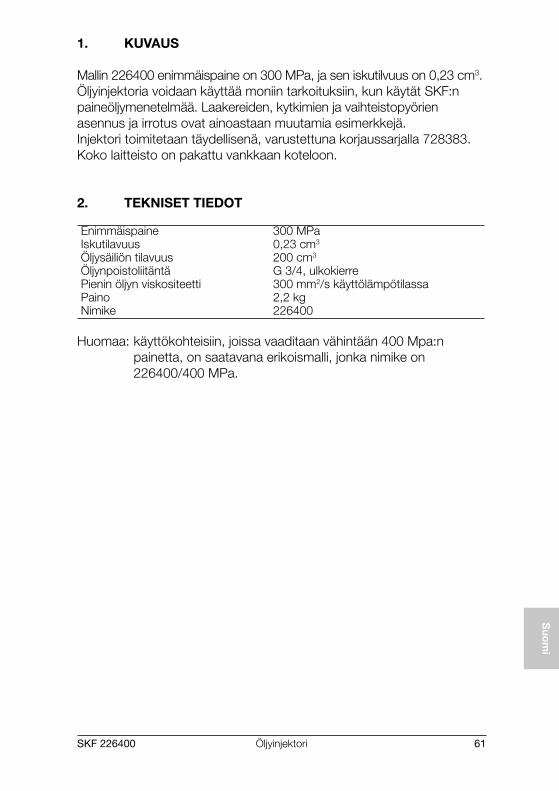
ÖljyinjektoriSKF 226400 61
Suo
mi
1. KUVAUS
Mallin 226400 enimmäispaine on 300 MPa, ja sen iskutilvuus on 0,23 cm3.Öljyinjektoria voidaan käyttää moniin tarkoituksiin, kun käytät SKF:npaineöljymenetelmää. Laakereiden, kytkimien ja vaihteistopyörienasennus ja irrotus ovat ainoastaan muutamia esimerkkejä.Injektori toimitetaan täydellisenä, varustettuna korjaussarjalla 728383.Koko laitteisto on pakattu vankkaan koteloon.
2. TEKNISET TIEDOT
Enimmäispaine 300 MPaIskutilavuus 0,23 cm3
Öljysäiliön tilavuus 200 cm3
Öljynpoistoliitäntä G 3/4, ulkokierrePienin öljyn viskositeetti 300 mm2/s käyttölämpötilassaPaino 2,2 kgNimike 226400
Huomaa: käyttökohteisiin, joissa vaaditaan vähintään 400 Mpa:npainetta, on saatavana erikoismalli, jonka nimike on226400/400 MPa.
MP518-LR.P65 07-11-2002, 16:0761

Öljyinjektori62 SKF 226400
3. KÄYTTÖOHJEET
a) Kun öljysäiliö (8) on täytettävä, upota suutin öljyyn ja vedä mäntätakaisin kahvan avulla. Nosta suutinta sitten ylöspäin ja paina kevyestiventtiilin kuulaa, joka estää öljyä valumasta ulos, jolloin mahdollinenilma poistuu. Voit nyt täyttää öljysäiliön uudelleen ilman, että sinuntarvitsee poistaa hydraulipainetta. Kun asennat laakereita SKF:npaineöljymenetelmällä tai hydraulimutterin avulla, suosittelemme ettäkäytät öljyä, jonka viskositeetti on noin 300 mm2/s käyttölämpötilassa.Laakereiden irrottamista varten suosittelemme, että käytät öljyä, jonkaviskositeetti on noin 900 mm2/s käyttölämpötilassa.
b) Injektori on ruuvattava käyttökohteeseen tukevasti.c) Avaa paineenalennusventtiili (6) ja ruuvaa täysinäinen öljysäiliö
paikalleen. Ruuvaa öljysäiliö injektoriin kevyesti, sillä jos käytät liikaavoimaa, suodatinliitin voi rikkoutua.
d) Tee muutama pumppausliike vivun avulla, kunnes injektorin rungonja haarukkanostimen väliin tunkeutuu puhdasta öljyä, jossa ei oleilmakuplia. Paineenalennusventtiili on nyt kireällä.
e) Jatka pumppaamista, kunnes paine on riittävä käyttökohteeseen.Enimmäispaine on 300 MPa.
f) Avaa paineenalennusventtiili, jolloin ylimääräinen öljy pääseepoistumaan. Ruuvaa öljysäiliötä auki muutaman kierroksen verran.Näin estät öljyä poistumasta säiliöstä.
MP518-LR.P65 07-11-2002, 16:0762

ÖljyinjektoriSKF 226400 63
Suo
mi
4. HUOLTO
4.1 ÖljynvaihtoVarmista öljynvaihdon ja huollon yhteydessä, ettei hydraulijärjestelmäänjää ilmaa. Tarkista tämä joka kerte ennen injektorin paineistusta. Käytäainoastaan puhdasta, suositusten mukaista hydrauliöljyä.
4.2 PuhtausPidä injektori puhtaana liasta ja metallihiukkasista välttääksesi liiallisenkulumisen.
4.3 Varaosat
Nimike Kuvaus728383 Korjaussarja (1-5)909792 Venttiliruuvi (6)1077597 Öljynsuodattimen liitin (7)920100 B Öljysäiliö (8)920100 B-1 O-rengas säiliöön (9)920100 B-2 Liitin (10)
4.4 Lisävarusteet
Nimike KuvausLHMF 300/5 Asennusöljy (5 litraa, 300 mm2/s lämpötilassa 20 °C)LHDF 900/5 Irrotusöljy (5 litraa, 900 mm2/s lämpötilassa 20 °C)
MP518-LR.P65 07-11-2002, 16:0763

64 SKF 226400∞ÓÙÏ›· Ï·‰ÈÔ‡ ˘„ËÏ‹˜ ›ÂÛ˘
¶EƒπEÃ√ªE¡∞
¢∏§ø™∏ ™Àªª√ƒºø™∏™ ªE ∆∏¡ √¢∏°π∞ ∆∏™ EÀƒø¶∞∫∏™ E¡ø™∏™ ¶Eƒπ ª∏Ã∞¡√§√°π∫√À E•√¶§π™ª√À 65
√‰ËÁ›Â˜ ·ÛÊ·Ï›·˜ 66
1. ¶ÂÚÈÁÚ·Ê‹ 67
2. ∆¯ÓÈο ‰Â‰Ô̤ӷ 67
3. √‰ËÁ›Â˜ ÏÂÈÙÔ˘ÚÁ›·˜ 68
4. ™˘ÓÙ‹ÚËÛË 694.1 ∞ÓÙÈηٿÛÙ·ÛË Ï·‰ÈÔ‡ 694.2 ∫·ı·ÚÈfiÙËÙ· 694.3 ∞ÓÙ·ÏÏ·ÎÙÈο 694.4 ™˘ÌÏËڈ̷ÙÈÎfi˜ ÂÍÔÏÈÛÌfi˜ 69
MP518-LR.P65 07-11-2002, 16:0764

SKF 226400 65∞ÓÙÏ›· Ï·‰ÈÔ‡ ˘„ËÏ‹˜ ›ÂÛ˘
EÏÏË
ÓÈο
¢∏§ø™∏ ™Àªª√ƒºø™∏™ ªE ∆∏¡ √¢∏°π∞ ∆∏™ EÀƒø¶∞∫∏™ E¡ø™∏™ ¶Eƒπ ª∏Ã∞¡√§√°π∫√À E•√¶§π™ª√À
∏ ÂÙ·ÈÚ›· SKF Maintenance Products,Kelvinbaan 16, 3439 MT NIEUWEGEIN, ∫¿Ùˆ ÃÒÚ˜,‰ËÏÒÓÂÈ fiÙÈ ·˘Ù‹ Ë
∞ÓÙÏπ· §·‰È√À À„ËÏ∏˜ ¶πÂÛ˘226400
¤¯ÂÈ Û¯Â‰È·Ûı› Î·È Î·Ù·Û΢·Ûı› Û‡Ìʈӷ Ì ÙËÓ √‰ËÁ›·ÙÔ˘ ™˘Ì‚Ô˘Ï›Ô˘ ÙˆÓ E˘Úˆ·˚ÎÒÓ ∫ÔÈÓÔÙ‹ÙˆÓ Ù˘ 14˘πÔ˘Ó›Ô˘ 1989, Ô˘ ÙÚÔÔÔÈ‹ıËΠÙËÓ 20Ë πÔ˘Ó›Ô˘ 1991,14Ë πÔ˘Ó›Ô˘ 1993 Î·È 22· πÔ˘Ï›Ô˘ 1993, ‚¿ÛÂÈ ÚÔÛ¤ÁÁÈÛ˘Ù˘ ÓÔÌÔıÂÛ›·˜ ÙˆÓ ÎÚ·ÙÒÓ ÌÂÏÒÓ ÂÚ› Ì˯·ÓÔÏÔÁÈÎÔ‡ÂÍÔÏÈÛÌÔ‡.
√ÏÏ·Ó‰›·, 1Ë ™ÂÙÂÌ‚Ú›Ô˘ 2002
Magnus Rydin¢È¢ı˘ÓÙ‹˜ ∞Ó¿Ù˘Í˘ ¶ÚÔ˚fiÓÙˆÓ Î·È ¶ÔÈfiÙËÙ·˜
MP518-LR.P65 07-11-2002, 16:0765

66 SKF 226400∞ÓÙÏ›· Ï·‰ÈÔ‡ ˘„ËÏ‹˜ ›ÂÛ˘
√‰ËÁ›Â˜ ·ÛÊ·Ï›·˜
EÂȉ‹ ÔÈ ˘„ËϤ˜ ȤÛÂȘ ÌÔÚ› Ó· ÂÚÈÎÏÂ›Ô˘Ó ÛÔ‚·ÚÔ‡˜ÎÈÓ‰‡ÓÔ˘˜ ÁÈ· ÙËÓ ·ÛÊ¿ÏÂÈ·, ı· Ú¤ÂÈ Ó· Ï·Ì‚¿ÓÔÓÙ·È˘fi„Ë ÔÈ ·ÎfiÏÔ˘ı˜ Ô‰ËÁ›Â˜:• √ ÂÍÔÏÈÛÌfi˜ Ú¤ÂÈ Ó· ¯ÚËÛÈÌÔÔÈÂ›Ù·È ÌfiÓÔ ·fi
ÂÎ·È‰Â˘Ì¤ÓÔ ÚÔÛˆÈÎfi.• ¡· ·ÎÔÏÔ˘ı›Ù ¿ÓÙÔÙ ÙȘ Ô‰ËÁ›Â˜ ÏÂÈÙÔ˘ÚÁ›·˜.• ¡· ÂϤÁ¯ÂÙ ÚÔÛÂÎÙÈο ÙËÓ ·ÓÙÏ›· Î·È fiÏ· Ù· ÂÍ·ÚÙ‹Ì·Ù·
ÚÈÓ ·fi ÙË ¯Ú‹ÛË. ¶ÔÙ¤ Ó· ÌËÓ ¯ÚËÛÈÌÔÔț٠·ÎfiÌË Î·ÈÂÏ·ÊÚÒ˜ ηÙÂÛÙÚ·Ì̤ӷ ÂÍ·ÚÙ‹Ì·Ù·.
• ¶ÚÈÓ ·Ó‚¿ÛÂÙ ÙËÓ ›ÂÛË Ù˘ ·ÓÙÏ›·˜, ‚‚·Èˆı›Ù fiÙÈfiÏÔ˜ Ô ·¤Ú·˜ ¤¯ÂÈ ‚ÁÂÈ ·fi ÙÔ ˘‰Ú·˘ÏÈÎfi Û‡ÛÙËÌ·.
• ¡· ¯ÚËÛÈÌÔÔț٠¿ÓÙÔÙ ÚÔÏfiÈ Ì¤ÙÚËÛ˘ ›ÂÛ˘.• ¡· ·ÛÊ·Ï›˙ÂÙ ¿ÓÙÔÙ ÙÔ ÂÍ¿ÚÙËÌ·/ÂÚÁ·ÏÂ›Ô ÁÈ· Ó· ÌËÓ
ÂÎÙÈÓ·¯ı› ÚÔ˜ Ù· ¤Íˆ, ÌÂÙ¿ ÙËÓ ·fiÙÔÌË·ÂÏ¢ı¤ÚˆÛË Ù˘ ›ÂÛ˘ (.¯. Ó· ¯ÚËÛÈÌÔÔț٠¤Ó· ›ϤÔÓ ÂÚÈÎfi¯ÏÈÔ).
• ¶ÔÙ¤ ÌËÓ ¯ÚËÛÈÌÔÔț٠ÙÔÓ ÂÍÔÏÈÛÌfi ¿Óˆ ·fi ÙËÓ·Ó·ÊÂÚfiÌÂÓË Ì¤ÁÈÛÙË ›ÂÛË.
• ªËÓ ÂÂÎÙ›ÓÂÙ ÙËÓ Ï·‚‹ Ù˘ ·ÓÙÏ›·˜ , Ô‡Ùˆ˜ ÒÛÙ ӷÌÂÈÒÛÂÙ ÙËÓ ‰‡Ó·ÌË Ô˘ ··ÈÙÂ›Ù·È ÁÈ· Ó· ÊÙ¿ÛÂÙ ÙËÓ̤ÁÈÛÙË ›ÂÛË. ÃÚËÛÈÌÔÔÈ‹ÛÙ ÌfiÓÔ ›ÂÛË ¯ÂÈÚfi˜.
• ™Â η̛· ÂÚ›ÙˆÛË ÌËÓ ¯ÚËÛÈÌÔÔț٠ÙËÓ ·ÓÙÏ›· ÌÂÛ˘ÌÏËڈ̷ÙÈÎfi ÂÍÔÏÈÛÌfi Ô˘ ·ÓÙ¤¯ÂÈ ¯·ÌËÏfiÙÂÚË›ÂÛË ·fi ÙË Ì¤ÁÈÛÙË ›ÂÛË Ù˘ ·ÓÙÏ›·˜.
• ÃÚËÛÈÌÔÔț٠ÚÔÛٷ٢ÙÈο Á˘·ÏÈ¿.• ¶ÔÙ¤ ÌËÓ ÙÚÔÔÔț٠ÙË ÌÔÓ¿‰·.• ¡· ¯ÚËÛÈÌÔÔț٠ÌfiÓÔ ÁÓ‹ÛÈ· ·ÓÙ·ÏÏ·ÎÙÈο.• ¡· ¯ÚËÛÈÌÔÔț٠ÌfiÓÔ Î·ı·Ú¿, ˘‰Ú·˘ÏÈο Ï¿‰È· Ô˘
Û˘ÓÈÛÙ¿ Ô Î·Ù·Û΢·ÛÙ‹˜ (.¯. SKF LHMF 300, LHDF 900‹ ·ÚfiÌÔÈ·).
• ™Â ÂÚ›ÙˆÛË ÔÔÈ·Û‰‹ÔÙ ·ÌÊÈ‚ÔÏ›·˜ Û¯ÂÙÈο Ì ÙËÓ¯Ú‹ÛË Ù˘ ·ÓÙÏ›·˜, ÂÈÎÔÈÓˆÓ‹ÛÙ Ì ÙËÓ SKF.
MP518-LR.P65 07-11-2002, 16:0766

SKF 226400 67∞ÓÙÏ›· Ï·‰ÈÔ‡ ˘„ËÏ‹˜ ›ÂÛ˘
EÏÏË
ÓÈο
1. ¶ÂÚÈÁÚ·Ê‹
∏ TMJL 226400 ¤¯ÂÈ Ì¤ÁÈÛÙË ›ÂÛË 300 MPa, Ì ·ÚÔ¯‹ ·Ó¿ÚÂÛ¿ÚÈÛÌ· 0,23 cm3. √Ù·Ó ÂÊ·ÚÌfi˙ÂÙ·È Ë Ì¤ıÔ‰Ô˜ ¤Á¯˘Û˘Ϸ‰ÈÔ‡ Ù˘ SKF, Ë ·ÓÙÏ›· Ï·‰ÈÔ‡ ˘„ËÏ‹˜ ›ÂÛ˘ ÚÔÛʤÚÂÙ·È ÁÈ·Â˘Ú›· ¯Ú‹ÛË. ∏ Û˘Ó·ÚÌÔÏfiÁËÛË Î·È ·ÔÛ˘Ó·ÚÌÔÏfiÁËÛËÚÔ˘ÏÂÌ¿Ó, Û˘Ó‰¤ÛÌˆÓ ·ÍfiÓˆÓ Î·È ÁÚ·Ó·˙ÈÒÓ, ·Ó·Ê¤ÚÔÓÙ·È ˆ˜ÂÓ‰ÂÈÎÙÈÎfi ·Ú¿‰ÂÈÁÌ·. ∏ ·ÓÙÏ›· ·Ú¤¯ÂÙ·È Ï‹Ú˘ Ì ÛÂÙÂÈÛ΢‹˜ 728383. √Ï· Ù· ·Ú·¿Óˆ Â›Ó·È Û˘Û΢·Ṳ̂ӷ Û ̛··ÓıÂÎÙÈ΋ ‚·Ï›ÙÛ·
2. ∆¯ÓÈο ‰Â‰Ô̤ӷ
ª¤ÁÈÛÙË ›ÂÛË 300 MPa¶·ÚÔ¯‹ ·Ó¿ ÚÂÛ¿ÚÈÛÌ· 0,23 cm3
ÈÚËÙÈÎfiÙËÙ· ‰Ô¯Â›Ô˘ Ï·‰ÈÔ‡ 200 cm3
EÍÔ‰Ô˜ Ï·‰ÈÔ‡ Â͈ÙÂÚÈÎfi Û›ڈ̷ G 3/4EÏ·¯. ÈÍ҉˜ Ï·‰ÈÔ‡ 300 mm2/s Û ıÂÚÌÔÎÚ·Û›· ÏÂÈÙÔ˘ÚÁ›·˜µ¿ÚÔ˜ 2,2 kg√ÓÔÌ·Û›· 226400
™ËÌ›ˆÛË: °È· ÂÊ·ÚÌÔÁ¤˜ fiÔ˘ ··ÈÙÔ‡ÓÙ·È 400 MPa, ‰È·Ù›ıÂÙ·ÈÂȉÈÎfi ÌÔÓÙ¤ÏÔ 226400/400 MPa.
MP518-LR.P65 07-11-2002, 16:0867

68 SKF 226400∞ÓÙÏ›· Ï·‰ÈÔ‡ ˘„ËÏ‹˜ ›ÂÛ˘
3. √‰ËÁ›Â˜ ÏÂÈÙÔ˘ÚÁ›·˜
a) °È· Ó· ÁÂÌ›ÛÂÙ ÙÔ ‰Ô¯Â›Ô Ï·‰ÈÔ‡ (8), ‚˘ı›ÛÙ ÙËÓ ¿ÎÚË ÙÔ˘ÛˆÏ‹Ó· ÛÙÔ Ï¿‰È Î·È Û˘ÌȤÛÙ ÙÔ ¤Ì‚ÔÏÔ ¯ÚËÛÈÌÔÔÈÒÓÙ·˜ ÙËÏ·‚‹. ™ÙË Û˘Ó¤¯ÂÈ·, ÛÙÚ¤„Ù ÙËÓ ¿ÎÚË ÙÔ˘ ۈϋӷ ÚÔ˜ Ù· ¿ÓˆÎ·È ȤÛÙ ÂÏ·ÊÚ¿ ÙËÓ Ì›ÏÈ·/‚·Ï‚›‰· Ô˘ Û˘ÁÎÚ·Ù› ÙÔ Ï¿‰È,ÂÈÙÚ¤ÔÓÙ·˜ ÙË ‰È·Ê˘Á‹ ÙÔ˘ ·¤Ú·. ªÔÚ›Ù ӷ Í·Ó·ÁÂÌ›ÛÂÙÂÙÔ ‰Ô¯Â›Ô Ï·‰ÈÔ‡ ¯ˆÚ›˜ Ó· ÂÎÙÔÓˆı› Ë ˘‰Ú·˘ÏÈ΋ ›ÂÛË. °È· ÙËÛ˘Ó·ÚÌÔÏfiÁËÛË ÚÔ˘ÏÂÌ¿Ó Ì ÙË ª¤ıÔ‰Ô EÁ¯˘Û˘ §·‰ÈÔ‡ Ù˘SKF ‹ ̤ۈ ˘‰Ú·˘ÏÈÎÔ‡ ÂÚÈÎÔ¯Ï›Ô˘, Û˘ÓÈÛÙ¿Ù·È Ë ¯Ú‹ÛË Ï·‰Èԇ̠‚·ıÌfi ÈÍÒ‰Ô˘˜ ÂÚ›Ô˘ 300 mm2/s Û ıÂÚÌÔÎÚ·Û›· ÏÂÈÙÔ˘ÚÁ›·˜.°È· ÙËÓ ·ÔÛ˘Ó·ÚÌÔÏfiÁËÛË ÚÔ˘ÏÂÌ¿Ó Û˘ÓÈÛÙ¿Ù·È Ë ¯Ú‹ÛË Ï·‰Èԇ̠‚·ıÌfi ÈÍÒ‰Ô˘˜ ÂÚ›Ô˘ 900 mm2/s Û ıÂÚÌÔÎÚ·Û›· ÏÂÈÙÔ˘ÚÁ›·˜.
b) ∏ ·ÓÙÏ›· Ú¤ÂÈ Ó· ‚ȉˆı› ÛÙ·ıÂÚ¿ ÛÙËÓ ÂÊ·ÚÌÔÁ‹.c) ∞ÓÔ›ÍÙ ÙË ‚·Ï‚›‰· ·ÛÊ·Ï›·˜ (6) Î·È ‚ȉÒÛÙ ÙÔ ÁÂÌ¿ÙÔ ‰Ô¯Â›Ô
Ï·‰ÈÔ‡ ÛÙË ı¤ÛË ÙÔ˘. ∆Ô ‰Ô¯Â›Ô Ï·‰ÈÔ‡ Ú¤ÂÈ Ó· ‚ȉˆı›ÂÏ·ÊÚ¿ ÛÙËÓ ·ÓÙÏ›·. ∞Ó ·Û΋ÛÂÙ ˘ÂÚ‚ÔÏÈ΋ ‰‡Ó·ÌË ÌÔÚ›ӷ Û¿ÛÂÈ Ô Ì·ÛÙfi˜ Ê›ÏÙÚÔ˘.
d) ∫ÈÓ‹ÛÙ ÁÈ· ÌÂÚÈΤ˜ ‰È·‰ÚÔ̤˜ ÙÔÓ ÌÔ¯Ïfi ̤¯ÚÈ Ó· ÂͤگÂÙ·Èηı·Úfi Ï¿‰È, ¯ˆÚ›˜ Ê˘Û·Ï›‰Â˜ ·¤Ú·, ÌÂٷ͇ ÙÔ˘ ÎÔÚÌÔ‡ ·ÓÙÏ›·˜Î·È ÙÔ˘ ÂÚÔÓˆÙÔ‡ ÌÔ¯ÏÔ‡. ™ÙË Û˘Ó¤¯ÂÈ· ·ÛÊ·Ï›ÛÙ ÙË ‚·Ï‚›‰··ÛÊ·Ï›·˜.
e) ™˘Ó¯›ÛÙ ÙËÓ ¿ÓÙÏËÛË Ì¤¯ÚÈ Ó· ÂÈÙ¢¯ı› Ë ··Ú·›ÙËÙË ›ÂÛËÁÈ· ÙËÓ ÂÊ·ÚÌÔÁ‹. ∏ ̤ÁÈÛÙË ›ÂÛË Â›Ó·È 300 MPa.
f) ∞ÓÔ›ÍÙ ÙË ‚·Ï‚›‰· ÂÎÙfiÓˆÛ˘, ¤ÙÛÈ ÒÛÙ ӷ ‰È·Ê‡ÁÂÈ ÙÔÏÂÔÓ¿˙ÔÓ Ï¿‰È. •Â‚ȉÒÛÙ ÙÔ ‰Ô¯Â›Ô Ï·‰ÈÔ‡ ηٿ ÌÂÚÈΤ˜ÛÙÚÔʤ˜. EÙÛÈ ı· ·ÔÙڷ› Ë ‰È·Ê˘Á‹ ÙÔ˘ Ï·‰ÈÔ‡ ·fi ÙÔ ‰Ô¯Â›Ô.
MP518-LR.P65 07-11-2002, 16:0868

SKF 226400 69∞ÓÙÏ›· Ï·‰ÈÔ‡ ˘„ËÏ‹˜ ›ÂÛ˘
EÏÏË
ÓÈο
4. ™˘ÓÙ‹ÚËÛË
4.1 ∞ÓÙÈηٿÛÙ·ÛË Ï·‰ÈÔ‡∫·Ù¿ ÙËÓ ·ÓÙÈηٿÛÙ·ÛË Ï·‰ÈÔ‡ ‹ ÌÂÙ¿ ÙË Û˘ÓÙ‹ÚËÛË, ‚‚·Èˆı›ÙÂfiÙÈ ‰ÂÓ ¤¯ÂÈ ·ÁÈ‰Â˘Ù› ·¤Ú·˜ ÛÙÔ ˘‰Ú·˘ÏÈÎfi Û‡ÛÙËÌ·.¶Ú·ÁÌ·ÙÔÔÈ‹ÛÙ ÙÔÓ Û¯ÂÙÈÎfi ¤ÏÂÁ¯Ô ÚÈÓ ·˘Í‹ÛÂÙ ÙËÓ ›ÂÛËÛÙËÓ ·ÓÙÏ›·. ¡· ¯ÚËÛÈÌÔÔț٠ÌfiÓÔ Î·ı·Ú¿, Û˘ÓÈÛÙÒÌÂÓ·˘‰Ú·˘ÏÈο Ï¿‰È·.
4.2 ∫·ı·ÚÈfiÙËÙ·¢È·ÙËÚ›Ù ÙËÓ ·ÓÙÏ›· ηı·Ú‹ ·fi Ú‡Ô˘˜ Î·È ÌÂÙ·ÏÏÈο ۈ̷ٛ‰È·ÚÔÎÂÈ̤ÓÔ˘ Ó· ·ÔÊ¢¯ı› Ë ˘ÂÚ‚ÔÏÈ΋ ÊıÔÚ¿.
4.3 ∞ÓÙ·ÏÏ·ÎÙÈο
√ÓÔÌ·Û›· ¶ÂÚÈÁÚ·Ê‹728383 ™ÂÙ ÂÈÛ΢‹˜ (1-5)909792 ∫ԯϛ·˜ ‚·Ï‚›‰·˜ (6)1077597 ª·ÛÙfi˜ Ê›ÏÙÚÔ˘ Ï·‰ÈÔ‡ (7)920100 B ¢Ô¯Â›Ô Ï·‰ÈÔ‡ (8)920100 B-1 ™ÙÂÁ·ÓÔÔÈËÙÈÎfi˜ ‰·ÎÙ‡ÏÈÔ˜ (O-ring) ‰Ô¯Â›Ô˘ Ï·‰ÈÔ‡.(9)920100 B-2 ª·ÛÙfi˜ Û‡Ó‰ÂÛ˘ (10)
4.4 ™˘ÌÏËڈ̷ÙÈÎfi˜ ÂÍÔÏÈÛÌfi˜
√ÓÔÌ·Û›· ¶ÂÚÈÁÚ·Ê‹LHMF 300/5 ÀÁÚfi Û˘Ó·ÚÌÔÏfiÁËÛ˘
(5 Ï›ÙÚ·, 300 mm2/s ÛÙÔ˘˜ 20 ÆC)LHDF 900/5 ÀÁÚfi ·ÔÛ˘Ó·ÚÌÔÏfiÁËÛ˘
(5 Ï›ÙÚ·, 900 mm2/s ÛÙÔ˘˜ 20 ÆC)
MP518-LR.P65 07-11-2002, 16:0869

70 SKF 226400∞ÓÙÏ›· Ï·‰ÈÔ‡ ˘„ËÏ‹˜ ›ÂÛ˘
MP518-LR.P65 07-11-2002, 16:0870

SKF 226400 71∞ÓÙÏ›· Ï·‰ÈÔ‡ ˘„ËÏ‹˜ ›ÂÛ˘
EÏÏË
ÓÈο
MP518-LR.P65 07-11-2002, 16:0871

MP
518
In line with our policy of continuous development of ourproducts we reserve the right to alter any part of the abovespecification without prior notice.
Although care has been taken to ensure the accuracy of thispublication, SKF does not assume any liability for errors oromissions.
Conformément à notre politique de développement continude nos produits, nous nous réservons le droit de modifier,sans préavis, tout ou partie des spécifications ci-dessus.
Gemäß unserer Firmenpolitik der ständigenWeiterentwicklung unserer Produkte behalten wir unsÄnderungen der obigen Daten ohne Vorankündigung vor.
En línea con nuestra política de constante desarrollo denuestros productos, nos reservamos el derecho a modificarcualquier parte de las especificaciones sin previanotificación.
In linea con la nostra politica di sviluppo continuo deiprodotti ci riserviamo il diritto di apportare modifiche senzapreavviso a qualsiasi parte della presente documentazione.
I linje med vår policy för kontinuerlig utveckling av våraprodukter förbehåller vi oss rätten att ändra ovanståendespecifikationer utan att meddela i förväg.
In verband met onze politiek van continue ontwikkeling vanonze produkten, behouden wij ons het recht voor om despecificaties van de vermelde onderdelen te wijzigen zondernota vooraf.
Em linha com a nossa política de desenvolvimento contínuodos nossos produtos, reservamo-nos o direito de alterareste catálogo sem aviso prévio.
I overensstemmelse med vor politik for kontinuerlig udviklingaf vore produkter forbeholder vi os ret til at ændre på hvilkensom helst af de i brochuren nævnte specifikationer, uden atmeddele dette i forvejen. Desuden tages der forbehold foreventuelle trykfejl.
Tavoitteenamme on tuotteidemme jatkuva kehittely.Pidätämme siksi oikeuden etukäteen ilmoittamatta muuttaayllä olevia erittelyjä.
™‡Ìʈӷ Ì ÙËÓ ÔÏÈÙÈ΋ Ù˘ Û˘Ó¯ԇ˜ ·Ó¿Ù˘Í˘ ÙˆÓÚÔ˚fiÓÙˆÓ Ì·˜, ‰È·ÙËÚԇ̠ÙÔ ‰Èη›ˆÌ· Ó· ·ÏÏ¿ÍÔ˘ÌÂÔÔÈÔ‰‹ÔÙ ̤ÚÔ˜ ÙˆÓ ·Ú·¿Óˆ ¯·Ú·ÎÙËÚÈÛÙÈÎÒÓ¯ˆÚ›˜ ÚÔÂȉÔÔ›ËÛË.
SKF Maintenance Products www.mapro.skf.com
© Copyright SKF 2002/11 www.skf.com/mount
MP518-LR.P65 07-11-2002, 16:0872

- 1 / 45 - M_A-P-U_EN
10.2007
Erection instructions / spare parts list for pillar-mounted and wall-mounted slewing cranes
Type Assistent, Praktikus, Unilift AS, AW, PS, PW, US, UW
Issue 10.2007 EN Scope of a pillar-mounted slewing crane of standard / basic design:
Slewing range max. 270/180° or limited mechanically by stops Manual slewing motion Power supply by means of cable supporting tube or round trailing cable

- 2 / 45 - M_A-P-U_EN
10.2007
1.1 Standard / basic design schematic diagram 1.1 For slewing cranes of special design, a general layout drawing and, if required, a
circuit diagram are enclosed with the documentation.
Above mentioned slewing cranes types must only be equipped with hoist units that can lift max. 1,6 times the crane SWL from the floor, their total weight must not exceed the permissible total weight in accordance with the master data sheet. The illustrations used are symbolic and may deviate from the actually supplied equipment.
For the exact technical design of the crane installation, see the order acknowledgement and the documentation included in the supply.
The serial plate of the column mounted slewing jib crane is located at the column above the main switch opening. The serial plate of the wall mounted slewing jib crane is located at the jib.
1. General
Manufacturer/Supplier
Fabriknr./Serial No./No. de Série: 1
Tragfähigkeit/Capacity/Force/Carga/ Portata/Lyftkraft/Bäreevne:
2
Ausladung/Swing/Portée/Brazo/
Sbraccio/Utliggning/Udläg: 3
Typ/Type: 3
Baujahr/Year of manufacture/ Année de fabrication:
5
VP: 6

- 3 / 45 - M_A-P-U_EN
10.2007
S1
S2
S3
S4
A1 P1
U1
K1 K2
A15
L1/L2
S5
A2
Position / Item
Benennung Designation
Ausleger Jib A1 Ausleger Assistent Jib Assistent A2 Rückenrohr Back tube
A15 Hebezeug Hoist L1/L2 Bolzen mit Lagerung Pin with bearing
K1 Lagerkonsole A Bracket A K2 Lagerkonsole B Bracket B P1 Ausleger Praktikus Jib Praktikus
Standsäule Fixed column S1 Säule Column S2 Fußflansch Footflange S3 Lasche Strap S4 Abdeckkappe Top cover U1 Ausleger Unilift Jib Unlift

- 4 / 45 - M_A-P-U_EN
10.2007
1.2 General information on crane erection
1.2.1 These instructions refer to the first assembly of the crane at its place of destination. Dismantling and re-erection of the crane are subject to additional inspection works. Please contact the manufacturer!
1.2.2 Field of application The cranes and crane components are designed for single shift operation under normal operating conditions. In case of higher demands on the cranes or special ambient conditions (i.e. higher frequency of use, high ambient temperature, radiation and explosion hazards, aggressive or abrasive atmosphere), the use of the crane and its components must be checked!
1.2.3 Requirements on supporting structures for slewing cranes o In case of installation on anchor bolts (system ANKERFIX)
Please check prior to the installation whether the foundation has been executed in accordance with foundation instructions and preset minimum dimensions. Remove the anchor bolt template if still in place! Anchor bolts shall not be dressed by heat treatment!
o Pillars featuring screw pitch circle DL shall not be directly fastened with resin bolts, dowels or equivalent fastening material! Compound anchor bolts require larger plates of a special type (Please contact us for details).
In case of non-observance the crane risks to turn over!
o Slewing cranes only work perfectly on a horizontal surface of sufficient strength and rigidity.
o Deformations of the supporting surface provided by the customer shall not exceed 1/1000 the distance of the surface in all slewing end positions with nominal load. Open sections such as double tee booms are subject to torsion and, if necessary, have to be reinforced.
o Important: The effective direction of cutting forces changes in the slewing positions!
o Contact or supporting surfaces must be even in the horizontal and vertical direction, respectively. The admissible deviation shall not exceed 1/1000 of the largest distance.
o Even floor bases must be available if crane pillars are mounted on anchor plates, top and
compact anchor pads, intermediate plates, machines or steel structures! Generally, cranes designed for concrete footing (standard design) do not provide an even surface!
o The supporting structure must not be subject to vibrations and oscillations.
o We are not liable for supports, columns, walls, bracings, floors, etc. provided by the
customer. Therefore, the supporting structure must be checked by the customer prior to the crane installation. Cutting forces are specified in our data sheets, catalogues, offers and order confirmation or are available on request.
o We will refuse any claims resulting from an insufficient supporting structure or from imperfect fastening.
o We expressly refer to the national and regional building regulations, the directives of building authorities etc..

- 5 / 45 - M_A-P-U_EN
10.2007
1.2.4 The installation has to be carried out by experienced expert companies or qualified
technicians (see BGV D6, § 26). In case of questions, please contact your supplier.
1.2.5 Slewing cranes only work perfectly, if they are erected in accordance with this manual and
on the condition that inspections and maintenance works are executed on a regular basis.
1.2.6 The non-observance of the assembly instructions, operating instructions and regulations of the Industrial Employers' Mutual Insurance Association present a risk to the safety of the operation and result in a refusal of claims.
1.2.7 Only use factory-supplied spare parts.
1.2.8 Prior to start the assembly, check centrelines and heights at site and compare same with
the crane design. Observe the specified safety distances.
1.2.9 Observe the manufacturer’s instructions for hoist units and slewing drives as well as for any other accessories.
1.2.10 For the outdoor use, hoists and slewing drives must be weather-protected. Appropriate shielding is available from the manufacturer/supplier.
1.2.11 The electrical installation works must only be carried out by a qualified specialist.
1.2.12 The assembly shall only be carried out when the power is off.
1.2.13 For cranes operated outdoors, the cable openings for earth and supply cables in the jib need additional sealing.
1.2.14 Install hoist unit and trolley strictly in compliance with the manufacturer’s/supplier’s
instructions.
1.2.15 Observe manufacturer’s instructions in respect of electrical protection.
1.2.16 Follow the inspection instructions according to § 19 of EN 60204-32.
1.2.17 After completion of assembly, carefully check all functions. The direction of motions must match the symbols of the control panel.
1.2.18 Crane operating instructions have to be attached on the crane, e.g. on the pillar, and shall be easily perceptible.
1.2.19 Prior of the start-up of motorized cranes and cranes with a capacity of more than 1000 kg, carry out the inspections according to the applicable regulations, e.g. UVV-Cranes BGV D6 , §25.
1.2.20 Observe manufacturer’s instructions for the operation and maintenance of cranes, hoists, slewing drives and other items. Please ask us for missing manuals/instructions prior to start the installation or start-up activities.

- 6 / 45 - M_A-P-U_EN
10.2007
1.3 Parts list (valid for all crane designs)
E = spare part; V = wear part
Mechanical equipment Pedestal Bearing A S1 Pillar L1 Bearing pin S2 Foot flange L1.1 Bearing PU-bush V S3 Strap L1.2 Sliding washer E S4 Top cover E L1.3 Hex.self-tapping screw S5 Mains connection switch opening Mains connection switch
retaining plate Bearing B
L2 Socket joint V L2.1 Pin Jib A1 L2.2 Securing cap E A1 Jib Assistent L2.3 Washer A2 Back tube L2.4 Hex. screw A3 End plate Trolley end stop /
slewing limitation
A4 Jib support plate K1 Round buffer V Jib P1 K2 Expanded rubber buffer V
K3 Slewing limitation V
P1 Jib Praktikus A2 Back tube P2 Diagonal tie P3 End plate
Anchorage
V1 Achor bolt M27 V2 Adjusting nut M27 Jib U1
V3 Washer 28 U1 Jib Unilift V4 Supporting ring A2 Back tube V5 Hex. nut M27 U2 Diagonal tie V6 Lock nut M27 U3 End plate U4 Shifting square Information plates
Auxiliary equipment (by the customer)
B1 Type plate H1 Power supply cable provided by the customer
B2 UVV plate E H2 Bearing block B3 Name plate H3 Spirit level B4 SWL plate E H4 Drilling machine B5 Warning tape E H5 G-clamp H6 Spacer H7 belongs to
delivery scope Alignment washer 50 with plummet
H8 Fixing srew
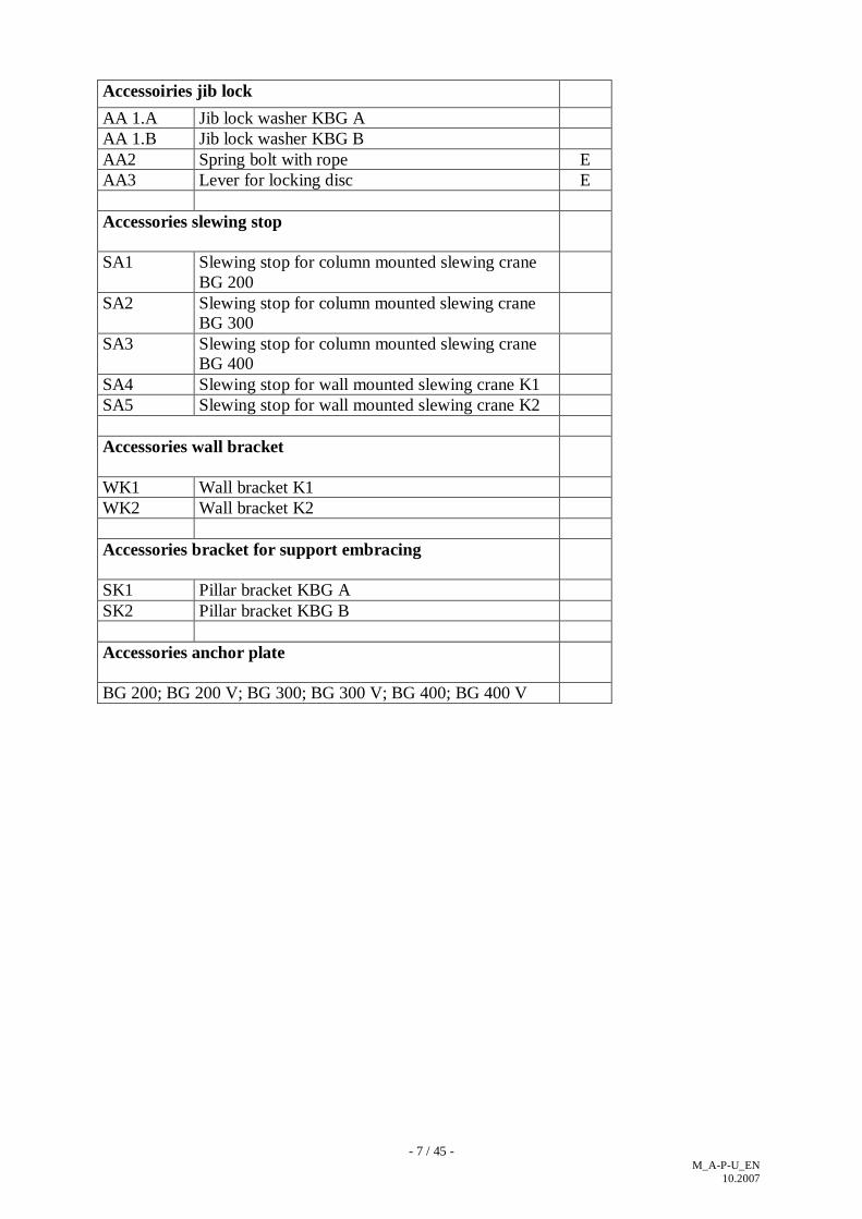
- 7 / 45 - M_A-P-U_EN
10.2007
Accessoiries jib lock AA 1.A Jib lock washer KBG A AA 1.B Jib lock washer KBG B AA2 Spring bolt with rope E AA3 Lever for locking disc E Accessories slewing stop
SA1 Slewing stop for column mounted slewing crane BG 200
SA2 Slewing stop for column mounted slewing crane BG 300
SA3 Slewing stop for column mounted slewing crane BG 400
SA4 Slewing stop for wall mounted slewing crane K1 SA5 Slewing stop for wall mounted slewing crane K2 Accessories wall bracket
WK1 Wall bracket K1 WK2 Wall bracket K2 Accessories bracket for support embracing
SK1 Pillar bracket KBG A SK2 Pillar bracket KBG B Accessories anchor plate
BG 200; BG 200 V; BG 300; BG 300 V; BG 400; BG 400 V

- 8 / 45 - M_A-P-U_EN
10.2007
approx. 9 cm
Foundation concrete B25
Base plate
GAP approx. 40-60mm
Anchor bolt
Inlet pipe for power supply cable
Nut M27 Washer Ø28 Template BG.... Washer Ø28 Nut M27
Removal of upper nut, washer and template.
2. Pillar erection with anchor bolts:
V1
V5
V3
V2

- 9 / 45 - M_A-P-U_EN
10.2007
2.1 Foot flange and undergrouting form:
Lower edge of foot flange = upper edge of base
Spirit level Foot flange Base plate Undergrouting Ground Foundation Anchor bolt
Upper edge of foundation=base plate:
Foot flange Base plate Undergrouting The edges have to be diagonal! Ground Foundation Anchor bolt
Foot flange in the undergrouting:
50
50
The anchor bolts must not be casted in and have to be permanently accessible.
Leave enough space for wrench!
90

- 10 / 45 - M_A-P-U_EN
10.2007
2.2 Assembling of the support rings:
Inner ring
Upper Konus ring
Lower Konus ring
Outer ring
Pre-finished support ring V4
Support ring V4
Washer V3
Nut V2
Information!! The support rings ensure that the anchor bolts are only subject to tensile strength and not to alternating stresses !
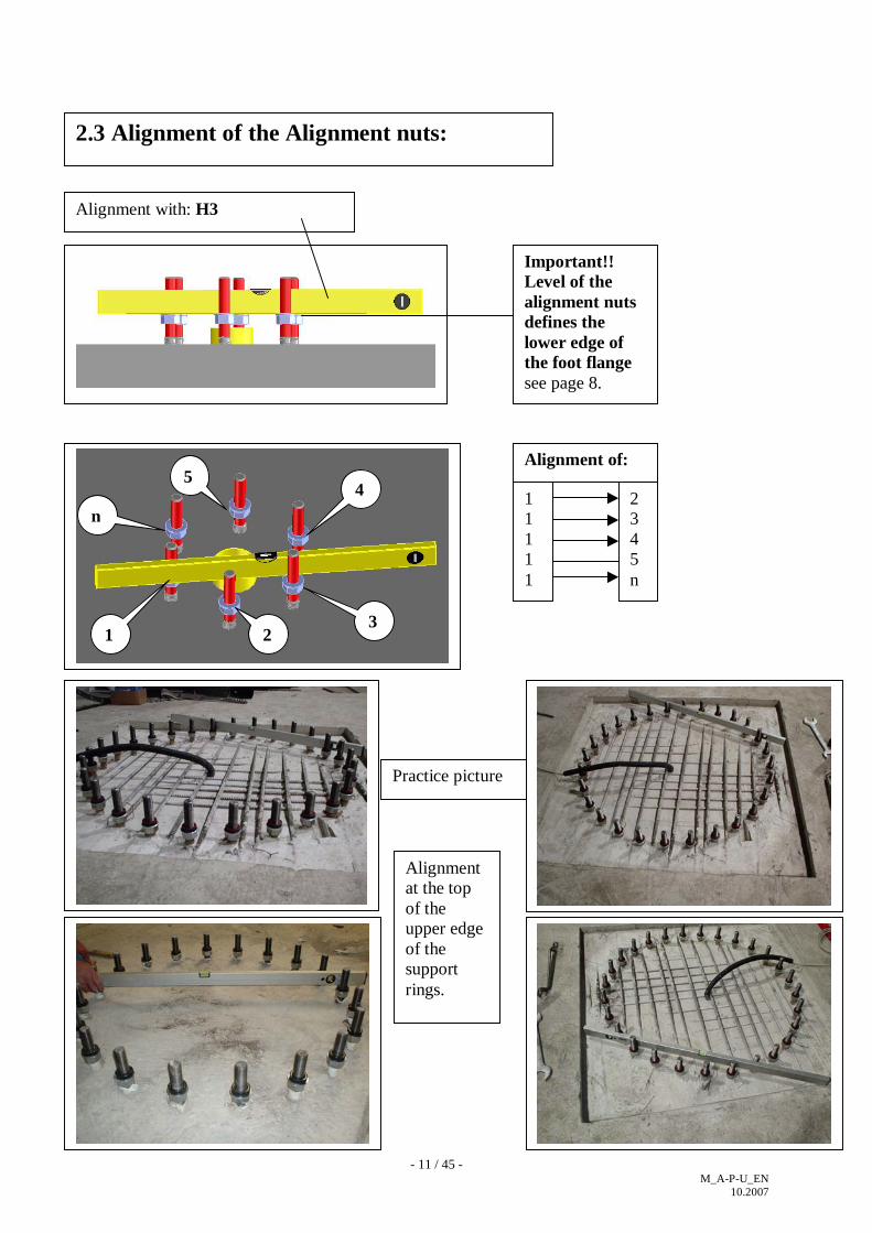
- 11 / 45 - M_A-P-U_EN
10.2007
2.3 Alignment of the Alignment nuts:
Alignment with: H3
Practice picture
1 2 3
4 5
n
Alignment of:
1 1 1 1 1
2 3 4 5 n
Important!! Level of the alignment nuts defines the lower edge of the foot flange see page 8.
Alignment at the top of the upper edge of the support rings.
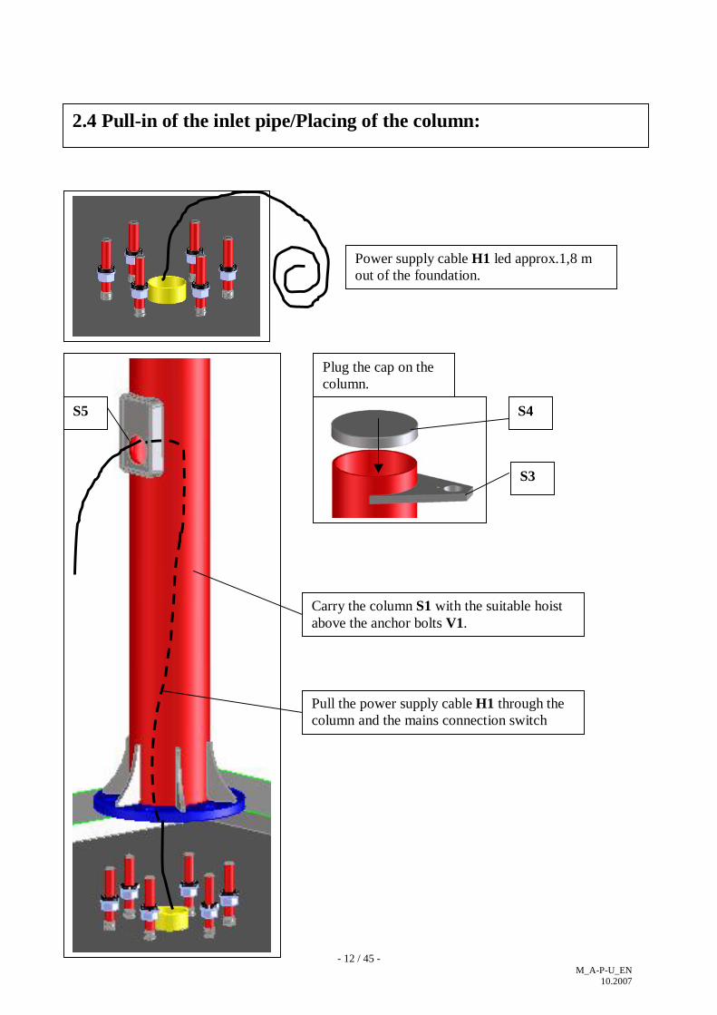
- 12 / 45 - M_A-P-U_EN
10.2007
2.4 Pull-in of the inlet pipe/Placing of the column:
Power supply cable H1 led approx.1,8 m out of the foundation.
Carry the column S1 with the suitable hoist above the anchor bolts V1.
Pull the power supply cable H1 through the column and the mains connection switch opening S5.
Plug the cap on the column.
S4
S3
S5
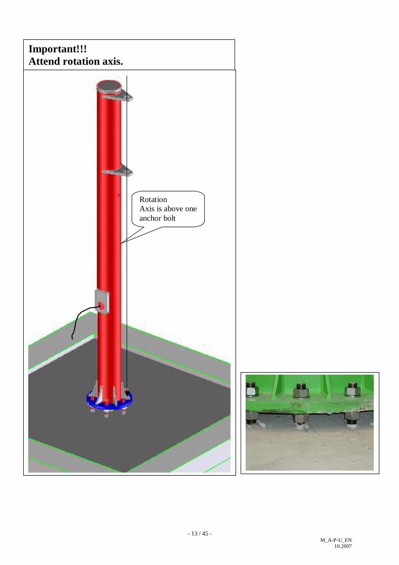
- 13 / 45 - M_A-P-U_EN
10.2007
Rotation Axis is above one anchor bolt
Important!!! Attend rotation axis.

- 14 / 45 - M_A-P-U_EN
10.2007
2.5 Alignment of the column with plumb line and alignment washer:
Plumb line H7 and alignment washer
Column declined backwards. Column declined forwards.
Ø50
Alignment washer H7
Plumb line H7
Alignment washer H7

- 15 / 45 - M_A-P-U_EN
10.2007
2.5 Alignment of the column with plumb line and alignment washer:
Column declined to the right. Column declined to the left.

- 16 / 45 - M_A-P-U_EN
10.2007
2.6 Correct aligned column:
1. Ma=100 Nm
2. Ma=100 Nm
Pillar correct aligned:
Tighten Upper nut first then lower nut with 100 Nm.

- 17 / 45 - M_A-P-U_EN
10.2007
3 The different types of jibs:
Type Assistent: A1
Type Praktikus: P1
Type Unilift: U1
A2
A4
A3
K1
K1
A2
A2
P2
K1
P3
K1
U2
U3
U4 K1 K1

- 18 / 45 - M_A-P-U_EN
10.2007
4 Mounting of the bearings with bearing bracket group A:
Bearing section L1.1 Mould-parting line has to be mounted at side of jib.
jib
Back tube A2
Bearing L1.1
Bearing bushes must be greased! Only use non-ageing grease on a lithium saponified base acc. DIN 51502, e.g. KP2K-30 (BP Energrease LS-EP2). Do not use grease with solids content, e.g. molybdenum disulphide.

- 19 / 45 - M_A-P-U_EN
10.2007
5 Mounting of the bearings with bearing bracket group B:
2
1 3
4
5
Pin: L2.1 Securing cap:L2.2
Upper bearing mounting:
Lower bearing mounting:
Pre-finished bearing mounting:
Socket joint: L2

- 20 / 45 - M_A-P-U_EN
10.2007
Ø26
Ø26
180
180
120
120
1110 840
Bearing bracket group A
Bearing bracket group B
6 Marking of the drill holes with water level:
180
Type: PW+UW=UK-120 Type: AW (F=150)=UK-930 Type: AW (F=170=UK-870
Type: PW+UW=UK-77 Type: AW (F=91)=UK-580 Type: AW (F=120=UK-525
horizontal vertikal
H3

- 21 / 45 - M_A-P-U_EN
10.2007
7 Drilling of the fixing holes:
Ø26
H4
H3
H7

- 22 / 45 - M_A-P-U_EN
10.2007
Bearing bracket group A
Bearing bracket group B
7.1 Marking/Drilling of the fixing holes (Brackets used as Drilling stencil. )
940
1430
Type: PW+UW=UK-127 Type: AW (F=91)=UK-630 Type: AW (F=120=UK-575
Type: PW+UW=UK-160 Type: AW (F=150)=UK-970 Type: AW (F=170=UK-910
Plumb line H7
Plumb line H7
H5

- 23 / 45 - M_A-P-U_EN
10.2007
7.2 Alignment of the bearing bracket with plumb line and alignment washer of the bearing bracket group A as shown in the picture: Movement in wall plain:
Lining of the bracket with bunk feeder:
Bunk feeder H6
Plumb line H7

- 24 / 45 - M_A-P-U_EN
10.2007
7.3 Drilling of the fixing holes and fixing of the bearing bracket:
Ø26
HV-Schraube M24 Güte10.9 Ma=1000 Nm
Fixing of the fixing screws: H8
Tighten of the fixing screws: H8
H4

- 25 / 45 - M_A-P-U_EN
10.2007
page 26 - 31
Pre-assembly of electrics

- 26 / 45 - M_A-P-U_EN
10.2007
8. Electrical components of round trailing cable power supply:
K1
E1
E2
E5
E4
E7
E9
E10
E6
E12
E3
E14
E13 E8
K2
K3
E11

- 27 / 45 - M_A-P-U_EN
10.2007
Accessories package: Round buffer Ø 25 x 30 Expanded rubber buffer 50 x 50 x 20 Slewing stop buffer Round cable 4 x 1,5^2 Cable tube M20 Cable tube strap Cable tube strap with clip Cable supporting tube strap Cable ties Cable bushing for pillar Conduit box Main switch for installation into the column Main switch for mounting on the wall Cable for conductor Earthing and designation Warning plate SWL plate UVV plate (only national) Alignment washer Ø 50 with plumb line
Pos K1 K2 K3 E7 E8 E9 E10 E11 E12 E13 E14 E15 E16 E17 E18 B5 B4 B2 H7
E17
E18
E15 H7
E16
B5
B2
AS 4 - 2 1 2 3 2 2 5 1 - 1 - 2 2 2 2 1 2
AW 4 - 2 1 2 3 2 2 5 - 1 - 1 2 2 2 2 1 2
PS 4 - 2 1 2 3 2 2 5 1 - 1 - 2 2 2 2 1 2
PW4 - 2 1 2 3 2 2 5 - 1 - 1 2 2 2 2 1 2
US- 2 2 - 1 2 3 2 2 5 1 - 1 - 2 2 2 2 1 2
UW2 2 - 1 2 3 2 2 5 - 1 - 1 2 2 2 2 1 2
B4
Outreach A< = 3 m
8.1 Electrical components of round cable power supply with cable tube:
V V VE E E E E E E E E E - - V V V -
E/V
E=spare part / V=wear part

- 28 / 45 - M_A-P-U_EN
10.2007
Accessories package: Round buffer Ø 25 x 30 Expanded rubber buffer 50 x 50 x2 0 Slewing stop buffer Clamp Jib arm (C-track) Eye bolt M8 Squeeze bushing Steel cord Ø 3 mm Trolley for roundcable Roundcable 4 x 1,5^2 Cable tube M20 Cable tube strap Cable tube strap with clip Cable supporting tube strap Cable ties Cable bushing for column Conduit box Main switch for installation into the column Main switch for mounting on the wall Cable for conductor Earthing and designation Warning plate SWL plate UVV plate (only national) Alignment washer Ø 50 mit Lot
Pos K1 K2 K3 E1 E2 E3 E4 E5 E6 E7 E8 E9 E10 E11 E12 E13 E14 E15 E16 E17 E18 B5 B4 B2 H7
AS4 - 2 4 2 2 2 1 * 1 1 2 2 - 4 1 - 1 - 2 2 2 2 1 2
AW4 - 2 4 2 2 2 1 * 1 1 2 2 - 4 - 1 - 1 2 2 2 2 1 2
PS 4 - 2 4 2 2 2 1 * 1 1 2 2 - 4 1 - 1 - 2 2 2 2 1 2
PW4 - 2 4 2 2 2 1 * 1 1 2 2 - 4 - 1 - 1 2 2 2 2 1 2
US - 2 - 4 2 2 2 1 * 1 1 2 - - 4 1 - 1 - 2 2 2 2 1 2
UW- 2 - 4 2 2 2 1 * 1 1 2 - - 4 - 1 - 1 2 2 2 2 1 2
Outreach A > 3 m
8.2 Electrical components of round cable power supply with round trailing cable:
A= 3 3,5 4 4,5 5 5,5 6 6,5 7 7,5 8 8,5 9 9,5m
*Anz.E6 3 4 5
E6 round cable
V V V- - - E VV E E E E E E E E E E - - V V V -
E/V
E=spare parts / V=wear parts

- 29 / 45 - M_A-P-U_EN
10.2007
10 Pre-assembly of the trailing cable power supply with cable support tube:
ca.A/2

- 30 / 45 - M_A-P-U_EN
10.2007
10 Pre-assembly of the round trailing cable power supply with trailing cable:

- 31 / 45 - M_A-P-U_EN
10.2007
10 Pre-assembly of the round trailing cable power supply:
Mount trolley and hoist according manufacturers instruction.
Power supply positioned to the right side of the jib Electric travel drive arranged on the opposite side Chain box directing at the pivot point

- 32 / 45 - M_A-P-U_EN
10.2007
page 33 - 37
Final assembly

- 33 / 45 - M_A-P-U_EN
10.2007
11 Final assembly of jib with bearing bracket group A as shown in pictures:
1
2
3
4 3
Sliding washer
< 800 mm
3 Ø 7,40,03
SPECIAL CASE Installation of bearing pins given little headroom < 800 mm Additional security required „up there“ by means of dowel pins
US ; UW
L1 L1.3
L1.2
L1.3
Ø 6 H12
Clean and slightly oil the bolt
Sliding surface to face up
M8: max. MA = 17 Nm
M8: max. Ma = 17 Nm
F100mm mm
F120mm
PS
AS
US F (AS, PS)
F (US)

- 34 / 45 - M_A-P-U_EN
10.2007
12 Final assembly of jib with bearing bracket group B as shown in pictures:
M20 x 100-10.9 Ma = 570 Nm
Insert bearing pin with Hex. Screw M20x100 and cover disk Ø70x12 into the bore of the bearing bracket.
L2.1
L2
L2.3
L2.4
L2.2
Conduit box E14 to be fixed under the bracket. Earthing of jib and support via cable for conductor E17.
upper bearing pin
not like that! Items L2.3 and L2.4 must be visible from the outside.
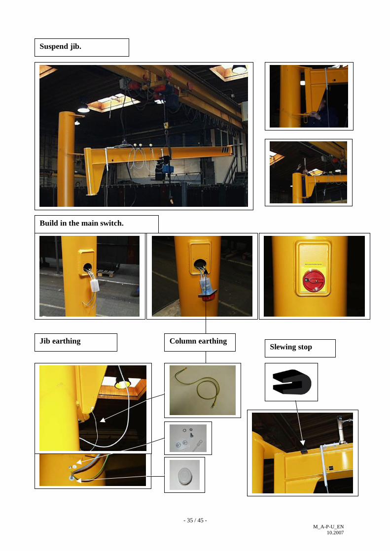
- 35 / 45 - M_A-P-U_EN
10.2007
Suspend jib.
Build in the main switch.
Jib earthing Slewing stop
Column earthing

- 36 / 45 - M_A-P-U_EN
10.2007
13 Checking the crane alignment:
A
X<A/1000
X
Laser land leveler or land leveler
Slewing cranes only operate perfectly if X<A/1000 is encapsulated..

- 37 / 45 - M_A-P-U_EN
10.2007
Wait curing of the undergrouting. (B25 = 28 days)
14 Undergrout foot flange
Casting compound at least B25 DIN 1045 or C20/25 DINEN206-1
Lock nut M27 Ma = 50 Nm
For outdoor operation the foot flange has to be permanently sealed.
1. Tighten all anchor nuts with a torque of Ma=400 Nm (A)
2. Afterwards all anchor nuts have to be loosened by 30-45° (B)
3. Then tighten all anchor nuts with a torque of Ma=300 Nm (C)
4. Tigthen all anchor nuts for a second time with a torque of Ma=300 Nm (D)
A 400 Nm B 30° - 45° C 300 Nm D 300 Nm

- 38 / 45 - M_A-P-U_EN
10.2007
page 39 - 44
Accessories

- 39 / 45 - M_A-P-U_EN
10.2007
Column mounted slewing crane:
Wall mounted slewing crane:
Ø 5,2 M6
Ø 5,2 M6
15 Accessories of jib locking device:
The locking device washer and the spring bolt has to be welded on site with two weldings a=3x50 mm in case of later assembly.
a=3x50
Locking device washer AA 1
Spring bolt AA 2
Lever for locking device AA 3

- 40 / 45 - M_A-P-U_EN
10.2007
16 Accessories of slewing stop: SA1....SA5
f
f f
20
e.g. slewing angle 150°
90°
60°
=f/2+20
=f/2+20
Cut off the designated slewing angle ls: e.g. 60° left;90° right
Buffer: K 3
Wall mounted slewing crane: SA4+SA5

- 41 / 45 - M_A-P-U_EN
10.2007
17 Accessories slewing stop pillar mounted crane/wall mounted crane:
Ø 8,5 M10

- 42 / 45 - M_A-P-U_EN
10.2007
18 Accessories wall bracket:
Wall bracket A:WK 1
Wall bracket B:WK 2
340
400
1040
1100
1110
120
120
1530
M27
M27
Washer Ø28 Nut M27 Lock nut
Ma=600 Nm
Ma=900 Nm
Wall is shown in section.
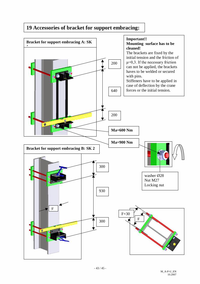
- 43 / 45 - M_A-P-U_EN
10.2007
19 Accessories of bracket for support embracing:
Bracket for support embracing B: SK 2
200
200
640
300
300
930
F F+30
F
Ma=600 Nm
Ma=900 Nm
Bracket for support embracing A: SK 1
washer Ø28 Nut M27 Locking nut
Important!! Mounting surface has to be cleaned! The brackets are fixed by the initial tension and the friction of μ=0,3. If the necessary friction can not be applied, the brackets haves to be welded or secured with pins. Stiffeners have to be applied in case of deflection by the crane forces or the initial tension.

- 44 / 45 - M_A-P-U_EN
10.2007
20 Accessories of dowel plate: BG200, BG200v, BG300, BG300v, BG400, BG400v
>=190
Dowel plate instruction according to Application rules/installation instruction
Base plate or ceiling of B25

- 45 / 45 - M_A-P-U_EN
10.2007
21. Putting into operation 21.1 Once the installation is completed and prior to start the crane operation the following
tests need to be performed in compliance with §19 of the EN 60204-32 have to be carried out: 1. test run
2. test of earthing conductors 3. measurement of the insulating resistance The crane and its fastening elements must remain permanently accessible for inspections.
21.2 When putting the crane into operation, accumulation of coating material (zinc, paint)
may occur on the running surfaces of the jib which hinder running of the trolleys. These accumulations must then be removed.
21.3 inspection when putting the product into operation for the first time (to accident
prevention regulations BGV D6)
Cranes must be subjected to an inspection when they are put into operation for the first time. The owner (operator) must ensure that cranes are inspected before being put into service for the first time by
a) Expert engineers (authorized crane expert engineers)
Acceptance test of crane installations in acc. with DIN 15030 and UVV BGV D6 (BGG 905) cranes, test load and lifting attachments must be provided by the customer. The following must be checked by expert engineers:
all cranes 1000 kg SWL all cranes with two or more powered motions.
b) Experienced technicians The following must be checked by experienced technicians:
all cranes which need not be checked by expert engineers
21.4 Routine inspections
Depending on the local and operating conditions, the owner must ensure that cranes are inspected as required, at least once a year, by an experienced technician for cranes.

KGB/V-K30 01.2009 E C - D e c l a r a t i o n o f C o n f o r m i t y concerning slewing cranes / cranes according to the sense of EC-directive concerning machines 98/37/EEC, appendix II A The declaration of conformity refers to cranes ready for operation which have been installed in accordance with the mounting instructions. The correct erection and inspection have been certified. Scope of supply, refer to inspection manual. We herewith declare that the design of slewing cranes / cranes of type AS, AW, PS, PW, US, UW, PR, M, MI, TS, B, BH, MOB, G, GN, BS, BW, GBW, GBD, PA, PB, P100, P200, P300, P400, P500 from the date of construction 01.2009 corresponds to the following relevant regulations: - EC-directive concerning machines 98/37/EEC dated August 12th, 1998 - EC-Low Voltage Directive 2006/95/EEC - EMV-Directive 2004/108/EEC In case of a modification of the equipment without our prior agreement this declaration will become invalid. Coordinated standard applied: - DIN EN ISO 12100, part 1 and part 2 Safety of machines - EN 60204, part 32 Electrical equipment of machines: Requirements for hoisting machines National standards and technical specifications applied: - BetrSichV Operational safety decree - GPSG Law on the safety of technical appliances and products - BGV A1 UVV general regulations (regulations for prevention of accidents) - BGV D6 Cranes - DIN 1045 Concrete and armoured concrete, dimensioning - DIN 15018 Part 1 and part 2 - Cranes/steel structures, calculation and execution - DIN 15019 Part 1 - Stability According to appendix V of the EC-directive concerning machines: - Grade labelling of the EC-label - Technical documentation is deposited in the manufacturer’s works - This declaration of conformity only becomes valid after termination and certification of the installation in accordance with the mounting instructions as well as after certified inspection without reservations prior to first commissioning. Note: The supporting structure provided by others is not subject of this declaration of conformity. However, a surface of sufficient strength and rigidity is required to ensure safe crane operation. VETTER Krantechnik GmbH Siegtalstraße 22 D-57080 Siegen, 2009-01-02
N.Hammes ppa. Truß General manager Technical Manager ------------------------------------------------------ (Signature)

- 1 / 15 - BW_Schwenkkrane_EN Slewing cranes 01.2005
Operating instruction slewing cranes 01.2005 EN
Maintenance instructions slewing cranes
1. Column
2. Jib arm
3. Roller box
4. End buffer
5. Ground/wall
6. Jib support
7. Slip ring
8. Emergency stop
9. Pendant control box
10. Plates showing type
and capacity
11. Isolator
12. Alignment screws
13. Foot
14. Large bearing
15. Hoist
16. Slewing drive
Type AS Type AW
Types PS/US Types PW/UW
Types M/TS Type PR
16

- 2 / 15 - BW_Schwenkkrane_EN Slewing cranes 01.2005
Type B Type BH
Mobile Cranes Type G + GN Type MOB
Type BS Type BW
Type GBW Type GBD

- 3 / 15 - BW_Schwenkkrane_EN Slewing cranes 01.2005
Lock
9. Pendant control box 11. Isolator
off on
8. Emergency stop Hoist up Hoist down Forward travelling Reverse travelling Slewing right Slewing left Button: 1-speed 2-speed

- 4 / 15 - BW_Schwenkkrane_EN Slewing cranes 01.2005
This device is a technical equipment/tool and should be used exclusively for commercial and industrial applications. Before the operation of the crane: Read carefully these instructions ! The crane operator shall be able to read the operating instructions. If necessary, the user has to arrange for translation into operator’s language. Slewing cranes only function without problems if that are controlled and operated in accordance with the operating instructions. In case of non-observance claims will be refused! Careful operation of the crane plant increases its life and safety! Selection of hoists: It is only allowed to use hoists 1. of which the total weight of the max. admissible hoist weight according to the certificate is not exceeded, 2. which can only lift 1,6 times* of the crane weight from the bottom due to the required stability. Generally, only
loads up to the maximum lifting capacity indicated on the label shall be lifted! Higher loads are not allowed! *mobile cranes see fig. 4.1
3. which do not exceed the maximum lifting speed of 16 m/min (type TS = 10 m/min) (observe manufacturer’s instructions; other crane types may require lower hoisting speeds) 4. of which the trolley travel speed does not exceed 20 m/min
1. Use in accordance with regulations: Only those persons are allowed to operate cranes who fulfil the stipulations mentioned in UVV-Krane BGV D6, § 29. Only trained persons are allowed to operate the crane. 1. Commissioning only after presentation of the declaration of conformity and grade labelling of the
EC-label. 2. Slewing cranes suitable for lifting and moving of material. 3. Slewing cranes suitable for a temperature range from -20° to +40°C. 4. Use slewing cranes only according to their lifting classes and load groups - classification acc. to DIN 15018.
(Classification, operating time - see test certificate/label). 5. Suitable for perpendicular erection on resilient and vibration-free foundations. 6. Slewing cranes suitable for floor operation. 7. For slewing cranes, the indicated capacity is valid up to the nominal working radius. 8. In general, an accident-safe operation, adapted to the local conditions, has to be ensured. 9. Secure cranes against unintentional movements. 10. Cranes for outdoor operation with electrical slewing are, if not otherwise expressively mentioned, suitable up
to wind force 4.
List of hazards acc. to DIN EN ISO 12100 for slewing cranes:
Pos. Hazards
Pos./Part of body Solution/Warning
1 - Location Persons Warning notice on the crane - of masses and stability Operator/other persons Training/information - of masses and acceleration Operator/other persons Training/information - insufficient mechanical
stability Operator/other persons Observe operating and maintenance
instructions 1.1 Crushing By the load/
operator/other persons Keep safety distances/observe load oscillation and braking distances
Crushing 2.3.6/operator Keep safety distances Crushing 4 limit stop/operator Keep safety distances Crushing
By the load in the periphery/operator/foot
Keep safety distances/observe load oscillation, keep clear way outs

- 5 / 15 - BW_Schwenkkrane_EN Slewing cranes 01.2005
Pos. Hazards
Pos./Part of body Solution/Warning
1.2 Shearing
Jib 2 - pillar 1/-wall 5-support 6 – slewing drive 16 operator, hand
Keep safety distances
1.6 Impact
Oscillating load/operator Keep safety distances
1.10 Slipping-out of parts
Load/operator Keep safety distances
1.11 Stability Foundation 5/floor wall/ceiling/operator
Leave danger area if possible, lower load immediately stop crane
Deposit load on good bearing soil only 1.12 Slipping, stumbling,
falling down Insufficient safety/ operator
Keep clear service ground, ensure sufficient steadiness
2
Electrical endangering
2.1 Electrical contact Damaged insulation of el. conductors/operator
Stop operation, disconnect current, replace electrical conductors
Slip ring element 7/ operator
Contact forbidden for operator
2.4 External effect p.ex. other conveyors/ operator
Carefully watch crane, load and area
3.1 Burns el. driven crane/ operator
Observe special instructions for hazardous location
7 Material (oils, greases, lubricants)
Slewing drive, hoist operator/other persons/ environment
See special operating instructions for hoist and drives
7.2 Fire and explosion el. driven crane/ operator/other persons
Not suitable for hazardous location
8.4 Insufficient local lighting
Operator/other persons Ensure sufficient visibility
8.6 Human error
Operator Training
10 + 10.3
Energy supply trouble malfunction of control system
Operator/other persons Operate emergency stop 8 resp. take measures for trouble elimination by qualified personnel
10.4 Faulty erection Operator Stop operation correct failures
11. Failure/wrong arrangement of protective measures
Operator Take all measures to reduce danger potential
11.1 + 11.2
Protective equipment Operator/other persons Check protective equipment
11.3 Starting and stopping equipment
Control box 9/operator Push emergency stop in case of defective control push buttons. Replace parts
11.4+ 11.5
Safety signs/signals information- and warning equipment
Label 10/operator Keep label 10 well legible
11.6 Disconnecting equipment of energy supply
Isolator 11 emergency stop 8 /operator
Check function prior to start of work
11.7 Emergency measures Working area/contractor Push emergency stop 8, if this reduces danger
11.9 Equipment for safe adjustment and/or maintenance
Operator Prior to each kind of work on the crane, lock isolator 11 at pos. „OFF“

- 6 / 15 - BW_Schwenkkrane_EN Slewing cranes 01.2005
2. Requirements by law
Display and observe operating manual 3. Control-/safety equipment Isolator 11 What is it? The isolator switch disconnects the crane from the main supply (all phases are disconnected)
Where is it? 1. For a slewing pillar crane, the isolator is an insert switch, usually arranged on the pillar. 2. For a wall slewing crane, the isolator is arranged on a wall/support In principle, the isolator has to be freely accessible. In case of several cranes, the isolator must be clearly assigned to the relative crane (identification on isolator and crane must correspond).
How does The isolator has two positions, one 0-position and one 1-position. it work? At 0-position, the contacts are open, and current supply to the crane is interrupted. 0-position can be locked by triple-turn lock. At 1-position, the contacts are closed, and current supply to the crane is given.
Control pendant What is it? The control pendant contains all control functions of the crane
Where is it? The control pendant can a) hang down from the hoist b) hang down from the C-rail (ideal control) c) hang down from the top of the crane d) be integrated in a separated contactor box as a special control.
How does All control functions are controlled by pushing the push button; there are two it work? different types of push button
a) the 1-speed push button which, by being pushed, actuates a certain speed, and b) the 2-speed push button which, by soft pushing, actuates a slow speed and, by
pushing through, actuates a quick speed. The function is terminated by releasing the push button.
Reversing motions, p.ex. hoist up and hoist down are interlocked. Never reverse a motion by pressing two buttons together, it could cause damage.
Crane switch (emergency stop) 8 Emergency stop is operated by pushing the red button. When red button is pressed, all functions are out of order. By partial turning to the right, the red button resets, and all functions are ready for operation.
4. Commissioning
1. For mobile cranes: Please refer to erection and start-up instructions of crane type MOB! 2. Loose locks, if existing. 3. Put isolator into position 1. 4. Unlock emergency stop switch. 5. Slewing crane is ready for operation.

- 7 / 15 - BW_Schwenkkrane_EN Slewing cranes 01.2005
5. Attaching the load 1. Choose suitable attachments/slings. 2. Move the crane hook of the trolley in a plumb line over the load 3. Attach load correctly. Attaching prohibitions: see point 8.
6. Lifting and transportation of the load
1. The total load to be conveyed must not exceed the maximum capacity of the crane. If necessary, the load has to be weighed by means of a crane balance.
2. Keep the transport distance short. After the transport put the load down. 3. Before removing the attachments/slings, make sure that the load is standing on sufficient stable soil resp.
ground. 4. After the transport, hook and bearing means must be without load.
6.a) Transportation with manually operated cranes 1. Together with the load, attach a chain into the crane hook, i.e. slewing or trolley travelling via chain or 2. attach chain or rope at the load directly or 3. attach chain or rope at the travelling gear of the hoist or 4. attach chain or rope at the crane jib (at the tip) or 5. use chain hoist trolley and slewing drive. As the distances are becoming considerably long for great heights
due to the required deflection angle, it is recommendable to use chain hoist drives or motive drives for frequent use. Some types of cranes can be retrofitted.
6. The crane driver must operate manual or semi-automatic cranes in such a way that he can stop started travelling or rotating movements without any danger. Tilting limitations must not be approached without braking.
6.b) Transportation with motive drives 1. For all motors with fine motion start and end all motions with the fine mode. Admissible duty cycle
(% ED related on 10 min). 2. If possible, lift the load approx. 10 cm at fine motion, and then lift it at quick motion up to the desired height. 3. Avoid oscillating movements at change-over of speed. 4. Transportation of the load into the desired position e.g. by actuating the push button
"Trolley forward/backward" or "Jib left/right". When travelling avoid oscillating movements (reverse „plugging“ of the push buttons to counter load swing is forbidden).
5. Lowering of the load by pushing through the push button "Hoist down" until approx. 10 cm above the depositing place. Then release the push button "Hoist down" until fine motion is obtained, and deposit the load at fine motion on the ground.
6. The crane driver is not allowed to approach end positions which are limited only by emergency limit switches or friction clutches.
Always keep sufficient safety distance to the load! Avoid load oscillation!

- 8 / 15 - BW_Schwenkkrane_EN Slewing cranes 01.2005
7. Placing out of service
a) Normal, daily placing out of service Put trolley into home position (rear jib position). Put jib over lock position, if fitted, and lock it. Put isolator into 0-position and, if necessary (e.g. at places open to the public), lock it. Secure crane against unintentional movements and unauthorized use. b) Placing out of service in case of emergency In case of emergency, the emergency stop push button or the isolator has to be actuated for quickly stopping the crane, e.g. if a push button is jammed or a contactor sticks, the emergency stop button has to be pushed. Emergency stop button/isolator immediately stops each and every crane movement. Then leave the danger area and inform a qualified person. c) Placing out of service in case of wind forces > 4 In case of wind forces > 4, the hoist has to be moved into home position at due time and, if existing, trolley and jib locks have to be actuated. Put isolator into 0-position and secure it against unauthorized use by means of a lock. d) Placing out of service in order to avoid hazards The crane has to be put out of service and to be secured against unauthorized use if hazards may occur caused by damage of the crane/hoist or due to certain service conditions. e) Maintenance of function in case of interruption of use To avoid tightening of driving units, brakes, etc., try all functions once a week at least.
8. Important operating prohibitions
1. Using a crane without EC-label (EC-declaration and declaration of conformity) valid within the range of the EG-directives concerning machines.
2. Attachment of loads which are not in a perpendicular position below the load hook 3. Moving trolley/hoist/ jib by putting the hook to the load or to the lock position by actuating “Hoist up” over the
load or locking position 4. Inclined hauling or hauling of loads 5. Pulling off of loads 6. Loads to be conveyed greater than the safe working load (crane capacity) 7. Load lifting by inching 8. Actuate a reverse motion into a running one 9. Transportation of molten material 10. Transportation of humans 11. Removing covers from vessels under residual vacuum 12. Do not stand under suspended loads 13. Lift loads for welding 14. Once a load is lifted it is not allowed to increase the load 15. After the transport
a) loads or partial load (except for attachments) to keep hanging on hook or crane b) to hang on new loads or partial loads and not to transport them
16. Attachments of hook on fixed point by “hoist up” so that hook and equipment is loaded

- 9 / 15 - BW_Schwenkkrane_EN Slewing cranes 01.2005
9. Explanatory notes
1. In general, for an accident-free operation, observance of the local conditions has to be ensured.
2. Operating instructions for drives, hoists and accessories have to be observed. 3. A sufficient visibility for the crane operator must be ensured, if necessary ask a third person. 4. Admissible cycle- and operating times must not be exceeded. Operating time is indicated in percent (ED) and
refers to 10 min. Non-observance can lead to an overload of the motors. 5. The crane does not reach a continuous sound level of 70 dB(A). 6. In case of slewing drives type M/TS weld shrinkage or slewing drives may be the reason for slight inclination
of the rollers or of the jib support. Due to the construction design this may cause some kind of clicking noise. The hollow body of the pillar intensifies the clicking which, however, does not cause any damages and is absolutely harmless! If slewing cranes without drive or with drive “B” are concerned, clicking can be reduced or even be eliminated by greasing the pillar ring using a standard adhesive lubricant.
10. Take out of service
- After expiry of the theoretical service life. - In case of damages or wear not allowing to be repaired
- see maintenance instructions - - In case of wear exceeding 10 % of the trolley travelling way (girder thickness). - At non-observance of the specified checks and maintenance works (see test badge on crane). Note: Even with a not regular use of the equipment it is subject to an annual inspection
executed by an expert.
- 10 / 15 - BW_Schwenkkrane_EN Slewing cranes 01.2005
11. Fundamental safety instructions
1.1 Warnings and symbols The following signs and designations are used in the manual to designate instructions of particular importance.
Important special information and how to use the machine/plant efficiently
Attention special information resp. instructions or prohibitions directed towards preventing damage
Danger information resp. instructions or prohibitions designed to prevent injury or extensive damage
1.2 Basic operation and designated use of the machine/plant 1.2.1 The machine/plant has been built in accordance with state-of-the-art technique and the recognized safety rules. Nevertheless, its use may constitute a risk to life and limb of the operator or of third parties, or cause damage to the machine and to other material property. 1.2.2 The machine/plant is only allowed to be used in technically perfect condition in accordance with its designated use and the instructions set out in the operating instruction. Any functional disorders, especially those affecting the safety of the machine/plant, should therefore be rectified immediately ! 1.2.3 The machine/plant is designed exclusively for the lifting and slewing of loads. Using the machine/plant for purposes other than those mentioned above (such as for pulling loads) is considered contrary to its designated use. The manufacturer/supplier cannot be held liable for any damage resulting from such use. The risk of such misuse lies entirely with the user. Operating the machine within the limits of its designated use also includes observing the instructions set out in the operating instructions and complying with the inspection and maintenance directives.
1.3 Organizational measures 1.3.1 The operating instructions must always be at hand at the place of use of the machine/plant, e.g. by stowing them in the tool compartment or tool-box provided for such purpose. 1.3.2 In addition to the operating instructions, observe and follow instructions in all other generally applicable legal and mandatory regulations relevant to accident prevention and environmental protection. These compulsory regulations may also deal with the handling of hazardous substances, issuing and/or wearing of personal protective equipment, or traffic regulations. 1.3.3 The operating instructions must be supplemented by instructions covering the duties involved in supervising and notifying special organizational features, such as job organization, working sequences or the personnel entrusted with the work. 1.3.4 Personnel entrusted with work on the machine must have read the operating instructions and in particular the chapter on safety before beginning working. It is too late to read the instructions after work has started. This applies especially to persons working only occasionally on the machine, e.g. during setting up or maintenance. 1.3.5 Check - at least from time to time - whether the personnel is carrying out the work in compliance with the operating instructions and paying attention to risks and safety factors. 1.3.6 For reasons of security, long hair must be tied back or otherwise secured, garments must be close-fitting and no
jewellery - such as rings - may be worn. Injury may result from being caught up in the machinery. 1.3.7 Use protective equipment wherever required by the circumstances or by law. 1.3.8 Observe all safety instructions and warnings attached to the machine/plant. 1.3.9 See to it that safety instructions and warnings attached to the machine are always complete and perfectly legible. 1.3.10 In the event of safety-relevant modifications or changes in the behaviour of the machine/plant during operation, stop the machine/plant immediately and report the malfunction to the competent authority/person. 1.3.11 Never make any modifications, additions or conversions which might affect safety without the supplier's approval. This also applies to the installation and adjustment of safety devices and valves as well as to welding on load-bearing elements. 1.3.12 Spare parts must comply with the technical requirements specified by the manufacturer. Spare parts from original equipment manufacturers can be relied to do so. 1.3.13 Replace hydraulic hoses within stipulated and appropriate intervals even if no safety-relevant defects have been detected. 1.3.14 Adhere to prescribed intervals or those specified in the operating instructions for routine checks and inspections.

- 11 / 15 - BW_Schwenkkrane_EN Slewing cranes 01.2005
1.3.15 For the execution of maintenance work, tools and workshop equipment adapted to the task on hand are absolutely
indispensable. 1.3.16 The personnel must be familiar with the location and operation of fire extinguishers. 1.3.17 Observe all fire-warning and fire-fighting procedures.
1.4 Selection and qualification of personnel; basic responsibilities 1.4.1 Any work on and with the machine/plant must be executed by reliable personnel only. Observe minimum age stipulated by law. 1.4.2 Entrust only trained or instructed staff and set out clearly the individual responsibilities of the personnel for operations, set-up, maintenance and repair. 1.4.3 Make sure that only authorized personnel works on or with the machine. 1.4.4 Define the machine operator's responsibilities - also with regard to observing traffic regulations - giving the operator the authority to refuse instructions by third parties that are contrary to safety. 1.4.5 Do not allow persons to be trained or instructed or persons taking part in a general training course to work on or with the machine/plant without being permanently supervised by an experienced person. 1.4.6 Work on the electrical system and equipment of the machine/ plant must be carried out only by a skilled electrician
or by instructed persons under the supervision and guidance of a skilled electrician and in accordance with electrical engineering rules and regulations.
1.4.7 Work on chassis, brake and steering systems is only allowed to be performed by skilled personnel only which has been specially trained for such work.
1.5 Safety instructions governing specific operational phases 1.5.1 Standard operation 1.5.1.1 Avoid any operational mode that might be prejudicial to safety. 1.5.1.2 Before beginning work, familiarise yourself with the surroundings and circumstances on site, such as obstacles in the working and travelling area, the soil bearing capacity and any barriers separating the construction site from public roads. 1.5.1.3 Take the necessary precautions to ensure that the machine is used only when in a safe and reliable state. Operate the machine only if all protective and safety-orientated devices, such as removable safety devices, emergency stop equipment, sound-proofing elements and exhausters, are in place and fully functional. 1.5.1.4 Check the machine/plant at least once per working shift for obvious damage and defects. Report any changes (incl.
changes in the machine's working behaviour) to the competent authority /person immediately. If necessary, stop the machine immediately and lock it.
1.5.1.5 In the event of malfunction, stop the machine/plant immediately and lock it. Have any defects rectified immediately. 1.5.1.7 During start-up and shut-down procedures always watch the indicators in accordance with the operating instructions. 1.5.1.8 Before starting up or setting the machine/plant in motion, make sure that nobody is at risk. 1.5.1.12 In conditions of poor visibility and after dark always switch on the lighting system. 1.5.1.15 Always keep at a distance from the edges of building pits and slopes. 1.5.1.16 Avoid any operation that might be risky to machine stability. 1.5.2 Special work in conjunction with utilization of the machine/plant and maintenance as well as repairs during operation; disposal 1.5.2.1 Observe the adjusting, maintenance and inspection activities and intervals set out in the operating instructions, including information on the replacement of parts and equipment. These activities may be executed by skilled personnel only. 1.5.2.2 Inform operating personnel before beginning special operations and maintenance work, and appoint a person to supervise the activities. 1.5.2.3 In any work concerning the operation, conversion or adjustment of the machine and its safety-orientated devices or any work related to maintenance, inspection and repair, always observe the start-up and shut-down procedures set out in the operating instructions and the information on maintenance work. 1.5.2.4 Ensure that the maintenance area is adequately secured, if necessary.

- 12 / 15 - BW_Schwenkkrane_EN Slewing cranes 01.2005
1.5.2.5 If the machine/plant is completely shut down for maintenance and repair work, it must be secured against inadvertent starting by: - locking the principal control elements and removing the key and/or - attaching a warning sign to the main switch 1.5.2.6 Carry out maintenance and repair work only if the machine is positioned on stable and level ground and has been secured against inadvertent movement and buckling. 1.5.2.7 To avoid the risk of accidents, individual parts and large assemblies being moved for replacement purposes should
be carefully attached to the hoist and secured. Use only suitable and technically perfect hoists and load attachments with adequate lifting capacity. Never work or stand under suspended loads.
1.5.2.8 The attachment of loads and the instructing of crane operators should be entrusted to experienced persons only. The instructor must be within sight or sound of the operator. 1.5.2.9 For carrying out overhead assembly work always use specially designed or otherwise safety-orientated ladders and working platforms. Never use machine parts as a climbing aid. Wear a safety harness when carrying out maintenance work at greater heights. Keep all handles, steps, handrails, platforms, landings and ladders free from dirt, snow and ice. 1.5.2.10 Clean the machine, especially connections and threaded unions, of any traces of oil, fuel or preservative before carrying out maintenance/repair. Never use aggressive detergents. Use lint-free cleaning rags. 1.5.2.11 Before cleaning the machine with water, steam jet (high-pressure cleaning) or detergents, cover or tape up all openings which - for safety and functional reasons - must be protected against water, steam or detergent penetration. Special care must be taken with electric motors and switchgear cabinets. 1.5.2.13 After cleaning, remove all covers and tapes applied for the purpose. 1.5.2.15 Always tighten any screwed connections that have been loosened during maintenance and repair. 1.5.2.16 Any safety devices removed for set-up, maintenance or repair purposes must be refitted and checked immediately upon completion of the maintenance and repair work. 1.5.2.17 Ensure that all consumables and replaced parts are disposed of safely and with minimum environmental impact.
1.6 Warning of special dangers 1.6.1 Electric energy 1.6.1.1 Use only original fuses with the specified current rating! Switch off the machine/plant immediately if trouble occurs in the electrical system! 1.6.1.2 When working with the machine/plant, maintain a safe distance from overhead electric lines. If work is to be carried out close to overhead lines, the working equipment must be kept well away from them. Danger! Check out the prescribed safety distances! 1.6.1.3 If your machine is exposed to a power transmission line - do not leave the machine - drive the machine out of the hazard zone - warn others against approaching and touching the machine - have the power transmission line de-energized - do not leave the machine unless you are sure that the power transmission line has been de-energized 1.6.1.4 Work on the electrical system or equipment may only be carried out by a skilled electrician himself or by specially instructed personnel under the control and supervision of such electrician and in accordance with the applicable electrical engineering rules.

- 13 / 15 - BW_Schwenkkrane_EN Slewing cranes 01.2005
1.6.1.5 If provided for in the regulations, the power supply to parts of machines and plants, on which inspection, maintenance and repair work is to be carried out must be cut off. Before starting any work, check the de-energized parts for the presence of power and ground or short-circuit them in addition to insulting adjacent live parts and elements. 1.6.1.6 The electrical equipment of machines/plants is to be inspected and checked at regular intervals. Defects such as loose connections or scorched cables must be rectified immediately. 1.6.1.7 Necessary work on live parts and elements must be carried out only in the presence of a second person who can cut off the power supply in case of danger by actuating the emergency stop or main power switch. Secure the working area with a red-and-white safety chain and a warning sign. Use insulated tools only. 1.6.2 Gas, dust, steam and smoke Observe the regulations in force at the respective site! 1.6.2.2 Carry out welding, flame-cutting and grinding work on the machine/plant only if this has been expressively authorized, as there may be a risk of explosion and fire. 1.6.2.3 Before carrying out welding, flame-cutting and grinding operations, clean the machine/plant and its surroundings from dust and other inflammable substances and make sure that the premises are adequately ventilated (risk of explosion). 1.6.3 Hydraulic and pneumatic equipment 1.6.3.2 Check all lines, hoses and screw connections regularly for leaks and obvious damage! Repair damage immediately! Splashed oil may cause injury and fire! 1.6.3.3 Depressurise all system sections and pressure pipe (hydraulic system, compressed-air system) to be removed in accordance with the specific instructions for the unit concerned before carrying out any repair work! 1.6.3.4 Hydraulic and compressed air lines must be laid and fitted properly! Ensure, that no connections are interchanged! The fittings, lengths and quality of the hoses must comply with the technical requirement. 1.6.4 Noise 1.6.4.1 During operation, all sound baffles must be closed. 1.6.4.2 Always wear the prescribed ear protectors! 1.6.5 Oil, grease and other chemical substances 1.6.5.1 When handling oil, grease and other chemical substances, ob-serve the product-related safety regulations! 1.6.5.2 Be careful when handling hot consumables (risk of burning or scalding)!
1.7 Transporting and towing - recommissioning
1.7.3 Use only appropriate means of transport and hoist of adequate capacity! 1.7.4 The recommissioning procedure must be strictly in accordance with the operating instructions!

- 14 / 15 - BW_Schwenkkrane_EN Slewing cranes 01.2005
Maintenance Instructions for Slewing Cranes Maintenance and check out are to be carried out only by experienced firms or competent persons according to the regulations of BGV D8 §23 and BGV D6 §26. Even with a not regular use of the equipment it is subject to an annual inspection executed by an expert. Careful maintenance of the crane plant increases its life and safety. In case of doubt please contact your supplier. Only genuine spare parts are to be used, as otherwise safety would be endangered. 1. Slewing cranes work satisfactorily only if they are maintained exactly in accordance with these instructions and the
prescribed, regular checks are carried out. By not observing the above requirements the operational safety of the crane is compromised and warranty claims will be rejected. For inspection purposes, the crane and especially all anchorings must be well accessible.
2. Please observe during all maintenance work particularly the regulations of the UVV Crane and Load Lifting Equipment (BGV D6 and BGR500-2.8).
3. Carry out checking of the cranes as required depending on use, but at least once a year.
4. For all work on the crane plant, first lock main switch in ,,off‘ position. Do not open the hand hole until the main switch is locked in ,,off“ position and the electric mains are unplugged.
5. The supplier has to be immediately informed in suitable form about defects with operation ceasing immediately. Any guarantee claim ceases as soon as changes, forbidden opening of the gear box and repairs have been carried out without prior permission of the manufacturer.
6. The cranes are supplied with a prime coat. On galvanized cranes, zinc accumulations may occur after start-up. In this case, the sliding surfaces have to be cleaned so that the trolley movement is not obstructed. The top coat has to be applied on site by the customer. All blank metal parts have to be treated with an anticorrosive agent. On slewing cranes with slewing drive, the gearwheel has to be greased.
7. All antifriction bearings are filled with grease with long-term lubricating effect and do not usually require relubricating. Large bearings (ball or roller) have to be lubricated regularly according to the instructions of the manufacturer.
8. The slip rings supplied are suitable for the use of the crane whether it is operated inside or outside and normally require no maintenance.
9. Among other things have to be checked: satisfactory position and bearing of the anchor (foundation) bolts, nuts, satisfactory adjustment and state of the trolley carriage and the hoisting gear mounting. Please also check if there are at least 10 mm space between the front end stop of the trolley gear and the end plate. If the end stop has been pushed out of place, adjust it again and screw down all nuts. Please examine all parts for mobility, functioning and safety. Replace all parts which show unacceptable wear.
10. Examine regularly the function of limit switches operating controls overload protection, signals etc., if provided.
11. Slewing drives: refer to operating instructions
12. For details please refer to the instructions for drives, hoisting gears and accessories.
13. On repair or replacement of a drive, a copy of the crane type sheet is required.
14. Examine the soundness of cables and wiring as well as of all other electrical components and control elements.
15. Check marking identification.

- 15 / 15 - BW_Schwenkkrane_EN Slewing cranes 01.2004
16. Examination of bolted connections: Bolted connections, even HSFG bolts, especially on cranes with large bearings, have to be checked in order to detect possible settings or fatigue cracks.
HSFG bolts are checked by tightening with the recommended tightening torque. For this purpose, the bolted connections should not be exposed to tensile loads due to exterior forces. The required torques, depending on quality and diameter of the bolts, are indicated on labels attached to the crane. Should these labels no longer be available, the tightening torques can be seen on the following schedule.
Tightening torques in dependence to bolt grade 10.9 for black HSFG bolts, lightly oiled, according to DIN 6914, with nuts and washers according to DIN 6915/16:
Values for through bolts:
Thread Grade 10.9
M16 284 Nm 28,4 kpm
M20 554 Nm 55,4 kpm
M22 762 Nm 76,2 kpm
M24 958 Nm 95,8 kpm
M27 1420 Nm
142,0 kpm
If HSFG bolts, grade 10.9, acc. To DIN 6914 are used to fasten components (components, minimum grade S355) with blind holes, e.g. welded plates, wall/support brackets, only apply 65 % of torque indicated in the a.m. table.
Example: M27 – 10.9
Ma = 1420 x 0,65 ≈ 900 Nm
Warning! The torques quoted here apply only to black HSFG bolts, lightly oiled, acc. to DIN 6914. They do not apply to special foundation bolts! Nuts for M27 special foundation bolts, greased, are tightened with a torque of 300 Nm = 32 kpm. All special foundation nuts must be secured with lock nuts. Bolts showing fatigue cracks or other defects have to be replaced immediately with operation ceasing at once.
Check intervals: The check should be made at least after 100 operating hours. After that, we recommend further regular checks after each 600 operating hours and all three months, respectively, in case of one-shift operation. However, the check intervals have to be adapted to the operation conditions in your works, however, at least once a year.
If the crane is equipped with adjustable limit stops, its examination has to be executed according to separate instruction. For cranes with anchor studs, please observe item ,,Inspections in Operation“ and confirm the inspection.
17. Checking of welding seams and structural parts: The most important welding seams, seam end zones and structural parts of a crane, particularly on foot flange, top plate and jib connections, have to be checked in order to detect any possible cracks. Check intervals see par. 16.
Attention! It is forbidden to carry out any alterations, to supplement or to add pieces to the crane without prior permission of the manufacturer or supplier.


ST Chain hoists_Operating and Maintenance Instructions

BAST
_02.
FM
2
Fundamental information
You have purchased a product manufactured by STAHL CraneSystems GmbH.This chain hoist has been constructed in compliance with the applicable standards and regulations.
Inspect hoist for damage caused in transit immediately upon delivery.
Report damage caused in transit and after consulting the manufacturer/supplier repair or have repaired before installation and commissioning. Do not install or commission a damaged hoist!
- Assembly- installation- commissioning- tests- maintenance and elimination of faults
may only be carried out by a qualified person
Terms employed
UserWhoever uses and employs the chain hoist or has it operated by suitable trained per-sonnel is considered to be the user (employer/company).
Trained personnelTrained personnel are persons who have been instructed and trained in the duties with which they are entrusted and the risks which may arise from incorrect behaviour, have been advised on the necessary protective devices, precautions, applicable regulations, accident prevention regulations and prevailing conditions and have proven their ability.
Skilled electricianA skilled electrician possesses knowledge and experience on electrical equipment arising from specialist training and, with knowledge of the applicable standards and regulations, is able to assess the work with which he is entrusted and detect and avoid possible risks.
Definition of a qualified person:A qualified person is one with the necessary qualification, based on theoretical and practical knowledge of hoists, for the required activities as listed in the operating instructions.The person must be in a position to assess the safety of the installation in conjunction with the application.Persons with the authority to undertake certain maintenance work on our products include service engineers of manufacturer and trained fitters with the corresponding certification.
Seminars: Comprehensive understanding of material handling products is a prerequisite for the correct use of equipment. Competent and practically oriented, we impart the special-ist knowledge required for the correct use, monitoring and care of your installation.Ask for our seminar programme.
09.07

BAST
_02.
FM
3
Table of contents
1 Safety instructions 1.1 Symbols .......................................................................................................................... 41.2 Operating instructions.................................................................................................. 41.3 Use for intended purpose ............................................................................................ 51.4 Safety-conscious operation........................................................................................ 51.5 Organisational safety precautions............................................................................. 61.6 Eletrical equipment....................................................................................................... 61.7 Warranty......................................................................................................................... 61.8 Periodic tests................................................................................................................. 6
2 Getting to know the chain hoist .................................................................................................................................................... 7
3 Installing 3.1 Installing stationary chain hoist ................................................................................. 83.2 Installing trolley............................................................................................................. 83.3 Installing trolley on chain hoist .................................................................................. 93.4 Connecting electric trolley ........................................................................................ 113.5 Runway endstop ......................................................................................................... 113.7 Fitting the chain box ................................................................................................... 113.8 Fitting the control pendant ........................................................................................ 123.9 Checking screw connections ................................................................................... 123.10 Mains connection ....................................................................................................... 123.11 Dismantling .................................................................................................................. 12
4 Commissioning 4.1 Checklist for commissioning ..................................................................................... 13
5 Operating 5.1 Duties of crane operator ........................................................................................... 145.2 Operating control pendant ........................................................................................ 155.3 Emergency stop .......................................................................................................... 15
6 Maintenance 6.1 Maintenance work ..................................................................................................... 166.2 Maintenance intervals ............................................................................................... 166.3 Hook .............................................................................................................................. 176.4 Load chain.................................................................................................................... 176.5 Checking function of slipping clutch ....................................................................... 186.6 Adjusting slipping clutch ........................................................................................... 186.7 Hoist motor brake ....................................................................................................... 206.8 Oil change .................................................................................................................... 206.9 Travel motor brake...................................................................................................... 216.10 Oil change .................................................................................................................... 216.11 General overhaul ........................................................................................................ 216.12 Trolley............................................................................................................................ 216.13 Operating hours counter (optional) ......................................................................... 21
7 Repairs 7.1 Chain drive ................................................................................................................... 22
8 Wearing parts 8.1 Hoist .............................................................................................................................. 248.2 Trolley............................................................................................................................ 24
9 Technical data 9.1 Classification in acc. with FEM ................................................................................ 259.2 Ambient conditions..................................................................................................... 259.3 Hoist motor data.......................................................................................................... 269.4 Travel motor data ........................................................................................................ 279.5 Specifications for mains connection....................................................................... 289.6 Lubricants..................................................................................................................... 309.7 Sound level................................................................................................................... 319.8 Chain certificate.......................................................................................................... 31
Subject to alterations
09.07

BAST
_02.
FM
4
1 Safety instructions
1.1 Symbols In these operating instructions, the following symbols indicate particularly important information on risks and safety in operation.
Safety at workThis symbol marks all information on safety at work where risks to life and limb are entailed.
Warning of electrical voltageCovers such as hoods and caps which are marked with this symbol may only be opened by "qualified persons or suitably instructed personnel".
Warning of suspended loadIt is forbidden for persons to stand under suspended loads. This entails risks to life and limb!
Safety in operationInformation marked with this symbol must be observed to avoid damage to the chain hoist or the goods transported.
1.2 Operating instructions Read carefully and follow the operating instructions
In these operating instructions, these symbols mark particularly important infor-mation on risks and safety in operation.
11.05

BAST
_02.
FM
5
1 Safety instructions
1.3 Use for intended purpose • Chain hoists are intended for lifting freely movable and guided loads that cannot tilt. Depending on their design, they are for stationary or mobile use. If loads are to be towed horizontally, or in the case of guided loads, automatic operation, continuous deadweight or constantly repeated hoisting motions, the individual application must be assessed. Contact the manufacturer in case of doubt.
• If the hoist forms "part of a machine," the person placing it on the market must ensure that the hoist meets the specific regulations of the application.
• Runways, suspensions and endstops must be of suitable dimensions.• Do not carry out any alterations or modifications. Additional fitments must be
authorised by the manufacturer. The declaration of conformity may be invalidated.• Load chain hoist only up to the permissible safe working load, following the data on
the rating plate. (Caution: danger of load falling)
Not permitted are for example:- Exceeding the safe working load- Transporting persons- Pulling loads at an angle- Pulling loads loose, dragging or towing loads- Manipulating the slipping clutch- Operating the hoist with slack chain- Touching the chain during the hoisting motion- Operating a damaged hoist- Operating the hoist with the chain twisted- Approaching the emergency limit switch in normal operation- Operating the chain hoist without a phase monitoring relay if the control pro-vided
by the customer is not installed in the terminal box on the chain hoist, but for example in a stationary control cabinet.
1.4 Safety-conscious operation The ST chain hoists are constructed according to the state of the art and equipped with a slipping clutch as overload protection. In spite of this, dangers may arise from incorrect use or use for an unintended purpose. • The operator, see page 2, is responsible for ensuring that work is carried out with
safety in mind and avoiding risks. (EC directive 99/92/EC, Decree on Safety at Work)• Read the operating instructions before starting to work with the chain hoist.• Observe the "Duties of crane operator", see page 14.• Before starting work, find out where the EMERGENCY STOP button is (usually in
the control pendant).• Do not place your hand between edges which may pinch or cut. See sketch• Do not use the emergency limit switch (ultimate limit switch for highest and lowest
hook position) as an operational limit switch.• Report damage and defects to the chain hoist (abnormal noises, impaired braking
function, deformations, ...) to the person responsible immediately. Do not use the chain hoist until the faults have been eliminated.
• Do not remove information plates from the chain hoist. Replace illegible or damaged plates.
• Have hoist inspected by the relevant authority before commissioning.
1.5 Organisational safety precautions • Only direct persons to operate the hoist if they have been trained or instructed in its use. Observe the legal minimum age!
• At regular intervals, check that work is being carried out in a safety-conscious manner.
• Observe the intervals specified for periodic tests. File the test reports in the test logbook.• Store the operating instructions within easy reach where the chain hoist is
operated.
10.06

BAST
_02.
FM
6
1 Safety instructions
1.6 Electrical equipment Chain hoists, models ST05, ST10, ST20, ST30, ST32, ST50 and ST60, can be supplied with various versions of electrical equipment.The chain hoist functions with dangerous electrical voltages.
• Disconnect the chain hoist before opening covers marked with this symbol. • The chain hoist may only be opened by qualified personnel (see page 2) or person-
nel having been instructed.
a) Direct control:The motor of the chain hoist is switched on and off directly, i.e. without the use of contactors. Mains voltage and mains current are present in the control pendant. Due to the limited ampacity of the control pendants, direct control is only available up to 1.6 kW motor output at 400 V, 3 ph, 50 Hz. Direct control is not permissible in various countries (e.g. Canada, U.S.A.) due to legal stipulations and standards.
b) Contactor control:The motor of the chain hoist is switched by means of a contactor-transformer combi-nation.A safety extra-low voltage is present in the control pendant.Contactor control is available for all motor sizes and outputs and is accepted world-wide. The control voltage generated by the transformer is selected corresponding to customer requirements and national standards. 48 V or 230 V control voltage is gene-rally used in Europe, 120 V in North America.
c) Version without control:STAHL chain hoists are available without control. The switchgear (e.g. contactors and transformer) are then not supplied. The rectifier for activating the brake remains part of the supply.
Safety note: if the hoist is supplied without control, it is recommended that the custo-mer install a phase monitoring relay. If the control is not installed in the terminal box on the chain hoist, but in a control cabinet for example, a phase monitoring relay is obligatory.If the control is supplied by others, or work carried out on the control, the braking function must be tested.
1.7 Warranty • The warranty will become invalid if these operating instructions are not observed for installation, operation, inspection and maintenance.
• Repairs and elimination of faults within the scope of the warranty may only be per-formed by qualified personnel (see page 2) after the manufacturer/supplier has been consulted and has given his approval.The warranty will become invalid if the hoist is modified or original spare parts not used.
1.8 Periodic tests Hoists and cranes must be inspected by a qualified person, see page 2, at least once a year. The results of the test must be recorded and filed in the test log book.The remaining service life of the hoist acc. to FEM 9.755 must also be established during this inspection.The periodic tests must be adapted to the hoist’s use. Intensive use entails shorter maintenance intervals.
All tests must be initiated by the user, see page 2.
11.05

BAST
_02.
FM
7
2 Getting to know the chain hoist
1 Chain drive2 Motor3 Gear4 Slipping clutch5 Brake6 Panel box7 Chain box8 Plug for control pendant9 Plug for travel drive10 Plug for mains connection11 Socket for control pendant12 Socket for travel drive13 Socket for mains connection14 Suspension hook 15 Suspension eye16 Bottom hook block, single fall17 Load hook18 Bottom hook block, 2-fall19 Control pendant20 Emergency off
Some illustrations include options
11.05

BAST
_02.
FM
8
3 Installation
3.1 Installing stationary chain hoist Note installation position of suspension eye or suspension hook ↑ sketch!(Tightening torque ST05 see page 12)
3.2 Installing trolley 3.2.1 Adjusting trolley to runway flange
1. Adjust play of wheel flanges, see sketch and table2. Tighten nut with specified torque, see page 12 3. Fit screw retentions.
Suspend the chain hoist in the centre of the trolley.Grease wheel gearing.
Use only original spare parts for modifying the flange width.
ST05 ST10 - ST60
11.05

BAST
_02.
FM
9
3 Installation
3.3 Installing trolley on chain hoist 1. US-G 10 with ST05 Always suspend chain hoist from centre of trolley. See sketch, page 8
US-G 10 with ST10 Fit suspension piece with suspension bolt (a) to chain hoist. Note installation position of suspension piece. Lock bolt (a) with washer (b) and cheese-headscrew (c). See sketch
KFN 10/32 with ST10/ST20-ST32; ST50 /ST60 1/1Fit suspension piece with suspension bolt (a) to chain hoist. Note installation position of suspension piece. Lock bolt (a) with locking plate (b) and cheese-head
2 screw (c). See sketch
2. Slide trolley onto runway or push on from below after swivelling the side cheeksup.
3. Check that screws and nuts are tightened with specified torque, see page 12.
4. The screw retentions must be fitted!
US-G10 with ST05 1/1 ... 2/1 US-G10 with ST10 1/1
KFN10/32 1/1 KFN10/32 2/1
10.06

BAST
_02.
FM
10
3 Installation
3.3 Installing trolley on chain hoist(continued)
1. KFN 63Fit suspension piece with suspension bolt (a) to chain hoist. Observe installation position of suspension piece for 1/1 and 2/1 reeving! Lock bolt (a) with washer (b) and circlip (c). See sketch
1. Slide trolley onto runway or push on from below after swivelling the side cheeksup.
2. Check that screws and nuts are tightened with specified torque, see page 12.
3. The screw retentions must be fitted!
KFK ..4. Turn wheel (d) by means of cam (e) until it is in contact with the running surface of
the runway.Tighten screw (f).
N.B.: The guide roller must be flush with the wheels.
abcf e
d
d
W0761
KFN 63 2/1
KFK ..KE-T 22
Wheel ∅ Max. S.W.L. [kg]
50 50063 500 (KE-T)63 100080 3200125 6300
11.05

BAST
_02.
FM
11
3 Installation
09.07
3.4 Connecting electric trolley Plug connection cable into chain hoist and secure.
3.5 Fitting guide rollers
3.6 Runway endstop
3.7 Fitting and securing chain box
Lubricate chain with the chain lubricant supplied!Chain box must be able to move freely. Max. length of chain see sticker on chain box.
KFN / KFK 10/ 32: B ≥ 260KFN / KFK 63 B: ≥ 300
ST 10/ ST20/ ST30 ST 32/ ST50/ST60ST 05

BAST
_02.
FM
12
3 Installation
3.8 Fitting control pendant N.B.:
The control pendant must be suspended from from the strain relief wire and not from the cable! Ensure sufficient clearance of the cable to the chain by turning the plug if necessary (±360°)! The cable must not touch the chain.
1. Plug in and secure cable.2. Fit strain relief wire.
If the customer connects the control cable by means of a plug kit, the circuit diagram must be followed (parts marked "A" are supplied loose).Prepare ends of cable acc. to sketch "Mains connection, plug-type".
For connecting control pendant without plug, see circuit diagram supplied. (Terminal strip X1, terminals 1...9. Connection is via a cable gland.)
3.9 Checking screw connections• Chain guide attachment • Distance bolt on trolley • Trolley suspension
*1 Self-locking/self-tapping screws (ST05)*2 Plug connection*3 Cable gland (in plastic)
3.10Netzanschluss herstellenSafety noteThe chain hoist may only be connected by a skilled electrician.The mains cable must meet the specifications given in the technical data, see page 28.
3.11Dismantling Dismantling chain hoist1. Remove load from hoist2. Disconnect chain hoist from mains at main isolator3. Disconnect electrical connections4. Remove chain hoist5. Remove trolley, if any6. Clean chain hoist and oil lightly7. Seal air vent screw in gear.
M.. [Nm] M.. [Nm]M5
M5*1M5*2M5*3
M6M8
M8*1M10M12
65
1,01,51024154883
M16M20
M20x1,5M24M30M36
120300300320640
1100
Mains connection with cable glandPlug-in mains connection1 2 3
09.07

BAST
_02.
FM
13
4 Commissioning
The test before first commissioning must be carried out by a qualified person, see page 2.
This applies for all chain hoists with electric trolley.An exception is made for chain hoists with an S.W.L. <1000 kg with push trolley or in stationary design.* (Monorail with push trolley, or stationary attachment.)
The following test steps must also be performed when recommissioning after a period in storage or stoppage.
4.1 Checklist for commissioning Test steps• Remove sticker from air vent screw in gear• Check suspension hook or suspension (visual inspection)• Check tightening torque of screw connections on hooks• Check load chain
- clean and oiled- must not be twisted on 2-fall reeving
• Check chain box- attachment
• Attach chain stopper to chain with hook at floor level and check chain anchorage• Measure and record hook aperture• Check electrical connection• Check runway
- clean, free of grease and paint, even- end stops present
• Check tightening torque of screw connections of suspension piece or trolley sus-pension.
• Open step of travel drive clean and greased.
During the following test steps, you must be able to activate the emergency off but-ton at all times.• Check function of chain hoist• - Direction of movement must correspond to the symbols on the control pendant.
If not, reverse two phases of the mains connection. (Do not open manufacturer’s control.)
• Check function of slipping clutch without load, see page 18, after a long standstill the coupling moment may have altered.
• Check function of brake, see page 20• Check function of travel drive
- Direction of motion must correspond to the symbols on the control pendant.- Check function of brake, see page 20.
• Check function of overload protection (slipping clutch, see page 18)• Confirm correct commissioning in test logbook.
If required by national regulations, have chain hoist tested before commissioning by a safety organisation (e.g. TÜV).
* The above exceptions do not apply if the chain hoist is operated on a crane!
09.07

BAST
_02.
FM
14
5 Operating chain hoist
5.1 Duties of crane operator When working with chain hoists, the following must be observed:• Every day before starting work, check brakes, load suspension devices and limit
switches and inspect the installation for any visible defects.• No-one must stand within the danger area of the moving load.• Do not move loads above people.• The crane operator must be able to see the whole of the working area. If this is not
the case, an assistant must guide the operator.• Loads must be attached safely and correctly, do not leave suspended loads unat-
tended. Control and emergency stop devices must be within easy reach.• Do not place your hand between edges which may pinch or cut.• If the chain should become slack, tauten it at slow speed before lifting.• The slipping clutch is a safety device.• It must not be activated during normal operation.• Approach the final positions for lifting, lowering and travelling in normal operation
only if an operational limit switch is fitted.• As far as possible, avoid inching operation (briefly switching on the motor to
achieve small movements.) This could damage switchgear and motors.• Do not move in the opposite direction until the hoist has come to a stop.• Observe the safety instructions, see page 4, 5.
11.05

BAST
_02.
FM
15
5 Operating chain hoist
5.2 Operating from control pendant
Safety noteIf the rocker switch is no longer depressed by the operator, it returns to the 0 posi-tion, the hoist motion is automatically stopped (dead man’s control).If the hoist malfunctions, e.g. the actual motion does not correspond to the motion intended in activating the rocker switch, release the rocker switch immediately. If the motion continues, press the emergency stop button.
5.3 Emergency stop Every hoist must have a means of disconnecting the power supply to all drives under load from the ground.After an emergency stop, the operator must not restart the hoist /crane system until a qualified person has determined that the fault which led to this function being activa-ted has been eliminated and no danger can arise from the continued operation of the system.
• The emergency stop button is on the control pendant.• Press emergency stop, the system comes to a halt.• To release the emergency stop: turn the button in the direction shown.
2-step
1st step: slow2nd step: fast
1st step: slow2nd step: fast
1st step: slowLong travel: right/left
Cross travel: right/left
Lifting/lowering::
2nd step: fast
Emergency stop
09.07

BAST
_02.
FM
16
6 Maintenance
6.1 Maintenance work Maintenance work on the chain hoist may only be carried out by qualified persons. Maintenance work beyond that described in these operating instructions may only be carried out by the manufacturer or trained after-sales service personnel.
The maintenance intervals below apply to the corresponding mechanism groups in accordance with FEM 9.511. If the chain hoist is operated in the FEM group specified by the manufacurer, the correction factors listed below must be applied for quarterly and annual maintenance work..
Example: Check hook attachment1 Bm 1 x per quarter2 m 4 x per quarter
6.2 Maintenance intervals 6.2.1 Every day• Check correct functioning of brake(s).• Check load chain (visual inspection)
- clean, lubicated and not twisted• Check bottom hook block (visual inspection)
6.2.2 Every month• Check suspension of control pendant (cable and strain relief wire must be fitted).• Check load chain for wear, see page 17
6.2.3 Every three months• Check hook for wear, see page 17• Check hook attachment• Grease output pinion and open step of gearing on electric trolley• Check attachment of rigid suspension or trolley suspension• Clean and lubricate chain• Check chain attachment (2/1 suspension bolt)
6.2.4 Every year• Check screw connections (tightening torques, corrosion)• Adjust brake • Adjust slipping clutch; function of limit switch is also tested when allowing clutch
to slip under overload • Calculate service life expired. Read operating hours counter if any.• Check chain stopper (visual inspection)
6.2.5 Every five years• Gear oil
Change oil, see "Oil change" page 21
6.2.6 Safety notePeriodic inspections including maintenance every 12 months, possibly earlier if so prescribed by national regulations, to be performed by a fitter engaged by the manu-facturer. Similarly, heavy-duty applications (e.g. multi-shift operation..) or adverse conditions (dirt, solvents) necessitate shortening the inspection and maintenance intervals
1Bm 1Am 2m 4m Mechanism group (operation)1 1 2 4 Correction factor
09.07

BAST
_02.
FM
17
6 Maintenance
6.3 Checking hook for wear - DIN 15405 part 1Check load hook or suspension hook for wear. The hook dimensions must not exceed those specified in the following table.
If load hook or suspension hook should display distortion, breaks, cracks or corro-sion impair the lifting capacity they must be replaced.
N.B.:Hook safety latch must close automatically, replace if necessary.
6.4 Checking and lubricating loadchain
- DIN 685 part 5• Operate chain hoist under load. If any loud cracking sounds can be heard, check
chain, chain sprocket and return sheaves for lubrication and wear.• Check chain dimensions, measure chain length over 11 links. The chain dimen-
sions must not exceed the values given in the table below.
• The load chain must be replaced immediately if it displays distortion, breaks, cracks or corrosion, see page 22
N.B.:Lubricate the load chain above all at the joints.
• Check chain guide, chain sprocket and idler sheave on the bottom hook block and replace if necessary, see page 22
• Check chain anchorage, replace if necessary.
Caution: Do not turn and refit a used chain suspension bolt!
ST05 ST10 ST20 ST30 ST32 ST50/ST601/1 2/1 1/1 2/1 1/1 2/1 1/1 2/1 1/1 2/1 1/1 2/1
[mm] [mm] [mm] [mm] [mm] [mm]
Load hook
h 19 24 19 24 24 31 31 37 31 40 37 48h min. 18 22,8 18 22,8 22,8 29,5 29,5 35,2 29,5 38 35,2 45,6
z 22 29,5 22 29,5 29,5 30 30 33 30 35 33 41z max. 24,2 32,5 24,2 32,5 32,5 33 33 36,3 33 38,5 36,5 45,1
Suspension hook
h 24 24 24 24 37 37 37 37 39,5 39,5 39,5 39,5h min. 22,8 22,8 22,8 22,8 35,1 35,1 35,1 35,1 37,5 37,5 37,5 37,5
z 29,5 29,5 31,5 31,5 41 41 41 41 42 42 42 42z max. 32,5 32,5 34,6 34,6 45,1 45,1 45,1 45,1 46,2 46,2 46,2 46,2
ST05 ST10 ST20 ST30 ST32 ST50/ST60[mm] [mm] [mm] [mm] [mm] [mm]
dxt 4x12 5x16 7x21,9 9x27 9x27 11,3x31d min 3,6 4,5 6,3 8,1 8,1 10,2t max 12,5 16,8 23 28,3 28,3 32,5
11 t max 134,4 179,66 245,92 303,18 303,18 350,37
Chain gauge (part no. 14 320 00 65 0)
09.07

BAST
_02.
FM
18
6 Maintenance
6.5 Checking function of slippingclutch - without load!
1. Without load, run bottom hook block to top or bottom hook position.2. Allow slipping clutch to slip in top or bottom hook position for a maximum of 3 sec.
The chain must not move, the motor must rotate.
N.B. Slipping clutches and brakes may only be adjusted by a qualified person. When star-ting to adjust the slipping clutch, the chain drive must be off-loaded!The motor must be at a standstill during all work on the slipping clutch! There is a risk of accidents, we recommend contacting our after-sales service.Before adjustment, the function of the slipping clutch must be checked (see 6.5).
6.6 Adjusting slipping clutch - without load
The slipping clutch can be tested easily with the FMD1 slipping clutch testing device, and adjusted if required without any danger to the structural steelwork.125% of nominal capacity is the specified value for the slipping clutch.The function of the chain hoist must be tested with nominal load at least once a year. Adjusting the slipping clutch with this testing device does not replace this test!
6.7 Adjusting slipping clutch withtest load
Adjusting the slipping clutch with a test load may only be performed by a qualified person. Before starting, it must be ensured that the entire suspension structure (such as crane, crane runway, crane runway suspensions right up to the roof of the buil-ding, etc.) can support the increased load on the chain hoist.Due to the polygon effect, oscillations and tolerances of the friction linings, in accor-dance with FEM adjustment values between min. 110% and max. 160% of nominal load are permissible for chain hoists.If necessary, take the chain hoist down and carry out adjustment on a test stand. The slipping clutch is factory set to 125% nominal load.
Before adjustment, the function of the slipping clutch must be checked. It is forbid-den to hoist test load to top hook position and activate the slipping clutch. The test load may be lifted by a maximum of 300 mm.• In bottom hook position attach 1.25 x rated load (test load).• Remove cover (1).• A small amount of gear oil may escape when the cover is removed (n/a for ST05)• Bend back locking plate (2) (ST05).• Release slipping clutch setting with clamping screw (2a) (ST32/ST50/ST60)• Adjust slipping clutch by turning the adjusting screw or nut (3).• Turning to the right → the reaction force increases• Turning to the left → the reaction force decreasesIf the reaction force is too high, the adjusting screw or nut must be loosened by one turn.• Adjust slipping clutch so that the test load is just lifted. The rated load must be held
firmly in every position.• Bend locking plate (2) up over 2 surfaces of the adjusting screw (ST05).• Lock slipping clutch setting with clamping screw (2a) (ST32/ST50/ST60)
• Replace cover (1) and gasket.
ST 05: if no further adjustment is possible, replace clutchST 10 - ST 60: non-wearing lining
09.07

BAST
_02.
FM
19
6 Maintenance
ST05 ST10/ST 20/ST 30 ST32/ ST50/ST60
09.07

BAST
_02.
FM
20
6 Maintenance
6.8 Hoist motor brake Check brake at regular intervals
6.7.1 Checking brake
1. Attach rated load2. Activate brake during lifting and lowering.
Slowing-down paths of up to 10 cm are permissible.
ST05 • Measure distance between fan cover and motor shaft1. with motor standing still2. with motor runningThe brake displacement is the difference between these two values. If value (S) is greater than 1.5 mm, the brake must be adjusted. Nominal dimension: 1±0.25 mm.
ST10 - ST601. Remove fan cover (1)2. Remove plug (8)3. Measure air gap (S) with feeler gauge (F). See table for max. permissible air gap
(S). If the max. permissible air gap (S) has been reached, the brake must be replaced
• Clean brake (wear a dust protection mask!)• Check friction surfaces for wear
6.8.2 Adjusting brake
ST05
• Set load down.Calculate number of shims to be removed. The brake displacement is altered by 0.5 mm per shim.
Example:Brake displacement measured: 0.8 mmRemove 2 shims: -1.0 mmNew brake displacement: 0.8 mm
• Lever off cover (1) with a screwdriver.• Remove 4 screws (2).• Pull off brake flange (3).• Remove number of shims (4) calculated.• Push on brake flange.• Reassemble in reverse order.• Check brake displacement.
Replace brake/slipping clutch unit if all shims have been removed. Then reset brake displacement.
Caution: After working on brake, always perform a functional test with rated load.
Hoist motor type S max.[mm]
./.E.. 1./.E..-MF 0,6
09.07

BAST
_02.
FM
21
6 Maintenance
6.9 Travel motor brake See operating instructions for travel motors
6.10Oil change
Dispose of used oil in accordance with environmental regulations.• Change oil while warm if possible.• See "Technical data" for suitable types and quantity.• Replace copper gaskets.• Screw down oil drain plug (2) and oil filling plug (1) (10 Nm).
6.11General overhaul The drive mechanism (motor and gear; does not apply to wearing parts) of the ST chain hoist is classified in accordance with FEM 9.511. The theoretical full load life-time in hours shown opposite (D) is applicable for normal hoist applications.If the full load lifetime (D) minus the lifetime expired is nought, the chain hoist must be overhauled by the manufacturer.The chain drive is classified in accordance with FEM 9.671.Components which are in the power flux may only be overhauled by the manufacturer.
6.12 Trolley Wheels, wheel drive and runway
• Visual inspection of wheels for wear. Replace if original diameter is reduced by max. 5%.
• Visual inspection of runway beam for wear. The running characteristics can be improved by a guide system. This avoids wear
and the flange play can be reduced.• Inspection of flanges for wear. A high degree of wear on the flanges indicates that the trolley is canting or running
heavily on one side. The cause must be ascertained and eliminated.
6.13 Operating hours counter (Option)
The operating hours counter fitted measures the hoisting time only, thus the value measured must be doubled.Example: 123 h measured; 246 h to be recorded
FEM9.511 1Bm 1Am 2m 3m 4mD [h] 400 800 1600 3200 6400
d[mm]
d1[mm]
b[mm]
b1[mm]
50 ≤48 15,5 ≥1763 ≤60 17 ≥18,582 ≤76 27,5 ≥29,5
100 ≤95 33 ≥35125 ≤119 38 ≥40 Limit for wear → Replace
09.07

BAST
_02.
FM
22
7 Repairs
7.1 Chain drive 7.1.1 Replacing load chain
Use only original manufacturer chains. Max. chain length, see sticker on chain box.
1. Attach a fitting aid, e.g. cable tie, to last link.2. Let chain run into guide at slow speed.Caution: risk of injury!
7.1.2 Replacing chain stopper
Min. projecting chain length X of free chain end
ST05 X = 130 mmST10-ST30 X = 100 mmST32-ST60 X = 150 mm
7.1.3 Checking and fitting chain anchorage
Secure chain suspension bolt (1) with lock (2).Replace chain suspension bolt if any grooves or distortion are visible.Caution: Do not turn over and refit a used chain suspension bolt!
ST05 ST10 - ST60
The welds of the upright chain links must point to the outside over the chain sprocket.
ST05 ST32/ST50/ST60ST10 - ST30
11.05

BAST
_02.
FM
23
7 Repairs
7.1 Chain drive (continued)7.1.4 Replacing single-fall bottom hook block
7.1.5 Replacing two-fall bottom hook block
1. Unscrew chain anchorage.2. Run chain into new bottom hook block.3. Refit chain anchorage.4. Grease moving parts.5. Run through hook path, check that chain is not twisted.
7.1.6 Replacing return sheave
10.06
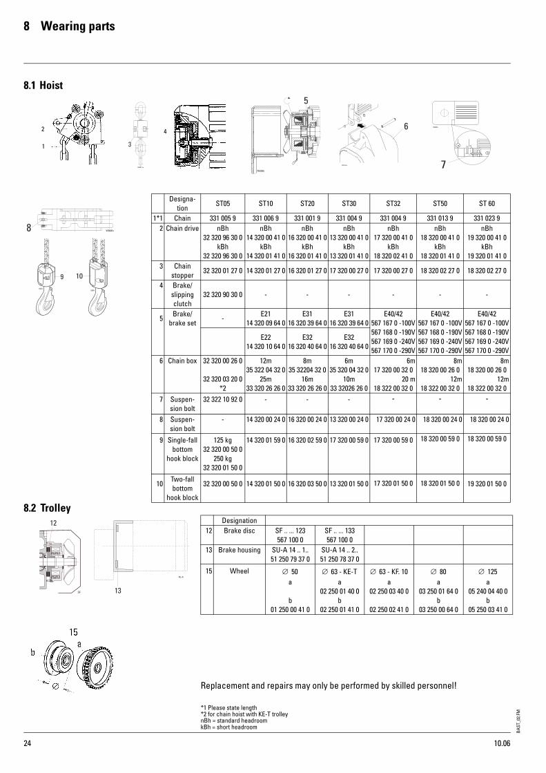
BAST
_02.
FM
24
8 Wearing parts
8.1 Hoist
8.2 Trolley
Replacement and repairs may only be performed by skilled personnel!
42
1
Designa-tion
ST05 ST10 ST20 ST30 ST32 ST50 ST 60
1*1 Chain 331 005 9 331 006 9 331 001 9 331 004 9 331 004 9 331 013 9 331 023 92 Chain drive nBh
32 320 96 30 0kBh
32 320 96 30 0
nBh14 320 00 41 0
kBh14 320 01 41 0
nBh16 320 00 41 0
kBh16 320 01 41 0
nBh13 320 00 41 0
kBh13 320 01 41 0
nBh17 320 00 41 0
kBh18 320 02 41 0
nBh18 320 00 41 0
kBh18 320 01 41 0
nBh19 320 00 41 0
kBh19 320 01 41 0
3 Chain stopper
32 320 01 27 0 14 320 01 27 0 16 320 01 27 0 17 320 00 27 0 17 320 00 27 0 18 320 02 27 0 18 320 02 27 0
4 Brake/slipping clutch
32 320 90 30 0 - - - - - -
5Brake/
brake set-
E2114 320 09 64 0
E3116 320 39 64 0
E3116 320 39 64 0
E40/42567 167 0 -100V567 168 0 -190V567 169 0 -240V567 170 0 -290V
E40/42567 167 0 -100V567 168 0 -190V567 169 0 -240V567 170 0 -290V
E40/42567 167 0 -100V567 168 0 -190V567 169 0 -240V567 170 0 -290V
E2214 320 10 64 0
E3216 320 40 64 0
E3216 320 40 64 0
6 Chain box 32 320 00 26 0
32 320 03 20 0*2
12m35 322 04 32 0
25m33 320 26 26 0
8m35 32204 32 0
16m33 320 26 26 0
6m35 320 04 32 0
10m33 32026 26 0
6m17 320 00 32 0
20 m18 322 00 32 0
8m18 320 00 26 0
12m18 322 00 32 0
8m18 320 00 26 0
12m18 322 00 32 0
7 Suspen-sion bolt
32 322 10 92 0 - - - - - -
8 Suspen-sion bolt
- 14 320 00 24 0 16 320 00 24 0 13 320 00 24 0 17 320 00 24 0 18 320 00 24 0 18 320 00 24 0
9 Single-fall bottom
hook block
125 kg32 320 00 50 0
250 kg32 320 01 50 0
14 320 01 59 0 16 320 02 59 0 17 320 00 59 0 17 320 00 59 0 18 320 00 59 0 18 320 00 59 0
10Two-fall bottom
hook block
32 320 00 50 0 14 320 01 50 0 16 320 03 50 0 13 320 01 50 0 17 320 01 50 0 18 320 01 50 0 19 320 01 50 0
Designation12 Brake disc SF .. ... 123
567 100 0SF .. ... 133567 100 0
13 Brake housing SU-A 14 .. 1..51 250 79 37 0
SU-A 14 .. 2..51 250 78 37 0
15 Wheel ∅ 50a
b01 250 00 41 0
∅ 63 - KE-Ta
02 250 01 40 0 b
02 250 01 41 0
∅ 63 - KF. 10a
02 250 03 40 0
02 250 02 41 0
∅ 80a
03 250 01 64 0b
03 250 00 64 0
∅ 125a
05 240 04 40 0b
05 250 03 41 0
*1 Please state length*2 for chain hoist with KE-T trolleynBh = standard headroomkBh = short headroom
10.06
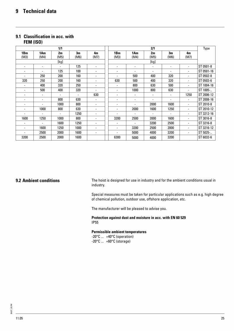
BAST
_02.
FM
25
9 Technical data
9.1 Classification in acc. withFEM (ISO)
9.2 Ambient conditions The hoist is designed for use in industry and for the ambient conditions usual in industry.
Special measures must be taken for particular applications such as e.g. high degree of chemical pollution, outdoor use, offshore application, etc.
The manufacturer will be pleased to advise you.
Protection against dust and moisture in acc. with EN 60 529IP55
Permissible ambient temperatures-20°C ... +40°C (operation)-20°C ... +60°C (storage)
1/1 2/1 Type1Bm(M3)
1Am(M4)
2m(M5)
3m(M6)
4m(M7)
1Bm(M3)
1Am(M4)
2m(M5)
3m(M6)
4m(M7)
[kg] [kg]- - - 125 - - - - - - ST 0501-8- - 125 100 - - - - - - ST 0501-16- 250 200 160 - - 500 400 320 - ST 0502-8
320 250 200 160 - 630 500 400 320 - ST 0503-6- 400 320 250 - - 800 630 500 - ST 1004-16- 500 400 320 - - 1000 800 630 - ST 1005-..- - - - 630 - - - - 1250 ST 2006-12- - 800 630 - - - - - - ST 2008-16- - 1000 800 - - - 2000 1600 - ST 2010-8- 1000 800 630 - - 2000 1600 1250 - ST 2010-12- - - 1250 - - - - - - ST 3212-16
1600 1250 1000 800 - 3200 2500 2000 1600 - ST 3016-8- - 1600 1250 - - - 3200 2500 - ST 3216-8- 1600 1250 1000 - - 3200 2500 2000 - ST 3216-12- 2500 2000 1600 - - 5000 4000 3200 - ST 5025-..
3200 2500 2000 1600 6300 5000 4000 3200 ST 6032-6
11.05

BAST
_02.
FM
26
9 Technical data
9.3 Hoist 9.3.1 Hoist motor data 50Hz
50 HzType Motor
typekW DC
%c/h In Ik cos ϕ k Mains fuse
230V 400V 500V 230V 400V 500V 230 V 400 V 500 V[A] [A]
ST 0501-8ST 0501-8/2ST 0501-16ST 0501-16/4ST 0502-8ST 0502-8/2ST 0503-6ST 0503-6/1
2A042/8A042A04
2/8A042A04
2/8A042A04
2/8A04
0,20,2/0,05
0,40,4/0,1
0,40,4/0,
0,40,4/0
4035/15
4035/15
4035/15
4035/15
240120/240
240120/240
240120/240
240120/240
2,32,3/1,9
2,32,3/1,9
2,32,3/1,9
2,32,3/1,9
1,31,3/1,1
1,31,3/1,1
1,31,3/1,1
1,31,3/1,1
1,01,0/0,9
1,01,0/0,9
1,01,0/0,9
1,01,0/0,9
5,75,7/2,1
5,75,7/2,1
5,75,7/2,1
5,75,7/2,1
3,33,3/1,2
3,33,3/1,2
3,33,3/1,2
3,33,3/1,2
2,62,6/1,0
2,62,6/1,0
2,62,6/1,0
2,62,6/1,0
0,880,88/0,83
0,880,88/0,83
0,880,88/0,83
0,880,88/0,83
66666666
66666666
66666666
ST 1005-8ST 1005-8/2ST 1005-12ST 1005-12/3
2E212/8E212E22
2/8E22
0,80,8/0,2
1,21,2/0,3
6040/20
6040/20
360120/240
360120/240
3,43,7/2,1
5,47,1/3,8
2,02,2/1,2
3,14,1/2,2
1,61,7/1,0
2,53,3/1,8
20,015,8/428,2
20,5/6,8
11,59,1/2,3
14,311,8/3,9
9,27,3/1,8
13,09,4/3,1
0,790,89/0,73
0,850,93/0,77
1061010
6666
6666
ST 2006-12ST 2006-12/3ST 2010-8ST 2010-8/2ST 2010-12ST 2010-12/3
2E312/8E312E31
2/8E312E32
2/8E32
1,51,5/0,37
1,51,5/0,37
2,32,3/0,57
6040/20
6040/20
6040/20
360120/240
360120/240
300120/240
6,36,8/3,7
6,36,8/3,7
9,09,9/5,2
3,63,9/2,1
3,63,9/2,1
5,75,7/3,0
2,93,1/1,7
2,93,1/1,7
4,64,6/2,4
28,925,6/7,3
28,925,6/7,3
55,742,6/10,6
16,614,7/4,2
16,614,7/4,2
24,524,5/6,1
13,311,8/3,4
13,311,8/3,4
19,619,6/4,9
0,820,92/0,80
0,820,92/0,80
0,900,90/0,79
161016102016
1061061010
6666
1010
ST 3016-8ST 3016-8
2E322/8E32
2,32,3/0,57
6040/20
300120/240
9,09,9/5,2
5,75,7/3,0
4,64,6/2,4
55,742,6/10,6
24,524,5/6,1
19,619,6/4,9
0,900,90/0,79
2016
1010
1010
ST 3212-16ST 3212-16/4ST 3216-8ST 3216-8/2ST 3216-12ST 3216-12/3
2E422/8E422E40
2/8E402E42
2/8E42
3,83,8/0,9
2,42,4/0,6
3,83,8/0,9
6033/17
6040/20
6033/17
360100/200
360120/240
360100/200
15,716,0/7,0
9,710,3/5,4
15,716,0/7,0
9,09,2/4,0
5,75,7/3,0
9,09,2/4,0
7,27,4/3,2
4,54,6/2,4
7,27,4/3,2
66,855,7/14,3
55,743,5/10,8
66,855,7/14,3
38,432,0/8,2
25,025,0/6,2
38,432,0/8,2
30,725,6/6,6
25,620,0/5,0
30,725,6/6,6
0,80,86/0,82
0,870,87/0,74
0,800,86/0,82
202020162020
161616101616
161010101610
ST 5025-6ST 5025-6/1ST 5025-8ST 5025-8/2
2E422/8E422E42
2/8E42
3,03,0/0,76
3,83,8/0,9
7040/20
6033/17
420120/240
360100/200
11,112,7/6,9
15,716,0/7,0
7,37,3/3,8
9,09,2/4,0
5,15,8/3,2
7,27,4/3,2
66,855,7/14,3
66,855,7/14,3
38,432,0/8,2
38,432,0/8,2
30,725,6/6,6
30,725,6/6,6
0,800,86/0,82
0,800,86/0,82
20202020
16161616
16101610
ST6032-6/1 2/8E42 3,8/0,9 33/17 100/200 16,0/7,0 9,2/4,0 7,4/3,2 55,7/14, 32,0/8,2 25,6/6,6 0,86/0,82 20 16 10
11.05

BAST
_02.
FM
27
9 Technical data
9.3.2 Hoist motor data 60 Hz
9.4 Trolley 9.4.1 Pole-changing travel motors 50Hz
9.4.2 Pole-changing travel motors 60Hz
60 HzType Motor
typekW DC
%c/h In Ik cos ϕ k Mains fuse
400V 460V 575V 400V 460V 575V 400 V 460 V 575 V[A] [A]
ST 0501-8ST 0501-8/2ST 0501-16ST 0501-16/4ST 0502-8ST 0502-8/2ST 0503-6ST 0503-6/1
2A042/8A042A04
2/8A042A04
2/8A042A04
2/8A04
0,240,24/0,06
0,480,48/0,12
0,480,48/0,12
0,480,48/0,12
4035/15
4035/15
4035/15
4035/15
240180/360
240120/240
240120/240
240120/240
1,61,6/1,3
1,61,6/1,3
1,61,6/1,3
1,61,6/1,3
1,41,4/1,1
1,41,4/1,1
1,41,4/1,1
1,41,4/1,1
1,11,1/0,9
1,11,1/0,9
1,11,1/0,9
1,11,1/0,9
4,04,0/1,5
4,04,0/1,5
4,04,0/1,5
4,04,0/1,5
3,53,5/1,3
3,53,5/1,3
3,53,5/1,3
3,53,5/1,3
2,82,8/1,0
2,82,8/1,0
2,82,8/1,0
2,82,8/1,0
0,880,88/0,83
0,880,88/0,83
0,880,88/0,83
0,880,88/0,83
66666666
66666666
66666666
ST 1005-8ST 1005-8/2ST 1005-12ST 1005-12/3
2E212/8E212E22
2/8E22
0,960,96/0,24
1,41,4/0,36
6040/20
6040/20
360120/240
360120/240
2,22,5/1,4
3,64,7/2,5
2,02,2/1,2
3,14,1/2,2
1,61,7/1,0
2,53,3/1,8
13,210,5/2,6
18,613,6/4,5
11,59,3/2,3
16,211,8/3,9
9,27,3/1,8
13,09,4/3,1
0,790,89/0,73
0,850,93/0,77
66106
6666
6666
ST 2006-12ST 2006-12/3ST 2010-8ST 2010-8/2ST 2010-12ST 2010-12/3
2E312/8E312E31
2/8E312E32
2/8E32
1,81,8/0,44
1,81,8/0,44
2,82,8/0,68
6040/20
6040/20
6040/20
360120/240
360120/240
360120/240
4,14,5/2,4
4,14,5/2,4
6,66,6/3,5
3,63,9/2,1
3,63,9/2,1
5,75,7/3,0
2,93,1/1,7
2,93,1/1,7
4,14,6/2,4
19,116,9/4,8
19,116,9/4,8
28,228,2/7,0
16,614,7/4,2
16,614,7/4,2
24,524,5/6,1
13,311,8/3,4
13,311,8/3,4
25,619,6/4,9
0,820,92/0,80
0,820,92/0,80
0,900,90/0,79
101010101010
1061061010
66661010
ST 3016-8ST 3016-8
2E322/8E32
2,82,8/0,68
6040/20
360120/240
6,66,6/3,5
5,75,7/3,0
4,14,6/2,4
28,228,2/7,0
24,524,5/6,1
25,619,6/4,9
0,900,90/0,79
1010
1010
1010
ST 3212-16ST 3212-16/4ST 3216-8ST 3216-8/2ST 3216-12ST 3216-12/3
2E422/8E422E40
2/8E402E42
2/8E42
4,64,6/1,1
2,92,9/0,72
4,64,6/1,1
6033/17
6040/20
6033/17
360100/200
360120/240
360100/200
10,410,6/4,6
6,46,6/3,5
10,410,6/4,6
9,09,2/4,0
5,65,5/3,0
9,09,2/4,0
7,27,4/3,2
4,54,6/2,4
7,27,4/3,2
44,236,8/9,4
36,828,8/7,1
44,236,8/9,4
38,432,0/8,2
32,025,0/6,2
38,432,0/8,2
30,725,6/6,6
25,620,0/5,0
30,725,6/6,6
0,800,86/0,82
0,870,87/0,74
0,800,86/0,82
161616161616
161616101616
161610101616
ST 5025-6ST 5025-6/1ST 5025-8ST 5025-8/2
2E422/8E422E42
2/8E42
3,63,6/0,91
4,64,6/1,1
7040/20
6033/17
420120/240
360100/200
7,48,4/4,4
10,410,6/4,6
6,47,3/3,8
9,09,2/4,0
5,15,8/3,0
7,27,4/3,2
44,236,8/9,4
44,236,8/9,4
38,432,0/8,2
38,432,0/8,2
30,725,6/6,6
30,725,6/6,6
0,780,78/0,49
0,800,86/0,82
16161616
16161616
16161616
ST 6032-6/1 2/8E42 4,6/1,1 33/17 100/200 10,6/4,6 9,2/4,0 7,4/3,2 36,8/9,4 32,0/8,2 25,6/6,6 0,86/0,82 16 16 16
50 HzType Motor
TypkW ED
%c/h In Ik cos ϕ k Mains fuse
230V 400V 500V 230V 400V 500V 230 V 400 V 500 V[A] [A]
SU-A 2/8A04 0,07/0,32 20/40 - 1,9/2,1 1,1/1,2 0,9/1,0 2,1/5,6 1,2/3,2 1,0/2,6 0,84/0,89 - - -SF 14 8/2F12 0,09/0,37 20/40 - 1,7/2,3 1,0/1,3 0,8/1,0 2,4/5,6 1,4/3,2 1,1/2,6 0,74/0,9 - - -
60 HzType Motor
TypkW ED
%c/h In Ik cos ϕ k Mains fuse
400 460V 575V 400V 460V 575V 400 V 460 V 575 V[A] [A]
SU-A 2/8A04 0,09/0,38 20/40 - 1,3/1,4 1,2/1,3 0,9/1,0 1,4/3,7 1,3/3,5 1,0/2,6 0,84/0,89SF 14 8/2F12 0,11/0,44 20/40 - 1,2/1,5 1,0/1,3 0,8/1,0 1,6/3,7 1,4/3,2 1,1/2,6 0,76/0,89 - - -
11.05

BAST
_02.
FM
28
9 Technical data
9.5 Specifications for mains connecction
Specifications for mains connection• All poles of the mains cable must be disconnected by a lockable switch.• The mains voltage must correspond to that stated on the rating plate.• Fixed installed cables e.g. NYM, NYY• Flexible cables e.g. RN-F, NGFLGöu, H07VVH2-F• Cable cross-section min. 1.5 mm2
• Mains voltage 380-415 VAC, 50 Hz Other mains voltages are available as options.• In accordance with EN 50014 a radio interference suppression module FEM1 must
be installed for all motors ≤1 kW• If a current-operated circuit-breaker is used, a fault current of approx. 17 mA must
be taken into account for each FEM1.
9.5.1 Max. length of supply cable
* Allocation to chain hoists see "Motor data" table*1 Voltage drop 2.5%*2 Voltage drop 1.5%*3 Voltage drop 5.0%*4 Voltage drop 4.0%
Direct control
50 Hz Max. cable length with direct control [m]Chain hoist Stationary *1 With trolley along runway *2
Connecting cable cross-section 1.5 mm² 2.5 mm² 1.5 mm² 2.5 mm²230 V 400 V 500 V 230 V 400 V 500 V 230 V 400 V 500 V 230 V 400 V 500 V
Hois
t mot
or ty
pe*
2A042/8A04 57 170 269 94 283 - 29 80 120 49 - -
2E218/2E21
1718
5055
7987
2831
8492
131144
1011
3033
4752
1718
5055
7987
2E228/2E22
1314
3842
6065
2123
6470
99109
88
2325
3639
1314
3842
6065
2E318/2E31
1111
3434
5353
1919
5757
8989
77
2121
3232
1111
3434
5353
Schützsteuerung50 Hz Max. Leitungslänge bei Schützsteuerung [m]
Kettenzug Stationär *3 mit Fahrwerk entlang der Laufbahn *4Anschlussquerschnitt 1,5 mm² 2,5 mm² 1,5 mm² 2,5 mm²
230 V 400 V 500 V 230 V 400 V 500 V 230 V 400 V 500 V 230 V 400 V 500 V
Hubm
otor
Typ
e*
2A048/2A04
113 340 531 - - - 71 214 334 118 - -
2E218/2E21
3640
109122
170190
6067
181203
283317
2729
8189
126139
4449
134148
210231
2E228/2E22
2730
8190
112141
4550
135150
121234
2022
6167
96104
3437
102111
159174
2E318/2E31
2424
7373
113114
4040
121122
189190
1818
5555
8686
3030
9191
143142
2E328/2E32
-15
4545
6070
2125
7575
99117
-11
3434
4654
1619
5757
7790
2E408/2E40
-15
4545
6271
2225
6676
103118
-12
3135
4855
1719
5858
8091
2E428/2E42
--
3236
5056
1820
5460
9393
--
2528
4343
1415
4246
7272
11.05

BAST
_02.
FM
29
9 Technical data
9.5.2 Max. length of supply cable
* Allocation to chain hoists see "Motor data" table*1 Voltage drop 2.5%*2 Voltage drop 1.5%*3 Voltage drop 5.0%*4 Voltage drop 4.0%
Direct control
60 Hz Max. cable length with direct control [m]Chain hoist Stationary *1 With trolley along runway *2
Connecting cable cross-section 1.5 mm² 2.5 mm² 1.5 mm² 2.5 mm²230 V 400 V 460 V 230 V 400 V 460 V 230 V 400 V 460 V 230 V 400 V 460 V
Hois
t mot
or ty
pe*
2A042/8A042E21
8/2E211416
4448
5864
2427
7380
97106
910
2629
3538
1416
4448
5864
2E228/2E22
1212
3036
3948
2020
4961
6580
77
1822
2329
1212
3036
3948
2E318/2E31
1010
3030
4040
1616
5050
6666
66
1818
2424
1010
3030
4040
Contactor control
60 Hz Max. cable length with contactor control [m]Chain hoist Stationary *3 With trolley along runway *4
Connecting cable cross-section 1.5 mm² 2.5 mm² 1.5 mm² 2.5 mm²400 V 460 V 575 V 400 V 460 V 575 V 400 V 460 V 575 V 400 V 460 V 575 V
Hois
t mot
or ty
pe*
2A048/2A04
113 340 531 - - - 71 214 334 118 - -
2E218/2E21
3640
109122
170190
6067
181203
283317
2729
8189
126139
4449
134148
210231
2E228/2E22
2730
8190
112141
4550
135150
121234
2022
6167
96104
3437
102111
159174
2E318/2E31
2424
7373
113114
4040
121122
189190
1818
5555
8686
3030
9191
143142
2E328/2E32
-15
4545
6070
2125
7575
99117
-11
3434
4654
1619
5757
7790
2E408/2E40
-15
4545
6271
2225
6676
103118
-12
3135
4855
1719
5858
8091
2E428/2E42
--
3236
5056
1820
5460
9393
--
2528
4343
1415
4246
7272
11.05
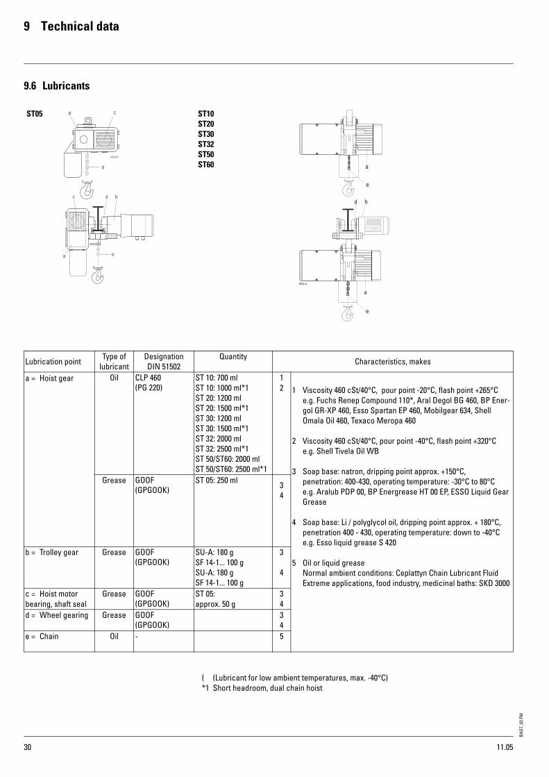
BAST
_02.
FM
30
9 Technical data
9.6 Lubricants
( (Lubricant for low ambient temperatures, max. -40°C)*1 Short headroom, dual chain hoist
ST05 ST10ST20ST30ST32ST50ST60
Lubrication point Type of lubricant
DesignationDIN 51502
Quantity Characteristics, makes
a = Hoist gear Oil CLP 460(PG 220)
ST 10: 700 mlST 10: 1000 ml*1ST 20: 1200 mlST 20: 1500 ml*1ST 30: 1200 mlST 30: 1500 ml*1ST 32: 2000 mlST 32: 2500 ml*1ST 50/ST60: 2000 ml ST 50/ST60: 2500 ml*1
12 1 Viscosity 460 cSt/40°C, pour point -20°C, flash point +265°C
e.g. Fuchs Renep Compound 110*, Aral Degol BG 460, BP Ener-gol GR-XP 460, Esso Spartan EP 460, Mobilgear 634, Shell Omala Oil 460, Texaco Meropa 460
2 Viscosity 460 cSt/40°C, pour point -40°C, flash point +320°Ce.g. Shell Tivela Oil WB
3 Soap base: natron, dripping point approx. +150°C,penetration: 400-430, operating temperature: -30°C to 80°Ce.g. Aralub PDP 00, BP Energrease HT 00 EP, ESSO Liquid Gear Grease
4 Soap base: Li / polyglycol oil, dripping point approx. + 180°C,penetration 400 - 430, operating temperature: down to -40°Ce.g. Esso liquid grease S 420
5 Oil or liquid greaseNormal ambient conditions: Ceplattyn Chain Lubricant FluidExtreme applications, food industry, medicinal baths: SKD 3000
Grease GOOF(GPGOOK)
ST 05: 250 ml 34
b = Trolley gear Grease GOOF(GPGOOK)
SU-A: 180 gSF 14-1... 100 gSU-A: 180 gSF 14-1... 100 g
3
4
c = Hoist motor bearing, shaft seal
Grease GOOF(GPGOOK)
ST 05: approx. 50 g
34
d = Wheel gearing Grease GOOF(GPGOOK)
34
e = Chain Oil - 5
11.05

BAST
_02.
FM
31
9 Technical data
9.7 Sound pressure level HoistSound level at 1 m from chain hoist, averaged out for an operating cycle of 50% with rated load and 50% without load.
Travel drivesThe sound pressure level was measured at a distance of 1 m from the crane. The mean noise level calculated for one operating cycle (50% with nominal load, 50% without load) can be seen from the tables.
Instead of stating an emission value based on a workplace, the values from the tables at measuring distance "h" can be used.
Indoors
Outdoors
9.8 Chain certificate
*1 Tractive force on chain*2 Test load*3 Minimum breaking load
Typ [dB A]ST05 - ST 60 74
Travel drive type
[db (A)] + / - 3h [m]
1 m 2 m 4 m 8 m 16 mSU-A .. 78 75 72 69 66
SF .. 2.. ... 72 69 66 66 63SF .. 8.. ... 78 75 72 69 66
Travel drive type
[db (A)] + / - 3h [m]
1 m 2 m 4 m 8 m 16 mSU-A .. 78 72 66 60 54
SF .. 2.. ... 72 66 60 54 48SF .. 8.. ... 78 72 66 60 54
W0923
Order No.
1/1 2/1
[mm] [kg] [kN] [kN] 3[m]
ST 05ST 10ST 20ST 30ST 32ST 50ST 60
45799
11.311,3
331 005 9331 006 9331 001 9331 004 9331 004 9331 013 9331 023 9
32050010001600160025003200
12,520406363100100
203260100100160160
HW + 0,3HW + 0,5HW + 0,6HW + 0,6HW + 0,7HW + 0,7HW + 0,7
2xHW + 0,42xHW + 0,62xHW + 0,72xHW + 0,82xHW + 1,02xHW + 1,02xHW + 1,0
*1 *2 *3
10.06

Vertriebspartnersales partner
Tochtergesellschaftsubsidiary
Europe T F E
Austria Steyregg +43 732 641111-0 +43 732 641111-33 [email protected]
France Paris +33 1 39985060 +33 1 34111818 [email protected]
Great Britain Birmingham +44 121 7676414 +44 121 7676490 [email protected]
Italy S. Colombano +39 0185 358391 +39 0185 358219 [email protected]
Netherlands EL Haarlem +31 23 51252-20 +31 23 51252-23 [email protected]
Portugal Lissabon +351 21 44471-61 +351 21 44471-69 [email protected]
Spain Madrid +34 91 484-0865 +34 91 490-5143 [email protected]
Switzerland Frick +41 62 82513-80 +41 62 82513-81 [email protected]
America/Asia T F E
China Shanghai +86 21 6257 2211 +86 21 6254 1907 [email protected]
India Chennai +91 44 4352-3955 +91 44 4352-3957 [email protected]
Singapore Singapore +65 6271 2220 +65 6377 1555 [email protected]
U.A.E. Dubai +971 4 805-3700 +971 4 805-3701 [email protected]
USA Charleston, SC +1 843 767-1951 +1 843 767-4366 [email protected]
F-B
A-1
.8-E
N-0
1.08
-mp
STAHL CraneSystems GmbH, Daimlerstr. 6, 74653 Künzelsau, GermanyTel +49 7940 128-0, Fax +49 7940 55665, [email protected]


- 1 / 5 - MB_SiC0-HF_EN
08.2006
Installation and operating instructions for hand controlled travelling bogies SiC0-HF 08.2006 EN Installation shall only be carried out by companies specialising in this work and/or by experienced persons! In case of doubt, please contact your supplier. 1. Technical data Type SiC0-HF 500 1000 2000
A o A o B o A o B o Girder width min. mm
max. mm 50 - 220
58 - 150
221- 305
66 - 220
221- 305
Load-bearing capacity kg 500 1000 2000 Max. weight of hoist kg 70 110 150 Max. horizontal width of eye mm 25 30 40 Max. vertical width of eye mm 30 35 45 Min. curve radius: m 0,9 1,0 1,2 Max. flange thickness mm 34 30 30 Dead weight kg 7 11 12 17 18 Permissible ambient temperature: - 15° to + 45° C Classification DIN 15018 Loading group 1Cm 2. Description Hand controlled travelling bogies may be used with hoists provided with a suspension hook with
safety catch, with suitable double hook eyes or with suitable suspension arms. Hand controlled travelling bogies can be easily and flexibly adapted to girder flanges of different
widths. The lateral plates of the hand controlled travelling bogies are fitted with protection devices to
allow safe access for operators and to prevent them from falling down. These travelling bogies use single-axle bogies with a lifting beam with an eye which can be
easily mounted. The travelling bogies are suitable for girders with parallel flanges and for girders with a
maximum flange taper of 14%. The turned rollers which run on ball bearings are encapsulated and permanently lubricated. The travelling bogies are finished with a black coating similar to RAL 9004, thickness approx.
30µ. When intended for outdoor use, it is recommend that an additional protective coating is applied and a shed provided to give protection. The lifting beam is galvanized.
3. Duties of the operator The operator shall select and design an appropriate supporting structure. Before commissioning, the operator shall ensure that the travel path is equipped with suitable
and effective end stops, e.g buffers for UNI-type trolleys. The travel path shall be horizontal.

- 2 / 5 - MB_SiC0-HF_EN
08.2006
The maximum weight of the hoist including any additional structures must be taken into account.
The same applies to the load-bearing capacity related to the different widths of the girder flanges. The information on the nameplate is definitive.
The operator shall arrange for an inspection prior to commissioning and for subsequent periodic
inspections.. 4. Installation Hand controlled travelling bogies consist of the following components: 1 lifting beam with eye 2 lateral plates with rollers 2 covers for protruding thread portions of the lifting beam. One side of the lifting beam is marked "L" (left-hand thread). The socket on the outside of one
lateral plate of the hand travelling bogie, in which the lifting beam must be inserted, is also marked "L" (left-hand thread).
Attention! The end of the lifting beam marked "L" must be inserted into the travelling bogie which is also
marked "L" on the outside socket (insertion depth: approx. 3 mm) The second lateral plate must be inserted into the free end of the lifting beam. The depth of
insertion must be the same as that for the first lateral plate. Turn the lifting beam to insert it deeper into the lateral plates until the dimension corresponding
to the width of the girder flange is reached. Place the travelling bogie onto the girder of the travel path so that the rollers are supported on
the lower girder flange. The space between the rollers and the girder flange can be adjusted by turning the lifting beam.
The dimension between the wheel flanges and the girder flange shall preferably be between
1 mm and 1.5 mm but should not exceed 2 mm. The centres of the eye of the lifting beam and of the girder web must correspond, and the
distance to the lateral plates must be the same. After correct adjustment the eyelet should be vertical. Then suspend the hook of the travelling bogie in the eye. Grease the thread of the lifting beam. Cut the covers to length and place them over the
protruding thread portions. 5. Commissioning - operating mode Carefully observe the operating instructions and observe them. Only use original components for repair or replacement. Failing this, no claims will be accepted! Check whether the travel path has the right dimensions for the hand controlled travelling bogie
and that it has the required load-carrying capacity. Check that the installation instructions have been observed. Make sure that the width of the travelling bogie corresponds to the width of the girder flange. Make sure that the travel path is equipped with suitable end stops.

- 3 / 5 - MB_SiC0-HF_EN
08.2006
Check before commissioning that all safety rules and rules for the prevention of accidents have been observed.
Only use the hand controlled travelling bogie for its intended use and at normal ambient
temperatures. In order to move the hand controlled travelling bogie, pull or push the lifting hook or the load
along the travel path. Never push or pull it in transverse direction to the travel path. Never pull it in an oblique direction.
Only move the hand controlled travelling bogie with the hook suspended in the eye, otherwise
the track may not be properly adjusted. Do not modify the hand controlled travelling bogie. Do not remove end stops or interfere with safety devices. Do not tilt the load intentionally. Do not create violent shocks when moving the hand controlled travelling bogie. Do not transport loads heavier than those specified on the nameplate. Do not use the hand controlled travelling bogie for carrying people! Do not transport molten products! 6. Putting out of operation Only use the hand controlled travelling bogie when it is in good condition. When the bogie and hoist are not in use, or in case of a heavy storm, they should be brought to
their home position. The trolley buffer (if any) should be locked, the system should be switched off and protected against any unauthorised use.

- 4 / 5 - MB_SiC0-HF_EN
08.2006
Travelling bogies SiC0-HF 500/1000/2000 for girder widths 50/58/66 mm – 305 mm
SiCC-Hoist
SiXX-Hoist

- 5 / 5 - MB_SiC0-HF_EN
08.2006
Type
: S
iC0-
HF
500
100
0
20
00
A
A
B
A
B
G
irder
wid
th
m
in. m
m
5
0-
58-
2
21-
66-
2
21-
m
ax.
mm
220
22
0
305
22
0
305
Load
-bea
ring
capa
city
kg
5
00
1
000
2
000
Max
. wei
ght o
f hoi
st
kg
70
110
150
M
ax. h
oriz
onta
l wid
th o
f eye
mm
25
30
4
0 M
ax. v
ertic
al w
idth
of e
ye
mm
30
35
45
M
in. c
urve
radi
us
m
0,9
1,0
1
,2
Max
. fla
nge
thic
knes
s
mm
34
30
30
D
ead
wei
ght
k
g
7
11
1
2
17
1
8

C E - D e c l a r a t i o n o f C o n f o r m i t y / C E - M a n u f a c t u r e r ’ s D e c l a r a t i o n acc. to the sense of EC-Directive concerning machines 98/37/EEC We declare with sole responsibility that the product Gravity-Balancer Type 7231/1 Year of constr.: 2009 is developed constructed and manufactured in compliance with EC directive 98/37/EEC dated 22.06.1998. Coordinated standards applied:
DIN EN ISO 12100 Part 1 und 2 Safety of Machinery
National standards applied:
DIN 15112 Gravity Balancer
If this product is to be installed in a machine, the initial operation of the product is prohibited until it is established that the machine complies with the provisions of the EC machinery directive and the standards to be applied. VETTER Krantechnik GmbH Siegtalstraße 22 57080 Siegen Siegen, 17.08.2009
N. Hammes ppa. Truß Manager Technical manager ------------------------------------------------------------ (Signature)


2022-D018080 05
2022-D018080 Revision: 05
SK+/SPK+
Operating Manual

SK+/SPK+
2022-D018080 Revision: 05
Revision history
Revision Date Comment Chapter1 15.02.2005 New Version All
2 17.06.2005 2-stage gearhead All
3 15.02.2006 SPK+ All
4 31.01.2008 ANSI, Layout 07 All
5 01.07.08 Layout WITTENSTEIN All
ServiceIn case you have technical questions, please contact:WITTENSTEIN alpha GmbHCustomer ServiceWalter-Wittenstein-Straße 1D-97999 Igersheim
Tel.: +49 7931 493-10900
Fax: +49 7931 493-10903E-mail: [email protected]
© WITTENSTEIN alpha GmbH 2008This documentation is copyright protected.WITTENSTEIN alpha GmbH reserves all the rights to photo-mechanical reproduction, copying, and the distribution by special processes (such as computers, file media, data networks), even in parts.Subject to technical and content changes without notice..

SK+/SPK+
Revision: 05 2022-D018080 en-1
Contents1 On this manual .....................................................................................................2
1.1 Signal words ........................................................................................................21.2 Safety symbols.....................................................................................................21.3 Information symbols.............................................................................................3
2 Safety.....................................................................................................................42.1 EC – Machinery directive .....................................................................................42.2 Dangers ...............................................................................................................42.3 Personnel .............................................................................................................42.4 Intended use ........................................................................................................42.5 Guarantee and Liability ........................................................................................42.6 General safety instructions ..................................................................................5
3 Description of the gearhead................................................................................63.1 General Information .............................................................................................63.2 Type plate ............................................................................................................63.3 Ordering code ......................................................................................................73.4 Performance statistics..........................................................................................73.5 Weight..................................................................................................................7
4 Transport and storage .........................................................................................84.1 Scope of delivery .................................................................................................84.2 Packaging ............................................................................................................84.3 Transport..............................................................................................................8
4.3.1 Transport of gearheads up to and including size SK+/SPK+ 140 ....................84.3.2 Transport of gearheads as of size SK+/SPK+ 180 ..........................................8
4.4 Storage ................................................................................................................85 Assembly ..............................................................................................................9
5.1 Preparation ..........................................................................................................95.2 Mounting the motor onto the gearhead..............................................................105.3 Mounting gearhead on a machine .....................................................................115.4 Mounting on the output side...............................................................................11
6 Startup and operation ........................................................................................127 Maintenance and disposal.................................................................................13
7.1 Maintenance work..............................................................................................137.1.1 Visual inspection ...........................................................................................137.1.2 Checking the tightening torques....................................................................13
7.2 Startup after maintenance work .........................................................................137.3 Maintenance schedule .......................................................................................137.4 Notes on the lubricant used ...............................................................................147.5 Supplementary information ................................................................................14
8 Malfunctions .......................................................................................................159 Appendix .............................................................................................................16
9.1 Specifications on mounting onto a motor ...........................................................169.1.1 Specifications for the SK+ version .................................................................169.1.2 Specifications for the SPK+ version...............................................................17
9.2 Specifications on mounting onto a machine ......................................................179.3 Tightening torques for common thread sizes in general mechanics..................18
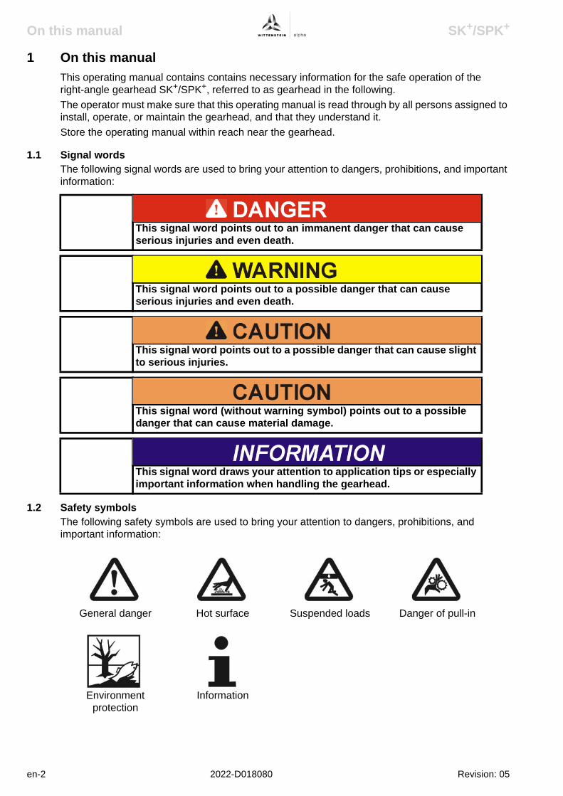
On this manual SK+/SPK+
1 On this manualThis operating manual contains contains necessary information for the safe operation of the right-angle gearhead SK+/SPK+, referred to as gearhead in the following.The operator must make sure that this operating manual is read through by all persons assigned to install, operate, or maintain the gearhead, and that they understand it.Store the operating manual within reach near the gearhead.
1.1 Signal wordsThe following signal words are used to bring your attention to dangers, prohibitions, and important information:
1.2 Safety symbolsThe following safety symbols are used to bring your attention to dangers, prohibitions, and important information:
This signal word points out to an immanent danger that can cause serious injuries and even death.
This signal word points out to a possible danger that can cause serious injuries and even death.
This signal word points out to a possible danger that can cause slight to serious injuries.
This signal word (without warning symbol) points out to a possible danger that can cause material damage.
This signal word draws your attention to application tips or especially important information when handling the gearhead.
General danger Hot surface Suspended loads Danger of pull-in
Environment protection
Information
en-2 2022-D018080 Revision: 05

SK+/SPK+ On this manual
1.3 Information symbolsThe following information symbols are used: requires you to carry out an action indicates the results of an actionprovides additional information on handling
Revision: 05 2022-D018080 en-3

Safety SK+/SPK+
2 SafetyThis operating manual, especially the safety instructions and the rules and regulations valid for the operating site, must be observed by all persons working with the gearhead.In addition to the safety specifications mentioned in the operating manual, the general and also the local regulations on the prevention of accidents and on environmental protection should be observed.
2.1 EC – Machinery directiveWithin terms of the EC - machinery directive 2006/42/EC, the gearhead is not considered as an autonomous machine, but as a “component to install in machines”.Operation is prohibited within the area of validity of the EC directive until it has been determined that the machine in which this gearhead is installed corresponds to the regulations within this directive.
2.2 DangersThe gearhead has been constructed according to current technological standards and accepted safety regulations. To avoid danger to the operator or damage to the machine, the gearhead may be put to use only for its intended usage (see chapter 2.4 "Intended use") and in a technically flawless and safe state.
2.3 PersonnelOnly persons who have read and understood this operating manual may carry out work on the gearhead.
2.4 Intended useThe gearhead is suitable for all industrial applications that do not come under article 2 of the EC directive 2002/95/EC (usage restriction of certain dangerous materials in electrical and electronic equipment).The gearhead is specified for installment on motors that:
- correspond to the design B5 (for any divergences, please consult our Customer Service Department [Technical Customer Service]).
- show a radial and axial runout tolerance of at least “N” according to DIN 42955 and- have a smooth shaft.
2.5 Guarantee and LiabilityGuarantee and liability claims are excluded for personal injury and material damage if the claims derive from one or more of the following causes:
- improper use- improper assembly/disassembly or improper operation- operation of the gearhead when safety devices and equipment are defective- operation of a heavily soiled gearhead- non-observance of information on transport and storage- modifications or reconstructions that have been carried out without the written authorisation of
WITTENSTEIN alpha GmbH- improper or neglected maintenance and repair
en-4 2022-D018080 Revision: 05

SK+/SPK+ Safety
2.6 General safety instructions
Objects flung out by rotating components can cause serious injuries. Remove objects and tools from the gearhead before putting it into
operation.
Rotating components on the gearhead can pull in parts of the body and cause serious injuries and even death. Keep a sufficient distance to rotating machinery while the gearhead is
running.
Hot gearhead housing can cause serious burns. Touch the gearhead housing only when wearing protective gloves or
after the gearhead has been idle for some time.
Solvents can pollute soil and water. Use and dispose of cleaning solvents appropriately.
Revision: 05 2022-D018080 en-5

Description of the gearhead SK+/SPK+
3 Description of the gearhead
3.1 General InformationThe gearhead is a one- or multistage, low-backlash right-angle gearhead, which is manufactured as standard in the “M” version (motor installation).Various planetary gearhead can be integrated on the drive side (SK+) as well as the gear output side (SPK+).Motor centring is performed:
- up to gearhead size SK+ 100 and a motor shaft diameter of 28 mm of through the clamping hub (plug receptacleand coupling).
- from gearhead size SK+ 140 and a motor shaft diameter of > 28 mm through the centring collar of the motor
Avoid a radial distortion of the motor.Adaptation to various motors is done through an adaptor plate and a spacer sleeve.The gearhead has been designed to compensate for thermal linear expansion of the motor shaft.
3.2 Type plateThe type plate is attached to the gearhead housing.
The output shaft is available in the following types: smooth face with feather key groove (according to DIN 6885) involute (according to DIN 5480).
DesignationA Ordering key (see chapter 3.3
"Ordering code")
B Ratio
C Series number
D Lubricant
Tbl-1: Type plate (sample values)
WITTENSTEIN alpha GmbH - Walter-Wittenstein-Str.1 - 97999 Igersheim
SK+ 100S-MF1-10 -0H1
SN: 1234567
Lubricated for Life: Oil Tribol 800/220
DMF: 31/08 Made in Germany
i = 10
A BD
C
en-6 2022-D018080 Revision: 05

SK+/SPK+ Description of the gearhead
3.3 Ordering code
3.4 Performance statisticsPlease refer to our catalogue or our Internet page at http://www.wittenstein-alpha.de for the maximum permitted speeds and torques.
3.5 WeightThe table "Tbl-2" specifies the gearhead dimensions with medium-sized adaptor plate. If another adaptor plate is mounted, the actual dimensions can deviate by up to 10%.
Please consult our service department if your gearhead is older than a year. You will then receive the valid performance data.
Gearhead size SK+ 060 075 100 140 1801–stage [kg] 2,9 4,8 9,3 22,6 45,4
2–stage [kg] 3,2 5,4 10 25 48
Gearhead size SPK+ — 075 100 140 1802–stage [kg] — 5,2 9,7 20 45
3–stage [kg] — 5,5 10,3 20,7 47,4
Tbl-2: Weight
Gearhead typeSK /SPK 060/075/100/140/180
+ +
Design codeS = Standard
X = Special gearhead
Gearhead versionsM = Motor-mounted gearhead
Gearhead designF = Standard
Stage number1 = 1 stage
2 = 2 stage
3 = 3 stage
Ratio i
Form of output shaft0 = Smooth shaft
1 = Key DIN 6885 Form A
2 = Involute: DIN 5480
4 = Other
Backlash0 = Reduced
1 = Standard
Bore diameters of theclamping hubSee catalogue
SK+100S-MF1-10-0H1
Revision: 05 2022-D018080 en-7

Transport and storage SK+/SPK+
en-8 2022-D018080 Revision: 05
4 Transport and storage
4.1 Scope of delivery Check the completeness of the delivery against the delivery note.
Missing parts or damage must be notified immediately in writing to the carrier the insurance, or WITTENSTEIN alpha GmbH.
4.2 PackagingThe gearhead is delivered packed in foil and cardboard boxes. Dispose of the packaging materials at the recycling sites intended for this purpose. Observe
the locally valid regulations for disposals.
4.3 Transport
For specifications on the weights see Chapter 3.5 "Weight".
4.3.1 Transport of gearheads up to and including size SK+/SPK+ 140No special transport mode is prescribed for transporting the gearhead.
4.3.2 Transport of gearheads as of size SK+/SPK+ 180For gearheads as of size SK+/SPK+ 180 a support bore (A) is provided for a ring screw (e.g. acc. to DIN 580). The ring screw is used for secure attachment to hoisting equipment.
4.4 StorageStore the gearhead in horizontal position and dry surroundings at a temperature of 0 °C to +30 °C in the original packaging. Store the gearhead for a maximum of 2 years.For storage logistics we recommend the “first in – first out” principle.
Impacts caused for instance by dropping or setting down too quickly may damage the gearhead. Use only hoisting equipment and transportation devices with sufficient
capacity. The permitted lifting weight of a hoist may not be exceeded. Lower the gearhead slowly.
Suspended loads may fall and cause serious injuries and even death. Do not stand under suspended loads.
Gearhead size SK+/SPK+
Support bore (A) [Ø] x depth [mm]
180 M8 x 14
Tbl-3: Support bore on the gearhead

SK+/SPK+ Assembly
5 Assembly
5.1 Preparation
Clean/de-grease the following gearhead components with a clean and lint-free cloth and grease-dissolving, non-aggressive detergent:- all fitting surfaces to neighbouring components- centring- the motor shaft- only the inside diameter of the clamping hub- the spacer sleeve (if provided) inside and out
Check the fitting surfaces in addition for damage and foreign bodies.
Loose or overloaded screw connections can damage the gearhead. Use a calibrated torque wrench to tighten and check all screw
connections for which a tightening torque has been specified.
Intensive distortions when assembling the motor (e.g. for motors with shaft shoulder, extensive chamfer radius or longer shafts than permitted for the gearhead) can damage the gearhead and the motor. Check the interfering edges by measuring, or by a measurement check
based on our catalogue specifications and the information of the motor manufacturer.
Contact our Customer Service Department.
Pressurised air can damage the gearhead. Do not use pressurised air to clean the gearhead.
Directly sprayed cleaning agents can alter the frictional values of the clamping hub. Only spray cleaning agents onto a cloth, with which you can then clean
the clamping hub.
Revision: 05 2022-D018080 en-9

Assembly SK+/SPK+
5.2 Mounting the motor onto the gearhead
Apply screw-bonding agent to the four screws (e.g. Loctite 243). Fasten the motor (A) onto the adaptor plate (B) with the four screws. Tighten the clamping bolt (H) of the clamping hub (I).
For screw sizes and specified torques refer to chapter 9.1 "Specifications on mounting onto a motor", tables "Tbl-10" and "Tbl-11".
Screw in plug (D) of the adaptor plate (B).For screw sizes and specified torques refer to table "Tbl-5".
If the motor shaft has a feather key, remove the feather key.
If recommended by the motor manufacturer, apply a half wedge.
Remove the plug (D) from the mounting bore in the adaptor plate (B).
Turn the clamping hub (I) until the clamping bolt (H) can be reached over the mounting bore.
Release the clamping bolt (H) of the clamping hub (I) with one revolution.
Push the motor shaft into the clamping hub of the gearhead.
The motor shaft should slip in easily. If this is not the case, the clamping bolt must be loosened more.A slotted spacer sleeve has to be installed extra for certain motor shaft diameters and applications.The slot of the spacer sleeve (if provided) and clamping hub have to be flush with the groove (if provided) of the motor shaft, see table "Tbl-4".No gap is premitted between motor (A) and the adaptor plate (B).
DesignationH Clamping bolt
I Clamping hub
J Spacer sleeve
K Grooved shaft
L Smooth shaft
Tbl-4: Arrangement of motor shaft, clamping hub and spacer sleeve
A
B
C
D
en-10 2022-D018080 Revision: 05
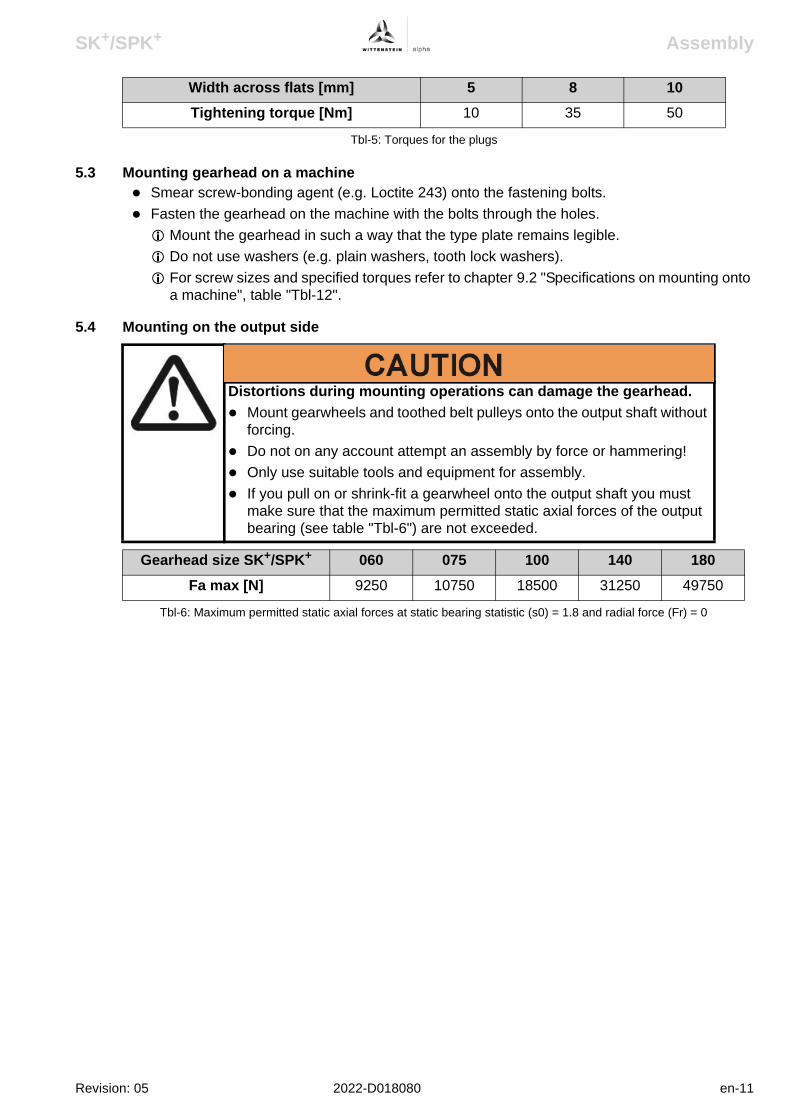
SK+/SPK+ Assembly
5.3 Mounting gearhead on a machine Smear screw-bonding agent (e.g. Loctite 243) onto the fastening bolts. Fasten the gearhead on the machine with the bolts through the holes.
Mount the gearhead in such a way that the type plate remains legible.Do not use washers (e.g. plain washers, tooth lock washers).For screw sizes and specified torques refer to chapter 9.2 "Specifications on mounting onto a machine", table "Tbl-12".
5.4 Mounting on the output side
Width across flats [mm] 5 8 10Tightening torque [Nm] 10 35 50
Tbl-5: Torques for the plugs
Distortions during mounting operations can damage the gearhead. Mount gearwheels and toothed belt pulleys onto the output shaft without
forcing. Do not on any account attempt an assembly by force or hammering! Only use suitable tools and equipment for assembly. If you pull on or shrink-fit a gearwheel onto the output shaft you must
make sure that the maximum permitted static axial forces of the output bearing (see table "Tbl-6") are not exceeded.
Gearhead size SK+/SPK+ 060 075 100 140 180Fa max [N] 9250 10750 18500 31250 49750
Tbl-6: Maximum permitted static axial forces at static bearing statistic (s0) = 1.8 and radial force (Fr) = 0
Revision: 05 2022-D018080 en-11

Startup and operation SK+/SPK+
en-12 2022-D018080 Revision: 05
6 Startup and operation
Operational conditions and requirements for the surroundings:- Because of the factory-filled lubricant, the ambient temperature may not lie under 0 °C, or over
+40 °C. Operating temperature may not exceed +90 °C.For other conditions of use, please consult our Customer Service Department.
- Only use the as Getriebegearhead up to its maximum limit values, see chapter 3.4 "Performance statistics".
- Only use the gearheadas Getriebe in a clean, dust-free and dry environment.
Objects flung out by rotating components can cause serious injuries. Remove objects and tools from the om Getriebegearhead before putting
ites into operation.
Rotating components on the m Getriebegearhead can pull in parts of the body and cause serious injuries and even death. Keep a sufficient distance to rotating machinery while the gearheadem
Getriebe is running.
Hot Getriebegearhead housing can cause serious burns. Touch the Getriebegearhead housing only when wearing protective
gloves or after the es Getriebesgearhead has been at standstill for some time.

SK+/SPK+ Maintenance and disposal
7 Maintenance and disposal
7.1 Maintenance work
7.1.1 Visual inspection Check the entire gearhead for exterior damage. The radial shaft seals are subject to wear. Therefore also check the gearhead for leakage
during each visual inspection.You can find more general information on radial shaft seals on our partner's Internet site at http://www.simrit.de.Check the mounting position, so that no foreign medium (e.g. oil) has collected on the output shaft.
7.1.2 Checking the tightening torques Check the tightening torque of the fastening bolts on the gearhead housing.
You can find the prescribed tightening torques in chapter 9.2 "Specifications on mounting onto a machine", table "Tbl-12".
Check the tightening torque of the clamping bolt on the motor mounting.You can find the prescribed tightening torques in chapter 9.1 "Specifications on mounting onto a motor", tables "Tbl-10" and "Tbl-11".
7.2 Startup after maintenance work Clean the outside of the gearhead. Assemble all safety devices. Do a trial run before releasing the gearhead again for operation.
7.3 Maintenance schedule
Hot gearhead housing can cause serious burns. Touch the housing only when wearing protective gloves or after the
gearhead has been at standstill for some time.
Rotating components on the gearhead can pull in parts of the body and cause serious injuries and even death. Disconnect the machine from the mains before starting maintenance
work. Secure the motor against restarting during maintenance work.
Maintenance work At start-up After 500 operating hours
or 3 months
Every 3 months
Yearly
Visual inspection X X X
Checking the tightening torques
X X X
Tbl-7: Maintenance schedule
Revision: 05 2022-D018080 en-13

Maintenance and disposal SK+/SPK+
7.4 Notes on the lubricant used
You can receive further information on the lubricants directly from the manufacturer:Castrol Industrie GmbH, MönchengladbachTel.: + 49 (0) 21 61 / 9 09 - 30
7.5 Supplementary informationConsult our Customer Service Department for supplementary information on exchanging the adaptor plate, on disassembly and on disposal of the gearhead. Dispose of the gearhead at the recycling sites intended for this purpose.
Observe the locally valid regulations for disposal.
All gearheads are permanently lubricated by the manufacturer with synthetic gear oil (polyglycols) of viscosity class ISO VG 100, ISO VG 220 or with a high-performance lubricant (see type plate). All bearings are permanently lubricated by the company.
en-14 2022-D018080 Revision: 05

SK+/SPK+ Malfunctions
Revision: 05 2022-D018080 en-15
8 Malfunctions
Changed operational behaviour can be an indication of existing damage to the gearhead, or cause damage to the gearhead. Do not put the gearhead back into operation until the cause of the
malfunction has been rectified.
Fault Possible cause SolutionIncreased operating
temperature The gearhead is not suited
for the task.Check the technical
specifications.
Motor is heating the gearhead.
Check the wiring of the motor.
Ensure adequate cooling.
Change the motor.
Ambient temperature too high.
Ensure adequate cooling.
Increased noise during operation
Distortion in motor mounting. Please consult our Customer Service Department.Damaged bearings.
Damaged gear teeth.
Loss of lubricant Lubricant quantity too high. Wipe off discharged lubricant and continue to watch the
gearhead. Lubricant discharge must stop after a
short time.
Seals not tight. Please consult our Customer Service Department.
Tbl-8: Malfunctions

Appendix SK+/SPK+
9 Appendix
9.1 Specifications on mounting onto a motor
9.1.1 Specifications for the SK+ version
DesignationH Clamping bolt
I Clamping hub
J Spacer sleeve
K shaft
Tbl-9: Arrangement of motor shaft, clamping hub and spacer sleeve
Gearhead size SK+
Clamping hub inside
Ø “x” [mm]
Clamping bolt (H)/ property
class DIN ISO 4762
Width across
flats [mm]
Tightening torque [Nm]
max. axial force Clamping hub [N]Plug
receptacleCoupling
060 1–stage x ≤ 1414 < x ≤ 19
M5 / 10.9 M6 / 10.9
4 5
8,514
— 10
2–stage x ≤ 1111 < x ≤ 14
M4 / 12.9M5 / 12.9
34
4,19,5
80 —
075 1–stage x ≤ 1919 < x ≤ 28
M6 / 10.9M8 / 10.9
56
14 35
— 20
2–stage x ≤ 1414 < x ≤ 19
M5 / 12.9M6 / 12.9
45
9,516
100 —
100 1–stage x ≤ 28 28 < x ≤ 38
M8 / 10.9 M10 / 10.9
68
3569
— 30
2–stage x ≤ 1919 < x ≤ 24
M6 / 12.9 M8 / 12.9
56
1639
120 —
140 1–stage x ≤ 38 M10 / 10.9 8 69 — 50
2–stage x ≤ 2424 < x ≤ 38
M8 / 12.9 M10 / 12.9
68
3979
150 —
180 1–stage x ≤ 48 M12 / 10.9 10 86 — 200
2–stage x ≤ 3838 < x ≤ 48
M10 / 12.9 M12 / 12.9
810
79 135
200 —
Tbl-10: Specifications on mounting onto a motor
en-16 2022-D018080 Revision: 05

SK+/SPK+ Appendix
9.1.2 Specifications for the SPK+ version
9.2 Specifications on mounting onto a machine
Gearhead size
SPK+
Clamping hub inside
Ø “x” [mm]
Clamping bolt (H)/ property
class DIN ISO 4762
Width across
flats [mm]
Tightening torque [Nm]
max. axial force Clamping hub [N]Plug
receptacleCoupling
075 2–stage x ≤ 1414 < x ≤ 19
M5 / 10.9M6 / 10.9
45
8,514
— 10
3–stage x ≤ 1111 < x ≤ 14
M4 / 12.9M5 / 12.9
34
4,19,5
80 —
100 2–stage x ≤ 1919 < x ≤ 24
M6 / 10.9 M8 / 10.9
56
1435
— 20
3–stage x ≤ 1414 < x ≤ 19
M5 / 12.9M6 / 12.9
45
9,516
100 —
140 2–stage x ≤ 2828 < x ≤ 38
M8 / 10.9M10 / 10.9
68
3569
— 30
3–stage x ≤ 1919 < x ≤ 24
M6 / 12.9M8 / 12.9
56
1639
120 —
180 2–stage x ≤ 38 M10 / 10.9 8 69 — 50
3–stage x ≤ 2424 < x ≤ 38
M8 / 12.9M10 / 12.9
68
3979
150 —
Tbl-11: Specifications on mounting onto a motor
Gearhead size SK+/SPK+
Bolt circle Ø [mm]
Bore Ø [mm] Screw size / property class
Tightening torque [Nm]
060 68 5,5 M5 / 12.9 9
075 85 6,6 M6 / 12.9 15,4
100 120 9,0 M8 / 12.9 37,3
140 165 11,0 M10 / 12.9 73,4
180 215 13,5 M12 / 12.9 126
Tbl-12: Specifications on mounting onto a machine
Revision: 05 2022-D018080 en-17

Appendix SK+/SPK+
9.3 Tightening torques for common thread sizes in general mechanicsThe specified tightening torques for headless screws and nuts are calculated values and are based on the following conditions:
- Calculation acc. VDI 2230 (Issue February 2003)- Friction value for thread and contact surfaces µ = 0.10- Exploitation of the yield stress 90 %
Tightening torque [Nm] for threadsProperty
classBolt / nut
M3 M4 M5 M6 M8 M10 M12 M14 M16 M18 M20 M22 M24
8.8 / 8 1.15 2.64 5.24 8.99 21.7 42.7 73.5 118 180 258 363 493 625
10.9 / 10 1.68 3.88 7.69 13.2 31.9 62.7 108 173 265 368 516 702 890
12.9 / 12 1.97 4.55 9.00 15.4 37.3 73.4 126 203 310 431 604 821 1042
Tbl-13: Tightening torques for headless screws and nuts
en-18 2022-D018080 Revision: 05

2022-D016681 08
2022-D016681 Revision: 08
TP+
Operating Manual

TP+
Revision history
Revision Date Comment Chapter1 24.02.05 New version All
2 14.10.05 Technical Data updated
All
3 25.04.06 TP+ High Torque introduced
All
4 16.08.06 bipartite plug receptacles
All
5 13.08.07 Product sizes 300 - 500,ANSI, Layout 07
All
6 02.11.07 Technical Data updated
9
7 25.03.08 TP+ High Torque: Product sizes 300 - 500
3.6, 5.2, 7.4, 9.1.1, 9.1.2, 9.2, 9.3
8 10.07.08 Layout WITTENSTEIN All
ServiceIn case you have technical questions, please contact:WITTENSTEIN alpha GmbHCustomer ServiceWalter-Wittenstein-Straße 1D-97999 Igersheim
Tel.: +49 7931 493-10900
Fax: +49 7931 493-10903E-mail: [email protected]
© WITTENSTEIN alpha GmbH 2008This documentation is copyright protected.WITTENSTEIN alpha GmbH reserves all the rights to photo-mechanical reproduction, copying, and the distribution by special processes (such as computers, file media, data networks), even in parts.Subject to technical and content changes without notice.
2022-D016681 Revision: 08

TP+
Revision: 08 2022-D016681 en-1
Contents1 On this manual .....................................................................................................2
1.1 Signal words ........................................................................................................21.2 Safety symbols.....................................................................................................21.3 Information symbols.............................................................................................3
2 Safety.....................................................................................................................42.1 EC – Machinery directive .....................................................................................42.2 Dangers ...............................................................................................................42.3 Personnel .............................................................................................................42.4 Intended use ........................................................................................................42.5 Guarantee and Liability ........................................................................................42.6 General safety instructions ..................................................................................5
3 Description of the gearhead................................................................................63.1 General Information .............................................................................................63.2 Overview of the gearhead components ...............................................................63.3 Type plate ............................................................................................................63.4 Ordering code ......................................................................................................73.5 Performance statistics..........................................................................................73.6 Weight..................................................................................................................7
4 Transport and storage .........................................................................................84.1 Scope of delivery .................................................................................................84.2 Packaging ............................................................................................................84.3 Transport..............................................................................................................84.4 Storage ................................................................................................................8
5 Assembly ..............................................................................................................95.1 Preparation ..........................................................................................................95.2 Mounting the motor onto the gearhead..............................................................105.3 Mounting the gearhead onto a machine ............................................................115.4 Mounted components on the gear output side...................................................11
6 Startup and operation ........................................................................................127 Maintenance and disposal.................................................................................13
7.1 Maintenance work..............................................................................................137.1.1 Visual inspection ...........................................................................................137.1.2 Checking the tightening torques....................................................................13
7.2 Startup after maintenance work .........................................................................137.3 Maintenance schedule .......................................................................................137.4 Notes on the lubricant used ...............................................................................147.5 Supplementary information ................................................................................14
8 Malfunctions .......................................................................................................159 Appendix .............................................................................................................16
9.1 Specifications on mounting onto a motor ...........................................................169.1.1 Specifications for the “M” version ..................................................................169.1.2 Specifications for the “MA” version................................................................17
9.2 Specifications on mounting on the gear output side ..........................................189.3 Specifications on mounting onto a machine ......................................................189.4 Tightening torques for common thread sizes in general mechanics..................19

On this manual TP+
1 On this manualThis operating manual contains necessary information for the safe operation of the planetary gearhead TP+, referred to as gearhead in the following.The operator must make sure that this operating manual is read through by all persons assigned to install, operate, or maintain the gearhead, and that they understand it.Store the operating manual within reach near the gearhead.
1.1 Signal wordsThe following signal words are used to bring your attention to dangers, prohibitions, and important information:
1.2 Safety symbolsThe following safety symbols are used to bring your attention to dangers, prohibitions, and important information:
This signal word points out to an immanent danger that can cause serious injuries and even death.
This signal word points out to a possible danger that can cause serious injuries and even death.
This signal word points out to a possible danger that can cause slight to serious injuries.
This signal word (without warning symbol) points out to a possible danger that can cause material damage.
This signal word draws your attention to application tips or especially important information when handling the gearhead.
General danger Hot surface Suspended loads Danger of pull-in
Environment protection
Information
en-2 2022-D016681 Revision: 08

TP+ On this manual
1.3 Information symbolsThe following information symbols are used:
requires you to carry out an actionindicates the results of an action
provides additional information on handling
Revision: 08 2022-D016681 en-3

Safety TP+
2 SafetyThis operating manual, especially the safety instructions and the rules and regulations valid for the operating site, must be observed by all persons working with the gearhead.In addition to the safety specifications mentioned in the operating manual, the general and also the local regulations on the prevention of accidents and on environmental protection should be observed.
2.1 EC – Machinery directiveWithin terms of the EC - machinery directive 2006/42/EC, the gearhead is not considered as an autonomous machine, but as a “component to install in machines”.Operation is prohibited within the area of validity of the EC directive until it has been determined that the machine in which this gearhead is installed corresponds to the regulations within this directive.
2.2 DangersThe gearhead has been constructed according to current technological standards and accepted safety regulations. To avoid danger to the operator or damage to the machine, the gearhead may be put to use only for its intended usage (see chapter 2.4 "Intended use") and in a technically flawless and safe state.
2.3 PersonnelOnly persons who have read and understood this operating manual may carry out work on the gearhead.
2.4 Intended useThe gearhead is suitable for all industrial applications that do not come under article 2 of the EC directive 2002/95/EC (usage restriction of certain dangerous materials in electrical and electronic equipment).The gearhead is specified for installment on motors that:
- correspond to the design B5 (for any divergences, please consult our Customer Service Department [Technical Customer Service]).
- show a radial and axial runout tolerance of at least “N” according to DIN 42955 and- have a smooth shaft.
2.5 Guarantee and LiabilityGuarantee and liability claims are excluded for personal injury and material damage if the claims derive from one or more of the following causes:
- improper use- improper assembly/disassembly or improper operation- operation of the gearhead when safety devices and equipment are defective- operation of a heavily soiled gearhead- non-observance of information on transport and storage- modifications or reconstructions that have been carried out without the written authorisation of
WITTENSTEIN alpha GmbH- improper or neglected maintenance and repair
en-4 2022-D016681 Revision: 08

TP+ Safety
2.6 General safety instructions
Objects flung out by rotating components can cause serious injuries.Remove objects and tools from the gearhead before putting it into operation.
Rotating components on the gearhead can pull in parts of the body and cause serious injuries and even death.
Keep a sufficient distance to rotating machinery while the gearhead is running.
Hot gearhead housing can cause serious burns.Touch the gearhead housing only when wearing protective gloves or after the gearhead has been idle for some time.
Solvents can pollute soil and water.Use and dispose of cleaning solvents appropriately.
Revision: 08 2022-D016681 en-5
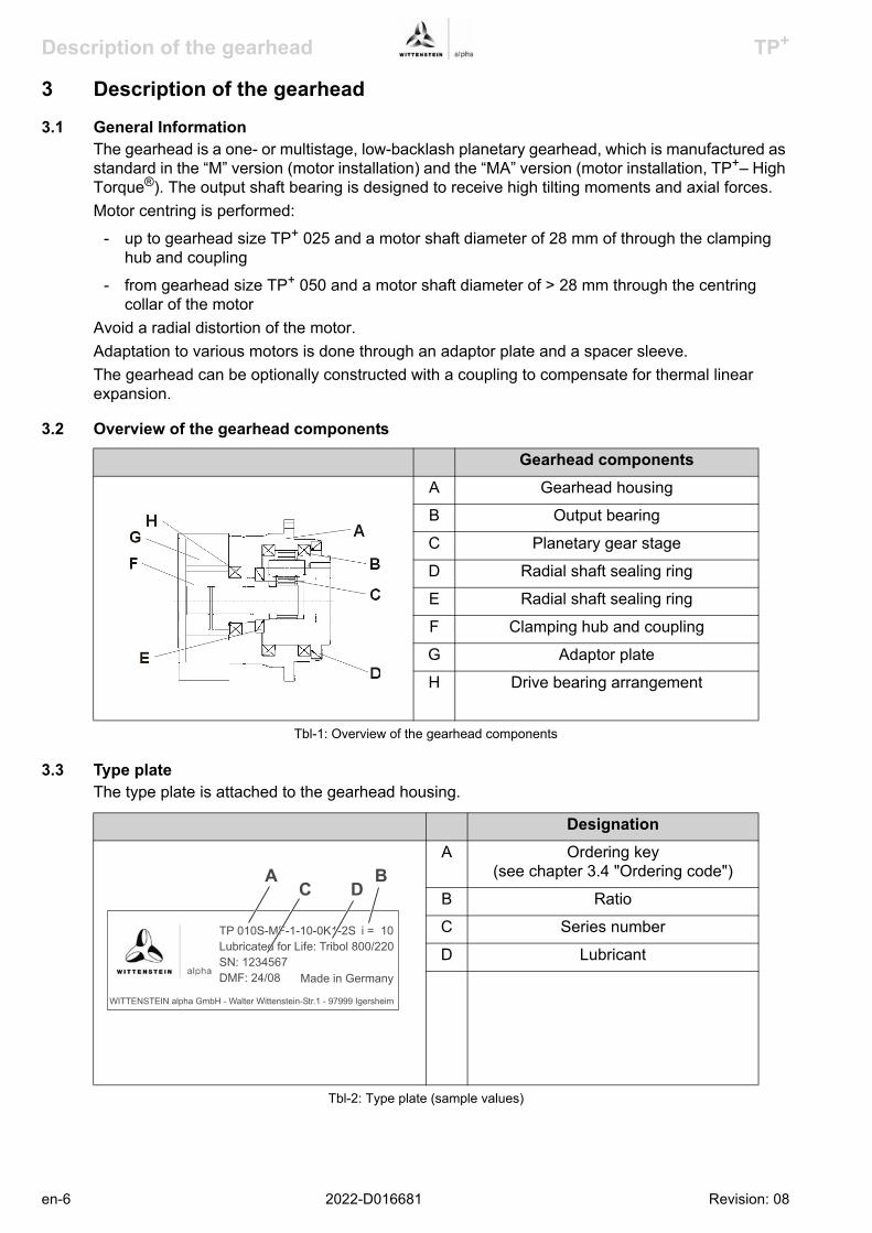
Description of the gearhead TP+
3 Description of the gearhead
3.1 General InformationThe gearhead is a one- or multistage, low-backlash planetary gearhead, which is manufactured as standard in the “M” version (motor installation) and the “MA” version (motor installation, TP+– High Torque®). The output shaft bearing is designed to receive high tilting moments and axial forces.Motor centring is performed:
- up to gearhead size TP+ 025 and a motor shaft diameter of 28 mm of through the clamping hub and coupling
- from gearhead size TP+ 050 and a motor shaft diameter of > 28 mm through the centring collar of the motor
Avoid a radial distortion of the motor.Adaptation to various motors is done through an adaptor plate and a spacer sleeve.The gearhead can be optionally constructed with a coupling to compensate for thermal linear expansion.
3.2 Overview of the gearhead components
3.3 Type plateThe type plate is attached to the gearhead housing.
Gearhead componentsA Gearhead housing
B Output bearing
C Planetary gear stage
D Radial shaft sealing ring
E Radial shaft sealing ring
F Clamping hub and coupling
G Adaptor plate
H Drive bearing arrangement
Tbl-1: Overview of the gearhead components
DesignationA Ordering key
(see chapter 3.4 "Ordering code")
B Ratio
C Series number
D Lubricant
Tbl-2: Type plate (sample values)
WITTENSTEIN alpha GmbH - Walter Wittenstein-Str.1 - 97999 Igersheim
TP 010S-MF-1-10-0K1-2S
SN: 1234567
DMF: 24/08
Lubricated for Life: Tribol 800/220
Made in Germany
i = 10
A BC D
en-6 2022-D016681 Revision: 08

TP+ Description of the gearhead
3.4 Ordering code
3.5 Performance statisticsPlease refer to our catalogue or our Internet page at http://www.wittenstein-alpha.de for the maximum permitted speeds and torques.
3.6 WeightThe table "Tbl-3" specifies the gearhead dimensions with medium-sized adaptor plate. If another adaptor plate is mounted, the actual dimensions can deviate by up to 10%.
Please consult our service department if your gearhead is older than a year. You will then receive the valid performance data.
Gear reducer size TP+
004 010 025 050 110 300 500
Design StagesM 1 1.4 3.7 6.3 14 30.1 57 79
2 1.5 3.5 6.6 14.1 33.9 58 74
MA 1 - - - - - 55 80
2 - 3.2 5.6 12.5 33.1 64 80
3 - 3.6 6.1 13.4 35.4 67 89
Tbl-3: Weight [kg]
TP+ 010 S-M F 1-10-0 K 1-2 S
Gearhead sizeTP+ 004/010/025/050/110/300/500
Type codeS = Standard
X = Special gear
Ratio i
Shape of output flange0 = Standard design
4 = Customized
Bore diameters of theclamping hubSee catalogue
Backlash
1 = Standard
0 = Reduced
Generation
Motor-mountedK = Coupling
S = Standard
Gearhead type
A = High Torque
F = Cyclic duty S5
®
Gearhead versionsM = Motor-mounted gearhead
Stage number1 = 1-stage
2 = 2-stage
3 = 3-stage
Revision: 08 2022-D016681 en-7

Transport and storage TP+
en-8 2022-D016681 Revision: 08
4 Transport and storage
4.1 Scope of deliveryCheck the completeness of the delivery against the delivery note.Missing parts or damage must be notified immediately in writing to the carrier the insurance, or WITTENSTEIN alpha GmbH.
4.2 PackagingThe gearhead is delivered packed in foil and cardboard boxes.
Dispose of the packaging materials at the recycling sites intended for this purpose. Observe the locally valid regulations for disposals.
4.3 Transport
For specifications on the weights see Chapter 3.6 "Weight".
4.4 StorageStore the gearhead in horizontal position and dry surroundings at a temperature of 0 °C to +30 °C in the original packaging. Store the gearhead for a maximum of 2 years.For storage logistics we recommend the “first in – first out” principle.
Hard knocks, for instance because of falling or hard dropping, can damage the gearhead.
Use only hoisting equipment and transportation devices with sufficient capacity.The permitted lifting weight of a hoist may not be exceeded.Lower the gearhead slowly.
Suspended loads may fall and cause serious injuries and even death.Do not stand under suspended loads.

TP+ Assembly
5 Assembly
5.1 Preparation
Clean/de-grease the following gearhead components with a clean and lint-free cloth and grease-dissolving, non-aggressive detergent:- all fitting surfaces to neighbouring components- centring- the motor shaft- only the inside diameter of the clamping hub- the spacer sleeve (if provided) inside and outCheck the fitting surfaces in addition for damage and foreign bodies.
Loose or overloaded screw connections can damage the gearhead.Use a calibrated torque wrench to tighten and check all screw connections for which a tightening torque has been specified.
Intensive distortions when assembling the motor (e.g. for motors with shaft shoulder, extensive chamfer radius or longer shafts than permitted for the gearhead) can damage the gearhead and the motor.
Check the interfering edges by measuring, or by a measurement check based on our catalogue specifications and the information of the motor manufacturer.Contact our Customer Service Department.
Pressurised air can damage the gearhead.Do not use pressurised air to clean the gearhead.
Directly sprayed cleaning agents can alter the frictional values of the clamping hub.
Only spray cleaning agents onto a cloth, with which you can then clean the clamping hub.
Revision: 08 2022-D016681 en-9

Assembly TP+
5.2 Mounting the motor onto the gearhead
Smear screw-bonding agent (for example Loctite 243) onto the four bolts (C).Fasten the motor (E) onto the adaptor plate (B) with the four screws.Tighten the clamping bolt (H) of the clamping hub (I).
For bolt sizes and specified torques refer to chapter 9.1 "Specifications on mounting onto a motor", tables "Tbl-8" and "Tbl-9".
Screw in plug (A) of the adaptor plate (B).For screw sizes and specified torques refer to table "Tbl-5".
If the motor shaft has a feather key, remove the feather key.
If recommended by the motor manufacturer, apply a half wedge.
Turn the clamping hub (I) until the clamping bolt (H) can be reached by the mounting bore.Loosen the clamping bolt (H) of the clamping hub (I) by one revolution.Push the motor shaft into the clamping hub of the gearhead.
The motor shaft should slip in easily. If this is not the case, the clamping bolt must be loosened more.A slotted spacer sleeve has to be installed extra for certain motor shaft diameters and applications.The slot of the spacer sleeve (if provided) and clamping hub have to be flush with the groove (if provided) of the motor shaft, see table "Tbl-4".No gap is premitted between motor (E) and the adaptor plate (B).
DesignationH Clamping bolt
I Clamping ring (part of the clamping hub)
J Spacer sleeve
K Grooved shaft
L Smooth shaft
Tbl-4: Arrangement of motor shaft, plug receptacle and spacer sleeve
en-10 2022-D016681 Revision: 08

TP+ Assembly
5.3 Mounting the gearhead onto a machine
5.4 Mounted components on the gear output side
For bolt sizes and specified torques refer to chapter 9.2 "Specifications on mounting on the gear output side", table "Tbl-10".
Width across flats [mm] 5 8 10 12 14Tightening torque [Nm] 10 35 50 70 140
Tbl-5: Torques for the plugs
Smear screw-bonding agent (for example Loctite 243) onto the fastening bolts.Fasten the gearhead on the machine with the fastening bolts through the through-holes (A).
Mount the gearhead in such a way that the type plate remains legible.Do not use washers (e.g. plain washers, tooth lock washers).For bolt sizes and specified torques refer to chapter 9.3 "Specifications on mounting onto a machine", table"Tbl-11".
Distortions during mounting operations can damage the gearhead.Mount gearwheels and toothed belt pulleys onto the output flange without forcing.Do not on any account attempt an assembly by force or hammering!Only use suitable tools and equipment for assembly.
Revision: 08 2022-D016681 en-11

Startup and operation TP+
en-12 2022-D016681 Revision: 08
6 Startup and operation
Operational conditions and requirements for the surroundings:- Because of the factory-filled lubricant, the ambient temperature may not lie under 0 °C, or over
+40 °C. Operating temperature may not exceed +90 °C.For other conditions of use, please consult our Customer Service Department.
- Only use the gearhead up to its maximum limit values, see chapter 3.5 "Performance statistics".
- Only use the gearhead in a clean, dust-free and dry environment.
Objects flung out by rotating components can cause serious injuries.Remove objects and tools from the gearhead before putting it into operation.
Rotating components on the gearhead can pull in parts of the body and cause serious injuries and even death.
Keep a sufficient distance to rotating machinery while the gearhead is running.
Hot gearhead housing can cause serious burns.Touch the gearhead housing only when wearing protective gloves or after the gearhead has been at standstill for some time.

TP+ Maintenance and disposal
7 Maintenance and disposal
7.1 Maintenance work
7.1.1 Visual inspectionCheck the entire gearhead for exterior damage.The radial shaft seals are subject to wear. Therefore also check the gearhead for leakage during each visual inspection.
You can find more general information on radial shaft seals on our partner's Internet site at http://www.simrit.de.Check the mounting position, so that no foreign medium (e.g. oil) has collected on the output flange.
7.1.2 Checking the tightening torquesCheck the tightening torque of the fastening bolts on the gearhead housing and at the output flange.
For bolt sizes and specified torques refer to Chapter 9.3 "Specifications on mounting onto a machine", table "Tbl-11" and Chapter 9.2 "Specifications on mounting on the gear output side", table "Tbl-10".
Check the tightening torque of the clamping bolt on the motor mounting.You can find the prescribed tightening torques in Chapter 9.1 "Specifications on mounting onto a motor", tables "Tbl-8" and "Tbl-9".
7.2 Startup after maintenance workClean the outside of the gearhead.Assemble all safety devices.Do a trial run before releasing the gearhead again for operation.
7.3 Maintenance schedule
Hot gearhead housing can cause serious burns.Touch the gearhead housing only when wearing protective gloves or after the gearhead has been idle for some time.
Rotating components on the gearhead can pull in parts of the body and cause serious injuries and even death.
Disconnect the machine from the mains before starting maintenance work.Secure the motor against restarting during maintenance work.
Maintenance work At start-up After 500 operating hours
or 3 months
Every 3 months
Yearly
Visual inspection X X X
Checking the tightening torques
X X X
Tbl-6: Maintenance schedule
Revision: 08 2022-D016681 en-13

Maintenance and disposal TP+
7.4 Notes on the lubricant used
You can receive further information on the lubricants directly from the manufacturer:Castrol Industrie GmbH, MönchengladbachTel.: + 49 (0) 21 61 / 9 09 - 30www.castrol.com
7.5 Supplementary informationConsult our Customer Service Department for supplementary information on exchanging the adaptor plate, on disassembly and on disposal of the gearhead.
Dispose of the gearhead at the recycling sites intended for this purpose. Observe the locally valid regulations for disposal.
All gearheads are permanently lubricated by the manufacturer with synthetic gear oil (polyglycols) of viscosity class ISO VG 220 or with a high-performance lubricant (see type plate). All bearings are permanently lubricated by the company.
en-14 2022-D016681 Revision: 08

TP+ Malfunctions
Revision: 08 2022-D016681 en-15
8 Malfunctions
Changed operational behaviour can be an indication of existing damage to the gearhead, or cause damage to the gearhead.
Do not put the gearhead back into operation until the cause of the malfunction has been rectified.
Fault Possible cause SolutionIncreased operating
temperature The gearhead is not suited
for the task.Check the technical
specifications.
Motor is heating the gearhead.
Check the wiring of the motor.
Ensure adequate cooling.
Change the motor.
Ambient temperature too high.
Ensure adequate cooling.
Increased noise during operation
Distortion in motor mounting. Please consult our Customer Service Department.Damaged bearings.
Damaged gear teeth.
Loss of lubricant Lubricant quantity too high. Wipe off discharged lubricant and continue to watch the
gearhead. Lubricant discharge must stop after a
short time.
Seals not tight. Please consult our Customer Service Department.
Tbl-7: Malfunctions
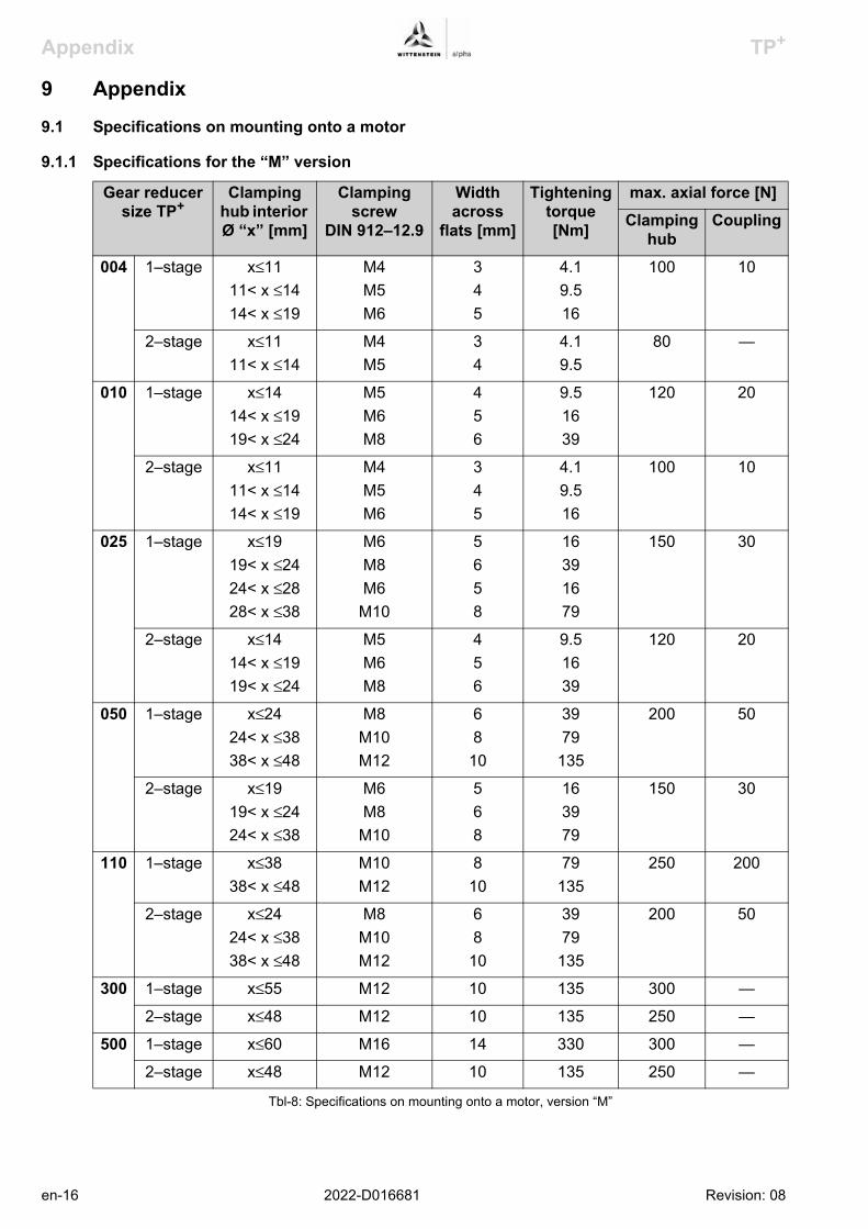
Appendix TP+
9 Appendix
9.1 Specifications on mounting onto a motor
9.1.1 Specifications for the “M” version
Gear reducer size TP+
Clamping hub interior Ø “x” [mm]
Clamping screw
DIN 912–12.9
Width across
flats [mm]
Tightening torque [Nm]
max. axial force [N]Clamping
hubCoupling
004 1–stage x≤1111< x ≤1414< x ≤19
M4M5M6
345
4.19.516
100 10
2–stage x≤1111< x ≤14
M4M5
34
4.19.5
80 —
010 1–stage x≤1414< x ≤1919< x ≤24
M5M6M8
456
9.51639
120 20
2–stage x≤1111< x ≤1414< x ≤19
M4M5M6
345
4.19.516
100 10
025 1–stage x≤1919< x ≤2424< x ≤2828< x ≤38
M6M8M6
M10
5658
16391679
150 30
2–stage x≤1414< x ≤1919< x ≤24
M5M6M8
456
9.51639
120 20
050 1–stage x≤2424< x ≤3838< x ≤48
M8M10M12
68
10
3979
135
200 50
2–stage x≤1919< x ≤2424< x ≤38
M6M8
M10
568
163979
150 30
110 1–stage x≤3838< x ≤48
M10M12
810
79135
250 200
2–stage x≤2424< x ≤3838< x ≤48
M8M10M12
68
10
3979
135
200 50
300 1–stage x≤55 M12 10 135 300 —
2–stage x≤48 M12 10 135 250 —
500 1–stage x≤60 M16 14 330 300 —
2–stage x≤48 M12 10 135 250 —
Tbl-8: Specifications on mounting onto a motor, version “M”
en-16 2022-D016681 Revision: 08

TP+ Appendix
9.1.2 Specifications for the “MA” version
Gear reducer size TP+
Clamping hub interior Ø “x” [mm]
Clamping screw
DIN 912–12.9
Width across
flats [mm]
Tightening torque [Nm]
max. axial force [N]Clamping
hubCoupling
010 2–stage x≤1414< x ≤19
M5M6
45
9.516
120 20
3–stage x≤14 M5 4 9.5 120 20
025 2–stage x≤1919< x ≤24
M6M8
56
1639
150 30
3–stage x≤19 M6 5 16 150 30
050 2–stage x≤2424< x ≤38
M8M10
68
3979
200 50
3–stage x≤24 M8 6 39 200 50
110 2–stage x≤3838< x ≤48
M10M12
810
79135
250 200
3–stage x≤38 M10 8 79 250 200
300 1–stage x≤55 M12 10 135 300 —
2–stage x≤48 M12 10 135 250 —
3–stage x≤38 M10 8 79 250 —
500 1–stage x≤60 M16 14 330 300 —
2–stage x≤48 M12 10 135 250 —
3–stage x≤3838< x ≤48
M10M12
810
79135
250 —
Tbl-9: Specifications on mounting onto a motor, version “MA”
Revision: 08 2022-D016681 en-17

Appendix TP+
9.2 Specifications on mounting on the gear output side
9.3 Specifications on mounting onto a machine
Thread in output flangeSize /
version TP+
Bore Ø[mm]
Quantity x thread x depth
[ ] x [mm] x [mm]
Property class Tightening torque [Nm]
004 M 31.5 8 x M5 x 7 10.9 7.69
010 M 50 8 x M6 x 10 10.9 13.2
025 M 63 12 x M6 x 12 10.9 13.2
050 M 80 12 x M8 x 15 10.9 31.9
110 M 125 12 x M10 x 20 10.9 62.7
300 M 140 12 x M16 x 31 10.9 265
500 M 160 12 x M20 x 31 10.9 516
010 MA 50 12 x M6 x 10 10.9 13.2
025 MA 63 12 x M8 x 12 10.9 31.9
050 MA 80 12 x M10 x 15 10.9 62.7
110 MA 125 12 x M12 x 19 10.9 108
300 MA 145 12 x M20 x 31 10.9 516
500 MA 166 12 x M24 x 37 10.9 890
MA = HighTorque®
Tbl-10: Specifications on mounting on the gear output side
Through-holes in gearhead housingSize /
version TP+
Bore Ø[mm]
Quantity x diameter [ ] x [mm]
For Screw size/property class
Tightening torque [Nm]
004 M 79 8 x 4.5 M4 / 12.9 4.55
010 M 109 8 x 5.5 M5 / 12.9 9.0
025 M 135 8 x 5.5 M5 / 12.9 9.0
050 M 168 12 x 6.6 M6 / 12.9 15.4
110 M 233 12 x 9.0 M8 / 12.9 37.3
300 M 280 16 x 13.5 M12 / 12.9 126
500 M 310 16 x 13.5 M12 / 12.9 126
010 MA 109 16 x 5.5 M5 / 12.9 9.0
025 MA 135 16 x 5.5 M5 / 12.9 9.0
050 MA 168 24 x 6.6 M6 / 12.9 15.4
110 MA 233 24 x 9.0 M8 / 12.9 37.3
300 MA 280 32 x 13.5 M12 / 12.9 126
500 MA 285 32 x 13.5 M12 / 12.9 126
Tbl-11: Specifications on mounting onto a machine; MA = HighTorque®
en-18 2022-D016681 Revision: 08
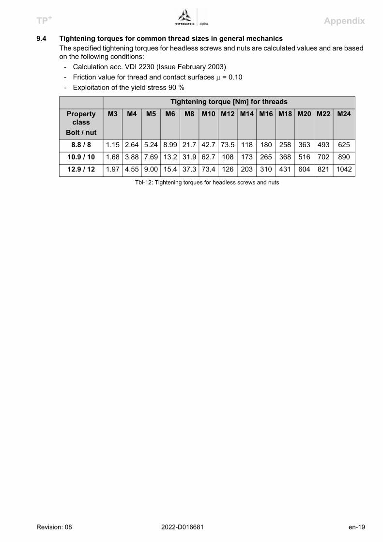
TP+ Appendix
9.4 Tightening torques for common thread sizes in general mechanicsThe specified tightening torques for headless screws and nuts are calculated values and are based on the following conditions:
- Calculation acc. VDI 2230 (Issue February 2003)- Friction value for thread and contact surfaces μ = 0.10- Exploitation of the yield stress 90 %
Tightening torque [Nm] for threadsProperty
classBolt / nut
M3 M4 M5 M6 M8 M10 M12 M14 M16 M18 M20 M22 M24
8.8 / 8 1.15 2.64 5.24 8.99 21.7 42.7 73.5 118 180 258 363 493 625
10.9 / 10 1.68 3.88 7.69 13.2 31.9 62.7 108 173 265 368 516 702 890
12.9 / 12 1.97 4.55 9.00 15.4 37.3 73.4 126 203 310 431 604 821 1042
Tbl-12: Tightening torques for headless screws and nuts
Revision: 08 2022-D016681 en-19

2022-D016681 : 08
enAC: XXXXXXXX 2022-D016681 Revision: 08
WITTENSTEIN alpha GmbHWalter-Wittenstein-Straße 197999 Igersheim
WITTENSTEIN - being one with the future
www.wittenstein.de

11/2009 1/2
Remarks
INFORMATION ABOUT THE DOCUMENTATION LISTS The lists are divided up into the following columns:
Item The column ITEM specifies the consecutive number of all parts in the parts list in question.
QNTY (quantity) The column QUANTITY specifies the quantity / weight / length of the parts of the machine.
This value refers to the number of parts in the machine and not to the number of spares recommended to be kept on stock.
UM (Unit of Quantity)
UM Description
pce Quantity / number of
kg Weight in kilograms
mm Length in millimetres
m Length in meters
S/N / Part This column specifies the SUBJECT-NUMBER or ORDER-NUMBER of the part.
Name This column specifies the name of the sub-assembly or of the part.
Remark Company-internal information may be given here.
Dimension / Type This column specifies the dimension or the type designation of the part in question.

11/2009 2/2
Remarks
Material This column shows the material that the part is made of.
Standard The STANDARD column shows the DIN, ISO or other standard that is applicable to the part in question
SP (Spare parts code number) The spare parts code number reflects the most probable order in which the spare part in question will wear or fail based on 2-shift operation of the machinery.
As it is not possible to say exactly when a part will be worn or will fail, the specifications given here are approximations only.
SP Description
v1 Likely to fail / need exchanging within a year (Standard spare part)
v2 Likely to fail / need exchanging after two years (5,000 hours)
v3 Likely to fail / need exchanging after three years (10,000 hours)
v4 Risk parts which will cause long-term stoppage of the machine if they fail
v5 Control cabinet and installation parts impossible to say when they will need to be exchanged
v9 Anti-friction bearings impossible to say when they will need to be exchanged
i Assembly drawings and schematics which contain spare parts and/or anti-friction bearings (Option)
Manufacturer This column shows the name of the manufacturer of the part in question.

S P A R E P A R T S L I S T
Item QNTY UM S/N / Part Name Dimension / Type Material Standard SP Manufacturer 10 1 pce 13-02220 LATHE DH 4500/350-23x20.000-1 bgf 190 1 pce 13-02220-00100 HEADSTOCK HOUSING bgf 10 0 pce 6200694 HEADSTOCK VIEWS GRP-ZCHG i,v0 90 2 pce 7-0051512 VENTILATION FILTER M 33X1.5 NO. 4100462112 bgf,v1,t Mann & Hummel 100 10000 mm 1-5200030 BUNA TOROID.SEAL.OILTIGHT DIA. 3 72 NBR v1,bgf 270 1 pce 503981 O-RING SEAL 441,00-8,00 72 NBR 872 v1 200 1 pce 13-02220-00120 MAIN SPINDLE AND BEARING bgf 10 0 pce 6200376 HEADSTOCK-GEAR GRP-ZCHG i,v0 30 1 pce 550020 CYLINDRICAL ROLLER BRG. NN 49/920 SK.M.SP.H74 DIN5412 v9,bgf 40 2 pce 504681 THRUST CYL ROLLER BRG 811/800-P5.J26AA.T52BF v9,n,bgf 50 16 pce 2509236 PRESSURE SPRING 64/1/3 2,5 X 12,5 X 47,5 DIN2098 n,bgf,v3 70 1 pce 500576 CYLINDRICAL ROLLER BRG. NN 48/630 SK.M.SP DIN5412 v9,bgf FAG 80 1 pce 2504682 V-RING V-1000-A v1,bgf 200 10 pce 2500116 O-Ring 24,20x3,00 72 NBR 872 v1 210 10 pce 2526831 SUPPORT RING SRA 30-2,6-1,0 v3,bgf 400 1 pce 2553544 RESISTANCE THERMOMETER 902030/31-380-1011-1-6-20 Pt v3,spi,bgf Jumo 420 1 pce 2553545 RESISTANCE THERMOMETER 902030/31-380-1011-1-6-15 Pt v3,spi,bgf Jumo 430 1 pce 2553543 RESISTANCE THERMOMETER 902030/31-380-1011-1-6-27 Pt v3,spi,bgf Jumo 460 1 pce 1005330 O-RING SEAL 29.20-3.00 72 NBR 872 v1 470 3 pce 556105 DIGITAL DISPLAY HDA 5500-3-1-DC-000 v3,spi,t HYDAC INTERNATIONAL 210 1 pce 13-02220-00121 GEAR PARTS bgf 10 0 pce 6200376 HEADSTOCK-GEAR GRP-ZCHG i,v0 30 1 pce 504830 CYLINDRICAL ROLLER BRG N 248 DIN5412 v9,n,bgf 40 1 pce 504831 CYLINDRICAL ROLLER BRG NU 1052 DIN5412 v9,n,bgf 50 1 pce 546447 ANGULAR CONTACT BALL BRG QJ 236 DIN628-4 v9,n,bgf 60 1 pce 546448 CYLINDRICAL ROLLER BRG N U 236 DIN5412 v9,n,bgf 210 1 pce 504836 CYLINDRICAL ROLLER BRG NU 326 DIN5412 v9,n,bgf 220 2 pce 550503 ANGULAR CONTACT BALL BRG 7330-B-MP DIN628 v9,n,bgf 370 1 pce 504588 CYLINDRICAL ROLLER BRG. NU 222 E.TVP2 DIN5412 v9,n,bgf 380 2 pce 550350 ANGULAR CONTACT BALL BRG 7326-B-TVP DIN628 v9,n,bgf FAG 440 1 pce 550683 V-RING V-120 A v1,bgf Busak & Shamban 480 1 pce 510079 O-Ring 329,57x5,33 BL-VI 70 SHORE v1 Busak & Luyken 220 1 pce 13-02220-00123 FLANGE CENTER bgf 10 1 pce 6203516 INSERT 300 16MNCRS5 WN 740 v1,n,bgf 230 1 pce 13-02220-00125 DRIVE COUPLING WITH BRAKE bgf 10 0 pce 363841 MAIN DRIVE GRP-ZCHG i,v0 40 1 pce 556249 ROTEX-COUPLING ROTEX 125 SBAN v3,bgf 70 1 pce 506328 DISC BRAKE SB 17-1200 PI v3,t,bgf Bubenzer 80 1 pce 517213 3/2-WAY VALVE MFH-3-1/4-24 V GS v1,spi,bgf Festo 90 1 pce 507335 SOUND ABSORBER U-1/4 v1,bgf Festo 240 1 pce 13-02220-00130 GEAR STEP SWITCHING bgf 10 0 pce 358508 HEADSTOCK GEAR SHIFTING ASS. DWG. i,v0 80 1 pce 550157 HYDRAULIC-DIFF CYLINDER RD 100/50 x 320 v3,t,spi Hänchen 250 1 pce 13-02220-00150 LUBRICATION + HYDRAULICS bgf 10 0 pce 706907 LUBRICATION + HYDRAULICS, SCHEMA i,v0 70 1 pce 552611 VALVE BLOCK VB/P2 NG6 spi,bgf,v1
S/N 13-0222 April 2011 1 / 54

Item QNTY UM S/N / Part Name Dimension / Type Material Standard SP Manufacturer 80 6 pce 8-8603260 COUPLER SOCKET CONNECTING WIRE 5M DIN 43650 n,spi,v3 Lütze 260 2 pce 502699 PRESSURE GAUGE DM1,2/P2 0-160 BAR 135 AR 6316 DIN 16063 v3,n 280 2 pce 500284 HIGH PRESSURE HOSE DN 2 MSHL ORDER NO.: S100-AC-AC-008 v3 Hydro-Technik 390 2 pce 511213 FLOW CONTROLLER S/P3.1,S/P3. VKG-2108R0R20 v3,spi Kobold Messring 400 2 pce 530594 DKO MEASUR.PIECE NO L22 2 MS/P3.1,MS/P VKA 3/22L A3C bgf,v1 Parker Hannifin 520 1 pce 500327 FLOW CONTROL VALVE DV2/P3.1 DV-12-01.X/0 bgf,v1 Flutec 540 2 pce 2-8115815 STRAIGHT SCREWED SOCKET EGE15-LR-ED A3C s,i,v1 Parker Hannifin 610 1 pce 500327 FLOW CONTROL VALVE DV/P3.3 DV-12-01.X/0 bgf,v1 Flutec 640 1 pce 509413 FLOW CONTROLLER S/P3.3 VKG-2107R0R15 v3,spi Kobold Messring 660 1 pce 530593 DKO-MEAS.CONNECTION PCE. MS/P3.3 VKA 3/18L A3C v1,bgf Parker Hannifin 740 1 pce 2-8551016 PRESSURE GAUGE DM/P3 0-16 BAR, 085 AR 6316 DIN 16063 v3,n Parker Hannifin 760 1 pce 500284 HIGH PRESSURE HOSE DN 2 MSHL ORDER NO.: S100-AC-AC-008 v3 Hydro-Technik 840 1 pce 2-8461042 PLUNGE DISTRIBUTOR,2-POS. DOS 0,03;0,0 NO. 342 444 000 v3 Willy Vogel 850 2 pce 2-8463003 DOSING NIPPLE 0.03 CCM NO. 995 994 103 bgf,v3 Willy Vogel 860 1 pce 8-8000366 PRESSURE SWITCH D1/P4 NO. 176 111 201 HTN:005240 v2,spi Willy Vogel 870 1 pce 501201 PRESSURE SWITCH D2/P4 NO. 176 120 200 v2,spi,bgf Willy Vogel 880 2 pce 8-8001722 PROTECTIVE CAP ORDER NO. 898 420 001 HTN:052992 v1 Willy Vogel 890 3 m 1-2849049 HYDRAULIC PIPE PI 4 X 0,85 PA12-H ähnl. DIN73 v1 260 1 pce 13-02220-00151 HYDRAULIC AND LUBRICATION AGGREGATE bgf 10 0 pce 706990 HYDRAULIC AND LUBRICATION SCHEMA i,v0 30 1 pce 8-8016360 TERMINAL BOX 90 AE 1030, 380 X 300 X 155 v5 Rittal 40 1 pce 8-8603262 VALVE PLUG A 7000-18121-6280500 v3,n,spi Murr Elektronik 50 4 pce 502760 METAL RUBBER BUFFER NO. 25336 A bgf,v1 Conti 140 4 pce 525059 FILTER ELEMENT PI 3230 SMX VST 10 v1,bgf,t Mahle Filtersys 200 4 pce 519859 FILTER ELEMENT PI 3130 SMX 10 v1,bgf,t Mahle Filtersys 260 4 pce 509909 FILTER ELEMENT PI 3105 SMX 10 v1,t,bgf Mahle Filtersys 270 1 pce 13-02220-00155 OIL COOLER bgf 10 0 pce 706967 OIL COOLER SCHEMA i,v0 20 1 pce 554827 PLATE HEAT EXCHANGER K/P1 PK-90-121-I-G11/2 bgf,v3,t Newcool GmbH 40 2 pce 511807 2-WAY BALL VALVE KH/P1,KH/T1 ART. TB 1110, R 1 1/2 bgf,v1 End Armaturen 90 2 pce 509907 2-WAY-BALL-VALVE KH1,KH2 ART. TB 111025 G1 bgf,v1 End Armaturen 280 1 pce 13-02220-00165 SPINDLE POSITIONING bgf 10 0 pce 363723 SPINDLE POSITIONING C-AXIS GRP-ZCHG i,v0 60 1 pce 7-0051510 AERATION-FILTER M 26 X 1,5 NO. 4100262102 bgf,v1,t Mann & Hummel 130 1 pce 553882 WORM GEAR A = 160, I = 17 v3,bgf 150 1 pce 505796 CYLINDRICAL ROLLER BRG. NU 211 DIA. 55/100 X 21 DIN5412 v9,n,bgf FAG 160 2 pce 503358 ANGULAR CONTACT BALL BRG. 7211-B-TVP-UO DIN628 v9,bgf 170 1 pce 508104 ADJUSTING NUT MSR 55 X 1,5 bgf,v1 Spieth 190 1 pce 2-3600522 ROTARY SHAFT SEAL C 52 X 72 X 10 DIN 3760 v1,n 220 2 pce 6-0900700 ANGULAR CONTACT BALL BRG 7214 B DIN628 v9,n,bgf 290 2 pce 6-0200600 DEEP GROOVE BALL BRG. 6212 DIN 625 v9,n 340 1 pce 344375 BOLT C 45 K bgf,v1 380 1 pce 519339 HYDRAULIC DIFF. CYLINDER 122 10103-01/32/16/55 v3,t,bgf Hänchen 290 1 pce 13-02220-00170 SPINDLE CLAMPING bgf 10 3 pce 535182 CLAMPING ELEMENT, STATIONARY v3,bgf C. Stiefelmayer 300 1 pce 13-02220-00180 ROTARY ENCODER MAIN SPINDLE + C1-AXIS bgf 10 0 pce 363803 ROTARY ENCODER,MAIN SPIND GRP-ZCHG i,v0 60 1 pce 2-3600602 ROTARY SHAFT SEAL C 60 X 80 X 10 DIN 3760 v1,n 80 1 pce 502940 INDUCT.PROXIMITY SWITCH BES 516-387-E1-X-PU-05 v3,spi,bgf Balluff 100 1 pce 506082 MEMBRANE COUPLING K 01, IDENT-NO 20030102 v4,spi,bgf Heidenhain
S/N 13-0222 April 2011 2 / 54

Item QNTY UM S/N / Part Name Dimension / Type Material Standard SP Manufacturer 310 1 pce 13-02220-00187 OPERATING PLATFORM bgf 10 0 pce 365021 PLATFORM HEADSTOCK GRP.-ZCHG i,v0 240 1 pce 6203306 SAFETY SOLENOID INTERLOCK AZM 190-02/01rk v2,spi,bgf,t Schmersal 250 1 pce 6203309 ACTUATOR AZM 190-B3/2x15 spi,v3,t Schmersal 290 1 pce 539316 CIRCUIT ELEMENT;1S 3SB3420-0B;(3SB1420-0B) HTN:238036 v2,spi,bgf Siemens 300 1 pce 539317 LAMPENFASSUNG 3SB3420-1A;(3SB1420-2A) v2,spi,bgf Siemens 310 1 pce 539320 LIGHT PUSH BUTTON GREEN 3SB3501-0AA41;(3SB1001-0A v2,spi,bgf Siemens 320 1 pce 543641 LED;WHITE;24V 3SB3901-1QA HTN:182906 spi,bgf,v3 Siemens 320 1 pce 13-02220-00190 FACE PLATE bgf 10 0 pce 365755 FACE PLATE GRP.-ZCHNG. i,v0 70 8 pce 2-5551000 DU-BUSH MB 10060 DU bgf,v3 IHG 80 4 pce 549983 CLAMPING SPINDLE MSP 200 v4,t,bgf 90 4 pce 549984 CLAMPING SPINDLE MSP 200 v4,t,bgf 220 8 pce 6204998 CLAMPING BRACKET 30 CRMOV 9 HH-G v2,bgf 240 4 pce 358596 FALSE JAW 30 CRMOV 9 v1,bgf 250 4 pce 358597 FALSE JAW 30 CRMOV 9 v1,bgf 330 1 pce 13-02220-00197 CLAMPING SPINDLE QUICK ADJUSTMENT bgf 10 0 pce 365021 PLATFORM HEADSTOCK GRP.-ZCHG i,v0 20 2 pce 2554230 HIGH TORQUE SCREWER LMP51 HR004-20 bgf,v3,t Atlas Copco 30 2 pce 2554231 INSTANT SUPPORT GEARING TYPE 4 bgf,v3 Atlas Copco 40 2 pce 2554232 RETROFIT KIT LH - RH ROTATION bgf,v3 Atlas Copco 340 1 pce 13-02220-00198 FACE PLATE PROTECTION DRIVE PNEUMATICAL bgf 10 0 pce 366172 FACE PLATE PROTECTION GRP-ZCHG i,v0 110 4 pce 542410 LINEAR BALL BEARING UNIT KGHK50-PP-AS bgf,v9 INA 130 1 pce 554240 DOPPELTWIRKENDER ZYLINDER DGP-40-1485-PPV-A bgf,v3,t 140 1 pce 555766 SAFETY SENSOR CSS 14-34-S-D-M-ST v2,spi,bgf,t Schmersal 150 1 pce 555769 ACTUATOR CST 34-S-1 v2,spi,bgf,t Schmersal 200 1 pce 502940 INDUCT.PROXIMITY SWITCH BES 516-387-E1-X-PU-05 v3,spi,bgf Balluff 210 2 pce 517213 3/2-WAY VALVE MFH-3-1/4-24 V GS MIT MAGNETSPULE v1,spi,bgf Festo 220 2 pce 507335 SOUND ABSORBER U-1/4 v1,bgf Festo 350 1 pce 13-02220-00201 WORKPIECE BED 2000 bgf 160 16 pce 2-2100064 DRAIN PLUG F 40 (FUER M 64) GPN 300 n,v1 Kapsto 330 4 m 1-7201550 RUBBER STEEL PIPE NW 32, PASS. AUF 1 ROHR bgf,v3 340 2 pce 1-7214470 HOSE CLIP LA 28-38 DIN 3017 n,bgf,v3 380 1 pce 13-02220-00230 MOTOR CONSOLE bgf 90 2 pce 512232 ENERGY BOX AE 1376.800 600X760X350 spi,bgf,v5 Rittal 420 1 pce 13-02220-00300 COUNTERSTAY bgf 60 1 pce 554508 BOLT BO-PP-32 v3,t,bgf AHP Merkle 70 1 pce 554507 LINK GAD.032 v3,t,bgf AHP Merkle 80 1 pce 554509 BEARING SUPPORT LB-CBA-32 v3,t,bgf AHP Merkle 90 1 pce 556329 HYDRAULIC-CYLINDRE HMZ250.63/40 v3,t,bgf 210 6 pce 527120 SPRING TENSION CYLINDER ZSF 35000 v3,t,bgf Optima 280 1 pce 556363 SPUR WHEEL BACK-GEARED MO RF77DV112M4-VS t,spi,bgf,v3 SEW Eurodrive 370 2 pce 503358 ANGULAR CONTACT BALL BRG. 7211-B-TVP-UO DIN628 v9,bgf 380 1 pce 508104 ADJUSTING NUT MSR 55 X 1,5 bgf,v1 Spieth 390 1 pce 506424 DEEP GROOVE BALL BRG. 6211-2RSR DIN625 v9,n,bgf 450 1 pce 500770 DEEP GROOVE BALL BRG. 6216-2RSR DIN625 v9,n,bgf FAG 510 1 pce 506424 DEEP GROOVE BALL BRG. 6211-2RSR DIN625 v9,n,bgf 520 1 pce 6-6000550 THRUST BALL BRG. 51111 DIN 711 v9,n INA 550 3 pce 500110 CLAMPING JAW IDENT.NO. 20003201 HTN:000483 spi,v1,bgf Heidenhain
S/N 13-0222 April 2011 3 / 54

Item QNTY UM S/N / Part Name Dimension / Type Material Standard SP Manufacturer 560 1 pce 503478 MEMBRANE-COUPLING K14 IDENT.NO.: 200 365 01 v4,v3 Heidenhain 580 0 pce 366007 Counter stay - views GRP-ZCHG i,v0 600 1 pce 8-8001323 LIMIT SWITCH 3SE3 120-1J v2,spi Siemens 670 1 pce 519768 SPRING STEEL PRE-WIPER LENGTH 500 MM bgf,v1 Kabelschlepp Gm 680 1 pce 519769 CLAMPING GIB LENGTH 1000 MM v1,bgf Kabelschlepp Gm 690 1 pce 2-9003000 WIPER BAS 25, 1000 MM LONG v1 Kabelschlepp Gm 421 1 pce 13-02220-00310 COUNTERSTAY HYDRAULIK + SCHMIERUNG bgf 10 0 pce 2707022 HYDRAULICS COUNTER STAY ASSEMBLY DRAWING i,v0 20 0 pce 2706923 LUBRICATION COUNTER STAY SCHEMA i,v0 30 1 pce 2555021 COMPACT-PUMP-UNIT P50 HC48DT/5,6 t,spi,bgf,v1 Hawe 40 7 pce 6201558 VALVE PLUG 7000-18021-6260500 n,spi,v5 Murr Elektronik 50 2 pce 6201000 VALVE PLUG A 7000-18121-6280500 n,spi,v3 Murr Elektronik 90 2 pce 2526402 PRESSURE SWITCH D2/81,D2/82 DG 34-1/4 v3,spi,bgf Hawe 10 1 pce 1653470 PRESSURE SWITCH UNIT NUR ERSATZTEIL DG34 bgf,v2,spi Hawe 100 2 pce 6201000 VALVE PLUG A 7000-18121-6280500 n,spi,v3 Murr Elektronik 380 2 pce 2514140 PRESSURE GAUGE DM1,2/P50 155 AR 6316 n,v3 410 1 pce 2524380 GEAR PUMP UNIT P54 MFE 5/BW 3 v3,t,spi,bgf Willy Vogel 10 1 pce 1005454 GEAR PUMP UNIT ERSATZTEILE MFE5 Willy Vogel 10 1 pce 1158252 FLOAT SWITCH WS32-2/150 v2 Willy Vogel 20 1 pce 1158252 FLOAT SWITCH WS32-2/150 v2 Willy Vogel 480 1 pce 6201951 PRESSURE GAUGE DM/P54 0-40 BAR, 105 AR 6316 DIN16063 n,v3 550 1 pce 1005240 PRESSURE SWITCH D1/P54 NO. 176 111 201 v2,spi Willy Vogel 560 1 pce 2501201 PRESSURE SWITCH D2/P54 176-120-200 v2,spi,bgf Willy Vogel 570 2 pce 1052992 PROTECTIVE CAP ORDER NO. 898 420 001 v3 Willy Vogel 430 1 pce 13-02220-00320 SENSORIC AT QUILL bgf 10 0 pce 6204883 SENSOR SYSTEM GRP-ZCHG i,v0 210 3 pce 6206611 PERMANENT BASE MAGNET DG 1003 bgf,v1 235 1 pce 6206613 CLAMPING HINGE NLM 31156 bgf,v1 Norelem 320 3 pce 6204893 FLAT GRIPPER MAGNET ORDER NO. 09071-04 bgf,v1 Norelem 330 1 pce 6204888 POSITION SENSOR capaNCDT6300 v3,spi,bgf,t Micro-Epsilon 340 1 pce 6204895 ALU CAST HOUSING ORDER NO 9117.210 bgf,v1 Rittal 441 1 pce 13-02220-00345 PLATFORM COUNTERSTAY bgf 500 1 pce 2512232 ENERGY BOX AE1376.600 spi,bgf,v5 Rittal 510 1 pce 2548793 CONTROL CABINET AE1038.800 bgf,spi,v5 Rittal 450 1 pce 13-02220-00350 PICKUP-STATION COUNTERSTAY bgf 90 1 pce 6204215 HYDRAULIC DIFF. CYLINDER RD 50/30 X 1325 STROKE v3,t,bgf Hänchen 170 1 pce 6204107 TAPE LINE COVER v3,bgf Kabelschlepp Gm 240 6 pce 6204096 SPRING PRESSURE PIECE M16X24 HWN 2206.616 v1,bgf Halter 245 18 pce 6209384 FEDERNDES DRUCKSTUECK 2206.110 (M10 X 22) v1,bgf 340 2 pce 6204096 SPRING PRESSURE PIECE M16X24 HWN 2206.616 v1,bgf Halter 345 6 pce 6209384 FEDERNDES DRUCKSTUECK 2206.110 (M10 X 22) v1,bgf 455 1 pce 13-02220-00355 WAY LIMIT bgf 100 6 pce 6200532 POSITION SWITCH 3SE5112-0CH01 v2,spi Siemens 460 1 pce 13-02220-00400 BED SLIDE 2000, R.H. bgf 10 0 pce 364438 BED SLIDE 2500R RITZELANTRIEB GRP-ZCHG i,v0 20 0 pce 357597 ALIGNMENT OF GUIDEWAY ASSEMBLY DRAWING i,v0 40 1 pce 553575 BALL SCREW 125/16L RD 220 X 3400 v4,t,bgf 130 2 pce 505714 THRUST CYL. ROLLER BRG. ZARN 90180 v9,bgf INA 140 2 pce 501524 ADJUSTMENT NUT MSW 85.60 (M 85 X 2) bgf,v1 Spieth 170 1 pce 500588 O-RING SEAL 11.30-2.40 72 NBR 872 v3
S/N 13-0222 April 2011 4 / 54

Item QNTY UM S/N / Part Name Dimension / Type Material Standard SP Manufacturer 180 1 pce 505713 O-RING SEAL 13.00-5.00 72 NBR 872 v3 280 6 m 501045 PROFILED JOINT TYPE 1011-15 PERBUNAN/CR/NBR v1,bgf Emka 380 2 pce 2-9003000 WIPER BAS 25, 1000 MM LONG v1 Kabelschlepp Gm 400 3000 mm 1-5200080 ROUND CORD, OIL-RESISTENT DIA 8 72 NBR bgf,v1 480 1 mm 1-5200080 ROUND CORD, OIL-RESISTENT DIA 8 72 NBR bgf,v1 470 1 pce 13-02220-00408 DRIVE X-AXIS bgf 40 1 pce 552317 BELLOW COUPLING BK3/4000/85/80/00 v3,t,bgf R. & W. Antrieb 50 1 pce 551630 PLANETARY GEAR SEW PSF921/M EPH10/24/19 v1,bgf,t SEW Eurodrive 480 1 pce 13-02220-00410 DRIVE Z-AXIS bgf 10 2 pce 550090 PLANETARY GEAR v1,bgf,t Wittenstein alp 490 1 pce 13-02220-00440 UPPER CARRIAGE,R.H. bgf 10 0 pce 363211 OBERSUPPORT 13.02200 GRP-ZCHG BL.1+2 i,v0 20 0 pce 363229 SUPPLY UNIT UPPER CARRIA GRP-ZCHG i,v0 30 0 pce 359935 CASTING OF GUIDE WAYS ASS. DWG. i,v0 80 2 pce 2-9003000 WIPER BAS 25, 1000 MM LONG v1 Kabelschlepp Gm 160 0,5 m 524677 FILT STRIPE 13 X 24 FILZ WEISS bgf,v3 170 1 pce 528981 WIPER FRAME BAS 25 COMPLETE v1,bgf Kabelschlepp Gm 180 1 pce 528982 WIPER FRAME BAS 25, COMPLETE v1,bgf Kabelschlepp Gm 270 4 pce 351717 CLAMPING PIECE G-CU ZN 34 AL 2 v3,bgf 300 4 pce 506135 SPRING LOADED CYLINDER ZSF 10000 special design v3,t,bgf Optima 360 2 m 524677 FILT STRIPE 13 X 24 FILZ WEISS bgf,v3 390 1 pce 507459 HYDRAULIC MOTOR TYPE: OMP 100 v3,t,bgf Danfoss 480 2 pce 6-6000450 D.GROOVE THRUST BALL BRG. 51109 DIN7111 v9,n,bgf INA 530 1 pce 8-8602010 LIMIT SWITCH EGT 1-5000 HTN:161809 v2,spi Euchner GmbH & 550 1 pce 514072 TURCON-STEPSEAL-RING RS1500500-T46N v1,bgf Busak & Luyken 570 1 pce 500771 O-RING 69.50-3.00 70 NBR 769 v1 580 1 pce 514072 TURCON-STEPSEAL-RING RS1500500-T46N v1,bgf Busak & Luyken 610 1 pce 514049 TURCON-GLYD RING S 55044-0700-46N/228-8307 v1,bgf Busak & Shamban 660 2 pce 8-8001231 LIMIT SWITCH N01 R 550 HTN:001932 v2,spi Euchner GmbH & 740 1 pce 550178 SERIES LIMIT SWITCH GSBF 12 D 12-502 v3,spi,bgf Euchner GmbH & 760 11 pce 505707 CAM WORKING LENGHT: 25 MM spi,bgf,v5 Euchner GmbH & 920 1 pce 541241 KOMPAKT-SCHALTSCHRANK AE1060.800 StahlBlech spi,bgf,v5 Rittal 930 1 pce 548793 Compact Control Cabinet AE1038.800 bgf,v5 Rittal 1020 1 pce 2552204 BASIC SWITCH BZ-2RQ18M v3,spi,bgf Honeywell 1030 1 pce 2522370 DRUCKFEDER ART.-NR.48/3/4 1,25 X 11,25 X 64 DIN 2098 n,bgf,v2 Knoerzer 500 1 pce 13-02220-00442 TOOL CARRIER CARRIAGE R.H. bgf 10 0 pce 365571 TOOL CLAMPING SYSTEM GRP-ZCHG i,v0 30 2 pce 528739 QUAD-RING QRAR04220 N 7004 AS 568A v1,n,bgf Busak & Shamban 40 2 pce 528741 BACK-UP RING BP 3200350 PT00 v3,bgf Busak & Shamban 50 1 pce 502296 O-Ring 14,30x2,40 88 NBR 156 v1 120 1 pce 2-5550350 DU-BUSH MB 3520 DU bgf,v1 IHG 140 1 pce 358745 CLAMPING SPINDLE ETG 88 v3,bgf 150 1 pce 347020 END PIECE X45NICRMO4 v1,bgf 160 2 pce 6-6940350 THRUST CYL. ROLLER BRG. 81207 TN DIN722 v9,n,bgf 240 1 pce 502940 INDUCT.PROXIMITY SWITCH BES 516-387-E1-X-PU-05 v3,spi,bgf Balluff 250 1 pce 506367 HYDRAULIC MOTOR OMR 160, 151-021300 v3,bgf,t Danfoss 280 1 pce 8-8602010 LIMIT SWITCH EGT 1-5000 HTN:161809 v2,spi Euchner GmbH & 510 1 pce 13-02220-00444 TOOL INSTALLATION CARRIAGE, R.H. bgf 10 0 pce 365571 TOOL CLAMPING SYSTEM GRP-ZCHG i,v0 20 0 pce 365575 FITTING DIMENSION TOOL MASSBILD i,v0
S/N 13-0222 April 2011 5 / 54

Item QNTY UM S/N / Part Name Dimension / Type Material Standard SP Manufacturer 30 1 pce 365581 TOOL TAPER SOCKET 42 CR MO 4 V bgf,v1 40 4 pce 506950 O-RING 17.20-3.00 72 NBR 872 v1 60 1 pce 347044 FEATHER KEY 16 MNCR 5 bgf,v1 70 1 pce 348641 FEATHER KEY 16 MNCR 5 bgf,v1 90 4 pce 506743 o-ring 19,30x2,40 88 NBR 156 v1 100 4 pce 406846 O-RING V 747-75 v1 Parker Hannifin 140 1 pce 528934 QUAD-RING QRAR04112 N 7004 AS 568A v1,n,bgf Busak & Shamban 520 1 pce 13-02220-00460 HYDROSTATIC CARRIAGE, R.H. bgf 10 0 pce 706815 HYDROSTATIC BED SLIDE SCHEMA i,v0 20 0 pce 365844 HYDROSTATIK UND HYDRAULIK GRP-ZCHG i,v0 30 0 pce 706870 HYDROSTATIC POCKET PLAN PRUEFBLATT i,v0 40 0 pce 706491 HYDROSTATIC POCKET PLAN X PRUEFBLATT i,v0 60 2 pce 599109 FILTER ELEMENT 21.1,21.2 PI 8511 Drg 100 v1,bgf,t Mahle Filtersys 70 2 pce 599108 FILTER ELEMENT 22.1,22.2 PI 1011 MIC 25 v1,bgf,t Mahle Filtersys 80 1 pce 8-8016360 TERMINAL BOX 30 AE 1030, 380 X 300 X 155 v5 Rittal 90 3 pce 8-8603262 VALVE PLUG A 7000-18121-6280500 v3,n,spi Murr Elektronik 100 4 pce 502760 METAL RUBBER BUFFER NO. 25336 A bgf,v1 Conti 170 4 pce 503855 FILTER ELEMENT PI 1105 MIC 10 v1,bgf,t Mahle Filtersys 300 2 pce 524707 20-CIRCUIT-GEAR PUMP P23,P24 ZM 2202/S7; 480V 60HZ v3,t,spi,bgf Willy Vogel 310 2 pce 504496 PRESSURE SWITCH D/P23,D/P24 PDS-1-008-M2-1 v2,spi,bgf Herion 320 2 pce 8-8603262 VALVE PLUG A 7000-18121-6280500 v3,n,spi Murr Elektronik 330 6 pce 2-8551040 PRESSURE GAUGE DM1,2,3/P23; 0-40 BAR, 105 AR 6316 DIN 16063 v3,n 340 6 pce 2-8116608 SCREW.PRESSURE GAUGE FIT. MAVE 8-LR A3C s,i,v1 Parker Hannifin 480 1 pce 524707 20-CIRCUIT-GEAR PUMP P25 ZM 2202/S7; 480V 60HZ v3,t,spi,bgf Willy Vogel 490 1 pce 504496 PRESSURE SWITCH D/P25 PDS-1-008-M2-1 v2,spi,bgf Herion 500 1 pce 8-8603262 VALVE PLUG A 7000-18121-6280500 v3,n,spi Murr Elektronik 510 3 pce 2-8551040 PRESSURE GAUGE DM1,2,3/P25 0-40 BAR, 105 AR 6316 DIN 16063 v3,n 520 3 pce 2-8116608 SCREW.PRESSURE GAUGE FIT. MAVE 8-LR A3C s,i,v1 Parker Hannifin 530 1 pce 13-02220-00470 HYDRAULIC INSTALLATION CARRIAGE, R.H. bgf 10 0 pce 706952 HYDRAULIC UPPER CARRIAGE SCHEMA i,v0 20 0 pce 363229 SUPPLY UNIT UPPER CARRIA GRP-ZCHG i,v0 30 1 pce 554755 COMPACT PUMP ASSEMBLY P40,P45 MP54A-H3,6-Z12,3 v3,t,spi,bgf Hawe 90 17 pce 8-8603260 COUPLER SOCKET CONNECTING WIRE 5M DIN 43650 n,spi,v3 Lütze 100 8 pce 8-8603262 VALVE PLUG A 7000-18121-6280500 v3,n,spi Murr Elektronik 410 2 pce 504554 PRESSURE GAUGE DM1,2/P40 145 AR 6316 DIN 16063 v1,n,bgf 430 2 pce 507870 MEASURING HOSE DN 2 MSHL ORDER NO 2120-04-01.00 bgf,v1 Hydro-Technik 540 2 pce 554857 PRESSURE SWITCH D2/61,D2/62 HED8OA2X/350K14S v2,spi,bgf Bosch Rexroth A 550 2 pce 8-8603262 VALVE PLUG A 7000-18121-6280500 v3,n,spi Murr Elektronik 570 2 pce 500285 TECALAN HOSE SHL AF 1.8 BE 8 S X 1000 bgf,v3 Deutsche Tecale 580 1 pce 514140 PRESSURE GAUGE DM/P45 155 AR 6316 DIN 16063 v3,n 600 1 pce 507870 MEASURING HOSE DN 2 MSHL ORDER NO 2120-04-01.00 bgf,v1 Hydro-Technik 560 1 pce 13-02220-00475 LIMIT SWITCHES, Z-AXIS CARRIAGE, R.H. bgf 10 0 pce 365394 LIMIT SWITCHES, Z-AXIS GRP-ZCHG i,v0 50 1 pce 535159 MULTI-LIMIT SWITCH GLBF 05 R 12-508 v3,spi,bgf 100 5 pce 509897 CAM WORKING LENGTH: 100mm DIN 69639 spi,bgf,v1 Balluff 570 1 pce 13-02220-00476 LIMIT SWITCHES X1-AXIS CARRIAGE, R.H. bgf 10 0 pce 365396 LIMIT SWITCHES X-AXIS GRP-ZCHG i,v0 50 5 pce 505706 CAM WORKING LENGHT: 63 MM spi,bgf,v1 60 1 pce 506036 SERIES LIMIT SWITCH GSBF 04 R 12-1508-M v3,spi,bgf Euchner GmbH & 580 1 pce 13-02220-00478 CABLE CHAIN Z CARRIAGE bgf
S/N 13-0222 April 2011 6 / 54

Item QNTY UM S/N / Part Name Dimension / Type Material Standard SP Manufacturer 60 4 pce 2-8630014 T-SLOT NUT M 12 X 14 8 DIN 508 n,v1 260 48 pce 528404 DOWEL HKD M8 A.-NR.64239/7 bgf,v1 Hilti 600 1 pce 13-02220-00490 MIST-TYPE COOLING DEVICE bgf 10 0 pce 6203674 MINIMAL LUBRICATION DEVIC SCHEMA i,v0 20 0 pce 6203675 ARRENGEMENT MIST COOLING ANORDNUNG i,v0 30 1 pce 6203676 MINIMAL QUANTITY LUBRICAT MINIMALMENGENSCHMIERUNG bgf,t,v1 35 1 pce 6207516 SCHALTBARE DÜSE SHG 5-90°-0,7 bgf,t,v1 140 1 pce 2513654 EXTENSION BOX+PLASTIC CAP 09 30 024 0304;HAN/Gr24B spi,bgf,v5 Harting Electri 150 3 pce 2553550 KNURLED THUMB SCREW BEST.-NR.: 06090-102x20 NIROSTA DIN464 bgf,v1 Norelem 160 3 pce 2553551 MAGNETIC HOLDER BEST.-NR.: 09065-10 bgf,v1 Norelem 610 1 pce 13-02220-00491 COMPRESSED AIR DEVICE bgf 10 0 pce 366037 COMPRESSED AIR DEVICE SCHEMA i,v0 40 4 pce 1-7214466 HOSE CLIP LA 16-25 DIN 3017 n,v3 130 1 pce 517213 3/2-WAY VALVE MFH-3-1/4-24 V GS MIT MAGNETSPULE v1,spi,bgf Festo 140 1 pce 507335 SOUND ABSORBER U-1/4 v1,bgf Festo 620 1 pce 13-02220-00492 TELESCOPING COVERING FRONT / REAR, R.H. bgf 10 0 pce 365601 COVER X-AXIS OVERVIEW GRP.-DRAWING i,v0 20 0 pce 365584 TELESCOPING COVER, FRONT GRP.-DRAWING i,v0 30 0 pce 365586 TELESCOPING COVER, REAR GRP-ZCHG i,v0 40 1 pce 554692 TELESCOPING COVER, FRONT v2,t,bgf 110 1 pce 359083 GUIDING BOLT C 45 GESCHLIFFE v3,bgf 120 1 pce 359084 GUIDING BOLT, FLAT C 45 GESCHLIFFE v3,bgf 130 2 pce 354464 CLAMPING DISK C 45 v3,bgf 150 2 pce 347753 RETAINER FLANGE C 45 v3,bgf 160 2 pce 550325 DRAW SPRING ARTICLE NO. 23/2/4 v3,bgf Knoerzer 200 16000 mm 1-5200030 BUNA TOROID.SEAL.OILTIGHT DIA. 3 72 NBR v1,bgf 230 10000 mm 1-5200040 BUNA-ROUND CORD,OIL PROOF DIA. 4 72 NBR v1 280 1 pce 554693 TELESCOPING COVER, REAR v2,t,bgf 40 0 pce 366630 WELDED SHEET METAL PARTS GEMAESS A-PLAN bgf 10 0 pce 366510 PLATFORM UPPER KONSTR BLATT 1-3 i,v0 180 2 pce 550263 HYDRAULIC-DIFF-CYLINDER RD 50/36 X 1900 HUB v3,t,bgf AHP Merkle 240 12 pce 538500 PEVOLON-WHEEL A150/040/5/20 bgf,v3 Räder Vogel 300 2 pce 555863 INDUCTIVE PROXIMITY SWITC BES 516-131-S4-C v2,spi,bgf Balluff 310 2 pce 552075 CONECTION PLUG WITH LED BKS-S20-8-PU-05 v2,spi,bgf Balluff 500 1 pce 6204197 SCHEIBE MAKROLON v2,bgf 520 2 pce 6204194 SCHEIBE MAKROLON v2,bgf 650 1 pce 13-02220-00497 OPERATING STATION bgf 10 0 pce 366654 OPERATING STATION GRP-ZCHG i,v0 20 2 pce 517009 CROSSED ROLLER BRG. XU120179 v9,bgf INA 190 100 pce 6-7100040 BALL DIA 4 KL.III WAELZLAGERSTAHL DIN5401 v9,n,bgf 660 1 pce 13-02220-00498 ENERGY SUPPLY TOP SLIDE bgf 10 0 pce 366488 ENERGY SUPPLY GRP-ZCHG i,v0 80 1 pce 528420 ATTACHMENT+PLASTIC CAP 09 20 016 0321;HAN/Gr16A spi,bgf,v5 Harting Electri 90 1 pce 534756 AnnexHousing+PlasticHood; 09 30 016 0302;HAN/Sz16B HTN:063027 spi,bgf,v5 Harting Electri 100 1 pce 534757 GrommetHous.;Flat;Straigh 09 30 016 1430;HAN/Sz16B spi,bgf,v5 Harting Electri 110 1 pce 534758 StiftEinsatz;6Pol;Schraub 09 38 006 2601 spi,bgf,v5 Harting Electri 120 1 pce 534759 BuchsenEinsatz;6Pol;Schra 09 38 006 2701 spi,bgf,v5 Harting Electri 130 1 pce 528438 AnbauGeh.+KunststoffKappe 09 20 010 0321;HAN/Gr10A spi,bgf,v5 Harting Electri 140 1 pce 513659 Housing;Flat;Straight;Pg1 09 20 010 1440;HAN/Sz10A spi,bgf,v5 Harting Electri 665 1 pce 13-02220-00499 SPLASH GUARD CARRIAGE bgf
S/N 13-0222 April 2011 7 / 54

Item QNTY UM S/N / Part Name Dimension / Type Material Standard SP Manufacturer 260 2 pce 553107 LAMP 1xT 26/18W v1,spi,bgf Adolf Schuch G 380 1 pce 6-0200120 DEEP GROOVE BALL BRG 6201 DIN625 v9,n,bgf 840 1 pce 6-0200120 DEEP GROOVE BALL BRG 6201 DIN625 v9,n,bgf 1270 2 pce 6203352 SAFETY SOLENOID INTERLOCK CET1-AX-LRA-00-50X-SA v2,t,spi,bgf Euchner GmbH & 1280 2 pce 6203353 ACTUATER CET CET-A-BWK-50X v2,t,spi,bgf Euchner GmbH & 1420 1 pce 556365 HALTEMAGNET FLACH BEST.-NR.: 09065-26 bgf,v1 Norelem 1430 4 pce 556366 GUMMI-ANSCHLAGPUFFER BEST.-NR.: 26110-02002455 bgf,v1 Norelem 1450 1 pce 6203364 ACTUATER P-W 059227 t,spi,bgf,v3 Euchner GmbH & 1460 1 pce 6203363 SAFETY SWITCH TP TP3-4141A024M v2,t,spi,bgf Euchner GmbH & 666 1 pce 13-02220-00540 BORING UNIT bgf 10 0 pce 366734 DRILL AGGREGATE GRP.-ZCHG. i,v0 60 1 pce 1-8160025 O-RING 10.00-2.00 72 NBR 872 v1 Simrit 70 1 pce 551515 HELI-COIL-GWD-EINSATZ M30 x 1,5D CU SN 6 v1,bgf Böllhoff Gmbh & 140 2 pce 550574 CYLINDRICAL ROLLER BRG. NJ 206 E TVP2 DIN5412 v9,n,bgf 220 4 pce 504352 SPINDLE BRG. B71918-E-T-P4S-UL v9,bgf FAG 260 4 pce 529276 SPINDLE BEARING B71919-E-T-P4S-UL v9,bgf FAG 370 2 pce 544584 COLLET CHUCK HSK A 63 v4,t,bgf Ortlieb 410 64 pce 555909 TELLERFEDER, BESCHICHTET 50 X 25,4 X 2,5 DIN 2093 v3,n,bgf 460 48 pce 524740 PRESSURE SPRING D-231 v3,bgf Gutekunst 680 1 pce 13-02220-00620 BOTTOM PART OF STEADY REST STEADY RESTS 1 AND 2 bgf 110 12 pce 2-9003000 WIPER BAS 25, 1000 MM LONG v1 Kabelschlepp Gm 170 12 pce 519768 SPRING STEEL PRE-WIPER LENGTH 500 MM bgf,v1 Kabelschlepp Gm 180 6 pce 519769 CLAMPING GIB LENGTH 1000 MM v1,bgf Kabelschlepp Gm 260 8 pce 500659 SPRING LOADED CYLINDER ZSF 10000 v3,t,bgf Optima 10 1 pce 550120 SEALING SET TO ZSF 10000 bgf,v1,t Hilma Rhömheld 300 1 pce 556362 SPUR WHEEL BACK-GEARED MO RF77DV112M4-VS t,spi,bgf,v3 SEW Eurodrive 305 1 pce 6205470 SPUR WHEEL BACK-GEARED MO RF77DV112M4-VS t,spi,bgf,v3 SEW Eurodrive 370 4 pce 503358 ANGULAR CONTACT BALL BRG. 7211-B-TVP-UO DIN628 v9,bgf 380 2 pce 508104 ADJUSTING NUT MSR 55 X 1,5 bgf,v1 Spieth 390 2 pce 506424 DEEP GROOVE BALL BRG. 6211-2RSR DIN625 v9,n,bgf 460 2 pce 500770 DEEP GROOVE BALL BRG. 6216-2RSR DIN625 v9,n,bgf FAG 520 2 pce 506424 DEEP GROOVE BALL BRG. 6211-2RSR DIN625 v9,n,bgf 530 2 pce 6-6000550 THRUST BALL BRG. 51111 DIN 711 v9,n INA 560 2 pce 552423 HYDRAULIC CYLINDRE Rd 450x370 v3,bgf,t 690 1 pce 13-02220-00621 TOP PART OF STEADY REST 1 bgf 110 2 pce 506274 WIPER 280-300-12-16 AUAS v1,bgf C. Freudenberg 200 2 pce 506425 DEEP GROOVE BALL BRG. 6213-2RSR DIN625 v9,n,bgf 210 2 pce 500529 DEEP GROOVE BALL BRG 6211-2Z DIN625 v9,n,bgf 290 4 pce 2-5550500 DU-BUSH MB 5040 DU bgf,v1 IHG 310 2 pce 506318 DU-WASHER WC 50 DU bgf,v1 IHG 410 4 pce 506277 RUNNING DISC LS85110 v9,bgf INA 420 4 pce 506403 THRUST CYL ROLLER BRG 81217 DIN722 v9,n,bgf INA 450 4 pce 506273 WIPER 200-220-12-16 AUAS v1,bgf C. Freudenberg 500 4 pce 364496 SLIDIING JAW C45 v3,bgf 565 4 pce 1245768 INDUCT. PROXIMITY SWITCH IB 180121 v2,spi ipf electronic 575 4 pce 8-8603237 ANGLE CLUTCH WITH CABLE RKWT 4-07 / 5M spi,v5 Lumberg Connect 710 1 pce 13-02220-00625 HYDROSTATIC, STEADY REST bgf 400 2 pce 540174 FLOAT SWITCH SCH WS 35-2/315 v3,spi,bgf Willy Vogel 410 2 pce 8-8603262 VALVE PLUG A 7000-18121-6280500 v3,n,spi Murr Elektronik 420 2 pce 543731 TEMPERATUR CONTROLLER TR TR12-K2-A-FM-300-2 v3,spi,bgf Goldammer
S/N 13-0222 April 2011 8 / 54

Item QNTY UM S/N / Part Name Dimension / Type Material Standard SP Manufacturer 430 2 pce 6203432 SCREWED HEATING UNIT HEI C/TH/A/RE/3/G2 v3,spi,bgf Helios 510 8 pce 522384 FILTER ELEMENT PI 4145 SMX 25 v1,bgf Mahle Filtersys 520 2 pce 8-8603262 VALVE PLUG A 7000-18121-6280500 v3,n,spi Murr Elektronik 710 2 pce 6203433 PUMP AGGREGATE P71,P81 -?- v3,bgf,spi,t Hawe 730 2 pce 6203434 PUMP AGGREGATE P72,P82 -?- v3,bgf,spi,t Hawe 740 8 pce 705059 VENTILATION NIPPLE S235JRG1 bgf 750 8 pce 521530 CONNECTION NIPPLE ORDER-NO: 6020 070 bgf Hawe 760 16 pce 2-3590006 SEAL RING D 6 X 10 CU DIN7603 n,s,i 770 4 pce 521531 DC-CHUNT MOTOR TYPE MOF 5890/1 bgf Hawe 780 12 pce 510279 PIPE EXECUTION TYPE UC-2805 bgf UCC 790 2 pce 550772 CONTROL BLOCK VB/P71,P72;V H 6 062 M 00 spi,bgf 10 1 pce 522140 PRESSURE SWITCH NUR ERSATZTEIL DG 365 v2,spi,bgf Hawe 800 12 pce 6203435 FLOW CONTROL S/P71,P72;S/ VKM-1204 R0 R15 0B v3,spi,bgf Kobold Messring 810 24 pce 8-8603262 VALVE PLUG A 7000-18121-6280500 v3,n,spi Murr Elektronik 960 12 pce 502273 PRESSURE GAUGE DM/P71,P72;D 155 JR 10016 DIN 16064 v3,n,bgf Wika 980 12 pce 507870 MEASURING HOSE DN 2 MSHL ORDER NO 2120-04-01.00 bgf,v1 Hydro-Technik 990 12 pce 506115 LOCKING COUPLING VK1/P71,P72; HP-006-0-WR517-12-1 v3,bgf Walther 1030 12 pce 506115 LOCKING COUPLING VK2/P71,P72; HP-006-0-WR517-12-1 v3,bgf Walther 1040 15 pce 506357 THREDED NIPPLE SN2/P71,P72; HP-006-1-WB017-12 v3,bgf Walther 1260 2 pce 551012 PRESSURE GAUGE DM/P71,72,73 A 0-600 BAR 165 AR 6316 DIN 16063 v3,n,bgf 1290 2 pce 554988 CAP VK1/P73;VK1/ HP-006-0-WB017-12-1 v3,bgf Walther 1330 4 pce 554988 CAP VK2/P73,VK2/ HP-006-0-WB017-12-1 v3,bgf Walther 1360 2 pce 543284 2-CIRCUIT GEAR PUMP UNIT P74,P84 M 205 v3,t,spi,bgf Willy Vogel 1380 4 pce 8-8603262 VALVE PLUG A 7000-18121-6280500 v3,n,spi Murr Elektronik 1470 2 pce 2-8551016 PRESSURE GAUGE DM/P70,P74;D 0-16 BAR, 085 AR 6316 DIN 16063 v3,n Parker Hannifin 1490 2 pce 507870 MEASURING HOSE DN 2 MSHL ORDER NO 2120-04-01.00 bgf,v1 Hydro-Technik 1590 2 pce 8-7308250 GEAR PUMP UNIT P75,P85 MFE 5 v3,t,spi,bgf Willy Vogel 1680 2 pce 2-8551040 PRESSURE GAUGE DM/P75,P76;D 0-40 BAR, 105 AR 6316 DIN 16063 v3,n 1700 2 pce 507870 MEASURING HOSE DN 2 MSHL ORDER NO 2120-04-01.00 bgf,v1 Hydro-Technik 1720 2 pce 2-8466042 PISTON DISTRIBUTOR DOS 1,0;1,0 2 POSITIONS, NO.392077000 bgf,v3 Willy Vogel 1730 8 pce 2-8467100 DOSING NIPPLE 1.00 CCM NO. 391 100/K bgf,v3 Willy Vogel 1740 2 pce 8-8000366 PRESSURE SWITCH D1/P75,D1/P8 NO. 176 111 201 HTN:005240 v2,spi Willy Vogel 1750 2 pce 501201 PRESSURE SWITCH D2/P75,D2/P8 NO. 176 120 200 v2,spi,bgf Willy Vogel 1760 4 pce 8-8001722 PROTECTIVE CAP ORDER NO. 898 420 001 HTN:052992 v1 Willy Vogel 1770 30 m 1-2849049 HYDRAULIC PIPE PI 4 X 0,85 PA12-H ähnl. DIN73 v1 1790 2 pce 8-7308245 GEAR PUMP UNIT P76,P86 MF5 HTN:106106 v3,t,spi,bgf Willy Vogel 1960 2 pce 511807 2-WAY BALL VALVE KH/R ART. TB 1110, R 1 1/2 bgf,v1 End Armaturen 720 1 pce 13-02220-00626 OIL COOLER DK - H 48 - V (2X) bgf 50 4 pce 510781 2-WAY BALL VALVE KH/P70,T70;K ART. TB 1110, R 1 1/4 bgf,v1 End Armaturen 100 4 pce 509907 2-WAY-BALL-VALVE KH5,KH6,KH7, ART. TB 111025 G1 bgf,v1 End Armaturen 730 1 pce 13-02220-00627 HYDRAULIC, STEADY REST bgf 10 0 pce 707006 HYDRAULIC STEADY REST SCHEMA i,v0 30 2 pce 6203473 PUMP AGGREGATE P60,P62 t,spi,bgf,v1 Parker Hannifin 100 8 pce 6203481 FILTER ELEMENT Pi 73010 DN Sm-x vst 10 v1,bgf,t Mahle Filtersys 110 2 pce 8-8603262 VALVE PLUG A 7000-18121-6280500 v3,n,spi Murr Elektronik 270 2 pce 554143 CONNECTOR PLUG NO. 5004072 v3,spi,bgf Parker Hannifin 280 4 pce 2-8117213 REDUCING PCE.W.INT.THREAD RI 1/2-EDX 3/8 A3C s,i Parker Hannifin 290 2 pce 2-8111510 STRAIHT SCREWED UNION GE10-ZSR-ED A3C s,i Parker Hannifin 300 2 pce 2-8111412 STRAIGHT SCREWED UNION GE12-ZLR-ED A3C s,i Parker Hannifin 310 3 m 1-2861020 PRECISION STEEL TUBE ST 37.4 CF-VERZ DIN 2391-C n,bgf,bgf,bgf,b Parker Hannifin
S/N 13-0222 April 2011 9 / 54

Item QNTY UM S/N / Part Name Dimension / Type Material Standard SP Manufacturer 320 3 m 1-2861215 PRECISION STEEL TUBE RO 12 X 1.5 ST 37.4 CF-VERZ DIN 2391-C n,s,i Parker Hannifin 330 2 pce 6203491 VENTILBLOCK, 3-FACH NG6 VB2/P60,VB2/ bgf Parker Hannifin 10 1 pce 6211552 PROPORTIONAL D1FPE50MB9NE5015 v3,spi,bgf Parker Hannifin 20 1 pce 6211556 3/2-WEGE-MAGNETVENTIL D1SE30BNJW v3,spi,bgf Parker Hannifin 30 1 pce 6211561 2/2-WEGE S2206-G24# v3,spi,bgf Wandfluh 40 1 pce 6211567 DRUCKSENSOR SCP-400-24-07 v3,spi,bgf Parker Hannifin 50 1 pce 6204183 PRESSURECONTROLLER SCPSD-400-04-27 v3,spi,bgf Parker Hannifin 340 2 pce 554147 CONNECTOR PLUG v3,spi,bgf Parker Hannifin 350 6 pce 8-8603260 COUPLER SOCKET CONNECTING WIRE 5M DIN 43650 n,spi,v3 Lütze 510 4 pce 514140 PRESSURE GAUGE DM1,2/P60;DM 155 AR 6316 DIN 16063 v3,n 530 4 pce 507870 MEASURING HOSE DN 2 ORDER NO 2120-04-01.00 bgf,v1 Hydro-Technik 750 1 pce 13-02220-00629 OPERATING PLATFORM STEADY REST 1XL,1XR bgf 40 2 pce 543258 SCREW IN HINGE BESTELL-NR. 1039-U15 bgf,v1 Emka 110 2 pce 543258 SCREW IN HINGE BESTELL-NR. 1039-U15 bgf,v1 Emka 310 4 pce 543258 SCREW IN HINGE BESTELL-NR. 1039-U15 bgf,v1 Emka 390 2 pce 6203702 BEDIENGEHÄUSE CP6531.200 StahlBlech... bgf,spi,v5 Rittal 780 1 pce 13-02220-00885 WASI-TOOL BOX bgf 40 1 pce 551515 HELI-COIL-GWD-EINSATZ M30 x 1,5D CU SN 6 v1,bgf Böllhoff Gmbh & 50 0 pce 366155 CLAMPING UNIT GRP ZCHG i,v0 800 1 pce 13-02220-00915 MACHINE LIGHTING bgf 10 3 pce 2553895 MACHINE LIGHTING HSWT 20 v1,spi,bgf Waldmann Herber 20 3 pce 549759 SOLENOID STAND FOR HSWT 2 190 057 019 v1,spi,bgf Waldmann Herber 30 2 pce 552055 HEADLAMP 230V/50HZ TYPE 8550 v3,spi,bgf 50 2 pce 552057 MERCURY DISCHARGE LAMP HME 125 W- E27 spi,bgf,v1 810 1 pce 13-02220-00919 PIPEWORK FOUNDATION bgf 130 25 pce 1-8160270 ROTSTRICH PIPE O-RING DN 70 v1 550 18 pce 510544 MOUNTING RAIL 14x28x1000 s,i,bgf,v1 Ermeto 580 15 pce 523887 TUBE CLIP MPN-S3 No. 229839/6 bgf,v1 Hilti 600 3000 mm 523892 THREAD BAR M10 5.6 DIN 975 n,bgf,v1 640 1 pce 1-4001105 HEMP IN PLAITS 1A-QUALITY HANF bgf,v1 820 1 pce 13-02220-00920 COMPRESSED AIR SUPPLY bgf 10 0 pce 366037 COMPRESSED AIR DEVICE SCHEMA i,v0 20 1 pce 515045 3/2-WAY SOLENOID VALVE 9857 MFH-3-1/2-24V= v3,spi,bgf Festo 30 1 pce 502384 SILENCER TYPE NO. U-1/2 v1,bgf Festo 60 1 pce 542054 MAINTENANCE UNIT 531 030 MSB6-AGE:J1:M1-WP v4,t,bgf Festo 830 1 pce 13-02220-00925 COOLING DEVICE VAKUUMROTATIONSFILTER bgf 5 0 pce 707030 KUEHLMITTELEINRICHTUNG SCHEMA i,v0 110 1 pce 528972 2/2-WAY VALVE V/P90 5-VMK20 NC G3/4 24V-DC v3,spi Müller Co-Ax G 120 1 pce 6201558 VALVE PLUG 7000-18021-6260500 n,spi,v5 Murr Elektronik 310 2 pce 528972 2/2-WAY VALVE V1/P91,V2/P9 5-VMK20 NC G3/4 24V-DC v3,spi Müller Co-Ax G 320 2 pce 6201558 VALVE PLUG 7000-18021-6260500 n,spi,v5 Murr Elektronik 840 1 pce 13-02220-00955 SIGNS bgf 480 7 pce 2-8891031 PLATE MOBILUX EP 2 18X52X0,8 AL-BLECH DIN 825 n,bgf,v1 500 2 pce 2-8891006 PLATE MOBIL VACTRA OIL NO.2 AL WN889 bgf,v1 510 3 pce 2-8891001 PLATE MOBIL D.T.E. 25 AL WN889 bgf,v1 540 1 pce 2-8891030 PLATE MOBILUX EP 004 18X52X0,8 AL-BLECH DIN 825 n,bgf,v1 570 1 pce 552307 SIGN SHELL TONNA S 68 18x52x0,8 AL bgf,v1 850 1 pce 13-02220-00960 ACCESSORIES FOR OPERATING bgf 170 1 pce 2-2830019 OFFSET SCREWDRIVER 19 SPEZIALSTAHL DIN 911 n,bgf,v1 440 1 pce 2520008 ADJUSTING NUT M 45 X 1.5 MRR 45 bgf,v2 IBF G. Bitterli
S/N 13-0222 April 2011 10 / 54

Item QNTY UM S/N / Part Name Dimension / Type Material Standard SP Manufacturer 450 2 pce 6204889 TAPERED ROLLER BEARING 32009-X-A DIN720 v9,bgf 860 1 pce 13-02220-00961 ACCESSORIES FOR MAINTENANCE bgf 60 1 pce 2-2880065 REEL TENSION JACK 65 STAHL DIN 3111 n,bgf,v1 90 1 pce 2-2880065 REEL TENSION JACK 65 STAHL DIN 3111 n,bgf,v1 470 1 pce 2-2830019 OFFSET SCREWDRIVER 19 SPEZIALSTAHL DIN 911 n,bgf,v1 870 1 pce 13-02220-00962 CONNECTING POINT bgf 20 6 pce 549681 CLEVIS TYPE SB 1 3/4" ST EN13889 bgf,v1 Mera 70 4 pce 552029 SHACKLE TYPE SB 1" ST EN13889 bgf,v1 130 4 pce 549684 CLEVIS TYPE SB 7/16" ST EN13889 bgf,v1 Mera 150 4 pce 549685 CLEVIS TYPE SB 3/8" ST EN13889 bgf,v1 Mera 160 1 pce 6204486 HITCH STEADY REST 7 T bgf,v1 170 1 pce 6204487 ANHAENGEGESCHIRR LUENETTE 7,5 T bgf,v1 180 1 pce 6204488 ANHAENGEGESCHIRR LUENETTE 15,5 T bgf,v1 15 1 pce 13-02221 ELECTRICAL EQUIPMENT 480V±10%;60Hz±1%;TNC bgf 10 1 pce 13-02221-00001 MAIN MOTORS bgf 10 1 pce 555753 DC-MOTOR HEADSTOCK 1GG7352-5NC40-1WV1-Z v4,t,spi,bgf Siemens 20 1 pce 556258 AC-MOTOR C-ACHSE 1FT6136-6AC71-4DG1 v4,t,spi,bgf Siemens 30 2 pce 556257 AC-MOTOR Z-ACHSE 1FT6108-8AC71-4DL3 v4,t,spi,bgf Siemens 40 1 pce 6000154 AC-MOTOR X-ACHSE 1FT6136-6AC71-1DG0 t,v4 Siemens 50 1 pce 6203931 AC-MOTOR BORING UNIT 1FK7105-5AF71-1AG3 t,spi,v4,bgf Siemens 30 1 pce 13-02221-00100 SIGNAL COLUMN bgf 10 1 pce 2543455 SIGNAL COLUMN 8WD44 spi,bgf,t,v1 Siemens 40 1 pce 13-02221-00180 ENCODER MAIN SPINDLE bgf 10 1 pce 532799 INCREMENTAL ANGLE ENCODER ROD 880 - 36000 increment t,spi,bgf,v4 Heidenhain 45 1 pce 13-02221-00300 ENCODER COUNTERSTAY bgf 10 1 pce 533895 ROTARY ENCODER ROQ 524 t,spi,bgf,v4 Heidenhain 48 1 pce 13-02221-00350 PICKUP-STATION bgf 10 6 pce 2502940 PROXIMITY SWITCH BES 516-387-E1-X-PU-05 v3,spi,bgf Balluff 20 1 pce 2502940 PROXIMITY SWITCH BES 516-387-E1-X-PU-05 v3,spi,bgf Balluff 30 1 pce 1161809 POSITION SWITCH EGT1-5000 v2,spi Euchner GmbH & 50 1 pce 13-02221-00472 MEASURING DEVICE Z-AXIS bgf 10 1 pce 550114 LENGTH GAUGE SET LB382C;ML=23,240mm v3,t,spi,bgf Heidenhain 60 1 pce 13-02221-00473 MEASURING DEVICE X-AXIS bgf 10 1 pce 556185 LENGTH GAUGE SET LC183;ML=02,440mm v3,t,spi,bgf Heidenhain 80 1 pce 13-02221-00720 CONTROL 480V±10%;60Hz±1%;TNC bgf 1010 1 pce 2548238 CONTROL PANEL FRONT OP 01 6FC5203-0AF02-0AA1 v3,spi,bgf Siemens 1020 1 pce 6200738 MACHINE CONTROL PANEL MCP 6FC5303-0AF22-0AA1 bgf,v6,spi,t Siemens 1030 1 pce 1236397 SINUMERIK 6FC5210-0DF31-2AA0 bgf,v6,spi Siemens 1040 1 pce 1197326 ASSEMBLY ANGLE FOR 6FC5248-0AF20-2AA0;/2 bgf,spi,v5 Siemens 1050 1 pce 2554872 840D SL NCU 720.2 PN 6FC5372-0AA01-0AA1 spi,bgf,v6 Siemens 1060 1 pce 1109346 HANDWHEEL 6FC9320-5DC01 bgf,v6,spi,v2 Siemens 1070 1 pce 6201092 SIGNAL CABLE;READY MADE 6FX8002-2CP00-1AC0 bgf,spi,v3 Siemens 2040 3 pce 2554875 +1 Axis/Spindle 6FC5800-0AA00-0YB0 spi,bgf,v6 Siemens 2050 1 pce 2554887 Safety Integrated SI-Comf 6FC5800-0AM64-0YB0 spi,bgf,v6 Siemens 2060 3 pce 2554879 +SI-Axis/Spindle-Package 6FC5800-0AC70-0YB0 spi,bgf,v6 Siemens 2070 1 pce 2554886 SagCompensation;MultiDime 6FC5800-0AM55-0YB0 spi,bgf,v6 Siemens 2090 1 pce 2554892 MCIS:DNC Machine 6FC5800-0AP40-0YB0 spi,bgf,v6 Siemens 2100 1 pce 2554882 Master/Slave For Drives 6FC5800-0AM03-0YB0 spi,bgf,v6 Siemens 3100 1 pce 6201980 DOC.PROGRAMMING CYCLES 6FC5398-3BP20-1AA0;GERMAN spi,bgf,t,v6 Siemens 9000 1 pce 2547813 FAX MODEM spi,bgf,v3 US Robotics
S/N 13-0222 April 2011 11 / 54

Item QNTY UM S/N / Part Name Dimension / Type Material Standard SP Manufacturer 10 1 pce 13-02221-20001 SWITCH CABINET 13-02221 (63103681) bgf 30 9 pce 1179506 FEED-THROUGH TERMINAL MHS ZDU2,5 f,v5 Weidmüller 40 3 pce 1179509 FEED-THROUGH TERMIN. MHS ZDU35 f,v5 Weidmüller 50 73 pce 1179510 GROUND TERMINAL MHS ZPE2,5 f,v5 Weidmüller 60 6 pce 1179506 FEED-THROUGH TERMINAL MHS ZDU2,5 f,v5 Weidmüller 70 2 pce 1179510 GROUND TERMINAL MHS ZPE2,5 f,v5 Weidmüller 80 1 pce 1044115 D-SUB PLUG CONNECTOR MHS 09672154704 f,v5 Harting Electri 90 1 pce 1050352 HOUSING MHS 09670150443 f,v5 Harting Electri 100 111 pce 1179506 FEED-THROUGH TERMINAL MHS ZDU2,5 f,v5 Weidmüller 110 15 pce 1179510 GROUND TERMINAL MHS ZPE2,5 f,v5 Weidmüller 120 1 pce 1179512 GROUND TERMINAL MHS ZPE6 f,v5 Weidmüller 130 34 pce 1179506 FEED-THROUGH TERMINAL MHS ZDU2,5 f,v5 Weidmüller 140 1 pce 1179512 GROUND TERMINAL MHS ZPE6 f,v5 Weidmüller 150 104 pce 1179506 FEED-THROUGH TERMINAL MHS ZDU2,5 f,v5 Weidmüller 160 1 pce 1179512 GROUND TERMINAL MHS ZPE6 f,v5 Weidmüller 170 95 pce 1179506 FEED-THROUGH TERMINAL MHS ZDU2,5 f,v5 Weidmüller 180 1 pce 1179512 GROUND TERMINAL MHS ZPE6 f,v5 Weidmüller 190 45 pce 1179506 FEED-THROUGH TERMINAL MHS ZDU2,5 f,v5 Weidmüller 200 6 pce 1179506 FEED-THROUGH TERMINAL MHS ZDU2,5 f,v5 Weidmüller 210 1 pce 1179512 GROUND TERMINAL MHS ZPE6 f,v5 Weidmüller 220 6 pce 1179506 FEED-THROUGH TERMINAL MHS ZDU2,5 f,v5 Weidmüller 230 4 pce 1179506 FEED-THROUGH TERMINAL MHS ZDU2,5 f,v5 Weidmüller 240 1 pce 1181678 FEED-THROUGH TERMIN. MHS ZDU4 f,v5 Weidmüller 870 1 pce 1163334 HYGROMETER MHS SK3118.000 f,v3 Rittal 880 1 pce 1169674 SOCKET MHS SZ2507.100 f,v5 Rittal 890 1 pce 1244119 UNIVERSAL LUMINAIRE MHS SZ4155.500 f,v2 Rittal 900 1 pce 1169674 SOCKET MHS SZ2507.100 f,v5 Rittal 910 1 pce 1244119 UNIVERSAL LUMINAIRE MHS SZ4155.500 f,v2 Rittal 920 1 pce 1169674 SOCKET MHS SZ2507.100 f,v5 Rittal 930 1 pce 1244119 UNIVERSAL LUMINAIRE MHS SZ4155.500 f,v2 Rittal 940 1 pce 1169674 SOCKET MHS SZ2507.100 f,v5 Rittal 950 1 pce 1244119 UNIVERSAL LUMINAIRE MHS SZ4155.500 f,v2 Rittal 960 1 pce 1169674 SOCKET MHS SZ2507.100 f,v5 Rittal 970 1 pce 1244119 UNIVERSAL LUMINAIRE MHS SZ4155.500 f,v2 Rittal 980 1 pce 1169674 SOCKET MHS SZ2507.100 f,v5 Rittal 990 1 pce 1244119 UNIVERSAL LUMINAIRE MHS SZ4155.500 f,v2 Rittal 1000 1 pce 1149278 RUN-UP ROLLER PS/ES MHS PS4538.000 f,v5 Rittal 1010 1 pce 1200521 COOLING DEVICE MHS SK3332.140 f,t,v2 Rittal 1020 1 pce 1149278 RUN-UP ROLLER PS/ES MHS PS4538.000 f,v5 Rittal 1030 1 pce 1200521 COOLING DEVICE MHS SK3332.140 f,t,v2 Rittal 1040 1 pce 1149278 RUN-UP ROLLER PS/ES MHS PS4538.000 f,v5 Rittal 1050 1 pce 1200521 COOLING DEVICE MHS SK3332.140 f,t,v2 Rittal 1060 1 pce 1149278 RUN-UP ROLLER PS/ES MHS PS4538.000 f,v5 Rittal 1070 1 pce 1200521 COOLING DEVICE MHS SK3332.140 f,t,v2 Rittal 1080 1 pce 1105993 CONTROL SWITCH MHS 5SX9100 f,v2 Siemens 1090 1 pce 1162186 LINE CIRCUIT BREAKER MHS 5SX2101-7 f,v2 Siemens 1100 1 pce 1105993 CONTROL SWITCH MHS 5SX9100 f,v2 Siemens 1110 1 pce 1162190 LINE CIRCUIT BREAKER MHS 5SX2106-7 f,v2 Siemens 1120 1 pce 1105993 CONTROL SWITCH MHS 5SX9100 f,v2 Siemens 1130 1 pce 1162190 LINE CIRCUIT BREAKER MHS 5SX2106-7 f,v2 Siemens
S/N 13-0222 April 2011 12 / 54

Item QNTY UM S/N / Part Name Dimension / Type Material Standard SP Manufacturer 1140 1 pce 1105993 CONTROL SWITCH MHS 5SX9100 f,v2 Siemens 1150 1 pce 1162192 LINE CIRCUIT BREAKER MHS 5SX2110-7 f,v2 Siemens 1160 1 pce 1105993 CONTROL SWITCH MHS 5SX9100 f,v2 Siemens 1170 1 pce 1162192 LINE CIRCUIT BREAKER MHS 5SX2110-7 f,v2 Siemens 1180 1 pce 1105993 CONTROL SWITCH MHS 5SX9100 f,v2 Siemens 1190 1 pce 1162193 LINE CIRCUIT BREAKER MHS 5SX2116-7 f,v2 Siemens 1200 1 pce 1105993 CONTROL SWITCH MHS 5SX9100 f,v2 Siemens 1210 1 pce 1162193 LINE CIRCUIT BREAKER MHS 5SX2116-7 f,v2 Siemens 1220 1 pce 1105993 CONTROL SWITCH MHS 5SX9100 f,v2 Siemens 1230 1 pce 1162190 LINE CIRCUIT BREAKER MHS 5SX2106-7 f,v2 Siemens 1240 1 pce 1105993 CONTROL SWITCH MHS 5SX9100 f,v2 Siemens 1250 1 pce 1162190 LINE CIRCUIT BREAKER MHS 5SX2106-7 f,v2 Siemens 1260 1 pce 1105993 CONTROL SWITCH MHS 5SX9100 f,v2 Siemens 1270 1 pce 1162190 LINE CIRCUIT BREAKER MHS 5SX2106-7 f,v2 Siemens 1280 1 pce 1105993 CONTROL SWITCH MHS 5SX9100 f,v2 Siemens 1290 1 pce 1162190 LINE CIRCUIT BREAKER MHS 5SX2106-7 f,v2 Siemens 1300 1 pce 1105993 CONTROL SWITCH MHS 5SX9100 f,v2 Siemens 1310 1 pce 1162193 LINE CIRCUIT BREAKER MHS 5SX2116-7 f,v2 Siemens 1320 1 pce 1105993 CONTROL SWITCH MHS 5SX9100 f,v2 Siemens 1330 1 pce 1162193 LINE CIRCUIT BREAKER MHS 5SX2116-7 f,v2 Siemens 1340 1 pce 1105993 CONTROL SWITCH MHS 5SX9100 f,v2 Siemens 1350 1 pce 1162193 LINE CIRCUIT BREAKER MHS 5SX2116-7 f,v2 Siemens 1360 1 pce 1105993 CONTROL SWITCH MHS 5SX9100 f,v2 Siemens 1370 1 pce 1162193 LINE CIRCUIT BREAKER MHS 5SX2116-7 f,v2 Siemens 1380 1 pce 6000873 FUSE HOLDER MHS 33306 f,bgf,spi,v5 Wöhner GmbH & C 1390 3 pce 6000874 CYLINDRICAL FUSE MHS 03231 f,bgf,v1,spi Wöhner GmbH & C 1400 1 pce 6000968 LABEL MHS 05-06000968 Resopal f,bgf,v5,spi MHS 1410 3 pce 6000875 CYLINDRICAL FUSE MHS 03233 f,bgf,v1,spi Wöhner GmbH & C 1420 1 pce 6000876 BUS-MOUNTING FUSE BASE MHS 33310 f,bgf,v5,spi Wöhner GmbH & C 1430 1 pce 6000969 LABEL MHS 05-06000969 Resopal f,bgf,v5,spi MHS 1440 3 pce 6000875 CYLINDRICAL FUSE MHS 03233 f,bgf,v1,spi Wöhner GmbH & C 1450 1 pce 6000876 BUS-MOUNTING FUSE BASE MHS 33310 f,bgf,v5,spi Wöhner GmbH & C 1460 1 pce 6000969 LABEL MHS 05-06000969 Resopal f,bgf,v5,spi MHS 1470 3 pce 6000875 CYLINDRICAL FUSE MHS 03233 f,bgf,v1,spi Wöhner GmbH & C 1480 1 pce 6000876 BUS-MOUNTING FUSE BASE MHS 33310 f,bgf,v5,spi Wöhner GmbH & C 1490 1 pce 6000969 LABEL MHS 05-06000969 Resopal f,bgf,v5,spi MHS 1500 1 pce 1244419 CYLINDRICAL FUSE MHS 31357 f,v1 Wöhner GmbH & C 1510 1 pce 1244420 FUSE HOLDER MHS 31284 f,v5 Wöhner GmbH & C 1520 1 pce 1244925 LABEL MHS 05-0244925 Resopal f,v5 1530 1 pce 1244419 CYLINDRICAL FUSE MHS 31357 f,v1 Wöhner GmbH & C 1540 1 pce 1244420 FUSE HOLDER MHS 31284 f,v5 Wöhner GmbH & C 1550 1 pce 1244925 LABEL MHS 05-0244925 Resopal f,v5 1560 1 pce 1244419 CYLINDRICAL FUSE MHS 31357 f,v1 Wöhner GmbH & C 1570 1 pce 1244420 FUSE HOLDER MHS 31284 f,v5 Wöhner GmbH & C 1580 1 pce 1244925 LABEL MHS 05-0244925 Resopal f,v5 1590 1 pce 1244419 CYLINDRICAL FUSE MHS 31357 f,v1 Wöhner GmbH & C 1600 1 pce 1244420 FUSE HOLDER MHS 31284 f,v5 Wöhner GmbH & C 1610 1 pce 1244925 LABEL MHS 05-0244925 Resopal f,v5 1620 1 pce 1105993 CONTROL SWITCH MHS 5SX9100 f,v2 Siemens 1630 1 pce 1162190 LINE CIRCUIT BREAKER MHS 5SX2106-7 f,v2 Siemens
S/N 13-0222 April 2011 13 / 54

Item QNTY UM S/N / Part Name Dimension / Type Material Standard SP Manufacturer 1640 1 pce 1105993 CONTROL SWITCH MHS 5SX9100 f,v2 Siemens 1650 1 pce 1162190 LINE CIRCUIT BREAKER MHS 5SX2106-7 f,v2 Siemens 1660 1 pce 1105993 CONTROL SWITCH MHS 5SX9100 f,v2 Siemens 1670 1 pce 1162190 LINE CIRCUIT BREAKER MHS 5SX2106-7 f,v2 Siemens 1680 1 pce 1105993 CONTROL SWITCH MHS 5SX9100 f,v2 Siemens 1690 1 pce 1162190 LINE CIRCUIT BREAKER MHS 5SX2106-7 f,v2 Siemens 1700 1 pce 1105993 CONTROL SWITCH MHS 5SX9100 f,v2 Siemens 1710 1 pce 1162190 LINE CIRCUIT BREAKER MHS 5SX2106-7 f,v2 Siemens 1720 1 pce 1105993 CONTROL SWITCH MHS 5SX9100 f,v2 Siemens 1730 1 pce 1162190 LINE CIRCUIT BREAKER MHS 5SX2106-7 f,v2 Siemens 1740 1 pce 1105993 CONTROL SWITCH MHS 5SX9100 f,v2 Siemens 1750 1 pce 1162190 LINE CIRCUIT BREAKER MHS 5SX2106-7 f,v2 Siemens 1760 1 pce 1105993 CONTROL SWITCH MHS 5SX9100 f,v2 Siemens 1770 1 pce 1162190 LINE CIRCUIT BREAKER MHS 5SX2106-7 f,v2 Siemens 1780 1 pce 1105993 CONTROL SWITCH MHS 5SX9100 f,v2 Siemens 1790 1 pce 1162193 LINE CIRCUIT BREAKER MHS 5SX2116-7 f,v2 Siemens 1800 1 pce 1175745 CONTACTOR MHS 3RT1015-1AP01 f,v2 Siemens 1810 1 pce 1180573 RC-ELEMENT MHS 3RT1926-1CD00 f,v3 Siemens 1820 1 pce 1175754 CONTACTOR RELAY MHS 3RH1140-1AF00 f,v2 Siemens 1830 1 pce 1175765 RC-ELEMENT MHS 3RT1936-1CC00 f,v3 Siemens 1840 1 pce 1187354 INTERNAL FAN MHS SK3108.100 f,v3 Rittal 1850 1 pce 1187354 INTERNAL FAN MHS SK3108.100 f,v3 Rittal 1860 1 pce 1187354 INTERNAL FAN MHS SK3108.100 f,v3 Rittal 1870 1 pce 1187354 INTERNAL FAN MHS SK3108.100 f,v3 Rittal 1880 1 pce 1187354 INTERNAL FAN MHS SK3108.100 f,v3 Rittal 1890 1 pce 1224378 LABEL MHS 05-0224378 f,v5 Schleifenbaum W 1900 6 pce 1227496 CONNECTION RAIL MHS 3VL9800-4EC30 f,v5 Siemens 1910 2 pce 1250737 CONNECTION COVER MHS 3VL9800-8CA30 f,v5 Siemens 1920 1 pce 6000966 POWER BREAKER;3POLE MHS 3VL7112-2GB30-2PC1 f,bgf,v3,spi Siemens 1930 1 pce 6000967 TOGGLE LEVER EXTENSION MHS 3VL9800-3JM01 f,bgf,v5,spi Siemens 1940 1 pce 1159176 PLATE MHS 05-0159176 f,v3 Schleifenbaum W 1950 1 pce 1233678 MAIN SWITCH MHS 3LD2804-0TK51 f,v2 Siemens 1960 6 pce 1238242 TERMINAL SHROUDING MHS 3LD9281-2A f,v5 Siemens 1970 1 pce 1182061 AUXILIARY SWITCH BLOCK MHS GVAE11 f,v2 Telemecanique 1980 1 pce 1242017 BUSBAR ADAPTER MHS 32436 f,v5 Wöhner GmbH & C 1990 1 pce 6000345 MOTOR CIRCUIT BREAKER MHS GV2ME06 f,v2 Telemecanique 2000 1 pce 1182061 AUXILIARY SWITCH BLOCK MHS GVAE11 f,v2 Telemecanique 2010 1 pce 1242017 BUSBAR ADAPTER MHS 32436 f,v5 Wöhner GmbH & C 2020 1 pce 6000359 TRANSFORMER CIRCUIT BREAK MHS GV2RT16 f,v2 Telemecanique 2030 1 pce 1182061 AUXILIARY SWITCH BLOCK MHS GVAE11 f,v2 Telemecanique 2040 1 pce 1242017 BUSBAR ADAPTER MHS 32436 f,v5 Wöhner GmbH & C 2050 1 pce 6000359 TRANSFORMER CIRCUIT BREAK MHS GV2RT16 f,v2 Telemecanique 2060 1 pce 1182061 AUXILIARY SWITCH BLOCK MHS GVAE11 f,v2 Telemecanique 2070 1 pce 1242017 BUSBAR ADAPTER MHS 32436 f,v5 Wöhner GmbH & C 2080 1 pce 6000359 TRANSFORMER CIRCUIT BREAK MHS GV2RT16 f,v2 Telemecanique 2090 1 pce 1182061 AUXILIARY SWITCH BLOCK MHS GVAE11 f,v2 Telemecanique 2100 1 pce 6000347 MOTOR CIRCUIT BREAKER MHS GV2ME16 f,v2 Telemecanique 2110 1 pce 6000366 BUSBAR ADAPTER MHS 32434 f,v5 Wöhner GmbH & C 2120 1 pce 1182061 AUXILIARY SWITCH BLOCK MHS GVAE11 f,v2 Telemecanique 2130 1 pce 6000347 MOTOR CIRCUIT BREAKER MHS GV2ME16 f,v2 Telemecanique
S/N 13-0222 April 2011 14 / 54

Item QNTY UM S/N / Part Name Dimension / Type Material Standard SP Manufacturer 2140 1 pce 6000366 BUSBAR ADAPTER MHS 32434 f,v5 Wöhner GmbH & C 2150 1 pce 1182061 AUXILIARY SWITCH BLOCK MHS GVAE11 f,v2 Telemecanique 2160 1 pce 6000347 MOTOR CIRCUIT BREAKER MHS GV2ME16 f,v2 Telemecanique 2170 1 pce 6000366 BUSBAR ADAPTER MHS 32434 f,v5 Wöhner GmbH & C 2180 1 pce 1182061 AUXILIARY SWITCH BLOCK MHS GVAE11 f,v2 Telemecanique 2190 1 pce 6000347 MOTOR CIRCUIT BREAKER MHS GV2ME16 f,v2 Telemecanique 2200 1 pce 6000366 BUSBAR ADAPTER MHS 32434 f,v5 Wöhner GmbH & C 2210 1 pce 1081279 SWITCH CAB. HEATING MHS SK3116.000 f,v3 Rittal 2220 1 pce 1081279 SWITCH CAB. HEATING MHS SK3116.000 f,v3 Rittal 2230 1 pce 1081279 SWITCH CAB. HEATING MHS SK3116.000 f,v3 Rittal 2240 1 pce 1081279 SWITCH CAB. HEATING MHS SK3116.000 f,v3 Rittal 2250 1 pce 1081279 SWITCH CAB. HEATING MHS SK3116.000 f,v3 Rittal 2260 1 pce 1078712 DOOR POSITION SWITCH MHS SZ4127.010 f,v2 Rittal 2270 1 pce 1078712 DOOR POSITION SWITCH MHS SZ4127.010 f,v2 Rittal 2280 1 pce 1078712 DOOR POSITION SWITCH MHS SZ4127.010 f,v2 Rittal 2290 1 pce 1078712 DOOR POSITION SWITCH MHS SZ4127.010 f,v2 Rittal 2300 1 pce 1078712 DOOR POSITION SWITCH MHS SZ4127.010 f,v2 Rittal 2310 1 pce 1078712 DOOR POSITION SWITCH MHS SZ4127.010 f,v2 Rittal 2320 1 pce 1245302 TRANSFORMER MHS TTL5,0-UR f,v3 EMB Wittlich Gm 2330 1 pce 1245302 TRANSFORMER MHS TTL5,0-UR f,v3 EMB Wittlich Gm 2340 1 pce 1245302 TRANSFORMER MHS TTL5,0-UR f,v3 EMB Wittlich Gm 2350 1 pce 1204842 FRONT PANEL MHS MSDD f,v5 Murr Elektronik 2360 1 pce 1066486 SOCKET OUTLET MHS 266875 f,v5 Klöckner 2370 1 pce 1066486 SOCKET OUTLET MHS 266875 f,v5 Klöckner 2380 1 pce 1066486 SOCKET OUTLET MHS 266875 f,v5 Klöckner 2390 1 pce 1066486 SOCKET OUTLET MHS 266875 f,v5 Klöckner 2400 1 pce 1109383 SOCKET-OUTLET MHS 6670/15 US f,v5 Peha 2410 1 pce 1109383 SOCKET-OUTLET MHS 6670/15 US f,v5 Peha 2420 1 pce 1109383 SOCKET-OUTLET MHS 6670/15 US f,v5 Peha 2430 1 pce 1109383 SOCKET-OUTLET MHS 6670/15 US f,v5 Peha 2580 1 pce 1231067 POWER SUPPLY (UPS) MHS QUINT-DC-UPS/24DC/40 f,v2 Phoenix 2590 1 pce 1231069 BATTERY MHS QUINT-BAT/24DC/7.2Ah f,v2 Phoenix 2600 1 pce 1231066 POWER SUPPLY (UPS) MHS QUINT-DC-UPS/24DC/20 f,v2 Phoenix 2610 1 pce 1231069 BATTERY MHS QUINT-BAT/24DC/7.2Ah f,v2 Phoenix 2620 1 pce 1231069 BATTERY MHS QUINT-BAT/24DC/7.2Ah f,v2 Phoenix 2630 1 pce 1231069 BATTERY MHS QUINT-BAT/24DC/7.2Ah f,v2 Phoenix 2640 1 pce 1231067 POWER SUPPLY (UPS) MHS QUINT-DC-UPS/24DC/40 f,v2 Phoenix 2650 1 pce 1231069 BATTERY MHS QUINT-BAT/24DC/7.2Ah f,v2 Phoenix 2660 1 pce 1245292 MINIATURE CIRCUIT-BREAKER MHS ESX10-TB-101-DC24V-6A f,v2 ETA 2670 1 pce 1245292 MINIATURE CIRCUIT-BREAKER MHS ESX10-TB-101-DC24V-6A f,v2 ETA 2680 1 pce 1245292 MINIATURE CIRCUIT-BREAKER MHS ESX10-TB-101-DC24V-6A f,v2 ETA 2690 1 pce 1245293 MINIATURE CIRCUIT-BREAKER MHS ESX10-TB-101-DC24V-10A f,v2 ETA 2700 1 pce 1245292 MINIATURE CIRCUIT-BREAKER MHS ESX10-TB-101-DC24V-6A f,v2 ETA 2710 1 pce 1245293 MINIATURE CIRCUIT-BREAKER MHS ESX10-TB-101-DC24V-10A f,v2 ETA 2720 1 pce 1245293 MINIATURE CIRCUIT-BREAKER MHS ESX10-TB-101-DC24V-10A f,v2 ETA 2730 1 pce 1245293 MINIATURE CIRCUIT-BREAKER MHS ESX10-TB-101-DC24V-10A f,v2 ETA 2740 1 pce 1245293 MINIATURE CIRCUIT-BREAKER MHS ESX10-TB-101-DC24V-10A f,v2 ETA 2750 1 pce 1245293 MINIATURE CIRCUIT-BREAKER MHS ESX10-TB-101-DC24V-10A f,v2 ETA 2760 1 pce 1245293 MINIATURE CIRCUIT-BREAKER MHS ESX10-TB-101-DC24V-10A f,v2 ETA 2770 1 pce 1245293 MINIATURE CIRCUIT-BREAKER MHS ESX10-TB-101-DC24V-10A f,v2 ETA
S/N 13-0222 April 2011 15 / 54

Item QNTY UM S/N / Part Name Dimension / Type Material Standard SP Manufacturer 2780 1 pce 1245117 MINIATURE CIRCUIT BREAKER MHS ESX10-TB-101-DC24V-0,5A f,v2 ETA 2790 1 pce 1243042 MINIATURE CIRCUIT-BREAKER MHS ESX10-TB-102-DC24V-6A f,v2 ETA 2800 1 pce 1243042 MINIATURE CIRCUIT-BREAKER MHS ESX10-TB-102-DC24V-6A f,v2 ETA 2810 1 pce 1243045 MINIATURE CIRCUIT-BREAKER MHS ESX10-TB-102-DC24V-12A f,v2 ETA 2820 1 pce 1243044 MINIATURE CIRCUIT-BREAKER MHS ESX10-TB-102-DC24V-10A f,v2 ETA 2830 1 pce 1243042 MINIATURE CIRCUIT-BREAKER MHS ESX10-TB-102-DC24V-6A f,v2 ETA 2840 1 pce 1243042 MINIATURE CIRCUIT-BREAKER MHS ESX10-TB-102-DC24V-6A f,v2 ETA 2850 1 pce 1243042 MINIATURE CIRCUIT-BREAKER MHS ESX10-TB-102-DC24V-6A f,v2 ETA 2860 1 pce 1243044 MINIATURE CIRCUIT-BREAKER MHS ESX10-TB-102-DC24V-10A f,v2 ETA 2870 1 pce 1243042 MINIATURE CIRCUIT-BREAKER MHS ESX10-TB-102-DC24V-6A f,v2 ETA 2880 1 pce 1245293 MINIATURE CIRCUIT-BREAKER MHS ESX10-TB-101-DC24V-10A f,v2 ETA 2890 1 pce 1245293 MINIATURE CIRCUIT-BREAKER MHS ESX10-TB-101-DC24V-10A f,v2 ETA 2900 1 pce 1245293 MINIATURE CIRCUIT-BREAKER MHS ESX10-TB-101-DC24V-10A f,v2 ETA 2910 1 pce 1245293 MINIATURE CIRCUIT-BREAKER MHS ESX10-TB-101-DC24V-10A f,v2 ETA 2920 1 pce 1245293 MINIATURE CIRCUIT-BREAKER MHS ESX10-TB-101-DC24V-10A f,v2 ETA 2930 1 pce 1245293 MINIATURE CIRCUIT-BREAKER MHS ESX10-TB-101-DC24V-10A f,v2 ETA 2940 1 pce 1245293 MINIATURE CIRCUIT-BREAKER MHS ESX10-TB-101-DC24V-10A f,v2 ETA 2950 1 pce 1245293 MINIATURE CIRCUIT-BREAKER MHS ESX10-TB-101-DC24V-10A f,v2 ETA 2960 1 pce 1196386 POWER SUPPLY MHS QUINT-PS-3x400-500AC24DC f,v2 Phoenix 2970 1 pce 1196391 POWER SUPPLY MHS QUINT-PS-100-240AC/24DC/2 f,v3,v2 Phoenix 2980 1 pce 1196386 POWER SUPPLY MHS QUINT-PS-3x400-500AC24DC f,v2 Phoenix 2990 1 pce 1163099 INDICATOR LAMP MHS 3SB3001-6AA30 f,v1 Siemens 3000 1 pce 1163115 LAMPHOLDER MHS 3SB3400-1A f,v3 Siemens 3010 1 pce 1167517 ROSETTE MHS 05-0167517 ALU f,v5 Schleifenbaum W 3020 1 pce 1182906 LED-LAMP MHS 3SB3901-1QA f,v1 Siemens 3030 1 pce 1182061 AUXILIARY SWITCH BLOCK MHS GVAE11 f,v2 Telemecanique 3040 1 pce 6000346 MOTOR CIRCUIT BREAKER MHS GV2ME10 f,v2 Telemecanique 3050 1 pce 6000366 BUSBAR ADAPTER MHS 32434 f,v5 Wöhner GmbH & C 3060 1 pce 1182061 AUXILIARY SWITCH BLOCK MHS GVAE11 f,v2 Telemecanique 3070 1 pce 6000346 MOTOR CIRCUIT BREAKER MHS GV2ME10 f,v2 Telemecanique 3080 1 pce 6000366 BUSBAR ADAPTER MHS 32434 f,v5 Wöhner GmbH & C 3090 1 pce 1232090 MODULE MHS DNSL-ZMA f,v3 Dina Elektronik 3100 1 pce 1232091 RACK MHS 13RS00 f,v3 Dina Elektronik 3110 1 pce 1232093 ROTARY SPEED DETECTION MHS DNSL-DS f,v3 Dina Elektronik 3120 1 pce 1245117 MINIATURE CIRCUIT BREAKER MHS ESX10-TB-101-DC24V-0,5A f,v2 ETA 3130 1 pce 1120977 ROSETTE MHS 05-0120977 f,v5 Schleifenbaum W 3140 1 pce 1163104 MUSHROOM PUSHBUTTON MHS 3SB3000-1HA20 f,v2 Siemens 3150 1 pce 1163112 SWITCHING ELEMENT MHS 3SB3400-0C f,v2 Siemens 3160 1 pce 1163113 SWITCHING ELEMENT MHS 3SB3400-0A f,v2 Siemens 3170 1 pce 1163096 ILLUMIN. PUSHBUTTON MHS 3SB3001-0AA51 f,v2 Siemens 3180 1 pce 1163115 LAMPHOLDER MHS 3SB3400-1A f,v3 Siemens 3190 1 pce 1182906 LED-LAMP MHS 3SB3901-1QA f,v1 Siemens 3200 1 pce 1182924 SWITCHING ELEMENT MHS 3SB3400-0D f,v3 Siemens 3210 1 pce 1163108 SAFETY LOCK MHS 3SB3000-4BD01 f,v2 Siemens 3220 1 pce 1163113 SWITCHING ELEMENT MHS 3SB3400-0A f,v2 Siemens 3230 1 pce 1166693 ROSETTE MHS 05-0166693 ALU f,v5 Schleifenbaum W 3960 1 pce 1175314 CONTACTOR MHS 3RT1015-1BB41 f,v2 Siemens 3970 1 pce 1175317 VARISTOR MHS 3RT1916-1BB00 f,v3 Siemens 3980 1 pce 1175776 AUXILIARY SWITCH MHS 3RH1911-1HA22 f,v1,v2 Siemens 3990 1 pce 1175314 CONTACTOR MHS 3RT1015-1BB41 f,v2 Siemens
S/N 13-0222 April 2011 16 / 54

Item QNTY UM S/N / Part Name Dimension / Type Material Standard SP Manufacturer 4000 1 pce 1175317 VARISTOR MHS 3RT1916-1BB00 f,v3 Siemens 4010 1 pce 1175317 VARISTOR MHS 3RT1916-1BB00 f,v3 Siemens 4020 1 pce 1175753 CONTACTOR RELAY MHS 3RH1122-1BB40 f,v2 Siemens 4130 1 pce 1105993 CONTROL SWITCH MHS 5SX9100 f,v2 Siemens 4140 1 pce 1162187 LINE CIRCUIT BREAKER MHS 5SX2102-7 f,v2 Siemens 4150 1 pce 6000210 BUSBAR ADAPTER MHS 32427 f,v5 Wöhner GmbH & C 4160 1 pce 6000212 DIRECT STARTER MHS LUB32 f,v3 Schneider Elect 4170 1 pce 6000218 CONTROL UNIT MHS LUCB18BL f,v3 Schneider Elect 4180 1 pce 6000220 AUXILIARY SWITCH MHS LUA1C11 f,v2 Schneider Elect 4190 1 pce 6000210 BUSBAR ADAPTER MHS 32427 f,v5 Wöhner GmbH & C 4200 1 pce 6000212 DIRECT STARTER MHS LUB32 f,v3 Schneider Elect 4210 1 pce 6000217 CONTROL UNIT MHS LUCB12BL f,v3 Schneider Elect 4220 1 pce 6000220 AUXILIARY SWITCH MHS LUA1C11 f,v2 Schneider Elect 4230 1 pce 6000210 BUSBAR ADAPTER MHS 32427 f,v5 Wöhner GmbH & C 4240 1 pce 6000212 DIRECT STARTER MHS LUB32 f,v3 Schneider Elect 4250 1 pce 6000217 CONTROL UNIT MHS LUCB12BL f,v3 Schneider Elect 4260 1 pce 6000220 AUXILIARY SWITCH MHS LUA1C11 f,v2 Schneider Elect 4270 1 pce 6000210 BUSBAR ADAPTER MHS 32427 f,v5 Wöhner GmbH & C 4280 1 pce 6000212 DIRECT STARTER MHS LUB32 f,v3 Schneider Elect 4290 1 pce 6000215 CONTROL UNIT MHS LUCB1XBL f,v3 Schneider Elect 4300 1 pce 6000220 AUXILIARY SWITCH MHS LUA1C11 f,v2 Schneider Elect 4310 1 pce 6000210 BUSBAR ADAPTER MHS 32427 f,v5 Wöhner GmbH & C 4320 1 pce 6000212 DIRECT STARTER MHS LUB32 f,v3 Schneider Elect 4330 1 pce 6000218 CONTROL UNIT MHS LUCB18BL f,v3 Schneider Elect 4340 1 pce 6000220 AUXILIARY SWITCH MHS LUA1C11 f,v2 Schneider Elect 4350 1 pce 6000210 BUSBAR ADAPTER MHS 32427 f,v5 Wöhner GmbH & C 4360 1 pce 6000212 DIRECT STARTER MHS LUB32 f,v3 Schneider Elect 4370 1 pce 6000216 CONTROL UNIT MHS LUCB05BL f,v3 Schneider Elect 4380 1 pce 6000220 AUXILIARY SWITCH MHS LUA1C11 f,v2 Schneider Elect 4390 1 pce 6000210 BUSBAR ADAPTER MHS 32427 f,v5 Wöhner GmbH & C 4400 1 pce 6000212 DIRECT STARTER MHS LUB32 f,v3 Schneider Elect 4410 1 pce 6000216 CONTROL UNIT MHS LUCB05BL f,v3 Schneider Elect 4420 1 pce 6000220 AUXILIARY SWITCH MHS LUA1C11 f,v2 Schneider Elect 4520 1 pce 1207204 SHIELD CONNECTION MHS 6SE6400-0GP00-0BA0 f,v5 Siemens 4530 1 pce 1208614 MICROMASTER 440 MHS 6SE6440-2AD24-0BA1 f,t,v4 Siemens 4540 1 pce 1624981 PROFIBUS MODULE MHS 6SE6400-1PB00-0AA0 f,v3 Siemens 4550 1 pce 1158516 BUS CONNECTION PLUG MHS 6ES7972-0BA41-0XA0 f,v5 Helukabel 4560 1 pce 1200608 CONVERTER MHS 6SE6440-2UD13-7AA1 f,t,v3 Siemens 4570 1 pce 1200617 SHIELD CONNECTION MHS 6SE6400-0GP00-0AA0 f,v5 Siemens 4580 1 pce 1624981 PROFIBUS MODULE MHS 6SE6400-1PB00-0AA0 f,v3 Siemens 4590 1 pce 1158516 BUS CONNECTION PLUG MHS 6ES7972-0BA41-0XA0 f,v5 Helukabel 4600 1 pce 1207205 SHIELD CONNECTION MHS 6SE6400-0GP00-0CA0 f,v5 Siemens 4610 1 pce 1239655 CONVERTER MHS 6SE6440-2AD27-5CA1 f,v3 Siemens 4620 1 pce 1624981 PROFIBUS MODULE MHS 6SE6400-1PB00-0AA0 f,v3 Siemens 4630 1 pce 1158516 BUS CONNECTION PLUG MHS 6ES7972-0BA41-0XA0 f,v5 Helukabel 4640 1 pce 1207204 SHIELD CONNECTION MHS 6SE6400-0GP00-0BA0 f,v5 Siemens 4650 1 pce 1208614 MICROMASTER 440 MHS 6SE6440-2AD24-0BA1 f,t,v4 Siemens 4660 1 pce 1624981 PROFIBUS MODULE MHS 6SE6400-1PB00-0AA0 f,v3 Siemens 4670 1 pce 1158516 BUS CONNECTION PLUG MHS 6ES7972-0BA41-0XA0 f,v5 Helukabel 4680 1 pce 1105993 CONTROL SWITCH MHS 5SX9100 f,v2 Siemens
S/N 13-0222 April 2011 17 / 54

Item QNTY UM S/N / Part Name Dimension / Type Material Standard SP Manufacturer 4690 1 pce 1162186 LINE CIRCUIT BREAKER MHS 5SX2101-7 f,v2 Siemens 4700 1 pce 1208616 COMMUTATING REACTOR MHS 6SE6400-3CC01-4BD3 f,v5 Siemens 4710 1 pce 1200612 COMMUTATING REACTOR MHS 6SE6400-3CC00-2AD3 f,v5 Siemens 4720 1 pce 1200616 COMMUTATING REACTOR MHS 6SE6400-2FA00-6AD0 f,v5 Siemens 4730 1 pce 1225180 COMMUTATING REACTOR MHS 6SE6400-3CC02-2CD3 f,v5 Siemens 4740 1 pce 1208616 COMMUTATING REACTOR MHS 6SE6400-3CC01-4BD3 f,v5 Siemens 4750 1 pce 6000210 BUSBAR ADAPTER MHS 32427 f,v5 Wöhner GmbH & C 4760 1 pce 6000212 DIRECT STARTER MHS LUB32 f,v3 Schneider Elect 4770 1 pce 6000217 CONTROL UNIT MHS LUCB12BL f,v3 Schneider Elect 4780 1 pce 6000220 AUXILIARY SWITCH MHS LUA1C11 f,v2 Schneider Elect 4790 1 pce 6000210 BUSBAR ADAPTER MHS 32427 f,v5 Wöhner GmbH & C 4800 1 pce 6000212 DIRECT STARTER MHS LUB32 f,v3 Schneider Elect 4810 1 pce 6000216 CONTROL UNIT MHS LUCB05BL f,v3 Schneider Elect 4820 1 pce 6000220 AUXILIARY SWITCH MHS LUA1C11 f,v2 Schneider Elect 4830 1 pce 6000210 BUSBAR ADAPTER MHS 32427 f,v5 Wöhner GmbH & C 4840 1 pce 6000212 DIRECT STARTER MHS LUB32 f,v3 Schneider Elect 4850 1 pce 6000217 CONTROL UNIT MHS LUCB12BL f,v3 Schneider Elect 4860 1 pce 6000220 AUXILIARY SWITCH MHS LUA1C11 f,v2 Schneider Elect 4870 1 pce 6000210 BUSBAR ADAPTER MHS 32427 f,v5 Wöhner GmbH & C 4880 1 pce 6000212 DIRECT STARTER MHS LUB32 f,v3 Schneider Elect 4890 1 pce 6000214 CONTROL UNIT MHS LUCBX6BL f,v3,v2 Schneider Elect 4900 1 pce 6000220 AUXILIARY SWITCH MHS LUA1C11 f,v2 Schneider Elect 4910 1 pce 6000210 BUSBAR ADAPTER MHS 32427 f,v5 Wöhner GmbH & C 4920 1 pce 6000212 DIRECT STARTER MHS LUB32 f,v3 Schneider Elect 4930 1 pce 6000214 CONTROL UNIT MHS LUCBX6BL f,v3,v2 Schneider Elect 4940 1 pce 6000220 AUXILIARY SWITCH MHS LUA1C11 f,v2 Schneider Elect 4950 1 pce 6000210 BUSBAR ADAPTER MHS 32427 f,v5 Wöhner GmbH & C 4960 1 pce 6000212 DIRECT STARTER MHS LUB32 f,v3 Schneider Elect 4970 1 pce 6000215 CONTROL UNIT MHS LUCB1XBL f,v3 Schneider Elect 4980 1 pce 6000220 AUXILIARY SWITCH MHS LUA1C11 f,v2 Schneider Elect 4990 1 pce 6000210 BUSBAR ADAPTER MHS 32427 f,v5 Wöhner GmbH & C 5000 1 pce 6000212 DIRECT STARTER MHS LUB32 f,v3 Schneider Elect 5010 1 pce 6000215 CONTROL UNIT MHS LUCB1XBL f,v3 Schneider Elect 5020 1 pce 6000220 AUXILIARY SWITCH MHS LUA1C11 f,v2 Schneider Elect 5030 1 pce 6000210 BUSBAR ADAPTER MHS 32427 f,v5 Wöhner GmbH & C 5040 1 pce 6000212 DIRECT STARTER MHS LUB32 f,v3 Schneider Elect 5050 1 pce 6000214 CONTROL UNIT MHS LUCBX6BL f,v3,v2 Schneider Elect 5060 1 pce 6000220 AUXILIARY SWITCH MHS LUA1C11 f,v2 Schneider Elect 5070 1 pce 6000210 BUSBAR ADAPTER MHS 32427 f,v5 Wöhner GmbH & C 5080 1 pce 6000212 DIRECT STARTER MHS LUB32 f,v3 Schneider Elect 5090 1 pce 6000219 CONTROL UNIT MHS LUCB32BL f,v3 Schneider Elect 5100 1 pce 6000220 AUXILIARY SWITCH MHS LUA1C11 f,v2 Schneider Elect 5110 1 pce 6000210 BUSBAR ADAPTER MHS 32427 f,v5 Wöhner GmbH & C 5120 1 pce 6000212 DIRECT STARTER MHS LUB32 f,v3 Schneider Elect 5130 1 pce 6000216 CONTROL UNIT MHS LUCB05BL f,v3 Schneider Elect 5140 1 pce 6000220 AUXILIARY SWITCH MHS LUA1C11 f,v2 Schneider Elect 5150 1 pce 6000210 BUSBAR ADAPTER MHS 32427 f,v5 Wöhner GmbH & C 5160 1 pce 6000212 DIRECT STARTER MHS LUB32 f,v3 Schneider Elect 5170 1 pce 6000219 CONTROL UNIT MHS LUCB32BL f,v3 Schneider Elect 5180 1 pce 6000220 AUXILIARY SWITCH MHS LUA1C11 f,v2 Schneider Elect
S/N 13-0222 April 2011 18 / 54

Item QNTY UM S/N / Part Name Dimension / Type Material Standard SP Manufacturer 5190 1 pce 6000210 BUSBAR ADAPTER MHS 32427 f,v5 Wöhner GmbH & C 5200 1 pce 6000212 DIRECT STARTER MHS LUB32 f,v3 Schneider Elect 5210 1 pce 6000219 CONTROL UNIT MHS LUCB32BL f,v3 Schneider Elect 5220 1 pce 6000220 AUXILIARY SWITCH MHS LUA1C11 f,v2 Schneider Elect 5230 1 pce 6000210 BUSBAR ADAPTER MHS 32427 f,v5 Wöhner GmbH & C 5240 1 pce 6000212 DIRECT STARTER MHS LUB32 f,v3 Schneider Elect 5250 1 pce 6000217 CONTROL UNIT MHS LUCB12BL f,v3 Schneider Elect 5260 1 pce 6000220 AUXILIARY SWITCH MHS LUA1C11 f,v2 Schneider Elect 5490 1 pce 1200618 OPERATOR PANEL MHS 6SE6400-0AP00-0AA1 f,t,v4 Siemens 5500 1 pce 1207204 SHIELD CONNECTION MHS 6SE6400-0GP00-0BA0 f,v5 Siemens 5510 1 pce 1208614 MICROMASTER 440 MHS 6SE6440-2AD24-0BA1 f,t,v4 Siemens 5520 1 pce 1624981 PROFIBUS MODULE MHS 6SE6400-1PB00-0AA0 f,v3 Siemens 5530 1 pce 1626568 CONNECTING SET MHS 6SE6400-1PC00-0AA0 f,v3 Siemens 5540 1 pce 1158516 BUS CONNECTION PLUG MHS 6ES7972-0BA41-0XA0 f,v5 Helukabel 5550 1 pce 1200608 CONVERTER MHS 6SE6440-2UD13-7AA1 f,t,v3 Siemens 5560 1 pce 1200617 SHIELD CONNECTION MHS 6SE6400-0GP00-0AA0 f,v5 Siemens 5570 1 pce 1624981 PROFIBUS MODULE MHS 6SE6400-1PB00-0AA0 f,v3 Siemens 5580 1 pce 1626568 CONNECTING SET MHS 6SE6400-1PC00-0AA0 f,v3 Siemens 5590 1 pce 1158516 BUS CONNECTION PLUG MHS 6ES7972-0BA41-0XA0 f,v5 Helukabel 5600 1 pce 1207205 SHIELD CONNECTION MHS 6SE6400-0GP00-0CA0 f,v5 Siemens 5610 1 pce 1239655 CONVERTER MHS 6SE6440-2AD27-5CA1 f,v3 Siemens 5620 1 pce 1624981 PROFIBUS MODULE MHS 6SE6400-1PB00-0AA0 f,v3 Siemens 5630 1 pce 1158516 BUS CONNECTION PLUG MHS 6ES7972-0BA41-0XA0 f,v5 Helukabel 5640 1 pce 1207204 SHIELD CONNECTION MHS 6SE6400-0GP00-0BA0 f,v5 Siemens 5650 1 pce 1208614 MICROMASTER 440 MHS 6SE6440-2AD24-0BA1 f,t,v4 Siemens 5660 1 pce 1624981 PROFIBUS MODULE MHS 6SE6400-1PB00-0AA0 f,v3 Siemens 5670 1 pce 1158516 BUS CONNECTION PLUG MHS 6ES7972-0BA41-0XA0 f,v5 Helukabel 5680 1 pce 1105993 CONTROL SWITCH MHS 5SX9100 f,v2 Siemens 5690 1 pce 1162186 LINE CIRCUIT BREAKER MHS 5SX2101-7 f,v2 Siemens 5700 1 pce 1208616 COMMUTATING REACTOR MHS 6SE6400-3CC01-4BD3 f,v5 Siemens 5710 1 pce 1200612 COMMUTATING REACTOR MHS 6SE6400-3CC00-2AD3 f,v5 Siemens 5720 1 pce 1200616 COMMUTATING REACTOR MHS 6SE6400-2FA00-6AD0 f,v5 Siemens 5730 1 pce 1225180 COMMUTATING REACTOR MHS 6SE6400-3CC02-2CD3 f,v5 Siemens 5740 1 pce 1208616 COMMUTATING REACTOR MHS 6SE6400-3CC01-4BD3 f,v5 Siemens 5750 1 pce 6000210 BUSBAR ADAPTER MHS 32427 f,v5 Wöhner GmbH & C 5760 1 pce 6000212 DIRECT STARTER MHS LUB32 f,v3 Schneider Elect 5770 1 pce 6000217 CONTROL UNIT MHS LUCB12BL f,v3 Schneider Elect 5780 1 pce 6000220 AUXILIARY SWITCH MHS LUA1C11 f,v2 Schneider Elect 5790 1 pce 6000210 BUSBAR ADAPTER MHS 32427 f,v5 Wöhner GmbH & C 5800 1 pce 6000212 DIRECT STARTER MHS LUB32 f,v3 Schneider Elect 5810 1 pce 6000216 CONTROL UNIT MHS LUCB05BL f,v3 Schneider Elect 5820 1 pce 6000220 AUXILIARY SWITCH MHS LUA1C11 f,v2 Schneider Elect 5830 1 pce 6000210 BUSBAR ADAPTER MHS 32427 f,v5 Wöhner GmbH & C 5840 1 pce 6000212 DIRECT STARTER MHS LUB32 f,v3 Schneider Elect 5850 1 pce 6000217 CONTROL UNIT MHS LUCB12BL f,v3 Schneider Elect 5860 1 pce 6000220 AUXILIARY SWITCH MHS LUA1C11 f,v2 Schneider Elect 5870 1 pce 6000210 BUSBAR ADAPTER MHS 32427 f,v5 Wöhner GmbH & C 5880 1 pce 6000212 DIRECT STARTER MHS LUB32 f,v3 Schneider Elect 5890 1 pce 6000214 CONTROL UNIT MHS LUCBX6BL f,v3,v2 Schneider Elect 5900 1 pce 6000220 AUXILIARY SWITCH MHS LUA1C11 f,v2 Schneider Elect
S/N 13-0222 April 2011 19 / 54

Item QNTY UM S/N / Part Name Dimension / Type Material Standard SP Manufacturer 5910 1 pce 6000210 BUSBAR ADAPTER MHS 32427 f,v5 Wöhner GmbH & C 5920 1 pce 6000212 DIRECT STARTER MHS LUB32 f,v3 Schneider Elect 5930 1 pce 6000214 CONTROL UNIT MHS LUCBX6BL f,v3,v2 Schneider Elect 5940 1 pce 6000220 AUXILIARY SWITCH MHS LUA1C11 f,v2 Schneider Elect 5950 1 pce 6000210 BUSBAR ADAPTER MHS 32427 f,v5 Wöhner GmbH & C 5960 1 pce 6000212 DIRECT STARTER MHS LUB32 f,v3 Schneider Elect 5970 1 pce 6000215 CONTROL UNIT MHS LUCB1XBL f,v3 Schneider Elect 5980 1 pce 6000220 AUXILIARY SWITCH MHS LUA1C11 f,v2 Schneider Elect 5990 1 pce 6000210 BUSBAR ADAPTER MHS 32427 f,v5 Wöhner GmbH & C 6000 1 pce 6000212 DIRECT STARTER MHS LUB32 f,v3 Schneider Elect 6010 1 pce 6000215 CONTROL UNIT MHS LUCB1XBL f,v3 Schneider Elect 6020 1 pce 6000220 AUXILIARY SWITCH MHS LUA1C11 f,v2 Schneider Elect 6030 1 pce 6000210 BUSBAR ADAPTER MHS 32427 f,v5 Wöhner GmbH & C 6040 1 pce 6000212 DIRECT STARTER MHS LUB32 f,v3 Schneider Elect 6050 1 pce 6000214 CONTROL UNIT MHS LUCBX6BL f,v3,v2 Schneider Elect 6060 1 pce 6000220 AUXILIARY SWITCH MHS LUA1C11 f,v2 Schneider Elect 6070 1 pce 6000210 BUSBAR ADAPTER MHS 32427 f,v5 Wöhner GmbH & C 6080 1 pce 6000212 DIRECT STARTER MHS LUB32 f,v3 Schneider Elect 6090 1 pce 6000219 CONTROL UNIT MHS LUCB32BL f,v3 Schneider Elect 6100 1 pce 6000220 AUXILIARY SWITCH MHS LUA1C11 f,v2 Schneider Elect 6110 1 pce 6000210 BUSBAR ADAPTER MHS 32427 f,v5 Wöhner GmbH & C 6120 1 pce 6000212 DIRECT STARTER MHS LUB32 f,v3 Schneider Elect 6130 1 pce 6000216 CONTROL UNIT MHS LUCB05BL f,v3 Schneider Elect 6140 1 pce 6000220 AUXILIARY SWITCH MHS LUA1C11 f,v2 Schneider Elect 6150 1 pce 6000210 BUSBAR ADAPTER MHS 32427 f,v5 Wöhner GmbH & C 6160 1 pce 6000212 DIRECT STARTER MHS LUB32 f,v3 Schneider Elect 6170 1 pce 6000219 CONTROL UNIT MHS LUCB32BL f,v3 Schneider Elect 6180 1 pce 6000220 AUXILIARY SWITCH MHS LUA1C11 f,v2 Schneider Elect 6190 1 pce 6000210 BUSBAR ADAPTER MHS 32427 f,v5 Wöhner GmbH & C 6200 1 pce 6000212 DIRECT STARTER MHS LUB32 f,v3 Schneider Elect 6210 1 pce 6000219 CONTROL UNIT MHS LUCB32BL f,v3 Schneider Elect 6220 1 pce 6000220 AUXILIARY SWITCH MHS LUA1C11 f,v2 Schneider Elect 6230 1 pce 6000210 BUSBAR ADAPTER MHS 32427 f,v5 Wöhner GmbH & C 6240 1 pce 6000212 DIRECT STARTER MHS LUB32 f,v3 Schneider Elect 6250 1 pce 6000217 CONTROL UNIT MHS LUCB12BL f,v3 Schneider Elect 6260 1 pce 6000220 AUXILIARY SWITCH MHS LUA1C11 f,v2 Schneider Elect 6490 1 pce 6000210 BUSBAR ADAPTER MHS 32427 f,v5 Wöhner GmbH & C 6500 1 pce 6000212 DIRECT STARTER MHS LUB32 f,v3 Schneider Elect 6510 1 pce 6000216 CONTROL UNIT MHS LUCB05BL f,v3 Schneider Elect 6520 1 pce 6000220 AUXILIARY SWITCH MHS LUA1C11 f,v2 Schneider Elect 6530 1 pce 6000210 BUSBAR ADAPTER MHS 32427 f,v5 Wöhner GmbH & C 6540 1 pce 6000212 DIRECT STARTER MHS LUB32 f,v3 Schneider Elect 6550 1 pce 6000216 CONTROL UNIT MHS LUCB05BL f,v3 Schneider Elect 6560 1 pce 6000220 AUXILIARY SWITCH MHS LUA1C11 f,v2 Schneider Elect 6570 1 pce 6000210 BUSBAR ADAPTER MHS 32427 f,v5 Wöhner GmbH & C 6580 1 pce 6000212 DIRECT STARTER MHS LUB32 f,v3 Schneider Elect 6590 1 pce 6000216 CONTROL UNIT MHS LUCB05BL f,v3 Schneider Elect 6600 1 pce 6000220 AUXILIARY SWITCH MHS LUA1C11 f,v2 Schneider Elect 6610 1 pce 6000210 BUSBAR ADAPTER MHS 32427 f,v5 Wöhner GmbH & C 6620 1 pce 6000212 DIRECT STARTER MHS LUB32 f,v3 Schneider Elect
S/N 13-0222 April 2011 20 / 54

Item QNTY UM S/N / Part Name Dimension / Type Material Standard SP Manufacturer 6630 1 pce 6000217 CONTROL UNIT MHS LUCB12BL f,v3 Schneider Elect 6640 1 pce 6000220 AUXILIARY SWITCH MHS LUA1C11 f,v2 Schneider Elect 6650 1 pce 1182061 AUXILIARY SWITCH BLOCK MHS GVAE11 f,v2 Telemecanique 6660 1 pce 6000346 MOTOR CIRCUIT BREAKER MHS GV2ME10 f,v2 Telemecanique 6670 1 pce 6000366 BUSBAR ADAPTER MHS 32434 f,v5 Wöhner GmbH & C 6760 1 pce 6000210 BUSBAR ADAPTER MHS 32427 f,v5 Wöhner GmbH & C 6770 1 pce 6000212 DIRECT STARTER MHS LUB32 f,v3 Schneider Elect 6780 1 pce 6000215 CONTROL UNIT MHS LUCB1XBL f,v3 Schneider Elect 6790 1 pce 6000220 AUXILIARY SWITCH MHS LUA1C11 f,v2 Schneider Elect 6800 1 pce 6000210 BUSBAR ADAPTER MHS 32427 f,v5 Wöhner GmbH & C 6810 1 pce 6000212 DIRECT STARTER MHS LUB32 f,v3 Schneider Elect 6820 1 pce 6000216 CONTROL UNIT MHS LUCB05BL f,v3 Schneider Elect 6830 1 pce 6000220 AUXILIARY SWITCH MHS LUA1C11 f,v2 Schneider Elect 6860 1 pce 1207204 SHIELD CONNECTION MHS 6SE6400-0GP00-0BA0 f,v5 Siemens 6870 1 pce 1208614 MICROMASTER 440 MHS 6SE6440-2AD24-0BA1 f,t,v4 Siemens 6880 1 pce 1624981 PROFIBUS MODULE MHS 6SE6400-1PB00-0AA0 f,v3 Siemens 6890 1 pce 1158516 BUS CONNECTION PLUG MHS 6ES7972-0BA41-0XA0 f,v5 Helukabel 6900 1 pce 1238429 SENSOR MODULE SMC20 MHS 6SL3055-0AA00-5BA2 f,v4 Siemens 6910 1 pce 1238430 DRIVE-CLIQ LINE MHS 6SL3060-4AF10-0AA0 f,v4 Siemens 6920 1 pce 1137333 PLUG MHS 6FC9348-7HP00 f,bgf,v5,spi Siemens 6930 1 pce 1105993 CONTROL SWITCH MHS 5SX9100 f,v2 Siemens 6940 1 pce 1162186 LINE CIRCUIT BREAKER MHS 5SX2101-7 f,v2 Siemens 6950 1 pce 1208616 COMMUTATING REACTOR MHS 6SE6400-3CC01-4BD3 f,v5 Siemens 6960 1 pce 6000210 BUSBAR ADAPTER MHS 32427 f,v5 Wöhner GmbH & C 6970 1 pce 6000212 DIRECT STARTER MHS LUB32 f,v3 Schneider Elect 6980 1 pce 6000219 CONTROL UNIT MHS LUCB32BL f,v3 Schneider Elect 6990 1 pce 6000220 AUXILIARY SWITCH MHS LUA1C11 f,v2 Schneider Elect 7020 1 pce 6000210 BUSBAR ADAPTER MHS 32427 f,v5 Wöhner GmbH & C 7030 1 pce 6000212 DIRECT STARTER MHS LUB32 f,v3 Schneider Elect 7040 1 pce 6000216 CONTROL UNIT MHS LUCB05BL f,v3 Schneider Elect 7050 1 pce 6000220 AUXILIARY SWITCH MHS LUA1C11 f,v2 Schneider Elect 7060 1 pce 6000210 BUSBAR ADAPTER MHS 32427 f,v5 Wöhner GmbH & C 7070 1 pce 6000212 DIRECT STARTER MHS LUB32 f,v3 Schneider Elect 7080 1 pce 6000214 CONTROL UNIT MHS LUCBX6BL f,v3,v2 Schneider Elect 7090 1 pce 6000220 AUXILIARY SWITCH MHS LUA1C11 f,v2 Schneider Elect 7140 1 pce 6000937 ACTIVE INTERFACE MODULE MHS 6SL3100-0BE25-5AB0 f,v4 Siemens 7150 1 pce 6203304 SCREEN CONNECTING SHEET MHS 6SL3162-1AH01-0AA0 f,spi,v7,bgf,v5 Siemens 7160 1 pce 1253354 TERMINAL ADAPTER MHS 6SL3162-2AA00-0AA0 f,v4,bgf,spi Siemens 7170 1 pce 6000936 ACTIVE LINE MODULE MHS 6SL3130-7TE25-5AA3 f,v4 Siemens 7180 1 pce 1105993 CONTROL SWITCH MHS 5SX9100 f,v2 Siemens 7190 1 pce 1162192 LINE CIRCUIT BREAKER MHS 5SX2110-7 f,v2 Siemens 7200 1 pce 1177695 TIME DELAY-RELAY MHS 3RP1540-1BN31 f,v2 Siemens 7210 1 pce 1189744 CONTACTOR MHS 3RT1054-1AP36 f,v2 Siemens 7220 1 pce 1197852 RC-ELEMENT MHS 3RT1956-1CD00 f,v3 Siemens 7230 2 pce 1227263 TERMINAL SHROUDING MHS 3RT1956-4EA2 f,v5 Siemens 7240 1 pce 1175317 VARISTOR MHS 3RT1916-1BB00 f,v3 Siemens 7250 1 pce 1175752 AUXILIARY RELAY MHS 3RH1131-1BB40 f,v2 Siemens 7260 1 pce 1240186 CONVERTER UNIT MHS 6RA7087-6FV62-0-ZD64+G94+ f,v7,bgf,spi,v3 Siemens 7270 1 pce 1190925 ANALOG DRIVE INTERF. MHS 6FC5211-0BA01-0AA4 f,bgf,v7,spi Siemens 7280 1 pce 1228309 BUS CONNECTION PLUG MHS 6ES7972-0BA12-0XA0 f,v5 Helukabel
S/N 13-0222 April 2011 21 / 54

Item QNTY UM S/N / Part Name Dimension / Type Material Standard SP Manufacturer 7290 1 pce 1228309 BUS CONNECTION PLUG MHS 6ES7972-0BA12-0XA0 f,v5 Helukabel 7300 1 pce 1120604 FUSE-BASE MHS 3NH3420 f,v5 Siemens 7310 2 pce 1120606 INSULATING COVER MHS 3NX3108 f,v5 Siemens 7320 1 pce 1202009 SITOR-FUSE MHS 3NE3334-0B f,v1 Siemens 7330 1 pce 1229299 LABEL MHS 05-0229299 Resopal f,v5 MHS 7340 1 pce 1120604 FUSE-BASE MHS 3NH3420 f,v5 Siemens 7350 2 pce 1120606 INSULATING COVER MHS 3NX3108 f,v5 Siemens 7360 1 pce 1202009 SITOR-FUSE MHS 3NE3334-0B f,v1 Siemens 7370 1 pce 1229299 LABEL MHS 05-0229299 Resopal f,v5 MHS 7380 2 pce 1230368 FUSE-LINK MHS 5SD480 f,v1 Siemens 7390 1 pce 1241544 BUS-MOUNTING FUSE-BASE MHS 31950 f,v5 Wöhner GmbH & C 7400 3 pce 1700330 D-SCREW CAP MHS K2 f,v5 Lindner 7410 2 pce 1700339 GAUGE PIECE MHS f,v5 7420 1 pce 1223719 CONTACTOR MHS 3TF6944-0CM7-Z f,v2 Siemens 7430 1 pce 1237510 COMMUTATING REACTOR MHS 4EU3921-2AA00-0A f,bgf,v5,spi Siemens 7440 1 pce 1223564 COMMUTATING REACTOR MHS 4EM5005-8CB00 f,bgf,v5,spi Siemens 7450 3 pce 1202010 SITOR-FUSE MHS 3NE3338-8 f,v1 Siemens 7460 1 pce 1230947 LABEL MHS 05-0230947 Resopal f,v5 7470 1 pce 1240066 SWITCH ISOLATOR MHS 33603 f,v2 Wöhner GmbH & C 7480 1 pce 1240075 COVER MHS 33144 f,v5 Wöhner GmbH & C 7490 1 pce 1182061 AUXILIARY SWITCH BLOCK MHS GVAE11 f,v2 Telemecanique 7500 1 pce 6000344 MOTOR CIRCUIT BREAKER MHS GV2ME04 f,v2 Telemecanique 7510 1 pce 1182061 AUXILIARY SWITCH BLOCK MHS GVAE11 f,v2 Telemecanique 7520 1 pce 6000350 MOTOR CIRCUIT BREAKER MHS GV2ME32 f,v2 Telemecanique 7560 1 pce 6000419 SINGLE MOTOR MODULE MHS 6SL3120-1TE23-0AA3 f,v4 Siemens 7570 1 pce 1238411 POWER PLUG MHS 6SL3162-2MA00-0AA0 f,v4,spi,bgf Siemens 7580 1 pce 1238323 PLUG MHS Y-ConKit-11 f,bgf,v5,spi Yamaichi 7590 1 pce 1238429 SENSOR MODULE SMC20 MHS 6SL3055-0AA00-5BA2 f,v4 Siemens 7600 1 pce 1238430 DRIVE-CLIQ LINE MHS 6SL3060-4AF10-0AA0 f,v4 Siemens 7610 1 pce 1137333 PLUG MHS 6FC9348-7HP00 f,bgf,v5,spi Siemens 7620 1 pce 6000419 SINGLE MOTOR MODULE MHS 6SL3120-1TE23-0AA3 f,v4 Siemens 7630 1 pce 1238411 POWER PLUG MHS 6SL3162-2MA00-0AA0 f,v4,spi,bgf Siemens 7640 1 pce 1238323 PLUG MHS Y-ConKit-11 f,bgf,v5,spi Yamaichi 7700 1 pce 6000420 SINGLE MOTOR MODULE MHS 6SL3120-1TE24-5AA3 f,v4,t Siemens 7710 1 pce 6203213 INTERMEDIATE CIRCUIT ADAP MHS 6SL3162-2BM01-0AA0 f,spi,v7,bgf Siemens 7720 1 pce 1238323 PLUG MHS Y-ConKit-11 f,bgf,v5,spi Yamaichi 7730 1 pce 1238429 SENSOR MODULE SMC20 MHS 6SL3055-0AA00-5BA2 f,v4 Siemens 7740 1 pce 1238430 DRIVE-CLIQ LINE MHS 6SL3060-4AF10-0AA0 f,v4 Siemens 7750 1 pce 1137333 PLUG MHS 6FC9348-7HP00 f,bgf,v5,spi Siemens 7760 1 pce 1253358 SHIELD CONNECT.PLATE MHS 6SL3162-1AF00-0AA1 f,bgf,v5,spi Siemens 7790 1 pce 6000420 SINGLE MOTOR MODULE MHS 6SL3120-1TE24-5AA3 f,v4,t Siemens 7800 1 pce 1238323 PLUG MHS Y-ConKit-11 f,bgf,v5,spi Yamaichi 7810 1 pce 1238429 SENSOR MODULE SMC20 MHS 6SL3055-0AA00-5BA2 f,v4 Siemens 7820 1 pce 1238430 DRIVE-CLIQ LINE MHS 6SL3060-4AF10-0AA0 f,v4 Siemens 7830 1 pce 1137333 PLUG MHS 6FC9348-7HP00 f,bgf,v5,spi Siemens 7840 1 pce 1209743 CABLE ADAPTER MHS DNDA 25/8 SIMO 611D f,bgf,v5,spi Dina Elektronik 7850 1 pce 1013698 PLUG-IN CONNECTOR MHS 09672254704 f,v5 Harting Electri 7860 1 pce 1049104 HOUSING MHS 09670250443 f,v5 Harting Electri 7870 1 pce 1013697 PLUG-IN CONNECTOR MHS 09672255604 f,v5 Harting Electri 7880 1 pce 1049104 HOUSING MHS 09670250443 f,v5 Harting Electri
S/N 13-0222 April 2011 22 / 54

Item QNTY UM S/N / Part Name Dimension / Type Material Standard SP Manufacturer 7890 1 pce 1253358 SHIELD CONNECT.PLATE MHS 6SL3162-1AF00-0AA1 f,bgf,v5,spi Siemens 7920 1 pce 6000419 SINGLE MOTOR MODULE MHS 6SL3120-1TE23-0AA3 f,v4 Siemens 7930 1 pce 1238411 POWER PLUG MHS 6SL3162-2MA00-0AA0 f,v4,spi,bgf Siemens 7940 1 pce 1238323 PLUG MHS Y-ConKit-11 f,bgf,v5,spi Yamaichi 7970 1 pce 1175746 AUXILIARY RELAY MHS 3RH1140-1AP00 f,v2 Siemens 7980 1 pce 1175766 RC-ELEMENT MHS 3RT1916-1CD00 f,v2 Siemens 7990 1 pce 1175785 AUXILIARY SWITCH MHS 3RH1911-1GA04 f,v1,v2 Siemens 8000 1 pce 1175318 VARISTOR MHS 3RT1926-1BB00 f,v3 Siemens 8010 1 pce 1175771 AUXILIARY SWITCH MHS 3RH1921-1HA31 f,v2 Siemens 8020 1 pce 1179669 CONTACTOR MHS 3RT1023-1BB40 f,v2 Siemens 8030 1 pce 1239157 ETHERNET SWITCH MHS 6GK5005-0BA00-1AA3 f,v3,t Siemens 8040 1 pce 2554872 840D SL NCU 720.2 PN WASI 6FC5372-0AA01-0AA1 f,spi,bgf,v6 Siemens 8050 1 pce 1200969 PROFIBUS PLUG MHS 6GK1500-0EA02 f,v5 Helukabel 8060 1 pce 1251782 NUMERIC Extensions NX15 MHS 6SL3040-0NB00-0AA0 f,v4,bgf,spi Siemens 8100 3 pce 2554875 +1 Axis/Spindle WASI 6FC5800-0AA00-0YB0 f,spi,bgf,v6 Siemens 8120 1 pce 2554882 Master/Slave For Drives WASI 6FC5800-0AM03-0YB0 f,spi,bgf,v6 Siemens 8130 1 pce 2554886 SagCompensation;MultiDime WASI 6FC5800-0AM55-0YB0 f,spi,bgf,v6 Siemens 8140 1 pce 2554887 Safety Integrated SI-Comf WASI 6FC5800-0AM64-0YB0 f,spi,bgf,v6 Siemens 8150 1 pce 2554892 MCIS:DNC Machine WASI 6FC5800-0AP40-0YB0 f,spi,bgf,v6 Siemens 8280 1 pce 6201980 DOC.PROGRAMMING CYCLES WASI 6FC5398-3BP20-1AA0;GERMAN f,spi,bgf,t,v6 Siemens 8290 1 pce 1158515 BUS CONNECTION PLUG MHS 6ES7972-0BB41-0XA0 f,v5 Helukabel 8300 1 pce 1207956 PLUG-IN CONNECTOR MHS HAN3A f,v5 Harting Electri 8310 1 pce 1207957 WALL CUTOUT MHS HAN3A f,v5 Harting Electri 8540 1 pce 1133770 MOUNTING CHANNEL MHS 6ES7390-1AE80-0AA0 f,v5 Siemens 8550 1 pce 1168376 REPEATER MHS 6ES7972-0AA01-0XA0 f,v2,v3 Siemens 8560 1 pce 1228309 BUS CONNECTION PLUG MHS 6ES7972-0BA12-0XA0 f,v5 Helukabel 8570 1 pce 1190926 SIMATIC DP MHS 6ES7153-1AA03-0XB0 f,v3 Siemens 8580 1 pce 1133770 MOUNTING CHANNEL MHS 6ES7390-1AE80-0AA0 f,v5 Siemens 8590 1 pce 1228309 BUS CONNECTION PLUG MHS 6ES7972-0BA12-0XA0 f,v5 Helukabel 8600 1 pce 1190926 SIMATIC DP MHS 6ES7153-1AA03-0XB0 f,v3 Siemens 8610 1 pce 1228309 BUS CONNECTION PLUG MHS 6ES7972-0BA12-0XA0 f,v5 Helukabel 8620 1 pce 6000970 INTERFACE MODULE MHS 6ES7151-1BA01-0AB0 f,v3 Siemens 8630 1 pce 6000971 POWER MODULE PM-E MHS 6ES7138-4CB10-0AB0 f,v2 Siemens 8640 1 pce 6001425 TERMINAL BLOCK MHS 6ES7193-4CD20-0AA0 f,v3 Siemens 8930 1 pce 1128950 FRONT CONNECTOR MHS 6ES7392-1AJ00-0AA0 f,v5 Siemens 8940 1 pce 1189406 ANALOG INPUT MHS 6ES7331-7KB02-0AB0 f,v2 Siemens 8950 1 pce 1128950 FRONT CONNECTOR MHS 6ES7392-1AJ00-0AA0 f,v5 Siemens 8960 1 pce 1201760 ANALOG OUTPUT MHS 6ES7332-5HB01-0AB0 f,v2 Siemens 9300 1 pce 1172815 FRONT CONNECTOR MHS 6ES7392-1AM00-0AA0 f,v5 Siemens 9310 1 pce 1228043 DIGITAL INPUT MHS 6ES7321-1BL00-0AA0 f,v2 Siemens 9320 1 pce 1172815 FRONT CONNECTOR MHS 6ES7392-1AM00-0AA0 f,v5 Siemens 9330 1 pce 1228043 DIGITAL INPUT MHS 6ES7321-1BL00-0AA0 f,v2 Siemens 9340 1 pce 1172815 FRONT CONNECTOR MHS 6ES7392-1AM00-0AA0 f,v5 Siemens 9350 1 pce 1228043 DIGITAL INPUT MHS 6ES7321-1BL00-0AA0 f,v2 Siemens 9360 1 pce 1172815 FRONT CONNECTOR MHS 6ES7392-1AM00-0AA0 f,v5 Siemens 9370 1 pce 1228043 DIGITAL INPUT MHS 6ES7321-1BL00-0AA0 f,v2 Siemens 9380 1 pce 1172815 FRONT CONNECTOR MHS 6ES7392-1AM00-0AA0 f,v5 Siemens 9390 1 pce 1228043 DIGITAL INPUT MHS 6ES7321-1BL00-0AA0 f,v2 Siemens 9400 1 pce 2543300 TERMIN.BLOCK TM-E30S44-01 MHS 6ES7193-4CG20-0AA0 f,v1,spi,bgf Siemens 9410 1 pce 6000973 ELECTRONIC MODULE MHS 6ES7138-4FA02-0AB0 f,v2 Siemens
S/N 13-0222 April 2011 23 / 54

Item QNTY UM S/N / Part Name Dimension / Type Material Standard SP Manufacturer 9420 1 pce 2543300 TERMIN.BLOCK TM-E30S44-01 MHS 6ES7193-4CG20-0AA0 f,v1,spi,bgf Siemens 9430 1 pce 6000973 ELECTRONIC MODULE MHS 6ES7138-4FA02-0AB0 f,v2 Siemens 9440 1 pce 2543300 TERMIN.BLOCK TM-E30S44-01 MHS 6ES7193-4CG20-0AA0 f,v1,spi,bgf Siemens 9450 1 pce 6000973 ELECTRONIC MODULE MHS 6ES7138-4FA02-0AB0 f,v2 Siemens 9460 1 pce 1172815 FRONT CONNECTOR MHS 6ES7392-1AM00-0AA0 f,v5 Siemens 9470 1 pce 1228043 DIGITAL INPUT MHS 6ES7321-1BL00-0AA0 f,v2 Siemens 9480 1 pce 1160407 ROSETTE MHS 05-0160407 f,v5 Schleifenbaum W 9490 1 pce 1163109 SAFETY LOCK MHS 3SB3000-4AD11 f,v3,v2 Siemens 9500 1 pce 1163112 SWITCHING ELEMENT MHS 3SB3400-0C f,v2 Siemens 9510 1 pce 1163113 SWITCHING ELEMENT MHS 3SB3400-0A f,v2 Siemens 9520 1 pce 1158127 TEMPERATURE CONTROL. MHS SK3110.000 f,v3 Rittal 17290 1 pce 1172815 FRONT CONNECTOR MHS 6ES7392-1AM00-0AA0 f,v5 Siemens 17300 1 pce 1228296 DIGITAL OUTPUT MHS 6ES7322-1BL00-0AA0 f,v2 Siemens 17310 1 pce 1172815 FRONT CONNECTOR MHS 6ES7392-1AM00-0AA0 f,v5 Siemens 17320 1 pce 1228296 DIGITAL OUTPUT MHS 6ES7322-1BL00-0AA0 f,v2 Siemens 17330 1 pce 1172815 FRONT CONNECTOR MHS 6ES7392-1AM00-0AA0 f,v5 Siemens 17340 1 pce 1228296 DIGITAL OUTPUT MHS 6ES7322-1BL00-0AA0 f,v2 Siemens 17350 1 pce 1172815 FRONT CONNECTOR MHS 6ES7392-1AM00-0AA0 f,v5 Siemens 17360 1 pce 1228296 DIGITAL OUTPUT MHS 6ES7322-1BL00-0AA0 f,v2 Siemens 17370 1 pce 2543300 TERMIN.BLOCK TM-E30S44-01 MHS 6ES7193-4CG20-0AA0 f,v1,spi,bgf Siemens 17380 1 pce 6000974 ELECTRONIC MODULE MHS 6ES7138-4FB02-0AB0 f,v2 Siemens 17390 1 pce 2543300 TERMIN.BLOCK TM-E30S44-01 MHS 6ES7193-4CG20-0AA0 f,v1,spi,bgf Siemens 17400 1 pce 6000974 ELECTRONIC MODULE MHS 6ES7138-4FB02-0AB0 f,v2 Siemens 17410 1 pce 2543300 TERMIN.BLOCK TM-E30S44-01 MHS 6ES7193-4CG20-0AA0 f,v1,spi,bgf Siemens 17420 1 pce 6000974 ELECTRONIC MODULE MHS 6ES7138-4FB02-0AB0 f,v2 Siemens 17430 1 pce 2543300 TERMIN.BLOCK TM-E30S44-01 MHS 6ES7193-4CG20-0AA0 f,v1,spi,bgf Siemens 17440 1 pce 6000974 ELECTRONIC MODULE MHS 6ES7138-4FB02-0AB0 f,v2 Siemens 17450 1 pce 1172815 FRONT CONNECTOR MHS 6ES7392-1AM00-0AA0 f,v5 Siemens 17460 1 pce 1228296 DIGITAL OUTPUT MHS 6ES7322-1BL00-0AA0 f,v2 Siemens 17470 1 pce 1175317 VARISTOR MHS 3RT1916-1BB00 f,v3 Siemens 17480 1 pce 1175751 AUXILIARY RELAY MHS 3RH1140-1BB40 f,v2 Siemens 17490 1 pce 1175317 VARISTOR MHS 3RT1916-1BB00 f,v3 Siemens 17500 1 pce 1175751 AUXILIARY RELAY MHS 3RH1140-1BB40 f,v2 Siemens 17510 1 pce 1175317 VARISTOR MHS 3RT1916-1BB00 f,v3 Siemens 17520 1 pce 1175751 AUXILIARY RELAY MHS 3RH1140-1BB40 f,v2 Siemens 17530 1 pce 2554796 PLUG-IN RELAIS 34.51.7.024.0010 AgNi (Kontakt) spi,bgf,v3 Finder GmbH 17540 1 pce 2554797 SOCKET 93.01.7.024 spi,bgf,v5 Finder GmbH 17550 1 pce 2554796 PLUG-IN RELAIS 34.51.7.024.0010 AgNi (Kontakt) spi,bgf,v3 Finder GmbH 17560 1 pce 2554797 SOCKET 93.01.7.024 spi,bgf,v5 Finder GmbH 17570 1 pce 2554796 PLUG-IN RELAIS 34.51.7.024.0010 AgNi (Kontakt) spi,bgf,v3 Finder GmbH 17580 1 pce 2554797 SOCKET 93.01.7.024 spi,bgf,v5 Finder GmbH 17590 1 pce 2554796 PLUG-IN RELAIS 34.51.7.024.0010 AgNi (Kontakt) spi,bgf,v3 Finder GmbH 17600 1 pce 2554797 SOCKET 93.01.7.024 spi,bgf,v5 Finder GmbH 17610 1 pce 2554796 PLUG-IN RELAIS 34.51.7.024.0010 AgNi (Kontakt) spi,bgf,v3 Finder GmbH 17620 1 pce 2554797 SOCKET 93.01.7.024 spi,bgf,v5 Finder GmbH 17630 1 pce 2554796 PLUG-IN RELAIS 34.51.7.024.0010 AgNi (Kontakt) spi,bgf,v3 Finder GmbH 17640 1 pce 2554797 SOCKET 93.01.7.024 spi,bgf,v5 Finder GmbH 17650 1 pce 2554796 PLUG-IN RELAIS 34.51.7.024.0010 AgNi (Kontakt) spi,bgf,v3 Finder GmbH 17660 1 pce 2554797 SOCKET 93.01.7.024 spi,bgf,v5 Finder GmbH 17670 1 pce 2554796 PLUG-IN RELAIS 34.51.7.024.0010 AgNi (Kontakt) spi,bgf,v3 Finder GmbH
S/N 13-0222 April 2011 24 / 54

Item QNTY UM S/N / Part Name Dimension / Type Material Standard SP Manufacturer 17680 1 pce 2554797 SOCKET 93.01.7.024 spi,bgf,v5 Finder GmbH 17690 1 pce 1175317 VARISTOR MHS 3RT1916-1BB00 f,v3 Siemens 17700 1 pce 1175751 AUXILIARY RELAY MHS 3RH1140-1BB40 f,v2 Siemens 17710 1 pce 1175317 VARISTOR MHS 3RT1916-1BB00 f,v3 Siemens 17720 1 pce 1175751 AUXILIARY RELAY MHS 3RH1140-1BB40 f,v2 Siemens 17730 1 pce 1175785 AUXILIARY SWITCH MHS 3RH1911-1GA04 f,v1,v2 Siemens 17740 1 pce 1175317 VARISTOR MHS 3RT1916-1BB00 f,v3 Siemens 17750 1 pce 1175751 AUXILIARY RELAY MHS 3RH1140-1BB40 f,v2 Siemens 17760 1 pce 1175317 VARISTOR MHS 3RT1916-1BB00 f,v3 Siemens 17770 1 pce 1175751 AUXILIARY RELAY MHS 3RH1140-1BB40 f,v2 Siemens 17780 1 pce 1175317 VARISTOR MHS 3RT1916-1BB00 f,v3 Siemens 17790 1 pce 1175751 AUXILIARY RELAY MHS 3RH1140-1BB40 f,v2 Siemens 17800 1 pce 1175317 VARISTOR MHS 3RT1916-1BB00 f,v3 Siemens 17810 1 pce 1175751 AUXILIARY RELAY MHS 3RH1140-1BB40 f,v2 Siemens 17820 1 pce 1175317 VARISTOR MHS 3RT1916-1BB00 f,v3 Siemens 17830 1 pce 1175751 AUXILIARY RELAY MHS 3RH1140-1BB40 f,v2 Siemens 17840 1 pce 1175317 VARISTOR MHS 3RT1916-1BB00 f,v3 Siemens 17850 1 pce 1175751 AUXILIARY RELAY MHS 3RH1140-1BB40 f,v2 Siemens 17860 1 pce 1175317 VARISTOR MHS 3RT1916-1BB00 f,v3 Siemens 17870 1 pce 1175751 AUXILIARY RELAY MHS 3RH1140-1BB40 f,v2 Siemens 17880 1 pce 1175317 VARISTOR MHS 3RT1916-1BB00 f,v3 Siemens 17890 1 pce 1175751 AUXILIARY RELAY MHS 3RH1140-1BB40 f,v2 Siemens 17900 1 pce 1175317 VARISTOR MHS 3RT1916-1BB00 f,v3 Siemens 17910 1 pce 1175751 AUXILIARY RELAY MHS 3RH1140-1BB40 f,v2 Siemens 17920 1 pce 1175317 VARISTOR MHS 3RT1916-1BB00 f,v3 Siemens 17930 1 pce 1175751 AUXILIARY RELAY MHS 3RH1140-1BB40 f,v2 Siemens 17940 1 pce 1175786 AUX. SWITCH BLOCK MHS 3RH1911-1GA22 f,v2 Siemens 17950 1 pce 1175317 VARISTOR MHS 3RT1916-1BB00 f,v3 Siemens 17960 1 pce 1175751 AUXILIARY RELAY MHS 3RH1140-1BB40 f,v2 Siemens 17970 1 pce 1175786 AUX. SWITCH BLOCK MHS 3RH1911-1GA22 f,v2 Siemens 17980 1 pce 1175317 VARISTOR MHS 3RT1916-1BB00 f,v3 Siemens 17990 1 pce 1175753 CONTACTOR RELAY MHS 3RH1122-1BB40 f,v2 Siemens 18000 1 pce 1175317 VARISTOR MHS 3RT1916-1BB00 f,v3 Siemens 18010 1 pce 1175753 CONTACTOR RELAY MHS 3RH1122-1BB40 f,v2 Siemens 18020 1 pce 1175317 VARISTOR MHS 3RT1916-1BB00 f,v3 Siemens 18030 1 pce 1175753 CONTACTOR RELAY MHS 3RH1122-1BB40 f,v2 Siemens 18040 1 pce 1175317 VARISTOR MHS 3RT1916-1BB00 f,v3 Siemens 18050 1 pce 1175753 CONTACTOR RELAY MHS 3RH1122-1BB40 f,v2 Siemens 18060 1 pce 1175317 VARISTOR MHS 3RT1916-1BB00 f,v3 Siemens 18070 1 pce 1175753 CONTACTOR RELAY MHS 3RH1122-1BB40 f,v2 Siemens 18080 1 pce 1175317 VARISTOR MHS 3RT1916-1BB00 f,v3 Siemens 18090 1 pce 1175753 CONTACTOR RELAY MHS 3RH1122-1BB40 f,v2 Siemens 18100 1 pce 1175317 VARISTOR MHS 3RT1916-1BB00 f,v3 Siemens 18110 1 pce 1175753 CONTACTOR RELAY MHS 3RH1122-1BB40 f,v2 Siemens 18120 1 pce 1175317 VARISTOR MHS 3RT1916-1BB00 f,v3 Siemens 18130 1 pce 1175753 CONTACTOR RELAY MHS 3RH1122-1BB40 f,v2 Siemens 18140 1 pce 1175317 VARISTOR MHS 3RT1916-1BB00 f,v3 Siemens 18150 1 pce 1175753 CONTACTOR RELAY MHS 3RH1122-1BB40 f,v2 Siemens 18160 1 pce 1175317 VARISTOR MHS 3RT1916-1BB00 f,v3 Siemens 18170 1 pce 1175753 CONTACTOR RELAY MHS 3RH1122-1BB40 f,v2 Siemens
S/N 13-0222 April 2011 25 / 54

Item QNTY UM S/N / Part Name Dimension / Type Material Standard SP Manufacturer 18180 1 pce 1175314 CONTACTOR MHS 3RT1015-1BB41 f,v2 Siemens 18190 1 pce 1175317 VARISTOR MHS 3RT1916-1BB00 f,v3 Siemens 18200 1 pce 1175314 CONTACTOR MHS 3RT1015-1BB41 f,v2 Siemens 18210 1 pce 1175317 VARISTOR MHS 3RT1916-1BB00 f,v3 Siemens 18220 1 pce 1175314 CONTACTOR MHS 3RT1015-1BB41 f,v2 Siemens 18230 1 pce 1175317 VARISTOR MHS 3RT1916-1BB00 f,v3 Siemens 19360 3 pce 1015142 ROSETTE MHS ZB2-BY6021 f,v5 Telemecanique 19370 1 pce 1034864 CIRCUIT DIAGRAM POCKET MHS TS4116.000 f,v5 Rittal 19380 3 m 1045553 COPPER BUS MHS Cu f,v5 19390 5 pce 1153443 CHOCK MHS TS4591.700 f,v5 Rittal 19400 2 pce 1153444 SEALING END MHS PS4013.239 f,v5 Rittal 19410 1 pce 1159159 WARNING SIGN MHS 05-0159159 ALU f,v5 Schleifenbaum W 19420 1 pce 1159163 WARNING SIGN MHS 05-0159163 Resopal f,v5 Schleifenbaum W 19430 4 pce 1181473 BASE MASK MHS TS8601.060 f,v5 Rittal 19440 30 pce 1181750 MODULAR CONNECTOR MHS TS8800.490 f,v5 Rittal 19450 16 pce 1181751 MODULAR ANGLE MHS TS8800.430 f,v5 Rittal 19460 8 pce 1192879 BASE ELEMENT MHS TS8602.200 f,v5 Rittal 19470 2 pce 1192880 BASE MASK MHS TS8602.060 f,v5 Rittal 19480 2 pce 1192881 BASE ELEMENT MHS TS8602.800 f,v5 Rittal 19490 8 pce 1192882 BASE CONNECTING KIT MHS TS8601.100 f,v5 Rittal 19500 4 pce 1197381 SWITCH GEAR CABINET MHS TS8206.500 f,v5 Rittal 19510 1 pce 1197384 SIDE PANEL MHS TS8106.235 f,v5 Rittal 19520 3 m 1201982 COPPER BUSBAR MHS SV3576.000 Cu f,v5 Rittal 19530 1 pce 1214028 COVER FOR TS MHS TS8609.030 f,v5 Rittal 19540 1 pce 1214401 MOUNTING PLATE FOR MHS 05-0214401 ZINK f,bgf,v5 19550 1 pce 1214586 PARTITION MHS TS8609.130 f,v5 Rittal 19560 6 pce 1214587 PARTITION MHS TS8609.140 f,v5 Rittal 19570 2 pce 1214588 PARTITION MHS TS8609.160 f,v5 Rittal 19580 8 pce 1214595 COVER PLATE MHS SZ2477.000 f,v5 Rittal 19590 2 pce 1214618 PARTITION MHS TS8609.150 StahlBlech;verz f,v5 Rittal 19600 4 pce 1214619 COVER PLATE MHS SZ2478.000 f,v5 Rittal 19610 1 pce 1216698 SWITCH GEAR CABINET MHS TS8606.500 f,v5 Rittal 19620 5 pce 1217552 COVER MHS TS8800.860 f,v5 Rittal 19630 1 pce 1218672 NAME PLATE MHS 05-0218672 f,v5 19640 1 pce 1222091 BASE ELEMENT MHS TS8602.600 f,v5 Rittal 19650 3 pce 1223908 COPPER BUSBAR MHS SV3578.000 Cu f,v5 Rittal 19660 8 pce 1239712 END COVER MHS 01573 f,v5 Wöhner GmbH & C 19670 2 pce 1240058 POWER CONNECTION MHS 01243 f,v5 Wöhner GmbH & C 19680 6 pce 1242716 BUSBAR SUPPORT MHS 01231 f,v5 Wöhner GmbH & C 19690 2 pce 1242717 END COVER MHS 01234 f,v5 Wöhner GmbH & C 19700 3 pce 1242718 BUSBAR COVER MHS 01252 f,v5 Wöhner GmbH & C 19710 1 pce 1242719 COVER MHS 01554 f,v5 Wöhner GmbH & C 19720 1 pce 1242720 COVER MHS 01136 f,v5 Wöhner GmbH & C 19730 1 pce 1242721 COVER MHS 01555 f,v5 Wöhner GmbH & C 19740 3 pce 1243641 SEPARATE PROFILE MHS 01237 f,v5 Wöhner GmbH & C 19750 5 pce 1244125 BUSBAR SUPPORT MHS 01508 f,v5 Wöhner GmbH & C 19760 6 pce 1244127 BOTTOM PLATE MHS 01518 f,v5 Wöhner GmbH & C 19770 3 pce 1244373 PROFILE RAIL MHS 01249 f,v5 Wöhner GmbH & C 19780 1 pce 1245016 SWITCH GEAR CABINET MHS TS8906.500 f,v5 Rittal 19790 5 pce 1245022 ADDITIONAL DOOR LOCK MHS TS4911.000 f,v5 Rittal
S/N 13-0222 April 2011 26 / 54

Item QNTY UM S/N / Part Name Dimension / Type Material Standard SP Manufacturer 19800 1 pce 1245023 PUMP ROD MHS TS4916.000 f,v5 Rittal 19810 4 pce 1245028 PUMP ROD MHS TS4920.000 f,v5 Rittal 19820 1 pce 1245029 MAIN DOOR LOCK MHS TS8611.310 f,v5 Rittal 19830 3 pce 6000605 TERMINAL MHS 01906 f,v5 Wöhner GmbH & C 19840 1 pce 1199449 CONTACT INSERT MHS HAN16ES f,v5 Harting Electri 19850 1 pce 1199450 CONTACT INSERT MHS HAN16ES f,v5 Harting Electri 19860 1 pce 1228771 HOUSING TOP MHS 19300160527 f,v5 Harting Electri 19870 1 pce 1228772 HOUSING BOTTOM MHS 09300160301 f,v5 Harting Electri 19880 1 pce 1001560 CONTACT INSERT MHS HAN64D f,bgf,v5,spi Harting Electri 19890 1 pce 1001561 CONTACT INSERT MHS HAN64D f,v5 Harting Electri 19900 1 pce 1228767 HOUSING BOTTOM MHS 09300240301 f,v5 Harting Electri 19910 1 pce 1622325 HOUSING TOP MHS 19300240528 f,v5 Harting Electri 19920 1 pce 1199447 CONTACT INSERT MHS HAN24ES f,v5 Harting Electri 19930 1 pce 1199448 CONTACT INSERT MHS HAN24ES f,v5 Harting Electri 19940 1 pce 1228767 HOUSING BOTTOM MHS 09300240301 f,v5 Harting Electri 19950 1 pce 1622325 HOUSING TOP MHS 19300240528 f,v5 Harting Electri 19960 1 pce 1001560 CONTACT INSERT MHS HAN64D f,bgf,v5,spi Harting Electri 19970 1 pce 1001561 CONTACT INSERT MHS HAN64D f,v5 Harting Electri 19980 1 pce 1228767 HOUSING BOTTOM MHS 09300240301 f,v5 Harting Electri 19990 1 pce 1622325 HOUSING TOP MHS 19300240528 f,v5 Harting Electri 20000 1 pce 1214596 CONTACT INSERT MHS 09210153101;HAN15D f,v5 Harting Electri 20010 1 pce 1214602 CONTACT INSERT MHS 09210153001;HAN15D f,v5 Harting Electri 20020 1 pce 1228765 HOUSING TOP MHS 19200100546 f,v5 Harting Electri 20030 1 pce 1611097 HOUSING BOTTOM MHS 09200100301 f,v5 Harting Electri 20040 1 pce 1199447 CONTACT INSERT MHS HAN24ES f,v5 Harting Electri 20050 1 pce 1199448 CONTACT INSERT MHS HAN24ES f,v5 Harting Electri 20060 1 pce 1228767 HOUSING BOTTOM MHS 09300240301 f,v5 Harting Electri 20070 1 pce 1622325 HOUSING TOP MHS 19300240528 f,v5 Harting Electri 20080 1 pce 1199449 CONTACT INSERT MHS HAN16ES f,v5 Harting Electri 20090 1 pce 1199450 CONTACT INSERT MHS HAN16ES f,v5 Harting Electri 20100 1 pce 1228771 HOUSING TOP MHS 19300160527 f,v5 Harting Electri 20110 1 pce 1228772 HOUSING BOTTOM MHS 09300160301 f,v5 Harting Electri 20120 1 pce 1001560 CONTACT INSERT MHS HAN64D f,bgf,v5,spi Harting Electri 20130 1 pce 1001561 CONTACT INSERT MHS HAN64D f,v5 Harting Electri 20140 1 pce 1228767 HOUSING BOTTOM MHS 09300240301 f,v5 Harting Electri 20150 1 pce 1622325 HOUSING TOP MHS 19300240528 f,v5 Harting Electri 20160 1 pce 1199447 CONTACT INSERT MHS HAN24ES f,v5 Harting Electri 20170 1 pce 1199448 CONTACT INSERT MHS HAN24ES f,v5 Harting Electri 20180 1 pce 1228767 HOUSING BOTTOM MHS 09300240301 f,v5 Harting Electri 20190 1 pce 1622325 HOUSING TOP MHS 19300240528 f,v5 Harting Electri 20200 1 pce 1199447 CONTACT INSERT MHS HAN24ES f,v5 Harting Electri 20210 1 pce 1199448 CONTACT INSERT MHS HAN24ES f,v5 Harting Electri 20220 1 pce 1228767 HOUSING BOTTOM MHS 09300240301 f,v5 Harting Electri 20230 1 pce 1622325 HOUSING TOP MHS 19300240528 f,v5 Harting Electri 20240 1 pce 1199447 CONTACT INSERT MHS HAN24ES f,v5 Harting Electri 20250 1 pce 1199448 CONTACT INSERT MHS HAN24ES f,v5 Harting Electri 20260 1 pce 1228767 HOUSING BOTTOM MHS 09300240301 f,v5 Harting Electri 20270 1 pce 1622325 HOUSING TOP MHS 19300240528 f,v5 Harting Electri 20280 1 pce 1199447 CONTACT INSERT MHS HAN24ES f,v5 Harting Electri 20290 1 pce 1199448 CONTACT INSERT MHS HAN24ES f,v5 Harting Electri
S/N 13-0222 April 2011 27 / 54

Item QNTY UM S/N / Part Name Dimension / Type Material Standard SP Manufacturer 20300 1 pce 1228767 HOUSING BOTTOM MHS 09300240301 f,v5 Harting Electri 20310 1 pce 1622325 HOUSING TOP MHS 19300240528 f,v5 Harting Electri 20320 1 pce 1199447 CONTACT INSERT MHS HAN24ES f,v5 Harting Electri 20330 1 pce 1199448 CONTACT INSERT MHS HAN24ES f,v5 Harting Electri 20340 1 pce 1228767 HOUSING BOTTOM MHS 09300240301 f,v5 Harting Electri 20350 1 pce 1622325 HOUSING TOP MHS 19300240528 f,v5 Harting Electri 20360 1 pce 1199447 CONTACT INSERT MHS HAN24ES f,v5 Harting Electri 20370 1 pce 1199448 CONTACT INSERT MHS HAN24ES f,v5 Harting Electri 20380 1 pce 1228767 HOUSING BOTTOM MHS 09300240301 f,v5 Harting Electri 20390 1 pce 1622325 HOUSING TOP MHS 19300240528 f,v5 Harting Electri 20400 1 pce 1199449 CONTACT INSERT MHS HAN16ES f,v5 Harting Electri 20410 1 pce 1199450 CONTACT INSERT MHS HAN16ES f,v5 Harting Electri 20420 1 pce 1228771 HOUSING TOP MHS 19300160527 f,v5 Harting Electri 20430 1 pce 1228772 HOUSING BOTTOM MHS 09300160301 f,v5 Harting Electri 20440 1 pce 1199447 CONTACT INSERT MHS HAN24ES f,v5 Harting Electri 20450 1 pce 1199448 CONTACT INSERT MHS HAN24ES f,v5 Harting Electri 20460 1 pce 1228767 HOUSING BOTTOM MHS 09300240301 f,v5 Harting Electri 20470 1 pce 1622325 HOUSING TOP MHS 19300240528 f,v5 Harting Electri 20480 1 pce 1199447 CONTACT INSERT MHS HAN24ES f,v5 Harting Electri 20490 1 pce 1199448 CONTACT INSERT MHS HAN24ES f,v5 Harting Electri 20500 1 pce 1228767 HOUSING BOTTOM MHS 09300240301 f,v5 Harting Electri 20510 1 pce 1622325 HOUSING TOP MHS 19300240528 f,v5 Harting Electri 20520 1 pce 1199449 CONTACT INSERT MHS HAN16ES f,v5 Harting Electri 20530 1 pce 1199450 CONTACT INSERT MHS HAN16ES f,v5 Harting Electri 20540 1 pce 1228771 HOUSING TOP MHS 19300160527 f,v5 Harting Electri 20550 1 pce 1228772 HOUSING BOTTOM MHS 09300160301 f,v5 Harting Electri 20560 1 pce 1214596 CONTACT INSERT MHS 09210153101;HAN15D f,v5 Harting Electri 20570 1 pce 1214602 CONTACT INSERT MHS 09210153001;HAN15D f,v5 Harting Electri 20580 1 pce 1228765 HOUSING TOP MHS 19200100546 f,v5 Harting Electri 20590 1 pce 1611097 HOUSING BOTTOM MHS 09200100301 f,v5 Harting Electri 20600 1 pce 1214596 CONTACT INSERT MHS 09210153101;HAN15D f,v5 Harting Electri 20610 1 pce 1214602 CONTACT INSERT MHS 09210153001;HAN15D f,v5 Harting Electri 20620 1 pce 1228765 HOUSING TOP MHS 19200100546 f,v5 Harting Electri 20630 1 pce 1611097 HOUSING BOTTOM MHS 09200100301 f,v5 Harting Electri 20640 1 pce 1199449 CONTACT INSERT MHS HAN16ES f,v5 Harting Electri 20650 1 pce 1199450 CONTACT INSERT MHS HAN16ES f,v5 Harting Electri 20660 1 pce 1228771 HOUSING TOP MHS 19300160527 f,v5 Harting Electri 20670 1 pce 1228772 HOUSING BOTTOM MHS 09300160301 f,v5 Harting Electri 20680 1 pce 1001560 CONTACT INSERT MHS HAN64D f,bgf,v5,spi Harting Electri 20690 1 pce 1001561 CONTACT INSERT MHS HAN64D f,v5 Harting Electri 20700 1 pce 1228767 HOUSING BOTTOM MHS 09300240301 f,v5 Harting Electri 20710 1 pce 1622325 HOUSING TOP MHS 19300240528 f,v5 Harting Electri 10 1 pce 13-02221-02440 RELEASE DOOR 1 13-02221 (63103681) bgf 3360 2 pce 1163111 SWITCHING ELEMENT 3SB3400-0B v2 Siemens 3370 1 pce 1238031 SAFETY LOCK 3SB3000-4SD01 v2 Siemens 3380 1 pce 1238374 EMPTY HOUSING 3SB3802-2AA3 v5 Siemens 3390 1 pce 1163095 ILLUMIN. PUSHBUTTON 3SB3001-0AA41 v2 Siemens 3400 1 pce 1163111 SWITCHING ELEMENT 3SB3400-0B v2 Siemens 3410 1 pce 1163115 LAMPHOLDER 3SB3400-1A v3 Siemens 3420 1 pce 1182906 LED-LAMP 3SB3901-1QA v1 Siemens
S/N 13-0222 April 2011 28 / 54

Item QNTY UM S/N / Part Name Dimension / Type Material Standard SP Manufacturer 20 1 pce 13-02221-03440 RELEASE DOOR 2 13-02221 (63103681) bgf 3430 2 pce 1163111 SWITCHING ELEMENT 3SB3400-0B v2 Siemens 3440 1 pce 1238031 SAFETY LOCK 3SB3000-4SD01 v2 Siemens 3450 1 pce 1238374 EMPTY HOUSING 3SB3802-2AA3 v5 Siemens 3460 1 pce 1163095 ILLUMIN. PUSHBUTTON 3SB3001-0AA41 v2 Siemens 3470 1 pce 1163111 SWITCHING ELEMENT 3SB3400-0B v2 Siemens 3480 1 pce 1163115 LAMPHOLDER 3SB3400-1A v3 Siemens 3490 1 pce 1182906 LED-LAMP 3SB3901-1QA v1 Siemens 40 1 pce 13-02221-05440 OPERATING PLATFORM LEFT 13-02221 (63103681) bgf 13180 1 pce 1163087 PUSHBUTTON 3SB3000-0AA11 v2 Siemens 13190 1 pce 1238036 SWITCHING ELEMENT 3SB3420-0B v2 Siemens 13200 1 pce 1238374 EMPTY HOUSING 3SB3802-2AA3 v5 Siemens 13210 1 pce 1163087 PUSHBUTTON 3SB3000-0AA11 v2 Siemens 13220 1 pce 1238036 SWITCHING ELEMENT 3SB3420-0B v2 Siemens 50 1 pce 13-02221-06440 OPERATING PLATFORM RIGHT 13-02221 (63103681) bgf 13230 1 pce 1163087 PUSHBUTTON 3SB3000-0AA11 v2 Siemens 13240 1 pce 1238036 SWITCHING ELEMENT 3SB3420-0B v2 Siemens 13250 1 pce 1238374 EMPTY HOUSING 3SB3802-2AA3 v5 Siemens 13260 1 pce 1163087 PUSHBUTTON 3SB3000-0AA11 v2 Siemens 13270 1 pce 1238036 SWITCHING ELEMENT 3SB3420-0B v2 Siemens 60 1 pce 13-02221-10440 TOP SLIDE 13-02221 (63103681) bgf 760 1 pce 1238324 PLUG Y-ConKit-21 S bgf,v5,spi Yamaichi 770 2 pce 1238324 PLUG Y-ConKit-21 S bgf,v5,spi Yamaichi 780 1 pce 1240151 COUPLING 6SC3066-2DA00-0AB0 v5 Siemens 17270 1 pce 2502940 PROXIMITY SWITCH WASI BES 516-387-E1-X-PU-05 f,v3,spi,bgf Balluff 17280 1 pce 1161809 POSITION SWITCH WASI EGT1-5000 f,v2,spi Euchner GmbH & 760 1 pce 1238324 PLUG Y-ConKit-21 S bgf,v5,spi Yamaichi 770 1 pce 1238324 PLUG Y-ConKit-21 S bgf,v5,spi Yamaichi 780 10 pce 1179510 GROUND TERMINAL WASI ZPE2,5 f,v5 Weidmüller 790 1 pce 1179512 GROUND TERMINAL WASI ZPE6 f,v5 Weidmüller 800 1 pce 1179513 GROUND TERMINAL WASI ZPE16 f,v5 Weidmüller 810 117 pce 1656396 FEED-THROUGH TERMIN. WASI WDU2.5 f,v5 Weidmüller 2590 1 pce 2553895 MACHINE LIGHTING WASI HSWT 20 f,v1,spi,bgf Waldmann Herber 2600 1 pce 2553895 MACHINE LIGHTING WASI HSWT 20 f,v1,spi,bgf Waldmann Herber 2610 1 pce 1008033 RECEPTACLE 238039 v5 Merten 2620 1 pce 1109383 SOCKET-OUTLET 6670/15 US v5 Peha 2630 1 pce 1109383 SOCKET-OUTLET 6670/15 US v5 Peha 3950 1 pce 6203363 SAFETY SWITCH TP WASI TP3-4141A024M f,v2,t,spi,bgf Euchner GmbH & 6780 1 pce 2524707 20-CIRCUIT-GEAR PUMP WASI ZM 2202/S7; 480V 60HZ f,v3,t,spi,bgf Willy Vogel 6790 1 pce 2554755 KOMPAKT-PUMPENAGGREGAT WASI MP54A-H3,6-Z12,3 f,v3,t,spi,bgf Hawe 6800 1 pce 1188605 INTERF.SUPPRESS.PART RC3R v3 Murr Elektronik 6810 1 pce 1188605 INTERF.SUPPRESS.PART RC3R v3 Murr Elektronik 8020 1 pce 1240151 COUPLING 6SC3066-2DA00-0AB0 v5 Siemens 8960 1 pce 1133770 MOUNTING CHANNEL 6ES7390-1AE80-0AA0 v5 Siemens 8970 1 pce 1228309 BUS CONNECTION PLUG 6ES7972-0BA12-0XA0 v5 Helukabel 8980 1 pce 1190926 SIMATIC DP 6ES7153-1AA03-0XB0 v3 Siemens 17150 1 pce 1172815 FRONT CONNECTOR 6ES7392-1AM00-0AA0 v5 Siemens 17160 1 pce 1228043 DIGITAL INPUT 6ES7321-1BL00-0AA0 v2 Siemens 17170 1 pce 1172815 FRONT CONNECTOR 6ES7392-1AM00-0AA0 v5 Siemens 17180 1 pce 1228043 DIGITAL INPUT 6ES7321-1BL00-0AA0 v2 Siemens
S/N 13-0222 April 2011 29 / 54

Item QNTY UM S/N / Part Name Dimension / Type Material Standard SP Manufacturer 17190 1 pce 2504496 PRESSURE SWITCH WASI PDS-1-008-M-2-1 f,v2,spi,bgf Herion 17200 1 pce 2550263 HYDRAULIC-DIFF-CYLINDER WASI RD 50/36 X 1900 HUB f,v3,t,bgf AHP Merkle 17210 1 pce 2550263 HYDRAULIC-DIFF-CYLINDER WASI RD 50/36 X 1900 HUB f,v3,t,bgf AHP Merkle 17220 1 pce 2550263 HYDRAULIC-DIFF-CYLINDER WASI RD 50/36 X 1900 HUB f,v3,t,bgf AHP Merkle 17230 1 pce 2550263 HYDRAULIC-DIFF-CYLINDER WASI RD 50/36 X 1900 HUB f,v3,t,bgf AHP Merkle 17250 1 pce 2555863 PROXIMITY SWITCH WASI BES M12EG-PSC80F-S04G f,v2,spi,bgf Balluff 17260 1 pce 2555700 MIST COOLANT SYSTEM SHG 2 WASI Micro lubricating system f,bgf,t,v1 17270 1 pce 2554857 PRESSURE SWITCH WASI HED8OA2X/350K14S f,v2,spi,bgf Bosch Rexroth A 17280 1 pce 2554857 PRESSURE SWITCH WASI HED8OA2X/350K14S f,v2,spi,bgf Bosch Rexroth A 17290 1 pce 2550178 SERIES LIMIT SWITCH WASI GSBF 12 D 12-502 f,v3,spi,bgf Euchner GmbH & 17300 1 pce 1161809 POSITION SWITCH WASI EGT1-5000 f,v2,spi Euchner GmbH & 17310 1 pce 1001932 SINGLE LIMIT SWITCH WASI N01R550-M f,v2,spi Euchner GmbH & 17320 1 pce 1001932 SINGLE LIMIT SWITCH WASI N01R550-M f,v2,spi Euchner GmbH & 19080 1 pce 1128950 FRONT CONNECTOR 6ES7392-1AJ00-0AA0 v5 Siemens 19090 1 pce 1223164 DIGITAL OUTPUT 6ES7322-1BF01-0AA0 v2 Siemens 19100 1 pce 1128950 FRONT CONNECTOR 6ES7392-1AJ00-0AA0 v5 Siemens 19110 1 pce 1223164 DIGITAL OUTPUT 6ES7322-1BF01-0AA0 v2 Siemens 19120 1 pce 1128950 FRONT CONNECTOR 6ES7392-1AJ00-0AA0 v5 Siemens 19130 1 pce 1223164 DIGITAL OUTPUT 6ES7322-1BF01-0AA0 v2 Siemens 19140 1 pce 1128950 FRONT CONNECTOR 6ES7392-1AJ00-0AA0 v5 Siemens 19150 1 pce 1223164 DIGITAL OUTPUT 6ES7322-1BF01-0AA0 v2 Siemens 19160 1 pce 1128950 FRONT CONNECTOR 6ES7392-1AJ00-0AA0 v5 Siemens 19170 1 pce 1223164 DIGITAL OUTPUT 6ES7322-1BF01-0AA0 v2 Siemens 19180 1 pce 1128950 FRONT CONNECTOR 6ES7392-1AJ00-0AA0 v5 Siemens 19190 1 pce 1223164 DIGITAL OUTPUT 6ES7322-1BF01-0AA0 v2 Siemens 19210 1 pce 2517213 3/2-WAY VALVE WASI MFH-3-1/4 MIT MAGNETSPULE f,v1,spi,bgf Festo 19220 1 pce 2554260 VALVE BLOCK 8-FOLD NG6 WASI IH15 f,spi,bgf,v3 19230 1 pce 2554260 VALVE BLOCK 8-FOLD NG6 WASI IH15 f,spi,bgf,v3 19240 1 pce 2555700 MIST COOLANT SYSTEM SHG 2 WASI Micro lubricating system f,bgf,t,v1 19250 1 pce 2555700 MIST COOLANT SYSTEM SHG 2 WASI Micro lubricating system f,bgf,t,v1 19260 1 pce 2555700 MIST COOLANT SYSTEM SHG 2 WASI Micro lubricating system f,bgf,t,v1 19270 1 pce 2555700 MIST COOLANT SYSTEM SHG 2 WASI Micro lubricating system f,bgf,t,v1 19280 1 pce 1238429 SENSOR MODULE SMC20 6SL3055-0AA00-5BA2 v4 Siemens 19290 1 pce 1137333 PLUG 6FC9348-7HP00 bgf,v5,spi Siemens 10 1 pce 13-02221-12440 HAND-HELD CONTROLLER 13-02221 (63103681) bgf 50 1 pce 6205775 HALTERUNG WASI HT2 bgf,v5,spi,f Häbel GmbH 60 1 pce 6205777 KABELFÜHRUNG WASI HT2 bgf,v5,spi,f Häbel GmbH 70 1 pce 6207832 SPIRALLEITUNG WASI SEMOFLEX ELEKTRONIK v2,spi,bgf,f Baude 390 6 pce 1179510 GROUND TERMINAL WASI ZPE2,5 f,v5 Weidmüller 400 2 pce 1179512 GROUND TERMINAL WASI ZPE6 f,v5 Weidmüller 410 3 pce 1179513 GROUND TERMINAL WASI ZPE16 f,v5 Weidmüller 420 3 pce 1181680 GROUND TERMINAL WASI ZPE4 f,v5 Weidmüller 430 50 pce 1656396 FEED-THROUGH TERMIN. WASI WDU2.5 f,v5 Weidmüller 2480 1 pce 1066486 SOCKET OUTLET 266875 v5 Klöckner 2490 1 pce 1066486 SOCKET OUTLET 266875 v5 Klöckner 2500 1 pce 1109383 SOCKET-OUTLET 6670/15 US v5 Peha 3250 1 pce 1229203 SWITCH ELEMENT 61-8520.12 v2 EAO Lumitas Gmb 3260 1 pce 1229204 SWITCH ELEMENT 61-9230.0 v2,v3 EAO Lumitas Gmb 3270 1 pce 1229205 FRONT FRAME SET 61-9931.0 Kunststoff v2 EAO Lumitas Gmb 3280 1 pce 6203278 LOOSE KEY SWITCH ANNEX 61-2701.0/D311 spi,bgf,v3 Lumitas
S/N 13-0222 April 2011 30 / 54

Item QNTY UM S/N / Part Name Dimension / Type Material Standard SP Manufacturer 3910 1 pce 1229196 KEY-OPERATED PUSHBUTTON 61-2101.0/D311 v2 EAO Lumitas Gmb 3920 1 pce 1229204 SWITCH ELEMENT 61-9230.0 v2,v3 EAO Lumitas Gmb 3930 1 pce 1229205 FRONT FRAME SET 61-9931.0 Kunststoff v2 EAO Lumitas Gmb 3940 1 pce 1230891 SWITCH ELEMENT 61-8420.12 v2,v3 EAO Lumitas Gmb 4040 1 pce 1229199 KEY-OPERATED PUSHBUTTON 61-2205.0/X314 v3 EAO Lumitas Gmb 4050 1 pce 1229204 SWITCH ELEMENT 61-9230.0 v2,v3 EAO Lumitas Gmb 4060 1 pce 1230891 SWITCH ELEMENT 61-8420.12 v2,v3 EAO Lumitas Gmb 4070 1 pce 2545961 RING TO PREVENT ROTATION 51-910 spi,bgf,v3 Lumitas 4080 1 pce 6204087 WERKZEUGSET K61-999.100 s,v5 EAO Lumitas Gmb 4090 1 pce 1230891 SWITCH ELEMENT 61-8420.12 v2,v3 EAO Lumitas Gmb 4100 1 pce 1238433 LED 10-2312.1069 v3 EAO Lumitas Gmb 4110 1 pce 1241028 ILLUM. PUSHBUTTON ELEMENT 61-1100.0 v2 EAO Lumitas Gmb 4120 1 pce 2545961 RING TO PREVENT ROTATION 51-910 spi,bgf,v3 Lumitas 4130 1 pce 6204066 PUSH BUTTON CAP 61-9331.5 bgf,v3,spi EAO Lumitas Gmb 7540 1 pce 1229212 LIGHT-STRIP INDICATOR DINALOG A96*24 v3,t Müller & Weiger 7550 1 pce 1229211 DIGITAL INDICATOR DIGEM 96*24 BK5 v3,t Müller & Weiger 8330 1 pce 1197326 ASSEMBLY ANGLE FOR WASI 6FC5248-0AF20-2AA0;/2 f,bgf,spi,v5 Siemens 8340 1 pce 1236397 SINUMERIK WASI 6FC5210-0DF31-2AA0 f,bgf,v6,spi Siemens 8350 1 pce 547813 FaxModem;56K;PCI WASI f,spi,bgf,v3 US Robotics 8360 1 pce 2548238 CONTROL PANEL FRONT OP 01 WASI 6FC5203-0AF02-0AA1 f,v3,spi,bgf Siemens 8370 1 pce 6200738 MACHINE CONTROL PANEL MCP WASI 6FC5303-0AF22-0AA1 f,bgf,v6,spi,t Siemens 8380 1 pce 6201092 SIGNAL CABLE;READY MADE WASI 6FX8002-2CP00-1AC0 f,bgf,v3 Siemens 8390 1 pce 1200969 PROFIBUS PLUG 6GK1500-0EA02 v5 Helukabel 8400 1 pce 1200969 PROFIBUS PLUG 6GK1500-0EA02 v5 Helukabel 8410 1 pce 1044113 PLUG-IN CONNECTOR 09672155604 v5 Harting Electri 8420 1 pce 1050352 HOUSING 09670150443 v5 Harting Electri 8430 1 pce 1044113 PLUG-IN CONNECTOR 09672155604 v5 Harting Electri 8440 1 pce 1050352 HOUSING 09670150443 v5 Harting Electri 8450 1 pce 1109346 HANDWHEEL WASI 6FC9320-5DC01 f,bgf,v6,spi,v2 Siemens 8460 1 pce 1148126 DOUBLE JUNCTION BOX TAE6/6NF/F v5 Conrad Electron 8720 1 pce 1133770 MOUNTING CHANNEL 6ES7390-1AE80-0AA0 v5 Siemens 8730 1 pce 1228309 BUS CONNECTION PLUG 6ES7972-0BA12-0XA0 v5 Helukabel 8740 1 pce 1190926 SIMATIC DP 6ES7153-1AA03-0XB0 v3 Siemens 9000 1 pce 1128950 FRONT CONNECTOR 6ES7392-1AJ00-0AA0 v5 Siemens 9010 1 pce 1200934 ANALOG INPUT 6ES7331-7KF02-0AB0 v4 Siemens 9020 1 pce 1128950 FRONT CONNECTOR 6ES7392-1AJ00-0AA0 v5 Siemens 9030 1 pce 1189407 ANALOG OUTPUT 6ES7332-5HD01-0AB0 v2 Siemens 9040 1 pce 1253374 POTENTIOMETER;CERAMIC/WIR RWI D 40/20 + A13 42 660 bgf,v1,spi Bürklin OHG Mün 9050 1 pce 1253374 POTENTIOMETER;CERAMIC/WIR RWI D 40/20 + A13 42 660 bgf,v1,spi Bürklin OHG Mün 9060 1 pce 1253374 POTENTIOMETER;CERAMIC/WIR RWI D 40/20 + A13 42 660 bgf,v1,spi Bürklin OHG Mün 9670 1 pce 1172815 FRONT CONNECTOR 6ES7392-1AM00-0AA0 v5 Siemens 9680 1 pce 1228043 DIGITAL INPUT 6ES7321-1BL00-0AA0 v2 Siemens 9690 1 pce 1172815 FRONT CONNECTOR 6ES7392-1AM00-0AA0 v5 Siemens 9700 1 pce 1228043 DIGITAL INPUT 6ES7321-1BL00-0AA0 v2 Siemens 9710 1 pce 1128950 FRONT CONNECTOR 6ES7392-1AJ00-0AA0 v5 Siemens 9720 1 pce 1151122 DIGITAL INPUT 6ES7321-1BH02-0AA0 v4 Siemens 9730 1 pce 6203155 KEY SWITCH P220-61061-S001 spi,bgf,v3 Sälzer Electric 9740 1 pce 1229185 PRESSURE CAP 61-9681.2 v2,v3 EAO Lumitas Gmb 9750 1 pce 1229193 SWITCH ELEMENT 61-8470.12 v2 EAO Lumitas Gmb 9760 1 pce 1229195 ILLUM. PUSHBUTTON ELEMENT 61-1100.0 v2,v3 EAO Lumitas Gmb
S/N 13-0222 April 2011 31 / 54

Item QNTY UM S/N / Part Name Dimension / Type Material Standard SP Manufacturer 9770 1 pce 1229205 FRONT FRAME SET 61-9931.0 Kunststoff v2 EAO Lumitas Gmb 9780 1 pce 1238433 LED 10-2312.1069 v3 EAO Lumitas Gmb 9790 1 pce 1229187 PRESSURE CAP 61-9681.5 v2,v3 EAO Lumitas Gmb 9800 1 pce 1229193 SWITCH ELEMENT 61-8470.12 v2 EAO Lumitas Gmb 9810 1 pce 1229195 ILLUM. PUSHBUTTON ELEMENT 61-1100.0 v2,v3 EAO Lumitas Gmb 9820 1 pce 1229205 FRONT FRAME SET 61-9931.0 Kunststoff v2 EAO Lumitas Gmb 9830 1 pce 1238433 LED 10-2312.1069 v3 EAO Lumitas Gmb 9840 1 pce 1158127 TEMPERATURE CONTROL. SK3110.000 v3 Rittal 9850 1 pce 1163112 SWITCHING ELEMENT 3SB3400-0C v2 Siemens 9860 1 pce 1163115 LAMPHOLDER 3SB3400-1A v3 Siemens 9870 1 pce 1182906 LED-LAMP 3SB3901-1QA v1 Siemens 9880 1 pce 1230117 ILLUMIN. MUSHROOM PUSHBUT 3SB3001-1DA31 v2 Siemens 9890 1 pce 1229187 PRESSURE CAP 61-9681.5 v2,v3 EAO Lumitas Gmb 9900 1 pce 1229193 SWITCH ELEMENT 61-8470.12 v2 EAO Lumitas Gmb 9910 1 pce 1229195 ILLUM. PUSHBUTTON ELEMENT 61-1100.0 v2,v3 EAO Lumitas Gmb 9920 1 pce 1229205 FRONT FRAME SET 61-9931.0 Kunststoff v2 EAO Lumitas Gmb 9930 1 pce 1238433 LED 10-2312.1069 v3 EAO Lumitas Gmb 9940 1 pce 1229187 PRESSURE CAP 61-9681.5 v2,v3 EAO Lumitas Gmb 9950 1 pce 1229193 SWITCH ELEMENT 61-8470.12 v2 EAO Lumitas Gmb 9960 1 pce 1229195 ILLUM. PUSHBUTTON ELEMENT 61-1100.0 v2,v3 EAO Lumitas Gmb 9970 1 pce 1229205 FRONT FRAME SET 61-9931.0 Kunststoff v2 EAO Lumitas Gmb 9980 1 pce 1238433 LED 10-2312.1069 v3 EAO Lumitas Gmb 9990 1 pce 1229187 PRESSURE CAP 61-9681.5 v2,v3 EAO Lumitas Gmb 10000 1 pce 1229193 SWITCH ELEMENT 61-8470.12 v2 EAO Lumitas Gmb 10010 1 pce 1229195 ILLUM. PUSHBUTTON ELEMENT 61-1100.0 v2,v3 EAO Lumitas Gmb 10020 1 pce 1229205 FRONT FRAME SET 61-9931.0 Kunststoff v2 EAO Lumitas Gmb 10030 1 pce 1238433 LED 10-2312.1069 v3 EAO Lumitas Gmb 10040 1 pce 1229187 PRESSURE CAP 61-9681.5 v2,v3 EAO Lumitas Gmb 10050 1 pce 1229193 SWITCH ELEMENT 61-8470.12 v2 EAO Lumitas Gmb 10060 1 pce 1229195 ILLUM. PUSHBUTTON ELEMENT 61-1100.0 v2,v3 EAO Lumitas Gmb 10070 1 pce 1229205 FRONT FRAME SET 61-9931.0 Kunststoff v2 EAO Lumitas Gmb 10080 1 pce 1238433 LED 10-2312.1069 v3 EAO Lumitas Gmb 10090 1 pce 1229186 PRESSURE CAP 61-9681.4 v2,v3 EAO Lumitas Gmb 10100 1 pce 1229193 SWITCH ELEMENT 61-8470.12 v2 EAO Lumitas Gmb 10110 1 pce 1229195 ILLUM. PUSHBUTTON ELEMENT 61-1100.0 v2,v3 EAO Lumitas Gmb 10120 1 pce 1229205 FRONT FRAME SET 61-9931.0 Kunststoff v2 EAO Lumitas Gmb 10130 1 pce 1238433 LED 10-2312.1069 v3 EAO Lumitas Gmb 10140 1 pce 1229186 PRESSURE CAP 61-9681.4 v2,v3 EAO Lumitas Gmb 10150 1 pce 1229193 SWITCH ELEMENT 61-8470.12 v2 EAO Lumitas Gmb 10160 1 pce 1229195 ILLUM. PUSHBUTTON ELEMENT 61-1100.0 v2,v3 EAO Lumitas Gmb 10170 1 pce 1229205 FRONT FRAME SET 61-9931.0 Kunststoff v2 EAO Lumitas Gmb 10180 1 pce 1238433 LED 10-2312.1069 v3 EAO Lumitas Gmb 10190 1 pce 1229187 PRESSURE CAP 61-9681.5 v2,v3 EAO Lumitas Gmb 10200 1 pce 1229193 SWITCH ELEMENT 61-8470.12 v2 EAO Lumitas Gmb 10210 1 pce 1229195 ILLUM. PUSHBUTTON ELEMENT 61-1100.0 v2,v3 EAO Lumitas Gmb 10220 1 pce 1229205 FRONT FRAME SET 61-9931.0 Kunststoff v2 EAO Lumitas Gmb 10230 1 pce 1238433 LED 10-2312.1069 v3 EAO Lumitas Gmb 10240 1 pce 1229186 PRESSURE CAP 61-9681.4 v2,v3 EAO Lumitas Gmb 10250 1 pce 1229193 SWITCH ELEMENT 61-8470.12 v2 EAO Lumitas Gmb 10260 1 pce 1229195 ILLUM. PUSHBUTTON ELEMENT 61-1100.0 v2,v3 EAO Lumitas Gmb
S/N 13-0222 April 2011 32 / 54

Item QNTY UM S/N / Part Name Dimension / Type Material Standard SP Manufacturer 10270 1 pce 1229205 FRONT FRAME SET 61-9931.0 Kunststoff v2 EAO Lumitas Gmb 10280 1 pce 1238433 LED 10-2312.1069 v3 EAO Lumitas Gmb 10290 1 pce 1229187 PRESSURE CAP 61-9681.5 v2,v3 EAO Lumitas Gmb 10300 1 pce 1229193 SWITCH ELEMENT 61-8470.12 v2 EAO Lumitas Gmb 10310 1 pce 1229195 ILLUM. PUSHBUTTON ELEMENT 61-1100.0 v2,v3 EAO Lumitas Gmb 10320 1 pce 1229205 FRONT FRAME SET 61-9931.0 Kunststoff v2 EAO Lumitas Gmb 10330 1 pce 1238433 LED 10-2312.1069 v3 EAO Lumitas Gmb 10340 1 pce 1229186 PRESSURE CAP 61-9681.4 v2,v3 EAO Lumitas Gmb 10350 1 pce 1229193 SWITCH ELEMENT 61-8470.12 v2 EAO Lumitas Gmb 10360 1 pce 1229195 ILLUM. PUSHBUTTON ELEMENT 61-1100.0 v2,v3 EAO Lumitas Gmb 10370 1 pce 1229205 FRONT FRAME SET 61-9931.0 Kunststoff v2 EAO Lumitas Gmb 10380 1 pce 1238433 LED 10-2312.1069 v3 EAO Lumitas Gmb 10390 1 pce 1229187 PRESSURE CAP 61-9681.5 v2,v3 EAO Lumitas Gmb 10400 1 pce 1229193 SWITCH ELEMENT 61-8470.12 v2 EAO Lumitas Gmb 10410 1 pce 1229195 ILLUM. PUSHBUTTON ELEMENT 61-1100.0 v2,v3 EAO Lumitas Gmb 10420 1 pce 1229205 FRONT FRAME SET 61-9931.0 Kunststoff v2 EAO Lumitas Gmb 10430 1 pce 1238433 LED 10-2312.1069 v3 EAO Lumitas Gmb 10440 1 pce 1229187 PRESSURE CAP 61-9681.5 v2,v3 EAO Lumitas Gmb 10450 1 pce 1229193 SWITCH ELEMENT 61-8470.12 v2 EAO Lumitas Gmb 10460 1 pce 1229195 ILLUM. PUSHBUTTON ELEMENT 61-1100.0 v2,v3 EAO Lumitas Gmb 10470 1 pce 1229205 FRONT FRAME SET 61-9931.0 Kunststoff v2 EAO Lumitas Gmb 10480 1 pce 1238433 LED 10-2312.1069 v3 EAO Lumitas Gmb 10490 1 pce 1229187 PRESSURE CAP 61-9681.5 v2,v3 EAO Lumitas Gmb 10500 1 pce 1229193 SWITCH ELEMENT 61-8470.12 v2 EAO Lumitas Gmb 10510 1 pce 1229195 ILLUM. PUSHBUTTON ELEMENT 61-1100.0 v2,v3 EAO Lumitas Gmb 10520 1 pce 1229205 FRONT FRAME SET 61-9931.0 Kunststoff v2 EAO Lumitas Gmb 10530 1 pce 1238433 LED 10-2312.1069 v3 EAO Lumitas Gmb 10540 1 pce 1229186 PRESSURE CAP 61-9681.4 v2,v3 EAO Lumitas Gmb 10550 1 pce 1229193 SWITCH ELEMENT 61-8470.12 v2 EAO Lumitas Gmb 10560 1 pce 1229195 ILLUM. PUSHBUTTON ELEMENT 61-1100.0 v2,v3 EAO Lumitas Gmb 10570 1 pce 1229205 FRONT FRAME SET 61-9931.0 Kunststoff v2 EAO Lumitas Gmb 10580 1 pce 1238433 LED 10-2312.1069 v3 EAO Lumitas Gmb 10590 1 pce 1229186 PRESSURE CAP 61-9681.4 v2,v3 EAO Lumitas Gmb 10600 1 pce 1229193 SWITCH ELEMENT 61-8470.12 v2 EAO Lumitas Gmb 10610 1 pce 1229195 ILLUM. PUSHBUTTON ELEMENT 61-1100.0 v2,v3 EAO Lumitas Gmb 10620 1 pce 1229205 FRONT FRAME SET 61-9931.0 Kunststoff v2 EAO Lumitas Gmb 10630 1 pce 1238433 LED 10-2312.1069 v3 EAO Lumitas Gmb 10640 1 pce 1229186 PRESSURE CAP 61-9681.4 v2,v3 EAO Lumitas Gmb 10650 1 pce 1229193 SWITCH ELEMENT 61-8470.12 v2 EAO Lumitas Gmb 10660 1 pce 1229195 ILLUM. PUSHBUTTON ELEMENT 61-1100.0 v2,v3 EAO Lumitas Gmb 10670 1 pce 1229205 FRONT FRAME SET 61-9931.0 Kunststoff v2 EAO Lumitas Gmb 10680 1 pce 1238433 LED 10-2312.1069 v3 EAO Lumitas Gmb 10690 1 pce 1229186 PRESSURE CAP 61-9681.4 v2,v3 EAO Lumitas Gmb 10700 1 pce 1229193 SWITCH ELEMENT 61-8470.12 v2 EAO Lumitas Gmb 10710 1 pce 1229195 ILLUM. PUSHBUTTON ELEMENT 61-1100.0 v2,v3 EAO Lumitas Gmb 10720 1 pce 1229205 FRONT FRAME SET 61-9931.0 Kunststoff v2 EAO Lumitas Gmb 10730 1 pce 1238433 LED 10-2312.1069 v3 EAO Lumitas Gmb 10740 1 pce 1229186 PRESSURE CAP 61-9681.4 v2,v3 EAO Lumitas Gmb 10750 1 pce 1229193 SWITCH ELEMENT 61-8470.12 v2 EAO Lumitas Gmb 10760 1 pce 1229195 ILLUM. PUSHBUTTON ELEMENT 61-1100.0 v2,v3 EAO Lumitas Gmb
S/N 13-0222 April 2011 33 / 54

Item QNTY UM S/N / Part Name Dimension / Type Material Standard SP Manufacturer 10770 1 pce 1229205 FRONT FRAME SET 61-9931.0 Kunststoff v2 EAO Lumitas Gmb 10780 1 pce 1238433 LED 10-2312.1069 v3 EAO Lumitas Gmb 10790 1 pce 1229186 PRESSURE CAP 61-9681.4 v2,v3 EAO Lumitas Gmb 10800 1 pce 1229193 SWITCH ELEMENT 61-8470.12 v2 EAO Lumitas Gmb 10810 1 pce 1229195 ILLUM. PUSHBUTTON ELEMENT 61-1100.0 v2,v3 EAO Lumitas Gmb 10820 1 pce 1229205 FRONT FRAME SET 61-9931.0 Kunststoff v2 EAO Lumitas Gmb 10830 1 pce 1238433 LED 10-2312.1069 v3 EAO Lumitas Gmb 10840 1 pce 1229193 SWITCH ELEMENT 61-8470.12 v2 EAO Lumitas Gmb 10850 1 pce 1229199 KEY-OPERATED PUSHBUTTON 61-2205.0/X314 v3 EAO Lumitas Gmb 10860 1 pce 1229204 SWITCH ELEMENT 61-9230.0 v2,v3 EAO Lumitas Gmb 10870 1 pce 1229205 FRONT FRAME SET 61-9931.0 Kunststoff v2 EAO Lumitas Gmb 10880 1 pce 1229186 PRESSURE CAP 61-9681.4 v2,v3 EAO Lumitas Gmb 10890 1 pce 1229193 SWITCH ELEMENT 61-8470.12 v2 EAO Lumitas Gmb 10900 1 pce 1229195 ILLUM. PUSHBUTTON ELEMENT 61-1100.0 v2,v3 EAO Lumitas Gmb 10910 1 pce 1229205 FRONT FRAME SET 61-9931.0 Kunststoff v2 EAO Lumitas Gmb 10920 1 pce 1238433 LED 10-2312.1069 v3 EAO Lumitas Gmb 10930 1 pce 1229186 PRESSURE CAP 61-9681.4 v2,v3 EAO Lumitas Gmb 10940 1 pce 1229193 SWITCH ELEMENT 61-8470.12 v2 EAO Lumitas Gmb 10950 1 pce 1229195 ILLUM. PUSHBUTTON ELEMENT 61-1100.0 v2,v3 EAO Lumitas Gmb 10960 1 pce 1229205 FRONT FRAME SET 61-9931.0 Kunststoff v2 EAO Lumitas Gmb 10970 1 pce 1238433 LED 10-2312.1069 v3 EAO Lumitas Gmb 10980 1 pce 1229186 PRESSURE CAP 61-9681.4 v2,v3 EAO Lumitas Gmb 10990 1 pce 1229193 SWITCH ELEMENT 61-8470.12 v2 EAO Lumitas Gmb 11000 1 pce 1229195 ILLUM. PUSHBUTTON ELEMENT 61-1100.0 v2,v3 EAO Lumitas Gmb 11010 1 pce 1229205 FRONT FRAME SET 61-9931.0 Kunststoff v2 EAO Lumitas Gmb 11020 1 pce 1238433 LED 10-2312.1069 v3 EAO Lumitas Gmb 11030 1 pce 1229186 PRESSURE CAP 61-9681.4 v2,v3 EAO Lumitas Gmb 11040 1 pce 1229193 SWITCH ELEMENT 61-8470.12 v2 EAO Lumitas Gmb 11050 1 pce 1229195 ILLUM. PUSHBUTTON ELEMENT 61-1100.0 v2,v3 EAO Lumitas Gmb 11060 1 pce 1229205 FRONT FRAME SET 61-9931.0 Kunststoff v2 EAO Lumitas Gmb 11070 1 pce 1238433 LED 10-2312.1069 v3 EAO Lumitas Gmb 11080 1 pce 1229186 PRESSURE CAP 61-9681.4 v2,v3 EAO Lumitas Gmb 11090 1 pce 1229193 SWITCH ELEMENT 61-8470.12 v2 EAO Lumitas Gmb 11100 1 pce 1229195 ILLUM. PUSHBUTTON ELEMENT 61-1100.0 v2,v3 EAO Lumitas Gmb 11110 1 pce 1229205 FRONT FRAME SET 61-9931.0 Kunststoff v2 EAO Lumitas Gmb 11120 1 pce 1238433 LED 10-2312.1069 v3 EAO Lumitas Gmb 11130 1 pce 1229186 PRESSURE CAP 61-9681.4 v2,v3 EAO Lumitas Gmb 11140 1 pce 1229193 SWITCH ELEMENT 61-8470.12 v2 EAO Lumitas Gmb 11150 1 pce 1229195 ILLUM. PUSHBUTTON ELEMENT 61-1100.0 v2,v3 EAO Lumitas Gmb 11160 1 pce 1229205 FRONT FRAME SET 61-9931.0 Kunststoff v2 EAO Lumitas Gmb 11170 1 pce 1238433 LED 10-2312.1069 v3 EAO Lumitas Gmb 11180 1 pce 1229186 PRESSURE CAP 61-9681.4 v2,v3 EAO Lumitas Gmb 11190 1 pce 1229193 SWITCH ELEMENT 61-8470.12 v2 EAO Lumitas Gmb 11200 1 pce 1229195 ILLUM. PUSHBUTTON ELEMENT 61-1100.0 v2,v3 EAO Lumitas Gmb 11210 1 pce 1229205 FRONT FRAME SET 61-9931.0 Kunststoff v2 EAO Lumitas Gmb 11220 1 pce 1238433 LED 10-2312.1069 v3 EAO Lumitas Gmb 11230 1 pce 1229186 PRESSURE CAP 61-9681.4 v2,v3 EAO Lumitas Gmb 11240 1 pce 1229193 SWITCH ELEMENT 61-8470.12 v2 EAO Lumitas Gmb 11250 1 pce 1229195 ILLUM. PUSHBUTTON ELEMENT 61-1100.0 v2,v3 EAO Lumitas Gmb 11260 1 pce 1229205 FRONT FRAME SET 61-9931.0 Kunststoff v2 EAO Lumitas Gmb
S/N 13-0222 April 2011 34 / 54

Item QNTY UM S/N / Part Name Dimension / Type Material Standard SP Manufacturer 11270 1 pce 1238433 LED 10-2312.1069 v3 EAO Lumitas Gmb 11280 1 pce 1229186 PRESSURE CAP 61-9681.4 v2,v3 EAO Lumitas Gmb 11290 1 pce 1229193 SWITCH ELEMENT 61-8470.12 v2 EAO Lumitas Gmb 11300 1 pce 1229195 ILLUM. PUSHBUTTON ELEMENT 61-1100.0 v2,v3 EAO Lumitas Gmb 11310 1 pce 1229205 FRONT FRAME SET 61-9931.0 Kunststoff v2 EAO Lumitas Gmb 11320 1 pce 1238433 LED 10-2312.1069 v3 EAO Lumitas Gmb 11330 1 pce 1229186 PRESSURE CAP 61-9681.4 v2,v3 EAO Lumitas Gmb 11340 1 pce 1229193 SWITCH ELEMENT 61-8470.12 v2 EAO Lumitas Gmb 11350 1 pce 1229195 ILLUM. PUSHBUTTON ELEMENT 61-1100.0 v2,v3 EAO Lumitas Gmb 11360 1 pce 1229205 FRONT FRAME SET 61-9931.0 Kunststoff v2 EAO Lumitas Gmb 11370 1 pce 1238433 LED 10-2312.1069 v3 EAO Lumitas Gmb 11380 1 pce 1229186 PRESSURE CAP 61-9681.4 v2,v3 EAO Lumitas Gmb 11390 1 pce 1229193 SWITCH ELEMENT 61-8470.12 v2 EAO Lumitas Gmb 11400 1 pce 1229195 ILLUM. PUSHBUTTON ELEMENT 61-1100.0 v2,v3 EAO Lumitas Gmb 11410 1 pce 1229205 FRONT FRAME SET 61-9931.0 Kunststoff v2 EAO Lumitas Gmb 11420 1 pce 1238433 LED 10-2312.1069 v3 EAO Lumitas Gmb 11430 1 pce 1229186 PRESSURE CAP 61-9681.4 v2,v3 EAO Lumitas Gmb 11440 1 pce 1229193 SWITCH ELEMENT 61-8470.12 v2 EAO Lumitas Gmb 11450 1 pce 1229195 ILLUM. PUSHBUTTON ELEMENT 61-1100.0 v2,v3 EAO Lumitas Gmb 11460 1 pce 1229205 FRONT FRAME SET 61-9931.0 Kunststoff v2 EAO Lumitas Gmb 11470 1 pce 1238433 LED 10-2312.1069 v3 EAO Lumitas Gmb 11480 1 pce 1229186 PRESSURE CAP 61-9681.4 v2,v3 EAO Lumitas Gmb 11490 1 pce 1229193 SWITCH ELEMENT 61-8470.12 v2 EAO Lumitas Gmb 11500 1 pce 1229195 ILLUM. PUSHBUTTON ELEMENT 61-1100.0 v2,v3 EAO Lumitas Gmb 11510 1 pce 1229205 FRONT FRAME SET 61-9931.0 Kunststoff v2 EAO Lumitas Gmb 11520 1 pce 1238433 LED 10-2312.1069 v3 EAO Lumitas Gmb 11530 1 pce 1229186 PRESSURE CAP 61-9681.4 v2,v3 EAO Lumitas Gmb 11540 1 pce 1229193 SWITCH ELEMENT 61-8470.12 v2 EAO Lumitas Gmb 11550 1 pce 1229195 ILLUM. PUSHBUTTON ELEMENT 61-1100.0 v2,v3 EAO Lumitas Gmb 11560 1 pce 1229205 FRONT FRAME SET 61-9931.0 Kunststoff v2 EAO Lumitas Gmb 11570 1 pce 1238433 LED 10-2312.1069 v3 EAO Lumitas Gmb 11580 1 pce 1229186 PRESSURE CAP 61-9681.4 v2,v3 EAO Lumitas Gmb 11590 1 pce 1229193 SWITCH ELEMENT 61-8470.12 v2 EAO Lumitas Gmb 11600 1 pce 1229195 ILLUM. PUSHBUTTON ELEMENT 61-1100.0 v2,v3 EAO Lumitas Gmb 11610 1 pce 1229205 FRONT FRAME SET 61-9931.0 Kunststoff v2 EAO Lumitas Gmb 11620 1 pce 1238433 LED 10-2312.1069 v3 EAO Lumitas Gmb 11630 1 pce 1229186 PRESSURE CAP 61-9681.4 v2,v3 EAO Lumitas Gmb 11640 1 pce 1229193 SWITCH ELEMENT 61-8470.12 v2 EAO Lumitas Gmb 11650 1 pce 1229195 ILLUM. PUSHBUTTON ELEMENT 61-1100.0 v2,v3 EAO Lumitas Gmb 11660 1 pce 1229205 FRONT FRAME SET 61-9931.0 Kunststoff v2 EAO Lumitas Gmb 11670 1 pce 1238433 LED 10-2312.1069 v3 EAO Lumitas Gmb 11680 1 pce 1229186 PRESSURE CAP 61-9681.4 v2,v3 EAO Lumitas Gmb 11690 1 pce 1229193 SWITCH ELEMENT 61-8470.12 v2 EAO Lumitas Gmb 11700 1 pce 1229195 ILLUM. PUSHBUTTON ELEMENT 61-1100.0 v2,v3 EAO Lumitas Gmb 11710 1 pce 1229205 FRONT FRAME SET 61-9931.0 Kunststoff v2 EAO Lumitas Gmb 11720 1 pce 1238433 LED 10-2312.1069 v3 EAO Lumitas Gmb 11730 1 pce 1229186 PRESSURE CAP 61-9681.4 v2,v3 EAO Lumitas Gmb 11740 1 pce 1229193 SWITCH ELEMENT 61-8470.12 v2 EAO Lumitas Gmb 11750 1 pce 1229195 ILLUM. PUSHBUTTON ELEMENT 61-1100.0 v2,v3 EAO Lumitas Gmb 11760 1 pce 1229205 FRONT FRAME SET 61-9931.0 Kunststoff v2 EAO Lumitas Gmb
S/N 13-0222 April 2011 35 / 54

Item QNTY UM S/N / Part Name Dimension / Type Material Standard SP Manufacturer 11770 1 pce 1238433 LED 10-2312.1069 v3 EAO Lumitas Gmb 11780 1 pce 1229186 PRESSURE CAP 61-9681.4 v2,v3 EAO Lumitas Gmb 11790 1 pce 1229193 SWITCH ELEMENT 61-8470.12 v2 EAO Lumitas Gmb 11800 1 pce 1229195 ILLUM. PUSHBUTTON ELEMENT 61-1100.0 v2,v3 EAO Lumitas Gmb 11810 1 pce 1229205 FRONT FRAME SET 61-9931.0 Kunststoff v2 EAO Lumitas Gmb 11820 1 pce 1238433 LED 10-2312.1069 v3 EAO Lumitas Gmb 11830 1 pce 1229186 PRESSURE CAP 61-9681.4 v2,v3 EAO Lumitas Gmb 11840 1 pce 1229193 SWITCH ELEMENT 61-8470.12 v2 EAO Lumitas Gmb 11850 1 pce 1229195 ILLUM. PUSHBUTTON ELEMENT 61-1100.0 v2,v3 EAO Lumitas Gmb 11860 1 pce 1229205 FRONT FRAME SET 61-9931.0 Kunststoff v2 EAO Lumitas Gmb 11870 1 pce 1238433 LED 10-2312.1069 v3 EAO Lumitas Gmb 11880 1 pce 1229186 PRESSURE CAP 61-9681.4 v2,v3 EAO Lumitas Gmb 11890 1 pce 1229193 SWITCH ELEMENT 61-8470.12 v2 EAO Lumitas Gmb 11900 1 pce 1229195 ILLUM. PUSHBUTTON ELEMENT 61-1100.0 v2,v3 EAO Lumitas Gmb 11910 1 pce 1229205 FRONT FRAME SET 61-9931.0 Kunststoff v2 EAO Lumitas Gmb 11920 1 pce 1238433 LED 10-2312.1069 v3 EAO Lumitas Gmb 11930 1 pce 1229186 PRESSURE CAP 61-9681.4 v2,v3 EAO Lumitas Gmb 11940 1 pce 1229193 SWITCH ELEMENT 61-8470.12 v2 EAO Lumitas Gmb 11950 1 pce 1229195 ILLUM. PUSHBUTTON ELEMENT 61-1100.0 v2,v3 EAO Lumitas Gmb 11960 1 pce 1229205 FRONT FRAME SET 61-9931.0 Kunststoff v2 EAO Lumitas Gmb 11970 1 pce 1238433 LED 10-2312.1069 v3 EAO Lumitas Gmb 11980 1 pce 1229186 PRESSURE CAP 61-9681.4 v2,v3 EAO Lumitas Gmb 11990 1 pce 1229193 SWITCH ELEMENT 61-8470.12 v2 EAO Lumitas Gmb 12000 1 pce 1229195 ILLUM. PUSHBUTTON ELEMENT 61-1100.0 v2,v3 EAO Lumitas Gmb 12010 1 pce 1229205 FRONT FRAME SET 61-9931.0 Kunststoff v2 EAO Lumitas Gmb 12020 1 pce 1238433 LED 10-2312.1069 v3 EAO Lumitas Gmb 12030 1 pce 1229186 PRESSURE CAP 61-9681.4 v2,v3 EAO Lumitas Gmb 12040 1 pce 1229193 SWITCH ELEMENT 61-8470.12 v2 EAO Lumitas Gmb 12050 1 pce 1229195 ILLUM. PUSHBUTTON ELEMENT 61-1100.0 v2,v3 EAO Lumitas Gmb 12060 1 pce 1229205 FRONT FRAME SET 61-9931.0 Kunststoff v2 EAO Lumitas Gmb 12070 1 pce 1238433 LED 10-2312.1069 v3 EAO Lumitas Gmb 12080 1 pce 1229186 PRESSURE CAP 61-9681.4 v2,v3 EAO Lumitas Gmb 12090 1 pce 1229193 SWITCH ELEMENT 61-8470.12 v2 EAO Lumitas Gmb 12100 1 pce 1229195 ILLUM. PUSHBUTTON ELEMENT 61-1100.0 v2,v3 EAO Lumitas Gmb 12110 1 pce 1229205 FRONT FRAME SET 61-9931.0 Kunststoff v2 EAO Lumitas Gmb 12120 1 pce 1238433 LED 10-2312.1069 v3 EAO Lumitas Gmb 12130 1 pce 1229186 PRESSURE CAP 61-9681.4 v2,v3 EAO Lumitas Gmb 12140 1 pce 1229193 SWITCH ELEMENT 61-8470.12 v2 EAO Lumitas Gmb 12150 1 pce 1229195 ILLUM. PUSHBUTTON ELEMENT 61-1100.0 v2,v3 EAO Lumitas Gmb 12160 1 pce 1229205 FRONT FRAME SET 61-9931.0 Kunststoff v2 EAO Lumitas Gmb 12170 1 pce 1238433 LED 10-2312.1069 v3 EAO Lumitas Gmb 12180 1 pce 1229186 PRESSURE CAP 61-9681.4 v2,v3 EAO Lumitas Gmb 12190 1 pce 1229193 SWITCH ELEMENT 61-8470.12 v2 EAO Lumitas Gmb 12200 1 pce 1229195 ILLUM. PUSHBUTTON ELEMENT 61-1100.0 v2,v3 EAO Lumitas Gmb 12210 1 pce 1229205 FRONT FRAME SET 61-9931.0 Kunststoff v2 EAO Lumitas Gmb 12220 1 pce 1238433 LED 10-2312.1069 v3 EAO Lumitas Gmb 18380 1 pce 1172815 FRONT CONNECTOR 6ES7392-1AM00-0AA0 v5 Siemens 18390 1 pce 1228296 DIGITAL OUTPUT 6ES7322-1BL00-0AA0 v2 Siemens 18400 1 pce 1172815 FRONT CONNECTOR 6ES7392-1AM00-0AA0 v5 Siemens 18410 1 pce 1228296 DIGITAL OUTPUT 6ES7322-1BL00-0AA0 v2 Siemens
S/N 13-0222 April 2011 36 / 54

Item QNTY UM S/N / Part Name Dimension / Type Material Standard SP Manufacturer 18420 1 pce 1128950 FRONT CONNECTOR 6ES7392-1AJ00-0AA0 v5 Siemens 18430 1 pce 1158476 DIGITAL OUTPUT 6ES7322-1BH01-0AA0 v4 Siemens 18440 1 pce 1229187 PRESSURE CAP 61-9681.5 v2,v3 EAO Lumitas Gmb 18450 1 pce 1229194 INDICATOR LIGHT ELEMENT 61-0000.02 v5,v3 EAO Lumitas Gmb 18460 1 pce 1229205 FRONT FRAME SET 61-9931.0 Kunststoff v2 EAO Lumitas Gmb 18470 1 pce 1238433 LED 10-2312.1069 v3 EAO Lumitas Gmb 18480 1 pce 1238340 ILLUM. INDICATOR 17-030351 v2,v3 EAO Lumitas Gmb 18490 1 pce 1229186 PRESSURE CAP 61-9681.4 v2,v3 EAO Lumitas Gmb 18500 1 pce 1229194 INDICATOR LIGHT ELEMENT 61-0000.02 v5,v3 EAO Lumitas Gmb 18510 1 pce 1229205 FRONT FRAME SET 61-9931.0 Kunststoff v2 EAO Lumitas Gmb 18520 1 pce 1238433 LED 10-2312.1069 v3 EAO Lumitas Gmb 19230 1 pce 6207089 CONTROL ENCLOSURE SL3000 bgf,spi,v5,i Rose Systemtech 19240 1 pce 6204262 FRONTPLATTE 13-0220 ALU v5,spi Häbel GmbH 19250 1 pce 6243818 ANSCHLUSS-BOX PN BASIC 6FC5303-0AA01-1AA0 bgf,v5,spi Siemens 19280 1 pce 1239157 ETHERNET SWITCH 6GK5005-0BA00-1AA3 v3,t,spi Siemens 19300 2 pce 1182924 SWITCHING ELEMENT 3SB3400-0D bgf,v3,spi Siemens 19310 1 pce 1163117 HOLDER 3SB3901-0AC v5,spi Siemens 19320 1 pce 1163114 SWITCHING ELEMENT 3SB3400-0E v2 Siemens 580 1 pce 1238324 PLUG Y-ConKit-21 S bgf,v5,spi Yamaichi 590 1 pce 1238324 PLUG Y-ConKit-21 S bgf,v5,spi Yamaichi 600 1 pce 1238324 PLUG Y-ConKit-21 S bgf,v5,spi Yamaichi 610 1 pce 1238324 PLUG Y-ConKit-21 S bgf,v5,spi Yamaichi 620 1 pce 1238324 PLUG Y-ConKit-21 S bgf,v5,spi Yamaichi 630 1 pce 1238324 PLUG Y-ConKit-21 S bgf,v5,spi Yamaichi 640 1 pce 1238324 PLUG Y-ConKit-21 S bgf,v5,spi Yamaichi 650 1 pce 1238324 PLUG Y-ConKit-21 S bgf,v5,spi Yamaichi 660 1 pce 1238324 PLUG Y-ConKit-21 S bgf,v5,spi Yamaichi 670 8 pce 1179510 GROUND TERMINAL WASI ZPE2,5 f,v5 Weidmüller 680 2 pce 1179513 GROUND TERMINAL WASI ZPE16 f,v5 Weidmüller 690 1 pce 1181680 GROUND TERMINAL WASI ZPE4 f,v5 Weidmüller 700 75 pce 1656396 FEED-THROUGH TERMIN. WASI WDU2.5 f,v5 Weidmüller 710 6 pce 1656396 FEED-THROUGH TERMIN. WASI WDU2.5 f,v5 Weidmüller 2520 1 pce 2553107 LUMINAIRE WASI 1xT 26/18W f,v1,spi,bgf Fa.Schuch 2530 1 pce 2553107 LUMINAIRE WASI 1xT 26/18W f,v1,spi,bgf Fa.Schuch 2540 1 pce 1008033 RECEPTACLE 238039 v5 Merten 3890 1 pce 6203352 SAFETY SOLENOID INTERLOCK WASI CET1-AX-LRA-00-50X-SA f,v2,t,spi,bgf Euchner GmbH & 3900 1 pce 6203352 SAFETY SOLENOID INTERLOCK WASI CET1-AX-LRA-00-50X-SA f,v2,t,spi,bgf Euchner GmbH & 3960 1 pce 2535159 MULTI-LIMIT SWITCH WASI GLBF05R12-508 f,v3,spi,bgf Euchner GmbH & 3970 1 pce 2506036 SERIES LIMIT SWITCH WASI GSBF 04 R 12-1508-M f,v3,spi,bgf Euchner GmbH & 6700 1 pce 2524707 20-CIRCUIT-GEAR PUMP WASI ZM 2202/S7; 480V 60HZ f,v3,t,spi,bgf Willy Vogel 6710 1 pce 2524707 20-CIRCUIT-GEAR PUMP WASI ZM 2202/S7; 480V 60HZ f,v3,t,spi,bgf Willy Vogel 6720 1 pce 1188605 INTERF.SUPPRESS.PART RC3R v3 Murr Elektronik 6730 1 pce 1188605 INTERF.SUPPRESS.PART RC3R v3 Murr Elektronik 7670 1 pce 1240151 COUPLING 6SC3066-2DA00-0AB0 v5 Siemens 7680 1 pce 1240151 COUPLING 6SC3066-2DA00-0AB0 v5 Siemens 7690 1 pce 2550114 LENGTH GAUGE SET WASI LB382C;ML=23,240mm f,v3,t,spi,bgf Heidenhain 7700 1 pce 2556257 3PHASE MOTOR WASI 1FT6108-8AC71-4DL3 f,v4,t,spi,bgf Siemens 7710 1 pce 2556257 3PHASE MOTOR WASI 1FT6108-8AC71-4DL3 f,v4,t,spi,bgf Siemens 7790 1 pce 2556185 LENGTH GAUGE SET WASI LC183;ML=02,440mm f,v3,t,spi,bgf Heidenhain 7800 1 pce 6000154 AC-MOTOR WASI 1FT6136-6AC71-1DG0 f,t,v4 Siemens
S/N 13-0222 April 2011 37 / 54

Item QNTY UM S/N / Part Name Dimension / Type Material Standard SP Manufacturer 7970 1 pce 1240151 COUPLING 6SC3066-2DA00-0AB0 v5 Siemens 8850 1 pce 1228309 BUS CONNECTION PLUG 6ES7972-0BA12-0XA0 v5 Helukabel 8860 1 pce 6000970 INTERFACE MODULE 6ES7151-1BA01-0AB0 v3 Siemens 8870 1 pce 6000971 POWER MODULE PM-E 6ES7138-4CB10-0AB0 v2 Siemens 8880 1 pce 6001425 TERMINAL BLOCK 6ES7193-4CD20-0AA0 v3 Siemens 8890 1 pce 1133770 MOUNTING CHANNEL 6ES7390-1AE80-0AA0 v5 Siemens 8900 1 pce 1228309 BUS CONNECTION PLUG 6ES7972-0BA12-0XA0 v5 Helukabel 8910 1 pce 1190926 SIMATIC DP 6ES7153-1AA03-0XB0 v3 Siemens 16970 1 pce 1172815 FRONT CONNECTOR 6ES7392-1AM00-0AA0 v5 Siemens 16980 1 pce 1228043 DIGITAL INPUT 6ES7321-1BL00-0AA0 v2 Siemens 16990 1 pce 1128950 FRONT CONNECTOR 6ES7392-1AJ00-0AA0 v5 Siemens 17000 1 pce 1151122 DIGITAL INPUT 6ES7321-1BH02-0AA0 v4 Siemens 17010 1 pce 2543300 TERMIN.BLOCK TM-E30S44-01 6ES7193-4CG20-0AA0 v1,spi,bgf Siemens 17020 1 pce 6000973 ELECTRONIC MODULE 6ES7138-4FA02-0AB0 v2 Siemens 17030 1 pce 2543300 TERMIN.BLOCK TM-E30S44-01 6ES7193-4CG20-0AA0 v1,spi,bgf Siemens 17040 1 pce 6000973 ELECTRONIC MODULE 6ES7138-4FA02-0AB0 v2 Siemens 17050 1 pce 2543300 TERMIN.BLOCK TM-E30S44-01 6ES7193-4CG20-0AA0 v1,spi,bgf Siemens 17060 1 pce 6000973 ELECTRONIC MODULE 6ES7138-4FA02-0AB0 v2 Siemens 17070 1 pce 2550263 HYDRAULIC-DIFF-CYLINDER WASI RD 50/36 X 1900 HUB f,v3,t,bgf AHP Merkle 17080 1 pce 2542283 DUPLEX FILTER WASI PI 2105-069;781.024.5 f,t,spi,bgf,v2 Mahle Filtersys 17090 1 pce 2504496 PRESSURE SWITCH WASI PDS-1-008-M-2-1 f,v2,spi,bgf Herion 17100 1 pce 2504496 PRESSURE SWITCH WASI PDS-1-008-M-2-1 f,v2,spi,bgf Herion 18960 1 pce 1128950 FRONT CONNECTOR 6ES7392-1AJ00-0AA0 v5 Siemens 18970 1 pce 1223164 DIGITAL OUTPUT 6ES7322-1BF01-0AA0 v2 Siemens 18980 1 pce 2543300 TERMIN.BLOCK TM-E30S44-01 6ES7193-4CG20-0AA0 v1,spi,bgf Siemens 18990 1 pce 6000974 ELECTRONIC MODULE 6ES7138-4FB02-0AB0 v2 Siemens 19000 1 pce 2543300 TERMIN.BLOCK TM-E30S44-01 6ES7193-4CG20-0AA0 v1,spi,bgf Siemens 19010 1 pce 6000974 ELECTRONIC MODULE 6ES7138-4FB02-0AB0 v2 Siemens 19020 1 pce 2543300 TERMIN.BLOCK TM-E30S44-01 6ES7193-4CG20-0AA0 v1,spi,bgf Siemens 19030 1 pce 6000974 ELECTRONIC MODULE 6ES7138-4FB02-0AB0 v2 Siemens 19040 2 pce 6205404 EVALUATION UNIT CES-A-ABA-01 v3,spi,bgf Euchner GmbH & 19050 2 pce 6205945 EUCHNER KABEL 1050071 spi,bgf,v5 Euchner GmbH & 15960 1 pce 1137297 FLOAT SWITCH WASI WS 63-2 f,v2,spi Willy Vogel 15970 1 pce 1137297 FLOAT SWITCH WASI WS 63-2 f,v2,spi Willy Vogel 15980 1 pce 1137297 FLOAT SWITCH WASI WS 63-2 f,v2,spi Willy Vogel 10 1 pce 13-02221-01000 HEADSTOCK 13-02221 (63103681) bgf 430 1 pce 1238324 PLUG Y-ConKit-21 S bgf,v5,spi Yamaichi 3850 1 pce 2555769 ACTUATOR WASI CST34-S-1 f,v2,spi,bgf,t Schmersal 3860 1 pce 2553158 SAFETY SOLENOID INTERLOCK WASI MZM100ST-1P2Pr-a f,v2,spi Schmersal 4440 1 pce 1188606 INTERF.SUPPRESS.PART RC3R v3 Murr Elektronik 4450 1 pce 1188605 INTERF.SUPPRESS.PART RC3R v3 Murr Elektronik 7550 1 pce 2555753 DC-MOTOR WASI 1GG7352-5NC40-1WV1-Z f,v4,t,spi,bgf Siemens 7900 1 pce 2532799 INCREMENTAL ANGLE ENCODER WASI ROD 880 - 36000 increment f,t,spi,bgf,v4 Heidenhain 7910 1 pce 2556258 3PHASE MOTOR WASI 1FT6136-6AC71-4DG1 f,v4,t,spi,bgf Siemens 15980 1 pce 2556105 DIGITAL DISPLAY WASI HDA5500-3-1-DC-000 f,v3,spi,t HYDAC INTERNATI 15990 1 pce 2556105 DIGITAL DISPLAY WASI HDA5500-3-1-DC-000 f,v3,spi,t HYDAC INTERNATI 16000 1 pce 2556105 DIGITAL DISPLAY WASI HDA5500-3-1-DC-000 f,v3,spi,t HYDAC INTERNATI 16010 1 pce 1005240 PRESSURE SWITCH WASI NO. 176 111 201 f,v2,spi Willy Vogel 16020 1 pce 2501201 PRESSURE SWITCH WASI 176-120-200 f,v2,spi,bgf Willy Vogel 16030 1 pce 2502940 PROXIMITY SWITCH WASI BES 516-387-E1-X-PU-05 f,v3,spi,bgf Balluff
S/N 13-0222 April 2011 38 / 54

Item QNTY UM S/N / Part Name Dimension / Type Material Standard SP Manufacturer 16040 1 pce 2550157 HYDRAULIC-DIFF CYLINDER WASI RD 100/50 x 320 f,v3,t,spi Hänchen 16050 1 pce 2550157 HYDRAULIC-DIFF CYLINDER WASI RD 100/50 x 320 f,v3,t,spi Hänchen 16060 1 pce 2519339 HYDRAULIC DIFF. CYLINDER WASI 122 10103-01/32/16/55 f,v3,t,bgf Hänchen 16070 1 pce 2519339 HYDRAULIC DIFF. CYLINDER WASI 122 10103-01/32/16/55 f,v3,t,bgf Hänchen 16080 1 pce 2502940 PROXIMITY SWITCH WASI BES 516-387-E1-X-PU-05 f,v3,spi,bgf Balluff 16090 1 pce 2553544 RESISTANCE THERMOMETER WASI 902030/31-380-1011-1-6-20 Pt f,v3,spi,bgf Jumo 16100 1 pce 2553545 RESISTANCE THERMOMETER WASI 902030/31-380-1011-1-6-15 Pt f,v3,spi,bgf Jumo 16110 1 pce 2553543 RESISTANCE THERMOMETER WASI 902030/31-380-1011-1-6-27 Pt f,v3,spi,bgf Jumo 16120 1 pce 2535182 CLAMPING ELEMENT, WASI STATIONARY f,v3,bgf C. Stiefelmayer 16130 1 pce 2535182 CLAMPING ELEMENT, WASI STATIONARY f,v3,bgf C. Stiefelmayer 16140 1 pce 2535182 CLAMPING ELEMENT, WASI STATIONARY f,v3,bgf C. Stiefelmayer 16150 1 pce 2535182 CLAMPING ELEMENT, WASI STATIONARY f,v3,bgf C. Stiefelmayer 16160 1 pce 2535182 CLAMPING ELEMENT, WASI STATIONARY f,v3,bgf C. Stiefelmayer 16170 1 pce 2535182 CLAMPING ELEMENT, WASI STATIONARY f,v3,bgf C. Stiefelmayer 16190 1 pce 2506328 DISC BRAKE WASI SB 17-1200 PI f,v3,t,bgf Bubenzer 10 1 pce 6211768 Bremsbelag Ersatzteil SB17-1200PI bgf,v1,v2,v4 Bubenzer 18730 1 pce 2543455 SIGNAL COLUMN WASI 8WD44 f,spi,bgf,t,v1 Siemens 10 1 pce 13-02221-01002 OPERATOR PANEL HEADSTOCK FRONT 13-02221 (63103681) bgf 3500 1 pce 1163104 MUSHROOM PUSHBUTTON 3SB3000-1HA20 v2 Siemens 3510 1 pce 1163112 SWITCHING ELEMENT 3SB3400-0C v2 Siemens 3520 1 pce 1163113 SWITCHING ELEMENT 3SB3400-0A v2 Siemens 3530 1 pce 1238490 ARCING RING 704.927.4 v5 EAO Lumitas Gmb 12780 1 pce 1229188 PRESSURE CAP 61-9681.7 v2,v3 EAO Lumitas Gmb 12790 1 pce 1229193 SWITCH ELEMENT 61-8470.12 v2 EAO Lumitas Gmb 12800 1 pce 1229195 ILLUM. PUSHBUTTON ELEMENT 61-1100.0 v2,v3 EAO Lumitas Gmb 12810 1 pce 1229205 FRONT FRAME SET 61-9931.0 Kunststoff v2 EAO Lumitas Gmb 12820 1 pce 1229188 PRESSURE CAP 61-9681.7 v2,v3 EAO Lumitas Gmb 12830 1 pce 1229193 SWITCH ELEMENT 61-8470.12 v2 EAO Lumitas Gmb 12840 1 pce 1229195 ILLUM. PUSHBUTTON ELEMENT 61-1100.0 v2,v3 EAO Lumitas Gmb 12850 1 pce 1229205 FRONT FRAME SET 61-9931.0 Kunststoff v2 EAO Lumitas Gmb 12860 1 pce 1229188 PRESSURE CAP 61-9681.7 v2,v3 EAO Lumitas Gmb 12870 1 pce 1229193 SWITCH ELEMENT 61-8470.12 v2 EAO Lumitas Gmb 12880 1 pce 1229195 ILLUM. PUSHBUTTON ELEMENT 61-1100.0 v2,v3 EAO Lumitas Gmb 12890 1 pce 1229205 FRONT FRAME SET 61-9931.0 Kunststoff v2 EAO Lumitas Gmb 12900 1 pce 1229193 SWITCH ELEMENT 61-8470.12 v2 EAO Lumitas Gmb 12910 1 pce 1229198 KEY-OPERATED PUSHBUTTON 61-2205.0/X313 v3 EAO Lumitas Gmb 12920 1 pce 1229204 SWITCH ELEMENT 61-9230.0 v2,v3 EAO Lumitas Gmb 12930 1 pce 1229205 FRONT FRAME SET 61-9931.0 Kunststoff v2 EAO Lumitas Gmb 12940 1 pce 1229188 PRESSURE CAP 61-9681.7 v2,v3 EAO Lumitas Gmb 12950 1 pce 1229193 SWITCH ELEMENT 61-8470.12 v2 EAO Lumitas Gmb 12960 1 pce 1229195 ILLUM. PUSHBUTTON ELEMENT 61-1100.0 v2,v3 EAO Lumitas Gmb 12970 1 pce 1229205 FRONT FRAME SET 61-9931.0 Kunststoff v2 EAO Lumitas Gmb 12980 1 pce 1229188 PRESSURE CAP 61-9681.7 v2,v3 EAO Lumitas Gmb 12990 1 pce 1229193 SWITCH ELEMENT 61-8470.12 v2 EAO Lumitas Gmb 13000 1 pce 1229195 ILLUM. PUSHBUTTON ELEMENT 61-1100.0 v2,v3 EAO Lumitas Gmb 13010 1 pce 1229205 FRONT FRAME SET 61-9931.0 Kunststoff v2 EAO Lumitas Gmb 18540 1 pce 1238340 ILLUM. INDICATOR 17-030351 v2,v3 EAO Lumitas Gmb 19270 1 pce 1048333 CONTROL HOUSING PILOT30 v5 Rose Systemtech 19280 1 pce 2360111 CONTROL PANEL HEADSTOCK F BL 1.5x69x279 ALU bgf,spi,v5 20 1 pce 13-02221-01003 OPERATOR PANEL HEADSTOCK REAR 13-02221 (63103681) bgf
S/N 13-0222 April 2011 39 / 54

Item QNTY UM S/N / Part Name Dimension / Type Material Standard SP Manufacturer 3540 1 pce 1163104 MUSHROOM PUSHBUTTON 3SB3000-1HA20 v2 Siemens 3550 1 pce 1163112 SWITCHING ELEMENT 3SB3400-0C v2 Siemens 3560 1 pce 1163113 SWITCHING ELEMENT 3SB3400-0A v2 Siemens 3570 1 pce 1238490 ARCING RING 704.927.4 v5 EAO Lumitas Gmb 13020 1 pce 1229188 PRESSURE CAP 61-9681.7 v2,v3 EAO Lumitas Gmb 13030 1 pce 1229193 SWITCH ELEMENT 61-8470.12 v2 EAO Lumitas Gmb 13040 1 pce 1229195 ILLUM. PUSHBUTTON ELEMENT 61-1100.0 v2,v3 EAO Lumitas Gmb 13050 1 pce 1229205 FRONT FRAME SET 61-9931.0 Kunststoff v2 EAO Lumitas Gmb 13060 1 pce 1229188 PRESSURE CAP 61-9681.7 v2,v3 EAO Lumitas Gmb 13070 1 pce 1229193 SWITCH ELEMENT 61-8470.12 v2 EAO Lumitas Gmb 13080 1 pce 1229195 ILLUM. PUSHBUTTON ELEMENT 61-1100.0 v2,v3 EAO Lumitas Gmb 13090 1 pce 1229205 FRONT FRAME SET 61-9931.0 Kunststoff v2 EAO Lumitas Gmb 13100 1 pce 1229188 PRESSURE CAP 61-9681.7 v2,v3 EAO Lumitas Gmb 13110 1 pce 1229193 SWITCH ELEMENT 61-8470.12 v2 EAO Lumitas Gmb 13120 1 pce 1229195 ILLUM. PUSHBUTTON ELEMENT 61-1100.0 v2,v3 EAO Lumitas Gmb 13130 1 pce 1229205 FRONT FRAME SET 61-9931.0 Kunststoff v2 EAO Lumitas Gmb 13140 1 pce 1229193 SWITCH ELEMENT 61-8470.12 v2 EAO Lumitas Gmb 13150 1 pce 1229198 KEY-OPERATED PUSHBUTTON 61-2205.0/X313 v3 EAO Lumitas Gmb 13160 1 pce 1229204 SWITCH ELEMENT 61-9230.0 v2,v3 EAO Lumitas Gmb 13170 1 pce 1229205 FRONT FRAME SET 61-9931.0 Kunststoff v2 EAO Lumitas Gmb 18550 1 pce 1238340 ILLUM. INDICATOR 17-030351 v2,v3 EAO Lumitas Gmb 19290 1 pce 1048333 CONTROL HOUSING PILOT30 v5 Rose Systemtech 19300 1 pce 2360112 CONTROL PANEL HEADSTOCK R BL 1.5x69x279 ALU bgf,v5 30 1 pce 13-02221-01004 OPERATOR PANEL GUARD DOOR 13-02221 (63103681) bgf 3580 2 pce 1163111 SWITCHING ELEMENT 3SB3400-0B v2 Siemens 3590 1 pce 1238031 SAFETY LOCK 3SB3000-4SD01 v2 Siemens 3600 1 pce 1238374 EMPTY HOUSING 3SB3802-2AA3 v5 Siemens 3610 1 pce 1163095 ILLUMIN. PUSHBUTTON 3SB3001-0AA41 v2 Siemens 3620 1 pce 1163112 SWITCHING ELEMENT 3SB3400-0C v2 Siemens 3630 1 pce 1163115 LAMPHOLDER 3SB3400-1A v3 Siemens 3640 1 pce 1182906 LED-LAMP 3SB3901-1QA v1 Siemens 310 20 pce 1179510 GROUND TERMINAL WASI ZPE2,5 f,v5 Weidmüller 320 1 pce 1179513 GROUND TERMINAL WASI ZPE16 f,v5 Weidmüller 330 1 pce 1181680 GROUND TERMINAL WASI ZPE4 f,v5 Weidmüller 340 93 pce 1656396 FEED-THROUGH TERMIN. WASI WDU2.5 f,v5 Weidmüller 350 1 pce 1179510 GROUND TERMINAL WASI ZPE2,5 f,v5 Weidmüller 360 12 pce 1656396 FEED-THROUGH TERMIN. WASI WDU2.5 f,v5 Weidmüller 370 1 pce 1179510 GROUND TERMINAL WASI ZPE2,5 f,v5 Weidmüller 380 21 pce 1656396 FEED-THROUGH TERMIN. WASI WDU2.5 f,v5 Weidmüller 390 1 pce 1179510 GROUND TERMINAL WASI ZPE2,5 f,v5 Weidmüller 400 24 pce 1656396 FEED-THROUGH TERMIN. WASI WDU2.5 f,v5 Weidmüller 2470 1 pce 2553895 MACHINE LIGHTING WASI HSWT 20 f,v1,spi,bgf Waldmann Herber 2480 1 pce 8-4615480 MAINS COUPLING 238039;2x10 A HTN:008033 sp,n,bgf,v5,spi Merten 2490 1 pce 1109383 SOCKET-OUTLET 6670/15 US v5 Peha 8680 1 pce 1168376 REPEATER 6ES7972-0AA01-0XA0 v2,v3 Siemens 8690 1 pce 1168376 REPEATER 6ES7972-0AA01-0XA0 v2,v3 Siemens 8700 1 pce 1238928 TERMINATING ELEMENT 6ES7972-0DA00-0AA0 v5 Siemens 8710 1 pce 1133770 MOUNTING CHANNEL 6ES7390-1AE80-0AA0 v5 Siemens 8720 1 pce 1228309 BUS CONNECTION PLUG 6ES7972-0BA12-0XA0 v5 Helukabel 8730 1 pce 1190926 SIMATIC DP 6ES7153-1AA03-0XB0 v3 Siemens
S/N 13-0222 April 2011 40 / 54

Item QNTY UM S/N / Part Name Dimension / Type Material Standard SP Manufacturer 9000 1 pce 1128950 FRONT CONNECTOR 6ES7392-1AJ00-0AA0 v5 Siemens 9010 1 pce 1200934 ANALOG INPUT 6ES7331-7KF02-0AB0 v4 Siemens 9560 1 pce 1172815 FRONT CONNECTOR 6ES7392-1AM00-0AA0 v5 Siemens 9570 1 pce 1228043 DIGITAL INPUT 6ES7321-1BL00-0AA0 v2 Siemens 9580 1 pce 1172815 FRONT CONNECTOR 6ES7392-1AM00-0AA0 v5 Siemens 9590 1 pce 1228043 DIGITAL INPUT 6ES7321-1BL00-0AA0 v2 Siemens 9600 1 pce 1128950 FRONT CONNECTOR 6ES7392-1AJ00-0AA0 v5 Siemens 9610 1 pce 1151122 DIGITAL INPUT 6ES7321-1BH02-0AA0 v4 Siemens 9620 1 pce 2514962 DUPLEX-FILTER WASI PI 3730-15;781.048.4 f,t,spi,bgf,v2 Mahle Filtersys 9630 1 pce 2542401 DUPLEX FILTER WASI PI 2130-069;777.450.8 f,t,spi,bgf,v2 Mahle Filtersys 9640 1 pce 2542283 DUPLEX FILTER WASI PI 2105-069;781.024.5 f,t,spi,bgf,v2 Mahle Filtersys 9650 1 pce 2511213 FLOW CONTROLLER WASI VKG-2108R0R20 f,v3,spi,bgf Kobold Messring 9660 1 pce 2511213 FLOW CONTROLLER WASI VKG-2108R0R20 f,v3,spi,bgf Kobold Messring 9670 1 pce 2511213 FLOW CONTROLLER WASI VKG-2108R0R20 f,v3,spi,bgf Kobold Messring 9680 1 pce 2509413 FLOW CONTROLLER WASI VKG-2107R0R15 f,v3,spi Kobold Messring 18270 1 pce 1128950 FRONT CONNECTOR 6ES7392-1AJ00-0AA0 v5 Siemens 18280 1 pce 1223164 DIGITAL OUTPUT 6ES7322-1BF01-0AA0 v2 Siemens 18290 1 pce 1128950 FRONT CONNECTOR 6ES7392-1AJ00-0AA0 v5 Siemens 18300 1 pce 1223164 DIGITAL OUTPUT 6ES7322-1BF01-0AA0 v2 Siemens 18310 1 pce 1128950 FRONT CONNECTOR 6ES7392-1AJ00-0AA0 v5 Siemens 18320 1 pce 1223164 DIGITAL OUTPUT 6ES7322-1BF01-0AA0 v2 Siemens 18330 1 pce 1128950 FRONT CONNECTOR 6ES7392-1AJ00-0AA0 v5 Siemens 18340 1 pce 1223164 DIGITAL OUTPUT 6ES7322-1BF01-0AA0 v2 Siemens 18350 1 pce 2552611 VENTILBLOCK WASI NG6 f,spi,bgf,v1 18360 1 pce 2515045 3/2-WAY SOLENOID VALVE WASI 9857 MFH-3-1/2-24V= f,v3,spi,bgf Festo 18370 1 pce 2517213 3/2-WAY VALVE WASI MFH-3-1/4 MIT MAGNETSPULE f,v1,spi,bgf Festo 18380 1 pce 2517213 3/2-WAY VALVE WASI MFH-3-1/4 MIT MAGNETSPULE f,v1,spi,bgf Festo 18390 1 pce 2517213 3/2-WAY VALVE WASI MFH-3-1/4 MIT MAGNETSPULE f,v1,spi,bgf Festo 10 1 pce 13-02221-03001 OPERATOR PANEL COUNTERSTAY 13-02221 (63103681) bgf 3650 1 pce 1163104 MUSHROOM PUSHBUTTON 3SB3000-1HA20 v2 Siemens 3660 1 pce 1163112 SWITCHING ELEMENT 3SB3400-0C v2 Siemens 3670 1 pce 1163113 SWITCHING ELEMENT 3SB3400-0A v2 Siemens 3680 1 pce 1238490 ARCING RING 704.927.4 v5 EAO Lumitas Gmb 8500 1 pce 1229211 DIGITAL INDICATOR DIGEM 96*24 BK5 v3,t Müller & Weiger 13280 1 pce 1229188 PRESSURE CAP 61-9681.7 v2,v3 EAO Lumitas Gmb 13290 1 pce 1229193 SWITCH ELEMENT 61-8470.12 v2 EAO Lumitas Gmb 13300 1 pce 1229195 ILLUM. PUSHBUTTON ELEMENT 61-1100.0 v2,v3 EAO Lumitas Gmb 13310 1 pce 1229205 FRONT FRAME SET 61-9931.0 Kunststoff v2 EAO Lumitas Gmb 13320 1 pce 1229188 PRESSURE CAP 61-9681.7 v2,v3 EAO Lumitas Gmb 13330 1 pce 1229193 SWITCH ELEMENT 61-8470.12 v2 EAO Lumitas Gmb 13340 1 pce 1229195 ILLUM. PUSHBUTTON ELEMENT 61-1100.0 v2,v3 EAO Lumitas Gmb 13350 1 pce 1229205 FRONT FRAME SET 61-9931.0 Kunststoff v2 EAO Lumitas Gmb 13360 1 pce 1229188 PRESSURE CAP 61-9681.7 v2,v3 EAO Lumitas Gmb 13370 1 pce 1229193 SWITCH ELEMENT 61-8470.12 v2 EAO Lumitas Gmb 13380 1 pce 1229195 ILLUM. PUSHBUTTON ELEMENT 61-1100.0 v2,v3 EAO Lumitas Gmb 13390 1 pce 1229205 FRONT FRAME SET 61-9931.0 Kunststoff v2 EAO Lumitas Gmb 13400 1 pce 1229185 PRESSURE CAP 61-9681.2 v2,v3 EAO Lumitas Gmb 13410 1 pce 1229193 SWITCH ELEMENT 61-8470.12 v2 EAO Lumitas Gmb 13420 1 pce 1229195 ILLUM. PUSHBUTTON ELEMENT 61-1100.0 v2,v3 EAO Lumitas Gmb 13430 1 pce 1229205 FRONT FRAME SET 61-9931.0 Kunststoff v2 EAO Lumitas Gmb
S/N 13-0222 April 2011 41 / 54

Item QNTY UM S/N / Part Name Dimension / Type Material Standard SP Manufacturer 13440 1 pce 1238433 LED 10-2312.1069 v3 EAO Lumitas Gmb 13450 1 pce 1229187 PRESSURE CAP 61-9681.5 v2,v3 EAO Lumitas Gmb 13460 1 pce 1229193 SWITCH ELEMENT 61-8470.12 v2 EAO Lumitas Gmb 13470 1 pce 1229195 ILLUM. PUSHBUTTON ELEMENT 61-1100.0 v2,v3 EAO Lumitas Gmb 13480 1 pce 1229205 FRONT FRAME SET 61-9931.0 Kunststoff v2 EAO Lumitas Gmb 13490 1 pce 1238433 LED 10-2312.1069 v3 EAO Lumitas Gmb 13500 1 pce 1229188 PRESSURE CAP 61-9681.7 v2,v3 EAO Lumitas Gmb 13510 1 pce 1229193 SWITCH ELEMENT 61-8470.12 v2 EAO Lumitas Gmb 13520 1 pce 1229195 ILLUM. PUSHBUTTON ELEMENT 61-1100.0 v2,v3 EAO Lumitas Gmb 13530 1 pce 1229205 FRONT FRAME SET 61-9931.0 Kunststoff v2 EAO Lumitas Gmb 13540 1 pce 1238433 LED 10-2312.1069 v3 EAO Lumitas Gmb 13550 1 pce 1229193 SWITCH ELEMENT 61-8470.12 v2 EAO Lumitas Gmb 13560 1 pce 1229198 KEY-OPERATED PUSHBUTTON 61-2205.0/X313 v3 EAO Lumitas Gmb 13570 1 pce 1229204 SWITCH ELEMENT 61-9230.0 v2,v3 EAO Lumitas Gmb 13580 1 pce 1229205 FRONT FRAME SET 61-9931.0 Kunststoff v2 EAO Lumitas Gmb 13590 1 pce 1229188 PRESSURE CAP 61-9681.7 v2,v3 EAO Lumitas Gmb 13600 1 pce 1229193 SWITCH ELEMENT 61-8470.12 v2 EAO Lumitas Gmb 13610 1 pce 1229195 ILLUM. PUSHBUTTON ELEMENT 61-1100.0 v2,v3 EAO Lumitas Gmb 13620 1 pce 1229205 FRONT FRAME SET 61-9931.0 Kunststoff v2 EAO Lumitas Gmb 13630 1 pce 1229188 PRESSURE CAP 61-9681.7 v2,v3 EAO Lumitas Gmb 13640 1 pce 1229193 SWITCH ELEMENT 61-8470.12 v2 EAO Lumitas Gmb 13650 1 pce 1229195 ILLUM. PUSHBUTTON ELEMENT 61-1100.0 v2,v3 EAO Lumitas Gmb 13660 1 pce 1229205 FRONT FRAME SET 61-9931.0 Kunststoff v2 EAO Lumitas Gmb 13670 1 pce 1238433 LED 10-2312.1069 v3 EAO Lumitas Gmb 13680 1 pce 1229188 PRESSURE CAP 61-9681.7 v2,v3 EAO Lumitas Gmb 13690 1 pce 1229193 SWITCH ELEMENT 61-8470.12 v2 EAO Lumitas Gmb 13700 1 pce 1229195 ILLUM. PUSHBUTTON ELEMENT 61-1100.0 v2,v3 EAO Lumitas Gmb 13710 1 pce 1229205 FRONT FRAME SET 61-9931.0 Kunststoff v2 EAO Lumitas Gmb 13720 1 pce 1238433 LED 10-2312.1069 v3 EAO Lumitas Gmb 13730 1 pce 1229185 PRESSURE CAP 61-9681.2 v2,v3 EAO Lumitas Gmb 13740 1 pce 1229193 SWITCH ELEMENT 61-8470.12 v2 EAO Lumitas Gmb 13750 1 pce 1229195 ILLUM. PUSHBUTTON ELEMENT 61-1100.0 v2,v3 EAO Lumitas Gmb 13760 1 pce 1229205 FRONT FRAME SET 61-9931.0 Kunststoff v2 EAO Lumitas Gmb 13770 1 pce 1238433 LED 10-2312.1069 v3 EAO Lumitas Gmb 13780 1 pce 1229187 PRESSURE CAP 61-9681.5 v2,v3 EAO Lumitas Gmb 13790 1 pce 1229193 SWITCH ELEMENT 61-8470.12 v2 EAO Lumitas Gmb 13800 1 pce 1229195 ILLUM. PUSHBUTTON ELEMENT 61-1100.0 v2,v3 EAO Lumitas Gmb 13810 1 pce 1229205 FRONT FRAME SET 61-9931.0 Kunststoff v2 EAO Lumitas Gmb 13820 1 pce 1238433 LED 10-2312.1069 v3 EAO Lumitas Gmb 13830 1 pce 1229187 PRESSURE CAP 61-9681.5 v2,v3 EAO Lumitas Gmb 13840 1 pce 1229193 SWITCH ELEMENT 61-8470.12 v2 EAO Lumitas Gmb 13850 1 pce 1229195 ILLUM. PUSHBUTTON ELEMENT 61-1100.0 v2,v3 EAO Lumitas Gmb 13860 1 pce 1229205 FRONT FRAME SET 61-9931.0 Kunststoff v2 EAO Lumitas Gmb 13870 1 pce 1238433 LED 10-2312.1069 v3 EAO Lumitas Gmb 13880 1 pce 1229185 PRESSURE CAP 61-9681.2 v2,v3 EAO Lumitas Gmb 13890 1 pce 1229193 SWITCH ELEMENT 61-8470.12 v2 EAO Lumitas Gmb 13900 1 pce 1229195 ILLUM. PUSHBUTTON ELEMENT 61-1100.0 v2,v3 EAO Lumitas Gmb 13910 1 pce 1229205 FRONT FRAME SET 61-9931.0 Kunststoff v2 EAO Lumitas Gmb 13920 1 pce 1238433 LED 10-2312.1069 v3 EAO Lumitas Gmb 13930 1 pce 1229188 PRESSURE CAP 61-9681.7 v2,v3 EAO Lumitas Gmb
S/N 13-0222 April 2011 42 / 54

Item QNTY UM S/N / Part Name Dimension / Type Material Standard SP Manufacturer 13940 1 pce 1229193 SWITCH ELEMENT 61-8470.12 v2 EAO Lumitas Gmb 13950 1 pce 1229195 ILLUM. PUSHBUTTON ELEMENT 61-1100.0 v2,v3 EAO Lumitas Gmb 13960 1 pce 1229205 FRONT FRAME SET 61-9931.0 Kunststoff v2 EAO Lumitas Gmb 13970 1 pce 1238433 LED 10-2312.1069 v3 EAO Lumitas Gmb 13980 1 pce 1229188 PRESSURE CAP 61-9681.7 v2,v3 EAO Lumitas Gmb 13990 1 pce 1229193 SWITCH ELEMENT 61-8470.12 v2 EAO Lumitas Gmb 14000 1 pce 1229195 ILLUM. PUSHBUTTON ELEMENT 61-1100.0 v2,v3 EAO Lumitas Gmb 14010 1 pce 1229205 FRONT FRAME SET 61-9931.0 Kunststoff v2 EAO Lumitas Gmb 14020 1 pce 1238433 LED 10-2312.1069 v3 EAO Lumitas Gmb 14030 1 pce 1229185 PRESSURE CAP 61-9681.2 v2,v3 EAO Lumitas Gmb 14040 1 pce 1229193 SWITCH ELEMENT 61-8470.12 v2 EAO Lumitas Gmb 14050 1 pce 1229195 ILLUM. PUSHBUTTON ELEMENT 61-1100.0 v2,v3 EAO Lumitas Gmb 14060 1 pce 1229205 FRONT FRAME SET 61-9931.0 Kunststoff v2 EAO Lumitas Gmb 14070 1 pce 1238433 LED 10-2312.1069 v3 EAO Lumitas Gmb 14080 1 pce 1229187 PRESSURE CAP 61-9681.5 v2,v3 EAO Lumitas Gmb 14090 1 pce 1229193 SWITCH ELEMENT 61-8470.12 v2 EAO Lumitas Gmb 14100 1 pce 1229195 ILLUM. PUSHBUTTON ELEMENT 61-1100.0 v2,v3 EAO Lumitas Gmb 14110 1 pce 1229205 FRONT FRAME SET 61-9931.0 Kunststoff v2 EAO Lumitas Gmb 14120 1 pce 1238433 LED 10-2312.1069 v3 EAO Lumitas Gmb 18560 1 pce 1238340 ILLUM. INDICATOR 17-030351 v2,v3 EAO Lumitas Gmb 18570 1 pce 1229185 PRESSURE CAP 61-9681.2 v2,v3 EAO Lumitas Gmb 18580 1 pce 1229194 INDICATOR LIGHT ELEMENT 61-0000.02 v5,v3 EAO Lumitas Gmb 18590 1 pce 1229205 FRONT FRAME SET 61-9931.0 Kunststoff v2 EAO Lumitas Gmb 18600 1 pce 1238433 LED 10-2312.1069 v3 EAO Lumitas Gmb 19310 1 pce 2365385 BEDIENSTATION GEGENHALTER BL 3x375x403 ALU bgf,v5 450 6 pce 1179510 GROUND TERMINAL WASI ZPE2,5 f,v5 Weidmüller 460 1 pce 1179512 GROUND TERMINAL WASI ZPE6 f,v5 Weidmüller 470 3 pce 1179513 GROUND TERMINAL WASI ZPE16 f,v5 Weidmüller 480 104 pce 1656396 FEED-THROUGH TERMIN. WASI WDU2.5 f,v5 Weidmüller 7010 1 pce 2533895 ENCODER WASI ROQ425;586634-07 f,t,spi,bgf,v4 Heidenhain 7020 1 pce 2556363 SPUR WHEEL BACK-GEARED MO WASI RF77DV112M4-TF/VS f,t,spi,bgf,v3 SEW Eurodrive 7110 1 pce 2527229 COMPACT PUMP UNIT WASI HC 2/1,1 f,spi,bgf,v3,t Hawe 10 1 pce 521814 PUMP UNIT NUR ERSATZTEIL HC 24/1,1 v3,spi,bgf,t Hawe 20 1 pce 520246 3/2-DIRECT. SEAT VALVE WH1N X24 v2,spi,bgf Hawe 30 1 pce 522974 PRESSURE SWITCH DG 34 v2,spi,bgf Hawe 7120 1 pce 2554298 GEAR PUMP UNIT WASI MFE 5/BW 7/S10 f,v3,spi,bgf 7130 1 pce 1188605 INTERF.SUPPRESS.PART RC3R v3 Murr Elektronik 7140 1 pce 1188605 INTERF.SUPPRESS.PART RC3R v3 Murr Elektronik 8540 1 pce 2556329 HYDRAULIC-CYLINDER WASI HMZ250.63/40 f,v3,t,bgf 8750 1 pce 1133770 MOUNTING CHANNEL 6ES7390-1AE80-0AA0 v5 Siemens 8760 1 pce 1228309 BUS CONNECTION PLUG 6ES7972-0BA12-0XA0 v5 Helukabel 8770 1 pce 1190926 SIMATIC DP 6ES7153-1AA03-0XB0 v3 Siemens 9110 1 pce 1128950 FRONT CONNECTOR 6ES7392-1AJ00-0AA0 v5 Siemens 9120 1 pce 1189407 ANALOG OUTPUT 6ES7332-5HD01-0AB0 v2 Siemens 9130 1 pce 1128950 FRONT CONNECTOR 6ES7392-1AJ00-0AA0 v5 Siemens 9140 1 pce 1189406 ANALOG INPUT 6ES7331-7KB02-0AB0 v2 Siemens 16210 1 pce 1172815 FRONT CONNECTOR 6ES7392-1AM00-0AA0 v5 Siemens 16220 1 pce 1228043 DIGITAL INPUT 6ES7321-1BL00-0AA0 v2 Siemens 16230 1 pce 1172815 FRONT CONNECTOR 6ES7392-1AM00-0AA0 v5 Siemens 16240 1 pce 1228043 DIGITAL INPUT 6ES7321-1BL00-0AA0 v2 Siemens
S/N 13-0222 April 2011 43 / 54

Item QNTY UM S/N / Part Name Dimension / Type Material Standard SP Manufacturer 16250 1 pce 2527229 COMPACT PUMP UNIT WASI HC 2/1,1 f,spi,bgf,v3,t Hawe 10 1 pce 521814 PUMP UNIT NUR ERSATZTEIL HC 24/1,1 v3,spi,bgf,t Hawe 20 1 pce 520246 3/2-DIRECT. SEAT VALVE WH1N X24 v2,spi,bgf Hawe 30 1 pce 522974 PRESSURE SWITCH DG 34 v2,spi,bgf Hawe 16260 1 pce 2526402 PRESSURE SWITCH WASI DG 34-1/4 f,v3,spi,bgf Hawe 10 1 pce 1653470 PRESSURE SWITCH UNIT NUR ERSATZTEIL DG34 bgf,v2,spi Hawe 16270 1 pce 2554298 GEAR PUMP UNIT WASI MFE 5/BW 7/S10 f,v3,spi,bgf 16280 1 pce 2502940 PROXIMITY SWITCH WASI BES 516-387-E1-X-PU-05 f,v3,spi,bgf Balluff 16290 1 pce 2550157 HYDRAULIC-DIFF CYLINDER WASI RD 100/50 x 320 f,v3,t,spi Hänchen 16300 1 pce 2550157 HYDRAULIC-DIFF CYLINDER WASI RD 100/50 x 320 f,v3,t,spi Hänchen 16310 1 pce 2519339 HYDRAULIC DIFF. CYLINDER WASI 122 10103-01/32/16/55 f,v3,t,bgf Hänchen 16320 1 pce 2519339 HYDRAULIC DIFF. CYLINDER WASI 122 10103-01/32/16/55 f,v3,t,bgf Hänchen 16330 1 pce 2519339 HYDRAULIC DIFF. CYLINDER WASI 122 10103-01/32/16/55 f,v3,t,bgf Hänchen 16340 1 pce 2519339 HYDRAULIC DIFF. CYLINDER WASI 122 10103-01/32/16/55 f,v3,t,bgf Hänchen 16350 1 pce 2502940 PROXIMITY SWITCH WASI BES 516-387-E1-X-PU-05 f,v3,spi,bgf Balluff 16360 1 pce 2550157 HYDRAULIC-DIFF CYLINDER WASI RD 100/50 x 320 f,v3,t,spi Hänchen 16370 1 pce 6200532 POSITION SWITCH WASI 3SE5112-0CH01 f,v2,spi Siemens 18750 1 pce 1128950 FRONT CONNECTOR 6ES7392-1AJ00-0AA0 v5 Siemens 18760 1 pce 1223164 DIGITAL OUTPUT 6ES7322-1BF01-0AA0 v2 Siemens 18770 1 pce 1128950 FRONT CONNECTOR 6ES7392-1AJ00-0AA0 v5 Siemens 18780 1 pce 1158476 DIGITAL OUTPUT 6ES7322-1BH01-0AA0 v4 Siemens 18790 1 pce 1128950 FRONT CONNECTOR 6ES7392-1AJ00-0AA0 v5 Siemens 18800 1 pce 1223164 DIGITAL OUTPUT 6ES7322-1BF01-0AA0 v2 Siemens 18810 1 pce 2527229 COMPACT PUMP UNIT WASI HC 2/1,1 f,spi,bgf,v3,t Hawe 10 1 pce 521814 PUMP UNIT NUR ERSATZTEIL HC 24/1,1 v3,spi,bgf,t Hawe 20 1 pce 520246 3/2-DIRECT. SEAT VALVE WH1N X24 v2,spi,bgf Hawe 30 1 pce 522974 PRESSURE SWITCH DG 34 v2,spi,bgf Hawe 18820 1 pce 2527229 COMPACT PUMP UNIT WASI HC 2/1,1 f,spi,bgf,v3,t Hawe 10 1 pce 521814 PUMP UNIT NUR ERSATZTEIL HC 24/1,1 v3,spi,bgf,t Hawe 20 1 pce 520246 3/2-DIRECT. SEAT VALVE WH1N X24 v2,spi,bgf Hawe 30 1 pce 522974 PRESSURE SWITCH DG 34 v2,spi,bgf Hawe 21090 1 pce 1137198 CONTACT INSERT HANK4/2 v5 Harting Electri 21100 1 pce 1137201 CONTACT INSERT HANK4/2 v5 Harting Electri 21110 1 pce 1228771 HOUSING TOP 19300160527 v5 Harting Electri 21120 1 pce 1228772 HOUSING BOTTOM 09300160301 v5 Harting Electri 10 1 pce 13-02221-11620 OP. PANEL STEADY TAILSTOCK SIDE 13-02221 (63103681) bgf 3770 1 pce 1163104 MUSHROOM PUSHBUTTON 3SB3000-1HA20 v2 Siemens 3780 1 pce 1163112 SWITCHING ELEMENT 3SB3400-0C v2 Siemens 3790 1 pce 1163113 SWITCHING ELEMENT 3SB3400-0A v2 Siemens 3800 1 pce 1238490 ARCING RING 704.927.4 v5 EAO Lumitas Gmb 8520 1 pce 1229211 DIGITAL INDICATOR DIGEM 96*24 BK5 v3,t Müller & Weiger 9080 1 pce 2556074 POTENTIOMETER;CERAMIC/WIR RWI D 40/20 + A13 31 660 v1,spi,bgf Bürklin OHG Mün 15040 1 pce 1229198 KEY-OPERATED PUSHBUTTON 61-2205.0/X313 v3 EAO Lumitas Gmb 15050 1 pce 1229204 SWITCH ELEMENT 61-9230.0 v2,v3 EAO Lumitas Gmb 15060 1 pce 1229205 FRONT FRAME SET 61-9931.0 Kunststoff v2 EAO Lumitas Gmb 15070 1 pce 1230891 SWITCH ELEMENT 61-8420.12 v2,v3 EAO Lumitas Gmb 15080 1 pce 1229196 KEY-OPERATED PUSHBUTTON 61-2101.0/D311 v2 EAO Lumitas Gmb 15090 1 pce 1229204 SWITCH ELEMENT 61-9230.0 v2,v3 EAO Lumitas Gmb 15100 1 pce 1229205 FRONT FRAME SET 61-9931.0 Kunststoff v2 EAO Lumitas Gmb 15110 1 pce 1230891 SWITCH ELEMENT 61-8420.12 v2,v3 EAO Lumitas Gmb
S/N 13-0222 April 2011 44 / 54

Item QNTY UM S/N / Part Name Dimension / Type Material Standard SP Manufacturer 15120 1 pce 1229188 PRESSURE CAP 61-9681.7 v2,v3 EAO Lumitas Gmb 15130 1 pce 1229193 SWITCH ELEMENT 61-8470.12 v2 EAO Lumitas Gmb 15140 1 pce 1229195 ILLUM. PUSHBUTTON ELEMENT 61-1100.0 v2,v3 EAO Lumitas Gmb 15150 1 pce 1229205 FRONT FRAME SET 61-9931.0 Kunststoff v2 EAO Lumitas Gmb 15160 1 pce 1238433 LED 10-2312.1069 v3 EAO Lumitas Gmb 15170 1 pce 1229187 PRESSURE CAP 61-9681.5 v2,v3 EAO Lumitas Gmb 15180 1 pce 1229193 SWITCH ELEMENT 61-8470.12 v2 EAO Lumitas Gmb 15190 1 pce 1229195 ILLUM. PUSHBUTTON ELEMENT 61-1100.0 v2,v3 EAO Lumitas Gmb 15200 1 pce 1229205 FRONT FRAME SET 61-9931.0 Kunststoff v2 EAO Lumitas Gmb 15210 1 pce 1238433 LED 10-2312.1069 v3 EAO Lumitas Gmb 15220 1 pce 1229187 PRESSURE CAP 61-9681.5 v2,v3 EAO Lumitas Gmb 15230 1 pce 1229193 SWITCH ELEMENT 61-8470.12 v2 EAO Lumitas Gmb 15240 1 pce 1229195 ILLUM. PUSHBUTTON ELEMENT 61-1100.0 v2,v3 EAO Lumitas Gmb 15250 1 pce 1229205 FRONT FRAME SET 61-9931.0 Kunststoff v2 EAO Lumitas Gmb 15260 1 pce 1238433 LED 10-2312.1069 v3 EAO Lumitas Gmb 15270 1 pce 1229193 SWITCH ELEMENT 61-8470.12 v2 EAO Lumitas Gmb 15280 1 pce 1238486 SELECTOR SWITCH 61-4210.0 v2 EAO Lumitas Gmb 15290 1 pce 1238488 FRONT FRAME SET 61-9936.0 v5 EAO Lumitas Gmb 15300 1 pce 1241319 TWIST GRIP 61-9028.0 v3 EAO Lumitas Gmb 15310 1 pce 1229187 PRESSURE CAP 61-9681.5 v2,v3 EAO Lumitas Gmb 15320 1 pce 1229193 SWITCH ELEMENT 61-8470.12 v2 EAO Lumitas Gmb 15330 1 pce 1229195 ILLUM. PUSHBUTTON ELEMENT 61-1100.0 v2,v3 EAO Lumitas Gmb 15340 1 pce 1229205 FRONT FRAME SET 61-9931.0 Kunststoff v2 EAO Lumitas Gmb 15350 1 pce 1238433 LED 10-2312.1069 v3 EAO Lumitas Gmb 15360 1 pce 1229185 PRESSURE CAP 61-9681.2 v2,v3 EAO Lumitas Gmb 15370 1 pce 1229193 SWITCH ELEMENT 61-8470.12 v2 EAO Lumitas Gmb 15380 1 pce 1229195 ILLUM. PUSHBUTTON ELEMENT 61-1100.0 v2,v3 EAO Lumitas Gmb 15390 1 pce 1229205 FRONT FRAME SET 61-9931.0 Kunststoff v2 EAO Lumitas Gmb 15400 1 pce 1238433 LED 10-2312.1069 v3 EAO Lumitas Gmb 15410 1 pce 1229187 PRESSURE CAP 61-9681.5 v2,v3 EAO Lumitas Gmb 15420 1 pce 1229193 SWITCH ELEMENT 61-8470.12 v2 EAO Lumitas Gmb 15430 1 pce 1229195 ILLUM. PUSHBUTTON ELEMENT 61-1100.0 v2,v3 EAO Lumitas Gmb 15440 1 pce 1229205 FRONT FRAME SET 61-9931.0 Kunststoff v2 EAO Lumitas Gmb 15450 1 pce 1238433 LED 10-2312.1069 v3 EAO Lumitas Gmb 15460 1 pce 1229188 PRESSURE CAP 61-9681.7 v2,v3 EAO Lumitas Gmb 15470 1 pce 1229193 SWITCH ELEMENT 61-8470.12 v2 EAO Lumitas Gmb 15480 1 pce 1229195 ILLUM. PUSHBUTTON ELEMENT 61-1100.0 v2,v3 EAO Lumitas Gmb 15490 1 pce 1229205 FRONT FRAME SET 61-9931.0 Kunststoff v2 EAO Lumitas Gmb 15500 1 pce 1229188 PRESSURE CAP 61-9681.7 v2,v3 EAO Lumitas Gmb 15510 1 pce 1229193 SWITCH ELEMENT 61-8470.12 v2 EAO Lumitas Gmb 15520 1 pce 1229195 ILLUM. PUSHBUTTON ELEMENT 61-1100.0 v2,v3 EAO Lumitas Gmb 15530 1 pce 1229205 FRONT FRAME SET 61-9931.0 Kunststoff v2 EAO Lumitas Gmb 15540 1 pce 1229188 PRESSURE CAP 61-9681.7 v2,v3 EAO Lumitas Gmb 15550 1 pce 1229193 SWITCH ELEMENT 61-8470.12 v2 EAO Lumitas Gmb 15560 1 pce 1229195 ILLUM. PUSHBUTTON ELEMENT 61-1100.0 v2,v3 EAO Lumitas Gmb 15570 1 pce 1229205 FRONT FRAME SET 61-9931.0 Kunststoff v2 EAO Lumitas Gmb 15580 1 pce 1229188 PRESSURE CAP 61-9681.7 v2,v3 EAO Lumitas Gmb 15590 1 pce 1229193 SWITCH ELEMENT 61-8470.12 v2 EAO Lumitas Gmb 15600 1 pce 1229195 ILLUM. PUSHBUTTON ELEMENT 61-1100.0 v2,v3 EAO Lumitas Gmb 15610 1 pce 1229205 FRONT FRAME SET 61-9931.0 Kunststoff v2 EAO Lumitas Gmb
S/N 13-0222 April 2011 45 / 54

Item QNTY UM S/N / Part Name Dimension / Type Material Standard SP Manufacturer 15620 1 pce 1238433 LED 10-2312.1069 v3 EAO Lumitas Gmb 15630 1 pce 1229188 PRESSURE CAP 61-9681.7 v2,v3 EAO Lumitas Gmb 15640 1 pce 1229193 SWITCH ELEMENT 61-8470.12 v2 EAO Lumitas Gmb 15650 1 pce 1229195 ILLUM. PUSHBUTTON ELEMENT 61-1100.0 v2,v3 EAO Lumitas Gmb 15660 1 pce 1229205 FRONT FRAME SET 61-9931.0 Kunststoff v2 EAO Lumitas Gmb 15670 1 pce 1229188 PRESSURE CAP 61-9681.7 v2,v3 EAO Lumitas Gmb 15680 1 pce 1229193 SWITCH ELEMENT 61-8470.12 v2 EAO Lumitas Gmb 15690 1 pce 1229195 ILLUM. PUSHBUTTON ELEMENT 61-1100.0 v2,v3 EAO Lumitas Gmb 15700 1 pce 1229205 FRONT FRAME SET 61-9931.0 Kunststoff v2 EAO Lumitas Gmb 15710 1 pce 1238433 LED 10-2312.1069 v3 EAO Lumitas Gmb 15720 1 pce 1229187 PRESSURE CAP 61-9681.5 v2,v3 EAO Lumitas Gmb 15730 1 pce 1229193 SWITCH ELEMENT 61-8470.12 v2 EAO Lumitas Gmb 15740 1 pce 1229195 ILLUM. PUSHBUTTON ELEMENT 61-1100.0 v2,v3 EAO Lumitas Gmb 15750 1 pce 1229205 FRONT FRAME SET 61-9931.0 Kunststoff v2 EAO Lumitas Gmb 15760 1 pce 1238433 LED 10-2312.1069 v3 EAO Lumitas Gmb 15770 1 pce 1229187 PRESSURE CAP 61-9681.5 v2,v3 EAO Lumitas Gmb 15780 1 pce 1229193 SWITCH ELEMENT 61-8470.12 v2 EAO Lumitas Gmb 15790 1 pce 1229195 ILLUM. PUSHBUTTON ELEMENT 61-1100.0 v2,v3 EAO Lumitas Gmb 15800 1 pce 1229205 FRONT FRAME SET 61-9931.0 Kunststoff v2 EAO Lumitas Gmb 15810 1 pce 1238433 LED 10-2312.1069 v3 EAO Lumitas Gmb 15820 1 pce 1229185 PRESSURE CAP 61-9681.2 v2,v3 EAO Lumitas Gmb 15830 1 pce 1229193 SWITCH ELEMENT 61-8470.12 v2 EAO Lumitas Gmb 15840 1 pce 1229195 ILLUM. PUSHBUTTON ELEMENT 61-1100.0 v2,v3 EAO Lumitas Gmb 15850 1 pce 1229205 FRONT FRAME SET 61-9931.0 Kunststoff v2 EAO Lumitas Gmb 15860 1 pce 1238433 LED 10-2312.1069 v3 EAO Lumitas Gmb 18670 1 pce 1238340 ILLUM. INDICATOR 17-030351 v2,v3 EAO Lumitas Gmb 18680 1 pce 1238339 ILLUM. INDICATOR 17-030350 v2 EAO Lumitas Gmb 18690 1 pce 1229185 PRESSURE CAP 61-9681.2 v2,v3 EAO Lumitas Gmb 18700 1 pce 1229194 INDICATOR LIGHT ELEMENT 61-0000.02 v5,v3 EAO Lumitas Gmb 18710 1 pce 1229205 FRONT FRAME SET 61-9931.0 Kunststoff v2 EAO Lumitas Gmb 18720 1 pce 1238433 LED 10-2312.1069 v3 EAO Lumitas Gmb 19340 1 pce 2366705 BEDIENTAFEL BL 403x295x3 ALU bgf,v5 20 1 pce 13-02221-12620 SECOND. OP. STATION STEADY 13-02221 (63103681) bgf 3810 1 pce 1163104 MUSHROOM PUSHBUTTON 3SB3000-1HA20 v2 Siemens 3820 1 pce 1163112 SWITCHING ELEMENT 3SB3400-0C v2 Siemens 3830 1 pce 1163113 SWITCHING ELEMENT 3SB3400-0A v2 Siemens 3840 1 pce 1238490 ARCING RING 704.927.4 v5 EAO Lumitas Gmb 9090 1 pce 2556074 POTENTIOMETER;CERAMIC/WIR RWI D 40/20 + A13 31 660 v1,spi,bgf Bürklin OHG Mün 15870 1 pce 1229188 PRESSURE CAP 61-9681.7 v2,v3 EAO Lumitas Gmb 15880 1 pce 1229193 SWITCH ELEMENT 61-8470.12 v2 EAO Lumitas Gmb 15890 1 pce 1229195 ILLUM. PUSHBUTTON ELEMENT 61-1100.0 v2,v3 EAO Lumitas Gmb 15900 1 pce 1229205 FRONT FRAME SET 61-9931.0 Kunststoff v2 EAO Lumitas Gmb 15910 1 pce 1229188 PRESSURE CAP 61-9681.7 v2,v3 EAO Lumitas Gmb 15920 1 pce 1229193 SWITCH ELEMENT 61-8470.12 v2 EAO Lumitas Gmb 15930 1 pce 1229195 ILLUM. PUSHBUTTON ELEMENT 61-1100.0 v2,v3 EAO Lumitas Gmb 15940 1 pce 1229205 FRONT FRAME SET 61-9931.0 Kunststoff v2 EAO Lumitas Gmb 19350 1 pce 2360114 CONTROL PANEL STEADY PILO BL 3x97.5x152.5 ALU bgf,spi,v5 500 15 pce 1179510 GROUND TERMINAL WASI ZPE2,5 f,v5 Weidmüller 510 1 pce 1179512 GROUND TERMINAL WASI ZPE6 f,v5 Weidmüller 520 3 pce 1179513 GROUND TERMINAL WASI ZPE16 f,v5 Weidmüller
S/N 13-0222 April 2011 46 / 54

Item QNTY UM S/N / Part Name Dimension / Type Material Standard SP Manufacturer 530 136 pce 1656396 FEED-THROUGH TERMIN. WASI WDU2.5 f,v5 Weidmüller 5290 1 pce 6203432 SCREWED HEATING UNIT WASI C/TH/A/RE/3/G2 f,v3,spi,bgf Helios 5320 1 pce 2543284 2-CIRCUIT GEAR PUMP UNIT WASI M 205 f,v3,t,spi,bgf Willy Vogel 5330 1 pce 8-7308250 GEAR PUMP UNIT WASI MFE 5 f,v3,t,spi,bgf Willy Vogel 5340 1 pce 552630 COMPACT PUMP ASSEMBLY WASI HC 24/1,1 f,t,spi,bgf,v3 5350 1 pce 8-7308245 GEAR PUMP UNIT WASI MF5 HTN:106106 f,v3,t,spi,bgf Willy Vogel 5360 1 pce 2556362 SPUR WHEEL BACK-GEARED MO WASI RF77DV112M4-VS f,t,spi,bgf,v3 SEW Eurodrive 5380 1 pce 6203433 PUMP AGGREGATE WASI -?- f,v3,bgf,spi,t Hawe 5390 1 pce 6203434 PUMP AGGREGATE WASI -?- f,v3,bgf,spi,t Hawe 5400 1 pce 6203473 PUMP AGGREGATE WASI f,t,spi,bgf,v1 Parker Hannifin 5410 1 pce 6203491 VENTILBLOCK, 3-FACH NG6 WASI f,bgf Parker Hannifin 10 1 pce 6211552 PROPORTIONAL NUR ERSATZTEIL D1FPE50MB9NE5015 v3,spi,bgf Parker Hannifin 20 1 pce 6211556 3/2-WEGE-MAGNETVENTIL D1SE30BNJW v3,spi,bgf Parker Hannifin 30 1 pce 6211561 2/2-WEGE S2206-G24# v3,spi,bgf Wandfluh 40 1 pce 6211567 DRUCKSENSOR SCP-400-24-07 v3,spi,bgf Parker Hannifin 50 1 pce 6204183 PRESSURECONTROLLER SCPSD-400-04-27 v3,spi,bgf Parker Hannifin 5430 1 pce 1188605 INTERF.SUPPRESS.PART RC3R v3 Murr Elektronik 5440 1 pce 1188605 INTERF.SUPPRESS.PART RC3R v3 Murr Elektronik 5450 1 pce 1188605 INTERF.SUPPRESS.PART RC3R v3 Murr Elektronik 5460 1 pce 1188605 INTERF.SUPPRESS.PART RC3R v3 Murr Elektronik 5470 1 pce 1188605 INTERF.SUPPRESS.PART RC3R v3 Murr Elektronik 5480 1 pce 1188605 INTERF.SUPPRESS.PART RC3R v3 Murr Elektronik 5490 1 pce 1188605 INTERF.SUPPRESS.PART RC3R v3 Murr Elektronik 5500 1 pce 1188605 INTERF.SUPPRESS.PART RC3R v3 Murr Elektronik 8790 1 pce 1133770 MOUNTING CHANNEL 6ES7390-1AE80-0AA0 v5 Siemens 8800 1 pce 1228309 BUS CONNECTION PLUG 6ES7972-0BA12-0XA0 v5 Helukabel 8810 1 pce 1190926 SIMATIC DP 6ES7153-1AA03-0XB0 v3 Siemens 9160 1 pce 1128950 FRONT CONNECTOR 6ES7392-1AJ00-0AA0 v5 Siemens 9170 1 pce 1200934 ANALOG INPUT 6ES7331-7KF02-0AB0 v4 Siemens 9180 1 pce 1128950 FRONT CONNECTOR 6ES7392-1AJ00-0AA0 v5 Siemens 9190 1 pce 1189406 ANALOG INPUT 6ES7331-7KB02-0AB0 v2 Siemens 9200 1 pce 1128950 FRONT CONNECTOR 6ES7392-1AJ00-0AA0 v5 Siemens 9210 1 pce 1189407 ANALOG OUTPUT 6ES7332-5HD01-0AB0 v2 Siemens 9220 1 pce 1128950 FRONT CONNECTOR 6ES7392-1AJ00-0AA0 v5 Siemens 9230 1 pce 1189407 ANALOG OUTPUT 6ES7332-5HD01-0AB0 v2 Siemens 16390 1 pce 1172815 FRONT CONNECTOR 6ES7392-1AM00-0AA0 v5 Siemens 16400 1 pce 1228043 DIGITAL INPUT 6ES7321-1BL00-0AA0 v2 Siemens 16410 1 pce 1172815 FRONT CONNECTOR 6ES7392-1AM00-0AA0 v5 Siemens 16420 1 pce 1228043 DIGITAL INPUT 6ES7321-1BL00-0AA0 v2 Siemens 16430 1 pce 2540174 FLOAT SWITCH WASI WS 35-2/315 f,v3,spi,bgf Willy Vogel 16450 1 pce 1245768 INDUCT. PROXIMITY SWITCH WASI IB 180121 f,v2,spi ipf electronic 16460 1 pce 1245768 INDUCT. PROXIMITY SWITCH WASI IB 180121 f,v2,spi ipf electronic 16470 1 pce 1005240 PRESSURE SWITCH WASI NO. 176 111 201 f,v2,spi Willy Vogel 16480 1 pce 2501201 PRESSURE SWITCH WASI 176-120-200 f,v2,spi,bgf Willy Vogel 16490 1 pce 2519796 DUPLEX FILTER WASI PI 2145-069 f,t,spi,bgf,v2 Mahle Filtersys 16510 1 pce 6203435 FLOW CONTROL WASI VKM-1204 R0 R15 0B f,v3,spi,bgf Kobold Messring 16520 1 pce 6203435 FLOW CONTROL WASI VKM-1204 R0 R15 0B f,v3,spi,bgf Kobold Messring 16530 1 pce 6203435 FLOW CONTROL WASI VKM-1204 R0 R15 0B f,v3,spi,bgf Kobold Messring 16540 1 pce 6203435 FLOW CONTROL WASI VKM-1204 R0 R15 0B f,v3,spi,bgf Kobold Messring 16550 1 pce 6203435 FLOW CONTROL WASI VKM-1204 R0 R15 0B f,v3,spi,bgf Kobold Messring
S/N 13-0222 April 2011 47 / 54

Item QNTY UM S/N / Part Name Dimension / Type Material Standard SP Manufacturer 16560 1 pce 6203435 FLOW CONTROL WASI VKM-1204 R0 R15 0B f,v3,spi,bgf Kobold Messring 16640 1 pce 6200532 POSITION SWITCH WASI 3SE5112-0CH01 f,v2,spi Siemens 16650 1 pce 6200532 POSITION SWITCH WASI 3SE5112-0CH01 f,v2,spi Siemens 18840 1 pce 1128950 FRONT CONNECTOR 6ES7392-1AJ00-0AA0 v5 Siemens 18850 1 pce 1223164 DIGITAL OUTPUT 6ES7322-1BF01-0AA0 v2 Siemens 18860 1 pce 1128950 FRONT CONNECTOR 6ES7392-1AJ00-0AA0 v5 Siemens 18870 1 pce 1158476 DIGITAL OUTPUT 6ES7322-1BH01-0AA0 v4 Siemens 18880 1 pce 1175317 VARISTOR 3RT1916-1BB00 v3 Siemens 18890 1 pce 1175753 CONTACTOR RELAY 3RH1122-1BB40 v2 Siemens 21140 1 pce 1137198 CONTACT INSERT HANK4/2 v5 Harting Electri 21150 1 pce 1137201 CONTACT INSERT HANK4/2 v5 Harting Electri 21160 1 pce 1228771 HOUSING TOP 19300160527 v5 Harting Electri 21170 1 pce 1228772 HOUSING BOTTOM 09300160301 v5 Harting Electri 21180 1 pce 1137198 CONTACT INSERT HANK4/2 v5 Harting Electri 21190 1 pce 1137201 CONTACT INSERT HANK4/2 v5 Harting Electri 21200 1 pce 1228771 HOUSING TOP 19300160527 v5 Harting Electri 21210 1 pce 1228772 HOUSING BOTTOM 09300160301 v5 Harting Electri 21220 1 pce 1137198 CONTACT INSERT HANK4/2 v5 Harting Electri 21230 1 pce 1137201 CONTACT INSERT HANK4/2 v5 Harting Electri 21240 1 pce 1228771 HOUSING TOP 19300160527 v5 Harting Electri 21250 1 pce 1228772 HOUSING BOTTOM 09300160301 v5 Harting Electri 21260 1 pce 1137198 CONTACT INSERT HANK4/2 v5 Harting Electri 21270 1 pce 1137201 CONTACT INSERT HANK4/2 v5 Harting Electri 21280 1 pce 1228771 HOUSING TOP 19300160527 v5 Harting Electri 21290 1 pce 1228772 HOUSING BOTTOM 09300160301 v5 Harting Electri 10 1 pce 13-02221-21620 OP. STATION STEADY HEADSTOCK SIDE 13-02221 (63103681) bgf 3690 1 pce 1163104 MUSHROOM PUSHBUTTON 3SB3000-1HA20 v2 Siemens 3700 1 pce 1163112 SWITCHING ELEMENT 3SB3400-0C v2 Siemens 3710 1 pce 1163113 SWITCHING ELEMENT 3SB3400-0A v2 Siemens 3720 1 pce 1238490 ARCING RING 704.927.4 v5 EAO Lumitas Gmb 8510 1 pce 1229211 DIGITAL INDICATOR DIGEM 96*24 BK5 v3,t Müller & Weiger 9060 1 pce 2556074 POTENTIOMETER;CERAMIC/WIR RWI D 40/20 + A13 31 660 v1,spi,bgf Bürklin OHG Mün 14130 1 pce 1229198 KEY-OPERATED PUSHBUTTON 61-2205.0/X313 v3 EAO Lumitas Gmb 14140 1 pce 1229204 SWITCH ELEMENT 61-9230.0 v2,v3 EAO Lumitas Gmb 14150 1 pce 1229205 FRONT FRAME SET 61-9931.0 Kunststoff v2 EAO Lumitas Gmb 14160 1 pce 1230891 SWITCH ELEMENT 61-8420.12 v2,v3 EAO Lumitas Gmb 14170 1 pce 1229196 KEY-OPERATED PUSHBUTTON 61-2101.0/D311 v2 EAO Lumitas Gmb 14180 1 pce 1229204 SWITCH ELEMENT 61-9230.0 v2,v3 EAO Lumitas Gmb 14190 1 pce 1229205 FRONT FRAME SET 61-9931.0 Kunststoff v2 EAO Lumitas Gmb 14200 1 pce 1230891 SWITCH ELEMENT 61-8420.12 v2,v3 EAO Lumitas Gmb 14210 1 pce 1229188 PRESSURE CAP 61-9681.7 v2,v3 EAO Lumitas Gmb 14220 1 pce 1229193 SWITCH ELEMENT 61-8470.12 v2 EAO Lumitas Gmb 14230 1 pce 1229195 ILLUM. PUSHBUTTON ELEMENT 61-1100.0 v2,v3 EAO Lumitas Gmb 14240 1 pce 1229205 FRONT FRAME SET 61-9931.0 Kunststoff v2 EAO Lumitas Gmb 14250 1 pce 1238433 LED 10-2312.1069 v3 EAO Lumitas Gmb 14260 1 pce 1229187 PRESSURE CAP 61-9681.5 v2,v3 EAO Lumitas Gmb 14270 1 pce 1229193 SWITCH ELEMENT 61-8470.12 v2 EAO Lumitas Gmb 14280 1 pce 1229195 ILLUM. PUSHBUTTON ELEMENT 61-1100.0 v2,v3 EAO Lumitas Gmb 14290 1 pce 1229205 FRONT FRAME SET 61-9931.0 Kunststoff v2 EAO Lumitas Gmb 14300 1 pce 1238433 LED 10-2312.1069 v3 EAO Lumitas Gmb
S/N 13-0222 April 2011 48 / 54

Item QNTY UM S/N / Part Name Dimension / Type Material Standard SP Manufacturer 14310 1 pce 1229187 PRESSURE CAP 61-9681.5 v2,v3 EAO Lumitas Gmb 14320 1 pce 1229193 SWITCH ELEMENT 61-8470.12 v2 EAO Lumitas Gmb 14330 1 pce 1229195 ILLUM. PUSHBUTTON ELEMENT 61-1100.0 v2,v3 EAO Lumitas Gmb 14340 1 pce 1229205 FRONT FRAME SET 61-9931.0 Kunststoff v2 EAO Lumitas Gmb 14350 1 pce 1238433 LED 10-2312.1069 v3 EAO Lumitas Gmb 14360 1 pce 1229193 SWITCH ELEMENT 61-8470.12 v2 EAO Lumitas Gmb 14370 1 pce 1238486 SELECTOR SWITCH 61-4210.0 v2 EAO Lumitas Gmb 14380 1 pce 1238488 FRONT FRAME SET 61-9936.0 v5 EAO Lumitas Gmb 14390 1 pce 1241319 TWIST GRIP 61-9028.0 v3 EAO Lumitas Gmb 14400 1 pce 1229187 PRESSURE CAP 61-9681.5 v2,v3 EAO Lumitas Gmb 14410 1 pce 1229193 SWITCH ELEMENT 61-8470.12 v2 EAO Lumitas Gmb 14420 1 pce 1229195 ILLUM. PUSHBUTTON ELEMENT 61-1100.0 v2,v3 EAO Lumitas Gmb 14430 1 pce 1229205 FRONT FRAME SET 61-9931.0 Kunststoff v2 EAO Lumitas Gmb 14440 1 pce 1238433 LED 10-2312.1069 v3 EAO Lumitas Gmb 14450 1 pce 1229185 PRESSURE CAP 61-9681.2 v2,v3 EAO Lumitas Gmb 14460 1 pce 1229193 SWITCH ELEMENT 61-8470.12 v2 EAO Lumitas Gmb 14470 1 pce 1229195 ILLUM. PUSHBUTTON ELEMENT 61-1100.0 v2,v3 EAO Lumitas Gmb 14480 1 pce 1229205 FRONT FRAME SET 61-9931.0 Kunststoff v2 EAO Lumitas Gmb 14490 1 pce 1238433 LED 10-2312.1069 v3 EAO Lumitas Gmb 14500 1 pce 1229187 PRESSURE CAP 61-9681.5 v2,v3 EAO Lumitas Gmb 14510 1 pce 1229193 SWITCH ELEMENT 61-8470.12 v2 EAO Lumitas Gmb 14520 1 pce 1229195 ILLUM. PUSHBUTTON ELEMENT 61-1100.0 v2,v3 EAO Lumitas Gmb 14530 1 pce 1229205 FRONT FRAME SET 61-9931.0 Kunststoff v2 EAO Lumitas Gmb 14540 1 pce 1238433 LED 10-2312.1069 v3 EAO Lumitas Gmb 14550 1 pce 1229188 PRESSURE CAP 61-9681.7 v2,v3 EAO Lumitas Gmb 14560 1 pce 1229193 SWITCH ELEMENT 61-8470.12 v2 EAO Lumitas Gmb 14570 1 pce 1229195 ILLUM. PUSHBUTTON ELEMENT 61-1100.0 v2,v3 EAO Lumitas Gmb 14580 1 pce 1229205 FRONT FRAME SET 61-9931.0 Kunststoff v2 EAO Lumitas Gmb 14590 1 pce 1229188 PRESSURE CAP 61-9681.7 v2,v3 EAO Lumitas Gmb 14600 1 pce 1229193 SWITCH ELEMENT 61-8470.12 v2 EAO Lumitas Gmb 14610 1 pce 1229195 ILLUM. PUSHBUTTON ELEMENT 61-1100.0 v2,v3 EAO Lumitas Gmb 14620 1 pce 1229205 FRONT FRAME SET 61-9931.0 Kunststoff v2 EAO Lumitas Gmb 14630 1 pce 1229188 PRESSURE CAP 61-9681.7 v2,v3 EAO Lumitas Gmb 14640 1 pce 1229193 SWITCH ELEMENT 61-8470.12 v2 EAO Lumitas Gmb 14650 1 pce 1229195 ILLUM. PUSHBUTTON ELEMENT 61-1100.0 v2,v3 EAO Lumitas Gmb 14660 1 pce 1229205 FRONT FRAME SET 61-9931.0 Kunststoff v2 EAO Lumitas Gmb 14670 1 pce 1229188 PRESSURE CAP 61-9681.7 v2,v3 EAO Lumitas Gmb 14680 1 pce 1229193 SWITCH ELEMENT 61-8470.12 v2 EAO Lumitas Gmb 14690 1 pce 1229195 ILLUM. PUSHBUTTON ELEMENT 61-1100.0 v2,v3 EAO Lumitas Gmb 14700 1 pce 1229205 FRONT FRAME SET 61-9931.0 Kunststoff v2 EAO Lumitas Gmb 14710 1 pce 1238433 LED 10-2312.1069 v3 EAO Lumitas Gmb 14720 1 pce 1229188 PRESSURE CAP 61-9681.7 v2,v3 EAO Lumitas Gmb 14730 1 pce 1229193 SWITCH ELEMENT 61-8470.12 v2 EAO Lumitas Gmb 14740 1 pce 1229195 ILLUM. PUSHBUTTON ELEMENT 61-1100.0 v2,v3 EAO Lumitas Gmb 14750 1 pce 1229205 FRONT FRAME SET 61-9931.0 Kunststoff v2 EAO Lumitas Gmb 14760 1 pce 1229188 PRESSURE CAP 61-9681.7 v2,v3 EAO Lumitas Gmb 14770 1 pce 1229193 SWITCH ELEMENT 61-8470.12 v2 EAO Lumitas Gmb 14780 1 pce 1229195 ILLUM. PUSHBUTTON ELEMENT 61-1100.0 v2,v3 EAO Lumitas Gmb 14790 1 pce 1229205 FRONT FRAME SET 61-9931.0 Kunststoff v2 EAO Lumitas Gmb 14800 1 pce 1238433 LED 10-2312.1069 v3 EAO Lumitas Gmb
S/N 13-0222 April 2011 49 / 54

Item QNTY UM S/N / Part Name Dimension / Type Material Standard SP Manufacturer 14810 1 pce 1229187 PRESSURE CAP 61-9681.5 v2,v3 EAO Lumitas Gmb 14820 1 pce 1229193 SWITCH ELEMENT 61-8470.12 v2 EAO Lumitas Gmb 14830 1 pce 1229195 ILLUM. PUSHBUTTON ELEMENT 61-1100.0 v2,v3 EAO Lumitas Gmb 14840 1 pce 1229205 FRONT FRAME SET 61-9931.0 Kunststoff v2 EAO Lumitas Gmb 14850 1 pce 1238433 LED 10-2312.1069 v3 EAO Lumitas Gmb 14860 1 pce 1229187 PRESSURE CAP 61-9681.5 v2,v3 EAO Lumitas Gmb 14870 1 pce 1229193 SWITCH ELEMENT 61-8470.12 v2 EAO Lumitas Gmb 14880 1 pce 1229195 ILLUM. PUSHBUTTON ELEMENT 61-1100.0 v2,v3 EAO Lumitas Gmb 14890 1 pce 1229205 FRONT FRAME SET 61-9931.0 Kunststoff v2 EAO Lumitas Gmb 14900 1 pce 1238433 LED 10-2312.1069 v3 EAO Lumitas Gmb 14910 1 pce 1229185 PRESSURE CAP 61-9681.2 v2,v3 EAO Lumitas Gmb 14920 1 pce 1229193 SWITCH ELEMENT 61-8470.12 v2 EAO Lumitas Gmb 14930 1 pce 1229195 ILLUM. PUSHBUTTON ELEMENT 61-1100.0 v2,v3 EAO Lumitas Gmb 14940 1 pce 1229205 FRONT FRAME SET 61-9931.0 Kunststoff v2 EAO Lumitas Gmb 14950 1 pce 1238433 LED 10-2312.1069 v3 EAO Lumitas Gmb 18610 1 pce 1238340 ILLUM. INDICATOR 17-030351 v2,v3 EAO Lumitas Gmb 18620 1 pce 1238339 ILLUM. INDICATOR 17-030350 v2 EAO Lumitas Gmb 18630 1 pce 1229185 PRESSURE CAP 61-9681.2 v2,v3 EAO Lumitas Gmb 18640 1 pce 1229194 INDICATOR LIGHT ELEMENT 61-0000.02 v5,v3 EAO Lumitas Gmb 18650 1 pce 1229205 FRONT FRAME SET 61-9931.0 Kunststoff v2 EAO Lumitas Gmb 18660 1 pce 1238433 LED 10-2312.1069 v3 EAO Lumitas Gmb 19320 1 pce 2366705 BEDIENTAFEL BL 403x295x3 ALU bgf,v5 20 1 pce 13-02221-22620 SECOND. OP. STATION STEADY 13-02221 (63103681) bgf 3730 1 pce 1163104 MUSHROOM PUSHBUTTON 3SB3000-1HA20 v2 Siemens 3740 1 pce 1163112 SWITCHING ELEMENT 3SB3400-0C v2 Siemens 3750 1 pce 1163113 SWITCHING ELEMENT 3SB3400-0A v2 Siemens 3760 1 pce 1238490 ARCING RING 704.927.4 v5 EAO Lumitas Gmb 9070 1 pce 2556074 POTENTIOMETER;CERAMIC/WIR RWI D 40/20 + A13 31 660 v1,spi,bgf Bürklin OHG Mün 14960 1 pce 1229188 PRESSURE CAP 61-9681.7 v2,v3 EAO Lumitas Gmb 14970 1 pce 1229193 SWITCH ELEMENT 61-8470.12 v2 EAO Lumitas Gmb 14980 1 pce 1229195 ILLUM. PUSHBUTTON ELEMENT 61-1100.0 v2,v3 EAO Lumitas Gmb 14990 1 pce 1229205 FRONT FRAME SET 61-9931.0 Kunststoff v2 EAO Lumitas Gmb 15000 1 pce 1229188 PRESSURE CAP 61-9681.7 v2,v3 EAO Lumitas Gmb 15010 1 pce 1229193 SWITCH ELEMENT 61-8470.12 v2 EAO Lumitas Gmb 15020 1 pce 1229195 ILLUM. PUSHBUTTON ELEMENT 61-1100.0 v2,v3 EAO Lumitas Gmb 15030 1 pce 1229205 FRONT FRAME SET 61-9931.0 Kunststoff v2 EAO Lumitas Gmb 19330 1 pce 2360114 CONTROL PANEL STEADY PILO BL 3x97.5x152.5 ALU bgf,spi,v5 540 15 pce 1179510 GROUND TERMINAL WASI ZPE2,5 f,v5 Weidmüller 550 1 pce 1179512 GROUND TERMINAL WASI ZPE6 f,v5 Weidmüller 560 3 pce 1179513 GROUND TERMINAL WASI ZPE16 f,v5 Weidmüller 570 136 pce 1656396 FEED-THROUGH TERMIN. WASI WDU2.5 f,v5 Weidmüller 6290 1 pce 6203432 SCREWED HEATING UNIT WASI C/TH/A/RE/3/G2 f,v3,spi,bgf Helios 6320 1 pce 2543284 2-CIRCUIT GEAR PUMP UNIT WASI M 205 f,v3,t,spi,bgf Willy Vogel 6330 1 pce 8-7308250 GEAR PUMP UNIT WASI MFE 5 f,v3,t,spi,bgf Willy Vogel 6340 1 pce 552630 COMPACT PUMP ASSEMBLY WASI HC 24/1,1 f,t,spi,bgf,v3 6350 1 pce 8-7308245 GEAR PUMP UNIT WASI MF5 HTN:106106 f,v3,t,spi,bgf Willy Vogel 6360 1 pce 2556362 SPUR WHEEL BACK-GEARED MO WASI RF77DV112M4-VS f,t,spi,bgf,v3 SEW Eurodrive 6380 1 pce 6203433 PUMP AGGREGATE WASI -?- f,v3,bgf,spi,t Hawe 6390 1 pce 6203434 PUMP AGGREGATE WASI -?- f,v3,bgf,spi,t Hawe 6400 1 pce 6203473 PUMP AGGREGATE WASI f,t,spi,bgf,v1 Parker Hannifin
S/N 13-0222 April 2011 50 / 54

Item QNTY UM S/N / Part Name Dimension / Type Material Standard SP Manufacturer 6410 1 pce 6203491 VENTILBLOCK, 3-FACH NG6 WASI f,bgf Parker Hannifin 10 1 pce 6211552 PROPORTIONAL NUR ERSATZTEIL D1FPE50MB9NE5015 v3,spi,bgf Parker Hannifin 20 1 pce 6211556 3/2-WEGE-MAGNETVENTIL D1SE30BNJW v3,spi,bgf Parker Hannifin 30 1 pce 6211561 2/2-WEGE S2206-G24# v3,spi,bgf Wandfluh 40 1 pce 6211567 DRUCKSENSOR SCP-400-24-07 v3,spi,bgf Parker Hannifin 50 1 pce 6204183 PRESSURECONTROLLER SCPSD-400-04-27 v3,spi,bgf Parker Hannifin 6430 1 pce 1188605 INTERF.SUPPRESS.PART RC3R v3 Murr Elektronik 6440 1 pce 1188605 INTERF.SUPPRESS.PART RC3R v3 Murr Elektronik 6450 1 pce 1188605 INTERF.SUPPRESS.PART RC3R v3 Murr Elektronik 6460 1 pce 1188605 INTERF.SUPPRESS.PART RC3R v3 Murr Elektronik 6470 1 pce 1188605 INTERF.SUPPRESS.PART RC3R v3 Murr Elektronik 6480 1 pce 1188605 INTERF.SUPPRESS.PART RC3R v3 Murr Elektronik 6490 1 pce 1188605 INTERF.SUPPRESS.PART RC3R v3 Murr Elektronik 6500 1 pce 1188605 INTERF.SUPPRESS.PART RC3R v3 Murr Elektronik 8820 1 pce 1133770 MOUNTING CHANNEL 6ES7390-1AE80-0AA0 v5 Siemens 8830 1 pce 1228309 BUS CONNECTION PLUG 6ES7972-0BA12-0XA0 v5 Helukabel 8840 1 pce 1190926 SIMATIC DP 6ES7153-1AA03-0XB0 v3 Siemens 9240 1 pce 1128950 FRONT CONNECTOR 6ES7392-1AJ00-0AA0 v5 Siemens 9250 1 pce 1200934 ANALOG INPUT 6ES7331-7KF02-0AB0 v4 Siemens 9260 1 pce 1128950 FRONT CONNECTOR 6ES7392-1AJ00-0AA0 v5 Siemens 9270 1 pce 1189406 ANALOG INPUT 6ES7331-7KB02-0AB0 v2 Siemens 9280 1 pce 1128950 FRONT CONNECTOR 6ES7392-1AJ00-0AA0 v5 Siemens 9290 1 pce 1189407 ANALOG OUTPUT 6ES7332-5HD01-0AB0 v2 Siemens 9300 1 pce 1128950 FRONT CONNECTOR 6ES7392-1AJ00-0AA0 v5 Siemens 9310 1 pce 1189407 ANALOG OUTPUT 6ES7332-5HD01-0AB0 v2 Siemens 16660 1 pce 1172815 FRONT CONNECTOR 6ES7392-1AM00-0AA0 v5 Siemens 16670 1 pce 1228043 DIGITAL INPUT 6ES7321-1BL00-0AA0 v2 Siemens 16680 1 pce 1172815 FRONT CONNECTOR 6ES7392-1AM00-0AA0 v5 Siemens 16690 1 pce 1228043 DIGITAL INPUT 6ES7321-1BL00-0AA0 v2 Siemens 16700 1 pce 2540174 FLOAT SWITCH WASI WS 35-2/315 f,v3,spi,bgf Willy Vogel 16720 1 pce 2532478 CABLE PLUG WASI BKS S49-1-PU-05 f,spi,bgf,v5 Balluff 16730 1 pce 2538285 INDUCT PROXIMITY SWITCH WASI BES 516-370-G-E5-Y-S49 f,v2,spi,bgf Balluff 16740 1 pce 2532478 CABLE PLUG WASI BKS S49-1-PU-05 f,spi,bgf,v5 Balluff 16750 1 pce 2553312 KIPP-STAHLKLEMMHEBEL WASI NLM-06441-216 x 25 f,bgf,v2 Norelem 16760 1 pce 1245768 INDUCT. PROXIMITY SWITCH WASI IB 180121 f,v2,spi ipf electronic 16770 1 pce 1245768 INDUCT. PROXIMITY SWITCH WASI IB 180121 f,v2,spi ipf electronic 16780 1 pce 1005240 PRESSURE SWITCH WASI NO. 176 111 201 f,v2,spi Willy Vogel 16790 1 pce 2501201 PRESSURE SWITCH WASI 176-120-200 f,v2,spi,bgf Willy Vogel 16800 1 pce 2519796 DUPLEX FILTER WASI PI 2145-069 f,t,spi,bgf,v2 Mahle Filtersys 16820 1 pce 6203435 FLOW CONTROL WASI VKM-1204 R0 R15 0B f,v3,spi,bgf Kobold Messring 16830 1 pce 6203435 FLOW CONTROL WASI VKM-1204 R0 R15 0B f,v3,spi,bgf Kobold Messring 16840 1 pce 6203435 FLOW CONTROL WASI VKM-1204 R0 R15 0B f,v3,spi,bgf Kobold Messring 16850 1 pce 6203435 FLOW CONTROL WASI VKM-1204 R0 R15 0B f,v3,spi,bgf Kobold Messring 16860 1 pce 6203435 FLOW CONTROL WASI VKM-1204 R0 R15 0B f,v3,spi,bgf Kobold Messring 16870 1 pce 6203435 FLOW CONTROL WASI VKM-1204 R0 R15 0B f,v3,spi,bgf Kobold Messring 16950 1 pce 6200532 POSITION SWITCH WASI 3SE5112-0CH01 f,v2,spi Siemens 16960 1 pce 6200532 POSITION SWITCH WASI 3SE5112-0CH01 f,v2,spi Siemens 18900 1 pce 1128950 FRONT CONNECTOR 6ES7392-1AJ00-0AA0 v5 Siemens 18910 1 pce 1223164 DIGITAL OUTPUT 6ES7322-1BF01-0AA0 v2 Siemens 18920 1 pce 1128950 FRONT CONNECTOR 6ES7392-1AJ00-0AA0 v5 Siemens
S/N 13-0222 April 2011 51 / 54

Item QNTY UM S/N / Part Name Dimension / Type Material Standard SP Manufacturer 18930 1 pce 1158476 DIGITAL OUTPUT 6ES7322-1BH01-0AA0 v4 Siemens 18940 1 pce 1175317 VARISTOR 3RT1916-1BB00 v3 Siemens 18950 1 pce 1175753 CONTACTOR RELAY 3RH1122-1BB40 v2 Siemens 21300 1 pce 1137198 CONTACT INSERT HANK4/2 v5 Harting Electri 21310 1 pce 1137201 CONTACT INSERT HANK4/2 v5 Harting Electri 21320 1 pce 1228771 HOUSING TOP 19300160527 v5 Harting Electri 21330 1 pce 1228772 HOUSING BOTTOM 09300160301 v5 Harting Electri 21340 1 pce 1137198 CONTACT INSERT HANK4/2 v5 Harting Electri 21350 1 pce 1137201 CONTACT INSERT HANK4/2 v5 Harting Electri 21360 1 pce 1228771 HOUSING TOP 19300160527 v5 Harting Electri 21370 1 pce 1228772 HOUSING BOTTOM 09300160301 v5 Harting Electri 21380 1 pce 1137198 CONTACT INSERT HANK4/2 v5 Harting Electri 21390 1 pce 1137201 CONTACT INSERT HANK4/2 v5 Harting Electri 21400 1 pce 1228771 HOUSING TOP 19300160527 v5 Harting Electri 21410 1 pce 1228772 HOUSING BOTTOM 09300160301 v5 Harting Electri 21420 1 pce 1137198 CONTACT INSERT HANK4/2 v5 Harting Electri 21430 1 pce 1137201 CONTACT INSERT HANK4/2 v5 Harting Electri 21440 1 pce 1228771 HOUSING TOP 19300160527 v5 Harting Electri 21450 1 pce 1228772 HOUSING BOTTOM 09300160301 v5 Harting Electri 20770 1 pce 1137198 CONTACT INSERT HANK4/2 v5 Harting Electri 20780 1 pce 1137201 CONTACT INSERT HANK4/2 v5 Harting Electri 20790 1 pce 1228771 HOUSING TOP 19300160527 v5 Harting Electri 20800 1 pce 1228772 HOUSING BOTTOM 09300160301 v5 Harting Electri 20810 1 pce 1137198 CONTACT INSERT HANK4/2 v5 Harting Electri 20820 1 pce 1137201 CONTACT INSERT HANK4/2 v5 Harting Electri 20830 1 pce 1228771 HOUSING TOP 19300160527 v5 Harting Electri 20840 1 pce 1228772 HOUSING BOTTOM 09300160301 v5 Harting Electri 20850 1 pce 1137198 CONTACT INSERT HANK4/2 v5 Harting Electri 20860 1 pce 1137201 CONTACT INSERT HANK4/2 v5 Harting Electri 20870 1 pce 1228771 HOUSING TOP 19300160527 v5 Harting Electri 20880 1 pce 1228772 HOUSING BOTTOM 09300160301 v5 Harting Electri 20890 1 pce 1137198 CONTACT INSERT HANK4/2 v5 Harting Electri 20900 1 pce 1137201 CONTACT INSERT HANK4/2 v5 Harting Electri 20910 1 pce 1228771 HOUSING TOP 19300160527 v5 Harting Electri 20920 1 pce 1228772 HOUSING BOTTOM 09300160301 v5 Harting Electri 20930 1 pce 1137198 CONTACT INSERT HANK4/2 v5 Harting Electri 20940 1 pce 1137201 CONTACT INSERT HANK4/2 v5 Harting Electri 20950 1 pce 1228771 HOUSING TOP 19300160527 v5 Harting Electri 20960 1 pce 1228772 HOUSING BOTTOM 09300160301 v5 Harting Electri 20970 1 pce 1137198 CONTACT INSERT HANK4/2 v5 Harting Electri 20980 1 pce 1137201 CONTACT INSERT HANK4/2 v5 Harting Electri 20990 1 pce 1228771 HOUSING TOP 19300160527 v5 Harting Electri 21000 1 pce 1228772 HOUSING BOTTOM 09300160301 v5 Harting Electri 21010 1 pce 1137198 CONTACT INSERT HANK4/2 v5 Harting Electri 21020 1 pce 1137201 CONTACT INSERT HANK4/2 v5 Harting Electri 21030 1 pce 1228771 HOUSING TOP 19300160527 v5 Harting Electri 21040 1 pce 1228772 HOUSING BOTTOM 09300160301 v5 Harting Electri 21050 1 pce 1137198 CONTACT INSERT HANK4/2 v5 Harting Electri 21060 1 pce 1137201 CONTACT INSERT HANK4/2 v5 Harting Electri 21070 1 pce 1228771 HOUSING TOP 19300160527 v5 Harting Electri
S/N 13-0222 April 2011 52 / 54

Item QNTY UM S/N / Part Name Dimension / Type Material Standard SP Manufacturer 21080 1 pce 1228772 HOUSING BOTTOM 09300160301 v5 Harting Electri 21090 1 pce 1137198 CONTACT INSERT HANK4/2 v5 Harting Electri 21100 1 pce 1137201 CONTACT INSERT HANK4/2 v5 Harting Electri 21110 1 pce 1228771 HOUSING TOP 19300160527 v5 Harting Electri 21120 1 pce 1228772 HOUSING BOTTOM 09300160301 v5 Harting Electri 10 1 pce 13-02221-00971 OPERATOR PANEL CHIP CONVEYOR 13-02221 (63103681) bgf 3280 1 pce 1163104 MUSHROOM PUSHBUTTON 3SB3000-1HA20 v2 Siemens 3290 1 pce 1163112 SWITCHING ELEMENT 3SB3400-0C v2 Siemens 3300 1 pce 1163113 SWITCHING ELEMENT 3SB3400-0A v2 Siemens 3310 1 pce 1238490 ARCING RING 704.927.4 v5 EAO Lumitas Gmb 12220 1 pce 1229200 KEY-OPERATED PUSHBUTTON 61-2607.0/D311 v3 EAO Lumitas Gmb 12230 1 pce 1229203 SWITCH ELEMENT 61-8520.12 v2 EAO Lumitas Gmb 12240 1 pce 1229204 SWITCH ELEMENT 61-9230.0 v2,v3 EAO Lumitas Gmb 12250 1 pce 1229205 FRONT FRAME SET 61-9931.0 Kunststoff v2 EAO Lumitas Gmb 12260 1 pce 1229187 PRESSURE CAP 61-9681.5 v2,v3 EAO Lumitas Gmb 12270 1 pce 1229193 SWITCH ELEMENT 61-8470.12 v2 EAO Lumitas Gmb 12280 1 pce 1229195 ILLUM. PUSHBUTTON ELEMENT 61-1100.0 v2,v3 EAO Lumitas Gmb 12290 1 pce 1229205 FRONT FRAME SET 61-9931.0 Kunststoff v2 EAO Lumitas Gmb 12300 1 pce 1238433 LED 10-2312.1069 v3 EAO Lumitas Gmb 12310 1 pce 1229185 PRESSURE CAP 61-9681.2 v2,v3 EAO Lumitas Gmb 12320 1 pce 1229193 SWITCH ELEMENT 61-8470.12 v2 EAO Lumitas Gmb 12330 1 pce 1229195 ILLUM. PUSHBUTTON ELEMENT 61-1100.0 v2,v3 EAO Lumitas Gmb 12340 1 pce 1229205 FRONT FRAME SET 61-9931.0 Kunststoff v2 EAO Lumitas Gmb 12350 1 pce 1229188 PRESSURE CAP 61-9681.7 v2,v3 EAO Lumitas Gmb 12360 1 pce 1229193 SWITCH ELEMENT 61-8470.12 v2 EAO Lumitas Gmb 12370 1 pce 1229195 ILLUM. PUSHBUTTON ELEMENT 61-1100.0 v2,v3 EAO Lumitas Gmb 12380 1 pce 1229195 ILLUM. PUSHBUTTON ELEMENT 61-1100.0 v2,v3 EAO Lumitas Gmb 12390 1 pce 1229205 FRONT FRAME SET 61-9931.0 Kunststoff v2 EAO Lumitas Gmb 12400 1 pce 1229188 PRESSURE CAP 61-9681.7 v2,v3 EAO Lumitas Gmb 12410 1 pce 1229193 SWITCH ELEMENT 61-8470.12 v2 EAO Lumitas Gmb 12420 1 pce 1229195 ILLUM. PUSHBUTTON ELEMENT 61-1100.0 v2,v3 EAO Lumitas Gmb 12430 1 pce 1229205 FRONT FRAME SET 61-9931.0 Kunststoff v2 EAO Lumitas Gmb 12440 1 pce 1238433 LED 10-2312.1069 v3 EAO Lumitas Gmb 12450 1 pce 1229188 PRESSURE CAP 61-9681.7 v2,v3 EAO Lumitas Gmb 12460 1 pce 1229193 SWITCH ELEMENT 61-8470.12 v2 EAO Lumitas Gmb 12470 1 pce 1229195 ILLUM. PUSHBUTTON ELEMENT 61-1100.0 v2,v3 EAO Lumitas Gmb 12480 1 pce 1229205 FRONT FRAME SET 61-9931.0 Kunststoff v2 EAO Lumitas Gmb 12490 1 pce 1238433 LED 10-2312.1069 v3 EAO Lumitas Gmb 18520 1 pce 1238340 ILLUM. INDICATOR 17-030351 v2,v3 EAO Lumitas Gmb 19230 1 pce 1048333 CONTROL HOUSING PILOT30 v5 Rose Systemtech 19240 1 pce 2366585 CONTROL PANEL CHIP CONVEY BL 1.5x69x279 ALU bgf,v5 270 5 pce 1179510 GROUND TERMINAL WASI ZPE2,5 f,v5 Weidmüller 280 1 pce 1179513 GROUND TERMINAL WASI ZPE16 f,v5 Weidmüller 290 53 pce 1656396 FEED-THROUGH TERMIN. WASI WDU2.5 f,v5 Weidmüller 50 1 pce 13-02221-00925 COOLING DEVICE 13-02221 (63103681) bgf 790 1 pce 1179510 GROUND TERMINAL WASI ZPE2,5 f,v5 Weidmüller 800 1 pce 1179513 GROUND TERMINAL WASI ZPE16 f,v5 Weidmüller 810 11 pce 1656396 FEED-THROUGH TERMIN. WASI WDU2.5 f,v5 Weidmüller 60 1 pce 13-02221-10100 HYDRAULIC HEADSTOCK 13-02221 (63103681) bgf 820 7 pce 1179510 GROUND TERMINAL WASI ZPE2,5 f,v5 Weidmüller
S/N 13-0222 April 2011 53 / 54

Item QNTY UM S/N / Part Name Dimension / Type Material Standard SP Manufacturer 830 1 pce 1179513 GROUND TERMINAL WASI ZPE16 f,v5 Weidmüller 4460 1 pce 2527664 SCREW-IN HEATG. CARTRIDGE WASI f,v3,spi Gebhard 4480 1 pce 1188606 INTERF.SUPPRESS.PART RC3R v3 Murr Elektronik 4490 1 pce 1188605 INTERF.SUPPRESS.PART RC3R v3 Murr Elektronik 4500 1 pce 1188605 INTERF.SUPPRESS.PART RC3R v3 Murr Elektronik 4510 1 pce 1188605 INTERF.SUPPRESS.PART RC3R v3 Murr Elektronik
S/N 13-0222 April 2011 54 / 54