opentower designer - bentley communities
TRANSCRIPT

OpenTower Designer CONNECT Edition (10.02.00.05)
User Manual
Last Updated: March 21, 2021
Table of Contents
1 Getting Started ......................................................................................................................................................... 8
Services and Support Information ............................................................................................................................... 9
2 Summary ................................................................................................................................................................. 10
3 Introduction ........................................................................................................................................................... 11
4 Tower Geometry .................................................................................................................................................. 12
Base Geometry ................................................................................................................................................................... 12
Section profiles ............................................................................................................................................................. 13
Materials .......................................................................................................................................................................... 13
Modeling Panels and Bays ........................................................................................................................................ 13
Open an Existing Tower Model .............................................................................................................................. 14
Creating a New Tower Model ................................................................................................................................. 14
Import a tnxTower file into OpenTower ............................................................................................................ 22
Section Detail ...................................................................................................................................................................... 23
Section Editor ................................................................................................................................................................ 25
Geometry ......................................................................................................................................................................... 25
Bracing Connections ................................................................................................................................................... 28
Leg Connection.............................................................................................................................................................. 30
Design Parameter Page ............................................................................................................................................. 36
Edit Section Overview ................................................................................................................................................ 38
Edit Custom Capacity ................................................................................................................................................. 39
Section Detail (Monopole) ............................................................................................................................................ 40
Guy Details ........................................................................................................................................................................... 42
Anchor Group Details ................................................................................................................................................. 43
Attachment Details ...................................................................................................................................................... 44
Modifications ...................................................................................................................................................................... 47
Highlighting Member ................................................................................................................................................. 49
5 Work Order............................................................................................................................................................. 51
Configure Work Order .................................................................................................................................................... 51
User Settings ....................................................................................................................................................................... 52
Project Data ......................................................................................................................................................................... 52
6 Loading Definition ............................................................................................................................................... 54
Wind Definition ................................................................................................................................................................. 54
Building code ................................................................................................................................................................. 55
Wind Parameters ......................................................................................................................................................... 56
Adjustment Factors ..................................................................................................................................................... 65
Load Combination Parameters ............................................................................................................................... 66
Existing Structure ............................................................................................................................................................. 67
Seismic Definition ............................................................................................................................................................. 68
Create a Seismic Definition ...................................................................................................................................... 68
7 Appurtenances ...................................................................................................................................................... 72
Appurtenance Group ....................................................................................................................................................... 72
Discrete Appurtenance ................................................................................................................................................... 74
Mount Level Summary ............................................................................................................................................... 74
Level Details ................................................................................................................................................................... 78
Miscellaneous ................................................................................................................................................................ 81
Output Summary .......................................................................................................................................................... 81
Linear Appurtenance ...................................................................................................................................................... 82
Linear Attachment Table .......................................................................................................................................... 83
Linear Appurtenance Table ..................................................................................................................................... 85
FeedLine Tool ................................................................................................................................................................ 86
Appurtenance Configuration ....................................................................................................................................... 90
8 Foundation Definition ........................................................................................................................................ 92
Isolated/MAT Footing Foundation ............................................................................................................................ 92
Isolated Footing Definition ...................................................................................................................................... 92
Soil Parameters ............................................................................................................................................................. 93
Footing Properties ....................................................................................................................................................... 95
Pedestal Properties ..................................................................................................................................................... 96
Material Properties ..................................................................................................................................................... 98
Drilled Pier Foundation .................................................................................................................................................. 99
Drilled Pier Definition ................................................................................................................................................ 99
Soil Parameters .......................................................................................................................................................... 101
Drilled Pier Properties ............................................................................................................................................ 102
Material Properties .................................................................................................................................................. 105
Guy Anchor Foundation .............................................................................................................................................. 105
Guy Anchor Definition ............................................................................................................................................ 106
Soil Parameters .......................................................................................................................................................... 107
Guy Anchor Properties ........................................................................................................................................... 108
Material Properties .................................................................................................................................................. 110
Design Foundation and Foundation Output ....................................................................................................... 111
9 Scenario Analysis .............................................................................................................................................. 116
Operations on Scenario ............................................................................................................................................... 117
Analysis .............................................................................................................................................................................. 120
Report ................................................................................................................................................................................. 123
Report Contents ......................................................................................................................................................... 124
Print Group .................................................................................................................................................................. 126
Page Setup Group ...................................................................................................................................................... 126
Scale Settings .............................................................................................................................................................. 127
Set Custom Margins ................................................................................................................................................. 128
Orientation ................................................................................................................................................................... 129
Size .................................................................................................................................................................................. 129
Navigation Group ...................................................................................................................................................... 129
Find dialog box ........................................................................................................................................................... 130
Zoom Group ................................................................................................................................................................. 131
Page Background Group ......................................................................................................................................... 132
Export group ............................................................................................................................................................... 132
10 Graphical Interface ........................................................................................................................................... 135
Standard Group .......................................................................................................................................................... 135
View Group .................................................................................................................................................................. 136
Selection Group .......................................................................................................................................................... 138
Analysis Group ........................................................................................................................................................... 139
Windows Group ......................................................................................................................................................... 140
Axis Group .................................................................................................................................................................... 140
Active Load Case Group .......................................................................................................................................... 146
Active Scenario........................................................................................................................................................... 146
Results Tab ....................................................................................................................................................................... 147
View Results Commands ........................................................................................................................................ 147
Member Design Tab ...................................................................................................................................................... 148
Tower Model Explorer ................................................................................................................................................. 150
View User Settings .................................................................................................................................................... 151
View Project Information ...................................................................................................................................... 151
View Tower Panels ................................................................................................................................................... 152
View Supports ............................................................................................................................................................ 153
View Mount ................................................................................................................................................................. 153
View Antenna ............................................................................................................................................................. 154
View Miscellaneous .................................................................................................................................................. 154
View Linear Attachment ........................................................................................................................................ 155
View Feedlines ........................................................................................................................................................... 155
Library Page ..................................................................................................................................................................... 156
Truss Leg Library ...................................................................................................................................................... 156
User Provided Table (UPT) ................................................................................................................................... 161
SPC Custom Section .................................................................................................................................................. 171
Edit Config ........................................................................................................................................................................ 174
Tower Profile Page ........................................................................................................................................................ 176
Examples Descriptions ................................................................................................................................................ 178
Bentley Cloud Services ................................................................................................................................................ 178
To Associate a ProjectWise Project with Your File ..................................................................................... 179
To Disassociate a ProjectWise Project from a File ...................................................................................... 180
OpenTower Analysis & Analysis Control Parameters ................................................................................. 181
1. Linear Analysis ...................................................................................................................................................... 181
2. P-Delta Analysis .................................................................................................................................................... 181
2.1 Introduction of P-Delta Effects .................................................................................................................... 181
2.2 Introduction of P-Delta Analysis Methods .............................................................................................. 182
2.3 Iterative Method ................................................................................................................................................ 183
2.4 Kg Method ............................................................................................................................................................. 183
2.5 Control Parameters .......................................................................................................................................... 183
3. Nonlinear Analysis ............................................................................................................................................... 184
3.1 Introduction of Newton Method ................................................................................................................. 185
3.2 Introduction of Tension-Only Approaches ............................................................................................. 187
3.3 Introduction of Retention Guys to Initial Tension Routine .............................................................. 189
3.4 Control Parameters .......................................................................................................................................... 190
Appendix ........................................................................................................................................................................ 193
New Features and Updates ..................................................................................................................................... 200
Index ................................................................................................................................................................................ 210

1 Getting Started OpenTower Connect Edition is purpose-built for analyzing and designing telecom towers. It can design different types of towers including monopoles, self -supported and guy masts. The program was developed by practicing tower engineers in collaboration with tower owners, consultants, and tower engineers. It is designed to capture the typical workflow of a tower analysis and modifications. A state-of-the-art technology (and graphics), the program is futuristic by design for its openness and user-friendliness. OpenTower can import tower models from legacy software, such as tnxTower.
It is a physical modeling system, where geometry is defined as a combination of multiple panels, starting from the top. Discrete and linear appurtenances can be easily attached and viewed through built-in catalogs and intuitive UI. OpenTower uses a modern graphical environment to get a realistic visualization of the model. Discrete and linear appurtenances are drawn to scale on your 3D tower model.
It has a comprehensive library of panel types and appurtenances that enables users to quickly generate telecom structures. It automatically generates loads for any number of directions with user-defined topographic configurations and quickly performs design checks. The program can create reports using the standard as well as user-defined templates. Reports can be exported in various formats, including PDF, HTML, CSV etc.
OpenTower Connect Edition supports US design Standards (EIA/TIA-222-F, TIA-222-G, and TIA-222-H).
You can design tower foundations (ACI 318) for tower legs and guy support points. It includes design for pad -pier, drilled pier, guy anchor, and mat foundations. The program can automatically design foundations for all the critical load cases for different criteria and automatically reports foundation rating.
Scenario analysis is an innovative approach and engineers will save time through scenario creation by combining geometric layers including modifications, appurtenance grouping, and loading criteria. It can create a physical model by applying hierarchical modification layers with revision history on top of the base geometry using built-in business logic. You can use advanced options like User-Provided Table (UPT) to create non-standard tower sections, materials and both discrete and linear appurtenances. You can use built-up sections, including industry-specific profiles like a split-pipe, bent plate, and more (30+ section types), as well as materials for virtually all global standards. With the help of the custom catalog, you can add any number of sections and shapes.
The program automatically calculates the effect of cluster formation on linear appurtenances. “Connection interface” can be used to easily define member connections with various bolt patterns including pre-defined bolt configurations. It automatically considers the effects of connections on member design calculations and check connections.

The result of the OpenTower building process is a complete OpenTower data file, that is saved, with the extension “STWR”.
Services and Support Information
Downloads and support of Bentley products are facilitated through Bentley CONNECT Services. For more detailed information visit Bentley CONNECT services.
Technotes, FAQs and additional Bentley product information, can be found on the Bentley Communities page. Here you can find answers to your technical questions about the program, as well as gain insight into current and emerging best practices in the industry.
Log issues that you encounter with Bentley products using the Service Request Manager.
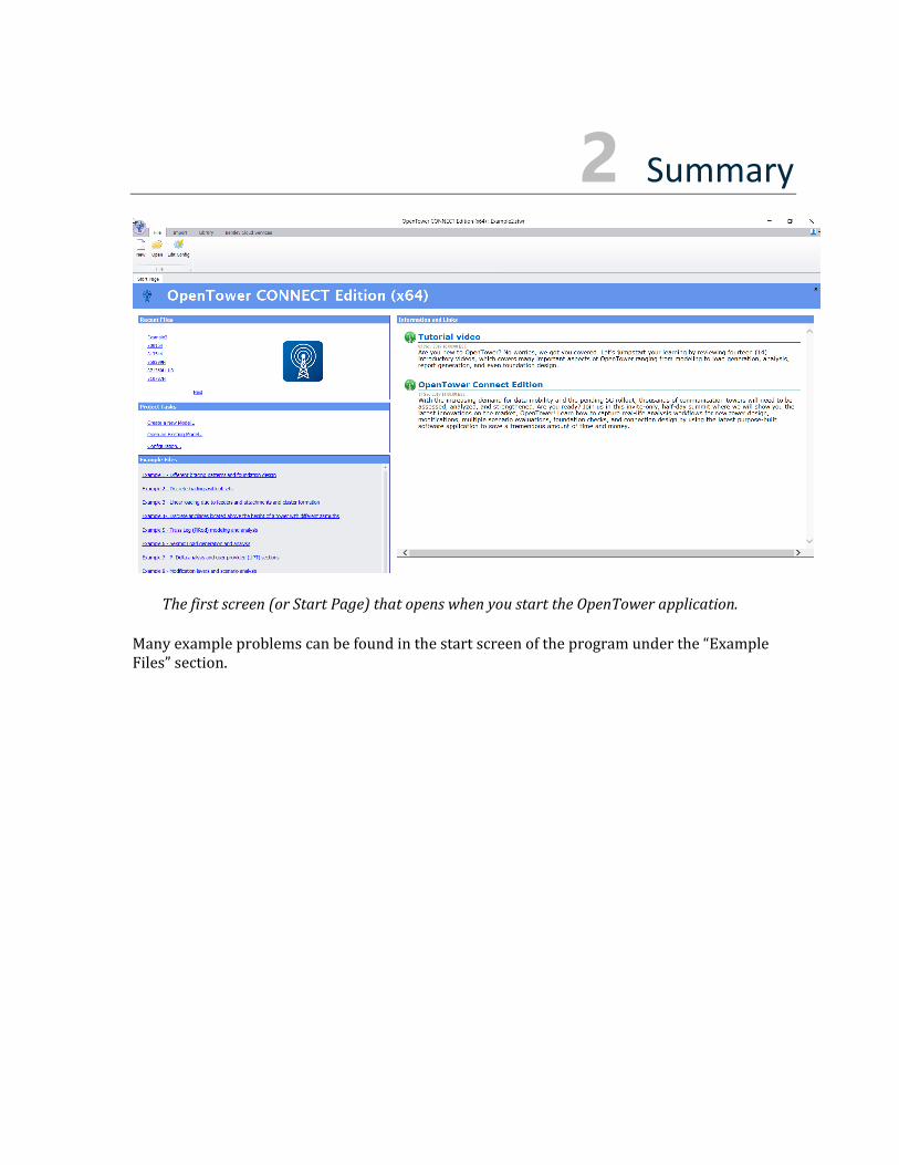
2 Summary
The first screen (or Start Page) that opens when you start the OpenTower application.
Many example problems can be found in the start screen of the program under the “Example Files” section.

3 Introduction OpenTower is a program developed by practicing tower engineers, for practicing tower engineers, and in collaboration with practicing tower engineers. It is designed to capture the typical workflow of a tower analysis and modification. A state-of-the-art technology, the program is futuristic by design for its openness and being user-friendly as the user interface was laid out by practicing engineers for the best possible user experience.
One of the most important aspects of the program is to divide the modeling into two distinct categories.
1) Geometry 2) Work Order (or loading)
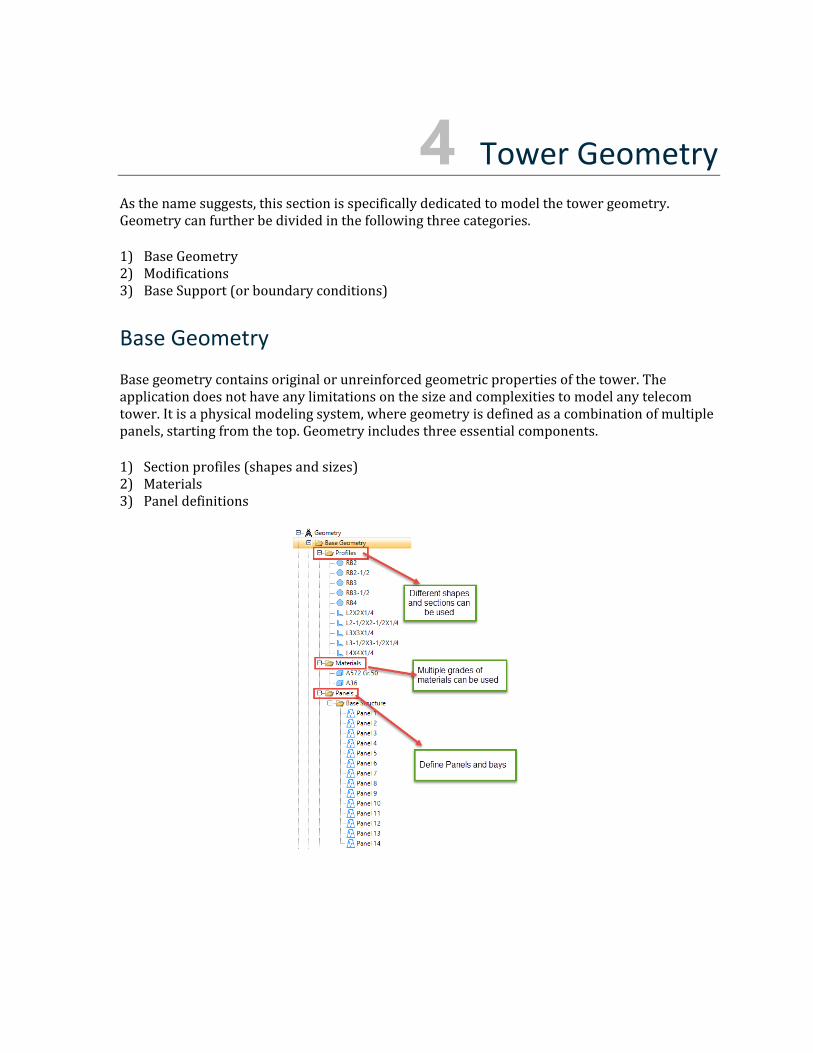
4 Tower Geometry As the name suggests, this section is specifically dedicated to model the tower geometry. Geometry can further be divided in the following three categories.
1) Base Geometry 2) Modifications 3) Base Support (or boundary conditions)
Base Geometry
Base geometry contains original or unreinforced geometric properties of the tower. The application does not have any limitations on the size and complexities to model any telecom tower. It is a physical modeling system, where geometry is defined as a combination of multiple panels, starting from the top. Geometry includes three essential components.
1) Section profiles (shapes and sizes) 2) Materials 3) Panel definitions
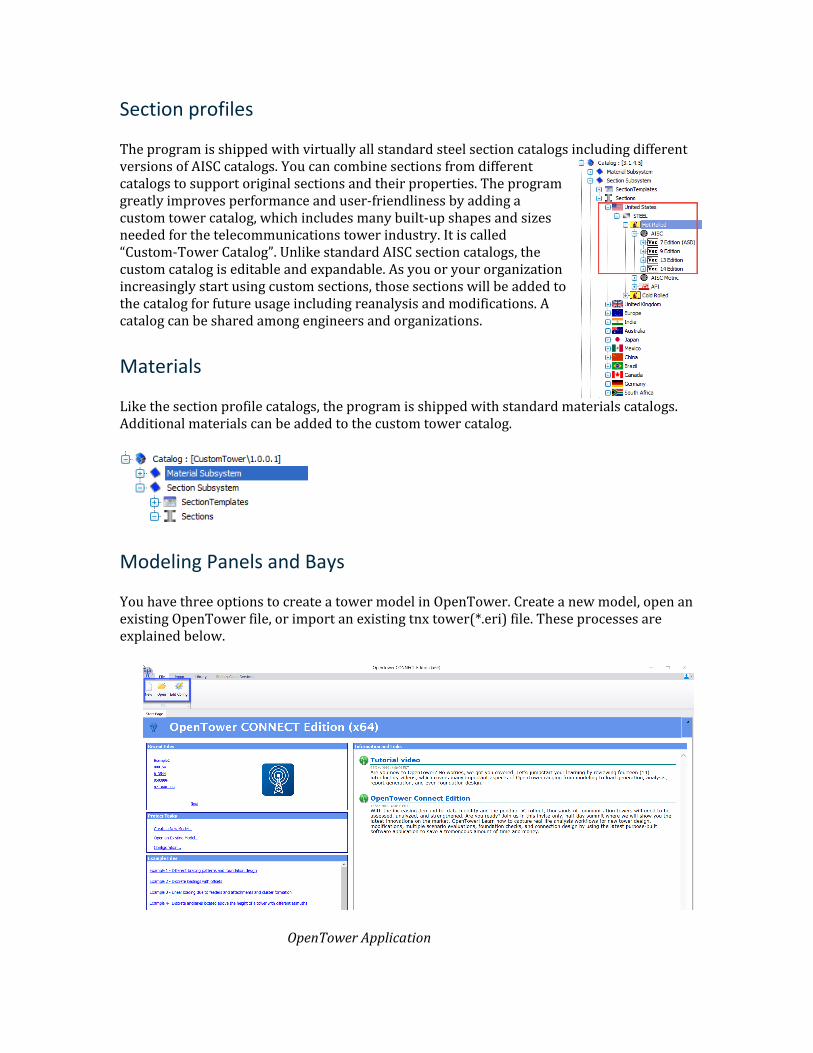
Section profiles
The program is shipped with virtually all standard steel section catalogs including different versions of AISC catalogs. You can combine sections from different catalogs to support original sections and their properties. The program greatly improves performance and user-friendliness by adding a custom tower catalog, which includes many built-up shapes and sizes needed for the telecommunications tower industry. It is called “Custom-Tower Catalog”. Unlike standard AISC section catalogs, the custom catalog is editable and expandable. As you or your organization increasingly start using custom sections, those sections will be added to the catalog for future usage including reanalysis and modifications. A catalog can be shared among engineers and organizations.
Materials
Like the section profile catalogs, the program is shipped with standard materials catalogs. Additional materials can be added to the custom tower catalog.
Modeling Panels and Bays
You have three options to create a tower model in OpenTower. Create a new model, open an existing OpenTower file, or import an existing tnx tower(*.eri) file. These processes are explained below.
OpenTower Application
Open an Existing Tower Model
1. On the Start ribbon tab, select Open.
2. Browse to and select the desired OpenTower (.STWR) file to open.
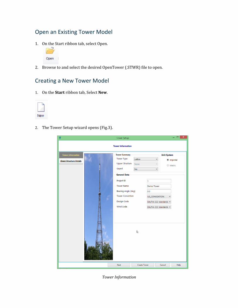
Creating a New Tower Model
1. On the Start ribbon tab, Select New.
2. The Tower Setup wizard opens (Fig.3).
Tower Information
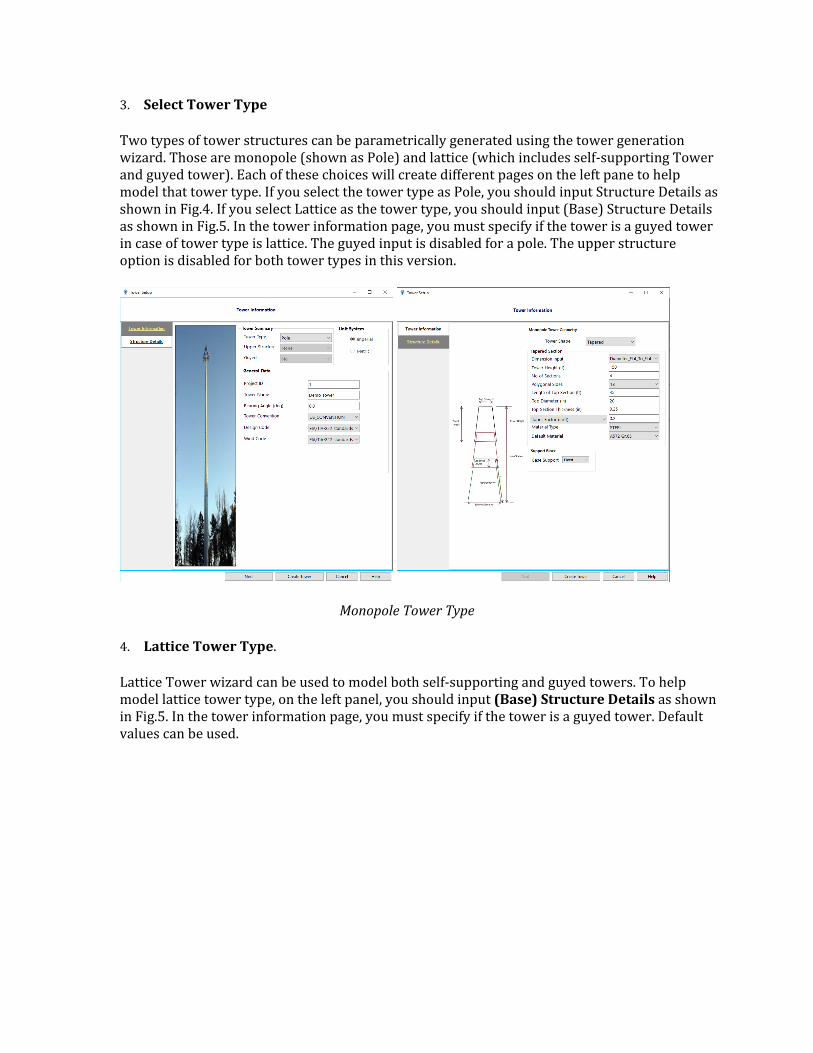
3. Select Tower Type
Two types of tower structures can be parametrically generated using the tower generation wizard. Those are monopole (shown as Pole) and lattice (which includes self-supporting Tower and guyed tower). Each of these choices will create different pages on the left pane to help model that tower type. If you select the tower type as Pole, you should input Structure Details as shown in Fig.4. If you select Lattice as the tower type, you should input (Base) Structure Details as shown in Fig.5. In the tower information page, you must specify if the tower is a guyed tower in case of tower type is lattice. The guyed input is disabled for a pole. The upper structure option is disabled for both tower types in this version.
Monopole Tower Type
4. Lattice Tower Type.
Lattice Tower wizard can be used to model both self-supporting and guyed towers. To help model lattice tower type, on the left panel, you should input (Base) Structure Details as shown in Fig.5. In the tower information page, you must specify if the tower is a guyed tower. Default values can be used.
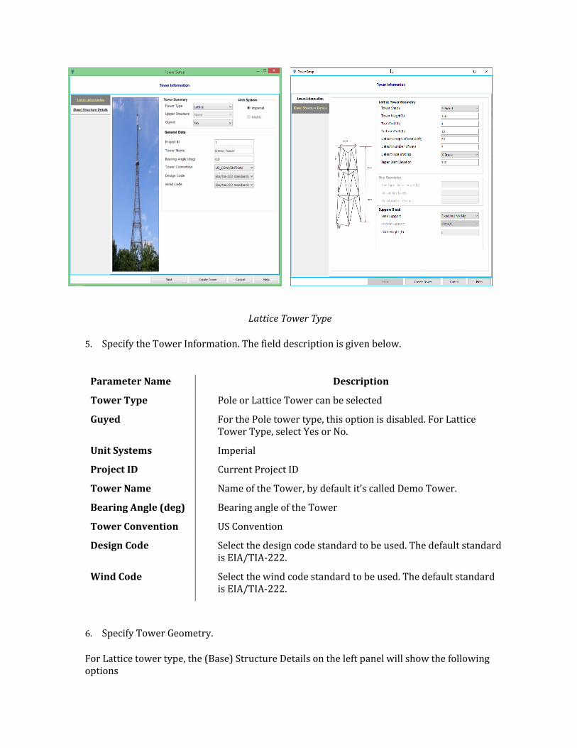
Lattice Tower Type
5. Specify the Tower Information. The field description is given below.
Parameter Name Description
Tower Type Pole or Lattice Tower can be selected
Guyed For the Pole tower type, this option is disabled. For Lattice Tower Type, select Yes or No.
Unit Systems Imperial
Project ID Current Project ID
Tower Name Name of the Tower, by default it’s called Demo Tower.
Bearing Angle (deg) Bearing angle of the Tower
Tower Convention US Convention
Design Code Select the design code standard to be used. The default standard is EIA/TIA-222.
Wind Code Select the wind code standard to be used. The default standard is EIA/TIA-222.
6. Specify Tower Geometry.
For Lattice tower type, the (Base) Structure Details on the left panel will show the following options
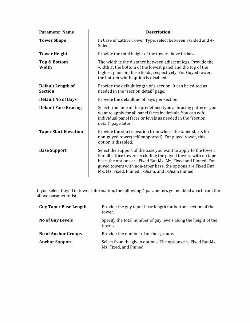
Parameter Name Description
Tower Shape In Case of Lattice Tower Type, select between 3-Sided and 4-Sided.
Tower Height Provide the total height of the tower above its base.
Top & Bottom Width
The width is the distance between adjacent legs. Provide the width at the bottom of the lowest panel and the top of the highest panel in these fields, respectively. For Guyed tower, the bottom width option is disabled.
Default Length of Section
Provide the default length of a section. It can be edited as needed in the “section detail” page.
Default No of Bays Provide the default no of bays per section.
Default Face Bracing Select from one of the predefined typical bracing patterns you want to apply for all panel faces by default. You can edit individual panel faces or levels as needed in the “section detail” page later.
Taper Start Elevation Provide the start elevation from where the taper starts for non-guyed tower(self-supported). For guyed tower, this option is disabled.
Base Support Select the support of the base you want to apply to the tower. For all lattice towers excluding the guyed towers with no taper base, the options are Fixed But Mx, Mz, Fixed and Pinned. For guyed towers with non-taper base, the options are Fixed But Mx, Mz, Fixed, Pinned, I-Beam, and I-Beam Pinned.
If you select Guyed in tower information, the following 4 parameters get enabled apart from the above parameter list.
Guy Taper Base Length Provide the guy taper base length for bottom section of the tower.
No of Guy Levels Specify the total number of guy levels along the height of the tower.
No of Anchor Groups Provide the number of anchor groups.
Anchor Support Select from the given options. The options are Fixed But Mx, Mz, Fixed, and Pinned.
Base Structure Details for Lattice Tower
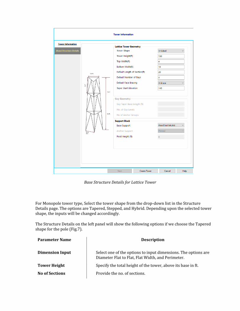
For Monopole tower type, Select the tower shape from the drop-down list in the Structure Details page. The options are Tapered, Stepped, and Hybrid. Depending upon the selected tower shape, the inputs will be changed accordingly.
The Structure Details on the left panel will show the following options if we choose the Tapered shape for the pole (Fig.7).
Parameter Name Description
Dimension Input Select one of the options to input dimensions. The options are Diameter Flat to Flat, Flat Width, and Perimeter.
Tower Height Specify the total height of the tower, above its base in ft.
No of Sections Provide the no. of sections.
Polygonal Sides Specify the number of polygonal sides (8,12,16,18) or choose Round.
Length of Top Section Provide the Length of Top Section in ft.
Top Diameter Provide the top section diameter in inch.
Top Section Thickness Provide the top section thickness in inch.
Taper Factor Provide tapered factor.
Material Type Choose the material type from the available options (steel or concrete)
Default Material Choose the default material from the combo box.
Base Support Select the Fixed base support. This input is common for all the pole shapes.
Structure Details for Tapered Shape Monopole Tower
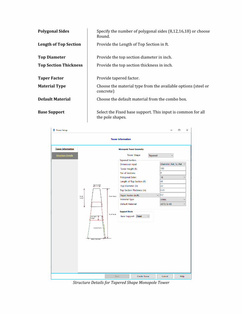
The structure details for the Stepped monopole tower will show the following input (Fig.8).
Parameter Name
Description
Tower Height Specify the total height of the tower, above its base in ft.
No of Sections Provide the no. of sections.
Country Select the United States
Specification Provide the specification from the combo box.
Shapes Select the shapes.
Default Section Profile
Provide the section profile from the option given in the combo box.
Material Type Choose the material type from the available options (steel or concrete)
Default Material Choose the default material from the combo box.
Base Support Select the Fixed base support. This input is common for all pole shapes.
Structure Details for Stepped Shape Monopole Tower
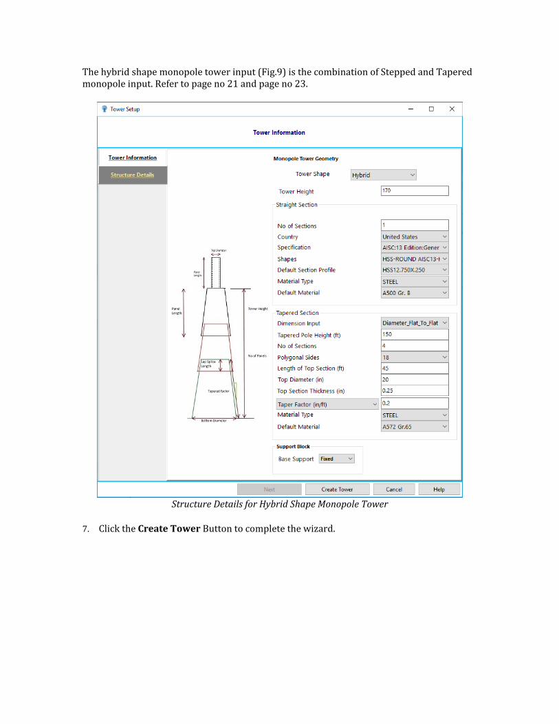
The hybrid shape monopole tower input (Fig.9) is the combination of Stepped and Tapered monopole input. Refer to page no 21 and page no 23.
Structure Details for Hybrid Shape Monopole Tower
7. Click the Create Tower Button to complete the wizard.
Import a tnxTower file into OpenTower
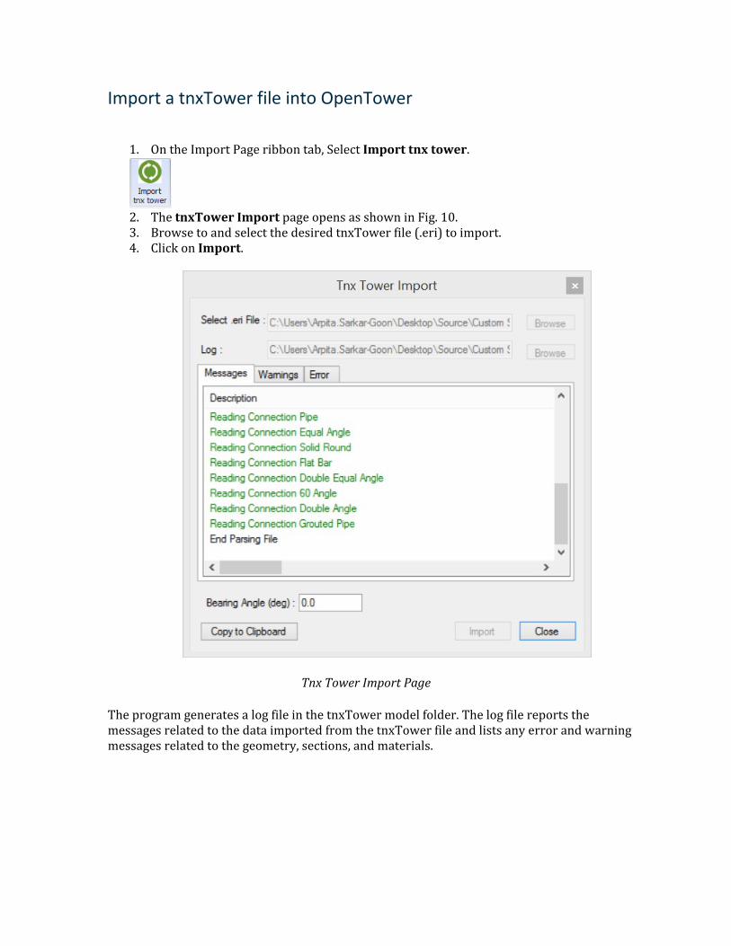
1. On the Import Page ribbon tab, Select Import tnx tower.
2. The tnxTower Import page opens as shown in Fig. 10. 3. Browse to and select the desired tnxTower file (.eri) to import. 4. Click on Import.
Tnx Tower Import Page
The program generates a log file in the tnxTower model folder. The log file reports the messages related to the data imported from the tnxTower file and lists any error and warning messages related to the geometry, sections, and materials.
Section Detail
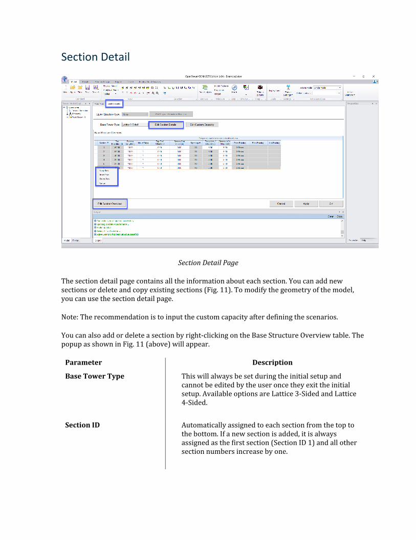
Section Detail Page
The section detail page contains all the information about each section. You can add new sections or delete and copy existing sections (Fig. 11). To modify the geometry of the model, you can use the section detail page.
Note: The recommendation is to input the custom capacity after defining the scenarios.
You can also add or delete a section by right-clicking on the Base Structure Overview table. The popup as shown in Fig. 11 (above) will appear.
Parameter Description
Base Tower Type This will always be set during the initial setup and cannot be edited by the user once they exit the initial setup. Available options are Lattice 3-Sided and Lattice 4-Sided.
Section ID Automatically assigned to each section from the top to the bottom. If a new section is added, it is always assigned as the first section (Section ID 1) and all other section numbers increase by one.
Top Elevation (ft) The height at the top of a given section, not including the base elevation. For lattice towers, this is simply the sum of the current section height and all the sections below.
Section Length (ft) The total length of the section is equal to the sum of all the bay lengths plus the top and bottom girt offsets. You can edit the section length.
No of Bays It is the number of braced sub-sections the tower section is divided into.
Top Girt Offset (in) The vertical distance from the top of the leg section to the working point where the first bay begins.
Bottom Girt Offset(in) The vertical distance from the working point where the last bay ends to the bottom of the leg section.
Spacing (ft) This is the length of each bay from the top to the bottom of the section. By default, each section is divided into equal bay height.
Top Width/(Depth) (ft) Width of the tower face at the top of each section as measured from center-to-center of the legs. For all but the top section, this is automatically set equal to the Bottom Width of the section above.
Bottom Width/(Depth) (ft) Width of the tower face at the bottom of each section as measured from center-to-center of the legs.
Face Bracing This is not user input, but simply a summary of the bracing types that are selected in the Section Editor. If the bracing type varies within a section, the table will have a comma-separated list of the bracing types for each bay from the top to the bottom of the section.
Plan Bracing A summary of the plan bracing for each bay as specified in the Section Editor.
Hip Bracing A summary of the hip bracing for each bay as specified in the Section Editor.
Section Editor
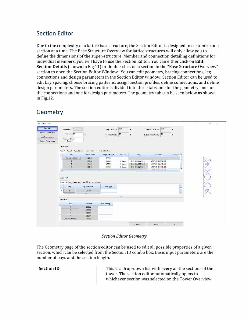
Due to the complexity of a lattice base structure, the Section Editor is designed to customize one section at a time. The Base Structure Overview for lattice structures will only allow you to define the dimensions of the super-structure. Member and connection detailing definitions for individual members, you will have to use the Section Editor. You can either click on Edit Section Details (shown in Fig.11) or double-click on a section in the “Base Structure Overview” section to open the Section Editor Window. You can edit geometry, bracing connections, leg connections and design parameters in the Section Editor window. Section Editor can be used to edit bay spacing, choose bracing patterns, assign Section profiles, define connections, and define design parameters. The section editor is divided into three tabs, one for the geometry, one for the connections and one for design parameters. The geometry tab can be seen below as shown in Fig.12.
Geometry
Section Editor Geometry
The Geometry page of the section editor can be used to edit all possible properties of a given section, which can be selected from the Section ID combo box. Basic input parameters are the number of bays and the section length.
Section ID This is a drop-down list with every all the sections of the tower. The section editor automatically opens to whichever section was selected on the Tower Overview,
but you can change the tower sections without returning to the Tower overview.
Top/Bottom Elevation These are non-editable fields displayed for reference. This information can only be adjusted in the Tower Overview.
Top/Bottom Face Width These are non-editable fields displayed for reference. This information can only be adjusted in the Tower Overview.
Top/Bottom Face Depth These are not inputs and are displayed for reference only. Also, it is displayed for 4-sided towers only.
Section Length (ft) You can input a section length here and the program should automatically adjust the table to evenly distribute the section length to the correct number of bays. However, if you change the length of an individual bay or adds a bay to the section, the section length should automatically update to reflect the sum of all bay lengths and girt offsets.
No of Bays This input directly edits the number of bays, the program evenly distributes the section length to the correct number of bays. However, if you add or delete a bay from the table, the number of bays in this box gets updated.
All Faces Identical (Checkbox)
When this option is checked you only need to enter data for face A and all other faces will use the same configuration. Checked by default. Member class Step does not get copied to the other faces and user has to input the profiles on each face if needed.
All Hips Identical (Checkbox)
When this option is checked you only need to enter data for Leg A hips and all other hips will use the same configuration. Checked by default.
All Bays Identical (Checkbox)
When this option is checked you only need to enter data for Bay 1 and all subsequent bays will be identical. Checked by default. Member class Bottom Horizontal does not get copied to the other bays as this class is applicable to the bottom segment of the panel.
Girt Offsets Girt offsets are applicable for the top and bottom bays only. All middle bays have this column inactive. If “All Bays Identical” is checked then the bottom girt offset automatically made equals to the top girt offset.
Top Horizontal The Top Horizontal of the Bay.
Bottom Horizontal The Bottom Horizontal is applicable to only bottom bay of the section.
Secondary Horizontal The secondary horizontal of the Bay.
Bracing Table** The bracing table is consisting of a few tables including one for each face, hip, and plan. The members can be assigned by double-clicking a cell to open the Section Profile Catalog. The default columns available for all face bracing types are Leg, Diagonal, Top Horizontal and Bottom Horizontals. However, depending on the selected bracing type, the columns may vary. The tables in the hip and plan tabs are different than the face tab and columns may vary depending on the selected bracing type. Refer to appendix for more details on different bracing patterns.
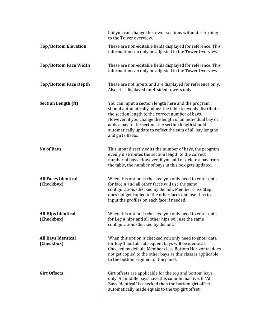
Section Profile Page
The section Profile Page (Fig. 13) can be used to edit or assign a section profile to a member. You can choose from any of the section catalogs including the custom tower catalog. Section and Materials can be Standard, Custom, or UPT. Depending on the type of selected catalog, available sections and materials are populated in the grid. You can mix and match, like select a section from a standard catalog along with a custom material, etc.
Section Profile
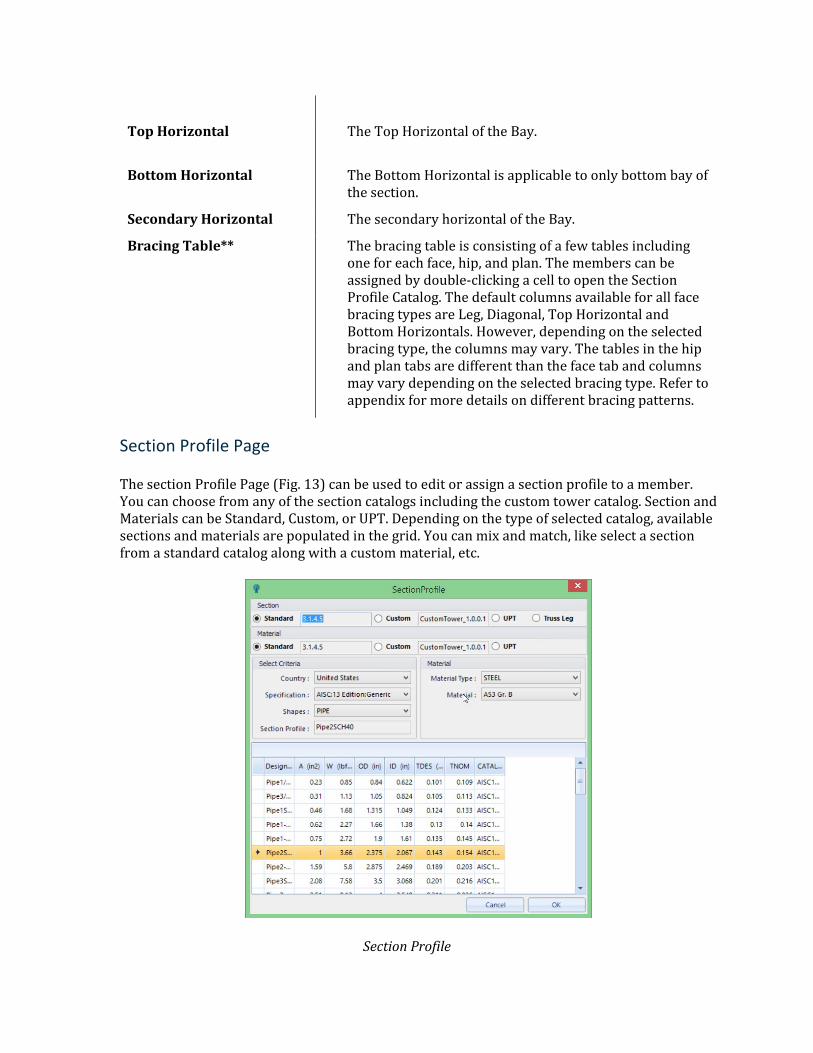
Bracing Connections
The bracing connection user interface allows users to assign bracing connections to the bracing members of a lattice tower. Though bracing connections on lattice towers are simple, they can be numerous and occasionally complex. The main goal of this interface is to allow the user to model the typical cases quickly while still having the flexibility to model complex connections as needed (Fig. 14).
Bracing Connections Page
Parameter Description
Bracing Connected Directly to Leg
This option is used to adjust the member lengths when bracing members are bolted or welded directly to the leg members. When checked, the effective length of the bracing members will be calculated from the internal edge of the leg members.
Member End Adjustment Length
This option is used to adjust the member length from both ends.
Section Adjustment Factors
These inputs are used to increase or decrease the wind area and weight of the section.
Group by Member and Type (Checkbox)
Checked by default. When checked all members of the same type and section property are grouped into one row.
Check Gusset Connections (Checkbox)
When checked four additional columns are enabled and user can define the start and end connection details for Gusset Horizontal Edge Distance (Gusset Hor.) and Gusset Vertical Edge Distance (Gusset Vert.). When unchecked these columns are disabled. The Gusset Horizontal Edge distance is further used to perform gusset bearing check calculations.
End Condition This input allows the program to do two things. First, it helps to design the bolt connections correctly using the shear condition on the bolts. All concentric connections are assumed to be double shear. Second, it allows the program to choose the effective slenderness ratio equation for design calculations.
Pattern* This is the bolt pattern used to connect the bracing member. Zero is an option if the connection is welded or requires special design consideration. Refer to Appendix.
Edge/Pitch/Gage/Gage Spacing
Provide the measurements of gage and edge distance. When bolt patterns are staggered, the pitch is the distance between two bolts in a row.
Gusset Horzi. /Gusset Vertical
These options are activated by the “Check Gusset Connection” checkbox. When active you can specify a horizontal and vertical edge distance from the gusset to the reference of the bolt group. If you enter zero for the vertical edge distance, then the bolt group is assumed to be in the middle of the gusset plate where there is no block rupture path involving the top or bottom edges of the gusset.
Mirror (Checkbox) When checked for an individual row this makes the end connection the same as the start connection. The top box is meant to toggle this option for all rows.
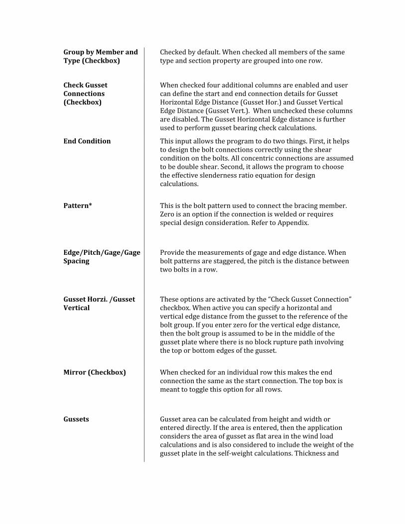
Gussets Gusset area can be calculated from height and width or entered directly. If the area is entered, then the application considers the area of gusset as flat area in the wind load calculations and is also considered to include the weight of the gusset plate in the self-weight calculations. Thickness and
Material are used to calculate the correct weight and to check the bolted connection on the gusset.
The Panel view on the right shows the image of the connection that gets updated based on your input.
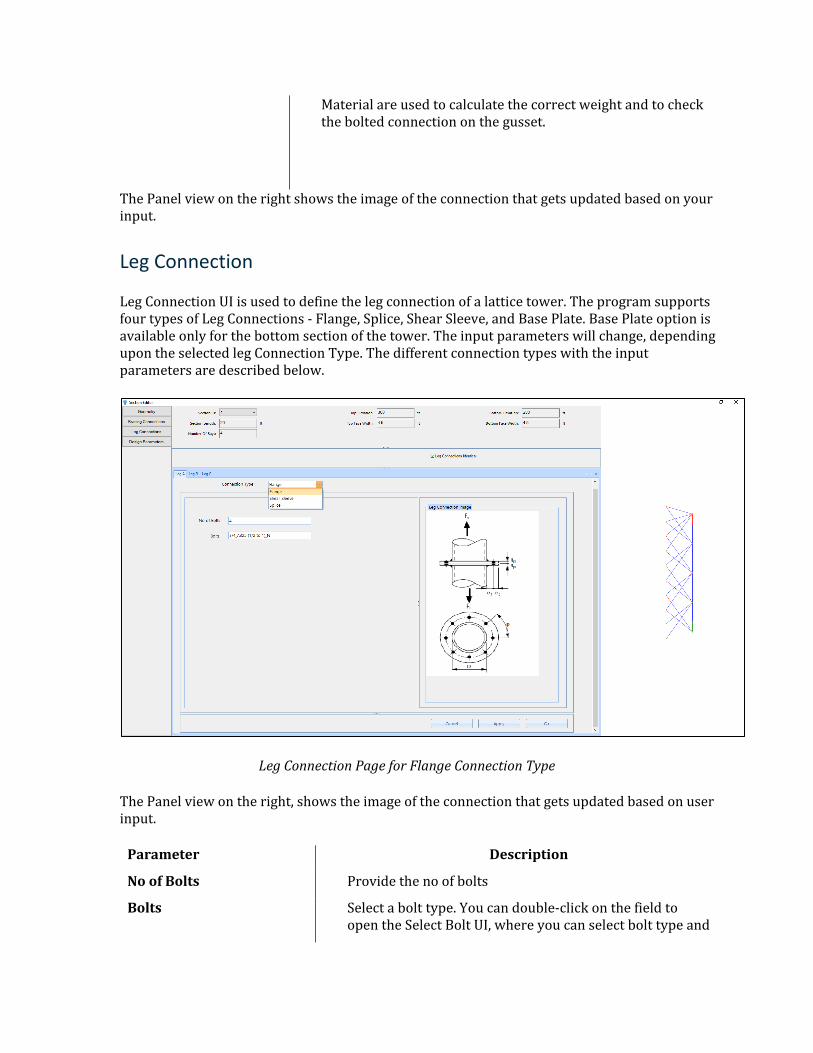
Leg Connection
Leg Connection UI is used to define the leg connection of a lattice tower. The program supports four types of Leg Connections - Flange, Splice, Shear Sleeve, and Base Plate. Base Plate option is available only for the bottom section of the tower. The input parameters will change, depending upon the selected leg Connection Type. The different connection types with the input parameters are described below.
Leg Connection Page for Flange Connection Type
The Panel view on the right, shows the image of the connection that gets updated based on user input.
Parameter Description
No of Bolts Provide the no of bolts
Bolts Select a bolt type. You can double-click on the field to open the Select Bolt UI, where you can select bolt type and
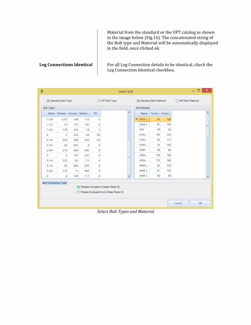
Material from the standard or the UPT catalog as shown in the image below (Fig.16). The concatenated string of the Bolt type and Material will be automatically displayed in the field, once clicked ok.
Leg Connections Identical For all Leg Connection details to be identical, check the Leg Connection Identical checkbox.
Select Bolt Types and Material
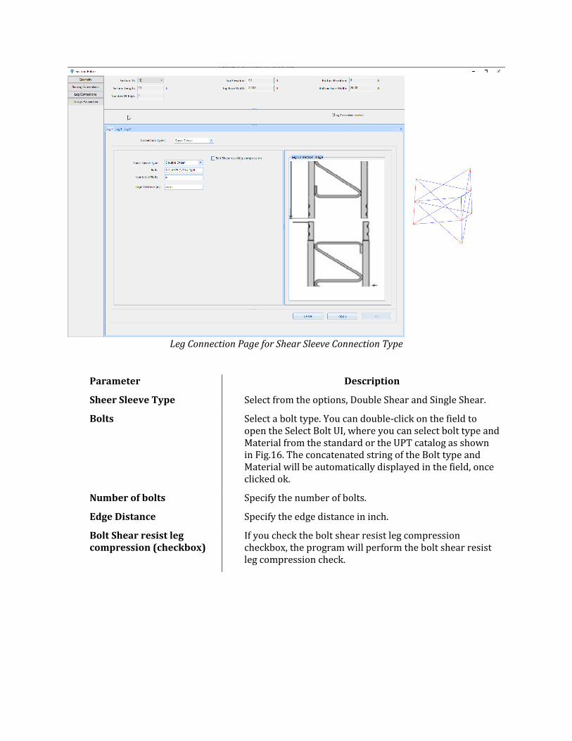
Leg Connection Page for Shear Sleeve Connection Type
Parameter Description
Sheer Sleeve Type Select from the options, Double Shear and Single Shear.
Bolts Select a bolt type. You can double-click on the field to open the Select Bolt UI, where you can select bolt type and Material from the standard or the UPT catalog as shown in Fig.16. The concatenated string of the Bolt type and Material will be automatically displayed in the field, once clicked ok.
Number of bolts Specify the number of bolts.
Edge Distance Specify the edge distance in inch.
Bolt Shear resist leg compression (checkbox)
If you check the bolt shear resist leg compression checkbox, the program will perform the bolt shear resist leg compression check.
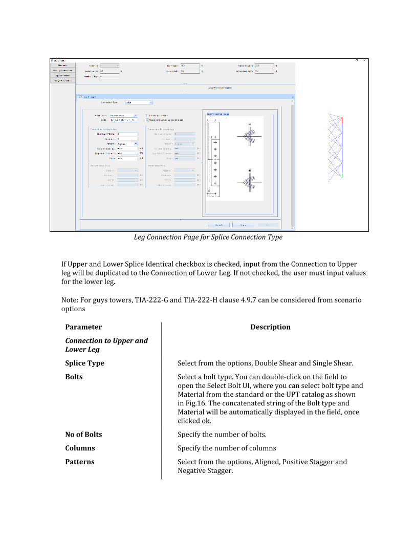
Leg Connection Page for Splice Connection Type
If Upper and Lower Splice Identical checkbox is checked, input from the Connection to Upper leg will be duplicated to the Connection of Lower Leg. If not checked, the user must input values for the lower leg.
Note: For guys towers, TIA-222-G and TIA-222-H clause 4.9.7 can be considered from scenario options
Parameter Description
Connection to Upper and Lower Leg
Splice Type Select from the options, Double Shear and Single Shear.
Bolts Select a bolt type. You can double-click on the field to open the Select Bolt UI, where you can select bolt type and Material from the standard or the UPT catalog as shown in Fig.16. The concatenated string of the Bolt type and Material will be automatically displayed in the field, once clicked ok.
No of Bolts Specify the number of bolts.
Columns Specify the number of columns
Patterns Select from the options, Aligned, Positive Stagger and Negative Stagger.
Column Spacing Specify column spacing in inch, by default auto is used.
Leg Edge Distance Specify column spacing in inch, by default auto is used.
Pitch Specify column spacing in inch, by default auto is used.
Outside and Inside Splice Plate
Material Select material from the combo box. This option is enabled only if Check Splice Plate checkbox is checked.
Thickness Specify the Splice Plate thickness in inch. This option is enabled only if Check Splice Plate checkbox is checked.
Width Specify the splice plate width in inch. This option is enabled only if Check Splice Plate checkbox is checked.
Edge Distance Specify the edge distance in inch. This option is enabled only if Check Splice Plate checkbox is checked.
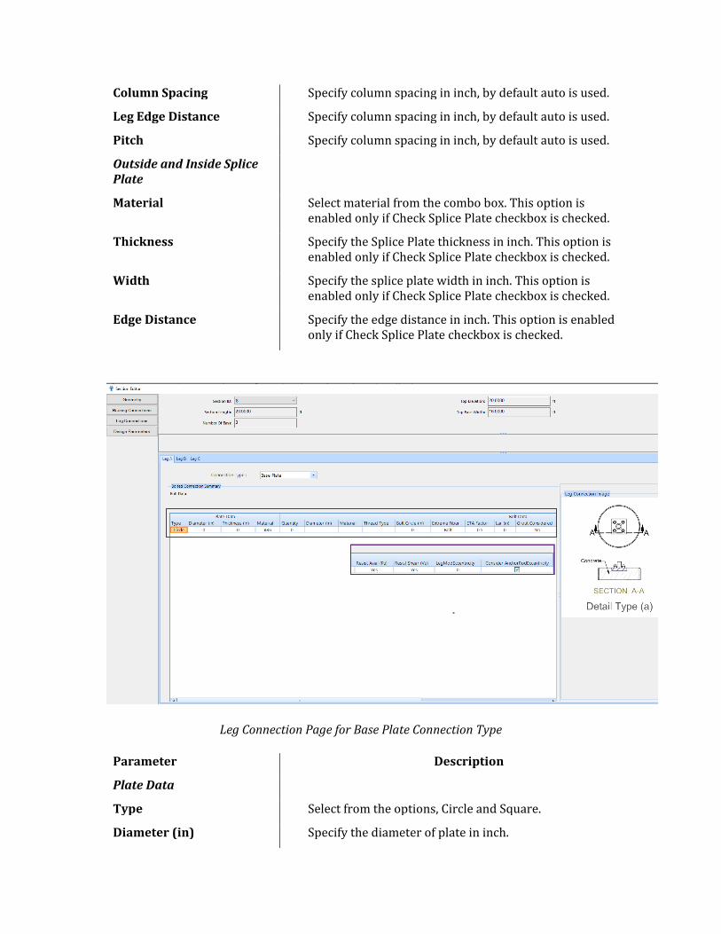
Leg Connection Page for Base Plate Connection Type
Parameter Description
Plate Data
Type Select from the options, Circle and Square.
Diameter (in) Specify the diameter of plate in inch.
Thickness (in) Specify the thickness of plate in inch.
Material Select material from the combo box.
Bolt Data
Quantity Specify the number of bolts.
Diameter (in) Select a bolt type. You can double-click on the field to open the Select Bolt UI, where you can select bolt type and Material from the standard or the UPT catalog as shown in Fig.16. The concatenated string of the Bolt type and Material will be automatically displayed in the field, once clicked ok.
Material It’s a read only parameter and gets populated after user selected the bolt diameter, material, and thread type in Select Bolt UI.
Thread Type It’s a read only parameter and gets populated after user selected the bolt diameter, material, and thread type in Select Bolt UI. Options threads included in shear plane or excluded from shear plane.
Bolt Circle (in) Specify the bolt circle in inch.
Extreme Fiber Select from the options Bolt and Bolts. represents different arrangement of bolts. Refer to appendix
ETA Factor Select from the options, 0.5,0.55,0.7, and 0.9. This option is used in the calculation for TIA-222-G design standard scenario.
Lar (in) Specify the lar in inch. “Lar” is the anchor rod projection from supporting surface to bottom of leveling nut.
Grout Considered Select from the options Yes and No. This option is applicable for TIA-222-G and TIA-222-H only. In case of Yes, the anchor rod bending interaction equation is secluded from the design checks whereas in case of No, based on the selected standard scenario, the design checks performed.
Resist Axial (Pu) Select from the options Yes and No.
Resist Shear (Vu) Select from the options Yes and No.
Leg Mod Eccentricity (in) Specify the eccentricity due to leg modification shapes connected to the baseplate.
Consider Anchor Rod Eccentricity
Check or uncheck the option to consider the eccentricity due to anchor rod locations. Default is checked always.
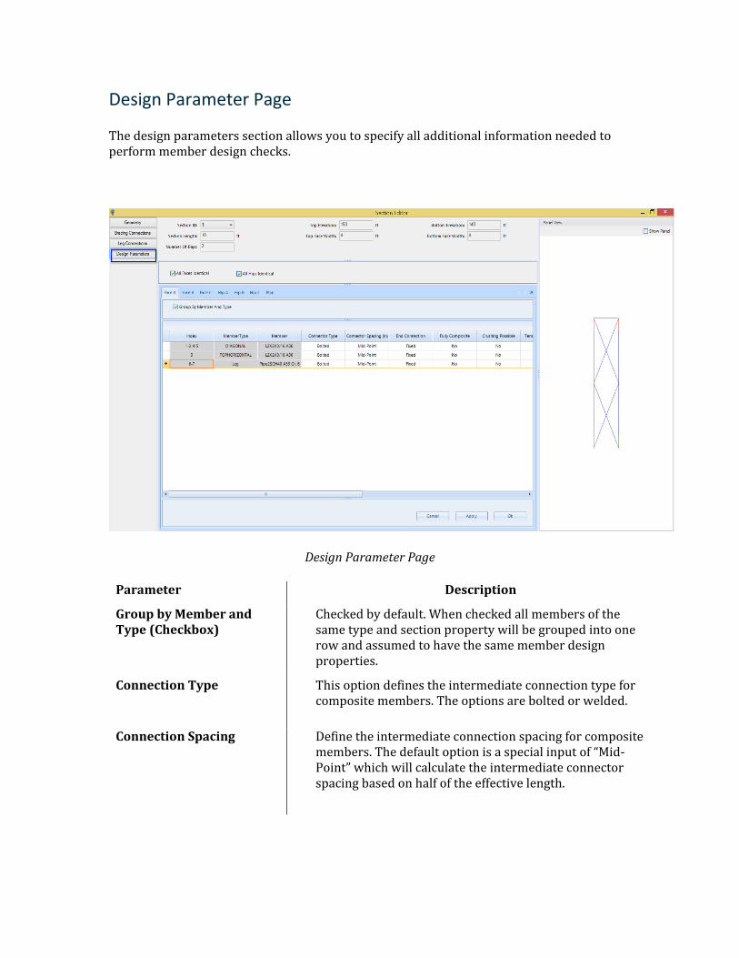
Design Parameter Page
The design parameters section allows you to specify all additional information needed to perform member design checks.
Design Parameter Page
Parameter Description
Group by Member and Type (Checkbox)
Checked by default. When checked all members of the same type and section property will be grouped into one row and assumed to have the same member design properties.
Connection Type This option defines the intermediate connection type for composite members. The options are bolted or welded.
Connection Spacing Define the intermediate connection spacing for composite members. The default option is a special input of “Mid-Point” which will calculate the intermediate connector spacing based on half of the effective length.
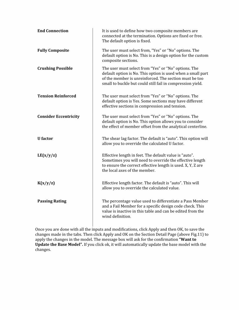
End Connection It is used to define how two composite members are connected at the termination. Options are fixed or free. The default option is fixed.
Fully Composite The user must select from, “Yes” or “No” options. The default option is No. This is a design option for the custom composite sections.
Crushing Possible The user must select from “Yes” or “No” options. The default option is No. This option is used when a small part of the member is unreinforced. The section must be too small to buckle but could still fail in compression yield.
Tension Reinforced The user must select from “Yes” or “No” options. The default option is Yes. Some sections may have different effective sections in compression and tension.
Consider Eccentricity The user must select from “Yes” or “No” options. The default option is No. This option allows you to consider the effect of member offset from the analytical centerline.
U factor The shear lag factor. The default is “auto”. This option will allow you to override the calculated U factor.
LE(x/y/z) Effective length in feet. The default value is “auto”. Sometimes you will need to override the effective length to ensure the correct effective length is used. X, Y, Z are the local axes of the member.
K(x/y/z) Effective length factor. The default is “auto”. This will allow you to override the calculated value.
Passing Rating The percentage value used to differentiate a Pass Member and a Fail Member for a specific design code check. This value is inactive in this table and can be edited from the wind definition.
Once you are done with all the inputs and modifications, click Apply and then OK, to save the changes made in the tabs. Then click Apply and OK on the Section Detail Page (above Fig.11) to apply the changes in the model. The message box will ask for the confirmation “Want to Update the Base Model”. If you click ok, it will automatically update the base model with the changes.
Edit Section Overview
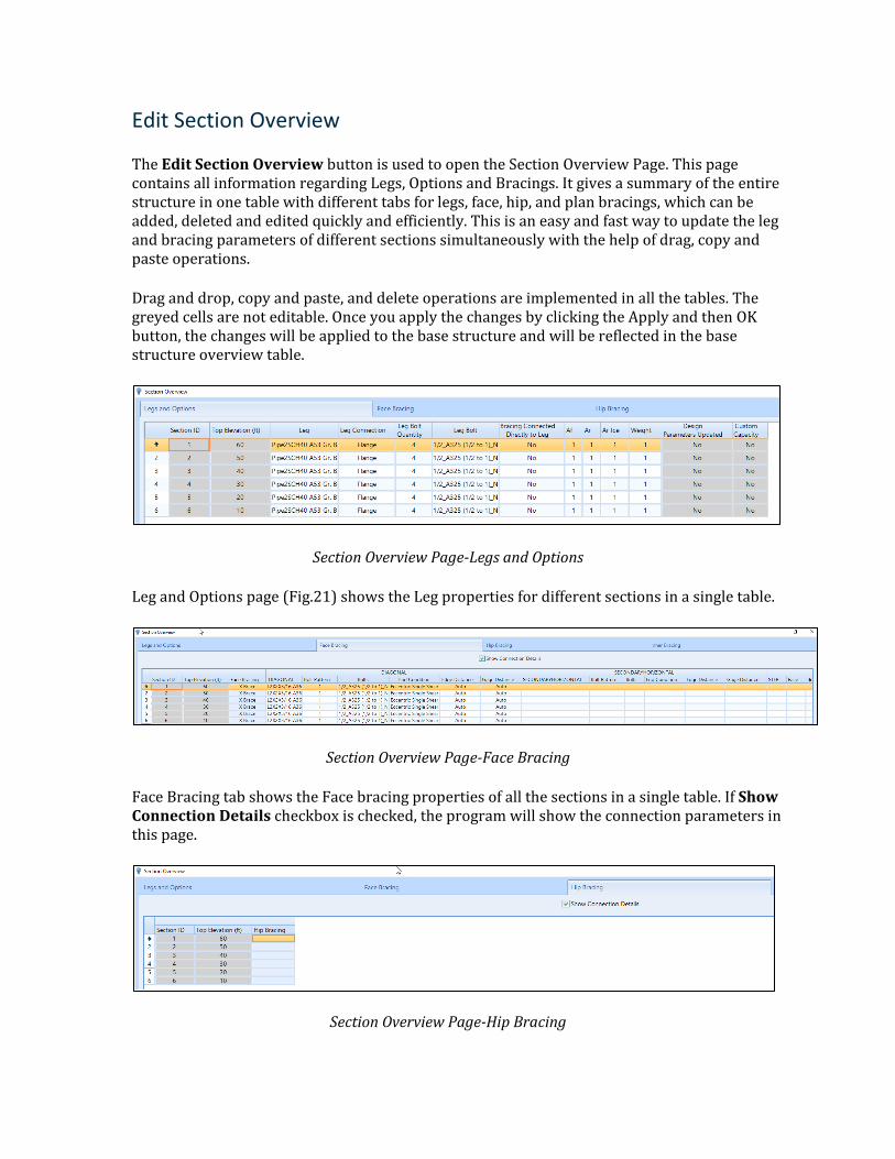
The Edit Section Overview button is used to open the Section Overview Page. This page contains all information regarding Legs, Options and Bracings. It gives a summary of the entire structure in one table with different tabs for legs, face, hip, and plan bracings, which can be added, deleted and edited quickly and efficiently. This is an easy and fast way to update the leg and bracing parameters of different sections simultaneously with the help of drag, copy and paste operations.
Drag and drop, copy and paste, and delete operations are implemented in all the tables. The greyed cells are not editable. Once you apply the changes by clicking the Apply and then OK button, the changes will be applied to the base structure and will be reflected in the base structure overview table.
Section Overview Page-Legs and Options
Leg and Options page (Fig.21) shows the Leg properties for different sections in a single table.
Section Overview Page-Face Bracing
Face Bracing tab shows the Face bracing properties of all the sections in a single table. If Show Connection Details checkbox is checked, the program will show the connection parameters in this page.
Section Overview Page-Hip Bracing
The hip Bracing tab shows the Hip bracing properties of all the sections in a single table. If Show Connection Details checkbox is checked it will show the connection parameters in the page.
Section Overview Page-Inner Bracing
Inner Bracing tab shows the Inner bracing properties of all the sections in a single table. Show Connection Details checkbox, if checked will show the connection parameters, in the page.
Edit Custom Capacity
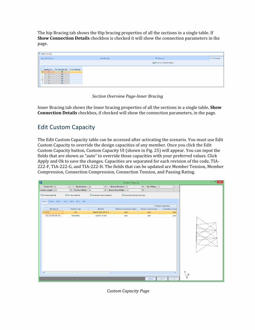
The Edit Custom Capacity table can be accessed after activating the scenario. You must use Edit Custom Capacity to override the design capacities of any member. Once you click the Edit Custom Capacity button, Custom Capacity UI (shown in Fig. 25) will appear. You can input the fields that are shown as “auto” to override those capacities with your preferred values. Click Apply and Ok to save the changes. Capacities are separated for each revision of the code, TIA-222-F, TIA-222-G, and TIA-222-H. The fields that can be updated are Member Tension, Member Compression, Connection Compression, Connection Tension, and Passing Rating.
Custom Capacity Page
Section Detail (Monopole)
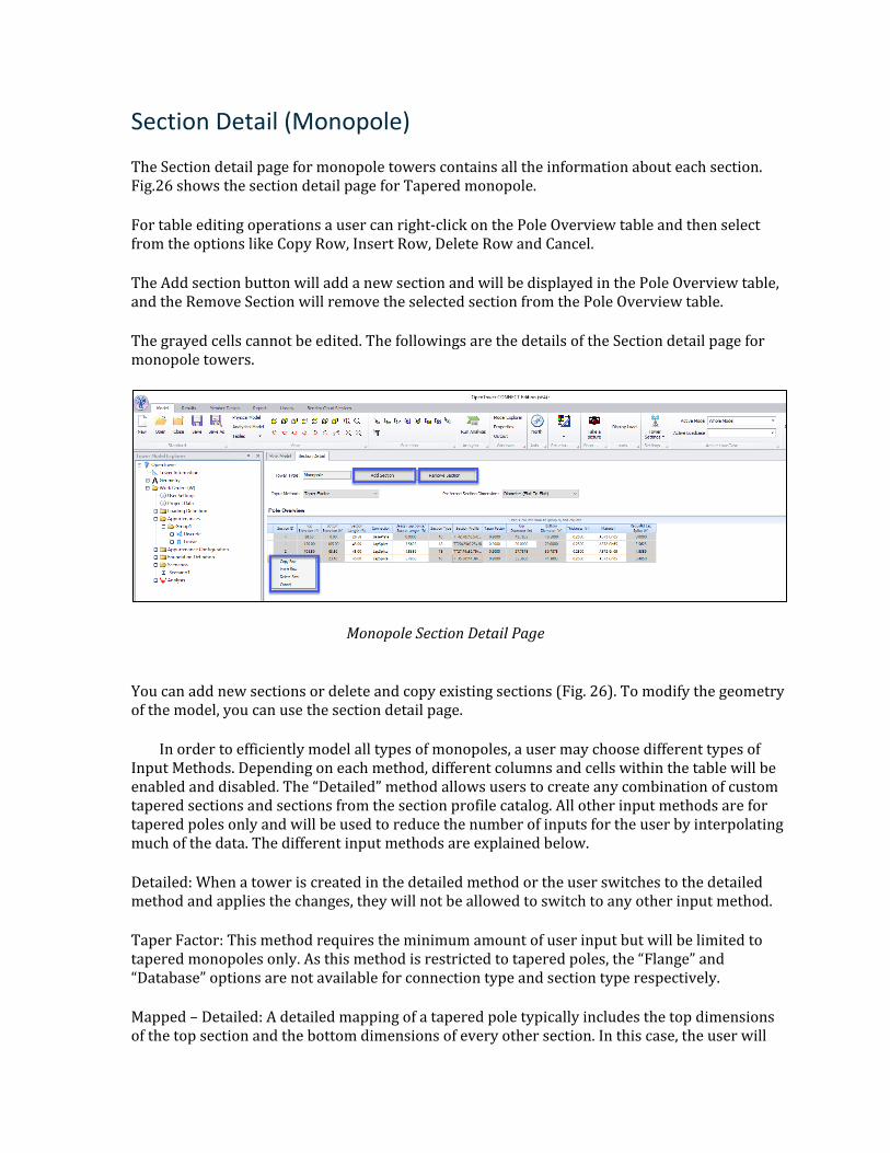
The Section detail page for monopole towers contains all the information about each section. Fig.26 shows the section detail page for Tapered monopole.
For table editing operations a user can right-click on the Pole Overview table and then select from the options like Copy Row, Insert Row, Delete Row and Cancel.
The Add section button will add a new section and will be displayed in the Pole Overview table, and the Remove Section will remove the selected section from the Pole Overview table.
The grayed cells cannot be edited. The followings are the details of the Section detail page for monopole towers.
Monopole Section Detail Page
You can add new sections or delete and copy existing sections (Fig. 26). To modify the geometry of the model, you can use the section detail page.
In order to efficiently model all types of monopoles, a user may choose different types of Input Methods. Depending on each method, different columns and cells within the table will be enabled and disabled. The “Detailed” method allows users to create any combination of custom tapered sections and sections from the section profile catalog. All other input methods are for tapered poles only and will be used to reduce the number of inputs for the user by interpolating much of the data. The different input methods are explained below.
Detailed: When a tower is created in the detailed method or the user switches to the detailed method and applies the changes, they will not be allowed to switch to any other input method.
Taper Factor: This method requires the minimum amount of user input but will be limited to tapered monopoles only. As this method is restricted to tapered poles, the “Flange” and “Database” options are not available for connection type and section type respectively.
Mapped – Detailed: A detailed mapping of a tapered pole typically includes the top dimensions of the top section and the bottom dimensions of every other section. In this case, the user will
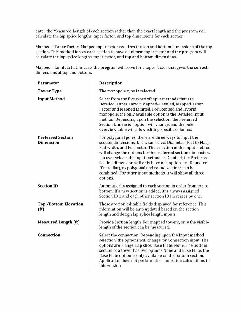
enter the Measured Length of each section rather than the exact length and the program will calculate the lap splice lengths, taper factor, and top dimensions for each section.
Mapped – Taper Factor: Mapped taper factor requires the top and bottom dimensions of the top section. This method forces each section to have a uniform taper factor and the program will calculate the lap splice lengths, taper factor, and top and bottom dimensions.
Mapped – Limited: In this case, the program will solve for a taper factor that gives the correct dimensions at top and bottom.
Parameter Description
Tower Type The monopole type is selected.
Input Method Select from the five types of input methods that are, Detailed, Taper Factor, Mapped-Detailed, Mapped Taper Factor and Mapped Limited. For Stepped and Hybrid monopole, the only available option is the Detailed input method. Depending upon the selection, the Preferred Section Dimension option will change, and the pole overview table will allow editing specific columns.
Preferred Section Dimension
For polygonal poles, there are three ways to input the section dimensions. Users can select Diameter (Flat to Flat), Flat width, and Perimeter. The selection of the input method will change the options for the preferred section dimension. If a user selects the input method as Detailed, the Preferred Section dimension will only have one option, i.e., Diameter (flat to flat), as polygonal and round sections can be combined. For other input methods, it will show all three options.
Section ID Automatically assigned to each section in order from top to bottom. If a new section is added, it is always assigned Section ID 1 and each other section ID increases by one.
Top /Bottom Elevation (ft)
These are non-editable fields displayed for reference. This information will be auto updated based on the section length and design lap splice length inputs.
Measured Length (ft) Provide Section length. For mapped towers, only the visible length of the section can be measured.
Connection Select the connection. Depending upon the Input method selection, the options will change for Connection input. The options are Flange, Lap slice, Base Plate, None. The bottom section of a tower has two options None and Base Plate, the Base Plate option is only available on the bottom section. Application does not perform the connection calculations in this version
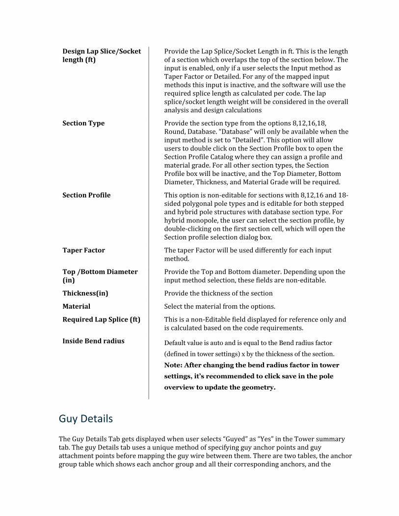
Design Lap Slice/Socket length (ft)
Provide the Lap Splice/Socket Length in ft. This is the length of a section which overlaps the top of the section below. The input is enabled, only if a user selects the Input method as Taper Factor or Detailed. For any of the mapped input methods this input is inactive, and the software will use the required splice length as calculated per code. The lap splice/socket length weight will be considered in the overall analysis and design calculations
Section Type Provide the section type from the options 8,12,16,18, Round, Database. “Database” will only be available when the input method is set to “Detailed”. This option will allow users to double click on the Section Profile box to open the Section Profile Catalog where they can assign a profile and material grade. For all other section types, the Section Profile box will be inactive, and the Top Diameter, Bottom Diameter, Thickness, and Material Grade will be required.
Section Profile This option is non-editable for sections with 8,12,16 and 18-sided polygonal pole types and is editable for both stepped and hybrid pole structures with database section type. For hybrid monopole, the user can select the section profile, by double-clicking on the first section cell, which will open the Section profile selection dialog box.
Taper Factor The taper Factor will be used differently for each input method.
Top /Bottom Diameter (in)
Provide the Top and Bottom diameter. Depending upon the input method selection, these fields are non-editable.
Thickness(in) Provide the thickness of the section
Material Select the material from the options.
Required Lap Splice (ft) This is a non-Editable field displayed for reference only and is calculated based on the code requirements.
Inside Bend radius Default value is auto and is equal to the Bend radius factor
(defined in tower settings) x by the thickness of the section.
Note: After changing the bend radius factor in tower
settings, it’s recommended to click save in the pole
overview to update the geometry.
Guy Details
The Guy Details Tab gets displayed when user selects “Guyed” as “Yes” in the Tower summary tab. The guy Details tab uses a unique method of specifying guy anchor points and guy attachment points before mapping the guy wire between them. There are two tables, the anchor group table which shows each anchor group and all their corresponding anchors, and the
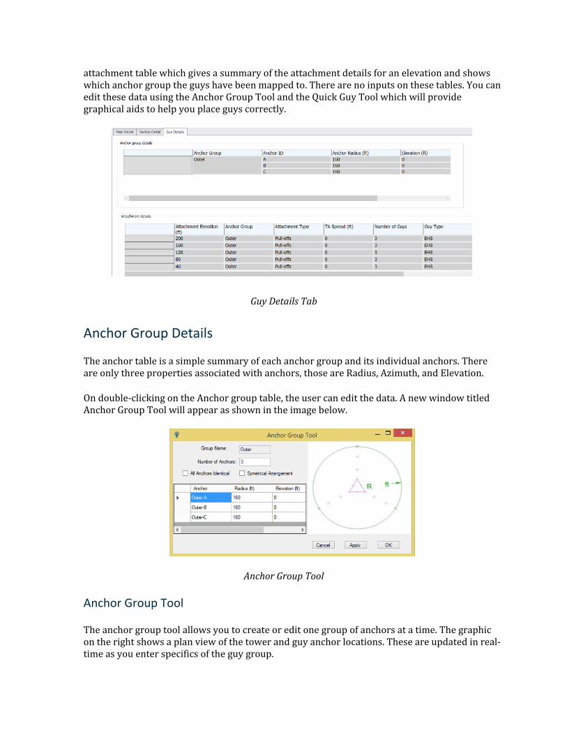
attachment table which gives a summary of the attachment details for an elevation and shows which anchor group the guys have been mapped to. There are no inputs on these tables. You can edit these data using the Anchor Group Tool and the Quick Guy Tool which will provide graphical aids to help you place guys correctly.
Guy Details Tab
Anchor Group Details
The anchor table is a simple summary of each anchor group and its individual anchors. There are only three properties associated with anchors, those are Radius, Azimuth, and Elevation.
On double-clicking on the Anchor group table, the user can edit the data. A new window titled Anchor Group Tool will appear as shown in the image below.
Anchor Group Tool
Anchor Group Tool
The anchor group tool allows you to create or edit one group of anchors at a time. The graphic on the right shows a plan view of the tower and guy anchor locations. These are updated in real-time as you enter specifics of the guy group.
Parameter Description
Group Name You can enter any name for the group when you are adding groups, else it will show the selected group.
Number of Anchors The number of anchors in a group. The default is 3.
Anchor Table There will be one row in this table for each anchor. The anchor names will be automatically generated based on the group name. Anchor radius, elevation, and azimuth can be edited here.
All Anchors Identical (Checkbox)
When checked, you only need to enter Radius and Elevation of the first anchor.
Symmetrical Arrangement (Checkbox)
When checked, you only need to enter an azimuth for the first anchor. All other anchors will be evenly distributed based on the number of anchors.
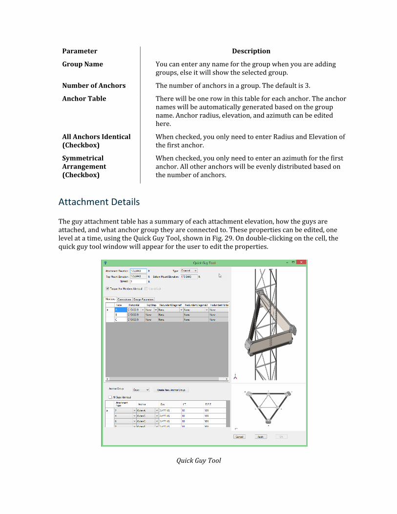
Attachment Details
The guy attachment table has a summary of each attachment elevation, how the guys are attached, and what anchor group they are connected to. These properties can be edited, one level at a time, using the Quick Guy Tool, shown in Fig. 29. On double-clicking on the cell, the quick guy tool window will appear for the user to edit the properties.
Quick Guy Tool
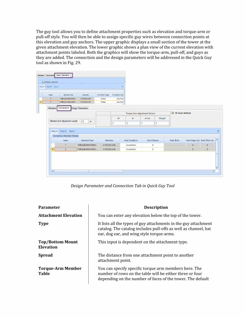
The guy tool allows you to define attachment properties such as elevation and torque-arm or pull-off style. You will then be able to assign specific guy wires between connection points at this elevation and guy anchors. The upper graphic displays a small section of the tower at the given attachment elevation. The lower graphic shows a plan view of the current elevation with attachment points labeled. Both the graphics will show the torque-arm, pull-off, and guys as they are added. The connection and the design parameters will be addressed in the Quick Guy tool as shown in Fig. 29.
Design Parameter and Connection Tab in Quick Guy Tool
Parameter Description
Attachment Elevation You can enter any elevation below the top of the tower.
Type It lists all the types of guy attachments in the guy attachment catalog. The catalog includes pull-offs as well as channel, bat ear, dog ear, and wing style torque-arms.
Top/Bottom Mount Elevation
This input is dependent on the attachment type.
Spread The distance from one attachment point to another attachment point.
Torque-Arm Member Table
You can specify specific torque arm members here. The number of rows on the table will be either three or four depending on the number of faces of the tower. The default
columns will be Top Strap, Bottom Strap, and Horizontal. Many additional columns will be added for various torque arm types
Torque Arm Members Identical (Checkbox)
When checked, you will only need to input member types for face A.
Anchor Group This is a dropdown box that lists all the anchor groups that you have already defined. There is also an option for “Varies” which will allow you to assign guys to anchors in any group. In case you did not define anchor groups before getting to this screen you can click the “create new anchor group” option to be taken to the Anchor Tool before continuing.
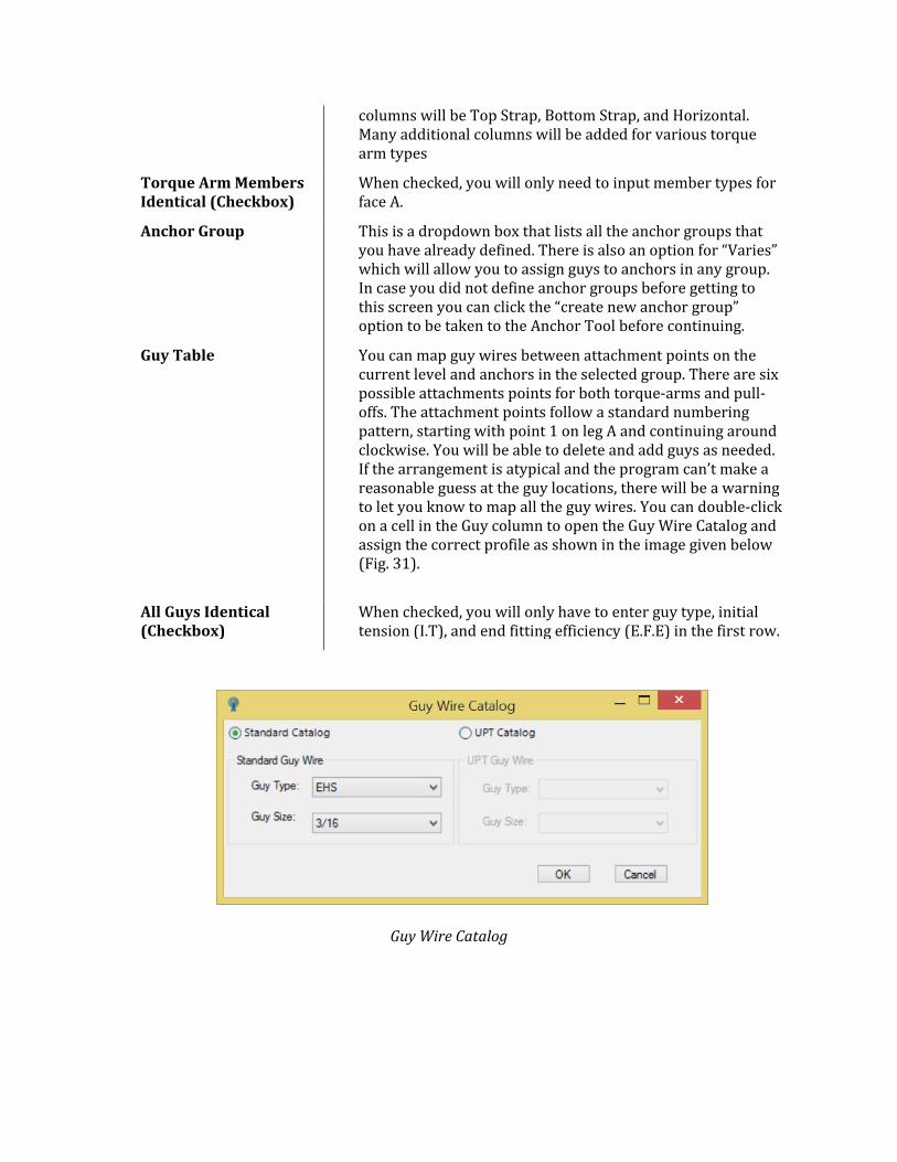
Guy Table You can map guy wires between attachment points on the current level and anchors in the selected group. There are six possible attachments points for both torque-arms and pull-offs. The attachment points follow a standard numbering pattern, starting with point 1 on leg A and continuing around clockwise. You will be able to delete and add guys as needed. If the arrangement is atypical and the program can’t make a reasonable guess at the guy locations, there will be a warning to let you know to map all the guy wires. You can double-click on a cell in the Guy column to open the Guy Wire Catalog and assign the correct profile as shown in the image given below (Fig. 31).
All Guys Identical (Checkbox)
When checked, you will only have to enter guy type, initial tension (I.T), and end fitting efficiency (E.F.E) in the first row.
Guy Wire Catalog
Modifications
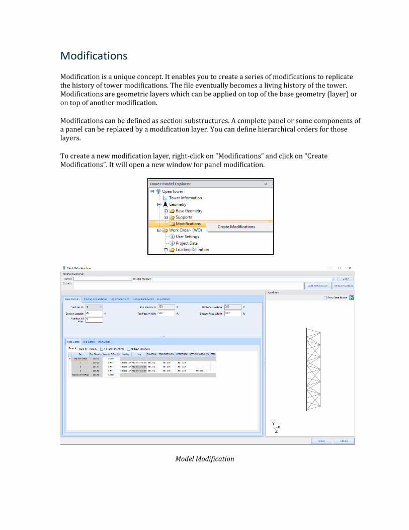
Modification is a unique concept. It enables you to create a series of modifications to replicate the history of tower modifications. The file eventually becomes a living history of the tower. Modifications are geometric layers which can be applied on top of the base geometry (layer) or on top of another modification.
Modifications can be defined as section substructures. A complete panel or some components of a panel can be replaced by a modification layer. You can define hierarchical orders for those layers.
To create a new modification layer, right-click on “Modifications” and click on “Create Modifications”. It will open a new window for panel modification.
Model Modification
Parameter Description
Name Alphanumeric Name of the layer
Existing Mod(s) Select one or more existing mods to copy from.
Copy Create a layer by copying data from selected existing mods
Details Description and other details of the current mod layer
Add New Section Add a new section starting from the top
Remove Section Remove currently selected section
Show Base Model Shows the original section before modification
Create Create a new modification layer
Edit Edit the current modification layer.
The rest of the controls are like “Section Editor”, ‘Bracing Connections”, “Leg Connections” and “Design Parameters” pages as described earlier.
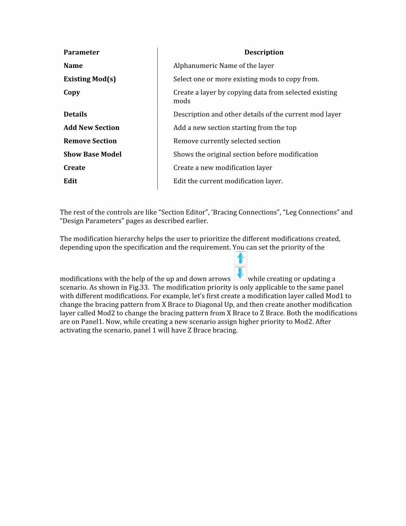
The modification hierarchy helps the user to prioritize the different modifications created, depending upon the specification and the requirement. You can set the priority of the
modifications with the help of the up and down arrows while creating or updating a scenario. As shown in Fig.33. The modification priority is only applicable to the same panel with different modifications. For example, let’s first create a modification layer called Mod1 to change the bracing pattern from X Brace to Diagonal Up, and then create another modification layer called Mod2 to change the bracing pattern from X Brace to Z Brace. Both the modifications are on Panel1. Now, while creating a new scenario assign higher priority to Mod2. After activating the scenario, panel 1 will have Z Brace bracing.
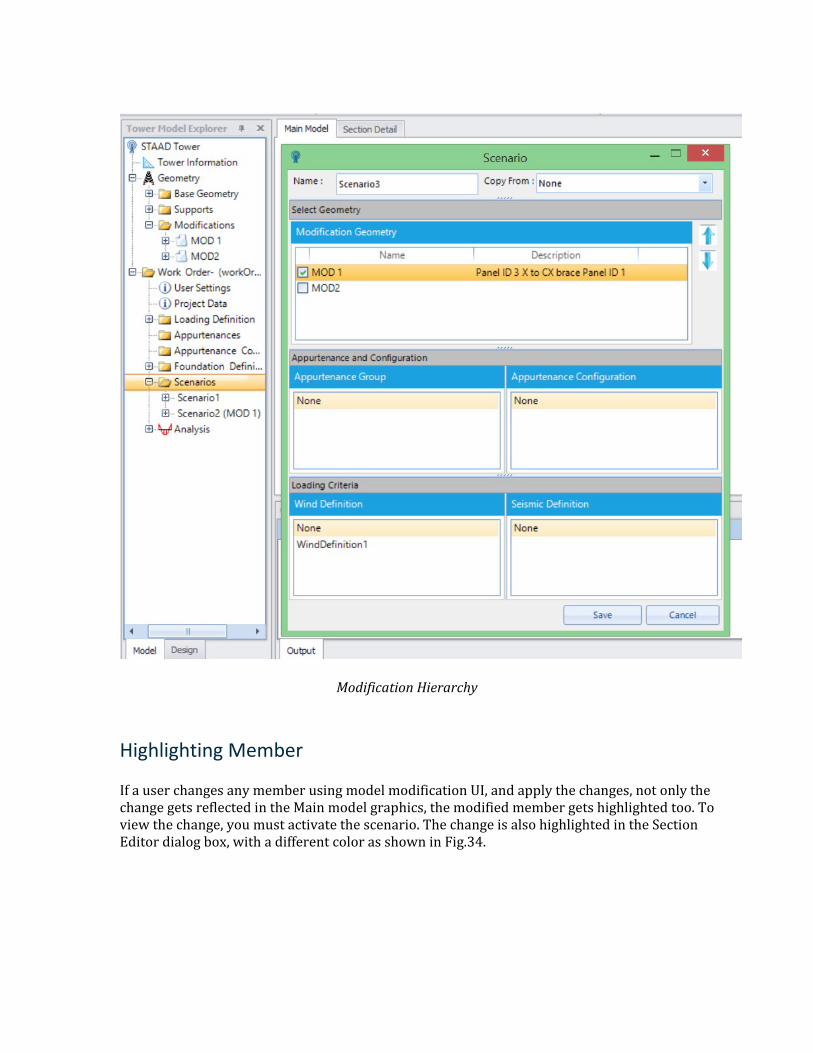
Modification Hierarchy
Highlighting Member
If a user changes any member using model modification UI, and apply the changes, not only the change gets reflected in the Main model graphics, the modified member gets highlighted too. To view the change, you must activate the scenario. The change is also highlighted in the Section Editor dialog box, with a different color as shown in Fig.34.
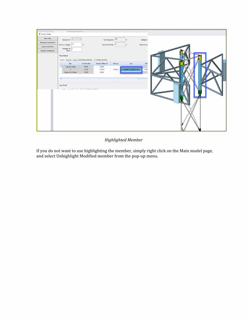
Highlighted Member
If you do not want to use highlighting the member, simply right click on the Main model page, and select Unhighlight Modified member from the pop-up menu.
5 Work Order A work order is a project-based approach to mimic tower engineers’ daily workflow. Project data or loading data are separated from the geometry layer.
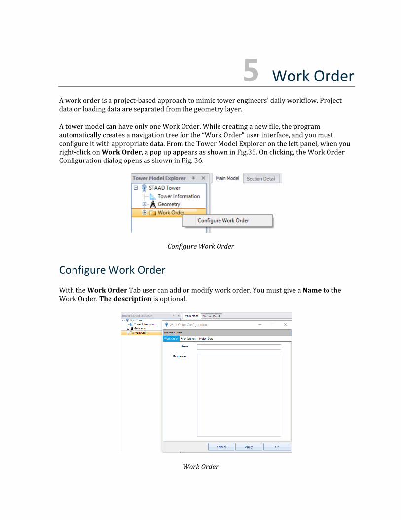
A tower model can have only one Work Order. While creating a new file, the program automatically creates a navigation tree for the “Work Order” user interface, and you must configure it with appropriate data. From the Tower Model Explorer on the left panel, when you right-click on Work Order, a pop up appears as shown in Fig.35. On clicking, the Work Order Configuration dialog opens as shown in Fig. 36.
Configure Work Order
Configure Work Order
With the Work Order Tab user can add or modify work order. You must give a Name to the Work Order. The description is optional.
Work Order
User Settings
User Settings Tab
To set the company information for a tower model, you can give the information as shown above in Fig.37.
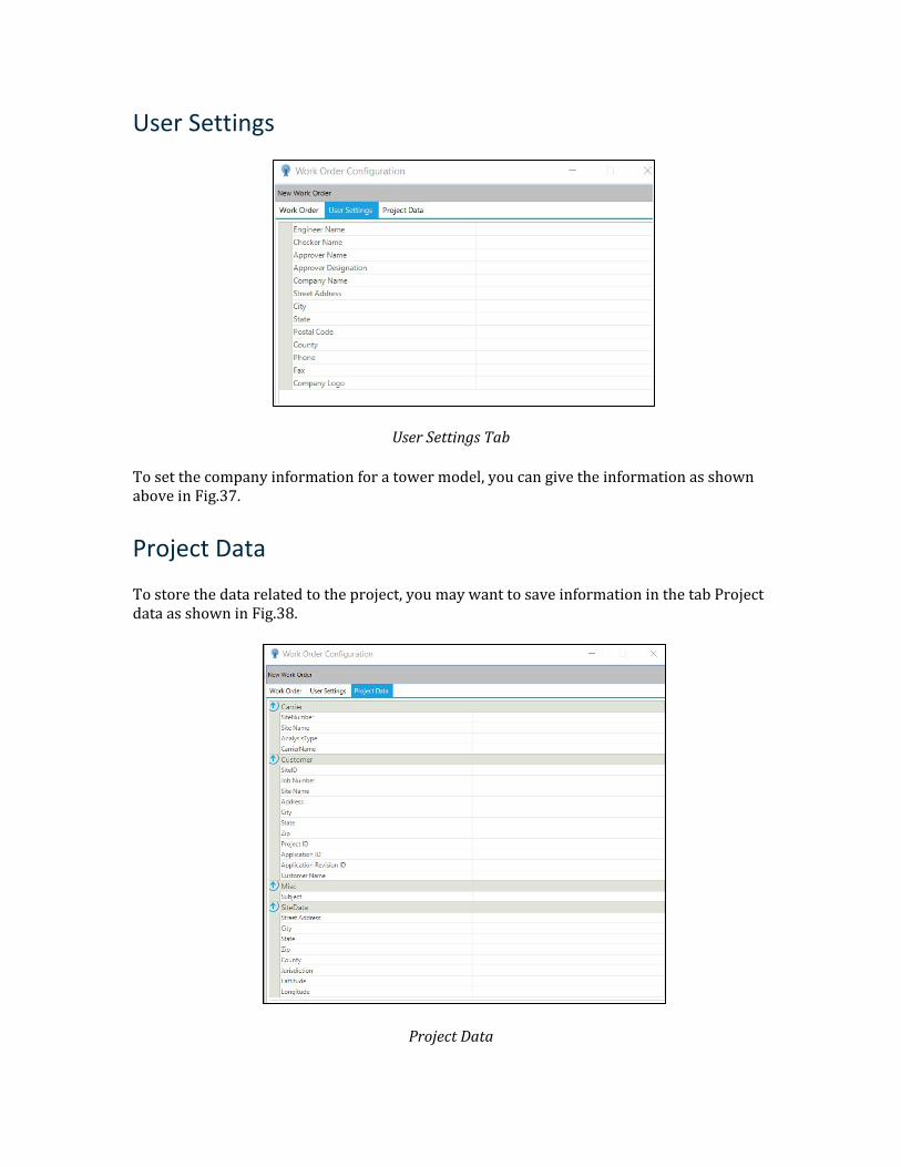
Project Data
To store the data related to the project, you may want to save information in the tab Project data as shown in Fig.38.
Project Data

Once Apply is clicked, the program will configure or update the work order. Cancel will undo all the recent changes made in the work order configuration page. To close it with saving, click the OK button.
6 Loading Definition Towers are most vulnerable to lateral loads, such as wind and earthquake loads. Wind loading is generally measured in terms of speed and can be affected by temperature (application considers the default temperature drop of 50 degree Celsius for guyed tower cable members) and the angle at which it is blowing as well as the surrounding terrain of the tower. This section describes the different parameters that can be changed related to the load application onto the tower due to wind.
Wind Definition
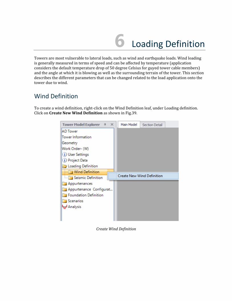
To create a wind definition, right-click on the Wind Definition leaf, under Loading definition. Click on Create New Wind Definition as shown in Fig.39.
Create Wind Definition
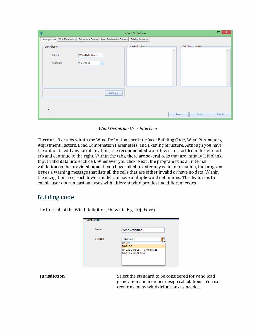
Wind Definition User Interface
There are five tabs within the Wind Definition user interface: Building Code, Wind Parameters, Adjustment Factors, Load Combination Parameters, and Existing Structure. Although you have the option to edit any tab at any time, the recommended workflow is to start from the leftmost tab and continue to the right. Within the tabs, there are several cells that are initially left blank. Input valid data into each cell. Whenever you click ‘Next’, the program runs an internal validation on the provided input. If you have failed to enter any valid information, the program issues a warning message that lists all the cells that are either invalid or have no data. Within the navigation tree, each tower model can have multiple wind definitions. This feature is to enable users to run past analyses with different wind profiles and different codes.
Building code
The first tab of the Wind Definition, shown in Fig. 40(above).
Jurisdiction Select the standard to be considered for wind load generation and member design calculations. You can create as many wind definitions as needed.
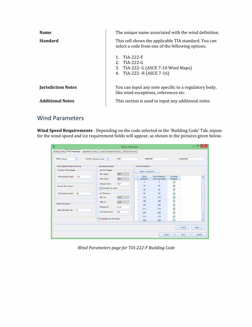
Name The unique name associated with the wind definition.
Standard This cell shows the applicable TIA standard. You can select a code from one of the following options.
1. TIA-222-F 2. TIA-222-G 3. TIA-222- G (ASCE 7-10 Wind Maps) 4. TIA-222- H (ASCE 7-16)
Jurisdiction Notes You can input any note specific to a regulatory body, like wind exceptions, references etc.
Additional Notes This section is used to input any additional notes
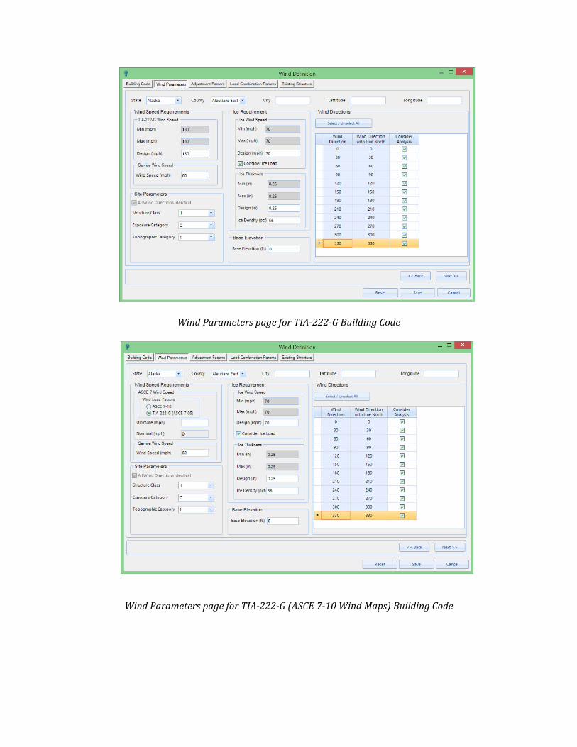
Wind Parameters
Wind Speed Requirements - Depending on the code selected in the ‘Building Code’ Tab, inputs for the wind speed and ice requirement fields will appear, as shown in the pictures given below.
Wind Parameters page for TIA-222-F Building Code
Wind Parameters page for TIA-222-G Building Code
Wind Parameters page for TIA-222-G (ASCE 7-10 Wind Maps) Building Code
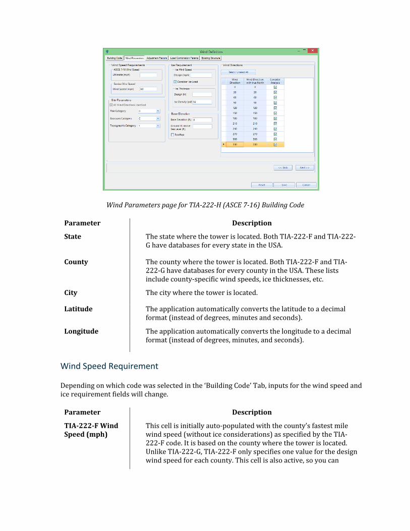
Wind Parameters page for TIA-222-H (ASCE 7-16) Building Code
Parameter Description
State The state where the tower is located. Both TIA-222-F and TIA-222-G have databases for every state in the USA.
County The county where the tower is located. Both TIA-222-F and TIA-222-G have databases for every county in the USA. These lists include county-specific wind speeds, ice thicknesses, etc.
City The city where the tower is located.
Latitude The application automatically converts the latitude to a decimal format (instead of degrees, minutes and seconds).
Longitude The application automatically converts the longitude to a decimal format (instead of degrees, minutes, and seconds).
Wind Speed Requirement
Depending on which code was selected in the ‘Building Code’ Tab, inputs for the wind speed and ice requirement fields will change.
Parameter Description
TIA-222-F Wind Speed (mph)
This cell is initially auto-populated with the county’s fastest mile wind speed (without ice considerations) as specified by the TIA-222-F code. It is based on the county where the tower is located. Unlike TIA-222-G, TIA-222-F only specifies one value for the design wind speed for each county. This cell is also active, so you can

change the wind speed. The value entered in this cell is what the application uses for the wind load generation.
Service Wind Speed (mph)
This is auto populated based on the code selected in the Building Code tab. It is 50 mph for TIA-222-F and 60 mph for TIA-222-G, and TIA-222-H, respectively.
TIA-222-G Wind Speed: Min (mph)
This cell is auto-populated with the minimum county 3-second gust wind speed (without ice considerations) specified by the TIA-222-G code. This cell cannot be edited. This cell is for reference only and will not be used in the analysis.
TIA-222-G Wind Speed: Max (mph)
The same rules apply to this cell as to the previous cell. The only difference is that this wind speed is the maximum allowable wind speed for the county.
TIA-222-G Wind Speed: Design (mph)
This is an active cell for you to manually input a special design wind speed. The value entered in this cell is what the application uses for the wind load generation. Default value is based on the maximum wind speed and can be edited as per the requirement.
Wind Load Factors
This option is visible only if the selected standard in the building code is “TIA-222-G (ASCE 7-10 Wind Map)”.You must choose to either use ASCE 7-10 load factors or TIA-222-G (ASCE 7-05) load factors. When the ASCE 7-10 load factors are selected, the application hides the nominal wind speed box. In this case, the ultimate wind speed used for the wind load generation. When the ASCE 7-05 wind speeds are selected, the nominal wind speed box reappears. The application automatically calculates the nominal wind speed based on your input for ultimate wind speed. The nominal wind speed cell is inactive, but this the wind speed use for wind load generation.
Ultimate (mph) This is an ultimate wind speed (without ice considerations) that you must specify.
Nominal (mph) This is a nominal wind speed (without ice considerations) that the application calculates based on your input for ultimate wind speed. This cell is inactive.
Ice Requirement
Ice Wind Speed: Min (mph)
This cell cannot be edited. This cell is for reference only and will not be used in the wind load generation.
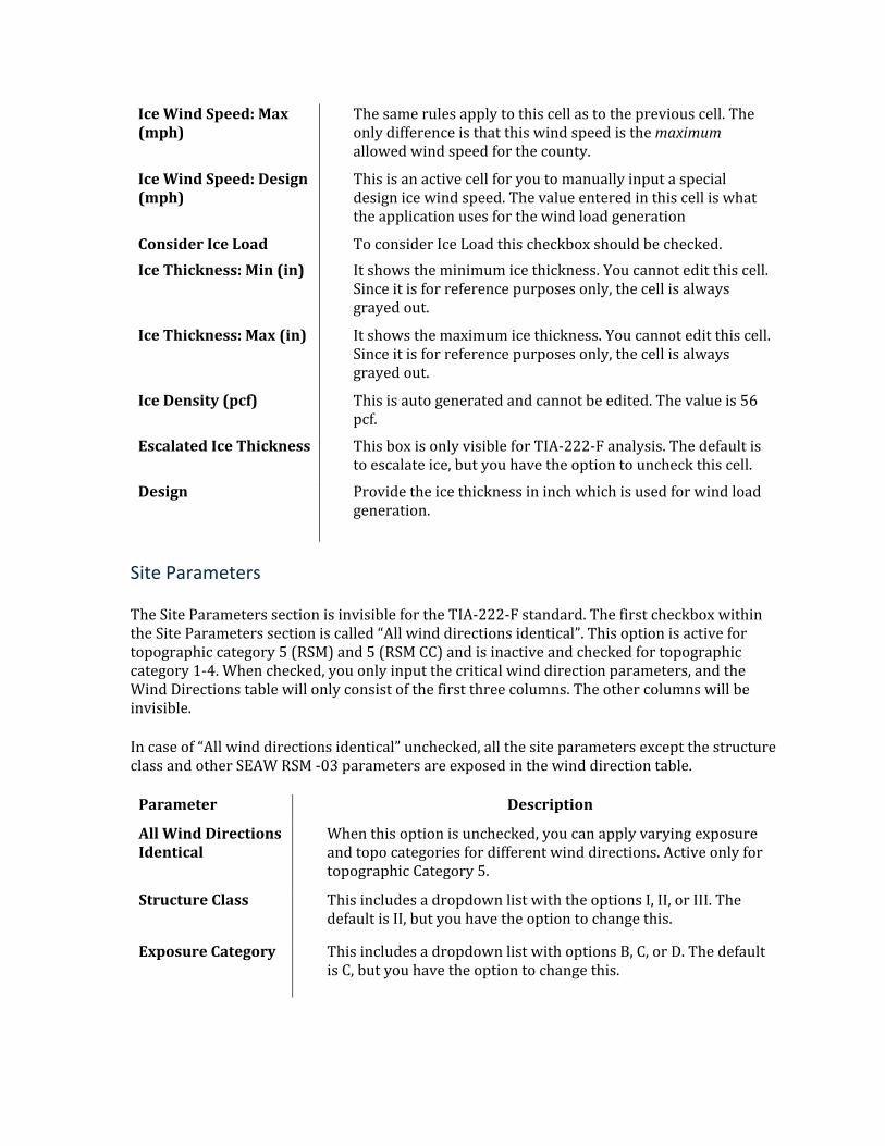
Ice Wind Speed: Max (mph)
The same rules apply to this cell as to the previous cell. The only difference is that this wind speed is the maximum allowed wind speed for the county.
Ice Wind Speed: Design (mph)
This is an active cell for you to manually input a special design ice wind speed. The value entered in this cell is what the application uses for the wind load generation
Consider Ice Load To consider Ice Load this checkbox should be checked. Ice Thickness: Min (in) It shows the minimum ice thickness. You cannot edit this cell.
Since it is for reference purposes only, the cell is always grayed out.
Ice Thickness: Max (in) It shows the maximum ice thickness. You cannot edit this cell. Since it is for reference purposes only, the cell is always grayed out.
Ice Density (pcf) This is auto generated and cannot be edited. The value is 56 pcf.
Escalated Ice Thickness This box is only visible for TIA-222-F analysis. The default is to escalate ice, but you have the option to uncheck this cell.
Design Provide the ice thickness in inch which is used for wind load generation.
Site Parameters
The Site Parameters section is invisible for the TIA-222-F standard. The first checkbox within the Site Parameters section is called “All wind directions identical”. This option is active for topographic category 5 (RSM) and 5 (RSM CC) and is inactive and checked for topographic category 1-4. When checked, you only input the critical wind direction parameters, and the Wind Directions table will only consist of the first three columns. The other columns will be invisible.
In case of “All wind directions identical” unchecked, all the site parameters except the structure class and other SEAW RSM -03 parameters are exposed in the wind direction table.
Parameter Description
All Wind Directions Identical
When this option is unchecked, you can apply varying exposure and topo categories for different wind directions. Active only for topographic Category 5.
Structure Class This includes a dropdown list with the options I, II, or III. The default is II, but you have the option to change this.
Exposure Category This includes a dropdown list with options B, C, or D. The default is C, but you have the option to change this.
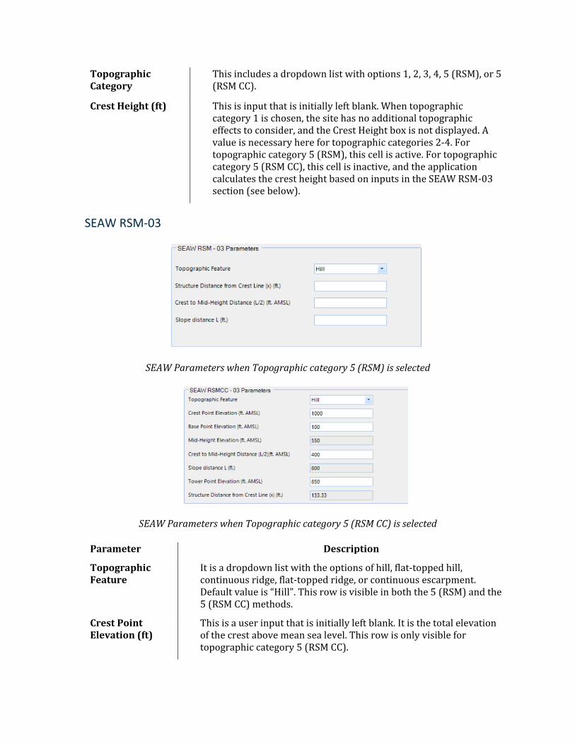
Topographic Category
This includes a dropdown list with options 1, 2, 3, 4, 5 (RSM), or 5 (RSM CC).
Crest Height (ft) This is input that is initially left blank. When topographic category 1 is chosen, the site has no additional topographic effects to consider, and the Crest Height box is not displayed. A value is necessary here for topographic categories 2-4. For topographic category 5 (RSM), this cell is active. For topographic category 5 (RSM CC), this cell is inactive, and the application calculates the crest height based on inputs in the SEAW RSM-03 section (see below).
SEAW RSM-03
SEAW Parameters when Topographic category 5 (RSM) is selected
SEAW Parameters when Topographic category 5 (RSM CC) is selected
Parameter Description
Topographic Feature
It is a dropdown list with the options of hill, flat-topped hill, continuous ridge, flat-topped ridge, or continuous escarpment. Default value is “Hill”. This row is visible in both the 5 (RSM) and the 5 (RSM CC) methods.
Crest Point Elevation (ft)
This is a user input that is initially left blank. It is the total elevation of the crest above mean sea level. This row is only visible for topographic category 5 (RSM CC).
Base Point Elevation (ft)
This input is initially left blank. It is the total elevation at the base of the topographic feature with respect to mean sea level. This row is only visible for topographic category 5 (RSM CC).
Mid-Height Elevation (ft)
This is the average of the crest point elevation and the base point elevation. It is automatically calculated by the application and is inactive. This row is only visible for topographic category 5 (RSM CC).
Crest to Mid-Height Distance (L/2) (ft)
This is the horizontal distance from the feature’s crest to the mid-height point of the topographic feature. This is initially left blank. This row is visible in both the 5 (RSM) and the 5 (RSM CC) methods.
Slope Distance L (ft)
The program calculates the total slope distance (L) as twice the crest to mid-height horizontal distance. This cell is auto-populated and inactive for user-input. It is visible in both the 5 (RSM) and the 5 (RSM CC) methods.
Tower Point Elevation (ft)
This row is only visible for topographic category 5 (RSM CC). It is the tower’s base elevation with respect to mean sea level. For hills and continuous ridges, this is a user-defined input and will initially be blank. For flat-topped ridges, flat-topped hills, and continuous escarpments, this cell will be automatically calculated by the application based on input for Structure Distance from Crest Line. The calculation assumes a constant slope for the feature and uses similar triangles to determine the tower point elevation.
Structure Distance from Crest Line (x) (ft)
This row is visible in both the 5 (RSM) and the 5 (RSM CC) methods. It is the horizontal distance from the crest to the tower.
Wind Directions
When the “All wind directions identical” checkbox is selected, the table within the Wind Directions section will have the wind direction information and checkbox option for user to select the directions to be considered for the analysis. For “All wind directions identical” unchecked, more information is available for the user to define including the consider analysis option.
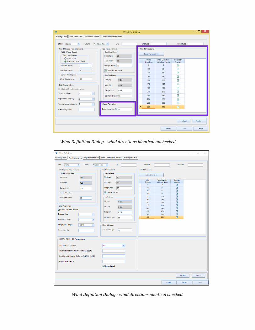
Wind Definition Dialog - wind directions identical unchecked.
Wind Definition Dialog - wind directions identical checked.
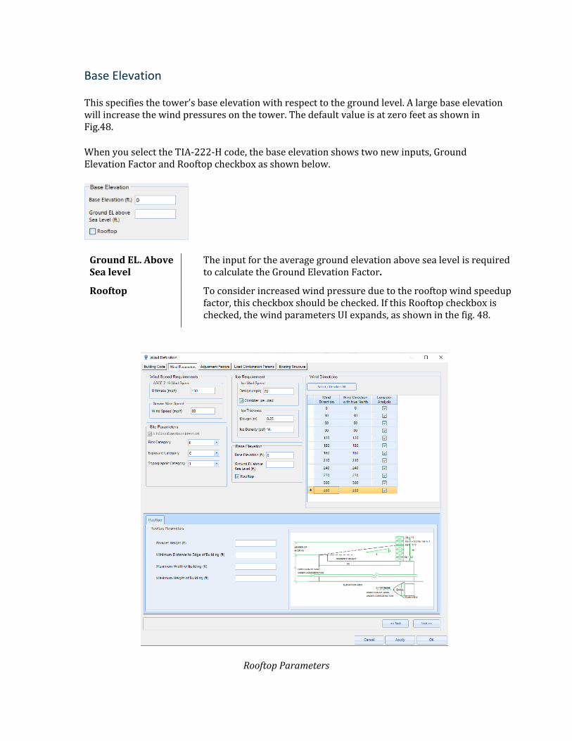
Base Elevation
This specifies the tower’s base elevation with respect to the ground level. A large base elevation will increase the wind pressures on the tower. The default value is at zero feet as shown in Fig.48.
When you select the TIA-222-H code, the base elevation shows two new inputs, Ground Elevation Factor and Rooftop checkbox as shown below.
Ground EL. Above Sea level
The input for the average ground elevation above sea level is required to calculate the Ground Elevation Factor.
Rooftop To consider increased wind pressure due to the rooftop wind speedup factor, this checkbox should be checked. If this Rooftop checkbox is checked, the wind parameters UI expands, as shown in the fig. 48.
Rooftop Parameters
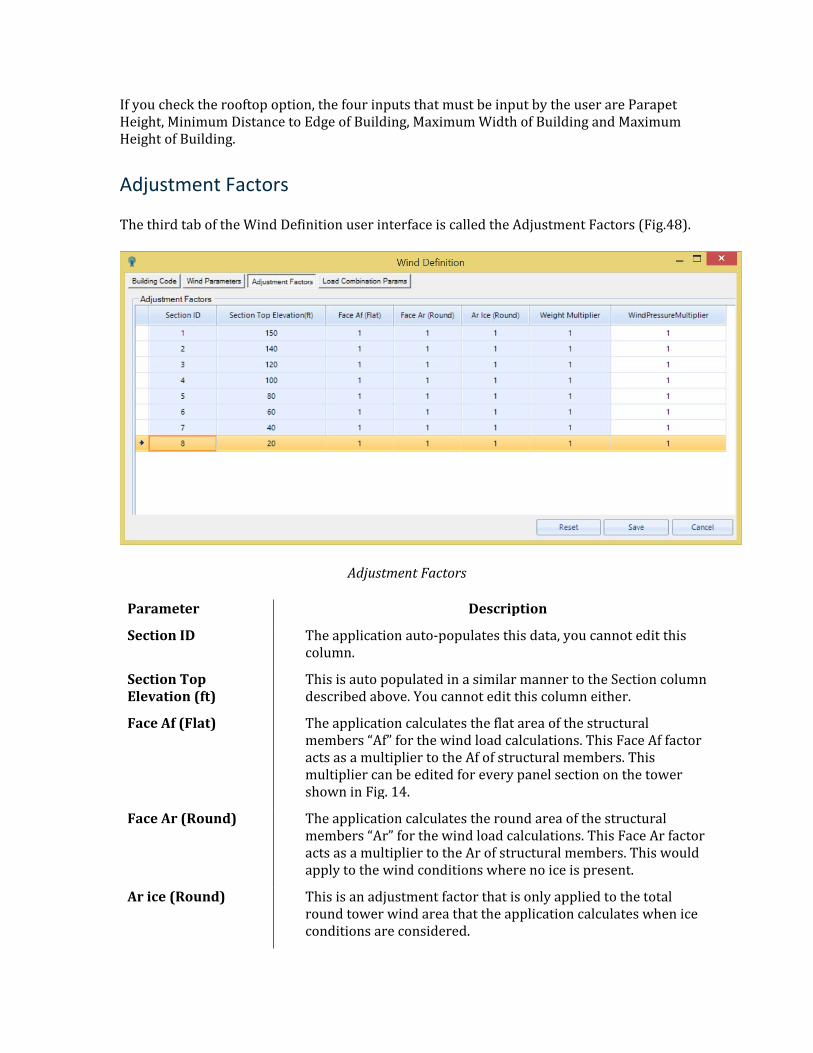
If you check the rooftop option, the four inputs that must be input by the user are Parapet Height, Minimum Distance to Edge of Building, Maximum Width of Building and Maximum Height of Building.
Adjustment Factors
The third tab of the Wind Definition user interface is called the Adjustment Factors (Fig.48).
Adjustment Factors
Parameter Description
Section ID The application auto-populates this data, you cannot edit this column.
Section Top Elevation (ft)
This is auto populated in a similar manner to the Section column described above. You cannot edit this column either.
Face Af (Flat) The application calculates the flat area of the structural members “Af” for the wind load calculations. This Face Af factor acts as a multiplier to the Af of structural members. This multiplier can be edited for every panel section on the tower shown in Fig. 14.
Face Ar (Round) The application calculates the round area of the structural members “Ar” for the wind load calculations. This Face Ar factor acts as a multiplier to the Ar of structural members. This would apply to the wind conditions where no ice is present.
Ar ice (Round) This is an adjustment factor that is only applied to the total round tower wind area that the application calculates when ice conditions are considered.
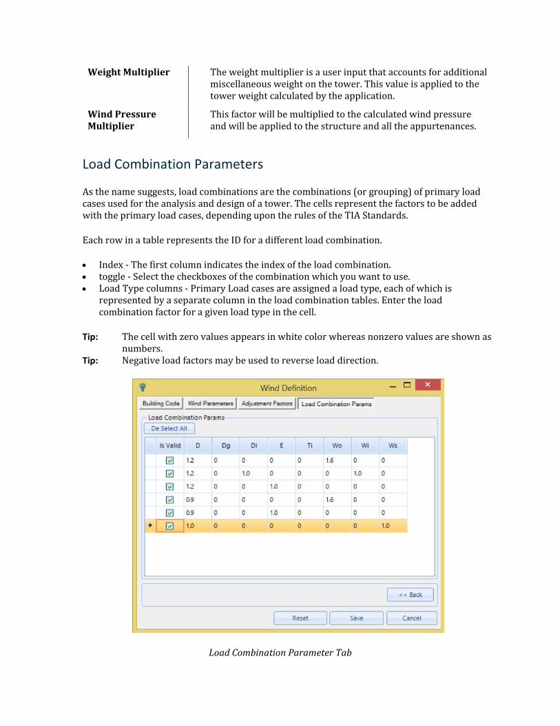
Weight Multiplier The weight multiplier is a user input that accounts for additional miscellaneous weight on the tower. This value is applied to the tower weight calculated by the application.
Wind Pressure Multiplier
This factor will be multiplied to the calculated wind pressure and will be applied to the structure and all the appurtenances.
Load Combination Parameters
As the name suggests, load combinations are the combinations (or grouping) of primary load cases used for the analysis and design of a tower. The cells represent the factors to be added with the primary load cases, depending upon the rules of the TIA Standards.
Each row in a table represents the ID for a different load combination.
• Index - The first column indicates the index of the load combination. • toggle - Select the checkboxes of the combination which you want to use. • Load Type columns - Primary Load cases are assigned a load type, each of which is
represented by a separate column in the load combination tables. Enter the load combination factor for a given load type in the cell.
Tip: The cell with zero values appears in white color whereas nonzero values are shown as numbers.
Tip: Negative load factors may be used to reverse load direction.
Load Combination Parameter Tab
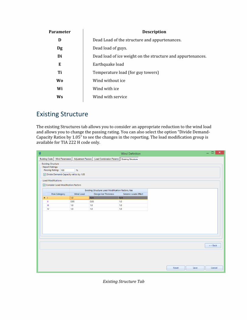
Parameter Description
D Dead Load of the structure and appurtenances.
Dg Dead load of guys.
Di Dead load of ice weight on the structure and appurtenances.
E Earthquake load
Ti Temperature load (for guy towers)
Wo Wind without ice
Wi Wind with ice
Ws Wind with service
Existing Structure
The existing Structures tab allows you to consider an appropriate reduction to the wind load and allows you to change the passing rating. You can also select the option “Divide Demand-Capacity Ratios by 1.05” to see the changes in the reporting. The load modification group is available for TIA 222 H code only.
Existing Structure Tab
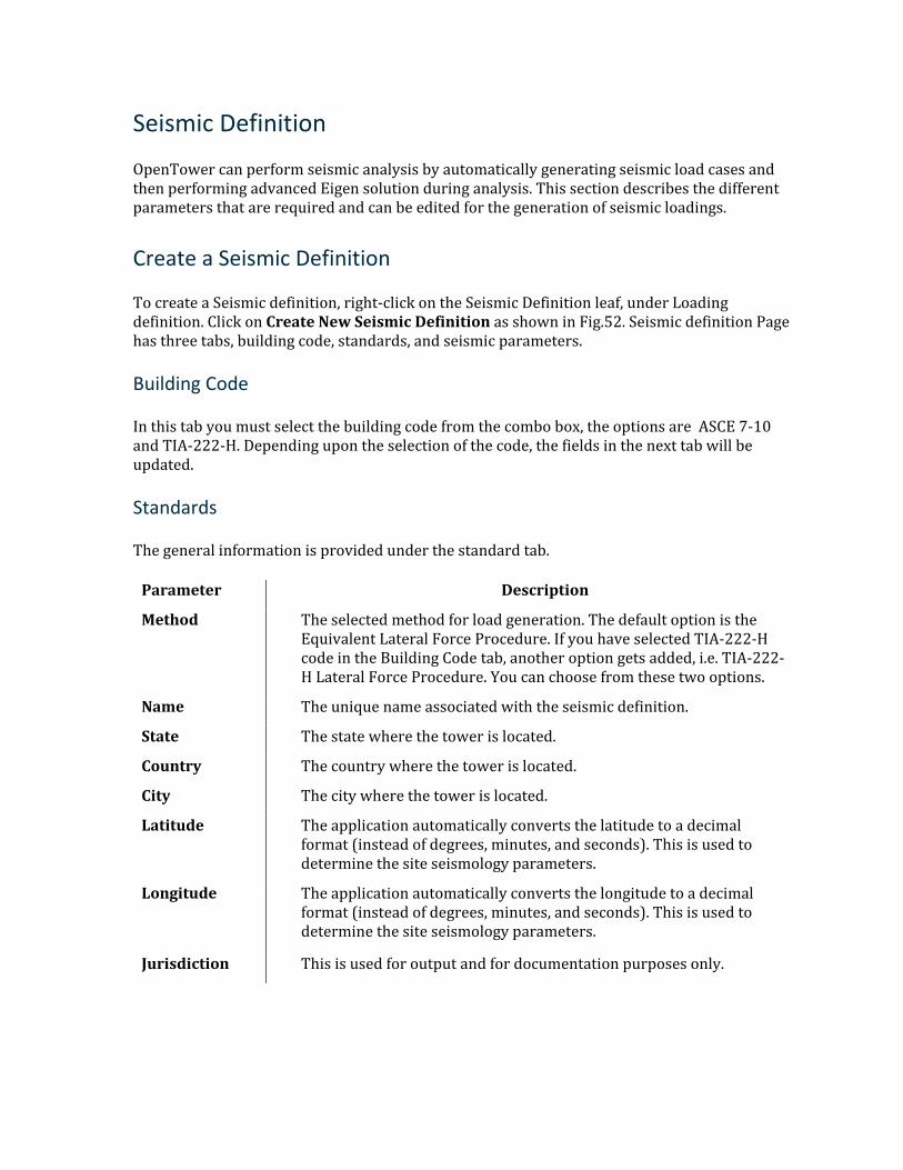
Seismic Definition
OpenTower can perform seismic analysis by automatically generating seismic load cases and then performing advanced Eigen solution during analysis. This section describes the different parameters that are required and can be edited for the generation of seismic loadings.
Create a Seismic Definition
To create a Seismic definition, right-click on the Seismic Definition leaf, under Loading definition. Click on Create New Seismic Definition as shown in Fig.52. Seismic definition Page has three tabs, building code, standards, and seismic parameters.
Building Code
In this tab you must select the building code from the combo box, the options are ASCE 7-10 and TIA-222-H. Depending upon the selection of the code, the fields in the next tab will be updated.
Standards
The general information is provided under the standard tab.
Parameter Description
Method The selected method for load generation. The default option is the Equivalent Lateral Force Procedure. If you have selected TIA-222-H code in the Building Code tab, another option gets added, i.e. TIA-222-H Lateral Force Procedure. You can choose from these two options.
Name The unique name associated with the seismic definition.
State The state where the tower is located.
Country The country where the tower is located.
City The city where the tower is located.
Latitude The application automatically converts the latitude to a decimal format (instead of degrees, minutes, and seconds). This is used to determine the site seismology parameters.
Longitude The application automatically converts the longitude to a decimal format (instead of degrees, minutes, and seconds). This is used to determine the site seismology parameters.
Jurisdiction This is used for output and for documentation purposes only.
Seismic Parameters
Structure category information is provided in the seismic Parameters tab.
Parameter Description
Risk Category
It determines the Importance Factor. You must select from the options given from One to Five.
Importance Factor This is auto-populated as per the input provided for Risk Category.
Response Modification Factor
You must provide the response modification factor.
Site Class It is to define the site soil type. You must choose from the options provided under the dropdown as shown in Fig. 53. Available options are dependent on the selected building code. For TIA-222-H, an additional option is added, which is Stiff Soil (Determined).
SS This is spectral response acceleration for the shorter period. You can click to “Fetch Ss, S1 and TL from” and the data will be auto-populated based on the “Latitude” and “Longitude” from the USGS website or can input manually.
S1 This is spectral response acceleration for a 1-sec period. You can click to “Fetch Ss, S1 and TL from” and the data will be auto-populated based on the “Latitude” and “Longitude” from the USGS website or can input manually.
TL This is the long period transition in seconds. You can click to “Fetch Ss, S1 and TL from” and the data will be auto-populated based on the “Latitude” and “Longitude” from the USGS website or can input manually.
Fundamental Period Method
This input is specific to the TIA-222-H code. Users must choose from one of the two available options, Rayleigh Method and user specified method.
Amplification Factor (As)
The amplification factor input is specific to the TIA-222-H code. The default value is 1.
Once the Load Definition is defined and saved, the load definition will be added in the tower model explorer under the seismic definition category as shown below.
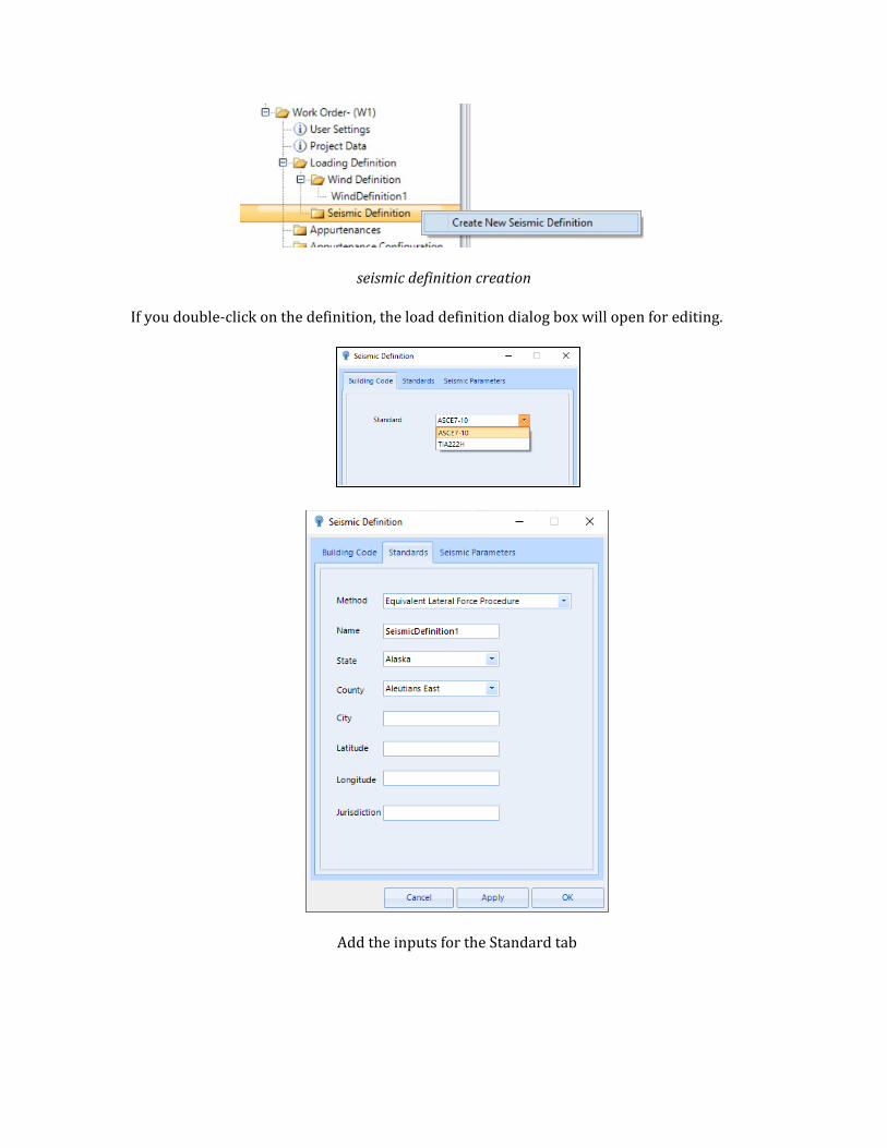
seismic definition creation
If you double-click on the definition, the load definition dialog box will open for editing.
Add the inputs for the Standard tab
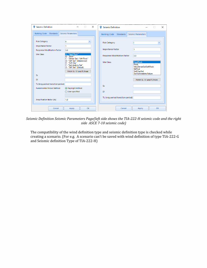
Seismic Definition Seismic Parameters Page(left side shows the TIA-222-H seismic code and the right side ASCE 7-10 seismic code)
The compatibility of the wind definition type and seismic definition type is checked while creating a scenario. (For e.g. A scenario can’t be saved with wind definition of type TIA-222-G and Seismic definition Type of TIA-222-H)
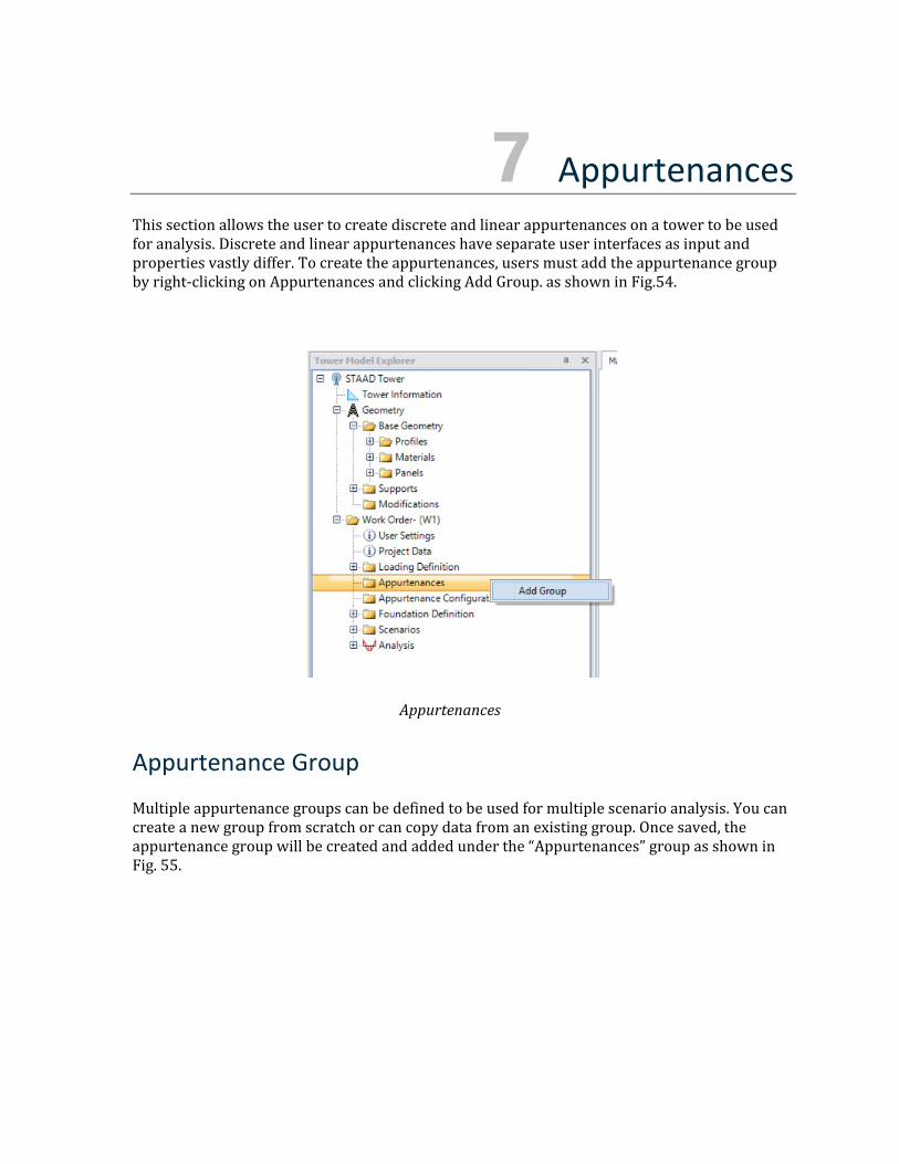
7 Appurtenances This section allows the user to create discrete and linear appurtenances on a tower to be used for analysis. Discrete and linear appurtenances have separate user interfaces as input and properties vastly differ. To create the appurtenances, users must add the appurtenance group by right-clicking on Appurtenances and clicking Add Group. as shown in Fig.54.
Appurtenances
Appurtenance Group
Multiple appurtenance groups can be defined to be used for multiple scenario analysis. You can create a new group from scratch or can copy data from an existing group. Once saved, the appurtenance group will be created and added under the “Appurtenances” group as shown in Fig. 55.
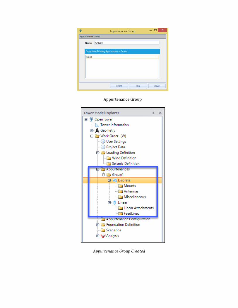
Appurtenance Group
Appurtenance Group Created
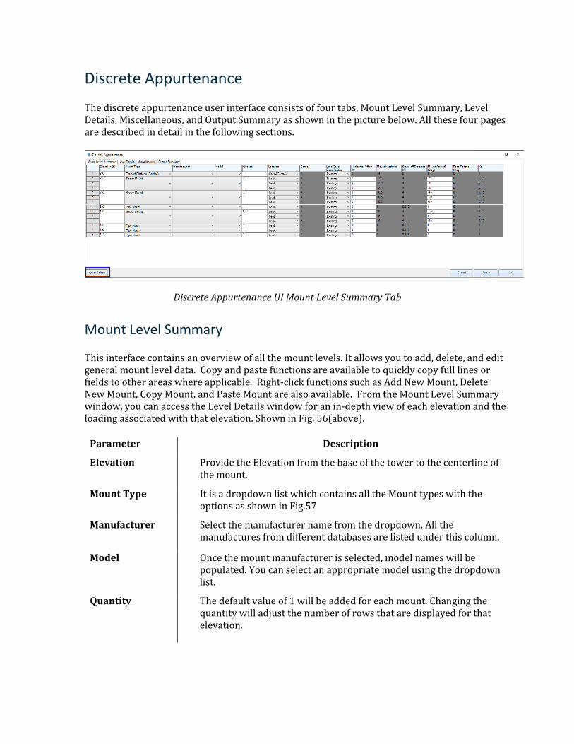
Discrete Appurtenance
The discrete appurtenance user interface consists of four tabs, Mount Level Summary, Level Details, Miscellaneous, and Output Summary as shown in the picture below. All these four pages are described in detail in the following sections.
Discrete Appurtenance UI Mount Level Summary Tab
Mount Level Summary
This interface contains an overview of all the mount levels. It allows you to add, delete, and edit general mount level data. Copy and paste functions are available to quickly copy full lines or fields to other areas where applicable. Right-click functions such as Add New Mount, Delete New Mount, Copy Mount, and Paste Mount are also available. From the Mount Level Summary window, you can access the Level Details window for an in-depth view of each elevation and the loading associated with that elevation. Shown in Fig. 56(above).
Parameter Description
Elevation Provide the Elevation from the base of the tower to the centerline of the mount.
Mount Type It is a dropdown list which contains all the Mount types with the options as shown in Fig.57
Manufacturer Select the manufacturer name from the dropdown. All the manufactures from different databases are listed under this column.
Model Once the mount manufacturer is selected, model names will be populated. You can select an appropriate model using the dropdown list.
Quantity The default value of 1 will be added for each mount. Changing the quantity will adjust the number of rows that are displayed for that elevation.
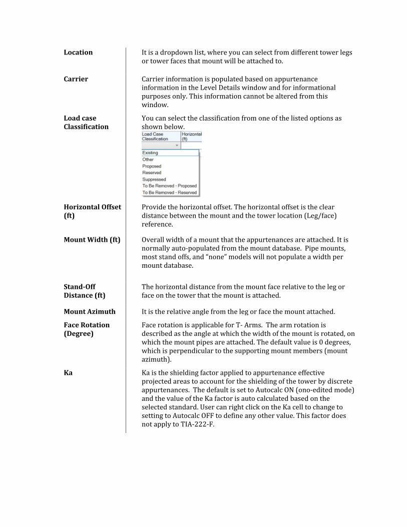
Location It is a dropdown list, where you can select from different tower legs or tower faces that mount will be attached to.
Carrier Carrier information is populated based on appurtenance information in the Level Details window and for informational purposes only. This information cannot be altered from this window.
Load case Classification
You can select the classification from one of the listed options as shown below.
Horizontal Offset (ft)
Provide the horizontal offset. The horizontal offset is the clear distance between the mount and the tower location (Leg/face) reference.
Mount Width (ft) Overall width of a mount that the appurtenances are attached. It is normally auto-populated from the mount database. Pipe mounts, most stand offs, and “none” models will not populate a width per mount database.
Stand-Off Distance (ft)
The horizontal distance from the mount face relative to the leg or face on the tower that the mount is attached.
Mount Azimuth It is the relative angle from the leg or face the mount attached.
Face Rotation (Degree)
Face rotation is applicable for T- Arms. The arm rotation is described as the angle at which the width of the mount is rotated, on which the mount pipes are attached. The default value is 0 degrees, which is perpendicular to the supporting mount members (mount azimuth).
Ka Ka is the shielding factor applied to appurtenance effective projected areas to account for the shielding of the tower by discrete appurtenances. The default is set to Autocalc ON (ono-edited mode) and the value of the Ka factor is auto calculated based on the selected standard. User can right click on the Ka cell to change to setting to Autocalc OFF to define any other value. This factor does not apply to TIA-222-F.
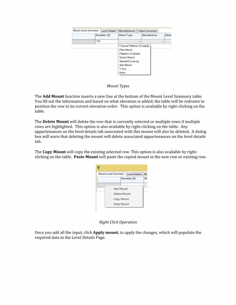
Mount Types
The Add Mount function inserts a new line at the bottom of the Mount Level Summary table. You fill out the information and based on what elevation is added, the table will be redrawn to position the row to its correct elevation order. This option is available by right-clicking on the table.
The Delete Mount will delete the row that is currently selected or multiple rows if multiple rows are highlighted. This option is also available by right-clicking on the table. Any appurtenances on the level details tab associated with this mount will also be deleted. A dialog box will warn that deleting the mount will delete associated appurtenances on the level details tab.
The Copy Mount will copy the existing selected row. This option is also available by right-clicking on the table. Paste Mount will paste the copied mount in the new row or existing row.
Right Click Operation
Once you add all the input, click Apply mount, to apply the changes, which will populate the required data in the Level Details Page.
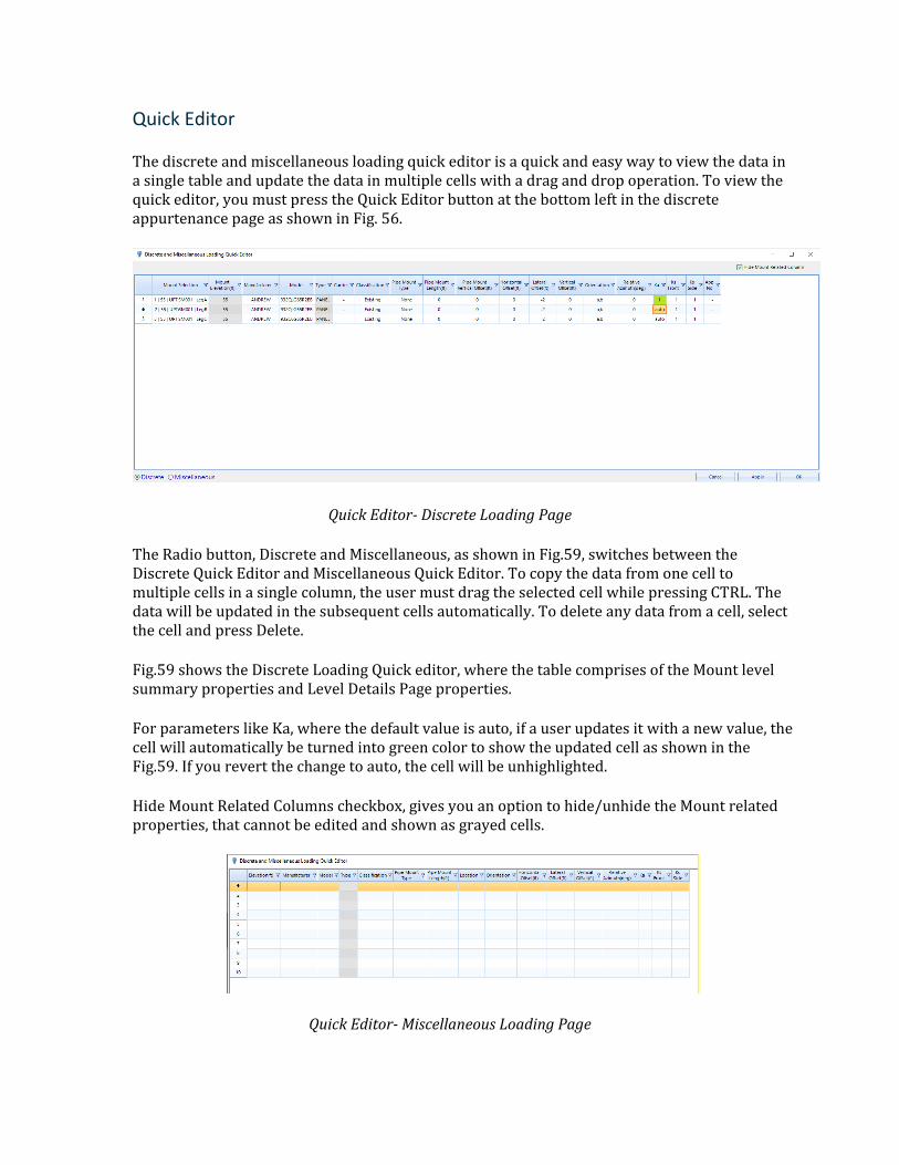
Quick Editor
The discrete and miscellaneous loading quick editor is a quick and easy way to view the data in a single table and update the data in multiple cells with a drag and drop operation. To view the quick editor, you must press the Quick Editor button at the bottom left in the discrete appurtenance page as shown in Fig. 56.
Quick Editor- Discrete Loading Page
The Radio button, Discrete and Miscellaneous, as shown in Fig.59, switches between the Discrete Quick Editor and Miscellaneous Quick Editor. To copy the data from one cell to multiple cells in a single column, the user must drag the selected cell while pressing CTRL. The data will be updated in the subsequent cells automatically. To delete any data from a cell, select the cell and press Delete.
Fig.59 shows the Discrete Loading Quick editor, where the table comprises of the Mount level summary properties and Level Details Page properties.
For parameters like Ka, where the default value is auto, if a user updates it with a new value, the cell will automatically be turned into green color to show the updated cell as shown in the Fig.59. If you revert the change to auto, the cell will be unhighlighted.
Hide Mount Related Columns checkbox, gives you an option to hide/unhide the Mount related properties, that cannot be edited and shown as grayed cells.
Quick Editor- Miscellaneous Loading Page
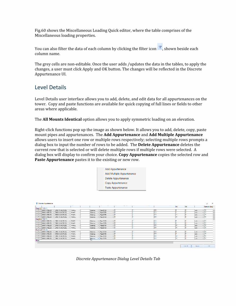
Fig.60 shows the Miscellaneous Loading Quick editor, where the table comprises of the Miscellaneous loading properties.
You can also filter the data of each column by clicking the filter icon , shown beside each column name.
The grey cells are non-editable. Once the user adds /updates the data in the tables, to apply the changes, a user must click Apply and OK button. The changes will be reflected in the Discrete Appurtenance UI.
Level Details
Level Details user interface allows you to add, delete, and edit data for all appurtenances on the tower. Copy and paste functions are available for quick copying of full lines or fields to other areas where applicable.
The All Mounts Identical option allows you to apply symmetric loading on an elevation.
Right-click functions pop up the image as shown below. It allows you to add, delete, copy, paste mount pipes and appurtenances. The Add Appurtenance and Add Multiple Appurtenance allows users to insert one row or multiple rows respectively; selecting multiple rows prompts a dialog box to input the number of rows to be added. The Delete Appurtenance deletes the current row that is selected or will delete multiple rows if multiple rows were selected. A dialog box will display to confirm your choice. Copy Appurtenance copies the selected row and Paste Appurtenance pastes it to the existing or new row.
Discrete Appurtenance Dialog Level Details Tab
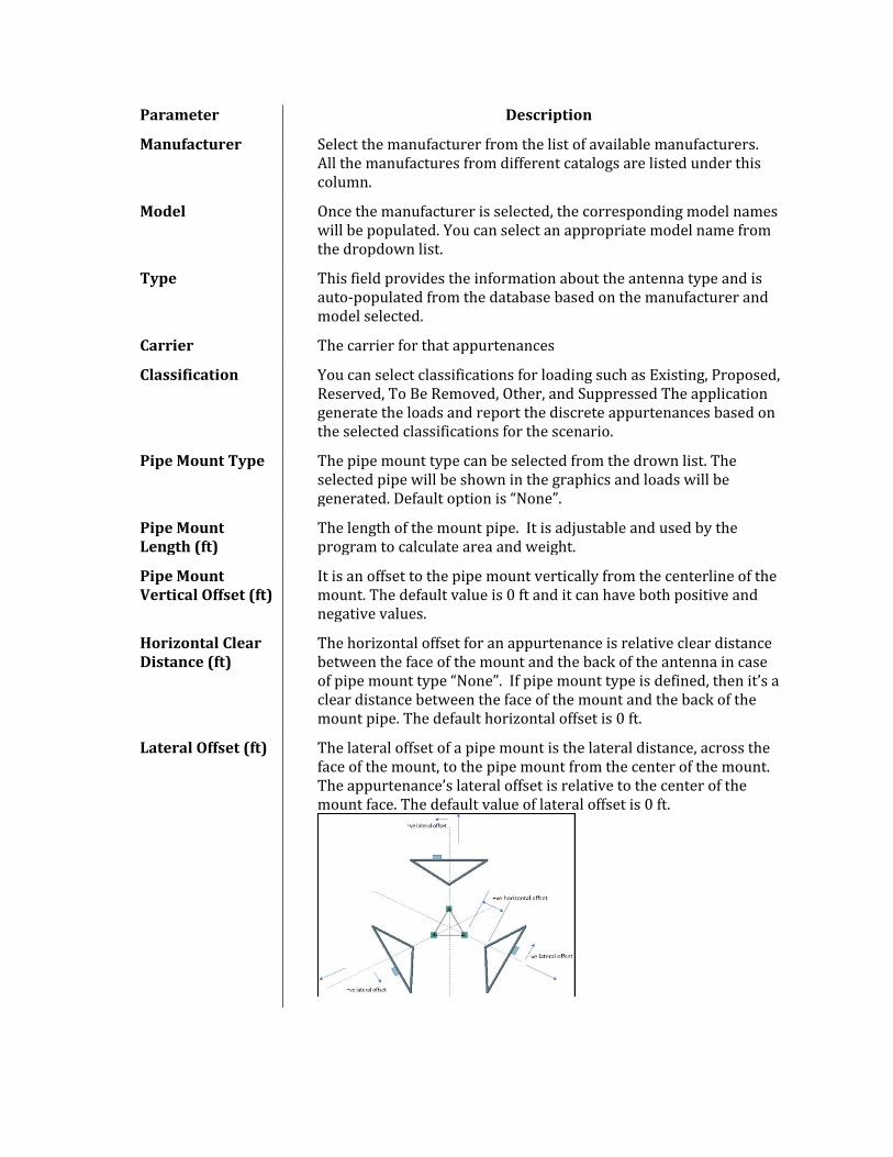
Parameter Description
Manufacturer Select the manufacturer from the list of available manufacturers. All the manufactures from different catalogs are listed under this column.
Model Once the manufacturer is selected, the corresponding model names will be populated. You can select an appropriate model name from the dropdown list.
Type This field provides the information about the antenna type and is auto-populated from the database based on the manufacturer and model selected.
Carrier The carrier for that appurtenances
Classification You can select classifications for loading such as Existing, Proposed, Reserved, To Be Removed, Other, and Suppressed The application generate the loads and report the discrete appurtenances based on the selected classifications for the scenario.
Pipe Mount Type The pipe mount type can be selected from the drown list. The selected pipe will be shown in the graphics and loads will be generated. Default option is “None”.
Pipe Mount Length (ft)
The length of the mount pipe. It is adjustable and used by the program to calculate area and weight.
Pipe Mount Vertical Offset (ft)
It is an offset to the pipe mount vertically from the centerline of the mount. The default value is 0 ft and it can have both positive and negative values.
Horizontal Clear Distance (ft)
The horizontal offset for an appurtenance is relative clear distance between the face of the mount and the back of the antenna in case of pipe mount type “None”. If pipe mount type is defined, then it’s a clear distance between the face of the mount and the back of the mount pipe. The default horizontal offset is 0 ft.
Lateral Offset (ft) The lateral offset of a pipe mount is the lateral distance, across the face of the mount, to the pipe mount from the center of the mount. The appurtenance’s lateral offset is relative to the center of the mount face. The default value of lateral offset is 0 ft.
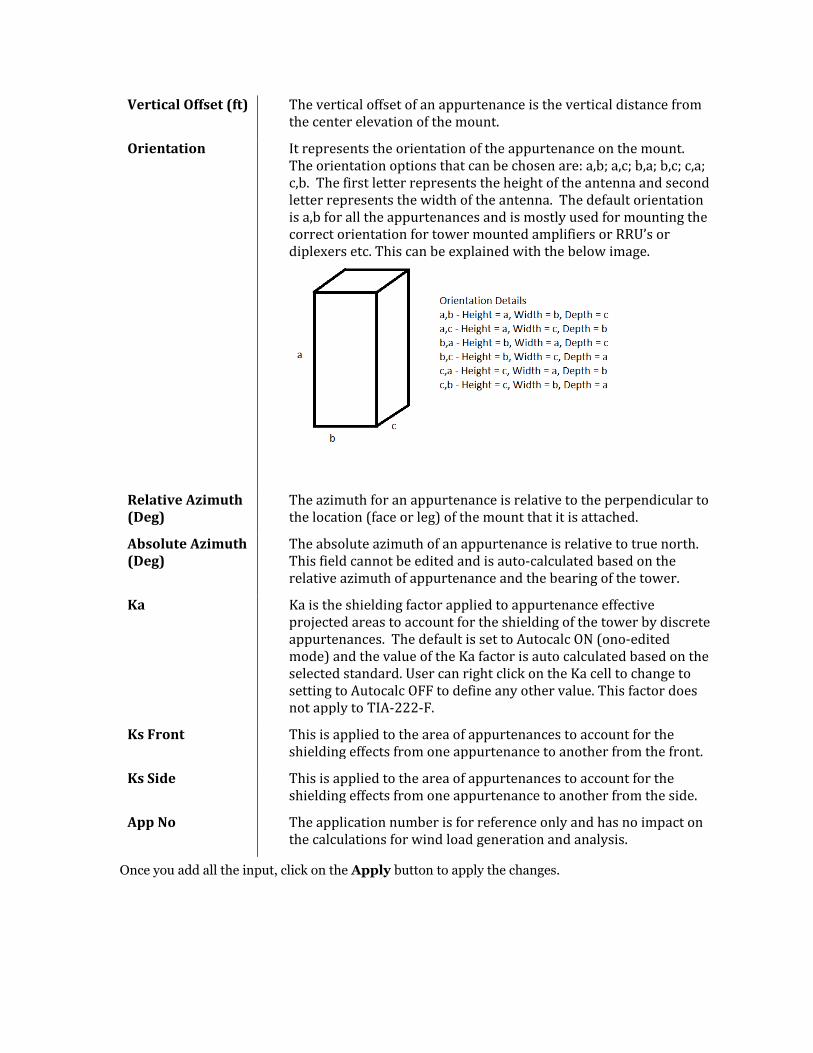
Vertical Offset (ft) The vertical offset of an appurtenance is the vertical distance from the center elevation of the mount.
Orientation It represents the orientation of the appurtenance on the mount. The orientation options that can be chosen are: a,b; a,c; b,a; b,c; c,a; c,b. The first letter represents the height of the antenna and second letter represents the width of the antenna. The default orientation is a,b for all the appurtenances and is mostly used for mounting the correct orientation for tower mounted amplifiers or RRU’s or diplexers etc. This can be explained with the below image.
Relative Azimuth (Deg)
The azimuth for an appurtenance is relative to the perpendicular to the location (face or leg) of the mount that it is attached.
Absolute Azimuth (Deg)
The absolute azimuth of an appurtenance is relative to true north. This field cannot be edited and is auto-calculated based on the relative azimuth of appurtenance and the bearing of the tower.
Ka Ka is the shielding factor applied to appurtenance effective projected areas to account for the shielding of the tower by discrete appurtenances. The default is set to Autocalc ON (ono-edited mode) and the value of the Ka factor is auto calculated based on the selected standard. User can right click on the Ka cell to change to setting to Autocalc OFF to define any other value. This factor does not apply to TIA-222-F.
Ks Front This is applied to the area of appurtenances to account for the shielding effects from one appurtenance to another from the front.
Ks Side This is applied to the area of appurtenances to account for the shielding effects from one appurtenance to another from the side.
App No The application number is for reference only and has no impact on the calculations for wind load generation and analysis.
Once you add all the input, click on the Apply button to apply the changes.
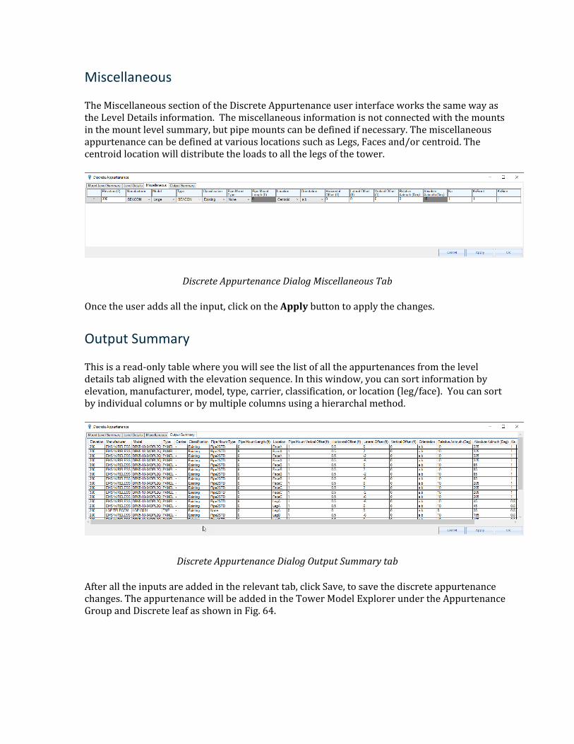
Miscellaneous
The Miscellaneous section of the Discrete Appurtenance user interface works the same way as the Level Details information. The miscellaneous information is not connected with the mounts in the mount level summary, but pipe mounts can be defined if necessary. The miscellaneous appurtenance can be defined at various locations such as Legs, Faces and/or centroid. The centroid location will distribute the loads to all the legs of the tower.
Discrete Appurtenance Dialog Miscellaneous Tab
Once the user adds all the input, click on the Apply button to apply the changes.
Output Summary
This is a read-only table where you will see the list of all the appurtenances from the level details tab aligned with the elevation sequence. In this window, you can sort information by elevation, manufacturer, model, type, carrier, classification, or location (leg/face). You can sort by individual columns or by multiple columns using a hierarchal method.
Discrete Appurtenance Dialog Output Summary tab
After all the inputs are added in the relevant tab, click Save, to save the discrete appurtenance changes. The appurtenance will be added in the Tower Model Explorer under the Appurtenance Group and Discrete leaf as shown in Fig. 64.
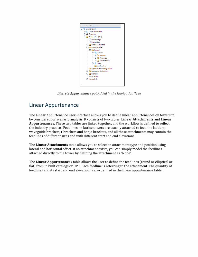
Discrete Appurtenance got Added in the Navigation Tree
Linear Appurtenance
The Linear Appurtenance user-interface allows you to define linear appurtenances on towers to be considered for scenario analysis. It consists of two tables, Linear Attachments and Linear Appurtenances. These two tables are linked together, and the workflow is defined to reflect the industry practice. Feedlines on lattice towers are usually attached to feedline ladders, waveguide brackets, t-brackets and banjo brackets, and all these attachments may contain the feedlines of different sizes and with different start and end elevations.
The Linear Attachments table allows you to select an attachment type and position using lateral and horizontal offset. If no attachment exists, you can simply model the feedlines attached directly to the tower by defining the attachment as “None”.
The Linear Appurtenances table allows the user to define the feedlines (round or elliptical or flat) from in built catalogs or UPT. Each feedline is referring to the attachment. The quantity of feedlines and its start and end elevation is also defined in the linear appurtenance table.
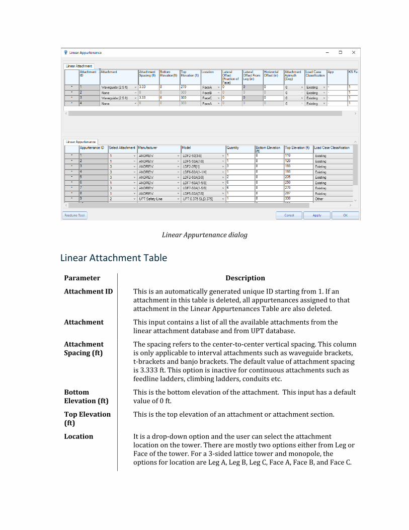
Linear Appurtenance dialog
Linear Attachment Table
Parameter Description
Attachment ID This is an automatically generated unique ID starting from 1. If an attachment in this table is deleted, all appurtenances assigned to that attachment in the Linear Appurtenances Table are also deleted.
Attachment This input contains a list of all the available attachments from the linear attachment database and from UPT database.
Attachment Spacing (ft)
The spacing refers to the center-to-center vertical spacing. This column is only applicable to interval attachments such as waveguide brackets, t-brackets and banjo brackets. The default value of attachment spacing is 3.333 ft. This option is inactive for continuous attachments such as feedline ladders, climbing ladders, conduits etc.
Bottom Elevation (ft)
This is the bottom elevation of the attachment. This input has a default value of 0 ft.
Top Elevation (ft)
This is the top elevation of an attachment or attachment section.
Location It is a drop-down option and the user can select the attachment location on the tower. There are mostly two options either from Leg or Face of the tower. For a 3-sided lattice tower and monopole, the options for location are Leg A, Leg B, Leg C, Face A, Face B, and Face C.
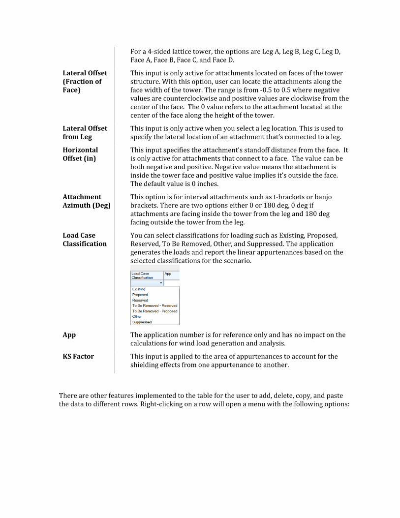
For a 4-sided lattice tower, the options are Leg A, Leg B, Leg C, Leg D, Face A, Face B, Face C, and Face D.
Lateral Offset (Fraction of Face)
This input is only active for attachments located on faces of the tower structure. With this option, user can locate the attachments along the face width of the tower. The range is from -0.5 to 0.5 where negative values are counterclockwise and positive values are clockwise from the center of the face. The 0 value refers to the attachment located at the center of the face along the height of the tower.
Lateral Offset from Leg
This input is only active when you select a leg location. This is used to specify the lateral location of an attachment that’s connected to a leg.
Horizontal Offset (in)
This input specifies the attachment’s standoff distance from the face. It is only active for attachments that connect to a face. The value can be both negative and positive. Negative value means the attachment is inside the tower face and positive value implies it’s outside the face. The default value is 0 inches.
Attachment Azimuth (Deg)
This option is for interval attachments such as t-brackets or banjo brackets. There are two options either 0 or 180 deg, 0 deg if attachments are facing inside the tower from the leg and 180 deg facing outside the tower from the leg.
Load Case Classification
You can select classifications for loading such as Existing, Proposed, Reserved, To Be Removed, Other, and Suppressed. The application generates the loads and report the linear appurtenances based on the selected classifications for the scenario.
App The application number is for reference only and has no impact on the
calculations for wind load generation and analysis.
KS Factor This input is applied to the area of appurtenances to account for the shielding effects from one appurtenance to another.
There are other features implemented to the table for the user to add, delete, copy, and paste the data to different rows. Right-clicking on a row will open a menu with the following options:
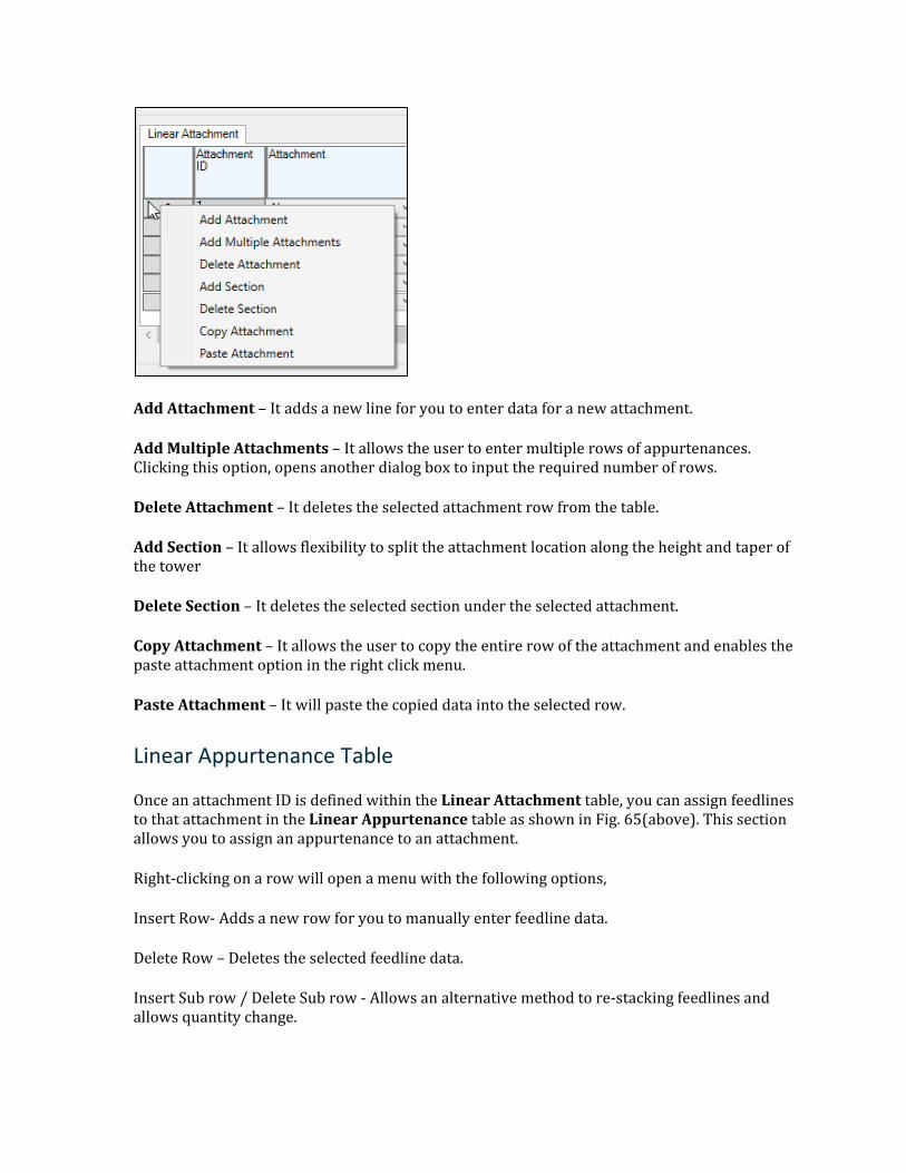
Add Attachment – It adds a new line for you to enter data for a new attachment.
Add Multiple Attachments – It allows the user to enter multiple rows of appurtenances. Clicking this option, opens another dialog box to input the required number of rows.
Delete Attachment – It deletes the selected attachment row from the table.
Add Section – It allows flexibility to split the attachment location along the height and taper of the tower
Delete Section – It deletes the selected section under the selected attachment.
Copy Attachment – It allows the user to copy the entire row of the attachment and enables the paste attachment option in the right click menu.
Paste Attachment – It will paste the copied data into the selected row.
Linear Appurtenance Table
Once an attachment ID is defined within the Linear Attachment table, you can assign feedlines to that attachment in the Linear Appurtenance table as shown in Fig. 65(above). This section allows you to assign an appurtenance to an attachment.
Right-clicking on a row will open a menu with the following options,
Insert Row- Adds a new row for you to manually enter feedline data.
Delete Row – Deletes the selected feedline data.
Insert Sub row / Delete Sub row - Allows an alternative method to re-stacking feedlines and allows quantity change.
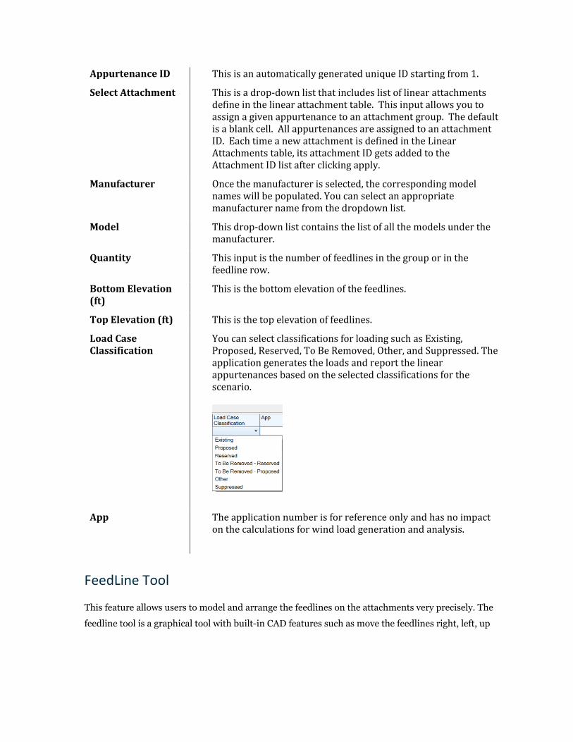
Appurtenance ID This is an automatically generated unique ID starting from 1.
Select Attachment This is a drop-down list that includes list of linear attachments define in the linear attachment table. This input allows you to assign a given appurtenance to an attachment group. The default is a blank cell. All appurtenances are assigned to an attachment ID. Each time a new attachment is defined in the Linear Attachments table, its attachment ID gets added to the Attachment ID list after clicking apply.
Manufacturer Once the manufacturer is selected, the corresponding model names will be populated. You can select an appropriate manufacturer name from the dropdown list.
Model This drop-down list contains the list of all the models under the manufacturer.
Quantity This input is the number of feedlines in the group or in the feedline row.
Bottom Elevation (ft)
This is the bottom elevation of the feedlines.
Top Elevation (ft) This is the top elevation of feedlines.
Load Case Classification
You can select classifications for loading such as Existing, Proposed, Reserved, To Be Removed, Other, and Suppressed. The application generates the loads and report the linear appurtenances based on the selected classifications for the scenario.
App The application number is for reference only and has no impact on the calculations for wind load generation and analysis.
FeedLine Tool
This feature allows users to model and arrange the feedlines on the attachments very precisely. The
feedline tool is a graphical tool with built-in CAD features such as move the feedlines right, left, up
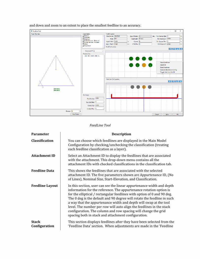
and down and zoom to an extent to place the smallest feedline to an accuracy.
FeedLine Tool
Parameter Description
Classification You can choose which feedlines are displayed in the Main Model Configuration by checking/unchecking the classification (treating each feedline classification as a layer).
Attachment ID Select an Attachment ID to display the feedlines that are associated with the attachment. This drop-down menu contains all the attachment IDs with checked classifications in the classification tab.
Feedline Data This shows the feedlines that are associated with the selected attachment ID. The five parameters shown are Appurtenance ID, (No of Lines), Nominal Size, Start-Elevation, and Classification.
Feedline Layout In this section, user can see the linear appurtenance width and depth information for the reference. The appurtenance rotation option is for the elliptical / rectangular feedlines with option of 0 and 90 deg. The 0 deg is the default and 90 degree will rotate the feedline in such a way that the appurtenance width and depth will swap at the tool level. The number per row will auto align the feedlines in the stack configuration. The column and row spacing will change the grid spacing both in stack and attachment configuration.
Stack Configuration
This section displays feedlines after they have been selected from the ‘Feedline Data’ section. When adjustments are made in the ‘Feedline
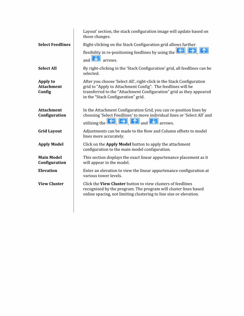
Layout’ section, the stack configuration image will update based on those changes.
Select Feedlines Right-clicking on the Stack Configuration grid allows further
flexibility in re-positioning feedlines by using the , ,
and arrows.
Select All By right-clicking in the ‘Stack Configuration’ grid, all feedlines can be selected.
Apply to Attachment Config
After you choose ‘Select All’, right-click in the Stack Configuration grid to “Apply to Attachment Config”. The feedlines will be transferred to the “Attachment Configuration” grid as they appeared in the “Stack Configuration” grid.
Attachment Configuration
In the Attachment Configuration Grid, you can re-position lines by choosing ‘Select Feedlines’ to move individual lines or ‘Select All’ and
utilizing the , , and arrows.
Grid Layout Adjustments can be made to the Row and Column offsets to model lines more accurately.
Apply Model Click on the Apply Model button to apply the attachment configuration to the main model configuration.
Main Model Configuration
This section displays the exact linear appurtenance placement as it will appear in the model.
Elevation Enter an elevation to view the linear appurtenance configuration at various tower levels.
View Cluster
Click the View Cluster button to view clusters of feedlines recognized by the program. The program will cluster lines based online spacing, not limiting clustering to line size or elevation.
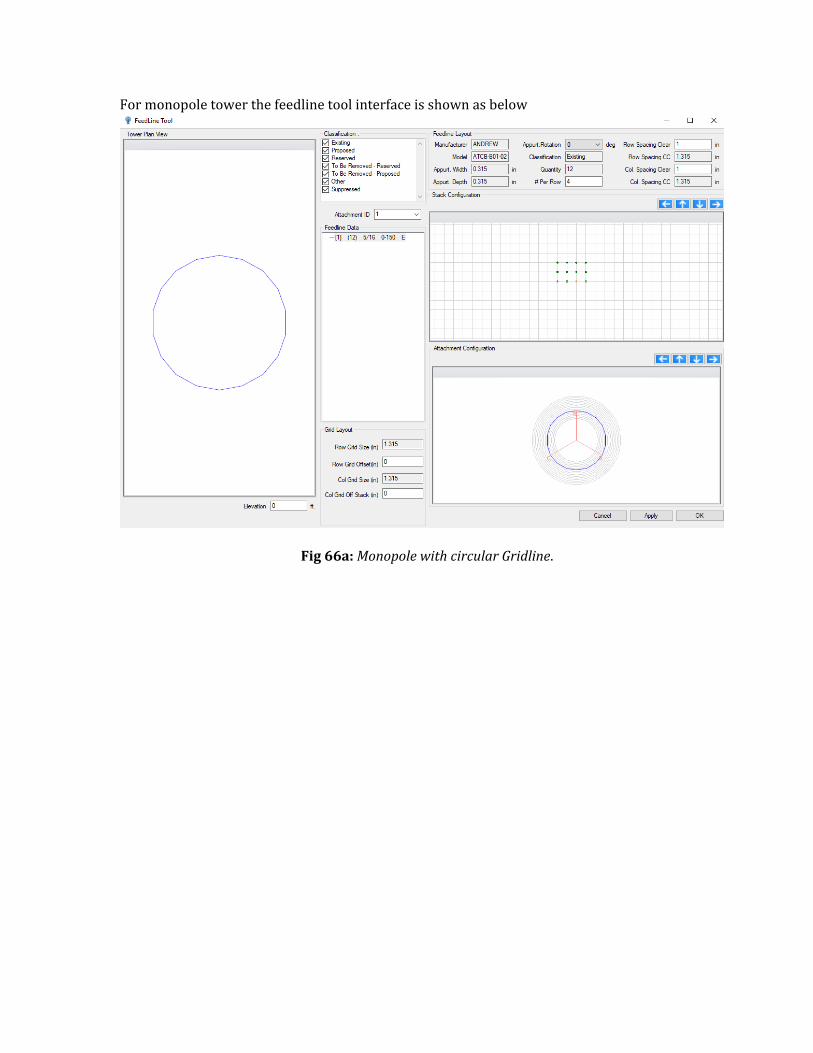
For monopole tower the feedline tool interface is shown as below
Fig 66a: Monopole with circular Gridline.
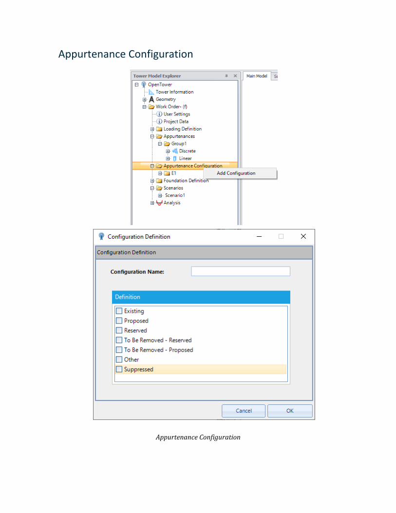
Appurtenance Configuration
Appurtenance Configuration

After creating the appurtenance group, the appurtenance configuration needs to be defined to consider into the scenario. Multiple appurtenance configurations can be created. Right-click on the Appurtenance configuration and then click Add configuration, the configuration definition dialog opens. In this dialog, you have to specify a name for the configuration and have to choose classifications from the list shown in Fig.67.
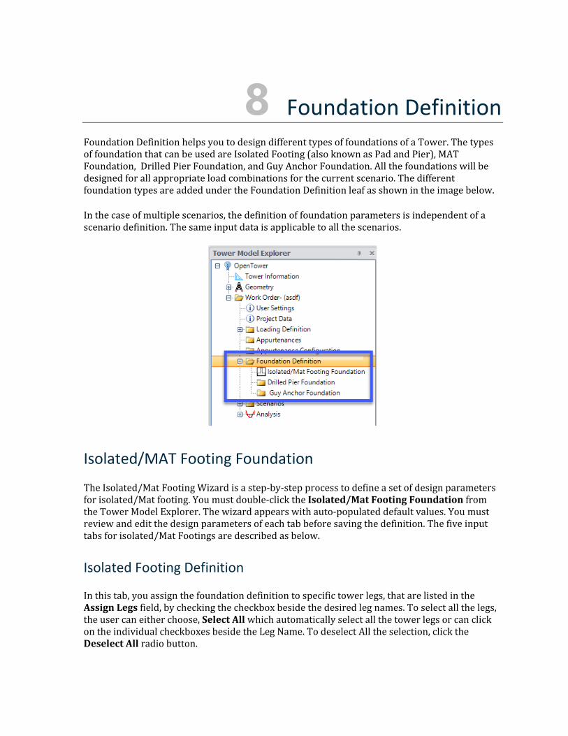
8 Foundation Definition Foundation Definition helps you to design different types of foundations of a Tower. The types of foundation that can be used are Isolated Footing (also known as Pad and Pier), MAT Foundation, Drilled Pier Foundation, and Guy Anchor Foundation. All the foundations will be designed for all appropriate load combinations for the current scenario. The different foundation types are added under the Foundation Definition leaf as shown in the image below.
In the case of multiple scenarios, the definition of foundation parameters is independent of a scenario definition. The same input data is applicable to all the scenarios.
Isolated/MAT Footing Foundation
The Isolated/Mat Footing Wizard is a step-by-step process to define a set of design parameters for isolated/Mat footing. You must double-click the Isolated/Mat Footing Foundation from the Tower Model Explorer. The wizard appears with auto-populated default values. You must review and edit the design parameters of each tab before saving the definition. The five input tabs for isolated/Mat Footings are described as below.
Isolated Footing Definition
In this tab, you assign the foundation definition to specific tower legs, that are listed in the Assign Legs field, by checking the checkbox beside the desired leg names. To select all the legs, the user can either choose, Select All which automatically select all the tower legs or can click on the individual checkboxes beside the Leg Name. To deselect All the selection, click the Deselect All radio button.
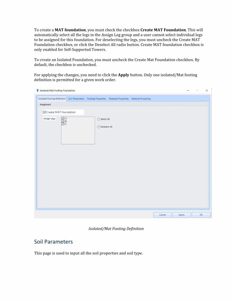
To create a MAT foundation, you must check the checkbox Create MAT Foundation. This will automatically select all the legs in the Assign Leg group and a user cannot select individual legs to be assigned for this foundation. For deselecting the legs, you must uncheck the Create MAT Foundation checkbox, or click the Deselect All radio button. Create MAT foundation checkbox is only enabled for Self-Supported Towers.
To create an Isolated Foundation, you must uncheck the Create Mat Foundation checkbox. By default, the checkbox is unchecked.
For applying the changes, you need to click the Apply button. Only one isolated/Mat footing definition is permitted for a given work order.
Isolated/Mat Footing Definition
Soil Parameters
This page is used to input all the soil properties and soil type.
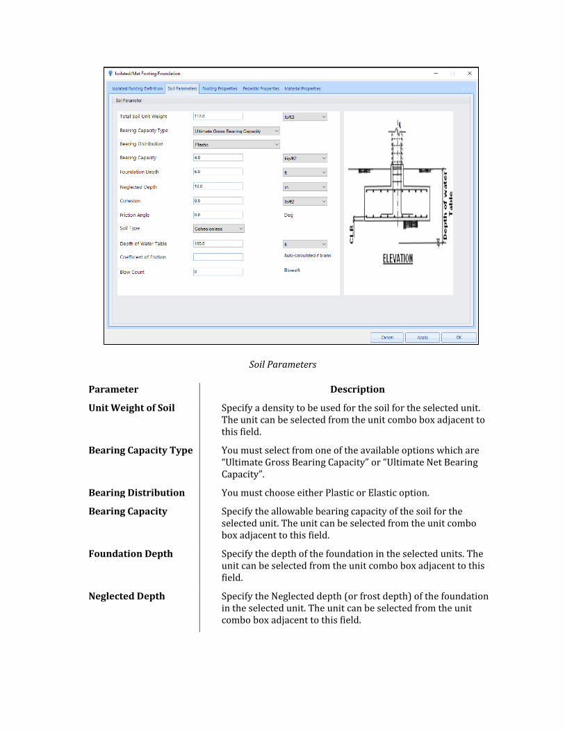
Soil Parameters
Parameter Description
Unit Weight of Soil Specify a density to be used for the soil for the selected unit. The unit can be selected from the unit combo box adjacent to this field.
Bearing Capacity Type You must select from one of the available options which are “Ultimate Gross Bearing Capacity” or “Ultimate Net Bearing Capacity”.
Bearing Distribution You must choose either Plastic or Elastic option.
Bearing Capacity Specify the allowable bearing capacity of the soil for the selected unit. The unit can be selected from the unit combo box adjacent to this field.
Foundation Depth Specify the depth of the foundation in the selected units. The unit can be selected from the unit combo box adjacent to this field.
Neglected Depth Specify the Neglected depth (or frost depth) of the foundation in the selected unit. The unit can be selected from the unit combo box adjacent to this field.
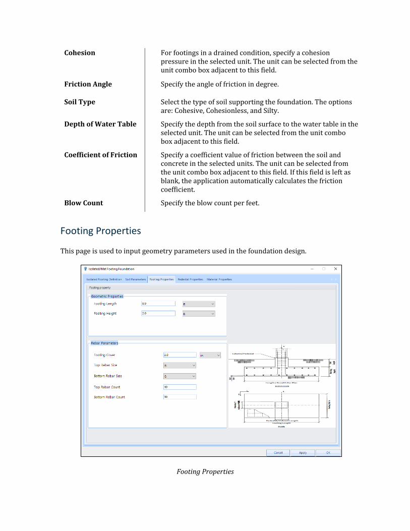
Cohesion For footings in a drained condition, specify a cohesion pressure in the selected unit. The unit can be selected from the unit combo box adjacent to this field.
Friction Angle Specify the angle of friction in degree.
Soil Type Select the type of soil supporting the foundation. The options are: Cohesive, Cohesionless, and Silty.
Depth of Water Table Specify the depth from the soil surface to the water table in the selected unit. The unit can be selected from the unit combo box adjacent to this field.
Coefficient of Friction Specify a coefficient value of friction between the soil and concrete in the selected units. The unit can be selected from the unit combo box adjacent to this field. If this field is left as blank, the application automatically calculates the friction coefficient.
Blow Count Specify the blow count per feet.
Footing Properties
This page is used to input geometry parameters used in the foundation design.
Footing Properties
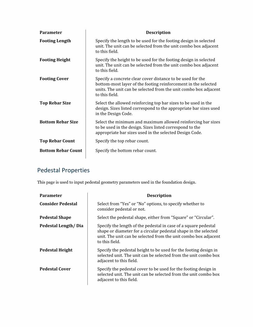
Parameter Description
Footing Length Specify the length to be used for the footing design in selected unit. The unit can be selected from the unit combo box adjacent to this field.
Footing Height Specify the height to be used for the footing design in selected unit. The unit can be selected from the unit combo box adjacent to this field.
Footing Cover Specify a concrete clear cover distance to be used for the bottom-most layer of the footing reinforcement in the selected units. The unit can be selected from the unit combo box adjacent to this field.
Top Rebar Size Select the allowed reinforcing top bar sizes to be used in the design. Sizes listed correspond to the appropriate bar sizes used in the Design Code.
Bottom Rebar Size Select the minimum and maximum allowed reinforcing bar sizes to be used in the design. Sizes listed correspond to the appropriate bar sizes used in the selected Design Code.
Top Rebar Count Specify the top rebar count.
Bottom Rebar Count Specify the bottom rebar count.
Pedestal Properties
This page is used to input pedestal geometry parameters used in the foundation design.
Parameter Description
Consider Pedestal Select from “Yes” or “No” options, to specify whether to consider pedestal or not.
Pedestal Shape Select the pedestal shape, either from “Square” or “Circular”.
Pedestal Length/ Dia Specify the length of the pedestal in case of a square pedestal shape or diameter for a circular pedestal shape in the selected unit. The unit can be selected from the unit combo box adjacent to this field.
Pedestal Height Specify the pedestal height to be used for the footing design in selected unit. The unit can be selected from the unit combo box adjacent to this field.
Pedestal Cover Specify the pedestal cover to be used for the footing design in selected unit. The unit can be selected from the unit combo box adjacent to this field.
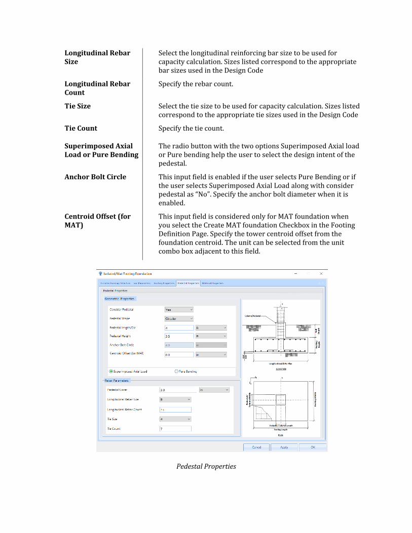
Longitudinal Rebar Size
Select the longitudinal reinforcing bar size to be used for capacity calculation. Sizes listed correspond to the appropriate bar sizes used in the Design Code
Longitudinal Rebar Count
Specify the rebar count.
Tie Size Select the tie size to be used for capacity calculation. Sizes listed correspond to the appropriate tie sizes used in the Design Code
Tie Count Specify the tie count.
Superimposed Axial Load or Pure Bending
The radio button with the two options Superimposed Axial load or Pure bending help the user to select the design intent of the pedestal.
Anchor Bolt Circle This input field is enabled if the user selects Pure Bending or if the user selects Superimposed Axial Load along with consider pedestal as “No”. Specify the anchor bolt diameter when it is enabled.
Centroid Offset (for MAT)
This input field is considered only for MAT foundation when you select the Create MAT foundation Checkbox in the Footing Definition Page. Specify the tower centroid offset from the foundation centroid. The unit can be selected from the unit combo box adjacent to this field.
Pedestal Properties
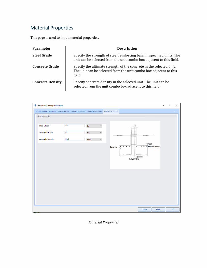
Material Properties
This page is used to input material properties.
Parameter Description
Steel Grade Specify the strength of steel reinforcing bars, in specified units. The unit can be selected from the unit combo box adjacent to this field.
Concrete Grade Specify the ultimate strength of the concrete in the selected unit. The unit can be selected from the unit combo box adjacent to this field.
Concrete Density Specify concrete density in the selected unit. The unit can be selected from the unit combo box adjacent to this field.
Material Properties
Drilled Pier Foundation
The Drilled Pier Footing Wizard is a step-by-step process to define a set of design parameters to be used for designing a drilled pier foundation. You must right-click on the Drilled Pier Foundation leaf from the Tower Model Explorer navigation tree to create a new definition. The wizard appears with auto-populated default values. You must select all the tabs and review all the parameters before clicking on Save to complete the wizard and create a new definition for a drilled pier foundation. The four input tabs for a Drilled Pier foundation are as described below.
Create New Drilled Pier Foundation
Drilled Pier Definition
In this tab, a user assigns the foundation definition to specific tower legs, that are listed in the Assign Legs field, by checking the checkbox beside the desired leg names. To select all the legs, the user can either choose, Select All which automatically select all the tower legs or can click on the individual checkboxes beside the Leg Name. To deselect All the selection, click the Deselect All radio button. For applying the changes, the user needs to click the Apply button. You can create multiple drilled pier definitions in a single work order. Once created, if you double-click on the definition name, the wizard automatically opens for editing.
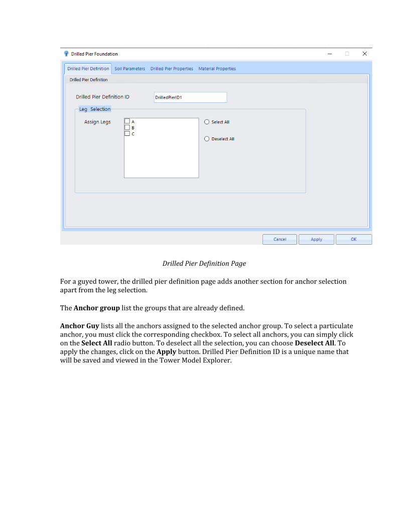
Drilled Pier Definition Page
For a guyed tower, the drilled pier definition page adds another section for anchor selection apart from the leg selection.
The Anchor group list the groups that are already defined.
Anchor Guy lists all the anchors assigned to the selected anchor group. To select a particulate anchor, you must click the corresponding checkbox. To select all anchors, you can simply click on the Select All radio button. To deselect all the selection, you can choose Deselect All. To apply the changes, click on the Apply button. Drilled Pier Definition ID is a unique name that will be saved and viewed in the Tower Model Explorer.
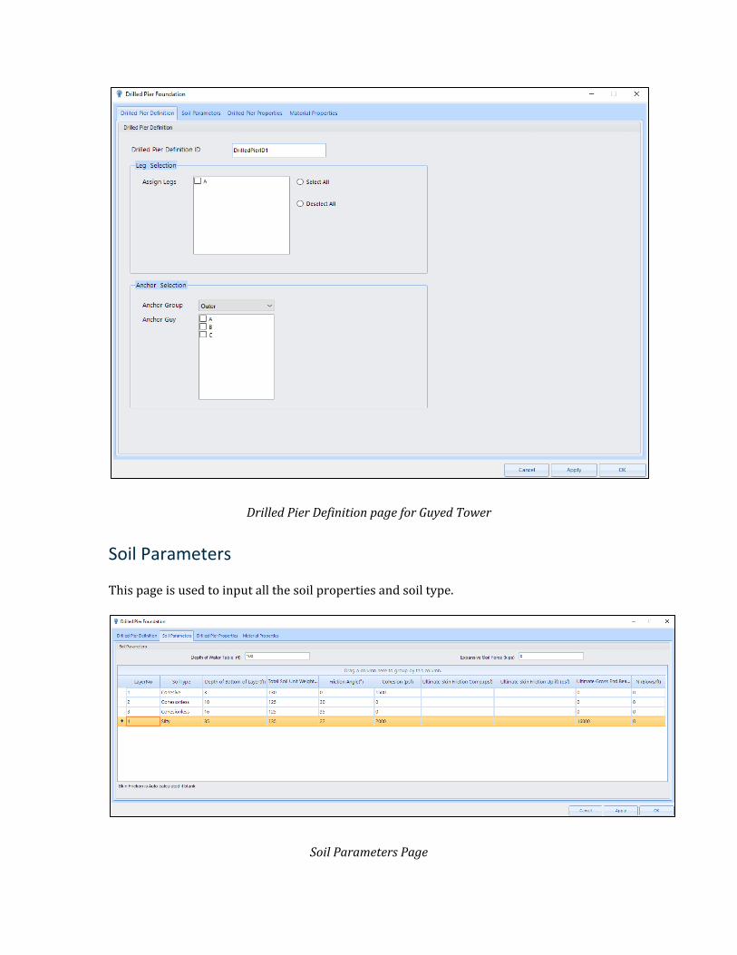
Drilled Pier Definition page for Guyed Tower
Soil Parameters
This page is used to input all the soil properties and soil type.
Soil Parameters Page
Parameter Description
Depth of Water Table (ft) Specify the water table depth measured from the Ground Elevation
Layer No This field is not editable, and auto incremental.
Soil Type Select the soil type that best describes the layer. Options are Cohesive, Cohesionless, and Silty.
Depth of Layer (ft) Depth for each soil layer is measured from Ground Elevation
Density (kcf) Specify soil density for the respective soil layer.
Friction Angle (Deg) Specify the Effective Friction Angle
Cohesion (ksf) Undrained shear strength of cohesive soil.
Ultimate Skin Friction (ksf)
Specify skin friction. If you leave this field blank, the program will automatically calculate Skin friction.
Ultimate Skin Friction Uplift (ksf)
Specify ultimate skin friction for uplift. If you leave this field blank, the program will automatically calculate ultimate skin friction for uplift.
Ultimate End Bearing Pressure (ksf)
Specify ultimate end bearing pressure at the bottom of a layer
N (Blows/ft) Specify the blow count
Expansive Soil Force Specify the extra soil force exerted due to expansive soil condition
Drilled Pier Properties
This Page is used to input drilled pier geometric properties and Reinforcing properties. It consists of two tables, Pier Profile, and Rebar Cage List. The rebar cage table is dependent on the pier profile table. It allows you to add and edit reinforcing related data of the corresponding section, selected in the pier profile table. You can add multiple sections to the pier with different diameters, depths, clear covers, and tie sizes. For a given geometric section, users can assign multiple rebar cages to that section.
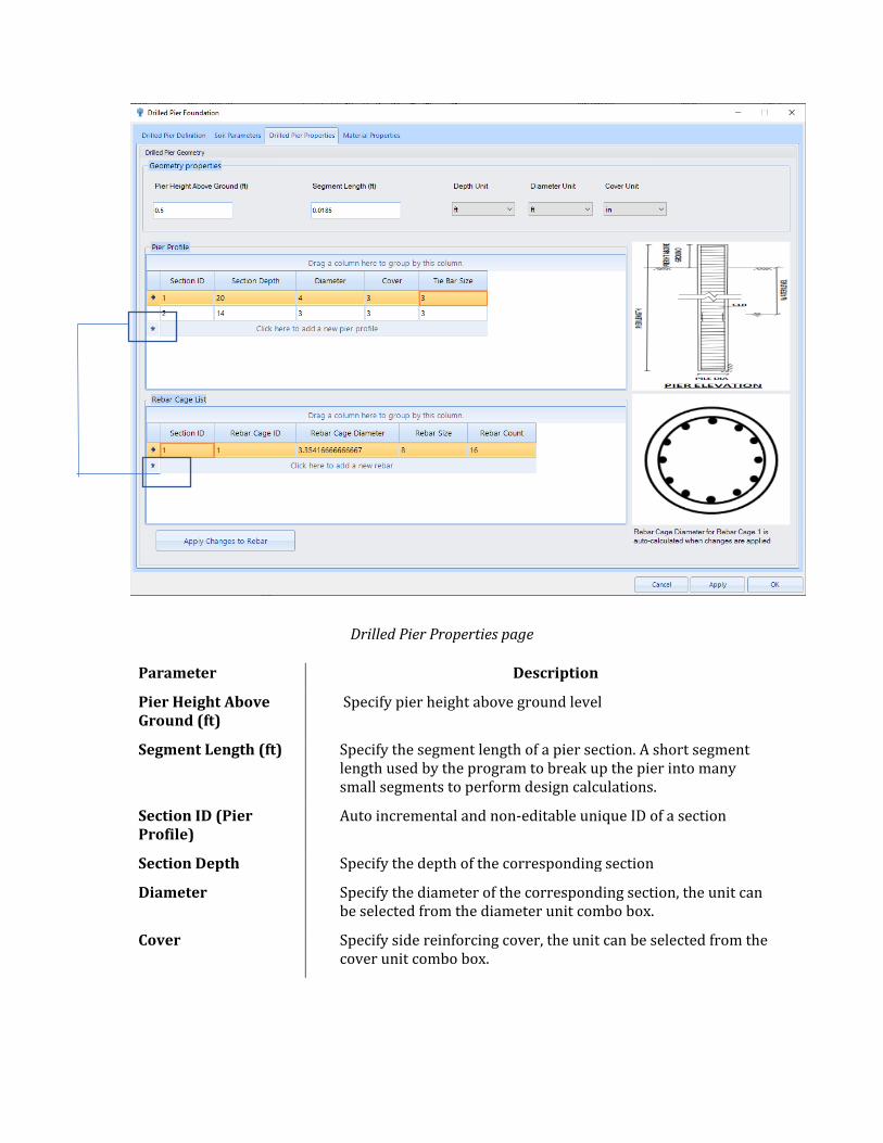
Drilled Pier Properties page
Parameter Description
Pier Height Above Ground (ft)
Specify pier height above ground level
Segment Length (ft) Specify the segment length of a pier section. A short segment length used by the program to break up the pier into many small segments to perform design calculations.
Section ID (Pier Profile)
Auto incremental and non-editable unique ID of a section
Section Depth Specify the depth of the corresponding section
Diameter Specify the diameter of the corresponding section, the unit can be selected from the diameter unit combo box.
Cover Specify side reinforcing cover, the unit can be selected from the cover unit combo box.
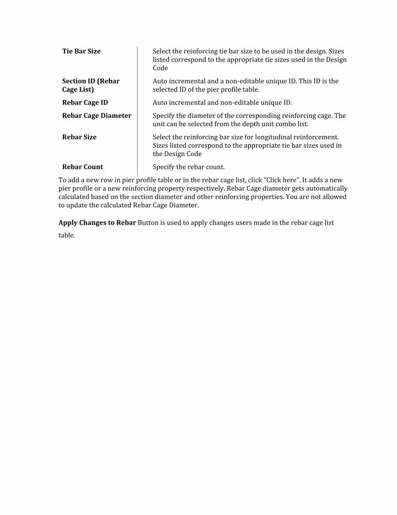
Tie Bar Size Select the reinforcing tie bar size to be used in the design. Sizes listed correspond to the appropriate tie sizes used in the Design Code
Section ID (Rebar Cage List)
Auto incremental and a non-editable unique ID. This ID is the selected ID of the pier profile table.
Rebar Cage ID Auto incremental and non-editable unique ID.
Rebar Cage Diameter Specify the diameter of the corresponding reinforcing cage. The unit can be selected from the depth unit combo list.
Rebar Size Select the reinforcing bar size for longitudinal reinforcement. Sizes listed correspond to the appropriate tie bar sizes used in the Design Code
Rebar Count Specify the rebar count.
To add a new row in pier profile table or in the rebar cage list, click “Click here”. It adds a new pier profile or a new reinforcing property respectively. Rebar Cage diameter gets automatically calculated based on the section diameter and other reinforcing properties. You are not allowed to update the calculated Rebar Cage Diameter.
Apply Changes to Rebar Button is used to apply changes users made in the rebar cage list
table.
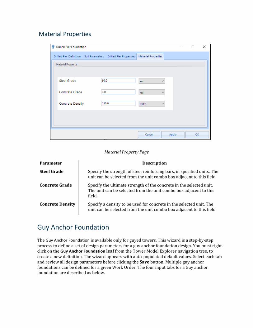
Material Properties
Material Property Page
Parameter Description
Steel Grade Specify the strength of steel reinforcing bars, in specified units. The unit can be selected from the unit combo box adjacent to this field.
Concrete Grade Specify the ultimate strength of the concrete in the selected unit. The unit can be selected from the unit combo box adjacent to this field.
Concrete Density Specify a density to be used for concrete in the selected unit. The unit can be selected from the unit combo box adjacent to this field.
Guy Anchor Foundation
The Guy Anchor Foundation is available only for guyed towers. This wizard is a step-by-step process to define a set of design parameters for a guy anchor foundation design. You must right-click on the Guy Anchor Foundation leaf from the Tower Model Explorer navigation tree, to create a new definition. The wizard appears with auto-populated default values. Select each tab and review all design parameters before clicking the Save button. Multiple guy anchor foundations can be defined for a given Work Order. The four input tabs for a Guy anchor foundation are described as below.
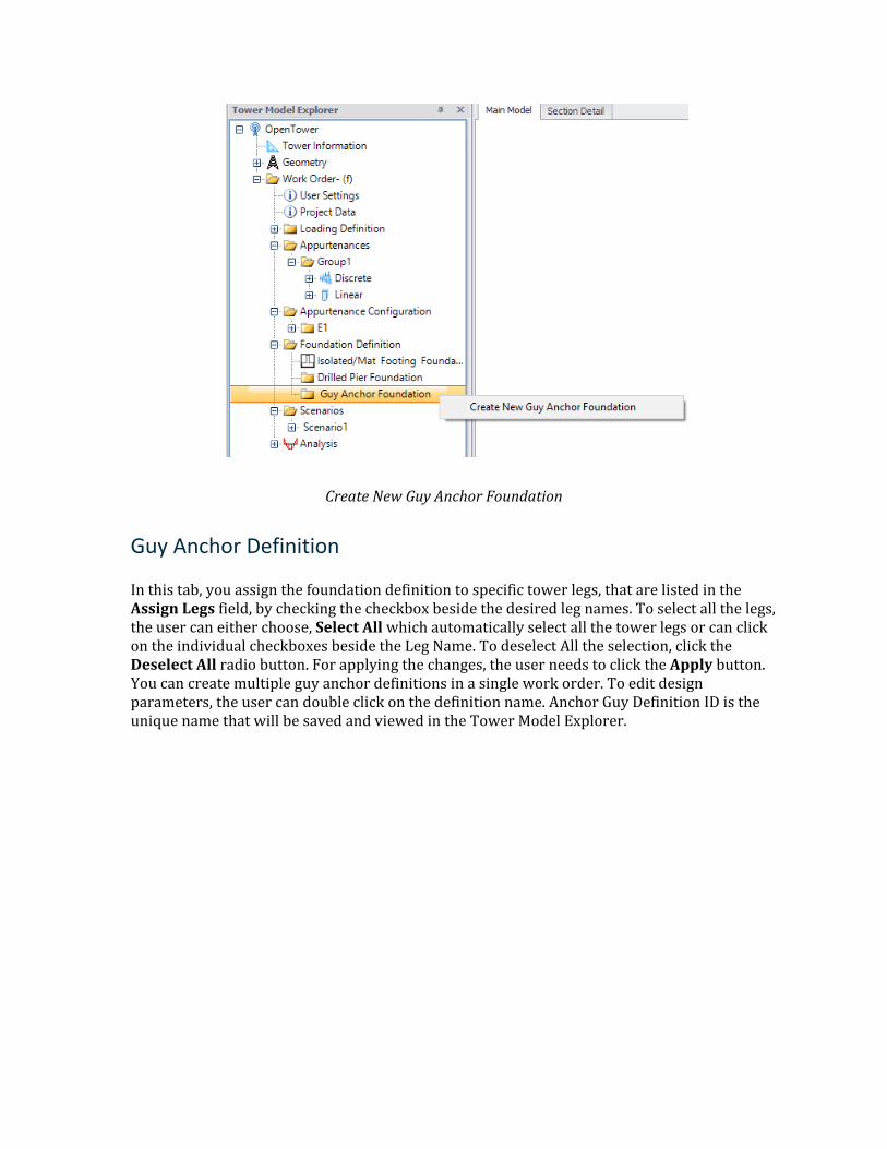
Create New Guy Anchor Foundation
Guy Anchor Definition
In this tab, you assign the foundation definition to specific tower legs, that are listed in the Assign Legs field, by checking the checkbox beside the desired leg names. To select all the legs, the user can either choose, Select All which automatically select all the tower legs or can click on the individual checkboxes beside the Leg Name. To deselect All the selection, click the Deselect All radio button. For applying the changes, the user needs to click the Apply button. You can create multiple guy anchor definitions in a single work order. To edit design parameters, the user can double click on the definition name. Anchor Guy Definition ID is the unique name that will be saved and viewed in the Tower Model Explorer.
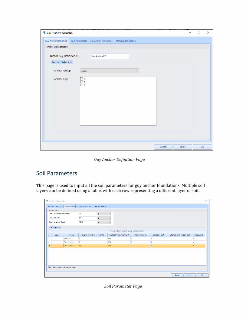
Guy Anchor Definition Page
Soil Parameters
This page is used to input all the soil parameters for guy anchor foundations. Multiple soil layers can be defined using a table, with each row representing a different layer of soil.
Soil Parameter Page
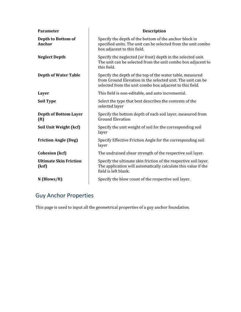
Parameter Description
Depth to Bottom of Anchor
Specify the depth of the bottom of the anchor block in specified units. The unit can be selected from the unit combo box adjacent to this field.
Neglect Depth Specify the neglected (or frost) depth in the selected unit. The unit can be selected from the unit combo box adjacent to this field.
Depth of Water Table Specify the depth of the top of the water table, measured from Ground Elevation in the selected unit. The unit can be selected from the unit combo box adjacent to this field.
Layer This field is non-editable, and auto incremental.
Soil Type Select the type that best describes the contents of the selected layer
Depth of Bottom Layer (ft)
Specify the bottom depth of each soil layer, measured from Ground Elevation
Soil Unit Weight (kcf) Specify the unit weight of soil for the corresponding soil layer
Friction Angle (Deg) Specify Effective Friction Angle for the corresponding soil layer
Cohesion (kcf) The undrained shear strength of the respective soil layer.
Ultimate Skin Friction (ksf)
Specify the ultimate skin friction of the respective soil layer. The application will automatically calculate this value if the field is left blank.
N (Blows/ft) Specify the blow count of the respective soil layer.
Guy Anchor Properties
This page is used to input all the geometrical properties of a guy anchor foundation.
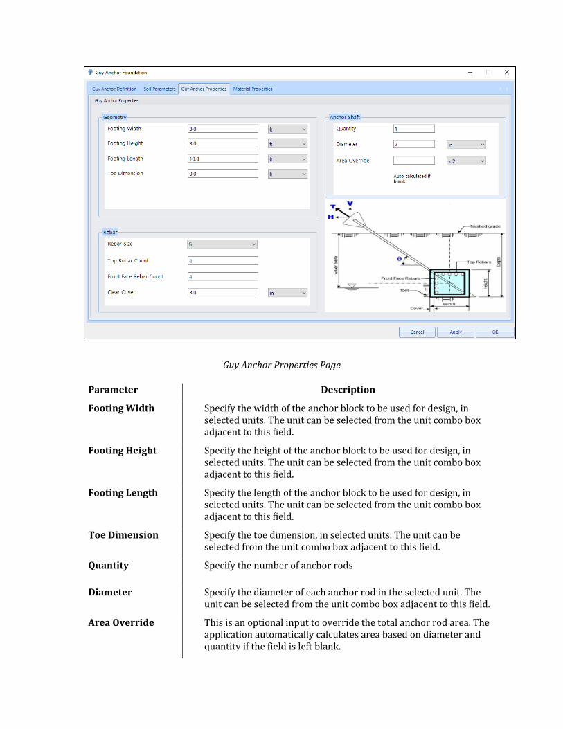
Guy Anchor Properties Page
Parameter Description
Footing Width Specify the width of the anchor block to be used for design, in selected units. The unit can be selected from the unit combo box adjacent to this field.
Footing Height Specify the height of the anchor block to be used for design, in selected units. The unit can be selected from the unit combo box adjacent to this field.
Footing Length Specify the length of the anchor block to be used for design, in selected units. The unit can be selected from the unit combo box adjacent to this field.
Toe Dimension Specify the toe dimension, in selected units. The unit can be selected from the unit combo box adjacent to this field.
Quantity Specify the number of anchor rods
Diameter Specify the diameter of each anchor rod in the selected unit. The unit can be selected from the unit combo box adjacent to this field.
Area Override This is an optional input to override the total anchor rod area. The application automatically calculates area based on diameter and quantity if the field is left blank.
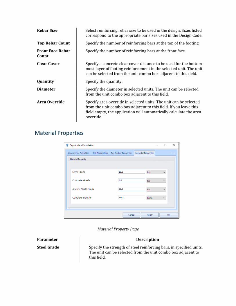
Rebar Size Select reinforcing rebar size to be used in the design. Sizes listed correspond to the appropriate bar sizes used in the Design Code.
Top Rebar Count Specify the number of reinforcing bars at the top of the footing.
Front Face Rebar Count
Specify the number of reinforcing bars at the front face.
Clear Cover Specify a concrete clear cover distance to be used for the bottom-most layer of footing reinforcement in the selected unit. The unit can be selected from the unit combo box adjacent to this field.
Quantity Specify the quantity.
Diameter Specify the diameter in selected units. The unit can be selected from the unit combo box adjacent to this field.
Area Override Specify area override in selected units. The unit can be selected from the unit combo box adjacent to this field. If you leave this field empty, the application will automatically calculate the area override.
Material Properties
Material Property Page
Parameter Description
Steel Grade Specify the strength of steel reinforcing bars, in specified units. The unit can be selected from the unit combo box adjacent to this field.
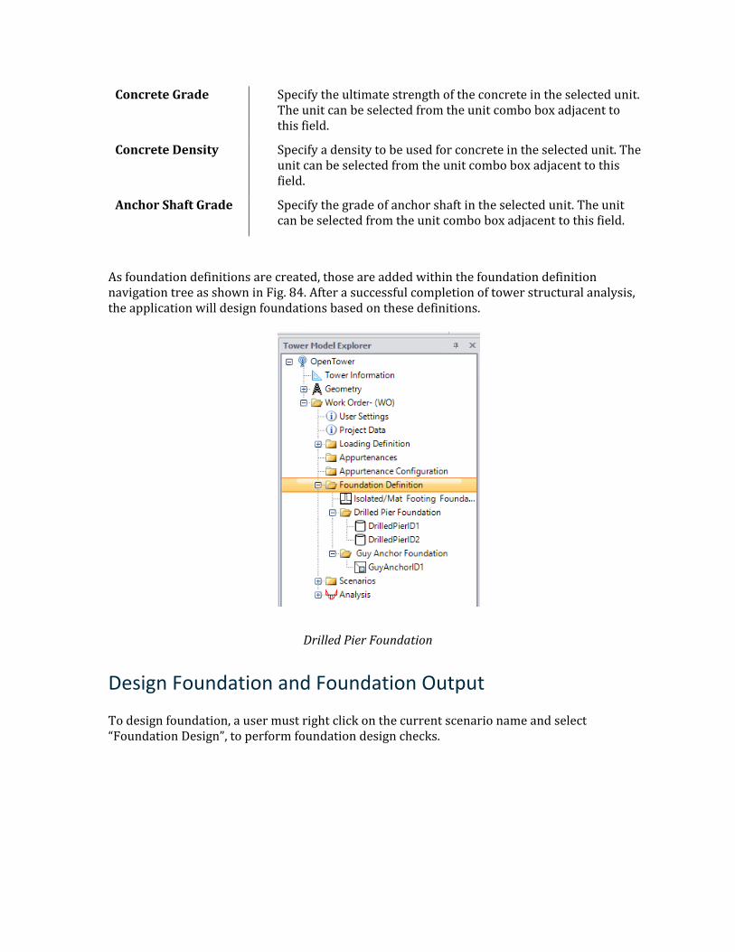
Concrete Grade Specify the ultimate strength of the concrete in the selected unit. The unit can be selected from the unit combo box adjacent to this field.
Concrete Density Specify a density to be used for concrete in the selected unit. The unit can be selected from the unit combo box adjacent to this field.
Anchor Shaft Grade Specify the grade of anchor shaft in the selected unit. The unit can be selected from the unit combo box adjacent to this field.
As foundation definitions are created, those are added within the foundation definition navigation tree as shown in Fig. 84. After a successful completion of tower structural analysis, the application will design foundations based on these definitions.
Drilled Pier Foundation
Design Foundation and Foundation Output
To design foundation, a user must right click on the current scenario name and select “Foundation Design”, to perform foundation design checks.
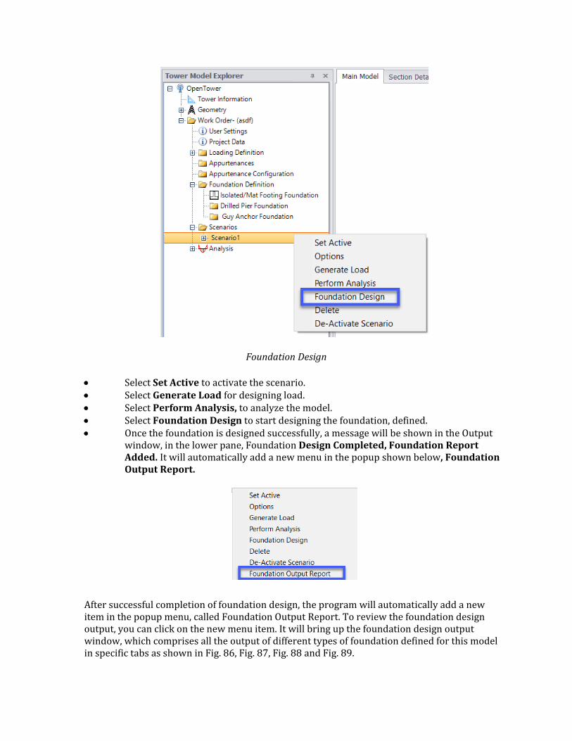
Foundation Design
• Select Set Active to activate the scenario. • Select Generate Load for designing load. • Select Perform Analysis, to analyze the model. • Select Foundation Design to start designing the foundation, defined. • Once the foundation is designed successfully, a message will be shown in the Output
window, in the lower pane, Foundation Design Completed, Foundation Report Added. It will automatically add a new menu in the popup shown below, Foundation Output Report.
After successful completion of foundation design, the program will automatically add a new item in the popup menu, called Foundation Output Report. To review the foundation design output, you can click on the new menu item. It will bring up the foundation design output window, which comprises all the output of different types of foundation defined for this model in specific tabs as shown in Fig. 86, Fig. 87, Fig. 88 and Fig. 89.
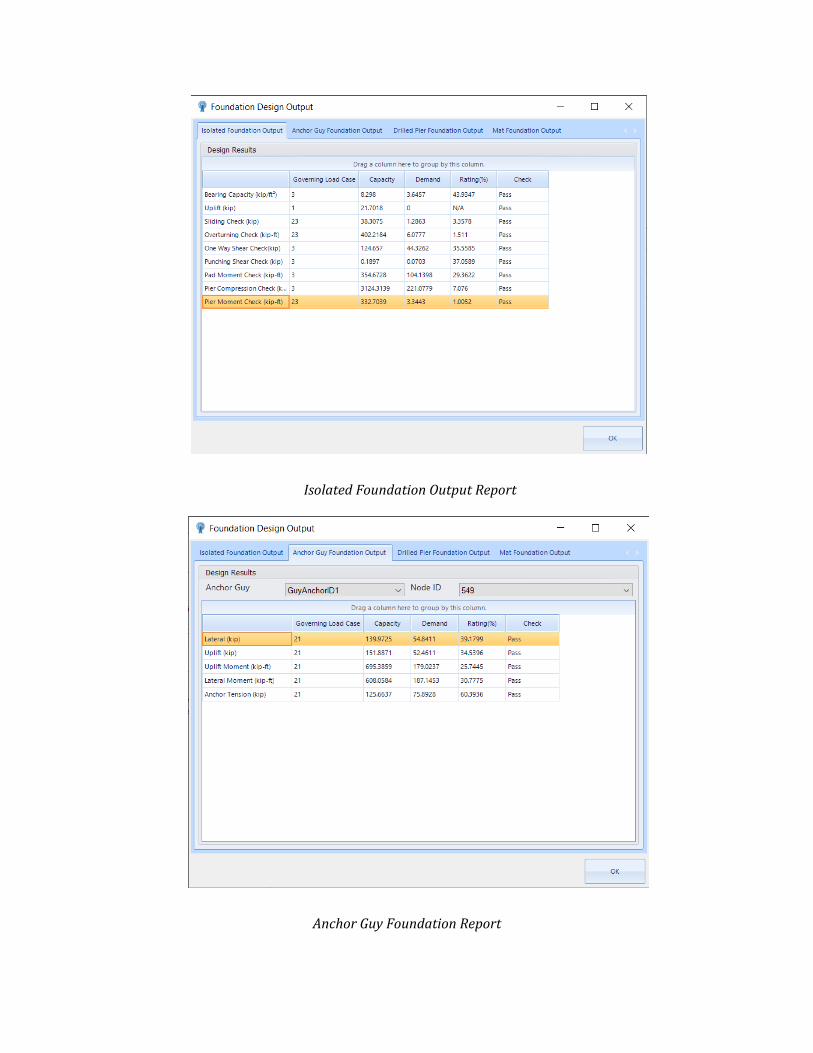
Isolated Foundation Output Report
Anchor Guy Foundation Report
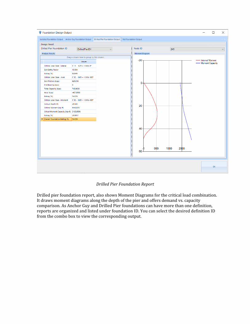
Drilled Pier Foundation Report
Drilled pier foundation report, also shows Moment Diagrams for the critical load combination. It draws moment diagrams along the depth of the pier and offers demand vs. capacity comparison. As Anchor Guy and Drilled Pier foundations can have more than one definition, reports are organized and listed under foundation ID. You can select the desired definition ID from the combo box to view the corresponding output.
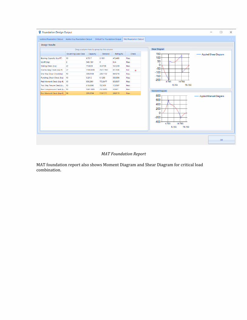
MAT Foundation Report
MAT foundation report also shows Moment Diagram and Shear Diagram for critical load combination.
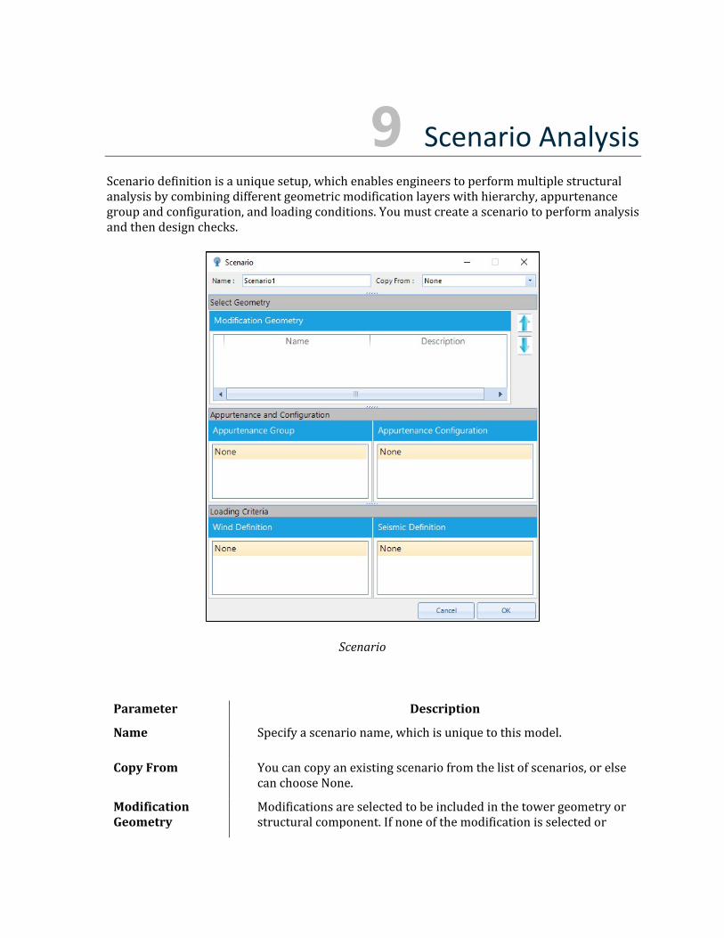
9 Scenario Analysis Scenario definition is a unique setup, which enables engineers to perform multiple structural analysis by combining different geometric modification layers with hierarchy, appurtenance group and configuration, and loading conditions. You must create a scenario to perform analysis and then design checks.
Scenario
Parameter Description
Name Specify a scenario name, which is unique to this model.
Copy From You can copy an existing scenario from the list of scenarios, or else can choose None.
Modification Geometry
Modifications are selected to be included in the tower geometry or structural component. If none of the modification is selected or
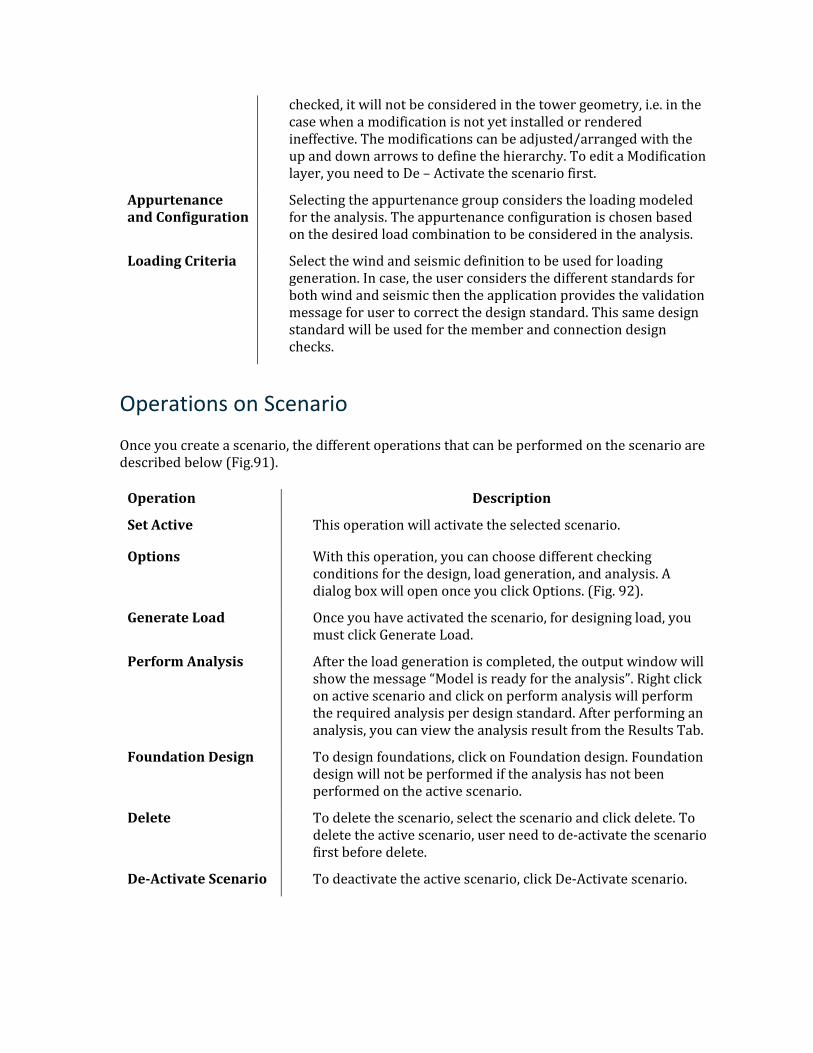
checked, it will not be considered in the tower geometry, i.e. in the case when a modification is not yet installed or rendered ineffective. The modifications can be adjusted/arranged with the up and down arrows to define the hierarchy. To edit a Modification layer, you need to De – Activate the scenario first.
Appurtenance and Configuration
Selecting the appurtenance group considers the loading modeled for the analysis. The appurtenance configuration is chosen based on the desired load combination to be considered in the analysis.
Loading Criteria Select the wind and seismic definition to be used for loading generation. In case, the user considers the different standards for both wind and seismic then the application provides the validation message for user to correct the design standard. This same design standard will be used for the member and connection design checks.
Operations on Scenario
Once you create a scenario, the different operations that can be performed on the scenario are described below (Fig.91).
Operation Description
Set Active This operation will activate the selected scenario.
Options With this operation, you can choose different checking conditions for the design, load generation, and analysis. A dialog box will open once you click Options. (Fig. 92).
Generate Load Once you have activated the scenario, for designing load, you must click Generate Load.
Perform Analysis After the load generation is completed, the output window will show the message “Model is ready for the analysis”. Right click on active scenario and click on perform analysis will perform the required analysis per design standard. After performing an analysis, you can view the analysis result from the Results Tab.
Foundation Design To design foundations, click on Foundation design. Foundation design will not be performed if the analysis has not been performed on the active scenario.
Delete To delete the scenario, select the scenario and click delete. To delete the active scenario, user need to de-activate the scenario first before delete.
De-Activate Scenario To deactivate the active scenario, click De-Activate scenario.
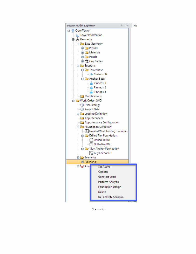
Scenario
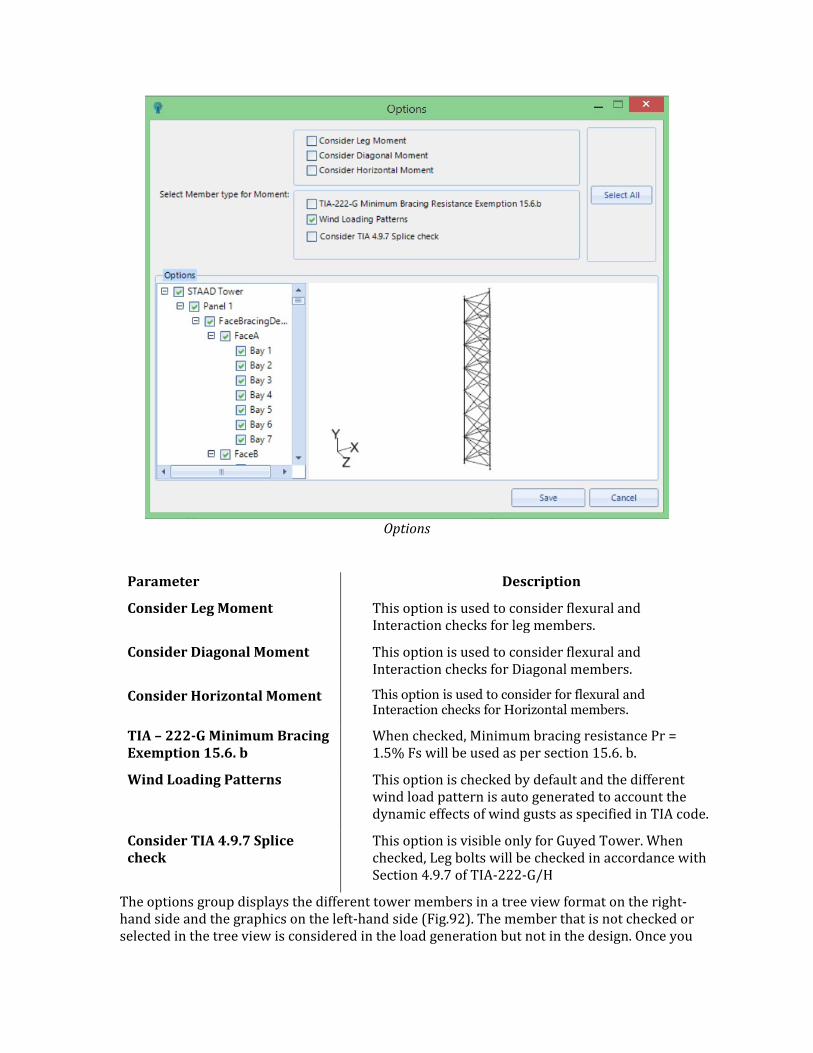
Options
Parameter Description
Consider Leg Moment This option is used to consider flexural and Interaction checks for leg members.
Consider Diagonal Moment This option is used to consider flexural and Interaction checks for Diagonal members.
Consider Horizontal Moment This option is used to consider for flexural and Interaction checks for Horizontal members.
TIA – 222-G Minimum Bracing Exemption 15.6. b
When checked, Minimum bracing resistance Pr = 1.5% Fs will be used as per section 15.6. b.
Wind Loading Patterns This option is checked by default and the different wind load pattern is auto generated to account the dynamic effects of wind gusts as specified in TIA code.
Consider TIA 4.9.7 Splice check
This option is visible only for Guyed Tower. When checked, Leg bolts will be checked in accordance with Section 4.9.7 of TIA-222-G/H
The options group displays the different tower members in a tree view format on the right-hand side and the graphics on the left-hand side (Fig.92). The member that is not checked or selected in the tree view is considered in the load generation but not in the design. Once you
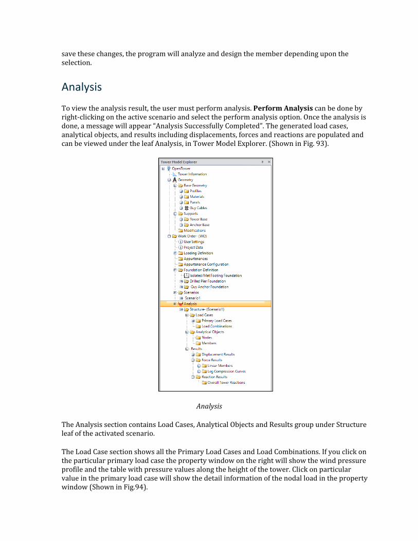
save these changes, the program will analyze and design the member depending upon the selection.
Analysis
To view the analysis result, the user must perform analysis. Perform Analysis can be done by right-clicking on the active scenario and select the perform analysis option. Once the analysis is done, a message will appear “Analysis Successfully Completed”. The generated load cases, analytical objects, and results including displacements, forces and reactions are populated and can be viewed under the leaf Analysis, in Tower Model Explorer. (Shown in Fig. 93).
Analysis
The Analysis section contains Load Cases, Analytical Objects and Results group under Structure leaf of the activated scenario.
The Load Case section shows all the Primary Load Cases and Load Combinations. If you click on the particular primary load case the property window on the right will show the wind pressure profile and the table with pressure values along the height of the tower. Click on particular value in the primary load case will show the detail information of the nodal load in the property window (Shown in Fig.94).
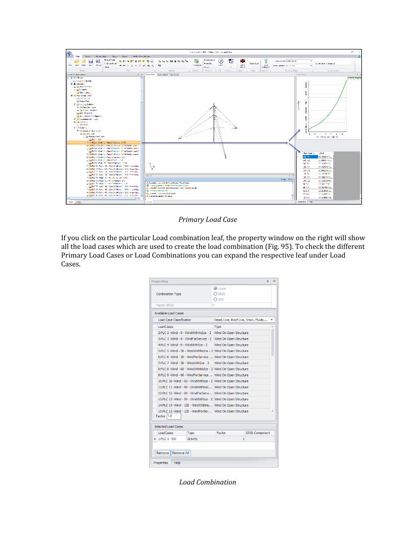
Primary Load Case
If you click on the particular Load combination leaf, the property window on the right will show all the load cases which are used to create the load combination (Fig. 95). To check the different Primary Load Cases or Load Combinations you can expand the respective leaf under Load Cases.
Load Combination
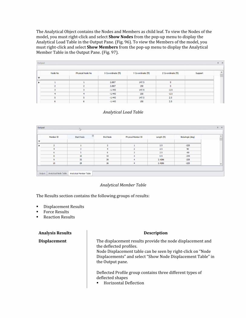
The Analytical Object contains the Nodes and Members as child leaf. To view the Nodes of the model, you must right-click and select Show Nodes from the pop-up menu to display the Analytical Load Table in the Output Pane. (Fig. 96). To view the Members of the model, you must right-click and select Show Members from the pop-up menu to display the Analytical Member Table in the Output Pane. (Fig. 97).
Analytical Load Table
Analytical Member Table
The Results section contains the following groups of results:
Displacement Results Force Results Reaction Results
Analysis Results Description
Displacement The displacement results provide the node displacement and the deflected profiles. Node Displacement table can be seen by right-click on “Node Displacements” and select “Show Node Displacement Table” in the Output pane.
Deflected Profile group contains three different types of deflected shapes Horizontal Deflection
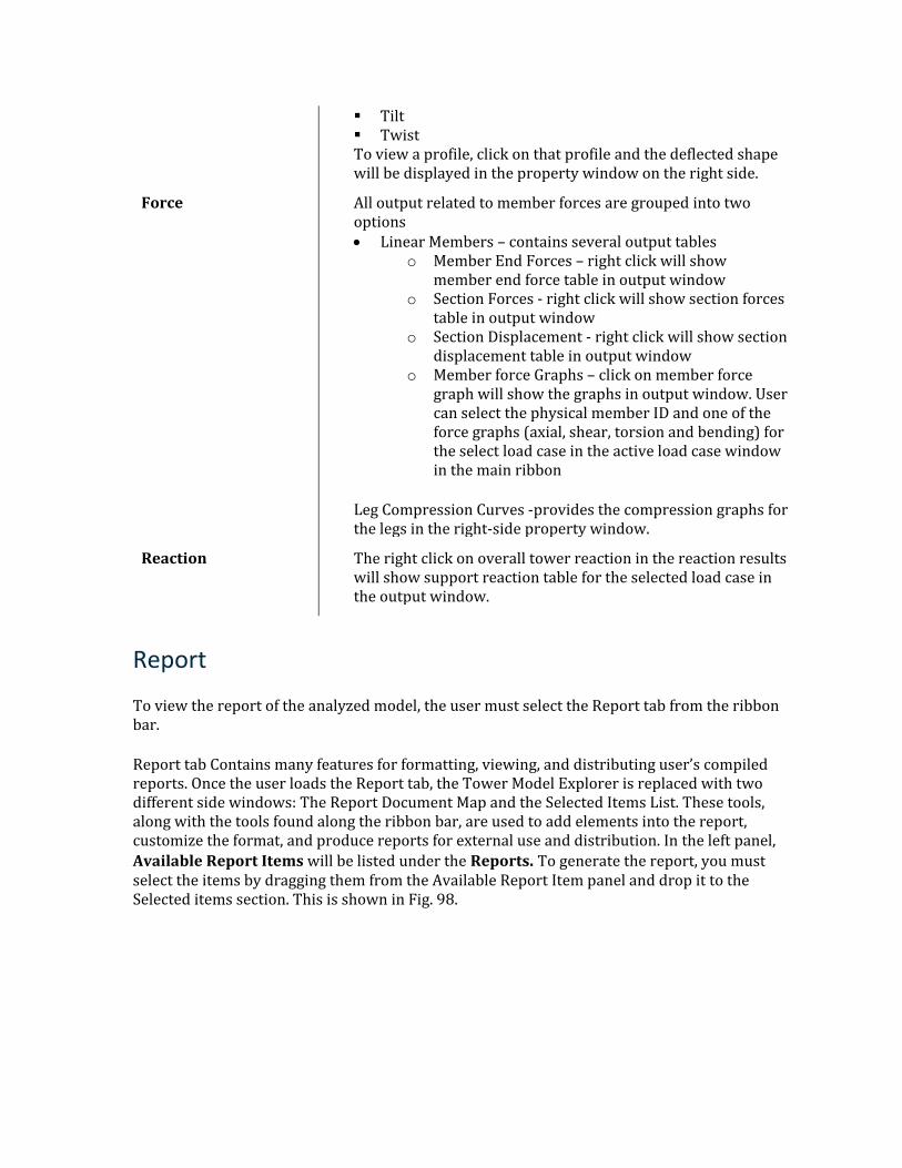
Tilt Twist To view a profile, click on that profile and the deflected shape will be displayed in the property window on the right side.
Force All output related to member forces are grouped into two options • Linear Members – contains several output tables
o Member End Forces – right click will show member end force table in output window
o Section Forces - right click will show section forces table in output window
o Section Displacement - right click will show section displacement table in output window
o Member force Graphs – click on member force graph will show the graphs in output window. User can select the physical member ID and one of the force graphs (axial, shear, torsion and bending) for the select load case in the active load case window in the main ribbon
Leg Compression Curves -provides the compression graphs for the legs in the right-side property window.
Reaction The right click on overall tower reaction in the reaction results will show support reaction table for the selected load case in the output window.
Report
To view the report of the analyzed model, the user must select the Report tab from the ribbon bar.
Report tab Contains many features for formatting, viewing, and distributing user’s compiled reports. Once the user loads the Report tab, the Tower Model Explorer is replaced with two different side windows: The Report Document Map and the Selected Items List. These tools, along with the tools found along the ribbon bar, are used to add elements into the report, customize the format, and produce reports for external use and distribution. In the left panel, Available Report Items will be listed under the Reports. To generate the report, you must select the items by dragging them from the Available Report Item panel and drop it to the Selected items section. This is shown in Fig. 98.
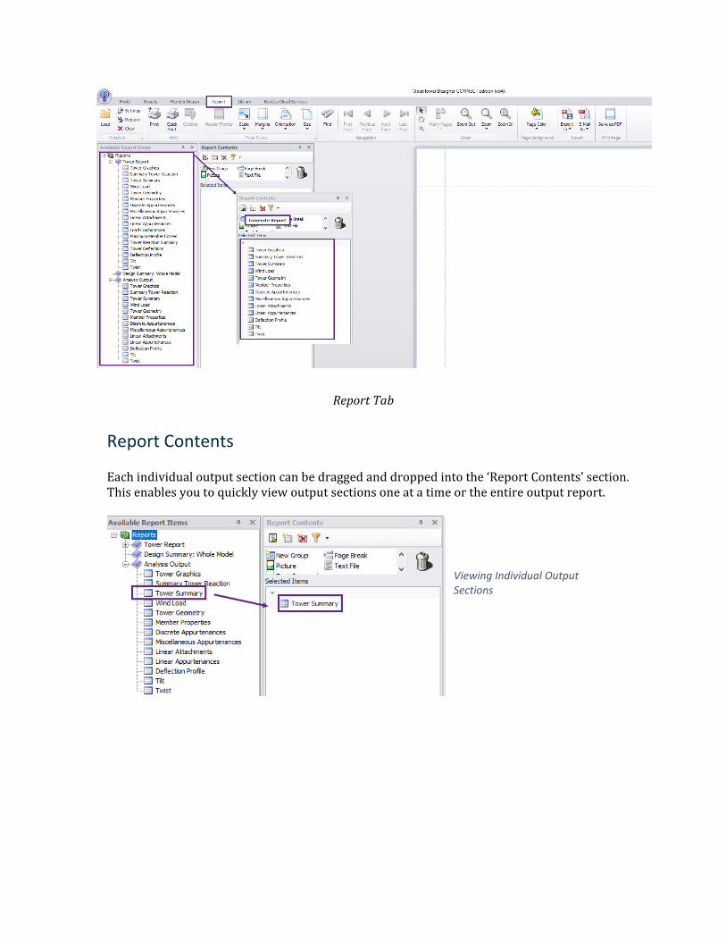
Report Tab
Report Contents
Each individual output section can be dragged and dropped into the ‘Report Contents’ section. This enables you to quickly view output sections one at a time or the entire output report.
Viewing Individual Output Sections
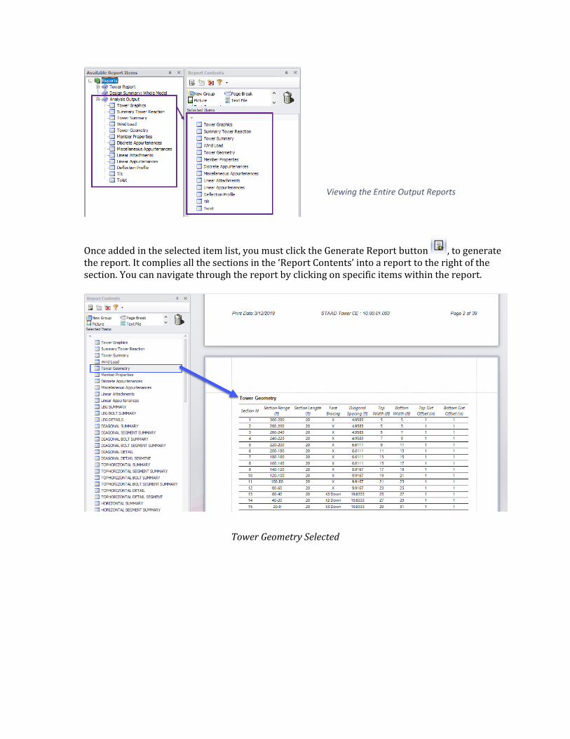
Viewing the Entire Output Reports
Once added in the selected item list, you must click the Generate Report button , to generate the report. It complies all the sections in the ‘Report Contents’ into a report to the right of the section. You can navigate through the report by clicking on specific items within the report.
Tower Geometry Selected
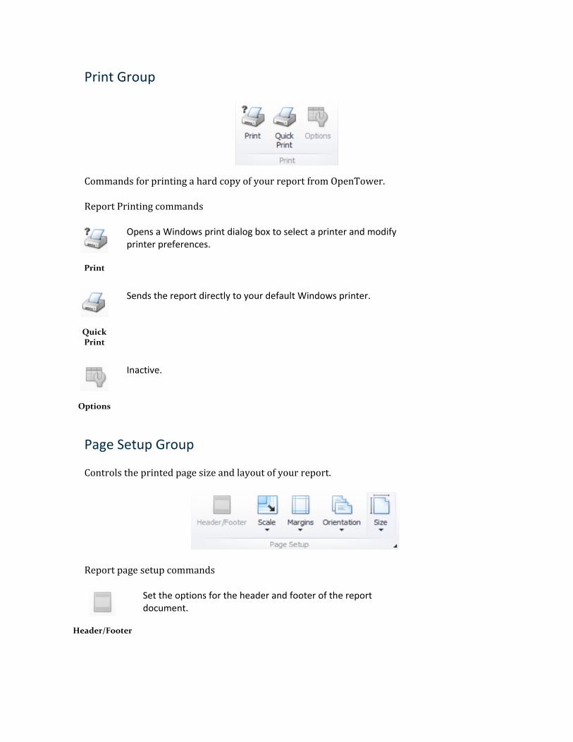
Print Group
Commands for printing a hard copy of your report from OpenTower.
Report Printing commands
Opens a Windows print dialog box to select a printer and modify printer preferences.
Quick Print
Sends the report directly to your default Windows printer.
Options
Inactive.
Page Setup Group
Controls the printed page size and layout of your report.
Report page setup commands
Header/Footer
Set the options for the header and footer of the report document.
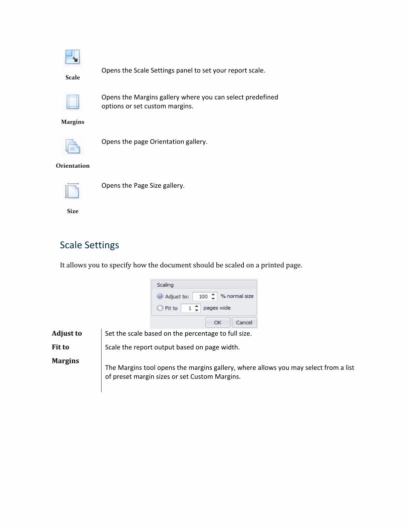
Scale
Opens the Scale Settings panel to set your report scale.
Margins
Opens the Margins gallery where you can select predefined options or set custom margins.
Orientation
Opens the page Orientation gallery.
Size
Opens the Page Size gallery.
Scale Settings
It allows you to specify how the document should be scaled on a printed page.
Adjust to Set the scale based on the percentage to full size.
Fit to Scale the report output based on page width.
Margins The Margins tool opens the margins gallery, where allows you may select from a list of preset margin sizes or set Custom Margins.
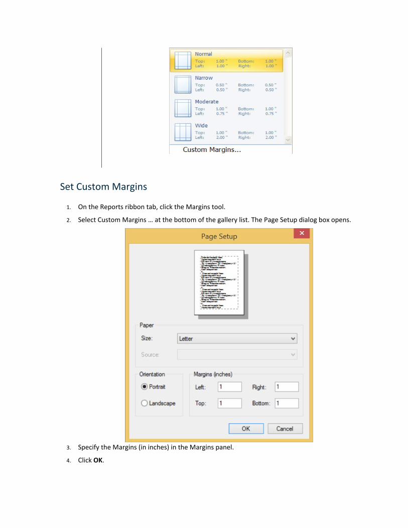
Set Custom Margins
1. On the Reports ribbon tab, click the Margins tool.
2. Select Custom Margins … at the bottom of the gallery list. The Page Setup dialog box opens.
3. Specify the Margins (in inches) in the Margins panel.
4. Click OK.
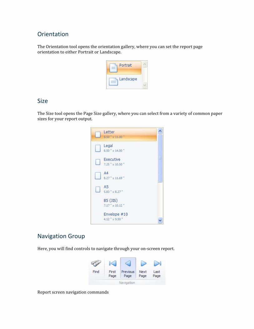
Orientation
The Orientation tool opens the orientation gallery, where you can set the report page orientation to either Portrait or Landscape.
Size
The Size tool opens the Page Size gallery, where you can select from a variety of common paper sizes for your report output.
Navigation Group
Here, you will find controls to navigate through your on-screen report.
Report screen navigation commands
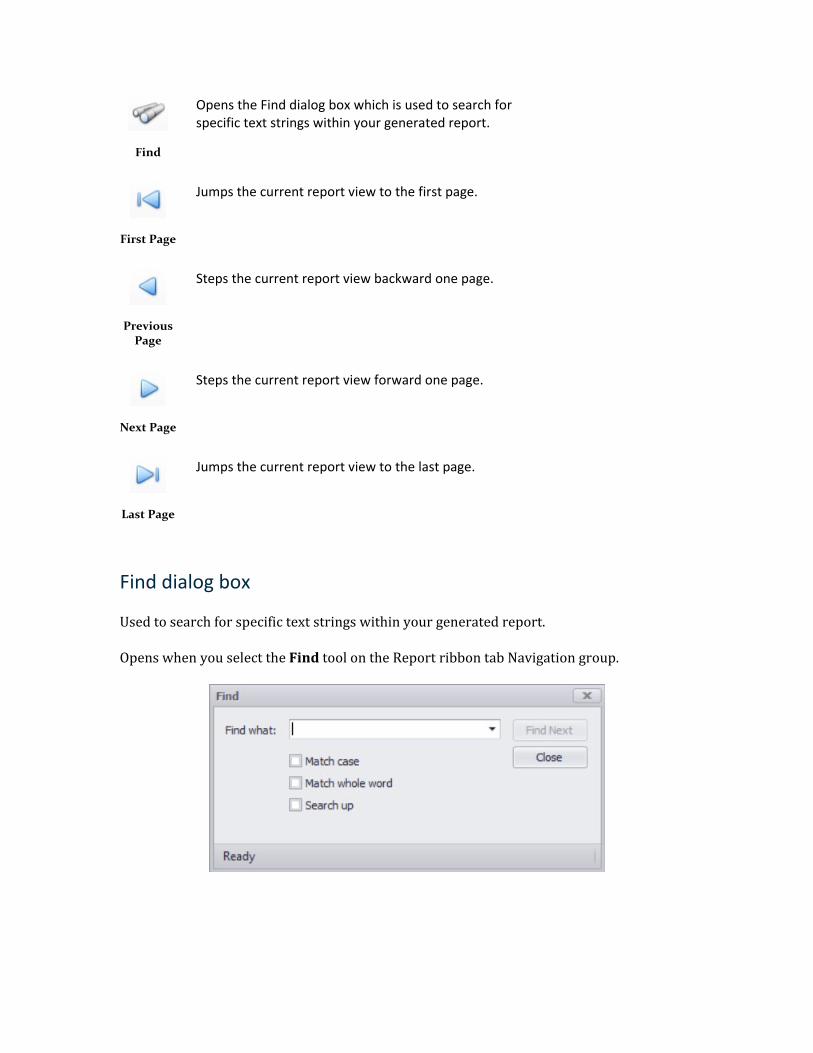
Find
Opens the Find dialog box which is used to search for specific text strings within your generated report.
First Page
Jumps the current report view to the first page.
Previous Page
Steps the current report view backward one page.
Next Page
Steps the current report view forward one page.
Last Page
Jumps the current report view to the last page.
Find dialog box
Used to search for specific text strings within your generated report.
Opens when you select the Find tool on the Report ribbon tab Navigation group.
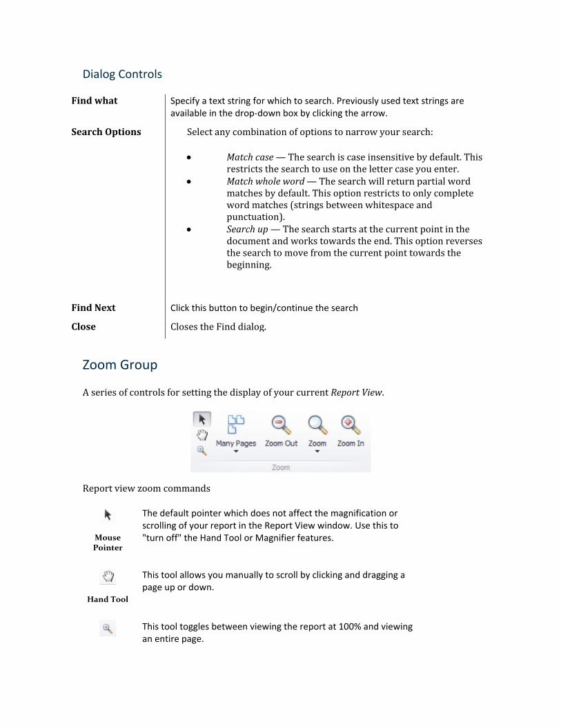
Dialog Controls
Find what Specify a text string for which to search. Previously used text strings are available in the drop-down box by clicking the arrow.
Search Options Select any combination of options to narrow your search:
• Match case — The search is case insensitive by default. This restricts the search to use on the letter case you enter.
• Match whole word — The search will return partial word matches by default. This option restricts to only complete word matches (strings between whitespace and punctuation).
• Search up — The search starts at the current point in the document and works towards the end. This option reverses the search to move from the current point towards the beginning.
Find Next Click this button to begin/continue the search
Close Closes the Find dialog.
Zoom Group
A series of controls for setting the display of your current Report View.
Report view zoom commands
Mouse Pointer
The default pointer which does not affect the magnification or scrolling of your report in the Report View window. Use this to "turn off" the Hand Tool or Magnifier features.
Hand Tool
This tool allows you manually to scroll by clicking and dragging a page up or down.
This tool toggles between viewing the report at 100% and viewing an entire page.
Magnifier
View Many Pages
Choose the page layout for displaying the report.
Zoom Out
Click to see more of the page.
Zoom
Produces a menu for resizing the page view to many preset sizes. You can also specify a custom zoom by percentage.
Zoom In
Get a close-up view of the document.
Page Background Group
You can customize the background of the report pages.
Table 7-30: Report page watermark commands
Page Color
You can choose a color for the background of the report document.
Export group
OpenTower gives you the capability to save a prepared report in a variety of file formats for later use or distribution. The Export To… tools are used to save the file to a storage device (local hard drive, network drive, etc.). The E-Mail To… tools will open your default windows application and add the file as an e-mail attachment. Both will provide you with the same file options dialog before saving or attaching.
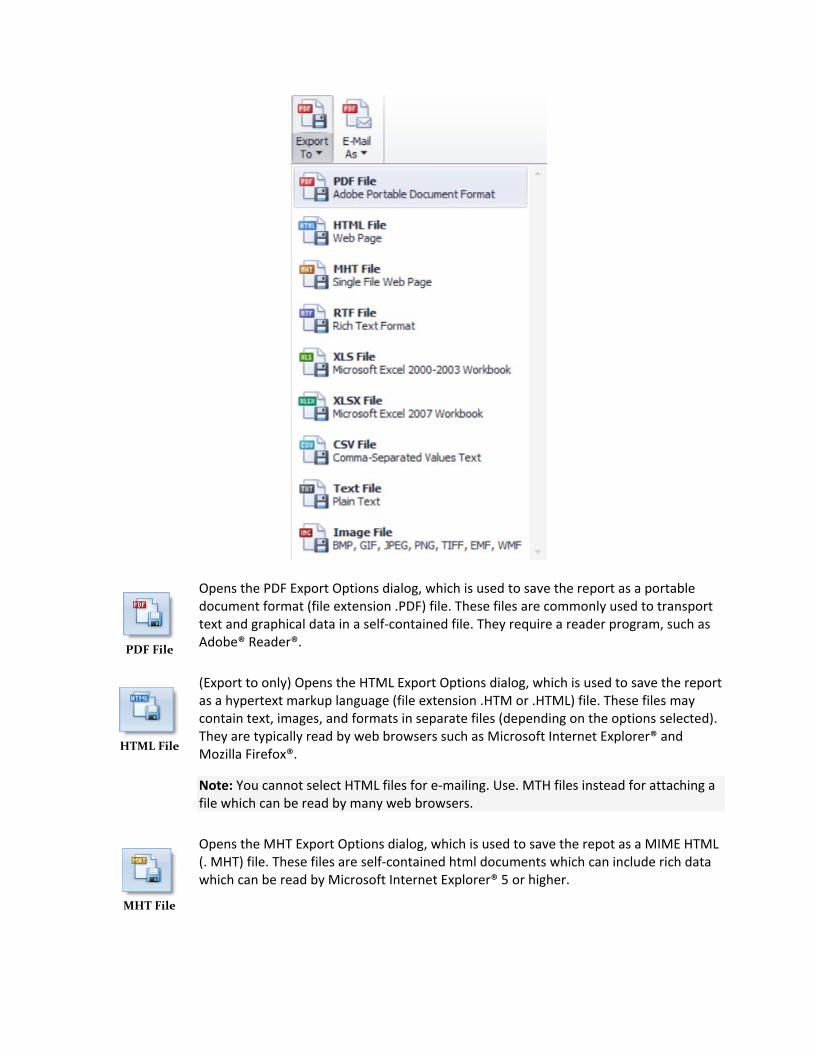
PDF File
Opens the PDF Export Options dialog, which is used to save the report as a portable document format (file extension .PDF) file. These files are commonly used to transport text and graphical data in a self-contained file. They require a reader program, such as Adobe® Reader®.
HTML File
(Export to only) Opens the HTML Export Options dialog, which is used to save the report as a hypertext markup language (file extension .HTM or .HTML) file. These files may contain text, images, and formats in separate files (depending on the options selected). They are typically read by web browsers such as Microsoft Internet Explorer® and Mozilla Firefox®.
Note: You cannot select HTML files for e-mailing. Use. MTH files instead for attaching a file which can be read by many web browsers.
MHT File
Opens the MHT Export Options dialog, which is used to save the repot as a MIME HTML (. MHT) file. These files are self-contained html documents which can include rich data which can be read by Microsoft Internet Explorer® 5 or higher.
RTF File
Opens the RTF Export Options dialog, which is used to save the repot as a rich text file (file extension .RTF). Rich text files contain both text and images in a single file and also preserves much of the formatting from your report. These files can be read by a wide variety of word processing programs, such as Microsoft Office Word® or Sun OpenOffice®.
Excel File
Opens the XLS Export Options dialog, which is used to save the report as a Microsoft Office Excel 2003 spreadsheet (file extension .XLS). These files can contain images and text data, as well as preserve the table structure. They also allow for some richer formatting features for making your data easier to read. They are typically only readable by spreadsheet programs such as Microsoft Office Excel®, IBM Lotus 1-2-3®, or Sun OpenOffice®.
CSV File
Opens the CSV Export Options dialog, which is used save the report as a comma-separated values text file (file extension .CSV). These files are plain text with a specified content delimiter (typically a comma).
Note: No images will be included in this format.
Text File
Opens the Text Export Options dialog, which is used to save the report as a plain text file. These files can be read by a wide variety of programs and devices.
Note: No images will be included in this format.
Image File
Opens the Image Export Options dialog, which is used to save the report to one of several image file types. Saving to an image file creates a raster image of the entire report output (though .WMF files can also include vector data). The data in the image file is not directly editable, though image editors can manipulate the file graphically. All information will be human readable, though.
Note: Reports saved to image file formats will create single image files of the entire report, except for a .TIFF file which are multi-paged images.
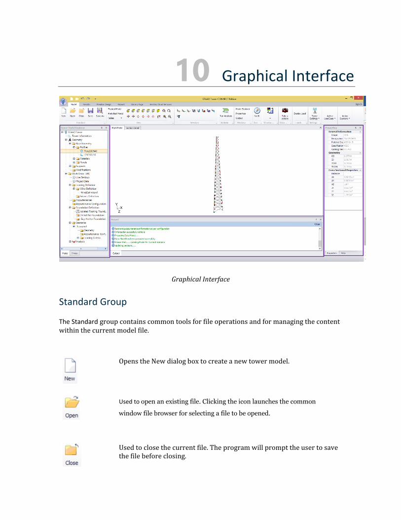
10 Graphical Interface
Graphical Interface
Standard Group
The Standard group contains common tools for file operations and for managing the content within the current model file.
Opens the New dialog box to create a new tower model.
Used to open an existing file. Clicking the icon launches the common
window file browser for selecting a file to be opened.
Used to close the current file. The program will prompt the user to save the file before closing.
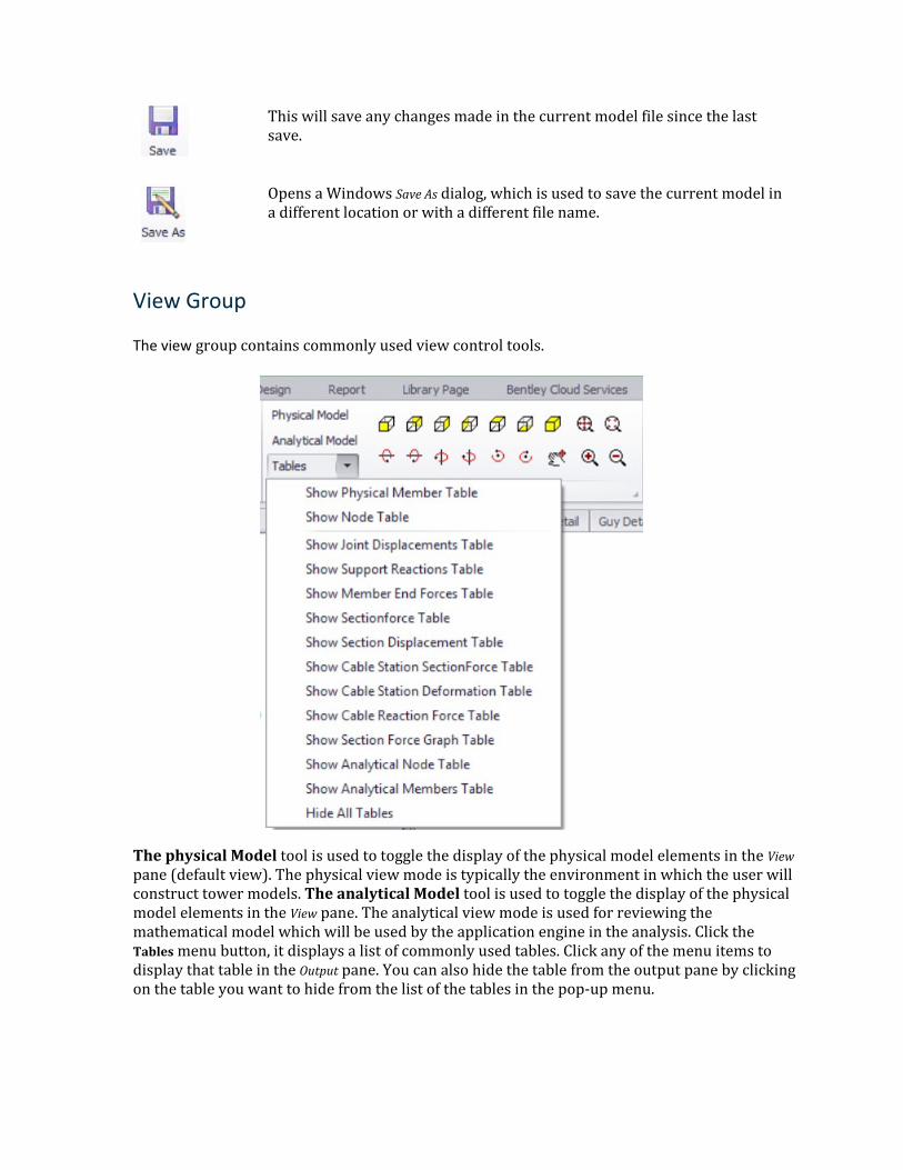
This will save any changes made in the current model file since the last save.
Opens a Windows Save As dialog, which is used to save the current model in a different location or with a different file name.
View Group
The view group contains commonly used view control tools.
The physical Model tool is used to toggle the display of the physical model elements in the View pane (default view). The physical view mode is typically the environment in which the user will construct tower models. The analytical Model tool is used to toggle the display of the physical model elements in the View pane. The analytical view mode is used for reviewing the mathematical model which will be used by the application engine in the analysis. Click the Tables menu button, it displays a list of commonly used tables. Click any of the menu items to display that table in the Output pane. You can also hide the table from the output pane by clicking on the table you want to hide from the list of the tables in the pop-up menu.
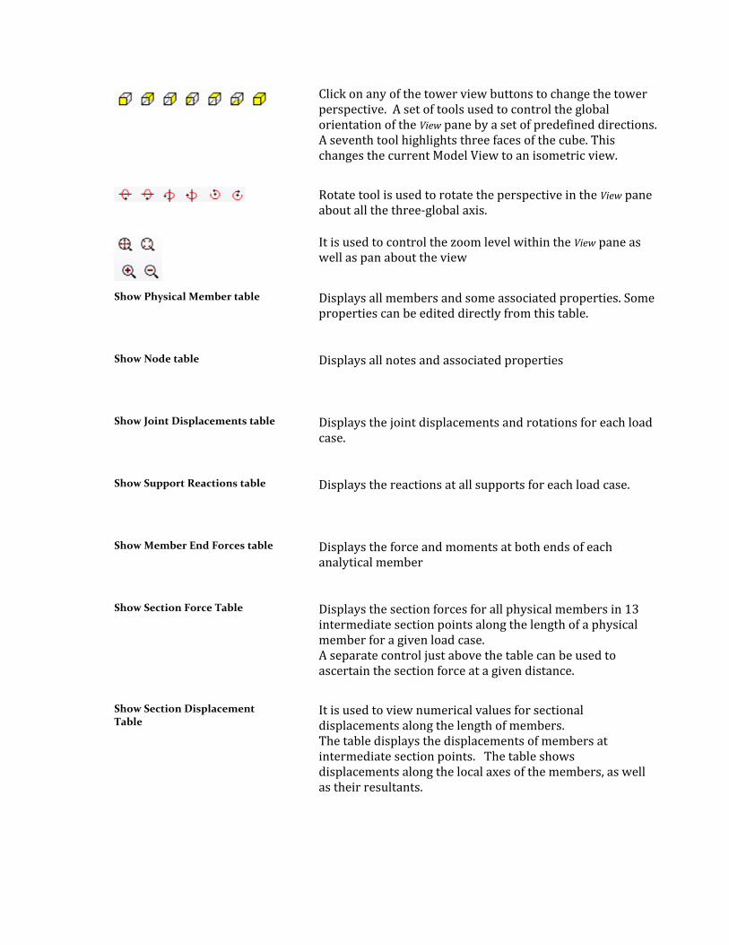
Click on any of the tower view buttons to change the tower perspective. A set of tools used to control the global orientation of the View pane by a set of predefined directions. A seventh tool highlights three faces of the cube. This changes the current Model View to an isometric view.
Rotate tool is used to rotate the perspective in the View pane about all the three-global axis.
It is used to control the zoom level within the View pane as well as pan about the view
Show Physical Member table
Displays all members and some associated properties. Some properties can be edited directly from this table.
Show Node table
Displays all notes and associated properties
Show Joint Displacements table Displays the joint displacements and rotations for each load case.
Show Support Reactions table
Displays the reactions at all supports for each load case.
Show Member End Forces table Displays the force and moments at both ends of each analytical member
Show Section Force Table Displays the section forces for all physical members in 13 intermediate section points along the length of a physical member for a given load case. A separate control just above the table can be used to ascertain the section force at a given distance.
Show Section Displacement Table
It is used to view numerical values for sectional displacements along the length of members. The table displays the displacements of members at intermediate section points. The table shows displacements along the local axes of the members, as well as their resultants.
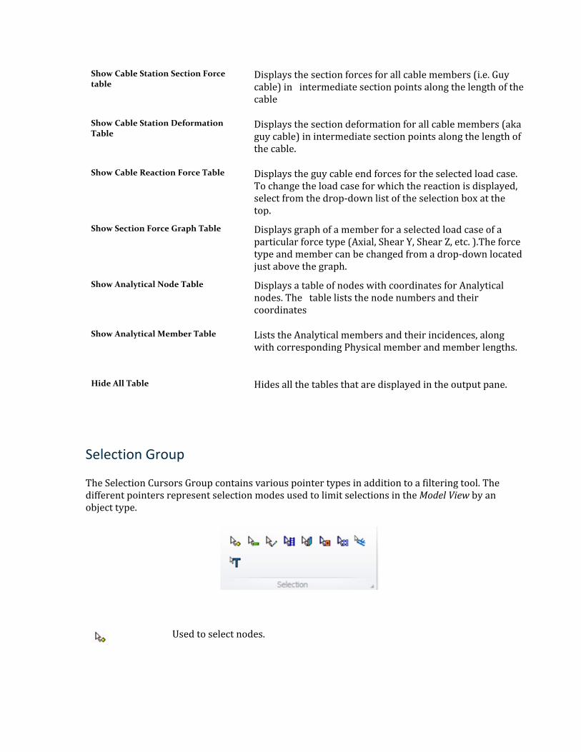
Show Cable Station Section Force table
Displays the section forces for all cable members (i.e. Guy cable) in intermediate section points along the length of the cable
Show Cable Station Deformation Table
Displays the section deformation for all cable members (aka guy cable) in intermediate section points along the length of the cable.
Show Cable Reaction Force Table Displays the guy cable end forces for the selected load case. To change the load case for which the reaction is displayed, select from the drop-down list of the selection box at the top.
Show Section Force Graph Table Displays graph of a member for a selected load case of a particular force type (Axial, Shear Y, Shear Z, etc. ).The force type and member can be changed from a drop-down located just above the graph.
Show Analytical Node Table Displays a table of nodes with coordinates for Analytical nodes. The table lists the node numbers and their coordinates
Show Analytical Member Table Lists the Analytical members and their incidences, along with corresponding Physical member and member lengths.
Hide All Table Hides all the tables that are displayed in the output pane.
Selection Group
The Selection Cursors Group contains various pointer types in addition to a filtering tool. The different pointers represent selection modes used to limit selections in the Model View by an object type.
Used to select nodes.
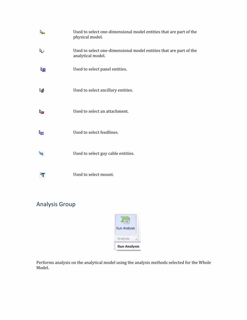
Used to select one-dimensional model entities that are part of the physical model.
Used to select one-dimensional model entities that are part of the analytical model.
Used to select panel entities.
Used to select ancillary entities.
Used to select an attachment.
Used to select feedlines.
Used to select guy cable entities.
Used to select mount.
Analysis Group
Performs analysis on the analytical model using the analysis methods selected for the Whole Model.
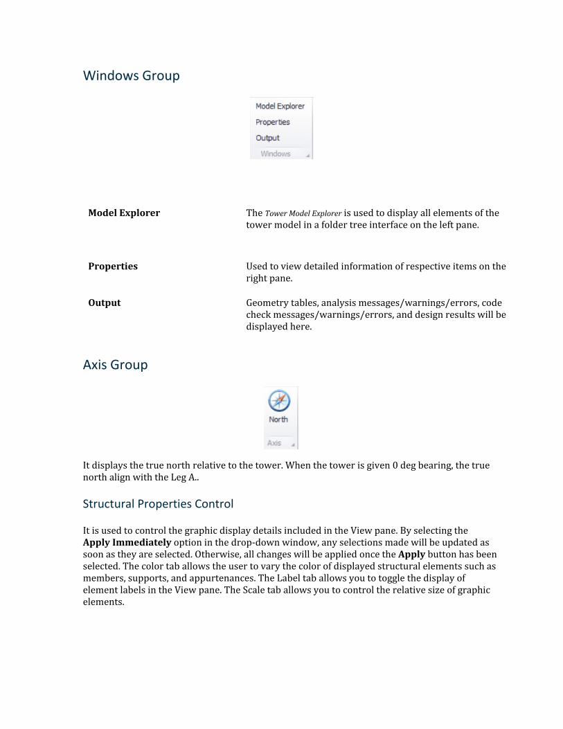
Windows Group
Model Explorer The Tower Model Explorer is used to display all elements of the tower model in a folder tree interface on the left pane.
Properties Used to view detailed information of respective items on the right pane.
Output Geometry tables, analysis messages/warnings/errors, code check messages/warnings/errors, and design results will be displayed here.
Axis Group
It displays the true north relative to the tower. When the tower is given 0 deg bearing, the true north align with the Leg A..
Structural Properties Control
It is used to control the graphic display details included in the View pane. By selecting the Apply Immediately option in the drop-down window, any selections made will be updated as soon as they are selected. Otherwise, all changes will be applied once the Apply button has been selected. The color tab allows the user to vary the color of displayed structural elements such as members, supports, and appurtenances. The Label tab allows you to toggle the display of element labels in the View pane. The Scale tab allows you to control the relative size of graphic elements.
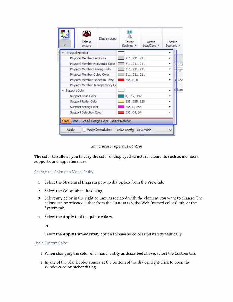
Structural Properties Control
The color tab allows you to vary the color of displayed structural elements such as members, supports, and appurtenances.
Change the Color of a Model Entity
1. Select the Structural Diagram pop-up dialog box from the View tab.
2. Select the Color tab in the dialog.
3. Select any color in the right column associated with the element you want to change. The colors can be selected either from the Custom tab, the Web (named colors) tab, or the System tab.
4. Select the Apply tool to update colors.
or
Select the Apply Immediately option to have all colors updated dynamically.
Use a Custom Color
1. When changing the color of a model entity as described above, select the Custom tab.
2. In any of the blank color spaces at the bottom of the dialog, right-click to open the Windows color picker dialog.
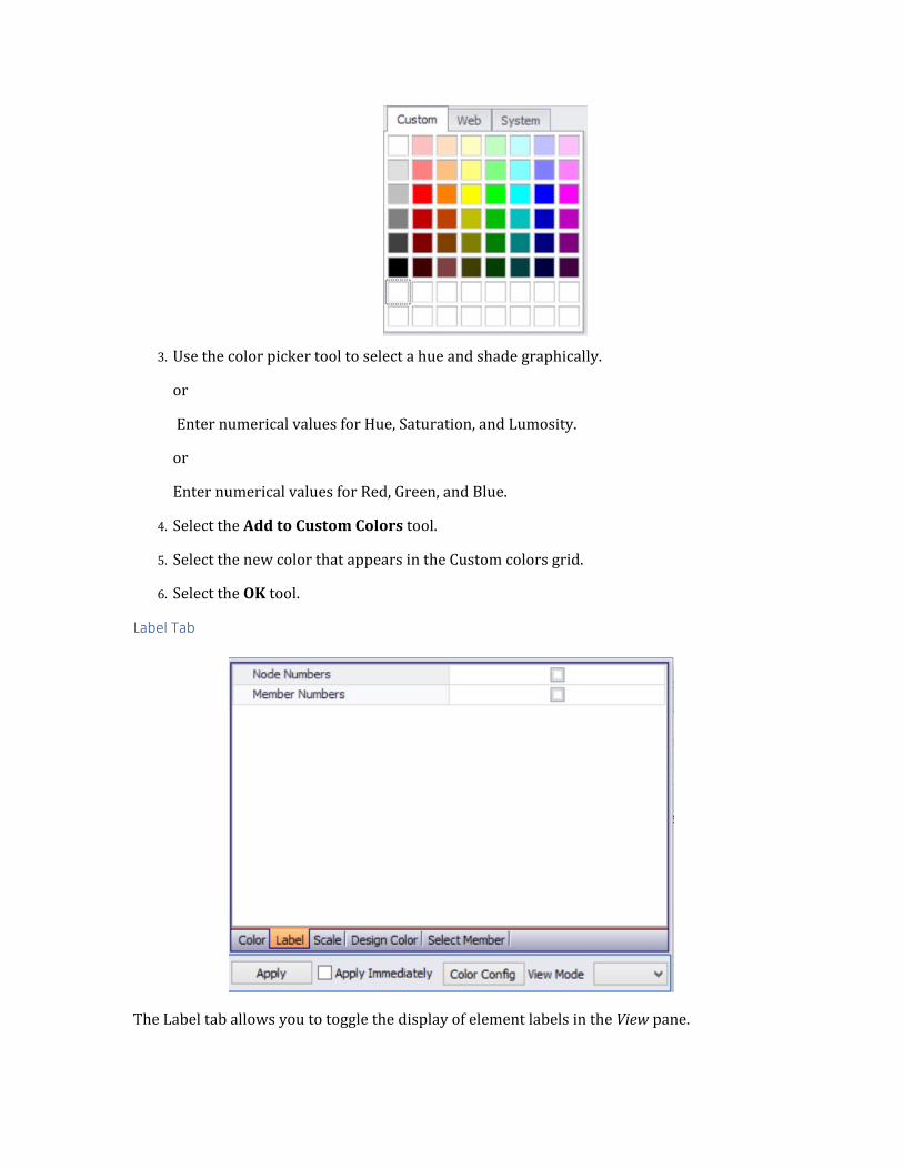
3. Use the color picker tool to select a hue and shade graphically.
or
Enter numerical values for Hue, Saturation, and Lumosity.
or
Enter numerical values for Red, Green, and Blue.
4. Select the Add to Custom Colors tool.
5. Select the new color that appears in the Custom colors grid.
6. Select the OK tool.
Label Tab
The Label tab allows you to toggle the display of element labels in the View pane.
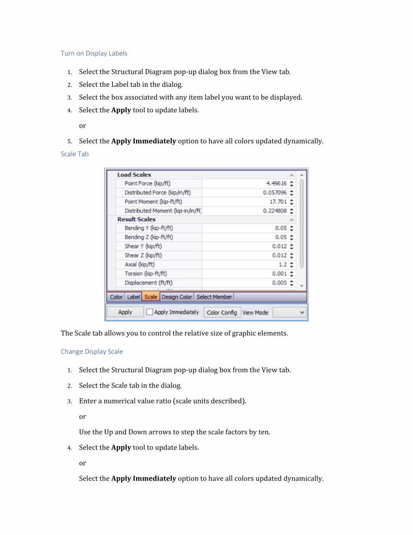
Turn on Display Labels
1. Select the Structural Diagram pop-up dialog box from the View tab.
2. Select the Label tab in the dialog.
3. Select the box associated with any item label you want to be displayed.
4. Select the Apply tool to update labels.
or
5. Select the Apply Immediately option to have all colors updated dynamically.
Scale Tab
The Scale tab allows you to control the relative size of graphic elements.
Change Display Scale
1. Select the Structural Diagram pop-up dialog box from the View tab.
2. Select the Scale tab in the dialog.
3. Enter a numerical value ratio (scale units described).
or
Use the Up and Down arrows to step the scale factors by ten.
4. Select the Apply tool to update labels.
or
Select the Apply Immediately option to have all colors updated dynamically.
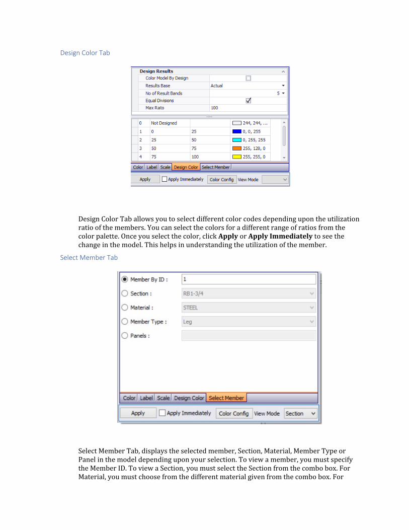
Design Color Tab
Design Color Tab allows you to select different color codes depending upon the utilization ratio of the members. You can select the colors for a different range of ratios from the color palette. Once you select the color, click Apply or Apply Immediately to see the change in the model. This helps in understanding the utilization of the member.
Select Member Tab
Select Member Tab, displays the selected member, Section, Material, Member Type or Panel in the model depending upon your selection. To view a member, you must specify the Member ID. To view a Section, you must select the Section from the combo box. For Material, you must choose from the different material given from the combo box. For
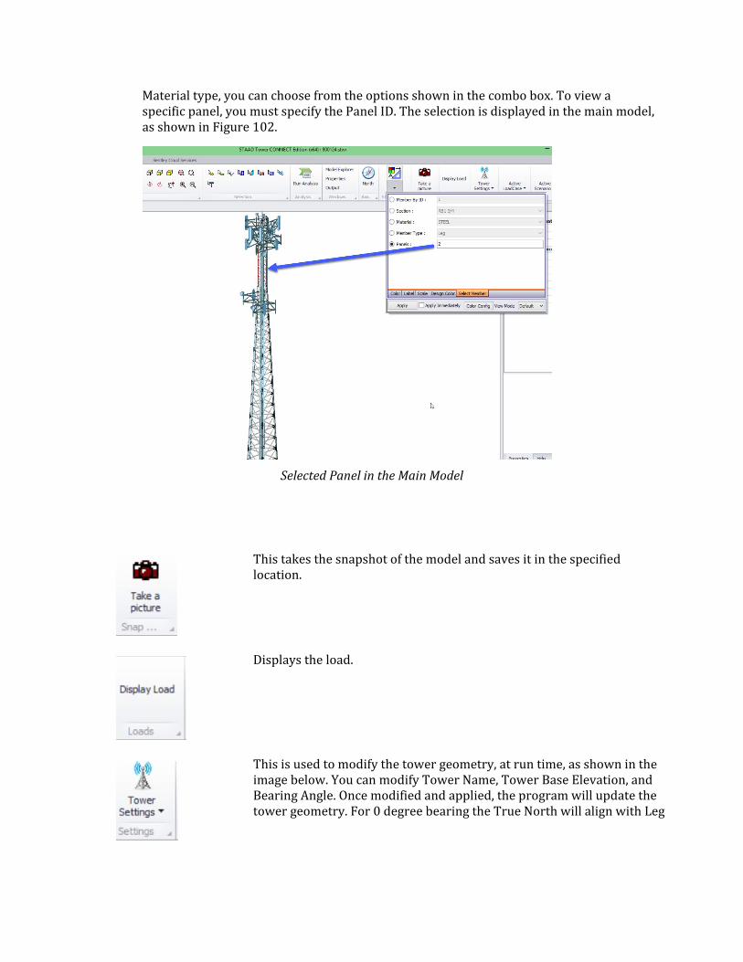
Material type, you can choose from the options shown in the combo box. To view a specific panel, you must specify the Panel ID. The selection is displayed in the main model, as shown in Figure 102.
Selected Panel in the Main Model
This takes the snapshot of the model and saves it in the specified location.
Displays the load.
This is used to modify the tower geometry, at run time, as shown in the image below. You can modify Tower Name, Tower Base Elevation, and Bearing Angle. Once modified and applied, the program will update the tower geometry. For 0 degree bearing the True North will align with Leg
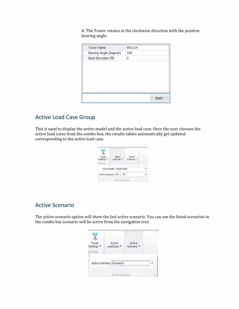
A. The Tower rotates in the clockwise direction with the positive bearing angle.
Active Load Case Group
This is used to display the active model and the active load case. Once the user chooses the active load cases from the combo box, the results tables automatically get updated corresponding to the active load case.
Active Scenario
The active scenario option will show the last active scenario. You can see the listed scenarios in the combo but scenario will be active from the navigation tree.
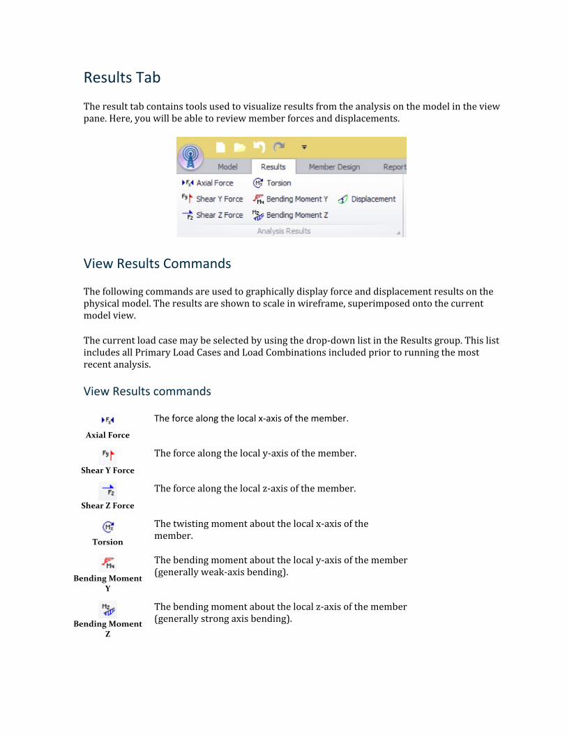
Results Tab
The result tab contains tools used to visualize results from the analysis on the model in the view pane. Here, you will be able to review member forces and displacements.
View Results Commands
The following commands are used to graphically display force and displacement results on the physical model. The results are shown to scale in wireframe, superimposed onto the current model view.
The current load case may be selected by using the drop-down list in the Results group. This list includes all Primary Load Cases and Load Combinations included prior to running the most recent analysis.
View Results commands
Axial Force
The force along the local x-axis of the member.
Shear Y Force
The force along the local y-axis of the member.
Shear Z Force
The force along the local z-axis of the member.
Torsion
The twisting moment about the local x-axis of the member.
Bending Moment
Y
The bending moment about the local y-axis of the member (generally weak-axis bending).
Bending Moment
Z
The bending moment about the local z-axis of the member (generally strong axis bending).

Displacement
The deformed shape of the structure will be displayed.
Member Design Tab
This page contains tools used for the design of individual members and member groups.
Note: Selecting the Member Design tab also selects the Design tab in the Tower Model Explorer pane.
Member Design Tab
Generate Design Groups
The program automatically generates the design groups based on member classes such as leg, bracing, horizontal, redundant and cross arms (torque-arms).
Perform Design
This command directs the application to perform member design checks for the entire tower structure.
In the Tower Model Explorer window under the Design tab, the Tower Design will be broken into the following three sections: Design Briefs, Design Groups, and Design results. Design Briefs includes three types of briefs which are Beam Briefs, Truss Briefs, and Guy Cable Briefs. When selected, a property window will have corresponding information to each brief in which the user can define or alter certain parameters for the design. The application will automatically create appropriate design briefs based on the selected loading criteria in the active scenario and assign them to members groups.
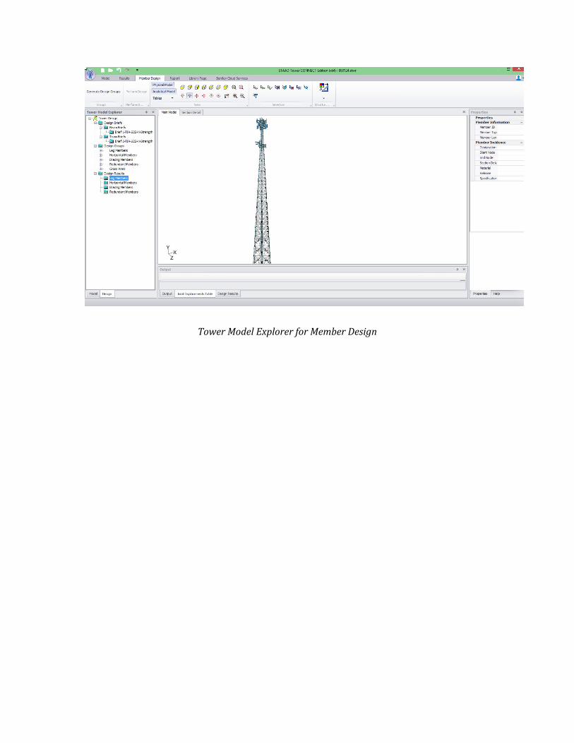
Tower Model Explorer for Member Design
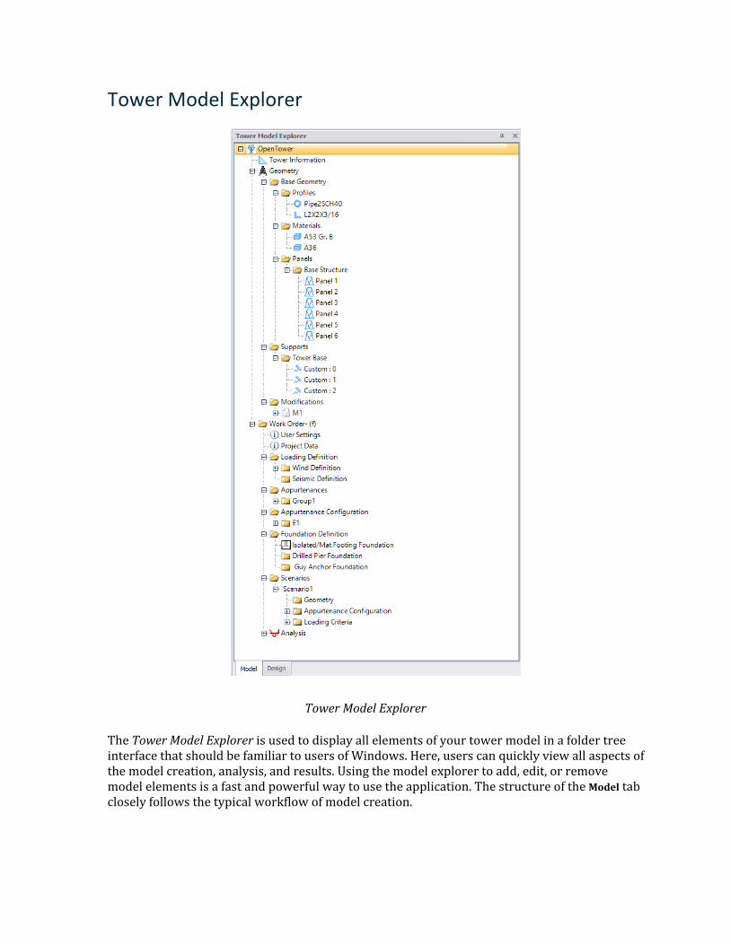
Tower Model Explorer
Tower Model Explorer
The Tower Model Explorer is used to display all elements of your tower model in a folder tree interface that should be familiar to users of Windows. Here, users can quickly view all aspects of the model creation, analysis, and results. Using the model explorer to add, edit, or remove model elements is a fast and powerful way to use the application. The structure of the Model tab closely follows the typical workflow of model creation.
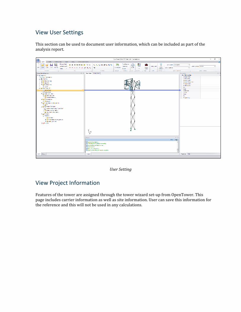
View User Settings
This section can be used to document user information, which can be included as part of the analysis report.
User Setting
View Project Information
Features of the tower are assigned through the tower wizard set-up from OpenTower. This page includes carrier information as well as site information. User can save this information for the reference and this will not be used in any calculations.

Project Information
View Tower Panels
Details of each section of the tower can be seen in Geometry > Panels. The Main model will also show the selected highlighted panel.
Tower Panel
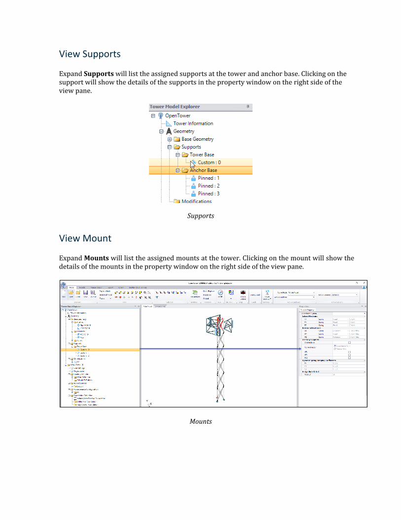
View Supports
Expand Supports will list the assigned supports at the tower and anchor base. Clicking on the support will show the details of the supports in the property window on the right side of the view pane.
Supports
View Mount
Expand Mounts will list the assigned mounts at the tower. Clicking on the mount will show the details of the mounts in the property window on the right side of the view pane.
Mounts
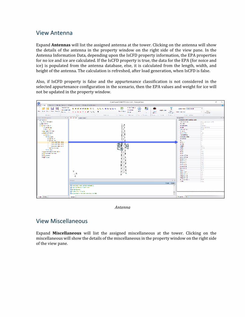
View Antenna
Expand Antennas will list the assigned antenna at the tower. Clicking on the antenna will show the details of the antenna in the property window on the right side of the view pane. In the Antenna Information Data, depending upon the IsCFD property information, the EPA properties for no ice and ice are calculated. If the IsCFD property is true, the data for the EPA (for noice and ice) is populated from the antenna database, else, it is calculated from the length, width, and height of the antenna. The calculation is refreshed, after load generation, when IsCFD is false.
Also, if IsCFD property is false and the appurtenance classification is not considered in the selected appurtenance configuration in the scenario, then the EPA values and weight for ice will not be updated in the property window.
Antenna
View Miscellaneous
Expand Miscellaneous will list the assigned miscellaneous at the tower. Clicking on the miscellaneous will show the details of the miscellaneous in the property window on the right side of the view pane.
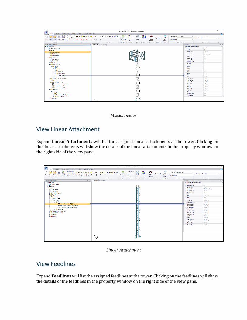
Miscellaneous
View Linear Attachment
Expand Linear Attachments will list the assigned linear attachments at the tower. Clicking on the linear attachments will show the details of the linear attachments in the property window on the right side of the view pane.
Linear Attachment
View Feedlines
Expand Feedlines will list the assigned feedlines at the tower. Clicking on the feedlines will show the details of the feedlines in the property window on the right side of the view pane.
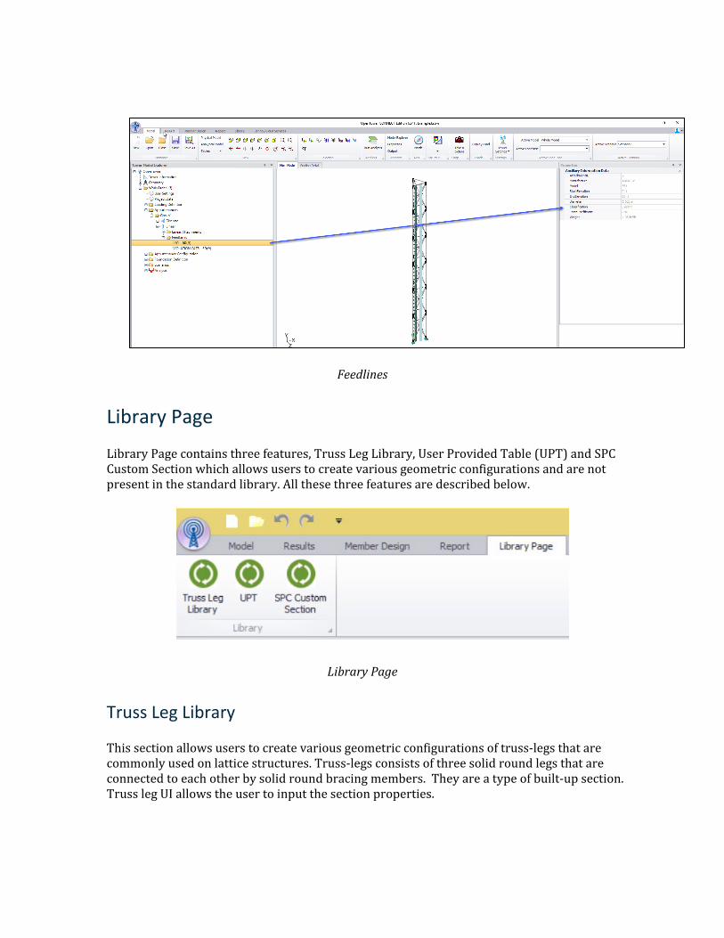
Feedlines
Library Page
Library Page contains three features, Truss Leg Library, User Provided Table (UPT) and SPC Custom Section which allows users to create various geometric configurations and are not present in the standard library. All these three features are described below.
Library Page
Truss Leg Library
This section allows users to create various geometric configurations of truss-legs that are commonly used on lattice structures. Truss-legs consists of three solid round legs that are connected to each other by solid round bracing members. They are a type of built-up section. Truss leg UI allows the user to input the section properties.
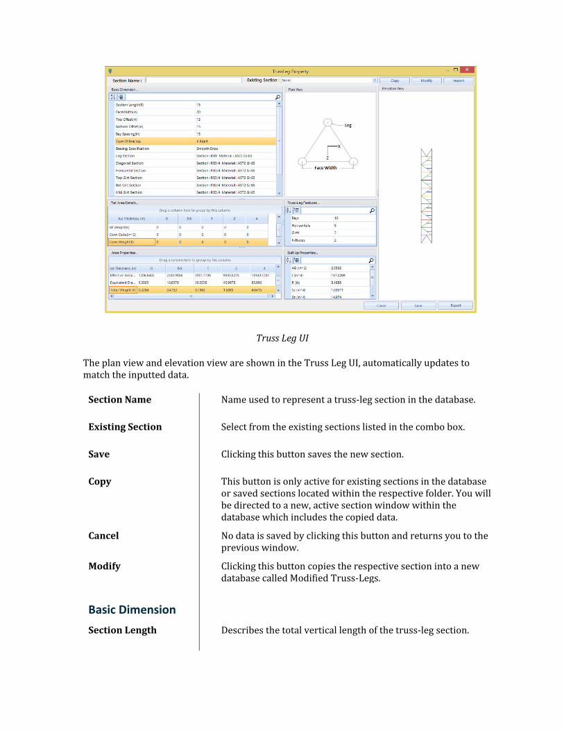
Truss Leg UI
The plan view and elevation view are shown in the Truss Leg UI, automatically updates to match the inputted data.
Section Name Name used to represent a truss-leg section in the database.
Existing Section Select from the existing sections listed in the combo box.
Save Clicking this button saves the new section.
Copy This button is only active for existing sections in the database or saved sections located within the respective folder. You will be directed to a new, active section window within the database which includes the copied data.
Cancel No data is saved by clicking this button and returns you to the previous window.
Modify Clicking this button copies the respective section into a new database called Modified Truss-Legs.
Basic Dimension
Section Length Describes the total vertical length of the truss-leg section.
Face Width Defines the center to center spacing of the legs along one face of the truss-leg section.
Top/Bottom Offset The vertical distance from either the top or the bottom of the leg section to the working point where the first bay begins or ends, respectively. This will offset the outermost horizontal member, whether it’s classified as a normal horizontal member or top or bottom girt
Bay Spacing Defines the length, a diagonal member span, vertically. The total quantity of bays is determined from the section length, top/bottom offset and bay spacing. If the total number of bays does not equal a whole number, then an additional diagonal member is generated for the remaining length.
Type of Bracing Choose from the drop-down selection of either Z, X or K-Right bracing.
Bracing Specification Choose from the drop-down selection of either Smooth Ends or Cut Ends, Continuous Ends, Concentric at Center or Layered at Center.
Leg Section/Diagonal Section/Horizontal Section
Specify the Section and the Grade of steel. You can select the section and material grade, by double-clicking on this field. Section Profile Page will appear, and the user can input the required fields.
Top/Mid/Bottom Girt Section
Entering a value under one of these cells will replace the horizontal member at the respective location with the proper girt diameter. You can select the section and material grade, by double-clicking on this field. Section Profile Page will appear, and the user can input the required fields.
Top/Bottom K-Brace Section
Entering values in these sections will create two diagonals forming a V-shape which is connected to the closest horizontal member. These values are only active when offsets are applied. You can select the section and material grade, by double-clicking on this field. Section Profile Page will appear, and the user can input the required fields.
Steps Section Steps are added to one face of the truss-legs and are included in area calculations. Steps are connected to the diagonals and legs in the middle of each bay. You can select the section and material grade, by double-clicking on this field. Section Profile Page will appear, and the user can input the required fields.
Flat Area Details
AF face(in2) This user input specifies the flat area that should be considered in determining the solidity ratio and the effective projected area of the truss-leg. This input applies to 0, 0.5,1,2, and 4 inches of ice.
AF Weight(K) Weight accounting for flat members entered under Af (Face). This input applies to 0, 0.5,1,2, and 4 inches of ice.
Conn CaAa(in2) Accounts for flat linear members extending the length of the truss-leg. This input applies to 0, 0.5,1,2, and 4 inches of ice.
Conn Weight(K) Weight accounting for flat linear members entered under Conn CaAa. This input applies to 0, 0.5,1,2, and 4 inches of ice.
Truss Leg Features This table lists the total quantity for bays, horizontals, girts, and k-braces. The value calculated for bays is the only cell in this table which does not need to be a whole number; this would signify that a smaller diagonal was generated for the section.
Area Properties
Total Round Area(∑Ar) (in^2)
Specifies the total calculated round area for one face of the truss-leg which is used to determine the effective projected area. This calculated value is only shown for 0 and 0.5 inches of ice.
Solidity Ratio(ε)
Specifies the solidity ratio for one face of the truss-leg as defined in TIA-222-G which is used to determine the effective projected area. This calculated value is only shown for 0 and 0.5 inches of ice.
Effective Area (EPAs)(in^2)
Specifies the calculated value for the effective projected area along one face as defined in TIA-222-G. This calculated value is only shown for 0 and 0.5 inches of ice.
Equivalent Diameter(in)
The effective projected area of the lattice-leg is converted into an equivalent round member. This calculated value is used in determining the EPA along the face of a lattice structure.
Total Weight (K)
The calculated value for total weight.
Built-Up Properties
AG (in2) The calculated value for the total cross-sectional area of the three legs acting as a built-up member.
I(in4) The calculated value for the moment of inertia of the 3 legs acting as a built-up member.
R (in) The calculated value for the radius of gyration of the 3 legs acting as a built-up member.
Sx/Sz (in4) The calculated value for the minimum section modulus (Sx or Sy) of the 3 legs acting as a built-up member.
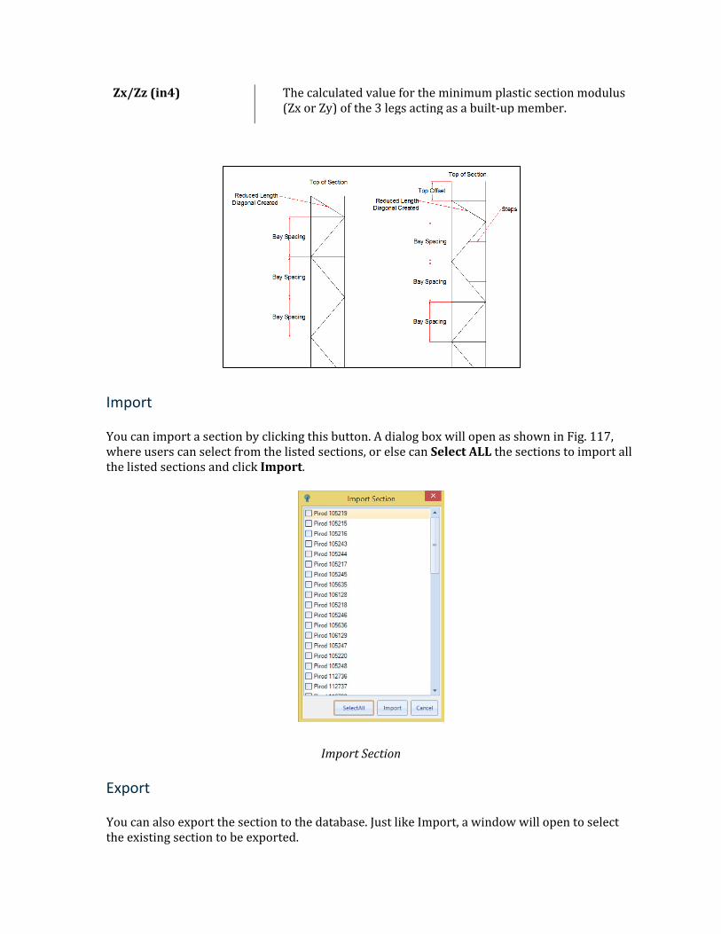
Zx/Zz (in4) The calculated value for the minimum plastic section modulus (Zx or Zy) of the 3 legs acting as a built-up member.
Import
You can import a section by clicking this button. A dialog box will open as shown in Fig. 117, where users can select from the listed sections, or else can Select ALL the sections to import all the listed sections and click Import.
Import Section
Export
You can also export the section to the database. Just like Import, a window will open to select the existing section to be exported.
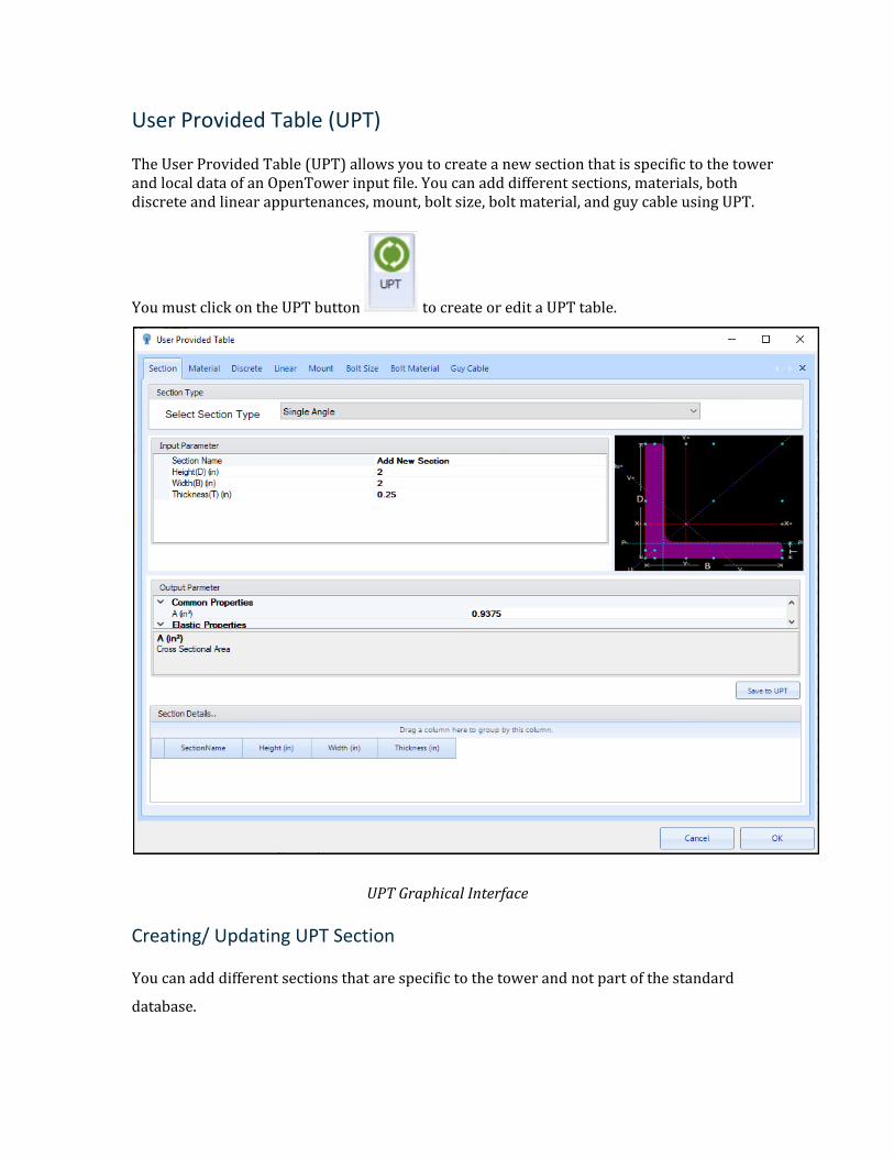
User Provided Table (UPT)
The User Provided Table (UPT) allows you to create a new section that is specific to the tower and local data of an OpenTower input file. You can add different sections, materials, both discrete and linear appurtenances, mount, bolt size, bolt material, and guy cable using UPT.
You must click on the UPT button to create or edit a UPT table.
UPT Graphical Interface
Creating/ Updating UPT Section
You can add different sections that are specific to the tower and not part of the standard
database.
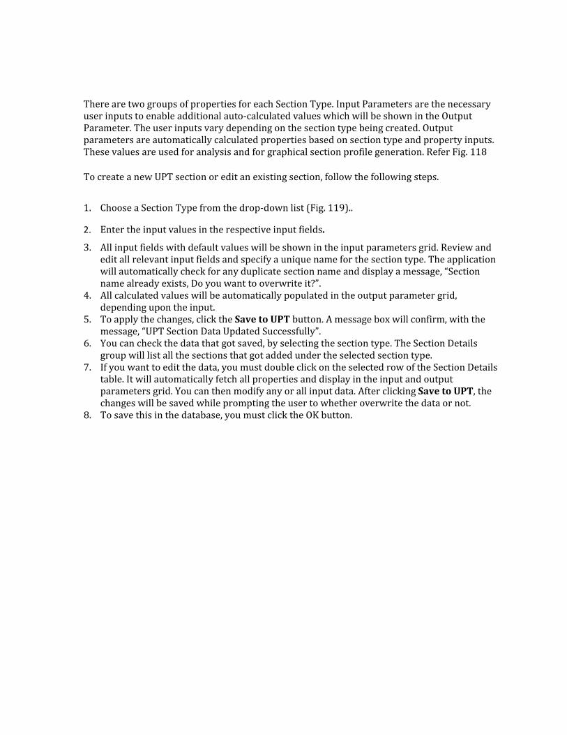
There are two groups of properties for each Section Type. Input Parameters are the necessary user inputs to enable additional auto-calculated values which will be shown in the Output Parameter. The user inputs vary depending on the section type being created. Output parameters are automatically calculated properties based on section type and property inputs. These values are used for analysis and for graphical section profile generation. Refer Fig. 118
To create a new UPT section or edit an existing section, follow the following steps.
1. Choose a Section Type from the drop-down list (Fig. 119)..
2. Enter the input values in the respective input fields.
3. All input fields with default values will be shown in the input parameters grid. Review and edit all relevant input fields and specify a unique name for the section type. The application will automatically check for any duplicate section name and display a message, “Section name already exists, Do you want to overwrite it?”.
4. All calculated values will be automatically populated in the output parameter grid, depending upon the input.
5. To apply the changes, click the Save to UPT button. A message box will confirm, with the message, “UPT Section Data Updated Successfully”.
6. You can check the data that got saved, by selecting the section type. The Section Details group will list all the sections that got added under the selected section type.
7. If you want to edit the data, you must double click on the selected row of the Section Details table. It will automatically fetch all properties and display in the input and output parameters grid. You can then modify any or all input data. After clicking Save to UPT, the changes will be saved while prompting the user to whether overwrite the data or not.
8. To save this in the database, you must click the OK button.
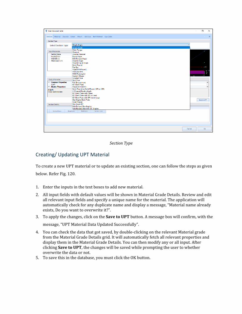
Section Type
Creating/ Updating UPT Material
To create a new UPT material or to update an existing section, one can follow the steps as given
below. Refer Fig. 120.
1. Enter the inputs in the text boxes to add new material.
2. All input fields with default values will be shown in Material Grade Details. Review and edit all relevant input fields and specify a unique name for the material. The application will automatically check for any duplicate name and display a message, “Material name already exists, Do you want to overwrite it?”.
3. To apply the changes, click on the Save to UPT button. A message box will confirm, with the
message, “UPT Material Data Updated Successfully”.
4. You can check the data that got saved, by double-clicking on the relevant Material grade from the Material Grade Details grid. It will automatically fetch all relevant properties and display them in the Material Grade Details. You can then modify any or all input. After clicking Save to UPT, the changes will be saved while prompting the user to whether overwrite the data or not.
5. To save this in the database, you must click the OK button.
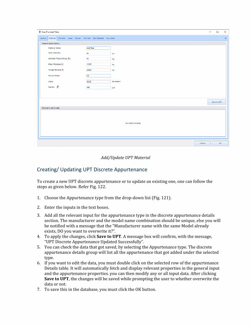
Add/Update UPT Material
Creating/ Updating UPT Discrete Appurtenance
To create a new UPT discrete appurtenance or to update an existing one, one can follow the steps as given below. Refer Fig. 122.
1. Choose the Appurtenance type from the drop-down list (Fig. 121).
2. Enter the inputs in the text boxes.
3. Add all the relevant input for the appurtenance type in the discrete appurtenance details section. The manufacturer and the model name combination should be unique, else you will be notified with a message that the “Manufacturer name with the same Model already exists, DO you want to overwrite it?”.
4. To apply the changes, click Save to UPT. A message box will confirm, with the message, “UPT Discrete Appurtenance Updated Successfully”.
5. You can check the data that got saved, by selecting the Appurtenance type. The discrete appurtenance details group will list all the appurtenance that got added under the selected type.
6. If you want to edit the data, you must double click on the selected row of the appurtenance Details table. It will automatically fetch and display relevant properties in the general input and the appurtenance properties. you can then modify any or all input data. After clicking Save to UPT, the changes will be saved while prompting the user to whether overwrite the data or not.
7. To save this in the database, you must click the OK button.
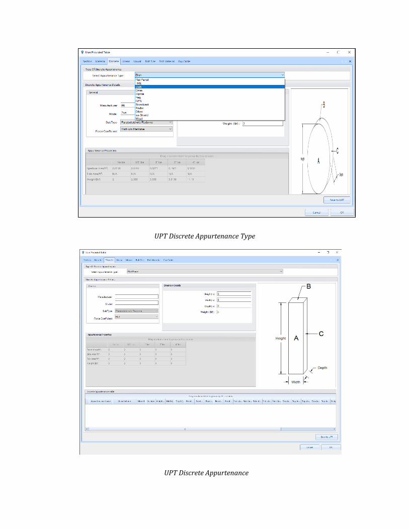
UPT Discrete Appurtenance Type
UPT Discrete Appurtenance
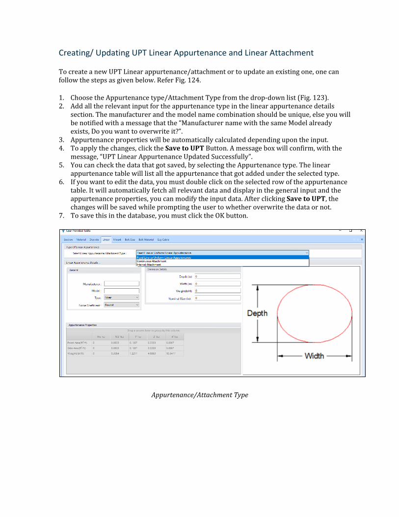
Creating/ Updating UPT Linear Appurtenance and Linear Attachment
To create a new UPT Linear appurtenance/attachment or to update an existing one, one can follow the steps as given below. Refer Fig. 124.
1. Choose the Appurtenance type/Attachment Type from the drop-down list (Fig. 123). 2. Add all the relevant input for the appurtenance type in the linear appurtenance details
section. The manufacturer and the model name combination should be unique, else you will be notified with a message that the “Manufacturer name with the same Model already exists, Do you want to overwrite it?”.
3. Appurtenance properties will be automatically calculated depending upon the input. 4. To apply the changes, click the Save to UPT Button. A message box will confirm, with the
message, “UPT Linear Appurtenance Updated Successfully”. 5. You can check the data that got saved, by selecting the Appurtenance type. The linear
appurtenance table will list all the appurtenance that got added under the selected type. 6. If you want to edit the data, you must double click on the selected row of the appurtenance
table. It will automatically fetch all relevant data and display in the general input and the appurtenance properties, you can modify the input data. After clicking Save to UPT, the changes will be saved while prompting the user to whether overwrite the data or not.
7. To save this in the database, you must click the OK button.
Appurtenance/Attachment Type
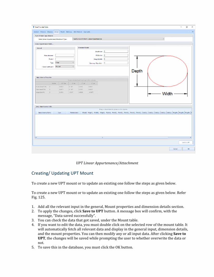
UPT Linear Appurtenance/Attachment
Creating/ Updating UPT Mount
To create a new UPT mount or to update an existing one follow the steps as given below.
To create a new UPT mount or to update an existing one follow the steps as given below. Refer Fig. 125.
1. Add all the relevant input in the general, Mount properties and dimension details section. 2. To apply the changes, click Save to UPT button. A message box will confirm, with the
message, “Data saved successfully”. 3. You can check the data that got saved, under the Mount table. 4. If you want to edit the data, you must double click on the selected row of the mount table. It
will automatically fetch all relevant data and display in the general input, dimension details, and the mount properties. You can then modify any or all input data. After clicking Save to UPT, the changes will be saved while prompting the user to whether overwrite the data or not.
5. To save this in the database, you must click the OK button.
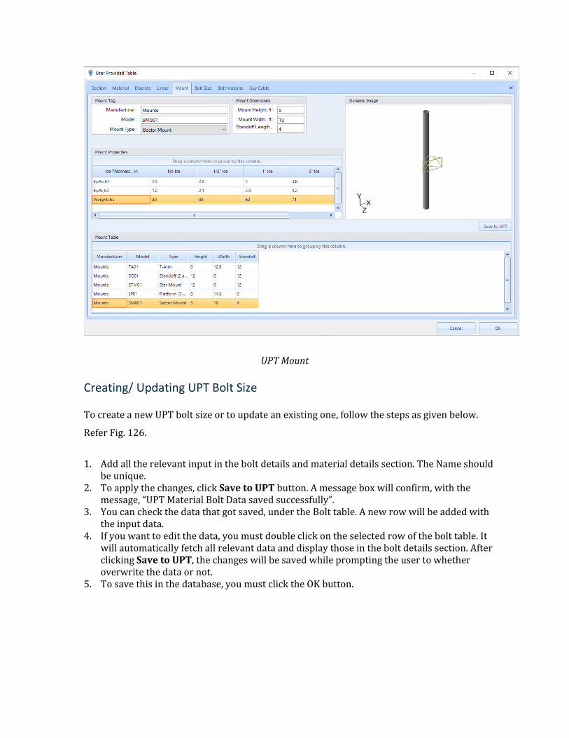
UPT Mount
Creating/ Updating UPT Bolt Size
To create a new UPT bolt size or to update an existing one, follow the steps as given below.
Refer Fig. 126.
1. Add all the relevant input in the bolt details and material details section. The Name should be unique.
2. To apply the changes, click Save to UPT button. A message box will confirm, with the message, “UPT Material Bolt Data saved successfully”.
3. You can check the data that got saved, under the Bolt table. A new row will be added with the input data.
4. If you want to edit the data, you must double click on the selected row of the bolt table. It will automatically fetch all relevant data and display those in the bolt details section. After clicking Save to UPT, the changes will be saved while prompting the user to whether overwrite the data or not.
5. To save this in the database, you must click the OK button.
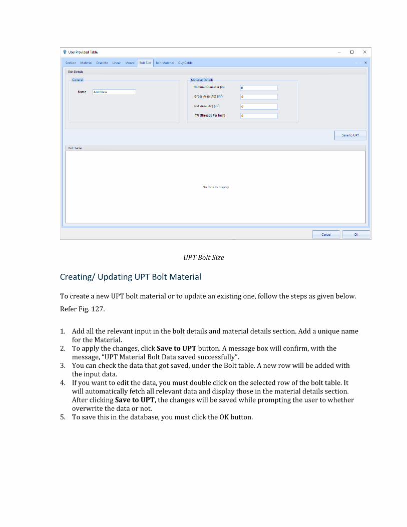
UPT Bolt Size
Creating/ Updating UPT Bolt Material
To create a new UPT bolt material or to update an existing one, follow the steps as given below.
Refer Fig. 127.
1. Add all the relevant input in the bolt details and material details section. Add a unique name for the Material.
2. To apply the changes, click Save to UPT button. A message box will confirm, with the message, “UPT Material Bolt Data saved successfully”.
3. You can check the data that got saved, under the Bolt table. A new row will be added with the input data.
4. If you want to edit the data, you must double click on the selected row of the bolt table. It will automatically fetch all relevant data and display those in the material details section. After clicking Save to UPT, the changes will be saved while prompting the user to whether overwrite the data or not.
5. To save this in the database, you must click the OK button.
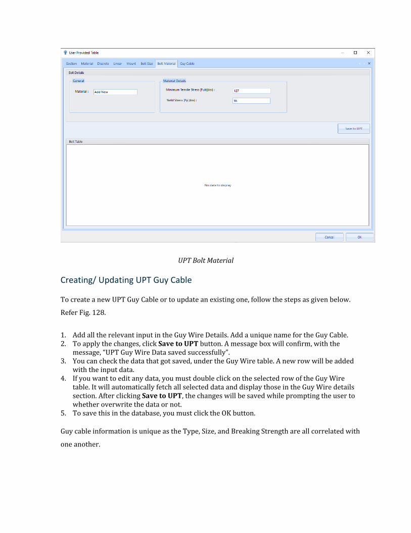
UPT Bolt Material
Creating/ Updating UPT Guy Cable
To create a new UPT Guy Cable or to update an existing one, follow the steps as given below.
Refer Fig. 128.
1. Add all the relevant input in the Guy Wire Details. Add a unique name for the Guy Cable. 2. To apply the changes, click Save to UPT button. A message box will confirm, with the
message, “UPT Guy Wire Data saved successfully”. 3. You can check the data that got saved, under the Guy Wire table. A new row will be added
with the input data. 4. If you want to edit any data, you must double click on the selected row of the Guy Wire
table. It will automatically fetch all selected data and display those in the Guy Wire details section. After clicking Save to UPT, the changes will be saved while prompting the user to whether overwrite the data or not.
5. To save this in the database, you must click the OK button.
Guy cable information is unique as the Type, Size, and Breaking Strength are all correlated with
one another.
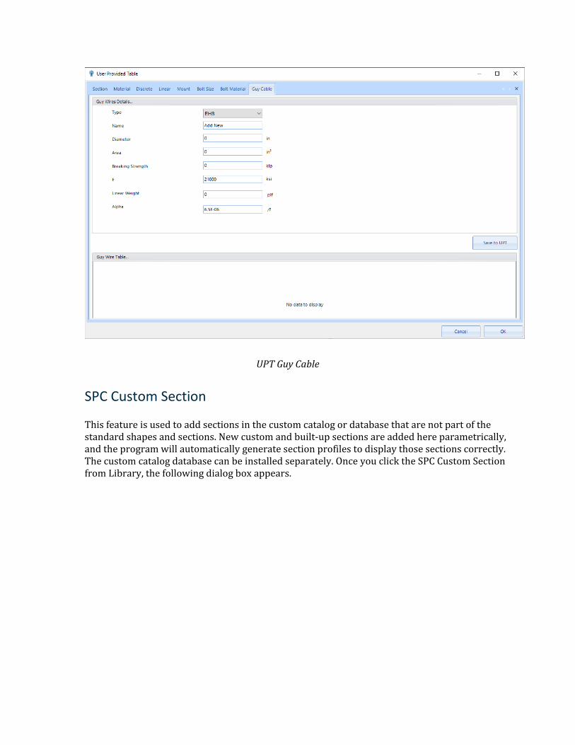
UPT Guy Cable
SPC Custom Section
This feature is used to add sections in the custom catalog or database that are not part of the standard shapes and sections. New custom and built-up sections are added here parametrically, and the program will automatically generate section profiles to display those sections correctly. The custom catalog database can be installed separately. Once you click the SPC Custom Section from Library, the following dialog box appears.
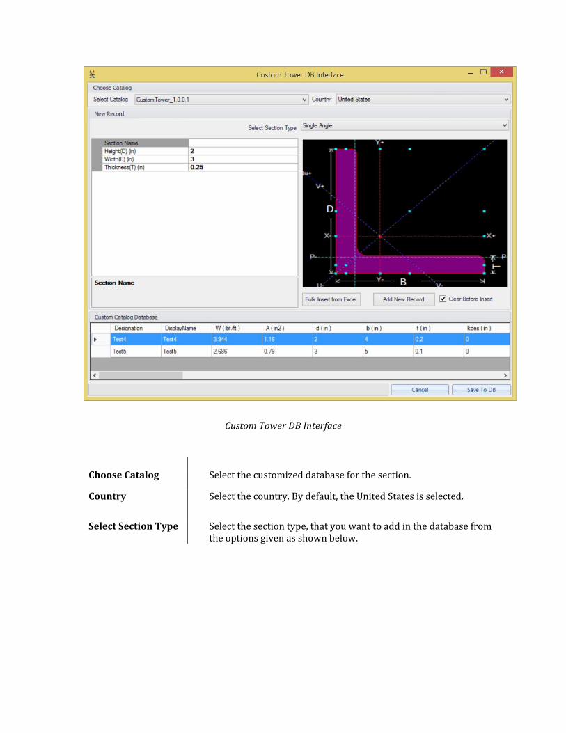
Custom Tower DB Interface
Choose Catalog Select the customized database for the section.
Country Select the country. By default, the United States is selected.
Select Section Type Select the section type, that you want to add in the database from the options given as shown below.
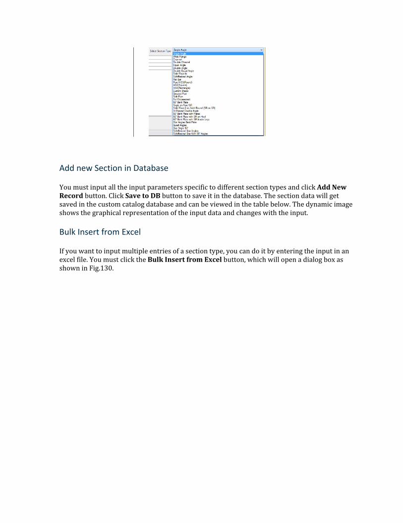
Add new Section in Database
You must input all the input parameters specific to different section types and click Add New Record button. Click Save to DB button to save it in the database. The section data will get saved in the custom catalog database and can be viewed in the table below. The dynamic image shows the graphical representation of the input data and changes with the input.
Bulk Insert from Excel
If you want to input multiple entries of a section type, you can do it by entering the input in an excel file. You must click the Bulk Insert from Excel button, which will open a dialog box as shown in Fig.130.
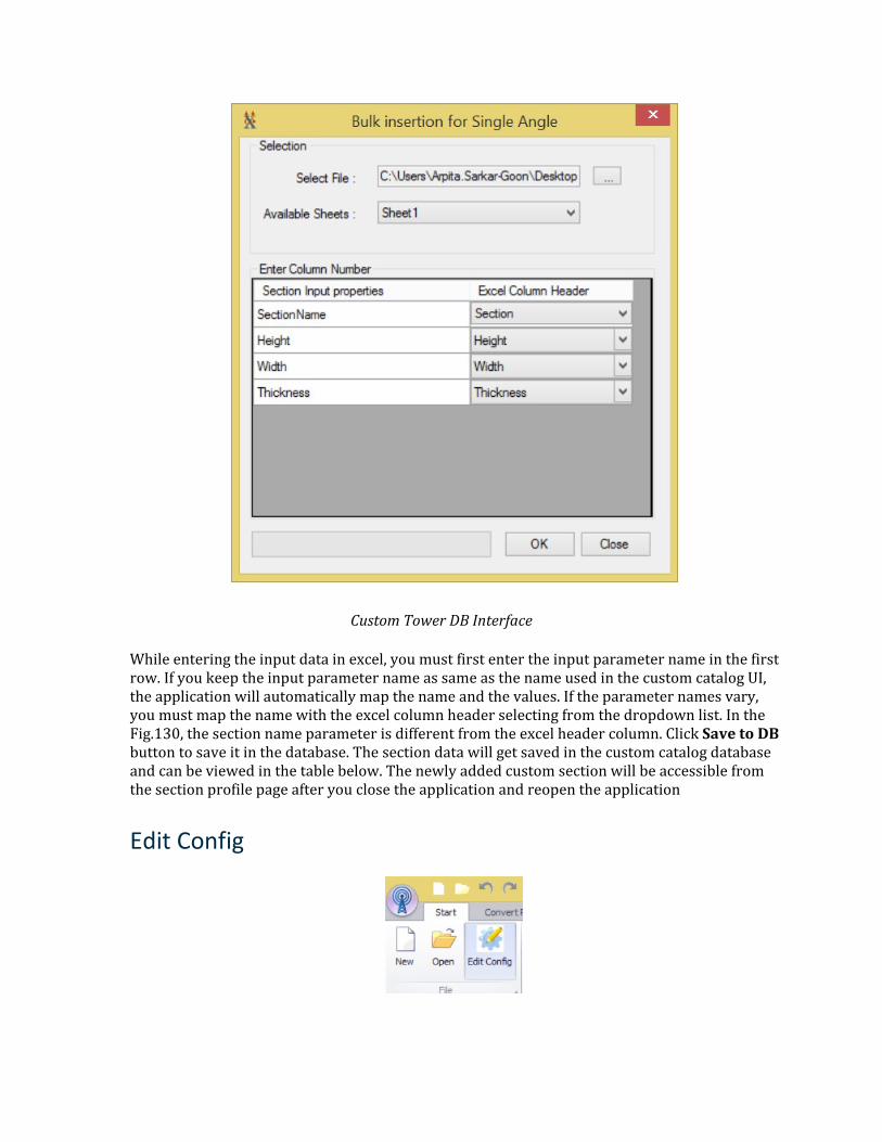
Custom Tower DB Interface
While entering the input data in excel, you must first enter the input parameter name in the first row. If you keep the input parameter name as same as the name used in the custom catalog UI, the application will automatically map the name and the values. If the parameter names vary, you must map the name with the excel column header selecting from the dropdown list. In the Fig.130, the section name parameter is different from the excel header column. Click Save to DB button to save it in the database. The section data will get saved in the custom catalog database and can be viewed in the table below. The newly added custom section will be accessible from the section profile page after you close the application and reopen the application
Edit Config
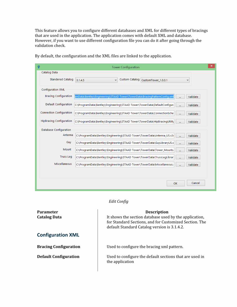
This feature allows you to configure different databases and XML for different types of bracings that are used in the application. The application comes with default XML and database. However, if you want to use different configuration file you can do it after going through the validation check.
By default, the configuration and the XML files are linked to the application.
Edit Config
Parameter Description Catalog Data It shows the section database used by the application,
for Standard Sections, and for Customized Section. The default Standard Catalog version is 3.1.4.2.
Configuration XML
Bracing Configuration Used to configure the bracing xml pattern.
Default Configuration Used to configure the default sections that are used in the application
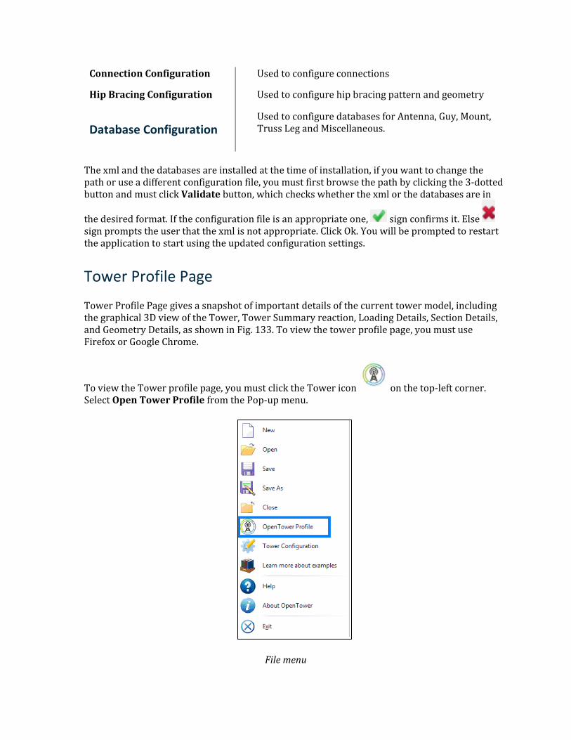
Connection Configuration Used to configure connections
Hip Bracing Configuration Used to configure hip bracing pattern and geometry
Database Configuration Used to configure databases for Antenna, Guy, Mount, Truss Leg and Miscellaneous.
The xml and the databases are installed at the time of installation, if you want to change the path or use a different configuration file, you must first browse the path by clicking the 3-dotted button and must click Validate button, which checks whether the xml or the databases are in
the desired format. If the configuration file is an appropriate one, sign confirms it. Else sign prompts the user that the xml is not appropriate. Click Ok. You will be prompted to restart the application to start using the updated configuration settings.
Tower Profile Page
Tower Profile Page gives a snapshot of important details of the current tower model, including the graphical 3D view of the Tower, Tower Summary reaction, Loading Details, Section Details, and Geometry Details, as shown in Fig. 133. To view the tower profile page, you must use Firefox or Google Chrome.
To view the Tower profile page, you must click the Tower icon on the top-left corner. Select Open Tower Profile from the Pop-up menu.
File menu
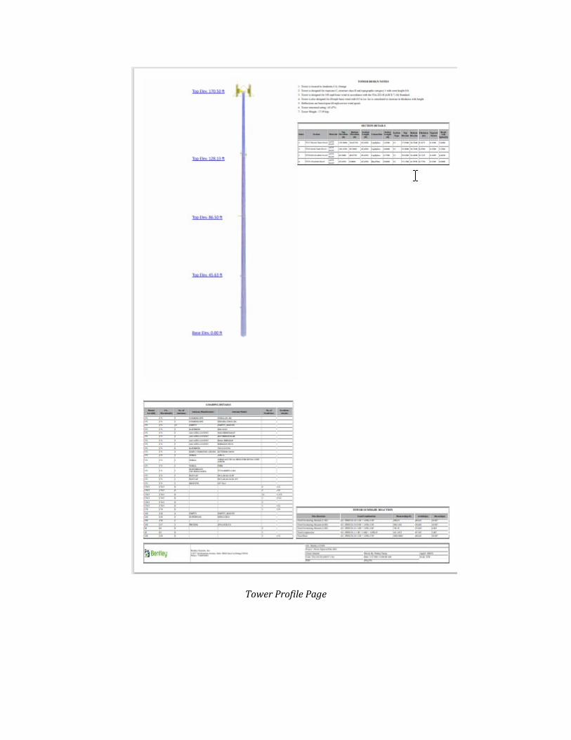
Tower Profile Page
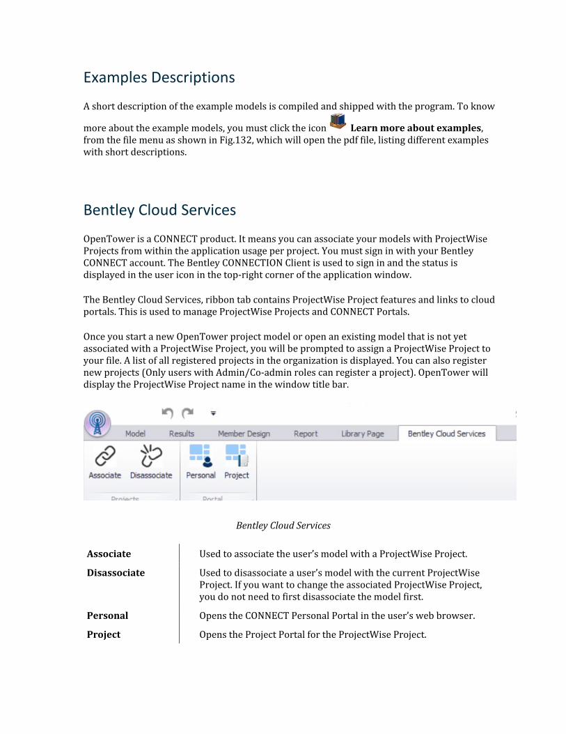
Examples Descriptions
A short description of the example models is compiled and shipped with the program. To know
more about the example models, you must click the icon Learn more about examples, from the file menu as shown in Fig.132, which will open the pdf file, listing different examples with short descriptions.
Bentley Cloud Services
OpenTower is a CONNECT product. It means you can associate your models with ProjectWise Projects from within the application usage per project. You must sign in with your Bentley CONNECT account. The Bentley CONNECTION Client is used to sign in and the status is displayed in the user icon in the top-right corner of the application window.
The Bentley Cloud Services, ribbon tab contains ProjectWise Project features and links to cloud portals. This is used to manage ProjectWise Projects and CONNECT Portals.
Once you start a new OpenTower project model or open an existing model that is not yet associated with a ProjectWise Project, you will be prompted to assign a ProjectWise Project to your file. A list of all registered projects in the organization is displayed. You can also register new projects (Only users with Admin/Co-admin roles can register a project). OpenTower will display the ProjectWise Project name in the window title bar.
Bentley Cloud Services
Associate Used to associate the user’s model with a ProjectWise Project.
Disassociate Used to disassociate a user’s model with the current ProjectWise Project. If you want to change the associated ProjectWise Project, you do not need to first disassociate the model first.
Personal Opens the CONNECT Personal Portal in the user’s web browser.
Project Opens the Project Portal for the ProjectWise Project.

To Associate a ProjectWise Project with Your File
When you create a new file or open an existing file that is not associated with a project, use the following procedure to associate the file with a ProjectWise project.
Note: You must be signed in using the CONNECTION client to associate a ProjectWise project with the file.
Tip: If you want to change the ProjectWise project associated with the file, use the following procedure.
1. On the Bentley Cloud Services ribbon tab, select the Associate tool in the Projects group. The Choose Project dialog opens.
2. (Optional) If you want to register a new project, do the following:
a. Click Register Project. The Register a Project page opens in your browser.
Note: Only users with Admin/Co-admin roles can register a project.
b. Type or select the required items (marked with an asterisk, "*") c. Click Save. A list of registered projects within your organization opens. The newly
created project is highlighted in green.
Tip: Alternatively, you can visit connect.bentley.com and select +New on the Recent Projects tile on your personal dashboard.
3. Select the desired project from the list.
Tip: Use the View controls and Search tool to locate your project.
4. Click Associate.
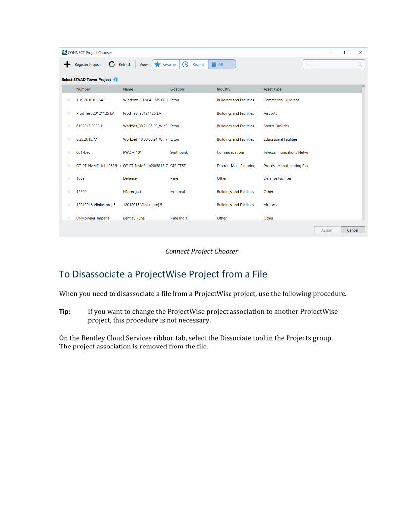
Connect Project Chooser
To Disassociate a ProjectWise Project from a File
When you need to disassociate a file from a ProjectWise project, use the following procedure.
Tip: If you want to change the ProjectWise project association to another ProjectWise project, this procedure is not necessary.
On the Bentley Cloud Services ribbon tab, select the Dissociate tool in the Projects group. The project association is removed from the file.
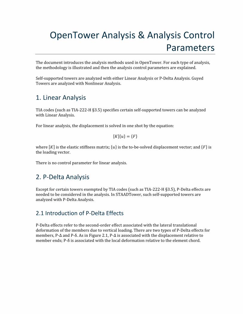
OpenTower Analysis & Analysis Control Parameters
The document introduces the analysis methods used in OpenTower. For each type of analysis, the methodology is illustrated and then the analysis control parameters are explained.
Self-supported towers are analyzed with either Linear Analysis or P-Delta Analysis. Guyed Towers are analyzed with Nonlinear Analysis.
1. Linear Analysis
TIA codes (such as TIA-222-H §3.5) specifies certain self-supported towers can be analyzed with Linear Analysis.
For linear analysis, the displacement is solved in one shot by the equation:
[𝐾𝐾]{𝑢𝑢} = {𝐹𝐹}
where [𝐾𝐾] is the elastic stiffness matrix; {𝑢𝑢} is the to-be-solved displacement vector; and {𝐹𝐹} is the loading vector.
There is no control parameter for linear analysis.
2. P-Delta Analysis
Except for certain towers exempted by TIA codes (such as TIA-222-H §3.5), P-Delta effects are needed to be considered in the analysis. In STAADTower, such self-supported towers are analyzed with P-Delta Analysis.
2.1 Introduction of P-Delta Effects
P-Delta effects refer to the second-order effect associated with the lateral translational deformation of the members due to vertical loading. There are two types of P-Delta effects for members, P-Δ and P-δ. As in Figure 2.1, P-Δ is associated with the displacement relative to member ends; P-δ is associated with the local deformation relative to the element chord.
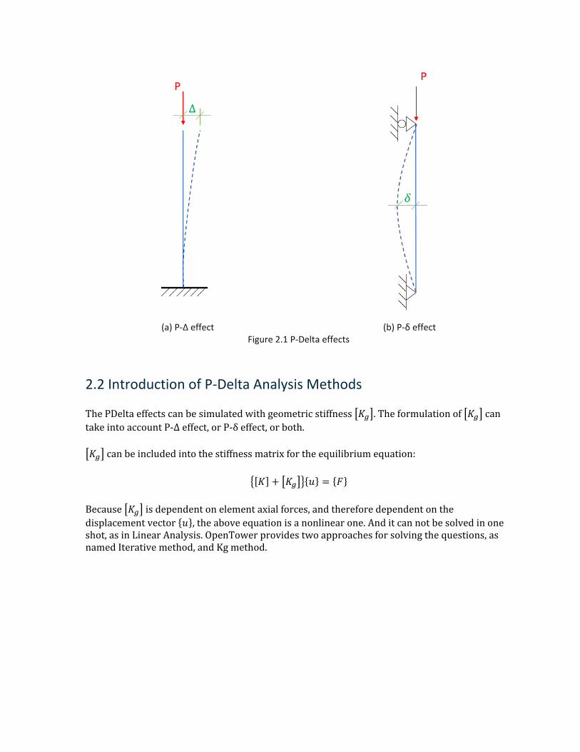
(a) P-Δ effect (b) P-δ effect Figure 2.1 P-Delta effects
2.2 Introduction of P-Delta Analysis Methods
The PDelta effects can be simulated with geometric stiffness �𝐾𝐾𝑔𝑔�. The formulation of �𝐾𝐾𝑔𝑔� can take into account P-Δ effect, or P-δ effect, or both.
�𝐾𝐾𝑔𝑔� can be included into the stiffness matrix for the equilibrium equation:
�[𝐾𝐾] + �𝐾𝐾𝑔𝑔��{𝑢𝑢} = {𝐹𝐹}
Because �𝐾𝐾𝑔𝑔� is dependent on element axial forces, and therefore dependent on the displacement vector {𝑢𝑢}, the above equation is a nonlinear one. And it can not be solved in one shot, as in Linear Analysis. OpenTower provides two approaches for solving the questions, as named Iterative method, and Kg method.
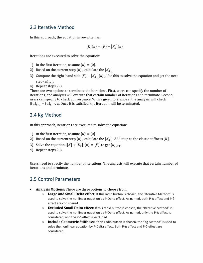
2.3 Iterative Method
In this approach, the equation is rewritten as:
[𝐾𝐾]{𝑢𝑢} = {𝐹𝐹} − �𝐾𝐾𝑔𝑔�{𝑢𝑢}
Iterations are executed to solve the equation:
1) In the first iteration, assume {𝑢𝑢} = {0}. 2) Based on the current step {𝑢𝑢}𝑖𝑖 , calculate the �𝐾𝐾𝑔𝑔�𝑖𝑖 . 3) Compute the right-hand side {𝐹𝐹} − �𝐾𝐾𝑔𝑔�𝑖𝑖{𝑢𝑢}𝑖𝑖 . Use this to solve the equation and get the next
step {𝑢𝑢}𝑖𝑖+1. 4) Repeat steps 2-3. There are two options to terminate the iterations. First, users can specify the number of iterations, and analysis will execute that certain number of iterations and terminate. Second, users can specify to check convergence. With a given tolerance 𝜀𝜀, the analysis will check |{𝑢𝑢}𝑖𝑖+1 − {𝑢𝑢}𝑖𝑖| < 𝜀𝜀. Once it is satisfied, the iteration will be terminated.
2.4 Kg Method
In this approach, iterations are executed to solve the equation:
1) In the first iteration, assume {𝑢𝑢} = {0}. 2) Based on the current step {𝑢𝑢}𝑖𝑖 , calculate the �𝐾𝐾𝑔𝑔�𝑖𝑖 . Add it up to the elastic stiffness [𝐾𝐾]. 3) Solve the equation �[𝐾𝐾] + �𝐾𝐾𝑔𝑔��{𝑢𝑢} = {𝐹𝐹}, to get {𝑢𝑢}𝑖𝑖+1. 4) Repeat steps 2-3.
Users need to specify the number of iterations. The analysis will execute that certain number of iterations and terminate.
2.5 Control Parameters
• Analysis Options: There are three options to choose from. o Large and Small Delta effect: If this radio button is chosen, the “Iterative Method” is
used to solve the nonlinear equation by P-Delta effect. As named, both P-Δ effect and P-δ effect are considered.
o Excluded Small Delta effect: If this radio button is chosen, the “Iterative Method” is used to solve the nonlinear equation by P-Delta effect. As named, only the P-Δ effect is considered, and the P-δ effect is excluded.
o Include Geometric Stiffness: If this radio button is chosen, the “Kg Method” is used to solve the nonlinear equation by P-Delta effect. Both P-Δ effect and P-δ effect are considered.
• No. of Iteration: This input number specifies the number of iterations. The analysis will run this certain number of iterations and then terminate. This input is used for both the “Iterative Method” and “Kg Method”. In other words, the input is appliable to all three options under “Analysis Options”.
• Converge Check: When this checkbox is checked, the analysis will check the convergence criteria to terminate the iterations, instead of running the certain number of iterations given by “No. of Iteration”. In other words, when this checkbox is checked, the input of “No. of Iteration” is ineffective; and vice versa. This convergence check approach is only applicable to the “Iterative Method”, which means it is only available to choose only when the selection in “Analysis Options” is either “Large and Small Delta effect” or “Exclude Small Delta effect”. It is not available when the selection is “Include Geometric Stiffness”. UI is also set in the same logic.
• Max Number of Iterations: The input specifies the max number of iterations to run when analysis checks converge to terminate iterations. The input is available only when the “Converge Check” checkbox is checked. The analysis will terminate when the converge is achieved or the number of iterations exceeds this input.
• Displacement Tolerance: The input specifies converge tolerance, in the unit of an inch. The input is available only when the “Converge Check” checkbox is checked. The analysis will pick the maximum value from the incremental solved displacement vector and compare it with this input. When the value is smaller than this tolerance input, the iteration is considered converged and terminated.
3. Nonlinear Analysis
For guyed towers, nonlinear static analysis is performed. The nonlinearity in the guyed towers are from:
• The highly geometric nonlinear of the guy cables; • The P-Delta effect in all frame elements (i.e. legs, diagonals, etc.). In the equilibrium equation:
�[𝐾𝐾] + �𝐾𝐾𝑔𝑔��{𝑢𝑢} = {𝐹𝐹}
Both [𝐾𝐾] and �𝐾𝐾𝑔𝑔� are dependent on {𝑢𝑢}. And the equation is a nonlinear one.
The analysis employs Full Newton method for solving nonlinear equations.
For guyed towers with a great number of tension-only members, two approaches are provided to assist the solution to converge.
To determining guy cables’ initial tensions, the procedure “Retention Guys to Initial Tension” is required, per users’ judgment.
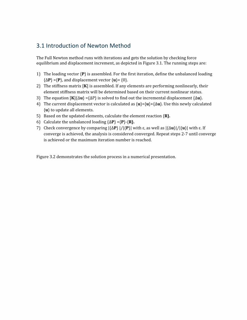
3.1 Introduction of Newton Method
The Full Newton method runs with iterations and gets the solution by checking force equilibrium and displacement increment, as depicted in Figure 3.1. The running steps are:
1) The loading vector {P} is assembled. For the first iteration, define the unbalanced loading {ΔP} ={P}, and displacement vector {u}= {0}.
2) The stiffness matrix [K] is assembled. If any elements are performing nonlinearly, their element stiffness matrix will be determined based on their current nonlinear status.
3) The equation [K]{Δu} ={ΔP} is solved to find out the incremental displacement {Δu}. 4) The current displacement vector is calculated as {u}={u}+{Δu}. Use this newly calculated
{u} to update all elements. 5) Based on the updated elements, calculate the element reaction {R}. 6) Calculate the unbalanced loading {ΔP} ={P}-{R}. 7) Check convergence by comparing |{ΔP} |/|{P}| with ε, as well as |{Δu}|/|{u}| with ε. If
converge is achieved, the analysis is considered converged. Repeat steps 2-7 until converge is achieved or the maximum iteration number is reached.
Figure 3.2 demonstrates the solution process in a numerical presentation.
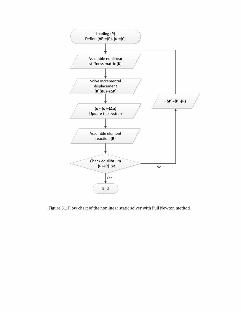
Assemble nonlinear stiffness matrix [K]
Loading {P}Define {ΔP}={P}, {u}={0}
Solve incremental displacement [K]{Δu}={ΔP}
{u}={u}+{Δu}Update the system
Assemble element reaction {R}
Check equilibrium|{P}-{R}|≤ε
End
Yes
No
{ΔP}={P}-{R}
Figure 3.1 Flow chart of the nonlinear static solver with Full Newton method
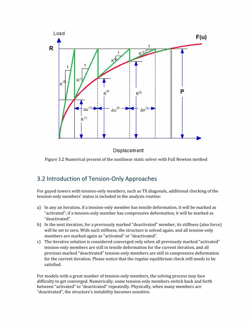
Figure 3.2 Numerical present of the nonlinear static solver with Full Newton method
3.2 Introduction of Tension-Only Approaches
For guyed towers with tension-only members, such as TX diagonals, additional checking of the tension-only members’ status is included in the analysis routine:
a) In any an iteration, if a tension-only member has tensile deformation, it will be marked as “activated”; if a tension-only member has compressive deformation, it will be marked as “deactivated”.
b) In the next iteration, for a previously marked “deactivated” member, its stiffness (also force) will be set to zero. With such stiffness, the structure is solved again; and all tension-only members are marked again as “activated” or “deactivated”.
c) The iterative solution is considered converged only when all previously marked “activated” tension-only members are still in tensile deformation for the current iteration, and all previous marked “deactivated” tension-only members are still in compressive deformation for the current iteration. Please notice that the regular equilibrium check still needs to be satisfied.
For models with a great number of tension-only members, the solving process may face difficulty to get converged. Numerically, some tension-only members switch back and forth between “activated” to “deactivated” repeatedly. Physically, when many members are “deactivated”, the structure’s instability becomes sensitive.
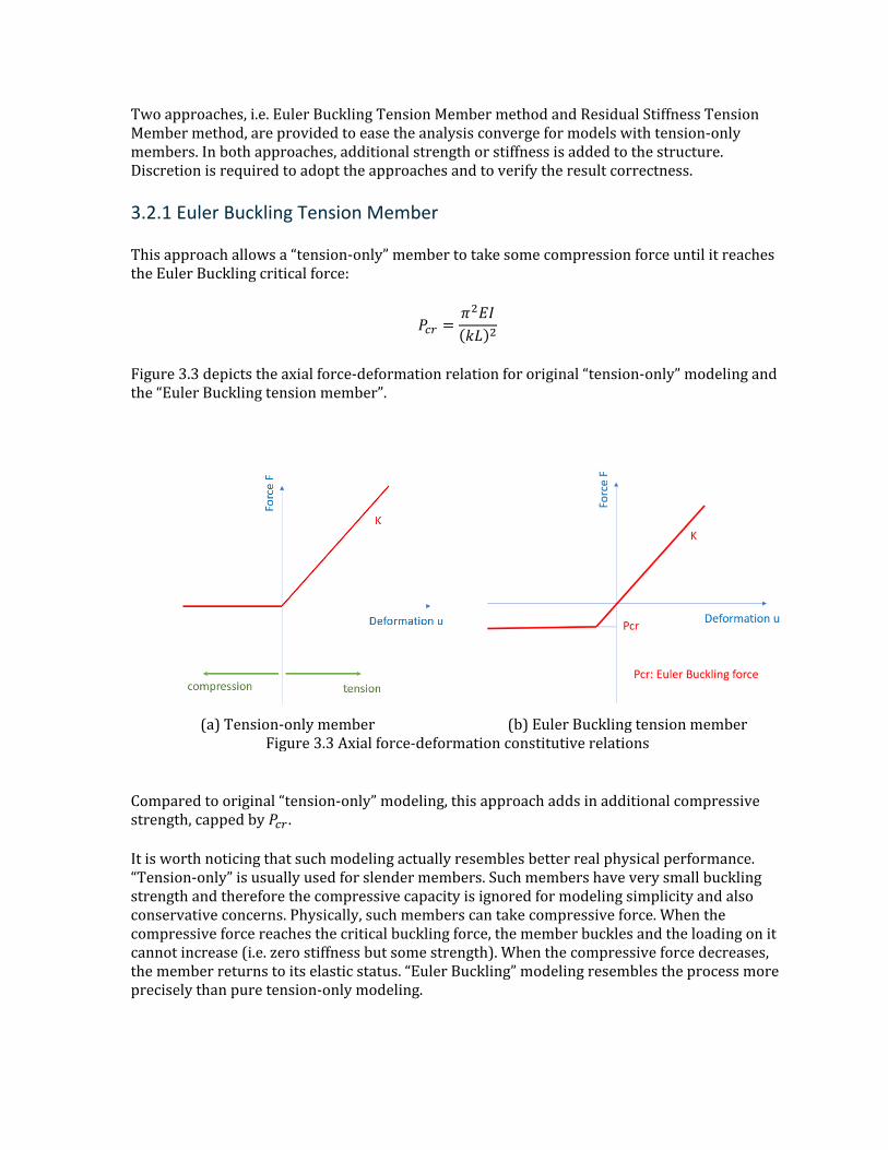
Two approaches, i.e. Euler Buckling Tension Member method and Residual Stiffness Tension Member method, are provided to ease the analysis converge for models with tension-only members. In both approaches, additional strength or stiffness is added to the structure. Discretion is required to adopt the approaches and to verify the result correctness.
3.2.1 Euler Buckling Tension Member
This approach allows a “tension-only” member to take some compression force until it reaches the Euler Buckling critical force:
𝑃𝑃𝑐𝑐𝑐𝑐 =𝜋𝜋2𝐸𝐸𝐸𝐸(𝑘𝑘𝑘𝑘)2
Figure 3.3 depicts the axial force-deformation relation for original “tension-only” modeling and the “Euler Buckling tension member”.
(a) Tension-only member (b) Euler Buckling tension member Figure 3.3 Axial force-deformation constitutive relations
Compared to original “tension-only” modeling, this approach adds in additional compressive strength, capped by 𝑃𝑃𝑐𝑐𝑐𝑐 .
It is worth noticing that such modeling actually resembles better real physical performance. “Tension-only” is usually used for slender members. Such members have very small buckling strength and therefore the compressive capacity is ignored for modeling simplicity and also conservative concerns. Physically, such members can take compressive force. When the compressive force reaches the critical buckling force, the member buckles and the loading on it cannot increase (i.e. zero stiffness but some strength). When the compressive force decreases, the member returns to its elastic status. “Euler Buckling” modeling resembles the process more precisely than pure tension-only modeling.
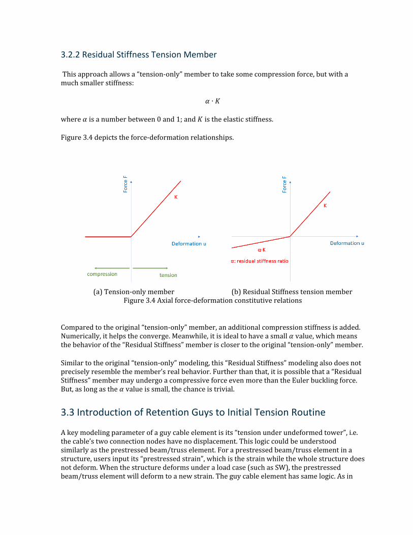
3.2.2 Residual Stiffness Tension Member
This approach allows a “tension-only” member to take some compression force, but with a much smaller stiffness:
𝛼𝛼 ∙ 𝐾𝐾
where 𝛼𝛼 is a number between 0 and 1; and 𝐾𝐾 is the elastic stiffness.
Figure 3.4 depicts the force-deformation relationships.
(a) Tension-only member (b) Residual Stiffness tension member Figure 3.4 Axial force-deformation constitutive relations
Compared to the original “tension-only” member, an additional compression stiffness is added. Numerically, it helps the converge. Meanwhile, it is ideal to have a small 𝛼𝛼 value, which means the behavior of the “Residual Stiffness” member is closer to the original “tension-only” member.
Similar to the original “tension-only” modeling, this “Residual Stiffness” modeling also does not precisely resemble the member’s real behavior. Further than that, it is possible that a “Residual Stiffness” member may undergo a compressive force even more than the Euler buckling force. But, as long as the 𝛼𝛼 value is small, the chance is trivial.
3.3 Introduction of Retention Guys to Initial Tension Routine
A key modeling parameter of a guy cable element is its “tension under undeformed tower”, i.e. the cable’s two connection nodes have no displacement. This logic could be understood similarly as the prestressed beam/truss element. For a prestressed beam/truss element in a structure, users input its “prestressed strain”, which is the strain while the whole structure does not deform. When the structure deforms under a load case (such as SW), the prestressed beam/truss element will deform to a new strain. The guy cable element has same logic. As in
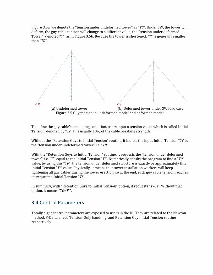
Figure 3.5a, we denote the “tension under undeformed tower” as “T0”. Under SW, the tower will deform, the guy cable tension will change to a different value, the “tension under deformed Tower”, denoted “T”, as in Figure 3.5b. Because the tower is shortened, “T” is generally smaller than “T0”.
(a) Undeformed tower (b) Deformed tower under SW load case Figure 3.5 Guy tension in undeformed model and deformed model
To define the guy cable’s tensioning condition, users input a tension value, which is called Initial Tension, denoted by “Ti”. It is usually 10% of the cable breaking strength.
Without the “Retention Guys to Initial Tension” routine, it indicts the input Initial Tension “Ti” is the “tension under undeformed tower” i.e. “T0”.
With the “Retention Guys to Initial Tension” routine, it requests the “tension under deformed tower”, i.e. “T”, equal to the Initial Tension “Ti”. Numerically, it asks the program to find a “T0” value, by using this “T0”, the tension under deformed structure is exactly or approximately this Initial Tension “Ti” value. Physically, it means that tower installation workers will keep tightening all guy cables during the tower erection, so at the end, each guy cable tension reaches its requested Initial Tension “Ti”.
In summary, with “Retention Guys to Initial Tension” option, it requests “T=Ti”. Without that option, it means “T0=Ti”.
3.4 Control Parameters
Totally eight control parameters are exposed to users in the UI. They are related to the Newton method, P-Delta effect, Tension-Only handling, and Retention Guy Initial Tension routine respectively.
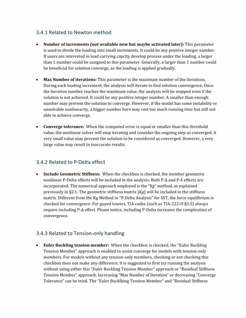
3.4.1 Related to Newton method
• Number of increments (not available now but maybe activated later): This parameter is used to divide the loading into small increments. It could be any positive integer number. If users are interested in load carrying capcity develop process under the loading, a larger than 1 number could be assigned to this parameter. Generally, a larger than 1 number could be beneficial for solution converge, as the loading is applied gradually.
• Max Number of iterations: This parameter is the maximum number of the iterations. During each loading increment, the analysis will iterate to find solution convergence. Once the iteration number reaches the maximum value, the analysis will be stopped even if the solution is not achieved. It could be any positive integer number. A smaller than enough number may prevent the solution to converge. However, if the model has some instability or unsolvable nonlinearity, a bigger number here may cost too much running time but still not able to achieve converge.
• Converge tolerance: When the computed error is equal or smaller than this threshold value, the nonlinear solver will stop iterating and consider the ongoing step as converged. A very small value may prevent the solution to be considered as converged. However, a very large value may result in inaccurate results.
3.4.2 Related to P-Delta effect
• Include Geometric Stiffness: When the checkbox is checked, the member geometric nonlinear P-Delta effects will be included in the analysis. Both P-Δ and P-δ effects are incorporated. The numerical approach employed is the “Kg” method, as explained previously in §2.1. The geometric stiffness matrix [Kg] will be included in the stiffness matrix. Different from the Kg Method in “P-Delta Analysis” for SST, the force equilibrium is checked for convergence. For guyed towers, TIA codes (such as TIA-222-H §3.5) always require including P-Δ effect. Please notice, including P-Delta increases the complexities of convergence.
3.4.3 Related to Tension-only handling
• Euler Buckling tension member: When the checkbox is checked, the “Euler Buckling Tension Member” approach is enabled to assist converge for models with tension-only members. For models without any tension-only members, checking or not checking this checkbox does not make any difference. It is suggested to first try running the analysis without using either this “Euler Buckling Tension Member” approach or “Residual Stiffness Tension Member” approach. Increasing “Max Number of Iteration” or decreasing “Converge Tolerance” can be tried. The “Euler Bucklking Tension Member” and “Residual Stiffness
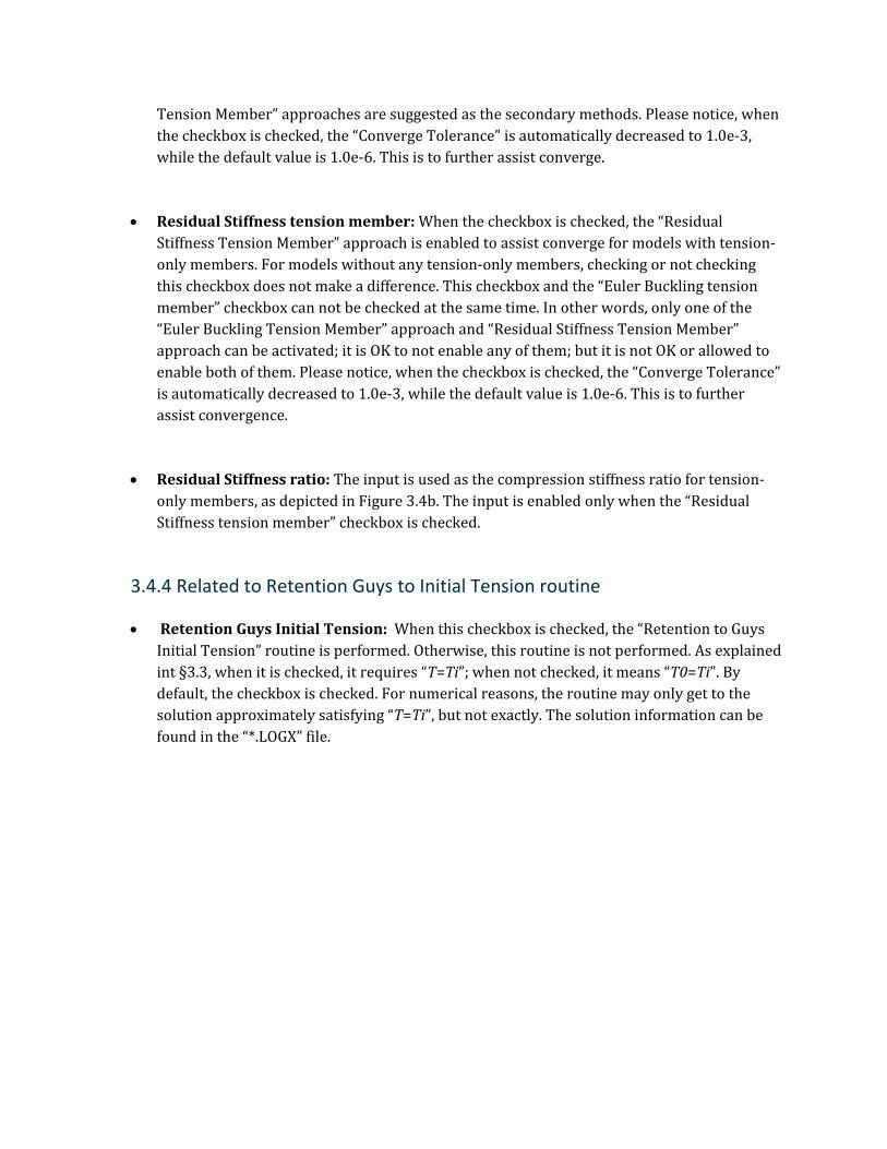
Tension Member” approaches are suggested as the secondary methods. Please notice, when the checkbox is checked, the “Converge Tolerance” is automatically decreased to 1.0e-3, while the default value is 1.0e-6. This is to further assist converge.
• Residual Stiffness tension member: When the checkbox is checked, the “Residual Stiffness Tension Member” approach is enabled to assist converge for models with tension-only members. For models without any tension-only members, checking or not checking this checkbox does not make a difference. This checkbox and the “Euler Buckling tension member” checkbox can not be checked at the same time. In other words, only one of the “Euler Buckling Tension Member” approach and “Residual Stiffness Tension Member” approach can be activated; it is OK to not enable any of them; but it is not OK or allowed to enable both of them. Please notice, when the checkbox is checked, the “Converge Tolerance” is automatically decreased to 1.0e-3, while the default value is 1.0e-6. This is to further assist convergence.
• Residual Stiffness ratio: The input is used as the compression stiffness ratio for tension-only members, as depicted in Figure 3.4b. The input is enabled only when the “Residual Stiffness tension member” checkbox is checked.
3.4.4 Related to Retention Guys to Initial Tension routine
• Retention Guys Initial Tension: When this checkbox is checked, the “Retention to Guys Initial Tension” routine is performed. Otherwise, this routine is not performed. As explained int §3.3, when it is checked, it requires “T=Ti”; when not checked, it means “T0=Ti”. By default, the checkbox is checked. For numerical reasons, the routine may only get to the solution approximately satisfying “T=Ti”, but not exactly. The solution information can be found in the “*.LOGX” file.
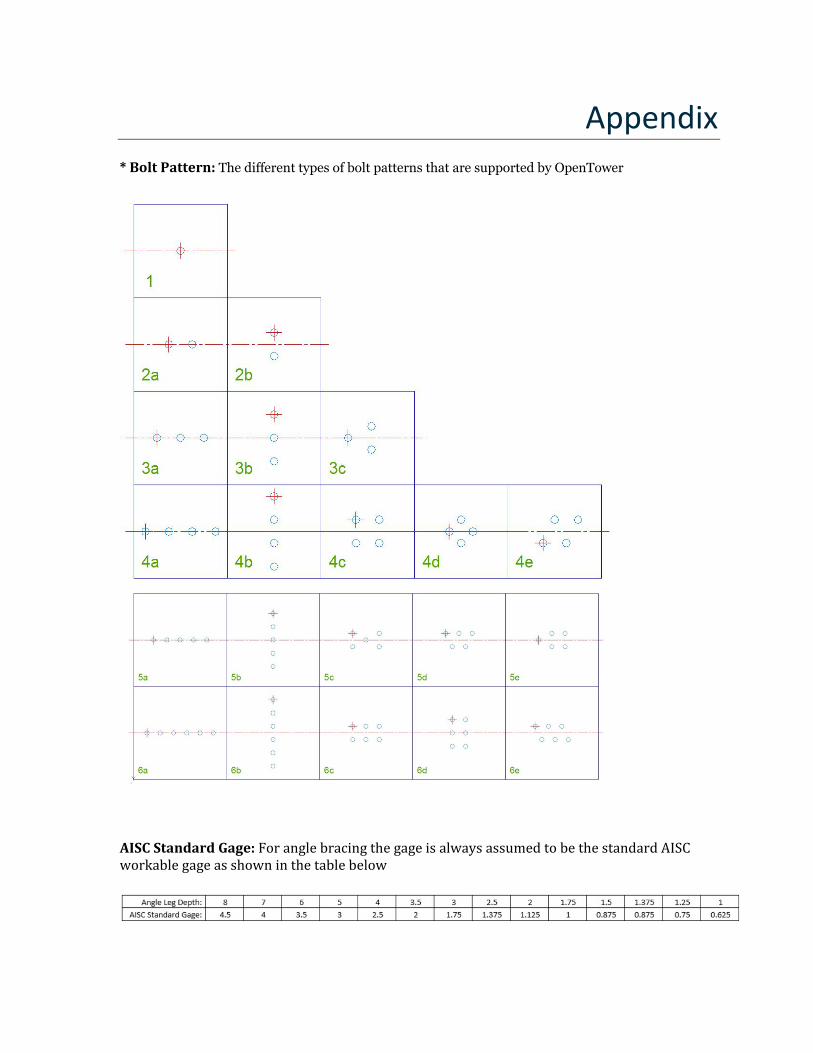
Appendix * Bolt Pattern: The different types of bolt patterns that are supported by OpenTower
AISC Standard Gage: For angle bracing the gage is always assumed to be the standard AISC workable gage as shown in the table below
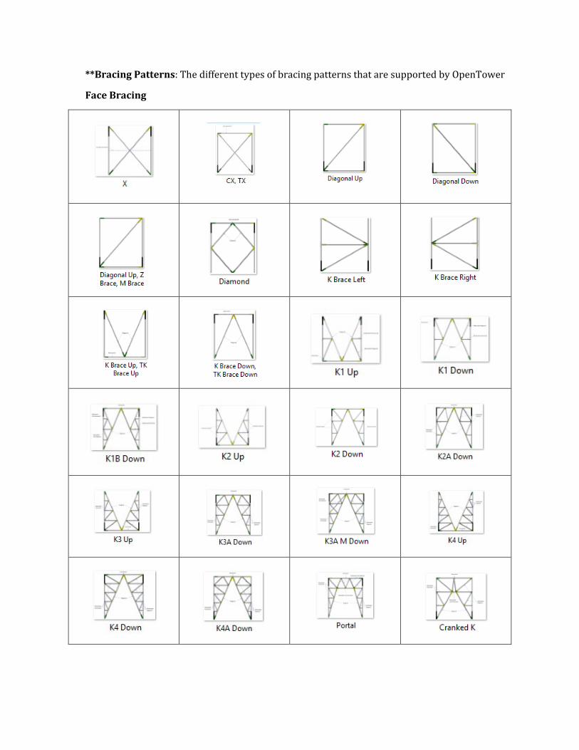
**Bracing Patterns: The different types of bracing patterns that are supported by OpenTower
Face Bracing
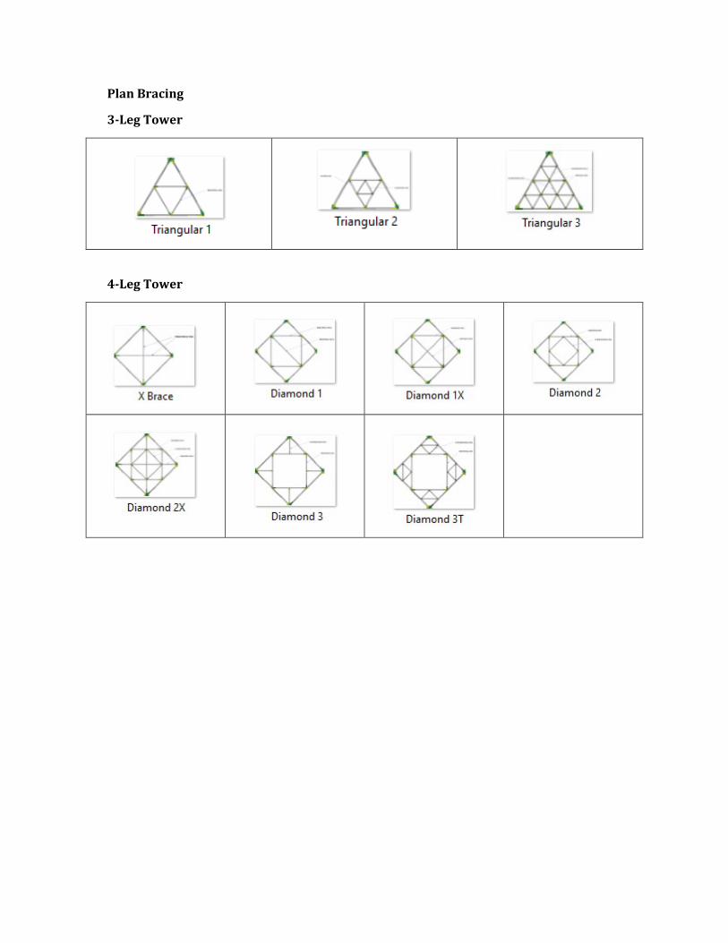
Plan Bracing
3-Leg Tower
4-Leg Tower
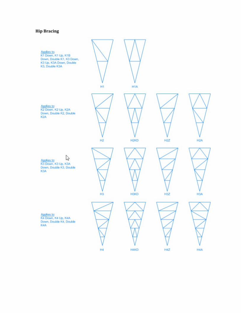
Hip Bracing
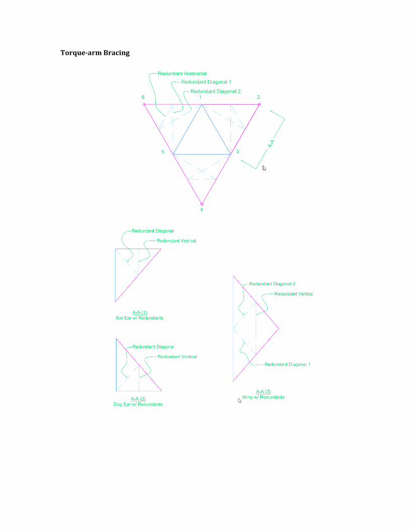
Torque-arm Bracing
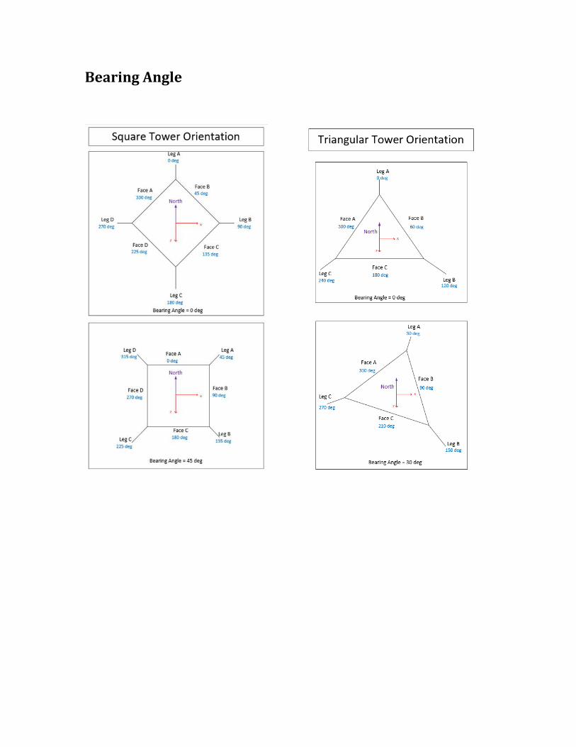
Bearing Angle
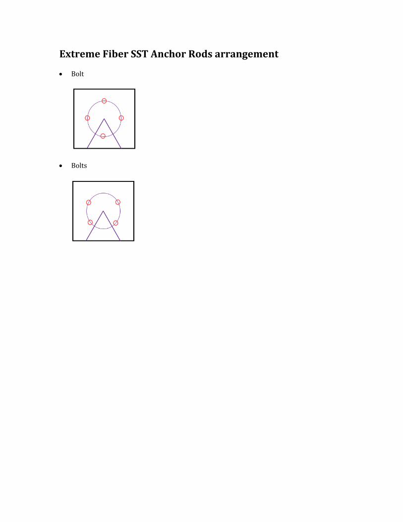
Extreme Fiber SST Anchor Rods arrangement
• Bolt
• Bolts
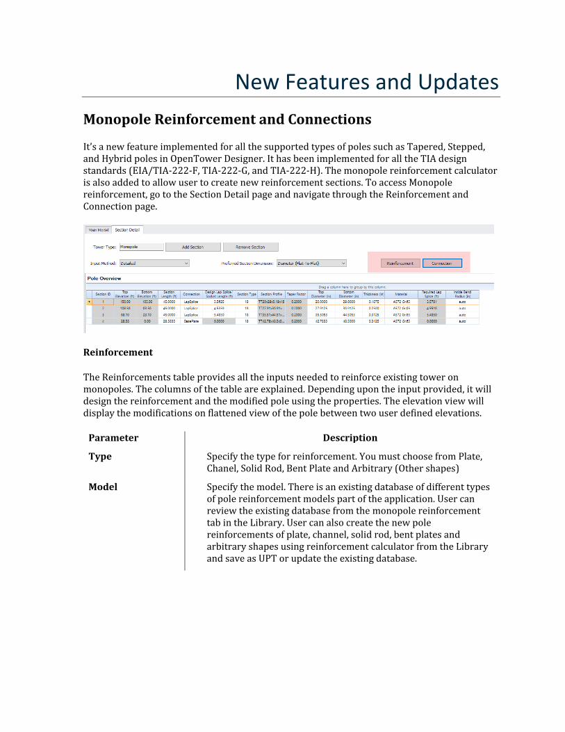
New Features and Updates Monopole Reinforcement and Connections
It’s a new feature implemented for all the supported types of poles such as Tapered, Stepped, and Hybrid poles in OpenTower Designer. It has been implemented for all the TIA design standards (EIA/TIA-222-F, TIA-222-G, and TIA-222-H). The monopole reinforcement calculator is also added to allow user to create new reinforcement sections. To access Monopole reinforcement, go to the Section Detail page and navigate through the Reinforcement and Connection page.
Reinforcement
The Reinforcements table provides all the inputs needed to reinforce existing tower on monopoles. The columns of the table are explained. Depending upon the input provided, it will design the reinforcement and the modified pole using the properties. The elevation view will display the modifications on flattened view of the pole between two user defined elevations.
Parameter Description
Type Specify the type for reinforcement. You must choose from Plate, Chanel, Solid Rod, Bent Plate and Arbitrary (Other shapes)
Model Specify the model. There is an existing database of different types of pole reinforcement models part of the application. User can review the existing database from the monopole reinforcement tab in the Library. User can also create the new pole reinforcements of plate, channel, solid rod, bent plates and arbitrary shapes using reinforcement calculator from the Library and save as UPT or update the existing database.
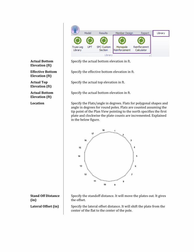
Actual Bottom Elevation (ft)
Specify the actual bottom elevation in ft.
Effective Bottom Elevation (ft)
Specify the effective bottom elevation in ft.
Actual Top Elevation (ft)
Specify the actual top elevation in ft.
Actual Bottom Elevation (ft)
Specify the actual bottom elevation in ft.
Location Specify the Flats/angle in degrees. Flats for polygonal shapes and angle in degrees for round poles. Flats are counted assuming the tip point of the Plan View pointing to the north specifies the first plate and clockwise the plate counts are incremented. Explained in the below figure.
Stand Off Distance (in)
Specify the standoff distance. It will move the plates out. It gives the offset.
Lateral Offset (in) Specify the lateral offset distance. It will shift the plate from the center of the flat to the center of the pole.
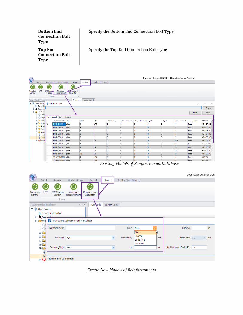
Bottom End Connection Bolt Type
Specify the Bottom End Connection Bolt Type
Top End Connection Bolt Type
Specify the Top End Connection Bolt Type
Existing Models of Reinforcement Database
Create New Models of Reinforcements
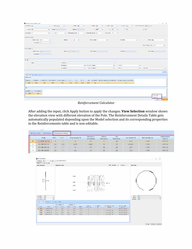
Reinforcement Calculator
After adding the input, click Apply button to apply the changes. View Selection window shows the elevation view with different elevation of the Pole. The Reinforcement Details Table gets automatically populated depending upon the Model selection and its corresponding properties in the Reinforcements table and is non editable.
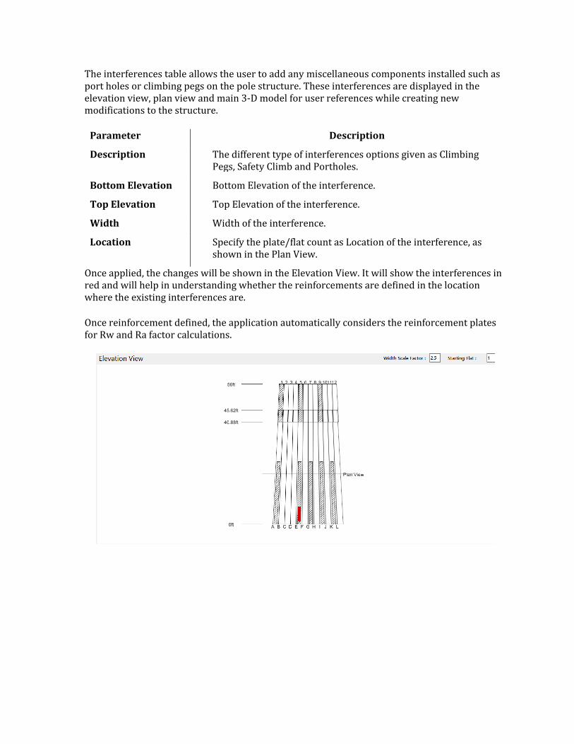
The interferences table allows the user to add any miscellaneous components installed such as port holes or climbing pegs on the pole structure. These interferences are displayed in the elevation view, plan view and main 3-D model for user references while creating new modifications to the structure.
Parameter Description
Description The different type of interferences options given as Climbing Pegs, Safety Climb and Portholes.
Bottom Elevation Bottom Elevation of the interference.
Top Elevation Top Elevation of the interference.
Width Width of the interference.
Location Specify the plate/flat count as Location of the interference, as shown in the Plan View.
Once applied, the changes will be shown in the Elevation View. It will show the interferences in red and will help in understanding whether the reinforcements are defined in the location where the existing interferences are.
Once reinforcement defined, the application automatically considers the reinforcement plates for Rw and Ra factor calculations.
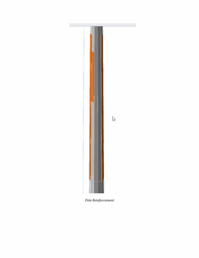
Pole Reinforcement
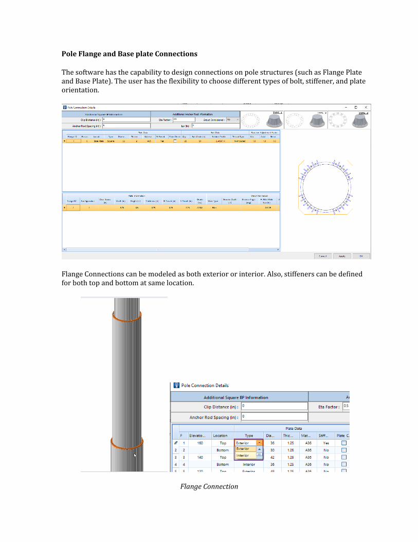
Pole Flange and Base plate Connections
The software has the capability to design connections on pole structures (such as Flange Plate and Base Plate). The user has the flexibility to choose different types of bolt, stiffener, and plate orientation.
Flange Connections can be modeled as both exterior or interior. Also, stiffeners can be defined for both top and bottom at same location.
Flange Connection
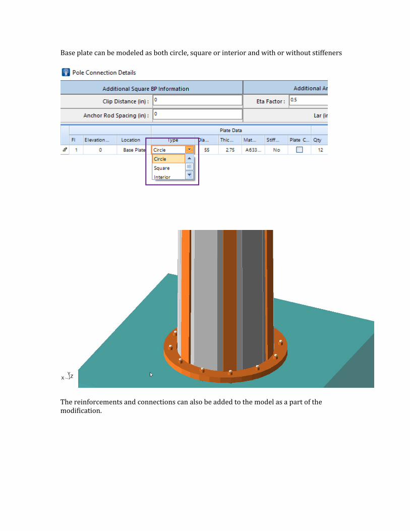
Base plate can be modeled as both circle, square or interior and with or without stiffeners
The reinforcements and connections can also be added to the model as a part of the modification.
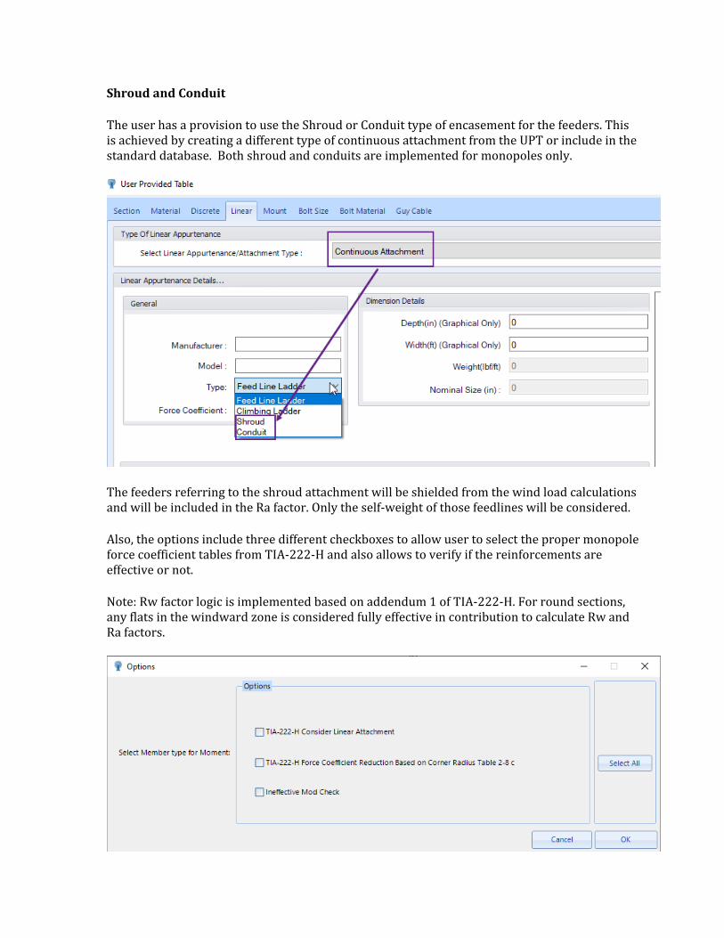
Shroud and Conduit
The user has a provision to use the Shroud or Conduit type of encasement for the feeders. This is achieved by creating a different type of continuous attachment from the UPT or include in the standard database. Both shroud and conduits are implemented for monopoles only.
The feeders referring to the shroud attachment will be shielded from the wind load calculations and will be included in the Ra factor. Only the self-weight of those feedlines will be considered.
Also, the options include three different checkboxes to allow user to select the proper monopole force coefficient tables from TIA-222-H and also allows to verify if the reinforcements are effective or not.
Note: Rw factor logic is implemented based on addendum 1 of TIA-222-H. For round sections, any flats in the windward zone is considered fully effective in contribution to calculate Rw and Ra factors.
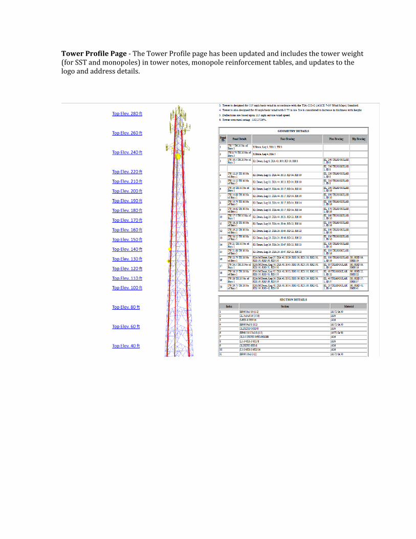
Tower Profile Page - The Tower Profile page has been updated and includes the tower weight (for SST and monopoles) in tower notes, monopole reinforcement tables, and updates to the logo and address details.

Index
A
anchor groups, 43
appurtenances, 72
configuration, 90
discrete, 74
groups, 72
linear, 82
B
Bentley cloud services, 178
bracing connections, 28
C
Code Check, 148
D
drilled pier foundations, 99
F
feed lines, 86
foundations, 92
design of, 111
guy anchors, 105
isolated footings, 92
foutndations
drilled piers, 99
G
geometry, 12
graphical interface reference, 135
guy anchor foundations, 105
guys, 42
I
isolated footings, 92
L
leg connections, 30
library, 156
load combinations
parameters, 66
loads, 54
seismic, 68
wind, 54
M
materials, 13
modifications, 47
P
project data, 52
ProjectWise projects
associating, 179

disassociating, 180
R
reports, 123
S
scenarios
definition, 116
section catalogs, 13
section editor, 25
section property catalog, 171
seismic load definitions, 68
SPC. See section property catalog
T
tower model expolorer, 150
tower models
create new, 14
import from TNX, 22
open existing, 14
truss leg library, 156
U
user settings, 52
user-provided tables, 161
W
wind load definitions, 54
work order, 51