novel scaffolds fabricated from protein-loaded microspheres for tissue engineering
TRANSCRIPT

ARTICLE IN PRESS
0142-9612/$ - se
doi:10.1016/j.bi
�CorrespondE-mail addr
Biomaterials 29 (2008) 185–192
www.elsevier.com/locate/biomaterials
Novel scaffolds fabricated from protein-loaded microspheresfor tissue engineering
Ana Jaklenec, Eugene Wan, Maria E. Murray, Edith Mathiowitz�
Center for Biomedical Engineering, Brown University, Providence, RI 02912, USA
Received 19 June 2007; accepted 18 September 2007
Abstract
Biodegradable scaffolds play an important role in tissue engineering by providing physical and biochemical support for both
differentiated and progenitor cells. Here, we describe a novel method for incorporating proteins in 3D biodegradable scaffolds by
utilizing protein-loaded microspheres as the building blocks for scaffold formation. Poly(L,D-lactic-co-glycolic acid) (PLGA)
microspheres containing bovine serum albumin (BSA) were fused into scaffolds using dichloromethane vapor for various time
intervals. Microspheres containing 0, 0.4, 1.5, 4.3% BSA showed that increased protein loading required increased fusion time for
scaffold fabrication. Protein release from the scaffolds was quantified in vitro over 20 days and compared to that of loose microspheres.
Scaffolds had a slightly lower (up to 20%) release over the first 10 days, however, the cumulative release from both microspheres and
scaffolds at the end of the study was not statistically different and the rate of release was the same, indicating that microsphere release can
be predictive of scaffold kinetics. Scaffolds fused from larger (113.3758.0mm) rather than smaller (11.15711.08mm) microspheres,
generated pores on the order of 200 mm as compared to 20mm, respectively, showing control over pore size. In addition, four dyes
(carbon black, acid green, red 27, and fast green FCF) were encapsulated in PLGA microspheres and fused into homogeneous and
partitioned scaffolds, indicating control over spatial distribution within the scaffold. Finally, the scaffolds were seeded with fibroblast
cells, which attached and were well spread over the polymer surface after 4 h of incubation. These results highlight the versatility of this
simple scaffold fusion method for incorporating essentially any combination of loaded microspheres into a 3D structure, making this a
powerful tool for tissue engineering and drug delivery applications.
r 2007 Published by Elsevier Ltd.
Keywords: Biodegradable; Cell adhesion; Controlled drug delivery; Microsphere; Protein; Scaffold
1. Introduction
Tissue engineering has emerged over the last severaldecades as a possible therapy for damaged tissues andorgans [1]. A common approach utilized by severallaboratories [2–7] has focused on seeding cells onto 3Dporous scaffolds in order to guide tissue regeneration.These constructs are then either cultured in vitro untilfunctional enough for implantation or they are implantedright after cell seeding and allowed to develop in situ. Thescaffold can serve as a temporary artificial matrix until thecells synthesize their own, or it can become integrated with
e front matter r 2007 Published by Elsevier Ltd.
omaterials.2007.09.017
ing author. Tel.: +1401 863 1358; fax: +1 401 863 1595.
ess: [email protected] (E. Mathiowitz).
the cells and provide structural support long term. Thereare several criteria for an ideal scaffold based on practicalissues regarding handling and implantation as well as fromempirical data [6]. The main requirement is high porosity(including adequate pore size) in order to allow for cellseeding, cell migration, diffusion and transport of nutrientsand waste products in and out of the scaffold. Second, thescaffold needs to promote cell attachment and bebiocompatible in order to prevent inflammation, scarringand induce proper integration with host tissue. Control ofscaffold biodegradability is also very important as itsdegradation needs to be coupled with cell proliferation andmatrix synthesis. Furthermore, the entire cell/scaffoldconstruct must be appropriate for surgical manipulation.Finally, the ability to program the scaffold prior to
ARTICLE IN PRESSA. Jaklenec et al. / Biomaterials 29 (2008) 185–192186
implantation with biochemical signals can be advantageousif one is trying to recruit cells, and has become animportant requirement for stem cells or progenitor cellsdifferentiation in situ [3].
Growth factor signaling is very important in embryonicand developmental cell biology as well as in tissue repairprocesses [8]. For example, stem cell differentiation on 3DPLGA scaffolds is greatly enhanced by growth factordosing [3]. Therefore, scaffolds that can direct cellularfunction via biochemical signals are likely to beuseful to tissue engineering. Several groups have developedmethods to deliver growth factors in scaffolds and shownthat they can be released in bioactive form [7,9–20].However, in many cases, the growth factors are simplymixed with or absorbed on to the biomaterial and therelease kinetics are not precisely known or controlled[7,21–33]. Mooney et al. [2] have developed alginatehydrogels that can release growth factors when trigg-ered by mechanical stimulation, emphasizing the impor-tance of responsive systems. They have also fabricateddual growth factor releasing scaffolds and shown theirangiogenic potential [15]. These studies demonstrate theimportance and need for controlled release of a widerange of drugs and proteins from a single construct orscaffold.
Therapeutic sustained growth factor delivery has beenavailable clinically for more than a decade. For example,human growth hormone encapsulated in PLGA micro-spheres is available for local injectable delivery fromProLeases (Alkermes, Cambridge, MA). Due to incredibleinterest by the pharmaceutical industry to develop suchdelivery systems a great research effort has been devoted toformulations that stabilize and deliver growth factors overlong term. PLGA microspheres have been by far the mostpopular delivery vehicle for several reasons. PLGA is acopolymer of lactic and glycolic acid monomers andadjustment of their ratio allows tailoring of the polymerdegradation rate from a few weeks to up to a year [34].Furthermore, PLGA has a history of clinical use inresorbable sutures, bone plates and extended releasepharmaceuticals. Therefore, it seems advantageous todevelop a protein delivery scaffold based on microsphereencapsulation technologies.
Our goal is to develop a simple and unique method forfabricating 3D scaffolds from protein loaded microspheres.While others have incorporated microspheres into theirscaffolds or hydrogels [7], here we describe a scaffoldfusion method where the microsphere itself is the buildingblock. The work presented describes how various para-meters, such as fusion time, microsphere composition andsize, affect the resulting scaffold structure and morphology.In addition, we highlight how scaffold composition can betailored from essentially any loaded microspheres and howmicrosphere (i.e. drug) distribution can be controlledwithin the scaffold. Furthermore, we show that thisscaffold can also act as a cell carrier, emphasizing itspotential in tissue engineering applications.
2. Materials and methods
2.1. Materials
Poly(L,D-lactic-co-glycolic acid) (PLGA, RG502H) was purchased
from Boehringer Inglheim, Germany and used as supplied. Poly(vinyl
alcohol) (PVA, 88% hydrolized, mw�25,000) was purchased from
Polysciences Inc, Warrington, PA. Bovine serum albumin (BSA) (98%),
fast green FCF and acid green 25 were obtained from Sigma-Aldrich,
St. Louis, MO. Raven carbon 1200 and red 27 were purchased from
Columbian Chemicals Company, Marietta, GA and Rachel’s Supply,
Gautier, MS, respectively. Dichloromethane (CH2Cl2) and 2,2,2-trifluor-
oethanol (TFE) were reagent grade.
2.2. Microsphere fabrication
Microspheres containing BSA or dyes were fabricated using a
spontaneous emulsion (SE) method [35]. Relatively small and large size
distributions were fabricated. For the smaller sized microspheres, 200mg
of PLGA were dissolved in 5mL of co-solvent (CH2Cl2:TFE::1:4) and
mixed with 300ml of BSA or dye (in distilled water), forming a clear, single
phase solution, which was added to 200mL of non-solvent (5% PVA).
The emulsion formed spontaneously and was allowed to stir at room
temperature for 3 h. The microspheres were collected by centrifugation,
washed 3 times with distilled water and lyophilized. Microspheres were
stored at �20 1C with desiccant until use. For the larger sized micro-
spheres, all conditions were held except the co-solvent ratio was changed
to CH2Cl2:TFE::3:2.
2.3. Microsphere size distribution
Size distribution of microspheres was determined using Coulter LS 230
software (Version 3.01) on a LS 230 Coulter Counter (Beckman Coulter,
Hialeah, FL).
2.4. Scaffold fusion
Microspheres were fused into 3D scaffolds using a teflon mold. Four to
twenty milligrams of microspheres were added to the disc-like mold (6mm
in diameter) and placed inside a sealed glass chamber (137.6mL volume)
containing 3mL of dichloromethane. The chamber was sealed and
microspheres were allowed to fuse for various time intervals. After fusion
the mold containing the scaffold was removed from the chamber and
allowed to air for 10min at room temperature, at which point the scaffold
was removed from the mold and dried under vacuum overnight. All
scaffolds were stored at �20 1C with desiccant until use.
2.5. Morphology
Microsphere and scaffold morphology was imaged by the Hitachi 2700
scanning electron microscope (SEM, Tokyo, Japan) at 5 kV. All samples
were secured to the stub using carbon tape, and were sputter coated with
PdAu for 4min at 20mA using the EMITECH K550 Sputter Coater
(Houston, TX).
Digital images of scaffolds and mold were obtained with Mamiya 645
AFD II camera (Elmsford, NY) with a 120mm f/4 macro lens, a macro
bellows, and a digital capture back.
2.6. Release study
Microsphere and scaffold release studies were carried out in phosphate
buffered saline (PBS, pH 7.2) at 37 1C. Ten milligrams of microspheres
were incubated with 1mL PBS in capped tubes and placed on a rotator.
For scaffolds, 10mg-sized scaffolds were placed in a 24 well plate with
1mL of PBS per scaffold and placed on an orbital shaker. At each time
ARTICLE IN PRESSA. Jaklenec et al. / Biomaterials 29 (2008) 185–192 187
point (1, 2, 4, 10, 14, 21 and 28 days), the releasate was removed and
stored at �80 1C until analysis. A fresh 1mL of PBS was added to samples
and they were re-incubated until the following time point. Amount of BSA
released from the samples was quantified using the micro BCA assay
(Pierce, Rockford, IL). All samples were run in triplicate and data points
are shown as mean7standard deviation. To determine significance
(po0.05), two-tailed t-test was performed assuming unequal variances.
2.7. Cell attachment study
Scaffolds were pre-wetted with media (Eagle’s Basal Medium with
2mM L-glutamine, 10% FBS) and incubated at 37 1C 5% CO2. After 12 h,
the media was aspirated and 10T1/2 cells (ATCC, Manassas, VA) were
added directly to each scaffold in 20 mL media suspension (1� 106 cells/
28.3mm3 scaffold volume). After 2 h, 2mL of media was slowly added to
each well without disturbing the scaffold. The plate was incubated on an
orbital shaker for an additional 2 h.
Seeded scaffolds were prepared for SEM analysis by first rinsing three
times in PBS. Then, the samples were placed in 2.5% glutaraldehyde
(Electron Microscopy Sciences, Hatfield, PA) in cacodylate buffer for 1 h,
after which, the samples were rinsed in distilled water and then dehydrated
in a series of ethanol washes (50%, 75%, 95%, and 100%). Finally, the
seeded scaffolds were soaked twice in hexamethyldisilazine (HMDS,
Sigma, St. Louis, MO) for 5min. The fixed scaffolds were then placed on a
SEM stub and coated for imaging as described in Section 2.5.
3. Results and discussion
3.1. Scaffold fusion
Microspheres fabricated for the scaffold fusion experi-ments were mostly less than 20 mm and the mean sizewas not significantly different between the formulations(Table 1). Thus, for the percentages tested, BSA loadinghas no significant effect on microsphere size. Furthermore,Fig. 1a shows that 4.3% BSA loaded microspheres are wellformed and with no evidence of aggregation.
The scaffolds fabricated were all disks about 6mm indiameter and 1–2mm in height. While this was the desiredmold for our studies, simply changing the mold can easilyalter the shape of the scaffold. This scaffold fabricationprocess relies on dichloromethane diffusion into themicrospheres, which lowers the polymer glass transitiontemperature (Tg), thus allowing microsphere fusion. In thisparticular study, we wanted to determine the optimalscaffold fusion time by controlling the microsphereexposure time to dichloromethane vapors. Fig. 1 showsthe morphology of scaffolds for various fusion times. Forthese samples the microsphere composition (4.3% BSA)and mass were held constant. It is clear that in thisexperiment, after 4min (Fig. 1c) the microspheres start to
Table 1
Size distribution of BSA loaded microspheres
BSA loading (%) Mean (mm)
0 7.777.4
0.4 6.476.5
1.5 7.378.3
4.3 9.4712.1
fuse together, after 4min and 30 s (Fig. 1e) the scaffold isover fused, finally turning into a film after 5min (Fig. 1f).The desirable scaffold structure or ideal fusion is repre-sentative of the sample in Fig. 1d. The spheres are fusedtogether but their underlying structure is still visible, andthe entire scaffold is easy to handle and transport with aspatula or forceps. This fusion method utilizes thedichloromethane vapor diffusion to lower the polymerglass transition temperature and soften the polymermicrospheres after which they fuse together. After thedichloromethane is eliminated, the polymer hardens againwhile preserving the fused structure. Once the fusionchamber has reached saturation vapor pressure fordichloromethane, the reaction is rather fast, as seen inFig. 1e and f, where the microspheres fuse into a film inabout 1min. At this point in the process, the dichlor-omethane has sufficiently penetrated throughout the entiremicrosphere matrix reducing the polymer Tg, whereas atearlier time stages only the microsphere surface wasaffected.Several observations were made regarding the scaffold
fusion time, including the effect of microsphere mass onfusion time. Ideal fusion time was identified qualitatively asthe point at which the scaffold had a connected network ofmicrospheres but still retained its porous shape (i.e. thepoint just prior to densification). Fig. 2 summarizes theresults of fusing 2, 10 and 20mg scaffolds for 4, 9 and10:30min, respectively. It is clear that fusion time increasesfor scaffold mass. This is expected because the fusionprocess is governed by dicholoromethane vapor diffusionand added mass generally indicates longer diffusion time.Since mass is an important factor in this process, for eachsubsequent experiment the microsphere mass was heldconstant between groups.Keeping the fusion time and amount of microspheres
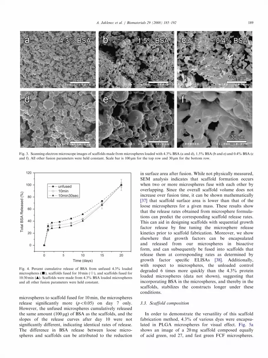
constant, the effect of protein loading on the extent offusion was studied (Fig. 3). Ten milligrams of microspheresloaded with 4.3% BSA (Fig. 3a and d), 1.5% BSA (Fig. 3band e) and 0.4% BSA (Fig. 3c and f) were all fused for9min. As evidenced by SEM analysis, under theseconditions the microspheres containing the least amountof BSA fused the most while those with the highest amountof BSA fused the least, showing that when fusion time andmass are held constant, the fusion process is morepronounced for samples with less BSA. This phenomenonis not a function of the amorphous PLGA and the low Tg,but of the BSA, which may be more ordered and acts asreinforcement for the soft microspheres, thus requiring
90%o (mm)
17.3
14.3
16.1
19.6

ARTICLE IN PRESS
Fig. 1. Scanning electron microscope images of microspheres fused for 0 (a), 3:30 (b), 4:00 (c), 4:15 (d), 4:30 (e) and 5:00 (f) minutes. Microsphere
composition (4.3% BSA), mass (2mg) and fusion conditions were held constant. Scale bar is 30mm, except (f) is 120mm.
Fig. 2. Scanning electron micrographs of optimal scaffolds where microsphere mass and fusion time was varied. Fusion time (min) and mass (mg) are (a)
4:00/2, (b) 9:00/10, (c) 10:30/20, respectively. All scaffolds were made from 4.3% BSA-loaded microspheres. Scale bar is 30 mm.
A. Jaklenec et al. / Biomaterials 29 (2008) 185–192188
more vapor for fusion. In this case, the polymer glasstransition temperature does not differ across the 0.4%,1.5% and 4.3% BSA loaded microspheres, however thevapor needed to cause fusion over the entire structure(polymer plus BSA) does increase. Also, the secondaryinteractions between the PLGA (-COOH terminated) andBSA chins could contribute to microsphere stability, thusrequiring more vapor to soften the microsphres and allowfor chain movement between the spheres [36].
Overall, the fusion time was found to be a controllingfactor in the fabrication of these scaffolds. The extent offusion displayed by the scaffolds increased as the amountof fusion time increased. The amount of fusion timerequired for optimum scaffold morphology also increasedwith increased protein loading and increased microspheremass.
3.2. Protein release from scaffolds
To evaluate the effect of the fusion process on proteinrelease rates, we compared BSA released from scaffoldswith unfused microspheres (Fig. 4). Release from twotypes of scaffolds was studied, one fused for 10min andone for 10:30min. Over the 20-day study, the BSA releasedwas not significantly different between the scaffolds(p40.05 for all time points), indicating that increasingfusion time by 30 s does not affect scaffold release eventhough it could significantly alter scaffold morpho-logy (Fig. 1). Comparing BSA release between loosemicrospheres and scaffold fused for 10:30min, we see thatfor the first week of release (time points day 1, 2, 4 and 7)there is significantly higher release (po0.05) for theloose microspheres. In addition, when comparing loose
ARTICLE IN PRESS
Fig. 3. Scanning electron microscope images of scaffolds made from microspheres loaded with 4.3% BSA (a and d), 1.5% BSA (b and e) and 0.4% BSA (c
and f). All other fusion parameters were held constant. Scale bar is 100mm for the top row and 30mm for the bottom row.
Fig. 4. Percent cumulative release of BSA from unfused 4.3% loaded
microspheres (’), scaffolds fused for 10min (B), and scaffolds fused for
10:30min (m). Scaffolds were made from 4.3% BSA loaded microspheres
and all other fusion parameters were held constant.
A. Jaklenec et al. / Biomaterials 29 (2008) 185–192 189
microspheres to scaffold fused for 10min, the microspheresrelease significantly more (po0.05) on day 7 only.However, the unfused microspheres cumulatively releasedthe same amount (100 mg) of BSA as the scaffolds, and theslopes of the release curves after day 10 were notsignificantly different, indicating identical rates of release.The difference in BSA release between loose micro-spheres and scaffolds can be attributed to the reduction
in surface area after fusion. While not physically measured,SEM analysis indicates that scaffold formation occurswhen two or more microspheres fuse with each other byoverlapping. Since the overall scaffold volume does notincrease over fusion time, it can be shown mathematically[37] that scaffold surface area is lower than that of theloose microspheres for a given mass. These results showthat the release rates obtained from microsphere formula-tions can predict the corresponding scaffold release rates.This can aid in designing scaffolds with sequential growthfactor release by fine tuning the microsphere releasekinetics prior to scaffold fabrication. Moreover, we showelsewhere that growth factors can be encapsulatedand released from our microspheres in bioactiveform, and can subsequently be fused into scaffolds thatrelease them at corresponding rates as determined bygrowth factor specific ELISAs [38]. Additionally,with respect to microspheres, the unloaded controldegraded 6 times more quickly than the 4.3% proteinloaded microspheres (data not shown), suggesting thatincorporating BSA in the microspheres, and thereby in thescaffolds, stabilizes the constructs longer under theseconditions.
3.3. Scaffold composition
In order to demonstrate the versatility of this scaffoldfabrication method, 4.3% of various dyes were encapsu-lated in PLGA microspheres for visual effect. Fig. 5ashows an image of a 20mg scaffold composed equallyof acid green, red 27, and fast green FCF microspheres.

ARTICLE IN PRESS
Fig. 5. Microspheres loaded with dyes fused into scaffolds after mixing acid green, red 27, and fast green FCF containing microspheres together (a) and
after positioning carbon black, acid green, red 27, and fast green FCF microspheres clockwise into 4 sections (b).
Fig. 6. Scanning electron microscope images of (a) small (11.15711.08mm) and (b) large (113.3758.0mm) microspheres and the resulting scaffolds after
fusion (c) and (d), respectively. Scale bars are 50mm.
A. Jaklenec et al. / Biomaterials 29 (2008) 185–192190
The colored microspheres were mixed with a spatula andfused into a scaffold containing a well-dispersed lavendercolored distribution. Some minor color aggregation doesoccur throughout the scaffold, but this can be remediedwith mechanical mixing and reduced static. In Fig. 5b,4.3% dye loaded microspheres were fused in a pie chart likearrangement. This produced a scaffold with spatiallydistinct regions of carbon black (Fig. 5b, clockwise), acidgreen, red 27, and fast green FCF. These results indicatejust how malleable these scaffolds are, as they can containanything that can be encapsulated within microspheres.Thus, the spatial distribution and composition of micro-spheres can be controlled within the 3D scaffold, which hasbeen shown to be important for controlled angiogenesis[39]. Furthermore, various polymers can be fused such ascapped PLGA, uncapped PLGA and PLLA (data notshown), allowing for additional control over scaffolddegradation.
3.4. Cell attachment to scaffolds
A requirement of scaffold design for tissue engineeringapplications is allowing enough void volume for cellseeding and proliferation prior to scaffold degradation, inaddition to using biocompatible materials. The datapresented above was obtained with relatively small sizedmicrospheres (see Table 1), which after fusion resulted inscaffolds of about 20 mm pores. In order to increase the sizeof the microspheres we changed the co-solvent ratio(CH2Cl2:TFE) of the organic phase in the SE methodfrom 1:4 to 3:2, yielding relatively small (11.15711.08 mm)and large (113.3758.0 mm) microspheres, respectively(Fig. 6a and b). These microspheres were subsequentlyfused into scaffolds, as shown in Fig. 6c and d for 8 and10:30min, respectively. The different fusion times werenecessary in order to obtain optimally fused scaffolds sincesmaller microspheres fuse into scaffolds faster than larger

ARTICLE IN PRESS
Fig. 7. Scanning electron microscope images of scaffolds alone (a and b) and seeded with fibroblast cells (c, d and e). Scale bars are (a and c) 300 mm, (b
and d) 100mm and (e) 37.5mm.
A. Jaklenec et al. / Biomaterials 29 (2008) 185–192 191
ones. This is attributed to the fact that for constant massthere is less surface area available for larger microspheresas compared to smaller ones per scaffold. Therefore, moretime is needed with larger microspheres for dichloro-methane vapor to diffuse into the microspheres and softenthe polymer enough allowing chain movement to occur.The pores within the scaffolds made of small and largespheres are on the order of 20 and 200 mm, respectively.This indicates that by increasing the mean microsphere sizetenfold, the resultant scaffold pore sizes can be increasedby the same factor. The mechanism here is most likelysimilar to that of sintering [40,41], where particles of largesize distributions lead to more porous structure because thelarge microspheres tend to engulf smaller ones, thusgenerating larger pores between particles. This phenomen-on introduces even more flexibility into the scaffoldfabrication method by allowing for control over scaffoldpore size.
In order to test the ability of these scaffolds to act as cellcarriers, a cell attachment study was performed on scaffoldsmade from large microspheres (113.3758.0mm). Fibroblastcells were seeded onto pre-wetted scaffolds and, after 4 h ofincubation, cell attachment was evaluated by SEM. Fig. 7shows SEM images of both empty and seeded scaffolds. Thecells are attached across the entire scaffold surface and somehave formed bridges across the pores (Fig. 7c and d). Inaddition, cells also penetrated and attached well inside thepores (Fig. 7e). Flat cell morphology is prevalent amongcells attached directly to the polymer surface (Fig. 7e), whilethe balled-like appearance is present in cells residing on topof other fibroblasts. These images show that the scaffolds
are favorable to cell attachment and are compatible with thefibroblast cells used for this experiment.
4. Conclusion
We have developed a novel and simple vapor fusionmethod for generating 3D scaffolds from protein-loadedmicrospheres. We have successfully shown that by varyingprocess parameters we can control scaffold morphology,composition, spatial distribution, pore size, and proteinrelease kinetics. The versatility of these scaffolds to carrycells and contain essentially any number/combination ofloaded microsphere makes them strong candidates for usein tissue engineering applications and therapeutic localizeddrug delivery.
Acknowledgments
The authors would like to thank Dr. Moses Goddard fortaking the digital photographs and Dr. Bahar Bilgen forediting the manuscript. This work was supported in partby the Vice President of Research Seed Grant, BrownUniversity.
References
[1] Langer R, Vacanti JP. Tissue engineering. Science 1993;260(5110):
920–6.
[2] Lee KY, Peters MC, Anderson KW, Mooney DJ. Controlled growth
factor release from synthetic extracellular matrices. Nature 2000;
408(6815):998–1000.
ARTICLE IN PRESSA. Jaklenec et al. / Biomaterials 29 (2008) 185–192192
[3] Levenberg S, Huang NF, Lavik E, Rogers AB, Itskovitz-Eldor J,
Langer R. Differentiation of human embryonic stem cells on three-
dimensional polymer scaffolds. Proc Natl Acad Sci USA 2003;
100(22):12741–6.
[4] Teng YD, Lavik EB, Qu X, Park KI, Ourednik J, Zurakowski D,
et al. Functional recovery following traumatic spinal cord injury
mediated by a unique polymer scaffold seeded with neural stem cells.
Proc Natl Acad Sci USA 2002;99(5):3024–9.
[5] Frenkel SR, Di Cesare PE. Scaffolds for articular cartilage repair.
Ann Biomed Eng 2004;32(1):26–34.
[6] Hunziker EB. Articular cartilage repair: basic science and clinical
progress. A review of the current status and prospects. Osteoarthritis
Cartilage 2002;10(6):432–63.
[7] Tabata Y. Tissue regeneration based on growth factor release. Tissue
Eng 2003;9(Suppl 1):S5–S15.
[8] Caplan AI, Elyaderani M, Mochizuki Y, Wakitani S, Goldberg VM.
Principles of cartilage repair and regeneration. Clin Orthop Relat Res
1997(342):254–69.
[9] Camarata PJ, Suryanarayanan R, Turner DA, Parker RG, Ebner TJ.
Sustained release of nerve growth factor from biodegradable polymer
microspheres. Neurosurgery 1992;30(3):313–9.
[10] DeFail AJ, Chu CR, Izzo N, Marra KG. Controlled release of
bioactive TGF-beta 1 from microspheres embedded within biode-
gradable hydrogels. Biomaterials 2006;27(8):1579–85.
[11] Edelman ER, Mathiowitz E, Langer R, Klagsbrun M. Controlled
and modulated release of basic fibroblast growth factor. Biomaterials
1991;12(7):619–26.
[12] Hosseinkhani H, Hosseinkhani M, Khademhosseini A, Kobayashi H,
Tabata Y. Enhanced angiogenesis through controlled release of basic
fibroblast growth factor from peptide amphiphile for tissue regenera-
tion. Biomaterials 2006;27(34):5836–44.
[13] Kawai K, Suzuki S, Tabata Y, Ikada Y, Nishimura Y. Accelerated
tissue regeneration through incorporation of basic fibroblast growth
factor-impregnated gelatin microspheres into artificial dermis.
Biomaterials 2000;21(5):489–99.
[14] Miyamoto S, Takaoka K, Okada T, Yoshikawa H, Hashimoto J,
Suzuki S, et al. Polylactic acid-polyethylene glycol block copolymer.
A new biodegradable synthetic carrier for bone morphogenetic
protein. Clin Orthop Relat Res 1993(294):333–43.
[15] Richardson TP, Peters MC, Ennett AB, Mooney DJ. Polymeric system
for dual growth factor delivery. Nat Biotechnol 2001;19(11):1029–34.
[16] Yuksel E, Weinfeld AB, Cleek R, Jensen J, Wamsley S, Waugh JM, et
al. Augmentation of adipofascial flaps using the long-term local
delivery of insulin and insulin-like growth factor-1. Plast Reconstr
Surg 2000;106(2):373–82.
[17] Yuksel E, Weinfeld AB, Cleek R, Wamsley S, Jensen J, Boutros S,
et al. Increased free fat-graft survival with the long-term, local
delivery of insulin, insulin-like growth factor-I, and basic fibroblast
growth factor by PLGA/PEG microspheres. Plast Reconstr Surg
2000;105(5):1712–20.
[18] Kim K, Fisher JP. Nanoparticle technology in bone tissue engineer-
ing. J Drug Target 2007;15(4):241–52.
[19] Na K, Kim SW, Sun BK, Woo DG, Yang HN, Chung HM, et al.
Osteogenic differentiation of rabbit mesenchymal stem cells in
thermo-reversible hydrogel constructs containing hydroxyapatite
and bone morphogenic protein-2 (BMP-2). Biomaterials 2007;28(16):
2631–7.
[20] Ma PX, Elisseeff JH. Scaffolding in tissue engineering. Boca Raton:
Taylor & Francis; 2005.
[21] Aebischer P, Salessiotis AN, Winn SR. Basic fibroblast growth factor
released from synthetic guidance channels facilitates peripheral nerve
regeneration across long nerve gaps. J Neurosci Res 1989;23(3):282–9.
[22] Arm DM, Tencer AF, Bain SD, Celino D. Effect of controlled release
of platelet-derived growth factor from a porous hydroxyapatite
implant on bone in growth. Biomaterials 1996;17(7):703–9.
[23] DeBlois C, Cote MF, Doillon CJ. Heparin-fibroblast growth factor-
fibrin complex: in vitro and in vivo applications to collagen-based
materials. Biomaterials 1994;15(9):665–72.
[24] Heckman JD, Boyan BD, Aufdemorte TB, Abbott JT. The use of
bone morphogenetic protein in the treatment of non-union in a
canine model. J Bone Joint Surg Am 1991;73(5):750–64.
[25] Hong L, Tabata Y, Yamamoto M, Miyamoto S, Yamada K,
Hashimoto N, et al. Comparison of bone regeneration in a rabbit
skull defect by recombinant human BMP-2 incorporated in
biodegradable hydrogel and in solution. J Biomater Sci Polym Ed
1998;9(9):1001–14.
[26] Lee M, Chen TT, Iruela-Arispe ML, Wu BM, Dunn JC. Modulation
of protein delivery from modular polymer scaffolds. Biomaterials
2007;28(10):1862–70.
[27] Nillesen ST, Geutjes PJ, Wismans R, Schalkwijk J, Daamen WF, van
Kuppevelt TH. Increased angiogenesis and blood vessel maturation
in acellular collagen-heparin scaffolds containing both FGF2 and
VEGF. Biomaterials 2007;28(6):1123–31.
[28] Ozeki M, Ishii T, Hirano Y, Tabata Y. Controlled release of
hepatocyte growth factor from gelatin hydrogels based on hydrogel
degradation. J Drug Target 2001;9(6):461–71.
[29] Park YJ, Lee YM, Park SN, Sheen SY, Chung CP, Lee SJ. Platelet
derived growth factor releasing chitosan sponge for periodontal bone
regeneration. Biomaterials 2000;21(2):153–9.
[30] Ripamonti U, Bosch C, van den Heever B, Duneas N, Melsen B,
Ebner R. Limited chondro-osteogenesis by recombinant human
transforming growth factor-beta 1 in calvarial defects of adult
baboons (Papio ursinus). J Bone Miner Res 1996;11(7):938–45.
[31] Stewart K, Pabbruwe M, Dickinson S, Sims T, Hollander AP,
Chaudhuri JB. The effect of growth factor treatment on meniscal
chondrocyte proliferation and differentiation on polyglycolic acid
scaffolds. Tissue Eng 2007;13(2):271–80.
[32] Tabata Y, Miyao M, Ozeki M, Ikada Y. Controlled release of
vascular endothelial growth factor by use of collagen hydrogels.
J Biomater Sci Polym Ed 2000;11(9):915–30.
[33] Takaoka K, Koezuka M, Nakahara H. Telopeptide-depleted bovine
skin collagen as a carrier for bone morphogenetic protein. J Orthop
Res 1991;9(6):902–7.
[34] Reed AM, Gilding DK. Biodegradable polymers for use in surgery-
poly(lactic)/poly(glycolic acid) homo and copolymers: 2. In vitro
degradation. Polymer 1981;22:494–8.
[35] Fu K, Harrell R, Zinski K, Um C, Jaklenec A, Frazier J, et al. A
potential approach for decreasing the burst effect of protein from
PLGA microspheres. J Pharm Sci 2003;92(8):1582–91.
[36] Ageorges C, Ye L, Hou M. Advances in fusion bonding techniques
for joining thermoplastic matrix composites: a review. Composites:
Part A: Appl Sci Manuf 2001;32:839–57.
[37] Eggers J. Coalescence of spheres by surface diffusion. Phys Rev Lett
1998;80(12):2634–7.
[38] Jaklenec A, Hinckfuss A, Ciombor DM, Aaron R, Mathiowitz E.
Sequential release from PLGA scaffolds fused from bioactive IGF-I
and TGF-b1 microspheres. Biomaterials 2007; under review.
[39] Chen RR, Silva EA, Yuen WW, Mooney DJ. Spatio-temporal VEGF
and PDGF delivery patterns blood vessel formation and maturation.
Pharmaceut Res 2007;24(2):258–64.
[40] Wang YU. Computer modeling and simulation of solid-state
sintering: a phase field approach. Acta Mater 2006;54:953–61.
[41] Kingery WD, Bowen HK, Uhlmann DR. Introduction to ceramics.
2nd ed. New York: Wiley; 1976.