next generation flight management systems for manned and
TRANSCRIPT
Next Generation Flight Management
Systems for Manned and
Unmanned Aircraft Operations
Automated Separation Assurance and
Collision Avoidance Functionalities
A thesis submitted in fulfilment of the requirements for the degree of
Doctor of Philosophy (Aerospace Engineering)
Subramanian Ramasamy, MEng
Supervisors:
Professor Roberto Sabatini
Dr Reece Clothier
School of Engineering
College of Science, Engineering and Health
RMIT University
February 2017

ii
This page is intentionally left blank to support presswork tasks

iii
Declaration
I certify that except where due acknowledgement has been made, this work
is that of the author alone; this work has not been submitted previously, in
whole or in part, to qualify for any other academic award; the content of this
thesis is the result of work, which has been carried out since the official
commencement date of the approved research program; any editorial
work, paid or unpaid, carried out by a third party is acknowledged; and,
ethics procedures and guidelines have been followed.
I acknowledge the support I have received for my research through the
provision of an Australian Government Research Training Program
Scholarship.
Subramanian Ramasamy
20 February 2017
iv
“The desire to fly is an idea handed
down to us by our ancestors who, in
their gruelling travels across trackless
lands in prehistoric times, looked
enviously on the birds soaring freely
through space, at full speed, above all
obstacles, on the infinite highway of
the air”. - Wilbur Wright

v
Acknowledgements
First and foremost, I want to express my sincere gratitude and admiration to
my primary supervisor Professor Roberto (Rob) Sabatini for nurturing me in line
with one of Albert Einstein’s quotes that reads “It is the supreme art of the
teacher to awaken joy in creative expression and knowledge”. Following the
anecdote “to perceive innovation as an extension of an ardent imagination
leading to profound excellence and deep satisfaction towards the benefit of
mankind”, I wholeheartedly thank Prof Rob Sabatini for his infinite insights and
encouragement throughout my doctoral work.
The support I received from my secondary advisor, Dr Reece Clothier has
been extremely important throughout my research work at RMIT University.
Many thanks to the Higher Degrees by research (HDR) milestone review panel
committee members for their constructive feedback. The scientific quest and
support that I always received from my fellow research colleagues and
compadres: Dr Alessandro G.M. Gardi, Dr Matthew Marino, Mr Francesco
Cappello, Ms Jing Liu, Mr Yixiang Lim, Mr Suraj Bijjahalli, Mr Rohan Kapoor, Mrs
Eranga Batuwangala and Mr Lanka Bogoda (RMIT University), and others at
Cranfield University (UK), has been highly instrumental during my doctoral
work. I would like to thank wholeheartedly the THALES Australia CASiA
collaborators including Mr Trevor Kistan, Mr Mark O'Flynn and Mr Philippe
Bernard-Flattot as well as RMIT Intelligent and Cyber-Physical Transport
Systems (ICTS) research group’s members. I take this opportunity to
acknowledge the financial support offered by the School of Engineering,
RMIT University and the Government of Australia through the Endeavour
International Postgraduate Research Scholarship and Australian
Postgraduate Award. I extend my impeccable gratitude to the technical and
administrative staff including Mrs Lina Bubic, Mrs Jeneffer Thompson and
Mrs Emilija Simic. Above all, I dedicate this work to my parents, Prof A.M.S.
Ramasamy and Mrs Girija Ramasamy for opening innumerable doors in me
into the world of science and technology from my childhood.
vi
Summary
The demand for improved safety, efficiency and dynamic demand-capacity
balancing due to the rapid growth of the aviation sector and the increasing
proliferation of Unmanned Aircraft Systems (UAS) in different classes of
airspace pose significant challenges to avionics system developers.
The design of Next Generation Flight Management Systems (NG-FMS) for
manned and unmanned aircraft operations is performed by addressing the
challenges identified by various Air Traffic Management (ATM) modernisation
programmes and UAS Traffic Management (UTM) system initiatives. In
particular, this research focusses on introducing automated Separation
Assurance and Collision Avoidance (SA&CA) functionalities (mathematical
models) in the NG-FMS. The innovative NG-FMS is also capable of supporting
automated negotiation and validation of 4-Dimensional Trajectory (4DT)
intents in coordination with novel ground-based Next Generation Air Traffic
Management (NG-ATM) systems.
One of the key research contributions is the development of a unified
method for cooperative and non-cooperative SA&CA, addressing the
technical and regulatory challenges of manned and unmanned aircraft
coexistence in all classes of airspace. Analytical models are presented and
validated to compute the overall avoidance volume in the airspace
surrounding a tracked object, supporting automated SA&CA functionalities.
The scientific basis of this approach is to assess real-time measurements and
associated uncertainties affecting navigation states (of the host aircraft
platform), tracking observables (of the static or moving object) and platform
dynamics, and translate them to unified range and bearing uncertainty
descriptors. The SA&CA unified approach provides an innovative analytical
framework to generate high-fidelity dynamic geo-fences suitable for
integration in the NG-FMS and in the ATM/UTM/defence decision
support tools.
vii
Table of Contents
Declaration ................................................................................................................... iii
Acknowledgements .................................................................................................... v
Summary ....................................................................................................................... vi
List of Figures .............................................................................................................. xiv
List of Tables ................................................................................................................ xx
List of Abbreviations .................................................................................................. xxii
1. Introduction
1.1 Research Context and Motivation ............................................................ 1
1.2 Research Gap Identification ...................................................................... 8
1.3 Research Questions...................................................................................... 8
1.4 Research Aim ................................................................................................ 9
1.5 Research Objectives .................................................................................... 9
1.6 Research Methodology ............................................................................... 9
1.7 Thesis Outline ............................................................................................... 11
1.8 References................................................................................................... 12
2. Literature Review
2.1 Introduction ................................................................................................. 15
2.2 Avionics and ATM System Modernisation ............................................... 15
2.3 Flight Management Systems ..................................................................... 18
2.4 Maintenance of Separation ..................................................................... 29
2.4.1 Airspace Categories and Classes ............................................................ 29
2.4.2 Rules of Air ................................................................................................... 30
viii
2.4.3 General Operation Principles and Flight Rules ...................................... 31
2.4.4 Separation Standards ................................................................................ 33
2.5 Collision Detection and Avoidance ........................................................ 34
2.5.1. Conflict Detection and Resolution Approaches ................................... 40
2.5.2. Theoretical Techniques for CD&R ............................................................ 41
2.5.3. Applied/Implemenetd Air Traffic Solutions for CD&R ........................... 43
2.6 SA&CA Technologies ................................................................................. 45
2.6.1 State-of-the-art SA Technologies ............................................................. 43
2.6.2 State-of-the-art SA supported by an ATM System ................................. 60
2.6.3 CA Sensors/Systems .................................................................................... 62
2.6.4 Attributes/Capbilities of UAS SA&CA Technologies .............................. 63
2.7 Tracking, Decision-Making and Avoidance Loop................................. 65
2.7.1 TDA Functions .............................................................................................. 66
2.8 Multi-Sensor Data Fusion Algorithms for SA&CA .................................... 68
2.9 UTM System .................................................................................................. 78
2.10 Dependency on LoS and BLoS Communications ................................. 86
2.11 Towards Higher Levels of Autonomy ....................................................... 87
2.12 SA&CA Requirements ................................................................................ 89
2.13 Research on SA&CA Avoidance Volumes ............................................. 91
2.14 Case for a Unified Approach to SA&CA ................................................ 94
2.15 Conclusions ................................................................................................. 97
2.16 References................................................................................................... 97
3. Next Generation Flight Management Systems
3.1 Introduction ............................................................................................... 109
3.2 NG-FMS and NG-ATM Systems ............................................................... 109
ix
3.3 System Requirements and New Functions ........................................... 117
3.4 NG-FMS Architecture ............................................................................... 122
3.5 NG-FMS Algorithms ................................................................................... 129
3.6 System State Error Analysis ...................................................................... 135
3.7 CNS Performance ..................................................................................... 138
3.8 NG-FMS Case Studies ............................................................................... 139
3.8.1 Platforms .................................................................................................... 139
3.8.2 Long-haul Flight ......................................................................................... 142
3.8.3 Medium-haul Flight ................................................................................... 146
3.8.4 UAS .............................................................................................................. 148
3.9 Negotiation and Validation Features .................................................... 150
3.9.1 Evaluation Process .................................................................................... 150
3.10 Conclusions ............................................................................................... 152
3.11 References................................................................................................. 153
4. Separation Assurance and Collision Avoidance Functionalities
4.1 Introduction ............................................................................................... 157
4.2 Unified Approach to SA&CA .................................................................. 157
4.3 Distinctiveness of an Unified Approach to SA&CA ............................. 169
4.4 Implementation in NG-FMS ..................................................................... 171
4.5 Conclusions ............................................................................................... 174
4.6 References................................................................................................. 175
5. Performance Analysis of SA&CA Functionalities
5.1 Introduction ............................................................................................... 177
5.2 Avoidance Volumes ................................................................................ 177
x
5.3 SA&CA Test Bed Architecture ................................................................ 178
5.4 Sensor/System Error Modelling ................................................................ 183
5.4.1 Test for Correlation ................................................................................... 188
5.4.2 Covariant and Contravariant Components ........................................ 190
5.4.3 Possible Cases ........................................................................................... 190
5.4.4 Effects of Data Size and Methodology ................................................. 191
5.4.5 Example: ADS-B Error Modelling ............................................................. 192
5.5 Sensor/System Error Modelling ................................................................ 197
5.5.1 Errors in Range ........................................................................................... 197
5.5.2 Errors in Bearing Measurements at a Given Range ............................ 199
5.5.3 Uncertainty in Velocity Measurements ................................................. 203
5.5.1 Wind and Wake Turbulence ................................................................... 204
5.6 Relative Dynamics between Platforms ................................................. 206
5.7 CNS Performance and Error Models ...................................................... 211
5.8 Avoidance Trajectory Optimisation ...................................................... 214
5.9 SA&CA Certification Framework ............................................................ 216
5.9.1 SA&CA Hardware and Software ............................................................ 217
5.9.2 Approach to Certification ...................................................................... 219
5.10 Conclusions ............................................................................................... 221
5.11 References................................................................................................. 221
6. Ground Obstacles SA&CA Case Study
6.1 Introduction ............................................................................................... 225
6.2 Ground Obstacle Detection and Warning Systems ........................... 225
6.3 UAS Obstacle Warning and Avoidance System ................................. 228
xi
6.4 Operational Requirements ..................................................................... 229
6.5 System Description ................................................................................... 230
6.6 Obstacle Detection and Classification Software ................................ 232
6.7 Mathematical Algorithms........................................................................ 234
6.8 Formats and Functions ............................................................................. 236
6.9 Simulation Case Study ............................................................................. 237
6.10 Conclusions ............................................................................................... 240
6.11 References................................................................................................. 240
7. Aerial Obstacles SA&CA Case Study
7.1 Introduction ............................................................................................... 243
7.2 Non-Cooperative SA&CA – FLS .............................................................. 243
7.3 Cooperative SA&CA – ADS-B ................................................................. 246
7.4 Simulation Case Studies ........................................................................... 249
7.4.1 Tracking and Detection Performance .................................................. 249
7.5 Conclusions ............................................................................................... 258
7.6 References................................................................................................. 258
8. Potential UAS Traffic Management Applications
8.1 Introduction ............................................................................................... 261
8.2 UTM System in the CNS+A Framework................................................... 261
8.3 Multi-UTM System ...................................................................................... 263
8.4 Pathways to Implementation ................................................................. 265
8.4.1 Multi-Platform Scenario ........................................................................... 265
8.4.2 TMA Environment ...................................................................................... 268
8.5 Simulation Case Studies ........................................................................... 271
xii
8.5.1 Geofences ................................................................................................. 275
8.5.1 Multi-Platform Coordination Scenario ................................................... 277
8.6 Conclusions ............................................................................................... 280
8.7 References................................................................................................. 280
9. Conclusions and Future Directions
9.1 Conclusions ............................................................................................... 283
9.1.1 Summary of Original Contributions ........................................................ 283
9.1.2 Achieved Research Objectives ............................................................. 285
9.2 Future Directions ....................................................................................... 289
Appendix A: UAS Integrated Navigation Systems
A.1 Introduction ............................................................................................... 295
A.2 Multi-sensor Data Fusion Techniques ..................................................... 295
A.3 Integrated Multi-sensor Data Fusion Architectures ............................. 300
A.4 Conclusions ............................................................................................... 302
A.5 References................................................................................................. 303
Appendix B: Certification Standards and Recommended Practices
B.1 Requirements ............................................................................................ 305
Appendix C: Elements of Human Machine Interface & Interactions
C.1 Introduction ............................................................................................... 309
C.2 Human Machine Interface and Interactions ....................................... 309
C.3 Formats and Functions for Automatic SA&CA ..................................... 313
C.4 Information Display ................................................................................... 317

xiii
C.5 Adaptive HMI2 ........................................................................................... 321
C.6 Conclusions ............................................................................................... 324
C.7 References................................................................................................. 324
Appendix D: List of Relevant Publications
D.1 Scientific Dissemination ........................................................................... 327
xiv
List of Figures
Figure 1.1. Combined objectives. ........................................................................ 2
Figure 1.2. Automated SA&CA tasks. ................................................................... 7
Figure 2.1. State-of-the-art FMS architecture. ................................................... 19
Figure 2.2. Waypoint types (a) fly-by and (b) fly-over..................................... 24
Figure 2.3. FMS guidance loop. .......................................................................... 25
Figure 2.4. FMS and AFCS interactions............................................................... 27
Figure 2.5. SA&CA system processes. ................................................................ 38
Figure 2.6. CATH, SSV and SST boundaries. ....................................................... 40
Figure 2.7. Trajectory prediction/estimation approaches. ............................. 42
Figure 2.8. Collision detection and resolution taxonomy. .............................. 42
Figure 2.9. Onboard collision avoidance system - early radar systems. ...... 46
Figure 2.10. Onboard collision avoidance system – BCAS. .............................. 46
Figure 2.11. Onboard collision avoidance system – TCAS. ............................... 46
Figure 2.12. Example of an encounter geometry. ............................................. 50
Figure 2.13. Limited robustness of TCAS. .............................................................. 51
Figure 2.14. Uncertainty propagation in ACAS. ................................................. 54
Figure 2.15. ACAS top-level architecture. ........................................................... 56
Figure 2.16. Functional component of ADS-B. .................................................... 57
Figure 2.17. Detection range of CA technologies for UAS. .............................. 65
Figure 2.18. Collision scenario at different time epochs. .................................. 67
Figure 2.19. GNC and TDA loops. ......................................................................... 68
Figure 2.20. SA&CA tasks........................................................................................ 68
Figure 2.21. Intelligent techniques for SA&CA MSDF. ........................................ 78
Figure 2.22. UTM system architecture. .................................................................. 79
Figure 2.23. UTM functions and stakeholders. ..................................................... 80
Figure 2.24. Role of SA&CA in UTM. ...................................................................... 83
Figure 2.25. UTM system concept - operational geographies. ........................ 85
Figure 2.26. Operational geographies of multiple UAS. .................................... 86
Figure 2.27. Well-clear threshold. .......................................................................... 93
Figure 2.28. Well-clear based confliction detection method. ......................... 93
xv
Figure 2.29. Number of SA&CA research gaps identified. ............................... 95
Figure 3.1. 4DT intent negotiation and validation. ......................................... 112
Figure 3.2. 4-PNV system initiated intent negotiation/validation loop. ...... 115
Figure 3.3. NG-FMS initiated intent negotiation/validation loop. ................ 115
Figure 3.4. SESAR trajectory management concept. ................................... 116
Figure 3.5. Multi-criteria departure procedure. .............................................. 118
Figure 3.6. Multi-criteria departure procedure. .............................................. 119
Figure 3.7. Continuous descent approach procedure. ................................ 120
Figure 3.8. NG-FMS and NG-ATM system interactions. .................................. 122
Figure 3.9. NG-FMS integrity monitor. ............................................................... 124
Figure 3.10. NG-FMS overall architecture. ......................................................... 125
Figure 3.11. NG-FMS 4DT planner and optimiser. ............................................. 126
Figure 3.12. NG-FMS integrity flag generation. ................................................. 126
Figure 3.13. NG-FMS performance management. .......................................... 127
Figure 3.14. CNS+A systems. ................................................................................ 128
Figure 3.15. RTSP elements and time frames. ................................................... 138
Figure 3.16. Airbus A380. ...................................................................................... 139
Figure 3.17. Airbus A320. ...................................................................................... 140
Figure 3.18. AEROSONDETM UAS. ......................................................................... 141
Figure 3.19. 4D trajectories................................................................................... 144
Figure 3.20. Climb Phase 4D Trajectory Intents. ................................................ 145
Figure 3.21. Cruise Phase 4D Trajectory Intents. ............................................... 145
Figure 3.22. Simulated set of 4DT intents. ........................................................... 146
Figure 3.23. 4D trajectory deviations. ................................................................. 147
Figure 3.24. Results of the 4DT optimisation for climb phase. ......................... 149
Figure 3.25. Results of the 4DT optimisation for descent phase. .................... 149
Figure 3.26. NG-FMS air-to-ground and air-to-air negotiation loops. ............ 150
Figure 3.27. NG-FMS and NG-ATM system negotiation and validation. ....... 152
Figure 4.1. Navigation and tracking error ellipsoids. ..................................... 158
Figure 4.2. Uncertainty volume (uncorrelated errors). .................................. 160
Figure 4.3. Uncertainty volumes obtained from range only errors. ............. 161
xvi
Figure 4.4. Combination of navigation and tracking errors. ........................ 161
Figure 4.5. Uncertainty volume due to error in bearing measurements. ... 163
Figure 4.6. Avoidance volumes at different time epochs. ........................... 163
Figure 4.7. Avoidance volumes at time of collision. ...................................... 164
Figure 4.8. Considered avoidance volume. ................................................... 168
Figure 4.9. Real function after parameterisation. .......................................... 168
Figure 4.10. Complex function after parameterisation. .................................. 169
Figure 4.11. NG-FMS architecture including SA&CA functions. ..................... 172
Figure 4.12. SA&CA software functional architecture. ................................... 172
Figure 4.13. Surveillance data processing. ........................................................ 173
Figure 4.14. Interactions within the NG-FMS. ..................................................... 174
Figure 5.1. Reconfigurable UAS SA&CA test bed architecture. .................. 180
Figure 5.2. FTA for autonomous decision-making tasks. ............................... 181
Figure 5.3. Error and radar ranges. ................................................................... 190
Figure 5.4. Error and reference ranges. ........................................................... 194
Figure 5.5. {σx_N, σy_N, σz_N} = 3, 2, 4 and {σx_T, σy_T, σz_T} = 8, 12, 3. ... 197
Figure 5.6. {σx_N, σy_N, σz_N} = 6, 2, 4 and {σx_T, σy_T, σz_T} = 8, 12, 3. ... 197
Figure 5.7. {σx_N, σy_N, σz_N} = 3, 8, 4 and {σx_T, σy_T, σz_T} = 8, 12, 3. ... 198
Figure 5.8. {σx_N, σy_N, σz_N} = 3, 2, 6 and {σx_T, σy_T, σz_T} = 8, 12, 3. ... 198
Figure 5.9. {σx_N, σy_N, σz_N} = 3, 2, 4 and {σx_T, σy_T, σz_T} = 3, 12, 3. ... 198
Figure 5.10. {σx_N, σy_N, σz_N} = 3, 2, 4 and {σx_T, σy_T, σz_T} = 8, 5, 3. ..... 199
Figure 5.11. {σx_N, σy_N, σz_N} = 3, 2, 4 and {σx_T, σy_T, σz_T} = 8, 12, 1. ... 199
Figure 5.12. Covariant case. ............................................................................... 200
Figure 5.13. Contravariant case. ........................................................................ 201
Figure 5.14. Effect of correlation coefficient. ................................................... 201
Figure 5.15. Errors in azimuth/elevation measurements = 35 degrees. ......... 202
Figure 5.16. Errors in azimuth/elevation measurements = 35 degrees. ......... 202
Figure 5.17. Errors in azimuth/elevation measurements = 10 degrees. ......... 203
Figure 5.18. Uncertainty in velocity = 7 m/sec. ................................................. 204
Figure 5.19. Uncertainty in velocity = 3 m/sec. ................................................. 205
Figure 5.20. Illustration of a conflict event. ........................................................ 206
xvii
Figure 5.21. Obtained resolution. ........................................................................ 208
Figure 5.22. Two objects in a collision course. .................................................. 208
Figure 5.23. Collision scenario. ............................................................................ 209
Figure 5.24. Navigation and surveillance sensors/systems. ............................ 212
Figure 5.25. Illustration of a collision detection & resolution mechanism. .... 213
Figure 5.26. Role of CNS performance and error models. .............................. 213
Figure 5.27. FAA FoR (a) and a possible sensors’ installation (b). .................. 218
Figure 5.28. NG-FMS hardware and software interface. ................................ 219
Figure 5.29. Two-way approach to certification. ............................................. 220
Figure 6.1. LOWAS FOV. ..................................................................................... 230
Figure 6.2. LOWAS scan pattern for a slowly advancing platform. ............ 231
Figure 6.3. LOWAS avionics integration architecture for UAS. ..................... 232
Figure 6.4. LOWAS signal processing software architecture. ....................... 233
Figure 6.5. Target sections. ................................................................................ 236
Figure 6.6. Obstacle avoidance scenario. ..................................................... 238
Figure 6.7. Case study scenario. ....................................................................... 238
Figure 6.8. Results of the avoidance trajectory generation algorithm. ...... 239
Figure 7.1. Acquired and stabilised visual image. ......................................... 244
Figure 7.2. Tracked object. ................................................................................ 244
Figure 7.3. Acquired thermal image and tracked object. ........................... 245
Figure 7.4. Measured and estimated X position. ............................................ 250
Figure 7.5. Measured and estimated Y position. ............................................ 250
Figure 7.6. Measured and estimated Z position. ............................................ 251
Figure 7.7. Acquired thermal image and tracked object. ........................... 251
Figure 7.8. MSE in X, Y and Z. ............................................................................. 252
Figure 7.9. MSE in X, Y and Z. ............................................................................. 252
Figure 7.10. Conflict probability. ......................................................................... 253
Figure 7.11. Real and required separation. ....................................................... 253
Figure 7.12. Avoidance volume at time of conflict. ........................................ 254
Figure 7.13. Conflict scenario. ............................................................................. 255
Figure 7.14. Range and bearing data. .............................................................. 255
xviii
Figure 7.15. Real and required separation. ....................................................... 256
Figure 7.16. Range and bearing data. .............................................................. 256
Figure 7.17. Avoidance of other traffic by host aircraft platform.................. 257
Figure 8.1. UTM system concept. ...................................................................... 262
Figure 8.2. UTM and surveillance nodes. ......................................................... 264
Figure 8.3. Multi-platform scenario. .................................................................. 267
Figure 8.4. Deconfliction scenario in the TMA. ............................................... 269
Figure 8.5. Fully autonomous deconfliction scenario in the TMA. ............... 270
Figure 8.6. Simulated urban environment. ...................................................... 271
Figure 8.7. Simulated urban environment in MATLABTM. .............................. 272
Figure 8.8. Vertices of imported objects. ........................................................ 272
Figure 8.9. Simulated urban environment in MATLABTM (3D). ..................... 273
Figure 8.10. Simulated urban environment in MATLABTM (2D). ..................... 273
Figure 8.11. UAV and the current FoV. .............................................................. 274
Figure 8.12. Optimised trajectory of the unmanned aircraft. ........................ 275
Figure 8.13. Avoidance of a ground obstacle geofence. ............................. 276
Figure 8.14. Avoidance of an aerial obstacle geofence. .............................. 277
Figure 8.15. Multi-platform coordination sceanario. ....................................... 277
Figure 8.16. Horizontal and vertical resolution – intruder 1. ............................ 278
Figure 8.17. Horizontal and vertical resolution – intruder 2. ............................ 278
Figure 8.18. Horizontal and vertical resolution – intruder 3. ............................ 279
Figure 8.19. Re-optimised host platform trajectory. ......................................... 279
Figure A.1. Multi-sensor data fusion process. ................................................... 296
Figure C.1. CDTI display showing other traffic. ................................................ 315
Figure C.2. PFD display showing resolution information. ................................ 316
Figure C.3. CDTI display showing resolution information. .............................. 316
Figure C.4. Case 1 - Detection of wires and an extended structure. .......... 318
Figure C.5. CDTI - Case 1. ................................................................................... 318
Figure C.6. Case 1 - Detection of wires and an extended structure. .......... 319
Figure C.7. TID - Case 2. ...................................................................................... 319
Figure C.8. Case 3 - Detection of wires and an extended structure. .......... 320
xix
Figure C.9. TID - Case 3. ...................................................................................... 320
Figure C.10. Adaptive HMI2 architecture. .......................................................... 321
Figure C.11. Adaptive HMI2 integration in the NG-FMS. .................................. 322
xx
List of Tables
Table 2.1. State-of-the-art FMS functions.......................................................... 22
Table 2.2. Waypoint categories. ........................................................................ 23
Table 2.3. Lateral guidance modes. ................................................................. 25
Table 2.4. Vertical guidance modes. ............................................................... 26
Table 2.5. ICAO separation standards. ............................................................ 34
Table 2.6. SA&CA core capabilities. ................................................................. 36
Table 2.7. SA&CA crosscutting capabilities. .................................................... 37
Table 2.8. ACAS X variants. ................................................................................. 55
Table 2.9. Airborne surveillance systems. ......................................................... 60
Table 2.10. Classification of autonomy levels .................................................... 88
Table 2.11. Research gaps for SA&CA................................................................ 96
Table 3.1. Performance weighting layout. ..................................................... 119
Table 3.2. Airbus A380 specifications .............................................................. 140
Table 3.3. Airbus A320 specifications .............................................................. 141
Table 3.4. AEROSNDETM UAS specifications. ................................................. 142
Table 3.5. AEROSONDETM UAS ADM parameters and derivatives. ........... 143
Table 3.6. Navigation system performance. .................................................. 147
Table 4.1. Summary of equipage. ................................................................... 173
Table 5.1. SA&CA technologies. ...................................................................... 179
Table 5.2. Correlation analysis. ........................................................................ 191
Table 5.3. Traffic application specific requirements summary. .................. 195
Table 5.4. Traffic ID specific requirements summary. ................................... 196
Table 6.1. EGPWS modes, causes and warnings. ......................................... 227
Table 6.2. Obstacle detection technologies. ................................................ 229
Table 6.3. LOWAS alerts. .................................................................................... 237
Table 7.1. Navigation uncertainty categories. .............................................. 248
Table 7.2. Navigation uncertainty categories - velocity. ............................ 248
Table A.1. Integrated NGS systems. ................................................................. 300
Table B.1. Operational requirements. ............................................................. 305
Table B.2. Technical and safety requirements. ............................................. 306
xxi
Table B.3. Human factors and T&E requirements. ......................................... 307
Table C.1. Symbology of CDTI display. ............................................................ 314
Table C.2. Aural annunciations. ....................................................................... 317
xxii
List of Abbreviations
3D Three Dimensional
4D Four Dimensional
3-DoF Three Degrees-of-Freedom
6-DoF Six Degrees-of-Freedom
A/THR Auto-Throttle
ABAS Aircraft-Based Augmentation System
ACARE Advisory Council for Aviation Research and innovation in Europe
ACARS Aircraft Communications Addressing and Reporting System
ACAS Airborne Collision Avoidance System
ACC Area Control Centre
ACL Aeronautical Clearance Services
ACM ATC Communication Management
ACP ATM Collision Prevention
ADAC Automated Dynamic Airspace Controller
ADC Air Data Computer
ADM Aircraft Dynamics Model
ADS Automatic Dependent Surveillance
ADS-A Automatic Dependent Surveillance – Address
ADS-B Automatic Dependent Surveillance – Broadcast
ADS-C Automatic Dependent Surveillance – Contract
ADS-R Automatic Dependent Surveillance – Rebroadcast
AFCS Automatic Flight Control System
AGC Automatic Gain Control
xxiii
AGL Above-Ground Level
AIRAC Aeronautical Information Regulation and Control
AMC Acceptable Means of Compliance
ANSP Air Navigation Service Provider
AOC Airline Operation Centre
APD Avalanche Photodiode
AP/FD Auto-Pilot and Flight Director
API Application Programming Interface
APPR Approach
APV Approach with Vertical Guidance
ARINC Aeronautical Radio Incorporated
ASAS Airborne Separation Assistance System
ASBU Aviation System Block Upgrades
ASTM American Society for Testing and Materials
ASTRAEA Autonomous System Technology Related Airborne Evaluation
and Assessment
A/THR Auto-Throttle
ATA Air Transport Association
ATC Air Traffic Control
ATCo Air Traffic Controller
ATCRBS Air Traffic Control Radar Beacon System
ATFM Air Traffic Flow Management
ATM Air Traffic Management
ATN Aeronautical Telecommunications Network
ATO Along-Track Offset
ATS Air Traffic Services
ATSA Air Traffic Situation Awareness
xxiv
ATZ Aerodrome Control Zone
AVR Automatic Voice Recognition
BADA Base of Aircraft Data
BDL Boolean Decision Logic
BITE Built-In-Test Equipment
BLoS Beyond Line-of-Sight
BRLoS Broad RLoS
CAA Civil Airworthiness Authority
CARATS Collaborative Action for Renovation of Air Traffic Systems
CAS Calibrated Air Speed
CASA Civil Aviation Safety Authority
CASiA Centre for Advanced Studies in Air Traffic Management
CAT Category (Instrument Landing)
CATH Collision Avoidance Threshold
CC Capability Class
CCD Continuous Climb Departure
CD Collision Detection
CD&R Collision Detection and Resolution
CDA Continuous Descent Approach
CDM Collaborative Decision Making
CDO Continuous Descent Operations
CDTI Cockpit Display of Traffic Information
CFIT Controlled Flight Into Terrain
CIF Caution Integrity Flag
CKF Cubature Kalman Filter
CM Conflict Management
xxv
CNS Communications, Navigation, Surveillance
CNS+A Communication, Navigation and Surveillance/ Air Traffic
Management and Avionics
CONOPS Concept of Operations
CPDLC Controller Pilot Data Link Communications
CRM Crew Resource Management
CTA Control Area
DAM Dynamic Airspace Management
DCB Demand-Capacity Balancing
DF Direct to a Fix
DM Domain Mode
DOD Department of Defence
DSS Decision Support System
DTD Distance-To-Destination
DTED Digital Terrain Elevation Database
DU Display Unit
EASA European Aviation Safety Authority
ECEF Earth-Centred Earth-Fixed
EFI Electronic Fuel Injection
EFIS Electronic Flight Instrument System
ELOS Equivalent Level of Safety
EKF Extended Kalman Filter
EPU Estimated Position Uncertainty
ERA Environmentally Responsible Aviation
ERAM En-Route Automation Modernization
ESM Electronic Surveillance Module
ETA Estimated Time of Arrival
xxvi
EUROCAE European Organisation for Civil Aviation Equipment
EVIGA Enhanced VBN-IMU-GNSS-ADM
FAA Federal Aviation Administration
FAF Final approach Fixed
FAR Federal Aviation Regulations
FANS Future Air Navigation System
FANS-1 Future Air Navigation System implemented by Boeing
FANS-A Future Air Navigation System implemented by Airbus
FCP Flight Control Panel
FCU Flight Control Unit
FHA Functional Hazard Assessment
FIC Flight Information Centre
FIANS Future Indian Air Navigation System
FIR Flight Information Region
FIS Flight Information Service
FL Flight Level
FLIR Forward Looking Infrared
FLS Forward-Looking Sensors
FIS-B Flight Information Service – Broadcast
FMECA Failure Modes Effects and Criticality Analysis
FMGU Flight Management Guidance Unit
FMS Flight Management System
FOR Field-of-Regard
FOV Field-of-View
FPA Flight Path Angle
FPGA Field Programmable Gate Array
xxvii
FPLN Flight Plan
FTA Fault Tree Analysis
FTE Flight Technical Error
GA Go Around
GAL Generic Array Logic
GBAS Ground-Based Augmentation System
GCS Ground Control Station
GLONASS GLObalnaya NAvigatsionnaya Sputnikovaya Sistema
GM Guidance Materials
GNC Guidance Navigation and Control
GNSS Global Navigation Satellite System
GPWS Ground Proximity Warning System
GPS Global Positioning System
GM Gauss-Markov
GS Ground Speed
GVA Geometric Vertical Accuracy
GW Gross Weight
HF Human Factors
HFE Human Factors Engineering
HFOM Horizontal Figure of Merit
HITL Human-In-The-Loop
HLP High Level Processing
HM S/D Helmet-Mounted Sight/Display
HMI2 Human–Machine Interface and Interactions
HUD Head-Up Display
IAF Initial Approach Fix
xxviii
IBO Intent-Based Operations
ICAO International Civil Aviation Organisation
ICT Information, Communication and Technology
ICTS Intelligent and Cyber-Physical Transport Systems
IDA Institute for Defense Analyses
IF Initial Fix
IFF Identify Friend or Foe
IFG Integrity Flag Generator
IFR Instrument Flight Rule
ILF Integrated LOWAS/FLS
ILS Instrument Landing System
IMU Inertial Measurement Unit
INS Inertial Navigation System
IRNSS Indian Regional Navigational Satellite System
IVHM Integrated Vehicle Health Management
JAA Joint Aviation Authorities
JAUS Joint Architecture for Unmanned Systems
JTI Joint Technological Initiative
LIDAR Light Detection and Ranging
LNAV Lateral Navigation
LoS Line-of-Sight
LOWAS Laser Obstacle Warning and Avoidance System
LLP Low Level Processing
M Mach number
MAC Mid-Air Collision
MAG DEV Magnetic Deviation
xxix
MASPS Minimum Aviation System Performance Standard
MATS Mobile Aircraft Tracking System
MCDP Multi-Criteria Departure Procedure
MCDU Multi-Function Control and Display Unit
MFD Multi-Function Display
MIDCAS Mid Air Collision Avoidance System
Mode A ATC Transponder Mode signifying aircraft call sign
Mode C ATC Transponder Mode signifying aircraft call sign and altitude
Mode S ATC Transponder Mode signifying call sign, altitude and
additional aircraft data
MOA Military Operations Area
MOPS Minimum Operational Performance Standards
MOUT Military Operations in Urban Terrain
MS Mode-Status
MSDF Multi-Sensor Data Fusion
MSE Mean Square Error
MSSR Mono-pulse Secondary Surveillance Radar
MSR Message Success Rate
MTOM Maximum Take-Off Mass
NACp Navigation Accuracy Category for Position
NACv Navigation Accuracy Category for Velocity
NADP Noise Abatement Departure Procedures
NAS National Airspace System
NASA National Aeronautics and Space Administration
NAVDB Navigation Database
NCDC National Climatic Data Center
ND Navigation Display
xxx
NextGen Next Generation Air Transport Management System (USA)
NFZ No-Fly Zone
NG-FMS Next Generation Flight Management System
NG-ATM Next Generation Air Traffic Management
NG-ACS Next Generation Aeronautical Communication System
NGS Navigation and Guidance System
NIC Navigation Integrity Category
NM nautical mile
NMAC Near Mid-Air Collisions
NLP Non-Linear Programming
NOAA National Oceanic and Atmospheric Administration
NSA Noise Sensitive Area
NTD Navigation and Tactical Display
OMD Object Modifiable Databases
OP Operational
OUSD Office of the Under Secretary of Defense
OWS Obstacle Warning System
PACT Pilot Authority and Control
PAL Programmable Array Logic
PLA Programmable Logic Array
PBC Performance-Based Communication
PBN Performance-Based Navigation
PBO Performance-Based Operations
PBS Performance-Based Surveillance
PCFR Persistent Contrail Formation Region
PERBDB Performance Database
xxxi
PF Pilot Flying
PNF Pilot Non-Flying
PFD Primary Flight Display
PID Proportional-Integral-Derivative
PMF Point Mass Filter
PPI Plan Position Indicator
PRNAV Precision Area Navigation
PSR Primary Surveillance Radar
PU Processing Unit
PVA Position, Velocity and Attitude
QZSS Quasi-Zenith Satellite System
R&D Research and Development
RA Resolution Advisory
RADAR Radio Detection And Ranging
RAM Random Access Memory
RALT Radio Altitude
RCP Required Communication Performance
RDDT&E Research, Development, Demonstration, Testing and Evaluation
RLoS Radio Line-of-Sight
RNAV area navigation
RNP Required Navigation Performance
RNP APCH RNP Approach
ROA Range-of-Applicability
RoC Risk-of-Collision
ROM Read-Only Memory
RSP Required Surveillance Performance
xxxii
RVSM Reduced Vertical Separation Minima
RTA Required Time of Arrival
RTCA Radio Technical Commission for Aeronautics
RWY TRK Runway Track
RTSP Required Total System Performance
SAF Safety
SA&CA Separation Assurance and Collision Avoidance
S&A See-and-Avoid
SAA Sense-And-Avoid
SAE Society of Automotive Engineers
SARP SAA Science and Research Panel
SAS Stability Augmentation System
SESAR Single European Sky ATM Research
SESAR JTI SESAR Joint Technology Initiative
SBAS Space-Based Augmentation System
SCM Strategic Conflict Management
SDA System Design Assurance
SHU Sensor Head Unit
SID Standard Instrument Departure
SIL Source Integrity Level
SIS Signal-in-Space
SL Safety Line
SLR Sideways-Looking Radar
SMC Sequential Monte Carlo
SP Separation Provision
SPKF Sigma-Point Kalman Filter
xxxiii
SPO Single Pilot Operations
SR-UKF Square Root-UKF
SS Self Separation
SSR Secondary Surveillance Radar
SST Self-Separation Threshold
SSV Self-Separation Volume
SSVR Surveillance State Vector
STANAG NATO Standardization Agreement
STAR Standard Terminal Arrival Route
SUA Special User Area
SVR Synthetic Voice Reply
SWaP Size, Weight and Power
SWIM System-Wide Information Management
TA Traffic Advisory
TACAN Tactical Air Navigation
TAWS Terrain Avoidance Warning System
TBO Trajectory-Based Operations
TC Technical
TCA Terminal Control Areas
TCAS Traffic Collision Avoidance System
TDA Tracking, Decision-Making and Avoidance
TDMA Time Division Multiple Access
TE Test and Evaluation
TIO Tailored Input/Output
TIS-B Traffic Information Service – Broadcast
TMA Terminal Manoeuvring Area
xxxiv
TOGA Take Off/Go Around
UAV Unmanned Aerial Vehicles
UAS Unmanned Aerial Systems
UKF Unscented Kalman Filter
URSV Unmanned Reusable Space Vehicle
UTM UAS Traffic Management
UTMS UTM System
V2V Vehicle-to-Vehicle
V2I Vehicle-to-Infrastructure
VBN Vision-Based Navigation
VHF Very High Frequency
VIGA VBN-IMU-GNSS-ADM
VOR VHF Omni-directional Ranging radio
VNAV Vertical Navigation
VS Vertical Speed
VTOL Vertical Take-Off and Landing
WAM Wide-Area Multilateration
WCET Worst Case Execution Time
WGN White Gaussian Noise
WGS World Geodetic System
WIF Warning Integrity Flag
WN White Noise
WP Waypoint
W&P Wires & Poles

xxxv
This page is intentionally left blank to support presswork tasks

xxxvi
This page is intentionally left blank to support presswork tasks
Ph.D. Thesis - Next Generation Flight Management Systems for Manned and Unmanned Aircraft Operations
- Automated Separation Assurance and Collision Avoidance Functionalities
1
CHAPTER 1
INTRODUCTION
“Innovation is hard. It really is. Because most people do not get it.
Remember, the automobile, the airplane, the telephone, these were all considered
toys at their introduction because they had no constituency. They were too new”. -
Nolan Bushnell
1.1 Research Context and Motivation
Scientific advances in microelectronics, sensing technologies, data fusion techniques
and automation are driving the design and development of high-performance and
reliable avionics systems for manned and unmanned aircraft operations. The
proliferation of avionics systems has been significant in both civil and military aviation. It is
to be noted that civil avionics systems account for 35-40 % of the total aircraft cost while
more than 50 % of the total cost in Research & Development (R&D) of military aircraft is
spent on avionics systems [1]. Global and regional air traffic is growing at a rapid pace
and it is predicted that current air passenger traffic will double in the next 15 years [2].
Therefore, R&D efforts in aviation are now focussing on the introduction of novel systems
that enhance safety, cost-effectiveness and operational efficiency as well as address
the environmental sustainability aspects of the air transportation system. Accordingly, a
number of large-scale and regional research initiatives are addressing the avionics and
Air Traffic Management (ATM) modernisation challenges [3, 4]. The prominent
programmes in Europe include Single European Sky Air Traffic Management Research
(SESAR) and the Clean Sky Joint Technological Initiative (JTI) for Aeronautics and Air
Transport. These two programmes are defining future air transportation in Europe by
addressing the challenges and benefits of increased air traffic growth [5 - 8]. The
Advisory Council for Aviation Research and Innovation in Europe (ACARE) has set an
ambitious target aiming to address the environmental sustainability of aviation in its
Strategic Research Agenda [9, 10]. Across the Atlantic Ocean, the Next Generation Air
Transportation System (NextGen) and National Aeronautics and Space Administration
Ph.D. Thesis - Next Generation Flight Management Systems for Manned and Unmanned Aircraft Operations
- Automated Separation Assurance and Collision Avoidance Functionalities
2
(NASA) Environmentally Responsible Aviation (ERA) programmes are the major research
initiatives leading the transformation efforts in the USA [11, 12]. Under the Airspace
Operations and Safety Program (AOSP), NextGen technologies are developed to further
improve the safety of current and future aircraft in collaboration with the Federal
Aviation Administration (FAA), industry and academic partners. Specific projects include
Airspace Technology Demonstrations (ATD), Shadow Mode Assessment Using Realistic
Technologies for the National Airspace System (SMART-NAS) for Safe Trajectory Based
Ops (TBO) and Safe Autonomous Systems Operations (SASO). Other programmes
worldwide include OneSKY in Australia, Collaborative Action for Renovation of Air Traffic
Systems (CARATS) in Japan, SIRIUS in Brazil and the Future Indian Air Navigation System
(FIANS) [13]. The International Civil Aviation Organization (ICAO) in its Global Air
Navigation Capacity and Efficiency Plan (Doc 9750) has identified the following four key
overarching performance improvement areas [14]:
Efficient flight path;
Optimum capacity and flexible flights;
Airport operations;
Globally interoperable systems and data.
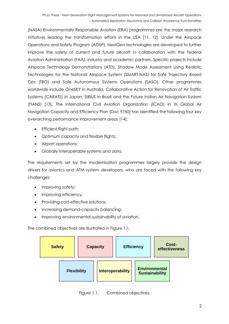
The requirements set by the modernisation programmes largely provide the design
drivers for avionics and ATM system developers, who are faced with the following key
challenges:
Improving safety;
Improving efficiency;
Providing cost-effective solutions;
Increasing demand-capacity balancing;
Improving environmental sustainability of aviation.
The combined objectives are illustrated in Figure 1.1.
Figure 1.1. Combined objectives.
Safety Capacity Efficiency Cost-
effectiveness
Flexibility Interoperability Environmental Sustainability
Ph.D. Thesis - Next Generation Flight Management Systems for Manned and Unmanned Aircraft Operations
- Automated Separation Assurance and Collision Avoidance Functionalities
3
Scientific advances in Communication, Navigation, Surveillance/Air Traffic Management
(CNS/ATM) and Avionics (CNS+A) systems are required to achieve the ambitious goals
set by national and international aviation organisations. The CNS+A concept was first
introduced by the ICAO Future Air Navigation Systems (FANS) committee and was later
implemented by Boeing, Airbus and other original equipment manufacturers as FANS-1
and FANS-A products. The key CNS+A concepts are [13]:
Four Dimensional (4D) Trajectory/Intent-Based Operations (TBO/IBO);
Performance-Based Communication, Navigation, Surveillance (PBC/PBN/PBS),
supporting Performance-Based Operations (PBO);
TBO/IBO facilitated by System Wide Information Management (SWIM);
Enhanced ground-based and satellite-based surveillance, including Automatic
Dependent Surveillance (ADS) and automated self-separation;
Improved Human Machine Interface and Interactions (HMI2), interoperability for
airborne and ground interfaces and increased levels of automation;
Enhanced Line-of-Sight (LoS) and Beyond Line-of-Sight (BLoS) aeronautical
communications, involving a substantial exploitation of data-links;
Collaborative Decision Making (CDM) to allow all stakeholders involved in flight
planning and management to participate in the enhancement of system
performance by utilising more accurate information from airborne systems;
Air Traffic Flow Management (ATFM) and Dynamic Airspace Management
(DAM).
These CNS+A concepts enable more accurate estimation of CNS performance and
involve higher levels of automation. It is to be emphasised that in recent years,
Unmanned Aircraft Systems (UAS) are being extensively employed in a variety of civil
and military applications as these vehicles provide cost-effective and safe alternatives
to manned aircraft in a wide range of operational scenarios. UAS offer a safer and cost-
effective alternative to manned aircraft in dangerous, sensitive and/or dull tasks
because of the absence of a pilot on board the aircraft. These distinctive abilities of UAS
are a result of adopting a number of enabling CNS+A concepts and technologies in a
phased manner and the widespread availability of a number of diverse airborne sensors
and systems. Accurate and fail-safe algorithms for navigation, guidance and effective
control of the platform are required to accomplish such missions. Currently, UAS can only
operate in segregated airspace, where collision risks are largely eliminated by
preventing or strictly controlling entry into this class of airspace by other aircraft. In order
to address the challenges of integrating UAS in all classes of airspace, and in existing
Ph.D. Thesis - Next Generation Flight Management Systems for Manned and Unmanned Aircraft Operations
- Automated Separation Assurance and Collision Avoidance Functionalities
4
ATM and future UAS Traffic Management (UTM) systems, the required levels of safety and
operational regulations need to be determined. Recent research shows that small UAS
could pose less risk to life and inanimate objects on the ground when compared with
manned aircraft [15]. The long term vision of the aviation community is to achieve
coordinated manned and unmanned aircraft operations in all classes of airspace. Initial
steps have been taken in this regard by the launch of programmes such as NASA’s
Unmanned Traffic Management (UTM) initiative [16]. Some recommendations for
research in the area of manned and unmanned aircraft coexistence in all classes of
airspace and aerodromes have been identified as part of the Aviation System Block
Upgrades (ASBU) by the ICAO [17]. Due to the fact that there are no definitive standards
available now, there are a number of groups and special committees working on UAS
including ASTM F38, EUROCAE WG-73, ICAO UASSG and RTCA SC-228 [18 - 20].
Specifically, in the CNS+A context, the first recommendation addressing the operational
and certification issues for civil UAS was issued by the Joint Aviation Authorities (JAA)
CNS/ATM Steering Group [19]. Some key recommendations include the development of
innovative methods and algorithms for dynamic allocation of airspace resources as well
as the introduction of CNS+A technologies enabling unrestricted access of UAS to all
classes or airspace. Subsequently, the EUROCAE Working Group (WG-73) endeavours to
address:
UAS operations and collision avoidance functions;
Command, control, communication, spectrum and security issues;
Airworthiness and continued airworthiness.
The architectures, interfaces, communication protocols, data elements and message
formats for operation of UAS are defined in the NATO Standardisation Agreement
(STANAG) 4586 [21]. In terms of general applicability, the Joint Architecture for
Unmanned Systems (JAUS) provides a better perspective than STAGNAG 4586. The JAUS
standard Domain Model (DM) and a reference architecture provide mechanisms for
UAS interoperability including integration into the airspace, architecture framework,
message formats and a set of standard messages [22]. UAS support is one of the key
performance improvement areas identified by the ICAO for ASBU [17]. In the TBO
context, the following are included:
Initial integration of UAS into non-segregated airspace: implementation of basic
procedures and functions including Sense-and-Avoid (SAA) for operating UAS;
UAS integration in traffic: implementation of defined procedures addressing lost
link as well as enhanced SAA functions;
Ph.D. Thesis - Next Generation Flight Management Systems for Manned and Unmanned Aircraft Operations
- Automated Separation Assurance and Collision Avoidance Functionalities
5
UAS transport management: implementation of UAS operations on the airport
surface and in non-segregated airspace similar to manned aircraft.
The integration of UAS into the non-segregated airspace requires recommendations
from committees for standardisation (RTCA SC-203, ASTM F 38, EUROCAE WG 73, and
others), which aim to develop the Minimum Aviation System Performance Standards
(MASPS). In this perspective, the key CNS+A systems/elements are:
LoS and BLoS communication systems;
High-integrity airborne and ground-based UAS navigation systems and integrated
fail-safe avionics architectures;
The adoption of fused cooperative/non-cooperative surveillance systems
incorporating collision avoidance and collaborative conflict resolution
capabilities in a network centric operational scenario;
Provision and integration of Separation Assurance and Collision Avoidance
(SA&CA) capabilities in the Next Generation Flight Management System
(NG-FMS);
Interactions between Guidance, Navigation and Control (GNC) and Track,
Decision-Making and Avoidance (TDA) loops.
Other issues that are addressed for a safe integration of the UAS in the airspace include
the definition of automation functions and standards for Human-In-The-Loop (HITL)
interactions, operational contingency procedures and certification processes.
Additionally, the air safety nets that can be used as a last resort necessity have to be
clearly defined for all UAS types to address the emergency scenarios rising in a CNS+A
context. Cooperative and non-cooperative SA&CA performance-based requirements
are currently developed in a research context and need to be accepted into a
regulatory framework in order to support the UAS operational improvements [23, 24]. The
initial integration of UAS requires capabilities including ground-based SAA systems and
the adoption of a combination of policies, procedures, and technologies intended to
facilitate safe airspace access. The SAA technology will be integrated in the flight
management system of the UAS to meet collision and hazard avoidance responsibility
and to provide situational awareness. UAS integration in traffic requires the development
of on board SA&CA algorithms, which must be able to fulfil the requirements for
detecting and successfully resolving any mid-air collisions in non-segregated airspace for
both cooperative and non-cooperative targets [23, 24]. In particular, this technology
enabler will cope with both air and ground obstacles of various characteristics (natural
and man-made) including long and thin structures such as electrical cables, poles and
Ph.D. Thesis - Next Generation Flight Management Systems for Manned and Unmanned Aircraft Operations
- Automated Separation Assurance and Collision Avoidance Functionalities
6
aerial obstacles such as other UAS and manned aircraft. Significant impacts are also
expected in the areas of SAA airworthiness and design standard evolutions. The UAS
research community is working on a number of SA&CA algorithms to replicate and even
to provide a higher level of performance of the see-and-avoid (S&A) capability of
humans. Despite a huge number of efforts that have been devoted to the integration of
UAS in non-segregated airspace, the standards as well as a certification framework for
SA&CA has yet to be established. Furthermore, the maturity of SA&CA techniques and
enabling technologies is considered very limited when viewed in the perspective of civil
airworthiness regulations for manned aircraft, raising concerns to certification authorities
and airspace users [25, 26]. Furthermore, large amounts of established reliability data are
not available as in the case of civil aviation. The separation assurance function is not
addressed in conjunction with the collision avoidance problem. A unified approach to
SA&CA for manned and unmanned aircraft is required to meet the challenges of UAS
integration and to provide a pathway to certification. One of the key technology
enablers to achieve this goal is the implementation of suitable hardware components
and data fusion techniques for cooperative and non-cooperative SA&CA tasks. Such
functions will provide manned and unmanned aircraft the capability to consistently and
reliably perform equally or even to exceed the see-and-avoid performance while
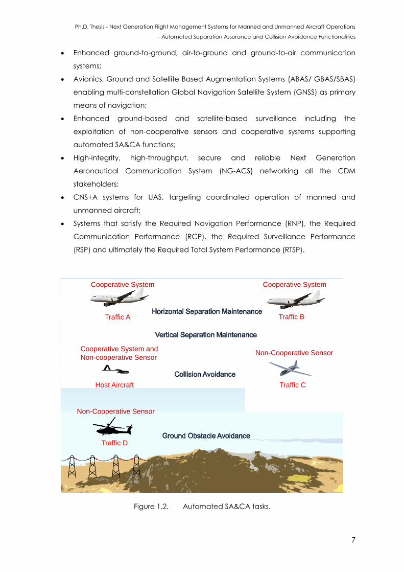
allowing a seamless integration of unmanned aircraft in the ATM and UTM network. In a
typical operational scenario, the host aircraft (manned/unmanned) would have to
ensure the required separation (horizontal and vertical) is maintained with other traffic
and also have to see/sense in advance any potential conflicts and avoid them. The host
aircraft and other traffic are conventionally equipped with a different set of non-
cooperative sensors and cooperative systems as shown in Figure 1.2.
Automated SA&CA tasks have to be carried out to ensure safety and in order to allow
the exploitation of the enhanced CNS+A concepts and capabilities, new ground-based
and airborne CNS+A systems have to be designed and developed. The key technology
enablers are novel CNS technologies onboard the aircraft (manned and unmanned)
and CDM based ground systems. These CNS+A systems include:
Modern avionics and ground-based systems for planning and real-time execution
of 4-Dimensional Trajectory (4DT) functionalities, including multi-objective 4D
trajectory optimisation, negotiation and validation in the TBO/IBO context. These
include the airborne component - NG-FMS and the ground component - Next
Generation ATM (NG-ATM) system;
Network-centric systems for strategic, tactical and emergency scenarios;
Ph.D. Thesis - Next Generation Flight Management Systems for Manned and Unmanned Aircraft Operations
- Automated Separation Assurance and Collision Avoidance Functionalities
7
Enhanced ground-to-ground, air-to-ground and ground-to-air communication
systems;
Avionics, Ground and Satellite Based Augmentation Systems (ABAS/ GBAS/SBAS)
enabling multi-constellation Global Navigation Satellite System (GNSS) as primary
means of navigation;
Enhanced ground-based and satellite-based surveillance including the
exploitation of non-cooperative sensors and cooperative systems supporting
automated SA&CA functions;
High-integrity, high-throughput, secure and reliable Next Generation
Aeronautical Communication System (NG-ACS) networking all the CDM
stakeholders;
CNS+A systems for UAS, targeting coordinated operation of manned and
unmanned aircraft;
Systems that satisfy the Required Navigation Performance (RNP), the Required
Communication Performance (RCP), the Required Surveillance Performance
(RSP) and ultimately the Required Total System Performance (RTSP).
Host Aircraft
Traffic A Traffic B
Traffic C
Traffic D
Cooperative System and
Non-cooperative Sensor
Cooperative System Cooperative System
Non-Cooperative Sensor
Non-Cooperative Sensor
Figure 1.2. Automated SA&CA tasks.
Ph.D. Thesis - Next Generation Flight Management Systems for Manned and Unmanned Aircraft Operations
- Automated Separation Assurance and Collision Avoidance Functionalities
8
The CNS systems provide better and more precise airborne navigation services, optimal
collision avoidance and separation assurance, as well as secure and reliable
communication links.
1.2 Research Gap Identification
State-of-the-art aircraft are equipped with FMS, which provide automated navigation
and guidance services that are largely restricted to the use of 3D trajectories. Time is not
used as a control variable, although setting Required Time of Arrival (RTA) and Estimated
Time of Arrival (ETA) at en-route waypoints and at the destination respectively provide
some initial implementations of time based operations. Hence a NG-FMS is required for
the full implementation of TBO/IBO.
On the other hand, one of the key challenges for the aviation community is to introduce
the SA&CA capability for manned and unmanned aircraft. It is also timely that a solid
mathematical framework be used for certifying the SA&CA. The maturity of the available
SA&CA techniques and enabling technologies is considered very limited when viewed in
the perspective of civil airworthiness regulations for manned aircraft, raising concerns to
certification authorities and airspace users. With the growing adoption of UAS for a
number of civil, commercial and scientific applications there is a need to certify SA&CA
systems according to established national and international standards.
1.3 Research Questions
This thesis addresses the challenges of introducing novel software algorithms in flight
management system (specifically separation maintenance and collision avoidance
automation functionalities for manned and unmanned aircraft) and answers the
following key research questions:
How are innovative analytical models adapted within the trajectory-based
operations context?
How is a unified approach to cooperative and non-cooperative separation
assurance and collision avoidance realised for manned and unmanned aircraft?
How is the safety and efficiency of aircraft operations improved by the
introduction of automated separation assurance and collision avoidance
algorithms?
How are the automated separation assurance and collision avoidance tasks
affected by the performance of onboard navigation and tracking sensors?
Ph.D. Thesis - Next Generation Flight Management Systems for Manned and Unmanned Aircraft Operations
- Automated Separation Assurance and Collision Avoidance Functionalities
9
1.4 Research Aim
This research endeavours to develop and implement novel mathematical algorithms for
automated SA&CA tasks. Within this framework, the key aim to develop a unified
methodology for cooperative and non-cooperative SA&CA.
The aim of this research work is:
To develop novel mathematical models (software functionalities) for manned and
unmanned aircraft NG-FMS primarily focussed on improving safety and efficiency by
providing automated SA&CA functions.
1.5 Research Objectives
The following objectives were identified:
Perform a detailed review of the existing literature on modern FMS focussing on
GNC and TDA functions;
Define the system level functional architecture of a NG-FMS suitable for manned
and unmanned aircraft operations;
Adapt suitable NG-FMS models and algorithms for on board planning and
optimisation of four dimensional trajectories to support TBO/IBO in the CNS+A
context;
Perform simulation case studies to test the validity of the NG-FMS models and
algorithms for safe and efficient operations;
Develop the mathematical models required to introduce a novel unified
approach to cooperative and non-cooperative SA&CA for manned and
unmanned aircraft;
Evaluate the mathematical models introduced for SA&CA in representative
simulation case studies (multiple manned and unmanned aircraft operations);
Define possible pathways for certification of SA&CA functions, allowing safe and
unrestricted operations of manned and unmanned aircraft in the future UTM
context.
1.6 Research Methodology
The methodology followed in this work is presented below:
Ph.D. Thesis - Next Generation Flight Management Systems for Manned and Unmanned Aircraft Operations
- Automated Separation Assurance and Collision Avoidance Functionalities
10
In the first phase, a comprehensive review of all existing work in the flight management
system functionalities, challenges of UAS integration into all classes of airspace and
SA&CA algorithms was undertaken.
In the second phase, novel mathematical models were developed to determine the
overall uncertainty volume in the airspace. These models were then evaluated to test for
fitness of use. The design and development of NG-FMS (including identification of
optimal system architecture and algorithms required for TBO/IBO) was carried out.
Furthermore, a performance analysis was carried out to investigate and explore the
potential of the unified approach to cooperative and non-cooperative SA&CA for
manned and unmanned aircraft.
In the third phase, modelling and simulation activities were performed to validate the
NG-FMS algorithms for 4D trajectory optimisation and SA&CA tasks.
The research methodology adopted is summarised as follows:
NG-FMS requirements definition;
Conceptual design and development of the NG-FMS implementing dedicated
functions for manned and unmanned aircraft operations:
- NG-FMS conceptual design;
- Development of tailored algorithms for 4D trajectory optimisation
supporting TBO/IBO;
- Implementation of near real-time 4DT estimation, negotiation and
validation functions, in synergy with ATM Decision Support Systems (DSS) for
TBO/IBO;
- Mathematical modelling and implementation of a unified approach for
cooperative and non-cooperative SA&CA functions;
- Tailoring of tracking and avoidance algorithms for implementing the
unified approach to separation maintenance and collision avoidance for
non-cooperative and cooperative scenarios;
Verification of the NG-FMS functions by performing modelling and simulation
activities. The application case studies are in a MATLAB/Simulink simulation
environment. Case studies that are representative of typical manned/unmanned
aircraft operational flight envelope were also considered. Additionally, the
facilities available at the THALES Australia Centre for Advanced Studies in ATM
(CASiA) including TopSky - ATM solutions and at the RMIT University avionics and
ATM system laboratory were utilised to verify some of the software functionalities.
Ph.D. Thesis - Next Generation Flight Management Systems for Manned and Unmanned Aircraft Operations
- Automated Separation Assurance and Collision Avoidance Functionalities
11
1.7 Thesis Outline
This section provides a general outline of the successive chapters of this thesis. In chapter
2, the theoretical background and algorithms of the GNC and TDA loops are presented.
The chapter starts with an introduction to state-of-the-art FMS and its functions. The
chapter then goes on to describe the SA&CA algorithms currently employed. Some
theoretical description of various multi-sensor data fusion techniques used for tracking in
the context of SA&CA are also described. The chapter also presents some general
considerations on SA&CA requirements in terms of available information, functions,
implementation and regulatory issues.
Chapter 3 provides the general design principles of NG-FMS. More specifically, it
provides an overview of system requirements, functions and implementation of NG-FMS
for manned and unmanned aircraft. Furthermore, the navigation, guidance and
performance management algorithms employed in NG-FMS are also described. The
general architecture of the simulation environment integrating the developed NG-FMS
system and the NG-ATM system is then summarised.
The unified approach to cooperative and non-cooperative SA&CA is described in
Chapter 4. The mathematical models required for the unified approach are then
documented in this chapter. Furthermore, the automated separation maintenance and
collision avoidance functions of NG-FMS are discussed in this context.
Performance analysis of navigation and surveillance sensor/system errors is presented in
Chapter 5. Covariance analysis and other statistical methods employed for
determination of navigation and tracking errors are described in detail. Some
description of assumptions and of the solutions used for conflict detection, resolution
evaluation and autonomous avoidance trajectory generation are also presented.
Pathways to certifying avionics systems that provide SA&CA functionalities in manned
and unmanned systems are also described. Appendix A provides a summary of multi-
sensor data fusion techniques implemented for UAS integrated navigation systems.
Appendix B provides a compilation of the certification standards, Acceptable Means of
Compliance (AMC), Guidance Materials (GM) and recommended practices.
Chapters 6 and 7 include the various case studies performed for evaluating the unified
approach in both cooperative and non-cooperative scenarios. The sensor modelling
techniques and assumptions used to choose various scenarios are spelled out. Key
aspects of the Human Machine Interface and Interaction (HMI2) design based on the
presented case studies are summarised in Appendix C.
Ph.D. Thesis - Next Generation Flight Management Systems for Manned and Unmanned Aircraft Operations
- Automated Separation Assurance and Collision Avoidance Functionalities
12
Chapter 8 provides an overview of the methodology to apply the unified approach to
SA&CA in an UTM context. Preliminary simulation case studies are also presented for
validation of the presented SA&CA algorithms in the UTM framework.
Finally chapter 9 ends with conclusions drawn from this work. Recommendations for
future research work are also presented. A list of relevant publications developed based
on the work carried out during this PhD research is provided in Appendix D.
1.8 References
1. P. Bieber, F. Boniol, M. Boyer, E. Noulard and C. Pagetti, “New Challenges for Future
Avionic Architectures”, Aerospace Lab Journal, Issue 4, May 2012.
2. Airbus, “Future Journeys, 2013-2032”, Global Market Forecast, 2013. Downloadable
from:
http://www.airbus.com/company/market/forecast/?eID=dam_frontend_push&docID=
33752
3. C. Haissig, “Air Traffic Management Modernization: Promise and Challenges”,
Encyclopedia of Systems and Control, pp. 28-33, 2015.
4. M.T. DeGarmo, “Issues Concerning Integration of Unmanned Aerial Vehicles in Civil
Airspace”, MITRE, 2004.
5. SESAR JU, “European ATM Master Plan”, Edition 2, Brussels, Belgium, 2012.
6. SESAR JU, “SESAR Consortium - Modernising the European Sky”, Brussels, Belgium, 2011.
7. SESAR JU, “SESAR Content Integration Team”, SESAR ATM Target Concept, Brussels,
Belgium, 2007.
8. Clean Sky JTI, Accessible at: www.cleansky.eu
9. Advisory Council for Aviation Research and Innovation in Europe (ACARE), “Strategic
Research Agenda, Volume 2”, 2004. Downloadable from:
http://www.acare4europe.org/sites/acare4europe.org/files/document/ASD-Annex-
final-211004-out-asd.pdf
10. Advisory Council for Aviation Research and Innovation in Europe (ACARE), “Strategic
Research & Innovation Agenda (SRIA)”, Volume 1, 2012. Downloadable from:
http://www.acare4europe.org/sites/acare4europe.org/files/attachment/SRIA%20Volu
me%201.pdf
11. FAA, “Avionics Roadmap, Version 2.0”, Federal Aviation Authority, Washington,
September 2011.
12. Federal Aviation Administration (FAA), “NextGen Implementation Plan”, Washington
DC, USA, 2011.
Ph.D. Thesis - Next Generation Flight Management Systems for Manned and Unmanned Aircraft Operations
- Automated Separation Assurance and Collision Avoidance Functionalities
13
13. R. Sabatini, A. Gardi, S. Ramasamy, T. Kistan and M. Marino, “Modern Avionics and ATM
Systems for Green Operations”, Encyclopedia of Aerospace Engineering, eds. R.
Blockley and W. Shyy, John Wiley: Chichester, 2015. DOI:
10.1002/9780470686652.eae1064
14. ICAO, “Global Navigation Plan, 2013-2028”, Doc 9750-AN/963, Capacity and
Efficeincy, Fourth Edition, 2013.
15. R. Melnyk, D. Schrage, V. Volovoi and H. Jimenez, “A Third-Party Casualty Risk Model for
Unmanned Aircraft System Operations”, Reliability Engineering & System Safety, Vol.
124, pp. 105-116, 2014.
16. P.H. Kopardekar, “Unmanned Aerial System (UAS) Traffic Management (UTM): Enabling
Low-Altitude Airspace and UAS Operations”, NASA Technical Report, 2014.
17. The International Civil Aviation Organization (ICAO), Working Document for the
Aviation System Block Upgrades - The Framework for Global Harmonization, Montreal,
Canada, 2013.
18. JAA, UAV TASK-FORCE, Final Report - A Concept for European Regulations for Civil
Unmanned Aerial Vehicles (UAVs), 2004.
19. G. Amato, EUROCAE WG-73 on Unmanned Aircraft Systems, ed: EUROCAE.
20. L. Cary, “International Regulatory Framework for Remotely Piloted Aircraft Systems”,
ICAO Representative, Remotely Piloted Aircraft Systems (RPAS) Conference, Paris,
France, 2012.
21. J.T. Platts, M.L. Cummings and R.J. Kerr, “Applicability of STANAG 4586 to Future
Unmanned Aerial Vehicles”, AIAA Infotech@ Aerospace Conference, Rohnert Park,
California, USA, 2007.
22. A. Oztekinmet and R. Wever, “Development of a Regulatory Safety Baseline for UAS
Sense and Avoid”, Handbook of Unmanned Aerial Vehicles, pp. 1817-1839, Springer
Verilag, Netherlands, 2015.
23. S. Ramasamy, R. Sabatini and A. Gardi, “A Unified Approach to Separation Assurance
and Collision Avoidance for Flight Management Systems”, Proceedings of the 35th
AIAA/IEEE Digital Avionics Systems Conference (DASC2016), Sacramento, CA, USA,
September 2016.
24. S. Ramasamy, R. Sabatini and A. Gardi, “Avionics Sensor Fusion for Small Size
Unmanned Aircraft Sense-and-Avoid”, IEEE Workshop on Metrology for Aerospace, pp.
271-276, Benevento, Italy, May 2014. DOI: 10.1109/MetroAeroSpace.2014.6865933
25. K. Dalamagkidis, K.P. Valavanis and L.A. Piegl, “On Unmanned Aircraft Systems Issues,
Challenges and Operational Restrictions Preventing Integration into the National
Ph.D. Thesis - Next Generation Flight Management Systems for Manned and Unmanned Aircraft Operations
- Automated Separation Assurance and Collision Avoidance Functionalities
14
Airspace System”, Progress in Aerospace Sciences, Elsevier, vol. 44, issue 7, pp. 503-519,
2008. DOI: 10.1016/j.paerosci.2008.08.001
26. K.D. Davis and S.P. Cook, “Achieving Sense and Avoid for Unmanned Aircraft Systems:
Assessing the Gaps for Science and Research”, Handbook of Unmanned Aerial
Vehicles, pp. 1841-1855, Springer Netherlands, 2015.
Ph.D. Thesis - Next Generation Flight Management Systems for Manned and Unmanned Aircraft Operations
- Automated Separation Assurance and Collision Avoidance Functionalities
15
CHAPTER 2
LITERATURE REVIEW
“The first rule of any technology used in a business is that automation applied to an
efficient operation will magnify the efficiency. The second is that automation
applied to an inefficient operation will magnify the inefficiency”. - Bill Gates
2.1 Introduction
This chapter presents the system architecture and algorithms employed in FMS. The two
key avionics system loops required to provide automated guidance, as well as SA&CA
functionalities are described in this chapter. A background on the currently available
SA&CA algorithms is presented. The chapter also provides a background of the role of
SA&CA in the modern ATM and UTM systems, describes the development process of
SA&CA functions, provides a review of the Conflict Detection and Resolution (CD&R)
algorithms and presents the case for introducing a unified approach to SA&CA within
modern avionics systems for manned and unmanned aircraft. A theoretical summary of
various multi-sensor data fusion techniques tailored for accomplishing an effective
SA&CA is also presented.
2.2 Avionics and ATM System Modernisation
The present day ATM system originated as a result of a mid-air collision over the Grand
Canyon (US) in 1956. It is essential to modernise the existing infrastructure (air and
ground) to attain substantial benefits in safety, efficiency and environmental
sustainability of aviation, and to ensure optimal demand-capacity balancing [1]. The
limited capacity of the ground infrastructure has to be increased by introducing
dynamic capacity-demand balancing to cope with growing air traffic [2]. The European
and U.S. airspace are good examples for this development. There are generally two
categories of airspace namely regulatory and non-regulatory. Within these two
categories, there may be controlled, uncontrolled, special use, and other airspace. With
a share of 65% in worldwide air traffic, the world’s busiest airspace areas and capacity
Ph.D. Thesis - Next Generation Flight Management Systems for Manned and Unmanned Aircraft Operations
- Automated Separation Assurance and Collision Avoidance Functionalities
16
problems have been experienced in the past in both of these areas [3]. The lessons
learned from the traffic situations in these areas are becoming driving factors supporting
the redesign of the existing ATM system. In the Australian context, by 2021, Airservices
Australia is looking at providing air traffic control services using an advanced and
integrated ATM system through collaboration with the Department of Defence, The plan
is to unify the Australian skies under a new, harmonised ATM system under the OneSKY
program to support integrated civil and military air traffic operations [4]. This will enable a
new level of operational and cost efficiency and safety, while also reducing delays for
the travelling public and providing opportunities to improve environmental outcomes.
The benefits of a combined civil and military air traffic management system, delivered
under the OneSKY Australia program, will include safety and efficiency improvements, as
well as cost savings and reliability. The key features are:
Improved safety and efficiency;
One flight information region;
Modular and adaptable systems;
Greater use of four dimensional trajectories.
The International Civil Aviation Organisation (ICAO) global ATM operational concept
defines a general framework for the ATM system operational concept. The concept
foresees that the key conceptual change for traffic synchronisation will be the
implementation of 4-Dimensional (4D) trajectory optimisation algorithms [5]. The
trajectories are expected to be negotiated between the airborne and ground systems,
and are targeted to be conflict-free. Regarding airspace user operations, the concept
anticipates that individual aircraft performance, flight conditions and capacity-demand
balancing will allow dynamically-optimised 4D trajectory planning, negotiation and
validation. In the context of conflict management, the concept identifies a three-
layered approach namely: Strategic Conflict Management (SCM), Separaration
Provision (SP) and CA.
SCM is considered to be achieved through airspace organisation and management
and covers the earliest planning stage up to shortly pre- departure. ICAO uses the term
strategic in this context, as opposed to tactical; because pre-flight phases do not
possess the same real deadlines as flight short term CD&R. Though, especially for long-
haul flights, strategic conflict management may also be applied after departure,
depending on the best means to resolve a conflict. Strategic conflict management is
comprised of:
Ph.D. Thesis - Next Generation Flight Management Systems for Manned and Unmanned Aircraft Operations
- Automated Separation Assurance and Collision Avoidance Functionalities
17
Airspace organisation and management;
Demand and capacity balancing;
Traffic synchronisation.
SP is the second layer of conflict management, which guarantees that aircraft are
separated according to the applicable standards. According to ICAO, separation
provision may be seen as an iterative process in which a conflict is detected, and then a
resolution is identified and communicated to the conflicting entities. The execution of
the resolution is monitored and, in case applicable minimum separation is not achieved,
resolution manoeuvres are identified. ICAO defines the operator for separation
management (separator) as the agent responsible for separation provision which can,
depending on the separation mode, also be delegated to an aircraft. Several notions
are defined in this context of conflict management including:
Self-separation: the airspace user is responsible for separation in respect to one or
more hazards;
Distributed: different predetermined separators are defined for different hazards;
Cooperative: role of separation is delegated temporarily until a termination
condition sets in.
Hazards to which aircraft need to be separated from are classified as:
Airborne:
- Other aircraft;
- Terrain;
- Atmospheric constraints (weather, wake turbulence, etc.);
- Restricted airspaces.
Ground:
- Vehicles operating in the airport (including other aircraft on the taxiway or
runway);
- Other obstructions while on the apron and manoeuvring area.
Common to both hazard situations is that for each hazard a separator needs to be
responsible for separation provision. The authority is vested on air traffic service providers,
governed by regulations and standards set out by international/national aviation
authorities providing guidelines for enforcement rules, discrepancies, etc. Collision
avoidance is essential in both layers, when strategic conflict management and
separation provision have failed.
Ph.D. Thesis - Next Generation Flight Management Systems for Manned and Unmanned Aircraft Operations
- Automated Separation Assurance and Collision Avoidance Functionalities
18
In additional to the need for implementing automated SA&CA functionalities for
increasing safety, efficiency and demand-capacity balancing, there is also the
requirement for supporting safe and widespread UAS operations. A system similar to an
ATM system is envisaged to be implemented and it is foreseen that low-altitude UAS
operations will occur in the same airspace where today’s gliders, general aviation and
helicopter operations occur [6]. Hence automated SA&CA functionalities are required to
be implemented for safe and efficient manned/unmanned aircraft as well as
multiplatform coordinated operations. These automated guidance and SA&CA
functionalities can be implemented as software modules (mathematical models) in
novel FMS onboard manned and unmanned aircraft, which is the focus of next section.
2.3 Flight Management Systems
Automated navigation and flight guidance functions on board modern aircraft are
designed to guide the aircraft along a safe and efficient trajectory. The first modern FMS
was introduced onboard the Boeing 767 in 1982 [7]. The original systems had 16-bit
processors using bit-slice technology and removable memory cards with 128 KB of
Random Access Memory (RAM), 128 KB of Read-Only Memory (ROM), clock rates of only
24 MHz. A dedicated hard drive provided 100 KB of non-volatile storage. State-of-the-art
FMS are primarily responsible for providing automated navigation and guidance services
from take-off to landing. The hardware components of modern FMS include the Multi
Control Display Unit (MCDU) and FM dedicated processor. FMS of modern aircraft
typically have a 64-bit Power PC micro- processor, 120 MB of RAM, 50 Mbytes of flash
memory and a clock rate of 800 MHz. The FMS operates in close relation with the
Automatic Flight Control System (AFCS). Flight plans are generated by the state-of-the-
art FMS in coordination with the Airline Operation Centre (AOC) and Air Navigation
Service Provider (ANSP). The modern FMS is hence an integrated set of avionics systems
that provides the flight crew with the ability to operate an aircraft in compliance with
the ANSP requirements in a manner that meets the expectations of the AOC. The flight
path of an aircraft is represented in the FMS as lateral and vertical profiles over time.
Typically, an FMS Flight Plan (FPLN) consists of lateral FPLN and vertical FPLN, which is in
turn divided into a number of segments, sections and integral steps. Each segment is
constructed based on a given set of local objectives with respect to the variables
provided by the guidance component. The core of an FMS consists of one or more flight
management computers/embedded processors and one or more Multifunction Control
Display Units (MCDU). The software component embedded in the FMS processor
performs the following functions [8, 9]:
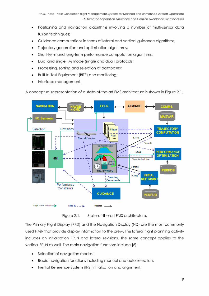
Ph.D. Thesis - Next Generation Flight Management Systems for Manned and Unmanned Aircraft Operations
- Automated Separation Assurance and Collision Avoidance Functionalities
19
Positioning and navigation algorithms involving a number of multi-sensor data
fusion techniques;
Guidance computations in terms of lateral and vertical guidance algorithms;
Trajectory generation and optimisation algorithms;
Short-term and long-term performance computation algorithms;
Dual and single FM mode (single and dual) protocols;
Processing, sorting and selection of databases;
Built-In-Test Equipment (BITE) and monitoring;
Interface management.
A conceptual representation of a state-of-the-art FMS architecture is shown in Figure 2.1.
Figure 2.1. State-of-the-art FMS architecture.
The Primary Flight Display (PFD) and the Navigation Display (ND) are the most commonly
used HMI2 that provide display information to the crew. The lateral flight planning activity
includes an initialisation FPLN and lateral revisions. The same concept applies to the
vertical FPLN as well. The main navigation functions include [8]:
Selection of navigation modes;
Radio navigation functions including manual and auto selection;
Inertial Reference System (IRS) initialisation and alignment;
Ph.D. Thesis - Next Generation Flight Management Systems for Manned and Unmanned Aircraft Operations
- Automated Separation Assurance and Collision Avoidance Functionalities
20
GNSS initialisation. These might include Global Positioning System (GPS), Galileo,
GLObalnaya NAvigatsionnaya Sputnikovaya Sistema (GLONASS), BeiDou (or
Compass), Indian Regional Navigational Satellite System (IRNSS), Quasi-Zenith
Satellite System (QZSS) or a combination of the available constellations.
The traditional databases associated with FMS are Magnetic Deviation (MAG DEV),
Performance Database (PERBDB) and Navigation Database (NAVDB). In addition to
these databanks, weather, demographic distribution, digital terrain elevation,
environmental and Object Modifiable Databases (OMD) can be introduced for
TBO/IBO. The FMS navigation function is interfaced with the NAVDB, which is updated
every 28 days as a pre-flight process, based on the ICAO’s Aeronautical Information
Regulation and Control (AIRAC) cycle. The NAVDB is structured to provide information
on standard navigational aids, waypoints, holding patterns, and airport information.
Airport data include information on terminal gates, runways, Standard Instrument
Departure (SID), Standard Terminal Arrival Route (STAR) approaches and missed
approach procedures. Uncertainty in the navigation performance requires large
separation distances between aircraft to ensure safety. This is often considered as a
technical constraint limiting the dynamic airspace allocation in the next generation ATM
(SESAR/NExtGen) environment. Hence, performance-based navigation enabled by the
introduction of satellite navigation systems (GNSS) are employed to improve the RNP in
order to meet the requirements specified in RTCA DO-236B.
State-of-the-art FMS provides automated navigation functionalities for estimation of the
aircraft’s position using the World Geodetic System (WGS-84) system coordinates. The
position of the aircraft is determined by using information from multiple navigation
sensors including the Inertial Reference System (IRS), VHF Omnidirectional Range (VOR),
Distance Measuring Equipment (DME), Instrument Landing System (ILS) and Microwave
Landing System (MLS). With the development of satellite-based navigation systems,
GNSS data are becoming the main source of navigation information in all flight phases.
In addition, FMS sends radio tuning commands for VOR, DME and ILS sensors based on
the radio frequencies retrieved from the navigation database [8, 9]. Turning of radio
parameters (frequency, etc.), is performed either manually by the pilot, or automatically
by the FMS by performing database management queries on the NAVDB. Engine
parameters and aircraft configuration from the Mode Control Panel (MCP), throttle
management and other pilot controls are provided to the thrust management module
of the FMS. This module supports the generation of vertical flight guidance steering
commands and provides engine-trim commands to the Full Authority Digital Engine
Ph.D. Thesis - Next Generation Flight Management Systems for Manned and Unmanned Aircraft Operations
- Automated Separation Assurance and Collision Avoidance Functionalities
21
Control (FADEC) or other engine control units. The FMS thrust management function also
offers the abillity to control the throttle with minimum fuel consumption.
The vertical FPLN defines the speed, altitude and time constraints at each waypoint
based on the lateral FPLN plan, temperature, atmospheric pressure, aircraft weight, wind
conditions, aircraft performance (given by PERFDB), cost index and flight predictions
(short and long term). The state-of-the-art FMS have advanced design features primarily
employing an intuitive use of the system and thereby reducing significantly the crew
workload. These functions are summarised in Table 2.1 [10].
The cost index varies among various airlines, routes and the selected FPLN. The cost
index is used to compute the best trip cost, which evidently affects the speed
(economical CAS/Mach speed) and altitude used in the vertical FPLN. Climbs are
computed with a transition from constant Calibrated Air Speed (CAS) to constant Mach
number assuming maximum climb thrust. Cruise segments are calculated at constant
Mach number and descents are programmed with a transition (dictated by a transition
altitude) from constant Mach number to constant CAS using ide thrust. The cost index is
given by:
(2.1)
The cost index is dictated by the cost of fuel/kg, time cost per minute of flight (given by
hourly maintenance cost, flight crew/cabin crew cost, depreciation/leasing cost) and
time of flight. A lower cost index this value put more emphasis on reducing fuel flow. With
a higher value the emphasis changes to high speed. The total cost is given by:
Cost = Fuel Used + Cost Index * Time (2.2)
Each FMS manufacturer provides a different range of CI and predominately, this index
varied from 0 to 99 or from 0 to 999.
Taking the Airbus A380 as a reference, the CI varies from 0 to 999 denoting maximum
range and maximum time respectively. Furthermore additional CIs can be introduced
such as long range cruise, maximum endurance and maximum range cruise. The
conventionally used CI is often revised when deviations occur between the nominal
flight plan and what is being actually flown, based on the aircraft dynamics and
environmental/external conditions. Typical deviations are delayed departures at airports
or errors in the predetermined en-route winds/weather conditions.
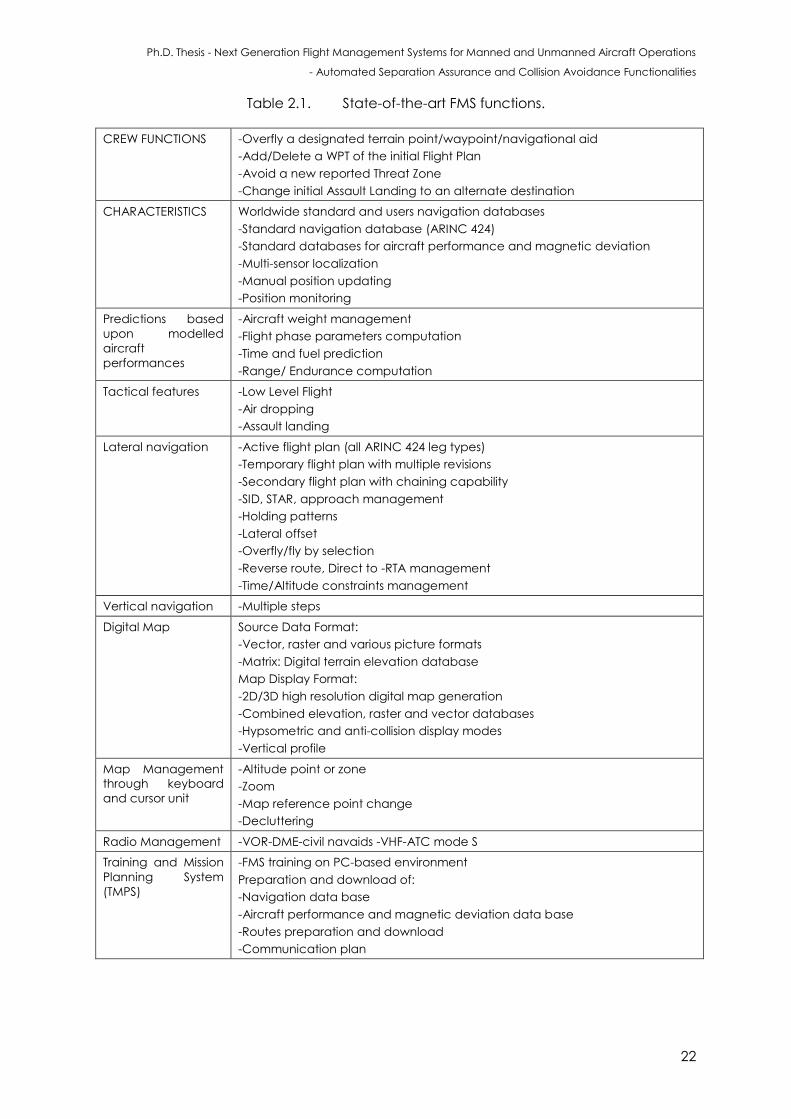
Ph.D. Thesis - Next Generation Flight Management Systems for Manned and Unmanned Aircraft Operations
- Automated Separation Assurance and Collision Avoidance Functionalities
22
Table 2.1. State-of-the-art FMS functions.
CREW FUNCTIONS -Overfly a designated terrain point/waypoint/navigational aid
-Add/Delete a WPT of the initial Flight Plan
-Avoid a new reported Threat Zone
-Change initial Assault Landing to an alternate destination
CHARACTERISTICS
Worldwide standard and users navigation databases
-Standard navigation database (ARINC 424)
-Standard databases for aircraft performance and magnetic deviation
-Multi-sensor localization
-Manual position updating
-Position monitoring
Predictions based
upon modelled
aircraft
performances
-Aircraft weight management
-Flight phase parameters computation
-Time and fuel prediction
-Range/ Endurance computation
Tactical features
-Low Level Flight
-Air dropping
-Assault landing
Lateral navigation
-Active flight plan (all ARINC 424 leg types)
-Temporary flight plan with multiple revisions
-Secondary flight plan with chaining capability
-SID, STAR, approach management
-Holding patterns
-Lateral offset
-Overfly/fly by selection
-Reverse route, Direct to -RTA management
-Time/Altitude constraints management
Vertical navigation -Multiple steps
Digital Map
Source Data Format:
-Vector, raster and various picture formats
-Matrix: Digital terrain elevation database
Map Display Format:
-2D/3D high resolution digital map generation
-Combined elevation, raster and vector databases
-Hypsometric and anti-collision display modes
-Vertical profile
Map Management
through keyboard
and cursor unit
-Altitude point or zone
-Zoom
-Map reference point change
-Decluttering
Radio Management -VOR-DME-civil navaids -VHF-ATC mode S
Training and Mission
Planning System
(TMPS)
-FMS training on PC-based environment
Preparation and download of:
-Navigation data base
-Aircraft performance and magnetic deviation data base
-Routes preparation and download
-Communication plan
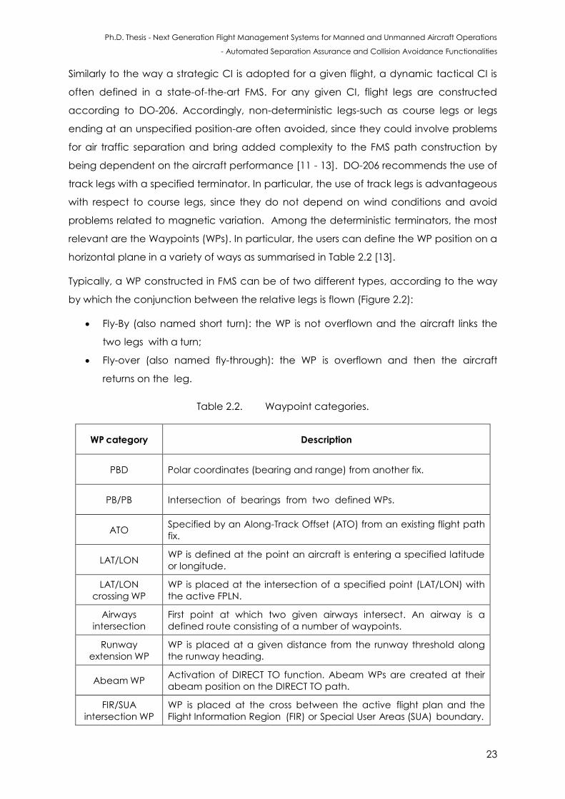
Ph.D. Thesis - Next Generation Flight Management Systems for Manned and Unmanned Aircraft Operations
- Automated Separation Assurance and Collision Avoidance Functionalities
23
Similarly to the way a strategic CI is adopted for a given flight, a dynamic tactical CI is
often defined in a state-of-the-art FMS. For any given CI, flight legs are constructed
according to DO-206. Accordingly, non-deterministic legs-such as course legs or legs
ending at an unspecified position-are often avoided, since they could involve problems
for air traffic separation and bring added complexity to the FMS path construction by
being dependent on the aircraft performance [11 - 13]. DO-206 recommends the use of
track legs with a specified terminator. In particular, the use of track legs is advantageous
with respect to course legs, since they do not depend on wind conditions and avoid
problems related to magnetic variation. Among the deterministic terminators, the most
relevant are the Waypoints (WPs). In particular, the users can define the WP position on a
horizontal plane in a variety of ways as summarised in Table 2.2 [13].
Typically, a WP constructed in FMS can be of two different types, according to the way
by which the conjunction between the relative legs is flown (Figure 2.2):
Fly-By (also named short turn): the WP is not overflown and the aircraft links the
two legs with a turn;
Fly-over (also named fly-through): the WP is overflown and then the aircraft
returns on the leg.
Table 2.2. Waypoint categories.
WP category Description
PBD Polar coordinates (bearing and range) from another fix.
PB/PB Intersection of bearings from two defined WPs.
ATO Specified by an Along-Track Offset (ATO) from an existing flight path
fix.
LAT/LON WP is defined at the point an aircraft is entering a specified latitude
or longitude.
LAT/LON
crossing WP
WP is placed at the intersection of a specified point (LAT/LON) with
the active FPLN.
Airways
intersection
First point at which two given airways intersect. An airway is a
defined route consisting of a number of waypoints.
Runway
extension WP
WP is placed at a given distance from the runway threshold along
the runway heading.
Abeam WP Activation of DIRECT TO function. Abeam WPs are created at their
abeam position on the DIRECT TO path.
FIR/SUA
intersection WP
WP is placed at the cross between the active flight plan and the
Flight Information Region (FIR) or Special User Areas (SUA) boundary.
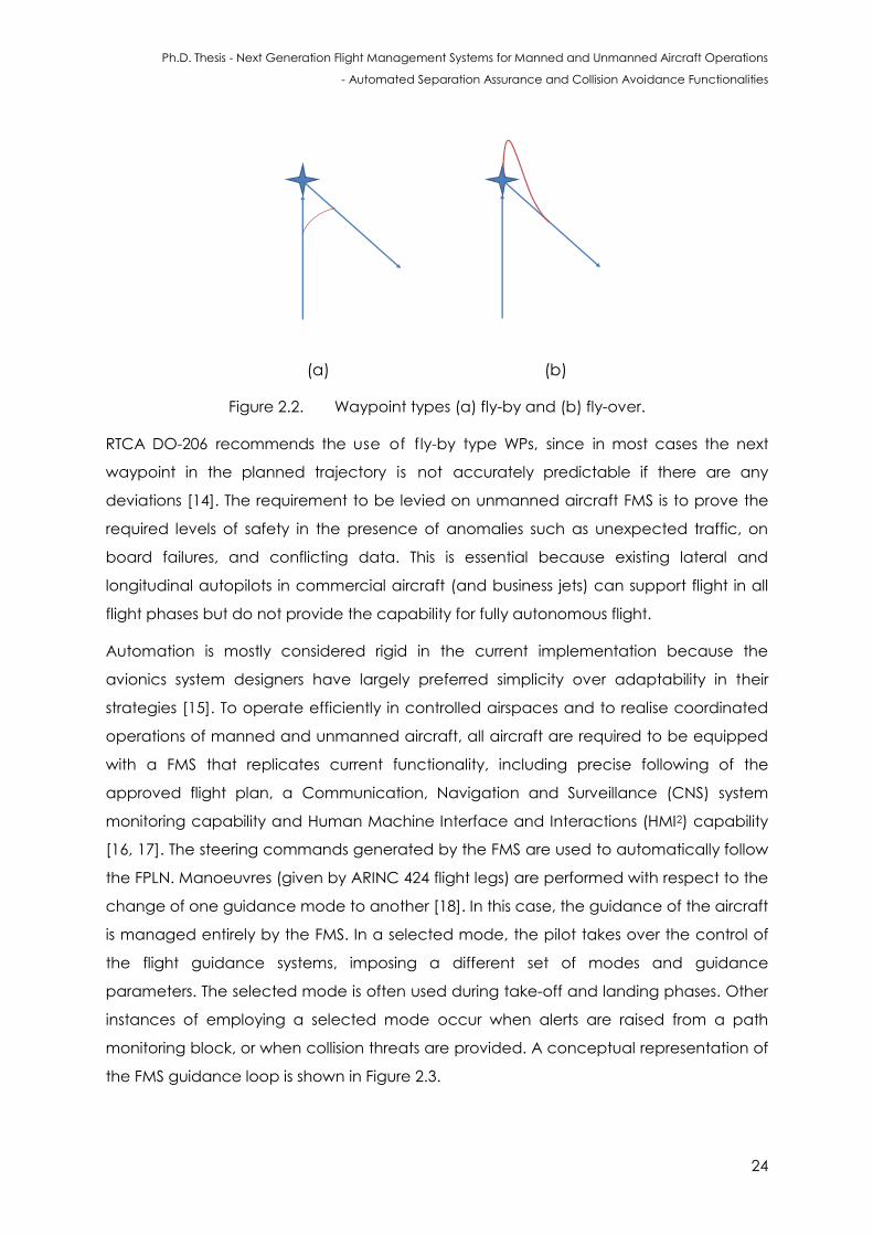
Ph.D. Thesis - Next Generation Flight Management Systems for Manned and Unmanned Aircraft Operations
- Automated Separation Assurance and Collision Avoidance Functionalities
24
(a) (b)
Figure 2.2. Waypoint types (a) fly-by and (b) fly-over.
RTCA DO-206 recommends the use of fly-by type WPs, since in most cases the next
waypoint in the planned trajectory is not accurately predictable if there are any
deviations [14]. The requirement to be levied on unmanned aircraft FMS is to prove the
required levels of safety in the presence of anomalies such as unexpected traffic, on
board failures, and conflicting data. This is essential because existing lateral and
longitudinal autopilots in commercial aircraft (and business jets) can support flight in all
flight phases but do not provide the capability for fully autonomous flight.
Automation is mostly considered rigid in the current implementation because the
avionics system designers have largely preferred simplicity over adaptability in their
strategies [15]. To operate efficiently in controlled airspaces and to realise coordinated
operations of manned and unmanned aircraft, all aircraft are required to be equipped
with a FMS that replicates current functionality, including precise following of the
approved flight plan, a Communication, Navigation and Surveillance (CNS) system
monitoring capability and Human Machine Interface and Interactions (HMI2) capability
[16, 17]. The steering commands generated by the FMS are used to automatically follow
the FPLN. Manoeuvres (given by ARINC 424 flight legs) are performed with respect to the
change of one guidance mode to another [18]. In this case, the guidance of the aircraft
is managed entirely by the FMS. In a selected mode, the pilot takes over the control of
the flight guidance systems, imposing a different set of modes and guidance
parameters. The selected mode is often used during take-off and landing phases. Other
instances of employing a selected mode occur when alerts are raised from a path
monitoring block, or when collision threats are provided. A conceptual representation of
the FMS guidance loop is shown in Figure 2.3.
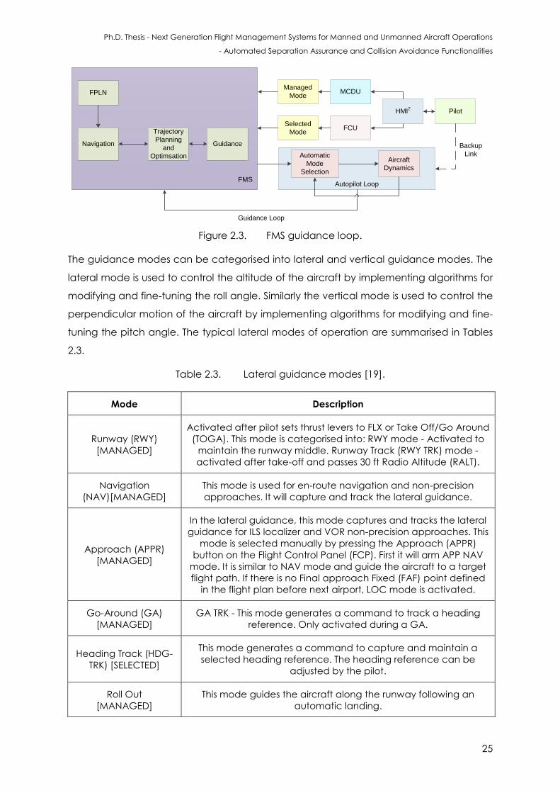
Ph.D. Thesis - Next Generation Flight Management Systems for Manned and Unmanned Aircraft Operations
- Automated Separation Assurance and Collision Avoidance Functionalities
25
FPLN
Navigation
Trajectory
Planning
and
Optimsation
Managed
Mode
Selected
Mode
MCDU
FCU
HMI2
Pilot
Automatic
Mode
Selection
Aircraft
Dynamics
Guidance Loop
Autopilot Loop
Backup
Link
Guidance
FMS
Figure 2.3. FMS guidance loop.
The guidance modes can be categorised into lateral and vertical guidance modes. The
lateral mode is used to control the altitude of the aircraft by implementing algorithms for
modifying and fine-tuning the roll angle. Similarly the vertical mode is used to control the
perpendicular motion of the aircraft by implementing algorithms for modifying and fine-
tuning the pitch angle. The typical lateral modes of operation are summarised in Tables
2.3.
Table 2.3. Lateral guidance modes [19].
Mode Description
Runway (RWY)
[MANAGED]
Activated after pilot sets thrust levers to FLX or Take Off/Go Around
(TOGA). This mode is categorised into: RWY mode - Activated to
maintain the runway middle. Runway Track (RWY TRK) mode -
activated after take-off and passes 30 ft Radio Altitude (RALT).
Navigation
(NAV)[MANAGED]
This mode is used for en-route navigation and non-precision
approaches. It will capture and track the lateral guidance.
Approach (APPR)
[MANAGED]
In the lateral guidance, this mode captures and tracks the lateral
guidance for ILS localizer and VOR non-precision approaches. This
mode is selected manually by pressing the Approach (APPR)
button on the Flight Control Panel (FCP). First it will arm APP NAV
mode. It is similar to NAV mode and guide the aircraft to a target
flight path. If there is no Final approach Fixed (FAF) point defined
in the flight plan before next airport, LOC mode is activated.
Go-Around (GA)
[MANAGED]
GA TRK - This mode generates a command to track a heading
reference. Only activated during a GA.
Heading Track (HDG-
TRK) [SELECTED]
This mode generates a command to capture and maintain a
selected heading reference. The heading reference can be
adjusted by the pilot.
Roll Out
[MANAGED]
This mode guides the aircraft along the runway following an
automatic landing.
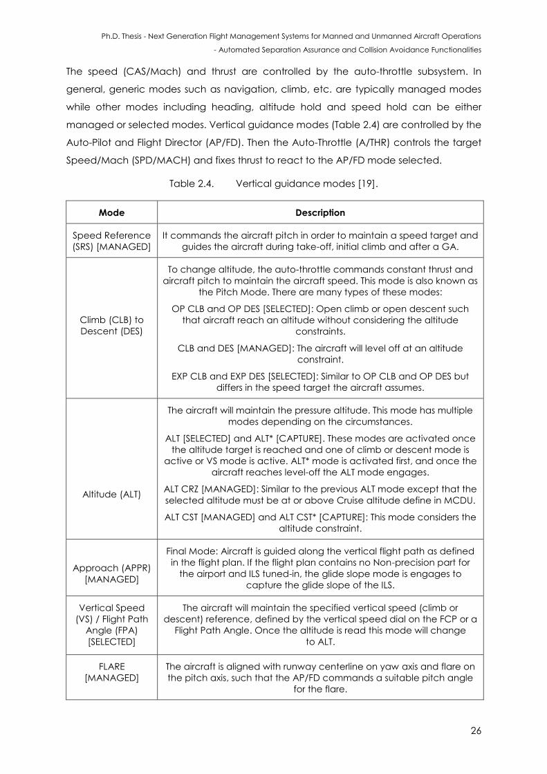
Ph.D. Thesis - Next Generation Flight Management Systems for Manned and Unmanned Aircraft Operations
- Automated Separation Assurance and Collision Avoidance Functionalities
26
The speed (CAS/Mach) and thrust are controlled by the auto-throttle subsystem. In
general, generic modes such as navigation, climb, etc. are typically managed modes
while other modes including heading, altitude hold and speed hold can be either
managed or selected modes. Vertical guidance modes (Table 2.4) are controlled by the
Auto-Pilot and Flight Director (AP/FD). Then the Auto-Throttle (A/THR) controls the target
Speed/Mach (SPD/MACH) and fixes thrust to react to the AP/FD mode selected.
Table 2.4. Vertical guidance modes [19].
Mode Description
Speed Reference
(SRS) [MANAGED]
It commands the aircraft pitch in order to maintain a speed target and
guides the aircraft during take-off, initial climb and after a GA.
Climb (CLB) to
Descent (DES)
To change altitude, the auto-throttle commands constant thrust and
aircraft pitch to maintain the aircraft speed. This mode is also known as
the Pitch Mode. There are many types of these modes:
OP CLB and OP DES [SELECTED]: Open climb or open descent such
that aircraft reach an altitude without considering the altitude
constraints.
CLB and DES [MANAGED]: The aircraft will level off at an altitude
constraint.
EXP CLB and EXP DES [SELECTED]: Similar to OP CLB and OP DES but
differs in the speed target the aircraft assumes.
Altitude (ALT)
The aircraft will maintain the pressure altitude. This mode has multiple
modes depending on the circumstances.
ALT [SELECTED] and ALT* [CAPTURE]. These modes are activated once
the altitude target is reached and one of climb or descent mode is
active or VS mode is active. ALT* mode is activated first, and once the
aircraft reaches level-off the ALT mode engages.
ALT CRZ [MANAGED]: Similar to the previous ALT mode except that the
selected altitude must be at or above Cruise altitude define in MCDU.
ALT CST [MANAGED] and ALT CST* [CAPTURE]: This mode considers the
altitude constraint.
Approach (APPR)
[MANAGED]
Final Mode: Aircraft is guided along the vertical flight path as defined
in the flight plan. If the flight plan contains no Non-precision part for
the airport and ILS tuned-in, the glide slope mode is engages to
capture the glide slope of the ILS.
Vertical Speed
(VS) / Flight Path
Angle (FPA)
[SELECTED]
The aircraft will maintain the specified vertical speed (climb or
descent) reference, defined by the vertical speed dial on the FCP or a
Flight Path Angle. Once the altitude is read this mode will change
to ALT.
FLARE
[MANAGED]
The aircraft is aligned with runway centerline on yaw axis and flare on
the pitch axis, such that the AP/FD commands a suitable pitch angle
for the flare.
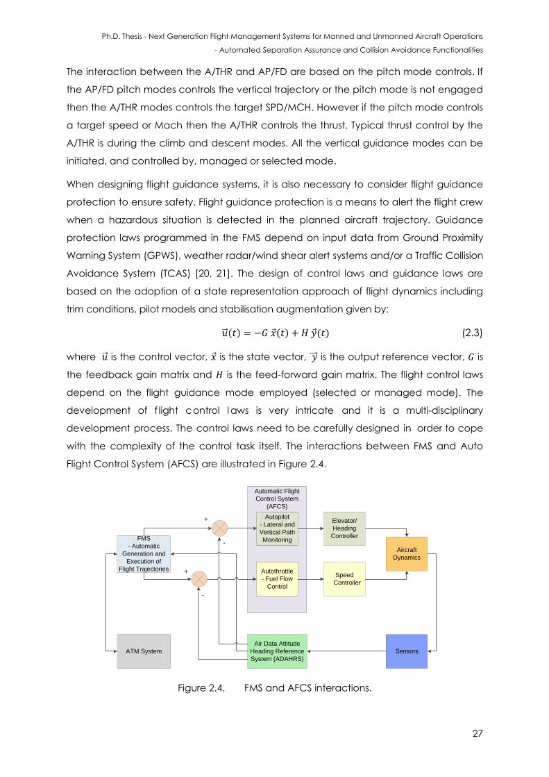
Ph.D. Thesis - Next Generation Flight Management Systems for Manned and Unmanned Aircraft Operations
- Automated Separation Assurance and Collision Avoidance Functionalities
27
The interaction between the A/THR and AP/FD are based on the pitch mode controls. If
the AP/FD pitch modes controls the vertical trajectory or the pitch mode is not engaged
then the A/THR modes controls the target SPD/MCH. However if the pitch mode controls
a target speed or Mach then the A/THR controls the thrust. Typical thrust control by the
A/THR is during the climb and descent modes. All the vertical guidance modes can be
initiated, and controlled by, managed or selected mode.
When designing flight guidance systems, it is also necessary to consider flight guidance
protection to ensure safety. Flight guidance protection is a means to alert the flight crew
when a hazardous situation is detected in the planned aircraft trajectory. Guidance
protection laws programmed in the FMS depend on input data from Ground Proximity
Warning System (GPWS), weather radar/wind shear alert systems and/or a Traffic Collision
Avoidance System (TCAS) [20, 21]. The design of control laws and guidance laws are
based on the adoption of a state representation approach of flight dynamics including
trim conditions, pilot models and stabilisation augmentation given by:
( ) ( ) ( ) (2.3)
where is the control vector, is the state vector, is the output reference vector, is
the feedback gain matrix and is the feed-forward gain matrix. The flight control laws
depend on the flight guidance mode employed (selected or managed mode). The
development of f light control l aws is very intricate and it is a multi-disciplinary
development process. The control laws need to be carefully designed in order to cope
with the complexity of the control task itself. The interactions between FMS and Auto
Flight Control System (AFCS) are illustrated in Figure 2.4.
FMS
- Automatic
Generation and
Execution of
Flight Trajectories
Automatic Flight
Control System
(AFCS)
Autopilot
- Lateral and
Vertical Path
Monitoring
Autothrottle
- Fuel Flow
Control
ATM System
Aircraft
Dynamics
Sensors
Air Data Attitude
Heading Reference
System (ADAHRS)
+
-
+
-
Elevator/
Heading
Controller
Speed
Controller
Figure 2.4. FMS and AFCS interactions.
Ph.D. Thesis - Next Generation Flight Management Systems for Manned and Unmanned Aircraft Operations
- Automated Separation Assurance and Collision Avoidance Functionalities
28
A typical FCS consists of control surface actuators, motion sensors and controllers. Either
the pilot or flight guidance system provides the reference inputs i.e., command signals.
The actuators translate the command signals into control surface deflections, while
motion sensors detect the changes in aircraft motion variables (linear / angular
accelerations and velocities). If there is a difference between the commanded state
and measured state, the controller generates command signals in accordance with the
implemented control law such that the actual state is driven towards the desired state.
The guidance system continuously monitors the path of the aircraft. In the case of any
deviation from the desired path, the guidance system issues path correction commands
to the flight control system. The flight control system then translates these commands into
control surface deflections to cause the required change in the motion of the aircraft.
Usually, an AFCS contains two loops: an inner loop known as a Stability Augmentation
System (SAS) and an outer flight path control loop known as an autopilot [22]. The
purpose of SAS is to augment the values of certain stability derivatives of the aircraft
through feedback control. The SAS improves the flying qualities of an aircraft and helps
in rejecting atmospheric disturbances. Usually, a SAS is engaged for the entire duration
of the flight to ensure that the airframe exhibits a stable behaviour. A dedicated SAS is
designed for each mode of aircraft motion. The most commonly used SAS functions are:
yaw damper, pitch rate stability augmentation and roll rate damper. The autopilot
enables an aircraft to follow a desired lateral / vertical profile, without any input from the
pilot. Essentially, the autopilot facilitates an aircraft at a desired altitude / heading /
airspeed. The autopilot comprises two sub-systems: the attitude control system and the
flight path control system [23]. Attitude control systems are used to place an aircraft in
the desired orientation in space and keep that orientation for the required duration of
time. Flight path control systems allow an aircraft to follow a predefined path with high
accuracy. The basic modes of an autopilot are listed below:
Longitudinal Channel:
Auto-throttle (speed control);
Altitude hold/select mode;
Vertical speed hold/select mode;
Attitude hold mode (pitch attitude).
Lateral Channel:
Attitude hold mode (roll attitude);
Heading hold/select mode.
Ph.D. Thesis - Next Generation Flight Management Systems for Manned and Unmanned Aircraft Operations
- Automated Separation Assurance and Collision Avoidance Functionalities
29
2.4 Maintenance of Separation
In this section, a short summary of the top-level components of airborne and ground
surveillance systems are defined and a brief description of the lower-level services,
functions, equipment, roles and procedures under each component are presented. The
top-level components of the ATM system as given by ICAO are CM, traffic
synchronisation, demand and capacity balancing, aerodrome/airspace operations,
and airspace and service delivery management.
2.4.1 Airspace Categories and Classes
The airspace is defined as the portion of the atmosphere controlled by a country above
its territory, including its territorial waters or, more generally, any specific 3D area of the
atmosphere [25]. According to CFR, Title 14, part 71-73 and the Aeronautical Information
Manual, the US national airspace is divided into two categories and four types based on
the complexity or density of aircraft movements, proximity to airports, altitude, the nature
of the operations conducted within the airspace, the level of safety required, and the
national and public interest. These categories and types are regulated as follows:
Explicit regulations for airspace class A, B, C, D, E, restricted and prohibited areas;
A non-regulatory framework that includes airspace class G, Military Operations
Area (MOA), warning areas, alert areas, and controlled firing areas.
While classes are mutually exclusive, categories can be defined within any class as
needed. Categories are typically used to provide additional information to pilots about
hazards activities common to the airspace. There are four types within these two
categories:
Controlled airspace;
Uncontrolled airspace;
Special use airspace;
Other airspace.
Airspace classes A through E, ordered from most restrictive to least, corresponds to
controlled airspace. However, when overlapping airspace designations apply to the
same airspace, the operating rules associated with the more restrictive airspace
designation apply [CFR §71.9].
Ph.D. Thesis - Next Generation Flight Management Systems for Manned and Unmanned Aircraft Operations
- Automated Separation Assurance and Collision Avoidance Functionalities
30
2.4.2 Rules of the Air
By definition, control areas are volumes of airspace that are sufficient to contain the
flight paths of Instrument Flight Rules (IFR) or portions thereof for which it is desired to
provide certain Air Traffic Services (ATS). Control areas also include ATS routes (airways)
and Terminal Control Areas (TCA), frequently known as Terminal Manoeuvring Areas
(TMA). Control zones complement control areas in their purpose and are specifically
conceived to contain arrival and departure IFR flight paths in close proximity to the
ground. For minor and isolated airports with limited IFR traffic, an appropriate
combination of control zones and ATS routes is usually sufficient to contain IFR traffic
safely. This is due to the fact that tactical deconfliction by ATM operators is almost never
required and occasional peaks of traffic can be successfully managed by exploiting
multiple approach and departure procedures and en-route holdings. Larger airports or
combinations of multiple minor airports in close proximity to each other require more
frequent tactical ATM interventions in terms of path stretching and separation measures.
Whenever additional allowance for these tactical measures is necessary, TCA/TMA is
established. In order to maximise safety of IFR traffic TCA/TMA are most commonly
granted the highest levels of ATS, corresponding to airspace classes “A”, “B” or, less
frequently, “C”.
Due to their distinctive nature, TCA/TMA have become the paradigm of dense air traffic
scenarios, where arriving, departing and overflying aircraft intersect leading to frequent
conflict situations. The highest levels of ATS assigned to TCA/TMA, implies that most of the
responsibilities for conflict detection, separation maintenance, sequencing and spacing
lies on the ATM side. This is effectively the opposite of recreational airspace assigned
classes “G” and “F”, and has important consequences for manned and unmanned
aircraft SA&CA.
CA algorithms have to take into account the same collision avoidance requirements of
the rules of the air for manned aviation, delineated in the ICAO Annex 2 [24], in order to
guarantee the Equivalent Level of Safety (ELOS).
Aviation regulations in eth United States, collectively known as Federal Aviation
Regulation (FAR), are codified in the Code of Federal Regulations (CFR), Title 14,
Chapter I [26]. The CFR, along with supplementary material like handbooks, orders,
advisory circulars and technical standards orders issued by the FAA, define appropriate
standards, procedures, and practices to ensure that manufactures and operators are
able to establish a minimum level of safety and reliability required for civil operations
Ph.D. Thesis - Next Generation Flight Management Systems for Manned and Unmanned Aircraft Operations
- Automated Separation Assurance and Collision Avoidance Functionalities
31
[27]. Aviation authorities in other counties (UK, Australia, etc.) have an equivalent code
of regulations applicable regionally.
2.4.3 General Operation Principles and Flight Rules
Code of Federal Aviation, Title 14, part 91 has established right-of-way rules, aircraft
speed, minimum safe altitudes, equipment, instrument, and certificate requirements,
maintenance, preventive maintenance, special flight operations i.e. aerobatic flight,
flight test areas, etc. for the US. Federal regulations do not permit pilots to fly below
10,000 ft or in proximity of airspace Class B, C, and D at speed exceeding 250 knots. It is
not allowed for aircraft to operate close to another aircraft in a way that creates a
collision hazard. The pilot is required to contribute to collision avoidance by being alert in
order to “see and avoid” other aircraft [CFR §91.111]. The flight rules that need to be
considered for implementing effective SA&CA algorithms for manned and unmanned
aircraft are summarised as follows:
Right-of-way rules – Except water operations: When an aircraft has the right-of-
way, other traffic shall give way to that aircraft and may not pass over, under, or
ahead of it unless well clear [CFR §91.113]. The main right-of-way rules are:
- The aircraft that is in distress has right of way over all other traffic;
- Landing aircraft or aircraft on final approach to land have right of way over
other aircraft in flight or operating on the surface. If two or more aircraft are
landing then the aircraft at the lower altitude has the right of way;
- Aircraft being overtaken have the right of way. Overtaking aircraft shall alter
course to the right to pass well clear;
- In an head-on scenario, each aircraft shall alter course to the right to pass well
clear;
- In case of a converging scenario:
when the aircraft are of the same category, then the aircraft to the other’s
right has the right of way;
if the aircraft are of different categories, then both aircraft have to follow
the rules provided in CFR; §91 for converging encounters.
Aircraft speed: The minimum safe airspeed defined by the [CFR; §91.117] is 250
knots (288 mph) for any particular aircraft operating below 10,000 ft MSL.
However, the minimum safe airspeed is 200 knots (230 mph) for any aircraft
operating at or below 2,500 ft above the surface within 4 NM of the primary
airport of a Class C or Class D airspace area. In regards to Class B, [CFR §91.117]
indicates that no person may operate an aircraft in the airspace underlying a
Ph.D. Thesis - Next Generation Flight Management Systems for Manned and Unmanned Aircraft Operations
- Automated Separation Assurance and Collision Avoidance Functionalities
32
Class B airspace designated for an airport or in a VFR corridor designated through
Class B airspace at an indicated airspeed of more than 200 knots (230 mph);
Minimum safe altitude: According to [CFR §91.199], the minimum safe altitudes
are categorized as follows:
- Over congested areas: an aircraft shall maintain an altitude of 1,000 ft above
the highest obstacle within a horizontal radius of 2,000 ft of the aircraft;
- Non-congested areas: minimum of 500 ft Above Ground Level (AGL) shall be
maintained (except over open water or sparsely populated areas);
- Anywhere else: an aircraft should maintain an altitude such that if the engine
fails, an emergency landing may be executed without undue hazard to
persons or property on the surface.
Failure of power unit(s): in case of power unit failure, the aircraft shall not fly
below the altitude necessary to make an emergency landing;
Land clear rule: when in densely populated areas, the aircraft shall not fly
below the altitude necessary to make a landing outside of the congested
area, in the event of a power unit failure;
Flying over open air assemblies: when flying over an organised open-air
assembly of more than 1000 persons, the aircraft shall fly above 1000 ft. Such
an altitude permits landing in the event of a power unit failure.
The CFR Title 14, Part 91 defines two types of flight rules, namely visual flight rules and
instrument flight rules, which apply to all aircraft except moored balloons, kites,
unmanned rockets, and unmanned free balloons.
The CFR Title 14, Part 27 (Airworthiness Standards: Normal Category Rotorcraft) and CFR
Title 14, Part 29 (Airworthiness Standards: Transport Category Rotorcraft) provide the
airworthiness standard for normal and transport category rotorcraft respectively. In most
countries, at airports/helipads, established standard departure and arrival procedures
ensure that (wherever possible), twin engine Vertical Take-Off and Landing (VTOL)
aircraft do not fly over residential areas below 1500ft. Normal flight is permitted down to
1000ft over residential areas and lower levels are permitted during landing and take-off.
The following conditions shall be applied in the authorisation of VTOL aircraft when flying
according to VFR:
such flights may be conducted during day only, unless otherwise permitted by
the competent authority;
by the pilot: (i) clear of cloud and with the ground surface in sight, (ii) the flight
visibility is not less than not less than 800 m; (iii) fly at a speed of 140 kts (instrument
Ph.D. Thesis - Next Generation Flight Management Systems for Manned and Unmanned Aircraft Operations
- Automated Separation Assurance and Collision Avoidance Functionalities
33
air speed) or less to give adequate chance to observe other traffic and any
obstacles to avoid a collision and take and timely actions if necessary.
In some circumstances, VTOL aircraft need to fly at lower altitudes (law enforcement,
search and rescue, emergency, medical and surveying purposes, etc.), which might
require authorisation from the regulatory authority. If a VTOL aircraft pilot requires to cross
a controlled zone around an airport, it may be necessary for the ATCo to hold the VTOL
aircraft in one place until it is safe to continue operations.
2.4.4 Separation Standards
Separation standards refer to the minimum distance that aircraft operating in controlled
airspace and at airports with an operational control tower must keep between them
[28]. Different separation standards apply to aircraft operating under IFR and VFR. In
Australia, aircraft flying under IFR in controlled airspace up to 29,000 ft altitude are
separated by 1000 ft vertically, unless they are separated horizontally. When above
29,000 ft, the vertical separation increases to 2000 ft, except in airspace where Reduced
Vertical Separation Minima (RVSM) is applied. It is generally guaranteed that when
aircraft are separated vertically, horizontal separation can be reduced without
compromising safety. In controlled en route airspace, the horizontal separation standard
between aircraft flying at the same altitude is 5 Nautical Miles (NM) while in terminal
area airspace, the minimum separation is 3 NM. For general aviation aircraft (non-
commercial aircraft) outside of controlled airspace, separation can be as close as 500 ft
vertically and 500 ft horizontally. ICAO rules divide aircraft into three main categories
including light, medium and heavy, in order to establish separation between aircraft
based on wake vortices. The classification is based on the maximum take-off weight of
the aircraft and the separation distances are based on experimental flight data (flight
tests). The ICAO classification is provided in Table 2.7 (adapted from [29]). The only
exception is for Airbus A380 aircraft, which has a different set of separation distance
standards.
An analytical model has been proposed for calculating the safe separation distance
between aircraft and is especially valuable in non-cooperative sensor based aircraft
separation. The safe separation distance is given by:
(2.3)
where is the safe separation distance, is the fraction of the available control moment
that is used, is the turbulent kinematic shear viscosity and :
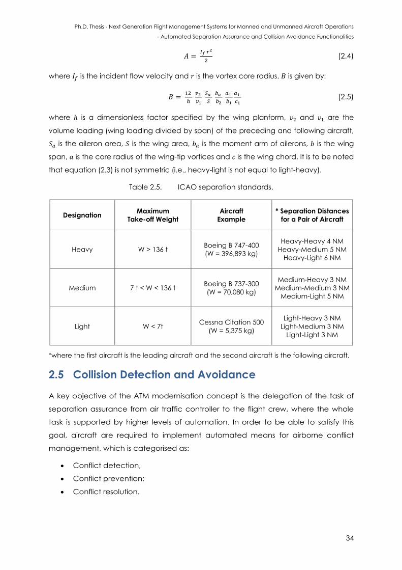
Ph.D. Thesis - Next Generation Flight Management Systems for Manned and Unmanned Aircraft Operations
- Automated Separation Assurance and Collision Avoidance Functionalities
34
(2.4)
where is the incident flow velocity and is the vortex core radius. is given by:
(2.5)
where is a dimensionless factor specified by the wing planform, and are the
volume loading (wing loading divided by span) of the preceding and following aircraft,
is the aileron area, is the wing area, is the moment arm of ailerons, is the wing
span, is the core radius of the wing-tip vortices and is the wing chord. It is to be noted
that equation (2.3) is not symmetric (i.e., heavy-light is not equal to light-heavy).
Table 2.5. ICAO separation standards.
Designation Maximum
Take-off Weight
Aircraft
Example
* Separation Distances
for a Pair of Aircraft
Heavy W > 136 t Boeing B 747-400
(W = 396,893 kg)
Heavy-Heavy 4 NM
Heavy-Medium 5 NM
Heavy-Light 6 NM
Medium 7 t < W < 136 t Boeing B 737-300
(W = 70,080 kg)
Medium-Heavy 3 NM
Medium-Medium 3 NM
Medium-Light 5 NM
Light W < 7t Cessna Citation 500
(W = 5,375 kg)
Light-Heavy 3 NM
Light-Medium 3 NM
Light-Light 3 NM
*where the first aircraft is the leading aircraft and the second aircraft is the following aircraft.
2.5 Collision Detection and Avoidance
A key objective of the ATM modernisation concept is the delegation of the task of
separation assurance from air traffic controller to the flight crew, where the whole
task is supported by higher levels of automation. In order to be able to satisfy this
goal, aircraft are required to implement automated means for airborne conflict
management, which is categorised as:
Conflict detection,
Conflict prevention;
Conflict resolution.
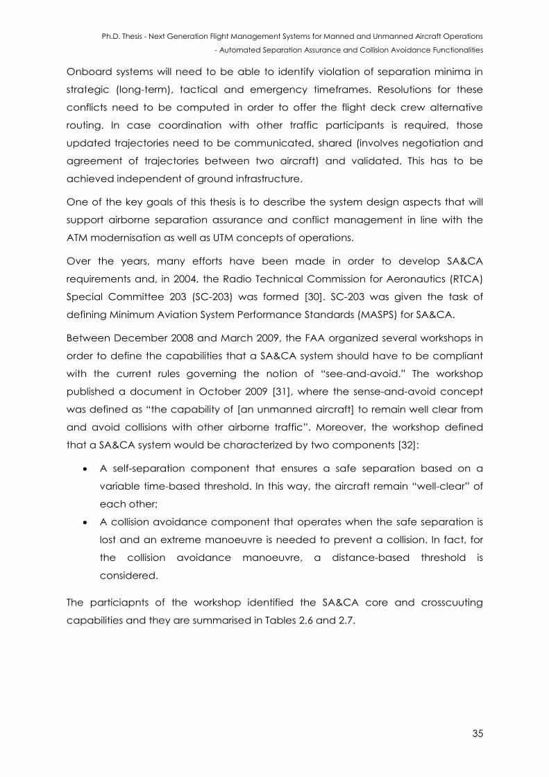
Ph.D. Thesis - Next Generation Flight Management Systems for Manned and Unmanned Aircraft Operations
- Automated Separation Assurance and Collision Avoidance Functionalities
35
Onboard systems will need to be able to identify violation of separation minima in
strategic (long-term), tactical and emergency timeframes. Resolutions for these
conflicts need to be computed in order to offer the flight deck crew alternative
routing. In case coordination with other traffic participants is required, those
updated trajectories need to be communicated, shared (involves negotiation and
agreement of trajectories between two aircraft) and validated. This has to be
achieved independent of ground infrastructure.
One of the key goals of this thesis is to describe the system design aspects that will
support airborne separation assurance and conflict management in line with the
ATM modernisation as well as UTM concepts of operations.
Over the years, many efforts have been made in order to develop SA&CA
requirements and, in 2004, the Radio Technical Commission for Aeronautics (RTCA)
Special Committee 203 (SC-203) was formed [30]. SC-203 was given the task of
defining Minimum Aviation System Performance Standards (MASPS) for SA&CA.
Between December 2008 and March 2009, the FAA organized several workshops in
order to define the capabilities that a SA&CA system should have to be compliant
with the current rules governing the notion of “see-and-avoid.” The workshop
published a document in October 2009 [31], where the sense-and-avoid concept
was defined as “the capability of [an unmanned aircraft] to remain well clear from
and avoid collisions with other airborne traffic”. Moreover, the workshop defined
that a SA&CA system would be characterized by two components [32]:
A self-separation component that ensures a safe separation based on a
variable time-based threshold. In this way, the aircraft remain “well-clear” of
each other;
A collision avoidance component that operates when the safe separation is
lost and an extreme manoeuvre is needed to prevent a collision. In fact, for
the collision avoidance manoeuvre, a distance-based threshold is
considered.
The particiapnts of the workshop identified the SA&CA core and crosscuuting
capabilities and they are summarised in Tables 2.6 and 2.7.
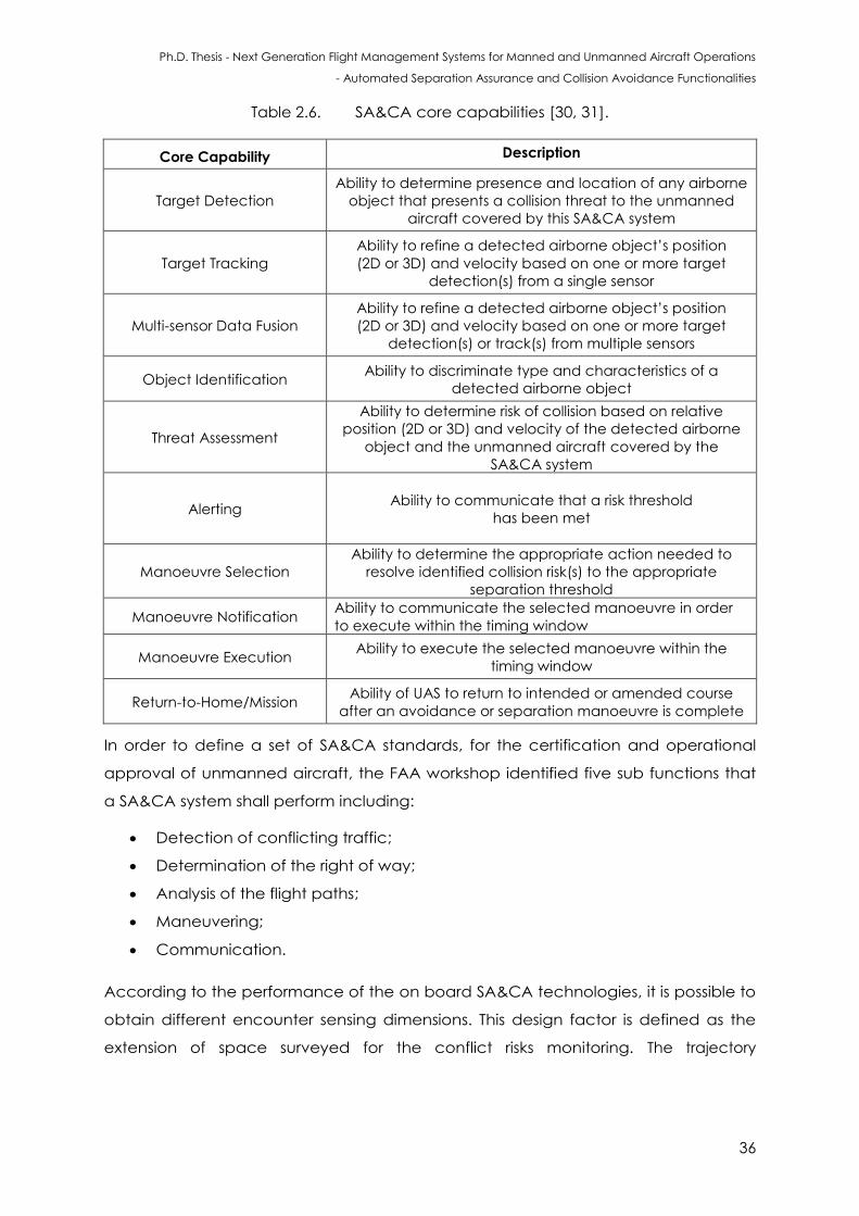
Ph.D. Thesis - Next Generation Flight Management Systems for Manned and Unmanned Aircraft Operations
- Automated Separation Assurance and Collision Avoidance Functionalities
36
Table 2.6. SA&CA core capabilities [30, 31].
Core Capability Description
Target Detection
Ability to determine presence and location of any airborne
object that presents a collision threat to the unmanned
aircraft covered by this SA&CA system
Target Tracking
Ability to refine a detected airborne object’s position
(2D or 3D) and velocity based on one or more target
detection(s) from a single sensor
Multi-sensor Data Fusion
Ability to refine a detected airborne object’s position
(2D or 3D) and velocity based on one or more target
detection(s) or track(s) from multiple sensors
Object Identification Ability to discriminate type and characteristics of a
detected airborne object
Threat Assessment
Ability to determine risk of collision based on relative
position (2D or 3D) and velocity of the detected airborne
object and the unmanned aircraft covered by the
SA&CA system
Alerting
Ability to communicate that a risk threshold
has been met
Manoeuvre Selection
Ability to determine the appropriate action needed to
resolve identified collision risk(s) to the appropriate
separation threshold
Manoeuvre Notification Ability to communicate the selected manoeuvre in order
to execute within the timing window
Manoeuvre Execution Ability to execute the selected manoeuvre within the
timing window
Return-to-Home/Mission Ability of UAS to return to intended or amended course
after an avoidance or separation manoeuvre is complete
In order to define a set of SA&CA standards, for the certification and operational
approval of unmanned aircraft, the FAA workshop identified five sub functions that
a SA&CA system shall perform including:
Detection of conflicting traffic;
Determination of the right of way;
Analysis of the flight paths;
Maneuvering;
Communication.
According to the performance of the on board SA&CA technologies, it is possible to
obtain different encounter sensing dimensions. This design factor is defined as the
extension of space surveyed for the conflict risks monitoring. The trajectory
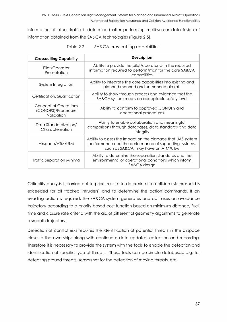
Ph.D. Thesis - Next Generation Flight Management Systems for Manned and Unmanned Aircraft Operations
- Automated Separation Assurance and Collision Avoidance Functionalities
37
information of other traffic is determined after performing multi-sensor data fusion of
information obtained from the SA&CA technologies (Figure 2.5).
Table 2.7. SA&CA crosscutting capabilities.
Crosscutting Capability Description
Pilot/Operator
Presentation
Ability to provide the pilot/operator with the required
information required to perform/monitor the core SA&CA
capabilities
System Integration Ability to integrate the core capabilities into existing and
planned manned and unmanned aircraft
Certification/Qualification Ability to show through process and evidence that the
SA&CA system meets an acceptable safety level
Concept of Operations
(CONOPS)/Procedure
Validation
Ability to conform to approved CONOPS and
operational procedures
Data Standardization/
Characterization
Ability to enable collaboration and meaningful
comparisons through databases, data standards and data
integrity
Airspace/ATM/UTM
Ability to assess the impact on the airspace that UAS system
performance and the performance of supporting systems,
such as SA&CA, may have on ATM/UTM
Traffic Separation Minima
Ability to determine the separation standards and the
environmental or operational conditions which inform
SA&CA design
Criticality analysis is carried out to prioritize (i.e. to determine if a collision risk threshold is
exceeded for all tracked intruders) and to determine the action commands. If an
evading action is required, the SA&CA system generates and optimises an avoidance
trajectory according to a priority based cost function based on minimum distance, fuel,
time and closure rate criteria with the aid of differential geometry algorithms to generate
a smooth trajectory.
Detection of conflict risks requires the identification of potential threats in the airspace
close to the own ship; along with continuous data updates, collection and recording.
Therefore it is necessary to provide the system with the tools to enable the detection and
identification of specific type of threats. These tools can be simple databases, e.g. for
detecting ground threats, sensors set for the detection of moving threats, etc.
Ph.D. Thesis - Next Generation Flight Management Systems for Manned and Unmanned Aircraft Operations
- Automated Separation Assurance and Collision Avoidance Functionalities
38
Obstacle/ Intruder Tracking (Trajectory Determination)
Criticality Analysis – Prioritizing, Declaration and Action Determination
Avoidance Trajectory / Separation Commands Generation
Sensor Management – Multi-sensor Data Fusion
Flight Management System
Autopilot
Flight Control System
Figure 2.5. SA&CA system processes.
Consider a classical two aircraft conflict, where an aircraft on the lower segment
flies at m/s, and an aircraft on the upper segment flies at m/s. The angle of
incidence is and D is the separation standard.
Let:
(2.6)
If two aircraft are in conflict, the following inequality should be satisfied to avoid any
conflicts.
( ) ( )
(2.7)
The above second degree inequality will only be satisfied if the following equation holds
true:
( ) ( )
(2.8)
Equation (2.5) has at least one solution. Hence the discriminant is given by:
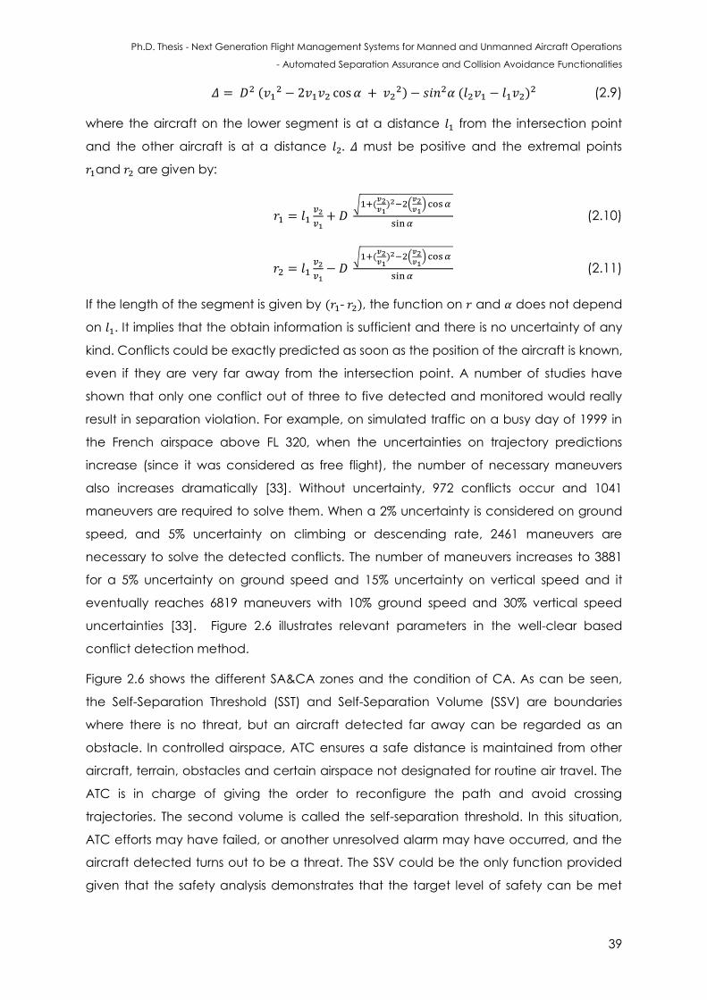
Ph.D. Thesis - Next Generation Flight Management Systems for Manned and Unmanned Aircraft Operations
- Automated Separation Assurance and Collision Avoidance Functionalities
39
(
) ( ) (2.9)
where the aircraft on the lower segment is at a distance from the intersection point
and the other aircraft is at a distance must be positive and the extremal points
and are given by:
√ ( ) (
)
(2.10)
√ ( ) (
)
(2.11)
If the length of the segment is given by ( - ), the function on and does not depend
on . It implies that the obtain information is sufficient and there is no uncertainty of any
kind. Conflicts could be exactly predicted as soon as the position of the aircraft is known,
even if they are very far away from the intersection point. A number of studies have
shown that only one conflict out of three to five detected and monitored would really
result in separation violation. For example, on simulated traffic on a busy day of 1999 in
the French airspace above FL 320, when the uncertainties on trajectory predictions
increase (since it was considered as free flight), the number of necessary maneuvers
also increases dramatically [33]. Without uncertainty, 972 conflicts occur and 1041
maneuvers are required to solve them. When a 2% uncertainty is considered on ground
speed, and 5% uncertainty on climbing or descending rate, 2461 maneuvers are
necessary to solve the detected conflicts. The number of maneuvers increases to 3881
for a 5% uncertainty on ground speed and 15% uncertainty on vertical speed and it
eventually reaches 6819 maneuvers with 10% ground speed and 30% vertical speed
uncertainties [33]. Figure 2.6 illustrates relevant parameters in the well-clear based
conflict detection method.
Figure 2.6 shows the different SA&CA zones and the condition of CA. As can be seen,
the Self-Separation Threshold (SST) and Self-Separation Volume (SSV) are boundaries
where there is no threat, but an aircraft detected far away can be regarded as an
obstacle. In controlled airspace, ATC ensures a safe distance is maintained from other
aircraft, terrain, obstacles and certain airspace not designated for routine air travel. The
ATC is in charge of giving the order to reconfigure the path and avoid crossing
trajectories. The second volume is called the self-separation threshold. In this situation,
ATC efforts may have failed, or another unresolved alarm may have occurred, and the
aircraft detected turns out to be a threat. The SSV could be the only function provided
given that the safety analysis demonstrates that the target level of safety can be met
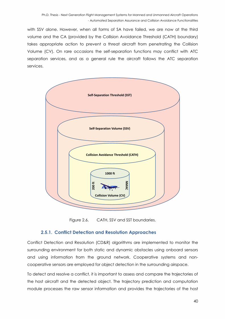
Ph.D. Thesis - Next Generation Flight Management Systems for Manned and Unmanned Aircraft Operations
- Automated Separation Assurance and Collision Avoidance Functionalities
40
with SSV alone. However, when all forms of SA have failed, we are now at the third
volume and the CA (provided by the Collision Avoidance Threshold (CATH) boundary)
takes appropriate action to prevent a threat aircraft from penetrating the Collision
Volume (CV). On rare occasions the self-separation functions may conflict with ATC
separation services, and as a general rule the aircraft follows the ATC separation
services.
20
0 f
t
Collision Volume (CV)
NM
AC
1000 ft
Collision Avoidance Threshold (CATH)
Self-Separation Volume (SSV)
Self-Separation Threshold (SST)
Figure 2.6. CATH, SSV and SST boundaries.
2.5.1. Conflict Detection and Resolution Approaches
Conflict Detection and Resolution (CD&R) algorithms are implemented to monitor the
surrounding environment for both static and dynamic obstacles using onboard sensors
and using information from the ground network. Cooperative systems and non-
cooperative sensors are employed for object detection in the surrounding airspace.
To detect and resolve a conflict, it is important to assess and compare the trajectories of
the host aircraft and the detected object. The trajectory prediction and computation
module processes the raw sensor information and provides the trajectories of the host
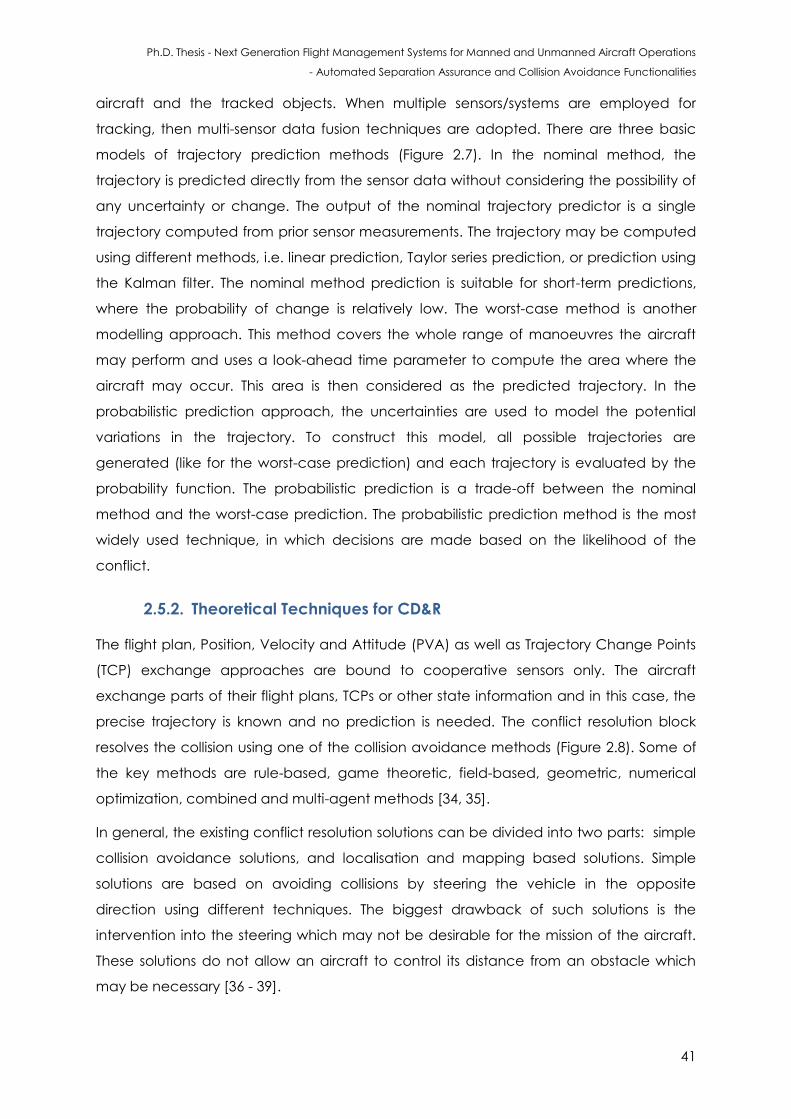
Ph.D. Thesis - Next Generation Flight Management Systems for Manned and Unmanned Aircraft Operations
- Automated Separation Assurance and Collision Avoidance Functionalities
41
aircraft and the tracked objects. When multiple sensors/systems are employed for
tracking, then multi-sensor data fusion techniques are adopted. There are three basic
models of trajectory prediction methods (Figure 2.7). In the nominal method, the
trajectory is predicted directly from the sensor data without considering the possibility of
any uncertainty or change. The output of the nominal trajectory predictor is a single
trajectory computed from prior sensor measurements. The trajectory may be computed
using different methods, i.e. linear prediction, Taylor series prediction, or prediction using
the Kalman filter. The nominal method prediction is suitable for short-term predictions,
where the probability of change is relatively low. The worst-case method is another
modelling approach. This method covers the whole range of manoeuvres the aircraft
may perform and uses a look-ahead time parameter to compute the area where the
aircraft may occur. This area is then considered as the predicted trajectory. In the
probabilistic prediction approach, the uncertainties are used to model the potential
variations in the trajectory. To construct this model, all possible trajectories are
generated (like for the worst-case prediction) and each trajectory is evaluated by the
probability function. The probabilistic prediction is a trade-off between the nominal
method and the worst-case prediction. The probabilistic prediction method is the most
widely used technique, in which decisions are made based on the likelihood of the
conflict.
2.5.2. Theoretical Techniques for CD&R
The flight plan, Position, Velocity and Attitude (PVA) as well as Trajectory Change Points
(TCP) exchange approaches are bound to cooperative sensors only. The aircraft
exchange parts of their flight plans, TCPs or other state information and in this case, the
precise trajectory is known and no prediction is needed. The conflict resolution block
resolves the collision using one of the collision avoidance methods (Figure 2.8). Some of
the key methods are rule-based, game theoretic, field-based, geometric, numerical
optimization, combined and multi-agent methods [34, 35].
In general, the existing conflict resolution solutions can be divided into two parts: simple
collision avoidance solutions, and localisation and mapping based solutions. Simple
solutions are based on avoiding collisions by steering the vehicle in the opposite
direction using different techniques. The biggest drawback of such solutions is the
intervention into the steering which may not be desirable for the mission of the aircraft.
These solutions do not allow an aircraft to control its distance from an obstacle which
may be necessary [36 - 39].
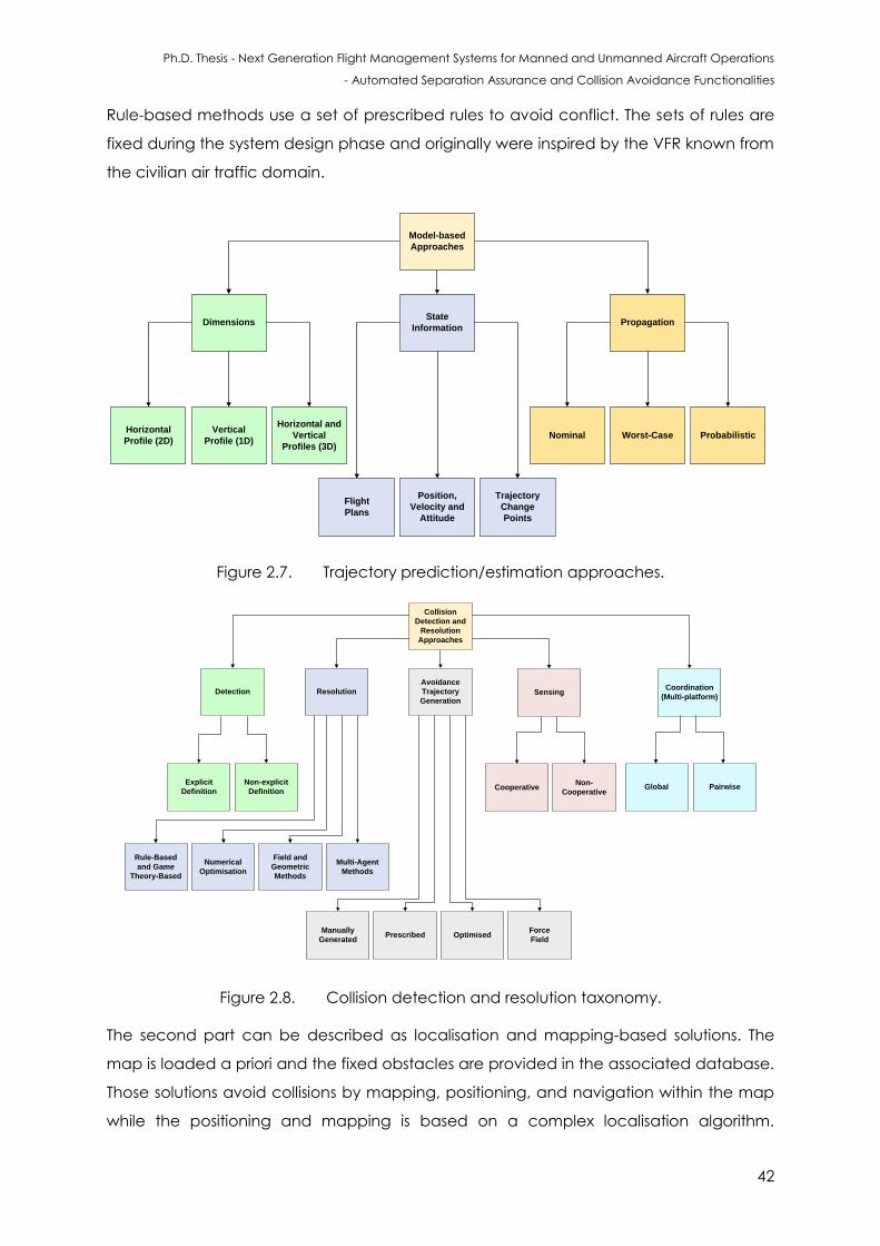
Ph.D. Thesis - Next Generation Flight Management Systems for Manned and Unmanned Aircraft Operations
- Automated Separation Assurance and Collision Avoidance Functionalities
42
Rule-based methods use a set of prescribed rules to avoid conflict. The sets of rules are
fixed during the system design phase and originally were inspired by the VFR known from
the civilian air traffic domain.
PropagationState
InformationDimensions
Model-based
Approaches
Horizontal
Profile (2D)
Vertical
Profile (1D)
Horizontal and
Vertical
Profiles (3D)
Nominal Worst-Case Probabilistic
Flight
Plans
Position,
Velocity and
Attitude
Trajectory
Change
Points
Figure 2.7. Trajectory prediction/estimation approaches.
SensingResolutionDetection
Collision
Detection and
Resolution
Approaches
Explicit
Definition
Non-explicit
DefinitionCooperative
Non-
CooperativeGlobal
Numerical
Optimisation
Field and
Geometric
Methods
Multi-Agent
Methods
Rule-Based
and Game
Theory-Based
Avoidance
Trajectory
Generation
Coordination
(Multi-platform)
Pairwise
Manually
GeneratedPrescribed Optimised
Force
Field
Figure 2.8. Collision detection and resolution taxonomy.
The second part can be described as localisation and mapping-based solutions. The
map is loaded a priori and the fixed obstacles are provided in the associated database.
Those solutions avoid collisions by mapping, positioning, and navigation within the map
while the positioning and mapping is based on a complex localisation algorithm.
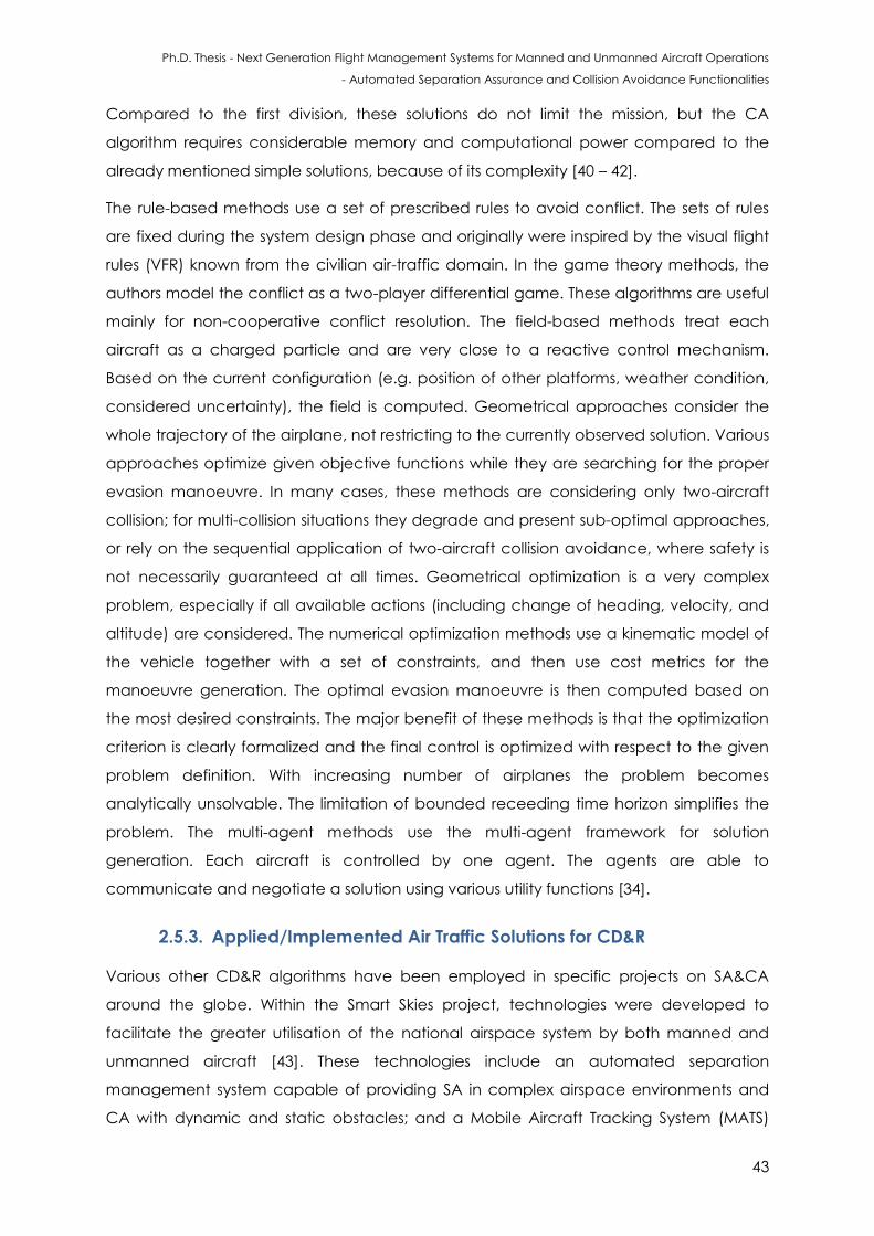
Ph.D. Thesis - Next Generation Flight Management Systems for Manned and Unmanned Aircraft Operations
- Automated Separation Assurance and Collision Avoidance Functionalities
43
Compared to the first division, these solutions do not limit the mission, but the CA
algorithm requires considerable memory and computational power compared to the
already mentioned simple solutions, because of its complexity [40 – 42].
The rule-based methods use a set of prescribed rules to avoid conflict. The sets of rules
are fixed during the system design phase and originally were inspired by the visual flight
rules (VFR) known from the civilian air-traffic domain. In the game theory methods, the
authors model the conflict as a two-player differential game. These algorithms are useful
mainly for non-cooperative conflict resolution. The field-based methods treat each
aircraft as a charged particle and are very close to a reactive control mechanism.
Based on the current configuration (e.g. position of other platforms, weather condition,
considered uncertainty), the field is computed. Geometrical approaches consider the
whole trajectory of the airplane, not restricting to the currently observed solution. Various
approaches optimize given objective functions while they are searching for the proper
evasion manoeuvre. In many cases, these methods are considering only two-aircraft
collision; for multi-collision situations they degrade and present sub-optimal approaches,
or rely on the sequential application of two-aircraft collision avoidance, where safety is
not necessarily guaranteed at all times. Geometrical optimization is a very complex
problem, especially if all available actions (including change of heading, velocity, and
altitude) are considered. The numerical optimization methods use a kinematic model of
the vehicle together with a set of constraints, and then use cost metrics for the
manoeuvre generation. The optimal evasion manoeuvre is then computed based on
the most desired constraints. The major benefit of these methods is that the optimization
criterion is clearly formalized and the final control is optimized with respect to the given
problem definition. With increasing number of airplanes the problem becomes
analytically unsolvable. The limitation of bounded receeding time horizon simplifies the
problem. The multi-agent methods use the multi-agent framework for solution
generation. Each aircraft is controlled by one agent. The agents are able to
communicate and negotiate a solution using various utility functions [34].
2.5.3. Applied/Implemented Air Traffic Solutions for CD&R
Various other CD&R algorithms have been employed in specific projects on SA&CA
around the globe. Within the Smart Skies project, technologies were developed to
facilitate the greater utilisation of the national airspace system by both manned and
unmanned aircraft [43]. These technologies include an automated separation
management system capable of providing SA in complex airspace environments and
CA with dynamic and static obstacles; and a Mobile Aircraft Tracking System (MATS)
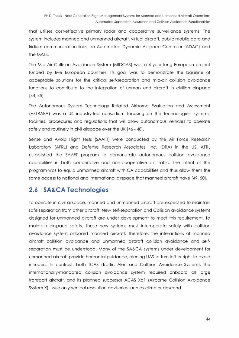
Ph.D. Thesis - Next Generation Flight Management Systems for Manned and Unmanned Aircraft Operations
- Automated Separation Assurance and Collision Avoidance Functionalities
44
that utilises cost-effective primary radar and cooperative surveillance systems. The
system includes manned and unmanned aircraft, virtual aircraft, public mobile data and
Iridium communication links, an Automated Dynamic Airspace Controller (ADAC) and
the MATS.
The Mid Air Collision Avoidance System (MIDCAS) was a 4 year long European project
funded by five European countries. Its goal was to demonstrate the baseline of
acceptable solutions for the critical self-separation and mid-air collision avoidance
functions to contribute to the integration of unman end aircraft in civilian airspace
[44, 45].
The Autonomous System Technology Related Airborne Evaluation and Assessment
(ASTRAEA) was a UK industry-led consortium focusing on the technologies, systems,
facilities, procedures and regulations that will allow autonomous vehicles to operate
safely and routinely in civil airspace over the UK [46 - 48].
Sense and Avoid Flight Tests (SAAFT) were conducted by the Air Force Research
Laboratory (AFRL) and Defense Research Associates, Inc. (DRA) in the US. AFRL
established the SAAFT program to demonstrate autonomous collision avoidance
capabilities in both cooperative and non-cooperative air traffic. The intent of the
program was to equip unmanned aircraft with CA capabilities and thus allow them the
same access to national and international airspace that manned aircraft have [49, 50].
2.6 SA&CA Technologies
To operate in civil airspace, manned and unmanned aircraft are expected to maintain
safe separation from other aircraft. New self-separation and Collision avoidance systems
designed for unmanned aircraft are under development to meet this requirement. To
maintain airspace safety, these new systems must interoperate safely with collision
avoidance system onboard manned aircraft. Therefore, the interactions of manned
aircraft collision avoidance and unmanned aircraft collision avoidance and self-
separation must be understood. Many of the SA&CA systems under development for
unmanned aircraft provide horizontal guidance, alerting UAS to turn left or right to avoid
intruders. In contrast, both TCAS (Traffic Alert and Collision Avoidance System), the
internationally-mandated collision avoidance system required onboard all large
transport aircraft, and its planned successor ACAS Xa1 (Airborne Collision Avoidance
System X), issue only vertical resolution advisories such as climb or descend.
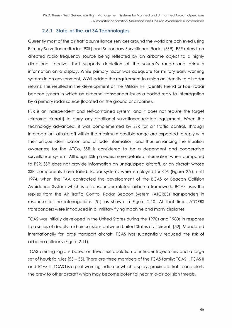
Ph.D. Thesis - Next Generation Flight Management Systems for Manned and Unmanned Aircraft Operations
- Automated Separation Assurance and Collision Avoidance Functionalities
45
2.6.1 State-of-the-art SA Technologies
Currently most of the air traffic surveillance services around the world are achieved using
Primary Surveillance Radar (PSR) and Secondary Surveillance Radar (SSR). PSR refers to a
directed radio frequency source being reflected by an airborne object to a highly
directional receiver that supports depiction of the source’s range and azimuth
information on a display. While primary radar was adequate for military early warning
systems in an environment, WWII added the requirement to assign an identity to all radar
returns. This resulted in the development of the Military IFF (Identify Friend or Foe) radar
beacon system in which an airborne transponder issues a coded reply to interrogation
by a primary radar source (located on the ground or airborne).
PSR is an independent and self-contained system, and it does not require the target
(airborne aircraft) to carry any additional surveillance-related equipment. When the
technology advanced, it was complemented by SSR for air traffic control. Through
interrogation, all aircraft within the maximum possible range are expected to reply with
their unique identification and altitude information, and thus enhancing the situation
awareness for the ATCo. SSR is considered to be a dependent and cooperative
surveillance system. Although SSR provides more detailed information when compared
to PSR, SSR does not provide information on unequipped aircraft, or on aircraft whose
SSR components have failed. Radar systems were employed for CA (Figure 2.9), until
1974, when the FAA contracted the development of the BCAS or Beacon Collision
Avoidance System which is a transponder related airborne framework. BCAS uses the
replies from the Air Traffic Control Radar Beacon System (ATCRBS) transponders in
response to the interrogations [51] as shown in Figure 2.10. At that time, ATCRBS
transponders were introduced in all military flying machine and many airplanes.
TCAS was initially developed in the United States during the 1970s and 1980s in response
to a series of deadly mid-air collisions between United States civil aircraft [52]. Mandated
internationally for large transport aircraft, TCAS has substantially reduced the risk of
airborne collisions (Figure 2.11).
TCAS alerting logic is based on linear extrapolation of intruder trajectories and a large
set of heuristic rules [53 – 55]. There are three members of the TCAS family; TCAS I, TCAS II
and TCAS III. TCAS I is a pilot warning indicator which displays proximate traffic and alerts
the crew to other aircraft which may become potential near mid-air collision threats.
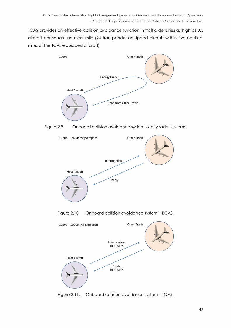
Ph.D. Thesis - Next Generation Flight Management Systems for Manned and Unmanned Aircraft Operations
- Automated Separation Assurance and Collision Avoidance Functionalities
46
TCAS provides an effective collision avoidance function in traffic densities as high as 0.3
aircraft per square nautical mile (24 transponder-equipped aircraft within five nautical
miles of the TCAS-equipped aircraft).
Host Aircraft
Other Traffic
Energy Pulse
Echo from Other Traffic
1960s
Figure 2.9. Onboard collision avoidance system - early radar systems.
Host Aircraft
Other Traffic
Interrogation
Reply
Low-density airspace1970s
Figure 2.10. Onboard collision avoidance system – BCAS.
Host Aircraft
Other Traffic
Interrogation
1090 MHz
Reply
1030 MHz
All airspaces1980s – 2000s
Figure 2.11. Onboard collision avoidance system – TCAS.
Ph.D. Thesis - Next Generation Flight Management Systems for Manned and Unmanned Aircraft Operations
- Automated Separation Assurance and Collision Avoidance Functionalities
47
When TCAS operates in traffic densities of 0.3 transponder-equipped aircraft per square
nautical mile or higher, it provides protection against collisions with other aircraft, so long
as those aircraft are closing at speeds of less than 500 kt.
TCAS is also capable of providing protection against aircraft closing at relative speeds of
up to 1200 kt in airspace characterized by densities of less than 0.06 transponder-
equipped aircraft per square nautical mile, which is equivalent to eighteen transponder-
equipped aircraft within ten nautical miles of the TCAS aircraft.
A TCAS I-equipped aircraft can receive limited alert and advisory information about
aircraft in its vicinity. TCAS I also participates in cross-link communication with TCAS II
equipped aircraft. TCAS I operates by listening for aircraft transponder transmissions
(replies). The replies detected may have been:
unsolicited transmissions from Mode S transponders (squitters);
replies elicited by ground station or TCAS II interrogations (passive TCAS I);
replies resulting from low-power interrogations from TCAS I (active TCAS I).
Additionally, TCAS I receives traffic advisory information from TCAS II aircraft. If an
intruding aircraft is equipped with TCAS II, and if that TCAS II aircraft determines that a
collision hazard exists, it will transmit advisory information to the TCAS I aircraft, which
includes bearing (if available), range and relative altitude of the TCAS II aircraft with
respect to the TCAS I aircraft. As an option, TCAS I can be implemented to provide an
indication of the transmitting transponder's bearing.
TCAS II, in addition, provides recommended vertical escape manoeuvres to the crew to
avert potential Near Mid-Air Collisions (NMAC). The term TCAS IV is reserved for future
TCAS equipment that has additional capabilities beyond those of TCAS II equipment;
such as the ability to generate resolution advisories in the horizontal plane (e.g., "TURN
RIGHT," "TURN LEFT"). The equipment described in this thesis does not have horizontal
resolution capability. In this document, TCAS I is denoted TCAS I; the use of the
unqualified term TCAS refers exclusively to TCAS II; and the last version is explicitly
denoted as TCAS IV. As the development of TCAS Versions 7 and 7.1 exemplified,
modifying the existing rules is extremely difficult and time consuming.
TCAS II is intended to improve air safety by acting as a last-resort method of preventing
mid-air collisions or near collisions between aircraft. By employing SSR technology, TCAS II
equipment operates independently of ground-based aids and ATC. Aircraft equipped
with TCAS II have the ability to interrogate airborne transponders to monitor range,
bearing, and reported altitude of other aircraft in the vicinity and assess the risk of
Ph.D. Thesis - Next Generation Flight Management Systems for Manned and Unmanned Aircraft Operations
- Automated Separation Assurance and Collision Avoidance Functionalities
48
collision. Non-transponding aircraft are not detected. TCAS II Version 6.0 was first
introduced in the United States in 1990 with collision avoidance logic. TCAS II Version 7.0
was introduced in the US and Europe in 2000 and was subsequently mandated by ICAO
for all commercial turbine-powered transport aircraft worldwide, having more than 19
passenger seats or having a maximum take-off weight above 5700 kg. TCAS II is referred
to as the Airborne Collision Avoidance System II (ACAS II) in ICAO terminology. TCAS II
provides traffic advisories and if warranted, resolution advisories in the vertical plane. RAs
are indications given to the flight crew; they recommend manoeuvres intended to
provide separation from all threats, or restrictions to maneuvers to maintain existing
separation. TCAS II operating procedures in the western world give RAs priority over ATC
clearances and instructions, i.e., flight crews are instructed to follow an RA even when it
conflicts with ATC guidance. Controllers have no knowledge of a TCAS RA, unless they
are notified by the flight crew via the radio (resolution advisory information is provided
by TCAS II to Mode S SSRs, but it is not normally presented to controllers). TCAS can track
up to 30 airplane in an ostensible scope of 14 nautical miles for Mode A or C targets,
and 30 nautical miles for Mode S targets. This data is passed to the collision avoidance
logic in the onboard electronics to decide the TAs or RAs.
The following section describes how to compute and update the CRS input variables
Coarse_Altitude, Fine_Altitude, Own_Corrected_Alt, Fine_Altitude_Rate, Radio_Altitude,
and ZRINT. These calculations use the parameters Init_Alt, Init_Alt_Rate, Alt_Accel,
Ground_Level, and Quant specified in the encounter input file of the TCAS [56 – 60].
At T=1 for own aircraft and at the time Encounter_Start is specified for other traffic, the
altitude (Alt) and altitude rate (Alt_Rate) for each aircraft are set to Init_Alt and
Init_Alt_Rate, respectively. At the end of each cycle (T=i) Alt and Alt_Rate are updated
for each aircraft for the next cycle (T = i+1) as follows:
(2.12)
(2.13)
Calculations for Alt and Alt_Rate always use the exact value of Alt, rather than rounding
to the nearest 100 ft. The CRS input variables:
Coarse_Altitude;
Fine_Altitude;
Own_Corrected_Alt;
Fine_Altitude_Rate;
Radio_Altitude;
Ph.D. Thesis - Next Generation Flight Management Systems for Manned and Unmanned Aircraft Operations
- Automated Separation Assurance and Collision Avoidance Functionalities
49
ZRINT.
These input variables are calculated at the beginning of each cycle from these values
as follows [56]:
(2.14)
(2.15)
(2.16)
(2.17)
(2.18)
( ) (2.19)
( ) (2.20)
These values are used to compute and update the CRS input variables RR (relative
range), BEAR (bearing), and Bear_Meas (raw bearing). These calculations use the
parameters Air_Speed, Init_Range, Range_Space, and Angle specified in the encounter
Input File.
Figure 2.12 illustrates an example of the encounter geometry. For all encounters, the own
aircraft is assumed to be travelling at a constant speed in the positive x-direction.
Forward_Range is the x-component of the distance of the other aircraft from own
aircraft. Side_Range is the y-component of the distance of the other aircraft from own
aircraft, with positive distance being measured to the right of own aircraft. Angle is the
heading angle of the other aircraft measured clockwise from the x-axis. Initially, at the
time Encounter_Start is specified, Forward_Range is set to Init_Range and Side_Range is
set to Range_Space.
At the end of each cycle Forward_Range and Side_Range are updated for the next
cycle as follows:
( ) (2.21)
( ) (2.22)
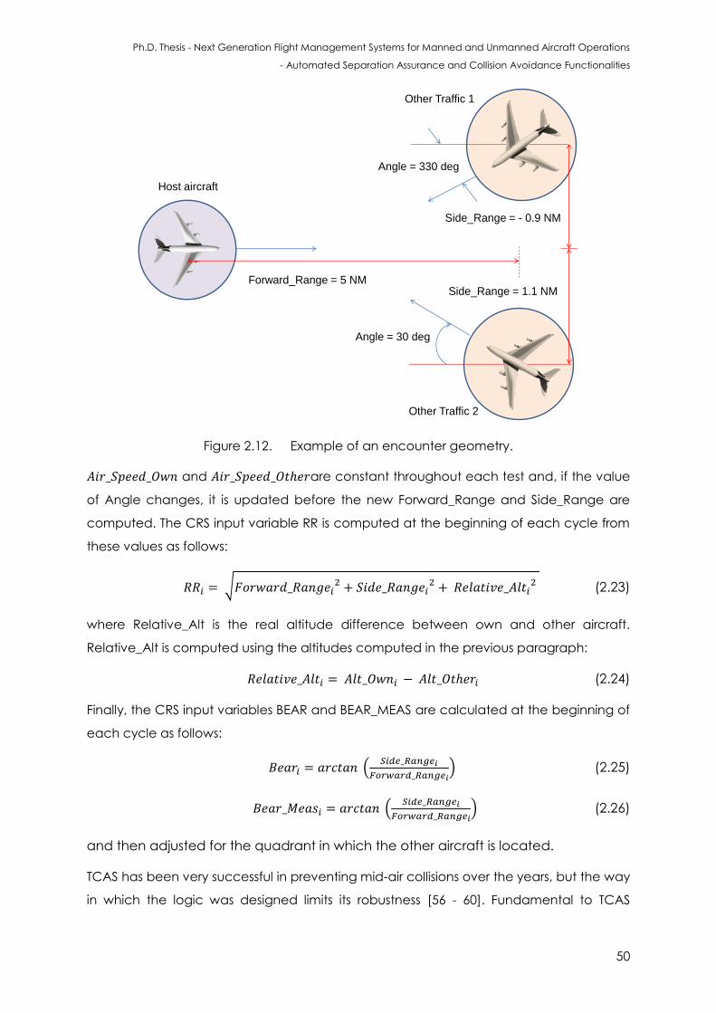
Ph.D. Thesis - Next Generation Flight Management Systems for Manned and Unmanned Aircraft Operations
- Automated Separation Assurance and Collision Avoidance Functionalities
50
Host aircraft
Other Traffic 1
Other Traffic 2
Forward_Range = 5 NM
Side_Range = - 0.9 NM
Side_Range = 1.1 NM
Angle = 30 deg
Angle = 330 deg
Figure 2.12. Example of an encounter geometry.
and are constant throughout each test and, if the value
of Angle changes, it is updated before the new Forward_Range and Side_Range are
computed. The CRS input variable RR is computed at the beginning of each cycle from
these values as follows:
√
(2.23)
where Relative_Alt is the real altitude difference between own and other aircraft.
Relative_Alt is computed using the altitudes computed in the previous paragraph:
(2.24)
Finally, the CRS input variables BEAR and BEAR_MEAS are calculated at the beginning of
each cycle as follows:
(
) (2.25)
(
) (2.26)
and then adjusted for the quadrant in which the other aircraft is located.
TCAS has been very successful in preventing mid-air collisions over the years, but the way
in which the logic was designed limits its robustness [56 - 60]. Fundamental to TCAS
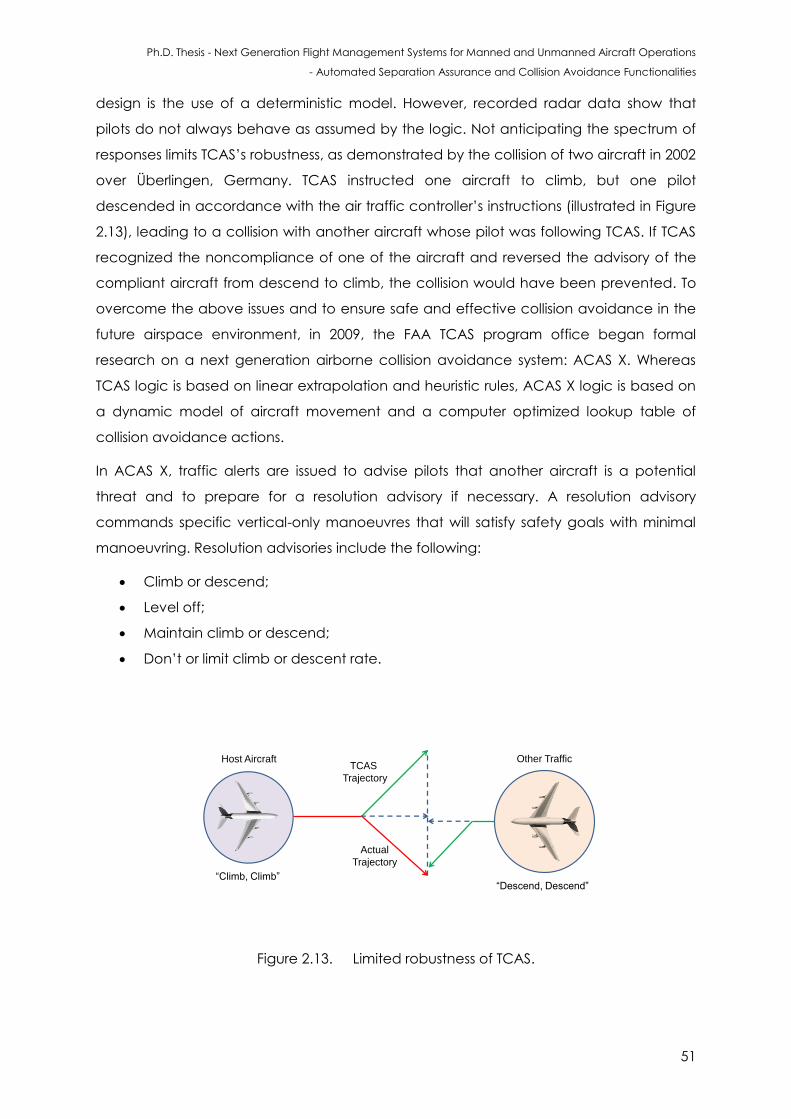
Ph.D. Thesis - Next Generation Flight Management Systems for Manned and Unmanned Aircraft Operations
- Automated Separation Assurance and Collision Avoidance Functionalities
51
design is the use of a deterministic model. However, recorded radar data show that
pilots do not always behave as assumed by the logic. Not anticipating the spectrum of
responses limits TCAS’s robustness, as demonstrated by the collision of two aircraft in 2002
over Überlingen, Germany. TCAS instructed one aircraft to climb, but one pilot
descended in accordance with the air traffic controller’s instructions (illustrated in Figure
2.13), leading to a collision with another aircraft whose pilot was following TCAS. If TCAS
recognized the noncompliance of one of the aircraft and reversed the advisory of the
compliant aircraft from descend to climb, the collision would have been prevented. To
overcome the above issues and to ensure safe and effective collision avoidance in the
future airspace environment, in 2009, the FAA TCAS program office began formal
research on a next generation airborne collision avoidance system: ACAS X. Whereas
TCAS logic is based on linear extrapolation and heuristic rules, ACAS X logic is based on
a dynamic model of aircraft movement and a computer optimized lookup table of
collision avoidance actions.
In ACAS X, traffic alerts are issued to advise pilots that another aircraft is a potential
threat and to prepare for a resolution advisory if necessary. A resolution advisory
commands specific vertical-only manoeuvres that will satisfy safety goals with minimal
manoeuvring. Resolution advisories include the following:
Climb or descend;
Level off;
Maintain climb or descend;
Don’t or limit climb or descent rate.
Host Aircraft Other TrafficTCAS
Trajectory
“Climb, Climb”
Actual
Trajectory
“Descend, Descend”
Figure 2.13. Limited robustness of TCAS.
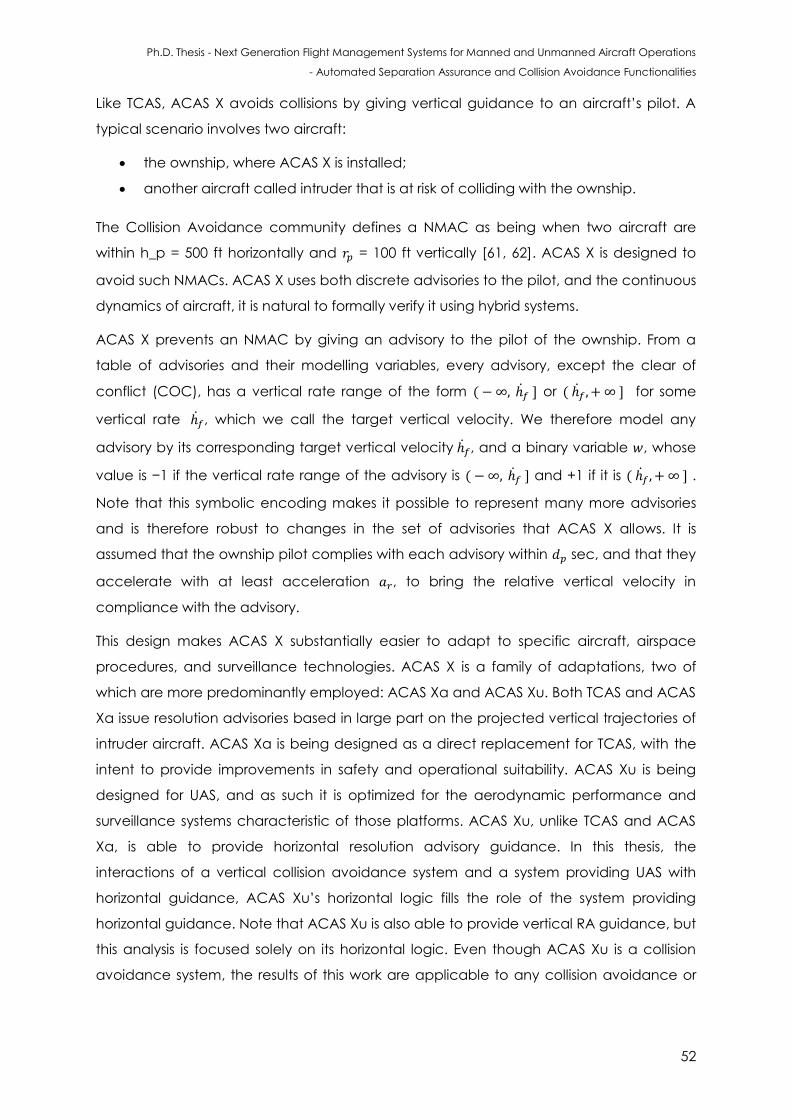
Ph.D. Thesis - Next Generation Flight Management Systems for Manned and Unmanned Aircraft Operations
- Automated Separation Assurance and Collision Avoidance Functionalities
52
Like TCAS, ACAS X avoids collisions by giving vertical guidance to an aircraft’s pilot. A
typical scenario involves two aircraft:
the ownship, where ACAS X is installed;
another aircraft called intruder that is at risk of colliding with the ownship.
The Collision Avoidance community defines a NMAC as being when two aircraft are
within h_p = 500 ft horizontally and = 100 ft vertically [61, 62]. ACAS X is designed to
avoid such NMACs. ACAS X uses both discrete advisories to the pilot, and the continuous
dynamics of aircraft, it is natural to formally verify it using hybrid systems.
ACAS X prevents an NMAC by giving an advisory to the pilot of the ownship. From a
table of advisories and their modelling variables, every advisory, except the clear of
conflict (COC), has a vertical rate range of the form ( or ( for some
vertical rate , which we call the target vertical velocity. We therefore model any
advisory by its corresponding target vertical velocity , and a binary variable , whose
value is −1 if the vertical rate range of the advisory is ( and +1 if it is ( .
Note that this symbolic encoding makes it possible to represent many more advisories
and is therefore robust to changes in the set of advisories that ACAS X allows. It is
assumed that the ownship pilot complies with each advisory within sec, and that they
accelerate with at least acceleration , to bring the relative vertical velocity in
compliance with the advisory.
This design makes ACAS X substantially easier to adapt to specific aircraft, airspace
procedures, and surveillance technologies. ACAS X is a family of adaptations, two of
which are more predominantly employed: ACAS Xa and ACAS Xu. Both TCAS and ACAS
Xa issue resolution advisories based in large part on the projected vertical trajectories of
intruder aircraft. ACAS Xa is being designed as a direct replacement for TCAS, with the
intent to provide improvements in safety and operational suitability. ACAS Xu is being
designed for UAS, and as such it is optimized for the aerodynamic performance and
surveillance systems characteristic of those platforms. ACAS Xu, unlike TCAS and ACAS
Xa, is able to provide horizontal resolution advisory guidance. In this thesis, the
interactions of a vertical collision avoidance system and a system providing UAS with
horizontal guidance, ACAS Xu’s horizontal logic fills the role of the system providing
horizontal guidance. Note that ACAS Xu is also able to provide vertical RA guidance, but
this analysis is focused solely on its horizontal logic. Even though ACAS Xu is a collision
avoidance system, the results of this work are applicable to any collision avoidance or
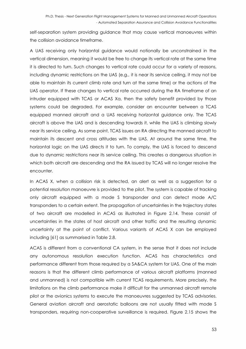
Ph.D. Thesis - Next Generation Flight Management Systems for Manned and Unmanned Aircraft Operations
- Automated Separation Assurance and Collision Avoidance Functionalities
53
self-separation system providing guidance that may cause vertical manoeuvres within
the collision avoidance timeframe.
A UAS receiving only horizontal guidance would notionally be unconstrained in the
vertical dimension, meaning it would be free to change its vertical rate at the same time
it is directed to turn. Such changes to vertical rate could occur for a variety of reasons,
including dynamic restrictions on the UAS (e.g., it is near its service ceiling, it may not be
able to maintain its current climb rate and turn at the same time) or the actions of the
UAS operator. If these changes to vertical rate occurred during the RA timeframe of an
intruder equipped with TCAS or ACAS Xa, then the safety benefit provided by those
systems could be degraded. For example, consider an encounter between a TCAS
equipped manned aircraft and a UAS receiving horizontal guidance only. The TCAS
aircraft is above the UAS and is descending towards it, while the UAS is climbing slowly
near its service ceiling. As some point, TCAS issues an RA directing the manned aircraft to
maintain its descent and cross altitudes with the UAS. At around the same time, the
horizontal logic on the UAS directs it to turn. To comply, the UAS is forced to descend
due to dynamic restrictions near its service ceiling. This creates a dangerous situation in
which both aircraft are descending and the RA issued by TCAS will no longer resolve the
encounter.
In ACAS X, when a collision risk is detected, an alert as well as a suggestion for a
potential resolution manoeuvre is provided to the pilot. The system is capable of tracking
only aircraft equipped with a mode S transponder and can detect mode A/C
transponders to a certain extent. The propagation of uncertainties in the trajectory states
of two aircraft are modelled in ACAS as illustrated in Figure 2.14. These consist of
uncertainties in the states of host aircraft and other traffic and the resulting dynamic
uncertainty at the point of conflict. Various variants of ACAS X can be employed
including [61] as summarised in Table 2.8.
ACAS is different from a conventional CA system, in the sense that it does not include
any autonomous resolution execution function. ACAS has characteristics and
performance different from those required by a SA&CA system for UAS. One of the main
reasons is that the different climb performance of various aircraft platforms (manned
and unmanned) is not compatible with current TCAS requirements. More precisely, the
limitations on the climb performance make it difficult for the unmanned aircraft remote
pilot or the avionics systems to execute the manoeuvres suggested by TCAS advisories.
General aviation aircraft and aerostatic balloons are not usually fitted with mode S
transponders, requiring non-cooperative surveillance is required. Figure 2.15 shows the
Ph.D. Thesis - Next Generation Flight Management Systems for Manned and Unmanned Aircraft Operations
- Automated Separation Assurance and Collision Avoidance Functionalities
54
top-level architecture of ACAS. The system receives sensor measurements every second.
On the basis of these sensor measurements, the system infers the distribution over the
aircraft’s current status. This status, or state estimation, takes into account the
probabilistic dynamic model and the probabilistic sensor model. This state distribution
determines where to look in the numeric logic table to determine the best action to
perform (e.g., whether to issue an advisory and if so, the vertical rate to adopt). This
processing chain is repeated once per second with every new sensor measurement.
Critical to understanding the logic optimization process inherent are two important
concepts. The first is a Markov decision process, which is essentially the probabilistic
dynamic model combined with the utility model. The second is dynamic programming,
which is the iterative computational process used to optimize the logic.
State
Uncertainty
Dynamic
Uncertainty
Figure 2.14. Uncertainty propagation in ACAS.
Besides being compatible with NextGen, ACAS X improves the safety of air travel and
provides more operational suitability. In addition to protecting the traveling public on
board every large commercial aircraft worldwide, ACAS X provides:
Reduced pilot workload (by reducing the number of confusing and surprising
advisories);
Capacity to accommodate new surveillance inputs that provide more detailed
and precise tracking data than currently used onboard transponders;
Ability to reduced fuel costs, emissions, and flight operating times, as well as
increased arrival rates at airports;
A minimised number of interruptions to normal air traffic flow;
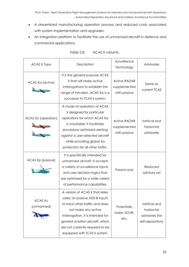
Ph.D. Thesis - Next Generation Flight Management Systems for Manned and Unmanned Aircraft Operations
- Automated Separation Assurance and Collision Avoidance Functionalities
55
A streamlined manufacturing operation process and reduced costs associated
with system implementation and upgrades;
An integration platform to facilitate the use of unmanned aircraft in defence and
commercial applications.
Table 2.8. ACAS X variants.
ACAS X Type Description Surveillance
Technology Advisories
ACAS Xa (active)
It is the general purpose ACAS
X that will make active
interrogations to establish the
range of intruders. ACAS Xa is a
successor to TCAS II system.
Active RADAR
supplemented
with passive
Same as
current TCAS
ACAS Xo (operation)
A mode of operation of ACAS
X designed for particular
operations for which ACAS Xa
is unsuitable. It facilitates
procedure-optimized alerting
against a user-selected aircraft
while providing global Xa
protection for all other traffic.
Active RADAR
supplemented
with passive
Vertical and
horizontal
advisories
ACAS Xp (passive)
It is specifically intended for
unmanned aircraft. It accepts
a variety of surveillance inputs
and uses decision-logics that
are optimised for a wide variety
of performance capabilities.
Passive only Reduced
advisory set
ACAS Xu
(unmanned)
A version of ACAS X that relies
solely on passive ADS-B inputs
to track other traffic and does
not make any active
interrogation. It is intended for
general aviation aircraft, which
are not currently required to be
equipped with TCAS II system.
Potentially
radar, EO/IR,
etc.
Vertical and
horizontal
advisories (for
self-separation)
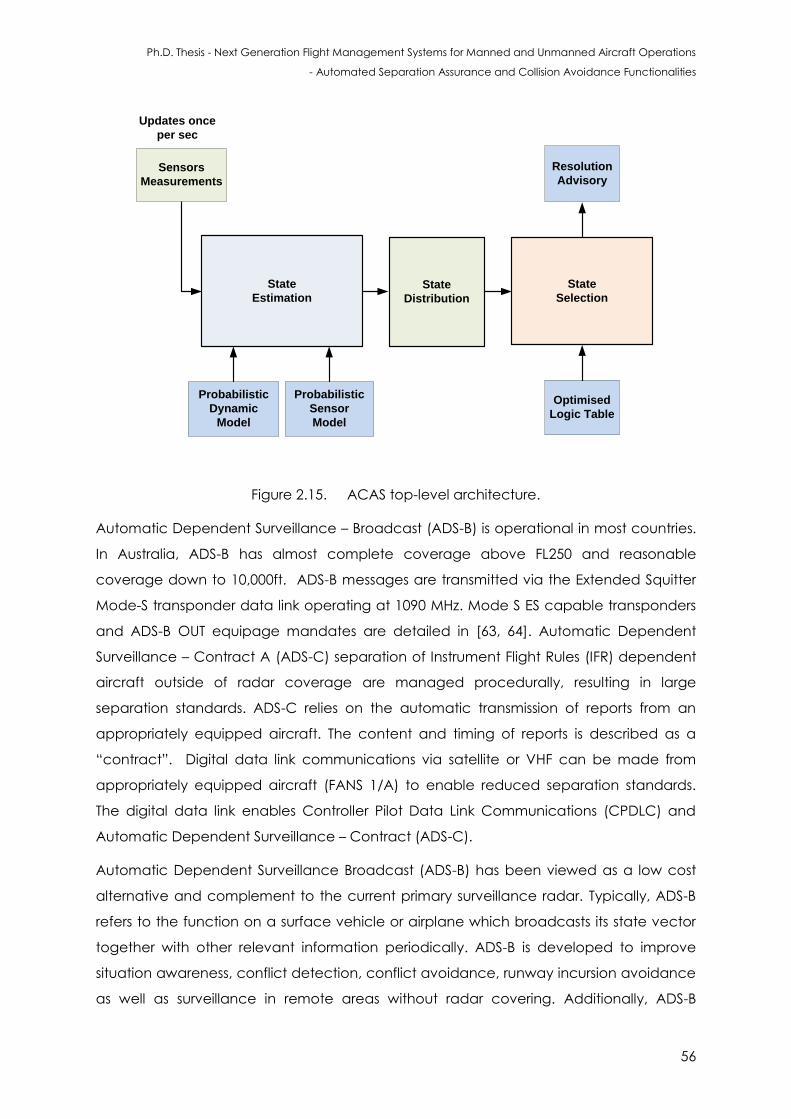
Ph.D. Thesis - Next Generation Flight Management Systems for Manned and Unmanned Aircraft Operations
- Automated Separation Assurance and Collision Avoidance Functionalities
56
State
Estimation
Probabilistic
Dynamic
Model
Probabilistic
Sensor
Model
Updates once
per sec
State
Distribution
State
Selection
Sensors
Measurements
Optimised
Logic Table
Resolution
Advisory
Figure 2.15. ACAS top-level architecture.
Automatic Dependent Surveillance – Broadcast (ADS-B) is operational in most countries.
In Australia, ADS-B has almost complete coverage above FL250 and reasonable
coverage down to 10,000ft. ADS-B messages are transmitted via the Extended Squitter
Mode-S transponder data link operating at 1090 MHz. Mode S ES capable transponders
and ADS-B OUT equipage mandates are detailed in [63, 64]. Automatic Dependent
Surveillance – Contract A (ADS-C) separation of Instrument Flight Rules (IFR) dependent
aircraft outside of radar coverage are managed procedurally, resulting in large
separation standards. ADS-C relies on the automatic transmission of reports from an
appropriately equipped aircraft. The content and timing of reports is described as a
“contract”. Digital data link communications via satellite or VHF can be made from
appropriately equipped aircraft (FANS 1/A) to enable reduced separation standards.
The digital data link enables Controller Pilot Data Link Communications (CPDLC) and
Automatic Dependent Surveillance – Contract (ADS-C).
Automatic Dependent Surveillance Broadcast (ADS-B) has been viewed as a low cost
alternative and complement to the current primary surveillance radar. Typically, ADS-B
refers to the function on a surface vehicle or airplane which broadcasts its state vector
together with other relevant information periodically. ADS-B is developed to improve
situation awareness, conflict detection, conflict avoidance, runway incursion avoidance
as well as surveillance in remote areas without radar covering. Additionally, ADS-B
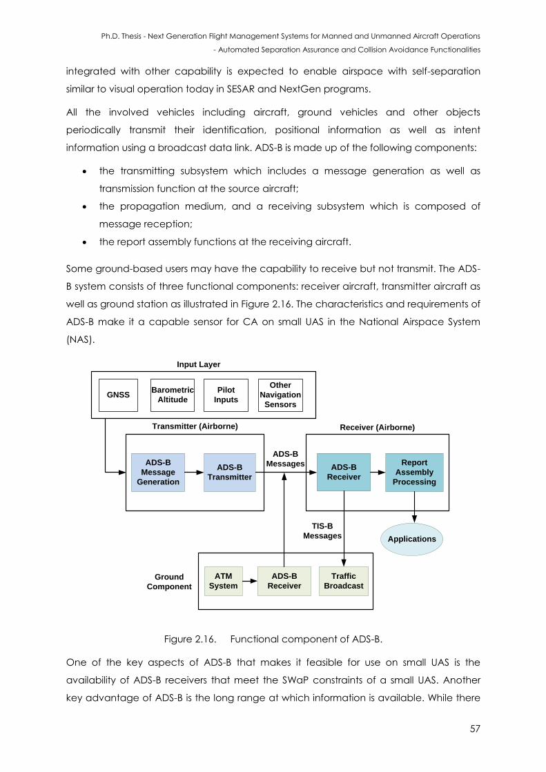
Ph.D. Thesis - Next Generation Flight Management Systems for Manned and Unmanned Aircraft Operations
- Automated Separation Assurance and Collision Avoidance Functionalities
57
integrated with other capability is expected to enable airspace with self-separation
similar to visual operation today in SESAR and NextGen programs.
All the involved vehicles including aircraft, ground vehicles and other objects
periodically transmit their identification, positional information as well as intent
information using a broadcast data link. ADS-B is made up of the following components:
the transmitting subsystem which includes a message generation as well as
transmission function at the source aircraft;
the propagation medium, and a receiving subsystem which is composed of
message reception;
the report assembly functions at the receiving aircraft.
Some ground-based users may have the capability to receive but not transmit. The ADS-
B system consists of three functional components: receiver aircraft, transmitter aircraft as
well as ground station as illustrated in Figure 2.16. The characteristics and requirements of
ADS-B make it a capable sensor for CA on small UAS in the National Airspace System
(NAS).
ADS-B
Message
Generation
ADS-B
Transmitter
ADS-B
Receiver
Report
Assembly
Processing
ADS-B
Receiver
ATM
System
Traffic
Broadcast
ADS-B
Messages
TIS-B
Messages
Transmitter (Airborne) Receiver (Airborne)
Ground
Component
Applications
GNSSBarometric
Altitude
Pilot
Inputs
Other
Navigation
Sensors
Input Layer
Figure 2.16. Functional component of ADS-B.
One of the key aspects of ADS-B that makes it feasible for use on small UAS is the
availability of ADS-B receivers that meet the SWaP constraints of a small UAS. Another
key advantage of ADS-B is the long range at which information is available. While there
Ph.D. Thesis - Next Generation Flight Management Systems for Manned and Unmanned Aircraft Operations
- Automated Separation Assurance and Collision Avoidance Functionalities
58
is a significant amount of variation in the range of ADS-B signals, the shortest expected
range is 10 NM. But, at the same time, currently, most small UAS cannot carry ADS-B
transponders. Furthermore, the density of ADS-B signals if all small UAS were equipped
with ADS-B would lead to communication signal collisions in the broadcast algorithm.
Additionally the long range of ADS-B is advantageous in that the quality of information
transmitted over ADS-B does not degrade with range. Thus the accuracy of ADS-B is not
dependent on the size, power, or range of the transmitter and receiver units. This is a
significant advantage over radar and optical sensors, and makes path planning for
conflict detection and separation assurance at long ranges easier.
However, the limitations of ADS-B system are:
It is heavily dependent on line-of-sight availability of GPS and ADS-B transmissions.
Without GPS information, ADS-B transponders are unable to transmit usable
position information. Air-to-air ADS-B transmissions also require line-of-sight visibility
for reliable exchange of information. Bandwidth constraints of ADS-B can also be
a limitation. Due to the fact that all ADS-B Out-capable aircraft must transmit a
message at least once per second on the same nominal frequency, the ADS-B
protocol specifies a multiple access scheme. While the scheme is different for the
978 MHz frequency and 1090 MHz frequency, all multiple access schemes have a
finite number of transmitters that they can support. This is especially applicable to
small UAS, and there are limitations of employing Time Division Multiple Access
(TDMA), which is typically used at 978 MHz;
The cost of procuring ADS-B equipage is another limitation. Certified ADS-B Out
hardware costs typically range from $1,000 to $25,000 AUD.
ADS-B uses three types of reports:
Surveillance State Vector (SSVR) report;
Mode-Status (MS) report;
On-condition report.
Information provide by these reports are detailed below. The SSVR report contains
information on the dynamics of the aircraft, which include geometric position, horizontal
and vertical velocity, and heading. In addition, the quality of the SSVR element is
contained in the MS report. The MS message includes current operational information of
the transmitting aircraft including capability class codes, operational mode codes and
SSV quality. The Capability Class (CC) code identifies the capability of a transmitting
ADS-B participant including TCAS installation information, Cockpit Display of Traffic
Ph.D. Thesis - Next Generation Flight Management Systems for Manned and Unmanned Aircraft Operations
- Automated Separation Assurance and Collision Avoidance Functionalities
59
Information (CDTI) capability, air referenced Velocity report capability, and trajectory
change report capability. OM codes indicate the current operational mode of a
transmitting element. The SSVR quality codes contain the Navigation Accuracy
Category for position (NACp), Navigation Accuracy Category for Velocity (NACv) and
Surveillance Integrity Level (SIL). All ADS-B participants must provide these SSVR and MS
reports. Upon reception of a state vector report, the system searches for a track of the
same type (ADS-B, ADS-R, TIS-B) and with the same 24-bit address as the report. If no
match is found, the system generates a new track containing the following parameters:
System time (track time of applicability);
Position time of applicability;
Velocity time of applicability;
Track type (ADS-B, ADS-R, TIS-B);
24-bit address;
Position (latitude, longitude, altitude);
Velocity (East/West velocity, North/South velocity, altitude rate);
Geometric Vertical Accuracy (GVA) = 1 (Version 2);
System Design Assurance (SDA) = 1 (Version 2);
State covariance matrices. (Covariance is a statistical concept, which seeks to
describe how two variables are related to each other. Two variables are said to
be positively related if they move in the same direction. The variables are
inversely related if they move in opposite directions. Covariance is a tool to
determine whether two variables are positively related or inversely related);
ID change flag = 0;
Index of correlated TIS-B track = null;
Time of correlation with TIS-B track = null;
Previous state (position and track time of applicability) matrix initialized as a row
vector;
Estimated turn rate = null.
Navigation Integrity Category (NIC);
NACP = 5;
NACV = 1;
SIL = 0;
Multilateration systems use a network of ground-based transceivers to localise aircraft
based on the difference in time of arrival of aircraft transponder transmissions.
Multilateration systems are currently deployed at a number of Class C CTR (for terminal
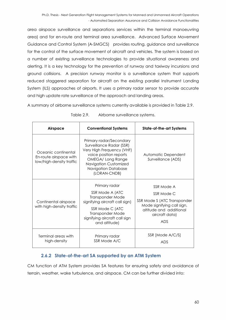
Ph.D. Thesis - Next Generation Flight Management Systems for Manned and Unmanned Aircraft Operations
- Automated Separation Assurance and Collision Avoidance Functionalities
60
area airspace surveillance and separations services within the terminal manoeuvring
area) and for en-route and terminal area surveillance. Advanced Surface Movement
Guidance and Control System (A-SMGCS) provides routing, guidance and surveillance
for the control of the surface movement of aircraft and vehicles. The system is based on
a number of existing surveillance technologies to provide situational awareness and
alerting. It is a key technology for the prevention of runway and taxiway incursions and
ground collisions. A precision runway monitor is a surveillance system that supports
reduced staggered separation for aircraft on the existing parallel Instrument Landing
System (ILS) approaches of airports. It uses a primary radar sensor to provide accurate
and high update rate surveillance of the approach and landing areas.
A summary of airborne surveillance systems currently available is provided in Table 2.9.
Table 2.9. Airborne surveillance systems.
Airspace Conventional Systems State-of-the-art Systems
Oceanic continental
En-route airspace with
low/high-density traffic
Primary radar/Secondary
Surveillance Radar (SSR)
Very High Frequency (VHF)
voice position reports
OMEGA/ Long Range
Navigation Customized
Navigation Database
(LORAN-CNDB)
Automatic Dependent
Surveillance (ADS)
Continental airspace
with high-density traffic
Primary radar
SSR Mode A (ATC
Transponder Mode
signifying aircraft call sign)
SSR Mode C (ATC
Transponder Mode
signifying aircraft call sign
and altitude)
SSR Mode A
SSR Mode C
SSR Mode S (ATC Transponder
Mode signifying call sign,
altitude and additional
aircraft data)
ADS
Terminal areas with
high-density
Primary radar
SSR Mode A/C
SSR [Mode A/C/S]
ADS
2.6.2 State-of-the-art SA supported by an ATM System
CM function of ATM System provides SA features for ensuring safety and avoidance of
terrain, weather, wake turbulence, and airspace. CM can be further divided into:
Ph.D. Thesis - Next Generation Flight Management Systems for Manned and Unmanned Aircraft Operations
- Automated Separation Assurance and Collision Avoidance Functionalities
61
SCM, which is achieved through airspace organisation and management,
demand and capacity balancing, and traffic synchronisation;
SP, which is the second layer and describes a range of primarily tactical sub-
functions intended to ensure separation minima are maintained. SP function
includes the issuing of instructions, clearances and information advisories to
airspace users. SP is supported by route adherence monitoring, cleared level
adherence monitoring and approach path monitoring. In the future, ASAS will be
available to complement the ATM SP functions (e.g., ADS-B In and Cockpit
Display of Traffic Information);
ATM Collision Prevention (ACP) services are provided to aid pilots in maintaining
well clear of other aircraft and hazards in the event that safe separation minima
have been lost. From an ATM system perspective, this involves the issuing of safety
alerts, which are defined as the provision of advice to an aircraft when an ATS
Officer becomes aware that an aircraft is in a position that is considered to place
it in unsafe proximity to terrain, obstructions or another aircraft. For example:
- Aircraft conflict alerts – alerts initiated by an ATM system when an ATCo
becomes aware of aircraft that are considered to be in unsafe proximity;
- Terrain/obstruction alerts – the provision of advice to an aircraft when an ATS
officer becomes aware that an aircraft is in a position which is considered to
place it in unsafe proximity to terrain or obstructions.
- PSR is operational at Class C aerodromes and some military aerodromes. ATCRBS
SSR is used for approach and en-route surveillance in most nations. Coverage is
primarily limited to areas surrounding the Control Area (CTA). The returned coded
reply is processed by a SSR system. In the case of the modern Mode 3/A ATCRBS,
the system provides coded aircraft identification (4 digits octal) and a Mode C
pressure altitude. ATCRBS sends a directional interrogation signal during the radar
volume scan on a 1030 MHz carrier frequency and expects a Mode 3/A (and
Mode C) reply in the 1090 MHz band. The advent of denser air traffic has resulted
in the need for a greater volume of data from the target transmitter (primarily for
more detailed identification) and considerably faster and more reliable digital
processing has given birth to a solution in the form of the Mode-S transponder
standard.
CM is a component of the ATM system that will be impacted by the integration of UAS
into the current ATM system.
Ph.D. Thesis - Next Generation Flight Management Systems for Manned and Unmanned Aircraft Operations
- Automated Separation Assurance and Collision Avoidance Functionalities
62
2.6.3 CA Sensors/Systems
A number of non-cooperative sensors have been adopted as part of research projects
dealing with developing CA functions. The technologies that have been used can be
divided into two macro areas [65]:
Cooperative technologies that typically require a transponder on board the
aircraft: they require other aircraft to equip with the same devices when sharing
the same airspace.
Non-cooperative technologies that identify all the aircraft not equipped with a
transponder or, for example, gliders, hot air balloons, and so on. They do not
require other aircraft to equip the same devices when sharing the same airspace.
Multi-sensor platforms for obstacle detection by using millimetre-wave radar, electro-
optic/infrared, Light Detection and Ranging (LIDAR) and acoustic sensors are currently
employed. Ground-based CA systems using electronic sensors are also currently
developed and they provide information for manoeuvre decision tasks especially in TMA
operations. The adoption of a multi-sensory approach to CA (employing passive and
active MMW radar, Forward Looking Infra-Red (FLIR), LIDAR and an Electronic
Surveillance Module (ESM) for obstacle detection) has resulted in adequate
performance in low- to medium-dynamics platform applications. A non-cooperative
collision avoidance system for UAS utilising pulsed Ka-band radar and optical sensors has
been developed [66]. Acoustic-based CA systems for small UAS may adopt a multi
sensor platform with acoustic sensors that allows detection of obstacles and intruders in
a 360 º FoV, and performs quick-reaction manoeuvres for avoidance [67]. This system
allows all weather operations and offers advantages in terms of power consumption and
cost. Encounter models and their applications to CA strategies address both
cooperative and non-cooperative scenarios.
Ground-based CA systems using electronic sensors, which are are also currently being
developed [68]. These ground based systems provide information for manoeuvre
decisions for terminal manoeuvring area operations. The states of the tracked obstacles
are obtained by adopting Extended/Unscented Kalman Filter (EKF/UKF) or other multi-
sensor data fusion techniques, which are used in order to predict the trajectory in a
given time horizon. On-board trajectory re-planning with dynamically updated
constraints based on the intruder and the host dynamics is at present used to generate
obstacle trajectories. Coarse-resolution radar based CA solutions are implemented for
small size UAS and the information is often fused with data from an ADS-B system. In the
Ph.D. Thesis - Next Generation Flight Management Systems for Manned and Unmanned Aircraft Operations
- Automated Separation Assurance and Collision Avoidance Functionalities
63
case of cooperative scenarios, ADS-B and TCAS are adopted for implementing CA
functions [69]. The avoidance trajectory is generated with the use of an on-board
trajectory re-planning module, which has dynamically updated constraints based on the
intruder and the host dynamics. The avoidance trajectories are also generated with the
use of a nonlinear differential geometric guidance law based on a collision cone
approach and dynamic inversion, which, combined with a first order autopilot, allows for
satisfactory guidance of the vehicle. The possible synergies attainable with the adoption
of different detection, tracking and trajectory avoidance algorithms are addressed in
the later chapters of the thesis.
In an operational perspective, guidelines and regulations are required to support the CA
system requirements development. The requirements for designing and developing an
effective CA system are derived from the current regulations applicable to the see-and-
avoid capability of manned aircraft. The proposed detection range and Field-of-Regard
(FoR) must be adequate to ensure separation from the intruder, in order to prevent a
probable near mid-air collision. This criterion is also naturally applicable in the case of
small UAS, since the vast majority of mid-air collision events occur below 3000 ft. In the
case of see-and-avoid, the main roles and responsibilities of pilot and crew are stated in
FAA AC 90-48C and FAR §91.113 regulations as follows: vigilance shall be maintained at
all times, regardless of whether the operation is conducted under IFR/VFR. Initial
requirements recognized by SC-203 and other aviation/UAS working groups state that
any UAS shall have a system capable of monitoring the surroundings at all times. This
system has to maintain a minimum separation distance with any cooperative or non-
cooperative obstacle/intruder.
2.6.4 Attributes/Capabilities of UAS SA&CA Technologies
The attributes/capabilities of SA&CA technologies can be summarized as follows [65]:
Optical sensors (pixel/visual):
- low cost, size, and weight;
- suffer from various atmospheric disturbances;
- have to be arranged in various positions on the aircraft;
- a visual radar can be used that is highly comparable to a human’s ability;
- dictated by the required Field-of-View (FoV);
- payload size and mounting issues.
Ph.D. Thesis - Next Generation Flight Management Systems for Manned and Unmanned Aircraft Operations
- Automated Separation Assurance and Collision Avoidance Functionalities
64
Infrared sensors:
- higher cost than optical sensors;
- low size and weight;
- useful in conducting night time operations;
- operate under severe weather conditions;
- to achieve the required FOV, sensors have to be arrayed in various positions
on the aircraft, taking up valuable external area;
- some sensors do not pick up objects lacking some type of heat signature
(cables or gliders);
- development and integration efforts are generally expensive.
Microwave RADAR:
- very mature technology;
- useful in detecting the intruder aircraft at great distances;
- generally bulky.
LIDAR:
- the size of the detection cone is very small and it makes possible to target a
specific obstacle;
- the revisit rate is poor and it takes multitude of laser sensors to achieve the
same rate as a microwave radar;
- highly developed for large UAS but underdeveloped for small UAS;
- high cost;
- inadequate in adverse weather (light can be absorbed and reflected
depending upon the external conditions).
The essential criteria for designing an effective CA system are as follows:
Quantitative:
The FOV has to be equivalent or superior to that of a pilot in the cockpit. This
corresponds to a primary FOV of -60˚ vertically/70˚ horizontally and a secondary
FOV of -100˚ vertically and 120˚ horizontally;
Sufficient detection range. As an example, the detection range of various CA
technologies available for UAS is shown in Figure 2.17.
Qualitative:
Accurate and precise intruder detection (static and dynamic), recognition and
trajectory prediction (dynamic);
Prior obstacle detection for allowing time for executing the trajectory avoidance
manoeuvres;
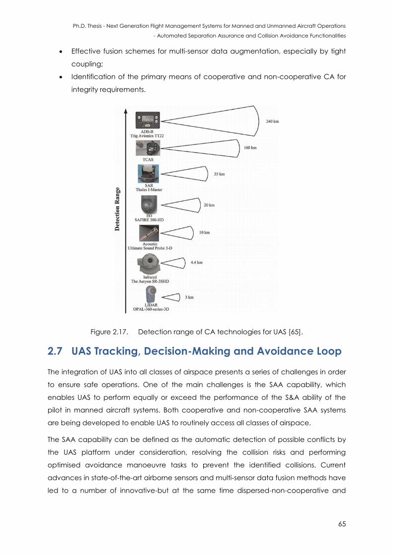
Ph.D. Thesis - Next Generation Flight Management Systems for Manned and Unmanned Aircraft Operations
- Automated Separation Assurance and Collision Avoidance Functionalities
65
Effective fusion schemes for multi-sensor data augmentation, especially by tight
coupling;
Identification of the primary means of cooperative and non-cooperative CA for
integrity requirements.
Figure 2.17. Detection range of CA technologies for UAS [65].
2.7 UAS Tracking, Decision-Making and Avoidance Loop
The integration of UAS into all classes of airspace presents a series of challenges in order
to ensure safe operations. One of the main challenges is the SAA capability, which
enables UAS to perform equally or exceed the performance of the S&A ability of the
pilot in manned aircraft systems. Both cooperative and non-cooperative SAA systems
are being developed to enable UAS to routinely access all classes of airspace.
The SAA capability can be defined as the automatic detection of possible conflicts by
the UAS platform under consideration, resolving the collision risks and performing
optimised avoidance manoeuvre tasks to prevent the identified collisions. Current
advances in state-of-the-art airborne sensors and multi-sensor data fusion methods have
led to a number of innovative-but at the same time dispersed-non-cooperative and
Ph.D. Thesis - Next Generation Flight Management Systems for Manned and Unmanned Aircraft Operations
- Automated Separation Assurance and Collision Avoidance Functionalities
66
cooperative SAA solutions. Non-cooperative Collision Detection and Resolution (CD&R)
for UAS is also considered to one of the major challenges that needs to be addressed
carefully.
2.7.1 TDA Functions
The TDA loop consists of the following [70]:
Tracking: A group of sensors collect the required data from the surrounding
environment. Tracking is accomplished by the continuous acquisition of
obstacle/intruder data. The sub-functions include:
- Data Acquisition: cooperative and non-cooperative detection;
- Low-Level Tracking: individual sensor and system tracks;
- High-Level Tracking: data fusion (optimal estimation).
Decision-Making: As other traffic/obstacles are tracked, suitable decision logics
are employed for evaluating the risk and declaring an action to be taken (if a
collision is identified). The sub-functions include:
- Evaluate: trajectory estimation within a given time horizon, calculate risk of
collision;
- Prioritise: Risk of Collision (RoC) vs. threshold and low level tracking vs.
threshold;
- Declare: deterministic/stochastic decision making process.
Avoidance: Once a possibility of collision is detected, then the on board FMS
determines an action to avoid the collision by re-generating and optimising the
flight trajectory against the set constraints and performance parameters.
- Determine Action: avoidance trajectories generation;
- Command: avoidance trajectory communication to pilot, Flight Control
System (FCS), Flight Management System (FMS);
- Execute: manoeuvre execution, history function, return-to-path.
Some relevant definitions are provided below.
Environment sensing: monitoring the surrounding airspace using non-cooperative
sensors/cooperative systems to detect and identify every potential hazard. The
primary aim is to get a synthetic description of the surrounding airspace in terms of
the current state of the threats including their position and, an accurate estimation
of its future states.
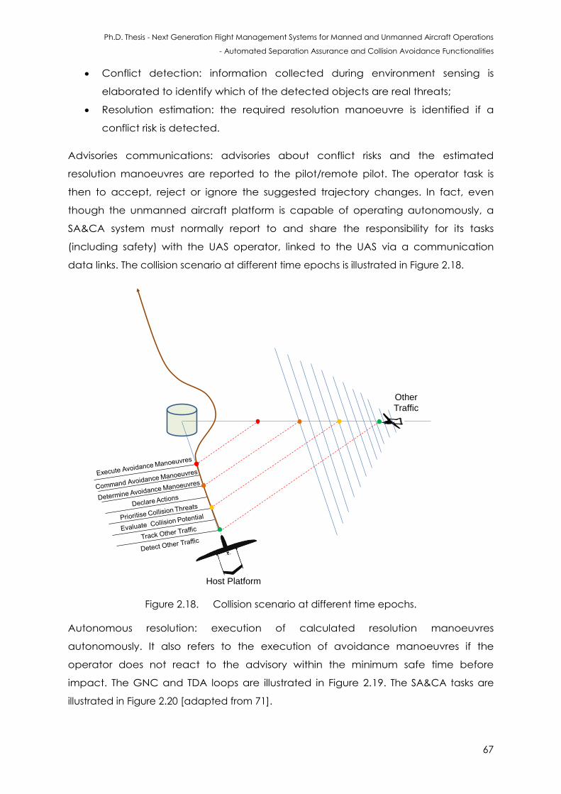
Ph.D. Thesis - Next Generation Flight Management Systems for Manned and Unmanned Aircraft Operations
- Automated Separation Assurance and Collision Avoidance Functionalities
67
Conflict detection: information collected during environment sensing is
elaborated to identify which of the detected objects are real threats;
Resolution estimation: the required resolution manoeuvre is identified if a
conflict risk is detected.
Advisories communications: advisories about conflict risks and the estimated
resolution manoeuvres are reported to the pilot/remote pilot. The operator task is
then to accept, reject or ignore the suggested trajectory changes. In fact, even
though the unmanned aircraft platform is capable of operating autonomously, a
SA&CA system must normally report to and share the responsibility for its tasks
(including safety) with the UAS operator, linked to the UAS via a communication
data links. The collision scenario at different time epochs is illustrated in Figure 2.18.
Host Platform
Other
Traffic
Figure 2.18. Collision scenario at different time epochs.
Autonomous resolution: execution of calculated resolution manoeuvres
autonomously. It also refers to the execution of avoidance manoeuvres if the
operator does not react to the advisory within the minimum safe time before
impact. The GNC and TDA loops are illustrated in Figure 2.19. The SA&CA tasks are
illustrated in Figure 2.20 [adapted from 71].
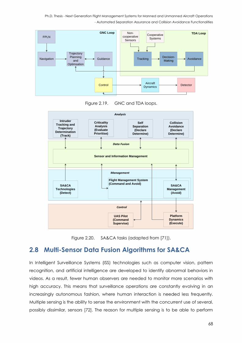
Ph.D. Thesis - Next Generation Flight Management Systems for Manned and Unmanned Aircraft Operations
- Automated Separation Assurance and Collision Avoidance Functionalities
68
FPLN
Navigation
Trajectory
Planning
and
Optimsation
Guidance
GNC Loop
Control
Non-
cooperative
Sensors
TrackingDecision-
MakingAvoidance
TDA LoopCooperative
Systems
Aircraft
DynamicsDetector
Figure 2.19. GNC and TDA loops.
Data Fusion
Management
Control
Analysis
Intruder
Tracking and
Trajectory
Determination
(Track)
Criticality
Analysis
(Evaluate
Prioritise)
Self
Separation
(Declare
Determine)
Collision
Avoidance
(Declare
Determine)
Sensor and Information Management
SA&CA
Technologies
(Detect)
SA&CA
Management
(Avoid)
Platform
Dynamics
(Execute)
UAS Pilot
(Command
Supervise)
Flight Management System
(Command and Avoid)
Figure 2.20. SA&CA tasks (adapted from [71]).
2.8 Multi-Sensor Data Fusion Algorithms for SA&CA
In Intelligent Surveillance Systems (ISS) technologies such as computer vision, pattern
recognition, and artificial intelligence are developed to identify abnormal behaviors in
videos. As a result, fewer human observers are needed to monitor more scenarios with
high accuracy. This means that surveillance operations are constantly evolving in an
increasingly autonomous fashion, where human interaction is needed less frequently.
Multiple sensing is the ability to sense the environment with the concurrent use of several,
possibly dissimilar, sensors [72]. The reason for multiple sensing is to be able to perform
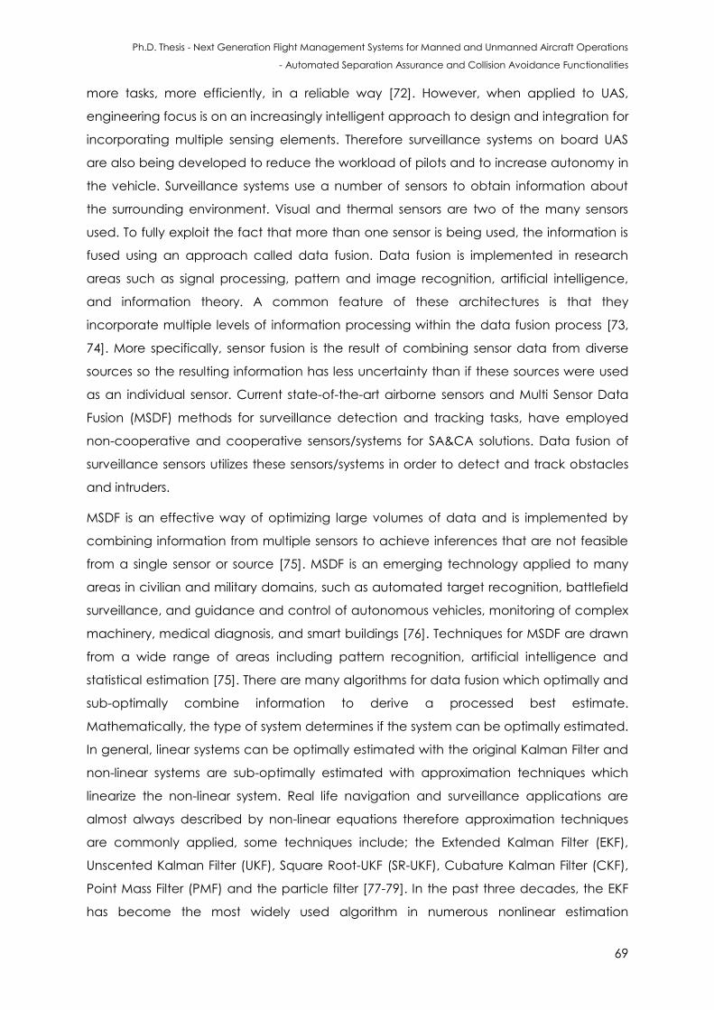
Ph.D. Thesis - Next Generation Flight Management Systems for Manned and Unmanned Aircraft Operations
- Automated Separation Assurance and Collision Avoidance Functionalities
69
more tasks, more efficiently, in a reliable way [72]. However, when applied to UAS,
engineering focus is on an increasingly intelligent approach to design and integration for
incorporating multiple sensing elements. Therefore surveillance systems on board UAS
are also being developed to reduce the workload of pilots and to increase autonomy in
the vehicle. Surveillance systems use a number of sensors to obtain information about
the surrounding environment. Visual and thermal sensors are two of the many sensors
used. To fully exploit the fact that more than one sensor is being used, the information is
fused using an approach called data fusion. Data fusion is implemented in research
areas such as signal processing, pattern and image recognition, artificial intelligence,
and information theory. A common feature of these architectures is that they
incorporate multiple levels of information processing within the data fusion process [73,
74]. More specifically, sensor fusion is the result of combining sensor data from diverse
sources so the resulting information has less uncertainty than if these sources were used
as an individual sensor. Current state-of-the-art airborne sensors and Multi Sensor Data
Fusion (MSDF) methods for surveillance detection and tracking tasks, have employed
non-cooperative and cooperative sensors/systems for SA&CA solutions. Data fusion of
surveillance sensors utilizes these sensors/systems in order to detect and track obstacles
and intruders.
MSDF is an effective way of optimizing large volumes of data and is implemented by
combining information from multiple sensors to achieve inferences that are not feasible
from a single sensor or source [75]. MSDF is an emerging technology applied to many
areas in civilian and military domains, such as automated target recognition, battlefield
surveillance, and guidance and control of autonomous vehicles, monitoring of complex
machinery, medical diagnosis, and smart buildings [76]. Techniques for MSDF are drawn
from a wide range of areas including pattern recognition, artificial intelligence and
statistical estimation [75]. There are many algorithms for data fusion which optimally and
sub-optimally combine information to derive a processed best estimate.
Mathematically, the type of system determines if the system can be optimally estimated.
In general, linear systems can be optimally estimated with the original Kalman Filter and
non-linear systems are sub-optimally estimated with approximation techniques which
linearize the non-linear system. Real life navigation and surveillance applications are
almost always described by non-linear equations therefore approximation techniques
are commonly applied, some techniques include; the Extended Kalman Filter (EKF),
Unscented Kalman Filter (UKF), Square Root-UKF (SR-UKF), Cubature Kalman Filter (CKF),
Point Mass Filter (PMF) and the particle filter [77-79]. In the past three decades, the EKF
has become the most widely used algorithm in numerous nonlinear estimation
Ph.D. Thesis - Next Generation Flight Management Systems for Manned and Unmanned Aircraft Operations
- Automated Separation Assurance and Collision Avoidance Functionalities
70
applications [80]. In comparison to the UKF, the EKF is difficult to manipulate (i.e.
computationally intractable) due to derivation of the Jacobean matrices. Furthermore,
the accuracy of the propagated mean and covariance is limited to first order Taylor
series expansion, which is caused by its linearization process [81]. The UKF overcomes the
limitations of the EKF by providing derivative-free higher-order approximations by
approximating a Gaussian distribution rather than approximating an arbitrary nonlinear
function [82]. The UKF is more accurate and robust in navigation applications by also
providing much better convergence characteristics. The UKF uses sigma points and a
process known as unscented transform to evaluate the statistics of a nonlinear
transformed random variable. Due to the advancements in modern computing
technologies, algorithms such as the UKF and the PF can now be implemented
effectively for real time systems. The aim of this research is to adopt MSDF techniques to
provide the best estimate of track data obtained from cooperative systems and non-
cooperative sensors. The UKF is used to processes the cooperative sensors and a PF is
adopted to combine the non-cooperative sensor measurements. The PF or Sequential
Monte Carlo (SMC) are a broad and well known category of Monte Carlo algorithms
developed in the last two decades to provide approximate solutions to intractable
inference problem. The methodology is used for nonlinear filtering problems seen in
Bayesian statistical inference and signal processing. Using the PF for filtering or estimation
problems, the observations are used to measure internal states in systems. The system
dynamic process and sensors are also filled with random noise utilised in the filtering
process. The objective is to compute the posterior distributions of states or hidden
variable, from the noisy and partial observations. The main objective of a PF is estimating
the posterior density of the hidden state variables using the observation variables if
applicable. The PF is designed for a hidden Markov model, where the system consists of
hidden and observable variables. The dynamical system describing the evolution of the
state variables is also known probabilistically obtained from the prediction and updating
process of the PF. A set of particles is initialised in the PF to generate a sample
distribution, where each particle is assigned a weight, which represents the probability of
that particle to be sampled from the probability density function. Weight disparity
leading to weight collapse is a common issue encountered in these filtering algorithms;
however it can be mitigated by including a resampling step before the weights become
too uneven.
ADS-B and TCAS are exploited in the MSDF architecture, which provide position and
velocity estimates for the detection and tracking solution. The MSDF technique used to
fuse the cooperative sensors is the UKF (which is MSDF technique N), the MSDF technique
Ph.D. Thesis - Next Generation Flight Management Systems for Manned and Unmanned Aircraft Operations
- Automated Separation Assurance and Collision Avoidance Functionalities
71
used to fuse the non-cooperative sensors is the PF (which is MSDF technique NC) and the
MSDF technique used to fuse the MSDF N and MSDF NC sensors is based on a memory
based learning. In order to estimate the non-linear functions, approximation methods
are used. On-board trajectory replanning, with dynamically updated constraints based
on the intruder and the host dynamics, is at present used to generate obstacle
avoidance trajectories. The states of the tracked obstacles are obtained by adopting
UKF/PF or other MSDF techniques, which are then used in order to predict the trajectory
in a given time horizon.
The real world may be described by nonlinear differential equations, and measurements
may not be a function of those states. In many problems, in this case, the measurements
are a linear function of the states, but the model of the real world is nonlinear. In order
to predict the track of the target object/aircraft MSDF techniques are used to obtain the
best estimate and then a probabilistic model is used. The UKF is used to obtain a better
estimate; therefore a better prediction will be obtained because the errors are
essentially reduced. The detection information provided by several awareness sensors
should be evaluated and prioritized taking into account the rest of the UAS information
such as telemetry, flight plan and mission information [83]. A multi-sensor surveillance
system includes function such as detection and tracking which utilize cooperative and
non-cooperative information sources in a multi-sensor architecture. The output of an
effective multi-sensor tracker provides a unified surveillance picture with a relatively small
number of confirmed tracks and improved target localization. Global multi-sensor fusion
and tracking should be capable of processing (potentially anomalous) AIS tracks and
contact-level or track-level data from other sensors to produce a single, consolidated
surveillance picture. The following filters have been used for implementing TDA loops
[84]:
Tracking for single object non maneuvering target
1. Optimal Bayesian filter
2. Kalman Filter
3. Extended Kalman Filter
4. Unscented Kalman Filter
5. Point Mass Filter
6. Particle Filter
Manoeuvring object tracking
1. Optimal Bayesian filter
2. Generalized pseudo-Bayes Filters (of order 1 and order 2)
Ph.D. Thesis - Next Generation Flight Management Systems for Manned and Unmanned Aircraft Operations
- Automated Separation Assurance and Collision Avoidance Functionalities
72
3. Interactive Multiple Models
4. Bootstrap Filter (Auxiliary)
5. Extended Kalman Auxiliary Particle Filter
Single Object Tracking in Clutter
1. Optimal Bayesian filter
2. Nearest neighbour filter
3. Particle filter
4. Extended Kalman auxiliary particle filter
Single- and Multiple-Object Tracking in Clutter: Object-Existence-Based
Approach
1. Optimal Bayes’ recursion
2. Joint Probabilistic Data association (JPD)
3. Interacting Multiple Models – Joint Integrated Probabilistic Data
Association (IMM-JIPDA)
Multiple-object tracking in clutter: random-set-based approach
Random Finite Set Formalism (RFS)
1. Optimal Bayesian multi-object tracking filter
2. Probabilistic hypothesis density approximation
Approximate filters
1. Gaussian mixture probability hypothesis density filter
2. Particle probability hypothesis density filter
3. Gaussian mixture cumulative probability hypothesis density algorithm
Object-existence-based tracking filter
1. Integrated probabilistic data association filter
Several well-known Bayesian filtering algorithms are employed for the single, multiple,
maneuvreing and non-maneuvreing object tracking problem. Maneuvering objects are
those objects whose dynamical behaviour changes overtime. An object that suddenly
turns or accelerates displays a maneuvering behaviour with regard to its tracked position
[84]. While the definition of a maneuvering object extends beyond the tracking of
position and speed, historically it is in this context that maneuvering object tracking
theory developed. This service has to incorporate 4D navigation in order to know at
what moment the aircraft is going to arrive at the different flight plan waypoints.
The Unscented Kalman Filter (UKF):
The UKF is an alternative to the EKF, and shares its computational simplicity while
avoiding the need to derive and compute Jacobians and achieving greater accuracy
Ph.D. Thesis - Next Generation Flight Management Systems for Manned and Unmanned Aircraft Operations
- Automated Separation Assurance and Collision Avoidance Functionalities
73
[84]. The UKF is based upon the unscented transformation process: this method
approximates the moments of a non-linearly transformed random variable. The
unscented transformation can be used as the basis of a non-linear filtering
approximation which has the same form as the EKF but is derived in a quite different
manner. The posterior PDF of xk using Bayes’ rule is given by:
( ) (
) ( ) (2.27)
The UKF approximates the joint density of the state and measurement conditional
on the measurement history that is approximated by a Gaussian density expressed
as:
( ) ([
] [
] [
]) (2.28)
This implies that:
( ) ( ) (2.29)
In general, the moments appearing in these equations cannot be computed exactly
and so must be approximated. The UT is used for this purpose. The state prediction is
performed by predicting the mean and covariance matrix of which represent the
moments of transformation given by:
( ) (2.30)
where the statistics are taken for given . The predicted mean and covariance
matrix are given by:
( ) ( ( )
) ( ( ) ) (2.31)
( ) ( ( )
)
( ( ) ) ( ) (2.32)
Approximations to the predicted mean and covariance matrix are to be obtained using
the unscented transformation. Sigma points
and weights are
selected to match the mean and the covariance matrix of ( ). With
( )
where , the approximations for the predicted mean and covariance matrix are
given by:
Ph.D. Thesis - Next Generation Flight Management Systems for Manned and Unmanned Aircraft Operations
- Automated Separation Assurance and Collision Avoidance Functionalities
74
∑
(2.33)
∑ (
)( )
(2.34)
The measurement prediction: The predicted statistics for the measurement yk are
moments of the transformation given by:
( ) (2.35)
where the statistics of given are available from the prediction step. Hence we
have:
( ) ( ( )
) (2.36)
( ) ( ( )
) ( ) (2.37)
( ) ( ( )
) (2.38)
Let
and denote the sigma points and weights, respectively, selected to
match the predicted mean and covariance matrix. The transformed sigma points are
(
), . The UT approximations to the moments are [83]:
∑
(2.39)
∑ ( )(
)
(2.40)
∑ ( )(
)
(2.41)
The resulting expression for the posterior probability distribution function is given by:
( ) ( ) (2.42)
where:
( ) (2.43)
(2.44)
As with the EKF, the UKF is strongly reminiscent of the KF, with the main difference being
the dependence of the posterior covariance matrix on the observed measurements. In
Ph.D. Thesis - Next Generation Flight Management Systems for Manned and Unmanned Aircraft Operations
- Automated Separation Assurance and Collision Avoidance Functionalities
75
UKF this occurs because the calculated sigma points generated in the UT process are
moment approximations and are determined based on state estimates which are
measurement dependent. Before concluding, we note that the assumption of additive
noise in the dynamic and measurement equations has been made only for the sake of
convenience [84]. The UT is equally applicable for non-additive noise. For instance, if the
dynamic equation is ( ), then the quality undergoing a non-linear
transformation is the augmented variable [
, which has the statistics
( ) [
]
and (
) ( ). The UT can be applied
to the random variable transformed through the function to approximate the
predicted state statistics. Since is of dimension , a larger number of sigma points
will be required than for the case where the dynamic noise is additive. Similar comments
hold for a measurement equation which is non-linear in the measurement noise. A
summary of the UKF is given by below.
Algorithm:
1. Determine sigma points
and weights to match a mean
and covariances matrix .
2. Compute the transformed sigma points (
), .
3. Compute the predicted state statistics:
∑
(2.45)
∑ (
)( )
(2.46)
4. Determine the sigma points
and weights to match mean and
covariance matrix .
5. Compute the transformed sigma points (
), .
6. Compute the predicted measurement statistics
∑
(2.47)
∑ (
)( )
(2.48)
∑ ( )(
)
(2.49)
7. Compute the posterior mean and covariance matrix
Ph.D. Thesis - Next Generation Flight Management Systems for Manned and Unmanned Aircraft Operations
- Automated Separation Assurance and Collision Avoidance Functionalities
76
( ) (2.50)
(2.51)
The Particle Filter:
There are different methods for target tracking, but particle filtering is one of the most
important and widely used methods. The particle filter is an implementation of Bayesian
recursive filtering using a sequential Monte Carlo sampling method. It is used in statistics
and signal processing, where it is known as a bootstrap filter and a Monte Carlo filter
respectively [85]. The target state is represented by where is time. is the set of all
observations. The posterior density function ( ) is represented by a set of weighted
samples. Observations ( ) can be non-gaussian. The main aim is the estimation of
the probability distribution function of the target object by a set of weighted samples
{( ( ) ( )) } such that ∑ ( ) [86]. Based on the observations, the
likelihood of each particle is applied in weight assignment by the equation below in
each step:
( ) ( ( )
) (2.52)
The particle filter consists of two stages, prediction and update. In the prediction state,
next step particles are calculated by using current step particles and target state
transition equations. In the update stage, the weights are assigned to new particles by
the following equation [86]:
( ) (
)
(
) (2.53)
where is the importance density function which is used in the sampling function. The
posteriori density function is estimated by using the following equation:
( ) ∑ ( )
(2.54)
The next step state vector is estimated by using the weighted average on current step
particles with the following equation [86]:
∑
(2.55)
Sequential Importance Resampling Particle Filter:
Ph.D. Thesis - Next Generation Flight Management Systems for Manned and Unmanned Aircraft Operations
- Automated Separation Assurance and Collision Avoidance Functionalities
77
One of the basic challenges in implementation of a PF is the appropriate choice of the
proposal density function. One of the common suboptimal choices of the proposal
density function is the transitional prior distribution [86].
( ) (
) ( ) (2.56)
By substituting ( ) into each particle’s weight, a new weighting can be calculated
based on:
( ) (2.57)
In each step of the SIR algorithm, re-sampling is done after state estimation. After re-
sampling, weights of all particles are equal to
where is the number of particles.
Hence the above equation is modified as:
(
) (2.58)
The implemented algorithm involves the initialisation of the particles using prior
distribution of the tracked object.
Then, for all the particles, the following steps are implemented:
a. Prediction: Generate particles using dynamic model
(
) (2.59)
b. Weighting: Calculate weight for particle
(
) (2.60)
The normalization of the particle weights is given by:
∑
(2.61)
c. Resampling:
The particles are resampled and new particles are obtained with same weight
and repeat from stage 2.
{(
)}
{(
)}
(2.62)
Statistical Learning Techniques:
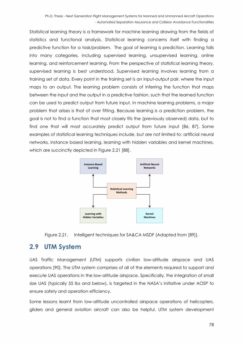
Ph.D. Thesis - Next Generation Flight Management Systems for Manned and Unmanned Aircraft Operations
- Automated Separation Assurance and Collision Avoidance Functionalities
78
Statistical learning theory is a framework for machine learning drawing from the fields of
statistics and functional analysis. Statistical learning concerns itself with finding a
predictive function for a task/problem. The goal of learning is prediction. Learning falls
into many categories, including supervised learning, unsupervised learning, online
learning, and reinforcement learning. From the perspective of statistical learning theory,
supervised learning is best understood. Supervised learning involves learning from a
training set of data. Every point in the training set is an input-output pair, where the input
maps to an output. The learning problem consists of inferring the function that maps
between the input and the output in a predictive fashion, such that the learned function
can be used to predict output from future input. In machine learning problems, a major
problem that arises is that of over fitting. Because learning is a prediction problem, the
goal is not to find a function that most closely fits the (previously observed) data, but to
find one that will most accurately predict output from future input [86, 87]. Some
examples of statistical learning techniques include, but are not limited to: artificial neural
networks, instance based learning, learning with hidden variables and kernel machines,
which are succinctly depicted in Figure 2.21 [88].
Statistical Learning Methods
Learning with Hidden Variables
Instance-Based Learning
Artificial Neural Networks
Kernel Machines
Figure 2.21. Intelligent techniques for SA&CA MSDF (Adapted from [89]).
2.9 UTM System
UAS Traffic Management (UTM) supports civilian low-altitude airspace and UAS
operations [90]. The UTM system comprises of all of the elements required to support and
execute UAS operations in the low-altitude airspace. Specifically, the integration of small
size UAS (typically 55 lbs and below), is targeted in the NASA’s initiative under AOSP to
ensure safety and operation efficiency.
Some lessons learnt from low-altitude uncontrolled airspace operations of helicopters,
gliders and general aviation aircraft can also be helpful. UTM system development

Ph.D. Thesis - Next Generation Flight Management Systems for Manned and Unmanned Aircraft Operations
- Automated Separation Assurance and Collision Avoidance Functionalities
79
accommodates manned aircraft along with Line-of-Sight (LoS) and Beyond LoS (BVLoS)
UAS operations in the low-altitude airspace. The supporting components include, but are
not limited to, the NAS information, Communication and Technology (ICT) systems, UAS
systems, regulations, policies, and procedures. The operation of multiple conventional
and autonomous transport vehicles is an important emerging issue to be considered in
the development of future traffic management systems.
Near-term Goal: Safely enable initial low-altitude UAS as early as possible;
Long-term Goal: Accommodate increased demand with highest safety,
efficiency, and capacity.
Figure 2.22 depicts the functional description of the UTM, and its functions are shown in
Figure 2.23.
UTM SERVICES:
UTM based on autonomicity, autonomy
and autonomous operations
UTM CHARACTERISTICS:
• Authentication
• Airspace design
• Geofence definition
• Weather integration
• Constraint management
• Sequencing and spacing
• Trajectory changes
• Separation management
• Contingency management
Airspace
Constraints
Real-time
Weather (and
Wind)
Weather and
Wind
Predictions
Other UTM
Operations
UAS Operations:
Line-of-Sight and Beyond Line-of-Sight – Manual to More Automation
UAS 1 UAS 2 UAS 3 UAS FleetUAS Fleet
Tracking:
• ADS-B
• Cellular
Mobile
Comms
• Satellite
• Non-
cooperativ
e sensors
Transition
between
UTM and
ATM
Constraints:
No-fly
zones, etc.
3D Maps:
terrain and
man-made
structures
Figure 2.22. UTM system architecture.
The UTM will support a wide variety of UAS, from those equipped with minimalistic
avionics to autonomous UAS [91-95]. The inputs to UTM will include: UAV mission/business
flight plan or trajectory, real-time weather and wind, predicted wind and weather,
airspace constraints (dynamically adjusted), community needs about sensitive areas
(dynamically adjusted), and three-dimensional maps that include man-made structures
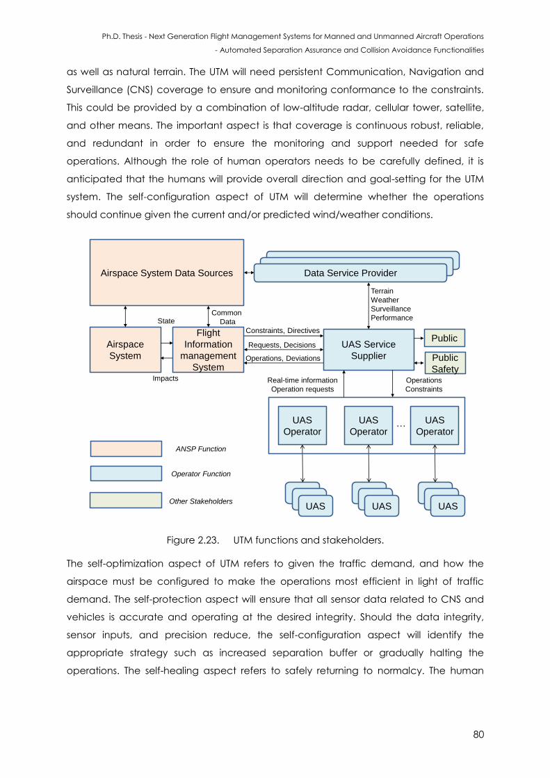
Ph.D. Thesis - Next Generation Flight Management Systems for Manned and Unmanned Aircraft Operations
- Automated Separation Assurance and Collision Avoidance Functionalities
80
as well as natural terrain. The UTM will need persistent Communication, Navigation and
Surveillance (CNS) coverage to ensure and monitoring conformance to the constraints.
This could be provided by a combination of low-altitude radar, cellular tower, satellite,
and other means. The important aspect is that coverage is continuous robust, reliable,
and redundant in order to ensure the monitoring and support needed for safe
operations. Although the role of human operators needs to be carefully defined, it is
anticipated that the humans will provide overall direction and goal-setting for the UTM
system. The self-configuration aspect of UTM will determine whether the operations
should continue given the current and/or predicted wind/weather conditions.
UAS
Operator
Data Service ProviderAirspace System Data Sources
Public
Safety
Public
UAS
Airspace
System
Flight
Information
management
System
UAS Service
Supplier
UASUAS
Common
Data
UAS
Operator
UASUAS
UAS
UAS
Operator
UASUAS
UAS
State
Impacts Real-time information
Operation requests
Constraints, Directives
Requests, Decisions
Operations, Deviations
Terrain
Weather
Surveillance
Performance
…
Operations
Constraints
ANSP Function
Operator Function
Other Stakeholders
Figure 2.23. UTM functions and stakeholders.
The self-optimization aspect of UTM refers to given the traffic demand, and how the
airspace must be configured to make the operations most efficient in light of traffic
demand. The self-protection aspect will ensure that all sensor data related to CNS and
vehicles is accurate and operating at the desired integrity. Should the data integrity,
sensor inputs, and precision reduce, the self-configuration aspect will identify the
appropriate strategy such as increased separation buffer or gradually halting the
operations. The self-healing aspect refers to safely returning to normalcy. The human
Ph.D. Thesis - Next Generation Flight Management Systems for Manned and Unmanned Aircraft Operations
- Automated Separation Assurance and Collision Avoidance Functionalities
81
may be the ultimate decision-maker regarding the continuation and return to normalcy
of the operations.
A list of UTM functions is provided below:
1. Airspace Operations and Management
Current: ~500 ft. and below;
Geographical needs and applications;
Rules of the airspace: performance-based;
Geofences: dynamic and static.
2. Wind and Weather Integration
Actual and predicted winds/weather;
Operator responsibility.
3. Congestion Management
Demand/capacity imbalance;
Only if needed –corridors, altitude for direction, etc.
4. Separation Management
Airspace reservation;
Vehicle-to-vehicle and vehicle-to-UTM;
Tracking: ADS-B, cellular, & satellite based;
Traffic avoidance;
SA&CA to manned aircraft predicated on right of way;
Status and intent exchange in accordance with standards;
Collaborative decision making;
Contingency planning and response (system outages, unreported weather, etc.).
5. Route Structure
Only where needed for safety or efficiency of flight;
Procedural rules-of-road (corridors, altitudes, etc.).
6. Air Traffic Control
Integrated with manned air traffic control, where positive UAS control is required
for safety or efficiency of flight;
Static or dynamic application (e.g., ability to respond in crisis situation where
sustained mixed operations are required).
7. Flow Management
Only where needed for safety or efficiency of flight;
Manage access into areas of operation, not particular operation;
8. Contingency Management
Ph.D. Thesis - Next Generation Flight Management Systems for Manned and Unmanned Aircraft Operations
- Automated Separation Assurance and Collision Avoidance Functionalities
82
Large-scale GPS or cell outage;
Cyber-physical attacks.
9. Track and Locate (cellular communication systems, ADS-B, satellite, etc.)
Conflict (V2V, sense and avoid) and hazard avoidance.
10. Last and First 50 Feet Operations
In terms of granting the required levels of operational safety when considering the
integration of autonomous traffic in the existing ATM and planned UTM networks
characterised by dense/mixed traffic and high levels of service, the emphasis is on
network-centric equipment that can meet strict performance requirements while also
supporting enhanced traffic management and optimisation functionalities. In particular,
in order to grant the required surveillance performance and autonomous Separation
Assurance and Collision Avoidance (SA&CA) capabilities for unrestricted access to
controlled airspace, UAS surveillance equipment involve a combination of non-
cooperative sensors and cooperative systems. Ground-based and satellite based data-
link communication systems act as the backbone of LoS and BLoS Vehicle-to-Vehicle
(V2V) and Vehicle-to-UTM (V2U) information exchanges [96].
The UTM system development is aimed at introducing safe separation functionalities by
exploiting the concept of dynamic geo-fences and providing a solution driven by the
unified approach to SA&CA. In the long term and to support faster-moving hybrid
unmanned vehicles, UTM research will have to develop efficient network-centric
functionalities for trajectory prediction and negotiation both within individual controlled
airspace/network sectors and across multiple sectors belonging to the same region, also
considering the inbound/outbound flows from adjacent regions. Three different
operating environments within the airspace systems that will be in the UTM system
concept of operations are [90]:
UAS operations inside uncontrolled Airspace (class G): In this environment, no
interaction with controlled air traffic will occur as the UAS operations occur
outside of controlled airspace operations. However, UAS share the airspace with
other airspace users, such as general aviation aircraft, helicopters, gliders,
balloons, and parachutists;
UAS operations inside controlled airspace, but segregated from controlled air
traffic: As many use cases of small UAS operations would benefit from operating
near airports and inside controlled airspace, there could be segregated areas
within the controlled airspace that can be made available for UAS operations.
These could be transition tunnels or blocks of airspace that are made available
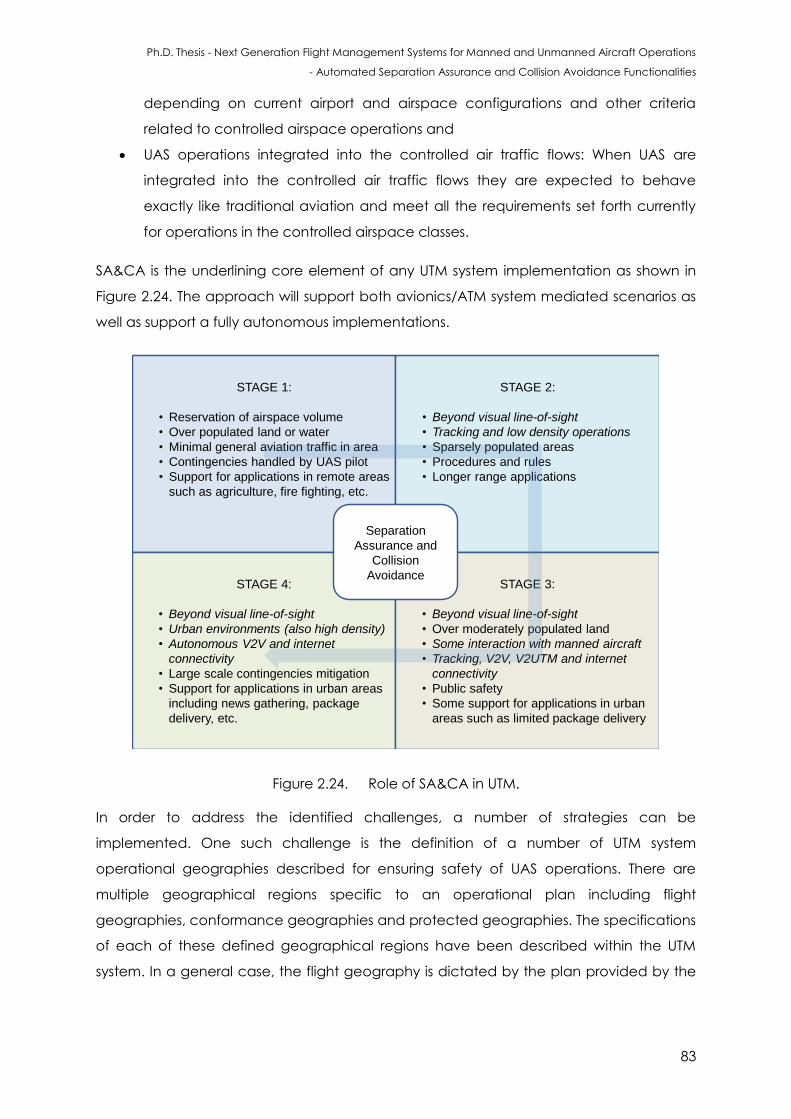
Ph.D. Thesis - Next Generation Flight Management Systems for Manned and Unmanned Aircraft Operations
- Automated Separation Assurance and Collision Avoidance Functionalities
83
depending on current airport and airspace configurations and other criteria
related to controlled airspace operations and
UAS operations integrated into the controlled air traffic flows: When UAS are
integrated into the controlled air traffic flows they are expected to behave
exactly like traditional aviation and meet all the requirements set forth currently
for operations in the controlled airspace classes.
SA&CA is the underlining core element of any UTM system implementation as shown in
Figure 2.24. The approach will support both avionics/ATM system mediated scenarios as
well as support a fully autonomous implementations.
STAGE 1:
• Reservation of airspace volume
• Over populated land or water
• Minimal general aviation traffic in area
• Contingencies handled by UAS pilot
• Support for applications in remote areas
such as agriculture, fire fighting, etc.
STAGE 2:
• Beyond visual line-of-sight
• Tracking and low density operations
• Sparsely populated areas
• Procedures and rules
• Longer range applications
STAGE 4:
• Beyond visual line-of-sight
• Urban environments (also high density)
• Autonomous V2V and internet
connectivity
• Large scale contingencies mitigation
• Support for applications in urban areas
including news gathering, package
delivery, etc.
STAGE 3:
• Beyond visual line-of-sight
• Over moderately populated land
• Some interaction with manned aircraft
• Tracking, V2V, V2UTM and internet
connectivity
• Public safety
• Some support for applications in urban
areas such as limited package delivery
Separation
Assurance and
Collision
Avoidance
Figure 2.24. Role of SA&CA in UTM.
In order to address the identified challenges, a number of strategies can be
implemented. One such challenge is the definition of a number of UTM system
operational geographies described for ensuring safety of UAS operations. There are
multiple geographical regions specific to an operational plan including flight
geographies, conformance geographies and protected geographies. The specifications
of each of these defined geographical regions have been described within the UTM
system. In a general case, the flight geography is dictated by the plan provided by the
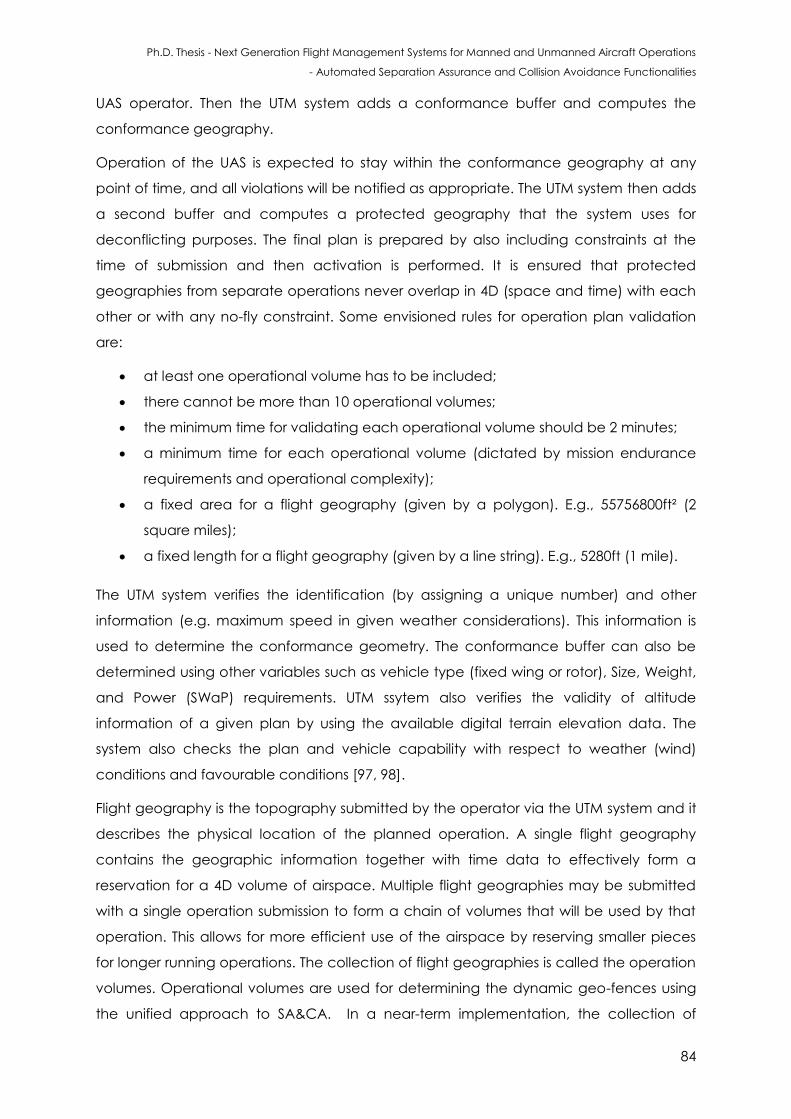
Ph.D. Thesis - Next Generation Flight Management Systems for Manned and Unmanned Aircraft Operations
- Automated Separation Assurance and Collision Avoidance Functionalities
84
UAS operator. Then the UTM system adds a conformance buffer and computes the
conformance geography.
Operation of the UAS is expected to stay within the conformance geography at any
point of time, and all violations will be notified as appropriate. The UTM system then adds
a second buffer and computes a protected geography that the system uses for
deconflicting purposes. The final plan is prepared by also including constraints at the
time of submission and then activation is performed. It is ensured that protected
geographies from separate operations never overlap in 4D (space and time) with each
other or with any no-fly constraint. Some envisioned rules for operation plan validation
are:
at least one operational volume has to be included;
there cannot be more than 10 operational volumes;
the minimum time for validating each operational volume should be 2 minutes;
a minimum time for each operational volume (dictated by mission endurance
requirements and operational complexity);
a fixed area for a flight geography (given by a polygon). E.g., 55756800ft² (2
square miles);
a fixed length for a flight geography (given by a line string). E.g., 5280ft (1 mile).
The UTM system verifies the identification (by assigning a unique number) and other
information (e.g. maximum speed in given weather considerations). This information is
used to determine the conformance geometry. The conformance buffer can also be
determined using other variables such as vehicle type (fixed wing or rotor), Size, Weight,
and Power (SWaP) requirements. UTM ssytem also verifies the validity of altitude
information of a given plan by using the available digital terrain elevation data. The
system also checks the plan and vehicle capability with respect to weather (wind)
conditions and favourable conditions [97, 98].
Flight geography is the topography submitted by the operator via the UTM system and it
describes the physical location of the planned operation. A single flight geography
contains the geographic information together with time data to effectively form a
reservation for a 4D volume of airspace. Multiple flight geographies may be submitted
with a single operation submission to form a chain of volumes that will be used by that
operation. This allows for more efficient use of the airspace by reserving smaller pieces
for longer running operations. The collection of flight geographies is called the operation
volumes. Operational volumes are used for determining the dynamic geo-fences using
the unified approach to SA&CA. In a near-term implementation, the collection of
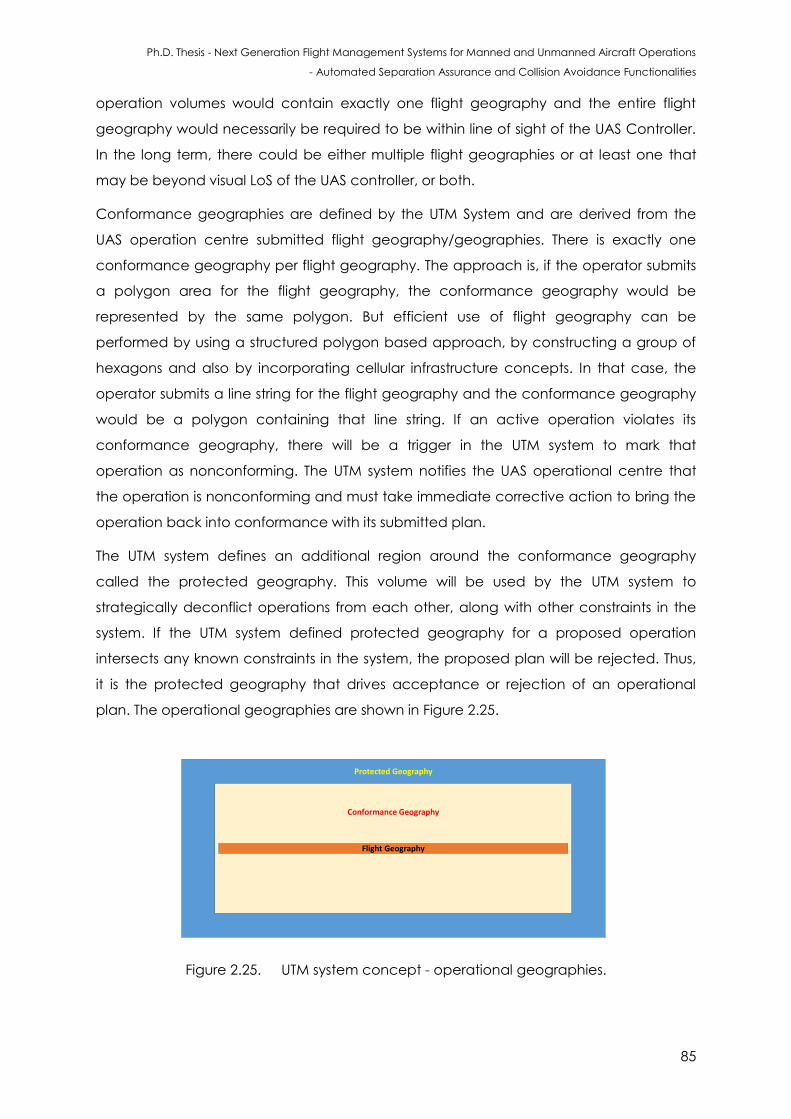
Ph.D. Thesis - Next Generation Flight Management Systems for Manned and Unmanned Aircraft Operations
- Automated Separation Assurance and Collision Avoidance Functionalities
85
operation volumes would contain exactly one flight geography and the entire flight
geography would necessarily be required to be within line of sight of the UAS Controller.
In the long term, there could be either multiple flight geographies or at least one that
may be beyond visual LoS of the UAS controller, or both.
Conformance geographies are defined by the UTM System and are derived from the
UAS operation centre submitted flight geography/geographies. There is exactly one
conformance geography per flight geography. The approach is, if the operator submits
a polygon area for the flight geography, the conformance geography would be
represented by the same polygon. But efficient use of flight geography can be
performed by using a structured polygon based approach, by constructing a group of
hexagons and also by incorporating cellular infrastructure concepts. In that case, the
operator submits a line string for the flight geography and the conformance geography
would be a polygon containing that line string. If an active operation violates its
conformance geography, there will be a trigger in the UTM system to mark that
operation as nonconforming. The UTM system notifies the UAS operational centre that
the operation is nonconforming and must take immediate corrective action to bring the
operation back into conformance with its submitted plan.
The UTM system defines an additional region around the conformance geography
called the protected geography. This volume will be used by the UTM system to
strategically deconflict operations from each other, along with other constraints in the
system. If the UTM system defined protected geography for a proposed operation
intersects any known constraints in the system, the proposed plan will be rejected. Thus,
it is the protected geography that drives acceptance or rejection of an operational
plan. The operational geographies are shown in Figure 2.25.
Protected Geography
Conformance Geography
Flight Geography
Figure 2.25. UTM system concept - operational geographies.
Ph.D. Thesis - Next Generation Flight Management Systems for Manned and Unmanned Aircraft Operations
- Automated Separation Assurance and Collision Avoidance Functionalities
86
When there are multiple UAS operating in the same topography, then operational
geographies are defined distinctively for each UAS occupying the topography. The
operational geographies of multiple UAS accessing the same topography are shown in
Figure 2.26.
Protected Geography 1
Conformance Geography 1
Flight Geography 1
Pro
tect
ed
Ge
ogr
aph
y 2
Co
nfo
rman
ce G
eo
grap
hy
2
Flig
ht
Ge
ogr
aph
y 2
Figure 2.26. UTM system concept - operational geographies of multiple UAS.
By evaluating these operational geographies, the NG-FMS generates 4D trajectories that
are then evaluated for SA&CA, given the surveillance information from the UTM system.
2.10 Dependency on LoS and BLoS Communications
The airworthiness requirements regarding CA&CA capabilities are highly dependent on
the operating modes. These modes are defined below.
Visual line-of-sight is defined by ICAO as being “a mode of UAS operation in which the
flight crew monitors the flight path in relation to other aircraft, persons, vehicles or
structures through direct and unaided visual contact with the aircraft, in order to
maintain separation and collision avoidance.”
Beyond VLoS (BVLoS): In this mode the aircraft is controlled from a GCS that is equipped
with necessary instrumentation and displays. When a communication relay is employed,
say using satellites, it is generally referred to as Broad RLoS (BRLoS). An UAV can be
operated in BRLoS but it can be still within the visual line-of-sight. There might be
propagation effects including interference and others, but the UAV can still be observed
in a clear sky.
In VLoS flight conditions, unmanned aircraft are constrained to very low altitudes in order
to be visible and also to enable control by the remote pilot/operator. ICAO rules state
that, except for take-off and landing flight phases, the minimum flight altitude has to be
Ph.D. Thesis - Next Generation Flight Management Systems for Manned and Unmanned Aircraft Operations
- Automated Separation Assurance and Collision Avoidance Functionalities
87
above 500 ft. In BVLoS/BRLoS operations, SA&CA algorithms are required to support the
remote pilot in the accomplishment of the following tasks:
maintaining appropriate separation distance from other airspace users;
avoidance of collision with terrain and obstacles;
avoidance of severe/adverse weather;
maintaining appropriate flight visibilities and distance from clouds;
visual observation of lighting and markings;
visual observation of any in flight interception signals;
visual observation of the landing/departure runway;
visual observation of next aircraft where reduced separation is approved.
2.11 Towards Higher Levels of Autonomy
Autonomy can be defined as the capability of making decisions without assistance by
human operators. Autonomy in UAS is essential to both increase the utility of the UAS and
the safety of its operation, as it allows the unmanned aircraft to avoid hazardous
situations if failures occur in the C2 loop [99]. Levels of autonomy were initially defined by
Sheridan [100]. Sheridan’s 10-level scale of autonomy is based on the decision-maker
(human or system) and on how the decisions are executed. Different implementations of
Sheridan’s scale were considered. UAS can be configured for autonomous, overridable,
aided and deliberate operations and are listed in Table 2.10.
These levels are based on information acquisition, information analysis, decision and
action selection, as well as action implementation functions. According to the
classification identified in the autonomous modes, UAS usually operates at Pilot Authority
and Control (PACT) level 3 [100].
The system communicates to the UAS GCS remote pilot any potential hazards that are
detected and the suggested resolution to enable him/her to make a decision for
executing an avoidance manoeuvre.
However, in the case of imminent collision situations, if the remote pilot does not react in
time, the SAA systems operates at PACT level 5 (autonomous mode of operations) and
executes the avoidance actions. The expert processing required is grant UAS the
appropriate levels of autonomy can be attained either by knowledge-based algorithms
or by more advanced forms of machine intelligence. Notwithstanding, it shall be noted
that autonomous decision-making in UAS is not limited to safety-critical purposes, and
usually accounts for other features, such as performance optimisation. Therefore, the
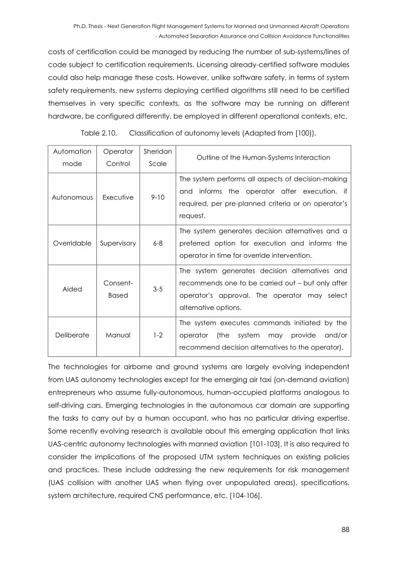
Ph.D. Thesis - Next Generation Flight Management Systems for Manned and Unmanned Aircraft Operations
- Automated Separation Assurance and Collision Avoidance Functionalities
88
costs of certification could be managed by reducing the number of sub-systems/lines of
code subject to certification requirements. Licensing already-certified software modules
could also help manage these costs. However, unlike software safety, in terms of system
safety requirements, new systems deploying certified algorithms still need to be certified
themselves in very specific contexts, as the software may be running on different
hardware, be configured differently, be employed in different operational contexts, etc.
Table 2.10. Classification of autonomy levels (Adapted from [100)).
Automation
mode
Operator
Control
Sheridan
Scale Outline of the Human-Systems Interaction
Autonomous Executive 9-10
The system performs all aspects of decision-making
and informs the operator after execution, if
required, per pre-planned criteria or on operator’s
request.
Overridable Supervisory 6-8
The system generates decision alternatives and a
preferred option for execution and informs the
operator in time for override intervention.
Aided Consent-
Based 3-5
The system generates decision alternatives and
recommends one to be carried out – but only after
operator’s approval. The operator may select
alternative options.
Deliberate Manual 1-2
The system executes commands initiated by the
operator (the system may provide and/or
recommend decision alternatives to the operator).
The technologies for airborne and ground systems are largely evolving independent
from UAS autonomy technologies except for the emerging air taxi (on-demand aviation)
entrepreneurs who assume fully-autonomous, human-occupied platforms analogous to
self-driving cars. Emerging technologies in the autonomous car domain are supporting
the tasks to carry out by a human occupant, who has no particular driving expertise.
Some recently evolving research is available about this emerging application that links
UAS-centric autonomy technologies with manned aviation [101-103]. It is also required to
consider the implications of the proposed UTM system techniques on existing policies
and practices. These include addressing the new requirements for risk management
(UAS collision with another UAS when flying over unpopulated areas), specifications,
system architecture, required CNS performance, etc. [104-106].
Ph.D. Thesis - Next Generation Flight Management Systems for Manned and Unmanned Aircraft Operations
- Automated Separation Assurance and Collision Avoidance Functionalities
89
2.12 SA&CA Requirements
It will be necessary that automated SA&CA systems provide a level of safety equalling or
exceeding that of manned aircraft (Title 14 Code of Federal Regulations). In July 2004,
an endeavour to set the standards for this equivalent level of safety was attempted
when the ASTM subcommittee released Document F2411-04 (since amended to F2411-
04e1) “Standard Specification for Design and Performance of an Airborne Sense-and-
Avoid System” [107]. Since its release, this document has served as a guideline for
developers and researchers working on UAS. In 2005, the United States Department of
Defense (DoD) adopted these performance standards for its UAS program.
In order to safely integrate UAS into all classes of airspace, UAS must adhere to the same
separation standards as manned aircraft and thus must be able to complete an ATC
clearance in a timely manner. However, UAS are inherently different from manned
aircraft in several aspects that affect end-to-end response time [108, 109].
For manned aircraft, the pilot is on board the aircraft and the control input is wired to the
control surfaces and other systems of the aircraft. For UAS, the pilot is in a control station
that is removed from the aircraft and the control input must travel wirelessly through the
air or through a satellite relay, depending on the data link architecture, adding a delay
not present with manned aircraft. The variable control delays can make the control of
the UAS more difficult [110]. A summary of the SA&CA requirements for manned and
unmanned aircraft are provided below:
General requirements include:
The SA&CA algorithms shall detect both cooperative and non-cooperative
collision threats during day and night and consider adverse weather conditions;
The SA&CA algorithms shall notify the operator for any imminent collision risk and
provide a collision resolution or execute an autonomous avoidance manoeuvre;
The SA&CA algorithms shall consider any direction or warning from other
avoidance systems;
The SA&CA algorithms shall provide a recommended course to resume action
after any avoidance manoeuvre.
Requirements of SA and CA include:
The SA&CA algorithms shall warn the operator of obstacles within an estimated
distance of 3000 m. In case of cooperative vehicles, the minimum separation
Ph.D. Thesis - Next Generation Flight Management Systems for Manned and Unmanned Aircraft Operations
- Automated Separation Assurance and Collision Avoidance Functionalities
90
shall follow the standards stated by the FAA or other aviation regulatory
authorities;
The generated avoidance manoeuvre shall be based in the standards
established in FAR §91.113 Appendix 3;
The generated avoidance manoeuvre shall prevent mid-air collision and has to
consider other avoidance manoeuvres generated by other systems such as
TCAS;
If the pilot avoidance manoeuvre increases the risk of collision with any other
obstacle the system shall override the pilot command;
If the pilot does not execute a return to course manoeuvre after an avoidance
action, either from the FCS or from the operator, then the aircraft shall
autonomously return to its original course.
Requirements for implementing autonomous actions include:
The SA&CA algorithms shall execute an autonomous avoidance manoeuvre if
the pilot does not perform the suggested resolution from the SA&CA system;
The SA&CA algorithms shall provide the operator the necessary information on
the progress of the autonomous manoeuvre (time and weather permitting);
The SA&CA algorithms shall execute a return-to-course action after an
autonomous manoeuvre is executed.
UTM requirements include:
Communication, Navigation, and Surveillance, Prediction and Separation
Management including SA&CA;
Persistent communication, navigation, and surveillance coverage under day and
night conditions;
Communication, navigation, and surveillance coverage under all visibility
conditions;
Ability to sense, detect and track all moving objects at an altitude up to 10,000 ft.
Most of the UAS for package delivery, wildlife monitoring, fire fighting, crop
dusting, and other applications will operate at much lower altitudes. A starting
point is Class G airspace under 2000 ft;
Ability to predict potential collisions between UAS as well as between UAS and
other moving objects including but not limited to birds, gliders, helicopters, model
aircraft, general aviation aircraft, personal air vehicles, special purpose balloons,
jet wind turbines, etc.;
Ph.D. Thesis - Next Generation Flight Management Systems for Manned and Unmanned Aircraft Operations
- Automated Separation Assurance and Collision Avoidance Functionalities
91
Ability to predict the trajectory for next mile and/or within the 5 minutes,
whichever is higher.
Ability to monitor separation among UAS and predict conditions where the
crossing or separation minima will be violated. The horizontal separation minima
be set to 1 mile at the beginning of UTM activity and will be reduced over time;
Ability to provide persistent, redundant, coverage by sensors to areas where
operations will be conducted.
The SA&CA requirements presented above assume a pilot-centric, manned-vehicle
perspective. But there is a requirement to look at existing policies and best practices to
modify them based on the new UAS requirements. For example, there is a possibility that
a UAS can hit another UAS without risk when an overflying unpopulated region, which
requires suitable policy changes but they are still at an embryonic stage when writing this
thesis.
2.13 Research on SA&CA Avoidance Volumes
Some work that has been previously performed on calculating the
avoidance/uncertainty volume in the context of SA&CA (manual as well as automated)
are highlighted below:
Collision Avoidance System and Method utilizing Variable Surveillance Envelope
(Patent): In this work, the size and shape of the safety volume is monitored by the
sensors and the volume is modified according to the speed and motion vectors
of the aircraft or other traffic, so as to maximize efficient use of sensor capabilities
and minimize the size, cost and power requirements of the system [111].
UAS Collision Encounter Modelling and Avoidance Algorithm Development for
Simulating Collision Avoidance: Detection of other traffic is performed by defining
a geometric sensor model and a collision cone approach. Avoidance algorithms
consist of proportional navigation guidance that uses information from the
collision potential between the unmanned aircraft and other traffic [112].
Dynamic Separation Thresholds for a Small Airborne Sense and Avoid System: In
this method, the distance-based thresholds are replaced with time-based
thresholds that account for intruder performance using turning flight geometry to
implement a computationally inexpensive solution [113].
UAS Collision Avoidance Algorithm Minimizing Impact on Route Surveillance: An
aggregated collision cone approach is implemented to detect and avoid
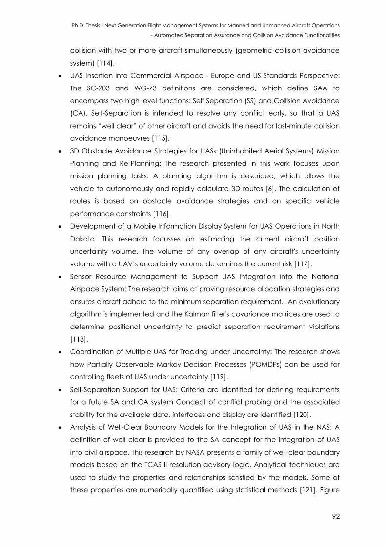
Ph.D. Thesis - Next Generation Flight Management Systems for Manned and Unmanned Aircraft Operations
- Automated Separation Assurance and Collision Avoidance Functionalities
92
collision with two or more aircraft simultaneously (geometric collision avoidance
system) [114].
UAS Insertion into Commercial Airspace - Europe and US Standards Perspective:
The SC-203 and WG-73 definitions are considered, which define SAA to
encompass two high level functions: Self Separation (SS) and Collision Avoidance
(CA). Self-Separation is intended to resolve any conflict early, so that a UAS
remains “well clear” of other aircraft and avoids the need for last-minute collision
avoidance manoeuvres [115].
3D Obstacle Avoidance Strategies for UASs (Uninhabited Aerial Systems) Mission
Planning and Re-Planning: The research presented in this work focuses upon
mission planning tasks. A planning algorithm is described, which allows the
vehicle to autonomously and rapidly calculate 3D routes [6]. The calculation of
routes is based on obstacle avoidance strategies and on specific vehicle
performance constraints [116].
Development of a Mobile Information Display System for UAS Operations in North
Dakota: This research focusses on estimating the current aircraft position
uncertainty volume. The volume of any overlap of any aircraft's uncertainty
volume with a UAV’s uncertainty volume determines the current risk [117].
Sensor Resource Management to Support UAS Integration into the National
Airspace System: The research aims at proving resource allocation strategies and
ensures aircraft adhere to the minimum separation requirement. An evolutionary
algorithm is implemented and the Kalman filter's covariance matrices are used to
determine positional uncertainty to predict separation requirement violations
[118].
Coordination of Multiple UAS for Tracking under Uncertainty: The research shows
how Partially Observable Markov Decision Processes (POMDPs) can be used for
controlling fleets of UAS under uncertainty [119].
Self-Separation Support for UAS: Criteria are identified for defining requirements
for a future SA and CA system Concept of conflict probing and the associated
stability for the available data, interfaces and display are identified [120].
Analysis of Well-Clear Boundary Models for the Integration of UAS in the NAS: A
definition of well clear is provided to the SA concept for the integration of UAS
into civil airspace. This research by NASA presents a family of well-clear boundary
models based on the TCAS II resolution advisory logic. Analytical techniques are
used to study the properties and relationships satisfied by the models. Some of
these properties are numerically quantified using statistical methods [121]. Figure
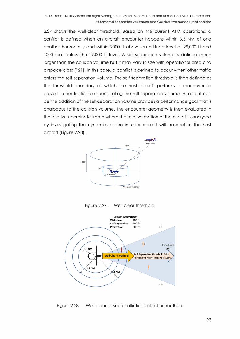
Ph.D. Thesis - Next Generation Flight Management Systems for Manned and Unmanned Aircraft Operations
- Automated Separation Assurance and Collision Avoidance Functionalities
93
2.27 shows the well-clear threshold. Based on the current ATM operations, a
conflict is defined when an aircraft encounter happens within 3.5 NM of one
another horizontally and within 2000 ft above an altitude level of 29,000 ft and
1000 feet below the 29,000 ft level. A self-separation volume is defined much
larger than the collision volume but it may vary in size with operational area and
airspace class [121]. In this case, a conflict is defined to occur when other traffic
enters the self-separation volume. The self-separation threshold is then defined as
the threshold boundary at which the host aircraft performs a maneuver to
prevent other traffic from penetrating the self-separation volume. Hence, it can
be the addition of the self-separation volume provides a performance goal that is
analogous to the collision volume. The encounter geometry is then evaluated in
the relative coordinate frame where the relative motion of the aircraft is analysed
by investigating the dynamics of the intruder aircraft with respect to the host
aircraft (Figure 2.28).
Well Clear Threshold
Other Traffic4000’
700’
100’
Host Aircraft
Figure 2.27. Well-clear threshold.
1000 ft
Vertical Separation:Well-clear: 400 ftSelf Separation: 900 ftPreventive: 900 ft
1.2 NM
2 NM
Well Clear Threshold Self Separation Threshold 80 sPreventive Alert Threshold 110 s
Time UntilCPA0.8 NM
Figure 2.28. Well-clear based confliction detection method.
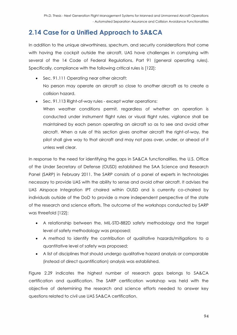
Ph.D. Thesis - Next Generation Flight Management Systems for Manned and Unmanned Aircraft Operations
- Automated Separation Assurance and Collision Avoidance Functionalities
94
2.14 Case for a Unified Approach to SA&CA
In addition to the unique airworthiness, spectrum, and security considerations that come
with having the cockpit outside the aircraft, UAS have challenges in complying with
several of the 14 Code of Federal Regulations, Part 91 (general operating rules).
Specifically, compliance with the following critical rules is [122]:
Sec. 91.111 Operating near other aircraft:
No person may operate an aircraft so close to another aircraft as to create a
collision hazard.
Sec. 91.113 Right-of-way rules - except water operations:
When weather conditions permit, regardless of whether an operation is
conducted under instrument flight rules or visual flight rules, vigilance shall be
maintained by each person operating an aircraft so as to see and avoid other
aircraft. When a rule of this section gives another aircraft the right-of-way, the
pilot shall give way to that aircraft and may not pass over, under, or ahead of it
unless well clear.
In response to the need for identifying the gaps in SA&CA functionalities, the U.S. Office
of the Under Secretary of Defense (OUSD) established the SAA Science and Research
Panel (SARP) in February 2011. The SARP consists of a panel of experts in technologies
necessary to provide UAS with the ability to sense and avoid other aircraft. It advises the
UAS Airspace Integration IPT chaired within OUSD and is currently co-chaired by
individuals outside of the DoD to provide a more independent perspective of the state
of the research and science efforts. The outcome of the workshops conducted by SARP
was threefold [122]:
A relationship between the, MIL-STD-882D safety methodology and the target
level of safety methodology was proposed;
A method to identify the contribution of qualitative hazards/mitigations to a
quantitative level of safety was proposed;
A list of disciplines that should undergo qualitative hazard analysis or comparable
(instead of direct quantification) analysis was established.
Figure 2.29 indicates the highest number of research gaps belongs to SA&CA
certification and qualification. The SARP certification workshop was held with the
objective of determining the research and science efforts needed to answer key
questions related to civil use UAS SA&CA certification.
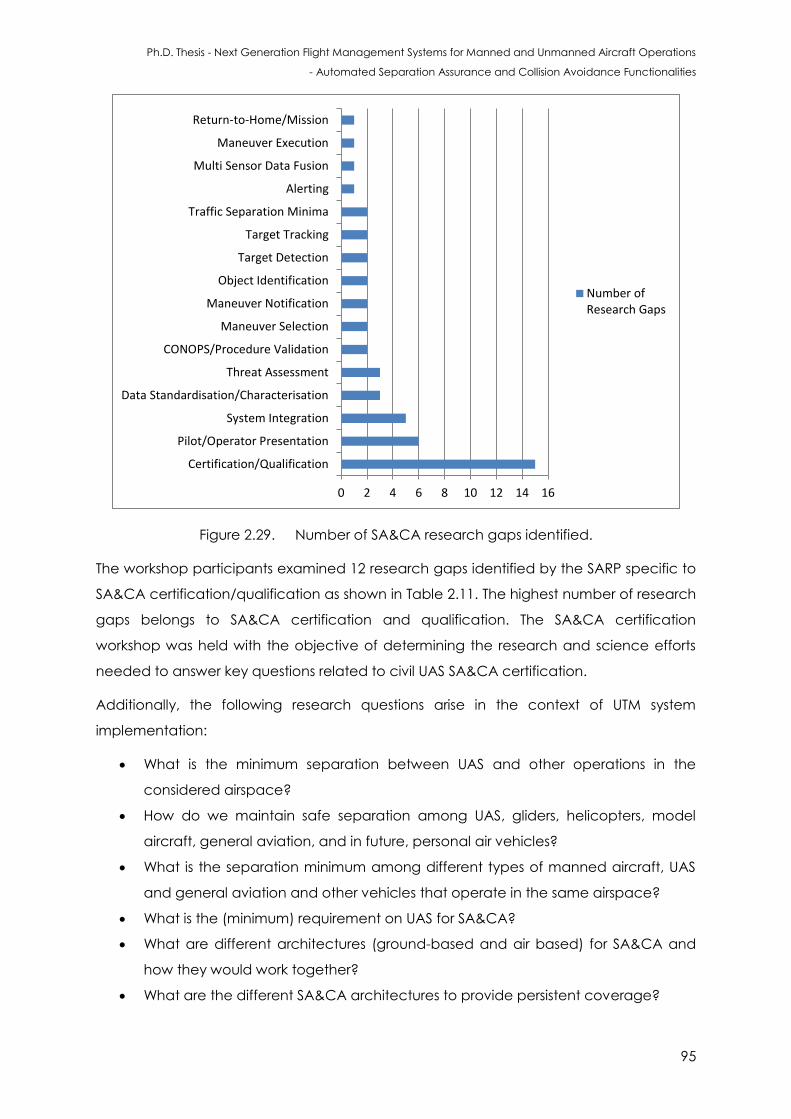
Ph.D. Thesis - Next Generation Flight Management Systems for Manned and Unmanned Aircraft Operations
- Automated Separation Assurance and Collision Avoidance Functionalities
95
Figure 2.29. Number of SA&CA research gaps identified.
The workshop participants examined 12 research gaps identified by the SARP specific to
SA&CA certification/qualification as shown in Table 2.11. The highest number of research
gaps belongs to SA&CA certification and qualification. The SA&CA certification
workshop was held with the objective of determining the research and science efforts
needed to answer key questions related to civil UAS SA&CA certification.
Additionally, the following research questions arise in the context of UTM system
implementation:
What is the minimum separation between UAS and other operations in the
considered airspace?
How do we maintain safe separation among UAS, gliders, helicopters, model
aircraft, general aviation, and in future, personal air vehicles?
What is the separation minimum among different types of manned aircraft, UAS
and general aviation and other vehicles that operate in the same airspace?
What is the (minimum) requirement on UAS for SA&CA?
What are different architectures (ground-based and air based) for SA&CA and
how they would work together?
What are the different SA&CA architectures to provide persistent coverage?
0 2 4 6 8 10 12 14 16
Certification/Qualification
Pilot/Operator Presentation
System Integration
Data Standardisation/Characterisation
Threat Assessment
CONOPS/Procedure Validation
Maneuver Selection
Maneuver Notification
Object Identification
Target Detection
Target Tracking
Traffic Separation Minima
Alerting
Multi Sensor Data Fusion
Maneuver Execution
Return-to-Home/Mission
Number ofResearch Gaps
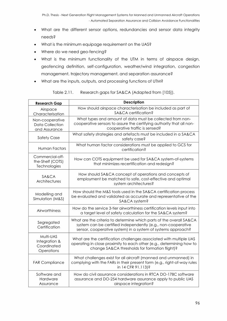
Ph.D. Thesis - Next Generation Flight Management Systems for Manned and Unmanned Aircraft Operations
- Automated Separation Assurance and Collision Avoidance Functionalities
96
What are the different sensor options, redundancies and sensor data integrity
needs?
What is the minimum equipage requirement on the UAS?
Where do we need geo-fencing?
What is the minimum functionality of the UTM in terms of airspace design,
geofencing definition, self-configuration, weather/wind integration, congestion
management, trajectory management, and separation assurance?
What are the inputs, outputs, and processing functions of UTM?
Table 2.11. Research gaps for SA&CA (Adapted from [105]).
Research Gap Description
Airspace
Characterisation
How should airspace characterisation be included as part of
SA&CA certification?
Non-cooperative
Data Collection
and Assurance
What types and amount of data must be collected from non-
cooperative sensors to assure the certifying authority that all non-
cooperative traffic is sensed?
Safety Case What safety strategies and artefacts must be included in a SA&CA
safety case?
Human Factors What human factor considerations must be applied to GCS for
certification?
Commercial-off-
the-Shelf (COTS)
Technologies
How can COTS equipment be used for SA&CA system-of-systems
that minimizes recertification and redesign?
SA&CA
Architectures
How should SA&CA concept of operations and concepts of
employment be matched to safe, cost-effective and optimal
system architectures?
Modelling and
Simulation (M&S)
How should the M&S tools used in the SA&CA certification process
be evaluated and validated as accurate and representative of the
SA&CA system?
Airworthiness How do the service 3-tier airworthiness certification levels input into
a target level of safety calculation for the SA&CA system?
Segregated
Certification
What are the criteria to determine which parts of the overall SA&CA
system can be certified independently (e.g., non-cooperative
sensor, cooperative system) in a system of systems approach?
Multi-UAS
Integration &
Coordinated
Operations
What are the certification challenges associated with multiple UAS
operating in close proximity to each other (e.g., determining how to
change SA&CA thresholds for formation flight)?
FAR Compliance
What challenges exist for all aircraft (manned and unmanned) in
complying with the FARs in their present form (e.g., right-of-way rules
in 14 CFR 91.113)?
Software and
Hardware
Assurance
How do civil assurance considerations in RTCA DO-178C software
assurance and DO-254 hardware assurance apply to public UAS
airspace integration?
Ph.D. Thesis - Next Generation Flight Management Systems for Manned and Unmanned Aircraft Operations
- Automated Separation Assurance and Collision Avoidance Functionalities
97
All the existing SA&CA technologies do not provide a cohesive mathematical framework
or and a system implementation approach that includes both cooperative and non-
cooperative means of implementing TDA loops and supports the case for certification.
One of the key technology enablers to achieve the goal of safe integration of UAS in
non-segregated airspace is the implementation of suitable data fusion techniques
supported by a unified approach to non-cooperative and cooperative SA&CA. A
unified approach would meet the requirements for manned and unmanned aircraft
coordinated operations. Such SA&CA functionalities can provide UAS the capability to
consistently and reliably perform equally the see-and-avoid performance of a human
pilot in manned aircraft, while allowing a seamless integration of UAS in the current and
planned dual-use civil/military ATM system and in the future UTM context.
2.15 Conclusions
This chapter provided an introduction to the system architecture and algorithms of Flight
Management Systems (FMS). The Guidance, Navigation and Control (GNC) and
Tracking, Decision-Making and Avoidance (TDA) avionics loops were described in detail.
The existing Separation Assurance and Collision Avoidance (SA&CA) procedures and
algorithms currently employed were also presented. The key multi-sensor data fusion
techniques tailored for accomplishing an effective TDA loop was also presented.
Furthermore, the UTM system requirements and the implications on SA&CA technologies,
standards and practices were also discussed.
2.16 References
1. R. Sabatini, A. Gardi, S. Ramasamy, T. Kistan and M. Marino, “Modern Avionics and ATM
Systems for Green Operations”, Encyclopedia of Aerospace Engineering, eds R.
Blockley and W. Shyy, John Wiley: Chichester, 2015. DOI:
10.1002/9780470686652.eae1064
2. M. Samà, A. D’Ariano, P. D’Ariano and D. Pacciarelli, “Air Traffic Optimization Models
for Aircraft Delay and Travel Time Minimization in Terminal Control Areas”, Public
Transport, Vol. 7, Issue 3, pp.321-337, 2015.
3. European Commision, “Flightpath 2050 Europe’s Vision for Aviation Report of the High
Level Group on Aviation Research”, EUR 098 EN, Belgium, 2011.
4. P. Hartley, “Joint Command and Control of Australian Airspace”, Australian Defence
Force Journal, Vol. 197, 2015.
Ph.D. Thesis - Next Generation Flight Management Systems for Manned and Unmanned Aircraft Operations
- Automated Separation Assurance and Collision Avoidance Functionalities
98
5. ICAO, “Global Air Traffic Management Operational Concept”, Doc 9854 AN/458, The
International Civil Aviation Organization, Montreal, Canada, 2005.
6. P. Kopardekar, “Unmanned Aerial System (UAS) Traffic Management (UTM): Enabling
Low-altitude Airspace and UAS Operations”, ARC-E-DAA-TN32373, NASA Ames
Research Center, NASA, Moffett Field, CA, USA, 2016.
7. Boeing, “Contribution of Flight Systems to Performance-Based Navigation”, Boeing
Aero Magazine, 2009.
8. M.R. Cramer, A. Herndon, D. Steinbach and R.H. Mayer, “Modern Aircraft Flight
Management Systems”, Encyclopedia of Aerospace Engineering, eds R. Blockley and
W. Shyy, John Wiley: Chichester, 2015.
9. R. Walter, “Flight Management Systems”, Digital Avionics Handbook, eds. C. Spitzer, U.
Ferrell, T. Ferrell, Third Edition, 2014.
10. Thales, “Intercative Flight Management System”, THALES GROUP, 2016. Accessed
December 2016. Available at:
https://www.thalesgroup.com/en/worldwide/defence/what-we-do-air-forces-
defence-onboard-electronics/military-interactive-flight
11. K. Eliker, H. Bouadi and M. Haddad, “Flight planning and guidance features for an UAV
Flight Management Computer”, Proceedings of IEEE 21st International Conference
on Emerging Technologies and Factory Automation (ETFA), pp. 1-6, Berlin, Germany,
2016.
12. J. Villarroel and L. Rodrigues, “Optimal Control Framework for Cruise Economy Mode of
Flight Management Systems”, Journal of Guidance, Control, and Dynamics, pp.1022-
1033, 2016.
13. RTCA, “Minimum Aviation System Performance Standards for Radiodetermination
Satellite Service (RDSS)”, DO-206, Radio Technical Commission for Aeronautics,
Washington DC, USA, 1990.
14. E.M. Atkins, “Certifiable Autonomous Flight Management for Unmanned Aircraft
Systems”, Winter Issue of The Bridge on Frontiers of Engineering, Vol. 40, No. 4, 2010.
15. C. Pasaoglu, N. Akcam, E. Koyuncu, A.F. Tarhan and G. Inalhan, “Collaborative Intent
Exchange Based Flight Management System with Airborne Collision Avoidance for
UAS”, Journal of Intelligent & Robotic Systems, pp.1-26, 2016.
16. P.F. Di Donato, S. Balachandran, K. McDonough, E. Atkins and I. Kolmanovsky,
“Envelope-aware Flight Management For Loss Of Control Prevention given Rudder
Jam”, Journal of Guidance, Control, and Dynamics, pp.1-15, 2016.
17. ARINC, “Navigational Data”, ARINC 424, Aeronautical Radio, Incorporated, Annapolis,
Maryland, US.
Ph.D. Thesis - Next Generation Flight Management Systems for Manned and Unmanned Aircraft Operations
- Automated Separation Assurance and Collision Avoidance Functionalities
99
18. A. Miele, “Optimal Trajectories and Guidance Trajectories for Aircraft Flight through
Windshears”, Proceedings of the 29th IEEE Conference on Decision and Control, pp.
737–746, 1990.
19. C.S. Ha, S.E. Kang, J.H. Mok, S. Ko and Y.W. Lee, “3-Dimensional Path Planning and
Guidance using the Dubins Curve for an 3-DOF Point-mass Aircraft Model”, Journal of
the Korean Society for Aviation and Aeronautics, Vol. 24, no. 1, pp.1-9, 2016.
20. M.A. Wahid, “Flight Guidance along 3D+T Trajectories and Space Indexed Traffic
Management, Doctoral dissertation, Université de Toulouse, Université Toulouse III-Paul
Sabatier, 2015.
21. L. Song, H. Yang, J. Xie, C. Ma and J. Huang, “Method for Improving the Natural
Lateral-Directional Stability of Flying Wings”, Journal of Aerospace Engineering,
p.06016003, 2016.
22. D. McLean, Automatic Flight Control Systems, Prentice Hall, Michigan, US, 1990.
23. ICAO, “International Standards Annex 2 - Amendment 44”, The International Civil
Aviation Organization, Montreal, Canada, 2005.
24. FAA, “Code of Federal Regulations”, CFR, Federal Aviation Administration, Washington
DC, USA.
25. Airservices, “Separation Standards”, Airservices Australia, Australian Capital Territory,
Australia, 2016.
26. Eurocontrol, “European Airspace Concept Handbook for PBN Implementation”, Third
Edition, Brussels, Belgium, 2013.
27. N. Durand, D. Gianazza, J.B. Gotteland and J.M. Alliot, “Airspace Management”,
Metaheuristics for Air Traffic Management, pp.69-83, 2016.
28. Air Services Australia, “Separation Standards”, Australia's Air Navigation Service
Provider, Canberra, Australia, 2016.
29. L.M.B.C. Campos and J.M.G. Marques, “On an Analytical Model of Wake Vortex
Separation of Aircraft”, The Aeronautical Journl, Vol. 120, No. 1232, pp. 1534-1565, 2016.
30. A. Oztekin and R. Wever, “Development of a Regulatory Safety Baseline for UAS Sense
and Avoid”, Handbook of Unmanned Aerial Vehicles, Springer, Netherlands, pp. 1817-
1839, 2015.
31. FAA, ‘Sense and avoid (SAA) for unmanned aircraft systems (UAS)’, Sense and Avoid
Workshop, Federal Aviation Administration, October 2009.
32. M.C. Consiglio, J.R. Comstock Jr, R.W. Ghatas and M.J. Vincent, “Unmanned Aircraft
Systems (UAS) Controller Acceptability Study 3 (CAS3): Collision Avoidance, Self
Separation, and Alerting Times (CASSAT): Combined PER/FER”, UAS in the NAS Project
Ph.D. Thesis - Next Generation Flight Management Systems for Manned and Unmanned Aircraft Operations
- Automated Separation Assurance and Collision Avoidance Functionalities
100
Briefing to FAA and Industry, NASA Langley Research Center, Hampton, VA, United
States, 2015.
33. G. Granger, “Détection et résolution de conflits aériens: modélisations et analyse”,
Doctoral Thesis, Informatique de l'Ecole Polytechnique, 2002.
34. S. Kopřiva, D. Šišlák and M. Pěchouček, “Sense and Avoid Concepts: Vehicle-Based
SAA Systems (Vehicle-to-Vehicle)”, Sense and Avoid in UAS: Research and Applications
ed P. Angelov, John Wiley & Sons, Ltd, Chichester, UK, 2012. DOI:
10.1002/9781119964049.ch6
35. M. Melega, “Autonomous Collision Avoidance for Unmanned Aerial Systems”, Doctoral
Dissertation, Cranfield University, 2014.
36. R. Pablo, E. Santamaria, J.M. Lema, E. Pastor and C. Barrado, “Integration of SAA
Capabilities into a UAS Distributed Architecture for Civil Applications”, Sense and Avoid
in UAS: Research and Applications 61, 2012.
37. S. Bouabdallah, M. Becker, V. de Perrot and R. Siegwart, “Toward obstacle avoidance
on Quadrotors”, Proceedings of the 12th International Symposium on Dynamic Problems
of Mechancis, Ilhabela, Brazil, pp. 1-10, 2007.
38. J.F. Roberts, T.S. Stirling, J.C. Zufferey and D. Floreano, “Quadrotor using Minimal Sensing
for Autonomous Indoor Flight”, Proceedings of MAV Conference (EMAV 2007),
Toulouse, France, pp. 1-8, 2007.
39. S. Scherer, S. Singh, L. Chamberlain and M. Elgersma, “Flying Fast and Low among
Obstacles: Methodology and Experiments”, International Journal of Robotics Research,
Vol. 27, Issue 5, pp. 549-574, 2008.
40. S. Shen, N. Michael and V. Kumar, “Autonomous Multi-Floor Indoor Navigation with a
Computationally Constrained MAV”, Proceedings of the IEEE International Conference
on Robotics and Automation, Shanghai, China, pp. 20-25, 2011.
41. M. Achtelik, A. Bachrach, R. He, S. Prentice and N. Roy, ”Autonomous Navigation And
Exploration of a Quadrotor Helicopter in GPS Denied Indoor Environments”,
Proceedings of the 1st Symposium on Indoor Flight, 2008. Available online at:
http://robot-chopper.googlecode.com/svnhistory/r479/trunk/References/2009MIT.pdf
42. G. Chowdhary, E.N. Johnson, D. Magree, A. Wu and A. Shein, “GPS Denied Indoor and
Outdoor Monocular Vision Aided Navigation and Control of Unmanned Aircraft”,
Journal of Field Robotics, Vol. 30, Issue 3, pp.415-438, 2013.
43. R. Clothier, R. Walker, R. Baumeister, M. Brünig, J. Roberts, A. Duggan and M. Wilson,
“The Smart Skies Project”, IEEE Aerospace and Electronic Systems Magazine, Vol. 26,
Issue 6, pp.14-23, 2011.
Ph.D. Thesis - Next Generation Flight Management Systems for Manned and Unmanned Aircraft Operations
- Automated Separation Assurance and Collision Avoidance Functionalities
101
44. M. Orefice, V. Di Vito and G. Torrano, “Sense and Avoid: Systems and Methods”,
Encyclopedia of Aerospace Engineering, eds R. Blockley and W. Shyy, John Wiley:
Chichester, 2015.
45. J. Pellebergs, The MIDCAS Project, Proceedings of the 27th International Congress of
the Aeronautical Sciences (ICAS), Nice, France, 2010.
46. P. Angelov, “Sense and Avoid in UAS: Research and Applications, John Wiley & Sons,
2012.
47. P. Woods, “FLAVIIR–An Integrated Programme of Research for UAVs”, Proceedings of
the 3rd AIAA Flow Control Conference, San Francisco, USA, pp. 5-7, 2008.
48. A.E. Heaton, “A Method to Support the Requirements Trade-Off of Integrated Vehicle
Health Management for Unmanned Aerial Systems”, PhD Thesis, Cranfield Univeristy,
2014.
49. O. Shakernia, W.Z. Chen, S. Graham, J. Zvanya, A. White, N. Weingarten and V.M.
Raska, “Sense and Avoid (SAA) Flight Test and Lessons Learned”, Proceedings of 2nd
AIAA Infotech@ Aerospace Conference and Exhibit, pp. 1-12, 2007.
50. B.C. Karhoff, J.I. Limb, S.W. Oravsky and A.D. Shephard, “Eyes in the Domestic Sky: an
Assessment of Sense and Avoid Technology for the Army's Warrior Unmanned Aerial
Vehicle”, IEEE Systems and Information Engineering Design Symposium, pp. 36-42, 2006.
51. T. Williamson and N.A. Spencer, “Development and Operation of the Traffic Alert and
Collision Avoidance System (TCAS)”, Proceedings of the IEEE, Vol. 77, Issue 11, pp.1735-
1744, 1989.
52. W. Harman, “TCAS-A System for Preventing Midair Collisions”, The Lincoln Laboratory
Journal, Vol. 2, Issue 3, pp.437-457, 1989.
53. H. Lenz and J. Gottstein, “TCAS Compatibility of Advanced Airborne Separation
Assurance System Operations”, Proceedings of the AIAA Infotech at Aerospace
Conference, ISSN: 0731-5090, 2015.
54. J.E. Kuchar and A.C. Drumm, “The Traffic Alert and Collision Avoidance System”,
Lincoln Laboratory Journal, vol. 16, issue 2, 2007.
55. C. Livadas, J. Lygeros and N.A. Lynch, “High-level Modeling and Analysis of the Traffic
Alert and Collision Avoidance System (TCAS)”, Proceedings of the IEEE, vol. 88, no. 7,
pp.926-948, 2000.
56. RTCA, “Minimum Operational Performance Standards for Traffic Alert and Collision
Avoidance Systems II (TCAS II)”, DO-185B, Radio Technical Commission for Aeronautics,
Washington DC, USA, 2008.
57. FAA, “Introduction to TCAS II”, Version 7.1, Federal Aviation Administration, Washington
DC, USA, February 2011.
Ph.D. Thesis - Next Generation Flight Management Systems for Manned and Unmanned Aircraft Operations
- Automated Separation Assurance and Collision Avoidance Functionalities
102
58. W.H. Harman, “TCAS: A System for Preventing Midair Collisions,” Lincoln Laboratory
Journal, vol. 2, no. 3, pp. 437–458, 1989.
59. J.K. Kuchar and A.C. Drumm, “The Traffic Alert and Collision Avoidance System,”
Lincoln Laboratory Journal, vol. 16, no. 2, pp. 277–296, 2007.
60. T.B. Billingsley, M.J. Kochenderfer, and J.P. Chryssanthacopoulos, “Collision Avoidance
for General Aviation,” in IEEE/ AIAA Digital Avionics Systems Conference, Seattle,
Washington, 2011
61. M.J. Kochenderfer, M.W.M. Edwards, L.P. Espindle, J.K. Kuchar, and J.D. Griffith,
“Airspace Encounter Models for Estimating Collision Risk,” Journal of Guidance, Control,
and Dynamics, vol. 33, no. 2, pp. 487–499, 2010.
62. M.J. Kochenderfer, J.E. Holland and P. James, “Chryssanthacopoulos: Next Generation
Airborne Collision Avoidance System”, Lincoln Laboratory Journal, Vol. 19, issue 1, pp.
17– 33, 2012.
63. CASA, “ADS-B mandates 2014-2017”, Civil Aviation Safety Authority, Woden, Australian
Capital Territory, Australia, 2016.
64. E. Valovage, “Enhanced ADS-B Research”, IEEE Aerospace and Electronics Systems
Magazine, Vol. 22, Issue 5, pp. 35–38, 2007.
65. X. Yu and Y. Zhang, “Sense and Avoid Technologies with Applications to Unmanned
Aircraft Systems: Review and Prospects, Progress in Aerospace Sciences, vol. 74,
pp.152-166, 2015.
66. G. Fasano, D. Accardo, A. Moccia, C. Carbone, U. Ciniglio, F. Corraro, and S. Luongo.
“Multi-Sensor-Based Fully Autonomous Non-Cooperative Collision Avoidance System for
Unmanned Air Vehicles,” Journal of Aerospace Computing, Information, and
Communication, vol. 5, no. 10, pp. 338-360, 2008.
67. A. Finn and S. Franklin, "Acoustic sense & avoid for UAV's", Seventh IEEE International
Conference on Intelligent Sensors, Sensor Networks and Information Processing (ISSNIP),
2011.
68. P. Cornic, P. Garrec, S. Kemkemian, L. Ratton, “Sense and Avoid Radar using Data
Fusion with Other Sensors,” in Proceedings of the IEEE Aerospace Conference, Big Sky,
USA, March 2010.
69. C.P. Lai, Y.J. Ren and C. Lin, “ADS-B based Collision Avoidance Radar for Unmanned
Aerial Vvehicles”, Proceedings of IEEE Microwave Symposium Digest 2009 (MTT'09), IEEE
MTT-S International, pp. 85-88, 2009.
70. S. Ramasamy, R. Sabatini and A. Gardi, “A Unified Approach to Separation Assurance
and Collision Avoidance for Flight Management Systems.” Proceedings of the 35th
Ph.D. Thesis - Next Generation Flight Management Systems for Manned and Unmanned Aircraft Operations
- Automated Separation Assurance and Collision Avoidance Functionalities
103
AIAA/IEEE Digital Avionics Systems Conference (DASC2016). Sacramento, CA (USA),
September 2016.
71. C.K. Lai, “A Novel Collision Avoidance Logic for Unmanned Aerial Vehicles using Real-
Time Trajectory Planning”, PhD Thesis, Cranfield Univeristy, UK, 2014.
72. J.K. Aggarwal, “Multisensor Fusion for Computer Vision,” vol. 99. Springer Science &
Business Media, 2013.
73. D.L. Hall and J. Llinas, “An Introduction to Multisensor Data Fusion”, Proceedings of the
IEEE, Vol. 85, Issue 1, pp.6-23, 1997.
74. D.J. Dailey, P. Harn and P.J. Lin, “ITS Data Fusion,” Final Research Report, Research
Project T9903, Task 9, ATIS/ATMS Regional IVHS Demonstration, 1996.
75. A. Gad and M. Farooq, “Data Fusion Architecture for Maritime Surveillance,”
Proceedings of the Fifth IEEE International Conference on Information Fusion, Vol. 1,
2002.
76. T. Tagarev and P. Ivanov, “Computational Intelligence in Multi-Source Data and
Information Fusion,” Issue: Information and Security, vol. 2, 1999.
77. D.L. Hall, “An Introduction to Multisensor Data Fusion,” Proceedings of the IEEE, vol. 85,
issue 1, 1997.
78. F. Cappello, S. Ramasamy and R. Sabatini, “A Low-Cost and High Performance
Navigation System for Small RPAS Applications”, Aerospace Science and Technology,
Elsevier, 2016. DOI: 10.1016/j.ast.2016.09.002
79. R. Sabatini, F. Cappello, S. Ramasamy, A. Gardi and R. Clothier, “An Innovative
Navigation and Guidance System for Small Unmanned Aircraft using Low-Cost
Sensors”, Journal of Aircraft Engineering and Aerospace Technology, vol. 87, issue 6,
2015. DOI: 10.1108/AEAT-06-2014-0081
80. F. Cappello, R. Sabatini, S. Ramasamy and M. Marino, “Particle Filter based Multi-sensor
Data Fusion Techniques for RPAS Navigation and Guidance,” Proceedings of the
Second International Workshop on Metrology for Aerospace (MetroAeroSpace 2015),
Benevento, Italy, 2015.
81. A.W. Eric and R.V.D. Merwe, “The Unscented Kalman Filter for Nonlinear Estimation”,
The IEEE Adaptive Systems for Signal Processing, Communications, and Control
Symposium, AS-SPCC, 2000.
82. R.V.D. Merwe, “Sigma-point Kalman Filters for Probabilistic Inference in Dynamic State-
space Models”, Dissertation, Oregon Health & Science University, 2004.
83. S.M. Oh, “Nonlinear Estimation for Vision-Based Air-to-Air Tracking”, Dissertation,
Georgia Institute of Technology, 2007.
Ph.D. Thesis - Next Generation Flight Management Systems for Manned and Unmanned Aircraft Operations
- Automated Separation Assurance and Collision Avoidance Functionalities
104
84. P. Angelov, “Sense and Avoid in UAS: Research and Applications,” John Wiley & Sons,
2012.
85. S. Challa, “Fundamentals of Object Tracking”, Cambridge University Press, 2011.
86. Y. Bengio, A. Courville and P. Vincent, “Representation Learning: A Review and New
Perspectives”, IEEE Transactions on Pattern Analysis and Machine Intellegience. 2013
Aug; vol. 35, issue 8, pp. 1798-828, DOI: 10.1109/TPAMI.2013.50
87. M.H.G. Anthony and N. Biggs, “Computational Learning Theory”, Cambridge University
Press, 1997.
88. M.A. Welling, “First Encounter with Machine Learning”, University of California, Irvine,
CA, USA, pp. 1-93, 2011.
89. F. Cappello, R. Sabatini and S. Ramasamy, “Multi-Sensor Data Fusion Techniques for
RPAS Detect, Track and Avoid”, SAE Technical Paper 2015-01-2475, SAE 2015 AeroTech
Congress & Exhibition, Seattle, Washington, USA, 2015. DOI: 10.4271/2015-01-2475
90. P. Kopardekar, “Safely Enabling Low-Altitude Airspace Operations: Unmanned Aerial
System Traffic Management (UTM)”, ARC-E-DAA-TN22234, NASA Ames Research
Center, NASA, Moffett Field, CA, USA, 2015.
91. J. Robinson, M. Johnson, J. Jung, P. Kopardekar, T. Prevot and J. Rios, “Unmanned
Aerial System Traffic Management Concept of Operations (v0.5) (UTM CONOPS)”,
NASA TM draft, Moffett Field, CA, USA, 2015.
92. C.W. Johnson, “The Safety Research Challenges for the Air Traffic Management of
Unmanned Aerial Systems (UAS)”, Proceedings of the 6th EUROCONTROL Experimental
Centre Safety Research and Development Workshop, Munich, Germany, October,
Vol. 21, 2009.
93. Y. Kim, J. Jo and M. Shaw, “A Lightweight Communication Architecture for Small UAS
Traffic Management (SUTM)”, IEEE Integrated Communication, Navigation and
Surveillance Conference (ICNS), pp. T4-1, 2015.
94. T. Prevot, J. Homola and J. Mercer, “From Rural to Urban Environments: Human/Systems
Simulation Research for Low Altitude UAS Traffic Management (UTM)”, 16th AIAA
Aviation Technology, Integration, and Operations Conference, Washington DC, USA,
pp. 3291, 2016.
95. V. Milanés, J. Godoy, J. Pérez, B. Vinagre, C. González, E. Onieva and J. Alonso, “V2I-
Based Architecture for Information Exchange among Vehicles”, IFAC Proceedings,
Vol. 43, Issue 16,, pp. 85-90, 2010.
96. P. Kopardekar, P. Lee, T. Prevot, J. Mercer, J. Homola, M. Mainini, N. Smith, A. Aweiss
and K. Lee, "Feasibility of Mixed Equipage Operations in the Same Airspace", Eighth
Ph.D. Thesis - Next Generation Flight Management Systems for Manned and Unmanned Aircraft Operations
- Automated Separation Assurance and Collision Avoidance Functionalities
105
USA/Europe Air Traffic Management Research and Development Seminar (ATM2009),
Napa, CA, USA, 2009.
97. K. Legrand, S. Puechmorel, D. Delahaye and Y. Zhu, “Aircraft Trajectory Planning under
Wind Uncertainties”, 35th AIAA/IEEE Digital Avionics Systems Conference, Enabling
Avionics For UAS/UTM (DASC 2016), Sacramento, CA, USA, 2016.
98. C. White, E.W. Lim, S. Watkins, A. Mohamed and M. Thompson, “A Feasibility Study of
Micro Air Vehicles Soaring Tall Buildings”, Journal of Wind Engineering and Industrial
Aerodynamics, Vol. 103, pp.41-49, 2012.
99. T.B. Sheridan, "Adaptive automation, level of automation, allocation authority,
supervisory control, and adaptive control: Distinctions and modes of adaptation," IEEE
Transactions on Systems, Man and Cybernetics, Part A: Systems and Humans, Vol. 41,
pp. 662-667, Jul 2011.
100. R.M. Taylor, “Capability, Cognition and Autonomy”, DTIC Document, 2003.
101. R.V. Hemm, D. Duncan and V.L. Stouffer. “On-Demand Aviation Regulatory Obstacles
and Resulting Research Roadmaps”, 16th AIAA Aviation Technology, Integration, and
Operations Conference, AIAA Aviation Forum, Washington DC, USA, 2016.
102. D.S. Jang, C. Ippolito, S. Sankararaman and V. Stepanyan, “Concepts of Airspace
Structures and System Analysis for UAS Traffic flows for Urban Areas”, AIAA Information
Systems-AIAA Infotech@ Aerospace (p. 0449), Grapevine, Texas, USA, 2017.
103. V.C. Nneji, A. Stimpson, M.M Cummings and K.H. Goodrich, “Exploring Concepts of
Operations for On-Demand Passenger Air Transportation”, 17th AIAA Aviation
Technology, Integration, and Operations Conference, pp. 3085, Denver, Colorado,
USA, 2017.
104. L. Ren, M. Castillo-Effen, H. Yu, E. Johnson, T. Nakamura, Y. Yoon and C.A. Ippolito,
“Small Unmanned Aircraft System (sUAS) Trajectory Modeling in Support of UAS Traffic
Management (UTM)”, 17th AIAA Aviation Technology, Integration, and Operations
Conference, pp. 4268, Denver, Colorado, USA, 2017.
105. R. Fontanella, A.R. Vetrella, G. Fasano, D. Accardo and R.S. Lo, “Requirements, Platform
Specifications, and System Architectures for Future Unmanned Traffic Management
Systems”, AIAA Information Systems-AIAA Infotech @ Aerospace, AIAA SciTech Forum,
(AIAA 2017-0225, Grapevine, Texas, USA, 2017.
106. V. Kumar, B.M. Horio and S. Hasan, “Modeling Approach for Evaluation of Traffic
Management Requirements and Policies for Unmanned Aircraft Systems”, 17th AIAA
Aviation Technology, Integration, and Operations Conference Denver, Colorado, USA,
2017.
Ph.D. Thesis - Next Generation Flight Management Systems for Manned and Unmanned Aircraft Operations
- Automated Separation Assurance and Collision Avoidance Functionalities
106
107. ASTM, “Standard Specification for Design and Performance of an Airborne Sense-and-
Avoid System”, ASTM F2411-04, American Society for Testing and Materials, 2004.
108. V.J. Gawron, “Human Factors Issues in the Development, Evaluation and Operations of
Uninhabited Air Vehicles”, Proceedings of the Association for Unmanned Vehicle
Systems International, Huntsville, AL, USA, pp. 431-438, 1998.
109. P.W. Merlin, “Ikhana Unmanned Aircraft System Western States Fire Missions”, National
Aeronautics and Space Administration, Washington DC, USA, 2009.
110. M. Mouloua, R. Gilson, J. Kring and P. Hancock, “Workload, Situational Awareness, and
Teaming Issues for UAV/UCAV Operations”, Proceedings of the Human Factors and
Ergonomics Society 45th Annual Meeting of the Human Factors and Ergonomics
Society, Santa Monica, USA, pp. 162-165, 2001.
111. D. Wood, "Collision Avoidance System and method Utilizing Variable Surveillance
Envelope", U.S. Patent 6,804,607, 2004.
112. A. Smith, D.M. Coulter and C.S. Jones, “UAS Collision Encounter Modeling and
Avoidance Algorithm Development for Simulating Collision Avoidance”, AIAA
Modeling and Simulation Technologies Conference, 2008.
113. M. Mullins, M. Holman, K. Foerster, N. Kaabouch and W. Semke, “Dynamic Separation
Thresholds for a Small Airborne Sense And Avoid System”, AIAA Infotech@ Aerospace
Conference, Boston, MA, USA, pp. 19-22, 2013.
114. A.L. Smith and F.G. Harmon, “UAS Collision Avoidance Algorithm Minimizing Impact on
Route Surveillance”, AIAA Guidance, Navigation, and Control Conferenc, pp. 1-20,
2009.
115. E.A. Euteneuer and G. Papageorgiou, “UAS Insertion into Commercial Airspace: Europe
and US Standards Perspective”, 30th AIAA/IEEE Digital Avionics Systems Conference
(DASC), pp. 5C5-1, 2011.
116. F. De Crescenzio, G. Miranda, F. Persiani and T. Bombardi, “3D Obstacle Avoidance
Strategies for UAS (Uninhabited Aerial System) Mission Planning and Replanning”,
Proceedings of the 26th Congress of the International Council of the Aeronautical
Sciences, 2008.
117. R. Marsh, K. Ogaard, M. Kary, J. Nordlie and C. Theisen, “Development of a mobile
information display system for UAS operations in North Dakota”, International Journal of
Computer Information Systems and Industrial Management Applications, vol. 3, pp.435-
443, 2011.
118. N. Hanlon, K. Cohen and E. Kivelevitch, “Sensor Resource Management to Support UAS
Integration into the National Airspace System”, AIAA SciTech 2015 Conference, 2015.
Ph.D. Thesis - Next Generation Flight Management Systems for Manned and Unmanned Aircraft Operations
- Automated Separation Assurance and Collision Avoidance Functionalities
107
119. J. Capitán, L. Merino and A. Ollero, “Coordination of Multiple UAS for Tracking under
Uncertainty”, Proceedings of the 1st Workshop on Research, Education and
Development on Unmanned Aerial Systems, RED-UAS, 2011.
120. J. Tadema, E. Theunissen and K.M Kirk, “Self Separation Support for UAS”, American
Institute of Aeronautics and Astronautics (AIAA), 2010.
121. J. Upchurch, C. Munoz, A. Narkawicz and J. Chamberlain, "Analysis of Well-Clear
Boundary Models for the Integration of UAS in the NAS”, Langley Research Center,
Hampton, Virginia, TM–2014–218280, NASA, 2014.
122. K.D. Davis and S.P. Cook, "Achieving Sense and Avoid for Unmanned Aircraft Systems:
Assessing the Gaps for Science and Research,” Handbook of Unmanned Aerial
Vehicles, pp. 1841-1855, Springer Netherlands, 2015.

Ph.D. Thesis - Next Generation Flight Management Systems for Manned and Unmanned Aircraft Operations
- Automated Separation Assurance and Collision Avoidance Functionalities
108
This page is intentionally left blank to support presswork tasks
Ph.D. Thesis - Next Generation Flight Management Systems for Manned and Unmanned Aircraft Operations
- Automated Separation Assurance and Collision Avoidance Functionalities
109
CHAPTER 3
NEXT GENERATION
FLIGHT MANAGEMENT SYSTEMS
“The philosopher is nature's pilot. And there you have our difference:
to be in hell is to drift: to be in heaven is to steer”. - George Bernard Shaw
3.1 Introduction
This chapter presents the system architecture and key design features of NG-FMS. The
next generation airborne and ground (NG-FMS and NG-ATM) systems are first
introduced. Then a system requirement analysis and a description of the novel
functionalities required in an advanced NG-FMS are described. Subsequently, the main
modules of the NG-FMS architecture that allow the generation of 4DT planning and
optimisation algorithms are presented. The features required for achieving full
interoperability with the NG-ATM system, enabling automated TBO/IBO are described.
Validation of the adopted trajectory optimisation algorithms is performed through
dedicated simulation test cases.
3.2 NG-FMS and NG-ATM Systems
In recent years, research interest has gathered in improving safety, capacity and
efficiency of air operations as well as attaining environmentally sustainable solutions. In
line with European Union’s SESAR, US’s NextGen, Australia’s OneSKY and other ATM
modernisation programmes, research on NG-FMS is aimed to provide 4D TBO/IBO with
NG-ATM and Next Generation Airborne Data Link (NG-ADL) systems.
The efficiency and effectiveness of NG-ATM system are increased by introducing more
information sharing and improving the operational and technological frameworks.
According to the SESAR ATM master plan [1], the foreseen future deployments evolve
from radar-based operations to TBO/IBO to achieve performance-driven ATM. As
Ph.D. Thesis - Next Generation Flight Management Systems for Manned and Unmanned Aircraft Operations
- Automated Separation Assurance and Collision Avoidance Functionalities
110
covered in Chapter 2 (Section 2.6), the current surveillance infrastructure is largely
composed of PSR, SSR, Mono-pulse Secondary Surveillance Radar (MSSR) and MSSR
Mode-S. Recent technological advances including the emergence of ADS-B and Wide-
Area Multilateration (WAM) have reached maturity and are being deployed in many
parts of the world supporting the evolution to performance-driven ATM. In addition to
ground-based surveillance, satellite based ADS-B is also becoming available as a source
for surveillance information, especially in oceanic and remote areas. ADS-B is also
supporting the development of new airborne surveillance operational services, including
Air Traffic Situational Awareness (ATSA) and the Airborne Separation Assistance System
(ASAS), which provide services such as sequencing and merging and self-separation in
SESAR and NextGen. Future airborne applications will require changes in the avionics to
process surveillance information in an automated manner and to display the airspace
situation to the pilot.
NextGEN is composed of programs including ADS-B, data communications, en-route
automation modernization, terminal automation modernization and replacement, the
national airspace system voice system and system wide information management. To
reduce the costs inherent in ground based radar systems and improve aircraft tracking
accuracy, an air traffic system based entirely on self-reporting traffic is proposed. The
cornerstone of this program is ADS-B for SA&CA. When all users are capable of
determining their three dimensional position and velocity vector, and then transmitting
that information to the appropriate ATC facility, the requirement for ground based radar
acquisition becomes obsolete. Because the system must remain safe and robust during
transition, and because the cost of the mandated new equipment is an issue, there are
many additional elements to the program to smooth transition. This incentive came in
the form of Broadcast Weather information, termed Flight Information Service –
Broadcast (FIS-B). To provide effective situational awareness, each ADSB-in receiver must
see all the traffic in the vicinity. With some users transmitting ADS-B on UAT and others on
1090ES, it was necessary to provide a translating repeater and hence ADS-R
(Rebroadcast) was introduced. Hence, the ATC received UAT transmissions, which are
rebroadcast on 1090ES and vice versa.
Because mandatory compliance is still a few years away, there are targets that will be
identified by ATCRBS that are not reporting position on either 1090ES or UAT. In an
endeavour to provide a comprehensive traffic picture, ATC provides a Traffic
Information Service – Broadcast (TIS-B) with these additional targets to all ADS-B (out)
equipped traffic.
Ph.D. Thesis - Next Generation Flight Management Systems for Manned and Unmanned Aircraft Operations
- Automated Separation Assurance and Collision Avoidance Functionalities
111
In the CNS+A context, the NG-FMS acts as the airborne counterpart that implements the
operational 4D trajectory concept. One of the key drawbacks in the current FMS is the
inability to handle traffic uncertainties in a predictive real-time manner. This results in
system inefficiencies that affect the system performance (both airborne and ground
systems). Hence, it is of paramount importance to implement the TBO/IBO concept
through the design and development of a NG-FMS and NG-ATM system providing [2]:
enhanced capability to exploit the CDM concept among all stakeholders utilising
accurate real-time information acquired from the airborne counterpart. In this
respect, the NG-FMS generates, synchronises and negotiates the predicted
aircraft intents with the ground NG-ATM based on real-time CNS system
performance, observed airspace and atmospheric conditions. CDM involves all
stakeholders in the ground communication network including 4-PNV systems, Air
Traffic Controllers (ATCo), Air Navigation Service Providers (ANSP) and Airline
Operation Centres (AOC);
introduction of higher levels of automation supporting role shifting of the ground
NG-ATM system from traditional command and control oriented units to highly
automated decision-making nodes in an interoperable environment. The
transition is supported by the introduction of user-preferred trajectories
downlinked from the aircraft. The changes to flight plans may be the result of
weather and traffic hazards, emergency situations, and system
degradation/failures resulting in a breach of agreed trajectory contract;
introduction of environment-related objectives based on cost functions to reduce
emissions in all flight phases and noise at the vicinity of airports whilst minimising
the total cost of a flight;
controlled time of arrival and strict adherence to required time of arrival
enforced by both ground and airborne systems;
continuous synchronisation of trajectory and state information to support the
introduction of time as a control variable in the trajectory optimisation process;
enhancing transition from voice communication to data-driven operations.
An innovative ground based 4D Trajectory Planning, Negotiation and Validation (4-PNV)
system for NG-ATM is assumed to be the 4DT planning, data exchange, negotiation and
validation counterpart of NG-FMS. The 4-PNV system incorporates CDM and global
optimisation criteria adhering to airspace constraints, and dedicated trajectory de-
confliction algorithms to enable IBO/TBO. The 4-PNV system receives multiple options of
4DT intents from each aircraft equipped with NG-FMS (both manned aircraft and UAS).
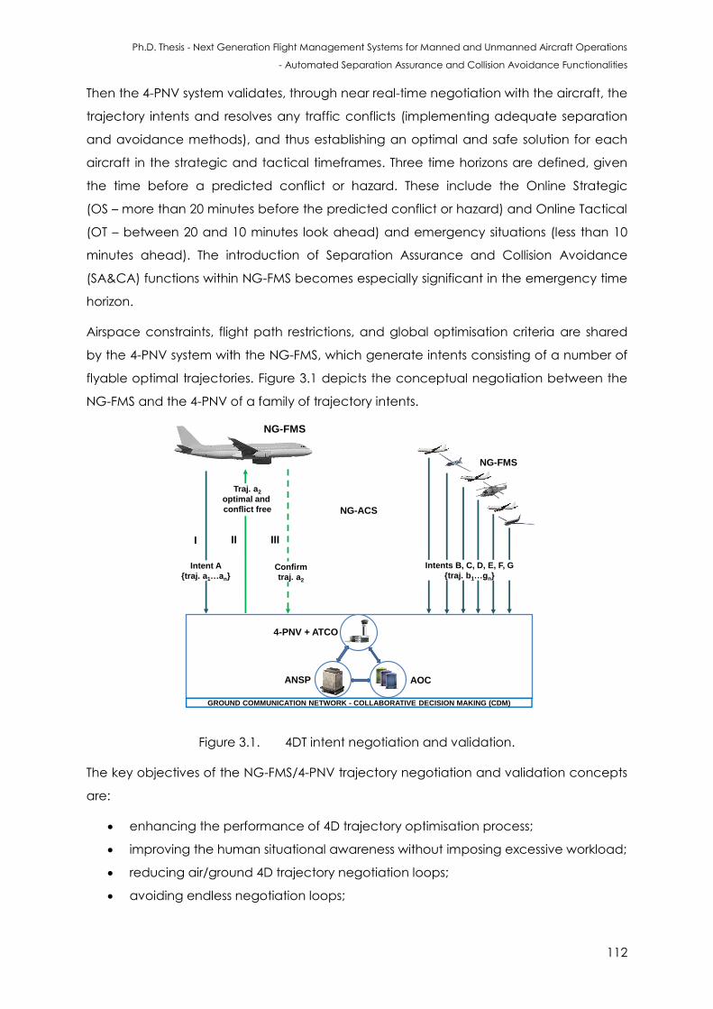
Ph.D. Thesis - Next Generation Flight Management Systems for Manned and Unmanned Aircraft Operations
- Automated Separation Assurance and Collision Avoidance Functionalities
112
Then the 4-PNV system validates, through near real-time negotiation with the aircraft, the
trajectory intents and resolves any traffic conflicts (implementing adequate separation
and avoidance methods), and thus establishing an optimal and safe solution for each
aircraft in the strategic and tactical timeframes. Three time horizons are defined, given
the time before a predicted conflict or hazard. These include the Online Strategic
(OS – more than 20 minutes before the predicted conflict or hazard) and Online Tactical
(OT – between 20 and 10 minutes look ahead) and emergency situations (less than 10
minutes ahead). The introduction of Separation Assurance and Collision Avoidance
(SA&CA) functions within NG-FMS becomes especially significant in the emergency time
horizon.
Airspace constraints, flight path restrictions, and global optimisation criteria are shared
by the 4-PNV system with the NG-FMS, which generate intents consisting of a number of
flyable optimal trajectories. Figure 3.1 depicts the conceptual negotiation between the
NG-FMS and the 4-PNV of a family of trajectory intents.
Intent A
{traj. a1…an}
Traj. a2
optimal and
conflict free
Confirm
traj. a2
NG-ACS
NG-FMS
GROUND COMMUNICATION NETWORK - COLLABORATIVE DECISION MAKING (CDM)
II IIII
Intents B, C, D, E, F, G
{traj. b1…gn}
4-PNV + ATCO
ANSP AOC
NG-FMS
Figure 3.1. 4DT intent negotiation and validation.
The key objectives of the NG-FMS/4-PNV trajectory negotiation and validation concepts
are:
enhancing the performance of 4D trajectory optimisation process;
improving the human situational awareness without imposing excessive workload;
reducing air/ground 4D trajectory negotiation loops;
avoiding endless negotiation loops;
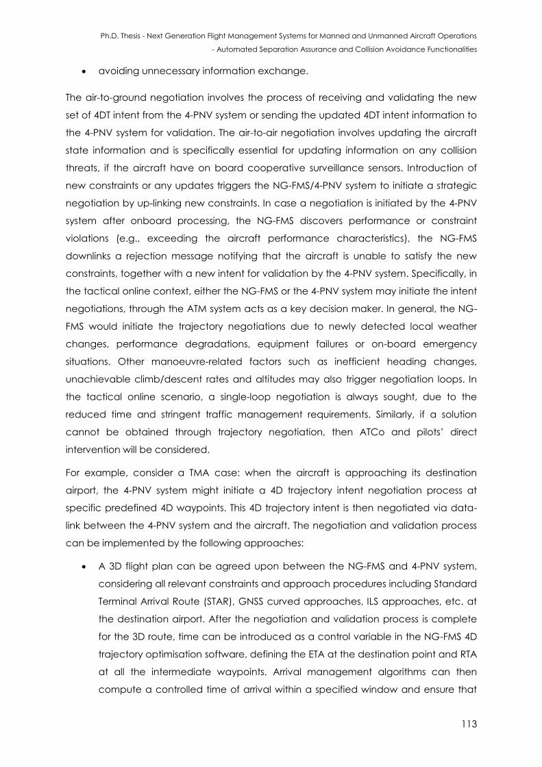
Ph.D. Thesis - Next Generation Flight Management Systems for Manned and Unmanned Aircraft Operations
- Automated Separation Assurance and Collision Avoidance Functionalities
113
avoiding unnecessary information exchange.
The air-to-ground negotiation involves the process of receiving and validating the new
set of 4DT intent from the 4-PNV system or sending the updated 4DT intent information to
the 4-PNV system for validation. The air-to-air negotiation involves updating the aircraft
state information and is specifically essential for updating information on any collision
threats, if the aircraft have on board cooperative surveillance sensors. Introduction of
new constraints or any updates triggers the NG-FMS/4-PNV system to initiate a strategic
negotiation by up-linking new constraints. In case a negotiation is initiated by the 4-PNV
system after onboard processing, the NG-FMS discovers performance or constraint
violations (e.g., exceeding the aircraft performance characteristics), the NG-FMS
downlinks a rejection message notifying that the aircraft is unable to satisfy the new
constraints, together with a new intent for validation by the 4-PNV system. Specifically, in
the tactical online context, either the NG-FMS or the 4-PNV system may initiate the intent
negotiations, through the ATM system acts as a key decision maker. In general, the NG-
FMS would initiate the trajectory negotiations due to newly detected local weather
changes, performance degradations, equipment failures or on-board emergency
situations. Other manoeuvre-related factors such as inefficient heading changes,
unachievable climb/descent rates and altitudes may also trigger negotiation loops. In
the tactical online scenario, a single-loop negotiation is always sought, due to the
reduced time and stringent traffic management requirements. Similarly, if a solution
cannot be obtained through trajectory negotiation, then ATCo and pilots’ direct
intervention will be considered.
For example, consider a TMA case: when the aircraft is approaching its destination
airport, the 4-PNV system might initiate a 4D trajectory intent negotiation process at
specific predefined 4D waypoints. This 4D trajectory intent is then negotiated via data-
link between the 4-PNV system and the aircraft. The negotiation and validation process
can be implemented by the following approaches:
A 3D flight plan can be agreed upon between the NG-FMS and 4-PNV system,
considering all relevant constraints and approach procedures including Standard
Terminal Arrival Route (STAR), GNSS curved approaches, ILS approaches, etc. at
the destination airport. After the negotiation and validation process is complete
for the 3D route, time can be introduced as a control variable in the NG-FMS 4D
trajectory optimisation software, defining the ETA at the destination point and RTA
at all the intermediate waypoints. Arrival management algorithms can then
compute a controlled time of arrival within a specified window and ensure that
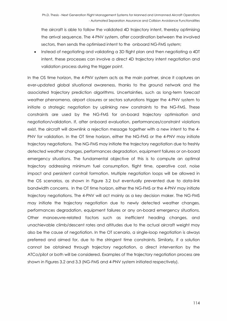
Ph.D. Thesis - Next Generation Flight Management Systems for Manned and Unmanned Aircraft Operations
- Automated Separation Assurance and Collision Avoidance Functionalities
114
the aircraft is able to follow the validated 4D trajectory intent, thereby optimising
the arrival sequence. The 4-PNV system, after coordination between the involved
sectors, then sends the optimised intent to the onboard NG-FMS system;
Instead of negotiating and validating a 3D flight plan and then negotiating a 4DT
intent, these processes can involve a direct 4D trajectory intent negotiation and
validation process during the trigger point.
In the OS time horizon, the 4-PNV system acts as the main partner, since it captures an
ever-updated global situational awareness, thanks to the ground network and the
associated trajectory prediction algorithms. Uncertainties, such as long-term forecast
weather phenomena, airport closures or sectors saturations trigger the 4-PNV system to
initiate a strategic negotiation by uplinking new constraints to the NG-FMS. These
constraints are used by the NG-FMS for on-board trajectory optimisation and
negotiation/validation. If, after onboard evaluation, performances/constraint violations
exist, the aircraft will downlink a rejection message together with a new intent to the 4-
PNV for validation. In the OT time horizon, either the NG-FMS or the 4-PNV may initiate
trajectory negotiations. The NG-FMS may initiate the trajectory negotiation due to freshly
detected weather changes, performances degradation, equipment failures or on-board
emergency situations. The fundamental objective of this is to compute an optimal
trajectory addressing minimum fuel consumption, flight time, operative cost, noise
impact and persistent contrail formation. Multiple negotiation loops will be allowed in
the OS scenarios, as shown in Figure 3.2 but eventually prevented due to data-link
bandwidth concerns. In the OT time horizon, either the NG-FMS or the 4-PNV may initiate
trajectory negotiations. The 4-PNV will act mainly as a key decision maker. The NG-FMS
may initiate the trajectory negotiation due to newly detected weather changes,
performances degradation, equipment failures or any on-board emergency situations.
Other manoeuvre-related factors such as inefficient heading changes, and
unachievable climb/descent rates and altitudes due to the actual aircraft weight may
also be the cause of negotiation. In the OT scenario, a single-loop negotiation is always
preferred and aimed for, due to the stringent time constraints. Similarly, if a solution
cannot be obtained through trajectory negotiation, a direct intervention by the
ATCo/pilot or both will be considered. Examples of the trajectory negotiation process are
shown in Figures 3.2 and 3.3 (NG-FMS and 4-PNV system initiated respectively).
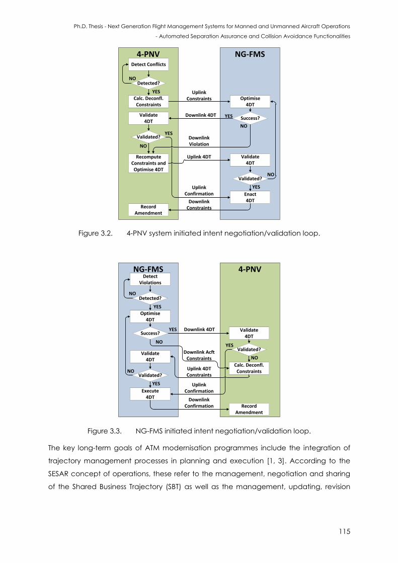
Ph.D. Thesis - Next Generation Flight Management Systems for Manned and Unmanned Aircraft Operations
- Automated Separation Assurance and Collision Avoidance Functionalities
115
Figure 3.2. 4-PNV system initiated intent negotiation/validation loop.
Figure 3.3. NG-FMS initiated intent negotiation/validation loop.
The key long-term goals of ATM modernisation programmes include the integration of
trajectory management processes in planning and execution [1, 3]. According to the
SESAR concept of operations, these refer to the management, negotiation and sharing
of the Shared Business Trajectory (SBT) as well as the management, updating, revision
4-PNV NG-FMS
Detected?
Detect Conflicts
Optimise4DT
Success?
YES
NO
Validate4DT
YES
Validated?
Enact4DT
YES
Recompute Constraints and Optimise 4DT
NO
NO
Validate4DT
Validated?
YES
RecordAmendment
NO
Uplink Constraints
Downlink 4DT
Downlink Violation
Uplink 4DT
Uplink Confirmation
Downlink Constraints
Calc. Deconfl. Constraints
4-PNVNG-FMS
Detected?
DetectViolations
Optimise4DT
Success?
YES
NO
Validate4DT
YESValidated?
Execute4DT
YES
Calc. Deconfl.Constraints
NO
NOValidate
4DT
Validated?
RecordAmendment
Uplink Confirmation
Downlink 4DT
Uplink 4DT Constraints
Downlink Confirmation
Downlink Acft Constraints
NO
YES
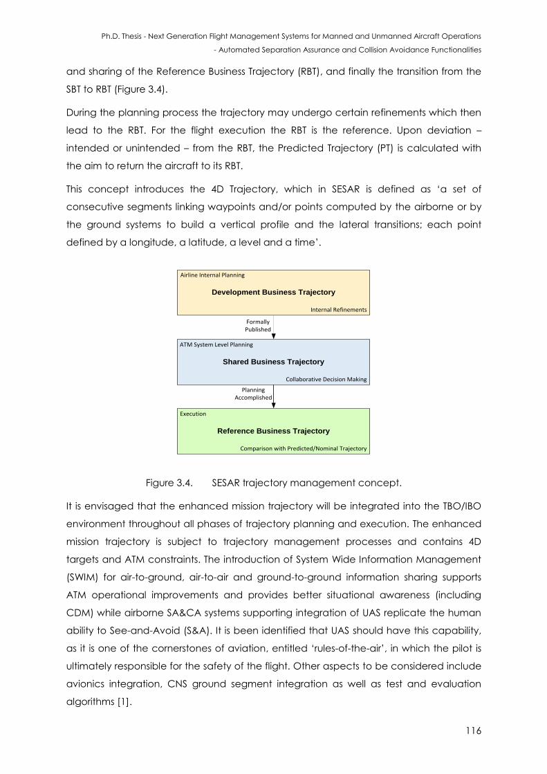
Ph.D. Thesis - Next Generation Flight Management Systems for Manned and Unmanned Aircraft Operations
- Automated Separation Assurance and Collision Avoidance Functionalities
116
and sharing of the Reference Business Trajectory (RBT), and finally the transition from the
SBT to RBT (Figure 3.4).
During the planning process the trajectory may undergo certain refinements which then
lead to the RBT. For the flight execution the RBT is the reference. Upon deviation –
intended or unintended – from the RBT, the Predicted Trajectory (PT) is calculated with
the aim to return the aircraft to its RBT.
This concept introduces the 4D Trajectory, which in SESAR is defined as ‘a set of
consecutive segments linking waypoints and/or points computed by the airborne or by
the ground systems to build a vertical profile and the lateral transitions; each point
defined by a longitude, a latitude, a level and a time’.
Shared Business Trajectory
Development Business Trajectory
Reference Business Trajectory
Formally Published
Planning Accomplished
Collaborative Decision Making
Internal Refinements
Airline Internal Planning
ATM System Level Planning
Execution
Comparison with Predicted/Nominal Trajectory
Figure 3.4. SESAR trajectory management concept.
It is envisaged that the enhanced mission trajectory will be integrated into the TBO/IBO
environment throughout all phases of trajectory planning and execution. The enhanced
mission trajectory is subject to trajectory management processes and contains 4D
targets and ATM constraints. The introduction of System Wide Information Management
(SWIM) for air-to-ground, air-to-air and ground-to-ground information sharing supports
ATM operational improvements and provides better situational awareness (including
CDM) while airborne SA&CA systems supporting integration of UAS replicate the human
ability to See-and-Avoid (S&A). It is been identified that UAS should have this capability,
as it is one of the cornerstones of aviation, entitled ‘rules-of-the-air’, in which the pilot is
ultimately responsible for the safety of the flight. Other aspects to be considered include
avionics integration, CNS ground segment integration as well as test and evaluation
algorithms [1].
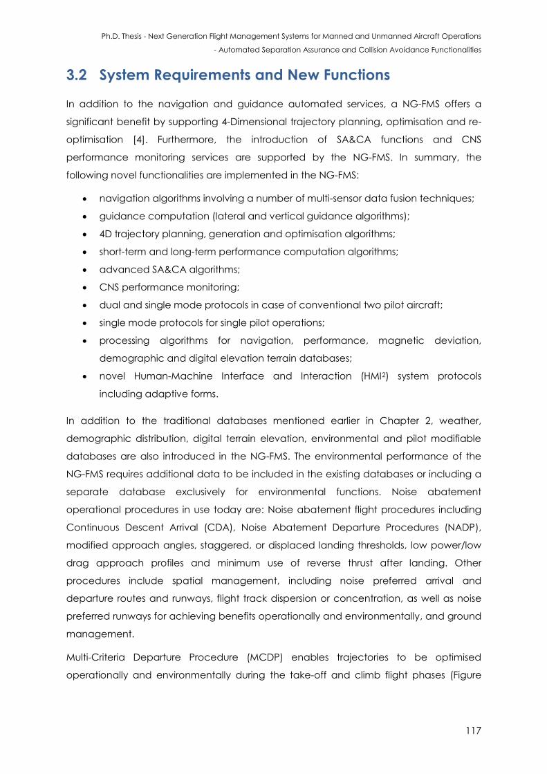
Ph.D. Thesis - Next Generation Flight Management Systems for Manned and Unmanned Aircraft Operations
- Automated Separation Assurance and Collision Avoidance Functionalities
117
3.2 System Requirements and New Functions
In addition to the navigation and guidance automated services, a NG-FMS offers a
significant benefit by supporting 4-Dimensional trajectory planning, optimisation and re-
optimisation [4]. Furthermore, the introduction of SA&CA functions and CNS
performance monitoring services are supported by the NG-FMS. In summary, the
following novel functionalities are implemented in the NG-FMS:
navigation algorithms involving a number of multi-sensor data fusion techniques;
guidance computation (lateral and vertical guidance algorithms);
4D trajectory planning, generation and optimisation algorithms;
short-term and long-term performance computation algorithms;
advanced SA&CA algorithms;
CNS performance monitoring;
dual and single mode protocols in case of conventional two pilot aircraft;
single mode protocols for single pilot operations;
processing algorithms for navigation, performance, magnetic deviation,
demographic and digital elevation terrain databases;
novel Human-Machine Interface and Interaction (HMI2) system protocols
including adaptive forms.
In addition to the traditional databases mentioned earlier in Chapter 2, weather,
demographic distribution, digital terrain elevation, environmental and pilot modifiable
databases are also introduced in the NG-FMS. The environmental performance of the
NG-FMS requires additional data to be included in the existing databases or including a
separate database exclusively for environmental functions. Noise abatement
operational procedures in use today are: Noise abatement flight procedures including
Continuous Descent Arrival (CDA), Noise Abatement Departure Procedures (NADP),
modified approach angles, staggered, or displaced landing thresholds, low power/low
drag approach profiles and minimum use of reverse thrust after landing. Other
procedures include spatial management, including noise preferred arrival and
departure routes and runways, flight track dispersion or concentration, as well as noise
preferred runways for achieving benefits operationally and environmentally, and ground
management.
Multi-Criteria Departure Procedure (MCDP) enables trajectories to be optimised
operationally and environmentally during the take-off and climb flight phases (Figure
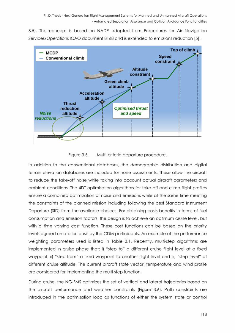
Ph.D. Thesis - Next Generation Flight Management Systems for Manned and Unmanned Aircraft Operations
- Automated Separation Assurance and Collision Avoidance Functionalities
118
3.5). The concept is based on NADP adopted from Procedures for Air Navigation
Services/Operations ICAO document 8168 and is extended to emissions reduction [5].
Top of climb
Speed
constraint
Thrust
reduction
altitude
Acceleration
altitude
Green climb
altitude
Altitude
constraint
Noise
reductions
Conventional climb
MCDP
Optimised thrust
and speed
Figure 3.5. Multi-criteria departure procedure.
In addition to the conventional databases, the demographic distribution and digital
terrain elevation databases are included for noise assessments. These allow the aircraft
to reduce the take-off noise while taking into account actual aircraft parameters and
ambient conditions. The 4DT optimisation algorithms for take-off and climb flight profiles
ensure a combined optimization of noise and emissions while at the same time meeting
the constraints of the planned mission including following the best Standard Instrument
Departure (SID) from the available choices. For obtaining costs benefits in terms of fuel
consumption and emission factors, the design is to achieve an optimum cruise level, but
with a time varying cost function. These cost functions can be based on the priority
levels agreed on a-priori basis by the CDM participants. An example of the performance
weighting parameters used is listed in Table 3.1. Recently, multi-step algorithms are
implemented in cruise phase that: i) “step to” a different cruise flight level at a fixed
waypoint, ii) “step from” a fixed waypoint to another flight level and iii) “step level” at
different cruise altitude. The current aircraft state vector, temperature and wind profile
are considered for implementing the multi-step function.
During cruise, the NG-FMS optimizes the set of vertical and lateral trajectories based on
the aircraft performance and weather constraints (Figure 3.6). Path constraints are
introduced in the optimisation loop as functions of either the system state or control
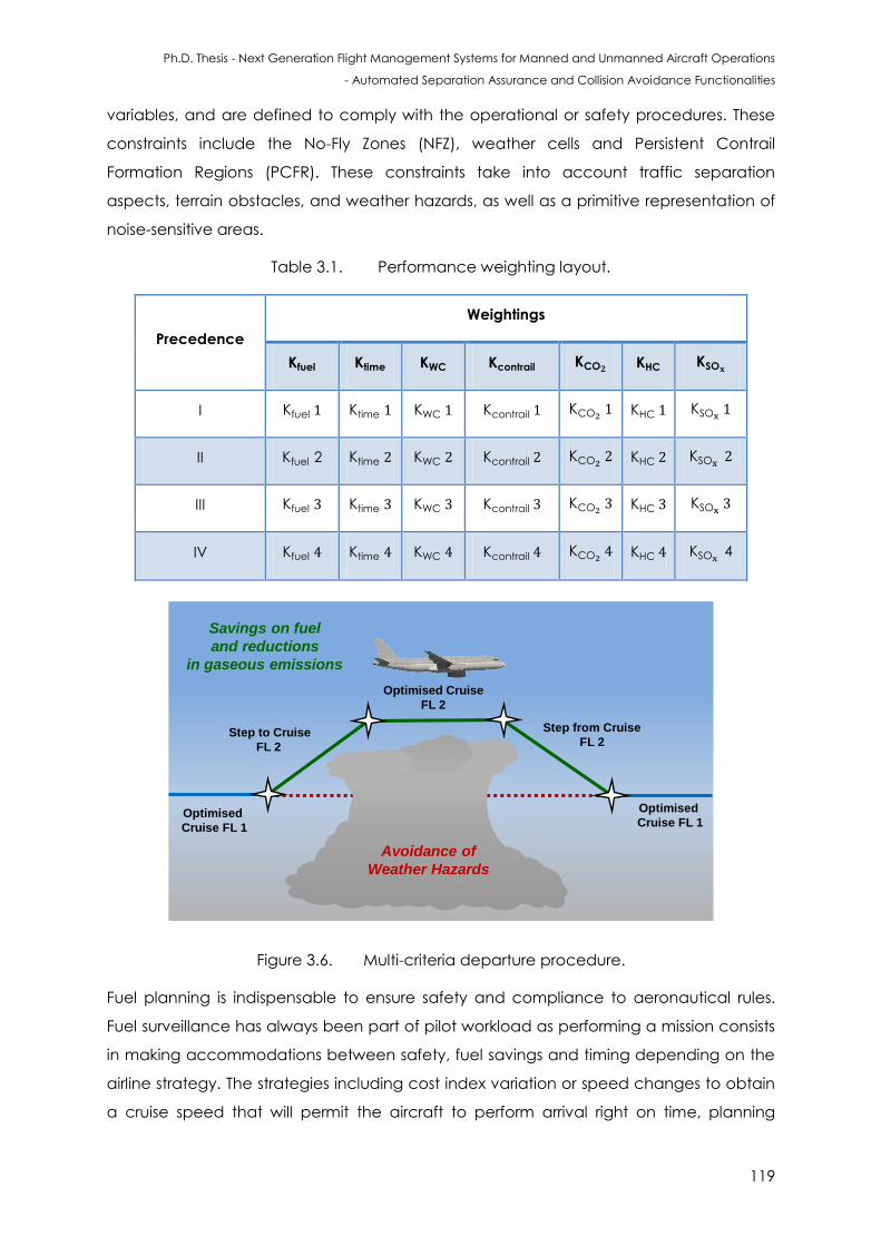
Ph.D. Thesis - Next Generation Flight Management Systems for Manned and Unmanned Aircraft Operations
- Automated Separation Assurance and Collision Avoidance Functionalities
119
variables, and are defined to comply with the operational or safety procedures. These
constraints include the No-Fly Zones (NFZ), weather cells and Persistent Contrail
Formation Regions (PCFR). These constraints take into account traffic separation
aspects, terrain obstacles, and weather hazards, as well as a primitive representation of
noise-sensitive areas.
Table 3.1. Performance weighting layout.
Precedence
Weightings
I Kfuel Ktime KWC Kcontrail KCO KHC KSO
II Kfuel 2 Ktime KWC Kcontrail KCO KHC KSO
III Kfuel Ktime KWC Kcontrail KCO KHC KSO
IV Kfuel Ktime KWC Kcontrail KCO KHC KSO 4
Optimised
Cruise FL 1
Step to Cruise
FL 2
Step from Cruise
FL 2
Savings on fuel
and reductions
in gaseous emissions
Optimised Cruise
FL 2
Optimised
Cruise FL 1
Avoidance of
Weather Hazards
Figure 3.6. Multi-criteria departure procedure.
Fuel planning is indispensable to ensure safety and compliance to aeronautical rules.
Fuel surveillance has always been part of pilot workload as performing a mission consists
in making accommodations between safety, fuel savings and timing depending on the
airline strategy. The strategies including cost index variation or speed changes to obtain
a cruise speed that will permit the aircraft to perform arrival right on time, planning
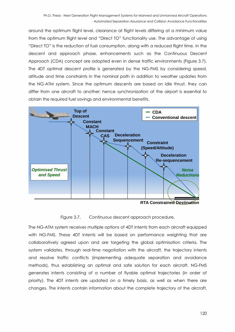
Ph.D. Thesis - Next Generation Flight Management Systems for Manned and Unmanned Aircraft Operations
- Automated Separation Assurance and Collision Avoidance Functionalities
120
around the optimum flight level, clearance at flight levels differing at a minimum value
from the optimum flight level and “Direct TO” functionality use. The advantage of using
“Direct TO” is the reduction of fuel consumption, along with a reduced flight time. In the
descent and approach phase, enhancements such as the Continuous Descent
Approach (CDA) concept are adopted even in dense traffic environments (Figure 3.7).
The 4DT optimal descent profile is generated by the NG-FMS by considering speed,
altitude and time constraints in the nominal path in addition to weather updates from
the NG-ATM system. Since the optimum descents are based on idle thrust, they can
differ from one aircraft to another; hence synchronization at the airport is essential to
obtain the required fuel savings and environmental benefits.
Top of
Descent
Constant
MACH
Deceleration
Sequencement
Noise
Reductions
Conventional descent
CDA
Optimised Thrust
and Speed
Constant
CAS
Constraint
(Speed/Altitude)
Deceleration
Re-sequencement
RTA Constrained Destination
Figure 3.7. Continuous descent approach procedure.
The NG-ATM system receives multiple options of 4DT intents from each aircraft equipped
with NG-FMS. These 4DT intents will be based on performance weighting that are
collaboratively agreed upon and are targeting the global optimisation criteria. The
system validates, through real-time negotiation with the aircraft, the trajectory intents
and resolve traffic conflicts (implementing adequate separation and avoidance
methods), thus establishing an optimal and safe solution for each aircraft. NG-FMS
generates intents consisting of a number of flyable optimal trajectories (in order of
priority). The 4DT intents are updated on a timely basis, as well as when there are
changes. The intents contain information about the complete trajectory of the aircraft,
Ph.D. Thesis - Next Generation Flight Management Systems for Manned and Unmanned Aircraft Operations
- Automated Separation Assurance and Collision Avoidance Functionalities
121
until it reaches its destination. The intent data includes all the waypoints (lateral and
vertical), leg and turn information [6].
In 4D TBO, time is introduced as one of the variables that can be controlled during all
flight phases. In initial TBO implementation, the RTA concept is introduced, which mostly
involves variation of speed in the lateral profile. The cruise altitude is fixed for an idle-
thrust performance path in most cases to achieve an efficient variation of the ETA at the
WPTs along the trajectory. Awareness of winds and meteorological data can be used for
all relevant timeframes (strategic, tactical and emergency). The weather and
temperature data for the entire flight plan is obtained from the AOC and is updated at
regular intervals with the information obtained from the ground systems or other aircraft
via the data link. The 4DT optimisation problem includes a number of environmental
objectives and operational constraints, also accounting for economic and operational
performances, as well as weather forecast information from various external sources.
Reduction of fuel consumption begins early in the process with route planning and the
filing of the flight plan. Companies have tools to optimise flight plan depending on the
predicted meteorological conditions, aircraft performances and available routes. The
flight plans provided by operations centres can include steps meant to remain close to
the computed optimum flight level. But these steps become geographical steps when
they are uploaded into the FMS before departure, and pilots generally clear them at the
beginning of cruise to update them as optimum steps using updated aircraft state.
These various methods are very efficient to saving time and fuel, but they have to face
operational limitations, which need to be taken into account:
flight envelope boundaries;
ATC clearance;
flight level availability;
traffic capacity of geographical zone.
It is highly desirable to set up optimum flight levels or use DIRECT TO for achieving the RTA
at the end of each flight phase and the ETA at the planned destination. Efficient
trajectories, based on more precise, reliable and predictable three dimensional flight
path will be optimized for minimum noise impact and low emissions and include agile
trajectory management, in response to meteorological hazard.
The sensing of atmospheric perturbations and atmospheric humidity is based on the
characterization and surveillance of the environment. It is achieved by the employment
of improved weather radar algorithms. These methods improve on board detection
accuracy for potentially hazardous weather conditions.
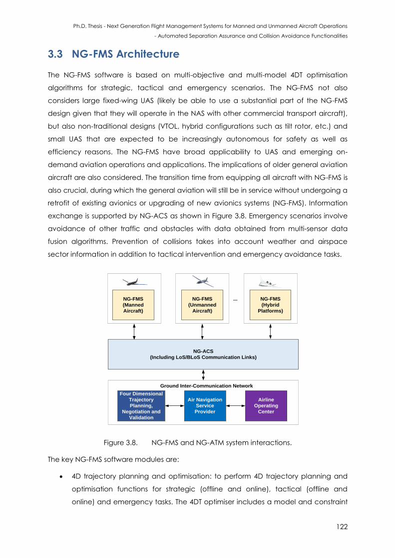
Ph.D. Thesis - Next Generation Flight Management Systems for Manned and Unmanned Aircraft Operations
- Automated Separation Assurance and Collision Avoidance Functionalities
122
3.3 NG-FMS Architecture
The NG-FMS software is based on multi-objective and multi-model 4DT optimisation
algorithms for strategic, tactical and emergency scenarios. The NG-FMS not also
considers large fixed-wing UAS (likely be able to use a substantial part of the NG-FMS
design given that they will operate in the NAS with other commercial transport aircraft),
but also non-traditional designs (VTOL, hybrid configurations such as tilt rotor, etc.) and
small UAS that are expected to be increasingly autonomous for safety as well as
efficiency reasons. The NG-FMS have broad applicability to UAS and emerging on-
demand aviation operations and applications. The implications of older general aviation
aircraft are also considered. The transition time from equipping all aircraft with NG-FMS is
also crucial, during which the general aviation will still be in service without undergoing a
retrofit of existing avionics or upgrading of new avionics systems (NG-FMS). Information
exchange is supported by NG-ACS as shown in Figure 3.8. Emergency scenarios involve
avoidance of other traffic and obstacles with data obtained from multi-sensor data
fusion algorithms. Prevention of collisions takes into account weather and airspace
sector information in addition to tactical intervention and emergency avoidance tasks.
Air Navigation
Service
Provider
Four Dimensional
Trajectory
Planning,
Negotiation and
Validation
Airline
Operating
Center
Ground Inter-Communication Network
NG-FMS
(Hybrid
Platforms)
...
NG-ACS
(Including LoS/BLoS Communication Links)
NG-FMS
(Manned
Aircraft)
NG-FMS
(Unmanned
Aircraft)
Figure 3.8. NG-FMS and NG-ATM system interactions.
The key NG-FMS software modules are:
4D trajectory planning and optimisation: to perform 4D trajectory planning and
optimisation functions for strategic (offline and online), tactical (offline and
online) and emergency tasks. The 4DT optimiser includes a model and constraint
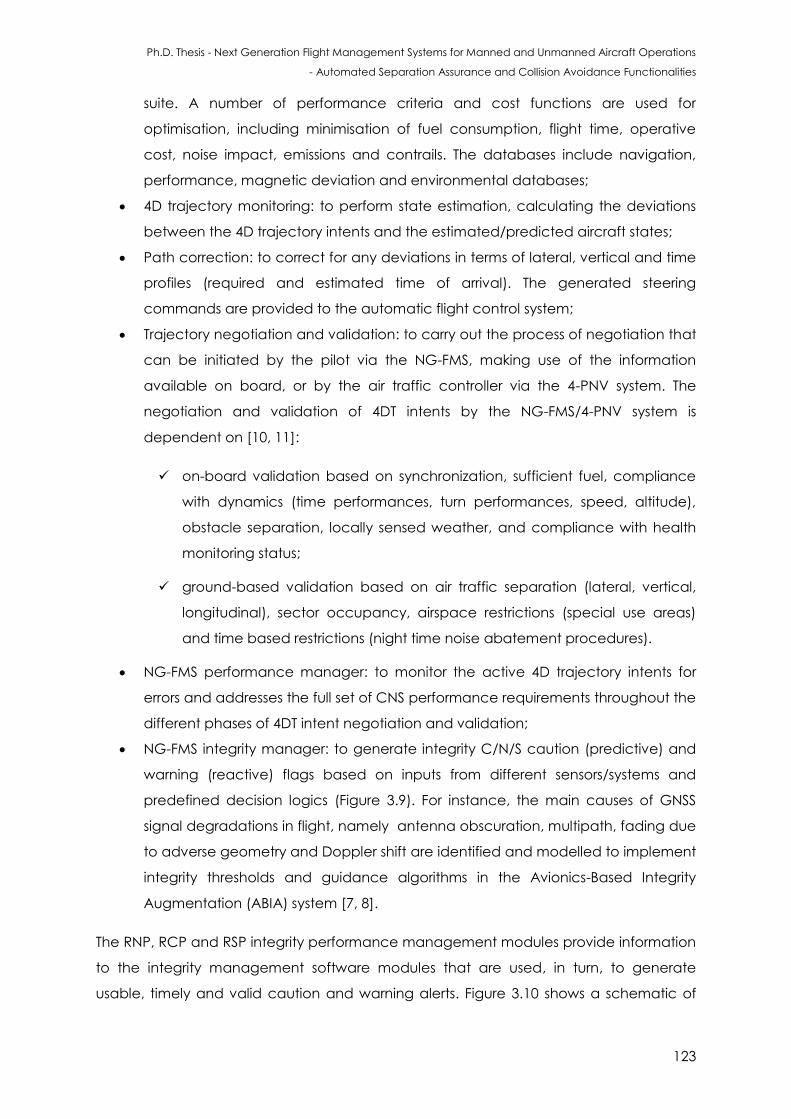
Ph.D. Thesis - Next Generation Flight Management Systems for Manned and Unmanned Aircraft Operations
- Automated Separation Assurance and Collision Avoidance Functionalities
123
suite. A number of performance criteria and cost functions are used for
optimisation, including minimisation of fuel consumption, flight time, operative
cost, noise impact, emissions and contrails. The databases include navigation,
performance, magnetic deviation and environmental databases;
4D trajectory monitoring: to perform state estimation, calculating the deviations
between the 4D trajectory intents and the estimated/predicted aircraft states;
Path correction: to correct for any deviations in terms of lateral, vertical and time
profiles (required and estimated time of arrival). The generated steering
commands are provided to the automatic flight control system;
Trajectory negotiation and validation: to carry out the process of negotiation that
can be initiated by the pilot via the NG-FMS, making use of the information
available on board, or by the air traffic controller via the 4-PNV system. The
negotiation and validation of 4DT intents by the NG-FMS/4-PNV system is
dependent on [10, 11]:
on-board validation based on synchronization, sufficient fuel, compliance
with dynamics (time performances, turn performances, speed, altitude),
obstacle separation, locally sensed weather, and compliance with health
monitoring status;
ground-based validation based on air traffic separation (lateral, vertical,
longitudinal), sector occupancy, airspace restrictions (special use areas)
and time based restrictions (night time noise abatement procedures).
NG-FMS performance manager: to monitor the active 4D trajectory intents for
errors and addresses the full set of CNS performance requirements throughout the
different phases of 4DT intent negotiation and validation;
NG-FMS integrity manager: to generate integrity C/N/S caution (predictive) and
warning (reactive) flags based on inputs from different sensors/systems and
predefined decision logics (Figure 3.9). For instance, the main causes of GNSS
signal degradations in flight, namely antenna obscuration, multipath, fading due
to adverse geometry and Doppler shift are identified and modelled to implement
integrity thresholds and guidance algorithms in the Avionics-Based Integrity
Augmentation (ABIA) system [7, 8].
The RNP, RCP and RSP integrity performance management modules provide information
to the integrity management software modules that are used, in turn, to generate
usable, timely and valid caution and warning alerts. Figure 3.10 shows a schematic of
Ph.D. Thesis - Next Generation Flight Management Systems for Manned and Unmanned Aircraft Operations
- Automated Separation Assurance and Collision Avoidance Functionalities
124
the NG-FMS architecture. Airline, airspace, aircraft performance (derived from the
performance database) and ATM operational constraints are taken into account in the
trajectory prediction and performance optimisation tasks. Each aircraft equipped with
NG-FMS generates 4DT intents. 4DT intents are defined according to the Flight
Management Computer (FMC) ARINC 702A-3 characteristic as a string of 4D points that
define the predicted trajectory of the aircraft along with the point type and turn radius
associated with the flight path transition [9, 10]. Intent data are updated in situations
such as a change in the nominal flight path, or the addition of new sequencing points
and weather data. The trajectory computation and optimisation component of the NG-
FMS is reconfigurable with that of the ground-based counterpart to enable negotiation
and validation updates in real-time (Figure 3.11).
NG-FMS CNS
Performance
Management
C/N/S Caution
Integrity Flag
CNS Integrity
Flag Generator
Aggregated
C/N/S
Errors
C/N/S Warning
integrity Flag
CNS Integrity
Analysis
Module
Surveillance
Equipment Navigation Sensors
4D Trajectory
Re-planning
Communication
Links
Recapture
Command
Figure 3.9. NG-FMS integrity monitor.
Additionally, the intents are recomputed according to flight plan revisions, weather
updates, guidance mode modification, cost index modification and corrections for
position uncertainties in real-time based on the 4D trajectory optimisation algorithms
described earlier. The efficiency and effectiveness of 4DT planning, negotiation and
validation functionalities of the NG-FMS are directly driven by the nature of information
sharing. Subject to various in-flight changes, trajectory calculations are refreshed to
maintain consistency and downlinked to the 4-PNV system via the NG-ACS.
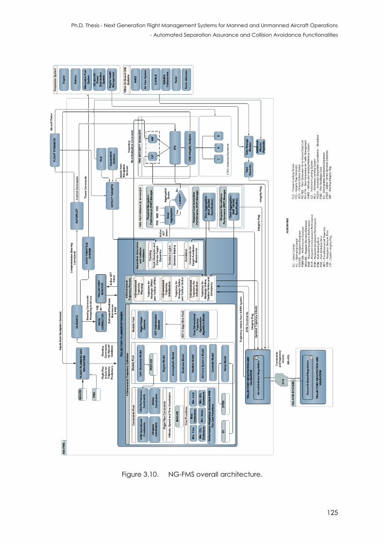
Ph.D. Thesis - Next Generation Flight Management Systems for Manned and Unmanned Aircraft Operations
- Automated Separation Assurance and Collision Avoidance Functionalities
125
Figure 3.10. NG-FMS overall architecture.
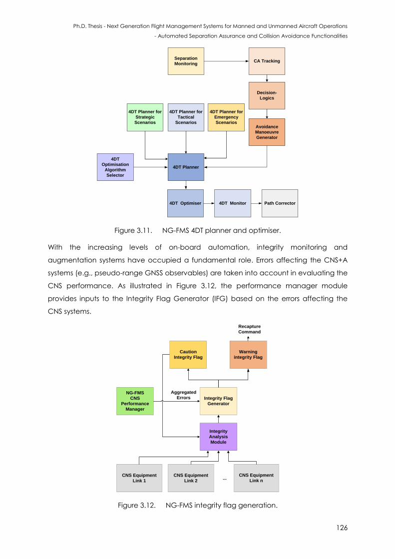
Ph.D. Thesis - Next Generation Flight Management Systems for Manned and Unmanned Aircraft Operations
- Automated Separation Assurance and Collision Avoidance Functionalities
126
4DT Optimiser
CA Tracking
4DT Planner
4DT Planner for
Emergency
Scenarios
4DT Planner for
Tactical
Scenarios
4DT Planner for
Strategic
Scenarios
Decision-
Logics
Avoidance
Manoeuvre
Generator
4DT Monitor Path Corrector
4DT
Optimisation
Algorithm
Selector
Separation
Monitoring
Figure 3.11. NG-FMS 4DT planner and optimiser.
With the increasing levels of on-board automation, integrity monitoring and
augmentation systems have occupied a fundamental role. Errors affecting the CNS+A
systems (e.g., pseudo-range GNSS observables) are taken into account in evaluating the
CNS performance. As illustrated in Figure 3.12, the performance manager module
provides inputs to the Integrity Flag Generator (IFG) based on the errors affecting the
CNS systems.
NG-FMS
CNS
Performance
Manager
Caution
Integrity Flag
Integrity Flag
Generator
Aggregated
Errors
Warning
integrity Flag
Integrity
Analysis
Module
CNS Equipment
Link 2
CNS Equipment
Link n
CNS Equipment
Link 1 ...
Recapture
Command
Figure 3.12. NG-FMS integrity flag generation.
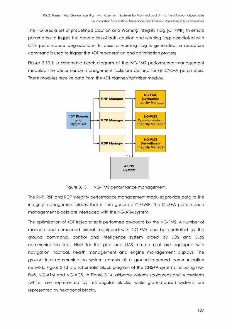
Ph.D. Thesis - Next Generation Flight Management Systems for Manned and Unmanned Aircraft Operations
- Automated Separation Assurance and Collision Avoidance Functionalities
127
The IFG uses a set of predefined Caution and Warning Integrity Flag (CIF/WIF) threshold
parameters to trigger the generation of both caution and warning flags associated with
CNS performance degradations. In case a warning flag is generated, a recapture
command is used to trigger the 4DT regeneration and optimisation process.
Figure 3.13 is a schematic block diagram of the NG-FMS performance management
modules. The performance management tasks are defined for all CNS+A parameters.
These modules receive data from the 4DT planner/optimiser module.
4DT Planner
and
Optimiser
4-PNV
System
RNP Manager
RCP Manager
NG-FMS
Navigation
Integrity Manager
NG-FMS
Communication
Integrity Manager
NG-FMS
Surveillance
Integrity Manager
RSP Manager
Figure 3.13. NG-FMS performance management.
The RNP, RSP and RCP integrity performance management modules provide data to the
integrity management blocks that in turn generate CIF/WIF. The CNS+A performance
management blocks are interfaced with the NG-ATM system.
The optimisation of 4DT trajectories is performed on-board by the NG-FMS. A number of
manned and unmanned aircraft equipped with NG-FMS can be controlled by the
ground command, control and intelligence system aided by LOS and BLoS
communication links. HMI2 for the pilot and UAS remote pilot are equipped with
navigation, tactical, health management and engine management displays. The
ground inter-communication system consists of a ground-to-ground communication
network. Figure 3.13 is a schematic block diagram of the CNS+A systems including NG-
FMS, NG-ATM and NG-ACS. In Figure 3.14, airborne systems (coloured) and subsystems
(white) are represented by rectangular blocks, while ground-based systems are
represented by hexagonal blocks.
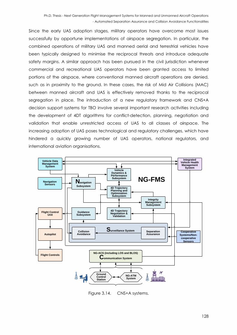
Ph.D. Thesis - Next Generation Flight Management Systems for Manned and Unmanned Aircraft Operations
- Automated Separation Assurance and Collision Avoidance Functionalities
128
Since the early UAS adoption stages, military operators have overcome most issues
successfully by opportune implementations of airspace segregation. In particular, the
combined operations of military UAS and manned aerial and terrestrial vehicles have
been typically designed to minimise the reciprocal threats and introduce adequate
safety margins. A similar approach has been pursued in the civil jurisdiction whenever
commercial and recreational UAS operators have been granted access to limited
portions of the airspace, where conventional manned aircraft operations are denied,
such as in proximity to the ground. In these cases, the risk of Mid Air Collisions (MAC)
between manned aircraft and UAS is effectively removed thanks to the reciprocal
segregation in place. The introduction of a new regulatory framework and CNS+A
decision support systems for TBO involve several important research activities including
the development of 4DT algorithms for conflict-detection, planning, negotiation and
validation that enable unrestricted access of UAS to all classes of airspace. The
increasing adoption of UAS poses technological and regulatory challenges, which have
hindered a quickly growing number of UAS operators, national regulators, and
international aviation organisations.
NG-FMS
Surveillance System
Vehicle Data Management
System
Navigation
Subsystem
Integrated Vehicle Health Management
System
Separation Assurance
Vehicle Dynamics & Performance Subsystem
Integrity Management Subsystem
4D Trajectory Negotiation &
Validation
4D Trajectory Planning and Optimisation Subsystem
Guidance Subsystem
NG-ACS (including LOS and BLOS)
Communication System
Flight Control Unit
Collision Avoidance
Ground Control Station
NG-ATM System
NavigationSensors
Cooperative
Systems/Non-
cooperative
Sensors
Autopilot
Flight Controls
Figure 3.14. CNS+A systems.
Ph.D. Thesis - Next Generation Flight Management Systems for Manned and Unmanned Aircraft Operations
- Automated Separation Assurance and Collision Avoidance Functionalities
129
A progressive integration of UAS by means of a gradual exploitation of the conventional
civil airspace structure and regulations has been considered. In particular, the safety of
manned aircraft would be substantially unaffected if UAS were to be granted access to
regions where conventional aircraft operations are very sparse. From this perspective, an
integration of UAS starting from less restrictive classes of airspace is traditionally favoured.
This would decrease requirements in terms of CNS and Avionics (CNS+A) equipment,
and require limited compliance to ATM clearances. The less demanding requirements,
especially in classes “F” and “G”, are certainly valued from the UAS perspective, as UAS
reliability is still far from the levels offered by manned aircraft. Nevertheless, separation in
these airspace regions is the responsibility of the pilots and based on visual detection
and deliberate execution of avoidance manoeuvres according to the rules of the air.
These aspects involve substantially higher technological challenges for UAS developers,
as separation relies uniquely upon on board SA&CA and decision-making processes,
hence higher levels of on board autonomy are required to mitigate the risks arising in
connection to possible failures to the Command and Control (C2) loop involving the
ground pilot.
3.4 NG-FMS Algorithms
The motion of an aircraft can be expressed in terms of a set of equations, representing
the translational and angular accelerations. Applying Newton’s second law to the
aircraft (which is considered to be a rigid body), the following equations are obtained:
(3.1)
(3.2)
where:
is the sum of all the applied forces;
is the sum of applied torques;
is the angular momentum;
is the mass of the aircraft;
is the total velocity vector.
The sum of external forces can be subdivided into: aerodynamic forces, gravitational
force and propulsive force. The forces and moments about the six degrees of freedom,
ore expressed as:
Ph.D. Thesis - Next Generation Flight Management Systems for Manned and Unmanned Aircraft Operations
- Automated Separation Assurance and Collision Avoidance Functionalities
130
∑
(3.3)
∑
(3.4)
∑
(3.5)
∑
(3.6)
∑
(3.7)
∑
(3.8)
where , , are the linear velocities along the , and -axis respectively;
are the forces acting on the aircraft along the three axes; and are the
components of angular momentum along the three axes. The effect of angular
velocities on linear velocities can be easily analysed. For example, considering the axial
velocity , the pitch rate increases the velocity by a factor , but the yaw rate
reduces it by a factor . The equations for the linear velocities are given by [11]:
(3.9)
(3.10)
(3.11)
where , and are the rates in linear velocities and is the roll rate. The above
equations are differentiated to obtain:
(3.12)
(3.13)
(3.14)
Substituting for and in the above equations, the below expressions are obtained:
(3.15)
(3.16)
(3.17)
The forces acting on the element of mass are given by:
(3.18)
Ph.D. Thesis - Next Generation Flight Management Systems for Manned and Unmanned Aircraft Operations
- Automated Separation Assurance and Collision Avoidance Functionalities
131
(3.19)
(3.20)
The inertia moments acting on the mass element are given by:
(3.21)
(3.22)
(3.23)
The forces and moments acting on the aircraft can be calculated by summing the
above equations over the complete aircraft mass. Assuming that the centre of gravity of
the aircraft coincides with the origin of the chosen axis system, the terms containing
and in the above equations can be ignored, since their summation over the
entire aircraft yields zero. Therefore, the force equations are expressed as:
( ) (3.24)
( ) (3.25)
( ) (3.26)
Similarly, the moments are expressed as:
( ) ( ) (3.27)
( ) ( ) (3.28)
( ) ( ) (3.29)
where and are the moments of inertia and are given by:
∑ ( ) (3.30)
∑ ( ) (3.31)
∑ ( ) (3.32)
∑ (3.33)
The state-of-the-art FMS employ a 3-Degrees-of-Freedom (3-DoF) model for generating
3D trajectories. NG-FMS generates 4DT intents composed by groups of single trajectories
t belonging to the global set T. A number of algorithms have been adopted for
trajectory generation and avoidance manoeuvres [12 - 15]. The consecutive TCPs are
defined with respect to the previous waypoints by conditional probability and generate
Ph.D. Thesis - Next Generation Flight Management Systems for Manned and Unmanned Aircraft Operations
- Automated Separation Assurance and Collision Avoidance Functionalities
132
fly-by and fly-over waypoints for each flight segment up to the destination. The NG-FMS
trajectory optimisation algorithms are based on a 3-Degrees-of-Freedom (3-DoF) or 6-
Degrees-of-Freedom (6-DoF) Aircraft Dynamics Model (ADM) with variable mass. The 3-
DoF Equations of Motion (EoM) describing the aircraft states and governing the
translational movements along the longitudinal, lateral and vertical axes are:
(3.34)
( ) (3.35)
(3.36)
(3.37)
( )
(3.38)
(
) (
) (3.39)
( ) ( (3.40)
( ) ( ) (3.41)
The above Differential Algebraic Equations (DAEs) incorporate three control variables
( ) where is the engine power setting, is the load factor and is the bank
angle. The seven state variables are ( h ) where is the aircraft
(variable) mass, is the geodetic latitude, is the geodetic longitude, is the altitude,
is the true air speed, is the flight path angle, is the heading. is the meridional
radius of curvature, T is the transverse radius of curvature, W is the wind velocity, T is the
thrust, D is the drag and is the nominal acceleration due to gravity of the Earth. This
model assumes a rigid body aircraft with a vertical plane of symmetry, nil wing bending
effect, a rigidly mounted aircraft engine on the vehicle body, zero thrust angle,
negligible moments of inertia, varying mass only as a result of fuel consumption and
uniform gravity. Wind effects are considered along the three geodetic reference axes.
Earth’s shape is approximated as an ellipsoid using the World Geodetic System of year
1984 (WGS 84) parameters. The lateral path is constructed in terms of segments (straight
and turns) and is based on the required course change and the aircraft predicted
ground speed during the turn. The specificity of the trajectory optimisation and optimal
Ph.D. Thesis - Next Generation Flight Management Systems for Manned and Unmanned Aircraft Operations
- Automated Separation Assurance and Collision Avoidance Functionalities
133
control with respect to other mathematical optimisation branches is the application to
dynamical systems. Therefore, a key component in the optimisation formulation is the set
of dynamic constraints, which are meant to reproduce the feasible motion of the system
within the optimisation problem [16]. A system of DAEs, consisting of the time derivatives
of the state variables, is usually adopted to introduce the system dynamics, and the
dynamic constraints are therefore written as:
( ) [ ( ) ( ) (3.42)
where is a set of system elements. All non-differential constraints imposed on the system
between the initial and final conditions are classified as path constraints, as they restrict
the path, i.e. the space of states and controls of the dynamical system. In order to
represent all possible non-differential restrictions on the vehicle motion, two types of
algebraic path constraints are considered: inequality constraints and equality
constraints. A generalised expression of an inequality constraint is [16]:
( ( ) ( ) ) (3.43)
whereas an equality constraint can be written as:
( ( ) ( ) ) (3.44)
Boundary conditions define the values that state and control variables of the dynamical
system shall have at the initial and final times. Since in some instances the boundary
conditions are not always restricted to definite values, it is useful to adopt a generalised
expression including relaxed conditions. The boundary conditions are expressed as [16]:
[ ( ) ( ) ( ) ( ) (3.45)
where is the initial time and is the final time in the time domain. In order to optimise
a given performance, it is necessary to introduce a scalar index: the performance index,
which by means of a suitably defined cost function quantifies the achievement of that
particular objective [16]. The optimal control problem can be tackled using direct and
indirect methods. Global collocation methods, which are aimed at obtaining a direct
solution of the optimal control problem, is attempted by enforcing the evaluation of the
state and control vectors in discrete collocation points across the entire problem
domain. Out of several global collocation methods, pseudospectral methods are
considered as one of the most computationally effective technique available for the
direct solution of large non-linear aircraft trajectory optimisation problems. They are
based on a global collocation of orthogonal (spectral) interpolating functions.
Uncertainties in input data, estimation models and in the trajectory propagation over
Ph.D. Thesis - Next Generation Flight Management Systems for Manned and Unmanned Aircraft Operations
- Automated Separation Assurance and Collision Avoidance Functionalities
134
time make some key assumptions void. Hence pseudo-optimal solutions are adopted for
generating 4D trajectory intents. The optimisation process is translated into the
mathematical minimisation (or maximisation) of such a performance index. The
optimisation problem consists of determining the controls u(t) and states x(t) that
minimize a performance index, given by the sum of Mayer ( ) and Lagrange ( ) terms
as follows:
[ ( ) ( ) ] ∫
[ ( ) ( ) (3.46)
The optimisation is classified as single-objective when an individual performance index J
is introduced and multi-objective when two or multiple performance indexes Ji are
defined. The NG-FMS receives the controlled time of arrival target defined by the 4-PNV
system, which becomes the RTA to be used by the NG-FMS in determining the optimal
trajectory states (final time). In general, NG-FMS software for all flight phases allow
incorporation of a cost index based on a manually entered CAS/Mach or a combined
pair. The cost index set by the mission operators is processed by the NG-FMS to set the
gain matrix weight, time, fuel, emissions, noise and other costs. The time cost, ti e is
given by:
ti e ttf (3.47)
Fuel consumption optimisation is achieved by minimising the difference between the
aircraft initial and final mass:
f e (tf)- (t ) (3.48)
In terms of aircraft emissions, although engine design and other factors play an influence
on the total amount of emission release, engine emission is generally considered as a
function of fuel burn, multiplied by a direct emission factor, . Hence, the mathematical
description of the emission rate, e ission defined with respect to emissions, e and time, t is
given by:
e ission ∫ e
t (tf) - t
tft
(3.49)
This function is based on modelling the dependence of on the engine power setting
for turbofan engines. The navigation costs, J is given by:
∑ ( √
(3.50)
where MTOM is the Maximum Take-Off Mass, DIS is the horizontal separation between
aircraft and intruder, depends on the country of implementation and URCH is the
Ph.D. Thesis - Next Generation Flight Management Systems for Manned and Unmanned Aircraft Operations
- Automated Separation Assurance and Collision Avoidance Functionalities
135
Unitary Rate Charges for air traffic services. These charges were first established by
EUROCONTROL for European countries. In order to implement the noise model,
demographic distribution and digital terrain elevation data are considered. The terrain
proximity cost, is obtained as a trade-off between an early turn take-off, low path
angle climb, low clearance margin from obstacles output and a very steep climb, long
straight departure and increased obstacle clearance margin solution [19]. The numerical
solution of the trajectory optimisation problem is performed by primarily combining the
multiple objectives by means of weighted sum, and subsequently solving the combined
optimisation problem by means of pseudospectral transcription into a constrained multi-
phase Non-Linear Programming (NLP) problem [16]. Other methods such as Mixed
Integer Linear Programming (MILP) can be implemented to overcome the
computational complexity of the NLP problem.
3.5 System State Error Analysis
The lateral path is constructed in terms of segments (straight and turns) and is based on
the required course change and the aircraft predicted ground speed during the turn. A
turn is constructed based on the maximum ground speed during a course change and
the turn radius is given by:
( ) (3.51)
where is the maximum ground speed during the turn. The turn arc length is given by:
(3.52)
Given the , the bank angle is calculated from:
(
) (3.53)
The NG-FMS computes turn altitude and speed based on the selected altitude by taking
into account the predicted wind at that altitude. The bank angle is determined based
on aircraft dynamics and airspace configurations. In order to construct the vertical
profile, a number of energy balance equations are typically adopted leading to
nominal climb/descent, fixed gradients climb/descent, intermediate speed changes
and level flight configurations. The integration steps are constrained by the mission
profile imposed altitude, speed and time restrictions as well as performance limitations
such as speed and buffet limits, maximum altitude and thrust limits. The data that drives
the energy balance equations come from the airframe/engine dependent thrust, fuel
Ph.D. Thesis - Next Generation Flight Management Systems for Manned and Unmanned Aircraft Operations
- Automated Separation Assurance and Collision Avoidance Functionalities
136
flow, drag and air speed schedule models stored in the PERFDB. The vertical profile is
obtained from the energy method given by:
( )
(
) (3.54)
where is the true air speed and is the gross weight. Designing a lateral track
control strategy, especially for UAS is very complex. A viable control strategy is based on
the relation [17]:
(3.55)
where and are the current track position of the aircraft with respect to a TCP.
The along-track and cross-track velocities are obtained from the airspeed and wind
speed velocity vectors. The condition to satisfy the control strategy is given by:
= ( )-( ) (3.56)
A number of controllers can be implemented to complete the GNC loop including those
that have been employed with reliability for a long period (Proportional-Integral-
Derivative (PID) and others) as well as emerging artificial intelligence tools (neural
network, fuzzy expert system, etc.). In order to study the effects of uncertainties on the
generated 4DT, a detailed error analysis is performed. The errors might be due to
database accuracy degradations, system modelling errors, atmospheric disturbances
and subsystem errors. The system states are modified with the addition of the stochastic
term, ( ) and are represented by:
( ) [ ( ) ( ) ( ) (3.57)
In order to perform a sensitivity analysis, the sensitivity of a trajectory attribute, J,
including consumption of fuel, noise, emissions, etc. is considered with respect to a
model parameter, Δ and is given by:
(3.58)
The open loop sensitivity of J is given by:
( ) ( )
(3.59)
The closed loop sensitivity of J is given by:
( ) ( )
(3.60)
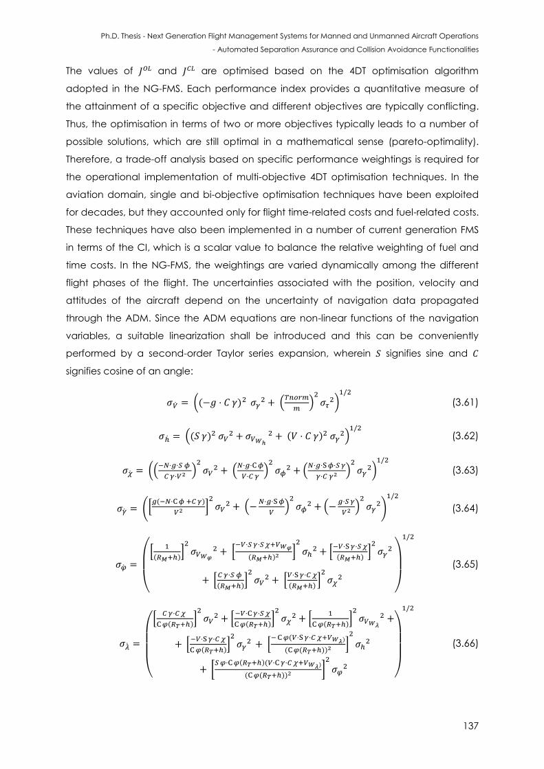
Ph.D. Thesis - Next Generation Flight Management Systems for Manned and Unmanned Aircraft Operations
- Automated Separation Assurance and Collision Avoidance Functionalities
137
The values of and are optimised based on the 4DT optimisation algorithm
adopted in the NG-FMS. Each performance index provides a quantitative measure of
the attainment of a specific objective and different objectives are typically conflicting.
Thus, the optimisation in terms of two or more objectives typically leads to a number of
possible solutions, which are still optimal in a mathematical sense (pareto-optimality).
Therefore, a trade-off analysis based on specific performance weightings is required for
the operational implementation of multi-objective 4DT optimisation techniques. In the
aviation domain, single and bi-objective optimisation techniques have been exploited
for decades, but they accounted only for flight time-related costs and fuel-related costs.
These techniques have also been implemented in a number of current generation FMS
in terms of the CI, which is a scalar value to balance the relative weighting of fuel and
time costs. In the NG-FMS, the weightings are varied dynamically among the different
flight phases of the flight. The uncertainties associated with the position, velocity and
attitudes of the aircraft depend on the uncertainty of navigation data propagated
through the ADM. Since the ADM equations are non-linear functions of the navigation
variables, a suitable linearization shall be introduced and this can be conveniently
performed by a second-order Taylor series expansion, wherein signifies sine and
signifies cosine of an angle:
(( ) (
)
)
(3.61)
(( )
( ) )
(3.62)
((
)
(
)
(
)
)
(3.63)
([ ( )
]
(
)
(
)
)
(3.64)
(
[
( )]
[
( ) ]
[
( )]
[
( )]
[
( )]
)
(3.65)
(
[
( )]
[
( )]
[
( )]
[
( )]
[ ( )
( ( )) ]
[ ( )( )
( ( )) ]
)
(3.66)
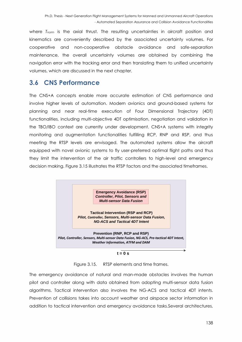
Ph.D. Thesis - Next Generation Flight Management Systems for Manned and Unmanned Aircraft Operations
- Automated Separation Assurance and Collision Avoidance Functionalities
138
where Tnorm is the axial thrust. The resulting uncertainties in aircraft position and
kinematics are conveniently described by the associated uncertainty volumes. For
cooperative and non-cooperative obstacle avoidance and safe-separation
maintenance, the overall uncertainty volumes are obtained by combining the
navigation error with the tracking error and then translating them to unified uncertainty
volumes, which are discussed in the next chapter.
3.6 CNS Performance
The CNS+A concepts enable more accurate estimation of CNS performance and
involve higher levels of automation. Modern avionics and ground-based systems for
planning and near real-time execution of Four Dimensional Trajectory (4DT)
functionalities, including multi-objective 4DT optimisation, negotiation and validation in
the TBO/IBO context are currently under development. CNS+A systems with integrity
monitoring and augmentation functionalities fulfilling RCP, RNP and RSP, and thus
meeting the RTSP levels are envisaged. The automated systems allow the aircraft
equipped with novel avionic systems to fly user-preferred optimal flight paths and thus
they limit the intervention of the air traffic controllers to high-level and emergency
decision making. Figure 3.15 illustrates the RTSP factors and the associated timeframes.
Prevention (RNP, RCP and RSP)
Pilot, Controller, Sensors, Multi-sensor Data Fusion, NG-ACS, Pre-tactical 4DT Intent, Weather Information, ATFM and DAM
Tactical Intervention (RSP and RCP)
Pilot, Controller, Sensors, Multi-sensor Data Fusion,
NG-ACS and Tactical 4DT Intent
Emergency Avoidance (RSP)
Controller, Pilot, Sensors and
Multi-sensor Data Fusion
t = 0 s
Figure 3.15. RTSP elements and time frames.
The emergency avoidance of natural and man-made obstacles involves the human
pilot and controller along with data obtained from adopting multi-sensor data fusion
algorithms. Tactical intervention also involves the NG-ACS and tactical 4DT intents.
Prevention of collisions takes into account weather and airspace sector information in
addition to tactical intervention and emergency avoidance tasks.Several architectures,
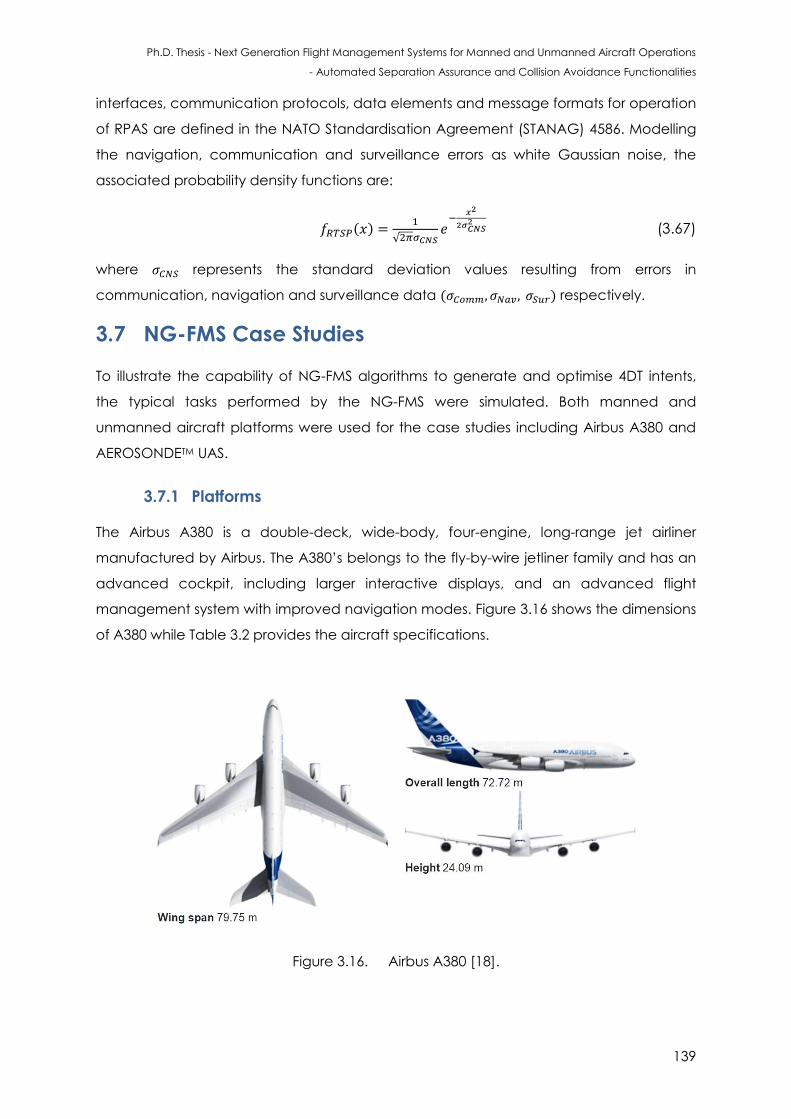
Ph.D. Thesis - Next Generation Flight Management Systems for Manned and Unmanned Aircraft Operations
- Automated Separation Assurance and Collision Avoidance Functionalities
139
interfaces, communication protocols, data elements and message formats for operation
of RPAS are defined in the NATO Standardisation Agreement (STANAG) 4586. Modelling
the navigation, communication and surveillance errors as white Gaussian noise, the
associated probability density functions are:
( )
√
(3.67)
where represents the standard deviation values resulting from errors in
communication, navigation and surveillance data ( ) respectively.
3.7 NG-FMS Case Studies
To illustrate the capability of NG-FMS algorithms to generate and optimise 4DT intents,
the typical tasks performed by the NG-FMS were simulated. Both manned and
unmanned aircraft platforms were used for the case studies including Airbus A380 and
AEROSONDETM UAS.
3.7.1 Platforms
The Airbus A380 is a double-deck, wide-body, four-engine, long-range jet airliner
manufactured by Airbus. The A380’s belongs to the fly-by-wire jetliner family and has an
advanced cockpit, including larger interactive displays, and an advanced flight
management system with improved navigation modes. Figure 3.16 shows the dimensions
of A380 while Table 3.2 provides the aircraft specifications.
Figure 3.16. Airbus A380 [18].
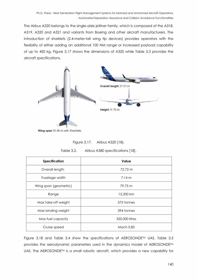
Ph.D. Thesis - Next Generation Flight Management Systems for Manned and Unmanned Aircraft Operations
- Automated Separation Assurance and Collision Avoidance Functionalities
140
The Airbus A320 belongs to the single-aisle jetliner family, which is composed of the A318,
A319, A320 and A321 and variants from Boeing and other aircraft manufacturers. The
introduction of sharklets (2.4-meter-tall wing tip devices) provides operators with the
flexibility of either adding an additional 100 NM range or increased payload capability
of up to 450 kg. Figure 3.17 shows the dimensions of A320 while Table 3.3 provides the
aircraft specifications.
Figure 3.17. Airbus A320 [18].
Table 3.2. Airbus A380 specifications [18].
Specification Value
Overall length 72.72 m
Fuselage width 7.14 m
Wing span (geometric) 79.75 m
Range 15,200 km
Max take-off weight 575 tonnes
Max landing weight 394 tonnes
Max fuel capacity 320,000 litres
Cruise speed Mach 0.85
Figure 3.18 and Table 3.4 show the specifications of AEROSONDETM UAS. Table 3.5
provides the aerodynamic parameters used in the dynamics model of AEROSONDETM
UAS. The AEROSONDETM is a small robotic aircraft, which provides a new capability for
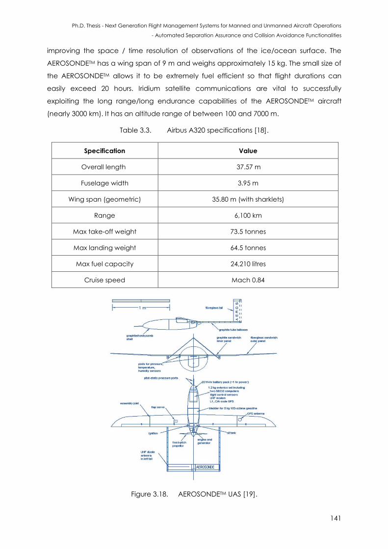
Ph.D. Thesis - Next Generation Flight Management Systems for Manned and Unmanned Aircraft Operations
- Automated Separation Assurance and Collision Avoidance Functionalities
141
improving the space / time resolution of observations of the ice/ocean surface. The
AEROSONDETM has a wing span of 9 m and weighs approximately 15 kg. The small size of
the AEROSONDETM allows it to be extremely fuel efficient so that flight durations can
easily exceed 20 hours. Iridium satellite communications are vital to successfully
exploiting the long range/long endurance capabilities of the AEROSONDETM aircraft
(nearly 3000 km). It has an altitude range of between 100 and 7000 m.
Table 3.3. Airbus A320 specifications [18].
Specification Value
Overall length 37.57 m
Fuselage width 3.95 m
Wing span (geometric) 35.80 m (with sharklets)
Range 6,100 km
Max take-off weight 73.5 tonnes
Max landing weight 64.5 tonnes
Max fuel capacity 24,210 litres
Cruise speed Mach 0.84
Figure 3.18. AEROSONDETM UAS [19].
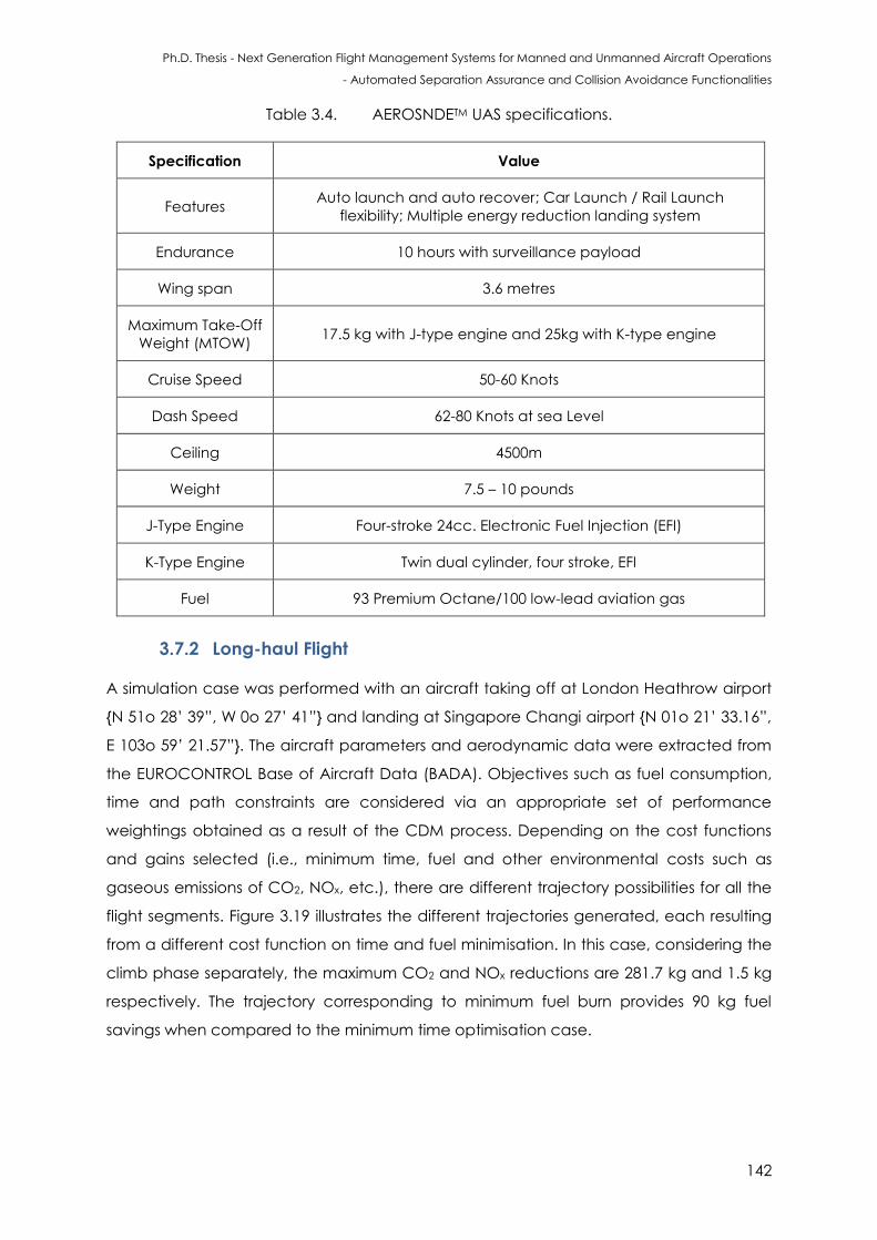
Ph.D. Thesis - Next Generation Flight Management Systems for Manned and Unmanned Aircraft Operations
- Automated Separation Assurance and Collision Avoidance Functionalities
142
Table 3.4. AEROSNDETM UAS specifications.
Specification Value
Features Auto launch and auto recover; Car Launch / Rail Launch
flexibility; Multiple energy reduction landing system
Endurance 10 hours with surveillance payload
Wing span 3.6 metres
Maximum Take-Off
Weight (MTOW) 17.5 kg with J-type engine and 25kg with K-type engine
Cruise Speed 50-60 Knots
Dash Speed 62-80 Knots at sea Level
Ceiling 4500m
Weight 7.5 – 10 pounds
J-Type Engine Four-stroke 24cc. Electronic Fuel Injection (EFI)
K-Type Engine Twin dual cylinder, four stroke, EFI
Fuel 93 Premium Octane/100 low-lead aviation gas
3.7.2 Long-haul Flight
A simulation case was performed with an aircraft taking off at London Heathrow airport
{N 51o 28’ 39”, W 0o 27’ 41”} and landing at Singapore Changi airport {N 01o 21’ 33.16”,
E 103o 59’ 21.57”}. The aircraft parameters and aerodynamic data were extracted from
the EUROCONTROL Base of Aircraft Data (BADA). Objectives such as fuel consumption,
time and path constraints are considered via an appropriate set of performance
weightings obtained as a result of the CDM process. Depending on the cost functions
and gains selected (i.e., minimum time, fuel and other environmental costs such as
gaseous emissions of CO2, NOx, etc.), there are different trajectory possibilities for all the
flight segments. Figure 3.19 illustrates the different trajectories generated, each resulting
from a different cost function on time and fuel minimisation. In this case, considering the
climb phase separately, the maximum CO2 and NOx reductions are 281.7 kg and 1.5 kg
respectively. The trajectory corresponding to minimum fuel burn provides 90 kg fuel
savings when compared to the minimum time optimisation case.
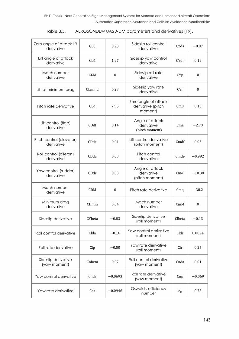
Ph.D. Thesis - Next Generation Flight Management Systems for Manned and Unmanned Aircraft Operations
- Automated Separation Assurance and Collision Avoidance Functionalities
143
Table 3.5. AEROSONDETM UAS ADM parameters and derivatives [19].
Zero angle of attack lift
derivative 0.23
Sideslip roll control
derivative
Lift angle of attack
derivative
Sideslip yaw control
derivative
Mach number
derivative
Sideslip roll rate
derivative
Lift at minimum drag Sideslip yaw rate
derivative
Pitch rate derivative Zero angle of attack
derivative (pitch
moment)
Lift control (flap)
derivative
Angle of attack
derivative ( )
Pitch control (elevator)
derivative
Lift control derivative
(pitch moment)
Roll control (aileron)
derivative
Pitch control
derivative
Yaw control (rudder)
derivative
Angle of attack
derivative
(pitch moment)
Mach number
derivative Pitch rate derivative
Minimum drag
derivative
Mach number
derivative
Sideslip derivative Sideslip derivative
(roll moment)
Roll control derivative Yaw control derivative
(roll moment)
Roll rate derivative Yaw rate derivative
(roll moment)
Sideslip derivative
(yaw moment)
Roll control derivative
(yaw moment)
Yaw control derivative Roll rate derivative
(yaw moment)
Yaw rate derivative Oswald's efficiency
number
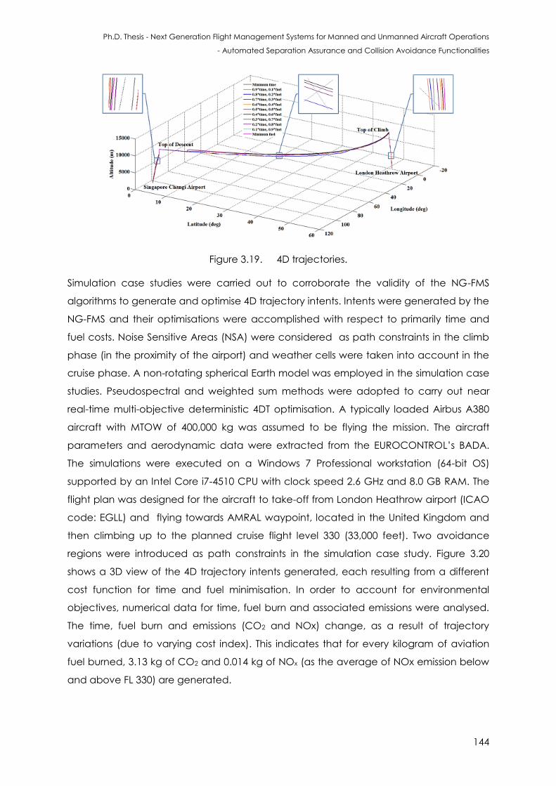
Ph.D. Thesis - Next Generation Flight Management Systems for Manned and Unmanned Aircraft Operations
- Automated Separation Assurance and Collision Avoidance Functionalities
144
Figure 3.19. 4D trajectories.
Simulation case studies were carried out to corroborate the validity of the NG-FMS
algorithms to generate and optimise 4D trajectory intents. Intents were generated by the
NG-FMS and their optimisations were accomplished with respect to primarily time and
fuel costs. Noise Sensitive Areas (NSA) were considered as path constraints in the climb
phase (in the proximity of the airport) and weather cells were taken into account in the
cruise phase. A non-rotating spherical Earth model was employed in the simulation case
studies. Pseudospectral and weighted sum methods were adopted to carry out near
real-time multi-objective deterministic 4DT optimisation. A typically loaded Airbus A380
aircraft with MTOW of 400,000 kg was assumed to be flying the mission. The aircraft
parameters and aerodynamic data were extracted from the EUROCONTROL’s BADA.
The simulations were executed on a Windows 7 Professional workstation (64-bit OS)
supported by an Intel Core i7-4510 CPU with clock speed 2.6 GHz and 8.0 GB RAM. The
flight plan was designed for the aircraft to take-off from London Heathrow airport (ICAO
code: EGLL) and flying towards AMRAL waypoint, located in the United Kingdom and
then climbing up to the planned cruise flight level 330 (33,000 feet). Two avoidance
regions were introduced as path constraints in the simulation case study. Figure 3.20
shows a 3D view of the 4D trajectory intents generated, each resulting from a different
cost function for time and fuel minimisation. In order to account for environmental
objectives, numerical data for time, fuel burn and associated emissions were analysed.
The time, fuel burn and emissions (CO2 and NOx) change, as a result of trajectory
variations (due to varying cost index). This indicates that for every kilogram of aviation
fuel burned, 3.13 kg of CO2 and 0.014 kg of NOx (as the average of NOx emission below
and above FL 330) are generated.
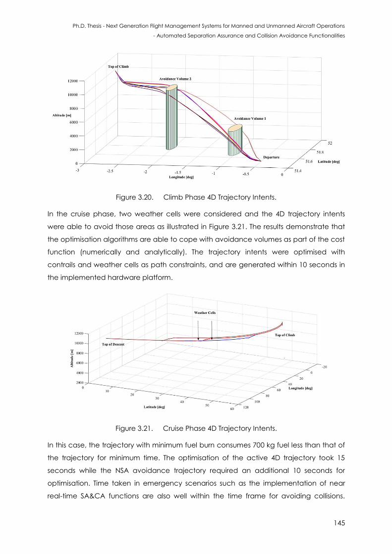
Ph.D. Thesis - Next Generation Flight Management Systems for Manned and Unmanned Aircraft Operations
- Automated Separation Assurance and Collision Avoidance Functionalities
145
Figure 3.20. Climb Phase 4D Trajectory Intents.
In the cruise phase, two weather cells were considered and the 4D trajectory intents
were able to avoid those areas as illustrated in Figure 3.21. The results demonstrate that
the optimisation algorithms are able to cope with avoidance volumes as part of the cost
function (numerically and analytically). The trajectory intents were optimised with
contrails and weather cells as path constraints, and are generated within 10 seconds in
the implemented hardware platform.
Figure 3.21. Cruise Phase 4D Trajectory Intents.
In this case, the trajectory with minimum fuel burn consumes 700 kg fuel less than that of
the trajectory for minimum time. The optimisation of the active 4D trajectory took 15
seconds while the NSA avoidance trajectory required an additional 10 seconds for
optimisation. Time taken in emergency scenarios such as the implementation of near
real-time SA&CA functions are also well within the time frame for avoiding collisions.
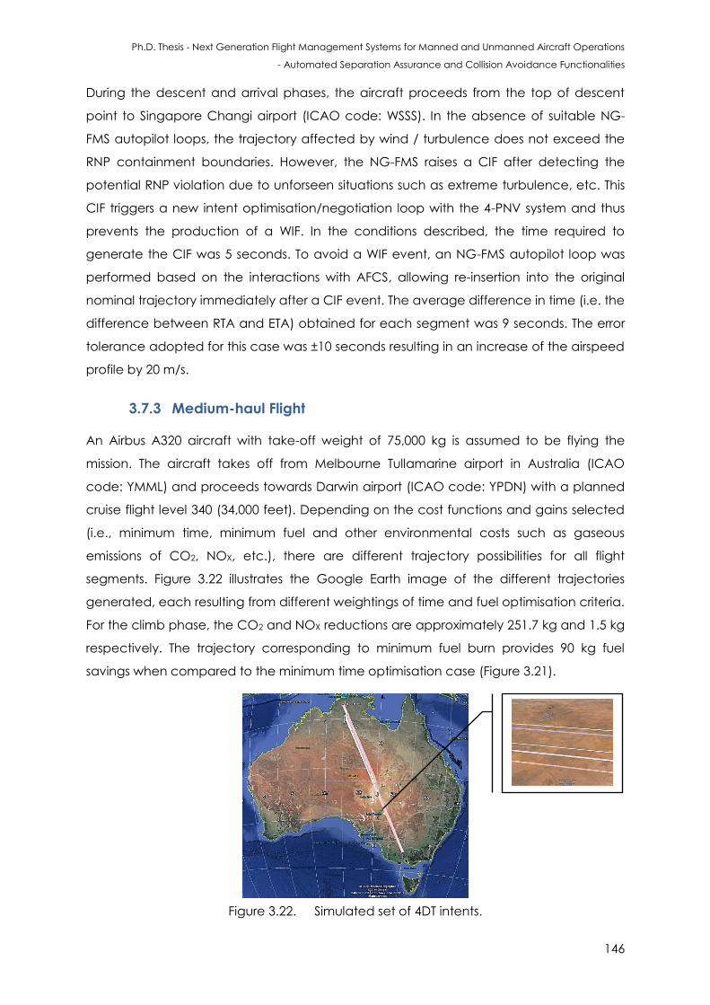
Ph.D. Thesis - Next Generation Flight Management Systems for Manned and Unmanned Aircraft Operations
- Automated Separation Assurance and Collision Avoidance Functionalities
146
During the descent and arrival phases, the aircraft proceeds from the top of descent
point to Singapore Changi airport (ICAO code: WSSS). In the absence of suitable NG-
FMS autopilot loops, the trajectory affected by wind / turbulence does not exceed the
RNP containment boundaries. However, the NG-FMS raises a CIF after detecting the
potential RNP violation due to unforseen situations such as extreme turbulence, etc. This
CIF triggers a new intent optimisation/negotiation loop with the 4-PNV system and thus
prevents the production of a WIF. In the conditions described, the time required to
generate the CIF was 5 seconds. To avoid a WIF event, an NG-FMS autopilot loop was
performed based on the interactions with AFCS, allowing re-insertion into the original
nominal trajectory immediately after a CIF event. The average difference in time (i.e. the
difference between RTA and ETA) obtained for each segment was 9 seconds. The error
tolerance adopted for this case was ±10 seconds resulting in an increase of the airspeed
profile by 20 m/s.
3.7.3 Medium-haul Flight
An Airbus A320 aircraft with take-off weight of 75,000 kg is assumed to be flying the
mission. The aircraft takes off from Melbourne Tullamarine airport in Australia (ICAO
code: YMML) and proceeds towards Darwin airport (ICAO code: YPDN) with a planned
cruise flight level 340 (34,000 feet). Depending on the cost functions and gains selected
(i.e., minimum time, minimum fuel and other environmental costs such as gaseous
emissions of CO2, NOX, etc.), there are different trajectory possibilities for all flight
segments. Figure 3.22 illustrates the Google Earth image of the different trajectories
generated, each resulting from different weightings of time and fuel optimisation criteria.
For the climb phase, the CO2 and NOX reductions are approximately 251.7 kg and 1.5 kg
respectively. The trajectory corresponding to minimum fuel burn provides 90 kg fuel
savings when compared to the minimum time optimisation case (Figure 3.21).
Figure 3.22. Simulated set of 4DT intents.
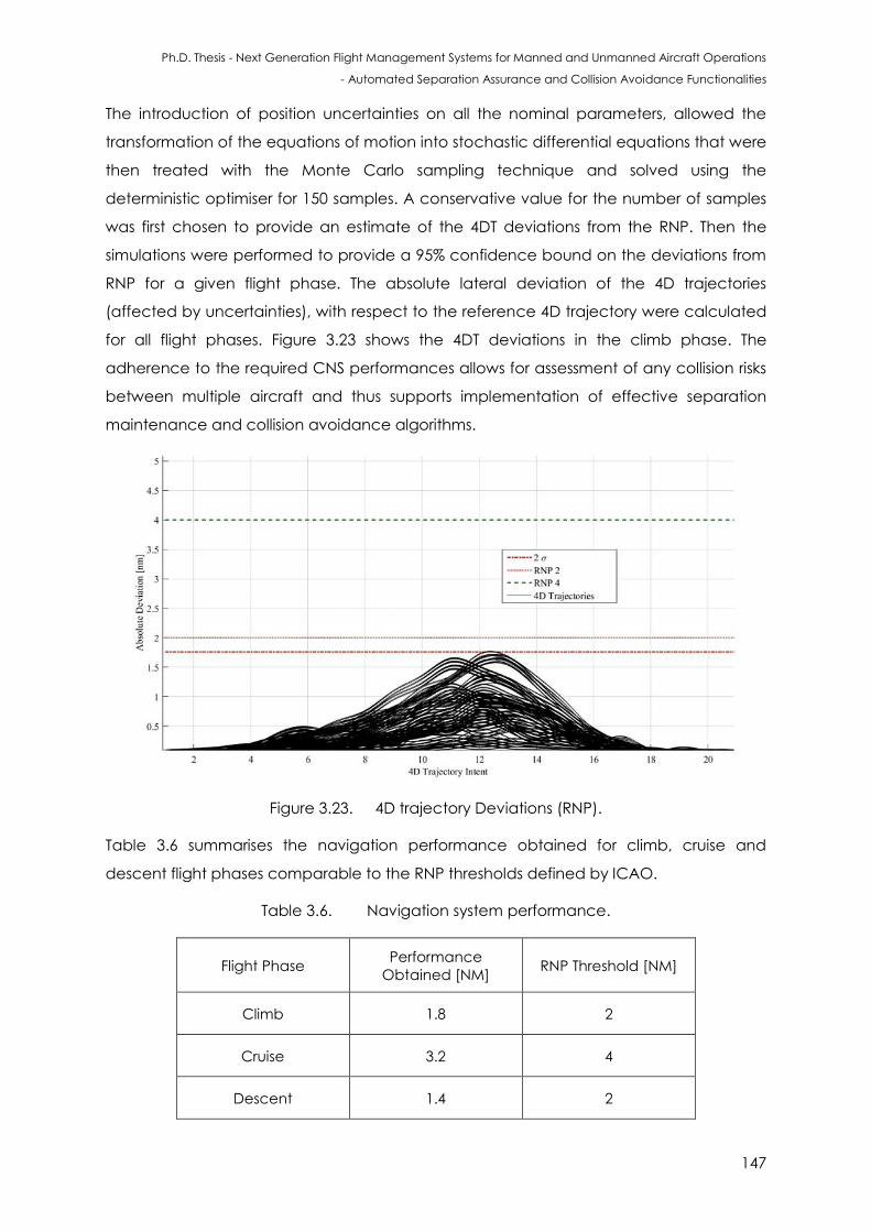
Ph.D. Thesis - Next Generation Flight Management Systems for Manned and Unmanned Aircraft Operations
- Automated Separation Assurance and Collision Avoidance Functionalities
147
The introduction of position uncertainties on all the nominal parameters, allowed the
transformation of the equations of motion into stochastic differential equations that were
then treated with the Monte Carlo sampling technique and solved using the
deterministic optimiser for 150 samples. A conservative value for the number of samples
was first chosen to provide an estimate of the 4DT deviations from the RNP. Then the
simulations were performed to provide a 95% confidence bound on the deviations from
RNP for a given flight phase. The absolute lateral deviation of the 4D trajectories
(affected by uncertainties), with respect to the reference 4D trajectory were calculated
for all flight phases. Figure 3.23 shows the 4DT deviations in the climb phase. The
adherence to the required CNS performances allows for assessment of any collision risks
between multiple aircraft and thus supports implementation of effective separation
maintenance and collision avoidance algorithms.
Figure 3.23. 4D trajectory Deviations (RNP).
Table 3.6 summarises the navigation performance obtained for climb, cruise and
descent flight phases comparable to the RNP thresholds defined by ICAO.
Table 3.6. Navigation system performance.
Flight Phase Performance
Obtained [NM] RNP Threshold [NM]
Climb 1.8 2
Cruise 3.2 4
Descent 1.4 2
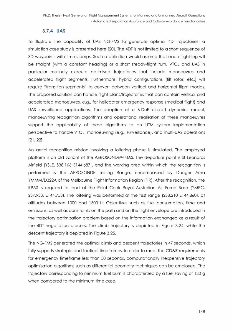
Ph.D. Thesis - Next Generation Flight Management Systems for Manned and Unmanned Aircraft Operations
- Automated Separation Assurance and Collision Avoidance Functionalities
148
3.7.4 UAS
To illustrate the capability of UAS NG-FMS to generate optimal 4D trajectories, a
simulation case study is presented here [20]. The 4DT is not limited to a short sequence of
3D waypoints with time stamps. Such a definition would assume that each flight leg will
be straight (with a constant heading) or a short steady-flight turn. VTOL and UAS in
particular routinely execute optimised trajectories that include manoeuvres and
accelerated flight segments. Furthermore, hybrid configurations (tilt rotor, etc.) will
require “transition segments” to convert between vertical and horizontal flight modes.
The proposed solution can handle flight plans/trajectories that can contain vertical and
accelerated manoeuvres, e.g., for helicopter emergency response (medical flight) and
UAS surveillance applications. The adoption of a 6-DoF aircraft dynamics model,
manoeuvring recognition algorithms and operational realisation of these manoeuvres
support the applicability of these algorithms to an UTM system implementation
perspective to handle VTOL, manoeuvring (e.g., surveillance), and multi-UAS operations
[21, 22].
An aerial recognition mission involving a loitering phase is simulated. The employed
platform is an old variant of the AEROSONDETM UAS. The departure point is St Leonards
Airfield (YSLE, S38.166 E144.687), and the working area within which the recognition is
performed is the AEROSONDE Testing Range, encompassed by Danger Area
YMMM/D322A of the Melbourne Flight Information Region (FIR). After the recognition, the
RPAS is required to land at the Point Cook Royal Australian Air Force Base (YMPC,
S37.933, E144.753). The loitering was performed at the test range (S38.210 E144.860), at
altitudes between 1000 and 1500 ft. Objectives such as fuel consumption, time and
emissions, as well as constraints on the path and on the flight envelope are introduced in
the trajectory optimization problem based on the information exchanged as a result of
the 4DT negotiation process. The climb trajectory is depicted in Figure 3.24, while the
descent trajectory is depicted in Figure 3.25.
The NG-FMS generated the optimal climb and descent trajectories in 47 seconds, which
fully supports strategic and tactical timeframes. In order to meet the CD&R requirements
for emergency timeframe less than 50 seconds, computationally inexpensive trajectory
optimisation algorithms such as differential geometry techniques can be employed. The
trajectory corresponding to minimum fuel burn is characterized by a fuel saving of 130 g
when compared to the minimum time case.
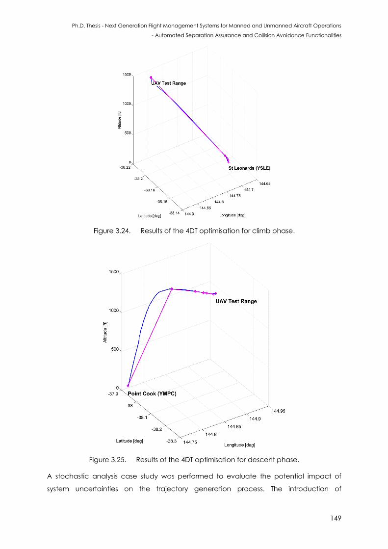
Ph.D. Thesis - Next Generation Flight Management Systems for Manned and Unmanned Aircraft Operations
- Automated Separation Assurance and Collision Avoidance Functionalities
149
Figure 3.24. Results of the 4DT optimisation for climb phase.
Figure 3.25. Results of the 4DT optimisation for descent phase.
A stochastic analysis case study was performed to evaluate the potential impact of
system uncertainties on the trajectory generation process. The introduction of

Ph.D. Thesis - Next Generation Flight Management Systems for Manned and Unmanned Aircraft Operations
- Automated Separation Assurance and Collision Avoidance Functionalities
150
uncertainties on all nominal parameters, with ranges equal to the standard deviations
allowed for the transformation of the equation of motion into stochastic differential
equations as before, which are then treated with the Monte Carlo sampling technique
and solved using the deterministic optimizer for 100 samples. In these simulations, real
weather data obtained with the Global Forecast System (GFS), kindly made available by
the National Climatic Data Center (NCDC) of the US National Oceanic and Atmospheric
Administration (NOAA), was adopted.
3.8 Negotiation and Validation Features
As described in Section 3.1, the negotiation and validation of 4DT intents by the NG-
FMS/ATM system is dependent on a number of factors including weather updates,
updated aircraft dynamics/ATM/AOC constraints, obstacle detection, Demand-
Capacity Balancing (DCB), sector occupancy, and airspace and time based
restrictions. A conceptual representation of the air-to-ground and air-to-air negotiation
processes is illustrated in Figure 3.26.
3.8.1 Evaluation Process
The negotiation and validation process between the NG-FMS and NG-ATM system was
evaluated using laboratory activities by server client protocols (Figures 3.26 and 3.27).
Next Generation Flight Management System
Human Machine
Interface and
Interaction
4D Intent
Negotiation
Air-to-ground
Negotiation
Autopilot
Conflict Detection
and Resolution
Separation
Maintenance
4D Intent
Generation
4D Intent Request/Accept,
Data Exchange
4D Intent Request/
Accept,
Weather Updates,
Constraint Updates,
Data Exchange
Collision
Threat
Updates
Air-to-air
Negotiation
4D Intent Update
Other
Traffic
States’
Updates
Figure 3.26. NG-FMS air-to-ground and air-to-air negotiation loops.
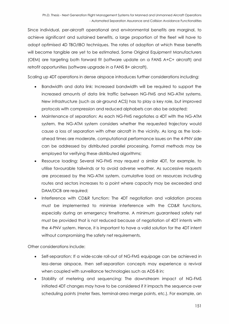
Ph.D. Thesis - Next Generation Flight Management Systems for Manned and Unmanned Aircraft Operations
- Automated Separation Assurance and Collision Avoidance Functionalities
151
Since individual, per-aircraft operational and environmental benefits are marginal, to
achieve significant and sustained benefits, a large proportion of the fleet will have to
adopt optimised 4D TBO/IBO techniques. The rates of adoption at which these benefits
will become tangible are yet to be estimated. Some Original Equipment Manufacturers
(OEM) are targeting both forward fit (software update on a FANS A+C+ aircraft) and
retrofit opportunities (software upgrade in a FANS B+ aircraft).
Scaling up 4DT operations in dense airspace introduces further considerations including:
Bandwidth and data link: Increased bandwidth will be required to support the
increased amounts of data link traffic between NG-FMS and NG-ATM systems.
New infrastructure (such as air-ground ACS) has to play a key role, but improved
protocols with compression and reduced alphabets can also be adopted;
Maintenance of separation: As each NG-FMS negotiates a 4DT with the NG-ATM
system, the NG-ATM system considers whether the requested trajectory would
cause a loss of separation with other aircraft in the vicinity. As long as the look-
ahead times are moderate, computational performance issues on the 4-PNV side
can be addressed by distributed parallel processing. Formal methods may be
employed for verifying these distributed algorithms;
Resource loading: Several NG-FMS may request a similar 4DT, for example, to
utilise favourable tailwinds or to avoid adverse weather. As successive requests
are processed by the NG-ATM system, cumulative load on resources including
routes and sectors increases to a point where capacity may be exceeded and
DAM/DCB are required;
Interference with CD&R function: The 4DT negotiation and validation process
must be implemented to minimise interference with the CD&R functions,
especially during an emergency timeframe. A minimum guaranteed safety net
must be provided that is not reduced because of negotiation of 4DT intents with
the 4-PNV system. Hence, it is important to have a valid solution for the 4DT intent
without compromising the safety net requirements.
Other considerations include:
Self-separation: If a wide-scale roll-out of NG-FMS equipage can be achieved in
less-dense airspace, then self-separation concepts may experience a revival
when coupled with surveillance technologies such as ADS-B in;
Stability of metering and sequencing: The downstream impact of NG-FMS
initiated 4DT changes may have to be considered if it impacts the sequence over
scheduling points (meter fixes, terminal-area merge points, etc.). For example, an
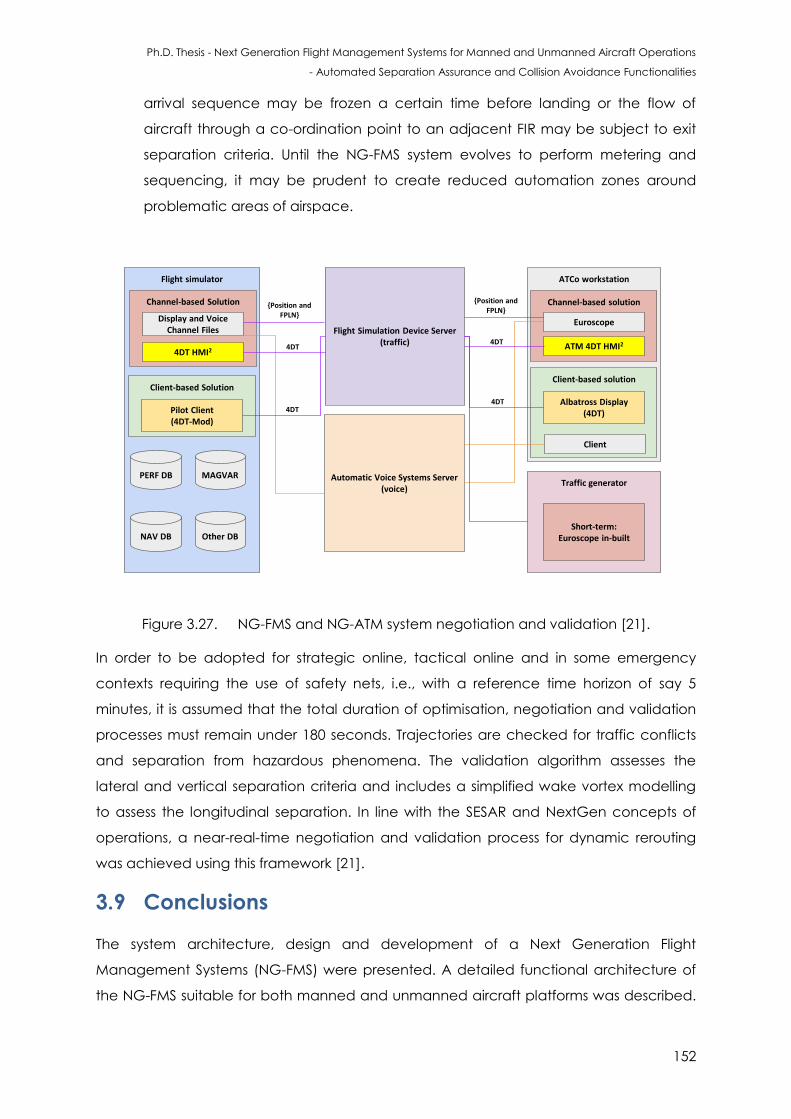
Ph.D. Thesis - Next Generation Flight Management Systems for Manned and Unmanned Aircraft Operations
- Automated Separation Assurance and Collision Avoidance Functionalities
152
arrival sequence may be frozen a certain time before landing or the flow of
aircraft through a co-ordination point to an adjacent FIR may be subject to exit
separation criteria. Until the NG-FMS system evolves to perform metering and
sequencing, it may be prudent to create reduced automation zones around
problematic areas of airspace.
Flight simulator
Channel-based Solution
ATCo workstation
Channel-based solution
Flight Simulation Device Server (traffic)
Automatic Voice Systems Server (voice)
NAV DB
PERF DB
Display and Voice Channel Files
Euroscope
ATM 4DT HMI2
Client-based solution
Albatross Display (4DT)
4DT HMI2
Client-based Solution
Pilot Client (4DT-Mod)
Traffic generator
Short-term:Euroscope in-built
Client
{Position and FPLN}
{Position and FPLN}
4DT4DT
4DT4DT
Other DB
MAGVAR
Figure 3.27. NG-FMS and NG-ATM system negotiation and validation [21].
In order to be adopted for strategic online, tactical online and in some emergency
contexts requiring the use of safety nets, i.e., with a reference time horizon of say 5
minutes, it is assumed that the total duration of optimisation, negotiation and validation
processes must remain under 180 seconds. Trajectories are checked for traffic conflicts
and separation from hazardous phenomena. The validation algorithm assesses the
lateral and vertical separation criteria and includes a simplified wake vortex modelling
to assess the longitudinal separation. In line with the SESAR and NextGen concepts of
operations, a near-real-time negotiation and validation process for dynamic rerouting
was achieved using this framework [21].
3.9 Conclusions
The system architecture, design and development of a Next Generation Flight
Management Systems (NG-FMS) were presented. A detailed functional architecture of
the NG-FMS suitable for both manned and unmanned aircraft platforms was described.
Ph.D. Thesis - Next Generation Flight Management Systems for Manned and Unmanned Aircraft Operations
- Automated Separation Assurance and Collision Avoidance Functionalities
153
Suitable mathematical models were developed to implement the 4DT-O capability,
addressing both the deterministic and stochastic trajectory optimisation problems.
Pseudospectral and weighted sum methods were adopted to carry out near real-time
multi-objective deterministic 4DT optimisation. Objectives such as fuel consumption,
time, noise impact and contrails were considered via an appropriate set of
performance weightings. Simulation cases involving Airbus commercial transport aircraft
and an AEROSONDETM pusher prop (aviation gas fuelled) UAS were presented. These
examples highlight how the NG-FMS is tailored to long-haul and short-haul transport with
traditional ATM coordination, and it could be extended to an UTM system
implementation to handle VTOL, manoeuvring (e.g., surveillance), and cooperative UAS
operations. Investigation of the total system error boundaries was conducted to
evaluate the effects of error propagation in the aircraft dynamics model. In addition, air-
to-ground 4DT negotiation algorithms were developed, aiming to attempt a trajectory
validation process. In line with the SESAR and NextGen concepts of operations, a near
real-time negotiation and validation process for dynamic rerouting was presented.
3.10 References
1. SESAR, “The European ATM Master Plan”, European Union and Eurocontrol, 2015.
2. R. Sabatini, A. Gardi, S. Ramasamy, T. Kistan and M. Marino, “Modern Avionics and ATM
Systems for Green Operations”, Encyclopedia of Aerospace Engineering, eds R.
Blockley and W. Shyy, John Wiley: Chichester, 2015. DOI:
10.1002/9780470686652.eae1064
3. D. Batchelor, “Comparing European ATM Master Plan and the NextGen
Implementation Plan,” IEEE Conference on Integrated Communication, Navigation
and Surveillance (ICNS), pp. 1-14, Washington DC, USA, 2015.
4. M. Ballin, D. Williams, “Prototype Flight Management Capabilities to Explore Temporal
RNP Concepts”, IEEE Digital Avionics Systems Conference, Minnesota, USA, 2008.
5. ICAO, “Procedures for Air Navigation Services - Aircraft Operations”, Document 8168,
Fifith Edition, The International Civil Aviation Organization, Montreal, Canada, 2006.
6. B. Honzik, “Airborne 4-Dimensional Trajectory Management”, AIAA/IEEE Digital Avionics
Systems Conference, Virginia, USA, 2012.
7. R. Sabatini, T. Moore and C. Hill, “A New Avionics-Based GNSS Integrity Augmentation
System: Part 1 – Fundamentals”, The Journal of Navigation, vol. 66, no. 3, pp. 363–384,
2013. DOI: 10.1017/S0373463313000027
8. R. Sabatini, T. Moore, C. Hill and S. Ramasamy, Assessing Avionics-Based GNSS Integrity
Augmentation Performance in UAS Mission- and Safety-Critical Tasks, Proceedings of
Ph.D. Thesis - Next Generation Flight Management Systems for Manned and Unmanned Aircraft Operations
- Automated Separation Assurance and Collision Avoidance Functionalities
154
International Conference on Unmanned Aircraft Systems (ICUAS 2015), Denver, CO,
USA, 2015. DOI: 10.1109/ICUAS.2015.7152347
9. ARINC 702A-4, “Advanced Flight Management Computer System”, Aeronautical
Radio, Incorporated, Cedar Rapids, Iowa, US, 2014.
10. SAE, “Flight Management System (FMS)”, ARP4102/9A, Society of Automotive Engineers,
Pennsylvania Troy, Michigan, USA, 2014.
11. D. Allerton, “Principles of Flight Simulation”, John Wiley and Sons Ltd, West Sussex, UK,
2009.
12. O. von Stryk and R. Bulirsch, “Direct and Indirect Methods for Trajectory
Optimization”,Annals of Operations Research, vol. 37, pp. 357-373, 1992.
13. J.T. Betts, “Survey of Numerical Methods for Trajectory Optimization”, Journal of
Guidance, Control and Dynamics, vol. 21, pp. 193-207, 1998.
14. J. Z. Ben-Asher, “Optimal Control Theory with Aerospace Applications, Education Series,
American Institute of Aeronautics and Astronautics (AIAA), Reston, VA, USA, 2010.
15. A.V. Rao, S“urvey of Numerical Methods for Optimal Control”, Advances in the
Astronautical Sciences, vol. 135, pp. 497-528, 2010.
16. A. Gardi, R. Sabatini and S. Ramasamy, “Multi-objective Optimisation of Aircraft Flight
Trajectories in the ATM and Avionics Context”, Progress in Aerospace Sciences, vol. 83,
pp. 1-36, 2016. DOI: 10.1016/j.paerosci.2015.11.006
17. N. Marius, “Lateral track control law for AEROSONDE UAV”, 39th Aerospace Sciences
Meeting and Exhibit, American Institute of Aeronautics and Astronautics, 2001.
18. Airbus, Aircraft Specifications, Airbus S.A.S, France. Information available from:
http://www.airbus.com/aircraftfamilies/passengeraircraft
19. J. Maslanik, “Polar remote sensing using an unpiloted aerial vehicle”, Seminar held at
Colorado Center for Astrodynamics Research (CCAR), University of Colorado at
Boulder. Available online at: http://www2.hawaii.edu/~jmaurer/ uav/#specifications
(overview and editing by J. Maurer), 2002. Webpage visited in 2016.
20. A. Gardi, S. Ramasamy and R. Sabatini, “4-Dimensional Trajectory Generation
Algorithms for RPAS Mission Management Systems”, Proceedings of the IEEE
International Conference on Unmanned Aircraft Systems (ICUAS 2015), Denver,
CO, USA, 2015. DOI: 10.1109/ICUAS.2015.7152314
21. A. Gardi, Y. Lim, T. Kistan, S. Ramasamy and R. Sabatini, “Air Traffic Management
Simulation Environment for 4-Dimensional Trajectory Based Operations”, 17th Australian
International Aerospace Congress, AIAC17, Melbourne, Australia, 2017.
Ph.D. Thesis - Next Generation Flight Management Systems for Manned and Unmanned Aircraft Operations
- Automated Separation Assurance and Collision Avoidance Functionalities
155
22. A. Gardi, “A Novel Air Traffic Management Decision Support System Multi-Objective 4-
Dimensional Trajectory Optimisation for Intent-Based Operations in Dynamic Airspace”,
Ph.D. Thesis, School of Engineeirng, RMIT University, 2016.

Ph.D. Thesis - Next Generation Flight Management Systems for Manned and Unmanned Aircraft Operations
- Automated Separation Assurance and Collision Avoidance Functionalities
156
This page is intentionally left blank to support presswork tasks
Ph.D. Thesis - Next Generation Flight Management Systems for Manned and Unmanned Aircraft Operations
- Automated Separation Assurance and Collision Avoidance Functionalities
157
CHAPTER 4
SEPARATION ASSURANCE AND
COLLISION AVOIDANCE FUNCTIONALITIES
“If knowledge and foresight are too penetrating and deep, unify them with ease
an sincerity”. - Xun Kuang
4.1 Introduction
This chapter presents the unified approach to SA&CA. In this approach, real-time safety-
critical data fusion algorithms suitable for both cooperative and non-cooperative
encounters are developed for a variety of safety-critical applications. The SA&CA
functions are integrated in the NG-FMS and are based on mathematical algorithms that
quantify in real-time the total avoidance volume in the airspace surrounding a target
(static or dynamic). Building on these analytical models, data processing techniques
allows the real-time transformation of navigation and tracking errors affecting the state
measurements into unified range and bearing uncertainty descriptors. The investigation
in later chapters focusses on representative scenarios for validating the automated
separation maintenance and collision avoidance resolution functions in both non-
cooperative and cooperative scenarios.
4.2 Unified Approach to SA&CA
The aim of the unified approach is to determine the overall avoidance volume
surrounding an obstacle or an intruder track. The approach provides an innovative
analytical framework to combine real-time measurements (and associated
uncertainties) of navigation states, platform dynamics and tracking observables to
produce high-fidelity avoidance volumes suitable for integration in future avionics, ATM
and defence decision support tools.
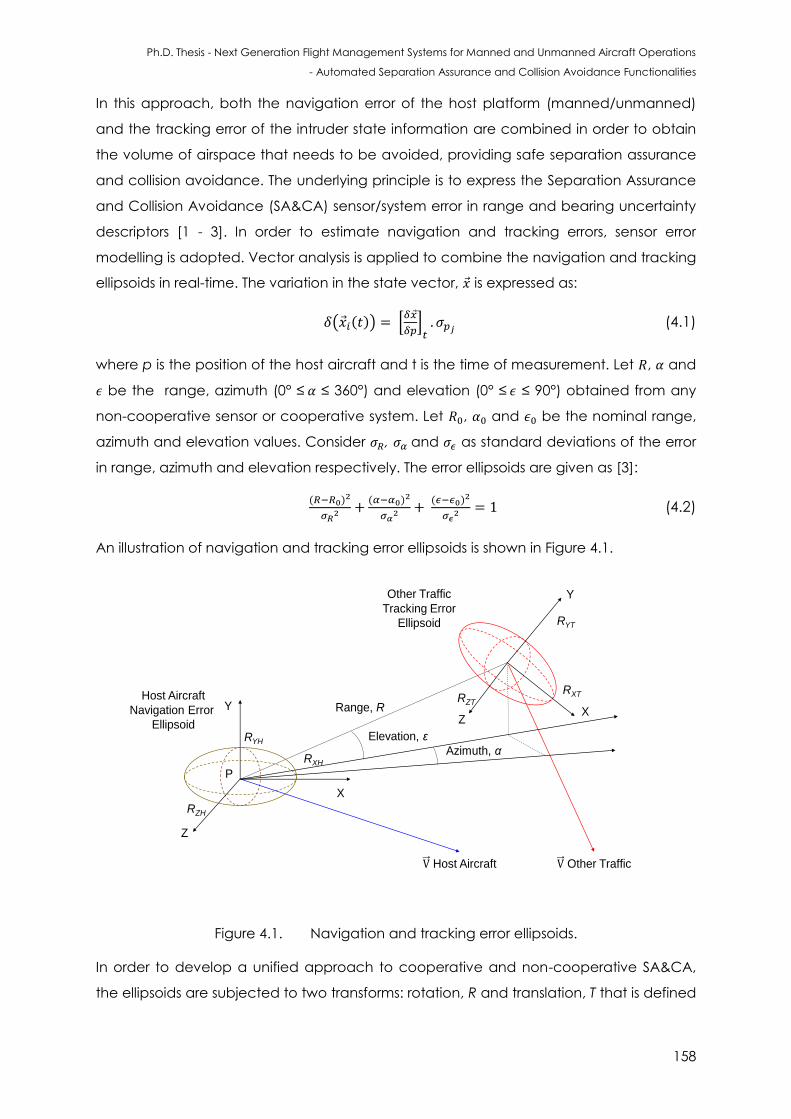
Ph.D. Thesis - Next Generation Flight Management Systems for Manned and Unmanned Aircraft Operations
- Automated Separation Assurance and Collision Avoidance Functionalities
158
In this approach, both the navigation error of the host platform (manned/unmanned)
and the tracking error of the intruder state information are combined in order to obtain
the volume of airspace that needs to be avoided, providing safe separation assurance
and collision avoidance. The underlying principle is to express the Separation Assurance
and Collision Avoidance (SA&CA) sensor/system error in range and bearing uncertainty
descriptors [1 - 3]. In order to estimate navigation and tracking errors, sensor error
modelling is adopted. Vector analysis is applied to combine the navigation and tracking
ellipsoids in real-time. The variation in the state vector, is expressed as:
( ( )) [
] (4.1)
where p is the position of the host aircraft and t is the time of measurement. Let , and
be the range, azimuth (0° ≤ ≤ 360°) and elevation (0° ≤ ≤ 90°) obtained from any
non-cooperative sensor or cooperative system. Let , and be the nominal range,
azimuth and elevation values. Consider , and as standard deviations of the error
in range, azimuth and elevation respectively. The error ellipsoids are given as [3]:
( )
( )
( )
(4.2)
An illustration of navigation and tracking error ellipsoids is shown in Figure 4.1.
Host Aircraft
Navigation Error
Ellipsoid
X
Y
Z
RXH
RYH
RZH
Other Traffic
Tracking Error
Ellipsoid
X
Y
Z
RXT
RYT
RZTRange, R
Host Aircraft Other Traffic
Azimuth, α
Elevation, ε
P
Figure 4.1. Navigation and tracking error ellipsoids.
In order to develop a unified approach to cooperative and non-cooperative SA&CA,
the ellipsoids are subjected to two transforms: rotation, R and translation, T that is defined
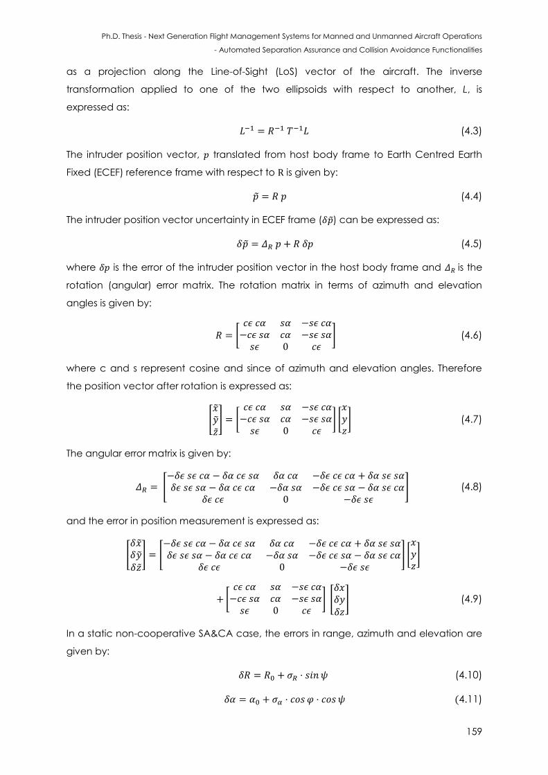
Ph.D. Thesis - Next Generation Flight Management Systems for Manned and Unmanned Aircraft Operations
- Automated Separation Assurance and Collision Avoidance Functionalities
159
as a projection along the Line-of-Sight (LoS) vector of the aircraft. The inverse
transformation applied to one of the two ellipsoids with respect to another, L, is
expressed as:
(4.3)
The intruder position vector, translated from host body frame to Earth Centred Earth
Fixed (ECEF) reference frame with respect to is given by:
(4.4)
The intruder position vector uncertainty in ECEF frame ( ) can be expressed as:
(4.5)
where is the error of the intruder position vector in the host body frame and is the
rotation (angular) error matrix. The rotation matrix in terms of azimuth and elevation
angles is given by:
[
] (4.6)
where c and s represent cosine and since of azimuth and elevation angles. Therefore
the position vector after rotation is expressed as:
[ ] [
] [ ] (4.7)
The angular error matrix is given by:
[
] (4.8)
and the error in position measurement is expressed as:
[
] [
] [ ]
[
] [
] (4.9)
In a static non-cooperative SA&CA case, the errors in range, azimuth and elevation are
given by:
(4.10)
(4.11)
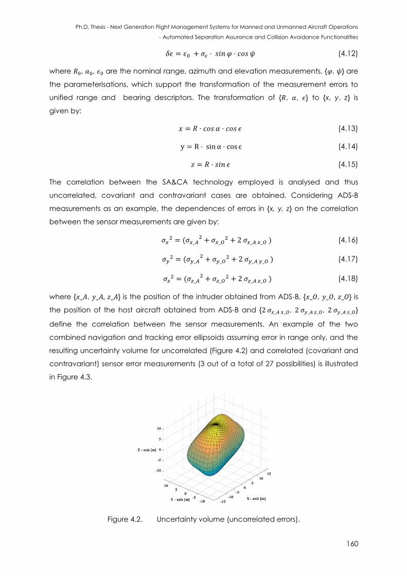
Ph.D. Thesis - Next Generation Flight Management Systems for Manned and Unmanned Aircraft Operations
- Automated Separation Assurance and Collision Avoidance Functionalities
160
(4.12)
where , , are the nominal range, azimuth and elevation measurements. { , } are
the parameterisations, which support the transformation of the measurement errors to
unified range and bearing descriptors. The transformation of { , , } to {x, y, z} is
given by:
(4.13)
(4.14)
(4.15)
The correlation between the SA&CA technology employed is analysed and thus
uncorrelated, covariant and contravariant cases are obtained. Considering ADS-B
measurements as an example, the dependences of errors in {x, y, z} on the correlation
between the sensor measurements are given by:
(
) (4.16)
(
) (4.17)
(
) (4.18)
where { , } is the position of the intruder obtained from ADS-B, { , } is
the position of the host aircraft obtained from ADS-B and { , , }
define the correlation between the sensor measurements. An example of the two
combined navigation and tracking error ellipsoids assuming error in range only, and the
resulting uncertainty volume for uncorrelated (Figure 4.2) and correlated (covariant and
contravariant) sensor error measurements (3 out of a total of 27 possibilities) is illustrated
in Figure 4.3.
Figure 4.2. Uncertainty volume (uncorrelated errors).
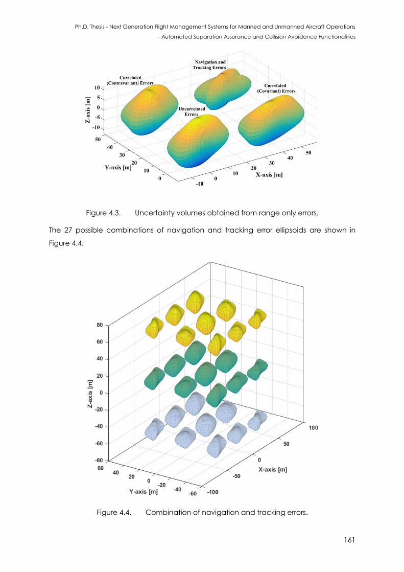
Ph.D. Thesis - Next Generation Flight Management Systems for Manned and Unmanned Aircraft Operations
- Automated Separation Assurance and Collision Avoidance Functionalities
161
Figure 4.3. Uncertainty volumes obtained from range only errors.
The 27 possible combinations of navigation and tracking error ellipsoids are shown in
Figure 4.4.
Figure 4.4. Combination of navigation and tracking errors.
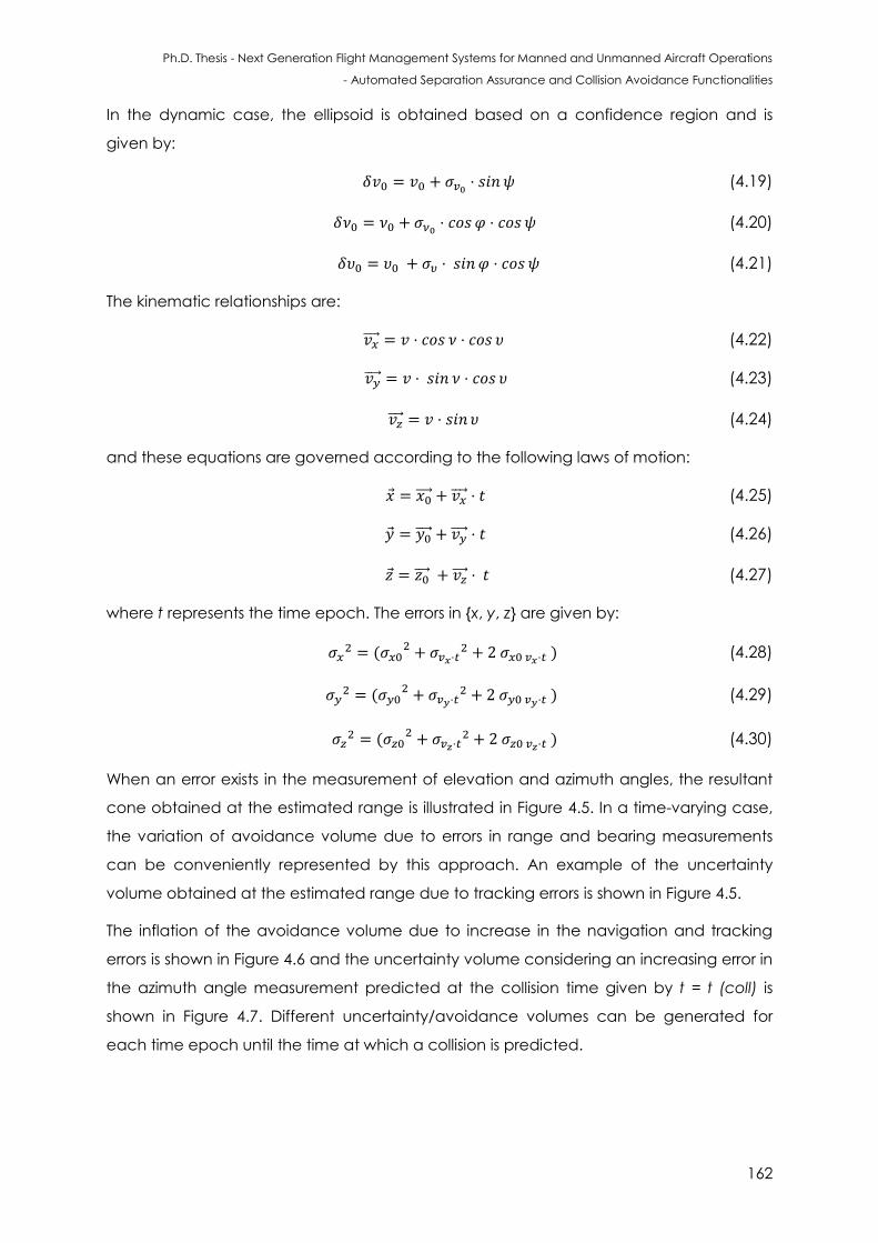
Ph.D. Thesis - Next Generation Flight Management Systems for Manned and Unmanned Aircraft Operations
- Automated Separation Assurance and Collision Avoidance Functionalities
162
In the dynamic case, the ellipsoid is obtained based on a confidence region and is
given by:
(4.19)
(4.20)
(4.21)
The kinematic relationships are:
(4.22)
(4.23)
(4.24)
and these equations are governed according to the following laws of motion:
(4.25)
(4.26)
(4.27)
where t represents the time epoch. The errors in {x, y, z} are given by:
(
) (4.28)
(
) (4.29)
(
) (4.30)
When an error exists in the measurement of elevation and azimuth angles, the resultant
cone obtained at the estimated range is illustrated in Figure 4.5. In a time-varying case,
the variation of avoidance volume due to errors in range and bearing measurements
can be conveniently represented by this approach. An example of the uncertainty
volume obtained at the estimated range due to tracking errors is shown in Figure 4.5.
The inflation of the avoidance volume due to increase in the navigation and tracking
errors is shown in Figure 4.6 and the uncertainty volume considering an increasing error in
the azimuth angle measurement predicted at the collision time given by t = t (coll) is
shown in Figure 4.7. Different uncertainty/avoidance volumes can be generated for
each time epoch until the time at which a collision is predicted.
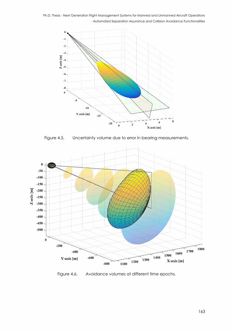
Ph.D. Thesis - Next Generation Flight Management Systems for Manned and Unmanned Aircraft Operations
- Automated Separation Assurance and Collision Avoidance Functionalities
163
Figure 4.5. Uncertainty volume due to error in bearing measurements.
Figure 4.6. Avoidance volumes at different time epochs.
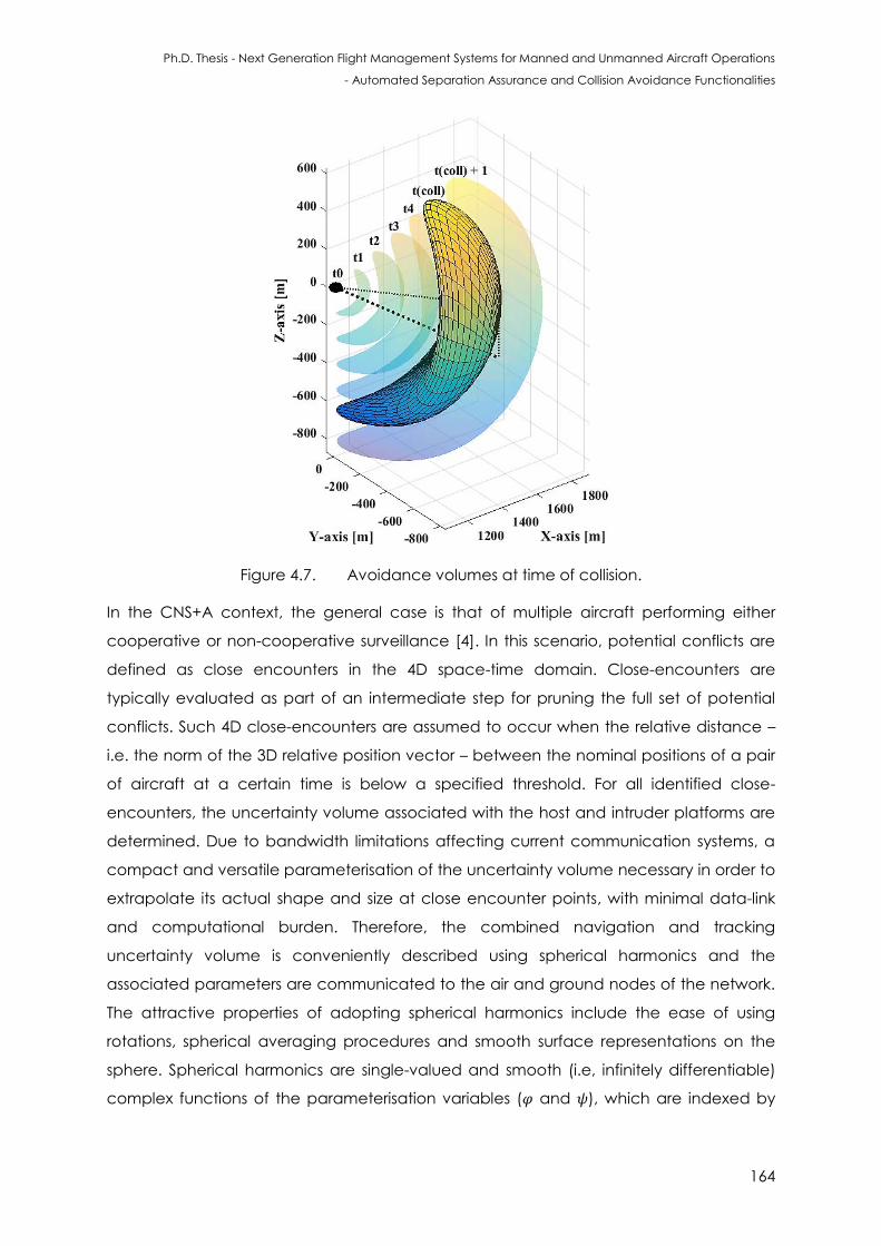
Ph.D. Thesis - Next Generation Flight Management Systems for Manned and Unmanned Aircraft Operations
- Automated Separation Assurance and Collision Avoidance Functionalities
164
Figure 4.7. Avoidance volumes at time of collision.
In the CNS+A context, the general case is that of multiple aircraft performing either
cooperative or non-cooperative surveillance [4]. In this scenario, potential conflicts are
defined as close encounters in the 4D space-time domain. Close-encounters are
typically evaluated as part of an intermediate step for pruning the full set of potential
conflicts. Such 4D close-encounters are assumed to occur when the relative distance –
i.e. the norm of the 3D relative position vector – between the nominal positions of a pair
of aircraft at a certain time is below a specified threshold. For all identified close-
encounters, the uncertainty volume associated with the host and intruder platforms are
determined. Due to bandwidth limitations affecting current communication systems, a
compact and versatile parameterisation of the uncertainty volume necessary in order to
extrapolate its actual shape and size at close encounter points, with minimal data-link
and computational burden. Therefore, the combined navigation and tracking
uncertainty volume is conveniently described using spherical harmonics and the
associated parameters are communicated to the air and ground nodes of the network.
The attractive properties of adopting spherical harmonics include the ease of using
rotations, spherical averaging procedures and smooth surface representations on the
sphere. Spherical harmonics are single-valued and smooth (i.e, infinitely differentiable)
complex functions of the parameterisation variables ( and ), which are indexed by
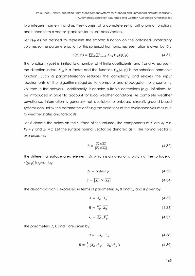
Ph.D. Thesis - Next Generation Flight Management Systems for Manned and Unmanned Aircraft Operations
- Automated Separation Assurance and Collision Avoidance Functionalities
165
two integers, namely and . They consist of a complete set of orthonormal functions
and hence form a vector space similar to unit basis vectors.
Let ( ) be defined to represent the smooth function on the obtained uncertainty
volume, so the parameterisation of this spherical harmonic representation is given by [5]:
( ) ∑ ∑
( ) (4.31)
The function ( ) is limited to a number of N finite coefficients, and and represent
the direction index. is a factor and the function ( ) is the spherical harmonic
function. Such a parameterisation reduces the complexity and relaxes the input
requirements of the algorithms required to compute and propagate the uncertainty
volumes in the network. Additionally, it enables suitable corrections (e.g., inflations) to
be introduced in order to account for local weather conditions. As complete weather
surveillance information is generally not available to onboard aircraft, ground-based
systems can uplink the parameters defining the variations of the avoidance volumes due
to weather states and forecasts.
Let denote the points on the surface of the volume. The components of are = x,
= y and = z. Let the surface normal vector be denoted as The normal vector is
expressed as:
| | (4.32)
The differential surface area element, which is an area of a patch of the surface at
( ) is given by:
(4.33)
| | (4.34)
The decomposition is expressed in terms of parameters A, B and C, and is given by:
(4.35)
(4.36)
(4.37)
The parameters D, E and F are given by:
(4.38)
(
) (4.39)
Ph.D. Thesis - Next Generation Flight Management Systems for Manned and Unmanned Aircraft Operations
- Automated Separation Assurance and Collision Avoidance Functionalities
166
(4.40)
The derivatives of the decomposition of the above parameters can be expressed as:
( )
(4.41)
( )
(4.42)
and so forth. The parameters D, E and F involve vector products of the derivatives of the
components of and . The parameter S is expressed as:
[
( ) ( ) (4.43)
The function ( ) are given by:
( ) √( )( )
( ) ( ) (4.44)
where represents the Legendre functions. The Legendre polynomial function is given
by:
( )
( )
(4.45)
Expanding as ( ) ( ), we have and defined as the
spherical harmonic coefficients. The spherical harmonic coefficients are obtained as [5]:
(4.46)
(4.47)
(4.48)
and for all other and :
(
) (
) ( )
( )( ) × (4.49)
∑( )( ) [ (
)
( ) ( )
(
) (
)
( )
where is the Kronecker delta and (a, b, c) represents the semi-major radius of the
navigation or tracking error ellipsoid. are the zonal coefficients (functions of latitude)
while and are the tesseral coefficients (functions of longitudes). are termed as
expansion coefficients. When l=m, sectorial coefficients are obtained which are
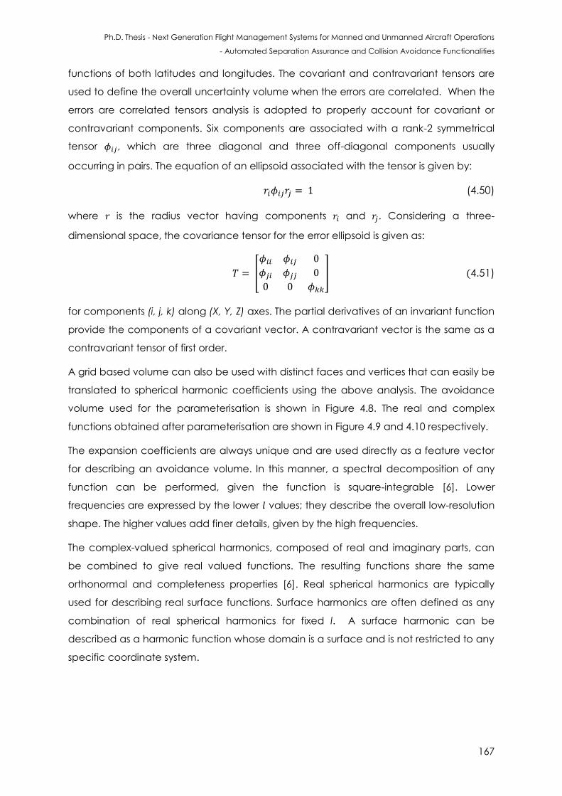
Ph.D. Thesis - Next Generation Flight Management Systems for Manned and Unmanned Aircraft Operations
- Automated Separation Assurance and Collision Avoidance Functionalities
167
functions of both latitudes and longitudes. The covariant and contravariant tensors are
used to define the overall uncertainty volume when the errors are correlated. When the
errors are correlated tensors analysis is adopted to properly account for covariant or
contravariant components. Six components are associated with a rank-2 symmetrical
tensor , which are three diagonal and three off-diagonal components usually
occurring in pairs. The equation of an ellipsoid associated with the tensor is given by:
(4.50)
where is the radius vector having components and . Considering a three-
dimensional space, the covariance tensor for the error ellipsoid is given as:
[
] (4.51)
for components (i, j, k) along (X, Y, Z) axes. The partial derivatives of an invariant function
provide the components of a covariant vector. A contravariant vector is the same as a
contravariant tensor of first order.
A grid based volume can also be used with distinct faces and vertices that can easily be
translated to spherical harmonic coefficients using the above analysis. The avoidance
volume used for the parameterisation is shown in Figure 4.8. The real and complex
functions obtained after parameterisation are shown in Figure 4.9 and 4.10 respectively.
The expansion coefficients are always unique and are used directly as a feature vector
for describing an avoidance volume. In this manner, a spectral decomposition of any
function can be performed, given the function is square-integrable [6]. Lower
frequencies are expressed by the lower values; they describe the overall low-resolution
shape. The higher values add finer details, given by the high frequencies.
The complex-valued spherical harmonics, composed of real and imaginary parts, can
be combined to give real valued functions. The resulting functions share the same
orthonormal and completeness properties [6]. Real spherical harmonics are typically
used for describing real surface functions. Surface harmonics are often defined as any
combination of real spherical harmonics for fixed l. A surface harmonic can be
described as a harmonic function whose domain is a surface and is not restricted to any
specific coordinate system.
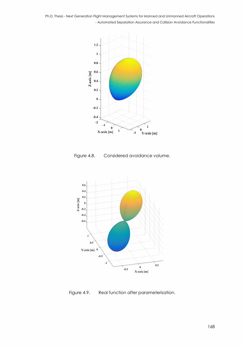
Ph.D. Thesis - Next Generation Flight Management Systems for Manned and Unmanned Aircraft Operations
- Automated Separation Assurance and Collision Avoidance Functionalities
168
Figure 4.8. Considered avoidance volume.
Figure 4.9. Real function after parameterisation.
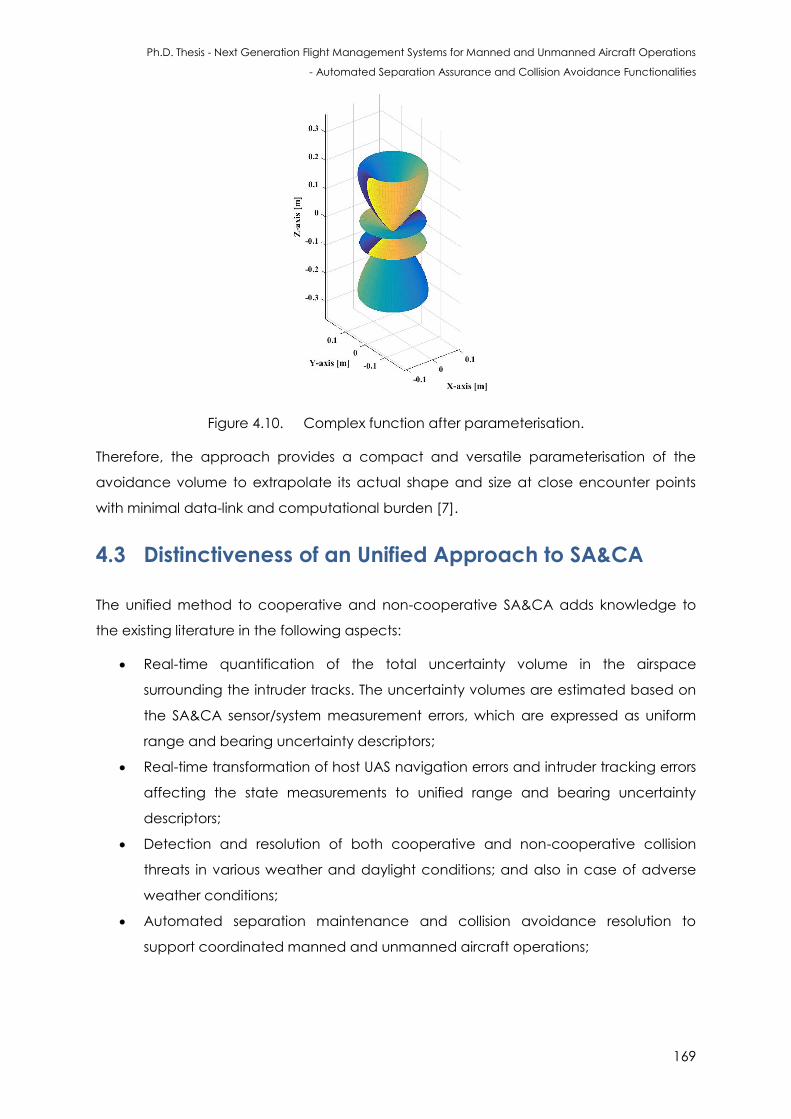
Ph.D. Thesis - Next Generation Flight Management Systems for Manned and Unmanned Aircraft Operations
- Automated Separation Assurance and Collision Avoidance Functionalities
169
Figure 4.10. Complex function after parameterisation.
Therefore, the approach provides a compact and versatile parameterisation of the
avoidance volume to extrapolate its actual shape and size at close encounter points
with minimal data-link and computational burden [7].
4.3 Distinctiveness of an Unified Approach to SA&CA
The unified method to cooperative and non-cooperative SA&CA adds knowledge to
the existing literature in the following aspects:
Real-time quantification of the total uncertainty volume in the airspace
surrounding the intruder tracks. The uncertainty volumes are estimated based on
the SA&CA sensor/system measurement errors, which are expressed as uniform
range and bearing uncertainty descriptors;
Real-time transformation of host UAS navigation errors and intruder tracking errors
affecting the state measurements to unified range and bearing uncertainty
descriptors;
Detection and resolution of both cooperative and non-cooperative collision
threats in various weather and daylight conditions; and also in case of adverse
weather conditions;
Automated separation maintenance and collision avoidance resolution to
support coordinated manned and unmanned aircraft operations;
Ph.D. Thesis - Next Generation Flight Management Systems for Manned and Unmanned Aircraft Operations
- Automated Separation Assurance and Collision Avoidance Functionalities
170
Real-time and close coordination of air, sea and ground operations as well as
operation of multiple manned and unmanned aircraft in close proximity to each
other;
Automatic selection of sensors/systems providing the most reliable SA&CA
solution, providing robustness in all flight phases (further details provided in
Chapter 5);
Generation of appropriate dynamic geo-fences, whose characteristics will be
dictated by the obstacle classification and intruder dynamics, to allow
computation of the optimal avoidance flight trajectories (further details provided
in Chapter 8);
Supervisory control of manned aircraft and UAS addressing various levels of
autonomous vehicle-vehicle and ground-vehicle collaborations (further details
provided in Appendix C);
Robust trajectory optimisation allowing the identification of the safest and more
efficient Three-Dimensional or Four-Dimensional (3D/4D) avoidance trajectory,
considering relative dynamics between the host UAS and intruder platforms,
airspace constraints, as well as meteorological and traffic conditions (further
details are provided in Chapter 3 (Section 3.7.4) and Chapter 5 (Section 5.6);
Optimal and dynamic sharing of airspace resources between civil and military
users, as well as enabling integrated civil-military Air Traffic Management and UAS
Traffic Management (ATM/UTM) operations (further details are provided in
Chapter 8 (Section 8.5.2);
Near real-time and off-line determination of the UAS safe-to-fly envelope based
on the installed avionics sensors and on the own/intruder platform dynamics or,
alternatively, identifying the sensors required for the UAS to safely fly a certain pre-
defined envelope supporting the development of the SA&CA system certification
case and can provide a pathway to certification.
As a result, it is expected that the SA&CA algorithms will allow:
operation of multiple manned and unmanned aircraft in close proximity to each
other;
the remote pilot and/or operator to supervise and supplement the execution of
various SA&CA tasks;
seamless integration of UAS into the existing ATM system and in the UTM context.
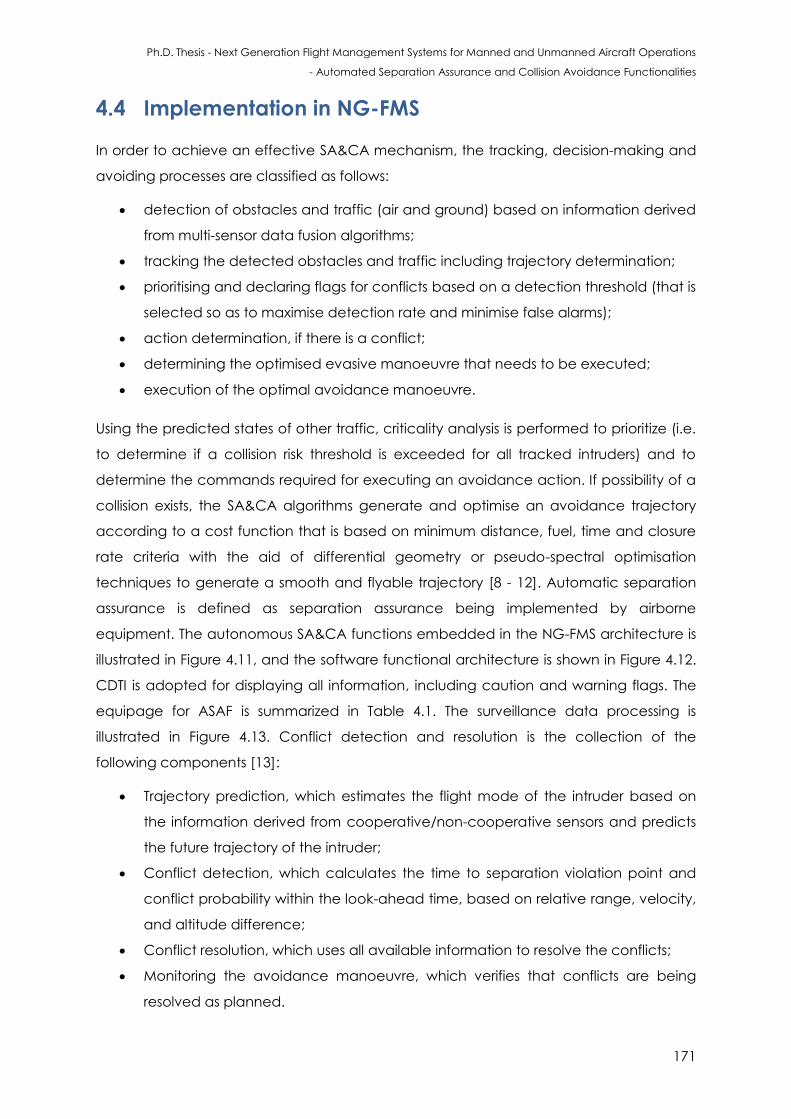
Ph.D. Thesis - Next Generation Flight Management Systems for Manned and Unmanned Aircraft Operations
- Automated Separation Assurance and Collision Avoidance Functionalities
171
4.4 Implementation in NG-FMS
In order to achieve an effective SA&CA mechanism, the tracking, decision-making and
avoiding processes are classified as follows:
detection of obstacles and traffic (air and ground) based on information derived
from multi-sensor data fusion algorithms;
tracking the detected obstacles and traffic including trajectory determination;
prioritising and declaring flags for conflicts based on a detection threshold (that is
selected so as to maximise detection rate and minimise false alarms);
action determination, if there is a conflict;
determining the optimised evasive manoeuvre that needs to be executed;
execution of the optimal avoidance manoeuvre.
Using the predicted states of other traffic, criticality analysis is performed to prioritize (i.e.
to determine if a collision risk threshold is exceeded for all tracked intruders) and to
determine the commands required for executing an avoidance action. If possibility of a
collision exists, the SA&CA algorithms generate and optimise an avoidance trajectory
according to a cost function that is based on minimum distance, fuel, time and closure
rate criteria with the aid of differential geometry or pseudo-spectral optimisation
techniques to generate a smooth and flyable trajectory [8 - 12]. Automatic separation
assurance is defined as separation assurance being implemented by airborne
equipment. The autonomous SA&CA functions embedded in the NG-FMS architecture is
illustrated in Figure 4.11, and the software functional architecture is shown in Figure 4.12.
CDTI is adopted for displaying all information, including caution and warning flags. The
equipage for ASAF is summarized in Table 4.1. The surveillance data processing is
illustrated in Figure 4.13. Conflict detection and resolution is the collection of the
following components [13]:
Trajectory prediction, which estimates the flight mode of the intruder based on
the information derived from cooperative/non-cooperative sensors and predicts
the future trajectory of the intruder;
Conflict detection, which calculates the time to separation violation point and
conflict probability within the look-ahead time, based on relative range, velocity,
and altitude difference;
Conflict resolution, which uses all available information to resolve the conflicts;
Monitoring the avoidance manoeuvre, which verifies that conflicts are being
resolved as planned.
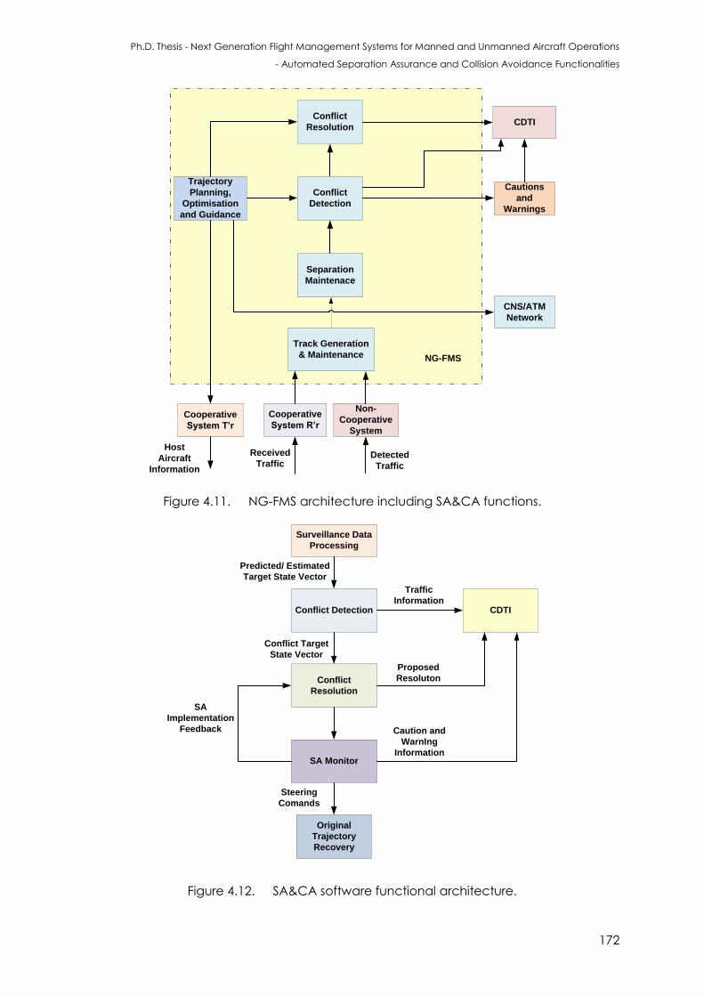
Ph.D. Thesis - Next Generation Flight Management Systems for Manned and Unmanned Aircraft Operations
- Automated Separation Assurance and Collision Avoidance Functionalities
172
Host
Aircraft
Information
Trajectory
Planning,
Optimisation
and Guidance
Conflict
Detection
Cooperative
System R’r
Conflict
Resolution
Track Generation
& Maintenance
Cooperative
System T’r
CDTI
Cautions
and
Warnings
Received
Traffic
NG-FMS
Detected
Traffic
Non-
Cooperative
System
Separation
Maintenace
CNS/ATM
Network
Figure 4.11. NG-FMS architecture including SA&CA functions.
Surveillance Data
Processing
Conflict Detection
Conflict
Resolution
CDTI
SA Monitor
Predicted/ Estimated
Target State Vector
Conflict Target
State Vector
Traffic
Information
Proposed
Resoluton
Caution and
WarnIng
Information
SA
Implementation
Feedback
Original
Trajectory
Recovery
Steering
Comands
Figure 4.12. SA&CA software functional architecture.
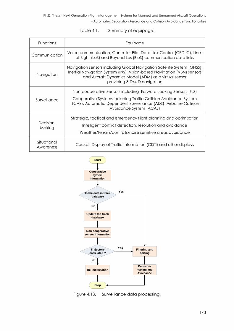
Ph.D. Thesis - Next Generation Flight Management Systems for Manned and Unmanned Aircraft Operations
- Automated Separation Assurance and Collision Avoidance Functionalities
173
Table 4.1. Summary of equipage.
Functions Equipage
Communication Voice communication, Controller Pilot Data Link Control (CPDLC), Line-
of-Sight (LoS) and Beyond Los (BloS) communication data links
Navigation
Navigation sensors including Global Navigation Satellite System (GNSS),
Inertial Navigation System (INS), Vision-based Navigation (VBN) sensors
and Aircraft Dynamics Model (ADM) as a virtual sensor
providing 3-D/4-D navigation
Surveillance
Non-cooperative Sensors including Forward Looking Sensors (FLS)
Cooperative Systems including Traffic Collision Avoidance System
(TCAS), Automatic Dependent Surveillance (ADS), Airborne Collision
Avoidance System (ACAS)
Decision-
Making
Strategic, tactical and emergency flight planning and optimisation
Intelligent conflict detection, resolution and avoidance
Weather/terrain/contrails/noise sensitive areas avoidance
Situational
Awareness Cockpit Display of Traffic Information (CDTI) and other displays
Start
Cooperative
system
information
Is the data in track
database
Update the track
database
Trajectory
correlated ?
Stop
Yes
No
No
Yes
Non-cooperative
sensor information
Re-initialisation
Filtering and
sorting
Decision-
making and
Avoidance
Figure 4.13. Surveillance data processing.
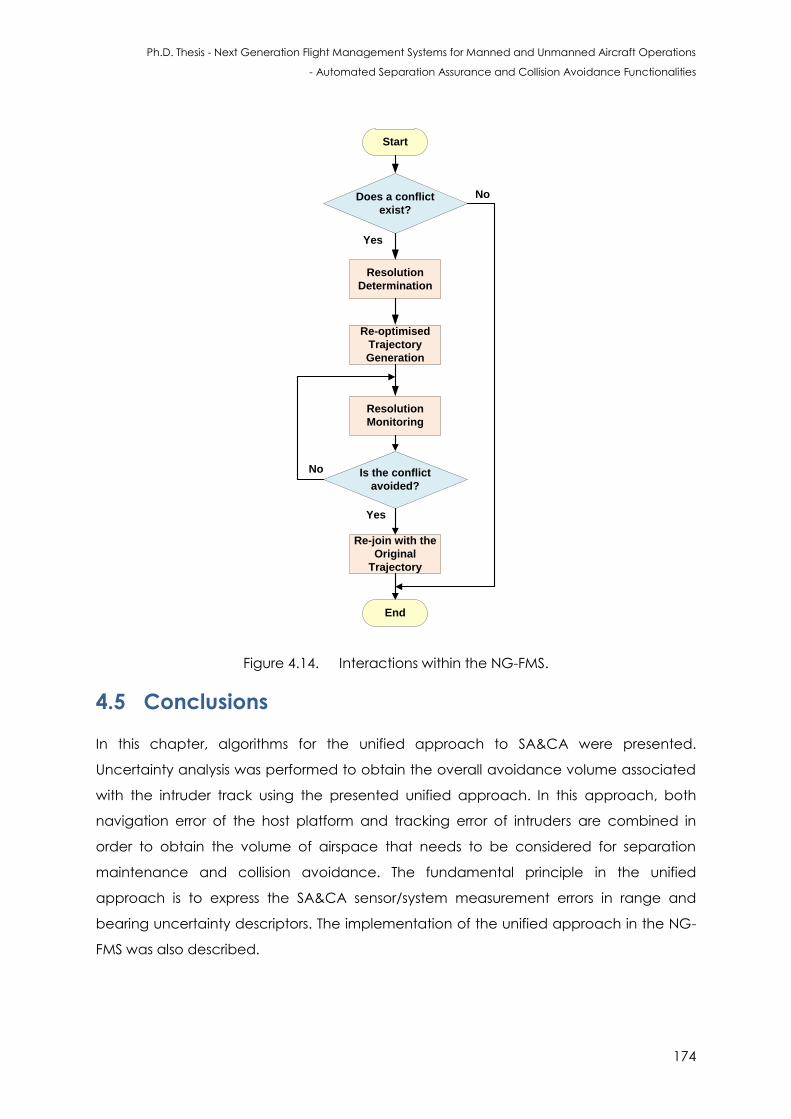
Ph.D. Thesis - Next Generation Flight Management Systems for Manned and Unmanned Aircraft Operations
- Automated Separation Assurance and Collision Avoidance Functionalities
174
Start
Resolution
Monitoring
Is the conflict
avoided?
End
Re-join with the
Original
Trajectory
Yes
No
Does a conflict
exist?
Resolution
Determination
Re-optimised
Trajectory
Generation
No
Yes
Figure 4.14. Interactions within the NG-FMS.
4.5 Conclusions
In this chapter, algorithms for the unified approach to SA&CA were presented.
Uncertainty analysis was performed to obtain the overall avoidance volume associated
with the intruder track using the presented unified approach. In this approach, both
navigation error of the host platform and tracking error of intruders are combined in
order to obtain the volume of airspace that needs to be considered for separation
maintenance and collision avoidance. The fundamental principle in the unified
approach is to express the SA&CA sensor/system measurement errors in range and
bearing uncertainty descriptors. The implementation of the unified approach in the NG-
FMS was also described.
Ph.D. Thesis - Next Generation Flight Management Systems for Manned and Unmanned Aircraft Operations
- Automated Separation Assurance and Collision Avoidance Functionalities
175
4.6 References
1. S. Ramasamy, R. Sabatini and A. Gardi, “LIDAR Obstacle Warning and Avoidance
System for Unmanned Aerial Vehicle Sense-and-Avoid”, Aerospace Science and
Technology, Elsevier, vol. 55, pp. 344–358, 2016. DOI: 10.1016/j.ast.2016.05.020
2. A. Gardi, S. Ramasamy, R. Sabatini and T. Kistan, “Terminal Area Operations:
Challenges and Opportunities”, Encyclopedia of Aerospace - UAS, eds R. Blockley and
W. Shyy, John Wiley: Chichester, 2016. DOI: 10.1002/9780470686652.eae1141
3. S. Ramasamy, R. Sabatini, A. Gardi, “Avionics Sensor Fusion for Small Size Unmanned
Aircraft Sense-and-Avoid”, IEEE Workshop on Metrology for Aerospace, pp. 271-276,
Benevento, Italy, May 2014. DOI: 10.1109/MetroAeroSpace.2014.6865933
4. E.J. Garboczi, “Three-dimensional Mathematical Analysis of Particle Shape using X-ray
Tomography and Spherical Harmonics: Application to Aggregates used in Concrete”,
Cement Concrete Research, vol. 32, no. 10, 1621–1638, 2002.
5. Z. Zhenjiang, Y. Meng, C. Hutao, C. Pingyuan, “The Method to Determine Spherical
Harmonic Model of Asteroid based on Polyhedron”, Proceedings of the 3rd
International Conference on Computer and Electrical Engineering, International
Proceedings of Computer Science and Information Technology, vol. 53, 2012.
6. R.J. Morris, R.J. Najmanovich, A. Kahraman and J.M. thornton, “Real Spherical
Harmonic Expansion Coefficients as 3D Shape Descriptors for Protein Binding Pocket
and Ligand Comparisons”, Bioinformatics, Oxford Journals, vol. 21, issue 10, pp. 2347-
2355, 2005.
7. R. Ramamoorthi and P. Hanrahan, “An Efficient Representation for Irradiance
Environment Maps”, Proceedings of the 28th ACM Annual Conference on Computer
Graphics and Interactive Techniques, Los Angeles, USA, pp. 497-500, 2001.
8. C. Carbone, U. Ciniglio, F. Corraro, and S. Luongo, “A Novel 3D Geometric Algorithm
for Aircraft Autonomous Collision Avoidance”, Proceedings of the 45th IEEE Conference
on Decision and Control, San Diego, California, USA, pp. 1580-1585, 2006.
9. C.G. Prévost, A. Desbiens, E. Ganon, and D. Hodouin, “UAV Optimal Obstacle
Avoidance while Respecting Target Arrival Specifications”, Preprints of the 18th IFAC
World Congress, Milano, Italy, pp. 11815-11820, 2008.
10. A. Gardi, R. Sabatini and S. Ramasamy, “Multi-objective Optimisation of Aircraft Flight
Trajectories in the ATM and Avionics Context”, Progress in Aerospace Sciences, Elsevier,
vol. 83, pp.1-36, 2016. DOI: 10.1016/j.paerosci.2015.11.006
Ph.D. Thesis - Next Generation Flight Management Systems for Manned and Unmanned Aircraft Operations
- Automated Separation Assurance and Collision Avoidance Functionalities
176
11. C.K. Lai, M. Lone, P. Thomas, J. Whidboerne and A. Cooke, “On-Board Trajectory
Generation for Collision Avoidance in Unmanned Aerial Vehicles”, Proceedings of the
IEEE Aerospace Conference, pp. 1-14, Big Sky, MT, USA, 2011.
12. D.A. Benson, G.T. Huntington, T.P. Thorvaldsen and A.V. Rao, “Direct Trajectory
Optimization and Costate Estimation via an Orthogonal Collocation Method”, Journal
of Guidance, Control, and Dynamics, vol. 29, no. 6, pp. 1435-1440, 2006.
13. S. Ramasamy, R. Sabatini and A. Gardi, “ A Unified Approach to Separation Assurance
and Collision Avoidance for UAS Operations and Traffic Management”, Proceedings of
IEEE International Conference on Unmanned Aircraft Systems (ICUAS 2017), Miami, FL,
USA, pp. 920-928, June 2017.
Ph.D. Thesis - Next Generation Flight Management Systems for Manned and Unmanned Aircraft Operations
- Automated Separation Assurance and Collision Avoidance Functionalities
177
CHAPTER 5
PERFORMANCE ANALYSIS OF
SA&CA FUNCTIONALITIES
“The an of science has earne to be ieve in j stification not by faith b t by
verification.” - Thomas Henry Huxley
5.1 Introduction
In this chapter, a performance analysis is carried out to investigate and explore the
potential of the unified approach to cooperative and non-cooperative SA&CA for
manned and unmanned aircraft. Based on the identified state-of-the-art SA&CA
technologies, a Boolean-Decision Logic (BDL) driven decision tree test bed system
reference architecture is presented. Implementations involving Boolean logics are
generally hard wired and cannot be reconfigured; this limits the scope of a unified
framework in terms of automatic decision making capability. Therefore adaptive BDL,
which are based on real-time monitoring of the surveillance sensors/systems
performance are implemented to provide a framework for providing autonomy in UAS
operations. A scheme for selecting the onboard sensors/systems is introduced, which is
based on the performance achieved at any given point of time. Covariance matrices
are used for estimating sensor and system performances. After identifying a Risk-of-
Collision (RoC), if the original trajectory of the host platform intersects the calculated
avoidance volume, a caution integrity flag is issued. An avoidance trajectory is
generated in real-time and the steering commands are provided to the flight control
surfaces.
5.2 Avoidance Volumes
An avoidance volume is a virtual, fixed, volume-based boundary in the airspace. The
overall avoidance volume obtained from the unified approach to SA&CA described in
Chapter 4 is a variable boundary projected along the velocity vector of the host aircraft.
Ph.D. Thesis - Next Generation Flight Management Systems for Manned and Unmanned Aircraft Operations
- Automated Separation Assurance and Collision Avoidance Functionalities
178
The avoidance volume is a variable depending upon the real-time navigation
measurements, tracking observables, relative dynamics between platforms, collision
distance, time and manoeuvrability of the platform. The inclusion of navigation error of
the host aircraft and the tracking errors of all other traffic in the airspace provides a
practical buffer. It also maximises the ability to predict collisions and provides the host
aircraft with adequate time to generate a re-optimised trajectory and execute the
required commands.
A buffer is also added taking into account the uncertainties in the aircraft states and the
resulting uncertainties in the propagation of errors in the nominal trajectory. The previous
research efforts on estimation of avoidance/uncertainty volume in the context of
SA&CA were discussed earlier in Chapter 2 (Section 2.13).
All the highlighted approaches have attempted to define an avoidance volume, which
are specific in application; meaning given a scenario or specific sensor/system, these
methods can provide information for automated SA or CA. The unified approach is an
innovative technique allowing the quantification of total uncertainty volume in the
airspace surrounding the intruder tracks in real-time for both cooperative and non-
cooperative scenarios. A thorough assessment and mitigation of the safety impact is
typically required to expedite the path to certification, allowing operators (including
UAS) to carry out an extended spectrum of autonomous and safety-critical tasks. The
unified approach allows carrying out such assessment and supports the case for
certification. Both near real-time and off-line determination of the safe-to-fly envelope is
based on the installed avionics sensors as well as on the own/intruder platform
dynamics. Alternatively, identifying the sensors required for the platform to safely fly a
certain pre-defined envelope (in the presence of intruders with specified vehicle
dynamics) can also determine the safety envelope. Further details on the certification
framework are provided in the later sections of the chapter.
5.3 SA&CA Test Bed Architecture
Evaluation of non-cooperative sensor/cooperative systems and the associated data
fusion algorithms is a key constituent of the SA&CA system design. A number of non-
cooperative sensors and cooperative systems can be employed for automated SA&CA.
State-of-the-art SA&CA technologies are listed in Table 5.1 representing C for
cooperative and NC for non-cooperative (both active and passive) sensors.
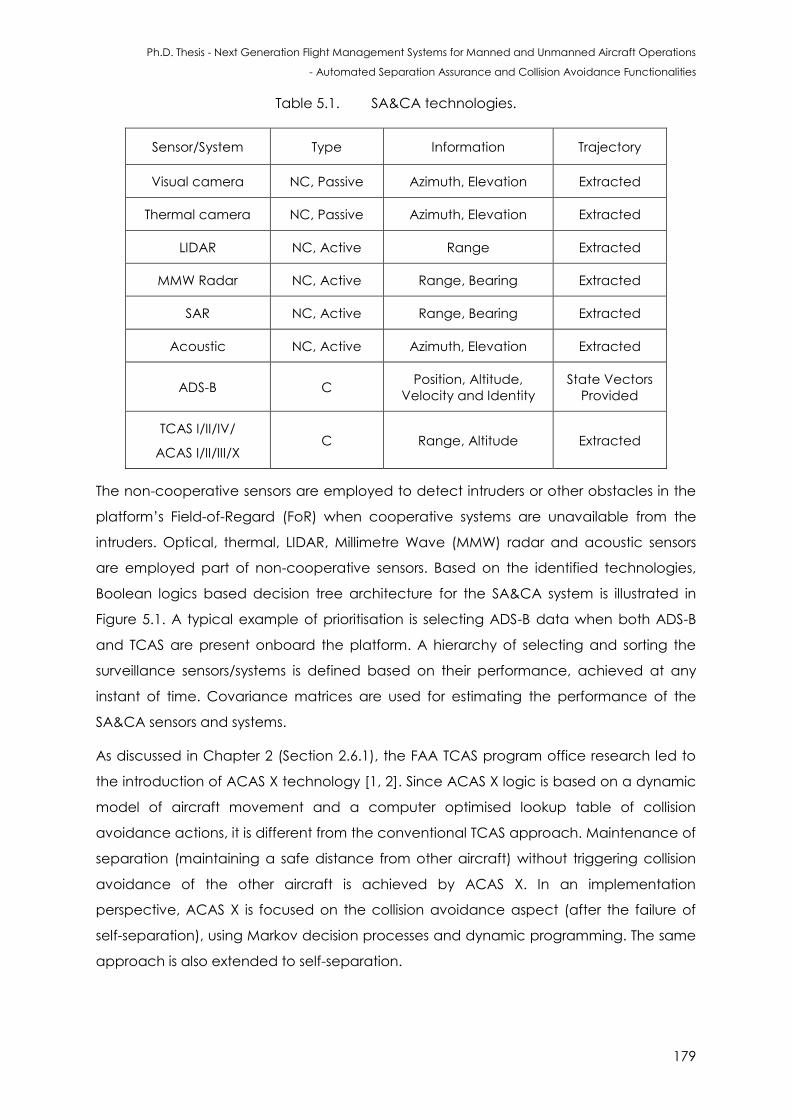
Ph.D. Thesis - Next Generation Flight Management Systems for Manned and Unmanned Aircraft Operations
- Automated Separation Assurance and Collision Avoidance Functionalities
179
Table 5.1. SA&CA technologies.
Sensor/System Type Information Trajectory
Visual camera NC, Passive Azimuth, Elevation Extracted
Thermal camera NC, Passive Azimuth, Elevation Extracted
LIDAR NC, Active Range Extracted
MMW Radar NC, Active Range, Bearing Extracted
SAR NC, Active Range, Bearing Extracted
Acoustic NC, Active Azimuth, Elevation Extracted
ADS-B C Position, Altitude,
Velocity and Identity
State Vectors
Provided
TCAS I/II/IV/
ACAS I/II/III/X C Range, Altitude Extracted
The non-cooperative sensors are employed to detect intruders or other obstacles in the
platform’s Field-of-Regard (FoR) when cooperative systems are unavailable from the
intruders. Optical, thermal, LIDAR, Millimetre Wave (MMW) radar and acoustic sensors
are employed part of non-cooperative sensors. Based on the identified technologies,
Boolean logics based decision tree architecture for the SA&CA system is illustrated in
Figure 5.1. A typical example of prioritisation is selecting ADS-B data when both ADS-B
and TCAS are present onboard the platform. A hierarchy of selecting and sorting the
surveillance sensors/systems is defined based on their performance, achieved at any
instant of time. Covariance matrices are used for estimating the performance of the
SA&CA sensors and systems.
As discussed in Chapter 2 (Section 2.6.1), the FAA TCAS program office research led to
the introduction of ACAS X technology [1, 2]. Since ACAS X logic is based on a dynamic
model of aircraft movement and a computer optimised lookup table of collision
avoidance actions, it is different from the conventional TCAS approach. Maintenance of
separation (maintaining a safe distance from other aircraft) without triggering collision
avoidance of the other aircraft is achieved by ACAS X. In an implementation
perspective, ACAS X is focused on the collision avoidance aspect (after the failure of
self-separation), using Markov decision processes and dynamic programming. The same
approach is also extended to self-separation.
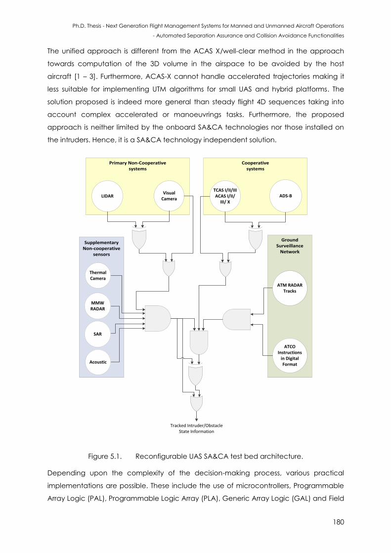
Ph.D. Thesis - Next Generation Flight Management Systems for Manned and Unmanned Aircraft Operations
- Automated Separation Assurance and Collision Avoidance Functionalities
180
The unified approach is different from the ACAS X/well-clear method in the approach
towards computation of the 3D volume in the airspace to be avoided by the host
aircraft [1 – 3]. Furthermore, ACAS-X cannot handle accelerated trajectories making it
less suitable for implementing UTM algorithms for small UAS and hybrid platforms. The
solution proposed is indeed more general than steady flight 4D sequences taking into
account complex accelerated or manoeuvrings tasks. Furthermore, the proposed
approach is neither limited by the onboard SA&CA technologies nor those installed on
the intruders. Hence, it is a SA&CA technology independent solution.
Supplementary Non-cooperative
sensors
Cooperative systems
Primary Non-Cooperative systems
Thermal Camera
Acoustic
MMW RADAR
TCAS I/II/IIIACAS I/II/
III/ XADS-B
SAR
Ground Surveillance
Network
LIDARVisual
Camera
ATM RADAR Tracks
ATCO Instructions
in Digital Format
Tracked Intruder/Obstacle State Information
Figure 5.1. Reconfigurable UAS SA&CA test bed architecture.
Depending upon the complexity of the decision-making process, various practical
implementations are possible. These include the use of microcontrollers, Programmable
Array Logic (PAL), Programmable Logic Array (PLA), Generic Array Logic (GAL) and Field
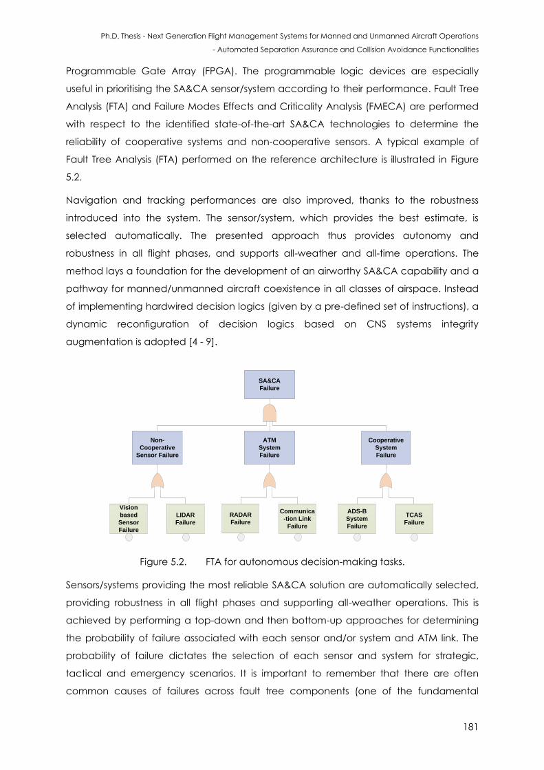
Ph.D. Thesis - Next Generation Flight Management Systems for Manned and Unmanned Aircraft Operations
- Automated Separation Assurance and Collision Avoidance Functionalities
181
Programmable Gate Array (FPGA). The programmable logic devices are especially
useful in prioritising the SA&CA sensor/system according to their performance. Fault Tree
Analysis (FTA) and Failure Modes Effects and Criticality Analysis (FMECA) are performed
with respect to the identified state-of-the-art SA&CA technologies to determine the
reliability of cooperative systems and non-cooperative sensors. A typical example of
Fault Tree Analysis (FTA) performed on the reference architecture is illustrated in Figure
5.2.
Navigation and tracking performances are also improved, thanks to the robustness
introduced into the system. The sensor/system, which provides the best estimate, is
selected automatically. The presented approach thus provides autonomy and
robustness in all flight phases, and supports all-weather and all-time operations. The
method lays a foundation for the development of an airworthy SA&CA capability and a
pathway for manned/unmanned aircraft coexistence in all classes of airspace. Instead
of implementing hardwired decision logics (given by a pre-defined set of instructions), a
dynamic reconfiguration of decision logics based on CNS systems integrity
augmentation is adopted [4 - 9].
SA&CA
Failure
Non-
Cooperative
Sensor Failure
Vision
based
Sensor
Failure
Cooperative
System
Failure
ATM
System
Failure
LIDAR
Failure
RADAR
Failure
Communica
-tion Link
Failure
ADS-B
System
Failure
TCAS
Failure
Figure 5.2. FTA for autonomous decision-making tasks.
Sensors/systems providing the most reliable SA&CA solution are automatically selected,
providing robustness in all flight phases and supporting all-weather operations. This is
achieved by performing a top-down and then bottom-up approaches for determining
the probability of failure associated with each sensor and/or system and ATM link. The
probability of failure dictates the selection of each sensor and system for strategic,
tactical and emergency scenarios. It is important to remember that there are often
common causes of failures across fault tree components (one of the fundamental
Ph.D. Thesis - Next Generation Flight Management Systems for Manned and Unmanned Aircraft Operations
- Automated Separation Assurance and Collision Avoidance Functionalities
182
assumptions inherent in fault trees are that the components are independent, which is
very difficult to assure in an actual system). Hence, the common causes of failures across
fault tree components (here within non-cooperative sensors, cooperative systems and
ATM system) need to be analysed.
Fault trees are very useful in deducing inferences about static models and situations. To
introduce a temporal axis to hazard analysis, event trees are considered. Event tree
analysis, which is a graphical approach, involves the assessment of the SA&CA for given
sets of undesired initiating events. The initiating events are mapped against a temporal
axis. For example, degradation or loss of GNSS data would impact the navigation and
tracking errors (provided ADS-B is onboard the host and intruder aircraft). This impact
can be modelled against time and the propagation effects can be studied. The effects
also include the study of error propagation against time through the aircraft dynamics,
SA&CA algorithms and NG-FMS components.
The decision logics are based on identifying the primary cooperative system and non-
cooperative sensor. In the architecture defined above, the primary cooperative system
is ADS-B and the key non-cooperative counterparts are vision-based sensors and
LIDAR/MMW radar. Considering the ADS-B and TCAS example, representing ADS-B
measurements as A, TCAS data as B and the output for cooperative scenario as O1, the
expression for the Boolean logics implementation is derived as follows:
O1 = A + (A ⊕ T) (5.1)
O1 = A + (A T’+ T A’) (5.2)
O1 = A (1 + T’) + T A’ (5.3)
O1 = A + T A’ (5.4)
Similarly, a Boolean logics decision tree is also employed for the non-cooperative case.
Denoting data from visual camera as V, thermal camera as I, LIDAR as L, MMW radar as
M, acoustic as A and the output for non-cooperative CA function as O2, the expression
for the Boolean logics implementation is derived as follows:
O2 = A · M · L · (V + (V ⊕ I)) (5.5)
O2 = A · M · L · (V + (V I’+ I V’)) (5.6)
O2 = A · M · L · (V + I V’) (5.7)
A combined decision tree is adopted for accommodating both non-cooperative
sensors and cooperative system information. This is described by the overall output O as:
Ph.D. Thesis - Next Generation Flight Management Systems for Manned and Unmanned Aircraft Operations
- Automated Separation Assurance and Collision Avoidance Functionalities
183
O = (O1 ⊕ O2) + O2 (5.8)
5.4 Sensor/System Error Modelling
The error models of subsystems are set up respectively and the matrices of the state and
measurement equations are fractional step discretisations.
The position and tracking information are given by the following formulation. A TCP is
typically defined as specific 4D points in the space-time domain at which an
anticipated change in the aircraft’s velocity vector would cause a change in the
nominal intent. The position of an aircraft is expressed as the 3-tuple, ( ) ( ) ( )}
and Є ℝ and . and are the lateral and longitudinal position of the aircraft
and z provides the elevation. For any given two points, say and , the distances are
given by:
( ) (5.9)
(√ , √ ) (5.10)
and
(
) (
) (5.11)
( ) ( ) (5.12)
The above equations are the Haversine formulae for calculating the great circle
distances between two points on an ellipsoid where is the radius of the sphere. A TCP
can be expressed as . Given two TCPs namely, and , and ,
then, the following constraints hold:
(5.13)
(5.14)
(5.15)
(5.16)
where and are the control variables. is the velocity and is the heading.
In dynamic cases, the elapsed time is important since imperfectly perceived velocity
enlarges altitude uncertainty between observations, and measurements separated by
known time intervals carry implicit velocity information. Weighting applied to the position
measurements is influenced by three factors [10]:
Ph.D. Thesis - Next Generation Flight Management Systems for Manned and Unmanned Aircraft Operations
- Automated Separation Assurance and Collision Avoidance Functionalities
184
A sensitivity matrix Hm whose (i, j) element is the partial derivative of the ith
component of the mth measured data vector to the jth state variable. In this scalar
measurement case Hm is a 1 × 2 matrix [1 0] for all values of m;
A covariance matrix Pm of error in state estimate at time tm (the ith diagonal
element is the mean squared error in estimating the ith state);
A covariance matrix Rm of measurement errors at time tm (in this scalar
measurement case, Rm is a 1 × 1 matrix—i.e., a scalar variance Rm).
Some relevant definitions are:
Variance of a variable is an estimate of the squared deviations of n measures of the
variable from their mean value. For a sample data with n observations for a variable ,
the variance is determined by the formula:
Var ( ) = ∑ ( )
(5.17)
where is the sample mean of .
For a sample data with n pairs of observations for two variables and , the covariance
is given by:
Cov ( , ) = ∑ ( ) ( )
(5.18)
where and denote the sample means of and , respectively. Cov ( , ) > 0
indicates the larger the value of , the larger the value of Y and vice versa. Cov ( , ) <
0 indicates the larger the value of , the smaller the value of Y and vice versa. Therefore:
Cov ( , ) = Cov ( ) (5.19)
That is, covariance is symmetric in and .
Covariance is estimated for two variables that have different units of measurement. By
measuring covariance, it can be found out whether their units are increasing or
decreasing. However, covariance cannot measure the degree to which the two
variables move together.
Pm changes with time (e.g., the effect of velocity error on position error), as well as with
any changes in the real-time measurements. In this continuous–discrete approach,
uncertainty is decremented at the discrete measurement events [10]:
Pm(+) = Pm(-) - Wm Hm Pm(-) (5.20)
Ph.D. Thesis - Next Generation Flight Management Systems for Manned and Unmanned Aircraft Operations
- Automated Separation Assurance and Collision Avoidance Functionalities
185
and, between events, dynamic behaviour follows a continuous model of the form given
by:
= AP +PAT + E (5.21)
The system model for tracking the targets is defined as:
(5.22)
where is the tracked object’s state vector, is the constant state transition matrix and
is the system noise. In a two dimensional approach the state vector can be defined
as a 4 dimensional vector ( ), where ( ) correspond to the position of
the tracked object in the FoV expressed on the body frame and ( ) corresponds to
the velocity of the object. The above equation becomes:
(
) (
)(
)
(
)
(5.23)
The measurement model is given by:
(5.24)
and expressed in matrices as:
(
) (
)(
) (
) (5.25)
where is the measurement vector, is the state observation vector and is the
measurement noise. If the measurement terms and system noise are statistically
uncorrelated (White Gaussian Noise (WGN)), then covariance matrices are given by:
(
)
(5.26)
(
) (5.27)
The diagonal elements of matrices and correspond to the variances of the state
vector and measurement vector respectively. Optimal control and estimation theory is
applied for predicting and updating the system states (e.g. EKF).
Ph.D. Thesis - Next Generation Flight Management Systems for Manned and Unmanned Aircraft Operations
- Automated Separation Assurance and Collision Avoidance Functionalities
186
The values of the Kalman gain give certain weight in the algorithm to the predictions or
the measurements. For large values of Kalman gain, the measurements have a
significant impact on the filter output, whereas for smaller values, predictions are
obtained considering a larger weight on the filter output. The Kalman filter is initialized if
the threshold of the test statistic function is exceeded. The initial conditions of the
Kalman Filter can be set up to [10, 11]:
(
) (5.28)
where and
correspond to the target position ( ) values obtained from the track-
before-detect stage. Typically, in other SA&CA algorithms, a large value is assigned to
the covariance matrix of the system states ( ) due to the initial uncertainty [10, 11].
In the case of a 2D problem, such as the one analysed in this case, the uncertainty can
be represented by an ellipse centred in . It is observed that the axis of the uncertainty
ellipse is given by √ ( ); and are the eigenvalues and eigenvectors of
respectively; is a constant.
Once the states are estimated, a future trajectory is predicted. The approach employed
is based on an extension of the platform states, and on the output equation, which is
given by:
( ) ( ) (5.29)
where [ and the matrix locates the states in the vector that belong to the
object position:
[ ( )
( )
( | )]
[
( )
[ ( )
[ [ ( )
] (5.30)
where is defined as a future horizon up to where it is desired to predict the trajectory.
( ) are the estimates of the track-to-track algorithm, that contains information for
all the local estimations, at the next sample time. The left hand side of equation (5.30) is
expressed as:
( | ) (5.31)
so the index ( | ) groups the prediction from sample time ( ) to sample time
( | ).
Ph.D. Thesis - Next Generation Flight Management Systems for Manned and Unmanned Aircraft Operations
- Automated Separation Assurance and Collision Avoidance Functionalities
187
The quality of the predicted trajectory is also important. It can be evaluated by assessing
the quality of the measurements (or by pre-estimation), which is in turn reflected in the
error on the predicted value. This error is given by:
( ) ( ) ( ) (5.32)
where ( ) is the modeled objected trajectory and ( ) is the predicted
optimal trajectory at sample time . Taking this to the prediction horizon sample time
, the following error expression is obtained:
( )
[
]
(5.33)
where:
(5.34)
for all { } and the matrix is the covariance matrix obtained from the
track-to-track algorithm at sample .
The following characteristics are determined for the trajectory prediction process:
The obstacle centre of mass corresponding to the position estimates;
The geometric characteristic of a selected time invariant shape (typically an
ellipsoid);
The orientation of the vehicle, which can be estimated with the track-before-
detect algorithm. It allows for heading estimation, as well as extension by the
employment of the Kalman filter (when multiple sensors and/or systems
measurements are supplied).
The sensor range of the platform is defined with an ellipsoidal shape. This same principle
is applied to the obstacle; however, the size of the ellipsoid is dependent on the
minimum separation distance, , established in accordance with the mission.
Ph.D. Thesis - Next Generation Flight Management Systems for Manned and Unmanned Aircraft Operations
- Automated Separation Assurance and Collision Avoidance Functionalities
188
5.4.1 Test for Correlation
The relationship between a measured and determined random variable is determined
as follows. Let ε ℝ be a n × 1 vector of jointly-distributed random variable with mean
and covariance matrix ε ℝ . Let be a new random variable that is not
measured but determined by a function, say = f( ), where f(.) is a function of in the
ℝ space. If the function is differentiable, up a certain Taylor series approximation (say
first/second order), then:
( ) ( ( )) (5.35)
where ( ) is the gradient vector evaluated at . Then the random variable has
mean:
( ) (5.36)
and variance:
( ) (5.37)
If the random variables are uncorrelated, the variance can be simplified as:
( ) (5.38)
where is given by the diagonal matrix expressed as:
([
) (5.39)
The relationship between and is given by:
∑ (
( )
)
(5.40)
assuming that are independent random variables and hence the covariance
= 0.
Statistical methods that can be employed for measuring correlation include Pearson,
Kendall rank and Spearman correlation techniques. The most commonly used statistic is
the linear correlation coefficient, , which is often referred to as the Pearson product
moment correlation coefficient and is given by:
√ (5.41)
where is given by:
∑( )( ) (5.42)
∑( ) (5.43)
Ph.D. Thesis - Next Generation Flight Management Systems for Manned and Unmanned Aircraft Operations
- Automated Separation Assurance and Collision Avoidance Functionalities
189
∑( ) (5.44)
In this case, measures the strength of the linear relationship between two variables. The
magnitude of indicates the strength, while the sign suggests the type of linear
relationship. Both random variables should be normally distributed. Other assumptions
include linearity and homoscedasticity. Linearity assumes a straight line relationship
between each of the variables in the analysis and homoscedasticity assumes that data
is normally distributed about the regression line.
Kendall rank correlation is a non-parametric test that measures the strength of
dependence between two variables. If we consider two samples, and , where each
sample size is , we know that the total number of pairings is ( ) . The following
formula is used to calculate the value of Kendall rank correlation:
( )
(5.45)
where is the number of concordant pairs and is the number of discordant pairs.
Spearman rank correlation is a non-parametric test and is used to measure the degree
of association between two variables by not considering any assumptions about the
distribution of the data. Is the appropriate correlation analysis when the variables are
measured on a scale that is at least ordinal. The Spearman rank correlation is given by:
∑
( ) (5.46)
where is the Spearman rank correlation, is the difference between the ranks of
corresponding values ( and ) and is the number of value in each data set.
For example, considering ADS-B and RADAR information, typically minimum ADS-B
performance requirements are based on a comparison to current RADAR performance
[12, 13]. Therefore, RADAR performance must first be characterised sufficiently for each
operational environment. One of the most critical parameters used for comparison is
surveillance accuracy (or typically termed as position uncertainty of the tracked object).
In current RADAR systems, azimuth position uncertainty is usually plotted as a function of
range from the radar, given a specific radar characteristic.
In general, radar azimuth position uncertainty increases for a given target as the target
moves away from the radar. Based on current operational procedures, for MSSR, two
points are defined relative to supported separations. In general, 3 NM separations can
be usually supported by MSSR for targets out to a maximum range of 60 NM from the
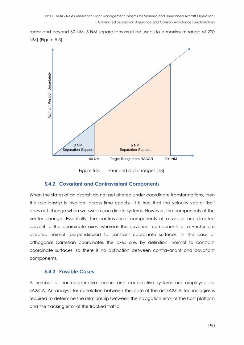
Ph.D. Thesis - Next Generation Flight Management Systems for Manned and Unmanned Aircraft Operations
- Automated Separation Assurance and Collision Avoidance Functionalities
190
radar and beyond 60 NM, 5 NM separations must be used (to a maximum range of 200
NM) (Figure 5.3).
60 NM 200 NM
3 NM
Separation Support
5 NM
Separation Support
Target Range from RADAR
Azim
uth
Positio
n U
ncert
ain
ty
Figure 5.3. Error and radar ranges [13].
5.4.2 Covariant and Contravariant Components
When the states of an aircraft do not get altered under coordinate transformations, then
the relationship is invariant across time epochs. It is true that the velocity vector itself
does not change when we switch coordinate systems. However, the components of the
vector change. Essentially, the contravariant components of a vector are directed
parallel to the coordinate axes, whereas the covariant components of a vector are
directed normal (perpendicular) to constant coordinate surfaces. In the case of
orthogonal Cartesian coordinates the axes are, by definition, normal to constant
coordinate surfaces, so there is no distinction between contravariant and covariant
components.
5.4.3 Possible Cases
A number of non-cooperative sensors and cooperative systems are employed for
SA&CA. An analysis for correlation between the state-of-the-art SA&CA technologies is
required to determine the relationship between the navigation error of the host platform
and the tracking error of the tracked traffic.
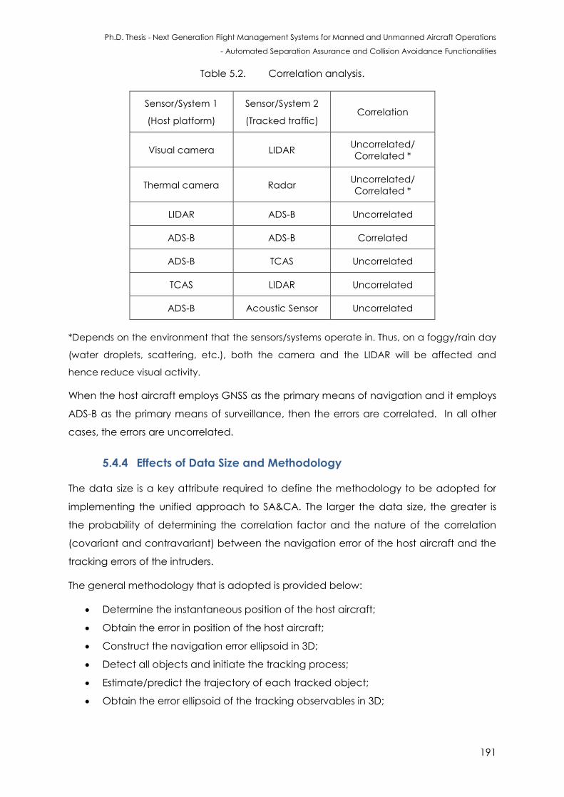
Ph.D. Thesis - Next Generation Flight Management Systems for Manned and Unmanned Aircraft Operations
- Automated Separation Assurance and Collision Avoidance Functionalities
191
Table 5.2. Correlation analysis.
Sensor/System 1
(Host platform)
Sensor/System 2
(Tracked traffic) Correlation
Visual camera LIDAR Uncorrelated/
Correlated *
Thermal camera Radar Uncorrelated/
Correlated *
LIDAR ADS-B Uncorrelated
ADS-B ADS-B Correlated
ADS-B TCAS Uncorrelated
TCAS LIDAR Uncorrelated
ADS-B Acoustic Sensor Uncorrelated
*Depends on the environment that the sensors/systems operate in. Thus, on a foggy/rain day
(water droplets, scattering, etc.), both the camera and the LIDAR will be affected and
hence reduce visual activity.
When the host aircraft employs GNSS as the primary means of navigation and it employs
ADS-B as the primary means of surveillance, then the errors are correlated. In all other
cases, the errors are uncorrelated.
5.4.4 Effects of Data Size and Methodology
The data size is a key attribute required to define the methodology to be adopted for
implementing the unified approach to SA&CA. The larger the data size, the greater is
the probability of determining the correlation factor and the nature of the correlation
(covariant and contravariant) between the navigation error of the host aircraft and the
tracking errors of the intruders.
The general methodology that is adopted is provided below:
Determine the instantaneous position of the host aircraft;
Obtain the error in position of the host aircraft;
Construct the navigation error ellipsoid in 3D;
Detect all objects and initiate the tracking process;
Estimate/predict the trajectory of each tracked object;
Obtain the error ellipsoid of the tracking observables in 3D;
Ph.D. Thesis - Next Generation Flight Management Systems for Manned and Unmanned Aircraft Operations
- Automated Separation Assurance and Collision Avoidance Functionalities
192
Compute the avoidance volume w.r.t. each tracked object assuming that the
errors are uncorrelated;
Assess the correlation between the navigation and tracking error according to
the trends in the data obtained from the tracking sensors/systems;
Recompute the avoidance volume if the errors are correlated and assume that
the relationship is covariant;
Assess the nature of the correlation between navigation and tracking errors;
Recompute the avoidance volume if the relationship is contravariant;
Perform an analysis for assessing the relative dynamics between the host platform
and each tracked intruder;
Compute the avoidance volumes at successive time epochs according to the
correlation, the relationship associated with correlation and relative dynamics
between the two platforms;
Ensure separation assurance at all the time epochs;
Initiate the trajectory re-optimisation module as a resolution mechanism if a
collision is detected (due to non-compliance of the separation assurance
function).
5.4.5 Radar and ADS-B Error Modelling
For radar, the horizontal position accuracy is normally expressed in terms of range and
azimuth. The overall errors are considered to have the following component errors:
Systematic biases;
Stochastic errors (usually expressed as a standard deviation).
Another important term for radar is core accuracy, which is a starting point for
examining radar accuracy, as compared to that of ADS-B data. Core accuracy is
defined as the 95% limit of the error distribution in a certain (single direction) dimension
with respect to the radar.
In the cross-range direction, the error is calculated from the azimuth error multiplied by
the reference range. For ADS-B, horizontal position accuracy is defined as the radius
(ra) of a circle cantered on the target’s reported position such that the probability
of the target’s actual position being inside the circle is 95%. T his radial error is the
resultant of errors in two dimensions (x and y). Assuming that the error distributions in
each dimension are independent Gaussian distributions with the same standard
deviation (σ), the resultant radial error distribution will be Rayleigh and the 95% point
Ph.D. Thesis - Next Generation Flight Management Systems for Manned and Unmanned Aircraft Operations
- Automated Separation Assurance and Collision Avoidance Functionalities
193
of this distribution will be 2.45σ. The required accuracy is derived from comparison with
single dimension radar 95% accuracy.
The above discussions can be easily extended to relative position and velocity
determination between ownship and intruders. For example, in addition to computing
GNSS position and velocity estimates for each aircraft and exchanging these estimates
through some data link, GNSS observables can be exchanged.
Expected sensor ranges might differ from one scenario to another. For example, most
lightweight, low-power and low-cost UAS LIDAR systems tend to offer range of less than 1
km. But the variation of detection range for a variety of obstacles can be estimated.
Flight test results obtained for detection of wire obstacles of 5 mm in diameter, in dry
weather (visibilities of 800 m, 1500 m and 2000 m) and incidence angles of 90 and 45
indicated dictated the minimum LIDAR sensor performance requirements set for
rotorcraft platforms [14].
In an operational scenario, these position and velocity reports are transmitted to the
ground (ATM system) and other aircraft using ADS-B, and include parameters
representing the accuracy and integrity performance of transmitted estimates. ADS-B
does not exhibit the same uncertainty versus range characteristic as radar. ADS-B
position uncertainty is primarily a function of the GNSS satellite geometry relative to the
aircraft, and is not related to range from any ground-based system. The assumption
takes into account the changes in satellite constellation for complex missions (military,
loitering scenarios, etc.), where, with the passing of time, the satellite constellation
coverage changes, even though the location does not. For this reason, ADS-B position
uncertainty is assumed to be a constant for a given environment when being compared
to radar performance. Hence in order to determine minimum performance requirements
for ADS-B, a radar reference range must be determined for each environment to
provide the appropriate comparison points between ADS-B and radar. One of the
drawbacks of ADS-В on the 1090 ES base is that the interference/saturation issue. If there
is a high density of air traffic, because the signals cannot be distinguished, it leads to
signal layering. Therefore, it is estimated that the effective range of the ADS-B is typically
50-70 km in zones with intensive air traffic. Hence the adoption of multiple SA&CA
technologies is Important. At different ranges, the employment of a suite of non-
cooperative sensors or cooperative systems provides the required flexibility.
Radar position errors can be thought of in terms of a 95% error composed from range
and azimuth (cross-range) components. The radar cross-range error component
increases with range from the radar, however, the range error component is constant
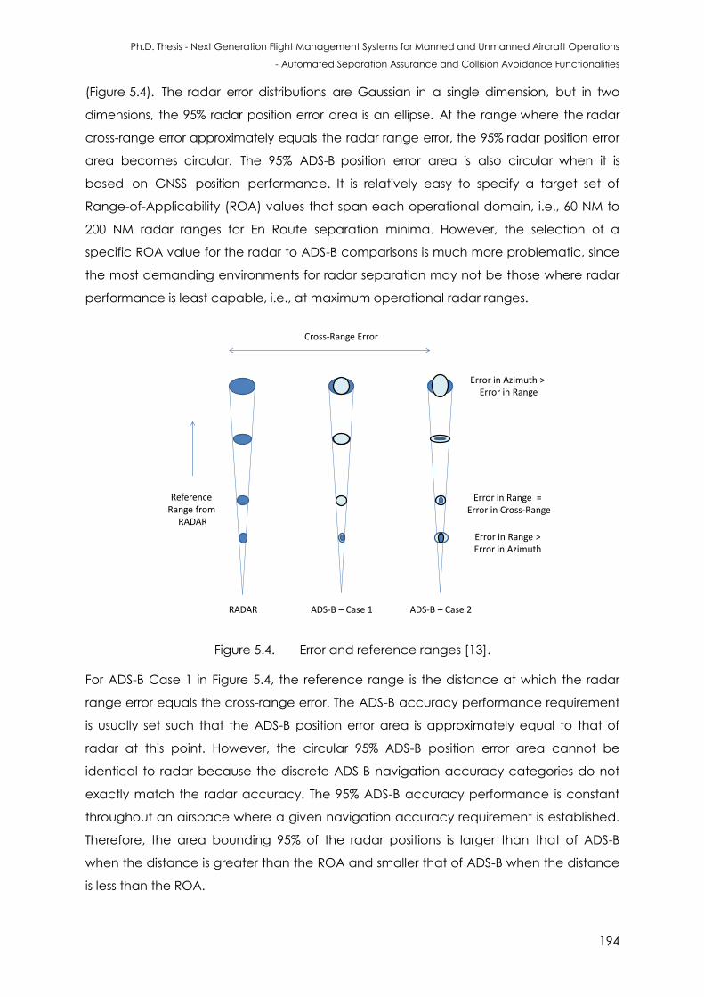
Ph.D. Thesis - Next Generation Flight Management Systems for Manned and Unmanned Aircraft Operations
- Automated Separation Assurance and Collision Avoidance Functionalities
194
(Figure 5.4). The radar error distributions are Gaussian in a single dimension, but in two
dimensions, the 95% radar position error area is an ellipse. At the range where the radar
cross-range error approximately equals the radar range error, the 95% radar position error
area becomes circular. The 95% ADS-B position error area is also circular when it is
based on GNSS position performance. It is relatively easy to specify a target set of
Range-of-Applicability (ROA) values that span each operational domain, i.e., 60 NM to
200 NM radar ranges for En Route separation minima. However, the selection of a
specific ROA value for the radar to ADS-B comparisons is much more problematic, since
the most demanding environments for radar separation may not be those where radar
performance is least capable, i.e., at maximum operational radar ranges.
Reference Range from
RADAR
Cross-Range Error
RADAR ADS-B – Case 1 ADS-B – Case 2
Error in Range > Error in Azimuth
Error in Range = Error in Cross-Range
Error in Azimuth > Error in Range
Figure 5.4. Error and reference ranges [13].
For ADS-B Case 1 in Figure 5.4, the reference range is the distance at which the radar
range error equals the cross-range error. The ADS-B accuracy performance requirement
is usually set such that the ADS-B position error area is approximately equal to that of
radar at this point. However, the circular 95% ADS-B position error area cannot be
identical to radar because the discrete ADS-B navigation accuracy categories do not
exactly match the radar accuracy. The 95% ADS-B accuracy performance is constant
throughout an airspace where a given navigation accuracy requirement is established.
Therefore, the area bounding 95% of the radar positions is larger than that of ADS-B
when the distance is greater than the ROA and smaller that of ADS-B when the distance
is less than the ROA.
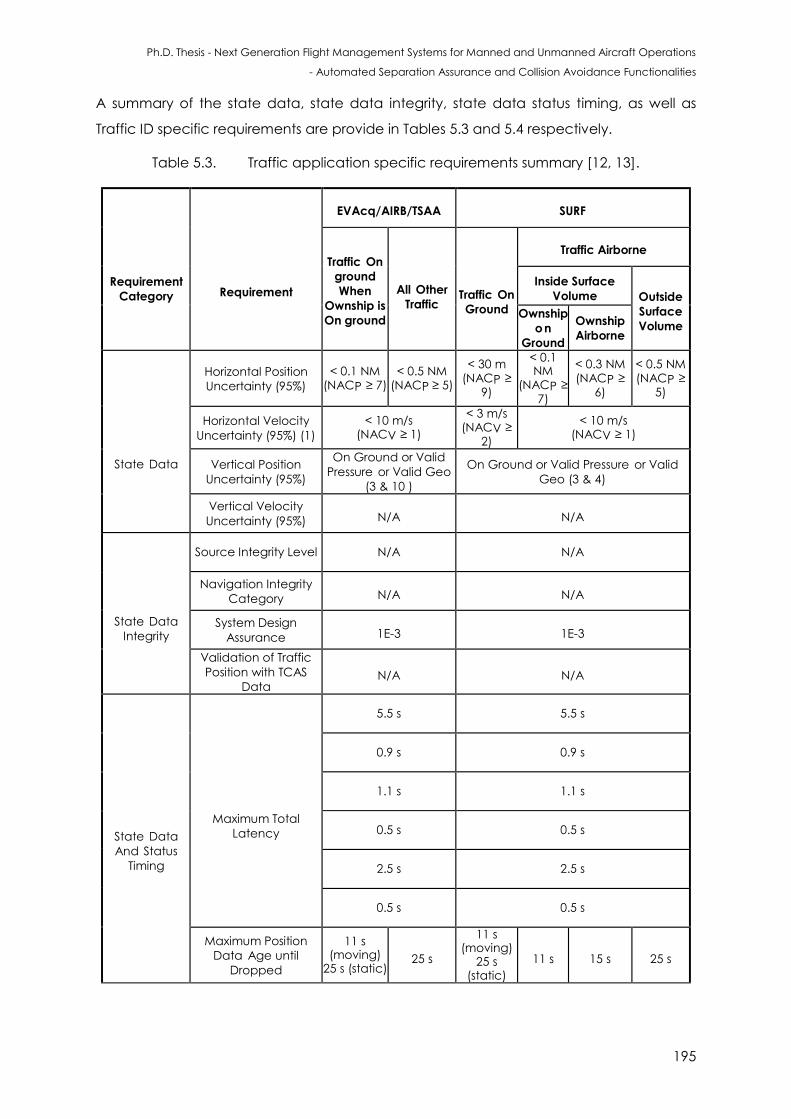
Ph.D. Thesis - Next Generation Flight Management Systems for Manned and Unmanned Aircraft Operations
- Automated Separation Assurance and Collision Avoidance Functionalities
195
A summary of the state data, state data integrity, state data status timing, as well as
Traffic ID specific requirements are provide in Tables 5.3 and 5.4 respectively.
Table 5.3. Traffic application specific requirements summary [12, 13].
Requirement
Category
Requirement
EVAcq/AIRB/TSAA SURF
Traffic On
ground
When
Ownship is
On ground
All Other
Traffic
Traffic On
Ground
Traffic Airborne
Inside Surface
Volume Outside
Surface
Volume Ownship
on
Ground
Ownship
Airborne
State Data
Horizontal Position
Uncertainty (95%)
< 0.1 NM (NACP ≥ 7)
< 0.5 NM (NACP ≥ 5)
< 30 m (NACP ≥
9)
< 0.1 NM
(NACP ≥ 7)
< 0.3 NM (NACP ≥
6)
< 0.5 NM (NACP ≥
5)
Horizontal Velocity
Uncertainty (95%) (1)
< 10 m/s (NACV ≥ 1)
< 3 m/s (NACV ≥
2)
< 10 m/s (NACV ≥ 1)
Vertical Position
Uncertainty (95%)
On Ground or Valid
Pressure or Valid Geo
(3 & 10 )
On Ground or Valid Pressure or Valid
Geo (3 & 4)
Vertical Velocity
Uncertainty (95%) N/A N/A
State Data
Integrity
Source Integrity Level N/A N/A
Navigation Integrity
Category N/A N/A
System Design
Assurance 1E-3 1E-3
Validation of Traffic
Position with TCAS
Data N/A N/A
State Data
And Status
Timing
Maximum Total
Latency
5.5 s 5.5 s
0.9 s 0.9 s
1.1 s 1.1 s
0.5 s 0.5 s
2.5 s 2.5 s
0.5 s 0.5 s
Maximum Position
Data Age until
Dropped
11 s (moving)
25 s (static) 25 s
11 s (moving)
25 s (static)
11 s 15 s 25 s
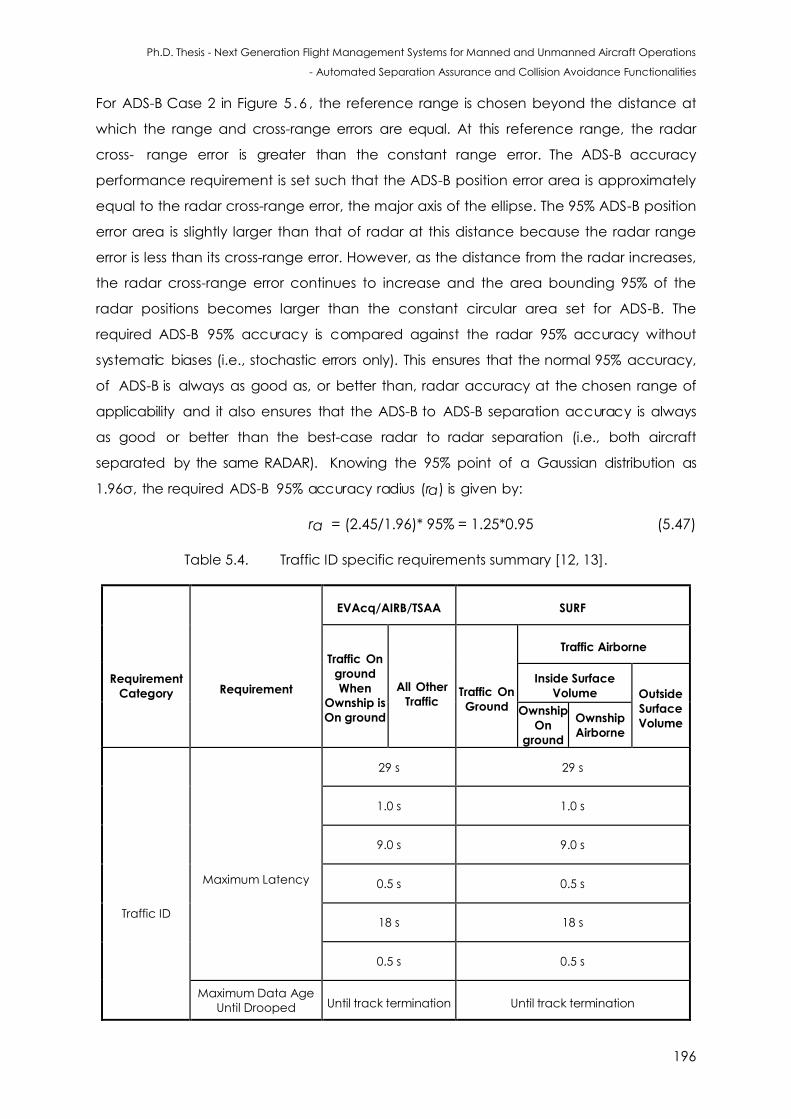
Ph.D. Thesis - Next Generation Flight Management Systems for Manned and Unmanned Aircraft Operations
- Automated Separation Assurance and Collision Avoidance Functionalities
196
For ADS-B Case 2 in Figure 5 .6 , the reference range is chosen beyond the distance at
which the range and cross-range errors are equal. At this reference range, the radar
cross- range error is greater than the constant range error. The ADS-B accuracy
performance requirement is set such that the ADS-B position error area is approximately
equal to the radar cross-range error, the major axis of the ellipse. The 95% ADS-B position
error area is slightly larger than that of radar at this distance because the radar range
error is less than its cross-range error. However, as the distance from the radar increases,
the radar cross-range error continues to increase and the area bounding 95% of the
radar positions becomes larger than the constant circular area set for ADS-B. The
required ADS-B 95% accuracy is compared against the radar 95% accuracy without
systematic biases (i.e., stochastic errors only). This ensures that the normal 95% accuracy,
of ADS-B is always as good as, or better than, radar accuracy at the chosen range of
applicability and it also ensures that the ADS-B to ADS-B separation accuracy is always
as good or better than the best-case radar to radar separation (i.e., both aircraft
separated by the same RADAR). Knowing the 95% point of a Gaussian distribution as
1.96σ, the required ADS-B 95% accuracy radius (ra) is given by:
ra = (2.45/1.96)* 95% = 1.25*0.95 (5.47)
Table 5.4. Traffic ID specific requirements summary [12, 13].
Requirement
Category
Requirement
EVAcq/AIRB/TSAA SURF
Traffic On
ground
When
Ownship is
On ground
All Other
Traffic
Traffic On
Ground
Traffic Airborne
Inside Surface
Volume Outside
Surface
Volume Ownship
On
ground
Ownship
Airborne
Traffic ID
Maximum Latency
29 s 29 s
1.0 s 1.0 s
9.0 s 9.0 s
0.5 s 0.5 s
18 s 18 s
0.5 s 0.5 s
Maximum Data Age
Until Drooped Until track termination Until track termination
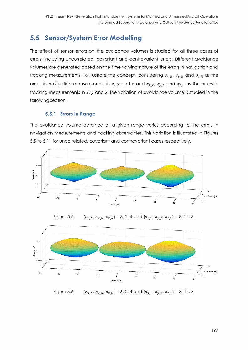
Ph.D. Thesis - Next Generation Flight Management Systems for Manned and Unmanned Aircraft Operations
- Automated Separation Assurance and Collision Avoidance Functionalities
197
5.5 Sensor/System Error Modelling
The effect of sensor errors on the avoidance volumes is studied for all three cases of
errors, including uncorrelated, covariant and contravariant errors. Different avoidance
volumes are generated based on the time varying nature of the errors in navigation and
tracking measurements. To illustrate the concept, considering , and as the
errors in navigation measurements in , and and , and as the errors in
tracking measurements in , and , the variation of avoidance volume is studied in the
following section.
5.5.1 Errors in Range
The avoidance volume obtained at a given range varies according to the errors in
navigation measurements and tracking observables. This variation is illustrated in Figures
5.5 to 5.11 for uncorrelated, covariant and contravariant cases respectively.
Figure 5.5. { , , } = 3, 2, 4 and { , , } = 8, 12, 3.
Figure 5.6. { , , } = 6, 2, 4 and { , , } = 8, 12, 3.
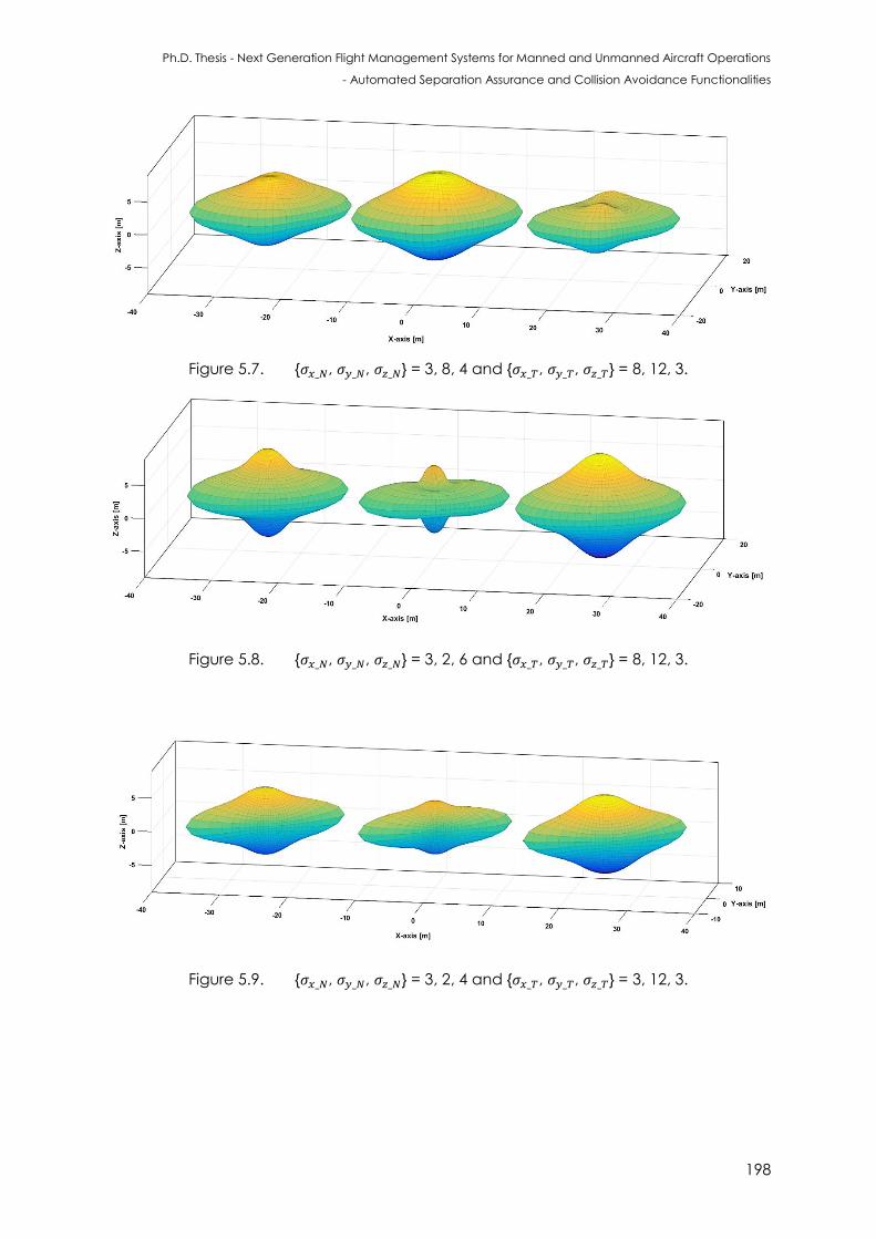
Ph.D. Thesis - Next Generation Flight Management Systems for Manned and Unmanned Aircraft Operations
- Automated Separation Assurance and Collision Avoidance Functionalities
198
Figure 5.7. { , , } = 3, 8, 4 and { , , } = 8, 12, 3.
Figure 5.8. { , , } = 3, 2, 6 and { , , } = 8, 12, 3.
Figure 5.9. { , , } = 3, 2, 4 and { , , } = 3, 12, 3.
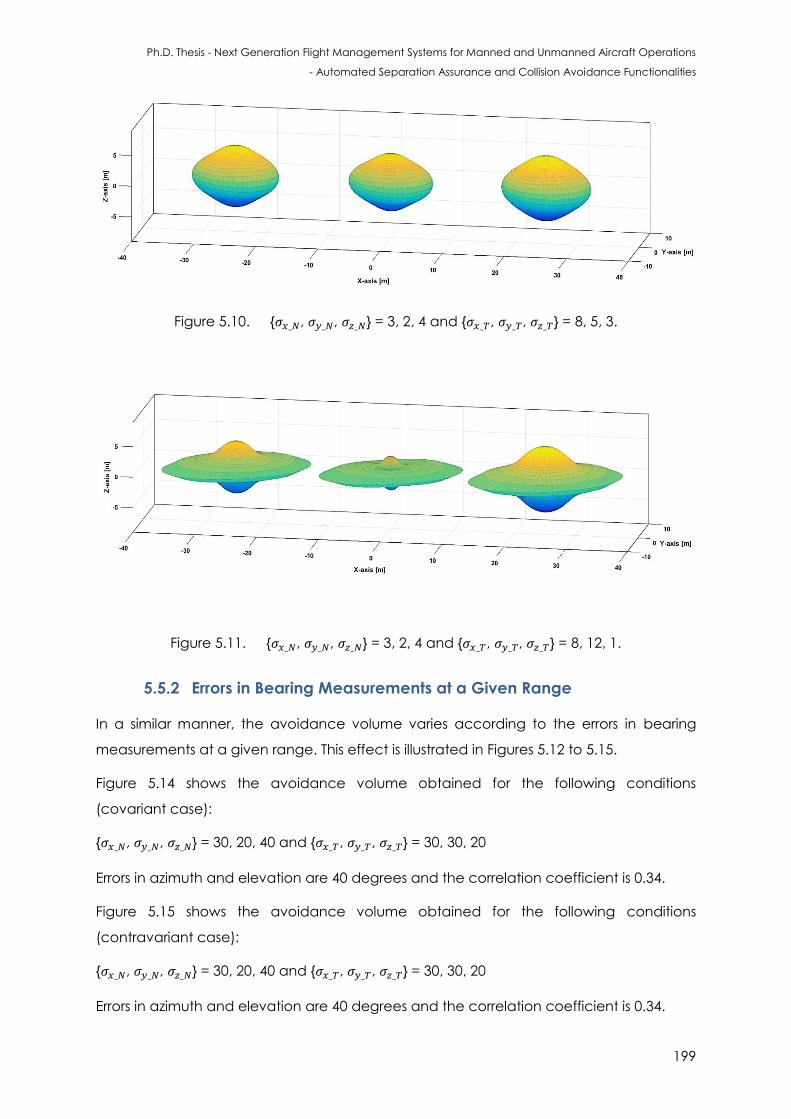
Ph.D. Thesis - Next Generation Flight Management Systems for Manned and Unmanned Aircraft Operations
- Automated Separation Assurance and Collision Avoidance Functionalities
199
Figure 5.10. { , , } = 3, 2, 4 and { , , } = 8, 5, 3.
Figure 5.11. { , , } = 3, 2, 4 and { , , } = 8, 12, 1.
5.5.2 Errors in Bearing Measurements at a Given Range
In a similar manner, the avoidance volume varies according to the errors in bearing
measurements at a given range. This effect is illustrated in Figures 5.12 to 5.15.
Figure 5.14 shows the avoidance volume obtained for the following conditions
(covariant case):
{ , , } = 30, 20, 40 and { , , } = 30, 30, 20
Errors in azimuth and elevation are 40 degrees and the correlation coefficient is 0.34.
Figure 5.15 shows the avoidance volume obtained for the following conditions
(contravariant case):
{ , , } = 30, 20, 40 and { , , } = 30, 30, 20
Errors in azimuth and elevation are 40 degrees and the correlation coefficient is 0.34.
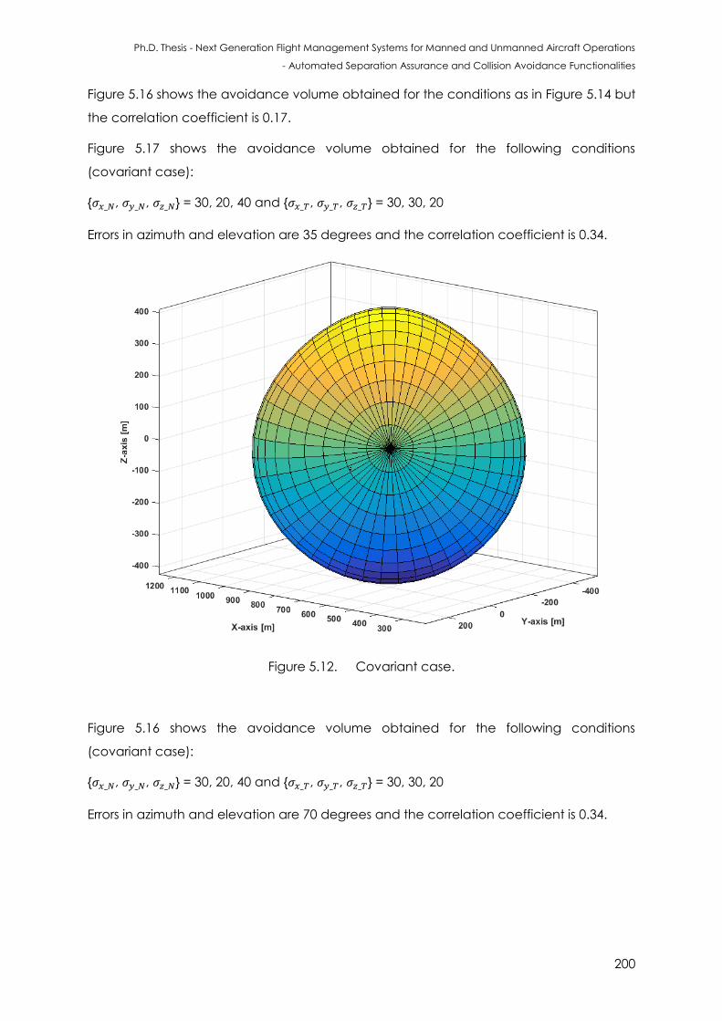
Ph.D. Thesis - Next Generation Flight Management Systems for Manned and Unmanned Aircraft Operations
- Automated Separation Assurance and Collision Avoidance Functionalities
200
Figure 5.16 shows the avoidance volume obtained for the conditions as in Figure 5.14 but
the correlation coefficient is 0.17.
Figure 5.17 shows the avoidance volume obtained for the following conditions
(covariant case):
{ , , } = 30, 20, 40 and { , , } = 30, 30, 20
Errors in azimuth and elevation are 35 degrees and the correlation coefficient is 0.34.
Figure 5.12. Covariant case.
Figure 5.16 shows the avoidance volume obtained for the following conditions
(covariant case):
{ , , } = 30, 20, 40 and { , , } = 30, 30, 20
Errors in azimuth and elevation are 70 degrees and the correlation coefficient is 0.34.
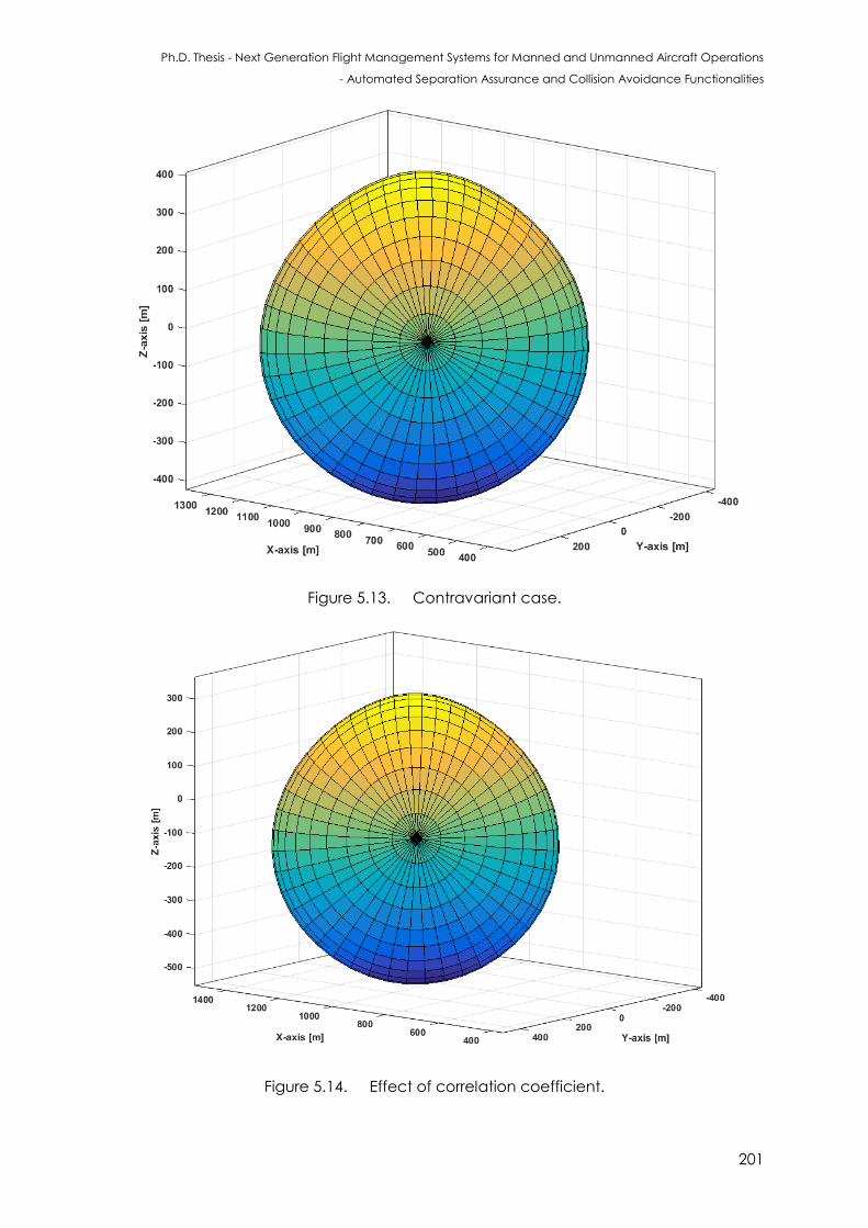
Ph.D. Thesis - Next Generation Flight Management Systems for Manned and Unmanned Aircraft Operations
- Automated Separation Assurance and Collision Avoidance Functionalities
201
Figure 5.13. Contravariant case.
Figure 5.14. Effect of correlation coefficient.
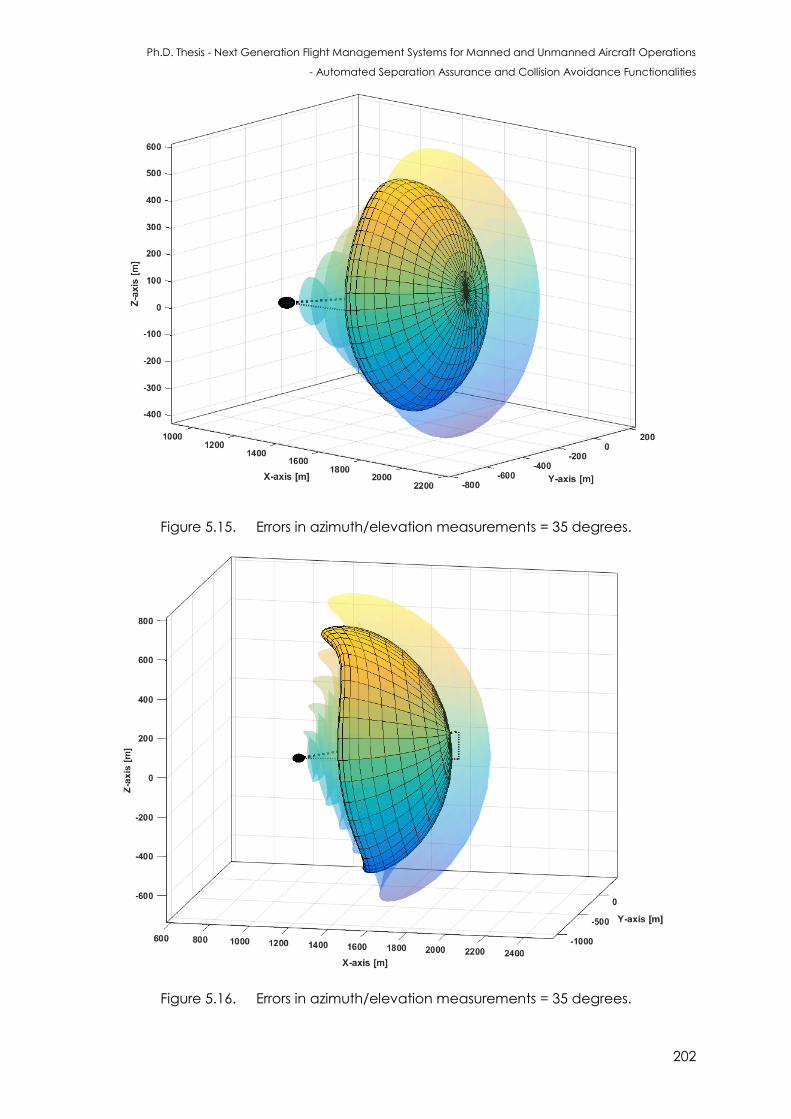
Ph.D. Thesis - Next Generation Flight Management Systems for Manned and Unmanned Aircraft Operations
- Automated Separation Assurance and Collision Avoidance Functionalities
202
Figure 5.15. Errors in azimuth/elevation measurements = 35 degrees.
Figure 5.16. Errors in azimuth/elevation measurements = 35 degrees.
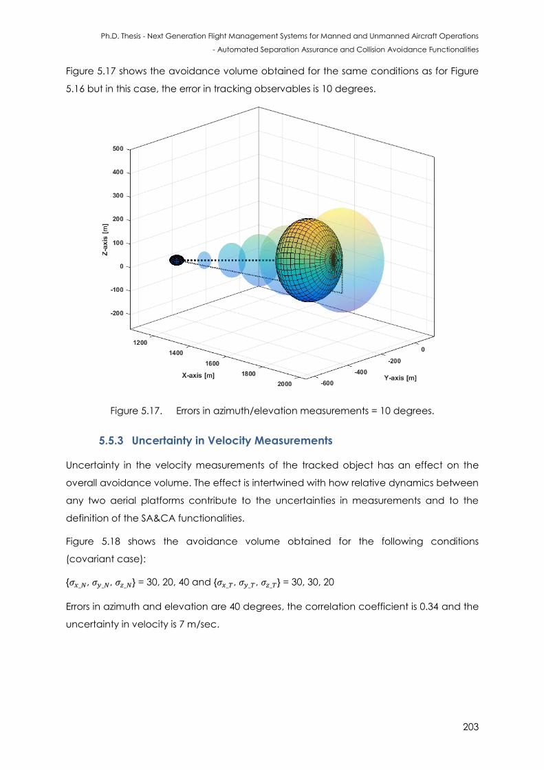
Ph.D. Thesis - Next Generation Flight Management Systems for Manned and Unmanned Aircraft Operations
- Automated Separation Assurance and Collision Avoidance Functionalities
203
Figure 5.17 shows the avoidance volume obtained for the same conditions as for Figure
5.16 but in this case, the error in tracking observables is 10 degrees.
Figure 5.17. Errors in azimuth/elevation measurements = 10 degrees.
5.5.3 Uncertainty in Velocity Measurements
Uncertainty in the velocity measurements of the tracked object has an effect on the
overall avoidance volume. The effect is intertwined with how relative dynamics between
any two aerial platforms contribute to the uncertainties in measurements and to the
definition of the SA&CA functionalities.
Figure 5.18 shows the avoidance volume obtained for the following conditions
(covariant case):
{ , , } = 30, 20, 40 and { , , } = 30, 30, 20
Errors in azimuth and elevation are 40 degrees, the correlation coefficient is 0.34 and the
uncertainty in velocity is 7 m/sec.
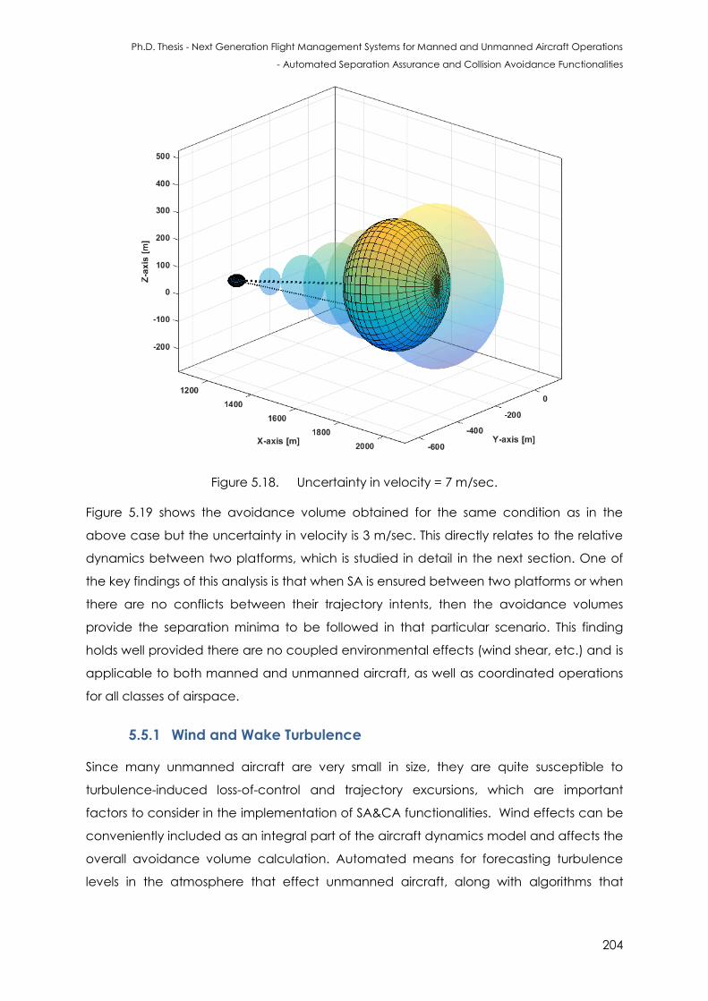
Ph.D. Thesis - Next Generation Flight Management Systems for Manned and Unmanned Aircraft Operations
- Automated Separation Assurance and Collision Avoidance Functionalities
204
Figure 5.18. Uncertainty in velocity = 7 m/sec.
Figure 5.19 shows the avoidance volume obtained for the same condition as in the
above case but the uncertainty in velocity is 3 m/sec. This directly relates to the relative
dynamics between two platforms, which is studied in detail in the next section. One of
the key findings of this analysis is that when SA is ensured between two platforms or when
there are no conflicts between their trajectory intents, then the avoidance volumes
provide the separation minima to be followed in that particular scenario. This finding
holds well provided there are no coupled environmental effects (wind shear, etc.) and is
applicable to both manned and unmanned aircraft, as well as coordinated operations
for all classes of airspace.
5.5.1 Wind and Wake Turbulence
Since many unmanned aircraft are very small in size, they are quite susceptible to
turbulence-induced loss-of-control and trajectory excursions, which are important
factors to consider in the implementation of SA&CA functionalities. Wind effects can be
conveniently included as an integral part of the aircraft dynamics model and affects the
overall avoidance volume calculation. Automated means for forecasting turbulence
levels in the atmosphere that effect unmanned aircraft, along with algorithms that
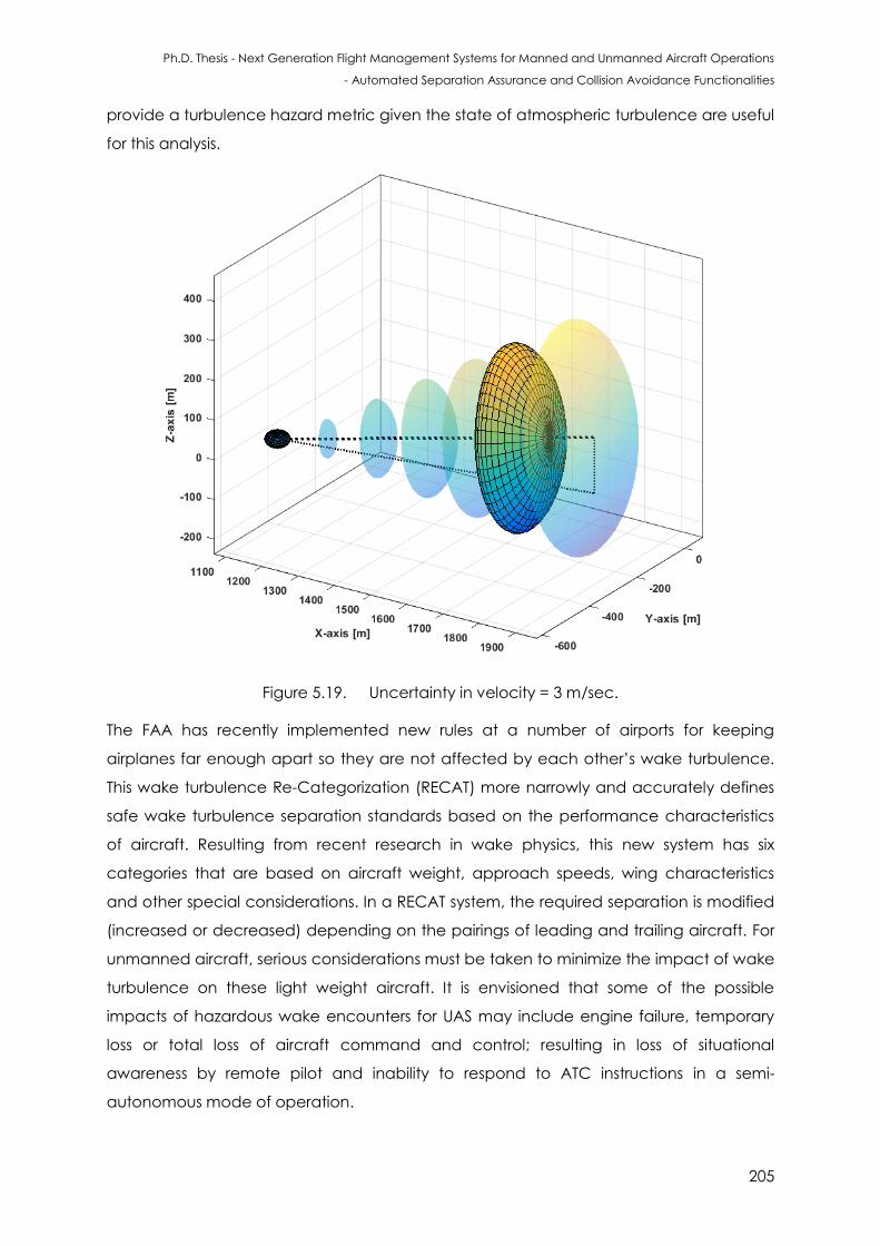
Ph.D. Thesis - Next Generation Flight Management Systems for Manned and Unmanned Aircraft Operations
- Automated Separation Assurance and Collision Avoidance Functionalities
205
provide a turbulence hazard metric given the state of atmospheric turbulence are useful
for this analysis.
Figure 5.19. Uncertainty in velocity = 3 m/sec.
The FAA has recently implemented new rules at a number of airports for keeping
airplanes far enough apart so they are not affected by each other’s wake turbulence.
This wake turbulence Re-Categorization (RECAT) more narrowly and accurately defines
safe wake turbulence separation standards based on the performance characteristics
of aircraft. Resulting from recent research in wake physics, this new system has six
categories that are based on aircraft weight, approach speeds, wing characteristics
and other special considerations. In a RECAT system, the required separation is modified
(increased or decreased) depending on the pairings of leading and trailing aircraft. For
unmanned aircraft, serious considerations must be taken to minimize the impact of wake
turbulence on these light weight aircraft. It is envisioned that some of the possible
impacts of hazardous wake encounters for UAS may include engine failure, temporary
loss or total loss of aircraft command and control; resulting in loss of situational
awareness by remote pilot and inability to respond to ATC instructions in a semi-
autonomous mode of operation.
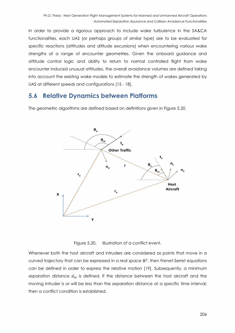
Ph.D. Thesis - Next Generation Flight Management Systems for Manned and Unmanned Aircraft Operations
- Automated Separation Assurance and Collision Avoidance Functionalities
206
In order to provide a rigorous approach to include wake turbulence in the SA&CA
functionalities, each UAS (or perhaps groups of similar type) are to be evaluated for
specific reactions (attitudes and altitude excursions) when encountering various wake
strengths at a range of encounter geometries. Given the onboard guidance and
attitude control logic and ability to return to normal controlled flight from wake
encounter induced unusual attitudes, the overall avoidance volumes are defined taking
into account the existing wake models to estimate the strength of wakes generated by
UAS at different speeds and configurations [15 - 18].
5.6 Relative Dynamics between Platforms
The geometric algorithms are defined based on definitions given in Figure 5.20.
X
Y
Host Aircraft
ra
rv
r
tv
nL
nv
ta
Other Traffic
na
θa
θar
θvr
θv
Figure 5.20. Illustration of a conflict event.
Whenever both the host aircraft and intruders are considered as points that move in a
curved trajectory that can be expressed in a real space ℝ , then Frenet-Serret equations
can be defined in order to express the relative motion [19]. Subsequently, a minimum
separation distance is defined. If the distance between the host aircraft and the
moving intruder is or will be less than the separation distance at a specific time interval,
then a conflict condition is established.
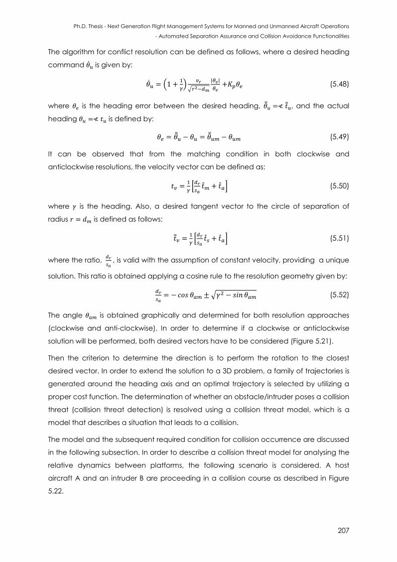
Ph.D. Thesis - Next Generation Flight Management Systems for Manned and Unmanned Aircraft Operations
- Automated Separation Assurance and Collision Avoidance Functionalities
207
The algorithm for conflict resolution can be defined as follows, where a desired heading
command is given by:
(
)
√
(5.48)
where is the heading error between the desired heading, , and the actual
heading is defined by:
(5.49)
It can be observed that from the matching condition in both clockwise and
anticlockwise resolutions, the velocity vector can be defined as:
[
] (5.50)
where is the heading. Also, a desired tangent vector to the circle of separation of
radius is defined as follows:
[
] (5.51)
where the ratio,
, is valid with the assumption of constant velocity, providing a unique
solution. This ratio is obtained applying a cosine rule to the resolution geometry given by:
√ (5.52)
The angle is obtained graphically and determined for both resolution approaches
(clockwise and anti-clockwise). In order to determine if a clockwise or anticlockwise
solution will be performed, both desired vectors have to be considered (Figure 5.21).
Then the criterion to determine the direction is to perform the rotation to the closest
desired vector. In order to extend the solution to a 3D problem, a family of trajectories is
generated around the heading axis and an optimal trajectory is selected by utilizing a
proper cost function. The determination of whether an obstacle/intruder poses a collision
threat (collision threat detection) is resolved using a collision threat model, which is a
model that describes a situation that leads to a collision.
The model and the subsequent required condition for collision occurrence are discussed
in the following subsection. In order to describe a collision threat model for analysing the
relative dynamics between platforms, the following scenario is considered. A host
aircraft A and an intruder B are proceeding in a collision course as described in Figure
5.22.
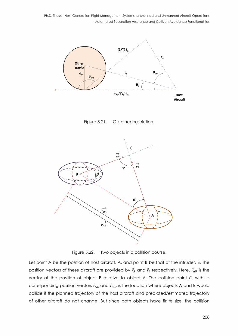
Ph.D. Thesis - Next Generation Flight Management Systems for Manned and Unmanned Aircraft Operations
- Automated Separation Assurance and Collision Avoidance Functionalities
208
Host Aircraft
(1/ϒ) ta
θd
Other Traffic
td θumdm
tv
θam
(dr/ϒsa) ts
Figure 5.21. Obtained resolution.
B
A
C
Figure 5.22. Two objects in a collision course.
Let point A be the position of host aircraft, A, and point B be that of the intruder, B. The
position vectors of these aircraft are provided by and respectively. Here, is the
vector of the position of object B relative to object A. The collision point , with its
corresponding position vectors and , is the location where objects A and B would
collide if the planned trajectory of the host aircraft and predicted/estimated trajectory
of other aircraft do not change. But since both objects have finite size, the collision
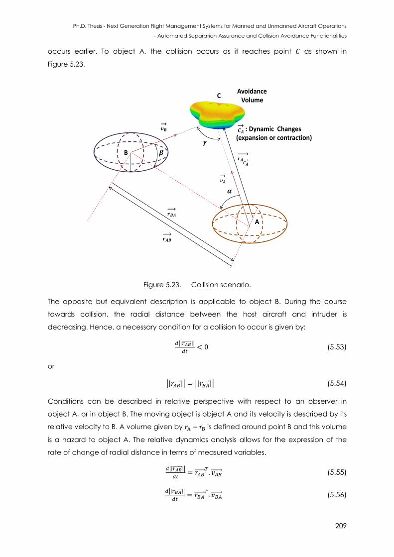
Ph.D. Thesis - Next Generation Flight Management Systems for Manned and Unmanned Aircraft Operations
- Automated Separation Assurance and Collision Avoidance Functionalities
209
occurs earlier. To object A, the collision occurs as it reaches point as shown in
Figure 5.23.
B
A
C
AvoidanceVolume
: Dynamic Changes (expansion or contraction)
Figure 5.23. Collision scenario.
The opposite but equivalent description is applicable to object B. During the course
towards collision, the radial distance between the host aircraft and intruder is
decreasing. Hence, a necessary condition for a collision to occur is given by:
| |
(5.53)
or
| | | | (5.54)
Conditions can be described in relative perspective with respect to an observer in
object A, or in object B. The moving object is object A and its velocity is described by its
relative velocity to B. A volume given by is defined around point B and this volume
is a hazard to object A. The relative dynamics analysis allows for the expression of the
rate of change of radial distance in terms of measured variables.
| |
(5.55)
| |
(5.56)
Ph.D. Thesis - Next Generation Flight Management Systems for Manned and Unmanned Aircraft Operations
- Automated Separation Assurance and Collision Avoidance Functionalities
210
Relative position and relative velocity are obtainable from direct measurement by on-
board range-and-direction sensors. The estimated time-to-collide ( ) is the time instance
with respect to current condition when collision is estimated to occur and is given by:
| | ( )
| | (5.57)
The above condition is not sufficient for a collision to occur. For example, if trajectories of
the host and intruder aircraft are parallel to each other, collision may not occur if the
separating distance between trajectories exceed certain value, namely the sum of both
object’s size radii. Therefore, another condition must be identified for describing the
collision. It can be seen that the extension line of vector intrudes the avoidance
volume, which means object A will collide with object B, provided the velocity vector of
the host aircraft does not change in its direction.
Angle is defined as the angle of encounter, by which the host aircraft encounters
the intruder aircraft. If the angle of encounter exceeds a certain predefined threshold
value, a miss situation may occur instead of a collision. Such angle of encounter is called
miss angle , or for short. By identifying these angles, the sufficient conditions
for avoiding a collision are obtained and are given by:
(5.58)
or
(5.59)
The other applicable conditions are given by:
(5.60)
or
(5.61)
The vectors for relative position and velocity are given by:
(5.62)
(5.63)
(5.64)
where and are the radial and tangential components of the vector. The
tangent angle is the angle of encounter . The radial and tangential components are
given by:
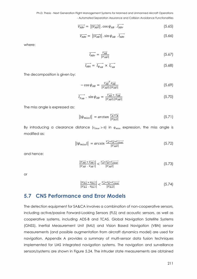
Ph.D. Thesis - Next Generation Flight Management Systems for Manned and Unmanned Aircraft Operations
- Automated Separation Assurance and Collision Avoidance Functionalities
211
| | (5.65)
| | (5.66)
where:
| | (5.67)
(5.68)
The decomposition is given by:
| | | | (5.69)
| | | | (5.70)
The miss angle is expressed as:
| |
| | (5.71)
By introducing a clearance distance ( ) in expression, the miss angle is
modified as:
| |
| | (5.72)
and hence:
| |
| |
| | (5.73)
or
| |
| |
| | (5.74)
5.7 CNS Performance and Error Models
The detection equipment for SA&CA involves a combination of non-cooperative sensors,
including active/passive Forward-Looking Sensors (FLS) and acoustic sensors, as well as
cooperative systems, including ADS-B and TCAS. Global Navigation Satellite Systems
(GNSS), Inertial Measurement Unit (IMU) and Vision Based Navigation (VBN) sensor
measurements (and possible augmentation from aircraft dynamics model) are used for
navigation. Appendix A provides a summary of multi-sensor data fusion techniques
implemented for UAS integrated navigation systems. The navigation and surveillance
sensors/systems are shown in Figure 5.24. The intruder state measurements are obtained
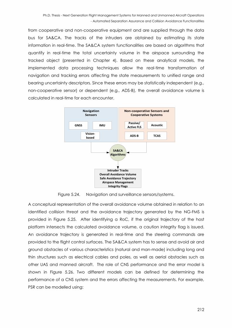
Ph.D. Thesis - Next Generation Flight Management Systems for Manned and Unmanned Aircraft Operations
- Automated Separation Assurance and Collision Avoidance Functionalities
212
from cooperative and non-cooperative equipment and are supplied through the data
bus for SA&CA. The tracks of the intruders are obtained by estimating its state
information in real-time. The SA&CA system functionalities are based on algorithms that
quantify in real-time the total uncertainty volume in the airspace surrounding the
tracked object (presented in Chapter 4). Based on these analytical models, the
implemented data processing techniques allow the real-time transformation of
navigation and tracking errors affecting the state measurements to unified range and
bearing uncertainty descriptors. Since these errors may be statistically independent (e.g.,
non-cooperative sensor) or dependent (e.g., ADS-B), the overall avoidance volume is
calculated in real-time for each encounter.
Navigation Sensors
Non-cooperative Sensors and Cooperative Systems
Intruder TracksOverall Avoidance Volume Safe Avoidance Trajectory
Airspace Management Integrity Flags
SA&CAAlgorithms
GNSS IMUPassive/
Active FLS
ADS-B TCAS
Acoustic
Vision-based
Figure 5.24. Navigation and surveillance sensors/systems.
A conceptual representation of the overall avoidance volume obtained in relation to an
identified collision threat and the avoidance trajectory generated by the NG-FMS is
provided in Figure 5.25. After identifying a RoC, if the original trajectory of the host
platform intersects the calculated avoidance volume, a caution integrity flag is issued.
An avoidance trajectory is generated in real-time and the steering commands are
provided to the flight control surfaces. The SA&CA system has to sense and avoid air and
ground obstacles of various characteristics (natural and man-made) including long and
thin structures such as electrical cables and poles, as well as aerial obstacles such as
other UAS and manned aircraft. The role of CNS performance and the error model is
shown in Figure 5.26. Two different models can be defined for determining the
performance of a CNS system and the errors affecting the measurements. For example,
PSR can be modelled using:
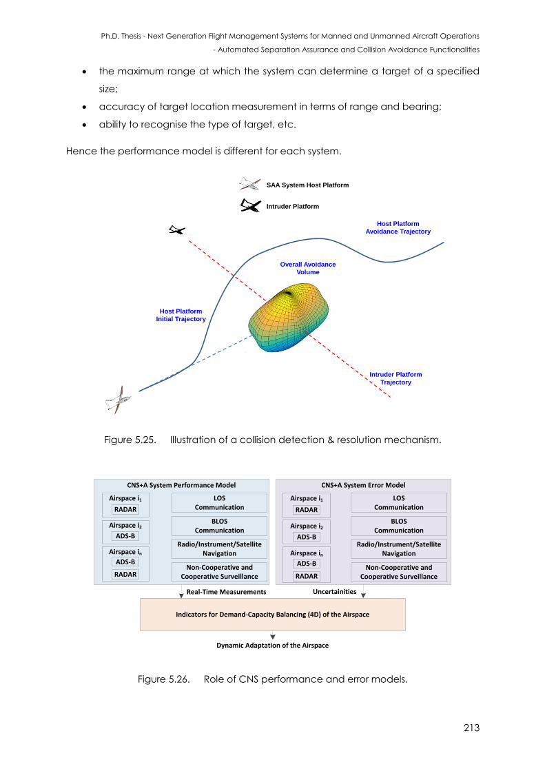
Ph.D. Thesis - Next Generation Flight Management Systems for Manned and Unmanned Aircraft Operations
- Automated Separation Assurance and Collision Avoidance Functionalities
213
the maximum range at which the system can determine a target of a specified
size;
accuracy of target location measurement in terms of range and bearing;
ability to recognise the type of target, etc.
Hence the performance model is different for each system.
Overall Avoidance
Volume
SAA System Host Platform
Intruder Platform
Host Platform
Avoidance Trajectory
Intruder Platform
Trajectory
Host Platform
Initial Trajectory
Figure 5.25. Illustration of a collision detection & resolution mechanism.
CNS+A System Performance Model
Real-Time Measurements Uncertainities
Indicators for Demand-Capacity Balancing (4D) of the Airspace
RADAR
Airspace i1
ADS-B
Airspace i2
RADAR
Airspace in
ADS-B
Dynamic Adaptation of the Airspace
LOS Communication
Radio/Instrument/Satellite Navigation
CNS+A System Error Model
RADAR
Airspace i1
ADS-B
Airspace i2
RADAR
Airspace in
ADS-B
BLOS Communication
Non-Cooperative and Cooperative Surveillance
LOS Communication
Radio/Instrument/Satellite Navigation
BLOS Communication
Non-Cooperative and Cooperative Surveillance
Figure 5.26. Role of CNS performance and error models.
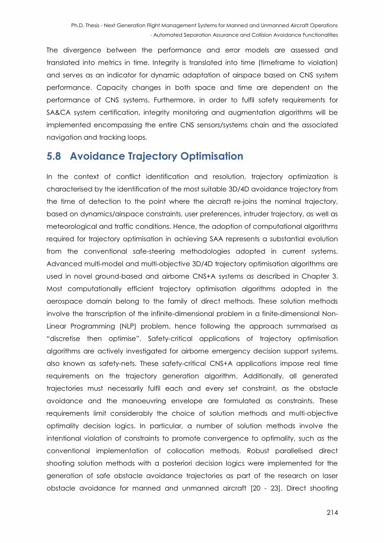
Ph.D. Thesis - Next Generation Flight Management Systems for Manned and Unmanned Aircraft Operations
- Automated Separation Assurance and Collision Avoidance Functionalities
214
The divergence between the performance and error models are assessed and
translated into metrics in time. Integrity is translated into time (timeframe to violation)
and serves as an indicator for dynamic adaptation of airspace based on CNS system
performance. Capacity changes in both space and time are dependent on the
performance of CNS systems. Furthermore, in order to fulfil safety requirements for
SA&CA system certification, integrity monitoring and augmentation algorithms will be
implemented encompassing the entire CNS sensors/systems chain and the associated
navigation and tracking loops.
5.8 Avoidance Trajectory Optimisation
In the context of conflict identification and resolution, trajectory optimization is
characterised by the identification of the most suitable 3D/4D avoidance trajectory from
the time of detection to the point where the aircraft re-joins the nominal trajectory,
based on dynamics/airspace constraints, user preferences, intruder trajectory, as well as
meteorological and traffic conditions. Hence, the adoption of computational algorithms
required for trajectory optimisation in achieving SAA represents a substantial evolution
from the conventional safe-steering methodologies adopted in current systems.
Advanced multi-model and multi-objective 3D/4D trajectory optimisation algorithms are
used in novel ground-based and airborne CNS+A systems as described in Chapter 3.
Most computationally efficient trajectory optimisation algorithms adopted in the
aerospace domain belong to the family of direct methods. These solution methods
involve the transcription of the infinite-dimensional problem in a finite-dimensional Non-
Linear Programming (NLP) problem, hence following the approach summarised as
“discretise then optimise”. Safety-critical applications of trajectory optimisation
algorithms are actively investigated for airborne emergency decision support systems,
also known as safety-nets. These safety-critical CNS+A applications impose real time
requirements on the trajectory generation algorithm. Additionally, all generated
trajectories must necessarily fulfil each and every set constraint, as the obstacle
avoidance and the manoeuvring envelope are formulated as constraints. These
requirements limit considerably the choice of solution methods and multi-objective
optimality decision logics. In particular, a number of solution methods involve the
intentional violation of constraints to promote convergence to optimality, such as the
conventional implementation of collocation methods. Robust parallelised direct
shooting solution methods with a posteriori decision logics were implemented for the
generation of safe obstacle avoidance trajectories as part of the research on laser
obstacle avoidance for manned and unmanned aircraft [20 - 23]. Direct shooting
Ph.D. Thesis - Next Generation Flight Management Systems for Manned and Unmanned Aircraft Operations
- Automated Separation Assurance and Collision Avoidance Functionalities
215
methods, involving the transcription into finite-dimensional NLP problem, can be either
performed by introducing a control parameterisation based on arbitrarily chosen
analytical functions, as in transcription methods, or by adopting a generalised piecewise
approximation of both control and state variables based on a polynomial sequence of
arbitrary degree, as in collocation methods. In both cases the transcribed dynamical
system is integrated along the time interval [ . The search of the optimal set of
discretisation parameters is formulated as a NLP problem, which is solved
computationally by exploiting efficient numerical NLP algorithms. In direct transcription
methods, a basis of known linearly independent functions ( ) with unknown
coefficients is adopted as the parameterisation in the general form:
( ) ∑ ( ) (5.75)
In direct shooting and multiple direct shooting, the parameterisation is performed on the
controls ( ) only, and the dynamic constraints are integrated with traditional numerical
methods such as the Runge-Kutta family, while the Lagrange term in the cost function is
approximated by a quadrature approximation.
In multiple shooting, the analysed time interval is partitioned into subintervals. The
direct shooting method is then applied to each subinterval. Parallel implementations of
direct shooting involve the simultaneous integration of a family of trajectories based on
different control parametrisation profiles, taking advantage of increasingly common
multi-thread/multi-core hardware architectures. The optimal solution is determined a
posteriori, both in the case of single objective and multi objective implementations. The
following set of differential algebraic equations for the aircraft dynamics are adopted:
{
( )
[( )
( )
( )
(5.76)
The state vector consists of the following variables: v is longitudinal velocity (scalar) [m s-
1]; γ is flight path angle (scalar) [rad]; is track angle (scalar) [rad]; is geographic
latitude [rad]; is geographic longitude [rad]; z is flight altitude [m]; is thrust angle of
Ph.D. Thesis - Next Generation Flight Management Systems for Manned and Unmanned Aircraft Operations
- Automated Separation Assurance and Collision Avoidance Functionalities
216
attack [rad] and m is aircraft mass [kg]; and the variables forming the control vector are:
T is thrust force [N]; N is load factor[dimensionless] and μ is bank angle [rad]. Other
variables and parameters include: D is aerodynamic drag [N]; vw is wind velocity, in its
three scalar components [m s-1]; g is the gravitational acceleration [m s-2]; RE is radius of
the Earth [m] and FF is fuel flow [kg s-1]. Adopting a multi-phase trajectory optimisation
formulation, the selection of the optimal trajectory along the first phase (safe steering) is
typically based on minimising a cost function of the form:
( ) ( ) ∫ ( ) (5.77)
where ( ) is the slant distance of the host platform along the avoidance trajectory from
the avoidance volume associated with the obstacle, is the time at
which the safe avoidance condition is successfully attained, TTT is the time-to-threat and
AMT is the avoidance manoeuvre time, ( ) is the host platform’s mass and
{ } are the positive weightings attributed to time, distance, integral distance
and fuel respectively. In time-critical avoidance applications (i.e., closing obstacles with
high relative velocities) appropriate higher weightings are used for the time and
distance cost elements.
In terms of achieving separation maintenance, considering sector/runway capacity
model, the time of separation between manned/ unmanned aircraft is given by:
[
] when (5.78)
[
] when (5.79)
where is the time of separation, and are the velocities of adjacent aircraft, is
the distance of separation, is the required separation and represents the order.
5.9 SA&CA Certification Framework
One of the fundamental limitations for certification authorities for SA&CA functions is the
inability to evaluate whether the system performance achieves comparable or superior
levels of collision detection and resolution to manned aircraft, along with separation
maintenance upon replacing the on board pilot with a Ground Control Station (GCS)
remote pilot. Appendix B provides a compilation of the certification standards, AMC,
GM, and recommended practices for the three categories (two-pilot aircraft, single-pilot
and UAS) encompassing the Operational (OP), Technical (TC), Safety (SAF), Human
Factors (HF) as well as Test and Evaluation (TE) aspects [24].
Ph.D. Thesis - Next Generation Flight Management Systems for Manned and Unmanned Aircraft Operations
- Automated Separation Assurance and Collision Avoidance Functionalities
217
The material was sourced from national/international organizations such as the
International Civil Aviation Organization (ICAO), Federal Aviation Authority (FAA),
European Aviation Safety Agency (EASA), Civil Aviation Authorities (CAA) from Australia,
the UK and New Zealand, the US Department of Defence (DOD) and the Institute for
Defense Analyses (IDA). References are also made to standards from Aeronautical
Radio Incorporated (ARINC), American Society of the International Association for
Testing and Materials (ASTM), Radio Technical Commission for Aeronautics (RTCA),
Society of Automotive Engineers (SAE), and NATO Standardization Agreements
(STANAGs) [25 - 28].
5.9.1 SA&CA Hardware and Software Selection in UAS
This section provide The avionics hardware in small UAS is typically chosen to be in the
PC/104 form factor or even a smaller configuration for achieving smaller size, ruggedness
and modularity. The Size, Weight and Power (SWaP) requirements are carefully analysed
for the hardware implementation. The Tailored Input/Output (TIO) software needs to be
able to provide information exchange from/to ARINC-429, RS-232/422/485, USB and
additional interfaces as required.
The hardware design needs to ensure a straightforward path to compliance with RTCA
DO-254 and other safety assessment standards for certification. The detailed hardware
requirements, design information and traceability matrix is provided during the system
development process. The SA&CA system is envisaged to be integrated into the existing
avionics compartment (within NG-FMS) so as to minimally impact the existing payload
capacity of the host aircraft.
The navigation and tracking sensors are distributed between the avionics compartment
and the airframe as appropriate (avoiding mechanical/electromechanical
interferences and mitigating impacts on payload capacity). A number of sensor
configurations are investigated during the SAA system development phase. As an
example, the FAA Field-of-Regard (FOR) recommendations are illustrated in
Figure 5.27 (a). Considering two non-cooperative sensors (visual camera and radar) for
Collision Detection and Resolution (CD&R) tasks, the FOR obtained is depicted in Figure
5.27 (b).
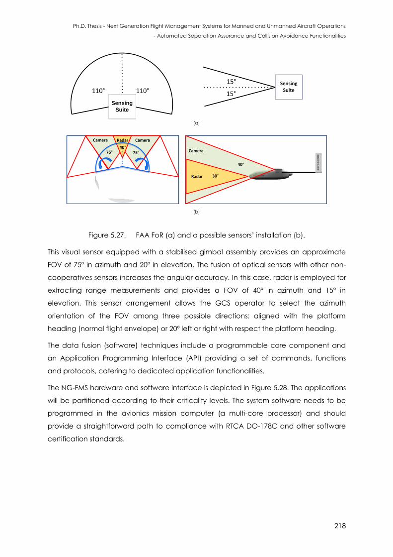
Ph.D. Thesis - Next Generation Flight Management Systems for Manned and Unmanned Aircraft Operations
- Automated Separation Assurance and Collision Avoidance Functionalities
218
30°
40°
SAA
System
110° 110°SAA
System
15°
15°
40°75°75°
Radar
Radar
Camera
CameraCamera
(a)
(b)
Sensing
Suite
SensingSuite
Figure 5.27. FAA FoR (a) and a possible sensors’ installation (b).
This visual sensor equipped with a stabilised gimbal assembly provides an approximate
FOV of 75º in azimuth and 20º in elevation. The fusion of optical sensors with other non-
cooperatives sensors increases the angular accuracy. In this case, radar is employed for
extracting range measurements and provides a FOV of 40º in azimuth and 15º in
elevation. This sensor arrangement allows the GCS operator to select the azimuth
orientation of the FOV among three possible directions: aligned with the platform
heading (normal flight envelope) or 20º left or right with respect the platform heading.
The data fusion (software) techniques include a programmable core component and
an Application Programming Interface (API) providing a set of commands, functions
and protocols, catering to dedicated application functionalities.
The NG-FMS hardware and software interface is depicted in Figure 5.28. The applications
will be partitioned according to their criticality levels. The system software needs to be
programmed in the avionics mission computer (a multi-core processor) and should
provide a straightforward path to compliance with RTCA DO-178C and other software
certification standards.
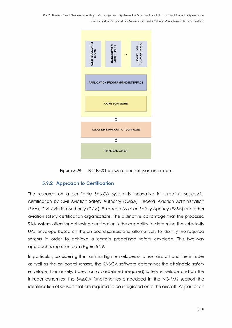
Ph.D. Thesis - Next Generation Flight Management Systems for Manned and Unmanned Aircraft Operations
- Automated Separation Assurance and Collision Avoidance Functionalities
219
APPLICATION PARTITIONS
CORE SOFTWARE
PHYSICAL LAYER
TAILORED INPUT/OUTPUT SOFTWARE
APPLICATION PROGRAMMING INTERFACE
SA
&C
A
FU
NC
TIO
NA
LIT
IES
TR
AJ
EC
TO
RY
MA
NA
GE
ME
NT
CO
MM
UN
ICA
TIO
N
DA
TA
LIN
KS
...
Figure 5.28. NG-FMS hardware and software interface.
5.9.2 Approach to Certification
The research on a certifiable SA&CA system is innovative in targeting successful
certification by Civil Aviation Safety Authority (CASA), Federal Aviation Administration
(FAA), Civil Aviation Authority (CAA), European Aviation Safety Agency (EASA) and other
aviation safety certification organisations. The distinctive advantage that the proposed
SAA system offers for achieving certification is the capability to determine the safe-to-fly
UAS envelope based on the on board sensors and alternatively to identify the required
sensors in order to achieve a certain predefined safety envelope. This two-way
approach is represented in Figure 5.29.
In particular, considering the nominal flight envelopes of a host aircraft and the intruder
as well as the on board sensors, the SA&CA software determines the attainable safety
envelope. Conversely, based on a predefined (required) safety envelope and on the
intruder dynamics, the SA&CA functionalities embedded in the NG-FMS support the
identification of sensors that are required to be integrated onto the aircraft. As part of an
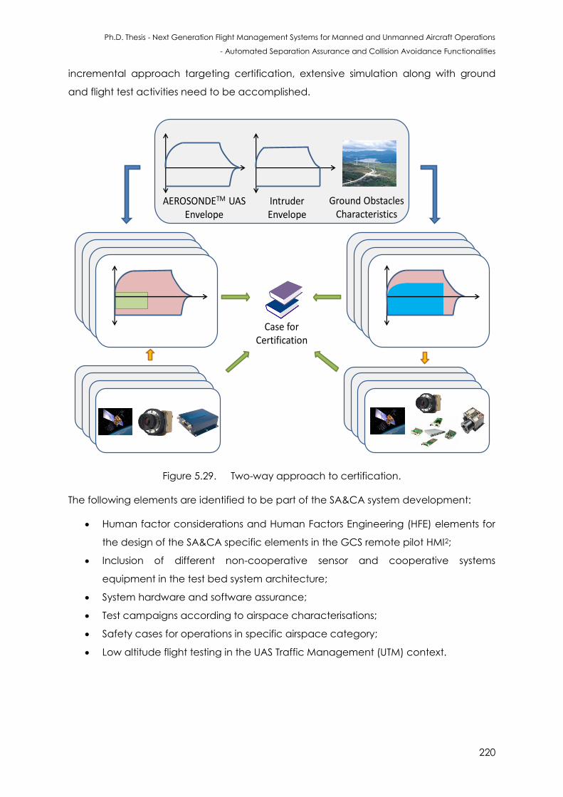
Ph.D. Thesis - Next Generation Flight Management Systems for Manned and Unmanned Aircraft Operations
- Automated Separation Assurance and Collision Avoidance Functionalities
220
incremental approach targeting certification, extensive simulation along with ground
and flight test activities need to be accomplished.
Case for Certification
AEROSONDETM UASEnvelope
IntruderEnvelope
Ground ObstaclesCharacteristics
Envelope - FLS only Envelope Envelope - FLS only
Envelope - FLS onlyEnvelope
Envelope
Envelope - FLS onlyEnvelope - FLS only
Envelope - FLS onlyEnvelope - FLS only
Envelope - FLS onlyEnvelope - FLS only
Figure 5.29. Two-way approach to certification.
The following elements are identified to be part of the SA&CA system development:
Human factor considerations and Human Factors Engineering (HFE) elements for
the design of the SA&CA specific elements in the GCS remote pilot HMI2;
Inclusion of different non-cooperative sensor and cooperative systems
equipment in the test bed system architecture;
System hardware and software assurance;
Test campaigns according to airspace characterisations;
Safety cases for operations in specific airspace category;
Low altitude flight testing in the UAS Traffic Management (UTM) context.
Ph.D. Thesis - Next Generation Flight Management Systems for Manned and Unmanned Aircraft Operations
- Automated Separation Assurance and Collision Avoidance Functionalities
221
5.10 Conclusions
The algorithms employed for determining the performance of sensors/systems and
determining the avoidance trajectory in the unified approach to cooperative and non-
cooperative SA&CA for manned and unmanned aircraft were described. Based on the
identified state-of-the-art SA&CA technologies, a BDL driven decision tree test bed
system reference architecture is presented. Implementations involving Boolean logics
are generally hard wired and cannot be reconfigured and this limits the scope of unified
framework in terms of automatic decision making capability. An architecture for
selecting the sensors/systems was defined based on their performance achieved at any
instant of time. Covariance matrices were used for estimating sensor and system
performances. After identifying a RoC, if the original trajectory of the host platform
intersects the calculated avoidance volume, a caution integrity flag is issued. The
algorithms used for avoidance trajectories (in near real-time) were also presented. The
need for a certifiable SA&CA system and the implementation design drivers were also
presented. The pathway to certification was described, with the unified approach
emerging as an innovative method in targeting successful certification by CASA, FAA,
CAA and other aviation regulatory bodies. By applying the unified approach and by
considering the nominal flight envelopes of the host UAS and other traffic as well as the
on board sensors, the approach determines the attainable safety envelope. Conversely,
based on a predefined (required) safety envelope and dynamics of other traffic, the
software is capable of identifying the sensors that are required to be integrated in the
aircraft.
5.11 References
1. M.J. Kochenderfer, J.E. Holland and P. James, “Chryssanthacopoulos: Next Generation
Airborne Collision Avoidance System”, Lincoln Laboratory Journal, Vol. 19, issue 1, pp.
17– 33, 2012.
2. J.B. Jeannin, K. Ghorbal, Y. Kouskoulas, R. Gardner, A. Schmidt, E. Zawadzki and A.
Platzer, “A Formally Verified Hybrid System for the Next-Generation Airborne Collision
Avoidance System”, International Conference on Tools and Algorithms for the
Construction and Analysis of Systems, TACAS 2015: Tools and Algorithms for the
Construction and Analysis of Systems, pp 21-36, Springer - Berlin Heidelberg, 2015.
3. C. Muñoz, A. Narkawicz, J. Chamberlain, M. Consiglio and J. Upchurch, “A family of
Well-Clear Boundary Models for the Integration of UAS in the NAS”, Proceedings of the
Ph.D. Thesis - Next Generation Flight Management Systems for Manned and Unmanned Aircraft Operations
- Automated Separation Assurance and Collision Avoidance Functionalities
222
14th AIAA Aviation Technology, Integration, and Operations (ATIO) Conference, AIAA-
2014-2412, Georgia, Atlanta, USA, 2014.
4. R. Sabatini, T. Moore, and C. Hill, “A New Avionics Based GNSS Integrity Augmentation
System: Part 1 – Fundamentals,” Journal of Navigation, vol. 66, no. 3, pp. 363-383, May
2013. DOI: 10.1017/S0373463313000027
5. R. Sabatini, T. Moore, and C. Hill, “A New Avionics Based GNSS Integrity Augmentation
System: Part 2 – Integrity Flags,” Journal of Navigation, vol. 66, no. 4, pp. 511-522, June
2013. DOI: 10.1017/S0373463313000143
6. R. Sabatini, T. Moore, C. Hill and S. Ramasamy, “Assessing Avionics-Based GNSS Integrity
Augmentation Performance in UAS Mission- and Safety-Critical Tasks”, Proceedings
of International Conference on Unmanned Aircraft Systems (ICUAS 2015), Denver, CO,
USA, 2015. DOI: 10.1109/ICUAS.2015.7152347
7. P.J. Górski, A. Czaplicka and J.A. Hołyst, “Coevolution of Information Processing and
Topology in Hierarchical Adaptive Random Boolean Networks”, The European Physical
Journal B, Vol. 89, no. 2, pp.1-9, 2016.
8. R.N. Kashi, M. D'Souza, S.K. Baghel and N. Kulkarni, “Formal Verification of Avionics Self
Adaptive Software: A case study”, Proceedings of the 9th ACM India Software
Engineering Conference, pp. 163-169, 2016.
9. A. Thayse and M. Davio, “Boolean Differential Calculus and its Application to Switching
Theory”, IEEE Transactions on Computers, Vol. 22, Issue 4, pp.409-420, 1973.
10. J.L. Farrell, “Navigation and Tracking”, Chapter 14, eds. C. Spitzer, U. Ferrell and T.
Ferrell, Digitial Avionics Handbook, Third Edition, CRC Press, 2014.
11. L.R. Sahawneh, “Airborne Collision Detection and Avoidance for Small UAS Sesne and
Avoid Systems”, PhD Thesies, Brigham Young University, 2016.
12. RTCA, “Minimum Operational Performance Standards (MOPS) for Aircraft Surveillance
Applications (ASA) System”, DO-317B, Radio Technical Commission for Aeronautics,
Washington DC, USA, 2011.
13. RTCA, “Safety, Performance and Interoperability Requirements Document for
Enhanced Air Traffic Services in Radar-Controlled Areas Using ADS-B Surveillance (ADS-
B-RAD)”, DO-318, Radio Technical Commission for Aeronautics, Washington DC, USA,
2009.
14. S. Ramasamy, R. Sabatini and A. Gardi, “LIDAR Obstacle Warning and Avoidance
System for Unmanned Aerial Vehicle Sense-and-Avoid”, Aerospace Science and
Technology, Elsevier, vol. 55, pp. 344–358, 2016. DOI: 10.1016/j.ast.2016.05.020
Ph.D. Thesis - Next Generation Flight Management Systems for Manned and Unmanned Aircraft Operations
- Automated Separation Assurance and Collision Avoidance Functionalities
223
15. J.N. Hallock, G.C. Greene, J.A. Tittsworth, P.A. Strande and F.Y. Wang, “Use of Simple
Models to Determine Wake Vortex Categories for New Aircraft”, 7th AIAA Atmospheric
and Space Environments Conference, AIAA AVIATION Forum, AIAA 2015-3172, 2015.
16. L. DeVries and D.A. Paley, “Wake Estimation and Optimal Control for Autonomous
Aircraft in Formation Flight”, Proceedinsg of the AIAA Guidance, Navigation, and
Control (GNC) Conference, (AIAA 2013-4705), Boston, USA, 2015.
17. A. He, P. Tian, Z.C. Zheng, H. Chao and Y. Gu, “A Study on UAS Wake Turbulence
Encounter Using Coupled Aerodynamics and Flight Dynamics Simulation”, 8th AIAA
Atmospheric and Space Environments Conference, AIAA AVIATION Forum, pp. 2016-
3439, 2016. DOI: 10.2514/6.2016-3439
18. J.M Alliot and N. Durand, “A Mathematical Analysis of the Influence of Wind
Uncertainty on MTCD Efficiency”, The controller, Meteorology and ATC (IFATCA), pp.
17-19, 2011.
19. P. Angelov, “Sense and Avoid in UAS: Research and Applications,” John Wiley & Sons,
2012.
20. A. Gardi, R. Sabatini and S. Ramasamy, “Multi-objective Optimisation of Aircraft Flight
Trajectories in the ATM and Avionics Context”, Progress in Aerospace Sciences, vol. 83,
pp. 1-36, 2016.
21. O. Von Stryk and R. Bulirsch, “Direct and Indirect Methods for Trajectory Optimization”,
Annals of Operations Research, vol. 37, pp. 357-373, 1992.
22. J. T. Betts, “Survey of Numerical Methods for Trajectory Optimization”, Journal of
Guidance, Control and Dynamics, vol. 21, pp. 193-207, 1998.
23. J. Z. Ben-Asher, “Optimal Control Theory with Aerospace Applications”, Education
Series, American Institute of Aeronautics and Astronautics (AIAA), Reston, VA, USA,
2010.
24. Y. Lim, B. Vincent, S. Ramasamy, J. Liu and R. Sabatini, “Commercial Airliner Single Pilot
Operations: System Design Drivers and Pathways to Certification”, IEEE Aerospace and
Electronic Systems Magazine, 2017.
25. Federal Aviation Administration, “Integration of Civil Unmanned Aircraft Systems (UAS)
in the National Airspace System (NAS) Roadmap”, First edition, Washington DC, USA,
2013.
26. D.L. Edwards, “Flight Standardization Board (FSB) Report: EMBRAER S.A. EMB-500”,
Federal Aviation Administration (FAA), Missouri, USA, 2014.
27. Civil Aviation Authority, “CAP 722 Unmanned Aircraft System Operations in UK Airspace
– Guidance”, UK CAA, Norwich,UK, 2012.
Ph.D. Thesis - Next Generation Flight Management Systems for Manned and Unmanned Aircraft Operations
- Automated Separation Assurance and Collision Avoidance Functionalities
224
28. ICAO, “Annexes 1 to 18”, International Civil Aviation Organization, Montreal, Canada,
2012.
29. EASA, “Acceptable Means of Compliance (AMC) and Guidance Material (GM) to
Part-CAT”, European Aviation Safety Agency, Cologne, Germany, 2013.
Ph.D. Thesis - Next Generation Flight Management Systems for Manned and Unmanned Aircraft Operations
- Automated Separation Assurance and Collision Avoidance Functionalities
225
CHAPTER 6
GROUND OBSTACLES SA&CA
CASE STUDY
“Invention consists in avoiding the constructing of useless contraptions and in
constructing the useful combinations which are in infinite minority”. - Henri Poincare
6.1 Introduction
Based on the analytical models described in Chapter 4, data processing techniques
allow the real-time transformation of navigation and tracking errors affecting the state
measurements to unified range and bearing uncertainty descriptors. The investigation of
this chapter focusses on validating the SA&CA algorithms for ground targets. An
introduction to the available ground obstacle detection and avoidance technologies is
presented, followed by a detailed case study on the LIDAR Obstacle Warning and
Avoidance System (LOWAS) as one of the possible implementation technologies for the
unified approach to SA&CA.
6.2 Ground Obstacle Detection and Warning Systems
The demand for reliable ground obstacle warning and avoidance capabilities to ensure
safe low-level flight operations has led to the development of compact collision
avoidance systems for a variety of fixed and rotary wing aircraft. Capabilities to prevent
Controlled Flight Into Terrain (CFIT) are primarily provided by the flight crew and the ATM
system ensuring safe operation of the aircraft. Safety is ensured by using primary
instrumentation onboard the aircraft, carefully adhering to the ATCo instructions and
being aware of the overall situation [1]. Secondary on-board guard against CFIT is
provided by employing terrain proximity detection and warning devices commonly
known as Terrain Awareness and Warning Systems (TAWS).
Ph.D. Thesis - Next Generation Flight Management Systems for Manned and Unmanned Aircraft Operations
- Automated Separation Assurance and Collision Avoidance Functionalities
226
TAWS are developed to provide warnings for possible conflicts with terrain by taking into
account inputs such as aircraft states, glideslope and databases (terrain, obstacles and
airport). TAWS are generally classified into three types namely:
Class-A TAWS: This class of equipment is required for turbine-powered airplanes
operated under part 121 (airline) and part 135 (charter) of 10 or more passenger
seats [2]. The system includes a minimum of five basic functions including forward
looking terrain avoidance, premature descent alert, attention alerts, terrain
awareness display and indications of imminent contact with the ground.
TAWS Class-B: This class of equipment is required for turbine-powered airplanes
operated under part 91 with six or more passenger seats and for turbine-powered
airplanes operated under part 135 with six to nine passenger seats [2]. The system
includes a minimum of four basic functions including forward looking terrain
avoidance, premature descent alert, attention alerts and indications of imminent
contact with the ground.
TAWS Class C: This class of equipment is targeted to be used in small general
aviation airplanes that are not required to install Class B equipment, which
includes minimum operational performance standards intended for piston-
powered and turbine-powered airplanes.
Statistics show that there is a significant drop of accidents after the introduction of radio
altimeter and Ground Proximity Warning Systems (GPWS) in commercial turbo jet aircraft
[1]. GPWS, also termed as Ground Collision Avoidance System (GCAS) in the military
context, uses on-board sensors for estimating radio altitude, air data and attitude to
assess the aircraft’s current state, compares it to known hazardous situations and
generates timely and usable visual and aural warnings. GPWS produces warnings in five
modes/states of undesirable aircraft behaviour including [1]:
Mode 1 - Excessive barometric sink rate with respect to terrain clearance;
Mode 2 - Excessive rate of terrain closure with respect to terrain clearance;
Mode 3 - Excessive altitude loss after take-off;
Mode 4 - Unsafe terrain clearance with respect to phase of flight, airspeed,
and/or aircraft configuration;
Mode 5 - Excessive descent below the Instrument Landing System (ILS) glideslope
angle.
In GPWS, a level flight towards terrain can only be implied by detecting rising terrain
under the aircraft. In case of flight towards steeply rising terrain, such an implementation
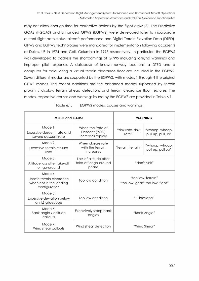
Ph.D. Thesis - Next Generation Flight Management Systems for Manned and Unmanned Aircraft Operations
- Automated Separation Assurance and Collision Avoidance Functionalities
227
may not allow enough time for corrective actions by the flight crew [3]. The Predictive
GCAS (PGCAS) and Enhanced GPWS (EGPWS) were developed later to incorporate
current flight path status, aircraft performance and Digital Terrain Elevation Data (DTED).
GPWS and EGPWS technologies were mandated for implementation following accidents
at Dulles, US in 1974 and Cali, Columbia in 1995 respectively. In particular, the EGPWS
was developed to address the shortcomings of GPWS including late/no warnings and
improper pilot response. A database of known runway locations, a DTED and a
computer for calculating a virtual terrain clearance floor are included in the EGPWS.
Seven different modes are supported by the EGPWS, with modes 1 through 4 the original
GPWS modes. The recent additions are the enhanced modes supported by terrain
proximity display, terrain ahead detection, and terrain clearance floor features. The
modes, respective causes and warnings issued by the EGPWS are provided in Table 6.1.
Table 6.1. EGPWS modes, causes and warnings.
MODE and CAUSE WARNING
Mode 1:
Excessive descent rate and
severe descent rate
When the Rate of
Descent (ROD)
increases rapidly
“sink rate, sink
rate”
“whoop, whoop,
pull up, pull up”
Mode 2:
Excessive terrain closure
rate
When closure rate
with the terrain
increases
“terrain, terrain” “whoop, whoop,
pull up, pull up”
Mode 3:
Altitude loss after take-off
or go-around
Loss of altitude after
take-off or go-around
phase
“don’t sink”
Mode 4:
Unsafe terrain clearance
when not in the landing
configuration
Too low condition “too low, terrain”
“too low, gear” too low, flaps”
Mode 5:
Excessive deviation below
an ILS glideslope
Too low condition “Glideslope”
Mode 6:
Bank angle / altitude
callouts
Excessively steep bank
angles “Bank Angle”
Mode 7:
Wind shear callouts Wind shear detection “Wind Shear”
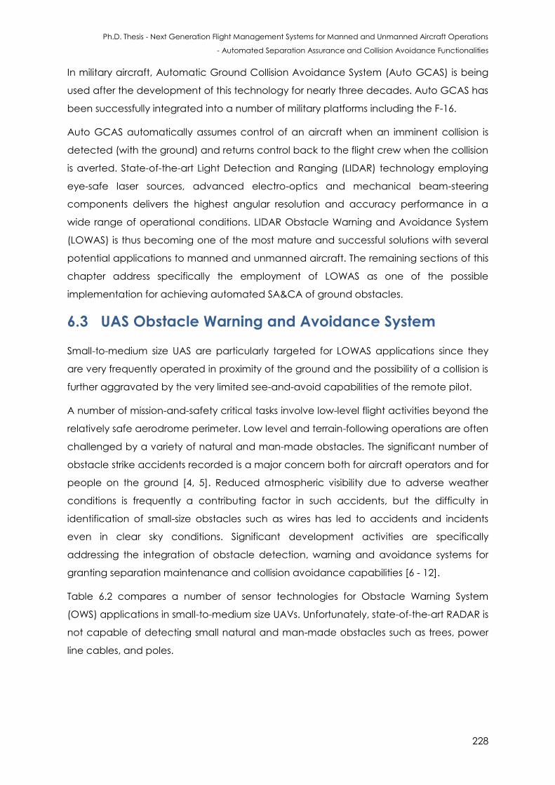
Ph.D. Thesis - Next Generation Flight Management Systems for Manned and Unmanned Aircraft Operations
- Automated Separation Assurance and Collision Avoidance Functionalities
228
In military aircraft, Automatic Ground Collision Avoidance System (Auto GCAS) is being
used after the development of this technology for nearly three decades. Auto GCAS has
been successfully integrated into a number of military platforms including the F-16.
Auto GCAS automatically assumes control of an aircraft when an imminent collision is
detected (with the ground) and returns control back to the flight crew when the collision
is averted. State-of-the-art Light Detection and Ranging (LIDAR) technology employing
eye-safe laser sources, advanced electro-optics and mechanical beam-steering
components delivers the highest angular resolution and accuracy performance in a
wide range of operational conditions. LIDAR Obstacle Warning and Avoidance System
(LOWAS) is thus becoming one of the most mature and successful solutions with several
potential applications to manned and unmanned aircraft. The remaining sections of this
chapter address specifically the employment of LOWAS as one of the possible
implementation for achieving automated SA&CA of ground obstacles.
6.3 UAS Obstacle Warning and Avoidance System
Small-to-medium size UAS are particularly targeted for LOWAS applications since they
are very frequently operated in proximity of the ground and the possibility of a collision is
further aggravated by the very limited see-and-avoid capabilities of the remote pilot.
A number of mission-and-safety critical tasks involve low-level flight activities beyond the
relatively safe aerodrome perimeter. Low level and terrain-following operations are often
challenged by a variety of natural and man-made obstacles. The significant number of
obstacle strike accidents recorded is a major concern both for aircraft operators and for
people on the ground [4, 5]. Reduced atmospheric visibility due to adverse weather
conditions is frequently a contributing factor in such accidents, but the difficulty in
identification of small-size obstacles such as wires has led to accidents and incidents
even in clear sky conditions. Significant development activities are specifically
addressing the integration of obstacle detection, warning and avoidance systems for
granting separation maintenance and collision avoidance capabilities [6 - 12].
Table 6.2 compares a number of sensor technologies for Obstacle Warning System
(OWS) applications in small-to-medium size UAVs. Unfortunately, state-of-the-art RADAR is
not capable of detecting small natural and man-made obstacles such as trees, power
line cables, and poles.
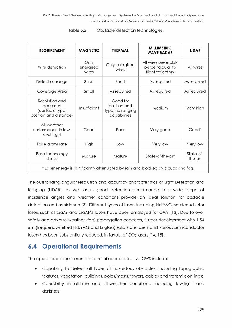
Ph.D. Thesis - Next Generation Flight Management Systems for Manned and Unmanned Aircraft Operations
- Automated Separation Assurance and Collision Avoidance Functionalities
229
Table 6.2. Obstacle detection technologies.
The outstanding angular resolution and accuracy characteristics of Light Detection and
Ranging (LIDAR), as well as its good detection performance in a wide range of
incidence angles and weather conditions provide an ideal solution for obstacle
detection and avoidance [3]. Different types of lasers including Nd:YAG, semiconductor
lasers such as GaAs and GaAlAs lasers have been employed for OWS [13]. Due to eye-
safety and adverse weather (fog) propagation concerns, further development with 1.54
m (frequency-shifted Nd:YAG and Er:glass) solid state lasers and various semiconductor
lasers has been substantially reduced, in favour of CO2 lasers [14, 15].
6.4 Operational Requirements
The operational requirements for a reliable and effective OWS include:
Capability to detect all types of hazardous obstacles, including topographic
features, vegetation, buildings, poles/masts, towers, cables and transmission lines;
Operability in all-time and all-weather conditions, including low-light and
darkness;
REQUIREMENT MAGNETIC THERMAL MILLIMETRIC
WAVE RADAR LIDAR
Wire detection
Only
energized
wires
Only energized
wires
All wires preferably
perpendicular to
flight trajectory
All wires
Detection range Short Short As required As required
Coverage Area Small As required As required As required
Resolution and
accuracy
(obstacle type,
position and distance)
Insufficient
Good for
position and
type, no ranging
capabilities
Medium Very high
All-weather
performance in low-
level flight
Good Poor Very good Good*
False alarm rate High Low Very low Very low
Base technology
status Mature Mature State-of-the-art
State-of-
the-art
* Laser energy is significantly attenuated by rain and blocked by clouds and fog.
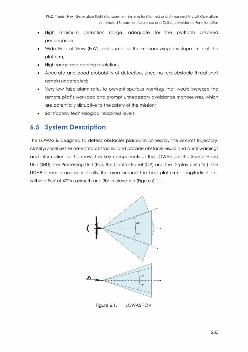
Ph.D. Thesis - Next Generation Flight Management Systems for Manned and Unmanned Aircraft Operations
- Automated Separation Assurance and Collision Avoidance Functionalities
230
High minimum detection range, adequate for the platform airspeed
performance;
Wide Field of View (FoV), adequate for the manoeuvring envelope limits of the
platform;
High range and bearing resolutions;
Accurate and good probability of detection, since no real obstacle threat shall
remain undetected;
Very low false alarm rate, to prevent spurious warnings that would increase the
remote pilot’s workload and prompt unnecessary avoidance manoeuvres, which
are potentially disruptive to the safety of the mission;
Satisfactory technological readiness levels.
6.5 System Description
The LOWAS is designed to detect obstacles placed in or nearby the aircraft trajectory,
classify/prioritise the detected obstacles, and provide obstacle visual and aural warnings
and information to the crew. The key components of the LOWAS are the Sensor Head
Unit (SHU), the Processing Unit (PU), the Control Panel (CP) and the Display Unit (DU). The
LIDAR beam scans periodically the area around the host platform’s longitudinal axis
within a FoV of 40° in azimuth and 30° in elevation (Figure 6.1).
15°
15°
20°
20°
Figure 6.1. LOWAS FOV.
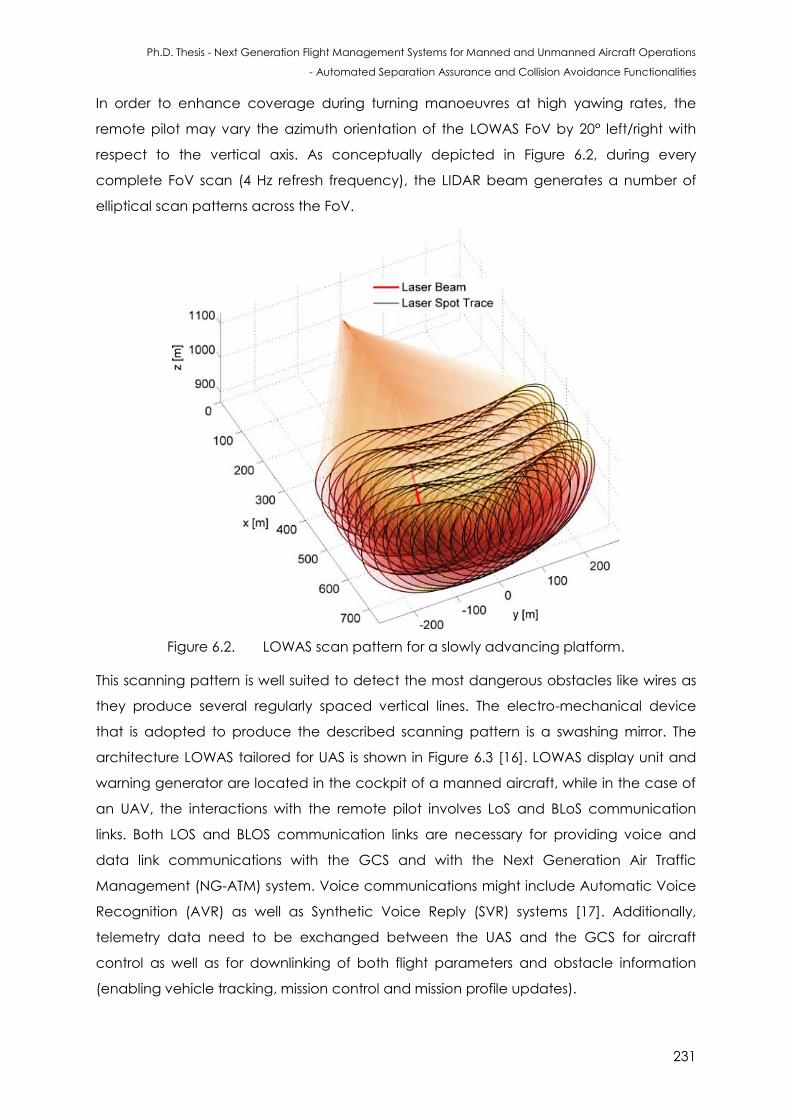
Ph.D. Thesis - Next Generation Flight Management Systems for Manned and Unmanned Aircraft Operations
- Automated Separation Assurance and Collision Avoidance Functionalities
231
In order to enhance coverage during turning manoeuvres at high yawing rates, the
remote pilot may vary the azimuth orientation of the LOWAS FoV by 20° left/right with
respect to the vertical axis. As conceptually depicted in Figure 6.2, during every
complete FoV scan (4 Hz refresh frequency), the LIDAR beam generates a number of
elliptical scan patterns across the FoV.
Figure 6.2. LOWAS scan pattern for a slowly advancing platform.
This scanning pattern is well suited to detect the most dangerous obstacles like wires as
they produce several regularly spaced vertical lines. The electro-mechanical device
that is adopted to produce the described scanning pattern is a swashing mirror. The
architecture LOWAS tailored for UAS is shown in Figure 6.3 [16]. LOWAS display unit and
warning generator are located in the cockpit of a manned aircraft, while in the case of
an UAV, the interactions with the remote pilot involves LoS and BLoS communication
links. Both LOS and BLOS communication links are necessary for providing voice and
data link communications with the GCS and with the Next Generation Air Traffic
Management (NG-ATM) system. Voice communications might include Automatic Voice
Recognition (AVR) as well as Synthetic Voice Reply (SVR) systems [17]. Additionally,
telemetry data need to be exchanged between the UAS and the GCS for aircraft
control as well as for downlinking of both flight parameters and obstacle information
(enabling vehicle tracking, mission control and mission profile updates).
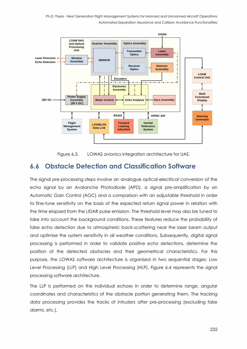
Ph.D. Thesis - Next Generation Flight Management Systems for Manned and Unmanned Aircraft Operations
- Automated Separation Assurance and Collision Avoidance Functionalities
232
LOAM SHU
and Optical
Processing
Unit
Electronic
Assembly
MIRROR
Scanner Assembly Optics Assembly
Gyro Assembly
Window
Assembly MIRROR
Transmitter
Optics
Receiver
Optics
Laser
Assembly
Detector
Assembly
Power Supply
Assembly
(28 V DC)
Motor Control Echo Analysis
Inhibit
Encoders
28V DC
Forward
Looking
Infra-Red
LOAM
Control Unit
LOS/BLOS
Data Link
Inertial
Reference
System
Warning
Generator
Multi
Functional
Display
ARINC 429RS422
Flight
Management
System
Laser Emission
Echo Detection
Figure 6.3. LOWAS avionics integration architecture for UAS.
6.6 Obstacle Detection and Classification Software
The signal pre-processing steps involve an analogue optical-electrical conversion of the
echo signal by an Avalanche Photodiode (APD), a signal pre-amplification by an
Automatic Gain Control (AGC) and a comparison with an adjustable threshold in order
to fine-tune sensitivity on the basis of the expected return signal power in relation with
the time elapsed from the LIDAR pulse emission. The threshold level may also be tuned to
take into account the background conditions. These features reduce the probability of
false echo detection due to atmospheric back-scattering near the laser beam output
and optimise the system sensitivity in all weather conditions. Subsequently, digital signal
processing is performed in order to validate positive echo detections, determine the
position of the detected obstacles and their geometrical characteristics. For this
purpose, the LOWAS software architecture is organised in two sequential stages: Low
Level Processing (LLP) and High Level Processing (HLP). Figure 6.4 represents the signal
processing software architecture.
The LLP is performed on the individual echoes in order to determine range, angular
coordinates and characteristics of the obstacle portion generating them. The tracking
data processing provides the tracks of intruders after pre-processing (excluding false
alarms, etc.).
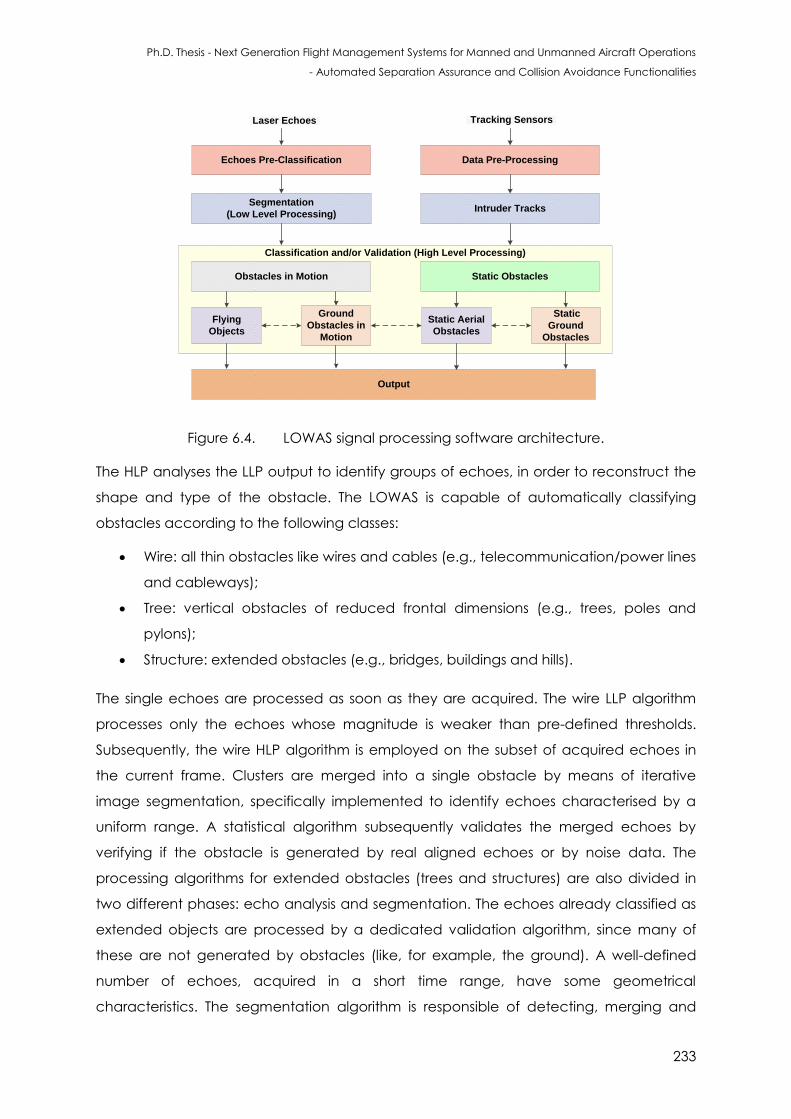
Ph.D. Thesis - Next Generation Flight Management Systems for Manned and Unmanned Aircraft Operations
- Automated Separation Assurance and Collision Avoidance Functionalities
233
Classification and/or Validation (High Level Processing)
Echoes Pre-Classification
Intruder Tracks
Laser Echoes Tracking Sensors
Segmentation
(Low Level Processing)
Obstacles in Motion Static Obstacles
Flying
Objects
Ground
Obstacles in
Motion
Data Pre-Processing
Static Aerial
Obstacles
Static
Ground
Obstacles
Output
Figure 6.4. LOWAS signal processing software architecture.
The HLP analyses the LLP output to identify groups of echoes, in order to reconstruct the
shape and type of the obstacle. The LOWAS is capable of automatically classifying
obstacles according to the following classes:
Wire: all thin obstacles like wires and cables (e.g., telecommunication/power lines
and cableways);
Tree: vertical obstacles of reduced frontal dimensions (e.g., trees, poles and
pylons);
Structure: extended obstacles (e.g., bridges, buildings and hills).
The single echoes are processed as soon as they are acquired. The wire LLP algorithm
processes only the echoes whose magnitude is weaker than pre-defined thresholds.
Subsequently, the wire HLP algorithm is employed on the subset of acquired echoes in
the current frame. Clusters are merged into a single obstacle by means of iterative
image segmentation, specifically implemented to identify echoes characterised by a
uniform range. A statistical algorithm subsequently validates the merged echoes by
verifying if the obstacle is generated by real aligned echoes or by noise data. The
processing algorithms for extended obstacles (trees and structures) are also divided in
two different phases: echo analysis and segmentation. The echoes already classified as
extended objects are processed by a dedicated validation algorithm, since many of
these are not generated by obstacles (like, for example, the ground). A well-defined
number of echoes, acquired in a short time range, have some geometrical
characteristics. The segmentation algorithm is responsible of detecting, merging and
Ph.D. Thesis - Next Generation Flight Management Systems for Manned and Unmanned Aircraft Operations
- Automated Separation Assurance and Collision Avoidance Functionalities
234
validating the clusters of echoes. The integration of high-resolution databases of fixed
obstacles (power lines, buildings, etc.), when flying over a well characterised operational
area into the LOWAS algorithms, can support reduction of the overall processing time
and provide an accurate estimation of their position. The LOWAS performs automatic
prioritisation of the detected obstacles based on the risk represented according to the
relevant range, and provides timely visual and aural warnings to the flight crew,
including information about the detected obstacles. The dedicated signal processing
algorithms grant reliable detection performance, independent from the platform
motion, allowing a reconstruction of the obstacle shape without using navigation data
(stand-alone integration) in slow-moving platforms characterised by a typical flight
envelope (rotorcraft and fixed-wing aircraft). The LOWAS can also be integrated with
the onboard navigation and guidance system to grant equally efficient reliable
detection in extreme flight envelopes of high-dynamics platforms [18, 19].
6.7 Mathematical Algorithms
The microwave radar range equation also applies to laser systems and the power
received by the detector is given by [4]:
(6.1)
where is the transmitter power, is the transmitter antenna gain, is the range [m],
is the aperture diameter [m], is the atmospheric transmittance and is the system
transmission factor. With laser systems, the transmitter antenna gain is substituted by the
aperture gain, expressed by the ratio of the steradian solid angle of the transmitter
beam width to that of the solid angle of a sphere as given by:
(6.2)
In the far field, the transmitter beam width can also be expressed in terms of aperture
illumination constant, as:
(6.3)
Substituting for and in equation (6.1), we obtain:
(6.4)
An aperture operating at the eye-safe wavelengths has a far-field distance of
approximately 20 km [5]. As a result, it is not unusual to operate in the near-field of the
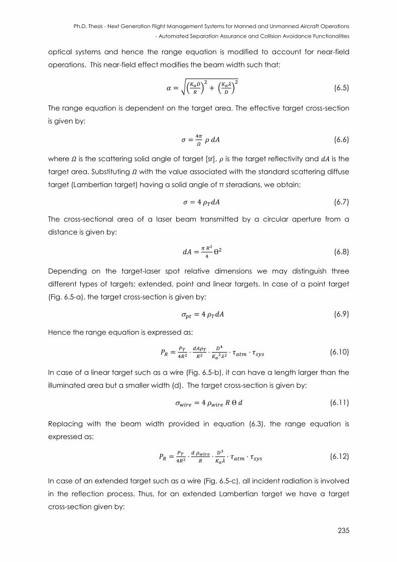
Ph.D. Thesis - Next Generation Flight Management Systems for Manned and Unmanned Aircraft Operations
- Automated Separation Assurance and Collision Avoidance Functionalities
235
optical systems and hence the range equation is modified to account for near-field
operations. This near-field effect modifies the beam width such that:
√(
) (
) (6.5)
The range equation is dependent on the target area. The effective target cross-section
is given by:
(6.6)
where is the scattering solid angle of target [sr], is the target reflectivity and is the
target area. Substituting with the value associated with the standard scattering diffuse
target (Lambertian target) having a solid angle of π steradians, we obtain:
(6.7)
The cross-sectional area of a laser beam transmitted by a circular aperture from a
distance is given by:
(6.8)
Depending on the target-laser spot relative dimensions we may distinguish three
different types of targets: extended, point and linear targets. In case of a point target
(Fig. 6.5-a), the target cross-section is given by:
(6.9)
Hence the range equation is expressed as:
(6.10)
In case of a linear target such as a wire (Fig. 6.5-b), it can have a length larger than the
illuminated area but a smaller width (d). The target cross-section is given by:
(6.11)
Replacing with the beam width provided in equation (6.3), the range equation is
expressed as:
(6.12)
In case of an extended target such as a wire (Fig. 6.5-c), all incident radiation is involved
in the reflection process. Thus, for an extended Lambertian target we have a target
cross-section given by:
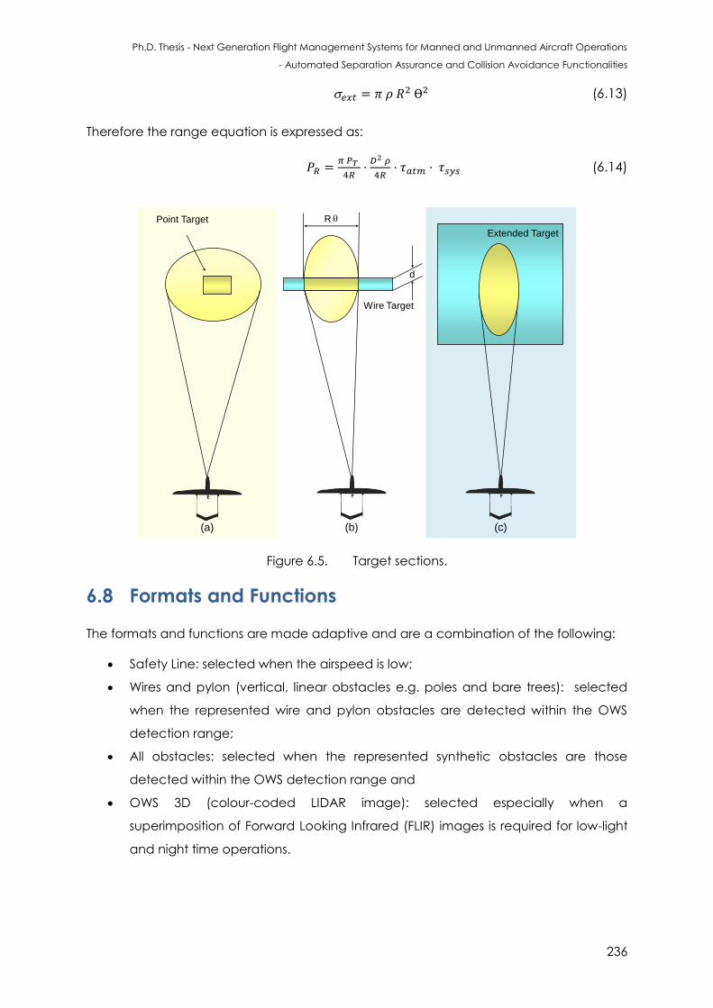
Ph.D. Thesis - Next Generation Flight Management Systems for Manned and Unmanned Aircraft Operations
- Automated Separation Assurance and Collision Avoidance Functionalities
236
(6.13)
Therefore the range equation is expressed as:
(6.14)
(a) (b) (c)
Point Target
Wire Target
d
R
Extended Target
Figure 6.5. Target sections.
6.8 Formats and Functions
The formats and functions are made adaptive and are a combination of the following:
Safety Line: selected when the airspeed is low;
Wires and pylon (vertical, linear obstacles e.g. poles and bare trees): selected
when the represented wire and pylon obstacles are detected within the OWS
detection range;
All obstacles: selected when the represented synthetic obstacles are those
detected within the OWS detection range and
OWS 3D (colour-coded LIDAR image): selected especially when a
superimposition of Forward Looking Infrared (FLIR) images is required for low-light
and night time operations.
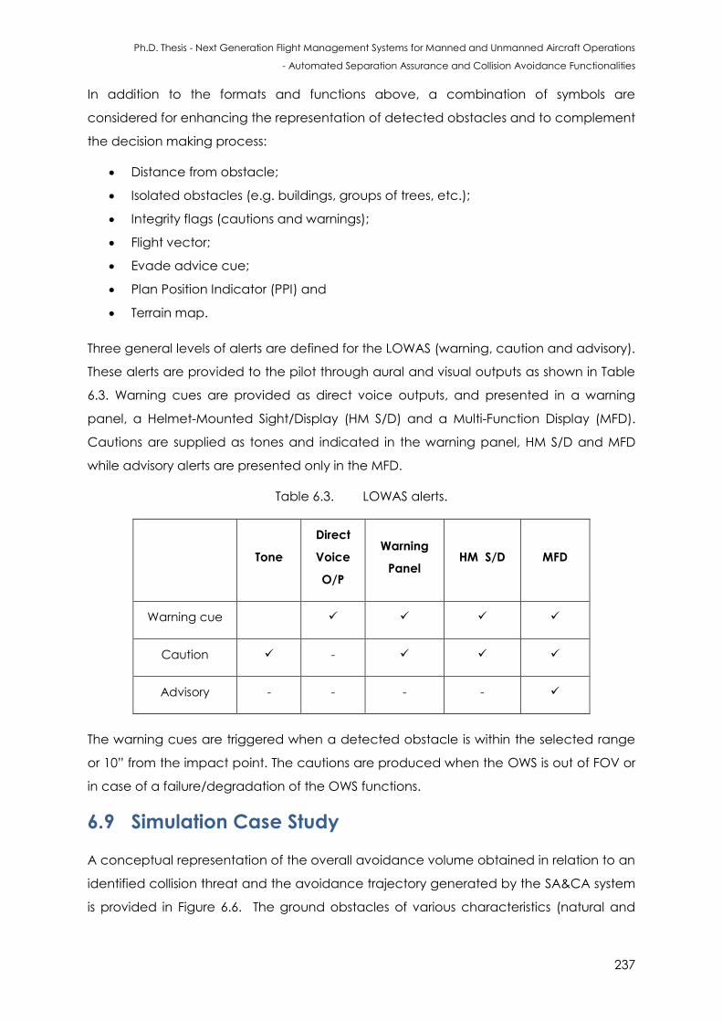
Ph.D. Thesis - Next Generation Flight Management Systems for Manned and Unmanned Aircraft Operations
- Automated Separation Assurance and Collision Avoidance Functionalities
237
In addition to the formats and functions above, a combination of symbols are
considered for enhancing the representation of detected obstacles and to complement
the decision making process:
Distance from obstacle;
Isolated obstacles (e.g. buildings, groups of trees, etc.);
Integrity flags (cautions and warnings);
Flight vector;
Evade advice cue;
Plan Position Indicator (PPI) and
Terrain map.
Three general levels of alerts are defined for the LOWAS (warning, caution and advisory).
These alerts are provided to the pilot through aural and visual outputs as shown in Table
6.3. Warning cues are provided as direct voice outputs, and presented in a warning
panel, a Helmet-Mounted Sight/Display (HM S/D) and a Multi-Function Display (MFD).
Cautions are supplied as tones and indicated in the warning panel, HM S/D and MFD
while advisory alerts are presented only in the MFD.
Table 6.3. LOWAS alerts.
Tone
Direct
Voice
O/P
Warning
Panel HM S/D MFD
Warning cue
Caution -
Advisory - - - -
The warning cues are triggered when a detected obstacle is within the selected range
or 10” from the impact point. The cautions are produced when the OWS is out of FOV or
in case of a failure/degradation of the OWS functions.
6.9 Simulation Case Study
A conceptual representation of the overall avoidance volume obtained in relation to an
identified collision threat and the avoidance trajectory generated by the SA&CA system
is provided in Figure 6.6. The ground obstacles of various characteristics (natural and
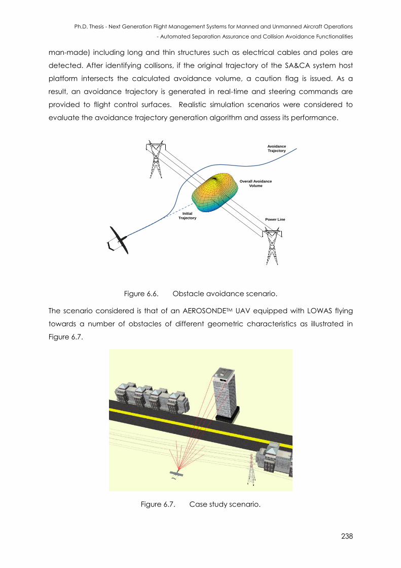
Ph.D. Thesis - Next Generation Flight Management Systems for Manned and Unmanned Aircraft Operations
- Automated Separation Assurance and Collision Avoidance Functionalities
238
man-made) including long and thin structures such as electrical cables and poles are
detected. After identifying collisons, if the original trajectory of the SA&CA system host
platform intersects the calculated avoidance volume, a caution flag is issued. As a
result, an avoidance trajectory is generated in real-time and steering commands are
provided to flight control surfaces. Realistic simulation scenarios were considered to
evaluate the avoidance trajectory generation algorithm and assess its performance.
Overall Avoidance
Volume
Avoidance
Trajectory
Power Line
Initial
Trajectory
Figure 6.6. Obstacle avoidance scenario.
The scenario considered is that of an AEROSONDETM UAV equipped with LOWAS flying
towards a number of obstacles of different geometric characteristics as illustrated in
Figure 6.7.
Figure 6.7. Case study scenario.
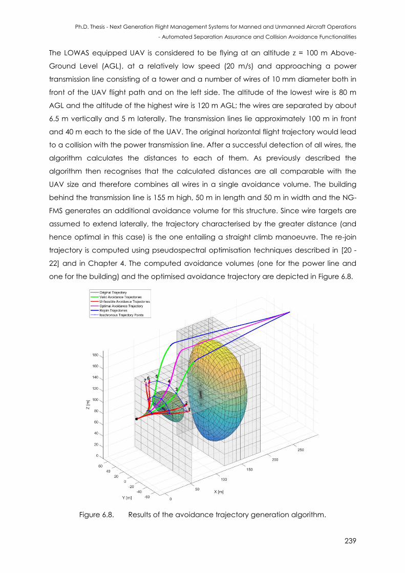
Ph.D. Thesis - Next Generation Flight Management Systems for Manned and Unmanned Aircraft Operations
- Automated Separation Assurance and Collision Avoidance Functionalities
239
The LOWAS equipped UAV is considered to be flying at an altitude z = 100 m Above-
Ground Level (AGL), at a relatively low speed (20 m/s) and approaching a power
transmission line consisting of a tower and a number of wires of 10 mm diameter both in
front of the UAV flight path and on the left side. The altitude of the lowest wire is 80 m
AGL and the altitude of the highest wire is 120 m AGL; the wires are separated by about
6.5 m vertically and 5 m laterally. The transmission lines lie approximately 100 m in front
and 40 m each to the side of the UAV. The original horizontal flight trajectory would lead
to a collision with the power transmission line. After a successful detection of all wires, the
algorithm calculates the distances to each of them. As previously described the
algorithm then recognises that the calculated distances are all comparable with the
UAV size and therefore combines all wires in a single avoidance volume. The building
behind the transmission line is 155 m high, 50 m in length and 50 m in width and the NG-
FMS generates an additional avoidance volume for this structure. Since wire targets are
assumed to extend laterally, the trajectory characterised by the greater distance (and
hence optimal in this case) is the one entailing a straight climb manoeuvre. The re-join
trajectory is computed using pseudospectral optimisation techniques described in [20 -
22] and in Chapter 4. The computed avoidance volumes (one for the power line and
one for the building) and the optimised avoidance trajectory are depicted in Figure 6.8.
Figure 6.8. Results of the avoidance trajectory generation algorithm.
Ph.D. Thesis - Next Generation Flight Management Systems for Manned and Unmanned Aircraft Operations
- Automated Separation Assurance and Collision Avoidance Functionalities
240
The UAV also avoids the extended target (building) by generating a smooth optimised
trajectory from the safe manoeuvring point. These simulations were executed on a
Windows 7 Professional workstation (64-bit OS) supported by an Intel Core i7-4510 CPU
with clock speed 2.6 GHz and 8.0 GB RAM. The execution time for uncertainty volume
determination and avoidance trajectory optimisation algorithms was in the order of 1.4
sec. Such an implementation makes it possible to perform the real-time separation
maintenance and collision avoidance task.
6.10 Conclusions
The LOWAS system was proposed as one of the core non-cooperative sensors in an
integrated SA&CA architecture for small-to-medium size UAS. The system architecture,
mathematical models and simulation case studies performed to develop a novel Laser
Obstacle Warning and Avoidance System (LOWAS) were presented. The algorithms for
computing the avoidance volumes associated with obstacles and for the generation of
optimal avoidance trajectories were presented along with a representative simulation
case study. Tailored display formats developed for the UAV remote pilot station were
presented including Safety Line (SL), Wires & Poles (W&P), all obstacles and Integrated
LOWAS/FLS (ILF) formats. The demonstrated detection, warning and avoidance
performance, determination of overall uncertainty volumes and avoidance trajectory
generation algorithms ensure a safe avoidance of all potentially conflicting obstacles.
Subsequently, a comprehensive simulation case study of the avoidance trajectory
generation algorithms is accomplished using the AEROSONDETM UAV as a test platform. It
is concluded that the ground obstacle detection and trajectory optimization algorithms
ensure a safe avoidance of all classes of obstacles (i.e., wire, extended and point
objects) in a wide range of weather and geometric conditions, providing a pathway for
possible integration of this technology into future NG-FMS architectures.
6.11 References
1. B.C. Breen, “Controlled Flight Into Terrain and the Enhanced Ground Proximity Warning
System’, IEEE Aerospace and Electronic Systems Magazine, Vol. 14, Issue 1, pp.19-24,
1999.
2. P. Novacek, “Terrain Awareness and Warning Ssytems – TAWS”, Buyer’s Guide, Pilot’s
Guide to Avionics Magazine, 2006.
3. B.C. Breen, “Terrain Awareness”, Chapter 21, eds. C. Spitzer, U. Ferrell and T. Ferrell,
Digital Avionics Handbook, Third Edition, CRC Press, 2014.
Ph.D. Thesis - Next Generation Flight Management Systems for Manned and Unmanned Aircraft Operations
- Automated Separation Assurance and Collision Avoidance Functionalities
241
4. J. Gauci and D. Zammit-Mangion, “Obstacle Detection around Aircraft on Ramps and
Taxiways through the Use of Computer Vision,” Proceedings of AIAA Guidance,
Navigation, and Control Conference (GNC 2009), Chicago, IL, USA, 2009
5. R. Sabatini and M. A. Richardson, “Airborne Laser Systems Testing and Analysis”, RTO
AGARDograph AG-300 vol. 26, Flight Test Instrumentation Series, Systems Concepts and
Integration Panel (SCI-126), NATO Science and Technology Organization, 2010.
Accessible at: http://www.dtic.mil/cgi-bin/GetTRDoc?AD=ADA534869
6. X. Yu and Y. Zhang, “Sense and Avoid Technologies with Applications to Unmanned
Aircraft Systems: Review and Prospects”, Progress in Aerospace Sciences, Elsevier, vol.
74, pp. 152-166, 2015. DOI: 10.1016/j.paerosci.2015.01.001
7. S.I. Ali Shah and E.N. Johnson, “3D Obstacle Detection using a Single Camera”,
Proceedings of AIAA Guidance, Navigation, and Control conference 2009 (GNC 2009),
Chicago, IL, USA, 2009.
8. A. Moses, M.J. Rutherford, and K.P. Valavanis, “Scalable RADAR-Based Sense-and-
Avoid System for Unmanned Aircraft”, Handbook of Unmanned Aerial Vehicles, pp.
1895-1953, Springer, 2014.
9. K.R.Noth, “Modeling and Simulation of a Ground based Sense and Avoid Architecture
for Unmanned Aircraft System operations”, Proceedings of 11th Integrated
Communications, Navigation and Surveillance Conference: Renovating the Global Air
Transportation System (ICNS 2011), Herndon, VA, USA, 2011, pp. O71-O79. DOI:
10.1109/ICNSURV.2011.5935356
10. S. Ramasamy and R. Sabatini, “A Unified Approach to Cooperative and Non-
Cooperative Sense-and-Avoid”, Proceedings of International Conference on
Unmanned Aircraft Systems (ICUAS 2015), Denver, CO, USA, 2015. DOI:
10.1109/ICUAS.2015.7152360
11. A. Mujumdar and R. Padhi, “Evolving Philosophies on Autonomous Obstacle/Collision
Avoidance of Unmanned Aerial Vehicles”, Journal of Aerospace Computing,
Information, and Communication, Vol. 8, Issue 2, pp. 17-41, 2011. DOI:
http://dx.doi.org/10.2514/1.49985
12. C. Geyer, S. Singh and L.J. Chamberlain, “Avoiding Collisions between Aircraft: State of
the Art and Requirements for UAVs Operating in Civilian Airspace”, Technical Report,
CMU-RI-TR-08-03, Carnegie Mellon University, USA, 2008. Accessible at:
http://www.frc.ri.cmu.edu/projects/senseavoid/Images/CMU-RI-TR-08-03.pdf
13. B. S. Goldstein and G. F. Dalrymple, "Gallium Arsenide Injection Laser Radar”,
Proceedings of the IEEE, Vol. 55, pp. 181-188, 1967. DOI: 10.1109/proc.1967.5437
Ph.D. Thesis - Next Generation Flight Management Systems for Manned and Unmanned Aircraft Operations
- Automated Separation Assurance and Collision Avoidance Functionalities
242
14. R. Sabatini, M. A. Richardson, H. Jia and D. Zammit-Mangion, "Airborne laser systems for
atmospheric sounding in the near infrared”, Proceedings of SPIE 8433, Laser Sources
and Applications, Photonics Europe 2012, Brussels, Belgium, 2012. DOI:
10.1117/12.915718
15. G. Hogg, K. Harrison and S. Minisclou, "The Anglo-French Compact Laser Radar
Demonstrator Programme”, AGARD-CP-563 - Low-Level and Nap-of-the-Earth (NOE)
Night Operations, NATO Science and Technology Organization, 1995.
16. R. Sabatini, M.A. Richardson, A. Gardi and S. Ramasamy, “Airborne Laser Sensors and
Integrated Systems”, Progress in Aerospace Sciences, Elsevier, vol. 79, pp. 15–63 2015.
DOI: 10.1016/j.paerosci.2015.07.002
17. L. Bouwmeester, R. Clothier, R. Sabatini and G. Williams, "Autonomous Communication
between Air Traffic Control and Remotely Piloted Aircraft”,
Proceedings of 16th Australian International Aerospace Congress (AIAC16), Engineers
Australia, pp. 48-57, 2015.
18. S. Ramasamy, R. Sabatini and A. Gardi, “LIDAR Obstacle Warning and Avoidance
System for Unmanned Aerial Vehicle Sense-and-Avoid”, Aerospace Science and
Technology, Elsevier, vol. 55, pp. 344–358, 2016. DOI: 10.1016/j.ast.2016.05.020
19. F. Cappello, S. Ramasamy and R. Sabatini, “Multi-Sensor Data Fusion Techniques for
RPAS Detect, Track and Avoid”, SAE Technical Paper 2015-01-2475, SAE 2015 AeroTech
Congress & Exhibition, Seattle, Washington, USA, 2015. DOI: 10.4271/2015-01-2475
20. A. Gardi, R. Sabatini and S. Ramasamy, “Multi-Objective Optimisation of Aircraft Flight
Trajectories in the ATM and Avionics Context”, Progress in Aerospace Sciences, Elsevier,
vol. 83, pp.1-36, 2016. DOI: 10.1016/j.paerosci.2015.11.006
21. J.Z. Ben-Asher, “Optimal Control Theory with Aerospace Applications”, Education
Series, American Institute of Aeronautics and Astronautics (AIAA), Reston, VA, USA,
2010.
22. A.V. Rao, “Survey of Numerical Methods for Optimal Control”, Advances in the
Astronautical Sciences, Vol. 135, pp. 497-528, 2010.
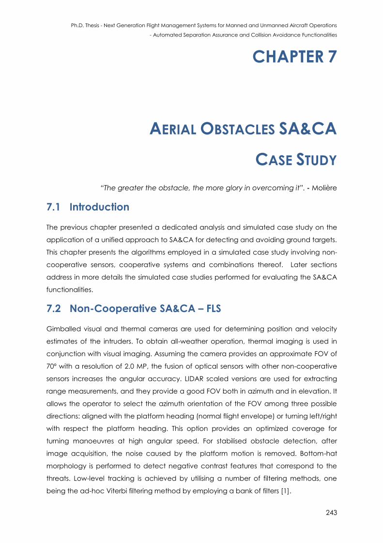
Ph.D. Thesis - Next Generation Flight Management Systems for Manned and Unmanned Aircraft Operations
- Automated Separation Assurance and Collision Avoidance Functionalities
243
CHAPTER 7
AERIAL OBSTACLES SA&CA
CASE STUDY
“The reater the obstac e the more glory in overcoming it”. - Molière 7.1 Introduction
The previous chapter presented a dedicated analysis and simulated case study on the
application of a unified approach to SA&CA for detecting and avoiding ground targets.
This chapter presents the algorithms employed in a simulated case study involving non-
cooperative sensors, cooperative systems and combinations thereof. Later sections
address in more details the simulated case studies performed for evaluating the SA&CA
functionalities.
7.2 Non-Cooperative SA&CA – FLS
Gimballed visual and thermal cameras are used for determining position and velocity
estimates of the intruders. To obtain all-weather operation, thermal imaging is used in
conjunction with visual imaging. Assuming the camera provides an approximate FOV of
70º with a resolution of 2.0 MP, the fusion of optical sensors with other non-cooperative
sensors increases the angular accuracy. LIDAR scaled versions are used for extracting
range measurements, and they provide a good FOV both in azimuth and in elevation. It
allows the operator to select the azimuth orientation of the FOV among three possible
directions: aligned with the platform heading (normal flight envelope) or turning left/right
with respect the platform heading. This option provides an optimized coverage for
turning manoeuvres at high angular speed. For stabilised obstacle detection, after
image acquisition, the noise caused by the platform motion is removed. Bottom-hat
morphology is performed to detect negative contrast features that correspond to the
threats. Low-level tracking is achieved by utilising a number of filtering methods, one
being the ad-hoc Viterbi filtering method by employing a bank of filters [1].
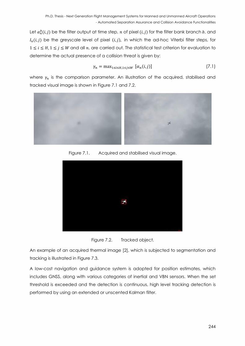
Ph.D. Thesis - Next Generation Flight Management Systems for Manned and Unmanned Aircraft Operations
- Automated Separation Assurance and Collision Avoidance Functionalities
244
Let ( ) be the filter output at time step, of pixel ( ) for the filter bank branch , and
( ) be the greyscale level of pixel ( ) in which the ad-hoc Viterbi filter steps, for
and all , are carried out. The statistical test criterion for evaluation to
determine the actual presence of a collision threat is given by:
[ ( ) (7.1)
where is the comparison parameter. An illustration of the acquired, stabilised and
tracked visual image is shown in Figure 7.1 and 7.2.
Figure 7.1. Acquired and stabilised visual image.
Figure 7.2. Tracked object.
An example of an acquired thermal image [2], which is subjected to segmentation and
tracking is illustrated in Figure 7.3.
A low-cost navigation and guidance system is adopted for position estimates, which
includes GNSS, along with various categories of inertial and VBN sensors. When the set
threshold is exceeded and the detection is continuous, high level tracking detection is
performed by using an extended or unscented Kalman filter.
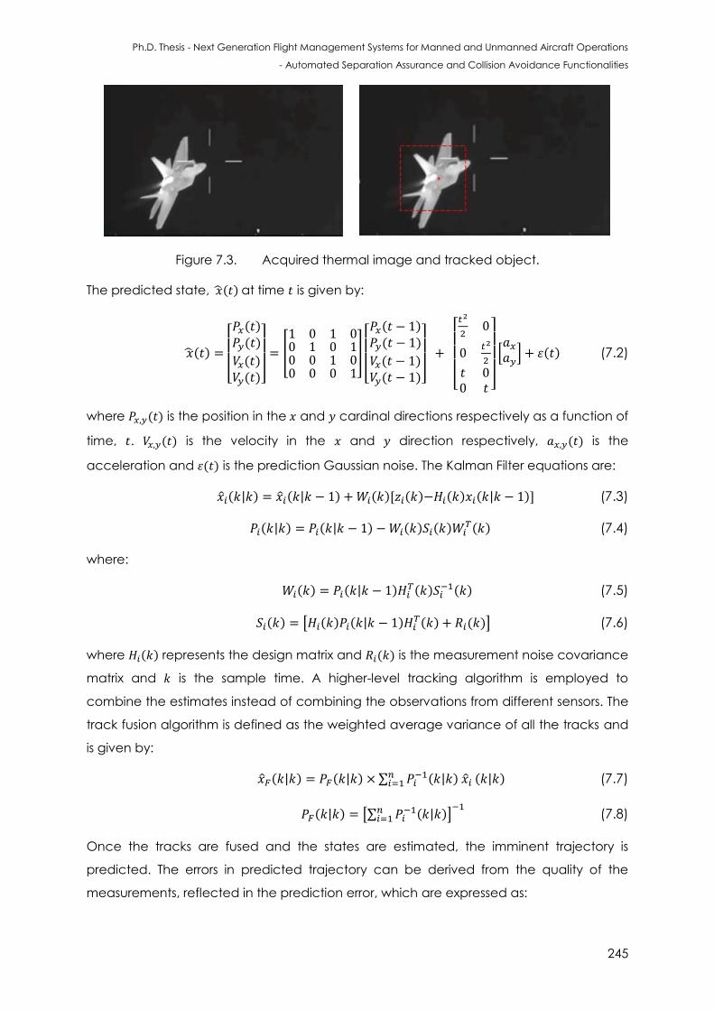
Ph.D. Thesis - Next Generation Flight Management Systems for Manned and Unmanned Aircraft Operations
- Automated Separation Assurance and Collision Avoidance Functionalities
245
Figure 7.3. Acquired thermal image and tracked object.
The predicted state, ( ) at time is given by:
( )
[ ( )
( )
( ) ( )]
[
]
[ ( )
( )
( ) ( )]
[
]
[
] ( ) (7.2)
where ( ) is the position in the and cardinal directions respectively as a function of
time, . ( ) is the velocity in the and direction respectively, ( ) is the
acceleration and ( ) is the prediction Gaussian noise. The Kalman Filter equations are:
( ) ( ) ( )[ ( ) ( ) ( ) (7.3)
( ) ( ) ( ) ( ) ( ) (7.4)
where:
( ) ( ) ( )
( ) (7.5)
( ) [ ( ) ( ) ( ) ( )] (7.6)
where ( ) represents the design matrix and ( ) is the measurement noise covariance
matrix and is the sample time. A higher-level tracking algorithm is employed to
combine the estimates instead of combining the observations from different sensors. The
track fusion algorithm is defined as the weighted average variance of all the tracks and
is given by:
( ) ( ) ∑ ( )
( ) (7.7)
( ) [∑ ( )
]
(7.8)
Once the tracks are fused and the states are estimated, the imminent trajectory is
predicted. The errors in predicted trajectory can be derived from the quality of the
measurements, reflected in the prediction error, which are expressed as:
Ph.D. Thesis - Next Generation Flight Management Systems for Manned and Unmanned Aircraft Operations
- Automated Separation Assurance and Collision Avoidance Functionalities
246
( ) [ ( ) ( ) (7.9)
where ( ) is the exhibited (modelled) trajectory and ( ) is the predicted
optimal trajectory at sample time .
For trajectory prediction, the obstacle centre of mass, the target orientation and the
geometric shape of the uncertainty volume are determined. Once the trajectory is
predicted, the Risk-of-Collision (RoC) is determined by calculating the probability of a
NMAC event for the predicted trajectory over the time horizon by employing Monte
Carlo approximations given by:
( ( ))
∑ ( | ( )| ) (7.10)
where is the number of samples, is defined as a future horizon up to where it is
desired to predict the trajectory, is the minimum distance required to avoid the
obstacle and is the time horizon defined for collision. The accuracy of the
approximation is entirely based on the number of samples.
7.3 Cooperative SA&CA – ADS-B
In a cooperative traffic scenario, the ADS-B system is used to obtain the state of the
intruders. The future position of the intruders is projected based on the estimate of the
current state vector and the flight profile. The ADS-B measurement model adopted for
intruder position and velocity estimates in and is given by:
( ) [
]
[ ]
[ ( ) ( ) ( )
( )]
(7.11)
Assuming that the velocity components, ( ), ( ), ( ) and ( ) are affected only
by Gaussian noise with zero mean, the standard deviation is defined by the covariance
matrix given by:
[ [
[
[
[ ]
(7.12)
where [ represents the mean. Using the data fusion model described in Chapter 2
(Section 2.8), the state vector of the intruders is determined and this is propagated to
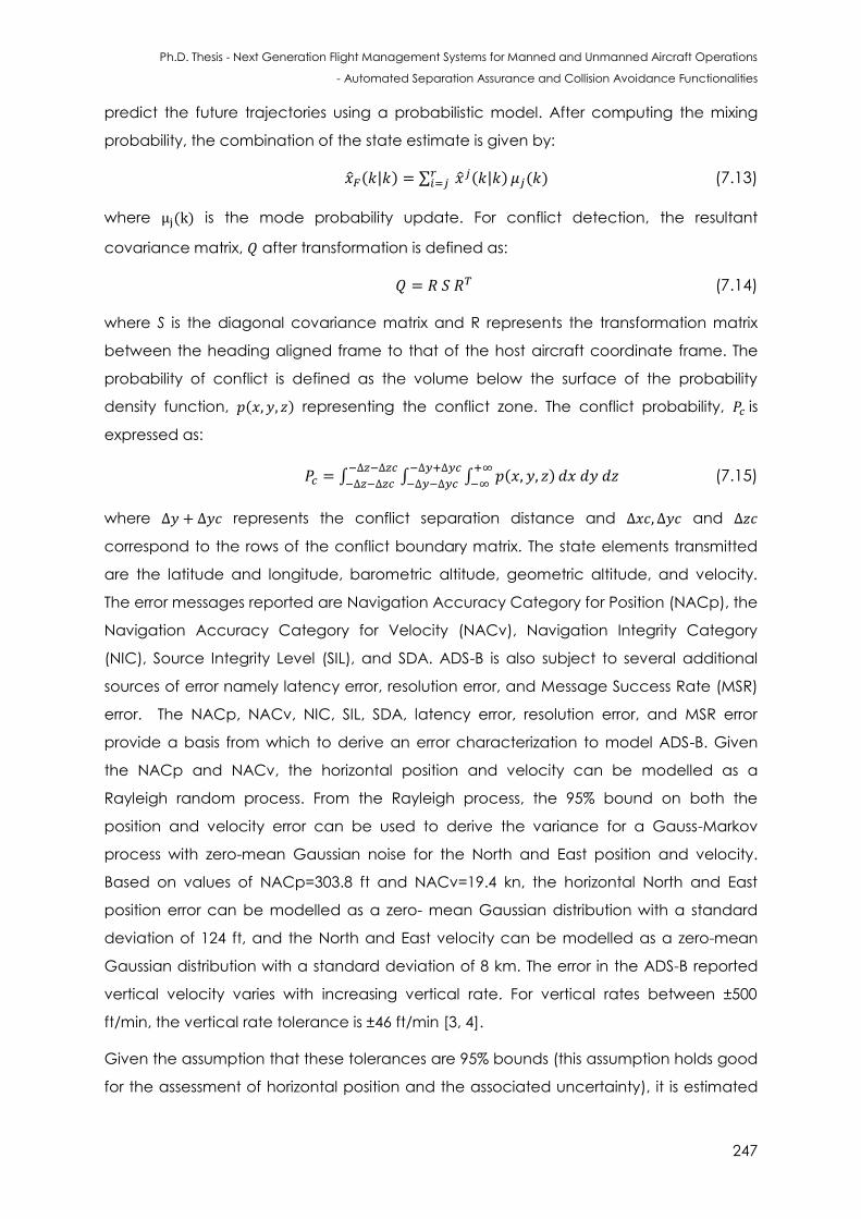
Ph.D. Thesis - Next Generation Flight Management Systems for Manned and Unmanned Aircraft Operations
- Automated Separation Assurance and Collision Avoidance Functionalities
247
predict the future trajectories using a probabilistic model. After computing the mixing
probability, the combination of the state estimate is given by:
( ) ∑ ( ) ( ) (7.13)
where ( ) is the mode probability update. For conflict detection, the resultant
covariance matrix, after transformation is defined as:
(7.14)
where S is the diagonal covariance matrix and R represents the transformation matrix
between the heading aligned frame to that of the host aircraft coordinate frame. The
probability of conflict is defined as the volume below the surface of the probability
density function, ( ) representing the conflict zone. The conflict probability, is
expressed as:
∫ ∫ ∫ ( )
(7.15)
where represents the conflict separation distance and and
correspond to the rows of the conflict boundary matrix. The state elements transmitted
are the latitude and longitude, barometric altitude, geometric altitude, and velocity.
The error messages reported are Navigation Accuracy Category for Position (NACp), the
Navigation Accuracy Category for Velocity (NACv), Navigation Integrity Category
(NIC), Source Integrity Level (SIL), and SDA. ADS-B is also subject to several additional
sources of error namely latency error, resolution error, and Message Success Rate (MSR)
error. The NACp, NACv, NIC, SIL, SDA, latency error, resolution error, and MSR error
provide a basis from which to derive an error characterization to model ADS-B. Given
the NACp and NACv, the horizontal position and velocity can be modelled as a
Rayleigh random process. From the Rayleigh process, the 95% bound on both the
position and velocity error can be used to derive the variance for a Gauss-Markov
process with zero-mean Gaussian noise for the North and East position and velocity.
Based on values of NACp=303.8 ft and NACv=19.4 kn, the horizontal North and East
position error can be modelled as a zero- mean Gaussian distribution with a standard
deviation of 124 ft, and the North and East velocity can be modelled as a zero-mean
Gaussian distribution with a standard deviation of 8 km. The error in the ADS-B reported
vertical velocity varies with increasing vertical rate. For vertical rates between ±500
ft/min, the vertical rate tolerance is ±46 ft/min [3, 4].
Given the assumption that these tolerances are 95% bounds (this assumption holds good
for the assessment of horizontal position and the associated uncertainty), it is estimated
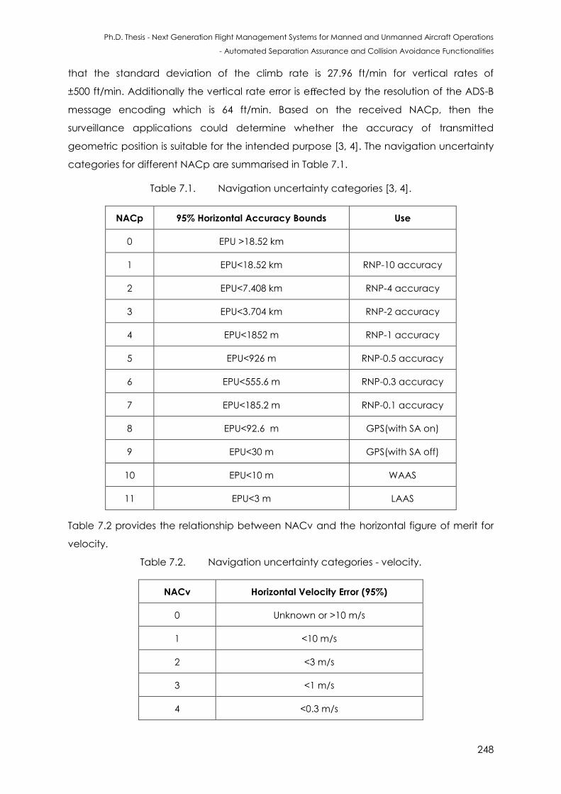
Ph.D. Thesis - Next Generation Flight Management Systems for Manned and Unmanned Aircraft Operations
- Automated Separation Assurance and Collision Avoidance Functionalities
248
that the standard deviation of the climb rate is 27.96 ft/min for vertical rates of
±500 ft/min. Additionally the vertical rate error is effected by the resolution of the ADS-B
message encoding which is 64 ft/min. Based on the received NACp, then the
surveillance applications could determine whether the accuracy of transmitted
geometric position is suitable for the intended purpose [3, 4]. The navigation uncertainty
categories for different NACp are summarised in Table 7.1.
Table 7.1. Navigation uncertainty categories [3, 4].
NACp 95% Horizontal Accuracy Bounds Use
0 EPU >18.52 km
1 EPU<18.52 km RNP-10 accuracy
2 EPU<7.408 km RNP-4 accuracy
3 EPU<3.704 km RNP-2 accuracy
4 EPU<1852 m RNP-1 accuracy
5 EPU<926 m RNP-0.5 accuracy
6 EPU<555.6 m RNP-0.3 accuracy
7 EPU<185.2 m RNP-0.1 accuracy
8 EPU<92.6 m GPS(with SA on)
9 EPU<30 m GPS(with SA off)
10 EPU<10 m WAAS
11 EPU<3 m LAAS
Table 7.2 provides the relationship between NACv and the horizontal figure of merit for
velocity.
Table 7.2. Navigation uncertainty categories - velocity.
NACv Horizontal Velocity Error (95%)
0 Unknown or >10 m/s
1 <10 m/s
2 <3 m/s
3 <1 m/s
4 <0.3 m/s
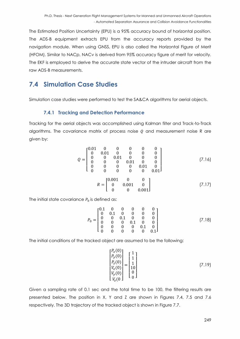
Ph.D. Thesis - Next Generation Flight Management Systems for Manned and Unmanned Aircraft Operations
- Automated Separation Assurance and Collision Avoidance Functionalities
249
The Estimated Position Uncertainty (EPU) is a 95% accuracy bound of horizontal position.
The ADS-B equipment extracts EPU from the accuracy reports provided by the
navigation module. When using GNSS, EPU is also called the Horizontal Figure of Merit
(HFOM). Similar to NACp, NACv is derived from 95% accuracy figure of merit for velocity.
The EKF is employed to derive the accurate state vector of the intruder aircraft from the
raw ADS-B measurements.
7.4 Simulation Case Studies
Simulation case studies were performed to test the SA&CA algorithms for aerial objects.
7.4.1 Tracking and Detection Performance
Tracking for the aerial objects was accomplished using Kalman filter and Track-to-Track
algorithms. The covariance matrix of process noise and measurement noise R are
given by:
[ ]
(7.16)
[
] (7.17)
The initial state covariance is defined as:
[ ]
(7.18)
The initial conditions of the tracked object are assumed to be the following:
[ ( )
( )
( )
( ) ( )
( ]
[ ]
(7.19)
Given a sampling rate of 0.1 sec and the total time to be 100, the filtering results are
presented below. The position in X, Y and Z are shown in Figures 7.4, 7.5 and 7.6
respectively. The 3D trajectory of the tracked object is shown in Figure 7.7.
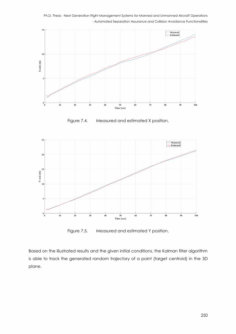
Ph.D. Thesis - Next Generation Flight Management Systems for Manned and Unmanned Aircraft Operations
- Automated Separation Assurance and Collision Avoidance Functionalities
250
Figure 7.4. Measured and estimated X position.
Figure 7.5. Measured and estimated Y position.
Based on the illustrated results and the given initial conditions, the Kalman filter algorithm
is able to track the generated random trajectory of a point (target centroid) in the 3D
plane.
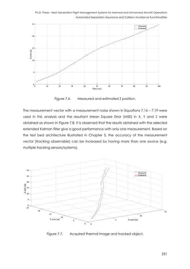
Ph.D. Thesis - Next Generation Flight Management Systems for Manned and Unmanned Aircraft Operations
- Automated Separation Assurance and Collision Avoidance Functionalities
251
Figure 7.6. Measured and estimated Z position.
The measurement vector with a measurement noise shown in Equations 7.16 – 7.19 were
used in this analysis and the resultant Mean Square Error (MSE) in X, Y and Z were
obtained as shown in Figure 7.8. It is observed that the results obtained with the selected
extended Kalman filter give a good performance with only one measurement. Based on
the test bed architecture illustrated in Chapter 5, the accuracy of the measurement
vector (tracking observable) can be increased by having more than one source (e.g.
multiple tracking sensors/systems).
Figure 7.7. Acquired thermal image and tracked object.
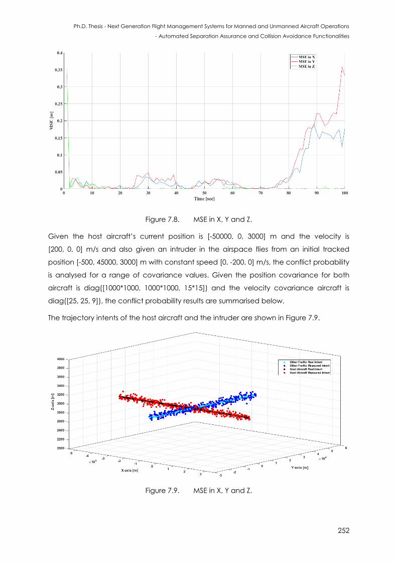
Ph.D. Thesis - Next Generation Flight Management Systems for Manned and Unmanned Aircraft Operations
- Automated Separation Assurance and Collision Avoidance Functionalities
252
Figure 7.8. MSE in X, Y and Z.
Given the host aircraft’s current position is [-50000, 0, 3000] m and the velocity is
[200, 0, 0] m/s and also given an intruder in the airspace flies from an initial tracked
position [-500, 45000, 3000] m with constant speed [0, -200, 0] m/s, the conflict probability
is analysed for a range of covariance values. Given the position covariance for both
aircraft is diag([1000*1000, 1000*1000, 15*15]) and the velocity covariance aircraft is
diag([25, 25, 9]), the conflict probability results are summarised below.
The trajectory intents of the host aircraft and the intruder are shown in Figure 7.9.
Figure 7.9. MSE in X, Y and Z.
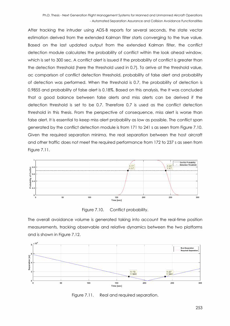
Ph.D. Thesis - Next Generation Flight Management Systems for Manned and Unmanned Aircraft Operations
- Automated Separation Assurance and Collision Avoidance Functionalities
253
After tracking the intruder using ADS-B reports for several seconds, the state vector
estimation derived from the extended Kalman filter starts converging to the true value.
Based on the last updated output from the extended Kalman filter, the conflict
detection module calculates the probability of conflict within the look ahead window,
which is set to 300 sec. A conflict alert is issued if the probability of conflict is greater than
the detection threshold (here the threshold used in 0.7). To arrive at the threshold value,
ac comparison of conflict detection threshold, probability of false alert and probability
of detection was performed. When the threshold is 0.7, the probability of detection is
0.9855 and probability of false alert is 0.18%. Based on this analysis, the It was concluded
that a good balance between false alerts and miss alerts can be derived if the
detection threshold is set to be 0.7. Therefore 0.7 is used as the conflict detection
threshold in this thesis. From the perspective of consequence, miss alert is worse than
false alert. It is essential to keep miss alert probability as low as possible. The conflict span
generated by the conflict detection module is from 171 to 241 s as seen from Figure 7.10.
Given the required separation minima, the real separation between the host aircraft
and other traffic does not meet the required performance from 172 to 237 s as seen from
Figure 7.11.
Figure 7.10. Conflict probability.
The overall avoidance volume is generated taking into account the real-time position
measurements, tracking observable and relative dynamics between the two platforms
and is shown in Figure 7.12.
Figure 7.11. Real and required separation.
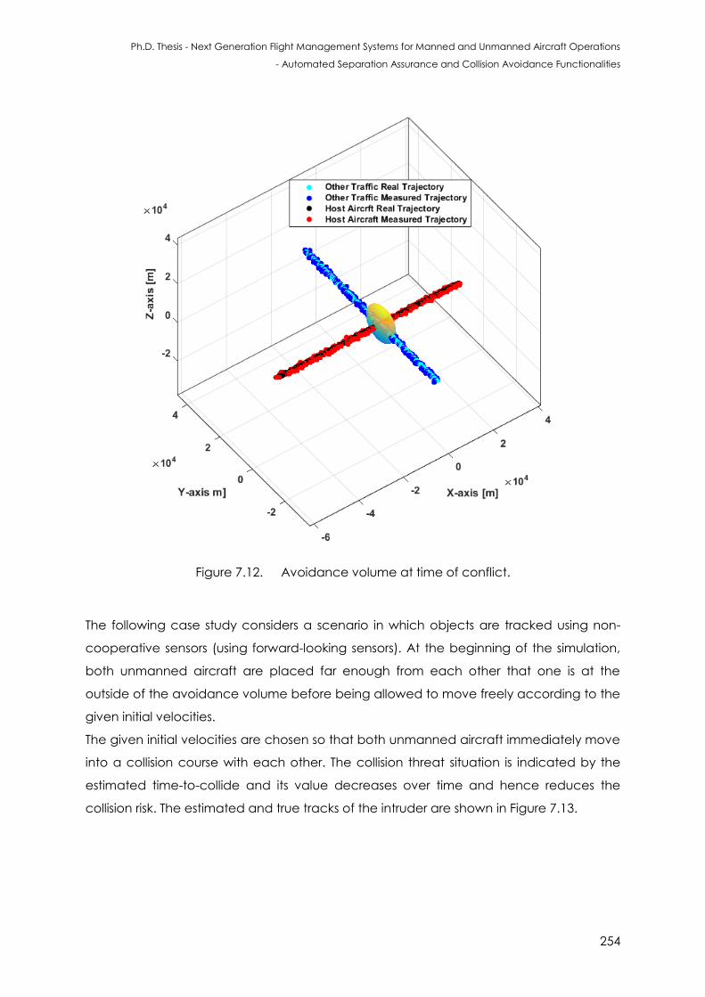
Ph.D. Thesis - Next Generation Flight Management Systems for Manned and Unmanned Aircraft Operations
- Automated Separation Assurance and Collision Avoidance Functionalities
254
Figure 7.12. Avoidance volume at time of conflict.
The following case study considers a scenario in which objects are tracked using non-
cooperative sensors (using forward-looking sensors). At the beginning of the simulation,
both unmanned aircraft are placed far enough from each other that one is at the
outside of the avoidance volume before being allowed to move freely according to the
given initial velocities.
The given initial velocities are chosen so that both unmanned aircraft immediately move
into a collision course with each other. The collision threat situation is indicated by the
estimated time-to-collide and its value decreases over time and hence reduces the
collision risk. The estimated and true tracks of the intruder are shown in Figure 7.13.
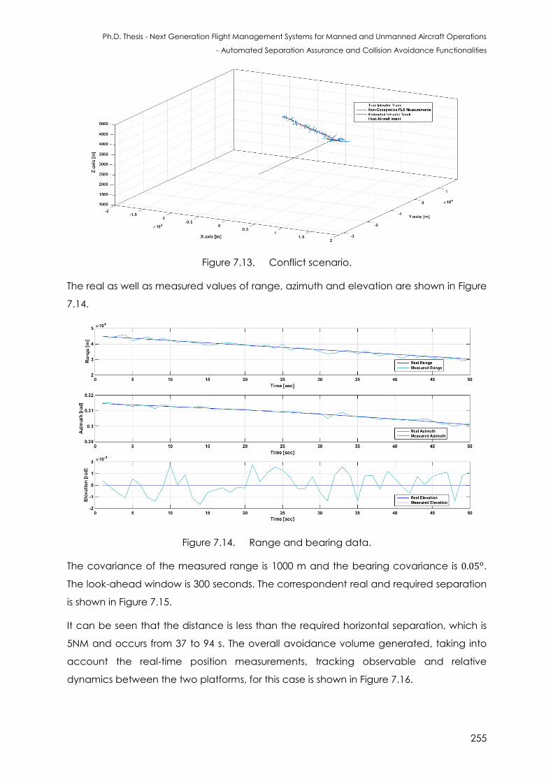
Ph.D. Thesis - Next Generation Flight Management Systems for Manned and Unmanned Aircraft Operations
- Automated Separation Assurance and Collision Avoidance Functionalities
255
Figure 7.13. Conflict scenario.
The real as well as measured values of range, azimuth and elevation are shown in Figure
7.14.
Figure 7.14. Range and bearing data.
The covariance of the measured range is 1000 m and the bearing covariance is .
The look-ahead window is 300 seconds. The correspondent real and required separation
is shown in Figure 7.15.
It can be seen that the distance is less than the required horizontal separation, which is
5NM and occurs from 37 to 94 s. The overall avoidance volume generated, taking into
account the real-time position measurements, tracking observable and relative
dynamics between the two platforms, for this case is shown in Figure 7.16.
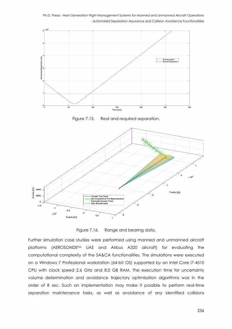
Ph.D. Thesis - Next Generation Flight Management Systems for Manned and Unmanned Aircraft Operations
- Automated Separation Assurance and Collision Avoidance Functionalities
256
Figure 7.15. Real and required separation.
Figure 7.16. Range and bearing data.
Further simulation case studies were performed using manned and unmanned aircraft
platforms (AEROSONDETM UAS and Airbus A320 aircraft) for evaluating the
computational complexity of the SA&CA functionalities. The simulations were executed
on a Windows 7 Professional workstation (64-bit OS) supported by an Intel Core i7-4510
CPU with clock speed 2.6 GHz and 8.0 GB RAM. The execution time for uncertainty
volume determination and avoidance trajectory optimisation algorithms was in the
order of 8 sec. Such an implementation may make it possible to perform real-time
separation maintenance tasks, as well as avoidance of any identified collisions
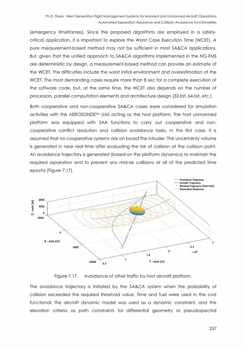
Ph.D. Thesis - Next Generation Flight Management Systems for Manned and Unmanned Aircraft Operations
- Automated Separation Assurance and Collision Avoidance Functionalities
257
(emergency timeframes). Since the proposed algorithms are employed in a safety-
critical application, it is important to explore the Worst Case Execution Time (WCET). A
pure measurement-based method may not be sufficient in most SA&CA applications.
But, given that the unified approach to SA&CA algorithms implemented in the NG-FMS
are deterministic by design, a measurement-based method can provide an estimate of
the WCET. The difficulties include the worst initial environment and overestimation of the
WCET. The most demanding cases require more than 8 sec for a complete execution of
the software code, but, at the same time, the WCET also depends on the number of
processors, parallel computation elements and architecture design (32-bit, 64-bit, etc.)
Both cooperative and non-cooperative SA&CA cases were considered for simulation
activities with the AEROSONDETM UAS acting as the host platform. The host unmanned
platform was equipped with SAA functions to carry out cooperative and non-
cooperative conflict resolution and collision avoidance tasks. In the first case, it is
assumed that no cooperative systems are on board the intruder. The uncertainty volume
is generated in near real-time after evaluating the risk of collision at the collision point.
An avoidance trajectory is generated (based on the platform dynamics) to maintain the
required separation and to prevent any mid-air collisions at all of the predicted time
epochs (Figure 7.17).
Figure 7.17. Avoidance of other traffic by host aircraft platform.
The avoidance trajectory is initiated by the SA&CA system when the probability of
collision exceeded the required threshold value. Time and fuel were used in the cost
functional; the aircraft dynamic model was used as a dynamic constraint, and the
elevation criteria as path constraints for differential geometry or pseudospectral
Ph.D. Thesis - Next Generation Flight Management Systems for Manned and Unmanned Aircraft Operations
- Automated Separation Assurance and Collision Avoidance Functionalities
258
trajectory optimisation algorithms. Three distinct points associated with the avoidance
algorithms include:
Break-off Point: Corresponding to the point where the host UAV initiates the
avoidance trajectory (commanded by the SA&CA system). The cost function
criteria adopted in this case is minimum time;
Safe Maneuvering Point: Corresponding to the point where the host UAV can
maneuver safely (any maneuver within its operational flight envelope) as it has
approximately 0 ROC. From this point onwards the SA&CA cost function criteria
switches to minimum time and minimum fuel to get back on the original (desired)
track;
Re-join Point: Corresponding to the point where the host UAV re-joins the original
(desired) track.
After the obstacles are detected and tracked, an avoidance trajectory is generated
and the corresponding action commands are executed. As a result, the intruder is
evaded and the trajectory of the host aircraft is restored to its original intended path
after performing the avoidance manoeuvres.
7.5 Conclusions
In this chapter, the algorithms used for intruder detection and avoidance were
described. Simulation case studies on the application of a unified approach to
Separation Assurance and Collision Avoidance (SA&CA) for detecting and avoiding
aerial targets were presented. The generation of an avoidance volume, when in the
presence of non-cooperative sensors (forward-looking sensors) as well as cooperative
systems such as Automatic Dependent Surveillance Broadcast (ADS-B) was
demonstrated. Simulation case studies were also presented for the analysis of relative
dynamics between platforms.
7.6 References
1. R. Carnie and R. Walker, "Image Processing Algorithms for UAV Sense and Avoid”,
Proceedings of the 2006 IEEE International Conference on Robotics and Automation,
Orlando, USA, pp. 2848-2853, 2006.
2. Flightglobal and FLIR Systems, “Farnborough Day 1 Flying Display in Infrared,” 2012.
3. RTCA, “Minimum Operational Performance Standards (MOPS) for Aircraft Surveillance
Applications (ASA) System”, DO-317B, Radio Technical Commission for Aeronautics,
Washington DC, USA, 2011.
Ph.D. Thesis - Next Generation Flight Management Systems for Manned and Unmanned Aircraft Operations
- Automated Separation Assurance and Collision Avoidance Functionalities
259
4. RTCA, “Safety, Performance and Interoperability Requirements Document for
Enhanced Air Traffic Services in Radar-Controlled Areas Using ADS-B Surveillance (ADS-
B-RAD)”, DO-318, Radio Technical Commission for Aeronautics, Washington DC, USA,
2009.

Ph.D. Thesis - Next Generation Flight Management Systems for Manned and Unmanned Aircraft Operations
- Automated Separation Assurance and Collision Avoidance Functionalities
260
This page is intentionally left blank to support presswork tasks
Ph.D. Thesis - Next Generation Flight Management Systems for Manned and Unmanned Aircraft Operations
- Automated Separation Assurance and Collision Avoidance Functionalities
261
CHAPTER 8
POTENTIAL UAS TRAFFIC MANAGEMENT
APPLICATIONS
“Everythin however co p icate - breaking waves, migrating birds, and tropical
forests - is made of atoms and obeys the equations of quantum physics. But even if
those equations could be solved, they wouldn't offer the enlightenment that
scientists seek. Each science has its own a tono o s concepts an aws”.
- Martin Rees
8.1 Introduction
The integration of UAS is targeted by the UTM system to ensure safety and operation
efficiency of the airspace. Some lessons learnt from low-altitude uncontrolled airspace
operations of helicopters, gliders and general aviation aircraft are used in UTM system
implementation. Uncertainties in navigation and tracking error measurements
associated with each manned/unmanned platform (as seen by all other conflicting
platforms) are required to be combined statistically to generate avoidance volumes for
manual as well as autonomous operations. The unified approach to SA&CA provides the
framework to generate uncertainty volumes at discrete time intervals as a function of
traffic relative dynamics and thus supports the generation of dynamic geo-fences and
UTM system implementation. Preliminary case studies are performed for evaluating the
feasibility and potential of applying the unified approach to SA&CA in an urban
environment.
8.2 UTM System in the CNS+A Framework
A brief introduction on UTM system implementation preliminaries was presented in
Chapter 2 (Section 2.9).
Opportunities exist for UTM research and technology in several key areas including [1-7]:
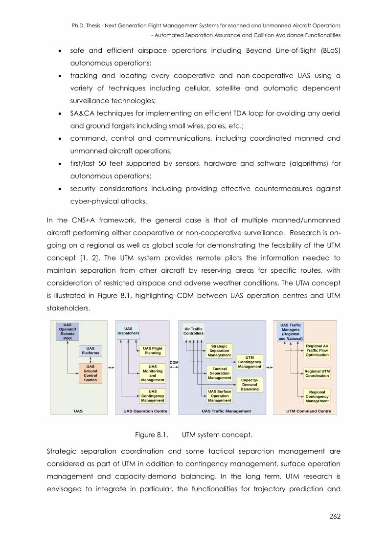
Ph.D. Thesis - Next Generation Flight Management Systems for Manned and Unmanned Aircraft Operations
- Automated Separation Assurance and Collision Avoidance Functionalities
262
safe and efficient airspace operations including Beyond Line-of-Sight (BLoS)
autonomous operations;
tracking and locating every cooperative and non-cooperative UAS using a
variety of techniques including cellular, satellite and automatic dependent
surveillance technologies;
SA&CA techniques for implementing an efficient TDA loop for avoiding any aerial
and ground targets including small wires, poles, etc.;
command, control and communications, including coordinated manned and
unmanned aircraft operations;
first/last 50 feet supported by sensors, hardware and software (algorithms) for
autonomous operations;
security considerations including providing effective countermeasures against
cyber-physical attacks.
In the CNS+A framework, the general case is that of multiple manned/unmanned
aircraft performing either cooperative or non-cooperative surveillance. Research is on-
going on a regional as well as global scale for demonstrating the feasibility of the UTM
concept [1, 2]. The UTM system provides remote pilots the information needed to
maintain separation from other aircraft by reserving areas for specific routes, with
consideration of restricted airspace and adverse weather conditions. The UTM concept
is illustrated in Figure 8.1, highlighting CDM between UAS operation centres and UTM
stakeholders.
UAS UAS Operation Centre UAS Traffic Management UTM Command Centre
UAS
Platforms
UAS
Ground
Control
Station
UAS
Operator/
Remote
Pilot
UAS Flight
Planning
UAS
Monitoring
and
Management
UAS
Contingency
Management
UAS
Dispatchers
Strategic
Separation
Management
Tactical
Separation
Management
UAS Surface
Operation
Management
Air Traffic
Controllers
UTM
Contingency
Management
Capacity-
Demand
Balancing
UAS Traffic
Managers
(Regional
and National)
Regional Air
Traffic Flow
Optimisation
Regional UTM
Coordination
Regional
Contingency
Management
CDM
Figure 8.1. UTM system concept.
Strategic separation coordination and some tactical separation management are
considered as part of UTM in addition to contingency management, surface operation
management and capacity-demand balancing. In the long term, UTM research is
envisaged to integrate in particular, the functionalities for trajectory prediction and
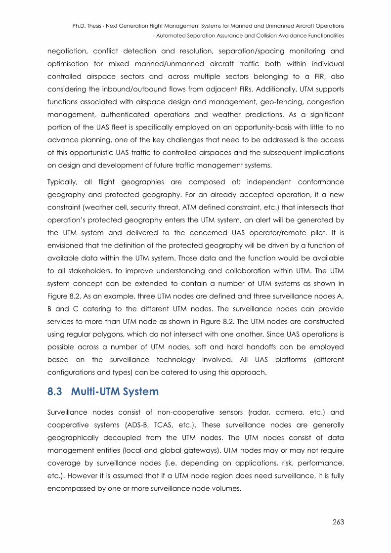
Ph.D. Thesis - Next Generation Flight Management Systems for Manned and Unmanned Aircraft Operations
- Automated Separation Assurance and Collision Avoidance Functionalities
263
negotiation, conflict detection and resolution, separation/spacing monitoring and
optimisation for mixed manned/unmanned aircraft traffic both within individual
controlled airspace sectors and across multiple sectors belonging to a FIR, also
considering the inbound/outbound flows from adjacent FIRs. Additionally, UTM supports
functions associated with airspace design and management, geo-fencing, congestion
management, authenticated operations and weather predictions. As a significant
portion of the UAS fleet is specifically employed on an opportunity-basis with little to no
advance planning, one of the key challenges that need to be addressed is the access
of this opportunistic UAS traffic to controlled airspaces and the subsequent implications
on design and development of future traffic management systems.
Typically, all flight geographies are composed of: independent conformance
geography and protected geography. For an already accepted operation, if a new
constraint (weather cell, security threat, ATM defined constraint, etc.) that intersects that
operation’s protected geography enters the UTM system, an alert will be generated by
the UTM system and delivered to the concerned UAS operator/remote pilot. It is
envisioned that the definition of the protected geography will be driven by a function of
available data within the UTM system. Those data and the function would be available
to all stakeholders, to improve understanding and collaboration within UTM. The UTM
system concept can be extended to contain a number of UTM systems as shown in
Figure 8.2. As an example, three UTM nodes are defined and three surveillance nodes A,
B and C catering to the different UTM nodes. The surveillance nodes can provide
services to more than UTM node as shown in Figure 8.2. The UTM nodes are constructed
using regular polygons, which do not intersect with one another. Since UAS operations is
possible across a number of UTM nodes, soft and hard handoffs can be employed
based on the surveillance technology involved. All UAS platforms (different
configurations and types) can be catered to using this approach.
8.3 Multi-UTM System
Surveillance nodes consist of non-cooperative sensors (radar, camera, etc.) and
cooperative systems (ADS-B, TCAS, etc.). These surveillance nodes are generally
geographically decoupled from the UTM nodes. The UTM nodes consist of data
management entities (local and global gateways). UTM nodes may or may not require
coverage by surveillance nodes (i.e. depending on applications, risk, performance,
etc.). However it is assumed that if a UTM node region does need surveillance, it is fully
encompassed by one or more surveillance node volumes.
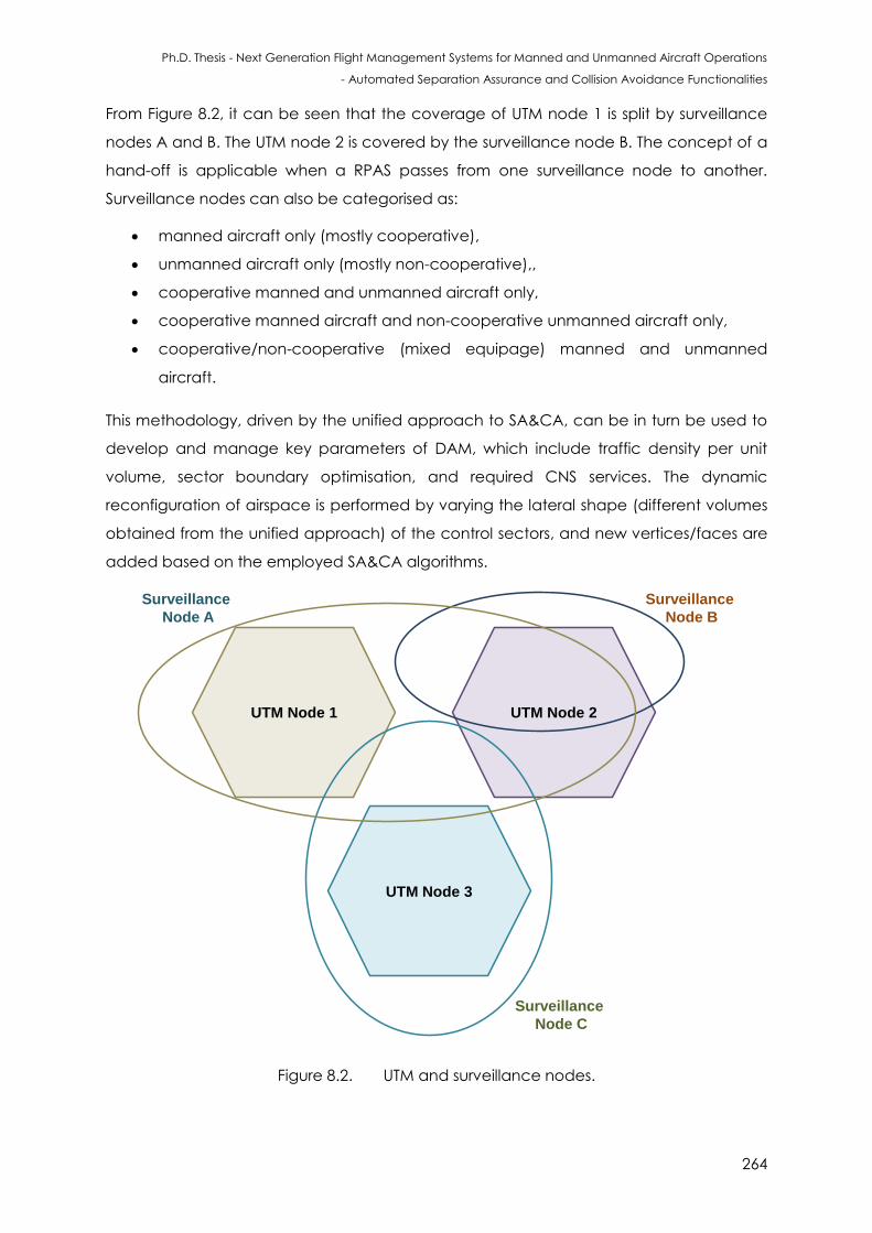
Ph.D. Thesis - Next Generation Flight Management Systems for Manned and Unmanned Aircraft Operations
- Automated Separation Assurance and Collision Avoidance Functionalities
264
From Figure 8.2, it can be seen that the coverage of UTM node 1 is split by surveillance
nodes A and B. The UTM node 2 is covered by the surveillance node B. The concept of a
hand-off is applicable when a RPAS passes from one surveillance node to another.
Surveillance nodes can also be categorised as:
manned aircraft only (mostly cooperative),
unmanned aircraft only (mostly non-cooperative),,
cooperative manned and unmanned aircraft only,
cooperative manned aircraft and non-cooperative unmanned aircraft only,
cooperative/non-cooperative (mixed equipage) manned and unmanned
aircraft.
This methodology, driven by the unified approach to SA&CA, can be in turn be used to
develop and manage key parameters of DAM, which include traffic density per unit
volume, sector boundary optimisation, and required CNS services. The dynamic
reconfiguration of airspace is performed by varying the lateral shape (different volumes
obtained from the unified approach) of the control sectors, and new vertices/faces are
added based on the employed SA&CA algorithms.
UTM Node 1
UTM Node 3
UTM Node 2
Surveillance
Node B
Surveillance
Node C
Surveillance
Node A
Figure 8.2. UTM and surveillance nodes.
Ph.D. Thesis - Next Generation Flight Management Systems for Manned and Unmanned Aircraft Operations
- Automated Separation Assurance and Collision Avoidance Functionalities
265
8.4 Pathways to Implementation
One of our traditional conceptions of warfare and UAS operations has been severely
disrupted over the last few years, in a sense that the operational space has shifted from
the field to the urban environment. This shift is driving a fundamental change in the
operation of UAS in a variety of civil and military applications, with concomitant
implications for technology development. The systems and assets required to support
open field campaigns are qualitatively different from that needed for Military Operations
in Urban Terrain (MOUT). Surveillance and reconnaissance operations in cities and towns
are a particular topic of interest. The urban environment is sufficiently different that the
utility of conventional sensing and communication platforms is rendered problematic. In
virtually all cases, the principal rationale for these vehicles is to help establish and
enhance sensing and communication networks in a network-centric environment [8].
8.4.1 Multi-Platform Scenario
The urban space is a dynamic environment. Small buildings arise in a matter of weeks,
and large buildings in months. Parked or abandoned vehicles and obstacles can be
perfectly effective blockades, and require a reactive, close-in mode of sensing. In fact,
geometrically, the urban space is of an entirely different scale than the traditional kind
of aircraft operations. While in free-space environments the focus has been on formation
flight and collective trajectory generation and tracking, urban environments impose
different challenges and offer different opportunities. In some situations, UAS can assist
one another, by serving as nodes or repeaters in a communications network, as
lookouts, decoys, or as slaved remote sensors. In even tighter models of collaboration,
multiple vehicles can be used to multi-laterate on a target signal; i.e., take signal
strength and/or directional measurements that can later be combined to geolocate the
target with more precision than any single vehicle-borne sensor possibly could [9].
Figure 8.3 shows one of the various possible scenarios of multi-platform operations in an
urban environment. In this scenario, three airspace sectors are considered. The
uncertainties in navigation and tracking associated with each manned/unmanned
platform (as seen by all other conflicting platforms) are combined to generate
avoidance volumes surrounding each aircraft. The avoidance volumes are computed
at discrete time intervals as a function of traffic relative dynamics. The host and other
traffic may be equipped with non-cooperative sensors, cooperative systems or
combinations thereof. Figure 8.3 also shows a conceptual representation of the variable
avoidance volume associated with aircraft 4, obtained by combining (in a statistical
Ph.D. Thesis - Next Generation Flight Management Systems for Manned and Unmanned Aircraft Operations
- Automated Separation Assurance and Collision Avoidance Functionalities
266
sense) the navigation and tracking errors related to cooperative and non-cooperative
SA&CA observations by all other aircraft at sequential time epochs as well as a function
of relative dynamics.
The more recent advances in Communication, Navigation, Surveillance, ATM and
Avionics (CNS+A) technologies are progressively supporting the introduction of dynamic
DCB strategies. The new CNS+A technologies greatly increase the flexibility of routes and
airspace configurations, which are both of great use for DCB. The novel CNS+A systems
for TBO/IBO are conceived to meet the ambitious CNS performance requirements and
expected to support an increase in traffic density without compromising flight safety.
These include the Next Generation Flight Management System (NG-FMS), Next
Generation ATM (NG-ATM) and UTM systems, supported by high-throughput, secure and
reliable data links. The capacity can be therefore expressed as a function of the CNS
performance as follows. The capacity factor of airspace sector due to Communication
Performance (CP) alone can be expressed as a factor of the minimum CP guaranteed
by all traffic j concurrently in the sector. An example, in terms of Communication
Integrity (CI) is given by [10]:
(8.1)
Similar expressions hold true for Navigation Integrity (NI) and Surveillance Integrity (SI):
(8.2)
(8.3)
After obtaining all the avoidance volumes in airspace sector 3, the largest of the four
avoidance volumes is selected as a reference to perform DCB. In addition to the CNS
systems both onboard and on the ground that dictate the adherence RTSP, the SA&CA
functionalities provide a methodology to perform DCB.
As shown in Chapter 5, given any two aircraft in the same or adjacent airspace sectors,
the condition before collision are such that the radial distance between the host aircraft
and intruder is decreasing. This is a necessary condition for a collision. Considering the
scenario presented in Figure 8.3, the necessary conditions between the host aircraft (H)
and the other four intruder (I) platforms are given by:
|| ||
(8.4)
and
|| || || || (8.5)
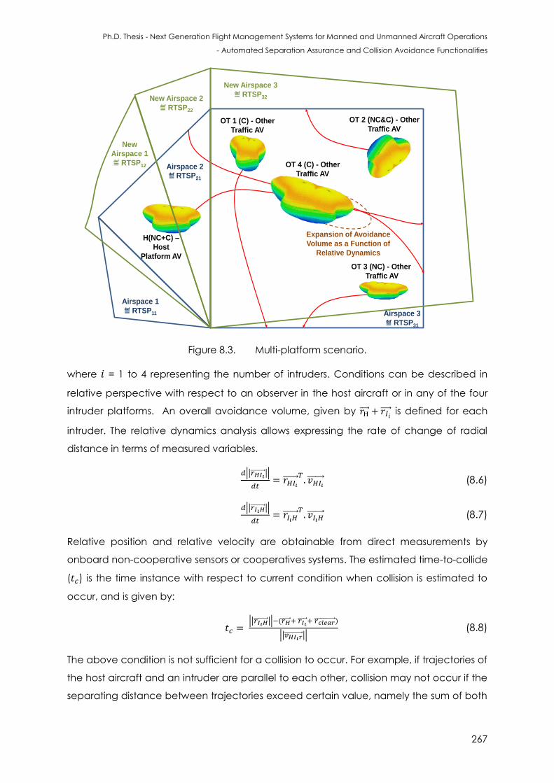
Ph.D. Thesis - Next Generation Flight Management Systems for Manned and Unmanned Aircraft Operations
- Automated Separation Assurance and Collision Avoidance Functionalities
267
H(NC+C) –
Host
Platform AV
Airspace 1
≝ RTSP11
Airspace 2
≝ RTSP21
OT 1 (C) - Other
Traffic AV
OT 2 (NC&C) - Other
Traffic AV
OT 3 (NC) - Other
Traffic AV
OT 4 (C) - Other
Traffic AV
Expansion of Avoidance
Volume as a Function of
Relative Dynamics
Airspace 3
≝ RTSP31
New Airspace 3
≝ RTSP32New Airspace 2
≝ RTSP22
New
Airspace 1
≝ RTSP12
Figure 8.3. Multi-platform scenario.
where = 1 to 4 representing the number of intruders. Conditions can be described in
relative perspective with respect to an observer in the host aircraft or in any of the four
intruder platforms. An overall avoidance volume, given by is defined for each
intruder. The relative dynamics analysis allows expressing the rate of change of radial
distance in terms of measured variables.
|| ||
(8.6)
|| ||
(8.7)
Relative position and relative velocity are obtainable from direct measurements by
onboard non-cooperative sensors or cooperatives systems. The estimated time-to-collide
( ) is the time instance with respect to current condition when collision is estimated to
occur, and is given by:
|| || ( )
|| || (8.8)
The above condition is not sufficient for a collision to occur. For example, if trajectories of
the host aircraft and an intruder are parallel to each other, collision may not occur if the
separating distance between trajectories exceed certain value, namely the sum of both
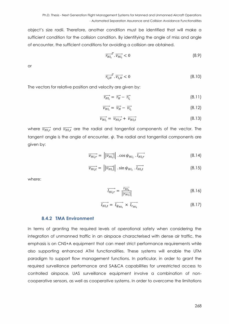
Ph.D. Thesis - Next Generation Flight Management Systems for Manned and Unmanned Aircraft Operations
- Automated Separation Assurance and Collision Avoidance Functionalities
268
object’s size radii. Therefore, another condition must be identified that will make a
sufficient condition for the collision condition. By identifying the angle of miss and angle
of encounter, the sufficient conditions for avoiding a collision are obtained.
(8.9)
or
(8.10)
The vectors for relative position and velocity are given by:
(8.11)
(8.12)
(8.13)
where and are the radial and tangential components of the vector. The
tangent angle is the angle of encounter, . The radial and tangential components are
given by:
|| || (8.14)
|| || (8.15)
where:
|| || (8.16)
(8.17)
8.4.2 TMA Environment
In terms of granting the required levels of operational safety when considering the
integration of unmanned traffic in an airspace characterised with dense air traffic, the
emphasis is on CNS+A equipment that can meet strict performance requirements while
also supporting enhanced ATM functionalities. These systems will enable the UTM
paradigm to support flow management functions. In particular, in order to grant the
required surveillance performance and SA&CA capabilities for unrestricted access to
controlled airspace, UAS surveillance equipment involve a combination of non-
cooperative sensors, as well as cooperative systems. In order to overcome the limitations
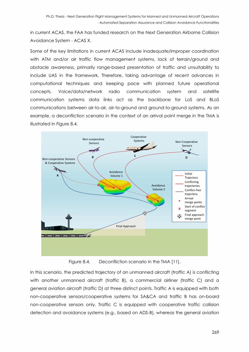
Ph.D. Thesis - Next Generation Flight Management Systems for Manned and Unmanned Aircraft Operations
- Automated Separation Assurance and Collision Avoidance Functionalities
269
in current ACAS, the FAA has funded research on the Next Generation Airborne Collision
Avoidance System - ACAS X.
Some of the key limitations in current ACAS include inadequate/improper coordination
with ATM and/or air traffic flow management systems, lack of terrain/ground and
obstacle awareness, primarily range-based presentation of traffic and unsuitability to
include UAS in the framework. Therefore, taking advantage of recent advances in
computational techniques and keeping pace with planned future operational
concepts, Voice/data/network radio communication system and satellite
communication systems data links act as the backbone for LoS and BLoS
communications between air-to-air, air-to-ground and ground-to-ground systems. As an
example, a deconfliction scenario in the context of an arrival point merge in the TMA is
illustrated in Figure 8.4.
Avoidance Volume 1
Avoidance Volume 2
Non-cooperative Sensors
Non-cooperative Sensors & Cooperative Systems
Initial Trajectory
Conflictingtrajectories
Conflict-freetrajectory
Final Approach
A
B
Cooperative Systems Non-Cooperative
Sensors
CD
Arrivalmerge points
Start of conflict segment
Final approachmerge point
Figure 8.4. Deconfliction scenario in the TMA [11].
In this scenario, the predicted trajectory of an unmanned aircraft (traffic A) is conflicting
with another unmanned aircraft (traffic B), a commercial airliner (traffic C) and a
general aviation aircraft (traffic D) at three distinct points. Traffic A is equipped with both
non-cooperative sensors/cooperative systems for SA&CA and traffic B has on-board
non-cooperative sensors only. Traffic C is equipped with cooperative traffic collision
detection and avoidance systems (e.g., based on ADS-B), whereas the general aviation
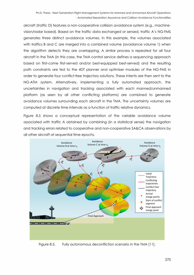
Ph.D. Thesis - Next Generation Flight Management Systems for Manned and Unmanned Aircraft Operations
- Automated Separation Assurance and Collision Avoidance Functionalities
270
aircraft (traffic D) features a non-cooperative collision avoidance system (e.g., machine-
vision/radar based). Based on the traffic data exchanged or sensed, traffic A’s NG-FMS
generates three distinct avoidance volumes. In this example, the volumes associated
with traffics B and C are merged into a combined volume (avoidance volume 1) when
the algorithm detects they are overlapping. A similar process is repeated for all four
aircraft in the TMA (in this case, the TMA control service defines a sequencing approach
based on first-come first-served and/or best-equipped best-served) and the resulting
path constraints are fed to the 4DT planner and optimiser modules of the NG-FMS in
order to generate four conflict-free trajectory solutions. These intents are then sent to the
NG-ATM system. Alternatively, implementing a fully automated approach, the
uncertainties in navigation and tracking associated with each manned/unmanned
platform (as seen by all other conflicting platforms) are combined to generate
avoidance volumes surrounding each aircraft in the TMA. The uncertainty volumes are
computed at discrete time intervals as a function of traffic relative dynamics.
Figure 8.5 shows a conceptual representation of the variable avoidance volume
associated with traffic A obtained by combining (in a statistical sense) the navigation
and tracking errors related to cooperative and non-cooperative SA&CA observations by
all other aircraft at sequential time epochs.
A
Avoidance Volume B at time t0
B C
Final Approach
Avoidance Volume C at time t0
Avoidance Volume D at time t0
D
Initial Trajectory
Conflictingtrajectories
Conflict-freetrajectory
Arrivalmerge points
Start of conflict segment
Final approachmerge point
Figure 8.5. Fully autonomous deconfliction scenario in the TMA [11].
Ph.D. Thesis - Next Generation Flight Management Systems for Manned and Unmanned Aircraft Operations
- Automated Separation Assurance and Collision Avoidance Functionalities
271
In this case, the NG-FMS exchange real-time avoidance information updates, compute
the optimal 4DT to be executed by each platform and communicate these intents to
the NG-ATM system. The concept of automated SA&CA operations for this scenario
provide the following characteristics [12]:
Airspace building blocks may or may not be necessary;
Automated SA&CA;
All aircraft are capable of automated SA&CA; or fewer unequipped aircraft and
more aircraft with automated SA&CA functionalities;
Addresses complexity management;
Arrival intents begin at top of descent, departure corridors end at top of climb,
overflight corridors may connect wind optimal user preferred routes;
Intents are dynamic, based on DCB and weather conditions;
Controller primarily manages air traffic flow, or else controller manages flows as
well as conflicts between aircraft with mixed equipage.
8.5 Simulation Case Studies
The case studies performed for evaluating the feasibility and potential of applying the
unified approach to SA&CA in the UTM context are presented in this section. The case
studies are performed in realistic scenarios such as urban environments. Different urban
environments were simulated with realistic models obtained from SketchUpTM as shown in
Figure 8.6.
Figure 8.6. Simulated urban environment.
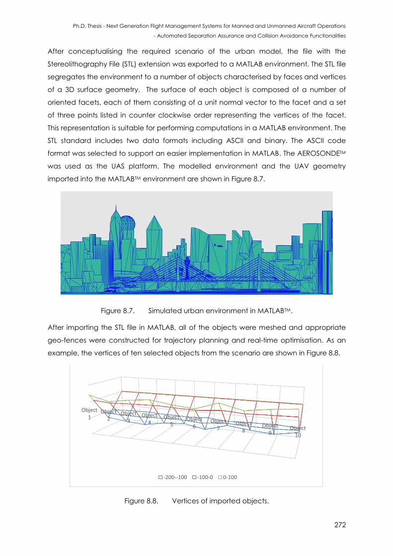
Ph.D. Thesis - Next Generation Flight Management Systems for Manned and Unmanned Aircraft Operations
- Automated Separation Assurance and Collision Avoidance Functionalities
272
After conceptualising the required scenario of the urban model, the file with the
Stereolithography File (STL) extension was exported to a MATLAB environment. The STL file
segregates the environment to a number of objects characterised by faces and vertices
of a 3D surface geometry. The surface of each object is composed of a number of
oriented facets, each of them consisting of a unit normal vector to the facet and a set
of three points listed in counter clockwise order representing the vertices of the facet.
This representation is suitable for performing computations in a MATLAB environment. The
STL standard includes two data formats including ASCII and binary. The ASCII code
format was selected to support an easier implementation in MATLAB. The AEROSONDETM
was used as the UAS platform. The modelled environment and the UAV geometry
imported into the MATLABTM environment are shown in Figure 8.7.
Figure 8.7. Simulated urban environment in MATLABTM.
After importing the STL file in MATLAB, all of the objects were meshed and appropriate
geo-fences were constructed for trajectory planning and real-time optimisation. As an
example, the vertices of ten selected objects from the scenario are shown in Figure 8.8.
Figure 8.8. Vertices of imported objects.
Object1
Object2
Object3
Object4
Object5
Object6
Object7
Object8
Object9
Object10
-200--100 -100-0 0-100
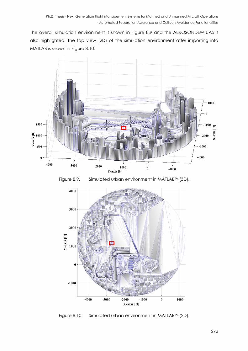
Ph.D. Thesis - Next Generation Flight Management Systems for Manned and Unmanned Aircraft Operations
- Automated Separation Assurance and Collision Avoidance Functionalities
273
The overall simulation environment is shown in Figure 8.9 and the AEROSONDETM UAS is
also highlighted. The top view (2D) of the simulation environment after importing into
MATLAB is shown in Figure 8.10.
Figure 8.9. Simulated urban environment in MATLABTM (3D).
Figure 8.10. Simulated urban environment in MATLABTM (2D).
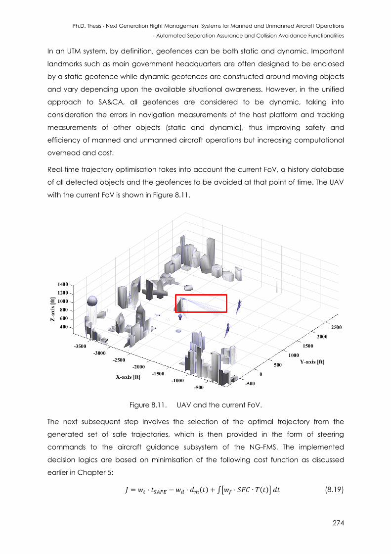
Ph.D. Thesis - Next Generation Flight Management Systems for Manned and Unmanned Aircraft Operations
- Automated Separation Assurance and Collision Avoidance Functionalities
274
In an UTM system, by definition, geofences can be both static and dynamic. Important
landmarks such as main government headquarters are often designed to be enclosed
by a static geofence while dynamic geofences are constructed around moving objects
and vary depending upon the available situational awareness. However, in the unified
approach to SA&CA, all geofences are considered to be dynamic, taking into
consideration the errors in navigation measurements of the host platform and tracking
measurements of other objects (static and dynamic), thus improving safety and
efficiency of manned and unmanned aircraft operations but increasing computational
overhead and cost.
Real-time trajectory optimisation takes into account the current FoV, a history database
of all detected objects and the geofences to be avoided at that point of time. The UAV
with the current FoV is shown in Figure 8.11.
Figure 8.11. UAV and the current FoV.
The next subsequent step involves the selection of the optimal trajectory from the
generated set of safe trajectories, which is then provided in the form of steering
commands to the aircraft guidance subsystem of the NG-FMS. The implemented
decision logics are based on minimisation of the following cost function as discussed
earlier in Chapter 5:
( ) ∫[ ( )] (8.19)
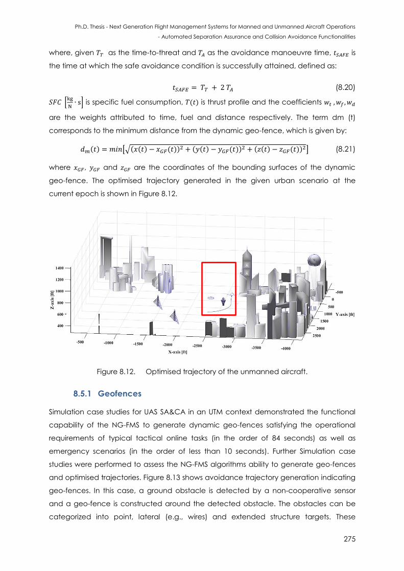
Ph.D. Thesis - Next Generation Flight Management Systems for Manned and Unmanned Aircraft Operations
- Automated Separation Assurance and Collision Avoidance Functionalities
275
where, given as the time-to-threat and as the avoidance manoeuvre time, is
the time at which the safe avoidance condition is successfully attained, defined as:
(8.20)
[
] is specific fuel consumption, ( ) is thrust profile and the coefficients
are the weights attributed to time, fuel and distance respectively. The term dm (t)
corresponds to the minimum distance from the dynamic geo-fence, which is given by:
( ) [√( ( ) ( )) ( ( ) ( ))
( ( ) ( )) ] (8.21)
where , and are the coordinates of the bounding surfaces of the dynamic
geo-fence. The optimised trajectory generated in the given urban scenario at the
current epoch is shown in Figure 8.12.
Figure 8.12. Optimised trajectory of the unmanned aircraft.
8.5.1 Geofences
Simulation case studies for UAS SA&CA in an UTM context demonstrated the functional
capability of the NG-FMS to generate dynamic geo-fences satisfying the operational
requirements of typical tactical online tasks (in the order of 84 seconds) as well as
emergency scenarios (in the order of less than 10 seconds). Further Simulation case
studies were performed to assess the NG-FMS algorithms ability to generate geo-fences
and optimised trajectories. Figure 8.13 shows avoidance trajectory generation indicating
geo-fences. In this case, a ground obstacle is detected by a non-cooperative sensor
and a geo-fence is constructed around the detected obstacle. The obstacles can be
categorized into point, lateral (e.g., wires) and extended structure targets. These
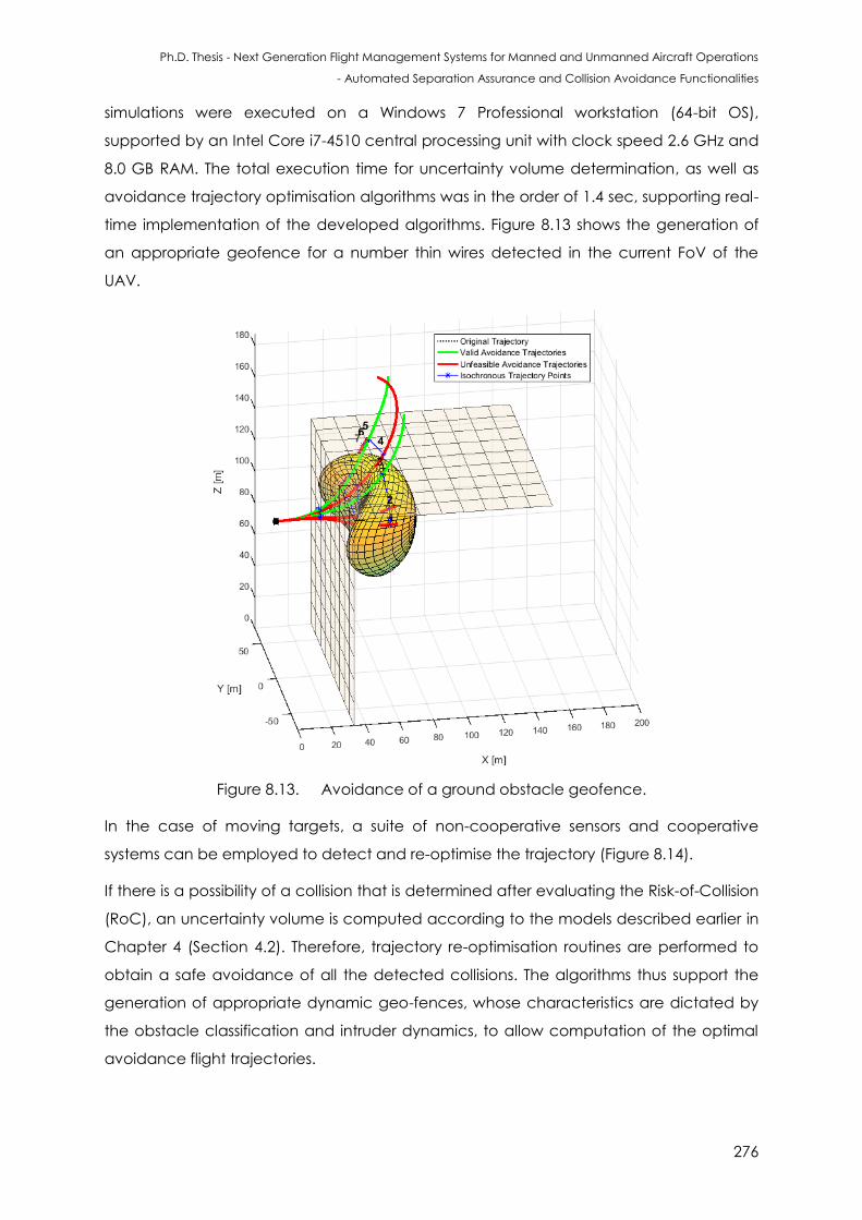
Ph.D. Thesis - Next Generation Flight Management Systems for Manned and Unmanned Aircraft Operations
- Automated Separation Assurance and Collision Avoidance Functionalities
276
simulations were executed on a Windows 7 Professional workstation (64-bit OS),
supported by an Intel Core i7-4510 central processing unit with clock speed 2.6 GHz and
8.0 GB RAM. The total execution time for uncertainty volume determination, as well as
avoidance trajectory optimisation algorithms was in the order of 1.4 sec, supporting real-
time implementation of the developed algorithms. Figure 8.13 shows the generation of
an appropriate geofence for a number thin wires detected in the current FoV of the
UAV.
Figure 8.13. Avoidance of a ground obstacle geofence.
In the case of moving targets, a suite of non-cooperative sensors and cooperative
systems can be employed to detect and re-optimise the trajectory (Figure 8.14).
If there is a possibility of a collision that is determined after evaluating the Risk-of-Collision
(RoC), an uncertainty volume is computed according to the models described earlier in
Chapter 4 (Section 4.2). Therefore, trajectory re-optimisation routines are performed to
obtain a safe avoidance of all the detected collisions. The algorithms thus support the
generation of appropriate dynamic geo-fences, whose characteristics are dictated by
the obstacle classification and intruder dynamics, to allow computation of the optimal
avoidance flight trajectories.
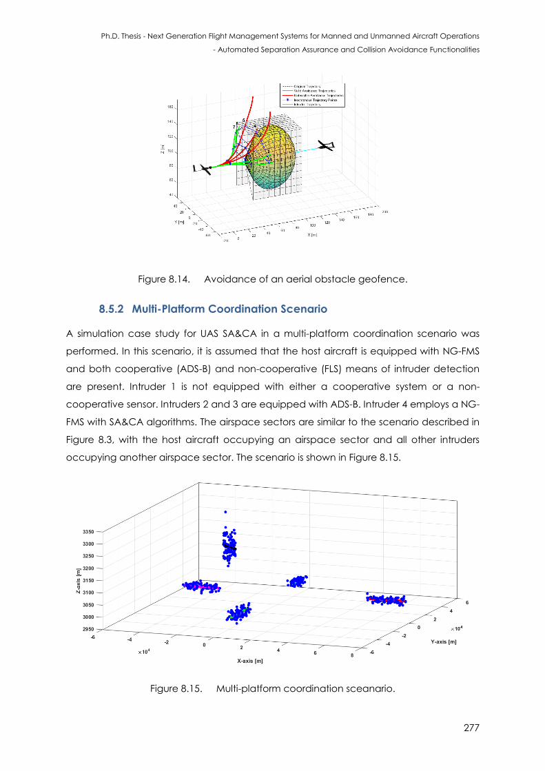
Ph.D. Thesis - Next Generation Flight Management Systems for Manned and Unmanned Aircraft Operations
- Automated Separation Assurance and Collision Avoidance Functionalities
277
Figure 8.14. Avoidance of an aerial obstacle geofence.
8.5.2 Multi-Platform Coordination Scenario
A simulation case study for UAS SA&CA in a multi-platform coordination scenario was
performed. In this scenario, it is assumed that the host aircraft is equipped with NG-FMS
and both cooperative (ADS-B) and non-cooperative (FLS) means of intruder detection
are present. Intruder 1 is not equipped with either a cooperative system or a non-
cooperative sensor. Intruders 2 and 3 are equipped with ADS-B. Intruder 4 employs a NG-
FMS with SA&CA algorithms. The airspace sectors are similar to the scenario described in
Figure 8.3, with the host aircraft occupying an airspace sector and all other intruders
occupying another airspace sector. The scenario is shown in Figure 8.15.
Figure 8.15. Multi-platform coordination sceanario.
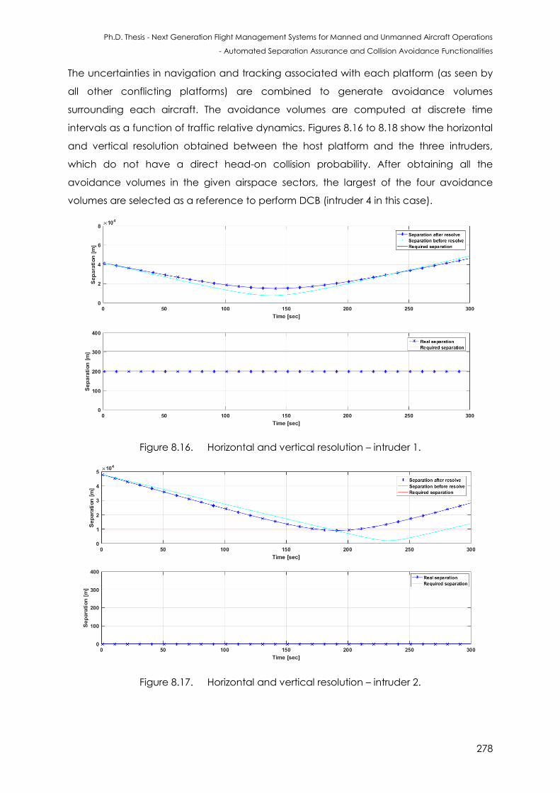
Ph.D. Thesis - Next Generation Flight Management Systems for Manned and Unmanned Aircraft Operations
- Automated Separation Assurance and Collision Avoidance Functionalities
278
The uncertainties in navigation and tracking associated with each platform (as seen by
all other conflicting platforms) are combined to generate avoidance volumes
surrounding each aircraft. The avoidance volumes are computed at discrete time
intervals as a function of traffic relative dynamics. Figures 8.16 to 8.18 show the horizontal
and vertical resolution obtained between the host platform and the three intruders,
which do not have a direct head-on collision probability. After obtaining all the
avoidance volumes in the given airspace sectors, the largest of the four avoidance
volumes are selected as a reference to perform DCB (intruder 4 in this case).
Figure 8.16. Horizontal and vertical resolution – intruder 1.
Figure 8.17. Horizontal and vertical resolution – intruder 2.
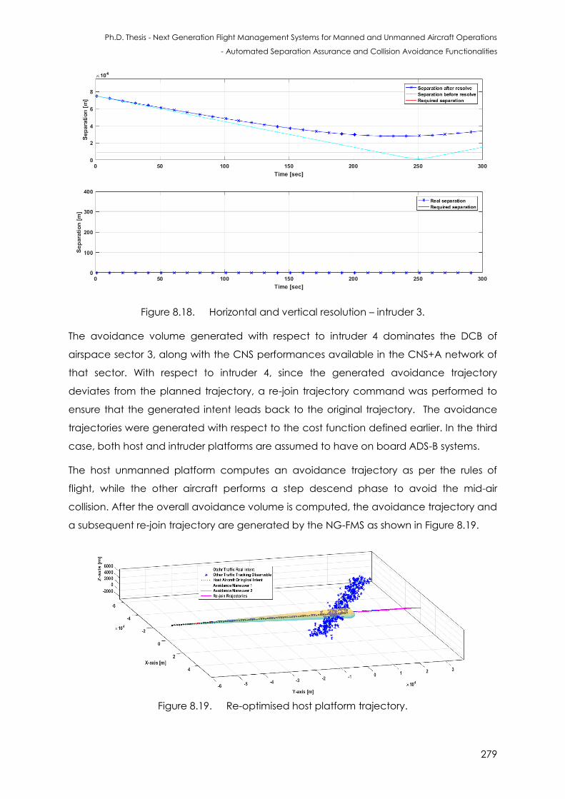
Ph.D. Thesis - Next Generation Flight Management Systems for Manned and Unmanned Aircraft Operations
- Automated Separation Assurance and Collision Avoidance Functionalities
279
Figure 8.18. Horizontal and vertical resolution – intruder 3.
The avoidance volume generated with respect to intruder 4 dominates the DCB of
airspace sector 3, along with the CNS performances available in the CNS+A network of
that sector. With respect to intruder 4, since the generated avoidance trajectory
deviates from the planned trajectory, a re-join trajectory command was performed to
ensure that the generated intent leads back to the original trajectory. The avoidance
trajectories were generated with respect to the cost function defined earlier. In the third
case, both host and intruder platforms are assumed to have on board ADS-B systems.
The host unmanned platform computes an avoidance trajectory as per the rules of
flight, while the other aircraft performs a step descend phase to avoid the mid-air
collision. After the overall avoidance volume is computed, the avoidance trajectory and
a subsequent re-join trajectory are generated by the NG-FMS as shown in Figure 8.19.
Figure 8.19. Re-optimised host platform trajectory.
Ph.D. Thesis - Next Generation Flight Management Systems for Manned and Unmanned Aircraft Operations
- Automated Separation Assurance and Collision Avoidance Functionalities
280
8.6 Conclusions
The UTM system was introduced, which comprises the various elements required to
support and execute UAS operations in low-altitude airspace. Specifically, the
integration of small-size UAS into the airspace is targeted in the UTM system to ensure
safety and operation efficiency. Some lessons learnt from low-altitude uncontrolled
airspace operations of helicopters, gliders and general aviation aircraft are valuable in
the UTM system implementation. Uncertainties in navigation and tracking associated to
each manned/unmanned platform (as seen by all other conflicting platforms) were
combined to generate avoidance volumes in all phases of flight (including low-altitude
operations). The uncertainty volumes were computed at discrete time intervals as a
function of traffic relative dynamics and thus support generation of dynamic geo-fences
and multi UTM system implementation. Case studies were performed for evaluating the
feasibility and potential of applying the unified approach to SA&CA in an urban
environment.
8.7 References
1. P. Kopardekar, “Unmanned Aerial System (UAS) Traffic Management (UTM): Enabling
Low-altitude Airspace and UAS Operations”, ARC-E-DAA-TN32373, NASA Ames
Research Center, NASA, Moffett Field, CA, USA, 2016.
2. J. Robinson, M. Johnson, J. Jung, P. Kopardekar, T. Prevot and J. Rios, “Unmanned
Aerial System Traffic Management Concept of Operations (v0.5) (UTM CONOPS)”,
NASA TM draft, Moffett Field, CA, USA, 2015.
3. C.W. Johnson, “The Safety Research Challenges for the Air Traffic Management of
Unmanned Aerial Systems (UAS)”, Proceedings of the 6th EUROCONTROL Experimental
Centre Safety Research and Development Workshop, Munich, Germany, October,
Vol. 21, 2009.
4. Y. Kim, J. Jo and M. Shaw, “A Lightweight Communication Architecture for Small UAS
Traffic Management (SUTM)”, IEEE Integrated Communication, Navigation and
Surveillance Conference (ICNS), pp. T4-1, 2015.
5. T. Prevot, J. Homola and J. Mercer, “From Rural to Urban Environments: Human/Systems
Simulation Research for Low Altitude UAS Traffic Management (UTM)”, 16th AIAA
Aviation Technology, Integration, and Operations Conference, Washington DC, USA,
p. 3291, 2016.
Ph.D. Thesis - Next Generation Flight Management Systems for Manned and Unmanned Aircraft Operations
- Automated Separation Assurance and Collision Avoidance Functionalities
281
6. V. Milanés, J. Godoy, J. Pérez, B. Vinagre, C. González, E. Onieva and J. Alonso, “V2I-
Based Architecture for Information Exchange among Vehicles”, IFAC Proceedings,
Vol. 43, Issue 16,, pp. 85-90, 2010.
7. P. Kopardekar, P. Lee, T. Prevot, J. Mercer, J. Homola, M. Mainini, N. Smith, A. Aweiss
and K. Lee, "Feasibility of Mixed Equipage Operations in the Same Airspace", Eighth
USA/Europe Air Traffic Management Research and Development Seminar (ATM2009),
Napa, CA, USA, 2009.
8. T. Samad, J.S. Bay and D. Godbole, “Network-centric Systems for Military Operations in
Urban Terrain: The Role of UAVs, Proceedings of the IEEE, Vol. 95, Issue 1, pp.92-107,
2007.
9. D.R.V. Rheeden, B.C. Brown, J.C. Price, B.A. Abbott, G.C. Willden, K. Chhokra, J. Scott,
and T. Bapty, “Automatic Positioning of UAVs to Optimize TDOA Geolocation
Performance”, Proceedings of the 23rd Digital Avionics Systems Conference (DASC),
pp. 24–28, 2004.
10. A. Gardi, S. Ramasamy, M. Marino, T. Kistan, R. Sabatini, M. O’Flynn and P. Bernard-
Flattot, “Implementation, Verification and Evaluation of 4D Route Planning and
Dynamic Airspace Functionalities in a Simulated Environment”, Next Generation Air
Traffic Management Systems: Multi-Objective Four-Dimensional Trajectory Optimisation,
Negotiation and Validation for Intent Based Operations, THALES RMIT University
Collaborative Research, Report 3, 2016.
11. A. Gardi, S. Ramasamy, R. Sabatini and T. Kistan, “Terminal Area Operations:
Challenges and Opportunities”, Encyclopedia of Aerospace - UAS, eds. R. Blockley and
W. Shyy, John Wiley: Chichester, 2016.
12. P. Kopardekar, K. Bilimoria and B. Sridhar, “Initial Concepts for Dynamic Airspace
Configuration”, Proceedings of 7th AIAA Aviation Technology, Integration and
Operations Conference (ATIO), Belfast, Northern Ireland, pp. 18-20, 2007.

Ph.D. Thesis - Next Generation Flight Management Systems for Manned and Unmanned Aircraft Operations
- Automated Separation Assurance and Collision Avoidance Functionalities
282
This page is intentionally left blank to support presswork tasks
Ph.D. Thesis - Next Generation Flight Management Systems for Manned and Unmanned Aircraft Operations
- Automated Separation Assurance and Collision Avoidance Functionalities
283
CHAPTER 9
CONCLUSIONS AND
FUTURE DIRECTIONS
“Great rea s of reat rea ers are a ways transcen e ”. – A.P.J. Abdul Kalam
9.1 Conclusions
The key design features of NG-FMS suitable for manned and unmanned aircraft
operations were presented. In particular, the novel mathematical models required for
the implementation of advanced SA&CA functionalities were developed. One of the
key research contributions was the formulation of a unified methodology to support
cooperative and non-cooperative SA&CA tasks, addressing the technical and
regulatory challenges of manned and unmanned aircraft coexistence in all classes of
airspace. The following section outlines the original contributions of this research project.
The conclusions of this research project are further elaborated in terms of achieved
research objectives in Section 9.4.
9.1.1 Summary of Original Contributions
This research investigated the introduction of NG-FMS algorithms for planning and near
real-time execution of 4DT functionalities in the TBO/IBO context as well as in the UTM
framework. The key emphasis was on the development of a unified approach to SA&CA
by considering navigation and tracking errors affecting the aircraft state vector and
translating them to unified range and bearing uncertainty descriptors, which apply both
to cooperative and non-cooperative scenarios. The main original contributions are
summarised below:
System architectures of the novel FMS for manned and unmanned aircraft
operations;
Ph.D. Thesis - Next Generation Flight Management Systems for Manned and Unmanned Aircraft Operations
- Automated Separation Assurance and Collision Avoidance Functionalities
284
Adaptation of mathematical models for NG-FMS to provide 4DT optimisation and
air-to-ground trajectory negotiation/validation to support TBO/IBO;
Development of analytical models that describe a unified approach to
cooperative and non-cooperative SA&CA providing the following key benefits:
- An approach to combine the uncertainties in navigation and tracking
measurements to generate overall avoidance volumes;
- Avoidance volume determination at discrete time intervals as a function
of relative dynamics (host platform and other traffic);
- Real-time transformation of host aircraft navigation error and target
tracking error affecting the state measurements to unified range and
bearing uncertainty descriptors;
- Detection and resolution of both cooperative and non-cooperative
collision threats in various weather and daylight conditions; and also in
case of adverse weather conditions;
- Automatic selection of sensors/systems providing the most reliable SA&CA
solution, providing robustness in all flight phases;
- A compact and versatile parameterisation of the avoidance volume to
extrapolate its actual shape and size at close encounter points with
minimal data-link and computational burden;
- Robust trajectory optimisation allowing the identification of the safest and
more efficient Three-Dimensional or Four-Dimensional (3D/4D) avoidance
trajectory, considering relative dynamics between the host aircraft and
other traffic, airspace constraints, as well as meteorological and traffic
conditions;
- Generation of appropriate dynamic geo-fences, whose characteristics
are dictated by the obstacle classification and dynamics of other
platforms (including ground obstacles), to allow computation of the
optimal avoidance flight trajectories;
- Pathways to certifying SA&CA functions for both manned and unmanned
aircraft (both near real-time and off-line determination of the host aircraft
safe-to-fly envelope);
- Effective utilisation of airspace resources;
- Easier integration of automated SA&CA functionalities in airborne avionics
(NG-FMS) and other ATM/UTM decision support tools.
Ph.D. Thesis - Next Generation Flight Management Systems for Manned and Unmanned Aircraft Operations
- Automated Separation Assurance and Collision Avoidance Functionalities
285
Recommendations for modifications and improvements in current flight
management system functionalities (software modules).
9.1.2 Achieved Research Objectives
In this research, advanced Next Generation Flight Management System (NG-FMS)
algorithms were developed for SA&CA. Specifically, a unified approach to SA&CA was
developed for non-cooperative and cooperative scenarios. The conclusions of this thesis
are provided below in terms of achieved research objectives:
Perform a detailed review of FMS and SA&CA algorithms.
In most state-of-the-art aircraft, automated navigation and flight guidance
functions are provided by a FMS, which supports the generation of safe and
efficient trajectories. The hardware components of modern FMS include the MCDU
and a dedicated processor. GNC and TDA loops that support automated
navigation, guidance, maintenance of separation and collision avoidance tasks
were identified. SA&CA functionalities and algorithms implemented in manned
and unmanned aircraft were summarised.
Define the system level functional architecture of the NG-FMS suitable for manned
and unmanned aircraft.
The NG-FMS performs all the traditional FMS tasks including navigation, guidance,
trajectory predictions, and provides auto-throttle controls for engines. Additionally,
the NG-FMS communicates with a ground-based 4-PNV system, which is part of a
CDM network also including AOC and ANSP. The NG-FMS software includes the
multi-objective and multi-model 4DT optimisation algorithms for strategic, tactical
and emergency scenarios. The avoidance of a conflict/collision involves the
human pilot and/or remote pilot with data obtained from multi-sensor tracking and
data fusion algorithms. The key NG-FMS software modules were also identified.
Develop/adapt suitable NG-FMS models and algorithms for on board planning and
optimisation of 4D trajectories to support TBO/IBO in the CNS+A context.
Suitable NG-FMS models and algorithms were developed for TBO/IBO as well as UAS
operations. The trajectory planning/optimisation module of the NG-FMS performs
4DT planning and optimisation functions for pre-tactical, tactical and emergency
timeframes. The 4DT optimiser includes the models pool and the constraints pool. A
number of performance criteria and cost functions are used for optimisation,
including minimisation of fuel consumption, flight time, operative cost, noise impact,

Ph.D. Thesis - Next Generation Flight Management Systems for Manned and Unmanned Aircraft Operations
- Automated Separation Assurance and Collision Avoidance Functionalities
286
emissions and contrails. The databases include navigation, performance, magnetic
deviation and environmental databases. The NG-FMS also incorporates the
cooperative and non-cooperative SA&CA software modules. The trajectory
monitoring module performs state estimation, calculating the deviations between
the active 4DT intents and the estimated/predicted aircraft states.
Perform simulation case studies to test the validity of the NG-FMS models and
algorithms for safe and efficient operations and to support environmental
sustainability of aviation.
Detailed simulation case studies were performed on manned (Airbus A380) and
unmanned (AEROSONDETM) aircraft. A number of 4DT intents were generated for
different flight phases. From the results of these simulation activities, the following
conclusions are drawn:
- Simulation case studies demonstrated the functional capability of the NG-
FMS to generate cost-effective and environmentally-friendly trajectory
profiles satisfying the operational requirements of typical tactical online tasks
(in the order of 72 seconds) as well as emergency scenarios (in the order of 8
seconds).
Recommendations for modifications and additional functionalities in current flight
management system/software based on adaptation of novel algorithms and results
obtained during modelling and simulation activities.
Suitable NG-FMS models and algorithms were developed for TBO/IBO as well as UAS
operations. In addition to the traditional databases including navigation,
performance and magnetic deviation, new databases including demographic
distribution, digital terrain elevation and environmental cost criteria databases can
be integrated. The SA&CA algorithms become an integral part of the NG-FMS
providing more automated functionalities. Errors affecting the CNS+A systems can
be taken into account in evaluating the CNS performances (RCP, RNP, RSP and
RTSP). The NG-FMS can also use a set of predefined Caution and Warning Integrity
Flags (CIF/WIF) threshold parameters to trigger the generation of both caution and
warning flags associated with CNS performance degradations.
Develop a unified approach to cooperative and non-cooperative SA&CA for
manned and unmanned aircraft operations.
Although there are a number of stand-alone SA&CA algorithms in literature, they
are specific to the scenarios considered (air/ground/cooperative/non-
Ph.D. Thesis - Next Generation Flight Management Systems for Manned and Unmanned Aircraft Operations
- Automated Separation Assurance and Collision Avoidance Functionalities
287
cooperative). A unified solution to the SA&CA is required, which also provides a
solid mathematical framework to support a clear pathway to certification. Safety-
critical data fusion algorithms suitable for both cooperative and non-cooperative
encounters were developed for a variety of safety-critical applications. The SA&CA
functions are integrated in the NG-FMS and based on mathematical algorithms
that quantify in real-time the total avoidance volume in the airspace surrounding a
target (static or dynamic). Data processing techniques allows the real-time
transformation of navigation and tracking errors affecting the state measurements
to unified range and bearing uncertainty descriptors.
Perform an analysis for investigating and exploring the potential of unified approach
to cooperative and non-cooperative SA&CA for manned and unmanned aircraft.
The detection equipment involve a combination of non-cooperative sensors,
including active/passive FLS and acoustic sensors, as well as cooperative systems,
including ADS-B and TCAS. GNSS, IMU and VBN sensor measurements (and possible
augmentation from ADM) are used for navigation computation. Based on the
identified state-of-the-art technologies, a typical BDL based decision tree test bed
system reference architecture was presented. Implementations involving Boolean
logics are generally hard wired and cannot be reconfigured, and this limits the
scope of unified framework in terms of automatic decision making capability.
Therefore adaptive BDL, which are based on real-time monitoring of the
surveillance sensors/systems performance were implemented to provide a
framework for providing autonomy in UAS operations. Sensor/system selection was
defined as being based on their performance achieved at any instant of time.
Covariance matrices were used for estimating sensor and system performances.
After identifying the RoC, if the original trajectory of the host platform intersects the
calculated avoidance volume, a caution integrity flag is issued. An avoidance
trajectory is generated in real-time and the steering commands are provided to
the flight control surfaces.
Evaluate analytical models for tracking and SA&CA, high-integrity software modules
to improve safety and efficiency of air navigation and guidance services by
providing automated separation maintenance and collision avoidance functions.
Tracking and avoidance algorithms customisation was described in the context of
the unified approach to SA&CA for non-cooperative and cooperative scenarios.
The employment of non-cooperative sensors (e.g. forward looking sensors) and
cooperative systems (e.g. ADS-B) in detecting other traffic/obstacles were
Ph.D. Thesis - Next Generation Flight Management Systems for Manned and Unmanned Aircraft Operations
- Automated Separation Assurance and Collision Avoidance Functionalities
288
described. Simulation case studies of the detection and avoidance trajectory
generation algorithms are accomplished using the AEROSONDETM UAV as a test
platform. It is concluded that obstacle detection and trajectory optimization
algorithms ensure a safe avoidance of all classes of obstacles (i.e., wire, extended
and point objects) and intruders in a wide range of weather and geometric
conditions, providing a pathway for integration of this technology into NG-FMS
architectures.
Perform an investigation to explore the potential of the unified approach to SA&CA
to enhance the performance of UAS and coordinated (manned/unmanned)
operations in the CNS/ATM and UTM context.
The UTM System is comprised of all of the elements required to support and execute
UAS operations in the low-altitude airspace. Specifically the integration of small size
UAS is targeted in the UTM system to ensure safety and operation efficiency. Some
lessons learnt from low-altitude uncontrolled airspace operations of helicopters,
gliders and general aviation aircraft can also be helpful. Uncertainties in navigation
and tracking associated with each manned/unmanned platform (as seen by all
other conflicting platforms) are combined to generate avoidance volumes in all
phases of flight (including low-altitude UAS operations). The uncertainty volumes
are computed at discrete time intervals as a function of traffic relative dynamics,
thus supporting the generation of dynamic geo-fences and multi UTM system
implementation.
Define a pathway to certifying SA&CA for manned and unmanned aircraft
operations.
One of the fundamental limitations for certification authorities in fully certifying
SA&CA functions is the inability to evaluate whether the system performance
achieves comparable or superior levels of collision detection and resolution, and
separation maintenance upon replacing the on board pilot with a remote pilot.
The need for a certifiable SA&CA system and the implementation design drivers
were presented. The pathway to certification was described, with the unified
approach emerging as an innovative method in targeting successful certification
by aviation regulatory bodies. By considering the nominal flight envelopes of the
host UAS and other traffic as well as the on board sensors, the approach
determines the attainable safety envelope. Conversely, based on a predefined
(required) safety envelope and dynamics of other traffic, the software is capable
of identifying the sensors that are required to be integrated in the aircraft.
Ph.D. Thesis - Next Generation Flight Management Systems for Manned and Unmanned Aircraft Operations
- Automated Separation Assurance and Collision Avoidance Functionalities
289
9.2 Future Directions
The following key areas are identified for performing further research and development
activities on the NG-FMS and on the unified approach to SA&CA.
Evaluate the computational efficiency benefits of computing the avoidance
volumes using tensor analysis;
Investigate the potential of introducing CNS integrity monitoring and
augmentation strategies to enhance the performance of NG-FMS for manned
and unmanned aircraft. Evolutions of the NG-FMS architectures have to be
explored by introducing suitable integrity monitoring and augmentation
functionalities dedicated for 4DT planning, negotiation, validation and update for
all flight phases.
Further evaluate the 4DT intents generated by the NG-FMS algorithms with current
flight data for paths flown by long-haul and medium-haul flights; in order to
baseline the presented algorithms against current ATM operations. Evaluate
further VTOL and hybrid platform operations by evaluating manoeuvring
trajectories when compared to general steady flight 4D sequences.
Further evaluate the effectiveness of advanced SA&CA functions to enhance the
performance of NG-ADL by introducing the required input and output
parameters for computing the data bandwidth and throughput requirements.
Furthermore, the assessment of the spherical harmonics decomposition would
enable an easier exchange of information for computing the overall avoidance
volumes and geo-fences;
Assess further the synergies between NG-FMS and NG-ATM algorithms by
implementing advanced real-time negotiation and validation functions;
Further investigate the potential of SA&CA algorithms to support the UTM
framework for operations involving mixed equipage;
Extend the unified approach of the SA&CA concept to real-time and close
coordination of air, sea and ground operations;
Investigate the potential of implementing NG-FMS for supervisory control of
manned aircraft and swarming UAS, addressing various levels of autonomous
vehicle-vehicle and ground-vehicle collaborations;
Investigate the next generation policies and practices required to achieve the
most efficient, safe, and inclusive air transportation system possible;
Ph.D. Thesis - Next Generation Flight Management Systems for Manned and Unmanned Aircraft Operations
- Automated Separation Assurance and Collision Avoidance Functionalities
290
Analyse the unified approach to the SA&CA framework for optimal and dynamic
sharing of airspace resources between civil and military users, as well as enabling
integrated civil-military ATM and UTM operations;
Explore the potential of NG-FMS to support interoperability among air and ground
systems (at signal-in-space, system and HMI2 levels) and to assess the required
levels of security for safer, protected and more reliable operations supported by
various cyber-physical systems in a networked environment;
Further investigate the effects of wind and wake turbulence on real-time
navigation measurements, tracking observables and relative dynamics (and
associated uncertainties), and the impacts on uncertainty volume generation (for
automated SA&CA) in multi-platform networked operations;
Validate the presented simulation case studies using actual flight test data
(employing a host platform and a number of intruders) by assessing real-time
measurements and associated uncertainties affecting navigation states (of the
host aircraft platform), tracking observables (of the static or moving object) and
relative platform dynamics. Provide benchmarking standards for the
performance of the presented algorithms against current FMS and ATM
procedures/SA&CA techniques in practice;
Capture statistical measures of the SA&CA algorithms’ performance by
performing a large number of Monte Carlo simulations and by examining the
boundary cases;
Investigate the potential of the unified approach for Intelligent and
Cyber-Physical Transport Systems (ICTS) applications by providing automated
SA&CA functions for air, sea and ground transport as well as coordinated
operations that will:
- support an autonomous ground/sea traffic management concept of
operations and real-time coordinated operations for multiple autonomous,
semi-autonomous and non-autonomous platforms;
- investigate the synergies between the unified approach to aircraft SA&CA
and the methodology used in autonomous cars, specifically looking at the
literature on LIDAR data processing and sensor error characterisation;
- assist an autonomous onboard SA&CA system and centralised traffic
management system to coordinate autonomous and semi-autonomously
driven (by humans) vehicles and to establish proper intersection
management, route diversion and communication management.

Ph.D. Thesis - Next Generation Flight Management Systems for Manned and Unmanned Aircraft Operations
- Automated Separation Assurance and Collision Avoidance Functionalities
291
This page is intentionally left blank to support presswork tasks

Ph.D. Thesis - Next Generation Flight Management Systems for Manned and Unmanned Aircraft Operations
- Automated Separation Assurance and Collision Avoidance Functionalities
292
This page is intentionally left blank to support presswork tasks
Ph.D. Thesis - Next Generation Flight Management Systems for Manned and Unmanned Aircraft Operations
- Automated Separation Assurance and Collision Avoidance Functionalities
293
APPENDICES

Ph.D. Thesis - Next Generation Flight Management Systems for Manned and Unmanned Aircraft Operations
- Automated Separation Assurance and Collision Avoidance Functionalities
294
This page is intentionally left blank to support presswork tasks
Ph.D. Thesis - Next Generation Flight Management Systems for Manned and Unmanned Aircraft Operations
- Automated Separation Assurance and Collision Avoidance Functionalities
295
APPENDIX A
UAS INTEGRATED NAVIGATION SYSTEMS
“I a we convince that 'Aeria Navi ation' wi for a ost pro inent feat re
in the progress of civilisation”. - Sir George Cayley
A.1 Introduction
The main objective of integrated navigation systems is to develop a high performance,
low-cost and low-weight/volume Navigation and Guidance System (NGS) capable of
providing the required level of navigation performance in all flight phases. The NGS
provides the best estimate of PVA measurements and supports the computation of the
host aircraft navigation error in order to compute the overall avoidance volume given
by the unified approach to SA&CA.
A.2 Multi-sensor Data Fusion Techniques
Low-cost avionics sensors (based on satellite, inertial and vision-based techniques) are
employed to provide an accurate and continuous knowledge of the aircraft navigation
states. In addition to these compact and inexpensive sensors, an ADM can be adopted
as a virtual sensor (i.e. knowledge-based module) to augment the state vector by
computing the aircraft trajectory and attitude motion [1 - 3]. Both 3-DoF and 6-DoF ADM
can be employed in the virtual sensor design. This appendix provides a summary of multi-
sensor data fusion techniques implemented and also discusses the performance
improvements obtained by the introduction of various integration architectures. The
concentration is primarily on 6-DoF ADM implementations, pre-filtering of the ADM virtual
sensor measurements to reduce the overall position and attitude error budget, as well as
a considerable extension of the ADM data validity time (i.e., errors below the RNP
thresholds). A key novel aspect of this approach is the employment of ADM
augmentation to compensate for the shortcomings of VBN and MEMS-IMU sensors in
high-dynamics attitude determination tasks. To obtain the best estimates of PVA,
different sensor combinations are analysed and a BDL is implemented for sensor
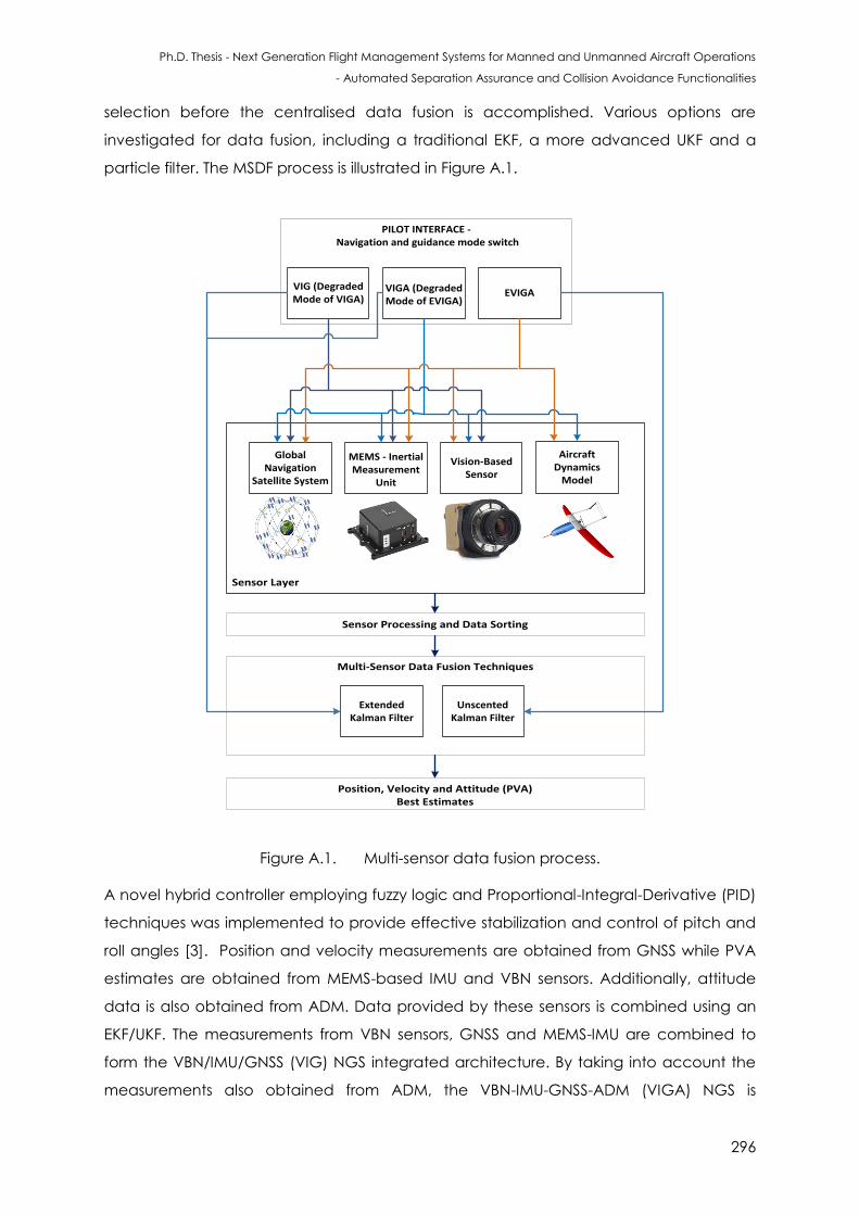
Ph.D. Thesis - Next Generation Flight Management Systems for Manned and Unmanned Aircraft Operations
- Automated Separation Assurance and Collision Avoidance Functionalities
296
selection before the centralised data fusion is accomplished. Various options are
investigated for data fusion, including a traditional EKF, a more advanced UKF and a
particle filter. The MSDF process is illustrated in Figure A.1.
PILOT INTERFACE - Navigation and guidance mode switch
Sensor Processing and Data Sorting
Position, Velocity and Attitude (PVA) Best Estimates
Sensor Layer
Multi-Sensor Data Fusion Techniques
MEMS - Inertial Measurement
Unit
Global Navigation
Satellite System
Vision-Based Sensor
Aircraft Dynamics
Model
VIGA (Degraded Mode of EVIGA)
VIG (Degraded Mode of VIGA)
EVIGA
Extended Kalman Filter
Unscented Kalman Filter
Figure A.1. Multi-sensor data fusion process.
A novel hybrid controller employing fuzzy logic and Proportional-Integral-Derivative (PID)
techniques was implemented to provide effective stabilization and control of pitch and
roll angles [3]. Position and velocity measurements are obtained from GNSS while PVA
estimates are obtained from MEMS-based IMU and VBN sensors. Additionally, attitude
data is also obtained from ADM. Data provided by these sensors is combined using an
EKF/UKF. The measurements from VBN sensors, GNSS and MEMS-IMU are combined to
form the VBN/IMU/GNSS (VIG) NGS integrated architecture. By taking into account the
measurements also obtained from ADM, the VBN-IMU-GNSS-ADM (VIGA) NGS is
Ph.D. Thesis - Next Generation Flight Management Systems for Manned and Unmanned Aircraft Operations
- Automated Separation Assurance and Collision Avoidance Functionalities
297
implemented. EKF is adopted in both VIG and VIGA systems. In the enhanced
architecture (EVIGA), the EKF is replaced by an UKF. Additionally, an UKF is also used to
process the ADM dynamics. The mathematical models developed for combining the
sensor information are described below. The state vector consists of the roll angle, pitch
angle and body rates of the aircraft. In order to apply the EKF techniques, the system is
described in state space notation by a set of first-order non-linear differential equations:
( ) (A.1)
where ℝ denotes the system state vector, ( ) is the process function of the states
and ℝ represents a zero mean random process. The matrix of the process noise
ℝ is given by:
( ) (A.2)
The measurement equation is considered to be a non-linear function of the measured
states and is given by:
( ) (A.3)
where ( ) is the observation function, ℝ is a zero mean random process described
by the matrix of measurement noise ℝ :
( ) (A.4)
It is possible to rewrite the non-linear equation of measurements for systems with discrete-
time measurements as:
( ) (A.5)
As the measurement equations are non-linear, it is necessary to linearise them by a first-
order approach to obtain the dynamic matrix of the system, and the measurement
matrix, . These matrices are related to the non-linear equations and are expressed as:
( )
|
(A.6)
( )
|
(A.7)
where represents the mean value. The fundamental matrix is approximated by the
Taylor series expansion as follows:
(A.8)
where is the sampling time and is the identity matrix. The Taylor series are often
approximated as:
(A.9)
Ph.D. Thesis - Next Generation Flight Management Systems for Manned and Unmanned Aircraft Operations
- Automated Separation Assurance and Collision Avoidance Functionalities
298
In the case of a linear system, the matrices: , and are linear. In EKF implementation,
these matrices are non-linear. The set of EKF equations for each time step are given by:
(
) (A.10)
(A.11)
(
) (A.12)
( ( )) (A.13)
( )
(A.14)
where is the time step: 1, 2, n; is the updated state covariance and is the filter
gain. Although the EKF provides a key advantage of linearisation of all non-linear models
(i.e., process and measurement models), it can be demanding to tune the filter
parameters and often provides unreliable estimates if the system non-linearities are
severe. Furthermore, the accuracy of propagated mean and covariance is limited to
first order due to truncations performed in the linearisation process.
Most of these EKF deficiencies are overcome by implementing an Unscented Kalman
Filter (UKF). The UKF is a recursive estimator used for calculating the statistics of a random
variable propagated through a non-linear system model [4 - 6]. Sigma-point Kalman
Filters (SPKFs), such as the UKF, provide derivative-free higher-order approximations by
fitting a Gaussian distribution rather than approximating an arbitrary nonlinear function
as the EKF does [7, 8]. Furthermore, an UKF is implemented to increase the accuracy of
the NGS, in addition to pre-processing the ADM measurements. It is assumed that the
equations of motion for the aircraft are disturbed by uncorrelated zero-mean Gaussian
noise. The UKF performance is compared with error perturbations in the system model’s
PVA measurements. The UKF weights and scaling parameters are given by:
( )
(A.15)
( )
( ) ( ) (A.16)
( )
( )
( ); (A.17)
( )
( )
( ); (A.18)
( ) (A.19)
√( ) (A.20)
Ph.D. Thesis - Next Generation Flight Management Systems for Manned and Unmanned Aircraft Operations
- Automated Separation Assurance and Collision Avoidance Functionalities
299
where is the secondary scaling parameter and is normally set to . , , and are the
scaling parameters. is the mean and the constant is used to incorperate prior
knowledge of the state distribution . For Gaussian distributions, is optimal and
represents a set of scalar weights [9, 10]. determines the spread of the sigma points
around the state mean and is set between 0 and 1. The covariance matrix is given by
. The unscented transformation process is precisely captured in the UKF state-estimation
algorithm described in the following set of equations. The noise is considered additive
and the unscented transformation is non-augmented. The UKF process is initialized by
using the expected mean, covariance and state vector values (i.e., PVA):
[ (A.21)
where the initial state vector estimate is and is the initial state vector of the ADM:
[( )( ) (A.22)
where is the initial state covariance matrix. The process model of the UKF is based
upon a set of sigma points where the random vector is approximated by
symmetric sigma points. The sigma points, are selected based on the mean and
covariance of , and are obtained as follows:
[ √ √ ] (A.23)
where P computes the diagonal values of the state covariance matrix and results in a
lower triangular matrix of the state covariance matrix. is the control parameter of the
dispersion distance from the mean estimate in the computation of , the sigma point
matrix. After the sigma points are calculated, a time update for each time step is
performed and is given by:
[ ] (A.24)
∑
( )
(A.25)
∑
( )[
][
]
(A.26)
[
√
√ ] (A.27)
[ ] (A.28)
∑
( )
(A.29)
In the measurement update equations listed above, represents the unobserved state
of the system. The process noise covariance matrix is represented by , in ( )
is the
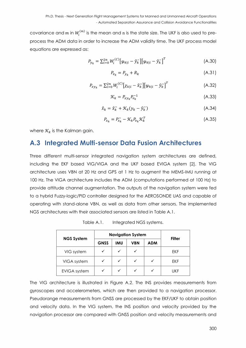
Ph.D. Thesis - Next Generation Flight Management Systems for Manned and Unmanned Aircraft Operations
- Automated Separation Assurance and Collision Avoidance Functionalities
300
covariance and in ( )
is the mean and is the state size. The UKF is also used to pre-
process the ADM data in order to increase the ADM validity time. The UKF process model
equations are expressed as:
∑ ( )
[ ][
]
(A.30)
(A.31)
∑ ( )
[ ][
]
(A.32)
(A.33)
(
) (A.34)
(A.35)
where is the Kalman gain.
A.3 Integrated Multi-sensor Data Fusion Architectures
Three different multi-sensor integrated navigation system architectures are defined,
including the EKF based VIG/VIGA and the UKF based EVIGA system [2]. The VIG
architecture uses VBN at 20 Hz and GPS at 1 Hz to augment the MEMS-IMU running at
100 Hz. The VIGA architecture includes the ADM (computations performed at 100 Hz) to
provide attitude channel augmentation. The outputs of the navigation system were fed
to a hybrid Fuzzy-logic/PID controller designed for the AEROSONDE UAS and capable of
operating with stand-alone VBN, as well as data from other sensors. The implemented
NGS architectures with their associated sensors are listed in Table A.1.
Table A.1. Integrated NGS systems.
NGS System Navigation System
Filter GNSS IMU VBN ADM
VIG system EKF
VIGA system EKF
EVIGA system UKF
The VIG architecture is illustrated in Figure A.2. The INS provides measurements from
gyroscopes and accelerometers, which are then provided to a navigation processor.
Pseudorange measurements from GNSS are processed by the EKF/UKF to obtain position
and velocity data. In the VIG system, the INS position and velocity provided by the
navigation processor are compared with GNSS position and velocity measurements and

Ph.D. Thesis - Next Generation Flight Management Systems for Manned and Unmanned Aircraft Operations
- Automated Separation Assurance and Collision Avoidance Functionalities
301
supplied to the EKF. A similar process is also applied to the INS and VBN attitude angles,
whose differences are incorporated in the EKF measurement vector. The EKF provides
estimates of the PVA errors, which are then removed from the sensor measurements to
obtain the corrected PVA states. The corrected PVA and estimates of accelerometer
and gyroscope biases are also used to update the INS raw measurements.
The VIGA architecture is illustrated in Figure A.2. As before, the INS position and velocity
provided by the navigation processor are compared to the GNSS data to form the
measurement input to the EKF. Additionally, in this case, the attitude data provided by
the ADM and the INS are compared to feed the EKF at 100 Hz, and the attitude data
provided by the VBN and MEMS-IMU sensors are compared at 20 Hz and input to the
EKF. As in the VIG architecture, the EKF provides estimations of PVA errors, which are
removed from the INS measurements to obtain the corrected PVA states. The attitude
best estimate is compared with the INS attitude to obtain the corrected attitude. During
the landing phase, the attitude best estimate is compared with the VBS attitude to
obtain the corrected attitude. In the EVIGA architecture, EKF is replaced by an UKF
(Figure A.3). Additionally, an UKF is also used to process the ADM navigation solution. The
ADM operates differently to that of the VIGA system, running in parallel to the centralised
UKF, and acts as a separate subsystem. The filtering of the ADM virtual sensor
measurements aids in achieving reduction of the overall position and attitude error
budget, and most importantly, results in considerable reduction in the ADM re-
initialisation time. PVA measurements are obtained as state vectors from both the
centralised UKF and ADM/UKF. These measurements are then fed into an error analysis
module in which the measurement values of the two UKFs are compared. In this
research, MEMS-INS errors are modeled as White Noise (WN) or Gauss-Markov (GM)
processes. Simulation of the VIG, VIGA and EVIGA navigation modes shows that all
integration schemes achieve horizontal/vertical position accuracies in line with CAT-I
(100% of the approach flight time) and CAT-II (98.4% of the approach flight time)
requirements. In all other flight phases, the VIGA system exhibits improvements in
position, velocity and attitude data with respect to the VIG system. The EVIGA system
shows the best performance in attitude data accuracy in addition to achieving an
increased ADM validity time (validity time of 126 sec before exceeding CAT I vertical
and horizontal error limits) [2].
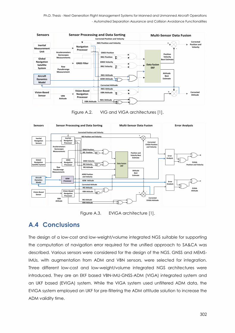
Ph.D. Thesis - Next Generation Flight Management Systems for Manned and Unmanned Aircraft Operations
- Automated Separation Assurance and Collision Avoidance Functionalities
302
Inertial Measurement
Unit
Global Navigation
Satellite System
Vision-Based Sensor
Navigation Processor
AccelerometersGyroscopes
Measurements
GNSS FilterRaw
Pseudorange Measurement
Vision-Based NavigationProcessor
CorrectedPosition and
Velocity
Data fusionEKF
+
+
-
-
Corrected AttitudeVBN
Attitude
IMU Position
IMU Velocity
IMU Attitude
GNSS Position
GNSS Velocity
IMU Position and Velocity
VBN Attitude
VBN Attitude
Aircraft Dynamics
Model
IMU Attitude
ADM Attitude
Corrected Position and Velocity
Corrected Attitude
Position Velocity
Best Estimate
Attitude Best
Estimate
IMU Attitude
Sensor Processing and Data SortingSensors Multi-Sensor Data Fusion
Figure A.2. VIG and VIGA architectures [1].
Sensors Error AnalysisSensor Processing and Data Sorting Multi-Sensor Data Fusion
GNSS Velocity
Inertial Navigation
Sensors
Inertial Navigation
Sensors
Global Navigation
Satellite System
Global Navigation
Satellite System
Vision-Based Navigation Processor
Vision-Based Navigation Processor
Data fusion UKF
GNSS Navigation Processor
GNSS Navigation Processor
Inertial Navigation Processor
Inertial Navigation Processor
Vision-Based Sensor
Vision-Based Sensor
AccelerometersGyroscopes
Measurements
RawPseudorange
Measurements
VBNAttitude
GNSS Position
INS Position
INS Velocity
Corrected Attitude
INS Attitude
Corrected EVIGA Attitude
Corrected EVIGA Position
and Velocity
+
-
+ -
Position and Velocity Best
Estimate
INS Attitude
VBN Attitude
Attitude Best
Estimate
Corrected Position and Velocity
INS Position and Velocity
Aircraft Dynamics
Model
INS Attitude
ADM Attitude
VBN Attitude
ADM Processor Error
Analysis
Error Analysis
Error Analysis
Error Analysis
ADM Position and Velocity
EVIGA Position and Velocity
EVIGA Attitude
Figure A.3. EVIGA architecture [1].
A.4 Conclusions
The design of a low-cost and low-weight/volume integrated NGS suitable for supporting
the computation of navigation error required for the unified approach to SA&CA was
described. Various sensors were considered for the design of the NGS. GNSS and MEMS-
IMUs, with augmentation from ADM and VBN sensors, were selected for integration.
Three different low-cost and low-weight/volume integrated NGS architectures were
introduced. They are an EKF based VBN-IMU-GNSS-ADM (VIGA) integrated system and
an UKF based (EVIGA) system. While the VIGA system used unfiltered ADM data, the
EVIGA system employed an UKF for pre-filtering the ADM attitude solution to increase the
ADM validity time.
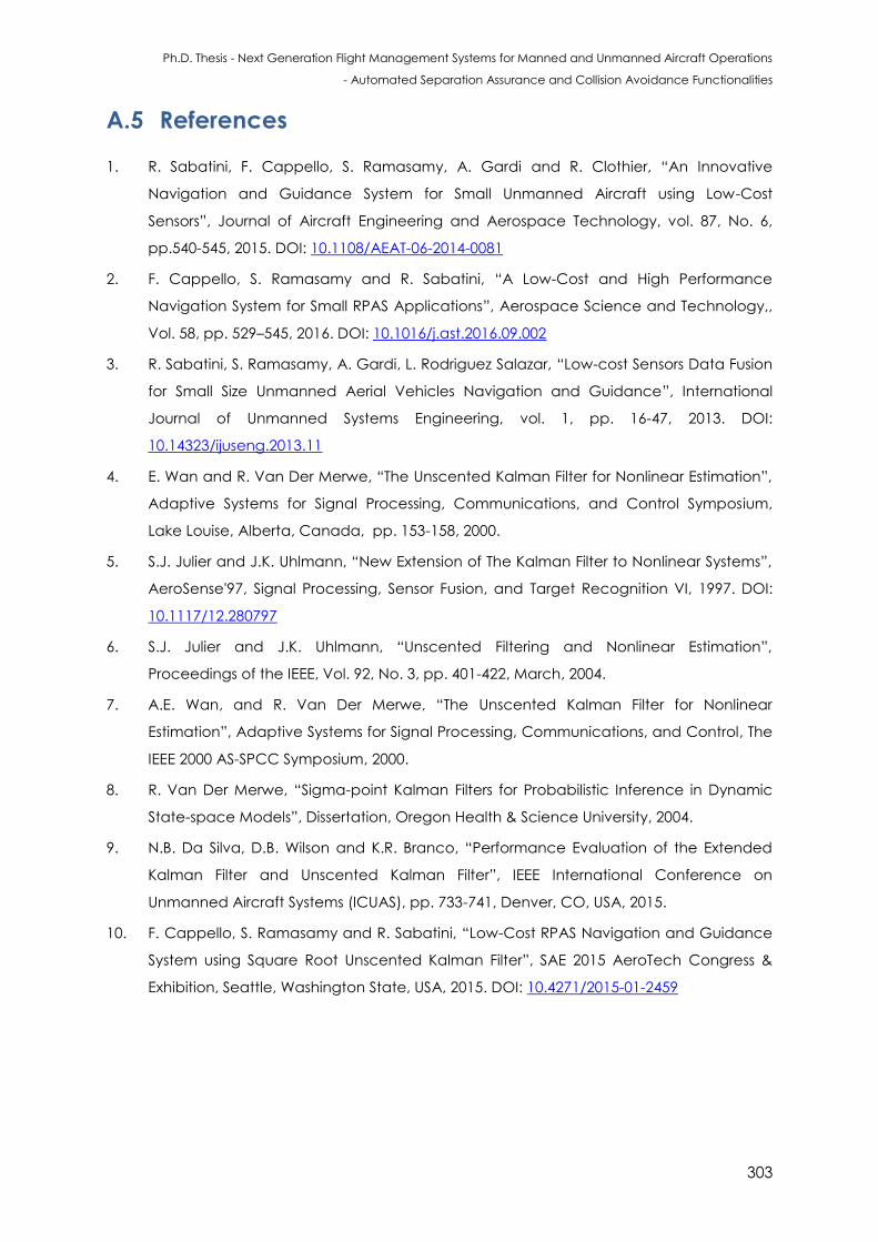
Ph.D. Thesis - Next Generation Flight Management Systems for Manned and Unmanned Aircraft Operations
- Automated Separation Assurance and Collision Avoidance Functionalities
303
A.5 References
1. R. Sabatini, F. Cappello, S. Ramasamy, A. Gardi and R. Clothier, “An Innovative
Navigation and Guidance System for Small Unmanned Aircraft using Low-Cost
Sensors”, Journal of Aircraft Engineering and Aerospace Technology, vol. 87, No. 6,
pp.540-545, 2015. DOI: 10.1108/AEAT-06-2014-0081
2. F. Cappello, S. Ramasamy and R. Sabatini, “A Low-Cost and High Performance
Navigation System for Small RPAS Applications”, Aerospace Science and Technology,,
Vol. 58, pp. 529–545, 2016. DOI: 10.1016/j.ast.2016.09.002
3. R. Sabatini, S. Ramasamy, A. Gardi, L. Rodriguez Salazar, “Low-cost Sensors Data Fusion
for Small Size Unmanned Aerial Vehicles Navigation and Guidance”, International
Journal of Unmanned Systems Engineering, vol. 1, pp. 16-47, 2013. DOI:
10.14323/ijuseng.2013.11
4. E. Wan and R. Van Der Merwe, “The Unscented Kalman Filter for Nonlinear Estimation”,
Adaptive Systems for Signal Processing, Communications, and Control Symposium,
Lake Louise, Alberta, Canada, pp. 153-158, 2000.
5. S.J. Julier and J.K. Uhlmann, “New Extension of The Kalman Filter to Nonlinear Systems”,
AeroSense'97, Signal Processing, Sensor Fusion, and Target Recognition VI, 1997. DOI:
10.1117/12.280797
6. S.J. Julier and J.K. Uhlmann, “Unscented Filtering and Nonlinear Estimation”,
Proceedings of the IEEE, Vol. 92, No. 3, pp. 401-422, March, 2004.
7. A.E. Wan, and R. Van Der Merwe, “The Unscented Kalman Filter for Nonlinear
Estimation”, Adaptive Systems for Signal Processing, Communications, and Control, The
IEEE 2000 AS-SPCC Symposium, 2000.
8. R. Van Der Merwe, “Sigma-point Kalman Filters for Probabilistic Inference in Dynamic
State-space Models”, Dissertation, Oregon Health & Science University, 2004.
9. N.B. Da Silva, D.B. Wilson and K.R. Branco, “Performance Evaluation of the Extended
Kalman Filter and Unscented Kalman Filter”, IEEE International Conference on
Unmanned Aircraft Systems (ICUAS), pp. 733-741, Denver, CO, USA, 2015.
10. F. Cappello, S. Ramasamy and R. Sabatini, “Low-Cost RPAS Navigation and Guidance
System using Square Root Unscented Kalman Filter”, SAE 2015 AeroTech Congress &
Exhibition, Seattle, Washington State, USA, 2015. DOI: 10.4271/2015-01-2459

Ph.D. Thesis - Next Generation Flight Management Systems for Manned and Unmanned Aircraft Operations
- Automated Separation Assurance and Collision Avoidance Functionalities
304
This page is intentionally left blank to support presswork tasks
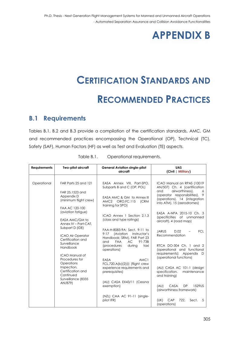
Ph.D. Thesis - Next Generation Flight Management Systems for Manned and Unmanned Aircraft Operations
- Automated Separation Assurance and Collision Avoidance Functionalities
305
APPENDIX B
CERTIFICATION STANDARDS AND
RECOMMENDED PRACTICES
B.1 Requirements
Tables B.1, B.2 and B.3 provide a compilation of the certification standards, AMC, GM
and recommended practices encompassing the Operational (OP), Technical (TC),
Safety (SAF), Human Factors (HF) as well as Test and Evaluation (TE) aspects.
Table B.1. Operational requirements.
Requirements Two-pilot aircraft General Aviation single-pilot
aircraft
UAS
(Civil | Military)
Operational
FAR Parts 25 and 121
FAR 25.1523 and
Appendix D
(minimum flight crew)
FAA AC 120-100
(aviation fatigue)
EASA AMC/GM to
Annex IV – Part-CAT,
Subpart D (IDE)
ICAO Air Operator
Certification and
Surveillance
Handbook
ICAO Manual of
Procedures for
Operations
Inspection,
Certification and
Continued
Surveillance (8335
AN/879)
EASA Annex VIII, Part-SPO,
Subparts B and C (OP, POL)
EASA AMC & GM to Annex III
AMC2 ORO.FC.115 (CRM
training for SPO)
ICAO Annex 1 Section 2.1.3
(class and type ratings)
FAA-H-8083-9A: Sect. 9-11 to
9-17 (Aviation Instructor’s
Handbook: SRM), FAR Part 23
and FAA AC 91-73B
(procedures during taxi
operations)
EASA AMC1
FCL.720.A(b)(2)(i) (flight crew
experience requirements and
prerequisites)
(AU) CASA EX43/11 (Cessna
exemption)
(NZL) CAA AC 91-11 (single-
pilot IFR)
ICAO Manual on RPAS (10019
AN/507) Ch. 4 (certification
and airworthiness), 6
(operator responsibilities), 9
(operations), 14 (integration
into ATM), 15 (aerodromes)
EASA A-NPA 2015-10 Ch. 3
(specificities of unmanned
aircraft), 4 (road map)
JARUS D.02 – FCL
Recommendation
RTCA DO-304 Ch. 1 and 2
(operational and functional
requirements); Appendix D
(operational functions)
(AU) CASA AC 101-1 (design
specification, maintenance
and training)
(AU) CASA DP 1529US
(airworthiness framework)
(UK) CAP 722, Sect. 5
(operations)
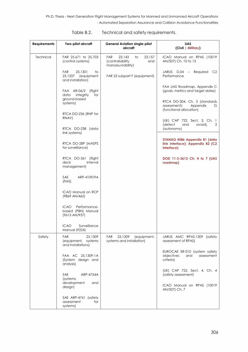
Ph.D. Thesis - Next Generation Flight Management Systems for Manned and Unmanned Aircraft Operations
- Automated Separation Assurance and Collision Avoidance Functionalities
306
Table B.2. Technical and safety requirements.
Requirements Two-pilot aircraft General Aviation single-pilot
aircraft
UAS
(Civil | Military)
Technical FAR 25.671 to 25.703
(control systems)
FAR 25.1301 to
25.1337 (equipment
and installation)
FAA AR-06/2 (flight
data integrity for
ground-based
systems)
RTCA DO-236 (RNP for
RNAV)
RTCA DO-238 (data
link systems)
RTCA DO-289 (MASPS
for surveillance)
RTCA DO-361 (flight
deck interval
management)
SAE ARP-4109/9A
(FMS)
ICAO Manual on RCP
(9869 AN/462)
ICAO Performance-
based (PBN) Manual
(9613 AN/937)
ICAO Surveillance
Manual (9224)
FAR 23.143 to 23.157
(controllability and
manoeuvrability)
FAR 23 subpart F (equipment)
ICAO Manual on RPAS (10019
AN/507) Ch. 10 to 13
JARUS D.04 – Required C2
Performance
FAA UAS Roadmap, Appendix C
(goals, metrics and target dates)
RTCA DO-304, Ch. 3 (standards
assessment); Appendix G
(functional allocation)
(UK) CAP 722, Sect. 3, Ch. 1
(detect and avoid), 3
(autonomy)
STANAG 4586 Appendix B1 (data
link interface); Appendix B2 (C2
interface)
DOD 11-S-3613 Ch. 4 to 7 (UAS
roadmap)
Safety FAR 25.1309
(equipment, systems
and installations)
FAA AC 25.1309-1A
(System design and
analysis)
SAE ARP-4754A
(systems
development and
design)
SAE ARP-4761 (safety
assessment for
systems)
FAR 23.1309 (equipment,
systems and installation)
JARUS AMC RPAS.1309 (safety
assessment of RPAS)
EUROCAE ER-010 (system safety
objectives and assessment
criteria)
(UK) CAP 722, Sect. 4, Ch. 4
(safety assessment)
ICAO Manual on RPAS (10019
AN/507) Ch. 7
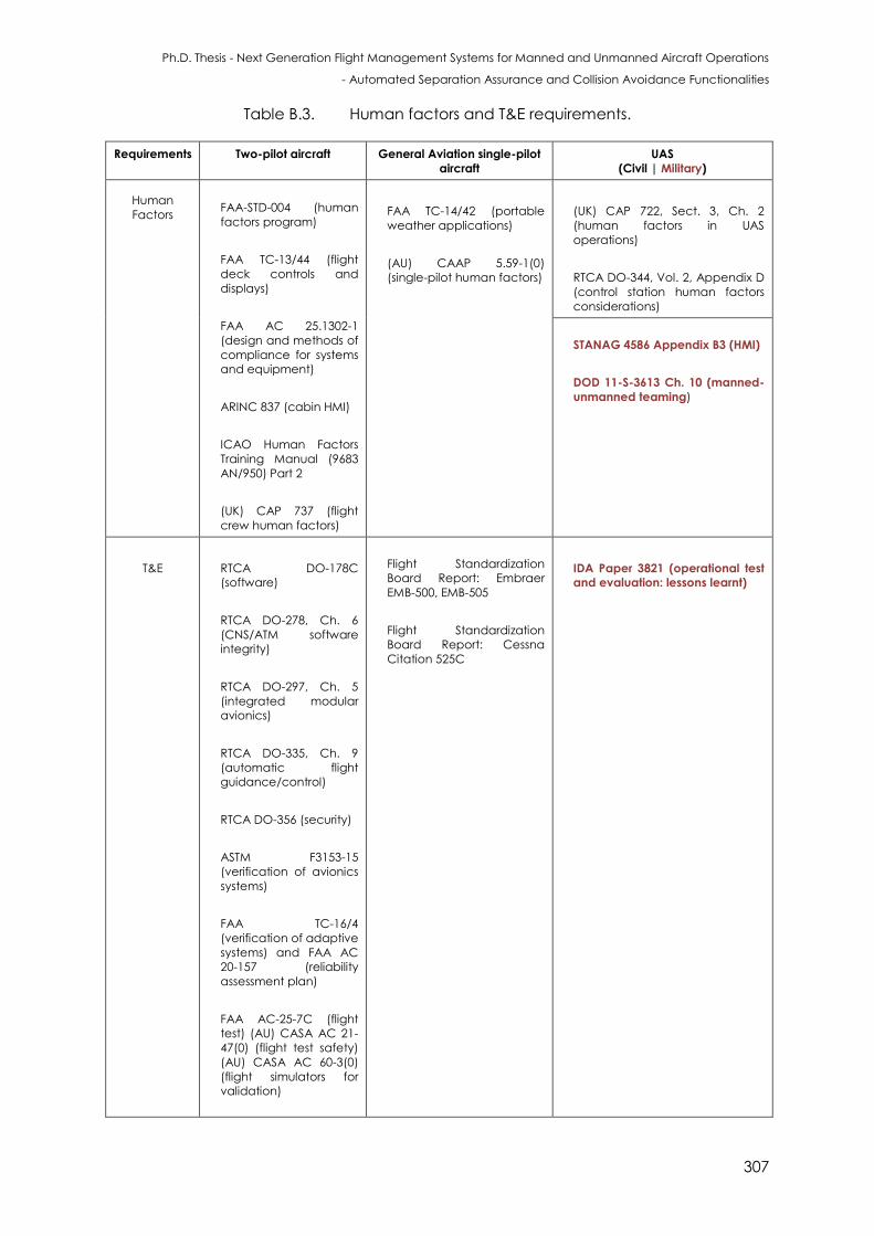
Ph.D. Thesis - Next Generation Flight Management Systems for Manned and Unmanned Aircraft Operations
- Automated Separation Assurance and Collision Avoidance Functionalities
307
Table B.3. Human factors and T&E requirements.
Requirements Two-pilot aircraft General Aviation single-pilot
aircraft
UAS
(Civil | Military)
Human
Factors
FAA-STD-004 (human
factors program)
FAA TC-13/44 (flight
deck controls and
displays)
FAA AC 25.1302-1
(design and methods of
compliance for systems
and equipment)
ARINC 837 (cabin HMI)
ICAO Human Factors
Training Manual (9683
AN/950) Part 2
(UK) CAP 737 (flight
crew human factors)
FAA TC-14/42 (portable
weather applications)
(AU) CAAP 5.59-1(0)
(single-pilot human factors)
(UK) CAP 722, Sect. 3, Ch. 2
(human factors in UAS
operations)
RTCA DO-344, Vol. 2, Appendix D
(control station human factors
considerations)
STANAG 4586 Appendix B3 (HMI)
DOD 11-S-3613 Ch. 10 (manned-
unmanned teaming)
T&E
RTCA DO-178C
(software)
RTCA DO-278, Ch. 6
(CNS/ATM software
integrity)
RTCA DO-297, Ch. 5
(integrated modular
avionics)
RTCA DO-335, Ch. 9
(automatic flight
guidance/control)
RTCA DO-356 (security)
ASTM F3153-15
(verification of avionics
systems)
FAA TC-16/4
(verification of adaptive
systems) and FAA AC
20-157 (reliability
assessment plan)
FAA AC-25-7C (flight
test) (AU) CASA AC 21-
47(0) (flight test safety)
(AU) CASA AC 60-3(0)
(flight simulators for
validation)
Flight Standardization
Board Report: Embraer
EMB-500, EMB-505
Flight Standardization
Board Report: Cessna
Citation 525C
IDA Paper 3821 (operational test
and evaluation: lessons learnt)

Ph.D. Thesis - Next Generation Flight Management Systems for Manned and Unmanned Aircraft Operations
- Automated Separation Assurance and Collision Avoidance Functionalities
308
This page is intentionally left blank to support presswork tasks
Ph.D. Thesis - Next Generation Flight Management Systems for Manned and Unmanned Aircraft Operations
- Automated Separation Assurance and Collision Avoidance Functionalities
309
APPENDIX C
ELEMENTS OF HUMAN MACHINE
INTERFACE & INTERACTIONS
“A tho h h ans to ay re ain ore capab e than machines for many tasks, by
2030 machine capabilities will have increased to the point that humans will have
become the weakest component in a wide array of systems and processes. Humans
and machines will need to become far more closely coupled, through improved
human- achine interfaces an by irect a entation of h an perfor ance”. -
Werner J.A. Dahm
C.1 Introduction
This appendix provides a summary of some key elements of HMI2 for NG-FMS. In
particular, the formats and functions required for supporting automated SA&CA
functionalities are presented. Some elements of the adaptive HMI2 system that
dynamically assists pilots and operators based on real-time detection of their
physiological and cognitive states are described. With an appropriate system
implementation, pilot error can be avoided and enhanced synergies can be attained
between humans and machines, improving the total system performance. Moreover,
the implementation of suitable decision logics (based on the estimated cognitive states
of the pilot or remote pilot) allows a continuous and optimal reconfiguration of the
automation levels.
C.2 Human Machine Interface and Interactions
HMI2 systems are essential for providing inputs as well as receiving information from
avionics systems. The key focus is on the interfaces required for the exchange of
information between the NG-FMS and the displays for pilot (manned aircraft) and
remote pilot (unmanned aircraft). Generally, Electronic Flight Instrument System (EFIS)
Ph.D. Thesis - Next Generation Flight Management Systems for Manned and Unmanned Aircraft Operations
- Automated Separation Assurance and Collision Avoidance Functionalities
310
displays are employed, which are the Primary Flight Display (PFD) and Navigation and
Tactical Display (NTD). EFIS displays enable continuous monitoring of flight information as
well as the required and parameters. Additionally, they also allow the pilots to
implement corrective measures if required (e.g. avoidance of ground obstacles). The
PFD provides information on thrust and control commands generated by the NG-FMS.
Track of flight plan, instantaneous position, Distance-To-Destination (DTD) based
waypoints for all flight phases, sectorisation of flight plan into segments, sections and
integral steps are displayed on the NTD. Other relevant information including navigation
aids, airports, altitude/speed/time constraints and wind information are also displayed
on the NTD. In order to support time based operations, the key parameters for
4-Dimensional Trajectory-Based Operations (TBO) have to be identified and included in
the trajectory prediction component of the current FMS. Furthermore, functions and
formats that support full 4D information, and human factors consideration for evaluation
of the 4D trajectory information have to be analysed considering mixed equipage.
Novel forms of HMI2 are required for the NG-FMS in order to enable time based
operations. Furthermore, recent research activities have been performed to identify the
specific requirements for single-pilot and UAS operations. Specifically, the HMI2 drivers for
effective sharing of information between NG-FMS and NG-ATM/GCS will vary
significantly from the manned version, wherein the control shifts from a pilot to a remote
pilot perspective. As pointed out in STAGNAG 4586, there is a need of greater levels of
interoperability and therefore a significant evolution of the HMI2 design is required [1, 2].
The new formats and functions development activities focus on:
4D trajectory navigation and guidance;
Next generation communications including LoS and BLOS data links;
Vehicle configuration data including telemetry data (specifically for UAS);
Automated SA&CA for non-cooperative and cooperative scenarios;
Monitoring of integrity by the generation of predictive (caution) and reactive
(warning) flags;
Monitoring of CNS+A performance metrics including RCP, RNP, RSP and RTSP.
The current state-of-the-art small-to-medium range commercial aircraft employ a two
person flight comprised of a Pilot Flying (PF) and a Pilot Non-Flying (PNF). In such flight
deck configurations, the flight tasks are distributed between the PF and PNF. The PF takes
the direct responsibility of directing the aircraft in line with the approved flight plan and
continuously monitors the flight path for any deviations. On the other hand, the roles of
the PNF as ‘pilot monitoring' are primarily focussed on monitoring the position of aircraft,
Ph.D. Thesis - Next Generation Flight Management Systems for Manned and Unmanned Aircraft Operations
- Automated Separation Assurance and Collision Avoidance Functionalities
311
controlling and monitoring radio transmissions, assisting the PF in high workload situations,
cross monitoring the actions of PF and taking over flight tasks in case of incapacitation of
PF. Based on the role allocations, the presence of a PNF is beneficial. In particular, the
PNF reduces the PF’s workload, however, an additional workload, associated with team
management, is introduced. According to statistics obtained between the years 2002 -
2011, 37% of all fatal accidents were caused by a failure in Crew Resource
Management (CRM) [3]. Another widely recognised advantage is that the PNF reduces
the probability of inadvertent errors made by PF. Nevertheless, several limitations such as
memory and attention problems affect the monitoring and corrective role of the PNF. In
order to avoid these errors, modern commercial aircraft are equipped with electronic
checklist functionalities that enable efficient cross-checking of PNF tasks.
Under current regulations, all large commercial aircraft are required to be flown by a
flight crew, consisting of not less than two pilots (FAR 14 CFR 121.385) [4]. However,
authorities also specify that all aircraft must be capable of being operated by a single
pilot from either seat, which means the current flight deck design is natively ready for
single pilot and UAS operations. Another constraint specifically for regional aircraft is that
they must be able to operate not only in big aerodromes but also from smaller airports
that might have fewer navigation and landing aids to support automated landings. In all
cases, CRM is an essential operational policy for two pilots to fly a commercial aircraft.
In the existing design, the aircraft is directed by a NG-FMS that coordinates with the
autopilot during most flight phases. Throughout the past few years, aircraft designers
have created a variety of modes for achieving an extensive range of functionalities. For
example, Airbus A320 has nine auto throttle modes, ten VNAV modes and seven LNAV
modes. However, such a large number of modes have emerged as a factor of confusion
for the pilot, leading to additional risks during the flight. In order to minimise hazards,
researchers and industries have committed to simplify the most complicated and
confusing systems. Commercial airliners, especially regional airliners, are the core users of
small and medium range commercial aircraft.
In the TBo/UTM context, SA&CA is handled in a distributed system, where the
pilot/remote pilot is designated with some of the conventional ATCo’s responsibilities in
order to achieve increased capacity-demand balancing. Eurocontrol has identified
three levels of delegation for achieving SA&CA. They are: limited, where the ATCo
performs conflict detection and resolution tasks while the pilot executes the ATCo’s
decision; extended, where the ATCo performs conflict detection, and delegates the
conflict resolution to be executed by the pilot; full, where the ATCo delegates full
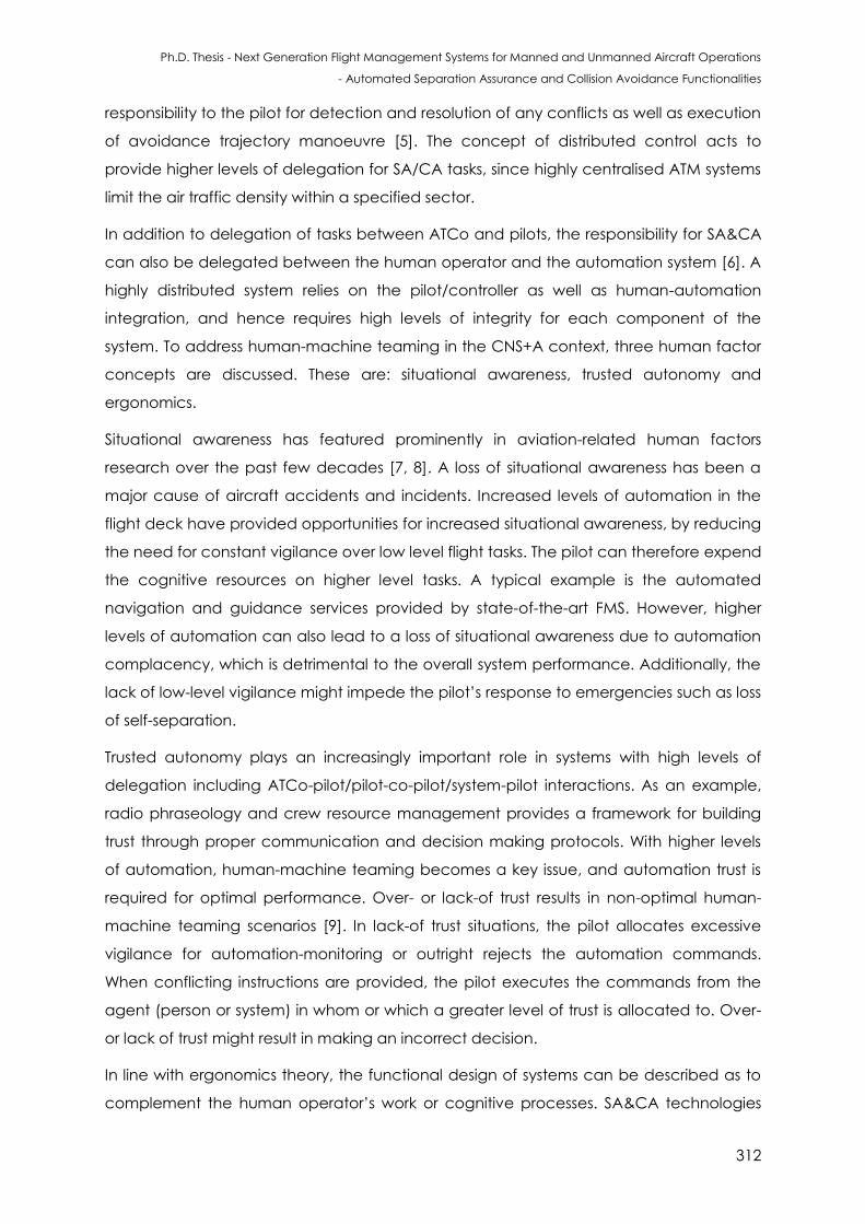
Ph.D. Thesis - Next Generation Flight Management Systems for Manned and Unmanned Aircraft Operations
- Automated Separation Assurance and Collision Avoidance Functionalities
312
responsibility to the pilot for detection and resolution of any conflicts as well as execution
of avoidance trajectory manoeuvre [5]. The concept of distributed control acts to
provide higher levels of delegation for SA/CA tasks, since highly centralised ATM systems
limit the air traffic density within a specified sector.
In addition to delegation of tasks between ATCo and pilots, the responsibility for SA&CA
can also be delegated between the human operator and the automation system [6]. A
highly distributed system relies on the pilot/controller as well as human-automation
integration, and hence requires high levels of integrity for each component of the
system. To address human-machine teaming in the CNS+A context, three human factor
concepts are discussed. These are: situational awareness, trusted autonomy and
ergonomics.
Situational awareness has featured prominently in aviation-related human factors
research over the past few decades [7, 8]. A loss of situational awareness has been a
major cause of aircraft accidents and incidents. Increased levels of automation in the
flight deck have provided opportunities for increased situational awareness, by reducing
the need for constant vigilance over low level flight tasks. The pilot can therefore expend
the cognitive resources on higher level tasks. A typical example is the automated
navigation and guidance services provided by state-of-the-art FMS. However, higher
levels of automation can also lead to a loss of situational awareness due to automation
complacency, which is detrimental to the overall system performance. Additionally, the
lack of low-level vigilance might impede the pilot’s response to emergencies such as loss
of self-separation.
Trusted autonomy plays an increasingly important role in systems with high levels of
delegation including ATCo-pilot/pilot-co-pilot/system-pilot interactions. As an example,
radio phraseology and crew resource management provides a framework for building
trust through proper communication and decision making protocols. With higher levels
of automation, human-machine teaming becomes a key issue, and automation trust is
required for optimal performance. Over- or lack-of trust results in non-optimal human-
machine teaming scenarios [9]. In lack-of trust situations, the pilot allocates excessive
vigilance for automation-monitoring or outright rejects the automation commands.
When conflicting instructions are provided, the pilot executes the commands from the
agent (person or system) in whom or which a greater level of trust is allocated to. Over-
or lack of trust might result in making an incorrect decision.
In line with ergonomics theory, the functional design of systems can be described as to
complement the human operator’s work or cognitive processes. SA&CA technologies
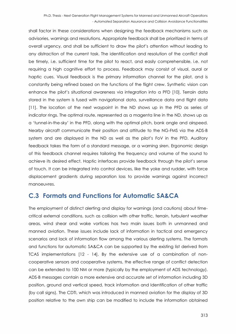
Ph.D. Thesis - Next Generation Flight Management Systems for Manned and Unmanned Aircraft Operations
- Automated Separation Assurance and Collision Avoidance Functionalities
313
shall factor in these considerations when designing the feedback mechanisms such as
advisories, warnings and resolutions. Appropriate feedback shall be prioritized in terms of
overall urgency, and shall be sufficient to draw the pilot’s attention without leading to
any distraction of the current task. The identification and resolution of the conflict shall
be timely, i.e. sufficient time for the pilot to react, and easily comprehensible, i.e. not
requiring a high cognitive effort to process. Feedback may consist of visual, aural or
haptic cues. Visual feedback is the primary information channel for the pilot, and is
constantly being refined based on the functions of the flight crew. Synthetic vision can
enhance the pilot’s situational awareness via integration into a PFD [10]. Terrain data
stored in the system is fused with navigational data, surveillance data and flight data
[11]. The location of the next waypoint in the ND shows up in the PFD as series of
indicator rings. The optimal route, represented as a magenta line in the ND, shows up as
a ‘tunnel-in-the-sky’ in the PFD, along with the optimal pitch, bank angle and airspeed.
Nearby aircraft communicate their position and attitude to the NG-FMS via the ADS-B
system and are displayed in the ND as well as the pilot’s FoV in the PFD. Auditory
feedback takes the form of a standard message, or a warning siren. Ergonomic design
of this feedback channel requires tailoring the frequency and volume of the sound to
achieve its desired effect. Haptic interfaces provide feedback through the pilot’s sense
of touch. It can be integrated into control devices, like the yoke and rudder, with force
displacement gradients during separation loss to provide warnings against incorrect
manoeuvres.
C.3 Formats and Functions for Automatic SA&CA
The employment of distinct alerting and display for warnings (and cautions) about time-
critical external conditions, such as collision with other traffic, terrain, turbulent weather
areas, wind shear and wake vortices has two main issues both in unmanned and
manned aviation. These issues include lack of information in tactical and emergency
scenarios and lack of information flow among the various alerting systems. The formats
and functions for automatic SA&CA can be supported by the existing list derived from
TCAS implementations [12 - 14]. By the extensive use of a combination of non-
cooperative sensors and cooperative systems, the effective range of conflict detection
can be extended to 100 NM or more (typically by the employment of ADS technology).
ADS-B messages contain a more extensive and accurate set of information including 3D
position, ground and vertical speed, track information and Identification of other traffic
(by call signs). The CDTI, which was introduced in manned aviation for the display of 3D
position relative to the own ship can be modified to include the information obtained
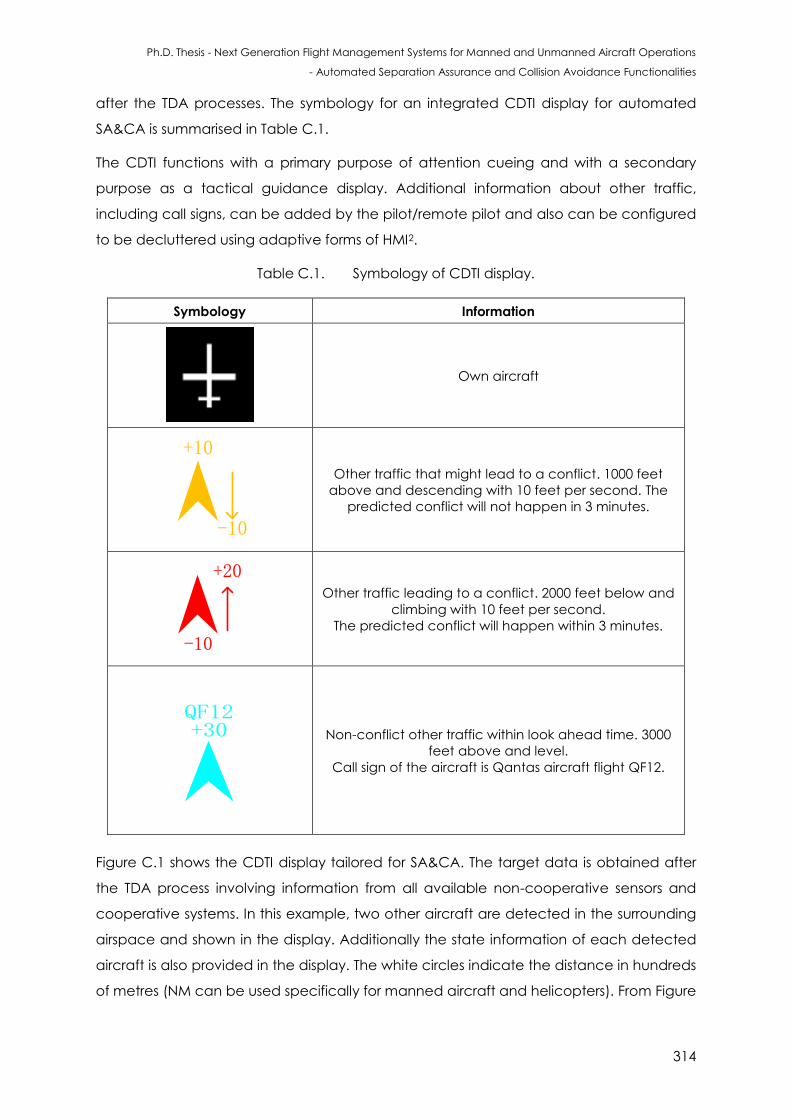
Ph.D. Thesis - Next Generation Flight Management Systems for Manned and Unmanned Aircraft Operations
- Automated Separation Assurance and Collision Avoidance Functionalities
314
after the TDA processes. The symbology for an integrated CDTI display for automated
SA&CA is summarised in Table C.1.
The CDTI functions with a primary purpose of attention cueing and with a secondary
purpose as a tactical guidance display. Additional information about other traffic,
including call signs, can be added by the pilot/remote pilot and also can be configured
to be decluttered using adaptive forms of HMI2.
Table C.1. Symbology of CDTI display.
Symbology Information
Own aircraft
+10
-10
Other traffic that might lead to a conflict. 1000 feet
above and descending with 10 feet per second. The
predicted conflict will not happen in 3 minutes.
-10
+20
Other traffic leading to a conflict. 2000 feet below and
climbing with 10 feet per second.
The predicted conflict will happen within 3 minutes.
+30QF12
Non-conflict other traffic within look ahead time. 3000
feet above and level.
Call sign of the aircraft is Qantas aircraft flight QF12.
Figure C.1 shows the CDTI display tailored for SA&CA. The target data is obtained after
the TDA process involving information from all available non-cooperative sensors and
cooperative systems. In this example, two other aircraft are detected in the surrounding
airspace and shown in the display. Additionally the state information of each detected
aircraft is also provided in the display. The white circles indicate the distance in hundreds
of metres (NM can be used specifically for manned aircraft and helicopters). From Figure
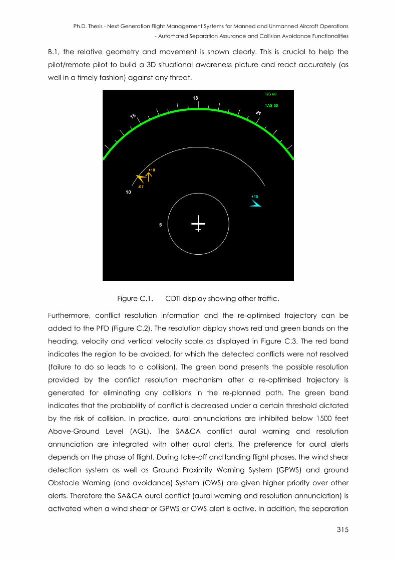
Ph.D. Thesis - Next Generation Flight Management Systems for Manned and Unmanned Aircraft Operations
- Automated Separation Assurance and Collision Avoidance Functionalities
315
B.1, the relative geometry and movement is shown clearly. This is crucial to help the
pilot/remote pilot to build a 3D situational awareness picture and react accurately (as
well in a timely fashion) against any threat.
Figure C.1. CDTI display showing other traffic.
Furthermore, conflict resolution information and the re-optimised trajectory can be
added to the PFD (Figure C.2). The resolution display shows red and green bands on the
heading, velocity and vertical velocity scale as displayed in Figure C.3. The red band
indicates the region to be avoided, for which the detected conflicts were not resolved
(failure to do so leads to a collision). The green band presents the possible resolution
provided by the conflict resolution mechanism after a re-optimised trajectory is
generated for eliminating any collisions in the re-planned path. The green band
indicates that the probability of conflict is decreased under a certain threshold dictated
by the risk of collision. In practice, aural annunciations are inhibited below 1500 feet
Above-Ground Level (AGL). The SA&CA conflict aural warning and resolution
annunciation are integrated with other aural alerts. The preference for aural alerts
depends on the phase of flight. During take-off and landing flight phases, the wind shear
detection system as well as Ground Proximity Warning System (GPWS) and ground
Obstacle Warning (and avoidance) System (OWS) are given higher priority over other
alerts. Therefore the SA&CA aural conflict (aural warning and resolution annunciation) is
activated when a wind shear or GPWS or OWS alert is active. In addition, the separation
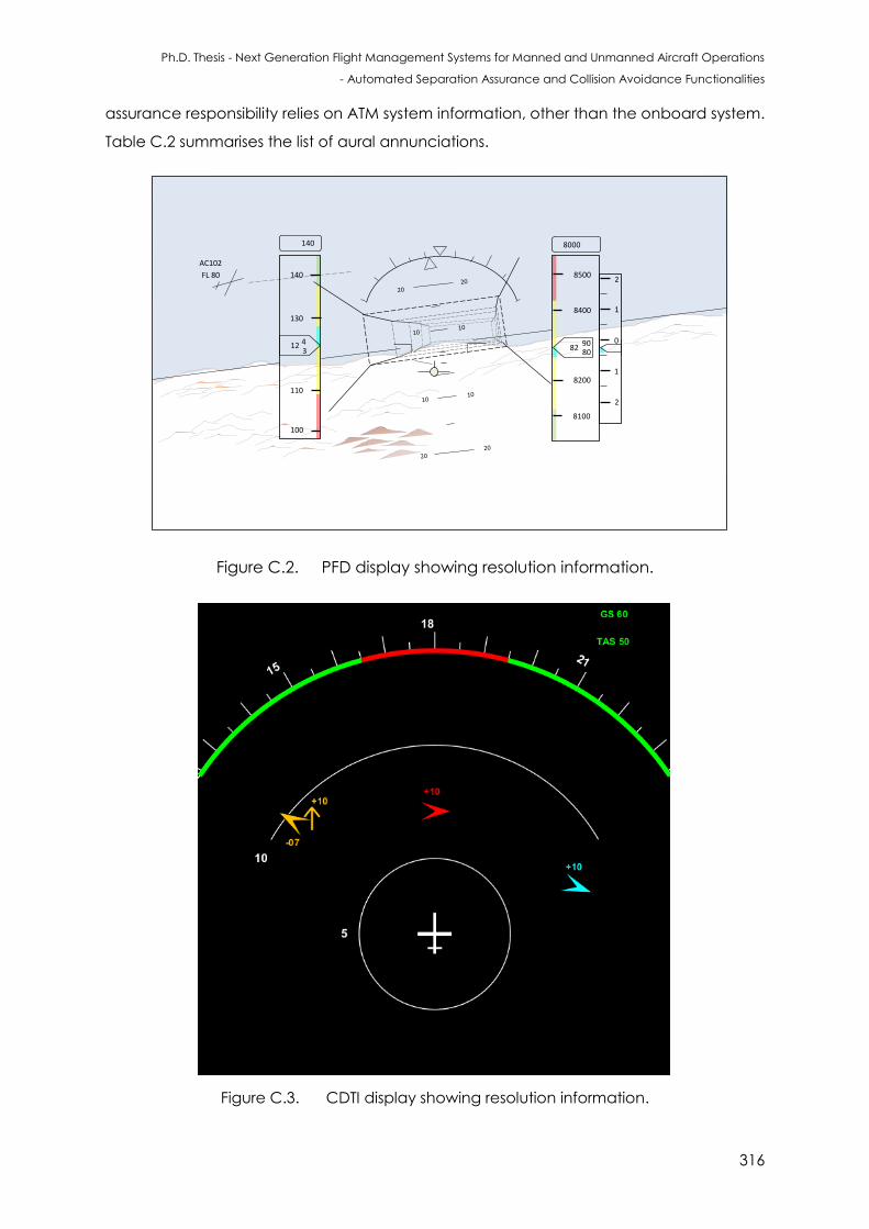
Ph.D. Thesis - Next Generation Flight Management Systems for Manned and Unmanned Aircraft Operations
- Automated Separation Assurance and Collision Avoidance Functionalities
316
assurance responsibility relies on ATM system information, other than the onboard system.
Table C.2 summarises the list of aural annunciations.
AC102
FL 80
8000
8200
8400
8500
8100
828090
2
1
1
2
012
130
110
140
100
43
140
Figure C.2. PFD display showing resolution information.
Figure C.3. CDTI display showing resolution information.
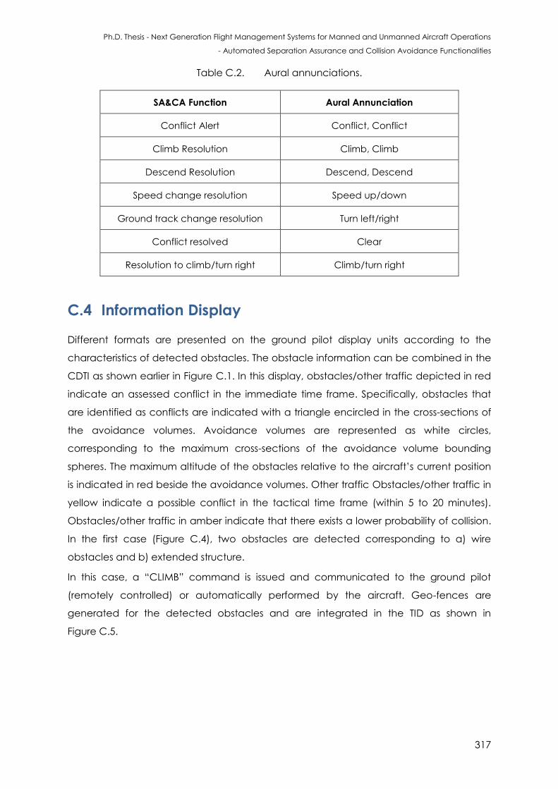
Ph.D. Thesis - Next Generation Flight Management Systems for Manned and Unmanned Aircraft Operations
- Automated Separation Assurance and Collision Avoidance Functionalities
317
Table C.2. Aural annunciations.
SA&CA Function Aural Annunciation
Conflict Alert Conflict, Conflict
Climb Resolution Climb, Climb
Descend Resolution Descend, Descend
Speed change resolution Speed up/down
Ground track change resolution Turn left/right
Conflict resolved Clear
Resolution to climb/turn right Climb/turn right
C.4 Information Display
Different formats are presented on the ground pilot display units according to the
characteristics of detected obstacles. The obstacle information can be combined in the
CDTI as shown earlier in Figure C.1. In this display, obstacles/other traffic depicted in red
indicate an assessed conflict in the immediate time frame. Specifically, obstacles that
are identified as conflicts are indicated with a triangle encircled in the cross-sections of
the avoidance volumes. Avoidance volumes are represented as white circles,
corresponding to the maximum cross-sections of the avoidance volume bounding
spheres. The maximum altitude of the obstacles relative to the aircraft’s current position
is indicated in red beside the avoidance volumes. Other traffic Obstacles/other traffic in
yellow indicate a possible conflict in the tactical time frame (within 5 to 20 minutes).
Obstacles/other traffic in amber indicate that there exists a lower probability of collision.
In the first case (Figure C.4), two obstacles are detected corresponding to a) wire
obstacles and b) extended structure.
In this case, a “CLIMB” command is issued and communicated to the ground pilot
(remotely controlled) or automatically performed by the aircraft. Geo-fences are
generated for the detected obstacles and are integrated in the TID as shown in
Figure C.5.
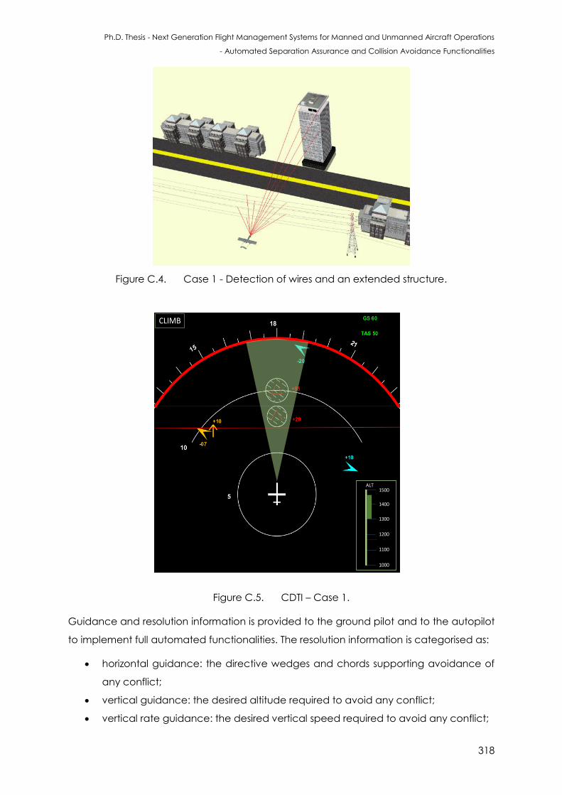
Ph.D. Thesis - Next Generation Flight Management Systems for Manned and Unmanned Aircraft Operations
- Automated Separation Assurance and Collision Avoidance Functionalities
318
Figure C.4. Case 1 - Detection of wires and an extended structure.
CLIMB
ALT
1000
1100
1200
1300
1400
1500
Figure C.5. CDTI – Case 1.
Guidance and resolution information is provided to the ground pilot and to the autopilot
to implement full automated functionalities. The resolution information is categorised as:
horizontal guidance: the directive wedges and chords supporting avoidance of
any conflict;
vertical guidance: the desired altitude required to avoid any conflict;
vertical rate guidance: the desired vertical speed required to avoid any conflict;
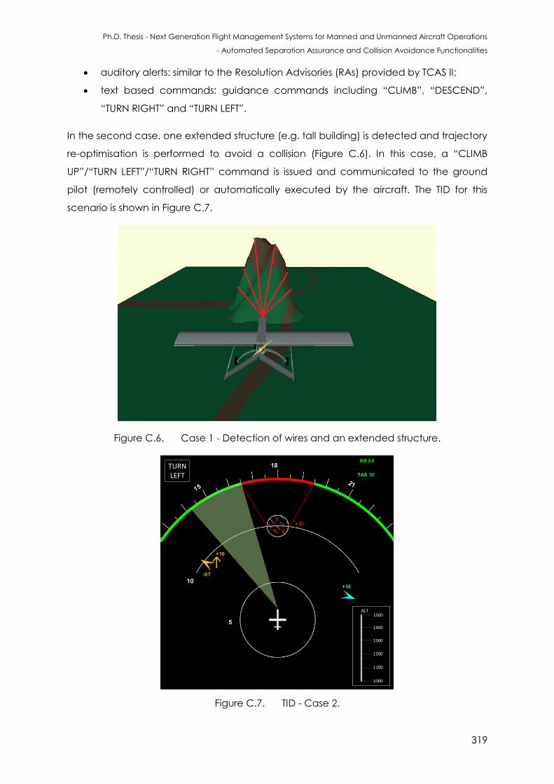
Ph.D. Thesis - Next Generation Flight Management Systems for Manned and Unmanned Aircraft Operations
- Automated Separation Assurance and Collision Avoidance Functionalities
319
auditory alerts: similar to the Resolution Advisories (RAs) provided by TCAS II;
text based commands: guidance commands including “CLIMB”, “DESCEND”,
“TURN RIGHT” and “TURN LEFT”.
In the second case, one extended structure (e.g. tall building) is detected and trajectory
re-optimisation is performed to avoid a collision (Figure C.6). In this case, a “CLIMB
UP”/“TURN LEFT”/“TURN RIGHT” command is issued and communicated to the ground
pilot (remotely controlled) or automatically executed by the aircraft. The TID for this
scenario is shown in Figure C.7.
Figure C.6. Case 1 - Detection of wires and an extended structure.
TURNLEFT
ALT
1000
1100
1200
1300
1400
1500
Figure C.7. TID - Case 2.
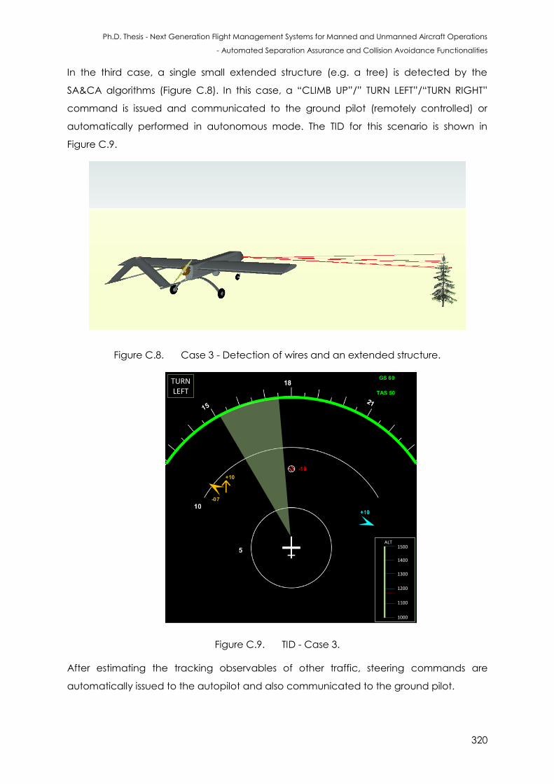
Ph.D. Thesis - Next Generation Flight Management Systems for Manned and Unmanned Aircraft Operations
- Automated Separation Assurance and Collision Avoidance Functionalities
320
In the third case, a single small extended structure (e.g. a tree) is detected by the
SA&CA algorithms (Figure C.8). In this case, a “CLIMB UP”/” TURN LEFT”/“TURN RIGHT”
command is issued and communicated to the ground pilot (remotely controlled) or
automatically performed in autonomous mode. The TID for this scenario is shown in
Figure C.9.
Figure C.8. Case 3 - Detection of wires and an extended structure.
TURNLEFT
ALT
1000
1100
1200
1300
1400
1500
Figure C.9. TID - Case 3.
After estimating the tracking observables of other traffic, steering commands are
automatically issued to the autopilot and also communicated to the ground pilot.
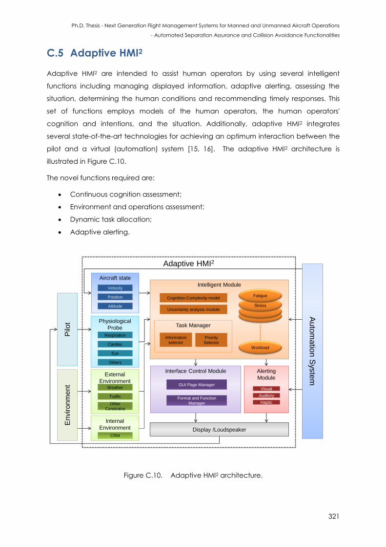
Ph.D. Thesis - Next Generation Flight Management Systems for Manned and Unmanned Aircraft Operations
- Automated Separation Assurance and Collision Avoidance Functionalities
321
C.5 Adaptive HMI2
Adaptive HMI2 are intended to assist human operators by using several intelligent
functions including managing displayed information, adaptive alerting, assessing the
situation, determining the human conditions and recommending timely responses. This
set of functions employs models of the human operators, the human operators'
cognition and intentions, and the situation. Additionally, adaptive HMI2 integrates
several state-of-the-art technologies for achieving an optimum interaction between the
pilot and a virtual (automation) system [15, 16]. The adaptive HMI2 architecture is
illustrated in Figure C.10.
The novel functions required are:
Continuous cognition assessment;
Environment and operations assessment;
Dynamic task allocation;
Adaptive alerting.
Adaptive HMI2
Physiological
Probe
Intelligent Module
Workload
Stress
Fatigue
Interface Control Module
Respiration
Cardiac
Eye
Others
External
Environment
Auto
matio
n S
yste
m
Alerting
Module
Visual
Auditory
Haptic
Pilo
tE
nvir
on
me
nt
Aircraft state
Velocity
Position
Attitude
Weather
Traffic
Other
Constrains
Cognition-Complexity model
Uncertainty analysis module
Priority
Selector
GUI Page Manager
Information
selector
Format and Function
Manager
Display /Loudspeaker
Internal
Environment
CRM
Task Manager
Figure C.10. Adaptive HMI2 architecture.
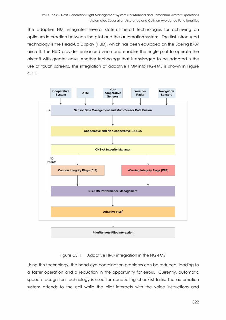
Ph.D. Thesis - Next Generation Flight Management Systems for Manned and Unmanned Aircraft Operations
- Automated Separation Assurance and Collision Avoidance Functionalities
322
The adaptive HMI integrates several state-of-the-art technologies for achieving an
optimum interaction between the pilot and the automation system. The first introduced
technology is the Head-Up Display (HUD), which has been equipped on the Boeing B787
aircraft. The HUD provides enhanced vision and enables the single pilot to operate the
aircraft with greater ease. Another technology that is envisaged to be adopted is the
use of touch screens. The integration of adaptive HMI2 into NG-FMS is shown in Figure
C.11.
Sensor Data Management and Multi-Sensor Data Fusion
Cooperative and Non-cooperative SA&CA
CNS+A Integrity Manager
Caution Integrity Flags (CIF) Warning Integrity Flags (WIF)
Cooperative
SystemATM
Non-
cooperative
Sensors
Weather
Radar
Navigation
Sensors
Pilot/Remote Pilot Interaction
NG-FMS Performance Management
Adaptive HMI2
4D
Intents
Figure C.11. Adaptive HMI2 integration in the NG-FMS.
Using this technology, the hand-eye coordination problems can be reduced, leading to
a faster operation and a reduction in the opportunity for errors. Currently, automatic
speech recognition technology is used for conducting checklist tasks. The automation
system attends to the call while the pilot interacts with the voice instructions and
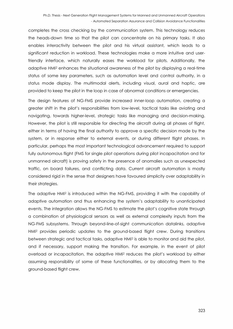
Ph.D. Thesis - Next Generation Flight Management Systems for Manned and Unmanned Aircraft Operations
- Automated Separation Assurance and Collision Avoidance Functionalities
323
completes the cross checking by the communication system. This technology reduces
the heads-down time so that the pilot can concentrate on his primary tasks. It also
enables interactivity between the pilot and his virtual assistant, which leads to a
significant reduction in workload. These technologies make a more intuitive and user-
friendly interface, which naturally eases the workload for pilots. Additionally, the
adaptive HMI2 enhances the situational awareness of the pilot by displaying a real-time
status of some key parameters, such as automation level and control authority, in a
status mode display. The multimodal alerts, including visual, aural and haptic, are
provided to keep the pilot in the loop in case of abnormal conditions or emergencies.
The design features of NG-FMS provide increased inner-loop automation, creating a
greater shift in the pilot’s responsibilities from low-level, tactical tasks like aviating and
navigating, towards higher-level, strategic tasks like managing and decision-making.
However, the pilot is still responsible for directing the aircraft during all phases of flight,
either in terms of having the final authority to approve a specific decision made by the
system, or in response either to external events, or during different flight phases. In
particular, perhaps the most important technological advancement required to support
fully autonomous flight (FMS for single pilot operations during pilot incapacitation and for
unmanned aircraft) is proving safety in the presence of anomalies such as unexpected
traffic, on board failures, and conflicting data. Current aircraft automation is mostly
considered rigid in the sense that designers have favoured simplicity over adaptability in
their strategies.
The adaptive HMI2 is introduced within the NG-FMS, providing it with the capability of
adaptive automation and thus enhancing the system’s adaptability to unanticipated
events. The integration allows the NG-FMS to estimate the pilot’s cognitive state through
a combination of physiological sensors as well as external complexity inputs from the
NG-FMS subsystems. Through beyond-line-of-sight communication datalinks, adaptive
HMI2 provides periodic updates to the ground-based flight crew. During transitions
between strategic and tactical tasks, adaptive HMI2 is able to monitor and aid the pilot,
and if necessary, support making the transition. For example, in the event of pilot
overload or incapacitation, the adaptive HMI2 reduces the pilot’s workload by either
assuming responsibility of some of these functionalities, or by allocating them to the
ground-based flight crew.
Ph.D. Thesis - Next Generation Flight Management Systems for Manned and Unmanned Aircraft Operations
- Automated Separation Assurance and Collision Avoidance Functionalities
324
C.6 Conclusions
After an introductory note on HMI2 systems for NG-FMS, the formats and functions
required for SA&CA were presented. In particular, the formats and functions developed
for ground obstacle SA&CA were described. The appendix also presented the
emergence of adaptive HMI2 systems. With an appropriate system implementation,
pilots’ errors can be reduced and enhanced synergies can be attained between
human and machine, improving the total system performance. Moreover, the
implementation of suitable decision logics (based on the estimated cognitive states of
the pilot or remote pilot) allows a continuous and optimal reconfiguration of the
automation levels. The design of adaptive HMI2 is still very much in the research phase,
as experimental measurements and results, especially in real-world flight situations, are
yet to be fully captured and evaluated.
C.7 References
1. J.T. Platts, M.L. Cummings and R.J. Kerr, “Applicability of STANAG 4586 to Future
Unmanned Aerial Vehicles”, Proceedings of AIAA Infotech Aerospace Conference,
Rohnert Park, California, USA, 2007.
2. R. Franklin, “STANAG 4586, NATO Network Enabled Capability Service Oriented
Architecture Working Group–Status Overview Presentation”, STANAG 4586, 2010.
3. CAA, "Global Fatal Accident Review 2002 to 2011", CAA CAP 1036, 2013.
4. FAA, “FAA Federal Aviation Regulations (FARS), 14 CFR”, Section 385, Composition of
Flight Crew, 2015.
5. E. Hoffman, J.P Nicolaon, C. Pusch and K. Zeghal, “Limited Delegation of Separation
Assurance to Aircraft”, The Freer-Flight Evolutionary Air-ground Cooperative ATM
Concepts, EUROCONTROL, 1999.
6. J.P. Dwyer and S. Landry, “Separation Assurance and Collision Avoidance Concepts for
the Next Generation Air Transportation System”, Human Interface, Part II, HCII 2009,
pp. 748–757, Springer-Verlag, Berlin-Heidelberg, 2009.
7. C.D. Wickens, J. Lee, Y. Liu and G.S. Becker, “An Introduction to Human Factors
Engineering”, Pearson Education Inc., USA, 2004.
8. V.J. Gawron, “Human Performance. In Human Performance, Workload, and Situational
Awareness Measures Handbook”, Second Edition, CRC Press, pp. 13-86, 2008.
9. J.D. Lee and K.A. See, “Trust in Automation: Designing for Appropriate Reliance”,
Human Factors: The Journal of the Human Factors and Ergonomics Society, vol. 46, pp.
50-80, 2004.
Ph.D. Thesis - Next Generation Flight Management Systems for Manned and Unmanned Aircraft Operations
- Automated Separation Assurance and Collision Avoidance Functionalities
325
10. G.L. Calhoun, M.H. Draper, M.F. Abernathy, M. Patzek and F. Delgado, “Synthetic Vision
System for Improving Unmanned Aerial Vehicle Operator Situation Awareness”,
Defense and Security, International Society for Optics and Photonics, pp. 219-230, 2005.
11. S. Temel and N. Unaldi, “Opportunities and Challenges of Terrain Aided Navigation
Systems for Aerial Surveillance by Unmanned Aerial Vehicles”, Wide Area Surveillance,
Springer, Berlin-Heidelberg, pp. 163-177.
12. Radio Technical Commission for Aeronautics, TCAS I Functional Guidelines, RTCA
DO-184, Washington DC, 1983.
13. Radio Technical Commission for Aeronautics, Report – Assessment and
Recommendations on Visual Alerts and Aural Annunciations for TCAS II, RTCA DO-299,
2009.
14. J. Meyer, M. Göttken, C. Vernaleken and S. Schärer, “Automatic Traffic Alert and
Collision Avoidance System (TCAS) Onboard UAS”, Handbook of Unmanned Aerial
Vehicles, Springer Netherlands, pp. 1857-1871, 2015.
15. J. Liu, A. Gardi, S. Ramasamy, Y. Lim and R. Sabatini, “Cognitive Pilot-Aircraft Interface
for Single-Pilot Operations”, Knowledge-Based Systems, Elsevier, 2016. DOI:
10.1016/j.knosys.2016.08.031
16. Y. Lim, J. Liu, S. Ramasamy and R. Sabatini, “Cognitive Remote Pilot-Aircraft Interface
for UAS Operations”, Proceedings of the 2016 International Conference on Intelligent
Unmanned Systems (ICIUS 2016), Xi'an, Shaanxi Province (China), August 2016.

Ph.D. Thesis - Next Generation Flight Management Systems for Manned and Unmanned Aircraft Operations
- Automated Separation Assurance and Collision Avoidance Functionalities
326
This page is intentionally left blank to support presswork tasks
Ph.D. Thesis - Next Generation Flight Management Systems for Manned and Unmanned Aircraft Operations
- Automated Separation Assurance and Collision Avoidance Functionalities
327
APPENDIX D
LIST OF RELEVANT PUBLICATIONS
Some of the key findings of this research work are documented in this section.
D.1 Scientific Dissemination
Book Chapters:
1. A. Gardi, S. Ramasamy, R. Sabatini and T. Kistan, “Terminal Area Operations:
Challenges and Opportunities”, Encyclopedia of Aerospace - UAS, eds. R. Blockley
and W. Shyy, John Wiley: Chichester, 2016. DOI: 10.1002/9780470686652.eae1141
2. R. Sabatini, A. Gardi, S. Ramasamy, T. Kistan and M. Marino, “Modern Avionics and
ATM Systems for Green Operations”, Green Aviation, Chapter 27, eds. R. Blockley et
al., John Wiley: Chichester, 2016. ISBN: 978-1-118-86635-1
Journal Papers:
1. S. Ramasamy, R. Sabatini and A. Gardi, “LIDAR Obstacle Warning and Avoidance
System for Unmanned Aerial Vehicle Sense-and-Avoid”, Aerospace Science and
Technology, vol. 55, pp. 344–358, 2016. DOI: 10.1016/j.ast.2016.05.020
2. S. Ramasamy, R. Sabatini and A. Gardi, “A Novel Unified Analytical Framework for
Aircraft Separation Assurance and UAS Sense-and-Avoid”, Journal of Intelligent &
Robotic Systems, pp. 1-20, 2017.
3. F. Cappello, S. Ramasamy and R. Sabatini, “A Low-Cost and High Performance
Navigation System for Small RPAS Applications”, Aerospace Science and
Technology, 2016. DOI: 10.1016/j.ast.2016.09.002
4. R. Sabatini, F. Cappello, S. Ramasamy, A. Gardi and R. Clothier, “An Innovative
Navigation and Guidance System for Small Unmanned Aircraft using Low-Cost
Sensors”, Journal of Aircraft Engineering and Aerospace Technology, 2015. DOI:
10.1108/AEAT-06-2014-0081
5. S. Ramasamy, R. Sabatini, A. Gardi and T. Kistan, “Next Generation Flight
Management System for Real-Time Trajectory Based Operations”, Applied
Ph.D. Thesis - Next Generation Flight Management Systems for Manned and Unmanned Aircraft Operations
- Automated Separation Assurance and Collision Avoidance Functionalities
328
Mechanics and Materials, vol. 629, pp. 344-349, 2014. DOI:
10.4028/www.scientific.net/AMM.629.344
6. S. Ramasamy, M. Sangam, R. Sabatini and A. Gardi, “Flight Management System for
Unmanned Reusable Space Vehicle Atmospheric and Re-entry Trajectory
Optimisation”, Applied Mechanics and Materials, vol. 629, pp. 304-309, 2014. DOI:
10.4028/www.scientific.net/AMM.629.304
7. J. Liu, A. Gardi, S. Ramasamy, Y. Lim and R. Sabatini, “Cognitive Pilot-Aircraft
Interface for Single-Pilot Operations”, Knowledge-Based Systems, 2016. DOI:
10.1016/j.knosys.2016.08.031
8. Y. Lim, B. Vincent, S. Ramasamy, J. Liu and R. Sabatini, “Commercial Airliner Single
Pilot Operations: System Design Drivers and Pathways to Certification”, IEEE
Aerospace and Electronic Systems Magazine, 2017. DOI: 10.1109/MAES.2017.160175
9. Y. Lim, S. Ramasamy, A. Gardi, T. Kistan and R. Sabatini, "Cognitive Human-Machine
Interfaces and Interactions for Unmanned Aircraft”, Journal of Intelligent & Robotic
Systems, pp. 1-19, 2017.
10. A. Gardi, R. Sabatini and S. Ramasamy, “Multi-Objective Optimisation of Aircraft
Flight Trajectories in the ATM and Avionics Context”, Progress in Aerospace Sciences,
vol. 83, pp.1-36, 2016. DOI: 10.1016/j.paerosci.2015.11.006
Conference Proceedings:
1. S. Ramasamy, R. Sabatini and A. Gardi, “A Unified Approach to Separation
Assurance and Collision Avoidance for UAS Operations and Traffic Management”,
Proceedings of the IEEE International Conference on Unmanned Aircraft Systems
(ICUAS 2017), Miami, FL, USA, pp. 920-928, June 2017.
2. S. Ramasamy, R. Sabatini and A. Gardi, “A Unified Approach to Separation
Assurance and Collision Avoidance for Flight Management Systems”, Proceedings of
the 35th AIAA/IEEE Digital Avionics Systems Conference (DASC2016), Sacramento,
CA, USA, September 2016. DOI: 10.1109/DASC.2016.7777964
3. S. Bijjahalli, S. Ramasamy and R. Sabatini, “Masking and Multipath Analysis for
Unmanned Aerial Vehicles in an Urban Environment”, Proceedings of the 35th
AIAA/IEEE Digital Avionics Systems Conference (DASC2016), Sacramento, CA (USA),
September 2016. DOI: 10.1109/DASC.2016.7778029
4. S. Ramasamy, R. Sabatini and A. Gardi, “Cooperative and Non-Cooperative Sense-
and-Avoid in the CNS+A Context: A Unified Methodology”, Proceedings of the IEEE
International Conference on Unmanned Aircraft Systems (ICUAS 2016), Arlington, VA,
USA, pp. 531-539, June 2016. DOI: 10.1109/ICUAS.2016.7502676
Ph.D. Thesis - Next Generation Flight Management Systems for Manned and Unmanned Aircraft Operations
- Automated Separation Assurance and Collision Avoidance Functionalities
329
5. S. Ramasamy and R. Sabatini, “Communication, Navigation and Surveillance
Performance Criteria for Safety-Critical Avionic Systems”, SAE Technical Paper 2015-
01-2544, SAE 2015 AeroTech Congress & Exhibition, Seattle, Washington, USA,
September 2015. DOI: 10.4271/2015-01-2544
6. F. Cappello, R. Sabatini and S. Ramasamy, “Multi-Sensor Data Fusion Techniques for
RPAS Detect, Track and Avoid”, SAE Technical Paper 2015-01-2475, SAE 2015
AeroTech Congress & Exhibition, Seattle, Washington (USA), 2015. DOI: 10.4271/2015-
01-2475
7. S. Ramasamy, A. Gardi, J. Liu and R. Sabatini, “A Laser Obstacle Detection and
Avoidance System for Manned and Unmanned Aircraft Applications”,
Proceedings of the IEEE International Conference on Unmanned Aircraft Systems
(ICUAS 2015), Denver, CO, USA, June 2015. DOI: 10.1109/ICUAS.2015.7152332
8. S. Ramasamy, R. Sabatini and A. Gardi, “Novel Flight Management Systems for
Improved Safety and Sustainability in the CNS+A Context”, Proceedings of the
AIAA/IEEE Integrated Communication, Navigation and Surveillance Conference
(ICNS 2015), Herndon, VA, USA, April 2015. DOI: 10.1109/ICNSURV.2015.7121225
Technical Reports (THALES Australia):
1. A. Gardi, S. Ramasamy, M. Marino, T. Kistan, R. Sabatini, M. O’Flynn and P. Bernard-
Flattot, “Implementation, Verification and Evaluation of 4D Route Planning and
Dynamic Airspace Functionalities in a Simulated Environment”, Next Generation Air
Traffic Management Systems: Multi-Objective Four-Dimensional Trajectory
Optimisation, Negotiation and Validation for Intent Based Operations, THALES RMIT
University Collaborative Research, Report 3, 2016.
2. M. Marino, A. Gardi, S. Ramasamy, T. Kistan, R. Sabatini, M. O’Flynn and P. Bernard-
Flattot, “System Level Implementation, Verification Requirements and Simulation
Case Studies for 4D Route Planning and Dynamic Airspace Functionalities”, Next
Generation Air Traffic Management Systems: Multi-Objective Four-Dimensional
Trajectory Optimisation, Negotiation and Validation for Intent Based Operations,
THALES RMIT University Collaborative Research, Report 2, 2015.

Ph.D. Thesis - Next Generation Flight Management Systems for Manned and Unmanned Aircraft Operations
- Automated Separation Assurance and Collision Avoidance Functionalities
330
This page is intentionally left blank to support presswork tasks