planetary entry flight experiments
TRANSCRIPT
N A S A C O N T R A C T O R
R E P O R T
PLANETARY/DoD ENTRY TECHNOLOGY
FLIGHT EXPERIMENTS
Planetary Entry Flight Experiments
By H.E. Cbrirtensen, R.]. Krieger, W.R. Mc~VeiiZy a d H.C. Veter
by
MCDONNELL DOUGLAS ASTRONAUTICS COMPANY - EAST
St. Louis, Missouri 6 3 M (314) 232-0232
for Ames Research Cmter
NATIONAL AERONAUTICS AND SPACE ADMINISTRATION WASHINGTON, DE. FEBRUARY 1m
PLANETARYIDoD ENTRY TECHNOLOGY FLIGHT EXPERIMENTS
COPY luo .32
Planetary Enby Flight Experiments
Distribution o f this report i s provided in the interest o f information exchange. Responsibility for the contents resides in the author or organization that prepared it.
Prepared Under Contract No. NAS 2-8678by
MCDONNELL DOUGLAS ASTRONAUTICS COMPANY - EAST
Saint Louis, Missouri
for
MfiOtlAL A€ ROtillUTICS AtO SPACE AOMllffTUTHm
Fo-
IBio final report uu prepared by 1QcDonasL1 b q l a s Astronautics Corpray-East
(MDAC-E) for M A S Ames Pasearch Center -tract MAS2-8678, Planetaqr/DoD Entry
Technology Flight Experfraatcr, It covers the period 1 April 1975 to 29 February
1976, This e f fo r t w a s performed fo r the Nationdl Aeronautics and Space Adminis-
t rat ion, Alres Research Center, under the directioa of the nterul Protection Branch
vith It, Phi l l ip it, bchtsbeim as Contract Techaical k n i t o r and v i th the coopera-
tion of Crpt, it, J, Callaban of US0 8txl B, C, laesch of Aerospace Corporation as
advisors fo r the DoD portion of the study.
The report consists of four volures:
Vol- I - Executive S u R a r y
V o l m I1 - P h t a r y Entry Plight Rperireats
V o l m 111 - Planetary Entry Flight Experiments Handbook
Volume I V - DoD Entry Flight Experiments
~ mrr r w t l r n rmr rurnruram immmca* 29FEmmmlS
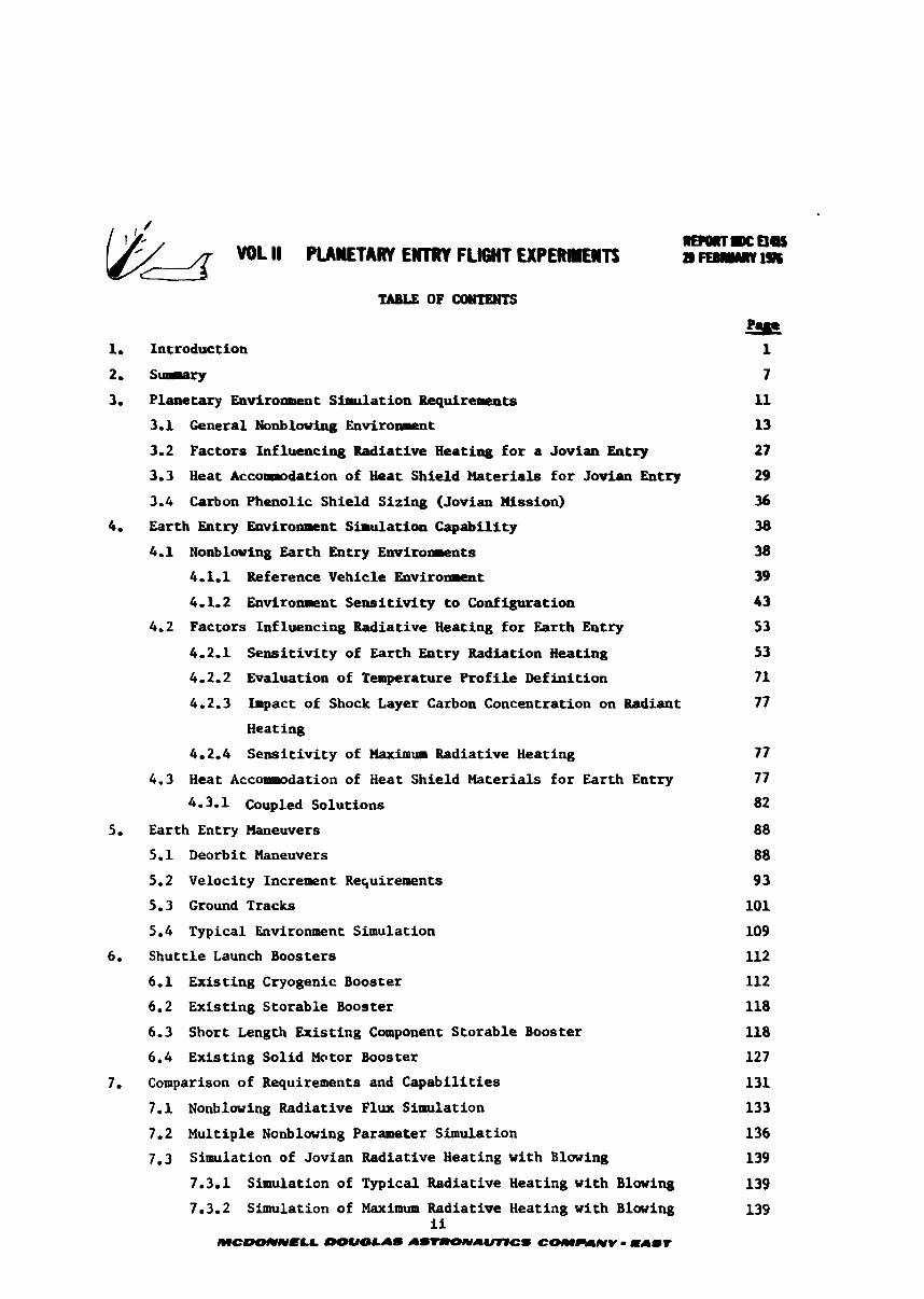
1, Introduction
2, S-ry
3, Planetary Eavironreent Simulation Requirerents 11
3.1 General Nonbloving Enviroll~ent 13
3.2 Factors Influencing Radiative Heating for a Jovian Entry 27
3.3 tieat AccoePodation of Heat Shield Haterials for Jovian btry 29
3.4 Carbon Phenolic Shield Sizing (Jovian Xission) 36
4, Earth Entry Environment Simulation Capability 38
4.1 Konblwing Earth Entry Envirolreats
41.1 Reference Vehicle Environment
4.1.2 Enviromnt Sensitivity to Configuration
4.2 Factors Influencing Radiative Heating for Earth Entry
4.2.1 Sensitivity of Earth Entry Radiation Heating
4.2-2 Evaluation of Temperature Profile Definition
4-2.3 Impact of Shock Layer Carbon Concentration on Radiant
Heating
4.2.4 Sensitivity of Maximum Radiative Heating
4.3 Heat Acconwmdation of Heat Shield Haterials for Earth Entry
4- 3. 1 Coupled Solutions
5. Earth Entry #aneuvers
5.1 Deorbit Maneuvers
5.2 Velocity Increment Re~uirements
5.3 Ground Tracks
5.4 Typical Environment Simulation
6. Shuttle Launch Boosters
6.1 Existing Cryogenic Booster
6.2 Existing Storable Booster
6.3 Short Length Existing Component Storable Booster
6.4 Existing Solid Motor Booster
7. Comparison of Requirements and Capabilities 131
7.1 Nonblowing Radiative Flux Simulation 133
7.2 Multiple Nonblowing Parameter Simulation 136
7.3 Simulation of Jovian Radiative Heating with Blowing 139
7.3.1 Simulation of Typical Radiative Heating with Blowing 139
7.3.2 Simulation of Maximum Radiative Heating with Blowing 139 ii
MCOOUN'LL -&AS A-A(mCS COMPLIIVV - ma-r
8, Entry Vehicle Experiments
8-1 E x p e r i r n t Bef ia i t ion
8-2 R e m n t W Measurerents
8.3 Electrostatic Probe
8.4 BPdioreters
8.4-1 Multichannel Badi-ter
8.4.2 Spectral Scanning Radiowter
8.5 Detectors
9. Entry "iehicle Design
9.1 Entry Vehicle Subsystem Evaluations
9.1-1 Aeroshell
9.1-2 Telemetry and Cosunieatiorts
9.1-3 ElectrAd Pover
9.1.4 Recovery
9.1.5 In ter faces
9.2 General A r r a n g m t
9.2.1 Entry Vehicle Design
9.2.2 Launch Configuration
9.3 Entry Vehicle Mass Propert ies
9.3-1 Ballast Options
9.3.2 Detailed !;ass Property Analysis
9-4 Cost Estifnates
10. Conclusions
11. BccaPreadations
12. References
L i s t of Pages
T i t l e Page
i through iv
1 through 221
iii
MCLIOCVNELL WUOLAS AS-AMCS COI~~PANY - m a l t
FtB
HL
IUS
U
KBPS
m PM
PDS
RCS
Ka
% SIP
Shutt le
SPS
Upper s tage t h a t provides in i t ia l thrus t on the PDS deployed from Shutt le , e-g., Transtage, Delta, Centaur, Ageaa, and may include 11S 368-6 auxi l ia ry stage.
Eastern Test Range
High Level Signal
Interim Upper Stage
Lou Level Signal
Kilo Bits Per Second
klt iplexer
Pulse Coded lbduled Sigaal
Payload Deploywmt Systea is the Shut t le deployed payload. The assembly of a booster, spin separation system plus entry vehicle and associated avionics.
Reaction Control System
Apa Apsis Radius
Nose Radius
Stra in Iso la t ion Pad
Space Shutt le
Samples Per Second
Switch
Thermocouple
Shock Temperature
Velocity
Distance through shock layer measured from vehicle surface
B a l l i s t i c coeff ic ient
Entry angle
Relative entry angle
Velocity increment
Shock standoff distance or Shock layer thickness
Density
Unmanned exploration of the outer planets of our s o l a r system is a major goal
of NASA. S t a r t l i n g new discoveries have been made by the Pioneer and llariner pro-
grams. Another s t e p i n this exploration process is the entry i n t o the atmosphere
of an outer planet, It is expected tha t a grea t number of atmospheric probe f l i g h t s
v i l l be made i n the futare, As the r e s u l t s of ear ly missions a r e analyzed, new
and more comprehensive measurements v i l l be planned. Progressively -re severe
environments w i l l be explored. To these ends advances i n planetary entry tech-
nology, par t icular ly i n the thermal protection syst-, w i l l be necessary.
Due t o the high approach veloci ty caused by the gravi ta t ional p u l l of a la rge
planet, intense radia t ive and convective heating is predicted f o r entry i n t o the
hydrogen-helium atmosphere of these planets. Entry probe designs have evolved
(References 1 and 2) which employ a blunt cone configuration t o reduce atmospheric 2 penetration ra t e , loads and heating, Even so, high heating (30 t o 50 kW/a ) is
predicted. Ground t e s t ing and f l i g h t t e s t ing of a probe-like vehicle v i l l estab-
l i s h probe in teg r i ty under extreae conditions.
A timely and cost-effective approach t o the advancement of planetary entry
technology is t o simulate the desired entry environment i n ear th f l i g h t test experi-
ments, using the Space Shutt le as a launch platform. Heretofore, such expetimenta-
t ion has been expensive, and higher speeds required of planetary entry simulation
w i l l be even more demanding than on previous experiments. Large sophisticated
space equiplnent w i l l be required. Such equipeent w i l l be avai lable a t reasonable
cost with the advent of the Space Shutt le and its upper stages, Thus, the purpose
of the present study is t o determine the f e a s i b i l i t y of using the Shutt le t o per-
form planetary entry technology f l i g h t experiments.
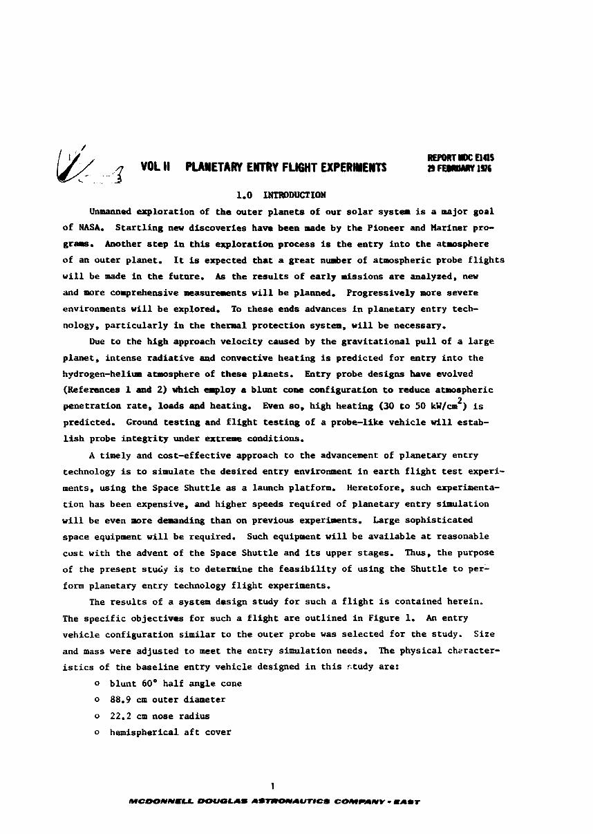
The r e s u l t s of a system design study f o r such a f l i g h t is contained herein,
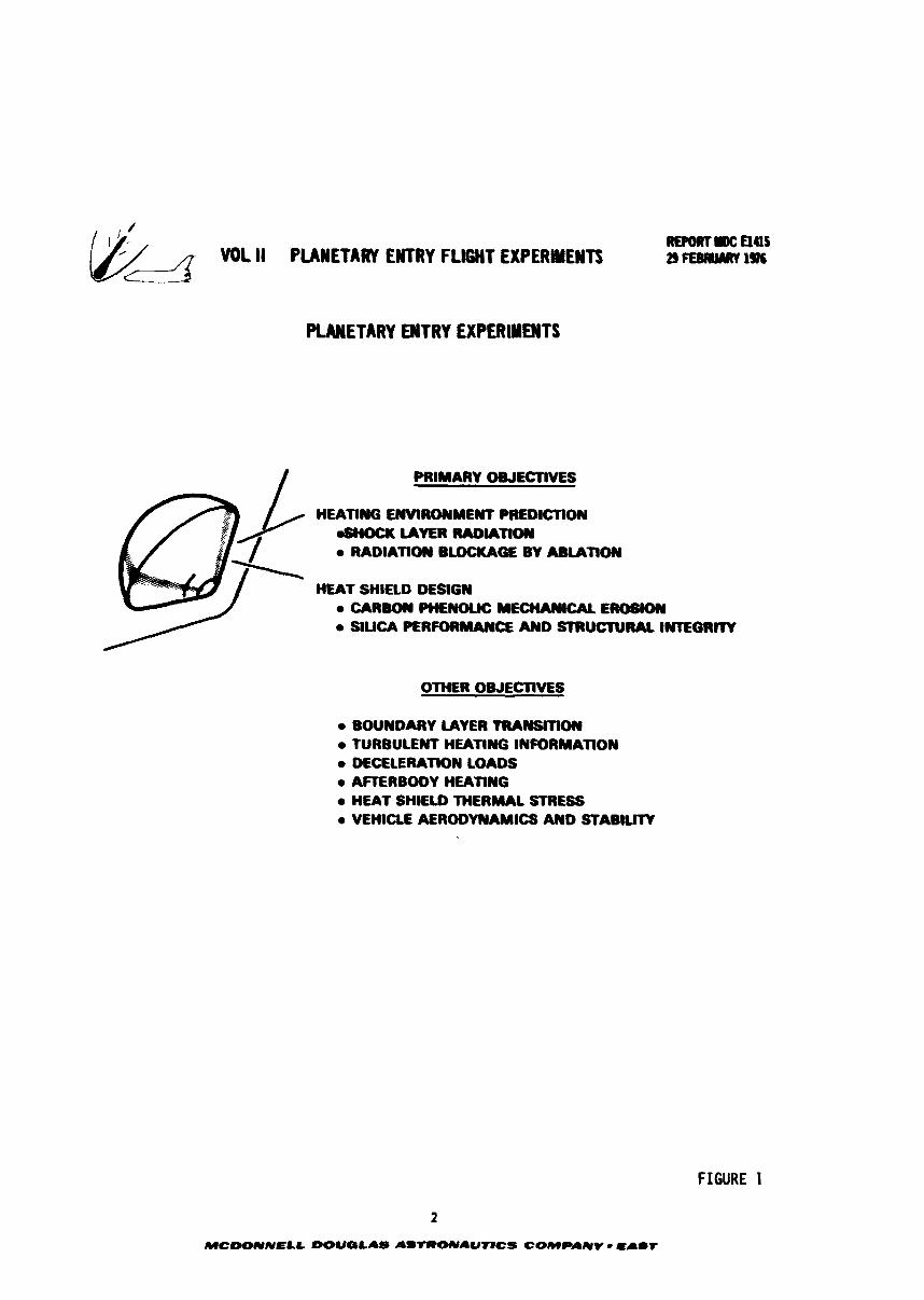
The spec i f i c objectives fo r such a f l i g h t a r e outlined i n Figure 1, An entry
vehicle configuration similar t o the outer probe was selected f o r the study. Size
and mass were adjusted t o meet the entry s i m l a t i o n needs, The physical cheracter-
i s t i c s of the basel ine entry vehicle designed i n t h i s ctudy are:
o blunt 60° half angle cone
o 88.9 cm outer diameter
o 22.2 crn nose radius
o hemispherical a f t cover
~ o ~ o f t r m c a45 VOL II PLANETARY ENTRY FLIGHT EXPERMEWTS a FEIWMY 19s
PUWETARY ENTRY EXPERIMENTS
I PRIMARY OWLCTlVES
H m n f f i ENWRO~~ME~YT PREDICTON &HOCK LAYER WOWTION
RADIANON BLOCKAGE BY A u n o c y
HEAT SHlLLD DESIGN a CAR- PH€#OUC MECHAUtCAL EROSfON
/ a SILICA CSRFORMAIYCE AND STRUCTURAL lNEGRrrV
OTHER OWECTIVLS
a BOUNDARY LAYER TRAnrSmOIY TURBULENT HEATINO INFORMATION
a DECELERATION LOAOS a AFERBODY HEATING a HEAT SHIELD THERMAL STRESS a VEHICLE AERODYNAMICS AND STABILITY
FIGURE 1
2
MCOOlVNELL DOIIQLAS AS-AUflCS COMPAIVV - ma-T
REPORT DC aas "DL II PuLwn E ~ R I ~ I G H T EXPERMENTI 29 FEBRUARY 1976
2 o 120 kglm b a l l i s t i c coe f f i c i en t
o instrument and system complement
0 air recovery system
C r i t i c a l t o ' t h e success of t he en t ry phase of t h e mission is the
predict ion of the s p e c t r a l r ad i a t ion caused by the compression of t he hydrogen-
helium atmosphere between the shock wave and t h e vehicle. Computation of shock
layer rad ia t ion depends on gas composition, temperature d i s t r i b u t i o n and sur face
temperature of t h e en t ry vehic le surface. The gas i n j ec t ed by the ab la t ing heat
sh i e ld a l s o inf luences the r ad i a t ive heating. Consequently the primary objec t ive
of the earth ent ry experiment is t o match the hea t ing and o ther environments
expected during outer planet entry. O f g r ea t importance during any t e s t is the
measurement of enviroweents, so the e a r t h en t ry f l i g h t experiments was designed
t o measure t h e r ad i a t ive heat ing and o ther environments. These measurements w i l l
be used t o va l ida t e t he predic t ion techniques and t o update predict ions f o r t he
hydrogen-helium environment. The hea t sh i e ld of the outer planet probe cons t i t u t e s
approximately 402 of i ts mass. Consequently t h e se l ec t ion of t he mater ia l f o r t he
hea t sh i e ld and its s i z ing grea t ly a f f e c t s t h e launch weight and the amount of
instrumentation t h a t can be carr ied. Candidate heat sh i e ld materials
f a l l i n t o two categories: (1) a carbonaceous ab la to r which accommodates the
in tense heat ing by ab la t ion r e s u l t i n g i n la rge m a s s i n j ec t ion and (2) a highly
r e f l e c t i v e mater ia l such as hyperpure s i l i c a which r e f l e c t s a l a rge port ion of the
r ad i a t ive heating. Carbon phenolic is subjec t t o mechanical erosion and s i l i c a is
subjec t t o s i g n i f i c a n t thermal stress. Validation of t he s t r u c t u r a l i n t e g r i t y of
both mater ials can be made i n an e a r t h entry test. Instrumentation w a s designed
t o measure the performance of t he hea t sh i e ld mater ials . Experiments were a l s o
devised t o measure :he parameters necessary t o increase the technology base f o r
designing outer planet probe.
The scenar io of a planetary en t ry f l i g h t experiment launched from Shu t t l e is
depicted i n Figure 2. After t he Shut t le has es tab l i shed a c i r c u l a r o r b i t (160 nmi,
nominally), the Payload Deployment System (PDS) cons is t ing of an assembly of a
booster (two o r three s tage propulsion system), a sp in system and the en t ry vehic le
is deployed from the Shut t le cargo bay. The f i r s t s t age of the booster Is f i r e d
t o accomplish the Hohmann t r ans fe r t o a high o r b i t (up t o synchronous a l t i t u d e )
where a deorb i t burn i s accomplished. The spent s tage is je t t i soned and the vehic le
acce lera tes towards e a r t h converting po ten t i a l energy i n t o k i n e t i c energy. Suet p r i o r
t o the sens ib l e atmosphere the f i n a l burn is accomplished increasing the en t ry
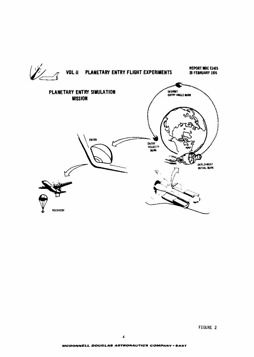
REPORT rBC UUS VOL II PLANETARY ENTRY FLIGHT EXPERIMENTS 29 FEMUCUW 1916
PLANETARY ENTRY SlNULATlON MISSION
FIGURE 2
4
MCDONNELL OOUGLAS ASTRONAUNCS COMPANV - EAST
REPORT IIC U4lS VOL I I PUMETARY ENTRY FLIGHT EXPERIMENTS 29 FEBRUARY 1916
velocity. The f i n a l s t age aad t he en t ry vehic le a r e sp in s t ab i l l r ed . During en t ry
the f l i g h t measurements a r e made documenting environments and vehic le performance.
A t the conclusion of the en t ry which occurs near the NASA t e s t range a t Ascension
Island, the en t ry vehic le is a i r recovered so the heat sh i e ld and other components
can be examined. The complete ana lys is of such a missior, including environments,
experiment design, vehicle design, booster in te r faces , hea t sh i e ld performance,
mission scenario, coanaunications analysis , ground t racks and cos t es t imates are
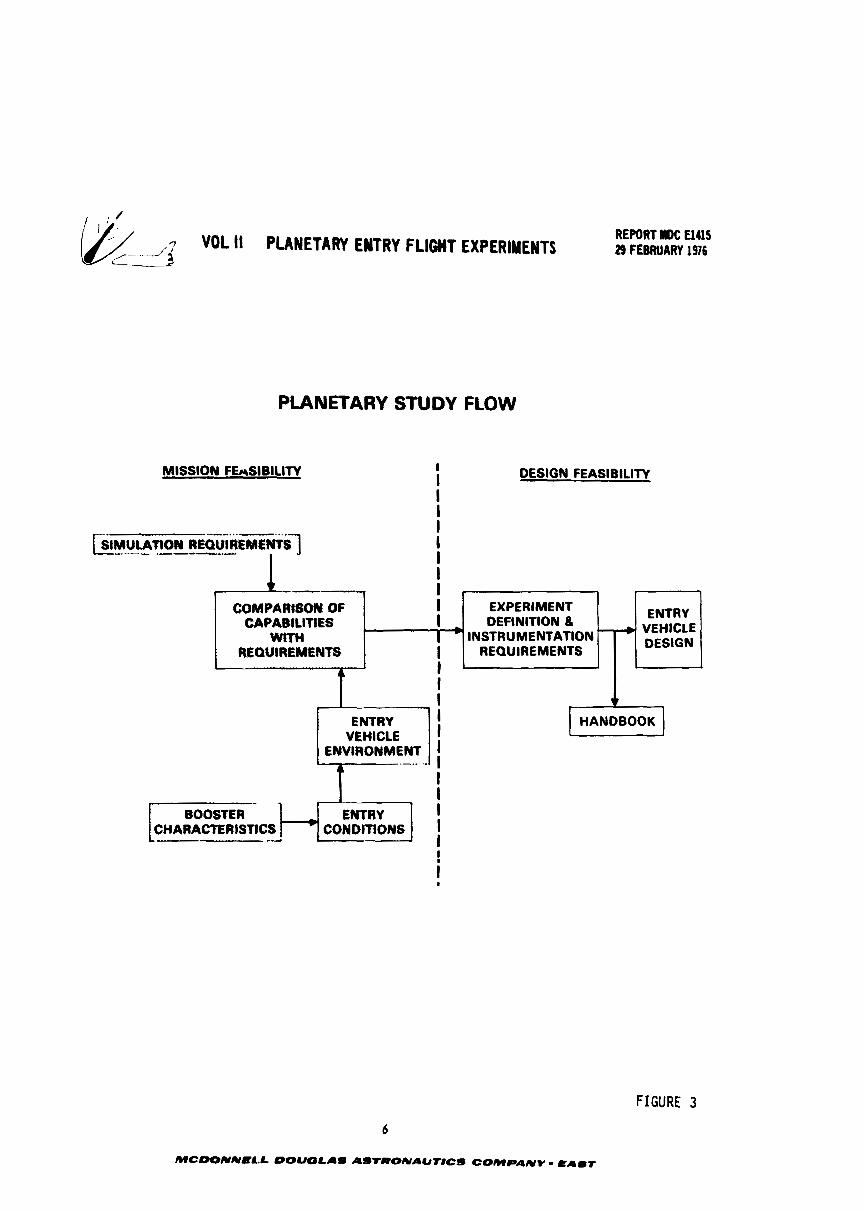
contained herein. The study flow is depicted i n Figure 3. Entry environments f o r
outer planet probes were used t o e s t ab l i sh the simulation requirements. Boosters
which can be launched from Shut t le were examined t o determine the en t ry condit ions
t h a t could be achieved t o deploy an en t ry vehicle. Predict ions of t he en t ry environ-
ments were made i n order t o compare with the simulation requirements. After estab-
l i s h i n g the mission f e a s i b i l i t y , the d e t a i l s of the mission and vehic le design were
worked out. Also a planetary en t ry f l i g h t experiment handbook was prepared (Volume
111) t o a i d i n continuing t h e design of such an experiment.
The authors appreciate the s i g n i f i c a n t contr ibut ions made t o the study by:
D. W. h g a n (NASA-ARC), W. E. Nicolet (Aerotherm), H. J. Fivel, W. H. Gustin,
H. E. Hommes, L. J. Mockapetris and C. Dm Poore of MDAC-E.
5
MCOONNELL OOUOLAS ASTW0NAUt)CS COMPANY - (LAIT
, 3 VOL II PLANETARY ENTRY FLIGIIT EXPERIMENTS REPORT #IDC El415 29 FEBRUARY 1916
PLANETARY STUDY FLOW
MISSION FEwSIBILIlV I I DESIGN FEASlBILlTV
I I
FIGURE 3
1 -- I I -
6
MCO0NNEL.L DOUOLAS AS'TRONAUNCS COMPANY - E A b r
COMPAf4tSclN OF CAPABltlTtES
WI'rH I REQUIREMENTS
1 I , I I
EXPERIMENT DEFINITION 8 ENTRY
INSTRUMENTATION REQUIREMENTS DESIGN
I I
a I * ENTRY
VEHICLE ENVtRONMENT
I HANDBOOK 1 1
i .----- I I I
BOOSTER ENTRY CONDInONS
I I I ! I t
REPORT MOC El415 VOL II PLANETARY ENTRY FLIGHT EXPERIMENTS 29 FEBRUARY 1976
2.0 SUMMARY
The t e c h n i c a l f e a s i b i l i t y of launching a high speed, low 0, e a r t h e n t r y v e h i c l e
from S h u t t l e t o advance technology f o r t h e exp lora t ion of t h e o u t e r p l a n e t s ' atmos-
pheres has been es tab l i shed . D i s c i p l i n e s of thermody~tamlcs, o r b i t a l mechanics,
aerodynamics propulsion, s t r u c t u r e s , des ign, e l e c t r o n i c s and system i n t e g r a t i o n
focused on t h e goa l of producing o u t e r p l a n e t environments on a probe shaped v e h i c l e
dur ing an e a r t h entry. This s tudy addressed seven major a s p e c t s of a n a l y s i s and
v e h i c l e design. They included: p lane ta ry environments, e a r t h e n t r y environment
c a p a b i l i t y , miss ion maneuvers, c a p a b i l i t i e s of S h u t t l e upper s t a g e s , a comparison
of e a r t h e n t r y p lane ta rv environments, experiment des ign and v e h i c l e design.
The p lane ta ry e n t r y parameters t h a t a r e required t o be s imulated were analyzed
and r e l a t e d d a t a ass imi la ted . Entry i n t o t h e o u t e r p l a n e t s is charac te r ized by a
r a d i a n t dominated hea t ing pulse. Consequently, d e t a i l e d s t u d i e s were conducted
c e n t e r i n g on t h e snders tanding of t h e i n t e n s e r a d i a t i v e h e a t i n g emanated from t h e
shock l a y e r . I n p a r t i c u l a r , t h e e f f e c t s on t h e s p e c t r a l energy d i s t r i b u t i o n from
a d i a b a t i c , cooled and mass i n j e c t e d shock l a y e r s were charac te r ized f o r both
carbonaceous and hyperpure s i l i c a h e a t s h i e l d s . Uncer ta in t i es i n t h e Jovian e n t r y
ang le (3 degrees spread) r e s u l t s - i n a 58% i n c r e a s e i n r a d i a t i v e hea t ing , a 19% i n c r e a s e
i n convect ive h e a t i n g and a 10% r i s e i n s t a g n a t i o n pressure . The two candidate
h e a t s h i e l d s a l s o in£ luenced t h e r a d i a t i v e environment. The blowing of t h e carbona-
ceous s h i e l d reduced t h e i n c i d e n t r a d i a t i v e hea t ing by 46% whereas t h e mass i n j e c -
t i o n f r o n t h e s i l i c a s h i e l d caused 18% reduction. iiowever, due t o s i l i c a ' s excel- 2 l e n t r e f l e c t a n c e p r o p e r t i e s , only 1.7 kW/cm had t o be accommodated by t h e h e a t
s h i e l d whereas carbon wi th i t s high absorptance (.8) had t o absorb 9.1 kwlcm2 i t
peak hea t ing condi t ions .
I n p a r a l l e l , t r a j e c t o r i e s and shock l a y e r s f o r high speed e a r t h e n t r y were
i n v e s t i g a t e d t o determine what environments could be achieved. Zoomparable r a d i a t i v e
hea t ing l e v e l s were computed and t h e in f luence of shock l a y e r p r o p e r t i e s on r a d i a t i v e
hea t ing were s i m i l a r t o t h o s e obta ined f o r t h e o u t e r p lane t s . The s p e c t r a l d i s t r i -
bu t ion of energy f o r e a r t h showed a. s h i f t t o a l a r g e r percentage i n t h e
vacuum u l t r a v i o l e t . (VW). Tra jec to ry parametr ics were computed and showed t h a t
not as high a n e n t r y v e l o c i t y i s requ i red on e a r t h a s t h e o u t e r p l a n e t s t o achieve
t h e same heat ing.
De ta i l ed mission ana tyses s t u d i e s including AV requirements, impulsive and
f i n i t e burn t r a j e c t o r i e s and ground t r a c k s were performed. Hohmann t r a n s f e r t r a -
7
MCDONNELL OOUOLAS ASTRONAUrJCS COMPANY E A b t
jec tor ics w i t h q m a p i o up to 40 earth r a d i i were caputed , W y trajec-
t o r i e s up to 6.3 cart!! radiivere needed t o achieve the r-uired heatiag. Depend- iag on the mission, once tht system is deployed from Shut t le 6 t o 13 hours are
required t o complete the nissioo,
A t the bcgiPPialt of t h i s study, the IUS cmr-ept had not been selected, Con-
sequently, four classes of boosters vere analyzed t o determine their a b i l i t y t o
a c c a p l i s h the I! 'rrsna trslrsfer a d deorbit, They included a cryogenic (Ceataur),
a s torable propellant (Tramstage), a ccapact booster constructed using the shut t le ' s
a l t i t u d e control propuls-lon components and a so l id rocket spotor ( S W booster,
Pergormsnce raps inc1w~in.g the entry e n v i r o a e n t s tha t would be abtained on a
m m b a l entry vehicle vere prepared f o r each class of booster, Midway through the
study the decision t o develop the SRM I U S was made by the goud~mmt. All the
m t e r concepts employed a TE364-4 as the f i n a l s tage i n order to obtain the desired
entry vdoc i ty , The £ i d stage and the ent ry vehicle w e r e spin stabi l ized. Details
of tfie booster performance were studied and factored in to a e w a r i s o n of s M i i t e d
coadftions against require!ments,
In the comparison of a t ta inable ea r th entry environments with the required
planetary environments, the importance of simulating radia t ive heating over shadowed
other parameters, Although ea r th entry conditions can be se lec ted t h a t r e s u l t i n
matching peak radia t ive heating f o r Saturn o r Jovian en t r i e s , the precise ~ta tching
of a l l parameters is not possible. Entering at 20 degrees produced the bes t match
for Jupi ter and a steeper angle was required f o r the Saturn simulation. Detailed
s tudies using shock layer flow f ie ld / radia t ion computer codes were conducted t o
shau the e f fec t of shock layer temperature d is t r ibut ion , w a l l temperature and species
concentration on the incidenr heating, These s e n s i t i v i t y s tudies shoved t h a t the
incident heat is s igni f icant ly reduced due t o cooling e f fec t s i n the shock layer and
blowing of ablat ion products. It appears t h a t both the incident and net radia t ive
heat f lux incident on a carbonaceous heat sh ie ld during a Jovian entry can be
duplicated during an ear th entry but more ne t f lux resu l t s on a silica heat sh ie ld
when the incident radia t ive f lux is duplicated. The difference i n conditions on
the s i l i c a sh ie ld i s due t o the highrtr percentage of energy i n the VUV f o r a i r where
s i l i c a ' s ref lectcnce is low. Despite t h i s mismatch, the silica shie ld has t o
accorPlPodate approximately half the radiant £1- tha t a carbonaceous shield. This
incrkase i n he t heat a l so means tha t a closer match i n t o t a l heat w i l l be achieved,
Radiative heating is s igni f icant ly reduced when heat sh ie ld mass injec t ion occurs.
'Ibis occurs more so during entry i a t o ear th than Jupiter. Hence entry energy rust
be increased t o achieve simulation when considering blwing. Trajectories t o 15 o r
16 ear th r a d i i are required t o produce the energetic conditions needed t o met the
maximum design Jovian eacry heating (blowing). The Trarrstage/TE364-4 booster w i l l
achieve these conditions whereas a more powerful SRM IUS booster, than the one
studied, needs t o he used. Even so, -.inry high radia t ive daipinated heating environ-
ren t can be achieved using the SRM IUS.
The pertinent information assembled during t h i s study were organized in to a
handbook (Volume 111) t o a id mission planners.
Experiments w e r e designed t o measure the environment and heat shie ld performance.
A cosplesrent of experiments w e r e selected t o l ~ e e t the areasurement objectives. Instru-
m t s included :
1. Therrocouples; surface, indepth stack and i n t e r i o r
2. Pressure probes
3. Acceleroee ters
6. Stra in gauges
5. Elect ros ta t ic probes
6. Rad io~e te r
'Fwo candidate radiosaeter designs w e r e developed tha t f i t compactly in to the ear th
entry vehicle. These designs warrant further study and testing.
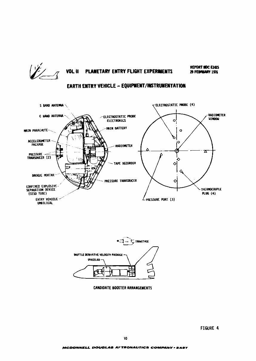
Design s tudies were accomplished for the ear th entry vehicle. The heat
shield, experiment/equipnrent, power and cotrsaunications along with the s t ructure
and mid-air recovery system were married in to an integrated design. Figure 4 is a
composite of the entry vehicle prof i le , equipment/instrument locations, and a shared
launch configuration. I f the short length booster were used, the entry experietent
could be sandwiched between other cargo. Even i f the Transtage o r SRM IUS were
used only 318 of the Shutt le cargo bay would be occupied and 57% of the shut t le ' s
payload weight capabil i ty would be available f o r other cargo, This w i l l permit
a shared launch and a l o w experiment cost.
EARTH EWTRY VEHICLE - EQUIPYEICT/l~TRUYENTATlON
5 BAND AI(TEII(A\ 7 ELECTRCtSTAlIt PROBE (4)
i ELECTROSTATIC PROBE ELECTROMICS
W E tlDRTAR ----
COHFIUED EXPLOSIVE ; fEPARATIOW DEVICE --
(CESD TUBE) ,/
EHTRr VEH 1 U E -', utU3ILICAL
CANDIDATE BOOSTER ARRANGWENTS
FIGURE 4
10
MCDONNEU DOUGUS AFtRONALmCS COMPANY - E A I r
3.0 PLANEUBY ENVIRONMENT SIMULATION R E Q U f m
Several i nves t iga to r s (3, 4 and 5) have beea ac t ive ly involved i n pred ic t ing
the e n v i r o a ~ e n t s t h a t can be expectad when enter ing t h e ou te r planets ; Jup i t e r ,
Saturn and Uranus. 1Yominal environments t h a t inf luence the design and performance
of a probe include: peak r ad ia t ive heating, peak convective heating, t o t a l heat ,
hea t pulse duration, peak s tagnat ion pressure and decelerat ion loads. The predic-
t i o n of these quan t i t i e s is of course dependent on t h e atmospheric Plodel, t r a j ec to ry ,
vehic le b a l l a s t i c coe f f i c i en t and the ~ethodology. Tra jec tor ies are continuing
t o be evaluated s o a typ ica l atmosphere t r a j ec to ry f o r a typ ica l probe vehic le was
used t o e s t ab l i sh en t ry environments. The r ad ia t ive heat ing predicted f c t planetary
en t ry is severe and dependent on t he ana ly t i ca l nodel. l h e d i f fe rence betveen
a n a l y t i c a l models stems from t h e assumptions regarding temperature and spec ies con-
cent ra t ions across t he shock layer ,
Predict ions have been coapiled for: ad iaba t ic shock layers , cooled shock l a y e r s
ami shock l aye r s with species concentrations r e su l t i ng from blowing of t h e ab l a t ion
hea t sh i e ld materials. I n an ad iaba t i c shock layer , a l l t h e gas is a t t h e shock
temperature and consequently produces t h e highest r ad i a t ive heating, In a cooled
shock layer , the gas temperature drops t c the wal l temperature near t he w a l l and
the r a d i a t i v e heating is lover. I n a shock l aye r with mass in jec t ion , t h e region
of l o w temperature is expanded f u r t h e r and the r ad i a t ive heat ing is f u r t h e r
reduced.
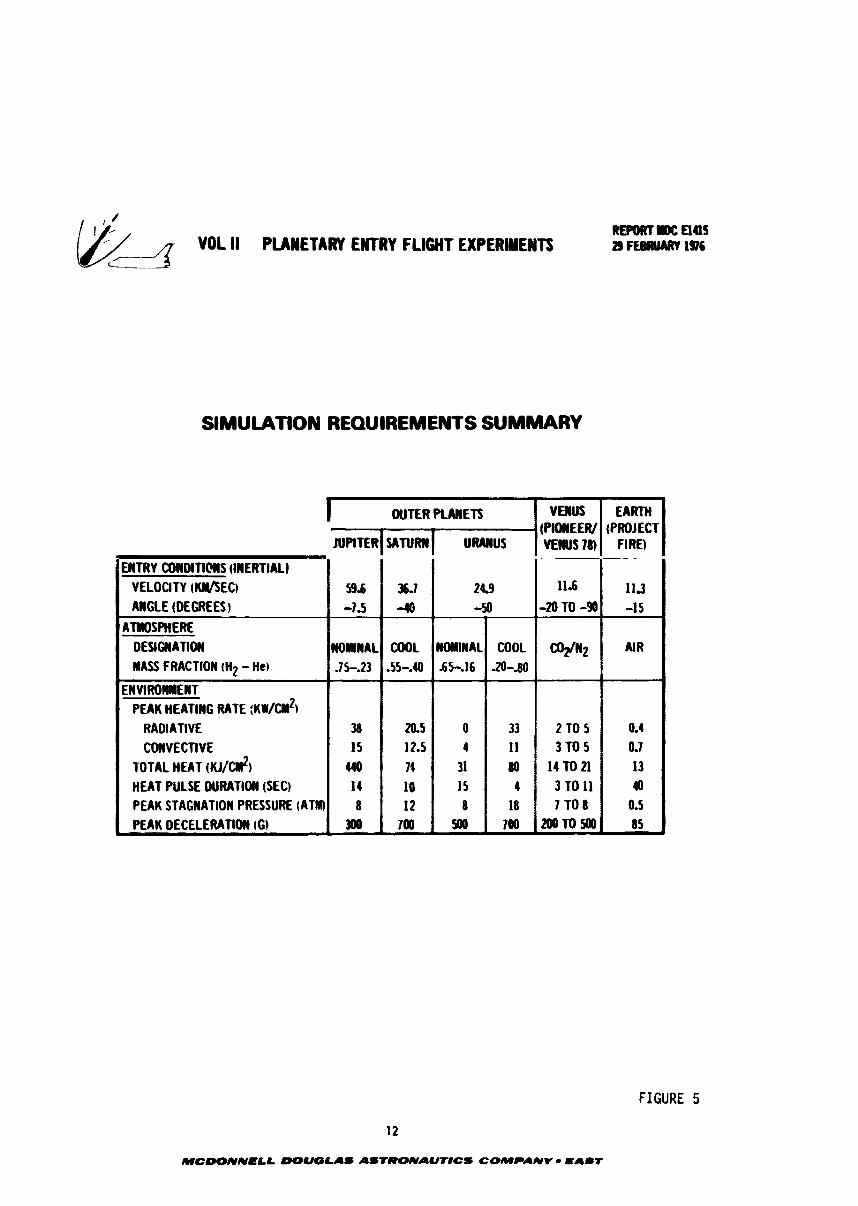
A compilation of ou ter planet en t ry environments is contained i n t he following
sec t ions and summarized i n Figure 5. The r ad ia t ive heat ing reported i n t h e f igu re
is f o r a cooled shock layer. Also included f ~ r reference a r e the en t ry environments
an t ic ipa ted f o r the forthcoming Venus probe mission as w e l l as those experienced
i n e a r t h by Project FIRE.
High heating parameters a r e the dominant environment associated with en t ry
i n t o the outer p lane ts but s tagnat ion pressure and decelerat ions are a l s o important.
Compared with ea r th entry, outer planet entry is characterized by high veloc i ty ,
high r a d i a t i v e and convective f luxes and sho r t en t ry t i m e s . Further, the heat ing
environment is dominanted by shock l aye r rad ia t ion a s opposed t o t he convective
dominated ea r th entry.
The general environments associated with the outer p lane ts a r e presented f i r s t
i n parametric curves followed by analyses of t he s p e c t r a l heating s e n s i t i v i t i e s and
MCDONNELL -LAd AStRONAUmCS COMPANY - EA-T
SlMULATiON REQUIREMENTS SUMMARY
FIGURE 5
12
MCOONNELL WUOLAS ASTRONAUTlCS COMPANY - PA67
I OUTER PLANETS YEWUS (pw#rEW VEIUS 78) .
11.6
-2OTO-9
C0fl2
2 TO 5 3 f O S
141021 3 1 0 1 1 7 TO 8
20010500
EARTH (PROJECT
FIRE)
11.3 -15
AIR
0.4 0.7 13 0
0.5 85
JUPITER SATURW
36.1 -10
COOL .55-.40
20.5 12.5 74
10 12
700
ENTRY COWDI11MS (IWERTIALI VELOCITY (KIIISECI ANGLE (DEGREES)
ATMOSPHERE DESIGNATION MASS FRACTION tH2 - He)
EWVlROWIlENT PEAK HEATING RATE :KW/C~W~)
RADIATIVE CONVECTIVE
TOTAL HEAT (KJ/C#12) HEAT PULSE DURATION (SEC) PEAK STAGNATION PRESSURE (ATRI) PEAK DECELERATION (GI
9.6 -1.5
WOlllNAL JS.23
38 15 110 I 4 8
300
U M U S
24.9 -50
NOMlNAL 6546
0 4
31 15 8
500
COOL .2O-t80
33 11 80
4 18
700
voL 11 PUltnw rmr runr apr r rm REPORT u El45
d 29 FEBRUARY 1 s
the inf luence of heat sh i e ld material an the heating.
It became apparent duritrg t h e course of this study t h a t var ious inves t iga to r s
have used s l i g h t l y d i f f e r e n t values f o r planetary models and en t ry parameters.
This is due t o a continuing e f f o r t by the s c i e n t i f i c c o m n i t y t o upgrade our
knowledge of t he s o l a r system. Where appl icable these va r i a t i ons w i l l be assessed
i n t h i s report.
3.1 Planetary Enviro-nts - Worst case design environments are tabulated
f o r each outer planet. However, eotphasis is placed on parametr ical ly descr ibing
s tagnat ion poin t conditions as a funct ion of en t ry angle, type of a tmsphere and
ent ry vehic le b a l l i s t i c coef f ic ien t . It allcrvs evaluat ion of fu tu re changes i n
mission and vehic le evolut ion and provides i n s igh t i n t o how c lose ly a given param-
e t e r should be simulated.
J u p i t e r Entry Environment - Mission and configurat ion parameters derived from
ava i l ab l e r e s u l t s of cur ren t ou ter planet probe s tud ie s were u t i l i z e d t o pred ic t
environments. Nominal parameters a r e as follows:
o J u p i t e r nominal a tmsphere - 85% Hz-15% He by volume
o I n e r t i a l entry ve loc i ty - 59.70 km/sec
o I n e r t i a l en t ry angle - -7.S0
o Lat i tude - 5.0 (North)
o Relat ive ve loc i ty - 47.244 km/sec
o Relat ive en t ry angle - -9.5O
o Entry a l t i t u d e - 450 km
o B a l l i s t ic coe f f i c i en t - 141.8 kg/m 2
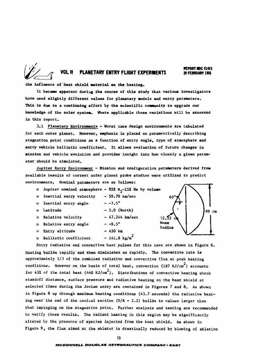
Entry r ad i a t ive and convective hea t pulses f o r t h i s case a r e shown i n Figure 6.
Heating bui lds rapidly and then diminishes as rapidly. The convective r a t e is
approximately 113 of the combined r ad ia t ive and convective f lux a t peak heat ing 2 conditions. However on the bas i s of t o t a l heat , convection (187 KJ/cm ) accounts
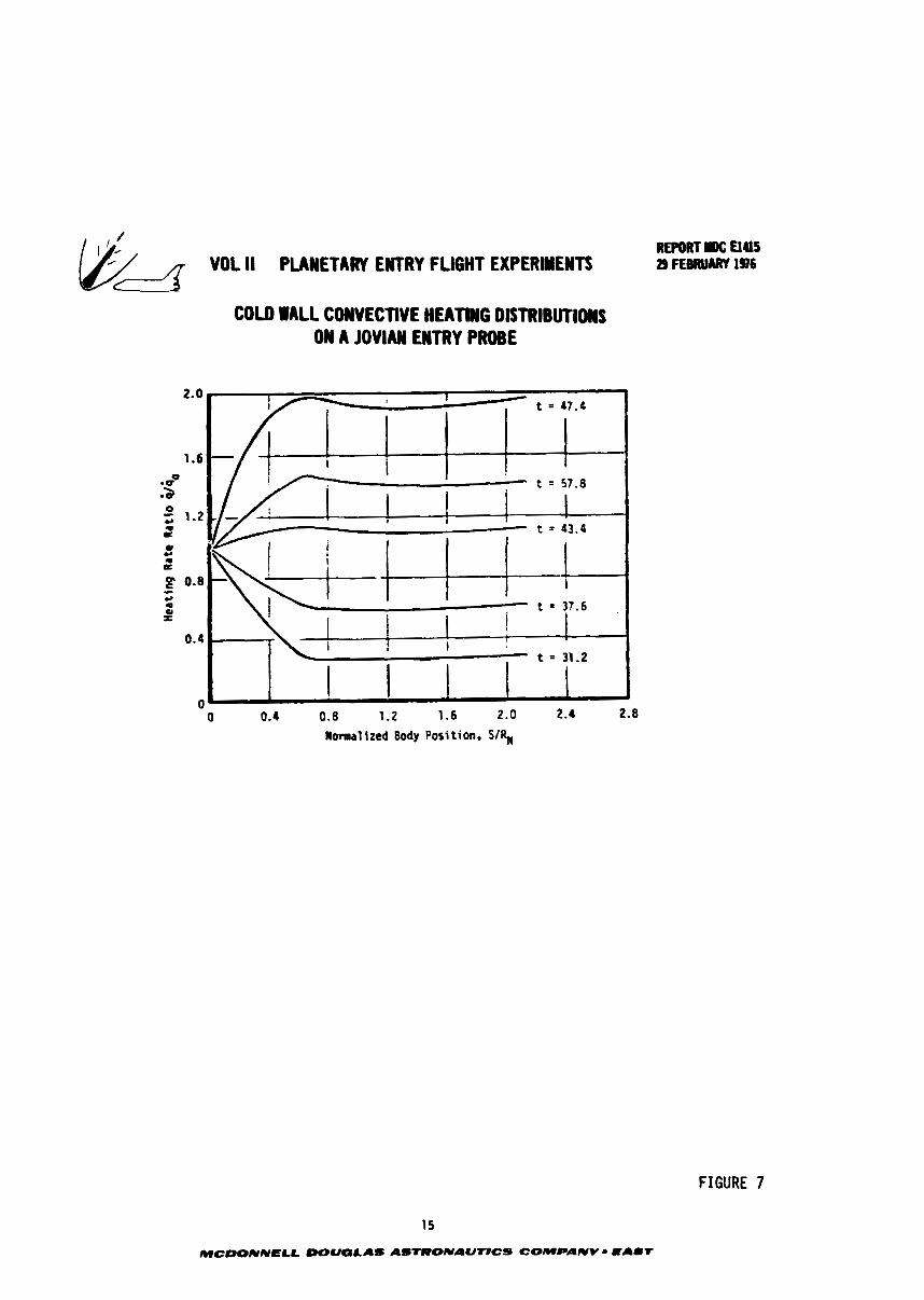
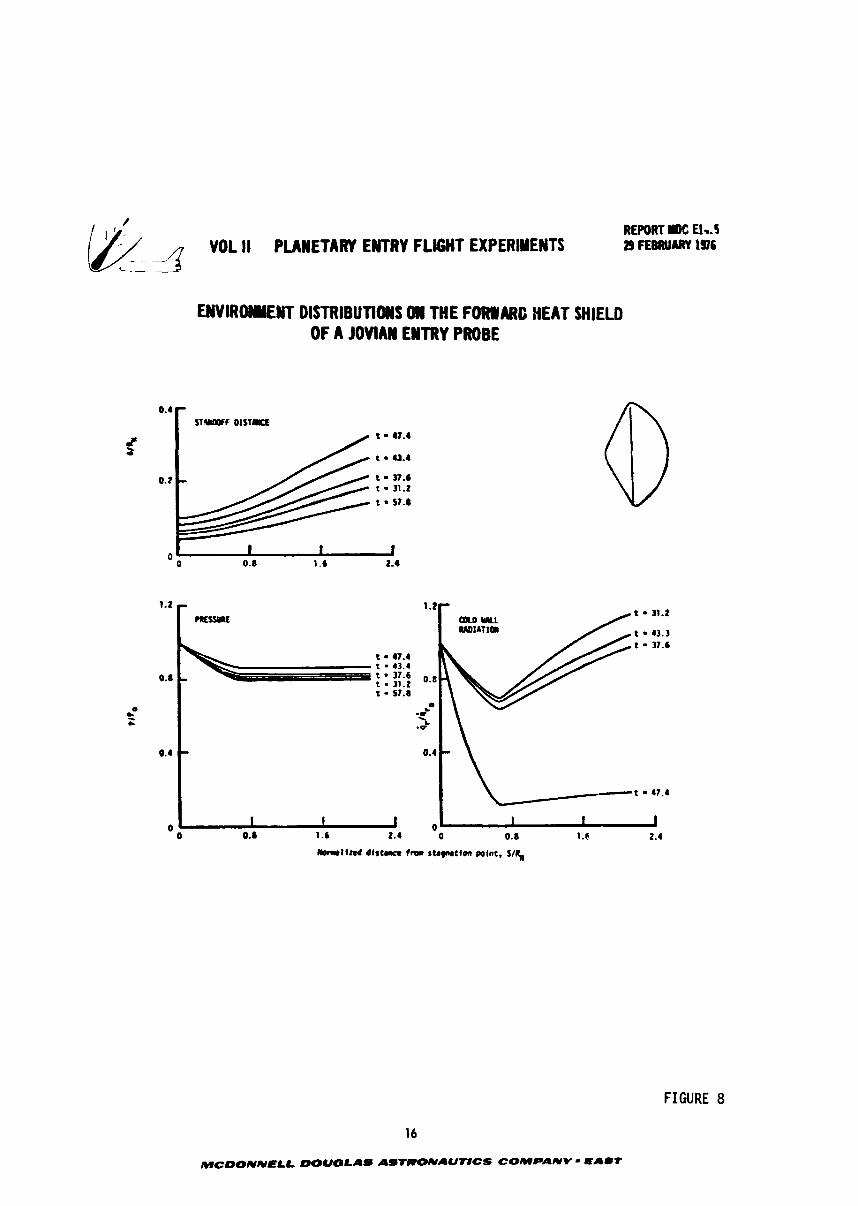
2 f o r 43% of the t o t a l heat (440 KJ/cm ). Distr ibut ions of convective heat ing shock
standoff dis tance, sur face pressure and r ad ia t ive heat ing on the hea t sh i e ld a t
se lec ted times during the Jovian entry a r e contained i n Figures 7 and 8. As shown
i n Figure 8 up through maximum heating conditions (43.7 seconds) t he r ad i a t ive heat-
ing near the end of the conical sec t ion (SIR = 2.2) bui lds t o values la rger than
t h a t impinging on the s tagnat ion point. Further ana lys is and t e s t i n g a r e recommended
t o ver i fy these resu l t s . The rad ian t heating i n t h i s region may be s ign i f i can t ly
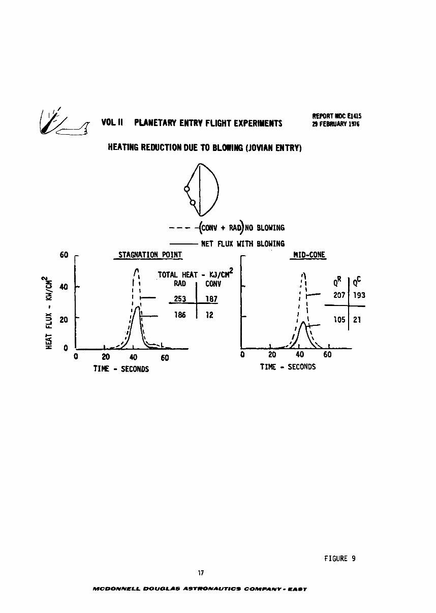
a l t e r ed by the presence of species in jec ted from the heat shield. A s shown i n
Figure 9 , t he f l ux aimed a t t h e ab la tor is d r a s t i c a l l y reduced by blowing of ab la t ion
13
MCOONNELL DOUQLAS AStRONAUTiCS COMPANV - CAST
ti€HRlIDC 043 VOL 1 PLANETARY EMTRY FLIGHT EXPERIMEPlTS a~aww~~lm
HEATIWG HISTORIES FOR JOVIAN ENTRY PROBE
MWVECT IVE
NOMINAL ATUOSPHEIE - STAWTION POINT --- HID crws~
Ts,43.7 SEC = 15, 540°K
'~,43.7 SEC = 5-97 Am
RADIATIVE HEATING IRCLUMS RADIANT LOSSES fROPI SHOCK LAYER
0 20 40 60 0 20 40 60
Tim frm Entry fsec)
FIGURE 6
14
MCLHINNELL 00UOlAS ASTRONAUTICS COMPANV - E A l t
WL II PLANETARY EWTRY FLIGHT UPWLNTS
COLD WALL COWVECTIVE HEATING DlSfRlBUTlMlS ON A JOVIAH ENTRY PROBE
o 0.4 0. a 1.2 1.6 2.0 2.4 2.8 R o ~ l i r e d Body Position, S/f$
FIGURE 7
15
MCWNNELL WUQLAS AStRONAUT8CS COMPANY - lFA#r
REPORT I1C El45 29 FEBRUARY 196
ENVIROAYEIST DISTRIBUTlUUS 011 THE FORlDARC HEAT SHIELD OF A JOVlAW EWTRY PROBE
-1lnd d t s t r m fror stap~tim point. Sf+
FIGURE 8
16
MCDONNIELL DOUGLAS ASTRONAU'T#CS COMPANY - malt
REPORT mc nus I9 FEEBRUARV 1¶6
HEATING REDUCTION DUE TO BLOlllffi (JOVIAN ENTRY)
NET nux WITH BLOWING
6o r STAGNATION WINT r RID-CONE
r, TOTAL HEAT - M/C$ I I I
I I IUD I
T I E - SECONDS TIME - SECONDS
FIGURE 9
17
MCDONNELL DOUGLAS ASTRONAUTICS COMPANY - EABT
10' II PLANETARY ENTRY FLIGHT EXPERIMEYTS REPORT U)(: El45
d 2) FEBRUARY 1976
products. A t the stagnation point the combined incident heat f lux is halved and
on the cone it is reduced by 68%. When blowing is accounted for , convective con-
t r ibu tes only 6% of the t o t a l heat a t the stagnation point aqd 17% on the conr.
The se lec t ion of entry angle and atmosphere model are of par t icular interes':
because of t h e i r uncertainties. The i n i t i a l entry angle corresponds t o a shallow
entry mission nominally targeted f o r a r e l a t i v e angle of -9.5 degrees which has a
typica l uncertainty of k1.5 degrees. Applying t h i s uncertainty r e s u l t s i n a worst
case condition of -11 degrees. This small uncertainty allows target ing fo r shallow
entry and r e f l e c t s the accurate knowledge of Jupi ter ephemeris and physical data
obtained from recent Pioneer missions.
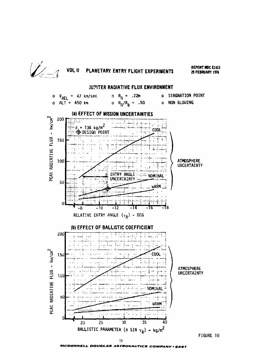
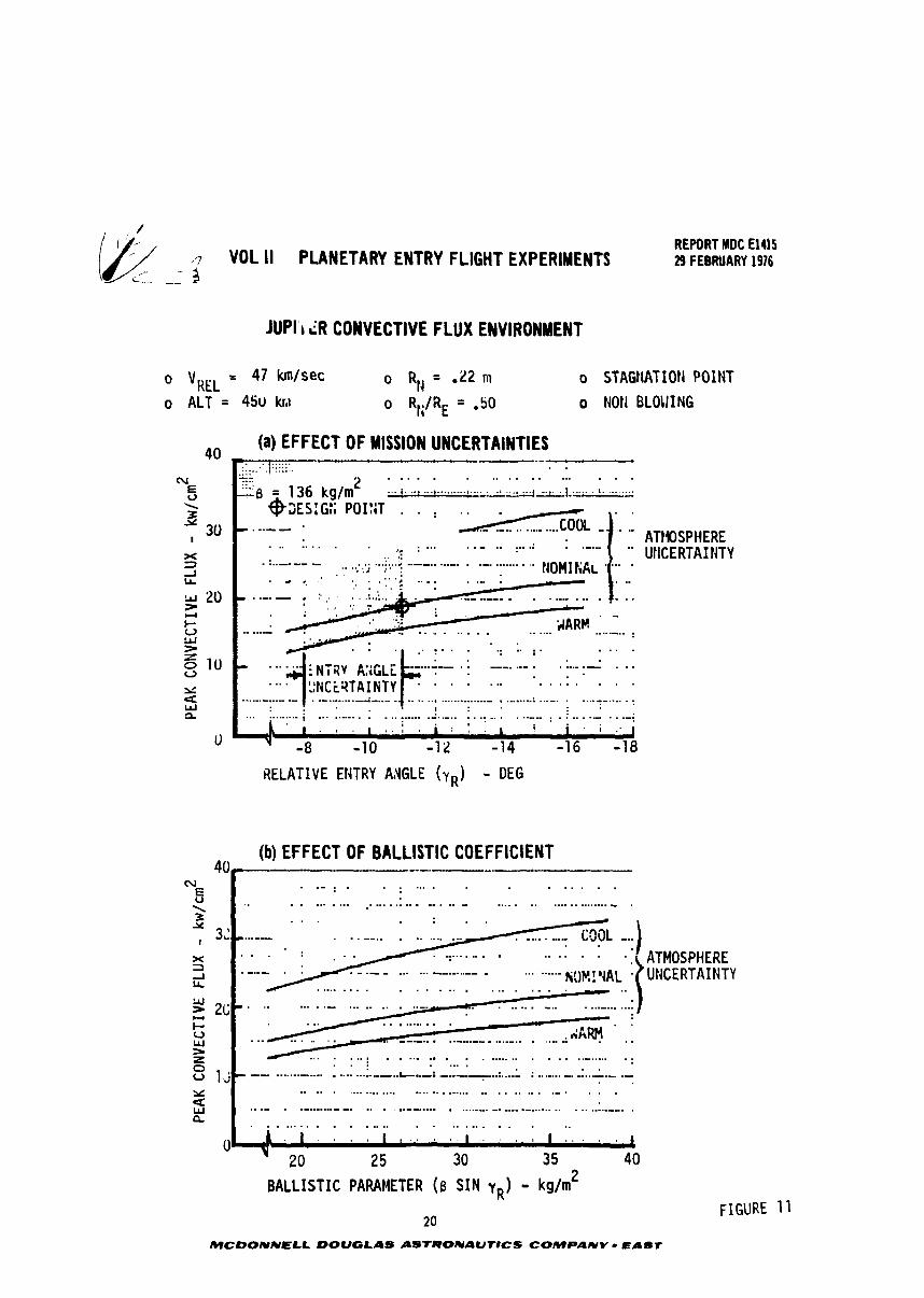
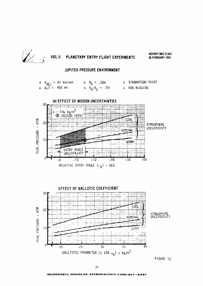
The e f f e c t of entry angle, atmosphtre model and b a l l i s t i c coeff ic ient var ia t ions
on peak ra'iative flux, convective f lux and pressure l eve l a r e shown i n Figures 10,
11 and 12. Atmospheric composition uncertaint ies were accounted f o r by parametrically
considering the cool, nominal and warm models described i n Reference 6.
IS
MCOONNELL OOUCSLAs ASTRONAUT#CS COMPANV = I A U T
ik/, j- VOL II PLANETARY ENTRY FLIGHT EXPERIMENTS REPORT MDC El415 29 FEBRUARY 1976
c-
JUPITER RADIATIVE FLUX ENVIRONMENT
o VREL = 47 km/sec o RI, = .2h o STAGNATION POINT
o ALT = 450 km o RN/RB = .50 o NON BLOLJING
-. (a) EFFECT OF MISSION UNCERTAINTIES
RELATIVE ENTRY ANGLE (yR) - DEG
(b) EFFECT OF BALLISTIC COEFFICIENT --A- . . . --- i . . . . . . . . . . . . . . . . . . . . 200 . . ; . . . .............. : . . . . . .:. . . . . . . . . . . . . . .:... . : .... . . . . . . . . . . --. . - ........... -. . .- ................ - ..... - - .............. .- . . . . . . . . . ! . . . , . . . . . . . . . . . . . . . . . . . . . . . . . . . . . . . . . . . . . . . . . . . . . . . . . . . . .
I : . .
...... . . . . . . ,
. . . . . . . . .
.... . . . . . . . . . . . . . . . . . . . . . . . . . . . . . . 0 A , l 1 , 1 . 8 1 1 , I
20 I
25 30 3 5 40
BALLIST IC PARAMETER (8 S I N yR) - kg/m2
19 MCDONNELI. DOUGLAS ASfRONAUflCS COMPANY
ATHOSPHERE UllCERTAI IiTY
ATMOSPHERE UNCERTAINTY
FIGURE
EAST
( ; VOL II PLANETARY ENTRY FLIGHT EXPERIMENTS C__-
REPORT MDC El415 29 FEBRUARY 1916
JUPl'r LR CONVECTIVE FLUX ENVIRONMENT
0 vKEL = 47 km/sec
0 ALT = 45u kr,~ o STAGtIATIOH POINT
o NOH BLOIIING
(a) EFFECT OF MISSION UNCERTAINTIES
RELATIVE ENTRY AiGLE (yR) - DEG
(b) EFFECT OF BALLISTIC COEFFICIENT
ATMOSPHERE Ut4CERTAINTY
BALL IST IC PARAMETER (B S I N yR) - kg/m2
20
MCOONNELL DOUGLAS LISTRONAUfICS COMPANY - EABT
FIGURE 11
; VOL II PLANETARY ENTRY FLIGHT EXPERIMENTS C---_,
REPORT MDC El415 29 FEBRUARY 1976
JUPITER PRESSURE ENVIRONMENT
"RCL = 47 kni/sec o R,, = .22m o STAGf4ATION P O I !IT
o A L T = 450 kin o Rl!/RU = .50 o Nor4 BLOlJ I l JG
- - (a) EFFECT OF MISSION UNCERTAINTIES
20 ATMOSPHERE U:ICCRTAI I i T Y
1 c)
0 8
R E L A T I V E Et iTRY ANGLE ( Y R ) - DEG
EFFECT OF BALLISTIC COEFFICIENT
. . , , . . . . . , . . . . . . . . . - a , . .<... ..* . . a 8 . . 4 . . . * _ . . . ._.__ *. ................. . . *..._*____ .. ..-.--A-A ..---.
.. . . . I . 1 . , .
I 1 . . . . , . , . . - ., . . . . . . . , . 4 . i : ; t : + , .A
J
2 0 2 S 3 0 3 5 40
ATMOSPHERE U I K E R T A I rJTY
EALLISTIC PARAMETER ( B S I N v R ) - kg/rn'
F I G U R E 12
2 1
MCDONNELL DOUGLAS ASTRONAUTICS COW&-A& V - EAST
/ REPORT IDC RUS 2~ .,r VOL II PLANETARY ENTRY FLIGHT EXPERIMENTS 21 F E ~ U A R T lac
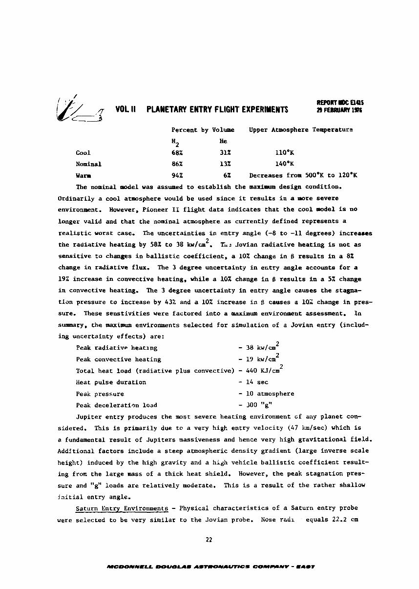
Percent by Volume Upper Atmosphere Temperaturr
H2 lie
Cool 68% 31% l l O ° K
Nominal 86% 13% 140°K
Warm 942 6% Decreases from 500°K t o 120°K
The nominal m d e l was a s s m d t o e s t a b l i s h t h e maximum design condition.
Ordinar i ly a cool atmosphere would be used s i n c e it r e s u l t s i n a more severe
environlseat. However, Pioneer 11 f l i g h t d a t a ind ica tes t h a t t h e cool model is no
longer va l id and t h a t the nominal atmosphere a s cur ren t ly defined represents a
realistic worst case, The uncer ta in t ies i n en t ry angle (-8 t o -11 degrees) incre-s 2 the r ad i a t i ve hea t ing by 58X t o 38 ku/un . Ti.2 Jovian r a d i a t i v e hea t ing is not as
s e n s i t i v e Co changes i n b a l l i s t i c coe f f i c i en t , a 10% change i n 8 r e s u l t s i n a 8%
change i n r ad i a t i ve flux, The 3 degree uncertaint-g i n eritry angle accounts f o r a
19% increase i n convective heating, while a 10% change i n 8 r e s u l t s i n a 5% change
i n convective heating, The 3 degree uncertainty i n en t ry angle causes t h e stagna-
t i on pressure t o increase by 432 and a 10% increase i n $ causes a 102 change i n pres-
sure. These s e n s t i v i t i e s w e r e factored i n t o a maximum environment assessment. I n
summary, the maximum environments se lec ted f o r s imulat ion of a Jovian en t ry (includ-
ing uncertainty e f f e c t s ) are:
Peak r ad i a t i ve heat ing - 38 kwlcm 2
Peak convective heat ing - 13 kw/cm 2
Total heat load ( r ad i a t i ve plus convective) - 440 KJ/cm 2
Heat pulse durat ion - 14 sec
Peak pressure - 10 atmosphere
Peak dece le ra t ion load - 300 "g"
Jup i t e r en t ry produces the most severe heat ing environment cf any p lane t con-
sidered, This is primarily due te a very high entry ve loc i ty (47 Zim/sec) which is
a fundamental r e s u l t of Jup i t e r s massiveness and hence very high g rav i t a t i ona l f i e l d .
AddStional f ac to r s include a s t eep atmospheric dens i ty gradient ( la rge inverse s c a l e
height) induced by the high grav i ty and a high vehic le b a l l i s t i c coe f f i c i en t r e su l t -
ing f roa the l a rge mass of a th ick heat sh ie ld . However, t he peak s tagna t ion pres-
sure and "g" loads a r e r e l a t i v e l y moderate. This is a r e s u l t of the r a t h e r shallow
j a i t i a l entry angle.
Saturn Entry Environments - Physical c h a r a c t e r i s t i c s of a Saturn en t ry probe
were se lec ted t o be very s imi l a r t o the Jovian probe. Nose rhai , equals 22.2 cm
MC001YHaU -&AS AS-LIUWCS COMMNV - mAmT
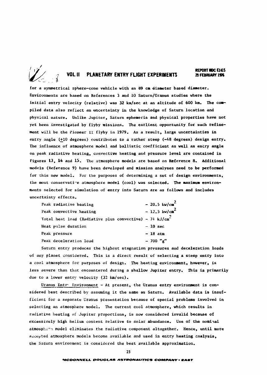
fo r a syr~setrical sphere-cone vehic le with an 89 c m diameter based diameter.
Environments a r e based on References 3 and 10 SaturnIUranus s t u d i e s where t he
i n i t i a l en t ry ve loc i ty ( r e l a t i ve ) w a s 32 blsec a t an a l t i t u d e of 600 b, The cop-
p i led da t a a l s o r e f l e c t an uncer ta in ty i n the knowledge of Saturn l oca t ion and
physical nature, Unlike Jup i t e r , Saturn ephemeris and physical p roper t ies have not
ye t been invest igated by flyby missions, The e a r l i e s t opportunity f o r such re f ine-
ment w i l l be t he Pioneer 11 flyby i n 1979. As a r e s u l t , l a r g e unce r t a in t i e s i n
en t ry angle (+lo - degrees) cont r ibu tes t o a r a t h e r s t eep (-48 degrees) design entry.
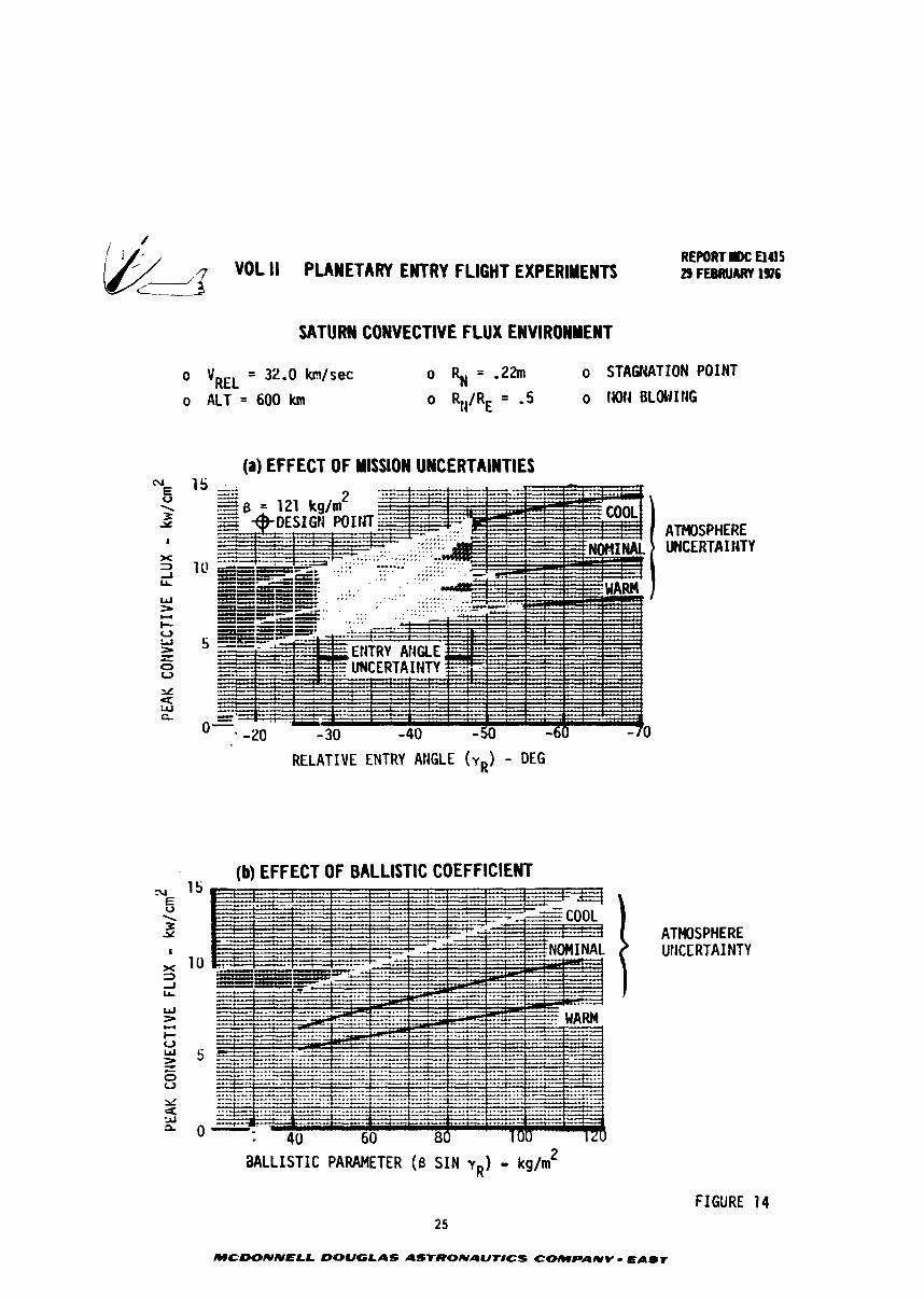
The inf luence of atmosphere model and b a l l i s t i c coe f f i c i en t as wel l as en i ry aag l e
on peak r ad i a t i ve heating, convective heat ing and pressure l e v e l are contained i n
Figures 13, 14 and 15. The atmosphere models a r e based on Reference 8, Additional
models (Reference 9) have been developed and mission analyses need t o be performed
f o r t h i s new model. For the purposes of determining a set of design environments,
the most conservati-e atmosphere model (cool) w a s se lec ted , The max- environ-
ments se lec ted f o r s imulat ion of en t ry i n t o Saturn are as fo l lovs and includes
uncertainty e f f ec t s .
Peak r ad i a t i ve heat ing - 20.5 kw/cm 2
Peak convective heat ing - 12.5 kwlcm 2 9
Total heat load (Radiative plus convective) - 74 kJ/cm"
Heat pulse durat ion - 10 sec
Peak pressure - 18 atm
Peak dece le ra t ion load - 700 "g"
Saturn en t ry produces the highest s tagna t ion pressures and dece le ra t ion loads
of any p lane t considered. This is a d i r e c t r e s u l t of s e l e c t i n g a s t eep en t ry i n t o
a cool atmosphere fo r purposes of design, The hea t ing environment, however, is
less severe than tha t encountered during a shallow J u p i t e r entry. This is p r h a r i l y
due t o a lower entry ve loc i ty (32 km/sec).
Uranus Entr- Environment - A t present, t h e Uranus en t ry environament is con-
s idered bes t described by assuming i t the same as Saturn, Available d a t a is insuf-
f i c i e n t f o r a separa te Uranus presentat ion because of s p e c i a l problems involved i n
s e l ec t i ng an atmosphere model. The cur ren t cool atmosphere, which r e s u l t s i n
r ad i a t i ve hea t ing of J u p i t e r proportions, is now considered inva l id because of
excessively high helium content r e l a t i v e t o s o l a r abundance. Use of the norai-tal
atmospk=r,: model e l iminates the r ad i a t i ve component a l together . Hence, u n t i l more
aicepted atmosphere models become ava i l ab l e and used i n en t ry hea t ing zna lys i s ,
the Saturn envirorrment i s considered the bes t ava i l ab l e approximation.
WCDONNELL DOUGLAS ASTRONAUtrCS COMPIUV - E A I t
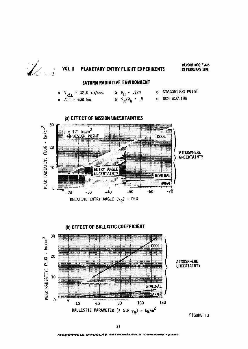
-. VOL II PLANETARY ENTRY FLIGHT EXPERIMENTS
SATURN RADIATIVE ENVIRONMENT
o VREL = 32.0 h / s % o RH = .ZZm
o ALT = 600 km o RI,/RII = .5
(a) EFFECT OF YISSION UNCERTAINTIES
o STABIATIOII POINT
o t.10l4 BLC'.lI1iG
ArnPHERE UliCERTA I NTY
(b) EFFECT OF BALLISTIC COEFFICIENT
---. ...-...- ..............--. .-- 40 60 80 100 1 20
BALLISTIC PARAMETER (5 S I N yR) - kg/m2
24
MCDOIYIVELL W U G L A S ASTlPOlYAUtlCS COMPANY - EAST
/
3 VOL II PLANETARY ENTRY FLIGHT EXPERIMENTS -- SATURN CONVECTIVE FLUX ENVIROWMENT
(a) EFFECT OF Y ISSlON UNCERTAINTIES
RELATIVE ENTRY ANGLE ( Y ~ ) - DEG
- .. (b) EFFECT OF BALLISTIC COEFFICIENT
REPORTDC El45 29 FEBRUARY 1976
o STAGIiATION POINT
0 14014 oLwInG
ATHOSPHERE UHCERTAIIJTY
ATMOSPHERE UIICCRTAINTY
MLLISTIC PARAMETER (6 SIN yR) - kg/m2
FIGURE 14
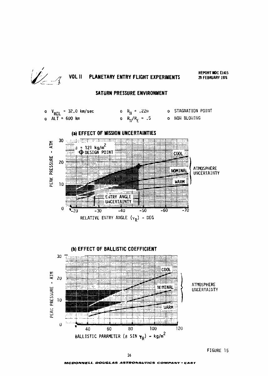
VOL II PLANETARY ENTRY FLIGHT EXPERIMENTS - -
o VREL = 32.0 krnlsec
o ALT = 600 krn
SATURN PRESSURE ENVIRONMENT
REPORT MDC El415 29 FEBRUARY 1976
(a) EFFECT OF MiSSlON UNCERTAINTIES ?A ..... ; ; .-.-.. :. .... ..A L.--I--.._r.. ..--. r * L. ...-.....
RELATIVE ENTRY AilGLE (vR) - DEG
(b) EFFECT OF BALLISTIC COEFFICIENT
FIGURE 15 26
MCDONNELL DOUGLAS ASTRONAUT8CS COMPAWV - ELIST
REPORT IW: u4lS VOL II PLANETARY ENTRY FLIGHT EXPERIMENTS 29 FLBRUARV 1 s
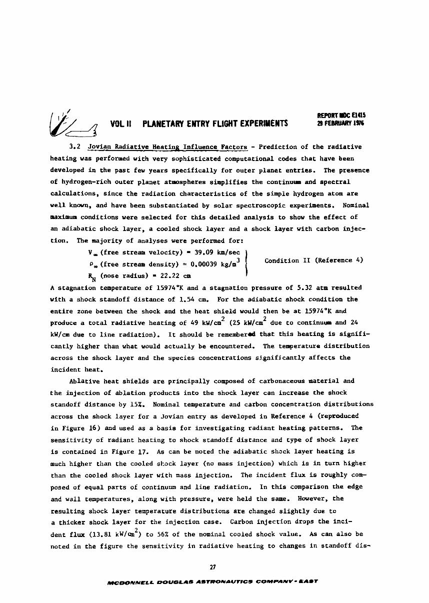
3.2 Jovian Radiative Heating Influence Factors - Predic t ion of t he r a d i a t i v e
heat ing w a s performed with very sophis t ica ted computational codes t h a t have been
developed i n the p a s t few years s p e c i f i c a l l y f o r ou t e r p lane t en t r i e s . The presence
of hydrogen-rich ou te r p l aae t atmospheres s imp l i f i e s t he continuum and s p e c t r a l
ca lcu la t ions , s i nce the r ad i a t i on c h a r a c t e r i s t i c s of the simple hydrogen atom are
w e l l known, and have been subs tan t ia ted by s o l a r spectroscopic experiments. Nominal
maximum condi t ions were se l ec t ed f o r t h i s de t a i l ed ana lys i s t o show t h e e f f e c t of
an ad i aba t i c shock layer , a cooled shock l aye r and a shock l aye r with carbon injec-
tion. The majority of analyses w e r e performed for :
V, ( f r ee stream ve loc i ty) = 39.09 km/sec
f r e e stream densi ty) = 0.00039 kg/m3 I Condition 11 (Reference 4)
% (nose radius) = 22.22 cm I
A s tagna t ion temperature of 15974OK and a s tagna t ion pressure of 5.32 a t m r e su l t ed
with a shock s tandoff d i s t ance of 1.54 cm. For the ad i aba t i c shock condi t ion t h e
e n t i r e zone between the shock and the heat sh i e ld would then be a t 1 5 9 7 4 * ~ and 2 2 produce a t o t a l r ad i a t i ve heat ing of 49 k ~ / c m (25 k ~ / c m due t o continuum and 24
kW/cm due t o l i n e radiat ion) . It should be rememberd t h a t t h i s hea t ing is s i g n i f i -
can t ly higher than what would ac tua l ly be encountered. The teraperature d i s t r i b u t i o n
across the shock l aye r and the spec ies concentrations s i g n i f i c a n t l y af f e c t s t he
incident heat.
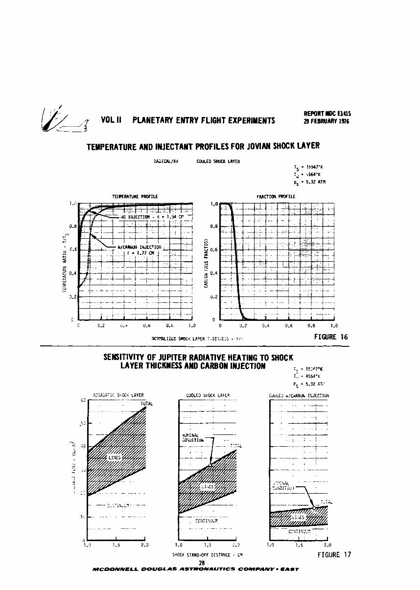
Ablative hea t s h i e l d s a r e pr inc ipa l ly composed of carbonaceous mater ia l and
t h e i n j ec t i on of ab l a t i on products i n t o the shock l aye r can increase t he shock
standoff d i s tance by 15%. Nominal temperature and carbon concentrat ion d i s t r i b u t i o n s
across t he shock l aye r f o r a Jovian en t ry as developed i n Reference 4 (reproduced
i n Figure 16) and used as a b a s i s f o r inves t iga t ing rad ian t heat ing pat terns . The
s e n s i t i v i t y of rad ian t heat ing t o shock standoff d i s tance and type of shock l aye r
is contained i n Figure 17. As can be noted the ad i aba t i c shock l aye r hea t ing is
much higher than the cooled skock l aye r (no mass i n j ec t i on ) which is i n tu rn higher
than the cooled shock l aye r with mass in jec t ion . The inc ident f l u x is roughly com-
posed of equal p a r t s of continuum and l i n e radiat ion. I n t h i s comparison the edge
and wal l temperatures, along with pressure, were held the same. However, the
r e su l t i ng shock l aye r temperature d i s t r i b u t i o n s are changed s l i g h t l y due t o
a th icker shock l aye r f o r the i n j e c t i o n case. Carbon i n j e c t i o n drops t he inc i - 2
dent f l u x (13.81 kW/m ) t o 56% of the nominal cooled shock value. As can a l s o be
noted i n the f i gu re the s e n s i t i v i t y i n r ad i a t i ve heat ing t o changes i n standoff dis-
REPORT I D C UUS Y O 1 11 PUNETARY ENTRY FLIGHT EXPERIMENTS 29 FEBRUARY 196 ---
TEMPERATURE AND INJECTANT PROFILES FOR JOVIAN SHOCK LAYER i U I U L / 6 J U E D WOtK LAVER
, , . . . . . . , i : :
, z . . . , , . , . , . . , . . . . ' .
-- - - - *-. ----*-- i -;--.a ..A . - - i . . . . . , ! ' C j ' I - '
0 0.2 0.0 U.b it. h 1.0
!iCR?"IZLO SW< LAVER i.:IC'<;E;S - v l i FIGURE
SENSITIVITY OF JUPITER RADIATIVE HEATING TO SHOCK LAYER THICKNESS AND CARBON INJECTION i? = 15?f17°K
7,. = 4564°K
PS = 5.32 CTi-
R i A C A T I I : SI'OCS LAYER f' r----TjAL C30LE3 S1.0tK LAVE?
. .
SHOCK STAND-OFF DISTANCE - cv FIGURE 28
MCIDONNELL DOUGLAS ASZRONAUr8CS COMPANY - EA@T
REPORT R C El45 & VOL II PUHETARI ENTRY FLIGHT EXPERMEITS 29 F E ~ U A R Y 1s6
tance is much less f o r carbon in fec t ion than e i t h e r t he ad i aba t i c o r cooled case.
The s e n s i t i v i t i e s of r ad i a t ive heat ing t o va r i a t i ons i n flow f i e l d conditions w i l l
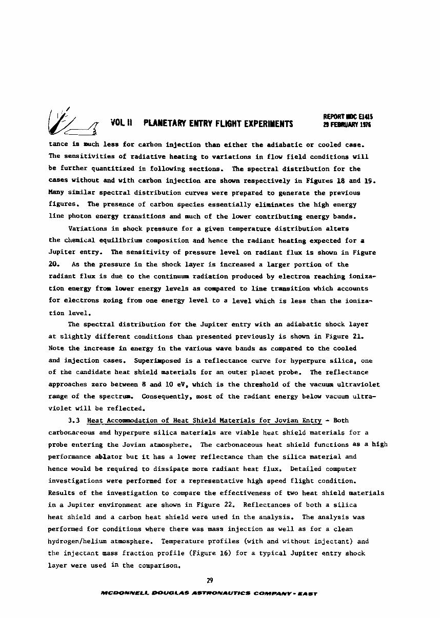
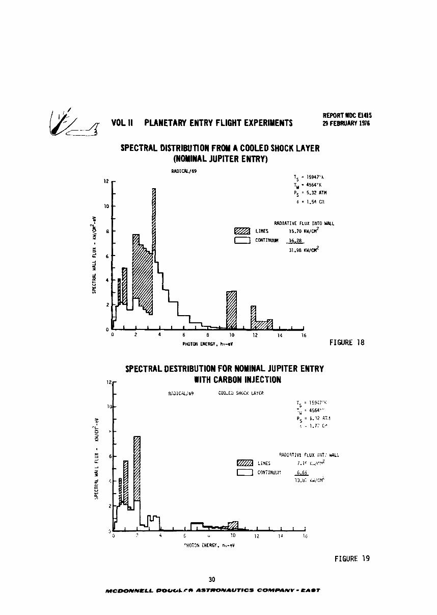
be fu r the r quant i t ized i n f o l l w i n g sections. The s p e c t r a l d i s t r i b u t i o n f o r t he
cases without and with carbon in j ec t ion are shown respect ively i n Figures 18 and 19.
Many similar s p e c t r a l d i s t r i b u t i o n curves w e r e prepared t o generate the previous
figures. The presence of carbon species e s s e n t i a l l y el iminates t he high energy
l i n e photon energy t r ans i t i ons and much of t h e l w e r cont r ibu t ing energy bands.
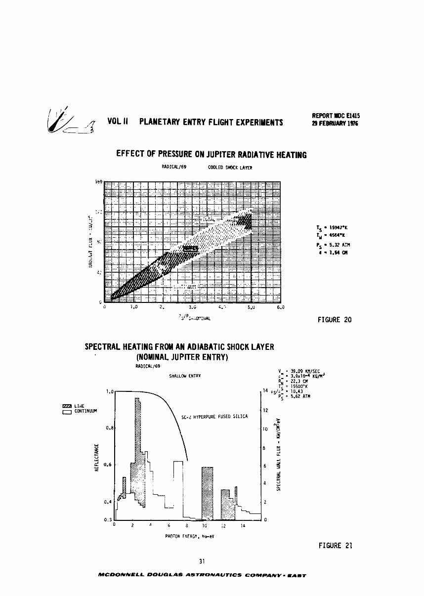
Variations i n shock pressure f o r a given temperature d i s t r i b u t i o n alters
the d~emical equilibrium composition and hence t h e rad ian t heat ing expected f o r o
Jup i t e r entry. The s e n s i t i v i t y of pressure l e v e l on rad ian t f l u x is shown i n Figure
20, As the pressure i n t he shock l aye r is increased a l a rge r port ion of t he
rad ian t f l u x is due t o t he continuum rad ia t ion produced by e l ec t ron reaching ioniza-
t i o n energy f r m lower energy l e v e l s as compared t o l i n e t r a n s i t i o n which accounts
f o r e lec t rons noing from one energy level t o a l e v e l which is less than the ioniza-
t i on level.
The s p e c t r a l d i s t r i b u t i o n f o r the J u p i t e r en t ry with an adiaba t ic shock l aye r
a t s l i g h t l y d i f f e r e n t conditions than presented previously is shown if. Figure 21,
Note the increase i n energy i n t h e various wave bands as compared to t h e cooled
and in j ec t ion cases. Superimposed is a ref lec tance curve f o r hyperpure s i l i c a , one
of the candidate heat sh i e ld materials f o r an outer planet probe, The re f lec tance
approaches zero between 8 and 10 e V , which is t h e threshold of the vacuum u l t r a v i o l e t
range of the spectrum. Consequently, most of t h e rad ian t energy below vacuum ul t ra -
v i o l e t w i l l be ref lected.
3.3 Heat Accormmdation of Heat Shield Materials f o r Jovian Entry - Both
carbor.aceous and hyperpure s i l i c a mater ia l s a r e v i ab le hea t sh i e ld mater ials f o r a
probe en ter ing the Jovian atmosphere, The carbonaceous heat sh i e ld funct ions a s a high
performance ab3ator bu t i t has a lower re f lec tance than the s i l i c a mater ia l and
hence would be required t o d i s s i p a t e more r ad i an t heat flux. Detailed computer
inves t iga t ions were performed f o r a representa t ive high speed f l i g h t condition.
Results of the inves t iga t ion t o compare the e f fec t iveness of two heat sh i e ld mater ia l s
i n a Jup i t e r environment a r e shown i n Figure 22. Reflectances of both a s i l i c a
heat sh i e ld and a carbon hea t sh i e ld were used i n the analysis . The ana lys is was
performed f o r condit ions where there w a s mass in j ec t ion a s wel l a s f o r a clean
hydrogen/helium atmosphere. Temperature p r o f i l e s (with and without i n j ec t an t ) and
the i n j e c t a n t mass f r ac t ion p r o f i l e (Figure 16) f o r a typ ica l J u p i t e r en t ry shock
layer were used i n the comparison.
REPORT ldOC El415 VDL I1 PLANETARY ENTRY FLIGHT EXPERIYENTt 29 FEBRUARY 1976
SPECTRAL blSTRlBUTlON FROM A COOLED SHOCK LAYER (NOMINAL JUPITER ENTRY)
Ts = 15947'L 12
T,, = 4564'K
Ps = 5.32 ATH
6 = 1.54 C:1 10
> i
N RADIATIVE FLUX IHTO MALL
8 LIHES 15.70 KU/& i+ a C M I M U U M 16.28 t
x a 31 -98 KU/Ct?
6 2
2 x
4 U W k "3
2
0 0 2 4 6 8 10 12 14 16
PHOTW ENERGY, hu-ev FIGURE 18
SPECTRAL DESTRIBUTION FOR NOMINAL JUPITER ENTRY VlTH CARBON INJECT ION
"HOTON INERGY, nv-cV
FIGURE 19
,:- VOL ll PLANETARY ENTRY FLIGHT EXPERIMENTS REPORT NDC a415 29 FEBRUARY 1976
L--
EFFECT OF PRESSURE ON JUPITER RADIATIVE HEATING RADICAL/69 COOLEO SHOCK LAYER
SPECTRAL HEATING FROM AN ADIABATIC SHOCK LAYER (NOMINAL JUPITER ENTRY) RADICAL169
SHALLOU EWTRV
A 6 8 10 12 14
PHOTON F I I E R G Y , hu-eV
FIGURE 20
39.09 M/SEC 3.9~10-4 KG/M' 22.3 CM 15500'K 10.43 5.62 ATM
FIGURE 21
MCDONNELL DOUGLAS ASTRONAUrtCS COMPANY - EAST
(j/j --/3 VOL II PLANETARY ENTRY FLIGHT EXPERIMENTS c__
REPORT MDC E 1415 29 FEBRUARY 1916
RADIANT HEATING COMPARISON OF SEVERAL INJECTANTS IN JUPITER ENTRY SHOCK LAYER
ATNOSPHERIC CWOSITIO~~ (UEIGHT FRACTION) tiELlUM (He) 0.21 HYDROGEN (ti2) 0.79
TS = 15947OK
PS = 5.32 ATM
FIGURE 22
32 MCDONNELL DOUGLAS ASrROIVAUflCS COMPANY - EAbT
a
NO INJECTANT
SILICON (Si ) INJECTION SILICA ABSORPTANCE
T,, = 3450°K
SILICON ( S i ) INJECTION ABSURPTATICE = 0.5
TW = 3450°K --
SILICA (Si02) IHJECTION
SILICA ADSORPTANCE TW = 3450°K
CARBON (C) It4JECTIOll ADSORPTANCE = 0.8 iW = 4564OK
: ~ T A ~ : ~ ~ O R (KWICM~)
I
0.376
10.521
I
0.973
9.080
A
(FLUX AWAY FROM WALL (KWICM~) 7
FLUX TOUARD UPLL (KUIC#)
COIJTI ~ ~ U U M
13.210
7.191
12.692
TOTAL
31.980
21.853.
21.853
24.252
13.810
CONTI~IUUH
16.280
13.577
13.577
13.182
6.650
LINES
8.267 ,
4.141
10.586
' LINES
15.700
8.275
8.275
11.070
7.160
TOTAL
21.477
11.332
23.279
4.730
- VOL II PLANETAR ENTRY FLIGHT EXPERIMENTS REPORT rDC El415 29 FEBRUARY 1916
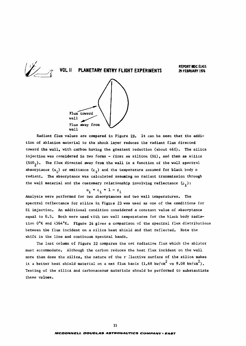
/ Flux towzrd w a l l / Flux away from w a l l
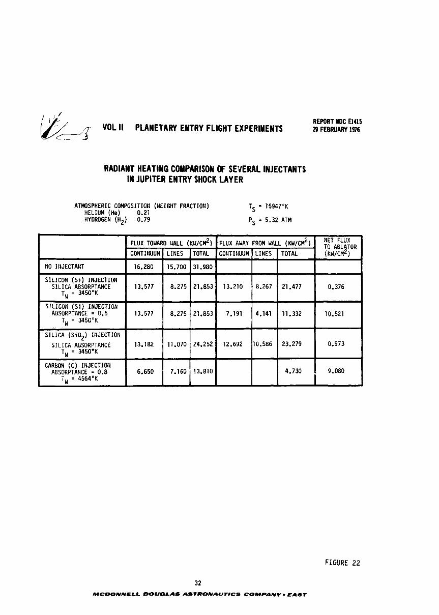
Radiant f l u x va lues are compared i n Figure 22, It can be seen t h a t t h e addi-
t i o n of a b l a t i o n material t o t h e shock l a y e r reduces t h e r a d i a n t f l u x d i r e c t e d
toward t h e wa l l , wi th carbon having t h e g r e a t e s t r educ t ion (about 46X). The s i l i c a
i n j e c t i o n w a s considered i n two forms - f i r s t a s s i l i c o n (S i ) , and then as s i l i c a
(Si02). The f l u x d i r e c t e d away from t h e w a l l is a func t ion of t h e w a l l s p e c t r a l
absorptance (ai) o r emit tance (ci) and t h e temperature assumed f o r b lack body o
rad ian t . The absorptance was c a l c u l a t e d assuming no r a d i a n t t ransmiss ion through
t h e w a l l material and t h e customary r e l a t i o n s h i p involving r e f l e c t a n c e (pi) :
a ' E - 1 - i i 'i
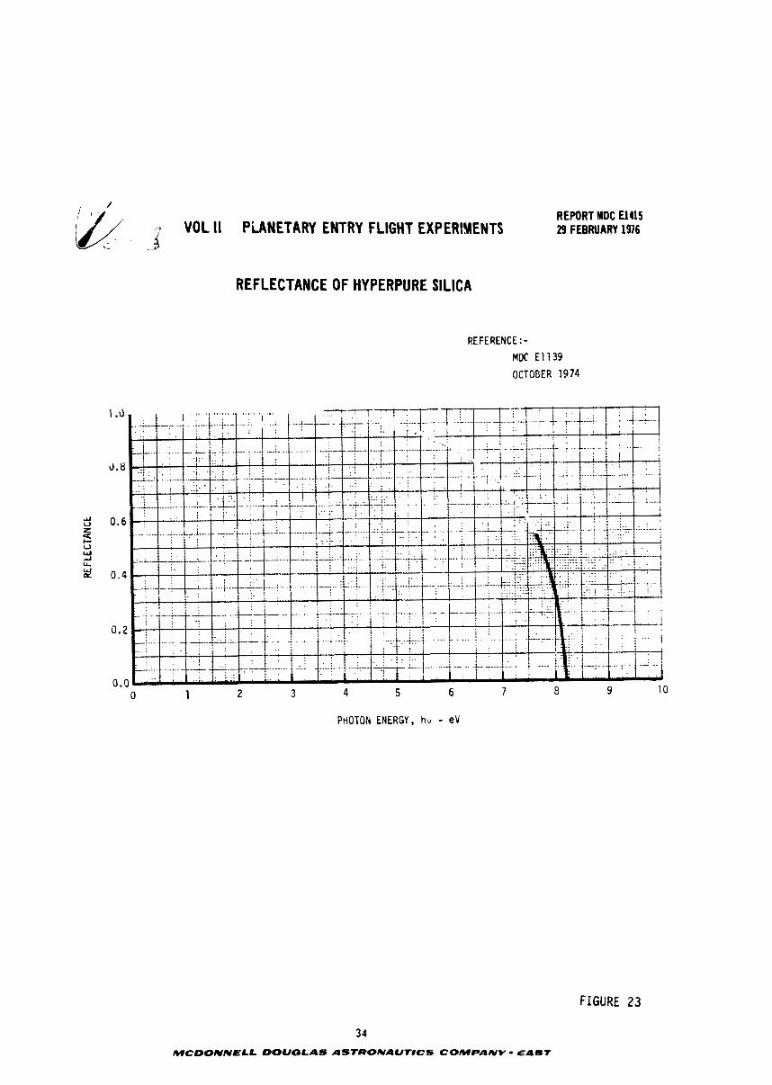
Analysis were performed f o r two absorptances and two w a l l temperatures. The
s p e c t r a l r e f l e c t a n c e f o r s i l i c a i n F igu le 23 was used as one of t h e cond i t ions f o r
S i i n j e c t i o n . An a d d i t i o n a l cond i t ion considered a cons tan t va lue of absorptance
equa l t o 0.5. Both were ueed k:ith two w a l l temperatures f o r t h e b lack body radia-
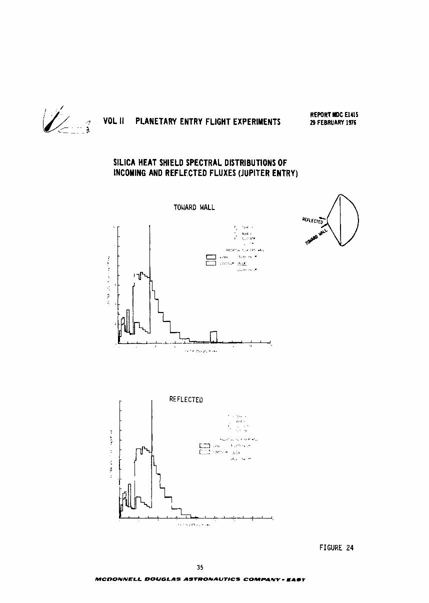
t i o n O°K and 4564OK. Figure 24 g i v e s a comparison of t h e s p e c t r a l f l u x d i s t r i b u t i o n s
between the f l u x i n c i d e n t on a ~ i l i c a h e a t s h i e l d and t h a t r e f l e c t e d . Note t h e
s h i f t i n t h e l i n e and continuum s p e c t r a l bands.
The last column of Figure 22 compares t h e n e t r a d i a t i v e f l u x which t h e a b l a t o r
must accommodate. Although t h e carbon reduces t h e hea t f l u x i n c i d e n t on t h e w a l l
more than does t h e s i l i c a , t h e n a t u r e of t h e r . 2 l e c t i v e s u r f a c e of t h e s i l i c a makes 2 2
it a b e t t e r h e a t s h i e l d m a t e r i a l on a n e t f l u x b a s i s (1.68 kw/cm v s 9.08 kw/cm ).
Tes t ing of t h e s i l i c a and carbonaceous m a t e r i a l s should be performed t o s u b s t a n t i a t e
these values.
3 3
MCDONNELL DOUGLAS ASTRONAUT8CS COMPANY - E A m T
VOL ll PLANETARY ENTRY FLIGHT EXPERiYENTS C
REPORT MDC El415 29 FEBRUARY 1976
REFLECTANCE OF HYPERPURE SILICA
REFERENCE : - MDC El139
OCTOBER 1974
PHOTON ENERGY, hv - eV
FIGURE 23
3 4
McDONNELL DOUGLAS ASTRONAUTlCS COMPANV - EAST
7 VOL II PLANETARY ENTRY FLIGHT EXPERIMENTS ,-- - 2
C--- - - -.
SILICA HEAT SHIELD SPECTRAL DISTRIBUTIONS OF INCOMING AND REFLECTED FLUXES (JUPITER ENTRY)
TOUARD WALL
REPORT MDC El415 29 FEBRUARY 1976
FIGURE 24
3 5
MCOONNELL DOUGLAS ASTRONAUTICS COMPANY - E A l T
, : REPO#Tmc Elus 9- VOL II PLANETARY ENTRY FLIGHT EXPERIMENTS 29 F€BMJARY 1316
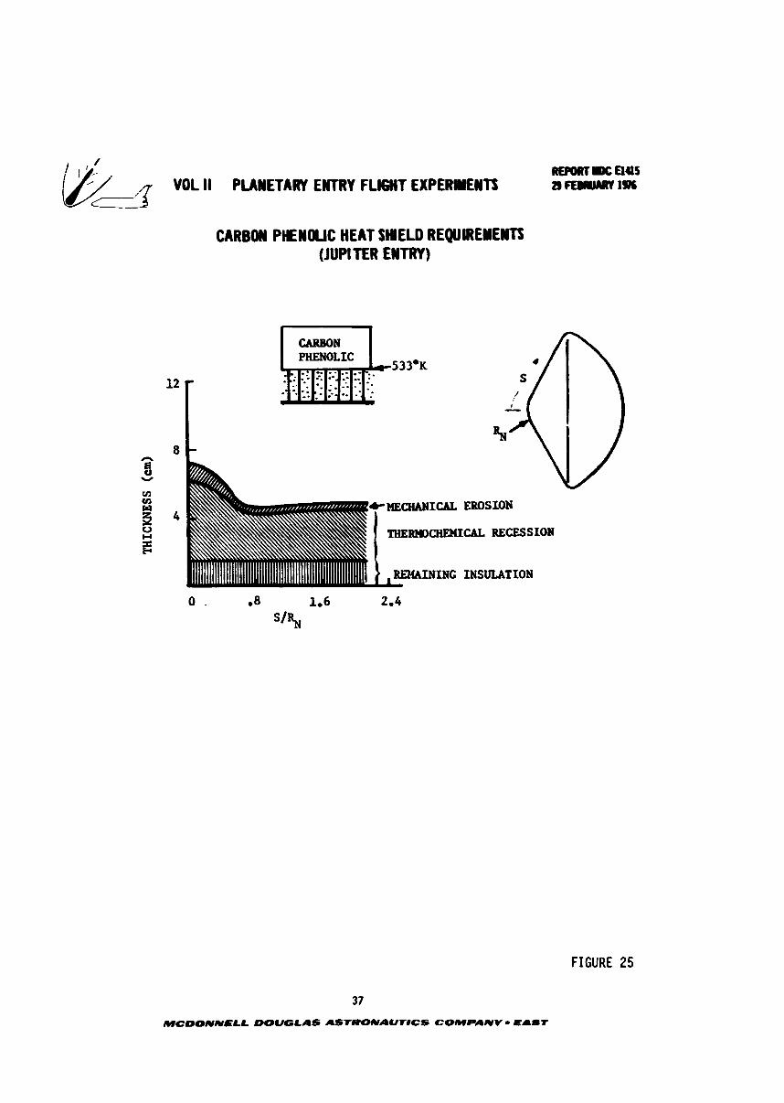
3.4 Carbon Phenolic H e a t Shield Sizing (Jovian Hission) - Detailed ana lys is
of heat sh ie ld requirements have been made by Jovian entry probe designers. The
e f f e c t s of eechanical erosion, themchemica l recession and the heat sh i e ld insula-
t i on were included i n the ana lys is t o l i m i t the bondline t o 533°K. Current designs
of a carbon phenolic heat sh i e ld relay on maintaining the adhesive i n t e g r i t y betveen
carbon phenolic layer and the honeycomb support s t ructure. Adhesives used f o r t h i s
purpose a r e l imited t o 533°K. As can be seen f r o r Figure 25 approximately 7.2 cm
of carbon phenolic a r e required f o r the s tagnat ion point (S/s = 0) and 5.0 cm on
the cone.
REPORT U 0 4 5 VOL ll PIAWETAR' E#TRV FLIGHT EXPERYEWTS a FEB~WRY I%
CARBON PHENWC HEAT SHEUI REQUREYEm (JUPITER ENTRY)
12
8 h
3 w
V1 cn
klECHANICAL EROSION
U
E 'RiEIZBUEHICAL RECESSION
INING INSULATION
FIGURE 25
37
MCDONNELL DOUGLAS ASTRONAUT8CS COMPANY - EaUT
RL#)RTIW: aas WL II PUIIETARY EWTRV FLWT EXPERIYE#TS a~~mwt~l%
4.0 EABM EHTRY ENVIRO~EBT SXWLATION cAPmnxn One of t he prime objec t ives of t h i s study centers on obtaining environments
during a high speed ent ry on e a r t h which are similar t o those predicted f o r an
outer planet probe. Horeover i t is important t o understand the c h a r a c t e r i s t i c s
of the envirollrents, t he s e n s i t i v i t y t o changes in e n t r y conditions, f law f i e l d
conditions, and heat s h i e l d design, Because of t h e intense rad ia t ive heat ing pre-
d ic ted f o r Jovian entry, the understanding of t h i s pa ra ra t e r during an e a r t h en t ry
is necessary. To these ends maps of entry environeents, s e n s i t i v i t y s tud ies , shock
layer ana lys is and heat sh i e ld perfot lance evaluat ions were performed f o r high
speed e a r t h en t ry f l igh ts .
4.1 Non-Blaring E a r ~ h Entry Environments - The environeents t h a t can be pro-
duced by high speed entry i n t o the e a r ~ h ' s atmosphere are presented i n t h i s sect ion,
Data are shown f o r the range of initial ent ry condit ions general ly a t t a i n a b l e by
Shut t le launched boosters. This i n f o r m t i o n i d e n t i f i e s the capab i l i t y of e a r t h
f l i g h t s t o siaulate planetary entry environment and the associated initial en t ry
conditions . The environmental parameters shown are in t en t iona l ly t he s;aa as those used
previously t o descr ibe the placetary entry environment. Stagnation poin t heat ing
cha rac t e r i s t i c s are emphasized but do not include the e f f e c t of re-radiat ion o r
boundary layer mass inject ion. These e f f e c t s w i l l be assessed i n later sect ions.
The range of i n i t i a l e a r t h en t ry veloci ty needed t o s imulate planetary heat ing
is much lover than ac tua l planetary mission en t ry ve loc i t ies . This is due t o d i f -
ferences i n atmosphere composition. The outer planet atmospheres are composed
primarily of hydrogen-helium mixtures a t about t h e s o l a r abundance r a t i o , whereas
the ea r th atmosphere is nearly 21 percent oxygen and 79 percent nitrogen. From
basic thermodynamics it is known t h a t the low molecular weight gases, hydroges and
hzlium, have a much higher heat capacity than a i r . Thus simulation of s imi l a r
shock layer temperatures o r heat ing r a t e s i n air requi re a much lower en t ry speed
than t h a t of planetary en t r ies . The higher molecular weight of a i r also r e s u l t s
i n a s teeper atmospheric densi ty gradient which enhances simulation of t he peak
environment conditions but reduces the heat ing duration.
A 3 degree of freedom point mass t r a j ec to ry computer program was used t o
compute e a r t h en t ry t r a j ec to r i e s . The e a r t h model was a sphe r i ca l ro t a t ing ear th.
A l l t r a j e c t o r i e s began a t 121.92 km with the i n e r t i a l ve loc i ty and f l i g h t path
angle defined. In addi t ion t o computing a l t i t u d e , ve loc i ty , f l i g h t path angle,
l a t i t ude , longitude and heading a s a funct ion of reentry time, the program a l s o
REPORT mc nas
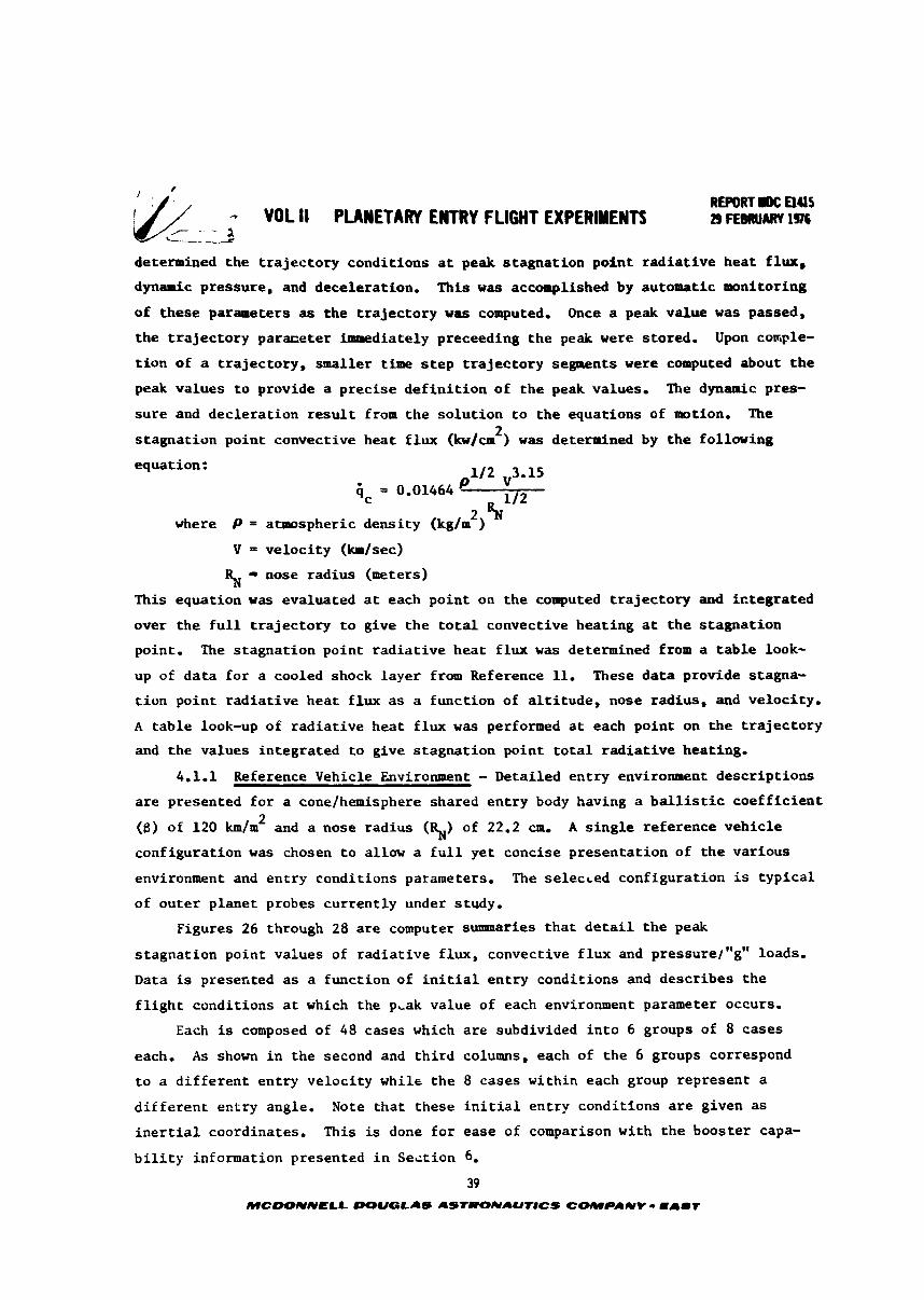
(k/ - VOL II PLANETARY ENTRY FLIGHT EXPERINENTI a F E ~ J A R Y 1% /-- ---2 ---
determined the t r a j ec to ry condi t ions a t peak s tagnat ion poin t r a d i a t i v e hea t f lux,
dynamic pressure, and deceleration. This w a s accomplished by automatic monitoring
of these parameters as the t r a j ec to ry w a s computed. Once a peak value w a s passed,
the t r a j e c t o r y p a r m e t e r immediately preceeding t h e peak were stored. Upon corriple-
t i o n of a t r a j ec to ry , smaller t h e s t e p t r a j e c t o r y segments were computed about t h e
peak values t o provide a prec ise d e f i n i t i o n of t h e peak values. The dynamic pres-
s u r e and dec le ra t ion r e s u l t from the so lu t ion t o t h e equations of motion. The 2 s tagna t ion point convective hea t f l u x ( k w / o ) w a s determined by t h e f o l l w i n g
equation:
2 aN where P = atmospheric dens i ty (kglm )
V = veloc i ty ( b l s e c )
5 - nose rad ius (meters)
This equation was evaluated a t each poin t on t he computed t r a j ec to ry and i c t eg ra t ed
over t he f u l l t r a j ec to ry t o give t h e t o t a l convective hea t ing a t t h e s tagna t ion
point. The s tagna t ion point r a d i a t i v e hea t f l u x w a s determined from a t a b l e look-
up of da ta fo r a cooled shock l aye r from Reference 11. These da t a provide stagna-
t i o n point r ad i a t i ve hea t f l ux as a funct ion of a l t i t u d e , nose radius , and veloci ty .
A t ab l e look-up of r ad i a t i ve heat f l u x w a s performed a t each point on t h e t r a j e c t o r y
and the values in tegra ted t o give s tagna t ion poin t t o t a l r a d i a t i v e heating.
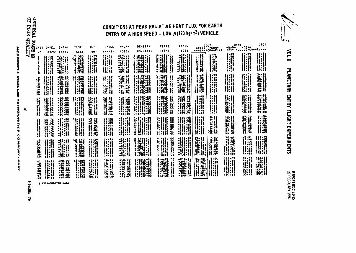
4.1.1 Reference Vehicle Environment - Detai led en t ry environment descr ip t ions
a r e presented f o r a cone/hemisphere shared en t ry body having a b a l l i s t i c coe f f i c i en t 2 (6) of 120 km/m and a nose radius (%) of 22.2 CIU. A s i n g l e reference veh ic l e
configurat ion was chosen t o allow a f u l l ye t concise presen ta t ion of t h e var ious
environment and en t ry condi t ions parameters. The se l ec i ed configurat ion is typ i ca l
of ou te r planet probes cur ren t ly under study,
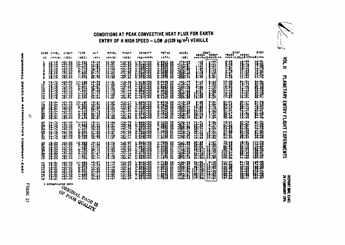
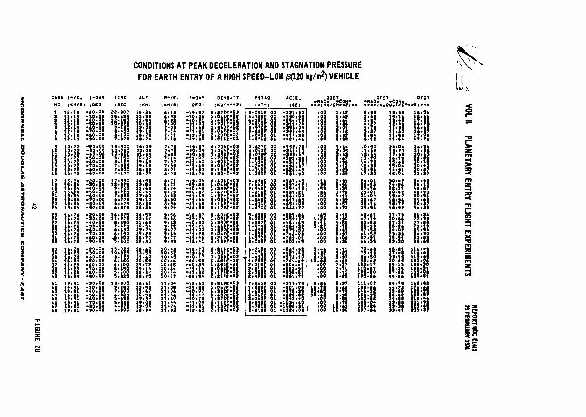
Figures 26 through 28 a r e computer summaries t h a t d e t a i l t h e peak
s tagna t ion point values of r ad i a t i ve f lux , convective f l u x and pressure~"g" loads.
Data is presented a s a funct ion of i n i t i a l en t ry condi t ions and descr ibes t h e
f l i g h t condi t ions a t which the p,ak value of each environment parameter occurs,
Each is composed of 48 cases which a r e subdivided i n t o 6 groups of 8 cases
each. A s shown i n the second and t h i r d columns, each of t he 6 groups correspond
t o a d i f f e r e n t en t ry ve loc i ty while t h e 8 cases within each group represent a
d i f f e r e n t en t ry angle. Note t ha t these i n i t i a l en t ry condi t ions are given a s
i n e r t i a l coordinates. This is done f o r ease of comparison with t h e booster capa-
b i l i t y information presented i n Se i t i on 6.
39 MCWNNELL DOUQLAS ASTUOICTAUTDCS COMPANY - E A I T
REPORT rW: U
4lS 29 FEBRUARY 1976
.-7 VOL II
PLANETARY ENTRY FLIGHT EXPERIM
ENTS
ORIG
INAL P&E Is
OF POOR QUALITY FIG
URE 26
MC
DO
NN
EL
L D
OU
GL
AS
AS
TR
ON
AU
T#
CS
CO
MP
AN
Y - E
AS
T
& ,
VOL II PLANETARY ENTRY FLIG
HT LXPERIYEWTS
41 FIG
URE 27 M
CW
NN
EL
L D
OU
GL
AS
A
ST
RO
NA
UflC
S
CO
MP
AN
V - E
AS
T
VOL II PLANETARY ENTRY FLIG
HT EXPERIYENTS
-Char
LU.YM*
U(l)*r.gU
I OM-
-..----- *.----..
FIGURE 28
MC
DO
NN
EL
L D
OU
GL
AS
AS
fRO
NA
UT
ICS
C
OM
PA
NY
- EA
mT
REFORT IDC aas - VOL II PLANETARY ENTRY FLIGHT EXPERIMENTS b FEBRUARY IS
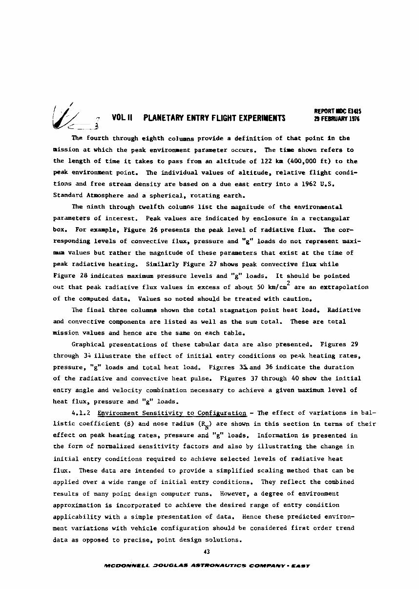
The four th through e igh th c o l m n s provide a d e f i n i t i o n of t h a t po in t i n t h e
mission a t which the peak e n v i r o m n t parameter occurs. The time shown r e f e r s t o
the length of t i m e i t takes t o pass from an a l t i t u d e of 122 km (400,000 f t ) t o t h e
peak enviroruaent point. The individual values of a l t i t u d e , r e l a t i v e f l i g h t condi-
t i o n s and f r e e stream dens i ty a r e based on a due e a s t en t ry i n t o a 1962 U.S.
Standard Atmosphere and a spher ica l , r o t a t i ng ear th .
The n in th through twelf th columns l ist t h e magnitude of t h e environmental
pararseters of i n t e r e s t , Peak values a r e indicated by enclosure i n a rectangular
box. For example, Figure 26 presents the peak l e v e l of r a d i a t i v e flux. The cor-
responding l e v e l s of convective f lux, pressure and "g" loads do not represent maxi-
r ~ u m values but r a the r the magnitude of these parameters t h a t exist a t t h e t i m e of
peak r ad i a t i ve heating. Similar ly Figure 27 shows peak convective f l u x while
Figure 28 ind ica tes maximum pressure l e v e l s and "g" loads. It should be pointed 2
ou t t ha t peak r a d i a t i v e f l u x values i n excess of about 50 km/cm a r e an ex t rapola t ion
of the computed data. Values s o noted should be t r ea t ed with caution.
The f i n a l th ree columns shown the t o t a l s tagna t ion poin t hea t load. Radiative
and convective components a r e l i s t e d as w e l l as the sum to t a l . These a r e t o t a l
mission values and hence a r e t he same on each table.
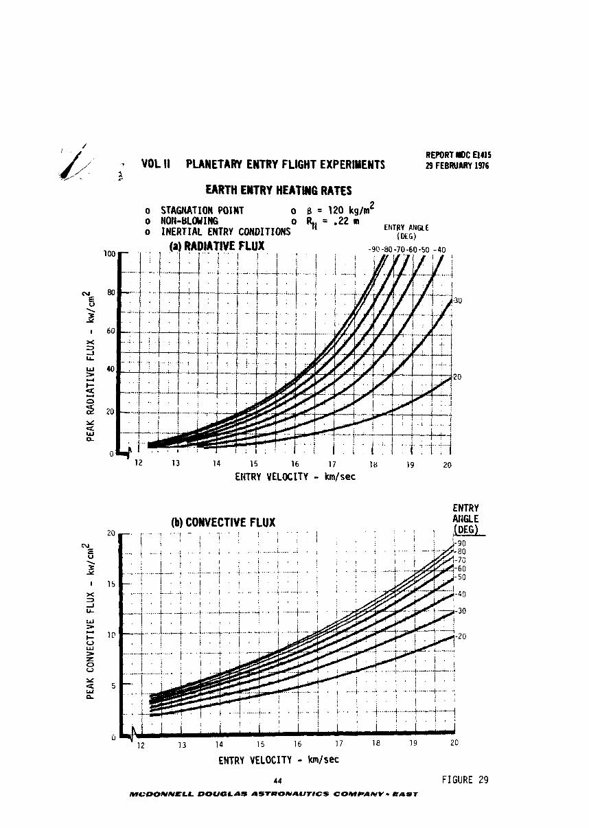
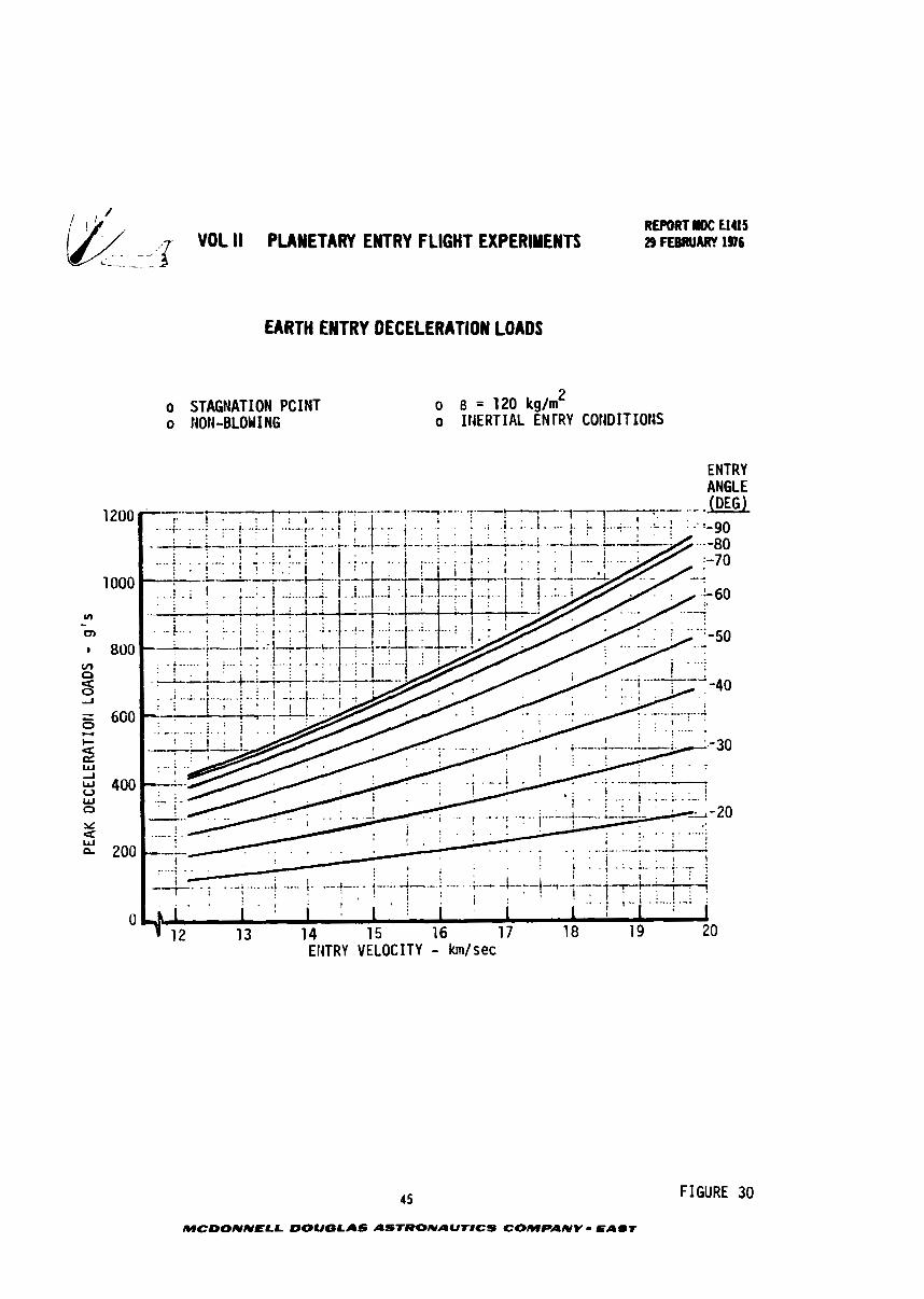
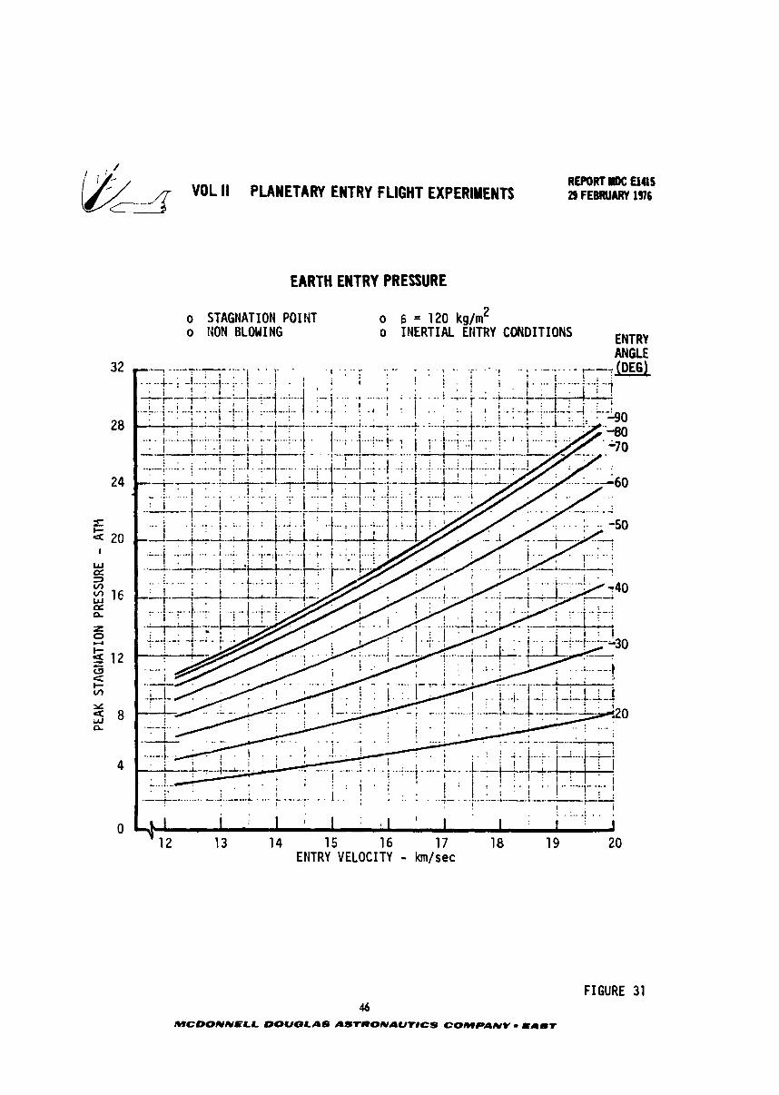
Graphical presentat ions of these tabular d a t a a r e a l s o presented. Figures 29
through 34 i l l u s t r a t e the e f f e c t of i n i t i a l en t ry condi t ions on peak hea t ing r a t e s ,
pressure, "g" loads and t o t a l hea t load, Figures 35and 36 ind i ca t e t he dura t ion
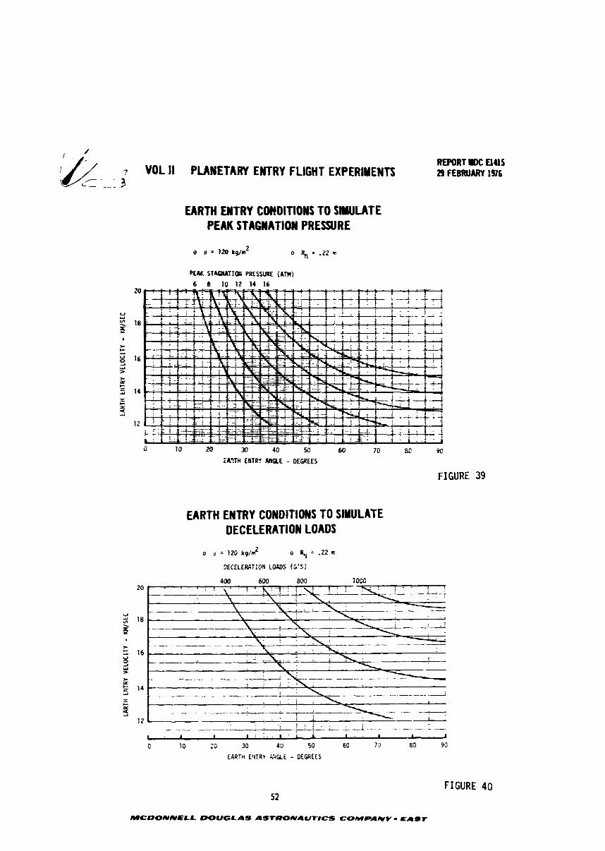
of the r ad i a t i ve and convective hea t pulse. Figures 37 through 40 show the i n i t i a l
en t ry angle and ve loc i ty combination necessary t o achieve a given maximum l e v e l of
hea t f lux , pressure and "g" loads.
4.1.2 Environment Sens i t i v i t y t o Configuration - The e f f e c t of va r i a t i ons i n bal-
l i s t i c coe f f i c i en t (8) and nose rad ius (P ) a r e shown i n t h i s s ec t i on i n terms of t h e i r N e f f e c t on peak hea t ing rates, pressure and "g" loads. Information is presented i n
the form of normalized s e n s i t i v i t y f ac to r s and a l so by i l l u s t r a t i n g the change i n
i n i t i a l en t ry conditions required t o achieve se lec ted l e v e l s of r a d i a t i v e hea t
flux. These da ta a r e intended t o provide a s impl i f ied s ca l i ng method t h a t can be
applied over a wide range of i n i t i a l en t ry conditions. They r e f l e c t the combined
r e s u l t s of many point design computer runs. However, a degree of environment
approximation is incorporated t o achieve t h e desired range of en t ry condi t ion
a p p l i c a b i l i t y with a simple presentat ion of data. Hence these predicted environ-
ment va r i a t i ons with vehic le configurat ion should be considered f i r s t o rder t rend
da t a as opposed t o prec ise , point design solut ions.
43
MCDONNELL DOUGLAS ASTRONAUTICS COMPANV - Eamr
REPORT lllOC UllS 29 FEBRUARY 1976
12 13 14 15 16 17 18 19 20
EHTRY VELOCITY - km/sec
ENTRY
ENTRY VELOCITY - km/sec
44 FIGURE MCDONNELL DOUQLAS ASTRONAUTICS COMPANY r BAST
REPORT IIDC a415 3 *DL II PLANETARY ENTRY FLIGHT EXPERlYENTS _ _ 29 FEBRUARY 196 C - ~
EARTH ENTRY DECELERATION LOADS
o STAGNATION PCINT 0 NOH-BLOUING
o 8 = 120 kg/m 2
o INERTIAL ENrRY COtIDITIOtJS
ENTRY ANGLE
Ef4TRY VELOCITY - km/sec
45
MCDONNELL DOUGLAS ASTRONAUNCS COMPANY - EAST
FIGURE 30
REPORT rOC El415 VOL II PLANETARY EMTRY FLIGHT EXPERIMENTS 29 FEBRUARY 196
EARTH ENTRY PRESSURE
o STAGNATION POINT o 6 = 120 kg/mZ o NON BLOWING o INERTIAL ENTRY CONDITIONS ENTRY
ANGLE
- w 12 13 1 4 15 16 17 18 19 20 ENTRY VELOCITY - km/sec
FIGURE 31 46
MCDONNELL DOUGLAS ASTRONAUTICS COMPANY - CAdT
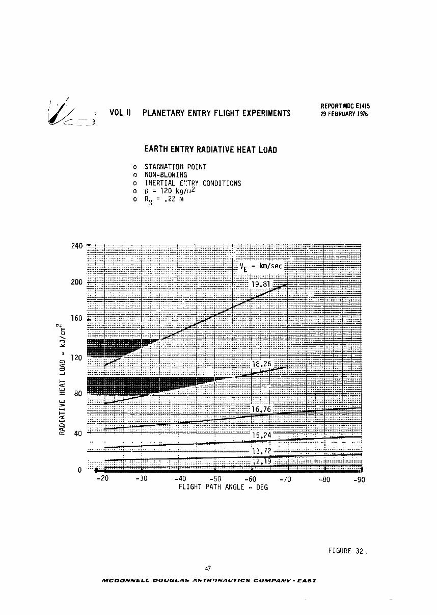
7 VOL II PLANETARY ENTRY FLIGHT EXPERIMENTS C_ ._
EARTH ENTRY RADIATIVE HEAT LOAD
o STAGNPTIOIi POINT O NON-BLOW I NG o INERTIAL E:':TRY CONDITIONS 0 6 = 1 2 0 k g / d o RE: = '22 m
REPORT MDC El415 29 FEBRUARY 1976
-40 - 50 -60 - 10 FLIGHT PATH ANGLE - DEG
FIGURE 32 .
47
MCDONNELL DOUGLAS P.STRONAUTICS COMPANY - EAST
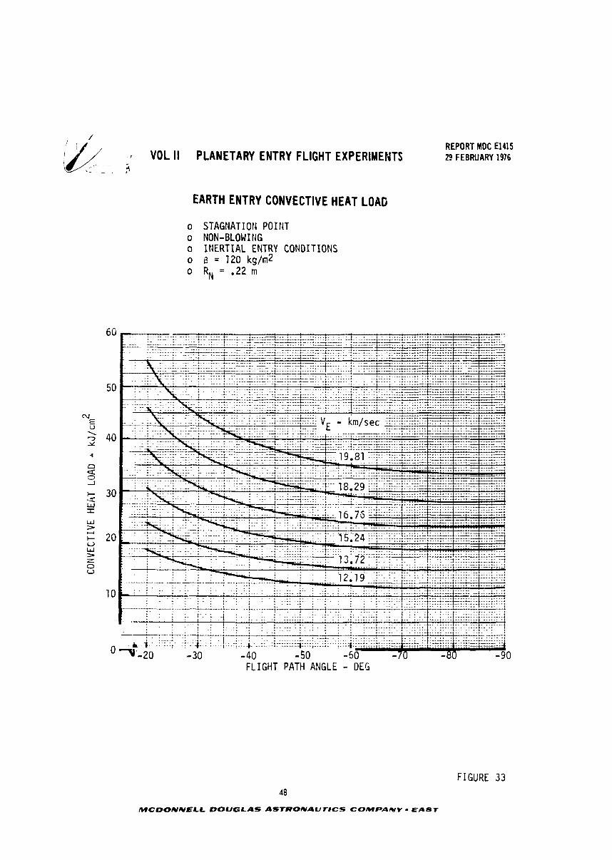
, 7 VOL II PLANETARY ENTRY FLIGHT EXPERIMENTS L - . 2
EARTHENTRYCONVECTIVEHEATLOAG
o STAGNATION POINT o NON-BLOW ING o INERTIAL ENTRY CONDITIONS o B = 120 kg/m2 o RN = .22 rn
REPORT MDC El415 29 FEBRUARY 1976
0 FLIGHT PATH ANGLE - DEG
FIGURE 33 48
MCDONNELL DOUGLAS AbTRONAUr#CS COMPAICIV - EAST
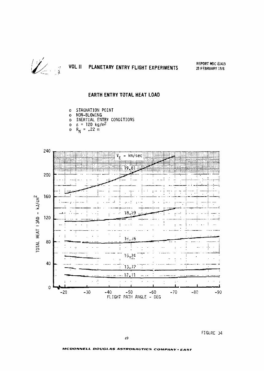
& G- VOL II PLANETARY ENTRY FLIGHT EXPERIMENTS REPORT MDC El415 29 FEBRUARY 1916
EARTH ENTRY TOTAL HEAT LOAD
o STAGNATION POINT o NON-BLOWIRG o INERTIAL ENTRY CONDITIONS o B = 120 kg/m2 o RN = -22 m
1 I 1 I 1-
-20 - 30 -40 - 50 -60 -70 -8Q -90 FL. IGHT PATH ANGLE - DEG
FIGURE 34 49
MCDONNELL DOUGLAS ASTRONAUT#CS COMPAICIY - EAST
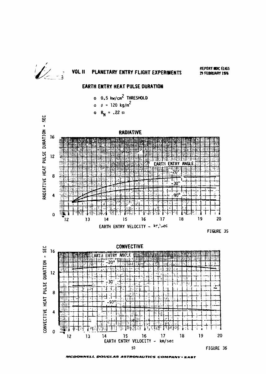
jfi VOL II PUYETARI ENTRY FLIGHT ElPERlYElTS - --- . A
L------L
EARTH ENTRY HE AT PULSE OURATlOW
o 0.5 kw/n2 THRESHOLD
o e = 120 kg/m 2
o F$ = -22 n
RADIATIVE
REPORT UE ElU5 29 RBRUMW 1376
-12 13 14 15 16 17 18 19 20
EARTH ENTRY VELOCITY - kr,'>ec FIGURE 35
CONVECTIVE
13 14 15 16 17 18 19 20 EARTH ENTRY VELOCITY - km/sec
50 FIGURE 36
MCDONNELL OOUGLAS ASTRONAUtlCS COMPANY - ELIS7
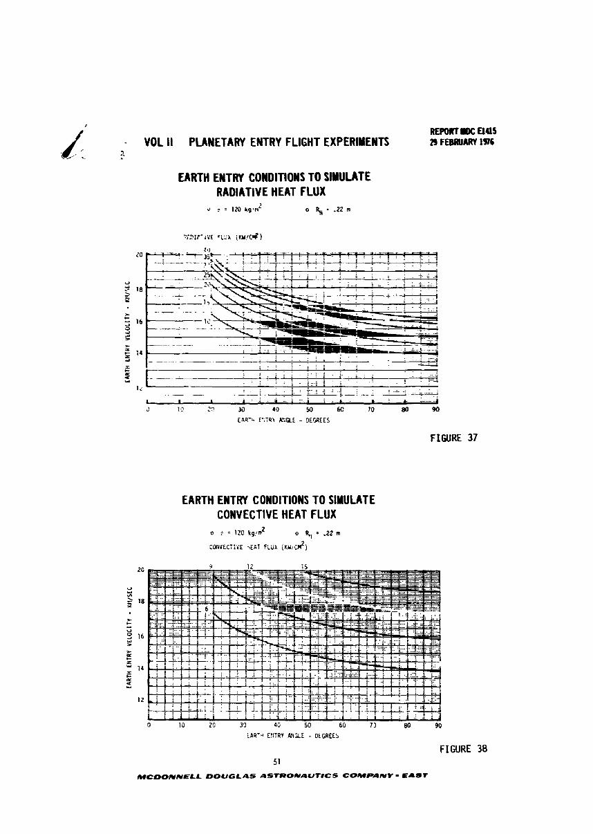
- VOL II PLANETARY ENTRY FLIGHT EXPERIUENTS ..
EARTH EMTRY COWDITIWS TO SIMULATE RADIATIVE HEAT FLUX
FIGURE 37
EARTH ENTRY CONDITIONS TO SIMULATE CONVECTIVE HEAT FLUX
LAR7* E!:TRY ANGLE - DEGREES
FIGURE 38 51
MCDONNELL DOUGLAS ASTRONAUflCS COMPANY - EAST
7 VOL I1 PUNETARY ENTRY FLIGHT EXPERIMENTS L ---1
EARTH ENTRY CO)IIOITIOMS TO SIMULATE
REFORT mc Elus 29 FEBRUARY 1976
PEAK STAGNATION PRESSURE
PEAK STA&IATl(n PlESWtE {Am) 6 8 10 12 14 16
U u - 18 3 I
* t d
16 0, i.) r
* r t Z 14 - - C r
5 12
20 30 40 50 60 70 8C 92
iA?TH ENTRY A5QE - E W E S
FIGURE 39
EAR1 H ENTRY CONDITIONS TO SIMULATE DECELERATION LOADS
400 600 800 1000
. ~ ~
12 L . . . . . . . . . . . . . . - . , . . . . . . , - - - - - - .. ~ . . L . ' 6
. . . . . . . I J
0 10 20 30 40 50 60 70 80 90
EARTH E'ITRV X 4 U L - DEGREES
FIGURE 40
MCDONNELL DOUGLAS AStffOUAUTlCS COMPAIIIV - EAST
RfPORT IM: UUS VOL II PLANETARY ENTRY FLIGHT EXPERIMENTS 29 FEBROARY 1976
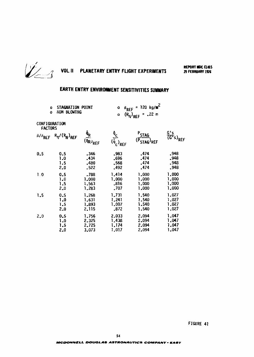
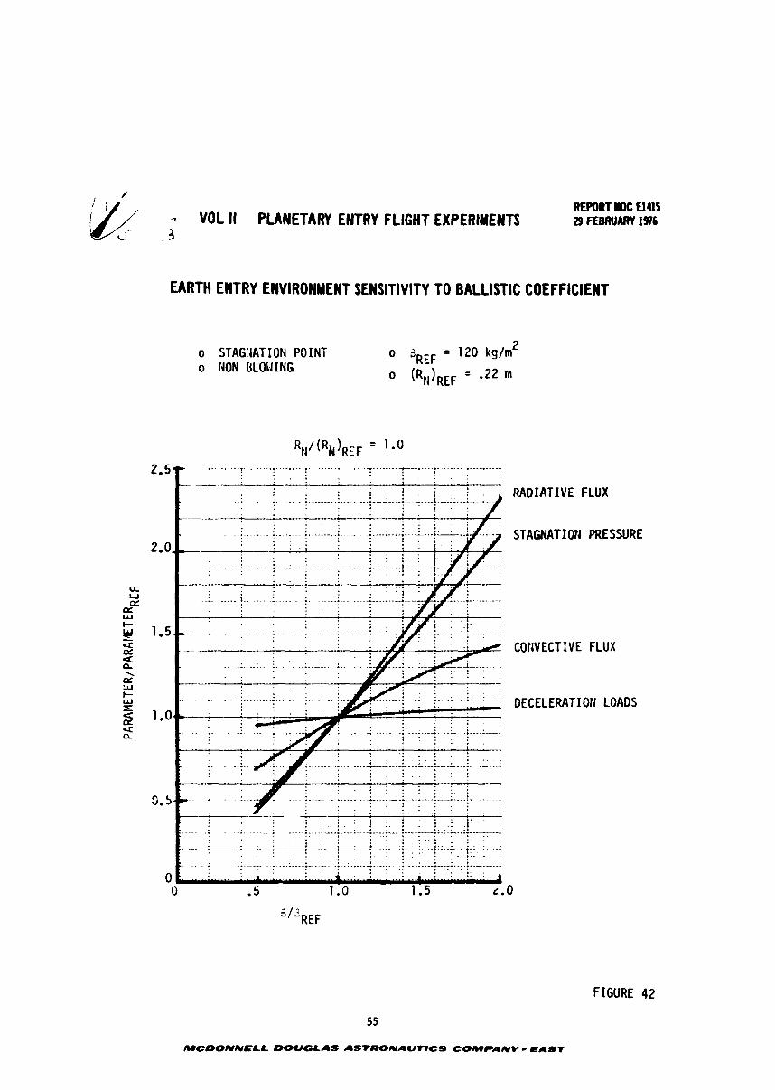
Normalized s e n s i t i v i t y f a c t o r s are suramarized i n Figure 4 1 and presented
graphical ly i n Figares 42 through 45, Vehicle c h a r a c t e r i s t i c s a r e referenced t o t h e
B and values employed i n Sect ion 4-1-1 S i d l a r l y , t h e environment parameters
are referenced t o t h e values shown i n Sect ion 4.1.1 f o r any given en t r ) angle and
ve loc i ty combination. As indicated, both r ad i a t i ve and convective f l ux l e v e l s
a r e influenced by both I3 and s. However, pressure l e v e l is a s t rong funct ion of B
but independent of E$ while dece le ra t ion "g" loads zre e s s e n t i a l l y independent of
both vehic le parameters. These unequal dependences on vehic le configurat ion i n f e r s
t h a t var ious combinations of environment parameters can be produced by proper mani-
pu la t ion of veh i c l e design cha-ac te r i s t ics .
Vehicle configurat ion va r i a t i ons a l s o inf luence en t ry condi t ion requirements
i f t h e l e v e l of environntent s imulat ion is fixed, This inf luence is i l l u s t r a t e d i n
Figures 46 through 50 f o r represen ta t ive l e v e l s of r a d i a t i v e heat flux. Figures
46 through 48 show t h e e f f e c t of 8 changes only (& = reference) while Figures 49
through 51 ind i ca t e t h e e f f e c t with a smaller $ (higher convective flux). These
d a t a show the increas ing f3 can be used t o subs t an t i a l l y lower e i t h e r t h e en t ry angle
o r t he en t ry ve loc i ty requirement f o r a spec i f i ed hea t ing leve l , This a l s o implies
t h a t a reduction i n required booster s i z e may be possible. I f B is increased by mass
addi t ion, the reduction i n booster AV required (lower en t ry condi t ions) may be
g rea t e r than t h e reduction i n booster AV capab i l i t y (payload mass increase) .
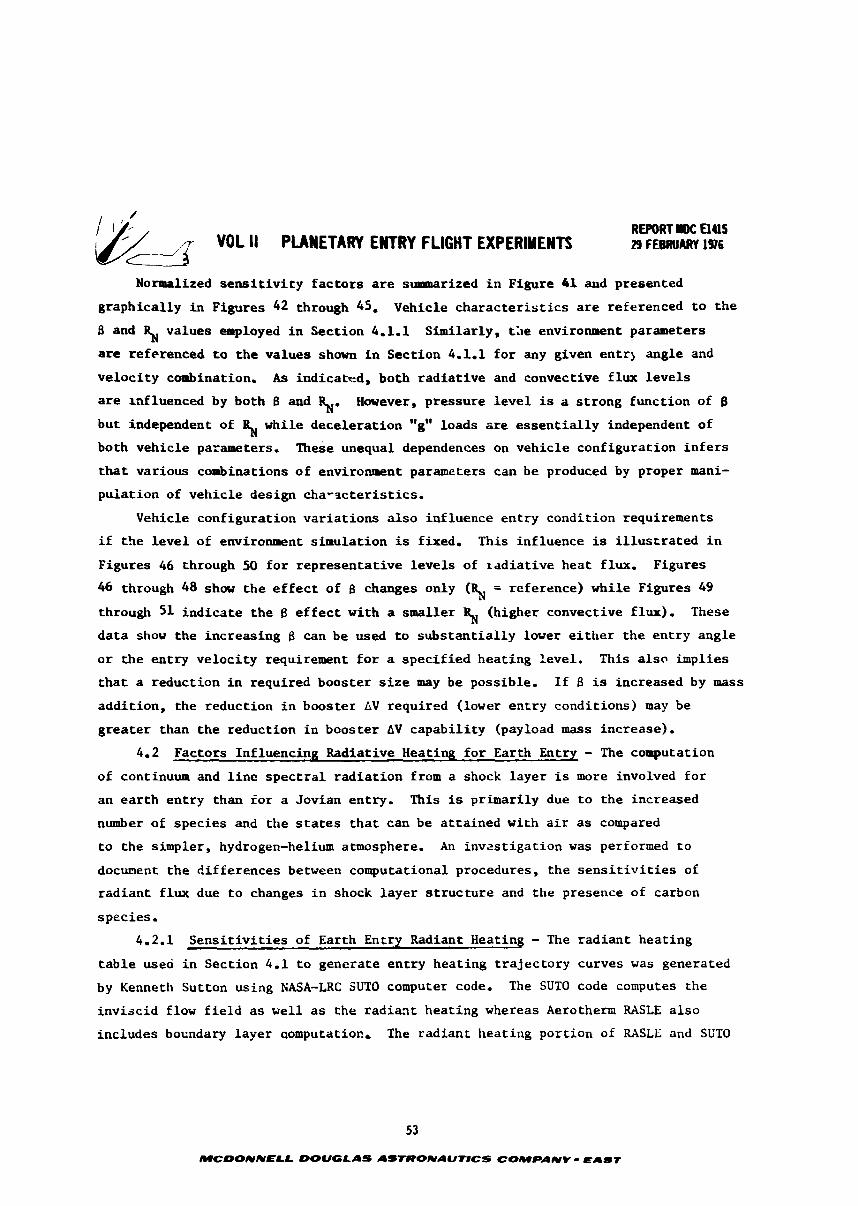
4.2 Factors Influencing Radiative Heating f o r Earth Entry - The coaputation
of continuum and l i n e s p e c t r a l r ad i a t i on from a shock l aye r is more involved f o r
an e a r t h en t ry than f o r a Jovian entry. This is primari ly due t o t he increased
number of spec ies and the s t a t e s t h a t can be a t t a ined with a i r as compared
t o the simpler, hydrogen-helium atmosphere. An invas t iga t ion was performed t o
document t he d i f fe rences between computational procedures, t he s e n s i t i v i t i e s of
rad ian t f l u x due t o changes i n shock l aye r s t r u c t u r e and the presence of carbon
species .
4.2.1 S e n s i t i v i t i e s of Earth Entry Radiant Heating - The r ad i an t heat ing
t a b l e used i n Sect ion 4.1 t o generate en t ry heat ing t r a j ec to ry curves was generated
by Kenneth Sutton using NASA-LRC SUTO computer code, The SUTO code computes the
i nv i sc id flow f i e l d a s w e l l a s t he r a d i a ~ t heat ing whereas Aerothem RASLE a l s o
includes boundary layer aomputatioc, The rad ian t heat ing port ion of RASLE and SET0
53
MCDONNELL DOUGLAS ASTIOONAUTICS COMPANY - EAST
VDL II PLANETARY E l R Y FLIGHT EIPERWNTI REPORT IDC UUS
<- - --2 29 FEBRUARY 196
EARTH ENTRY ENVIRONMENT SENSITIVITIES SUMMARY
o STAGNATI(X4 POINT o = 120 kg/. 2
0 t4ON BLOWING 0 (RIOREF = -22 m
CONFIGURATION FACTORS
54
MCOONNELL DOUGLAS AStRONAU~CS COMPANV - E4-T
-. VOL I1 PLANETARY ENTRY FLIGHT EXPERIMENTS C - L 4
REPORT IDC UIlS 29 FEBRUARY 1976
EARTH ENTRY ENVIRONMENT SENSITIVITY TO BALLISTIC COEFFICIENT
RADIATIVE FLUX
STAGNATXON PRESSURE
COtlVECTIVE FLUX
DECELERATION LOADS
FIGURE 42
55
MCWNNELL WUGLAS AS'IffONAUTICS COMPANY * E A l T
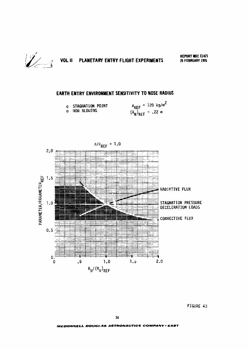
VOL ll PLANETARY ENTRY FLIGHT EXPERIMENTS
EARTH ENTRY ENVIRONMENT SENSITIVITY TO NOSE RADIUS n
o STAGIiATlON POINT o t4ON BLOLIItiG
REPORT IM: El415 29 FEBRUARY 1976
FIGURE 43
56
MCDONNELL DOUGLAS ASTRONAUTlCS COMPANV = EAST
REPORT IIOC a415 ;k/ VOL I! PLANETARY ENTRY FLIGHT EXPERIMENTS 29 FEBRUARY 1976 . .-- 3
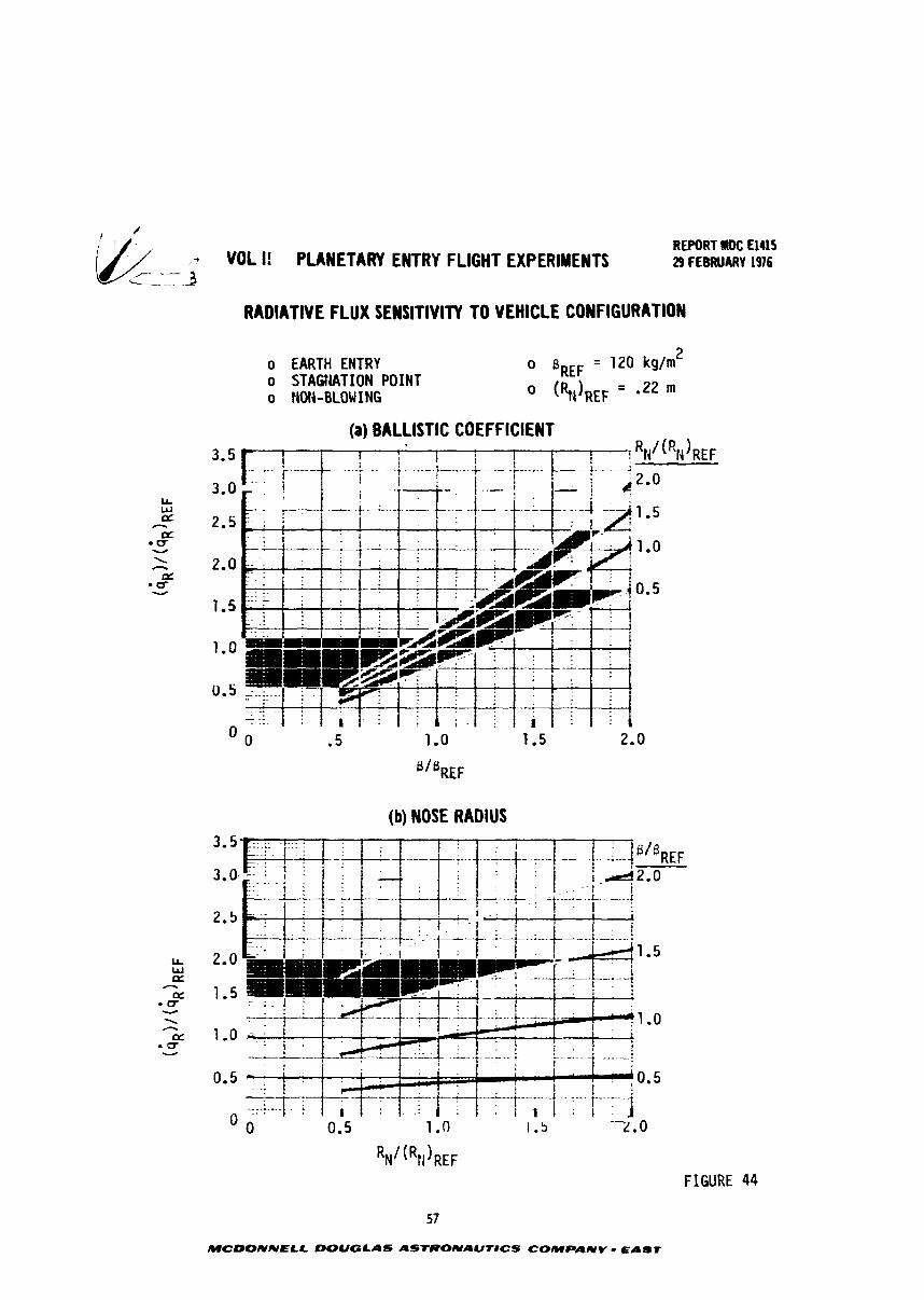
RADIATIVE FLUX SENSITIVITY TO VEHICLE CONFIGURATION
o EARTH ENTRY o B~~~ = 120 kglm 2
o STAGtlATION POINT o HON-BLOW ING 0 (%IREF ' -22 m
(a) BALLISTIC COEFFICIENT
(b) NOSE RADIUS
R ~ I ( R ~ ) ~ ~ ~ FIGURE 44
MCDONNELL DOUGLAS ASTRONAUflCS COMPANY - EAST
-- ..- VOL II PLANETARY ENTRY FLIGHT EXPERIMENTS
, ,
REPORT IDC El41 5 29 FEBRUARY I976
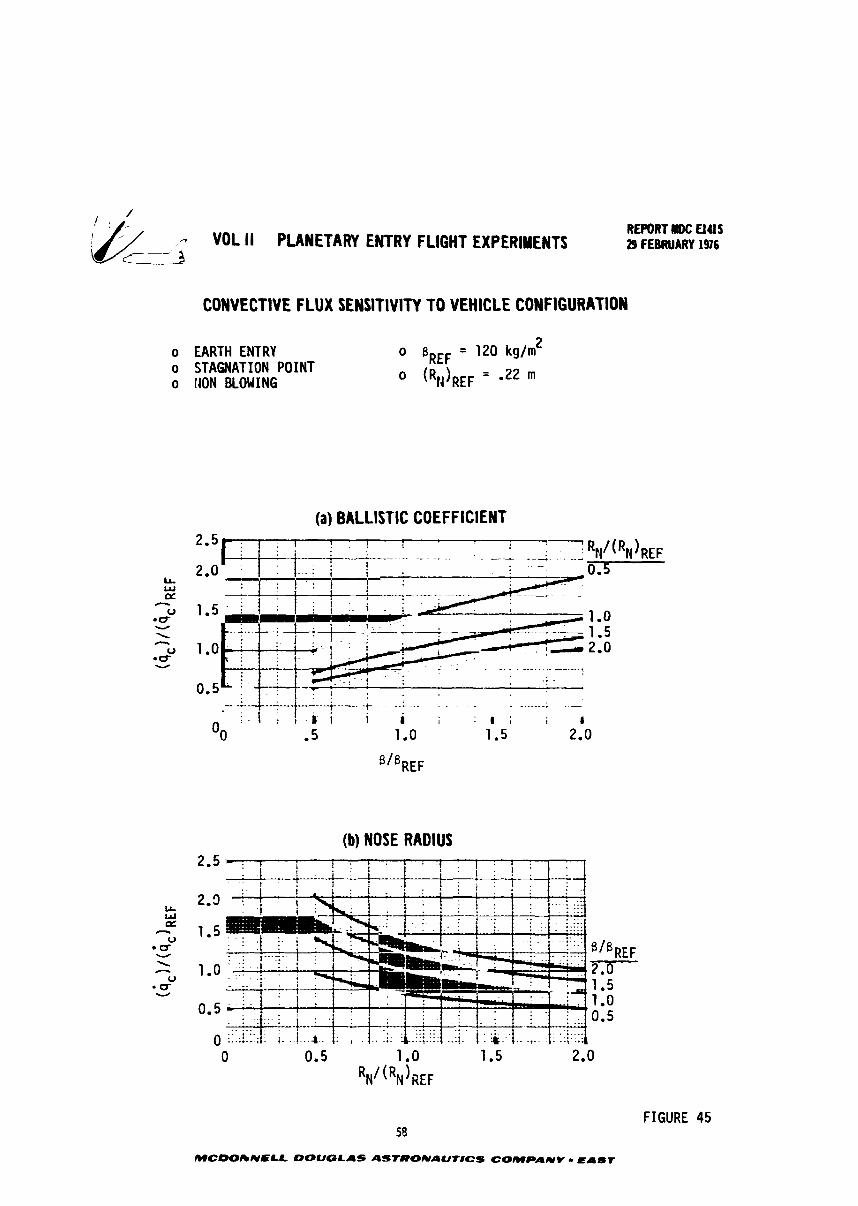
COWVECTlVE FLUX SENSITIVITY TO VEHICLE CONFIGURATION
o EARTH ENTRY o BREF = 120 kg/m 2
o STAGNATION POINT o flON BLOWING 0 (RNlREF = - 2 2 m
(a) BALLISTIC COEFFICIENT !-R /(R )
. -2. . . . N N REF
@/@REF
(b) NOSE RADIUS
FIGURE 45 58
MCDORNELL DOUGLAS ASTCIONAUT#CS COMPANY - EAST
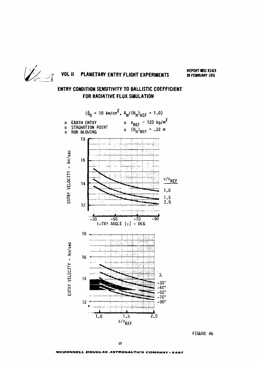
VOL I1 PLANETARY ENTRY FLIGHT EXPERIMENTS
ENTRY CONDITION SENSITIVITY TO BALLISTIC COEFFICIENT FOR RADIATIVE FLUX SIMULATION
2 ( = 10 kw/cm . RN/(RN)REF = 1.0)
o EARTH ENTRY o B~~~ = 1 2 0 kg/m 2
o STAGtiATION POINT o NON BLOtlIMG 0 (RIIIREF ' -22 '
I . . . . -. h - 3 0 - 5 0 -70 -90
EitTRY AFlGtE (y) - DEG
REWRT r D C El415 29 FEBRUAZW 1976
FIGURE 46
MCOONNELL DOUGLAS ASTRONAUTICS COMPANY 0 EAST
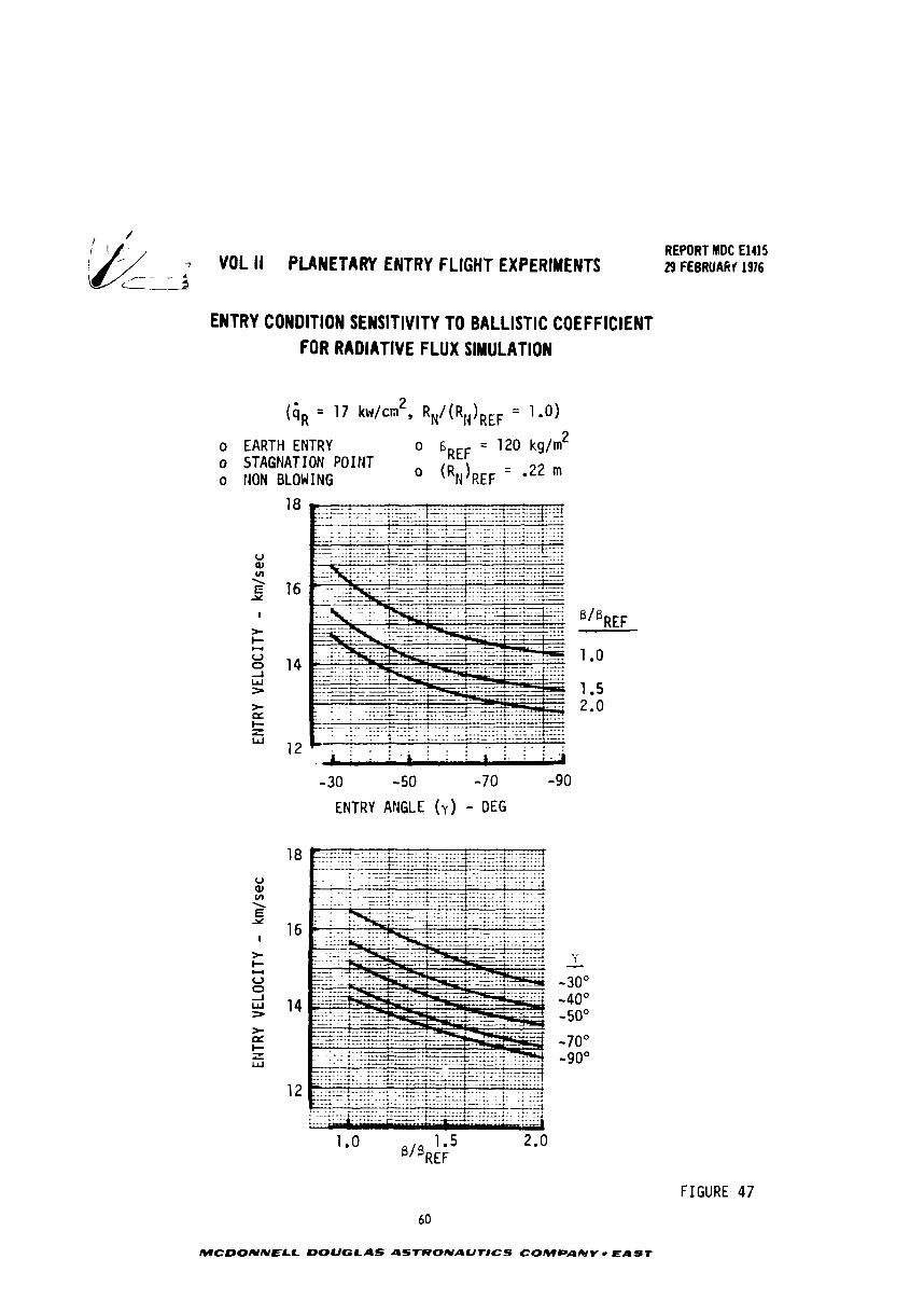
7 VOL II PLANETARY ENTRY FLIGHT EXPERIMENTS /- -- * t- 9
ENTRY CONDITION SENSITIVITY TO BALLISTIC COEFFICIENT FOR RADIATIVE FLUX SIMULATION
o EARTH ENTRY o 6REF = 120 kg/m2 o STAGNATION POIliT o NON BLOWING o (RN)REF = '22 m
ENTRY ANGLE (y ) - DEG
REPORT MDC El415 29 FEBRUARf 1976
FIGURE 47
60
MCDONNELL DOUGLAS ASTRONAUTICS COMPANY r EAST
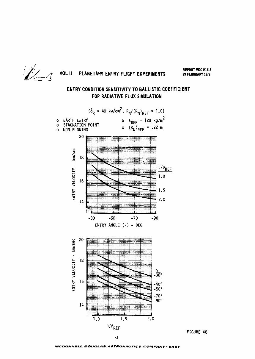
REPORT MDC El415 VOL II PLANETARY ENTRY FLIGHT EXPERIMENTS 29 FEBRUARY 19'16
ENTRY CONDITION SENSITIVITY TO BALLISTIC COEFFICIENT FOR RADIATIVE FLUX SIMULATION
o EARTH tt*TRY o STAGNATION POINT o NO14 BLOWING
- 30 - 50 -70 -90
ENTRY ANGLE ( v ) - DEG
61
MCbONNELL DOUGLAS ASfRONAUTBCS COMPANY - EAST
FIGURE 48
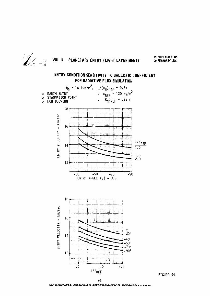
REPORT MDC El415 VOL II PLANETARY ENTRY FLIGHT EXPERIMENTS 29 FEBRUARY 196
ENTRY CONDITION SENSITIVITY TO BALLISTIC COEFFICIENT FOR RADIATIVE FLUX SIMULATION
n
( = 10 kw/cmL, RN/(RN)REF = 0.5)
o EARTH ENTRY o = 1 2 0 k g / m 2
o STAGNATION POINT o NON BLOWING 0 (RNIREF = 022 m
FIGURE 49
MCUONNELL DOUGLAS ASTRONAUT#CS COMPANV - EAST
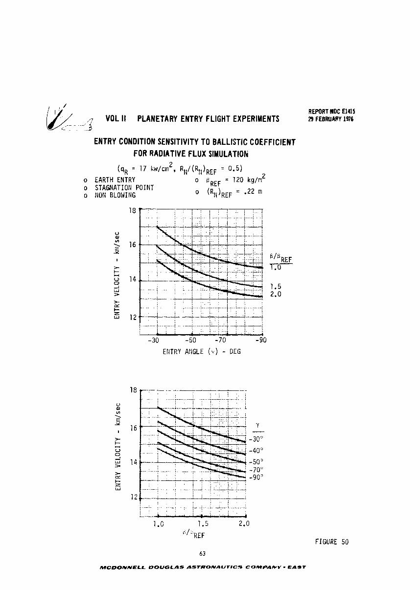
VOL II PLANETARY ENTRY FLIGHT EXPERIMENTS 7.- ~ ~- -, 3
rc- _ -
ENTRY CONDITION SENSITIVITY TO BALLISTIC COEFFICIENT FOR RADIATIVE FLUX SlMULATlOti
o EARTH ENTRY o STAGNATIOti POINT 0 Noti BLOLJIlJG
EtiTRY ANGLE ( y ) - DEG
REPORT MDC El415 29 FEBRUARY 1976
MCDONNELL DOUGLAS ASIRONAUTIC.5 COmPaIC(v - East
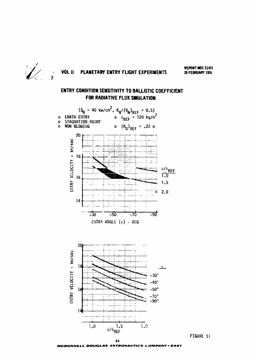
REPORT IM: 0415 VOL ll PLANETARY ENTRY FLIGHT EXPERIMENTS 29 FEBRUARY 1916 - - - 3
ENTRY CONDITION SENSITIVITY TO BALLISTIC COEFFICIENT FOR RADIATIVE FLUX SIMULATION
(4, = 4 0 kw/cmz, = 0.5)
o EARTH ENTRY 0 sREF = 1 2 0 kg/"' o STAGt4ATIOti POINT o MON B L O U I X o (RIOREF = - 2 2 M
EtlTRY AtiGLE ( v ) - DEG
64 MCDONNCLL DOUGLAS ASTRONAUTICS GOMPANV - EAST
FIGURE 51
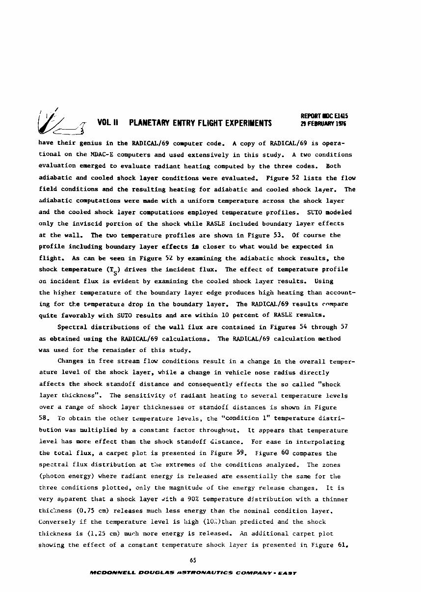
have t h e i r genius i n t h e RADICAL/69 computer code. A copy of RU)ICAL/~~ is opera-
t i o n a l on t h e MDAC-E computers and used ex tens ive ly i n t h i s study. A two condi t ions
eva lua t ion emerged t o e v a l u a t e r a d i a n t h e a t i n g computed by t h e t h r e e codes. Both
a d i a b a t i c and cooled shock l a y e r cond i t ions were evaluated. Figure 52 lists t h e flow
f i e l d cond i t ions and t h e r e s u l t i n g h e a t i n g f o r a d i a b a t i c and cooled shock l ayer . The
h d i a b a t i c computations were made wi th a uniform temperature a c r o s s t h e shock l a y e r
and t h e cooled shock l a y e r computations employed t enpera tu re p r o f i l e s . SLTO modeled
only t h e i n v i s c i d p o r t i o n of t h e shock whi le RASLE included boundary l a y e r e f f e c t s
at t h e w a l l . The two temperature p r o f i l e s are shown i n Figure 53. Of course t h e
p r o f i l e inc lud ing boundary l a y e r e f f e c t s iS c l o s e r t o what would b e expected i n
f l i g h t . A s can be seen i n Figure 52 by examining t h e a d i a b a t i c shock r e s u l t s , t h e
shock temperature (T ) d r i v e s t h e i n c i d e n t f lux. The e f f e c t of temperature p r o f i l e S
on i n c i d e n t f l u x is ev iden t by examining t h e cooled shock l a y e r r e s u l t s . Using
t h e h igher temperature of t h e boundary l a y e r edge produces high h e a t i n g than account-
ing f o r t k e temperature drop i n t h e boundary l ayer . The RADICAL/^^ r e s u l t s compare
q u i t e favorably v i t h SUTO r e s u l t s and are w i t h i n 10 percent of RASLE r e s u l t s .
S p e c t r a l d i s t r i b u t i o n s of t h e w a l l f l u x are conta ined i n Figures 54 through 57
as obtained us ing t h e RADICAL/69 ca lcu la t ions . The WICAL/69 c a l c u l a t i o n method
w a s used f o r t h e renainder of t h i s study.
Changes i n f r e e s t ream flow condi t ions r e s u l t i n a change i n t h e o v e r a l l temper-
a t u r e l e v e l of t h e shock l ayer , whi le a change i n v e h i c l e nose rad ius d i r e c t l y
a f f e c t s t h e shock s tandoff d i s t a n c e and consequently e f f e c t s t h e s o c a l l e d "shock
l a y e r thickness". The s e n s i t i v i t y of r a d i a n t hea t ing t o s e v e r a l temperature l e v e l s
over a range of shock l a y e r th icknesses o r s tandoff d i s t a n c e s is shown i n Figure
58. To o b t a i n t h e o t h e r temperature l e v e l s , t h e "condi t ion 1" temperature d i s t r i -
but ion w a s mul t ip l i ed by a constant f a c t o r throughout. It appears t h a t temperature
l e v e l has more e f f e c t than t h e shock s tandoff d i s t ance . For ease i n i n t e r p o l a t i n g
the t o t a l f l u x , a c a r p e t p l o t is presented i n Figure 59. Figure 60 compares t h e
s p e c t r a l f l u x d i s t r i b u t i o n a t t h e extremes of t h e cond i t ions analyzed. The zones
(photon energy) where r a d i a n t energy is re leased are e s s e n t i a l l y t h e same f o r t h e
th ree cond i t ions p l o t t e d , only t h e magnitude of t h e energy r e l e a s e changes. I t is
very apparent t h a t a shock l a y e r k i t h a 90Z temperature distribution with a th inner
tt1icI:ness (0.75 cm) r e l e a s e s much less energy than the nominal condi t ion l ayer .
Conversely i f t h e temperature l e v e l is !ligh (10;;)than p red ic ted and the shock
th ickness is (1.25 cm) much more energy is re leased. An a d d i t i o n a l c a r p e t p l o t
showing t h e e f f e c t of a cons tan t temperature shock l a y e r is presented i n Figure 61.
65
MCDOffNELL DOUGLAS aSTlPOlVAUNCS COMPANY - EAST
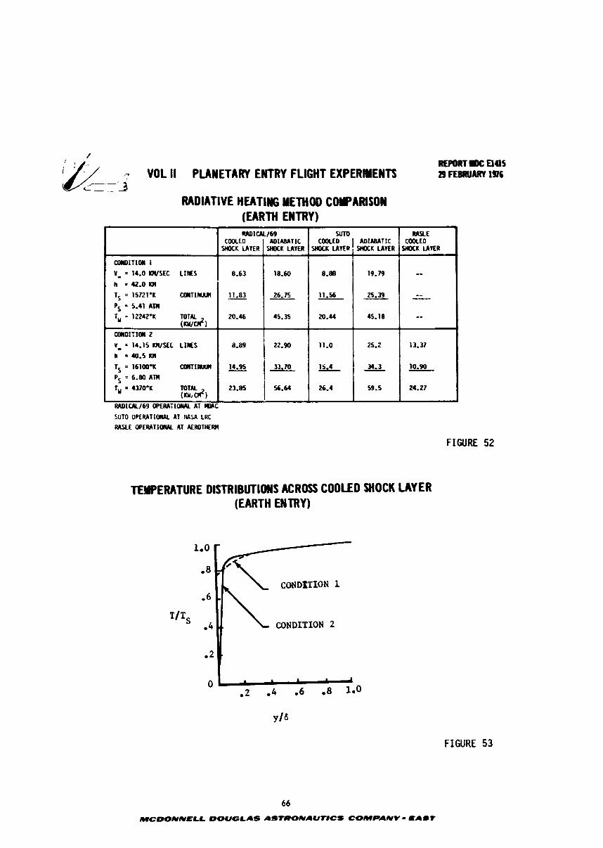
REP[)CITIK:ElItS .? VOL li PUWETARY ENTRY FLIGHT EXPERIENTS z ~ F E B I ~ ~ A R V I %
-~ -- '3 - .-
RADIATIVE HEATING METHOD COCPAfUSM (EARTH ENTRY)
SUTO Of'ERATlOnAL AT HASA LRt RASLE WEIUTI(ML kT EROTHERH
FIGURE 52
-
aWIITlOil 1
Y_ = 14.0 WSEC LIES h = 42.0 m TS = 15721°K MIITIIIIUII
Ps = 5.41 All4
1, = 12242.1; TOTAL (artdl
tOlU)1:10II 2
V_ = 14.15 WSEC L I E S h = 40.5 1111
1, = 16100gK CalllfWI1
Ps = 6-80 Am
1, = 4370-K TOTAL (art&)
i
RMIW169 O P E R A ~ I O I W AT lOLC
TEYPERATURE DlSTRlBUTlOWS ACROSS COOLED SHOCK LAYER (EARTH EMTRY)
FIGURE 53
W E COOLtD
Y M K LAVER
--
-- - -
13-37
10.90
24.27
RMICALI69 YlTO COOLED I MIAMTIC COOLED
SHOCK LAYER
8.63
11.83
20.46
8.W
SHOCK LAVE@
6-88
11.56
20.44
11.0
15.4
25.4
ADIABATIC W K LAVER
18.60
26.75
45.35
22.90
SHOCK LAVER
19.79
25.39
45.18
25.2
- 34.3
59.5
1 31.10
2 3 . I 56.64
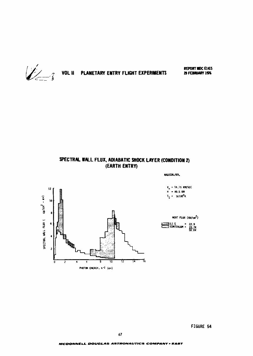
EPWl1)(: E l45 jk;/ . "DL II PLANETARY ENTRY FLIGHT EXPERIMEUTS BFERUMRYI% .----'A C___
SPECTRAL WALL FLUX. ADIABATIC WOCK LAYER (CONDITION 4 (EARTH ENTRY)
S A T FLUX (KN/a2)
PHOTON ENERGY, h 3 iev)
FIGURE 54
67
MCWNNELL DOUGLAS ASTRONAWTICS COMPANY - E A d t
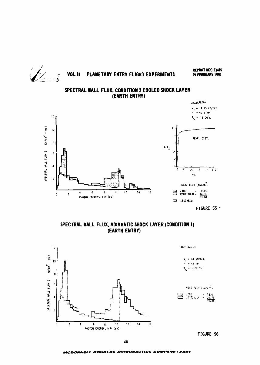
/ REPORT mc Elus
-? VOL II PLANETARY ENTRY FLIGHT EXPERIMENTS 29 FEE~UJARY 1976
SPECTRAL WALL FLUX, COWDITION 2 COOLED SHOCK LAYER (EARTH EN1 RY)
~~ir lCCl / t ' j
b = = iG.15 W S E C n = 40.5 W
TS = 161Q0°r
FIGURE 55 -
SPECTRAL WALL FLUX, ADIABATIC SHOCK LAYER (CONDITION 1) (EARTH ENTRY)
FIGURE 56
MCDONNELL mUGLI IS ASTRONAUNCS COMPANV - EAST

VOL II PLANETARY ENTRY FLIGHT EXPERIYENTS
SPECTRAL FLUX FOR CONDlllON 1 COOLED SHOCK LAYER (EARTH ENTRY)
PnOTm EllfRCY. n S (er)
REPORT DC €145 29 FEBRUARY 1%
6=3 ~ s o R s r a
FIGURE 57
SENSITIVITY OF RADIANT HEATIWG TO SHOCK LAYER TEMPERATURE AND THICKNESS v_ = 14.0 wxc
EARTH ENTRY
RhDIW69. tOOLED S i i a K UYER
.... ~
41 40
ru 3 B , 3 fJ x =I
-1 LL
T Al
2 20
2 10
'2 0.70 1.00 ..a C 70 1.00 1 .30 0.70 1.00 1.30 7 --
SHOCK STAND-OFF DISTAWCE - cr
FIGURE
69
MCDONNELL DOUGLAS ASfRONAUNCS COW-ANV - EAST
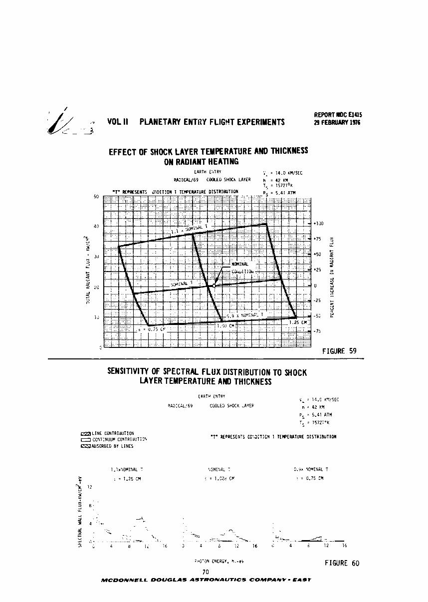
REPORT IIW: E M I S ,7 VOL II PLANETARY ENTRY FLIG9T EXPERIMENTS 29 FEBRUARY 1916
- - a -2
EFFECT OF SHOCK LAYER TEMPERATURE AND THICKNESS ON RADIANT HEATING
EARTH EiTRV :' = 14.0 KU/SEC
RA3ISL/69 Zi##ED S W h LAVER h = 42 &q Ts = 1 5 7 2 1 ~ ~
'To REPESEHTS J::DIT:OII 1 TEWERATURE O I S T R I W T I O N F- = 5 A1 ATM
FIGURE 59
SENSITIVITY OF SPECTRAL FLUX DISTRIBUTION TO SHOCK LAYER TEMPERATURE AND THICKNESS
V _ = lb.C K!:/SEC
n = 42 KM
PS = 5.41 ATM
TS = 15721°K
W L I N E CONTRlaUTIC!i 0 CONT NUUM CONTR I W T i 0'" =&SORBED BV L I N E S
'1' REPRE SE:iiS CC'.3iTiCX 1 TEMPERATURE 1 I S T R I E U T I O I I
FrfOTSN ENERGY. h . -e l FIGURE 60 7 0
MCDONNELL DOUGLAS ASTRONAUT#CS COMPANY - EAST
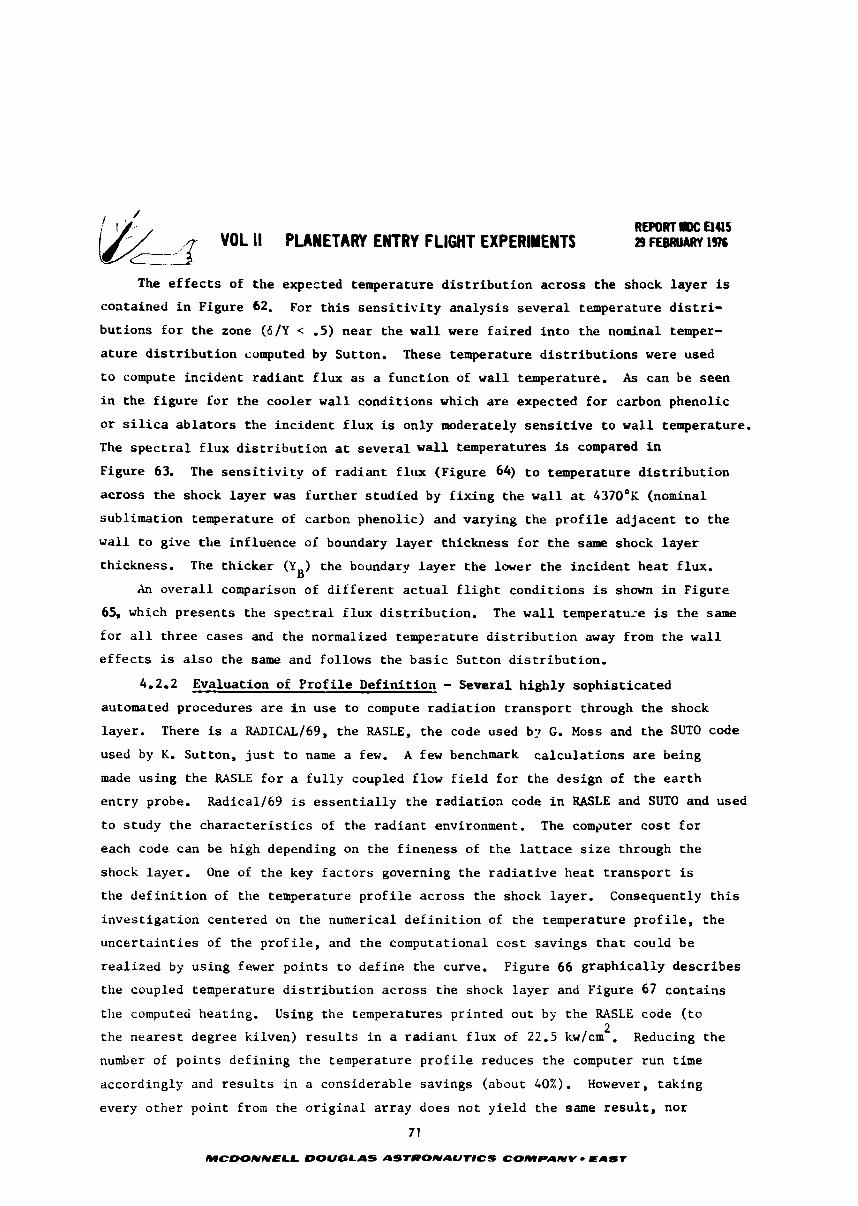
VDL II PLANETARY ENTRY FLlGh'T EXPERIMENTS REPORT M: u4lS
3- 29 FEBRUM 1976
The e f f e c t s of t h e expected temperature d i s t r i b u t i o n a c r o s s t h e shock l a y e r is
contained i n Figure 62. For t h i s s e n s i t i v i t y a n a l y s i s s e v e r a l temperature d i s t r i -
but ions f o r t h e zone ( 6 / Y < -5) near t h e w a l l were f a i r e d i n t o the nominal temper-
a t u r e d i s t r i b u t i o n computed by Sutton. These temperature d i s t r i b u t i o n s were used
t o compute i n c i d e n t rad ian t f l u x a s a f u n c t i o n of w a l l temperature. As can be seen
i n t h e f i g u r e f o r t h e coo le r w a l l cond i t ions which we expected f o r carbon phenol ic
o r silica a b l a t o r s t h e i n c i d e n t f l u x is only moderately s e n s i t i v e t o w a l l temperature.
The s p e c t r a l f l u x d i s t r i b u t i o n a t s e v e r a l w a l l t e ~ l p e r a t u r e s is compared i n
Figure 63. The s e n s i t i v i t y of r a d i a n t f l u x (Figure 64) t o temperature d i s t r i b u t i o n
a c r o s s t h e shock l a y e r was f u r t h e r s t u d i e d by f i x i n g t h e w a l l at 4370°K (nominal
subl imat ion temperature of carbon phenolic) and varying t h e p r o f i l e ad jacen t t o t h e
w a l l t o g ive t h e in f luence of boundary l a y e r th ickness f o r t h e same shock l a y e r
th ickness . The t h i c k e r (Y ) t h e boundary l a y e r t h e lwer t h e i n c i d e n t h e a t f lux. B
An o v e r a l l comparison of d i f f e r e n t a c t u a l f l i g h t cond i t ions is shown i n Figure
65, which p resen t s t h e s p e c t r a l f l u x d i s t r i b u t i o n . The w a l l temperatuze is t h e same
f o r a l l t h r e e cases and t h e normalized temperature d i s t r i b u t i o n away from t h e w a l l
e f f e c t s i s a l s o t h e same and follows t h e b a s i c Sut ton d i s t r i b u t i o n .
4.2.2 Evaluat ion OF P r o f i l e D e f i n i t i o n - Severa l h igh ly s o p h i s t i c a t e d
automated procedures a r e i n use t o compute r a d i a t i o n t r a n s p o r t through t h e shock
l ayer . There is a RADICAL/^^, t h e RASLE, t h e code used b ; ~ G. Moss and t h e SUTO code
used by K. Sut ton, j u s t t o name a few. A few benchmark c a l c u l a t i o n s are being
made us ing t h e RASLE f o r a f u l l y coupled flow f i e l d f o r t h e des ign of t h e e a r t h
e n t r y probe. Radical169 is e s s e n t i a l l y t h e r a d i a t i o n code i n RASLE and SUTO and used
t o s tudy t h e c h a r a c t e r i s t i c s of the r a d i a n t environment. The computer c o s t f o r
each code can be high depending on t h e f ineness of t h e l a t t a c e s i z e through t h e
shock l ayer . One of t h e key f a c t o r s governing t h e r a d i a t i v e h e a t t r a n s p o r t is
t h e d e f i n i t i o n of t h e temperature p r o f i l e a c r o s s t h e shock layer . Consequently t h i s
i n v e s t i g a t i o n centered on t h e numerical d e f i n i t i o n of t h e temperature p r o f i l e , t h e
u n c e r t a i n t i e s of the p r o f i l e , and t h e computational c o s t savings t h a t could be
r e a l i z e d by us ing fewer po in t s t o d e f i n e t h e curve. Figure 66 g r a p h i c a l l y d e s c r i b e s
the coupled temperature d i s t r i b u t i o n a c r o s s t h e shock l a y e r and Figure 67 con ta ins
ttie computed heat ing. Using t h e temperatures p r i n t e d ou t by t h e RASLE code ( t o 2
t h e n e a r e s t degree k i lven) r e s u l t s i n a rad ianc f l u x of 22.5 kwlcm . Reducing t h e
number of p o i n t s d e f i n i n g the temperature p r o f i l e reduces t h e computer run time
accordingly and r e s u l t s i n a considerable savings (about 40%). However, t ak ing
every o t h e r po in t from t h e o r i g i n a l a r r a y does no t y i e l d t h e same r e s u l t , nor
7 1
MCDONNELL DOUGLAS ASTRONAUT#CS COMPANY EAST
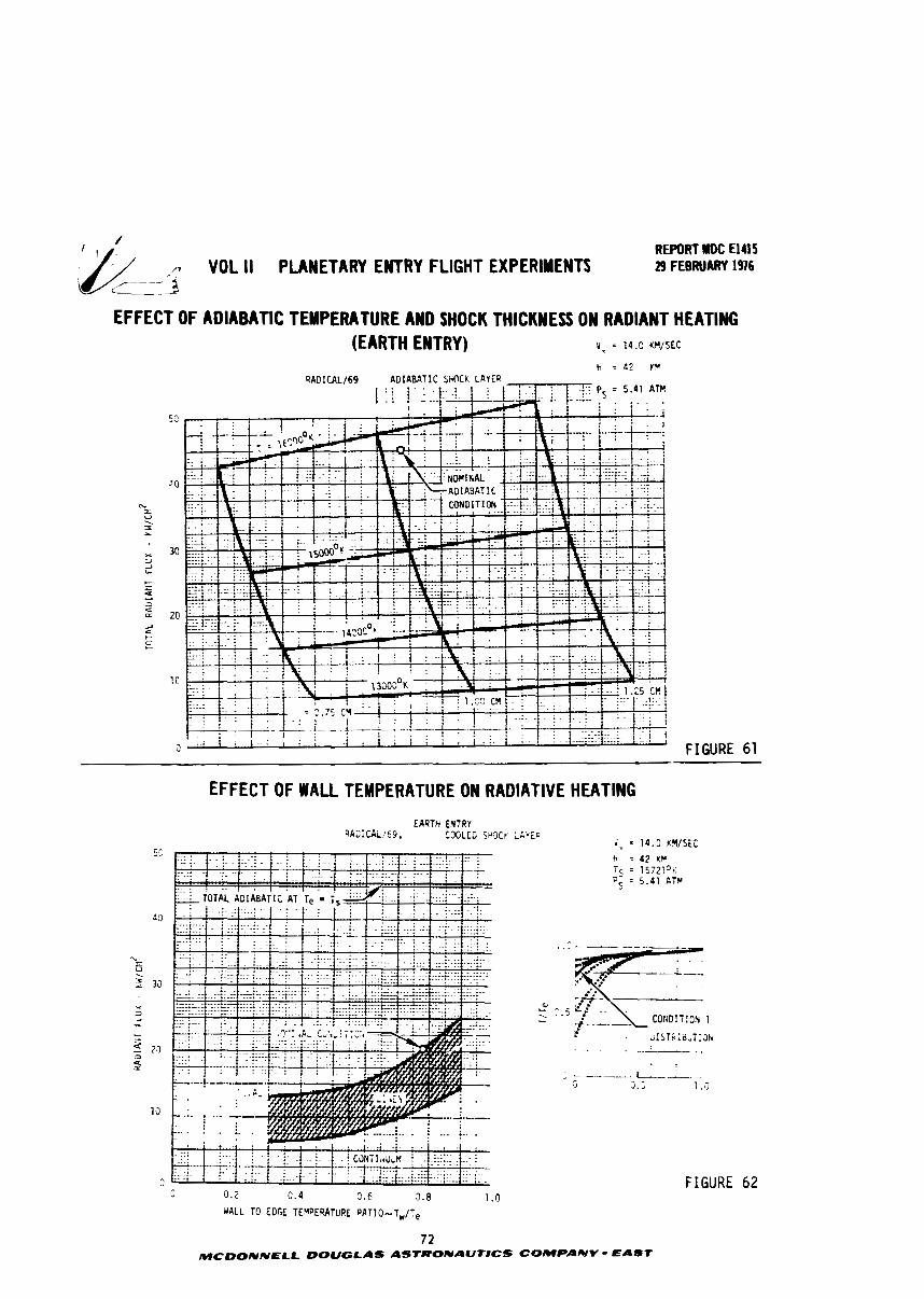
REPORT U I C El415 .- VOL I1 PLANETARY ENTRY FLIGHT EXPERIMENTS . ,
29 FEBRUARY 1976 <--- ---a EFFECT OF ADIABATIC TEMPERATURE AND SHOCK THICKNESS ON RADIANT HEATING
(EARTH ENTRY) Y= = 1u.c W/SEC
h = 42 YY
FIGURE 61
EFFECT OF WALL TEMPERATURE ON RADIATIVE HEATING
EARTH ENTRY 9ACICAL!69, CJOLECI SrO(
.; . I . . . I .. . , I ,
i I t j ~ L 8 -:y[:i:::-. . . . . .i.: . . .
C 0.2 0.4 0.6 3.8 1 .O WALL TO EDGE TEYPERATURE P A T I O - - T W I T e
FIGURE 62
72 MCOONNELL DOUGLAS ASTRONAUtICS COMPANY - EAST
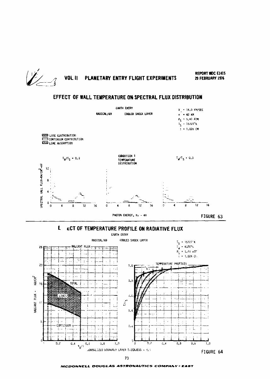
YOL li PLANETARY ENTRY FLIGHT EXPERIMENTS REPORT IIDC El415
.4- 29 FEBRUARY 1976 '---::--4
EFFECT OF WALL TEMPERATURE ON SPECTRAL FLUX DISTRIBUTION
EARTH ENTRY Y . = 14.0 KHISEC RADICK/69 COOLED SHOCK U Y E R n = 4 Z H
Ps = 5.41 ATU
TS = 15721°K
: = 1.028 CU
LIRE COIITRI W T I O l i 0 CmTI t iuun CONTRIBUTION
LINE &SDRPTI@I
PHOTOti ENERGY, hv - eY FIGURE 63
L cCT OF TEMPERATURE PROFILE ON RADIATIVE FLUX EARTH ENTRY
RADICAL169 COOLED SHOCK LAYFR
1 .o TEWERATURE PROFILES
0.6
d.6 "7 - \ C
3.4
,tORl&LIZtD b0UrtDAi:Y LAYER TI I IUG~ESS - Y, : FIGURE 64
MCDONNELL DOUGLAS ASTRONAUTICS COMPAlbV - EAST
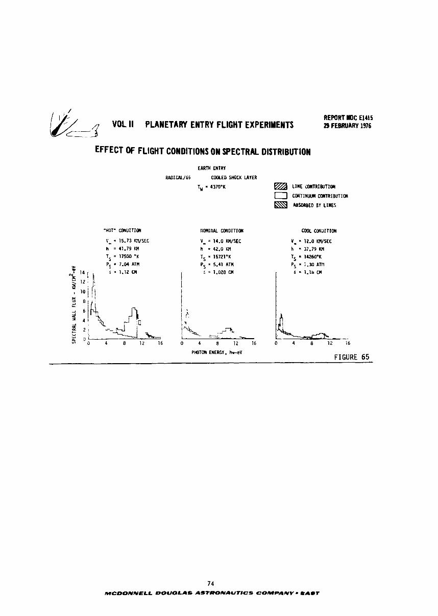
REPORT llOC 5415 VOL II PLANETARY ENTRY FLIGHT EXPERIMENTS 29 FEBRUARY 1976
EFFECT OF FLIGHT CONDITIONS ON SPECTRAL DISTRIBUTION
EARTH ENTRY
R A D I U l I B E COOLED SHOCK UYER
T,, = 1370°K a L I ~ E WRIBUTIOW
0 COMTINW UIHTRIBUTIW
ABSORBED BY LIMES
HOT* WUITIW t t ~ n ~ t ( ~ t C W D I T I ~ cool c c r n ; i ~ ~ r c # r
PHOTON ENERGY. b e V FIGURE 65
74 MCDONNELL DOUGLAS AStRONAUTlCS COMPANV = EAST
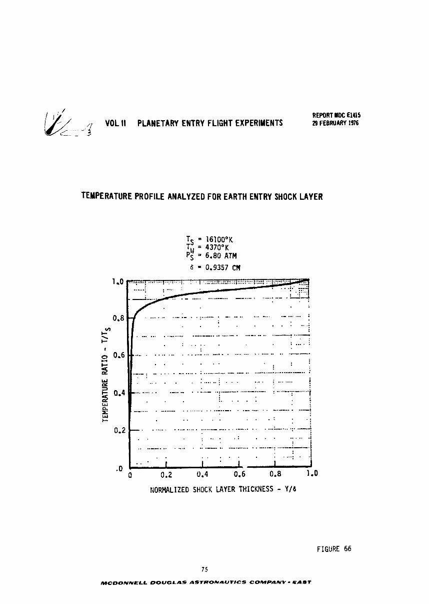
& ----T VOL II PLANETARY ENTRY FLIGHT EXPERIMENTS L -2
REPORT BOC El415 29 FEBRUARY f 976
TEMPERATURE PROFILE ANALYZED FOR EARTH ENTRY SHOCK LAYER
TS = 16100°K TW = 4370°K PS = 6.80 ATM
6 = 0.9357 CH
IiORMALIZED SHOCK LAYER THICKNESS - Y / b
FIGURE 66
7 5
MCDONNELL DOUGLAS ASTRONAUTICS COMPANV - EAST
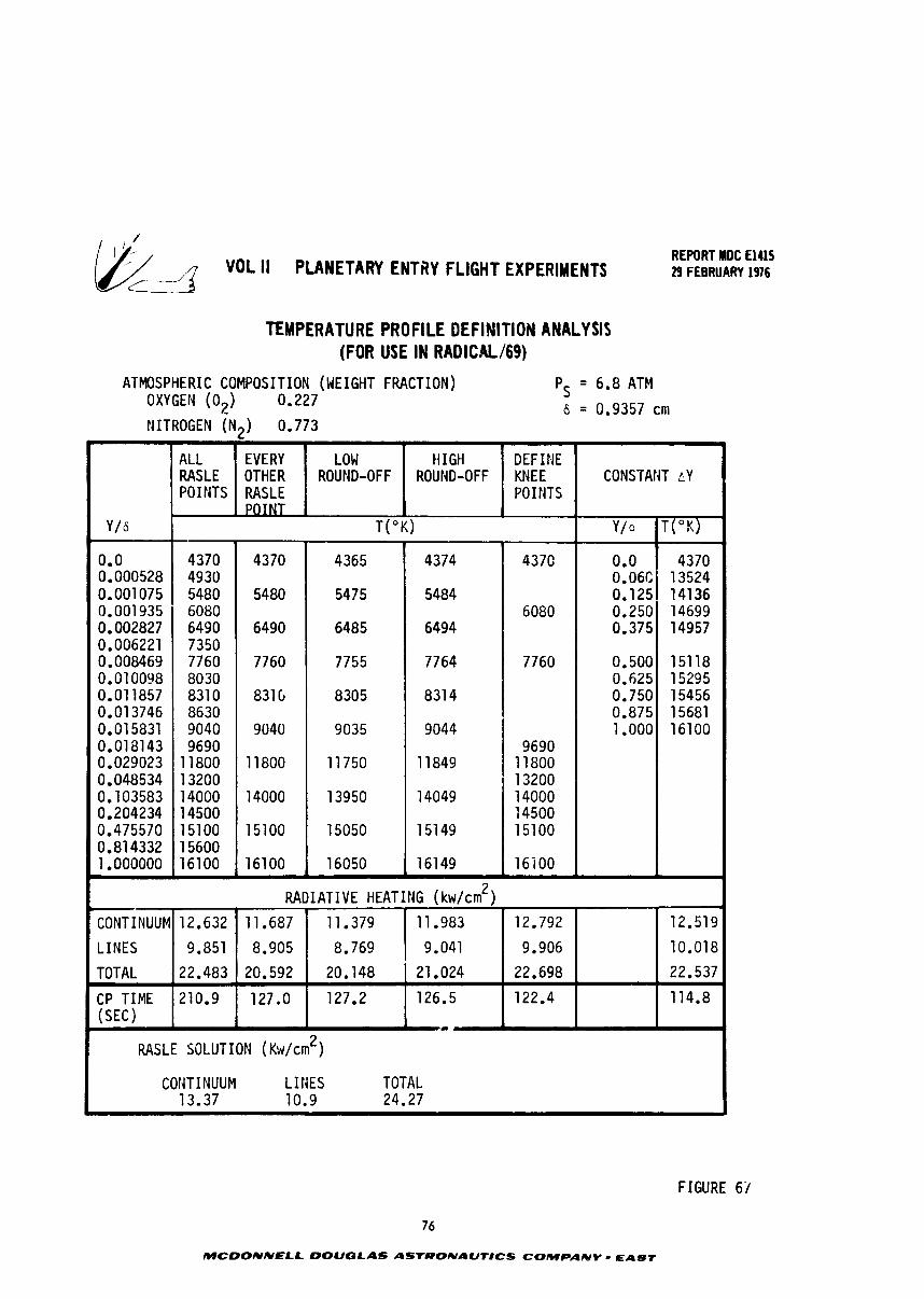
REPORT MDC El415 VOL 11 PLANETARY ENTfiY FLIGHT EXPERIMENTS 29 FEBRUARY 1976
L
TEMPERATURE PROFILE DEFINITION ANALYSIS (FOR USE IN RADICALl69)
ATMOSPHERIC COMPOSITION (WEIGHT FRACTION) OXYGEN (02) 0.227
PS = 6.8 ATM
6 = 0.9357 cm NITROGEN (N2) 0.773
CONSTANT f i Y
Y / 6
0.0 0.000528 0.001075 0.001 935 0.002827 0.006221 0.008469 0.010098 0.011857 0.01 3746 0.015831 0.0181 43 0.029023 0.048534 0.103583 0.204234 0.475570 0.81 4332 1.000000
- RADIATIVE HEATING (kw/cm2)
CONTINUUM12.632 11.687 11.379 11.983 12.792 12.519
LINES 9.851 8.905 8.769 9.041 9.906 10.018
TOTAL 22.483 20.592 20.148 21 -024 22.698 22.537
CP TIME 210.9 127.0 127.2 126.5 122.4 114.8 (SEC)
a
I COFJTINUUM LINES TOTAL 13.37 10.9 24.27
-
FIGURE 61
ALL RASLE POINTS
76
MCDONNELL DOUGLAS ASTRONAUTICS COMPANY r EAST
EVERY OTHER RASLE POINT
T(OK)
LOW ROUND-OFF
4370 4930 5480 6080 6490 7350 7760 8030 8310 8630 9040 9690
1 1800 13200 14000 14500 151 00 1 5600 16100
ti I GH ROUND-OFF
4370
5480
6490
7760
8316
9040
1 1800
14000
151 00
16100
DEFINE KNEE POINTS
4365
5475
6485
7755
8305
9035
11 750
1 3950
15050
16050
4374
5484
6494
7764
831 4
9044
11 849
14049
15149
16149
437C
6080
7760
9690 1 1800 13200 14000 14500 15100
16i 00
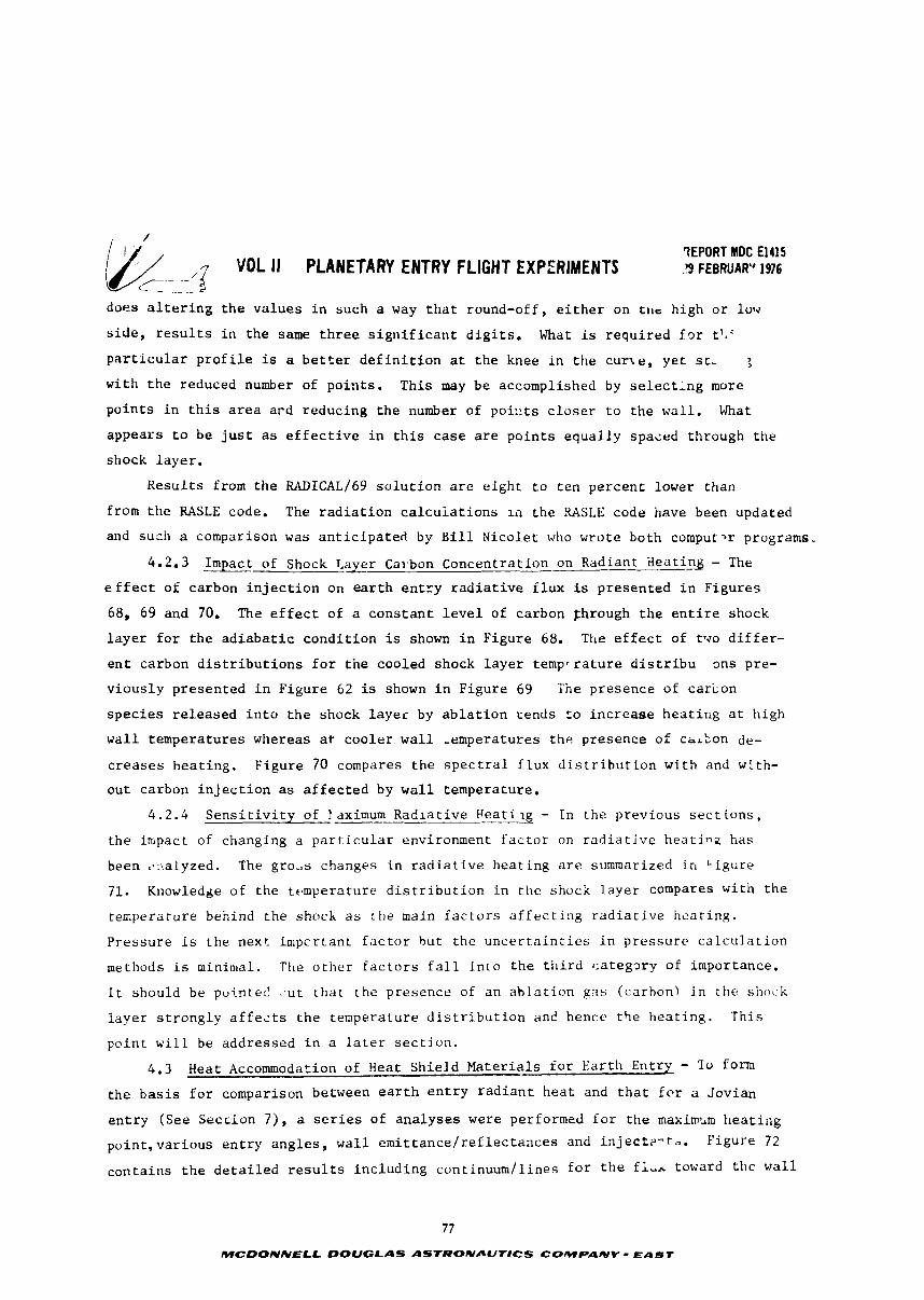
7EPORT MDC El415 0- VOL II PLANETARY ENTRY FLIGHT EXPERIMENTS .!9 FEBRUAR" 1976
does a l t e r i n g t h e v a l u e s i n such a way t h a t round-off , e i t h e r on h igh o r low
s i d e , r e s u l t s i n t h e same t h r e e s i g n i f i c a n t d i g i t s . What is r e q u i r e d f ~ r tl&'
p a r t i c u l a r p r o f i l e is a b e t t e r d e f i n i t i o n at t h e knee i n t h e c u r l e , y e t stL ;
wi th t h e reduced number of p o i n t s . T h i s may be accomplished by selecting more
p o i n t s i n t h i s a r e a a r d r educ ing t h e number of poi::ts c l o s e r t o t h e wa l l . \ h a t
a p p e a r s t o b e j u s t as e f f e c t i v e i n t h i s c a s e a r e p o i n t s e q u a l l y spaced through t h e
shock l a y e r .
R e s u l t s from t h e RADICAL/69 s o l u t i o n a r e e i g h t t o t e n p e r c e n t lower t han
from t h e RASLE code. The r a d i a t i o n c a l c u i a t i o n s I n t h e USLE code have been updated
and such a comparison was a n t i c i p a t e d by B i l l N i c o l e t who wro te bo th comput-r programs.
4 . 2 . 3 Impact of Shock T,a_lrer Cat-bon Concentrat ion-on Radiant Sea t i% - The
e f f e c t o f carbon i n j e c t i o n on e a r t h e n t r y r a d i a t i v e f l u x is p r e s e n t e d i n F i g u r e s
68, 69 and 70. The e f f e c t of a c o n s t a n t l e v e l of carbon fhrough t h e e n t i r e shock
l a y e r f o r t h e a d i a b a t i c c o n d i t i o n is shown i n F i g u r e 68. The e f f e c t of t v o d i f f e r -
e n t carbon d i s t r i b u t i o n s f o r t h e cooled shock l a y e r t e m p r r a t u r e d i s t r i b u 3ns pre-
v i o u s l y p r e s e n t e d i n F i g u r e 62 is shown i n F igu re 69 The p re sence of ca rcon
s p e c i e s r e l e a s e d i n t o t h e shock l a y e r by a b l a t i o n r ends t o i n c r e a s e hes t i r i g a t h igh
w a l l t empera tu re s whereas a t c o o l e r w a l l -empera tures t h e p re sence o f c h ~ k o n de-
c r e a s e s h e a t i n g . F i g u r e 70 compares t h e s p e c t r a l f l u x d i s t r i b u t i o n w i t h and w:th-
o u t carbon i n j e c t i o n as a f f e c t e d by w a l l t empera ture .
4 .2 .4 S e n s i t i v i t y of taximum Radiative F e a t i ~ g - I n t h e p r e v i o u s s e c t i o n s ,
t h e i rr~pact of changing a p a r t i c u l a r environment f a c t o r on r a d i a t i v e h e a t i n g h a s
been ..:.:alyzed. The gro,s changes i n r a d i a t i v e h e a t i n g a r e summarized i n L i g u r e
71. Knowledge o f t h e t t ,mpera ture d i s t r i b u t i o n i n t h e shock l a y e r compares w i t h t h e
t e z p e r a t u r e behind t h e shock a s t h e main f a c t o r s a f f e c t i n g r a d i a t i v e h e a t i n g .
P r e s s u r e i s t h e nex t i m p c r t a n t f a c t o r b u t t h e u n c e r t a i n t i e s i n p r e s s u r e c a l c u l a t i o n
methods is minimal . The o t h e r f a c t o r s f a l l i n t o t h e t h i r d c a t e g x y of importance.
I t should be poi -n te l <:ut t h a t t h e p re sence of an a b l a t i o n gas ( ca rbon) i n t h e s h o c k
l a y e r s t r o n g l y a f f e ~ t s t h e t empera tu re d i s t r i b u t i o n an6 hence t h e h e a t i n g . T h i s
p o i n t w i l l be add re s sed i n a l a t e r s e c t i o n .
4 . 3 Heat Accommodation of Heat S h i e l d M a t e r i a l s f o r E a r t h En t ry - To form
t h e b a s i s f o r comparison between e a r t h e n t r y r a d i a n t h e a t and t h a t f o r a Jovian
e n t r y (See Secc ion 7 ) , a s e r i e s of a n a l y s e s were performed f o r t h e maximbm h e a t i n g
p o i n t , v a r i o u s e n t r y a n g l e s , w a l l e m i t t a n c e / r e f l e c t a n c e s and i n j e c t ? - t a . F igu re 72
c o n t a i n s t h e d e t a i l e d r e s u l t s i n c l u d i n g con t inuum/ l ines f o r t h e flu.-. toward t h e w a l l
77
MCDONNELL DOUGLAS ASTRONAUTICS COMPANY - EAST
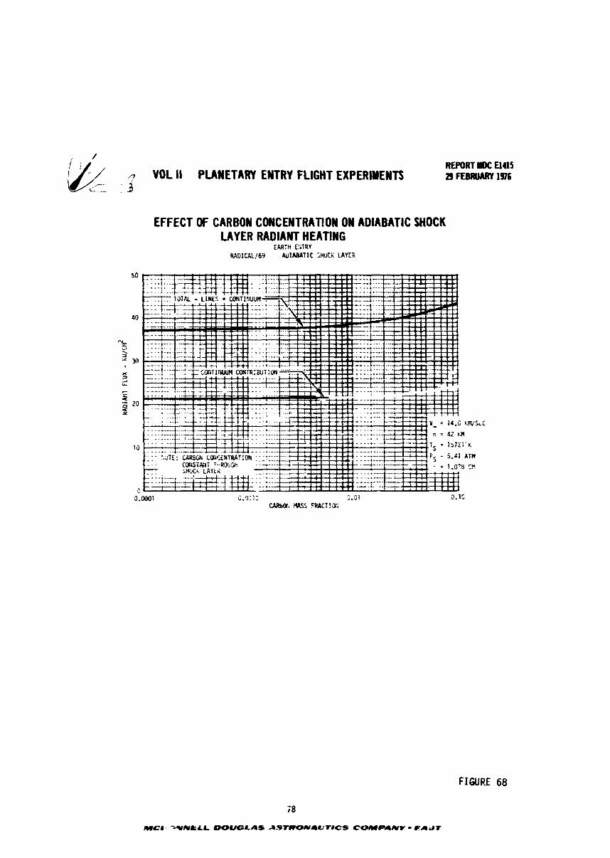
VOL Ii PLANETARY ENTRY FLIGHT EXPERIMENTS
EFFECT OF CARBON CONCENTRATION ON ADIABATIC SHOCK LAYER RADIANT HEATING
REPORT I)(: ElUS 29 rrSRUARY 1%
FIGURE 68
REPORT I)C UUS - VOL II PLANETARY ENTRY FLIGHT EXPERIMENTS 29 FEBRUARY 1976 L -.k
EFFECT OF WALL TEMPERATURE ON RADIATIVE HEATING WITH CARBON INJECTION
F;TRV V = i4.O WSEC 3: 1 C&i; 69 C@)LiO SHCCL: LAYER fi = 42 K?l
T = 15721'K
50 P: = 5.41 Pin i = i .zem
c. u 5.2 -.'t 1.f .-c. : -0 . .
&: -C TC*TE;>T-R S&il: - - - I . . FIGURE 69
EFFECT OF WALL TEMPERATURE ON SPECTRAL FLUX WiTH CARBON INJECT!ON
>;:::* z . - . - . . % I
:.-*->*, c.':=.Jv , r, -c, FIGURE 70 73
OUGLAS ASTRONaUTlCS COMPAUV - EL)ST
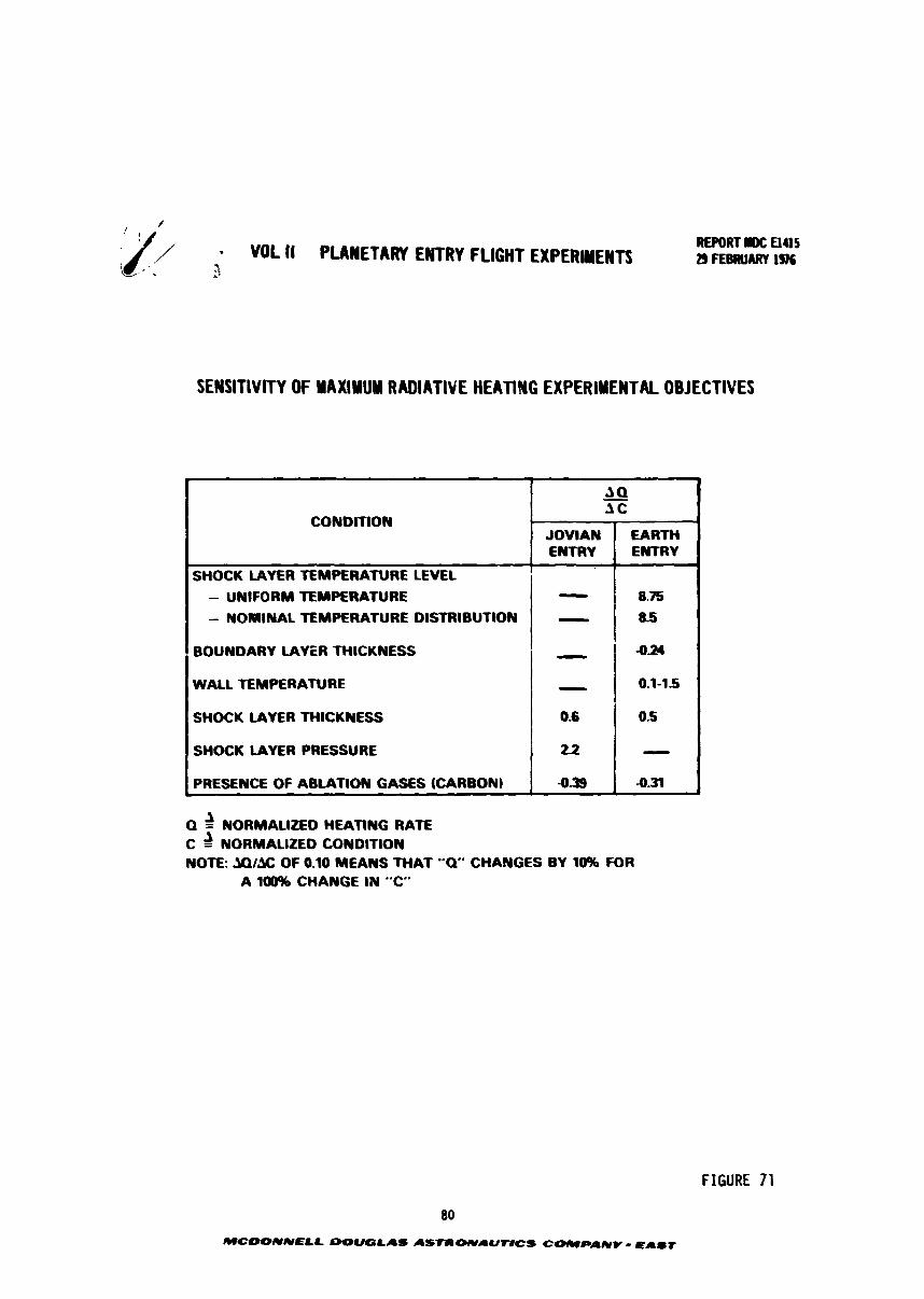
// - VOL I1 PUMETARV ENTRY FLIGHT EXPERIMENTS i~--, .' Z
SENSITIVITY OF YAXIYUY RADIATIVE HEATING EXPERIMENTAL OBJECTIVES
Q 2 NORMALIZED HEATING RATE C 2 NORMALIZED CONDITION NOTE: JOIX OF 0.10 MEANS THAT "Q" CHANGES BY 10% FOR
A 100% CHANGE IN " C
t
CONDITION
FIGURE 71
80
MCDONNELL DOU(3LAS ASTIP WI.UTVCS COICIPAWV - QAST
JQ - AC
JOVIAN ENTRY
SHOCK LAYER TEMPERATURE LEVEL - UNIFORM TEMPERATURE - NOMINAL TEMPERATURE DISTRIBUTION
BOUNDARY LAYER THICKNESS
WALL TEMPERATURE
SHOCK LAYER THICKNESS
SHOCK LAYER PRESSURE
PRESENCE OF ABLATION GASES (CARBON)
EARTH ENTRY
I - 8.75 - 1 115
- - 0.6
22
9.39
-024
0.1-15
0-5
- 4-31
b
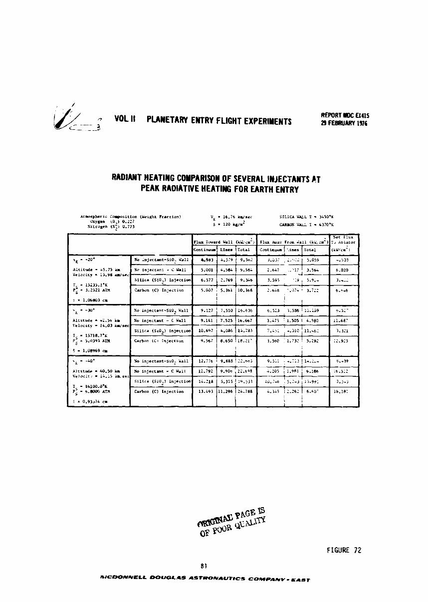
' /
& - VOL II PLANETARY ENTRY FLIGHT EXPERIMENTS a <.-.--e
RADIANT HEATIWG COYPARISOW OF SEVERAL JNJECTAKTS C.T PEAK RADIATIVE HEATING FOR EARTH ENTRY
Atwspfrer i s m s i t i o a (Liclght Fracr ion) VE l t , i 6 &,st< SILICA W L T - 3150.K *sen \0*1 0.22:
S l t r ogcn (S,) 0.773 5 = 13.3 h i m - 7 . 1370.K
FIGURE 72
, - Scr f l u x Flux Toward Uli (ad;i;ca-) F l u x h a ? F r a X a l i Ili' ,;e-1 Tj Aoiatar
Tota l G m t i w u e ! '-ines ( ~ L S ~ C S - j
8 1
mJCDOIVNPLL DOUGLAS ASfRONAUrICS COMPANY - EAST
?, - -20.
Ai t icude - s 5 . 5 lo Yeloci ty - i3.9& d s c c
i = i5235.1.K ?: = 3.2521 A l l
? - 1.06803 c r
Altitude r2.50 h Ce'riocity - 14.03 W s e c
1, - 15718. i .~ 1; - 5.0393 A T S
J - 1.08969 cm
.. - -a* L
Al r i t udc - U).SO i a f c ! oc i : : - A A. ii a- s tc
T - 16100.0-1; ?f - b.LRMr) AT3
i = 0.93jiL cr
.% .njecturr-SiO.. Sa:: -.523
So injectan: - i Y l l i 2.6i: ' 3.56; 6.020 a-
S i l i c a (SiO,) Injection 3.595 ' ,:j , 5.9-4 3.-::
k - b z n (Cf I n j e c t i ~ n 7 5.361 1 0 8 8 .J:i : 3.;;: 6.a-6 1 ! I
So in jec tmt-510, Xa l l 9.127 5-52 .
?k i n j e c t a n t - t Yal l 9.121 j 7,525 f 16-66: '
S i l i c a (SlJ,) i n : e t c~oo l0.6Qi &.CIS 1 iL.783 i
Carboe (CI f n j ec t aon 9.56i ! 8.655 ! 18.217
!
! ~u i n j e c t a n t - ~ i o , G a l l 1 ::.be3
i n j e c t a a t - C u a l l ; 22.6'38 --------------- S i l i c a (Sio I 1n:ec:ian 14.218 1 5 . 3 i j i 9 . 5 3 3 2 L
Carbon (C) i n j e c t i o n 13.493 i1.296 ! 2;.?89
I
3.-75 ! 1.505 i 4.980
- ,-. :..>A - - 3 i ~ 11..62
3.56C i 1.732 ! 3-29:
i
9 . j i i : -.::? i-.:--
i . X 5 i . 9 8 i 6.i86
IS.;-$ : 5.:-3 i5.99: 1
-.3i5 2.26: 1 6.kO-
i i , I i
ii.68:
3.3:l
;2.3:5
I
9.-33
i6.5::
3 . 5 - j
lS.;@:
*
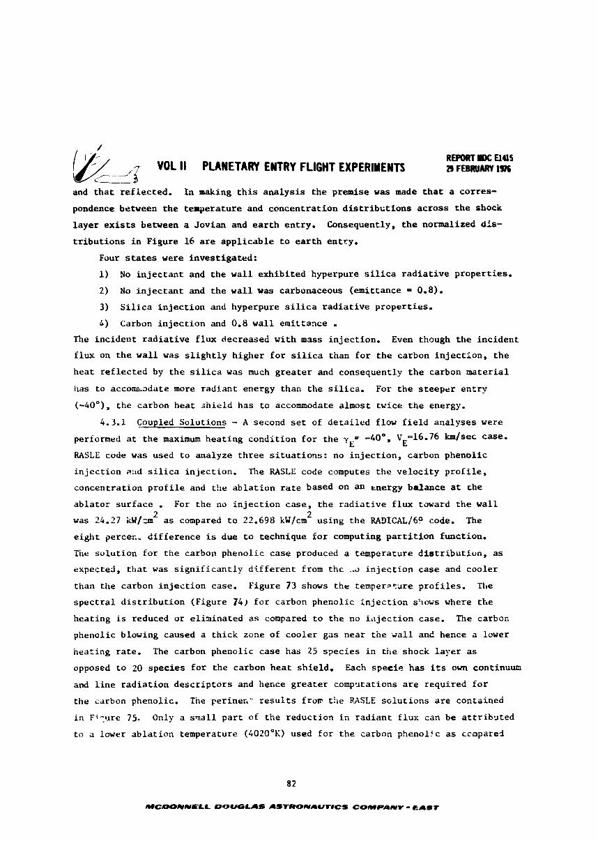
VOL II PLAlETARY ENTRY FLIGHT EXPERIUEYTS REPORT DC U4l5
'/- .. -/-$~ 29 FEsRUARV 1976
and t h a t r e f l e c t e d . I n making t h i s a n a l y s i s t h e premise w a s made t h a t a cor res -
pondence between t h e temperature and concen t ra t ion d i s t r i b c t i o n s a c r o s s t h e shock
l a y e r e x i s t s between a Jovian and e a r t h entry . Consequently, t h e normalized dis-
t r i b u t i o n s i n Figure 16 are a p p l i c a b l e t o e a r t h entry .
Four states were inves t iga ted :
1 ) No i n j e c t a n t and t h e w a l l exh ib i t ed hyperpure s i l i c a r a d i a t i v e p roper t i e s .
2) No i n j e c t a n t and t h e w a l l was carbonaceous (emittance = 0.8).
3) S i l i c a i n j e c t i o n and hyperpure s i l i c a r a d i a t i v e p roper t i e s .
A) Carbon i n j e c t i o n and 0.8 w a l l emit tance . The i n c i d e n t r a d i a t i v e f l u x decreased w i t h m a s s i n j e c t i o n . Even though t h e i n c i d e n t
f l u x on t h e w a l l w a s s l i g h t l y h igher f o r s i l i c a than f o r t h e carbon i n j e c t i o n , t h e
hea t r e f l e c t e d by t h e s i l i c a w a s much g r e a t e r and consequently t h e carbon m a t e r i a l
has t o a c c o u a d a t e more r a d i a n t energy than t h e s i l i c a . For t h e s t e e p e r e n t r y
(-40°), t h e carbon hea t s h i e l d has t o accommodate almost twice t h e energy.
4.3.1 Coupled So lu t ions - A second s e t of d e t a i l e d flow f i e l d ana lyses were
performed at t h e maximum h e a t i n g cond i t ion f o r t h e y = -40°, V ~ 1 6 . 7 6 b / s e c case- E E RASLE code was used t o analyze t h r e e s i t u a t i o n s : no i n j e c t i o n , carbon phenol ic
i n j e c t i o n ?:id s i l i c a i n j e c t i o n . The RASLE code computes t h e v e l o c i t y p r o f i l e ,
concentra t ion p r o f i l e and t h e a b l a t i o n r a t e based on an energy ba lance at rhe
a b l a t o r s u r f a c e . For t h e no i n j e c t i o n case, t h e r a d i a t i v e f l u x toward t h e w a l l 2 2
was 24.27 icW/=n a s compared t o 22.698 kW/cm us ing the RADICAL/6P code. The
e i g h t pe rce t - d i f f e r e n c e is due t o technique f o r computing p a r t i t i o n function.
The s o l u t i o n f o r t h e carbon phenol ic case produced a temperature d i s t r i b u t i o n , as
expected, t h a t w a s s i q n i f i c a n t l y d i f f e r e n t from t h c ,a i n j e c t i o n c a s e and coo le r
than t h e carbon i n j e c t i o n case. Figure 73 shows t h e temperPCare p r o f i l e s . n r e
s p e c t r a l d i s t r i b u t i o n (Figure 74) f o r carbon phenol ic i n j e c t i o n shows where t h e
heat ing is reduced o r e l i a i n a t e d a s compared t o t h e no i l l j e c t i o n case. The carbon
phenolic blowing caused a t h i c k zone of coo le r gas near t h e g a l l and hence a lower
hea t ing r a t e . The carbon phenol ic case has 25 s p e c i e s i n t h e shock l a y e r as
opposed t o 20 s p e c i e s f o r t h e carbon h e a t sh ie ld . Each specie has i ts own continuum
and l i n e r a d i a t i o n d e s c r i p t o r s and hence g r e a t e r comp*~tat ions a r e requ i red f o r
t h e carbon phenolic. The per inec ' r e s u l t s f r o v t h e FASLE s c l u t i o n s a r e contained
i n F i y r e 75. Only a smal l p a r t of t h e reduc t ion i n r a d i a n t f l u x can be a t t r i b 3 t e d
t o a lower a b l a t i o n temperature (4020°K) used f o r t h e carbon phenol ic a s ccmpared
82
MCIOOUIVELL DOUGLAS AS-NAUT8CS C-PANV - EAST
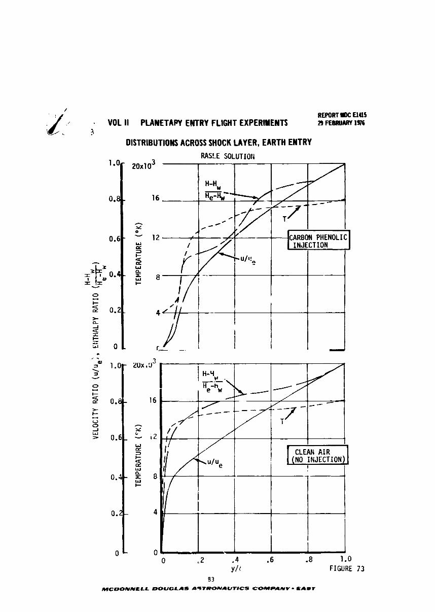
REPORT IK: UUS - VOL II PWNETAPY ENTRY FLIGHT EXPERIYENTS 29 FEBRUARY 1976
3 DlSTRlBUT IONS ACROSS SHOCK LAYER, EARTH EN1 RY
RASLE SOLUTION CI
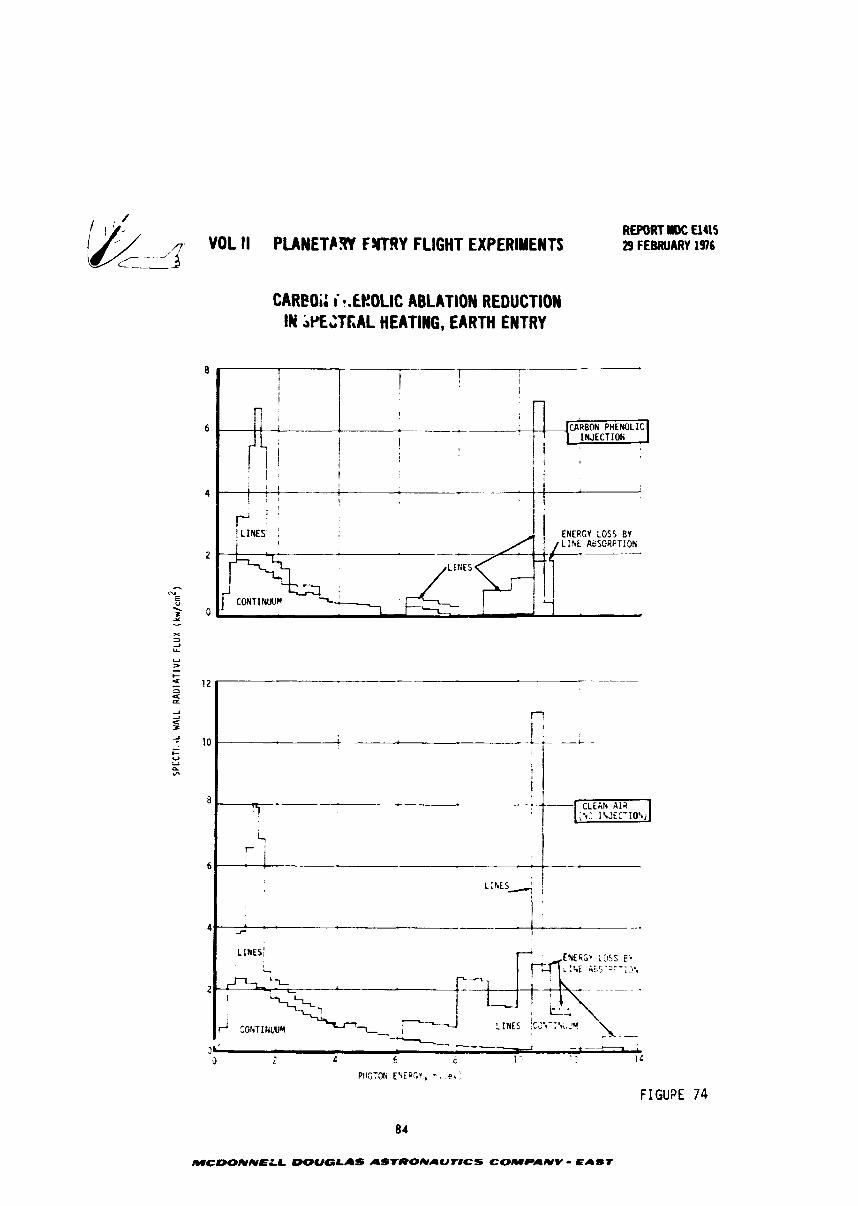
VOL II PLANETCRY FWRY FLIGHT EXPERIMENTS
CAREOi: i *.€t!OLIC ABLATION REDUCTION IIY iPECTFIAL HEATING, EARTH ENTRY
REPORT rDC a415 29 FEBRUARY 1976
FIGUPE 74
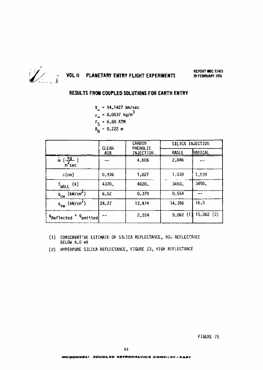
- VOL ll PLANETARY ENTRY FLIGHT EXPERIMENTS REPORT llOC El415 29 FEBRUARY 1976
RESULTS FROM COUPLED SOLUTIONS FOR EARTH ENTRY
Vm = 14,1427 km/sec
= 0.0037 kg/m 3 '' m
FS = 6.80 ATM
RN = 0.222 m
(1 ) CONSERVATIVE ESTIMATE OF S I L I C A REFLECTAHCE , 90% REFLECTANCE BELOW 6.0 eV
(2) HYPERPURE S I L I C A REFLECTANCE, FIGURE 23, HIGH REFLECTANCE
FIGURE 75
&
( + I m sec
6 (m)
T H A ~ ~ (K)
qcw (kw/cmL)
q w ( k~/cm*)
q ~ e f 1 ected + 'emi t ted
S I L I C A INJECTION CLEAN
A I R - -
0.936
4370.
6.52
24.27
--
RASLE
2.846
1,039 - -.
3450.
0.554
14.356
9.062 (11
CARBOtl PHENOL I C INJECTION
4.006
1.027 .- -
4020.
0.379
12.474
2.554
'MI! I CAL
--
1 .C39
3450.
-- 16.5
15.082 (2)
REPORT DC Elus VOL II PLANETARY EWTRY FLIGHT EXPERIMENTS 29 F EBRUARY 1976
t o the no i n j e c t i o n case (4370'~). The carbon phenolic i n j e c t i o n case s h w s about
a 502 reduction i n r a d i a t i v e hea t ing and almost a complete e l iminat ion of convec-
t i v e heating (from 6.52 t o 0,379 kw/cmL).
l h e s i l i c a i n j e c t i o n case had a temperature d i s t r i b u t i o n t h a t was d i f f e r e n t
than the o ther cases examined (See Figure 76). Tventy spec ies were considered i n
the analysis. Also t h e ab l a t i on temperature (3450°K) used f o r s i l i c a was much 2
lower than t h a t f o r t he other mater ia l s , Even so, t he r a d i a t i v e f l u x (14.356 kW/cm ) 2
was higher than t h a t predicted f o r carbon phenolic (12.474 kW/cm ). A s imi l a r
increzse was experienced i n t h e f i r s t study of carbon and s i l i c a in jec t ion . 2
The r a d i a t i v e f l ux computed f o r t he 3 4 5 0 ° ~ s i l i c a wal l was 14.356 k /cm as
opposed t o 25.481°1i f o r t he 4370°K s i l i c a wal l , Cooling t h e wal l temperature
rap id ly decreases the r a d i a t i v e flux.
86
MCOONNELL W U G L I S ASTRONPUt8CS COMPANY - eAdT
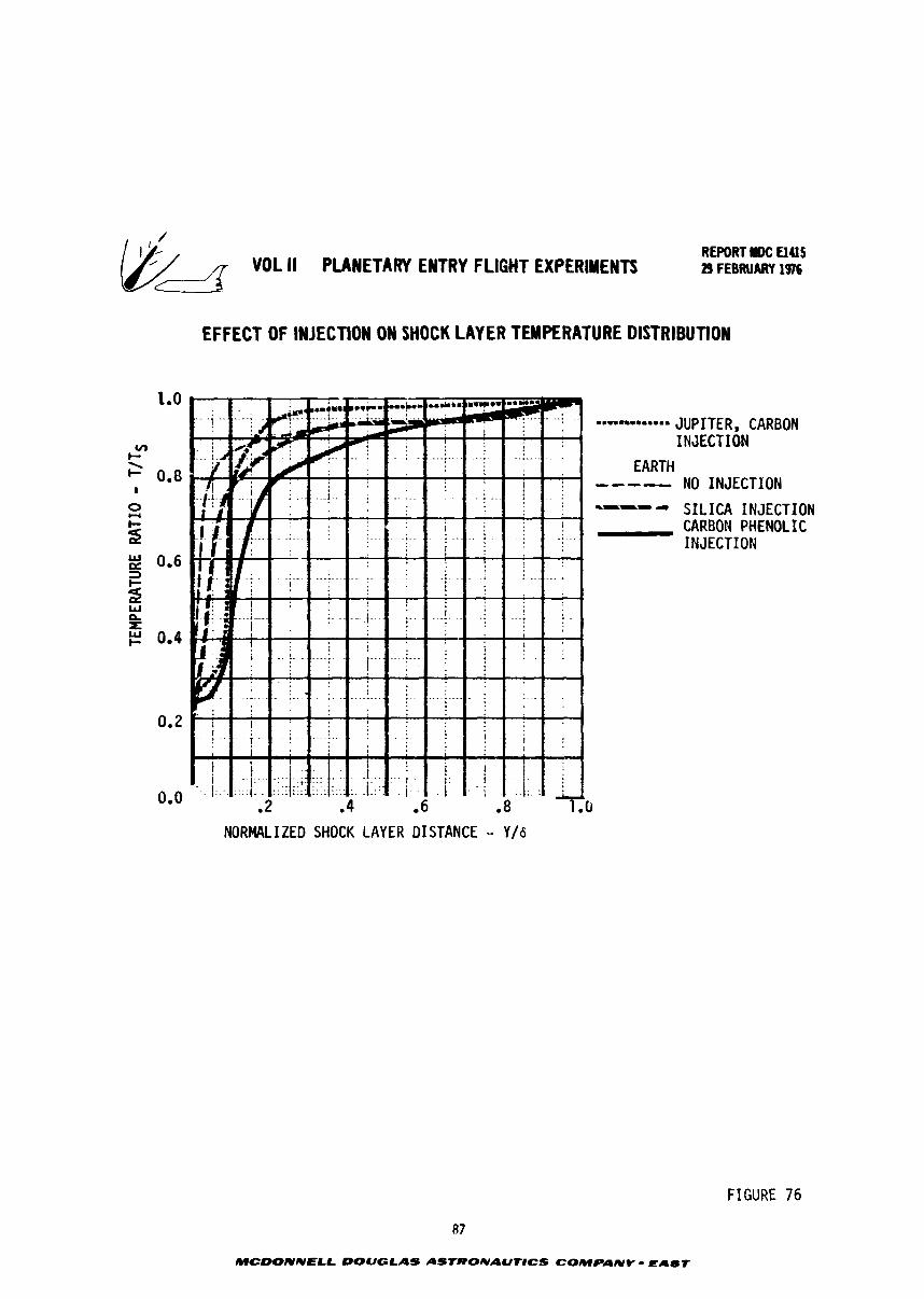
& VOL II PLANETARY ENTRY FLIGHT EXPERIMENTS REPORT IK: El415 29 FEBRUARY 197576
EFFECT OF INJECTION ON SHOCK LAYER TEMPERATURE DISTRIBUTION
NORMALIZED SHOCK LAYER DISTANCE - Y/6
87
MCOONNELL DOUGLAS ASIRONAUTICS COMPANY - EAUf
M L I1 PLANETARY EWRY FLIGHT EXPERIYENTI REPORT rOC UU5
d 29 FEBRUARY 1976
5.0 EARTH ENTRY MANEWERS
*.z .naneurer requirements necessary t o achieve a range of s t e e p , f a s t e n t r y
c0nditior.s a r e developed i n t h i s sec t ion . This informat i o n g i v e s experiment p lanners
a n i n i t i a l i n s i g h t i n t o t h e scope and n a t u r e of t h e o r b i t a l miss ion phase. Addi-
t i o n a l l y , t h e s e d a t a provide a mans of comparing t h e i n i t i a l e n t r y cond i t ions
requ i red f o r environment s imula t ion (Section 3) wi th t h e performance c a p a b i l i t y of
t y p i c a l S h u t t l e launched boos te r s (Sect ion 7).
The e a r t h o r b i t maneuver requirements is divided i n t o f o u r p a r t s . The f i r s t
d e s c r i b e s t h e bas ic , high apoapsis d e o r b i t maneuver necessary t o produce t h e extreme
e n t r y cond i t ions of i n t e r e s t . The second p a r t d e f i n e s t h e required v e l o c i t y incre-
ments f o r each maneuver b u m as a f u n c t i o n of e n t r y condi t ions . The t h i r d p a r t
shows r e p r e s e n t a t i v e mission p r o f i l e s i n terms of ascen t and descen t ground t racks .
The f o u r t h p a r t i l l u s t r a t e s t h e c o r r e l a t i o n of environment s imula t ion wi th v e l o c i t y
increment requirements us ing r a d i a t i v e h e a t f l u x a s t h e example.
5.1 Deorbit Maneuvers - The s e l e c t e d d e o r b i t maneuver s t r a t e g y is p i c t o r i a l l y
descr ibed i n Figure 77. This h igh ly e l l i p t i c a l t r a j e c t o r y technique, suggested
by NASA-Ames, a l lows high speed and angle e n t r i e s t o be e f f i c5enLly achieved from
a 1 0 ~ 7 , c i r c u l a r i n i t i a l o r b i t . Compared wi th a d i r e c t d e o r b i t from low a l t i t u d e ,
t h i s manewer s t r a t e g y reduces requ i red t h r u s t t o those normally a t t a i n -
a b l e wi th t y p i c a l S h u t t l e upper s t a g e s and minimizes t h e v e l o c i t y increment (AV)
needed f o r s t e e p e n t r i e s .
As shown i n Figure 77, t h r e e maneuver burns a r e used t o accomplish d e o r b i t
beginning i n a 296 km c i r c u l a r o r b i t . This i n i t i a i o r b i t s e l e c t e d as t y p i c a l
of S h u t t l e i n s e r t i o n condi t ions . The f i r s t maneJver is a t a n g e n t i a l , poslgrade
burn t h a t i n i t i a t e c Hohmzinn t r a n s f e r t o a p r e s e l x t e d apoapsis a l t i t u d e (R ). The a va lue of R is t r e a t e d a s a b a s i c mission v a r i a b l c and was v a r i e d from 2 t o 40 e a r t h a r a d i i above t h e e a r t h ' s center . The second maneuver is a ~ a n g e n t i a l , r e t r o g r a d e
burn appl ied a t apoapsis t o achieve t h e d e s i r e d e n t r y angle. This maneuver a l s o
a d j u s t s t h e t r a j e c t o r y s o t h a t e n t r y occurs a t a proper l o c a t i o n r e l a t i v e t o ;tie
d e s i r e d impact point . Any plane change c o r r e c t i o n s required t o a t t a i n such an en t ry
l o c a t i o n would be included i n t h e second burn by vec to r summing. The t h i r d maneuver
burn is app l ied a long t h e f l i g h t path j u s t be fore e n t r y t o i n c r e a s e v e l o c i t y t o
the d e s i r e d value.
88
MCOONNELL OOUOLAS ASTCIONAUT#CS COMPANY - reCAUr
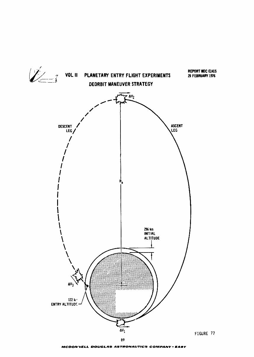
REPORT NDC El415
7- - VOL II PLANETARY ENTRY FLIGHT EXPERIMENTS 29 FEBRUARY 1976
DEORBIT MANEUVER STRATEGY
/ I
DESCENT LEG / /
I I / I I I I I I I I \ \
296 km INITIAL
\ \
ENTRY ALTITUDE
FIGURE 77
/ /
REPORT MDC El415 /& 1- VOL II PLANETARY ENTRY FLIGHT EXPERIMENTS 29 FEBRUPRY 1976 /- -----
Figure 78 shows t h e e n t r y v e l o c i t y t h a t would r e s u l t i f on ly t h e f i r s t two
maneuver burns were accomplished. A s ind ica ted , each combination of e n t r y angle
and apoapsis d i s t a n c e produce a unique va lue of e n t r y v e l o c i t y t h a t dec reases w i t h
s t e e p e r ang les and i n c r e a s e s wi th h igh apoapsis d i s t ances . A s apoapsis i n c r e a s e s ,
t h e e f f e c t of e n t r y ang le d i n i n i s h e s t o e s s e n t i a l l y ze ro and e n t r y v e l o c i t y approaches
an upper l i m i t of about 11 km/sec. This is w e l l below t h e 1 3 t o 20 km/sec range of
r equ i red e n t r y v e l o c i t y ( re fe rence Sec t ion 3.0). Hence a t h i r d burn is always
required, t h e mangitude of xh ich is t h e d i f f e r e n c e between t h e requ i red e n t r y
v e l o c i t y and t h a t achieved by a two burn maneuver.
Figure 79 shows t h e miss ion t i m e i n t e r v a l r equ i red t o accomplish t h e d e o r b i t
maneuver. This is t h e e lapsed t i m e between t h e f i r s t maneuver burn and t h e beginning
of atmospheric e n t r y a t 122 km (400,000 f t ) . As shown, t h e time i n t e r v a l r equ i red
is a s t r o n g func t ion of apoapsis a l t i t u d e b u t e s s e n t i a l l y independent of e n t r y
angle
90
MCWNNELL DOUGLAS A57:~ONAUNCS COMPANV - EaLIYT
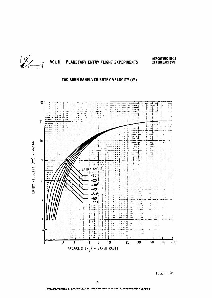
VOL I I PLANETARY ENTRY FLIGHT EXPERIMENTS
TWO BURN MANEUVER ENTRY VELOCITY (V')
REPORT I#DC El415 29 FEBRUARY 1976
APOAPSIS (R,) - E A H ~ H RADII Q
9 1
MCDONNELC OOUQLAS ASTRONAUT8CS COMPANY = E A m t
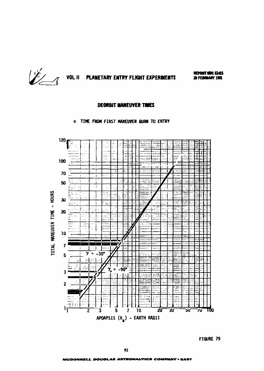
DEOBBJT WEUWER
o TI?€ FMM FIRST efB#EUUER BURN TO ENTRY
APOAPSIS (Ra) - EARTH R A D I I
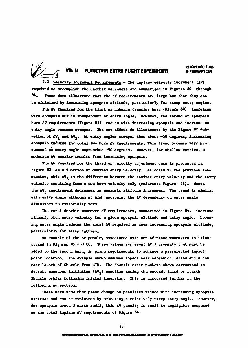
5.2 Velocity hcrenent bquircllrcnts - The inplaae ~ te loe i ty incrcrrcat (AV)
required t o accomplish the d w r b i t maneuvers are seaarized in Pigures 80 - These data i l l u s t r a t e that the AV requircrcats are large but that they cm
be minimized by increasing apoapais al t i tude, part icularly for steep entry Wt8, The AV required fo r the f i r s t o r hokrsna transfer burn (Figure 80) incmas9s
w i t h apoapsis but is in$epcndc~t of entry angle, Barever, the secoad o r apapal.
burn AV requirerents (Figure 81) reduce w i t h increasing apoap8is and iacrerst re
entry angle becomes steeper. The net effect is i l lus t ra ted by the Pigure 82 S i Q I
matioa of AVl artd AVZ, A t entry angles steeper than about -50 d e w , increasing
apoapsis raduces the t o t a l tvo burn AV requirements, This trend beuams very pre-
nounced & entry angle aoproaches -90 degrees. Hatcvcr, fo r s W w entries, a
roderate AV penalty resul ts fram increasing apoapsis,
The AV required for the third o r velocity adjust#nt burn is przaented i n
Figure 83 as a function of desired entry uslocity, As noted ia the previous sub-
section, this AV3 is the difference between the desired entry velocity and the entry
velocity result ing f r m a two bum velocity only (reference Figure 78)- Hence
the AV requirement decreases as apoapsis a l t i tude increases, The trend is sinilar 3 with entry angle altho-at high apoapsis, the AV dependency on entry angle
diminishes t o essentially zero,
The t o t a l deorbit maneuver AV requirements, sumarieed in Figure 84, increase
linearly with entry velocity for a given apoapsis a l t i tude and entry angle. Lower-
i n g entry angle reduces the t o t a l AV required as does increasing apoapsis a l t i tude,
part icularly fo r steep entries,
An ezaaple of the AV penalty associated with out-of-plane maneuvers is i l lus-
trated i n Figures 85 and 86. These values represent AV increments that must be
added t o the second bum, i n plane requirements t o achieve a preselected impact
point location. The exantple s h m assumes impact near Ascension Island and a due
east launch of Shuttle from ETR, The Shuttle o rb i t nunhers s h m correspond to
deorbit maneuver in i t i a t ion (AV ) so-time during the second, tnird or fourth 1
Shuttle orbi ts following i n i t i a l insertion, This is discussed further i n the
following subsection,
These data show that plane change AV penalties reduce with increasing apoapsis
a l t i tude and can be minimized by selecting a relat ively steep entry angle. However,
for apoapsis above 3 earth radi i , t h i s AV penalty is small t o negligible compared
to the t o t a l inplane AV requirements of Figure 84.
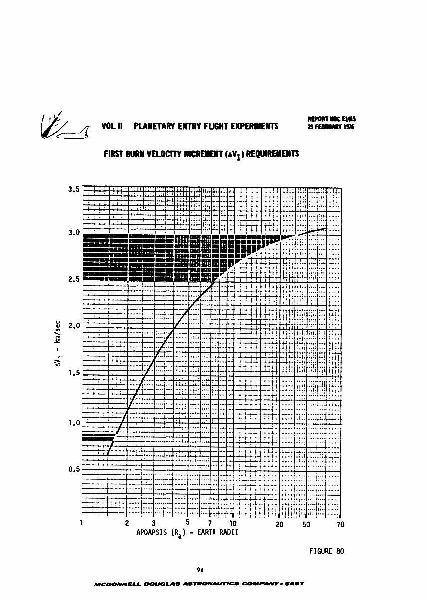
2 3 5 7 10 APOAPSI S (R, ) - EARTH RADI I
FIGURE 80
AWAPSIS (R,) - EARTH RADI I
FIGURE 81
95
MCDONNaLL W U O U S AS-AUoICS COMPANY - SALIT
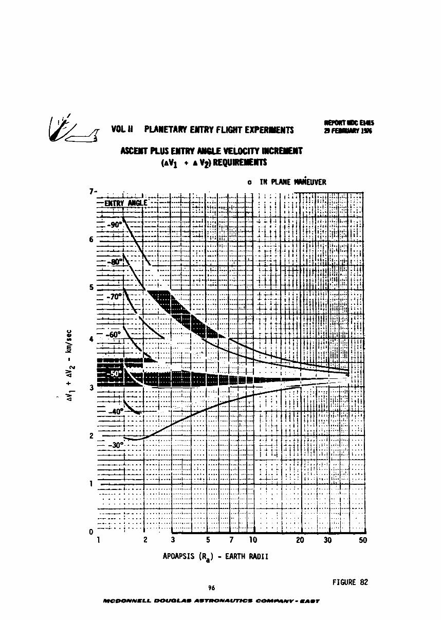
1 2 3 5 7 10 20 30 50
APOAPSIS (Ra) - EARTH RADII
FIGURE 82
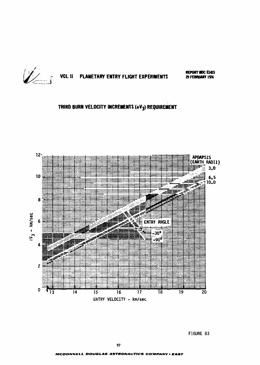
- VOL II PUHETARY ENTRY FLIGHT EXPERMENTI -- -3 L-
THIRD BURN VELOCITY INCREVEWn (aV3) REQUIREMENT
ENTRY VELOCITY - km/sec
97
MCOONNELL DOUGLAS ASTCPONAUTlCS CO.WPANV - EAST
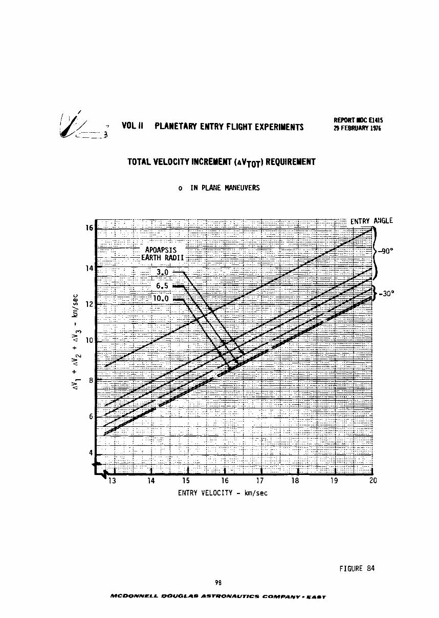
7 VOL II PLANETARY ENTRY FLIGHT EXPERIMENTS 9
REPORT rDC El415 29 FEBRUARY 1976
TOTAL VELOCITY I#CRENENT (AVTOT) REQUIREMENT
o I N PLANE MANEUVERS
. . . . . . . . . . . - . - . . - ; ...........
. . . . . . . . . . . . . . . . . . . . . . - .-. , .......... - . . . . ........................... ....... .................................. ................. ............... - - - -.. -. . . . :... APOAPSIS . . . . . . . . . . .......... -90"
....................... . . -- * . . - . .
-30'
. . . . . . . . . . . . . . .................. ............ * .............. ...-... _.A ........ L . .--~ . . . . . . . . . . . . . . . . . . ....................... * ............ .---.... + ..... ---. ......... .--... - * ~ ' . . . . . . . . . . . . , . ........ . * ..................... .- 4 ---" --' - ................... ...-.... ---..-.. . . . . . . . . . . . . . . . . . . . . . . . . . . . . . . ., . *.. & --.-..- * c t ........ .--- -...... . . . . . . . . . . . . . . . . . . . . . . . . . . . . . . . ..... - . . . . - . . . . . . ...+.. *. -.+ ., ..................... .............. . . . . . . . . . . . . . . . . . . ,..... . . * . . . . . . . . . . . . . . . . . . . ' ......... ,. ................................. - . . . . . . . . . . . . . . . . . . . . . . ..................... ............... ..,.. ..... +. . . . . ................... ....... . . . . . . . . . . . . . - - - . . . . . . . . . . . . . . . . . . . . . . . . . . . . . . . . . ; + . ~ * . .,... . . . . . . . . . . . . . . . . . . . . . . . . . . . . ......& ............... .,. ... ..l-rlr::_r:;:.... .. '....'. ..' ........ ..., . . ---' * . . . .................. .............-.. .. ......... ..* .-.-.... '+"&' .....---. .--, .............. .... ....... .... . -..* ............... ' . . . . . . . . . . . . . . . . . .* ................ .*... ~ . - & 4.- .................. ....- .-.--....... *.. . - - . - . . . . . . . . - - . .-.. ....................... ......... .*.. .... . . . . . . . . . . . . . . . . . . . . . . .......... ..-~-....*. ....... . . . . . . . . . . . . . . . . . . . . * . . -Au- .............................
'1 3 14 15 16 17 18 19 20
EI4TRY VELOCITY - km/sec
FIGURE 84
98
MCDONNPLL DOUGLAS ASTRONAUTlCS COMPANV = EAST
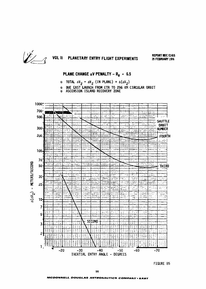
VDL II PLANETARY ENTRY FLIGHT ElPERlYtYTS REPORT NDC El415 29 FEBRUARY 1916
PLANE CHANGE AV PENALTY - R, = 6.5
0 TOTAL A v 2 = A v 2 ( I N P L m ) + A ( A ~ ~ )
o WE EAST LAUt4CH FROM ETR TO 296 I31 CIRCULAR ORBIT o ASCENSION ISLAND RECOVERY ZONE
INERTIAL ENTRY ANGLE - DEGREES
FIGURE 85
99
MCDONNELL DOUGLAS ASTRONAUT#CS COMPANY - S A m T
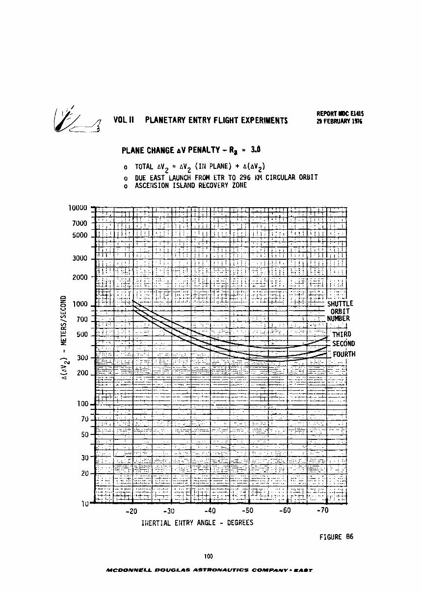
- "DL II PLANETARY ENTRY FLIGHT EXPERIHEITI
PLANE CHANGE AV PENALTY - Ra = 3.0
o TOTAL A V ~ = AV2 (Ill PLANE) + A(bVZ)
o DUE EAST LAUNCH FROM ETR TO 2 9 6 Kt4 CIRCULAR ORBIT o ASCEtlS ION ISLAND RECOVERY ZOtlE
U - 1 : . . . . . . w . : . . . , 1 . . 1 ' ORBIT
700 !~.. , ; . . I . i i - t NUMBER
- 2 0 -30 - 4 0 -50
I I IERTIAL EIITRY ANGLE - DEGREES
- 70
FIGURE 86
100
MCDONNELL DOUGLAS ASTRONAUNCS COMPANY r EAUT
REPORT I)C El415 VOL II PLANETARY ENTRY FLIGHT EXPERIMENTS 29 FEBRUARY 136
5.3 Ground Tracks - I n t h e previous s e c t i o n s t h e boos te r AV requirements f o r
each burn and t h e r e s u l t a n t i n e r t i a l e n t r y cond i t ions have been defined. This sec-
t i o n i d e n t i f i e s t h e l a t i t u d e and long i tude of t h e f i r s t and second boos te r burns,
t h e r e s u l t a n t en t ry cond i t ions f o r impact a t Ascension I s land , t h e S h u t t l e o r b i t s
from which these can be achieved, and two r e p r e s e n t a t i v e ground t racks .
To e s t a b l i s h these parameters, t h e fol lowing d e o r b i t s t r a t e g y w a s used. The
f i r s t burn of t h e Hohmann t r a n s f e r was assumed t o be made from a p o i n t on t h e Shut-
t l e o r b i t and a t t h e same heading as t h e S h u t t l e , i.e., no plane change was
a s s o c i a t e d wi th t h e f i r s t burn. The l o c a t i o n of apoapsi8 on t h e liohmann t r a n s f e r
o r b i t is then a t a l a t i t u d e equa l i n magnitude b u t oppos i t e i n s i g n t o t h e f i r s t
burn l a t i t u d e . The apoapsis long i tude w i l l be t h e f i r s t burn long i tude p l u s 180
degree minus t h e e a r t h ' s angular v e l o c i t y , R , mul t ip l i ed by t h e Hohmann t r a n s f e r
t i m e , T, from t h e tirst burn t o apoapsis, i.e.,
Once t h e apoapsis l o c a t i o n was determined, t h e t r a j e c t o r y from apoapsis t o impact a t
Ascension was computed a s follows. F i r s t t h e impact po in t l a t i t u d e and long i tude
a t Ascension was s e l e c t e d as -7.95 deg (7.95 deg south),345.667 deg (14.333 deg
west) , r e spec t ive ly . Then t h e d e o r b i t t r a j e c t o r y required t o h i t t h e impact p o i n t
from apogee was computed a long wi th t h e i n e r t i a l e n t r y cond i t ions a t t h e p i e r c e
point . The d e o r b i t t r a j e c t o r y v e l o c i t y , f l i g h t pa th angle , and azimuth a t apoapsis
i s e s t a b l i s h e d by t h e second burn of t h e booster . The v e c t o r i a l d i f f e r e n c e between
pre-burn and post-burn cond i t ions a t apogee e s t a b l i s h t h e AP requirements f o r t h e
booster . This a n a l y s i s i d e n t i f i e s a l a t i t u d e and long i tude f o r t h e f i r s t and
second burns on s p e c i f i e d S h u t t l e o r b i t s and t h e r e s u l t a n t v e l o c i t y , f l i g h t path
angle , and azimuth t h a t can be achieved a t Ascension Is land. The t r a j e c t o r y from
e n t r y t o impact neg lec t s atmospheric e f f e c t s . This does n o t a f f e c r t h e r e s u l t s
s i g n i f i c a n t l y .
The f i r s t ques t ion t o be resolved was: what S h u t t l e launch azimuth should b c
used from KSC? For tunate ly , a due e a s t launch from KSC t o a 296 km c i r c u l a r o r b i t
provides impact a t Ascensian wi th e s s e n t i a l l y no plane change requirements a t apogee
and e n t r y v e l o c i t i e s ( p r i o r t o t h e t h i r d burn) of more than 10 kmlsec over a wide
range of f l i g h t path angles. Figure 87 is a summary t a b l e d e f i n i n g p o t e n t i a l f i r s t
burn l o c a t i o n s and r e s u l t a n t e n t r y cond i t ions f o r a 6.5 e a r t h r a d i i d e o r b i t t r a j e c -
tory. The S h u t t l e long i tude and l a t i t u d e correspond t o 10 deg increments a long t h e
o r b i t a l path. The p a r t i c u l a r va lues s e l e c t e d provide i n e r t i a l e n t r y cond i t ions i n
MCDONNELL OOUGLAS ASTRONAUTlCS COMPANY - PA-T
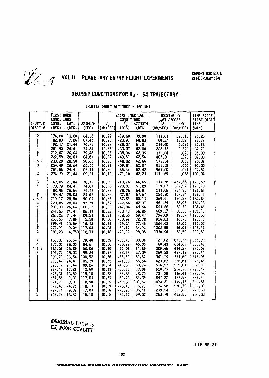
/ REPORT HOC El415 q - VOL II PLANETARY ENTRYFLIGHT EXPERIMENTS 29 FEBRUARY 1976
DEORBIT CONDITIONS FOR R a = 6.5 TRAJECTORY
SHUTTLE ORBIT ALTITUDE = 160 NMI
FIGURE 87
102
MCDONNECL DOUGLAS ASrRONAUTtCS COMPANV - EAST
SHUTTLE ORBIT#
2
t
AZIWTH (DEG)
64.82 67.42 70.76 74.81 79.48
FIRST CONDITIONS LONG. (DEG)
174.04 182.90 192.17 201.90 212.07
2 3 11 2
3
3
i 3 6 4
4
4 4
4 & 5 5
5
BURN
LAT. (DEG)
13.80 17.86 21.44 24.41 26.64
INERTIAL
AZIWTH (DEG)
39.90 60.63 61.51 62.00 62.35
VE (KHISEC)
10.29 10.28 10.27 10.26 10.25
222.58 233.28 254.49 264.66 274.39
169.06 178.79 188.96 199.47 210.17 220.88 231.35 241.55 251.28 260.56 269.42 277.94 286.23
165.85 176.36 187.06 197,77 208.28 218.44 228.17 237.45 246.31 254.83 271.29 279.45 287.74 296.26
TIME SIRCE F l RST ORBIT TIME (MIt4)
75.26 77.77 80.28 82.79 85.30
62.56 62.66 62.57 62.42 62.23
46.65 51.29 54.81 57,67 60.13 62.37 64.56 66.85 69.47 72.78 77.45 84.93 98.95
38.36 46.00 51.80 57.09 61.52 65.64 69.74 73.95 78.70 84.39
101.62 115.77 135.46 159.02
ENTRY CONDITIONS
YE (DEG)
-19.60 -23.97 -28.57 -33.37 -38.36
10.24 10.23 10.21 10.20 10.19
10.29 10.28 10.27 10.26 10.25 10.24 10.23 10.22 10.21 10-20 10.19 10.18 10.18
10.29 10.28 10.39 10.27 10.26 10.25 10.24 10.23 10.22 10.21 10.19 10.19 10.18 10,18
BOOSTER AV AV;~ "OGEE
87.80 90.31 95.33 97.84
100.34
170.59 173.10 175.61 178.11 180.62 183.13 185.64 188.15 190.65 193.16 195.67 198.18 200.69
265.92 268.42 270.93 273.44 275.95 278.46 2 8 0 9 6 283.47 285.98 288.49 293.51 296.02 298.53 301.03
-43.51 -48.82 -59.81 -65.44 -71.10
-19.76 -23.87 -28.26 -32.87 -37.69 -42.68 -47.84 -53.13 -58.50 -63.92 -69.31 -74.52 -79.27
-20.40 -23.99 -27.05 -32.14 -36.59 -41.23 -46.01 -50,90 -55.84 -60.73 -69.83 -73.49 -75.90 -76.43
(01lSEC)
113.81 160.27 218.40 288.73 371.64 467.20 575.24 825.39 965.00
1111.69
115.38 159.07 214.08
28.03 84.61 28.50 1 90.00
AAV (KTVSEC)
32.310 13.59 5.595 2.248
-845 .275 .062 .005 .021 .033
454,28 327.97 234,90
26.64 24.41 21.44
21.44 24.41 26.64 28.03 28.50 28.03 26.64 24.41 21.44 17.86 13.80 9.39
26.64 28.03 28.50 28.03 26.64 24.41 21.44 17.86 13.80 9.39 0.0
-4.75 -9.39
-13.80
100.52 105.19 109.24
70.76 74.81 79.48 84.61 90.00 95.39
100.52 105.19 109.24 112.58 115.18 117.03
4.753118.13
79.48 84.61 90.00 95.39
100.52 105.19 109.24 112.58 115.18 117.03 118.50 118,13 117.03 115.18
280.90 16i.34 359.91 1 120.27 451.24 554.68 669.37 794.09 926.83
1064.63 1202.55 1330.94
121.62 160.43 209.65 269.80 341.14 423.67 516.97 620.13 731.28 847.82
1078.21 1174.98 1239.54 1253.79
88.92 68.74 56.33 49.37 46.76 48.63 56.93 78.59
863.33 684.69 546.27 437.12 351.61 286.61 239,C4 206.30 186.41 177.97 199.15 238.79 313.63 438.86
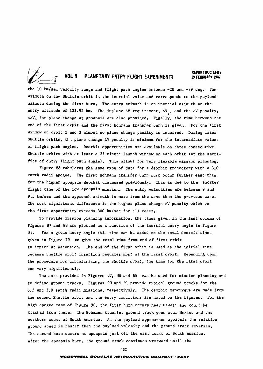
REPORT MDC El415 VOL I1 PLANETARY ENTRY FLIGHT EXPERIMENTS 29 FEBRUARY 1976
the 10 km/sec v e l o c i t y range and f l i g h t path ang les between -20 and -79 deg. The
azimuth on t h e S h u t t l e o r b i t is t h e i n e r t i a l va lue and corresponds t o t h e payload
azimuth dur ing t h e f i r s t burn. The e n t r y azimuth is a n i n e r t i a l azimuth a t t h e
e n t r y a l t i t u d e of 121.92 km. The inp lane AV requirement, AV2, and t h e AV pena l ty ,
AAV, f o r p lane change a t apoapsis a r e a l s o provided. F i n a l l y , t h e t ime between t h e
end of t h e f i r s t o r b i t and t h e f i r s t Hohmann t r a n s f e r burn i s given, For t h e f i r s t
window on o r b i t 2 and 3 almost no p lane change pena l ty is incurred. During l a t e r
S h u t t l e o r b i t s , ti- . plane change AV pena l ty is minimum f o r t h e in te rmedia te va lues
of f l i g h t path angles. Deorbit o p p o r t u n i t i e s a r e a v a i l a b l e on t h r e e consecut ive
S h u t t l e o r b i t s wi th a t l e a s t a 25 minute launch window on each o r b i t ( a t t h e s a c r i -
f i c e of e n t r y f l i g h t pa th angle) . This a l lows f o r very f l e x i b l e miss ion planning.
Figure 88 t a b u l a t e s t h e same type of d a t a f o r a d e o r b i t t r a j e c t o r y wi th a 3.0
e a r t h r a d i i apogee. The f i r s t Hohmann t r a n s f e r burn must occur f u r t h e r e a s t than
f o r t h e h igher apoapsis d e o r b i t d i scussed previously . This i s due t o t h e s h o r t e r
f l i g h t t ime of t h e low apoapsis mission. The e n t r y v e l o c i t i e s are between 9 and
9.5 km/sec and t h e approach azimuth is more from t h e west than t h e previous case.
The most s i g n i f i c a n t d i f f e r e n c e is t h e h igher p lane change AV pena l ty which on
t h e f i r s t oppor tun i ty exceeds 300 km/sec f o r a l l cases .
To provide miss ion planning informat ion, t h e times given i n t h e l a s t column of
Figures 87 and 88 a r e p l o t t e d a s a f u n c t i o n of t h e i n e r t i a l e n t r y angle i n Figure
89. For a given e n t r y ang le t h i s time can be added t o t h e t o t a l d e o r b i t times
given i n Figure 79 t o g ive t h e t o t a l time from end of f i r s t o r b i t
t o impact a t Ascension. The end of t h e f i r s t o r b i t is used a s t h e i n i t i a l time
because S h u t t l e o r b i t i n s e r t i o n r e q u i r e s most of t h e f i r s t o r b i t . Depending upon
the procedure f o r c i r c u l a r i z i n g t h e S h u t t l e o r b i t , t h e time f o r t h e f i r s t o r b i t
can vary s i g n i f i c a n t l y . The d a t a provided i n Figures 87, 38 and 89 can b e used f o r miss ion planning and
t o d e f i n e ground t racks . Figures 90 and 91 provide t y p i c a l ground t r a c k s f o r t h e
6.5 and 3.0 e a r t h r a d i i miss ions , r e spec t ive ly . The d e o r b i t maneuvers a r e made from
the second S h u t t l e o r b i t and t h e e n t r y cond i t ions a r e noted on t h e f i g u r e s . For t h e
high apogee case of Figure 90, t h e f i r s t burn occurs nea r Hawaii and coul .! be
t racked from there . The Hohmann t r a n s f e r ground t r a c k goes over Mexico and t h e
nor the rn c o a s t of South America. A s t h e payload approaches apoaps i s t h e r e l a t i v e
ground speed is f a s t e r than t h e payload v e l o c i t y and t h e ground t r a c k reverses .
The second burn occurs a t apoapsis j u s t o f f t h e e a s t c o a s t of South America.
A f t e r the apuapsis burn, t h e ground t r a c k con t inues westward u n t i l t h e
103
MCDONNELL DOUGLAS ASTRONAUTlCS COMPANY - EAST
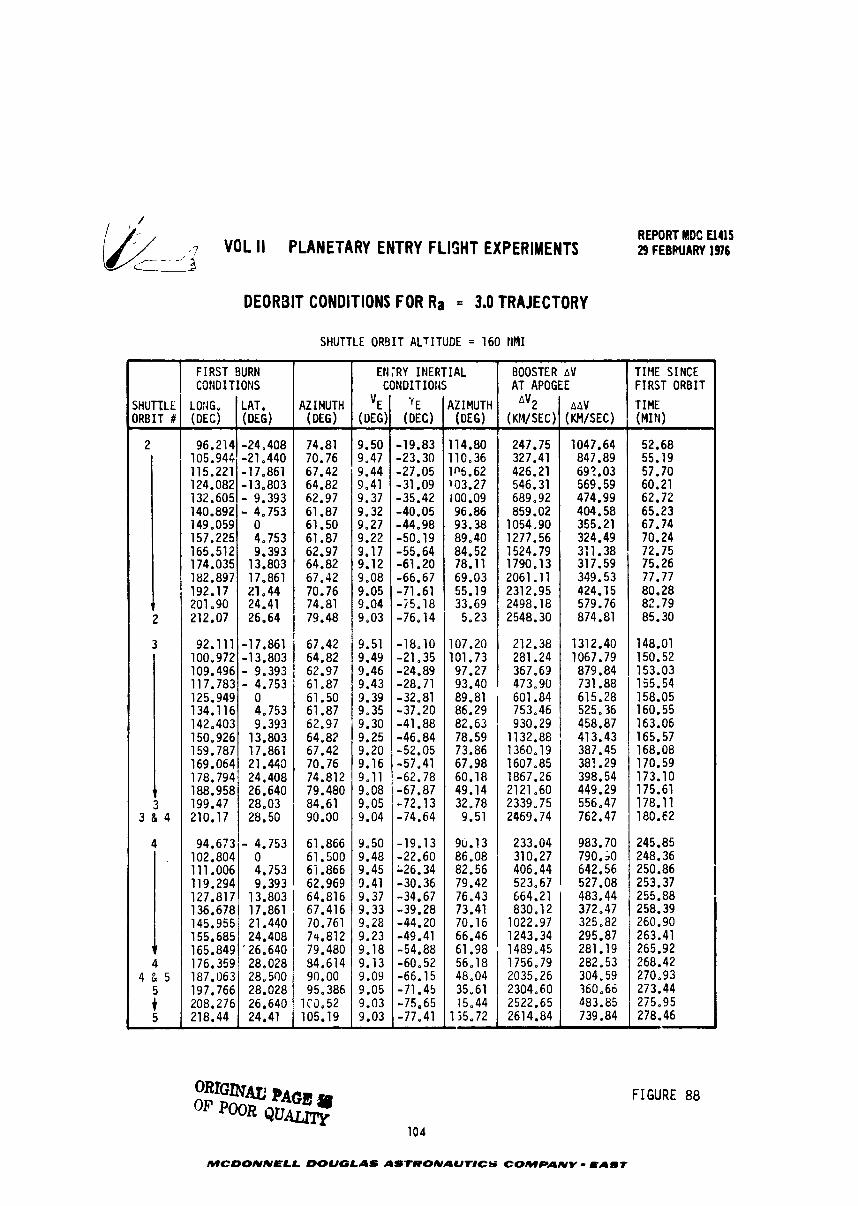
- 1 VOL II PLANETARY ENTRY FLIGHT EXPERIMENTS REWRT MDC El415 29 FEBRUARY 1976
L - 3
DEORBIT CONDITIONS FOR Ra = 3.0 TRAJECTORY
SHUTTLE ORBIT ALTITUDE = 160 I I M I
FIGURE 88
SHUTTLE ORBIT#
2
1 2
3
1 3
3 & 4
4 .
T 4
4 & 5
5 5
v
MCDONNELL DOUGLAS ASrRONAUTlCS COMPANY - hABf
FIRST COfiOITIOMS
LOfiG. (DEC)
96.214 105.944 115.221 124.082 132.605 140.892 149.059 157.225 165.512 174.035 182.897 192.17 201.90 212.07
92.111 100.972 109.496 117.783 125.949 134.116 142.403 150.926 159.787 169.064 178.794 188.958 199.47 210.17
AZIMUTH (DEG)
74.81 70.76 67.42 64.82 62.97 61.87 61.50 61.87 62.97 64.82 67.42 70.76 74.81 79.48
67.42 64.82
1 62.97 61.87 61.50 61.87 62.97 64.82 67.42
, 70.76 74.812 79.480 84.61
1 90.30
BURN
LAT. (DEG)
-24.408 -21.440 -17.861 -13.803 - 9.393 - 4.753
0 4.753 9.393
13.803 17.861 21-44 24.41 26.64
-17.861 -13.803 - 9.393 - 4.753
0 4.753 9.393
13.803 17.861 21.443 24.408 26.640 28.03 28.50
94.673 102.804 111.006 119.294 127.817 136.678 145.955 155.685 165.849 176.359 187.063 197.766 208.276 218.44
2
TIME SINCE FIRST ORBIT
TIME (MIN)
52.68 55.19 57.70 60.21 62.72 65.23 67.74 70.24 72.75 75.26 77.77 80.28 82.79 85.30
148.01 150.52 153.03 155.54 158.05 160.55 163.06 165.57 168.08 170.59 173.10 175.61 178.11 180.62
245.85 248.36 250.86 253.37 255.88 258.39 260.90 263.41 265.92 268.42 270.93 273.44 215.95
Ell
'E (DEG)
9.50 9,47
* 9.44 9.41 9.37 9.32 9.27 9.22 9.17 9.12 9.08 9.05 9.04 9,03
9.51 9.49 9.46 9.43 9.39 9,35 9.30 9.25 9.20 9.16 9.11 9,08 9.05 9.04
- 4.753 0 4.753 9.393
9.50 9.48 9.45 3.41 9.37 9.33 9.28 9.23 9.18 9.13 9.09 9.05 9.03 9.03
BOOSTER AT APOGEE
AV2 (KM/SEC)
247.75 327.41 426.21 546.31 689.92 859.02
1054,90 1277.56 1524.79 1790.13 2061.11 2312.95 2498.18 2548.30
212.38 281.24 367.63 473.90 601.84 753,46 930.29
1132.88 1360.19 1607.85 1867.26 2121.60 2339.75 2469.74
61.866 61.500 65.866 62.969
;RY INERTIAL CONDITIOfiS
'E (DEC)
-19.83 -23.30 -27.05 -31.09 -35.42 -40.05 -44,98 -50.19 -55.64 -61.20 -66.67 -71.61 -75.18 -76.14
-18.10 -21.35 -24.89 -28.71 -32.81 -37.20 -41.88 -46.84 -52.05 -57.41 -62.78 -67.87 -72.13 -74.64
AV
AAV (KM/SEC)
1047.64 847.89 69?.03 569.59 474.99 404.58 355.21 324.49 3:1.38 317.59 349.53 424.15 579.76 874.81
1312.40 1067.79 879.84 731.88 615.28 525.36 458.87 413.43 387.45 387.29 398.54 449.29 556.47 762.47
233.04 310.27 406.44 523.67 664.21 830.12
1022,97 1243.34 1489.45 1756.79 2035.26 2304.60 2522.65 2614.84
AZIMUTH (DEG)
114.80 110.36 105.62 103.27 100.09 96.86 93.38 89.40 84.52 78.11 69.03 55.19 33.69 5.23
107.20 101.73 97.27 93.40 89.81 86.29 82.63 78.59 73.86 67.98 60.18 49.14 32.78 9.51
-19.13 -22.60 126.34 -30.36 -34.67 -39.28 -44.20 -49.41 -54.88 -60.52 -66.15 -71.45 -75.65 -77.41
983.70 790.;0 642.56 527.08 483.44 372.47 325.82 295.87 281.19 282.53 304.59 360.66 483.85 739.84
13.803 64.816 17.8611 67.416
9u.13 86.08 82.56 79.42 76.43 73.41 70.16 66.46 61.98 56.18 48.04 35.61 15.44
135.72
21.440 24.408
'26.640 28.028 28.500 28.028 26.640 24.41
70.761 74.812 79.480 84.614 90.00 95.386
1C5.52 105.19
REPdRT I#: €145 VOL I1 PLANETARY EWRY FLWT EXPERIMENTS ~ ~ ~ ~ A U A R T I ~
velocity again exceeds ea r th ro ta t i ena l speed near the w e s t coast of South America-
The ground track then proceeds northeast i m t i l impact a t Ascension. Because of the
apogee a l t i t u d e of 6.5 ea r th r ad i i , the second burn is observable from Ascension.
The ground track f o r the lau apoapsis deorbit is quite d i f f e r m t as shown i n
Figure 91. me f i r s t Hohrann transf er burn occr rs over Indonesia and north of
Austrsl ia - considerably w e s t of the previous ca-e. The Hohmann t ransfer o r b i t
track is onlw sa ight ly d i f fe ren t from a typical Shutt le t rack u n t i l it passes over
the coast of Hexico, A p a p s i s is achieved over northern South America. A t t h i s
a l t i t u d e the s e ~ o n d b u m w i l l be observable f r o r Ascension, The ground t rack from
apogee t o irpact then approaches Ascension from the w e s t as compared t o the south-
w e s t approach fo r the higher apoapsis.
The tire l i n e fo r the Ra = 3.0 and 6.5 missions a r e sumarized i n Figure 92,
The Ra = 3.0 mission takes about s i x hours and the R = 6-5 mission takes just under a
13 hours.
In conclusion, a due east launch from KSC provides m l t i p l e opportunities fo r
payload targeting at AScension. Opportunities e x i s t during the second, third, o r
fourth orbits. The plane change penalty a t apoapsis can be minimized by se lec t ing
appropriate launch points on the Shutt le orbi t . Coverage of the second burn is
a c e l l e n t from Ascension; coverage of the f i r s t burn may be possible from Hawaii,
ICHR, o r Guars f o r s p e c i f i c e n t r y conditions.
105
MCWNNELL DOUGLAS A S m A U 1 1 C S COMPANY - ~ 4 8 1
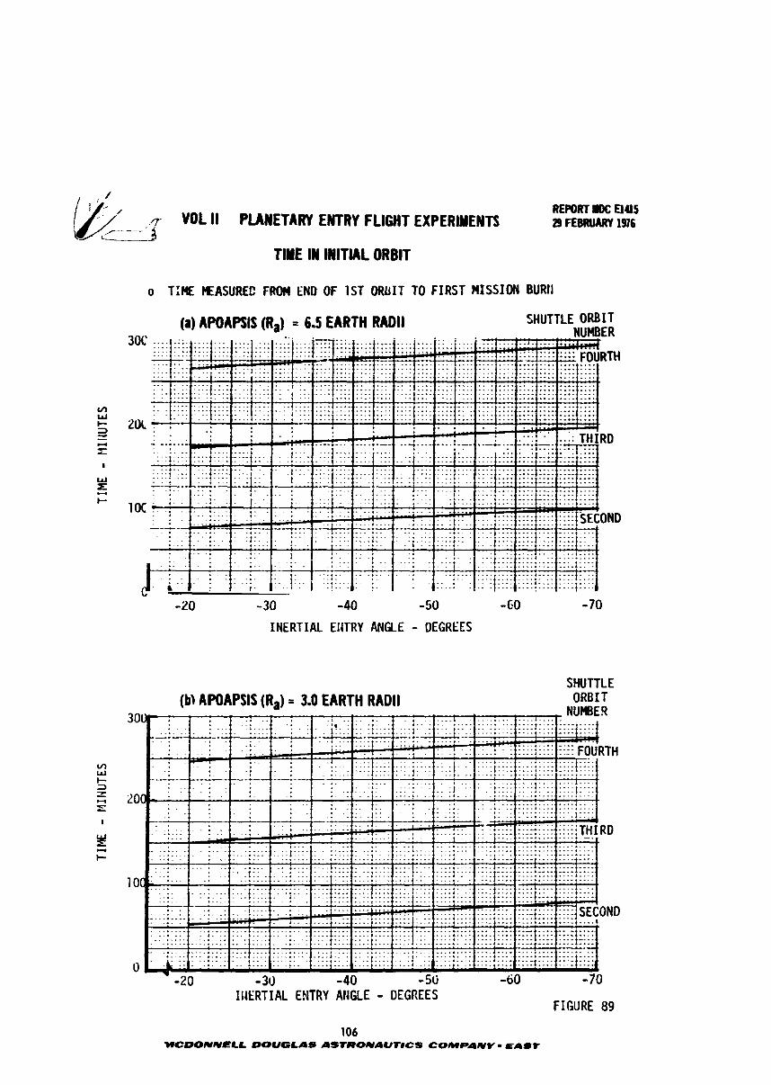
.-7 VOL ll PLANETARY ENTRY FLIGHT EXPERIMENTS : *
TlYE IN INITIAL ORBIT
o T:HE MEASUREC FRW END OF 1ST ORUIT TO FIRST HISSION BUM
REPORT UDC ElUS 29 FEBROARY 1376
(a) AWAKIS (Ra) = 6.5 EARTH RADII SHUTTLE ORBIT
- 30 -40 - 50 -GO
INERTIAL EliTRY At4GlE - DEGREES
INERTIAL ENTRY ANGLE - DEGREES
(b, AWAPSIS (R,) = 3.0 EARTH RADII
FIGURE 89
SHUTTLE ORB 1 T
..*.... NUMBE.9
.. .
-1 .... I . . . . ......... .................
106 WCDONNELL DOUGLAS AStROlVAUTlCS COMPANY - EAST
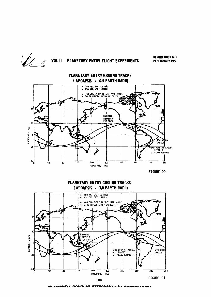
&=5r VOL ll PUWETARY EIUTRY FLIGHT EXPERIMENTS REPORT I)(: El45 23 FEBRUARY 19.76
FIGURE 90
PUWETARY ENTRY GROUND TRACKS ( APOAPSM = 3.0 EARTH RADII)
MCDONNELL bOUGLAS ASTRONAUTtCS COMPANY - EAST
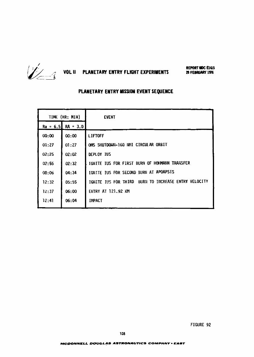
REWRTDC Elas -.- VOL II PLANETARY ENTRY FLIGHT EXPERIMENTS / i 2 9 ~ 1 9 7 6
i .-
PLANETARY ENTRY NlSSlON EVENT SEQUENCE
FIGURE 92
108
MCDONNELL DOUGLAS AS'IRONAUTICS COMPANY - E A I T
-
EVENT
J
LIFTOFF
OMS SHUTMIUN-160 1811 CIRCUl AR ORBIT
DEPLOY IUS
. IGI~ITE IUS FOR FIRST BURH OF tiw~~rjrj TRAIISFER
IGW!TE IUS FOR SECOND BURfi AT APOAPSIS
IGNITE IUS FOR THIRD BURti TO ItiCREASE ENTRY VELOCITY
EIITRY AT 121 -92 KIA
IMPACT
L
TIME (HR: MIH) I
Ra = 6.5
0O:OO
01 : 27
02: 25
02: 55
08: 06
12:32
12:37
12:41
R A = 3.0
00:Oo
01 : 27
02 : 02
02:32
04: 34
05: 55
06: 00
06: 04
n- VOL II PLAMETARY ENTRY FLIGHT ElPWLlTS ~KPORTIDC aus 29FEmARYlS
df 5.4 -Typical Environnent S w a t i o n - The previous subsections have addressed
the deorbit maneuver requirements i n the general terms of i n i t i a l entry conditions.
However, these r e q u i r e e n t s can a l s o be expressed more d i rec t ly in terms of environ-
aent parasleter simulation. For exataple, the deorbit maneuver AV requirements are
presented i n Figures 93 through 94 using peak radia t ive f lux as the spec i f i c
environment parameter.
The o p t h m entry angle (y) is shorn i n Figure 93 as a function of apoapsis
distance (R ). This is the y t ha t minimizes the t o t a l inplane aV needed t o s h u - a l a t e a given l e v e l of radia t ive flux. Figure 94 graphically i l l u s t r a t e s the
procedure fo r identifying the optimum value of y, Note tha t the option is rather
f l a t ; variat ions of - +5 degrees around the optimum y do not s ign i f i can t ly e f f e c t bV
requirements.
Figure 94 presents the t o t a l AV required as a function of apoapsis distance
ar.d radia t ive f lux level , The benef ic ia l e f fec t of increasing Ra is qu i t e pro-
nounced a t IOU a l t i tudes but diminishes rapidly above an R of about 4 ea r th radii . a 2
The e f fec t of radia t ive f lux l e v e l o r bV is nearly l inea r above about 20 kW/cn~ ,
109
MCOONNELL DOUGLAS ASTCPONAUtlCS COMPANY - E A I T
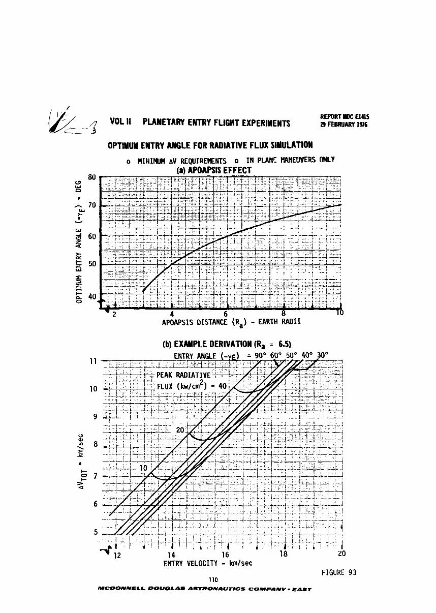
/
-.-LJfl VOL II PLANETARY ENTRY FLIGHT EXPERIMENTS
-.
REPORT I1C U4lS 29 FEBRUARY 1!W6
OPTMU EWT RY ANGLE FOR RADIATIVE FLUX SIYUUTIOW
o HINIW aV REQUIREt€DCTS o 114 PIANE PIMIEWERS ONLY (a) AWAPSlS EFFECT
- APUAPSIS DISTANCE (R,) - EARTH RADII (b) EXAMPLE DERIVATION (Ra = 6.5)
ENTRY VELOCITY - kmfsec FIGURE
110 MCDONNELL DOUGLAS ASTROUAUrHCS COMPANV - EAST
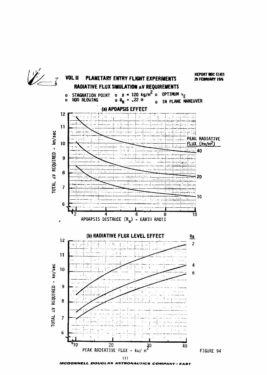
REPORT mc Elas 29 FfBRUART 196 VOL II PMMETARY ENTRY FLIGHT EXPERlYENn
RADIATIVE FLUX SWUTlON nV REQUIREYENTS o STAUUTIOH POINT o 0 = 120 kg/m2 0 OPTIWn YE o l4Of4 BLOUING 0 % " o 2 a 0 IN PLANE IIA)(EUVER
. .
(a) APOAPSlS EFFECT
. . . . . . . . . . . . . . . . . . . . . . . . . . . . . . . . - -.- -. -. .- - -- -- ---- -- . ..
APOAPSIS DISTAIICE (R,) - EARTll R A D I I
(b) RADIATIVE FLUX LEVEL EFFECT - Ra
FIGURE 94
111 MCDOIVNELL DOUGLAS ASTRONAUTICS COMPANY - EAST
REPORT I#; Eta5 VOL II PUWETARY EWTRY FLIGHT EXPERIMENTS ~)FU##IART~QC
6.0 SHUTTLE LAUNCHED BOOSTERS
The physical cha rac t e r i s t i c s and performance c a p a b i l i t i e s of t yp i ca l Shu t t l e
launched boosters are summarized i n t h i s sect ion. The purpose of these d a t a is
t o provide an understanding of t he payload mass versus e a r t h en t ry condi t ion
cons t ra in t s imposed by cur ren t technology, Shu t t l e upper s tages . Figure 95 shows
the candidates boosters and assembled vehic les in r e l a t i o n t o t h e Shuttle.
These boosters f a l l i n t o four ca tegor ies which cover t h e e x i s t i n g technology
range of upper s t a g e p e r f o m n c e and physical s ize . Each class is i l l u s t r a t e d by
a represen ta t ive design. Category 1 is a cryogenic prope l lan t c l a s s of booster
such as the Centaur. This class represents t h e highest ava i l ab l e performance but
a l s o the biggest. Category 2, an e x i s t i n g s t o r a b l e prope l lan t booster, such as
the Transtage, is presented as h-. example of intermediate s i z e and performance.
Agena and Delta a l s o f a l l i n t o t h i s category. Category 3 is a s t o r a b l e prope l lan t
design based on using components from the S h u t t l e aux i l i a ry propulsion system.
This mult i -s tage ve loc i ty package is an example of a very compact configurat ion
tha t allows maximum opportunity f o r shared payload launches of t he Shut t le .
Category 4, a s o l i d prape l lan t booster, is shown using t h e b e s t ava i l ab l e d r f i n i -
t i o n of the recent ly s e l ec t ed Interim Upper Stage (IUS) concept.
Each booster c l a s s is described by a survey (including References 11, 12 and
13) of dimensional and mass c h a r a c t e r i s t i c s and by parametric performance curves.
The performance capab i l i t y is shown i n terms of payload mass versus ve loc i ty incre-
ment (AV) and a l s o by the en t ry angle versus ve loc i ty a t t a i n a b l e f o r se lec ted values
of apoapsis d i s tance and payload mass.
6.1 Exis t ing Cryogenic Booster - The Centaur, which i s t h e only cryogenic
( 0 /H ) s t a g e cur ren t ly i n use, i s shown a s t h e example design f o r t h i s c l a s s of 2 2 booster . Figure 96 presents the mass, dimensional and propulsion cha rac t e r i s t i c s
of the Centaur plus a sp in s t a b i l i z e d , TE364-4 s o l i d motor second stage. Although
the Centaur alone performance is within t h e en t ry s imulat ion range of i n t e r e s t , i t
is l e s s than the other candidate, multi-stage, vehicles . Adding t h e TE364-4 s tage ,
make the performance of t h i s system the highest of any considered. Hence, t h i s
two s t age configurat ion is presented a s an example of t h e maximuq performance capa-
b i l i t y avai lable .
Figure 97 i l l u s t r a t e s performance capab i l i t y i n terms of 2ayload mass versus
ve loc i ty increment (AV). Figure 98 descr ibes t he en t ry condi t ions t h a t can be
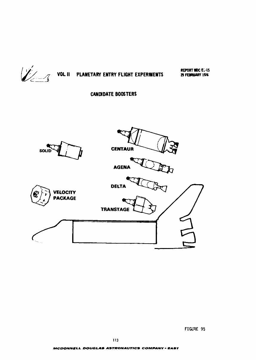
REPORT I)C E; ;IS
& VOL II PUYETARY ENTRY FLIGHT EXPERIYEWTS 7'
23 F E W W 196
CANW DATE BOOSTERS
CENTAUR
AGENA
FIGL'RE 95
113
MCDONNELL DOUGLAS ASTRONAUT#CS COMPANV - t a m r
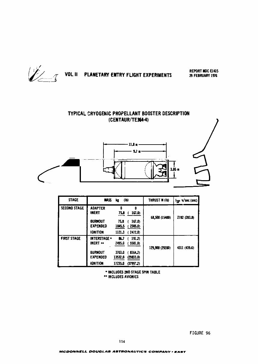
~ cr--q- "DL II PLAlETARY E W R Y FLIGHT EXPERIMENTS REPORT lWOC El415 29 FEBRUARY 1976
TYPICAL CRYOGENIC PROPELLANT BOOSTER DESCRIPTION (CENTAUR/TEW)
* INCLUDES 2ND STAGE SPIN TABLE ** INCLUDES AVlOISlCS
F I G U R E 96
STAGE
SECOND STAGE
FIRST STAGE
r-
114
MCDONNNL DOUGLAS ASTRONAUr#CS COMPANY - EAUT
THRUST N (Ib)
68500 (15400)
129,900 (ma)
IRASS kg (lb)
ADAPTER 0 0 INERT 75.8 ( 167.0) -- BURNOUT 75.8 ( 167.0) EXPENDED 10453 ( 2305.0) -- IGNITION 1121.3 ( 2472.0)
INTERSTAGE* 86.7 ( 191.2) INERT ** 2495.0 ( 5501.0) -- BURNOUT 3703.0 ( 8161.2) EXPENDED 13532.0 (29833.0) -- IGNITION 17235.0 (379972)
Isp dsec (sec)
2782 0
4311 (439.6)
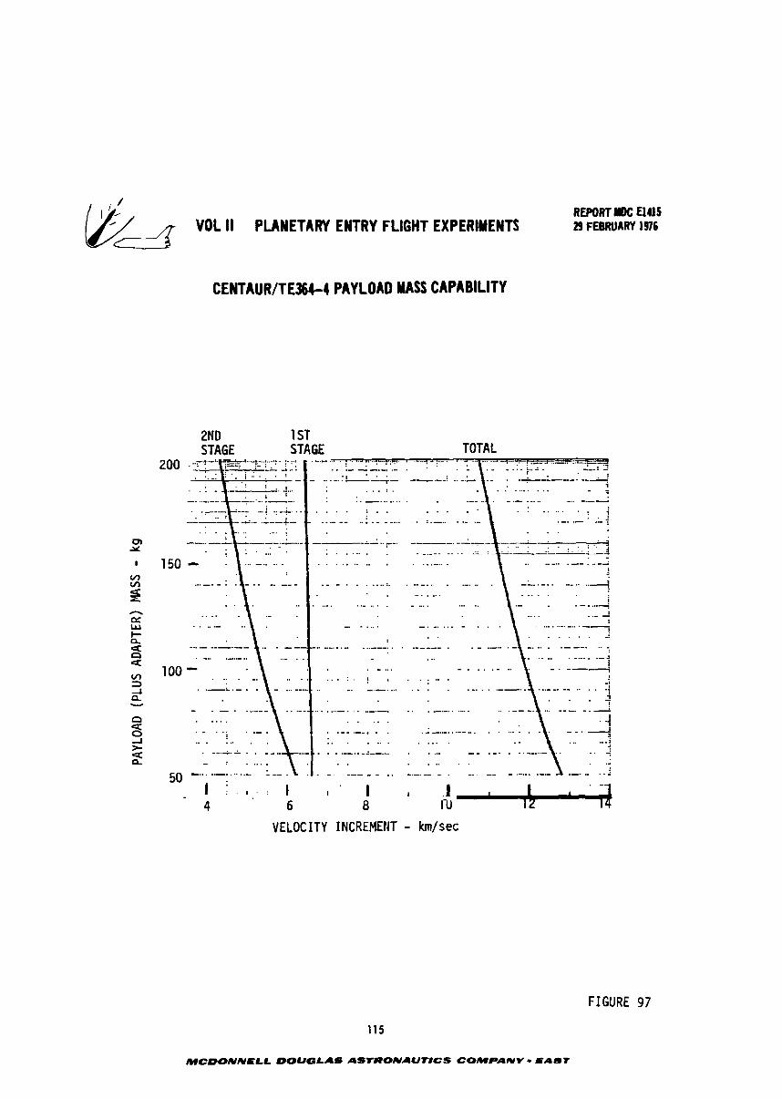
VDL li PLANETARY ENTRY FLIGHT EXPERIMENTS d CENTAUR/TEJ&I PAYLOAD MASS CAPABILITY
REPORT rOC El415 29 FEBRUARY 1916
VELOCITY INCREMENT - km/sec
FIGURE 97
115
MCDONNELL DOUGLAS ASTRONAUtlCS COMPANY - PAbf
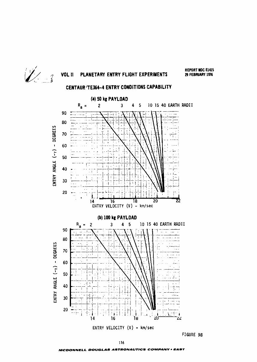
4 VOL II PLANETARY ENTRY FLIGHT EXPERIMENTS REPORT ROC El415 29 FEBRUARY 1916
CENTAURJTE3S4-4 ENTRY CONDITIONS CAPABILITY
(a) 50 kg PAYLOAD R, = 2 3 4 5 1 0 1 5 40 EARTH R A D I I
ENTRY VELOCITY (V) - km/sec
(b) 100 kg PAYLOAD R,= 2 3 4 5 1 0 1 5 4 0 E A R T H R A D I I
ENTRY VELOCITY ( V ) - km/sec
FIGURE 98
116
MCDONNELL DOUGLAS ASTRONAUT#CS COMPANY - EAmT
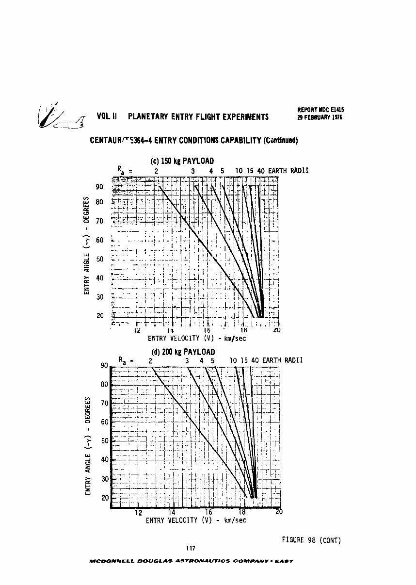
REPORT RlDC El415 VOL II PLANETARY ENTRY FLIGHT EXPERIMENTS 29 FEBRUARY 1976
CENTAUR/'E364-4 ENTRY CONDITIONS CAPABILITY (Continued)
RADI I
ENTRY VELOCITY ( V ) - km/sec
FIGURE 98 (CONT) 117
MCDONNELL DOUGLAS ASTRONJUTICS COMPANY LAUT
REWRT MDC El415 VOL II PLANETARY ENTRY FLIGHT EXPERIMENTS 29 FEBRUARY 1976
achieved f o r s e l e c t e d v a l u e s of apoapsis d i s t a n c e and payload mass (50, 100, 150 and
200 kg). Note t h a t as apoapsis (R ) is increased, h igher e n t r y v e l o c i t i e s can be a
a t t a i n e d a t s t e e p e r e n t r y angles. I n a l l cases , t h e Centaur s t a g e accomplishes t h e
f i r s t and second maneuver burn and a p o r t i o n of t h e t h i r d o r f i n a l burn whi le the
s o l i d motor is used t o complete t h e f i n a l burn.
6.2 E x i s t i n g S t o r a b l e Booster - m e Transtage is s e l e c r e d as t h e example
des ign f o r t h i s boos te r c l a s s on t h e b a s i s t h a t it provides m~ximum perCcrmance
c a p a b i l i t y w i t h minimum modif ica t ion. Cf t h e des igns considered ware t h e Del ta
acd kgena s t ages . Phys ica l and p ropu l s ion c h a r a c t e r i s t i c s of t h e Transtage p lus
a TE364-4 s o l i d motor upper s t a g e a r e desc r ibed i n Figur* 99. An a u x i l i a r y s t a g e
i s necessary t o achieve performance l e v e l s high enough t o be of i n t e r e s t f o r
environment s i m u l a t i o n missions.
Figures 100 and 101 p resen t t h e TranstagelTE364-4 performance c a p a b i l i t y i n
terms of payload mass and e n t r y cond i t ions respec t ive ly . The second s t a g e r e s t a r t
l i n e of Figure 101 r e f l e c t s t h e l i m i t e d AV c a p a b i l i t y of t h e Transtage p l u s t h e
s i n g l e s t a r t l i m i t a t i o n of c u r r e n t s o l i d motors. To achieve s t e e p e n t r i e s a t
lower apoapsis a l t i t u d e s , t h e f i r s t two maneuver burns r e q u i r e more AV than i s
a v a i l a b l e from t h e Transtage alone. Hence t h e second s t a g e must be used t o con-
p l e t e the second o r apoapsis burn. It must then be shu t down dur ing t h e coas t t o
low a l t i t u d e and r e s t a r t e d t o accomplish t h e t h i r d o r v e l o c i t y a d j u s t m a t burn.
6.3 Shor t Length E x i s t i n g Component S t c r a b l e Booster - A mul t i -s tage v e l o c i t y
package compo--4 of S h u t t l e Auxi l iary Propuls ion System Components i s shown t o
i l l u s t r a t e :t l e n g t h high AV c l a s s of s t o r a b l e ( N G /MMH) boqs te r s . The 2 4
compact v e l ~ -y package is an example of how e x i s t i - 5 components can be configured
t o b e s t u t i l i z e the wide b u t l eng th l i m i t e d shape of t h e S h u t t l e payload bay.
This maximizes c2por tun i ty f o r shared payload launches of t h e S h u t t l e . I n con-
t r a s t , t he o t h e r boos te r c l a s s e s r epresen t r e l a t i v e l y long, narrow upper s t a g e s
t h a t were o r i g i n a l l y designed f o r ground launched, expendable boos te r s .
Figure 102 d e s c r i b e s t h e phys ica l and p ropu l s ion c h a r a c t e r i s t i c s of t h e t h r e e
c t a g e v e l o c i t y package. The f i r s t two s t a g e s a r e i d e n t i c a l and com2osed of tank,
o,ngine and flow c o n t r o l componer~ts ueinq developed f u r t h e ?.-action Control System
(RCS) of S h u t t l e . The t h i r d sLage i s a s p i n s t a b i l i z e d , TE364-4 solirh motor.
Figure 103 shows t h e b a s i c payload mass ve r sus AV per5ormance c a p a b i l i t y of
each s t a g e whi le Figure 104 p resen t s t h e e n t r y cond i t ion c a p a b i l i t y f o r representa-
t i v e apoapsis d i s t a n c e s and payload masses. The t h i r d s t a g e r e s t a r t l i m i t of
MCDONNELL DQUGLAS ASTRONAUTICS COMPANY = EAST
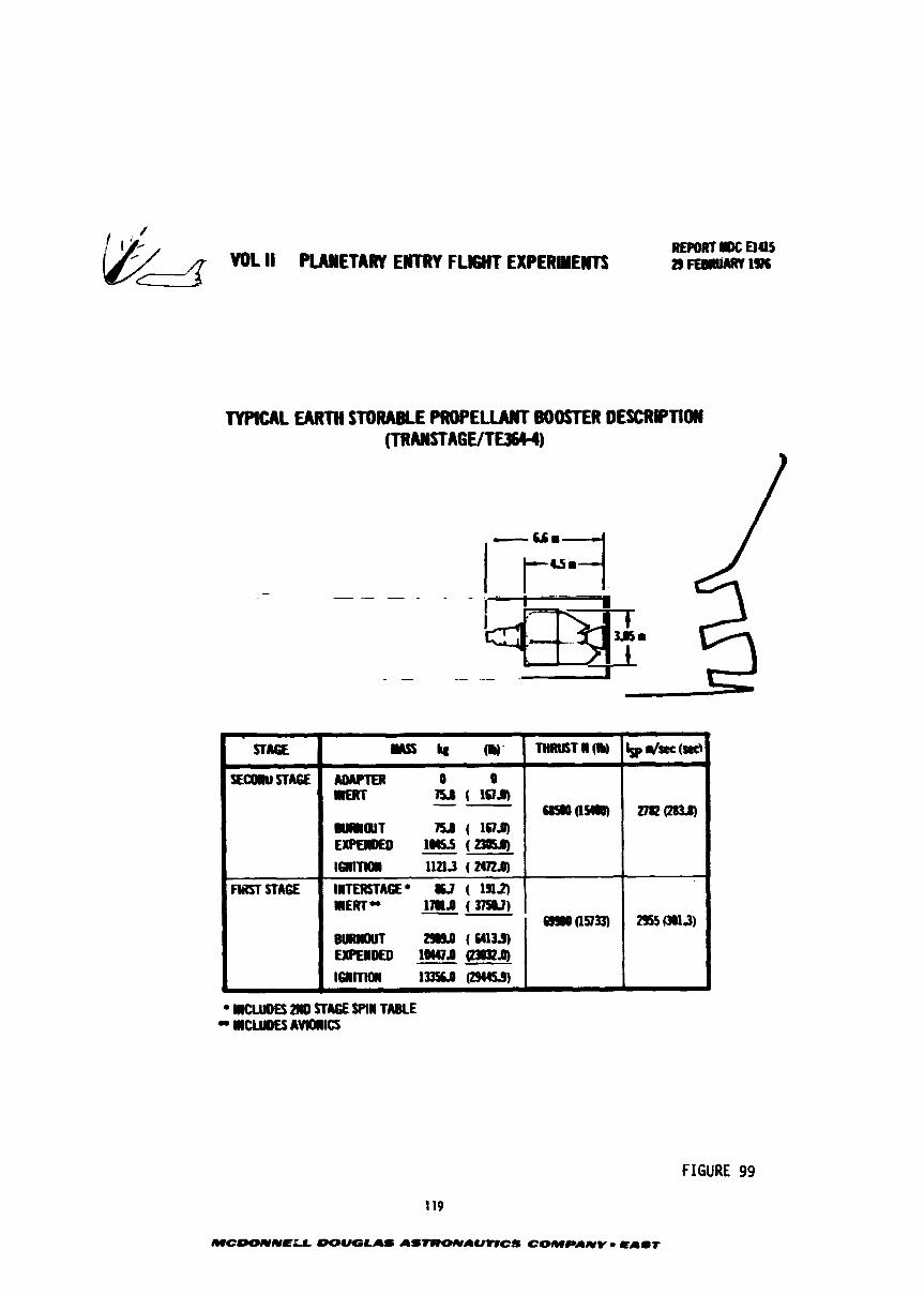
W d VOL ll W E T A M ENTRY FLIGHT UPERYEWTS
TYPlCAL EARTH STORABLE P R O P E W BOOSlWl OESCRIPTIOW (TRWA-1
IUCWDES ZllO STA6E SPIN TABLE - MCURES AVlOlllCS
FIGURE 99
119
MCOOIVNELL -U8 As-AMICS COMPANY - e A l t
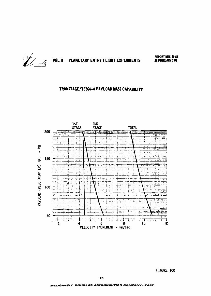
/$/ VOL I1 PLANETARY ENTRY FLIGHT EXPERIMENTS
TRANSTAGElTE364-4 PAYLOAD NASS CAPABlLlTV
1 ST 2ND STAGE STAGE TOTAL
VELOCITY INCREMENT - km/sec
FIGURE 100
120
MCDONNELL OOUGLAS ASTRONAUT8CS COMPANV - CELLST
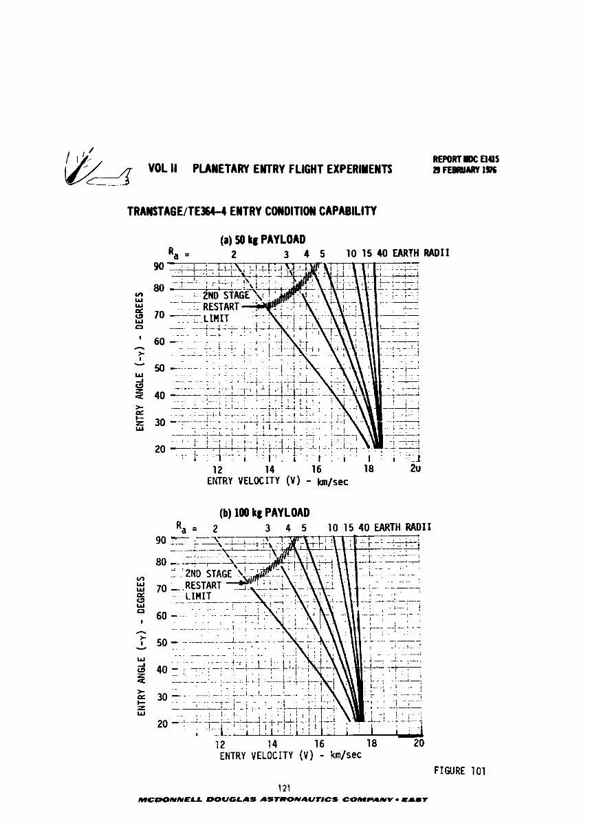
ENTR
Y AN
GLE
(-y
) - D
EGRE
ES
f:
gg
22
"0
88
ENTR
Y AN
GLE
(o
Y) - D
EGRE
ES
8'
68
8
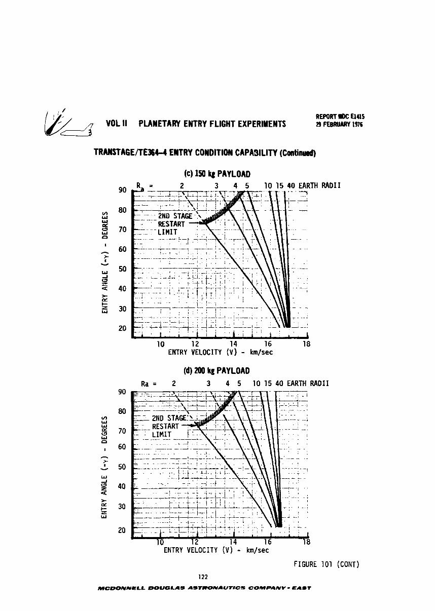
/
/ , VOL II PLANETARY ENTRY FLIGHT EXPERIMENTS
TRANSTAGE/TE3644 EWT RY COWDITION CAPASlLllY (Canti-)
(c) 150 kg PAYLOAD
REPORT IK: UUS 29 FEBRUARY 1916
RADI I
(d) 200 kg PAY LOAD
ENTRY VELOCITY ( V ) - km/sec
FIGURE 101 (CONT)
122
MCDONNELL DOUGLAS A S w N A U T # C S COMPANV EAST
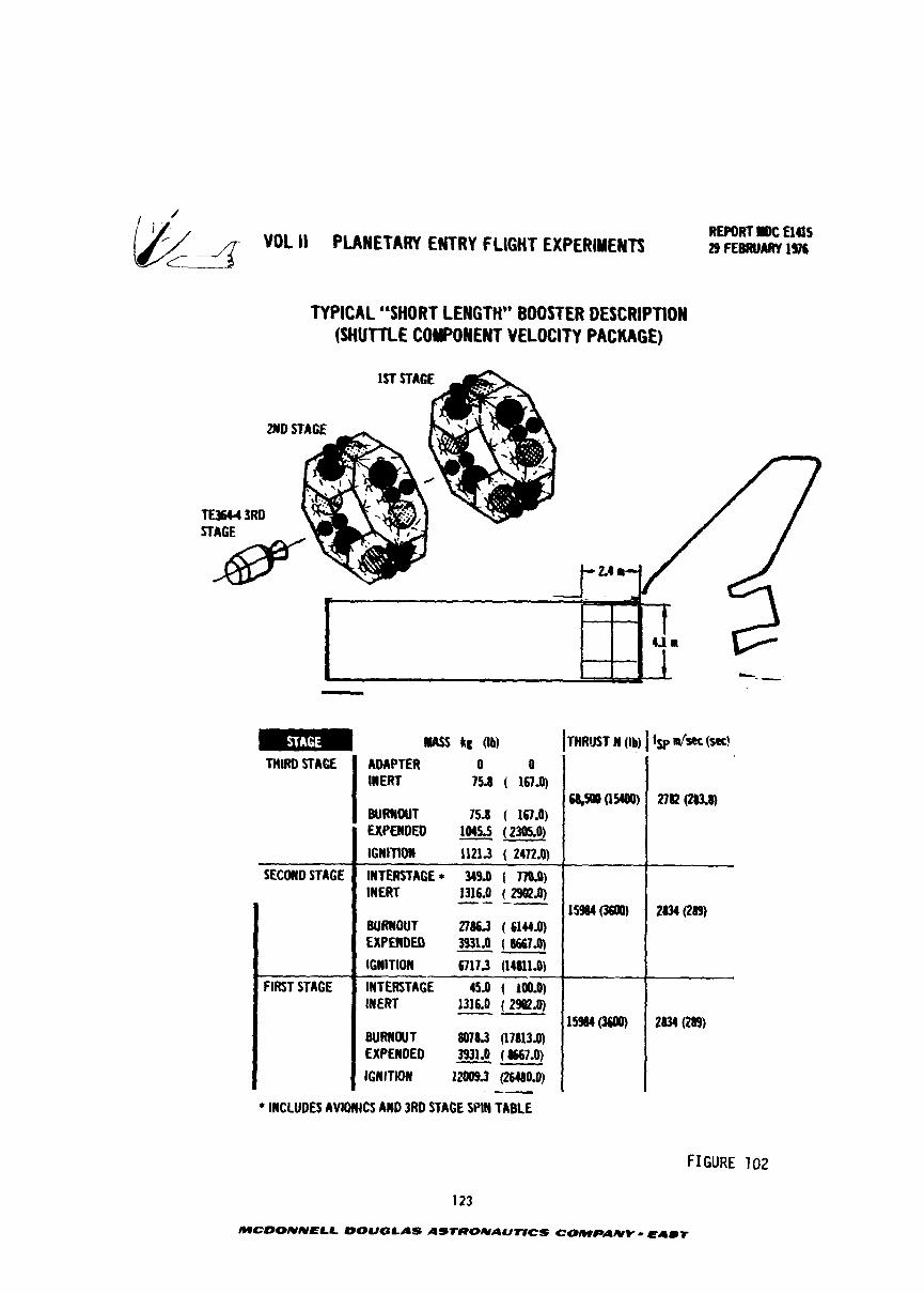
VOL I1 PLANETARY ENTRY FLIGHT EXPERIMENTS REPORT IlOC ElUS 29 FEBRUAftY 1%
TYPICAL "SHORT LENGTH" BOOSTER DESCRIPTION (SHUTTLE COMPONENT VELOCITY PACKAGE)
mEm w lu (Ib) THIRD STAGE I :,"gTIER 0 0
15d ( 161.0)
FIRST STAGE
BURNOUT 2786.3 ( 6144.0) EXPEWOED 3931 J ( 6667.0) -- IGWlTlOIl 67173 (1IIUl.O) - INTERSTAGE 45.0 ( 100.0) !NER'I 1316.0 ( 2W.Q --
I BURISOUT 8078.3 07813.0) ExPEnoEo 3931.0 ICNITIOW 12009.3 (26480.0)
, -- * INCLUDES AVIONICS AND 3RD STAGE SPIN TABLE
FIGURE 102
MCDONNELL bOUGLAS ASTRONAUflCS COAIPANY - EAST
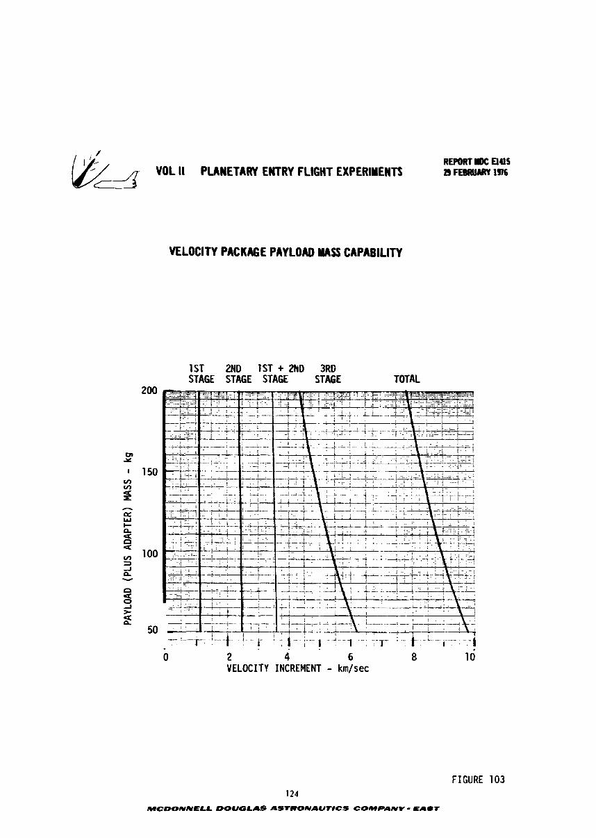
fiL VOL I1 PLANETARY EWTRY FLIGHT EXPERIMENTS
VELOCITY PACKAGE PAYLOAD MASS CAPABILITY
1 S T 2ND 1ST + 2hD 3RD STAGE STAGE STAGE STAGE TOTAL
0 2 4 6 8 1 0 VELOCITY INCREMENT - km/sec
FIGURE 1 0 3 124
MCDONNELL DOUGLAS ASTRONAUTICS COMPANY = EALIT
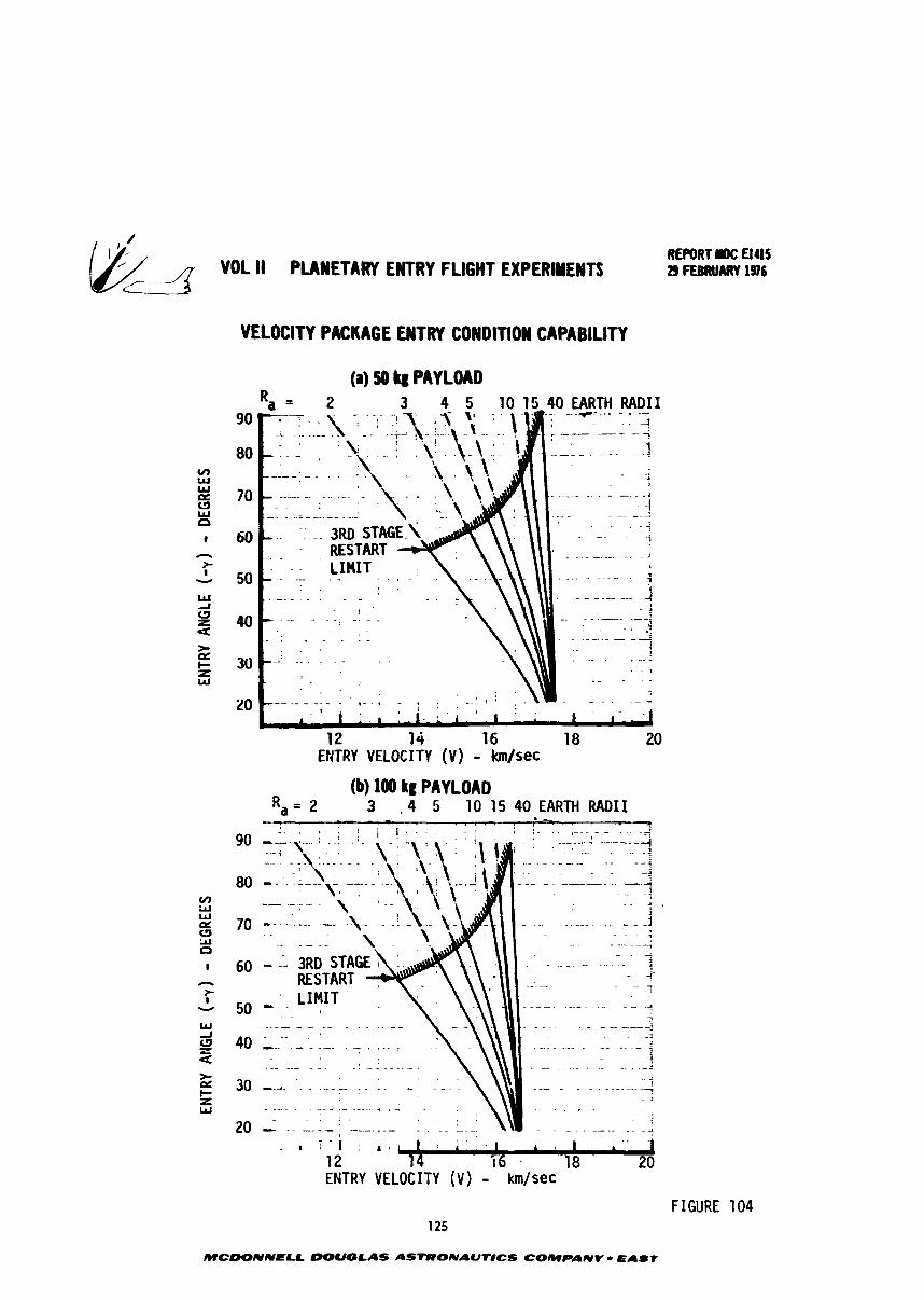
4 VOL il PLANETARY ENTRY FLIGHT EXPERIMEWTS
VELOCITY PACKAGE EWTRY COWDlTlOW CAPABILITY
(a) 50 PAYLOAD
I ! I . r , . - I . L i . * t i ' . s . .
A r ' -:A 12 14 16 18 20
ENTRY VELOCITY ( V ) - km/sec
(b) 100 kg PAYLOAD R,= 2 3 - 4 5 10 15 40EARTH RADII
. . -- - ----- . . . , . - . . ! i I * . : , . >
i ; : - : - 7 - - - - -- - ,
REPORT r)C a415 29 FEBRUARY 1916
- - , . 1 1 I ; 1 : r 2 i . t a 1 3 1 L
12 14 I 6 18 20 ENTRY VELOCITY (V) - km/sec
FIGURE 104 125
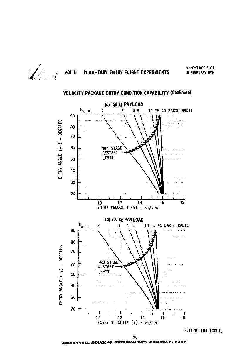
REPORT IM: El45 7 VOL I1 PLANETARY ENTRY FLIGHT EXPERIMENTS 29 FEBRUARY IS6
VELOCITY PACKAGE ENTRY CONDITION CAPABILITY (Catin&)
(c) 150 kg PAYLOAD 2 3 4 5 10 15 40 EARTli RADII
I 1 1 I ' I ' I t I i 1 10 12 14 16 18 ENTRY VELOCITY (V) - km/sec
(dl 200 kg PAYLOAD R = a 2 3 4 5 10 15 40 EARTtf RnDI I
1 P 12 14 16 I 8 NTRY VELOCITY ( V ) - km/sec
FIGURE 104 (COl4Tj 126
MCDONNELL DOUGLAS ASTRONAUT#CS COMPANV - EABT
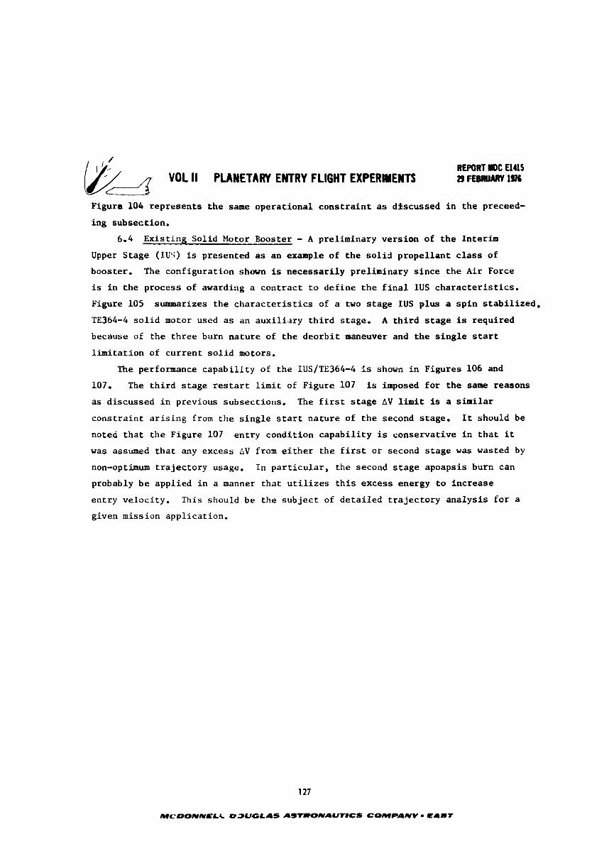
REPORT rDC UUS 29 FEBRUARY 196
Figure 104 represen t s t h e same opera t iona l c o n s t r a i n t as discussed i n t h e preceed-
ing subsection.
6.4 E x i s t i n g Sol id blotor Booster - A preliminary vers ion of t h e In ter im
Upper Stage (IUS) is presented a s an example of the s o l i d p r o p e l l a n t c l a s s of
booster. The conf igura t ion shown is necessa r i ly preliminary s i n c e the A i r Force
is i n the process of awarding a c o n t r a c t t o d e f i n e t h e f i n a l IUS c h a r a c t e r i s t i c s .
Figure 105 summarizes t h e c h a r a c t e r i s t i c s of a two s t a g e IUS p lus a s p i n s t a b i l i z e d ,
TE364-4 s o l i d motor used a s an a u x i l i a r y t h i r d stage. A t h i r d s t a g e is required
because of t h e t h r e e burn na tu re of t h e d e o r b i t maneuver and t h e s i n g l e start
l i m i t a t i o n of c u r r e n t s o l i d motors,
The performance c a p a b i l i t y of t h e IUS/TE364-4 is shown i n Figures 106 and
107. The t h i r d s t a g e r e s t a r t l i m i t of Figure 107 is imposed f o r t h e same reasons
a s d iscussed i n previous subsect ions , The f i r s t s t a g e AV l i m i t is a similar
c o n s t r a i n t a r i s i n g from t h e s i n g l e s t a r t na tu re of t h e second s tage . I t should be
noted t h a t t h e Figure 107 en t ry condi t ion c a p a b i l i t y is conservat ive i n t h a t i t
was assumed t h a t any excess AV f r o n e i t h e r t h e f i r s t o r second s t a g e was wasted by
non-optimum t r a j e c t o r y usage. I n p a r t i c u l a r , the second s t a g e apoapsis burn can
probably b e appl ied i n a manner t h a t u t i l i z e s t h i s excess energy t o inc rease
en t ry ve loc i ty . This should be the s u b j e c t of d e t a i l e d t r a j e c t o r y a n a l y s i s f o r a
given mission appl ica t ion.
127
MCDONNELC D3UGLAS LISTCIONAUT8CS COMPANY - EAUT
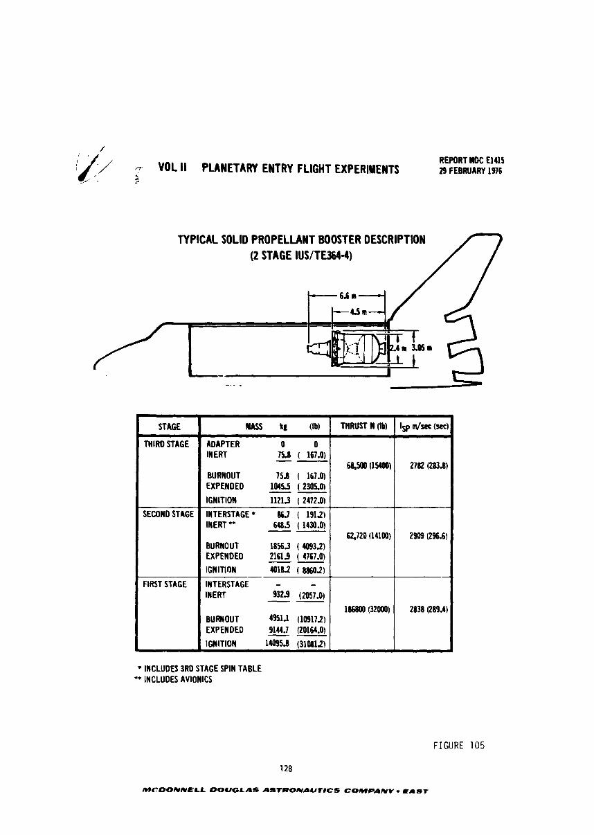
VOL ll PLANETARY ENTRY FLIGHT EXPERIMENTS 4
REPORT NDC U 4 l S 29 FEBRUARY 1976
TYPICAL SOLID PROPELLANT BOOSTER DESCRIPTION (2 STAGE IUSITE364-4)
* INCLUDES 3RD STAGE SPIN TABLE ** INCLUDES AVIONICS
STAGE
THIRD STAGE
SECONDSTAGE
FIRST STAGE
*
FIGURE 105
128
IWCDONNELL DOUGLAS ASTRONAUNCS COMPANY - EAST
Iw dsec (sec)
2 7 8 (283.8)
-
2909 (2S.6)
2838 (289.4)
MASS kg (Ib) THRUST W (Ib)
ADAPTER 0 0 INERT 75.8 ( 167.0) -- BURNOUT 75.8 ( 167.0) EXPENDED 1045.5 ( 2305.0) -- IGNITION 11213 ( 24721)
INTERSTAGE* W ( 1912) INERT ** 6485 ( 1430.0) -- BURNOUT 18563 ( 1093.2) EXPENDED -- 2161.9 ( 4767.0)
IGNITION - 4016.2 ( 8860.2) INTERSTAGE - - INERT 932.9 (2057.0) -- BURNOUT 49511 (10917.2) EXPENDED -- 9144.7 (20164.0)
IGNITION 11095.8 (310812)
68,500 (1W)
62,720 (14100)
1116800 (32000)
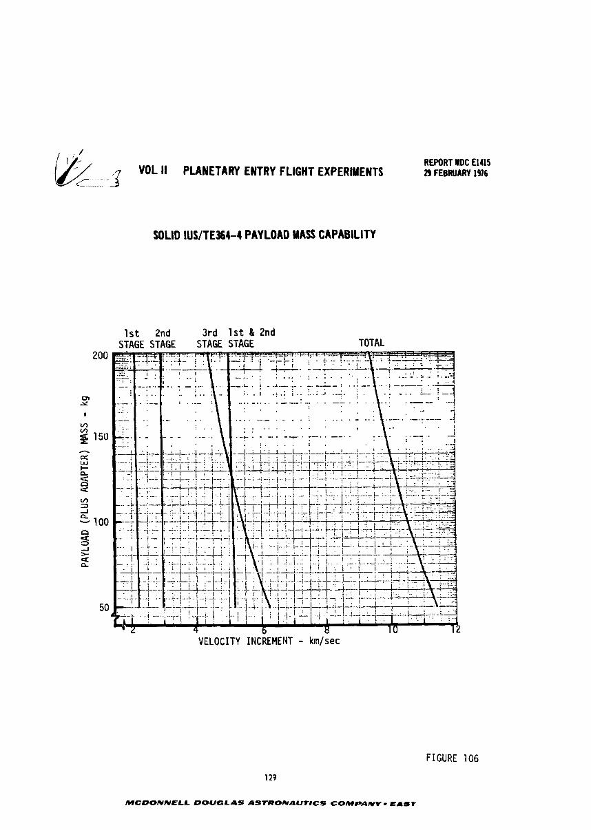
- 3 VOL I1 PUWLTARY ENTRY f LIGHT EXPERlYEWTS C---
SOLID IUS/TE3664 PAYLOAD MASS CAPABILITY
1 s t 2nd 3rd 1 s t & 2nd STAGE STAGE STAGE STAGE TOTAL
REWRT IIDC €1415 29 FEBRUARY 1976
VELOCITY INCREMENT - krn/sec
FIGURE 106
129
MCOONNELL DOUGLAS ASTRONAUflCS COMPANY - EAST
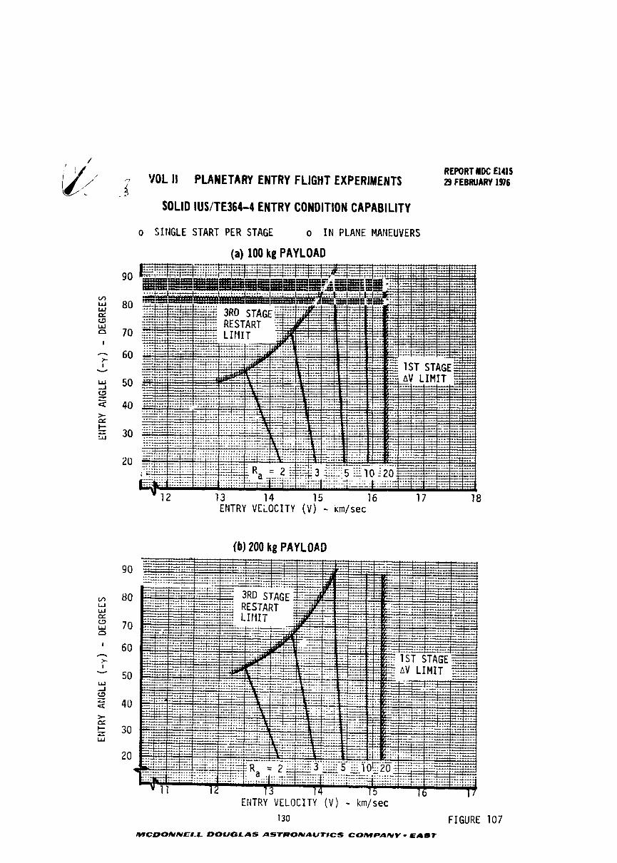
,-7 VOL I 1 PLANETARY ENTRY FLIGHT EXPERIMENTS i
. J
SOLID IUSlTE364-4 ENTRY CONDITION CAPABILITY
o SIriGLE START PER STAGE o I N PLANE MANEUVERS
(a) 100 kg PAYLOAD
(b) 200 kg PAYLOAD
REPORT HDC El415 29 FEEWARY 1976
130 FIGURE 107 MCD0NNEI.L DOUGLAS ASTRONAUflCS COMPANY - EAST
REPORT llOC El415 VOL II PLANETARY ENTRY FLIGHT EXPE9IMENTS 29 FEBRUARY 1976
7.0 COM?ARISON OF REQUIREMENTS AND CAPABILITIES
The environments t h a t can be produced dur ing a high speed e a r t h e n t r y a r e com-
pared i n t h i s s e c t i o n wi th those p red ic ted f o r t h e o u t e r p l a n e t s t o determine what
cond i t ions w i l l produce t h e b e s t s imulat ion. Four a s p e c t s of t h e s i m u l a t i o n a r e
examined. Do d i f f e r e n c e s i n atmospheric composition a f f e c t shock l a y e r s p e c t r a l
r a d i a t i v e heat ing? What cond i t ions can t h e b o o s t e r s produce t o b e s t s i m u l a t e peak
r a d i a t i v e h e a t i u g (nonblowing)? What cond i t ions can t h e boos te r produce t o b e s t
s imula te m u l t i p l e nonblowing environments? And f i n a l l y , what cond i t ions w i l l pro-
duce t h e b e s t s imula t ion when t h e h e a t i n g is reduced due t o mass i n j e c t i o n carbon-
aceous and hyperpure s i l i c a h e a t s h i e l d s ?
The atmosphere composition d i f f e r e n c e s between e a r t h and an o u t e r p l a n e t r a i s e
the i s s u e of shock l a y e r r a d i a t i o n s p e c t r a l d i s t r i b u t i o n . The i n c i d e n t r a d i a t i o n
spectrum is a complex f u n c t i o n of many v a r i a b l e s , ch ie f among which a r e gas composi-
t i o n , t o t a l energy, d e n s i t y and shock l a y e r Ehickness. The shock l a y e r r a d i a t i o n
i n t e r a c t s wi th t h e boundary l a y e r gases s o t h a t t h e s p e c t r a l i n t e n s i t y and t o t a l
r a d i a n t energy i n c i d e n t on t h e h e a t s h i e l d s u r f a c e can d i f f e r s i g n i f i c a n t l y from
t h e i n i t i a l shock l a y e r values. WhiLe p lane ta ry e n t r y l e v e l s of r a d i a t i v e h e a t i n g
can be s imulated dur ing e a r t h e n t r y , t h e d i f f e r e n c e i n atmosphere composition r e s u l t s
i n a d i f f e r e n t s p e c t r a l d i s t r i b u t i o n . S p e c t r a l d i s t r i b u t i o n s of i n c i d e n t r a d i a t i v e
f l u x f o r a Jov ian and an e a r t h e n t r y were ccmpared (see Figure 108) t o determine
s i m i l a r i t i e s . There a r e obviously s i m i l a r i t i e s as w e l l a s d i f f e r e n c e s . Both have
q u a l i t a t i v e l y s i m i l a r d i s t r i b u t i o n s . The J u p i t e r d i s t r i b u t i o n peaks i n t h e v i s i b l e
spectrum and again i n t h e VUV a t about 11 e l e c t r o n v o l t s . The e a r t h d i s t r i b u t i o n
peaks i n t h e near- infrared and a l s o i n t h e WV a t 10-11 e l e c t r o n v o l t s . For t h e
hydrr-on-helium a~mosphere of J u p i t e r p o s t of t h e energy is produced i n t h e u l t r a
via;.:., v i s i b l e and i n f r a r e d regimes wi th on ly 20% l i e s i n t h e vacuum u l t r a v i o l e t
(VUV) regior.. This is n o t t h e c a s e f o r an e a r t h ent ry . Approximately h a l f of t h e
enerq!l l i e s i n t h e VUV r eg ion (photon energy g r e a t e r than 6.5 ev) . The r e f l e c t a n c e
of s i l i c a drops o f f ir. t h e VUV, s o almost a l l t h e energy i n t h i s r eg ion w i l l b e
absorbed. Consequently, about 50% of t h e i n c i d e n t r a d i a t i o n w i l l be absorbed by t h e
s i l i c a s h i e l d f o r an e a r t h e n t r y as compared t o 25% f o r a Jov ian en t ry . These per-
centages w i l l change when blowing i s present .
While t h e s p e c t r a l d i s t r i b u t i o n d i f f e r e n c e s a r e of l i t t l e concern f o r t e s t i n g
carbonaceous hea t s h i e l d s , they a r e a c o n s i d e r a t i o n i n t e s t i n g r e f l e c t i v e sili ca
hea t s h i e l d s . Since t h e r e f l e c t i v i t y of s i l i c a is s p e c t r a l l y dependent a s dep ic ted
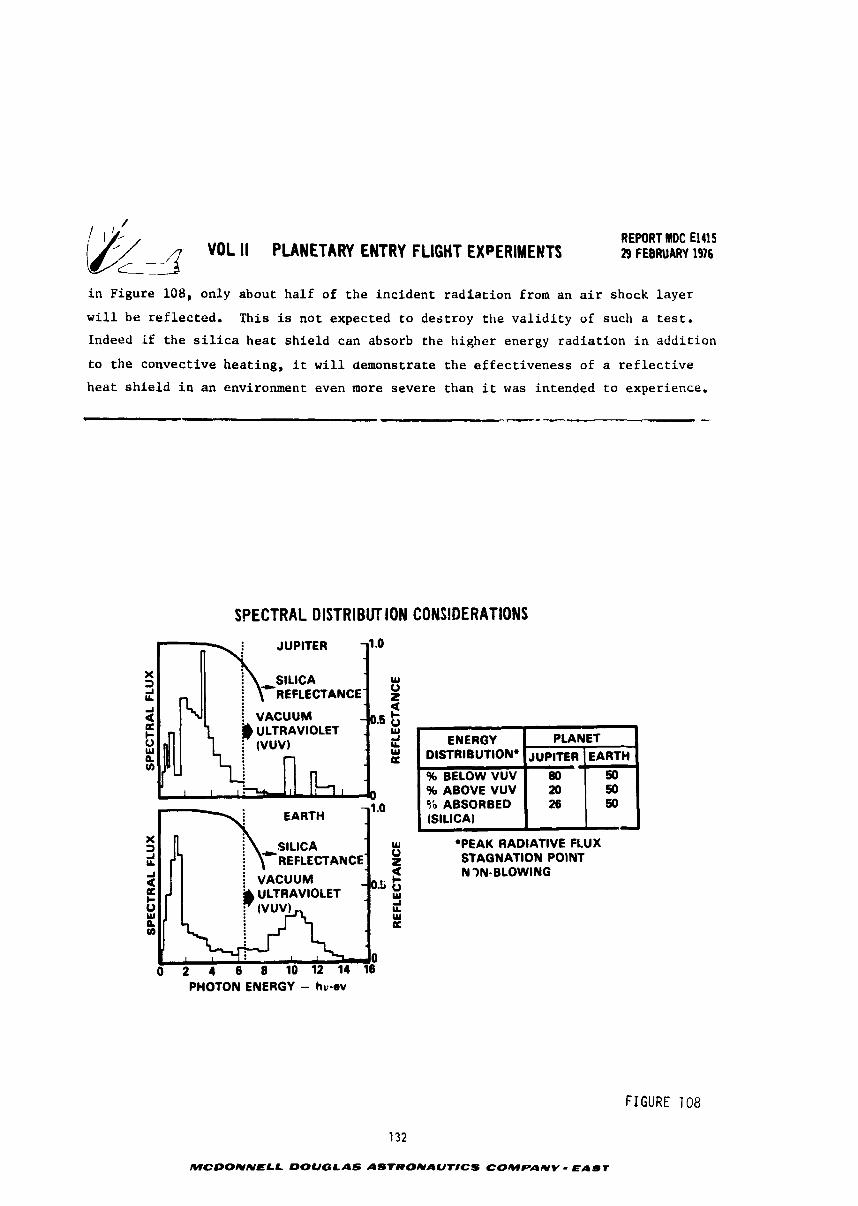
VOL II PLANETARY ENTRY FLIGHT EXPERIMENTS c-
REWRT MDC El415 29 FEBRUARY 1976
i n Figure 108, only about ha l f of t h e inc iden t r a d i a t i o n from an a i r shock l a y e r
w i l l be r e f l e c t e d . This is no t expected t o des t roy t h e v a l i d i t y of such a t e s t .
Indeed if t h e s i l i c a h e a t s h i e l d can absorb the higher energy r a d i a t i o n i n a d d i t i o n
t o t h e convective hea t ing , i t w i l l demonstrate t h e e f f e c t i v e n e s s of a r e f l e c t i v e
h e a t s h i e l d i n an environment even more severe than i t was intended t o e x p e r i e ~ c e .
SPECTRAL DISTRIBUTION CONSlDERATlONS
*PEAK RADIATIVE FLUX STAGNATION POINT N 9N-BLOWING
PHOTON ENERGY - hv-ov
FIGURE 108
ENERGY DISTRIBUTION*
% BELOW VUV % ABOVE VUV Sb ABSORBED (SILICA)
>
132
MCOONNELL DOUGLAS ASTRONAUTICS COMPANY - EAST
i
PLANET JUPITER
80 20 26
EARTH '
50 50 50
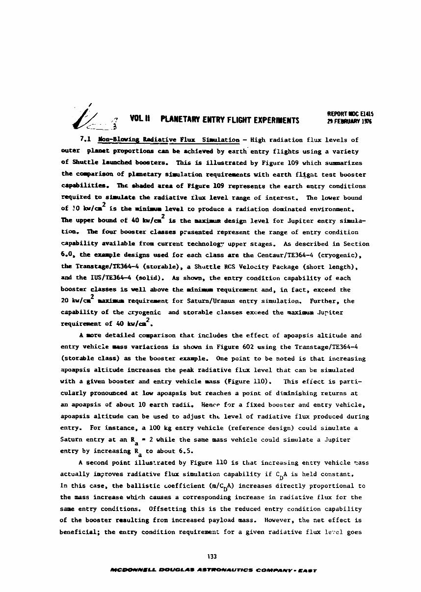
PLANETARY ENTRY FLIGHT EXPERIMENTS REPORT I#: El45 n FEBAUARY lac
7.1 #op-Blaring Bndiative Flux Simulation - High rad ia t ion f lux l e v e l s of
outer planet proportioas can be achieved by ear th ' en t ry f l i g h t s using a va r i e ty
of Shu t t l e launched boosters, 'Ilhis is i l l u s t r a t e d by Figure 109 which sumaarizes
the comparison of planetary simulation requirements with e a r t h f l i g n t test booster
capabi l i t i es . The shaded area of Figure 109 represents t he e a r t h en t ry conditions
m u i r e d t o sirulrte the r ad i a t ive klux l e v e l range of interest. The lover bound 2
of 20 b/cr is the anirur l e v e l t o produce a rad ia t ion dominated environment. 2
The upper bound of 40 b/ca is t h e mxhaa design l e v e l f o r Jup i t e r en t ry simula-
t ion, Tbe four booster classes presented represent the range of en t ry condition
capabi l i ty ava i lab le f r o r cur ren t technology upper stages. As described i n Section
6.0, the exasple designs used f o r each c l a s s are the Centaur/TE364-4 (cryogenic),
the Transtage/TE364-4 (storable), a Shu t t l e RCS Velocity Package (short length),
and t he IUS/TE364-4 (solid). As shown, t h e en t ry condit ion capabi l i ty of each
booster classes is w e l l above t h e minimum requi re ren t and, i n f a c t , exceed the 2
20 b/a requirement f o r Saturn/Uranus en t ry simulation. Further, the
czipability of t h e cryogenic and s to rab le classes exceed the maximum J u p i t e r 2 requirement of 40 b / c m .
A rore de ta i l ed comparison t h a t includes t h e e f f e c t of apoapsis a l t i t u d e and
en t ry vehicle mass var ia r ions is shown i n Figure 602 using the Transtage/TE364-4
(s torable class) as t he booster example. One point t o be noted is t h a t increasing
apoapsis a l t i t u d e increases the peak r ad i a t ive f l u l e v e l t h a t can be simulated
with a given booster and en t ry vehicle mass (Figure 110). This e f f e c t is par t i -
cu la r ly pronounced at law apoapsis but reaches a point of diminishing re turns a t
an apoapsis of about 10 e a r t h radi i . Hence f o r a f ixed booster and en t ry vehicle ,
apoapsis a l t i t u d e can be used t o ad jus t t h r l e v e l of r ad i a t ive f lux produced during
entry. For instance, a 100 kg en t ry vehic le (reference design) could simulate a
Saturn en t ry a t an R = 2 while the same mass vehic le could simulate a Jup i t e r a
entry by increasing R t o about 6.5. a A second point i l l u s t r a t e d by Figure 110 is t h a t increasing entry vehicle cass
ac tua l ly im2roves r ad i a t ive f lux simulation capabi l i ty i f C A is held constant. D I n t h i s case, the b a l l i s t i c coe f f i c i en t (m/cDA) increases d i r e c t l y proportional t o
the mass increase which causes a corresponding increase i n r ad i a t ive f lux fo r t he
same entry conditions. Offse t t ing t h i s is the reduced en t ry condition capabi l i ty
of the booster r e su l t i ng from increased payload mass. However, the ne t e f f e c t is
beneficial ; t he entry condition requirement f o r a given r ad ia t ive f l u le-:el goes
MCDOnUIU -LAO A S m A U m C S COMPANY - EAST
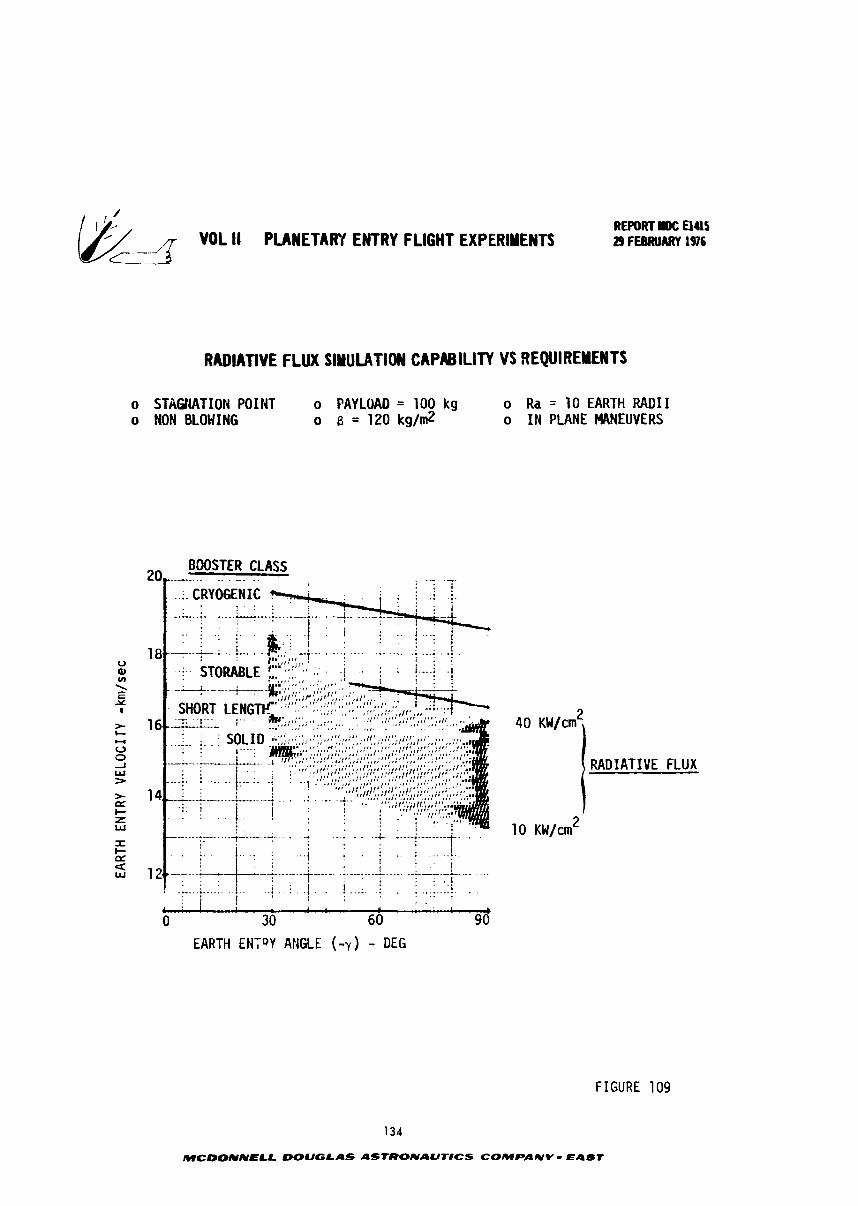
-: VDL II PUlETARV ENTRY FLIGHT EXPERIMENTS
RADIAnVE FLUX SIMULATION CAPABILITY VS REQUIREMENTS
o STAGHATION POINT o PAYLOAD = 100 kg o Ra = 10 EARTH RADII o NON BLOHING o 8 = 120 kg/m2 o I N PLANE MANEUVERS
BOOSTER CLASS 2 0 . . . . . . . .
(RADIATIVE FLUX
* . + :--- ... . . . . . ..... I I- a . : .. 1 j . . ..... i t---. .
t : . I # . .... . ,
i .-+--.---- I : . : . I * .
. . ........ ... .. i . . . i . . . ! . ! .: ! i . : ; I , -.
, . f L r 1
0 30 60 9d EARTH ENTQY ANGLE (-v) - DEG
FIGURE 109
134
MCOONNELL DOUGLAS ASfRONAUr#CS COMPANY - EAST
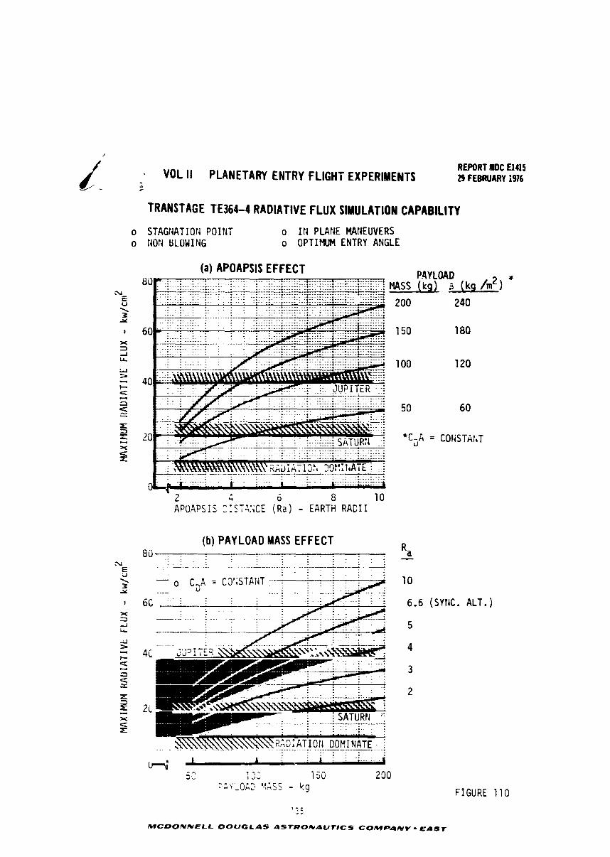
- VOL II PLANETARY ENTRY FLlGHi EXPERIMENTS REPORT rDC El415 29 F EBIWIARY i976
TRANSTAGE TE364-4 RADIATIVE FLUX SIMULATION CAPABILITY
o STAGNATION POINT o I N PLANE MAIIEUVERS o MON tiLOWING o OPTIMUM ENTRY ANGLE
(b) PAY L O A D MASS EFFECT
PAY LOAD HnSS (kg) 3 (kg /m2) *
6.6 (SYtIC. ALT.)
-,..,. p P - $ ,!..- L., v L i.7:s - 49
F I G U R E 110
MCDONNELL DOUGLAS ASTRONaUTICS COMPAAIV - EAST
/ REPORT MOC El415
VOL II PLANETARY ENTRY FLIGHT EXPERIMENTS 29 FEBRUARY 1976
down f a s t e r than t h e boos te r e n t r y cond i t ion c a p a b i l i t y . This can be seen i n F i g u r e
110 by no t ing t h a t as payload mass inc reases , h igher r a d i a t i v e f l u x l e v e l s a r e
achievable i f R is he ld cons tan t o r a lower R can be used i f r a d i a t i v e f l u x is a a
he ld constant .
7.2 Mult ip le Non-Blowing Parameter Simulation - Although e a r t h e n t r y condi- /
t i o n s can be s e l e c t e d t h a t w i l l r e s u l t i n matching peak r a d i a t i v e h e a t f l u x levels
f o r e n t r y i n t o Sa tu rn o r J u p i t e r , t h e p r e c i s e simultaneous matching of a l l o t h e r
e n t r y parameters can only be approximated. Figure 111 presen t s f o u r a d d i t i o n a l
e a r t h e n t r y environment parameters as a func t ion of t h e peak r a d i a t i v e h e a t f l u s .
It is seen t h a t peak convective h e a t f l u x is e s s e n t i a l l y independent of e n t r y angle
and always f a l l s s h o r t of t h e p lane ta ry va lue by j u s t under a f a c t o r of two. The
t o t a l i n t e g r a t e d h e a t load can be v a r i e d by about a f a c t o r of t h r e e depending on
t h e s e l e c t i o n of t h e e n t r y angle. This permits one t o match t h e t o t a l h e a t load
f o r Saturn. itowever, even t h e shal lowest e a r t h e n t r y f a l l s s h o r t of t h e t o t a l h e a r
load f o r J u p i t e r . Although t h i s might be of some concern i f t h e f l i g h t t e s t i s
meant t o q u a l i f y a J u p i t e r h e a t s h i e l d , i t is n o t expected t o be a s e r i o u s aeficienc;;
when t h e f l i g h t t e s t is intended t o en la rge t h e technology base. G-loads and srag-
na t ion p ressure are c l o s e l y r e l a t e d and can be n e a r l y matched f o r e i t h e r J u p i t e r
o r Saturn. The b e s t o v e r a l l match can be obta ined f o r J u p i t e r a t a 20 degree e n t r y
angle. Referr ing back t o Figure 109 i t is seen t h a t th's r e q u i r e s an e a r t h e n t r y
v e l o c i t y on t h e o r d e r of 20 km/sec. This w i l l of course be extremely d i f f i c u l t t o
achieve wi th any bu t t h e most e n e r g e t i c upper s t a g e boosters .
As shown i n Sec t ion 4, v e h i c l e conf igura t ion can a l s o in f luence t h e r e l a t i v e
as w e l l a s the a b s o l u t e l e v e l of e n v i r o n m e ~ ~ t parameter simulation. I n addit icxl t o
varying t h e e n t r y v e l o c i t y and f l i g h t path angle , t h e l e v e l of r a d i a t i o n f l u x c a n
be a l t e r e d by s e l e c t i n g d i f f e r e n t b a l l i s t i c c o e f f i c i e n t s and d i f f e r e n t nose r d i i
f o r t h e e n t r y vehic le . For example, doubling t h e b a l l i s t i c c o e f f i c i e n t more than
doubles r a d i a t i v e f l u x bu t i n c r e a s e s convective f l u x by l e s s than 50 percent .
S imi la r ly reducing nose r a d i u s by a f a c t o r of 2 reduces r a d i a t i v e f l u x by about
26 percent but i n c r e a s e s convective f l u x by approximately 40 percent . This p o i n t s
o u t the p o t e n t i a l use of v e h i c l e conf igura t ion " t a i l o r i n g " as a means of c l o s e r
simultaneous s imula t ion o f environment parameters. For example, Figure 112 i l l u s -
t r a t e s how reducing nose r a d i u s can more c l o s e l y achieve simultaneous s imulat ion
of peak convective and r a d i a t i v e f l u x l e v e l s .
136
MCDONNELL DOUGLAS ASTRONAUTICS COMPANY - EAST
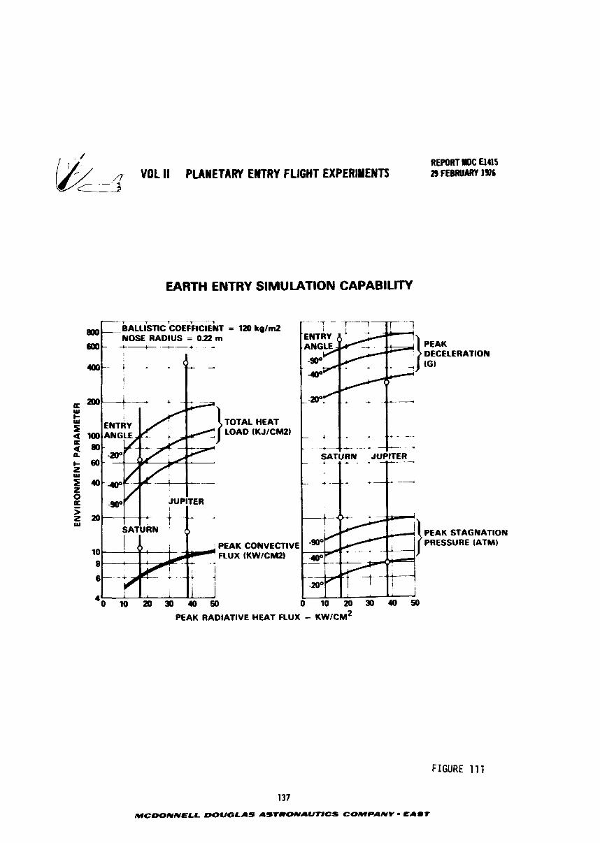
VOL ll PLANETARY ENTRY FLIGHT EXPERIYENTS c13
EARTH ENTRY SIMULATION CAPABILITY
= 120 k g / d
TOTAL HEAT LOAD (KJICM2I
PEAK STAGNATION
PEAK CONVECTIVE PRESSURE (ATMI
FLUX (KWICMZI
0 1 0 2 0 3 0 4 0 5 0
FIGURE 11 1
137
MCWNNELL DOUGLAS ASTRONAUTtCS COMPANV - E I U f
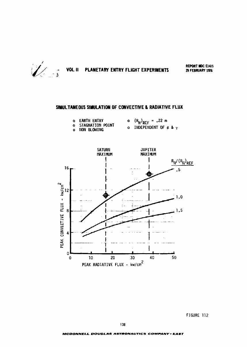
/ REPORT r(#: El415
0 VOL II PLANETARY ENTRY FLIGHT EXPERIYEYTS 29 FEBRUARY 1976 i- - - 3
SINULTANEWS SINULATION OF CONVECTIVE 8 RADIATIVE FLUX
o EARTH ENTRY 0 (k),m = -22 m o STAGNATION POINT II nLr
o NOH BLOWING 0 INDEf'EtiDEkiT OF 0 81 y
SATURtI JUPITER t.MX I WH MAXIMUM
PEAK RADIATIVE FLUX - kwlcm 2
FIGURE 112
138
MCDONNELL DOUGLAS ASTRONAUIICS COMPANV - PAST
REPORT IW: El415 & -7 VOL II PLANETARY ENTRY FLIGHT EXPERIMENTS 7----
29 FEBRUARY 1916 <-- __ 1
7.3 Simulation of Jovian Radiat ive Heating wi th Blowing - A s mentioned pre-
v iously , t h e computation of r a d i a t i v e h e a t i n g i n t h e presence of mass i n j e c t i o n due
t o a b l a t i o n involves s o p h i s t i c a t e d computer codes. Methodology w i t h i n t h e s e codes
y i e l d s l i g h t l y d i f f e r e n t v a h e s of hea t ing due t o t h e formulat ion of temperature
p r o f i l e s , s p e c i e s concen t ra t ion p r o f i l e s , s p e c t r a l r e f l e c t a n c e , i n t e g r a t i o n techni-
que, s p e c t r a l absorp t ion c o e f f i c i e n t s , etc, Detai led analysez were made f o r s e v e r a l
Jov iac f l i g h t cond i t ions and e a r t h f l i g h t cond i t ions , and f o r t h r e e h e a t s h i e l d
materials; carbon, carbon phenol ic and hyperpure s i l i c a . F i r s t , a p o i n t comparison
is presented f o r a t y p i c a l Jovian cond i t ion followed by t h e parametr ic a n a l y s i s f o r
s imula t ion of maximum heating.
7.3.1 Simulation of Typicai Rad ia t ive t ieating wi th Blowing - I n Sec t ion 3.2,
t h e i n c i d e n t and n e t h e a t f l u x were determined a t a peak h e a t i n g (condi t ion "11")
dur ing a t y p i c a l Jovian entry . For t h e carbon h e a t s h i e l d , t h e i n c i d e n t r a d i a t i v e 2
f l u x was 13.81 kW/cm and t h e n e t f l u x t h a t t h e h e a t s h i e l d had t o accommodate w a s 2
9.08 kU/cm . For t h e hyperpure s i l i c a h e a t s h i e l d , t h e i n c i d e n t f l u x was 24 kW/cm 2
2 with 1.0 kU/cm t h a t had t o be accommodated. These h e a t i n g va lues are compared i n
Figure 113 wi th peak f l u x produced dur ing e a r t h e n t r y from VE = 16.76 b / sec as a
func t ion of ene t ry angle. It should be noted t h a t Jovian similar p r o f i l e s through
t h e shock l a y e r were used f o r t h e e a r t h e n t r y computations. The shaded bands on
t h i s f i g u r e represen t changes i n h e a t i n g t h a t may occur due t o moderate mass in jec -
t ion. When massive blowing occurs , a l a r g e r change i n h e a t i n g is obtained. The
carbon s h i e l d shows a much smal le r change i n h e a t i n g than obta ined f o r carbon
phenolic. I n a d d i t i o n t o t h e carbon s p e c i e s generated by t h e carbon s h i e l d t h e
carbon phenol ic l i b e r a t e s C-H r a d i c a l s which a r e good absorbers of VW r a d i a t i o n
and hence a lower heat ing.
A s shown on t h e f i g u r e b o t h t h e i n c i d e n t and t h e n e t r a d i a t i v e f l u x e s t o t h e
carbon a r e matched a t an e n t r y angle of -22 degrees. The i n c i d e n t f l u x on t h e s i l i c a
s h i e l d is matched a t -48 degrees bu t t h e n e t f l u x w i l l be s u b s t a n t i a l l y g r e a t e r than
p red ic ted f o r t h e Jovian entry . This i n c r e a s e is beneficial i n s imula t ing t o t a l
h e a t and h e a t s h i e l d performance. S imi la r r e s u l t s a r e obta ined i n t h e next s e c t i o n
when analyzing maximum design h e a t i n g s imulat ion.
7.3.2 Simulation of Maximum Radiat ive Heating wi th Blowing - The u n c e r t a i n t i e s
i n Jovian e n t r y cond i t ions r e s u l t e d i n a maximum non-blown r a d i a t i v e h e a t i n g of 2
38 kW/cm . The corresponding blown r a d i a t i v e hea t ing va lues f o r t h e candidate h e a t
s h i e l d s a re :
139
MCDONNELL DOUGLAS ASTRONAUT#CS COMPANV = EAST
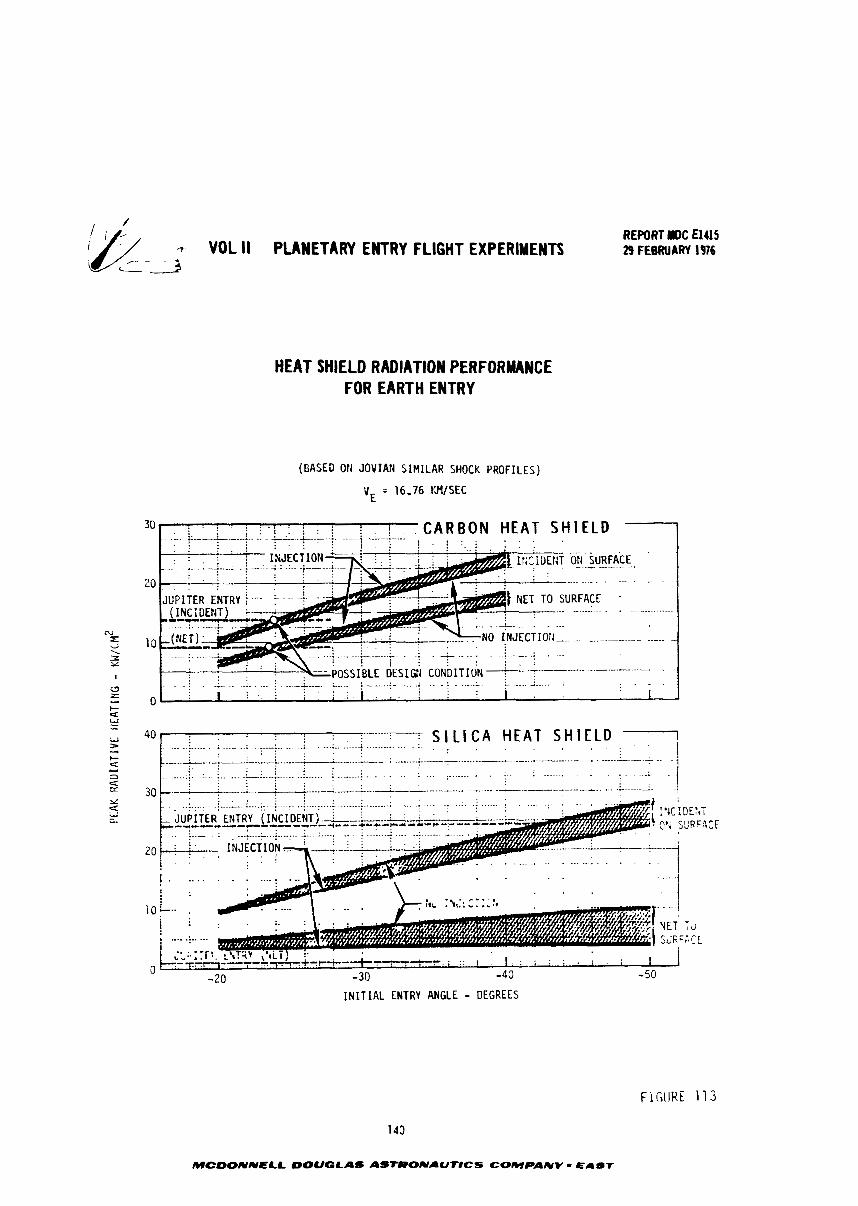
- VOL II PLANETARY ENTRY FLIGHT EXPERIMENTS
HEAT SHIELD RADIATION PERFORMANCE FOR EARTH ENTRY
(BASED Otl JOVIAri SIMILAR SHOCK PROFILES)
vE = 16.76 t34lSEC
REPORT YDC ElaS 29 FEBRUARY 196
C A R B O N HEAT S H I E L D
-~ . .
I N I T I A L ENTRY ANGLE - DEGREES
FiGlJHE 113
143
MCDONNELL DOUGLAS ASIRONAUT#CS COMPANY - EAST
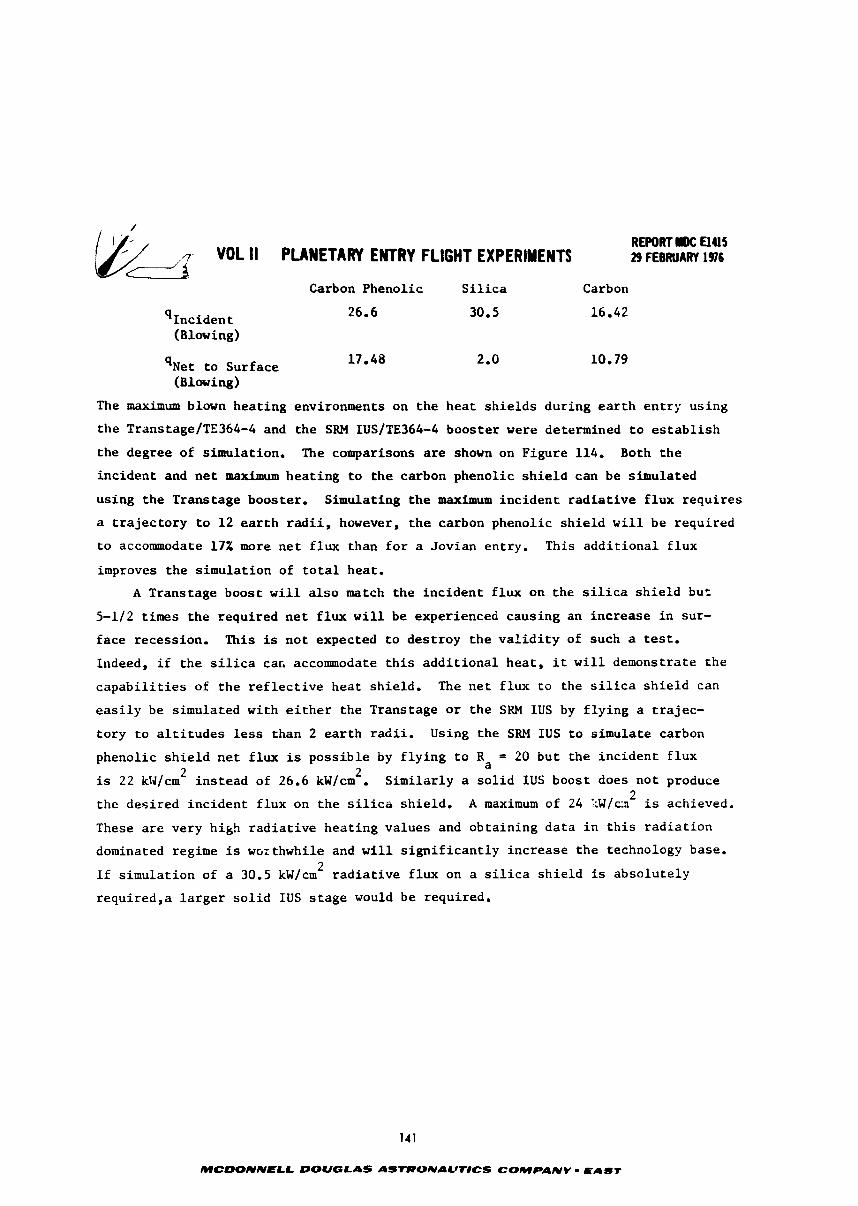
/
REWRT MDC El415 VOL II PLANETARY ENTRY FLIGHT EXPERIMENTS 29 FEBRUARY 1916
Carbon Phenol ic S i l i c a Carbon
(Blowing)
q ~ e t t o Surface (Blowing)
The maximum blown hea t ing environments on t h e h e a t s h i e l d s dur ing e a r t h e n t r y us ing
t h e TranstagelTE364-4 and t h e SRH IUSlTE364-4 boos te r were determined t o e s t a b l i s h
t h e degree of s imulat ion. The comparisons are shown on Figure 114. Both t h e
i n c i d e n t and n e t maximum h e a t i n g t o t h e carbon phenol ic s h i e l d can be s imulated
us ing t h e Transtage booster. Simulating t h e maximum i n c i d e n t r a d i a t i v e f l u x r e q u i r e s
a t r a j e c t o r y t o 1 2 e a r t h r a d i i , however, t h e carbon phenolic s h i e l d w i l l be requ i red
t o accommodate 17% more n e t f l u x than f o r a Jov ian entry. This a d d i t i o n a l f l u x
improves t h e s imula t ion of t o t a l heat .
A Transtage boost w i l l a l s o match t h e i n c i d e n t f l u x on t h e s i l i c a s h i e l d bu t
5-1/2 t imes t h e required n e t f l u x w i l l be experienced causing an i n c r e a s e i n sur-
f ace recess ion. This is n o t expected t o d e s t r o y t h e v a l i d i t y of such a test.
Indeed, i f t h e s i l i c a car, accommodate t h i s a d d i t i o n a l h e a t , i t w i l l demonstrate t h e
c a p a b i l i t i e s of t h e r e f l e c t i v e h e a t sh ie ld . The n e t f l u x t o the s i l i c a s h i e l d can
e a s i l y be simulated wi th e i t h e r t h e Transtage o r t h e SRM IUS by f l y i n g a t r a j e c -
t o r y t o a l t i t u d e s less than 2 e a r t h r a d i i . Using t h e SRM IUS t o s imula te carbon
phenol ic s h i e l d n e t f l u x is p o s s i b l e by f l y i n g t o Ra = 20 bu t t h e i n c i d e n t f l u x 2
is 22 k ~ / c m ~ i n s t e a d of 26.6 kW/cm . S i m i l a r l y a s o l i d IUS boost does n o t produce 2
t h e d e s i r e d i n c i d e n t f l u x on t h e s i l i c a s h i e l d . A maximum of 24 1:W/cm is achieved.
These a r e very hikh r a d i a t i v e h e a t i n g va lues and ob ta in ing d a t a i n t h i s r a d i a t i o n
dominated regime is wcithwhile and w i l l s i g n i f i c a n t l y i n c r e a s e t h e technology base. 2
If s imula t ion of a 30.5 kW/cm r a d i a t i v e f l u x on a s i l i c a s h i e l d is abso lu te ly
requ i red ,a l a r g e r s o l i d IUS s t a g e would be required.
141
MCDONNELL DOUGLAS ASTRONAUTICS COMPANV - EABT
REPORT DC aus VOL II PLANETARY EWTRY FLIGHT EXPERIMENTS 29 FESRUAW 196
BLOWING RADIATIVE FLUX SIMULATION - EARTH
(100 kg; B = 100 kg/m2 VEHICLE)
TRANSTAG E/TE364-4
( INCIDENT)
APOAPS I S RADIUS
SRM IUSlTE364-4
(INCIDENT) (NET)
APOAPSIS RADIUS
C/P - CARBON PHENOLIC S - S I L I C A
FIGURE 114
142
MCDONNELL DOUGLAS ASTlPONAUTlCS COMPANV EAeT
-- VOL II PLANETARY ENTRY FLIGHT EXPERIMENTS REPORT MDC El415 29 FEBUdQRU i976
8.0 ENTRY VEHICLE EXPERIMENTS
Projected technology needs for a complement of entry individual experiments
were assessed by reviewing state of the art measurement goals and by conversation
with outer probe teams and key NASA personnel. The experiment goals were defined
and the return expected from a measuring device weighed against the impact on the
vehicle design and weight increment. A recommended list of experiments was compiled
and the location of instruments coordinated with the design of the entry vehicle.
Because the flight experiment vehicle is primarily a heat shieldlthermal ecvironment
research tool, its heat shield must be a part of the experiments in addition to
providing vehicle thermal protection. In some instances the experiments and/or
instrumentation drove vehicle design.
Candidate heat shield concepts were identified (Figure 115) and their
attributes are as follows:
A. Single Ablator - This concept, which would employ either a reflective or non-reflective heat shield is conceptually the simplest and most reliable.
For any given entry profile, it is probably also the lightest; thus this
concept should permit a larger fraction of vehicle mass to be devoted to
instrumentation, data management, and recovery. Separate flights would
be required to address each of the candidate heat shield materials.
B. Heat Sink Approaches - The large heating rates which the entry vehicle will encounter precludes the useful application of beryllium heat sinks in the
manner employed by the PAET, or FIRE vehicles (References 14
and 15). For instance, time-to-melt for a berryllium heat sink at a flux '7 7
of 1 kW/cm- is approximately 7 seconds, at 10 kW/cmk it is 0.07 seconds.
Because efficiency of mass transfer cooling increases with free stream
enthalpy, the possibility exists that local application of transpiration
cooled surfaces may be feasible. Active transpiration has been success~ully
employed on reentry vehicles to protect small areas from convective heating
comparable in severity to the required environment. In assessing the feasi-
bility of employing transpiration locally, the effect of the radiative
environment needs to be evaluated.
C. Dual Ablator Concepts - A number of possibilities exist for using more than one ablator in the heat shield. Such an approach suggests the possibility
of obtaining performance comparisons between two or more heat shield
materials which have been exposed to the same environment. In addition,
143
MCDONNELL DOUGLAS ASTRONAUTICS COMPANY PAST
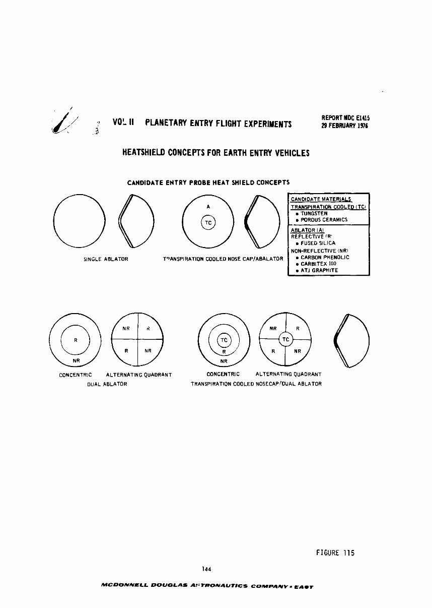
3 VOL I I PLANETARY ENTRY FLIGHT EXPERIMENTS --
HEATSHIELD CONCEPTS FOR EARTH ENTRY VEHICLES
CANDIDATE ENTRY PROBE HEAT SHIELD CONCEPTS
SINGLE ABLATOR TQANSPIRATION COOLED NOSE CAP/ABALATOR
REPORT MOC El415 29 FEBRUARY 1916
8
CANDIDATE MATERIALS TRANSPIRATION COOLED (TCI
TUNGSTEN WROUS CERAMICS
ABLATOR (A) REFLECTIVE (RI
FUSED SILICA NON-REFLECTIVE (NR)
CARBON PHENOLIC CARBITEX 100 ATJ GRAPnlTE
CONCENTRIC ALTERNATING QUADRANT CONCENTRIC ALTERNATING QUADRANT
DUALABLATOR TRANSPIRATION COOLED NOSECAP'DUAL ABLATOR
FIGURE 115
144
MCDONNELL DOUGLAS AfiTRONAUT8CS COMPANY - EAST

REPORT MDC €1415 7- VOL II PLANETARY ENTRY FLIGHT EXPERIMENTS 29 FEBRUARY 1976
LL-3 t h e r e i s an obvious appeal t o t e s t i n g two o r more h e a t s h i e l d s '.'for t h e
p r i c e of one", A number of p o t e n t i a l problems r e q a i r e i n v e s t i g a t i o n
b e f o r e such an approach can be judged completely f e a s i b l e . Some of t h e s e
a r e :
o Contamination - Can i n t e r - a b l a t o r contamination e i t h e r i n t h e
boundary l a y e r o r due t o l i q u i d runoff be avoided?
o M a t e r i a l I n t e r f a c e s - Are problems l i k e l y t o a r i s e due t c s u r f a c e
d i s c o n t i n u i t i e s a t a b l a t o r m a t e r i a l i n t e r f a c e s ? Are chemical r e a c t i o n s
between ad jo in ing a b l a t o r s l i k e l y t o cause d i f f i c u l t i e s ?
o Vehicle aerodynamics - Are d i f f e r e n c e s i n r ecess ion rates between
a b l a t o r s l i k e l y t o in t roduce p i t c h i n g o r r o l l i n g moments?
o T r a j e c t o r i e s - Are d i f f e r e n t t e s t t r a j e c t o r i e s f o r reflective and
carbonaceous a b l a t o r s necessary t o meet p lane ta ry e n t r y technology
needs ?
o S t r u c t u r a l i n t e g r i t y - Can s t r u c t u r a l i n t e g r i t y be preserved wi th a
m u l t i p l e a b l a t o r h e a t s h i e l d ?
The a l t e r n a t i n g quadrant approach shown i n Figure 115 has been s u c c e s s f u l l y
employed t o t e s t more than one a b l a t o r . However, t h e v e h i c l e geometry and
f l i g h t environment were d i f f e r e n t from those envis ioned f o r t h e p lane ta ry
e n t r y s imula t ion and ground t e s t i n g is necessary b e f o r e f l i g h t .
The key experlrnent a f f e c t i n g v e h i c l e des ign was t h e complexity of t h e h e a t
s h i e l d design. A l l cand ida te hea t s h i e l d des igns were eva lua ted and t h e s i n g l e
m a t e r i a l des ign s e l e c t e d , The o t h e r des igns d i d n o t t e s t cand ida te o u t e r p l a n e t h e a t
s h i e l d m a t e r i a l s o r had problems wi th i n t e r f a c e s between m a t e r i a l s chat would recede
a t d i f f e r e n t r a t e s and contaminate one mii ter ia l by t h e flow of d i s s i m i l a r a b l a t i o n
products over ad jacen t m a t e r i a l s . Also a h e a t s h i e l d segmented w i t h d i s s i m i l a r mate-
r i a l s would have s t r e s s and s t r a i n p a t t e r n s f a r d i f f e r e n t than t h e s i n g l e h e a t s h i e l d
des ign used i n t h e o u t e r p l a n e t probes. Ins t rumenta t ion loca t io i l would a l s o have
t o be compromised because of at tachment dev ices and minimum edge d i s t a n c e requ i re -
ments needed t o minimize l o c a l s t r e s s concen t ra t ions .
145
MCDONNELL DOUGLAS ASTRONAUTICS COMPANY - EAST
REPORT MDC €1415 -? VOL 11 PLANETARY ENTRY FLIGHT EXPERIMENTS 29 FEBRUI RY 1976
.,- --, c ----
8.1 Experiment - Oefinition - One of the end products of this program i~ the design of cn earth astry flight experiment which will provide valuable information for
the successful entry of a probe irto the atmosphere of an outer planet. In general,
flight experiments are used to achieve an adequate entry technology base for future
design by firming up the foundations in several areas of technology, The principal
planetzry entry technology needs are:
a. Verizied shock layer radiation heating predictions.
b. Verified predictions of radiation blockage by ablation.
c. Verification of heat shield design
- carbon phenolic mechanical and chemical srosion characterization - silica performance and structural integrity
d. Establishment of a reliable transition criteria under conditions of high
energy flow and high rates of ablation.
. Determination of turbulent heat transfer.
f. Determination of the influence of the chemical state of the shock layer
and ablation product gases on radiative and convective heat trznsfer.
g. Development of reliable predictions of afterbody heating and loads.
n. Determination o heat shield stresses.
i. Investigate vehicle aerodynamics and stability.
It is very important to test a full heat shield so that the correct stress
le~els, mechanical and thermal, can be developed. Consequently, the experiments
wh-cn are described in this section are based on a full ablative heat shielu. The
candidate experiments envisioned to meet t5ese needs can be grouped in three
categories:
a. Flow field
b. Heat sh 1.d performance
c. Aerodynamics
Measurements of various parameters can provide data with which to substantiate or
update theoretical analyses or provide empirical correlations. Instrumentation
available to make measurements and which can be packaged in the earth entry vehfcle
include:
1, Thermocouples; surface, indepth stack, and internal.
2 , Pressure probes
3. Accelerometers
146
MCDONNELL DOUGLAS ASTRONAUTlCS COMPANY - EAST
& WL ll PUlETAW ENTRY F M T EXPERIMEWTS
4. S t r a i n gauges
5. E l e c t r o s t a t i c probes
6. R a d i m t e r
Other instruments such as boundary l a y e r microphones were considered bu t they were
ellminat5d bemuse of complexity and cha t o t h e r ins t ruments would provide t h e same
data. Spec i f i c experilrental o b j e c t i v e s are s-rized i n Figure 116. Included on
t h e f i g u r e is an i n d i c a t i o n of t h e p a r t i c u l a r i n s t r m ~ ~ t a t ~ o n dev ices vhich can be
used. The e n t r y v e h i c l e w i l l be a i r - recoverable s o t h a t pos t f l i g h t h e a t s h i e l d
and veh ic le examiaatias can be made,
lpca t ion of t h e var ious i n s t r u a e n t a t i o n dev ices on t h e h e a t s h i e l d is shown i n
Figure 1 1 7 and were coordinated w i t h t h e packaging o f equipment w i t h i n t h e vehic le .
Furthermore t h e quan t i ty of each instrument w a s e s t a b l i s h e d t o produce s u f f i c i e n t
d a t a t o met experiPrent needs. A n at tempt has been made t o Loczte t h e dev ices i n
such a way ss t a de:ect expected minima o r maxima measurements i n t h e r a d i a l
d i recr ion. The e n t r y v e h i c l e w i l l be spun up f o r s t a b i l i t y e tc . as w e l l as t h e
probe f o r o u t e r entry . Expected r a d i a l d i s t r i b u t i o n of p ressure and r a d i a t i v e
heat ing f o r a q -p ica1 case is s h a m i n F-gure 118.
The e l e c t r o s t a t i c o r Langmuir probe is a device from which t h e e l e c t r o n concen-
t r a f i o a f l u x a t t h e w a l l may be determined. This dev ice has been proven i n f l i g h t
t o be a use fu l t o o l i n coraparing measurements wi th t h e o r e t i c a l a n a l y t i c a l predic-
t ions . Typical e l e c t r o n concentra t ion p r o f i l e s f o r high speed e a r t h e n t r y are
s h o ~ r t i n Figure 119. Probe i n s t a l l a t i o n and a s s o c i a t e equipment c h a r a c t e r i s t i c s
are described i n Sect ion 9.2.
The radiometer is the primary piece of equipsent and measures t o t a l r a d i a n t
energy and s p e c t r a l values. Host f l i g h t radiometers a r e t a i l o r made f o r a p a r t i -
c u l a r jo5 and t h e s t u d i e s performed f o r t h e e n t r y v e h i c l e is no exception. Design
of a radiometer is aided by examining t h e s p e c t r a l w a l l f l u x p l o t s shown i n Figures
120 and 121. The s p e c t r a l d i s t r i b u t i o n of w a l l f l u x is compared f o r carbon i n j e c t i o n ,
s i l i c a i n j e c t i o n , and a c lean atmosphere f o r an e a r t h e n t r y shock l ayer . Also shown
i n the f i g u r e s (and i n Figure 122) are t h e wavelengths s e l e c t e d f o r a mul t ichannel
radiometer i n order t o c h a r a c t e r i z e t h e r a d i a n t f lux , These wavelengths (12) were
s e l e c t e d s o t h a t the same i n s ~ r u m e n t can be used f o r measurements wi th e i t h e r a car-
bon heat s h i e l d o r a si; a hea t sh ie ld . The temperature and i n j e c t a n t mass f rac -
t i o n p r o f i l e s used i n the computation of t h e s p e c t r a are shown i n Figure 123,
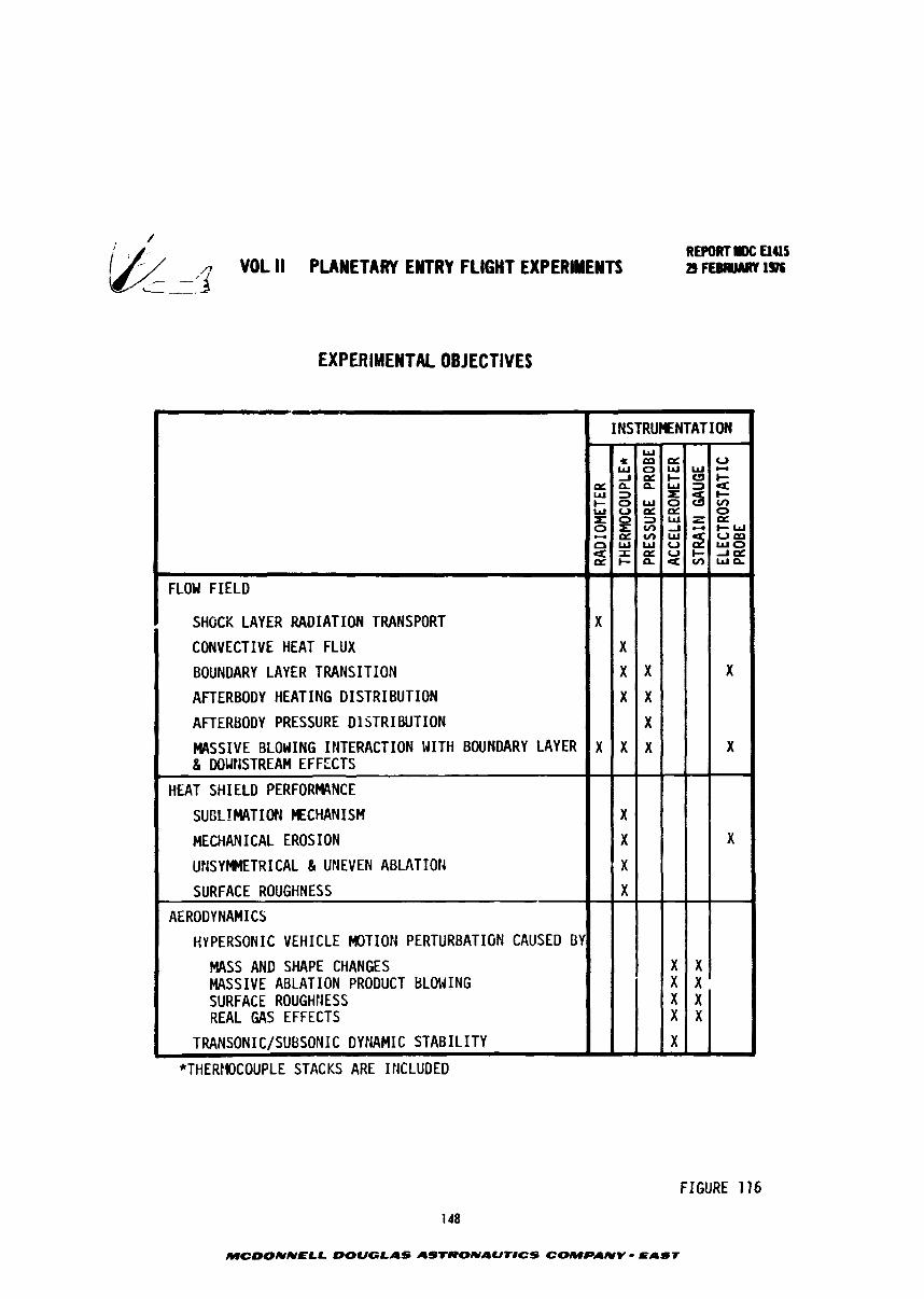
/ REPORT tax aus
VOL II PLANETARY ENTRY FLIGHT EXPERIMENTS ~ F E B R U A R T ~ ~ L-___
EXPERIMENTAL OBJECTIVES
*THERHOCOUPLE STACKS ARE ItlCLUDED
FLOU FIELD
I SHOCK LAYER RADIATION TRANSPORT
CONVECTIVE HEAT FLUX
BOUNDARY LAYER TRANSITION
AFTERBODY HEATING DISTRIBUTION
AFTERBODY PRESSURE D lSTRI BUTION
MASSIVE BLOWING INTERACTION WITH BOUNDARY LAYER 8 DOWNSTREAM EFFECTS
HEAT SHIELD PERFORWNCE
SUBLIMATION MECHANISH
MECHANICAL EROSION
UNSYMMETRICAL 81 UNEVEN ABLATIOR
SURFACE ROUGHNESS
AERODYNAMICS
HYPERSONIC VEHICLE MOTION PERTURBATION CAUSED BY
MASS AND SHAPE CHANGES MASSIVE ABLATION PRODUCT BLO!JING SURFACE ROUGHtiESS REAL GAS EFFECTS
TRANSONIC/SUBSONIC DYNAMIC STABILITY v
FIGURE 116
148
MCOONNELL DOUGLAS ASTRONAUT8CS COMPANY - EAST
J
U
0
u r n
X
X
X
aEu+
X X X X
w
X
X
W * m =
w u a P L
a V ) w
X
X
X
X
3
X
X
X
X
X
X
X
X
1NSTRU)LNTATION
w o w w - A a l - C I I C
c t z n n u ~ e + o w o a V ) ~ O = > W Z o c ~ x V ) J - C - W ~ W W U S W O u x a u t - - I ~ = I - n e V ) w n
X X X X
X
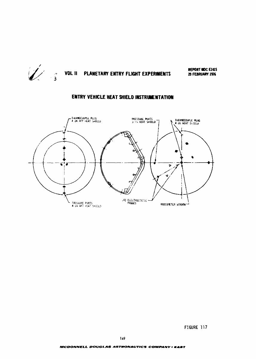
- VOL II PLANETARY ENTRY FLIGHT EXPERIMENTS 3
ENTRY VEHICLE HEAT SHIELD IWSTRUYNTATION
REPO#T ac aas 29 rreCWARY 1936
FIGURE 117
143
MCDOlYNElL DOUGLAS ASTRONAUflCS COMPAUY - EAl l t

, - VOL II PLANETARY EYTRY FLIGHT EXPERIMENTS - - - i L/-.
REPORT IW: El415 29 FEBRUARY 1976
EXPECTED RADIAL DISTRIBUTION OF PRESSURE AND RADIATIVE HEATMG FOR A 60 HEMSPHERE CONE
! PRESSURE 3.6 --- ...L-- -, - --2 - - - - . - - - - . - : L - --.- - -
2.5 3 .0
FIGURE 118
MCDONNELL DOUGLAS ASTRONAUTlCS COMPANV - EAST
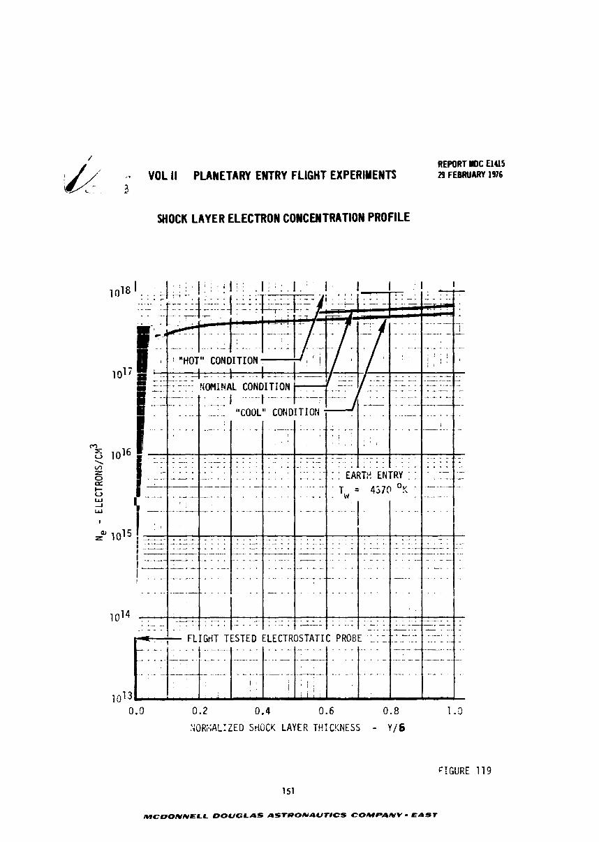
;. VOL II PLANETARY ENTRY FLIGHT EXPERIMENTS *-
SHOCK LAYER ELECTRON CONCENTRATION PROFILE
REPORT I D C €1415 29 FEBRUARY 1976
0.2 0.4 9.6 0.8
.';OR;.;AL:ZED SriGCY LAYER Tir.ICKNESS - Y/6
FIGURE 119
151
MCOONNELL DOUGLAS ASTRONAUT#CS COMPANV - EAST
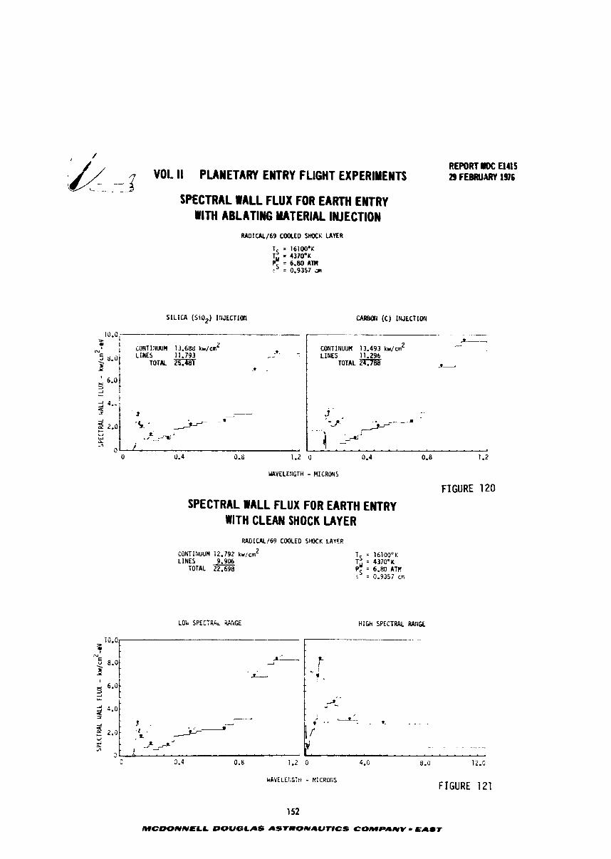
J/ - 3 VOI. II PLANETARY ENTRY FLIGHT EXPERIMENTS L- -
REPORT El415 29 FEBRUARY 1976
SPECTRAL WALL FLUX FOR EARTH ENTRY WlTH ABLATING MATERIAL INJECTION
RADICAL/69 COOLED SHOCK LAYER
SILICA (Si02) I!lu'ECTIOn CAREON (C) IWECTIOfl
10.o1 - > ., 1
>-- No I iOllT1:IUUII 13.688 kh/mZ
d
LlnEs 11.793 . d f
TOTAL xxi TOTAL ZSTJiis Z - 3-
f i t . I - - ' - - . . . A - . .
WVELEtGTH - HICROHS
FIGURE 120
SPECTRAL WALL FLUX FOR EARTH ENTRY WITH CLEAN SHOCK LAYER
RADICALI69 COOLED SHOCK LAVER
CONTIIiUUH 12.792 kw/cn2 LINES 9.906
TOTAL 22.698
Lob SPECTREL WRGE tilt% SPECTRAL RAIIQ
0 0.4 0.8 1.2 0 4.G 8.0 12.0
kAVE LEI;CTti - MICROliS FIGURE 121
152
MCOONNELL DOUGLAS AS'TRONIIUT#CS COMPANY - Easr
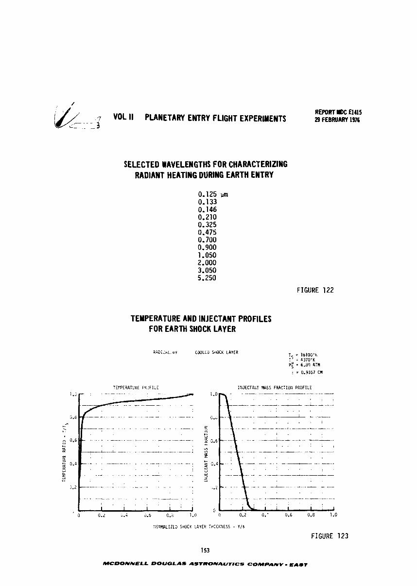
& - - - 7 VOL II PLANETARY ENTRY FLIGHT EXPERIMENTS C--. -- 3
REPORT NDC El415 29 FEBRUARY 1916
SELECTED WAVELENGTHS FOR CHARACTERIZING RADIANT HEATING DURING EARTH ENTRY
FIGURE 122
TEMPERATURE AND INJECTANT PROFILES FOR EARTH SHOCK LAYER
RAS;i i iL, 09 C N L E 3 StIOCK LAYER T - 16100 'h 7' = 437OK P: = 6.aQ ATN
r = 0.9357 C11
!:;JECTA:iT l&SS FRACTIOri PROFILE
: ;9RMLIZE3 StitiCK LAVER i t+ ICKNESS - V / 6
153
FIGURE 123
MCOONNELL DOUGLAS ASTRONAUT#CS COMPANY - EAST
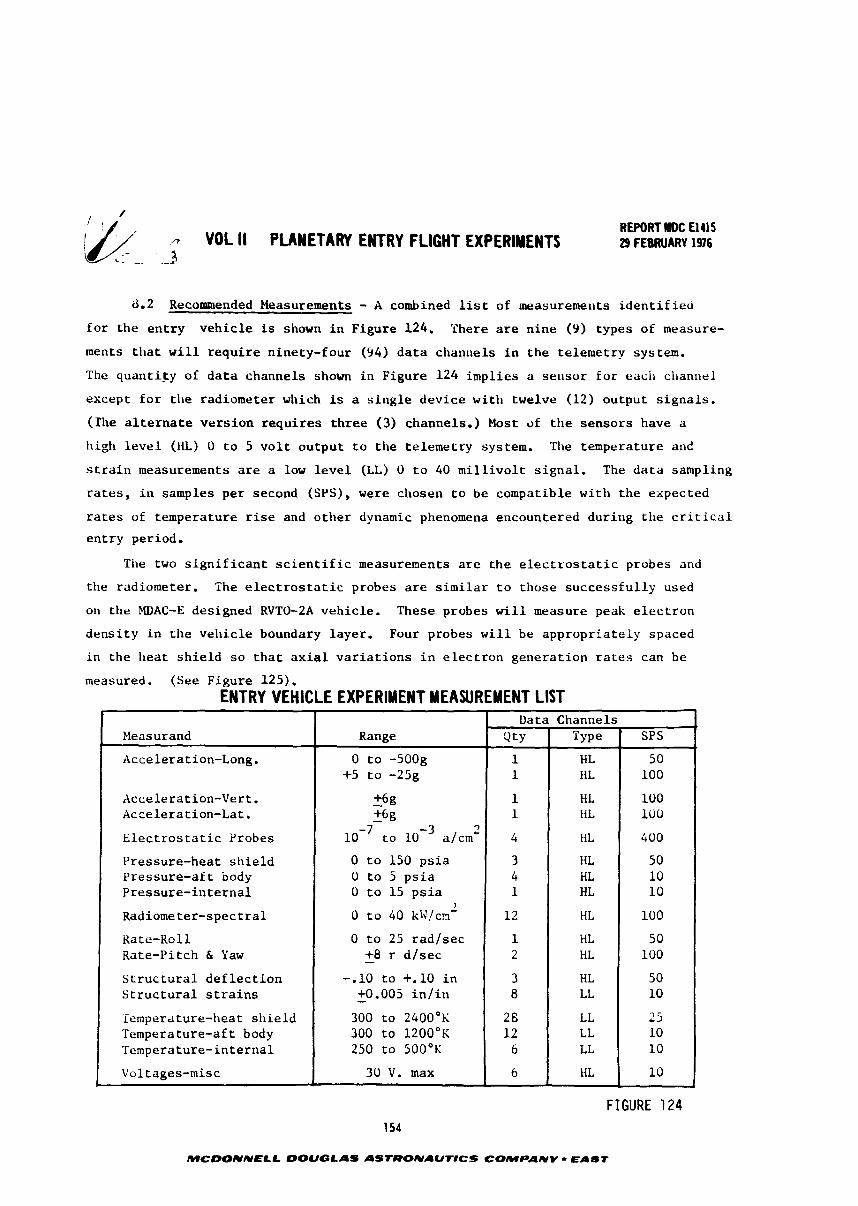
REPORT IIDC El415 . VOL II PLANETARY ENTRY FLIGHT EXPERIMENTS 29 FEBRUARY 1976
d.2 Recommended Measurements - A combined list of measurenlerrts identified for the entry vehicle is shown in Figure 124. There are nine (9) types of measure-
ments that will require ninety-four (94) data channels in the telemetry system.
The quantity of data channels shown in Figure 124 implies a selisor for each channel
except for tlre radiometer which is a single device with twelve (12) output signals.
(The alternate version requires three (3) channels.) Most of the sensors have a
high level (liL) O to 5 volt output to the telemetry system. Tlle temperature and
strain measurements are a low level (LL) 0 to 40 millivolt signal. The data sampling
rates, in samples per second (SPS), were chosen to be compatible with the expected
rates of temperature rise and other dynamic phenomena encountered during tile critical
entry period.
The two significant scientific measurements are the electrostatic probes and
the radiometer. The electrostatic probes are similar to those successfully used
on the EfDAC-E designed RVTO-2A vehicle. These probes will measure peak electron
density in the vehicle boundary layer. Four probes will be appropriately spaced
in the heat shield so that axial variations in electron generation rates can be
measured. (See Figure 125). ENTRY VEHICLE EXPERIMENT MEASUREMENT LIST
FIGURE 124 154
r
MCDONNELL DOUGLAS AStRONAUTlCS COMPANY - EAST
t
Measurand
Acceleration-Long.
Acceleration-Vert. Acceleration-Lat.
Electrostatic Probes
Pressure-heat shield Pressure-aft body Pressure-internal
Radiometer-spectral
Kate-Koll Rate-Pitch & Yaw
Structural deflection Structural strains
Temper~ture-heat shield Temperature-aft body Temperature-internal
Voltages-misc
Range
0 to -500g +5 to -25g
- +6g - +6g to a/cm2
0 to 150 psia 0 to 5 psia O to 15 psia
3
0 to 40 kW!cn'
0 to 25 rad/sec - +8 r dlsec
-.lo to +.lo in - +0.005 in/in
300 to 2400°K 300 to 1200°K 250 to 500°K
30 V. max
Data Q ~ Y
1 1
1 1
4
3 4 1
12
1 2
3 8
2 6 12
6
6
Channels Type
HL kiL
HL HL
HL
IiL HL HL
HL
HL HL
HL LL
LL LL LL
liL
' SPS
5 0 100
100 100
400
5 0 10 10
100
5 0 100
50 10
2 5 10 10
10
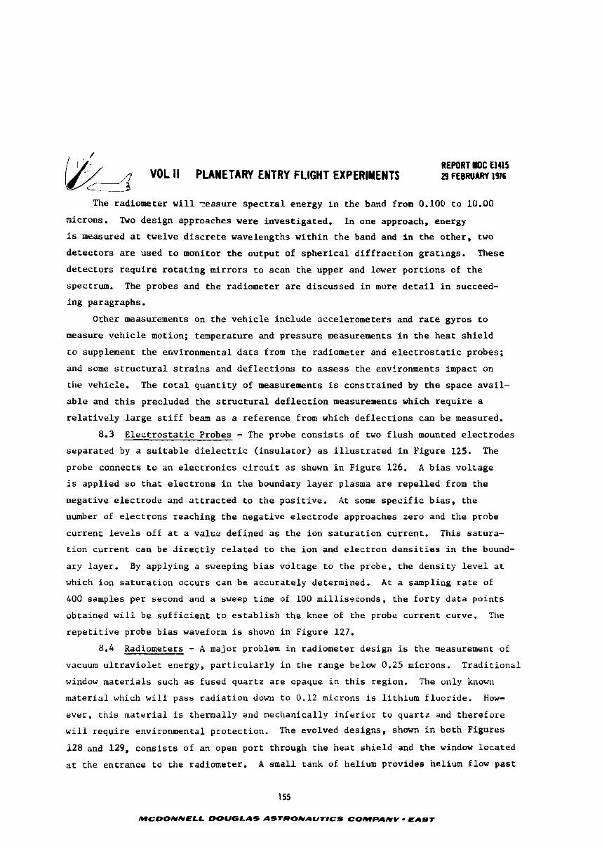
REWRT 1DC El415 29 FEBRUARY 1976
The radiometer w i l l ~ e a s u r e s p e c t r a l energy i n t h e band from 0.100 t o 10.00
microns. Two des ign approaches were i n v e s t i g a t e d . I n one approach, energy
i s measured a t twelve d i s c r e t e wavelengths w i t h i n t h e band and i n t h e o t h e r , two
d e t e c t o r s a r e used t o monitor t h e ou tpu t of s p h e r i c a l d i f f r a c t i o n g r a t i n g s . These
d e t e c t o r s r e q u i r e r o t a t i n g m i r r o r s t o scan t h e upper and lower p o r t i o n s of t h e
spectrum. The probes and t h e radiometer a r e d i scussed i n more d e t a i l i n succeed-
i n g paragraphs.
Other measurements on t h e v e h i c l e inc lude accelerometers and r a t e gyros t o
measure v e h i c l e motion; temperature and p r e s s u r e measurements i n t h e h e a t s h i e l d
t o supplement t h e environmental d a t a from t h e radiometer and e l e c t r o s t a z i c probes;
and some s t r u c t u r a l s t r a i n s and d e f l e c t i o n s t o assess t h e environments impact on
the vehic le . The t o t a l q u a n t i t y of measurements is cons t ra ined by t h e space a v a i l -
a b l e and t h i s precluded t h e s t r u c t u r a l d e f l e c t i o n measurements which r e q u i r e a
r e l a t i v e l y l a r g e s t i f f beam a s a r e fe rence from which d e f l e c t i o n s can be measured.
8.3 E l e c t r o s t a t i c Probes - The probe c o n s i s t s of two f l u s h mounted e l e c t r o d e s
separa ted by a s u i t a b l e d i e l e c t r i c ( i n s u l a t o r ) as i l l u s t r a t e d i n Figure 125. The
probe connects t o a n e l e c t r o n i c s c i r c u i t a s shown i n Figure 126. A b i a s v o l t a g e
i s app l i ed s o t h a t e l e c t r o n s i n the boundary l a y e r plasma a r e r e p e l l e d from t h e
nega t ive e l e c t r o d e and a t t r a c t e d t o t h e p o s i t i v e . A t some s p e c i f i c b i a s , t h e
number of e l e c t r o n s reaching t h e nega t ive e l e c t r o d e approaches ze ro and t h e probe
c u r r e n t l e v e l s o f f a t a v a l c z def ined as t h e i o n s a t u r a t i o n cur ren t . This sa tu ra -
t i o n c u r r e n t can be d i r e c t l y r e l a t e d t o t h e i o n and e l e c t r o n d e n s i t i e s i n t h e bound-
a r y layer . By applying a sweeping b i a s v o l t a g e t o t h e probe, t h e d e n s i t y l e v e l a t
which i o n s a t u r a t i o n occurs can be a c c u r a t e l y determined. A t a sampling r a t e of
400 samples p e r second and a sweep time of 100 mi l l i seconds , t h e f o r t y d a t a p o i n t s
obta ined w i l l be s u f f i c i e n t t o e s t a b l i s h t h e knee of the probe c u r r e n t curve. The
r e p e t i t i v e probe b i a s waveform is shown i n Figure 127.
8.4 Radiometers - A major problem i n radiometer des ign i s t h e measurement of
vacuum u l t r a v i o l e t energy, p a r t i c u l a r l y i n t h e range below 0.25 microns. T r a d i t i o n d
window m a t e r i a l s such as fused q u a r t z a r e opaque i n t h i s region. The only known
m a t e r i a l which w i l l pass r a d i a t i o n down t o 0.12 microns i s l i t h i u m f l u o r i d e . How-
e v e r , t h i s m a t e r i a l i s thermally and mechanically i n f e r i o r t o q u a r t z and t h e r e f o r e
w i l l r e q u i r e environmental p r o t e c t i o n . The evolved des igns , shown i n both F igures
1 2 8 and 129, c o n s i s t s of an open p o r t through t h e h e a t s h i e l d and t h e window l o c a t e d
a t the en t rance t o t h e radiometer. A s m a l l tank of helium provides helium f l o w . p a s t
MCDONNELL DOUGLAS ASrRONAUTICS COMPANY - EAST
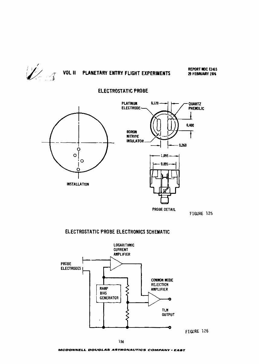
/j ,I- VOL II PLANETARY ENTRY FLIGHT EXPERIMENTS REPORT Ig)C a415 29 FEBRUARY 1976
( -- - -
ELECTROSTATIC PROBE
PLATlNW QUARTZ ELECTRODE
INSULATOR
INSTALLATION
PROBE DETAIL FIGURE 125
ELECTROSTATIC PROBE ELECTRONICS SCHEMATIC
LOGARITHMIC CURRENT AMPLIFIER
PROBE ELECTRODES
COMMON MODE REJECTION AMPLIFIER
OUTPUT
FIGURE '126
MCDONNELL DOUGLAS ASTRONAUT8CS COMPANY - EAST
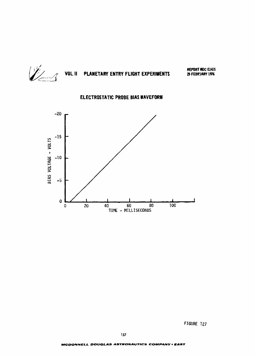
VOL ll PLANETARY ENTRY FLIGHT EXPIRIYNTS REPORT MJC El415 29 FWJARY 1976
c-2
ELECTROSTATIC PROBE BIAS WAVEFORM
TIME - MILLISECONDS
FIGURE 127
157
MCDONNELL DOUGLAS ASTRONAU'tlCS COMPANY - EAbT
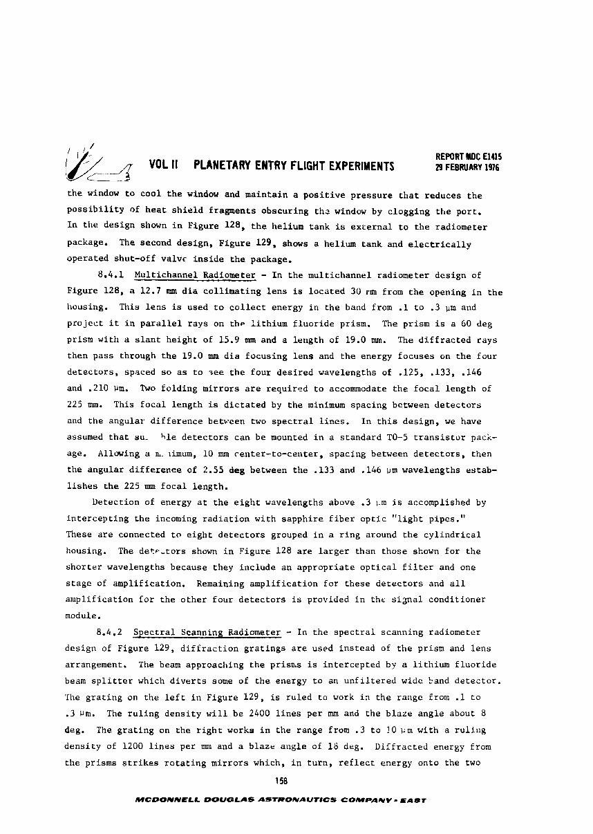
/ REPORT BDC El415
VOL II PLANETARY ENTRY FLIGHT EXPERIMENTS 29 FEBRUARY 1916 c_____&
t h e window t o coo l t h e window and mainta in a p o s i t i v e p r e s s u r e t h a t reduces t h e
p o s s i b i l i t y of h e a t s h i e l d fragments obscur ing t h c window by c logging t h e por t .
I n t h e des ign shown i n Figure 128, t h e helium tank is excerna l t o t h e radiometer
package. The second des ign, F igure 129, shows a helium tank and e l e c t r i c a l l y
opera ted shut-off va lvc i n s i d e t h e package.
8.4.1 Multichannel Radiometer - I n t h e mul t ichannel radiometer des ign of
Figure 128, a 12.7 mm d i a c o l l i m a t i n g l e n s is l o c a t e d 30 run from t h e opening i n t h e
housing. This l e n s is used t o c o l l e c t energy i n t h e band from .1 t o .3 u m and
p r o j e c t i t i n p a r a l l e l r a y s on t h e l i t h i u m f l u o r i d e prism. The prism is a 60 deg
prism with a s l a n t he igh t of 15.9 mm and a l eng th of 19.0 mm. The d i f f r a c t e d r a y s
then pass through t h e 19.0 mm d i a focus ing l e n s and t h e energy focuses on t h e four
d e t e c t o r s , spaced s o as t o s e e t h e f o u r d e s i r e d wavelengths of .125, .133, .I46
and .210 Pm. Two f o l d i n g mi r ro r s a r e r equ i red t o accommodate t h e f o c a l l eng th of
225 mm. This f o c a l l eng th is d i c t a t e d by t h e minimum spacing between d e t e c t o r s
and the angular d i f f e r e n c e between two s p e c t r a l l i n e s . I n t h i s des ign , we have
assumed t h a t su- h l e d e t e c t o r s can be mounted i n a s t andard TO-5 t r a n s i s t o r pack-
age. Allowing a &. ~imum, 10 mm center- to-center , spac ing between d e t e c t o r s , then
the angular d i f f e r e n c e of 2.55 deg between t h e ,133 and .I46 iim wavelengths es tab-
l i s h e s t h e 225 mm f o c a l length .
Detect ion of energy a t t h e e i g h t wavelengths above .3 pm i s accomplished by
i n t e r c e p t i n g t h e incoming r a d i a t i o n wi th sapph i re f i b e r o p t i c " l i g h t pipes."
These a r e connected t o e i g h t d e t e c t o r s grouped i n a r i n g around t h e c y l i n d r i c a l
housing. The de tp - to r s shown i n Figure 128 a r e l a r g e r than those shown f o r t h e
s h o r t e r wavelengths because they inc lude an a p p r o p r i a t e o p t i c a l f i l t e r and one
s t a g e of ampl i f i ca t ion . Remaining a m p l i f i c a t i o n f o r these d e t e c t o r s and a l l
a m p l i f i c a t i o n f o r t h e o t h e r f o u r d e t e c t o r s is provided i n the s i g n a l cond i t ioner
module.
8.4.2 S p e c t r a l Scanning Radiometer - I n t h e s p e c t r a l scanning radiometer
des ign of Figure 129, d i f f r a c t i o n g r a t i n g s a r e used i n s t e a d of t h e prism and l e n s
arrangement. The beam approaching t h e prisn.s is i n t e r c e p t e d by a l i t h i u m f l u o r i d e
beam s p l i t t e r which d i v e r t s some of t h e energy t o an u n f i l t e r e d wide band d e t e c t o r .
The g r a t i n g on the l e f t i n Figure 129, is ru led t o work i~ t h e range from .1 t o
.3 pm. The r u l i n g d e n s i t y w i l l be 2400 l i n e s per mm and t h e b l a z e ang le about 8
deg. The g r a t i n g on t h e r i g h t works i n t h e range from . 3 t o !O i i m wi th a r u l i n g
d e n s i t y of 1200 l i n e s per mm and a b laze ang le of 1 8 deg. D i f f r a c t e d energy from
t h e prisms s t r i k e s r o t a t i n g m i r r o r s which, i n t u r n , r e f l e c t energy onto the two
1 58
MCDONNELL DOUQLAS ASTRONAUTICS COMPANY EABT
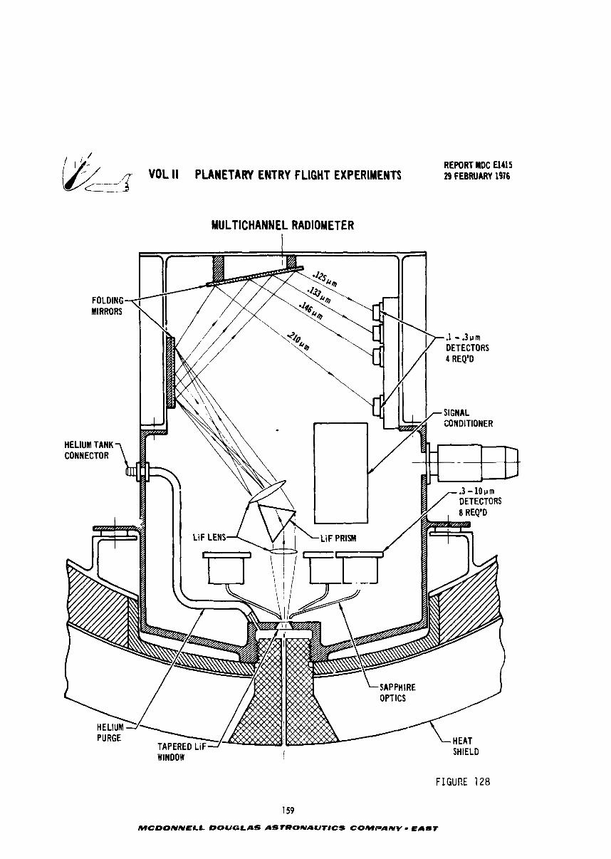
REPORT MDC El415 29 FEBRUARY 1976
MULTICHANNEL RADIOMETER
WINDOW I SHIELD
FIGURE 128
159
MCDONNELL DOUGLAS ASTRONAUT8CS COMPANV - EAST
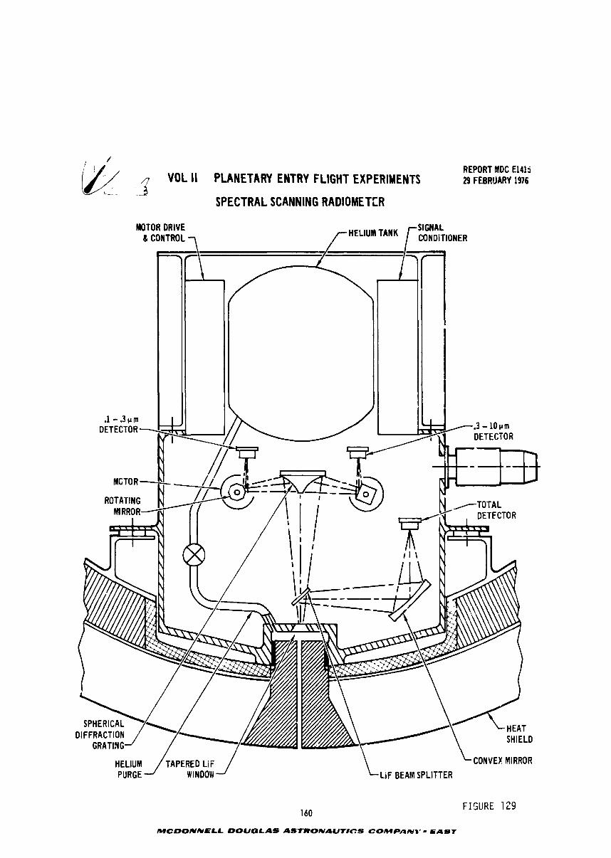
~ -2 REPORT MDC El415 VOL II PLANETARY ENTRY FLIGHT EXPERIMENTS 29 FEBRUARY 1976
c-.- .
SPECTRAL SCANNING RADIOMETER
MOTOR DRIVE
--- ---- ---
LiF BEAM SPLITTER
160 FISURE 129
MCDONNELL DOUGLAS ASTRONAUTICS C0MPANB'- EAST
- VOL II PLANETARY EUTRY FLIGHT EXPERIMENTS . REPORT I#: UU5 2) FEWWRY 196
i e t e c t o r s . kt11 motors opera te a t 600 rpm and t h e PCM samples each d e t e c t o r a t
800 . In t h e -1 t o .3 pm band, the e ight-s ided mi r ro r genera tes 80 s p e c t r a l
scans F r second, g iv ing d a t a output a t 10 d i s c r e t e wavelengths updated 8 0 t imes
per second. i n tilt . 3 to 10 band, t h e four-sided mi r ro r genera tes 40 s p e c t r a l
sc.itls per seconi , g iv ing d a t a output a t 20 d i s c r e t e wavelengths, updated 40 times
per second.
Coaparing the two des igns , the mu1tic;iannel radiometer has t h e advantage of
simplici:y, sixlce t h e r e a r e no moving p a r t s and t h e c o n s t r u c t i o n can be s u f f i c i e n t i y
r i g i d :hat t h e o p t i c a l c h a r a c t e r i s t i c s are no t a f f e c t e d by t h e f l i g h t environment.
rite amplitude of the s i g n a l s seen by t h e d e t e c t o r s i n the twelve channel des ign are
L i m e v a r i a n t an ly , wi th in tile s ~ e c t r a l bandwidth of t h e f i l t e r s used; whereas i n
tile s p e c t r a l scanning des ign, t h e s i g n a l is both t i m e and wavelength v a r i a n t as a
funct ion o i t l ~ r r o t a t i n g mi r ro r s which scan t h e g r a t i n g s . The use of many d i s c r e t e
iilatlntlls has the advantage of des ign s i m p l i c i t y bu t t h e number of channels may be
i n s u f f i c i e n t t o adequately d e f i n e t h e s p e c t r a l energy d i s t r i b u t i o n . The maximum
uumber c t i channels is l imi ted by space a v a i l a b l e i n t h e v e h i c l e f o r t h e radiometer
package. Use of two scanned channels (one f o r W from 0.1 t o 0.3 microns and one
f o r v i s i b l e and IR from 0.3 t o 10 microns) provides b e t t e r s p e c t r a l coverage but
the need i e r motors t o d r i v e t h e mi r ro r s nakes t h e radiometer des ign more complex.
Ca l ib ra t ion and subsequent da,a process ing a r e a l s o made more d i f f i c u l t s i n c e t h e
mirror p o s i t i o n must be measured and c o r r e l a t e d wi th t h e radiometer d a t a t o avoid
s p e c t r a l vavelength e r r o r s . The motor speed must be cons tan t and unaf fec ted by
in - f lAght environmental condi t ions . A prism and l e n s was shown i n one des ign and
a d i f f r a c t i o n g r a t i n g i n t b e o ther . Xctual ly , e i t h e r d i f f r a c t i o n dev ice w i l l
work i n e i t h e r design. More d e t a i l e d des ign, inc lud ing c o s t e s t ~ r r a t e s , w i l l be
required t o determine the b e s t choice.
8.5 D e t e c t ~ r s - Detec to r s recommended f o r t h e spect rometers are s i l i c o n
photodiodes and p y r o e l e c t r i c devices. Both type dev iccs a r e a v a i l a b l e commercially
i o r operat;.on i n the v i s i b l e and i n f r a r e d wavelengths. Typical photodiodes have
good response i n t h e range frqm . 3 t o 1.1 bm. P y r o e l e c t r i c d e t e c t o r s work b e s t i n
the i n f r a r e d b u t a r e usable a t s h o r t e r vave1enp'-"s. By applying a t h i n gold f i l m t o
s i l i c o n p h o t o d i o d ? ~ , they a r e usable a t vacczm t ~ ~ t r a v i o l e t wavelengths, having a
quantum e f f i c i e n c y of t h r e e (3) and a s e n s i ~ i v i t y ( e l e c t r o n s pe r i n c i d e n t photo) of
.2 t o -35 over t h e s- an from -125 t o -210 ;lm. I n t h e mul t ichannel radiometer , gold
coated photodiodes a r e recommended f o r t h e -125. -133, .I46 and ,210 ,im d e t e c t o r s
shown i n the upper r i g h t p o r t i o n of Figure 128. A t t h e e i g h t longer wavelengths,
MCWNNELL DOUGLAS ASfRONAUNCS COMPANY - EAST
VOL II PUWETARY ENTRY FLIGHT EXPERIMENTS
p y r o e l e c t r i c d e t e c t o r s are recornaended, These are phys ica l ly l a r g e r because t h e
f i r s t s t a g e of s i g n a l condi t ioning a m p l i f i c a t i o n is included i n t h e housing and
each d e t e c t o r has a f i l t e r window t h a t passes energy a t t h e s p e c i f i e d wavelength.
These f i l t - r s a r e commercially a v a i l a b l e and have a half-power bandwidth of from
2.5 t o 5% of t h e c e n t e r wavelength, The d e t e c t o r s i n t h e s p e c t r a l scanning radio-
meter are similar except t h a t narraw band-pass f i l t e r s a r e not used. Some develop-
ment e f f o r t w i l l be necessary a t t h e s h o r t wavelengths t o c l e a r l y d e f i n e response
c h s r a c t e r i s t i c s ,
162
MCDONNELL DOUGLAS AS7RONAUTICS COMPANV - EAST
VOL II PUNETARI ENTRY FLIGHT EXPERLNTS i --__ - 3
REPORT UUS 29FEBRUARVlS6
9. ENTRY VEHICLE DESIGN
After concluding that it was feasible to launch a high speed earth entry test
of a probe-like vehicle, a system and vehicle design was accomplished.
9.1 Entry Vehicle Subsystem Evaluations - As part of the integrated design
of the entry vehicle, the components of the entry vehicle were grouped in five
subsystems: aeroshell, telemetry and communications, electrical power, recovery
and electromechanical interfaces. The facets of each system were evaluated and a
balance achieved to arrive at a unified design that married requir~d instrumenta-
tion equipment and test objectives.
9.1.1 Aeroshell - The geometry of the entry vehicle was selected to be a symmf-.trical blunted 60° half angle cone with a 22.2 cm nose radius and a base dia-
meter of 89 cm with a hemispherical aft cover. The main structure is divided into
two parts, a conical forebody and a heaispherical shaped afterbody. The forebody
structure is the most important since it acts as a decelerator, protects the entry
payload during ballistic entry, and provides continuous structure support for the
main heat shield. The afterbody structure supports the afterbody heat shield acd
encloses the entry payload. Alternate structural arrangements were evaluated and
the integrally stiffened ribbed structure used by outer probe des-gners was selec~ed.
This strccture (Figure 130) permits attaching a variety of heat shield concepts.
The structure consists of a honeycomb sandwich conical shell with a fiberglass outer
face sheet and dn integrally machined aluminum inner face sheet with four integral
machined stiffening rings. Loads from the forward heat shield are carried by a
honeycomb sandwich to the integrally stiffened structure. This design permits flv-
ing either a carbon phenolic Qr a hyperpure silica heat shield. The aft cover made
of light weight ablator is fastened to the structure near ihe maximum diameter
point. It too is supported by a honeycomb sandwich, but a much thi~ner one because
of the lower loads. The afterbody support structure consists of a rnotiocoque honey-
comb phenolic fiberglass sandwich shell. In order to deploy the recovery parachutes
(see Section 8 .2 .4 ) , provisions are made in the aft cover for an enclosed cutting
charge.
The details of laminant layup for the carbon phenolic heat shield and :he
casting cf the hyperpure silica shield are under development by other investigators
and hence was not evaluated in this study. It will suffice to say that these details
-.dill be well docmented by the time entry flights are authorized. As described in
Section 8, several penetrations rhro~gh the heat shield are necessary: radiometer
port, pressure ports, electrostatic probes and thermocouple stacks. In the case of
163
MCOONNELL OOUGLBS ASTRONAUTICS COMPANY - EAST
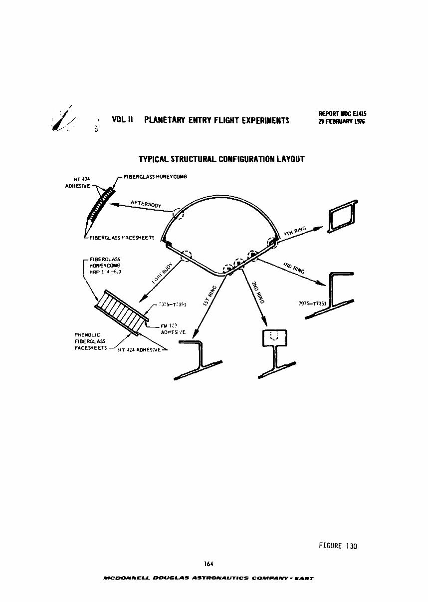
REPORT #DC El95 VOL ll PLANETARY EWRY FLIGHT EXPERIMENTS 2) FEBRUARY 19%
,2
TYPICAL STRUCTURAL CONFIGURATION LAYOUT
HT 424 r FIBERGLASS HONEYCOMB
F'HEWOLIC A U P Z > . i E
FIBERGLASS
FIGURE 130
164
MCDONkELL DOUGLAS ASTRONAUTlCS COMPANV - E a s r
REPORT IDC U4l5 VOL I I PLANETARY ENTRY FLIGHT EXPERIMENTS 29 FEBRUARY 1076
. .
t h e e l e c t r o s t a t i c probe and t h e thermocouple s t a c k s , t h e machined h o l e s are f i l l e d
u i r h t h e same material as t h e h e a t s h i e l d . The d i f f e r e n c e i n t h e the rma l expans ion
c o e f f i c i e n t s between t h e h e a t s h i e l d and t h e s u p p o r t s t r u c t u r e as w e l l as t h e
accommodation of l o a d s may r e q u i r e a S t r a i n I s o l a t i o n Pad (SIP), T h i s may b e
p a r t i c u l a r l y t r u e f o r t h e s i l i c a h e a t s h i e l d , Technology developed f o r t h e l o v
d e n s i t y s i l ica h e a t s h i e l d material on S h u t t l e w a s e v a l u a t e d and deemed a p p r o p r i a t e .
F igu re 131 shows t h e a t t achmen t sys tem f o r t h e h e a t s h i e l d , h e a t s h i e l d c o r n e r
a t t achmea t and o t h e r d e s i g n f e a t u r e s . The h e a t s h i e l d is bonded t o a N O M Z X SIP
which i n t u r n is bonded t o t h e honeycomb s t r u c t u r e . The SIP is a good f r i s u l a t o r
as w e l l as be ing a b l e t o accoramodate s t r a i n s a t t empera tu re below t h e g l a s s t r a n s i -
t i o n tempera ture of adhes ives , The SIP is nade i n e i g h t p i e s e c t i o n s t o a l l o w f o r
ease of bonding, e l i m i n a t e w r i n k l e s and p rov ides a d d i t i o n a l expans ion j o i n t s . Also
slluun i n t h e f i g u r e is t h e thermocouple s t a c k i n s t a l l a t i o n . Thermocouples are
formed by b u t t weld ing t h e i r l e a d s and t h e n i n s t a l l i n g i n a p lug such t h a t t h e l e a d s
l i e a long i so the rms b e f o r e b e i n g r o u t e d down t h e s i d e s o f t h e p lug , The e n t i r e
assembly is then f i t t e d i n t o t h e h e a t s h i e l d and bonded t o t h e SIP d u r i n g t h e
a t t achmen t of t h e h e a t s h i e l d . T h i s t echn ique h a s been s u c c e s s f u l l y used i n f l i g h t
and i n many ground tests.
9 . 1 . 2 Telemetry and Communications - From t h e d a t a channe l s d e f i n c d i n F igure
132, n PC?! system w a s s e l e c t e d t o p rov ide s n adequa te q u a n t i t y of d a t a channe l s i n
a s t r a i g h t f o r w a r d frame s t r u c t u r e , a t t h e c o r r e c t sampling rates. These s p e c i f i -
c a t i o n s a r e a l s o inc luded i n F igu re 132.
The use of 8 b i t words p r o v i d e s a d a t a r e s o l u t i a n a n o r d e r of magnitude b e t t e r
than ave rage d a t a accuracy . The number of s p a r e channe l s a r e i nc luded t o accnmmo-
d a t e shangss t h a t can be e s p e c t e d i n t h e d e s i g n phase. The b i t r a t e of 48 KBPS is
s u f f i c i e n t l y low t o p rov ide g ~ o d s i g n a l margins when used w i t h a 5 w a t t t r a n s m i t t e r ,
and the f l i g h t t a p e r e c o r d e r can o p e r a t e a t a s t a n d a r d low speed o f 18.4 cm p e r
second. A t t h i s speed on ly 6 me te r s of t a p e is r e q u i r e d i n t h e r e c o r d e r t o p rov ide
t h i r t y ( 3 0 ) secniids of r eco rd t ime. One unique f e a t u r e of t h e sugges t ed b i t rate
is t h a t b s adding a s w i t c h a b l e "divide-by-four" c o u n t e r i n t h e PCH t iming system,
the o u t p u t b i t r a t e can be reduced t o 16 KBPS which is t h e s t a n d a r d b i t r a t e f o r
S h u t t l e comnunicat ion w i t h a s e p a r a t e d payload. Th i s makes i t compa t ib l e w i t h a
p o s t - s e p a r a t i o n checkout of a l l d a t a channe l s sampled a t one-four th t h e normal
r a t e .
165
MCDONNELL DOUGLAS ASTRONAUtlCS COMPANV - Els f
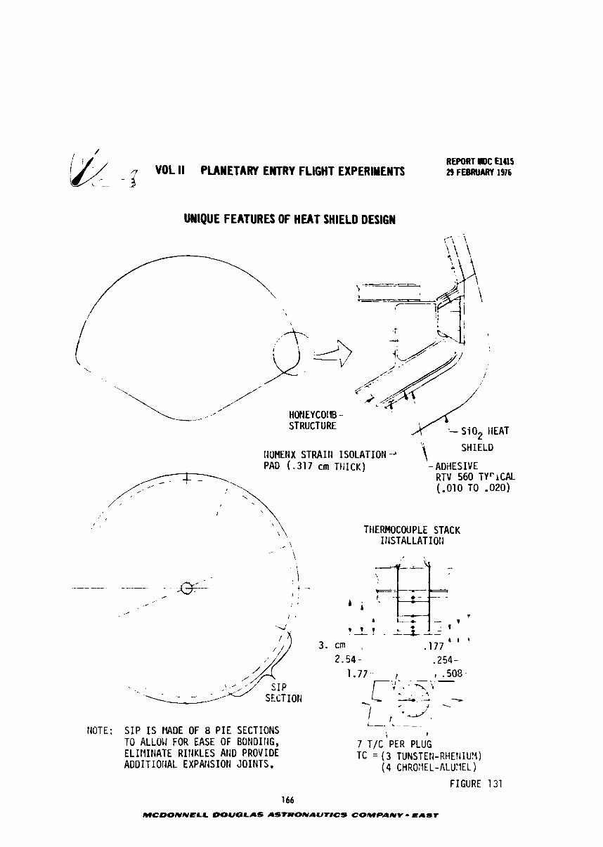
REPORT III)C El415 VOL II PLANETARY ENTRY FLIGHT EXPERIMENTS 29 FEBRUARY 1916
UNIQUE FEATURES OF H U T SHIELD DESIGN
1 - I .- -
/--
'.
4
'..
,-' /" , HONEYCOIIB - STRUCTURE '- S i 0 2 tiEAT
IIOHEHX STRAI t l ISOLATION " SHIELD
PAD ( - 3 1 7 cm TtiICK) - ADiiESIVE /
- RTV 560 TYr lCAL /< 7'. (-010 TO - 0 2 0 )
,' , . .
f , ' '\ \ . TIIERMOCOUPLE STACK
/ ,/ ,.
. - - . - -------- ! d SECTION S I P
1 , ../, i-. r~
NOTE: S I P I S tWDE OF 8 P I E SECTIONS TO ALLOII FOR EASE OF BONDIIIG, 7 TIC 'PER P L ~ G ELII I INATE RIf lKLES AND PROVIDE TC = ( 3 TUNSTEtl-RHEIIIUY) ADDITIOIlAL EXPAT.ISIOtl JOINTS. ( 4 CHR0;JEL-ALUYEL )
FIGURE 131
166
MCWNNELL DOUGLAS ASTRONAUr#CS COMPANY - EAST
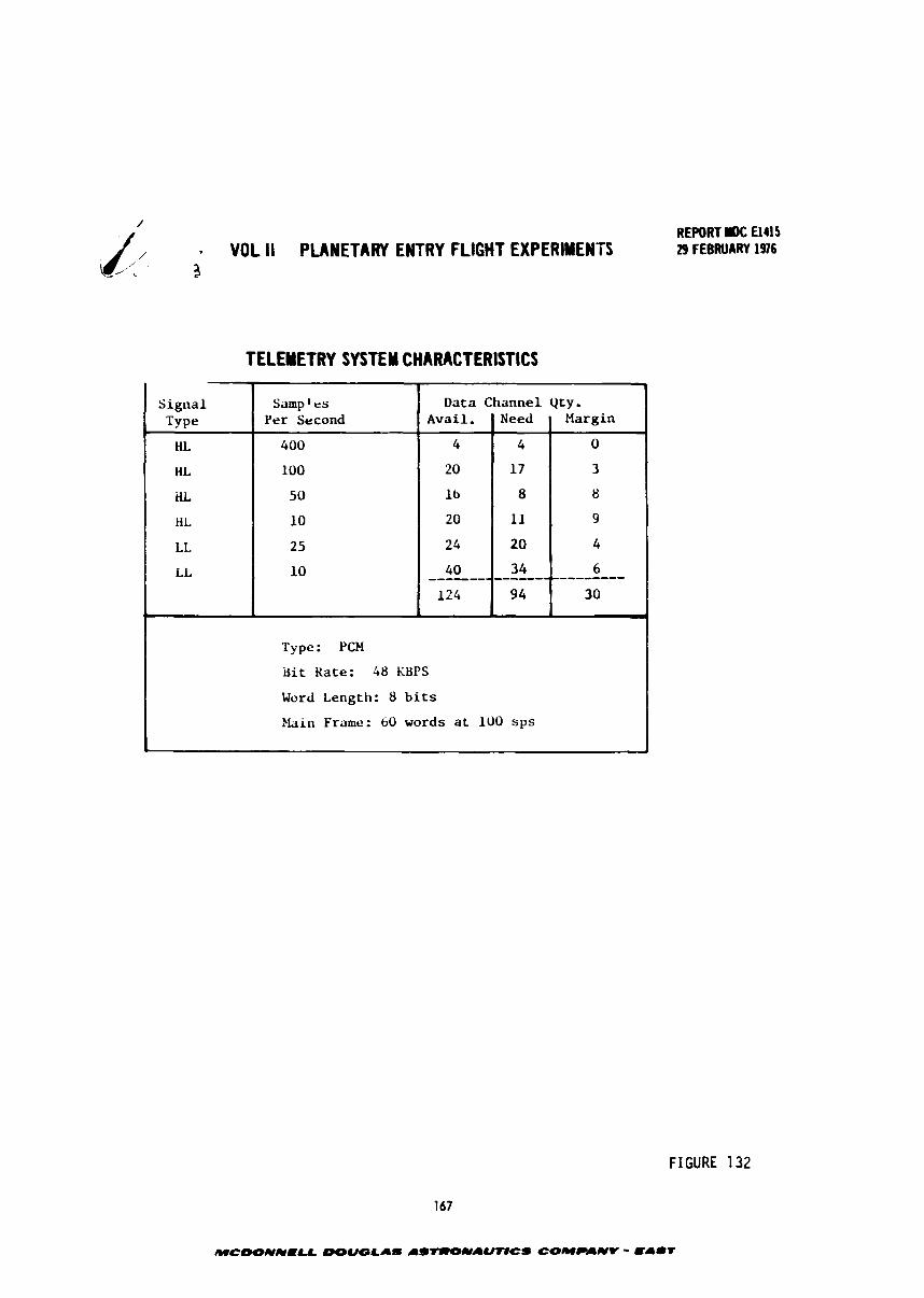
VOL II PLANETARY ENTRY FLIGHT EXPERIMENTS REPORT r )C €1415 29 FEBRUAfW 1916
TELEY ETRY SYSTEM CHARACTERIST ICS
FIGURE 132
Signal Type
HL
HL
iiL
HL
LL
LL
Type: PCH
&it Kate: 48 U P S
Word Length: 8 b i t s
?lain Frame: bO words a t 100 s p s
Samp t tts Per Second
400
100
50
10
25
10
Data Channel Qty. Avail .
4
20
16
20
24
40
124
Need
4
17
8
11
20
34 _---_-_----------------- 9 4
Margin
0
3
8
9
4
6
30 I
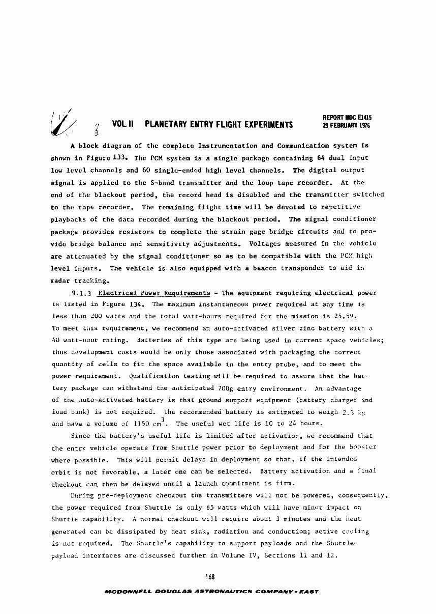
VOL ll PLANETARY ENTRY FLIGHT EXPERIMENTS REPORT rDC El415 29 FEBRUARY 1976
A b l o c k diagram of t h e complete I n s t r u m e n t a t i o n and Communication system is
shown i n F i g u r c 1330 Tlic PCM system is a s i n g l e package c o n t a i n i n g 64 d u a l inpu t
low l e v e l channe l s and 60 single-ended high l e v e l channels. The d i g i t a l o u t p u t
s i g n a l is a p p l i e d t o t h e S-band t r a n s m i t t e r and t h e loop t a p e rccorder . A t t h e
end of t h e b l a c k o u t p e r i o d , t h e record head is d i s a b l e d and t h e t r a n s m i t t e r switc1ic.d
t o t h e t a p e recorder . The remaining f l i g h t t i m e w i l l b e devoted t o r e p e t i t i v e
p laybacks of t h e d a t a recorded d u r i n g t h e b l a c k o u t per iod. The s i g n a l c o n d i t i o n e r
package p rov ides r e s i s t o r s t o cornplcte t h e s t r a i n gage b r i d g e c i r c u i t s and t o pro-
v i d e b r i d g e b a l a n c e and s e n s i t i v i t y a i j u s t m e n t s . Vol tages measured i n t h e v e h i c l e
are a t t e n u a t e d by t h e s i g n a l c o n d i t i o n e r s o as t o b e compat ib le w i t h t h e PC:.: high
l e v e l i n p u t s . The v e h i c l e is a l s o equipped w i t h a beacon t r ansponder t o a i d i n
r a d a r t r a c k i n g .
9.1.3 E l e c t r i c a l Power Requirements - The equipment r e q u i r i n g e l e c t r i c a l power
is l i s t e d i n Figure 134. Tfie maximum ins tan taneous power requ i red a t any time is
l e s s than 100 w a t t s and the t o t a l watt-liours r equ i red f o r the miss ion is 25.59.
To meet t h i s requiremerlt, we recommend an auto-act ivated s i l v e r z i n c b a t t e r y wi th a
40 watt-ilour r a t i n g . BaEter ies of t h i s type a r e being used i n c u r r e n t space v e h i c l e s ;
thus development c o s t s would be only those a s s o c i a t e d wi th packaging t h e c o r r e c t
q u a n t i t y of c e l l s t o f i t t h e space a v a i l a b l e i n the e n t r y probe, and t o meet the
power requirement. Q u a l i f i c a t i o n t e s t i n g w i l l be required t o a s s u r e t h a t the bat-
t e r y package can wittistand the a t i t i c ipa ted 700g e n t r y environment. An advantage
of the auto-ac t i v a ted b a t t e r y i s t h a t ground suppor t equipment ( b a t t e r y charger and
load bank) is not required. The recommended b a t t e r y is estimated t o weigh 2 . 3 kK 3 and iiave a volume --.f 1150 cm . The u s e f u l wet l i f e is 10 t o 24 hours.
Since t h e b a t t e r y ' s u s e f u l l i f e is l i m i t e d a f t e r a c t i v a t i o n , we recommend t h a t
the e n t r y v e h i c l e o p e r a t e from S h u t t l e power p r i o r t o deplovment and f o r the booster
where p o s s i b l e . This w i l l permit de lays i n deplovment s o t h a t , i f the in tended
o r b i t is not f avorab le , a l a t e r one can be s e l e c t e d . Ba t t e ry a c t i v a t i o n and a f i n a l
checkout can then be delayed u n t i l a launch commitment is f i rm.
D u r i ~ g ?re-deplo:~ment checkout the t r a n s m i t t e r s w i l l n o t be powered, c o n s e q u e ~ t l p ,
the power requ i red from S h u t t l e is only 85 w a t t s which w i l l iiave minor impact on
St lu t t le c a p a b i l i t y . X normal checkout w i l l r e q u i r e about 3 minutes and the iieat
generated can be d i s s i p a t e d by heat s i n k , r a d i a t i o n and conduction; a c t i v e coo l ing
is not required. T'ne S i iu t t l e ' s c a p a b i l i t y t o suppor t payloads and the Shu t t l e -
payload i n t e r f a c e s a r e d i scussed f u r t h e r i n Volume I V , Sec t ions 11 and 12.
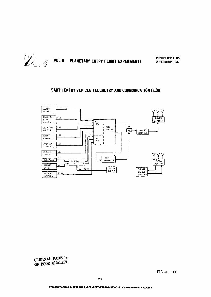
YOL ll PLANETARY ENTRY FLIGHT EXPERIMENTS C - -
REPORT llOC U4lS 29 FEBRUARY 1976
EARTH ENTRY VEHICLE 1 ELEMETRY AND CWMUNICATION FLOW
DIVIDER
C-&%D irEACOS
0UGINA.L PAGE IS OF ,FR Q u a
FIGURE 1 33
169
MCDONNELL DOUGLAS ASTRONAUtlCS COMPANY - EAST
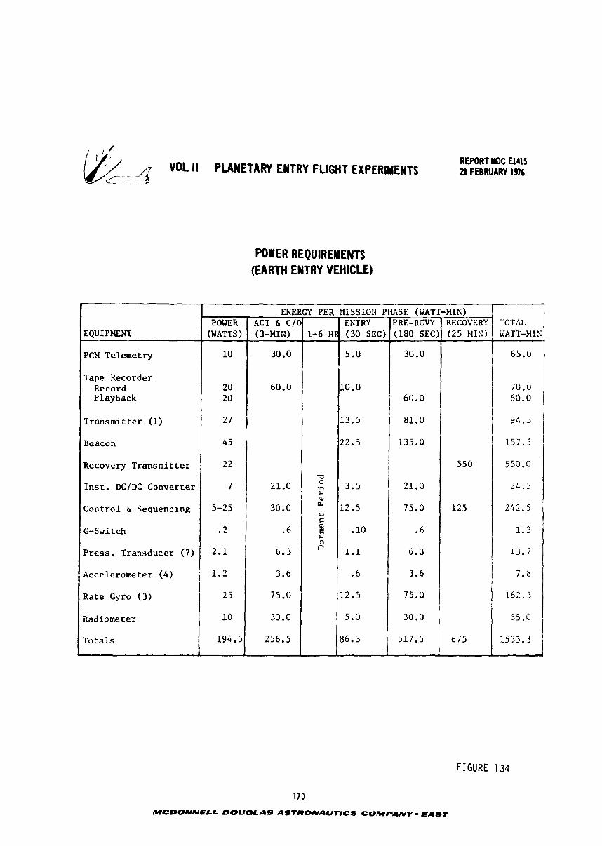
YOL II PLANETARY ENTRY FLIGHT EXPERLNTI d REPORT IW: El415 29 FEBRUARY 1976
POWER REQUIREMENTS (EARTH ENTRY VEHICLE)
FIGURE 134
EQUIPMENT
PCM Telemetry
Tape Recorder Record Playback
170
MCDONNELL DOUGLhS A S ~ ~ o U A U T l C S COMPANY - EAST
TOTAL WATT-XIS
65.0
70.0 60.0
ENERGY PER MISSIOl? PliASE (WATT-MIN)
94.5
157.5
550.0
24.5
242.5
1.3
13.7
7.8
162.5
1535.3
POWER (WATTS)
10
20 20
Transmitter (1) 27 1 Beacon I
ACT & C/O (3-MIN)
30.0
60.0
3 0
.A !-I m a4
U C ol E b 3 a
Recovery Transmitter
In s t . DC/DC Converter
Control & Sequencing
G-Switch
Press. Transducer (7)
1-6 HR
13.5
22.5
3.5
i2 .5
.10
1.1
.6
12.5
5.0
86.3
2 2
7
5-25
.2
2.1
21.0
30.0
.6
6.3
Accelerometer ( 4 ) ; 1.2
Rare Gyro (3) I
25
Radiorne t e r 10
Totals 194.5
ENTRY (30 SEC)
5 .O
10.0
81.0
135.0
21.0
75.0
.6
6.3
3.6
75.0
30.0
517.5
3.6
75.0
30.0
256.5
550
125
675
PRE-RCVY (180 SEC)
30 .O
60.0
RECOVERY (25 MIX)
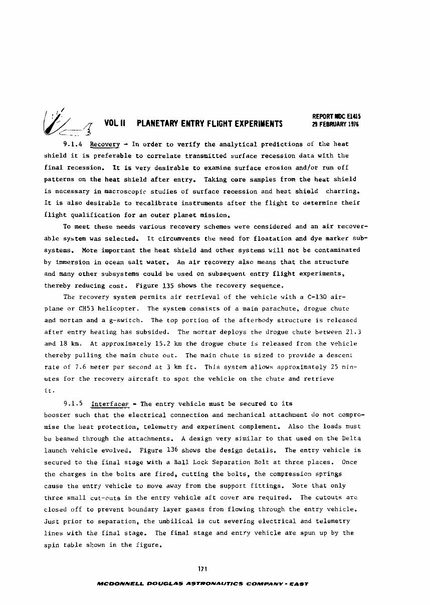
1 1 REPORT D C El415 3 - VOL 11 PLANETAW ENTRY FLIGHT EXPERlYENTf 29 FEBRUARY 1976 ,--- L-
9.1.4 Recovery - I n o r d e r t o v e r i f y t h e a n a l y t i c a l p r e d i c t i o n s of t h e h e a t
s h i e l d i t is p r e f e r a b l e t o c o r r e l a t e t r ansmi t t ed s u r f a c e recess ion d a t a w i t h t h e
f i n a l recess ion. It i s very d e s i r a b l e t o examine s u r f a c e e r o s i o n and/or run o f f
p a t t e r n s on t h e h e a t s h i e l d a f t e r ent ry . Taking c o r e samples from t h e h e a t s h i e l d
is necessary i n macroscopic s t u d i e s of s u r f a c e r e c e s s i o n and hea t s h i e l d charr ing.
It is a l s o d e s i r a b l e t o r e c a l i b r a t e ins t ruments a f t e r t h e f l i g h t t o determine t h e i r
f l i g h t q u a l i f i c a t i o n f o r an o u t e r p l a n e t mission.
To meet these needs va r ious recovery schemes were considered and an a i r recover-
a b l e system w a s se lec ted . It circumvents t h e need f o r f l o a t a t i o n and dye marker sub-
systems. More important t h e h e a t s h i e l d and o t h e r systems w i l l no t b e contaminated
by immersion i n ocean s a l t water. An a i r recovery a l s o means t h a t t h e s t r u c t u r e
and many o t h e r subsystems could be used on subsequent e n t r y f l i g h t experiments,
thereby reducing c o s t . F igure 135 shows t h e recovery sequence.
The recovery system permits a i r r e t r i e v a l of t h e v e h i c l e v i t h a C-130 a i r -
p lane o r CH53 h e l i c o p t e r . The system c o n s i s t s of a main parachute , drogue chute
and mortan and a g-switch. The top p o r t i o n of the af terbody s t r u c t u r e i s re leased
a f t e r e n t r y hea t ing h a s subsided. The mortar deploys the drogue chute between 21.3
and 1 8 kxt. A t approximately 15.2 km t h e drogue chute is re leased from the v e h i c l e
thereby p u l l i n g the main chute ou t . The main chute is s i z e d t o provide a descen:
r a t e of 7.6 meter pe r second a t 3 km f t . This system al lows approximately 25 min-
u t e s f o r the recovery a i r c r a f t t o spo t t h e v e h i c l e on t h e chute and r e t r i e v e
i t .
9.1.5 I n t e r f a c e s - The e n t r y v e h i c l e must be secured t o its
boos te r such t h a t t h e e l e c t r i c a l connection and mechanical at tachment do n o t compro-
mise the h e a t protectioxi , te lemetry and experiment complement. Also t h e loads must
be beamed through t h e at tachments. A des ign very s i m i l a r t o t h a t used on t h e De l t a
launch v e h i c l e evolved. Figure 136 shows t h e des ign d e t a i l s . The e n t r y v e h i c l e is
secured t o the f i n a l s t a g e wi th a B a l l Lock Separa t ion Bolt a t t h r e e p laces . Once
the charges i n t h e b o l t s a r e f i r e d , c u t t i n g t h e b o l t s , t h e compression s p r i n g s
cause t h e e n t r y v e h i c l e t o move away from t h e suppor t f i t t i n g s . Note t h a t only
t h r e e smal l cu t -cu t s i n the e n t r y v e h i c l e a f t cover a r e required. The c u t o u t s a r e
c losed o f f t o prevent boundary l a y e r gases from flowing through t h e e n t r y veh ic le .
J u s t p r i o r t o s e p a r a t i o n , t h e umbi l i ca l is c u t s e v e r i n g e l e c t r i c a l and t e l emet ry
l i n e s wi th the f i n a l s tage . The f i n a l s t a g e and e n t r y v e h i c l e a r e spun up by t h e
s p i n t a b l e shown i n t h e f i g u r e .
171
MCDONNELL DOUGLAS ASTRONAUTlCS COMPANY - EAST
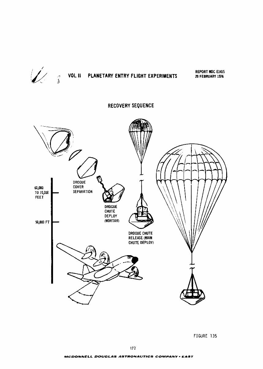
REPORT MDC El415 ,.? VOL li PLANETARY ENTRY FLIGHT EXPERIMENTS 29 FEBRUARY 1976 -4 A
RECOVERY SEQUENCE
TO 70,000 FEET I DROGUE
COVER SEPARATION
DROGUE CHUTE DEPLOY (MORTAR)
DROGUECHUTE RELEASE (MAIN CHUTE DEPLOY)
FIGURE 135
172
MCDONNELL DOUGLAS ASTRONAUTtCS COMPANY - EAST
~ 4 YOL II PLANETARY ENTRY FLIGHT IXPERIYENTS REPORT MOC El415 29 FEBRUARY 1976
CIA
ELECTROMECHANICAL INTERFACES
ENTRY VEHICLE
- ENTRY VEHICLE
TE-364 MOTOR
- IUS INTERFACE
ENTRY VEHICLE ENTRY VEHICLE UMBILICAL
BALL LOCK SEPARATION BOLT ENTRY VEHICLE CUTTER
--- , J
SPRING .FL. -.-, r . 3 ,
ENTRY VEHICLE
UMBILICAL SUPPORT A F I T T I N G
I
SUPPORT F I T T I N G
A B - B STRUCTL RAL INTERFACE
ELECTRICAL INTERFACE
TYPICAL 3 PLACES ( II'iSTRUMENTATIC11)
173 FIGURE 136 MCDONNELL DOUGLAS ASTRONAUTICS COMPANY - EAST
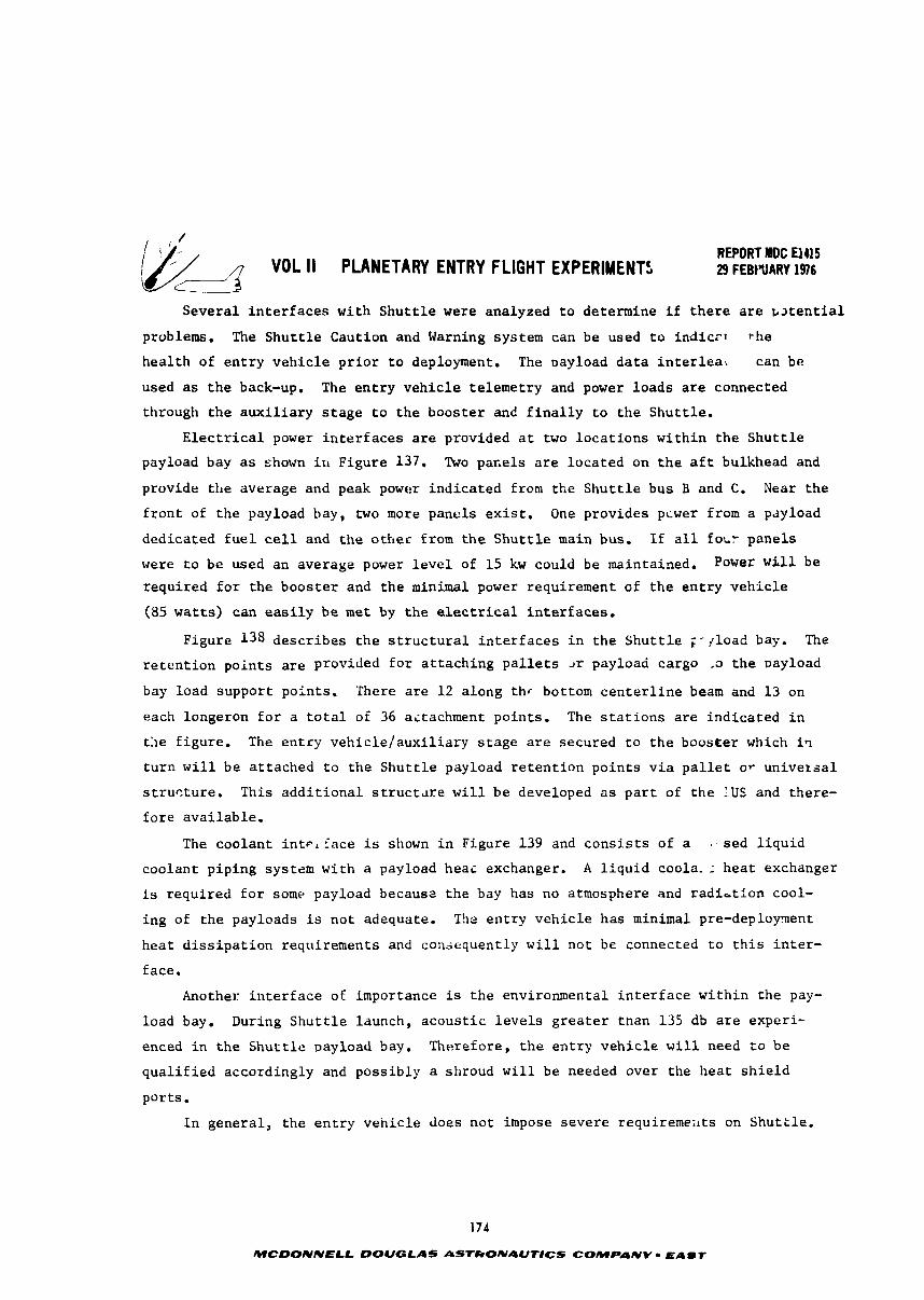
/ REPORT MDC El415 3- VOL II PLANETARY ENTRY FLIGHT EXPERIMENTS I 29 FEBIVARY 1976
C__
Severa l i n t e r f a c e s w i t h S h u t t l e were analyzed t o determine i f t h e r e are t ~ t e n t i a l
problems. The S h u t t l e Caution and Warning system can be used t o i n d i c ~ l t h e
h e a l t h of e n t r y v e h i c l e p r i o r t o deployment. The oayload d a t a in ter lea*. . can be
used a s t h e back-up. The e n t r y v e h i c l e t e l emet ry and power l o a d s a r e connected
through t h e a u x i l i a r y s t a g e t o t h e boos te r and f i n a l l y t o t h e S h u t t l e .
E l e c t r i c a l power i n t e r f a c e s a r e provided a t two l o c a t i o n s w i t h i n t h e S h u t t l e
payload bay a s shown i n Figure 137. Two pariels a r e l o c a t e d on t h e a f t bulkhead and
provide tile average and peak powc!r i n d i c a t e d from t h e S h u t t l e bus B and C. Near t h e
f r o n t of t h e payload bay, two more panels e x i s t . One provides pcwer from a payload
dedicated f u e l cell and t h e o t h e r from t h e S h u t t l e main bus. I f a l l f o ~ r pane l s
were t o be used an average power l e v e l of 15 kw could be maintained. Power w i l l be
r equ i red f o r the boos te r and t h e minimal power requirement of t h e e n t r y v e h i c l e
(85 w a t t s ) can e a s i l y be m e t by t h e e l e c t r i c a l i n t e r f a c e s .
Figure 138 d e s c r i b e s t h e s t r u c t u r a l i n t e r f a c e s i n t h e S h u t t l e ;- j load bay. The
r e t e n t i o n p o i n t s a r e provided f o r a t t a c h i n g p a l l e t s dr payload cargo ,a t h e payload
bay load suppor t po in t s . There a r e 12 a long thc bottom c e n t e r l i n e beam and 1 3 on
each longeron f o r a t o t a l of 36 ai tachment po in t s . The s t a t i o n s a r e i n d i c a t e d i n
the f igure . The e n t r y v e h i c i e / a u x i l i a r y s t a g e a r e secured t o t h e boos te r which i?
t u r n w i l l b e a t t ached t o t h e S h u t t l e payload r e t e n t i o n p o i n t s v i a p a l l e t o r un ivezsa l
s t r u c t u r e . This a d d i t i o n a l s t r u c t d r e w i l l be developed 2s p a r t of t h e LUS and there-
f o r e a v a i l a b l e .
The coo lan t i n t ~ , Eace i s shown i n Figure 139 and c o n s i s t s of a sed l i q u i d
coo lan t p ip ing system w i t h a payload h e a i exchanger. A l i q u i d coola. : h e a t exchanger
is requ i red f o r some payload becausz t h e bay has no atmosphere and r a d i a t i o n cool-
ing of t h e payloads is no t adequate. The e n t r y v e h i c l e has minimal pre-deploynent
hea t d i s s i p a t i o n requirements and consequently w i l l no t be connected t o t h i s i n t e r -
face.
Another i n t e r f a c e of importance is t h e environmental i n t e r f a c e w i t h i n t h e pay-
load bay. During S h u t t l e launch, a c o u s t i c l e v e l s g r e a t e r tnan 135 db a r e exper i -
enced i n t h e S h u t t l e payload bay. Therefore , t h e e n t r y v e h i c l e w i l l need t o b e
q u a l i f i e d accordingly and poss ib ly a shroud w i l l be needed over the h e a t s h i e l d
por ts .
I n genera l , t h e e n t r y v e h i c l e does n o t impose s e v e r e requiremeats on S h u t t l e .
174
MCDONNELL DOUGLAS ASTRONAUTICS COMPANY EAST
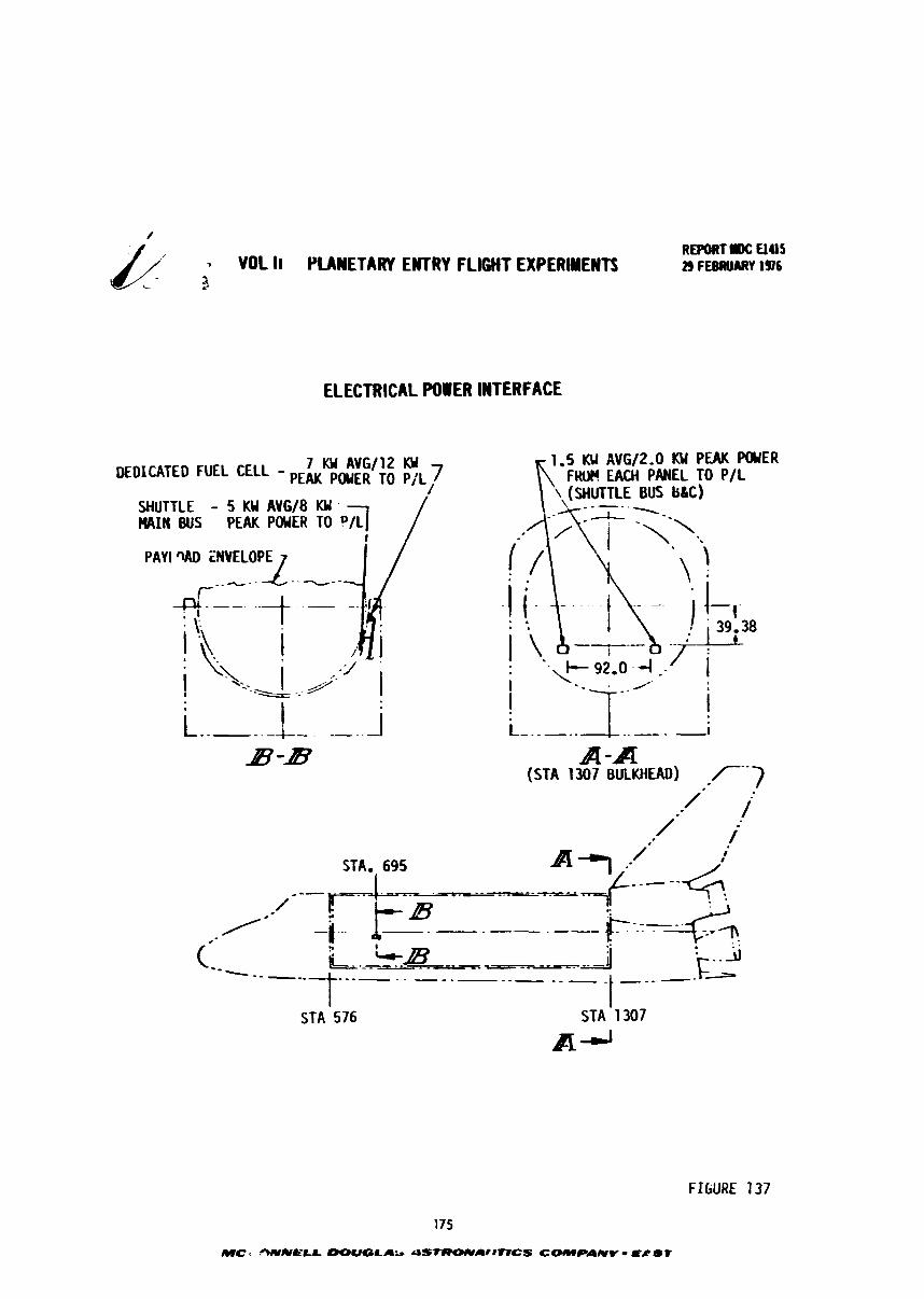
7 VOL II PLANETARY EWTRY f LIGHT EXPERIMENTS 9
ELECTRICAL POWER INTERFACE
PAY1 WD ZNVELOPE
.. . .
REPORT OC UU5 29 FEBRUARY 1¶6
1.5 KU AVG/2,0 KW PEAK POUER F W EACH PANEL TO P/L
\ (SHUTTLE BUS b&C)
A -A (STA 1307 BULKHEAD) r--]
I
STA. 695 --
I STA 576
I STA 1307
A-'
FIGURE 137
175
MC s OIVNC'LL DOUOLAb dS-ArIlVCS COMPAIVV S8 S f
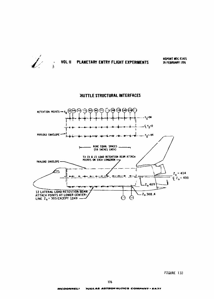
,A/ -. YOL II PLANETARY ENTRY FLIGHT EXPERWENTI L-' L 3
REWRT I1C El415 29 FEBRUARY 1976
HUTTLE STRUCTURAL INTERFACES
i-. nIa EQUAL ~PKES --, (59 lnCHES EACH) / /
13 (X I 2) L(UD RETEWTIOII BEM ATTACH
PAYLOAD EWELOPE
Z, = 414
5 Zo = 400
i
z0 308 -4 LINE 2, = 305 EXCEPT 1249
FIGURE 7 38
176
MCWUIVELP BUGLAS asrwowaur~cs COWPANV - ELI-ST
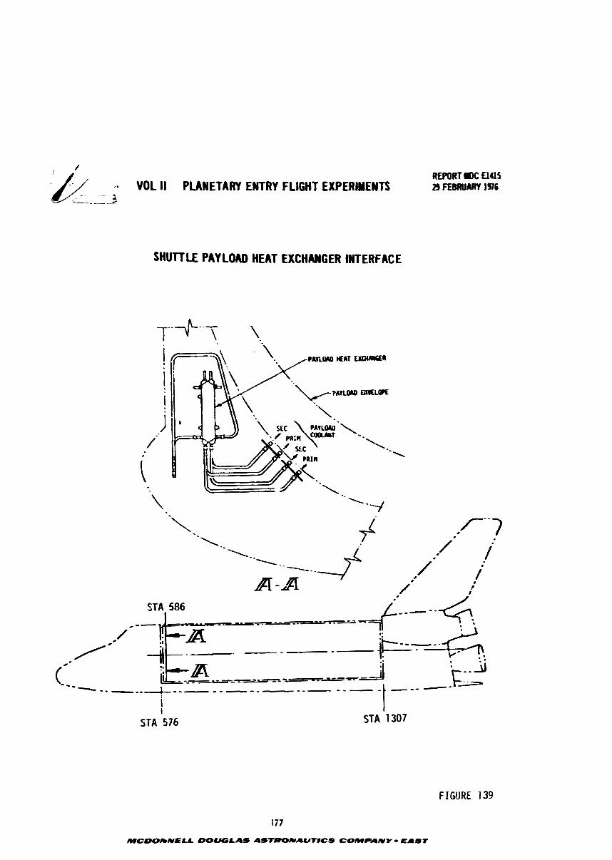
- ; VOL II PLANETARY ENTRY FLIGHT EXPERIMENTS --- f
SHUTTLE PAY LOAD HEAT EXCHWGER INTERFACE
STA 586 I
STA 576 STA 1307
FIGURE 139
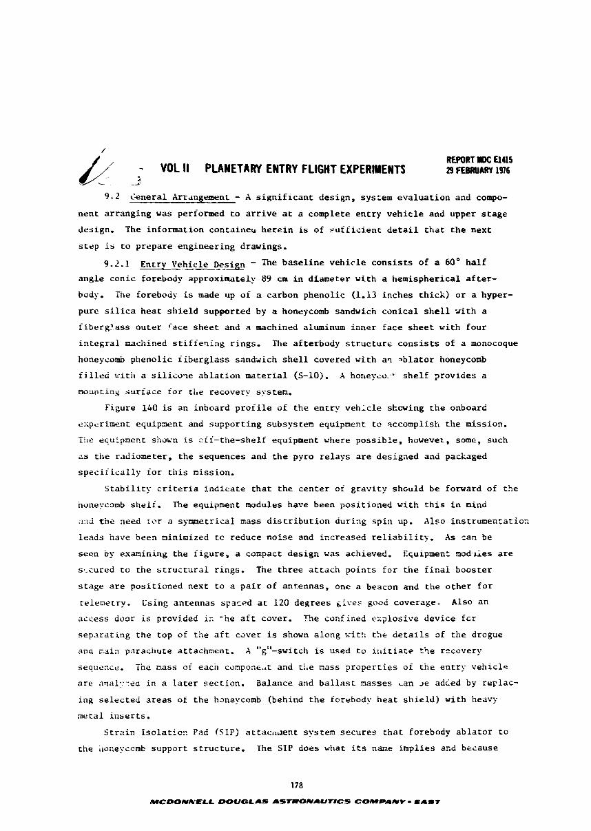
REPORT IDC El415 - VOL It PLANETARY ENTRY FLIGHT EXPERIMENTS 29 FEBRUARY 1976
9 .2 Cenera l Arrangement - A s i g n i f i c a n t d e s i g n , sys:em e v a l u a t i o n and compo-
n e n t a r r a n g i n g w a s performed t o a r r i v e at a comple te e n t r y v e h i c l e and upper s t a g e
design. The in fo rma t ion containerr h e r e i n is o f s u f f i c i e n t d e t a i l t h a t t h e n e x t
s t e p is t o p r e p a r e e n g i n e e r i n g drawings.
9.2.1 Ent rv v e h i c l e D e s i g n - The b a s e l i n e v e h i c l e c o n s i s t s o f a 60° h a l f
ai lgle c o n i c forebody approximate ly 89 c m i n d i a m e t e r w i t h a h e m i s p h e r i c a l a f t e r -
body. T i e forebody is made up o f a carbon pheno l i c (1.13 i n c h e s t h i c k ) o r a hyper-
pure s i l ica h e a t s h i e l d suppor t ed by a honeycomb sandwich c o n i c a l s h e l l x i t h a
f iberg 'ass o u t e r f a c e s h e e t and a machined aluminum i n n e r f a c e s h e e t w i t h f o u r
i n t e g r a l machined s t i f fer l ing r ings . The a£ t e rbody s t r u c t u r e c o n s i s t s of a monocoque
honeycomb p h e n o l i c f i b e r g l a s s s andx ich s h e l l covered w i t h aq ~ b l a t o r honeycomb
i i ~ l l e c i w i t h a s i l i c o q e a b l a t i o n naterial (S-lo), X h o n e y ~ o : ~ s h e l f p r o v i d e s a
m x n t i n g s u r f a c e f o r rite recovery s?-sten,
F igure 140 is an inboard p r o f i l e o f t h e e n t r y v e h i c l e skewing t h e onboard
e :<prr inrn t e q u i p a e n t and s u p p o r t i n g subsystem equipment t o accomplisti t h e mission. -- L i k e eqaipmect siltx-n i s s i i - t i l e - she l f equipment where p o s s i b l e , however, some, such
zs t h e radiometer , t h e sequences and t h e pyro r e l a y s a r e des igned and packaged
s p e c i f i c a l l y f o r t h i s n i s s i o n .
S t a b i l i t y c r i t e r i a i n d i c a t e t h a t t h e c e n t e r of g r a v i t y s h c u l d b e forward of the
hone::conb s h e l f . The equipment modules have been p o s i t i o n e d w i t h t h i s i n mind
2116 tr~e need ;or a s p n n e t r i c a l %ass d i s t r i b u t i o n d u r i n g s p i n up. Also i n s t r u n e n r a t i o s
l e a d s have been minimized tc reduce n o i s e and i n c r e a s e d r e l i a b i l i t y , A s can be
seer. by examining t h e f i g u r e , a compact d e s i g n w a s achieved. Equipmen: mod-lies are
s ,-cured t o t h e s t r u c t u r a l r i n g s , The t h r e e a t t a c h p o i n t s f o r t h e f i n a l b o o s t e r
s t a g e are p o s i t i o n e d nex t t o a p a i r o f an t ennas , one a beacon and the o t h e r f o r
re iemetry . Cs ing an tennas s ~ a r f ? d a t 120 d e g r e e s gl l -es gocd coverage . Also a n
a c c e s s door is provided ic 'he a f t cover , f h e conf ined e:-:?losive d e v i c e f c r
s e p z r a t i n g t h e t o p of t h e a f t c J v e r is shown a l o n g w i t h t h e d e t a i l s of t h e drogue
and z a i n pa rachu te a t tachment . X "g"-switch is used t o i r l i t i a t e t i e recovery -. sequence. tne nass of each compone..t and t!.e mass p r o p e r t i e s of t h e e n t r y v e f ~ i c l e
are anal;:-yea i n a La te r s e c t i o n . Balance and b a l l a s t masses can Je ad ied by r e p l a c -
i n g s e l e c t e d a r e a s of t h e haneycomb (behind t h e forebody h e a t s h i e l d ) w i t h heavy
metal i n s e r t s .
S t r a i n I s o l a t i o c Pad (SIP) at taci t taent s y s tern s e c u r e s t h a t forebody a b l a t o r t o
t h e ;lonel;comb s u p p o r t s t r u c t u r e . The S I P does what i ts name i m p l i e s and because
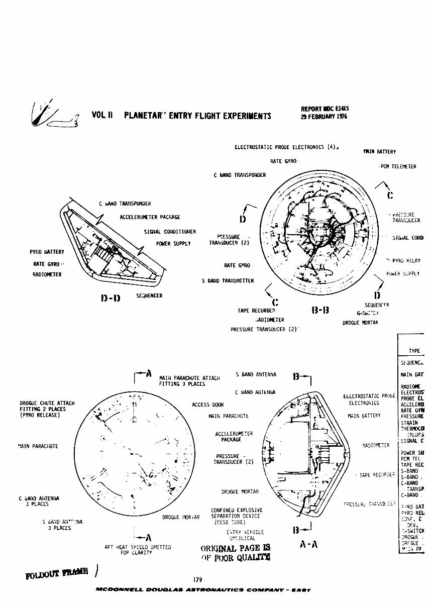
/ ' - REPORT I)C
VOL II PUNETAIT' ENTRY FLIGHT EXPERIMENTS E) FEBRUARY 1376
ELECTROSTAiIC PROSE ELECTRONICS (4) r M I N BATTERY
RATE GYRO. PC# TELEHETER
(A\ ACCELERITER PACKAGE
sIau COHOITIW~ER
POMR SUPPLY PYl:O tiATTERY
RATE GYRO - WIOCIETER --
C WLO TRlViSPOtiDER
T%'tSYJCER
PYRu RELAY
POWER SGPPLY W I D TRAfiSI!I'ETER
\, TAPE RECORDE?
..AD:OSTER
PRESSURE TRANSDUCER ( 2 ) '
MIA PARACHUTE ATTACH 5 BAND AHTEHSA F' FITTIKG 1 PLACES
DROGUE CHUTE ATTACH FITTIRG 2 PLACES (PYRO RELEASE) i .. . . W I t I PAWCHUTt
L-- . - ACCtLERmTER
3 . -. DAf YACF .< - - * - W I N PARACiiUTE . - - I PA3 I
.- - -- . L. DDFCCI:L?F -
C b&JD Pll'iTEliidA 3 PLACES .
DROGUE !@RI AR "IRA
COtiF IfiEO EXPLOSIVE SEPARATIOS DEVICE
(CESD :PBE! 3 PLACES
E:.TRY VEHICLE '-11 X 1 L ; C A L
I]-'
AFT HEAT SP!ELD OII~TTED ORIQfNaL PAGE I1 - 41 FOP i L A R I T r
POOR Q U ~
TYPE
5 ~ E N C L
M I # rar RADIom E L E C T ~ S PROBE EL ACiELERO WTE G a PRESSURE STRAIN
;PL;IFS SIGNAL C
W i R SU PCU ?EL TAPE REC 5-B.UD S-BAND C-BAND
72ANSP C-W?D .
:'SO BAT 2.783 REL; C3'iF. E:
3F.V. :-SWITCH 7'tOUJE . X G i i E . vr:il i'P -
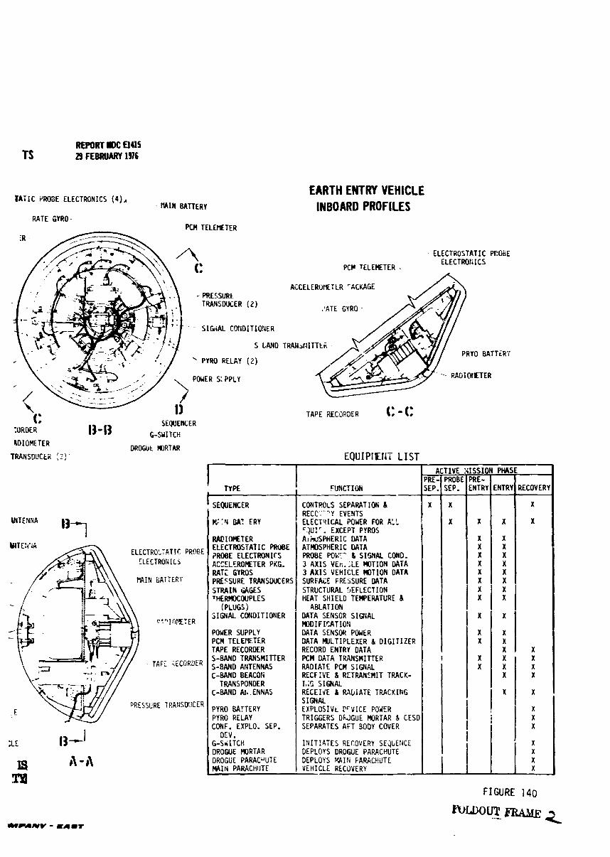
REPORT IDC aus TS 29 FEBRUARY 1976
BATIC PRO3E ELECTRONICS ( 4 ) ~ EARTH ENTRY VEHICLE
- ~MIN BATTERY INBOARD PROFILES RATE GYRO
TRANSDUCER (2 )
- S I W A L C@iDITIO?iER
s LAND
PYRO RELAY (2 )
LD IOETER
TRANSDUCER : Z f '
13-13 SEQUEHCER
ESYITCH
ELECTROSTATIC PCOEE
PCP TELErTTER - ELECTROtiICS
ACCELEROMTLR 'ACUGE
.'ATE GYRO -
RADIOIETER
TAPE RECORDER (: - (: DROUit m T A R
EQUIPllEllT LIST
FIGURE 140
i U L D o l r r m a -- ~
I ACTIVE :iISSIMI P M S E 1
VITEXiA
ELECTRO-YP.TIC
% I 1 BATTERY
- TAFL <ECORDER
PRESSERE TRAfiSDUCER
l3J X i
IS b l - 11 a
F W C T 1 ON
CONTROLS SEPARATIW h RECC'T'-3Y EVENTS ELECTPICAL WUER FOR ALL '=.fL'!'. EXCEPT PIROS Ai i rrSPHERIC DATA ATMDSPHERIC DhTA PROBE ~0gt2 & s ~ r $ l ~ ~ COND- 3 AX IS VEr;. : iE PIOTION DATA 3 AX IS VEHICLE K I T I O N DATA SURFACE PRESSURE M T A STRUCTURAL 5EFLECTION HEAT SHIELD TEWERATGRE h
ABLATl ON DATA SENSOR SIGNAL K I D I F l r A T I O k i DATA SENSOR POWER DATA WLTIPLEXER 8 DIGIT IZER RECORD ENTRY DATA PCM DATA T W S R I T T E R RADIATE PCM SIGNAL RECFlVE L RETRANZMIT TRACK- It& SIGNAL RECEIJE h M G I A T E TRACKltdG SIGNAL EXPLOSIVt PrVICE POWER TRIGGERS DUGUE WRTAR 8 CESD SEPARATES AFT BODY COVER
INIT!47ES RECOVERY SEQLENCE DEPLOYS DROGUE PARACHUTE DEPLOYS VAIN FARACUUTE VEHICLE RECOVERY
TYPE
SEQUENCER
F"::Y BAT XRY
R M I M T E R ELECTROqTATIC PRUBE ?ROBE EiECTRONlrS ACtELEROFETER PKG. RAT; GYROS PRESSURE TRANS3UCERS STRAIN U G E S THERMOCOUPLES
(PLUGS) SIGNAL CONDITIONER
W E R SUPPLY PCM TELEH-TER TAPE RECORDER S-BAND TRANSMITTER S - B ~ D ANTENNAS C-BAND BEACON
TRANSPONDER C-8AND At.. EHNAS
pyRO BATTERY PYRO RELAY CONF. EXPLO. SEP.
DEV. G-SY ITCH DROGUE PIORTAR DROGUE PARACUUTE MQIt4 PARACHIITE
X X
X X
X X x X X
.
1
il
X
X X x X X
X
X X
X X
X
X
I i I X X
X X
X
X X X X
X
X X X X X X
X X X X
- VQL ll PLANETbTW FYTRY FLIGHT EXPERIMENTS :&: -;-; REWRT llDC El415 29 FEBRUARY 1976
it is made of a f i b r o u s m a t e r i a l ' t k . i ' l accommodate s t r a i n s even a t cryogenic
temperatures. The d e t a i - s of -'le JT.k i n s t a l l a t i o n , h e a t s h i e l d corner at tachment
and thermocouple s t a c k c o n f i g u r a t i o n have been desc r ibed previously .
h l s q shown on t h e f i g u r e is t h e s c e n a r i o of when t h e va r ious p i e c e s of equip-
ment func t ion dur ing t h e miss ion and t h e func t ion of each p i e c e of equipment.
9 . 2 . 2 Launch Conf igura t ion - The e n t r y v e h i c l e , upper s t a g e and main b o o s t e r - takes up less than 3/8 of t h e 18.25 meter S h u t t f e cargo bay and 43% of its payload
capabi l i ty . A t y p i c a l launch conf igura t ion a s shown i n F igure 1 4 1 w e i g h s 13516 kg
and would most l i k e l y be pos i t ioned nore iorward i n t h e ca rgo bay depending on t t le
requirements of o t h e r cargo. The upper s t a g e houses a TE-364 s o l i d rocke t , con ta ins
wire bundles and a s s o c i a t e d gea r , supgiorts t h e e n t r y v e h i c l e , has a s p i n t a b l e and
mkes tile necessary s t r u c t u r a l t i e s t o a 3.048 meters d iameter a d a p t e r r ing . This
universa l a d a p t e r r i n g makes t h e upper s t a g e compatible w i t h t h e a l l b o o s t e r s con-
sidered. The w i r e bundle-umbilical assembly passes power and t e l emet ry between t h e
ent ry v e h i c l e and t h e main booster . The main boos te r c o n t a i n s a l l c!ie g.~idar?cr and
con t ro l equipment anci t e l emet ry equipment necessary t o f l y t h e miss ion and f i r e
tile upper s t age . This des ign is very s i m i l a r t o t h a t used on t h e Delta launch
vehicle.
9.3 Entry Vehicle Sfass P r o p e r t i e s - X d e t a i l e d mass p r o p e r t i e s e v a l u a t i o n was
con2ucted --qr t h e e n t r y test v e h i c l e conf igura t ion desc r ibed i n Figure 140. Two
i n t e r r e l a t e d asDects were oL primary i n t e r e s t : (i) t h e anount of b a l l a s t needed t o
provide a proper e n t r y c e n t e r of g r a v i t y (c.g.) l o c a t i o n , (2) t h e i n c r e a s e I n
b a l l i s 2 i c c o e f f i c i e n t ( 2 ) a c t a i c a b l e by i n c r e a s i n g only v e h i c l e mass ,and (3) d e t a i l e d
mdss p roper ty a n a l y s i s .
9.3.1 B a l l s s t -- - The concern f o r c.g. l o c a t i o n a r i s e s from t h e reguire-
ncnt f o r a p o s i t i v e s t a t i c s t a ~ i l i t y margin. Hence tile l o n g i t u d i n a l c.g. l o c a t i o n
:nust be prevented from being appreciably a f t of t h e t h e o r e t i c a l cone/hemispiiere
i c t e r s e c t i o n plane. The l o c a t i o n of t h i s aerodynamic r e f e r e n c e p lane is shown i n
Figure 142. However, equipmenr. arrangement, p a r t i c u l a r l y t h e n e c z s s a r i l y a f t loca-
t ion of t h e recovery parachute system, Lndicatod t h e probable need t o for b a l l a s t
i n the forward, c o n i c a l s e c t i o n . Fur ther a s i g n i f i c a n t amount of b a l l a s t was
a n t i c i p a t e d because of t h e b l u n t body shape which o f f e r s a r e l a t i v e l y s h o r t b a l l a s t
IilOment a m .
O r d i n a r i l y , a l a r g e b a l l a s t mass would be d e t r i m e n t a l because i t reduces t h e
LV a v a i l a b l e f r o m a given booster . However, t h e corresponding i n c r e a s e i n
180
MCOONNELL DOIJGLAS ASTRONAUftCS COMPANY - S A S t
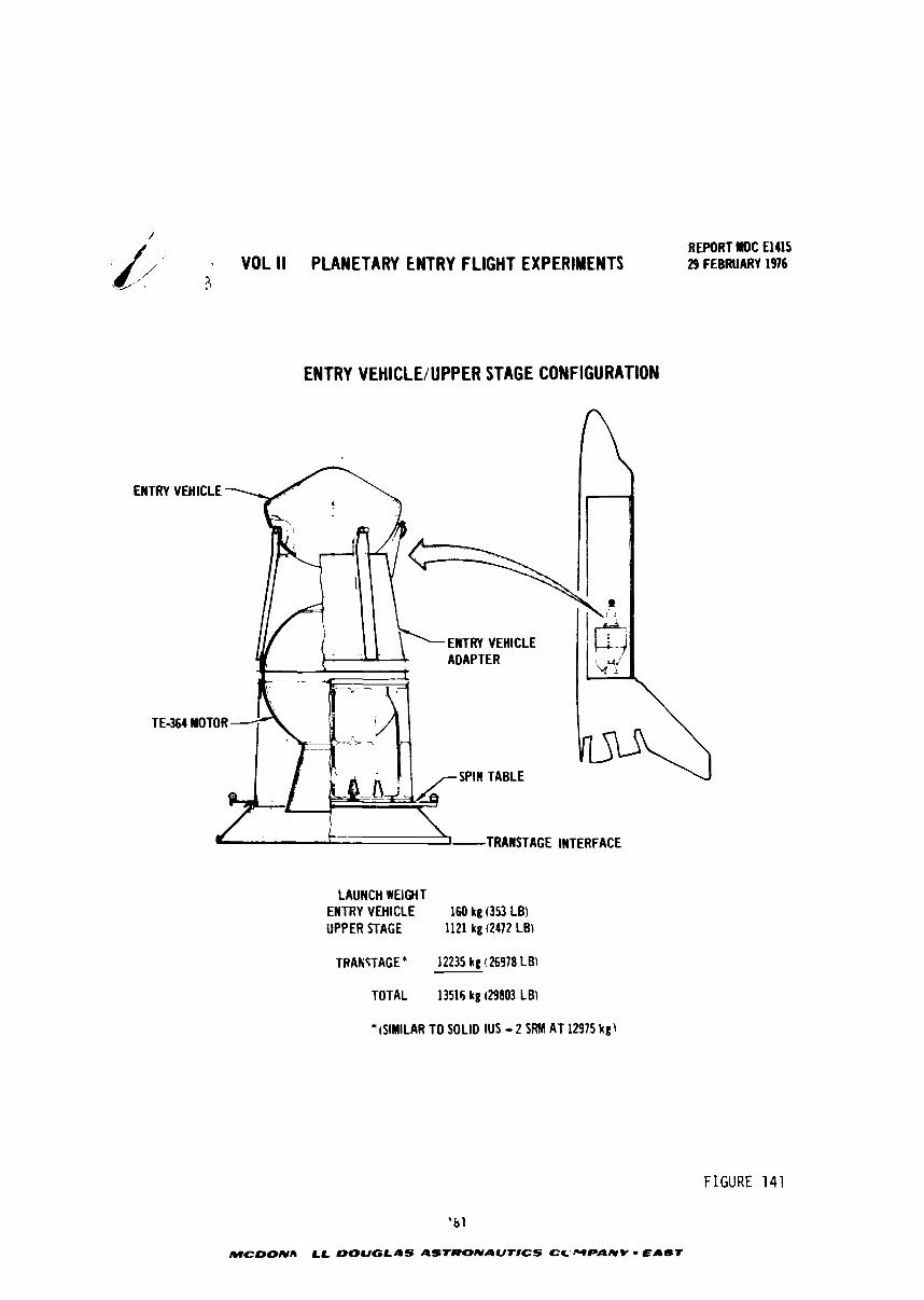
/ REPORT lWDC El415
VOL II PLANETARY ENTRY FLIGHT EXPERIMENTS d FEBRUARY 1976 '? L'
ENTRY VEHICLE/UPPER STAGE CONFIGURATION
LAUNCH WEIGHT ENTRY VEHICLE 160 kg ( 3 9 LB) UPPER STAGE 1121 kg (2472 LB)
TRAIFTAGE * 12235 kg 126978 LB)
TOTAL 13516 kg (29803 LB)
* rSIMILAR TO SOLID IUS - 2 SRM AT 12975 kg)
FIGURE 141
' b l
M C L ) O N A LL DOUGLAS ASTRONAUT#CS CC-WPANY - EAST
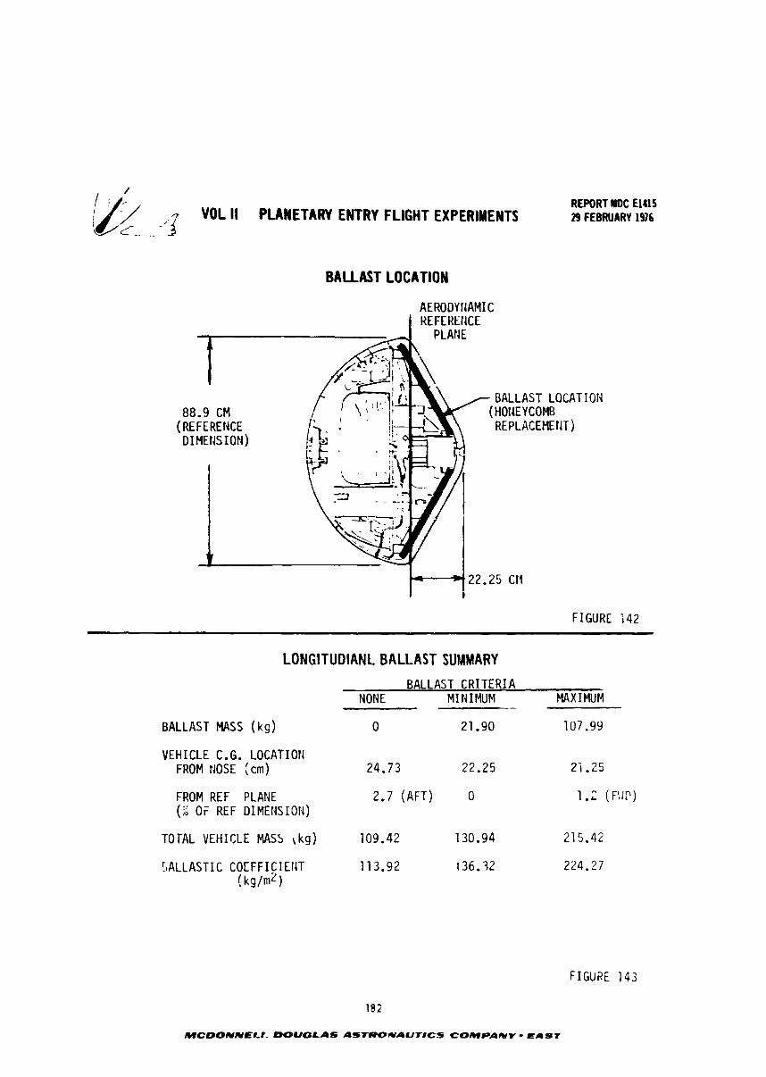
VOL ll PLANETARY ENTRY FLIGHT EXPERIMENTS
BALLAST LOCATION
AERODY l lAMIC 1 HEFEUEllCE
REPORT IIDC El415 29 FEBRUARY 1976
88.9 CM
FIGURE
LONGITUDIANL BALLAST SUMMARY
BALLAST CRITERIA NONE M I I4IMUM -
WXIMUM
BALLAST MASS (ks) 0 21.90 107.99
VEHICLE C.G. LOCATION FROM NOSE (cm) 24.73 22.25 2 i .?5
FROM REF PLANE 2.7 (AFT) 0 (7: OF REF DIMENSION)
TOTAL VEHICLE MASS \kg) 109.42 130.94 215.42
FIGURE 143
102
MCDONNELI- DOUGLAS ASTROUAUTICS COMPANY - EAST
I ' REPORT NDC El415 kz ,,I VOL 11 PLANETARY ENTRY FLIGHT EXPERIMENTS 29 FEBRUARY 1 9 6 7
ballistic coefficient is a mitigating factor unique to this high radiative flux
simulation mission. As noted previously, increasing B decreases the entry velo-
city and hence the booster A V required to simulate a given level of radiative flux.
If d is increased only by mass addition (C A = constant) the net boostcr effect is D
still advantageous. The reduction in booster A V required is greater than the re-
duction in booster A V capability.
Entry vehicle mass properties were determine3 using computer codes developed
for the outer planet probe. The effect of ballast mass on total vehicle mass,
ballistic coefficient and center of gravity locations was determi.:ed. Representa-
tive results are tabulated in Figure 143 and are graphicallv illustrated in Figure
144. Ballast was assumed to be in the form of steel plate segments that replace
the honeycomb core of the forward heat shield structure (ref Figure 143). As
expected the "no ballast" case resulted in a c.8. location aft of the aerodynamic
reference plan. However, it was only displaced by -98 cm (2.7% of reference dimen-
sion) relative to the reference plane which was not as far aft as anticipated.
While this is marginally acceptable, a c.g. location at or forward of the aercdy-
namic reference plane was considered necessary at this preliminary design stage
to insure an adequate stability margin in the final configuration. Hence a minimum
ballast case was investigated in which just enough aluminum honeycomb core was
replaced with steel plate to move the c.g. forward to the aerodynamic reference
plane. This 21.9 kg of ballast increased total vehicle mass from about 109 kg to 2 131 kg and B from approximately 114 kg/m2 to 136 kg/m . Although this provided a
satisfactory c.g. location it did not represent a maximum ballistic cocffi~,ient
configuration. A maximum ballast case was therefore evaluated in w h i c h all of the
aluminum honeycomb core was replaced with steel plate The -esulting 108 kg of 7
ballast increased vehicle mass to 215 kg and 6 to 22; k g / n L , while moving the c . ~ .
forward of the reference plane h;. 1.2Z <)f reference dimension. Since this is
suhstantially higher than the 120 kg/m2 valua assumed for the earth entry environ-
ment analysis, a net reducticn in required booster performance is possibl,,. Further,
the maximum ballast c?se offers a unique vehicle d e s i g n opptlrtunity. tl simple.
steel structural shell can be used rather than the more sophisticated tloneyiL-;;S
structure. This would provide a less exp~qsive structural design that a l s v nini-
mizes booster performance requirements and insures a proper c . ~ . location.
183
MCDONNELL DOUGLAS ASTRONAUTtCS COMPAIIIV - EAST
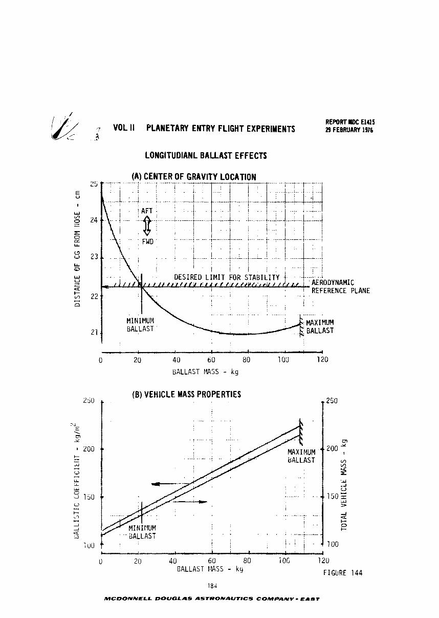
/ REPORT MDC El415
7 VOL II PLANETARY ENTRY FLIGHT EXPERIMENTS 29 FEBRUARY 1976 1
LONGITUDIANL BALLAST EFFECTS
(A) CENTER OF GRAVITY LOCATION
3
I
1 1 * 4
0 2 0 4 0 6 0 80 100 120
UALLAST 1445s - kg
(B) VEHICLE MASS PROPERTIES
i t k 1 1
0 20 4 0 6 0 80 i Ofi 120 BALLAST 1lASS - kg F I GbRE
MCDONNELL DOUGLAS AST*ONAUTIC.S COMPAmY - E A m t
REWRT NDC El415 VOL 11 PLANETARY ENTRY FLIGHT EXPERIMENTS 29 FEBRUARY 1976
9 . 3 . 2 Detailed Mass Property Analysis - The mass properties of both the maxi- mum ballast and the minimum ballast mass configuration were analyzed in detail.
Component mass/location and structural mass/location were employed to determine
overall mass, center of gravity, moment of inertia and associated derivatives.
The entry test vehicle is spin-stabilized during the preentry coast period
following booster separation and must be aerodynamically stable during entry and
terminal descent. This imposes constraints on the vehicle mass properties which
cause the three axis center of gravity (c.g.), the ratio of roll to pitch or yaw
inertia and the roll-yaw and roll-pitch products of inertia to be critical.
Nuch of the engineering equipment is off the shelf and not tailored to pro-
vide a forward c.g. location and the recovery system is located in the aft compart-
ment for convenience and minrmum cost. The aft c.g. resulting from these design
considerations is offset by adding ballast in the form of steel plates in place
of the honeycomb core of the forward heat shield backup structure. In addition
to the longitudinal ballast a small amount of lateral ballast is added to drive
the roll coupled cross products of inertia and the c.g. ecentricities about the
roll axis to zero. This ballast can be eliminated in the final design by relocat-
ing part of the equipment; however, an allowance is needed for final corrections
during actual measurement of the flight vehicle.
The reference axss diagram is presented in Figure 145. The earth entry
vehicle mass properties for the maximum and minimum mass are presented in Figures
146 through 1'8 and Figures 149 through 151 respectively. Figures 146 and 149
summari~e the mass perperties of each vehicle while Figures 147 and 15G provide
the mission profiles. Figures 148 and 151 present the detail mass, c.g. and radius
of gyration data used to compute the vehicle mass properties. In these detail
listings the subtotals (and thus the group names) follow the items listel. Note
that at all points in the missior, profiles of both vehicles the roll inertia is
at least 1.3 times the large; of the pitch or yaw inertia thus providing a comfort-
able marg;n above t\e 1.1 ratio required for dynamic stability during the coast
phase of the m~ssion.
185
MCDGNNELL DOUGLAS ASTRoNAUTlCS COMPPNV - EAST
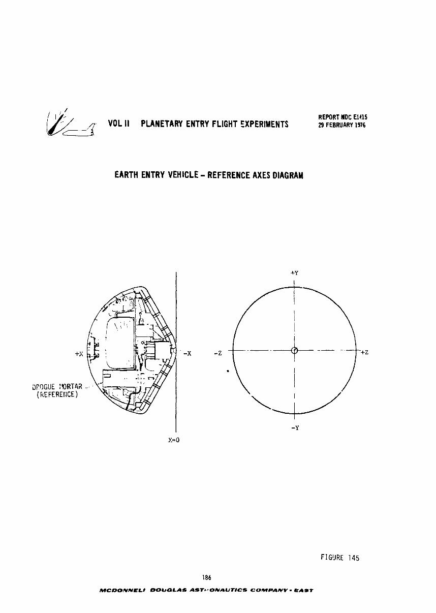
REPORT MDC El415 q- VOL II PLANETARY ENTRY FLIGHT EXPERIMENTS 29 FEBRUARY 1976
EARTH ENTRY VEHICLE - REFERENCE AXES DIAGRAM
FIGURE 145
186
WCDONNELI DOUGLAS ASTr.~ONAUTlCS C O M P A W V EAST
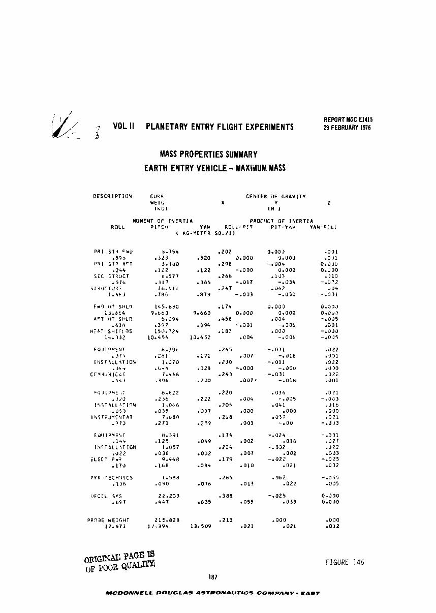
REPORT MDC €1415 VOL ll PLANETARY ENTRY FLIGHT EXPERIMENTS 29 FEBRUARY 1976
MASS PROPERTIES SUMMARY
EARTH EYTRY VEHICLE - MAXI'iUM MASS
D E S C R I P T l U N CUq R
WE l b l K G l
C E N T E R OF G R A V I T Y X V 2
I n )
MOMENT OF 1 Y E 9 T I A P R O r ' l C T OF I N E R T I A ROLL P I T C e V A N R O L L - " ! T P I T - V a k YAW-QIILL
( K G - V E T C R S 0 . / 1 1
P R I S T 4 FbU . 5 9 s
P R 1 5 T g A C T - 2 4 4
SEC :T?UCT .5 76
57 - ? l K T U ? Z 1 . 4 6 3
F#r) HT S I I L O 1 3 . C i 4
A C T t i T jHLO . 6 3 H
t+:a: SH::LDS lu . 312
FOJ I P b l k N T . J 7 %
I C S T 4LL 31 I O N . 3 A r
C r ' 4 ~ l u U I C L r - 4 4 3
F0.J IPME 47 -3.25
I a J 5 T A L L I T 19N . 05.3 I h i T C ; ! E Y T A T
.? 73
E ~ O I P Y E ' V T . 1 4 +
I N S T k L L i T IGN .022
E L E C T P,.l - 1 7 0
!IFCEL S V S 25.203 a 3 8 8 -.025 0 e590 . 6 9 7 . 447 - 6 3 5 - 0 5 5 . 3 3 3 0.0JO
~ R T ~ ' I N A I : PAGE OF POOR Q U ~
FIGURE ? 4 6
187
MCDONNELL DOUGLAS ASTRONAUTICS COMPANY - EPST
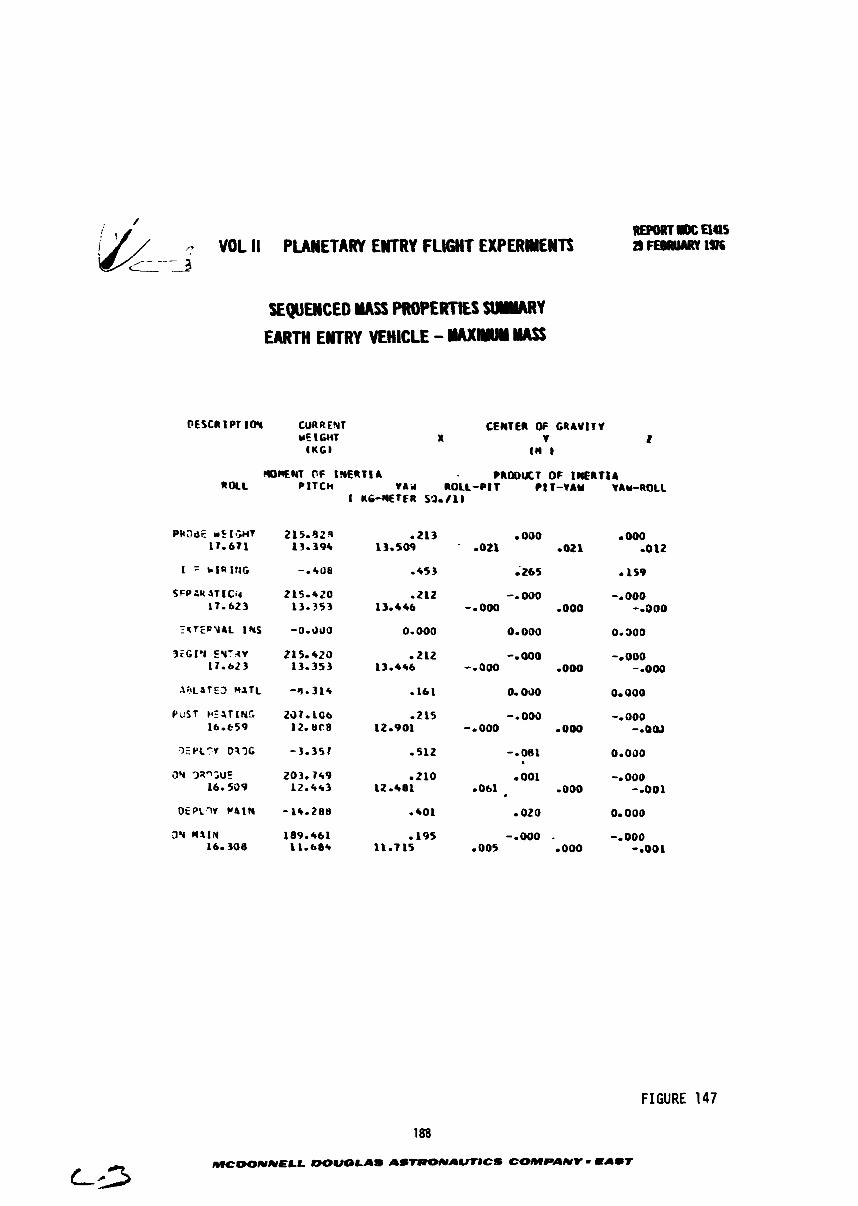
SEQUMCED YASS PROPERTkS SUUWRY
EARTH EMTRY VEHICLE - WIUY UASS
OESCR 1 PT IOY CUR R EYT WE 1 WIT
I U G I
CENTER OF C R A V t T 1 X r L
tH t
~ M N T OF I S E R T ~ A ? R 0 0 U T OF INERT I A ROLL PITCH rai l ROLL-PIT C ~ ~ - Y A Y VAW-ROLL
I KG-8EWR SO./lb
FIGURE 147
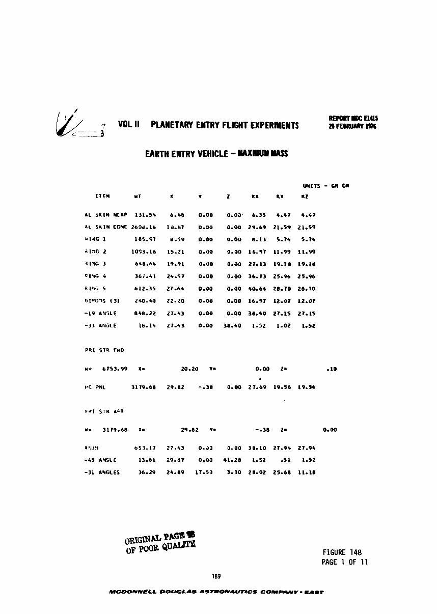
VOL ll PUWETARY EWTRY F L M T EXPERIllEWTS - -- EARTH ENTRY VEHICLE - YClXYUY W
AL S K I N M A P 131-S*
aL SKIN CfMF 263d-A6
n l . i t 1 185*9?
al#G Z 1093-16
71% 3 648.64
Ct%G 4 34i.41
P . l % i i 5 612-35
OIo03S (3) 240-40
-19 AtGLE 848-22
-33 A ~ ~ G L E 18. 1s
FIGURE 148 PAGE 1 OF 11
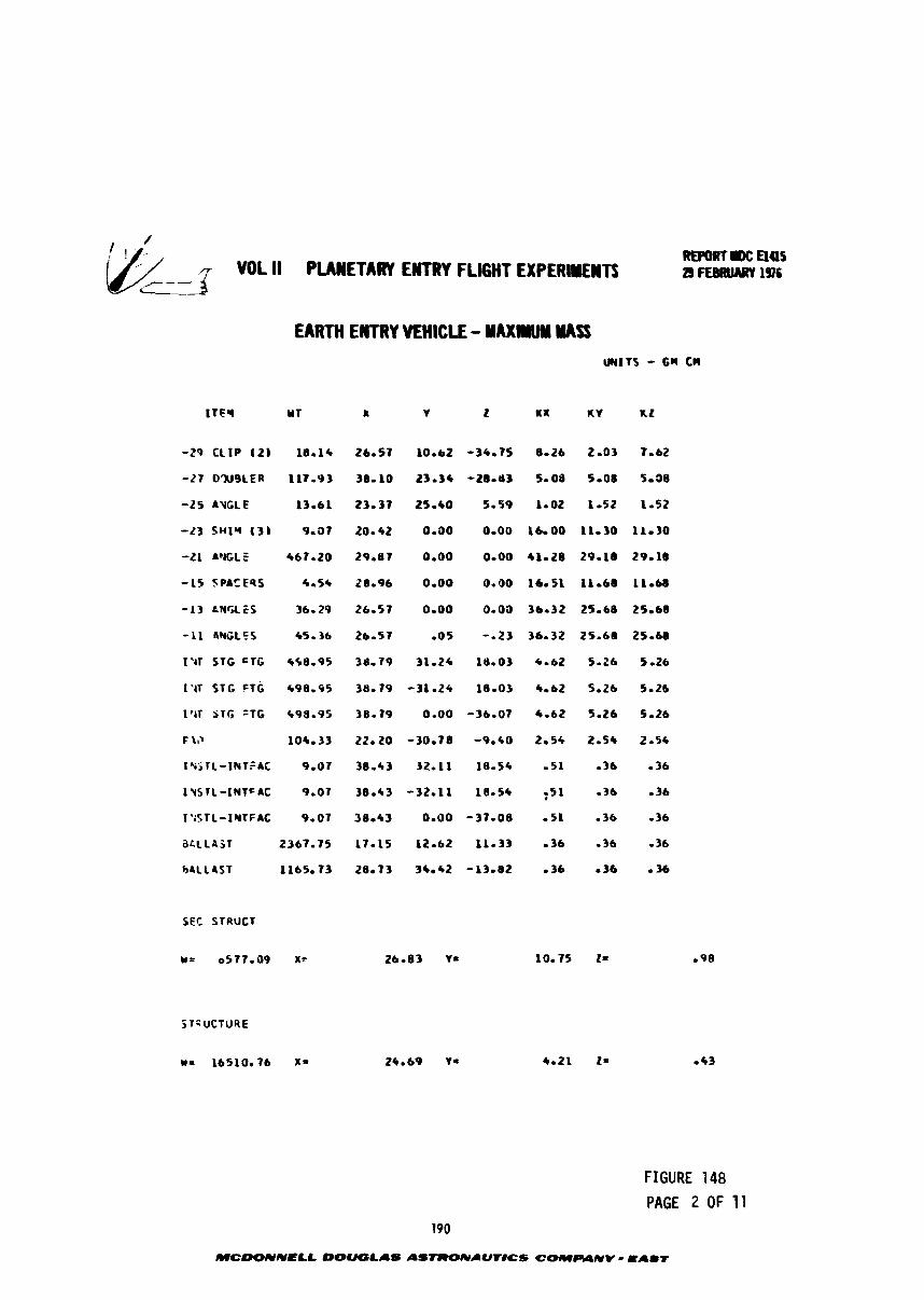
REPORT= aas VOL II PUWETARY ENTRY F L M T EXPERtOllENTS ~ ~ ~ ~ R U A R V I Y ? ~
EARTH EMTRY VEHICLE - YAXW WSS UNlTS - GII CM
-29 C L I P I 2 1 18-16
-27 O'NSLER 117-93
-25 AVtLE 13-61
-23 SHIM ( 3 ) 9-37
-21 A'JCLE 467.20
-15 SPA5 E 9 S 4-56
-13 tNGLES 36- 29
-11 4WLtS 450 36
I W ST6 GTG 4S8-95
1-41 STG FTG 498-95
I'(1 STG 'TG 699.95
F \P 104-33
1qSTL-INTFAC 3-07
i%srL-twFAc 9-07
I'iSTL-IYTFAC 9-07
~ C L L I S T 2367-75
h4LL4ST 1165.73
FIGURE 148 PAGE 2 OF 11
MCWNNELL OOUQLAS ASTRONIUTlCS COMPANV - =A61
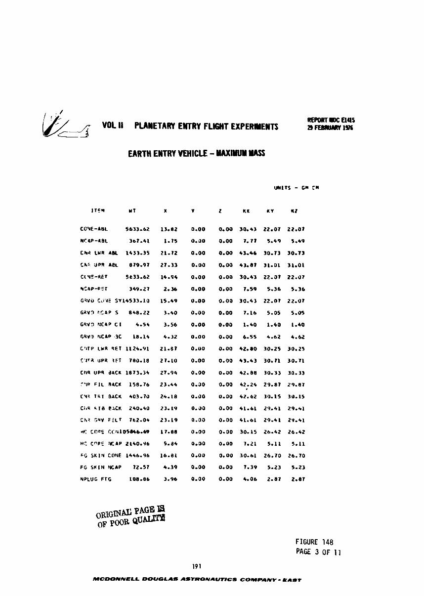
. -
,---' &a- VOL ll PUNETARY EWTRY FLIGHT EXPERWENTS REPORT IW: aas 29fEmlnml~
EARTH ENTRY YMlCLE - MAXIYUY YASf
CCYE-ABL 5633.62
Nr &P-A8L 3a7.41
Chi LUR &BL 1433.35
C h t UPo 4eL 879.97
C[ YE-RET 5t33-62
&CAP-Rf T 349.27
GGVi, t i i ' 4E SV14533.16
GaV? t C 4 P 5 848.22
f R V 3 Y C 4 P CI 6-54
GRV3 NCAP -3C 18-16
C'ITP LMR PET 1124.91
t - J T ~ UPR ~ F T 7a0.18
CtJQ UPS dPCK 1873.34
F I L RACK 158.76
CY? T * I BACK 403.73
C i t R 616 eACK 240.40
ChZ SQV FZLf 7t2.04
MC COO5 CC~JiO'I84beblP
ME CnPE %CAP ZLCOeY6
G G S K I N COY€ 1446.96
FGSUINNCAP 72.57
YPLUG FTG 108.86
FIGURE 148 PAGE 3 OF 11
MCOONNELL DOUGLAS ASTRONAUr#CS COMPANY - O A b t
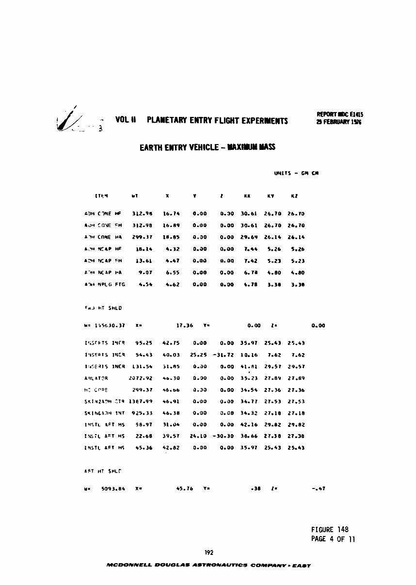
& -- VOL ll PUHETARY ENTRY FLIGHT EXPERIYEWTS c - - -- -.3
EARTH EWTRY VEHICLE - M A X I M YASS
k3H C3NE HF 312-91 1 0.00 0-30 30-61 26-70 26-70
A 3 H EOYE 'H 312-98 16-89 0-00 0-00 30-61 26-70 26-70
A M C ~ M E n4 299-37 1e.85 0.00 0.00 29.6~ 26-ir ~6.14
A:!H %CAP Hf 18.1* 4-32 0.30 0-00 1-44 So26 So26
A 2 H %CAP C H 3 4-47 0.00 0.00 To42 5-23 5-23
A ~ I * NCIP CIA 9-07 6.55 0-00 0-00 6-78 4-00 4-00
A714 #PLG FTC 4-54 4-62 0-00 0.30 C-78 3-38 3-38
1-ts~ars I K C Q
1:rcE a1 S INCR
ASLAT?R
PI: Cf'25
SKIMZ%!?H ZTQ
S K I k L 4 3 M IN1
1 ' l C f ~ %FT nS
rx, \rs; i AFT ns
INSTL AFT Ht
a c i HT swLr
FIGURE 148 PAGE 4 OF 11
MCOONNELL WUOLAS AS-AWCS COMPANY - EAIT
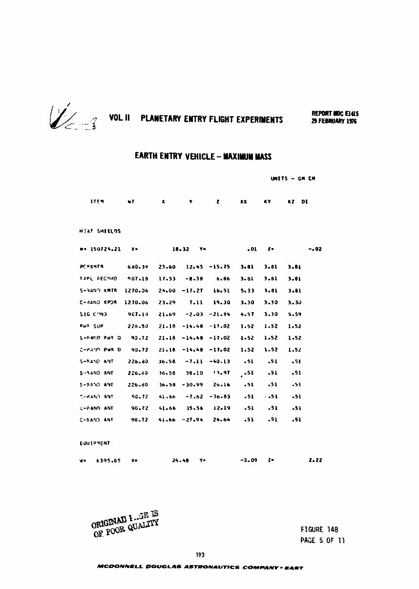
VOL II PLANETARY EWTRY FLIGHT EXPERIYENTS
EARTH ENTRY VEHICLE - NAXlYllN W S S
WITS - cw cn
X Y 2 UX uv uz 01
p C v x r r s
T S P i SECClitD
S-9AtJr) XMTR
C - 3 ~ ~ 3 I P 3 R
SIG C O Y 3
ow0 SUP
S-R6?!f? P i t 3 9
c-r.iprn PUS o
j -PA%D ANT
S - - 9 P N 3 ANT
S - 3 a - a A Y T
?-aAh? 457
il-ebrhn ANT
' , -6A.O ANT
FIGURE 148 PACE 5 OF 11
193
MCDONNELL DOUGLAS ASTRONAUTICS COMPANV mAmr
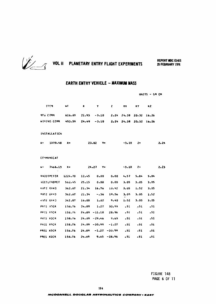
- *DL II PLANETARY ENTRY FLIGHT E X P E R I I B T S c Li'
REPORT llfC El415 29 FEBRUARY 1976
EARTH ENTRY VEHICLE - MAXIMUM MASS
Q401rJME TER
l C C E L F 3 O Y E T
R B T E G Y R O
Q a f E G Y Q O
d?TE G V R 3
PR'S XOCR
DFFS X 9 C 4
PAFS X D C R
P R E S XQCR
PRES XOCR
PRES XDCR
FIGURE 148 PAGE 6 OF 11
194
MCbONNPLL DOUGLAS ASTRONAUTICS COMPANV - E I l T
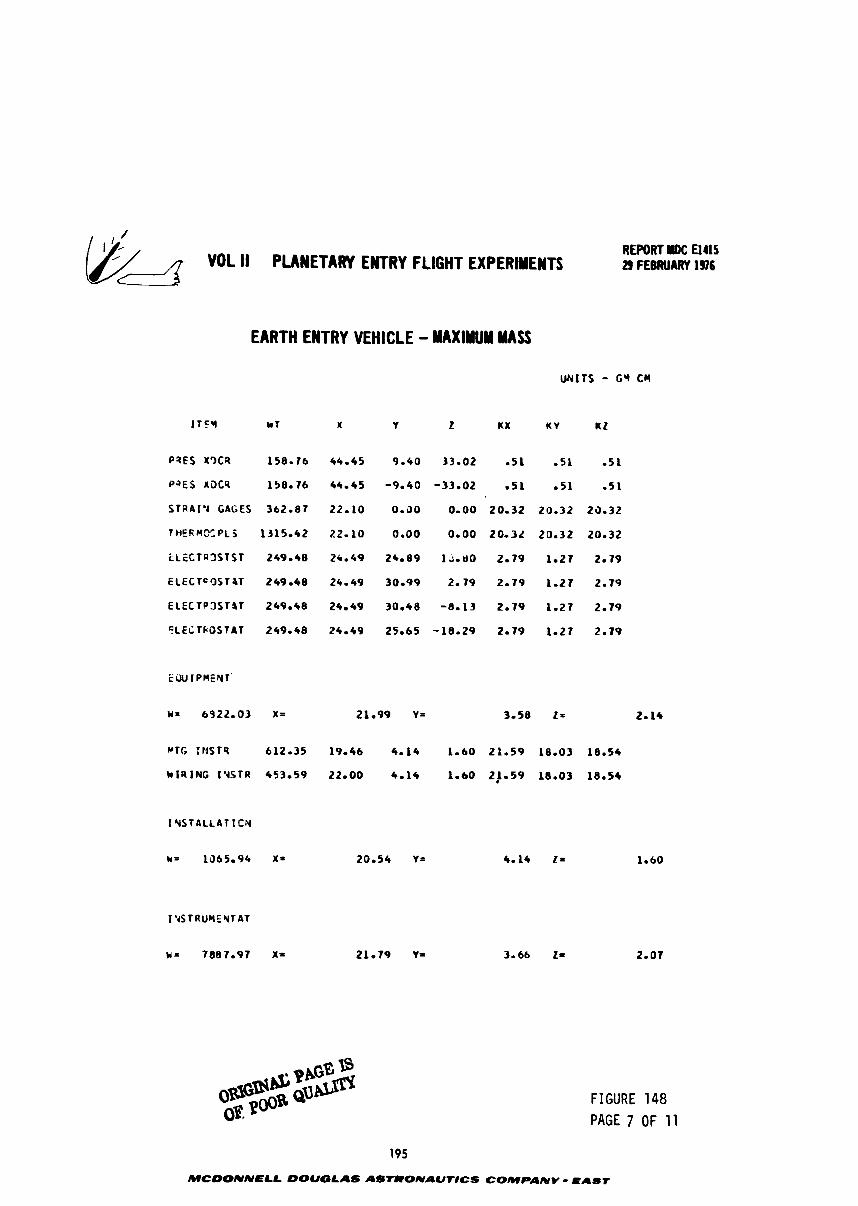
REPORT I)C El415 29 FEBRUARY 196
EARTH ENTRY VEHICLE - MAXIMUM MASS
UNITS - 6'4 CU
SfaAI '4 GAGES 362.87 22.10 0 - 3 0 0 -00 20.32 20.32 23.32
fHEf iMOCPLZ 1315.42 22 -10 0 - 0 0 0.00 20 -32 20 -32 20.32
E L E C T R 3 S T S T 249.48 26-49 21.89 1A-80 2.79 1 -27 2.79
ECECTc'3ST4T 249.48 24.49 30-99 2 - 7 9 2 - 7 9 1 -27 2.79
E L E C T P 3 S l l T 249.48 24.49 30.48 -8.13 2 - 1 9 1.21 2 -19
f L E i T P O S T A T 249.48 24.49 25.65 -18.29 2 -79 1 -27 2.19
WTG IP ISTQ 612.35 19-46 4 - 1 4 1 - 6 0 21.59 18.03 18.54
kiRING I Y S T R 453.59 22-00 4.14 1 - 6 0 2 J - 5 9 18.03 18.54
I YST 4 L L A T I C N
k= 1365.94 X * 20.54 Y= 4-14 21 1.60
FIGURE 148 PAGE 7 OF 11
195
MCOONNELL DOUGLAS ASrRONAUr#CS COMPANY - Easr
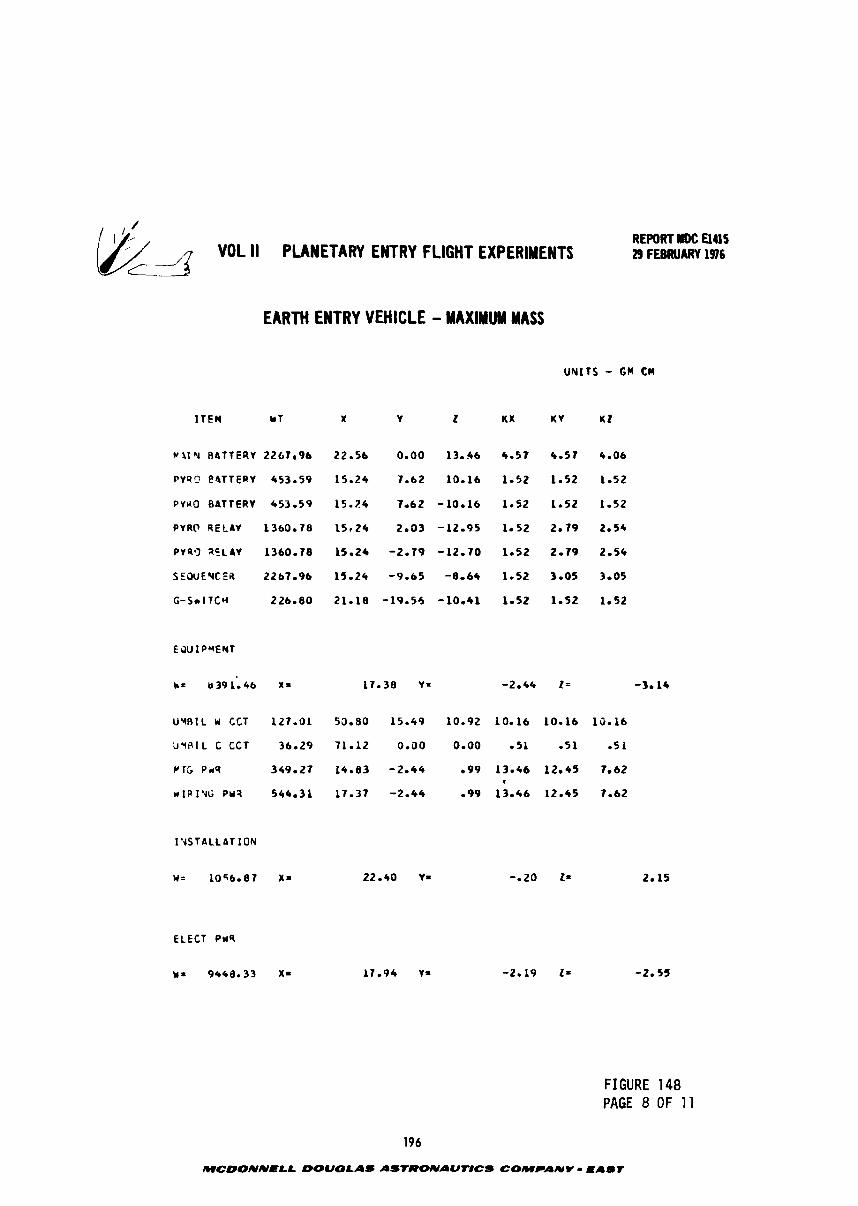
REPORT mc UUS VOL I I PLANETAFW ENTRY FLIGHT EXPERIMENTS 29 FEBRUARY 196
c
EARTH ENTRY VEHICLE - MAXIMUM MASS
I T E M * T
C a I Y R I T T ERV 2267r96
P V q Q 8 4 T T E R Y 453.59
P Y n o B ~ T T E R Y 453.59
PYRO RELAY 1360.78
P V ~ ~ ~ ~ L A V 1360.78
S E W E Y C E B 2267.96
G-Sn I TCW 226.80
UvRlL U CCT 127.01 50.80 15.49 10.92 10.16 10.16 16-16
I Y S T A L L A T ION
ELECT PwQ
FIGURE 148 PAGE 8 OF 11
196
MCOONNELL DOUGLAS ASIRONAUT'DCS COMPANY - EAbT
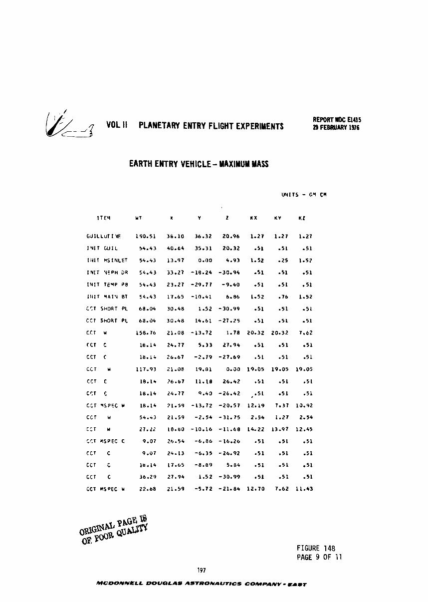
VOL I I PLANETARY ENTRY FLIGHT EXPERIMENTS REPORT ldOC U415 29 FEElRUARY 1976
EARTH ENTRY VEHICLE - MAXIMUM MASS
G J I L L U T I Y E
I N I T G U I L
I :d l T k S 1 NCET
I N l i V E P H 04
I t J I T T E Y P P8
I r r I T r 4 1 v BT
i C , T SHORT PL
it1 ShORT P L
CCT w
TCT c
CCT C
c c r r
C C T C
CC.T C
C i T *SPEC w
C C T w
CCT Y
t T T YSPEC C
CCT C
C C l C
C C T c
CCT MSPEC U
190.51
54.43
54.43
54.43
54.43
54.43
68.04
68.04
158.76
18.14
10.14
117.93
18.14
18.14
18.14
54.43
27.22
9.07
9.07
la. 1%
36.29
22.68
FIGURE 148 PAGE 9 OF 11
MCDOWNELL DOUGLAS ASrHONAUr#CS COMPANY - ea-T
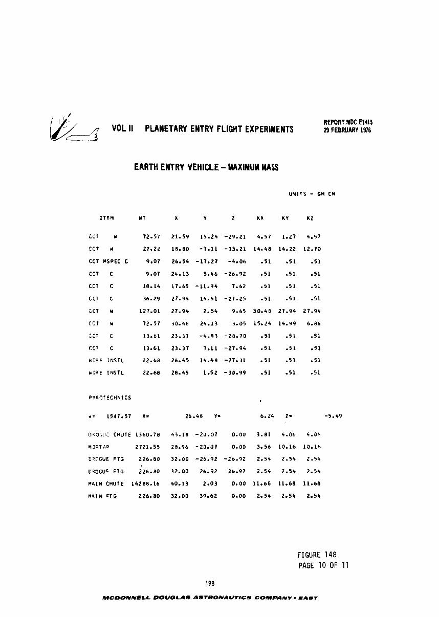
; f - VOL II PUYETARY ENTRY FLIGHT EXPERIMENTS REPORT MDC €1415 29 FEBRUARY 1976
c-
EARTH ENTRY VEHICLE - MAXIMUM MASS
UNITS - GM CM
i C T U
C C f I)
CCT MSPEC C
CCT c
CCT c
CCT C
CCT W
C C T u
,r,l c
tr,r c
W I Q E INSTL
r ~ Q . E IYSTL
OzOGif: CHUTE 1360.78 4 7 . 1 8 - 2 3 . 0 7 0 .00 3 .81 4.06 4.Oh
CI3ETLP 2721.55 28 .96 -20 .07 0 .00 3 .56 10 .16 10.16
CqFGUE F I G 226 .80 3 2 . 9 0 -26 .92 - 2 6 . 9 2 2.54 2 - 5 4 2.54
CQ3GUC F T G 226.80 3 2 . 0 0 26.92 26.92 2 .54 2 . 5 4 2 . 5 4
MaIN CHUTE 14288 .16 40.13 2 . 0 3 0 . 0 0 1 1 . 6 8 11.68 11 .68
M4IN F T G 226.80 32 .00 39.62 0 .00 2 .54 2 .54 2.54
FIGURE 148 PAGE 10 OF 11
MCDONNELL DOUGLAS ASTRONAUTlCS COMPANY EAST
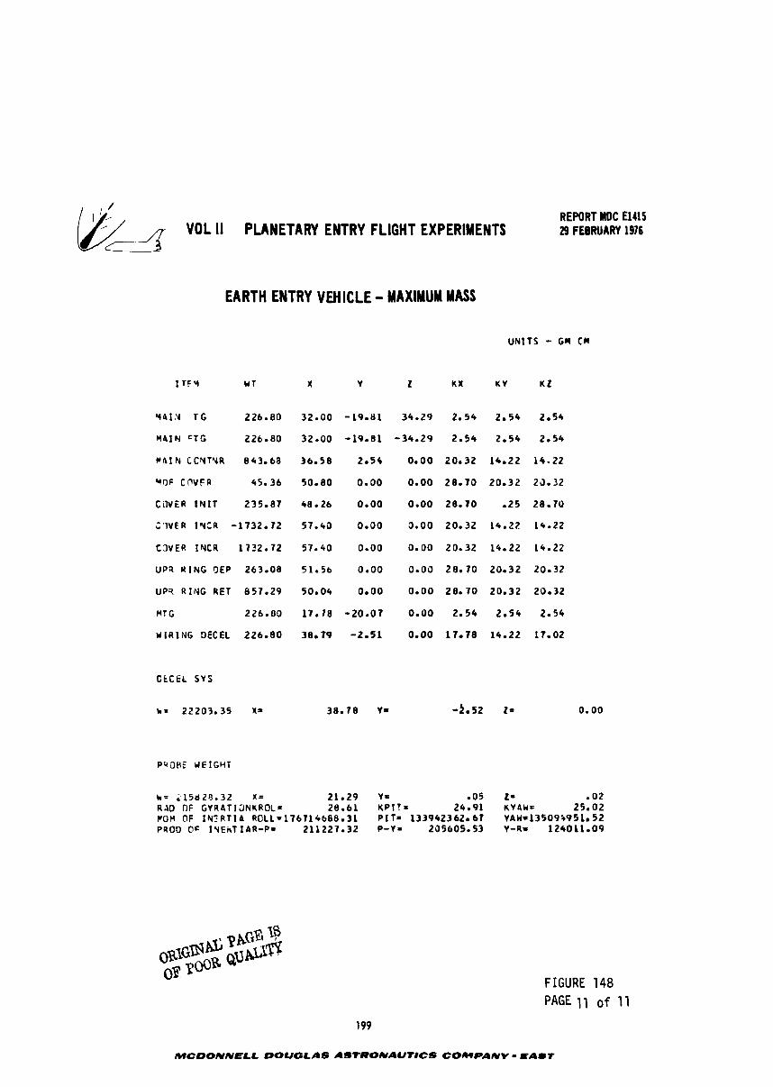
& q- VOL II PLANETARY ENTRY FLIGHT EXPERIMENTS REPORT MDC El415 29 FEBRUARY 1976
EARTH ENTRY VMICLE - MAXIMUM MASS
Y114 TG 226.80
M41 N CTG 226.80
WAIN CCYTYR 843.68
UOF COVFR 45.36
COVER i N I T 235.87
C'IVER 1WtR -1732.72
C3VER IYCR 17Z2.72
UP9 WING OEP 263.08
UP9 RING RET 857.29
HTG 226.00
W I R I N G DECEL 226.80
CLCEL SYS
PqOHE HEIGHT
h= 215620.32 X = 21.29 YE 005 t s .02 R A D n~ G V R A T I ~ N K R O L = 26.61 KPIT= 2 4 - 9 1 KYAW= 25.02 POM OF I N l R T I A ROLL=176714688.3A PIT- 133942362.67 YAW=13509195l. 5 2 PROD 0 s IYEkT IAR-PI 211227.32 P-Y- 205605.53 Y-R- 124011.09
FIGURE 148 PAGE 11 of 11
MCDONNELL DOUQLAS ASTRONAUTICS COWPAMY EAST
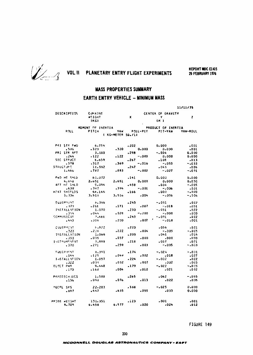
REPORT HDC El415
-
VOL II PLANETARY ENTRY FLIGHT EXPERIMENTS 29 FEBRUARY 196
MASS PROPERTIES SUMMARY
EARTH ENTRY VEHICLE - MINIMUM MASS
D E S C R I P T IC1Ii C U P R EtdT *C I G H T
1KGJ
C E N T E R OF G R A V I T Y X Y 2
tn b
~ O ~ E N T n~ INERTIA PRODUCT OF I N E R T I A R n L L P I T C H YAW R O L L - P I T P I T - Y A Y YAW-ROLL
I KG-METER SO./lJ
P R I S T 3 FWD 596
PRI S T R 4 6 1 .244
SCC S T Q U C T - 5 7 8
STRUCTiJR? 1.466
F U D H T SHLL) 4 .698
A F T rir SHLD - 6 3 8 '
H F 4 T SHIELDS 5.336
E C U l p ' A . u T b. 396 2 4 5 -. 03 1 0 0 2 2 . 319 - 2 6 1 - 1 7 1 - 0 0 7 -a018 - 0 5 1 I N S T 4 L L Z T ION 1 . 3 7 0 .230 - .031 .022
, 3 5 4 . a44 O2R - 0 0 0 0 - .000 0 0 3 0 C.C*MlJtd I C 4T 7.466 - 2 4 3 0 3 1 .O22
.4G3 . ) O h - 2 0 0 - 0 0 7 ' -a018 ,001
CQUIPVEYT . 3 2 5
I rJSlALLAT I O N . J53 I * t S T F U M ' Y T LT
- 3 7 0
W t F L S Y S 22.203 . 3 & 8 -.025 0 .OOO - 6 9 7 . 4 4 7 i 6 3 5 055 .033 0.000
FIGURE 149
200
MCDONNELL DOUGLAS ASTRONAU'lrlCS COMPANY - EAeT
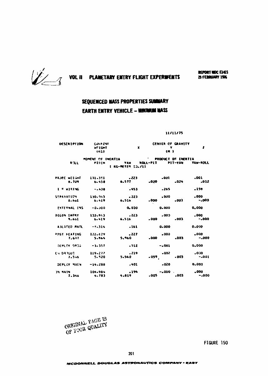
SEQUEWED UASS PROPERTIES m R Y
EARTH WTRY YEHICLL - YIIIlYUY WSS
raORElrl r?F 1ZFRTlA PROOUT OF E~ERTIA a=L P l T C H *AM IIDLL-PIT P1T-TAM YAW-ROLL
1 KG-WTE- $3-118
FIGURE 150
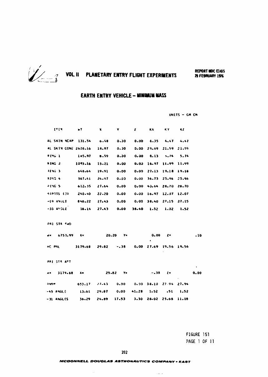
VOL ll PLANETARY ENTRY FLIGHT EXPERINENTS -- REPORT Elas 29 rreaUARY 19%
EARTH EWTRY VEHICLE - YlNIWY MASS
d = 6753.99 XI 20.20 Y= 0.00 I = . HC PNL 3179.68 29-82 3 6 0 -00 27-69 19-56 19.56
awl* 6 5 3 r l 7 7 - 4 3 0.00 0.30 38.10 2 7 . 9 + 27-94
-45 ANGLE 13.61 29.87 0.00 41.28 1-52 - 5 1 1.52
-31 ANGLES 36.29 24-09 17-53 3.30 28-02 25.68 11.18
FIGURE 151 PAGE 1 OF 11
202
MCDONNELL DOUGLAS ASTCIONAUTICS COMPANY - EAST
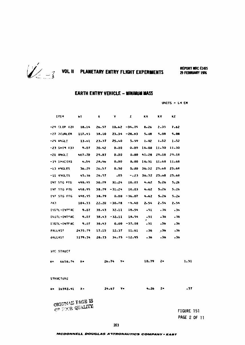
VOL II PUWETARY EWTRY FLIGHT EXPERIMENTS
EARTH EKTRY VEHICLE - YlWiYUY MASS
-29 Cl l P I21 18-11
-27 3CiJRLER 117-93
-25 AF;;lF 13.61
-23 S n t ~ I31 9.07
-21 ANGLE 467 20
-15 SPACEAS 4-54
-13 AYGLES 36.29
-11 A'UCLES 45- 36
tYT STC FTG 496.95
1%; 516 FTC 498.95
IYT STG FTC 498.95
Z S J 104-33
1 r i j TL -1 %TEN 9-07
ItaSTL-IYTGAC 9.07
I:iSlL-IYTFIC 9.i17
C ~ L L ~ S ~ t*st 79
a4LLAST 1179.36
STRUCTURE
FIGURE 151 PAGE 2 OF 11
MCWNNELL DOUGLAS LIf TRONAUTlCS COMPANY - I I U T
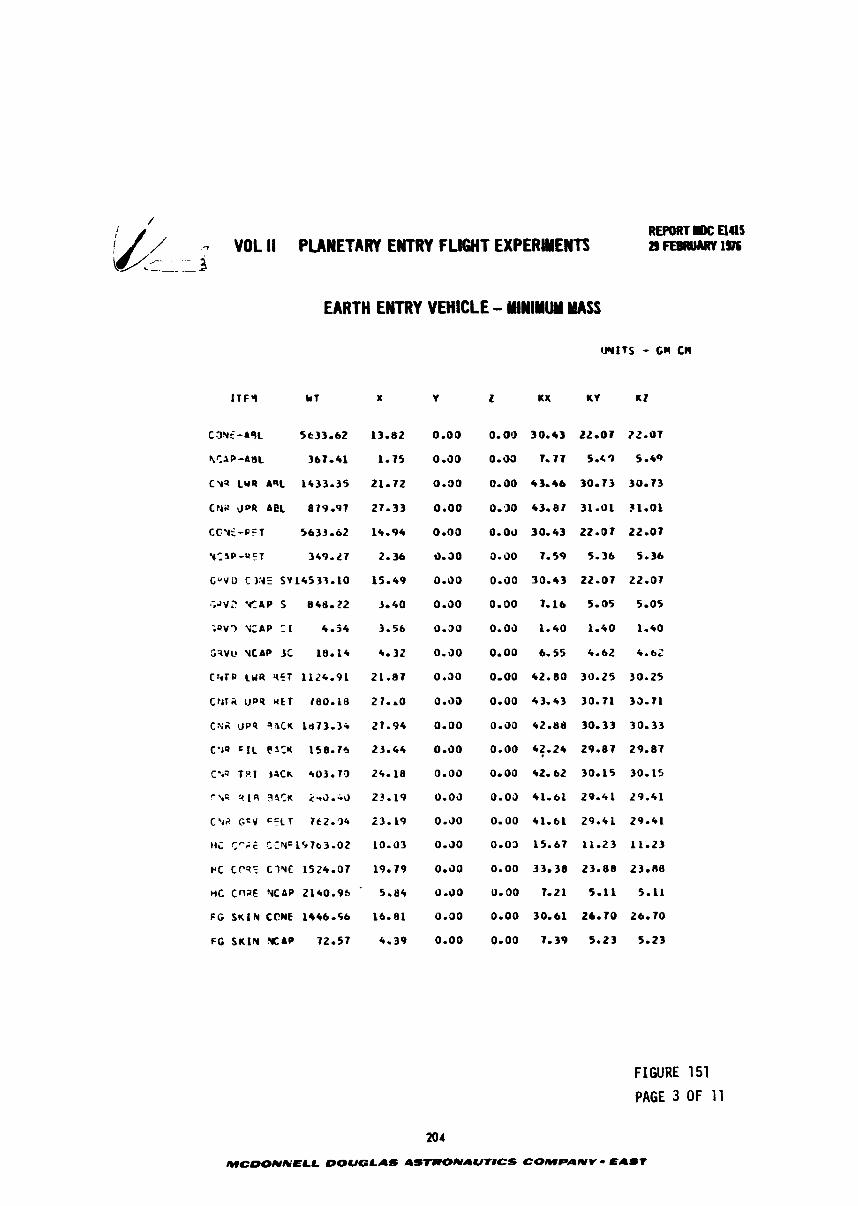
/ REPORT= Elas
// / WIL II PUYETID* ENTRY FLl6HT EXPERYEHTI 2) FEBRUARY SOL w ---_ --- - - - .- B
Cmi-A%L st33 - 6 2
RCAP-AgL 367-41
C Y S LUS AqL 1433.35
CNS $OR ACL 879.97
CtVf-FcT 5633-62
y:%P-uFT 349.27
G U V D C 11' SY 14533.10
?V2 W A P 5 MCB.72
;SV? .<CAP T I 4.54
S?VQ VCAP 3C 18.14
C 4 T R C U R 9 E T 1124.91
crrrii I J P ~ U L T t e 0 . 1 ~
C Y A UPP ?ICU l d 7 3 . 3 i
C'IQ ' I L @ i Z K 158.75
C.43 T9. l jack 403.T')
r \ G 2 1 9 3 3 ' ~ 293.-3
C.42 G c V ' = L T 7t2.34
ti; tPii CLNc197b3.02
r c ccs: c ~ u t 1524.07
tic cnaE YCAP 2140.9s '
FG SUI N CCNE 1446.56
FG SKIN X A P 72.57
FIGURE 151
PAGE 3 OF 11
204
MCDOUIC'ELL OOUGLAS 4S7UONAUTICS COMPANV - PAST
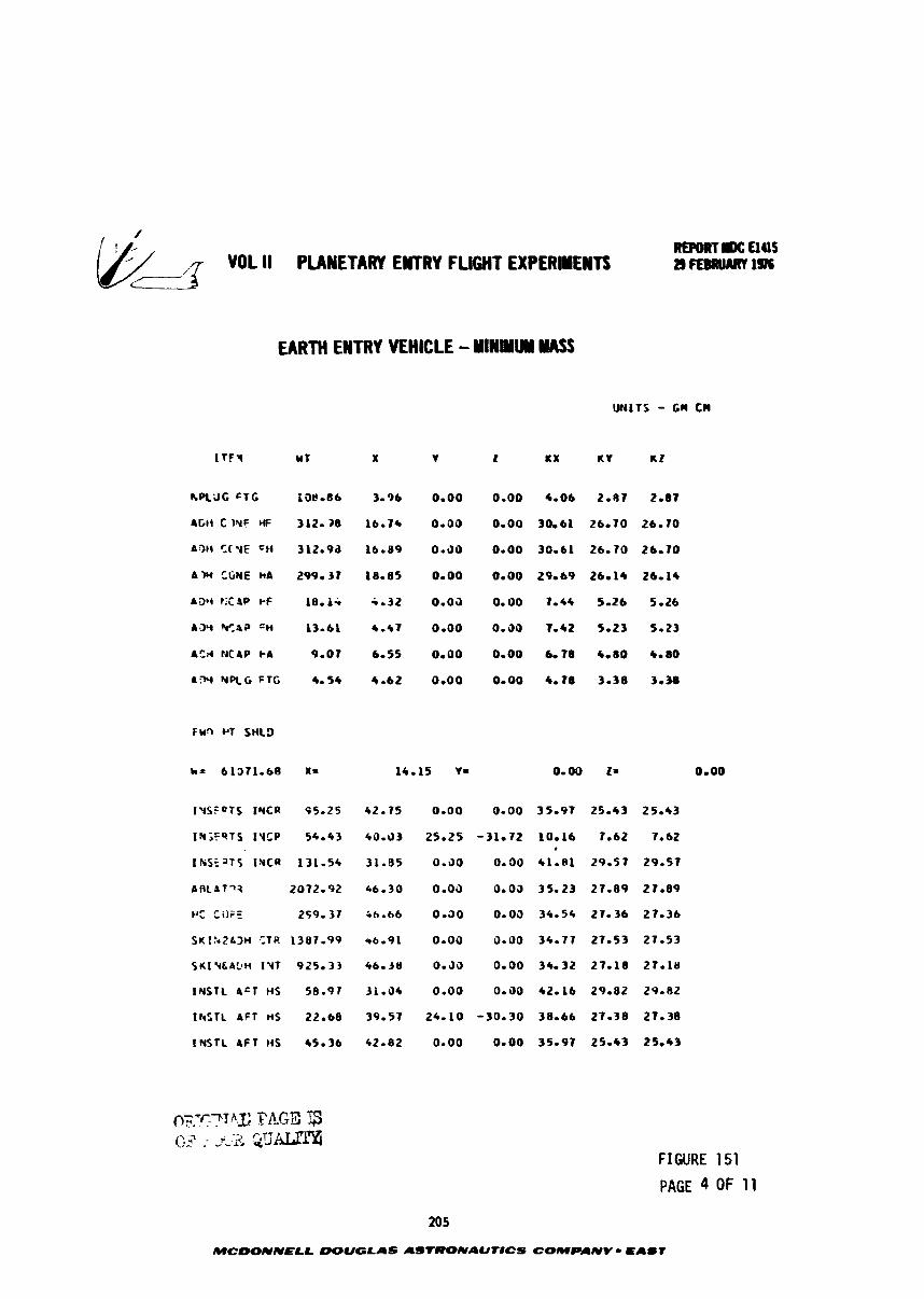
, VOL II PUWETARY EllTRl FLIGHT EXPERIEYTS 7-
REPOUTIK: aas 2¶ EmuMY 1974
hPL3G CTC
AGl i C )YF HF
A318 C I Y E CH
A M *rWE h A
a 3 1 r i t !IP I-F
A.JY Y,4P =H
A Z ; ~ ticap PA
a- NRG FTG
Fbi2 PT S H L D
I Y S F Q T S I Y C R 95-25
I N i F S T S I Y C P 5 4 - 4 3
I k S E a T S I N C R 131.54
A R L b T q 3 2072- 92
PC C i l F E 2S9.37
5Klh2LJH ,:Ti? 1387.99
S I C I V G ~ ~ H IYT 925.33
I N S T L A C T H S 58.97
IWTL AFT ns 22-68
I NSTL A F T H S 45.36
FIGURE 151
PAGE 4 OF 1 1
205
MCDONNELL DOUGLAS ASTMNAUT#CS COMPANV - ELLIT
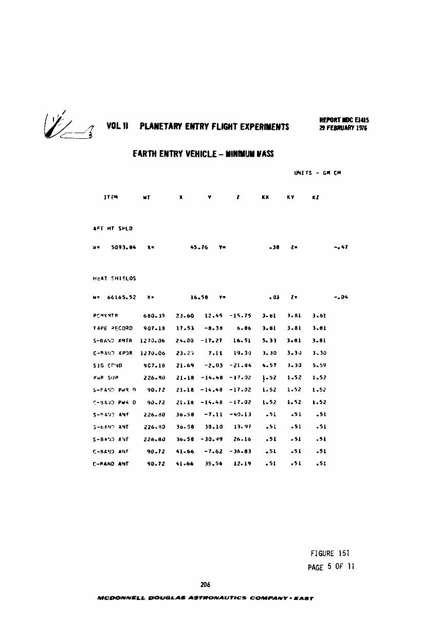
, "DL I1 PLANETARY EMTRY FLIGHT EXPERIMENTS
M t A T SHIELDS
PCVXqTR 680.37
TAPE 2ECOaD 907.13
S-BAh2 XqfR 1275-06
C-afrl7 XPfJR l l l r ) .C6
S I C CfYO PC70 18
PkP St)? 226.90
S-F-O'i? Pd5 0 90.72
7-3&43 Prlli 0 93-12
5-"'13 AVf 226.80
S-bt.M? PYT 226.90
S-8a73 A Y f 226.83
C-RLLl3 ANT 90.72
C-RAN0 hYT 90.72
FIGURE 151
PAGE 5 OF 11
206
MCDONNELL DOUGLAS AStRONAUNCS COMPANV KAur
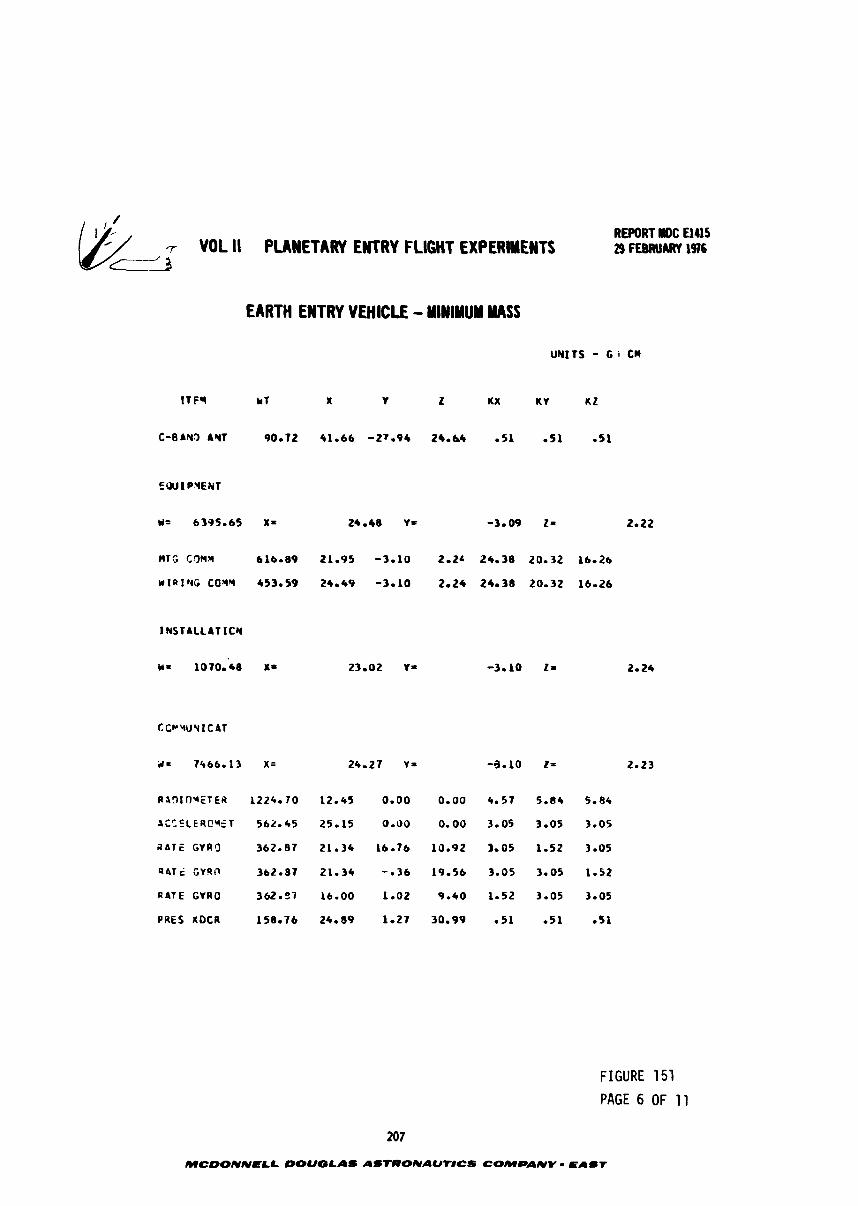
7 VOL !I PLANETARY ENTRY FLIGHT EXPLRMEYTS cc-z3
REPORT rOC UUS 29 FEBRUARY 1916
UNITS - G i CII
t ~ ~ r * T x Y z t x K Y az
C-BAYS AYT 90.72 41.66 -27.94 26-64 - 5 1 0 5 1 051
1 NSTALLAT ICY
R l ! l l O q E T E R 1224.70 12.45 0.00 0.00 4.57 5.84 5-84
SCCFLERC*ET 562-45 25*15 0 - 0 0 0.00 3.05 3.05 3.05
A A T E GYRQ 362.87 21.34 1 6 iS .92 3.05 1-52 3-05
R A T c CVRir 362-87 21.34 -036 19.56 3.05 3.05 1.52
R A T E GYRO 362.37 16-00 1 -02 9 - 4 0 1-52 3.05 3.05
PRES XOCR 158.76 24.89 1.27 30-99 0 5 1 051 - 5 1
FIGURE 151
PAGE 6 OF 11
207
MCDONNELL DOUGLAS AStRONAUNCS COMPANY L A I T
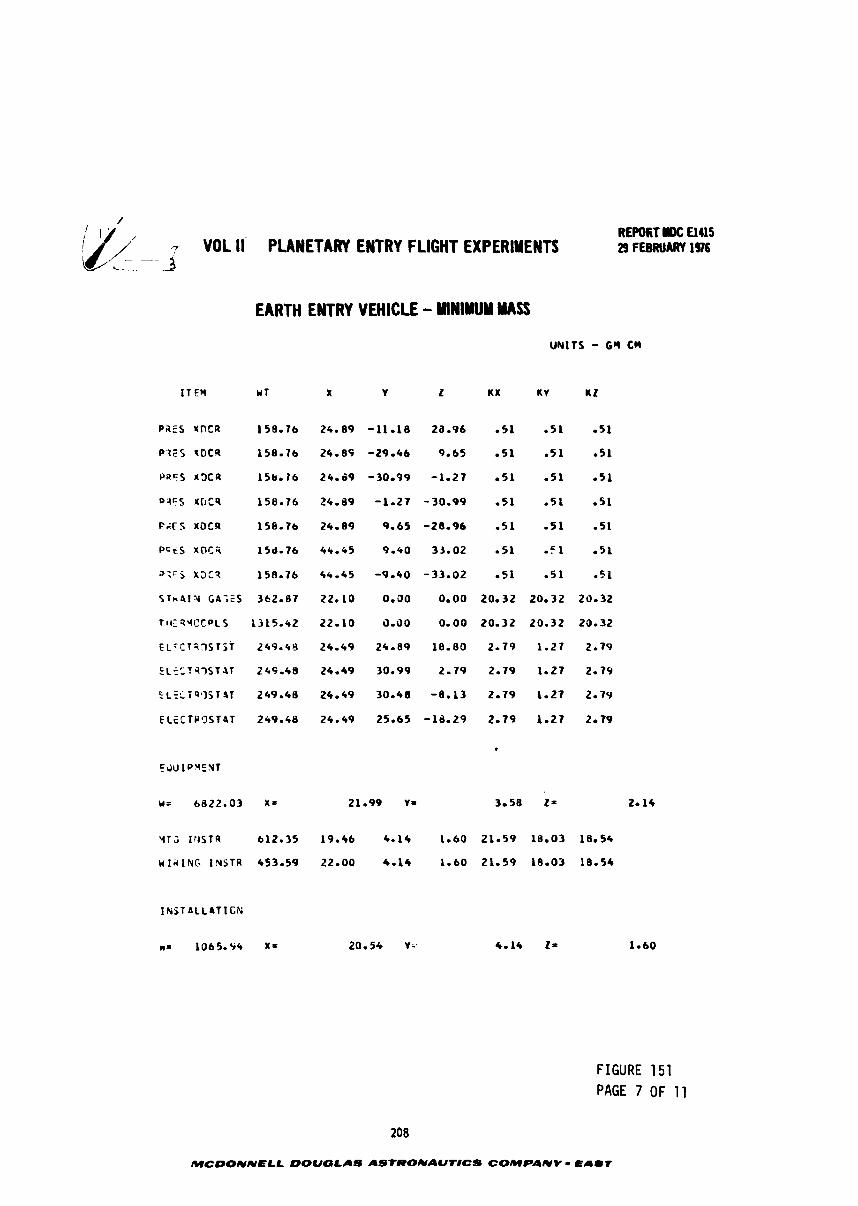
// VOL II PLANETARY ENTRY FLIGHT EXPERIMENTS './ L-z-1- 3
REPORT IW: Elus 29 FEBRUARY 1976
EARTH ENTRY VEHICLE - MINIMUM MASS
PafS NDCR
P 1 F S t G C R
PRES r(t)CR
P4FS X O C 9
P g F S lOCR
P G t S X C l I i i
u;irS X3t9
S T h 4 1 % GA;ES
TI(.: R4OCPLS
E L ~ C T ? D S T ~ T
E L f C T q 7 S T A f
5 L c L i Q 7 S T % T
ELcCTP'JST4T
FIGURE 151 PAGE 7 OF 11
208
MCDONNELL DOUGLAS ASTRONAUT#CS COIHOAUY - EAUT
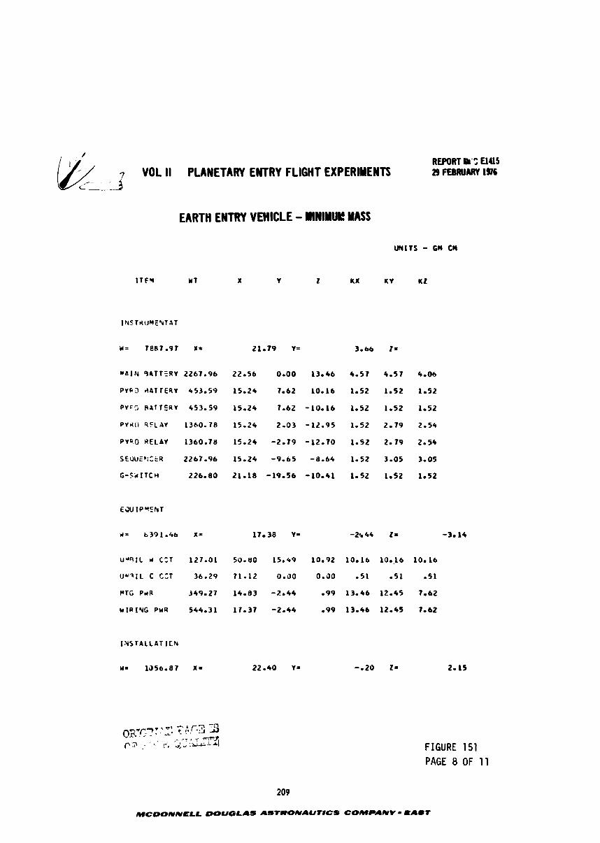
3 VOL II PLANETARY ENTRY FLIGHT EXPERIMENTS - _ - - .
EARTH ENTRY VEHICLE - WINIYUI! WSS
I N S T A L L A T ICN
FIGURE 151 PAGE 8 OF 11
209
MCDONNPLL DOUGLAS ASTRONAUT8CS COMPANV * E A m T
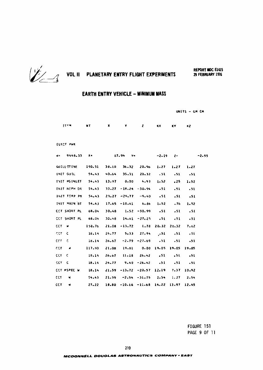
- VOL II PLANETARY ENTRY FLIGHT EXPERIMENTS REPORT llDC El415 29 FEBRUARY 1976
EARTH ENTRY VEHICLE - MINIMUM MASS
U N I T S - GN CN
ELFCT PYR
WILL OT I Y E
1NIT GrJlL
I Y I T WSIYLEl
l h I T NEPH Oi l
I l + I T T5NP PR
I U I T * P I N 'BT
CCT S t O R T PL
t C T S t i 3 R T PL
CCT Y
C CT c
C t T t
t C T U
CCT C
CCT C
CCT M S P E C Y
CCT Y
C C T w
FIGURE 151 PAGE 9 OF 11
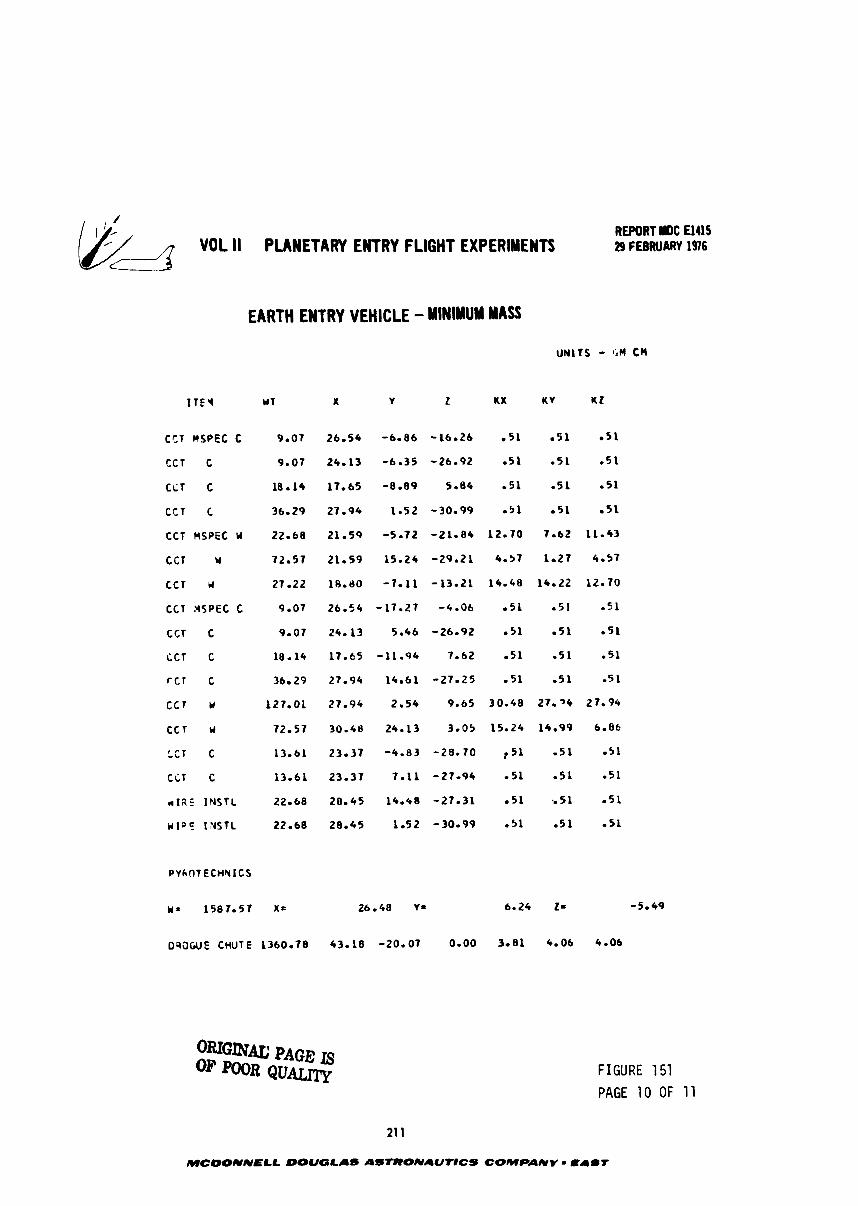
Wd- VOL II PLANETARY ENTRY FLIGHT EXPERIMENTS REPORT WOC El415 29 FEBRUARY 1976
EARTH ENTRY VEHICLE - MINIMUM MASS
UNITS - GM CM
C C T M S P f C C 9.07 26.54
tCT C 9.07 24.13
CiT C 18.14 17.65
CCT C 36.29 27.94
CCT nsPEc u 22.68 21.59
CCT r 72.57 21.59
CCT Ld 27.22 18-60
CCT MSPEC C 9.07 26.54
CCT C 9.07 24.13
CCT C 18.14 17.65
r c r c 36-29 27-94
C C f Y 127.01 27.94
C C T U 72 -51 30.48
I C - c T C 13.61 23.37
t i T C 13.61 23.37
~ 1 4 5 INSTL 22.68 28.45
W l o E INSTC 22.68 28.45
D?3GUE CHUTE 1360.78 43.18 -20.07 0.00 3.81 4-06 4.06
OmGmU PAGE IS OF Q U A W FIGURE 151
PAGE 10 OF 11
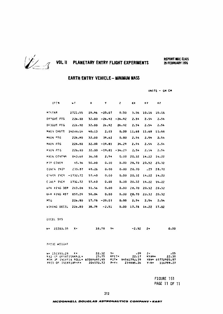
3 YDL II PLANETARY ENTRY FLIGHT EXPERIMENTS i
REPORT r D C El415 29 FEBRUARY 1976
EARTH ENTRY VEHICLE - MINIMUM MASS
Y T T h R 2721.55
DQ?G'.fE F T G 226.80
OgJGUE F T G 226.90
MAl.4 CHUTE 142dM. lb
M 4 I N =TG 226.80
MAI?d F T G 226.80
V l I Y F f G 226.80
P A 1 h CPPlTIY9 8 4 3 . 6 8
MG- C O V E 9 45.36
C O V F ~ I Y ~ T 235.~7
C n V E R I * l C 9 -1732.72
C ' l V t o I N C A 1732.72
UPR alvG SEP 263.08
IJkR R I Y G R E T 857.29
MT G 226.80
UlRING O E C E L 226.80
DECEL S Y S
FIGURE 151 PAGE 11 OF 11
212
MCDONNPLL DOUGLAS ASTRONAUTlCS COMPANY - EAST
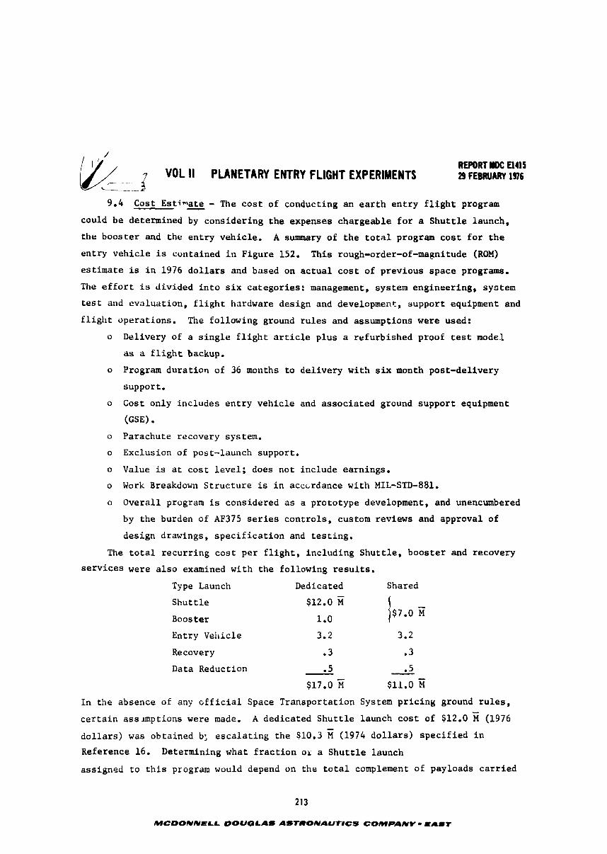
; VoL 11 PLANETARY ENTRY FLIGHT EXPERIMENTS REWRT rDC El415 29 FEBRUARY 1976
C---.
9 .4 Cost Estimate - - The c o s t of conducting an e a r t h e n t r y f l i g h t program
could be determined by cons ide r ing t h e expenses chargeable f o r a S h u t t l e launch,
t h e boos te r and t h e e n t r y vehic le . A summary of t h e t o t a l program c o s t f o r t h e
e n t r y v e h i c l e is conta ined i n Figure 152. This rough-order-of -magnitude (ROM)
es t ima te is i n 1976 d o l l a r s and based on a c t u a l c o s t of previous space programs.
The e f f o r t is d iv ided i n t o s i x ca tegor ies : management, system engineer ing, s y r t e n
t e s t and eva lua t ion , f l i g h t hardware des ign and development, suppor t equipment and
f l i g h t opera t ions . The fol lowing ground r u l e s and assumptions were used:
o Delivery of a s i n g l e f l i g h t a r t i c l e p l u s a re fu rb i shed proof t e s t model
as a f l i g h t backup.
o Program d u r a t i o n of 36 months t o d e l i v e r y w i t h s i x month post -del ivery
suppor t . o Cost only inc ludes e n t r y v e h i c l e and a s s o c i a t e d ground suppor t equipment
(GSE)
o Parachute recovery system.
o Exclusion of post-launch support .
o Value is a t c o s t l e v e l ; does not inc lude earnings .
o Work Breakdown S t r u c t u r e is i n acccrdance wi th MIL-STD-881.
o Overa l l program is considered a s a p ro to type development, and unencumbered
by t h e burden of AF375 s e r i e s c o n t r o l s , custom reviews and approval of
des ign drawings, s p e c i f i c a t i o n and t e s t i n g .
The t o t a l r e c u r r i n g c o s t p e r f l i g h t , inc lud ing S h u t t l e , b o o s t e r and recovery
s e r v i c e s were a l s o examined wi th t h e fo l lowing r e s u l t s .
Type Launch Dedicated Shared
S h u t t l e
Booster
Entry Vehicle 3.2 3.2
Recovery .3 . 3
Data Reduction .5 - .5 - $17.0 % $11.0 z
I n the absence of any o f f i c i a l Space Transpor ta t ion System p r i c i n g ground r u l e s ,
c e r t a i n ass lmpt ions were made. A dedicated S h u t t l e launch c o s t of $12.0 (1976
d o l l a r s ) was obta ined b; e s c a l a t i n g t h e $10.3 M (1974 d o l l a r s ) s p e c i f i e d i n
Reference 16. Determining what f r a c t i o n ox a S h u t t l e launch
ass igned t o t h i s program would depend on t h e t o t a l complement of payloads c a r r i e d
MCDONNELL OOUQLAS AS'IRONAUr8CS COMPANY - E A I T
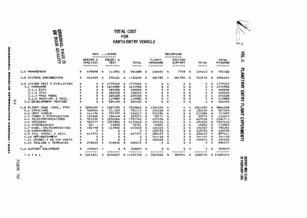
1.0 MANAGEMENT
2.0 SYSTEMS ENGINEERING
3.0 SYSTEM TEST 8 EVALUAT ION 3.1 HARDWARE
3.1.1 ESTU 3.1.2 STVO 3.1.3 MASS MODEL 3.1.4 MOCK-UPS 8 MISC.
21 P
3.2 DEVELOPMENT T E S T I N G
4.0 F L I G H T HDdE ( I N C L . PTM) 4.1 STRIJCTURE 4.2 HEAT S H I E L D 4.3 POWER 8 D I S T R l d U T I O N 4.4 TELECOMMUNICATIONS Q.5 RECOVERY 4.6 PYROTECHNICS 4.7 ENGR. INSTRUMENTATION 4 -8 EXPERIMENTS 4.9 SYS. INTGR. 8 ASSI . 4 1 0 REFURBISHMENT 0.11 SPARES 8 REJJ41R PARTS 4.12 TOOLING 8 TEMPLATES
0
5.0 SUPPORT EQUIPMENT
T O T A L
TOTAL COST FOR
EARTH ENTRY VEHICLE
N O W ,- IJ~RING RECURRING ------------- --------- OESIGN 8 EQUIP. 8 F L I G H T M I S S I O N ANALYSIS TEST TOTAL HAROWARE SUPPORT -------- -------- ----- -------- -..----- TOTAL -----
144213
763570
0 0 n 0 0 0 0
2500692 136230 231594
93771 427036 193452 45852
126303 128755 280237 lU4UlP. 488055
0
0 ------- 5208476
TOTAL PRDGRAM -------
% 735302
s i95645n
% 1779315 % 1274890 B 483590 % 450203 B 225108 % 115989 % 504U25
% 9864508 % 927345 % 747407 % 418Ok5 S 21827'6 % 2327120 % 115943 1 790351 % 128735 % 897611 % 14U:lR 1 489065 P 696272
1 349649 ------- % 14685224
a l o f t and what satellites w e r e retr ieved from space. The length of the payload is
important i n deterr iPing how u c h roor is available f o r shared payloads, If
e i the r Transtage/TE363-4 o r the 2 s tage SBLI XUS/TE364-4 booster were used iess than
318 of the bay vould be used a ~ d i f the "short lengthn booster vere used only 1/7
would be occupied. For shared payload launches, a l inea r relat ionship of cos t with
payload length vss assumed, This r e f l e c t s the resu l t s f roa past examination of
avai lable t r a f f i c d e l s d i c h indicated tha t less than 50% of the Shut t le f l i g h t s
w e r e mass l i a i t e d whereas almost 90% of the f l i g h t s w e r e length l i a i t ed . The
booster cost of $1.0 fi is the current f igure being quoted fo r the so l id IUS i n the
open l i te ra ture . Costs of the other boosters rns idered range fraa $3 t o over
$6 n. The shared launch cos t of $7.0 fo r Shutt le and booster r e f l e c t s e i t h e r a
so l id IUS with 50% payload sharing o r a shor t length booster tha t occupies 1/7 of
the payload bay length,
REPORT IDC a115 - VOL II PUWETARV ENTRY FLIGHT EXPERIMENTS B F ~ B R U A R Y ~ ~ ~ L
10. CONCLUSIONS
The major conclusion of t h i s study is t h a t t h e Shu t t l e and its upper s t age
can provide high speed e a r t h en t ry s imulat ion of ou t e r p lane t environments on a
probe shape vehicle. F u r t h e m r e , candidate hea t sh i e ld concepts can be qua l i f i ed
as w e l l a s i n t ense env i romen t s measured t o expand s c i e n t i f i c knowledge of en t ry
physics. Even though the en t ry environments of r a d i a t i v e heating, convective heat-
ing, dece le ra t ion loads and sur face pressures are severe, design provis ions enable
a i r recovery s o t h a t post f l i g h t examination can be made,
From the ass imi la t jons and ana lys i s of en t ry t r a j e c t o r i e s and env i ro~ l l~en t s
ca lcu la t ions f o r en t ry i n t o t he ou t e r p lane ts several conclusions can be drawn.
An ou te r p lane t probe m e s t withstand a rad ian t d d n a n t en t ry hea t pulse t h a t is
s e n s i t i v e t o the en t ry path angle, veh ic le b a l l i s t i c c o e f f i c i e n t and the a m s p h e r i c
composition. Jovian en t ry environments were t h e most severe condi t ions and used
more extensivelv t o design the e a r t h en t ry vehicle. Radiative hea t ing is about
th ree times grea t e r than convective, Un te r t a in t i e s i n Jovian en t ry angle (three
degree spread) r e s u l t s i n a 582 increase i n r a d i a t i v e heating, a 19% increase i n
convective heat ing and a 102 increase i n shock pressure. Adequate descr ip t ion of
shock temperature, remperature d i s t r i b u t i o n across t h e shock layer , and spec ies con-
cen t ra t ion a r e important i n determibing r a d i a t i v e heati1.g. Radiative hea t ing is
composed of approximately ha l f continuum a&G half l i n e radiat ion. Knowledge of
the temperature d i s t r i b u t i o n across the shock l aye r is important t o computing radia-
t i v e heating. Both carbonaceous and hyperpure s i l i c a hea t s h i e l d s were analyzed f o r
Jovian entry. In jec t ion of ab l a t i on matei-ial i n t o t he shock f u r t h e r reduced radia-
t i v e heat ing t o t he wal l with carbon having t h e g r e a t z s t reduction (46X), silica
about 182. However, due t o silica's exce l l en t ref lectance, i t had t o accor~modate 2 f a r l e s s heat , only 1.7 kwlcm a s compared t o 9.1 k w / d f o r carbon. Test ing of
hyperpure and carbonaceous mater ia l s under simulated Jovian environments should
be performed t o subs t an t i a t e these finds.
I t was a l s o concluded t h a t ou te r planet r a d i a t i v e heat ing can be simulated
during a high speed ea r th entry. This conclusion is based on ana lys i s of non-blow-
ing, cooled and mass in jec ted shock layers . Maps of a t t a i n a b l e environments were
prepared t o a i d t he experiment planner. The conclusions f o r charac te r iz ing Jovian
en t ry rad ian t heat ing a r e appl icab le t o e a r t h en t ry shock l aye r rad ia t ion . Due t o
the higher molecular weight and lower hea t capaci ty of air a s compared t o hydrogen-
helium, attainment of s imi l a r shock l aye r temperatures, o r hea t ing r a t e s , can be
MC-NELL DOUGLAS ASTRONAUTlCS COMPANl - L I S T
RFPORf mc a45 VOL II PLANETARY ENTRY FLIGHT EXPERMIENTI a FEBRUART 1%
7
accomplished a t much lover en t ry speed than t h a t of t h e ou t e r planets. Air shock
l aye r s r ad i a t e nearly 50 percent of t h e i r i n t e n s i t y i n t he vacuum u l t r a v i o l e t (VUV)
whereas most of t he r ad i a t i on i n hydrogen-helium mixtures occur i n t he u l t r a v i o l e t ,
v i s i b l e and inf ra red regimes, However, when mass i n j e c t i o n occurs most of t he VUV
never reaches the sur f ace.
Launching the payload on a Hohmann t r a n s f e r o r b i t t o an apoapsis between tvo
and 6.5 e a r t h r a d i i followed by deo rb i t a t apoapsis and a kick AV j u s t p r i o r
en t ry proved a v i ab l e way t o achieve t h e necessary e a r t h en t ry velocity. Increasing
apoapsis rad ius with a given booster increases r a d i a t i v e heating, s tagna t ion pres-
sure , dece le ra t ion loads but decreases t o t a l heat. Saturn r a d i a t i v e hea t ing can be
simulated using apoapsis radius of two and Jovian hea t ing with an apoapsis rad ius
of 6-5. I f need be t he r a d i a t i v e hea t ing can be f u r t h e r increased by increas ing
en t ry vehic le b a l l i s t i c coef f ic ien t .
Although e a r t h en t ry condi t ions can be s e l ec t ed t h a t w i l l result in matching
peak rad ia t ive f l u x l e v e l s (non-blowing) f o r en t ry i n t o Saturn o r Jup i t e r , t he pre-
cise reatching of a l l o ther par-ters is not possible. The b e s t o v e r a l l m t c h of
inc ident environments can be obtained f o r J u p i t e r a t 20 degree en t ry angle and Saturn
a t some higher angle (approaching 90 degrees). Mass in j ec t i on s i g n i f i c a n t l y reduces
r ad i a t i ve heating. Both the r e s u l t i n g inc ident and ne t r a d i a t i v e f l u x t o a carbon-
aceous heat sh i e ld can be simulated but ne t f l u x t o a silica s h i e l d w i l l be higher
than required f o r J u p i t e r when the inc ident r a d i a t i v e f l ux is simulated. This is
due t o the s h i f t of spectral rad ia t ion i n t o t he vacuum u l t r a v i o l e t region where
s i l i c a ' s re f lec tance is la?. The TranstagelTE363-4 booster is capable of achieving
the necessary en t ry conditions. Analysis i nd i ca t e t h a t a more powerful s o l i d IUS
than was s tudied w i l l be needed t o ob ta in the desired conditions. Even so, t h e
s o l i d IL'S can be used to produce in tense r ad i a t i on dominate environments necessary
f o r planetary technology s tud ies .
The instrumentation needs of Lhe en t ry vehic le can be m e t wi th standard,
commercially ava i l ab l e equipment. The an t ic ipa ted high acee l e r a t i on may
requi re more rugged packaging than is usual ly required. The only a r e a of concern
is the radiometer which w i l l r equi re some development, In order t o keep the pack-
age s i z e small, o p t i c a l foca l lengths must be sho r t , which i n t u rn requi res t h a t
de tec tors be physical ly small s o t h a t they can be spaced cons is ten t with t h e small
d i f f e r e n t i a l d i f f r a c t i o n angles. Previous space probes, such as the Skylab ATM
experiments, used photomultiplier tubes a s de tec tors . These a r e too l a r g e f o r t h i s
MCWNNELL OOUGLAS AS-AU-CS COMPANY - EAST
voL 11 w i E n w rml r LIGHT E x P E w E m REPORT HDC am 29 fEmJARV 1%
c- --
a p p l i c a t i o n , and development o f s i l i c o n photodiodes i n t h e u l t r a - v i o l e t band is t h e
nrajor r e q u i r e n t f o r t h i s radiometer, Fur the r a n a l y s i s w i l l de termine whether a
prism o r a g r a t i n g is t h e b e s t d i f f r a c t i o n technique. Fabr ica t ion methods f o r
l i t h i u m f l u o r i d e and ruling of g r a t i n g s t o small r a d i i need t o be s tudied.
The t e lemet ry d a t a r a t e o f 48 lCBPS should be adequate, bu t even i f a need f o r
a d d i t i o n a l measurements arises, i t can b e kept b e l w 64 U P S which makes pre-
deployment checkout, over one S h u t t l e i n t e r f a c e , a s imple task,
Mission ana lyses concluded t h a t boos te r f i r i n g would occur over t h e
P a c i f i c Ocean, d e o r b i t a t apoapsis would occur over South America and t h a t r a d a r s
at Ascension Test Range could t r a c k the e n t r y v e h i c l e dur ing t h e e n t i r e descent ,
Entry v e h i c l e des ign s tudy shawed t h a t such a v e h i c l e would have s u f f i c i e n t
i n s t r u n e n t a t i o n and equipment t o perform its mission and woula be compatible w i t h
t h e S h u t t l e and its i n t e r f a c e s . Power requirements are minimal and "off t h e s h e l f "
equipment can be arranged compactly wi th in t h e vehic le . Even though mid-air recovery
system had t o be loca ted beneath t h e a f t cover, v e h i c l e c.g, c o n t r o l was maintained.
The e n t r y veh ic le , upper s t a g e and main boos te r t akes up less than h a l f of S h u t t l e ' s
cargo bay and 43% of its payload c a p a b i l i t y . T h i s p e w i t s shared S h u t t l e launches
and thereby reducing r e c u r r i n g c o s t t o $11 f ~ r e n t r y veh ic le , booster , recovery
and d a t a a n a l y s i s ,
218
MCDONNELL DOUGLAS ASTROUAUTICS COMPANY - EAST
WCJI- VOL II PLANETARY ENTRY FLIGHT EXPERIMENTS REPORT mc Elas 29 FEmUART 1 s
11.0 RECOWENDATIONS
Despite t he f a c t t h a t t he Shu t t l e deployed high speed en t ry vehic le has been
shown t o be a v i ab le means of simulating outer planet environments and a means t o
demonstrate hea t sh i e ld performance, lore vork remains t o be done. In general t he
add i t i ona l work centers on doing those th ings necessary t o broaden tile technology
base by sharpening a n a l y t i c a l too ls , developing mater ials , conducting performance
tests, c r i t i qu ing designs, planning missions, etc., a l l of which lead up t o f l y ing
the e a r t h en t ry vehicle. By doing these things the design of t he outer planet probes
and t h e s c e n t i f i c da t a y i e ld w i l l be vas t ly improved. The recommended vork follows,
The understanding of carbon phenolic and hyperpure s i l i c a hea t sh i e lds per-
forsance should be expanded by ana lys is of hea t sh i e ld i n t e g r i t y and demonstration
t e s t i n g under simulated planetary environments. In t h e a r ea of heat sh i e ld . in t eg r i t y
the fo l lov ing is recomended:
o Study the s e n s i t i v i t y of performance t o the shock shape and invisc id flow
f i e l d modeling.
o Analyze e f f e c t s of cooled shock l aye r s on inv isc id flaw f i e l d propert ies .
o Improve me~hods f o r pred ic t ing d i s t r i b u t i o n s of environments on t h e vehicle.
o Characterize e f f e c t s of mass i n j ec t ion (moderate and massive blowing) on
shock layer radiation.
o Characterize e f f e c t s of mass i n j e c t i o n on convective heating,
o Improve modeling of ab l a to r s
- Energy balance a t ab l a to r sur face
- Energy t ranspor t i n mater ia l
- Surface recession
o Determine thermochemical s t r u c t u r a l c a p a b i l i t i e s of t he hea t sh ie lds ,
In the area of heat sh i e ld demonstration it is recomnended t o move forward on the
design, mission planning analysis , and o ther a c t i v i t i e s necessary t o f l y the en t ry
vehicle evolved i n the present study.
o To support the continuing development of an e a t t h en t ry vehic le and the outer
planet probe design, charac te r iza t ion of the candidate heat sh i e ld mater ia l s is
appropriate. This can be accomplished by comparative a r c tunnel t e s t i n g of heat
sh ie ld specimens and co r re l a t ion of measured performance with predict ions. The
r e s u l t s would then feed back i n t o the ana ly t i ca l e f f o r t t o update ca lcu la t ion
techniques.
o Development e f f o r t on the radiometer should be pursued. Two design approaches
have been suggested i n t h i s study, these and o ther possible designs should be s tudied
219
MCOONNELL OOUGLAS ASfRONAUlrlCS COMPANY - EAST
REPORT IDC El45 (& 1 VOL II PLANETARY EWTRY FLIGHT EXPERIMENTS .---.
29 FEBRUARY 196 c
i n more d e t a i l and a bes t approach selected, The f o l l w i n g areas e spec i a l l y need
irbves t i g a t ion.
a. Small de tec tors f o r t h e -1 t o .3 vm wavelengths.
b. Detector e l ec t ron i c s including b ias , chopping and amplif icat ion,
c. Concave d i f f r a c t i o n gra t ings having s m a l l r a d i i and high ru l i ng density.
d. Environmental and o p t i c a l p roper t ies of l i th ium f luoride.
It is a l s o conceivable t h a t t he radiozneter could be t e s t ed during t h e arc tunnel
t e s t i n g of t he candidate hea t s h i e l d materials, thereby charac te r iz ing t h e ground
test environment by an i n - s i t u measurement and qua l i fy ing the hardware.
o As the IUS and upper s t a g e s f o r Shu t t l e become b e t t e r defined, i n t e g r a t e t h e i r
performance i n t o t h e mission s imulat ion capab i l i t y analysis . Also conduct a complete
mission safe ty /d i spers ion analysis.
o Design, f a b r i c a t e and test an engineering model of t h e e n t r y vehic le t o demon-
strate component r e l i a b i l i t y . R e l i a b i l i t y w i l l be very important i n order t o mini-
mize checkout requirements and delayed Shu t t l e launches due t o payload equipment
f a i l u r e . o It is a l s o recommended that t h e e a r t h en t ry f l i g h t experiment be added t o the
Shu t t l e t r a f f i c model s o t h a t t h e mission can be properly planned and accomplished
on an e a r l y Shu t t l e f l i g h t i n t i m e t o a id t he planetary probe missions.
o Accomplishment of these a c t i v i t i e s w i l l g r e a t l y expand t h e technology base f o r
explorat ion of t he s o l a r system.
220
MCDONNELL DOUGLAS AS'TRONIIOTNCS COMPANY - EAST
"DL II PLANETARY ENTRY FLIGHT EXPtRlYYTS REPORT HDC El115 29 FEBRUARY 1976
12.0 REFERENCES
Bradley, F. E.; and Cowan, W. D., 1980 Pioneer J u p i t e r O r b i t e r Probe Mission,
Atmospheric Entry Probe Design Considerations, AIAA Paper 75-1162.
Vojvodich, N. S.; Reynolds, R. T.; Grant, T. L.; and Nachtsheim, P. R.,
Outer P l a n e t Atmospheric Entry Probes - An Overview of Technology Readiness,
AIAA Paper 75-1147.
Sutton, K., Radia t ive Heating About Outer P lane t Entry Probes, AIAA Paper
7&183.
Moss, J. N. and Bolz, C. W., Jr., Viscous-Shock-Layer So lu t ions wi th Radiat ion
and Ablat ion I n j e c t i o n f o r Jovian Entry, AIAA Paper 75-671.
Nicole t , W. E., Aerothemdynamic Environment f o r Jovian Entry Condit ions,
AZAA Paper 75-672.
The P lane t J u p i t e r (1970), NASA Space Vehicle Design Criteria (Ecvironment),
NASA SP-8069, December 1971.
The P lane t Saturn (1970), Space Vehicle Design C r i t e r i a ( ~ n v i r o n m e n t ) , NASA
SP-8091, June 1972.
Myers, H., Models of t h e Atmosphere of Uranus, McDonnell Douglas Corporation
Report E1163, 1 8 October 1974.
Saturn/Uranus Atmospheric Entry Probe, McDonnell Douglas Corporation Report
E0870, 1 8 J u l y 1973.
Sut ton, K., S tagna t ion P o i n t Rad ia t ive Heat Flux f o r High Speed Ear th Entry ,
received May 1975 ( t o be published).
McNeilly, W. R. (1975), Advanced S h u t t l e Payloads S i z i n g Study, MDC €1189
(NAS1-12436), McDonnell Douglas As t ronau t ics Company-East, St . Louis, Mo.
Tee te r , R. R. et a1 (1973), Space S h u t t l e Expendable Upper S tages , BMI-NLVP-
TM-73-4, Battelle Columbus Labora to r ies , Columbus, Ohio.
Ve t te r , H. C., McNeilly, W. R., Siemers, P. M. 111, Nachtsheim, P. R.,
S h u t t l e Launched F l i g h t Tests : Supporting Technology f o r P l a n e t a r y Entry
Missions, A M Paper 75-1152.
S e i f f , A., e t a1 (1973) P E T , An Entry Probe Experiment i n t h e Ear th ' s Atmos-
phere, ICAUUS 18, 525-563.
S c a l l i o n , W. I. and Lewis, J. H. Jr. (1965), F l i g h t Parameters and Vehicle
Performance f o r P r o j e c t FIRE F l i g h t 1, Launch of A p r i l 14, 1964, SXSA TND-2996,
Langley Research Center, Hampton, Va.
221
MCOONNELL DOUGLAS ASTRONAUTICS COMPANY - E I U T