high precision planetary gearboxes - netivtech
TRANSCRIPT
EN |
03.2
0 | 1
0409
931
Güdel AGGaswerkstrasse 264900 LangenthalSwitzerlandPhone +41 62 916 91 [email protected]
Hig
h pr
ecis
ion
plan
etar
y ge
arbo
xes
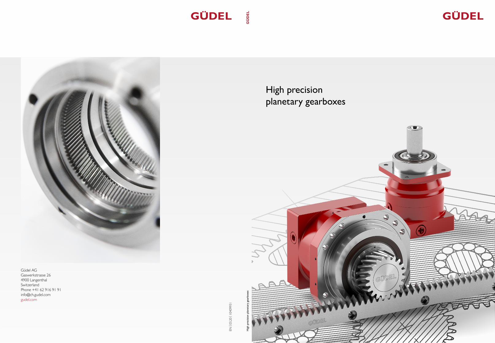
High precision planetary gearboxes


High precision planetary gearboxes
Content
High precision planetary gearboxes
Insights Products meet industry .....................................................................................................................6
Product overview Take six – The product at a glance ......................................................................8
GAdjustment NGHP – An innovative system solution ...................................................................10
Performance Six types to cover a wide range of application requirements ......................... 12
Preselection Make your decision – Range, speed & torque .......................................................... 14
Inputs Great adaptability – Standard & optional inputs .................................................................... 16
Outputs Unlimited flexibility – Standard and optional outputs ...................................................18
Positioning Reliability – Regardless of the mounting position ..................................................... 20
Function packages Your ideal drive train – Gearbox, rack & pinion ........................................22
Configuration Find your right size – Performance & configuration ........................................ 24
Configuration Find your right configuration – Available inputs and outputs ..................... 26
Technical data sheets
Type NRH.................................................................................................................................................................. 30
Type NRHP ............................................................................................................................................................... 42
Type NGHP .............................................................................................................................................................. 54
Type NR ...................................................................................................................................................................... 66
Type SR ....................................................................................................................................................................... 78
Type PR ....................................................................................................................................................................... 98
Your ideal drive train
Pinion – helical teeth ........................................................................................................................................... 120
Rack – helical teeth ................................................................................................................................................ 121
Technical information
Order reference Generate the code of your planetary gearbox ........................................... 128
Order reference Choose your appropriate motor interface .................................................... 130
Flowcharts Calculate your planetary gearbox ......................................................................................132
Flowcharts Calculate your ideal drive train ............................................................................................136
Güdel worldwide
Contacts ..................................................................................................................................................................... 140
1 5
Insights
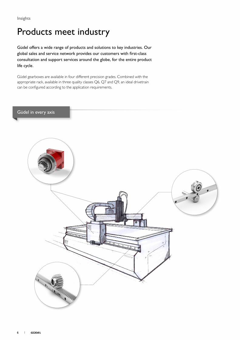
Products meet industryGüdel offers a wide range of products and solutions to key industries. Our global sales and service network provides our customers with first-class consultation and support services around the globe, for the entire product life cycle.
Güdel gearboxes are available in four different precision grades. Combined with the appropriate rack, available in three quality classes Q6, Q7 and Q9, an ideal drivetrain can be configured according to the application requirements.
Güdel in every axis
6 1
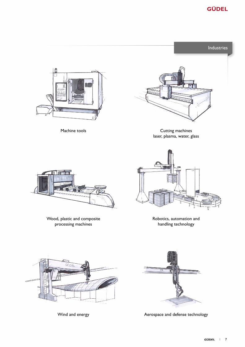
Aerospace and defense technology
Industries
Machine tools Cutting machines laser, plasma, water, glass
Wood, plastic and composite processing machines
Wind and energy
Robotics, automation and handling technology
1 7
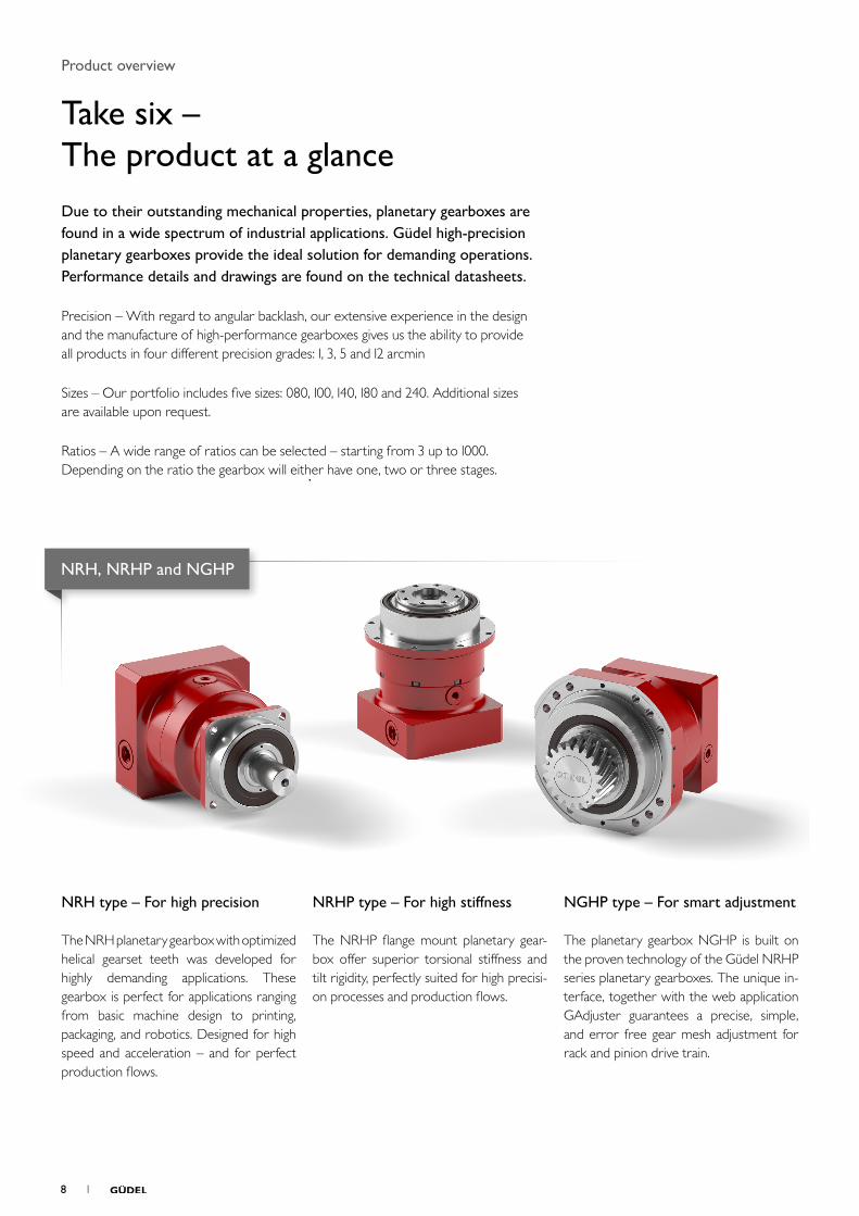
NRH, NRHP and NGHP
Product overview
Take six – The product at a glanceDue to their outstanding mechanical properties, planetary gearboxes are found in a wide spectrum of industrial applications. Güdel high-precision planetary gearboxes provide the ideal solution for demanding operations. Performance details and drawings are found on the technical datasheets.
Precision – With regard to angular backlash, our extensive experience in the design and the manufacture of high-performance gearboxes gives us the ability to provide all products in four different precision grades: 1, 3, 5 and 12 arcmin
Sizes – Our portfolio includes five sizes: 080, 100, 140, 180 and 240. Additional sizes are available upon request.
Ratios – A wide range of ratios can be selected – starting from 3 up to 1000. Depending on the ratio the gearbox will either have one, two or three stages.
NRH type – For high precision The NRH planetary gearbox with optimized helical gearset teeth was developed for highly demanding applications. These gearbox is perfect for applications ranging from basic machine design to printing, packaging, and robotics. Designed for high speed and acceleration – and for perfect production flows.
NRHP type – For high stiffness The NRHP flange mount planetary gear-box offer superior torsional stiffness and tilt rigidity, perfectly suited for high precisi-on processes and production flows.
NGHP type – For smart adjustment The planetary gearbox NGHP is built on the proven technology of the Güdel NRHP series planetary gearboxes. The unique in-terface, together with the web application GAdjuster guarantees a precise, simple, and error free gear mesh adjustment for rack and pinion drive train.
8 1
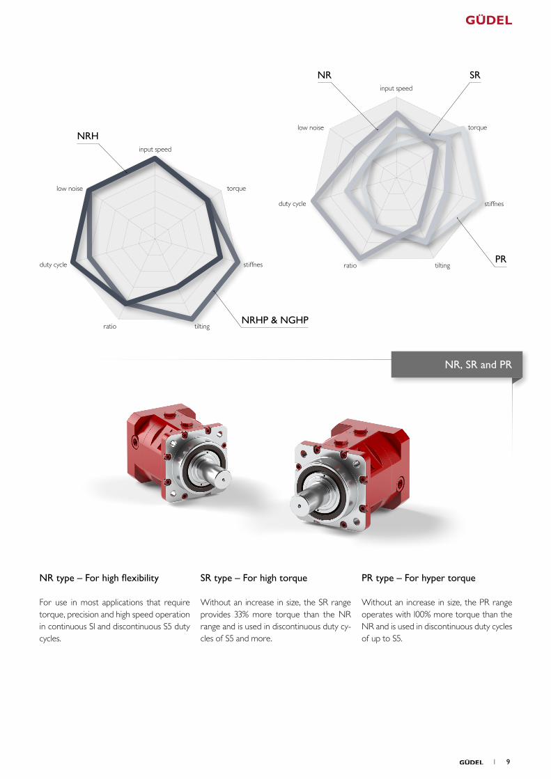
NR type – For high flexibility For use in most applications that require torque, precision and high speed operation in continuous S1 and discontinuous S5 duty cycles.
SR type – For high torque Without an increase in size, the SR range provides 33% more torque than the NR range and is used in discontinuous duty cy-cles of S5 and more.
PR type – For hyper torque Without an increase in size, the PR range operates with 100% more torque than the NR and is used in discontinuous duty cycles of up to S5.
NR
NRH
SR
PR
NRHP & NGHP
NR, SR and PR
low noise
low noise
duty cycle
duty cycle
ratio
ratio
input speed
input speed
torque
torque
stiffnes
stiffnes
tilting
tilting
1 9
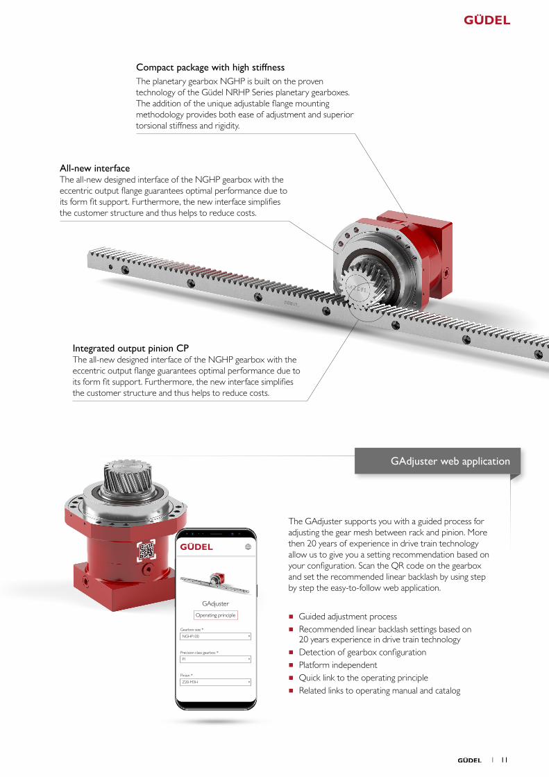
GAdjustment
NGHP – An innovative system solutionPlanetary gearbox with integrated eccentric output flange which provides precise gear mesh adjustment for the rack and pinion drive train.
The performance of a rack and pinion drive system is greatly influenced by how precisely the gear mesh between rack and pinion are set, as well as by the precision of the individual components. This gear mesh is typically set via the radial relationship of the pinion to the rack. To achieve low backlash, the pinion engages with the rack through a linear movement of the gearbox.
While seemingly easy in theory, this proves difficult in practice and can only be achieved with great effort, trained personnel, and suitable measurement equipment. Costly repetitive measurements and perhaps even specific equipment may be required for the customer’s machine structure.
Güdel has now developed an innovative system, which in a very simple way, resolves the setting of the gear mesh between rack and pinion, while setting new standards when it comes to precision, performance, cost-effectiveness, and ease of maintenance.
At the heart of this innovative GAdjustment system is a low backlash planetary gearbox with an internal eccentric flange that rotates about the pinion. Once the gearbox is mounted into the machine structure by attaching the flange the pinion is engaged with the rack by rotating the gearbox housing. Fully supporting the radial mounting surface of the output flange provides maximum stiffness, resulting in longer gearbox bearing life. A benefit of this method of adjustment is that the ratio between rotation and pinion linear motion allows finer adjustment increments. This results in high precision and accuracy of the gear mesh between rack and pinion. This eccentric motion also enables the pinion to be completely disengaged from the rack when the planetary gearbox is rotated 180 degrees into the mounting position. In this way, the drive system can be quickly decoupled to allow manual movement for maintenance activity.
Key features of this system
Quick disengagement of the pinion from the rack for maintenance work
Assembly and disassembly with standard tools
Compact functional unit with integral mounting and positioning system built into one component
Precise and repeatable adjustment process for setting gear mesh
Simple and cost-effective interface to the customer’s machine structure
Maximum stiffness due to form fit support of the output bearing and the CP (compact pinion) solution
Optimal force transmission into the customer-side machine structure
Set-up guidance through the easy-to-use web application GAdjuster
10 1
GAdjuster
Gearbox size *
Precision class gearbox *
Pinion *
Operating principle
P1
Z20-M3H
NGHP100
GAdjuster web application
Compact package with high stiffnessThe planetary gearbox NGHP is built on the proven technology of the Güdel NRHP Series planetary gearboxes. The addition of the unique adjustable flange mounting methodology provides both ease of adjustment and superior torsional stiffness and rigidity.
All-new interfaceThe all-new designed interface of the NGHP gearbox with the eccentric output flange guarantees optimal performance due to its form fit support. Furthermore, the new interface simplifies the customer structure and thus helps to reduce costs.
Integrated output pinion CPThe all-new designed interface of the NGHP gearbox with the eccentric output flange guarantees optimal performance due to its form fit support. Furthermore, the new interface simplifies the customer structure and thus helps to reduce costs.
The GAdjuster supports you with a guided process for adjusting the gear mesh between rack and pinion. More then 20 years of experience in drive train technology allow us to give you a setting recommendation based on your configuration. Scan the QR code on the gearbox and set the recommended linear backlash by using step by step the easy-to-follow web application.
■ Guided adjustment process ■ Recommended linear backlash settings based on
20 years experience in drive train technology ■ Detection of gearbox configuration ■ Platform independent ■ Quick link to the operating principle ■ Related links to operating manual and catalog
1 11
SRNR PRNRH NRHP NGHP
NR SR PRNRH NRHP NGHP
110%133%
100%110%110%
200%
100%
100%
60% Discontinuous S5
Continuous S1
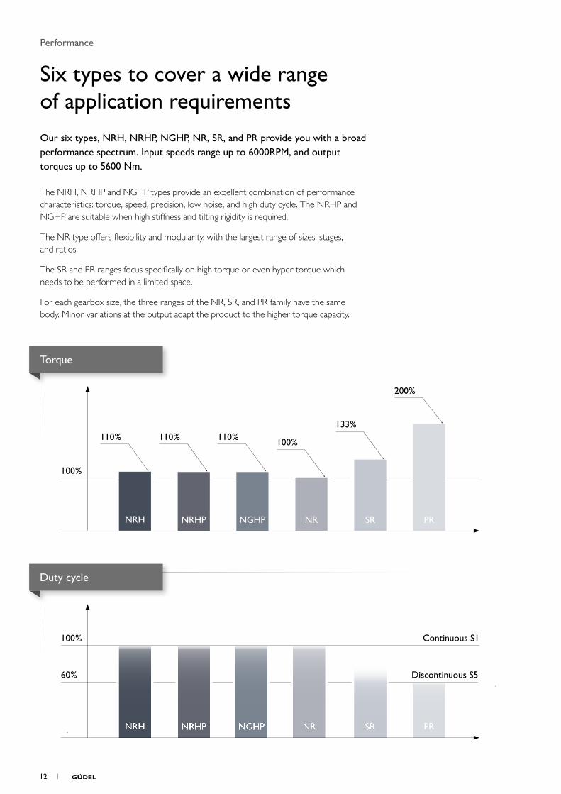
Performance
Six types to cover a wide range of application requirementsOur six types, NRH, NRHP, NGHP, NR, SR, and PR provide you with a broad performance spectrum. Input speeds range up to 6000RPM, and output torques up to 5600 Nm.
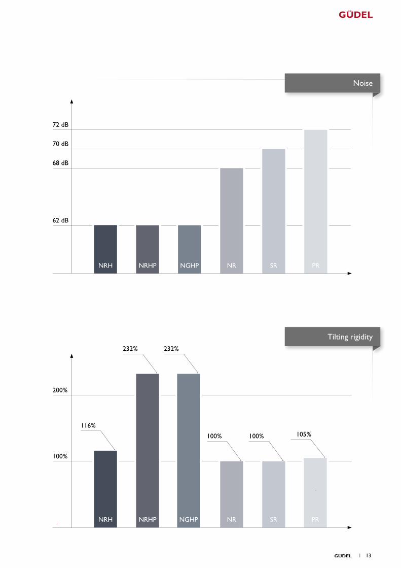
The NRH, NRHP and NGHP types provide an excellent combination of performance characteristics: torque, speed, precision, low noise, and high duty cycle. The NRHP and NGHP are suitable when high stiffness and tilting rigidity is required.
The NR type offers flexibility and modularity, with the largest range of sizes, stages, and ratios.
The SR and PR ranges focus specifically on high torque or even hyper torque which needs to be performed in a limited space.
For each gearbox size, the three ranges of the NR, SR, and PR family have the same body. Minor variations at the output adapt the product to the higher torque capacity.
Torque
Duty cycle
12 1
PRSRNRH NRNRHP NGHP
SRNRH NR PRNRHP NGHP
100%100%
232% 232%
116%105%
100%
200%
62 dB
68 dB
70 dB
72 dB
Noise
Tilting rigidity
1 13
NRH NRHP NGHP NR SR PR
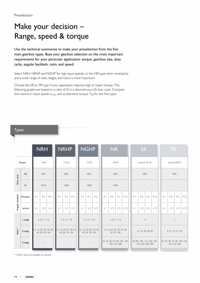
Torque 110% 110 % 110 % 100 % around 133 % around 200 %
Dut
y cy
cle S5 60% 60% 60% 60% 60% 60%
S1 100 % 100% 100% 100% – –
Ang
ular
bac
klas
h
Precision P 1 P 3 P 5 P 1 P 3 P 5 P 1 P 3 P 5 P 1 P 3 P 5 P 12 P 1 P 3 P 5 P 12 P 1 P 3 P 5 P 12
arcmin ≤ 1 ≤ 3 ≤ 5 ≤ 1 ≤ 3 ≤ 5 ≤ 1 ≤ 3 ≤ 5 ≤ 1 ≤ 3 ≤ 5 ≤ 12 ≤ 1 ≤ 3 ≤ 5 ≤ 12 ≤ 1 ≤ 3 ≤ 5 ≤ 12
Rat
io *
1-stage 3, 4, 5, 7, 10 3, 4, 5, 7, 10 3, 4, 5, 7, 10 3, 4, 5, 7, 10 4 3
2-stage12, 16, 20, 25, 30, 35,
40, 50, 70, 10012, 16, 20, 25, 30, 35,
40, 50, 70, 10012, 16, 20, 25, 30, 35,
40, 50, 70, 10012, 16, 20, 25, 30, 35, 40,
50, 70, 10012, 16, 20, 28, 40 9, 12, 15, 21, 30
3-stage – – –36, 45, 60, 75, 90, 105, 120,
150, 210, 30060, 80, 100, 112, 120, 140,
160, 200, 280, 40036, 45, 60, 75, 90, 105, 120,
150, 210, 300
* Other ratios are available on request.
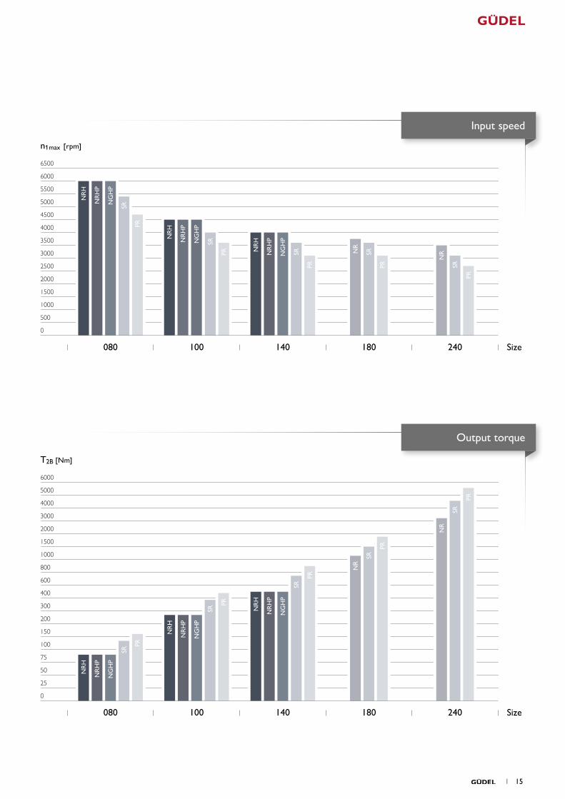
Preselection
Make your decision – Range, speed & torqueUse the technical summaries to make your preselection from the five main gearbox types. Base your gearbox selection on the most important requirements for your particular application: torque, gearbox size, duty cycle, angular backlash, ratio, and speed.
Select NRH, NRHP and NGHP for high input speeds, or the NR type when modularity and a wide range of sizes, stages, and ratios is most important.
Choose the SR or PR type if your application requires high or hyper torque. The following graphs are based on a ratio of 12 in a discontinuous S5 duty cycle. Compare the maximum input speed n1max and acceleration torque T2B for the five types.
Types
14 1
500
1000
1500
2000
2500
3000
3500
4000
4500
5000
5500
6000
6500
NR
H
NR
H
NR
H
NR
NR
SR
SR
SR SR
SR
PR
PR
PR PR
PR
0
25
50
75
100
150
200
300
400
600
800
1000
1500
2000
3000
4000
5000
6000
NR
H
NR
H
NR
H
NR
NR
SR
SR
SR
SR
SR
PR
PR
PR
PR
PR
NR
HP
NG
HP
NR
HP
NG
HP
NR
HP
NG
HP
NR
HP
NG
HP
NR
HP
NG
HP
NR
HP
NG
HP
0
n1max [ rpm]
080 100 140 180 240
T2B [Nm]
080 100 140 180 240
Size
Size
Input speed
Output torque
1 15
C
A
B
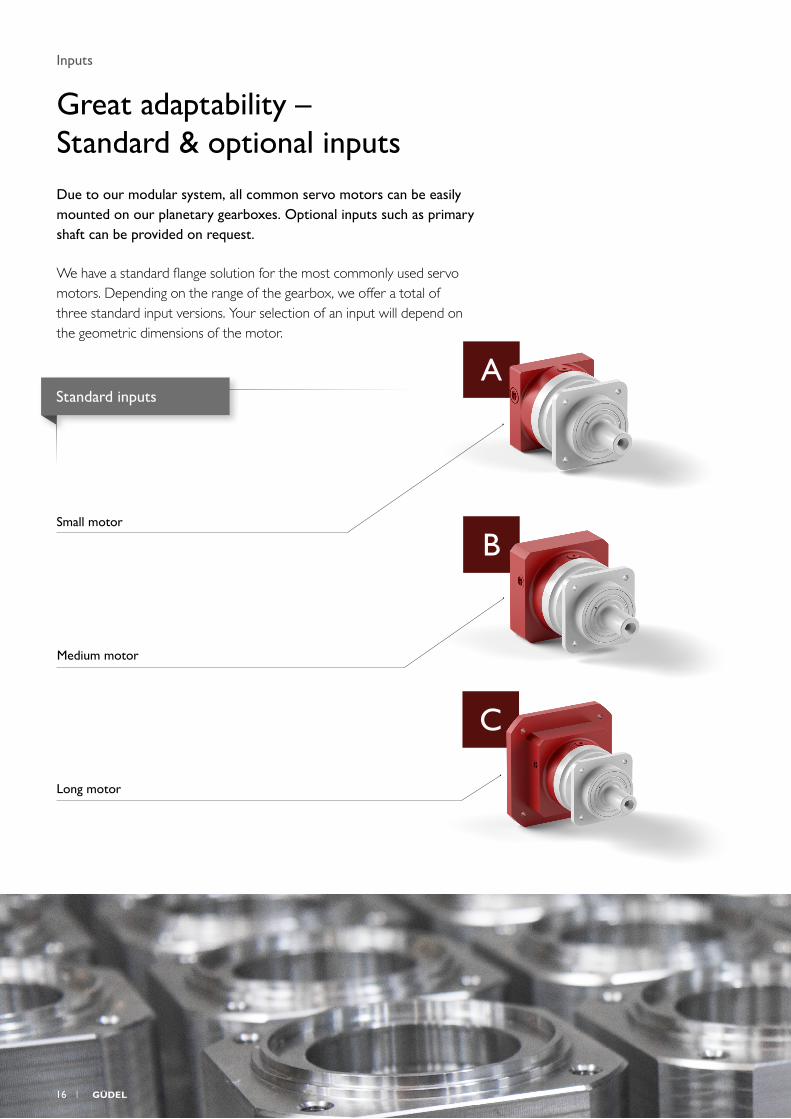
Inputs
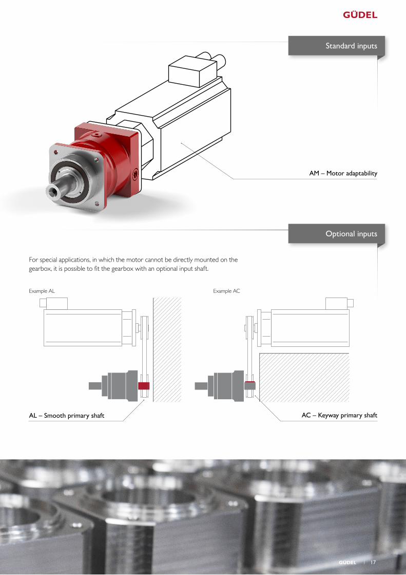
Great adaptability – Standard & optional inputsDue to our modular system, all common servo motors can be easily mounted on our planetary gearboxes. Optional inputs such as primary shaft can be provided on request.
We have a standard flange solution for the most commonly used servo motors. Depending on the range of the gearbox, we offer a total of three standard input versions. Your selection of an input will depend on the geometric dimensions of the motor.
Small motor
Medium motor
Long motor
Standard inputs
16 1
skallieren 86.603neigen -170°
AM – Motor adaptability
AL – Smooth primary shaft
Example AL Example AC
For special applications, in which the motor cannot be directly mounted on the gearbox, it is possible to fit the gearbox with an optional input shaft.
AC – Keyway primary shaft
Standard inputs
Optional inputs
1 17
1
2
0
Outputs
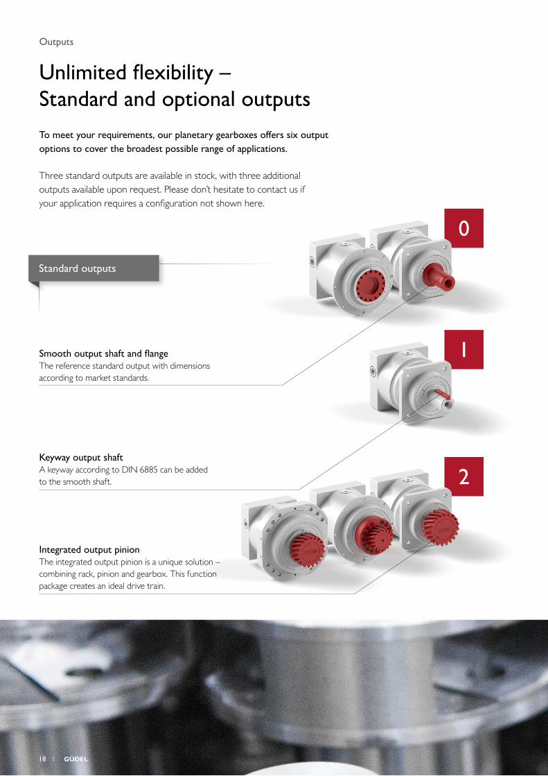
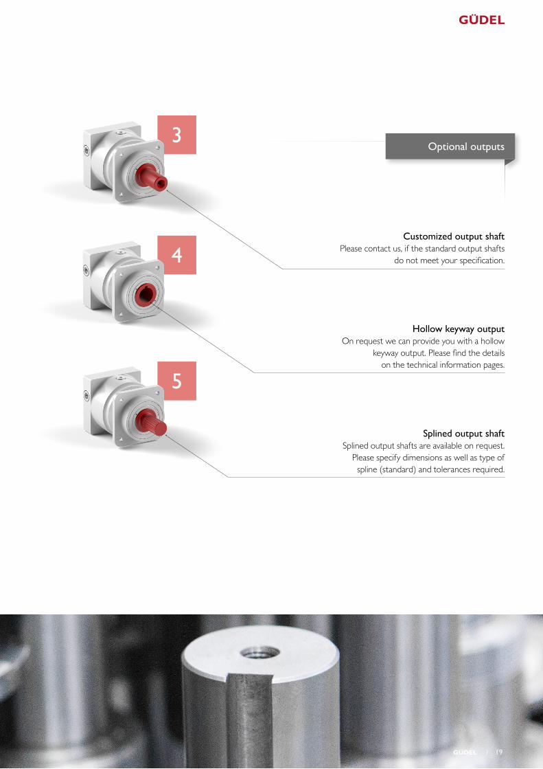
Unlimited flexibility – Standard and optional outputsTo meet your requirements, our planetary gearboxes offers six output options to cover the broadest possible range of applications.
Three standard outputs are available in stock, with three additional outputs available upon request. Please don’t hesitate to contact us if your application requires a configuration not shown here.
Smooth output shaft and flangeThe reference standard output with dimensions according to market standards.
Keyway output shaftA keyway according to DIN 6885 can be added to the smooth shaft.
Integrated output pinionThe integrated output pinion is a unique solution – combining rack, pinion and gearbox. This function package creates an ideal drive train.
Standard outputs
18 1
3
4
5
Customized output shaftPlease contact us, if the standard output shafts
do not meet your specification.
Hollow keyway outputOn request we can provide you with a hollow
keyway output. Please find the details on the technical information pages.
Splined output shaftSplined output shafts are available on request.
Please specify dimensions as well as type of spline (standard) and tolerances required.
Optional outputs
1 19
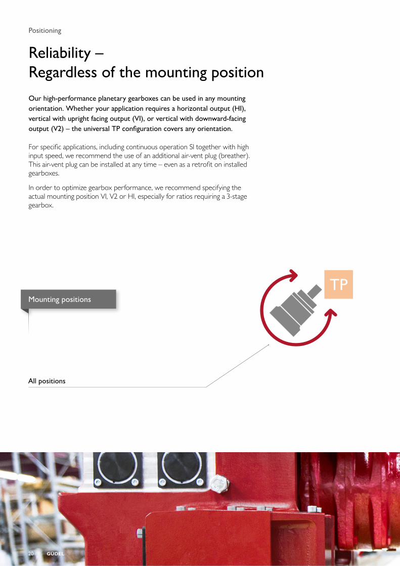
Positioning
Reliability – Regardless of the mounting positionOur high-performance planetary gearboxes can be used in any mounting orientation. Whether your application requires a horizontal output (H1), vertical with upright facing output (V1), or vertical with downward-facing output (V2) – the universal TP configuration covers any orientation.
For specific applications, including continuous operation S1 together with high input speed, we recommend the use of an additional air-vent plug (breather). This air-vent plug can be installed at any time – even as a retrofit on installed gearboxes.
In order to optimize gearbox performance, we recommend specifying the actual mounting position V1, V2 or H1, especially for ratios requiring a 3-stage gearbox.
Mounting positions
TP
All positions
20 1
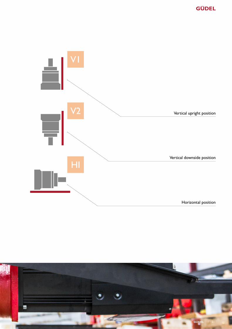
V1
V2
H1
Vertical upright position
Vertical downside position
Horizontal position
1 21
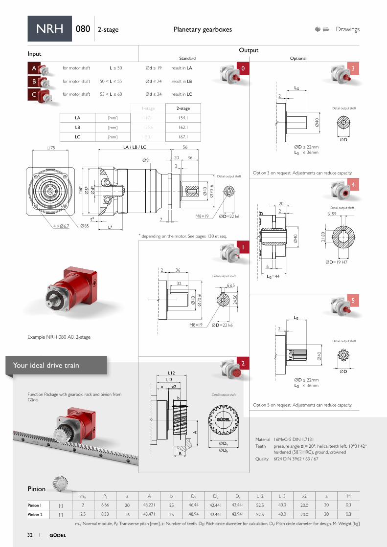
Input OutputStandard Optional
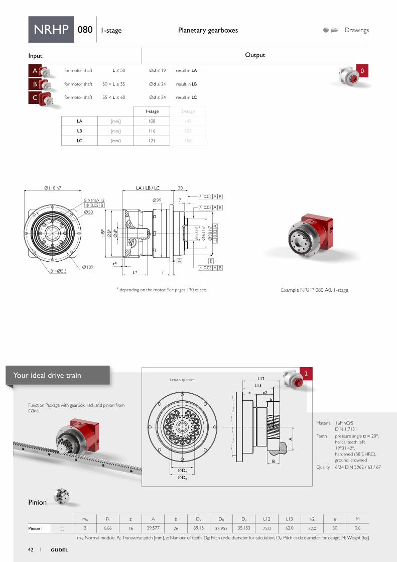
A for motor shaft L ≤ 50 Ød ≤ 19 result in LA 0 3
B for motor shaft 50 < L ≤ 55 Ød ≤ 24 result in LB
C for motor shaft 55 < L ≤ 60 Ød ≤ 24 result in LC
4
1 4
5
aa
2
ØDv
L12
L13
x2
b
B
a
A
ØDk
2 36
32
Ø40
24.5
0
Ø70
j6
M8×19
6js5
ØD=22 k6
Ø40
ØD
2
LG
ØD ≤ 22mmLG ≤ 36mm
Ø40
ØD=19 H7
LG=44
6 JS9
20
2
6
21.8
0Ø
40
ØD
LG
2
ØD ≤ 22mmLG ≤ 36mm
75
Ø91
B*
t*
L*
7
LA / LB / LC 56
20
2
36
Ø854 ×Ø6.7
Ød*
ØS*
Ø40
Ø70
j6
ØD=22 k6M8×19
Material 16MnCr5 DIN 1.7131
Teeth pressure angle α = 20°, helical teeth left, 19°31‘42“ hardened (58+4
0 HRC), ground, crowned
Quality 6f24 DIN 3962 / 63 / 67
Function Package with gearbox, rack and pinion from Güdel
Pinion
Planetary gearboxes Performance Drawings Planetary gearboxes
* depending on the motor. See pages 148 et seq.
Rack
Option 5 on request. Adjustments can reduce capacity.
Option 3 on request. Adjustments can reduce capacity.
More on the technical datasheets your ideal drive train on pages 138 et seq.
For proper sizing follow flowchart calculate your ideal drive train on pages 154 et seq.
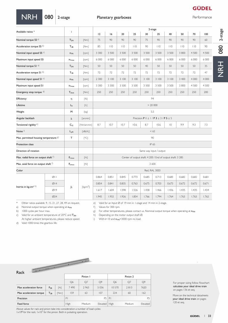
Pinion 1 Pinion 2
Q6 Q7 Q9 Q6 Q7 Q9
Max acceleration force F2B [ N ] 7 490 2 963 5 036 10 570 2 813 7 620
Max acceleration torque T2B [ Nm ] 159 63 107 224 60 162
Precision P1 P5 P1 P5
Feed force High Medium Elevated High Medium Elevated
Above values for rack and pinion take into consideration a number of load cycles:1x10⁶ for the rack; 1x10⁷ for the pinion. Both in pulsating operation.
mn Pt z A b Dk D0 Dv L12 L13 x2 a M
Pinion 1 [-] 2 6.66 20 43.221 25 46.44 42.441 42.441 52.5 40.0 20.0 20 0.3
Pinion 2 [-] 2.5 8.33 16 43.471 25 48.94 42.441 43.941 52.5 40.0 20.0 20 0.3
mn: Normal module, Pt: Transverse pitch [mm], z : Number of teeth, D0: Pitch circle diameter for calculation, Dv: Pitch circle diameter for design, M: Weight [kg]
NR
H08
01-
stag
e
NRH 080 1-stageNRH 080 1-stage
Available ratios i1-stage
3 4 5 7 10
Nominal torque S5 a) T2N [ Nm ] 65 75 76 76 60
Acceleration torque S5 b) T2B [ Nm ] 85 110 110 110 90
Nominal input speed S5 c) n1N [rpm] 2 900 2 900 2 900 3 100 3 100
Maximum input speed S5 n1max [rpm] 5 000 6 000 6 000 6 000 6 000
Nominal torque S1 a) T2N [Nm ] – 50 50 50 35
Acceleration torque S1 b) T2B [ Nm] – 72 72 72 44
Nominal input speed S1 c) n1N [rpm] – 2 600 2 600 2 800 2 800
Maximum input speed S1 n1max [rpm] – 2 900 2 900 3 100 3 100
Emergency stop torque d) T2not [ Nm ] 250 250 250 250 200
Efficiency h [ % ] 97
Lifetime Lh [ h ] > 20 000
Weight M [ kg ] 4
Angular backlash jt [ arcmin ] Precision P 1 ≤ 1 / P 3 ≤ 3 / P 5 ≤ 5
Torsionnal rigidity e) Ct2 [ Nm/arcmin ] 9 10.7 11 9.9 7.7
Noise i) L pA [ dB(A) ] < 62
Max. permitted housing temperature g) T [ °C ] 90
Protection class IP 65
Direction of rotation Same way input / output
Max. radial force on output shaft f) Frmax [ N ] Center of output shaft: 4 200 / End of output shaft: 3 285
Max. axial force on output shaft f) Famax [ N ] 3 600
Color Red, RAL 3003
Inertia in kg.cm² h)
Ø11
J1 [ kgcm2 ]
1.103 0.881 0.796 0.724 0.688
Ø14 1.093 0.871 0.786 0.714 0.678
Ø19 1.856 1.634 1.549 1.477 1.441
Ø24 2.184 1.962 1.877 1.805 1.769
a) Nominal output torque when operating at n1N.
b) 1000 cycles per hour max.
c) Valid for an ambient temperature of 20°C and T2N.
At higher ambient temperatures, please reduce speed.
d) Valid 1000 times the gearbox life.
e) Valid for an Input Ø of 24 mm in 1-stage and 19 mm in 2-stage.
f) Values for 300 rpm.
g) For other temperatures, please contact us. Nominal output torque when operating at n1N.
h) Depending on the motor output shaft Ø.
i) With i=10 and n1N=3000 rpm no load.
1-stage 2-stage
LA [ mm ] 117.1 154.1
LB [ mm ] 125.6 162.1
LC [ mm ] 130.1 167.1
Example NRH 080 A0, 1-stage
Type NRH
Detail output shaft
Detail output shaft
Detail output shaft
Detail output shaft
Detail output shaft
Detail output shaft
1 3130 1
Your ideal drive train
Function packages
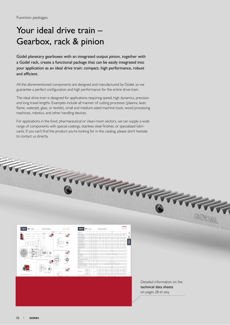
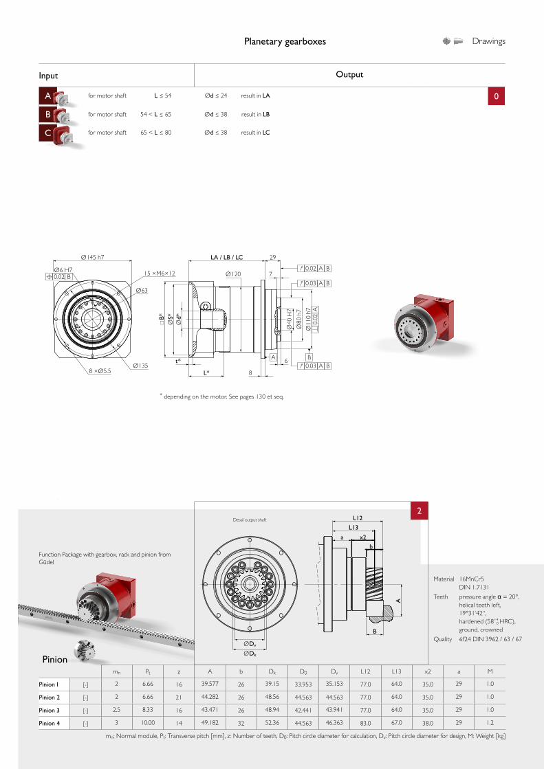
Your ideal drive train – Gearbox, rack & pinionGüdel planetary gearboxes with an integrated output pinion, together with a Güdel rack, create a functional package that can be easily integrated into your application as an ideal drive train: compact, high performance, robust and efficient.
All the aforementioned components are designed and manufactured by Güdel, so we guarantee a perfect configuration and high performance for the entire drive train.
The ideal drive train is designed for applications requiring speed, high dynamics, precision and long travel lengths. Examples include all manner of cutting processes (plasma, laser, flame, waterjet, glass, or textile), small and medium-sized machine tools, wood processing machines, robotics, and other handling devices.
For applications in the food, pharmaceutical or clean-room sectors, we can supply a wide range of components with special coatings, stainless steel finishes, or specialized lubri-cants. If you can’t find the product you’re looking for in this catalog, please don’t hesitate to contact us directly.
Detailed information on the technical data sheets on pages 28 et seq.
22 1
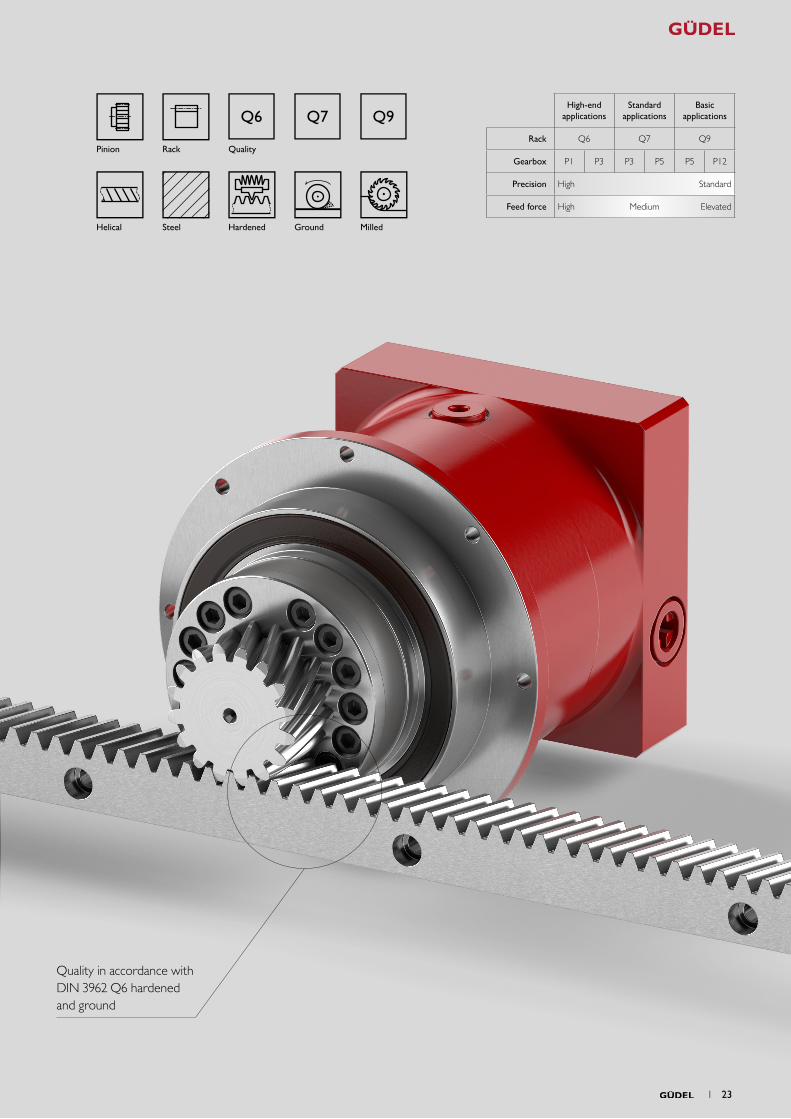
Q6 Q7 Q9
Helical Steel Hardened Ground Milled
RackPinion Quality
Quality in accordance with DIN 3962 Q6 hardened and ground
High-end applications
Standard applications
Basic applications
Rack Q6 Q7 Q9
Gearbox P1 P3 P3 P5 P5 P12
Precision High Standard
Feed force High Medium Elevated
1 23
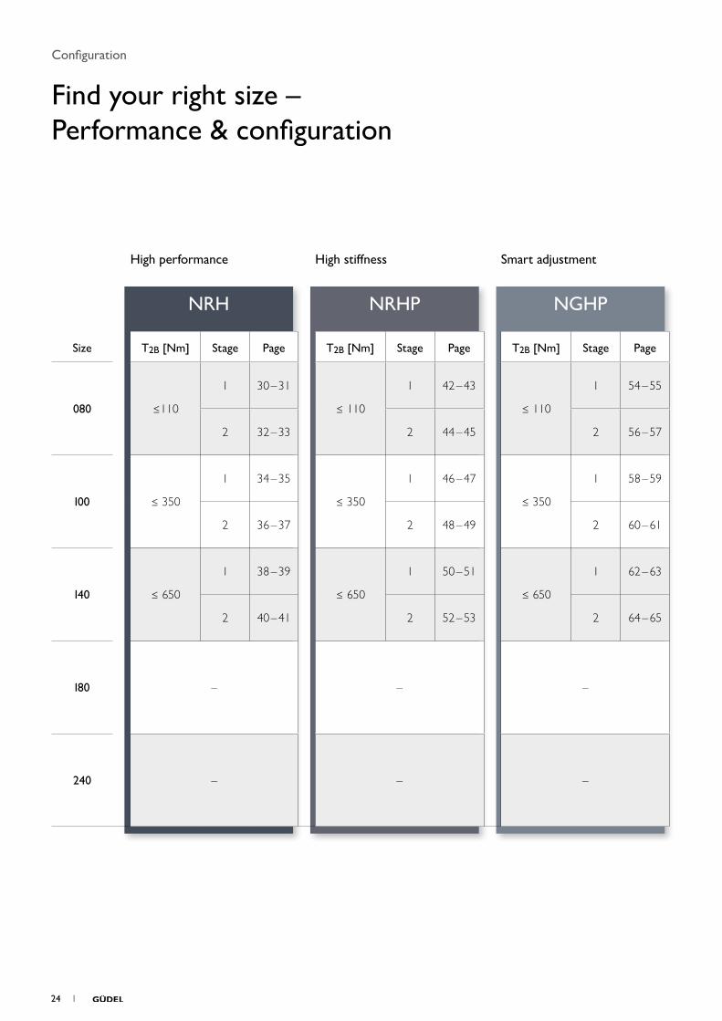
NRH NRHP NGHP
High performance High stiffness Smart adjustment
Size T2B [Nm] Stage Page T2B [Nm] Stage Page T2B [Nm] Stage Page
080 ≤110
1 30 – 31
≤ 110
1 42 – 43
≤ 110
1 54 – 55
2 32 – 33 2 44 – 45 2 56 – 57
100 ≤ 350
1 34 – 35
≤ 350
1 46 – 47
≤ 350
1 58 – 59
2 36 – 37 2 48 – 49 2 60 – 61
140 ≤ 650
1 38 – 39
≤ 650
1 50 – 51
≤ 650
1 62 – 63
2 40 – 41 2 52 – 53 2 64 – 65
180 – – –
240 – – –
Configuration
Find your right size – Performance & configuration
24 1
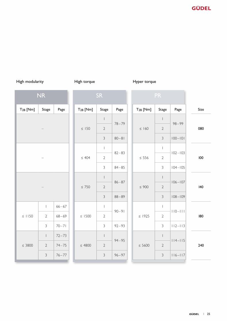
NR SR PR
High modularity High torque Hyper torque
T2B [Nm] Stage Page T2B [Nm] Stage Page T2B [Nm] Stage Page Size
– ≤ 150
178 – 79
≤ 160
198 – 99
0802 2
3 80 – 81 3 100 –101
– ≤ 404
182 – 83
≤ 556
1102 –103
1002 2
3 84 – 85 3 104 –105
– ≤ 750
186 – 87
≤ 900
1106 –107
1402 2
3 88 – 89 3 108 –109
≤ 1150
1 66 – 67
≤ 1500
190 – 91
≤ 1925
1110 –111
1802 68 – 69 2 2
3 70 – 71 3 92 – 93 3 112 –113
≤ 3800
1 72 – 73
≤ 4800
194 – 95
≤ 5600
1114 –115
2402 74 – 75 2 2
3 76 – 77 3 96 – 97 3 116 –117
1 25
• Available / * We provide additional flanges for bigger motors on request.
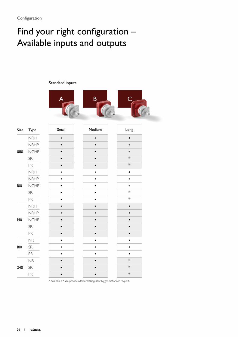
Standard inputs
A B C
Size Type Small Medium Long
080
NRH
• • •NRHP • • •NGHP • • •SR • • *PR • • *
100
NRH • • •NRHP • • •NGHP • • •SR • • *PR • • *
140
NRH • • •NRHP • • •NGHP • • •SR • • •PR • • •
180
NR • • •SR • • •PR • • •
240
NR • • *SR • • *PR • • *
Configuration
Find your right configuration – Available inputs and outputs
26 1
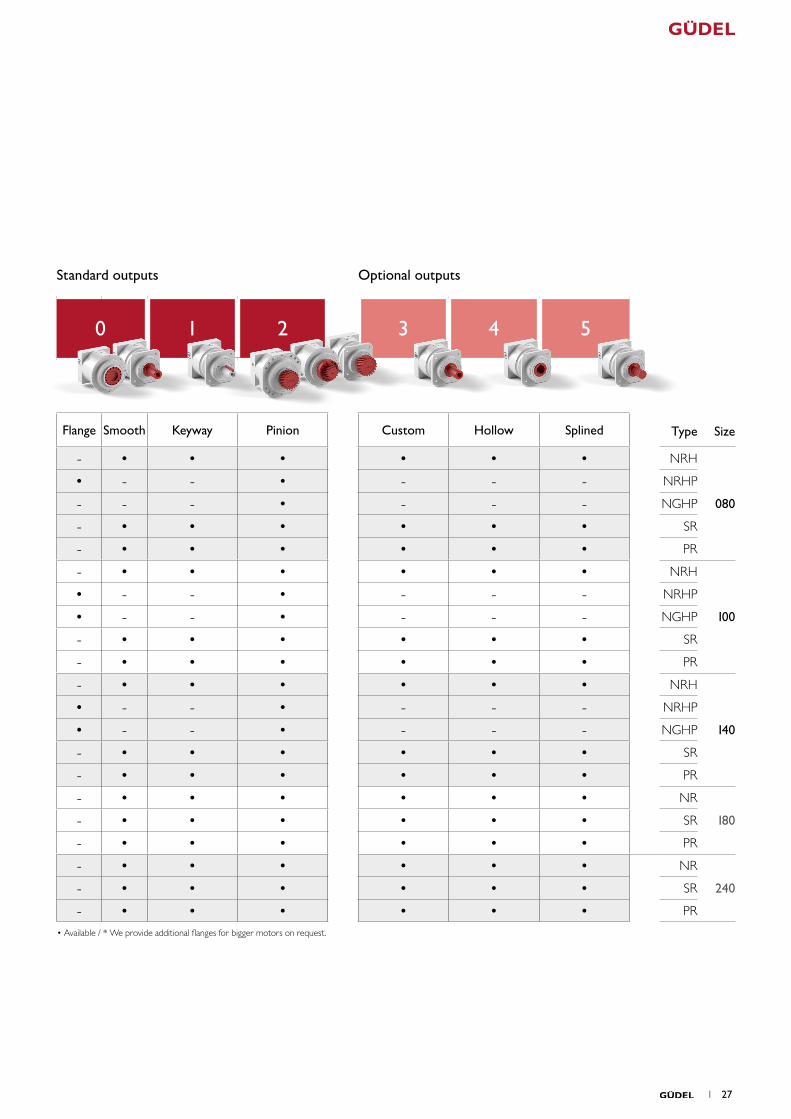
• Available / * We provide additional flanges for bigger motors on request.
Standard outputs Optional outputs
0 1 2 3 4 5
Flange Smooth Keyway Pinion Custom Hollow Splined Type Size
- • • • • • • NRH
080
• - - • - - - NRHP
- - - • - - - NGHP
- • • • • • • SR
- • • • • • • PR
- • • • • • • NRH
100
• - - • - - - NRHP
• - - • - - - NGHP
- • • • • • • SR
- • • • • • • PR
- • • • • • • NRH
140
• - - • - - - NRHP
• - - • - - - NGHP
- • • • • • • SR
- • • • • • • PR
- • • • • • • NR
180- • • • • • • SR
- • • • • • • PR
- • • • • • • NR
240- • • • • • • SR
- • • • • • • PR
1 27

Technical data sheets
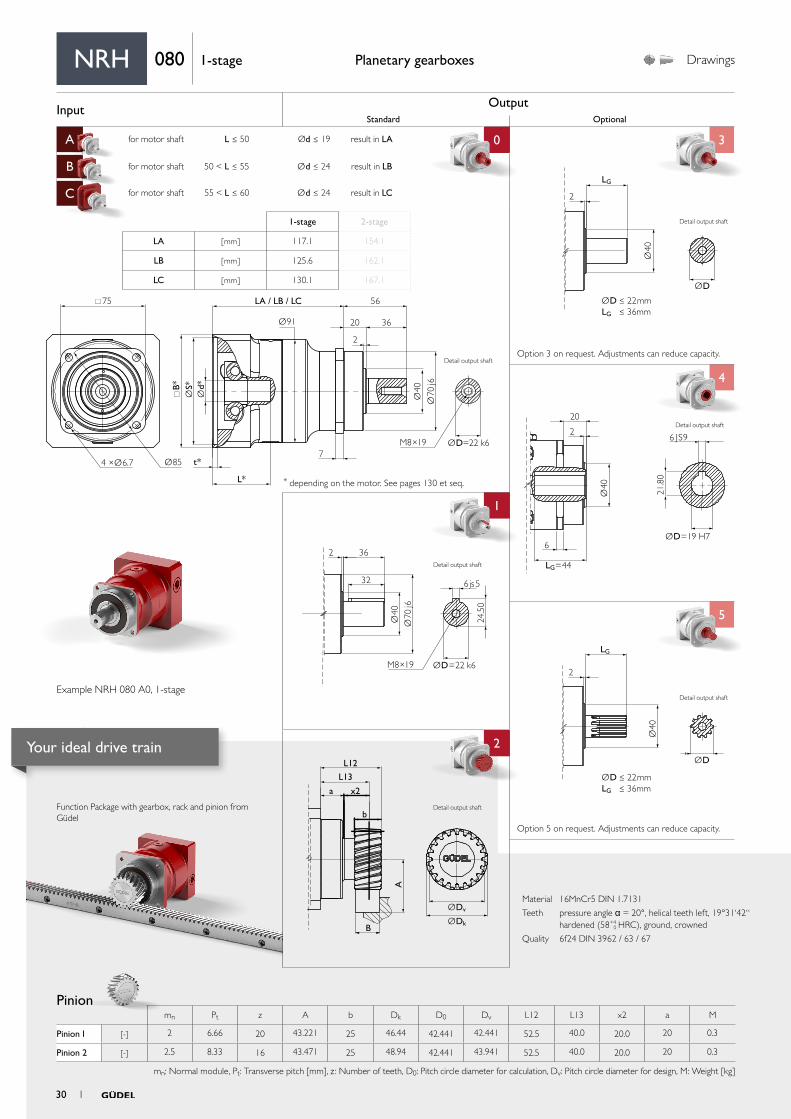
Input OutputStandard Optional
A for motor shaft L ≤ 50 Ød ≤ 19 result in LA 0 3
B for motor shaft 50 < L ≤ 55 Ød ≤ 24 result in LB
C for motor shaft 55 < L ≤ 60 Ød ≤ 24 result in LC
4
1 4
5
aa
2
ØDv
L12
L13
x2
b
B
a
A
ØDk
2 36
32
Ø40
24.5
0
Ø70
j6
M8×19
6js5
ØD=22 k6
Ø40
ØD
2
LG
ØD ≤ 22mmLG ≤ 36mm
Ø40
ØD=19 H7
LG=44
6 JS9
20
2
6
21.8
0Ø
40
ØD
LG
2
ØD ≤ 22mmLG ≤ 36mm
75
Ø91
B*
t*
L*
7
LA / LB / LC 56
20
2
36
Ø854 ×Ø6.7
Ød*
ØS*
Ø40
Ø70
j6
ØD=22 k6M8×19
Material 16MnCr5 DIN 1.7131
Teeth pressure angle α = 20°, helical teeth left, 19°31‘42“ hardened (58+4
0 HRC), ground, crowned
Quality 6f24 DIN 3962 / 63 / 67
Function Package with gearbox, rack and pinion from Güdel
Pinion
Planetary gearboxes Drawings
* depending on the motor. See pages 130 et seq.
Option 5 on request. Adjustments can reduce capacity.
Option 3 on request. Adjustments can reduce capacity.
mn Pt z A b Dk D0 Dv L12 L13 x2 a M
Pinion 1 [-] 2 6.66 20 43.221 25 46.44 42.441 42.441 52.5 40.0 20.0 20 0.3
Pinion 2 [-] 2.5 8.33 16 43.471 25 48.94 42.441 43.941 52.5 40.0 20.0 20 0.3
mn: Normal module, Pt: Transverse pitch [mm], z : Number of teeth, D0: Pitch circle diameter for calculation, Dv: Pitch circle diameter for design, M: Weight [kg]
NRH 080 1-stage
1-stage 2-stage
LA [ mm ] 117.1 154.1
LB [ mm ] 125.6 162.1
LC [ mm ] 130.1 167.1
Example NRH 080 A0, 1-stage
Detail output shaft
Detail output shaft
Detail output shaft
Detail output shaft
Detail output shaft
Detail output shaft
30 1
Your ideal drive train
PerformancePlanetary gearboxes
Rack
More on the technical datasheets your ideal drive train on pages 120 et seq.
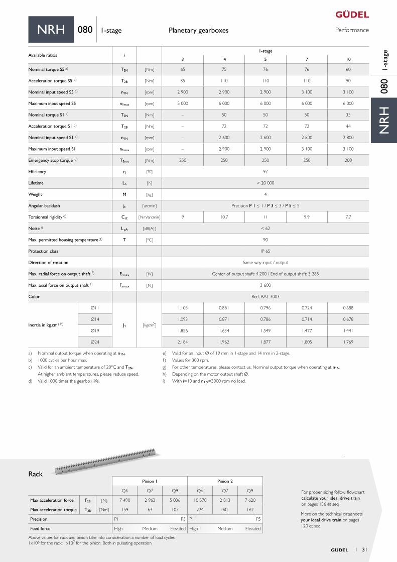
For proper sizing follow flowchart calculate your ideal drive train on pages 136 et seq.
Pinion 1 Pinion 2
Q6 Q7 Q9 Q6 Q7 Q9
Max acceleration force F2B [ N ] 7 490 2 963 5 036 10 570 2 813 7 620
Max acceleration torque T2B [ Nm ] 159 63 107 224 60 162
Precision P1 P5 P1 P5
Feed force High Medium Elevated High Medium Elevated
Above values for rack and pinion take into consideration a number of load cycles:1x10⁶ for the rack; 1x10⁷ for the pinion. Both in pulsating operation.
NR
H08
01-
stag
e
NRH 080 1-stage
Available ratios i1-stage
3 4 5 7 10
Nominal torque S5 a) T2N [ Nm ] 65 75 76 76 60
Acceleration torque S5 b) T2B [ Nm ] 85 110 110 110 90
Nominal input speed S5 c) n1N [rpm] 2 900 2 900 2 900 3 100 3 100
Maximum input speed S5 n1max [rpm] 5 000 6 000 6 000 6 000 6 000
Nominal torque S1 a) T2N [Nm ] – 50 50 50 35
Acceleration torque S1 b) T2B [ Nm] – 72 72 72 44
Nominal input speed S1 c) n1N [rpm] – 2 600 2 600 2 800 2 800
Maximum input speed S1 n1max [rpm] – 2 900 2 900 3 100 3 100
Emergency stop torque d) T2not [ Nm ] 250 250 250 250 200
Efficiency h [ % ] 97
Lifetime Lh [ h ] > 20 000
Weight M [ kg ] 4
Angular backlash jt [ arcmin ] Precision P 1 ≤ 1 / P 3 ≤ 3 / P 5 ≤ 5
Torsionnal rigidity e) Ct2 [ Nm/arcmin ] 9 10.7 11 9.9 7.7
Noise i) L pA [ dB(A) ] < 62
Max. permitted housing temperature g) T [ °C ] 90
Protection class IP 65
Direction of rotation Same way input / output
Max. radial force on output shaft f) Frmax [ N ] Center of output shaft: 4 200 / End of output shaft: 3 285
Max. axial force on output shaft f) Famax [ N ] 3 600
Color Red, RAL 3003
Inertia in kg.cm² h)
Ø11
J1 [ kgcm2 ]
1.103 0.881 0.796 0.724 0.688
Ø14 1.093 0.871 0.786 0.714 0.678
Ø19 1.856 1.634 1.549 1.477 1.441
Ø24 2.184 1.962 1.877 1.805 1.769
a) Nominal output torque when operating at n1N.
b) 1000 cycles per hour max.
c) Valid for an ambient temperature of 20°C and T2N.
At higher ambient temperatures, please reduce speed.
d) Valid 1000 times the gearbox life.
e) Valid for an Input Ø of 19 mm in 1-stage and 14 mm in 2-stage.
f) Values for 300 rpm.
g) For other temperatures, please contact us. Nominal output torque when operating at n1N.
h) Depending on the motor output shaft Ø.
i) With i=10 and n1N=3000 rpm no load.
1 31
Input OutputStandard Optional
A for motor shaft L ≤ 50 Ød ≤ 19 result in LA 0 3
B for motor shaft 50 < L ≤ 55 Ød ≤ 24 result in LB
C for motor shaft 55 < L ≤ 60 Ød ≤ 24 result in LC
4
1 4
5
aa
2
ØDv
L12
L13
x2
b
B
a
A
ØDk
2 36
32
Ø40
24.5
0
Ø70
j6
M8×19
6js5
ØD=22 k6
Ø40
ØD
2
LG
ØD ≤ 22mmLG ≤ 36mm
Ø40
ØD=19 H7
LG=44
6 JS9
20
2
6
21.8
0Ø
40
ØD
LG
2
ØD ≤ 22mmLG ≤ 36mm
75
Ø91
B*
t*
L*
7
LA / LB / LC 56
20
2
36
Ø854 ×Ø6.7
Ød*
ØS*
Ø40
Ø70
j6ØD=22 k6M8×19
Material 16MnCr5 DIN 1.7131
Teeth pressure angle α = 20°, helical teeth left, 19°31‘42“ hardened (58+4
0 HRC), ground, crowned
Quality 6f24 DIN 3962 / 63 / 67
Function Package with gearbox, rack and pinion from Güdel
Planetary gearboxes Drawings
* depending on the motor. See pages 130 et seq.
Option 5 on request. Adjustments can reduce capacity.
Option 3 on request. Adjustments can reduce capacity.
Pinion
NRH 080 2-stage
1-stage 2-stage
LA [ mm ] 117.1 154.1
LB [ mm ] 125.6 162.1
LC [ mm ] 130.1 167.1
Detail output shaftDetail output shaft
Detail output shaft
Detail output shaft
Detail output shaftExample NRH 080 A0, 2-stage
mn Pt z A b Dk D0 Dv L12 L13 x2 a M
Pinion 1 [-] 2 6.66 20 43.221 25 46.44 42.441 42.441 52.5 40.0 20.0 20 0.3
Pinion 2 [-] 2.5 8.33 16 43.471 25 48.94 42.441 43.941 52.5 40.0 20.0 20 0.3
mn: Normal module, Pt: Transverse pitch [mm], z : Number of teeth, D0: Pitch circle diameter for calculation, Dv: Pitch circle diameter for design, M: Weight [kg]
Detail output shaft
Detail output shaft
32 1
Your ideal drive train
PerformancePlanetary gearboxes
Rack
More on the technical datasheets your ideal drive train on pages 120 et seq.
For proper sizing follow flowchart calculate your ideal drive train on pages 136 et seq.
Pinion 1 Pinion 2
Q6 Q7 Q9 Q6 Q7 Q9
Max acceleration force F2B [ N ] 7 490 2 963 5 036 10 570 2 813 7620
Max acceleration torque T2B [ Nm ] 159 63 107 224 60 162
Precision P1 P5 P1 P5
Feed force High Medium Elevated High Medium Elevated
Above values for rack and pinion take into consideration a number of load cycles:1x10⁶ for the rack; 1x10⁷ for the pinion. Both in pulsating operation.
NR
H08
02-
stag
e
NRH 080 2-stage
Available ratios * i2-stage
12 16 20 25 30 35 40 50 70 100
Nominal torque S5 a) T2N [ Nm ] 75 90 90 90 75 90 90 90 90 60
Acceleration torque S5 b) T2B [ Nm ] 85 110 110 110 90 110 110 110 110 90
Nominal input speed S5 c) n1N [rpm] 3 300 3 500 3 500 3 500 3 500 3 500 3 500 3 800 4 500 4 500
Maximum input speed S5 n1max [rpm] 6 000 6 000 6 000 6 000 6 000 6 000 6 000 6 000 6 000 6 000
Nominal torque S1 a) T2N [Nm ] 50 50 50 50 40 50 50 50 50 35
Acceleration torque S1 b) T2B [ Nm] 72 72 72 72 72 72 72 72 72 47
Nominal input speed S1 c) n1N [rpm] 2 300 3 100 3 100 3 100 3 100 3 100 3 100 3 400 4 000 4 000
Maximum input speed S1 n1max [rpm] 3 300 3 300 3 500 3 500 3 500 3 500 3 500 3 800 4 500 4 500
Emergency stop torque d) T2not [ Nm ] 250 250 250 250 250 250 250 250 250 200
Efficiency h [ % ] 94
Lifetime Lh [ h ] > 20 000
Weight M [ kg ] 5.5
Angular backlash jt [ arcmin ] Precision P 1 ≤ 1 / P 3 ≤ 3 / P 5 ≤ 5
Torsionnal rigidity e) Ct2 [ Nm/arcmin ] 8.7 10.7 10.7 10.6 8.7 10.6 10 9.9 9.3 7.3
Noise i) L pA [ dB(A) ] < 62
Max. permitted housing temperature g) T [ °C ] 90
Protection class IP 65
Direction of rotation Same way input / output
Max. radial force on output shaft f) Frmax [ N ] Center of output shaft: 4 200 / End of output shaft: 3 285
Max. axial force on output shaft f) Famax [ N ] 3 600
Color Red, RAL 3003
Inertia in kg.cm² h)
Ø11
J1 [ kgcm2 ]
0.864 0.851 0.845 0.773 0.685 0.713 0.683 0.682 0.682 0.681
Ø14 0.854 0.841 0.835 0.763 0.675 0.703 0.673 0.672 0.672 0.671
Ø19 1.617 1.604 1.598 1.526 1.438 1.466 1.436 1.435 1.435 1.434
Ø24 1.945 1.932 1.926 1.854 1.766 1.794 1.764 1.763 1.763 1.762
* Other ratios available. 9, 15, 21, 27, 28, 49 on request.
a) Nominal output torque when operating at n1N.
b) 1000 cycles per hour max.
c) Valid for an ambient temperature of 20°C and T2N.
At higher ambient temperatures, please reduce speed.
d) Valid 1000 times the gearbox life.
e) Valid for an Input Ø of 19 mm in 1-stage and 14 mm in 2-stage.
f) Values for 300 rpm.
g) For other temperatures, please contact us. Nominal output torque when operating at n1N.
h) Depending on the motor output shaft Ø.
i) With i=10 and n1N=3000 rpm no load.
1 33
Input OutputStandard Optional
A for motor shaft L ≤ 54 Ød ≤ 24 result in LA 0 3
B for motor shaft 54 < L ≤ 65 Ød ≤ 38 result in LB
C for motor shaft 65 < L ≤ 80 Ød ≤ 38 result in LC
4
1 4
5
aa
2
ØDv
L12
L13
x2
b
B
a
A
ØDk
2 58
50
Ø50 35
Ø90
j6
M12×20ØD=32 k6
10js5
Ø50
ØD
2
LG
ØD ≤ 32mmLG ≤ 58mm
Ø50
ØD=32 H7
LG=50
10 JS9
27
2
14
35.3
0Ø
38
ØD
LG
2
ØD ≤ 32mmLG ≤ 58mm
115
Ø120
B*
t*
L*
10
LA / LB / LC 85
27
2
58
Ø1204 ×Ø9
Ød*
ØS*
Ø90
j6
ØD=32 k6M12×20
Ø50
Material 16MnCr5 DIN 1.7131
Teeth pressure angle α = 20°, helical teeth left, 19°31‘42“ hardened (58+4
0 HRC), ground, crowned
Quality 6f24 DIN 3962 / 63 / 67
Function Package with gearbox, rack and pinion from Güdel
Planetary gearboxes Drawings
* depending on the motor. See pages 130 et seq.
Option 5 on request. Adjustments can reduce capacity.
Option 3 on request. Adjustments can reduce capacity.
Pinion
NRH 100 1-stage
1-stage 2-stage
LA [ mm ] 130 181
LB [ mm ] 141 192
LC [ mm ] 161 212
Detail output shaft
Detail output shaft
Detail output shaft
Detail output shaftExample NRH 100 A0, 1-stage
mn Pt z A b Dk D0 Dv L12 L13 x2 a M
Pinion 1 [-] 2 6.66 25 48.526 25 57.05 53.052 53.052 63.3 51.0 24.0 27 0.4
Pinion 2 [-] 3 10.00 20 57.831 30 69.66 63.662 63.662 69.0 54.0 27.0 27 0.7
mn: Normal module, Pt: Transverse pitch [mm], z : Number of teeth, D0: Pitch circle diameter for calculation, Dv: Pitch circle diameter for design, M: Weight [kg]
Detail output shaft
Detail output shaft
34 1
Your ideal drive train

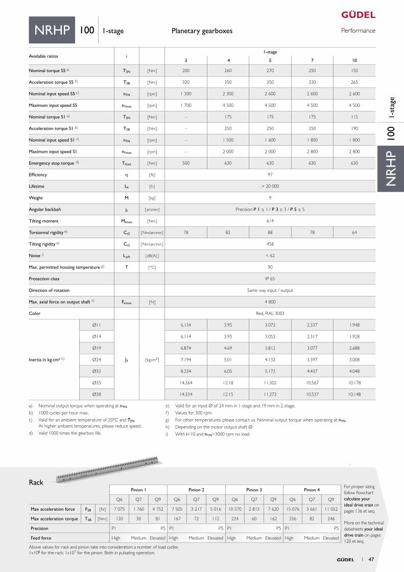
PerformancePlanetary gearboxes
Rack
More on the technical datasheets your ideal drive train on pages 120 et seq.
For proper sizing follow flowchart calculate your ideal drive train on pages 136 et seq.
Pinion 1 Pinion 2
Q6 Q7 Q9 Q6 Q7 Q9
Max acceleration force F2B [ N ] 7 540 4 107 4 805 16 163 7 565 12 980
Max acceleration torque T2B [ Nm ] 200 109 127 515 241 413
Precision P1 P5 P1 P5
Feed force High Medium Elevated High Medium Elevated
Above values for rack and pinion take into consideration a number of load cycles:1x10⁶ for the rack; 1x10⁷ for the pinion. Both in pulsating operation.
NR
H10
01-
stag
e
NRH 100 1-stage
Available ratios i1-stage
3 4 5 7 10
Nominal torque S5 a) T2N [ Nm ] 200 260 270 250 150
Acceleration torque S5 b) T2B [ Nm ] 320 350 350 330 265
Nominal input speed S5 c) n1N [rpm] 2 500 2 500 2 500 2 800 2 800
Maximum input speed S5 n1max [rpm] 4 000 4 500 4 500 4 500 4 500
Nominal torque S1 a) T2N [Nm ] – 175 175 175 115
Acceleration torque S1 b) T2B [ Nm] – 250 250 250 190
Nominal input speed S1 c) n1N [rpm] – 2 200 2 200 2 500 2 500
Maximum input speed S1 n1max [rpm] – 2 500 2 500 2 800 2 800
Emergency stop torque d) T2not [ Nm ] 500 630 630 630 630
Efficiency h [ % ] 97
Lifetime Lh [ h ] > 20 000
Weight M [ kg ] 7
Angular backlash jt [ arcmin ] Precision P 1 ≤ 1 / P 3 ≤ 3 / P 5 ≤ 5
Torsionnal rigidity e) Ct2 [ Nm/arcmin ] 34 42 44 44 37
Noise i) L pA [ dB(A) ] < 62
Max. permitted housing temperature g) T [ °C ] 90
Protection class IP 65
Direction of rotation Same way input / output
Max. radial force on output shaft f) Frmax [ N ] Center of output shaft: 6 600 / End of output shaft: 4 300
Max. axial force on output shaft f) Famax [ N ] 5 700
Color Red, RAL 3003
Inertia in kg.cm² h)
Ø11
J1 [ kgcm2 ]
4.56 3.061 2.504 2.047 1.806
Ø14 4.54 3.041 2.484 2.027 1.786
Ø19 5.3 3.801 3.244 2.787 2.546
Ø24 5.62 4.121 3.564 3.107 2.866
Ø32 6.66 5.161 4.604 4.147 3.906
Ø35 12.79 11.291 10.734 10.277 10.036
Ø38 12.76 11.261 10.704 10.247 10.006
a) Nominal output torque when operating at n1N.
b) 1000 cycles per hour max.
c) Valid for an ambient temperature of 20°C and T2N.
At higher ambient temperatures, please reduce speed.
d) Valid 1000 times the gearbox life.
e) Valid for an Input Ø of 24 mm in 1-stage and 19 mm in 2-stage.
f) Values for 300 rpm.
g) For other temperatures, please contact us. Nominal output torque when operating at n1N.
h) Depending on the motor output shaft Ø.
i) With i=10 and n1N=3000 rpm no load.
1 35
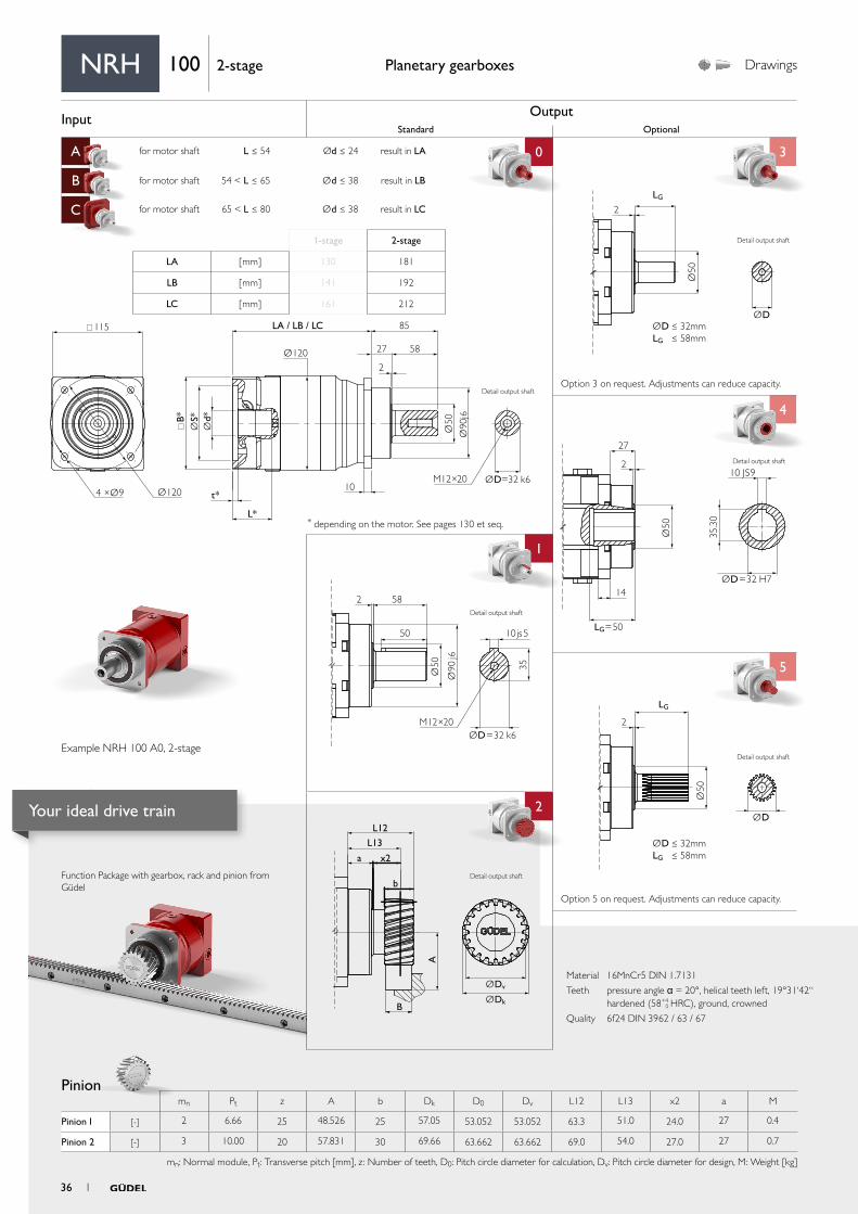
Input OutputStandard Optional
A for motor shaft L ≤ 54 Ød ≤ 24 result in LA 0 3
B for motor shaft 54 < L ≤ 65 Ød ≤ 38 result in LB
C for motor shaft 65 < L ≤ 80 Ød ≤ 38 result in LC
4
1 4
5
aa
2
ØDv
L12
L13
x2
b
B
a
A
ØDk
Ø50
ØD
LG
2
ØD ≤ 32mmLG ≤ 58mm
2 58
50
Ø50 35
Ø90
j6
M12×20ØD=32 k6
10js5
Ø50
ØD=32 H7
LG=50
10 JS9
27
2
14
35.3
0
Ø50
ØD
2
LG
ØD ≤ 32mmLG ≤ 58mm
115
Ø120
B*
t*
L*
10
LA / LB / LC 85
27
2
58
Ø1204 ×Ø9
Ød*
ØS*
Ø50
Ø90
j6
ØD=32 k6M12×20
Material 16MnCr5 DIN 1.7131
Teeth pressure angle α = 20°, helical teeth left, 19°31‘42“ hardened (58+4
0 HRC), ground, crowned
Quality 6f24 DIN 3962 / 63 / 67
Function Package with gearbox, rack and pinion from Güdel
Planetary gearboxes Drawings
* depending on the motor. See pages 130 et seq.
Option 5 on request. Adjustments can reduce capacity.
Option 3 on request. Adjustments can reduce capacity.
Pinion
NRH 100 2-stage
1-stage 2-stage
LA [ mm ] 130 181
LB [ mm ] 141 192
LC [ mm ] 161 212
Detail output shaft
Detail output shaft
Detail output shaft
Detail output shaftExample NRH 100 A0, 2-stage
mn Pt z A b Dk D0 Dv L12 L13 x2 a M
Pinion 1 [-] 2 6.66 25 48.526 25 57.05 53.052 53.052 63.3 51.0 24.0 27 0.4
Pinion 2 [-] 3 10.00 20 57.831 30 69.66 63.662 63.662 69.0 54.0 27.0 27 0.7
mn: Normal module, Pt: Transverse pitch [mm], z : Number of teeth, D0: Pitch circle diameter for calculation, Dv: Pitch circle diameter for design, M: Weight [kg]
Detail output shaft
Detail output shaft
36 1
Your ideal drive train
PerformancePlanetary gearboxes
Rack
More on the technical datasheets your ideal drive train on pages 120 et seq.
For proper sizing follow flowchart calculate your ideal drive train on pages 136 et seq.
Pinion 1 Pinion 2
Q6 Q7 Q9 Q6 Q7 Q9
Max acceleration force F2B [ N ] 7 540 4 107 4 805 16 163 7 565 12 980
Max acceleration torque T2B [ Nm ] 200 109 127 515 241 413
Precision P1 P5 P1 P5
Feed force High Medium Elevated High Medium Elevated
Above values for rack and pinion take into consideration a number of load cycles:1x10⁶ for the rack; 1x10⁷ for the pinion. Both in pulsating operation.
NR
H10
02-
stag
e
NRH 100 2-stage
* Other ratios available. 9, 15, 21, 27, 28, 49 on request.
a) Nominal output torque when operating at n1N.
b) 1000 cycles per hour max.
c) Valid for an ambient temperature of 20°C and T2N. At higher ambient temperatures, please reduce speed.
d) Valid 1000 times the gearbox life.
e) Valid for an input Ø of 24 mm in 1-stage and 19 mm in 2-stage.
f) Values for 300 rpm.
g) For other temperatures, please contact us. Nominal output torque when operating at n1N.
h) Depending on the motor output shaft Ø.
i) With i=10 and n1N=3000 rpm no load.
Available ratios * i2-stage
12 16 20 25 30 35 40 50 70 100
Nominal torque S5 a) T2N [ Nm ] 200 260 270 270 200 270 260 270 250 150
Acceleration torque S5 b) T2B [ Nm ] 320 350 350 350 320 350 350 320 330 265
Nominal input speed S5 c) n1N [rpm] 2 900 3 100 3 100 3 100 3 100 3 100 3 100 3 500 4 200 4 200
Maximum input speed S5 n1max [rpm] 4 500 4 500 4 500 4 500 4 500 4 500 4 500 4 500 4 500 4 500
Nominal torque S1 a) T2N [Nm ] 175 175 175 175 175 175 175 175 175 115
Acceleration torque S1 b) T2B [ Nm] 250 250 250 250 250 250 250 250 250 190
Nominal input speed S1 c) n1N [rpm] 2 000 2 200 2 800 2 800 2 800 2 800 2 800 3 100 3 800 3 800
Maximum input speed S1 n1max [rpm] 2 900 3 100 3 100 3 100 3 100 3 100 3 100 3 500 4 200 4 200
Emergency stop torque d) T2 n o t [ Nm ] 630 630 630 630 630 630 630 630 630 630
Efficiency h [ % ] 94
Lifetime Lh [ h ] > 20 000
Weight M [ kg ] 12
Angular backlash jt [ arcmin ] Precision P 1 ≤ 1 / P 3 ≤ 3 / P 5 ≤ 5
Torsionnal rigidity e) Ct2 [ Nm/arcmin ] 34 44 44 44 34 44 42 44 44 37
Noise i) L pA [ dB(A) ] < 62
Max. permitted housing temperature g) T [ °C ] 90
Protection class IP 65
Direction of rotation Same way input / output
Max. radial force on output shaft f) Fr m a x [ N ] Center of output shaft: 6 600 / End of output shaft: 4 300
Max. axial force on output shaft f) Fa m a x [ N ] 5 700
Color Red, RAL 3003
Inertia in kg.cm² h)
Ø11
J1 [ kgcm2 ]
2.934 2.841 2.806 2.34 1.786 1.964 1.771 1.765 1.761 1.758
Ø14 2.914 2.821 2.786 2.32 1.766 1.944 1.751 1.745 1.741 1.738
Ø19 3.674 3.581 3.546 3.08 2.526 2.704 2.511 2.505 2.501 2.498
Ø24 3.994 3.901 3.866 3.4 2.846 3.024 2.831 2.825 2.821 2.818
Ø32 5.034 4.941 4.906 4.44 3.886 4.064 3.871 3.865 3.861 3.858
Ø35 11.164 11.071 11.036 10.57 10.016 10.194 10.001 9.995 9.991 9.988
Ø38 11.134 11.041 11.006 10.54 9.986 10.164 9.971 9.965 9.961 9.958
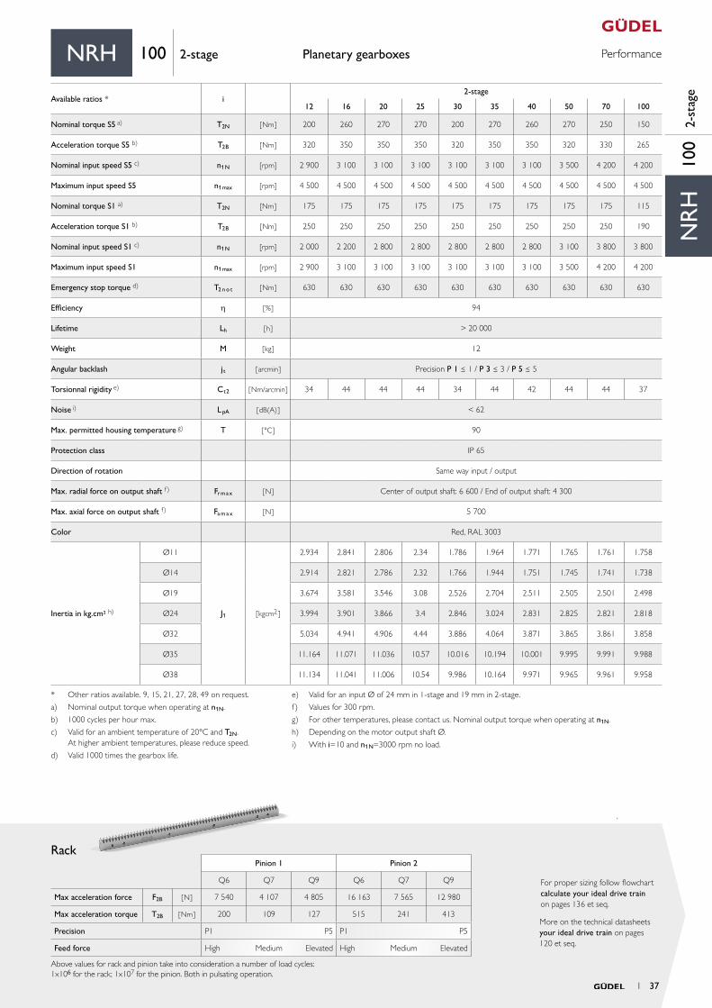
1 37
Input OutputStandard Optional
A for motor shaft L ≤ 62 Ød ≤ 38 result in LA 0 3
B for motor shaft 62 < L ≤ 115 Ød ≤ 48 result in LB
4
1 4
5
aa
2
ØDv
L12
L13
x2
b
B
a
A
ØDk
Ø65
ØD=42 H7
LG=58
12 JS9
27
2
16
45.3
0Ø
65LG
2
ØD ≤ 40mmLG ≤ 82mm
2 82
70
Ø65 43
Ø13
0 j6
M16×36 ØD=40 k6
12 js5
Ø65
ØD
2
16
LG
ØD ≤ 40mmLG ≤ 82mm142
B*
t*L* 14
LA / LB 109
272
82
Ø1654 ×Ø11
Ød*
ØS*
Ø65
Ø13
0 j6
ØD=40 k6M16×36
Material 16MnCr5 DIN 1.7131
Teeth pressure angle α = 20°, helical teeth left, 19°31‘42“ hardened (58+4
0 HRC), ground, crowned
Quality 6f24 DIN 3962 / 63 / 67
Function Package with gearbox, rack and pinion from Güdel
Planetary gearboxes Drawings
* depending on the motor. See pages 130 et seq.
Option 5 on request. Adjustments can reduce capacity.
Option 3 on request. Adjustments can reduce capacity.
Pinion
NRH 140 1-stage
Detail output shaft
Detail output shaft
Detail output shaft
Detail output shaftExample NRH 140 A0, 1-stage
mn Pt z A b Dk D0 Dv L12 L13 x2 a M
Pinion 1 [-] 3 10.00 22 61.014 30 76.03 70.028 70.028 69.5 54.5 27.5 27 0.8
Pinion 2 [-] 4 13.33 20 77.441 40 92.88 84.883 84.883 79.0 59.0 32.0 27 1.6
mn: Normal module, Pt: Transverse pitch [mm], z : Number of teeth, D0: Pitch circle diameter for calculation, Dv: Pitch circle diameter for design, M: Weight [kg]
1-stage 2-stage
LA [ mm ] 160 193
LB [ mm ] 212 204
LC [ mm ] 224
Detail output shaft
Detail output shaft
38 1
Your ideal drive train

PerformancePlanetary gearboxes
Rack
More on the technical datasheets your ideal drive train on pages 120 et seq.
For proper sizing follow flowchart calculate your ideal drive train on pages 136 et seq.
Pinion 1 Pinion 2
Q6 Q7 Q9 Q6 Q7 Q9
Max acceleration force F2B [ N ] 16 230 8 715 12 919 28 585 14 084 24 045
Max acceleration torque T2B [ Nm ] 568 305 452 1 213 598 1 021
Precision P1 P5 P1 P5
Feed force High Medium Elevated High Medium Elevated
Above values for rack and pinion take into consideration a number of load cycles:1x10⁶ for the rack; 1x10⁷ for the pinion. Both in pulsating operation.
NR
H14
01-
stag
e
NRH 140 1-stage
Available ratios i1-stage
3 4 5 7 10
Nominal torque S5 a) T2N [ Nm ] 400 490 500 470 310
Acceleration torque S5 b) T2B [ Nm ] 520 650 650 650 500
Nominal input speed S5 c) n1N [rpm] 2 100 2 100 2 100 2 600 2 600
Maximum input speed S5 n1max [rpm] 3 500 4 000 4 000 4 000 4 000
Nominal torque S1 a) T2N [Nm ] – 260 260 260 130
Acceleration torque S1 b) T2B [ Nm] – 370 370 370 220
Nominal input speed S1 c) n1N [rpm] – 1 900 1 900 2 300 2 300
Maximum input speed S1 n1max [rpm] – 2 100 2 100 2 600 2 600
Emergency stop torque d) T2 n o t [ Nm ] 1 300 1 300 1 300 1 300 1 260
Efficiency h [ % ] 97
Lifetime Lh [ h ] > 20 000
Weight M [ kg ] 15
Angular backlash jt [ arcmin ] Precision P 1 ≤ 1 / P 3 ≤ 3 / P 5 ≤ 5
Torsionnal rigidity e) Ct2 [ Nm/arcmin ] 90 101 107 106 98
Noise i) L pA [ dB(A) ] < 62
Max. permitted housing temperature g) T [ °C ] 90
Protection class IP 65
Direction of rotation Same way input / output
Max. radial force on output shaft f) Fr m a x [ N ] Center of output shaft: 9 950 / End of output shaft: 6 700
Max. axial force on output shaft f) Fa m a x [ N ] 10 300
Color Red, RAL 3003
Inertia in kg.cm² h)
Ø19
J1 [ kgcm2 ]
11.83 7.32 5.647 4.224 3.499
Ø24 12.15 7.64 5.967 4.544 3.819
Ø32 18.01 13.5 11.827 10.404 9.679
Ø35 18.6 14.09 12.417 10.994 10.269
Ø38 19.07 14.56 12.887 11.464 10.739
Ø42 19.4 14.89 13.217 11.794 11.069
Ø48 23.38 18.87 17.197 15.774 15.049
a) Nominal output torque when operating at n1N.
b) 1000 cycles per hour max.
c) Valid for an ambient temperature of 20°C and T2N. At higher ambient temperatures, please reduce speed.
d) Valid 1000 times the gearbox life.
e) Valid for an input Ø of 38 mm in 1-stage and 24 mm in 2-stage.
f) Values for 300 rpm.
g) For other temperatures, please contact us. Nominal output torque when operating at n1N.
h) Depending on the motor output shaft Ø.
i) With i=10 and n1N=3000 rpm no load.
1 39
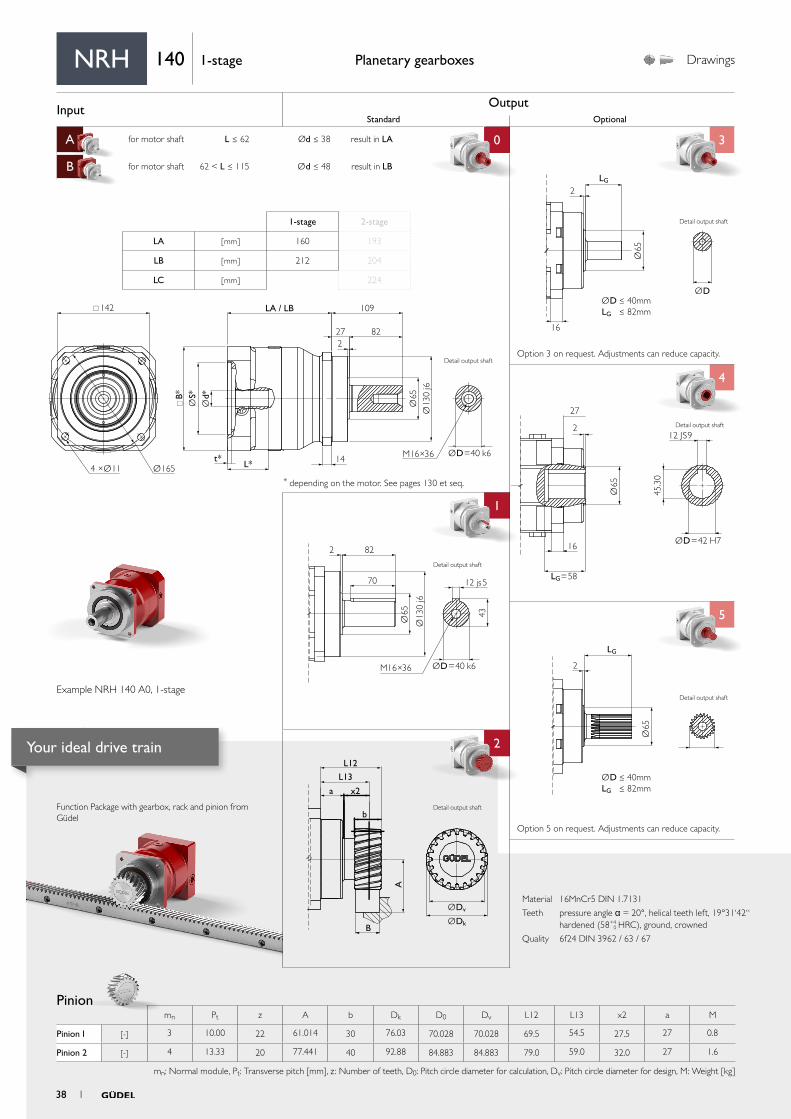
Input OutputStandard Optional
A for motor shaft L ≤ 54 Ød ≤ 32 result in LA 0 3
B for motor shaft 54 < L ≤ 65 Ød ≤ 38 result in LB
C for motor shaft 65 < L ≤ 80 Ød ≤ 38 result in LC
4
1 4
5
aa
2
ØDv
L12
L13
x2
b
B
a
A
ØDk
Ø65
ØD=42 H7
LG=58
12 JS9
27
2
16
45.3
0Ø
65LG
2
ØD ≤ 40mmLG ≤ 82mm
2 82
70
Ø65 43
Ø13
0 j6
M16×36 ØD=40 k6
12 js5
Ø65
ØD
2
16
LG
ØD ≤ 40mmLG ≤ 82mm142
B*
t*
L* 14
LA / LB / LC 109
272
82
Ø1654 ×Ø11
Ød*
ØS*
Ø65
Ø13
0 j6
ØD=40 k6M16×36
Material 16MnCr5 DIN 1.7131
Teeth pressure angle α = 20°, helical teeth left, 19°31‘42“ hardened (58+4
0 HRC), ground, crowned
Quality 6f24 DIN 3962 / 63 / 67
Function Package with gearbox, rack and pinion from Güdel
Planetary gearboxes Drawings
* depending on the motor. See pages 130 et seq.
Option 5 on request. Adjustments can reduce capacity.
Option 3 on request. Adjustments can reduce capacity.
Pinion
Example NRH 140 A0, 2-stage
NRH 140 2-stage
Detail output shaft
Detail output shaft
Detail output shaft
Detail output shaft
mn Pt z A b Dk D0 Dv L12 L13 x2 a M
Pinion 1 [-] 3 10.00 22 61.014 30 76.03 70.028 70.028 69.5 54.5 27.5 27 0.8
Pinion 2 [-] 4 13.33 20 77.441 40 92.88 84.883 84.883 79.0 59.0 32.0 27 1.6
mn: Normal module, Pt: Transverse pitch [mm], z : Number of teeth, D0: Pitch circle diameter for calculation, Dv: Pitch circle diameter for design, M: Weight [kg]
1-stage 2-stage
LA [ mm ] 160 193
LB [ mm ] 212 204
LC [ mm ] 224
Detail output shaft
Detail output shaft
40 1
Your ideal drive train
PerformancePlanetary gearboxes
Rack
More on the technical datasheets your ideal drive train on pages 120 et seq.
For proper sizing follow flowchart calculate your ideal drive train on pages 136 et seq.
Pinion 1 Pinion 2
Q6 Q7 Q9 Q6 Q7 Q9
Max acceleration force F2B [ N ] 16 230 8 715 12 919 28 585 14 084 24 045
Max acceleration torque T2B [ Nm ] 568 305 452 1 213 598 1 021
Precision P1 P5 P1 P5
Feed force High Medium Elevated High Medium Elevated
Above values for rack and pinion take into consideration a number of load cycles:1x10⁶ for the rack; 1x10⁷ for the pinion. Both in pulsating operation.
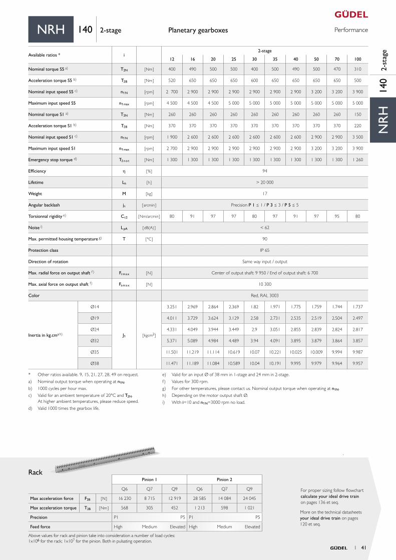
NR
H14
02-
stag
e
NRH 140 2-stage
* Other ratios available. 9, 15, 21, 27, 28, 49 on request.
a) Nominal output torque when operating at n1N.
b) 1000 cycles per hour max.
c) Valid for an ambient temperature of 20°C and T2N. At higher ambient temperatures, please reduce speed.
d) Valid 1000 times the gearbox life.
e) Valid for an input Ø of 38 mm in 1-stage and 24 mm in 2-stage.
f) Values for 300 rpm.
g) For other temperatures, please contact us. Nominal output torque when operating at n1N.
h) Depending on the motor output shaft Ø.
i) With i=10 and n1N=3000 rpm no load.
Available ratios * i2-stage
12 16 20 25 30 35 40 50 70 100
Nominal torque S5 a) T2N [ Nm ] 400 490 500 500 400 500 490 500 470 310
Acceleration torque S5 b) T2B [ Nm ] 520 650 650 650 600 650 650 650 650 500
Nominal input speed S5 c) n1N [rpm] 2 700 2 900 2 900 2 900 2 900 2 900 2 900 3 200 3 200 3 900
Maximum input speed S5 n1max [rpm] 4 500 4 500 4 500 5 000 5 000 5 000 5 000 5 000 5 000 5 000
Nominal torque S1 a) T2N [Nm ] 260 260 260 260 260 260 260 260 260 150
Acceleration torque S1 b) T2B [ Nm] 370 370 370 370 370 370 370 370 370 220
Nominal input speed S1 c) n1N [rpm] 1 900 2 600 2 600 2 600 2 600 2 600 2 600 2 900 2 900 3 500
Maximum input speed S1 n1max [rpm] 2 700 2 900 2 900 2 900 2 900 2 900 2 900 3 200 3 200 3 900
Emergency stop torque d) T2 n o t [ Nm ] 1 300 1 300 1 300 1 300 1 300 1 300 1 300 1 300 1 300 1 260
Efficiency h [ % ] 94
Lifetime Lh [ h ] > 20 000
Weight M [ kg ] 17
Angular backlash jt [ arcmin ] Precision P 1 ≤ 1 / P 3 ≤ 3 / P 5 ≤ 5
Torsionnal rigidity e) Ct2 [ Nm/arcmin ] 80 91 97 97 80 97 91 97 95 80
Noise i) L pA [ dB(A) ] < 62
Max. permitted housing temperature g) T [ °C ] 90
Protection class IP 65
Direction of rotation Same way input / output
Max. radial force on output shaft f) Fr m a x [ N ] Center of output shaft: 9 950 / End of output shaft: 6 700
Max. axial force on output shaft f) Fa m a x [ N ] 10 300
Color Red, RAL 3003
Inertia in kg.cm² h)
Ø14
J1 [ kgcm2 ]
3.251 2.969 2.864 2.369 1.82 1.971 1.775 1.759 1.744 1.737
Ø19 4.011 3.729 3.624 3.129 2.58 2.731 2.535 2.519 2.504 2.497
Ø24 4.331 4.049 3.944 3.449 2.9 3.051 2.855 2.839 2.824 2.817
Ø32 5.371 5.089 4.984 4.489 3.94 4.091 3.895 3.879 3.864 3.857
Ø35 11.501 11.219 11.114 10.619 10.07 10.221 10.025 10.009 9.994 9.987
Ø38 11.471 11.189 11.084 10.589 10.04 10.191 9.995 9.979 9.964 9.957
1 41
Input Output
A for motor shaft L ≤ 50 Ød ≤ 19 result in LA 0
B for motor shaft 50 < L ≤ 55 Ød ≤ 24 result in LB
C for motor shaft 55 < L ≤ 60 Ød ≤ 24 result in LC
aa
2
Ø118 h7
t*
L*
Ø99
LA / LB / LC 30
7
Ø109
Ø50
B*
Ød*
ØS*
Ø63
h7
Ø31
.5 H
7
Ø90
h7
8 ×Ø5.5
8 ×M6×12
7
0.02 A B
0.03 A B
0.03 AA B
B
B 0.02
0.02
A
B
L12
L13
x2
b
a
A
ØDv
ØDk
Function Package with gearbox, rack and pinion from Güdel
Pinion
Planetary gearboxes Drawings
* depending on the motor. See pages 130 et seq.
Material 16MnCr5 DIN 1.7131
Teeth pressure angle α = 20°, helical teeth left, 19°31‘42“, hardened (58+4
0 HRC), ground, crowned
Quality 6f24 DIN 3962 / 63 / 67
Detail output shaft
Example NRHP 080 A0, 1-stage
NRHP 080 1-stage
1-stage 2-stage
LA [ mm ] 108 145
LB [ mm ] 116 153
LC [ mm ] 121 158
mn Pt z A b Dk D0 Dv L12 L13 x2 a M
Pinion 1 [-] 2 6.66 16 39.577 26 39.15 33.953 35.153 75.0 62.0 32.0 30 0.6
mn: Normal module, Pt: Transverse pitch [mm], z : Number of teeth, D0: Pitch circle diameter for calculation, Dv: Pitch circle diameter for design, M: Weight [kg]
42 1
Your ideal drive train
PerformancePlanetary gearboxes
Rack
More on the technical datasheets your ideal drive train on pages 120 et seq.
For proper sizing follow flowchart calculate your ideal drive train on pages 136 et seq.
Material 16MnCr5 DIN 1.7131
Teeth pressure angle α = 20°, helical teeth left, 19°31‘42“, hardened (58+4
0 HRC), ground, crowned
Quality 6f24 DIN 3962 / 63 / 67
Pinion 1
Q6 Q7 Q9
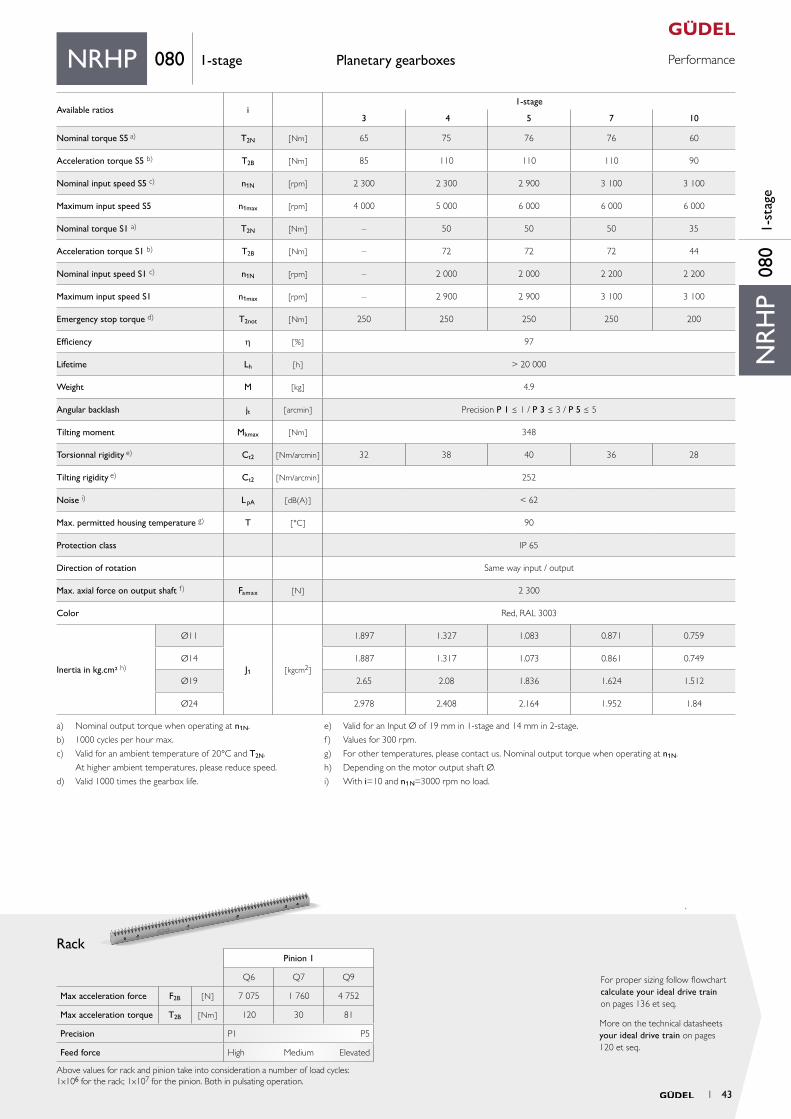
Max acceleration force F2B [ N ] 7 075 1 760 4 752
Max acceleration torque T2B [ Nm ] 120 30 81
Precision P1 P5
Feed force High Medium Elevated
Above values for rack and pinion take into consideration a number of load cycles:1x10⁶ for the rack; 1x10⁷ for the pinion. Both in pulsating operation.
NR
HP
080
1-st
age
NRHP 080 1-stage
Available ratios i1-stage
3 4 5 7 10
Nominal torque S5 a) T2N [ Nm ] 65 75 76 76 60
Acceleration torque S5 b) T2B [ Nm ] 85 110 110 110 90
Nominal input speed S5 c) n1N [rpm] 2 300 2 300 2 900 3 100 3 100
Maximum input speed S5 n1max [rpm] 4 000 5 000 6 000 6 000 6 000
Nominal torque S1 a) T2N [Nm ] – 50 50 50 35
Acceleration torque S1 b) T2B [ Nm] – 72 72 72 44
Nominal input speed S1 c) n1N [rpm] – 2 000 2 000 2 200 2 200
Maximum input speed S1 n1max [rpm] – 2 900 2 900 3 100 3 100
Emergency stop torque d) T2not [ Nm ] 250 250 250 250 200
Efficiency h [ % ] 97
Lifetime Lh [ h ] > 20 000
Weight M [ kg ] 4.9
Angular backlash jt [ arcmin ] Precision P 1 ≤ 1 / P 3 ≤ 3 / P 5 ≤ 5
Tilting moment Mkmax [ Nm ] 348
Torsionnal rigidity e) Ct2 [ Nm/arcmin ] 32 38 40 36 28
Tilting rigidity e) Ct2 [ Nm/arcmin ] 252
Noise i) L pA [ dB(A) ] < 62
Max. permitted housing temperature g) T [ °C ] 90
Protection class IP 65
Direction of rotation Same way input / output
Max. axial force on output shaft f) Famax [ N ] 2 300
Color Red, RAL 3003
Inertia in kg.cm² h)
Ø11
J1 [ kgcm2 ]
1.897 1.327 1.083 0.871 0.759
Ø14 1.887 1.317 1.073 0.861 0.749
Ø19 2.65 2.08 1.836 1.624 1.512
Ø24 2.978 2.408 2.164 1.952 1.84
a) Nominal output torque when operating at n1N.
b) 1000 cycles per hour max.
c) Valid for an ambient temperature of 20°C and T2N.
At higher ambient temperatures, please reduce speed.
d) Valid 1000 times the gearbox life.
e) Valid for an Input Ø of 19 mm in 1-stage and 14 mm in 2-stage.
f) Values for 300 rpm.
g) For other temperatures, please contact us. Nominal output torque when operating at n1N.
h) Depending on the motor output shaft Ø.
i) With i=10 and n1N=3000 rpm no load.
1 43
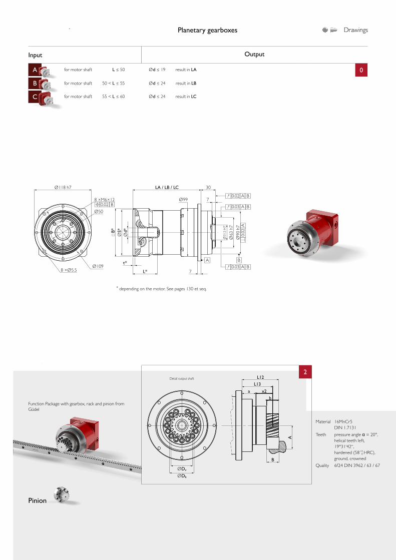
Input Output
A for motor shaft L ≤ 50 Ød ≤ 19 result in LA 0
B for motor shaft 50 < L ≤ 55 Ød ≤ 24 result in LB
C for motor shaft 55 < L ≤ 60 Ød ≤ 24 result in LC
aa
2
Ø118 h7
t*
L*
Ø99
LA / LB / LC 30
7
Ø109
Ø50
B*
Ød*
ØS*
Ø63
h7
Ø31
.5 H
7
Ø90
h7
8 ×Ø5.5
8 ×M6×12
7
B
0.02 A B
0.03 A B
0.03 AA B
B
0.02
0.02
A
B
L12
L13
x2
b
a
A
ØDv
ØDk
Function Package with gearbox, rack and pinion from Güdel
Pinion
Planetary gearboxes Drawings
* depending on the motor. See pages 130 et seq.
Material 16MnCr5 DIN 1.7131
Teeth pressure angle α = 20°, helical teeth left, 19°31‘42“, hardened (58+4
0 HRC), ground, crowned
Quality 6f24 DIN 3962 / 63 / 67
Detail output shaft
Example NRHP 080 A0, 2-stage
mn Pt z A b Dk D0 Dv L12 L13 x2 a M
Pinion 1 [-] 2 6.66 16 39.577 26 39.15 33.953 35.153 75.0 62.0 32.0 30 0.6
mn: Normal module, Pt: Transverse pitch [mm], z : Number of teeth, D0: Pitch circle diameter for calculation, Dv: Pitch circle diameter for design, M: Weight [kg]
44 1
Your ideal drive train
PerformancePlanetary gearboxes
Rack
More on the technical datasheets your ideal drive train on pages 120 et seq.
For proper sizing follow flowchart calculate your ideal drive train on pages 136 et seq.
Material 16MnCr5 DIN 1.7131
Teeth pressure angle α = 20°, helical teeth left, 19°31‘42“, hardened (58+4
0 HRC), ground, crowned
Quality 6f24 DIN 3962 / 63 / 67
Pinion 1
Q6 Q7 Q9
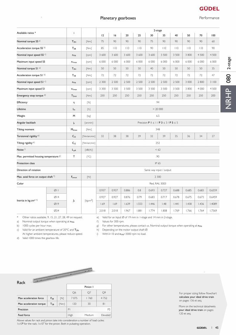
Max acceleration force F2B [ N ] 7 075 1 760 4 752
Max acceleration torque T2B [ Nm ] 120 30 81
Precision P1 P5
Feed force High Medium Elevated
Above values for rack and pinion take into consideration a number of load cycles:1x10⁶ for the rack; 1x10⁷ for the pinion. Both in pulsating operation.
NR
HP
080
2-st
age
* Other ratios available. 9, 15, 21, 27, 28, 49 on request.
a) Nominal output torque when operating at n1N.
b) 1000 cycles per hour max.
c) Valid for an ambient temperature of 20°C and T2N.
At higher ambient temperatures, please reduce speed.
d) Valid 1000 times the gearbox life.
e) Valid for an Input Ø of 19 mm in 1-stage and 14 mm in 2-stage.
f) Values for 300 rpm.
g) For other temperatures, please contact us. Nominal output torque when operating at n1N.
h) Depending on the motor output shaft Ø.
i) With i=10 and n1N=3000 rpm no load.
Available ratios * i2-stage
12 16 20 25 30 35 40 50 70 100
Nominal torque S5 a) T2N [ Nm ] 75 90 90 90 75 90 90 90 90 60
Acceleration torque S5 b) T2B [ Nm ] 85 110 110 110 90 110 110 110 110 90
Nominal input speed S5 c) n1N [rpm] 3 600 3 600 3 600 3 600 3 600 3 500 3 500 3 800 4 500 4 500
Maximum input speed S5 n1max [rpm] 6 000 6 000 6 000 6 000 6 000 6 000 6 000 6 000 6 000 6 000
Nominal torque S1 a) T2N [Nm ] 50 50 50 50 40 50 50 50 50 35
Acceleration torque S1 b) T2B [ Nm] 72 72 72 72 72 72 72 72 72 47
Nominal input speed S1 c) n1N [rpm] 2 300 2 500 2 500 2 500 2 500 2 500 2 500 3 000 2 800 3 100
Maximum input speed S1 n1max [rpm] 3 300 3 500 3 500 3 500 3 500 3 500 3 500 3 800 4 000 4 500
Emergency stop torque d) T2not [ Nm ] 250 250 250 250 250 250 250 250 250 200
Efficiency h [ % ] 94
Lifetime Lh [ h ] > 20 000
Weight M [ kg ] 6.5
Angular backlash jt [ arcmin ] Precision P 1 ≤ 1 / P 3 ≤ 3 / P 5 ≤ 5
Tilting moment Mkmax [ Nm ] 348
Torsionnal rigidity e) Ct2 [ Nm/arcmin ] 32 38 38 39 32 39 35 36 34 27
Tilting rigidity e) Ct2 [ Nm/arcmin ] 252
Noise i) L pA [ dB(A) ] < 62
Max. permitted housing temperature g) T [ °C ] 90
Protection class IP 65
Direction of rotation Same way input / output
Max. axial force on output shaft f) Famax [ N ] 2 300
Color Red, RAL 3003
Inertia in kg.cm² h)
Ø11
J1 [ kgcm2 ]
0.937 0.937 0.886 0.8 0.693 0.727 0.688 0.685 0.683 0.6559
Ø14 0.927 0.927 0.876 0.79 0.683 0.717 0.678 0.675 0.673 0.6459
Ø19 1.69 1.69 1.639 1.553 1.446 1.48 1.441 1.438 1.436 1.4089
Ø24 2.018 2.018 1.967 1.881 1.774 1.808 1.769 1.766 1.764 1.7369
1 45
Input Output
A for motor shaft L ≤ 54 Ød ≤ 24 result in LA 0
B for motor shaft 54 < L ≤ 65 Ød ≤ 38 result in LB
C for motor shaft 65 < L ≤ 80 Ød ≤ 38 result in LC
aa
2
B
L12
L13
x2
b
a
A
ØDv
ØDk
Ø145 h7
t*
L*
Ø120
LA / LB / LC 29
7
6Ø135
Ø63
B*
Ød*
ØS*
Ø80
h7
Ø40
H7
Ø11
0 h7
8 ×Ø5.5
15 ×M6×12Ø6 H7
8
0.02 A B
0.03 A B
0.03 AA B
B
0.02
A
0.02 B
Function Package with gearbox, rack and pinion from Güdel
Planetary gearboxes Drawings
* depending on the motor. See pages 130 et seq.
Pinion
Material 16MnCr5 DIN 1.7131
Teeth pressure angle α = 20°, helical teeth left, 19°31‘42“, hardened (58+4
0 HRC), ground, crowned
Quality 6f24 DIN 3962 / 63 / 67
Detail output shaft
mn Pt z A b Dk D0 Dv L12 L13 x2 a M
Pinion 1 [-] 2 6.66 16 39.577 26 39.15 33.953 35.153 77.0 64.0 35.0 29 1.0
Pinion 2 [-] 2 6.66 21 44.282 26 48.56 44.563 44.563 77.0 64.0 35.0 29 1.0
Pinion 3 [-] 2.5 8.33 16 43.471 26 48.94 42.441 43.941 77.0 64.0 35.0 29 1.0
Pinion 4 [-] 3 10.00 14 49.182 32 52.36 44.563 46.363 83.0 67.0 38.0 29 1.2
mn: Normal module, Pt: Transverse pitch [mm], z : Number of teeth, D0: Pitch circle diameter for calculation, Dv: Pitch circle diameter for design, M: Weight [kg]
NRHP 100 1-stage
Example NRHP 100 A0, 1-stage
46 1
Your ideal drive train
PerformancePlanetary gearboxes
Rack
More on the technical datasheets your ideal drive train on pages 120 et seq.
For proper sizing follow flowchart calculate your ideal drive train on pages 136 et seq.
ElevatedElevated Elevated Elevated
Material 16MnCr5 DIN 1.7131
Teeth pressure angle α = 20°, helical teeth left, 19°31‘42“, hardened (58+4
0 HRC), ground, crowned
Quality 6f24 DIN 3962 / 63 / 67
Pinion 1 Pinion 2 Pinion 3 Pinion 4
Q6 Q7 Q9 Q6 Q7 Q9 Q6 Q7 Q9 Q6 Q7 Q9
Max acceleration force F2B [ N ] 7 075 1 760 4 752 7 505 3 217 5 016 10 570 2 813 7 620 15 076 3 661 11 052
Max acceleration torque T2B [ Nm ] 120 30 81 167 72 112 224 60 162 336 82 246
Precision P1 P5 P1 P5 P1 P5 P1 P5
Feed force High Medium High Medium High Medium High Medium
Above values for rack and pinion take into consideration a number of load cycles:1x10⁶ for the rack; 1x10⁷ for the pinion. Both in pulsating operation.
NR
HP
100
1-st
age
NRHP 100 1-stage
a) Nominal output torque when operating at n1N.
b) 1000 cycles per hour max.
c) Valid for an ambient temperature of 20°C and T2N. At higher ambient temperatures, please reduce speed.
d) Valid 1000 times the gearbox life.
e) Valid for an input Ø of 24 mm in 1-stage and 19 mm in 2-stage.
f) Values for 300 rpm.
g) For other temperatures, please contact us. Nominal output torque when operating at n1N.
h) Depending on the motor output shaft Ø.
i) With i=10 and n1N=3000 rpm no load.
Available ratios i1-stage
3 4 5 7 10
Nominal torque S5 a) T2N [ Nm ] 200 260 270 250 150
Acceleration torque S5 b) T2B [ Nm ] 320 350 350 330 265
Nominal input speed S5 c) n1N [rpm] 1 300 2 300 2 600 2 600 2 600
Maximum input speed S5 n1max [rpm] 1 700 4 500 4 500 4 500 4 500
Nominal torque S1 a) T2N [Nm ] – 175 175 175 115
Acceleration torque S1 b) T2B [ Nm] – 250 250 250 190
Nominal input speed S1 c) n1N [rpm] – 1 500 1 600 1 800 1 800
Maximum input speed S1 n1max [rpm] – 2 000 2 000 2 800 2 800
Emergency stop torque d) T2not [ Nm ] 500 630 630 630 630
Efficiency h [ % ] 97
Lifetime Lh [ h ] > 20 000
Weight M [ kg ] 9
Angular backlash jt [ arcmin ] Precision P 1 ≤ 1 / P 3 ≤ 3 / P 5 ≤ 5
Tilting moment Mkmax [ Nm ] 614
Torsionnal rigidity e) Ct2 [ Nm/arcmin ] 78 82 88 78 64
Tilting rigidity e) Ct2 [ Nm/arcmin ] 458
Noise i) L pA [ dB(A) ] < 62
Max. permitted housing temperature g) T [ °C ] 90
Protection class IP 65
Direction of rotation Same way input / output
Max. axial force on output shaft f) Famax [ N ] 4 800
Color Red, RAL 3003
Inertia in kg.cm² h)
Ø11
J1 [ kgcm2 ]
6.134 3.95 3.072 2.337 1.948
Ø14 6.114 3.93 3.052 2.317 1.928
Ø19 6.874 4.69 3.812 3.077 2.688
Ø24 7.194 5.01 4.132 3.397 3.008
Ø32 8.234 6.05 5.172 4.437 4.048
Ø35 14.364 12.18 11.302 10.567 10.178
Ø38 14.334 12.15 11.272 10.537 10.148
1 47
Input Output
A for motor shaft L ≤ 54 Ød ≤ 24 result in LA 0
B for motor shaft 54 < L ≤ 65 Ød ≤ 38 result in LB
C for motor shaft 65 < L ≤ 80 Ød ≤ 38 result in LC
aa
2
B
L12
L13
x2
b
a
A
ØDv
ØDk
Ø145 h7
t*
L*
Ø120
LA / LB / LC 29
7
6Ø135
Ø63
B*
Ød*
ØS*
Ø80
h7
Ø40
H7
Ø11
0 h7
8 ×Ø5.5
15 ×M6×12Ø6 H7
8
0.02 A B
0.03 A B
0.03 AA B
B
0.02
A
0.02 B
Function Package with gearbox, rack and pinion from Güdel
Planetary gearboxes Drawings
* depending on the motor. See pages 130 et seq.
Pinion
Material 16MnCr5 DIN 1.7131
Teeth pressure angle α = 20°, helical teeth left, 19°31‘42“, hardened (58+4
0 HRC), ground, crowned
Quality 6f24 DIN 3962 / 63 / 67
Detail output shaft
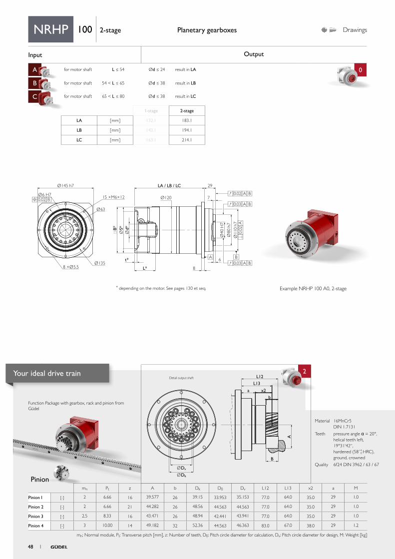
1-stage 2-stage
LA [ mm ] 132.1 183.1
LB [ mm ] 143.1 194.1
LC [ mm ] 163.1 214.1
NRHP 100 2-stage
Example NRHP 100 A0, 2-stage
mn Pt z A b Dk D0 Dv L12 L13 x2 a M
Pinion 1 [-] 2 6.66 16 39.577 26 39.15 33.953 35.153 77.0 64.0 35.0 29 1.0
Pinion 2 [-] 2 6.66 21 44.282 26 48.56 44.563 44.563 77.0 64.0 35.0 29 1.0
Pinion 3 [-] 2.5 8.33 16 43.471 26 48.94 42.441 43.941 77.0 64.0 35.0 29 1.0
Pinion 4 [-] 3 10.00 14 49.182 32 52.36 44.563 46.363 83.0 67.0 38.0 29 1.2
mn: Normal module, Pt: Transverse pitch [mm], z : Number of teeth, D0: Pitch circle diameter for calculation, Dv: Pitch circle diameter for design, M: Weight [kg]
48 1
Your ideal drive train
PerformancePlanetary gearboxes
Rack
More on the technical datasheets your ideal drive train on pages 120 et seq.
For proper sizing follow flowchart calculate your ideal drive train on pages 136 et seq.
ElevatedElevated Elevated Elevated
Material 16MnCr5 DIN 1.7131
Teeth pressure angle α = 20°, helical teeth left, 19°31‘42“, hardened (58+4
0 HRC), ground, crowned
Quality 6f24 DIN 3962 / 63 / 67
Pinion 1 Pinion 2 Pinion 3 Pinion 4
Q6 Q7 Q9 Q6 Q7 Q9 Q6 Q7 Q9 Q6 Q7 Q9
Max acceleration force F2B [ N ] 7 075 1 760 4 752 7 505 3 217 5 016 10 570 2 813 7 620 15 076 3 661 11 052
Max acceleration torque T2B [ Nm ] 120 30 81 167 72 112 224 60 162 336 82 246
Precision P1 P5 P1 P5 P1 P5 P1 P5
Feed force High Medium High Medium High Medium High Medium
Above values for rack and pinion take into consideration a number of load cycles:1x10⁶ for the rack; 1x10⁷ for the pinion. Both in pulsating operation.
NR
HP
100
2-st
age
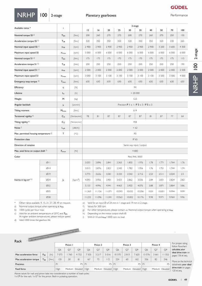
NRHP 100 2-stage
* Other ratios available. 9, 15, 21, 27, 28, 49 on request.
a) Nominal output torque when operating at n1N.
b) 1000 cycles per hour max.
c) Valid for an ambient temperature of 20°C and T2N. At higher ambient temperatures, please reduce speed.
d) Valid 1000 times the gearbox life.
e) Valid for an input Ø of 24 mm in 1-stage and 19 mm in 2-stage.
f) Values for 300 rpm.
g) For other temperatures, please contact us. Nominal output torque when operating at n1N.
h) Depending on the motor output shaft Ø.
i) With i=10 and n1N=3000 rpm no load.
Available ratios * i2-stage
12 16 20 25 30 35 40 50 70 100
Nominal torque S5 a) T2N [ Nm ] 200 260 270 270 200 270 260 270 250 150
Acceleration torque S5 b) T2B [ Nm ] 320 350 350 350 320 350 350 320 330 265
Nominal input speed S5 c) n1N [rpm] 2 400 2 900 2 900 2 900 2 900 2 900 2 900 3 200 3 600 4 300
Maximum input speed S5 n1max [rpm] 5 000 6 000 6 000 6 000 6 000 6 000 6 000 6 000 6 000 6 000
Nominal torque S1 a) T2N [Nm ] 175 175 175 175 175 175 175 175 175 115
Acceleration torque S1 b) T2B [ Nm] 250 250 250 250 250 250 250 250 250 190
Nominal input speed S1 c) n1N [rpm] 2 000 2 000 2 000 2 000 2 000 2 000 2 000 2 000 2 000 2 500
Maximum input speed S1 n1max [rpm] 3 000 3 100 3 100 3 100 3 100 3 100 3 100 3 500 3 500 4 000
Emergency stop torque d) T2not [ Nm ] 630 630 630 630 630 630 630 630 630 630
Efficiency h [ % ] 94
Lifetime Lh [ h ] > 20 000
Weight M [ kg ] 12.5
Angular backlash jt [ arcmin ] Precision P 1 ≤ 1 / P 3 ≤ 3 / P 5 ≤ 5
Tilting moment Mkmax [ Nm ] 614
Torsionnal rigidity e) Ct2 [ Nm/arcmin ] 78 81 87 87 87 87 81 87 77 64
Tilting rigidity e) Ct2 [ Nm/arcmin ] 458
Noise i) L pA [ dB(A) ] < 62
Max. permitted housing temperature g) T [ °C ] 90
Protection class IP 65
Direction of rotation Same way input / output
Max. axial force on output shaft f) Famax [ N ] 4 800
Color Red, RAL 3003
Inertia in kg.cm² h)
Ø11
J1 [ kgcm2 ]
3.033 2.896 2.841 2.363 1.802 1.976 1.78 1.771 1.764 1.76
Ø14 3.013 2.876 2.821 2.343 1.782 1.956 1.76 1.751 1.744 1.74
Ø19 3.773 3.636 3.581 3.103 2.542 2.716 2.52 2.511 2.504 2.5
Ø24 4.093 3.956 3.901 3.423 2.862 3.036 2.84 2.831 2.824 2.82
Ø32 5.133 4.996 4.941 4.463 3.902 4.076 3.88 3.871 3.864 3.86
Ø35 11.263 11.126 11.071 10.593 10.032 10.206 10.01 10.001 9.994 9.99
Ø38 11.233 11.096 11.041 10.563 10.002 10.176 9.98 9.971 9.964 9.96
1 49
Input Output
A for motor shaft L ≤ 62 Ød ≤ 38 result in LA 0
B for motor shaft 62 < L ≤ 115 Ød ≤ 48 result in LB
C
4
aa
2
Ø179 h7
t*
L*
Ø158
LA / LB 38
7.5
Ø168
Ø80
Ø8 H7
B*
Ød*
ØS*
Ø10
0 h7
Ø50
H7
Ø14
0 h7
12 ×Ø6.6
11 ×M8×15
10
10A B
ø0.02
0.02 A B
0.03 A B
0.03
A
0.03 A B
B
L12
L13
x2
b
a
A
ØDv
ØDk
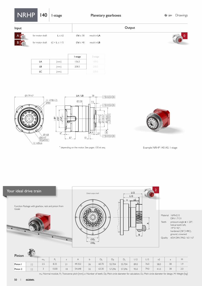
Function Package with gearbox, rack and pinion from Güdel
Pinion
Planetary gearboxes Drawings
* depending on the motor. See pages 130 et seq.
Material 16MnCr5 DIN 1.7131
Teeth pressure angle α = 20°, helical teeth left, 19°31‘42“, hardened (58+4
0 HRC), ground, crowned
Quality 6f24 DIN 3962 / 63 / 67
Detail output shaft
NRHP 140 1-stage
Example NRHP 140 A0, 1-stage
mn Pt z A b Dk D0 Dv L12 L13 x2 a M
Pinion 1 [-] 2.5 8.33 21 49.352 26 60.70 55.704 55.704 89.0 76.0 38.0 38 1.9
Pinion 2 [-] 3 10.00 18 54.648 32 63.30 57.296 57.296 95.0 79.0 41.0 38 2.0
mn: Normal module, Pt: Transverse pitch [mm], z : Number of teeth, D0: Pitch circle diameter for calculation, Dv: Pitch circle diameter for design, M: Weight [kg]
1-stage 2-stage
LA [ mm ] 156.5 189.5
LB [ mm ] 208.5 200.5
LC [ mm ] 220.5
50 1
Your ideal drive train
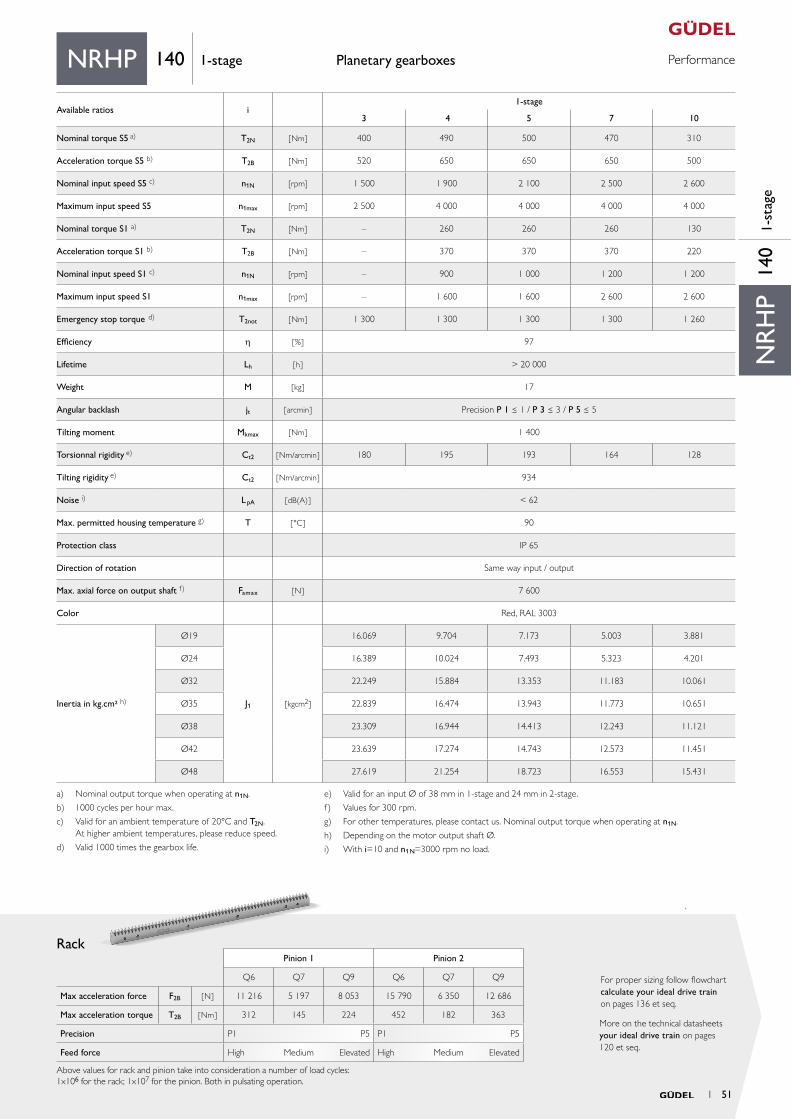
PerformancePlanetary gearboxes
Rack
More on the technical datasheets your ideal drive train on pages 120 et seq.
For proper sizing follow flowchart calculate your ideal drive train on pages 136 et seq.
Material 16MnCr5 DIN 1.7131
Teeth pressure angle α = 20°, helical teeth left, 19°31‘42“, hardened (58+4
0 HRC), ground, crowned
Quality 6f24 DIN 3962 / 63 / 67
Pinion 1 Pinion 2
Q6 Q7 Q9 Q6 Q7 Q9
Max acceleration force F2B [ N ] 11 216 5 197 8 053 15 790 6 350 12 686
Max acceleration torque T2B [ Nm ] 312 145 224 452 182 363
Precision P1 P5 P1 P5
Feed force High Medium Elevated High Medium Elevated
Above values for rack and pinion take into consideration a number of load cycles:1x10⁶ for the rack; 1x10⁷ for the pinion. Both in pulsating operation.
NR
HP
140
1-st
age
NRHP 140 1-stage
a) Nominal output torque when operating at n1N.
b) 1000 cycles per hour max.
c) Valid for an ambient temperature of 20°C and T2N. At higher ambient temperatures, please reduce speed.
d) Valid 1000 times the gearbox life.
e) Valid for an input Ø of 38 mm in 1-stage and 24 mm in 2-stage.
f) Values for 300 rpm.
g) For other temperatures, please contact us. Nominal output torque when operating at n1N.
h) Depending on the motor output shaft Ø.
i) With i=10 and n1N=3000 rpm no load.
Available ratios i1-stage
3 4 5 7 10
Nominal torque S5 a) T2N [ Nm ] 400 490 500 470 310
Acceleration torque S5 b) T2B [ Nm ] 520 650 650 650 500
Nominal input speed S5 c) n1N [rpm] 1 500 1 900 2 100 2 500 2 600
Maximum input speed S5 n1max [rpm] 2 500 4 000 4 000 4 000 4 000
Nominal torque S1 a) T2N [Nm ] – 260 260 260 130
Acceleration torque S1 b) T2B [ Nm] – 370 370 370 220
Nominal input speed S1 c) n1N [rpm] – 900 1 000 1 200 1 200
Maximum input speed S1 n1max [rpm] – 1 600 1 600 2 600 2 600
Emergency stop torque d) T2not [ Nm ] 1 300 1 300 1 300 1 300 1 260
Efficiency h [ % ] 97
Lifetime Lh [ h ] > 20 000
Weight M [ kg ] 17
Angular backlash jt [ arcmin ] Precision P 1 ≤ 1 / P 3 ≤ 3 / P 5 ≤ 5
Tilting moment Mkmax [ Nm ] 1 400
Torsionnal rigidity e) Ct2 [ Nm/arcmin ] 180 195 193 164 128
Tilting rigidity e) Ct2 [ Nm/arcmin ] 934
Noise i) L pA [ dB(A) ] < 62
Max. permitted housing temperature g) T [ °C ] 90
Protection class IP 65
Direction of rotation Same way input / output
Max. axial force on output shaft f) Famax [ N ] 7 600
Color Red, RAL 3003
Inertia in kg.cm² h)
Ø19
J1 [ kgcm2 ]
16.069 9.704 7.173 5.003 3.881
Ø24 16.389 10.024 7.493 5.323 4.201
Ø32 22.249 15.884 13.353 11.183 10.061
Ø35 22.839 16.474 13.943 11.773 10.651
Ø38 23.309 16.944 14.413 12.243 11.121
Ø42 23.639 17.274 14.743 12.573 11.451
Ø48 27.619 21.254 18.723 16.553 15.431
1 51
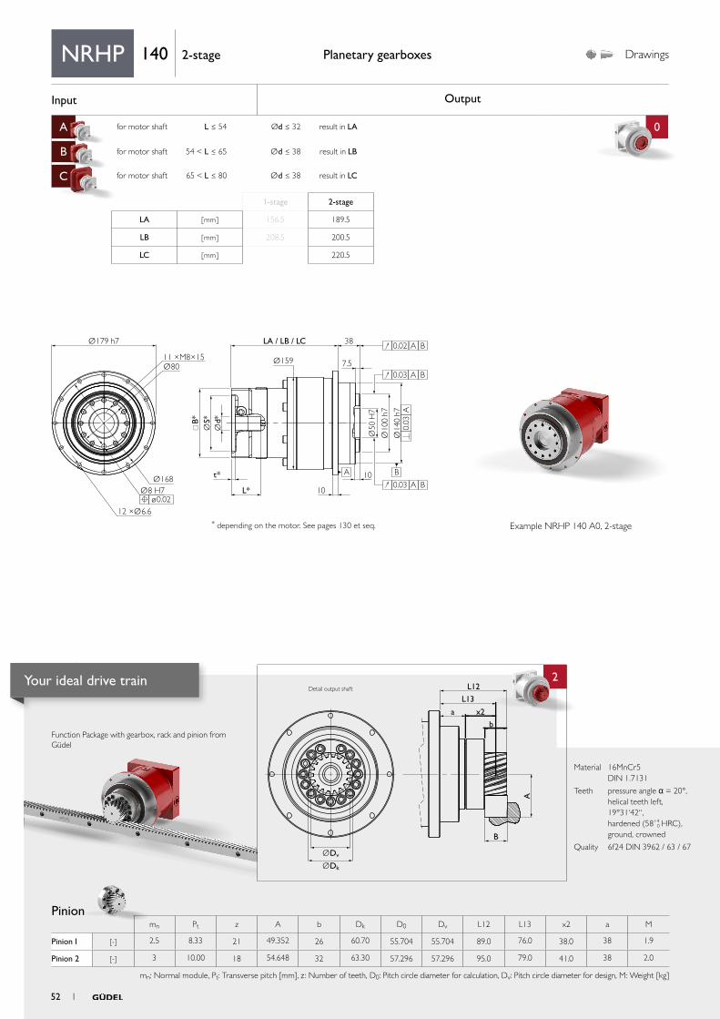
Input Output
A for motor shaft L ≤ 54 Ød ≤ 32 result in LA 0
B for motor shaft 54 < L ≤ 65 Ød ≤ 38 result in LB
C for motor shaft 65 < L ≤ 80 Ød ≤ 38 result in LC
aa
2
Ø179 h7
t*
L*
Ø159
LA / LB / LC 38
7.5
Ø168
Ø80
B*
Ød*
ØS*
Ø10
0 h7
Ø50
H7
Ø14
0 h7
12 ×Ø6.6
Ø8 H7
11 ×M8×15
10
10A B
0.02 A B
0.03 A B
0.03
A
0.03 A B
ø0.02
B
L12
L13
x2
b
a
A
ØDv
ØDk
Function Package with gearbox, rack and pinion from Güdel
Pinion
Planetary gearboxes Drawings
* depending on the motor. See pages 130 et seq.
Material 16MnCr5 DIN 1.7131
Teeth pressure angle α = 20°, helical teeth left, 19°31‘42“, hardened (58+4
0 HRC), ground, crowned
Quality 6f24 DIN 3962 / 63 / 67
Detail output shaft
NRHP 140 2-stage
Example NRHP 140 A0, 2-stage
mn Pt z A b Dk D0 Dv L12 L13 x2 a M
Pinion 1 [-] 2.5 8.33 21 49.352 26 60.70 55.704 55.704 89.0 76.0 38.0 38 1.9
Pinion 2 [-] 3 10.00 18 54.648 32 63.30 57.296 57.296 95.0 79.0 41.0 38 2.0
mn: Normal module, Pt: Transverse pitch [mm], z : Number of teeth, D0: Pitch circle diameter for calculation, Dv: Pitch circle diameter for design, M: Weight [kg]
1-stage 2-stage
LA [ mm ] 156.5 189.5
LB [ mm ] 208.5 200.5
LC [ mm ] 220.5
52 1
Your ideal drive train
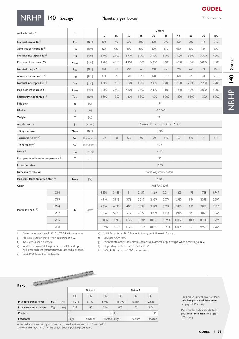
PerformancePlanetary gearboxes
Rack
More on the technical datasheets your ideal drive train on pages 120 et seq.
For proper sizing follow flowchart calculate your ideal drive train on pages 136 et seq.
Material 16MnCr5 DIN 1.7131
Teeth pressure angle α = 20°, helical teeth left, 19°31‘42“, hardened (58+4
0 HRC), ground, crowned
Quality 6f24 DIN 3962 / 63 / 67
Pinion 1 Pinion 2
Q6 Q7 Q9 Q6 Q7 Q9
Max acceleration force F2B [ N ] 11 216 5 197 8 053 15 790 6 350 12 686
Max acceleration torque T2B [ Nm ] 312 145 224 452 182 363
Precision P1 P5 P1 P5
Feed force High Medium Elevated High Medium Elevated
Above values for rack and pinion take into consideration a number of load cycles:1x10⁶ for the rack; 1x10⁷ for the pinion. Both in pulsating operation.
NR
HP
140
2-st
age
NRHP 140 2-stage
* Other ratios available. 9, 15, 21, 27, 28, 49 on request.
a) Nominal output torque when operating at n1N.
b) 1000 cycles per hour max.
c) Valid for an ambient temperature of 20°C and T2N. At higher ambient temperatures, please reduce speed.
d) Valid 1000 times the gearbox life.
e) Valid for an input Ø of 24 mm in 1-stage and 19 mm in 2-stage.
f) Values for 300 rpm.
g) For other temperatures, please contact us. Nominal output torque when operating at n1N.
h) Depending on the motor output shaft Ø.
i) With i=10 and n1N=3000 rpm no load.
Available ratios * i2-stage
12 16 20 25 30 35 40 50 70 100
Nominal torque S5 a) T2N [ Nm ] 400 490 500 500 400 500 490 500 470 310
Acceleration torque S5 b) T2B [ Nm ] 520 650 650 650 600 650 650 650 650 500
Nominal input speed S5 c) n1N [rpm] 2 900 2 900 2 900 3 000 3 000 3 000 3 000 3 300 3 300 4 000
Maximum input speed S5 n1max [rpm] 4 200 4 200 4 200 5 000 5 000 5 000 5 000 5 000 5 000 5 000
Nominal torque S1 a) T2N [Nm ] 260 260 260 260 260 260 260 260 260 150
Acceleration torque S1 b) T2B [ Nm] 370 370 370 370 370 370 370 370 370 220
Nominal input speed S1 c) n1N [rpm] 1 400 1 400 1 800 1 800 2 000 2 000 2 000 2 000 2 200 2 200
Maximum input speed S1 n1max [rpm] 2 700 2 900 2 800 2 800 2 800 2 800 2 800 3 000 3 000 3 200
Emergency stop torque d) T2not [ Nm ] 1 300 1 300 1 300 1 300 1 300 1 300 1 300 1 300 1 300 1 260
Efficiency h [ % ] 94
Lifetime Lh [ h ] > 20 000
Weight M [ kg ] 20
Angular backlash jt [ arcmin ] Precision P 1 ≤ 1 / P 3 ≤ 3 / P 5 ≤ 5
Tilting moment Mkmax [ Nm ] 1 400
Torsionnal rigidity e) Ct2 [ Nm/arcmin ] 170 185 185 183 160 183 177 178 147 117
Tilting rigidity e) Ct2 [ Nm/arcmin ] 934
Noise i) L pA [ dB(A) ] < 62
Max. permitted housing temperature g) T [ °C ] 90
Protection class IP 65
Direction of rotation Same way input / output
Max. axial force on output shaft f) Famax [ N ] 7 600
Color Red, RAL 3003
Inertia in kg.cm² h)
Ø14
J1 [ kgcm2 ]
3.556 3.158 3 2.457 1.869 2.014 1.805 1.78 1.758 1.747
Ø19 4.316 3.918 3.76 3.217 2.629 2.774 2.565 2.54 2.518 2.507
Ø24 4.636 4.238 4.08 3.537 2.949 3.094 2.885 2.86 2.838 2.827
Ø32 5.676 5.278 5.12 4.577 3.989 4.134 3.925 3.9 3.878 3.867
Ø35 11.806 11.408 11.25 10.707 10.119 10.264 10.055 10.03 10.008 9.997
Ø38 11.776 11.378 11.22 10.677 10.089 10.234 10.025 10 9.978 9.967
1 53
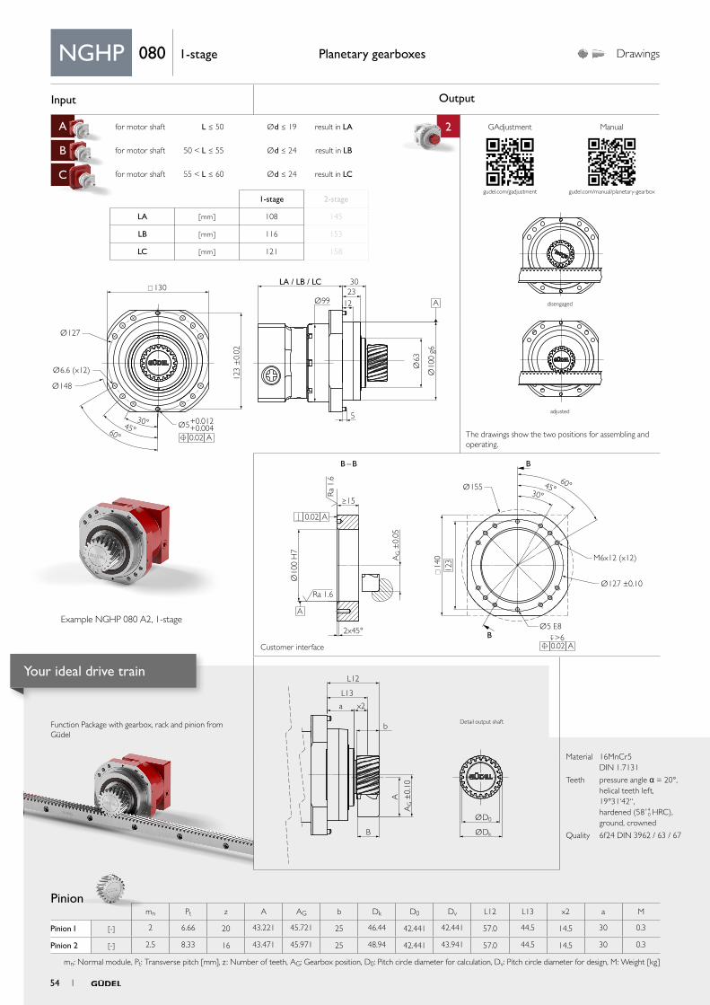
Input Output
A for motor shaft L ≤ 50 Ød ≤ 19 result in LA 2
B for motor shaft 50 < L ≤ 55 Ød ≤ 24 result in LB
C for motor shaft 55 < L ≤ 60 Ød ≤ 24 result in LC
aa
Ø127
Ø63
Ø10
0 g6
Ø99
Ø6.6 (x12)
Ø148
30°45°60°
LA / LB / LC 3023
12
5
123
±0.
02
Ø5+0.012+0.004
130
A
A
0.02
AG ±
0.10
ØD0
ØDk
L12
L13
x2
b
A
B
a
Ø155
Ø127 ±0.10
>6
M6x12 (x12)
Ø10
0 H
7
2x45°
≥15
Ra
1.6
Ra 1.6
B
BB – B
60°45°30°
AG ±
0.05
Ø5 E8
14
0
A 0.02
A 0.02
A
123
Function Package with gearbox, rack and pinion from Güdel
Pinion
Planetary gearboxes Drawings
Material 16MnCr5 DIN 1.7131
Teeth pressure angle α = 20°, helical teeth left, 19°31‘42“, hardened (58+4
0 HRC), ground, crowned
Quality 6f24 DIN 3962 / 63 / 67
NGHP 080 1-stage
1-stage 2-stage
LA [ mm ] 108 145
LB [ mm ] 116 153
LC [ mm ] 121 158
mn Pt z A AG b Dk D0 Dv L12 L13 x2 a M
Pinion 1 [-] 2 6.66 20 43.221 45.721 25 46.44 42.441 42.441 57.0 44.5 14.5 30 0.3
Pinion 2 [-] 2.5 8.33 16 43.471 45.971 25 48.94 42.441 43.941 57.0 44.5 14.5 30 0.3
mn: Normal module, Pt: Transverse pitch [mm], z : Number of teeth, AG: Gearbox position, D0: Pitch circle diameter for calculation, Dv: Pitch circle diameter for design, M: Weight [kg]
Example NGHP 080 A2, 1-stage
Customer interface
The drawings show the two positions for assembling and operating.
GAdjustment Manual
gudel.com/gadjustment
disengaged
adjusted
Detail output shaft
gudel.com/manual/planetary-gearbox
54 1
Your ideal drive train
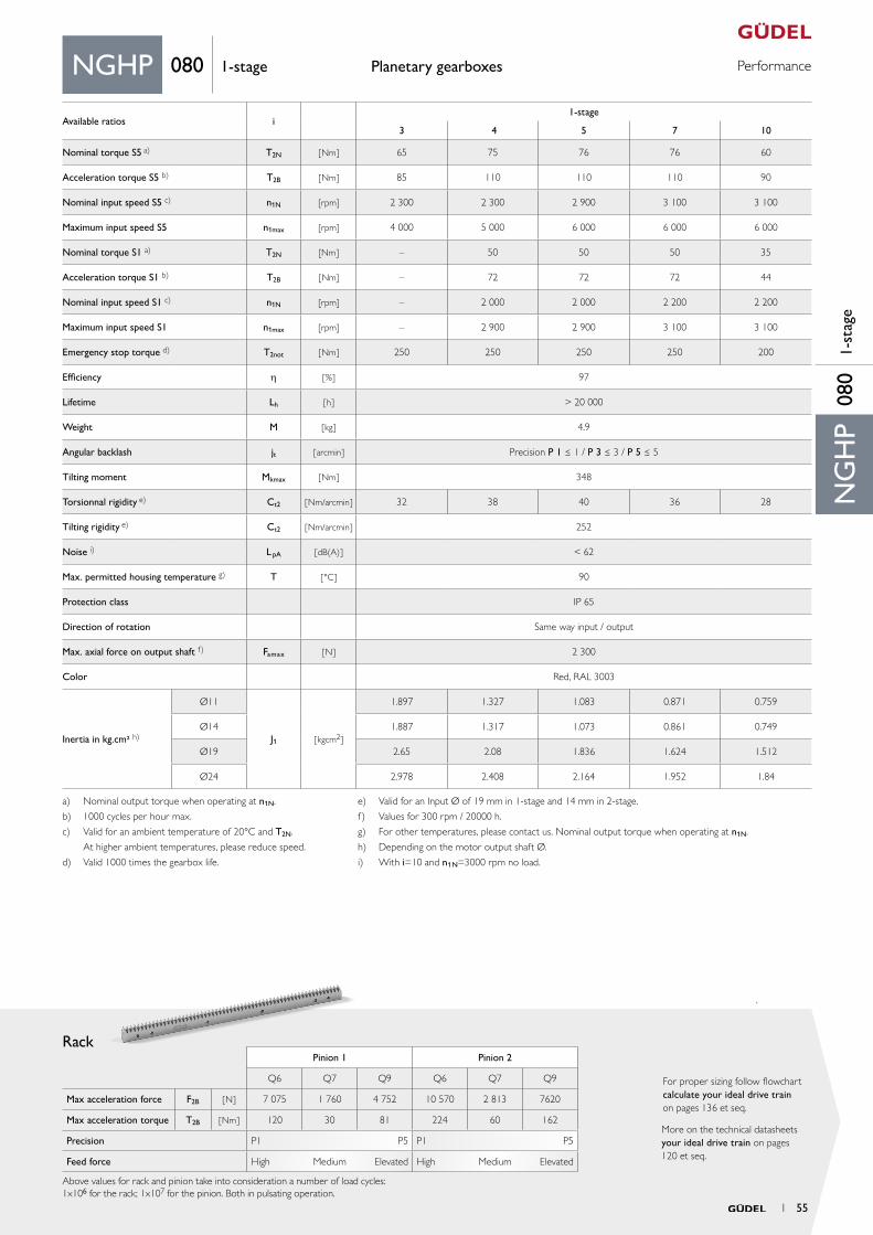
PerformancePlanetary gearboxes
Rack
More on the technical datasheets your ideal drive train on pages 120 et seq.
For proper sizing follow flowchart calculate your ideal drive train on pages 136 et seq.
Material 16MnCr5 DIN 1.7131
Teeth pressure angle α = 20°, helical teeth left, 19°31‘42“, hardened (58+4
0 HRC), ground, crowned
Quality 6f24 DIN 3962 / 63 / 67
Pinion 1 Pinion 2
Q6 Q7 Q9 Q6 Q7 Q9
Max acceleration force F2B [ N ] 7 075 1 760 4 752 10 570 2 813 7620
Max acceleration torque T2B [ Nm ] 120 30 81 224 60 162
Precision P1 P5 P1 P5
Feed force High Medium Elevated High Medium Elevated
Above values for rack and pinion take into consideration a number of load cycles:1x10⁶ for the rack; 1x10⁷ for the pinion. Both in pulsating operation.
NG
HP
080
1-st
age
NGHP 080 1-stage
Available ratios i1-stage
3 4 5 7 10
Nominal torque S5 a) T2N [ Nm ] 65 75 76 76 60
Acceleration torque S5 b) T2B [ Nm ] 85 110 110 110 90
Nominal input speed S5 c) n1N [rpm] 2 300 2 300 2 900 3 100 3 100
Maximum input speed S5 n1max [rpm] 4 000 5 000 6 000 6 000 6 000
Nominal torque S1 a) T2N [Nm ] – 50 50 50 35
Acceleration torque S1 b) T2B [ Nm] – 72 72 72 44
Nominal input speed S1 c) n1N [rpm] – 2 000 2 000 2 200 2 200
Maximum input speed S1 n1max [rpm] – 2 900 2 900 3 100 3 100
Emergency stop torque d) T2not [ Nm ] 250 250 250 250 200
Efficiency h [ % ] 97
Lifetime Lh [ h ] > 20 000
Weight M [ kg ] 4.9
Angular backlash jt [ arcmin ] Precision P 1 ≤ 1 / P 3 ≤ 3 / P 5 ≤ 5
Tilting moment Mkmax [ Nm ] 348
Torsionnal rigidity e) Ct2 [ Nm/arcmin ] 32 38 40 36 28
Tilting rigidity e) Ct2 [ Nm/arcmin ] 252
Noise i) L pA [ dB(A) ] < 62
Max. permitted housing temperature g) T [ °C ] 90
Protection class IP 65
Direction of rotation Same way input / output
Max. axial force on output shaft f) Famax [ N ] 2 300
Color Red, RAL 3003
Inertia in kg.cm² h)
Ø11
J1 [ kgcm2 ]
1.897 1.327 1.083 0.871 0.759
Ø14 1.887 1.317 1.073 0.861 0.749
Ø19 2.65 2.08 1.836 1.624 1.512
Ø24 2.978 2.408 2.164 1.952 1.84
a) Nominal output torque when operating at n1N.
b) 1000 cycles per hour max.
c) Valid for an ambient temperature of 20°C and T2N.
At higher ambient temperatures, please reduce speed.
d) Valid 1000 times the gearbox life.
e) Valid for an Input Ø of 19 mm in 1-stage and 14 mm in 2-stage.
f) Values for 300 rpm / 20000 h.
g) For other temperatures, please contact us. Nominal output torque when operating at n1N.
h) Depending on the motor output shaft Ø.
i) With i=10 and n1N=3000 rpm no load.
1 55
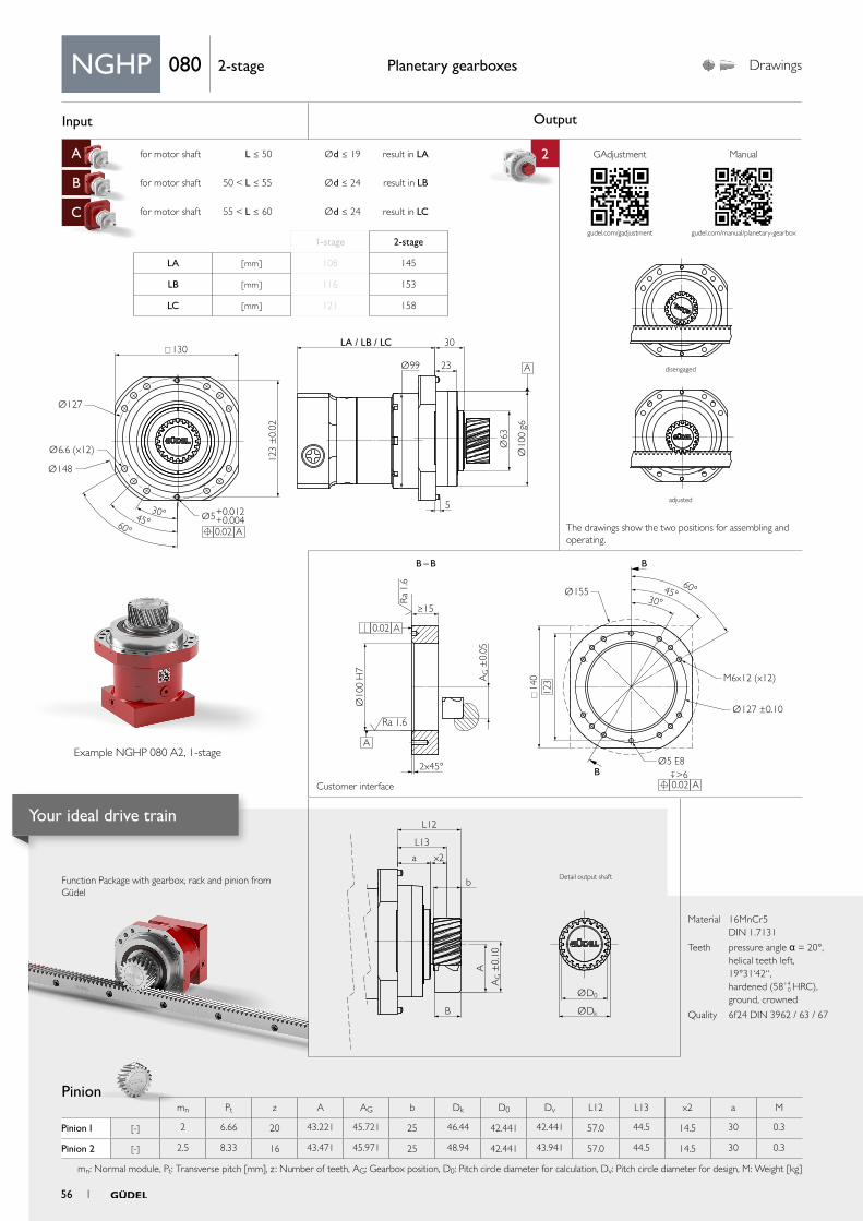
Input Output
A for motor shaft L ≤ 50 Ød ≤ 19 result in LA 2
B for motor shaft 50 < L ≤ 55 Ød ≤ 24 result in LB
C for motor shaft 55 < L ≤ 60 Ød ≤ 24 result in LC
aa
Ø127
Ø63
Ø10
0 g6
Ø6.6 (x12)
Ø148
30°45°60°
Ø99
LA / LB / LC 30
23
5
123
±0.
02
Ø5+0.012+0.004
130
A 0.02
A
AG ±
0.10
ØD0
ØDk
L12
L13
x2
b
A
B
a
Ø155
Ø127 ±0.10
>6
M6x12 (x12)
Ø10
0 H
7
2x45°
≥15
Ra
1.6
Ra 1.6
B
BB – B
60°45°30°
AG ±
0.05
Ø5 E8
14
0
A 0.02
A 0.02
A
123
Function Package with gearbox, rack and pinion from Güdel
Planetary gearboxes Drawings
Material 16MnCr5 DIN 1.7131
Teeth pressure angle α = 20°, helical teeth left, 19°31‘42“, hardened (58+4
0 HRC), ground, crowned
Quality 6f24 DIN 3962 / 63 / 67
NGHP 080 2-stage
1-stage 2-stage
LA [ mm ] 108 145
LB [ mm ] 116 153
LC [ mm ] 121 158
Pinion mn Pt z A AG b Dk D0 Dv L12 L13 x2 a M
Pinion 1 [-] 2 6.66 20 43.221 45.721 25 46.44 42.441 42.441 57.0 44.5 14.5 30 0.3
Pinion 2 [-] 2.5 8.33 16 43.471 45.971 25 48.94 42.441 43.941 57.0 44.5 14.5 30 0.3
mn: Normal module, Pt: Transverse pitch [mm], z : Number of teeth, AG: Gearbox position, D0: Pitch circle diameter for calculation, Dv: Pitch circle diameter for design, M: Weight [kg]
Example NGHP 080 A2, 1-stage
The drawings show the two positions for assembling and operating.
disengaged
adjusted
Detail output shaft
Customer interface
GAdjustment Manual
gudel.com/gadjustment gudel.com/manual/planetary-gearbox
56 1
Your ideal drive train
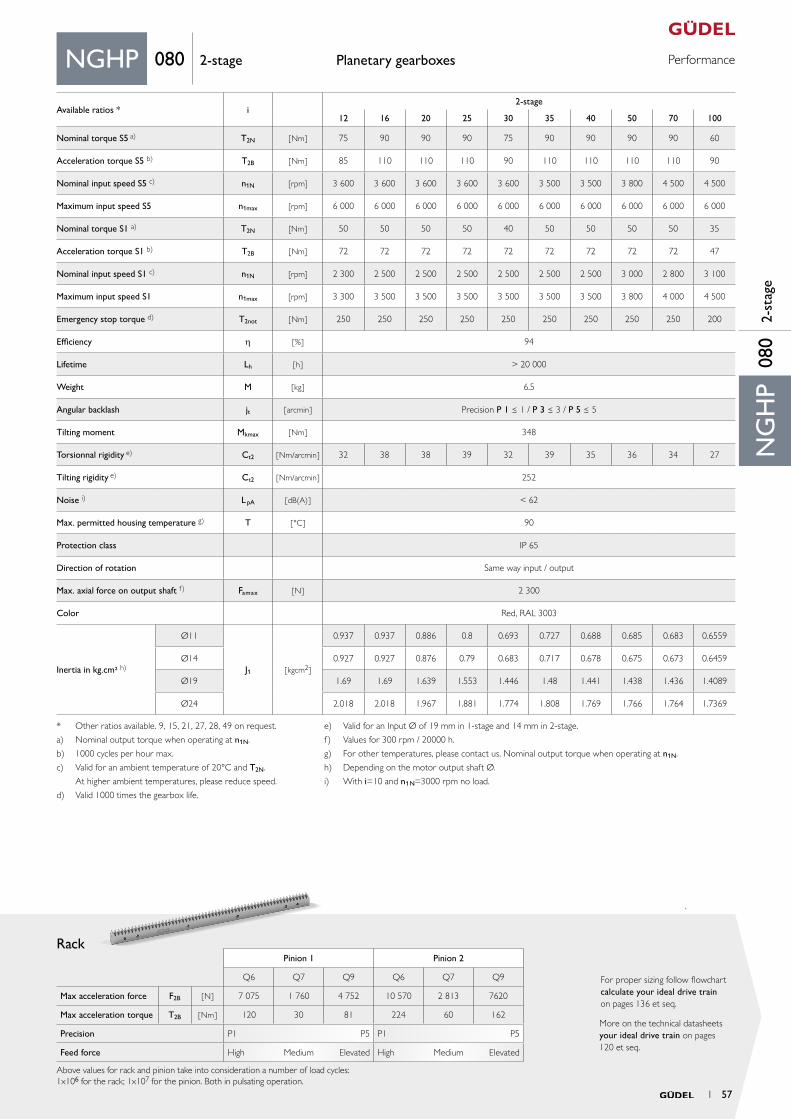
PerformancePlanetary gearboxes
Rack
More on the technical datasheets your ideal drive train on pages 120 et seq.
For proper sizing follow flowchart calculate your ideal drive train on pages 136 et seq.
Material 16MnCr5 DIN 1.7131
Teeth pressure angle α = 20°, helical teeth left, 19°31‘42“, hardened (58+4
0 HRC), ground, crowned
Quality 6f24 DIN 3962 / 63 / 67
Pinion 1 Pinion 2
Q6 Q7 Q9 Q6 Q7 Q9
Max acceleration force F2B [ N ] 7 075 1 760 4 752 10 570 2 813 7620
Max acceleration torque T2B [ Nm ] 120 30 81 224 60 162
Precision P1 P5 P1 P5
Feed force High Medium Elevated High Medium Elevated
Above values for rack and pinion take into consideration a number of load cycles:1x10⁶ for the rack; 1x10⁷ for the pinion. Both in pulsating operation.
NGHP 080 2-stage
NG
HP
080
2-st
age
Available ratios * i2-stage
12 16 20 25 30 35 40 50 70 100
Nominal torque S5 a) T2N [ Nm ] 75 90 90 90 75 90 90 90 90 60
Acceleration torque S5 b) T2B [ Nm ] 85 110 110 110 90 110 110 110 110 90
Nominal input speed S5 c) n1N [rpm] 3 600 3 600 3 600 3 600 3 600 3 500 3 500 3 800 4 500 4 500
Maximum input speed S5 n1max [rpm] 6 000 6 000 6 000 6 000 6 000 6 000 6 000 6 000 6 000 6 000
Nominal torque S1 a) T2N [Nm ] 50 50 50 50 40 50 50 50 50 35
Acceleration torque S1 b) T2B [ Nm] 72 72 72 72 72 72 72 72 72 47
Nominal input speed S1 c) n1N [rpm] 2 300 2 500 2 500 2 500 2 500 2 500 2 500 3 000 2 800 3 100
Maximum input speed S1 n1max [rpm] 3 300 3 500 3 500 3 500 3 500 3 500 3 500 3 800 4 000 4 500
Emergency stop torque d) T2not [ Nm ] 250 250 250 250 250 250 250 250 250 200
Efficiency h [ % ] 94
Lifetime Lh [ h ] > 20 000
Weight M [ kg ] 6.5
Angular backlash jt [ arcmin ] Precision P 1 ≤ 1 / P 3 ≤ 3 / P 5 ≤ 5
Tilting moment Mkmax [ Nm ] 348
Torsionnal rigidity e) Ct2 [ Nm/arcmin ] 32 38 38 39 32 39 35 36 34 27
Tilting rigidity e) Ct2 [ Nm/arcmin ] 252
Noise i) L pA [ dB(A) ] < 62
Max. permitted housing temperature g) T [ °C ] 90
Protection class IP 65
Direction of rotation Same way input / output
Max. axial force on output shaft f) Famax [ N ] 2 300
Color Red, RAL 3003
Inertia in kg.cm² h)
Ø11
J1 [ kgcm2 ]
0.937 0.937 0.886 0.8 0.693 0.727 0.688 0.685 0.683 0.6559
Ø14 0.927 0.927 0.876 0.79 0.683 0.717 0.678 0.675 0.673 0.6459
Ø19 1.69 1.69 1.639 1.553 1.446 1.48 1.441 1.438 1.436 1.4089
Ø24 2.018 2.018 1.967 1.881 1.774 1.808 1.769 1.766 1.764 1.7369
* Other ratios available. 9, 15, 21, 27, 28, 49 on request.
a) Nominal output torque when operating at n1N.
b) 1000 cycles per hour max.
c) Valid for an ambient temperature of 20°C and T2N.
At higher ambient temperatures, please reduce speed.
d) Valid 1000 times the gearbox life.
e) Valid for an Input Ø of 19 mm in 1-stage and 14 mm in 2-stage.
f) Values for 300 rpm / 20000 h.
g) For other temperatures, please contact us. Nominal output torque when operating at n1N.
h) Depending on the motor output shaft Ø.
i) With i=10 and n1N=3000 rpm no load.
1 57
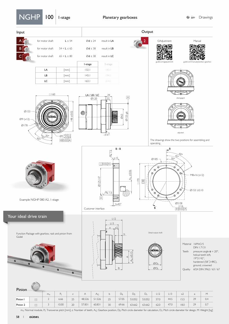
Input Output
A for motor shaft L ≤ 54 Ød ≤ 24 result in LA 2
B for motor shaft 54 < L ≤ 65 Ød ≤ 38 result in LB
C for motor shaft 65 < L ≤ 80 Ød ≤ 38 result in LC
aa
Ø153
Ø178
Ø9 (x12) Ø63
Ø12
5 g6
Ø120
30°45°60°
LA / LB / LC 2922
5
148
±0.
02
Ø5+0.012+0.004
160
A 0.02
A
AG ±
0.15
ØD0
ØDk
L12
L13
x2
b
A
B
a
B – B
A 0.02
Ø185
Ø153 ±0.10
M8x16 (x12)
Ø12
5 H
7
17
0
>6 Ø5 E8
A 0.02
148A
G ±
0.06
2x45°
≥15
Ra
1.6
Ra 1.6
A
B
B
45°60°
30°
Function Package with gearbox, rack and pinion from Güdel
Planetary gearboxes Drawings
Material 16MnCr5 DIN 1.7131
Teeth pressure angle α = 20°, helical teeth left, 19°31‘42“, hardened (58+4
0 HRC), ground, crowned
Quality 6f24 DIN 3962 / 63 / 67
1-stage 2-stage
LA [ mm ] 132.1 183.1
LB [ mm ] 143.1 194.1
LC [ mm ] 163.1 214.1
NGHP 100 1-stage
Pinion mn Pt z A AG b Dk D0 Dv L12 L13 x2 a M
Pinion 1 [-] 2 6.66 25 48.526 51.526 25 57.05 53.052 53.052 57.0 44.5 15.5 29 0.4
Pinion 2 [-] 3 10.00 20 57.831 60.831 30 69.66 63.662 63.662 62.0 47.0 18.0 29 0.7
mn: Normal module, Pt: Transverse pitch [mm], z : Number of teeth, AG: Gearbox position, D0: Pitch circle diameter for calculation, Dv: Pitch circle diameter for design, M: Weight [kg]
Example NGHP 080 A2, 1-stage
The drawings show the two positions for assembling and operating.
disengaged
adjusted
Detail output shaft
Customer interface
GAdjustment Manual
gudel.com/gadjustment gudel.com/manual/planetary-gearbox
58 1
Your ideal drive train
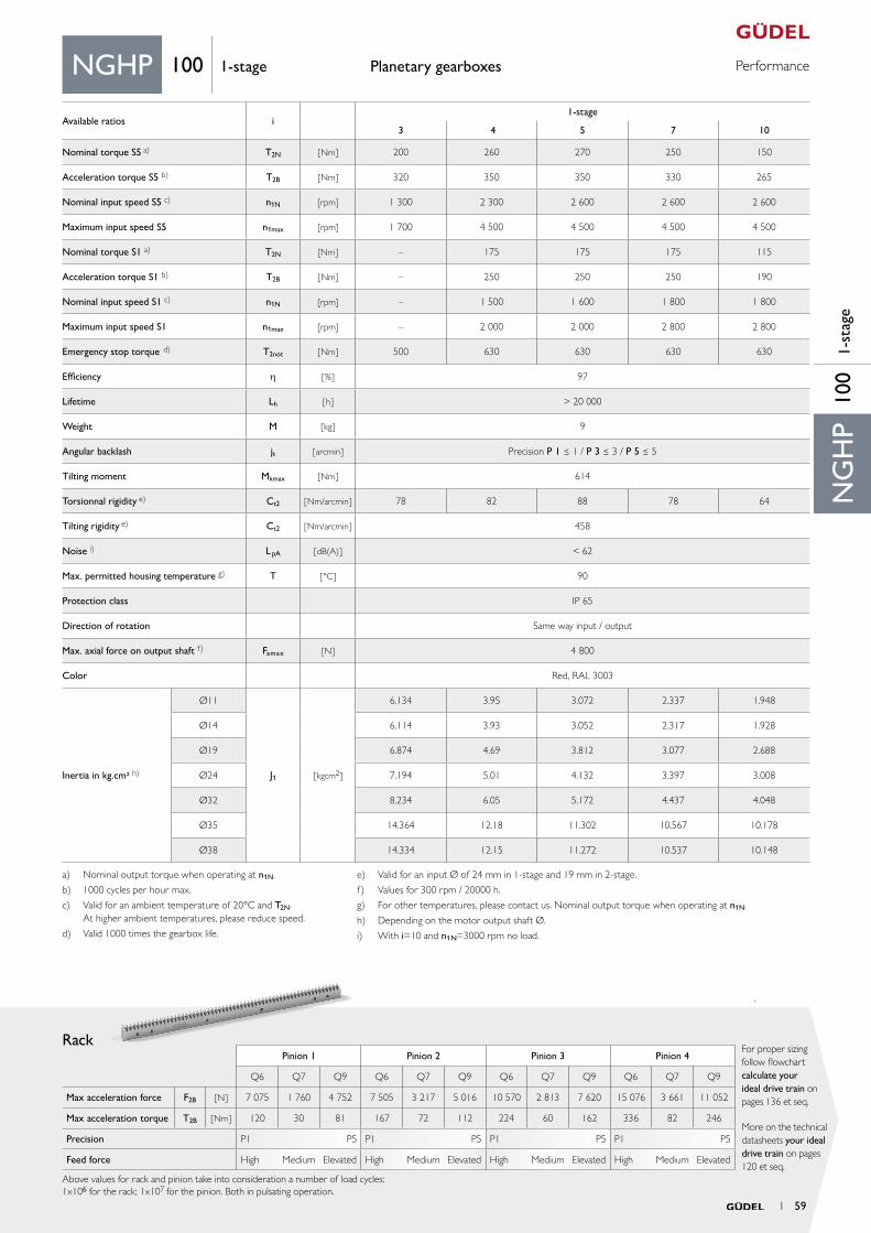
PerformancePlanetary gearboxes
Rack
More on the technical datasheets your ideal drive train on pages 120 et seq.
For proper sizing follow flowchart calculate your ideal drive train on pages 136 et seq.
ElevatedElevated Elevated Elevated
Material 16MnCr5 DIN 1.7131
Teeth pressure angle α = 20°, helical teeth left, 19°31‘42“, hardened (58+4
0 HRC), ground, crowned
Quality 6f24 DIN 3962 / 63 / 67
Pinion 1 Pinion 2 Pinion 3 Pinion 4
Q6 Q7 Q9 Q6 Q7 Q9 Q6 Q7 Q9 Q6 Q7 Q9
Max acceleration force F2B [ N ] 7 075 1 760 4 752 7 505 3 217 5 016 10 570 2 813 7 620 15 076 3 661 11 052
Max acceleration torque T2B [ Nm ] 120 30 81 167 72 112 224 60 162 336 82 246
Precision P1 P5 P1 P5 P1 P5 P1 P5
Feed force High Medium High Medium High Medium High Medium
Above values for rack and pinion take into consideration a number of load cycles:1x10⁶ for the rack; 1x10⁷ for the pinion. Both in pulsating operation.
NG
HP
100
1-st
age
NGHP 100 1-stage
a) Nominal output torque when operating at n1N.
b) 1000 cycles per hour max.
c) Valid for an ambient temperature of 20°C and T2N. At higher ambient temperatures, please reduce speed.
d) Valid 1000 times the gearbox life.
e) Valid for an input Ø of 24 mm in 1-stage and 19 mm in 2-stage.
f) Values for 300 rpm / 20000 h.
g) For other temperatures, please contact us. Nominal output torque when operating at n1N.
h) Depending on the motor output shaft Ø.
i) With i=10 and n1N=3000 rpm no load.
Available ratios i1-stage
3 4 5 7 10
Nominal torque S5 a) T2N [ Nm ] 200 260 270 250 150
Acceleration torque S5 b) T2B [ Nm ] 320 350 350 330 265
Nominal input speed S5 c) n1N [rpm] 1 300 2 300 2 600 2 600 2 600
Maximum input speed S5 n1max [rpm] 1 700 4 500 4 500 4 500 4 500
Nominal torque S1 a) T2N [Nm ] – 175 175 175 115
Acceleration torque S1 b) T2B [ Nm] – 250 250 250 190
Nominal input speed S1 c) n1N [rpm] – 1 500 1 600 1 800 1 800
Maximum input speed S1 n1max [rpm] – 2 000 2 000 2 800 2 800
Emergency stop torque d) T2not [ Nm ] 500 630 630 630 630
Efficiency h [ % ] 97
Lifetime Lh [ h ] > 20 000
Weight M [ kg ] 9
Angular backlash jt [ arcmin ] Precision P 1 ≤ 1 / P 3 ≤ 3 / P 5 ≤ 5
Tilting moment Mkmax [ Nm ] 614
Torsionnal rigidity e) Ct2 [ Nm/arcmin ] 78 82 88 78 64
Tilting rigidity e) Ct2 [ Nm/arcmin ] 458
Noise i) L pA [ dB(A) ] < 62
Max. permitted housing temperature g) T [ °C ] 90
Protection class IP 65
Direction of rotation Same way input / output
Max. axial force on output shaft f) Famax [ N ] 4 800
Color Red, RAL 3003
Inertia in kg.cm² h)
Ø11
J1 [ kgcm2 ]
6.134 3.95 3.072 2.337 1.948
Ø14 6.114 3.93 3.052 2.317 1.928
Ø19 6.874 4.69 3.812 3.077 2.688
Ø24 7.194 5.01 4.132 3.397 3.008
Ø32 8.234 6.05 5.172 4.437 4.048
Ø35 14.364 12.18 11.302 10.567 10.178
Ø38 14.334 12.15 11.272 10.537 10.148
1 59
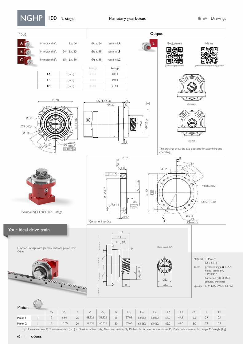
Input Output
A for motor shaft L ≤ 54 Ød ≤ 24 result in LA 2
B for motor shaft 54 < L ≤ 65 Ød ≤ 38 result in LB
C for motor shaft 65 < L ≤ 80 Ød ≤ 38 result in LC
aa
Ø153
Ø178
Ø9 (x12) Ø63
Ø12
5 g6
Ø120
30°45°60°
LA / LB / LC 2922
5
148
±0.
02
Ø5+0.012+0.004
160
A 0.02
A
AG ±
0.15
ØD0
ØDk
L12
L13
x2
b
A
B
a
B – B
A 0.02
Ø185
Ø153 ±0.10
M8x16 (x12)
Ø12
5 H
7
17
0
>6 Ø5 E8
A 0.02
148A
G ±
0.06
2x45°
≥15
Ra
1.6
Ra 1.6
A
B
B
45°60°
30°
Function Package with gearbox, rack and pinion from Güdel
Planetary gearboxes Drawings
Material 16MnCr5 DIN 1.7131
Teeth pressure angle α = 20°, helical teeth left, 19°31‘42“, hardened (58+4
0 HRC), ground, crowned
Quality 6f24 DIN 3962 / 63 / 67
1-stage 2-stage
LA [ mm ] 132.1 183.1
LB [ mm ] 143.1 194.1
LC [ mm ] 163.1 214.1
NGHP 100 2-stage
Pinion mn Pt z A AG b Dk D0 Dv L12 L13 x2 a M
Pinion 1 [-] 2 6.66 25 48.526 51.526 25 57.05 53.052 53.052 57.0 44.5 15.5 29 0.4
Pinion 2 [-] 3 10.00 20 57.831 60.831 30 69.66 63.662 63.662 62.0 47.0 18.0 29 0.7
mn: Normal module, Pt: Transverse pitch [mm], z : Number of teeth, AG: Gearbox position, D0: Pitch circle diameter for calculation, Dv: Pitch circle diameter for design, M: Weight [kg]
Example NGHP 080 A2, 1-stage
The drawings show the two positions for assembling and operating.
disengaged
adjusted
Detail output shaft
Customer interface
GAdjustment Manual
gudel.com/gadjustment gudel.com/manual/planetary-gearbox
60 1
Your ideal drive train
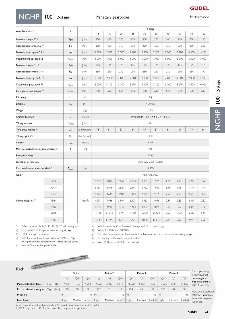
PerformancePlanetary gearboxes
Rack
More on the technical datasheets your ideal drive train on pages 120 et seq.
For proper sizing follow flowchart calculate your ideal drive train on pages 136 et seq.
ElevatedElevated Elevated Elevated
Material 16MnCr5 DIN 1.7131
Teeth pressure angle α = 20°, helical teeth left, 19°31‘42“, hardened (58+4
0 HRC), ground, crowned
Quality 6f24 DIN 3962 / 63 / 67
Pinion 1 Pinion 2 Pinion 3 Pinion 4
Q6 Q7 Q9 Q6 Q7 Q9 Q6 Q7 Q9 Q6 Q7 Q9
Max acceleration force F2B [ N ] 7 075 1 760 4 752 7 505 3 217 5 016 10 570 2 813 7 620 15 076 3 661 11 052
Max acceleration torque T2B [ Nm ] 120 30 81 167 72 112 224 60 162 336 82 246
Precision P1 P5 P1 P5 P1 P5 P1 P5
Feed force High Medium High Medium High Medium High Medium
Above values for rack and pinion take into consideration a number of load cycles:1x10⁶ for the rack; 1x10⁷ for the pinion. Both in pulsating operation.
NG
HP
100
2-st
age
NGHP 100 2-stage
* Other ratios available. 9, 15, 21, 27, 28, 49 on request.
a) Nominal output torque when operating at n1N.
b) 1000 cycles per hour max.
c) Valid for an ambient temperature of 20°C and T2N. At higher ambient temperatures, please reduce speed.
d) Valid 1000 times the gearbox life.
e) Valid for an input Ø of 24 mm in 1-stage and 19 mm in 2-stage.
f) Values for 300 rpm / 20000 h.
g) For other temperatures, please contact us. Nominal output torque when operating at n1N.
h) Depending on the motor output shaft Ø.
i) With i=10 and n1N=3000 rpm no load.
Available ratios * i2-stage
12 16 20 25 30 35 40 50 70 100
Nominal torque S5 a) T2N [ Nm ] 200 260 270 270 200 270 260 270 250 150
Acceleration torque S5 b) T2B [ Nm ] 320 350 350 350 320 350 350 320 330 265
Nominal input speed S5 c) n1N [rpm] 2 400 2 900 2 900 2 900 2 900 2 900 2 900 3 200 3 600 4 300
Maximum input speed S5 n1max [rpm] 5 000 6 000 6 000 6 000 6 000 6 000 6 000 6 000 6 000 6 000
Nominal torque S1 a) T2N [Nm ] 175 175 175 175 175 175 175 175 175 115
Acceleration torque S1 b) T2B [ Nm] 250 250 250 250 250 250 250 250 250 190
Nominal input speed S1 c) n1N [rpm] 2 000 2 000 2 000 2 000 2 000 2 000 2 000 2 000 2 000 2 500
Maximum input speed S1 n1max [rpm] 3 000 3 100 3 100 3 100 3 100 3 100 3 100 3 500 3 500 4 000
Emergency stop torque d) T2not [ Nm ] 630 630 630 630 630 630 630 630 630 630
Efficiency h [ % ] 94
Lifetime Lh [ h ] > 20 000
Weight M [ kg ] 12.5
Angular backlash jt [ arcmin ] Precision P 1 ≤ 1 / P 3 ≤ 3 / P 5 ≤ 5
Tilting moment Mkmax [ Nm ] 614
Torsionnal rigidity e) Ct2 [ Nm/arcmin ] 78 81 87 87 87 87 81 87 77 64
Tilting rigidity e) Ct2 [ Nm/arcmin ] 458
Noise i) L pA [ dB(A) ] < 62
Max. permitted housing temperature g) T [ °C ] 90
Protection class IP 65
Direction of rotation Same way input / output
Max. axial force on output shaft f) Famax [ N ] 4 800
Color Red, RAL 3003
Inertia in kg.cm² h)
Ø11
J1 [ kgcm2 ]
3.033 2.896 2.841 2.363 1.802 1.976 1.78 1.771 1.764 1.76
Ø14 3.013 2.876 2.821 2.343 1.782 1.956 1.76 1.751 1.744 1.74
Ø19 3.773 3.636 3.581 3.103 2.542 2.716 2.52 2.511 2.504 2.5
Ø24 4.093 3.956 3.901 3.423 2.862 3.036 2.84 2.831 2.824 2.82
Ø32 5.133 4.996 4.941 4.463 3.902 4.076 3.88 3.871 3.864 3.86
Ø35 11.263 11.126 11.071 10.593 10.032 10.206 10.01 10.001 9.994 9.99
Ø38 11.233 11.096 11.041 10.563 10.002 10.176 9.98 9.971 9.964 9.96
1 61
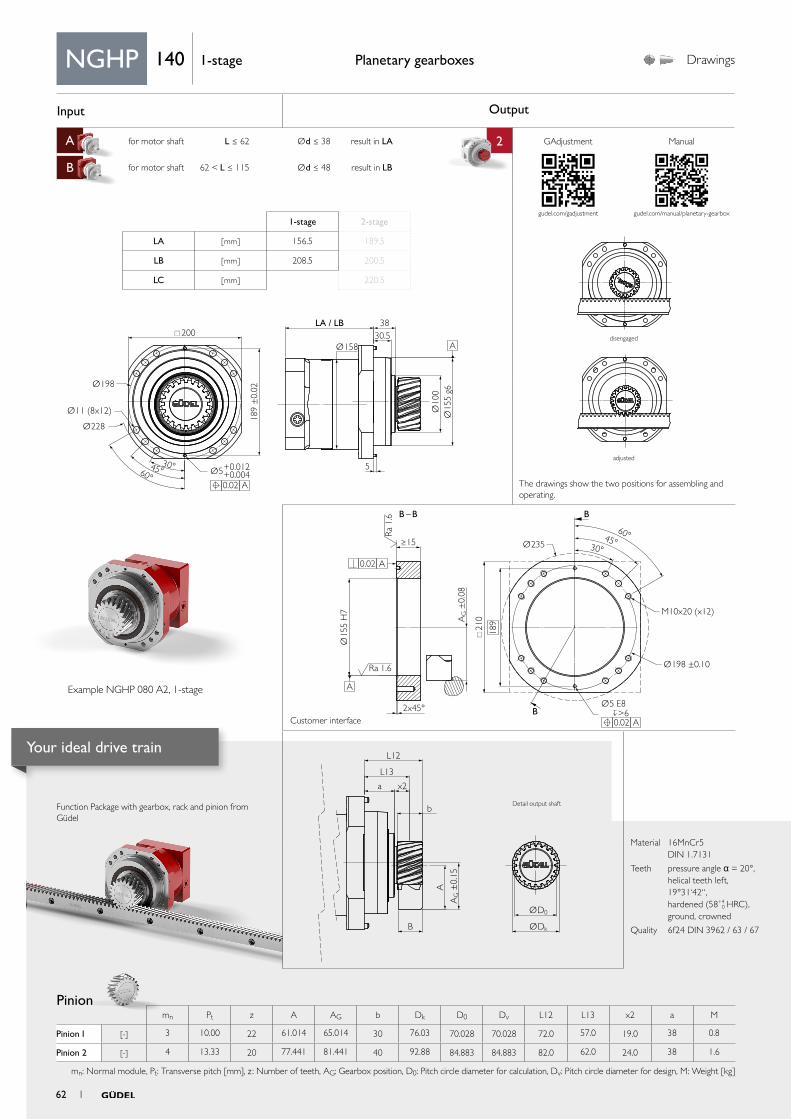
Input Output
A for motor shaft L ≤ 62 Ød ≤ 38 result in LA 2
B for motor shaft 62 < L ≤ 115 Ød ≤ 48 result in LB
aa
Ø198
Ø158
Ø228
Ø11 (8x12) Ø10
0Ø
155
g6
30°45°60°
LA / LB 38
5
30.5
189
±0.
02
Ø5+0.012+0.004
200
A
A
0.02
AG ±
0.15
ØD0
ØDk
L12
L13
x2
b
A
B
a
B – B
A 0.02
Ø235
Ø198 ±0.10
M10x20 (x12)
Ø15
5 H
7
≥15
21
0
>6 Ø5 E8
A 0.02
189A
G ±
0.08
2x45°
Ra
1.6
Ra 1.6
A
B
B
45°60°
30°
Function Package with gearbox, rack and pinion from Güdel
Planetary gearboxes Drawings
Material 16MnCr5 DIN 1.7131
Teeth pressure angle α = 20°, helical teeth left, 19°31‘42“, hardened (58+4
0 HRC), ground, crowned
Quality 6f24 DIN 3962 / 63 / 67
NGHP 140 1-stage
1-stage 2-stage
LA [ mm ] 156.5 189.5
LB [ mm ] 208.5 200.5
LC [ mm ] 220.5
Pinion mn Pt z A AG b Dk D0 Dv L12 L13 x2 a M
Pinion 1 [-] 3 10.00 22 61.014 65.014 30 76.03 70.028 70.028 72.0 57.0 19.0 38 0.8
Pinion 2 [-] 4 13.33 20 77.441 81.441 40 92.88 84.883 84.883 82.0 62.0 24.0 38 1.6
mn: Normal module, Pt: Transverse pitch [mm], z : Number of teeth, AG: Gearbox position, D0: Pitch circle diameter for calculation, Dv: Pitch circle diameter for design, M: Weight [kg]
Example NGHP 080 A2, 1-stage
The drawings show the two positions for assembling and operating.
disengaged
adjusted
Detail output shaft
Customer interface
GAdjustment Manual
gudel.com/gadjustment gudel.com/manual/planetary-gearbox
62 1
Your ideal drive train
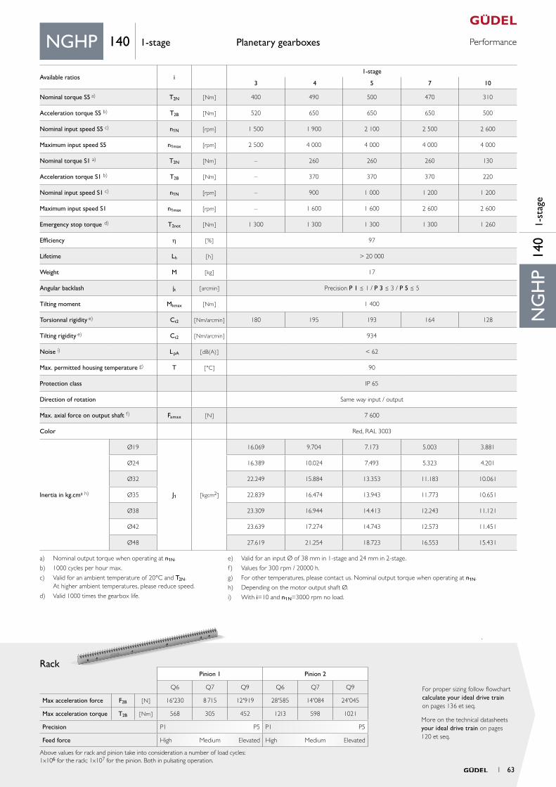
PerformancePlanetary gearboxes
Rack
More on the technical datasheets your ideal drive train on pages 120 et seq.
For proper sizing follow flowchart calculate your ideal drive train on pages 136 et seq.
Material 16MnCr5 DIN 1.7131
Teeth pressure angle α = 20°, helical teeth left, 19°31‘42“, hardened (58+4
0 HRC), ground, crowned
Quality 6f24 DIN 3962 / 63 / 67
Pinion 1 Pinion 2
Q6 Q7 Q9 Q6 Q7 Q9
Max acceleration force F2B [ N ] 16'230 8 715 12'919 28'585 14'084 24'045
Max acceleration torque T2B [ Nm ] 568 305 452 1213 598 1021
Precision P1 P5 P1 P5
Feed force High Medium Elevated High Medium Elevated
Above values for rack and pinion take into consideration a number of load cycles:1x10⁶ for the rack; 1x10⁷ for the pinion. Both in pulsating operation.
NG
HP
140
1-st
age
NGHP 140 1-stage
a) Nominal output torque when operating at n1N.
b) 1000 cycles per hour max.
c) Valid for an ambient temperature of 20°C and T2N. At higher ambient temperatures, please reduce speed.
d) Valid 1000 times the gearbox life.
e) Valid for an input Ø of 38 mm in 1-stage and 24 mm in 2-stage.
f) Values for 300 rpm / 20000 h.
g) For other temperatures, please contact us. Nominal output torque when operating at n1N.
h) Depending on the motor output shaft Ø.
i) With i=10 and n1N=3000 rpm no load.
Available ratios i1-stage
3 4 5 7 10
Nominal torque S5 a) T2N [ Nm ] 400 490 500 470 310
Acceleration torque S5 b) T2B [ Nm ] 520 650 650 650 500
Nominal input speed S5 c) n1N [rpm] 1 500 1 900 2 100 2 500 2 600
Maximum input speed S5 n1max [rpm] 2 500 4 000 4 000 4 000 4 000
Nominal torque S1 a) T2N [Nm ] – 260 260 260 130
Acceleration torque S1 b) T2B [ Nm] – 370 370 370 220
Nominal input speed S1 c) n1N [rpm] – 900 1 000 1 200 1 200
Maximum input speed S1 n1max [rpm] – 1 600 1 600 2 600 2 600
Emergency stop torque d) T2not [ Nm ] 1 300 1 300 1 300 1 300 1 260
Efficiency h [ % ] 97
Lifetime Lh [ h ] > 20 000
Weight M [ kg ] 17
Angular backlash jt [ arcmin ] Precision P 1 ≤ 1 / P 3 ≤ 3 / P 5 ≤ 5
Tilting moment Mkmax [ Nm ] 1 400
Torsionnal rigidity e) Ct2 [ Nm/arcmin ] 180 195 193 164 128
Tilting rigidity e) Ct2 [ Nm/arcmin ] 934
Noise i) L pA [ dB(A) ] < 62
Max. permitted housing temperature g) T [ °C ] 90
Protection class IP 65
Direction of rotation Same way input / output
Max. axial force on output shaft f) Famax [ N ] 7 600
Color Red, RAL 3003
Inertia in kg.cm² h)
Ø19
J1 [ kgcm2 ]
16.069 9.704 7.173 5.003 3.881
Ø24 16.389 10.024 7.493 5.323 4.201
Ø32 22.249 15.884 13.353 11.183 10.061
Ø35 22.839 16.474 13.943 11.773 10.651
Ø38 23.309 16.944 14.413 12.243 11.121
Ø42 23.639 17.274 14.743 12.573 11.451
Ø48 27.619 21.254 18.723 16.553 15.431
1 63
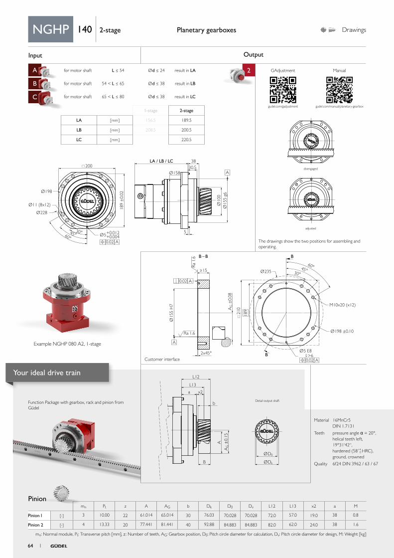
Input Output
A for motor shaft L ≤ 54 Ød ≤ 24 result in LA 2
B for motor shaft 54 < L ≤ 65 Ød ≤ 38 result in LB
C for motor shaft 65 < L ≤ 80 Ød ≤ 38 result in LC
aa
Ø198
Ø158
Ø228
Ø11 (8x12) Ø10
0Ø
155
g630°45°60°
LA / LB / LC 38
5
30.5
189
±0.
02
Ø5+0.012+0.004
200
A
A
0.02
AG ±
0.15
ØD0
ØDk
L12
L13
x2
b
A
B
a
B – B
A 0.02
Ø235
Ø198 ±0.10
M10x20 (x12)
Ø15
5 H
7
≥15
21
0
>6 Ø5 E8
A 0.02
189A
G ±
0.08
2x45°
Ra
1.6
Ra 1.6
A
B
B
45°60°
30°
Function Package with gearbox, rack and pinion from Güdel
Planetary gearboxes Drawings
Material 16MnCr5 DIN 1.7131
Teeth pressure angle α = 20°, helical teeth left, 19°31‘42“, hardened (58+4
0 HRC), ground, crowned
Quality 6f24 DIN 3962 / 63 / 67
NGHP 140 2-stage
1-stage 2-stage
LA [ mm ] 156.5 189.5
LB [ mm ] 208.5 200.5
LC [ mm ] 220.5
Pinion mn Pt z A AG b Dk D0 Dv L12 L13 x2 a M
Pinion 1 [-] 3 10.00 22 61.014 65.014 30 76.03 70.028 70.028 72.0 57.0 19.0 38 0.8
Pinion 2 [-] 4 13.33 20 77.441 81.441 40 92.88 84.883 84.883 82.0 62.0 24.0 38 1.6
mn: Normal module, Pt: Transverse pitch [mm], z : Number of teeth, AG: Gearbox position, D0: Pitch circle diameter for calculation, Dv: Pitch circle diameter for design, M: Weight [kg]
Example NGHP 080 A2, 1-stage
The drawings show the two positions for assembling and operating.
disengaged
adjusted
Detail output shaft
Customer interface
GAdjustment Manual
gudel.com/gadjustment gudel.com/manual/planetary-gearbox
64 1
Your ideal drive train
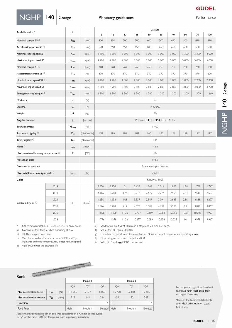
PerformancePlanetary gearboxes
Rack
More on the technical datasheets your ideal drive train on pages 120 et seq.
For proper sizing follow flowchart calculate your ideal drive train on pages 136 et seq.
Material 16MnCr5 DIN 1.7131
Teeth pressure angle α = 20°, helical teeth left, 19°31‘42“, hardened (58+4
0 HRC), ground, crowned
Quality 6f24 DIN 3962 / 63 / 67
Pinion 1 Pinion 2
Q6 Q7 Q9 Q6 Q7 Q9
Max acceleration force F2B [ N ] 11 216 5 197 8 053 15 790 6 350 12 686
Max acceleration torque T2B [ Nm ] 312 145 224 452 182 363
Precision P1 P5 P1 P5
Feed force High Medium Elevated High Medium Elevated
Above values for rack and pinion take into consideration a number of load cycles:1x10⁶ for the rack; 1x10⁷ for the pinion. Both in pulsating operation.
NG
HP
140
2-st
age
NGHP 140 2-stage
* Other ratios available. 9, 15, 21, 27, 28, 49 on request.
a) Nominal output torque when operating at n1N.
b) 1000 cycles per hour max.
c) Valid for an ambient temperature of 20°C and T2N. At higher ambient temperatures, please reduce speed.
d) Valid 1000 times the gearbox life.
e) Valid for an input Ø of 38 mm in 1-stage and 24 mm in 2-stage.
f) Values for 300 rpm / 20000 h.
g) For other temperatures, please contact us. Nominal output torque when operating at n1N.
h) Depending on the motor output shaft Ø.
i) With i=10 and n1N=3000 rpm no load.
Available ratios * i2-stage
12 16 20 25 30 35 40 50 70 100
Nominal torque S5 a) T2N [ Nm ] 400 490 500 500 400 500 490 500 470 310
Acceleration torque S5 b) T2B [ Nm ] 520 650 650 650 600 650 650 650 650 500
Nominal input speed S5 c) n1N [rpm] 2 900 2 900 2 900 3 000 3 000 3 000 3 000 3 300 3 300 4 000
Maximum input speed S5 n1max [rpm] 4 200 4 200 4 200 5 000 5 000 5 000 5 000 5 000 5 000 5 000
Nominal torque S1 a) T2N [Nm ] 260 260 260 260 260 260 260 260 260 150
Acceleration torque S1 b) T2B [ Nm] 370 370 370 370 370 370 370 370 370 220
Nominal input speed S1 c) n1N [rpm] 1 400 1 400 1 800 1 800 2 000 2 000 2 000 2 000 2 200 2 200
Maximum input speed S1 n1max [rpm] 2 700 2 900 2 800 2 800 2 800 2 800 2 800 3 000 3 000 3 200
Emergency stop torque d) T2not [ Nm ] 1 300 1 300 1 300 1 300 1 300 1 300 1 300 1 300 1 300 1 260
Efficiency h [ % ] 94
Lifetime Lh [ h ] > 20 000
Weight M [ kg ] 20
Angular backlash jt [ arcmin ] Precision P 1 ≤ 1 / P 3 ≤ 3 / P 5 ≤ 5
Tilting moment Mkmax [ Nm ] 1 400
Torsionnal rigidity e) Ct2 [ Nm/arcmin ] 170 185 185 183 160 183 177 178 147 117
Tilting rigidity e) Ct2 [ Nm/arcmin ] 934
Noise i) L pA [ dB(A) ] < 62
Max. permitted housing temperature g) T [ °C ] 90
Protection class IP 65
Direction of rotation Same way input / output
Max. axial force on output shaft f) Famax [ N ] 7 600
Color Red, RAL 3003
Inertia in kg.cm² h)
Ø14
J1 [ kgcm2 ]
3.556 3.158 3 2.457 1.869 2.014 1.805 1.78 1.758 1.747
Ø19 4.316 3.918 3.76 3.217 2.629 2.774 2.565 2.54 2.518 2.507
Ø24 4.636 4.238 4.08 3.537 2.949 3.094 2.885 2.86 2.838 2.827
Ø32 5.676 5.278 5.12 4.577 3.989 4.134 3.925 3.9 3.878 3.867
Ø35 11.806 11.408 11.25 10.707 10.119 10.264 10.055 10.03 10.008 9.997
Ø38 11.776 11.378 11.22 10.677 10.089 10.234 10.025 10 9.978 9.967
1 65
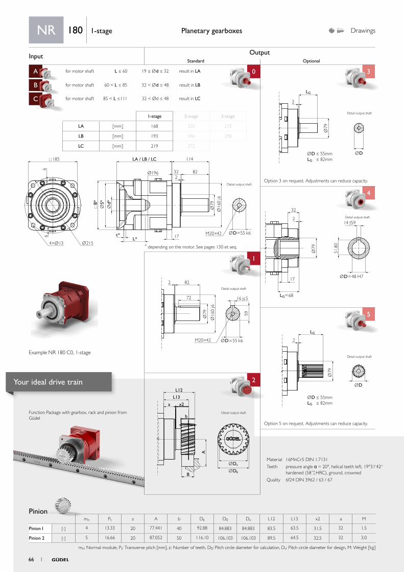
Input OutputStandard Optional
A for motor shaft L ≤ 60 19 ≤ Ød ≤ 32 result in LA 0 3
B for motor shaft 60 < L ≤ 85 32 < Ød ≤ 48 result in LB
C for motor shaft 85 < L ≤111 32 < Ød ≤ 48 result in LC
4
1 4
5
aa
2
ØDv
L12
L13
x2
b
B
a
A
ØDk
Ø79
ØD
LG
2
ØD ≤ 55mmLG ≤ 82mm
2 82
72
Ø79 59
Ø16
0 j6
M20×42 ØD=55 k6
16 js5
Ø79
ØD=48 H7
LG=68
14 JS9
32
2
17
51.8
0
Ø79
2
LG
ØD ≤ 55mmLG ≤ 82mm
ØD185
Ø196
B*
t*L* 17
LA / LB / LC 114
322
82
66
Ø2154×Ø13
Ød*
ØS*
Ø79
Ø16
0 j6
M20×42 ØD=55 k6
Material 16MnCr5 DIN 1.7131
Teeth pressure angle α = 20°, helical teeth left, 19°31‘42“ hardened (58+4
0 HRC), ground, crowned
Quality 6f24 DIN 3962 / 63 / 67
Function Package with gearbox, rack and pinion from Güdel
Pinion
Planetary gearboxes Drawings
* depending on the motor. See pages 130 et seq.
Option 5 on request. Adjustments can reduce capacity.
Option 3 on request. Adjustments can reduce capacity.
NR 180 1-stage
1-stage 2-stage 3-stage
LA [ mm ] 168 220 273
LB [ mm ] 193 246 298
LC [ mm ] 219 272
Example NR 180 C0, 1-stage
Detail output shaft
Detail output shaft
Detail output shaft
Detail output shaft
mn Pt z A b Dk D0 Dv L12 L13 x2 a M
Pinion 1 [-] 4 13.33 20 77.441 40 92.88 84.883 84.883 83.5 63.5 31.5 32 1.5
Pinion 2 [-] 5 16.66 20 87.052 50 116.10 106.103 106.103 89.5 64.5 32.5 32 3.0
mn: Normal module, Pt: Transverse pitch [mm], z : Number of teeth, D0: Pitch circle diameter for calculation, Dv: Pitch circle diameter for design, M: Weight [kg]
Detail output shaft
Detail output shaft
66 1
Your ideal drive train

PerformancePlanetary gearboxes
Rack
More on the technical datasheets your ideal drive train on pages 120 et seq.
For proper sizing follow flowchart calculate your ideal drive train on pages 136 et seq.
Pinion 1 Pinion 2
Q6 Q7 Q9 Q6 Q7 Q9
Max acceleration force F2B [ N ] 28 585 14 084 24 045 44 505 23 785 40 048
Max acceleration torque T2B [ Nm ] 1 213 598 1 021 2 361 1 262 2 125
Precision P1 P12 P1 P12
Feed force High Medium Elevated High Medium Elevated
Above values for rack and pinion take into consideration a number of load cycles:1x10⁶ for the rack; 1x10⁷ for the pinion. Both in pulsating operation.
NR
180
1-st
age
NR 180 1-stage
Available ratios i1-stage
3 4 5 7 10
Nominal torque S5 a) T2N [ Nm ] 750 770 780 760 680
Acceleration torque S5 b) T2B [ Nm ] 1 150 1 150 1 150 1 150 880
Nominal input speed S5 c) n1N [rpm] 1 500 1 500 1 500 2 300 2 300
Maximum input speed S5 n1max [rpm] 3 000 3 500 3 500 3 500 3 500
Nominal torque S1 a) T2N [Nm ] 380 380 380 380 340
Acceleration torque S1 b) T2B [ Nm] 560 560 560 560 570
Nominal input speed S1 c) n1N [rpm] 1 100 1 300 1 300 2 100 2 100
Maximum input speed S1 n1max [rpm] 1 500 1 500 1 500 2 300 2 300
Emergency stop torque d) T2 n o t [ Nm ] 2 550 2 780 2 780 2 780 2 250
Efficiency h [ % ] 97
Lifetime Lh [ h ] > 20 000
Weight M [ kg ] 32
Angular backlash jt [ arcmin ] Precision P 1 ≤ 1 / P 3 ≤ 3 / P 5 ≤ 5 / P 12 ≤12
Torsionnal rigidity e) Ct2 [ Nm/arcmin ] 156.3 182.7 193.5 210.1 183.3
Noise i) L pA [ dB(A) ] ≤ 71
Max. permitted housing temperature g) T [ °C ] 90
Protection class IP 65
Direction of rotation Same way input / output
Max. radial force on output shaft f) Fr m a x [ N ] Center of output shaft: 15 500 / End of output shaft: 11 500
Max. axial force on output shaft f) Fa m a x [ N ] 15 000
Color Red, RAL 3003
Inertia in kg.cm² h)
Ø19
J1 [ kgcm2 ]
38.19 23.35 17.21 12.12 9.18
Ø24 39.24 24.40 18.26 13.17 10.23
Ø32 41.45 26.61 20.47 15.38 12.44
Ø35 44.37 29.53 23.39 18.30 15.36
Ø38 49.97 35.13 28.99 23.90 20.96
Ø42 49.47 34.63 28.49 23.40 20.46
Ø48 49.87 35.03 28.89 23.80 20.86
a) Nominal output torque when operating at n1N.
b) 1000 cycles per hour max.
c) Valid for an ambient temperature of 20°C and T2N. At higher ambient temperatures, please reduce speed.
d) Valid 1000 times the gearbox life.
e) Valid for an input Ø of 48 mm in 1-stage and 38 mm in 2- and 3-stage.
f) Values for 300 rpm.
g) For other temperatures, please contact us. Nominal output torque when operating at n1N.
h) Depending on the motor output shaft Ø.
i) With i=10 and n1N=3000 rpm no load.
1 67
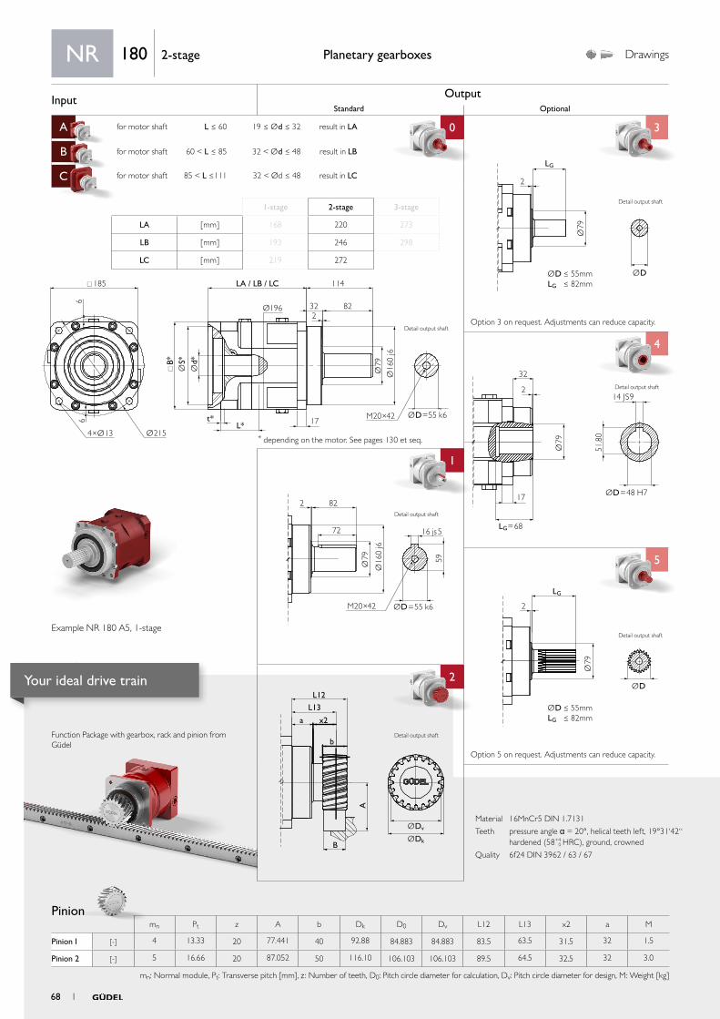
Input OutputStandard Optional
A for motor shaft L ≤ 60 19 ≤ Ød ≤ 32 result in LA 0 3
B for motor shaft 60 < L ≤ 85 32 < Ød ≤ 48 result in LB
C for motor shaft 85 < L ≤111 32 < Ød ≤ 48 result in LC
4
1 4
5
aa
2
ØDv
L12
L13
x2
b
B
a
A
ØDk
Ø79
ØD
LG
2
ØD ≤ 55mmLG ≤ 82mm
2 82
72
Ø79 59
Ø16
0 j6
M20×42 ØD=55 k6
16 js5
Ø79
ØD=48 H7
LG=68
14 JS9
32
2
17
51.8
0
Ø79
2
LG
ØD ≤ 55mmLG ≤ 82mm
ØD185
Ø196
B*
t*L* 17
LA / LB / LC 114
322
82
66
Ø2154×Ø13
Ød*
ØS*
Ø79
Ø16
0 j6
M20×42 ØD=55 k6
Material 16MnCr5 DIN 1.7131
Teeth pressure angle α = 20°, helical teeth left, 19°31‘42“ hardened (58+4
0 HRC), ground, crowned
Quality 6f24 DIN 3962 / 63 / 67
Function Package with gearbox, rack and pinion from Güdel
Pinion
Planetary gearboxes Drawings
* depending on the motor. See pages 130 et seq.
Option 5 on request. Adjustments can reduce capacity.
Option 3 on request. Adjustments can reduce capacity.
NR 180 2-stage
1-stage 2-stage 3-stage
LA [ mm ] 168 220 273
LB [ mm ] 193 246 298
LC [ mm ] 219 272
Example NR 180 A5, 1-stage
Detail output shaft
Detail output shaft
Detail output shaft
Detail output shaft
mn Pt z A b Dk D0 Dv L12 L13 x2 a M
Pinion 1 [-] 4 13.33 20 77.441 40 92.88 84.883 84.883 83.5 63.5 31.5 32 1.5
Pinion 2 [-] 5 16.66 20 87.052 50 116.10 106.103 106.103 89.5 64.5 32.5 32 3.0
mn: Normal module, Pt: Transverse pitch [mm], z : Number of teeth, D0: Pitch circle diameter for calculation, Dv: Pitch circle diameter for design, M: Weight [kg]
Detail output shaft
Detail output shaft
68 1
Your ideal drive train

PerformancePlanetary gearboxes
Rack
More on the technical datasheets your ideal drive train on pages 120 et seq.
For proper sizing follow flowchart calculate your ideal drive train on pages 136 et seq.
NR
180
2-st
age
NR 180 2-stage
* Other ratios available. 9, 15, 21, 27, 28, 49 on request.
a) Nominal output torque when operating at n1N.
b) 1000 cycles per hour max.
c) Valid for an ambient temperature of 20°C and T2N. At higher ambient temperatures, please reduce speed.
d) Valid 1000 times the gearbox life.
e) Valid for an input Ø of 48 mm in 1-stage and 38 mm in 2- and 3-stage.
f) Values for 300 rpm.
g) For other temperatures, please contact us. Nominal output torque when operating at n1N.
h) Depending on the motor output shaft Ø.
i) With i=10 and n1N=3000 rpm no load.
Available ratios * i2-stage
12 16 20 25 30 35 40 50 70 100
Nominal torque S5 a) T2N [ Nm ] 750 770 780 780 750 780 770 780 760 680
Acceleration torque S5 b) T2B [ Nm ] 1 150 1 150 1 150 1 150 1 150 1 150 1 150 1 150 1 150 880
Nominal input speed S5 c) n1N [rpm] 2 500 2 700 2 700 2 700 2 700 2 700 2 700 2 900 2 900 3 400
Maximum input speed S5 n1max [rpm] 3 800 3 800 3 800 3 800 3 800 3 800 3 800 3 800 3 800 3 800
Nominal torque S1 a) T2N [Nm ] 380 380 380 380 380 380 380 380 380 340
Acceleration torque S1 b) T2B [ Nm] 560 560 560 560 560 560 560 560 570 570
Nominal input speed S1 c) n1N [rpm] 1 700 2 400 2 400 2 400 2 400 2 400 2 400 2 600 2 600 3 000
Maximum input speed S1 n1max [rpm] 2 500 2 700 2 700 2 700 2 700 2 700 2 700 2 900 2 900 3 400
Emergency stop torque d) T2 n o t [ Nm ] 2 780 2 780 2 780 2 780 2 550 2 780 2 780 2 780 2 780 2 250
Efficiency h [ % ] 94
Lifetime Lh [ h ] > 20 000
Weight M [ kg ] 39
Angular backlash jt [ arcmin ] Precision P 1 ≤ 1 / P 3 ≤ 3 / P 5 ≤ 5 / P 12 ≤12
Torsionnal rigidity e) Ct2 [ Nm/arcmin ] 140.6 164.4 174.0 174.0 140.6 174.0 164.4 174.0 189.2 165.0
Noise i) L pA [ dB(A) ] ≤ 71
Max. permitted housing temperature g) T [ °C ] 90
Protection class IP 65
Direction of rotation Same way input / output
Max. radial force on output shaft f) Fr m a x [ N ] Center of output shaft: 15 500 / End of output shaft: 11 500
Max. axial force on output shaft f) Fa m a x [ N ] 15 000
Color Red, RAL 3003
Inertia in kg.cm² h)
Ø19
J1 [ kgcm2 ]
23.57 22.65 16.76 16.51 9.22 11.77 9.07 9.01 8.96 8.93
Ø24 24.62 23.7 17.81 17.56 10.27 12.82 10.12 10.06 10.01 9.98
Ø32 26.83 25.91 20.02 19.77 12.48 15.03 12.33 12.27 12.22 12.19
Ø35 29.75 28.83 22.94 22.69 15.4 17.95 15.25 15.19 15.14 15.11
Ø38 35.35 34.43 28.54 28.29 21 23.55 20.85 20.79 20.74 20.71
Ø42 34.85 33.93 28.04 27.79 20.5 23.05 20.35 20.29 20.24 20.21
Ø48 35.25 34.33 28.44 28.19 20.9 23.45 20.75 20.69 20.64 20.61
Pinion 1 Pinion 2
Q6 Q7 Q9 Q6 Q7 Q9
Max acceleration force F2B [ N ] 28 585 14 084 24 045 44 505 23 785 40 048
Max acceleration torque T2B [ Nm ] 1 213 598 1 021 2 361 1 262 2 125
Precision P1 P12 P1 P12
Feed force High Medium Elevated High Medium Elevated
Above values for rack and pinion take into consideration a number of load cycles:1x10⁶ for the rack; 1x10⁷ for the pinion. Both in pulsating operation.
1 69

Input OutputStandard Optional
A for motor shaft L ≤ 60 19 ≤ Ød ≤ 32 result in LA 0 3
B for motor shaft 60 < L ≤ 85 32 < Ød ≤ 48 result in LB
C for motor shaft 85 < L ≤111 32 < Ød ≤ 48 result in LC
4
1 4
5
aa
2
ØDv
L12
L13
x2
b
B
a
A
ØDk
Ø79
ØD
LG
2
ØD ≤ 55mmLG ≤ 82mm
2 82
72
Ø79 59
Ø16
0 j6
M20×42 ØD=55 k6
16 js5
Ø79
ØD=48 H7
LG=68
14 JS9
32
2
17
51.8
0
Ø79
2
LG
ØD ≤ 55mmLG ≤ 82mm
ØD185
Ø196
B*
t*L* 17
LA / LB / LC 114
322
82
66
Ø2154×Ø13
Ød*
ØS*
Ø79
Ø16
0 j6
M20×42 ØD=55 k6
Material 16MnCr5 DIN 1.7131
Teeth pressure angle α = 20°, helical teeth left, 19°31‘42“ hardened (58+4
0 HRC), ground, crowned
Quality 6f24 DIN 3962 / 63 / 67
Function Package with gearbox, rack and pinion from Güdel
Pinion
Planetary gearboxes Drawings
* depending on the motor. See pages 130 et seq.
Option 5 on request. Adjustments can reduce capacity.
Option 3 on request. Adjustments can reduce capacity.
NR 180 3-stage
1-stage 2-stage 3-stage
LA [ mm ] 168 220 273
LB [ mm ] 193 246 298
LC [ mm ] 219 272
Example NR 180 A0, 1-stage
Detail output shaft
Detail output shaft
Detail output shaft
Detail output shaft
mn Pt z A b Dk D0 Dv L12 L13 x2 a M
Pinion 1 [-] 4 13.33 20 77.441 40 92.88 84.883 84.883 83.5 63.5 31.5 32 1.5
Pinion 2 [-] 5 16.66 20 87.052 50 116.10 106.103 106.103 89.5 64.5 32.5 32 3.0
mn: Normal module, Pt: Transverse pitch [mm], z : Number of teeth, D0: Pitch circle diameter for calculation, Dv: Pitch circle diameter for design, M: Weight [kg]
Detail output shaft
Detail output shaft
70 1
Your ideal drive train
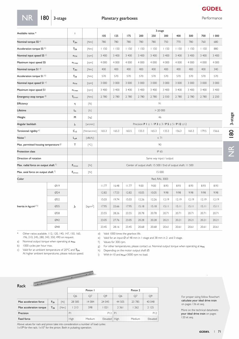
PerformancePlanetary gearboxes
Rack
More on the technical datasheets your ideal drive train on pages 120 et seq.
For proper sizing follow flowchart calculate your ideal drive train on pages 136 et seq.
NR
180
3-st
age
NR 180 3-stage
Available ratios * i3-stage
105 125 175 200 250 300 400 500 700 1 000
Nominal torque S5 a) T2N [ Nm ] 780 780 780 780 780 750 770 780 760 680
Acceleration torque S5 b) T2B [ Nm ] 1 150 1 150 1 150 1 150 1 150 1 150 1 150 1 150 1 150 880
Nominal input speed S5 c) n1N [rpm] 3 400 3 400 3 400 3 400 3 400 3 400 3 400 3 400 3 400 3 400
Maximum input speed S5 n1max [rpm] 4 000 4 000 4 000 4 000 4 000 4 000 4 000 4 000 4 000 4 000
Nominal torque S1 a) T2N [Nm ] 400 400 400 400 400 400 400 400 400 340
Acceleration torque S1 b) T2B [ Nm] 570 570 570 570 570 570 570 570 570 570
Nominal input speed S1 c) n1N [rpm] 3 000 3 000 3 000 3 000 3 000 3 000 3 000 3 000 3 000 3 000
Maximum input speed S1 n1max [rpm] 3 400 3 400 3 400 3 400 3 400 3 400 3 400 3 400 3 400 3 400
Emergency stop torque d) T2 n o t [ Nm ] 2 780 2 780 2 780 2 780 2 780 2 550 2 780 2 780 2 780 2 250
Efficiency h [ % ] 91
Lifetime Lh [ h ] > 20 000
Weight M [ kg ] 46
Angular backlash jt [ arcmin ] Precision P 1 ≤ 1 / P 3 ≤ 3 / P 5 ≤ 5 / P 12 ≤12
Torsionnal rigidity e) Ct2 [ Nm/arcmin ] 165.3 165.3 165.5 133.3 165.3 133.3 156.3 165.3 179.5 156.6
Noise i) L pA [ dB(A) ] ≤ 71
Max. permitted housing temperature g) T [ °C ] 90
Protection class IP 65
Direction of rotation Same way input / output
Max. radial force on output shaft f) Fr m a x [ N ] Center of output shaft: 15 500 / End of output shaft: 11 500
Max. axial force on output shaft f) Fa m a x [ N ] 15 000
Color Red, RAL 3003
Inertia in kg.cm² h)
Ø19
J1 [ kgcm2 ]
11.77 16.48 11.77 9.00 9.00 8.93 8.93 8.93 8.93 8.93
Ø24 12.82 17.53 12.82 10.05 10.05 9.98 9.98 9.98 9.98 9.98
Ø32 15.03 19.74 15.03 12.26 12.26 12.19 12.19 12.19 12.19 12.19
Ø35 17.95 22.66 17.95 15.18 15.18 15.11 15.11 15.11 15.11 15.11
Ø38 23.55 28.26 23.55 20.78 20.78 20.71 20.71 20.71 20.71 20.71
Ø42 23.05 27.76 23.05 20.28 20.28 20.21 20.21 20.21 20.21 20.21
Ø48 23.45 28.16 23.45 20.68 20.68 20.61 20.61 20.61 20.61 20.61
* Other ratios available. 112, 120, 140, 147, 150, 160, 196, 210, 245, 280, 343, 350, 490 on request.
a) Nominal output torque when operating at n1N.
b) 1000 cycles per hour max.
c) Valid for an ambient temperature of 20°C and T2N. At higher ambient temperatures, please reduce speed.
d) Valid 1000 times the gearbox life.
e) Valid for an input Ø of 48 mm in 1-stage and 38 mm in 2- and 3-stage.
f) Values for 300 rpm.
g) For other temperatures, please contact us. Nominal output torque when operating at n1N.
h) Depending on the motor output shaft Ø.
i) With i=10 and n1N=3000 rpm no load.
Pinion 1 Pinion 2
Q6 Q7 Q9 Q6 Q7 Q9
Max acceleration force F2B [ N ] 28 585 14 084 24 045 44 505 23 785 40 048
Max acceleration torque T2B [ Nm ] 1 213 598 1 021 2 361 1 262 2 125
Precision P1 P12 P1 P12
Feed force High Medium Elevated High Medium Elevated
Above values for rack and pinion take into consideration a number of load cycles:1x10⁶ for the rack; 1x10⁷ for the pinion. Both in pulsating operation.
1 71
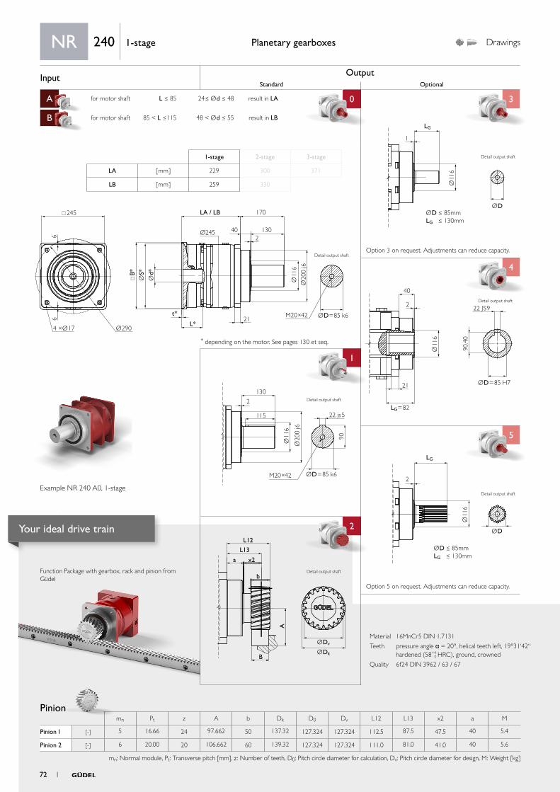
Input OutputStandard Optional
A for motor shaft L ≤ 85 24≤ Ød ≤ 48 result in LA 0 3
B for motor shaft 85 < L ≤115 48 < Ød ≤ 55 result in LB
C
4
1 4
5
aa
2
ØDv
L12
L13
x2
b
B
a
A
ØDk
Ø11
6
ØD
LG
2
ØD ≤ 85mmLG ≤ 130mm
2
130
115
Ø11
6
90
Ø20
0 j6
M20×42 ØD=85 k6
22 js5
Ø11
6
ØD=85 H7
LG=82
22 JS9
40
2
21
90.4
0
Ø11
6
ØD
1
LG
ØD ≤ 85mmLG ≤ 130mm
245
Ø245
B*
t*
L*21
LA / LB 170
402
130
66
Ø2904 ×Ø17
Ød*
ØS*
Ø11
6Ø
200
j6
ØD=85 k6M20×42
Material 16MnCr5 DIN 1.7131
Teeth pressure angle α = 20°, helical teeth left, 19°31‘42“ hardened (58+4
0 HRC), ground, crowned
Quality 6f24 DIN 3962 / 63 / 67
Function Package with gearbox, rack and pinion from Güdel
Pinion
Planetary gearboxes Drawings
* depending on the motor. See pages 130 et seq.
Option 5 on request. Adjustments can reduce capacity.
Option 3 on request. Adjustments can reduce capacity.
NR 240 1-stage
1-stage 2-stage 3-stage
LA [ mm ] 229 300 371
LB [ mm ] 259 330
Example NR 240 A0, 1-stage
Detail output shaft
Detail output shaft
Detail output shaft
Detail output shaft
mn Pt z A b Dk D0 Dv L12 L13 x2 a M
Pinion 1 [-] 5 16.66 24 97.662 50 137.32 127.324 127.324 112.5 87.5 47.5 40 5.4
Pinion 2 [-] 6 20.00 20 106.662 60 139.32 127.324 127.324 111.0 81.0 41.0 40 5.6
mn: Normal module, Pt: Transverse pitch [mm], z : Number of teeth, D0: Pitch circle diameter for calculation, Dv: Pitch circle diameter for design, M: Weight [kg]
Detail output shaft
Detail output shaft
72 1
Your ideal drive train
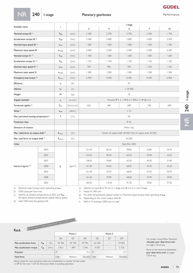
PerformancePlanetary gearboxes
Rack
More on the technical datasheets your ideal drive train on pages 120 et seq.
For proper sizing follow flowchart calculate your ideal drive train on pages 136 et seq.
Pinion 1 Pinion 2
Q6 Q7 Q9 Q6 Q7 Q9
Max acceleration force F2B [ N ] 44 786 29 748 39 992 63 300 - 59 005
Max acceleration torque T2B [ Nm ] 2 851 1 894 2 546 4 030 - 3 756
Precision P1 P12 P1 P12
Feed force High Medium Elevated High Medium Elevated
Above values for rack and pinion take into consideration a number of load cycles:1x10⁶ for the rack; 1x10⁷ for the pinion. Both in pulsating operation.
NR
240
1-st
age
NR 240 1-stage
Available ratios i1-stage
3 4 5 7 10
Nominal torque S5 a) T2N [ Nm ] 2 400 2 700 2 700 2 500 1 700
Acceleration torque S5 b) T2B [ Nm ] 3 400 3 800 3 800 3 600 2 400
Nominal input speed S5 c) n1N [rpm] 1 000 1 000 1 000 1 500 1 500
Maximum input speed S5 n1max [rpm] 2 000 2 200 2 200 2 200 2 200
Nominal torque S1 a) T2N [Nm ] 1 400 1 600 1 600 1 600 1 600
Acceleration torque S1 b) T2B [ Nm] 1 750 1 750 1 750 1 750 1 750
Nominal input speed S1 c) n1N [rpm] 700 900 900 1 350 1 350
Maximum input speed S1 n1max [rpm] 1 000 1 000 1 000 1 500 1 500
Emergency stop torque d) T2 n o t [ Nm ] 6 900 8 500 8 500 8 500 6 800
Efficiency h [ % ] 97
Lifetime Lh [ h ] > 20 000
Weight M [ kg ] 70
Angular backlash jt [ arcmin ] Precision P 1 ≤ 1 / P 3 ≤ 3 / P 5 ≤ 5 / P 12 ≤12
Torsionnal rigidity e) Ct2 [ Nm/arcmin ] 626 684 698 728 698
Noise i) L pA [ dB(A) ] ≤ 72
Max. permitted housing temperature g) T [ °C ] 90
Protection class IP 65
Direction of rotation Motor way
Max. radial force on output shaft f) Fr m a x [ N ] Center of output shaft: 30 000 / End of output shaft: 20 000
Max. axial force on output shaft f) Fa m a x [ N ] 34 000
Color Red, RAL 3003
Inertia in kg.cm² h)
Ø24
J1 [ kgcm2 ]
151.00 83.30 58.00 36.80 24.30
Ø32 153.20 85.50 60.20 39.00 26.50
Ø35 158.50 90.80 65.50 44.30 31.80
Ø38 161.90 94.20 68.90 47.70 35.20
Ø42 161.40 93.70 68.40 47.20 34.70
Ø48 161.60 93.90 68.60 47.40 34.90
Ø55 184.20 116.50 91.20 70.00 57.50
a) Nominal output torque when operating at n1N.
b) 1000 cycles per hour max.
c) Valid for an ambient temperature of 20°C and T2N. At higher ambient temperatures, please reduce speed.
d) Valid 1000 times the gearbox life.
e) Valid for an input Ø of 55 mm in 1-stage and 48 mm in 2- and 3-stage.
f) Values for 300 rpm.
g) For other temperatures, please contact us. Nominal output torque when operating at n1N.
h) Depending on the motor output shaft Ø.
i) With i=10 and n1N=2000 rpm no load.
1 73
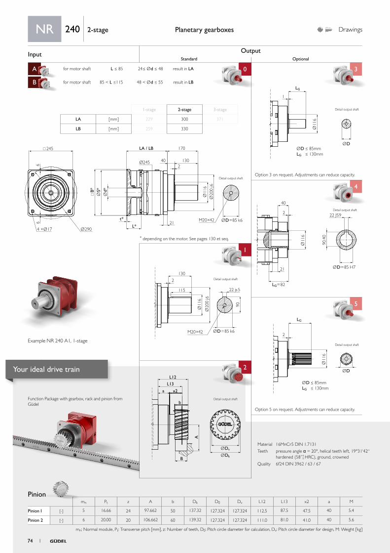
Input OutputStandard Optional
A for motor shaft L ≤ 85 24≤ Ød ≤ 48 result in LA 0 3
B for motor shaft 85 < L ≤115 48 < Ød ≤ 55 result in LB
C
4
1 4
5
aa
2
ØDv
L12
L13
x2
b
B
a
A
ØDk
Ø11
6
ØD
LG
2
ØD ≤ 85mmLG ≤ 130mm
2
130
115
Ø11
6
90
Ø20
0 j6
M20×42 ØD=85 k6
22 js5
Ø11
6
ØD
1
LG
ØD ≤ 85mmLG ≤ 130mm
245
Ø245
B*
t*
L*21
LA / LB 170
402
130
66
Ø2904 ×Ø17
Ød*
ØS*
Ø11
6Ø
200
j6
ØD=85 k6M20×42
Ø11
6
ØD=85 H7
LG=82
22 JS9
40
2
21
90.4
0
Material 16MnCr5 DIN 1.7131
Teeth pressure angle α = 20°, helical teeth left, 19°31‘42“ hardened (58+4
0 HRC), ground, crowned
Quality 6f24 DIN 3962 / 63 / 67
Function Package with gearbox, rack and pinion from Güdel
Pinion
Planetary gearboxes Drawings
* depending on the motor. See pages 130 et seq.
Option 5 on request. Adjustments can reduce capacity.
Option 3 on request. Adjustments can reduce capacity.
NR 240 2-stage
1-stage 2-stage 3-stage
LA [ mm ] 229 300 371
LB [ mm ] 259 330
Example NR 240 A1, 1-stage
Detail output shaft
Detail output shaft
Detail output shaft
Detail output shaft
mn Pt z A b Dk D0 Dv L12 L13 x2 a M
Pinion 1 [-] 5 16.66 24 97.662 50 137.32 127.324 127.324 112.5 87.5 47.5 40 5.4
Pinion 2 [-] 6 20.00 20 106.662 60 139.32 127.324 127.324 111.0 81.0 41.0 40 5.6
mn: Normal module, Pt: Transverse pitch [mm], z : Number of teeth, D0: Pitch circle diameter for calculation, Dv: Pitch circle diameter for design, M: Weight [kg]
Detail output shaft
Detail output shaft
74 1
Your ideal drive train

PerformancePlanetary gearboxes
Rack
More on the technical datasheets your ideal drive train on pages 120 et seq.
For proper sizing follow flowchart calculate your ideal drive train on pages 136 et seq.
Pinion 1 Pinion 2
Q6 Q7 Q9 Q6 Q7 Q9
Max acceleration force F2B [ N ] 44 786 29 748 39 992 63 300 - 59 005
Max acceleration torque T2B [ Nm ] 2 851 1 894 2 546 4 030 - 3 756
Precision P1 P12 P1 P12
Feed force High Medium Elevated High Medium Elevated
Above values for rack and pinion take into consideration a number of load cycles:1x10⁶ for the rack; 1x10⁷ for the pinion. Both in pulsating operation.
NR
240
2-st
age
NR 240 2-stage
Available ratios * i2-stage
12 16 20 25 30 35 40 50 70 100
Nominal torque S5 a) T2N [ Nm ] 2 400 2 700 2 700 2 700 2 400 2 700 2 700 2 700 2 500 1 700
Acceleration torque S5 b) T2B [ Nm ] 3 200 3 800 3 800 3 800 3 200 3 800 3 800 3 800 3 600 2 200
Nominal input speed S5 c) n1N [rpm] 1 700 1 900 1 900 1 900 1 900 1 900 1 900 2 100 2 100 2 400
Maximum input speed S5 n1max [rpm] 3 500 3 500 3 500 3 500 3 500 3 500 3 500 3 500 3 500 3 500
Nominal torque S1 a) T2N [Nm ] 1 600 1 600 1 600 1 600 1 600 1 600 1 600 1 600 1 600 1 600
Acceleration torque S1 b) T2B [ Nm] 1 750 1 750 1 750 1 750 1 750 1 750 1 750 1 750 1 750 1 750
Nominal input speed S1 c) n1N [rpm] 1 200 1 700 1 700 1 700 1 700 1 700 1 700 1 900 1 900 2 100
Maximum input speed S1 n1max [rpm] 1 700 1 900 1 900 1 900 1 900 1 900 1 900 2 100 2 100 2 400
Emergency stop torque d) T2 n o t [ Nm ] 6 900 8 500 8 500 8 500 6 900 8 500 8 500 8 500 8 500 6 800
Efficiency h [ % ] 94
Lifetime Lh [ h ] > 20 000
Weight M [ kg ] 90
Angular backlash jt [ arcmin ] Precision P 1 ≤ 1 / P 3 ≤ 3 / P 5 ≤ 5 / P 12 ≤12
Torsionnal rigidity e) Ct2 [ Nm/arcmin ] 564.5 582.0 599.5 599.5 564.5 599.5 582.0 599.5 587.8 564.5
Noise i) L pA [ dB(A) ] ≤ 72
Max. permitted housing temperature g) T [ °C ] 90
Protection class IP 65
Direction of rotation Same way input / output
Max. radial force on output shaft f) Fr m a x [ N ] Center of output shaft: 30 000 / End of output shaft: 20 000
Max. axial force on output shaft f) Fa m a x [ N ] 34 000
Color Red, RAL 3003
Inertia in kg.cm² h)
Ø24
J1 [ kgcm2 ]
79.1 74.9 73.3 51.5 23.6 33.5 22.9 22.7 22.4 22.3
Ø32 81.3 77.1 75.5 53.7 25.8 35.7 25.1 24.9 24.6 24.5
Ø35 86.6 82.4 80.8 59 31.1 41 30.4 30.2 29.9 29.8
Ø38 90 85.8 84.2 62.4 34.5 44.4 33.8 33.6 33.3 33.2
Ø42 89.5 85.3 83.7 61.9 34 43.9 33.3 33.1 32.8 32.7
Ø48 89.7 85.5 83.9 62.1 34.2 44.1 33.5 33.3 33 32.9
Ø55 112.3 108.1 106.5 84.7 56.8 66.7 56.1 55.9 55.6 55.5
* Other ratios available. 9, 15, 21, 27, 28, 49 on request.
a) Nominal output torque when operating at n1N.
b) 1000 cycles per hour max.
c) Valid for an ambient temperature of 20°C and T2N. At higher ambient temperatures, please reduce speed.
d) Valid 1000 times the gearbox life.
e) Valid for an input Ø of 55 mm in 1-stage and 48 mm in 2- and 3-stage.
f) Values for 300 rpm.
g) For other temperatures, please contact us. Nominal output torque when operating at n1N.
h) Depending on the motor output shaft Ø.
i) With i=10 and n1N=2000 rpm no load.
1 75

Input OutputStandard Optional
A for motor shaft L ≤ 85 24≤ Ød ≤ 48 result in LA 0 3
B for motor shaft 85 < L ≤115 48 < Ød ≤ 55 result in LB
C
4
1 4
5
aa
2
ØDv
L12
L13
x2
b
B
a
A
ØDk
Ø11
6
ØD
LG
2
ØD ≤ 85mmLG ≤ 130mm
2
130
115
Ø11
6
90
Ø20
0 j6
M20×42 ØD=85 k6
22 js5
Ø11
6
ØD=85 H7
LG=82
22 JS9
40
2
21
90.4
0
Ø11
6
ØD
1
LG
ØD ≤ 85mmLG ≤ 130mm
245
Ø245
B*
t*
L*21
LA / LB 170
402
130
66
Ø2904 ×Ø17
Ød*
ØS*
Ø11
6Ø
200
j6
ØD=85 k6M20×42
Material 16MnCr5 DIN 1.7131
Teeth pressure angle α = 20°, helical teeth left, 19°31‘42“ hardened (58+4
0 HRC), ground, crowned
Quality 6f24 DIN 3962 / 63 / 67
Function Package with gearbox, rack and pinion from Güdel
Pinion
Planetary gearboxes Drawings
* depending on the motor. See pages 130 et seq.
Option 5 on request. Adjustments can reduce capacity.
Option 3 on request. Adjustments can reduce capacity.
NR 240 3-stage
1-stage 2-stage 3-stage
LA [ mm ] 229 300 371
LB [ mm ] 259 330
Example NR 240 A2, 1-stage
Detail output shaft
Detail output shaft
Detail output shaft
Detail output shaft
mn Pt z A b Dk D0 Dv L12 L13 x2 a M
Pinion 1 [-] 5 16.66 24 97.662 50 137.32 127.324 127.324 112.5 87.5 47.5 40 5.4
Pinion 2 [-] 6 20.00 20 106.662 60 139.32 127.324 127.324 111.0 81.0 41.0 40 5.6
mn: Normal module, Pt: Transverse pitch [mm], z : Number of teeth, D0: Pitch circle diameter for calculation, Dv: Pitch circle diameter for design, M: Weight [kg]
Detail output shaft
Detail output shaft
76 1
Your ideal drive train

PerformancePlanetary gearboxes
Rack
More on the technical datasheets your ideal drive train on pages 120 et seq.
For proper sizing follow flowchart calculate your ideal drive train on pages 136 et seq.
NR
240
3-st
age
NR 240 3-stage
Available ratios * i3-stage
105 125 175 200 250 300 400 500 700 1 000
Nominal torque S5 a) T2N [ Nm ] 2 700 2 700 2 700 2 700 2 700 2 400 2 700 2 700 2 500 1 500
Acceleration torque S5 b) T2B [ Nm ] 3 800 3 800 3 800 3 800 3 800 3 000 3 800 3 800 3 600 2 200
Nominal input speed S5 c) n1N [rpm] 2 400 2 400 2 400 2 400 2 400 2 400 2 400 2 400 2 400 2 400
Maximum input speed S5 n1max [rpm] 3 500 3 500 3 500 3 500 3 500 3 500 3 500 3 500 3 500 3 500
Nominal torque S1 a) T2N [Nm ] 1 600 1 600 1 600 1 600 1 600 1 600 1 600 1 600 1 600 1 600
Acceleration torque S1 b) T2B [ Nm] 1 750 1 750 1 750 1 750 1 750 1 750 1 750 1 750 1 750 1 750
Nominal input speed S1 c) n1N [rpm] 2 100 2 100 2 100 2 100 2 100 2 100 2 100 2 100 2 100 2 100
Maximum input speed S1 n1max [rpm] 2 400 2 400 2 400 2 400 2 400 2 400 2 400 2 400 2 400 2 400
Emergency stop torque d) T2 n o t [ Nm ] 8 500 8 500 8 500 8 500 8 500 6 900 8 500 8 500 8 500 6 800
Efficiency h [ % ] 91
Lifetime Lh [ h ] > 20 000
Weight M [ kg ] 110
Angular backlash jt [ arcmin ] Precision P 1 ≤ 1 / P 3 ≤ 3 / P 5 ≤ 5 / P 12 ≤12
Torsionnal rigidity e) Ct2 [ Nm/arcmin ] 538 538 538 538 538 506 524 538 556 524
Noise i) L pA [ dB(A) ] ≤ 72
Max. permitted housing temperature g) T [ °C ] 90
Protection class IP 65
Direction of rotation Same way input / output
Max. radial force on output shaft f) Fr m a x [ N ] Center of output shaft: 30 000 / End of output shaft: 20 000
Max. axial force on output shaft f) Fa m a x [ N ] 34 000
Color Red, RAL 3003
Inertia in kg.cm² h)
Ø24
J1 [ kgcm2 ]
35.10 51.30 35.10 22.80 22.60 22.30 22.30 22.30 22.30 22.30
Ø32 37.30 53.50 37.30 25.00 24.80 24.50 24.50 24.50 24.50 24.50
Ø35 42.60 58.80 42.60 30.30 30.10 29.80 29.80 29.80 29.80 29.80
Ø38 46.00 62.20 46.00 33.70 33.50 33.20 33.20 33.20 33.20 33.20
Ø42 45.50 61.70 45.50 33.20 33.00 32.70 32.70 32.70 32.70 32.70
Ø48 45.70 61.70 45.70 33.40 33.20 32.90 32.90 32.90 32.90 32.90
Ø55 68.30 84.50 68.30 56.00 55.80 55.50 55.50 55.50 55.50 55.50
* Other ratios available. 112, 120, 140, 147, 150, 160, 196, 210, 245, 280, 343, 350, 490 on request.
a) Nominal output torque when operating at n1N.
b) 1000 cycles per hour max.
c) Valid for an ambient temperature of 20°C and T2N. At higher ambient temperatures, please reduce speed.
d) Valid 1000 times the gearbox life.
e) Valid for an input Ø of 55 mm in 1-stage and 48 mm in 2- and 3-stage.
f) Values for 300 rpm.
g) For other temperatures, please contact us. Nominal output torque when operating at n1N.
h) Depending on the motor output shaft Ø.
i) With i=10 and n1N=2000 rpm no load.
Pinion 1 Pinion 2
Q6 Q7 Q9 Q6 Q7 Q9
Max acceleration force F2B [ N ] 44 786 29 748 39 992 63 300 - 59 005
Max acceleration torque T2B [ Nm ] 2 851 1 894 2 546 4 030 - 3 756
Precision P1 P12 P1 P12
Feed force High Medium Elevated High Medium Elevated
Above values for rack and pinion take into consideration a number of load cycles:1x10⁶ for the rack; 1x10⁷ for the pinion. Both in pulsating operation.
1 77
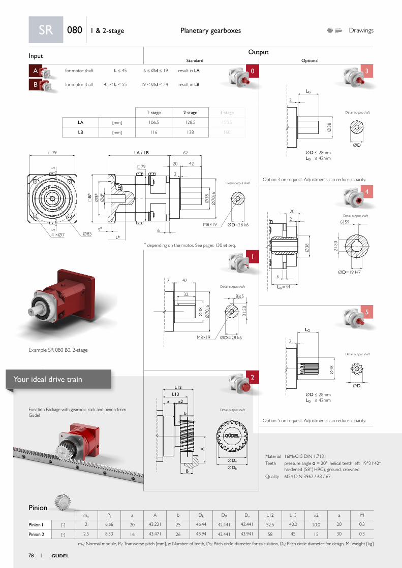
Input OutputStandard Optional
A for motor shaft L ≤ 45 6 ≤ Ød ≤ 19 result in LA 0 3
B for motor shaft 45 < L ≤ 55 19 < Ød ≤ 24 result in LB
C
4
1 4
5
aa
2
ØDv
L12
L13
x2
b
B
a
A
ØDk
2 42
32
Ø38
31.5
0
Ø70
j6
M8×19
8js5
ØD=28 k6
Ø38
ØD
2
LG
ØD ≤ 28mmLG ≤ 42mm
Ø38
ØD=19 H7
LG=44
6 JS9
20
2
6
21.8
0Ø
38
ØD
LG
2
ØD ≤ 28mmLG ≤ 42mm
79
79
B*
t*
L*
6
LA / LB 62
20
2
42
55
Ø854 ×Ø7
Ød*
ØS*
Ø38
Ø70
j6
ØD=28 k6M8×19
Material 16MnCr5 DIN 1.7131
Teeth pressure angle α = 20°, helical teeth left, 19°31‘42“ hardened (58+4
0 HRC), ground, crowned
Quality 6f24 DIN 3962 / 63 / 67
Function Package with gearbox, rack and pinion from Güdel
Pinion
Planetary gearboxes Drawings
* depending on the motor. See pages 130 et seq.
Option 5 on request. Adjustments can reduce capacity.
Option 3 on request. Adjustments can reduce capacity.
SR 080 1 & 2-stage
1-stage 2-stage 3-stage
LA [ mm ] 106.5 128.5 150.5
LB [ mm ] 116 138 160
Example SR 080 B0, 2-stage
Detail output shaft
Detail output shaft
Detail output shaft
Detail output shaft
mn Pt z A b Dk D0 Dv L12 L13 x2 a M
Pinion 1 [-] 2 6.66 20 43.221 25 46.44 42.441 42.441 52.5 40.0 20.0 20 0.3
Pinion 2 [-] 2.5 8.33 16 43.471 26 48.94 42.441 43.941 58 45 15 30 0.3
mn: Normal module, Pt: Transverse pitch [mm], z : Number of teeth, D0: Pitch circle diameter for calculation, Dv: Pitch circle diameter for design, M: Weight [kg]
Detail output shaft
Detail output shaft
78 1
Your ideal drive train

PerformancePlanetary gearboxes
Rack
More on the technical datasheets your ideal drive train on pages 120 et seq.
For proper sizing follow flowchart calculate your ideal drive train on pages 136 et seq.
SR08
01
& 2
-sta
ge
SR 080 1 & 2-stage
Available ratios i1-stage 2-stage
4 12 16 20 28 40
Nominal torque S5 a) T2N [ Nm ] 95 95 95 95 95 95
Acceleration torque S5 b) T2B [ Nm ] 150 140 140 140 140 140
Nominal input speed S5 c) n1N [rpm] 2 600 2 900 3 100 3 100 3 100 3 100
Maximum input speed S5 n1max [rpm] 5 400 5 400 5 400 5 400 5 400 5 400
Emergency stop torque d) T2not [ Nm ] 250 250 250 250 250 250
Efficiency h [ % ] 96 93
Lifetime Lh [ h ] > 20 000
Weight M [ kg ] 4 5
Angular backlash jt [ arcmin ] Precision P 1 ≤ 1 / P 3 ≤ 3 / P 5 ≤ 5 / P 12 ≤12
Torsionnal rigidity e) Ct2 [ Nm/arcmin ] 11.7 11.1 11.1 11.3 11.1 11.1
Noise i) L pA [ dB(A) ] ≤ 70
Max. permitted housing temperature g) T [ °C ] 90
Protection class IP 65
Direction of rotation Same way input / output
Max. radial force on output shaft f) Frmax [ N ] Center of output shaft: 4 200 / End of output shaft: 3 285
Max. axial force on output shaft f) Famax [ N ] 3 600
Color Red, RAL 3003
Inertia in kg.cm² h)
Ø11
J1 [ kgcm2 ]
0.46 0.46 0.45 0.45 0.34 0.31
Ø14 1.02 1.01 1.00 1.00 0.89 0.86
Ø19 1.03 1.03 1.02 1.01 0.91 0.88
Ø24 1.85 1.84 1.83 1.83 1.72 1.69
Pinion 1 Pinion 2
Q6 Q7 Q9 Q6 Q7 Q9
Max acceleration force F2B [ N ] 7 490 2 963 5 036 7 490 2 963 5 036
Max acceleration torque T2B [ Nm ] 159 63 107 159 63 107
Precision P1 P12 P1 P12
Feed force High Medium Elevated High Medium Elevated
Above values for rack and pinion take into consideration a number of load cycles:1x10⁶ for the rack; 1x10⁷ for the pinion. Both in pulsating operation.
a) Nominal output torque when operating at n1N.
b) 1000 cycles per hour max.
c) Valid for an ambient temperature of 20°C and T2N. At higher ambient temperatures, please reduce speed.
d) Valid 1000 times the gearbox life.
e) Valid for an input Ø of 19mm in 1-stage and 14mm in 2- and 3-stage.
f) Values for 300 rpm.
g) For other temperatures, please contact us. Nominal output torque when operating at n1N.
h) Depending on the motor output shaft Ø.
i) With i=10 and n1N=2500 rpm no load.
1 79
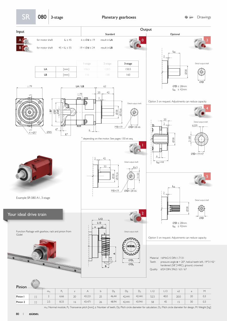
Input OutputStandard Optional
A for motor shaft L ≤ 45 6 ≤ Ød ≤ 19 result in LA 0 3
B for motor shaft 45 < L ≤ 55 19 < Ød ≤ 24 result in LB
C
4
1 4
5
aa
2
ØDv
L12
L13
x2
b
B
a
A
ØDk
2 42
32
Ø38
31.5
0
Ø70
j6
M8×19
8js5
ØD=28 k6
Ø38
ØD
2
LG
ØD ≤ 28mmLG ≤ 42mm
Ø38
ØD=19 H7
LG=44
6 JS9
20
2
6
21.8
0Ø
38
ØD
LG
2
ØD ≤ 28mmLG ≤ 42mm
79
79
B*
t*
L*
6
LA / LB 62
20
2
42
55
Ø854 ×Ø7
Ød*
ØS*
Ø38
Ø70
j6
ØD=28 k6M8×19
Material 16MnCr5 DIN 1.7131
Teeth pressure angle α = 20°, helical teeth left, 19°31‘42“ hardened (58+4
0 HRC), ground, crowned
Quality 6f24 DIN 3962 / 63 / 67
Function Package with gearbox, rack and pinion from Güdel
Pinion
Planetary gearboxes Drawings
* depending on the motor. See pages 130 et seq.
Option 5 on request. Adjustments can reduce capacity.
Option 3 on request. Adjustments can reduce capacity.
SR 080 3-stage
1-stage 2-stage 3-stage
LA [ mm ] 106.5 128.5 150.5
LB [ mm ] 116 138 160
Example SR 080 A1, 3-stage
Detail output shaft
Detail output shaft
Detail output shaft
Detail output shaft
mn Pt z A b Dk D0 Dv L12 L13 x2 a M
Pinion 1 [-] 2 6.66 20 43.221 25 46.44 42.441 42.441 52.5 40.0 20.0 20 0.3
Pinion 2 [-] 2.5 8.33 16 43.471 26 48.94 42.441 43.941 58 45 15 30 0.3
mn: Normal module, Pt: Transverse pitch [mm], z : Number of teeth, D0: Pitch circle diameter for calculation, Dv: Pitch circle diameter for design, M: Weight [kg]
Detail output shaft
Detail output shaft
80 1
Your ideal drive train
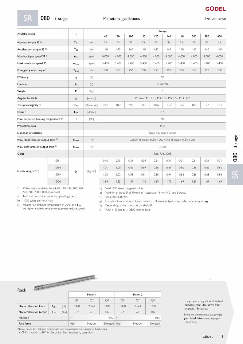
PerformancePlanetary gearboxes
Rack
More on the technical datasheets your ideal drive train on pages 120 et seq.
For proper sizing follow flowchart calculate your ideal drive train on pages 136 et seq.
SR08
03-
stag
e
SR 080 3-stage
Available ratios i3-stage
60 80 100 112 120 140 160 200 280 400
Nominal torque S5 a) T2N [ Nm ] 95 95 95 95 95 95 95 95 95 95
Acceleration torque S5 b) T2B [ Nm ] 140 140 140 140 140 140 140 140 140 140
Nominal input speed S5 c) n1N [rpm] 4 000 4 000 4 000 4 000 4 000 4 000 4 000 4 000 4 000 4 000
Maximum input speed S5 n1max [rpm] 5 400 5 400 5 400 5 400 5 400 5 400 5 400 5 400 5 400 5 400
Emergency stop torque d) T2not [ Nm ] 250 250 250 250 250 250 250 250 250 250
Efficiency h [ % ] 90
Lifetime Lh [ h ] > 20 000
Weight M [ kg ] 6
Angular backlash jt [ arcmin ] Precision P 1 ≤ 1 / P 3 ≤ 3 / P 5 ≤ 5 / P 12 ≤12
Torsionnal rigidity e) Ct2 [ Nm/arcmin ] 10.7 10.7 9.8 10.6 10.6 10.7 10.6 10.7 10.6 10.1
Noise i) L pA [ dB(A) ] ≤ 70
Max. permitted housing temperature g) T [ °C ] 90
Protection class IP 65
Direction of rotation Same way input / output
Max. radial force on output shaft f) Frmax [ N ] Center of output shaft: 4 200 / End of output shaft: 3 285
Max. axial force on output shaft f) Famax [ N ] 3 600
Color Red, RAL 3003
Inertia in kg.cm² h)
Ø11
J1 [ kgcm2 ]
0.46 0.45 0.31 0.34 0.31 0.34 0.31 0.31 0.31 0.31
Ø14 1.01 1.00 0.86 0.89 0.86 0.89 0.86 0.86 0.86 0.86
Ø19 1.03 1.02 0.88 0.91 0.88 0.91 0.88 0.88 0.88 0.88
Ø24 1.84 1.83 1.69 1.72 1.69 1.72 1.69 1.69 1.69 1.69
Pinion 1 Pinion 2
Q6 Q7 Q9 Q6 Q7 Q9
Max acceleration force F2B [ N ] 7 490 2 963 5 036 7 490 2 963 5 036
Max acceleration torque T2B [ Nm ] 159 63 107 159 63 107
Precision P1 P12 P1 P12
Feed force High Medium Elevated High Medium Elevated
Above values for rack and pinion take into consideration a number of load cycles:1x10⁶ for the rack; 1x10⁷ for the pinion. Both in pulsating operation.
* Other ratios available. 36, 64, 84, 180, 196, 300, 360, 500, 600, 700, 1 000 on request.
a) Nominal output torque when operating at n1N.
b) 1000 cycles per hour max.
c) Valid for an ambient temperature of 20°C and T2N. At higher ambient temperatures, please reduce speed.
d) Valid 1000 times the gearbox life.
e) Valid for an input Ø of 19 mm in 1-stage and 14 mm in 2- and 3-stage.
f) Values for 300 rpm.
g) For other temperatures, please contact us. Nominal output torque when operating at n1N.
h) Depending on the motor output shaft Ø.
i) With i=10 and n1N=2500 rpm no load.
1 81
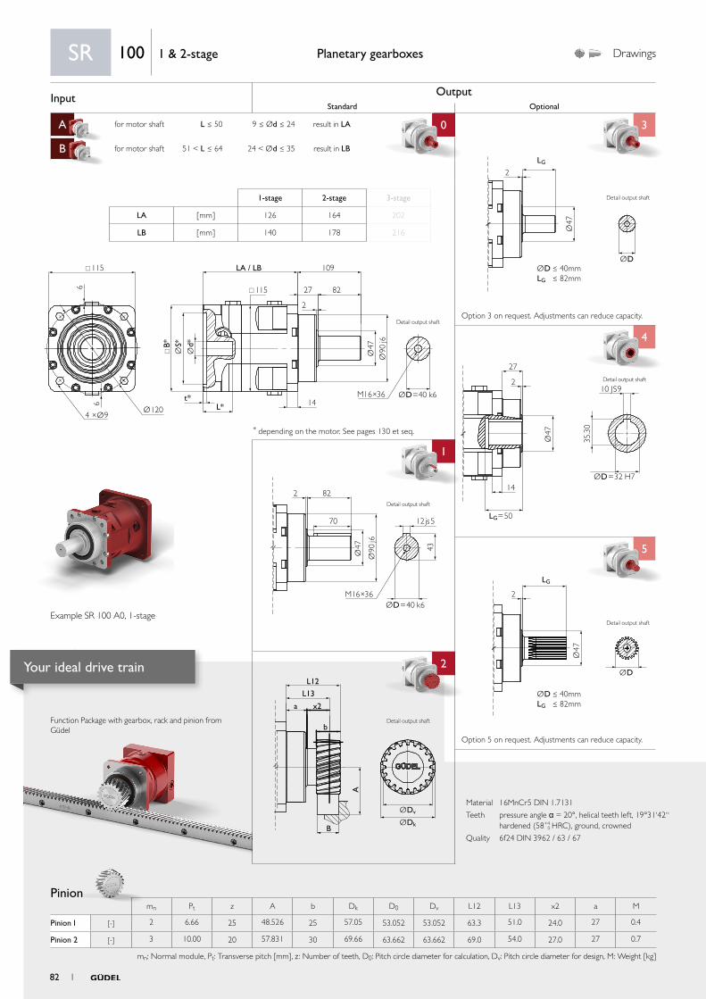
Input OutputStandard Optional
A for motor shaft L ≤ 50 9 ≤ Ød ≤ 24 result in LA 0 3
B for motor shaft 51 < L ≤ 64 24 < Ød ≤ 35 result in LB
C
4
1 4
5
aa
2
ØDv
L12
L13
x2
b
B
a
A
ØDk
Ø47
ØD
LG
2
ØD ≤ 40mmLG ≤ 82mm
2 82
70
Ø47 43
Ø90
j6
M16×36ØD=40 k6
12js5
Ø47
ØD=32 H7
LG=50
10 JS9
27
2
14
35.3
0
Ø47
ØD
2
LG
ØD ≤ 40mmLG ≤ 82mm
115
115
B*
t*L* 14
LA / LB 109
27
2
826
6
Ø1204 ×Ø9
Ød*
ØS*
Ø47
Ø90
j6
ØD=40 k6M16×36
Material 16MnCr5 DIN 1.7131
Teeth pressure angle α = 20°, helical teeth left, 19°31‘42“ hardened (58+4
0 HRC), ground, crowned
Quality 6f24 DIN 3962 / 63 / 67
Function Package with gearbox, rack and pinion from Güdel
Pinion
Planetary gearboxes Drawings
* depending on the motor. See pages 130 et seq.
Option 5 on request. Adjustments can reduce capacity.
Option 3 on request. Adjustments can reduce capacity.
SR 100 1 & 2-stage
1-stage 2-stage 3-stage
LA [ mm ] 126 164 202
LB [ mm ] 140 178 216
Example SR 100 A0, 1-stage
Detail output shaft
Detail output shaft
Detail output shaft
Detail output shaft
mn Pt z A b Dk D0 Dv L12 L13 x2 a M
Pinion 1 [-] 2 6.66 25 48.526 25 57.05 53.052 53.052 63.3 51.0 24.0 27 0.4
Pinion 2 [-] 3 10.00 20 57.831 30 69.66 63.662 63.662 69.0 54.0 27.0 27 0.7
mn: Normal module, Pt: Transverse pitch [mm], z : Number of teeth, D0: Pitch circle diameter for calculation, Dv: Pitch circle diameter for design, M: Weight [kg]
Detail output shaft
Detail output shaft
82 1
Your ideal drive train
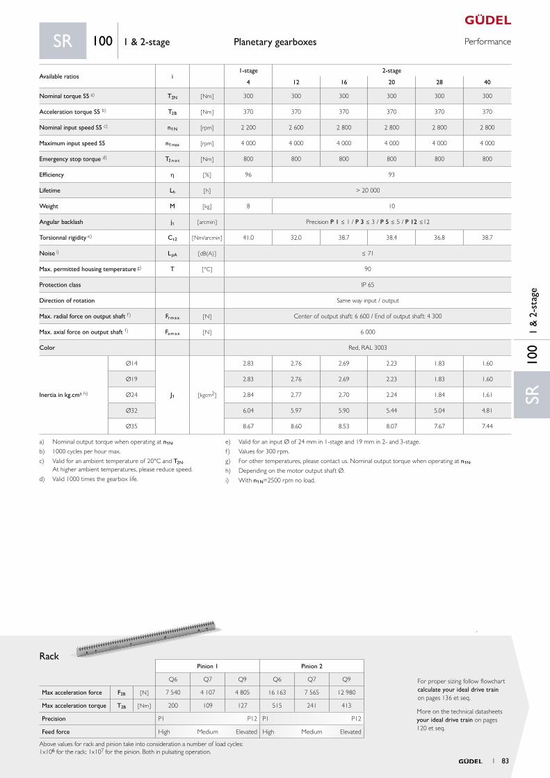
PerformancePlanetary gearboxes
Rack
More on the technical datasheets your ideal drive train on pages 120 et seq.
For proper sizing follow flowchart calculate your ideal drive train on pages 136 et seq.
Pinion 1 Pinion 2
Q6 Q7 Q9 Q6 Q7 Q9
Max acceleration force F2B [ N ] 7 540 4 107 4 805 16 163 7 565 12 980
Max acceleration torque T2B [ Nm ] 200 109 127 515 241 413
Precision P1 P12 P1 P12
Feed force High Medium Elevated High Medium Elevated
Above values for rack and pinion take into consideration a number of load cycles:1x10⁶ for the rack; 1x10⁷ for the pinion. Both in pulsating operation.
SR10
01
& 2
-sta
ge
SR 100 1 & 2-stage
Available ratios i1-stage 2-stage
4 12 16 20 28 40
Nominal torque S5 a) T2N [ Nm ] 300 300 300 300 300 300
Acceleration torque S5 b) T2B [ Nm ] 370 370 370 370 370 370
Nominal input speed S5 c) n1N [rpm] 2 200 2 600 2 800 2 800 2 800 2 800
Maximum input speed S5 n1max [rpm] 4 000 4 000 4 000 4 000 4 000 4 000
Emergency stop torque d) T2 n o t [ Nm ] 800 800 800 800 800 800
Efficiency h [ % ] 96 93
Lifetime Lh [ h ] > 20 000
Weight M [ kg ] 8 10
Angular backlash jt [ arcmin ] Precision P 1 ≤ 1 / P 3 ≤ 3 / P 5 ≤ 5 / P 12 ≤12
Torsionnal rigidity e) Ct2 [ Nm/arcmin ] 41.0 32.0 38.7 38.4 36.8 38.7
Noise i) L pA [ dB(A) ] ≤ 71
Max. permitted housing temperature g) T [ °C ] 90
Protection class IP 65
Direction of rotation Same way input / output
Max. radial force on output shaft f) Fr m a x [ N ] Center of output shaft: 6 600 / End of output shaft: 4 300
Max. axial force on output shaft f) Fa m a x [ N ] 6 000
Color Red, RAL 3003
Inertia in kg.cm² h)
Ø14
J1 [ kgcm2 ]
2.83 2.76 2.69 2.23 1.83 1.60
Ø19 2.83 2.76 2.69 2.23 1.83 1.60
Ø24 2.84 2.77 2.70 2.24 1.84 1.61
Ø32 6.04 5.97 5.90 5.44 5.04 4.81
Ø35 8.67 8.60 8.53 8.07 7.67 7.44
a) Nominal output torque when operating at n1N.
b) 1000 cycles per hour max.
c) Valid for an ambient temperature of 20°C and T2N. At higher ambient temperatures, please reduce speed.
d) Valid 1000 times the gearbox life.
e) Valid for an input Ø of 24 mm in 1-stage and 19 mm in 2- and 3-stage.
f) Values for 300 rpm.
g) For other temperatures, please contact us. Nominal output torque when operating at n1N.
h) Depending on the motor output shaft Ø.
i) With n1N=2500 rpm no load.
1 83
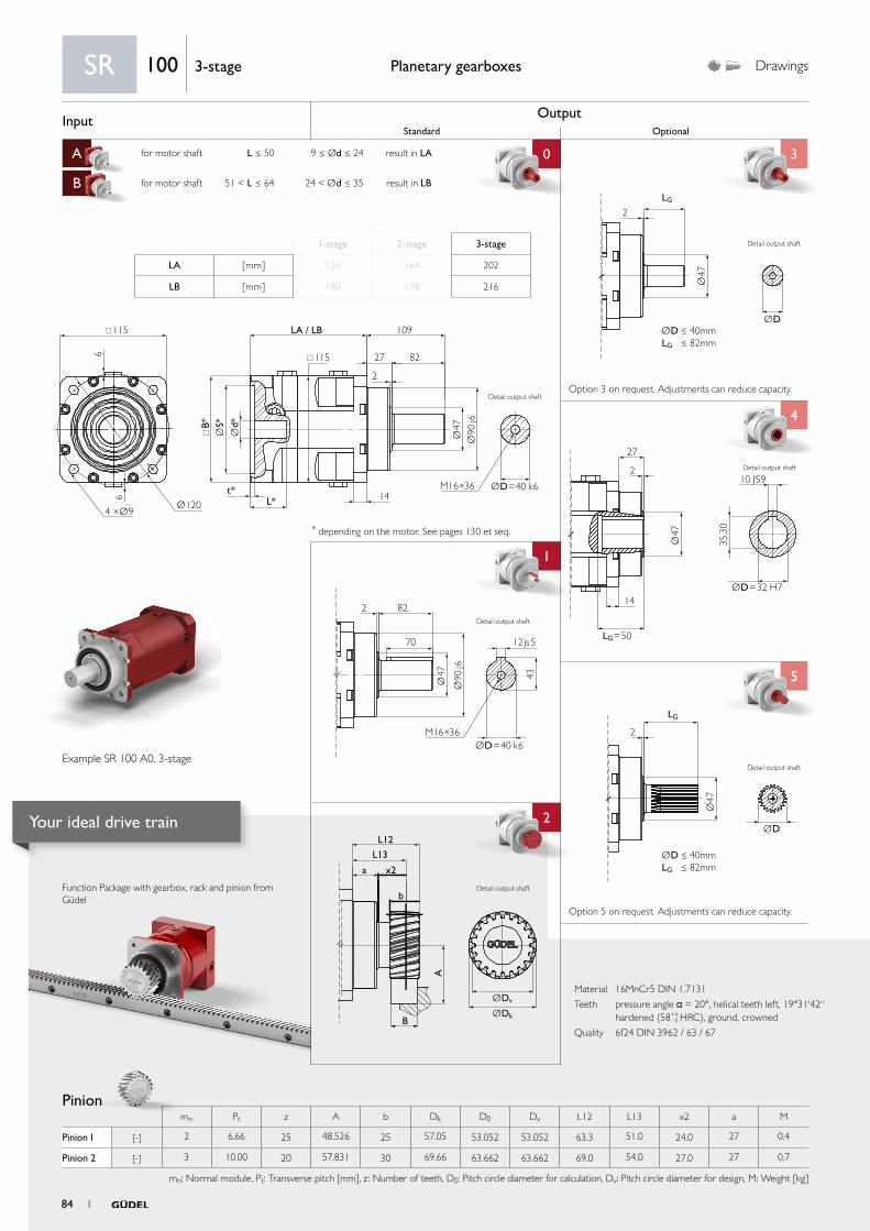
Input OutputStandard Optional
A for motor shaft L ≤ 50 9 ≤ Ød ≤ 24 result in LA 0 3
B for motor shaft 51 < L ≤ 64 24 < Ød ≤ 35 result in LB
C
4
1 4
5
aa
2
ØDv
L12
L13
x2
b
B
a
A
ØDk
Ø47
ØD
LG
2
ØD ≤ 40mmLG ≤ 82mm
2 82
70
Ø47 43
Ø90
j6
M16×36ØD=40 k6
12js5
Ø47
ØD=32 H7
LG=50
10 JS9
27
2
14
35.3
0
Ø47
ØD
2
LG
ØD ≤ 40mmLG ≤ 82mm
115
115
B*
t*L* 14
LA / LB 109
27
2
826
6
Ø1204 ×Ø9
Ød*
ØS*
Ø47
Ø90
j6
ØD=40 k6M16×36
Material 16MnCr5 DIN 1.7131
Teeth pressure angle α = 20°, helical teeth left, 19°31‘42“ hardened (58+4
0 HRC), ground, crowned
Quality 6f24 DIN 3962 / 63 / 67
Function Package with gearbox, rack and pinion from Güdel
Pinion
Planetary gearboxes Drawings
* depending on the motor. See pages 130 et seq.
Option 5 on request. Adjustments can reduce capacity.
Option 3 on request. Adjustments can reduce capacity.
SR 100 3-stage
1-stage 2-stage 3-stage
LA [ mm ] 126 164 202
LB [ mm ] 140 178 216
Example SR 100 A0. 3-stage
Detail output shaft
Detail output shaft
Detail output shaft
Detail output shaft
mn Pt z A b Dk D0 Dv L12 L13 x2 a M
Pinion 1 [-] 2 6.66 25 48.526 25 57.05 53.052 53.052 63.3 51.0 24.0 27 0.4
Pinion 2 [-] 3 10.00 20 57.831 30 69.66 63.662 63.662 69.0 54.0 27.0 27 0.7
mn: Normal module, Pt: Transverse pitch [mm], z : Number of teeth, D0: Pitch circle diameter for calculation, Dv: Pitch circle diameter for design, M: Weight [kg]
Detail output shaft
Detail output shaft
84 1
Your ideal drive train
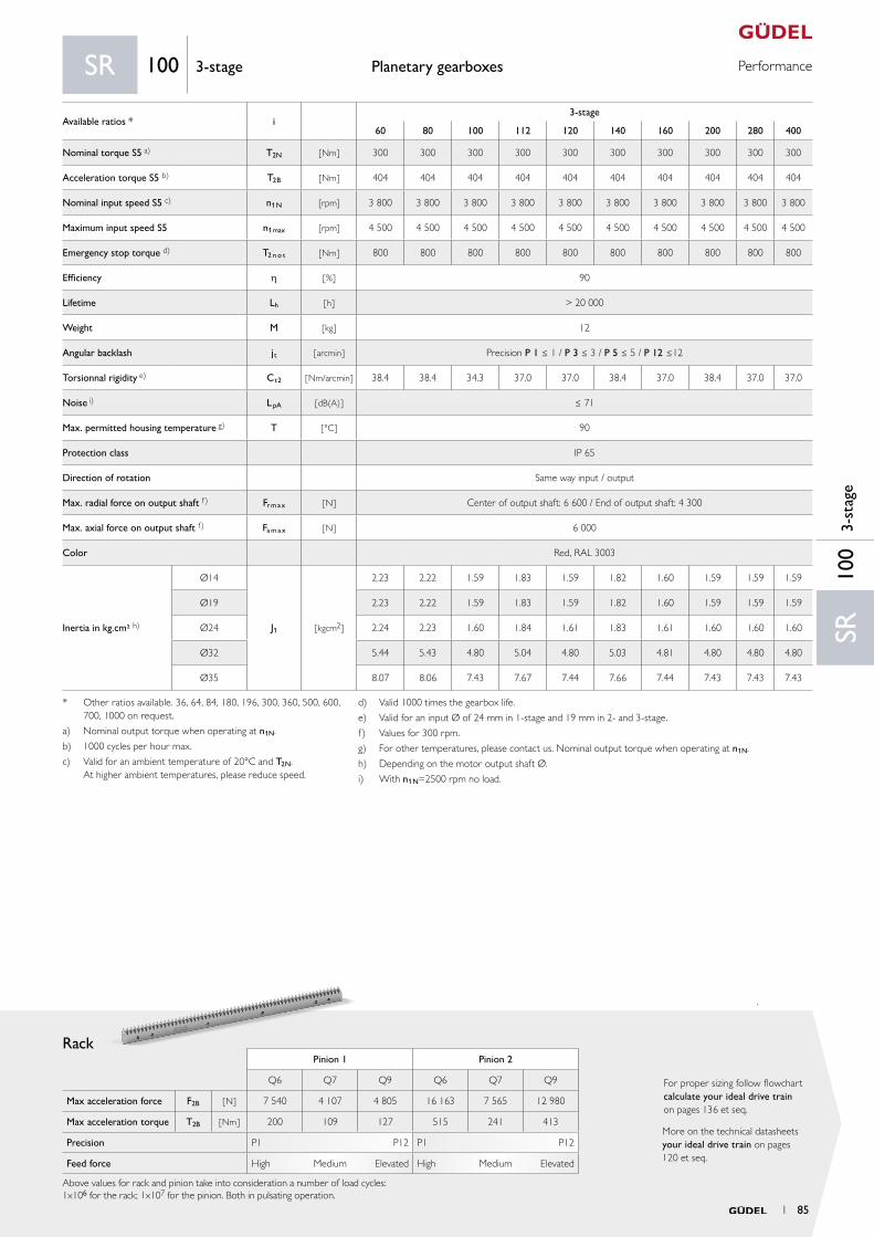
PerformancePlanetary gearboxes
Rack
More on the technical datasheets your ideal drive train on pages 120 et seq.
For proper sizing follow flowchart calculate your ideal drive train on pages 136 et seq.
Pinion 1 Pinion 2
Q6 Q7 Q9 Q6 Q7 Q9
Max acceleration force F2B [ N ] 7 540 4 107 4 805 16 163 7 565 12 980
Max acceleration torque T2B [ Nm ] 200 109 127 515 241 413
Precision P1 P12 P1 P12
Feed force High Medium Elevated High Medium Elevated
Above values for rack and pinion take into consideration a number of load cycles:1x10⁶ for the rack; 1x10⁷ for the pinion. Both in pulsating operation.
SR10
03-
stag
e
SR 100 3-stage
Available ratios * i3-stage
60 80 100 112 120 140 160 200 280 400
Nominal torque S5 a) T2N [ Nm ] 300 300 300 300 300 300 300 300 300 300
Acceleration torque S5 b) T2B [ Nm ] 404 404 404 404 404 404 404 404 404 404
Nominal input speed S5 c) n1N [rpm] 3 800 3 800 3 800 3 800 3 800 3 800 3 800 3 800 3 800 3 800
Maximum input speed S5 n1max [rpm] 4 500 4 500 4 500 4 500 4 500 4 500 4 500 4 500 4 500 4 500
Emergency stop torque d) T2 n o t [ Nm ] 800 800 800 800 800 800 800 800 800 800
Efficiency h [ % ] 90
Lifetime Lh [ h ] > 20 000
Weight M [ kg ] 12
Angular backlash jt [ arcmin ] Precision P 1 ≤ 1 / P 3 ≤ 3 / P 5 ≤ 5 / P 12 ≤12
Torsionnal rigidity e) Ct2 [ Nm/arcmin ] 38.4 38.4 34.3 37.0 37.0 38.4 37.0 38.4 37.0 37.0
Noise i) L pA [ dB(A) ] ≤ 71
Max. permitted housing temperature g) T [ °C ] 90
Protection class IP 65
Direction of rotation Same way input / output
Max. radial force on output shaft f) Fr m a x [ N ] Center of output shaft: 6 600 / End of output shaft: 4 300
Max. axial force on output shaft f) Fa m a x [ N ] 6 000
Color Red, RAL 3003
Inertia in kg.cm² h)
Ø14
J1 [ kgcm2 ]
2.23 2.22 1.59 1.83 1.59 1.82 1.60 1.59 1.59 1.59
Ø19 2.23 2.22 1.59 1.83 1.59 1.82 1.60 1.59 1.59 1.59
Ø24 2.24 2.23 1.60 1.84 1.61 1.83 1.61 1.60 1.60 1.60
Ø32 5.44 5.43 4.80 5.04 4.80 5.03 4.81 4.80 4.80 4.80
Ø35 8.07 8.06 7.43 7.67 7.44 7.66 7.44 7.43 7.43 7.43
* Other ratios available. 36, 64, 84, 180, 196, 300, 360, 500, 600, 700, 1000 on request.
a) Nominal output torque when operating at n1N.
b) 1000 cycles per hour max.
c) Valid for an ambient temperature of 20°C and T2N. At higher ambient temperatures, please reduce speed.
d) Valid 1000 times the gearbox life.
e) Valid for an input Ø of 24 mm in 1-stage and 19 mm in 2- and 3-stage.
f) Values for 300 rpm.
g) For other temperatures, please contact us. Nominal output torque when operating at n1N.
h) Depending on the motor output shaft Ø.
i) With n1N=2500 rpm no load.
1 85
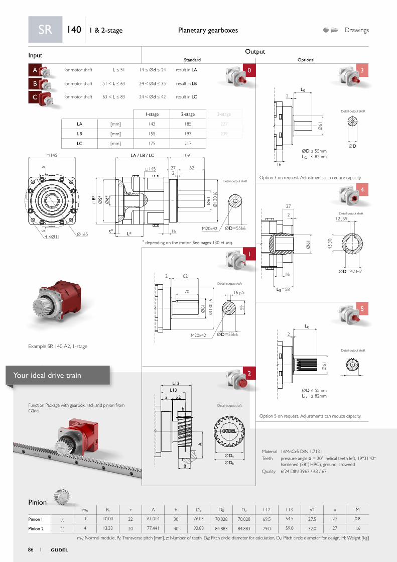
Input OutputStandard Optional
A for motor shaft L ≤ 51 14 ≤ Ød ≤ 24 result in LA 0 3
B for motor shaft 51 < L ≤ 63 24 < Ød ≤ 35 result in LB
C for motor shaft 63 < L ≤ 83 24 < Ød ≤ 42 result in LC
4
1 4
5
aa
2
ØDv
L12
L13
x2
b
B
a
A
ØDk
Ø61
ØD=42 H7
LG=58
12 JS9
27
2
16
45.3
0Ø
61LG
2
ØD ≤ 55mmLG ≤ 82mm
2 82
70
Ø61 59
Ø13
0 j6
M20x42 ØD=55k6
16 js5
Ø61
ØD
2
16
LG
ØD ≤ 55mmLG ≤ 82mm145
145
B*
t*L* 16
LA / LB / LC 109
272
8266
Ø1654 ×Ø11
Ød*
ØS*
Ø61
Ø13
0 j6
ØD=55k6M20x42
Material 16MnCr5 DIN 1.7131
Teeth pressure angle α = 20°, helical teeth left, 19°31‘42“ hardened (58+4
0 HRC), ground, crowned
Quality 6f24 DIN 3962 / 63 / 67
Function Package with gearbox, rack and pinion from Güdel
Pinion
Planetary gearboxes Drawings
* depending on the motor. See pages 130 et seq.
Option 5 on request. Adjustments can reduce capacity.
Option 3 on request. Adjustments can reduce capacity.
SR 140 1 & 2-stage
1-stage 2-stage 3-stage
LA [ mm ] 143 185 227
LB [ mm ] 155 197 239
LC [ mm ] 175 217
Example SR 140 A2, 1-stage
Detail output shaft
Detail output shaft
Detail output shaft
Detail output shaft
mn Pt z A b Dk D0 Dv L12 L13 x2 a M
Pinion 1 [-] 3 10.00 22 61.014 30 76.03 70.028 70.028 69.5 54.5 27.5 27 0.8
Pinion 2 [-] 4 13.33 20 77.441 40 92.88 84.883 84.883 79.0 59.0 32.0 27 1.6
mn: Normal module, Pt: Transverse pitch [mm], z : Number of teeth, D0: Pitch circle diameter for calculation, Dv: Pitch circle diameter for design, M: Weight [kg]
Detail output shaft
Detail output shaft
86 1
Your ideal drive train
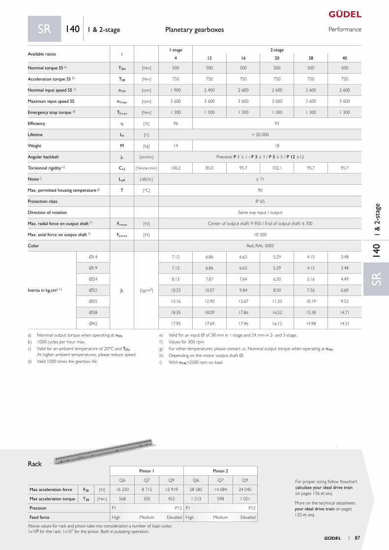
PerformancePlanetary gearboxes
Rack
More on the technical datasheets your ideal drive train on pages 120 et seq.
For proper sizing follow flowchart calculate your ideal drive train on pages 136 et seq.
Pinion 1 Pinion 2
Q6 Q7 Q9 Q6 Q7 Q9
Max acceleration force F2B [ N ] 16 230 8 715 12 919 28 585 14 084 24 045
Max acceleration torque T2B [ Nm ] 568 305 452 1 213 598 1 021
Precision P1 P12 P1 P12
Feed force High Medium Elevated High Medium Elevated
Above values for rack and pinion take into consideration a number of load cycles:1x10⁶ for the rack; 1x10⁷ for the pinion. Both in pulsating operation.
SR14
01
& 2
-sta
ge
SR 140 1 & 2-stage
Available ratios i1-stage 2-stage
4 12 16 20 28 40
Nominal torque S5 a) T2N [ Nm ] 500 500 500 500 500 500
Acceleration torque S5 b) T2B [ Nm ] 750 750 750 750 750 750
Nominal input speed S5 c) n1N [rpm] 1 900 2 400 2 600 2 600 2 600 2 600
Maximum input speed S5 n1max [rpm] 3 600 3 600 3 600 3 600 3 600 3 600
Emergency stop torque d) T2 n o t [ Nm ] 1 300 1 300 1 300 1 300 1 300 1 300
Efficiency h [ % ] 96 93
Lifetime Lh [ h ] > 20 000
Weight M [ kg ] 14 18
Angular backlash jt [ arcmin ] Precision P 1 ≤ 1 / P 3 ≤ 3 / P 5 ≤ 5 / P 12 ≤12
Torsionnal rigidity e) Ct2 [ Nm/arcmin ] 106.2 85.0 95.7 102.1 95.7 95.7
Noise i) L pA [ dB(A) ] ≤ 71
Max. permitted housing temperature g) T [ °C ] 90
Protection class IP 65
Direction of rotation Same way input / output
Max. radial force on output shaft f) Fr m a x [ N ] Center of output shaft: 9 950 / End of output shaft: 6 700
Max. axial force on output shaft f) Fa m a x [ N ] 10 300
Color Red, RAL 3003
Inertia in kg.cm² h)
Ø14
J1 [ kgcm2 ]
7.12 6.86 6.63 5.29 4.15 3.48
Ø19 7.12 6.86 6.63 5.29 4.15 3.48
Ø24 8.13 7.87 7.64 6.30 5.16 4.49
Ø32 10.33 10.07 9.84 8.50 7.36 6.69
Ø35 13.16 12.90 12.67 11.33 10.19 9.52
Ø38 18.35 18.09 17.86 16.52 15.38 14.71
Ø42 17.95 17.69 17.46 16.12 14.98 14.31
a) Nominal output torque when operating at n1N.
b) 1000 cycles per hour max.
c) Valid for an ambient temperature of 20°C and T2N. At higher ambient temperatures, please reduce speed.
d) Valid 1000 times the gearbox life.
e) Valid for an input Ø of 38 mm in 1-stage and 24 mm in 2- and 3-stage.
f) Values for 300 rpm.
g) For other temperatures, please contact us. Nominal output torque when operating at n1N.
h) Depending on the motor output shaft Ø.
i) With n1N=2500 rpm no load.
1 87
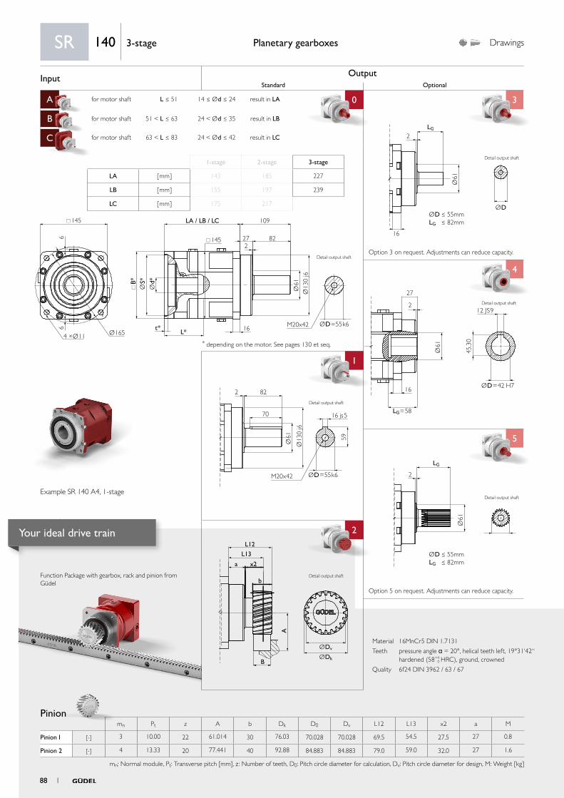
Input OutputStandard Optional
A for motor shaft L ≤ 51 14 ≤ Ød ≤ 24 result in LA 0 3
B for motor shaft 51 < L ≤ 63 24 < Ød ≤ 35 result in LB
C for motor shaft 63 < L ≤ 83 24 < Ød ≤ 42 result in LC
4
1 4
5
aa
2
ØDv
L12
L13
x2
b
B
a
A
ØDk
Ø61
ØD=42 H7
LG=58
12 JS9
27
2
16
45.3
0Ø
61LG
2
ØD ≤ 55mmLG ≤ 82mm
2 82
70
Ø61 59
Ø13
0 j6
M20x42 ØD=55k6
16 js5
Ø61
ØD
2
16
LG
ØD ≤ 55mmLG ≤ 82mm145
145
B*
t*L* 16
LA / LB / LC 109
272
8266
Ø1654 ×Ø11
Ød*
ØS*
Ø61
Ø13
0 j6
ØD=55k6M20x42
Material 16MnCr5 DIN 1.7131
Teeth pressure angle α = 20°, helical teeth left, 19°31‘42“ hardened (58+4
0 HRC), ground, crowned
Quality 6f24 DIN 3962 / 63 / 67
Function Package with gearbox, rack and pinion from Güdel
Pinion
Planetary gearboxes Drawings
* depending on the motor. See pages 130 et seq.
Option 5 on request. Adjustments can reduce capacity.
Option 3 on request. Adjustments can reduce capacity.
SR 140 3-stage
1-stage 2-stage 3-stage
LA [ mm ] 143 185 227
LB [ mm ] 155 197 239
LC [ mm ] 175 217
Example SR 140 A4, 1-stage
Detail output shaft
Detail output shaft
Detail output shaft
Detail output shaft
mn Pt z A b Dk D0 Dv L12 L13 x2 a M
Pinion 1 [-] 3 10.00 22 61.014 30 76.03 70.028 70.028 69.5 54.5 27.5 27 0.8
Pinion 2 [-] 4 13.33 20 77.441 40 92.88 84.883 84.883 79.0 59.0 32.0 27 1.6
mn: Normal module, Pt: Transverse pitch [mm], z : Number of teeth, D0: Pitch circle diameter for calculation, Dv: Pitch circle diameter for design, M: Weight [kg]
Detail output shaft
Detail output shaft
88 1
Your ideal drive train

PerformancePlanetary gearboxes
Rack
More on the technical datasheets your ideal drive train on pages 120 et seq.
For proper sizing follow flowchart calculate your ideal drive train on pages 136 et seq.
Pinion 1 Pinion 2
Q6 Q7 Q9 Q6 Q7 Q9
Max acceleration force F2B [ N ] 16 230 8 715 12 919 28 585 14 084 24 045
Max acceleration torque T2B [ Nm ] 568 305 452 1 213 598 1 021
Precision P1 P12 P1 P12
Feed force High Medium Elevated High Medium Elevated
Above values for rack and pinion take into consideration a number of load cycles:1x10⁶ for the rack; 1x10⁷ for the pinion. Both in pulsating operation.
SR14
03-
stag
e
SR 140 3-stage
Available ratios * i3-stage
60 80 100 112 120 140 160 200 280 400
Nominal torque S5 a) T2N [ Nm ] 500 500 500 500 500 500 500 500 500 500
Acceleration torque S5 b) T2B [ Nm ] 750 750 750 750 750 750 750 750 750 750
Nominal input speed S5 c) n1N [rpm] 3 500 3 500 3 500 3 500 3 500 3 500 3 500 3 500 3 500 3 500
Maximum input speed S5 n1max [rpm] 4 000 4 000 4 000 4 000 4 000 4 000 4 000 4 000 4 000 4 000
Emergency stop torque d) T2 n o t [ Nm ] 1 300 1 300 1 300 1 300 1 300 1 300 1 300 1 300 1 300 1 300
Efficiency h [ % ] 90
Lifetime Lh [ h ] > 20 000
Weight M [ kg ] 22
Angular backlash jt [ arcmin ] Precision P 1 ≤ 1 / P 3 ≤ 3 / P 5 ≤ 5 / P 12 ≤12
Torsionnal rigidity e) Ct2 [ Nm/arcmin ] 92 92 84 86 86 92 86 92 86 86
Noise i) L pA [ dB(A) ] ≤ 71
Max. permitted housing temperature g) T [ °C ] 90
Protection class IP 65
Direction of rotation Same way input / output
Max. radial force on output shaft f) Fr m a x [ N ] Center of output shaft: 9 950 / End of output shaft: 6 700
Max. axial force on output shaft f) Fa m a x [ N ] 10 300
Color Red, RAL 3003
Inertia in kg.cm² h)
Ø14
J1 [ kgcm2 ]
5.28 5.27 3.44 4.14 3.47 4.11 3.47 3.46 3.45 3.44
Ø19 5.28 5.27 3.44 4.14 3.47 4.11 3.47 3.46 3.45 3.44
Ø24 6.29 6.28 4.45 5.15 4.48 5.12 4.48 4.47 4.46 4.45
Ø32 8.49 8.48 6.65 7.35 6.68 7.32 6.68 6.67 6.66 6.65
Ø35 11.32 11.31 9.48 10.18 9.51 10.15 9.51 9.50 9.49 9.48
Ø38 16.51 16.50 14.67 15.37 14.70 15.34 14.70 14.69 14.68 14.67
Ø42 16.11 16.10 14.27 14.97 14.30 14.94 14.30 14.29 14.28 14.27
* Other ratios available. 36, 64, 84, 180, 196, 300, 360, 500, 600, 700, 1 000 on request.
a) Nominal output torque when operating at n1N.
b) Maximal 1 000 Zyklen pro Stunde
c) Valid for an ambient temperature of 20°C and T2N. At higher ambient temperatures, please reduce speed.
d) Valid 1000 times the gearbox life.
e) Valid for an input Ø of 38 mm in 1-stage and 24 mm in 2- and 3-stage.
f) Values for 300 rpm.
g) For other temperatures, please contact us. Nominal output torque when operating at n1N.
h) Depending on the motor output shaft Ø.
i) With n1N=2500 rpm no load.
1 89
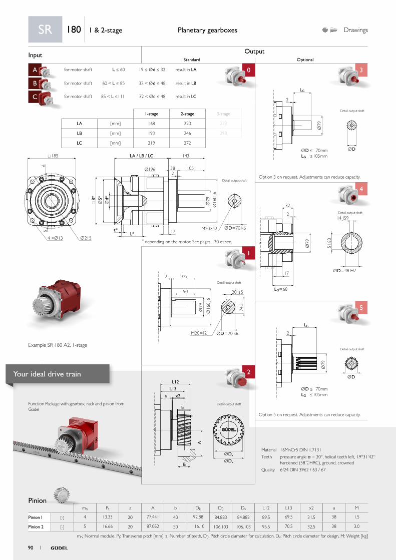
Input OutputStandard Optional
A for motor shaft L ≤ 60 19 ≤ Ød ≤ 32 result in LA 0 3
B for motor shaft 60 < L ≤ 85 32 < Ød ≤ 48 result in LB
C for motor shaft 85 < L ≤111 32 < Ød ≤ 48 result in LC
4
1 4
5
aa
2
ØDv
L12
L13
x2
b
B
a
A
ØDk
Ø79
ØD
LG
2
ØD ≤ 70mmLG ≤ 105mm
2 105
90
Ø79
74.5
Ø16
0 j6
M20×42 ØD=70 k6
20 js5
Ø79
ØD=48 H7
LG=68
14 JS9
32
2
17
51.8
0
Ø79
ØD
2
LG
ØD ≤ 70mmLG ≤ 105mm185
Ø196
B*
t*L* 17
LA / LB / LC 143
382
105
66
Ø2154 ×Ø13
Ød*
ØS*
Ø79
Ø16
0 j6
M20×42 ØD=70 k6
Material 16MnCr5 DIN 1.7131
Teeth pressure angle α = 20°, helical teeth left, 19°31‘42“ hardened (58+4
0 HRC), ground, crowned
Quality 6f24 DIN 3962 / 63 / 67
Function Package with gearbox, rack and pinion from Güdel
Pinion
Planetary gearboxes Drawings
* depending on the motor. See pages 130 et seq.
Option 5 on request. Adjustments can reduce capacity.
Option 3 on request. Adjustments can reduce capacity.
SR 180 1 & 2-stage
1-stage 2-stage 3-stage
LA [ mm ] 168 220 273
LB [ mm ] 193 246 298
LC [ mm ] 219 272
Example SR 180 A2, 1-stage
Detail output shaft
Detail output shaft
Detail output shaft
Detail output shaft
mn Pt z A b Dk D0 Dv L12 L13 x2 a M
Pinion 1 [-] 4 13.33 20 77.441 40 92.88 84.883 84.883 89.5 69.5 31.5 38 1.5
Pinion 2 [-] 5 16.66 20 87.052 50 116.10 106.103 106.103 95.5 70.5 32.5 38 3.0
mn: Normal module, Pt: Transverse pitch [mm], z : Number of teeth, D0: Pitch circle diameter for calculation, Dv: Pitch circle diameter for design, M: Weight [kg]
Detail output shaft
Detail output shaft
90 1
Your ideal drive train

PerformancePlanetary gearboxes
Rack
More on the technical datasheets your ideal drive train on pages 120 et seq.
For proper sizing follow flowchart calculate your ideal drive train on pages 136 et seq.
Pinion 1 Pinion 2
Q6 Q7 Q9 Q6 Q7 Q9
Max acceleration force F2B [ N ] 28 585 14 084 24 045 44 505 23 785 40 048
Max acceleration torque T2B [ Nm ] 1 213 598 1 021 2 361 1 262 2 125
Precision P1 P12 P1 P12
Feed force High Medium Elevated High Medium Elevated
Above values for rack and pinion take into consideration a number of load cycles:1x10⁶ for the rack; 1x10⁷ for the pinion. Both in pulsating operation.
SR18
01
& 2
-sta
ge
SR 180 1 & 2-stage
Available ratios i1-stage 2-stage
4 12 16 20 28 40
Nominal torque S5 a) T2N [ Nm ] 1 100 1 100 1 100 1 100 1 100 1 100
Acceleration torque S5 b) T2B [ Nm ] 1 500 1 500 1 500 1 500 1 500 1 500
Nominal input speed S5 c) n1N [rpm] 1 300 2 200 2 400 2 400 2 400 2 400
Maximum input speed S5 n1max [rpm] 3 100 3 600 3 600 3 600 3 600 3 600
Emergency stop torque d) T2 n o t [ Nm ] 2 780 2 780 2 780 2 780 2 780 2 780
Efficiency h [ % ] 96 93
Lifetime Lh [ h ] > 20 000
Weight M [ kg ] 32 39
Angular backlash jt [ arcmin ] Precision P 1 ≤ 1 / P 3 ≤ 3 / P 5 ≤ 5 / P 12 ≤12
Torsionnal rigidity e) Ct2 [ Nm/arcmin ] 191.8 147.5 172.5 182.7 172.5 172.5
Noise i) L pA [ dB(A) ] ≤ 72
Max. permitted housing temperature g) T [ °C ] 90
Protection class IP 65
Direction of rotation Same way input / output
Max. radial force on output shaft f) Fr m a x [ N ] Center of output shaft: 18 000 / End of output shaft: 13 000
Max. axial force on output shaft f) Fa m a x [ N ] 15 000
Color Red, RAL 3003
Inertia in kg.cm² h)
Ø19
J1 [ kgcm2 ]
23.35 23.57 22.65 16.76 11.90 9.07
Ø24 24.40 24.62 23.70 17.81 12.95 10.12
Ø32 26.61 26.83 25.91 20.02 15.16 12.33
Ø35 29.53 29.75 28.83 22.94 18.08 15.25
Ø38 35.13 35.35 34.43 28.54 23.68 20.85
Ø42 34.63 34.85 33.93 28.04 23.18 20.35
Ø48 35.03 35.25 34.33 28.44 23.58 20.75
a) Nominal output torque when operating at n1N.
b) 1000 cycles per hour max.
c) Valid for an ambient temperature of 20°C and T2N. At higher ambient temperatures, please reduce speed.
d) Valid 1000 times the gearbox life.
e) Valid for an input Ø of 48 mm in 1-stage and 38 mm in 2- and 3-stage.
f) Values for 300 rpm.
g) For other temperatures, please contact us. Nominal output torque when operating at n1N.
h) Depending on the motor output shaft Ø.
i) With n1N=2500 rpm no load.
1 91
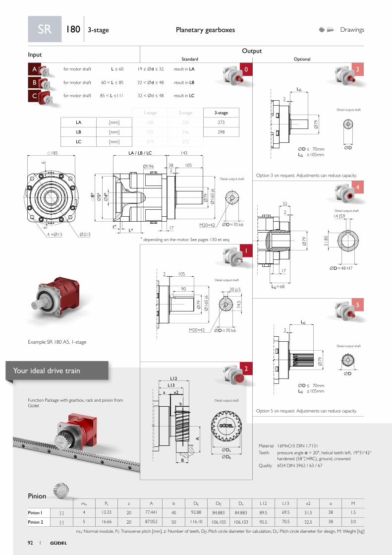
Input OutputStandard Optional
A for motor shaft L ≤ 60 19 ≤ Ød ≤ 32 result in LA 0 3
B for motor shaft 60 < L ≤ 85 32 < Ød ≤ 48 result in LB
C for motor shaft 85 < L ≤111 32 < Ød ≤ 48 result in LC
4
1 4
5
aa
2
ØDv
L12
L13
x2
b
B
a
A
ØDk
Ø79
ØD
LG
2
ØD ≤ 70mmLG ≤ 105mm
2 105
90
Ø79
74.5
Ø16
0 j6
M20×42 ØD=70 k6
20 js5
Ø79
ØD=48 H7
LG=68
14 JS9
32
2
17
51.8
0
Ø79
ØD
2
LG
ØD ≤ 70mmLG ≤ 105mm185
Ø196
B*
t*L* 17
LA / LB / LC 143
382
105
66
Ø2154 ×Ø13
Ød*
ØS*
Ø79
Ø16
0 j6
M20×42 ØD=70 k6
Material 16MnCr5 DIN 1.7131
Teeth pressure angle α = 20°, helical teeth left, 19°31‘42“ hardened (58+4
0 HRC), ground, crowned
Quality 6f24 DIN 3962 / 63 / 67
Function Package with gearbox, rack and pinion from Güdel
Pinion
Planetary gearboxes Drawings
* depending on the motor. See pages 130 et seq.
Option 5 on request. Adjustments can reduce capacity.
Option 3 on request. Adjustments can reduce capacity.
SR 180 3-stage
1-stage 2-stage 3-stage
LA [ mm ] 168 220 273
LB [ mm ] 193 246 298
LC [ mm ] 219 272
Example SR 180 A5, 1-stage
Detail output shaft
Detail output shaft
Detail output shaft
mn Pt z A b Dk D0 Dv L12 L13 x2 a M
Pinion 1 [-] 4 13.33 20 77.441 40 92.88 84.883 84.883 89.5 69.5 31.5 38 1.5
Pinion 2 [-] 5 16.66 20 87.052 50 116.10 106.103 106.103 95.5 70.5 32.5 38 3.0
mn: Normal module, Pt: Transverse pitch [mm], z : Number of teeth, D0: Pitch circle diameter for calculation, Dv: Pitch circle diameter for design, M: Weight [kg]
Detail output shaft
Detail output shaft
Detail output shaft
92 1
Your ideal drive train
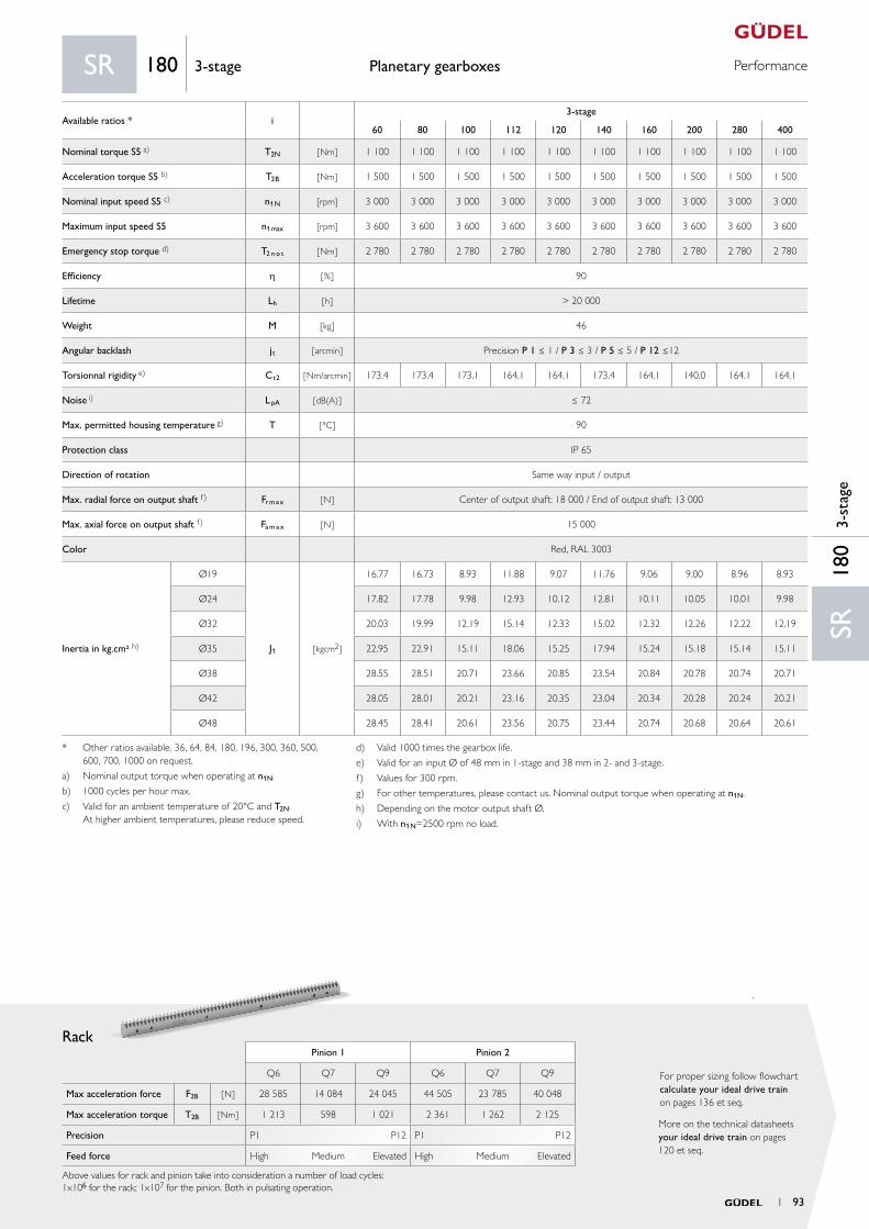
PerformancePlanetary gearboxes
Rack
More on the technical datasheets your ideal drive train on pages 120 et seq.
For proper sizing follow flowchart calculate your ideal drive train on pages 136 et seq.
Pinion 1 Pinion 2
Q6 Q7 Q9 Q6 Q7 Q9
Max acceleration force F2B [ N ] 28 585 14 084 24 045 44 505 23 785 40 048
Max acceleration torque T2B [ Nm ] 1 213 598 1 021 2 361 1 262 2 125
Precision P1 P12 P1 P12
Feed force High Medium Elevated High Medium Elevated
Above values for rack and pinion take into consideration a number of load cycles:1x10⁶ for the rack; 1x10⁷ for the pinion. Both in pulsating operation.
SR18
03-
stag
e
SR 180 3-stage
Available ratios * i3-stage
60 80 100 112 120 140 160 200 280 400
Nominal torque S5 a) T2N [ Nm ] 1 100 1 100 1 100 1 100 1 100 1 100 1 100 1 100 1 100 1 100
Acceleration torque S5 b) T2B [ Nm ] 1 500 1 500 1 500 1 500 1 500 1 500 1 500 1 500 1 500 1 500
Nominal input speed S5 c) n1N [rpm] 3 000 3 000 3 000 3 000 3 000 3 000 3 000 3 000 3 000 3 000
Maximum input speed S5 n1max [rpm] 3 600 3 600 3 600 3 600 3 600 3 600 3 600 3 600 3 600 3 600
Emergency stop torque d) T2 n o t [ Nm ] 2 780 2 780 2 780 2 780 2 780 2 780 2 780 2 780 2 780 2 780
Efficiency h [ % ] 90
Lifetime Lh [ h ] > 20 000
Weight M [ kg ] 46
Angular backlash jt [ arcmin ] Precision P 1 ≤ 1 / P 3 ≤ 3 / P 5 ≤ 5 / P 12 ≤12
Torsionnal rigidity e) Ct2 [ Nm/arcmin ] 173.4 173.4 173.1 164.1 164.1 173.4 164.1 140.0 164.1 164.1
Noise i) L pA [ dB(A) ] ≤ 72
Max. permitted housing temperature g) T [ °C ] 90
Protection class IP 65
Direction of rotation Same way input / output
Max. radial force on output shaft f) Fr m a x [ N ] Center of output shaft: 18 000 / End of output shaft: 13 000
Max. axial force on output shaft f) Fa m a x [ N ] 15 000
Color Red, RAL 3003
Inertia in kg.cm² h)
Ø19
J1 [ kgcm2 ]
16.77 16.73 8.93 11.88 9.07 11.76 9.06 9.00 8.96 8.93
Ø24 17.82 17.78 9.98 12.93 10.12 12.81 10.11 10.05 10.01 9.98
Ø32 20.03 19.99 12.19 15.14 12.33 15.02 12.32 12.26 12.22 12.19
Ø35 22.95 22.91 15.11 18.06 15.25 17.94 15.24 15.18 15.14 15.11
Ø38 28.55 28.51 20.71 23.66 20.85 23.54 20.84 20.78 20.74 20.71
Ø42 28.05 28.01 20.21 23.16 20.35 23.04 20.34 20.28 20.24 20.21
Ø48 28.45 28.41 20.61 23.56 20.75 23.44 20.74 20.68 20.64 20.61
* Other ratios available. 36, 64, 84, 180, 196, 300, 360, 500, 600, 700, 1000 on request.
a) Nominal output torque when operating at n1N.
b) 1000 cycles per hour max.
c) Valid for an ambient temperature of 20°C and T2N. At higher ambient temperatures, please reduce speed.
d) Valid 1000 times the gearbox life.
e) Valid for an input Ø of 48 mm in 1-stage and 38 mm in 2- and 3-stage.
f) Values for 300 rpm.
g) For other temperatures, please contact us. Nominal output torque when operating at n1N.
h) Depending on the motor output shaft Ø.
i) With n1N=2500 rpm no load.
1 93

Input OutputStandard Optional
A for motor shaft L ≤ 85 24 ≤ Ød ≤ 48 result in LA 0 3
B for motor shaft 85 < L ≤115 48 < Ød ≤ 55 result in LB
C
4
1 4
5
aa
2
ØDv
L12
L13
x2
b
B
a
A
ØDk
Ø11
6
ØD
LG
2
ØD ≤ 100mmLG ≤ 130mm
2
130
115
Ø11
6
106
Ø20
0 j6
M24×48 ØD=100 k6
28 js5
Ø11
6
ØD=85 H7
LG=82
22 JS9
40
2
21
90.4
0
Ø11
6
ØD
1
LG
ØD ≤ 100mmLG ≤ 130mm
245
Ø245
B*
t*
L*21
LA / LB 178
482
130
66
Ø2904 ×Ø17
Ød*
ØS*
Ø11
6Ø
200
j6
ØD=100 k6M24×48
Material 16MnCr5 DIN 1.7131
Teeth pressure angle α = 20°, helical teeth left, 19°31‘42“ hardened (58+4
0 HRC), ground, crowned
Quality 6f24 DIN 3962 / 63 / 67
Function Package with gearbox, rack and pinion from Güdel
Pinion
Planetary gearboxes Drawings
* depending on the motor. See pages 130 et seq.
Option 5 on request. Adjustments can reduce capacity.
Option 3 on request. Adjustments can reduce capacity.
SR 240 1 & 2-stage
1-stage 2-stage 3-stage
LA [ mm ] 229 300 371
LB [ mm ] 259 330
Example SR 240 B4, 1-stage
Detail output shaft
Detail output shaft
Detail output shaft
Detail output shaft
mn Pt z A b Dk D0 Dv L12 L13 x2 a M
Pinion 1 [-] 5 16.66 24 97.662 50 137.32 127.324 127.324 120.5 95.5 47.5 48 5.4
Pinion 2 [-] 6 20.00 20 106.662 60 139.32 127.324 127.324 119.0 89.0 41.0 48 5.6
mn: Normal module, Pt: Transverse pitch [mm], z : Number of teeth, D0: Pitch circle diameter for calculation, Dv: Pitch circle diameter for design, M: Weight [kg]
Detail output shaft
Detail output shaft
94 1
Your ideal drive train

PerformancePlanetary gearboxes
Rack
More on the technical datasheets your ideal drive train on pages 120 et seq.
For proper sizing follow flowchart calculate your ideal drive train on pages 136 et seq.
Pinion 1 Pinion 2
Q6 Q7 Q9 Q6 Q7 Q9
Max acceleration force F2B [ N ] 44 786 29 748 39 992 63 300 - 59 005
Max acceleration torque T2B [ Nm ] 2 851 1 894 2 546 4 030 - 3 756
Precision P1 P12 P1 P12
Feed force High Medium Elevated High Medium Elevated
Above values for rack and pinion take into consideration a number of load cycles:1x10⁶ for the rack; 1x10⁷ for the pinion. Both in pulsating operation.
SR24
01
& 2
-sta
ge
SR 240 1 & 2-stage
Available ratios i1-stage 2-stage
4 12 16 20 28 40
Nominal torque S5 a) T2N [ Nm ] 3 600 3 600 3 600 3 600 3 600 3 600
Acceleration torque S5 b) T2B [ Nm ] 4 800 4 800 4 800 4 800 4 800 4 800
Nominal input speed S5 c) n1N [rpm] 900 1 500 1 700 1 700 1 700 1 700
Maximum input speed S5 n1max [rpm] 2 000 3 100 3 100 3 100 3 100 3 100
Emergency stop torque d) T2 n o t [ Nm ] 8 500 8 500 8 500 8 500 8 500 8 500
Efficiency h [ % ] 96 93
Lifetime Lh [ h ] > 20 000
Weight M [ kg ] 70 90
Angular backlash jt [ arcmin ] Precision P 1 ≤ 1 / P 3 ≤ 3 / P 5 ≤ 5 / P 12 ≤12
Torsionnal rigidity e) Ct2 [ Nm/arcmin ] 718.8 593.5 611.0 628.5 611.0 611.0
Noise i) L pA [ dB(A) ] ≤ 73
Max. permitted housing temperature g) T [ °C ] 90
Protection class IP 65
Direction of rotation Same way input / output
Max. radial force on output shaft f) Fr m a x [ N ] Center of output shaft: 37 500 / End of output shaft: 25 000
Max. axial force on output shaft f) Fa m a x [ N ] 34 000
Color Red, RAL 3003
Inertia in kg.cm² h)
Ø24
J1 [ kgcm2 ]
83.3 79.1 74.9 73.3 34.0 22.9
Ø32 85.5 81.3 77.1 75.5 36.2 25.1
Ø35 90.8 86.6 82.4 80.8 41.5 30.4
Ø38 94.2 90.0 85.8 84.2 44.9 33.8
Ø42 93.7 89.5 85.3 83.7 44.4 33.3
Ø48 93.9 89.7 85.5 83.9 44.6 33.5
Ø55 116.5 112.3 108.1 106.5 67.2 56.1
a) Nominal output torque when operating at n1N.
b) 1000 cycles per hour max.
c) Valid for an ambient temperature of 20°C and T2N. At higher ambient temperatures, please reduce speed.
d) Valid 1000 times the gearbox life.
e) Valid for an input Ø of 55 mm in 1-stage and 48 mm in 2- and 3-stage.
f) Values for 300 rpm.
g) For other temperatures, please contact us. Nominal output torque when operating at n1N.
h) Depending on the motor output shaft Ø.
i) With n1N=1800 rpm no load.
1 95
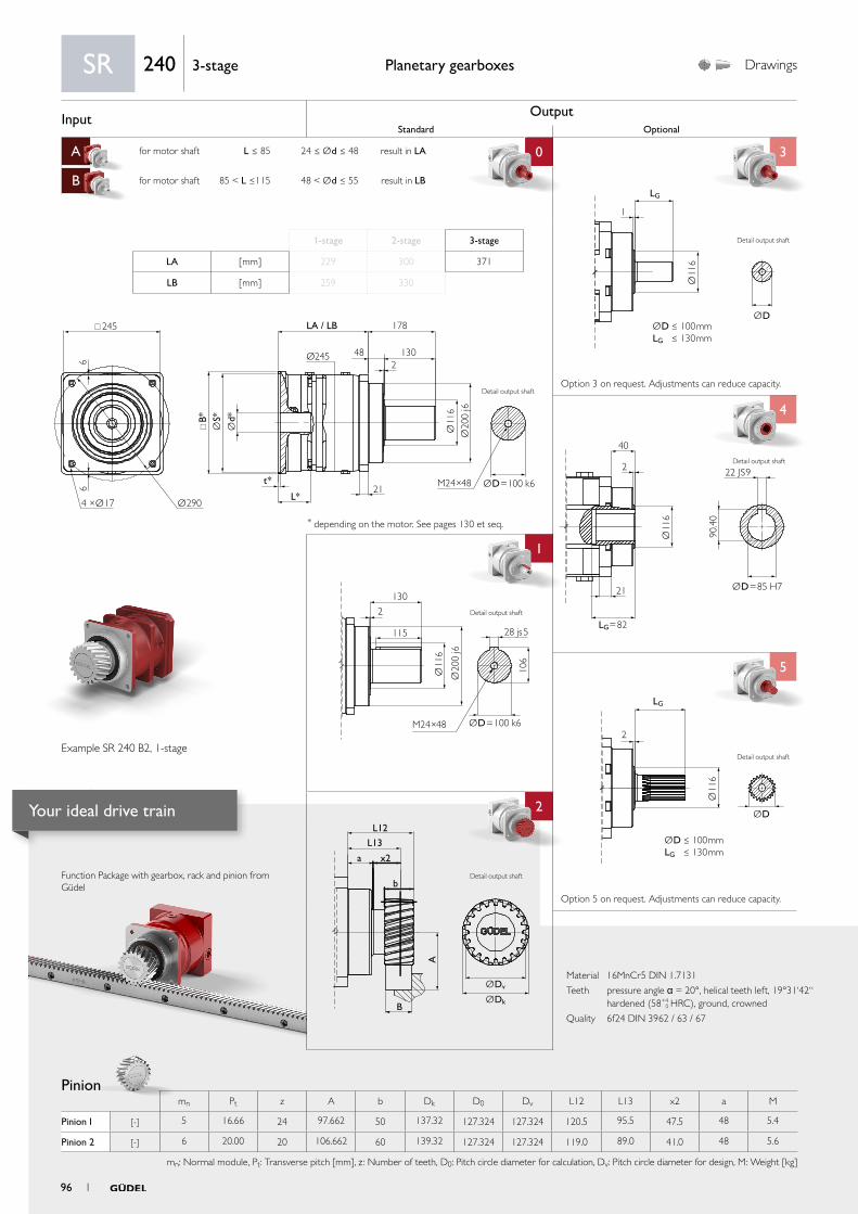
Input OutputStandard Optional
A for motor shaft L ≤ 85 24 ≤ Ød ≤ 48 result in LA 0 3
B for motor shaft 85 < L ≤115 48 < Ød ≤ 55 result in LB
C
4
1 4
5
aa
2
ØDv
L12
L13
x2
b
B
a
A
ØDk
Ø11
6
ØD
LG
2
ØD ≤ 100mmLG ≤ 130mm
2
130
115
Ø11
6
106
Ø20
0 j6
M24×48 ØD=100 k6
28 js5
Ø11
6
ØD=85 H7
LG=82
22 JS9
40
2
21
90.4
0
Ø11
6
ØD
1
LG
ØD ≤ 100mmLG ≤ 130mm
245
Ø245
B*
t*
L*21
LA / LB 178
482
130
66
Ø2904 ×Ø17
Ød*
ØS*
Ø11
6Ø
200
j6
ØD=100 k6M24×48
Material 16MnCr5 DIN 1.7131
Teeth pressure angle α = 20°, helical teeth left, 19°31‘42“ hardened (58+4
0 HRC), ground, crowned
Quality 6f24 DIN 3962 / 63 / 67
Function Package with gearbox, rack and pinion from Güdel
Pinion
Planetary gearboxes Drawings
* depending on the motor. See pages 130 et seq.
Option 5 on request. Adjustments can reduce capacity.
Option 3 on request. Adjustments can reduce capacity.
SR 240 3-stage
1-stage 2-stage 3-stage
LA [ mm ] 229 300 371
LB [ mm ] 259 330
Example SR 240 B2, 1-stage
Detail output shaft
Detail output shaft
Detail output shaft
Detail output shaft
mn Pt z A b Dk D0 Dv L12 L13 x2 a M
Pinion 1 [-] 5 16.66 24 97.662 50 137.32 127.324 127.324 120.5 95.5 47.5 48 5.4
Pinion 2 [-] 6 20.00 20 106.662 60 139.32 127.324 127.324 119.0 89.0 41.0 48 5.6
mn: Normal module, Pt: Transverse pitch [mm], z : Number of teeth, D0: Pitch circle diameter for calculation, Dv: Pitch circle diameter for design, M: Weight [kg]
Detail output shaft
Detail output shaft
96 1
Your ideal drive train
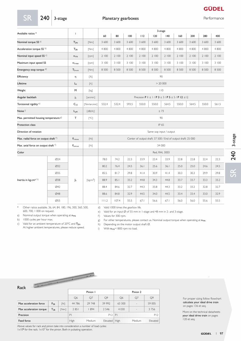
PerformancePlanetary gearboxes
Rack
More on the technical datasheets your ideal drive train on pages 120 et seq.
For proper sizing follow flowchart calculate your ideal drive train on pages 136 et seq.
Pinion 1 Pinion 2
Q6 Q7 Q9 Q6 Q7 Q9
Max acceleration force F2B [ N ] 44 786 29 748 39 992 63 300 - 59 005
Max acceleration torque T2B [ Nm ] 2 851 1 894 2 546 4 030 - 3 756
Precision P1 P12 P1 P12
Feed force High Medium Elevated High Medium Elevated
Above values for rack and pinion take into consideration a number of load cycles:1x10⁶ for the rack; 1x10⁷ for the pinion. Both in pulsating operation.
SR24
03-
stag
e
SR 240 3-stage
Available ratios * i3-stage
60 80 100 112 120 140 160 200 280 400
Nominal torque S5 a) T2N [ Nm ] 3 600 3 600 3 600 3 600 3 600 3 600 3 600 3 600 3 600 3 600
Acceleration torque S5 b) T2B [ Nm ] 4 800 4 800 4 800 4 800 4 800 4 800 4 800 4 800 4 800 4 800
Nominal input speed S5 c) n1N [rpm] 2 100 2 100 2 100 2 100 2 100 2 100 2 100 2 100 2 100 2 100
Maximum input speed S5 n1max [rpm] 3 100 3 100 3 100 3 100 3 100 3 100 3 100 3 100 3 100 3 100
Emergency stop torque d) T2 n o t [ Nm ] 8 500 8 500 8 500 8 500 8 500 8 500 8 500 8 500 8 500 8 500
Efficiency h [ % ] 90
Lifetime Lh [ h ] > 20 000
Weight M [ kg ] 110
Angular backlash jt [ arcmin ] Precision P 1 ≤ 1 / P 3 ≤ 3 / P 5 ≤ 5 / P 12 ≤12
Torsionnal rigidity e) Ct2 [ Nm/arcmin ] 532.4 532.4 593.5 550.0 550.0 564.5 550.0 564.5 550.0 561.5
Noise i) L pA [ dB(A) ] ≤ 73
Max. permitted housing temperature g) T [ °C ] 90
Protection class IP 65
Direction of rotation Same way input / output
Max. radial force on output shaft f) Fr m a x [ N ] Center of output shaft: 37 500 / End of output shaft: 25 000
Max. axial force on output shaft f) Fa m a x [ N ] 34 000
Color Red, RAL 3003
Inertia in kg.cm² h)
Ø24
J1 [ kgcm2 ]
78.0 74.2 22.3 33.9 23.4 33.9 22.8 22.8 22.4 22.3
Ø32 80.2 76.4 24.5 36.1 25.6 36.1 25.0 25.0 24.6 24.5
Ø35 85.5 81.7 29.8 41.4 30.9 41.4 30.3 30.3 29.9 29.8
Ø38 88.9 85.1 33.2 44.8 34.3 44.8 33.7 33.7 33.3 33.2
Ø42 88.4 84.6 32.7 44.3 33.8 44.3 33.2 33.2 32.8 32.7
Ø48 88.6 84.8 32.9 44.5 34.0 44.5 33.4 33.4 33.0 32.9
Ø55 111.2 107.4 55.5 67.1 56.6 67.1 56.0 56.0 55.6 55.5
* Other ratios available. 36, 64, 84, 180, 196, 300, 360, 500, 600, 700, 1 000 on request.
a) Nominal output torque when operating at n1N.
b) 1000 cycles per hour max.
c) Valid for an ambient temperature of 20°C and T2N. At higher ambient temperatures, please reduce speed.
d) Valid 1000 times the gearbox life.
e) Valid for an input Ø of 55 mm in 1-stage and 48 mm in 2- and 3-stage.
f) Values for 300 rpm.
g) For other temperatures, please contact us. Nominal output torque when operating at n1N.
h) Depending on the motor output shaft Ø.
i) With n1N=1800 rpm no load.
1 97
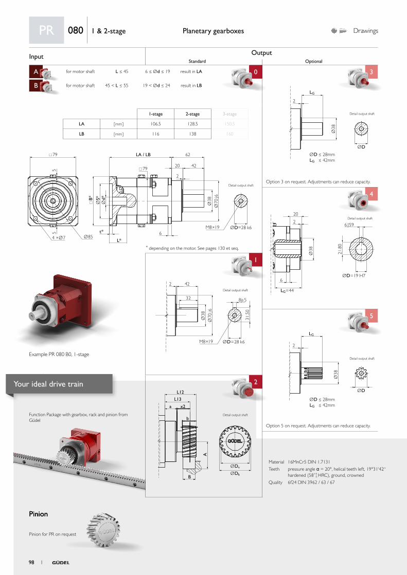
Input OutputStandard Optional
A for motor shaft L ≤ 45 6 ≤ Ød ≤ 19 result in LA 0 3
B for motor shaft 45 < L ≤ 55 19 < Ød ≤ 24 result in LB
C
4
1 4
5
aa
2
ØDv
L12
L13
x2
b
B
a
A
ØDk
2 42
32
Ø38
31.5
0
Ø70
j6
M8×19 ØD=28 k6
8js5
Ø38
ØD
2
LG
ØD ≤ 28mmLG ≤ 42mm
Ø38
ØD=19 H7
LG=44
6 JS9
20
2
6
21.8
0Ø
38
ØD
LG
2
ØD ≤ 28mmLG ≤ 42mm
79
79
B*
t*
L*
6
LA / LB 62
20
2
42
55
Ø854 ×Ø7
Ød*
ØS*
Ø38
Ø70
j6
ØD=28 k6M8×19
Material 16MnCr5 DIN 1.7131
Teeth pressure angle α = 20°, helical teeth left, 19°31‘42“ hardened (58+4
0 HRC), ground, crowned
Quality 6f24 DIN 3962 / 63 / 67
Function Package with gearbox, rack and pinion from Güdel
Pinion
Planetary gearboxes Drawings
* depending on the motor. See pages 130 et seq.
Option 5 on request. Adjustments can reduce capacity.
Option 3 on request. Adjustments can reduce capacity.
Pinion
Pinion for PR on request
PR 080 1 & 2-stage
1-stage 2-stage 3-stage
LA [ mm ] 106.5 128.5 150.5
LB [ mm ] 116 138 160
Example PR 080 B0, 1-stage
Detail output shaft
Detail output shaft
Detail output shaft
Detail output shaft
Detail output shaft
Detail output shaft
98 1
Your ideal drive train
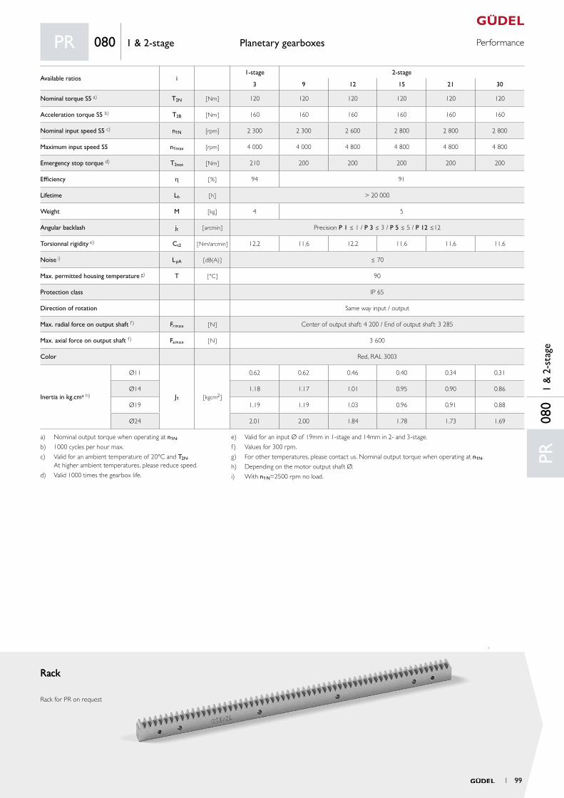
PerformancePlanetary gearboxes
RackRack
Rack for PR on request
PR08
01
& 2
-sta
ge
PR 080 1 & 2-stage
Available ratios i1-stage 2-stage
3 9 12 15 21 30
Nominal torque S5 a) T2N [ Nm ] 120 120 120 120 120 120
Acceleration torque S5 b) T2B [ Nm ] 160 160 160 160 160 160
Nominal input speed S5 c) n1N [rpm] 2 300 2 300 2 600 2 800 2 800 2 800
Maximum input speed S5 n1max [rpm] 4 000 4 000 4 800 4 800 4 800 4 800
Emergency stop torque d) T2not [ Nm ] 210 200 200 200 200 200
Efficiency h [ % ] 94 91
Lifetime Lh [ h ] > 20 000
Weight M [ kg ] 4 5
Angular backlash jt [ arcmin ] Precision P 1 ≤ 1 / P 3 ≤ 3 / P 5 ≤ 5 / P 12 ≤12
Torsionnal rigidity e) Ct2 [ Nm/arcmin ] 12.2 11.6 12.2 11.6 11.6 11.6
Noise i) L pA [ dB(A) ] ≤ 70
Max. permitted housing temperature g) T [ °C ] 90
Protection class IP 65
Direction of rotation Same way input / output
Max. radial force on output shaft f) Frmax [ N ] Center of output shaft: 4 200 / End of output shaft: 3 285
Max. axial force on output shaft f) Famax [ N ] 3 600
Color Red, RAL 3003
Inertia in kg.cm² h)
Ø11
J1 [ kgcm2 ]
0.62 0.62 0.46 0.40 0.34 0.31
Ø14 1.18 1.17 1.01 0.95 0.90 0.86
Ø19 1.19 1.19 1.03 0.96 0.91 0.88
Ø24 2.01 2.00 1.84 1.78 1.73 1.69
a) Nominal output torque when operating at n1N.
b) 1000 cycles per hour max.
c) Valid for an ambient temperature of 20°C and T2N. At higher ambient temperatures, please reduce speed.
d) Valid 1000 times the gearbox life.
e) Valid for an input Ø of 19mm in 1-stage and 14mm in 2- and 3-stage.
f) Values for 300 rpm.
g) For other temperatures, please contact us. Nominal output torque when operating at n1N.
h) Depending on the motor output shaft Ø.
i) With n1N=2500 rpm no load.
1 99
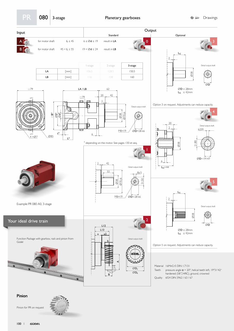
Input OutputStandard Optional
A for motor shaft L ≤ 45 6 ≤ Ød ≤ 19 result in LA 0 3
B for motor shaft 45 < L ≤ 55 19 < Ød ≤ 24 result in LB
C
4
1 4
5
aa
2
ØDv
L12
L13
x2
b
B
a
A
ØDk
2 42
32
Ø38
31.5
0
Ø70
j6
M8×19 ØD=28 k6
8js5
Ø38
ØD
2
LG
ØD ≤ 28mmLG ≤ 42mm
Ø38
ØD=19 H7
LG=44
6 JS9
20
2
6
21.8
0Ø
38
ØD
LG
2
ØD ≤ 28mmLG ≤ 42mm
79
79
B*
t*
L*
6
LA / LB 62
20
2
42
55
Ø854 ×Ø7
Ød*
ØS*
Ø38
Ø70
j6
ØD=28 k6M8×19
Material 16MnCr5 DIN 1.7131
Teeth pressure angle α = 20°, helical teeth left, 19°31‘42“ hardened (58+4
0 HRC), ground, crowned
Quality 6f24 DIN 3962 / 63 / 67
Function Package with gearbox, rack and pinion from Güdel
Pinion
Planetary gearboxes Drawings
* depending on the motor. See pages 130 et seq.
Option 5 on request. Adjustments can reduce capacity.
Option 3 on request. Adjustments can reduce capacity.
Pinion
Pinion for PR on request
PR 080 3-stage
1-stage 2-stage 3-stage
LA [ mm ] 106.5 128.5 150.5
LB [ mm ] 116 138 160
Example PR 080 A0, 3-stage
Detail output shaft
Detail output shaft
Detail output shaft
Detail output shaft
Detail output shaft
Detail output shaft
100 1
Your ideal drive train
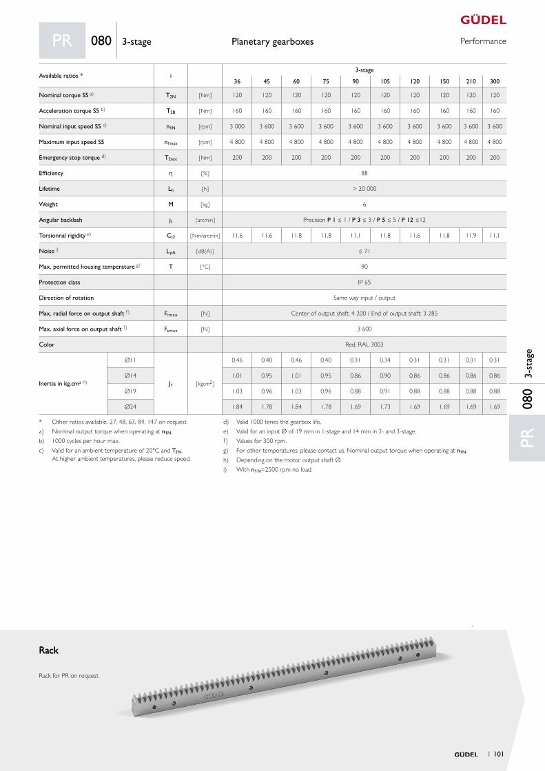
PerformancePlanetary gearboxes
RackRack
Rack for PR on request
PR08
03-
stag
e
PR 080 3-stage
Available ratios * i3-stage
36 45 60 75 90 105 120 150 210 300
Nominal torque S5 a) T2N [ Nm ] 120 120 120 120 120 120 120 120 120 120
Acceleration torque S5 b) T2B [ Nm ] 160 160 160 160 160 160 160 160 160 160
Nominal input speed S5 c) n1N [rpm] 3 000 3 600 3 600 3 600 3 600 3 600 3 600 3 600 3 600 3 600
Maximum input speed S5 n1max [rpm] 4 800 4 800 4 800 4 800 4 800 4 800 4 800 4 800 4 800 4 800
Emergency stop torque d) T2not [ Nm ] 200 200 200 200 200 200 200 200 200 200
Efficiency h [ % ] 88
Lifetime Lh [ h ] > 20 000
Weight M [ kg ] 6
Angular backlash jt [ arcmin ] Precision P 1 ≤ 1 / P 3 ≤ 3 / P 5 ≤ 5 / P 12 ≤12
Torsionnal rigidity e) Ct2 [ Nm/arcmin ] 11.6 11.6 11.8 11.8 11.1 11.8 11.6 11.8 11.9 11.1
Noise i) L pA [ dB(A) ] ≤ 71
Max. permitted housing temperature g) T [ °C ] 90
Protection class IP 65
Direction of rotation Same way input / output
Max. radial force on output shaft f) Frmax [ N ] Center of output shaft: 4 200 / End of output shaft: 3 285
Max. axial force on output shaft f) Famax [ N ] 3 600
Color Red, RAL 3003
Inertia in kg.cm² h)
Ø11
J1 [ kgcm2 ]
0.46 0.40 0.46 0.40 0.31 0.34 0.31 0.31 0.31 0.31
Ø14 1.01 0.95 1.01 0.95 0.86 0.90 0.86 0.86 0.86 0.86
Ø19 1.03 0.96 1.03 0.96 0.88 0.91 0.88 0.88 0.88 0.88
Ø24 1.84 1.78 1.84 1.78 1.69 1.73 1.69 1.69 1.69 1.69
* Other ratios available. 27, 48, 63, 84, 147 on request.
a) Nominal output torque when operating at n1N.
b) 1000 cycles per hour max.
c) Valid for an ambient temperature of 20°C and T2N. At higher ambient temperatures, please reduce speed.
d) Valid 1000 times the gearbox life.
e) Valid for an input Ø of 19 mm in 1-stage and 14 mm in 2- and 3-stage.
f) Values for 300 rpm.
g) For other temperatures, please contact us. Nominal output torque when operating at n1N.
h) Depending on the motor output shaft Ø.
i) With n1N=2500 rpm no load.
1 101
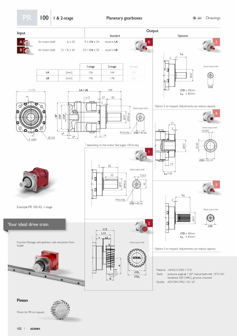
Input OutputStandard Optional
A for motor shaft L ≤ 50 9 ≤ Ød ≤ 24 result in LA 0 3
B for motor shaft 51 < L ≤ 64 24 < Ød ≤ 35 result in LB
C
4
1 4
5
aa
2
ØDv
L12
L13
x2
b
B
a
A
ØDk
Ø47
ØD=32 H7
LG=50
10 JS9
27
2
14
35.3
0Ø
47
ØD
LG
2
ØD ≤ 40mmLG ≤ 82mm
2 82
70
Ø47 43
Ø90
j6
M16×36ØD=40 k6
12 js5
Ø47
ØD
2
LG
ØD ≤ 40mmLG ≤ 82mm
115
115
B*
t*L* 14
LA / LB 109
27
2
826
6
Ø1204 ×Ø9
Ød*
ØS*
Ø47
Ø90
j6
ØD=40 k6M16×36
Material 16MnCr5 DIN 1.7131
Teeth pressure angle α = 20°, helical teeth left, 19°31‘42“ hardened (58+4
0 HRC), ground, crowned
Quality 6f24 DIN 3962 / 63 / 67
Function Package with gearbox, rack and pinion from Güdel
Pinion
Planetary gearboxes Drawings
* depending on the motor. See pages 130 et seq.
Option 5 on request. Adjustments can reduce capacity.
Option 3 on request. Adjustments can reduce capacity.
Pinion
Pinion for PR on request
PR 100 1 & 2-stage
1-stage 2-stage 3-stage
LA [ mm ] 126 164 202
LB [ mm ] 140 178 216
Example PR 100 A5, 1-stage
Detail output shaft
Detail output shaft
Detail output shaft
Detail output shaft
Detail output shaft
Detail output shaft
102 1
Your ideal drive train
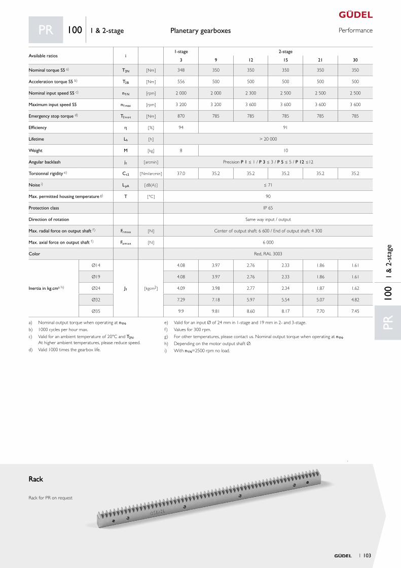
PerformancePlanetary gearboxes
RackRack
Rack for PR on request
PR10
01
& 2
-sta
ge
PR 100 1 & 2-stage
Available ratios i1-stage 2-stage
3 9 12 15 21 30
Nominal torque S5 a) T2N [ Nm ] 348 350 350 350 350 350
Acceleration torque S5 b) T2B [ Nm ] 556 500 500 500 500 500
Nominal input speed S5 c) n1N [rpm] 2 000 2 000 2 300 2 500 2 500 2 500
Maximum input speed S5 n1max [rpm] 3 200 3 200 3 600 3 600 3 600 3 600
Emergency stop torque d) T2 n o t [ Nm ] 870 785 785 785 785 785
Efficiency h [ % ] 94 91
Lifetime Lh [ h ] > 20 000
Weight M [ kg ] 8 10
Angular backlash jt [ arcmin ] Precision P 1 ≤ 1 / P 3 ≤ 3 / P 5 ≤ 5 / P 12 ≤12
Torsionnal rigidity e) Ct2 [ Nm/arcmin ] 37.0 35.2 35.2 35.2 35.2 35.2
Noise i) L pA [ dB(A) ] ≤ 71
Max. permitted housing temperature g) T [ °C ] 90
Protection class IP 65
Direction of rotation Same way input / output
Max. radial force on output shaft f) Fr m a x [ N ] Center of output shaft: 6 600 / End of output shaft: 4 300
Max. axial force on output shaft f) Fa m a x [ N ] 6 000
Color Red, RAL 3003
Inertia in kg.cm² h)
Ø14
J1 [ kgcm2 ]
4.08 3.97 2.76 2.33 1.86 1.61
Ø19 4.08 3.97 2.76 2.33 1.86 1.61
Ø24 4.09 3.98 2.77 2.34 1.87 1.62
Ø32 7.29 7.18 5.97 5.54 5.07 4.82
Ø35 9.9 9.81 8.60 8.17 7.70 7.45
a) Nominal output torque when operating at n1N.
b) 1000 cycles per hour max.
c) Valid for an ambient temperature of 20°C and T2N. At higher ambient temperatures, please reduce speed.
d) Valid 1000 times the gearbox life.
e) Valid for an input Ø of 24 mm in 1-stage and 19 mm in 2- and 3-stage.
f) Values for 300 rpm.
g) For other temperatures, please contact us. Nominal output torque when operating at n1N.
h) Depending on the motor output shaft Ø.
i) With n1N=2500 rpm no load.
1 103
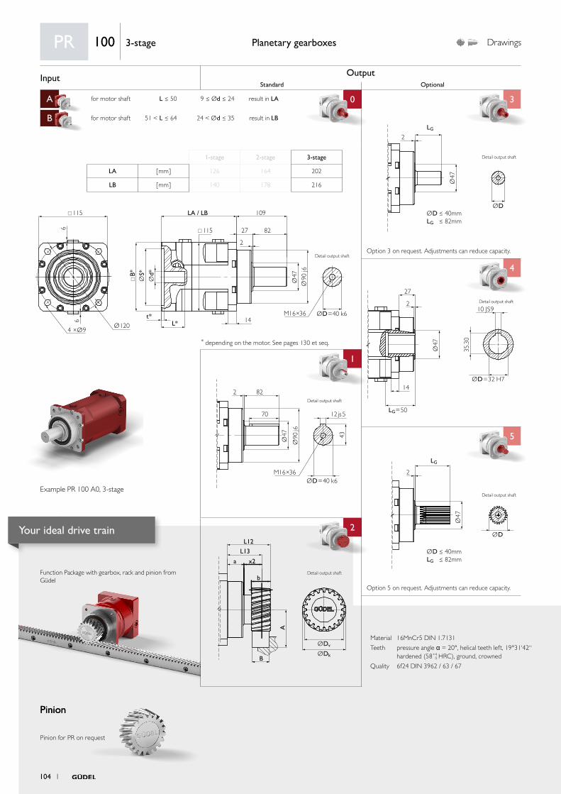
Input OutputStandard Optional
A for motor shaft L ≤ 50 9 ≤ Ød ≤ 24 result in LA 0 3
B for motor shaft 51 < L ≤ 64 24 < Ød ≤ 35 result in LB
C
4
1 4
5
aa
2
ØDv
L12
L13
x2
b
B
a
A
ØDk
Ø47
ØD=32 H7
LG=50
10 JS9
27
2
14
35.3
0Ø
47
ØD
LG
2
ØD ≤ 40mmLG ≤ 82mm
2 82
70
Ø47 43
Ø90
j6
M16×36ØD=40 k6
12 js5
Ø47
ØD
2
LG
ØD ≤ 40mmLG ≤ 82mm
115
115
B*
t*L* 14
LA / LB 109
27
2
826
6
Ø1204 ×Ø9
Ød*
ØS*
Ø47
Ø90
j6
ØD=40 k6M16×36
Material 16MnCr5 DIN 1.7131
Teeth pressure angle α = 20°, helical teeth left, 19°31‘42“ hardened (58+4
0 HRC), ground, crowned
Quality 6f24 DIN 3962 / 63 / 67
Function Package with gearbox, rack and pinion from Güdel
Pinion
Planetary gearboxes Drawings
* depending on the motor. See pages 130 et seq.
Option 5 on request. Adjustments can reduce capacity.
Option 3 on request. Adjustments can reduce capacity.
Pinion
Pinion for PR on request
PR 100 3-stage
1-stage 2-stage 3-stage
LA [ mm ] 126 164 202
LB [ mm ] 140 178 216
Example PR 100 A0, 3-stage
Detail output shaft
Detail output shaft
Detail output shaft
Detail output shaft
Detail output shaft
Detail output shaft
104 1
Your ideal drive train
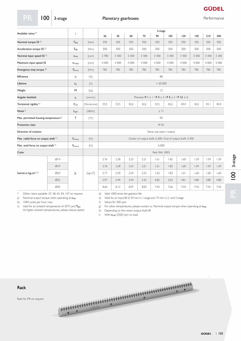
PerformancePlanetary gearboxes
RackRack
Rack for PR on request
PR10
03-
stag
e
PR 100 3-stage
Available ratios * i3-stage
36 45 60 75 90 105 120 150 210 300
Nominal torque S5 a) T2N [ Nm ] 350 350 350 350 350 350 350 350 350 350
Acceleration torque S5 b) T2B [ Nm ] 500 500 500 500 500 500 500 500 500 500
Nominal input speed S5 c) n1N [rpm] 2 700 3 300 3 300 3 300 3 300 3 300 3 300 3 300 3 300 3 300
Maximum input speed S5 n1max [rpm] 4 000 4 000 4 000 4 000 4 000 4 000 4 000 4 000 4 000 4 000
Emergency stop torque d) T2 n o t [ Nm ] 785 785 785 785 785 785 785 785 785 785
Efficiency h [ % ] 88
Lifetime Lh [ h ] > 20 000
Weight M [ kg ] 12
Angular backlash jt [ arcmin ] Precision P 1 ≤ 1 / P 3 ≤ 3 / P 5 ≤ 5 / P 12 ≤12
Torsionnal rigidity e) Ct2 [ Nm/arcmin ] 33.5 33.5 42.2 42.2 33.5 42.2 40.4 42.2 43.1 40.4
Noise i) L pA [ dB(A) ] ≤ 71
Max. permitted housing temperature g) T [ °C ] 90
Protection class IP 65
Direction of rotation Same way input / output
Max. radial force on output shaft f) Fr m a x [ N ] Center of output shaft: 6 600 / End of output shaft: 4 300
Max. axial force on output shaft f) Fa m a x [ N ] 6 000
Color Red, RAL 3003
Inertia in kg.cm² h)
Ø14
J1 [ kgcm2 ]
2.76 2.28 2.23 2.21 1.61 1.82 1.60 1.59 1.59 1.59
Ø19 2.76 2.28 2.23 2.21 1.61 1.82 1.60 1.59 1.59 1.59
Ø24 2.77 2.29 2.24 2.22 1.62 1.83 1.61 1.60 1.60 1.60
Ø32 5.97 5.49 5.44 5.42 4.82 5.03 4.81 4.80 4.80 4.80
Ø35 8.60 8.12 8.07 8.05 7.45 7.66 7.44 7.43 7.43 7.43
* Other ratios available. 27, 48, 63, 84, 147 on request.
a) Nominal output torque when operating at n1N.
b) 1000 cycles per hour max.
c) Valid for an ambient temperature of 20°C and T2N. At higher ambient temperatures, please reduce speed.
d) Valid 1000 times the gearbox life.
e) Valid for an input Ø of 24 mm in 1-stage and 19 mm in 2- and 3-stage.
f) Values for 300 rpm.
g) For other temperatures, please contact us. Nominal output torque when operating at n1N.
h) Depending on the motor output shaft Ø.
i) With n1N=2500 rpm no load.
1 105

Input OutputStandard Optional
A for motor shaft L ≤ 51 14 ≤ Ød ≤ 24 result in LA 0 3
B for motor shaft 51 < L ≤ 63 24 < Ød ≤ 35 result in LB
C for motor shaft 63 < L ≤ 83 24 < Ød ≤ 42 result in LC
4
1 4
5
aa
2
ØDv
L12
L13
x2
b
B
a
A
ØDk
Ø61
ØD=42 H7
LG=58
12 JS9
27
2
16
45.3
0Ø
61LG
2
ØD ≤ 55mmLG ≤ 82mm
ØD
2 82
70
Ø61 59
Ø13
0 j6
M20×42 ØD=55 k6
16 js5
Ø61
ØD
2
16
LG
ØD ≤ 55mmLG ≤ 82mm145
145
B*
t*L* 16
LA / LB / LC 109
272
8266
Ø1654 ×Ø11
Ød*
ØS*
Ø61
Ø13
0 j6
ØD=55 k6M20×42
Material 16MnCr5 DIN 1.7131
Teeth pressure angle α = 20°, helical teeth left, 19°31‘42“ hardened (58+4
0 HRC), ground, crowned
Quality 6f24 DIN 3962 / 63 / 67
Function Package with gearbox, rack and pinion from Güdel
Pinion
Planetary gearboxes Drawings
* depending on the motor. See pages 130 et seq.
Option 5 on request. Adjustments can reduce capacity.
Option 3 on request. Adjustments can reduce capacity.
Pinion
Pinion for PR on request
PR 140 1 & 2-stage
1-stage 2-stage 3-stage
LA [ mm ] 143 185 227
LB [ mm ] 155 197 239
LC [ mm ] 175 217
Example PR 140 A1, 1-stage
Detail output shaft
Detail output shaft
Detail output shaft
Detail output shaft
Detail output shaft
Detail output shaft
106 1
Your ideal drive train
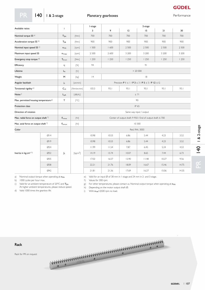
PerformancePlanetary gearboxes
RackRack
Rack for PR on request
PR14
01
& 2
-sta
ge
PR 140 1 & 2-stage
Available ratios i1-stage 2-stage
3 9 12 15 21 30
Nominal torque S5 a) T2N [ Nm ] 700 700 700 700 700 700
Acceleration torque S5 b) T2B [ Nm ] 900 900 900 900 900 900
Nominal input speed S5 c) n1N [rpm] 1 500 1 600 2 500 2 500 2 500 2 500
Maximum input speed S5 n1max [rpm] 2 500 2 600 3 200 3 200 3 200 3 200
Emergency stop torque d) T2 n o t [ Nm ] 1 250 1 250 1 250 1 250 1 250 1 250
Efficiency h [ % ] 94 91
Lifetime Lh [ h ] > 20 000
Weight M [ kg ] 14 18
Angular backlash jt [ arcmin ] Precision P 1 ≤ 1 / P 3 ≤ 3 / P 5 ≤ 5 / P 12 ≤12
Torsionnal rigidity e) Ct2 [ Nm/arcmin ] 103.3 93.1 93.1 93.1 93.1 93.1
Noise i) L pA [ dB(A) ] ≤ 71
Max. permitted housing temperature g) T [ °C ] 90
Protection class IP 65
Direction of rotation Same way input / output
Max. radial force on output shaft f) Fr m a x [ N ] Center of output shaft: 9 950 / End of output shaft: 6 700
Max. axial force on output shaft f) Fa m a x [ N ] 10 300
Color Red, RAL 3003
Inertia in kg.cm² h)
Ø14
J1 [ kgcm2 ]
10.98 10.53 6.86 5.44 4.23 3.52
Ø19 10.98 10.53 6.86 5.44 4.23 3.52
Ø24 11.99 11.54 7.87 6.45 5.24 4.53
Ø32 14.19 13.74 10.07 8.65 7.44 6.73
Ø35 17.02 16.57 12.90 11.48 10.27 9.56
Ø38 22.21 21.76 18.09 16.67 15.46 14.75
Ø42 21.81 21.36 17.69 16.27 15.06 14.35
a) Nominal output torque when operating at n1N.
b) 1000 cycles per hour max.
c) Valid for an ambient temperature of 20°C and T2N. At higher ambient temperatures, please reduce speed.
d) Valid 1000 times the gearbox life.
e) Valid for an input Ø of 38 mm in 1-stage and 24 mm in 2- and 3-stage.
f) Values for 300 rpm.
g) For other temperatures, please contact us. Nominal output torque when operating at n1N.
h) Depending on the motor output shaft Ø.
i) With n1N=2500 rpm no load.
1 107
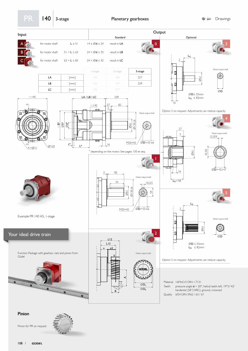
Input OutputStandard Optional
A for motor shaft L ≤ 51 14 ≤ Ød ≤ 24 result in LA 0 3
B for motor shaft 51 < L ≤ 63 24 < Ød ≤ 35 result in LB
C for motor shaft 63 < L ≤ 83 24 < Ød ≤ 42 result in LC
4
1 4
5
aa
2
ØDv
L12
L13
x2
b
B
a
A
ØDk
Ø61
ØD=42 H7
LG=58
12 JS9
27
2
16
45.3
0Ø
61LG
2
ØD ≤ 55mmLG ≤ 82mm
ØD
2 82
70
Ø61 59
Ø13
0 j6
M20×42 ØD=55 k6
16 js5
Ø61
ØD
2
16
LG
ØD ≤ 55mmLG ≤ 82mm
Detail Abtriebswelle
145
145
B*
t*L* 16
LA / LB / LC 109
272
8266
Ø1654 ×Ø11
Ød*
ØS*
Ø61
Ø13
0 j6
ØD=55 k6M20×42
Material 16MnCr5 DIN 1.7131
Teeth pressure angle α = 20°, helical teeth left, 19°31‘42“ hardened (58+4
0 HRC), ground, crowned
Quality 6f24 DIN 3962 / 63 / 67
Function Package with gearbox, rack and pinion from Güdel
Pinion
Planetary gearboxes Drawings
* depending on the motor. See pages 130 et seq.
Option 5 on request. Adjustments can reduce capacity.
Option 3 on request. Adjustments can reduce capacity.
Pinion
Pinion for PR on request
PR 140 3-stage
1-stage 2-stage 3-stage
LA [ mm ] 143 185 227
LB [ mm ] 155 197 239
LC [ mm ] 175 217
Example PR 140 A5, 1-stage
Detail output shaft
Detail output shaft
Detail output shaft
Detail output shaft
Detail output shaft
Detail output shaft
108 1
Your ideal drive train
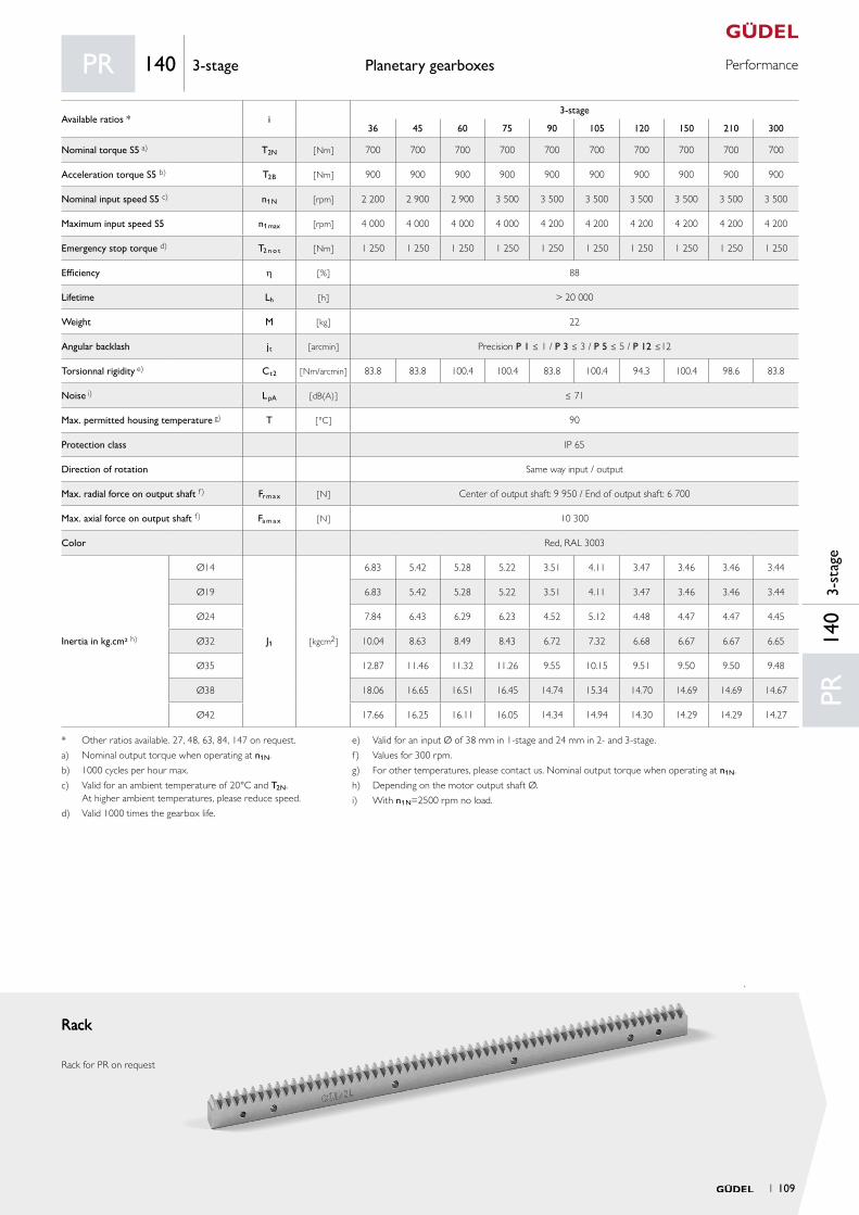
PerformancePlanetary gearboxes
RackRack
Rack for PR on request
PR14
03-
stag
e
PR 140 3-stage
Available ratios * i3-stage
36 45 60 75 90 105 120 150 210 300
Nominal torque S5 a) T2N [ Nm ] 700 700 700 700 700 700 700 700 700 700
Acceleration torque S5 b) T2B [ Nm ] 900 900 900 900 900 900 900 900 900 900
Nominal input speed S5 c) n1N [rpm] 2 200 2 900 2 900 3 500 3 500 3 500 3 500 3 500 3 500 3 500
Maximum input speed S5 n1max [rpm] 4 000 4 000 4 000 4 000 4 200 4 200 4 200 4 200 4 200 4 200
Emergency stop torque d) T2 n o t [ Nm ] 1 250 1 250 1 250 1 250 1 250 1 250 1 250 1 250 1 250 1 250
Efficiency h [ % ] 88
Lifetime Lh [ h ] > 20 000
Weight M [ kg ] 22
Angular backlash jt [ arcmin ] Precision P 1 ≤ 1 / P 3 ≤ 3 / P 5 ≤ 5 / P 12 ≤12
Torsionnal rigidity e) Ct2 [ Nm/arcmin ] 83.8 83.8 100.4 100.4 83.8 100.4 94.3 100.4 98.6 83.8
Noise i) L pA [ dB(A) ] ≤ 71
Max. permitted housing temperature g) T [ °C ] 90
Protection class IP 65
Direction of rotation Same way input / output
Max. radial force on output shaft f) Fr m a x [ N ] Center of output shaft: 9 950 / End of output shaft: 6 700
Max. axial force on output shaft f) Fa m a x [ N ] 10 300
Color Red, RAL 3003
Inertia in kg.cm² h)
Ø14
J1 [ kgcm2 ]
6.83 5.42 5.28 5.22 3.51 4.11 3.47 3.46 3.46 3.44
Ø19 6.83 5.42 5.28 5.22 3.51 4.11 3.47 3.46 3.46 3.44
Ø24 7.84 6.43 6.29 6.23 4.52 5.12 4.48 4.47 4.47 4.45
Ø32 10.04 8.63 8.49 8.43 6.72 7.32 6.68 6.67 6.67 6.65
Ø35 12.87 11.46 11.32 11.26 9.55 10.15 9.51 9.50 9.50 9.48
Ø38 18.06 16.65 16.51 16.45 14.74 15.34 14.70 14.69 14.69 14.67
Ø42 17.66 16.25 16.11 16.05 14.34 14.94 14.30 14.29 14.29 14.27
* Other ratios available. 27, 48, 63, 84, 147 on request.
a) Nominal output torque when operating at n1N.
b) 1000 cycles per hour max.
c) Valid for an ambient temperature of 20°C and T2N. At higher ambient temperatures, please reduce speed.
d) Valid 1000 times the gearbox life.
e) Valid for an input Ø of 38 mm in 1-stage and 24 mm in 2- and 3-stage.
f) Values for 300 rpm.
g) For other temperatures, please contact us. Nominal output torque when operating at n1N.
h) Depending on the motor output shaft Ø.
i) With n1N=2500 rpm no load.
1 109
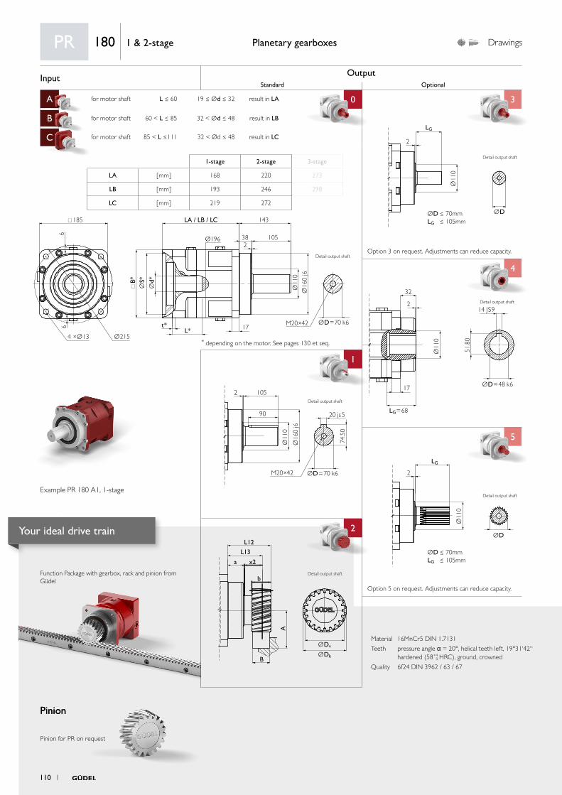
Input OutputStandard Optional
A for motor shaft L ≤ 60 19 ≤ Ød ≤ 32 result in LA 0 3
B for motor shaft 60 < L ≤ 85 32 < Ød ≤ 48 result in LB
C for motor shaft 85 < L ≤111 32 < Ød ≤ 48 result in LC
4
1 4
5
aa
2
ØDv
L12
L13
x2
b
B
a
A
ØDk
2 105
90
Ø11
0
74.5
0
Ø16
0 j6
M20×42 ØD=70 k6
20 js5
Ø11
0
ØD
LG
2
ØD ≤ 70mmLG ≤ 105mm
Ø11
0
ØD=48 k6
LG=68
14 JS9
32
2
17
51.8
0
Ø11
0
ØD
2
LG
ØD ≤ 70mmLG ≤ 105mm185
Ø196
B*
t*L* 17
LA / LB / LC 143
382
105
66
Ø2154 ×Ø13
Ød*
ØS*
Ø11
0Ø
160
j6
ØD=70 k6M20×42
Material 16MnCr5 DIN 1.7131
Teeth pressure angle α = 20°, helical teeth left, 19°31‘42“ hardened (58+4
0 HRC), ground, crowned
Quality 6f24 DIN 3962 / 63 / 67
Function Package with gearbox, rack and pinion from Güdel
Pinion
Planetary gearboxes Drawings
* depending on the motor. See pages 130 et seq.
Option 5 on request. Adjustments can reduce capacity.
Option 3 on request. Adjustments can reduce capacity.
Pinion
Pinion for PR on request
PR 180 1 & 2-stage
1-stage 2-stage 3-stage
LA [ mm ] 168 220 273
LB [ mm ] 193 246 298
LC [ mm ] 219 272
Example PR 180 A1, 1-stage
Detail output shaft
Detail output shaft
Detail output shaft
Detail output shaft
Detail output shaft
Detail output shaft
110 1
Your ideal drive train

PerformancePlanetary gearboxes
RackRack
Rack for PR on request
PR18
01
& 2
-sta
ge
PR 180 1 & 2-stage
Available ratios i1-stage 2-stage
3 9 12 15 21 30
Nominal torque S5 a) T2N [ Nm ] 1 600 1 600 1 600 1 600 1 600 1 600
Acceleration torque S5 b) T2B [ Nm ] 1 925 1 900 1 900 1 900 1 900 1 900
Nominal input speed S5 c) n1N [rpm] 1 200 2 000 2 000 2 100 2 100 2 100
Maximum input speed S5 n1max [rpm] 2 400 2 400 3 200 3 200 3 200 3 200
Emergency stop torque d) T2 n o t [ Nm ] 3 000 3 000 3 000 3 000 3 000 3 000
Efficiency h [ % ] 94 91
Lifetime Lh [ h ] > 20 000
Weight M [ kg ] 32 39
Angular backlash jt [ arcmin ] Precision P 1 ≤ 1 / P 3 ≤ 3 / P 5 ≤ 5 / P 12 ≤12
Torsionnal rigidity e) Ct2 [ Nm/arcmin ] 366.6 349.1 333.4 300.3 281.1 274.1
Noise i) L pA [ dB(A) ] ≤ 72
Max. permitted housing temperature g) T [ °C ] 90
Protection class IP 65
Direction of rotation Same way input / output
Max. radial force on output shaft f) Fr m a x [ N ] Center of output shaft: 18 000 / End of output shaft: 13 000
Max. axial force on output shaft f) Fa m a x [ N ] 20 000
Color Red, RAL 3003
Inertia in kg.cm² h)
Ø19
J1 [ kgcm2 ]
38.19 38.58 16.57 17.35 12.20 9.22
Ø24 39.24 39.63 17.62 18.40 13.25 10.27
Ø32 41.45 41.84 19.83 20.61 15.46 12.48
Ø35 44.37 44.76 22.75 23.53 18.38 15.40
Ø38 49.97 50.36 28.35 29.13 23.98 21.00
Ø42 49.47 49.86 27.85 28.63 23.48 20.50
Ø48 49.87 50.26 28.25 29.03 23.88 20.90
a) Nominal output torque when operating at n1N.
b) 1000 cycles per hour max.
c) Valid for an ambient temperature of 20°C and T2N. At higher ambient temperatures, please reduce speed.
d) Valid 1000 times the gearbox life.
e) Valid for an input Ø of 48 mm in 1-stage and 38 mm in 2- and 3-stage.
f) Values for 300 rpm.
g) For other temperatures, please contact us. Nominal output torque when operating at n1N.
h) Depending on the motor output shaft Ø.
i) With n1N=2500 rpm no load.
1 111
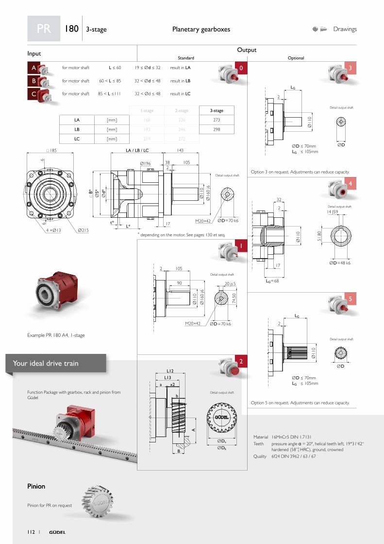
Input OutputStandard Optional
A for motor shaft L ≤ 60 19 ≤ Ød ≤ 32 result in LA 0 3
B for motor shaft 60 < L ≤ 85 32 < Ød ≤ 48 result in LB
C for motor shaft 85 < L ≤111 32 < Ød ≤ 48 result in LC
4
1 4
5
aa
2
ØDv
L12
L13
x2
b
B
a
A
ØDk
2 105
90
Ø11
0
74.5
0
Ø16
0 j6
M20×42 ØD=70 k6
20 js5
Ø11
0
ØD
LG
2
ØD ≤ 70mmLG ≤ 105mm
Ø11
0
ØD=48 k6
LG=68
14 JS9
32
2
17
51.8
0
Ø11
0
ØD
2
LG
ØD ≤ 70mmLG ≤ 105mm185
Ø196
B*
t*L* 17
LA / LB / LC 143
382
105
66
Ø2154 ×Ø13
Ød*
ØS*
Ø11
0Ø
160
j6
ØD=70 k6M20×42
Material 16MnCr5 DIN 1.7131
Teeth pressure angle α = 20°, helical teeth left, 19°31‘42“ hardened (58+4
0 HRC), ground, crowned
Quality 6f24 DIN 3962 / 63 / 67
Function Package with gearbox, rack and pinion from Güdel
Pinion
Planetary gearboxes Drawings
* depending on the motor. See pages 130 et seq.
Option 5 on request. Adjustments can reduce capacity.
Option 3 on request. Adjustments can reduce capacity.
Pinion
Pinion for PR on request
PR 180 3-stage
1-stage 2-stage 3-stage
LA [ mm ] 168 220 273
LB [ mm ] 193 246 298
LC [ mm ] 219 272
Example PR 180 A4, 1-stage
Detail output shaft
Detail output shaft
Detail output shaft
Detail output shaft
Detail output shaft
Detail output shaft
112 1
Your ideal drive train
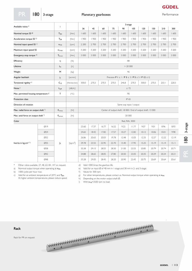
PerformancePlanetary gearboxes
RackRack
Rack for PR on request
PR18
03-
stag
e
PR 180 3-stage
Available ratios * i3-stage
36 45 60 75 90 105 120 150 210 300
Nominal torque S5 a) T2N [ Nm ] 1 600 1 600 1 600 1 600 1 600 1 600 1 600 1 600 1 600 1 600
Acceleration torque S5 b) T2B [ Nm ] 1 900 1 900 1 900 1 900 1 900 1 900 1 900 1 900 1 900 1 900
Nominal input speed S5 c) n1N [rpm] 2 200 2 700 2 700 2 700 2 700 2 700 2 700 2 700 2 700 2 700
Maximum input speed S5 n1max [rpm] 3 200 3 200 3 200 3 200 3 200 3 200 3 200 3 200 3 200 3 200
Emergency stop torque d) T2 n o t [ Nm ] 3 000 3 000 3 000 3 000 3 000 3 000 3 000 3 000 3 000 3 000
Efficiency h [ % ] 88
Lifetime Lh [ h ] > 20 000
Weight M [ kg ] 46
Angular backlash jt [ arcmin ] Precision P 1 ≤ 1 / P 3 ≤ 3 / P 5 ≤ 5 / P 12 ≤12
Torsionnal rigidity e) Ct2 [ Nm/arcmin ] 300.0 270.3 270.3 270.3 246.8 270.3 300.0 270.3 253.1 220.5
Noise i) L pA [ dB(A) ] ≤ 72
Max. permitted housing temperature g) T [ °C ] 90
Protection class IP 65
Direction of rotation Same way input / output
Max. radial force on output shaft f) Fr m a x [ N ] Center of output shaft: 18 000 / End of output shaft: 13 000
Max. axial force on output shaft f) Fa m a x [ N ] 20 000
Color Red, RAL 3003
Inertia in kg.cm² h)
Ø19
J1 [ kgcm2 ]
23.60 17.37 16.77 16.52 9.22 11.77 9.07 9.01 8.96 8.93
Ø24 24.65 18.42 17.82 17.57 10.27 12.82 10.12 10.06 10.01 9.98
Ø32 26.86 20.63 20.03 19.78 12.48 15.03 12.33 12.27 12.22 12.19
Ø35 29.78 23.55 22.95 22.70 15.40 17.95 15.25 15.19 15.14 15.11
Ø38 35.38 29.15 28.55 28.30 21.00 23.55 20.85 20.79 20.74 20.71
Ø42 34.88 28.65 28.05 27.80 20.50 23.05 20.35 20.29 20.24 20.21
Ø48 35.28 29.05 28.45 28.20 20.90 23.45 20.75 20.69 20.64 20.61
* Other ratios available. 27, 48, 63, 84, 147 on request.
a) Nominal output torque when operating at n1N.
b) 1000 cycles per hour max.
c) Valid for an ambient temperature of 20°C and T2N. At higher ambient temperatures, please reduce speed.
d) Valid 1000 times the gearbox life.
e) Valid for an input Ø of 48 mm in 1-stage and 38 mm in 2- and 3-stage.
f) Values for 300 rpm.
g) For other temperatures, please contact us. Nominal output torque when operating at n1N.
h) Depending on the motor output shaft Ø.
i) With n1N=2500 rpm no load.
1 113
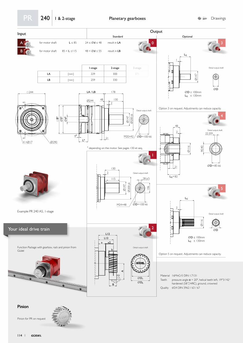
Input OutputStandard Optional
A for motor shaft L ≤ 85 24 ≤ Ød ≤ 48 result in LA 0 3
B for motor shaft 85 < L ≤115 48 < Ød ≤ 55 result in LB
C
4
1 4
5
aa
2
ØDv
L12
L13
x2
b
B
a
A
ØDk
Ø11
6
ØD
LG
2
ØD ≤ 100mmLG ≤ 130mm
2
130
115
Ø14
7
106
Ø20
0 j6
M24×48 ØD=100 k6
28 js5
Ø11
6
ØD=85 k6
LG=82
22 JS9
48
2
21
90.4
0
Ø14
7
ØD
1
LG
ØD ≤ 100mmLG ≤ 130mm
244
Ø244
B*
t*
L*21
LA / LB 178
482
130
66
Ø2904 ×Ø17
Ød*
ØS*
Ø14
7Ø
200
j6
ØD=100 k6M20×42
Material 16MnCr5 DIN 1.7131
Teeth pressure angle α = 20°, helical teeth left, 19°31‘42“ hardened (58+4
0 HRC), ground, crowned
Quality 6f24 DIN 3962 / 63 / 67
Function Package with gearbox, rack and pinion from Güdel
Pinion
Planetary gearboxes Drawings
* depending on the motor. See pages 130 et seq.
Option 5 on request. Adjustments can reduce capacity.
Option 3 on request. Adjustments can reduce capacity.
Pinion
Pinion for PR on request
PR 240 1 & 2-stage
1-stage 2-stage 3-stage
LA [ mm ] 229 300 371
LB [ mm ] 259 330
Example PR 240 A5, 1-stage
Detail output shaft
Detail output shaft
Detail output shaft
Detail output shaft
Detail output shaft
Detail output shaft
114 1
Your ideal drive train

PerformancePlanetary gearboxes
RackRack
Rack for PR on request
PR24
01
& 2
-sta
ge
PR 240 1 & 2-stage
Available ratios i1-stage 2-stage
3 9 12 15 21 30
Nominal torque S5 a) T2N [ Nm ] 4 400 4 400 4 400 4 400 4 400 4 400
Acceleration torque S5 b) T2B [ Nm ] 5 600 5 600 5 600 5 600 5 600 5 600
Nominal input speed S5 c) n1N [rpm] 800 800 1 400 1 500 1 500 1 500
Maximum input speed S5 n1max [rpm] 1 600 1 600 2 800 2 800 2 800 2 800
Emergency stop torque d) T2 n o t [ Nm ] 8 500 8 500 8 500 8 500 8 500 8 500
Efficiency h [ % ] 94 91
Lifetime Lh [ h ] > 20 000
Weight M [ kg ] 70 90
Angular backlash jt [ arcmin ] Precision P 1 ≤ 1 / P 3 ≤ 3 / P 5 ≤ 5 / P 12 ≤12
Torsionnal rigidity e) Ct2 [ Nm/arcmin ] 814.7 730.3 756.6 779.8 805.9 736.1
Noise i) L pA [ dB(A) ] ≤ 74
Max. permitted housing temperature g) T [ °C ] 90
Protection class IP 65
Direction of rotation Same way input / output
Max. radial force on output shaft f) Fr m a x [ N ] Center of output shaft: 37 500 / End of output shaft: 25 000
Max. axial force on output shaft f) Fa m a x [ N ] 34 000
Color Red, RAL 3003
Inertia in kg.cm² h)
Ø24
J1 [ kgcm2 ]
161.0 146.0 79.1 55.0 35.4 23.6
Ø32 163.2 148.2 81.3 57.2 37.6 25.8
Ø35 168.5 153.5 86.6 62.5 42.9 31.1
Ø38 171.9 156.9 90.0 65.9 46.3 34.5
Ø42 171.4 156.4 89.5 65.4 45.8 34.0
Ø48 171.6 156.6 89.7 65.6 46.0 34.2
Ø55 194.2 179.2 112.3 88.2 68.6 56.8
a) Nominal output torque when operating at n1N.
b) 1000 cycles per hour max.
c) Valid for an ambient temperature of 20°C and T2N. At higher ambient temperatures, please reduce speed.
d) Valid 1000 times the gearbox life.
e) Valid for an input Ø of 55 mm in 1-stage and 48 mm in 2- and 3-stage.
f) Values for 300 rpm.
g) For other temperatures, please contact us. Nominal output torque when operating at n1N.
h) Depending on the motor output shaft Ø.
i) With n1N=1800 rpm no load.
1 115
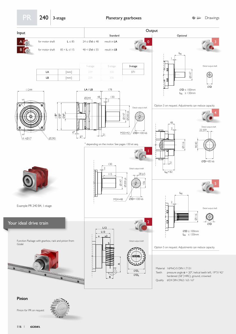
Input OutputStandard Optional
A for motor shaft L ≤ 85 24 ≤ Ød ≤ 48 result in LA 0 3
B for motor shaft 85 < L ≤115 48 < Ød ≤ 55 result in LB
C
4
1 4
5
aa
2
ØDv
L12
L13
x2
b
B
a
A
ØDk
Ø11
6
ØD
LG
2
ØD ≤ 100mmLG ≤ 130mm
2
130
115
Ø14
7
106
Ø20
0 j6
M24×48 ØD=100 k6
28 js5
Ø11
6
ØD=85 k6
LG=82
22 JS9
48
2
21
90.4
0
Ø14
7
ØD
1
LG
ØD ≤ 100mmLG ≤ 130mm
244
Ø244
B*
t*
L*21
LA / LB 178
482
130
66
Ø2904 ×Ø17
Ød*
ØS*
Ø14
7Ø
200
j6
ØD=100 k6M20×42
Material 16MnCr5 DIN 1.7131
Teeth pressure angle α = 20°, helical teeth left, 19°31‘42“ hardened (58+4
0 HRC), ground, crowned
Quality 6f24 DIN 3962 / 63 / 67
Function Package with gearbox, rack and pinion from Güdel
Pinion
Planetary gearboxes Drawings
* depending on the motor. See pages 130 et seq.
Option 5 on request. Adjustments can reduce capacity.
Option 3 on request. Adjustments can reduce capacity.
Pinion
Pinion for PR on request
PR 240 3-stage
1-stage 2-stage 3-stage
LA [ mm ] 229 300 371
LB [ mm ] 259 330
Example PR 240 B4, 1-stage
Detail output shaft
Detail output shaft
Detail output shaft
Detail output shaft
Detail output shaft
Detail output shaft
116 1
Your ideal drive train
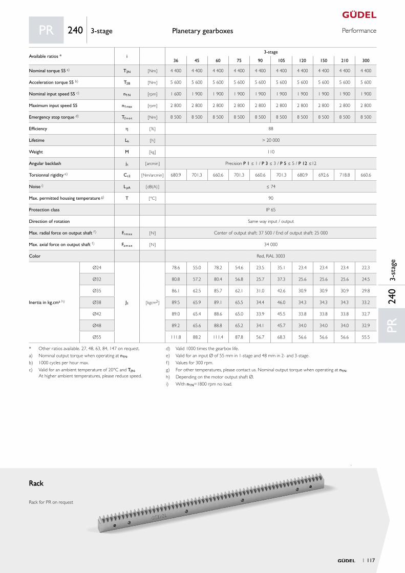
PerformancePlanetary gearboxes
RackRack
Rack for PR on request
PR24
03-
stag
e
PR 240 3-stage
* Other ratios available. 27, 48, 63, 84, 147 on request.
a) Nominal output torque when operating at n1N.
b) 1000 cycles per hour max.
c) Valid for an ambient temperature of 20°C and T2N. At higher ambient temperatures, please reduce speed.
d) Valid 1000 times the gearbox life.
e) Valid for an input Ø of 55 mm in 1-stage and 48 mm in 2- and 3-stage.
f) Values for 300 rpm.
g) For other temperatures, please contact us. Nominal output torque when operating at n1N.
h) Depending on the motor output shaft Ø.
i) With n1N=1800 rpm no load.
Available ratios * i3-stage
36 45 60 75 90 105 120 150 210 300
Nominal torque S5 a) T2N [ Nm ] 4 400 4 400 4 400 4 400 4 400 4 400 4 400 4 400 4 400 4 400
Acceleration torque S5 b) T2B [ Nm ] 5 600 5 600 5 600 5 600 5 600 5 600 5 600 5 600 5 600 5 600
Nominal input speed S5 c) n1N [rpm] 1 600 1 900 1 900 1 900 1 900 1 900 1 900 1 900 1 900 1 900
Maximum input speed S5 n1max [rpm] 2 800 2 800 2 800 2 800 2 800 2 800 2 800 2 800 2 800 2 800
Emergency stop torque d) T2 n o t [ Nm ] 8 500 8 500 8 500 8 500 8 500 8 500 8 500 8 500 8 500 8 500
Efficiency h [ % ] 88
Lifetime Lh [ h ] > 20 000
Weight M [ kg ] 110
Angular backlash jt [ arcmin ] Precision P 1 ≤ 1 / P 3 ≤ 3 / P 5 ≤ 5 / P 12 ≤12
Torsionnal rigidity e) Ct2 [ Nm/arcmin ] 680.9 701.3 660.6 701.3 660.6 701.3 680.9 692.6 718.8 660.6
Noise i) L pA [ dB(A) ] ≤ 74
Max. permitted housing temperature g) T [ °C ] 90
Protection class IP 65
Direction of rotation Same way input / output
Max. radial force on output shaft f) Fr m a x [ N ] Center of output shaft: 37 500 / End of output shaft: 25 000
Max. axial force on output shaft f) Fa m a x [ N ] 34 000
Color Red, RAL 3003
Inertia in kg.cm² h)
Ø24
J1 [ kgcm2 ]
78.6 55.0 78.2 54.6 23.5 35.1 23.4 23.4 23.4 22.3
Ø32 80.8 57.2 80.4 56.8 25.7 37.3 25.6 25.6 25.6 24.5
Ø35 86.1 62.5 85.7 62.1 31.0 42.6 30.9 30.9 30.9 29.8
Ø38 89.5 65.9 89.1 65.5 34.4 46.0 34.3 34.3 34.3 33.2
Ø42 89.0 65.4 88.6 65.0 33.9 45.5 33.8 33.8 33.8 32.7
Ø48 89.2 65.6 88.8 65.2 34.1 45.7 34.0 34.0 34.0 32.9
Ø55 111.8 88.2 111.4 87.8 56.7 68.3 56.6 56.6 56.6 55.5
1 117

Your ideal drive train
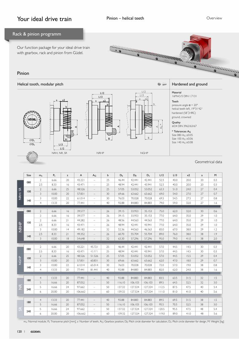
NR
H /
SRN
RH
PN
RSR
NG
HP
Helical tooth, modular pitch Hardened and ground
Material 16MnCr5 DIN 1.7131
Teeth pressure angle α = 20° helical teeth left, 19°31‘42“
hardened (58+4 0 HRC)
ground, crowned
Quality 6f24 DIN 3962/63/67
* Tolerances AG Size 080 AG ±0.05 Size 100 AG ±0.06 Size 140 AG ±0.08
AG *
L12L13
x2
b
A
B
a
L12
L13
x2
b
B
a
A
ØDv
ØDk
B
L12L13
x2b
a
A
Geometrical data
Pinion
Your ideal drive train
Rack & pinion programm
Our function package for your ideal drive train with gearbox, rack and pinion from Güdel.
Size mn Pt z A AG b Dk D0 Dv L12 L13 x2 a M
0802 6.66 20 43.221 – 25 46.44 42.441 42.441 52.5 40.0 20.0 20 0.3
2.5 8.33 16 43.471 – 25 48.94 42.441 43.941 52.5 40.0 20.0 20 0.3
1002 6.66 25 48.526 – 25 57.05 53.052 53.052 63.3 51.0 24.0 27 0.4
3 10.00 20 57.831 – 30 69.66 63.662 63.662 69.0 54.0 27.0 27 0.7
1403 10.00 22 61.014 – 30 76.03 70.028 70.028 69.5 54.5 27.5 27 0.8
4 13.33 20 77.441 – 40 92.88 84.883 84.883 79.0 59.0 32.0 27 1.6
080 2 6.66 16 39.577 – 26 39.15 33.953 35.153 75.0 62.0 32.0 30 0.6
100
2 6.66 16 39.577 – 26 39.15 33.953 35.153 77.0 64.0 35.0 29 1.0
2 6.66 21 44.282 – 26 48.56 44.563 44.563 77.0 64.0 35.0 29 1.0
2.5 8.33 16 43.471 – 26 48.94 42.441 43.941 77.0 64.0 35.0 29 1.0
3 10.00 14 49.182 – 32 52.36 44.563 46.363 83.0 67.0 38.0 29 1.2
1402.5 8.33 21 49.352 – 26 60.70 55.704 55.704 89.0 76.0 38.0 38 1.9
3 10.00 18 54.648 – 32 63.30 57.296 57.296 95.0 79.0 41.0 38 2.0
0802 6.66 20 43.221 45.721 25 46.44 42.441 42.441 57.0 44.5 14.5 30 0.3
2.5 8.33 16 43.471 45.971 25 48.94 42.441 43.941 57.0 44.5 14.5 30 0.3
1002 6.66 25 48.526 51.526 25 57.05 53.052 53.052 57.0 44.5 15.5 29 0.4
3 10.00 20 57.831 60.831 30 69.66 63.662 63.662 62.0 47.0 18.0 29 0.7
1403 10.00 22 61.014 65.014 30 76.03 70.028 70.028 72.0 57.0 19.0 38 0.8
4 13.33 20 77.441 81.441 40 92.88 84.883 84.883 82.0 62.0 24.0 38 1.6
1804 13.33 20 77.441 – 40 92.88 84.883 84.883 83.5 63.5 31.5 32 1.5
5 16.66 20 87.052 – 50 116.10 106.103 106.103 89.5 64.5 32.5 32 3.0
2405 16.66 24 97.662 – 50 137.32 127.324 127.324 112.5 87.5 47.5 40 5.4
6 20.00 20 106.662 – 60 139.32 127.324 127.324 111.0 81.0 41.0 40 5.6
1804 13.33 20 77.441 – 40 92.88 84.883 84.883 89.5 69.5 31.5 38 1.5
5 16.66 20 87.052 – 50 116.10 106.103 106.103 95.5 70.5 32.5 38 3.0
2405 16.66 24 97.662 – 50 137.32 127.324 127.324 120.5 95.5 47.5 48 5.4
6 20.00 20 106.662 – 60 139.32 127.324 127.324 119.0 89.0 41.0 48 5.6
mn: Normal module, Pt: Transverse pitch [mm], z : Number of teeth, AG: Gearbox position, D0: Pitch circle diameter for calculation, Dv: Pitch circle diameter for design, M: Weight [kg]
NRH, NR, SR NRHP NGHP
Pinion – helical teeth
120 1
Overview
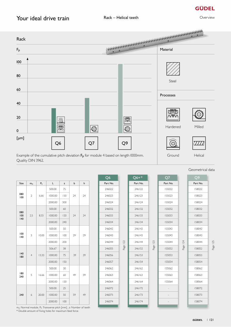
Q6+ *Q6 Q7 Q9
Fp Material
Processes
Q9Q7Q6
Size mn Pt L z b h Part No. Part No. Part No. Part No.
080 100
2 6.66
500.00 75
24 24
246022
Page
122
246122
Page
123
155022
Page
124
158022
Page
125
1000.00 150 246023 246123 155023 158023
2000.00 300 246024 246124 155024 158024
080 100 140
2.5 8.33
500.00 60
24 24
246032 246132 155032 158032
1000.00 120 246033 246133 155033 158033
2000.00 240 246034 246134 155034 158034
100 140
3 10.00
500.00 50
29 29
246042 246142 155042 158042
1000.00 100 246043 246143 155043 158043
2000.00 200 246044 246144 155044 158044
140 180
4 13.33
506.67 38
39 39
246055 246152 155052 158052
1000.00 75 246056 246153 155053 158053
2000.00 150 246057 246154 155054 158054
180 240
5 16.66
500.00 30
49 39
246062 246162 155062 158062
1000.00 60 246063 246163 155063 158063
2000.00 120 246064 246164 155064 158064
240 6 20.00
500.00 25
59 49
246072 246172 - 158072
1000.00 50 246073 246173 - 158073
2000.00 100 246074 246174 - 158074
mn: Normal module, Pt: Transverse pitch [mm] , z: Number of teeth * Double amount of fixing holes for maximum feed force
Geometrical data
Rack
Your ideal drive train
0
20
[µm]
40
60
80
100
Steel
Hardened
Ground
Milled
Example of the cumulative pitch deviation Fp for module 4 based on length 1000mm. Quality DIN 3962.
Rack – Helical teeth
Helical
1 121
Overview
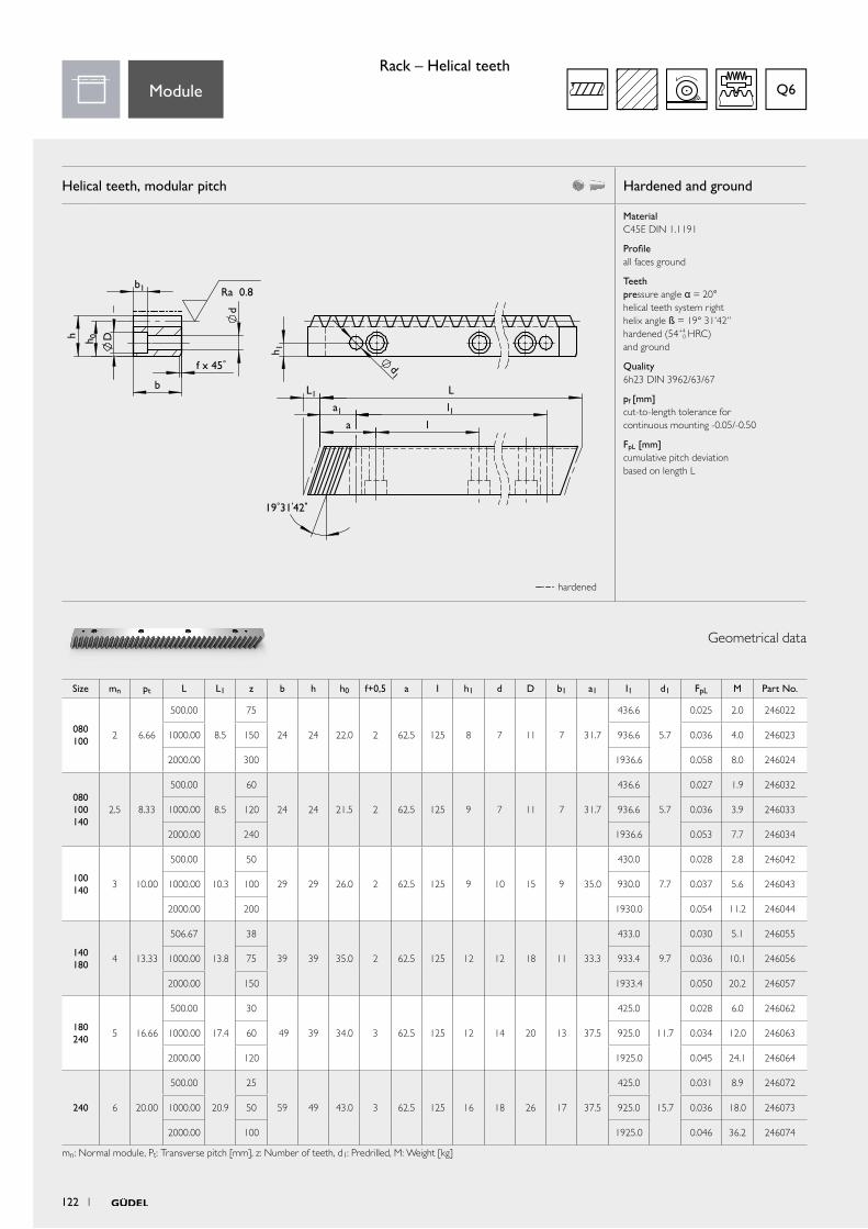
Helical teeth, modular pitch Hardened and ground
Material C45E DIN 1.1191
Profile all faces ground
Teeth pressure angle α = 20° helical teeth system right helix angle ß = 19° 31’42’’ hardened (54+4
0 HRC) and ground
Quality 6h23 DIN 3962/63/67
pf [mm] cut-to-length tolerance for continuous mounting -0.05/-0.50
FpL [mm] cumulative pitch deviation based on length L
b
h h 0
f x 45°
b1
D
d
h 0
b1
Seite 3.26
Zahsta-helical02_cat
Ra 0.8
D
d
h 1
d1
l
l1
h 1
d1
l1l
Ra 0.8
b
f x 45°
h
L
a1
L1
a
19°31'42"
19°31'42"
a
a1
LL1
Geometrical data
hardened
Size mn pt L L1 z b h h0 f+0,5 a I h1 d D b1 a1 I1 d1 FpL M Part No.
080 100
2 6.66
500.00
8.5
75
24 24 22.0 2 62.5 125 8 7 11 7 31.7
436.6
5.7
0.025 2.0 246022
1000.00 150 936.6 0.036 4.0 246023
2000.00 300 1936.6 0.058 8.0 246024
080 100 140
2.5 8.33
500.00
8.5
60
24 24 21.5 2 62.5 125 9 7 11 7 31.7
436.6
5.7
0.027 1.9 246032
1000.00 120 936.6 0.036 3.9 246033
2000.00 240 1936.6 0.053 7.7 246034
100 140
3 10.00
500.00
10.3
50
29 29 26.0 2 62.5 125 9 10 15 9 35.0
430.0
7.7
0.028 2.8 246042
1000.00 100 930.0 0.037 5.6 246043
2000.00 200 1930.0 0.054 11.2 246044
140 180
4 13.33
506.67
13.8
38
39 39 35.0 2 62.5 125 12 12 18 11 33.3
433.0
9.7
0.030 5.1 246055
1000.00 75 933.4 0.036 10.1 246056
2000.00 150 1933.4 0.050 20.2 246057
180 240
5 16.66
500.00
17.4
30
49 39 34.0 3 62.5 125 12 14 20 13 37.5
425.0
11.7
0.028 6.0 246062
1000.00 60 925.0 0.034 12.0 246063
2000.00 120 1925.0 0.045 24.1 246064
240 6 20.00
500.00
20.9
25
59 49 43.0 3 62.5 125 16 18 26 17 37.5
425.0
15.7
0.031 8.9 246072
1000.00 50 925.0 0.036 18.0 246073
2000.00 100 1925.0 0.046 36.2 246074
mn: Normal module, Pt: Transverse pitch [mm], z: Number of teeth, d1: Predrilled, M: Weight [kg]
Q6Module
Rack – Helical teeth
122 1
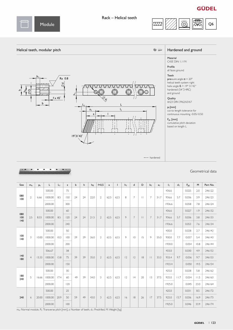
Helical teeth, modular pitch Hardened and ground
Material C45E DIN 1.1191
Profile all faces ground
Teeth pressure angle α = 20° helical teeth system right helix angle ß = 19° 31’42’’ hardened (54+4
0 HRC) and ground
Quality 6h23 DIN 3962/63/67
pf [mm] cut-to-length tolerance for continuous mounting -0.05/-0.50
FpL [mm] cumulative pitch deviation based on length L
h h 0
f x 45°
b1 Ra 0.8
D
d
h 1
d1
l
l1
19°31'42"
a
a1
LL1b
Geometrical data
hardened
Size mn pt L L1 z b h h0 f+0,5 a I h1 d D b1 a1 I1 d1 FpL M Part No.
080 100
2 6.66
500.00
8.5
75
24 24 22.0 2 62.5 62.5 8 7 11 7 31.7
436.6
5.7
0.025 2.0 246122
1000.00 150 936.6 0.036 3.9 246123
2000.00 300 1936.6 0.058 7.8 246124
080 100 140
2.5 8.33
500.00
8.5
60
24 24 21.5 2 62.5 62.5 9 7 11 7 31.7
436.6
5.7
0.027 1.9 246132
1000.00 120 936.6 0.036 3.8 246133
2000.00 240 1936.6 0.053 7.6 246134
100 140
3 10.00
500.00
10.3
50
29 29 26.0 2 62.5 62.5 9 10 15 9 35.0
430.0
7.7
0.028 2.7 246142
1000.00 100 930.0 0.037 5.4 246143
2000.00 200 1930.0 0.054 10.8 246144
140 180
4 13.33
506.67
13.8
38
39 39 35.0 2 62.5 62.5 12 12 18 11 33.3
433.0
9.7
0.030 4.9 246152
1000.00 75 933.4 0.036 9.7 246153
2000.00 150 1933.4 0.050 19.5 246154
180 240
5 16.66
500.00
17.4
30
49 39 34.0 3 62.5 62.5 12 14 20 13 37.5
425.0
11.7
0.028 5.8 246162
1000.00 60 925.0 0.034 11.5 246163
2000.00 120 1925.0 0.045 23.0 246164
240 6 20.00
500.00
20.9
25
59 49 43.0 3 62.5 62.5 16 18 26 17 37.5
425.0
15.7
0.031 8.5 246172
1000.00 50 925.0 0.036 16.9 246173
2000.00 100 1925.0 0.046 33.9 246174
mn: Normal module, Pt: Transverse pitch [mm], z: Number of teeth, d1: Predrilled, M: Weight [kg]
Q6ModuleRack – Helical teeth
1 123
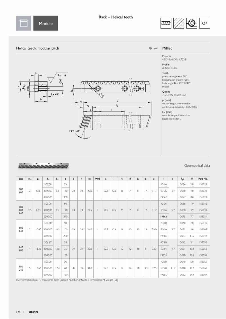
Helical teeth, modular pitch Millled
Material 42CrMo4 DIN 1.72251
Profile all faces milled
Teeth pressure angle α = 20° helical teeth system right helix angle ß = 19° 31’42’’ milled
Quality 7h25 DIN 3962/63/67
pf [mm] cut-to-length tolerance for continuous mounting -0.05/-0.50
FpL [mm] cumulative pitch deviation based on length L
b
h h 0
f x 45°
b1 Ra 1.6
D
d
h 1
d1
l
l1
19°31'42"
a
a1
LL1
Geometrical data
Size mn pt L L1 z b h h0 f+0,5 a I h1 d D b1 a1 I1 d1 FpL M Part No.
080 100
2 6.66
500.00
8.5
75
24 24 22.0 1 62.5 125 8 7 11 7 31.7
436.6
5.7
0.036 2.0 155022
1000.00 150 936.6 0.050 4.0 155023
2000.00 300 1936.6 0.077 8.0 155024
080 100 140
2.5 8.33
500.00
8.5
60
24 24 21.5 1 62.5 125 9 7 11 7 31.7
436.6
5.7
0.038 1.9 155032
1000.00 120 936.6 0.050 3.9 155033
2000.00 240 1936.6 0.075 7.7 155034
100 140
3 10.00
500.00
10.3
50
29 29 26.0 1 62.5 125 9 10 15 9 35.0
430.0
7.7
0.040 2.8 155042
1000.00 100 930.0 0.051 5.6 155043
2000.00 200 1930.0 0.073 11.2 155044
140 180
4 13.33
506.67
13.8
38
39 39 35.0 1 62.5 125 12 12 18 11 33.3
433.0
9.7
0.042 5.1 155052
1000.00 75 933.4 0.051 10.1 155053
2000.00 150 1933.4 0.070 20.2 155054
180 240
5 16.66
500.00
17.4
30
49 39 34.0 1 62.5 125 12 14 20 13 37.5
425.0
11.7
0.040 6.0 155062
1000.00 60 925.0 0.048 12.0 155063
2000.00 120 1925.0 0.062 24.1 155064
mn: Normal module, Pt: Transverse pitch [mm], z: Number of teeth, d1: Predrilled, M: Weight [kg]
Q7Module
Rack – Helical teeth
124 1
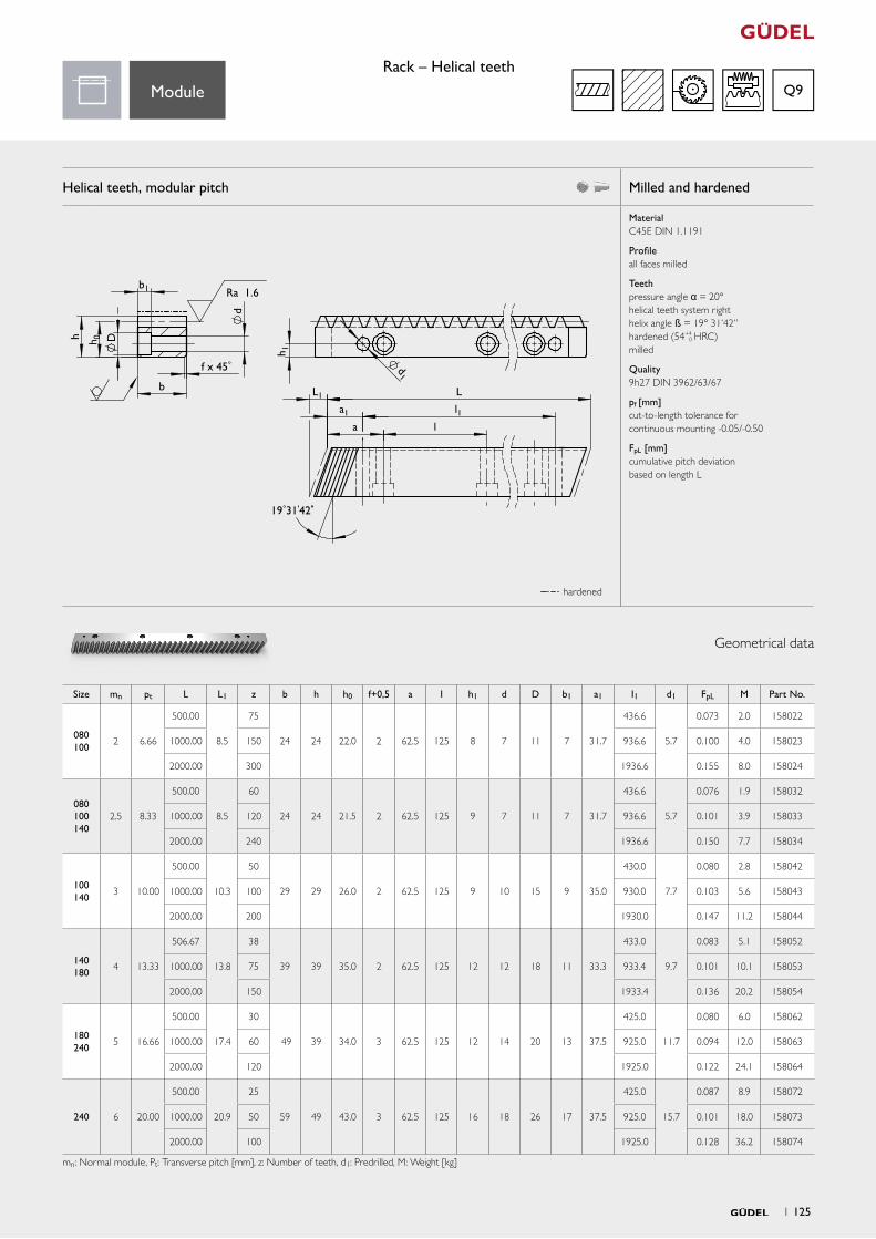
Helical teeth, modular pitch Milled and hardened
Material C45E DIN 1.1191
Profile all faces milled
Teeth pressure angle α = 20° helical teeth system right helix angle ß = 19° 31’42’’ hardened (54+4
0 HRC) milled
Quality 9h27 DIN 3962/63/67
pf [mm] cut-to-length tolerance for continuous mounting -0.05/-0.50
FpL [mm] cumulative pitch deviation based on length L
h h 0
f x 45°
b1
D
d
h 0
b1
Seite 3.26
Zahsta-helical02_cat
Ra 1.6
D
d
h 1
d1
l
l1
h 1
d1
l1l
Ra 0.8
b
f x 45°
h
L
a1
L1
a
19°31'42"
19°31'42"
a
a1
LL1b
Geometrical data
hardened
Size mn pt L L1 z b h h0 f+0,5 a I h1 d D b1 a1 I1 d1 FpL M Part No.
080 100
2 6.66
500.00
8.5
75
24 24 22.0 2 62.5 125 8 7 11 7 31.7
436.6
5.7
0.073 2.0 158022
1000.00 150 936.6 0.100 4.0 158023
2000.00 300 1936.6 0.155 8.0 158024
080 100 140
2.5 8.33
500.00
8.5
60
24 24 21.5 2 62.5 125 9 7 11 7 31.7
436.6
5.7
0.076 1.9 158032
1000.00 120 936.6 0.101 3.9 158033
2000.00 240 1936.6 0.150 7.7 158034
100 140
3 10.00
500.00
10.3
50
29 29 26.0 2 62.5 125 9 10 15 9 35.0
430.0
7.7
0.080 2.8 158042
1000.00 100 930.0 0.103 5.6 158043
2000.00 200 1930.0 0.147 11.2 158044
140 180
4 13.33
506.67
13.8
38
39 39 35.0 2 62.5 125 12 12 18 11 33.3
433.0
9.7
0.083 5.1 158052
1000.00 75 933.4 0.101 10.1 158053
2000.00 150 1933.4 0.136 20.2 158054
180 240
5 16.66
500.00
17.4
30
49 39 34.0 3 62.5 125 12 14 20 13 37.5
425.0
11.7
0.080 6.0 158062
1000.00 60 925.0 0.094 12.0 158063
2000.00 120 1925.0 0.122 24.1 158064
240 6 20.00
500.00
20.9
25
59 49 43.0 3 62.5 125 16 18 26 17 37.5
425.0
15.7
0.087 8.9 158072
1000.00 50 925.0 0.101 18.0 158073
2000.00 100 1925.0 0.128 36.2 158074
mn: Normal module, Pt: Transverse pitch [mm], z: Number of teeth, d1: Predrilled, M: Weight [kg]
Q9ModuleRack – Helical teeth
1 125


Technical information
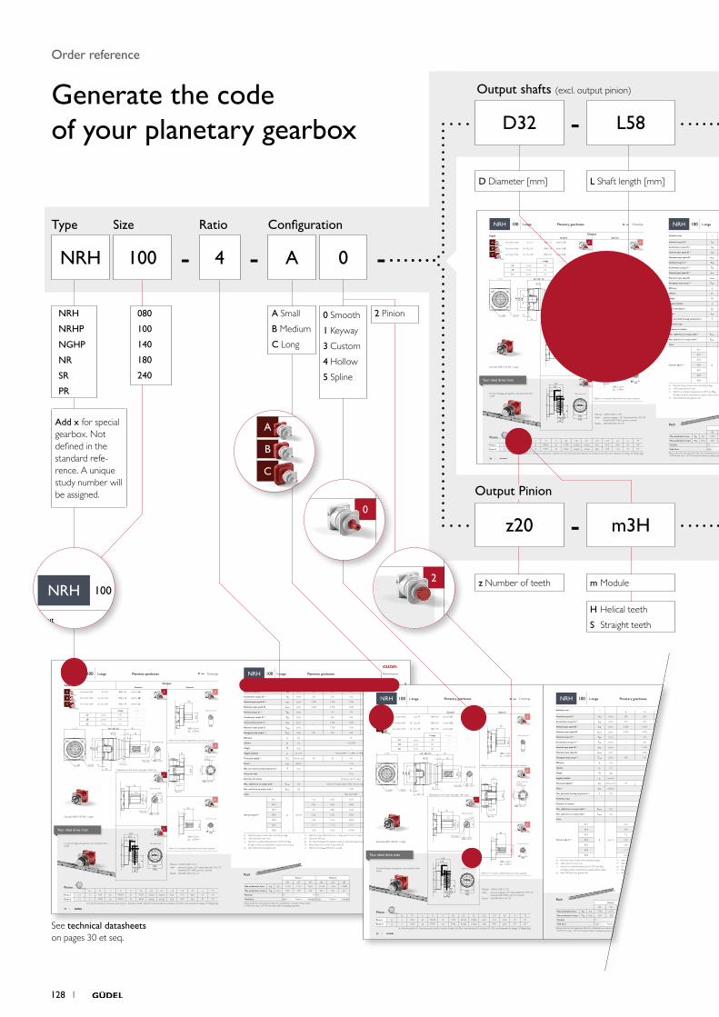
-Output Pinion
Input OutputStandard Optional
A for motor shaft L ≤ 54 Ød ≤ 24 result in LA 0 3
B for motor shaft 54 < L ≤ 65 Ød ≤ 38 result in LB
C for motor shaft 65 < L ≤ 80 Ød ≤ 38 result in LC
4
1 4
5
aa
2
ØDv
L12
L13
x2
b
B
a
A
ØDk
2 58
50
Ø50 35
Ø90
j6
M12×20ØD=32 k6
10js5
Ø50
ØD
2
LG
ØD ≤ 32mmLG ≤ 58mm
Ø50
ØD=32 H7
LG=50
10 JS9
27
2
14
35.3
0Ø
38
ØD
LG
2
ØD ≤ 32mmLG ≤ 58mm
115
Ø120
B*
t*
L*
10
LA / LB / LC 85
27
2
58
Ø1204 ×Ø9
Ød*
ØS*
Ø90
j6
ØD=32 k6M12×20
Ø50
Material 16MnCr5 DIN 1.7131
Teeth pressure angle α = 20°, helical teeth left, 19°31‘42“ hardened (58+4
0 HRC), ground, crowned
Quality 6f24 DIN 3962 / 63 / 67
Function Package with gearbox, rack and pinion from Güdel
Planetary gearboxes Performance Drawings Planetary gearboxes
* depending on the motor. See pages 148 et seq.
Rack
Option 5 on request. Adjustments can reduce capacity.
Option 3 on request. Adjustments can reduce capacity.
More on the technical datasheets your ideal drive train on pages 138 et seq.
For proper sizing follow flowchart calculate your ideal drive train on pages 154 et seq.Pinion
Pinion 1 Pinion 2
Q6 Q7 Q9 Q6 Q7 Q9
Max acceleration force F2B [ N ] 7 540 4 107 4 805 16 163 7 565 12 980
Max acceleration torque T2B [ Nm ] 200 109 127 515 241 413
Precision P1 P5 P1 P5
Feed force High Medium Elevated High Medium Elevated
Above values for rack and pinion take into consideration a number of load cycles:1x10⁶ for the rack; 1x10⁷ for the pinion. Both in pulsating operation.
NR
H10
01-
stag
e
NRH 100 1-stageNRH 100 1-stage
Available ratios i1-stage
3 4 5 7 10
Nominal torque S5 a) T2N [ Nm ] 200 260 270 250 150
Acceleration torque S5 b) T2B [ Nm ] 320 350 350 330 265
Nominal input speed S5 c) n1N [rpm] 2 500 2 500 2 500 2 800 2 800
Maximum input speed S5 n1max [rpm] 4 000 4 500 4 500 4 500 4 500
Nominal torque S1 a) T2N [Nm ] – 175 175 175 115
Acceleration torque S1 b) T2B [ Nm] – 250 250 250 190
Nominal input speed S1 c) n1N [rpm] – 2 200 2 200 2 500 2 500
Maximum input speed S1 n1max [rpm] – 2 500 2 500 2 800 2 800
Emergency stop torque d) T2not [ Nm ] 500 630 630 630 630
Efficiency h [ % ] 97
Lifetime Lh [ h ] > 20 000
Weight M [ kg ] 7
Angular backlash jt [ arcmin ] Precision P 1 ≤ 1 / P 3 ≤ 3 / P 5 ≤ 5
Torsionnal rigidity e) Ct2 [ Nm/arcmin ] 34 42 44 44 37
Noise i) L pA [ dB(A) ] < 62
Max. permitted housing temperature g) T [ °C ] 90
Protection class IP 65
Direction of rotation Same way input / output
Max. radial force on output shaft f) Frmax [ N ] Center of output shaft: 6 600 / End of output shaft: 4 300
Max. axial force on output shaft f) Famax [ N ] 5 700
Color Red, RAL 3003
Inertia in kg.cm² h)
Ø11
J1 [ kgcm2 ]
4.56 3.061 2.504 2.047 1.806
Ø14 4.54 3.041 2.484 2.027 1.786
Ø19 5.3 3.801 3.244 2.787 2.546
Ø24 5.62 4.121 3.564 3.107 2.866
Ø32 6.66 5.161 4.604 4.147 3.906
Ø35 12.79 11.291 10.734 10.277 10.036
Ø38 12.76 11.261 10.704 10.247 10.006
a) Nominal output torque when operating at n1N.
b) 1000 cycles per hour max.
c) Valid for an ambient temperature of 20°C and T2N.
At higher ambient temperatures, please reduce speed.
d) Valid 1000 times the gearbox life.
e) Valid for an Input Ø of 24 mm in 1-stage and 19 mm in 2-stage.
f) Values for 300 rpm.
g) For other temperatures, please contact us. Nominal output torque when operating at n1N.
h) Depending on the motor output shaft Ø.
i) With i=10 and n1N=3000 rpm no load.
1-stage 2-stage
LA [ mm ] 130 181
LB [ mm ] 141 192
LC [ mm ] 161 212
Detail output shaft
Detail output shaft
Detail output shaft
Detail output shaftExample NRH 100 A0, 1-stage
mn Pt z A b Dk D0 Dv L12 L13 x2 a M
Pinion 1 [-] 2 6.66 25 48.526 25 57.05 53.052 53.052 63.3 51.0 24.0 27 0.4
Pinion 2 [-] 3 10.00 20 57.831 30 69.66 63.662 63.662 69.0 54.0 27.0 27 0.7
mn: Normal module, Pt: Transverse pitch [mm], z : Number of teeth, D0: Pitch circle diameter for calculation, Dv: Pitch circle diameter for design, M: Weight [kg]
Detail output shaft
Detail output shaft
1 3534 1
Your ideal drive train
See technical datasheets on pages 30 et seq.
Ratio Configuration
Output shafts (excl. output pinion)
Type Size
Order reference
Generate the code of your planetary gearbox
128 1
4 A 0NRH 100 - -
-
-
Add x for special gearbox. Not defined in the standard refe-rence. A unique study number will be assigned.
NRH
NRHP
NGHP
NR
SR
PR
080
100
140
180
240
z Number of teeth
Input OutputStandard Optional
A for motor shaft L ≤ 54 Ød ≤ 24 result in LA 0 3
B for motor shaft 54 < L ≤ 65 Ød ≤ 38 result in LB
C for motor shaft 65 < L ≤ 80 Ød ≤ 38 result in LC
4
1 4
5
aa
2
ØDv
L12
L13
x2
b
B
a
A
ØDk
2 58
50
Ø50 35
Ø90
j6
M12×20ØD=32 k6
10js5
Ø50
ØD
2
LG
ØD ≤ 32mmLG ≤ 58mm
Ø50
ØD=32 H7
LG=50
10 JS9
27
2
14
35.3
0Ø
38
ØD
LG
2
ØD ≤ 32mmLG ≤ 58mm
115
Ø120
B*
t*
L*
10
LA / LB / LC 85
27
2
58
Ø1204 ×Ø9
Ød*
ØS*
Ø90
j6
ØD=32 k6M12×20
Ø50
Material 16MnCr5 DIN 1.7131
Teeth pressure angle α = 20°, helical teeth left, 19°31‘42“ hardened (58+4
0 HRC), ground, crowned
Quality 6f24 DIN 3962 / 63 / 67
Function Package with gearbox, rack and pinion from Güdel
Planetary gearboxes Performance Drawings Planetary gearboxes
* depending on the motor. See pages 148 et seq.
Rack
Option 5 on request. Adjustments can reduce capacity.
Option 3 on request. Adjustments can reduce capacity.
More on the technical datasheets your ideal drive train on pages 138 et seq.
For proper sizing follow flowchart calculate your ideal drive train on pages 154 et seq.Pinion
Pinion 1 Pinion 2
Q6 Q7 Q9 Q6 Q7 Q9
Max acceleration force F2B [ N ] 7 540 4 107 4 805 16 163 7 565 12 980
Max acceleration torque T2B [ Nm ] 200 109 127 515 241 413
Precision P1 P5 P1 P5
Feed force High Medium Elevated High Medium Elevated
Above values for rack and pinion take into consideration a number of load cycles:1x10⁶ for the rack; 1x10⁷ for the pinion. Both in pulsating operation.
NR
H10
01-
stag
e
NRH 100 1-stageNRH 100 1-stage
Available ratios i1-stage
3 4 5 7 10
Nominal torque S5 a) T2N [ Nm ] 200 260 270 250 150
Acceleration torque S5 b) T2B [ Nm ] 320 350 350 330 265
Nominal input speed S5 c) n1N [rpm] 2 500 2 500 2 500 2 800 2 800
Maximum input speed S5 n1max [rpm] 4 000 4 500 4 500 4 500 4 500
Nominal torque S1 a) T2N [Nm ] – 175 175 175 115
Acceleration torque S1 b) T2B [ Nm] – 250 250 250 190
Nominal input speed S1 c) n1N [rpm] – 2 200 2 200 2 500 2 500
Maximum input speed S1 n1max [rpm] – 2 500 2 500 2 800 2 800
Emergency stop torque d) T2not [ Nm ] 500 630 630 630 630
Efficiency h [ % ] 97
Lifetime Lh [ h ] > 20 000
Weight M [ kg ] 7
Angular backlash jt [ arcmin ] Precision P 1 ≤ 1 / P 3 ≤ 3 / P 5 ≤ 5
Torsionnal rigidity e) Ct2 [ Nm/arcmin ] 34 42 44 44 37
Noise i) L pA [ dB(A) ] < 62
Max. permitted housing temperature g) T [ °C ] 90
Protection class IP 65
Direction of rotation Same way input / output
Max. radial force on output shaft f) Frmax [ N ] Center of output shaft: 6 600 / End of output shaft: 4 300
Max. axial force on output shaft f) Famax [ N ] 5 700
Color Red, RAL 3003
Inertia in kg.cm² h)
Ø11
J1 [ kgcm2 ]
4.56 3.061 2.504 2.047 1.806
Ø14 4.54 3.041 2.484 2.027 1.786
Ø19 5.3 3.801 3.244 2.787 2.546
Ø24 5.62 4.121 3.564 3.107 2.866
Ø32 6.66 5.161 4.604 4.147 3.906
Ø35 12.79 11.291 10.734 10.277 10.036
Ø38 12.76 11.261 10.704 10.247 10.006
a) Nominal output torque when operating at n1N.
b) 1000 cycles per hour max.
c) Valid for an ambient temperature of 20°C and T2N.
At higher ambient temperatures, please reduce speed.
d) Valid 1000 times the gearbox life.
e) Valid for an Input Ø of 24 mm in 1-stage and 19 mm in 2-stage.
f) Values for 300 rpm.
g) For other temperatures, please contact us. Nominal output torque when operating at n1N.
h) Depending on the motor output shaft Ø.
i) With i=10 and n1N=3000 rpm no load.
1-stage 2-stage
LA [ mm ] 130 181
LB [ mm ] 141 192
LC [ mm ] 161 212
Detail output shaft
Detail output shaft
Detail output shaft
Detail output shaftExample NRH 100 A0, 1-stage
mn Pt z A b Dk D0 Dv L12 L13 x2 a M
Pinion 1 [-] 2 6.66 25 48.526 25 57.05 53.052 53.052 63.3 51.0 24.0 27 0.4
Pinion 2 [-] 3 10.00 20 57.831 30 69.66 63.662 63.662 69.0 54.0 27.0 27 0.7
mn: Normal module, Pt: Transverse pitch [mm], z : Number of teeth, D0: Pitch circle diameter for calculation, Dv: Pitch circle diameter for design, M: Weight [kg]
Detail output shaft
Detail output shaft
1 3534 1
Your ideal drive train
L Shaft length [mm]D Diameter [mm]
H Helical teeth
S Straight teeth
m Module
m3H
Input OutputStandard Optional
A for motor shaft L ≤ 54 Ød ≤ 24 result in LA 0 3
B for motor shaft 54 < L ≤ 65 Ød ≤ 38 result in LB
C for motor shaft 65 < L ≤ 80 Ød ≤ 38 result in LC
4
1 4
5
aa
2
ØDv
L12
L13
x2
b
B
a
A
ØDk
2 58
50
Ø50 35
Ø90
j6
M12×20ØD=32 k6
10js5
Ø50
ØD
2
LG
ØD ≤ 32mmLG ≤ 58mm
Ø50
ØD=32 H7
LG=50
10 JS9
27
2
14
35.3
0Ø
38
ØD
LG
2
ØD ≤ 32mmLG ≤ 58mm
115
Ø120
B*
t*
L*
10
LA / LB / LC 85
27
2
58
Ø1204 ×Ø9
Ød*
ØS*
Ø90
j6
ØD=32 k6M12×20
Ø50
Material 16MnCr5 DIN 1.7131
Teeth pressure angle α = 20°, helical teeth left, 19°31‘42“ hardened (58+4
0 HRC), ground, crowned
Quality 6f24 DIN 3962 / 63 / 67
Function Package with gearbox, rack and pinion from Güdel
Planetary gearboxes Performance Drawings Planetary gearboxes
* depending on the motor. See pages 148 et seq.
Rack
Option 5 on request. Adjustments can reduce capacity.
Option 3 on request. Adjustments can reduce capacity.
More on the technical datasheets your ideal drive train on pages 138 et seq.
For proper sizing follow flowchart calculate your ideal drive train on pages 154 et seq.Pinion
Pinion 1 Pinion 2
Q6 Q7 Q9 Q6 Q7 Q9
Max acceleration force F2B [ N ] 7 540 4 107 4 805 16 163 7 565 12 980
Max acceleration torque T2B [ Nm ] 200 109 127 515 241 413
Precision P1 P5 P1 P5
Feed force High Medium Elevated High Medium Elevated
Above values for rack and pinion take into consideration a number of load cycles:1x10⁶ for the rack; 1x10⁷ for the pinion. Both in pulsating operation.
NR
H10
01-
stag
e
NRH 100 1-stageNRH 100 1-stage
Available ratios i1-stage
3 4 5 7 10
Nominal torque S5 a) T2N [ Nm ] 200 260 270 250 150
Acceleration torque S5 b) T2B [ Nm ] 320 350 350 330 265
Nominal input speed S5 c) n1N [rpm] 2 500 2 500 2 500 2 800 2 800
Maximum input speed S5 n1max [rpm] 4 000 4 500 4 500 4 500 4 500
Nominal torque S1 a) T2N [Nm ] – 175 175 175 115
Acceleration torque S1 b) T2B [ Nm] – 250 250 250 190
Nominal input speed S1 c) n1N [rpm] – 2 200 2 200 2 500 2 500
Maximum input speed S1 n1max [rpm] – 2 500 2 500 2 800 2 800
Emergency stop torque d) T2not [ Nm ] 500 630 630 630 630
Efficiency h [ % ] 97
Lifetime Lh [ h ] > 20 000
Weight M [ kg ] 7
Angular backlash jt [ arcmin ] Precision P 1 ≤ 1 / P 3 ≤ 3 / P 5 ≤ 5
Torsionnal rigidity e) Ct2 [ Nm/arcmin ] 34 42 44 44 37
Noise i) L pA [ dB(A) ] < 62
Max. permitted housing temperature g) T [ °C ] 90
Protection class IP 65
Direction of rotation Same way input / output
Max. radial force on output shaft f) Frmax [ N ] Center of output shaft: 6 600 / End of output shaft: 4 300
Max. axial force on output shaft f) Famax [ N ] 5 700
Color Red, RAL 3003
Inertia in kg.cm² h)
Ø11
J1 [ kgcm2 ]
4.56 3.061 2.504 2.047 1.806
Ø14 4.54 3.041 2.484 2.027 1.786
Ø19 5.3 3.801 3.244 2.787 2.546
Ø24 5.62 4.121 3.564 3.107 2.866
Ø32 6.66 5.161 4.604 4.147 3.906
Ø35 12.79 11.291 10.734 10.277 10.036
Ø38 12.76 11.261 10.704 10.247 10.006
a) Nominal output torque when operating at n1N.
b) 1000 cycles per hour max.
c) Valid for an ambient temperature of 20°C and T2N.
At higher ambient temperatures, please reduce speed.
d) Valid 1000 times the gearbox life.
e) Valid for an Input Ø of 24 mm in 1-stage and 19 mm in 2-stage.
f) Values for 300 rpm.
g) For other temperatures, please contact us. Nominal output torque when operating at n1N.
h) Depending on the motor output shaft Ø.
i) With i=10 and n1N=3000 rpm no load.
1-stage 2-stage
LA [ mm ] 130 181
LB [ mm ] 141 192
LC [ mm ] 161 212
Detail output shaft
Detail output shaft
Detail output shaft
Detail output shaftExample NRH 100 A0, 1-stage
mn Pt z A b Dk D0 Dv L12 L13 x2 a M
Pinion 1 [-] 2 6.66 25 48.526 25 57.05 53.052 53.052 63.3 51.0 24.0 27 0.4
Pinion 2 [-] 3 10.00 20 57.831 30 69.66 63.662 63.662 69.0 54.0 27.0 27 0.7
mn: Normal module, Pt: Transverse pitch [mm], z : Number of teeth, D0: Pitch circle diameter for calculation, Dv: Pitch circle diameter for design, M: Weight [kg]
Detail output shaft
Detail output shaft
1 3534 1
Your ideal drive train
0 Smooth
1 Keyway
3 Custom
4 Hollow
5 Spline
A Small
B Medium
C Long
L58D32
z20
Input OutputStandard Optional
A for motor shaft L ≤ 54 Ød ≤ 24 result in LA 0 3
B for motor shaft 54 < L ≤ 65 Ød ≤ 38 result in LB
C for motor shaft 65 < L ≤ 80 Ød ≤ 38 result in LC
4
1 4
5
aa
2
ØDv
L12
L13
x2
b
B
a
A
ØDk
2 58
50
Ø50 35
Ø90
j6
M12×20ØD=32 k6
10js5
Ø50
ØD
2
LG
ØD ≤ 32mmLG ≤ 58mm
Ø50
ØD=32 H7
LG=50
10 JS9
27
2
14
35.3
0Ø
38
ØD
LG
2
ØD ≤ 32mmLG ≤ 58mm
115
Ø120
B*
t*
L*
10
LA / LB / LC 85
27
2
58
Ø1204 ×Ø9
Ød*
ØS*
Ø90
j6
ØD=32 k6M12×20
Ø50
Material 16MnCr5 DIN 1.7131
Teeth pressure angle α = 20°, helical teeth left, 19°31‘42“ hardened (58+4
0 HRC), ground, crowned
Quality 6f24 DIN 3962 / 63 / 67
Function Package with gearbox, rack and pinion from Güdel
Planetary gearboxes Performance Drawings Planetary gearboxes
* depending on the motor. See pages 148 et seq.
Rack
Option 5 on request. Adjustments can reduce capacity.
Option 3 on request. Adjustments can reduce capacity.
More on the technical datasheets your ideal drive train on pages 138 et seq.
For proper sizing follow flowchart calculate your ideal drive train on pages 154 et seq.Pinion
Pinion 1 Pinion 2
Q6 Q7 Q9 Q6 Q7 Q9
Max acceleration force F2B [ N ] 7 540 4 107 4 805 16 163 7 565 12 980
Max acceleration torque T2B [ Nm ] 200 109 127 515 241 413
Precision P1 P5 P1 P5
Feed force High Medium Elevated High Medium Elevated
Above values for rack and pinion take into consideration a number of load cycles:1x10⁶ for the rack; 1x10⁷ for the pinion. Both in pulsating operation.
NR
H10
01-
stag
e
NRH 100 1-stageNRH 100 1-stage
Available ratios i1-stage
3 4 5 7 10
Nominal torque S5 a) T2N [ Nm ] 200 260 270 250 150
Acceleration torque S5 b) T2B [ Nm ] 320 350 350 330 265
Nominal input speed S5 c) n1N [rpm] 2 500 2 500 2 500 2 800 2 800
Maximum input speed S5 n1max [rpm] 4 000 4 500 4 500 4 500 4 500
Nominal torque S1 a) T2N [Nm ] – 175 175 175 115
Acceleration torque S1 b) T2B [ Nm] – 250 250 250 190
Nominal input speed S1 c) n1N [rpm] – 2 200 2 200 2 500 2 500
Maximum input speed S1 n1max [rpm] – 2 500 2 500 2 800 2 800
Emergency stop torque d) T2not [ Nm ] 500 630 630 630 630
Efficiency h [ % ] 97
Lifetime Lh [ h ] > 20 000
Weight M [ kg ] 7
Angular backlash jt [ arcmin ] Precision P 1 ≤ 1 / P 3 ≤ 3 / P 5 ≤ 5
Torsionnal rigidity e) Ct2 [ Nm/arcmin ] 34 42 44 44 37
Noise i) L pA [ dB(A) ] < 62
Max. permitted housing temperature g) T [ °C ] 90
Protection class IP 65
Direction of rotation Same way input / output
Max. radial force on output shaft f) Frmax [ N ] Center of output shaft: 6 600 / End of output shaft: 4 300
Max. axial force on output shaft f) Famax [ N ] 5 700
Color Red, RAL 3003
Inertia in kg.cm² h)
Ø11
J1 [ kgcm2 ]
4.56 3.061 2.504 2.047 1.806
Ø14 4.54 3.041 2.484 2.027 1.786
Ø19 5.3 3.801 3.244 2.787 2.546
Ø24 5.62 4.121 3.564 3.107 2.866
Ø32 6.66 5.161 4.604 4.147 3.906
Ø35 12.79 11.291 10.734 10.277 10.036
Ø38 12.76 11.261 10.704 10.247 10.006
a) Nominal output torque when operating at n1N.
b) 1000 cycles per hour max.
c) Valid for an ambient temperature of 20°C and T2N.
At higher ambient temperatures, please reduce speed.
d) Valid 1000 times the gearbox life.
e) Valid for an Input Ø of 24 mm in 1-stage and 19 mm in 2-stage.
f) Values for 300 rpm.
g) For other temperatures, please contact us. Nominal output torque when operating at n1N.
h) Depending on the motor output shaft Ø.
i) With i=10 and n1N=3000 rpm no load.
1-stage 2-stage
LA [ mm ] 130 181
LB [ mm ] 141 192
LC [ mm ] 161 212
Detail output shaft
Detail output shaft
Detail output shaft
Detail output shaftExample NRH 100 A0, 1-stage
mn Pt z A b Dk D0 Dv L12 L13 x2 a M
Pinion 1 [-] 2 6.66 25 48.526 25 57.05 53.052 53.052 63.3 51.0 24.0 27 0.4
Pinion 2 [-] 3 10.00 20 57.831 30 69.66 63.662 63.662 69.0 54.0 27.0 27 0.7
mn: Normal module, Pt: Transverse pitch [mm], z : Number of teeth, D0: Pitch circle diameter for calculation, Dv: Pitch circle diameter for design, M: Weight [kg]
Detail output shaft
Detail output shaft
1 3534 1
Your ideal drive train
2 Pinion
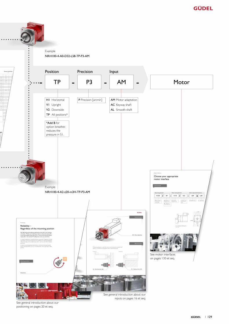
Positioning
Reliability – Regardless of the mounting positionOur high-performance planetary gearboxes can be used in any mounting orientation. Whether your application requires a horizontal output (H1), vertical with upright facing output (V1), or vertical with downward-facing output (V2) – the universal TP configuration covers any orientation.
For specific applications, including continuous operation S1 together with high input speed, we recommend the use of an additional air-vent plug (breather). This air-vent plug can be installed at any time – even as a retrofit on installed gearboxes.
In order to optimize gearbox performance, we recommend specifying the actual mounting position V1, V2 or H1, especially for ratios requiring a 3-stage gearbox.
V1
V2
H1Mounting positions
TP
Vertical upright position
Vertical downside position
All positions
Horizontal position
20 1 1 21
C
A
B
skallieren 86.603neigen -170°
AM – Motor adaptability
Inputs
Great adaptability – Standard & optional inputsDue to our modular system, all common servo motors can be easily mounted on our planetary gearboxes. Optional inputs such as primary shaft can be provided on request.
We have a standard flange solution for the most commonly used servo motors. Depending on the range of the gearbox, we offer a total of three standard input versions. Your selection of an input will depend on the geometric dimensions of the motor.
AL – Smooth primary shaft
Example AL Example AC
For special applications, in which the motor cannot be directly mounted on the gearbox, it is possible to fit the gearbox with an optional input shaft.Small motor
Medium motor
Long motorAC – Keyway primary shaft
Standard inputs
Optional inputs
Standard inputs
16 1 1 17
Input OutputStandard Optional
A for motor shaft L ≤ 54 Ød ≤ 24 result in LA 0 3
B for motor shaft 54 < L ≤ 65 Ød ≤ 38 result in LB
C for motor shaft 65 < L ≤ 80 Ød ≤ 38 result in LC
4
1 4
5
aa
2
ØDv
L12
L13
x2
b
B
a
A
ØDk
2 58
50
Ø50 35
Ø90
j6
M12×20ØD=32 k6
10js5
Ø50
ØD
2
LG
ØD ≤ 32mmLG ≤ 58mm
Ø50
ØD=32 H7
LG=50
10 JS9
27
2
14
35.3
0Ø
38
ØD
LG
2
ØD ≤ 32mmLG ≤ 58mm
115
Ø120
B*
t*
L*
10
LA / LB / LC 85
27
2
58
Ø1204 ×Ø9
Ød*
ØS*
Ø90
j6
ØD=32 k6M12×20
Ø50
Material 16MnCr5 DIN 1.7131
Teeth pressure angle α = 20°, helical teeth left, 19°31‘42“ hardened (58+4
0 HRC), ground, crowned
Quality 6f24 DIN 3962 / 63 / 67
Function Package with gearbox, rack and pinion from Güdel
Planetary gearboxes Performance Drawings Planetary gearboxes
* depending on the motor. See pages 148 et seq.
Rack
Option 5 on request. Adjustments can reduce capacity.
Option 3 on request. Adjustments can reduce capacity.
More on the technical datasheets your ideal drive train on pages 138 et seq.
For proper sizing follow flowchart calculate your ideal drive train on pages 154 et seq.Pinion
Pinion 1 Pinion 2
Q6 Q7 Q9 Q6 Q7 Q9
Max acceleration force F2B [ N ] 7 540 4 107 4 805 16 163 7 565 12 980
Max acceleration torque T2B [ Nm ] 200 109 127 515 241 413
Precision P1 P5 P1 P5
Feed force High Medium Elevated High Medium Elevated
Above values for rack and pinion take into consideration a number of load cycles:1x10⁶ for the rack; 1x10⁷ for the pinion. Both in pulsating operation.
NR
H10
01-
stag
e
NRH 100 1-stageNRH 100 1-stage
Available ratios i1-stage
3 4 5 7 10
Nominal torque S5 a) T2N [ Nm ] 200 260 270 250 150
Acceleration torque S5 b) T2B [ Nm ] 320 350 350 330 265
Nominal input speed S5 c) n1N [rpm] 2 500 2 500 2 500 2 800 2 800
Maximum input speed S5 n1max [rpm] 4 000 4 500 4 500 4 500 4 500
Nominal torque S1 a) T2N [Nm ] – 175 175 175 115
Acceleration torque S1 b) T2B [ Nm] – 250 250 250 190
Nominal input speed S1 c) n1N [rpm] – 2 200 2 200 2 500 2 500
Maximum input speed S1 n1max [rpm] – 2 500 2 500 2 800 2 800
Emergency stop torque d) T2not [ Nm ] 500 630 630 630 630
Efficiency h [ % ] 97
Lifetime Lh [ h ] > 20 000
Weight M [ kg ] 7
Angular backlash jt [ arcmin ] Precision P 1 ≤ 1 / P 3 ≤ 3 / P 5 ≤ 5
Torsionnal rigidity e) Ct2 [ Nm/arcmin ] 34 42 44 44 37
Noise i) L pA [ dB(A) ] < 62
Max. permitted housing temperature g) T [ °C ] 90
Protection class IP 65
Direction of rotation Same way input / output
Max. radial force on output shaft f) Frmax [ N ] Center of output shaft: 6 600 / End of output shaft: 4 300
Max. axial force on output shaft f) Famax [ N ] 5 700
Color Red, RAL 3003
Inertia in kg.cm² h)
Ø11
J1 [ kgcm2 ]
4.56 3.061 2.504 2.047 1.806
Ø14 4.54 3.041 2.484 2.027 1.786
Ø19 5.3 3.801 3.244 2.787 2.546
Ø24 5.62 4.121 3.564 3.107 2.866
Ø32 6.66 5.161 4.604 4.147 3.906
Ø35 12.79 11.291 10.734 10.277 10.036
Ø38 12.76 11.261 10.704 10.247 10.006
a) Nominal output torque when operating at n1N.
b) 1000 cycles per hour max.
c) Valid for an ambient temperature of 20°C and T2N.
At higher ambient temperatures, please reduce speed.
d) Valid 1000 times the gearbox life.
e) Valid for an Input Ø of 24 mm in 1-stage and 19 mm in 2-stage.
f) Values for 300 rpm.
g) For other temperatures, please contact us. Nominal output torque when operating at n1N.
h) Depending on the motor output shaft Ø.
i) With i=10 and n1N=3000 rpm no load.
1-stage 2-stage
LA [ mm ] 130 181
LB [ mm ] 141 192
LC [ mm ] 161 212
Detail output shaft
Detail output shaft
Detail output shaft
Detail output shaftExample NRH 100 A0, 1-stage
mn Pt z A b Dk D0 Dv L12 L13 x2 a M
Pinion 1 [-] 2 6.66 25 48.526 25 57.05 53.052 53.052 63.3 51.0 24.0 27 0.4
Pinion 2 [-] 3 10.00 20 57.831 30 69.66 63.662 63.662 69.0 54.0 27.0 27 0.7
mn: Normal module, Pt: Transverse pitch [mm], z : Number of teeth, D0: Pitch circle diameter for calculation, Dv: Pitch circle diameter for design, M: Weight [kg]
Detail output shaft
Detail output shaft
1 3534 1
Your ideal drive train
S
4 x Ød/M
R
d
F / ØD
Lt
ts*
* ts > t precise motor reference, and in this case change t by ts in the reference of motor flange.
Motor NRH / NRHP NR / SR / PR CodeR Ød /M S t dxL 080 100 140 1T 140 2T 080 100 140 180 240
63 d 4.5 40 2.5 9 x 20 A A A A A R63 / d4.5-S40 / t2.5-d9 x 20
63 d 5.5 40 2.5 9 x 25 A A A A A R63 / d5.5-S40 / t2.5-d9 x 25
64 d 5.4 40 2 9 x 20 A A A A A R64 / d5.4-S40 / t2-d9 x 20
70 d 4.5 40 2.5 9 x 20 A A A A A R70 / d4.5-S40 / t2.5-d9 x 20
70 d 4.5 50 3 11 x 30 A A A A A A A R70 / d4.5-S50 / t3-d11 x 30
70 d 5.5 50 3 14 x 30 A A A A A A R70 / d5.5-S50 / t3-d14 x 30
75 d 5.5 60 2.5 11 x 23 A A A A A A A R75 / d5.5-S60 / t2.5-d11 x 23
75 d 5.5 60 2.5 14 x 30 A A A A A A A R75 / d5.5-S60 / t2.5-d14 x 30
75 d 5.5 60 3 14 x 30 A A A A A A A R75 / d5.5-S60 / t3-d14 x 30
75 d 5.8 60 2.5 11 x 23 A A A A A A R75 / d5.8-S60 / t2.5-d11 x 23
75 d 6.5 60 3 14 x 30 A A A A A A A A R75 / d6.5-S60 / t3-d14 x 30
90 d 6 70 3 19 x 35 A A A A A A A A R90 / d6-S70 / t3-d19 x 35
90 d 7 70 3 14 x 30 A A A A A A A A R90 / d7-S70 / t3-d14 x 30
90 d 7 70 3 16 x 40 A A A A A A A A R90 / d7-S70 / t3-d16 x 40
72 / 75 6.5 60 3 14 x 30 A A A A A A R72-75(Slot) / d6.5-S60 / t3-d14 x 30
95 d 6.6 50 2.5 14 x 30 A A A A A A A R95 / d6.6-S50 / t2.5-d14 x 30
100 d 7 80 3 14 x 30 A A A A A A A A R100 / d7-S80 / t3-d14 x 30
100 d 7 80 3 19 x 40 A A A A A A A A R100 / d7-S80 / t3-d19 x 40
100 d 6.5 80 2.5 14 x 30 A A A A A A A R100 / d6.5-S80 / t2.5-d14 x 30
100 d 6.5 80 3 19 x 40 A A A A A A A A R100 / d6.5-S80 / t3-d19 x 40
100 d 6.6 80 4 10 x 32 A A A A A A R100 / d6.6-S80 / t4-d10 x 32
100 d 6.6 80 5 14 x 37 A A A A A A A R100 / d6.6-S80 / t5-d14 x 37
100 d 6.6 80 5 16 x 40 A A A A A A A A R100 / d6.6-S80 / t5-d16 x 40
115 d 9 95 3 19 x 40 A A A A A A A A R115 / d9-S95 / t3-d19 x 40
115 d 7 95 3 24 x 45 A A A A A A A A A R115 / d7-S95 / t3-d24 x 45
115 d 11 95 3 19 x 40 A A A A A A A A R115 / d11-S95 / t3-d19 x 40
130 d 9 95 3 19 x 40 B A A A A A A A R130 / d9-S95 / t3-d19 x 40
130 d 9 95 3 24 x 50 B A A A B A A A A R130 / d9-S95 / t3-d24 x 50
130 d 9 110 3 24 x 50 B A A A B A A A A R130 / d9-S110 / t3-d24 x 50
130 d 9 110 3.5 24 x 50 B A A A B A A A A R130 / d9-S110 / t3.5-d24 x 50
130 d 11 110 3.5 19 x 40 B A A A A A A A R130 / d11-S110 / t3.5-d19 x 40
130 M8 110 3.5 24 x 50 B A A A B A A A A R130 / M8-S110 / t3.5-d24 x 50
130 M8 110 3.5 28 x 60 B A B B B A A R130 / M8-S110 / t3.5-d28 x 60
130 M8 110 3.5 38 x 80 C B C C B A R130 / M8-S110 / t3.5-d38 x 80
145 d 9 110 6 19 x 55 B B A B B B B A R145 / d9-S110 / t6-d19 x 55
145 d 9 110 6 28 x 63 B B B B B B A R145 / d9-S110 / t6-d28 x 63
145 d 10 110 3.5 16 x 40 B A A A A A A A R145 / d10-S110 / t3.5-d16 x 40
165 d 11 130 3 28 x 60 B A B B B A A R165 / d11-S130 / t3-d28 x 60
200 13.5 114.3 3.2 35 x 79 C B C C B A R200 / d13.5-S114.3 / t3.2-d35 x 79
200 13.5 114.3 3.2 42 x 113 B C B R200 / d13.5-S114.3 / t3.2-d42 x 113
165 d 11 130 3.5 19 x 28 B A A A B A A A R165 / d11-S130 / t3.5-d19 x 28
165 d 11 130 3.5 24 x 50 B A A A B A A A A R165 / d11-S130 / t3.5-d24 x 50
165 d 11 130 3.5 32 x 58 B A B B B A A R165 / d11-S130 / t3.5-d32 x 58
165 d 11 130 4 32 x 58 B A B B B A A R165 / d11-S130 / t4-d32 x 58
215 d 14 130 4 32 x 60 C B C B B A A R215 / d14-S130 / t4-d32 x 60
215 d 14 130 4 38 x 60 C B C B B A A R215 / d14-S130 / t4-d38 x 60
190 d 11 155 3 32 x 60 B B B B B A A R190 / d11-S155 / t3-d32 x 60
190 d 11 155 3 35 x 60 B B B B B A A R190 / d11-S155 / t3-d35 x 60
215 d 13.5 180 4 28 x 60 C B C B B A A R215 / d13.5-S180 / t4-d28 x 60
215 d 13.5 180 4 38 x 80 C B C C B A R215 / d13.5-S180 / t4-d38 x 80
215 d 14 180 4 28 x 42 C B C B A A A R215 / d14-S180 / t4-d28 x 42
215 d 14 180 4 28 x 60 C B C B B A A R215 / d14-S180 / t4-d28 x 60
215 d 14 180 4 32 x 58 C B C B B A A R215 / d14-S180 / t4-d32 x 58
215 d 14 180 4 32 x 60 C B C B B A A R215 / d14-S180 / t4-d32 x 60
215 d 14 180 4 32 x 80 C B C C B A R215 / d14-S180 / t4-d32 x 80
215 d 13.5 180 4 38 x 80 C B C C B A R215 / d13.5-S180 / t4-d38 x 80
265 d 13 230 4 38 x 80 B C B A R265 / d13-S230 / t4-d38 x 80
265 d 14 230 4 55 x 110 B R265 / d14-S230 / t4-d55 x 110
300 d 18 250 5 42 x 110 C B R300 / d18-S250 / t5-d42 x 110
300 d 18 250 5 48 x 82 B A R300 / d18-S250 / t5-d48 x 82
300 d 18 250 5 48 x 110 C B R300 / d18-S250 / t5-d48 x 110
300 d 19 250 5 48 x 110 C B R300 / d19-S250 / t5-d48 x 110
*
R130 d9 S110 t3.5 d24 L50/ - - x/
R Pitch diameter of fixing holes or threads [mm]
Ød Diameter of fixing holes [mm]
M Diameter of fixing threads [mm]
S Centering diameter [mm]
t Depth of cen-tering shoulder [mm]
d Diameter [mm] L Length [mm]
Motor fixing diameter Motor centring diameter Motor output shaft dimensions
/ - - x/
Order reference
Choose your appropriate motor interface
* On request
Code example
1 149148 1
See general introduction about our inputs on pages 16 et seq.
See general introduction about our positioning on pages 20 et seq.
See motor interfaces on pages 130 et seq.
Position Precision Input
Example
NRH100-4-A2-z20-m3H-TP-P3-AM
Example
NRH100-4-A0-D32-L58-TP-P3-AM
1 129
MotorTP P3 AM ----
P Precision [arcmin]H1 Horizontal
V1 Upright
V2 Downside
TP All positions*
*Add B for option breather. reduces the pressure in S1.
AM Motor adaptation
AC Keyway shaft
AL Smooth shaft
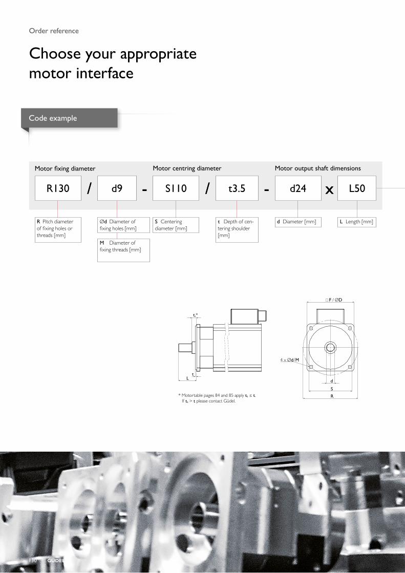
S
4 x Ød/M
R
d
F / ØD
Lt
ts*
* Motortable pages 84 and 85 apply tS ≤ t. If tS > t please contact Güdel.
R130 d9 S110 t3.5 d24 L50/ - - x/
R Pitch diameter of fixing holes or threads [mm]
Ød Diameter of fixing holes [mm]
M Diameter of fixing threads [mm]
S Centering diameter [mm]
t Depth of cen-tering shoulder [mm]
d Diameter [mm] L Length [mm]
Motor fixing diameter Motor centring diameter Motor output shaft dimensions
/ - - x/
Order reference
Choose your appropriate motor interface
Code example
130 1
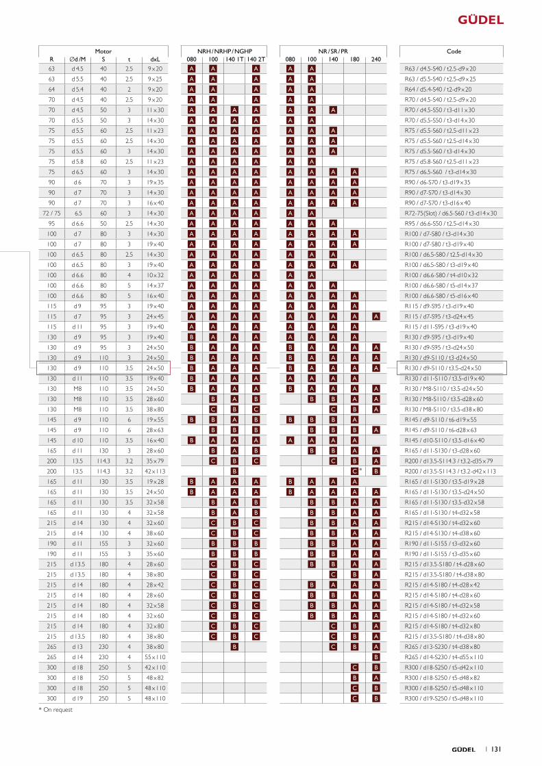
Motor NRH / NRHP / NGHP NR / SR / PR CodeR Ød /M S t dxL 080 100 140 1T 140 2T 080 100 140 180 240
63 d 4.5 40 2.5 9 x 20 A A A A A R63 / d4.5-S40 / t2.5-d9 x 20
63 d 5.5 40 2.5 9 x 25 A A A A A R63 / d5.5-S40 / t2.5-d9 x 25
64 d 5.4 40 2 9 x 20 A A A A A R64 / d5.4-S40 / t2-d9 x 20
70 d 4.5 40 2.5 9 x 20 A A A A A R70 / d4.5-S40 / t2.5-d9 x 20
70 d 4.5 50 3 11 x 30 A A A A A A A R70 / d4.5-S50 / t3-d11 x 30
70 d 5.5 50 3 14 x 30 A A A A A A R70 / d5.5-S50 / t3-d14 x 30
75 d 5.5 60 2.5 11 x 23 A A A A A A A R75 / d5.5-S60 / t2.5-d11 x 23
75 d 5.5 60 2.5 14 x 30 A A A A A A A R75 / d5.5-S60 / t2.5-d14 x 30
75 d 5.5 60 3 14 x 30 A A A A A A A R75 / d5.5-S60 / t3-d14 x 30
75 d 5.8 60 2.5 11 x 23 A A A A A A R75 / d5.8-S60 / t2.5-d11 x 23
75 d 6.5 60 3 14 x 30 A A A A A A A A R75 / d6.5-S60 / t3-d14 x 30
90 d 6 70 3 19 x 35 A A A A A A A A R90 / d6-S70 / t3-d19 x 35
90 d 7 70 3 14 x 30 A A A A A A A A R90 / d7-S70 / t3-d14 x 30
90 d 7 70 3 16 x 40 A A A A A A A A R90 / d7-S70 / t3-d16 x 40
72 / 75 6.5 60 3 14 x 30 A A A A A A R72-75(Slot) / d6.5-S60 / t3-d14 x 30
95 d 6.6 50 2.5 14 x 30 A A A A A A A R95 / d6.6-S50 / t2.5-d14 x 30
100 d 7 80 3 14 x 30 A A A A A A A A R100 / d7-S80 / t3-d14 x 30
100 d 7 80 3 19 x 40 A A A A A A A A R100 / d7-S80 / t3-d19 x 40
100 d 6.5 80 2.5 14 x 30 A A A A A A A R100 / d6.5-S80 / t2.5-d14 x 30
100 d 6.5 80 3 19 x 40 A A A A A A A A R100 / d6.5-S80 / t3-d19 x 40
100 d 6.6 80 4 10 x 32 A A A A A A R100 / d6.6-S80 / t4-d10 x 32
100 d 6.6 80 5 14 x 37 A A A A A A A R100 / d6.6-S80 / t5-d14 x 37
100 d 6.6 80 5 16 x 40 A A A A A A A A R100 / d6.6-S80 / t5-d16 x 40
115 d 9 95 3 19 x 40 A A A A A A A A R115 / d9-S95 / t3-d19 x 40
115 d 7 95 3 24 x 45 A A A A A A A A A R115 / d7-S95 / t3-d24 x 45
115 d 11 95 3 19 x 40 A A A A A A A A R115 / d11-S95 / t3-d19 x 40
130 d 9 95 3 19 x 40 B A A A A A A A R130 / d9-S95 / t3-d19 x 40
130 d 9 95 3 24 x 50 B A A A B A A A A R130 / d9-S95 / t3-d24 x 50
130 d 9 110 3 24 x 50 B A A A B A A A A R130 / d9-S110 / t3-d24 x 50
130 d 9 110 3.5 24 x 50 B A A A B A A A A R130 / d9-S110 / t3.5-d24 x 50
130 d 11 110 3.5 19 x 40 B A A A A A A A R130 / d11-S110 / t3.5-d19 x 40
130 M8 110 3.5 24 x 50 B A A A B A A A A R130 / M8-S110 / t3.5-d24 x 50
130 M8 110 3.5 28 x 60 B A B B B A A R130 / M8-S110 / t3.5-d28 x 60
130 M8 110 3.5 38 x 80 C B C C B A R130 / M8-S110 / t3.5-d38 x 80
145 d 9 110 6 19 x 55 B B A B B B B A R145 / d9-S110 / t6-d19 x 55
145 d 9 110 6 28 x 63 B B B B B B A R145 / d9-S110 / t6-d28 x 63
145 d 10 110 3.5 16 x 40 B A A A A A A A R145 / d10-S110 / t3.5-d16 x 40
165 d 11 130 3 28 x 60 B A B B B A A R165 / d11-S130 / t3-d28 x 60
200 13.5 114.3 3.2 35 x 79 C B C C B A R200 / d13.5-S114.3 / t3.2-d35 x 79
200 13.5 114.3 3.2 42 x 113 B C B R200 / d13.5-S114.3 / t3.2-d42 x 113
165 d 11 130 3.5 19 x 28 B A A A B A A A R165 / d11-S130 / t3.5-d19 x 28
165 d 11 130 3.5 24 x 50 B A A A B A A A A R165 / d11-S130 / t3.5-d24 x 50
165 d 11 130 3.5 32 x 58 B A B B B A A R165 / d11-S130 / t3.5-d32 x 58
165 d 11 130 4 32 x 58 B A B B B A A R165 / d11-S130 / t4-d32 x 58
215 d 14 130 4 32 x 60 C B C B B A A R215 / d14-S130 / t4-d32 x 60
215 d 14 130 4 38 x 60 C B C B B A A R215 / d14-S130 / t4-d38 x 60
190 d 11 155 3 32 x 60 B B B B B A A R190 / d11-S155 / t3-d32 x 60
190 d 11 155 3 35 x 60 B B B B B A A R190 / d11-S155 / t3-d35 x 60
215 d 13.5 180 4 28 x 60 C B C B B A A R215 / d13.5-S180 / t4-d28 x 60
215 d 13.5 180 4 38 x 80 C B C C B A R215 / d13.5-S180 / t4-d38 x 80
215 d 14 180 4 28 x 42 C B C B A A A R215 / d14-S180 / t4-d28 x 42
215 d 14 180 4 28 x 60 C B C B B A A R215 / d14-S180 / t4-d28 x 60
215 d 14 180 4 32 x 58 C B C B B A A R215 / d14-S180 / t4-d32 x 58
215 d 14 180 4 32 x 60 C B C B B A A R215 / d14-S180 / t4-d32 x 60
215 d 14 180 4 32 x 80 C B C C B A R215 / d14-S180 / t4-d32 x 80
215 d 13.5 180 4 38 x 80 C B C C B A R215 / d13.5-S180 / t4-d38 x 80
265 d 13 230 4 38 x 80 B C B A R265 / d13-S230 / t4-d38 x 80
265 d 14 230 4 55 x 110 B R265 / d14-S230 / t4-d55 x 110
300 d 18 250 5 42 x 110 C B R300 / d18-S250 / t5-d42 x 110
300 d 18 250 5 48 x 82 B A R300 / d18-S250 / t5-d48 x 82
300 d 18 250 5 48 x 110 C B R300 / d18-S250 / t5-d48 x 110
300 d 19 250 5 48 x 110 C B R300 / d19-S250 / t5-d48 x 110
*
* On request
1 131
Flowcharts
Calculate your planetary gearboxThis outline enables you to select your gearbox quickly. If you know which motor you will be using, you can create a preliminary design for your application.
132 1
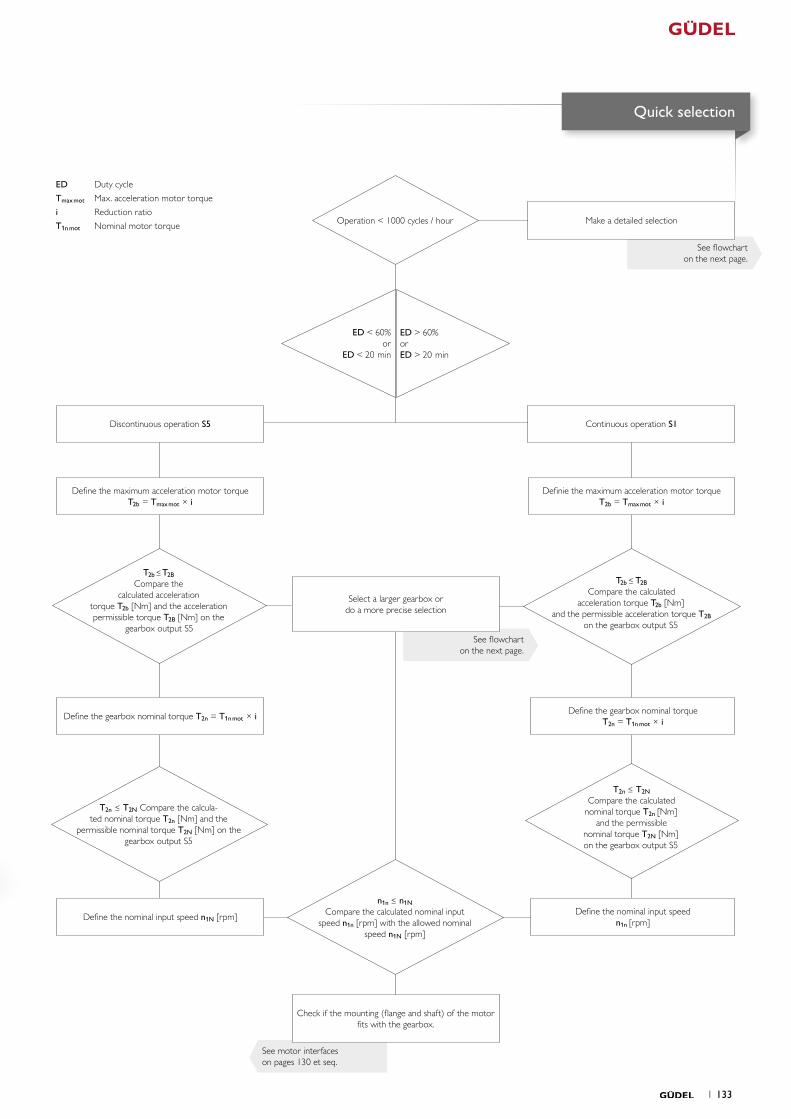
See motor interfaceson pages 130 et seq.
See flowcharton the next page.
See flowcharton the next page.
Discontinuous operation S5
Make a detailed selection
Continuous operation S1
Definie the maximum acceleration motor torque T2b = Tmaxmot × i
Check if the mounting (flange and shaft) of the motor fits with the gearbox.
Define the gearbox nominal torque T2n = T1n mot × i
Define the nominal input speed n1n [rpm]
Define the maximum acceleration motor torque T2b = Tmax mot × i
Define the gearbox nominal torque T2n = T1n mot × i
Define the nominal input speed n1N [rpm]
T2b ≤ T2B Compare the calculated
acceleration torque T2b [Nm] and the permissible acceleration torque T2B
on the gearbox output S5
T2b≤T2B Compare the
calculated acceleration torque T2b [Nm] and the acceleration permissible torque T2B [Nm] on the
gearbox output S5
ED < 60% or
ED < 20 min
ED > 60% or ED > 20 min
T2n ≤ T2N Compare the calcula-ted nominal torque T2n [Nm] and the
permissible nominal torque T2N [Nm] on the gearbox output S5
n1n ≤ n1N
Compare the calculated nominal input speed n1n [rpm] with the allowed nominal
speed n1N [rpm]
Operation < 1000 cycles / hour
T2n ≤ T2N
Compare the calculated nominal torque T2n [Nm]
and the permissible nominal torque T2N [Nm] on the gearbox output S5
ED Duty cycle
Tmaxmot Max. acceleration motor torque
i Reduction ratio
T1n mot Nominal motor torque
Select a larger gearbox or do a more precise selection
Quick selection
1 133
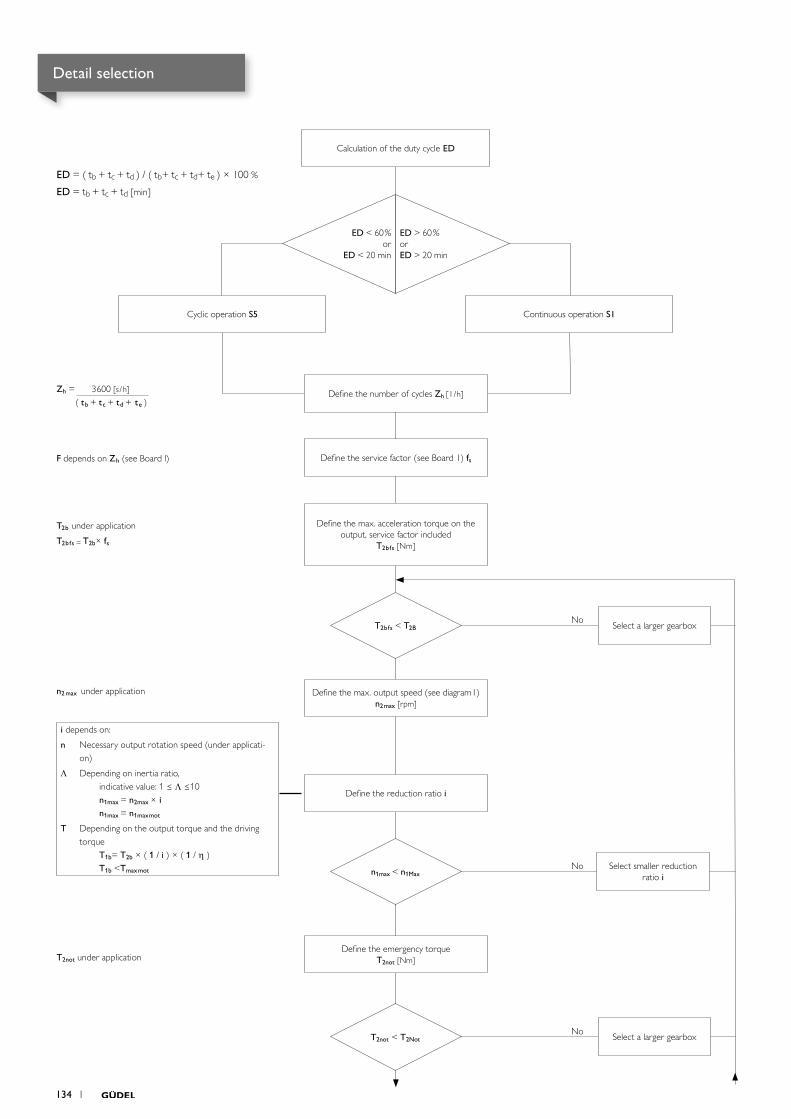
No
No
No
Define the service factor (see Board 1) fs
Define the max. acceleration torque on the output, service factor included
T2bfs [Nm]
Define the max. output speed (see diagram1) n2max [rpm]
Define the reduction ratio i
Define the emergency torque T2not [Nm]
ED = ( tb + tc + td ) / ( tb+ tc + td+ te ) × 100 %
ED = tb + tc + td [min]
Define the number of cycles Zh [1/h]Zh = 3600 [s/h] ( tb + tc + td + te )
n2 max under application
T2b under application
T2bfs = T2b× fs
F depends on Zh (see Board l)
T2not under application
Select a larger gearbox
Select smaller reduction ratio i
Select a larger gearbox
i depends on:
n Necessary output rotation speed (under applicati-on)
Λ Depending on inertia ratio, indicative value: 1 ≤ Λ ≤10 n1max = n2max × i n1max = n1maxmot
T Depending on the output torque and the driving torque T1b= T2b × ( 1 / i ) × ( 1 / h ) T1b <Tmaxmot
Cyclic operation S5 Continuous operation S1
T2bfs < T2B
n1max < n1Max
T2not < T2Not
ED < 60% or
ED < 20 min
ED > 60% or ED > 20 min
Calculation of the duty cycle ED
Detail selection
134 1
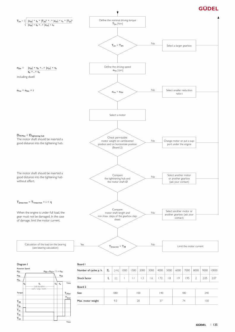
Diagram 1Rotation Speed
Time
Torque
n2c
T2d
T2e
T2c
T2b
T2B
n2e
n2b
T2Not
T2not
tb tc tetd
n2d
n2b = n2d = ½ x n2c
cycle duration work / stop / event
Time
No
No
No
No
No
NoYesCalculation of the load on the bearing (see bearing calculation) Limit the motor current
When the engine is under full load, the gear must not be damaged. In the case of damage, limit the motor current.
T2max mot = T1maxmot × i × h
Select another motor or another gearbox (ask your
contact)
Select smaller reduction ratio i
Select a larger gearbox
T2m = 3 |n2b| × tb × |T2b|3 +...+ |n2n| × tn × |T2n|3
|n2b| × tb +...+ |n2n| × tn
Define the nominal driving torque T2m [Nm]
n2m = |n2b| × tb +...+ |n2n| × tn tb +...+ tn
including dwell
n1m = n2m × i
Define the driving speed n1m [rpm]
Select a motor
T2m < T2N
n1m < n1N
DW.Mot < Dtightening hub The motor shaft should be inserted a good distance into the tightening hub.
Change motor or put a sup-port under the engine
Check permissible motor weight on cantilevered
position and on horizontale position (Board 2)
The motor shaft should be inserted a good distance into the tightening hub without effort.
Select another motor or another gearbox (ask your contact)
Compare the tightnening hub and
the motor shaft Ø
Compare motor shaft length and
min./max. steps of the gearbox step sheet
T2maxmot < T2B
Board 1
Number of cycles p. h. Zh [1/h] 1000 1500 2000 3000 4000 5000 6000 7000 8000 9000 10000
Shock factor fs [-] 1 1.1 1.3 1.6 1.72 1.8 1.9 1.95 2 2.05 2.07
Board 2
Size 080 100 140 180 240
Max. motor weight 9.3 20 37 74 150
1 135
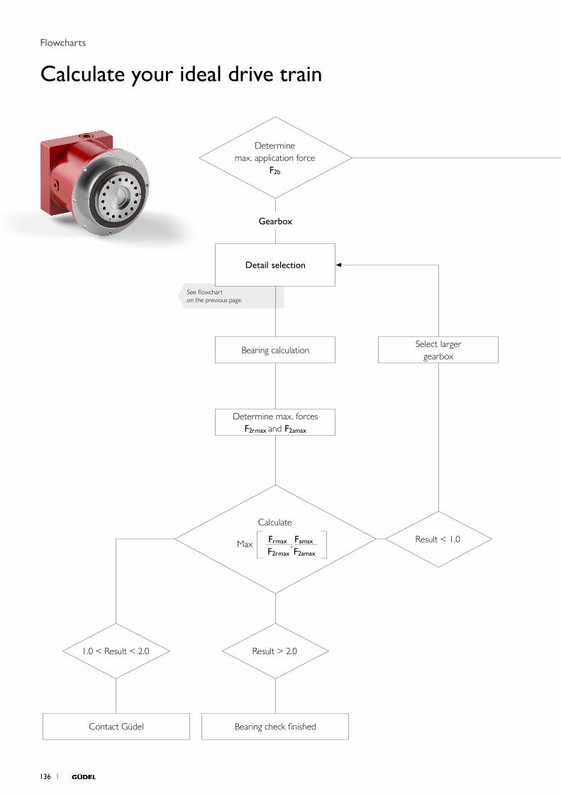
See flowchart on the previous page.
Determine max. application force
F2b
Result < 1.0
Bearing calculation
Detail selection
Determine max. forces F2rmax and F2amax
Select largergearbox
Bearing check finishedContact Güdel
Calculate
Max Frmax ; Famax
F2rmax F2amax
1.0 < Result < 2.0 Result > 2.0
Gearbox
Flowcharts
Calculate your ideal drive train
136 1
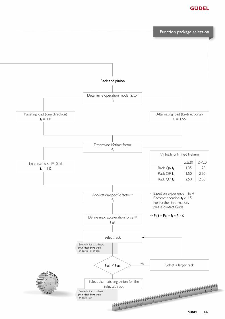
No
See technical datasheets your ideal drive train on pages 121 et seq.
See technical datasheet your ideal drive train on page 120.
Select a larger rack
Select the matching pinion for the selected rack
Application-specific factor *fs
F2bf < F2B
Rack and pinion
Determine operation mode factor fl
Determine lifetime factor fc
Pulsating load (one direction)fl = 1.0
Alternating load (bi-directional)fl = 1.55
Load cycles ≤ 1*10^6fc = 1.0
Select rack
* Based on experience 1 to 4 Recommendation: fs > 1.5 For further information, please contact Güdel
Define max. acceleration force **
F2bf
** F2bf = F2b × f1 × fc × fs
Function package selection
Virtually unlimited lifetime
Z≥20 Z<20
Rack Q6 fc 1.35 1.75
Rack Q9 fc 1.50 2.50
Rack Q7 fc 2.50 2.50
1 137

Güdel worldwide

Switzerland Güdel Group AG (Headquarters)Gaswerkstrasse 264900 LangenthalPhone +41 62 916 9191info@ ch.gudel.com
Güdel AGGaswerkstrasse 264900 LangenthalPhone +41 62 916 91 91info @ ch.gudel.com
Austria Güdel GmbHSchöneringer Strasse 484073 WilheringPhone +43 7226 20690 0info @ at.gudel.com
NetherlandsGüdel AGEertmansweg 30 7595 PA WeerseloPhone +31 541 66 22 50info @ nl.gudel.com
Czech RepublicGüdel a.s.Holandská 1063900 BrnoPhone +420 519 323 431info @ gudel.cz
FranceGüdel SASTour de l‘Europe 2133 Bd de l‘Europe68100 Mulhouse Phone +33 1 69 89 80 16info @ fr.gudel.com
Güdel Sumer SASLe RoqualZone industrielleCarsac-Aillac24200 Sarlat-la-CanédaPhone +33 5 53 30 30 [email protected]
GermanyGüdel Germany GmbH(German Headquarters)Industriepark 10774706 OsterburkenPhone +49 6291 6446 0info @ de.gudel.com
Güdel Germany GmbH (Altenstadt) Carl-Benz-Strasse 563674 AltenstadtPhone +49 6047 9639 0info @ de.gudel.com
Güdel Intralogistics GmbHGewerbegebiet Salzhub 11 83737 IrschenbergPhone +49 8062 7075 0intralogistics @ de.gudel.com
ItalyGüdel S.r.l.Strada per Cernusco, 720060 Bussero (MI)Phone +39 02 9217021info @ it.gudel.com
PolandGüdel Sp. z o.o.ul. Legionów 26/2843-300 Bielsko - BiałaPhone +48 33 819 01 25info @ pl.gudel.com
RussiaGüdel AGYubileynaya 40Offi ce 1902445057 TogliattiPhone +7 8482 775444info @ ru.gudel.com
Europe
Contacts
140 1

BrazilGüdel Lineartec Comércio de Automção Ltda.Rua Américo Brasiliensen° 2170, cj. 506Chácara Santo AntonioSão Paulo, CEP 04715 - 005Phone +41 62 916 91 [email protected]
MexicoGüdel TSC S.A. de C.V. Gustavo M. Garcia 308Col. Buenos AiresMonterrey, N.L. 64800Phone +52 81 8374 - 2500info @ mx.gudel.com
USAGüdel Inc.4881 Runway Blvd.Ann Arbor, MI 48108Phone +1 734 214 0000info @ us.gudel.com
ChinaGüdel International Trading Co. Ltd.Block A, 8 Floor, C2 BLDGNo. 1599 New Jin Qiao Road Pudong Shanghai 201206Phone +86 21 5055 0012info @ cn.gudel.com
IndiaGüdel India Pvt. Ltd.Gat no. 458-459Mauje Kasar Amboli Pirangut, Tal.MulshiPune 412 111Phone +91 20 679 10200 info @ in.gudel.com
South KoreaGüdel Lineartec Inc.7-15 Incheon towerdaero 25beon gil.Post no. 22013Yeonsu gu IncheonPhone +82 32 858 0541info @ kr.gudel.com
Taiwan, ChinaGüdel Lineartec Co. Ltd.No. 99, An-Chai 8th St.Hsin-Chu Industrial Park30373 Hu-Ko, Hsin-Chu Phone +88 635 97 8808info @ tw.gudel.com
ThailandGüdel Lineartec Co. Ltd.19/28 Private Ville Hua Mak RoadHua Mak Bang Kapi10240 BangkokPhone +66 2 374 0709info @ th.gudel.com
SpainGüdel AGAvinguda de Catalunya 49B1º 3ª08290 Cerdanyola del Vallés, BarcelonaPhone +34 644 347 058info @ es.gudel.com
United KingdomGüdel Lineartec (U.K.) Ltd.Unit 5 Wickmans DriveBanner LaneCV4 9XA Coventry, West MidlandsPhone +44 24 7669 5444info @ uk.gudel.com
Americas Asia Pacifi c
1 141

© Güdel AG
We have taken the greatest care in compiling this catalog with specifications and technical information. Please understand that we accept no liability for misprints, technical changes, or consequential damage in relation to the published information. The catalog is purely for information purposes, so the illustrations and information in no way represent guaranteed properties. The text, photos, drawings, and any other display formats in this catalog are intellectual property of Güdel AG. Please note that any duplication, editing, trans- lation, saving, or any other subsequent use of the catalog or its components in print or electronically may only be carried out with the previous, express consent of Güdel AG. Güdel AG reserves the right to modify the provided information at any time in order to always be able to present you with the most up-to-date version of our catalog and products.
142 1
