network infrastructure concept description
TRANSCRIPT
NETWORK INFRASTRUCTURE CONCEPT DESCRIPTION
Document number .................................................................. WP2‐030.080.000‐TD.001Revision ........................................................................................................................... 1Author ................................................................................................................ R.McCoolDate ................................................................................................................. 2011‐06‐02Status .............................................................................................. Approved for Release
Name Designation Affiliation Date Signature
Submitted by:
R.McCool 2011‐06‐02
Accepted by:
Approved by:
P.Dewdney 2011‐06‐13

WP2‐030.080.000‐TD.001 Revision : 1
2011‐06‐02 Page 2 of 24
DOCUMENT HISTORY Revision Date Of Issue Engineering Change
Number
Comments
A 2011‐05‐09 ‐ First draft release for internal review
B 2011‐06‐02 Second updated draft for aproval
1 2011‐06‐13 Update with comments approved for release
DOCUMENT SOFTWARE Package Version Filename
Wordprocessor MsWord Word 2007 WP2‐030.080.000‐TD.001v1 InfConcept.docx
Block diagrams
Other
ORGANISATION DETAILS Name
Physical/Postal Address
Fax. Website
WP2‐030.080.000‐TD.001 Revision : 1
TABLE OF CONTENTS
1 INTRODUCTION ............................................................................................. 6 1.1 Purpose of the document ....................................................................................................... 6 1.2 Scope of the document ........................................................................................................... 6
2 SYSTEM CONTEXT FOR NETWORK INFRASTRUCTURE ............................................... 6 2.1 SKA Hierarchy .......................................................................................................................... 6 2.2 Role of SKA Network Infrastructure in the SKA ...................................................................... 7 2.3 First Draft Interface Description ............................................................................................. 7
3 TARGET REQUIREMENTS AND FUNCTIONALITY ...................................................... 9 3.1 Functional Requirements ........................................................................................................ 9 3.2 Non‐Functional Requirements ................................................................................................ 9
4 FIRST DRAFT DESCRIPTION OF THE PHYSICAL NETWORK INFRASTRUCTURE DESIGN ........ 9 4.1 Designing network infrastructure for extensibility to SKA2 ................................................. 11
5 TRENCHCOAT ESTIMATES OF PHYSICAL LAYER INFRASTRUCTURE SIZE METRICS. ........... 12
6 IMPACT OF EXTENSIBILITY TO AIP AND SKA2 .................................................... 13 6.1 Providing extensibility using a passive duct network ........................................................... 14
7 FIRST DRAFT POWER REQUIREMENTS .............................................................. 14
8 FIRST DRAFT RELIABILITY CONSIDERATIONS ....................................................... 14 8.1 Network Architecture and its impact on availability ............................................................ 14 8.2 Accuracy of the Inventory and Maintenance System ........................................................... 15
9 FIRST DRAFT COST REPORT. .......................................................................... 15 9.1 Quantity Estimation .............................................................................................................. 15 9.2 List of cost estimates itemized .............................................................................................. 15 9.3 Summary of 10 year cost of ownership ................................................................................ 16 9.4 Description of the procurement method.............................................................................. 16 9.5 Sensitivity Analysis of Cost estimates. .................................................................................. 17
10 FIRST DRAFT RISK ANALYSIS ....................................................................... 19
11 PLANNING FOR THE NEXT PHASE ................................................................... 24
12 REFERENCES ........................................................................................... 24
2011‐06‐02 Page 3 of 24

WP2‐030.080.000‐TD.001 Revision : 1
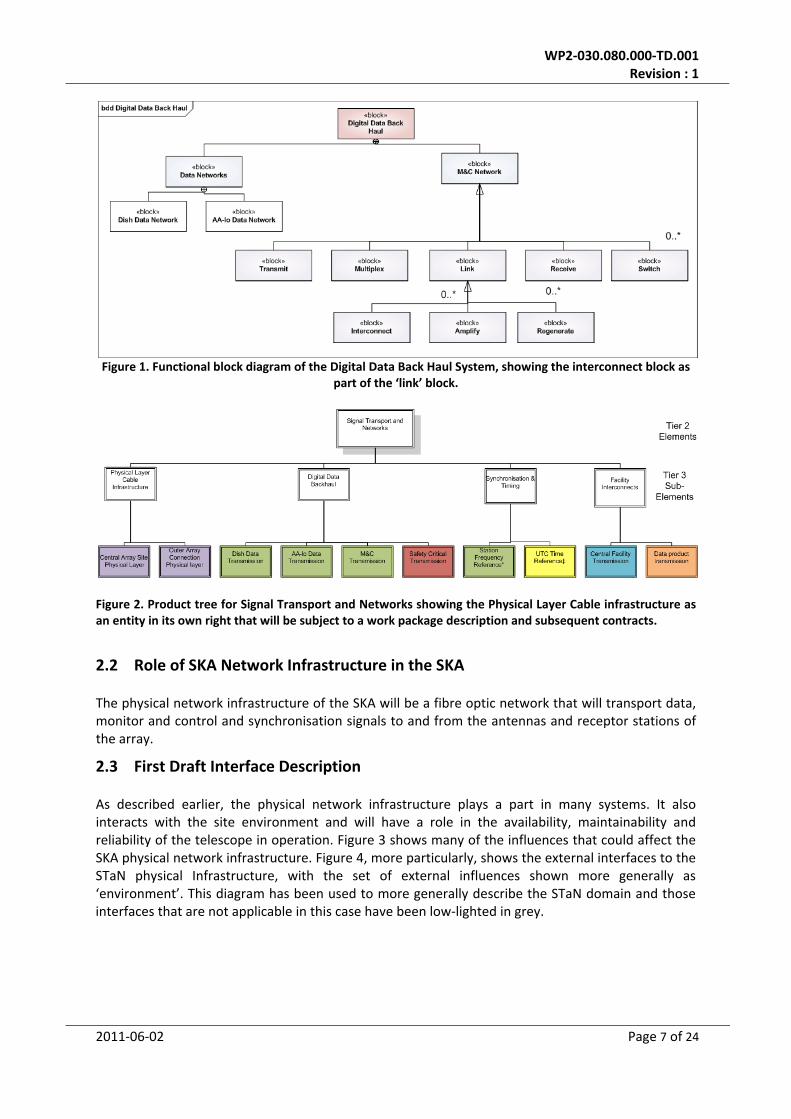
LIST OF FIGURES Figure 1. Functional block diagram of the Digital Data Back Haul System, showing the interconnect
block as part of the ‘link’ block. .................................................................................................... 7 Figure 2. Product tree for Signal Transport and Networks showing the Physical Layer Cable
infrastructure as an entity in its own right that will be subject to a work package description and subsequent contracts. ........................................................................................................... 7
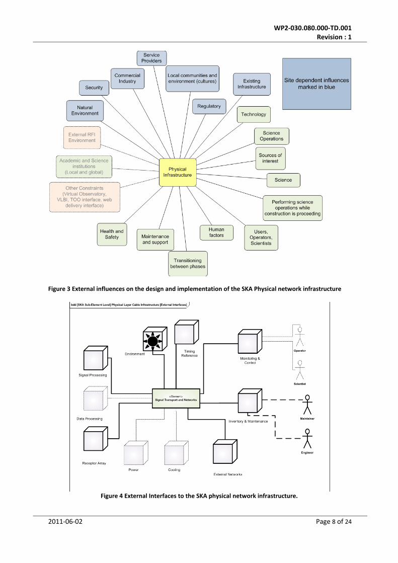
Figure 3 External influences on the design and implementation of the SKA Physical network infrastructure ................................................................................................................................ 8
Figure 4 External Interfaces to the SKA physical network infrastructure. .............................................. 8 Figure 5 SKA1 layout (zoom6) ............................................................................................................... 11 Figure 6 SKA2 layout (zoom6) ............................................................................................................... 11 Figure 7 SKA1 dish core (zoom 16) Figure 8 SKA2 Dish Core (zoom 16) ......................................... 11 Figure 9 Chart illustrating the network fibre required to serve various extensibility options ............. 13 Figure 10 The development of array configurations and the interdependencies involved. ................ 18
LIST OF TABLES Table 1 Network metrics obtained from TrenchCOAT optimisation. ................................................... 12 Table 2 Cost component list for STaN network infrastructure ............................................................. 16
2011‐06‐02 Page 4 of 24

WP2‐030.080.000‐TD.001 Revision : 1
LIST OF ABREVIATIONS AA‐Lo ............................... Low Frequency Aperture Array AIP ............................... Advanced Instrumentation programme CBP ............................... Cannot be predicted CDR ............................... Critical Design Review CoDR ............................... Concept Design Review COTS ............................... Commercial Off the Shelf CPF ............................... Central Processing Facility DDBH ............................... Digital Data Back Haul DRM ............................... Design Reference Mission HLD ............................... High Level Description HMI ............................... Human Machine Interface I&M ............................... Inventory and Maintenance ID ............................... Identity M&C ............................... Monitor and Control NDA ............................... Non Disclosure Agreement NVC ............................... Non Visibility Computing OH ............................... Overhead OSF ............................... Operations support facility PEP ............................... Project Execution Plan RFI ............................... Radio Frequency Interference SATS ............................... Synchronisation and Timing Sub‐System SEMP ............................... System Engineering Management Plan SKA ............................... Square Kilometre Array SKA1 ............................... Square Kilometre Array Phase 1 SKA2 ............................... Square Kilometre array Phase 2 SPDO ............................... SKA Program development Office SPF ............................... Single Pixel Feed SRC ............................... SKA Regional Centre SRR ............................... Specification Requirements Review STaN ............................... Signal Transport and Networks SYSML ............................... Systems Modelling Language SYSMOD ............................... System Modelling Process TBC ............................... to be confirmed TBD ............................... to be determined UTC ............................... Universal Time Constant
2011‐06‐02 Page 5 of 24
WP2‐030.080.000‐TD.001 Revision : 1
1 Introduction
1.1 Purpose of the document
This document describes the initial design work undertaken for the network infrastructure for the SKA at the SPDO.
1.2 Scope of the document
This document will describe the network infrastructure of the SKA including the following; • Its context within the SKA Signal Transport and Networks. • First draft description of interfaces • Physical description of the sub‐system • First draft description of the design, including;
o Architecture o Impact of array configurations o Installation, Commissioning and Maintenance considerations o Impact of extensibility to AIP and SKA2
• Cost estimates • First Draft Risk analysis • Identification of gaps and further work • Plans to proceed to the next phase
2 System Context for Network Infrastructure
2.1 SKA Hierarchy
The Network infrastructure is a common part of many Sub‐Elements in the SKA telescope. From a functional hierarchy point of view the network infrastructure is only a part of a larger system. The requirements on the networks vary according to the functional role it plays within a Sub‐Element. In a physical and product sense it exists in the telescope as an entity in its own right as a single infrastructure that serves many purposes and locations. It will be described as such for the purposes of letting contracts in the construction phase. It is this dual character that often makes the physical infrastructure difficult to adequately describe and capture at the early stages of a project like the SKA. An example of this dual character can be seen in figures 1 and 2. In figure 1 the physical infrastructure is defined in the ‘interconnect’ block which is an Assembly of the DDBH Sub‐Element. In figure 2 the ‘physical layer cable infrastructure’ exists as an entity in the product tree of Signal Transport and Networks. There are a number of characteristics of the network infrastructure that mark it out for special attention earlier in the design process than its status in a functional hierarchy would normally warrant:
1. It will be a large cost centre for the SKA, 2. it will be one of the first items constructed on site and, 3. once constructed will not be easy to upgrade.
2011‐06‐02 Page 6 of 24
WP2‐030.080.000‐TD.001 Revision : 1
Figure 1. Functional block diagram of the Digital Data Back Haul System, showing the interconnect block as
part of the ‘link’ block.
Figure 2. Product tree for Signal Transport and Networks showing the Physical Layer Cable infrastructure as an entity in its own right that will be subject to a work package description and subsequent contracts.
2.2 Role of SKA Network Infrastructure in the SKA
The physical network infrastructure of the SKA will be a fibre optic network that will transport data, monitor and control and synchronisation signals to and from the antennas and receptor stations of the array.
2.3 First Draft Interface Description
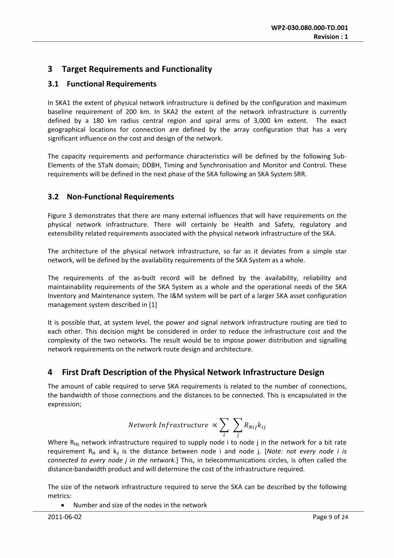
As described earlier, the physical network infrastructure plays a part in many systems. It also interacts with the site environment and will have a role in the availability, maintainability and reliability of the telescope in operation. Figure 3 shows many of the influences that could affect the SKA physical network infrastructure. Figure 4, more particularly, shows the external interfaces to the STaN physical Infrastructure, with the set of external influences shown more generally as ‘environment’. This diagram has been used to more generally describe the STaN domain and those interfaces that are not applicable in this case have been low‐lighted in grey.
2011‐06‐02 Page 7 of 24
WP2‐030.080.000‐TD.001 Revision : 1
Figure 3 External influences on the design and implementation of the SKA Physical network infrastructure
Figure 4 External Interfaces to the SKA physical network infrastructure.
2011‐06‐02 Page 8 of 24
WP2‐030.080.000‐TD.001 Revision : 1
3 Target Requirements and Functionality
3.1 Functional Requirements
In SKA1 the extent of physical network infrastructure is defined by the configuration and maximum baseline requirement of 200 km. In SKA2 the extent of the network infrastructure is currently defined by a 180 km radius central region and spiral arms of 3,000 km extent. The exact geographical locations for connection are defined by the array configuration that has a very significant influence on the cost and design of the network. The capacity requirements and performance characteristics will be defined by the following Sub‐Elements of the STaN domain; DDBH, Timing and Synchronisation and Monitor and Control. These requirements will be defined in the next phase of the SKA following an SKA System SRR.
3.2 Non‐Functional Requirements
Figure 3 demonstrates that there are many external influences that will have requirements on the physical network infrastructure. There will certainly be Health and Safety, regulatory and extensibility related requirements associated with the physical network infrastructure of the SKA. The architecture of the physical network infrastructure, so far as it deviates from a simple star network, will be defined by the availability requirements of the SKA System as a whole. The requirements of the as‐built record will be defined by the availability, reliability and maintainability requirements of the SKA System as a whole and the operational needs of the SKA Inventory and Maintenance system. The I&M system will be part of a larger SKA asset configuration management system described in [1] It is possible that, at system level, the power and signal network infrastructure routing are tied to each other. This decision might be considered in order to reduce the infrastructure cost and the complexity of the two networks. The result would be to impose power distribution and signalling network requirements on the network route design and architecture.
4 First Draft Description of the Physical Network Infrastructure Design
The amount of cable required to serve SKA requirements is related to the number of connections, the bandwidth of those connections and the distances to be connected. This is encapsulated in the expression;
Where RNij network infrastructure required to supply node i to node j in the network for a bit rate requirement RN and kij is the distance between node i and node j. [Note: not every node i is connected to every node j in the network.] This, in telecommunications circles, is often called the distance∙bandwidth product and will determine the cost of the infrastructure required. The size of the network infrastructure required to serve the SKA can be described by the following metrics:
• Number and size of the nodes in the network
2011‐06‐02 Page 9 of 24
WP2‐030.080.000‐TD.001 Revision : 1
2011‐06‐02 Page 10 of 24
• Number of kilometres of trench in the network • Number of fibre.kms in the network • Number of terminations in the network
Metric values have been estimated for the following scenarios using the TrenchCOAT tool developed in conjunction with the University of Cambridge [2]:
• SKA1 baseline design • SKA1 baseline design extensible to an SKA1 incorporating PAFs • SKA1 baseline design extensible to an SKA2 baseline design • SKA1 baseline design extensible to an SKA2 incorporating WBSPF • SKA1 baseline design extensible to an SKA2 incorporating PAFs
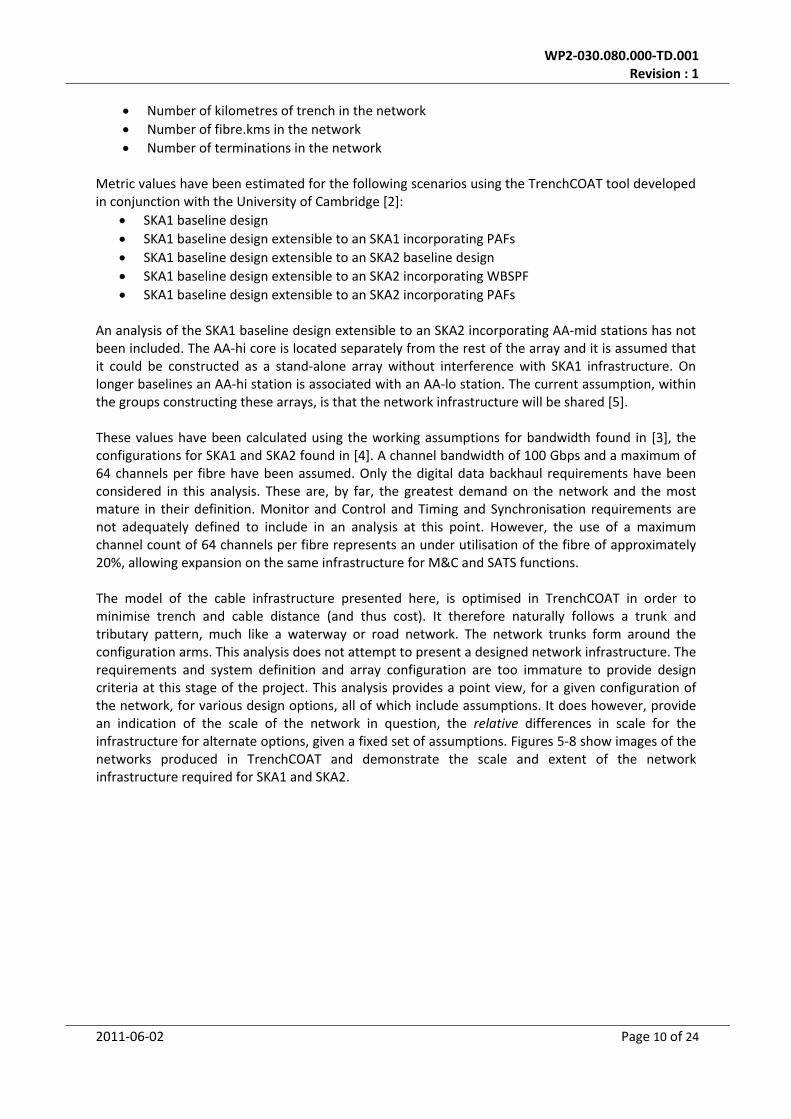
An analysis of the SKA1 baseline design extensible to an SKA2 incorporating AA‐mid stations has not been included. The AA‐hi core is located separately from the rest of the array and it is assumed that it could be constructed as a stand‐alone array without interference with SKA1 infrastructure. On longer baselines an AA‐hi station is associated with an AA‐lo station. The current assumption, within the groups constructing these arrays, is that the network infrastructure will be shared [5]. These values have been calculated using the working assumptions for bandwidth found in [3], the configurations for SKA1 and SKA2 found in [4]. A channel bandwidth of 100 Gbps and a maximum of 64 channels per fibre have been assumed. Only the digital data backhaul requirements have been considered in this analysis. These are, by far, the greatest demand on the network and the most mature in their definition. Monitor and Control and Timing and Synchronisation requirements are not adequately defined to include in an analysis at this point. However, the use of a maximum channel count of 64 channels per fibre represents an under utilisation of the fibre of approximately 20%, allowing expansion on the same infrastructure for M&C and SATS functions. The model of the cable infrastructure presented here, is optimised in TrenchCOAT in order to minimise trench and cable distance (and thus cost). It therefore naturally follows a trunk and tributary pattern, much like a waterway or road network. The network trunks form around the configuration arms. This analysis does not attempt to present a designed network infrastructure. The requirements and system definition and array configuration are too immature to provide design criteria at this stage of the project. This analysis provides a point view, for a given configuration of the network, for various design options, all of which include assumptions. It does however, provide an indication of the scale of the network in question, the relative differences in scale for the infrastructure for alternate options, given a fixed set of assumptions. Figures 5‐8 show images of the networks produced in TrenchCOAT and demonstrate the scale and extent of the network infrastructure required for SKA1 and SKA2.
WP2‐030.080.000‐TD.001 Revision : 1
Figure 5 SKA1 layout (zoom6)
Figure 6 SKA2 layout (zoom6)
Figure 7 SKA1 dish core (zoom 16) Figure 8 SKA2 Dish Core (zoom 16)
Further work should include analysis of array configuration options and the impact of those options on the network infrastructure.
4.1 Designing network infrastructure for extensibility to SKA2
The extensible designs have been generated using the SKA2 array configuration; • all dishes and stations not connected to the SKA1 design are excluded • all those SKA2 dish and station locations that are in the pathway for SKA1 have the required
connectivity included • Dishes and stations not included in SKA1, but which would be connected to SKA1 locations
have their required bandwidth added to the SKA1 locations in the downstream path the CPF A simple example should clarify these ideas: Consider the following configuration:
B1 ‐ > A1 ‐> B2 ‐ > A2 ‐> CPF. Here, B1 and B2 refer to antennas belonging exclusively to SKA2, whereas A1 and A2 antennas belong to SKA1 (and therefore to SKA2 as well). Let’s assume, that the geometry is such that the most cost effective links would be the ones displayed in the scheme above (the signal flows from the outermost B1 towards the CPF, via trenches towards A1, from there towards B2, from there towards A2 finally reaching the CPF).
2011‐06‐02 Page 11 of 24
WP2‐030.080.000‐TD.001 Revision : 1
For SKA1 (without planning ahead for SKA2) the link would look like this:
A1‐‐‐‐‐‐‐‐‐‐>A2‐> CPF The cables connecting A1 to A2 and A2 to the CPF would be just enough to transport the data rates associated with the A1 and A2 antennas. When planning ahead for SKA2, one would like SKA1 to consist of the following network:
A1‐‐‐‐‐‐(b2)===>A2==>CPF Notice that (b2) means that although antenna B2 will not be deployed in SKA1, the additional optic fibre would be added inside the trench between A1 and A2 starting from the point where B2 would be deployed. In this way, connecting B2 to the network infrastructure during SKA2 would be a simple task. Also, the output data rate of A1 has to be increased to accommodate for the missing B1 antenna, during SKA1. Namely, the link A1‐‐‐‐(b2) has to be able to carry, already during SKA1, not only the data of A1 but also the future data rate of B1. Nevertheless, there is no need to implement the trenching between B1 and A1 during SKA1 at all, as this is exclusively a SKA2 link. The SKA2 extensible network presented here is therefore not optimised for SKA1 but should become cost‐efficient overall upon extension to SKA2. It is important to establish once more that the analysis presented here is not a final SKA network infrastructure design, but an indication of the impact that extensibility could have in the network. Further, more detailed work, is required on final configurations, establishing the trunk network routes and building in capacity along these routes. Any design that includes extensibility will require an established and stable SKA2 configuration in order to avoid the construction of links to locations that subsequently change.
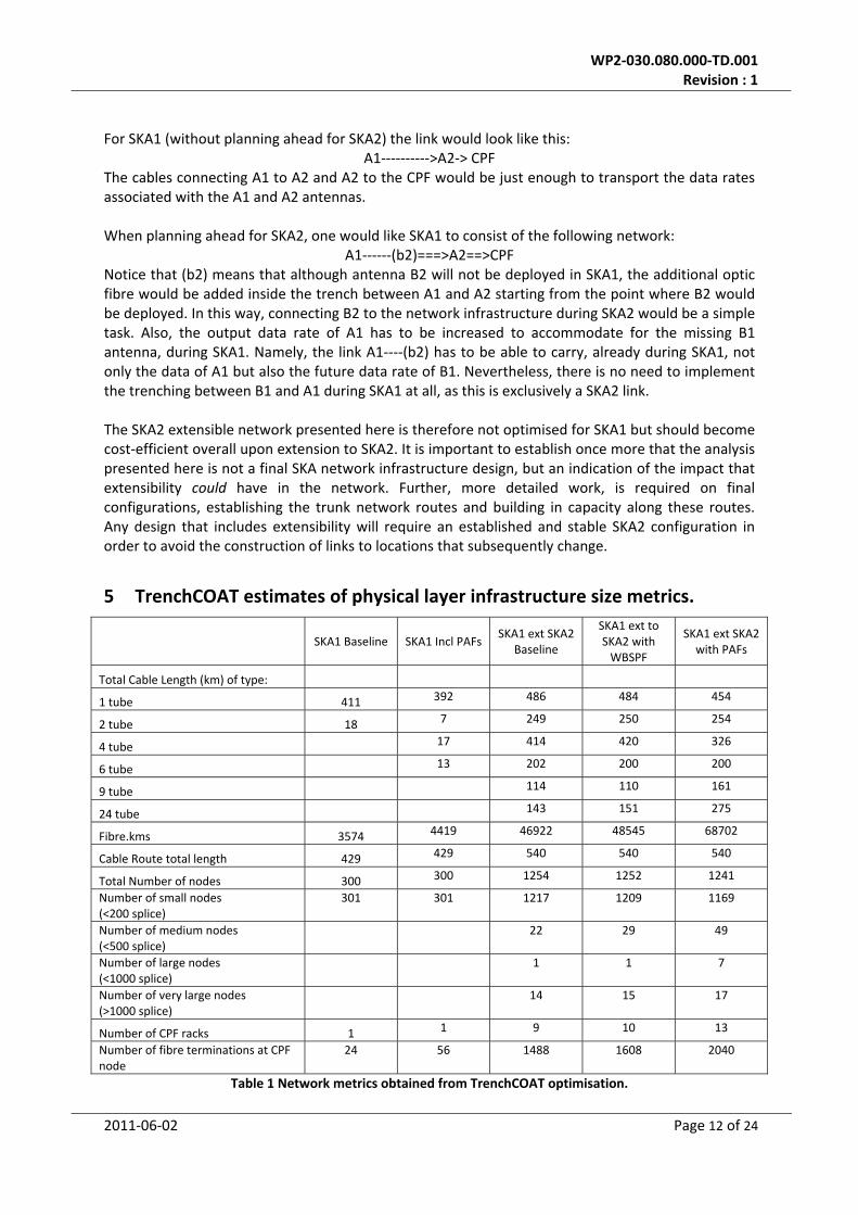
5 TrenchCOAT estimates of physical layer infrastructure size metrics.
SKA1 Baseline SKA1 Incl PAFs SKA1 ext SKA2
Baseline
SKA1 ext to SKA2 with WBSPF
SKA1 ext SKA2 with PAFs
Total Cable Length (km) of type:
1 tube 411 392 486 484 454
2 tube 18 7 249 250 254
4 tube 17 414 420 326
6 tube 13 202 200 200
9 tube 114 110 161
24 tube 143 151 275
Fibre.kms 3574 4419 46922 48545 68702
Cable Route total length 429 429 540 540 540
Total Number of nodes 300 300 1254 1252 1241
Number of small nodes (<200 splice)
301 301 1217 1209 1169
Number of medium nodes (<500 splice)
22 29 49
Number of large nodes (<1000 splice)
1 1 7
Number of very large nodes (>1000 splice)
14 15 17
Number of CPF racks 1 1 9 10 13
Number of fibre terminations at CPF node
24 56 1488 1608 2040
Table 1 Network metrics obtained from TrenchCOAT optimisation.
2011‐06‐02 Page 12 of 24
WP2‐030.080.000‐TD.001 Revision : 1
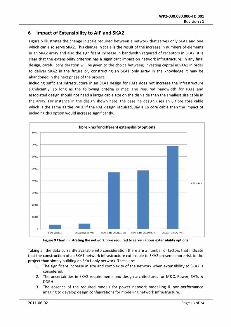
6 Impact of Extensibility to AIP and SKA2
Figure 5 illustrates the change in scale required between a network that serves only SKA1 and one which can also serve SKA2. This change in scale is the result of the increase in numbers of elements in an SKA2 array and also the significant increase in bandwidth required of receptors in SKA2. It is clear that the extensibility criterion has a significant impact on network infrastructure. In any final design, careful consideration will be given to the choice between; investing capital in SKA1 in order to deliver SKA2 in the future or, constructing an SKA1 only array in the knowledge it may be abandoned in the next phase of the project. Including sufficient infrastructure in an SKA1 design for PAFs does not increase the infrastructure significantly, so long as the following criteria is met: The required bandwidth for PAFs and associated design should not need a larger cable size on the dish side than the smallest size cable in the array. For instance in the design shown here, the baseline design uses an 8 fibre core cable which is the same as the PAFs. If the PAF design required, say a 16 core cable then the impact of including this option would increase significantly.
0
10000
20000
30000
40000
50000
60000
70000
80000
SKA1 Baseline SKA1 including PAFs SKA1 ext to SKA2 Baseline SKA1 ext to SKA2 WBSPF SKA1 ext to SKA2 PAFs
fibre.kms for different extensibility options
fibre.kms
Figure 9 Chart illustrating the network fibre required to serve various extensibility options
Taking all the data currently available into consideration there are a number of factors that indicate that the construction of an SKA1 network infrastructure extensible to SKA2 presents more risk to the project than simply building an SKA1 only network. These are:
1. The significant increase in size and complexity of the network when extensibility to SKA2 is considered.
2. The uncertainties in SKA2 requirements and design architectures for M&C, Power, SATs & DDBH.
3. The absence of the required models for power network modelling & non‐performance imaging to develop design configurations for modelling network infrastructure.
2011‐06‐02 Page 13 of 24
WP2‐030.080.000‐TD.001 Revision : 1
4. The absence of the required processes to specify the requirements for the delivery of ‘As‐built’ records from contractors to the project.
5. The schedule pressure on the SKA project to undertake the construction of network infrastructure in 2015.
In order to justify the additional costs involved in the delivery of extensibility for SKA2 these risks must be mitigated, in advance.
6.1 Providing extensibility using a passive duct network
A compromise strategy of providing extensibility for SKA2 uses the installation of a passive duct network on trunk routes for future use. These routes do not need to be cabled in SKA1 but can be populated with cables in SKA2. This reduces the cost risk to the project if the configuration, network architecture or requirements change between SKA1 and SKA2. In addition it means that the trenching required for SKA2 is reduced when the time comes for construction. The data provided in the analysis presented so far enables the identification of future SKA2 trunk routes on SKA1 cable routes. However this analysis has not been completed in time for this review. This will be the subject of further work.
7 First Draft Power Requirements
The physical network infrastructure of the SKA is a passive entity and as such has no power requirements in operation. Monitor and Control requirements for location and identification detection may impose some active components into an otherwise passive network. A trade‐off between the cost of powering active components in a network and the operational requirements served by this design enhancement are a matter for further work. The network connectivity at very large nodes may be of sufficient scale that housings are required for connection racks. Power for standard services, such as lighting, will be required in this infrastructure. In construction and commissioning installation teams will have, as yet undefined, power requirements in order to install and commission the network.
8 First Draft Reliability Considerations
8.1 Network Architecture and its impact on availability
The concept described here assumes a simple star architecture for the physical network infrastructure of the SKA. A star architecture has the distinct disadvantage that it represents a single point of failure in the chain between a receptor and the correlator. In addition, in an optimised network the cable infrastructure is often concentrated along aggregated routes in order to minimise the trench network required for the network infrastructure. This means that a critical impact on a cable along one of these trunk routes could affect many dishes and stations in the array. Commercial operators use ring and mesh networks in order to avoid this problem and provide highly available networks. This adds additional complexity and therefore cost into both the physical layer and the transmission layer of the network. A special case of the requirements on availability are the safety critical functions that must be maintained in the event of a failure in the network. It is possible that these safety critical functions may be provided by a separate system, for instance a satellite link or redundant dial up line routed along power infrastructure . It is also possible that the requirements for safety critical functions are
2011‐06‐02 Page 14 of 24

WP2‐030.080.000‐TD.001 Revision : 1
defined on the basis of their distance from the array operating site. For instance; those dishes and stations in the core arrays may not require an ‘always up’ link because failures there can be easily accessed by an array operating centre. Careful definition of the requirements on safety critical functions could significantly reduce their impact on the design and subsequent cost of the physical network infrastructure. A detailed availability analysis will have to be carried out in order to assess the impact of the network architecture on SKA System availability, cost and complexity.
8.2 Accuracy of the Inventory and Maintenance System
The SKA network is large enough that the accuracy of the ‘As built’ record could have a significant impact on the ability of the SKA organisation to operate the telescope. With potentially hundreds and thousands of fibre inter‐connections it is necessary that each connection through the system can be traced and located. Whilst terminal equipment will advertise locations and identifications to the M&C systems the intermediate network is inherently passive and the locations of the interconnection points from cable to cable must be accurately recorded in order to trace a link through the network. If this does not happen it is possible that telescope operators will know what equipment is at the end of a link, but not the cable in which the link fibre is located. Or that a particular link has a fault at a known distance from the CPF, but not the route along which the fault resides. The need for an accurate ‘As‐built’ record becomes more imperative if extensibility to SKA2 is taken into consideration. In this instance the passive network will sit, largely unlit, and entirely passive. Without accurate Inventory and Maintenance systems the subsequent connection of these dormant networks in SKA2 could become so difficult as to render, questionable, the provision of this extensibility in the first place.
9 First Draft Cost Report.
Cost data for the network infrastructure is available to the project from a number of sources: 1. The ALMA infrastructure cost estimates, written by Corning Cable System Inc. are available
to the SKA [6]. The SKA physical network infrastructure is analogous to the ALMA network. It has a trunk, joint and branch architecture, which is very similar to the way the SKA network will look in the central region, where the antenna and station locations are fairly densely packed.
2. Nokkia Siemens Networks cost estimates. These estimates are subject to a Non‐Disclosure Agreement and will be presented in [7] under the procedure outlined in [8] for information of this type.
9.1 Quantity Estimation
The size of the physical infrastructure required for various design scenarios is described in sections 4 and 5 of this document.
9.2 List of cost estimates itemized
Description of cost Cost component Included? YES/NO/NA
Cost estimate Base Year Value 2007
Reference to Substantiating
evidence
Notes
Subsystem Hardware costs incl of: Component cost YES 3.5 M€ ‐ ALMA cost
Costs presented are for SKA1 Baseline
2011‐06‐02 Page 15 of 24

WP2‐030.080.000‐TD.001 Revision : 1
2011‐06‐02 Page 16 of 24
SKA1 Baseline Network.
7.9 M€ ‐ SKA2
Baseline Network.
estimates [6][7], 2005 – inflated by an LCI index of
3.6%
design. 97% of the cost is in the trench network. Node costs are assumed to be €25 per node connection incl of installation, hardware & test.
Safe Operation N/A
Internal M&C N/A
Internal Power NO
Inherently passive unless active M&C components are added.
Internal Software & licences NO GIS Systems for I&M
Localised or Internal Temp Control N/A
EMC (shielding and resilience) N/A
Integrated diagnostics NO M&C specific active components
Test, Verification, Validation YES
Internal Integration N/A
Spares NO
Star links, no redundancy, no diverse routes
Repair and rework YES
Quality control YES
NRE development costs N/A
Labour (manufacture & field installation) YES
Simulators N/A
Test Equipment NO
Lightening protection NO
Environmental protection NO
Hardware Sub‐system Operations costs incl:
Maintenance NOAnnual power costs N/AUpgrades NOLabour NO
Table 2 Cost component list for STaN network infrastructure
9.3 Summary of 10 year cost of ownership
This information is subject to an NDA and can be found in [8]
9.4 Description of the procurement method
The physical network infrastructure will be provided by external contractors under one or more contracts let by the project. It is anticipated it will be operated as a private network by the project; either, directly by project staff or possibly as a contract let by the project.

WP2‐030.080.000‐TD.001 Revision : 1
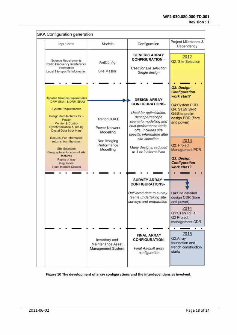
9.5 Sensitivity Analysis of Cost estimates.
The cost estimates are based on single point analysis of particular scenarios and as such are extremely sensitive to the input variables, in particular, the array configuration. A single generic array configuration has thus far been generated for the purposes of site selection. Further work is need in establishing configurations that trade‐off cost with performance parameters. Fig 10 shows a schematic of the development of configurations and the interdependencies of the input information, modelling capacity and project timeline.
2011‐06‐02 Page 17 of 24
WP2‐030.080.000‐TD.001 Revision : 1
Figure 10 The development of array configurations and the interdependencies involved.
2011‐06‐02 Page 18 of 24
WP2‐030.080.000‐TD.001 Revision : 1
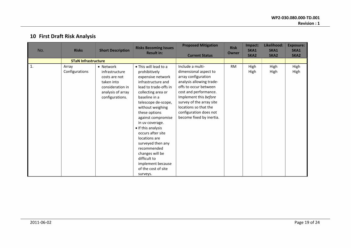
10 First Draft Risk Analysis
No. Risks Short Description Risks Becoming Issues
Result in:
Proposed Mitigation
Current Status
Risk Owner
Impact:SKA1 SKA2
Likelihood:SKA1 SKA2
Exposure:SKA1 SKA2
STaN Infrastructure1. Array
Configurations • Network infrastructure costs are not taken into consideration in analysis of array configurations.
• This will lead to a prohibitively expensive network infrastructure and lead to trade‐offs in collecting area or baseline in a telescope de‐scope, without weighing these options against compromise in uv coverage.
• If this analysis occurs after site locations are surveyed then any recommended changes will be difficult to implement because of the cost of site surveys.
Include a multi‐dimensional aspect to array configuration analysis allowing trade‐offs to occur between cost and performance. Implement this before survey of the array site locations so that the configuration does not become fixed by inertia.
RM HighHigh
HighHigh
HighHigh
2011‐06‐02 Page 19 of 24
WP2‐030.080.000‐TD.001 Revision : 1
2. SKA2 requirements insufficiently stable to develop configurations
• The design architectures, requirements and models for SKA2 are not sufficiently stable to assess alternative configuration designs.
• Unstable configuration designs used in the development of extensible networks
• If these networks are constructed and the configuration changes the initial investment may be redundant
Establish programmes in order to develop modelling capacity in the areas of power networks and non‐imaging performance so that configuration options can be assessed.
PED HighHigh
HighHigh
HighHigh
3. SKA2 requirements insufficiently stable to develop credible designs
• The design architectures and requirements for SKA2 are not sufficiently stable to develop network designs extensible to SKA2.
• Unstable SKA2 requirements lead to the design of network infrastructure that is over or under specified for SKA2 needs.
Assess design maturity and use in the decision between the construction of an SKA1 only network, or one extensible to SKA2.
PED HighHigh
HighHigh
HighHigh
4. SKA Configuration management requirements are left unspecified
• The SKA Asset Configuration Management requirements are not sufficiently mature to define processes for the collection and recording of ‘As‐built’ records
• A network is constructed, but insufficient ‘As built’ records compromise the reliability, availability and maintainability of the networks
Select an asset management system for the SKA and define the processes needed to interface with it. Assess design maturity and use in the decision between the construction of an SKA1 only network, or one extensible to SKA2.
PED HighHigh
HighHigh
HighHigh
2011‐06‐02 Page 20 of 24
WP2‐030.080.000‐TD.001 Revision : 1
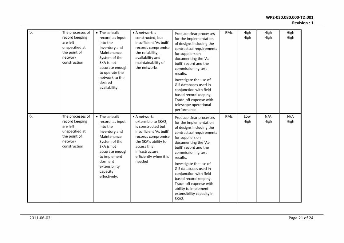
5. The processes of record keeping are left unspecified at the point of network construction
• The as‐built record, as input into the Inventory and Maintenance System of the SKA is not accurate enough to operate the network to the desired availability.
• A network is constructed, but insufficient ‘As built’ records compromise the reliability, availability and maintainability of the networks
Produce clear processes for the implementation of designs including the contractual requirements for suppliers on documenting the ‘As‐built’ record and the commissioning test results.
Investigate the use of GIS databases used in conjunction with field based record keeping. Trade‐off expense with telescope operational performance.
RMc HighHigh
HighHigh
HighHigh
6. The processes of record keeping are left unspecified at the point of network construction
• The as‐built record, as input into the Inventory and Maintenance System of the SKA is not accurate enough to implement dormant extensibility capacity effectively.
• A network, extensible to SKA2, is constructed but insufficient ‘As built’ records compromise the SKA’s ability to access this infrastructure efficiently when it is needed
Produce clear processes for the implementation of designs including the contractual requirements for suppliers on documenting the ‘As‐built’ record and the commissioning test results.
Investigate the use of GIS databases used in conjunction with field based record keeping. Trade‐off expense with ability to implement extensibility capacity in SKA2.
RMc LowHigh
N/AHigh
N/AHigh
2011‐06‐02 Page 21 of 24
WP2‐030.080.000‐TD.001 Revision : 1
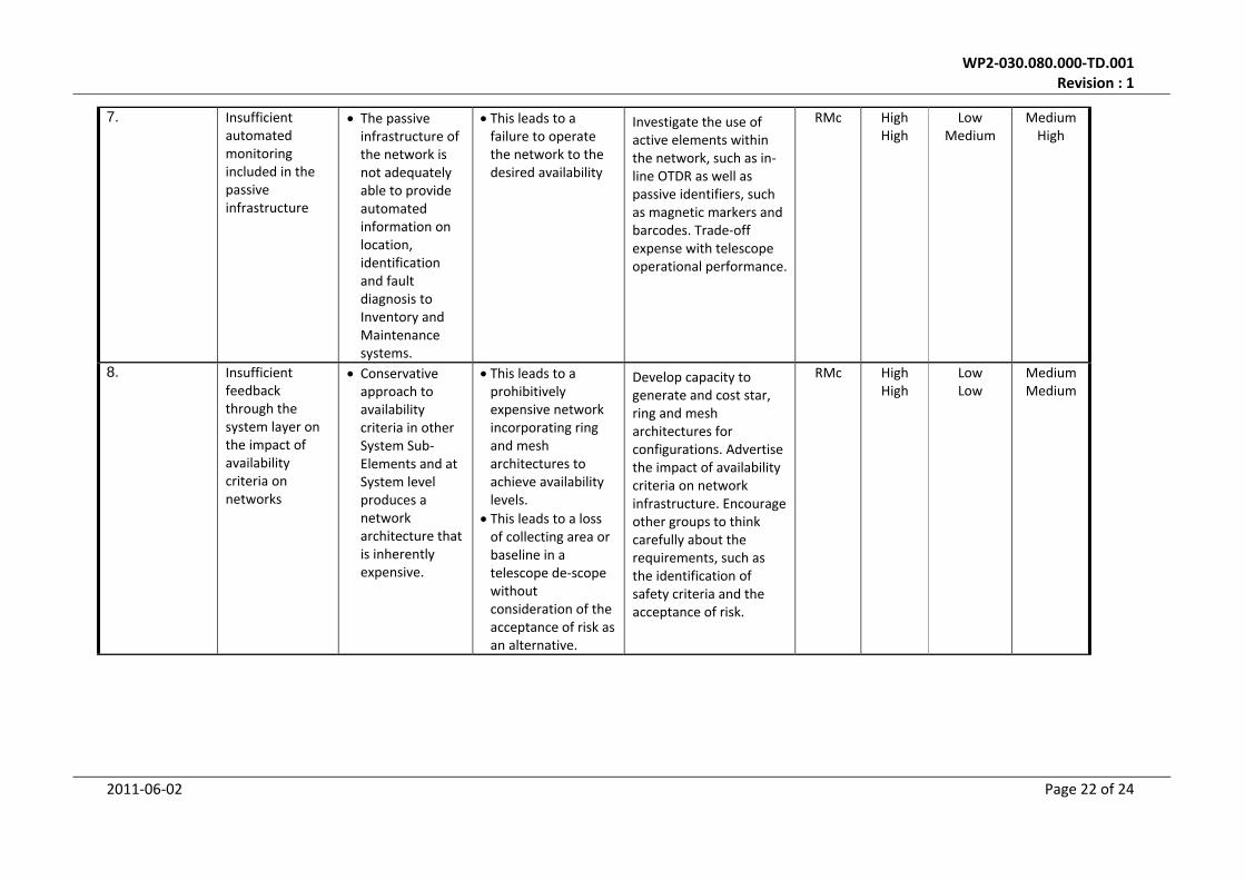
7. Insufficient automated monitoring included in the passive infrastructure
• The passive infrastructure of the network is not adequately able to provide automated information on location, identification and fault diagnosis to Inventory and Maintenance systems.
• This leads to a failure to operate the network to the desired availability
Investigate the use of active elements within the network, such as in‐line OTDR as well as passive identifiers, such as magnetic markers and barcodes. Trade‐off expense with telescope operational performance.
RMc HighHigh
LowMedium
MediumHigh
8. Insufficient feedback through the system layer on the impact of availability criteria on networks
• Conservative approach to availability criteria in other System Sub‐Elements and at System level produces a network architecture that is inherently expensive.
• This leads to a prohibitively expensive network incorporating ring and mesh architectures to achieve availability levels.
• This leads to a loss of collecting area or baseline in a telescope de‐scope without consideration of the acceptance of risk as an alternative.
Develop capacity to generate and cost star, ring and mesh architectures for configurations. Advertise the impact of availability criteria on network infrastructure. Encourage other groups to think carefully about the requirements, such as the identification of safety criteria and the acceptance of risk.
RMc HighHigh
LowLow
MediumMedium
2011‐06‐02 Page 22 of 24

WP2‐030.080.000‐TD.001 Revision : 1
2011‐06‐02 Page 23 of 24
9. Schedule • The scheduled timetable for Site and System design are not sufficiently aligned to allow the design for the physical network infrastructure to develop in time for the Site PDR and CDRs.
• Site infrastructure is constructed with insufficient data about network design, architectures and requirements.
• The constructed infrastructure is subsequently found to be unfit for purpose.
Highlight the link between Site, System and the Physical Network Infrastructure and create a formal programmatic link between them so that delays in one are reflected in the other
KC HighHigh
HighHigh
HighHigh
Abbreviations: Risk ID – Unique risk identifier L = Likelihood (1‐5) C = Consequence (1‐5) IR = Intrinsic Risk (untreated) (High, Medium, Low) Risk owner – person/organisation responsible for managing the risk RL = Residual likelihood (likelihood that will remain after treatment) RC = Residual consequence (consequence that will remain after treatment) RR = Residual risk (the risk rating after treatment (High, Medium, Low)
Kobus Cloete KC Peter Dewdney PED Andre Gunst AG Duncan Hall DH Roshene McCool RMc Rob Millenaar RM Neil Roddis NR Tim Stevenson TS Wallace Turner WT
WP2‐030.080.000‐TD.001 Revision : 1
11 Planning for the next phase In the next phase work on network infrastructure will continue in five main areas;
1. The collection of Sub‐Element requirements for the network infrastructure and consideration of their impact on the design
2. The development of alternative array configurations and investigation of the network infrastructure costs of these configurations.
3. The investigation of methods and processes for ‘as‐built’ record keeping for the array, in particular options such as GIS.
4. The continued interaction between STaN and groups working on site infrastructure in the precursors to ensure this experience is fed in to the project.
5. The continued development of infrastructure design and refinement of cost estimates. There is no resource allocated for these tasks in PREPSKA, over and above the time of the SPDO Domain Specialist. However the task has been identified in the PEP [10] as WP7.3 Network Infrastructure. In addition to the tasks identified above resource will be allocated to;
6. The leadership and coordination of the network infrastructure task, including review of plans and designs, up to and including a CDR in the pre‐production phase.
7. The integration of site information and network infrastructure designs 8. The preparation of the procurement datapacks.
Additional work has been identified in the course of preparing this review document, this is; 9. The investigation of the use of active components (e.g in‐line OTDRs) to achieve
maintainability targets for the passive network infrastructure.
12 References [1] SKA Operational Concepts, P.E. Dewdney, SKA Project Document WP2‐001.010.010‐PLA‐002, 2011‐02‐21. [2] “Cost‐effective infrastructure in a multi‐antenna telescope layout”, G. Grigorescu, P. Alexander, R. C.
Bolton, R. McCool Experimental astronomy, Oct 2009. Also published as SKA Memo 121 [3] STaN High Level D description, R. McCool, STaN CoDR Document ‐ WP2‐030.030.030‐TD‐001, 2011‐05‐09 [4] SKA Configurations Design, R. Bolton et al, SKA Project Document – WP3‐050.020.000‐R‐002, 2011‐02‐17. [5] The Aperture Arrays for the SKA: the SKADS White Paper, SKA Memo 122, A Faulkner et al. [6] ALMA External Optical Cabling Design Project, Bill of Materials and Installation Cost Analysis, C. Holden
(Corning Cable Systems Inc), R.McCool (JBO), ALMA Project Document BEND‐54.09.00.00‐005 A BOM, 2005‐05‐05. [Not for publication outside the ALMA project, permission for SKA use obtained in 2009]
[7] ALMA AOS INTERNAL FIBRE SYSTEM BOM and Budgetary Costs, C. Holden (Corning Cable Systems Inc), ALMA‐DES‐ROO‐056, 2006‐03‐10. [Not for publication outside the ALMA project, permission for SKA use obtained in 2009]
[8] CoDR Information Subject to an NDA, R. McCool, WP2‐030.030.030‐TD‐002, 2011‐06‐14. [9] STaN CoDR Plan, R. McCool, STaN CoDR Document – WP2‐030.030.030‐PLA‐001, 2011‐05‐09. [10] Project Execution Plan, Pre‐Construction Phase for the Square Kilometre Array, R.T Schilizzi et al, SKA
project document MGT‐001.005.005‐MP‐001(K).