norma infrastructure
TRANSCRIPT

NORMA INFRASTRUCTURE 1
Connecting and supporting technologyfor building and infrastructure.
www.normagroup.com
CONSTRUCTION SANITARY WATeR mANAgemeNT SHIPBUILDINg
NORMA INFRASTRUCTURe

NORMA INFRASTRUCTURE2
CONNeCtiNg sOlutiONs FOR DeCADeS
NORMA Group is a global market and
technology leader with strong growth prospects
in attractive niche markets for engineered
joining technologies.
The company manufactures and sells a
wide range of high-quality engineered joining
technology solutions in three product categories:
clamp, connect and fluid. These are often
mission-critical for the performance, reliability
and quality of the respective customer end
products.
Headquartered in Maintal, Germany, NORMA
Group has a global network, which includes 17
manufacturing and distribution facilities as well
as ten sales and distribution sites across Europe,
the Americas and Asia Pacific.
The company offers more than 35,000 high-
quality products and solutions to approximately
10,000 customers in a wide range of industries,
including agricultural machinery, commercial
vehicles, construction equipment, engines,
aviation, infrastructure/construction/water
management, passenger vehicles, railway, white
goods, wholesalers and technical distributors.
Commercial vehicles engines Infrastructure / Water management Aviation Construction equipment

NORMA INFRASTRUCTURE 3
Agricultural equipment Shipbuilding White goods Passenger vehicles Railways
Sales and distribution centres
• Australia• Brazil• China• France• germany• india• indonesia• italy• Japan• Malaysia
• Philippines• singapore• south Korea• spain• sweden• switzerland• turkey• uK• usA• Vietnam
manufacturing locations
• China • Czech Republic• France• germany• india• italy• Mexico
• Poland• Russia• serbia• sweden• thailand• uK• usA
WORldWide PReSeNCe

NORMA INFRASTRUCTURE4
NORMA INFRASTRUCTURe
ORiENTEd: our orientation is to secure your process by delivering global solution.
REsPONsiblE: our products are fully tested to meet your quality requirements.
AdvANTAGE: our global solutions enable customers to be innovative and competitive on their markets.
CusTOMER: we are fully dedicated to your individual satisfaction – wholesalers and end-users.
LEARNiNG: our solution development is driven by your feedback.
ExPERT: our know-how and competencies allows us to respond to your applications.
NORMA iNFRAsTRuCTuRE a division within NORMA Group, supplying technical added value solution for connecting, supporting and fixing for building and infrastructure.
OuR MissiON => 100% SECURITY FOR YOUR PROCESS
CONSTRUCTION WATeR mANAgemeNT
PIPeLINeS SHIP BUILDINgSANITARY
NORMA INFRASTRUCTURE 5
NORMA QUALITY
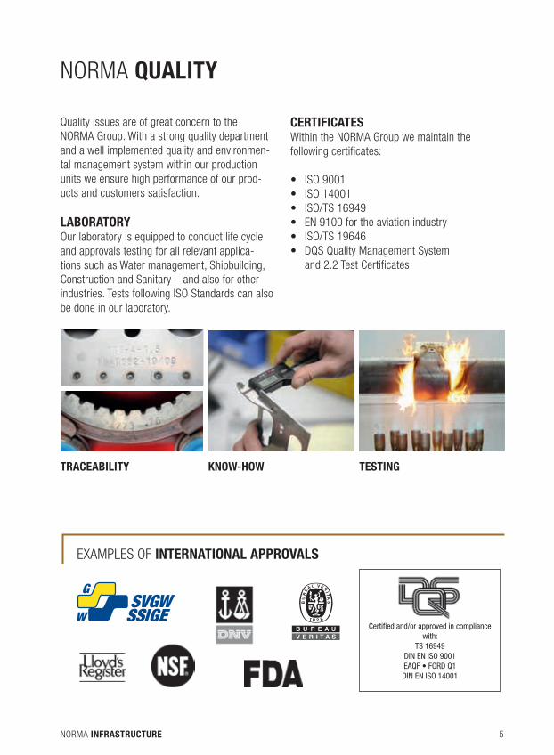
Quality issues are of great concern to theNORMA Group. With a strong quality department and a well implemented quality and environmen-tal management system within our production units we ensure high performance of our prod-ucts and customers satisfaction.
LabORaTORYOur laboratory is equipped to conduct life cycle and approvals testing for all relevant applica-tions such as Water management, shipbuilding, Construction and sanitary – and also for other industries. Tests following isO standards can also be done in our laboratory.
CERTIFICaTESWithin the NORMA Group we maintain the following certificates:
• ISO9001• ISO14001• ISO/TS16949• EN9100fortheaviationindustry• ISO/TS19646• DQSQualityManagementSystem
and 2.2 Test Certificates
TRaCEabILITY KNOW-HOW TESTINg
ExAMPlEs OF INTERNaTIONaL aPPROvaLS
Certified and/or approved in compliance with:
TS 16949DIN EN ISO 9001EAQF • FORD Q1DIN EN ISO 14001

NORMA INFRASTRUCTURE6
NORMA iNFRAstRuCtuRe –IN LINe WITH YOUR NeeDSNORMA iNFRAsTRuCTuRE offers a wide range of solutions for needs you face on the field. see, on the next pages, more details about our solutions which are suitable to your applications.
SaNITaRY
CONSTRUCTION
INdUSTRIES
NORMA INFRASTRUCTURE 7
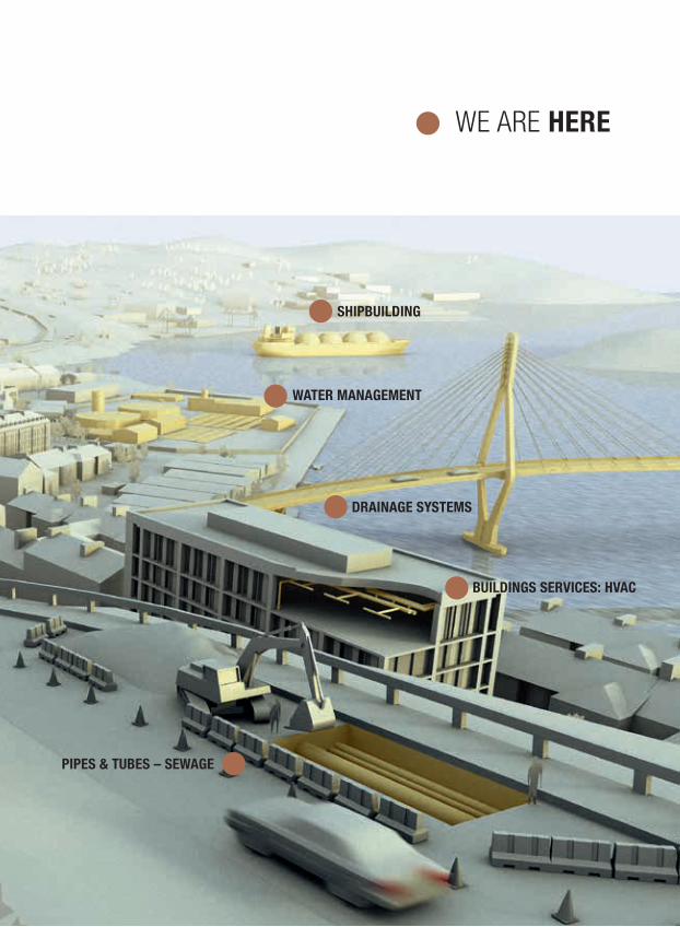
We ARe HeRe
SHIPbUILdINg
WaTER MaNagEMENT
dRaINagE SYSTEMS
bUILdINgS SERvICES: HvaC
PIPES & TUbES – SEWagE
NORMA INFRASTRUCTURE8
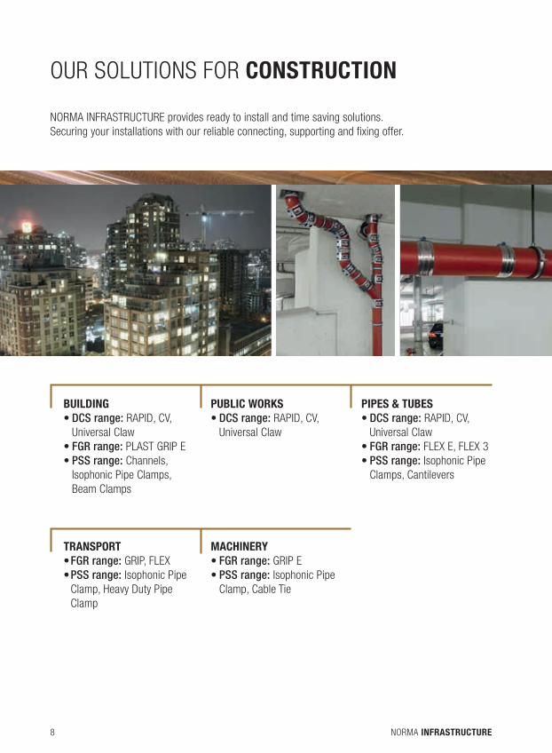
OuR sOlutiONs FOR CONSTRUCTION
bUILdINg •DCS range: RAPid, Cv, universal Claw•FGR range: PlAsT GRiP E•PSS range: Channels, isophonic Pipe Clamps, beam Clamps
PUbLIC WORKS • DCS range: RAPid, Cv, universal Claw
PIPES & TUbES •DCS range: RAPid, Cv, universal Claw•FGR range: FlEx E, FlEx 3•PSS range: isophonic Pipe Clamps, Cantilevers
TRaNSPORT • FGR range: GRiP, FlEx•PSS range: isophonic Pipe Clamp, Heavy duty Pipe Clamp
MaCHINERY • FGR range: GRiP E• PSS range: isophonic Pipe Clamp, Cable Tie
NORMA iNFRAsTRuCTuRE provides ready to install and time saving solutions. securing your installations with our reliable connecting, supporting and fixing offer.
NORMA INFRASTRUCTURE 9
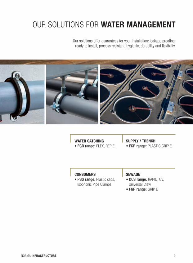
OuR sOlutiONs FOR WATeR mANAgemeNT
Our solutions offer guarantees for your installation: leakage proofing, ready to install, process resistant, hygienic, durability and flexibility.
WaTER CaTCHINg•FGR range: FlEx, REP E
SUPPLY / TRENCH•FGR range: PlAsTiC GRiP E
CONSUMERS•PSS range: Plastic clips, isophonic Pipe Clamps
SEWagE•DCS range: RAPid, Cv, universal Claw•FGR range: GRiP E

NORMA INFRASTRUCTURE10
OuR sOlutiONs FOR SANITARY
Our solutions provide to sANiTARY sector easy & quick installation systems and long term reliability, flexibility regarding pipes material and dimensions.
dRaINagE•DCS range: RAPid, Cv, universal Claw•PSS range: Gutter Pipe Clamps
WaTER SUPPLY•FGR range: FlEx, FlEx3•PSS range: Plastic Clips, isophonic Pipe Clamps
HvaC•PSS range: insulated Pipe Clamps, Cantilevers
NORMA INFRASTRUCTURE 11
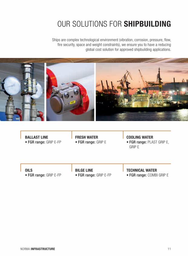
OuR sOlutiONs FOR SHIPBUILDINg
ships are complex technological environment (vibration, corrosion, pressure, flow, fire security, space and weight constraints), we ensure you to have a reducing
global cost solution for approved shipbuilding applications.
baLLaST LINE•FGR range: GRiP E-FP
FRESH WaTER•FGR range: GRiP E
COOLINg WaTER•FGR range: PlAsT GRiP E, GRiP E
OILS•FGR range: GRiP E-FP
bILgE LINE•FGR range: GRiP E-FP
TECHNICaL WaTER•FGR range: COMbi GRiP E
NORMA INFRASTRUCTURE12
INDeXFgRIntroOur solution, approvals, etc ...................16
For axial non-restraint connectionsFlEx/FlEx E ........................................26FlEx 3 ................................................28REP E ..................................................30
For axial restraint connectionsGRiP/GRiP E .........................................34GRiP/GRiP E-FP ....................................37PlAsT GRiP / PlAsT GRiP E ..................40COMbi GRiP / COMbi GRiP E .................42
Accessories .........................................44
DCS
PSS
IntroOur solution, certificates, etc .................48
For non pull-out resistant connectionsdCs RAPid ..........................................54dCs RAPid MsM ..................................55dCs Cv/CE ..........................................56dCs svE .............................................57
For pull-out resistant connectionsdCs uNivERsAl Restraint Collar ...........60dCs REKORd Restraint Collar ................61dCs KOMbi Restraint Collar ..................62
Changeover connectorsdCs Fix ..............................................64
survey of sizes .....................................65
IntroOur solutions, certificates, etc ...............68
Non Isophonic Pipe ClampsPipe clamp M8/M10 with captive screws .. 72Heavy duty pipe clamp M12 ..................73drain pipe clamp M8 ............................74sprinkler pipe clamp .............................75bridge pipe clamp ................................76Conduit clip .........................................77
Isophonic Pipe Clampsisophonic quick clamp with hinge M8/M10 ..............................................80 isophonic quick clamp with hinge and fixing M8/M10 ...............................81isophonic pipe clamp M8/M10 with captive screws .....................................82isophonic heavy duty pipe clamp M12 .....84M8 isophonic gutter pipe clamp .............85bridge isophonic pipe clamp..................86insulated pipe clamp 13 mm-M8/M10 .... 87Insulatedpipeclamp19mm-M8/M10 ....88
Plastic ClipSimple&doubleplasticclipM6 .............90
ChannelsChannel 27/18 C-shape .......................93Channel 28/30 C-shape .......................93Channel38/40C-shape .......................94Cantilever 27/18 C-shape .....................95Cantilever 28/30 C-shape .....................96Channel screw for C-shape channel ........97Fixing plate for C-shape channel ............98vertical & horizontal support for C-shape channel ..................................99Channel41/21strut41-shape ............101
NORMA INFRASTRUCTURE 13
PSS
Channel41/41strut41-shape ............102Cantilever41/21strut41shape ..........103Cantilever41/41strut41shape ..........104Uplateforstrut41shape ...................105Channelnutforstrut41shape ............105Channelscrewforstrut41shape ........106135°fixingplateforstrut41shape .....10790°fixingplateforstrut41shape,2 slots ...............................................10790°fxingplateforstrut41shape,3 slots ...............................................108Reinforcedsquareforstrut41shape4slots ...............................................108Doublebaseforstrut41shape ...........109Bridge5slotsforstrut41shape .........109BeamclampM10forstrut41shape ....110C&strut41shapechannelconnection..111Capsforcansstrut41shapechannel ..112
accessoriesThreaded screws ................................116double thread screw ...........................116Hexagonal nut ....................................117large washer .....................................117screw anchor .....................................118Wedge anchor ....................................118brass anchor .....................................119drop-in anchor ...................................119Threaded rod .....................................120Threaded pins ....................................120double threaded screw .......................121Elevation nut ......................................121Coupling nut ......................................122Round base plate ...............................123Perforated band .................................124Cable tie –White and black .................125Cable tie – Colors ...............................126
PSS
Tie mount plug ...................................126screw mount & adhesive pad ..............127PliersforcabletiePA6.6 ....................128PliersforcabletiePA6.6andPA12 ...128
Fixing on steel structurebeam clamp ......................................131Threaded rod horizontal clip ................132Cable tie horizontal clip .......................133Perforated band horizontal clip ............134Threaded rod vertical clip ....................135Cable tie vertical clip ..........................136Perforated band vertical clip ................137beam clip ..........................................138
Stainless Steel Supporting and Fixingstainless steel pipe clamp M8/M10 with captive screws ............................140stainless steel channel 28/30 C-shape ..141Stainlesssteelchannel38/40C-shape ..141stainless steel channel screw for C-shape channel ................................142stainless steel fixing plate for C-shape channel ................................143stainless steel double threaded screw .. 144stainless steel hexgonal nut ................144stainless steel large washer ................145stainless steel threaded rod ................145stainless steel rectangular base plate ...146stainless steel band ...........................146
Technical information ..........................147
ADDITIONAL SOLUTIONSNORMAClAMP® .................................164Market development ...........................166
NORMA INFRASTRUCTURE14 FGR
NORMA INFRASTRUCTURE 15FGR
FGR

NORMA INFRASTRUCTURE16 FGR
OUR SOLUTION FOR CONNECTING – FGR
FGR pipe couplings are a compact, eco nomical and
reliable means for connecting plain-ended pipes.
They are suitable to join plastic and metal pipes and
especially pipes made from stainless steel. They can
be used in mechanical engineering and construction,
shipbuilding, civil engineering and in hydro technology.
Supply pipes as well as exhaust pipes for solid, liquid
or gaseous media can be joined easily and safely in a
very short period of time even in narrow spaces.
Thanks to the wide range of various types and sizes
they are suitable for use both in standard and special-
ized applications.
AppROvALS
Certified and/or approved in compliance with:
TS 16949DIN EN ISO 9001EAQF • FORD Q1DIN EN ISO 14001

NORMA INFRASTRUCTURE 17FGR
GL-Directory 2006/2007
Your hotline to GL for �eet in service
+49 40 · 36149 · 1111
No. 68
FGR
NORMA INFRASTRUCTURE18 FGR
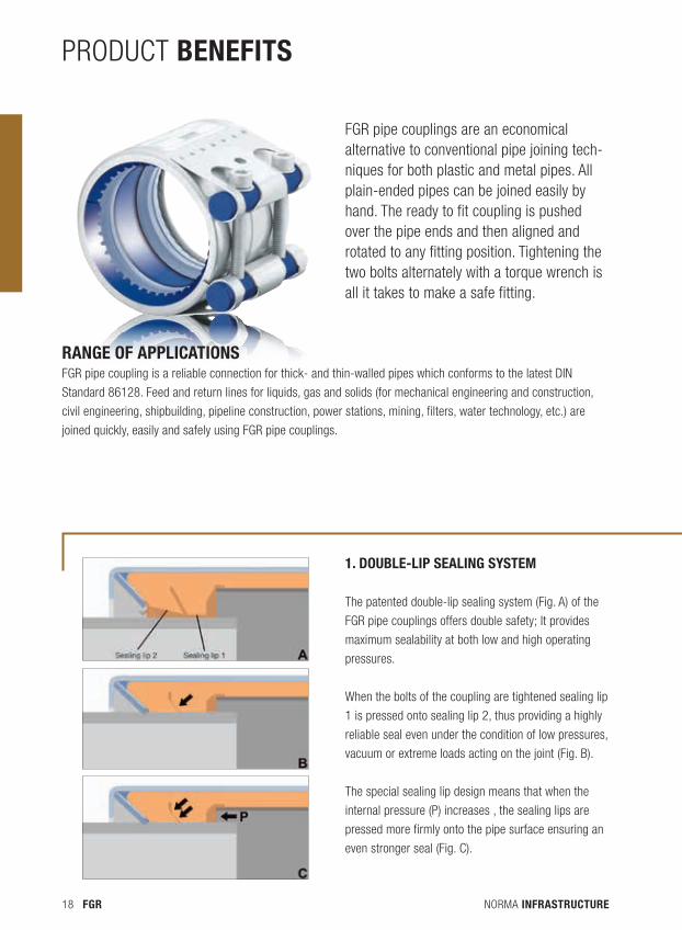
pROdUcT bENEFITs
FGR pipe couplings are an economical alternative to conventional pipe joining tech-niques for both plastic and metal pipes. All plain-ended pipes can be joined easily by hand. The ready to fit coupling is pushed over the pipe ends and then aligned and rotated to any fitting position. Tightening the two bolts alternately with a torque wrench is all it takes to make a safe fitting.
Range of applicationsFGR pipe coupling is a reliable connection for thick- and thin-walled pipes which conforms to the latest DIN
Standard 86128. Feed and return lines for liquids, gas and solids (for mechanical engineering and construction,
civil engineering, shipbuilding, pipe line construction, power stations, mining, filters, water technology, etc.) are
joined quickly, easily and safely using FGR pipe couplings.
1. Double-lip sealing system
The patented double-lip sealing system (Fig. A) of the
FGR pipe couplings offers double safety; It provides
maximum sealability at both low and high operating
pressures.
When the bolts of the coupling are tightened sealing lip
1 is pressed onto sealing lip 2, thus providing a highly
reliable seal even under the condition of low pressures,
vacuum or extreme loads acting on the joint (Fig. B).
The special sealing lip design means that when the
internal pressure (P) increases , the sealing lips are
pressed more firmly onto the pipe surface ensuring an
even stronger seal (Fig. C).
NORMA INFRASTRUCTURE 19FGR
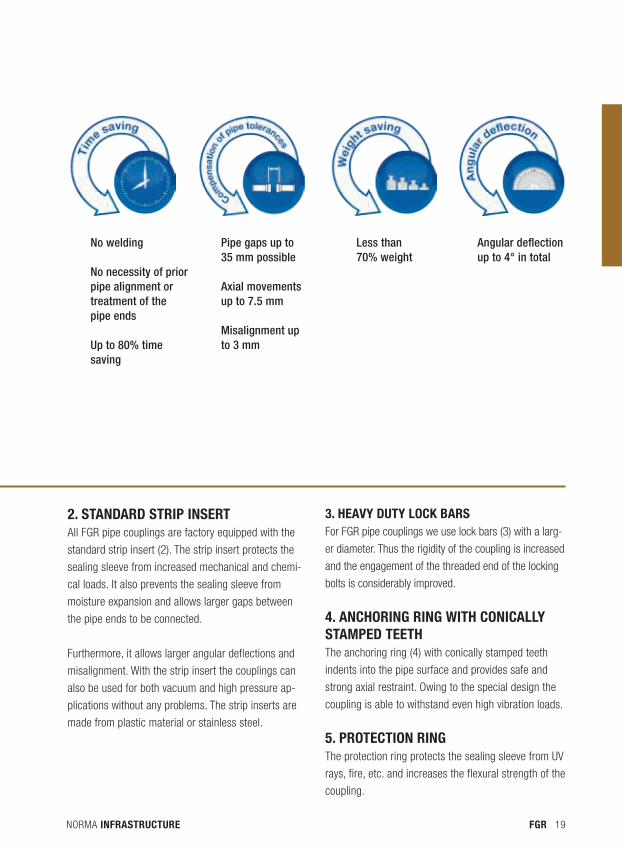
2. stanDaRD stRip inseRtAll FGR pipe couplings are factory equipped with the
standard strip insert (2). The strip insert protects the
sealing sleeve from increased mechanical and chemi-
cal loads. It also prevents the sealing sleeve from
moisture expansion and allows larger gaps between
the pipe ends to be connected.
Furthermore, it allows larger angular deflections and
misalignment. With the strip insert the couplings can
also be used for both vacuum and high pressure ap-
plications without any problems. The strip inserts are
made from plastic material or stainless steel.
3. Heavy Duty lock baRsFor FGR pipe couplings we use lock bars (3) with a larg-
er diameter. Thus the rigidity of the coupling is increased
and the engagement of the threaded end of the locking
bolts is considerably improved.
4. ancHoRing Ring witH conically stampeD teetHThe anchoring ring (4) with conically stamped teeth
indents into the pipe surface and provides safe and
strong axial restraint. Owing to the special design the
coupling is able to withstand even high vibration loads.
5. pRotection RingThe protection ring protects the sealing sleeve from UV
rays, fire, etc. and increases the flexural strength of the
coupling.
No welding
No necessity of prior pipe alignment or treatment of the pipe ends
Up to 80% time saving
Pipe gaps up to 35 mm possible
Axial movements up to 7.5 mm
Misalignment up to 3 mm
Less than 70% weight
Angular deflection up to 4° in total
NORMA INFRASTRUCTURE20 FGR
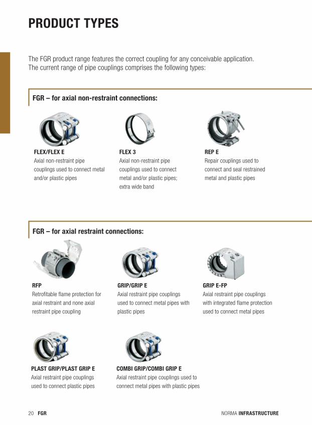
PRODUCT TYPEs
flex/flex e
Axial non-restraint pipe
couplings used to connect metal
and/or plastic pipes
flex 3
Axial non-restraint pipe
couplings used to connect
metal and/or plastic pipes;
extra wide band
Rep e Repair couplings used to
connect and seal restrained
metal and plastic pipes
Rfp
Retrofitable flame protection for
axial restraint and none axial
restraint pipe coupling
gRip/gRip e Axial restraint pipe couplings
used to connect metal pipes with
plastic pipes
gRip e-fp Axial restraint pipe couplings
with integrated flame protection
used to connect metal pipes
The FGR product range features the correct coupling for any conceivable application. The current range of pipe couplings comprises the following types:
plast gRip/plast gRip e
Axial restraint pipe couplings
used to connect plastic pipes
combi gRip/combi gRip e
Axial restraint pipe couplings used to
connect metal pipes with plastic pipes
fgR – for axial non-restraint connections:
fgR – for axial restraint connections:
NORMA INFRASTRUCTURE 21FGR
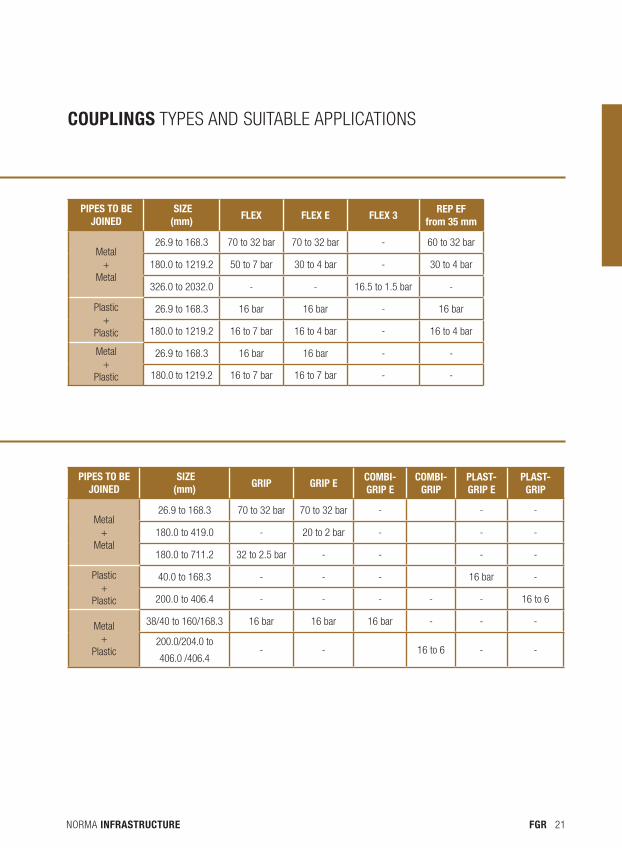
COUPlINGs TypeS ANd SUITAbLe AppLIcATIONS
PIPEs TO bE JOINED
sIzE (mm) FlEx FlEx E FlEx 3
REP EF from 35 mm
Metal+
Metal
26.9 to 168.3 70 to 32 bar 70 to 32 bar - 60 to 32 bar
180.0 to 1219.2 50 to 7 bar 30 to 4 bar - 30 to 4 bar
326.0 to 2032.0 - - 16.5 to 1.5 bar -
plastic+
plastic
26.9 to 168.3 16 bar 16 bar - 16 bar
180.0 to 1219.2 16 to 7 bar 16 to 4 bar - 16 to 4 bar
Metal+
plastic
26.9 to 168.3 16 bar 16 bar - -
180.0 to 1219.2 16 to 7 bar 16 to 7 bar - -
PIPEs TO bE JOINED
sIzE (mm) GRIP GRIP E
COmbI-GRIP E
COmbI- GRIP
PlasT-GRIP E
PlasT-GRIP
Metal+
Metal
26.9 to 168.3 70 to 32 bar 70 to 32 bar - - -
180.0 to 419.0 - 20 to 2 bar - - -
180.0 to 711.2 32 to 2.5 bar - - - -
plastic+
plastic
40.0 to 168.3 - - - 16 bar -
200.0 to 406.4 - - - - - 16 to 6
Metal+
plastic
38/40 to 160/168.3 16 bar 16 bar 16 bar - - -
200.0/204.0 to
406.0 /406.4- - 16 to 6 - -
NORMA INFRASTRUCTURE22 FGR
FGR maTERIals
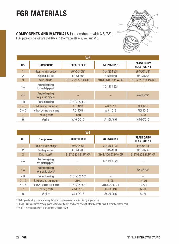
components anD mateRials in accordance with AISI/BS.FGR pipe couplings are available in the materials W2, W4 and W5.
W2
No. Component FlEx/FlEx E GRIP/GRIP EPlasT GRIP/ PlasT GRIP E
1 Housing with bridge 304/304 S31 304/304 S31 304/304 S31
2 Sealing sleeve epdM/NbR epdM/NbR epdM/NbR
3 Strip insert1) 316Ti/320 S31/pA-GR 316Ti/320 S31/pA-GR 316Ti/320 S31/pA-GR
4 AAnchoring ring
for metal pipes2) – 301/301 S21 –
4 AAnchoring ring
for plastic pipes2) – – pA-GF-NS3)
4 b protection ring 316Ti/320 S31 – –
5 + 6 Solid locking trunnions AISI 1213 AISI 1213 AISI 1213
5 + 6 Hollow locking trunnions AISI 1518 AISI 1518 AISI 1518
7 Locking bolts 10,9 10,9 10,9
8 Washer A4-80/316 A4-80/316 A4-80/316
W4
No. Component FlEx/FlEx E GRIP/GRIP EPlasT GRIP/ PlasT GRIP E
1 Housing with bridge 304/304 S31 304/304 S31 304/304 S31
2 Sealing sleeve epdM/NbR epdM/NbR epdM/NbR
3 Strip insert1) 316Ti/320 S31/pA-GR 316Ti/320 S31/pA-GR 316Ti/320 S31/pA-GR
4 AAnchoring ring
for metal pipes2) – 301/301 S21 –
4 AAnchoring ring
for plastic pipes2) – – pA-GF-NS3)
4 b protection ring 316Ti/320 S31 – –
5 + 6 Solid locking trunnions 316L 316L 1.4404
5 + 6 Hollow locking trunnions 316Ti/320 S31 316Ti/320 S31 1.4571
7 Locking bolts A4-80/316 A4-80/316 A4-80
8 Washer A4-80/316 A4-80/316 A4-80
1) pA-GF plastic strip inserts are only for pipe couplings used in shipbuilding applications.2) cOMbI GRIp couplings are equipped with two different anchoring rings (1 x for the metal end, 1 x for the plastic end).3) pA-GF: pA reinforced with fi bre glass; NS: new silver.
NORMA INFRASTRUCTURE 23FGR
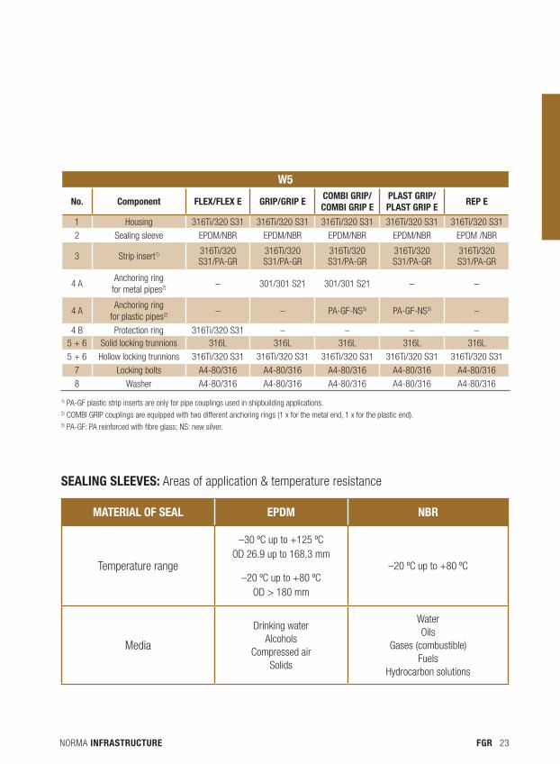
W5
No. Component FlEx/FlEx E GRIP/GRIP E COmbI GRIP/ COmbI GRIP E
PlasT GRIP/ PlasT GRIP E
REP E
1 Housing 316Ti/320 S31 316Ti/320 S31 316Ti/320 S31 316Ti/320 S31 316Ti/320 S31
2 Sealing sleeve epdM/NbR epdM/NbR epdM/NbR epdM/NbR epdM /NbR
3 Strip insert1) 316Ti/320 S31/pA-GR
316Ti/320 S31/pA-GR
316Ti/320 S31/pA-GR
316Ti/320 S31/pA-GR
316Ti/320 S31/pA-GR
4 AAnchoring ring
for metal pipes2) – 301/301 S21 301/301 S21 – –
4 AAnchoring ring
for plastic pipes2) – – pA-GF-NS3) pA-GF-NS3) –
4 b protection ring 316Ti/320 S31 – – – –5 + 6 Solid locking trunnions 316L 316L 316L 316L 316L
5 + 6 Hollow locking trunnions 316Ti/320 S31 316Ti/320 S31 316Ti/320 S31 316Ti/320 S31 316Ti/320 S31
7 Locking bolts A4-80/316 A4-80/316 A4-80/316 A4-80/316 A4-80/316
8 Washer A4-80/316 A4-80/316 A4-80/316 A4-80/316 A4-80/316
sealing sleeves: Areas of application & temperature resistance
maTERIal OF sEal EPDm NbR
Temperature range
–30 ºc up to +125 ºcOd 26.9 up to 168,3 mm
–20 ºc up to +80 ºcOd > 180 mm
–20 ºc up to +80 ºc
Media
drinking waterAlcohols
compressed airSolids
WaterOils
Gases (combustible)Fuels
Hydrocarbon solutions
1) pA-GF plastic strip inserts are only for pipe couplings used in shipbuilding applications.2) cOMbI GRIp couplings are equipped with two different anchoring rings (1 x for the metal end, 1 x for the plastic end).3) pA-GF: pA reinforced with fibre glass; NS: new silver.

NORMA INFRASTRUCTURE24 FGR
NORMA INFRASTRUCTURE 25FGR
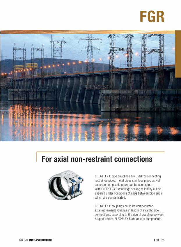
for axial non-restraint connections
FLEX/FLEX E pipe couplings are used for connecting restrained pipes, metal pipes stainless pipes as well concrete and plastic pipes can be connected. With FLEX/FLEX E couplings sealing reliability is also ensured under conditions of gaps between pipe ends which are compensated.
FLEX/FLEX E couplings could be compensated axial movements /change in length of straight pipe connections, according to the size of coupling between 5 up to 15mm. FLEX/FLEX E are able to compensate.
FGR
NORMA INFRASTRUCTURE26 FGR
1
2
3
1
2
3
4
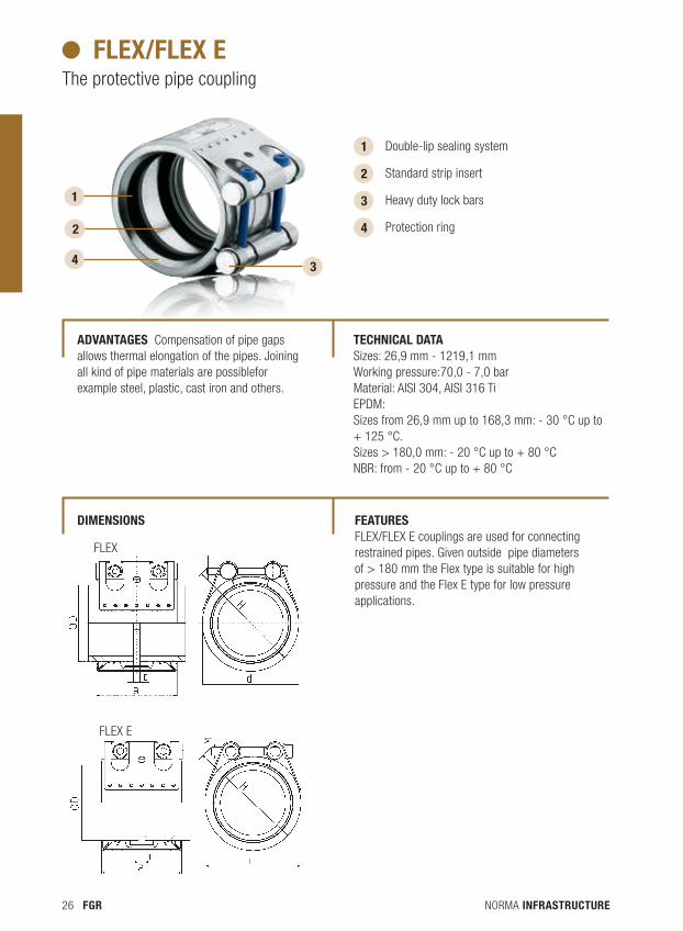
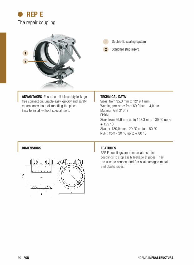
Double-lip sealing system
Standard strip insert
Heavy duty lock bars
Protection ring
4
flex/flex e The protective pipe coupling
FLEX
FLEX E
aDvantages Compensation of pipe gaps allows thermal elongation of the pipes. Joining all kind of pipe materials are possiblefor example steel, plastic, cast iron and others.
tecHnical Data Sizes: 26,9 mm - 1219,1 mmWorking pressure:70,0 - 7,0 barMaterial: AISI 304, AISI 316 TiEPDM: Sizes from 26,9 mm up to 168,3 mm: - 30 °C up to + 125 °C. Sizes > 180,0 mm: - 20 °C up to + 80 °C NBR: from - 20 °C up to + 80 °C
featuRes FLEX/FLEX E couplings are used for connecting restrained pipes. Given outside pipe diameters of > 180 mm the Flex type is suitable for high pressure and the Flex E type for low pressure applications.
Dimensions
NORMA INFRASTRUCTURE 27FGR
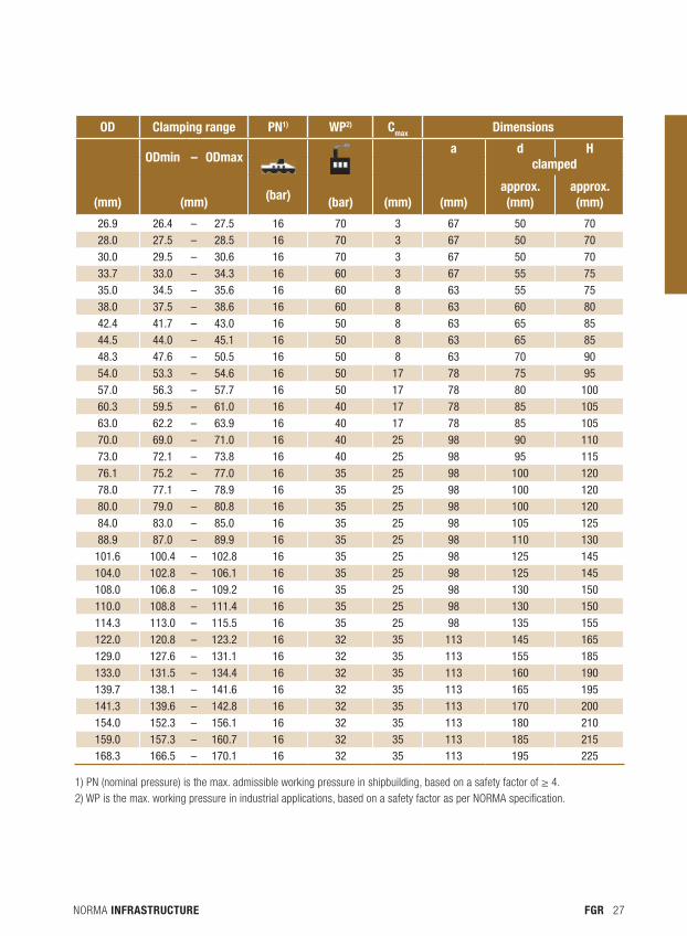
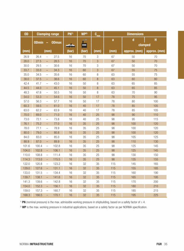
OD Clamping range PN1) WP2) Cmax Dimensions
ODmin – ODmax
a d H
clamped
(mm) (mm) (bar) (bar) (mm) (mm)approx. (mm)
approx. (mm)
26.9 26.4 – 27.5 16 70 3 67 50 7028.0 27.5 – 28.5 16 70 3 67 50 7030.0 29.5 – 30.6 16 70 3 67 50 7033.7 33.0 – 34.3 16 60 3 67 55 7535.0 34.5 – 35.6 16 60 8 63 55 7538.0 37.5 – 38.6 16 60 8 63 60 8042.4 41.7 – 43.0 16 50 8 63 65 8544.5 44.0 – 45.1 16 50 8 63 65 8548.3 47.6 – 50.5 16 50 8 63 70 9054.0 53.3 – 54.6 16 50 17 78 75 9557.0 56.3 – 57.7 16 50 17 78 80 10060.3 59.5 – 61.0 16 40 17 78 85 10563.0 62.2 – 63.9 16 40 17 78 85 10570.0 69.0 – 71.0 16 40 25 98 90 11073.0 72.1 – 73.8 16 40 25 98 95 11576.1 75.2 – 77.0 16 35 25 98 100 12078.0 77.1 – 78.9 16 35 25 98 100 12080.0 79.0 – 80.8 16 35 25 98 100 12084.0 83.0 – 85.0 16 35 25 98 105 12588.9 87.0 – 89.9 16 35 25 98 110 130
101.6 100.4 – 102.8 16 35 25 98 125 145104.0 102.8 – 106.1 16 35 25 98 125 145108.0 106.8 – 109.2 16 35 25 98 130 150110.0 108.8 – 111.4 16 35 25 98 130 150114.3 113.0 – 115.5 16 35 25 98 135 155122.0 120.8 – 123.2 16 32 35 113 145 165129.0 127.6 – 131.1 16 32 35 113 155 185133.0 131.5 – 134.4 16 32 35 113 160 190139.7 138.1 – 141.6 16 32 35 113 165 195141.3 139.6 – 142.8 16 32 35 113 170 200154.0 152.3 – 156.1 16 32 35 113 180 210159.0 157.3 – 160.7 16 32 35 113 185 215168.3 166.5 – 170.1 16 32 35 113 195 225
1) PN (nominal pressure) is the max. admissible working pressure in shipbuilding, based on a safety factor of ≥ 4.2) WP is the max. working pressure in industrial applications, based on a safety factor as per NORMA specification.
NORMA INFRASTRUCTURE28 FGR
3
1
2
1
2
3
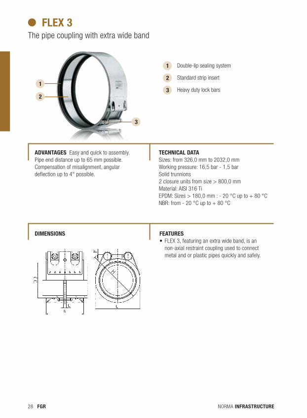
Double-lip sealing system
Standard strip insert
Heavy duty lock bars
flex 3 The pipe coupling with extra wide band
aDvantages Easy and quick to assembly.Pipe end distance up to 65 mm possible.Compensation of misalignment, angular deflection up to 4° possible.
tecHnical Data Sizes: from 326,0 mm to 2032,0 mmWorking pressure: 16,5 bar - 1,5 barSolid trunnions2 closure units from size > 800,0 mmMaterial: AISI 316 TiEPDM: Sizes > 180,0 mm : - 20 °C up to + 80 °C NBR: from - 20 °C up to + 80 °C
featuRes • FLEX3,featuringanextrawideband,isan
non-axial restraint coupling used to connect metal and or plastic pipes quickly and safely.
Dimensions
NORMA INFRASTRUCTURE 29FGR
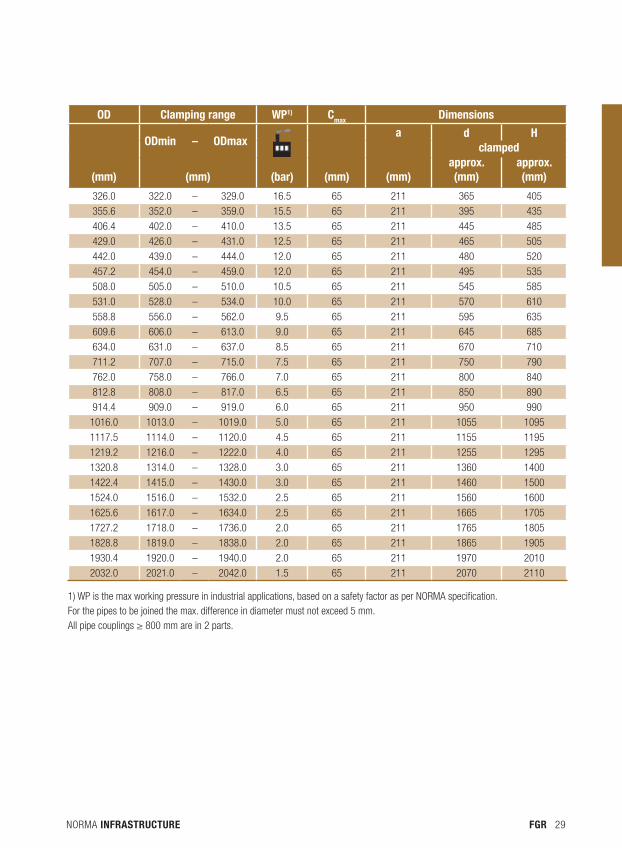
OD Clamping range WP1) Cmax Dimensions
ODmin – ODmax
a d H
clamped
(mm) (mm) (bar) (mm) (mm)approx. (mm)
approx. (mm)
326.0 322.0 – 329.0 16.5 65 211 365 405
355.6 352.0 – 359.0 15.5 65 211 395 435
406.4 402.0 – 410.0 13.5 65 211 445 485
429.0 426.0 – 431.0 12.5 65 211 465 505
442.0 439.0 – 444.0 12.0 65 211 480 520
457.2 454.0 – 459.0 12.0 65 211 495 535
508.0 505.0 – 510.0 10.5 65 211 545 585
531.0 528.0 – 534.0 10.0 65 211 570 610
558.8 556.0 – 562.0 9.5 65 211 595 635
609.6 606.0 – 613.0 9.0 65 211 645 685
634.0 631.0 – 637.0 8.5 65 211 670 710
711.2 707.0 – 715.0 7.5 65 211 750 790
762.0 758.0 – 766.0 7.0 65 211 800 840
812.8 808.0 – 817.0 6.5 65 211 850 890
914.4 909.0 – 919.0 6.0 65 211 950 990
1016.0 1013.0 – 1019.0 5.0 65 211 1055 1095
1117.5 1114.0 – 1120.0 4.5 65 211 1155 1195
1219.2 1216.0 – 1222.0 4.0 65 211 1255 1295
1320.8 1314.0 – 1328.0 3.0 65 211 1360 1400
1422.4 1415.0 – 1430.0 3.0 65 211 1460 1500
1524.0 1516.0 – 1532.0 2.5 65 211 1560 1600
1625.6 1617.0 – 1634.0 2.5 65 211 1665 1705
1727.2 1718.0 – 1736.0 2.0 65 211 1765 1805
1828.8 1819.0 – 1838.0 2.0 65 211 1865 1905
1930.4 1920.0 – 1940.0 2.0 65 211 1970 2010
2032.0 2021.0 – 2042.0 1.5 65 211 2070 2110
1) WP is the max working pressure in industrial applications, based on a safety factor as per NORMA specification.For the pipes to be joined the max. difference in diameter must not exceed 5 mm.All pipe couplings ≥ 800 mm are in 2 parts.
NORMA INFRASTRUCTURE30 FGR
1
2
1
2
Double-lip sealing system
Standard strip insert
Rep e The repair coupling
aDvantages Ensure a reliable safety leakage free connection. Enable easy, quickly and safety reparation without dismantling the pipesEasy to install without special tools.
tecHnical Data Sizes: from 35,0 mm to 1219,1 mmWorking pressure: from 60,0 bar to 4,0 barMaterial: AISI 316 TiEPDM: Sizes from 26,9 mm up to 168,3 mm: - 30 °C up to + 125 °C. Sizes > 180,0mm: - 20 °C up to + 80 °C NBR : from - 20 °C up to + 80 °C
featuRes REP E couplings are none axial restraint couplings to stop easily leakage at pipes. They are used to connect and / or seal damaged metal and plastic pipes.
Dimensions
NORMA INFRASTRUCTURE 31FGR
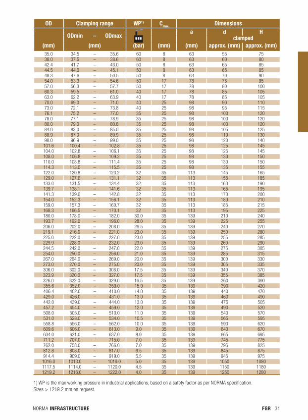
1) WP is the max working pressure in industrial applications, based on a safety factor as per NORMA specification. Sizes > 1219.2 mm on request.
OD Clamping range WP1) Cmax Dimensions
ODmin – ODmax
a d H clamped
(mm) (mm) (bar) (mm) (mm) approx. (mm) approx. (mm)35.0 34.5 – 35.6 60 8 63 55 7538.0 37.5 – 38.6 60 8 63 60 8042.4 41.7 – 43.0 50 8 63 65 8544.5 44.0 – 45.1 50 8 63 65 8548.3 47.6 – 50.5 50 8 63 70 9054.0 53.3 – 54.6 50 17 78 75 9557.0 56.3 – 57.7 50 17 78 80 10060.3 59.5 – 61.0 40 17 78 85 10563.0 62.2 – 63.9 40 17 78 85 10570.0 69.0 – 71.0 40 25 98 90 11073.0 72.1 – 73.8 40 25 98 95 11576.1 75.2 – 77.0 35 25 98 100 12078.0 77.1 – 78.9 35 25 98 100 12080.0 79.0 – 80.8 35 25 98 100 12084.0 83.0 – 85.0 35 25 98 105 12588.9 87.0 – 89.9 35 25 98 110 13098.0 96.9 – 99.0 35 25 98 120 140
101.6 100.4 – 102.8 35 25 98 125 145104.0 102.8 – 106.1 35 25 98 125 145108.0 106.8 – 109.2 35 25 98 130 150110.0 108.8 – 111.4 35 25 98 130 150114.3 113.0 – 115.5 35 25 98 135 155122.0 120.8 – 123.2 32 35 113 145 165129.0 127.6 – 131.1 32 35 113 155 185133.0 131.5 – 134.4 32 35 113 160 190139.7 138.1 – 141.6 32 35 113 165 195141.3 139.6 – 142.8 32 35 113 170 200154.0 152.3 – 156.1 32 35 113 180 210159.0 157.3 – 160.7 32 35 113 185 215168.3 166.5 – 170.1 32 35 113 195 225180.0 178.0 – 182.0 30.0 35 139 210 240193.7 192.0 – 196.0 28.0 35 139 225 255206.0 202.0 – 208.0 26.5 35 139 240 270219.1 216.0 – 221.0 23.0 35 139 250 280225.0 222.0 – 227.0 23.0 35 139 255 285229.9 228.0 – 232.0 23.0 35 139 260 290244.5 242.0 – 247.0 22.0 35 139 275 305254.0 250.0 – 256.0 21.0 35 139 285 315267.0 264.0 – 269.0 20.0 35 139 300 330273.0 270.0 – 275.0 20.0 35 139 305 335306.0 302.0 – 308.0 17.5 35 139 340 370323.9 320.0 – 327.0 17.5 35 139 355 385326.0 322.0 – 329.0 16.5 35 139 360 390355.6 352.0 – 359.0 15.0 35 139 390 420406.4 402.0 – 410.0 14.0 35 139 440 470429.0 426.0 – 431.0 13.0 35 139 460 490442.0 439.0 – 444.0 13.0 35 139 475 505457.2 454.0 – 459.0 12.0 35 139 490 520508.0 505.0 – 510.0 11.0 35 139 540 570531.0 528.0 – 534.0 10.5 35 139 565 595558.8 556.0 – 562.0 10.0 35 139 590 620609.6 606.0 – 613.0 9.0 35 139 640 670634.0 631.0 – 637.0 8.0 35 139 665 695711.2 707.0 – 715.0 7.0 35 139 745 775762.0 758.0 – 766.0 7.0 35 139 795 825812.8 808.0 – 817.0 6.5 35 139 845 875914.4 909.0 – 919.0 5.5 35 139 945 975
1016.0 1013.0 – 1019.0 5.0 35 139 1050 10801117.5 1114.0 – 1120.0 4.5 35 139 1150 11801219.2 1216.0 – 1222.0 4.0 35 139 1250 1280

NORMA INFRASTRUCTURE32 FGR
NORMA INFRASTRUCTURE 33FGR
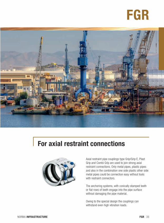
for axial restraint connections
Axial restraint pipe couplings type Grip/Grip E, Plast Grip and Combi Grip are used to join strong axial restraint connections. Only metal pipes, plastic pipes and also in the combination one side plastic other side metal pipes could be connection easy without tools with restraint connectors.
The anchoring systems, with conically stamped teeth or flat rows of teeth engage into the pipe surface without damaging the pipe material.
Owing to the special design the couplings can withstand even high vibration loads.
FGR
NORMA INFRASTRUCTURE34 FGR
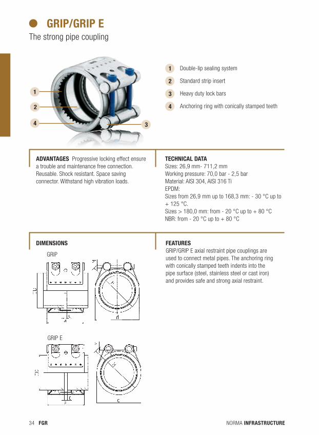
gRip/gRip e The strong pipe coupling
1
2
3
1
2
3
4
Double-lip sealing system
Standard strip insert
Heavy duty lock bars
Anchoring ring with conically stamped teeth
4
GRIP E
GRIP
aDvantages Progressive locking effect ensure a trouble and maintenance free connection. Reusable. Shock resistant. Space saving connector. Withstand high vibration loads.
tecHnical Data Sizes: 26,9 mm- 711,2 mmWorking pressure: 70,0 bar - 2,5 barMaterial: AISI 304, AISI 316 TiEPDM:Sizes from 26,9 mm up to 168,3 mm: - 30 °C up to + 125 °C. Sizes > 180,0 mm: from - 20 °C up to + 80 °CNBR: from - 20 °C up to + 80 °C
featuRes GRIP/GRIP E axial restraint pipe couplings are used to connect metal pipes. The anchoring ring with conically stamped teeth indents into the pipe surface (steel, stainless steel or cast iron) and provides safe and strong axial restraint.
Dimensions
NORMA INFRASTRUCTURE 35FGR
OD Clamping range PN1) WP2) Cmax Dimensions
(mm)
ODmin – ODmax
(bar) (bar)
(mm)
a d H
(mm)
clamped
(mm) approx. (mm) approx. (mm)
26.9 26.4 – 27.5 16 70 3 67 50 70
28.0 27.5 – 28.5 16 70 3 67 50 70
30.0 29.5 – 30.6 16 70 3 67 50 70
33.7 33.0 – 34.3 16 60 3 67 55 75
35.0 34.5 – 35.6 16 60 8 63 55 75
38.0 37.5 – 38.6 16 60 8 63 60 80
42.4 41.7 – 43.0 16 50 8 63 65 85
44.5 44.0 – 45.1 16 50 8 63 65 85
48.3 47.6 – 50.5 16 50 8 63 70 90
54.0 53.3 – 54.6 16 50 17 78 75 95
57.0 56.3 – 57.7 16 50 17 78 80 100
60.3 59.5 – 61.0 16 40 17 78 85 105
63.0 62.2 – 63.9 16 40 17 78 85 105
70.0 69.0 – 71.0 16 40 25 98 90 110
73.0 72.1 – 73.8 16 40 25 98 95 115
76.1 75.2 – 77.0 16 35 25 98 100 120
78.0 77.1 – 78.9 16 35 25 98 100 120
80.0 79.0 – 80.8 16 35 25 98 100 120
84.0 83.0 – 85.0 16 35 25 98 105 125
88.9 87.0 – 89.9 16 35 25 98 110 130
101.6 100.4 – 102.8 16 35 25 98 125 145
104.0 102.8 – 106.1 16 35 25 98 125 145
110.0 108.8 – 111.4 16 35 25 98 130 150
114.3 113.0 – 115.5 16 35 25 98 135 155
122.0 120.8 – 123.2 16 32 35 115 145 165
129.0 127.6 – 131.1 16 32 35 115 155 185
133.0 131.5 – 134.4 16 32 35 115 160 190
139.7 138.1 – 141.6 16 32 35 115 165 195
141.3 139.6 – 142.8 16 32 35 115 170 200
154.0 152.3 – 156.1 16 32 35 115 180 210
159.0 157.3 – 160.7 16 32 35 115 185 215
168.3 166.5 – 170.1 16 32 35 115 195 225
1) PN (nominal pressure) is the max. admissible working pressure in shipbuilding, based on a safety factor of ≥ 4.2) WP is the max. working pressure in industrial applications, based on a safety factor as per NORMA specification.
NORMA INFRASTRUCTURE36 FGR
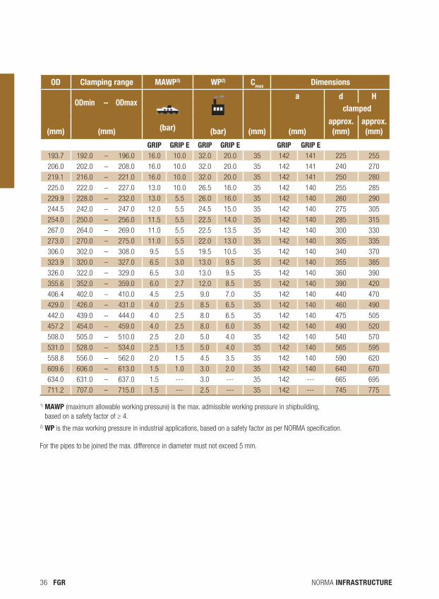
1) maWP (maximum allowable working pressure) is the max. admissible working pressure in shipbuilding, based on a safety factor of ≥ 4.
2) WP is the max working pressure in industrial applications, based on a safety factor as per NORMA specification.
For the pipes to be joined the max. difference in diameter must not exceed 5 mm.
OD Clamping range maWP3) WP2) Cmax Dimensions
ODmin – ODmax
a d H
clamped
(mm) (mm) (bar) (bar) (mm) (mm)approx. (mm)
approx. (mm)
GRIP GRIP E GRIP GRIP E GRIP GRIP E193.7 192.0 – 196.0 16.0 10.0 32.0 20.0 35 142 141 225 255
206.0 202.0 – 208.0 16.0 10.0 32.0 20.0 35 142 141 240 270
219.1 216.0 – 221.0 16.0 10.0 32.0 20.0 35 142 141 250 280
225.0 222.0 – 227.0 13.0 10.0 26.5 16.0 35 142 140 255 285
229.9 228.0 – 232.0 13.0 5.5 26.0 16.0 35 142 140 260 290
244.5 242.0 – 247.0 12.0 5.5 24.5 15.0 35 142 140 275 305
254.0 250.0 – 256.0 11.5 5.5 22.5 14.0 35 142 140 285 315
267.0 264.0 – 269.0 11.0 5.5 22.5 13.5 35 142 140 300 330
273.0 270.0 – 275.0 11.0 5.5 22.0 13.0 35 142 140 305 335
306.0 302.0 – 308.0 9.5 5.5 19.5 10.5 35 142 140 340 370
323.9 320.0 – 327.0 6.5 3.0 13.0 9.5 35 142 140 355 385
326.0 322.0 – 329.0 6.5 3.0 13.0 9.5 35 142 140 360 390
355.6 352.0 – 359.0 6.0 2.7 12.0 8.5 35 142 140 390 420
406.4 402.0 – 410.0 4.5 2.5 9.0 7.0 35 142 140 440 470
429.0 426.0 – 431.0 4.0 2.5 8.5 6.5 35 142 140 460 490
442.0 439.0 – 444.0 4.0 2.5 8.0 6.5 35 142 140 475 505
457.2 454.0 – 459.0 4.0 2.5 8.0 6.0 35 142 140 490 520
508.0 505.0 – 510.0 2.5 2.0 5.0 4.0 35 142 140 540 570
531.0 528.0 – 534.0 2.5 1.5 5.0 4.0 35 142 140 565 595
558.8 556.0 – 562.0 2.0 1.5 4.5 3.5 35 142 140 590 620
609.6 606.0 – 613.0 1.5 1.0 3.0 2.0 35 142 140 640 670
634.0 631.0 – 637.0 1.5 --- 3.0 --- 35 142 --- 665 695
711.2 707.0 – 715.0 1.5 --- 2.5 --- 35 142 --- 745 775
NORMA INFRASTRUCTURE 37FGR
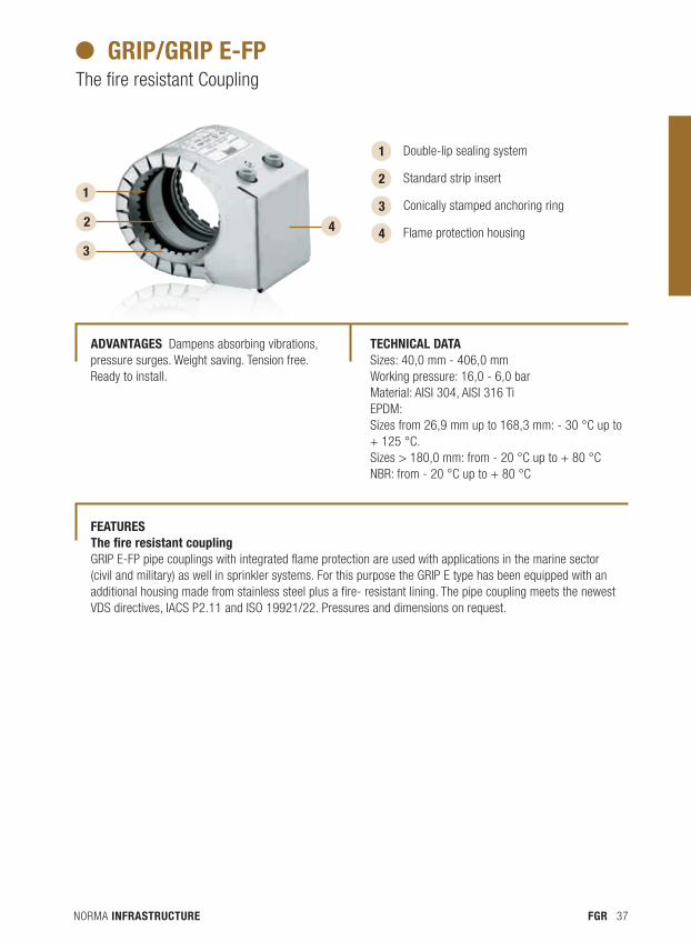
gRip/gRip e-fp The fire resistant Coupling
1
2
3
4
Double-lip sealing system
Standard strip insert
Conically stamped anchoring ring
Flame protection housing
1
2
3
4
aDvantages Dampens absorbing vibrations, pressure surges. Weight saving. Tension free. Ready to install.
tecHnical Data Sizes: 40,0 mm - 406,0 mmWorking pressure: 16,0 - 6,0 barMaterial: AISI 304, AISI 316 TiEPDM: Sizes from 26,9 mm up to 168,3 mm: - 30 °C up to + 125 °C. Sizes > 180,0 mm: from - 20 °C up to + 80 °CNBR: from - 20 °C up to + 80 °C
featuRes the fire resistant couplingGRIP E-FP pipe couplings with integrated flame protection are used with applications in the marine sector (civil and military) as well in sprinkler systems. For this purpose the GRIP E type has been equipped with an additional housing made from stainless steel plus a fire- resistant lining. The pipe coupling meets the newest VDS directives, IACS P2.11 and ISO 19921/22. Pressures and dimensions on request.
NORMA INFRASTRUCTURE38 FGR
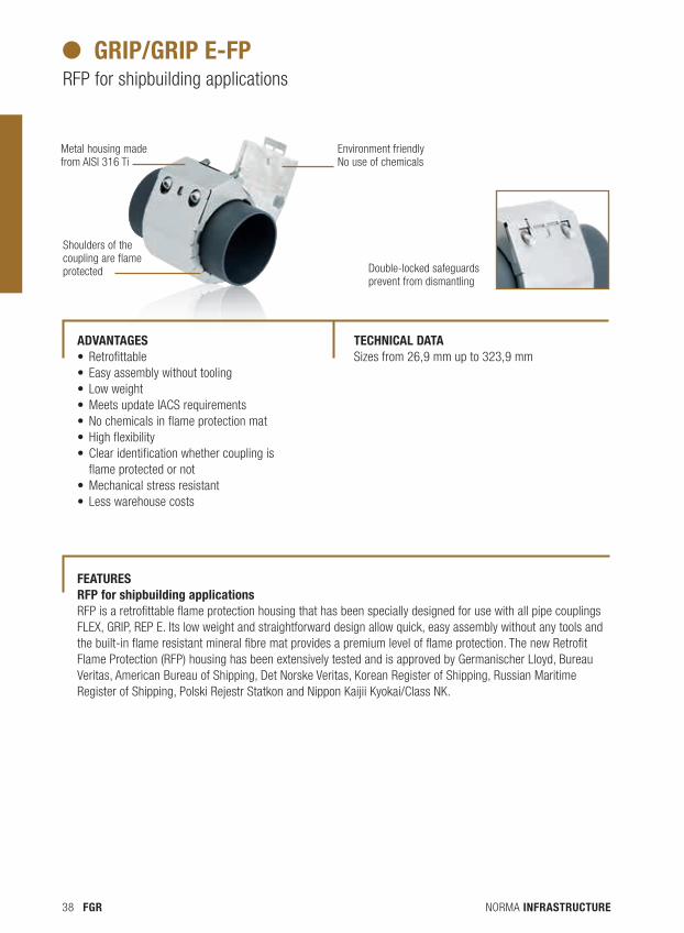
gRip/gRip e-fp RFP for shipbuilding applications
Metal housing made from AISI 316 Ti
Environment friendly No use of chemicals
Shoulders of the coupling are flame protected Double-locked safeguards
prevent from dismantling
aDvantages •Retrofittable• Easy assembly without tooling• Low weight•Meets update IACS requirements•No chemicals in flame protection mat•High flexibility•Clear identification whether coupling is flame protected or not•Mechanical stress resistant• Less warehouse costs
tecHnical Data Sizes from 26,9 mm up to 323,9 mm
featuRes Rfp for shipbuilding applications RFP is a retrofittable flame protection housing that has been specially designed for use with all pipe couplings FLEX, GRIP, REP E. Its low weight and straightforward design allow quick, easy assembly without any tools and the built-in flame resistant mineral fibre mat provides a premium level of flame protection. The new Retrofit Flame Protection (RFP) housing has been extensively tested and is approved by Germanischer Lloyd, Bureau Veritas, American Bureau of Shipping, Det Norske Veritas, Korean Register of Shipping, Russian Maritime Register of Shipping, Polski Rejestr Statkon and Nippon Kaijii Kyokai/Class NK.
NORMA INFRASTRUCTURE 39FGR
NORMA INFRASTRUCTURE40 FGR
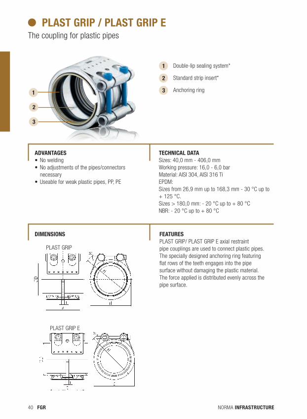
plast gRip / plast gRip eThe coupling for plastic pipes
1
2
3
Double-lip sealing system*
Standard strip insert*
Anchoring ring
PLAST GRIP E
1
2
3
PLAST GRIP
aDvantages •No welding•No adjustments of the pipes/connectors necessary•Useable for weak plastic pipes, PP, PE
tecHnical Data Sizes: 40,0 mm - 406,0 mmWorking pressure: 16,0 - 6,0 barMaterial: AISI 304, AISI 316 TiEPDM:Sizes from 26,9 mm up to 168,3 mm - 30 °C up to + 125 °C.Sizes > 180,0 mm: - 20 °C up to + 80 °C NBR: - 20 °C up to + 80 °C
featuRes PLAST GRIP/ PLAST GRIP E axial restraint pipe couplings are used to connect plastic pipes. The specially designed anchoring ring featuring flat rows of the teeth engages into the pipe surface without damaging the plastic material. The force applied is distributed evenly across the pipe surface.
Dimensions
NORMA INFRASTRUCTURE 41FGR
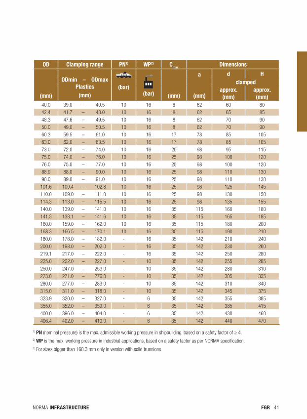
OD Clamping range PN1) WP2) Cmax Dimensions
(mm)
ODmin – ODmaxPlastics
(mm)
(bar)(bar)
(mm)
a
(mm)
d Hclamped
approx. (mm)
approx. (mm)
40.0 39.0 – 40.5 10 16 8 62 60 80
42.4 41.7 – 43.0 10 16 8 62 65 85
48.3 47.6 – 49.5 10 16 8 62 70 90
50.0 49.0 – 50.5 10 16 8 62 70 90
60.3 59.5 – 61.0 10 16 17 78 85 105
63.0 62.0 – 63.5 10 16 17 78 85 105
73.0 72.0 – 74.0 10 16 25 98 95 115
75.0 74.0 – 76.0 10 16 25 98 100 120
76.0 75.0 – 77.0 10 16 25 98 100 120
88.9 88.0 – 90.0 10 16 25 98 110 130
90.0 89.0 – 91.0 10 16 25 98 110 130
101.6 100.4 – 102.8 10 16 25 98 125 145
110.0 109.0 – 111.0 10 16 25 98 130 150
114.3 113.0 – 115.5 10 16 25 98 135 155
140.0 139.0 – 141.0 10 16 35 115 160 180
141.3 138.1 – 141.6 10 16 35 115 165 185
160.0 159.0 – 162.0 10 16 35 115 180 200
168.3 166.5 – 170.1 10 16 35 115 190 210
180.0 178.0 – 182.0 - 16 35 142 210 240
200.0 198.0 – 202.0 - 16 35 142 230 260
219.1 217.0 – 222.0 - 16 35 142 250 280
225.0 222.0 – 227.0 - 10 35 142 255 285
250.0 247.0 – 253.0 - 10 35 142 280 310
273.0 271.0 – 276.0 - 10 35 142 305 335
280.0 277.0 – 283.0 - 10 35 142 310 340
315.0 311.0 – 318.0 - 10 35 142 345 375
323.9 320.0 – 327.0 - 6 35 142 355 385
355.0 352.0 – 359.0 - 6 35 142 385 415
400.0 396.0 – 404.0 - 6 35 142 430 460
406.4 402.0 – 410.0 - 6 35 142 440 470
1) PN (nominal pressure) is the max. admissible working pressure in shipbuilding, based on a safety factor of ≥ 4.2) WP is the max. working pressure in industrial applications, based on a safety factor as per NORMA specification.3) For sizes bigger than 168.3 mm only in version with solid trunnions
NORMA INFRASTRUCTURE42 FGR
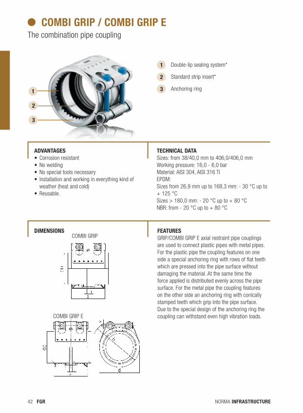
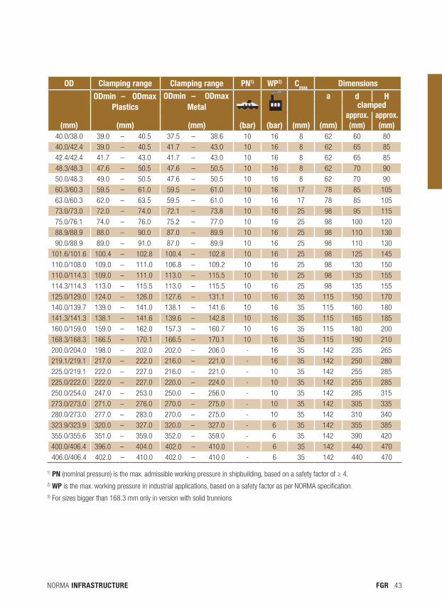
combi gRip / combi gRip eThe combination pipe coupling
1
2
3
Double-lip sealing system*
Standard strip insert*
Anchoring ring
COMBI GRIP
COMBI GRIP E
1
2
3
aDvantages •Corrosion resistant•No welding•No special tools necessary• Installation and working in everything kind of weather (heat and cold)•Reusable.
tecHnical Data Sizes: from 38/40,0 mm to 406,0/406,0 mmWorking pressure: 16,0 - 6,0 barMaterial: AISI 304, AISI 316 TiEPDM:Sizes from 26,9 mm up to 168,3 mm: - 30 °C up to + 125 °CSizes > 180,0 mm: - 20 °C up to + 80 °C NBR: from - 20 °C up to + 80 °C
featuRes GRIP/COMBI GRIP E axial restraint pipe couplings are used to connect plastic pipes with metal pipes. For the plastic pipe the coupling features on one side a special anchoring ring with rows of flat teeth which are pressed into the pipe surface without damaging the material. At the same time the force applied is distributed evenly across the pipe surface. For the metal pipe the coupling features on the other side an anchoring ring with conically stamped teeth which grip into the pipe surface. Due to the special design of the anchoring ring the coupling can withstand even high vibration loads.
Dimensions
NORMA INFRASTRUCTURE 43FGR
OD Clamping range Clamping range PN1) WP2) Cmax Dimensions
ODmin – ODmax ODmin – ODmax
a d HPlastics metal clamped
(mm) (mm) (mm) (bar) (bar) (mm) (mm)approx. (mm)
approx. (mm)
40.0/38.0 39.0 – 40.5 37.5 – 38.6 10 16 8 62 60 8040.0/42.4 39.0 – 40.5 41.7 – 43.0 10 16 8 62 65 8542.4/42.4 41.7 – 43.0 41.7 – 43.0 10 16 8 62 65 85
48.3/48.3 47.6 – 50.5 47.6 – 50.5 10 16 8 62 70 90
50.0/48.3 49.0 – 50.5 47.6 – 50.5 10 16 8 62 70 90
60.3/60.3 59.5 – 61.0 59.5 – 61.0 10 16 17 78 85 105
63.0/60.3 62.0 – 63.5 59.5 – 61.0 10 16 17 78 85 105
73.0/73.0 72.0 – 74.0 72.1 – 73.8 10 16 25 98 95 115
75.0/76.1 74.0 – 76.0 75.2 – 77.0 10 16 25 98 100 120
88.9/88.9 88.0 – 90.0 87.0 – 89.9 10 16 25 98 110 130
90.0/88.9 89.0 – 91.0 87.0 – 89.9 10 16 25 98 110 130
101.6/101.6 100.4 – 102.8 100.4 – 102.8 10 16 25 98 125 145
110.0/108.0 109.0 – 111.0 106.8 – 109.2 10 16 25 98 130 150
110.0/114.3 109.0 – 111.0 113.0 – 115.5 10 16 25 98 135 155
114.3/114.3 113.0 – 115.5 113.0 – 115.5 10 16 25 98 135 155
125.0/129.0 124.0 – 126.0 127.6 – 131.1 10 16 35 115 150 170
140.0/139.7 139.0 – 141.0 138.1 – 141.6 10 16 35 115 160 180
141.3/141.3 138.1 – 141.6 139.6 – 142.8 10 16 35 115 165 185
160.0/159.0 159.0 – 162.0 157.3 – 160.7 10 16 35 115 180 200
168.3/168.3 166.5 – 170.1 166.5 – 170.1 10 16 35 115 190 210
200.0/204.0 198.0 – 202.0 202.0 – 206.0 - 16 35 142 235 265
219.1/219.1 217.0 – 222.0 216.0 – 221.0 - 16 35 142 250 280
225.0/219.1 222.0 – 227.0 216.0 – 221.0 - 10 35 142 255 285
225.0/222.0 222.0 – 227.0 220.0 – 224.0 - 10 35 142 255 285
250.0/254.0 247.0 – 253.0 250.0 – 256.0 - 10 35 142 285 315
273.0/273.0 271.0 – 276.0 270.0 – 275.0 - 10 35 142 305 335
280.0/273.0 277.0 – 283.0 270.0 – 275.0 - 10 35 142 310 340
323.9/323.9 320.0 – 327.0 320.0 – 327.0 - 6 35 142 355 385
355.0/355.6 351.0 – 359.0 352.0 – 359.0 - 6 35 142 390 420
400.0/406.4 396.0 – 404.0 402.0 – 410.0 - 6 35 142 440 470
406.0/406.4 402.0 – 410.0 402.0 – 410.0 - 6 35 142 440 470
1) PN (nominal pressure) is the max. admissible working pressure in shipbuilding, based on a safety factor of ≥ 4.2) WP is the max. working pressure in industrial applications, based on a safety factor as per NORMA specification.3) For sizes bigger than 168.3 mm only in version with solid trunnions
NORMA INFRASTRUCTURE44 FGR
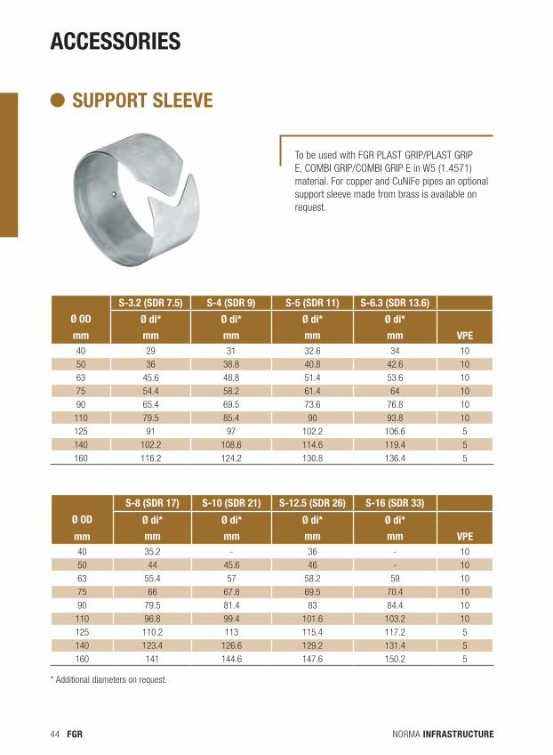
aCCEssORIEs
s-3.2 (sDR 7.5) s-4 (sDR 9) s-5 (sDR 11) s-6.3 (sDR 13.6)
Ø OD Ø di* Ø di* Ø di* Ø di*
mm mm mm mm mm VPE40 29 31 32.6 34 10
50 36 38.8 40.8 42.6 10
63 45.6 48.8 51.4 53.6 10
75 54.4 58.2 61.4 64 10
90 65.4 69.5 73.6 76.8 10
110 79.5 85.4 90 93.8 10
125 91 97 102.2 106.6 5
140 102.2 108.6 114.6 119.4 5
160 116.2 124.2 130.8 136.4 5
s-8 (sDR 17) s-10 (sDR 21) s-12.5 (sDR 26) s-16 (sDR 33)
Ø OD Ø di* Ø di* Ø di* Ø di*
mm mm mm mm mm VPE40 35.2 - 36 - 10
50 44 45.6 46 - 10
63 55.4 57 58.2 59 10
75 66 67.8 69.5 70.4 10
90 79.5 81.4 83 84.4 10
110 96.8 99.4 101.6 103.2 10
125 110.2 113 115.4 117.2 5
140 123.4 126.6 129.2 131.4 5
160 141 144.6 147.6 150.2 5
To be used with FGR PLAST GRIP/PLAST GRIP E, COMBI GRIP/COMBI GRIP E in W5 (1.4571) material. For copper and CuNiFe pipes an optional support sleeve made from brass is available on request.
suppoRt sleeve
* Additional diameters on request.
NORMA INFRASTRUCTURE 45FGR
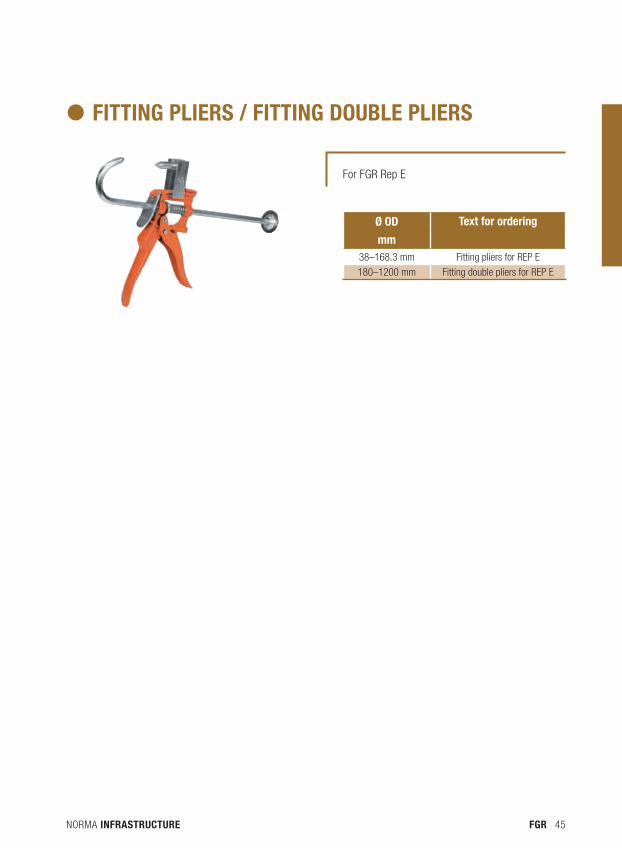
For FGR Rep E
fitting plieRs / fitting Double plieRs
Ø OD Text for ordering
mm38–168.3 mm Fitting pliers for Rep e
180–1200 mm Fitting double pliers for Rep e
NORMA INFRASTRUCTURE46 DCS
NORMA INFRASTRUCTURE 47DCS
DCS

NORMA INFRASTRUCTURE48 DCS
A large number of well-known companies have been using our know-how in the development and manufac-ture of pipe connections for many years. Thus behind many successful brands enjoying a well established reputation you can find the certified quality and the reliability of NORMA® connections.
Since the materials for our products are carefully chosen to match their applications and operating conditions, we can assure you that they function safely for a long time – as you would expect from a modern piping system.
The original product for high quality and reliability. The complete DCS range has been proven a million times when used to achieve both a reliable and economic connection of plain ended drainage pipes.
Inside buildings, in underground car parks, buried in soil, in purification plants and for drainage systems in bridges, DCS is the ideal connect ing solution.
OUR SOLUTION FOR DRAINAGE CONNECTING – DCS
NORMA INFRASTRUCTURE 49DCS
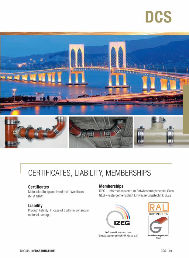
CertificatesMaterialprüfungsamt Nordrhein-Westfalen (MPA NRW)
LiabilityProduct liability: In case of bodily injury and/or material damage.
MembershipsIZEG – Informationszentrum Entwässerungstechnik GussGEG – Gütergemeinschaft Entwässerungstechnik Guss
DCS
CeRTIFICaTeS, LIabILITy, MeMbeRShIpS
NORMA INFRASTRUCTURE50 DCS
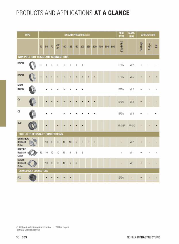
PRODuCTS AND APPlICATIONS aT a gLanCe
TYPe Dn anD Pressure [bar]seaL TYPe
MaTe-rIaL
aPPLICaTIon
40 50 7070/80
100 125 150 200 250 300 400 500 600
STAN
DARD
Build
ings
Brid
ges
Soil
non PuLL-ouT resIsTanT ConneCTIons
RAPID• • • • • • • • EPDM W 2 • - -
RAPID• • • • • • • • • • EPDM W 5 • • •
MSM
RAPID • • • • • • • EPDM W 2 • - -
CV• • • • • • • • • EPDM W 2 • - -
CE• • • • • • • • EPDM W 4 • - •*
SVE• • • • • • NR-SBR PP-CO - - •
PuLL-ouT resIsTanT ConneCTIonsUNIVERSALRestraint Collar
10 10 10 10 10 5 5 3 3 - W 2 • - -
REKORDRestraint Collar
10 10 10 10 10 5 5 3 - W 1 • - -
KOMBIRestraint Collar
10 10 10 10 5 5 - W 1 • - -
Changeover ConneCTors
FIX • • • • • EPDM - • - -
•* Additional protection against corrosion * NBR on requestTechnical Changes reserved
NORMA INFRASTRUCTURE 51DCS
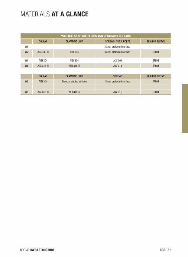
MATERIAlS aT a gLanCe
MaTerIaLs for CouPLIngs anD resTraInT CoLLars
COLLAR CLAMPINg UNIT SCREwS, NUTS, BOLTS SEALINg SLEEVE
w1 Steel, protected surface –
w2 AISI 430 Ti AISI 304 Steel, protected surface EPDM
w4 AISI 304 AISI 304 AISI 304 EPDM
w5 AISI 316 Ti AISI 316 Ti AISI 316 EPDM
COLLAR CLAMPINg UNIT SCREwS SEALINg SLEEVE
w2 AISI 304 Steel, protected surface Steel, protected surface EPDM
w5 AISI 316 Ti AISI 316 Ti AISI 316 EPDM

NORMA INFRASTRUCTURE52 DCS
NORMA INFRASTRUCTURE 53DCS
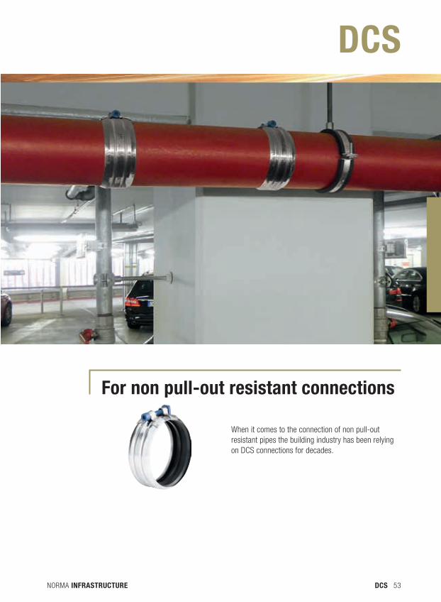
for non pull-out resistant connections
When it comes to the connection of non pull-out resistant pipes the building industry has been relying on DCS connections for decades.
DCS
NORMA INFRASTRUCTURE54 DCS
1 2
3
1
2
3
4
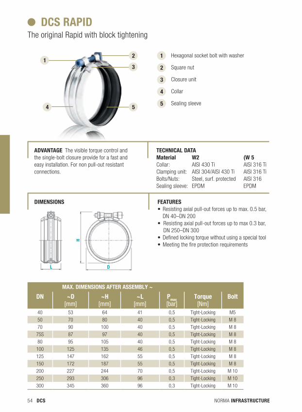
Hexagonal socket bolt with washer
Square nut
Closure unit
Collar
Sealing sleeve 5 5 4
DCs raPID The original Rapid with block tightening
aDvanTage The visible torque control and the single-bolt closure provide for a fast and easy installation. For non pull-out resistant connections.
TeChnICaL DaTa Material W2 (W 5Collar: AISI 430 Ti AISI 316 TiClamping unit: AISI 304/AISI 430 Ti AISI 316 TiBolts/Nuts: Steel, surf. protected AISI 316Sealing sleeve: EPDM EPDM
feaTures • Resisting axial pull-out forces up to max. 0.5 bar,
DN 40–DN 200• Resisting axial pull-out forces up to max 0.3 bar,
DN 250 –DN 300• Defined locking torque without using a special tool • Meeting the fire protection requirements
Max. DIMensIons afTer asseMbLY ~
Dn ~D [mm]
~h [mm]
~L [mm]
Pmax [bar]
Torque[Nm]
bolt
40 53 64 41 0,5 Tight-Locking M5
50 70 80 40 0,5 Tight-Locking M 8
70 90 100 40 0,5 Tight-Locking M 8
75S 87 97 40 0,5 Tight-Locking M 8
80 95 105 40 0,5 Tight-Locking M 8
100 125 135 46 0,5 Tight-Locking M 8
125 147 162 55 0,5 Tight-Locking M 8
150 172 187 55 0,5 Tight-Locking M 8
200 227 244 70 0,5 Tight-Locking M 10
250 293 306 96 0,3 Tight-Locking M 10
300 345 360 96 0,3 Tight-Locking M 10
DIMensIons
NORMA INFRASTRUCTURE 55DCS
Max. DIMensIons afTer asseMbLY ~
Dn ~D [mm]
~h [mm]
~L [mm]
Pmax [bar]
Torque[Nm]
bolt
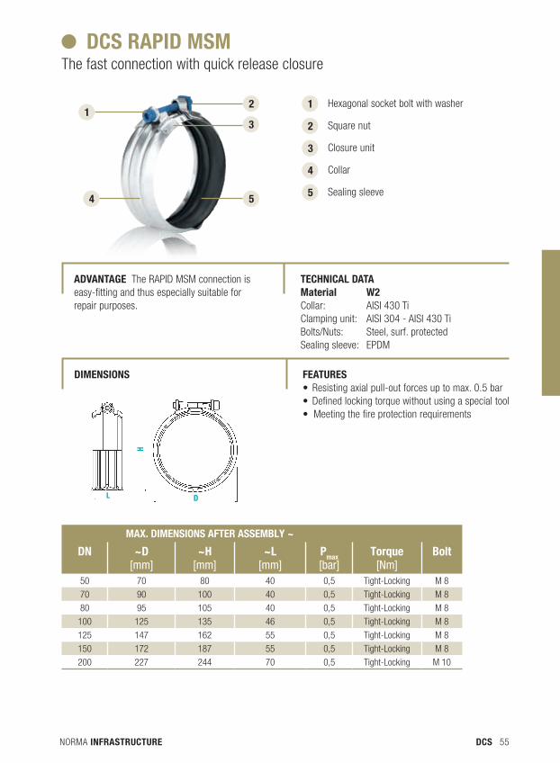
50 70 80 40 0,5 Tight-Locking M 8
70 90 100 40 0,5 Tight-Locking M 8
80 95 105 40 0,5 Tight-Locking M 8
100 125 135 46 0,5 Tight-Locking M 8
125 147 162 55 0,5 Tight-Locking M 8
150 172 187 55 0,5 Tight-Locking M 8
200 227 244 70 0,5 Tight-Locking M 10
1
2
3
4
Hexagonal socket bolt with washer
Square nut
Closure unit
Collar
Sealing sleeve 5
DCs raPID MsM The fast connection with quick release closure
aDvanTage The RAPID MSM connection is easy-fitting and thus especially suitable for repair purposes.
TeChnICaL DaTa Material W2 Collar: AISI 430 Ti Clamping unit: AISI 304 - AISI 430 TiBolts/Nuts: Steel, surf. protected Sealing sleeve: EPDM
feaTures • Resisting axial pull-out forces up to max. 0.5 bar• Defined locking torque without using a special tool• Meeting the fire protection requirements
DIMensIons
1 2
3
5 4
NORMA INFRASTRUCTURE56 DCS
1 2
3 1
2
3
4
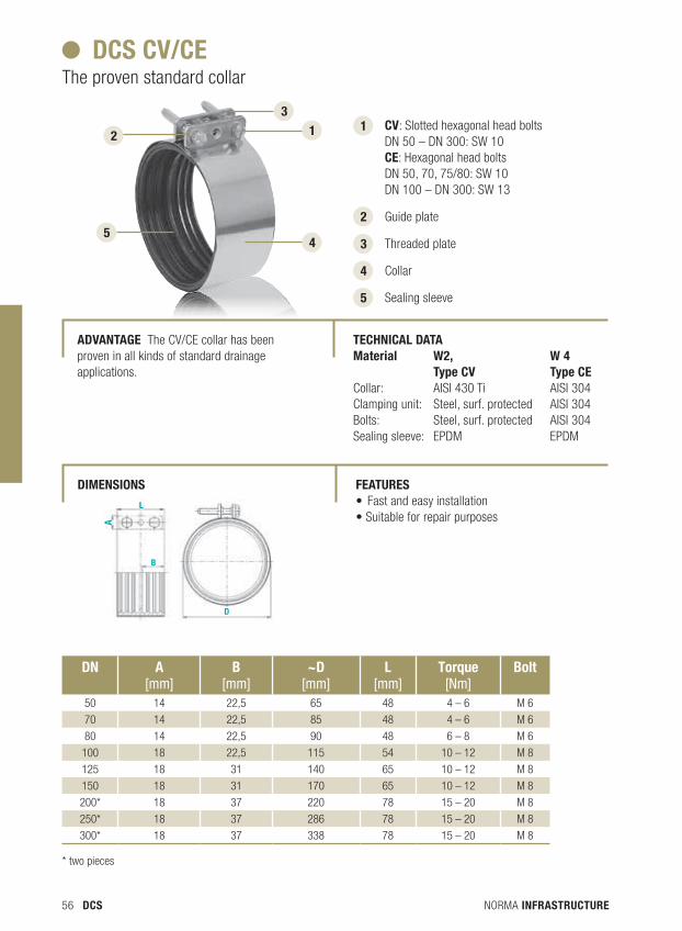
Cv: Slotted hexagonal head bolts DN 50 – DN 300: SW 10Ce: Hexagonal head bolts DN 50, 70, 75/80: SW 10 DN 100 – DN 300: SW 13
Guide plate
Threaded plate
Collar
Sealing sleeve 5
4 5
DCs Cv/Ce The proven standard collar
aDvanTage The CV/CE collar has been proven in all kinds of standard drainage applications.
TeChnICaL DaTa Material W2, W 4 Type Cv Type CeCollar: AISI 430 Ti AISI 304Clamping unit: Steel, surf. protected AISI 304Bolts: Steel, surf. protected AISI 304Sealing sleeve: EPDM EPDM
feaTures • Fast and easy installation• Suitable for repair purposes
DIMensIons
Dn a[mm]
b [mm]
~D [mm]
L [mm]
Torque[Nm]
bolt
50 14 22,5 65 48 4 – 6 M 6
70 14 22,5 85 48 4 – 6 M 6
80 14 22,5 90 48 6 – 8 M 6
100 18 22,5 115 54 10 – 12 M 8
125 18 31 140 65 10 – 12 M 8
150 18 31 170 65 10 – 12 M 8
200* 18 37 220 78 15 – 20 M 8
250* 18 37 286 78 15 – 20 M 8
300* 18 37 338 78 15 – 20 M 8
* two pieces
NORMA INFRASTRUCTURE 57DCS
1
2
1
2
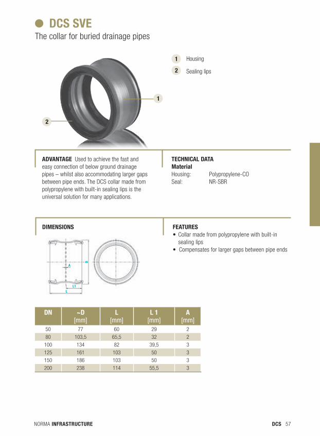
Housing
Sealing lips
DCs sve The collar for buried drainage pipes
aDvanTage used to achieve the fast and easy connection of below ground drainage pipes – whilst also accommodating larger gaps between pipe ends. The DCS collar made from polypropylene with built-in sealing lips is the universal solution for many applications.
TeChnICaL DaTa Material Housing: Polypropylene-COSeal: NR-SBR
feaTures • Collar made from polypropylene with built-in
sealing lips• Compensates for larger gaps between pipe ends
DIMensIons
Dn ~D [mm]
L [mm]
L 1[mm]
a [mm]
50 77 60 29 2
80 103,5 65,5 32 2
100 134 82 39,5 3
125 161 103 50 3
150 186 103 50 3
200 238 114 55,5 3

NORMA INFRASTRUCTURE58 DCS
NORMA INFRASTRUCTURE 59DCS
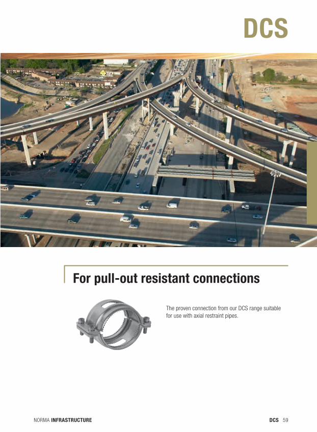
for pull-out resistant connections
The proven connection from our DCS range suitable for use with axial restraint pipes.
DCS
NORMA INFRASTRUCTURE60 DCS
5
4
3 1
2
3
4
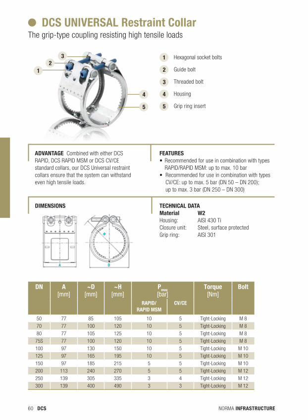
Hexagonal socket bolts
Guide bolt
Threaded bolt
Housing
Grip ring insert 5
DCs unIversaL restraint Collar The grip-type coupling resisting high tensile loads
aDvanTage Combined with either DCS RAPID, DCS RAPID MSM or DCS CV/CE standard collars, our DCS universal restraint collars ensure that the system can withstand even high tensile loads.
TeChnICaL DaTa Material W2 Housing: AISI 430 TiClosure unit: Steel, surface protectedGrip ring: AISI 301
DIMensIons
feaTures • Recommended for use in combination with types RAPID/RAPID MSM: up to max. 10 bar• Recommended for use in combination with types
CV/CE: up to max. 5 bar (DN 50 – DN 200); up to max. 3 bar (DN 250 – DN 300)
1 2
Dn a [mm]
~D [mm]
~h [mm]
Pmax [bar]
Torque[Nm]
bolt
RAPID/ RAPID MSM
CV/CE
50 77 85 105 10 5 Tight-Locking M 8
70 77 100 120 10 5 Tight-Locking M 8
80 77 105 125 10 5 Tight-Locking M 8
75S 77 100 120 10 5 Tight-Locking M 8
100 97 130 150 10 5 Tight-Locking M 10
125 97 165 195 10 5 Tight-Locking M 10
150 97 185 215 5 5 Tight-Locking M 10
200 113 240 270 5 5 Tight-Locking M 12
250 139 305 335 3 4 Tight-Locking M 12
300 139 400 490 3 3 Tight-Locking M 12
NORMA INFRASTRUCTURE 61DCS
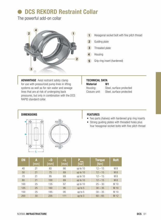
DCs reKorD restraint Collar The powerful add-on collar
aDvanTage Axial restraint safety clamp for use with pressurized pump lines in lifting systems as well as for rain water and sewage lines that are at risk of undergoing back pressures, but only in combination with the DCS RAPID standard collar.
TeChnICaL DaTa Material W1 Housing: Steel, surface protectedClosure unit: Steel, surface protected
feaTures • Two parts (halves) with hardened grip ring inserts• Strong guiding plates with threaded holes plus
four hexagonal socket bolts with fine pitch thread
DIMensIons
1
3
1
2
Hexagonal socket bolt with fine pitch thread
Guiding plate
Threaded plate
Housing
Grip ring insert (hardened)
3
4
5
2 4
2
Dn a [mm]
~D [mm]
~L [mm]
Pmax [bar]
Torque[Nm]
bolt
40 21 65 66 up to 10 12 – 15 M 8
50 21 75 69 up to 10 12 – 15 M 8
70 21 95 69 up to 10 12 – 15 M 8
80 21 100 69 up to 10 12 – 15 M 8
100 25 135 87 up to 10 25 – 30 M 10
125 25 160 95 up to 5 30 – 35 M 10
150 25 185 95 up to 5 30 – 35 M 10
200 30 235 111 up to 3 60 – 65 M 12
NORMA INFRASTRUCTURE62 DCS
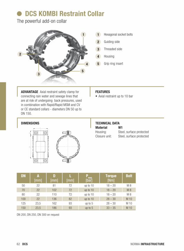
5
4
3
1
2
3
4
Hexagonal socket bolts
Guiding side
Threaded side
Housing
Grip ring insert 5
DCs KoMbI restraint Collar The powerful add-on collar
aDvanTage Axial restraint safety clamp for connecting rain water and sewage lines that are at risk of undergoing back pressures, used in combination with Rapid/Rapid MSM and CV or CE standard collars - diameters DN 50 up to DN 150.
TeChnICaL DaTa Material W1 Housing: Steel, surface protectedClosure unit: Steel, surface protected
DIMensIons
feaTures • Axial restraint up to 10 bar
1
2
DN 200, DN 250, DN 300 on request
Dn a [mm]
D [mm]
L [mm]
Pmax [bar]
Torque[Nm]
bolt
50 22 81 72 up to 10 18 – 20 M 8
70 22 102 72 up to 10 18 – 20 M 8
80 22 110 72 up to 10 18 – 20 M 8
100 22 136 82 up to 10 28 – 30 M 10
125 23,5 162 93 up to 5 28 – 30 M 10
150 23,5 186 93 up to 5 33 – 35 M 10
NORMA INFRASTRUCTURE 63DCS
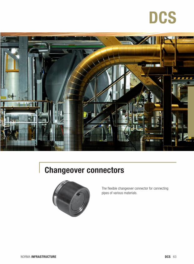
Changeover connectors
The flexible changeover connector for connecting pipes of various materials.
DCS
NORMA INFRASTRUCTURE64 DCS
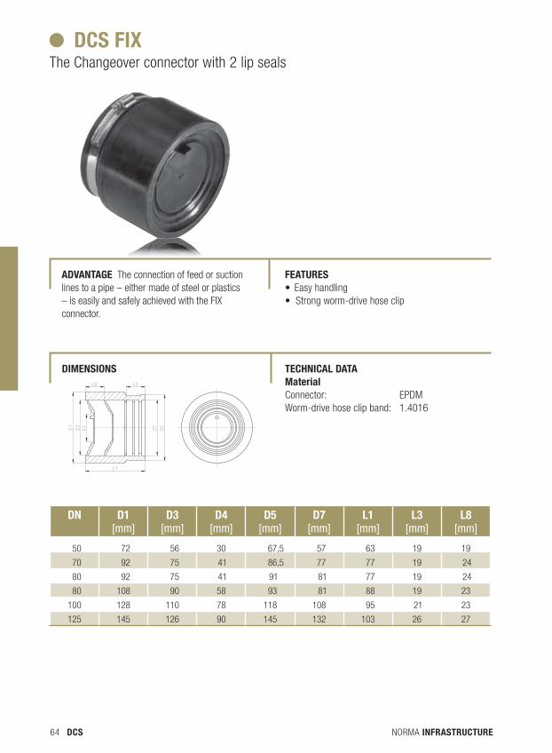
DCs fIx The Changeover connector with 2 lip seals
aDvanTage The connection of feed or suction lines to a pipe – either made of steel or plastics – is easily and safely achieved with the FIX connector.
TeChnICaL DaTa Material Connector: EPDMWorm-drive hose clip band: 1.4016
DIMensIons
feaTures • Easy handling• Strong worm-drive hose clip
Dn D1 [mm]
D3 [mm]
D4 [mm]
D5 [mm]
D7 [mm]
L1 [mm]
L3 [mm]
L8 [mm]
50 72 56 30 67,5 57 63 19 19
70 92 75 41 86,5 77 77 19 24
80 92 75 41 91 81 77 19 24
80 108 90 58 93 81 88 19 23
100 128 110 78 118 108 95 21 23
125 145 126 90 145 132 103 26 27
NORMA INFRASTRUCTURE 65DCS
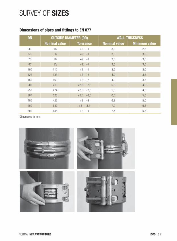
SURVey OF SIZES
Dn OuTSIDE DIAMETER (OD) WAll ThICkNESS
nominal value Tolerance nominal value Minimum value 40 48 +2 –1 3,0 2,5
50 58 +2 –1 3,5 3,0
70 78 +2 –1 3,5 3,0
80 83 +2 –1 3,5 3,0
100 110 +2 –1 3,5 3,0
125 135 +2 –2 4,0 3,5
150 160 +2 –2 4,0 3,5
200 210 +2,5 –2,5 5,0 4,0
250 274 +2,5 –2,5 5,5 4,5
300 326 +2,5 –2,5 6,0 5,0
400 429 +2 –3 6,3 5,0
500 532 +2 –3,5 7,0 5,2
600 635 +2 –4 7,7 5,8
Dimensions of pipes and fittings to en 877
Dimensions in mm
NORMA INFRASTRUCTURE66 PSS
NORMA INFRASTRUCTURE 67PSS
PSS
NORMA INFRASTRUCTURE68 PSS
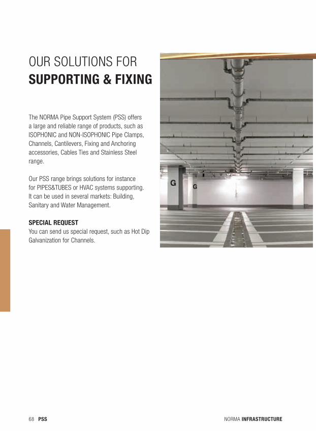
OUR SOLUTIONS FOR SUPPORTING & FIXING
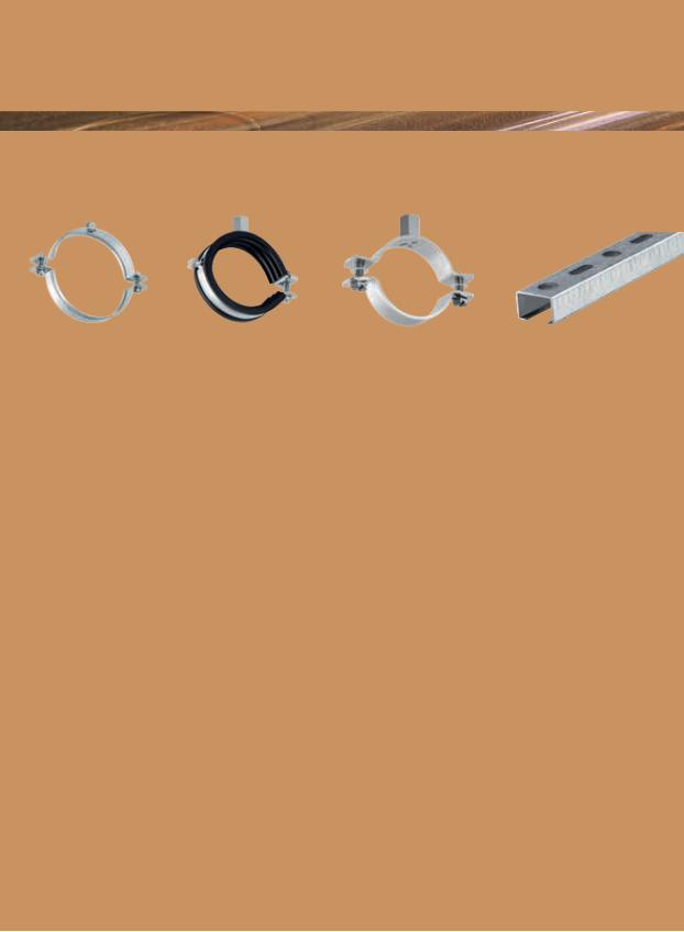
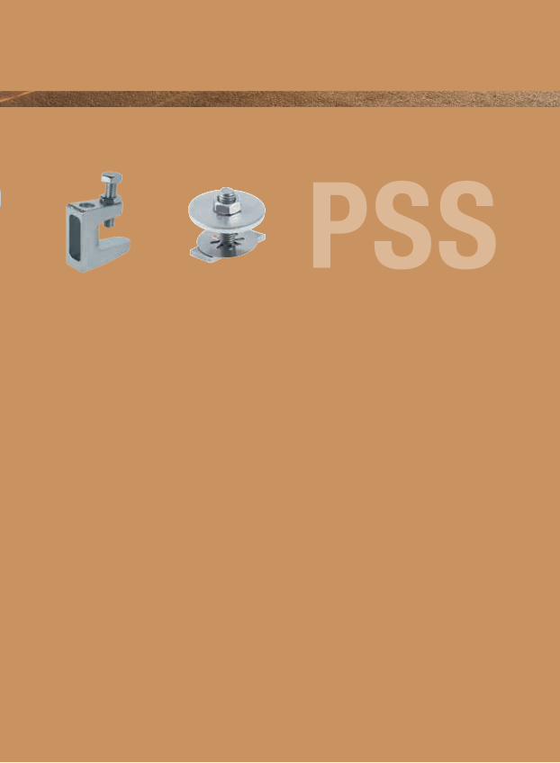
The NORMA Pipe Support System (PSS) offers a large and reliable range of products, such as ISOPHONIC and NON-ISOPHONIC Pipe Clamps, Channels, Cantilevers, Fixing and Anchoring accessories, Cables Ties and Stainless Steel range.
Our PSS range brings solutions for instance for PIPES&TUBES or HVAC systems supporting. It can be used in several markets: Building, Sanitary and Water Management.
SPECIAL REQUESTYou can send us special request, such as Hot Dip Galvanization for Channels.

NORMA INFRASTRUCTURE 69PSS

NORMA INFRASTRUCTURE70 PSS
NORMA INFRASTRUCTURE 71PSS
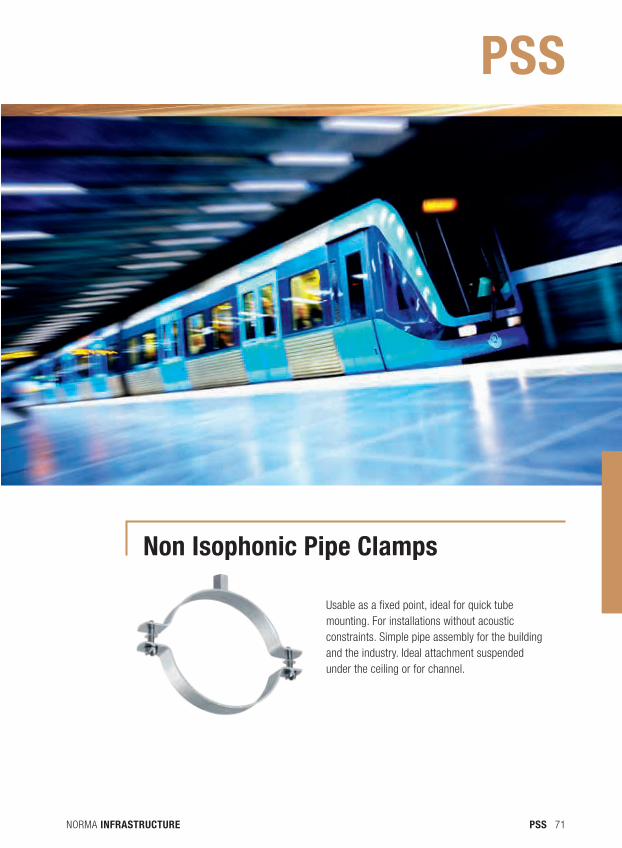
Non Isophonic Pipe Clamps
Usable as a fixed point, ideal for quick tube mounting. For installations without acoustic constraints. Simple pipe assembly for the building and the industry. Ideal attachment suspended under the ceiling or for channel.
PSS
NORMA INFRASTRUCTURE72 PSS
1
2
1
2
3
3
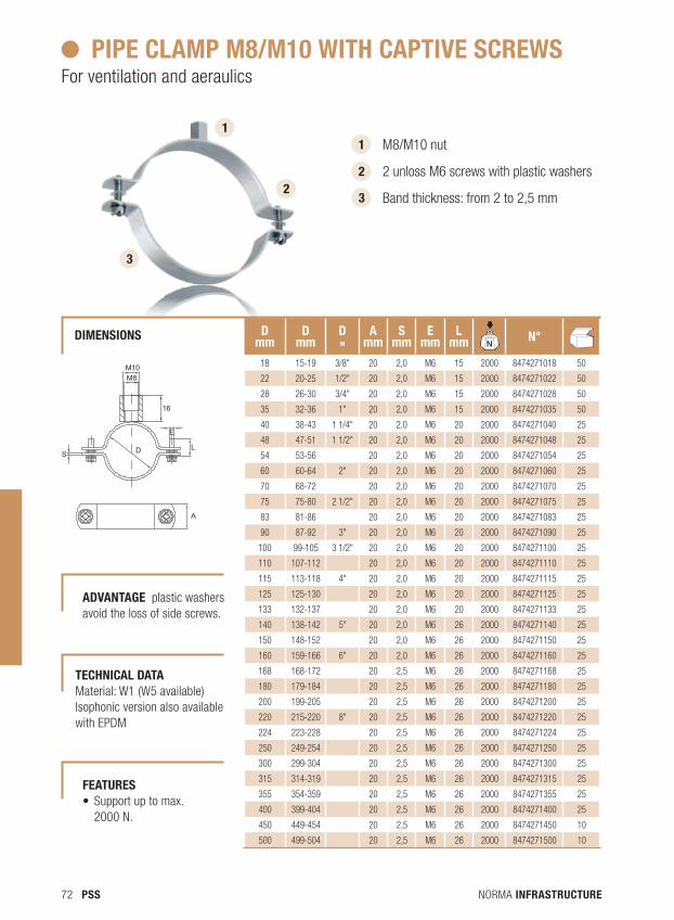
M8/M10 nut
2 unloss M6 screws with plastic washers
Band thickness: from 2 to 2,5 mm
PIPE CLAMP M8/M10 WITH CAPTIVE SCREWSFor ventilation and aeraulics
TECHNICAL dATA Material: W1 (W5 available) Isophonic version also available with EPDM
dIMENSIONS
S
M10M8
16
E
L
A
D
d mm
d mm
d "
Amm
Smm
Emm
Lmm N
dBN°N
dB
18 15-19 3/8" 20 2,0 M6 15 2000 8474271018 50
22 20-25 1/2" 20 2,0 M6 15 2000 8474271022 50
28 26-30 3/4" 20 2,0 M6 15 2000 8474271028 50
35 32-36 1" 20 2,0 M6 15 2000 8474271035 50
40 38-43 1 1/4" 20 2,0 M6 20 2000 8474271040 25
48 47-51 1 1/2" 20 2,0 M6 20 2000 8474271048 25
54 53-56 20 2,0 M6 20 2000 8474271054 25
60 60-64 2" 20 2,0 M6 20 2000 8474271060 25
70 68-72 20 2,0 M6 20 2000 8474271070 25
75 75-80 2 1/2" 20 2,0 M6 20 2000 8474271075 25
83 81-86 20 2,0 M6 20 2000 8474271083 25
90 87-92 3" 20 2,0 M6 20 2000 8474271090 25
100 99-105 3 1/2" 20 2,0 M6 20 2000 8474271100 25
110 107-112 20 2,0 M6 20 2000 8474271110 25
115 113-118 4" 20 2,0 M6 20 2000 8474271115 25
125 125-130 20 2,0 M6 20 2000 8474271125 25
133 132-137 20 2,0 M6 20 2000 8474271133 25
140 138-142 5" 20 2,0 M6 26 2000 8474271140 25
150 148-152 20 2,0 M6 26 2000 8474271150 25
160 159-166 6" 20 2,0 M6 26 2000 8474271160 25
168 168-172 20 2,5 M6 26 2000 8474271168 25
180 179-184 20 2,5 M6 26 2000 8474271180 25
200 199-205 20 2,5 M6 26 2000 8474271200 25
220 215-220 8" 20 2,5 M6 26 2000 8474271220 25
224 223-228 20 2,5 M6 26 2000 8474271224 25
250 249-254 20 2,5 M6 26 2000 8474271250 25
300 299-304 20 2,5 M6 26 2000 8474271300 25
315 314-319 20 2,5 M6 26 2000 8474271315 25
355 354-359 20 2,5 M6 26 2000 8474271355 25
400 399-404 20 2,5 M6 26 2000 8474271400 25
450 449-454 20 2,5 M6 26 2000 8474271450 10
500 499-504 20 2,5 M6 26 2000 8474271500 10
FEATURES • Supportuptomax.
2000 N.
AdVANTAGE plastic washers avoid the loss of side screws.
NORMA INFRASTRUCTURE 73PSS
S D
E
A
L
M12
2 1
2
3
3
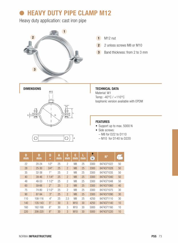
M12 nut
2 unloss screws M8 or M10
Band thickness: from 2 to 3 mm
HEAVY dUTY PIPE CLAMP M12 Heavy duty application: cast iron pipe
dIMENSIONS TECHNICAL dATA Material: W1 Temp: -40°C / +110°C Isophonic version available with EPDM
d mm
d mm
d "
Amm
Smm
Emm
Lmm N
dBN°N
dB
22 20-24 1/2" 25 2 M8 25 3300 8474371022 50
28 25-30 3/4" 25 2 M8 25 3300 8474371028 50
35 32-38 1" 25 2 M8 25 3300 8474371035 50
40 39-46 1 1/4" 25 2 M8 25 3300 8474371040 50
48 48-53 1 1/2" 25 2 M8 25 3300 8474371048 50
60 59-66 2" 25 2 M8 25 3300 8474371060 40
75 74-80 2 1/2" 25 2 M8 25 3300 8474371075 30
90 87-94 3" 25 2 M8 25 3300 8474371090 30
110 108-116 4" 25 2,5 M8 25 4250 8474371110 30
140 135-143 5" 30 3 M10 30 4250 8474371140 10
160 162-168 6" 30 3 M10 30 5000 8474371160 10
220 206-220 8" 30 3 M10 30 5000 8474371220 10
1
FEATURES • Supportuptomax.5000N• Sidescrews:
– M8 for D22 to D110 – M10 for D140 to D220
NORMA INFRASTRUCTURE74 PSS
1
1
2
2
3
3
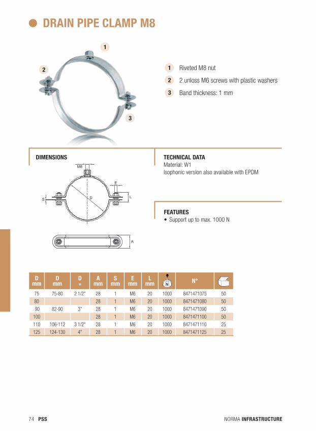
Riveted M8 nut
2 unloss M6 screws with plastic washers
Band thickness: 1 mm
dRAIN PIPE CLAMP M8
dIMENSIONS TECHNICAL dATA Material: W1Isophonic version also available with EPDM
S
M8
E
L
A
D
d mm
d mm
d "
Amm
Smm
Emm
Lmm N
dBN° N
dB
75 75-80 2 1/2" 28 1 M6 20 1000 8471471075 50
80 28 1 M6 20 1000 8471471080 50
90 82-90 3" 28 1 M6 20 1000 8471471090 50
100 28 1 M6 20 1000 8471471100 50
110 106-112 3 1/2" 28 1 M6 20 1000 8471471110 25
125 124-130 4" 28 1 M6 20 1000 8471471125 25
FEATURES • Supportuptomax.1000N
NORMA INFRASTRUCTURE 75PSS
1
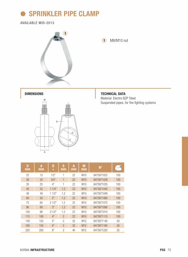
1 M8/M10 nut
SPRINKLER PIPE CLAMP
dIMENSIONS TECHNICAL dATA Material: Electro BZP SteelSuspended pipes, for fire fighting systems
D
S
A
M
d
d mm
dmm
d "
Smm
Amm
Mmm N° N
dB
22 15 1/2" 1 22 M10 8473971022 100
28 20 3/4" 1 22 M10 8473971028 100
35 25 4" 1 22 M10 8473971035 100
40 32 1 1/4" 1,2 22 M10 8473971040 100
48 40 1 1/2" 1,2 22 M10 8473971048 100
60 50 2" 1,2 22 M10 8473971060 100
75 65 2 1/2" 1,2 22 M10 8473971075 100
90 80 3" 1,2 22 M10 8473971090 100
100 90 3 1/2" 1,2 22 M10 8473971010 100
115 100 4" 2 22 M10 8473971115 100
140 125 5" 2 32 M12 8473971140 50
160 150 6" 2 32 M12 8473971160 50
220 200 8" 2 40 M12 8473971220 25
AVAILABLE MID-2013
NORMA INFRASTRUCTURE76 PSS
1
2
1
2
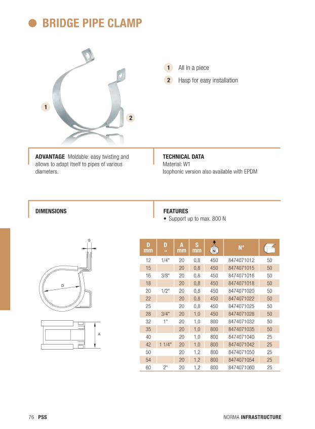
All in a piece
Hasp for easy installation
BRIdGE PIPE CLAMP
AdVANTAGE Moldable: easy twisting and allows to adapt itself to pipes of various diameters.
TECHNICAL dATA Material: W1Isophonic version also available with EPDM
A
D
Sd
mmd "
Amm
Smm N
dBN° N
dB
12 1/4" 20 0,8 450 8474071012 50
15 20 0,8 450 8474071015 50
16 3/8" 20 0,8 450 8474071016 50
18 20 0,8 450 8474071018 50
20 1/2" 20 0,8 450 8474071020 50
22 20 0,8 450 8474071022 50
25 20 0,8 450 8474071025 50
28 3/4" 20 1,0 450 8474071028 50
32 1" 20 1,0 800 8474071032 50
35 20 1,0 800 8474071035 50
40 20 1,0 800 8474071040 25
42 1 1/4" 20 1,0 800 8474071042 25
50 20 1,2 800 8474071050 25
54 20 1,2 800 8474071054 25
60 2" 20 1,2 800 8474071060 25
A
D
S
FEATURES • Supportuptomax.800N
dIMENSIONS
NORMA INFRASTRUCTURE 77PSS
S
D
LxE
A
1
1
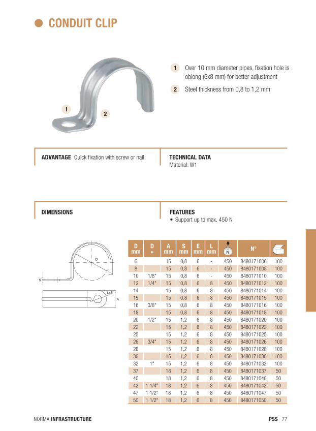
2
Over 10 mm diameter pipes, fixation hole is oblong (6x8 mm) for better adjustment
Steel thickness from 0,8 to 1,2 mm
CONdUIT CLIP
AdVANTAGE Quick fixation with screw or nail. TECHNICAL dATA Material: W1
2
d mm
d "
Amm
Smm
Emm
Lmm N
dBN° N
dB
6 15 0,8 6 - 450 8480171006 1008 15 0,8 6 - 450 8480171008 100
10 1/8" 15 0,8 6 - 450 8480171010 10012 1/4" 15 0,8 6 8 450 8480171012 10014 15 0,8 6 8 450 8480171014 10015 15 0,8 6 8 450 8480171015 10016 3/8" 15 0,8 6 8 450 8480171016 10018 15 0,8 6 8 450 8480171018 10020 1/2" 15 1,2 6 8 450 8480171020 10022 15 1,2 6 8 450 8480171022 10025 15 1,2 6 8 450 8480171025 10026 3/4" 15 1,2 6 8 450 8480171026 10028 15 1,2 6 8 450 8480171028 10030 15 1,2 6 8 450 8480171030 10032 1" 15 1,2 6 8 450 8480171032 10037 18 1,2 6 8 450 8480171037 5040 18 1,2 6 8 450 8480171040 5042 1 1/4" 18 1,2 6 8 450 8480171042 5047 1 1/2" 18 1,2 6 8 450 8480171047 5050 1 1/2" 18 1,2 6 8 450 8480171050 50
S
D
LxE
A
FEATURES • Supportuptomax.450N
dIMENSIONS

NORMA INFRASTRUCTURE78 PSS
NORMA INFRASTRUCTURE 79PSS
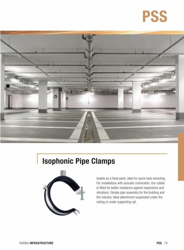
Isophonic Pipe Clamps
Usable as a fixed point, ideal for quick tube mounting. For installations with acoustic constraints. Our rubber is fitted for better resistance against expansions and vibrations. Simple pipe assembly for the building and the industry. Ideal attachment suspended under the ceiling or under supporting rail.
PSS
NORMA INFRASTRUCTURE80 PSS
1
2
1
2
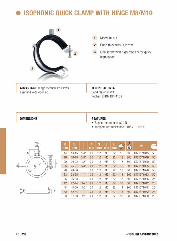
M8/M10 nut
Band thickness: 1,2 mm
One screw with high mobility for quick installation
ISOPHONIC QUICK CLAMP WITH HINGE M8/M10
TECHNICAL dATA Band material: W1 Rubber: EPDM DIN 4109
33
S D
16
M10M8
E
L
A
AdVANTAGE Hinge mechanism allows easy and wide opening.
d mm
d mm
d "
Amm
Smm
Emm
LmmN
dB NdB
N°NdB
14 14-15 1/4" 20 1,2 M5 22 18 800 8471571015 50
16 16-18 3/8" 20 1,2 M5 22 18 800 8471571016 50
20 20-22 1/2" 20 1,2 M5 22 18 800 8471571020 50
25 25-27 3/4" 20 1,2 M5 22 18 800 8471571025 50
28 28-30 20 1,2 M5 22 18 800 8471571028 50
33 33-35 1" 20 1,2 M5 22 18 800 8471571033 50
36 36-38 20 1,2 M5 22 18 800 8471571036 25
42 42-44 11/4" 20 1,2 M5 22 18 800 8471571042 25
48 48-50 11/2" 20 1,2 M5 22 18 800 8471571048 25
52 52-54 20 1,2 M5 22 18 800 8471571052 25
60 57-60 2" 20 1,2 M5 22 18 800 8471571060 25
FEATURES • Supportuptomax.800N• Temperatureresistance:-40°/+110°C
dIMENSIONS
NORMA INFRASTRUCTURE 81PSS
S LD
E
8
M8/M10
A
S LD
E
8
M8/M10
A
1
1
2
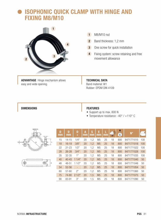
M8/M10 nut
Band thickness: 1,2 mm
One screw for quick installation
Fixing system: screw retaining and free movement allowance
ISOPHONIC QUICK CLAMP WITH HINGE ANd FIXING M8/M10
AdVANTAGE Hinge mechanism allows easy and wide opening.
TECHNICAL dATA Band material: W1 Rubber: EPDM DIN 4109
2
d mm
d mm
d "
Amm
Smm
Emm
LmmN
dB NdB
N°NdB
15 14-15 1/4" 20 1,2 M5 25 18 800 8471771015 100
18 16-19 3/8" 20 1,2 M5 25 18 800 8471771018 100
22 21-23 1/2" 20 1,2 M5 25 18 800 8471771022 100
28 26-28 3/4" 20 1,2 M5 25 18 800 8471771028 100
35 32-35 1" 20 1,2 M5 25 18 800 8471771035 100
40 40-43 1 1/4" 20 1,2 M5 25 18 800 8471771040 50
48 48-51 1 1/2" 20 1,2 M5 25 18 800 8471771048 50
54 52-56 - 20 1,2 M5 25 18 800 8471771054 50
60 57-60 2" 20 1,2 M5 25 18 800 8471771060 50
75 74-80 2 1/2" 20 1,5 M5 25 18 800 8471771075 50
90 83-91 3" 20 1,5 M5 25 18 800 8471771090 50
3
4 3
4
FEATURES • Supportuptomax.800N• Temperatureresistance:-40°/+110°C
dIMENSIONS
NORMA INFRASTRUCTURE82 PSS
1
2
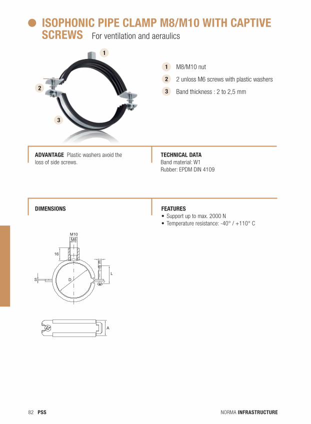
M8/M10 nut
2 unloss M6 screws with plastic washers
Band thickness : 2 to 2,5 mm
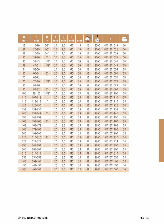
ISOPHONIC PIPE CLAMP M8/M10 WITH CAPTIVE SCREWS For ventilation and aeraulics
TECHNICAL dATA Band material: W1 Rubber: EPDM DIN 4109
3
S D
16
M10M8
E
L
A
AdVANTAGE Plastic washers avoid the loss of side screws.
1
3
2
FEATURES • Supportuptomax.2000N• Temperatureresistance:-40°/+110°C
dIMENSIONS
NORMA INFRASTRUCTURE 83PSS
d mm
d mm
d "
Amm
Smm
Emm
LmmN
dB NdB
N° NdB
18 15-19 3/8" 20 2,0 M6 15 18 2000 8471871018 50
22 20-25 1/2" 20 2,0 M6 15 18 2000 8471871022 50
28 26-30 3/4" 20 2,0 M6 15 18 2000 8471871028 50
35 32-36 1" 20 2,0 M6 15 18 2000 8471871035 50
40 38-43 11/4" 20 2,0 M6 20 18 2000 8471871040 25
48 47-51 11/2" 20 2,0 M6 20 18 2000 8471871048 25
54 53-56 20 2,0 M6 20 18 2000 8471871054 25
60 60-64 2" 20 2,0 M6 20 18 2000 8471871060 25
70 68-72 20 2,0 M6 20 18 2000 8471871070 25
75 75-80 21/2" 20 2,0 M6 20 18 2000 8471871075 25
83 81-86 20 2,0 M6 20 18 2000 8471871083 25
90 87-92 3" 20 2,0 M6 20 18 2000 8471871090 25
100 99-105 31/2" 20 2,0 M6 20 18 2000 8471871100 25
110 107-112 20 2,0 M6 20 18 2000 8471871110 25
115 113-118 4" 20 2,0 M6 20 18 2000 8471871115 25
125 125-130 20 2,0 M6 26 18 2000 8471871125 25
133 132-137 20 2,0 M6 26 18 2000 8471871133 25
140 138-142 5" 20 2,0 M6 26 18 2000 8471871140 25
150 148-152 20 2,0 M6 26 18 2000 8471871150 25
160 159-166 6" 20 2,0 M6 26 18 2000 8471871160 25
168 168-172 20 2,5 M6 26 18 2000 8471871168 25
180 179-184 20 2,5 M6 26 18 2000 8471871180 25
200 199-205 20 2,5 M6 26 18 2000 8471871200 25
220 215-220 8" 20 2,5 M6 26 18 2000 8471871220 25
224 223-228 20 2,5 M6 26 18 2000 8471871224 25
250 249-254 20 2,5 M6 26 18 2000 8471871250 25
300 299-304 20 2,5 M6 26 18 2000 8471871300 25
315 314-319 20 2,5 M6 26 18 2000 8471871315 25
355 354-359 20 2,5 M6 26 18 2000 8471871355 25
400 399-404 20 2,5 M6 26 18 2000 8471871400 25
450 449-454 20 2,5 M6 26 18 2000 8471871450 10
500 499-504 20 2,5 M6 26 18 2000 8471871500 10
NORMA INFRASTRUCTURE84 PSS
2
1
2
3
3
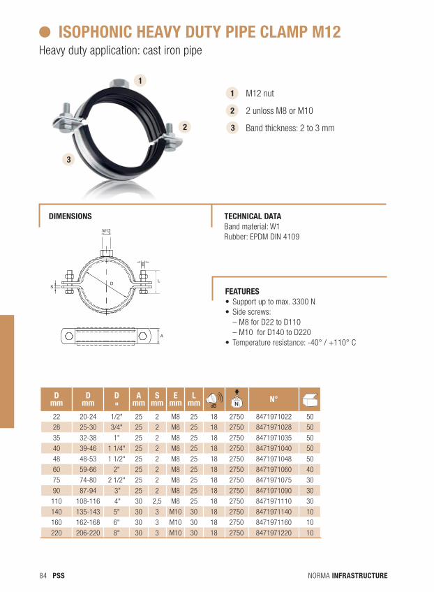
M12 nut
2 unloss M8 or M10
Band thickness: 2 to 3 mm
ISOPHONIC HEAVY dUTY PIPE CLAMP M12Heavy duty application: cast iron pipe
TECHNICAL dATA Band material: W1 Rubber: EPDM DIN 4109
dIMENSIONS
SD
M12
E
A
LS
D
M12
E
A
L
1
d mm
d mm
d "
Amm
Smm
Emm
LmmN
dB NdB
N° NdB
22 20-24 1/2" 25 2 M8 25 18 2750 8471971022 50
28 25-30 3/4" 25 2 M8 25 18 2750 8471971028 50
35 32-38 1" 25 2 M8 25 18 2750 8471971035 50
40 39-46 1 1/4" 25 2 M8 25 18 2750 8471971040 50
48 48-53 1 1/2" 25 2 M8 25 18 2750 8471971048 50
60 59-66 2" 25 2 M8 25 18 2750 8471971060 40
75 74-80 2 1/2" 25 2 M8 25 18 2750 8471971075 30
90 87-94 3" 25 2 M8 25 18 2750 8471971090 30
110 108-116 4" 30 2,5 M8 25 18 2750 8471971110 30
140 135-143 5" 30 3 M10 30 18 2750 8471971140 10
160 162-168 6" 30 3 M10 30 18 2750 8471971160 10
220 206-220 8" 30 3 M10 30 18 2750 8471971220 10
FEATURES • Supportuptomax.3300N• Sidescrews:
– M8 for D22 to D110 – M10 for D140 to D220
• Temperatureresistance:-40°/+110°C
NORMA INFRASTRUCTURE 85PSS
S
M8
D
E
L
A
S
M8
D
E
L
A
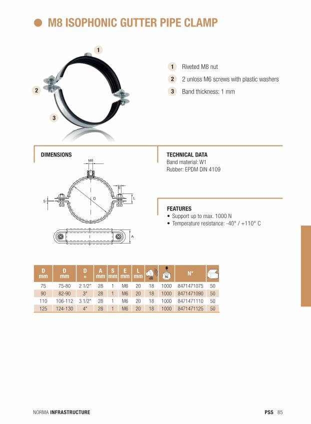
1
1
2
3
Riveted M8 nut
2 unloss M6 screws with plastic washers
Band thickness: 1 mm
M8 ISOPHONIC GUTTER PIPE CLAMP
dIMENSIONS TECHNICAL dATA Band material: W1 Rubber: EPDM DIN 4109
d mm
d mm
d "
Amm
Smm
Emm
LmmN
dB NdB
N°NdB
75 75-80 2 1/2" 28 1 M6 20 18 1000 8471471075 50
90 82-90 3" 28 1 M6 20 18 1000 8471471090 50
110 106-112 3 1/2" 28 1 M6 20 18 1000 8471471110 50
125 124-130 4" 28 1 M6 20 18 1000 8471471125 50
2
3
FEATURES • Supportuptomax.1000N• Temperatureresistance:-40°/+110°C
NORMA INFRASTRUCTURE86 PSS
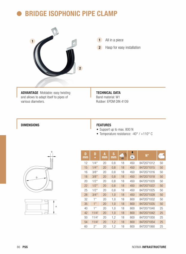
1 1 All in a piece
Hasp for easy installation
BRIdGE ISOPHONIC PIPE CLAMP
AdVANTAGE Moldable: easy twisting and allows to adapt itself to pipes of various diameters.
TECHNICAL dATA Band material: W1 Rubber: EPDM DIN 4109
A
D
S
A
D
S
d mm
d "
Amm
SmmN
dB NdB
N° NdB
12 1/4'' 20 0,8 18 450 8472071012 50
15 1/4'' 20 0,8 18 450 8472071015 50
16 3/8'' 20 0,8 18 450 8472071016 50
18 3/8'' 20 0,8 18 450 8472071018 50
20 1/2'' 20 0,8 18 450 8472071020 50
22 1/2'' 20 0,8 18 450 8472071022 50
25 1/2'' 20 0,8 18 450 8472071025 50
28 3/4'' 20 1,0 18 450 8472071028 50
32 1'' 20 1,0 18 800 8472071032 50
35 1'' 20 1,0 18 800 8472071035 50
40 1'' 20 1,0 18 800 8472071040 25
42 11/4' 20 1,0 18 800 8472071042 25
50 11/4' 20 1,2 18 800 8472071050 25
54 11/4' 20 1,2 18 800 8472071054 25
60 2'' 20 1,2 18 800 8472071060 25
2
2
FEATURES • Supportuptomax.800N• Temperatureresistance:-40°/+110°C
dIMENSIONS
NORMA INFRASTRUCTURE 87PSS
SRd
D
E
L
M8
M10
A C
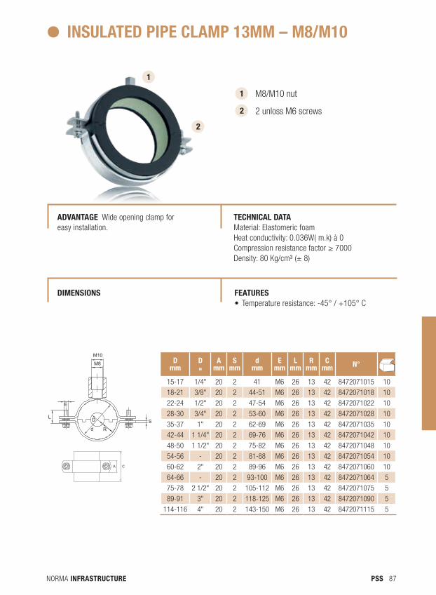
1 M8/M10 nut
2 unloss M6 screws
INSULATEd PIPE CLAMP 13MM – M8/M10
AdVANTAGE Wide opening clamp for easy installation.
TECHNICAL dATA Material: Elastomeric foamHeat conductivity: 0.036W( m.k) à 0Compression resistance factor ≥ 7000Density: 80 Kg/cm³ (± 8)
2
1
2
d mm
d "
Amm
Smm
dmm
Emm
Lmm
Rmm
Cmm N°N
dB
15-17 1/4" 20 2 41 M6 26 13 42 8472071015 10
18-21 3/8" 20 2 44-51 M6 26 13 42 8472071018 10
22-24 1/2" 20 2 47-54 M6 26 13 42 8472071022 10
28-30 3/4" 20 2 53-60 M6 26 13 42 8472071028 10
35-37 1" 20 2 62-69 M6 26 13 42 8472071035 10
42-44 1 1/4" 20 2 69-76 M6 26 13 42 8472071042 10
48-50 1 1/2" 20 2 75-82 M6 26 13 42 8472071048 10
54-56 - 20 2 81-88 M6 26 13 42 8472071054 10
60-62 2" 20 2 89-96 M6 26 13 42 8472071060 10
64-66 - 20 2 93-100 M6 26 13 42 8472071064 5
75-78 2 1/2" 20 2 105-112 M6 26 13 42 8472071075 5
89-91 3" 20 2 118-125 M6 26 13 42 8472071090 5
114-116 4" 20 2 143-150 M6 26 13 42 8472071115 5
SRd
D
E
L
M8
M10
A C
FEATURES • Temperatureresistance:-45°/+105°C
dIMENSIONS
NORMA INFRASTRUCTURE88 PSS
SRd
D
E
L
M8
M10
A C
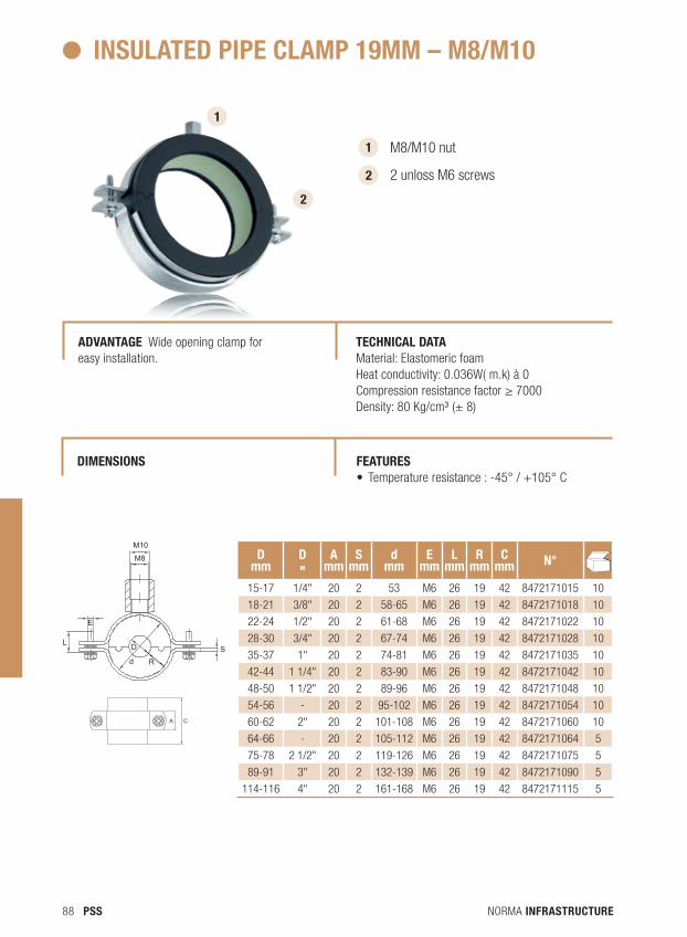
1 M8/M10 nut
2 unloss M6 screws
INSULATEd PIPE CLAMP 19MM – M8/M10
AdVANTAGE Wide opening clamp for easy installation.
TECHNICAL dATA Material: Elastomeric foamHeat conductivity: 0.036W( m.k) à 0Compression resistance factor ≥ 7000Density: 80 Kg/cm³ (± 8)
2
1
2
SRd
D
E
L
M8
M10
A C
d mm
d "
Amm
Smm
dmm
Emm
Lmm
Rmm
Cmm N°N
dB
15-17 1/4" 20 2 53 M6 26 19 42 8472171015 10
18-21 3/8" 20 2 58-65 M6 26 19 42 8472171018 10
22-24 1/2" 20 2 61-68 M6 26 19 42 8472171022 10
28-30 3/4" 20 2 67-74 M6 26 19 42 8472171028 10
35-37 1" 20 2 74-81 M6 26 19 42 8472171035 10
42-44 1 1/4" 20 2 83-90 M6 26 19 42 8472171042 10
48-50 1 1/2" 20 2 89-96 M6 26 19 42 8472171048 10
54-56 - 20 2 95-102 M6 26 19 42 8472171054 10
60-62 2" 20 2 101-108 M6 26 19 42 8472171060 10
64-66 - 20 2 105-112 M6 26 19 42 8472171064 5
75-78 2 1/2" 20 2 119-126 M6 26 19 42 8472171075 5
89-91 3" 20 2 132-139 M6 26 19 42 8472171090 5
114-116 4" 20 2 161-168 M6 26 19 42 8472171115 5
FEATURES • Temperatureresistance:-45°/+105°C
dIMENSIONS

NORMA INFRASTRUCTURE 89PSS
Plastic Clip
All of our clips can be implemented quickly. No sharp edges. Can be used indoor or outdoor. Thin walled copper or steel tubes for horizontal or vertical mounting. Resistant to oil and petrol, corrosion, UV and ageing. Our clips are halogen free.Recyclable.
PSS
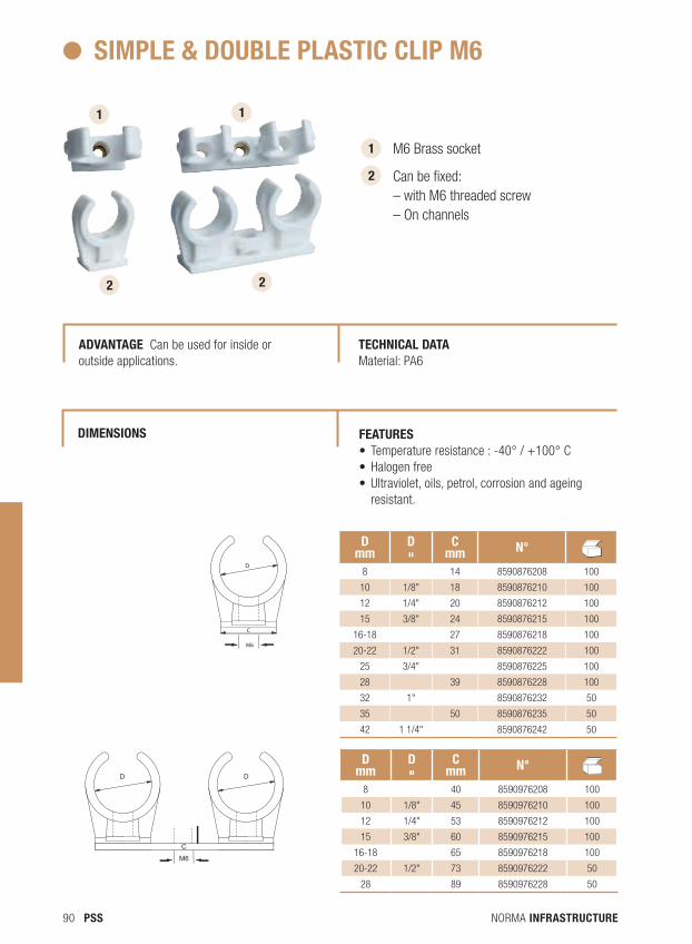
NORMA INFRASTRUCTURE90 PSS
1 M6 Brass socket
Can be fixed: – with M6 threaded screw – On channels
SIMPLE & dOUBLE PLASTIC CLIP M6
AdVANTAGE Can be used for inside or outside applications.
TECHNICAL dATA Material: PA6
2
1 1
2 2
D
C
M6
D D
C
M6
d mm
d "
Cmm N° N
dB
8 14 8590876208 100
10 1/8" 18 8590876210 100
12 1/4" 20 8590876212 100
15 3/8" 24 8590876215 100
16-18 27 8590876218 100
20-22 1/2" 31 8590876222 100
25 3/4" 8590876225 100
28 39 8590876228 100
32 1" 8590876232 50
35 50 8590876235 50
42 1 1/4" 8590876242 50
d mm
d "
Cmm N° N
dB
8 40 8590976208 100
10 1/8" 45 8590976210 100
12 1/4" 53 8590976212 100
15 3/8" 60 8590976215 100
16-18 65 8590976218 100
20-22 1/2" 73 8590976222 50
28 89 8590976228 50
FEATURES • Temperatureresistance:-40°/+100°C• Halogenfree• Ultraviolet,oils,petrol,corrosionandageing
resistant.
dIMENSIONS

NORMA INFRASTRUCTURE 91PSS
Channels Our rails allow quick tube fasteningWith our wide range of accessories you have a multitude of mounting options. Engraved markings on the sides and rail lips make it easy to adjust and cut different elements. High bending resistance due to the profile’s shape. We offer a soundproof strip adapted to each type of rail. You can create a neat finish with the end caps.
Our consoles are ideal as supportThe welded plate is very resistant and its oblong slots allow vertical adjustment. Our consoles have different lengths corresponding to most mounting options.Various combinations are possible with our bases and our assembly wall lamps. You can create a neat finish with the end caps.
PSS
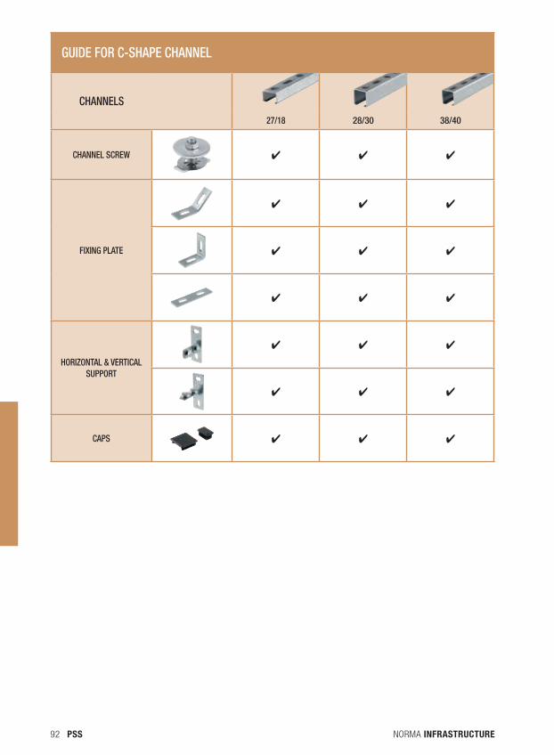
NORMA INFRASTRUCTURE92 PSS
GUIDE FOR C-SHAPE CHANNEL
CHANNELS
27/18 28/30 38/40
CHANNEL SCREW ✔ ✔ ✔
FIXING PLATE
✔ ✔ ✔
✔ ✔ ✔
✔ ✔ ✔
HORIZONTAL & VERTICAL SUPPORT
✔ ✔ ✔
✔ ✔ ✔
CAPS ✔ ✔ ✔
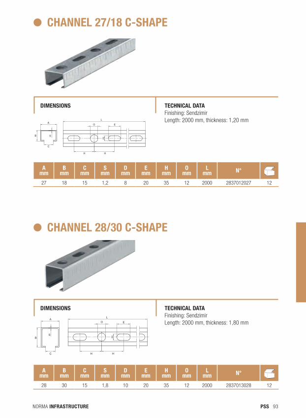
NORMA INFRASTRUCTURE 93PSS
CHANNEL 27/18 C-SHAPE
dIMENSIONS TECHNICAL dATA Finishing: Sendzimir Length: 2000 mm, thickness: 1,20 mm
A mm
Bmm
Cmm
Smm
dmm
Emm
Hmm
Omm
Lmm N° N
dB
27 18 15 1,2 8 20 35 12 2000 2837012027 12
B
A
C
S
L
H H
D
EO
CHANNEL 28/30 C-SHAPE
dIMENSIONS TECHNICAL dATA Finishing: Sendzimir Length: 2000 mm, thickness: 1,80 mm
A mm
Bmm
Cmm
Smm
dmm
Emm
Hmm
Omm
Lmm N° N
dB
28 30 15 1,8 10 20 35 12 2000 2837013028 12
A
SB
C H H
O
L
E
D
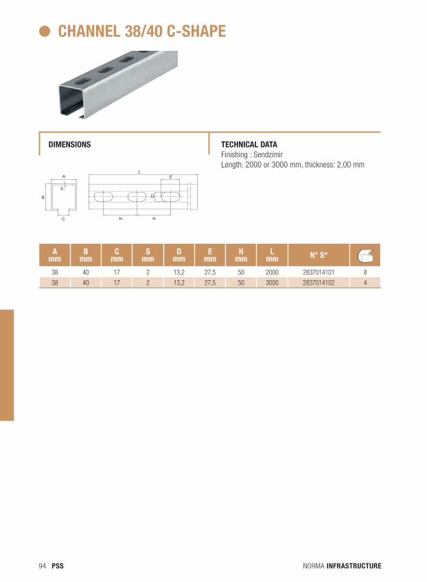
NORMA INFRASTRUCTURE94 PSS
CHANNEL 38/40 C-SHAPE
dIMENSIONS TECHNICAL dATA Finishing : Sendzimir Length: 2000 or 3000 mm, thickness: 2,00 mm
A mm
Bmm
Cmm
Smm
dmm
Emm
Hmm
Lmm N° S* N
dB
38 40 17 2 13,2 27,5 50 2000 2837014101 8
38 40 17 2 13,2 27,5 50 3000 2837014102 4
B
C
AL
H
E
D
S
H
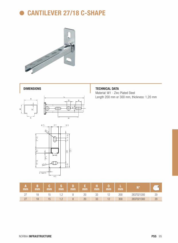
NORMA INFRASTRUCTURE 95PSS
CANTILEVER 27/18 C-SHAPE
dIMENSIONS TECHNICAL dATA Material: W1 - Zinc Plated SteelLength 200 mm or 300 mm, thickness: 1,20 mm
A mm
Bmm
Cmm
Smm
dmm
Emm
Hmm
Omm
Lmm N° N
dB
27 18 15 1,2 8 20 33 12 200 2837021200 20
27 18 15 1,2 8 20 33 12 300 2837021300 20
B
A
C
S
L
EO
D
H
B
A
C
S
L
EO
D
H

NORMA INFRASTRUCTURE96 PSS
CANTILEVER 28/30 C-SHAPE
dIMENSIONS TECHNICAL dATA Material: W1 - Zinc Plated SteelLength 200 mm, 300 mm or 600 mm, thickness: 1,80 mm
A mm
Bmm
Cmm
Smm
dmm
Emm
Hmm
Omm
Lmm N° N
dB
28 30 15 1,8 8 20 33 12 200 2837022200 20
28 30 15 1,8 8 20 33 12 300 2837022300 20
28 30 15 1,8 8 20 33 12 600 2837022600 20
A
B
C
S
D
E O
HH
L
A
B
C
S
D
E O
HH
L
A
B
C
S
D
E O
HH
L
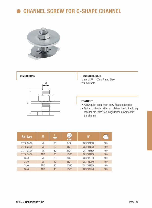
NORMA INFRASTRUCTURE 97PSS
CHANNEL SCREW FOR C-SHAPE CHANNEL
dIMENSIONS TECHNICAL dATA Material: W1 - Zinc Plated Steel W4 available
Rail type M Lmm mm
N° NdB
27/18-28/30 M6 20 6x18 2837031620 100
27/18-28/30 M8 20 8x24 2837031820 100
27/18-28/30 M8 30 8x24 2837031830 100
27/18-28/30 M10 30 10x30 2837031930 100
38/40 M8 30 8x24 2837032830 100
38/40 M8 40 8x24 2837032840 100
38/40 M10 30 10x30 2837032930 100
38/40 M10 40 10x30 2837032940 100
M
L FEATURES • AllowquickinstallationonC-Shapechannels• Quickpositioningafterinstallationduetothefixing
mechanism, with free longitudinal movement in the channel
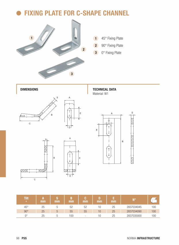
NORMA INFRASTRUCTURE98 PSS
FIXING PLATE FOR C-SHAPE CHANNEL
dIMENSIONS TECHNICAL dATA Material: W1
Tilt°
Amm
Smm
Bmm
Cmm
dmm
Emm N° N
dB
45° 25 5 52 52 10 25 2837034045 100
90° 25 5 55 55 10 25 2837034090 100
0° 25 5 100 - 10 25 2837035000 100
1 45° Fixing Plate
90° Fixing Plate
0° Fixing Plate
2
3
3
S A
D
B
C
E
S
B
C
E
A
D
1
2
D
E
B
SA
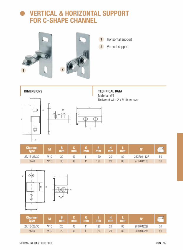
NORMA INFRASTRUCTURE 99PSS
VERTICAL & HORIZONTAL SUPPORT FOR C-SHAPE CHANNEL
dIMENSIONS TECHNICAL dATA Material: W1 Delivered with 2 x M10 screws
1 2
Channel type M B
mmC
mmO
mmE
mmH
mmL
mm N° NdB
27/18-28/30 M10 30 40 11 120 20 80 2837041127 50
38/40 M10 30 40 11 120 20 80 2737041138 50
Channel type M B
mmC
mmO
mmE
mmH
mmL
mm N° NdB
27/18-28/30 M10 20 40 11 120 20 80 2837042227 50
38/40 M10 20 40 11 120 20 80 2837042238 50
1 Horizontal support
Vertical support 2
L
H
M
B
E
C
OL
H
M
B
E
C
O
L
M
B E
C
O
H
L
M
B E
C
O
H
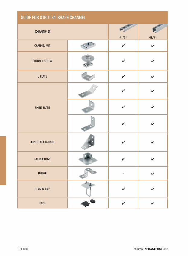
NORMA INFRASTRUCTURE100 PSS
GUIDE FOR STRUT 41-SHAPE CHANNEL
CHANNELS41/21 41/41
CHANNEL NUT ✔ ✔
CHANNEL SCREW ✔ ✔
U PLATE ✔ ✔
FIXING PLATE
✔ ✔
✔ ✔
✔ ✔
REINFORCED SQUARE ✔ ✔
DOUBLE BASE ✔ ✔
BRIDGE - ✔
BEAM CLAMP ✔ ✔
CAPS ✔ ✔
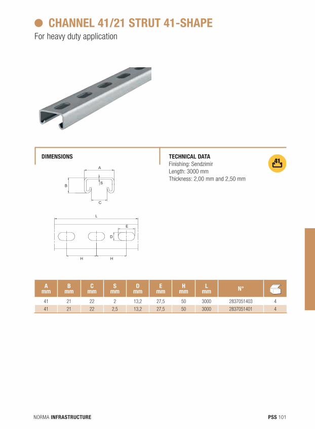
NORMA INFRASTRUCTURE 101PSS
CHANNEL 41/21 STRUT 41-SHAPEFor heavy duty application
dIMENSIONS TECHNICAL dATA Finishing: SendzimirLength: 3000 mmThickness: 2,00 mm and 2,50 mm
A mm
Bmm
Cmm
Smm
dmm
Emm
Hmm
Lmm N° N
dB
41 21 22 2 13,2 27,5 50 3000 2837051403 4
41 21 22 2,5 13,2 27,5 50 3000 2837051401 4
A L
B
C
SE
D
H HA L
B
C
SE
D
H H
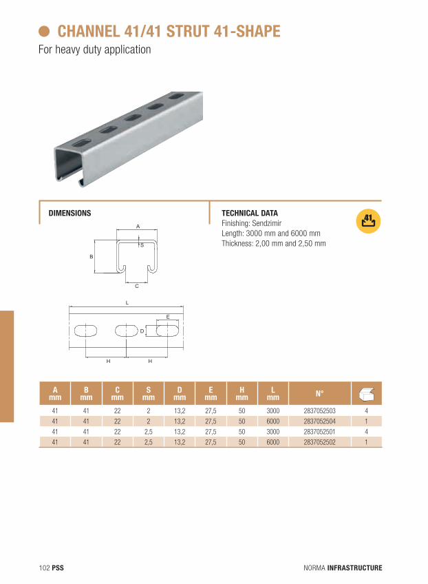
NORMA INFRASTRUCTURE102 PSS
CHANNEL 41/41 STRUT 41-SHAPEFor heavy duty application
dIMENSIONS TECHNICAL dATA Finishing: SendzimirLength: 3000 mm and 6000 mmThickness: 2,00 mm and 2,50 mm
A mm
Bmm
Cmm
Smm
dmm
Emm
Hmm
Lmm N° N
dB
41 41 22 2 13,2 27,5 50 3000 2837052503 4
41 41 22 2 13,2 27,5 50 6000 2837052504 1
41 41 22 2,5 13,2 27,5 50 3000 2837052501 4
41 41 22 2,5 13,2 27,5 50 6000 2837052502 1
A L
B
C
S E
D
H H
A L
B
C
S E
D
H H
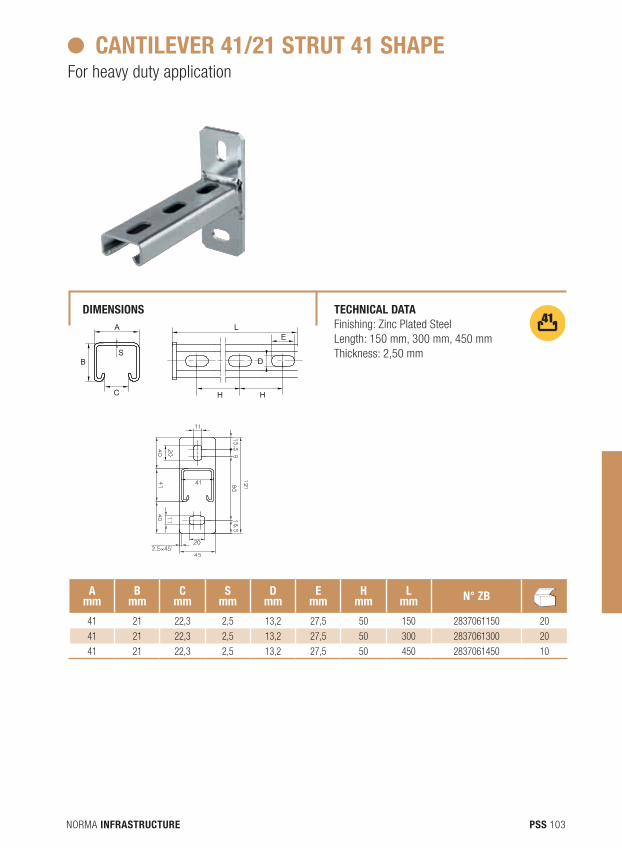
NORMA INFRASTRUCTURE 103PSS
CANTILEVER 41/21 STRUT 41 SHAPEFor heavy duty application
dIMENSIONS TECHNICAL dATA Finishing: Zinc Plated SteelLength: 150 mm, 300 mm, 450 mm Thickness: 2,50 mm
A mm
Bmm
Cmm
Smm
dmm
Emm
Hmm
Lmm N° ZB N
dB
41 21 22,3 2,5 13,2 27,5 50 150 2837061150 20
41 21 22,3 2,5 13,2 27,5 50 300 2837061300 20
41 21 22,3 2,5 13,2 27,5 50 450 2837061450 10
A
B
C
D
LE
HH
S
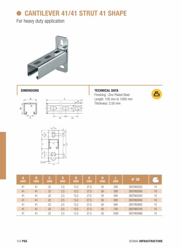
NORMA INFRASTRUCTURE104 PSS
CANTILEVER 41/41 STRUT 41 SHAPEFor heavy duty application
dIMENSIONS TECHNICAL dATA Finishing : Zinc Plated SteelLength: 150 mm to 1000 mmThickness: 2,50 mm
A mm
Bmm
Cmm
Smm
dmm
Emm
Hmm
Lmm N° ZB N
dB
41 41 22 2,5 13,2 27,5 50 200 2837063250 10
41 41 22 2,5 13,2 27,5 50 300 2837063300 10
41 41 22 2,5 13,2 27,5 50 400 2837063450 10
41 41 22 2,5 13,2 27,5 50 500 2837063550 10
41 41 22 2,5 13,2 27,5 50 600 2837063600 10
41 41 22 2,5 13,2 27,5 50 750 2837063750 10
41 41 22 2,5 13,2 27,5 50 1000 2837063999 10
A
B
C
D
LE
HH
S

NORMA INFRASTRUCTURE 105PSS
AB
CO
S
CHANNEL NUT FOR STRUT 41 SHAPE
dIMENSIONS TECHNICAL dATA Material: W1
M Hmm
Lmm
Imm N° N
dB
M6 6 34,5 19 2837071001 100
M8 6 34,5 19 2837072101 100
M10 8 34,5 19 2837073201 100
M12 8 34,5 19 2837074301 100
L
l
M
H
U PLATE FOR STRUT 41 SHAPE
dIMENSIONS TECHNICAL dATA Material: W1
Amm
Bmm
Cmm
Smm
Omm N° N
dB
40 45 20 4 14 2837078001 50
L
l
M
H
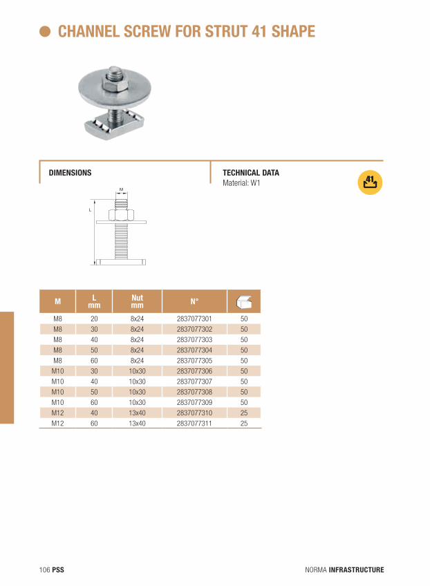
NORMA INFRASTRUCTURE106 PSS
CHANNEL SCREW FOR STRUT 41 SHAPE
dIMENSIONS TECHNICAL dATA Material: W1
M Lmm
Nutmm N° N
dB
M8 20 8x24 2837077301 50
M8 30 8x24 2837077302 50
M8 40 8x24 2837077303 50
M8 50 8x24 2837077304 50
M8 60 8x24 2837077305 50
M10 30 10x30 2837077306 50
M10 40 10x30 2837077307 50
M10 50 10x30 2837077308 50
M10 60 10x30 2837077309 50
M12 40 13x40 2837077310 25
M12 60 13x40 2837077311 25
M
L
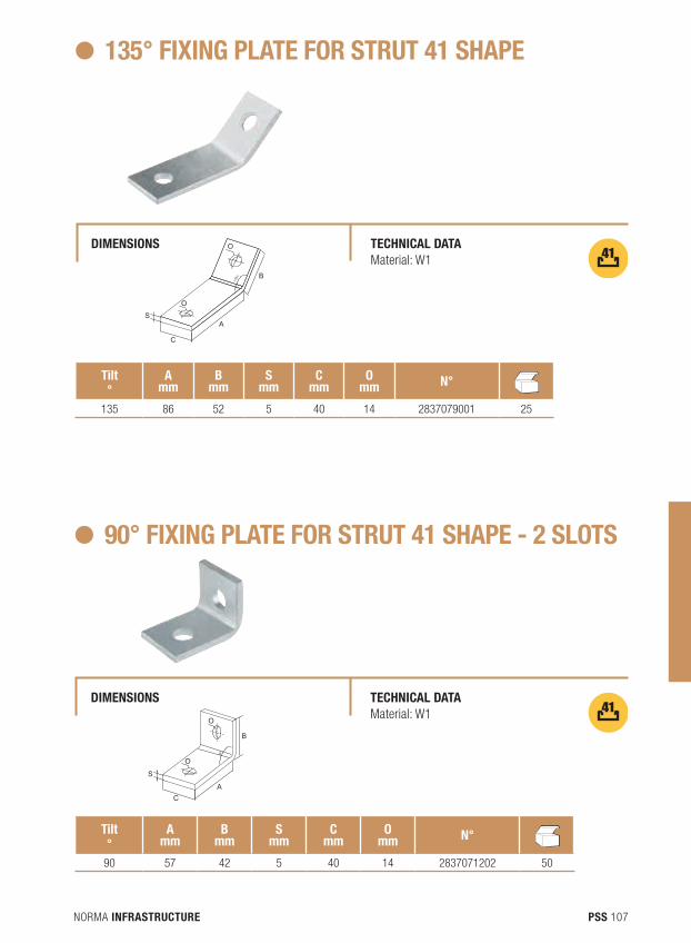
NORMA INFRASTRUCTURE 107PSS
S
A
B
90°
C
O
O
SA
B
C
O
O
135° FIXING PLATE FOR STRUT 41 SHAPE
dIMENSIONS TECHNICAL dATA Material: W1
Tilt°
Amm
Bmm
Smm
Cmm
Omm N° N
dB
135 86 52 5 40 14 2837079001 25
90° FIXING PLATE FOR STRUT 41 SHAPE - 2 SLOTS
dIMENSIONS TECHNICAL dATA Material: W1
Tilt°
Amm
Bmm
Smm
Cmm
Omm N° N
dB
90 57 42 5 40 14 2837071202 50
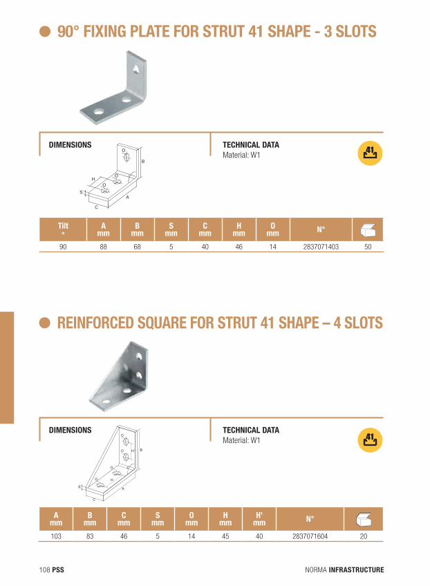
NORMA INFRASTRUCTURE108 PSS
S
H
H'
A
B
90°
C
O
O
O
O
S
H
A
B
90°
C
O
O
O
90° FIXING PLATE FOR STRUT 41 SHAPE - 3 SLOTS
dIMENSIONS TECHNICAL dATA Material: W1
Tilt°
Amm
Bmm
Smm
Cmm
Hmm
Omm N° N
dB
90 88 68 5 40 46 14 2837071403 50
REINFORCEd SQUARE FOR STRUT 41 SHAPE – 4 SLOTS
dIMENSIONS TECHNICAL dATA Material: W1
Amm
Bmm
Cmm
Smm
Omm
Hmm
H’mm N° N
dB
103 83 46 5 14 45 40 2837071604 20
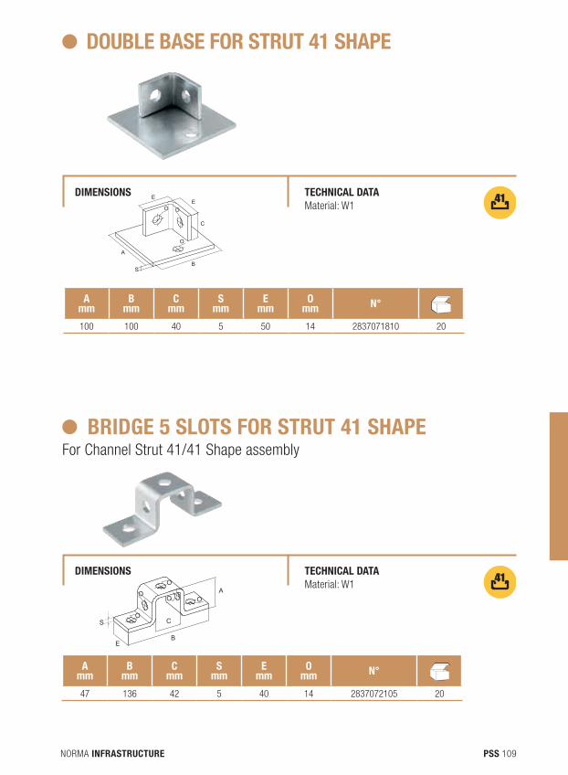
NORMA INFRASTRUCTURE 109PSS
EE
C
O O
O
A
BS
dOUBLE BASE FOR STRUT 41 SHAPE
dIMENSIONS TECHNICAL dATA Material: W1
Amm
Bmm
Cmm
Smm
Emm
Omm N° N
dB
100 100 40 5 50 14 2837071810 20
BRIdGE 5 SLOTS FOR STRUT 41 SHAPEFor Channel Strut 41/41 Shape assembly
dIMENSIONS TECHNICAL dATA Material: W1
Amm
Bmm
Cmm
Smm
Emm
Omm N° N
dB
47 136 42 5 40 14 2837072105 20
O
O
OO O
A
C
EB
S
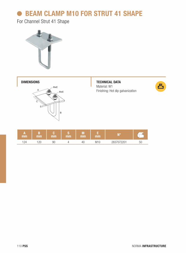
NORMA INFRASTRUCTURE110 PSS
BEAM CLAMP M10 FOR STRUT 41 SHAPEFor Channel Strut 41 Shape
dIMENSIONS TECHNICAL dATA Material: W1Finishing: Hot dip galvanization
Amm
Bmm
Cmm
Smm
Mmm
Emm N° N
dB
124 120 90 4 40 M10 2837072201 50
AMxE
MxE
B
S
C
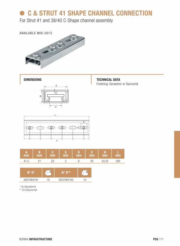
NORMA INFRASTRUCTURE 111PSS
H
D
A
C
B
L
E
S
H
D
A
C
B
L
E
S
C & STRUT 41 SHAPE CHANNEL CONNECTIONFor Strut 41 and 38/40 C-Shape channel assembly
dIMENSIONS TECHNICAL dATA Finishing: Sendzimir or Dacromet
Amm
Bmm
Cmm
Smm
dmm
Emm
Hmm
Lmm
41,5 21 22 2 8 20 33,33 200
N° S* NdB
N° d** NdB
2837084101 10 2837084102 10
* S=Sendzimir** D=Dacromet
AVAILABLE MID-2013
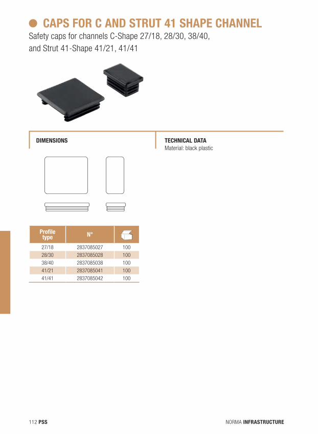
NORMA INFRASTRUCTURE112 PSS
CAPS FOR C ANd STRUT 41 SHAPE CHANNELSafety caps for channels C-Shape 27/18, 28/30, 38/40, and Strut 41-Shape 41/21, 41/41
dIMENSIONS TECHNICAL dATA Material: black plastic
Profile type N° N
dB
27/18 2837085027 100
28/30 2837085028 100
38/40 2837085038 100
41/21 2837085041 100
41/41 2837085042 100
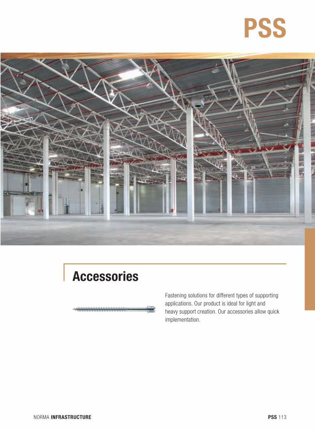
NORMA INFRASTRUCTURE 113PSS
AccessoriesFastening solutions for different types of supporting applications. Our product is ideal for light and heavy support creation. Our accessories allow quick implementation.
PSS
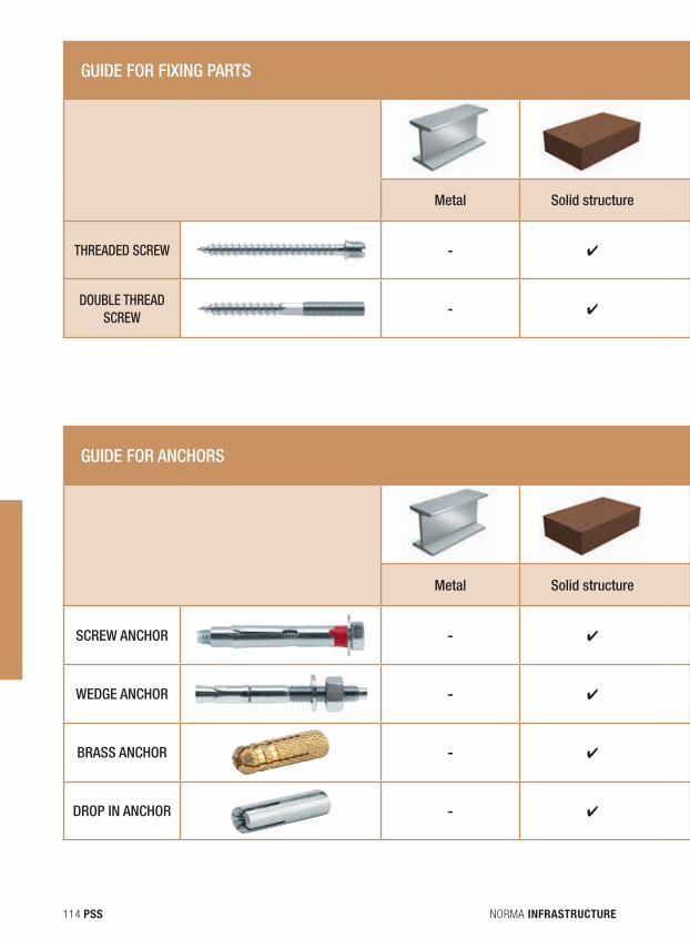
NORMA INFRASTRUCTURE114 PSS
GUIDE FOR FIXING PARTS
Metal Solid structure Hollow structure Concrete Aerated concrete Wood Plaster board
THREADED SCREW - ✔ ✔ ✔ - ✔ ✔
DOUBLE THREAD SCREW
- ✔ ✔ ✔ - ✔ ✔
GUIDE FOR ANCHORS
Metal Solid structure Hollow structure Concrete Aerated concrete Wood Plaster board
SCREW ANCHOR - ✔ - ✔ - - -
WEDGE ANCHOR - ✔ - ✔ - - -
BRASS ANCHOR - ✔ - ✔ - - -
DROP IN ANCHOR - ✔ - ✔ - - -
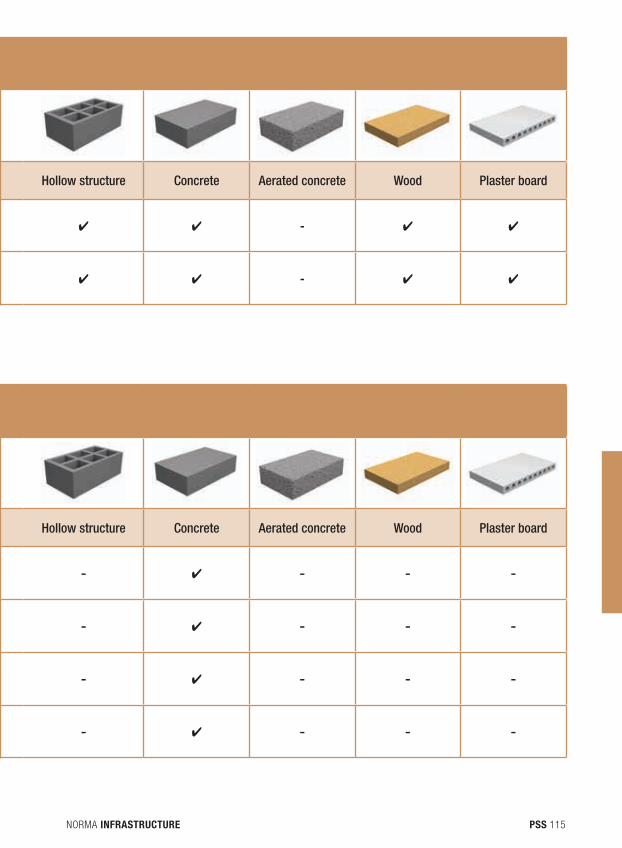
NORMA INFRASTRUCTURE 115PSS
GUIDE FOR FIXING PARTS
Metal Solid structure Hollow structure Concrete Aerated concrete Wood Plaster board
THREADED SCREW - ✔ ✔ ✔ - ✔ ✔
DOUBLE THREAD SCREW
- ✔ ✔ ✔ - ✔ ✔
GUIDE FOR ANCHORS
Metal Solid structure Hollow structure Concrete Aerated concrete Wood Plaster board
SCREW ANCHOR - ✔ - ✔ - - -
WEDGE ANCHOR - ✔ - ✔ - - -
BRASS ANCHOR - ✔ - ✔ - - -
DROP IN ANCHOR - ✔ - ✔ - - -
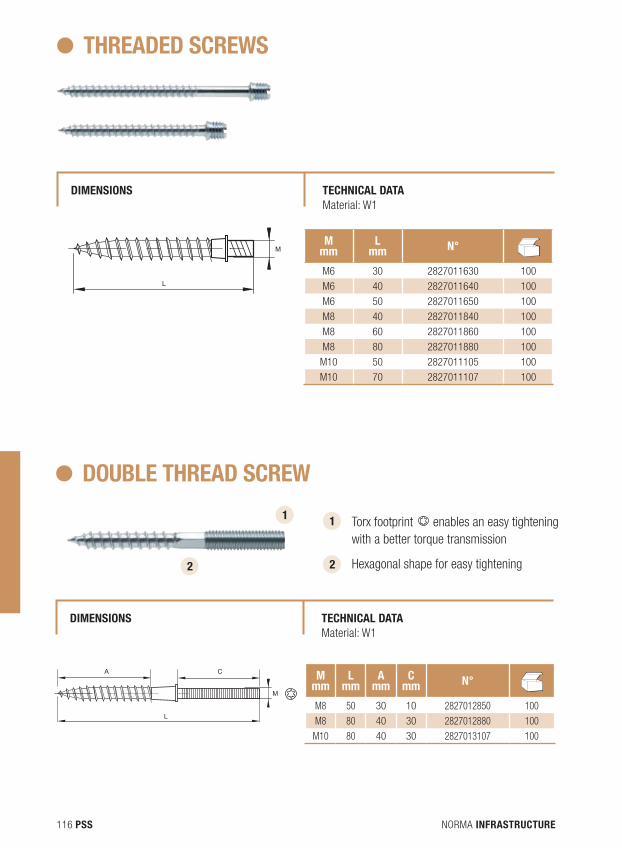
NORMA INFRASTRUCTURE116 PSS
THREAdEd SCREWS
dIMENSIONS TECHNICAL dATA Material: W1
Mmm
Lmm N° N
dB
M6 30 2827011630 100
M6 40 2827011640 100
M6 50 2827011650 100
M8 40 2827011840 100
M8 60 2827011860 100
M8 80 2827011880 100
M10 50 2827011105 100
M10 70 2827011107 100
L
M
dOUBLE THREAd SCREW
dIMENSIONS TECHNICAL dATAMaterial: W1
Mmm
Lmm
Amm
Cmm N° N
dB
M8 50 30 10 2827012850 100
M8 80 40 30 2827012880 100
M10 80 40 30 2827013107 100
1 Torx footprint L
A C
M enables an easy tightening with a better torque transmission
Hexagonal shape for easy tightening 2
1
2
L
A C
M
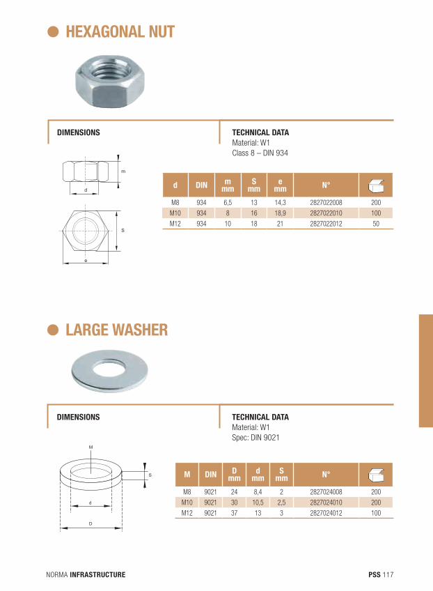
NORMA INFRASTRUCTURE 117PSS
HEXAGONAL NUT
dIMENSIONS TECHNICAL dATA Material: W1 Class 8 – DIN 934
d dIN mmm
Smm
emm N° N
dB
M8 934 6,5 13 14,3 2827022008 200
M10 934 8 16 18,9 2827022010 100
M12 934 10 18 21 2827022012 50
d
e
m
S
LARGE WASHER
dIMENSIONS TECHNICAL dATAMaterial: W1 Spec: DIN 9021
M dIN dmm
dmm
Smm N° N
dB
M8 9021 24 8,4 2 2827024008 200
M10 9021 30 10,5 2,5 2827024010 200
M12 9021 37 13 3 2827024012 100
M
d
D
S
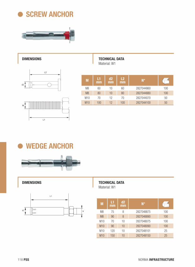
NORMA INFRASTRUCTURE118 PSS
SCREW ANCHOR
dIMENSIONS
dIMENSIONS
TECHNICAL dATA Material: W1
TECHNICAL dATA Material: W1
M L1mm
d2mm
L2mm N° N
dB
M8 60 10 60 2827044860 100
M8 80 10 80 2827044880 100
M10 70 12 70 2827044070 50
M10 100 12 100 2827044100 50M
d2
L1
L2
WEdGE ANCHOR
M L1mm
d2mm N° N
dB
M8 75 8 2827048875 100
M8 90 8 2827048890 100
M10 70 10 2827048075 100
M10 90 10 2827048090 100
M10 120 10 2827048101 25
M10 150 10 2827048150 25
d2 M
L1
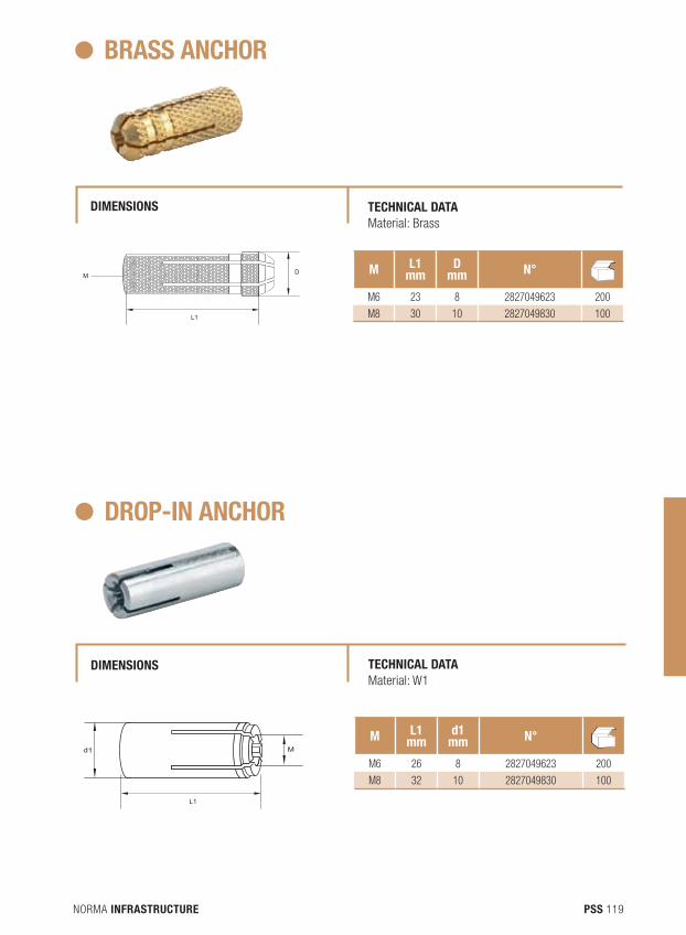
NORMA INFRASTRUCTURE 119PSS
L1
DM
BRASS ANCHOR
dIMENSIONS TECHNICAL dATA Material: Brass
M L1mm
dmm N° N
dB
M6 23 8 2827049623 200
M8 30 10 2827049830 100
dROP-IN ANCHOR
dIMENSIONS TECHNICAL dATA Material: W1
M L1mm
d1mm N° N
dB
M6 26 8 2827049623 200
M8 32 10 2827049830 100
L1
d1 M
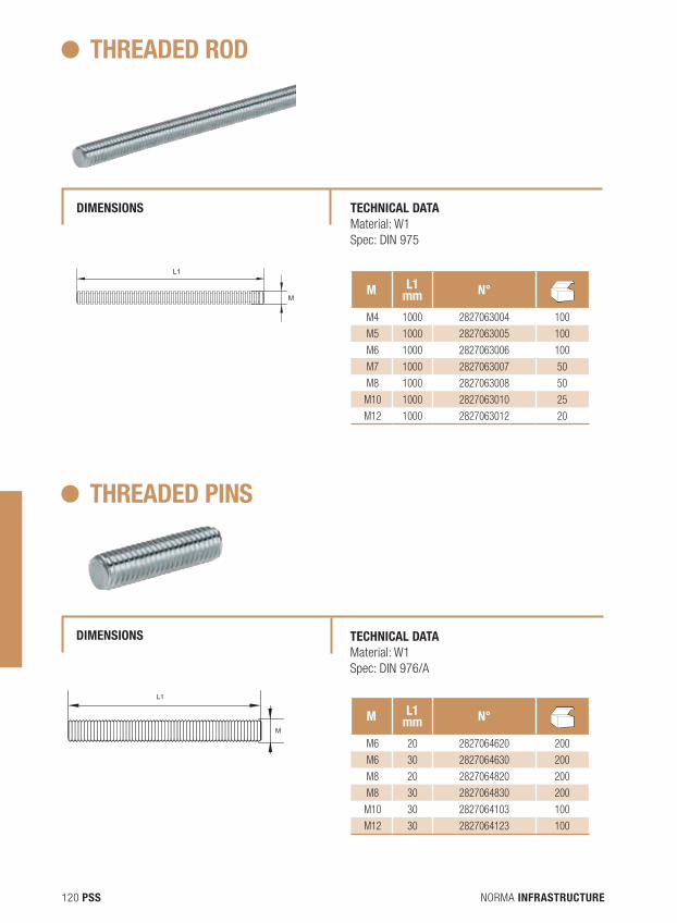
NORMA INFRASTRUCTURE120 PSS
THREAdEd ROd
dIMENSIONS TECHNICAL dATA Material: W1 Spec: DIN 975
M L1mm N° N
dB
M4 1000 2827063004 100
M5 1000 2827063005 100
M6 1000 2827063006 100
M7 1000 2827063007 50
M8 1000 2827063008 50
M10 1000 2827063010 25
M12 1000 2827063012 20
L1
M
THREAdEd PINS
dIMENSIONS TECHNICAL dATA Material: W1 Spec: DIN 976/A
M L1mm N° N
dB
M6 20 2827064620 200
M6 30 2827064630 200
M8 20 2827064820 200
M8 30 2827064830 200
M10 30 2827064103 100
M12 30 2827064123 100
L1
M
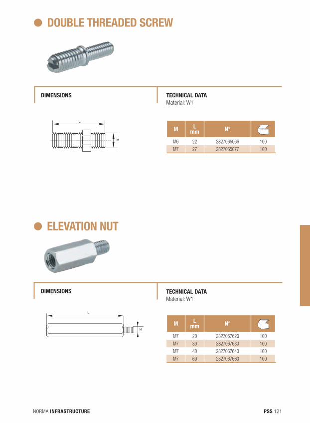
NORMA INFRASTRUCTURE 121PSS
dOUBLE THREAdEd SCREW
dIMENSIONS TECHNICAL dATA Material: W1
M Lmm N° N
dB
M6 22 2827065066 100
M7 27 2827065077 100
M
L
ELEVATION NUT
dIMENSIONS TECHNICAL dATA Material: W1
M Lmm N° N
dB
M7 20 2827067620 100
M7 30 2827067630 100
M7 40 2827067640 100
M7 60 2827067660 100
L
M
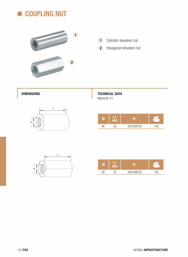
NORMA INFRASTRUCTURE122 PSS
COUPLING NUT
dIMENSIONS TECHNICAL dATA Material: X1
M L1mm N° N
dB
M7 30 2827069730 100
M L1mm N° N
dB
M7 20 2827068720 100
1 Cylindric elevation nut
Hexagonal elevation nut 2
1
2
L1
M
L1
M
L1
M
L1
M
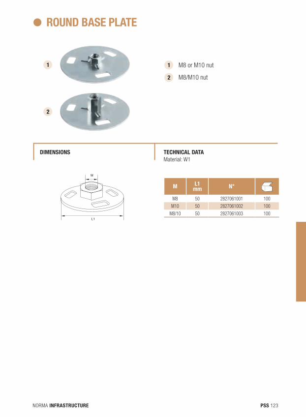
NORMA INFRASTRUCTURE 123PSS
ROUNd BASE PLATE
dIMENSIONS TECHNICAL dATA Material: W1
M L1mm N° N
dB
M8 50 2827061001 100
M10 50 2827061002 100
M8/10 50 2827061003 100
1 M8 or M10 nut
M8/M10 nut 2
1
2
M
L1
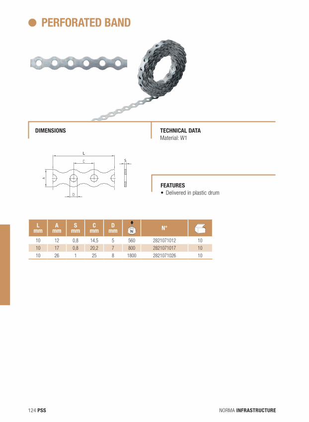
NORMA INFRASTRUCTURE124 PSS
PERFORATEd BANd
dIMENSIONS TECHNICAL dATA Material: W1
S
S
S
L
L
L
Lmm
Amm
Smm
Cmm
dmm N
dBN° N
dB
10 12 0,8 14,5 5 560 2821071012 10
10 17 0,8 20,2 7 800 2821071017 10
10 26 1 25 8 1800 2821071026 10
FEATURES • Deliveredinplasticdrum
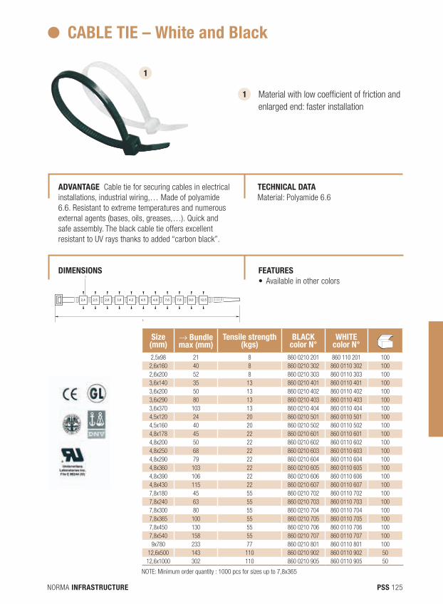
NORMA INFRASTRUCTURE 125PSS
2,4 2,5 2,6 3,6 4,2 4,5 4,8 7,6 7,8 9,0 12,5
L
I
CABLE TIE – White and Black
Size (mm)
→ Bundle max (mm)
Tensile strength (kgs)
BLACK color N°
WHITE color N°N dB
2,5x98 21 8 860 0210 201 860 110 201 1002,6x160 40 8 860 0210 302 860 0110 302 1002,6x200 52 8 860 0210 303 860 0110 303 1003,6x140 35 13 860 0210 401 860 0110 401 1003,6x200 50 13 860 0210 402 860 0110 402 1003,6x290 80 13 860 0210 403 860 0110 403 1003,6x370 103 13 860 0210 404 860 0110 404 1004,5x120 24 20 860 0210 501 860 0110 501 1004,5x160 40 20 860 0210 502 860 0110 502 1004,8x178 45 22 860 0210 601 860 0110 601 1004,8x200 50 22 860 0210 602 860 0110 602 1004,8x250 68 22 860 0210 603 860 0110 603 1004,8x290 79 22 860 0210 604 860 0110 604 1004,8x360 103 22 860 0210 605 860 0110 605 1004,8x390 106 22 860 0210 606 860 0110 606 1004,8x430 115 22 860 0210 607 860 0110 607 1007,8x180 45 55 860 0210 702 860 0110 702 1007,8x240 63 55 860 0210 703 860 0110 703 1007,8x300 80 55 860 0210 704 860 0110 704 1007,8x365 100 55 860 0210 705 860 0110 705 1007,8x450 130 55 860 0210 706 860 0110 706 1007,8x540 158 55 860 0210 707 860 0110 707 1009x780 233 77 860 0210 801 860 0110 801 100
12,6x500 143 110 860 0210 902 860 0110 902 5012,6x1000 302 110 860 0210 905 860 0110 905 50
1
1
Material with low coefficient of friction and enlarged end: faster installation
AdVANTAGE Cable tie for securing cables in electrical installations, industrial wiring,… Made of polyamide 6.6. Resistant to extreme temperatures and numerous external agents (bases, oils, greases,…). Quick and safe assembly. The black cable tie offers excellent resistant to UV rays thanks to added “carbon black”.
TECHNICAL dATA Material: Polyamide 6.6
FEATURES • Availableinothercolors
dIMENSIONS
NOTE: Minimum order quantity : 1000 pcs for sizes up to 7,8x365
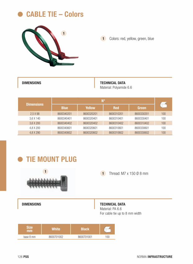
NORMA INFRASTRUCTURE126 PSS
CABLE TIE – Colors
dIMENSIONS TECHNICAL dATA Material: Polyamide 6.6
dimensions N°
NdBBlue Yellow Red Green
2,5 X 98 8600340201 8600320201 8600310201 8600330201 100
3,6 X 140 8600340401 8600320401 8600310401 8600330401 100
3,6 X 200 8600340402 8600320402 8600310402 8600310402 100
4,8 X 200 8600340601 8600320601 8600310601 8600330601 100
4,8 X 290 8600340602 8600320602 8600310602 8600330602 100
TIE MOUNT PLUG
dIMENSIONS TECHNICAL dATA Material: PA 6.6 For cable tie up to 8 mm width
Sizemm White Black N
dB
base 8 mm 8600701002 8600701001 100
1 1
Colors: red, yellow, green, blue
1 Thread: M7 x 150 Ø 8 mm 1
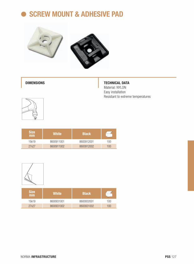
NORMA INFRASTRUCTURE 127PSS
SCREW MOUNT & AdHESIVE PAd
dIMENSIONS TECHNICAL dATA Material: NYLONEasy installationResistant to extreme temperatures
Sizemm White Black N
dB
19x19 8600911001 8600912001 100
27x27 8600911002 8600912002 100
Sizemm White Black N
dB
19x19 8600931001 8600932001 100
27x27 8600931002 8600931002 100
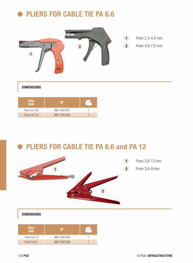
NORMA INFRASTRUCTURE128 PSS
PLIERS FOR CABLE TIE PA 6.6
dIMENSIONS
Sizemm N° N
dB
From 2,2-4,8 860 1000 001 1
From 4,8-7,8 860 1000 004 1
Sizemm N° N
dB
From 3,6-13 860 1000 005 1
From 3,6-9 860 1000 006 1
PLIERS FOR CABLE TIE PA 6.6 and PA 12
dIMENSIONS
1
1
From 2,2-4,8 mm
From 4,8-7,8 mm 2 2
1 From 3,6-13 mm
From 3,6-9 mm 2 1
2
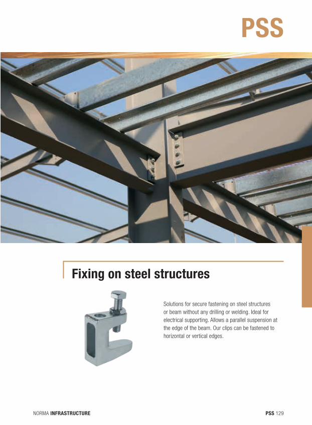
NORMA INFRASTRUCTURE 129PSS
Fixing on steel structures
Solutions for secure fastening on steel structures or beam without any drilling or welding. Ideal for electrical supporting. Allows a parallel suspension at the edge of the beam. Our clips can be fastened to horizontal or vertical edges.
PSS
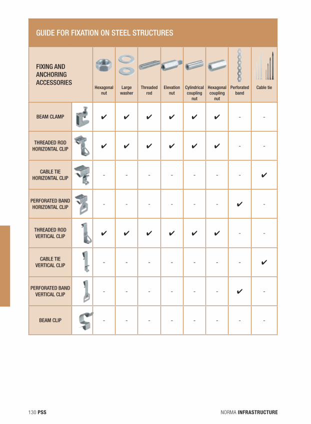
NORMA INFRASTRUCTURE130 PSS
GUIDE FOR FIXATION ON STEEL STRUCTURES
FIXING AND ANCHORING ACCESSORIES
Hexagonal
nutLarge
washerThreaded
rodElevation
nutCylindrical coupling
nut
Hexagonal coupling
nut
Perforated band
Cable tie
BEAM CLAMP ✔ ✔ ✔ ✔ ✔ ✔ - -
THREADED ROD HORIZONTAL CLIP ✔ ✔ ✔ ✔ ✔ ✔ - -
CABLE TIE HORIZONTAL CLIP - - - - - - - ✔
PERFORATED BAND HORIZONTAL CLIP - - - - - - ✔ -
THREADED ROD VERTICAL CLIP ✔ ✔ ✔ ✔ ✔ ✔ - -
CABLE TIE VERTICAL CLIP - - - - - - - ✔
PERFORATED BAND VERTICAL CLIP - - - - - - ✔ -
BEAM CLIP - - - - - - - -
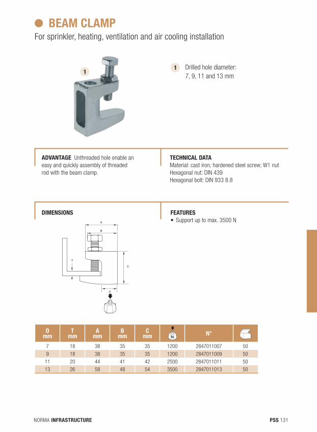
NORMA INFRASTRUCTURE 131PSS
C
T
A
B
D
BEAM CLAMPFor sprinkler, heating, ventilation and air cooling installation
1 Drilled hole diameter: 7, 9, 11 and 13 mm
1
dmm
Tmm
Amm
Bmm
Cmm N
dBN° N
dB
7 18 38 35 35 1200 2847011007 50
9 18 38 35 35 1200 2847011009 50
11 20 44 41 42 2500 2847011011 50
13 26 58 48 54 3500 2847011013 50
AdVANTAGE Unthreaded hole enable an easy and quickly assembly of threaded rod with the beam clamp.
TECHNICAL dATA Material: cast iron; hardened steel screw; W1 nutHexagonal nut: DIN 439Hexagonal bolt: DIN 933 8.8
FEATURES • Supportuptomax.3500N
dIMENSIONS
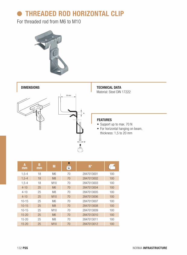
NORMA INFRASTRUCTURE132 PSS
THREAdEd ROd HORIZONTAL CLIP For threaded rod from M6 to M10
Amm
Bmm M
NdB
N° NdB
1,5-4 18 M6 70 2847013001 100
1,5-4 18 M8 70 2847013002 100
1,5-4 18 M10 70 2847013003 100
4-10 25 M6 70 2847013004 100
4-10 25 M8 70 2847013005 100
4-10 25 M10 70 2847013006 100
10-15 25 M6 70 2847013007 100
10-15 25 M8 70 2847013008 100
10-15 25 M10 70 2847013009 100
15-20 25 M6 70 2847013010 100
15-20 25 M8 70 2847013011 100
15-20 25 M10 70 2847013012 100
B min
A
M
B min
A
M
TECHNICAL dATA Material: Steel DIN 17222
dIMENSIONS
FEATURES • Supportuptomax.70N• Forhorizontalhangingonbeam,
thickness: 1,5 to 20 mm
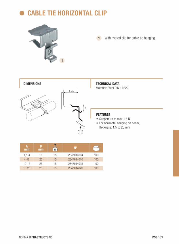
NORMA INFRASTRUCTURE 133PSS
CABLE TIE HORIZONTAL CLIP
1 With riveted clip for cable tie hanging
Amm
Bmm N
dBN° N
dB
1,5-4 18 15 2847014004 100
4-10 25 15 2847014010 100
10-15 25 15 2847014015 100
15-20 25 15 2847014020 100
B min
A
3x10
B min
A
3x10
1
TECHNICAL dATA Material: Steel DIN 17222
dIMENSIONS
FEATURES • Supportuptomax.15N• Forhorizontalhangingonbeam,
thickness: 1,5 to 20 mm
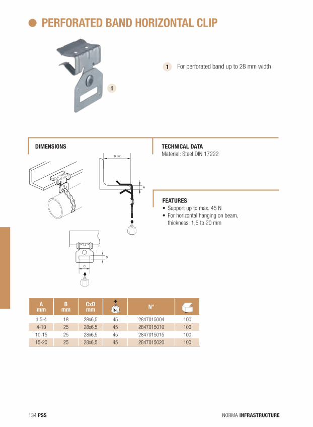
NORMA INFRASTRUCTURE134 PSS
PERFORATEd BANd HORIZONTAL CLIP
1 For perforated band up to 28 mm width
B min
AD
C
B min
AD
C
1
B min
AD
C
Amm
Bmm
Cxdmm N
dBN° N
dB
1,5-4 18 28x6,5 45 2847015004 100
4-10 25 28x6,5 45 2847015010 100
10-15 25 28x6,5 45 2847015015 100
15-20 25 28x6,5 45 2847015020 100
TECHNICAL dATA Material: Steel DIN 17222
dIMENSIONS
FEATURES • Supportuptomax.45N• Forhorizontalhangingonbeam,
thickness: 1,5 to 20 mm
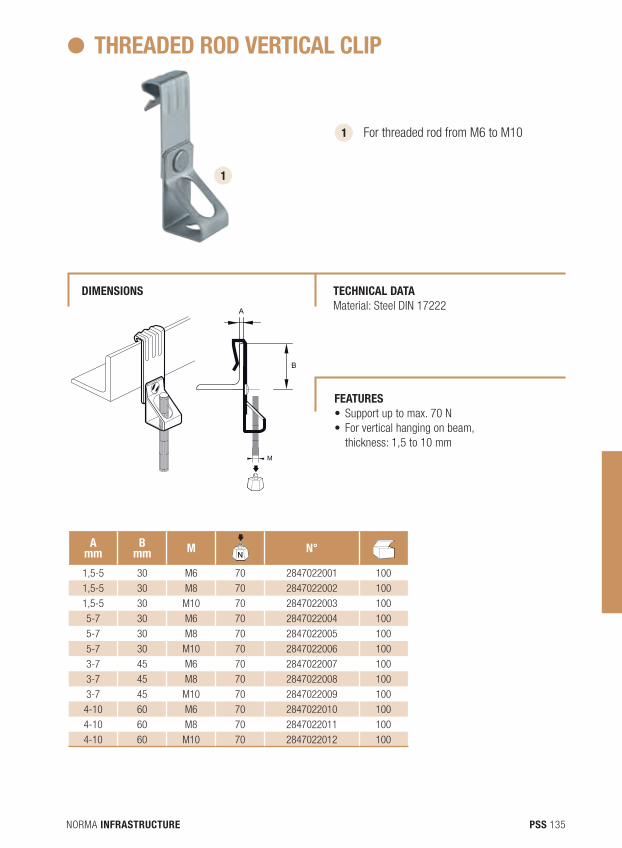
NORMA INFRASTRUCTURE 135PSS
THREAdEd ROd VERTICAL CLIP
1 For threaded rod from M6 to M10
Amm
Bmm M
NdB
N° NdB
1,5-5 30 M6 70 2847022001 100
1,5-5 30 M8 70 2847022002 100
1,5-5 30 M10 70 2847022003 100
5-7 30 M6 70 2847022004 100
5-7 30 M8 70 2847022005 100
5-7 30 M10 70 2847022006 100
3-7 45 M6 70 2847022007 100
3-7 45 M8 70 2847022008 100
3-7 45 M10 70 2847022009 100
4-10 60 M6 70 2847022010 100
4-10 60 M8 70 2847022011 100
4-10 60 M10 70 2847022012 100
B
A
M
B
A
M
1
TECHNICAL dATA Material: Steel DIN 17222
dIMENSIONS
FEATURES • Supportuptomax.70N• Forverticalhangingonbeam,
thickness: 1,5 to 10 mm
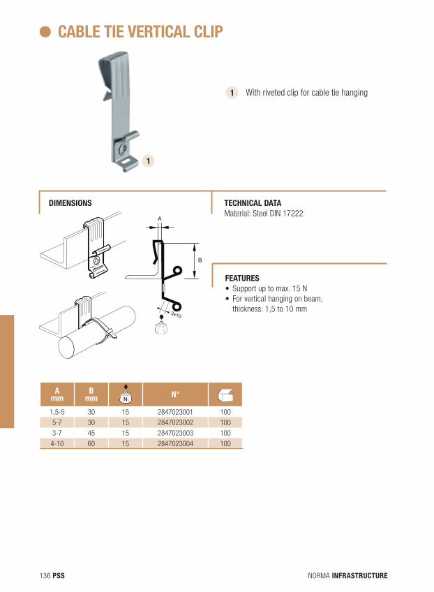
NORMA INFRASTRUCTURE136 PSS
CABLE TIE VERTICAL CLIP
1 With riveted clip for cable tie hanging
Amm
Bmm N
dBN° N
dB
1,5-5 30 15 2847023001 100
5-7 30 15 2847023002 100
3-7 45 15 2847023003 100
4-10 60 15 2847023004 100
3x10
B
A
3x10
B
A
3x10
B
A
1
TECHNICAL dATA Material: Steel DIN 17222
dIMENSIONS
FEATURES • Supportuptomax.15N• Forverticalhangingonbeam,
thickness: 1,5 to 10 mm
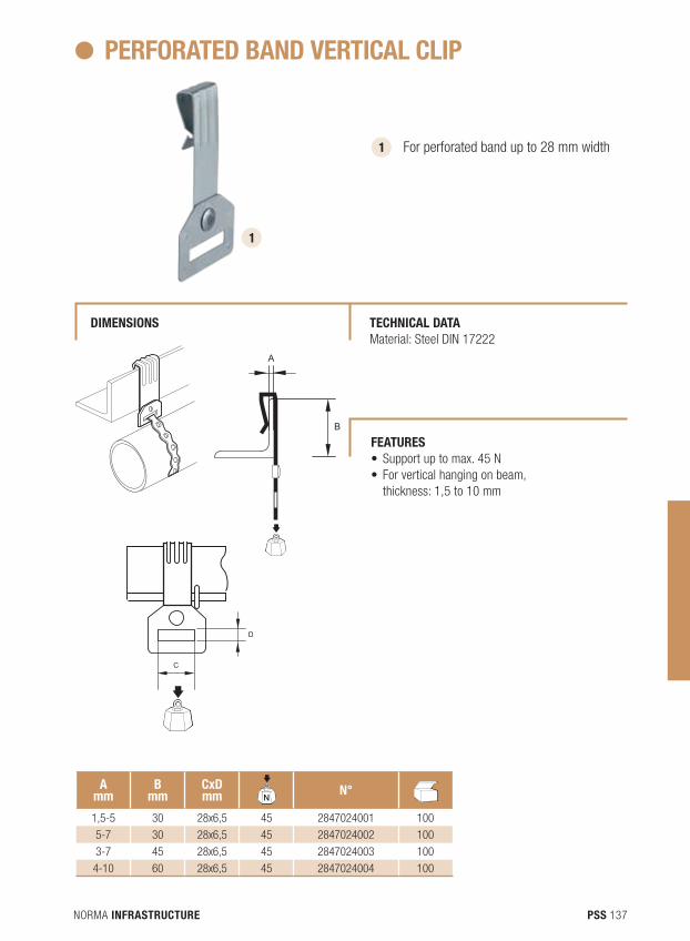
NORMA INFRASTRUCTURE 137PSS
PERFORATEd BANd VERTICAL CLIP
1 For perforated band up to 28 mm width
Amm
Bmm
Cxdmm N
dBN° N
dB
1,5-5 30 28x6,5 45 2847024001 100
5-7 30 28x6,5 45 2847024002 100
3-7 45 28x6,5 45 2847024003 100
4-10 60 28x6,5 45 2847024004 100
B
A
D
CB
A
D
C
B
A
D
C
1
TECHNICAL dATA Material: Steel DIN 17222
dIMENSIONS
FEATURES • Supportuptomax.45N• Forverticalhangingonbeam,
thickness: 1,5 to 10 mm
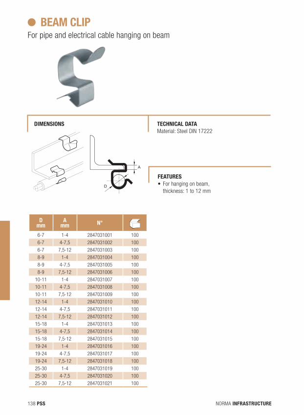
NORMA INFRASTRUCTURE138 PSS
BEAM CLIPFor pipe and electrical cable hanging on beam
dmm
Amm N° N
dB
6-7 1-4 2847031001 100
6-7 4-7,5 2847031002 100
6-7 7,5-12 2847031003 100
8-9 1-4 2847031004 100
8-9 4-7,5 2847031005 100
8-9 7,5-12 2847031006 100
10-11 1-4 2847031007 100
10-11 4-7,5 2847031008 100
10-11 7,5-12 2847031009 100
12-14 1-4 2847031010 100
12-14 4-7,5 2847031011 100
12-14 7,5-12 2847031012 100
15-18 1-4 2847031013 100
15-18 4-7,5 2847031014 100
15-18 7,5-12 2847031015 100
19-24 1-4 2847031016 100
19-24 4-7,5 2847031017 100
19-24 7,5-12 2847031018 100
25-30 1-4 2847031019 100
25-30 4-7,5 2847031020 100
25-30 7,5-12 2847031021 100
A
D
A
D
TECHNICAL dATA Material: Steel DIN 17222
dIMENSIONS
FEATURES• Forhangingonbeam,
thickness: 1 to 12 mm

NORMA INFRASTRUCTURE 139PSS
Stainless Steel Supporting and Fixing
Our stainless steel products have a better resistance to corrosion, oxidation and moisture. They are mainly used in the field of piping, chemical industry, petrochemical and agri-food.
PSS
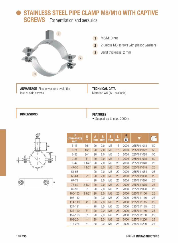
NORMA INFRASTRUCTURE140 PSS
STAINLESS STEEL PIPE CLAMP M8/M10 WITH CAPTIVE SCREWS For ventilation and aeraulics
1 1
M8/M10 nut
2 unloss M6 screws with plastic washers
Band thickness: 2 mm
2
2
3
3
S
M10M8
16
E
L
A
D
S
M10M8
16
E
L
A
D
AdVANTAGE Plastic washers avoid the loss of side screws.
TECHNICAL dATA Material: W5 (W1 available)
FEATURES • Supportuptomax.2000N
dIMENSIONS
d(min-max)
mmd"
Amm
Smm
Emm
Lmm N
dBN° N
dB
5-18 3/8" 20 2,0 M6 15 2000 2857011018 50
0-24 1/2" 20 2,0 M6 15 2000 2857011022 50
6-30 3/4" 20 2,0 M6 15 2000 2857011028 50
2-36 1" 20 2,0 M6 15 2000 2857011035 50
6-42 1 1/4" 20 2,0 M6 20 2000 2857011040 25
47-50 1 1/2" 20 2,0 M6 20 2000 2857011048 25
51-55 - 20 2,0 M6 20 2000 2857011054 25
60-64 2" 20 2,0 M6 20 2000 2857011060 25
67-73 - 20 2,0 M6 20 2000 2857011070 25
75-80 2 1/2" 20 2,0 M6 20 2000 2857011075 25
82-90 3" 20 2,0 M6 20 2000 2857011090 25
100-103 3 1/2" 20 2,0 M6 20 2000 2857011100 25
106-112 - 20 2,0 M6 20 2000 2857011110 25
114-119 4" 20 2,0 M6 26 2000 2857011115 25
124-131 - 20 2,0 M6 26 2000 2857011125 25
133-140 5" 20 2,0 M6 26 2000 2857011140 25
159-163 6" 20 2,0 M6 26 2000 2857011160 25
199-204 - 20 2,0 M6 26 2000 2857011200 25
215-225 8" 20 2,0 M6 26 2000 2857011220 25
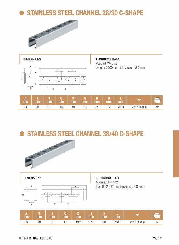
NORMA INFRASTRUCTURE 141PSS
STAINLESS STEEL CHANNEL 28/30 C-SHAPE
dIMENSIONS TECHNICAL dATA Material: W4 / A2Length: 2000 mm, thickness: 1,80 mm
Amm
Bmm
Smm
Cmm
dmm
Emm
Hmm
Omm
Lmm N° N
dB
28 30 1,8 15 10 20 35 12 2000 2857032028 12
A
SB
C H H
O
L
E
D
A
SB
C H H
O
L
E
D
STAINLESS STEEL CHANNEL 38/40 C-SHAPE
dIMENSIONS TECHNICAL dATAMaterial: W4 / A2Length: 2000 mm, thickness: 2,00 mm
Amm
Bmm
Smm
Cmm
dmm
Emm
Hmm
Lmm N° N
dB
38 40 2 17 13,2 27,5 50 2000 2857033038 12
B
C
AL
H
E
D
S
H
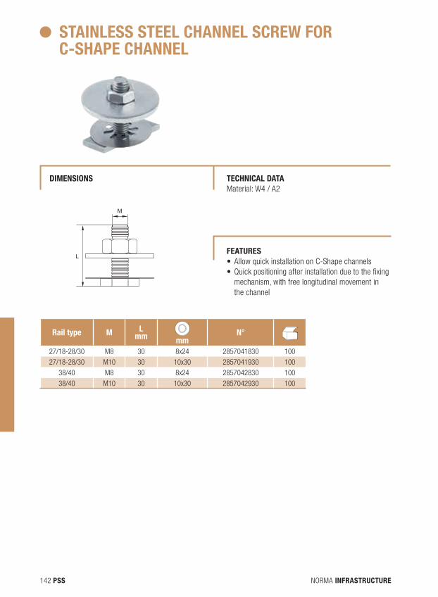
NORMA INFRASTRUCTURE142 PSS
STAINLESS STEEL CHANNEL SCREW FOR C-SHAPE CHANNEL
dIMENSIONS TECHNICAL dATA Material: W4 / A2
Rail type M Lmm mm
N° NdB
27/18-28/30 M8 30 8x24 2857041830 100
27/18-28/30 M10 30 10x30 2857041930 100
38/40 M8 30 8x24 2857042830 100
38/40 M10 30 10x30 2857042930 100
M
LFEATURES • AllowquickinstallationonC-Shapechannels• Quickpositioningafterinstallationduetothefixing
mechanism, with free longitudinal movement in the channel
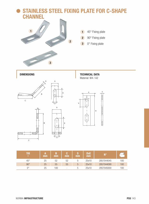
NORMA INFRASTRUCTURE 143PSS
STAINLESS STEEL FIXING PLATE FOR C-SHAPE CHANNEL
dIMENSIONS TECHNICAL dATA Material: W4 / A2
Tilt°
Amm
Bmm
Cmm
Smm
dxEmm N° N
dB
45° 25 52 52 5 25x10 2857044045 100
90° 25 55 55 5 25x10 2857044090 100
0° 25 100 - 5 25x10 2857045000 100
1 45° Fixing plate
90° Fixing plate
0° Fixing plate
2
3
3
S A
D
B
C
E
S
B
C
E
A
D
1
2
D
E
B
SA
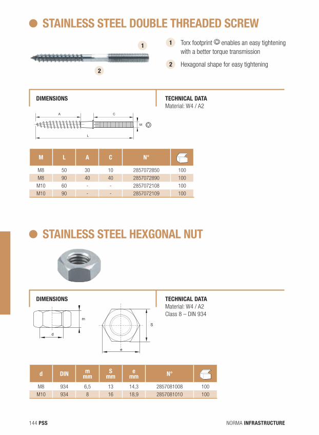
NORMA INFRASTRUCTURE144 PSS
STAINLESS STEEL dOUBLE THREAdEd SCREW
dIMENSIONS TECHNICAL dATAMaterial: W4 / A2
M L A C N° NdB
M8 50 30 10 2857072850 100
M8 90 40 40 2857072890 100
M10 60 - - 2857072108 100
M10 90 - - 2857072109 100
1 Torx footprint
L
A C
M enables an easy tightening with a better torque transmission
Hexagonal shape for easy tightening 2
L
A C
M
2
1
STAINLESS STEEL HEXGONAL NUT
dIMENSIONS TECHNICAL dATAMaterial: W4 / A2Class 8 – DIN 934
d dIN mmm
Smm
emm N° N
dB
M8 934 6,5 13 14,3 2857081008 100
M10 934 8 16 18,9 2857081010 100
d
e
m
S
d
e
m
S
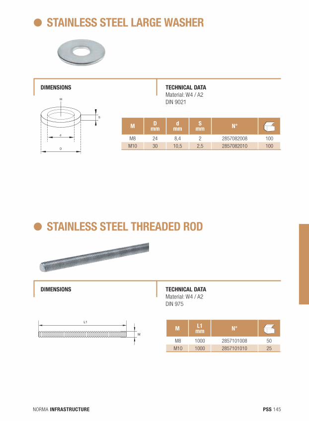
NORMA INFRASTRUCTURE 145PSS
M
d
D
S
STAINLESS STEEL LARGE WASHER
dIMENSIONS TECHNICAL dATAMaterial: W4 / A2DIN 9021
M dmm
dmm
Smm N° N
dB
M8 24 8,4 2 2857082008 100
M10 30 10,5 2,5 2857082010 100
STAINLESS STEEL THREAdEd ROd
dIMENSIONS TECHNICAL dATA Material: W4 / A2 DIN 975
M L1mm N° N
dB
M8 1000 2857101008 50
M10 1000 2857101010 25
L1
M
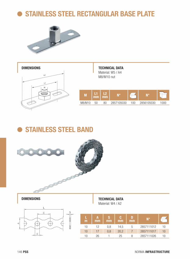
NORMA INFRASTRUCTURE146 PSS
STAINLESS STEEL RECTANGULAR BASE PLATE
dIMENSIONS TECHNICAL dATA Material: W5 / A4 M8/M10 nut
M L1mm
L2mm N° N
dBN°N
dB
M8/M10 50 80 2857105030 100 2856105030 1000
M
L1
L2
STAINLESS STEEL BANd
dIMENSIONS TECHNICAL dATAMaterial: W4 / A2
Lm
Amm
Smm
Cmm
dmm N° N
dB
10 12 0,8 14,5 5 2857111012 10
10 17 0,8 20,2 7 2857111017 10
10 26 1 25 8 2857111026 10
S
S
S
L
L
L
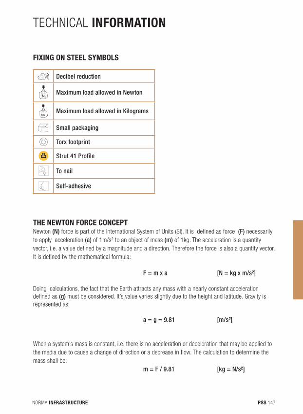
NORMA INFRASTRUCTURE 147PSS
TECHNICAL INFORMATION
FIXING ON STEEL SYMBOLS
THE NEWTON FORCE CONCEPT Newton (N) force is part of the International System of Units (SI). It is defined as force (F) necessarily to apply acceleration (a) of 1m/s² to an object of mass (m) of 1kg. The acceleration is a quantity vector, i.e. a value defined by a magnitude and a direction. Therefore the force is also a quantity vector. It is defined by the mathematical formula:
F = m x a [N = kg x m/s²]
Doing calculations, the fact that the Earth attracts any mass with a nearly constant acceleration defined as (g) must be considered. It’s value varies slightly due to the height and latitude. Gravity is represented as:
a = g = 9.81 [m/s²]
When a system’s mass is constant, i.e. there is no acceleration or deceleration that may be applied to the media due to cause a change of direction or a decrease in flow. The calculation to determine the mass shall be: m = F / 9.81 [kg = N/s²]
NdB
Decibel reduction
NdB
Maximum load allowed in Newton
KGMaximum load allowed in Kilograms
NdB
Small packaging
Torx footprint
Strut 41 Profile
To nail
Self-adhesive
NORMA INFRASTRUCTURE148 PSS
Example of calculation: A pipe clamp can withstand a maximum force of 490N. To determine the maximum weight in kg that can be attached, the following calculation must be done:
m = 490/9,81 = 50 [kg = N/s²]
Knowing the maximum weight in kg that the pipe clamp can withstand, the equivalent force can be found by a reciprocal calculation:
F = 50 x 9,81 = 490 [N = kg x m/s²]
In our catalogue we indicated the maximum force that our fasteners can withstand. If there are changings in in the acceleration (increase or decrease) of the fluid inside the installation, the mass must be recalculated.
Recommendation: To prevent system failures, it is not allowed to exceed the specified maximum strength.
Technical Recommendations: In general, for sanitary installations, we recommend using our isophonic EPDM pipe clamps, which offer better protection against noise and vibration.
For gas installations, we recommend isophonic and plastic pipe clamps.For corrosive environments, we recommend stainless steel pipe clamps.
Installation Tips: Generally, the space between two clamps is 0.5 meters to 2 meters. The weight of the medium inside a pipe must be considered because of respecting the maximum permissible load, referring to the load it bears and the clamp used model. It is therefore recommended to take into account the clamp’s safety coefficients.
Never tighten a clamp with an inappropriate tools because the pipe clamp safety factor may be overtaken and cause damages to the clamp. In general, a manual tightening of the clamp is enough.In case of doubt in the installation, consult our technical department who will answer your questions.
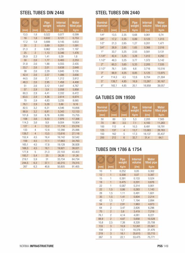
NORMA INFRASTRUCTURE 149PSS
Pipe weight
Internal volume
Water filled pipe
[mm] [mm] Kg/m [l/m] Kg/m
13,5 1,8 0,522 0,077 0,59916 1,8 0,632 0,121 0,753
17,2 1,8 0,688 0,145 0,83320 2 0,89 0,201 1,091
21,3 2 0,962 0,235 1,19725 2 1,13 0,346 1,476
26,9 2,3 1,41 0,39 1,830 2,6 1,77 0,483 2,253
31,8 2,6 1,88 0,555 2,43533,7 2,6 2,01 0,638 2,64838 2,6 2,29 0,845 3,135
42,4 2,6 2,57 1,086 3,65644,5 2,6 2,7 1,212 3,91248,3 2,6 2,95 1,458 4,40851 2,6 3,12 1,647 4,76757 2,9 3,9 2,058 5,958
60,3 2,9 4,41 2,332 6,47263,5 2,9 4,36 2,614 6,97470 2,9 4,83 3,235 8,065
76,1 2,9 5,28 3,88 9,1682,5 3,2 6,31 4,546 10,85688,9 3,2 6,81 5,343 12,153101,6 3,6 8,76 6,995 15,755108 3,6 9,33 7,976 17,306
114,3 3,6 9,9 9,004 18,904127 4 12,2 11,116 23,316133 4 12,8 12,266 25,066
139,7 4 13,5 13,616 27,116152,4 4,5 16,4 16,142 32,542159 4,5 17,1 17,663 34,763
165,1 4,5 17,8 19,128 36,928168,3 4,5 18,1 19,921 38,021177,8 5 21,3 22,103 43,403193,7 5,4 25 26,26 51,26219,1 5,9 31 33,734 64,734244,5 6,3 37,1 42,215 79,315267 6,3 40,6 50,805 91,405
Nominal diameter
Pipe weight
Internal volume
Water filled pipe
[”] [mm] [mm] Kg/m [l/m] Kg/m
1/4" 13,5 2,35 0,68 0,061 0,74
3/8" 17,2 2,35 0,89 0,123 1,013
1/2" 21,3 2,65 1,27 0,201 1,471
3/4" 26,9 2,65 1,65 0,366 2,016
1" 33,7 3,25 2,55 0,581 3,131
1.1/4" 42,4 3,25 3,28 1,012 4,292
1.1/2" 48,3 3,25 3,77 1,372 5,142
2" 60,3 3,65 5,33 2,205 7,535
2.1/2" 76,1 3,65 6,8 3,716 10,516
3" 88,9 4,05 8,85 5,125 13,975
4" 114,3 4,5 12,6 8,704 21,304
5" 139,7 4,85 16,9 13,267 30,167
6" 165,1 4,85 20,1 18,958 39,057
STEEL TUBES DIN 2448 STEEL TUBES DIN 2440
Nominal diameter
Pipe weight
Internal volume
Water filled pipe
[mm] [mm] [mm] Kg/m [l/m] Kg/m
50 60 3,5 5,3 2,205 7,50570 80 3,5 7,1 4,183 11,283
100 112 4 10,3 8,491 18,791125 137 4 13,7 13,063 26,763150 162 5 17,3 18,137 35,437200 212 6 32,7 31,4 64,1
GA TUBES DIN 19500
Pipe weight
Internal volume
Water filled pipe
[mm] [mm] Kg/m [l/m] Kg/m
10 1 0,252 0,05 0,30212 1 0,308 0,07 0,38715 1 0,391 0,133 0,52418 1 0,475 0,201 0,67622 1 0,587 0,314 0,90122 1,5 0,86 0,283 1,14328 1,5 1,11 0,491 1,60135 1,5 1,41 0,804 2,21442 1,5 1,7 1,194 2,89454 2 2,91 1,963 4,87364 2 3,47 2,826 6,29670 2 3,8 3,419 7,219
76,1 2 4,14 4,081 8,22188,9 2 4,87 5,658 10,52810,8 2,5 7,38 8,328 25,708133 3 10,9 12,261 23,561159 3 13,1 18,376 31,476219 3 18,1 35,615 53,715267 3 22,1 53,475 75,771
TUBES DIN 1786 & 1754
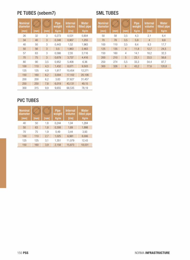
NORMA INFRASTRUCTURE150 PSS
Nominal diameter
Pipe weight
Internal volume
Water filled pipe
[mm] [mm] [mm] Kg/m [l/m] Kg/m
26 32 3 0,273 0,531 0,804
34 40 3 0,348 0,907 1,255
40 50 3 0,443 1,52 1,963
50 56 3 0,5 1,963 2,463
57 63 3 0,566 2,55 3,116
70 75 3 0,679 3,737 4,416
80 90 3,5 0,952 5,408 6,36
100 110 4,3 1,432 8,071 9,503
125 125 4,9 1,817 10,454 12,271
150 160 6,2 3,004 17,102 20,106
200 200 6,2 3,83 27,627 31,457
250 250 7,8 6,019 43,131 49,15
300 315 9,9 9,655 68,535 78,19
PE TUBES (sebem7)
Nominal diameter
Pipe weight
Internal volume
Water filled pipe
[mm] [mm] [mm] Kg/m [l/m] Kg/m
50 58 3,5 4,3 2,1 6,4
70 78 3,5 5,9 4 9,9
100 110 3,5 8,4 9,3 17,7
125 135 4 11,8 12,7 24,5
150 160 4 14,1 18,2 32,3
200 210 5 23,1 33,5 56,6
250 274 5,5 33,3 54,4 87,7
300 326 6 43,2 77,6 120,8
Nominal diameter
Pipe weight
Internal volume
Water filled pipe
[mm] [mm] [mm] Kg/m [l/m] Kg/m
40 50 1,8 0,244 1,04 1,284
50 63 1,8 0,308 1,69 1,998
70 75 1,9 0,49 3,44 3,93
100 110 2,7 1,025 6,981 8,006
125 125 3,1 1,351 11,079 12,43
150 160 3,9 2,158 15,873 18,031
SML TUBES
PVC TUBES
NORMA INFRASTRUCTURE 151PSS
MATERIALS USEd: RAW MATERIAL
Steel: We use hott rolled carbon steel according to European standard EN 10051 to manufacture our steel clamps.
Stainless steel: The stainless steel clamps are made of AISI 316 (1.4401)/A4, the profiles and some accessories of AISI 304 (1.4301)/A2.
The AISI 304 steel includes a basic anti-corrosive grade. This allows good resistance to atmospheric corrosion, neutral wet environments, alkaline corrosion, non-chlorinated nor sulphuric acidic environments. The main applications are piping and heat exchangers for the chemical, cryogenic petrochemical and boiler fabrication industries, food industries, construction and decoration.The AISI 316 steel contains Molybdenum allowing better reaction to chlorinated wet environments than AISI 304 steel. The main applications are piping for tubular heat exchangers in the chemical, petrochemical, sheet metal work and food industries.
COATINGS
Zinc: Metal clamps have anticorrosive protection made with an applied electrolytic zinc coating.
Plastic: The plastic clamps are coated with Polyamide 11 or Rilsan.Technical characteristic: Solidity/Hardness Shore D ASTM D2240: Shore 75, Electrical insulation: 25-38Kv/mm. Resistance to salt fog, no corrosion point after 2000 hours of exposure (ASTM B-117 or AENOR X 41-002). Resistance to seawater, no corrosion after 6 years of exposure.
Sendzimir galvanized: Channels and accessories with Sendzimir galvanized finishing are covered with a layer of zinc, according to the specifics provided by the material supplier. Galvanization according to EN 10327: continuously hot dip coating for low carbon strips and sheets for cold forming. Hot dip galvanized: Channels and accessories are coated with a layer of zinc of at least 395 g/m².Hot dip galvanized according to UNE:EN ISO 1461: 1999 for various parts.
NORMA INFRASTRUCTURE152 PSS
dACROMET
The rails and accessories have a Dacromet finish that has an excellent coating composed of zinc and aluminium strips in a matrix of chromium oxide.
Salt testing (Grade B) over 1000 hours without red oxide. Without the formation of white oxide (zinc corrosion) before 250 hours.
SPECIAL PLASTIC
Polyamide 11, a protective cover that acts like a true thermoplastic free solvent and catalyst agents.
What is polyamide?Polyamide 11 is a corrosion protective coating, with a powdered texture, that provides protection in the equipment used in the water industry.
This material (polyamide 11) was subjected to tests conducted by different international organizations such as EEUU, Europe and Asia, with the aim of satisfying the basic rules of system protection against corrosion and the following complement of requirements:• Not toxic• Protect equipment from corrosion in all its aspects (bacteria, formation of tubercles)• Have flexibility and resistance to impact and erosion supporting UV rays and weathering• Can be repaired on the spot and simple to use.
What are the benefits of a special finishing plastic polyamide 11?• Excellent corrosion, wear and abrasion resistance. • Excellent resistance to water and ice.• Electrical insulation and unique combination of materials for long-term protection.• Low coefficient of friction and high resistance to impact.• Prevents bacteria from adhering and approval for contact with food.• Very good service life when facing multiple conditions.• Compared to other painted plastics, the higher cost is due to a 700% greater service life, which in
the long-term returns a lower cost.• It is a product made from plant material, which explains why its price does not depend on the
availability of mineral and petroleum oils or other materials.
NORMA INFRASTRUCTURE 153PSS
MATERIALS
Standard GumElastomer base ............................EPDMColour .........................................BlackDensity ........................................1.32 g/cm3 Hardness .....................................45 Shore DSound reduction ...........................18 db(A), DIN 4109Tensile strength ............................91 kg/cm²Stretch ........................................440%Tear resistance.............................S/ASTM D-624 Type C, I: 24,9 Kg/cmResistance to external agents ........ExcellentResistance to ozone ......................Grade 0Temperature resistance ................-40°C / + 110°CFire resistance .............................Class B2 (DIN 4102)UV resistance ...............................Excellent
Polyurethane with lateral rubber Pipe supports are made of PUR in the central part, and comprises 2 parts of rubber on each side. The whole part is coated with a black vapour barrier.
Temperature resistance ..... -45°C / + 105°CThermal conductivity .......... 0.036 W(m.K) at 0°C.Density ............................. 80 Kg/m3Storage Temperature ......... -10°C / +30°CColour ..............................BlackWater steam resistance factor ...............>7000Compressive strength ........ 850 (+/-200)Tensile strength ................. 550 (+/-50)
Polyurethane with aluminiumPipe supports are made of PUR; covered with a vapour barrier with a strap made of two layers of aluminium and a layer of polyester.
Temperature resistance ......-40°C / +80°CThermal conductivity ...........0.030 W(m.K) at 0°C.Density ..............................80 (+/-8) Kg/m3Colour ...............................PUR: salmonCompressive strength .........1000 (+/-2000)Tensile strength ..................550 (+/-50)
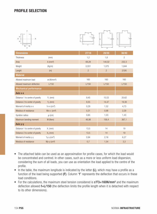
NORMA INFRASTRUCTURE154 PSS
PROFILE SELECTION
X X
y
y
y1
y2
X1 X2
Dimensions 27/18 28/30 38/40
Thickness (mm) 1,2 1,8 2
Area A (mm²) 69,28 144,02 232,3
Weight (Kg/m) 0,551 1,075 1,844
Lenght (m) 2 2 2/3/6
Material
Allowed maximum load σ (N/mm²) 160 160 160
Allowed maximum deflection L/150 L/150 L/150 L/150
Mechanical performance
Axis x-x
Distance 1 to centre of gravity Y1 (mm) 9,45 15,53 20,62
Distance 2 to center of gravity Y2 (mm) 8,55 14,47 19,38
Moment of inertia x-x 1x-x (cm4) 0,29 1,52 4,73
Modulus of resistance Wx-x (cm³) 0,31 0,98 2,29
Gyration radius ρ (cm) 0,65 1,03 1,43
Maximum bending moment M (Nxm) 48,98 156,4 367,1
Axis y-y
Distance 1 to centre of gravity X1 (mm) 13,5 14 19
Distance 2 to center of gravity X2 (mm) 13,5 14 19
Moment of inertia y-y 1y-y (cm4) 0,94 2,16 6,27
Modulus of resistance Wy-y (cm³) 0,7 1,54 3,3
• The attached table can be used as an approximation for profile cases, for which the load would be concentrated and centred. In other cases, such as a more or less uniform load dispersion, considering the sum of all loads, you can use as orientation the load applied to the centre of the profile.
• In the table, the maximum longitude is indicated by the letter (L), which may have a profile as a function of the load being supported (F). Column “f” represents the deflection that occurs in these load conditions.
• For the calculations, the maximum steel tension considered is s’F3=160N/mm² and the maximum deflection allowed f=L/150 (the deflection limits the profile length when it is detached with respect to its other dimensions).
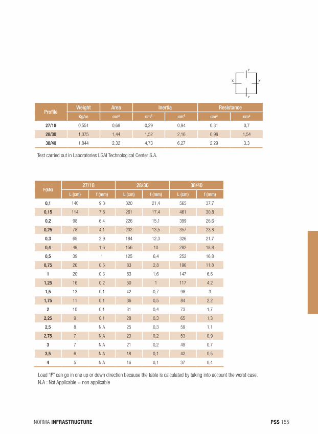
NORMA INFRASTRUCTURE 155PSS
X X
Y
Y
ProfileWeight Area Inertia Resistance
Kg/m cm² cm4 cm4 cm³ cm³
27/18 0,551 0,69 0,29 0,94 0,31 0,7
28/30 1,075 1,44 1,52 2,16 0,98 1,54
38/40 1,844 2,32 4,73 6,27 2,29 3,3
Test carried out in Laboratories LGAI Technological Center S.A.
Load “F” can go in one up or down direction because the table is calculated by taking into account the worst case.N.A : Not Applicable = non applicable
F(kN)27/18 28/30 38/40
L (cm) f (mm) L (cm) f (mm) L (cm) f (mm)
0,1 140 9,3 320 21,4 565 37,7
0,15 114 7,6 261 17,4 461 30,8
0,2 98 6,4 226 15,1 399 26,6
0,25 78 4,1 202 13,5 357 23,8
0,3 65 2,9 184 12,3 326 21,7
0,4 49 1,6 156 10 282 18,8
0,5 39 1 125 6,4 252 16,8
0,75 26 0,5 83 2,8 196 11,8
1 20 0,3 63 1,6 147 6,6
1,25 16 0,2 50 1 117 4,2
1,5 13 0,1 42 0,7 98 3
1,75 11 0,1 36 0,5 84 2,2
2 10 0,1 31 0,4 73 1,7
2,25 9 0,1 28 0,3 65 1,3
2,5 8 N.A 25 0,3 59 1,1
2,75 7 N.A 23 0,2 53 0,9
3 7 N.A 21 0,2 49 0,7
3,5 6 N.A 18 0,1 42 0,5
4 5 N.A 16 0,1 37 0,4
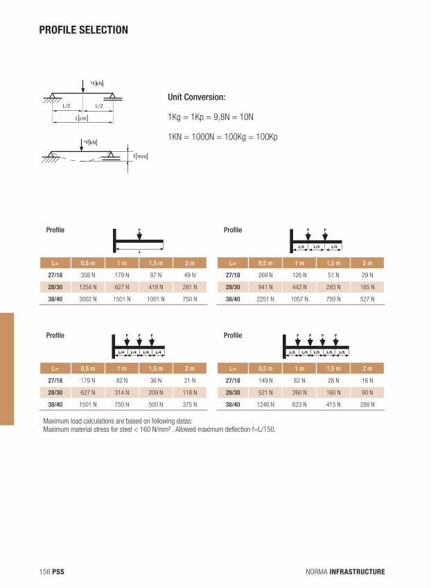
NORMA INFRASTRUCTURE156 PSS
Profile F
L
Profile F
L/3
F
L/3L/3
L= 0,5 m 1 m 1,5 m 2 m L= 0,5 m 1 m 1,5 m 2 m
27/18 358 N 179 N 87 N 49 N 27/18 269 N 126 N 51 N 29 N
28/30 1254 N 627 N 418 N 281 N 28/30 941 N 442 N 293 N 165 N
38/40 3002 N 1501 N 1001 N 750 N 38/40 2251 N 1057 N 750 N 527 N
Profile
L/4
F
L/4 L/4 L/4
F F Profile
L/5
F
L/5 L/5 L/5 L/5
F F F
L= 0,5 m 1 m 1,5 m 2 m L= 0,5 m 1 m 1,5 m 2 m
27/18 179 N 82 N 36 N 21 N 27/18 149 N 62 N 28 N 16 N
28/30 627 N 314 N 209 N 118 N 28/30 521 N 260 N 160 N 90 N
38/40 1501 N 750 N 500 N 375 N 38/40 1246 N 623 N 415 N 288 N
Maximum load calculations are based on following datas: Maximum material stress for steel < 160 N/mm² . Allowed maximum deflection f=L/150.
Unit Conversion:
1Kg = 1Kp = 9,8N = 10N
1KN = 1000N = 100Kg = 100Kp
*F kN
L/2 L/2
*F kN
L cm
f mm
PROFILE SELECTION
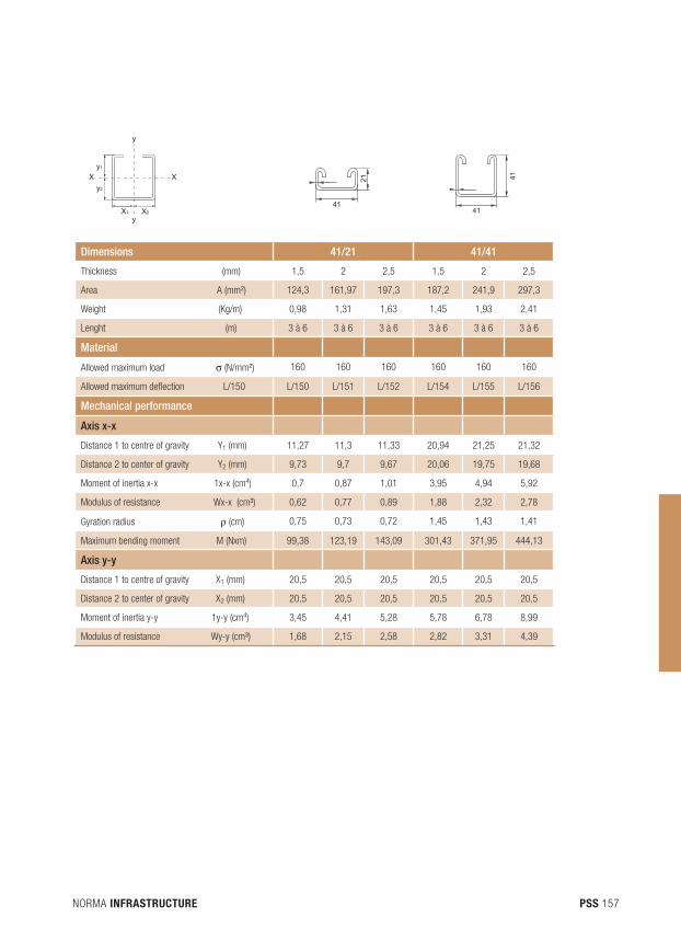
NORMA INFRASTRUCTURE 157PSS
X X
y
y
y1
y2
X1 X241
21
41
41
Dimensions 41/21 41/41
Thickness (mm) 1,5 2 2,5 1,5 2 2,5
Area A (mm²) 124,3 161,97 197,3 187,2 241,9 297,3
Weight (Kg/m) 0,98 1,31 1,63 1,45 1,93 2,41
Lenght (m) 3 à 6 3 à 6 3 à 6 3 à 6 3 à 6 3 à 6
Material
Allowed maximum load σ (N/mm²) 160 160 160 160 160 160
Allowed maximum deflection L/150 L/150 L/151 L/152 L/154 L/155 L/156
Mechanical performance
Axis x-x
Distance 1 to centre of gravity Y1 (mm) 11,27 11,3 11,33 20,94 21,25 21,32
Distance 2 to center of gravity Y2 (mm) 9,73 9,7 9,67 20,06 19,75 19,68
Moment of inertia x-x 1x-x (cm4) 0,7 0,87 1,01 3,95 4,94 5,92
Modulus of resistance Wx-x (cm³) 0,62 0,77 0,89 1,88 2,32 2,78
Gyration radius ρ (cm) 0,75 0,73 0,72 1,45 1,43 1,41
Maximum bending moment M (Nxm) 99,38 123,19 143,09 301,43 371,95 444,13
Axis y-y
Distance 1 to centre of gravity X1 (mm) 20,5 20,5 20,5 20,5 20,5 20,5
Distance 2 to center of gravity X2 (mm) 20,5 20,5 20,5 20,5 20,5 20,5
Moment of inertia y-y 1y-y (cm4) 3,45 4,41 5,28 5,78 6,78 8,99
Modulus of resistance Wy-y (cm³) 1,68 2,15 2,58 2,82 3,31 4,39
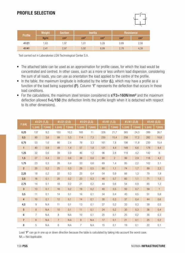
NORMA INFRASTRUCTURE158 PSS
• The attached table can be used as an approximation for profile cases, for which the load would be concentrated and centred. In other cases, such as a more or less uniform load dispersion, considering the sum of all loads, you can use as orientation the load applied to the centre of the profile.
• In the table, the maximum longitude is indicated by the letter (L), which may have a profile as a function of the load being supported (F). Column “f” represents the deflection that occurs in these load conditions.
• For the calculations, the maximum steel tension considered is s’F3=160N/mm² and the maximum deflection allowed f=L/150 (the deflection limits the profile length when it is detached with respect to its other dimensions).
X X
Y
Y
ProfileWeight Section Inertia Resistance
Kg/m cm² cm4 cm4 cm³ cm³
41/21 1,63 1,97 1,01 5,28 0,89 2,58
41/41 2,41 2,97 5,92 8,99 2,78 4,39
Test carried out in Laboratories LGAI Technological Center S.A.
Load “F” can go in one up or down direction because the table is calculated by taking into account the worst case.NA = Not Applicable
F (kN)41/21 (1,5) 41/21 (2,0) 41/21 (2,5) 41/41 (1,5) 41/41 (2,0) 41/41 (2,5)
L (cm) f (mm) L (cm) f (mm) L (cm) f (mm) L (cm) f (mm) L (cm) f (mm) L (cm) f (mm)
0,25 137 9,2 153 10,2 165 11 326 21,7 365 24,3 399 26,7
0,5 80 3,6 99 5,5 114 7,3 230 15,4 258 17,2 282 18,8
0,75 53 1,6 66 2,4 76 3,3 161 7,8 198 11,8 230 15,4
1 40 0,9 49 1,4 57 1,8 121 4,4 149 6,6 178 9,4
1,25 32 0,6 39 0,9 46 1,2 96 2,8 119 4,2 142 6
1,5 27 0,4 33 0,6 38 0,8 80 2 99 2,9 118 4,2
1,75 23 0,3 28 0,4 33 0,6 69 1,4 85 2,2 102 3,1
2 20 0,2 25 0,3 29 0,5 60 1,1 74 1,7 89 2,3
2,25 18 0,2 22 0,3 25 0,4 54 0,9 66 1,3 79 1,9
2,5 16 0,1 20 0,2 23 0,3 48 0,7 60 1,1 71 1,5
2,75 14 0,1 18 0,2 21 0,2 44 0,6 54 0,9 65 1,2
3 13 0,1 16 0,2 19 0,2 40 0,5 50 0,7 59 1
3,5 11 0,1 14 0,1 16 0,1 34 0,4 43 0,5 51 0,8
4 10 0,1 12 0,1 14 0,1 30 0,3 37 0,4 44 0,6
4,5 9 N.A 11 0,1 13 0,1 27 0,2 33 0,3 39 0,5
5 8 N.A 10 0,1 11 0,1 24 0,2 30 0,3 36 0,4
6 7 N.A 8 N.A 10 0,1 20 0,1 25 0,2 30 0,3
7 6 N.A 7 N.A 8 N.A 17 0,1 21 0,1 25 0,2
8 5 N.A 6 N.A 7 N.A 15 0,1 19 0,1 22 0,1
PROFILE SELECTION
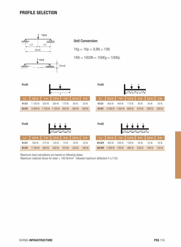
NORMA INFRASTRUCTURE 159PSS
Load “F” can go in one up or down direction because the table is calculated by taking into account the worst case.NA = Not Applicable
Unit Conversion:
1Kg = 1Kp = 9,8N = 10N
1KN = 1000N = 100Kg = 100Kp
*F kN
L/2 L/2
*F kN
L cm
f mm
Profil F
L
Profil F
L/3
F
L/3L/3
L= 0,5 m 1 m 1,5 m 2 m 2,5 m 3 m L= 0,5 m 1 m 1,5 m 2 m 2,5 m 3 m
41/21 1 100 N 550 N 300 N 170 N 80 N 50 N 41/21 800 N 400 N 175 N 95 N 45 N 30 N
41/41 3 400 N 1 700 N 1 150 N 850 N 500 N 300 N 41/41 2 500 N 1 300 N 850 N 575 N 300 N 200 N
Profil
L/4
F
L/4 L/4 L/4
F F Profil
L/5
F
L/5 L/5 L/5 L/5
F F F
L= 0,5 m 1 m 1,5 m 2 m 2,5 m 3 m L= 0,5 m 1 m 1,5 m 2 m 2,5 m 3 m
41/21 550 N 275 N 120 N 70 N 30 N 20 N 41/21 450 N 230 N 100 N 50 N 23 N 16 N
41/41 1 700 N 850 N 550 N 410 N 230 N 160 N 41/41 1 400 N 700 N 460 N 320 N 180 N 120 N
Maximum load calculations are based on following datas: Maximum material stress for steel < 160 N/mm² . Allowed maximum deflection f=L/150.
PROFILE SELECTION
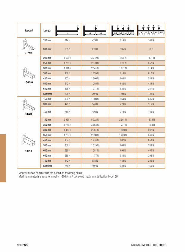
NORMA INFRASTRUCTURE160 PSS
Support Length
F
L L/2
F
L/2 L/4
F
L/4 L/4 L/4
F F
L/5
F
L/5 L/5 L/5 L/5
F F F
41/42 41/82
38/40
41/41
41/2127/18
200 mm 214 N 429 N 214 N 143 N
300 mm 135 N 270 N 135 N 90 N
41/42 41/82
38/40
41/41
41/2127/18
200 mm 1 606 N 3 212 N 1606 N 1 071 N
250 mm 1 285 N 2 570 N 1285 N 857 N
300 mm 1 071 N 2 141 N 1 071 N 714 N
350 mm 908 N 1 835 N 918 N 612 N
400 mm 803 N 1 606 N 803 N 535 N
500 mm 642 N 1 285 N 642 N 428 N
600 mm 535 N 1 071 N 535 N 357 N
1000 mm 199 N 397 N 199 N 132 N
41/42 41/82
38/40
41/41
41/2127/18
150 mm 954 N 1 908 N 954 N 636 N
300 mm 473 N 946 N 473 N 315 N
450 mm 210 N 420 N 210 N 140 N
41/42 41/82
38/40
41/41
41/2127/18
150 mm 2 961 N 5 922 N 2 961 N 1 974 N
250 mm 1 777 N 3 553 N 1 777 N 1 184 N
300 mm 1 480 N 2 961 N 1 480 N 987 N
350 mm 1 269 N 2 538 N 1 269 N 846 N
450 mm 987 N 1 974 N 987 N 658 N
550 mm 808 N 1 615 N 808 N 538 N
600 mm 690 N 1 381 N 690 N 460 N
650 mm 588 N 1 177 N 588 N 392 N
750 mm 442 N 884 N 442 N 295 N
1000 mm 249 N 497 N 249 N 166 N
Maximum load calculations are based on following datas: Maximum material stress for steel < 160 N/mm² . Allowed maximum deflection f=L/150.
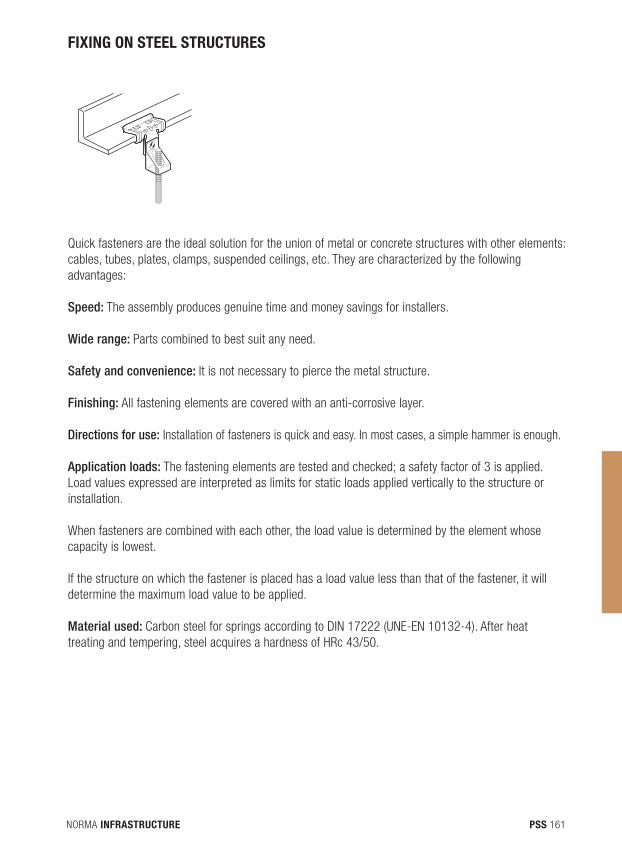
NORMA INFRASTRUCTURE 161PSS
FIXING ON STEEL STRUCTURES
Quick fasteners are the ideal solution for the union of metal or concrete structures with other elements: cables, tubes, plates, clamps, suspended ceilings, etc. They are characterized by the following advantages:
Speed: The assembly produces genuine time and money savings for installers.
Wide range: Parts combined to best suit any need.
Safety and convenience: It is not necessary to pierce the metal structure.
Finishing: All fastening elements are covered with an anti-corrosive layer.
Directions for use: Installation of fasteners is quick and easy. In most cases, a simple hammer is enough.
Application loads: The fastening elements are tested and checked; a safety factor of 3 is applied. Load values expressed are interpreted as limits for static loads applied vertically to the structure or installation.
When fasteners are combined with each other, the load value is determined by the element whose capacity is lowest.
If the structure on which the fastener is placed has a load value less than that of the fastener, it will determine the maximum load value to be applied.
Material used: Carbon steel for springs according to DIN 17222 (UNE-EN 10132-4). After heat treating and tempering, steel acquires a hardness of HRc 43/50.
B min
A
M
NORMA INFRASTRUCTURE162 PSS
CORROSION PROTECTION
Zinc phosphatingFor indoor and non-corrosive environments: Corrosion protection with joint impregnation with rust inhibiting oil.
Finishing For interior, exterior, wet or slightly corrosive atmospheres:• Non-hydrogenating coating (without electrolysis or acidic stripping) • Electrical conductivity. High temperature resistance.• Without chromium VI nor chromium III. Reduced friction values.• High protection against corrosion. Cathodic protection.• Optical: Gray – Silver
RESISTANCE to corrosion in salt spray chamber up to 480 h (DIN 50021).
NOTE: Thanks to industrial improvements, NORMA Group reserves the right to modify the design of the fasteners shown while respecting the static load characteristics.

NORMA INFRASTRUCTURE 163
NORMA GROUP AdditiONAl solutions and development
NORMA GROUP, as a global supplier, offers a large complementary range of solutions to fit with your needs, such as hose clamps and retaining products.We are focus on new development for WATER MANAGEMENT market. Our purpose is to deliver high quality solutions to respond to this mega trend sector.
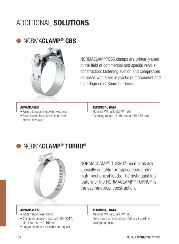
NORMA INFRASTRUCTURE164
NORMACLAMP® GBS
NORMACLAMP®GBS clamps are primarily used in the field of commercial and special vehicle construction: fastening suction and compressed air hoses with steel or plastic reinforcement and high degrees of Shore hardness.
ADVANTAGES • Failure torques improved twice over• Band tensile force levels improved three times over
TEChNiCAL DATA Material: W1, W2, W3, W4, W5Clamping range: 17-19 mm to 239-252 mm
NORMACLAMP® TORRO®
NORMACLAMP® TORRO® hose clips are specially suitable for applications under high mechanical loads. The distinguishing feature of the NORMACLAMP® TORRO® is the asymmetrical construction.
ADVANTAGES • Multi-range hose clamp• Clamping ranges in acc. with DIN 3017: 8-16 mm to 140-160 mm• Larger diameters available on request
TEChNiCAL DATA Material: W1, W2, W3, W4, W5From now on, no chromium (VI) to be used for coating purposes
AdditiONAl solutions
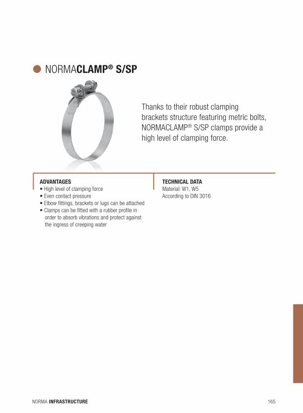
NORMA INFRASTRUCTURE 165
NORMACLAMP® S/SP
Thanks to their robust clamping brackets structure featuring metric bolts, NORMACLAMP® S/SP clamps provide a high level of clamping force.
ADVANTAGES • High level of clamping force• Even contact pressure• Elbow fittings, brackets or lugs can be attached• Clamps can be fitted with a rubber profile in order to absorb vibrations and protect against the ingress of creeping water
TEChNiCAL DATA Material: W1, W5According to DIN 3016
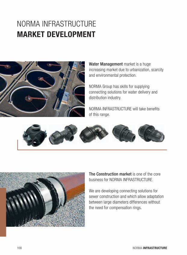
NORMA INFRASTRUCTURE166
NORMA iNFRAStRUCtURE market development
Water Management market is a huge increasing market due to urbanization, scarcity and environmental protection.
NORMA Group has skills for supplying connecting solutions for water delivery and distribution industry.
NORMA INFRASTRUCTURE will take benefits of this range.
The Construction market is one of the core business for NORMA INFRASTRUCTURE.
We are developing connecting solutions for sewer construction and which allow adaptation between large diameters differences without the need for compensation rings.
NORMA INFRASTRUCTURE 167
GENERAl inFormation
iNSTALLATiONFor couplings installations, the following information must be observed:• Remove burrs and clean pipe ends. Damage such as scratches, cracks, etc. or coatings such as paint, rust, etc. must be removed from the sealing lip area.• Mark half width of the coupling on both pipe ends.• Slide couplings over pipe ends and align to the pipe marks. Tighten bolts slightly and alternately with ratchet spanner or screwdriver. Do not rotate coupling any further once its teeth have engaged with the pipe. Tighten bolts alternately to a defined torque with a torque wrench (see details on coupling label). Never tighten bolts to more than the specified torque. If leaks occur after fitting, remove coupling and run steps again.
For more detailed information, please refer to installations guidelines include in products packaging.
WARRANTYOur products range follow legal warranties, for more information please contact your local dealer or NORMA representatives.
CONTACTFor any questions, please send an email to the following address :[email protected]
Reproduction rights are reserved for all countries: any reproduction, even partial, cannot take place without the prior written consent of Norma. We are constantly adapting our products to keep up with user needs and technological developments, which is why the models presented in this catalogue, as well as the compositions (representations, photographs, specifications, dimensions and weights) can be modified or deleted without notice and without obligation on our part to make the changes on products previously sold.The operational tips in this catalogue do not replace the Goode Practices or the legal and regulatory provisions applicable to safety. Reference to standards in force as of 01/02/2013 is not a contractual commitment.

www.normagroup.com
1-7Z
-6-1
2110
1-SE
ADRESSNORMA Group Edisson Strasse 463477 MaintalGERMANY