mr angiography of the intracranial vessels: technical aspects and clinical applications
TRANSCRIPT

Technical considerations
Time-of-flight magnetic resonance angiography
In time-of-flight magnetic resonance angiography (TOFMRA), repetitive pulses are used to suppress stationarybackground tissues, while the unsuppressed protons offlowing blood create a signal. The high signal intensity inthe blood vessels during TOF MRA is attributable toflow-related enhancement, and the absence of flow is
characterized by reduced signal intensity [1]. The signalintensity of flowing blood depends on its velocity, thelength and course of the vessel being imaged, the flowcharacteristics, and sequence parameters. The main lim-itations of the technique are the spin dephasing thatoccurs in complex or turbulent flow pattern, particularlyin three-dimensional (3D) TOF, and in vessels in closeproximity to tissues with short T1, such as fat or subacutehemorrhage (Table 1). Signal loss may also occur in thepresence of flow resulting from the spin saturation effect,
Ozkan Ozsarlak
Johan W. Van Goethem
Menno Maes
Paul M. Parizel
MR angiography of the intracranial vessels:technical aspects and clinical applications
Received: 19 April 2004Accepted: 6 September 2004Published online: 4 December 2004� Springer-Verlag 2004
Abstract Evaluation of the intra-cranial circulation provides valuableinformation in the diagnosis andprognosis of various intracranialabnormalities and may influencepatient management. Technical ad-vances in magnetic resonance angi-ography (MRA) have improved theaccuracy of this technique in variousclinical situations, such asaneurysms, arterial and venous ste-no-occlusive diseases, vascular mal-formations, inflammatory arterialdiseases, preoperative assessment ofthe patency of dural sinuses, andcongenital vascular abnormalities.In many centers, MRA has replacedconventional digital subtractionangiography in screening for intra-cranial vascular disease, because ofits non-invasive and non-ionizingcharacter. Several MRA techniqueshave been developed for the imagingof the intracranial vascular system,such as time-of-flight MRA (TOF
MRA), phase-contrast MRA (PCMRA), and more recently contrast-enhanced MRA (CE MRA). In theevaluation of steno-occlusive dis-ease, the three-dimensional (3D)TOF-MRA technique is recom-mended for arterial evaluation, andthe 2D TOF or 2D PC-MRA tech-nique for venous evaluation. For theevaluation of aneurysms and arte-riovenous malformations (AVMs),we recommend the 3D CE-MRAtechnique, especially dynamicsequences in case of AVM. In thisreview, the technical aspects, limita-tions, and optimization of theseMRA techniques will be discussedtogether with their indications inintracranial disease.
Keywords Magnetic resonance ÆVascular studies Æ Infarction ÆAneurysm Æ Intracranial ÆArteriovenous malformations
Neuroradiology (2004) 46: 955–972DOI 10.1007/s00234-004-1297-9 DIAGNOSTIC NEURORADIOLOGY
O. Ozsarlak (&) Æ J. W. Van GoethemM. Maes Æ P. M. ParizelNeuroradiology Section,Department of Radiology,University Hospital Antwerp,Wilrijkstraat 10, 2650 Edegem, BelgiumE-mail: [email protected].: +32-3-8214585Fax: +32-3-8252026
Table
1Lim
itationsandremediesofMR
angiographytechniques
(TOFtime-of-flight,PCphase
contrast,CEcontrastenhancedMR
angiography,VENCvelocity
encoding,
MOTSA
multiple
overlappingthin
slabacquisition)
Lim
itations
MRA
technique
Effect
Site
Rem
edies
Complexflow,turbulentflow
(intravoxel
dephasing)
TOFPC
(2D>
3D)
Signalloss
Cavernoussegment
Largeflip
angle
(45–60)
Carotidbulb
Smallestvoxel
size,thinner
slices
Beyondthestenosis
Lower
TE(<
7msec)
Inlargeulcerations
Flow
compensation
Aneurysm
Use
3D
TOF
MRA
Slow
flow
(spin
saturation)
TOFPC
Signalloss
Deeper
vesselson3D
TOF
Thin
sections(M
OTSA)
on2D
TOF
Skip
sign(occlusion)
Transverse
flowing
vesselson2D
TOF
Longer
TE
Distalto
astenosis
Lower
flip
angle
Perpendicularim
ageplane
Gadolinium
application
Lower
VENC
factors
forPC
MRA
Short
T1tissues
(fat,blood)
TOFCE
Obscure
vesseldelineation
Periorbitalregion
Backgroundsuppression
(magnetizationtransfer,spectral
fatsaturation,spectralwater
excitation,im
agesubtraction)
Peripheralvessels
Thrombus
TOF
Methem
oglobin
simulatesnorm
al
vessel(short
T1relaxation)
Thrombus
Use
PC
MRA
Deoxyhem
oglobin
obscuresthevesselmargins
(magnetic
susceptibilityeff
ects)
Aliasing
PC
Misinterpretation
Anylocation
Higher
VENC
factor
Decreasedvesselwalldelineation
PC
Misinterpretation
Anylocation
Lower
VENC
factor
956
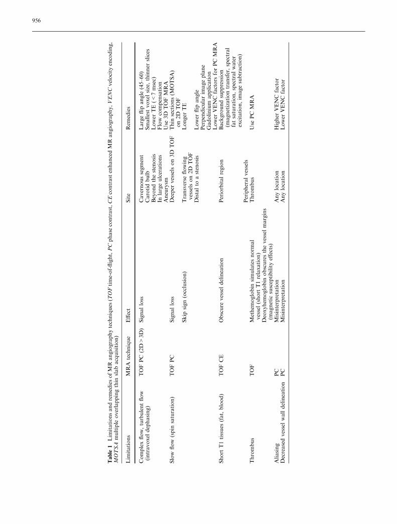
as in the case of slow flow in the distal intracranial vessels,or becuase of intravoxel phase dispersion, as in situationsof turbulent flow or magnetic field inhomogeneities [1, 2].Image quality on 3D TOFMRA can be improved by useof a technique called ‘‘multiple overlapping thin slabacquisition’’, to overcome flow saturation effects, and bythe application of magnetization transfer (MT) prepulsesto suppress the background signal of the stationary tis-sues [3, 4]. Moreover, a judicious choice of TR (40–50 ms) and careful selection of the imaging plane per-pendicular to the direction of flow may further decreasethe spin saturation effects. Intravoxel spin phase disper-sion may be overcome by the use of smaller voxel sizes,thinner slices, and short TE (7–9 ms) [1]. Saturation ef-fects can also beminimized by using lower flip angles (15–20�) in combination with longer TRs, thiner slices, andthe shortest possible TE [5]. The variable flip-angleexcitation technique, termed ‘‘tilted optimized nonsatu-rating excitation’’, has also been shown to increase thesignal and lower the spin phase dispersion effect withinthe vessels [6]. In this technique, the flip angle variesacross the slab that it is set lower at the inlet side andgradually increases as it approaches the exit side to in-crease the blood signal [6]. The remaining saturation ef-fects of slow-flow in small arterial branches can be furthereliminated by intravenous injection of paramagneticcontrast material, but with the disadvantages of in-creased cost, possible superimposition of veins, andenhancement of surrounding tissues [7]. The use of aclassic ‘‘single’’ dose of gadolinium (0.1 mmol/kg) mayobscure the arteries by excessive enhancement of thesurrounding soft tissues and the venous system [8]. Forexample, venous enhancement in the cavernous sinus canobscure the visibility of the internal carotid arteries.Postcontrast visualization of branches of the distalmedian cerebral artery is reported to improve in 69% ofcases, and 30% of branches become visible only afteradministration of contrast material. Studies performedwith a smaller amount of contrast (less than 5 ml bolus)also report an adequate visualization of the distal intra-cranial arteries with slow flow (Fig. 1), with less inter-ference of enhancing surrounding tissues [8, 9]. Althoughdepending on the matrix size and other sequenceparameters, the total acquisition time of high resolution3D TOF MRA is about 6 min (TR 40 ms, TE 7.15 ms,25� of flip angle, 256·512matrix, 64 partitions, and 1 mmslice thickness). With the application of the parallelacquisition technique with an acceleration factor of 2,this can be lowered to 3–4 min, without a significantdecrease in signal-to-noise ratio (SNR) [8].
Phase contrast magnetic resonance angiography
Phase contrast (PC) MRA uses a different technique tocreate vascular contrast, based on manipulating the
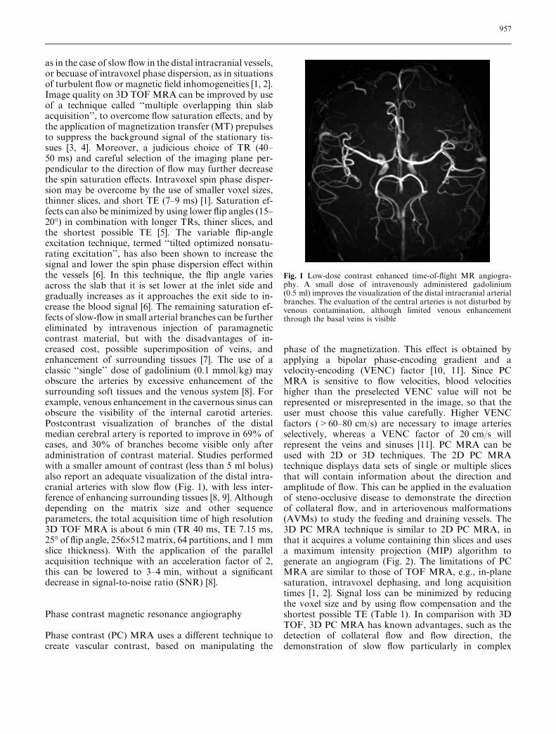
phase of the magnetization. This effect is obtained byapplying a bipolar phase-encoding gradient and avelocity-encoding (VENC) factor [10, 11]. Since PCMRA is sensitive to flow velocities, blood velocitieshigher than the preselected VENC value will not berepresented or misrepresented in the image, so that theuser must choose this value carefully. Higher VENCfactors (>60–80 cm/s) are necessary to image arteriesselectively, whereas a VENC factor of 20 cm/s willrepresent the veins and sinuses [11]. PC MRA can beused with 2D or 3D techniques. The 2D PC MRAtechnique displays data sets of single or multiple slicesthat will contain information about the direction andamplitude of flow. This can be applied in the evaluationof steno-occlusive disease to demonstrate the directionof collateral flow, and in arteriovenous malformations(AVMs) to study the feeding and draining vessels. The3D PC MRA technique is similar to 2D PC MRA, inthat it acquires a volume containing thin slices and usesa maximum intensity projection (MIP) algorithm togenerate an angiogram (Fig. 2). The limitations of PCMRA are similar to those of TOF MRA, e.g., in-planesaturation, intravoxel dephasing, and long acquisitiontimes [1, 2]. Signal loss can be minimized by reducingthe voxel size and by using flow compensation and theshortest possible TE (Table 1). In comparison with 3DTOF, 3D PC MRA has known advantages, such as thedetection of collateral flow and flow direction, thedemonstration of slow flow particularly in complex
Fig. 1 Low-dose contrast enhanced time-of-flight MR angiogra-phy. A small dose of intravenously administered gadolinium(0.5 ml) improves the visualization of the distal intracranial arterialbranches. The evaluation of the central arteries is not disturbed byvenous contamination, although limited venous enhancementthrough the basal veins is visible
957
vessel structures, and aneurysms and AVMs. However,these advantages affect predominantly small vessels anddo not result in an improvement of the detection orgrading of stenosis in the major intracranial vessels incomparison with 3D TOF MRA [12]. Visualization ofsmaller distal branches can be improved with the use ofcontrast material. Another limitation of the techniqueis velocity aliasing, which occurs when true velocitiesexceed the peak VENC. In such cases, flow can beincorrectly shown as being in the opposite direction.One other major disadvantage of 3D PC MRA is thatthe pulse sequence is relatively more time-consumingthan 2D acquisition. Therefore, it is currently used lessfrequently. Four acquisitions are required to encodeflow in all directions, and this therefore lengthens thescan time [13]. This problem is partially solved withnew ultrafast imaging sequences, such as flow-sensitivegradient echo imaging and echo planar imaging [13,14]. The benefits of 3D PC MRA include a higher
SNR, small voxel size, and a shorter TE when com-pared with 2D acquisitions.
Contrast enhanced magnetic resonance angiography
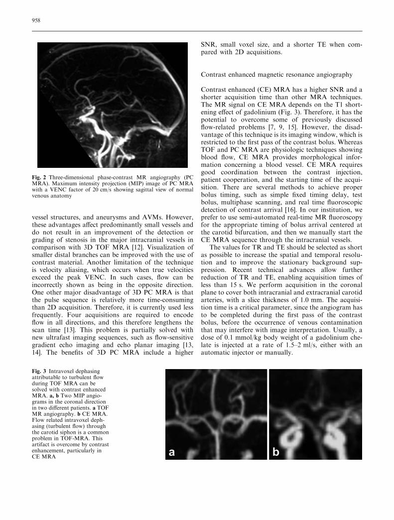
Contrast enhanced (CE) MRA has a higher SNR and ashorter acquisition time than other MRA techniques.The MR signal on CE MRA depends on the T1 short-ening effect of gadolinium (Fig. 3). Therefore, it has thepotential to overcome some of previously discussedflow-related problems [7, 9, 15]. However, the disad-vantage of this technique is its imaging window, which isrestricted to the first pass of the contrast bolus. WhereasTOF and PC MRA are physiologic techniques showingblood flow, CE MRA provides morphological infor-mation concerning a blood vessel. CE MRA requiresgood coordination between the contrast injection,patient cooperation, and the starting time of the acqui-sition. There are several methods to achieve properbolus timing, such as simple fixed timing delay, testbolus, multiphase scanning, and real time fluoroscopicdetection of contrast arrival [16]. In our institution, weprefer to use semi-automated real-time MR fluoroscopyfor the appropriate timing of bolus arrival centered atthe carotid bifurcation, and then we manually start theCE MRA sequence through the intracranial vessels.
The values for TR and TE should be selected as shortas possible to increase the spatial and temporal resolu-tion and to improve the stationary background sup-pression. Recent technical advances allow furtherreduction of TR and TE, enabling acquisition times ofless than 15 s. We perform acquisition in the coronalplane to cover both intracranial and extracranial carotidarteries, with a slice thickness of 1.0 mm. The acquisi-tion time is a critical parameter, since the angiogram hasto be completed during the first pass of the contrastbolus, before the occurrence of venous contaminationthat may interfere with image interpretation. Usually, adose of 0.1 mmol/kg body weight of a gadolinium che-late is injected at a rate of 1.5–2 ml/s, either with anautomatic injector or manually.
Fig. 2 Three-dimensional phase-contrast MR angiography (PCMRA). Maximum intensity projection (MIP) image of PC MRAwith a VENC factor of 20 cm/s showing sagittal view of normalvenous anatomy
Fig. 3 Intravoxel dephasingattributable to turbulent flowduring TOF MRA can besolved with contrast enhancedMRA. a, b Two MIP angio-grams in the coronal directionin two different patients. a TOFMR angiography. b CE MRA.Flow related intravoxel deph-asing (turbulent flow) throughthe carotid siphon is a commonproblem in TOF-MRA. Thisartifact is overcome by contrastenhancement, particularly inCE MRA
958

Currently used MRA techniques, their advantages,disadvantages, and major applications are summarizedin Table 2.
Background suppression: ‘‘water excitation’’
In TOF techniques, fatty tissue surrounding vascularstructures may obscure the visibility of vessels because ofits high signal intensity [15]. As a result of a small fre-quency difference of hydrogen nuclei in fat and water,selective saturation of fat (fat-suppression) can beachieved by the excitation of RF pulses centered on theaverage fat frequency. However, fat-saturated imageshave to be acquired with a conventional fat-suppressionpulse during every repetition cycle. Therefore, theexamination time is relatively long [15]. An alternativemethod for stationary background tissue suppression,‘‘selective water excitation’’ has been described. In thistechnique, the RF excitation is designed only for waterprotons in the selected slice plane, without affecting thefat protons [17]. This application is most useful whenarteries must be delineated from the surrounding fat
tissue, such as orbital regions, especially when an MIPalgorithm is applied (Fig. 4).
Subtraction technique
Another strategy to improve the contrast to backgroundratio is the use of subtraction techniques [18]. Thesetechniques are generally applied to CE MRA, whichusually contain residual signal intensity in the tissuesadjacent to the vessels. However, any change in patientposition between the precontrast and contrast-enhancedacquisitions results in artifacts. The main limitations ofthe subtraction technique are the deletion of vascularsignal intensity caused by in-flow effects on the precon-trast images, increased imaging time because of therequirement of two data sets, and increased noise level.
Post-processing
After acquisition of the raw data, source images andgraphic representation of MRA data can be generated
Table 2 MRA techniques, their advantages, disadvantages, and major applications (SNR signal-to-noise ratio, VENC velocity encoding,AVM arteriovenous malformation)
TOF MRA PC MRA CE MRA
2D 3D 2D 3D 3D
AdvantagesMinimal saturation effects Less intravoxel dephasing Less saturation effects No saturation
effectsNo saturation effects
Coverage of large distances High SNR Direction andquantificationof flow velocities
Excellentbackgroundsuppression
Reduced intravoxeldephasing bygadolinium
Sensitivity to venousslow flow
Smoother vessel contour Excellent backgroundsuppression
High SNR
Shorter acquisition time Shorter acquisition time Short acquisitiontime, decreasedmotion artifactsExcellent backgroundsuppression
DisadvantagesIntravoxel dephasing More saturation effects Intravoxel dephasing Long acquisition
timeVenous puncture
Insensitive to in-planeblood flow
Insensitive to slow flow Choosing an appropriateVENC factor
High cost of gadolinium
Artifacts attributable tothrombus and shortT1 substances
Artifacts attributable tothrombus and short T1substances
Critical bolus timing andvenous enhancement
Major applicationCarotid bifurcation High-flow (arterial structures) Localizer Cerebral arteries Cerebral arteriesVenous flow (dural sinusthrombosis, corticalvein mapping)
AVMs Cerebral veins Cerebral veinsAneurysm AVMs Dynamic evaluation
of AVMs,dural fistula, shunts
Carotid disease Bleeding lesions (rupturedaneurysm, bleeding AVM)
Aneurysm and treatmentfollow-up
Cavernous hemangioma Carotid disease
959
through the use of MIP algorithms. By varying theprojection angle, multiple projective images can beobtained retrospectively [19]. For filming purposes,segmented MIP images rotated through 180� at 18�increments with a total 11 images are sufficient.However, the MIP algorithm overestimates stenosisbecause of threshold values. Therefore, image inter-pretation must always include the source images(Fig. 5), particularly in the assessment of a vesselnarrowing or in complex anatomical situations. The3D data set can also be processed with advancedviewing algorithms, such as volume rendering or sha-ded surface display.
Multi-channel RF coils and the parallel acquisitiontechnique
Since their introduction, RF coil arrays containingmultiple coil elements have been increasingly used inclinical MR studies. The main purpose of these RFarrays is to improve the image quality and the SNR ofthe MR images [15, 20]. Generally, multi-channelphased-array coils offer increased SNR over standardvolume coils near the array elements, while preservingthe SNR at the center of the volume. Besides devel-oping multi-channel phased-array RF coil designs, theimprovements in gradients, system hardware, and thesequence design in recent years allow ultrafast magneticresonance imaging (MRI) techniques, such as the par-allel acquisition technique (PAT) [21]. Various parallelMRI techniques have been described, and numerousclinical applications have been explored. Parallel MRItechniques use spatial information from arrays of RFdetector coils to accelerate imaging [21]. Parallelimaging reconstruction techniques include simultaneousacquisition of spatial harmonics, sensitivity encoding,and some newer approaches currently under develop-
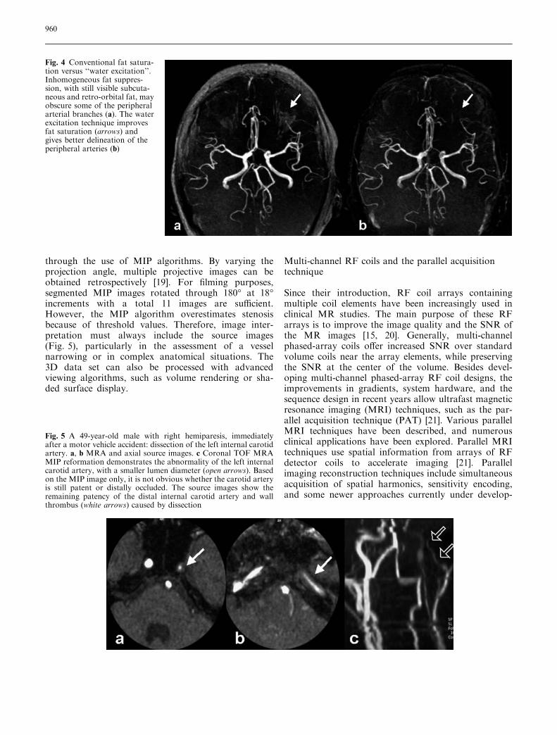
Fig. 4 Conventional fat satura-tion versus ‘‘water excitation’’.Inhomogeneous fat suppres-sion, with still visible subcuta-neous and retro-orbital fat, mayobscure some of the peripheralarterial branches (a). The waterexcitation technique improvesfat saturation (arrows) andgives better delineation of theperipheral arteries (b)
Fig. 5 A 49-year-old male with right hemiparesis, immediatelyafter a motor vehicle accident: dissection of the left internal carotidartery. a, b MRA and axial source images. c Coronal TOF MRAMIP reformation demonstrates the abnormality of the left internalcarotid artery, with a smaller lumen diameter (open arrows). Basedon the MIP image only, it is not obvious whether the carotid arteryis still patent or distally occluded. The source images show theremaining patency of the distal internal carotid artery and wallthrombus (white arrows) caused by dissection
960

ment [21, 22]. Applying PAT with an acceleration fac-tor of 2 results in a 43% time gain, when comparedwith an acquisition with the same parameters withoutPAT [8] (Fig. 6). A gain in acquisition time obtained byparallel MRI may improve the temporal and/or spatialresolution, increase the volume coverage, and evenreduce the time-dependent artifacts, such as motion, orbreathing artifacts [23].
High-field strength (3.0-T) magnetic resonanceangiography
The published data in the literatute and experience withhigh-field strength MRA of the intracranial vessels arelimited to 3D TOF MRA. The main advantage of 3.0-TMRI is a doubling of the available SNR over 1.5-T.The better SNR at high-magnetic-field strengths is awell-known potential benefit for further increasingspatial resolution in 3D TOF MRA [24]. The longer T1relaxation times at 3.0-T may make the backgroundeasier to suppress. However, there are important dis-advantages, such as more rapid saturation of slowlyflowing blood, increased RF-energy deposition, andstronger susceptibility effects [24, 25]. With high-reso-lution 3.0-T MRI, it is possible to increase spatialresolution with a voxel volume of 0.13 mm3
(0.30·0.44·1.00 mm) [24]. This has implications withregard to the improvement of the visualization of smallvessel segments and vascular diseases, such as thedetection of stenosis or small aneurysms less than 5 mmin size [24]. The smaller vessels in 3.0-T MRI arereported to be generally sharper, in particular becauseof the darker background and reduced noise [25],although sharper visualization of the small vessels and
the same improved background suppression may causemore ghosting artifacts, particularly at the proximalvessel portions. Lowering of the TE (as short as 3.4 ms)may reduce these undesired effects [25]. Another dis-advantage of the high-resolution 3.0-T MRI is theincreased acquisition times up to 8 min [24]. Intracra-nial high-resolution 3D TOF MRA at 3.0-T has takenits place in clinical routine and will further reduce theneed for invasive diagnostic angiographies.
Clinical applications of MRA
Arterial steno-occlusive disease
Cerebral stroke is a major cause of death and disability inthe Western society. The main etiology of stroke is ath-erosclerosis and its related complications such as steno-sis, occlusion, or emboli originating from ulceratedatherosclerotic plaques. The role of the neuroradiologistin acute cerebral stroke is to confirm the clinical diag-nosis and more specifically to identify the causativearterial occlusion for appropriate and timely therapy [1](Fig. 7). Among the noninvasive imaging techniques,MRA allows more accurate evaluation of intracranialsteno-occlusive disease and is widely used as a screeningmethod in stroke patients [26]. At this time, noninvasiveimaging techniques are not yet able to replace intra-arterial digital subtraction angiography (DSA), becauseof the lower spatial resolution and lack of precise he-modynamic information. Moreover, the potential over-estimation of stenosis on MRA is still a problem.However, a good morphologic correlation in depictingsteno-occlusive lesions of the proximal intracranialarteries has been reported with a sensitivity of 80%–
Fig. 6 Parallel acquisition tech-nique (PAT) applied to 3DTOFMRA. Axial 3D TOFMRangiograms, without (a) andwith parallel acquisition appli-cation (b) in the same patient.The acquisition time of 3DTOF MRA without using PATis 6 min, 30 s. PAT with anacceleration factor of 2decreases the imaging time to3 min, 46 s, with no significantdecrease in vascular assessment
961

100% and a specificity of 80%–99% [20]. Several types ofartifacts cause limitations in identifying and grading thestenosis by TOF MRA [26, 27, 28]:
1. Vessels close to the skull base and around the sphe-noid sinus are affected by artifactual narrowing ornonvisualization because of susceptibility artifactscaused by adjacent bone and air. In these locations,multiplanar reformation or axial source data imagescan be helpful.
2. Intravoxel dephasing caused by turbulent flow in thecarotid siphon and loss of laminar flow may alsocontribute to artifactual reduced signal, which cansimulate narrowing.
3. MR angiograms of severely stenotic vessels oftenshow a discontinuity in a vessel (skip sign), againcaused by intravoxel spin dephasing and the acceler-ation of flow through the stenosis.
4. MIP may create additional artifacts in the area of astenosis. Axial source images are more reliable thanthe MIP images alone for assessing the severity ofintracranial stenosis.
5. Although the use of longer TEs may increase theinterpretation of artifactual narrowing or flow gaps,the lower field gradient MR units (<1 T) limit thechoice of shorter TEs within an acceptable SNR.MRA can reliably demonstrate a proximal middlecerebral artery occlusion and, knowing the poorerclinical outcome of these patients, it may have a role indeciding and targeting the thrombolytic therapy [29].
Aneurysm
In the acute clinical setting of subarachnoid hemor-rhage, one should exclude the possibility of an intra-cranial aneurysm as the underlying cause. Because evensmall aneurysms (2 mm or less) can rupture, the idealdiagnostic test to be used should provide the best pos-sible anatomical detail. DSA is still considered the goldstandard in the investigation for intracranial aneurysms.False-negative rates of 5%–10% are reported in theliterature, attributable not to limitations of spatial res-olution, but to the limited number of projections of theneck of an aneurysm. This problem is largely overcomewith 3D rotational DSA, but this expensive technique isnot yet widely available. Nevertheless, DSA requires ahighly skilled radiologist to perform the procedure andremains an invasive technique with arterial puncture andintra-arterial catheter manipulation, with a 1% majorcomplication risk and a 0.5% rate of persistent neuro-logical deficit [30]. Technical advances in MRAthroughout the 1990s have continued to improve thesensitivity of this technique for detecting cerebralaneurysms as a screening tool, and MRA has been usedas an alternative to DSA for the presurgical work-up ofaneurysmal subarachnoid hemorrhage [31]. Aneurysmsas small as 3 mm can now be detected with 3D TOFMRA [32]. Once obtained, MRA data can be viewedfrom any projection in both 2D and 3D reformationalgorithms to detect the aneurysm and to evaluate itsneck. Multiplanar reformations are particularly helpfulin defining the neck and also the parent and branchvessels related to aneurysms [33] (Fig. 8). The detectionand treatment of an aneurysm before it ruptures withpossible lethal subarachnoid hemorrhage is an impor-tant research topic. TOF MRA can identify aneurysms(at least 3 mm in size) with a sensitivity of 74%–98%[32, 34]. MRA is ideal for screening cerebral aneurysmsbecause the procedure is noninvasive and the patient isnot exposed to radiation. The differences in diagnosticconfidence in the detection of intracranial aneurysms are
Fig. 7 A 80-year-old female with right hemiparesis and speechdifficulties: left internal carotid artery occlusion. The diffusion-weighted image (a) reveals a small area of increased signal and adiffusion defect attributable to cytotoxic edema in the parieto-occipital areas. Although, there is an occlusion of the left internalcarotid artery, the arterial circulation of the left hemisphere and thedistal branches of middle cerebral artery (b, white arrows) is largelyrepaired with collateral circulation through the vertebro-basilarysystem (open arrow). This is probably provides an explanation ofthe relatively small parenchymal (watershed) injury, but massiveproximal occlusion
962
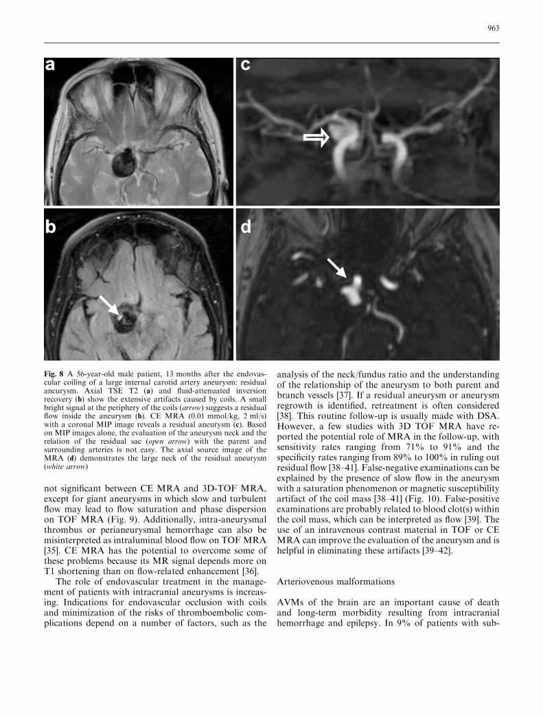
not significant between CE MRA and 3D-TOF MRA,except for giant aneurysms in which slow and turbulentflow may lead to flow saturation and phase dispersionon TOF MRA (Fig. 9). Additionally, intra-aneurysmalthrombus or perianeurysmal hemorrhage can also bemisinterpreted as intraluminal blood flow on TOFMRA[35]. CE MRA has the potential to overcome some ofthese problems because its MR signal depends more onT1 shortening than on flow-related enhancement [36].
The role of endovascular treatment in the manage-ment of patients with intracranial aneurysms is increas-ing. Indications for endovascular occlusion with coilsand minimization of the risks of thromboembolic com-plications depend on a number of factors, such as the
analysis of the neck/fundus ratio and the understandingof the relationship of the aneurysm to both parent andbranch vessels [37]. If a residual aneurysm or aneurysmregrowth is identified, retreatment is often considered[38]. This routine follow-up is usually made with DSA.However, a few studies with 3D TOF MRA have re-ported the potential role of MRA in the follow-up, withsensitivity rates ranging from 71% to 91% and thespecificity rates ranging from 89% to 100% in ruling outresidual flow [38–41]. False-negative examinations can beexplained by the presence of slow flow in the aneurysmwith a saturation phenomenon or magnetic susceptibilityartifact of the coil mass [38–41] (Fig. 10). False-positiveexaminations are probably related to blood clot(s) withinthe coil mass, which can be interpreted as flow [39]. Theuse of an intravenous contrast material in TOF or CEMRA can improve the evaluation of the aneurysm and ishelpful in eliminating these artifacts [39–42].
Arteriovenous malformations
AVMs of the brain are an important cause of deathand long-term morbidity resulting from intracranialhemorrhage and epilepsy. In 9% of patients with sub-
Fig. 8 A 56-year-old male patient, 13 months after the endovas-cular coiling of a large internal carotid artery aneurysm: residualaneurysm. Axial TSE T2 (a) and fluid-attenuated inversionrecovery (b) show the extensive artifacts caused by coils. A smallbright signal at the periphery of the coils (arrow) suggests a residualflow inside the aneurysm (b). CE MRA (0.01 mmol/kg, 2 ml/s)with a coronal MIP image reveals a residual aneurysm (c). Basedon MIP images alone, the evaluation of the aneurysm neck and therelation of the residual sac (open arrow) with the parent andsurrounding arteries is not easy. The axial source image of theMRA (d) demonstrates the large neck of the residual aneurysm(white arrow)
963

arachnoid hemorrhage and 4% of patients with primaryintracranial hemorrhage, an AVM is the underlyingcause. The detection rate of AVMs has been increasing
recently because of the technological advances in imag-ing modalities and the wide availability of non-invasivetechniques. An AVM is defined as an anastomotic net-work of blood vessels in which arteriovenous shuntingoccurs in a central nidus. To date, there is no standardreference investigation for the diagnosis of AVM. Thereare usually several tortuous high-flow feeding arteries ofdifferent sizes and courses that converge toward the ni-dus where the arteriovenous shunting occurs (Fig. 11).These feeding arteries typically originate from more thanone intracranial branch of the internal carotid and/orvertebrobasilar systems. Because of the high flow andlow resistance of an AVM, diffuse small arterial brachesfrom the surrounding brain tissue may form a collateralnetwork around the AVM [43]. MRI and particularlyMRA play an important role in the evaluation of nidussize and its anatomical relations [44]. The draining veinsare often anomalous, because of hemodynamic stressescausing stenosis, ectasia, or varix formation. Associatedaneurysms can be visualized in 10% of patients withAVMs [45] (Fig. 12). These aneurysms may be multipleand tend to be small in cases of hereditary hemorrhagictelangiectasia and other neurocutaneous disorders, suchas Wyburn–Mason syndrome [46]. Several MR angio-graphic techniques, such as 3D PC MRA and contrast-enhanced 3D TOF techniques have been applied asnon-invasive means of diagnosis [11]. These MRangiographic techniques accurately depict anatomicdetails and the flow direction of AVMs; however, theydo not provide any further hemodynamic information.
Fig. 10 A 73-year-old male pa-tient: partially thrombosedlarge posterior cerebral arteryaneurysm. The 3D TOF MRangiograms (a, b) and sourceimage (c) reveal a large hyper-intensity at the right posteriorcerebral artery. Not only theflow, but also acute thrombus ishyperintense on TOF MRimages; this may cause a prob-lem in the differentiation of theflow contained in the aneurysmfrom a blood clot. The coronal(d) reformation of the pre-con-trast 3D gradient echo T1source image demonstrates thatthe hyperintensity is caused byacute thrombus (arrow)
Fig. 9 Giant aneurysm: MIP projection. Although CE MRA issuperior to TOF MR angiography in the evaluation of giantaneurysms, the turbulent flow may cause an inhomogeneous signal.Note the dark signal at the bottom of the giant aneurysm in the M1segment of the right middle cerebral artery
964

The hemodynamics of AVMs are important in definingthe risk factors for hemorrhage, together with their largesize, deep venous drainage, and nidus aneurysm.Although the temporal resolution is not yet sufficient,recent reports have shown that the time-resolved con-
trast-enhanced 3D MR angiography (MR-DSA) arecapable of providing dynamic angiographic images(Fig. 13) [47, 48]. Nevertheless, the technique has severallimitations: (1) spatial resolution is still inadequate; (2)the section thickness is inadequate to cover relatively
Fig. 12 A 36-year-old malepatient with an extensive AVMand associated aneurysms. Twodifferent MIPs of 3D TOF MRangiography show a large AVMin the right hemisphere. Twoassociated small aneurysms(open arrows) are present
Fig. 11 A 25-year-old femalewith a large AVM. The axialTSE T2-weighted image(a) shows a large tortuous sig-nal voiding in the right parietallobe corresponding to theAVM. 3D TOF MR angiogram(b) obtained without venoussaturation reveals a largenetwork of arterial and venousstructures converging towardthe nidus. Note the involvementof both anterior and middlecerebral arteries and the dilatedvenous system
965
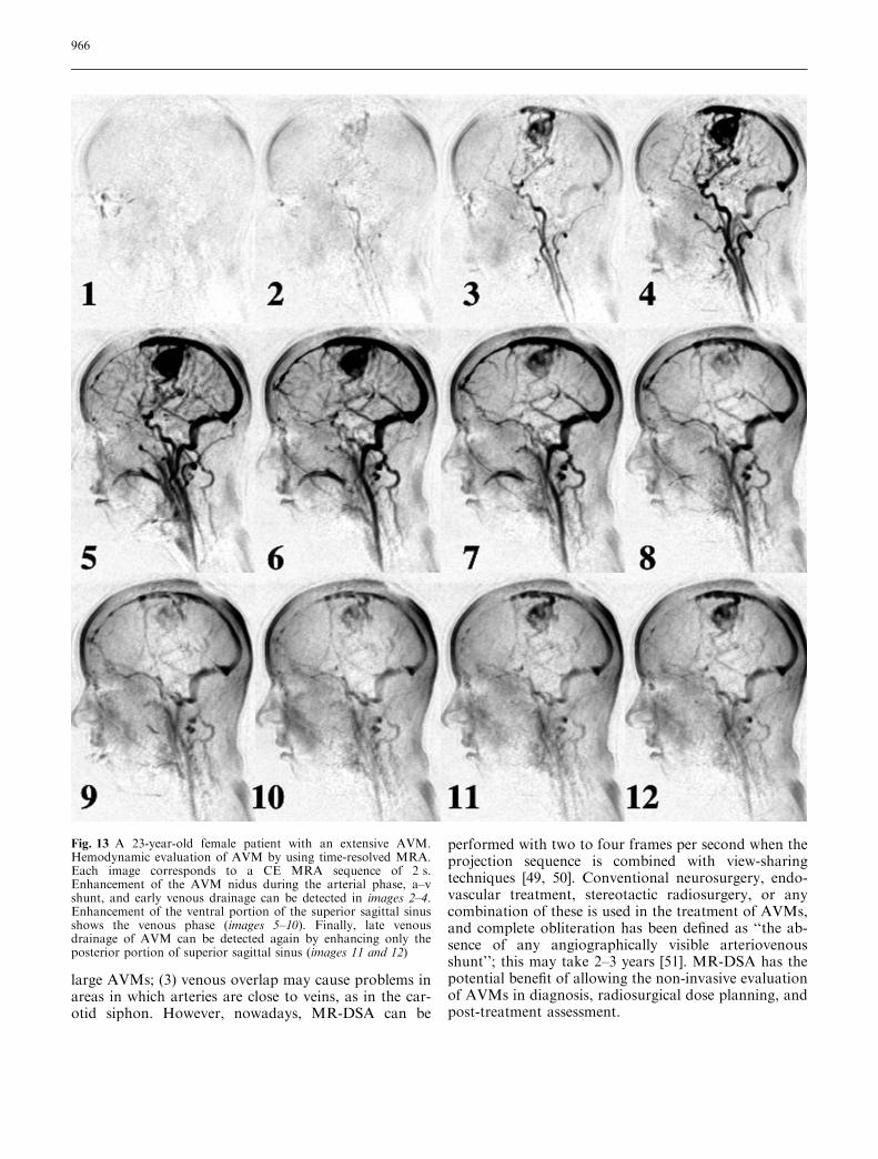
large AVMs; (3) venous overlap may cause problems inareas in which arteries are close to veins, as in the car-otid siphon. However, nowadays, MR-DSA can be
performed with two to four frames per second when theprojection sequence is combined with view-sharingtechniques [49, 50]. Conventional neurosurgery, endo-vascular treatment, stereotactic radiosurgery, or anycombination of these is used in the treatment of AVMs,and complete obliteration has been defined as ‘‘the ab-sence of any angiographically visible arteriovenousshunt’’; this may take 2–3 years [51]. MR-DSA has thepotential benefit of allowing the non-invasive evaluationof AVMs in diagnosis, radiosurgical dose planning, andpost-treatment assessment.
Fig. 13 A 23-year-old female patient with an extensive AVM.Hemodynamic evaluation of AVM by using time-resolved MRA.Each image corresponds to a CE MRA sequence of 2 s.Enhancement of the AVM nidus during the arterial phase, a–vshunt, and early venous drainage can be detected in images 2–4.Enhancement of the ventral portion of the superior sagittal sinusshows the venous phase (images 5–10). Finally, late venousdrainage of AVM can be detected again by enhancing only theposterior portion of superior sagittal sinus (images 11 and 12)
966

As a rare congenital abnormality, the vein of Galenmalformation (VGAM) (Fig. 14) is described as a truearteriovenous malformation with severe morbidity andmortality [52, 53]. MRI is mandatory for the accurateassessment of the associated hematoma, ischemia, orhydrocephalus. If there is severe parenchymal damage,endovascular treatment cannot compensate the irre-versible changes. Since conventional angiography is onlyindicated if embolization is planned, MRI and MRAhave a role in the pre-treatment period at 3 and6 months after birth and then following treatment, ifclinical conditions are stable [52, 53]. MRA is capable ofindicating the major vessels of supply and the tortuosityof arterial access and venous anatomy [53].
Venous occlusive disease
Dural venous sinus thrombosis is seen in various condi-tions, such as dehydration, hypercoagulation disorders,
infection, or direct tumoral invasion. Delayed diagnosisof sinus thrombosis may cause morbidity and mortality[54]. The diagnosis of a sinus thrombosis on MRI orMRA is not always easy because both thrombus and flowcan produce high signal intensity [54, 55] (Fig. 15). Both3D TOF MRA and 2D PC MRA are unsuitable for thevisualization of the intracranial venous system because ofstrong in-plane saturation and intravoxel dephasing.Although the quantitative determination of bloodvelocities may be possible, long imaging times and theproper setting of the VENC factor beforehand are themajor limitations of PC MRA, which is more susceptibleto motion artifacts because of the longer acquisitiontimes. However, this latter technique gives a better dis-tinction between thrombus and flowing blood [56]. Idealvenous system assessment can be achieved by using 2DTOF MRA. However, with 2D TOF MR venography, itis difficult to distinguish an acquired thrombosis from ahypoplastic or absent sinus, which is a common ana-tomical variation (Figs. 16, 17). This phenomenon is
Fig. 14 A 9-month-old baby-boy: vein of Galen malforma-tion. Mid-sagittal TSE T1(a) and axial TSE T2 (b) imagesshowing a pathognomonic as-pect of Galen malformationwith dilation of the great cere-bral vein of Galen and straightsinus. No parenchymal angio-matous malformation is visiblethat corresponds to a type-1Galen malformation. Lateralview of the 3D TOF MRangiogram (c) showing theextensive enlargement and highvelocity flow enhancement ofthe great cerebral vein of Galenand straight sinus
967

known as a ‘‘transverse sinus flow gap’’ and can be ob-served at the non-dominant transverse sinuses (usuallyon the left) in as many as 31% of patients [57]. Con-ventional catheter angiograms show the presence ofhypoplastic, but patent, non-dominant transverse sinusesin these patients. Other pitfalls may include signal lossbecause of in-plane flow saturation or complex flow,particularly through the sigmoid sinus and jugular bulb[57, 58]. To interpret MR angiograms accurately and toavoid such potential pitfalls in the diagnosis, one must beaware of the technical limitations of 2D-TOF imaging. Itis therefore desirable to set the slice thickness as small aspossible (1.0–1.5 mm) and to orient the acquisition plane
perpendicular to the long axis of the vessel. Because ofthe complex 3D morphology of the venous structures, itis sometimes necessary to repeat MR venography indifferent directions (coronal, sagittal, or oblique) for fullcoverage of the sinuses (Fig. 18). Recent reports recom-mend the use of 3D contrast-enhanced magnetized pre-pared rapid gradient echography in diseases of the largedeep veins and dural sinuses [59]. However, there are alsoseveral pitfalls that occur with this technique, such as thevisualization of intrasinus fibrotic bands and pacchio-nian granulation, which may be misdiagnosed as athrombosis, and being able to distinguish a chronicthrombosis from normal contrast enhancement of thesinus [60].
Other pathologies
MRI has replaced conventional angiography as theprimary imaging tool for the diagnosis and localization
Fig. 15 A 30-year-old male with headache: dural sinus thrombosis.Mid-sagittal TSE T1 (a), axial TSE T2 (b), and axial TSE T1(c) images reveal an enlargement of the superior sagittal sinusbecause of a thrombus (white arrows). Iso- to hyperintense signalon T1 and high signal intensity on T2-weighted images correspondto a late subacute thrombus. Dynamic contrast-enhanced MRangiograms (d) demonstrate the patency of the sagittal sinus andthe presence of flow around the organized thrombus (black arrow)
968

of intracranial tumors and their vascularization patternsand relationship to surrounding vascular structures [61].
Central nervous system (CNS) vasculitis represents aheterogeneous group of inflammatory diseases that pri-marily affect the small leptomeningeal or parenchymalblood vessels of the brain. A wide range of neurologicalconditions may cause CNS vasculitis, including infec-tion, malignancy, ionizing radiation, cocaine ingestion,and autoimmune disease [62]. MRI is highly sensitive in
showing secondary manifestations of CNS vasculitis,such as supratentorial infarctions in the cortical andsubcortical regions; however, this appearance is notspecific for vasculitis [63]. Furthermore, the correlationbetween MRI and angiography is only moderate, andeven brain biopsies show high false-negative results [2].MRA may reveal stenosis and occlusion of the proximalintracranial arterial branches, but no prospective studiesare available on the sensitivity and specificity of MRA[64]. Therefore, only positive MRA results can directlyinfluence clinical management.
Moyamoya disease is a rare progressive cerebrovas-cular occlusive disease characterized by the developmentof small arterial and arteriolar collateral vessels aroundthe obstructed major arteries [65]. These new vesselsshow a typical angiographic appearance ‘‘like a puff of
Fig. 17 Transverse sinus gap(white arrows) attributable tothe spin saturation effect ofslow flow on 2D TOF coronal(a) and transverse (b) MRangiograms. The patient alsohas a venous angioma draininginto the superior sagittal sinus(open arrows)
Fig. 16 A 22-year-old female with headache and vomiting: throm-bosis of the transverse sinus and venous infarction. Axial TSE T2(a) and axial diffusion-weighted EPI (b) images reveal a corticalinfarction caused by thrombosis of the left transverse sigmoidsinuses and jugular vein, which is clearly visible by 2D TOF MRangiography (c)
969
smoke’’ or a ‘‘moyamoya’’, which is a word derivedfrom Japanese. Affected children have risks of cerebralischemia resulting in transient ischemic events or
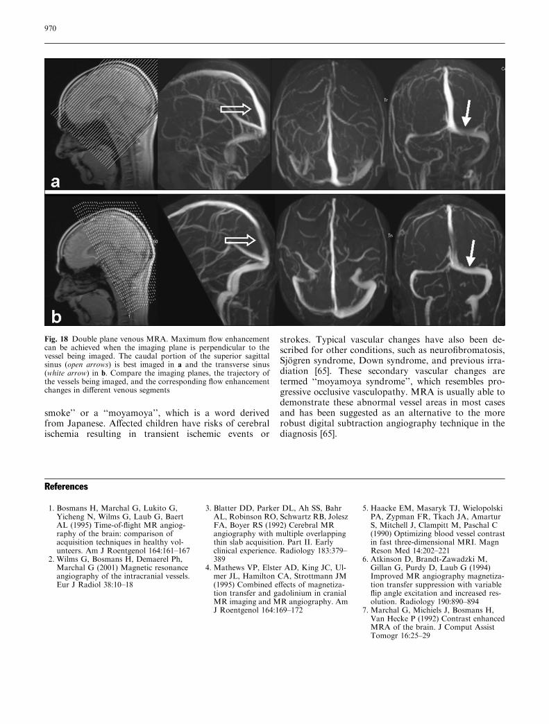
strokes. Typical vascular changes have also been de-scribed for other conditions, such as neurofibromatosis,Sjogren syndrome, Down syndrome, and previous irra-diation [65]. These secondary vascular changes aretermed ‘‘moyamoya syndrome’’, which resembles pro-gressive occlusive vasculopathy. MRA is usually able todemonstrate these abnormal vessel areas in most casesand has been suggested as an alternative to the morerobust digital subtraction angiography technique in thediagnosis [65].
Fig. 18 Double plane venous MRA. Maximum flow enhancementcan be achieved when the imaging plane is perpendicular to thevessel being imaged. The caudal portion of the superior sagittalsinus (open arrows) is best imaged in a and the transverse sinus(white arrow) in b. Compare the imaging planes, the trajectory ofthe vessels being imaged, and the corresponding flow enhancementchanges in different venous segments
References
1. Bosmans H, Marchal G, Lukito G,Yicheng N, Wilms G, Laub G, BaertAL (1995) Time-of-flight MR angiog-raphy of the brain: comparison ofacquisition techniques in healthy vol-unteers. Am J Roentgenol 164:161–167
2. Wilms G, Bosmans H, Demaerel Ph,Marchal G (2001) Magnetic resonanceangiography of the intracranial vessels.Eur J Radiol 38:10–18
3. Blatter DD, Parker DL, Ah SS, BahrAL, Robinson RO, Schwartz RB, JoleszFA, Boyer RS (1992) Cerebral MRangiography with multiple overlappingthin slab acquisition. Part II. Earlyclinical experience. Radiology 183:379–389
4. Mathews VP, Elster AD, King JC, Ul-mer JL, Hamilton CA, Strottmann JM(1995) Combined effects of magnetiza-tion transfer and gadolinium in cranialMR imaging and MR angiography. AmJ Roentgenol 164:169–172
5. Haacke EM, Masaryk TJ, WielopolskiPA, Zypman FR, Tkach JA, AmarturS, Mitchell J, Clampitt M, Paschal C(1990) Optimizing blood vessel contrastin fast three-dimensional MRI. MagnReson Med 14:202–221
6. Atkinson D, Brandt-Zawadzki M,Gillan G, Purdy D, Laub G (1994)Improved MR angiography magnetiza-tion transfer suppression with variableflip angle excitation and increased res-olution. Radiology 190:890–894
7. Marchal G, Michiels J, Bosmans H,Van Hecke P (1992) Contrast enhancedMRA of the brain. J Comput AssistTomogr 16:25–29
970

8. Ozsarlak O, Parizel PM, Van GoethemJW (2004) Low-dose gadoliniumenhanced 3D time-of-flight MR angi-ography of the intracranial vessels usingPAT optimized phased array 8-channelhead coil. Eur Radiol 14:2067–2071
9. Jung HW, Chang KH, Choi DS, HanMH, Han MC (1995) Contrast-enhanced MR angiography for thediagnosis of intracranial vasculardisease: optimal dose of gadopentatedimeglumine. Am J Roentgenol165:1251–1255
10. Dumoulin CL, Souza SP, Walker MF,Wagle W (1989) Three-dimensionalphase contrast angiography. MagnReson Med 9:139–149
11. Marks MP, Pelc MJ, Ross MR, Enz-mann DR (1992) Determination ofcerebral blood flow with a phase-con-trast cine MR imaging technique: eval-uation of normal subjects and patientswith arteriovenous malformation.Radiology 182:467–476
12. Oelerich M, Lentschig MG, Zunker P,Reimer P, Rummeny EJ, Schuierer G(1998) Intracranial vascular stenosis andocclusion: comparison of 3D time-of-flight and 3D phase-contrast MR angi-ography. Neuroradiology 40:567–573
13. Korosec FR, Mistretta CA (1998) MRangiography: basic principles and the-ory. Magn Reson Imaging Clin N Am6:223–256
14. Van Goethem JW, Hauwe L van den,Ozsarlak O, Parizel PM (2003) Phase-contrast magnetic resonance angiogra-phy. JBR-BTR 86:340–344
15. Hilfiker PR, Herfkens RJ, Heiss SG,Alley MT, Fleischmann D, Pelc NJ(2000) Partial fat-saturated contrast-enhanced three-dimensional MRangiography compared with non-fat-saturated and conventional fat-saturated MR angiography. Radiology216:298–303
16. Riederer SJ, Bernstein MA, Breen JF,Busse RF, Ehman RI, Fain SB, Hulsh-izer TC, Iii JH, King BF, Kruger DG,Rosmann PJ, Shah S (2000) Three-dimensional contrast-enhanced MRangiography with real-time fluoroscopictriggering: design specifications andtechnical reliability in 330 patient stud-ies. Radiology 215:584–593
17. Schick F (1996) Pulsed magnetizationtransfer contrast MRI by a sequencewith water selective excitation. J Com-put Assist Tomogr 20:73–79
18. Lee VS, Flyer MA, Weinreb JC, Krin-sky GA, Rofsky NM (1996) Imagesubtraction in gadolinium-enhancedMR imaging. Am J Roentgenol167:1427–1432
19. Masarsky TJ, Modic MT, Ross JS,Ruggieri PM, Laub GA, Lenz GW,Haacke EM, Selman WR, Wiznitzer M,Harik SI (1989) Intracranial circulation:preliminary clinical results with three-dimensional (volume) MR angiography.Radiology 171:793–799
20. Porter JR, Wright SM, Reykowski A(1998) A 16-element phased-arrayhead coil. Magn Reson Med 40:272–279
21. Sodickson DK, McKenzie CA, OhligerMA, Yeh AN, Price MD (2002) Recentadvances in image reconstruction, coilsensitivity calibration, and coil designfor SMASH and generalized parallelMRI. MAGMA 13:158–163
22. Pruessmann KP, Weiger M, Scheideg-ger MB, Boesiger P (1999) SENSE:sensitivity encoding for fast MRI. MagReson Med 42:952–962
23. Heidemann RM, Ozsarlak O, ParizelPM, Michiels J, Kiefer B, Jellus V,Muller M, Breuer F, Blaimer M,Griswold MA, Jakob PM (2003) Abrief review of parallel magnetic reso-nance imaging. Eur Radiol 13:2323–2337
24. Willinek WA, Born M, Simon B,Tschampa HJ, Krautmacher C, GiesekeJ, Urbach H, Textor HJ, Schild HH(2003) Time-of-flight MR angiographyof 3.0-T imaging and 1.5-T imag-ing—initial experience. Radiology229:913–920
25. Al-Kwifi O, Emery DJ, Wilman AH(2002) Vessel contrast at three Tesla intime-of-flight magnetic resonance angi-ography of the intracranial and carotidarteries. Magn Reson Imaging 20:181–187
26. Heiserman JE, Drayer BP, Keller PJ,Fram EK (1992) Intracranial vascularstenosis and occlusion: evaluationwith three-dimensional time-of-flightMR angiography. Radiology 185:667–673
27. Furst G, Hofer M, Sitzer M, Kahn T,Muller E, Modder U (1995) Factorsinfluencing flow-induced signal loss inMR angiography: an in vitro study.J Comput Assist Tomogr 19:692–699
28. Hirai T, Korogi Y, Ono K, Nagano M,Maruoka K, Uemura S, Takahashi M(2002) Prospective evaluation of sus-pected steno-occlusive disease of theintracranial artery: combined MRangiography and CT angiographycompared with digital subtractionangiography. Am J Neuroradiol 23:93–101
29. Barber PA, Davis SM, Darby DG,Desmond PM, Gerraty RP, Yang Q,Jolley D, Donnan GA, Tress BM (1999)Absent middle cerebral artery flow pre-dicts the presence and evolution of theischemic penumbra. Neurology52:1125–1132
30. Heiserman JE, Dean BL, Hodak JA,Flom RA, Bird CR, Drayer BP, FramEK (1994) Neurological complicationsof cerebral angiography. Am J Neuro-radiol 15:1401–1407
31. Sankhla SK, Gunawardena WJ, Cout-inho CMA, Jones AP, Keogh AJ (1996)Magnetic resonance angiography in themanagement of aneurysmal subarach-noid hemorrhage: a study of 51 cases.Neuroradiology 38:724–729
32. Bosmans H, Wilms G, Marchal G,Demaerel P, Baert AL (1995) Charac-terization of intracranial aneurysmswith MR angiography. Neuroradiology37:262–266
33. Adams WM, Laitt RD, Jackson A(2000) The role of MR angiography inthe pretreatment assessment of intra-cranial aneurysms: a comparative study.Am J Neuroradiol 21:1618–1628
34. White PM, Wardlaw JM, Lindsay KW,Sloss S, Patel DK, Teasdale EM (2003)The non-invasive detection of intracra-nial aneurysms: are neuroradiologistsany better than other observers? EurRadiol 13:389–396
35. Brugieres P, Blustajn J, Le Guerinel C,Meder J, Thomas P, Gaston A (1998)Magnetic resonance angiography ofgiant intracranial aneurysms. Neurora-diology 40:96–102
36. Jager HR, Ellamushi H, Moore EA,Grieve JP, Kitchen ND, Taylor WJ(2000) Contrast-enhanced MR angiog-raphy of intracranial giant aneurysms.Am J Neuroradiol 21:1900–1907
37. Fernandez-Zubillaga A, Guglielmi G,Vinuela F, Duckwiler G (1994) Endo-vascular occlusion of intracranialaneurysms with electrolytically detach-able coils: correlation of aneurysm necksize and treatment results. Am J Neu-roradiol 15:815–820
38. Cottier JP, Bleuzen-Couthon A, GallasS, Vinikoff-sonier CB, Bertrand P, Do-mengie F, Barantin L, Herbreteau D(2003) Intracranial aneurysms treatedwith Guglielmi detachable coils: is con-trast material necessary in the follow-upwith 3D time-of-flight MR angiogra-phy? Am J Neuroradiol 24:1797–1803
39. Kahara VJ, Seppanen SK, Ryymin PS,Mattila P, Kuurne T, Laasonen EM(1999) MR angiography with three-dimensional time-of-flight and targetedmaximum-intensity-projection recon-structions in the follow-up of intracra-nial aneurysms embolized withGuglielmi detachable coils. Am J Neu-roradiol 20:1470–1475
971

40. Anzalone N, Righi C, Simionato F,Scomazzoni F, Pagani G, Calori G,Santino P, Scotti G (2000) Three-dimensional time-of-flight MR angiog-raphy in the evaluation of intracranialaneurysms treated with Guglielmidetachable coils. Am J Neuroradiol21:746–752
41. Boulin A, Pierot L (2001) Follow-upintracranial aneurysms treated withdetachable coils: comparison of gado-linium enhanced 3D time-of-flight MRangiography and digital subtractionangiography. Radiology 219:108–113
42. Leclerc X, Navez JF, Gauvrit JY,Lejeune JP, Pruvo JP (2002) Aneurysmsof the anterior communicating arterytreated with Guglielmi detachable coils:follow-up with contrast-enhanced MRangiography. Am J Neuroradiol23:1121–1127
43. Montanera W, Marotta TR, terBruggeKG, Lasjaunias P, Willinsky R, WallaceMC (1990) Cerebral arteriovenousmalformations associated with moya-moya phenomenon. Am J Neuroradiol11:1153–1156
44. Noorbehesht B, Fabrikant JI, EnzmannDR (1987) Size determination ofsupratentorial arteriovenous malforma-tions by MR, CT and angio. Neurora-diology 29:512–518
45. Westphal M, Grzyska U (2000) Clinicalsignificance of pedicle aneurysms onfeeding vessels, especially those locatedin infratentorial arteriovenous malfor-mations. J Neurosurg 92:995–1001
46. Fulbright RK, Chaloupka JC, PutmanCM, Sze GK, Merriam MM, Lee GK,Fayad PB, Awad IA, White RI Jr(1998) MR of hereditary hemorrhagictelangiectasia: prevalence and spectrumof cerebrovascular malformations. AmJ Neuroradiol 19:477–484
47. Tsuchiyaa K, Katasea S, Yoshinoa A,Hachiyaa J (2000) MR digital subtrac-tion angiography of cerebral arteriove-nous malformations. Am J Neuroradiol21:707–711
48. Carroll TJ (2002) The emergence oftime-resolved contrast-enhanced MRimaging for intracranial angiography.Am J Neuroradiol 23:346–348
49. Griffiths PD, Hoggard N, Warren DJ,Wilkinson ID, Anderson B, Roma-nowski CA (2000) Brain arteriovenousmalformations: assessment with dy-namic MR digital subtraction angiog-raphy. Am J Neuroradiol 21:1892–1899
50. Strecker R, Scheffler K, Klisch J,Lehnhardt S, Winterer S, Laubenberger J,Fischer H, Hennig J (2000) Fast func-tional MRA using time-resolved pro-jection MR-angiography withcorrelation analysis. Magn Reson Med43:303–309
51. Oppenheim C, Meder JF, Trystram D,Nataf F, Godon-Hardy S, Blustajn J,Merienne L, Schlienger M, Fredy D(1999) Radiosurgery of cerebral arte-riovenous malformation: is an earlyangiogram needed? Am J Neuroradiol20:475–481
52. Mitchell PJ, Rosenfeld JV, DargavilleP, Loughnan P, Ditchfield MR, FrawleyG, Tress BM (2001) Endovascularmanagement of vein of Galen aneuris-mal malformations presenting in theneonatal period. Am J Neuroradiol22:1403–1409
53. Campi A, Rodesch G, Scotti G, Las-jaunias P (1998) Aneurysmal malfor-mation of the vein of Galen in threepatients: clinical and radiological fol-low-up. Neuoradiology 40:816–821
54. Ayanzen RH, Bird CR, Keller PJ,McCully FJ, Theobald MR, HeisermanJE (2000) Cerebral MR venography:normal anatomy and potential diag-nostic pitfalls. Am J Neuroradiol 21:74–78
55. Yousem DM, Balakrishnan J, DebrunGM, Bryan RN (1990) Hyperintensethrombus on GRASS MR images: po-tential pitfall in flow evaluation. AmJ Neuroradiol 11:51–58
56. Liauw L, Buchem MA van, Spilt A,Bruine FT de, Berg R van den,Hermans J, Wasser MNJM (2000) MRangiography of the intracranial venoussystem. Radiology 214:678–682
57. Vogl TJ, Bergman C, Villringer A,Einhaup K, Lissner J, Felix R (1994)Dural sinus thrombosis: value of venousMR angiography for diagnosis andfollow-up. Am J Roentgenol 162:1191–1198
58. Kallmes DF, Cloft HJ, Jensen ME,Kaptain GJ, Dion JE, Matsumoto JA(1998) Dural arteriovenous fistula: apitfall of time-of-flight MR venographyfor the diagnosis of sinus thrombosis.Neuroradiology 40:242–244
59. Liang L, Korogi Y, Sugahara T, Ono-michi M, Shigematsu Y, Yanga D,Kitajimaa M, Hiaia Y, Takahashia M(2001) Evaluation of the intracranialdural sinuses with a 3D contrast-enhanced MP-RAGE sequence: pro-spective comparison with 2D-TOF MRvenography and digital subtractionangiography. Am J Neuroradiol22:481–492
60. Dormont L, Sag K, Biondi A, WechslerB, Marsault C (1995) Gadolinium-en-hanced MR of chronic dural sinusthrombosis. Am J Neuroradiol 16:1347–1352
61. Wilms G, Bosmans H, Marchal G,Demaerel P, Goffin J, Plets C, Baert AL(1995) Magnetic resonance angiographyof supratentorial tumors: comparisonwith selective digital subtraction angi-ography. Neuroradiology 37:42–47
62. Pomper MG, Miller TJ, Stone JH,Tidmore WC, Hellmann DB (1999)CNS vasculitis in autoimmune disease:MR imaging findings and correlationwith angiography. Am J Neuroradiol20:75–85
63. Duna GF, Calabrese LH (1995) Limi-tations of invasive modalities in thediagnosis of primary angiitis of thecentral nervous system. J Rheumatol22:662–667
64. Schluter A, Hirsch W, Jassoy A,Komhuber M, Behrmann C, Keyser G,Spielmann RP (2001) MR angiographyin diagnosis of vasculitis and benignnagiopathies of the central nervoussystem. Rofo Fortschr Geb RontgenstrNeuen Bildgeb Verfahr 173:522–527
65. Demaerel P, Wilms G, Casaer P,Casteels-Van Daele M, Bosmans H,Marchal G, Baert AL (1991) Moya-moya disease: MRI and MR angiogra-phy. Neuroradiology 33 (Suppl):50–52
972