modern design trend of metal aircraft fuselage structure
TRANSCRIPT

MODERN DESIGN TREND OF METAL AIRCRAFT FUSELAGE STRUCTURE
International Science Postgraduate Conference 2012 (ISPC 2012)
© Universiti Teknologi Malaysia
MODERN DESIGN TREND OF METAL AIRCRAFT FUSELAGE
STRUCTURE
MOHAMED P.HASSAN 1*
, MOHD RAFIE A. S.2 AND FAIRUZ L. ROMLI
3
Abstract. Throughout the years, development of aircraft design has already accomplished
several major milestones. However, as can be observed from existing aircraft models, the
fuselage structure remains still, mostly like it was in 1930s. In this paper, the trend of fuselage
designs introduced within last few decades is studied through patents and published researches,
particularly with regards to the development in metal fuselage structure. All in all, it can be
concluded that there seems to be a big push towards more integral structures where the structural
requirements are satisfied through pre-manufactured panels. Based on these findings, several
potentials and opportunities for improvement are identified and discussed. It is believed
implementing new and better fuselage designs can have a significant effect on aircraft industry.
Thus, making air transportation more accessible to most people, by reducing the production time
and cost.
Keywords Fuselage design, very light jet, design trend, aircraft industry
Abstrak. Sepanjang tahun, pembangunan reka bentuk pesawat telah mencapai beberapa
kejayaan besar. Walau bagaimanapun, seperti yang dapat diperhatikan daripada model pesawat
yang telah sedia , struktur fiuslaj masih kekal, kebanyakannya seperti adalah pada tahun 1930-an.
Dalam kertas ini, trend reka bentuk fiuslaj yang diperkenalkan dalam tempoh beberapa dekad
yang lalu dikaji melalui paten dan kajian yang diterbitkan, khususnya dari segi pembangunan
dalam struktur fiuslaj logam.Dalam semua, ia boleh membuat kesimpulan bahawa terdapat
seolah-olah menjadi dorongan besar ke arah struktur yang lebih penting yang mana keperluan
struktur berpuas hati melalui panel pra-pembuatan. Berdasarkan penemuan ini, potensi dan
beberapa peluang untuk penambah baikan dikenal pasti dan dibincangkan. Adalah dipercayai
melaksanakan reka bentuk fiuslaj yang baru dan lebih baik boleh mempunyai kesan yang besar
ke atas industri pesawat. Terutamanya, menjadikan pengangkutan udara lebih mudah bagi
kebanyakan orang, dengan mengurangkan masa dan kos pengeluaran.
Kata kunci Reka bentuk fiuslaj, jet sangat ringan, trend reka bentuk, industri pesawat
1,2,3
Aerospace Department, Faculty of Engineering, Universiti Putra Malaysia, 43400, UPM
Serdang, Selangor, Malaysia
* Corresponding author: [email protected]
808
MODERN DESIGN TREND OF METAL AIRCRAFT FUSELAGE STRUCTURE
1.0 INTRODUCTION
From dawn of Aircraft design up
till now, major milestones have been
accomplished. Yet it’s of most
importance to realize, we are still at
dawn of real industry evolution.
Currently not each person can have
an airplane; however same person
could easily get a car.
Using relevant articles and patents,
we first started with new VLJ aircraft
considering it being a similar
example to the traditional private car.
We then investigated proposed
designs of metal fuselage structure, in
general, looking for defined
milestones; to be used in predicting
the design trend. Relevant history and
Airframe structure books have been
reviewed as well.
1.1 History
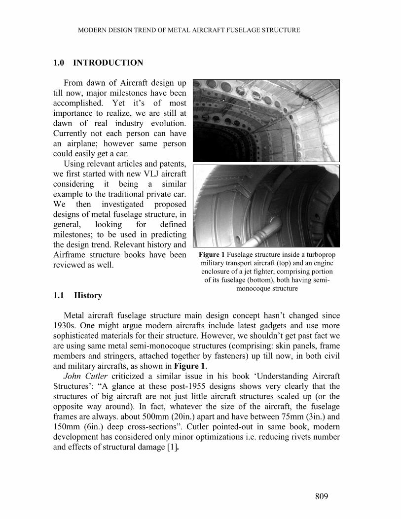
Metal aircraft fuselage structure main design concept hasn’t changed since
1930s. One might argue modern aircrafts include latest gadgets and use more
sophisticated materials for their structure. However, we shouldn’t get past fact we
are using same metal semi-monocoque structures (comprising: skin panels, frame
members and stringers, attached together by fasteners) up till now, in both civil
and military aircrafts, as shown in Figure 1.
John Cutler criticized a similar issue in his book ‘Understanding Aircraft
Structures’: “A glance at these post-1955 designs shows very clearly that the
structures of big aircraft are not just little aircraft structures scaled up (or the
opposite way around). In fact, whatever the size of the aircraft, the fuselage
frames are always. about 500mm (20in.) apart and have between 75mm (3in.) and
150mm (6in.) deep cross-sections”. Cutler pointed-out in same book, modern
development has considered only minor optimizations i.e. reducing rivets number
and effects of structural damage [1].
Figure 1 Fuselage structure inside a turboprop
military transport aircraft (top) and an engine
enclosure of a jet fighter; comprising portion
of its fuselage (bottom), both having semi-
monocoque structure
809

MODERN DESIGN TREND OF METAL AIRCRAFT FUSELAGE STRUCTURE
A recent study concluded; aircraft industry compared with automobile’s, is
lagging 4 phases from a total of 8 phases automobile industry had already
fulfilled to reach today’s mature level.
2.0 VERY LIGHT JET
Very Light Jet or simply VLJ is a class of three to eight passenger turbofan-
powered aircraft that entered service in 2006. The price of models introduced in
2006 broke previous minimum price tag which was around 4 million American
dollars and were sold for about 1 million dollar. Current VLJ aircrafts need just
less than 700m to takeoff [3].
Searching for “very light jet” we obtained about 500 article and patent, where
27 had VLJ as their main topic.14 of these were concerned with future traffic
models after introducing the new breed (VLJs), 2 with environment expected
changes, 2 with marketing VLJs and 1 with engine configuration. While only 8
were found to be concerned with design.
The 8 researches had: 1 discussing general theories for development of VLJs,
1 defining and giving an approach aimed at change of external design
configuration in order to achieve a cheaper VLJ, 1 optimizing external design for
better performance, 1 about audio system, 1 developing model for engineering
students, 1 study concerned with interior passenger continence facilities and 2
specifying general guide model for VLJ specs and design.
2.1 VLJ Development
Since VLJ is “recent", it was to use all advancement developed, to produce this
new segment of industry. However, need to mass produce the vehicle, was faced
by manufacturing techniques limitations. We can easily recall Citation Mustang
VLJ, “world's first fully certified entry-level business jet” which required Cessna
Aircraft Company almost 5 years to roll out 400 of [4].
It was hence suggested in 2008, these vehicles to be produced out of
composite materials and to contain as little as 200 structural parts. Moreover
along “reduced number of parts” goal, a highly automated process is to be used
for manufacturing and assembly [5]. Another research in 2010, considered
revising arrangement of members within semi-monocoque structure where it was
to choose between different concepts [6]. These later concepts dealing mainly
with number of frame members related to that of stringers, where these
arrangements (concepts) were tested in order to choose best combination.
810

MODERN DESIGN TREND OF METAL AIRCRAFT FUSELAGE STRUCTURE
However more researches in 2009 and 2010, still considered it was essential to
improve aircraft’s aerodynamic profile and performance [7], [8], [9].
2.2 Innovation importance
Since big aircrafts’ manufacturers might not benefit as much of such
development. It was of great importance to start off with this particular new
category of small aircrafts. Hence help visualize significant effect, a cheaper and
faster to manufacture developed design of current structure, might have on
facilitating a possible mass production of these small aircrafts.
3.0 NEW IDEAS INTRODUCED
Revolutionary designs were looked past, while minor ones got implemented
Searching for “airframe structure” and “fuselage structure”; about 4500 results
were obtained. Through first 250 results that appeared and after filtration by title
50% of articles and patents were relevant to research topic. Through second 250
results only 12% relevance within same category was obtained. Through rest of
first 1000 reachable results within Google scholar search (within next 500
results), only 2.6% was found to be relevant. On other hand, searching for
“integral airframe structure” only returned 1% relevance.
Researches in 2001 and 2004, related to fuselage development, were more
concerned with replacing traditional metal structures with carbon fiber [10], [11].
However in 2006, one research under same topic was investigating as titled:
“challenges of the metallic fuselage” [12].
3.1 Patents timeline
As early as 1948, Richard H. Prewitt, filed for a patent titled “Method and
apparatus for fabricating Airframes”. In which he explained a revolutionary
design stating that: “The entire unit may be adhesively assembled in one curing
operation”. Prewitt wasn’t granted the patent until 11th
of September 1956. The
invention comprised a structure made out of spiral member, running along length
of fuselage, which was to be assembled on a mandrel with respective spiral
recesses [13].
The spiral member to have a C-channel cross section, with leaps projected
outwards at each edge. These leaps were to be adjacent to each other, with almost
811

MODERN DESIGN TREND OF METAL AIRCRAFT FUSELAGE STRUCTURE
no space in between. Thus comprising a closed structure even before skin was
applied. The section to be opened towards outer skin, which is later, bonded to the
spiral structure. The patent was very detailed that it introduced solution to a
possible undesired deformation of outer skin while force is being applied during
bonding.
Ten years later, in year 1965, an inventor, at state of Ohio in United States,
proposed another innovative design for fuselage that would only require a spiral
coil acting as “frames” along length of fuselage. The coil to be welded to
members extended along length of fuselage and angularly spaced apart
(longerons), thus comprising main structure which would later be fitted with
stressed outer skin [14].
Although later design looked logically acceptable and provided a relatively
crash resistant fuselage (due to spiral coil ability to absorb shocks, even patent
was entitled “Aircraft Safety Body”). The design wasn’t structurally sound i.e. it
didn’t comprise enough strength against torsional stresses (one of main functions
of traditional fuselage peripheral frames). Unfortunately it didn’t change way
planes are designed or manufactured, at least not yet.
In 1981 a patent was granted for a new approach in “Airframe assembly”. The
patent concluded using diffusion bonding and superplastic forming could
eventually make it feasible to produce airframe comprising i.e. fuselage and wing,
in a simultaneous operation. Where a blank or blank sheet is superplastically
formed in a mold, after/during which fusion bonding is carried out to bond the
newly formed structure to other components of same nature. Thus surpassing
need for conventional machining or welding [15].
In 1991, some inventors, working for a Japanese company in Tokyo, proposed
as they indicated “A plurality of ring-shaped members”. These were to be first
prepared, to have recesses along there peripheral. After which a counter parts to
these recesses with extended length are to be inserted so as to group these rings
together thus concluding “stringers”. The “frames” are concluded from a lip that
extrudes along peripheral of pre-prepared “rings”. Finally, the assembled
structure would be much similar to traditional semi-monocoque fuselage in terms
of structural worthiness [16].
3.2 NASA Report
In May 2000, NASA in a report performed by Boeing investigated Integral
Airframe Structures. The report title says it all: “Validated Feasibility Study of
Integrally Stiffened Metallic Fuselage Panels for Reducing Manufacturing Costs”.
It goes on adding; although integral structures are cost effective there still some
unresolved issues regarding i.e. Structure durability. The report mentions testing
812

MODERN DESIGN TREND OF METAL AIRCRAFT FUSELAGE STRUCTURE
different manufacturing concepts, some use forming and others use machining.
One significant conclusion was, although forming (i.e. by extrusion) is cheaper,
post machining required sums up total to be greater than using machining process
performed alone. The report later mentions alternative processes: “Shot peening,
roll forming, and stretch forming do not appear to be physically possible as
forming options”. Where, Shot peening is a cold working process used to produce
a compressive residual stress layer and modify mechanical properties of metals
[17]. Concepts pursued in report were experimentally tested and other tests
carried on prototypes. As a result; roll forming only, roll forming then five-axis
machine, extrusion only, extrusion then three-axis machine and casting only all
got low rating, while three-axis machine then forming got high rating; as
indicated by report. Report later suggested based on tested concepts; priority
should be to: Three-axis machine then forming and Extrusion then three-axis
machine. As for material forms to be further investigated report suggested:
Extrusions and Machined Plates. It also defined two forming methods for further
study: bump formed and Age creep forming. At one point, study estimated
moving to IAS panels would reduce parts number by 91% and cost by 58%.
Based on the concept, proposed IAS (Integral Airframe Structures) panels would
only need to have skins and frames in comparison to built-up panels which
comprise: Skins, frames, shear ties, stringer clips and stringers. The report
however clarified later concepts mentioned were just "a starting point" [18].
3.3 More integral structures
In 2007, an inventor named Cord Haack, proposed an integral structure which
comprises a frame and connection elements for connecting to skin fitted with
stringers. In addition to that, a cross beam is attached to circumferential frame,
structure to be pre-fabricated to form a single piece for each integral unit. Along
with this patent Haack filed for another patent (on same day) concerning an idea
Figure 2 Fuselage panels design development, where those to right
are expected future fewer integral skin panels comprising stiffeners
i.e. stringers (adapted from previously mentioned NASA’s report) [18]
813
MODERN DESIGN TREND OF METAL AIRCRAFT FUSELAGE STRUCTURE
to comprise fuselage of plurality of shells, the skin to be added later to integral
structure so as to form a complete integral unit, which basically then forms a
transverse portion of the fuselage [19], [20].
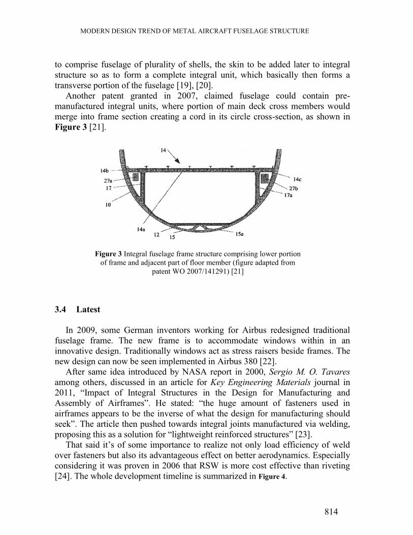
Another patent granted in 2007, claimed fuselage could contain pre-
manufactured integral units, where portion of main deck cross members would
merge into frame section creating a cord in its circle cross-section, as shown in
Figure 3 [21].
3.4 Latest
In 2009, some German inventors working for Airbus redesigned traditional
fuselage frame. The new frame is to accommodate windows within in an
innovative design. Traditionally windows act as stress raisers beside frames. The
new design can now be seen implemented in Airbus 380 [22].
After same idea introduced by NASA report in 2000, Sergio M. O. Tavares
among others, discussed in an article for Key Engineering Materials journal in
2011, “Impact of Integral Structures in the Design for Manufacturing and
Assembly of Airframes”. He stated: “the huge amount of fasteners used in
airframes appears to be the inverse of what the design for manufacturing should
seek”. The article then pushed towards integral joints manufactured via welding,
proposing this as a solution for “lightweight reinforced structures” [23].
That said it’s of some importance to realize not only load efficiency of weld
over fasteners but also its advantageous effect on better aerodynamics. Especially
considering it was proven in 2006 that RSW is more cost effective than riveting
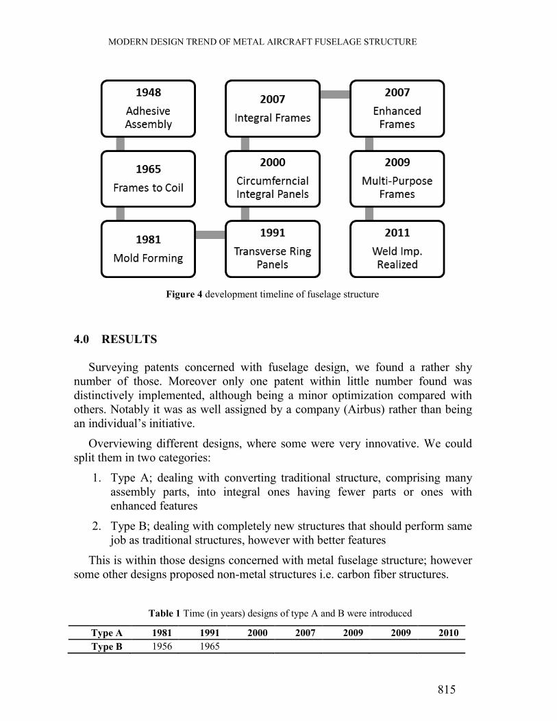
[24]. The whole development timeline is summarized in Figure 4.
Figure 3 Integral fuselage frame structure comprising lower portion
of frame and adjacent part of floor member (figure adapted from
patent WO 2007/141291) [21]
814
MODERN DESIGN TREND OF METAL AIRCRAFT FUSELAGE STRUCTURE
4.0 RESULTS
Surveying patents concerned with fuselage design, we found a rather shy
number of those. Moreover only one patent within little number found was
distinctively implemented, although being a minor optimization compared with
others. Notably it was as well assigned by a company (Airbus) rather than being
an individual’s initiative.
Overviewing different designs, where some were very innovative. We could
split them in two categories:
1. Type A; dealing with converting traditional structure, comprising many
assembly parts, into integral ones having fewer parts or ones with
enhanced features
2. Type B; dealing with completely new structures that should perform same
job as traditional structures, however with better features
This is within those designs concerned with metal fuselage structure; however
some other designs proposed non-metal structures i.e. carbon fiber structures.
Table 1 Time (in years) designs of type A and B were introduced
Type A 1981 1991 2000 2007 2009 2009 2010
Type B 1956 1965
Figure 4 development timeline of fuselage structure
815

MODERN DESIGN TREND OF METAL AIRCRAFT FUSELAGE STRUCTURE
From simple data presented in Table 1, we could see there have been tendency
and more concern towards improving current semi-monocoque structure (Type
A), in one way or another, rather than introducing a completely new better design
(Type B).
5.0 CONCLUSION
There is lack of interest to improve current structure or solve major issues for
good. Moreover recent patents are in fact more concerned with solving minor
issues and improving current semi-monocoque structure i.e. through integral
structures, rather than inventing a new structure altogether.
New designs or optimizations might have a real chance getting implemented
when being assigned by a company rather than being an individual initiative.
Designs introduced recently within patents along related articles and
researches concerned with metal aircraft fuselage development are pushing
forward: “Integral structures”, where fuselage would be formed out of few pre-
manufactured panels comprising all structural requirements. It is thus expected
future development would be more concerned with these new easier to assemble
integral structures, rather than sticking with fixing issues arising in old “piece by
piece” assembled structures.
ACKNOWLEDGMENTS
We would like to thank “Universiti Putra Malaysia” for providing facilities that
helped with this paper, specially having provided both military and civil aircrafts
in full form.
REFERENCES
[1] J. Cutler and J. Liber, "History, Semi-monocoque structures," in Understanding Aircraft Structures,
4th ed., Padstow, Cornwall: Blackwell, 2005, pp. 9-14.
[2] M. P. Hassan, M. R. A. S. and F. I. Romli, "Aircraft industry current phase," Unpublished results,
2012.
[3] B. P. and H. R. J., "Investigation of the Potential Impacts of the Entry of Very Light Jets in the
National Airspace System," MIT International Center for Air Transportation (ICAT), Cambridge,
Massachusetts 02139 USA, 2006.
[4] Very-Light-Jet.com, "Cessna Citation Mustang Reaches 400 Aircraft," 27 January 2012. [Online].
Available: http://www.very-light-jet.com/vlj-manufacturer-news/cessna-citation-mustang-reaches-400-
aircraft.html.
816
MODERN DESIGN TREND OF METAL AIRCRAFT FUSELAGE STRUCTURE
[5] S. Tsach, O. Rix and R. Bublitsky, "Innovative Approach For Future Aircraft Development At IAI," in
26th Congress of International Council of the Aeronautical Sciences, Alaska, 2008.
[6] K. YUSUF, N. Y., S. Z. DAWAL, D. CHANDRA and N. SOFIA, "Conceptual Design of Fuselage
Structure of Very Light Jet Aircraft," in HEAPFL'10 Proceedings of the 2010 international conference
on theoretical and applied mechanics, and 2010 international conference on Fluid mechanics and heat
& mass transfer, Stevens Point, Wisconsin, USA, 2010.
[7] P. Kadarno, S. Z. M. Dawal, T. Y. S. T. Ya, K. Yusuf, N. Yusoff and P. Edi, "Initial Design of Very
Light Jet with Unconventional Arrangement," in HEAPFL'10 Proceedings of the 2010 international
conference on theoretical and applied mechanics, and 2010 international conference on Fluid
mechanics and heat & mass transfer, Stevens Point, Wisconsin, USA, 2010.
[8] P. EDI, K. YUSUF, A. R. A. GHANI and H. S. S. ALJIBORI, "The Design of Light Jet Aircraft,"
WSEAS TRANSACTIONS on APPLIED and THEORETICAL MECHANICS, vol. 4, no. 2, pp. 85-94,
2009.
[9] E. Iuliano and D. Quagliarella, "Efficient Aerodynamic Optimization of a Very Light Jet Aircraft using
Evolutionary Algorithms and RANS flow models," in Evolutionary Computation (CEC), 2010 IEEE
Congress on, Capua, Italy, 2010.
[10] J. HINRICHSEN and C. BAUTISTA, "The Challenge of Reducing both Airframe Weight and
Manufacturing Cost," AIR & SPACE EUROPE, vol. 3, no. 3, pp. 119-121, 2001.
[11] B. Kolesnikov and L. Herbeck, "Carbon Fiber Composite Airplane Fuselage: Concept and Analysis,"
SECTION II. POSSIBLE WAYS OF RUSSIA-EUROPE COOPERATION, 2004.
[12] M. Pacchione and J. Telgkamp, "CHALLENGES OF THE METALLIC FUSELAGE," in 25TH
INTERNATIONAL CONGRESS OF THE AERONAUTICAL SCIENCES, Hamburg, Germany, 2006.
[13] R. H. Prewitt, "METHOD AND APPARATUS FOR FABRICATING AIRFRAMES". United States
of America Patent 2,762,419, 11 September 1956.
[14] C. O. Scott, "AIRCRAFT SAFETY BODY". United States of America Patent 3,337,164, 22 August
1967.
[15] J. A. Fouse and S. W. McClaren, "AIRFRAME ASSEMBLY AND PROCESS". United States of
America Patent 4,294,419, 13 October 1981.
[16] K. Hamamoto, K. Amaoka, N. Takizawa and M. Hosoi, "AIRCRAFT FUSELAGE STRUCTURE".
Japan Patent 5,170,967, 15 December 1992.
[17] Wikipedia, the free encyclopedia, "Shot peening," Wikimedia Foundation, Inc., 6 May 2012. [Online].
Available: http://en.wikipedia.org/wiki/Shot_peening. [Accessed 28 May 2012].
[18] J. Munroe, K. Wilkins and M. Gruber, "Validated Feasibility Study of Integrally Stiffened Metallic
Fuselage Panels for Reducing Manufacturing Costs," National Aeronautics and Space Administration,
Hampton, 2000.
[19] C. Haack, "AIRCRAFT FUSELAGE STRUCTURE AND METHOD FOR PRODUCING IT". United
States of America Patent US 2010/0181426 A1, 22 July 2010.
[20] C. Haack, "AIRCRAFT FUSELAGE STRUCTURE AND METHOD FOR ITS PRODUCTION".
United States of America Patent US 2009/0314891 A1, 24 December 2009.
[21] R. Thorsten and S. Thorsten, "AIRCRAFT FUSELAGE STRUCTURE AND METHOD FOR ITS
PRODUCTION". Germany Patent WO 2007/141291 A1, 13 December 2007.
[22] V. Dittmar, J. Rohde, R. Brunken and M. Lange, "FUSELAGE STRUCTURE FOR AIRCRAFT".
United States of America Patent US 2010/0320324 A1, 23 December 2010.
[23] S. M. O. Tavares and P. M. S. T. d. Castro, "Impact of Integral Structures in the Design for
Manufacturing and Assembly of Airframes," Key Engineering Materials, vol. 450, pp. 279-282, 2011.
[24] P. Briskham, N. Blundell, L. Han, R. Hewitt, K. Young and D. Boomer, "Comparison of Self-Pierce
Riveting, Resistance Spot Welding and Spot Friction Joining for Aluminium Automotive Sheet," in
SAE 2006 World Congress & Exhibition, Detroit, Michigan, 2006.
817