miltiadisa.boboulos manufacturingprocessesandmaterials: exercises
TRANSCRIPT
Miltiadis A. Boboulos
Manufacturing Processes and Materials:Exercises
Download free books at
Download free eBooks at bookboon.com
2
Miltiadis A. Boboulos
Manufacturing Processes and Materials: Exercises

Download free eBooks at bookboon.com
3
Manufacturing Processes and Materials: Exercises© 2010 Miltiadis A. Boboulos & Ventus Publishing ApSISBN 978-87-7681-695-7
Download free eBooks at bookboon.com
Click on the ad to read more
Manufacturing Processes and Materials: Exercises
4
Contents
Contents
Summary 6
Question 1: Non-conventional manufacturing processes 7
Question 2: The Electro-discharge Machining (EDM) process 14
Question 3: Factors causing tool wear 20
Question 4: Acceptance sampling 33
Question 5: Principles of the Resin Transfer Moulding (RTM) 45
Question 6: Fibre reinforced plastic composites 50
Question 7: A cutting test on a steel bar 55
Question 8: Electro-discharge machining (EDM) requirements & properties 58
Question 9: Hard and soft automation 62
Question 10: Surface integrity of manufactured surfaces: properties & applications 65
Question 11: Bored holes - plug and gap gauges 68
ENGINEERS, UNIVERSITY GRADUATES & SALESPROFESSIONALSJunior and experienced F/M
Total will hire 10,000 people in 2013. Why not you?
Are you looking for work in process, electrical or other types of engineering, R&D, sales & marketing or support professions such as information technology?
We’re interested in your skills.
Join an international leader in the oil, gas and chemical industry by applying at
www.careers.total.comMore than 600 job openings are now online!
Potential for development
Cop
yrig
ht :
Tota
l/Cor
bis
for development
Potential for exploration
Download free eBooks at bookboon.com
Click on the ad to read more
Manufacturing Processes and Materials: Exercises
5
Contents
Question 12: Integrated Manufacturing Systems: a facility of large and small machines 73
Question 13: Simulation method, determining the time to complete the batch and the machine utilisation 79
Question 14: Plain carbon steels and high strength low alloy steels (HSLA) 91
Question 15: Ferritic stainless steel & the mechanism of corrosion 97
Question 16: Impact Strength (J) to Test Temperature 102
Question 17: Metal and polymer material applicability 108
Question 18: Maximum tolerable through thickness crack size 112
Question 19: Glass fibres production - Reinforced composite design 117
References 122
Endnotes 124
EADS unites a leading aircraft manufacturer, the world’s largest helicopter supplier, a global leader in space programmes and a worldwide leader in global security solutions and systems to form Europe’s largest defence and aerospace group. More than 140,000 people work at Airbus, Astrium, Cassidian and Eurocopter, in 90 locations globally, to deliver some of the industry’s most exciting projects.
An EADS internship offers the chance to use your theoretical knowledge and apply it first-hand to real situations and assignments during your studies. Given a high level of responsibility, plenty of
learning and development opportunities, and all the support you need, you will tackle interesting challenges on state-of-the-art products.
We welcome more than 5,000 interns every year across disciplines ranging from engineering, IT, procurement and finance, to strategy, customer support, marketing and sales. Positions are available in France, Germany, Spain and the UK.
To find out more and apply, visit www.jobs.eads.com. You can also find out more on our EADS Careers Facebook page.
Internship opportunities
CHALLENGING PERSPECTIVES

Download free eBooks at bookboon.com
Manufacturing Processes and Materials: Exercises
6
Summary
Summary The edition addresses issues essential to modern manufacturing, ranging from traditional topics such as casting, forming, machining, and joining, to advanced topics such as the fabrication of nanomaterials. Comprehensive coverage of relevant engineering fundamentals, mathematical analysis, and traditional as well as advanced applications of manufacturing processes and operations. This material is written mainly for students in mechanical, industrial, and metallurgical and materials engineering programs. The text continually emphasizes the important interactions among a wide variety of technical disciplines and the economics of manufacturing operations. A solid introduction to the fundamentals of manufacturing along with the most up-to-date information. In order to make the concepts easier to understand, a variety of engineering materials are discussed as well as their properties and means of modifying them. Manufacturing processes and the concepts dealing with producing quality products are also covered.
Download free eBooks at bookboon.com
Manufacturing Processes and Materials: Exercises
7
Question 1: Non-conventional manufacturing processes
Question 1: Non-conventional manufacturing processes You are a Manufacturing Engineer employed by a toolmaking company whose main business is in sub-contract manufacture of a wide range of tools used in the injection moulding and forging industries. There is also a specialist division machining small batches of precision components for the aerospace industry. Component workpiece materials include most toolsteels, high duty alloys and a range of sintered materials, non-ferrous materials stainless steels and ceramics. The existing manufacturing facility include all the usual conventional machine tools including a number of stand alone CNC multi-tool machining centres. Your Managing Director, through his trade association and by glancing through technical journals is aware that competitors of the company are introducing non-conventional manufacturing processes to their facilities. You have been requested to submit a brief report covering the following issues:
a) What is meant by the term non-conventional manufacturing processes? [2 Marks]
b) What are the areas of application of such processes?
[8 Marks]
c) How do non-conventional processes compare with the companies existing process facilities in respect to: Feature capability, surface finish, surface integrity, material removal rate, tool wear, environmental issues and skill requirements.
[12 Marks]
d) What particular non-conventional process might be suitable for the companies current product portfolio?
[3 Marks]
Download free eBooks at bookboon.com
Manufacturing Processes and Materials: Exercises
8
Question 1: Non-conventional manufacturing processes
Question 1a Conventional and wide spread machining processes include: mechanical cutting operations, material removal techniques – chipping off, forging, casting, stamping, engraving. Additionally, conventional processes include turning, milling, drilling, grinding etc. mechanical operations. Back in the 1940s the needs of the defense industry, aviation and space industry, electronics and other industries necessitated machining techniques to be adopted for processing thin, fragile or special and very thin products that could not be manufactured using the conventional processes or this would have been rather impractical and costly. Therefore, a new group of “non-conventional” manufacturing processes emerged to provide improved, convenient and economically advantageous means for specific types of production. These were based on latest scientific and technical achievements and some new findings for using laws of nature relating to light – lasers, sound – ultrasonic processes, magnetism, atomic physics – plasma, electronics and new “powder” metallurgy materials.
Non-conventional processes include:
a) Chemical machining (CM) b) Electrochemical machining (ECM) c) Electrochemical grinding (ECG) d) Electrical discharge machining (EDM) e) Wire electrical discharge machining (WEDM) f) Laser-beam machining (LBM) g) Electron-beam machining (EBM) h) Water-jet machining (WJM) i) Abrasive water-jet machining (AWJM) j) Abrasive-jet machining (AJM) (using air, sand or beads)
Additionally, we could include here Ultrasonic machining (UM) and Deburring processes. Example: A typical non-conventional process is the machining of abrasive discs using diamond (adopted in 1955) or synthetic tools – cubic boron carbide (1970). In some applications these processes replaced almost completely the aluminium oxide processes (1893) and the green silicon carbide processes (1891). Other non-conventional processes include powder metallurgy processes used to produce hard-alloy cutting tools made of tungsten carbide, titanium carbide, cobalt carbide, etc.
Download free eBooks at bookboon.com
Manufacturing Processes and Materials: Exercises
9
Question 1: Non-conventional manufacturing processes
Question 1 b The areas of application of non-conventional manufacturing processes are as follows:
a) Chemical machining (CM): This is used for removing a layer of metal material, either shallow or deep, by means of etching using chemical compounds, like acids, bases, etc. This is a comparatively old process and it has several options: 1. chemical milling, 2. chemical blanking and 3. photo-chemical machining. Chemical milling is usually applied where larger quantities of material is to be removed from large plates or panels in the aircraft industry, space industry or cutting in depths of up to 12 mm. The process is used to make large aluminium alloy, etc. plates and sheet-metal parts lighter. Chemical blanking is used for manufacturing various scales, dials, rulers, etc. in the instrument-making industry and fine mechanical engineering industry as well as for manufacturing a variety of thin component parts in the mechanical engineering industry. The photo-chemical blanking is applied for manufacturing printed circuit boards for the electronic industry, electrical wiring, electronic chip sets and very thin component parts (depths of up to 0.0025 mm) for the aero-space industry, optics, microelectronics, instrument-making industry, printing industry, crafts – engraving metal or other material articles.
b) Electrochemical machining (ECM): This is based on “dissolving” ions of the processed material (metal) in the area around the tool, which is the electrode (-) of the DC source and the processed part is the (+), the ions thus being removed from the conductive electrolyte. This is used in wide machining applications for high-alloyed rigid steels and materials and also for manufacturing complex cutting shapes – turbine propellers, tools – stamps, moulds, dies. The technique is suitable for drilling small holes and cutting into hard materials
c) Electrochemical grinding (ECG): This process is a combination between ECM and a conventional grinding machine. The difference is in the electrical insulation provided in the machine spindle and grinding wheel and the use of an electrolyte instead of a coolant. The tool – the grinding wheel is the (-) of the electrical source and the part being machined is the (+). The technique is applied in machining carbide tools and alloy tools, carbide steel parts, etc. alloys featuring high strength characteristics. Used for grinding, milling and drilling small holes. Not suitable for manufacturing diesл
d) Electrical discharge machining (EDM): This is a widely applied and very useful method based
on the erosion of metals caused by the discharge occurring between the electrode and the processed part. The technique is applied for manufacturing tools and dies – for machining cavities and contour shaping and cutting. Used to cut and machine very hard and hardened conductor materials. Could find application in various machine engineering fields, etc. Also applied in automated processes involving CNC machining centers. Used to manufacture complex dies, for example for extrusion of aluminium component parts, etc.
e) Wire electrical discharge machining (WEDM): This is an optional EDM technique where the
electrode is a continuous wire, which is used to cut the metal material similar to a band saw. Used for contour cutting of flat or curved surfaces – Figure 1.
Download free eBooks at bookboon.com
Click on the ad to read more
Manufacturing Processes and Materials: Exercises
10
Question 1: Non-conventional manufacturing processes
The depth of the cutting plates is adjustable to up to 300mm. The tool (the wire) is usually made of copper, brass or tungsten and of outside diameter 0.25 mm. Another optional EDM technique is the electrical discharge grinding where a conventional internal grinding machine is used the grinding stone of which is a conductor material (brass, graphite) playing the role of the electrode and the part being machined is any conductor material. Mostly used for grinding hard carbide alloys of titanium, tungsten, cobalt and tool steels; for machining fragile and brittle small-size components, surgical tools, optical devices, electronic devices, etc.
f) Laser-beam machining (LBM) is used for similar applications to those stated above – cutting, drilling, marking and for surface machining and welding operations involving various materials: metals, ceramics, plastics, leather, textiles, composite materials (in the aircraft industry, etc.).
g) Electron-beam (plasma) machining (EBM) is used in similar applications to those described
for LBM but performed in a vacuum surrounding medium: precise cutting and welding of various materials.
h) Water-jet machining (WJM): This technique is used for dynamic cutting and machining
various materials: plastic, rubber, foodstuffs, paper, leather, insulation materials, composite materials of up to 25mm thickness. Finds application in the food industry and the production of plastics.
Maersk.com/Mitas
�e Graduate Programme for Engineers and Geoscientists
Month 16I was a construction
supervisor in the North Sea
advising and helping foremen
solve problems
I was a
hes
Real work International opportunities
�ree work placementsal Internationaor�ree wo
I wanted real responsibili� I joined MITAS because
www.discovermitas.com
Download free eBooks at bookboon.com
Manufacturing Processes and Materials: Exercises
11
Question 1: Non-conventional manufacturing processes
i) Abrasive water-jet machining (AWJM): for “shooting” under pressure and applying dynamic action to the surface of the machined component part. Used for the same applications and materials as those described for WJM.
j) Abrasive jet(gas) machining (AJM): Applied for machining small holes, cleaning surfaces
from removing sand or scale in foundry applications, stamped forgings and also for non-metal and fragile materials, as well as for deburring operations.
Question 1c As described in paragraph 1b above, machining operations feature similar or various spheres and sites of application. Non-conventional manufacturing processes are applied where conventional methods are not applicable, such as cutting and machining very hard, fragile, brittle or small-size component parts.
ii) Based on the particular characteristics of the process we can select the most suitable technique for each specific application. For example, cutting the internal cavity of an average-sized temperature treated high-hardness die is usually slow and expensive when using conventional machining techniques. A suitable non-conventional process for such an application is the EDM method. We select the suitable method based on the material hardness, brittleness, part size and material type. If we have to cut thick steel plates along an external contour that could be of a complicated shape the suitable method is the WEDM process. For drilling and welding various materials we select the LBM method and for drilling holes of outside diameter smaller than 0.1 – an operation which is almost impossible to perform using conventional techniques-the EDM or ECG process.
Machining rough or corroded (oxidized) external surfaces is best performed using the AJM manufacturing process.
iii) Quality comparison: Several quality characteristics are important here and these include surface roughness (Ra), dimensional tolerances, structure of the material in the cutting area. To examine these parameters we use data from tables, graphs, formulae and process studies.
For example, these include the Roughness (Ra)/ process type relation charts as shown in Figure 2 and the tolerance/process type relation chart, as well as the average and extreme repetition probabilities for their values.
iv) Comparison based on structure: Some manufacturing processes, like for example the LBM and EBM result in distortions of internal material structure in the cutting area, so other techniques are to be preferred when this is not desirable, such as CM or ECM, EDG and EDM.
Download free eBooks at bookboon.com
Manufacturing Processes and Materials: Exercises
12
Question 1: Non-conventional manufacturing processes
v) Process efficiency comparison (material removal rate comparison) (MRR): This is based on the data and formulae used to calculate the quantity of removed material (metal chips) per unit time of operation. For example, for EDM the material removal rate MRR = 4 x 44 ITw
–1.23
[mm3 / min]. This equation points out the major factors that influence the MRR rate – the current I (A) and electrode wear Tw. It is a known fact for this particular process that increasing the current I and reducing the discharge frequency (number of discharges per second) [Hz] will reduce process efficiency (material removal rate). For the ECG process the material removal rate MRR = CI/A0, where in this particular case C is a constant value which depends on the type of machined material (values for C are taken from tables – for Al C-2.0; for Cu C = 4.4, for Fe …) These expressions could be used to evaluate, compare and draw conclusions on the value of energy used in the process and hence, estimate process efficiency.
vi) Tool wear [R]. We will discuss this factor separately and as an integral part of the factors used to judge for the suitable manufacturing process. Here again we use available data and formulae to make calculations. Hence, for EDM R = 2.25 Tr
–2.3, where Tr = TW / TE; TW is the melting temperature of the material and TE is the melting temperature of the electrode (tool). Using copper, graphite or tungsten electrodes can extend tool life but would result in different tool cost. We can estimate tool consumption for a certain period based on tool wear and eventually estimate the efficiency of the selected process also considering the MRR rate.
vii) Environmental considerations: It is important to assess the environmental impact of the
process. Processes like EDM, which involve machining in a kerosene fluid, de-ionized water, etc. do not normally emit harmful substances into the atmosphere and are a preferred selection from an environmental viewpoint compared, for example, to laser-beam machining or other thermal metal cutting techniques.
The LBM method could be very dangerous to operators as it might cause radiation and harmful fumes. The AJM should by all means be used with protective clothing for operators or air-tight automated chambers. The process emits dust and flying “damaging” metal particles, etc. It is necessary that the machines in most of the described processes are equipped with the required air filters, settlement sedimentations and air conditioning systems.
viii) Personnel skills: To be able to compare and select the most suitable non-conventional process it is important to give consideration to the required personnel skills available in the company. Described machining processes generally require higher qualification and more costly labour. This is even more important when CNC-control machining centers are used. Some of the processes could also employ low-skilled operators but training cost and labour safety measures will be involved here.
Conclusion: A more precise and correct selection, assessment and comparison of the processes could be made using the table describing the general process characteristics – Appendix 1.
Download free eBooks at bookboon.com
Click on the ad to read more
Manufacturing Processes and Materials: Exercises
13
Question 1: Non-conventional manufacturing processes
Question 1d The current average-size toolmaking range of the company can preferably employ any conventional equipment and techniques used for this type of production along with the EDM, WEDM, AJM, ECG and ECM non-conventional manufacturing processes. The production of more complicated small-size component parts for the aerospace industry should preferably employ the EBM. LBM, EDM, ECM and EDG manufacturing processes. A precise estimate of process efficiency should be made when selecting the suitable type of process taking into account relatively expensive machines and equipment involved in the EDM, LBM, EBM, etc. processes.
“The perfect start of a successful, international career.”
CLICK HERE to discover why both socially
and academically the University
of Groningen is one of the best
places for a student to be www.rug.nl/feb/education
Excellent Economics and Business programmes at:
Download free eBooks at bookboon.com
Manufacturing Processes and Materials: Exercises
14
Question 2: The Electro-discharge Machining (EDM) process
Question 2: The Electro-discharge Machining (EDM) process
a) The Electro-discharge Machining (EDM) process is widely used m the toolmaking industry. In this context discuss the advantages and the disadvantages of the die sinking EDM process.
[14 marks]
b) With the aid of an annotated sketch illustrate a typical EDM single voltage pulse, indicating voltage levels and timescales. Explain why a characteristic pulse has this profile.
[6 marks]
c) (Explain the principles and features of the "orbital technique" as applied to the EDM process. [5 marks]
Question 2 a When applying the EDM manufacturing process the workpiece is machined either “sunk” into a specific fluid or not, the fluid which covers the workpiece in the cutting area being a dielectric. The method which involves die-sinking uses a work table specifically made airtight (a sinking bath where the fluid is provided). The type of fluid most widely used is kerosene (petrol), distilled water or deionized water. This arrangement of the application of the EDM manufacturing process provides for the electrical discharge between the tool [electrode (-)] and the cathode (+), which in fact is the machined workpiece, to take place in dielectric fluid medium. The method features the following advantages and disadvantages: 2a 1 Advantages:
1. The fact that the process takes place in a fluid medium improves the removal of metal chips from the cutting area and enhances cooling characteristics of the tool and workpiece.
2. Improved cooling and fast discharge resulting from switching off of the electrical impulse
(frequency between 50 and 500 KHz) improves the wear resistance of the electrode (tool) and improves surface integrity (Ra) of the machined surface.
3. Due to the electrical discharge the process eliminates almost completely the emission of
harmful gases into the atmosphere.
4. The process allows for “heavy” duty operation in higher frequency and current (A) values which results in increased process efficiency.

Download free eBooks at bookboon.com
Manufacturing Processes and Materials: Exercises
15
Question 2: The Electro-discharge Machining (EDM) process
2a 2 Disadvantages:
1. The presence of a work table, a bath tank, requires longer servicing time and impedes the process. When the workpiece is to be positioned onto the work table the tank has to be emptied of the contained fluid and the same happens when the machined part is to be removed from the work table.
2. Above requirements bring certain inconvenience during operation and involve higher energy consumption for filling in and pumping out the fluid from the tank. The machine itself becomes more complex in design and more expensive as it requires to be equipped with suitably designed units.
3. Removal of metal chips could in some cases be provided when machining blind holes such that chips are accumulated at the bottom of the vertical tool feed.
4. The presence of a large quantity of fluid, kerosene, in the machine in the operational area is a fire hazard. Special fire and explosion protection measures will be required for the machine and personnel.
5. When the WEDM method is to be applied for cutting operations the entire machine will be much more complicated requiring additional sealing for the wire (the electrode).
6. Applying the EDM method for turning lathes, grinding machines, etc. having horizontal work axis is not very easy as is the case for EDG (Electrical discharge grinding).
7. Applying the “orbital” processing technique is rather difficult.
8. The process provides poor visibility over the machined part for the operator to observe the process.
9. Item 8 above results in using mostly CNC control machines and equipment, which are in turn more complicated and expensive to use.
Download free eBooks at bookboon.com
Click on the ad to read more
Manufacturing Processes and Materials: Exercises
16
Question 2: The Electro-discharge Machining (EDM) process
Question 2b
1. Corona and spark discharge This type of discharge process occurs when a relatively high pressure is available and electrodes are featured by very high non-uniformity of the discharge area (gap). Ionization takes place only in a thin layer around the electrode characterized by a small radius of the curve. This is called an ionizing layer. In real practice these are “corona” cylindrical wires. When DC voltage is supplied, a negative (-) or positive (+) corona is available depending on the polarity of the corona electrode. As the voltage on the corona electrode increases, the corona undergoes arch discharge or spark discharge (when the source output power is insufficient to maintain stationary arch discharge – constant electrical arch.*
When a positive corona is applied spark discharge occurs at lower voltage (U) compared to negative corona. The temperature of the gas in the spark “channel” reaches 10000K. This allows for thermal ionization to occur. This phenomenon does not fall within the category of the theory of the “avalanche”- type of discharge and is explained by the theory of “streamers”. The first condition for the formation of “streamers” is the following:
(1) dpda
pE
10.19,2epa 2
1
38pd
pa
© Agilent Technologies, Inc. 2012 u.s. 1-800-829-4444 canada: 1-877-894-4414
Teach with the Best. Learn with the Best.Agilent offers a wide variety of affordable, industry-leading electronic test equipment as well as knowledge-rich, on-line resources —for professors and students.We have 100’s of comprehensive web-based teaching tools, lab experiments, application notes, brochures, DVDs/ CDs, posters, and more. See what Agilent can do for you.
www.agilent.com/find/EDUstudentswww.agilent.com/find/EDUeducators
Download free eBooks at bookboon.com
Manufacturing Processes and Materials: Exercises
17
Question 2: The Electro-discharge Machining (EDM) process
where a – coefficient of volumetric ionization [M-1]; p – gas pressure [Pa] d – distance between electrodes E3 – voltage in the area between electrodes [V/m]. From (1) we can conclude U3 = E3d (2), Where U3 is the voltage required for a spark to occur [V], and E3 is the voltage in the area between electrodes [V/m]. Thus calculated, the voltage U3 is exactly identical with experimental data measured at p.d > 250 [MPa]. The second condition for streamer formation is: (3) ni ≥ 7 . 1020 [ions/m3 ], where: ni is the concentration of ions in the avalanche head. The condition (3) refers to relatively short spark gaps (times) and is always met when (1) is met as well. Study case 1: Calculate drilling voltage between flat electrodes in air medium at p = 105 [Pa] (760mm mercury column) and T = 293K (20C):
- for d = 1 cm (0.01m) U3 = 31.35 [kV] - for d = 2 cm (0.02m) U3 = 58.10 [kV]
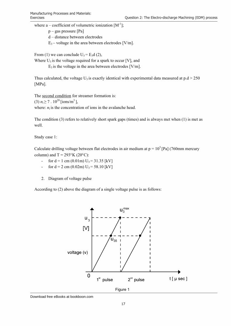
2. Diagram of voltage pulse
According to (2) above the diagram of a single voltage pulse is as follows:
Figure 1
Download free eBooks at bookboon.com
Manufacturing Processes and Materials: Exercises
18
Question 2: The Electro-discharge Machining (EDM) process
Where U35 is the voltage of spark occurrence (electrical discharge) U3
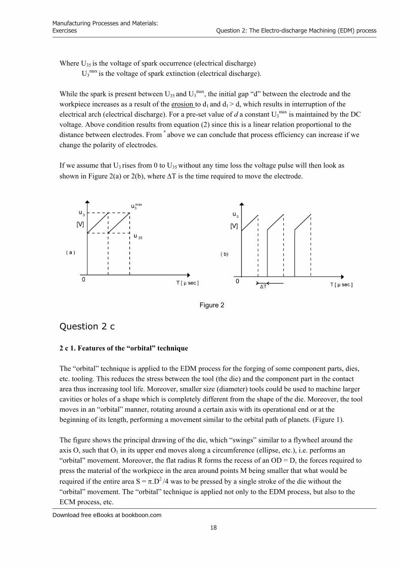
max is the voltage of spark extinction (electrical discharge). While the spark is present between U35 and U3
max, the initial gap “d” between the electrode and the workpiece increases as a result of the erosion to d1 and d1 > d, which results in interruption of the electrical arch (electrical discharge). For a pre-set value of d a constant U3
max is maintained by the DC voltage. Above condition results from equation (2) since this is a linear relation proportional to the distance between electrodes. From * above we can conclude that process efficiency can increase if we change the polarity of electrodes. If we assume that U3
rises from 0 to U35 without any time loss the voltage pulse will then look as shown in Figure 2(a) or 2(b), where T is the time required to move the electrode.
Figure 2
Question 2 c 2 c 1. Features of the “orbital” technique The “orbital” technique is applied to the EDM process for the forging of some component parts, dies, etc. tooling. This reduces the stress between the tool (the die) and the component part in the contact area thus increasing tool life. Moreover, smaller size (diameter) tools could be used to machine larger cavities or holes of a shape which is completely different from the shape of the die. Moreover, the tool moves in an “orbital” manner, rotating around a certain axis with its operational end or at the beginning of its length, performing a movement similar to the orbital path of planets. (Figure 1). The figure shows the principal drawing of the die, which “swings” similar to a flywheel around the axis O, such that O1 in its upper end moves along a circumference (ellipse, etc.), i.e. performs an “orbital” movement. Moreover, the flat radius R forms the recess of an OD = D, the forces required to press the material of the workpiece in the area around points M being smaller that what would be required if the entire area S = .D2 /4 was to be pressed by a single stroke of the die without the “orbital” movement. The “orbital” technique is applied not only to the EDM process, but also to the ECM process, etc.
Download free eBooks at bookboon.com
Manufacturing Processes and Materials: Exercises
19
Question 2: The Electro-discharge Machining (EDM) process
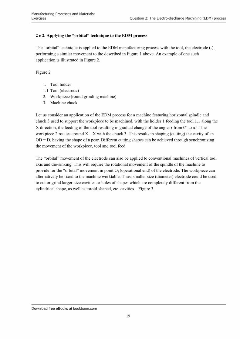
2 c 2. Applying the “orbital” technique to the EDM process
The “orbital” technique is applied to the EDM manufacturing process with the tool, the electrode (-), performing a similar movement to the described in Figure 1 above. An example of one such application is illustrated in Figure 2. Figure 2
1. Tool holder 1.1 Tool (electrode) 2. Workpiece (round grinding machine) 3. Machine chuck
Let us consider an application of the EDM process for a machine featuring horizontal spindle and chuck 3 used to support the workpiece to be machined, with the holder 1 feeding the tool 1.1 along the X direction, the feeding of the tool resulting in gradual change of the angle from 0 to . The workpiece 2 rotates around X – X with the chuck 3. This results in shaping (cutting) the cavity of an OD = D, having the shape of a pear. Different cutting shapes can be achieved through synchronizing the movement of the workpiece, tool and tool feed. The “orbital” movement of the electrode can also be applied to conventional machines of vertical tool axis and die-sinking. This will require the rotational movement of the spindle of the machine to provide for the “orbital” movement in point O1 (operational end) of the electrode. The workpiece can alternatively be fixed to the machine worktable. Thus, smaller size (diameter) electrode could be used to cut or grind larger-size cavities or holes of shapes which are completely different from the cylindrical shape, as well as toroid-shaped, etc. cavities – Figure 3.

Download free eBooks at bookboon.com
Click on the ad to read more
Manufacturing Processes and Materials: Exercises
20
Question 3: Factors causing tool wear
Question 3: Factors causing tool wear
a) In conventional metal cutting process tool wear is inevitable. Discuss the most significant factors that cause tool wear and explain why cutting tool failure is difficult to predict.
[8 marks]
b) Describe four different methods that might be used for the on-line monitoring of tool wear, indicating the possible problems associated with each method and justify the method that you consider to show the most promise.
[12 marks]
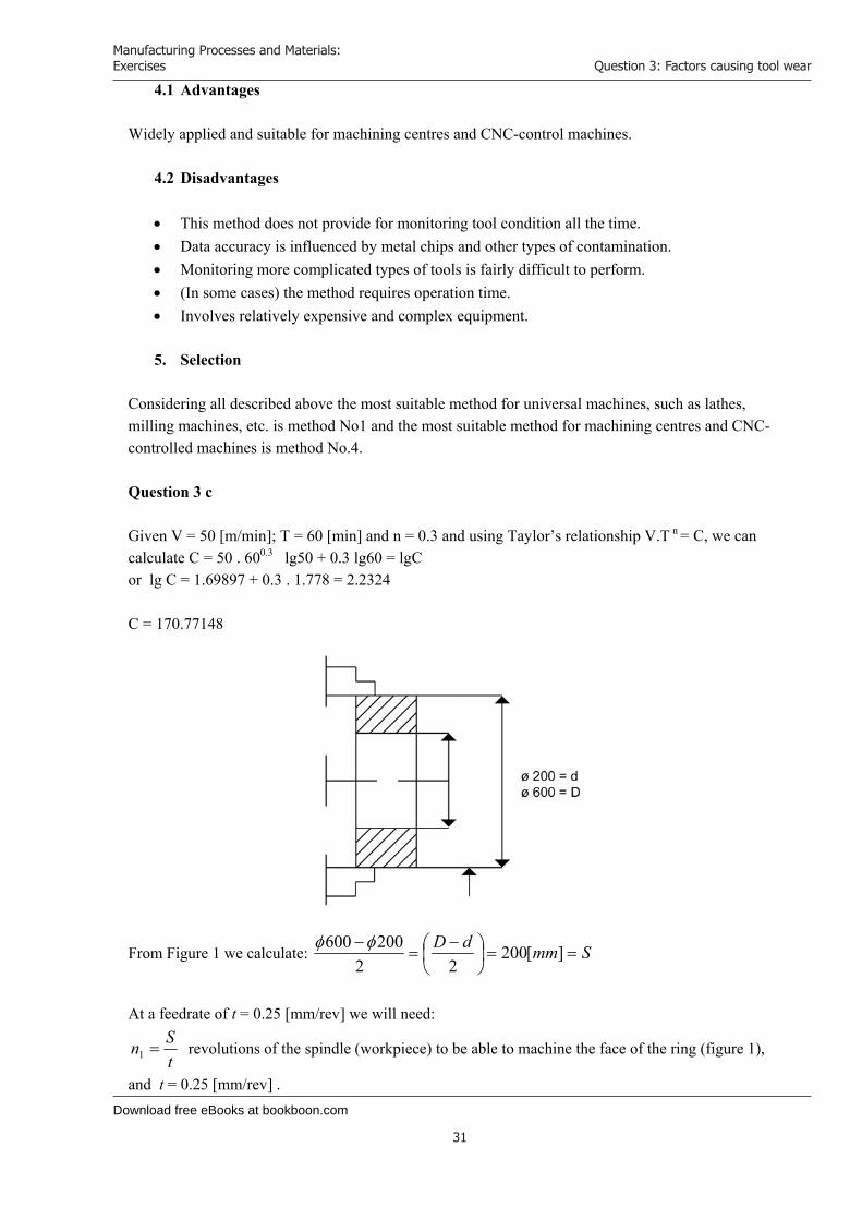
c) A steel ring outside diameter 600mm and an internal diameter of 200mm is being faced on a vertical CNC lathe. The machine is capable of maintaining a constant surface speed, as the face of the ring is being machined and the feedrate is set to 0.25 mm/rev. From tests when v = 50n/min Tool Life T is 60 mins n = 0.3. Given Taylor's empirical tool life relationship VT = C. Determine the number of components that can be machined per tool for a tool life of 50 mins.
[5 marks]
Get Help Now
Go to www.helpmyassignment.co.uk for more info
Need help with yourdissertation?Get in-depth feedback & advice from experts in your topic area. Find out what you can do to improvethe quality of your dissertation!
Download free eBooks at bookboon.com
Manufacturing Processes and Materials: Exercises
21
Question 3: Factors causing tool wear
Question 3a
1. Tool wear – causes and significant factors 1.1 Introduction
When processing metals using cutting tools, which is usually accompanied by chipping (sometimes no chipping is involved), tools wear and get damaged. Worn tools are usually re-sharpened for re-use or replaced when unrecoverably damaged. The causes for this phenomenon are various and result from the nature of the different machining processes involved (metal cutting, alloy cutting, cutting other types of material) and also from all other subjective factors involved and influencing the process. Processing, i.e. cutting conditions usually involve significant energy consumption, occurrence of substantial forces, vibrations, shocks and emission of heat. In this sense, cutting conditions are heavy processing conditions and therefore lead to faster tool wear or damage especially when hard, tough and high-strength materials are to be processed or when high-speed processing or fast-feed processing aimed at increasing production efficiency is involved.
1.2 Causes and significant factors Generally, causes for cutting tool wear or damage are cutting edge wear or the occurrence of obvious breaking out on cutting edges or internal cracking and stress. These are determined by the extent of applied pressure and slipping of metal chips as well as the nature of surface being machined. Included in the cumulative load is also the tool temperature in the area where the load is applied. Tool temperature usually rises due to the heat Q emitted during the processing (cutting) operation.
min/ccal427
V.PQ z (1)
where Q is the emitted heat; Pz is the shear force [dN] and V is the cutting speed [m/min]. Although cutting speed is an independent variable, the forces and temperatures generated are dependent variables and are functions of numerous parameters. Similarly, wear depends on tool and workpiece materials (their physical, mechanical and chemical properties, tool geometry, cutting fluid properties and various other operating parameters). The types of wear on a tool depends on the relative roles of these variables. Due to the complicated relations and numerous factors influencing tool wear, various experimental methods and data is usually used to define the type of wear.
Download free eBooks at bookboon.com
Manufacturing Processes and Materials: Exercises
22
Question 3: Factors causing tool wear
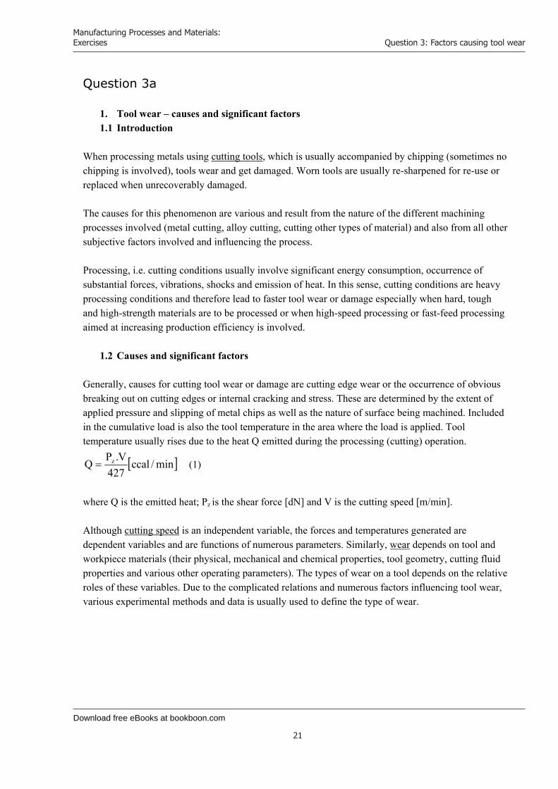
Let us consider, for example, tool wear on a conventional lathe knife – figure 1.
Key:
1. Front face 2. Rake face 3. Flank face 4. Cutting edge 5. Tool tip 6. Auxiliary cutting edge
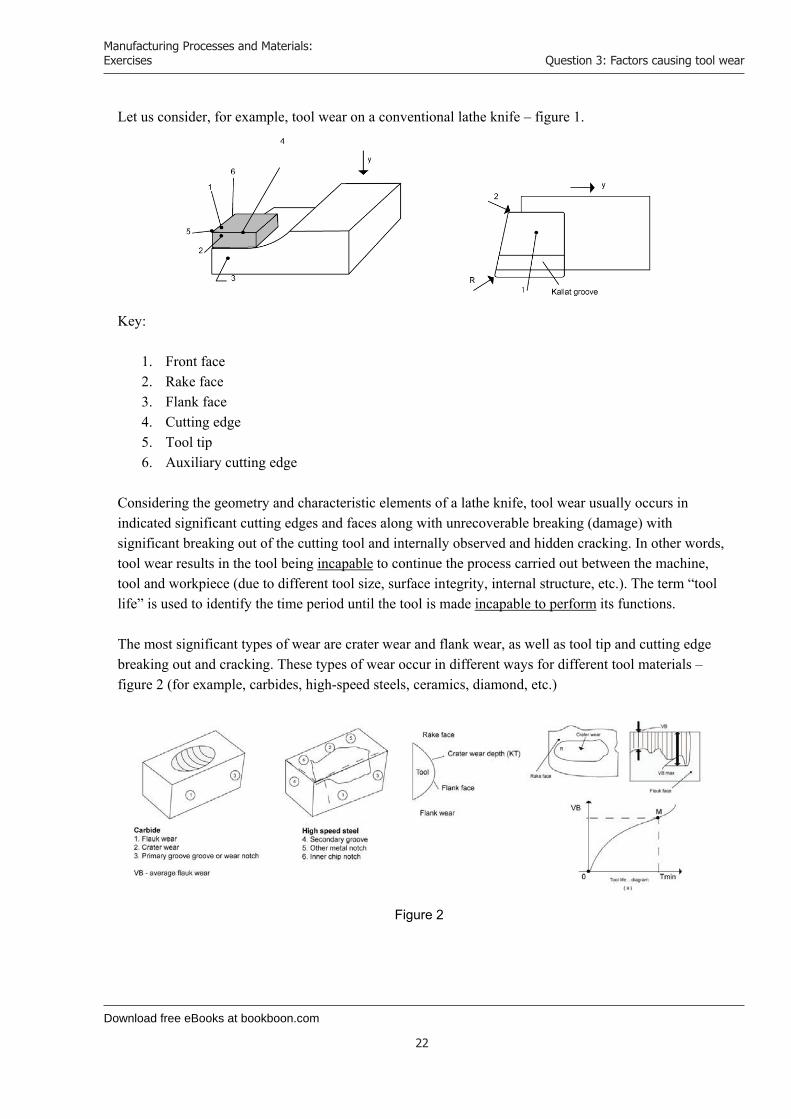
Considering the geometry and characteristic elements of a lathe knife, tool wear usually occurs in indicated significant cutting edges and faces along with unrecoverable breaking (damage) with significant breaking out of the cutting tool and internally observed and hidden cracking. In other words, tool wear results in the tool being incapable to continue the process carried out between the machine, tool and workpiece (due to different tool size, surface integrity, internal structure, etc.). The term “tool life” is used to identify the time period until the tool is made incapable to perform its functions. The most significant types of wear are crater wear and flank wear, as well as tool tip and cutting edge breaking out and cracking. These types of wear occur in different ways for different tool materials – figure 2 (for example, carbides, high-speed steels, ceramics, diamond, etc.)
Figure 2

Download free eBooks at bookboon.com
Click on the ad to read more
Manufacturing Processes and Materials: Exercises
23
Question 3: Factors causing tool wear
Key:
1. Flank wear 2. Crater wear 3. Primary groove or wear notch 4. Secondary groove 5. Other metal chip notch 6. Inner chip notch 7. VB – average flank wear.
Tool life is as illustrated in Figure 2: (a) – the tool is within the normal required process parameters between points O and M. Following point M, KT and VB have reached the allowable limit.
© U
BS
2010
. All
rig
hts
res
erve
d.
www.ubs.com/graduates
Looking for a career where your ideas could really make a difference? UBS’s
Graduate Programme and internships are a chance for you to experience
for yourself what it’s like to be part of a global team that rewards your input
and believes in succeeding together.
Wherever you are in your academic career, make your future a part of ours
by visiting www.ubs.com/graduates.
You’re full of energyand ideas. And that’s just what we are looking for.
Download free eBooks at bookboon.com
Manufacturing Processes and Materials: Exercises
24
Question 3: Factors causing tool wear
Wear usually refers to gradually increasing wear without any visible scratching and furrowing, and damage is usually referred to notching with breaking off of particles from cutting edges. The ratio of occurrence of the two types of wear in a particular type of processing operation depends on load conditions at the tool-workpiece interface. In ceramics, for example, plates and tools operating under vibration and used to machine fire-resistant and alloy steels usually break off along their cutting edges. Apart from normal tool wear (flank wear) there are a number of other factors that influence tool wear: insufficient tool strength characteristics and available internal cracks. When the applied pressure (as a result of Pz) exceeds the ultimate strength limit this results in sudden breaking off along the cutting edge. High speeds and temperatures cause diffusion - interpenetration and rubbing of tool-workpiece materials. Friction causes abrasive and adhesive wear. To summarize, the most significant factors include:
- Cutting conditions: speed, feed, cooling, geometry - Tool and workpiece materials (physical and mechanical properties, chemical composition,
inclusions, density, etc.) - The characteristics of the machine-tool-workpiece system (stability, output, etc.) - Other factors – operator, qualification, processing technology.
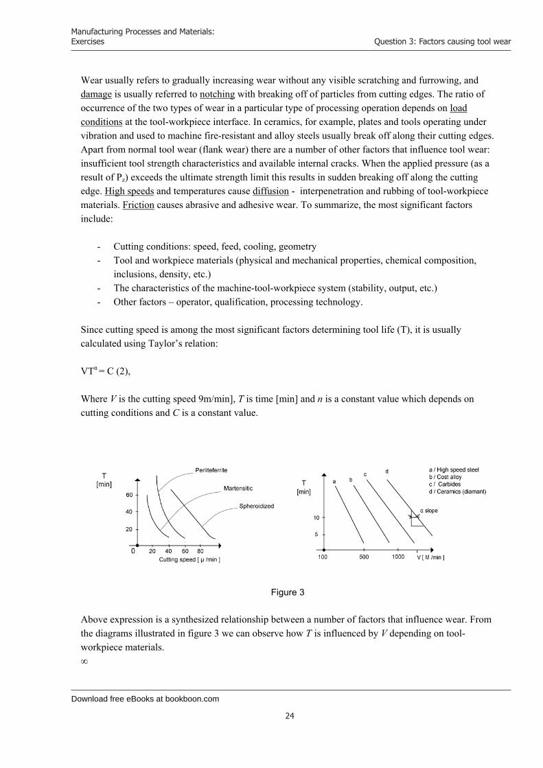
Since cutting speed is among the most significant factors determining tool life (T), it is usually calculated using Taylor’s relation: VTn = C (2), Where V is the cutting speed 9m/min], T is time [min] and n is a constant value which depends on cutting conditions and C is a constant value.
Figure 3 Above expression is a synthesized relationship between a number of factors that influence wear. From the diagrams illustrated in figure 3 we can observe how T is influenced by V depending on tool-workpiece materials. ∞
Download free eBooks at bookboon.com
Manufacturing Processes and Materials: Exercises
25
Question 3: Factors causing tool wear
Workpiece material Tool material
a) High-speed steel b) Cast alloy c) Carbides d) Ceramic (diamond)
- the slope angle: determines the value of “n” It is obvious here that tool life increases when the speed V is reduced and the hardness and toughness of the material being processed are reduced, too. If we apply the expression (2) we can calculate that under certain conditions (fixed n and C), tool life T increases by 300% when V[m/min] is reduced by only 50%. It is a proven fact that for a constant tool life to be maintained, the speed is reduced when the feed f and the depth d are increased and vice versa.
1.3 Difficulties in forecasting (predicting) tool wear All explained above makes it clear why it is so hard and sometimes even impossible to give precise forecast for tool life. It is not always possible to predict the influence that numerous factors and their combinations may have. If we take, for example, the expression for Pz(shear force) given above
hjrmpzYX
pzz kkkkkHBStCP pzpz ..... (3)
where the following parameters are included: feed, cutting depth, hardness and a number of experimentally determined coefficients … up to kh, thus illustrating the complexity of the problem. If we assume that the main factor influencing tool life “T” is the applied load expressed by the applied forces, temperature (heat), shocks, vibrations, then the applied load is in turn influenced by:
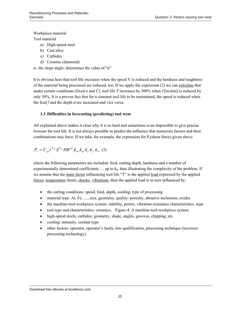
the cutting conditions: speed, feed, depth, cooling, type of processing material type: Al, Fe….., size, geometry, quality: porosity, abrasive inclusions, oxides the machine-tool-workpiece system: stability, power, vibration resistance characteristics, type tool type and characteristics: ceramics, Figure 4: A machine-tool-workpiece system high-speed steels, carbides; geometry, shape, angles, grooves, chipping, etc. cooling: intensity, coolant type other factors: operator, operator’s faults, low qualification, processing technique (incorrect
processing technology).

Download free eBooks at bookboon.com
Click on the ad to read more
Manufacturing Processes and Materials: Exercises
26
Question 3: Factors causing tool wear
Figure 4: A machine-tool-workpiece system When cutting long workpieces the change in the angle on the tool holder can sometimes cause unexpected vibrations, tool wear or breaking off due to operator’s fault (poor qualification). The complexity of the problem can also be demonstrated using the expression for T = C7 V7 d-1 f-4.
Download free eBooks at bookboon.com
Manufacturing Processes and Materials: Exercises
27
Question 3: Factors causing tool wear
Question 3 b Monitoring the condition of tools throughout various machining processes is very important for any production process and has significant influence on process efficiency. This is usually performed in two ways: a) Directly and b) Indirectly
a) The direct method involves visual observation by the operator for any signs of wear, wear hardening (getting dull) or breaking off. It usually requires the operator to stop the machine to dismantle and replace the worn tool. This method of monitoring tool condition involves visual observation or examining under special microscope for some out-of-service adjustment.
b) The indirect method uses indirect information to monitor the condition of the tool: noise, vibrations, size of machined workpiece, shear forces, surface roughness, etc. This is a relatively new method, convenient for CNC machines and is used to assess the condition of the tool “on-line” within the process.
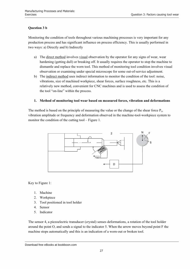
1. Method of monitoring tool wear based on measured forces, vibration and deformations
The method is based on the principle of measuring the value or the change of the shear force Pz, vibration amplitude or frequency and deformation observed in the machine-tool-workpiece system to monitor the condition of the cutting tool – Figure 1.
Key to Figure 1:
1. Machine 2. Workpiece 3. Tool positioned in tool holder 4. Sensor 5. Indicator
The sensor 4, a piezoelectric transducer (crystal) senses deformations, a rotation of the tool holder around the point O, and sends a signal to the indicator 5. When the arrow moves beyond point F the machine stops automatically and this is an indication of a worn-out or broken tool.
Download free eBooks at bookboon.com
Manufacturing Processes and Materials: Exercises
28
Question 3: Factors causing tool wear
1.2 Advantages This is a convenient and easily applicable method. The sensor 4 can be mounted on the tool holder or on a number of other locations or assemblies: the spindle, tailstock, lathe bed, etc. In these positions we can measure the value of torsion, deflection, etc. resulting from cutting forces and momentums.
1.3 Disadvantages Requires additionally rather complex electrical equipment to be installed and it is not always convenient to mount since it requires additional space on the machine and additional electrical connections. This is rather inconvenient for moving operational parts of the machine, such as the carriage, tailstock, etc.
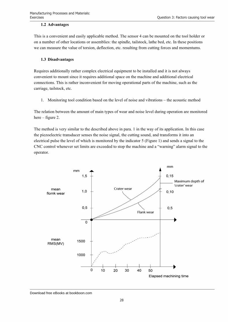
1. Monitoring tool condition based on the level of noise and vibrations – the acoustic method The relation between the amount of main types of wear and noise level during operation are monitored here – figure 2. The method is very similar to the described above in para. 1 in the way of its application. In this case the piezoelectric transducer senses the noise signal, the cutting sound, and transforms it into an electrical pulse the level of which is monitored by the indicator 5 (Figure 1) and sends a signal to the CNC control whenever set limits are exceeded to stop the machine and a “warning” alarm signal to the operator.
Download free eBooks at bookboon.com
Click on the ad to read more
Manufacturing Processes and Materials: Exercises
29
Question 3: Factors causing tool wear
2.1 Advantages The monitoring device and the equipment it involves can be positioned outside the machine, far from moving machine parts.
2.2 Disadvantages
Here, again special equipment and hardware is required to connect the device to the CNC control.
Not all materials and cutting conditions allow for monitoring wear based on noise level.
www.sylvania.com
We do not reinvent the wheel we reinvent light.Fascinating lighting offers an infinite spectrum of possibilities: Innovative technologies and new markets provide both opportunities and challenges. An environment in which your expertise is in high demand. Enjoy the supportive working atmosphere within our global group and benefit from international career paths. Implement sustainable ideas in close cooperation with other specialists and contribute to influencing our future. Come and join us in reinventing light every day.
Light is OSRAM
Download free eBooks at bookboon.com
Manufacturing Processes and Materials: Exercises
30
Question 3: Factors causing tool wear
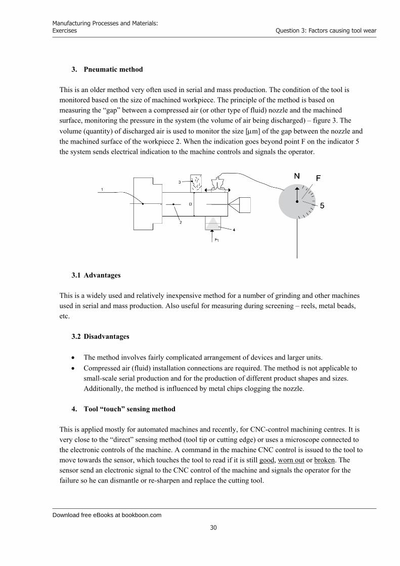
3. Pneumatic method
This is an older method very often used in serial and mass production. The condition of the tool is monitored based on the size of machined workpiece. The principle of the method is based on measuring the “gap” between a compressed air (or other type of fluid) nozzle and the machined surface, monitoring the pressure in the system (the volume of air being discharged) – figure 3. The volume (quantity) of discharged air is used to monitor the size [m] of the gap between the nozzle and the machined surface of the workpiece 2. When the indication goes beyond point F on the indicator 5 the system sends electrical indication to the machine controls and signals the operator.
3.1 Advantages This is a widely used and relatively inexpensive method for a number of grinding and other machines used in serial and mass production. Also useful for measuring during screening – reels, metal beads, etc.
3.2 Disadvantages
The method involves fairly complicated arrangement of devices and larger units. Compressed air (fluid) installation connections are required. The method is not applicable to
small-scale serial production and for the production of different product shapes and sizes. Additionally, the method is influenced by metal chips clogging the nozzle.
4. Tool “touch” sensing method
This is applied mostly for automated machines and recently, for CNC-control machining centres. It is very close to the “direct” sensing method (tool tip or cutting edge) or uses a microscope connected to the electronic controls of the machine. A command in the machine CNC control is issued to the tool to move towards the sensor, which touches the tool to read if it is still good, worn out or broken. The sensor send an electronic signal to the CNC control of the machine and signals the operator for the failure so he can dismantle or re-sharpen and replace the cutting tool.
Download free eBooks at bookboon.com
Manufacturing Processes and Materials: Exercises
31
Question 3: Factors causing tool wear
4.1 Advantages Widely applied and suitable for machining centres and CNC-control machines.
4.2 Disadvantages
This method does not provide for monitoring tool condition all the time. Data accuracy is influenced by metal chips and other types of contamination. Monitoring more complicated types of tools is fairly difficult to perform. (In some cases) the method requires operation time. Involves relatively expensive and complex equipment.
5. Selection
Considering all described above the most suitable method for universal machines, such as lathes, milling machines, etc. is method No1 and the most suitable method for machining centres and CNC-controlled machines is method No.4. Question 3 c Given V = 50 [m/min]; T = 60 [min] and n = 0.3 and using Taylor’s relationship V.T n = C, we can calculate C = 50 . 600.3 lg50 + 0.3 lg60 = lgC or lg C = 1.69897 + 0.3 . 1.778 = 2.2324 C = 170.77148
From Figure 1 we calculate: SmmdD
][200
22200600
At a feedrate of t = 0.25 [mm/rev] we will need:
tSn 1 revolutions of the spindle (workpiece) to be able to machine the face of the ring (figure 1),
and t = 0.25 [mm/rev] .
Download free eBooks at bookboon.com
Click on the ad to read more
Manufacturing Processes and Materials: Exercises
32
Question 3: Factors causing tool wear
80025.0
2001 n [rev].
Since according to the initial assignment the cutting speed is constant Vc = const., then from Taylor’s V.T n = C and for T = 50 [min] we w+ill have: V . 500.3 = 170.77148 V = 52.81 [m/min] The path of the tool between 600mm and 200 mm is:
][8.1004800).200600(14.3
)(
...
11
11
m
ndDS
dnDSd
Dd
The time T1 required for a single workpiece to be machined by the tool is:
min0266.1981.52
8.100411
VST
The number of components that can be machined is
62.202.19
50
1
TTN components.
www.mastersopenday.nl
Visit us and find out why we are the best!Master’s Open Day: 22 February 2014
Join the best atthe Maastricht UniversitySchool of Business andEconomics!
Top master’s programmes• 33rdplaceFinancialTimesworldwideranking:MScInternationalBusiness
• 1stplace:MScInternationalBusiness• 1stplace:MScFinancialEconomics• 2ndplace:MScManagementofLearning• 2ndplace:MScEconomics• 2ndplace:MScEconometricsandOperationsResearch• 2ndplace:MScGlobalSupplyChainManagementandChange
Sources: Keuzegids Master ranking 2013; Elsevier ‘Beste Studies’ ranking 2012; Financial Times Global Masters in Management ranking 2012
MaastrichtUniversity is
the best specialistuniversity in the
Netherlands(Elsevier)
Download free eBooks at bookboon.com
Manufacturing Processes and Materials: Exercises
33
Question 4: Acceptance sampling
Question 4: Acceptance sampling 4a Acceptance sampling is often viewed to be at odds with a TQM (Total Quality Management) philosophy. Why is acceptance sampling still in use by many companies and how might it conflict with the goals of a “world class” operation?
1. Introduction Lot-by-lot acceptance sampling by attributes is the most common type of sampling. With this type of sampling a predetermined number of units (samples) from each lot is inspected by attributes. If the amount defective is less than the prescribed minimum, the lot is accepted, if not, it is rejected as being below standard. Each lot in the shipment or order is sampled and either rejected or accepted. Acceptance sampling can be used either for the amount defective or for defects per unit. Sampling plans are established for each class of defect severity (critical, major, minor) or on a demerit-per-unit basis. A single sampling plan is defined by the lot size N, the sample size n and the acceptance number c. (Example: N = 5000, n = 250, c = 20. 20 in 250 are defectives). Acceptance sampling can be performed in a number of different situations where there is a consumer-producer relationship.
2. Why is Acceptance Sampling (AS) widely used by manufacturing companies and other organizations?
The basic and most significant reason is the fact that the method can be applied in a variety of situations related to quality management, complying with contractual terms, preventing unexpected situations, etc. Moreover, it delivers results or conclusions of sufficient accuracy for a wide variety of purposes. The method is applied in situations where: * The inspection results in damage or destruction to the product. If instead of this method (AS) a 100% inspection is applied, this will destroy the entire amount of finished produce. Example: Inspection of batches of ammunitions (cartridges, shells, etc.) or melting electrical fuses (for 10A)[J].
Since 100% inspection of products would involve additional cost this would add to the cost of the final products (quality control inspections are included in the cost of the product).
When a large variety of similar products have to be inspected (a wide product range based on a single type of product or principle) sampling will produce as good, if not better results than 100% inspection. Such mass inspections cause fatigue to quality control personnel due to the monotonous work which might in turn result in more errors than the average accepted percentage when using the Sampling acceptance method.
When the x and R and p indicators are not provided in the information relating to quality – no diagrams are available (Paretto chart, etc.)
When no automated means of control are provided and products are inspected manually or visually.
Download free eBooks at bookboon.com
Manufacturing Processes and Materials: Exercises
34
Question 4: Acceptance sampling
Besides all said above, the AS method has the following additional advantages compared to 100% inspection:
1. It is less costly owing to fewer inspections 2. Less handling damage during inspection 3. Fewer inspectors are involved, thereby simplifying recruiting, training and supervising. 4. Upgrading the inspection job from monotonous piece-by-piece decisions to lot-by-lot
decisions. 5. Rejection of entire lots, rather than the return of defectives, thereby providing stronger
motivation for improvement.
3. How might Acceptance sampling conflict with the goals of “World-class” operations. Besides all listed in para 2 above preferences and advantages in adopting the acceptance sampling method in practice for many companies and organizations (industry, trade, transport, etc.), the method also features several disadvantages. These might, in particular situations, make it unsuitable or completely unfit to use. Inherent disadvantages of AS are:
There are certain risks of accepting defective lots and rejecting good lots. More time and effort is devoted to planning and documentation. Less information is usually provided about the product
If we consider, for example some specialized and high-tech manufacturing processes, space and aviation, aerospace industry, microelectronics and all applications where requirements and responsibilities for defective components and products are much higher, AS is not an applicable method. In such applications very strict 100% inspection is usually performed on each individual component, parameter or event. For an aircraft engine, for example, the quality of component parts, parameters, assembly and functioning must be checked more than a single time. In some cases, multiple inspections and tests have to be carried out to prove the required quality and fitness for the purpose. Also, in the production of bearings, the production of balls, rollers, bearing rings involves 100% automated control and ranking in size and class. The same inspection is also involved in the production of a number of elements for the electronics – integrated circuit boards, chips, standard electronic component, etc.
In developing sampling plans and Operating characteristics (OC) it is possible that in some cases characteristics and diagrams do not provide a clear idea and satisfactory results when errors have occurred in specific indicators, such as lot size N, n, c, etc.
In view of all described above we should exercise great care when adopting the Acceptance sampling method for inspecting (and forecasting) the quality of production, transportation, services, trade and many other fields of application keeping in mind the allowable requirements and acceptable risk of losses and consequences. AS might in some cases lead to conflicts between manufacturers (suppliers) and users (customers). The producer is usually looking for lower possible rejection of manufactured products even when there is a high percentage of defective products in individual lots and the buyer (customer) has the opposite interest – higher possibility for not having defective goods above the agreed percentage and even have reduced percentage of defectives.

Download free eBooks at bookboon.com
Click on the ad to read more
Manufacturing Processes and Materials: Exercises
35
Question 4: Acceptance sampling
Question 4b The ACME packing company produces plastic bottles for the Kooler company, a soft drink manufacturer. Kooler have specified an acceptable quality level (AQL) of 1% and a tolerance proportion defective (LTPD) of 6%. If a batch (5000 bottles) is rejected then all the bottles in the batch are scrapped and consequently the producer’s risk () be no more than 2%. In this case the consumers’ risk () has been specified as 4%.
(i) Design a sampling plan for the above conditions by determination of the required sample size and the acceptable maximum number of defectives in each batch.
Designed for high-achieving graduates across all disciplines, London Business School’s Masters in Management provides specific and tangible foundations for a successful career in business.
This 12-month, full-time programme is a business qualification with impact. In 2010, our MiM employment rate was 95% within 3 months of graduation*; the majority of graduates choosing to work in consulting or financial services.
As well as a renowned qualification from a world-class business school, you also gain access to the School’s network of more than 34,000 global alumni – a community that offers support and opportunities throughout your career.
For more information visit www.london.edu/mm, email [email protected] or give us a call on +44 (0)20 7000 7573.
Masters in Management
The next step for top-performing graduates
* Figures taken from London Business School’s Masters in Management 2010 employment report
Download free eBooks at bookboon.com
Manufacturing Processes and Materials: Exercises
36
Question 4: Acceptance sampling
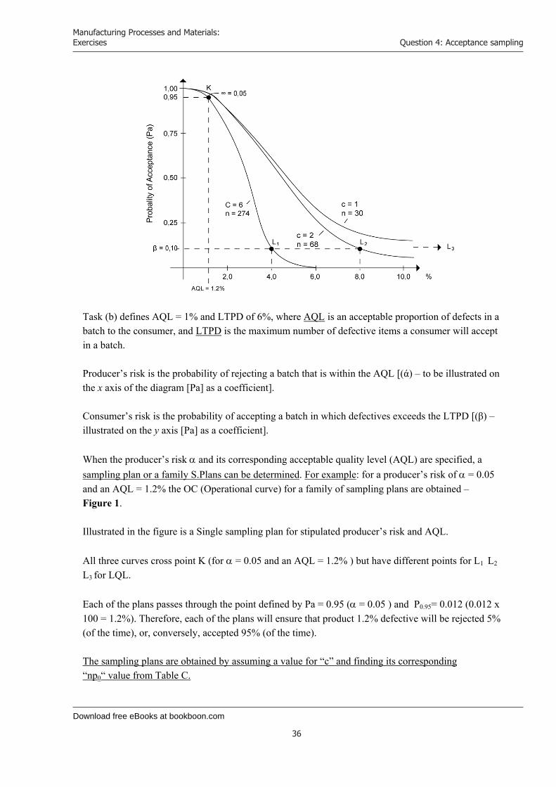
Task (b) defines AQL = 1% and LTPD of 6%, where AQL is an acceptable proportion of defects in a batch to the consumer, and LTPD is the maximum number of defective items a consumer will accept in a batch. Producer’s risk is the probability of rejecting a batch that is within the AQL [(ά) – to be illustrated on the x axis of the diagram [Pa] as a coefficient]. Consumer’s risk is the probability of accepting a batch in which defectives exceeds the LTPD [(β) – illustrated on the y axis [Pa] as a coefficient]. When the producer’s risk and its corresponding acceptable quality level (AQL) are specified, a sampling plan or a family S.Plans can be determined. For example: for a producer’s risk of = 0.05 and an AQL = 1.2% the OC (Operational curve) for a family of sampling plans are obtained – Figure 1. Illustrated in the figure is a Single sampling plan for stipulated producer’s risk and AQL. All three curves cross point K (for = 0.05 and an AQL = 1.2% ) but have different points for L1 L2 L3 for LQL. Each of the plans passes through the point defined by Pa = 0.95 ( = 0.05 ) and P0.95= 0.012 (0.012 x 100 = 1.2%). Therefore, each of the plans will ensure that product 1.2% defective will be rejected 5% (of the time), or, conversely, accepted 95% (of the time). The sampling plans are obtained by assuming a value for “c” and finding its corresponding “np0“ value from Table C.
Download free eBooks at bookboon.com
Manufacturing Processes and Materials: Exercises
37
Question 4: Acceptance sampling
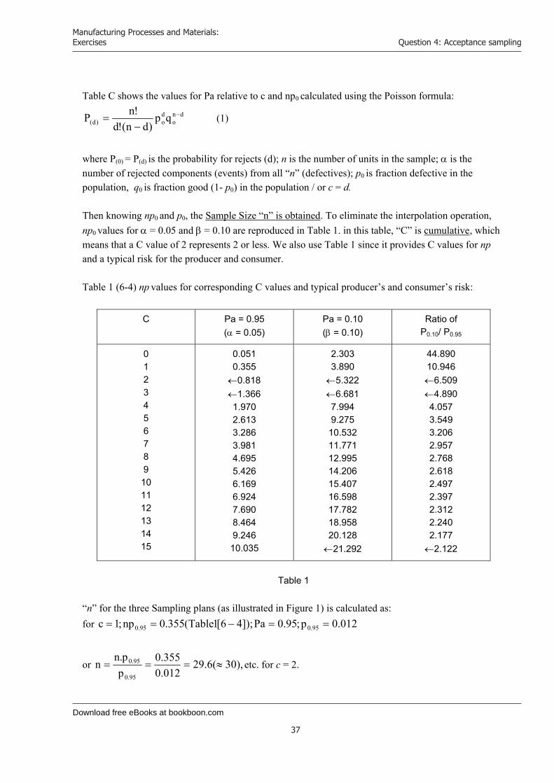
Table C shows the values for Pa relative to c and np0 calculated using the Poisson formula:
dno
do)d( qp
)dn(!d!nP
(1)
where P(0) = P(d) is the probability for rejects (d); n is the number of units in the sample; is the number of rejected components (events) from all “n” (defectives); p0 is fraction defective in the population, q0 is fraction good (1- p0) in the population / or c = d. Then knowing np0 and p0, the Sample Size “n” is obtained. To eliminate the interpolation operation, np0 values for = 0.05 and = 0.10 are reproduced in Table 1. in this table, “C” is cumulative, which means that a C value of 2 represents 2 or less. We also use Table 1 since it provides C values for np
and a typical risk for the producer and consumer. Table 1 (6-4) np values for corresponding C values and typical producer’s and consumer’s risk:
C Pa = 0.95 ( = 0.05)
Pa = 0.10 ( = 0.10)
Ratio of P0.10/ P0.95
012345678910 11 12 13 14 15
0.051 0.355 0.818 1.366 1.970 2.613 3.286 3.981 4.695 5.426 6.169 6.924 7.690 8.464 9.246 10.035
2.303 3.890 5.322 6.681 7.994 9.275 10.532 11.771 12.995 14.206 15.407 16.598 17.782 18.958 20.128 21.292
44.890 10.946 6.509 4.890 4.057 3.549 3.206 2.957 2.768 2.618 2.497 2.397 2.312 2.240 2.177 2.122
Table 1
“n” for the three Sampling plans (as illustrated in Figure 1) is calculated as: for 012.0p;95.0Pa]);46[1Table(355.0np;1c 95.095.0
or ),30(6.29012.0355.0
pp.n
n95.0
95.0 etc. for c = 2.
Download free eBooks at bookboon.com
Click on the ad to read more
Manufacturing Processes and Materials: Exercises
38
Question 4: Acceptance sampling
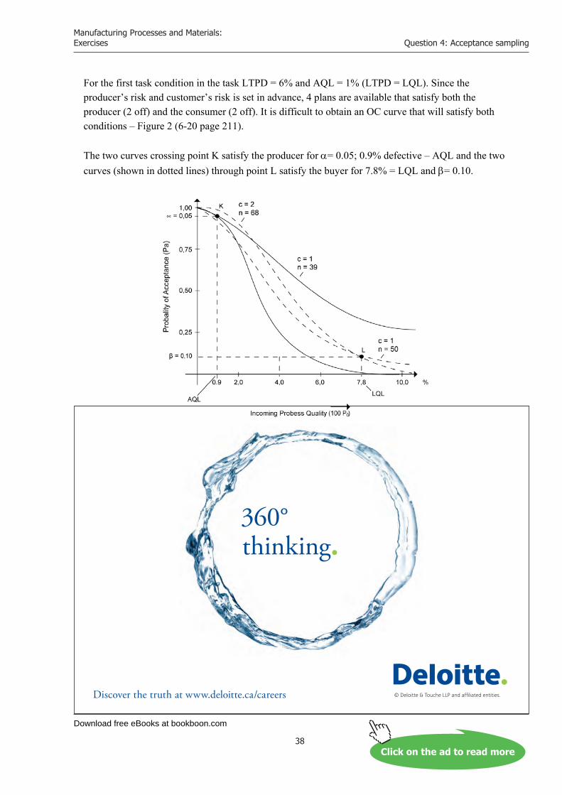
For the first task condition in the task LTPD = 6% and AQL = 1% (LTPD = LQL). Since the producer’s risk and customer’s risk is set in advance, 4 plans are available that satisfy both the producer (2 off) and the consumer (2 off). It is difficult to obtain an OC curve that will satisfy both conditions – Figure 2 (6-20 page 211). The two curves crossing point K satisfy the producer for = 0.05; 0.9% defective – AQL and the two curves (shown in dotted lines) through point L satisfy the buyer for 7.8% = LQL and = 0.10.
© Deloitte & Touche LLP and affiliated entities.
360°thinking.
Discover the truth at www.deloitte.ca/careers
© Deloitte & Touche LLP and affiliated entities.
360°thinking.
Discover the truth at www.deloitte.ca/careers
© Deloitte & Touche LLP and affiliated entities.
360°thinking.
Discover the truth at www.deloitte.ca/careers © Deloitte & Touche LLP and affiliated entities.
360°thinking.
Discover the truth at www.deloitte.ca/careers
Download free eBooks at bookboon.com
Manufacturing Processes and Materials: Exercises
39
Question 4: Acceptance sampling
Since we are interested in satisfying the interests of both the producer and customer, we use the following expressions:
00.601.006.0
AQL)LTPD(LQL
PP
95.0
10.0 (2)
From Table 1 (6-4), which is recommended for use as (AQL) varies between 0.01 and 0.10 (0.15), which is sufficient in most cases, we select
509.6)Ratio(PP
95.0
10.0
which corresponds to c = 2 (closer to c = 2) but is between: 4.890 and 6.509, or 4.890 < 6.00 < 6.509, where 4.890 is for c = 3. We can now make up 2 x 2 plans OC for the producer using c = 2 and 3 and for the consumer, with c = 2, 3.
- We now calculate “n” for every c(2,3): (n = sample size): a) for the producer:
For c = 2 95.0
95.0
pnp
n (3)
p0.95 = 0.01 (1%) n p0.95 = 0.818 (para 6-4)
Plans that exactly meet the producer’s stipulation of AQL = 1% (for = 0.05)
From (3) ]pcs[828.8101.0
818.0n 2
For c = 3 ]pcs[1376.13601.0
366.1n 3
n p0.95 = 1.366 [from para 6-4] N = 5000; n2 = 82; c = 2; N = 5000; n3 = 137; c = 3
Plans that exactly meet the consumer’s stipulation of LTPD = 6% ( for = 0.10):
For c = 2 10.0
10.0
pnp
n (4)
np0.10 = 5.322 (for c = 2) n p0.10 = 6.681 (for c = 3) [from table 1(6-4)]
From (4) ]pcs[897.8806.0
322.5n 2
p0.10 = 0.06 (according to the initial requirement)
Download free eBooks at bookboon.com
Manufacturing Processes and Materials: Exercises
40
Question 4: Acceptance sampling
For c = 3 ]pcs[1113.11106.0681.6n 2
N = 5000; n2 = 89; c = 2; N = 5000; n3 = 111; c = 3
For the second task: () AQL 2%; () LTDP 4%; Similar to above we can calculate:
From (2) 00.2)02.004.0:or(
24
AQLLTPD
From Table 1 (6-4) we calculate 2.122 > 2.00 > …; c = 15 For c = 15 … for the producer:
95.0
95.0
pnp
n
np0.95 = 10.035 (para 1) p0.95 = 0.02 (2%)
][50275.50102.0035.10 pcsn
For c = 15 … for the consumer:
][5323.53204.0292.21 pcsn
np0.10 = 21.292 (para 1) p0.10 = 0.04 (4%) Maximum number of defectives in the batches (Cn) is:
1. For AQL = 1% LTPD = 6% Cn1 = N . LTPD (5) 2. For AQL = 2% LTPD = 4% Cn1 = 5000 . 6% = 300 [pcs] Cn2 = 5000 . 4% = 200 [pcs] Question 4 b (ii) Draw the “Operating Characteristic” [OC] curve for the inspection station and determine the probability that the batch with 3% defective will be rejected.
1. Assessment of the particular sampling plan Operating characteristic (OC) is an excellent technique for this purpose. It is desirable to know the probability (Pa) that a lot submitted with a certain percent defective, 100po will be accepted or rejected. The OC curve will provide this information.

Download free eBooks at bookboon.com
Click on the ad to read more
Manufacturing Processes and Materials: Exercises
41
Question 4: Acceptance sampling
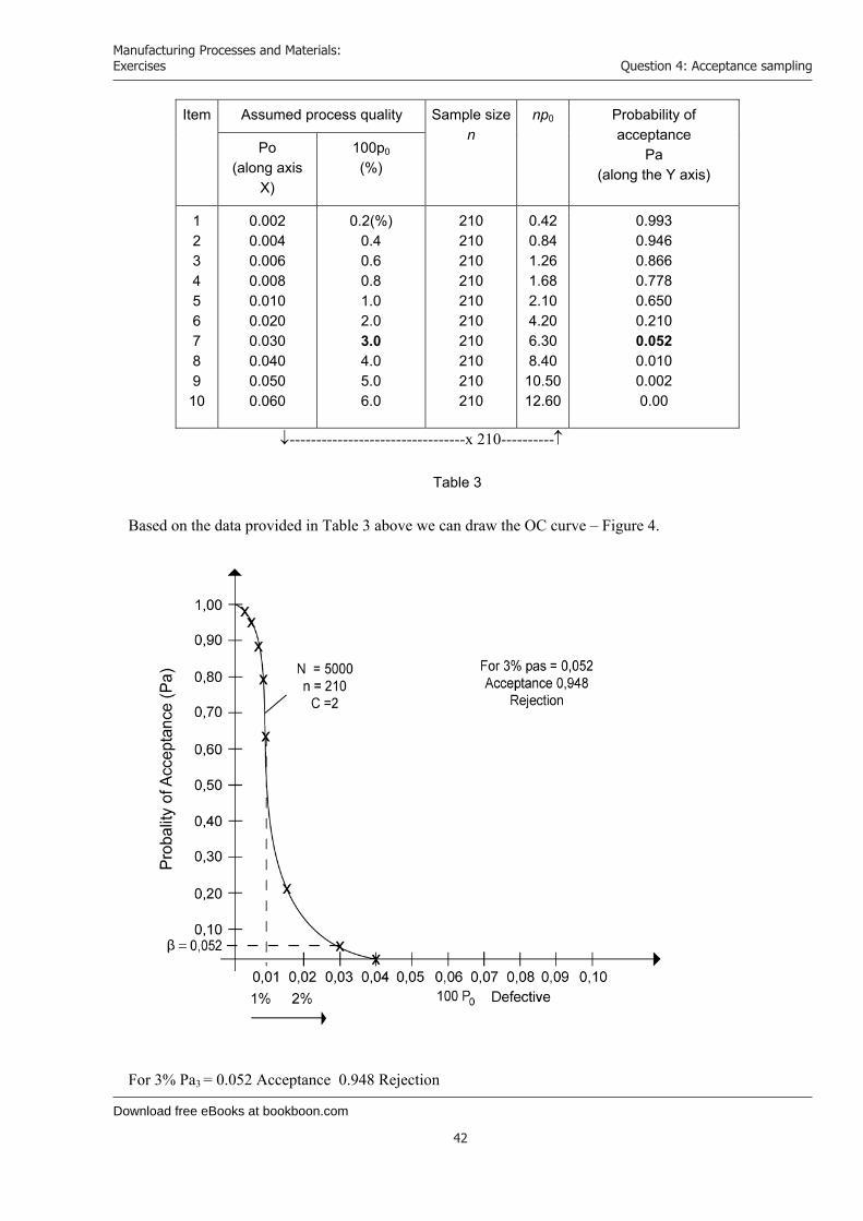
2. Designing the OC curve We have a single sampling plan available with set parameters and for this particular case we assume N= 5000 (lot size), a sampling size of n = 210 and an acceptance number c = 2. Additionally, we have the condition of 5% defectives. It is assumed that the lots are from a steady stream of product which can be considered infinite and therefore the binominal probability distribution can be used for the probability calculations. We use the Poisson’s equation. In graphing the curve with variables: Pa (probability of acceptance) and 100p0 (percent defective), one value 100p0 will be assumed and the other calculated. Acceptance of the lot is based on the acceptance number c = 2 and is possible when there is 0, 1, 2 defectives in the sample. For 3% defectives: np0 = 210 . 0,03 = 6.30 . 3% = 0.03 Pa = P (0) + P (1) + P (2) = 0.052 (From Table “C” for 6.30). The value 0.052 is too close to 0 and the curve is asymmetrically inclined towards the X axis. We draw up the Table 3: N = 5000, n = 210, c = 2
Find your next education here!
Click here
bookboon.com/blog/subsites/stafford
Download free eBooks at bookboon.com
Manufacturing Processes and Materials: Exercises
42
Question 4: Acceptance sampling
Item Assumed process quality Sample size n
np0 Probability of acceptance
Pa(along the Y axis)
Po(along axis
X)
100p0
(%)
12345678910
0.002 0.004 0.006 0.008 0.010 0.020 0.030 0.040 0.050 0.060
0.2(%)0.40.60.81.02.03.04.05.06.0
210 210 210 210 210 210 210 210 210 210
0.42 0.84 1.26 1.68 2.10 4.20 6.30 8.40
10.5012.60
0.993 0.946 0.866 0.778 0.650 0.210 0.052 0.010 0.002 0.00
---------------------------------x 210----------
Table 3 Based on the data provided in Table 3 above we can draw the OC curve – Figure 4.
For 3% Pa3 = 0.052 Acceptance 0.948 Rejection
Download free eBooks at bookboon.com
Manufacturing Processes and Materials: Exercises
43
Question 4: Acceptance sampling
Supplement to Question 4 b (ii)
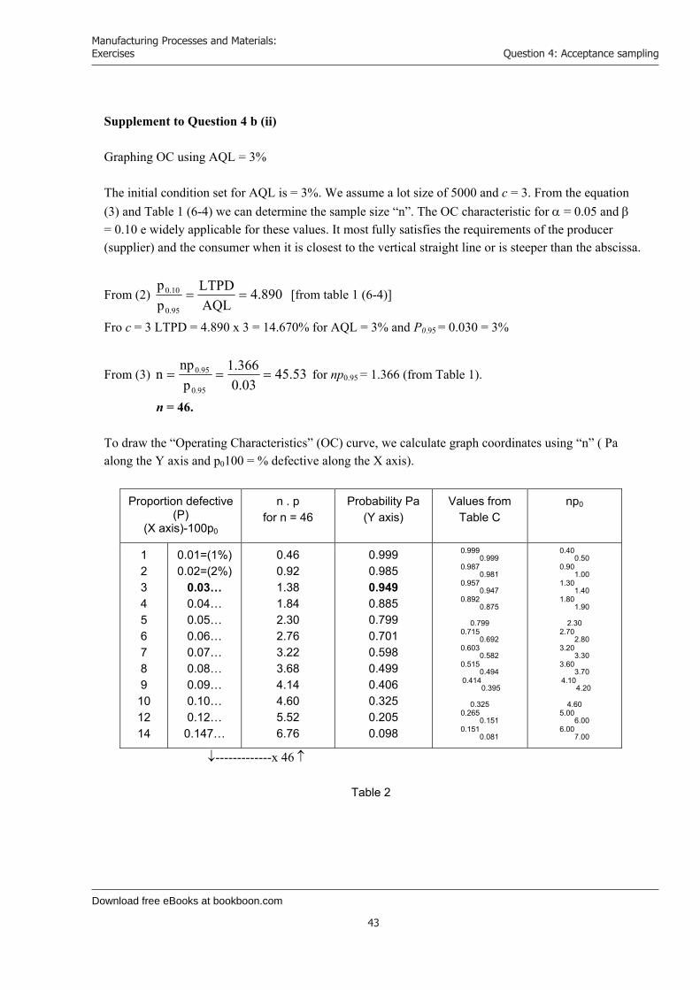
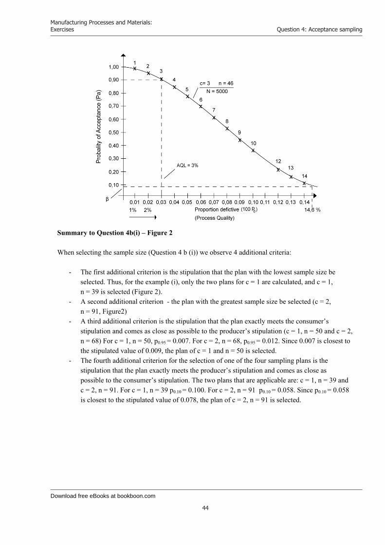
Graphing OC using AQL = 3% The initial condition set for AQL is = 3%. We assume a lot size of 5000 and c = 3. From the equation (3) and Table 1 (6-4) we can determine the sample size “n”. The OC characteristic for = 0.05 and = 0.10 e widely applicable for these values. It most fully satisfies the requirements of the producer (supplier) and the consumer when it is closest to the vertical straight line or is steeper than the abscissa.
From (2) 890.4AQLLTPD
pp
95.0
10.0 [from table 1 (6-4)]
Fro c = 3 LTPD = 4.890 x 3 = 14.670% for AQL = 3% and P0.95 = 0.030 = 3%
From (3) 53.4503.0
366.1p
npn
95.0
95.0 for np0.95 = 1.366 (from Table 1).
n = 46. To draw the “Operating Characteristics” (OC) curve, we calculate graph coordinates using “n” ( Pa along the Y axis and p0100 = % defective along the X axis).
Proportion defective (P)
(X axis)-100p0
n . p for n = 46
Probability Pa (Y axis)
Values from Table C
np0
12345678910 12 14
0.01=(1%)0.02=(2%)
0.03… 0.04… 0.05… 0.06… 0.07… 0.08… 0.09… 0.10… 0.12… 0.147…
0.46 0.92 1.38 1.84 2.30 2.76 3.22 3.68 4.14 4.60 5.52 6.76
0.999 0.985 0.949 0.885 0.799 0.701 0.598 0.499 0.406 0.325 0.205 0.098
0.9990.999
0.9870.981
0.9570.947
0.8920.875
0.799 0.715
0.692 0.603
0.582 0.515
0.494 0.414
0.395
0.325 0.265
0.151 0.151
0.081
0.400.50
0.901.00
1.301.40
1.801.90
2.30 2.70
2.80 3.20
3.30 3.60
3.70 4.10
4.20
4.60 5.00
6.00 6.00
7.00
-------------x 46
Table 2
Download free eBooks at bookboon.com
Manufacturing Processes and Materials: Exercises
44
Question 4: Acceptance sampling
Summary to Question 4b(i) – Figure 2 When selecting the sample size (Question 4 b (i)) we observe 4 additional criteria:
- The first additional criterion is the stipulation that the plan with the lowest sample size be selected. Thus, for the example (i), only the two plans for c = 1 are calculated, and c = 1, n = 39 is selected (Figure 2).
- A second additional criterion - the plan with the greatest sample size be selected (c = 2, n = 91, Figure2)
- A third additional criterion is the stipulation that the plan exactly meets the consumer’s stipulation and comes as close as possible to the producer’s stipulation (c = 1, n = 50 and c = 2, n = 68) For c = 1, n = 50, p0.95 = 0.007. For c = 2, n = 68, p0.95 = 0.012. Since 0.007 is closest to the stipulated value of 0.009, the plan of c = 1 and n = 50 is selected.
- The fourth additional criterion for the selection of one of the four sampling plans is the stipulation that the plan exactly meets the producer’s stipulation and comes as close as possible to the consumer’s stipulation. The two plans that are applicable are: c = 1, n = 39 and c = 2, n = 91. For c = 1, n = 39 p0.10 = 0.100. For c = 2, n = 91 p0.10 = 0.058. Since p0.10 = 0.058 is closest to the stipulated value of 0.078, the plan of c = 2, n = 91 is selected.

Download free eBooks at bookboon.com
Click on the ad to read more
Manufacturing Processes and Materials: Exercises
45
Question 5: Principles of the Resin Transfer Moulding (RTM)
Question 5: Principles of the Resin Transfer Moulding (RTM) Outline briefly the basic principles of Resin Transfer Moulding (RTM) in the context of design and production of fibre reinforced plastic artefacts.
[5 Marks] Discuss the requirements of 'blocker' doors in aero-engine thrust reverse systems and why the RTM process has been selected for manufacturing carbon fibre reinforced epoxy versions of them.
[20 Marks] Question 5a Resin transfer moulding is based on transfer moulding where the resin is mixed with the hardening agent (catalyst) and inserted into the mould by means of a compression plunger. The reinforcement material, the fiber, is positioned into the mould in advance of this process. The technique is an alternative to manual moulding of the resin and to spraying and compression moulding. The process is usually used for average-size serial production.
Download free eBooks at bookboon.com
Manufacturing Processes and Materials: Exercises
46
Question 5: Principles of the Resin Transfer Moulding (RTM)
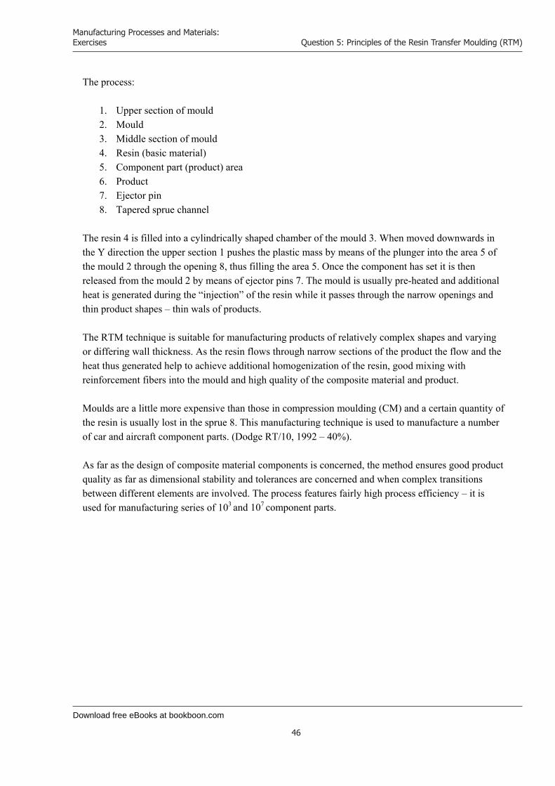
The process:
1. Upper section of mould 2. Mould 3. Middle section of mould 4. Resin (basic material) 5. Component part (product) area 6. Product 7. Ejector pin 8. Tapered sprue channel
The resin 4 is filled into a cylindrically shaped chamber of the mould 3. When moved downwards in the Y direction the upper section 1 pushes the plastic mass by means of the plunger into the area 5 of the mould 2 through the opening 8, thus filling the area 5. Once the component has set it is then released from the mould 2 by means of ejector pins 7. The mould is usually pre-heated and additional heat is generated during the “injection” of the resin while it passes through the narrow openings and thin product shapes – thin wals of products. The RTM technique is suitable for manufacturing products of relatively complex shapes and varying or differing wall thickness. As the resin flows through narrow sections of the product the flow and the heat thus generated help to achieve additional homogenization of the resin, good mixing with reinforcement fibers into the mould and high quality of the composite material and product. Moulds are a little more expensive than those in compression moulding (CM) and a certain quantity of the resin is usually lost in the sprue 8. This manufacturing technique is used to manufacture a number of car and aircraft component parts. (Dodge RT/10, 1992 – 40%). As far as the design of composite material components is concerned, the method ensures good product quality as far as dimensional stability and tolerances are concerned and when complex transitions between different elements are involved. The process features fairly high process efficiency – it is used for manufacturing series of 103 and 107 component parts.
Download free eBooks at bookboon.com
Manufacturing Processes and Materials: Exercises
47
Question 5: Principles of the Resin Transfer Moulding (RTM)
Question 5 b
1. “Blocker” doors in general Thrust reversers have various types Blocker doors, C’Ducts and Integrated Cold Stream reversers. The clam shell type utilizes two doors at the rear of the engine, which come together and deflect the exhaust gas to flow in the opposing direction to the motion. This is a fairly simple method of thrust reversal and is common on JT8D engines used on Boeing 737 – 100, … 200’s. The C’Ducts are the modern type and these have several functions. The prime function is thrust reversal. There are two halves to this type and in thrust reversal there is a translating sleeve which deploys and moves backwards. This causes “Blocker doors” to come up onto the by-pass air and deflect cascade fairing, which direct the air forward to oppose the motion of the aircraft. The second function of this type is noise suppression and acoustics are an important consideration in these units. The other type works similar to the C duct but rather than being a two-half reverser, it is a full annular section. This is commonly used on the RB 211-524 G/H units. Again it uses a translating sleeve and blocker door system to deflect the air from the by-pass through the cascades to oppose the forward motion of the aircraft. The thrust reverser acts along with the brakes of the aircraft to reduce the speed of the aircraft during the touchdown segment of landing. They are particularly useful in situations where the brakes fail or there is a shortened runway.
2. Requirements and operating conditions Blocker doors in thrust reversers are generally subjected to high load conditions: the pressure of the jet stream, the high temperature of exhaust gas and flaring of the jet engine, vibrations and shocks occurring at engine start up. Moreover, components should have the lowest possible weight and feature high strength characteristics; they shall also be reliable and capable of withstanding fatigue. The function of blocker doors is as illustrated in figure 1.

Download free eBooks at bookboon.com
Click on the ad to read more
Manufacturing Processes and Materials: Exercises
48
Question 5: Principles of the Resin Transfer Moulding (RTM)
Figure 1:
1. Blocker door 2. Shifting system for folding wing 3. (Jet) engine 4. Direction of movement of aircraft 5. Reversed jet stream 6. Wing 7. Engine 8. F – resultant force from the pressure exerted by the reversed jet stream
your chance to change the worldHere at Ericsson we have a deep rooted belief that the innovations we make on a daily basis can have a profound effect on making the world a better place for people, business and society. Join us.
In Germany we are especially looking for graduates as Integration Engineers for • Radio Access and IP Networks• IMS and IPTV
We are looking forward to getting your application!To apply and for all current job openings please visit our web page: www.ericsson.com/careers
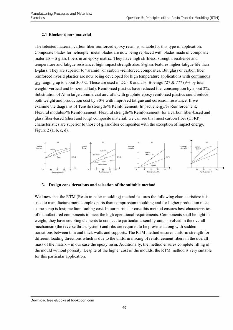
Download free eBooks at bookboon.com
Manufacturing Processes and Materials: Exercises
49
Question 5: Principles of the Resin Transfer Moulding (RTM)
2.1 Blocker doors material The selected material, carbon fiber reinforced epoxy resin, is suitable for this type of application. Composite blades for helicopter metal blades are now being replaced with blades made of composite materials – S glass fibers in an epoxy matrix. They have high stiffness, strength, resilience and temperature and fatigue resistance, high impact strength also. S-glass features higher fatigue life than E-glass. They are superior to “aramid” or carbon –reinforced composites. But glass or carbon fiber reinforced hybrid plastics are now being developed for high temperature applications with continuous use ranging up to about 300C. These are used in DC-10 and also Boeings 727 & 777 (9% by total weight- vertical and horizontal tail). Reinforced plastics have reduced fuel consumption by about 2%. Substitution of Al in large commercial aircrafts with graphite-epoxy reinforced plastics could reduce both weight and production cost by 30% with improved fatigue and corrosion resistance. If we examine the diagrams of Tensile strength/% Reinforcement; Impact energy/% Reinforcement; Flexural modulus/% Reinforcement; Flexural strength/% Reinforcement for a carbon fiber-based and glass fiber-based (short and long) composite material, we can see that most carbon fiber (CFRP) characteristics are superior to those of glass-fiber composites with the exception of impact energy. Figure 2 (a, b, c, d).
3. Design considerations and selection of the suitable method We know that the RTM (Resin transfer moulding) method features the following characteristics: it is used to manufacture more complex parts than compression moulding and for higher production rates; some scrap is lost; medium tooling cost. In our particular case this method ensures best characteristics of manufactured components to meet the high operational requirements. Components shall be light in weight, they have coupling elements to connect to particular assembly units involved in the overall mechanism (the reverse thrust system) and ribs are required to be provided along with sudden transitions between thin and thick walls and supports. The RTM method ensures uniform strength for different loading directions which is due to the uniform mixing of reinforcement fibers in the overall mass of the matrix – in our case the epoxy resin. Additionally, the method ensures complete filling of the mould without porosity. Despite of the higher cost of the moulds, the RTM method is very suitable for this particular application.
Download free eBooks at bookboon.com
Manufacturing Processes and Materials: Exercises
50
Question 6: Fibre reinforced plastic composites
Question 6: Fibre reinforced plastic composites In the case of a fibre reinforced plastic composite, explain the varied roles played by the different component parts in producing its physical properties.
[15 Marks]
With the aid of diagrams, describe the 'pultrusion' AND 'vacuum-bag moulding' processes for fabricating composite materials.
[10 Marks] Question 6a Composites are a combination of two or more chemically different and non-dissolving constituent compounds, the properties and structure of the resulting composite being superior to those of each individual constituent separately. Strength stiffness and creep resistance characteristics of plastic materials are usually inferior to those of metals and alloys. Adding reinforcing materials (phases) to the basic matrix of plastic results in significant changes and improvements of characteristics. Thus, the resulting composite material features improved abovementioned characteristics and strength-to-weight and stiffness-to-weight ratios as well as other improved physical properties. Example: An epoxy resin has the following characteristics: UTC [MPa] = 35-140, E [GPa] = 3.5 – 17, Elongation % 10 – 1. An epoxy-based composite will have UTC [MPa] = 70-1400, E [GPa] = 21 – 52, Elongation % 4 – 2.
1. Roles played by different constituents in producing the physical properties of composites
1.1 Reinforcing materials – fibers These mostly include glass, graphite (carbon), boron. All of them feature very high strength characteristics. Each of them is brittle, tough and poorly elongated itself – they have low structural value as a design material. Actually, the composite is a basic plastic material of homogenous nature, a matrix in which other phases (another phase) of fibers are spread, thus occupying part of the overall volume. The fiber content is usually between 10% and 60%. Material characteristics vary with the percentage of fiber content, the type of reinforcement material and the material of the matrix. For example: glass fibers render high strength, ductility and higher density (compared to carbon). Carbon fibers render higher strength, higher E, lower density (compared to glass fibers and boron). Carbon composites can withstand higher temperatures (1500 – 3000 ). Aramids feature very high specific strength – “Kevlar”. Also, they provide for certain plastic deformation. Boron contains thin tungsten fibers of 0.012mm OD and renders very high tensile strength and high-temperature stability. This is due to the alignment of molecules along fiber length and the small cross-sectional area of the fibers. The smaller the cross-sectional area, the smaller the bending stress of the fibers.

Download free eBooks at bookboon.com
Click on the ad to read more
Manufacturing Processes and Materials: Exercises
51
Question 6: Fibre reinforced plastic composites
1.2 Shape, size and alignment (positioning) of reinforcement fibers
Fibers can either be short (20 ÷ 60) or long (200 ÷ 500). They differ in the fact that if we increase the length of a given fiber and improve its mechanical properties, it is a “short-length” fiber and vice versa. Fibers are usually in the form of continuous rovings, woven fabric, yarn and mats of various combinations. The reinforcing element may also be in the form of particles and flakes. They may be aligned either longitudinally, transversely or scattered throughout the matrix.
1.3 Role played by the matrix The matrix has the function of absorbing and transferring the stress to the fibers, protecting the fibers from physical damage caused by load conditions and reduce the spreading of cracks inside the composite by virtue of the intrinsic ductility and toughness of the matrix. Materials include resins: epoxy, polyester, phenolic, etc. Polyamide resins withstanding up to 300C are usually used with graphite fibers.
Maersk.com/Mitas
�e Graduate Programme for Engineers and Geoscientists
Month 16I was a construction
supervisor in the North Sea
advising and helping foremen
solve problems
I was a
hes
Real work International opportunities
�ree work placementsal Internationaor�ree wo
I wanted real responsibili� I joined MITAS because
www.discovermitas.com
Download free eBooks at bookboon.com
Manufacturing Processes and Materials: Exercises
52
Question 6: Fibre reinforced plastic composites
1.4 Composite characteristics To conclude we can say that characteristics depend on: the quality of constituents, shape and alignment of fibers, length of fibers and percentage content of the matrix with the reinforcement material. Short fibers are less effective than long ones and their characteristics are far more dependent on time and temperatures. Long fibers provide better load transfer through the matrix and are therefore used for critical condition applications – critical loads and temperatures. These relations are illustrated in the tensile strength/% reinforcement charts (for different fibers), impact energy/reinforcement % charts; flexural modulus/reinforcement % charts, etc., as shown in Figure 2. Fiber reinforcement affects many other properties of composites, such as heat conductivity, thermal elongation, electrical resistance, stretching resistance, wear, endurance limit – see Figure 3. A critical factor in reinforced plastics is the strength of the bond between the fiber and the polymer matrix, since the load is transmitted through the fiber-matrix interface. Weak bonding causes fiber pullout and delamination of the structure. Adhesion at the interface can be improved by special surface treatments, such as coatings and coupling agents. Generally, the greatest stiffness and strength in reinforced plastics is obtained when fibers are aligned in the direction of the tension force – Figure 4. Figure 4 illustrates the effect of percentage filling of the matrix with fibers and the alignment of fibers relative to tensile strength.
1.5 Strength and elasticity modulus of reinforced plastics The overall load on the composite is given by the expression: Pc = Pf + Pm and the elastic modulus of the composite is: Ec = x Ef + (1-x) Em , where x is the cross-sectional area of fibers included in the composite, and Ef is the elastic modulus of the fiber and Em is the elastic modulus of the matrix. The total load on the fiber and the matrix is calculated using the equation:
mm
ff
m EAEA
P
Pf , where Af is the cross-sectional area of the composite of the fiber
and Am is the cross-sectional area of the composite for the matrix.
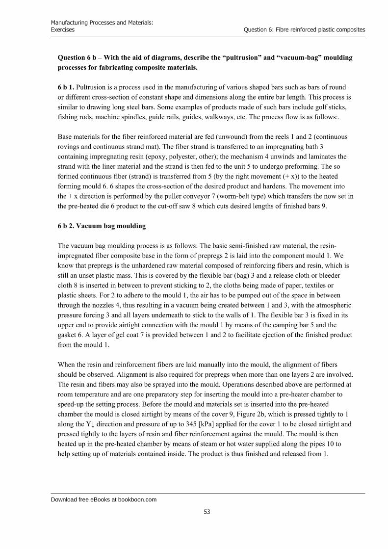
Download free eBooks at bookboon.com
Manufacturing Processes and Materials: Exercises
53
Question 6: Fibre reinforced plastic composites
Question 6 b – With the aid of diagrams, describe the “pultrusion” and “vacuum-bag” moulding processes for fabricating composite materials. 6 b 1. Pultrusion is a process used in the manufacturing of various shaped bars such as bars of round or different cross-section of constant shape and dimensions along the entire bar length. This process is similar to drawing long steel bars. Some examples of products made of such bars include golf sticks, fishing rods, machine spindles, guide rails, guides, walkways, etc. The process flow is as follows:. Base materials for the fiber reinforced material are fed (unwound) from the reels 1 and 2 (continuous rovings and continuous strand mat). The fiber strand is transferred to an impregnating bath 3 containing impregnating resin (epoxy, polyester, other); the mechanism 4 unwinds and laminates the strand with the liner material and the strand is then fed to the unit 5 to undergo preforming. The so formed continuous fiber (strand) is transferred from 5 (by the right movement (+ x)) to the heated forming mould 6. 6 shapes the cross-section of the desired product and hardens. The movement into the + x direction is performed by the puller conveyor 7 (worm-belt type) which transfers the now set in the pre-heated die 6 product to the cut-off saw 8 which cuts desired lengths of finished bars 9. 6 b 2. Vacuum bag moulding The vacuum bag moulding process is as follows: The basic semi-finished raw material, the resin-impregnated fiber composite base in the form of prepregs 2 is laid into the component mould 1. We know that prepregs is the unhardened raw material composed of reinforcing fibers and resin, which is still an unset plastic mass. This is covered by the flexible bar (bag) 3 and a release cloth or bleeder cloth 8 is inserted in between to prevent sticking to 2, the cloths being made of paper, textiles or plastic sheets. For 2 to adhere to the mould 1, the air has to be pumped out of the space in between through the nozzles 4, thus resulting in a vacuum being created between 1 and 3, with the atmospheric pressure forcing 3 and all layers underneath to stick to the walls of 1. The flexible bar 3 is fixed in its upper end to provide airtight connection with the mould 1 by means of the camping bar 5 and the gasket 6. A layer of gel coat 7 is provided between 1 and 2 to facilitate ejection of the finished product from the mould 1. When the resin and reinforcement fibers are laid manually into the mould, the alignment of fibers should be observed. Alignment is also required for prepregs when more than one layers 2 are involved. The resin and fibers may also be sprayed into the mould. Operations described above are performed at room temperature and are one preparatory step for inserting the mould into a pre-heater chamber to speed-up the setting process. Before the mould and materials set is inserted into the pre-heated chamber the mould is closed airtight by means of the cover 9, Figure 2b, which is pressed tightly to 1 along the Y↓ direction and pressure of up to 345 [kPa] applied for the cover 1 to be closed airtight and pressed tightly to the layers of resin and fiber reinforcement against the mould. The mould is then heated up in the pre-heated chamber by means of steam or hot water supplied along the pipes 10 to help setting up of materials contained inside. The product is thus finished and released from 1.

Download free eBooks at bookboon.com
Click on the ad to read more
Manufacturing Processes and Materials: Exercises
54
Question 6: Fibre reinforced plastic composites
Key:
1. Mould 2. Resin and glass 3. Flexible bar (cover) 4. Vacuum trap 5. Camping bar 6. Gasket 7. Gel coat (mould release) 8. Release cloth, bleeder cloth 9. Cover 10. Steam pipes
We will turn your CV into an opportunity of a lifetime
Do you like cars? Would you like to be a part of a successful brand?We will appreciate and reward both your enthusiasm and talent.Send us your CV. You will be surprised where it can take you.
Send us your CV onwww.employerforlife.com

Download free eBooks at bookboon.com
Manufacturing Processes and Materials: Exercises
55
Question 7: A cutting test on a steel bar
Question 7: A cutting test on a steel bar
a) i. A cutting test on a steel bar was performed and the following values were noted; Fc – shear force = 680 N Ft – thrust force = 380 N R - resultant force (N) Fs – shear force on shear plane (N) F – friction force along rake face (N) N- normal force to rake face (N) - shear angle = 20 - rake angle = 10 - mean friction angle (degree) Draw a force diagram, to scale, to show the graphical relationship between these parameters.
ii. For this test the following values were noted; w- width of cut = 3.5 mm t1- undeformed chip thickness = 0.21 mm t2 – deformed chip thickness = 0.60 mm Determine R,,F,Fs, cutting ratio, the apparent coefficient of friction between tool and the chip, and the apparent shear stress s of the cut material.
iii. For this test the cutting speed was 1 m/s, and the mass flow rate = 3.5 g/s.
Specific heat capacity of the work material was C = 500 J/kgC.
Determine the temperature s at the shear plane assuming 90% of head is transported with the chip and the original work material temperature was
o= 20C. The velocity along the shear plane is given by;
cos)cos(
VV cS

Download free eBooks at bookboon.com
Manufacturing Processes and Materials: Exercises
56
Question 7: A cutting test on a steel bar
b)Explain what actions may be taken to reduce the rise in coolant temperature in a turning operation.
a) i.
N
R
A
B
toolworkFs
Fc
Ft
ii.
8155.0tanNFtantan
N23715.2
S
sin
N493
/cos/
arctan
N780973,778R
2.39tan
mFswtF
N780)cos(RF2.39sin.780sin.RF
N67.5092.49cos.7802.49cos.RF2.49cosFFR
2.39102.29FFFF
2s
1s
c
s
ss
c
t
2t
2c
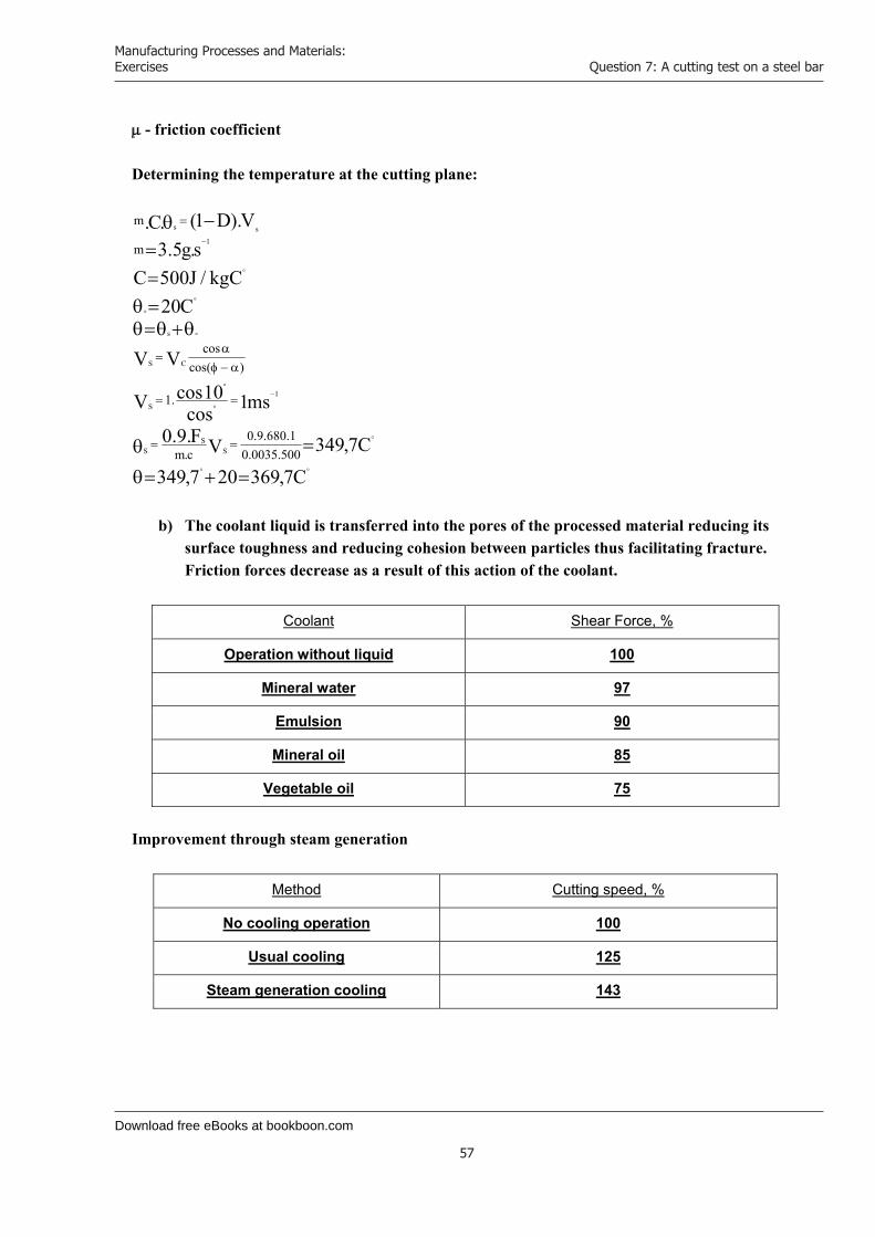
Download free eBooks at bookboon.com
Manufacturing Processes and Materials: Exercises
57
Question 7: A cutting test on a steel bar
- friction coefficient
Determining the temperature at the cutting plane:
C7,369207,349
C7,349VF.9.0
ms1cos10cosV
VV
C20kgC/J500C
s.g5.3V).D1(.C.
500.0035.01.680.9.0
c.m
.1
)cos(cos
m
m
SS
S
1
S
CS
s
1ss
b) The coolant liquid is transferred into the pores of the processed material reducing its
surface toughness and reducing cohesion between particles thus facilitating fracture. Friction forces decrease as a result of this action of the coolant.
Coolant Shear Force, %
Operation without liquid 100
Mineral water 97
Emulsion 90
Mineral oil 85
Vegetable oil 75
Improvement through steam generation
Method Cutting speed, %
No cooling operation 100
Usual cooling 125
Steam generation cooling 143

Download free eBooks at bookboon.com
Click on the ad to read more
Manufacturing Processes and Materials: Exercises
58
Question 8: Electro-discharge machining (EDM) requirements & properties
Question 8: Electro-discharge machining (EDM) requirements & properties a)
i. Explain why for Electro-discharge machining (EDM) a servomechanism and is essential to the control of the feed.
ii. Explain the requirements and properties of the EDM dielectric fluid b)
i. An electrochemical machining (ECM) process, using a 9mm x 9 mm square tool, is applied to a zinc workpiece. A feedrate of 0.5 mm/s is required. Determine an expression for the volumetric removal rate w (mm³/s) and hence the current setting I (A) needed. The density of zinc is = 7.13 x 10⁻³ g mm-3 and the process has a current efficiency of 90%. Would a machine rated at 1.4 kA be sufficient for the job?
Assume that m = e.I.t where; m = mass of material removed (g) e = electrochemical equivalent of zinc = 0.34 x 10⁻³ g/AsI = current (A) t = time during which current is applied (s)
ii. List the advantages and disadvantages claimed for ECM
Win one of the six full tuition scholarships for International MBA or MSc in Management
Are you remarkable?
register now
www.Nyenrode
MasterChallenge.com
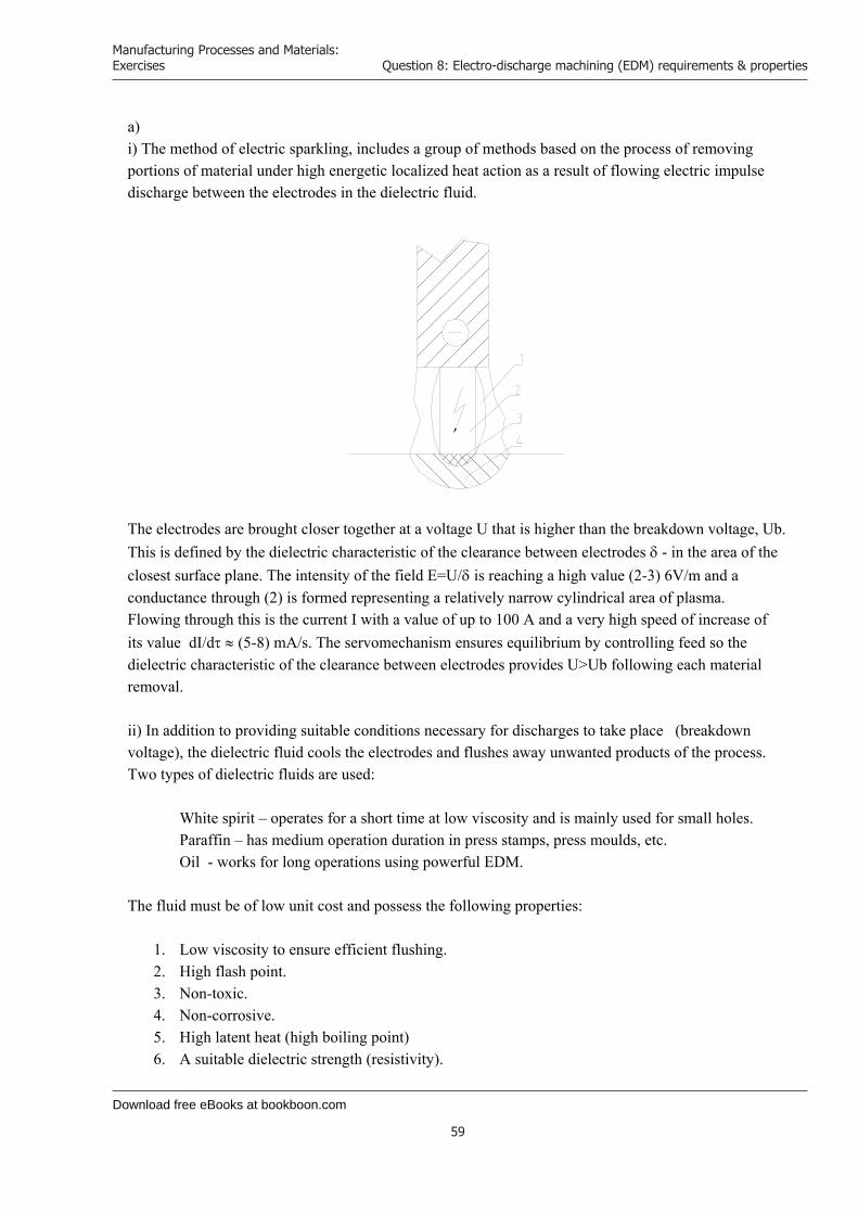
Download free eBooks at bookboon.com
Manufacturing Processes and Materials: Exercises
59
Question 8: Electro-discharge machining (EDM) requirements & properties
a) i) The method of electric sparkling, includes a group of methods based on the process of removing portions of material under high energetic localized heat action as a result of flowing electric impulse discharge between the electrodes in the dielectric fluid.
The electrodes are brought closer together at a voltage U that is higher than the breakdown voltage, Ub. This is defined by the dielectric characteristic of the clearance between electrodes - in the area of the closest surface plane. The intensity of the field E=U/ is reaching a high value (2-3) 6V/m and a conductance through (2) is formed representing a relatively narrow cylindrical area of plasma. Flowing through this is the current I with a value of up to 100 A and a very high speed of increase of its value dI/d (5-8) mA/s. The servomechanism ensures equilibrium by controlling feed so the dielectric characteristic of the clearance between electrodes provides U>Ub following each material removal. ii) In addition to providing suitable conditions necessary for discharges to take place (breakdown voltage), the dielectric fluid cools the electrodes and flushes away unwanted products of the process. Two types of dielectric fluids are used:
White spirit – operates for a short time at low viscosity and is mainly used for small holes. Paraffin – has medium operation duration in press stamps, press moulds, etc. Oil - works for long operations using powerful EDM.
The fluid must be of low unit cost and possess the following properties:
1. Low viscosity to ensure efficient flushing. 2. High flash point. 3. Non-toxic. 4. Non-corrosive. 5. High latent heat (high boiling point) 6. A suitable dielectric strength (resistivity).
Download free eBooks at bookboon.com
Manufacturing Processes and Materials: Exercises
60
Question 8: Electro-discharge machining (EDM) requirements & properties
The gas- and hydrodynamic processes taking place in the discharge area cause boiling and flowing out of melted material, de-ionization of the area between electrodes and restoration of its dielectric characteristics. Contaminated dielectric fluid deteriorates sparkling processing. Therefore filters are provided to ensure clean fluid. b) i) Volumetric ratio W = e.I/ (mm³/s) , Where e is electrochemical equivalent e = 0.34 x 10--33 g/As = 7.13 x 10--33 g mm--33 m= e.I.t , Where e is t = 1 s 40= 0.34.10--33.I/7.13. 10--33 , Hence I= 849,3 A At 90% efficiency:
ef = I/0.9 = 943,6 A , hence the power of the machine is adequate for the required 1.4 kA. ii) Advantages and disadvantages of ECM In its capabilities ECM is the most universal method for electric processing of metals in all. Almost all kinds of operations involving cutting can be performed using ECM but there are some which have no conventional analogues, like sharpening, grinding (flat, circle, profile), three-dimensional copying, profile processing, broaching, graduating, cutting off, honing, etc. The disadvantages occur in the reverse relation between quality and efficiency and the necessity to control a great number of factors which complicates overall process control. We also, have relatively low output efficiency and possible risk of ecological contamination. A list with some of the advantages and disadvantages claimed for ECM is presented below: Advantages
1. No tool wear. 2. High amperage (energy) can be concentrated on small areas. 3. Very high removal rates. 4. Surface finish isn’t adversely affected by high removal rates. 5. Cold machining less than 100C leaving metal properties unaltered. 6. May be applied to tool grinding (Electro-chemical Grinding ECG) 7. No servomechanism required for feed control.

Download free eBooks at bookboon.com
Click on the ad to read more
Manufacturing Processes and Materials: Exercises
61
Question 8: Electro-discharge machining (EDM) requirements & properties
Disadvantages
1. High initial and running cost of machine and associated equipment. 2. Extreme pressures and flow rate necessitating special pumping equipment. 3. Extensive tooting and fixtures due to very high electrolyte pressures. 4. Hostile work environment. 5. Tolerances at best 0.05mm (less than EDM) 6. Sludge disposal and hence extraction (hydrogen). Expensive and problematic.
© Agilent Technologies, Inc. 2012 u.s. 1-800-829-4444 canada: 1-877-894-4414
Budget-Friendly. Knowledge-Rich.The Agilent InfiniiVision X-Series and 1000 Series offer affordable oscilloscopes for your labs. Plus resources such as lab guides, experiments, and more, to help enrich your curriculum and make your job easier.
See what Agilent can do for you.www.agilent.com/find/EducationKit
Scan for free Agilent iPhone Apps or visit qrs.ly/po2Opli
Download free eBooks at bookboon.com
Manufacturing Processes and Materials: Exercises
62
Question 9: Hard and soft automation
Question 9: Hard and soft automation
a) i. Distinguish between “hard” and “soft” automation. ii. List some of the advantages claimed for mechanical automation in manufacturing.
b) Automatic control systems in CNC are often called servomechanisms. Explain what they are and what their purpose is. Your answer should include mention of open and closed loop systems, transducers and servomotors.
c) The end of an industrial robot wrist is usually termed an “end effector”. List tools and devices, which end effectors, are commonly equipped with?
a) i. Automation can generally be defined as the process of following a predetermined sequence
of operations with little or no human labor, using specialised equipment and devices that perform and control manufacturing processes. In hard, or fixed-position, automation, the production machines are designed to produce a standardized product, such as engine blocks, valves, gears, or spindles. Although product size and processing parameters (such as speed, feed, and depth of cut) can be changed, these machines are specialised. They lack flexibility and cannot be modified to any significant extent to accommodate products that have different shapes and dimensions. Machines used in hard-automation applications are usually built on the building block, or modular principle. They are generally called transfer machines, and consist of the following two major components: powerhead production units and transfer mechanisms. Because these machines are expensive to design and construct, their economic use requires mass production of parts in very large quantities. It has been stated that hard automation generally involves mass-production machines that lack flexibility. In soft (or flexible) automation, greater flexibility is achieved through computer control of the machine and its various functions using a lot of programs. Soft automation is an important development because the machine can be easily and readily reprogrammed to produce a part that has a different shape or dimensions than the one just produced. Because of this capability, soft automation can produce parts with complex shapes. Advances in flexible automation, with extensive use of modern computers, have led to the development of flexible manufacturing systems with high levels of efficiency and productivity.
ii. Some of the advantages, which are claimed for mechanical automation, are presented below:
- Responsiveness to shorter product life cycles, changing market demand, and global
competition. - Emphasis on product quality and its uniformity through better process control. - Better use of materials, machinery, and personnel, and reduction of work-in-progress
inventory, thus improving productivity and lowering product cost. - Better control of production, scheduling, and management of the total manufacturing
operation, resulting in lower product cost.
Download free eBooks at bookboon.com
Manufacturing Processes and Materials: Exercises
63
Question 9: Hard and soft automation
- Standardization of process plans, thus improving the productivity of process, reducing lead times, reducing planning costs, and improving the consistency of product quality and reliability.
- Parts can be produced randomly and in batch sizes as small as one and at lower unit cost. - Direct labor and inventories are reduced, with major savings over conventional systems. - Production is more reliable because the system is self-correcting and product quality is
uniform. - High-quality parts at low cost. - Reduced inspection and rework of parts
b) Automatic control systems are sometimes called servomechanisms. They may be a complex array of electromechanical components or it may be just a simple mechanical device. These are power units, which control the line of movement of the tool and/ or the work.
An open loop system is the simplest form of servomechanism. It is characterised as a system, which lacks feedback i.e. there is no sensing device to confirm the action of the control signal.
A closed loop system is characterised by the presence of feedback. It makes use of an error detector that returns a signal proportional to the difference between input and feedback i.e. error activated and strives to make the error zero.
Typical CNC servomechanisms include the following components:
i) Transducers which is defined as any device that senses an output condition and transforms the sensed information into a form that which can be understood by the servo system. A device that outputs a voltage in direct proportion to a measured linear movement is a typical example.
ii) Servomotors, or drives, are devices that convert electrical command signals to mechanical motions. Digital to analogue converters may be required to convert digital commands from the machine control unit to a continuous voltage, which in turn is used as the control signal to the axial drive.
c) In the terminology of robotics, an end effector can be defined as a device which is attached to the robot’s wrist to perform a specific task. The task might be work such as handling, spot welding, spray painting, or any of a great variety of other functions. The end effector is the special-purpose tooling which enables the robot to perform a particular job. Robot’s wrists are commonly equipped with devices such as grippers, and tools.

Download free eBooks at bookboon.com
Click on the ad to read more
Manufacturing Processes and Materials: Exercises
64
Question 9: Hard and soft automation
Grippers are used to hold either workparts or tools. The most common grasp methods used in robot grippers are:
- Mechanical grippers, where friction or the physical configuration of gripper retains the object - Suction cups ( also called vacuum cups ), used for flat objects - Magnetized gripper devices, used for ferrous objects - Hooks, used to lift parts off conveyors - Scoops or ladles used for fluids, powders, pellets, or granular substances.
There are a limited number of applications in which a gripper is used to grasp a tool and use it during the work cycle. In most applications where the robot manipulates a tool during the cycle, the tool is fastened directly to the robot wrist and becomes the end effector. A few examples of tools used with robots are the following:
- Spot welding gun- Arc welding tools (and wire-feed mechanisms)- Spray painting gun- Drilling spindle- Routers, grinders- Heating torches.
Download free eBooks at bookboon.com
Manufacturing Processes and Materials: Exercises
65
Question 10: Suface integrity of manufactured surfaces: properties & applications
Question 10: Surface integrity of manufactured surfaces: properties & applications
a) Briefly explain the meaning of ’surface integrity’ in relation to manufactured surfaces and their properties and applications.
b) Engineering parts require varying surface characteristics according to their function. List reasons for these varying requirements.
c) A magnified pen recording from a stylus type surface texture measuring instrument shows a pattern approximating to a series of triangles H = 6 mm the horizontal magnifications were x 20 and x 2000 respectively. Determine a relationship between H and Ra and hence the Ra (m) value. Is this in the normal range for a turned surface? What factors do you think caused this regular pattern to be produced on the work?
d) When considering the evaluation of fine manufactured surface using light interference methods, with the aid of a sketch show that the difference in separation between adjacent interference fringes is equal to /2 where is the wavelength of monochromatic light of an incident ray L1 .
a) In manufacturing processes, surfaces and their properties are as least as important as the bulk
properties of the materials. Surface integrity describes not only the topological (geometric) aspects of surfaces, but also their mechanical and metallurgical properties and characteristics. Surface integrity is an important consideration in manufacturing operations because it influences the properties of the product, such as its fatigue strength and resistance to corrosion and its service life. Therefore, surface integrity pertains to properties such as fatigue life and corrosion resistance, which are influenced strongly by the type of surface produced. Factors influencing surface integrity are temperatures generated during processing, residual stresses, metallurgical (phase) transformations, surface plastic deformation, tearing and cracking. Several defects caused and produced during manufacturing can be also identified. They may be responsible for lack of surface integrity. These defects are usually caused by a combination of factors, such as defects in the original material, the method by which the surface is produced, and lack of control of process parameters that can result in excessive stresses and temperatures.
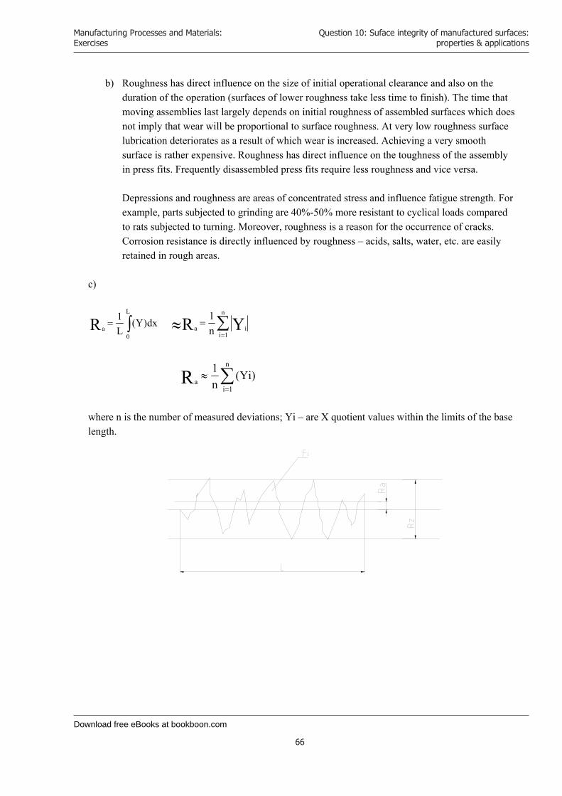
Download free eBooks at bookboon.com
Manufacturing Processes and Materials: Exercises
66
Question 10: Suface integrity of manufactured surfaces: properties & applications
b) Roughness has direct influence on the size of initial operational clearance and also on the duration of the operation (surfaces of lower roughness take less time to finish). The time that moving assemblies last largely depends on initial roughness of assembled surfaces which does not imply that wear will be proportional to surface roughness. At very low roughness surface lubrication deteriorates as a result of which wear is increased. Achieving a very smooth surface is rather expensive. Roughness has direct influence on the toughness of the assembly in press fits. Frequently disassembled press fits require less roughness and vice versa. Depressions and roughness are areas of concentrated stress and influence fatigue strength. For example, parts subjected to grinding are 40%-50% more resistant to cyclical loads compared to rats subjected to turning. Moreover, roughness is a reason for the occurrence of cracks. Corrosion resistance is directly influenced by roughness – acids, salts, water, etc. are easily retained in rough areas.
c)
L
0a
dx)Y(L1R
n
1iia YR n
1
n
1ia
)Yi(n1R
where n is the number of measured deviations; Yi – are X quotient values within the limits of the base length.
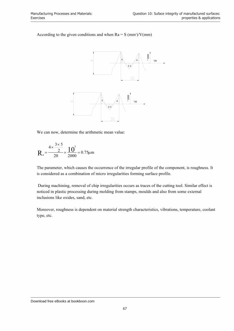
Download free eBooks at bookboon.com
Manufacturing Processes and Materials: Exercises
67
Question 10: Suface integrity of manufactured surfaces: properties & applications
According to the given conditions and when Ra = S (mm2)/V(mm)
*20*20
00
11
2 3
4
We can now, determine the arithmetic mean value:
m75.0200020
2534 10R
3
a
The parameter, which causes the occurrence of the irregular profile of the component, is roughness. It is considered as a combination of micro irregularities forming surface profile. During machining, removal of chip irregularities occurs as traces of the cutting tool. Similar effect is noticed in plastic processing during molding from stamps, moulds and also from some external inclusions like oxides, sand, etc. Moreover, roughness is dependent on material strength characteristics, vibrations, temperature, coolant type, etc.
*20*20
00
11
2 3
4

Download free eBooks at bookboon.com
Click on the ad to read more
Manufacturing Processes and Materials: Exercises
68
Question 11: Bored holes - plug and gap gauges
Question 11: Bored holes - plug and gap gauges a) A plate cam, 25 mm thick, has a bored hole at its centre of rotation in which a keyway, 5
mm wide and 4 mm deep, is to be broached i. Given the empirical expression; broach tooth pitch (mm) = 1.77 sqr(bore length), determine,
the length of the cutting portion of the broach and the maximum force required to pull it through the hole if the rise per tooth of the broach is 0.09 mm, and the force to remove 1 mm2 of metal is 2500N.
ii. Explain why knowledge of this force is desirable for manufacturing purposes.
b) The following values are taken BS 4500 and refer to a ‘average location’ for round hole and shaft of 50 mm nominal diameter. What is meant by a ‘nominal’ diameter?
Hole H7 +0.025 mm +0.000 mm
Shaft g6 -0.009 mm -0.025 mm
With us you can shape the future. Every single day. For more information go to:www.eon-career.com
Your energy shapes the future.

Download free eBooks at bookboon.com
Manufacturing Processes and Materials: Exercises
69
Question 11: Bored holes - plug and gap gauges
Draw a simple diagram representing the hole and on it show, with numerical values; i. nominal diameter ii. tolerances iii. deviationsWhat kind of fit is achieved? Sketch suitable plug and gap gauges to check this hole and shaft. Indicate the GO and NOT go sizes. a) i.
mm85.85*77.12577.1p Number of teeth z= 4/0.09=44.44 -> 45 mm Length L= p x z = 398.25 -> 400 mm 8.85 x 45 Number of teeth in contact - z c = H /p = 25/8.85 = 2.82 -> 3
The force F = area x z c x k = (5x0.09)x3x 2500 = 3375 N ii. Knowledge for this force is needed when considering the capabilities of the machine where broaching is going to be carried out. b) The nominal diameter is the dimension calculated from the static or kinematic strength of the material by considering kinematic and dimensional chains or taking into account other conditions and considerations and rounding them to the closest highest value in the standard. BS 4500 D = 50 mm Hole ф 50 H7 Shaft ф 50 g6
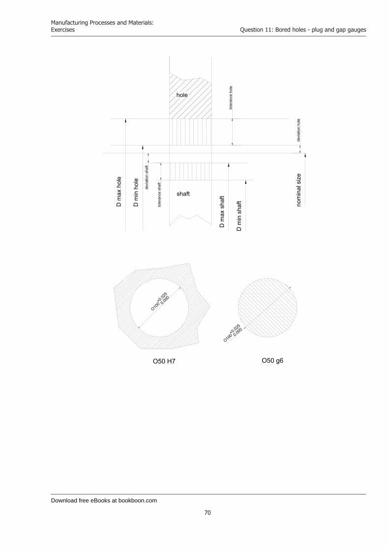
Download free eBooks at bookboon.com
Manufacturing Processes and Materials: Exercises
70
Question 11: Bored holes - plug and gap gauges
hole
shaft
nom
inal
size
dev i
atio
nho
le
tole
ranc
eho
le
devi
atio
nsh
a ft
tole
ranc
esh
a ft
Dm
axho
le
Dm
inho
le
Dm
insh
aft
Dm
axs h
aft
O100+0.0
25
0.000
O100+0.025
0.000
O50 H7 O50 g6
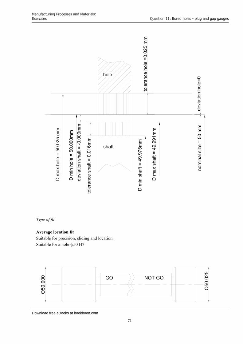
Download free eBooks at bookboon.com
Manufacturing Processes and Materials: Exercises
71
Question 11: Bored holes - plug and gap gauges
hole
shaft
nom
inal
siz e
=50
mm
dev i
atio
nh o
le=0
t ole
ran c
eho
le=0
.02 5
mm
dev i
atio
ns h
aft=
-0.0
09m
m
tol e
ranc
esh
aft =
0.01
6 mm
Dm
axh o
le=
5 0.0
25m
m
Dm
inho
le=
50.0
00m
m
Dm
ins h
aft=
4 9.9
75m
m
Dm
axsh
aft=
4 9.9
91m
m
Type of fit
Average location fit Suitable for precision, sliding and location. Suitable for a hole ф50 H7
O50
. 025
O50
.00 0 NOT GOGO

Download free eBooks at bookboon.com
Click on the ad to read more
Manufacturing Processes and Materials: Exercises
72
Question 11: Bored holes - plug and gap gauges
Suitable for a shaft ф50 g6
49.9
91
49.9
7 5 GO NOT GO
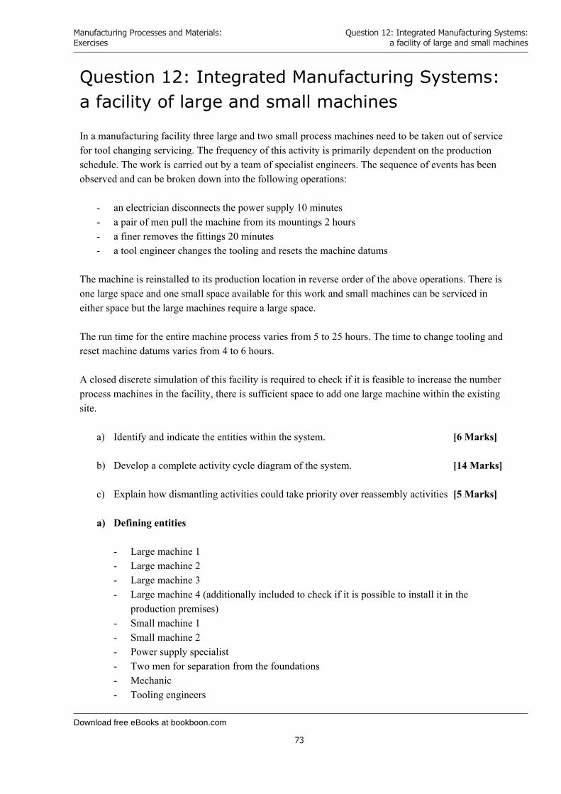
Download free eBooks at bookboon.com
Manufacturing Processes and Materials: Exercises
73
Question 12: Integrated Manufacturing Systems: a facility of large and small machines
Question 12: Integrated Manufacturing Systems: a facility of large and small machines In a manufacturing facility three large and two small process machines need to be taken out of service for tool changing servicing. The frequency of this activity is primarily dependent on the production schedule. The work is carried out by a team of specialist engineers. The sequence of events has been observed and can be broken down into the following operations:
- an electrician disconnects the power supply 10 minutes - a pair of men pull the machine from its mountings 2 hours - a finer removes the fittings 20 minutes - a tool engineer changes the tooling and resets the machine datums
The machine is reinstalled to its production location in reverse order of the above operations. There is one large space and one small space available for this work and small machines can be serviced in either space but the large machines require a large space. The run time for the entire machine process varies from 5 to 25 hours. The time to change tooling and reset machine datums varies from 4 to 6 hours. A closed discrete simulation of this facility is required to check if it is feasible to increase the number process machines in the facility, there is sufficient space to add one large machine within the existing site.
a) Identify and indicate the entities within the system. [6 Marks]
b) Develop a complete activity cycle diagram of the system. [14 Marks]
c) Explain how dismantling activities could take priority over reassembly activities [5 Marks]
a) Defining entities
- Large machine 1 - Large machine 2 - Large machine 3 - Large machine 4 (additionally included to check if it is possible to install it in the
production premises) - Small machine 1 - Small machine 2 - Power supply specialist - Two men for separation from the foundations - Mechanic - Tooling engineers

Download free eBooks at bookboon.com
Manufacturing Processes and Materials: Exercises
74
Question 12: Integrated Manufacturing Systems: a facility of large and small machines
- Large bay - Small bay
b) To build the cycle of activities I will need to describe each entity involved in the
production premises: Entity Status Large bay In action (A) (the cycle is similar to that for the small bay) Idle (Q) Power supply specialist - disconnecting (A) (the cycle is similar to that for - waits (Q) the two men for separation from - connecting (A) the foundation and for the mechanic) Tooling engineer - works on the large bay (A)
- waits (Q) - works on the small bay (A)
Large machine 1 - waits for tool change (Q) (the cycle is similar - disconnecting cables (A) for the rest of the machines) - waits (Q) - separation from foundation (A) - waits (Q) - coupling disconnection (A) - waits (Q) - tool change (A) - waits (Q) - coupling connection (A) - waits (Q) - fastening to the foundation (A) - waits (Q) - connecting cables (A) - finished machine (Q) - operates according to the production schedule (A)
Defining the cycle of individual entities
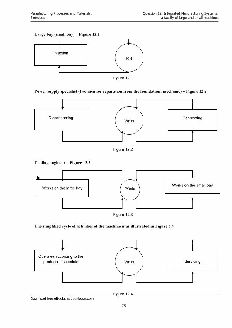
Download free eBooks at bookboon.com
Manufacturing Processes and Materials: Exercises
75
Question 12: Integrated Manufacturing Systems: a facility of large and small machines
Large bay (small bay) – Figure 12.1
In
Figure 12.1
Power supply specialist (two men for separation from the foundation; mechanic) – Figure 12.2
In
Figure 12.2
Tooling engineer – Figure 12.3
In
Figure 12.3
The simplified cycle of activities of the machine is as illustrated in Figure 6.4
In
Figure 12.4
In action Idle
Disconnecting Waits
Connecting
Works on the large bay Waits Works on the small bay
Operates according to the production schedule Waits Servicing

Download free eBooks at bookboon.com
Click on the ad to read more
Manufacturing Processes and Materials: Exercises
76
Question 12: Integrated Manufacturing Systems: a facility of large and small machines
Keeping in mind the different cycles of activities in servicing individual machines we can now build the complete cycle of activities – Figure 12.5
By 2020, wind could provide one-tenth of our planet’s electricity needs. Already today, SKF’s innovative know-how is crucial to running a large proportion of the world’s wind turbines.
Up to 25 % of the generating costs relate to mainte-nance. These can be reduced dramatically thanks to our systems for on-line condition monitoring and automatic lubrication. We help make it more economical to create cleaner, cheaper energy out of thin air.
By sharing our experience, expertise, and creativity, industries can boost performance beyond expectations.
Therefore we need the best employees who can meet this challenge!
The Power of Knowledge Engineering
Brain power
Plug into The Power of Knowledge Engineering.
Visit us at www.skf.com/knowledge
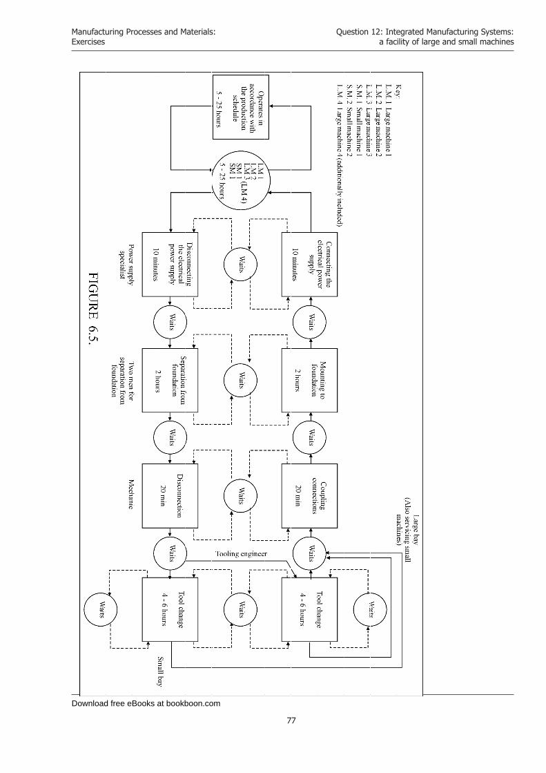
Download free eBooks at bookboon.com
Manufacturing Processes and Materials: Exercises
77
Question 12: Integrated Manufacturing Systems: a facility of large and small machines
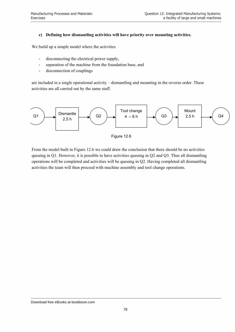
Download free eBooks at bookboon.com
Manufacturing Processes and Materials: Exercises
78
Question 12: Integrated Manufacturing Systems: a facility of large and small machines
c) Defining how dismantling activities will have priority over mounting activities. We build up a simple model where the activities
- disconnecting the electrical power supply, - separation of the machine from the foundation base, and - disconnection of couplings
are included in a single operational activity – dismantling and mounting in the reverse order. These activities are all carried out by the same staff.
Figure 12.6
From the model built in Figure 12.6 we could draw the conclusion that there should be no activities queuing in Q1. However, it is possible to have activities queuing in Q2 and Q3. Thus all dismantling operations will be completed and activities will be queuing in Q2. Having completed all dismantling activities the team will then proceed with machine assembly and tool change operations.
Q1 Dismantle2.5 h
Q2 Tool change
4 6 h Q3 Mount 2.5 h Q4
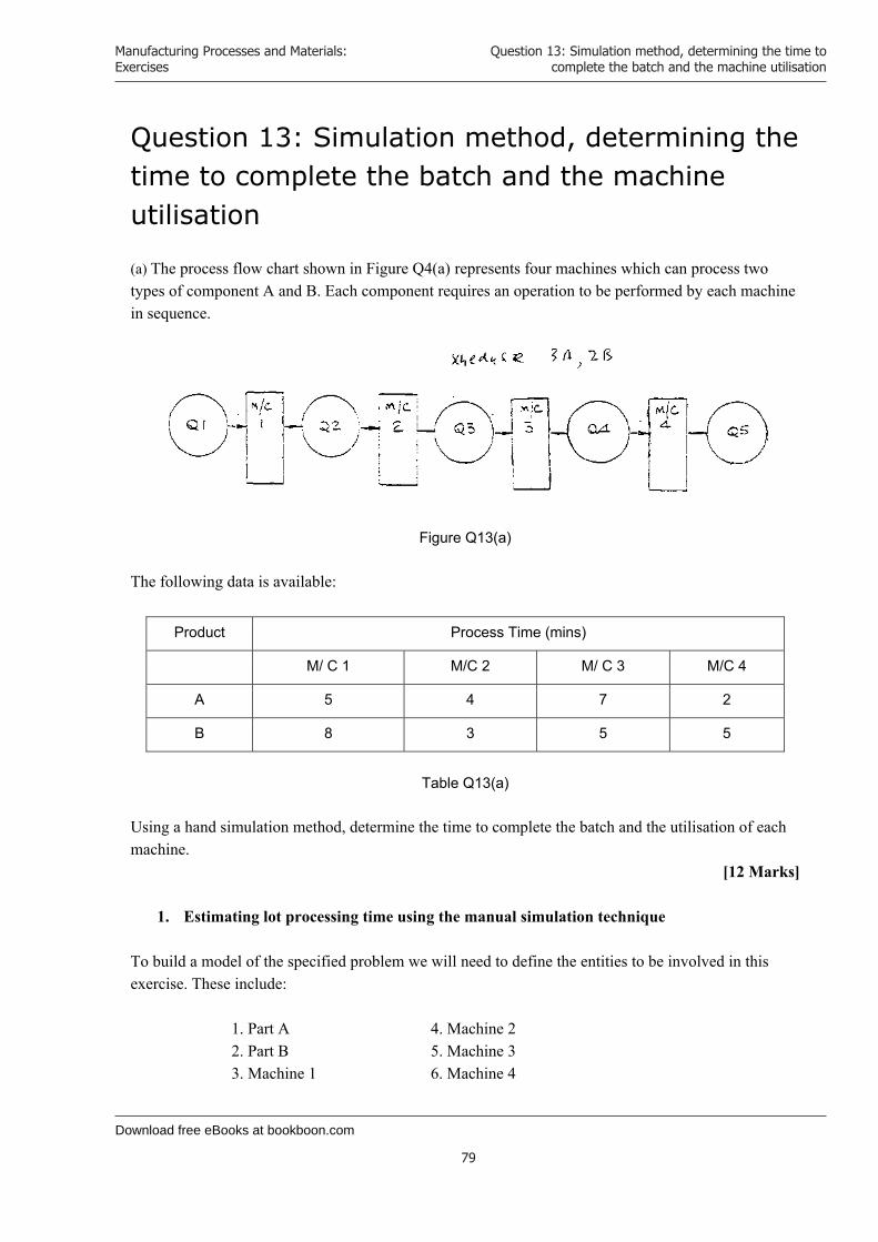
Download free eBooks at bookboon.com
Manufacturing Processes and Materials: Exercises
79
Question 13: Simulation method, determining the time to complete the batch and the machine utilisation
Question 13: Simulation method, determining the time to complete the batch and the machine utilisation (a) The process flow chart shown in Figure Q4(a) represents four machines which can process two types of component A and B. Each component requires an operation to be performed by each machine in sequence.
Figure Q13(a) The following data is available:
Product Process Time (mins)
M/ C 1 M/C 2 M/ C 3 M/C 4
A 5 4 7 2
B 8 3 5 5
Table Q13(a)
Using a hand simulation method, determine the time to complete the batch and the utilisation of each machine.
[12 Marks]
1. Estimating lot processing time using the manual simulation technique To build a model of the specified problem we will need to define the entities to be involved in this exercise. These include:
1. Part A 4. Machine 2 2. Part B 5. Machine 3 3. Machine 1 6. Machine 4
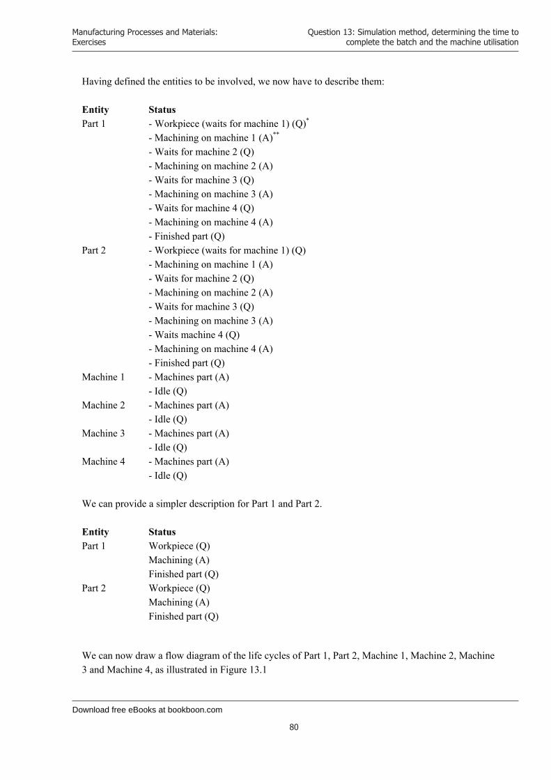
Download free eBooks at bookboon.com
Manufacturing Processes and Materials: Exercises
80
Question 13: Simulation method, determining the time to complete the batch and the machine utilisation
Having defined the entities to be involved, we now have to describe them: Entity Status Part 1 - Workpiece (waits for machine 1) (Q)* - Machining on machine 1 (A)** - Waits for machine 2 (Q) - Machining on machine 2 (A) - Waits for machine 3 (Q) - Machining on machine 3 (A) - Waits for machine 4 (Q) - Machining on machine 4 (A) - Finished part (Q) Part 2 - Workpiece (waits for machine 1) (Q) - Machining on machine 1 (A) - Waits for machine 2 (Q) - Machining on machine 2 (A) - Waits for machine 3 (Q) - Machining on machine 3 (A) - Waits machine 4 (Q) - Machining on machine 4 (A)
- Finished part (Q) Machine 1 - Machines part (A)
- Idle (Q) Machine 2 - Machines part (A)
- Idle (Q) Machine 3 - Machines part (A)
- Idle (Q) Machine 4 - Machines part (A)
- Idle (Q) We can provide a simpler description for Part 1 and Part 2. Entity Status Part 1 Workpiece (Q) Machining (A) Finished part (Q) Part 2 Workpiece (Q) Machining (A) Finished part (Q)
We can now draw a flow diagram of the life cycles of Part 1, Part 2, Machine 1, Machine 2, Machine 3 and Machine 4, as illustrated in Figure 13.1
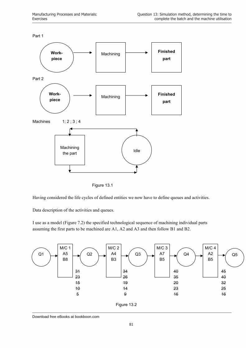
Download free eBooks at bookboon.com
Manufacturing Processes and Materials: Exercises
81
Question 13: Simulation method, determining the time to complete the batch and the machine utilisation
Part 1
Part 2
Machines 1; 2 ; 3 ; 4
Figure 13.1 Having considered the life cycles of defined entities we now have to define queues and activities. Data description of the activities and queues. I use as a model (Figure 7.2) the specified technological sequence of machining individual parts assuming the first parts to be machined are A1, A2 and A3 and then follow B1 and B2.
Figure 13.2
Work- piece
Machining Finished
part
Work-piece
Machining Finished
part
Machining the part Idle
342619149
4035202316
4540322516
312315105
M/C 1 A5B8
M/C 2A4B3
Q1 Q2 Q3 M/C 3
A7B5
Q4 M/C 4
A2B5
Q5

Download free eBooks at bookboon.com
Click on the ad to read more
Manufacturing Processes and Materials: Exercises
82
Question 13: Simulation method, determining the time to complete the batch and the machine utilisation
To record the simulation I will use the “Simulation record sheet”, Figure 7.3. The result of the performed simulation is that the specified lot of component parts will take 45 minutes to process. Machine 1 – operates from 0 to 31 min with no idle time. Machine 2 – operates from 5 to 54 min with 11 min idle time. Machine 3 – operates from 9 to 40 min with no idle time. Machine 4 – operates from 16 to 45 min with 13 min idle time. Therefore, the most heavily loaded machines are:
Machine 1 – operates for 31 minutes, and Machine 3 – operates for 31 minutes.
The financial industry needs a strong software platformThat’s why we need you
Meet Lars and other employees at simcorp.com/meetouremployees
Mitigate risk Reduce cost Enable growthsimcorp.com
Working at SimCorp means making a difference. At SimCorp, you help create the tools
that shape the global financial industry of tomorrow. SimCorp provides integrated
software solutions that can turn investment management companies into winners.
With SimCorp, you make the most of your ambitions, realising your full potential in
a challenging, empowering and stimulating work environment.
Are you among the best qualified in finance, economics, computer science or mathematics?
Find your next challenge at www.simcorp.com/careers
“When I joined SimCorp, I was very impressed with the introduc-tion programme offered to me.”

Download free eBooks at bookboon.com
Manufacturing Processes and Materials: Exercises
83
Question 13: Simulation method, determining the time to complete the batch and the machine utilisation
Time End Start Sim. ClockTime
IDLE TIME ON MACHINES NUMBER OF JOBS
IN QUEUES MACHINE 1 MACHINE 2 MACHINE 3 MACHINE 4
ON OFF DUR ON OFF DUR ON OFF DUR ON OFF DUR Q1 Q2 Q3 Q4 Q5
0 0 4 0 0 0 0
5 5 3 0 0 0 0
9 9 3 0 0 0 0
10 0 1 2 0 0 0 0
14 2 0 1 0 0
15 0 1 1 0 1 0 0
16 0 16 1 0 0 0 0
18 1 0 0 0 1
19 1 0 1 0 1
23 0 4 0 5 0 0 0 0 1
25 0 0 0 0 2
26 0 0 1 0 2
30 0 5 0 0 0 0 2
31 5 0 0 0 0 2
32 0 0 0 0 3
34 0 0 1 0 3
35 0 3 0 0 0 0 3
40 0 0 0 0 0 4
45 0 0 0 0 5
Figure 13.2
(b) Three types of product are processed through machining centres for 1 to 3 operations, followed by wash and inspect. The pans are moved on transfer pallets, which are recycled within the cell. The plant is expected to operate 280 days per annum at 20 hours per day. Anticipated annual demand is for 30,000 units, with 50% type A. 25% type B and the remainder type C. The following data is available, all times are in minutes.
PartType
Machining Times Wash Time
Inspection Time
OP1 OP2 OP3
A 15 12 - 5 8
B 9 9 6 5 6
C 16 7 - 5 9
Table Q13(b)

Download free eBooks at bookboon.com
Manufacturing Processes and Materials: Exercises
84
Question 13: Simulation method, determining the time to complete the batch and the machine utilisation
Determine the provisional number of machining centres, wash stations, inspection stations and pallets to be included in a simulation model.
[13 Marks] Preparing a block diagram along with activity times and rules of operation. To build the simulation model we will need to define the entities to be involved.
1. Part A 2. Part B 3. Part C 4. Machine 1 5. Machine 2 6. Machine 3 7. Washing work station 8. Inspection work station
Description of entities:
Part A - Workpiece (waits M/1) (Q) - Machining on M/1 (A) - Waits M/2 (Q)- Waits for washing work station (Q)- Washing work station (A)- Waits for inspection work station (Q)- Inspection work station (A)- Finished part (Q)
Part B - Workpiece (waits M/1) (Q)
- Machining on M/1 (A) - Waits M/2 (Q)- Machining on M/2 (A)- Waits for M/3 (Q)- Machining on M/3 (A)- Waits for washing work station (Q)- Washing work station (A)- Waits for inspection work station (Q)- Inspection work station (A)- Finished part (Q)
Part C - Workpiece (waits M/1) (Q)
- Machining on M/1 (A) - Waits for M/2 (Q)- Machining on M/2 (A)- Waits for washing work station (Q)- Washing work station (A)- Waits for inspection work station (Q)

Download free eBooks at bookboon.com
Click on the ad to read more
Manufacturing Processes and Materials: Exercises
85
Question 13: Simulation method, determining the time to complete the batch and the machine utilisation
- Inspection work station (A)- Finished part (Q)
Machine 1 - Machines part (A)
- Idle (Q) Machine 2 - Machines part (A)
- Idle (Q) Machine 3 - Machines part (A)
- Idle (Q) Washing work station - Process part (A)
- - Idle (Q) Inspection work station - Process part (A)
- Idle (Q) First we build the simulation model of each of the three parts A, B and C. Simulation model of part A (Figure 13.4)
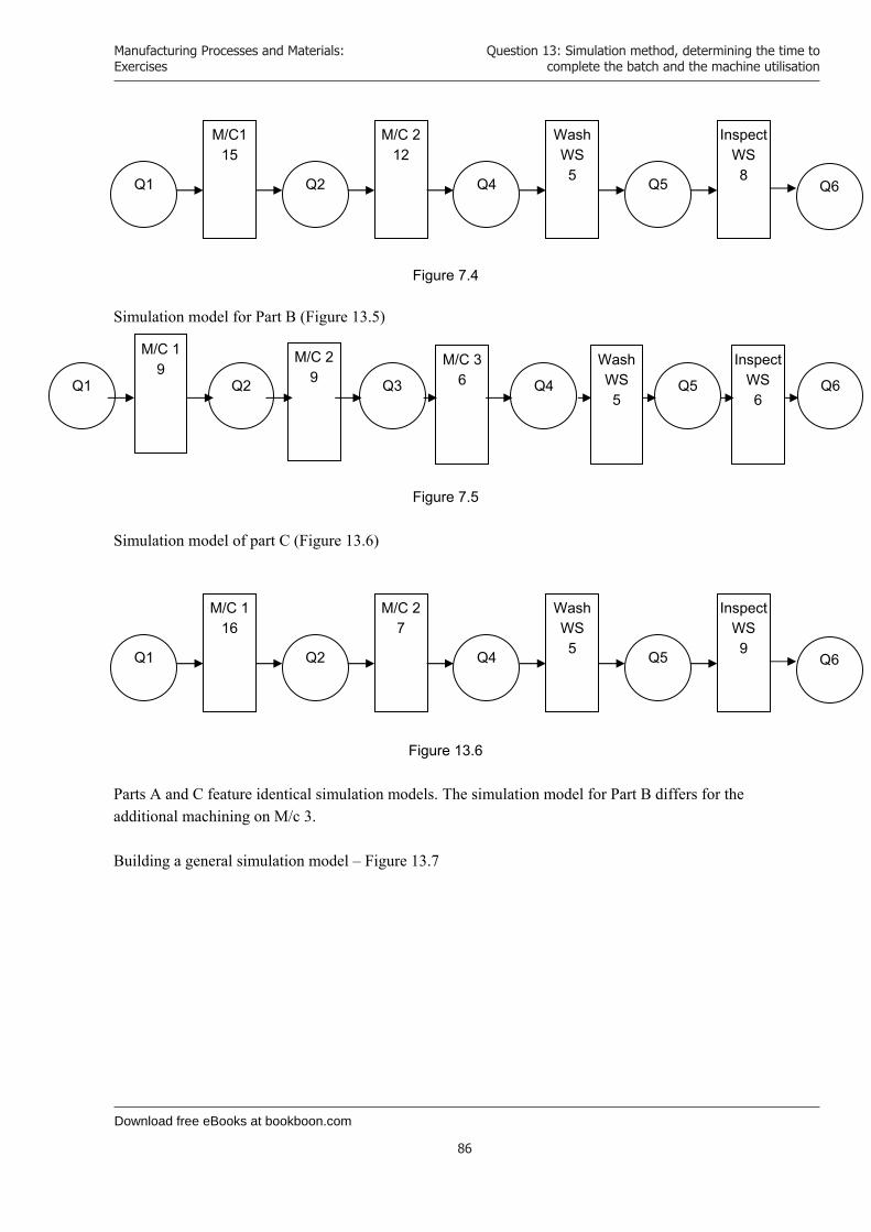
Download free eBooks at bookboon.com
Manufacturing Processes and Materials: Exercises
86
Question 13: Simulation method, determining the time to complete the batch and the machine utilisation
Figure 7.4
Simulation model for Part B (Figure 13.5)
Figure 7.5 Simulation model of part C (Figure 13.6)
Figure 13.6
Parts A and C feature identical simulation models. The simulation model for Part B differs for the additional machining on M/c 3. Building a general simulation model – Figure 13.7
M/C115
M/C 212
Q1 Q2 Q4
Wash WS 5 Q5
Inspect WS8
Q6
M/C 1 9
M/C 2 9Q1 Q2 Q3
Wash WS 5
Q5
Inspect WS6
Q6
M/C 36 Q4
M/C 1 16
M/C 27
Q1 Q2 Q4
Wash WS 5 Q5
Inspect WS9
Q6
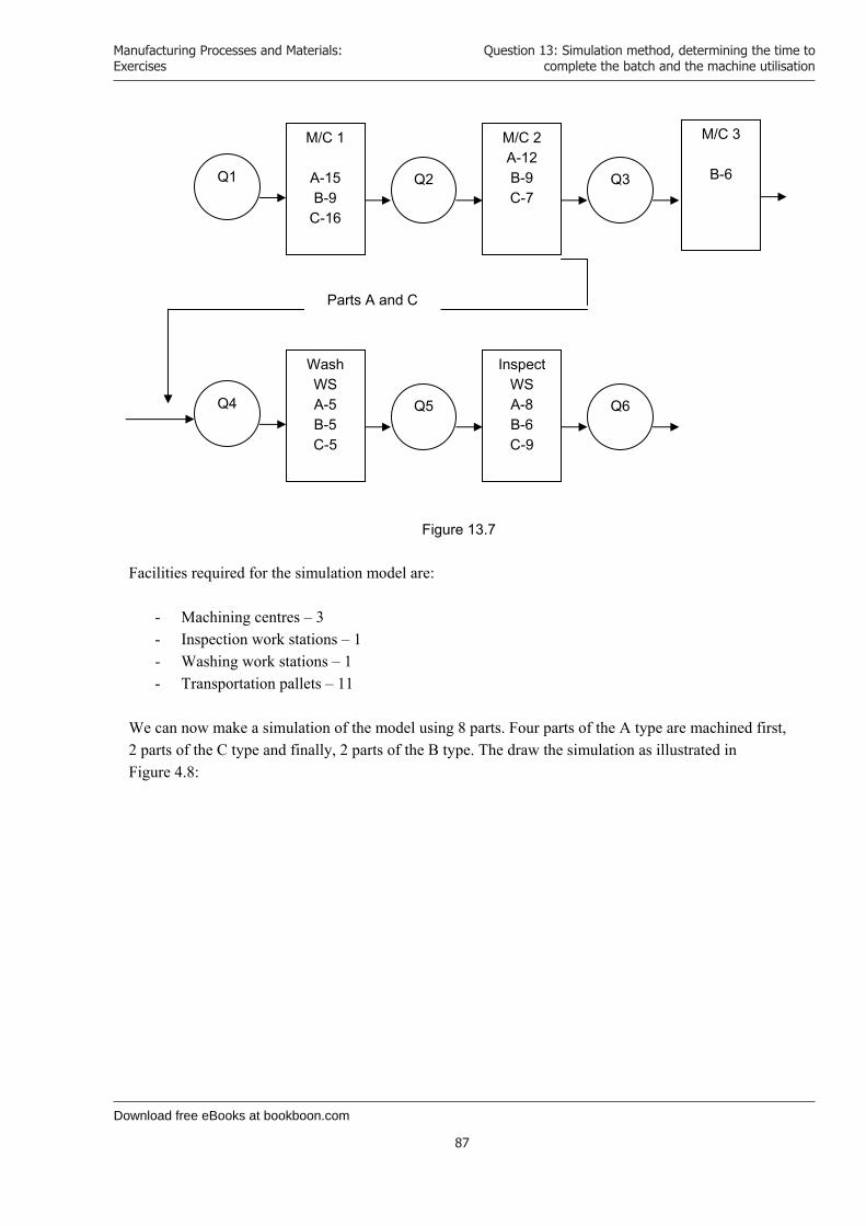
Download free eBooks at bookboon.com
Manufacturing Processes and Materials: Exercises
87
Question 13: Simulation method, determining the time to complete the batch and the machine utilisation
Figure 13.7 Facilities required for the simulation model are:
- Machining centres – 3 - Inspection work stations – 1 - Washing work stations – 1 - Transportation pallets – 11
We can now make a simulation of the model using 8 parts. Four parts of the A type are machined first, 2 parts of the C type and finally, 2 parts of the B type. The draw the simulation as illustrated in Figure 4.8:
Q1 Q2 Q3
M/C 1
A-15B-9
C-16
M/C 2 A-12B-9C-7
M/C 3
B-6
Q4 Q5 Q6
Wash WS A-5B-5C-5
Inspect WS A-8B-6C-9
Parts A and C

Download free eBooks at bookboon.com
Manufacturing Processes and Materials: Exercises
88
Question 13: Simulation method, determining the time to complete the batch and the machine utilisation
Time
End
Start
Sim
. C
lockTim
e
IDLE
TIME
ON
MAC
HIN
ES
N
UM
BE
R O
F JOBS
IN Q
UE
UE
S M
AC
HIN
E 1
MA
CH
INE
2 M
AC
HIN
E 3
WA
SH
TIME
INS
PE
CT TIM
E
ON
OFF
DU
R
ON
O
FF D
UR
O
N
OFF
DU
R
ON
O
FF D
UR
O
N
OFF
DU
R
Q1
Q2
Q3
Q4
Q5
Q6
0 0
0
7
0 0
0 0
0
15
0
15
6 0
0 0
0 0
27
27
6
0 0
0 0
0
30
0
3
5 0
0 0
0 0
32
32 5
0 0
0 0
0
40
5
0 0
0 0
1
42
10
5
0 0
0 0
1
45
0
3
4 0
0 0
0 1
47
7 4
0 0
0 0
1
55
4
0 0
0 0
2
57
10
4
0 0
0 0
2
60
0
3
3 0
0 0
0 2
62
7 3
0 0
0 0
2
70
3
0 0
0 0
3
72
10
3
0 0
0 0
3
76
0
4
2 0
0 0
0 3
77
7 2
0 0
0 0
3
83
6
2
0 0
0 0
3
85
2
0 0
0 0
4
88
3 2
0 0
0 0
4
92
0
9
1 0
0 0
0 4
97
1
0 0
0 0
5
99
11
1
0 0
0 0
5
101
0
2
0 0
0 0
0 5
104
7 0
0 0
0 0
5
110
0
110
0 0
0 0
0 5
113
0
0 0
0 0
6
116
12
0
0 0
0 0
6
119
3
0 0
0 0
0 6
121
11 0
0 0
0 0
6
125
4
0
0 0
0 0
6
127
0
0 0
0 0
7
130
3 0
0 0
0 0
7
136
0
0 0
0 0
8
Figure 13.8

Download free eBooks at bookboon.com
Click on the ad to read more
Manufacturing Processes and Materials: Exercises
89
Question 13: Simulation method, determining the time to complete the batch and the machine utilisation
Analysis of the Simulation Process The first part A will be finished for 40 minutes and the second part, for 55 minutes. Therefore, every subsequent part will be finished for 15 minutes (this is the step size). The time between the last part A and the first part C (finished) is 12 minutes. The step between parts C is 16 minutes. The time between the last part C and the first finished part B is 14 minutes. The step of parts B is 9 minutes. The annual schedule for parts A is 15000 pieces; parts B – 7500 pieces and parts C – 7500 pieces.
Do you want your Dream Job?
More customers get their dream job by using RedStarResume than any other resume service.
RedStarResume can help you with your job application and CV.
Go to: Redstarresume.com
Use code “BOOKBOON” and save up to $15
(enter the discount code in the “Discount Code Box”)

Download free eBooks at bookboon.com
Manufacturing Processes and Materials: Exercises
90
Question 13: Simulation method, determining the time to complete the batch and the machine utilisation
The time required to process the whole lot is as follows:
Tlot = 40 + 14999 x 15 + 12 + 7499 x 16 + 14 + 7499 x 9 = = 40 + 224985 + 12 + 119984 + 14 + 67491 = 412526 min
Annual working time: Tann = 280 . 20 = 5600 hours x 60 = 336000 min. Comparing both times we find:
Tlot > Tann
Therefore, this particular lot cannot be processed within one year. Analysing the simulation thus carried out we find the bottle neck issues are:
1. Machine 1 and machine 2 for part A 2. Machine 1 for part C
We can now determine the time required to implement this program. When machining part A, 1 machine will additionally be involved for operation 1 and 1 machine for operation 2. When machining part C, 1 machine will additionally be involved for operation 1. The required number of machining centers is 5. Washing work stations – 1 off Inspection work stations – 1 off Transportation pallets – 18 off
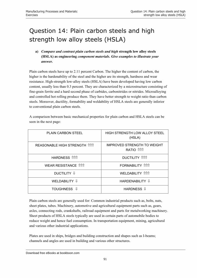
Download free eBooks at bookboon.com
Manufacturing Processes and Materials: Exercises
91
Question 14: Plain carbon steels and high strength low alloy steels (HSLA)
Question 14: Plain carbon steels and high strength low alloy steels (HSLA)
a) Compare and contrast plain carbon steels and high strength low alloy steels (HSLA) as engineering component materials. Give examples to illustrate your answer.
Plain carbon steels have up to 2.11 percent Carbon. The higher the content of carbon, the higher is the hardenability of the steel and the higher are its strength, hardness and wear resistance. High-strength low-alloy steels (HSLA) have been developed having low carbon content, usually less than 0.3 percent. They are characterized by a microstructure consisting of fine-grain ferrite and a hard second phase of carbides, carbonitrides or nitrides. Microalloying and controlled hot rolling produce them. They have better strength to weight ratio than carbon steels. Moreover, ductility, formability and weldability of HSLA steels are generally inferior to conventional plain carbon steels. A comparison between basic mechanical properties for plain carbon and HSLA steels can be seen in the next page:
PLAIN CARBON STEEL HIGH STRENGTH LOW ALLOY STEEL (HSLA)
REASONABLE HIGH STRENGTH IMPROVED STRENGTH TO WEIGHT RATIO
HARDNESS DUCTILITY
WEAR RESISTANCE FORMABILITY
DUCTILITY WELDABILITY
WELDABILITY HARDENABILITY
TOUGHNESS HARDNESS
Plain carbon steels are generally used for: Common industrial products such as, bolts, nuts, sheet plates, tubes. Machinery, automotive and agricultural equipment parts such as, gears, axles, connecting rods, crankshafts, railroad equipment and parts for metalworking machinery. Sheet products of HSLA steels typically are used in certain parts of automobile bodies to reduce weight and hence fuel consumption. In transportation equipment, mining, agricultural and various other industrial applications. Plates are used in ships, bridges and building construction and shapes such as I-beams; channels and angles are used in building and various other structures.

Download free eBooks at bookboon.com
Click on the ad to read more
Manufacturing Processes and Materials: Exercises
92
Question 14: Plain carbon steels and high strength low alloy steels (HSLA)
b) Select from the materials in Table 1 below the most suitable for each of the following applications. In each case, provide full justification for the choice of materials.
i) An aircraft component requiring maximum strength/weight ratio. ii) A railway locomotive component requiring maximum damage tolerance.
MATERIAL YIELD
STRENGTH(MPa)
DENSITY
(Mg*m-3)
K ic (Mpa*m-0.5)
AL-Cu-Mg-Zn Alloy 450 2.7 25
Titanium alloy 700 4.5 50
Low alloy steel 1 1,000 7.8 55
Low alloy steel 2 800 7.8 100
Table Q1: Properties of Two Alloys
Challenging? Not challenging? Try more
Try this...
www.alloptions.nl/life
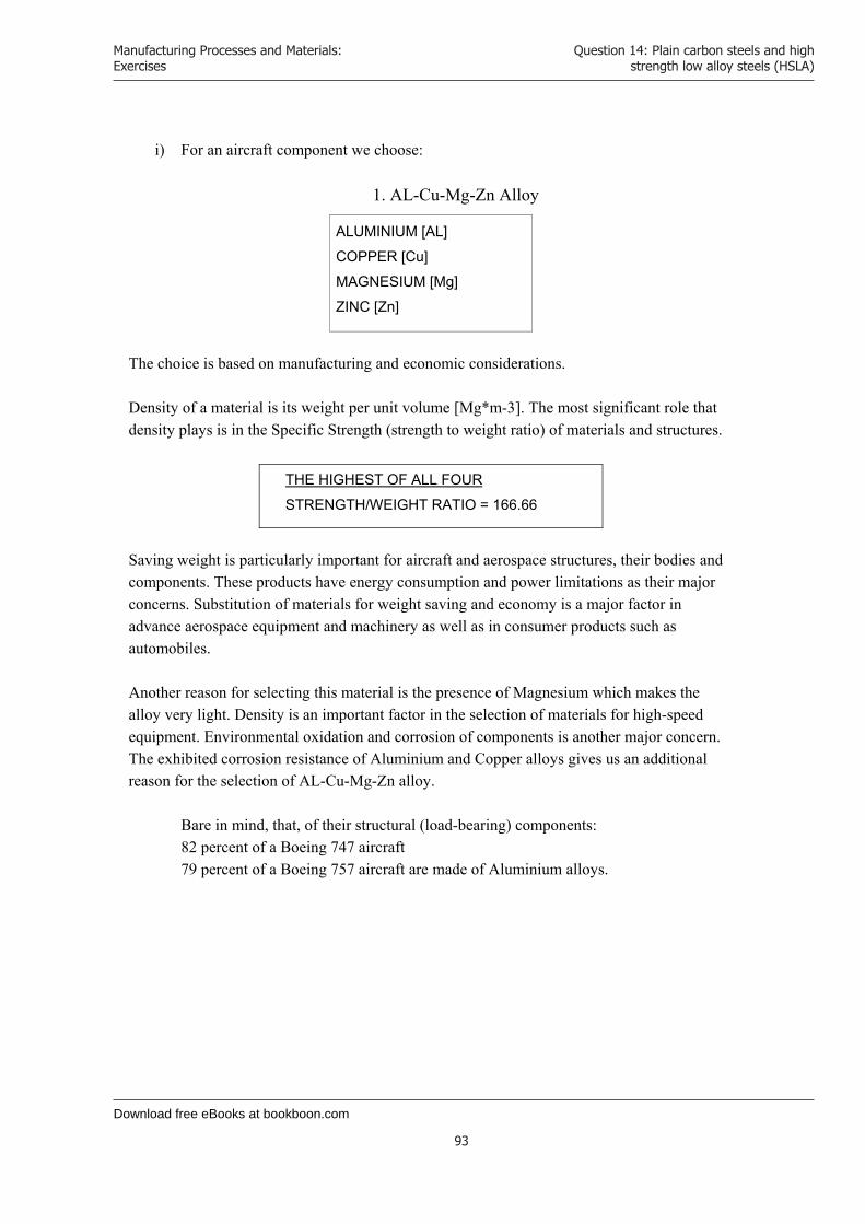
Download free eBooks at bookboon.com
Manufacturing Processes and Materials: Exercises
93
Question 14: Plain carbon steels and high strength low alloy steels (HSLA)
i) For an aircraft component we choose:
1. AL-Cu-Mg-Zn Alloy
ALUMINIUM [AL]
COPPER [Cu]
MAGNESIUM [Mg]
ZINC [Zn]
The choice is based on manufacturing and economic considerations. Density of a material is its weight per unit volume [Mg*m-3]. The most significant role that density plays is in the Specific Strength (strength to weight ratio) of materials and structures.
THE HIGHEST OF ALL FOUR
STRENGTH/WEIGHT RATIO = 166.66
Saving weight is particularly important for aircraft and aerospace structures, their bodies and components. These products have energy consumption and power limitations as their major concerns. Substitution of materials for weight saving and economy is a major factor in advance aerospace equipment and machinery as well as in consumer products such as automobiles. Another reason for selecting this material is the presence of Magnesium which makes the alloy very light. Density is an important factor in the selection of materials for high-speed equipment. Environmental oxidation and corrosion of components is another major concern. The exhibited corrosion resistance of Aluminium and Copper alloys gives us an additional reason for the selection of AL-Cu-Mg-Zn alloy.
Bare in mind, that, of their structural (load-bearing) components: 82 percent of a Boeing 747 aircraft 79 percent of a Boeing 757 aircraft are made of Aluminium alloys.
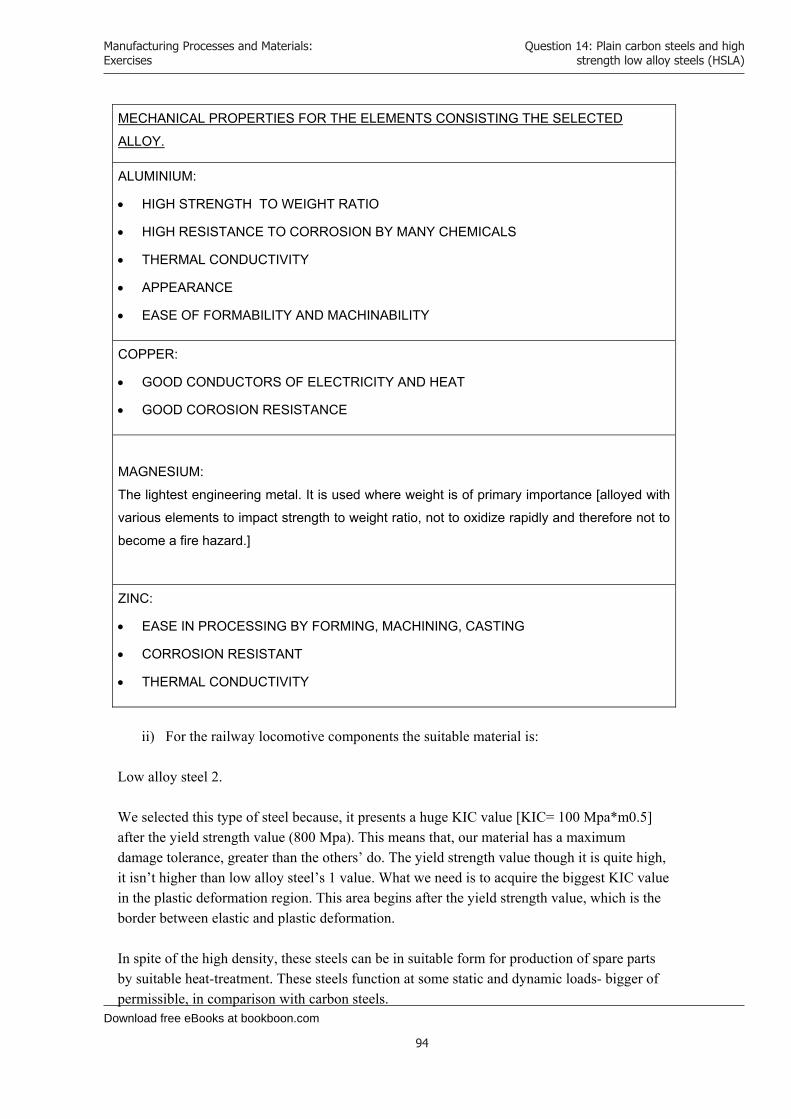
Download free eBooks at bookboon.com
Manufacturing Processes and Materials: Exercises
94
Question 14: Plain carbon steels and high strength low alloy steels (HSLA)
MECHANICAL PROPERTIES FOR THE ELEMENTS CONSISTING THE SELECTED
ALLOY.
ALUMINIUM:
HIGH STRENGTH TO WEIGHT RATIO
HIGH RESISTANCE TO CORROSION BY MANY CHEMICALS
THERMAL CONDUCTIVITY
APPEARANCE
EASE OF FORMABILITY AND MACHINABILITY
COPPER:
GOOD CONDUCTORS OF ELECTRICITY AND HEAT
GOOD COROSION RESISTANCE
MAGNESIUM:
The lightest engineering metal. It is used where weight is of primary importance [alloyed with
various elements to impact strength to weight ratio, not to oxidize rapidly and therefore not to
become a fire hazard.]
ZINC:
EASE IN PROCESSING BY FORMING, MACHINING, CASTING
CORROSION RESISTANT
THERMAL CONDUCTIVITY
ii) For the railway locomotive components the suitable material is:
Low alloy steel 2. We selected this type of steel because, it presents a huge KIC value [KIC= 100 Mpa*m0.5] after the yield strength value (800 Mpa). This means that, our material has a maximum damage tolerance, greater than the others’ do. The yield strength value though it is quite high, it isn’t higher than low alloy steel’s 1 value. What we need is to acquire the biggest KIC value in the plastic deformation region. This area begins after the yield strength value, which is the border between elastic and plastic deformation. In spite of the high density, these steels can be in suitable form for production of spare parts by suitable heat-treatment. These steels function at some static and dynamic loads- bigger of permissible, in comparison with carbon steels.

Download free eBooks at bookboon.com
Click on the ad to read more
Manufacturing Processes and Materials: Exercises
95
Question 14: Plain carbon steels and high strength low alloy steels (HSLA)
c) Name and discuss two alternative heat-treatment sequences to produce the
properties for the low alloy steel in Table Q1. Appropriate heat-treatments.
1. Hardening: Heat to 850 °C, Tempering: Quench to 500 °C, oil quenched Isothermal transformation to upper Bainite [Hardening and tempering at 500-600 °C]
2. Hardening: Heat to 850 °C, Tempering Quench to 300 °C, in salt bath. Isothermal transformation to lower Bainite [Hardening and tempering at 300 °C]

Download free eBooks at bookboon.com
Manufacturing Processes and Materials: Exercises
96
Question 14: Plain carbon steels and high strength low alloy steels (HSLA)
Tempering If steels are hardened by heat treatment, tempering is used in order to reduce brittleness, increase ductility and toughness and reduce residual stresses. In tempering, the steel is heated to a specific temperature, depending on composition and cooled at a prescribed rate. Alloy steels may undergo temper embrittlement caused by the segregation of impurities along the grain boundaries at temperatures between 480 °C and 590 °C. In austempering, the heated steel is quenched from the austenitising temperature rapidly enough to avoid formation of ferrite or pearlite. It is then held at a certain temperature until isothermal transformation from austenite to bainite is complete. It is then cooled to room temperature usually in still air, at a moderate rate to avoid thermal gradients within the part. The quenching medium most commonly used is molten salt, at temperatures ranging from 160 °C and 750 °C.
Download free eBooks at bookboon.com
Manufacturing Processes and Materials: Exercises
97
Question 15: Ferritic stainless steel & the mechanism of corrosion
Question 15: Ferritic stainless steel & the mechanism of corrosion
a) Washing machine tubs are often made from ferritic stainless steel. Discuss concisely the properties of this material, which make it suitable for this application. Name an alternative non-metallic material, which has been used, successfully for this application.
a) Ferritic stainless steels are utilized for washing machine tubs.
Chemical composition: 0.08% - 0.45% Carbon 12% - 27% Chromium
Properties of ferritic stainless steelsTensile Strength: 565 – 620 Mpa Yield Strength: 240 – 290 Mpa Elongation: 55 – 60%
Hardness: to 200 HRC, having a high Carbon content 0.26 – 0.45%, hardness will increase to 51 HRC.
Corrosion resistance: High value
Weldability: Satisfactory. Arch or gas welding.
Ferritic stainless steels can have a higher content of Cr and Ni:
Cr – [ 18 – 27 % ] Ni – [3.7 – 5.5 %]
Chromium in higher content improves Stiffness, Corrosion resistance, Machinability and Formability.
Higher Nickel content improves Strength and Toughness.
The alternative non-metallic materials, which have been used, are:
1. Polycarbonates, having very good mechanical properties and a high strength. They have low absorbability in contact with the water.
2. Polyamides 3. Fibre glass from polyester-acryl 4. Phenol-formaldehyde 5. Fiber-reinforced epoxies
Download free eBooks at bookboon.com
Manufacturing Processes and Materials: Exercises
98
Question 15: Ferritic stainless steel & the mechanism of corrosion
b) Early twin-tub washing machines often suffered from corrosion failures. Explain carefully the nature and mechanism of this type of failure and state how it has been overcome in modern front loading machines.
The nature of corrosion.
The corrosion is a surface destroying mechanism of metals and steels, as a result of a chemical and electrochemical influence of aggressive environment.
The corrosion is of two types: even and uneven.
1. Chemical corrosion appears as a result of interaction between the metal and environment (gas or non-electrolyte).
2. Electrochemical corrosion is associated with electrolyte. In this mode the character of the effect produced is electrochemical.
The mechanism of corrosion.
The atoms (ions) must receive a rather huge kinetic energy in order to tear off the surface of metal. Let’s assume that the metal has dipped into the water or into a solution of acid salt (electrolyte). We have to expect that an interaction will take place between them. Water molecules will possess positive and negative electric charges and create dipoles. Dipoles will attract cations from the surface of the metal. In this way, the energy necessary for tearing one ion off the metal surface will decrease considerably and the cations will start to be transferred in the water solution. This will cause the chemical combination between water molecules and metal cations.
[Cation (-) M(+)] + n *H2O M(+)n *H2O + Cation (-)
metal Cation + water molecule hydrated ion + free electron
The cations will continue to be transferred into the water solution while in the metal their respective electrons won’t move. Thus, creating on the border between metal and the solution a potential difference (electronic potential). The potential difference will reach the highest value when the cations will finish to tear off the surface of the metal, resulting in dynamic balance.This means that, the number of cations been transferred in the solution equals to the dehydrated and precipitated ions on the surface of the metal.
Assuming that a double phase system is dipped into a solution of electrolyte, then two heterogeneous crystals will make a short circuit of galvanic elements. In electrolyte, the crystal, which has negative potential, will be called anode and the one that has positive will be called cathode.

Download free eBooks at bookboon.com
Click on the ad to read more
Manufacturing Processes and Materials: Exercises
99
Question 15: Ferritic stainless steel & the mechanism of corrosion
Prevention of Corrosion
Ferrous alloys and steels don’t corrode when they get in touch with dry air and pure water. In order to corrode electrolyte is needed to be present. The chemical pure metals corrode with more difficulty, compared to alloys. Corrosion can be transferred by contact between two metals. The metal, which will have negative potential, will corrode faster. Corrosion can be overcome in metals by alloying with other elements.
For example if we alloy: Iron with 12%Cr – Corrosion resistance will be in low levels. Iron with 12 to 14%Cr - Corrosion resistance in moderate to high levels.
The necessary condition in order to acquire corrosion resistance is to create homogeneous solid solutions. The alloys with 12 – 14%Cr are homogeneous solid solutions, which form a preventive layer to protect them from this type of failure.
ENGINEERS, UNIVERSITY GRADUATES & SALESPROFESSIONALSJunior and experienced F/M
Total will hire 10,000 people in 2013. Why not you?
Are you looking for work in process, electrical or other types of engineering, R&D, sales & marketing or support professions such as information technology?
We’re interested in your skills.
Join an international leader in the oil, gas and chemical industry by applying at
www.careers.total.comMore than 600 job openings are now online!
Potential for development
Cop
yrig
ht :
Tota
l/Cor
bis
for development
Potential for exploration
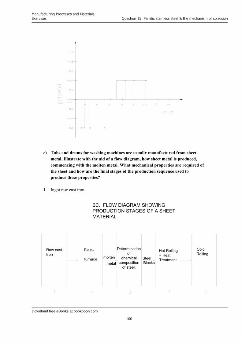
Download free eBooks at bookboon.com
Manufacturing Processes and Materials: Exercises
100
Question 15: Ferritic stainless steel & the mechanism of corrosion
c) Tubs and drums for washing machines are usually manufactured from sheet metal. Illustrate with the aid of a flow diagram, how sheet metal is produced, commencing with the molten metal. What mechanical properties are required of the sheet and how are the final stages of the production sequence used to produce these properties?
1. Ingot raw cast iron.
Raw cast Iron
Blast-
furnace moltenmetal
Determination of
chemical composition
of steel.
Steel Blocks
Hot Rolling + Heat Treatment
Cold Rolling
2C. FLOW DIAGRAM SHOWING PRODUCTION STAGES OF A SHEET MATERIAL.
Download free eBooks at bookboon.com
Click on the ad to read more
Manufacturing Processes and Materials: Exercises
101
Question 15: Ferritic stainless steel & the mechanism of corrosion
2. Blast furnace for production of molten metal.
3. Determination of chemical composition of steel: the liquid metal is manufactured by
combustion of different alloys such as Silicon, Sulfur, Manganese, and Phosphorus in a convector.
4. Hot Rolling + Heat treatment: The mould is heated to a determined temperature and treated in a rolling mill. This is repeated twice. After these procedures the sheet is rolled to the desired thickness. The hot-rolled sheet has a dark exogenous surface and comparatively coarse granules. These sheets need to be annealed to acquire pure metal surface and smaller granule size.
5. Cold Rolling: The sheet is rolled rapidly at room temperature, reducing the thickness of the sheet from 5 mm gradually to 2 mm.
EADS unites a leading aircraft manufacturer, the world’s largest helicopter supplier, a global leader in space programmes and a worldwide leader in global security solutions and systems to form Europe’s largest defence and aerospace group. More than 140,000 people work at Airbus, Astrium, Cassidian and Eurocopter, in 90 locations globally, to deliver some of the industry’s most exciting projects.
An EADS internship offers the chance to use your theoretical knowledge and apply it first-hand to real situations and assignments during your studies. Given a high level of responsibility, plenty of
learning and development opportunities, and all the support you need, you will tackle interesting challenges on state-of-the-art products.
We welcome more than 5,000 interns every year across disciplines ranging from engineering, IT, procurement and finance, to strategy, customer support, marketing and sales. Positions are available in France, Germany, Spain and the UK.
To find out more and apply, visit www.jobs.eads.com. You can also find out more on our EADS Careers Facebook page.
Internship opportunities
CHALLENGING PERSPECTIVES
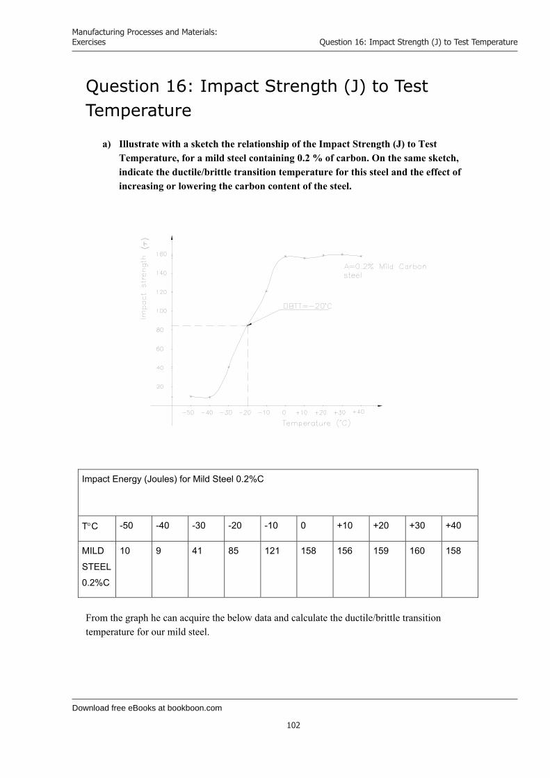
Download free eBooks at bookboon.com
Manufacturing Processes and Materials: Exercises
102
Question 16: Impact Strength (J) to Test Temperature
Question 16: Impact Strength (J) to Test Temperature
a) Illustrate with a sketch the relationship of the Impact Strength (J) to Test Temperature, for a mild steel containing 0.2 % of carbon. On the same sketch, indicate the ductile/brittle transition temperature for this steel and the effect of increasing or lowering the carbon content of the steel.
Impact Energy (Joules) for Mild Steel 0.2%C
TC -50 -40 -30 -20 -10 0 +10 +20 +30 +40
MILD
STEEL
0.2%C
10 9 41 85 121 158 156 159 160 158
From the graph he can acquire the below data and calculate the ductile/brittle transition temperature for our mild steel.

Download free eBooks at bookboon.com
Click on the ad to read more
Manufacturing Processes and Materials: Exercises
103
Question 16: Impact Strength (J) to Test Temperature
For A Lower energy: 10 J
For A Higher energy: 160 J
Total energy: 170 J 2 = 85 J
At 85 J related temperature is –20 C
Therefore, DBTT = -20 C
In our mild steel: By increasing the C%, the DBTT will increase . By lowering the C%, the DBTT will decrease . For example, Mild steel: 0.2%C, 0.5%Mn, has DBTT = 0 C Mild steel: 0.15%C, 1.5%Mn, has DBTT = -20 to -30 C
Maersk.com/Mitas
�e Graduate Programme for Engineers and Geoscientists
Month 16I was a construction
supervisor in the North Sea
advising and helping foremen
solve problems
I was a
hes
Real work International opportunities
�ree work placementsal Internationaor�ree wo
I wanted real responsibili� I joined MITAS because
www.discovermitas.com
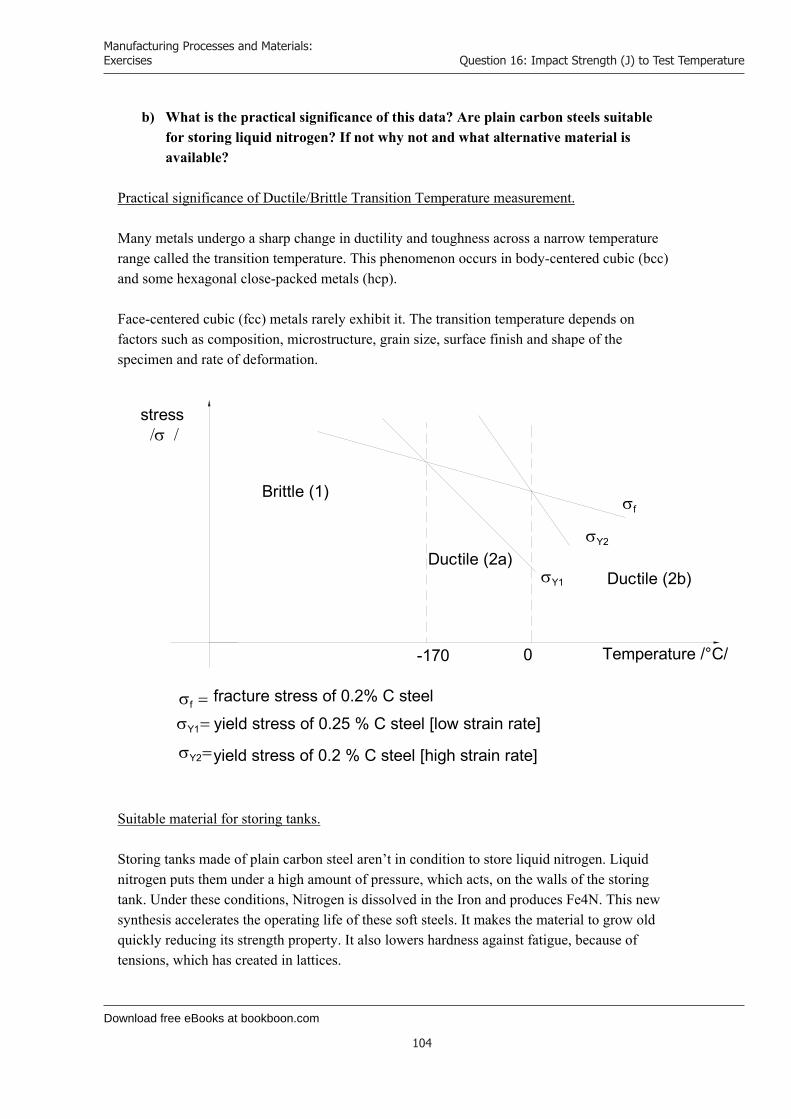
Download free eBooks at bookboon.com
Manufacturing Processes and Materials: Exercises
104
Question 16: Impact Strength (J) to Test Temperature
b) What is the practical significance of this data? Are plain carbon steels suitable for storing liquid nitrogen? If not why not and what alternative material is available?
Practical significance of Ductile/Brittle Transition Temperature measurement. Many metals undergo a sharp change in ductility and toughness across a narrow temperature range called the transition temperature. This phenomenon occurs in body-centered cubic (bcc) and some hexagonal close-packed metals (hcp). Face-centered cubic (fcc) metals rarely exhibit it. The transition temperature depends on factors such as composition, microstructure, grain size, surface finish and shape of the specimen and rate of deformation.
stress
Brittle (1)
Ductile (2a)Ductile (2b)
Y2
Y1
f fracture stress of 0.2% C steel
yield stress of 0.25 % C steel [low strain rate]
yield stress of 0.2 % C steel [high strain rate]
Y2
Y1
f
-170 0 Temperature /°C/
Suitable material for storing tanks. Storing tanks made of plain carbon steel aren’t in condition to store liquid nitrogen. Liquid nitrogen puts them under a high amount of pressure, which acts, on the walls of the storing tank. Under these conditions, Nitrogen is dissolved in the Iron and produces Fe4N. This new synthesis accelerates the operating life of these soft steels. It makes the material to grow old quickly reducing its strength property. It also lowers hardness against fatigue, because of tensions, which has created in lattices.
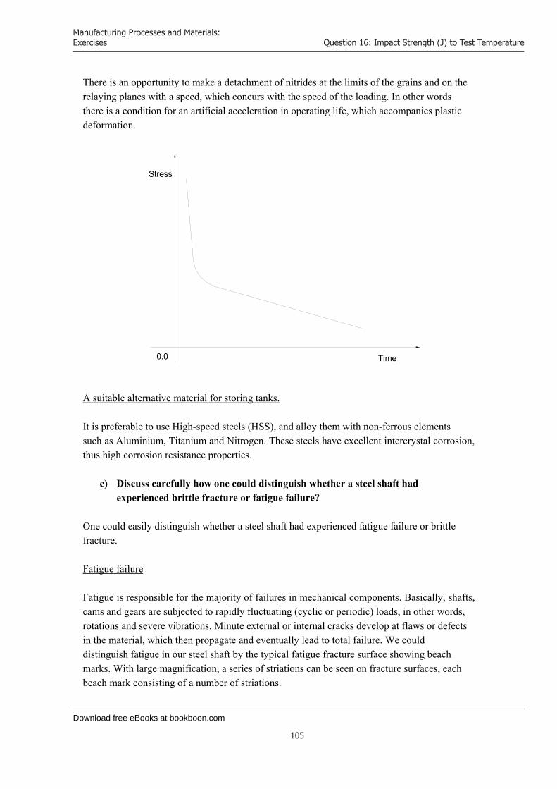
Download free eBooks at bookboon.com
Manufacturing Processes and Materials: Exercises
105
Question 16: Impact Strength (J) to Test Temperature
There is an opportunity to make a detachment of nitrides at the limits of the grains and on the relaying planes with a speed, which concurs with the speed of the loading. In other words there is a condition for an artificial acceleration in operating life, which accompanies plastic deformation.
0.0 Time
Stress
A suitable alternative material for storing tanks. It is preferable to use High-speed steels (HSS), and alloy them with non-ferrous elements such as Aluminium, Titanium and Nitrogen. These steels have excellent intercrystal corrosion, thus high corrosion resistance properties.
c) Discuss carefully how one could distinguish whether a steel shaft had experienced brittle fracture or fatigue failure?
One could easily distinguish whether a steel shaft had experienced fatigue failure or brittle fracture. Fatigue failure Fatigue is responsible for the majority of failures in mechanical components. Basically, shafts, cams and gears are subjected to rapidly fluctuating (cyclic or periodic) loads, in other words, rotations and severe vibrations. Minute external or internal cracks develop at flaws or defects in the material, which then propagate and eventually lead to total failure. We could distinguish fatigue in our steel shaft by the typical fatigue fracture surface showing beach marks. With large magnification, a series of striations can be seen on fracture surfaces, each beach mark consisting of a number of striations.

Download free eBooks at bookboon.com
Click on the ad to read more
Manufacturing Processes and Materials: Exercises
106
Question 16: Impact Strength (J) to Test Temperature
Furthermore, fatigue can be identified by the endurance or fatigue limit. On the below, stress – number of cycles (N), this curve shows, the maximum stress to which the material can be subjected without fatigue failure, regardless of the number of cycles. Any failure below this limit would be considered as other type of failure because there is no fatigue failure occurring below this curve. The fatigue limit for steels is about one-half (1/2) of their tensile strength. Especially, steels have a definite fatigue limit, while other metals do not have one. Brittle fracture Brittle fracture will occur with little or no gross plastic deformation. In our steel it could be identified by the rapid separation of the material into two or more pieces. Brittle fracture mostly occurs under static loads.
d) How may the toughness and tensile strength of brittle thermosets such as PF resin (Bakelite) be increased?
In thermoplastics the typical effects of temperature on the strength, the stiffness and toughness are similar to those for metals. Thus, with increasing temperature, the strength and the stiffness decrease and toughness increases.
“The perfect start of a successful, international career.”
CLICK HERE to discover why both socially
and academically the University
of Groningen is one of the best
places for a student to be www.rug.nl/feb/education
Excellent Economics and Business programmes at:

Download free eBooks at bookboon.com
Manufacturing Processes and Materials: Exercises
107
Question 16: Impact Strength (J) to Test Temperature
Because of the nature of their bonds, temperature or rate of deformation doesn’t affect the strength, stiffness and toughness of thermosets unlike thermoplastics. Moreover, if the temperature is increased sufficiently, the thermosetting begins to burn up and char. Strength, stiffness and toughness will increase, if we reinforce the thermoset with fibers. Reinforced thermosets consist of fibers (the discontinuous or despaired phase). The fibers are strong and stiff and have high specific strength (strength to weight ratio) and specific modulus (stiffness to weight ratio). However, they are generally brittle and abrasive and lack toughness. Thus, fibers themselves have little structural value. The thermosetting matrix is less strong and less stiff but tougher than the fibers. Thus, reinforced thermosets combine the advantages of each of the two constituents. In addition to high specific strength and specific modulus, reinforced thermosets have improved toughness and creep resistance than unreinforced thermosets.

Download free eBooks at bookboon.com
Manufacturing Processes and Materials: Exercises
108
Question 17: Metal and plymer material applicability
Question 17: Metal and polymer material applicability
a) Compare and contrast metals and polymers for use in THREE of the following applications. In each case suggest TWO suitable materials, ONE a metal and a polymer.
v) 300 mm ruler iv) Small rectangular instrument case iii) Office or restaurant chair legs
For the 300-mm ruler we have selected: Polymer: Acrylonitride-butadiene-styrene (ABS). It is dimensionally stable and rigid and has good impact, abrasion and chemical resistance. It has also, high strength, toughness, low temperature properties and electrical resistance. Metal: Aluminium (Al). The important factors in selecting Aluminium are its high strength to weight ratio, resistance to corrosion by many chemicals, high thermal and electrical conductivity, nontoxicity, reflectivity, appearance. Ease of formability and machinability. Aluminium is also nonmagnetic. For the rectangular instrument case we have selected: Polymer: Polystyrene (PS). Polystyrenes are inexpensive materials. They have generally average strength, toughness, chemical and electrical resistance. They are somewhat brittle. Metal: Low carbon steel. It has less than 0.3% carbon. It is generally used for common industrial products that don’t require high strength, hardness and wear resistance. Office or restaurant chair legs. For this application we have chosen: Polymer: ABS Reinforced. It has higher values of strength and stiffness than unreinforced ABS. It is therefore, more stable and rigid and suites the purpose of selection for this application. Metal: Ferritic stainless steel. This type of stainless steel has a high chromium content: up to 27%. It has good strength and impact toughness. It is magnetic and has good corrosion resistance. In comparison with austenitic stainless steel has lower ductility. Ferritic stainless steel is hardened by cold working and is generally used for non-structural applications such as kitchen and office equipment.

Download free eBooks at bookboon.com
Manufacturing Processes and Materials: Exercises
109
Question 17: Metal and plymer material applicability
Applications
300 mm
Ruler
Sm
all rectangular instrument case
Office or restaurant chair legs
Suitable m
aterials A
BS
A
luminium
Polystyrene
Low
Carbon
steel A
BS
Reinforced
Ferritic Stainless
steel
Physical
Density-w
eight Light
light light
Reasonably heavy
light R
easonably heavy
Dim
ensional stability high
high low
m
oderate high
high
Electrical resistivity
moderate
high high
high high
high
Corrosion
resistance-degradation
moderate
high m
oderate m
oderate m
oderate high
Mechanical
Tensile Strength
moderate
high low
low
high
high
Stiffness
high high
low
low
moderate
moderate
Impact Toughness
low
moderate
low
low
moderate
moderate
Resistance to W
ear low
m
oderate low
low
m
oderate m
oderate
Appearance
Surface finish, Texture
excellent excellent
excellent excellent
excellent excellent

Download free eBooks at bookboon.com
Click on the ad to read more
Manufacturing Processes and Materials: Exercises
110
Question 17: Metal and plymer material applicability
b) Choose one of the components already selected and name and justify manufacturing processes for the metal and polymer versions respectively.
We choose the 300-mm ruler and undertake an analysis in the manufacturing processes for the metal and polymer versions respectively. Aluminium ruler Rolling: The process of reducing the thickness or changing the cross-section of our workpiece by compressive forces applied through a set of rolls similar to rolling dough with a rolling pin to reduce its thickness. Our operation is flat rolling where, the rolled products are flat sheets (ruler thickness less than 3 mm).
© Agilent Technologies, Inc. 2012 u.s. 1-800-829-4444 canada: 1-877-894-4414
Teach with the Best. Learn with the Best.Agilent offers a wide variety of affordable, industry-leading electronic test equipment as well as knowledge-rich, on-line resources —for professors and students.We have 100’s of comprehensive web-based teaching tools, lab experiments, application notes, brochures, DVDs/ CDs, posters, and more. See what Agilent can do for you.
www.agilent.com/find/EDUstudentswww.agilent.com/find/EDUeducators
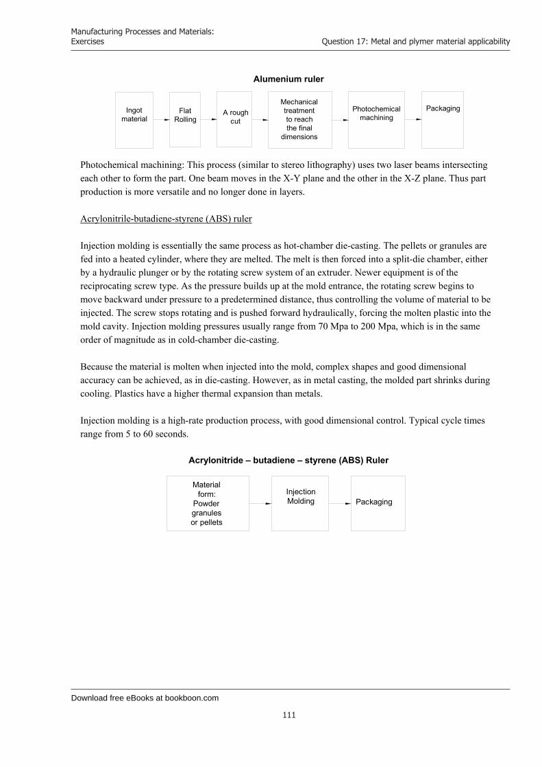
Download free eBooks at bookboon.com
Manufacturing Processes and Materials: Exercises
111
Question 17: Metal and plymer material applicability
Alumenium ruler
Ingotmaterial
FlatRolling
Mechanical treatment to reach the final
dimensions
Photochemicalmachining
PackagingA rough cut
Photochemical machining: This process (similar to stereo lithography) uses two laser beams intersecting each other to form the part. One beam moves in the X-Y plane and the other in the X-Z plane. Thus part production is more versatile and no longer done in layers. Acrylonitrile-butadiene-styrene (ABS) ruler Injection molding is essentially the same process as hot-chamber die-casting. The pellets or granules are fed into a heated cylinder, where they are melted. The melt is then forced into a split-die chamber, either by a hydraulic plunger or by the rotating screw system of an extruder. Newer equipment is of the reciprocating screw type. As the pressure builds up at the mold entrance, the rotating screw begins to move backward under pressure to a predetermined distance, thus controlling the volume of material to be injected. The screw stops rotating and is pushed forward hydraulically, forcing the molten plastic into the mold cavity. Injection molding pressures usually range from 70 Mpa to 200 Mpa, which is in the same order of magnitude as in cold-chamber die-casting. Because the material is molten when injected into the mold, complex shapes and good dimensional accuracy can be achieved, as in die-casting. However, as in metal casting, the molded part shrinks during cooling. Plastics have a higher thermal expansion than metals. Injection molding is a high-rate production process, with good dimensional control. Typical cycle times range from 5 to 60 seconds.
Acrylonitride – butadiene – styrene (ABS) Ruler
Materialform:
Powder granulesor pellets
InjectionMolding Packaging
Download free eBooks at bookboon.com
Manufacturing Processes and Materials: Exercises
112
Question 18: Maximum tolerable through thickness crack size
Question 18: Maximum tolerable through thickness crack size
a) Steam turbine blades are manufactured from austenitic stainless steel. Determine the maximum tolerable through thickness crack size for the components and state any assumptions made. Name and justify a suitable non-destructive technique to locate such cracks.
(Operating stress) = 300 Mpa; KIC = 50 Mpa*m
In this case we use the Stress Intensity factor KIC for center crack length 2a in an infinitive plate. This factor it is given by the formula:
K aIC F C . /1 2
,where F operating stress;
aC = 1/2 critical crack length. We transform the formula to get:
aK
CIC
F
2 1.
aC
50300
0 318472. ,
a mC 8 84610 3, .
Critical crack 2ac = 17,69.10-3 m through thickness crack size for the component. Firstly, let’s see which techniques don’t work for the detection of our flaw: Dye penetration technique. This method can only detect defects that are open on the surface, not internal defects such as the one we have. Magnetic particle inspection technique. This method is appropriate primarily for surface breaking defects and discontinuities not more than 10 mm below the surface of the component. Our through crack size is = 17.7 mm.

Download free eBooks at bookboon.com
Click on the ad to read more
Manufacturing Processes and Materials: Exercises
113
Question 18: Maximum tolerable through thickness crack size
Eddy-current inspection method. Again, and this method is limited to surface and slightly sub surface flaws. Radiography The smallest defect that can be detected is 2% of thickness. The process becomes less reliable as the section thickness increases. In this respect it is a disadvantage compared with ultrasonic testing which can detect small flaws in steel up to 15 meters thick. Other disadvantages are: costly equipment, potential radiation and leakage hazard. The suitable non-destructive technique that we have chosen is the Ultrasonic Inspection method. Ultrasonic Inspection In Ultrasonic Inspection, an ultrasonic beam travels through the part, is interrupted from an internal defect and reflects back a portion of the ultrasonic energy. This method is suitable for our case, because it can be used to inspect flaws in surface and in large volumes of materials (deep flaws). It has also, penetrating power and sensitivity, thus high accuracy.
Get Help Now
Go to www.helpmyassignment.co.uk for more info
Need help with yourdissertation?Get in-depth feedback & advice from experts in your topic area. Find out what you can do to improvethe quality of your dissertation!

Download free eBooks at bookboon.com
Manufacturing Processes and Materials: Exercises
114
Question 18: Maximum tolerable through thickness crack size
b) During service, the blades described in a) must not suffer an axial strain of more than 0.001. Using table Q4.1 below, determine the maximum operating temperature of the blades, if a service life of at least 10,000 hours is required.
Operating temperature (C)
480 500 520 540 560
Strain rate/hour 1.2*10-8 2.5*10-8 4.4*10-8 8.2*10-8 1.6*10-7
Table Q4.1: Creep data for austenitic stainless Steel.
Firstly, we need to find the appropriate strain rate * hour-1value using formula A and then link it to the maximum operating temperature.
Our conditions are: Maximum axial strain value = 0,001 = 10-3
Maximum service life value = 10000 hours = 104 hours
Using, strain rate * hour-1 = 8,2.10-8 we receive: 8,2 . 10-8 .10000 = 0,00082 Which, is an acceptable value for axial strain. In order to find a strain value of 0.001, we need to determine the exact service life value. Manipulating formula A, we receive:
axial strain = service lifestrain rate . hour -1
The above number satisfies the second condition we have been given. Using, these service life values into formula A we get:
8,2 . 10-8 . 12,195 = 0,001 axial strain Thus, satisfying the first condition, by keeping axial strain 0.001 as our maximum axial strain value. We have determined:
strain rate . hour -1 . Service life = axial strain A
strain rate . hour -1 = 8,2 . 10-8
Service life = 12,195 hours
195,1210.2,8001,0
8 hours

Download free eBooks at bookboon.com
Click on the ad to read more
Manufacturing Processes and Materials: Exercises
115
Question 18: Maximum tolerable through thickness crack size
Using the above strain rate * hour-1 value we accept that the maximum operating temperature is:
c) A dentist’s drill rotates at 4,000 revolutions per second (rps). The drill has experienced the service history shown in table Q4.2 below. Using Miner’s rule (the cumulative damage law), estimate the remaining life expectancy of the drill in seconds, if it is operated at a stress range of 350 Mpa. Hence determine whether or not the drill bit should be changed before the next operation, which requires an estimated drilling time of 30 seconds.
Stress Range (Mpa) 250 300 350
N (cycles) 1 * 109 1 * 108 1 * 107
N(cycles) 1 * 109 1 * 107 5 * 106
Table Q4.2: The Service History of a Dentist’s Drill Miner’s Rule [ the cumulative damage law]
nN 1
T = 540 C
© U
BS
2010
. All
rig
hts
res
erve
d.
www.ubs.com/graduates
Looking for a career where your ideas could really make a difference? UBS’s
Graduate Programme and internships are a chance for you to experience
for yourself what it’s like to be part of a global team that rewards your input
and believes in succeeding together.
Wherever you are in your academic career, make your future a part of ours
by visiting www.ubs.com/graduates.
You’re full of energyand ideas. And that’s just what we are looking for.

Download free eBooks at bookboon.com
Manufacturing Processes and Materials: Exercises
116
Question 18: Maximum tolerable through thickness crack size
life expectancy = 1750 sec
Where, n = number of stress cycles; N = number of stress cycles to cause failures.
Stress(MPa)
Log N
Grounded case
1Nn
Nn
Nn
Nn
4
4
3
3
2
2
1
1
110n
1010
1010
1010
74
7
6
8
7
9
8
74 10.1,01,01,01n
700000010.7,0n 74
The speed of the drill is 4000 rev/sec 7000000
4000= 1750 sec = 29,17 min
Therefore, the drill bit shouldn’t be changed before the next 30 sec operation because the remaining life expectancy is a huge number compared with the drilling time.

Download free eBooks at bookboon.com
Manufacturing Processes and Materials: Exercises
117
Question 19: Glass fibres production - Reinforced composite design
Question 19: Glass fibres production - Reinforced composite design
a) Describe concisely how glass fibres are produced and how and why they are protected from surface damage. Using the data below, determine the maximum flaw size to ensure a minimum glass fibre tensile strength of 2,200 Mpa.
E = 100 Gpa; = 0.8 J * m-2
Glass fibers are the most widely used and least expensive of all fibers. The composite material is called glass-fiber reinforced plastic (GFRP) and may contain between 30% and 60% glass fibers by volume. Drawing molten glass through small openings in platinum dies makes Glass fibers. Continuous fibers are drawn through multiple (200-400) orifices in heated platinum plates at speeds as high as 500 m/s. Fibres as small as 2m in diameter can be produced by this method. In order to protect their surfaces, the fibers are subsequently coated with chemicals. Surface treatment may be necessary to:
Impart color or special surface texture Improve corrosion and oxidation resistance Improve stiffness and fatigue resistance
Griffith’s Crack Criteria formula:
2/1
F a.E..2
,where F critical stress for crack propagation, [N.m-2];
surface energy or work of Fracture, [J.m-2];
E Young’s Modulus or Modulus of Elasticity, [N.m-2]; = 3,14; a crack depth, [m]. glass fibre tensile strength F = 2200 MPa = 2,2 GPa = 2,2.109 N.m-2 surface energy = 0,8 J.m-2 Young’s Modulus E = 100 GPa = 100.109 N.m-2

Download free eBooks at bookboon.com
Click on the ad to read more
Manufacturing Processes and Materials: Exercises
118
Question 19: Glass fibres production - Reinforced composite design
First resolution
a.10.100.8,0.2
a.10.100.8,0.210.2,2
999
2
9
92
10.2,2.10.100.8,0.2
a
77229
9
10.84,4.14,36,1
10.2,2.14,38,0.2
10.2,2.10.100.8,0.2a
710.105,0a 910.5,10a m = 10,5.10 6 mm
Second resolution
a.14,3
10.100.8,0.210.2,29
29
9
929
9
10.5,1010.84,4.14,3
100.6,110.84,4.14,310.100.6,1a mm
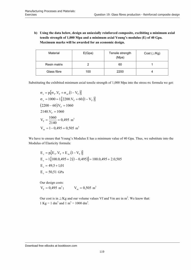
Download free eBooks at bookboon.com
Manufacturing Processes and Materials: Exercises
119
Question 19: Glass fibres production - Reinforced composite design
b) Using the data below, design an uniaxially reinforced composite, excibiting a minimum axial
tensile strength of 1,000 Mpa and a minimum axial Young’s modulus (E) of 40 Gpa. Maximum marks will be awarded for an economic design.
Material E(Gpa) Tensile strength (Mpa)
Cost (/Kg)
Resin matrix 2 60 1
Glass fibre 100 2200 4
Substituting the exhibited minimum axial tensile strength of 1,000 Mpa into the stress c formula we get:
FmFFc V1.V..p
FFc V1.60V.2200.11000
1060V.602200 F
1060V.2140 F
495,021401060VF m3
505,0495,01Vm m3 We have to ensure that Young’s Modulus E has a minimum value of 40 Gpa. Thus, we substitute into the Modulus of Elasticity formula:
FmFFc V1.EV.E.pE
505,0.2495,0.100495,01.2495,0.100.1Ec
01,15,49Ec
51,50Ec GPa
Our design costs: 495,0VF m3 ; 505,0Vm m3
Our cost is in /Kg and our volume values Vf and Vm are in m3. We know that: 1 Kg = 1 dm3 and 1 m3 = 1000 dm3.
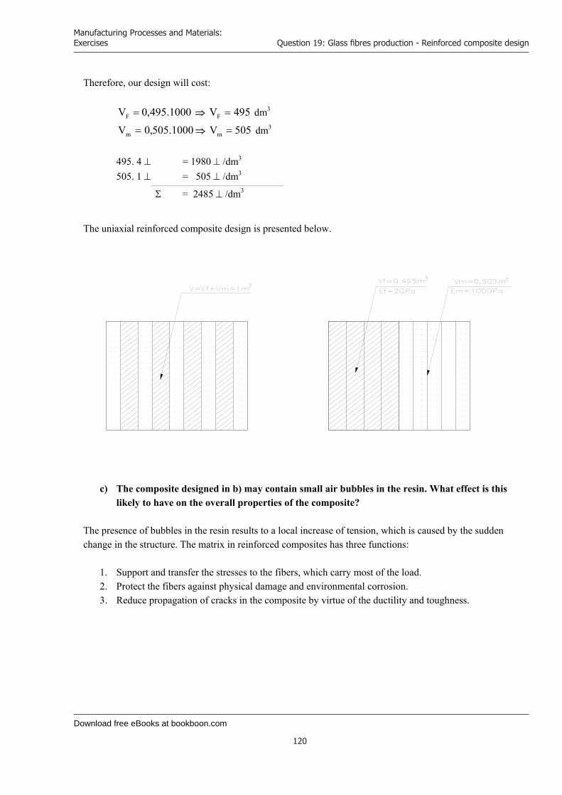
Download free eBooks at bookboon.com
Manufacturing Processes and Materials: Exercises
120
Question 19: Glass fibres production - Reinforced composite design
Therefore, our design will cost:
1000.495,0VF 495VF dm3
1000.505,0Vm 505Vm dm3
495. 4 = 1980 /dm3 505. 1 = 505 /dm3
= 2485 /dm3
The uniaxial reinforced composite design is presented below.
c) The composite designed in b) may contain small air bubbles in the resin. What effect is this likely to have on the overall properties of the composite?
The presence of bubbles in the resin results to a local increase of tension, which is caused by the sudden change in the structure. The matrix in reinforced composites has three functions:
1. Support and transfer the stresses to the fibers, which carry most of the load. 2. Protect the fibers against physical damage and environmental corrosion. 3. Reduce propagation of cracks in the composite by virtue of the ductility and toughness.
Download free eBooks at bookboon.com
Click on the ad to read more
Manufacturing Processes and Materials: Exercises
121
Question 19: Glass fibres production - Reinforced composite design
The presence of bubbles causes a weak strength of the bond between the fiber and the polymer matrix. Thus, our composite under static loading will present fiber pullout and delamination of the structure, particularly under adverse environmental conditions. The presence of bubbles reduces ductility and toughness of the composite, which means that, under static loading (transmitted through the fiber-matrix interface) the structure is expected to fail (brittle failure). This case is analogous to opening holes in a brick structure. It causes poor bonding between the bricks and the mortar. Under loading and extensive tension along the surface the structure collapses.
www.sylvania.com
We do not reinvent the wheel we reinvent light.Fascinating lighting offers an infinite spectrum of possibilities: Innovative technologies and new markets provide both opportunities and challenges. An environment in which your expertise is in high demand. Enjoy the supportive working atmosphere within our global group and benefit from international career paths. Implement sustainable ideas in close cooperation with other specialists and contribute to influencing our future. Come and join us in reinventing light every day.
Light is OSRAM
Download free eBooks at bookboon.com
Manufacturing Processes and Materials: Exercises
122
References
References
1. K. L. Edwards. Designing of engineering components for optimal materials and manufacturing process utilisation. Materials & Design, Volume 24, Issue 5, August 2003, Pages 355-366.
2. M.V. Gandhi, B.S. Thompson, F. Fischer. Manufacturing-process-driven design methodologies for components fabricated in composite materials. Composites Manufacturing, Volume 1, Issue 1, March 1990, Pages 32-40.
3. M. Jahazi, S. Hossein-Nejad. The development of an optimum manufacturing and material selection process for the fabrication of labyrinth seal strips. Journal of Materials Processing Technology, Volume 152, Issue 3, 30 October 2004, Pages 272-275.
4. P. Eyerer, B. Wiedemann, K. -H. Dusel, B. Keller. Materials for solid freeform manufacturing processes. Computers in Industry, Volume 28, Issue 1, December 1995, Pages 35-45.
5. Yong-Min Kwak, Charalabos C. Doumanidis. Geometry Regulation of Material Deposition in Near-Net Shape Manufacturing by Thermally Scanned Welding. Journal of Manufacturing Processes, Volume 4, Issue 1, 2002, Pages 28-41.
6. K.P. Karunakaran, S. Suryakumar, Vishal Pushpa, Sreenathbabu Akula. Low cost integration of additive and subtractive processes for hybrid layered manufacturing. Robotics and Computer-Integrated Manufacturing, Volume 26, Issue 5, October 2010, Pages 490-499.
7. B. Gopalakrishnan, V. Pandiarajan. Materials and manufacturing processes selection system for product designs in concurrent engineering. Journal of Materials Processing Technology, Volume 28, Issues 1-2, September 1991, Pages 93-103.
8. M. Perzyk, O. K. Meftah. Selection of manufacturing process in mechanical design. Journal ofMaterials Processing Technology, Volume 76, Issues 1-3, April 1998, Pages 198-202.
9. F. Liu, H. Zhang, P. Wu, H. J. Cao. A model for analyzing the consumption situation of product material resources in manufacturing systems. Journal of Materials Processing Technology, Volume 122, Issues 2-3, 28 March 2002, Pages 201-207.
10. Shaw C. Feng, Eugene Y. Song. A manufacturing process information model for design and process planning integration. Journal of Manufacturing Systems, Volume 22, Issue 1, 2003, Pages 1-15.
11. I. Ferrer, J. Rios, J. Ciurana. An approach to integrate manufacturing process information in part design phases. Journal of Materials Processing Technology, Volume 209, Issue 4, 19 February 2009, Pages 2085-2091.
12. M.V Gandhi, B.S Thompson, F Fischer. Manufacturing-process-driven design methodologies for components fabricated in composite materials. Materials & Design, Volume 11, Issue 5, October 1990, Pages 235-242.
13. M. Hou, L. Ye, Y.W. Mai. Manufacturing process and mechanical properties of thermoplastic composite components. Journal of Materials Processing Technology, Volume 63, Issues 1-3, January 1997, Pages 334-338.
14. C. J. Luis Pérez, J. Vivancos Calvet, M. A. Sebastián Pérez. Geometric roughness analysis in solid free-form manufacturing processes. Journal of Materials Processing Technology, Volume 119, Issues 1-3, 20 December 2001, Pages 52-57.
15. Shu-Kai S. Fan, Yen Lin. Multiple-input dual-output adjustment scheme for semiconductor manufacturing processes using a dynamic dual-response approach. European Journal of Operational Research, Volume 180, Issue 2, 16 July 2007, Pages 868-884.
Download free eBooks at bookboon.com
Manufacturing Processes and Materials: Exercises
123
References
16. Elvin Karana, Paul Hekkert, Prabhu Kandachar. Meanings of materials through sensorial properties and manufacturing processes. Materials & Design, Volume 30, Issue 7, August 2009, Pages 2778-2784.
17. A. M. Lovatt, H. R. Shercliff. Manufacturing process selection in engineering design. Part 1: the role of process selection. Materials and Design, Volume 19, Issues 5-6, 17 December 1998, Pages 205-215.
18. S.H. Choi and, H.H. Cheung. A topological hierarchy-based approach to toolpath planning for multi-material layered manufacturing. Computer-Aided Design, Volume 38, Issue 2, February 2006, Pages 143-156.
19. W. B. Lee, C. F. Cheung, J. G. Li. Applications of virtual manufacturing in materials processing. Journal of Materials Processing Technology, Volume 113, Issues 1-3, 15 June 2001, Pages 416-423.
20. S. Kalpakjian. Manufacturing processes for engineering materials: Addison Wesley Publishing Company, Reading, Ma. 1984, 839pp.
21. R. E. Kirchain. Cost Modeling of Materials and Manufacturing Processes. Encyclopaedia ofMaterials: Science and Technology, 2008, Pages 1718-1727.
Click on the ad to read more
Manufacturing Processes and Materials: Exercises
124
Endnotes
Endnotes * Q - queue
** A - activity
www.mastersopenday.nl
Visit us and find out why we are the best!Master’s Open Day: 22 February 2014
Join the best atthe Maastricht UniversitySchool of Business andEconomics!
Top master’s programmes• 33rdplaceFinancialTimesworldwideranking:MScInternationalBusiness
• 1stplace:MScInternationalBusiness• 1stplace:MScFinancialEconomics• 2ndplace:MScManagementofLearning• 2ndplace:MScEconomics• 2ndplace:MScEconometricsandOperationsResearch• 2ndplace:MScGlobalSupplyChainManagementandChange
Sources: Keuzegids Master ranking 2013; Elsevier ‘Beste Studies’ ranking 2012; Financial Times Global Masters in Management ranking 2012
MaastrichtUniversity is
the best specialistuniversity in the
Netherlands(Elsevier)