computer aided modelling exercises
TRANSCRIPT

1
Computer Aided Modelling Exercises
Monique Snoeck1, Raf Haesen1,3, Herman Buelens2, Manu De Backer1, Geert Monsieur1 Katholieke Universiteit Leuven
1Management Information Systems, Naamsestraat 69, 3000 Leuven 2Dienst Universitair Onderwijs, Naamsestraat 98, 3000 Leuven
3Campus Vlekho, Koningsstraat 336, 1000 Brussels E-mail: {monique.snoeck, raf.haesen, manu.debacker, geert.monsieur}@econ.kuleuven.be,
Abstract This paper describes a didactical Computer Aided Software Engineering (CASE)-tool that was developed for use within the context of a course in object-oriented domain modelling. In particular, the tool was designed to address several inconveniences that challenge the realisation of the course objectives: the number of students enrolled does not allow for individual feedback (a); students have little opportunity to build a concrete information system, therefore they fail to predict the consequences of the different choices when building a conceptual model (b); students lack examples and practice on how to convert a conceptual model into a concrete information system (c); at the beginning of the course students have very different levels of prior knowledge leading to major differences in motivation and learning outcomes (d), The tool was evaluated positively by the students and was shown to have a positive impact on the student’s capabilities to construct object-oriented models. It is argued that even better learning results can be realised by capitalizing on the opportunities for social interaction in an educational context. Keywords Teaching object-oriented modelling, computer aided modelling, CASE, automated consistency control in modelling processes, prototyping and concretizing models, model driven development
1. Educational context The main goal of the course “object-oriented business modelling”(1) is to familiarise students with object-oriented analysis techniques and to have them acquire the necessary skills to actually perform business modelling. In addition, students should be able to envisage the mutual relationship and influence between the IT-system and the organisational work system. For example, the student should learn to evaluate the implications of differences between models both from an IT and an organisational perspective. As a prerequisite, the students should have basic knowledge of and have written and run simple programs in at least one computer programming language, preferably an object oriented one. The course is taught in the second semester of the academic year. About 20 to 40 students with very different levels of programming expertise and educational background are enrolled in the course. To achieve the objectives of the course students need to make a lot of exercises. Therefore, some years ago a series of paper and pencil exercises was finished. Exercises started with a textual description of some user requirements, which should be interpreted by the student and transformed into an object-oriented business model. Given the fact that such user requirements can and will be interpreted in different ways (because of their informal aspect) by students, students should receive individual feedback on their solution. Additionally, a detailed comparison of their solution with a model-solution and/or with alternative solutions of other students should stimulate them to actively explore the consequences and implications of their own particular modelling choices. Unfortunately, both the number of students enrolled and the use of paper and pencil exercises hamper the realisations of these (course) objectives. Furthermore, students have very different levels of prior knowledge at the beginning of the course. This leads to major differences in motivation and learning outcomes (d).
1 The course’s page can be found on http://mermaid.econ.kuleuven.be/content.aspx/

2
In order to address the inconveniences that challenge the realisation of the course objectives, a didactical Computer Aided Software Engineering (CASE)-tool was developed. The remainder of the paper is structured as follows. The second section describes the functionality of the tool. It starts with a description of the supported modelling techniques. We then define the goal of the tool and describe the features of the tool that support these goals as far as the modelling process is concerned. The section continues with a description of the prototyping facility and concludes with explaining how the tool improves taking differences in prior knowledge into account. Subsequently, section three describes how the tool is used in the context of the course and how it contributes to the learning process. Section four then reports on our experiences and the evaluation of the tool by the students. Finally, section 5 suggests some future directions. 2. Realisations
2.1 Modelling techniques supported by the tool
An object-oriented business model typically consists of several views that together define a platform independent model that is a formal representation of the user requirements. In the modelling method used in this course, a business domain model consists of a class diagram, an interaction model and a number of state charts. The class diagram is a restricted form of UML class diagram: the types of associations are limited to binary associations, with a cardinality of 1 to many or 1 to 1. Many to many associations need to be converted to an intermediate class. The interaction model consists of an object-event table, created according to the principles of Merode (Snoeck and Dedene, 1998). In Merode, "business events" represent atomic actions from the real world in which one or more business domain object can participate. In the Object-Event Table the requirements engineer indicates which domain object type is involved in the processing of a given business event. This processing can be the creation, modification or ending of an instance of that domain object type, respectively indicated with C, M or E in the table (see Table 1). As an example, adding an order line to an order to order a product, will require the domain object type PRODUCT to verify the availability of the product and update the stock-level of that product, will require the domain object type ORDER LINE to create an instance of that class and will require the domain object type ORDER to add the created order line to the order instance. Finally, the platform independent model of the domain contains one or more finite state machines per domain object type. The finite state machines allow the object type to impose sequence constraints on the business events it is involved in. Multiple Finites State Machines allow to model independent aspects as parallel machines. A simple example illustrates the complete process. Figure 1 shows the data-view of a small domain model in which buses can be assigned to regular line services or to special trips. Besides the specification of informational requirements, modelling cases always include a significant behavioural aspect. In this case, the business rules for the line service specify a process that includes approval of a new proposed line service by town authorities. When the company asks for approval, that approval may be refused without appeal or town authorities may ask the bus company to change the trajectory upon which the company may ask again for approval. This procedure may be repeated a number of times. When approval is given, the line service is included in the business of the company to become operational. From that time on, busses can be assigned to the line service. The line service may be suspended for some time for all kinds of reasons. At a certain moment in time, the line service is cancelled. The list of events is set of against the participating object types from the class diagram in the object-event table shown in Table 1. The resulting life cycle of line service is shown in Figure 2.

3
Figure 1. Data View for the Bus Company
Figure 2: FSM for Line Table 1. Object-Event Table BUS LINE SPECIAL ASSIGNMENT _TO_LINE ASSIGNMENT _TO_SPECIAL create_bus C modify_bus M end_bus E create_line C modify_line M end_line E refuse E change M suspend M release M approve M require_change M request_approval M create_special C modify_special M end_special E assign_to_line M M C modify_assign_to_line M M M end_assign_to_line M M E assign_to_special M M C modify_assign_to_special M M M end_assign_to_special M M E

4
2.2 Goal of the CASE-tool
The goal of the modelling tool is to support the didactical aspects of teaching object-oriented analysis: 1. During the modelling process, the tool should offer a number of techniques to provide the student
with feedback on the quality of the developed model. 2. The tool should help the student in building a mental model of a concrete information system build
from the conceptual model. Starting from an existing in-house made CASE-tool, the tool was modified in order to • provide interactive feedback and verification on models and • offer a prototyping facility which allows to have an idea of what the resulting information system
could be like and to verify the correct implementation of the user requirements. Special attention is given to realise the behavioural aspects and the "process logic" as modelled in finite-state machines. The prototype should focus on these aspects and not be restricted to an MS Access-like implementation with only the classical insert-update-delete forms on database tables.
The existing CASE-tool was augmented with a number of features. The features have been modularized and can be turned on and off using the project settings.
Figure 3 Turning educational features on and off per project.
2.3 Interactive feedback and Verification of models
In order to provide students with an elementary form of feedback, a model-to-text feature which converts a model to plain English has been provided. In previous years we experienced that "reading" the data view aloud (like " This model says that… Is that what you meant?"), very often was sufficient to make students realise obvious mistakes. Especially students who are totally unfamiliar with modelling benefit from this feature. This model-to-text facility is called the "learning report" and has been implemented for the data view (see Figure 4). Students can request for a learning report to pop up each time when drawing an association between classes, or can request a learning report for the data view as a whole.

5
Figure 4 Example of the learning report for the data view
A second feature concerns the tool’s intelligence for managing consistency between the three views of the universe of discourse: the data view, the behavioural view and the interaction view. In its initial form, the tool followed a "consistency-by-construction" approach (Haesen and Snoeck, 2004; Snoeck et al., 2003). In this approach, each time when entering specifications in one view, specifications that can be derived for other views are automatically generated by the tool. As an example, one of the design guidelines states that when defining a class, one should provide at least one method to create instances of that class and one method to terminate instances. So, when defining a class "customer" in the data view, a creating and ending method cr_customer and end_customer are automatically generated and the corresponding events that trigger the execution of these methods (see Figure 5). In the new version of the tool, students can switch this generative feature on and off. If switched off, the student can request a verification report that will warn the student about the missing elements, upon which the student can manually add the necessary methods and events
Figure 5 Automatic generation of creating and ending methods for a class
Also the behavioural modelling with finite state machines has been augmented with a number of verification tools. The first set of tools act on a finite state machine and report about anomalies in the diagram: forward and backward inaccessible state, non-determinism and missing methods (see Figure 6).
6
Figure 6. Checking Finite State Automata
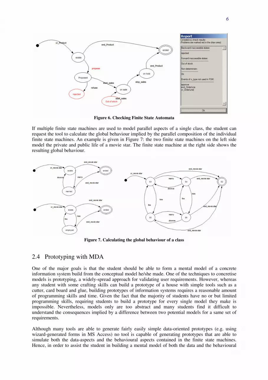
If multiple finite state machines are used to model parallel aspects of a single class, the student can request the tool to calculate the global behaviour implied by the parallel composition of the individual finite state machines. An example is given in Figure 7: the two finite state machines on the left side model the private and public life of a movie star. The finite state machine at the right side shows the resulting global behaviour.
Figure 7. Calculating the global behaviour of a class
2.4 Prototyping with MDA
One of the major goals is that the student should be able to form a mental model of a concrete information system build from the conceptual model he/she made. One of the techniques to concretise models is prototyping, a widely-spread approach for validating user requirements. However, whereas any student with some crafting skills can build a prototype of a house with simple tools such as a cutter, card board and glue, building prototypes of information systems requires a reasonable amount of programming skills and time. Given the fact that the majority of students have no or but limited programming skills, requiring students to build a prototype for every single model they make is impossible. Nevertheless, models only are too abstract and many students find it difficult to understand the consequences implied by a difference between two potential models for a same set of requirements. Although many tools are able to generate fairly easily simple data-oriented prototypes (e.g. using wizard-generated forms in MS Access) no tool is capable of generating prototypes that are able to simulate both the data-aspects and the behavioural aspects contained in the finite state machines. Hence, in order to assist the student in building a mental model of both the data and the behavioural

7
view, the CASE-tool generates a completely running Java application using a code generator based on the Model Driven Architecture (MDA) (see www.omg.org/mda). This prototyping feature has been build using the AndroMDA-framework (see andromda.org), based on the considerations that it is open source, provides a number of existing cartridges for object persistence and is extensible with proprietary cartridges. The transition from the case-tool to AndroMDA is achieved by means of XMI: the student exports his model to XMI format and submits the file to the AndroMDA-application on the server. By means of a number of cartridges (some of which have been developed for Mermaid), the XMI-file is transformed to code. The student receives a ZIP-archive, containing both a compiled application and the source-code (see Figure 8).
Figure 8: Mermaid in the AndroMDA framework
2.5 Discovering relationships between models and prototype applications
When using the prototype to test, visualize and concretize the model, the student interacts with the generated application through the graphical user interface (GUI). This allows assessing the desired functionality and behaviour. In case the application does not contain the desired functionality, the student can start a trial and error based correction process by changing the models and regenerating a prototype with the tool. The correction process can be improved or sped up by giving students deeper insight in what is hidden beneath the GUI and how prototype generation is realized. Code and prototype generation occurs with precisely defined transformations. These transformations express relationships between high-level abstract models and the low-level concrete behaviour and working of applications based on the models. These relationships define the meaning of high-level modelling concepts, which students should understand very well in a modelling process. Before we will discuss some relationships (and thus transformations) in detail, we give a short overview of the structure of a generated prototype application. It consists of three layers, a graphical user interface (GUI) layer, an event handling layer and a persistence layer (see Figure 9). The graphical user interface has only basic functionality like triggering the creating and ending of objects, and triggering other business events. The GUI layer is built on top of the event handling layer. The task of the latter layer is to handle all events correctly by managing the appropriate interactions with the objects in the persistence layer.

8
Figure 9. Layers in the generated prototype
Relationships between modeling concepts and generated application layers
Persistence layer Generation of the persistence layer is quite straightforward. The basic elements of this layer are easy to understand for students, in particular for the students with a background in database management. However, there is one crucial element in the persistence layer, namely the concept of state objects. This brings us to an important relationship. Students should know that each object has a reference to a generated state object that stores the current state of the object. State objects are built according to the finite state machines defined in the business model. Event handling layer This layer consists of a collection of so called event handlers. Obviously the object-event table is a platform independent interaction model, but cannot be implemented as such. The implementation of a business event requires the elaboration of a collaboration schema that specifies the required interactions to process the actions associated with a business event. Crucial in the students learning process is the understanding of the relationship between a business event defined in the model and a corresponding event handler. Students must know the working of an event handler, so that they understand the meaning of a business event. The working of an event handler can be described in four steps: Step 1 The event handler ‘asks’ every participating object (an object which is involved in the processing of a business event) whether all preconditions set by the object are met. These preconditions can be defined by the analyst, but also include conditions that can be derived from other parts of the model. For example, associations between classes will lead to preconditions to maintain referential integrity. Step 2 Similarly to the previous step the event handler retrieves from every participating object its current state (or reference to the corresponding state object) and checks whether that state allows further processing of the event. Step 3 If all results of the tasks in step 1 and 2 are positive, the event handler invokes the methods in the participating objects which correspond with the triggered event to process the event in the specific object. Step 4 Next, (if all results of the tasks in step 1 and 2 are positive) the event handler executes in all state objects retrieved in step 2 the method for modifying the state (according to the triggered event). While executing a business event in a prototype application users (or students) can follow in a separated application window a kind of trace log of what is happening beneath the GUI of the generated application. Figure 10 shows example of the execution steps for the event assign_to_line.

9
Figure 10. Trace log of execution steps for the event assign_to_line
GUI Layer The GUI layer is the visible part of the application. The generated application provides a main menu with one button per class (Figure 11). Each class has a window that allows viewing the list of instances of that class and one button per event to trigger methods of that class (Figure 12). The list shows the values of the attributes and the value of the state. In addition, buttons allow navigating to related instances, e.g. the assignment_to_line or assigment_to_special objects.
Figure 11. Main menu for the prototype application

10
Figure 12. Screen per Domain Class
By clicking a button, the execution of the event is requested. The event window will then request the user to choose the instances of the objects involved in the event (Figure 13). If an event is rejected (e.g. because not allowed in that state), the application gives the result of the rejection (Figure 14). This allows the student to validate whether the scenarios allowed and rejected by the application match the user requirements.
Figure 13. Screen to trigger an event
Figure 14. Business Rule Violation

11
2.6 Taking into account (differences in) prior knowledge
The tool is used by students with a large variation in prior knowledge of object-oriented concepts and programming skills. One can roughly identify three major groups of students. One group of students are very much technology oriented and have good object-oriented programming skills. Their IT-orientation is sometimes a disadvantage as it hampers them in taking a more business oriented view towards specifications: they tend to think in a solution-oriented mode, while the goal of the course is to focus on the characteristics of the problem world. The second group of students have a substantial set of business-oriented skills, are skilled in data modelling and have basic skills in object-oriented programming. This is the group of students that is most at ease with the presented material. However, because of their preliminary database course, these students tend to think in a purely data-oriented way, and have difficulties in conceptualising the behavioural aspects of an object-oriented model as defined in class operations and finite state machines (FSM). Finally, for a third group of students, this course is their first contact with object-orientation. They have no programming skills and have not yet followed a course on database modelling. Especially this group has difficulties of imagining the concrete system that will result out of an abstract model. Several authors have pointed out the difficulties that come along with teaching a heterogeneous group of students in the context of introductory programming courses (Hagan and Markam, 2000; Wilson and Shrock, 2001). Not handling substantial differences in prior knowledge between students will result in large differences in motivation and learning outcomes. However, as the case-tool offers feedback tailored towards the individual solution it improves the way we can tailor the learning process according to the prior knowledge of students. As the Java-code of the prototype is made available to students, the more technology-oriented students can take advantage of this by comparing model and code. The iterative approach between visual models and concrete implementations stimulates the abstract understanding of object-oriented concepts (Hadar and Hadar, 2006). For the second group of students, the modelling of behaviour aspects and the possibilities for real-life testing of scenarios by means of the prototype stimulates them to an in-depth analysis of the behavioural aspects of software. Finally, the last group of students will benefit of the routine verifications offered and the concretisation of models in the form of a prototype. These features should speed up their learning process so as to enable them to reach the same level of understanding as the former groups of students. 3. Use of the CASE tool The course is build around three types of activities. Lectures are used to convey new knowledge, in casu new concepts of object oriented business modelling. Lectures are complemented with reading material and worked out examples. Subsequently, students are requested to apply the new knowledge by solving a number of case studies on their own or in groups of up to four students, depending on the size of the case. The goal of this type of activity is to develop analysis skills, such as understanding user requirements and describing, refining, and representing the problem domain using object-oriented concepts. Further goals are the development of design skills, reuse skills by applying analysis patterns (e.g. (Boyd, 1998)) to their case studies, and critical thinking skills, such as evaluating, explaining, and justifying models. Students use the concepts they learned to develop solutions for real-life cases. Finally, communication with fellow students and the instructor allow students confronting their solution with those of fellow students and a model solution presented by the instructor. For larger cases, group work already stimulates the dialogue with fellow students prior to the feedback session in class. This latter type of activities constitute the dialogue phase, an essential component of the learning process: in the constructivist approach learning occurs as students construct, verify, test, and improve

12
their knowledge through discussion, dialogue, collaboration, and information sharing (Hadjerrouit, 2005). The use of the case-tool has improved the dialogue phase in two ways. Firstly, the case-tool can perform some routine tasks which were previously done by the instructor, leaving the instructor more time for in-depth discussions with the students. An example of a routine feedback given by the tool is the learning dialogue shown in Figure 4. Other examples are verifying a Finite State Machine for non-determinism and inaccessible state as shown in Figure 6 and the general model verification report. Secondly and more importantly, the calculating power of a computer enables feedback and testing possibilities a human instructor cannot provide for. Examples of this type of feedback are:
- Finite State Machine Composition (see Figure 7).
- Consistency of the OET: The construction of the OET follows a number of rules (see (Snoeck and Dedene, 1998) for details), which are hard to verify by hand for larger, realistic cases. The tool enables the automatic verification of these rules. On the one hand, when trying to enter erroneous entries in the table, the student will receive feedback as to why an entry is wrong. On the other hand, the student can request a verification of the completeness of the table, by clicking the question mark button in the OET-window. The tool will complete the missing entries in the table in red (see Figure 15).
Figure 15. Result of the Check OET tool
- Prototyping: A business model is an abstract representation of the rules governing the
universe of discourse. To verify if the model captures the rules correctly as stated in the user requirements (that is, the case study description), an instructor can perform a structured walkthrough of a model. Time constraints usually limit such walkthroughs to a few typical solutions per case. By generating a prototype, the tool provides the possibility of a real-life testing of each individual solution.

13
The case-tool also allows improving the way we take the learners’ individual orientation into consideration. Instead of providing instructor feedback on typical solution, the case-tool offers tailored feedback on each individual solution. This stimulates the students to actively explore the consequences and implications of their own particular modelling choices. Furthermore, using the project settings (see Figure 3), students can tailor the kind and amount of feedback they will receive. At the beginning of the course, students are advised to switch the learning facility on and the automatic consistency enforcement off. As they progress in the learning cycle, students can gradually turn the learning feature off and enable the automatic consistency features. In this way, the tool automatically generates consistent models, and the student can concentrate on the interpretation of models, rather than focusing on the construction process. 4. Evaluation and experiences The tool is currently in its third year of use in teaching object-oriented business modelling. The first year only the feedback and verification tools were available. The prototyping facility has been used for only one year yet, and is in its second year of use right now. The past two years, students were requested to evaluate each didactic feature of the tool on a range of 1 (not useful) to 5 (extremely useful). Table 2 shows the result of this evaluation. All features score largely above average (very useful), the only exception being the calculation of the global behaviour the first year, the reason being that it had not been extensively demonstrated in class. A classroom demo in the next year yielded an improved score of 4 (very useful). Table 2 Evaluation of Mermaid as a Didactic Instrument
How helpful were the following features ? (1 = Not o 5 = extremely helpful) Year 1 Year 2
E1 Show learning dialog after inserting dependency 3,6 3,6 E2 Generate creating and ending events automatically 4,6 4,6
E3 Generate creating and ending methods automatically 4,7 4,5
E5 Create default finite state machines for finite state machines 3,8 3,8
E6 Generate model report 3,7 3,3 E7 Verify All: Consistency Report 4,1 4,2 E8 OET: Check methods tool 4,4 4,5 E9 FSM: Check FSM tool 3,5 4,3 E10 FSM: Calculated FSM tool 2,6 4 E11 Code Generator/ Rapid Prototyping 3,7
E12 Is the use of the tool MERMAID in general helpful in learning the method? 3,9 4,5
Average Score 3.89 4,13 In the first year of use of the prototyping facility we still struggled with a number of problems. As an example, the use of names for classes and attributes in the model needed to conform to Java syntax requirements. Initially, students had to test this manually. Other problems were related to the installation of JBoss (see jboss.org) on the PC before being able to run the prototype. Due to their low technical skills, students experienced difficulties in downloading and installing JBoss, and setting environment variables. Despite these early problems the prototyping was rated as quite useful (3.7 out of 5). In the mean time, these problems have been solved by providing students with an all-in-one installation package and we expect this tool to score even better in 2006.

14
From a teaching perspective, we see that exam grades have improved, even though the exam assignment has become more difficult compared to early years of teaching this course (see Table 3). Before the introduction of the tool, the average exam score used to be around 12 out of 20, with a failure rate of around 15%. In 2004, the first year the tool was used, the average exam score rose to 15 out of 20 and the failure rate dropped to 5%. In 2005, we raised the complexity of the exam assignment, yielding an average exam score of 13 out of 20 and a failure rate of only 5%. In 2006, the average score was 13,5 and the failure rate 4%.
Table 3 Evolution of obtained grades before after (more complex exam)
2004 2005 2006 Average 12 15 13 13,5
Failure rate 15% 5% 5% 4%
5. Future directions
Although it is clear that the design and use of the CASE-tool contribute to a better understanding of object-oriented design and programming, several things still can be improved, and some questions remain unanswered.
As far as the future development of the tool itself is considered, we decided to follow an open source approach. Each year, the tool is improved during a 3-month internship by bachelors in programming. In the future we intend to further improve both the feedback and verification features and the intelligence of the prototyping tool. Our evaluation of the tool did not take into account a possible impact of (differences in) prior knowledge. However, doing so might reveal which aspect of the tool is most used by and valuable for which kind of students and whether or not the impact on the learning objectives is the similar for all groups. Furthermore, it remains unclear to what extent the difference in prior knowledge remains relevant after using the tool for some time (Holden 2003). Next, as it became clear to the teachers of this course, and as it is stressed by a social constructivistic approach to teaching and learning, dialogue is the catalyst for knowledge acquisition. Deep level understanding is facilitated through social interaction, through questioning and explaining, through reciprocal challenging and offering timely support and feedback. It is our conviction that there is room for further improvement here. As suggested by several socio-constructivistic authors (e.g. (Brown, 1994; Duffy and Jonassen, 1992; Dillenbourg and Schneider, 1995)) learning communities create an ideal learning culture where students can learn from en with each other. In the coming years we will try and establish such communities by:
• Working with a WIKI where students can view and comment each other’s solutions • Working with group-spaces to stimulate the sharing of models within a group. • Creating discussion groups per assignment to allow students to discuss possible interpretations
of user requirements. A first experiment with a positive result already has been conducted for the exam assignment of 2006.
Finally, the heterogeneity of the group could be exploited by assigning student with different backgrounds to a single team to stimulate the interaction with and learning from fellow students (Walker and Lambert, 1996). Acknowledgement This research was funded by K.U.Leuven educational innovation grant OOI2003/25 and by the Research Fund K.U.Leuven (OT 05/07).

15
6. References AndroMDA, http://andromda.org Boyd LL., Business Patterns of Association Objects. Pattern Languages of Program Design 3, Chapter 23 (1998) Brown, A. L. (1994). The advancement of learning. Educational Researcher, 23(8), 4–12. Bruner J. (1990). Acts of Meaning. Cambridge, MA: Harvard University Press. Dillenbourg, P. S., & Schneider, D. (1995). Collaborative Learning and the Internet. [on-line] Available: http://tecfa.unige.ch/tecfa/tecfa-research/CMC/iccai95_1.html. Duffy, T. M., & Jonassen, D. H. (1992). Constructivism and the technology of instruction: A conversation. Hillsdale, NJ: Erlbaum. Hadar I., Hadar E., Iterative Cycle for Teaching Object Oriented Concepts: From Abstract Thinking to Specific Language Implementation, Tenth Workshop on Pedagogies and Tools for the Teaching and Learning of Object Oriented Concepts, ECOOP 2006, Nantes, retrieved from http://www.cs.umu.se/~jubo/Meetings/ECOOP06/, last accessed October 29th, 2006 Hadjerrouit S., Object-Oriented Software Development Education: a Constructivist Framework, Informatics in Education, 2005, Vol. 4, No. 2, 167–192 167 Haesen R., Snoeck M., Implementing Consistency Management Techniques for Conceptual Modeling, accepted for UML2004: 7th conference in the UML series, Lisbon, Portugal, October 10-15, 2004. Hagan, D. & Markam, S. (2000). Does it help to have some programming experience before beginning a computing degree program? ITiCSE Helsinki, Finland, July, 25-28. Holden, E. & Weeden, E. (2003). Software development: The impact of prior experience in an information technology programming course sequence. Proceeding of the 4th Conference on Information Technology Education. Lafayette, Indiana, October 16-18, 41-46. JBoss, http://www.jboss.org Snoeck M., Michiels C., Dedene G., Consistency by construction: the case of MERODE, in Jeusfeld, M. A., Pastor, O., (Eds.) Conceptual Modeling for Novel Application Domains, ER 2003 Workshops ECOMO, IWCMQ, AOIS, and XSDM, Chicago, IL, USA, October 13, 2003, Proceedings, 2003 XVI, 410 p., Lecture Notes in Computer Science, Volume 2814, pp.105-117. Snoeck M., Dedene G., Existence dependency: the key to semantic integrity between structural and behavioural aspects of object types. IEEE Trans. Software Eng., 24(4):233-251, 1998. OMG, Model-Driven Architecture, http://www.omg.org/mda Walker, R. A., & Lambert, P. E. (1996). Designing Electronic Learning Environments to Support Communities of Learners: A Tertiary Application. [on-line] Available http://walkerr.edfac.usyd.edu/henresite/aare/AARE-paper-.html Wilson, B. & Shrock, S. (2001). Contributing to success in an introductory computer science course: A study of 12 factors. SIGCSE. Charlotte, NC, February, 184-188.

16
7. Biographies Monique Snoeck is full professor in the Management Information Systems Group of the Faculty of Economic and applied economic Sciences at K.U.Leuven. Her research focuses on object- oriented conceptual modelling, software architecture, and software quality. She received her PhD in computer science from K.U.Leuven. Raf Haesen is a PhD student at the KBC-Vlekho-K.U.Leuven Research Center. His research interests are object-oriented conceptual modelling, service and component-based architecture, and model-driven development. He received his civil engineering degree from the Computer Science Dept. at K.U. Leuven. Herman Buelens obtained a PhD in Psychology from the K.U.Leuven. He is currently Head of the Educational Support Office at the K.U.Leuven and an Assistant Professor at the University of Antwerp, Department of Applied Economical Sciences, where he lectures on Learning Processes and Multimedia Educational Support. His research interests include group processes and collaborative (e-)learning. Manu De Backer is a PhD student in the Management Information Systems Group of the Faculty of Economic and applied economic Sciences at K.U.Leuven. His research interests are in the formalization and verification of business process modelling and Web Service compositions. Geert Monsieur is a PhD student in the Management Information Systems Group of the Faculty of Economic and applied economic Sciences at K.U.Leuven. He holds a Master in Computer Science degree from the K.U.Leuven. His research interests include topics like Enterprise Application Integration, Service Oriented Architectures, Event Driven Architectures and Model Driven Development.