masoneilan - svi* ii ap dtm software - ares sureste
TRANSCRIPT
GE Oil & Gas
Masoneilan*
SVI* II AP DTM SoftwareInstruction Manual (Rev C.)
GE Data Classification: Public
© 2016 General Electric Company. All rights reserved.2 | =GE Oil & Gas
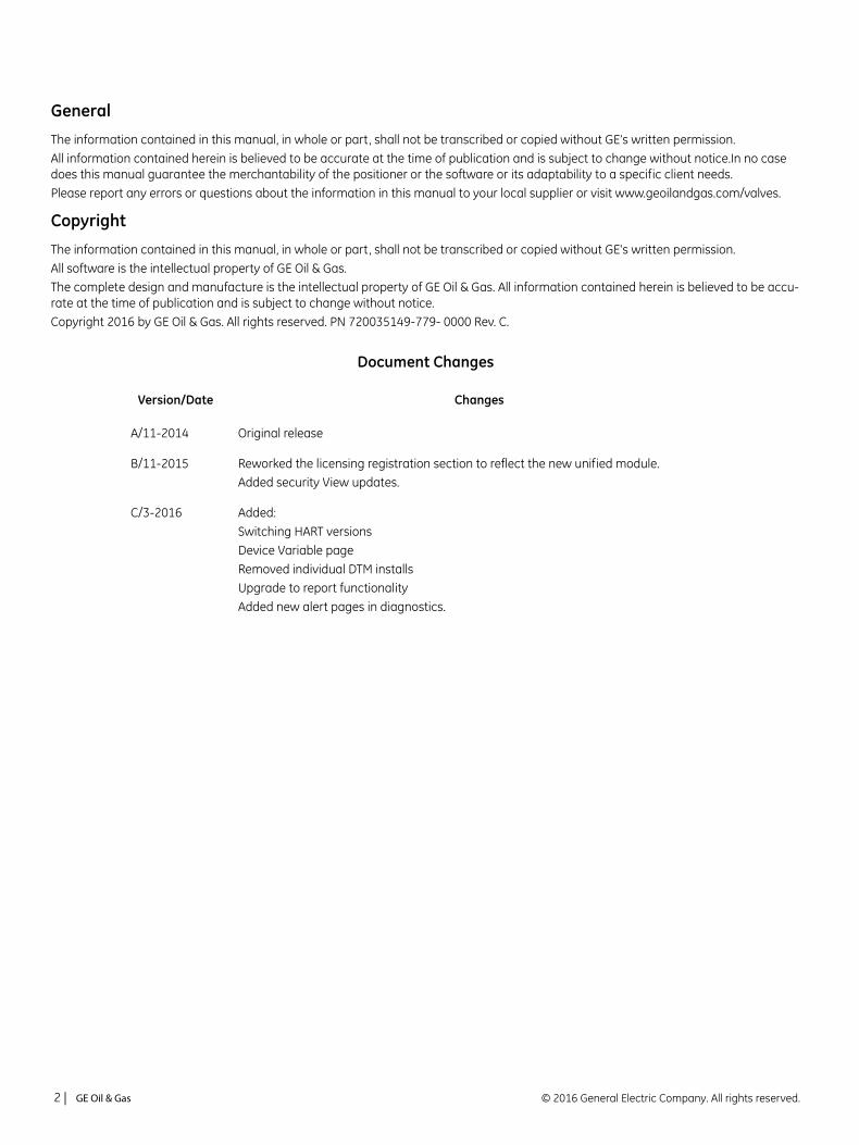
General
The information contained in this manual, in whole or part, shall not be transcribed or copied without GE’s written permission.All information contained herein is believed to be accurate at the time of publication and is subject to change without notice.In no case does this manual guarantee the merchantability of the positioner or the software or its adaptability to a specific client needs.Please report any errors or questions about the information in this manual to your local supplier or visit www.geoilandgas.com/valves.
Copyright
The information contained in this manual, in whole or part, shall not be transcribed or copied without GE's written permission.All software is the intellectual property of GE Oil & Gas. The complete design and manufacture is the intellectual property of GE Oil & Gas. All information contained herein is believed to be accu-rate at the time of publication and is subject to change without notice. Copyright 2016 by GE Oil & Gas. All rights reserved. PN 720035149-779- 0000 Rev. C.
Document Changes
Version/Date Changes
A/11-2014 Original release
B/11-2015 Reworked the licensing registration section to reflect the new unified module.Added security View updates.
C/3-2016 Added:Switching HART versionsDevice Variable pageRemoved individual DTM installsUpgrade to report functionalityAdded new alert pages in diagnostics.
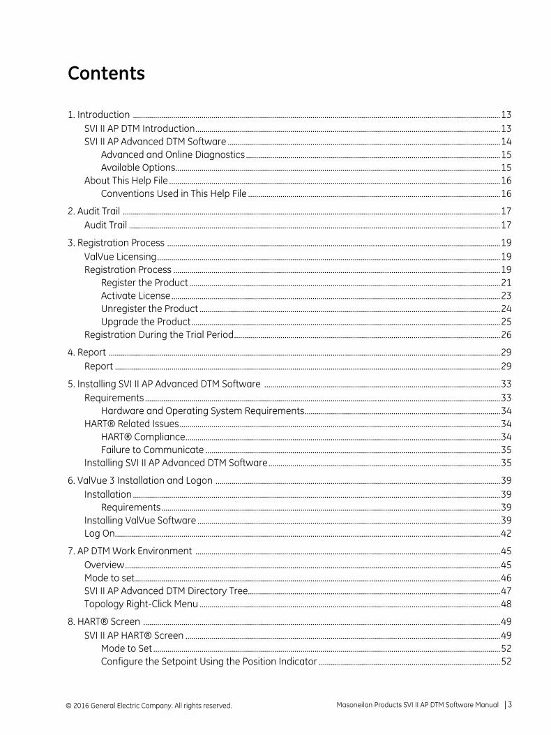
Contents
1. Introduction ......................................................................................................................................................................................13SVI II AP DTM Introduction.......................................................................................................................................................13SVI II AP Advanced DTM Software .......................................................................................................................................14
Advanced and Online Diagnostics ..............................................................................................................................15Available Options.................................................................................................................................................................15
About This Help File ....................................................................................................................................................................16Conventions Used in This Help File .............................................................................................................................16
2. Audit Trail ...........................................................................................................................................................................................17Audit Trail ........................................................................................................................................................................................17
3. Registration Process .....................................................................................................................................................................19ValVue Licensing..........................................................................................................................................................................19Registration Process ..................................................................................................................................................................19
Register the Product ..........................................................................................................................................................21Activate License...................................................................................................................................................................23Unregister the Product .....................................................................................................................................................24Upgrade the Product.........................................................................................................................................................25
Registration During the Trial Period....................................................................................................................................26
4. Report ..................................................................................................................................................................................................29Report ...............................................................................................................................................................................................29
5. Installing SVI II AP Advanced DTM Software .....................................................................................................................33Requirements ................................................................................................................................................................................33
Hardware and Operating System Requirements.................................................................................................34HART® Related Issues...............................................................................................................................................................34
HART® Compliance............................................................................................................................................................34Failure to Communicate ..................................................................................................................................................35
Installing SVI II AP Advanced DTM Software...................................................................................................................35
6. ValVue 3 Installation and Logon .............................................................................................................................................39Installation ......................................................................................................................................................................................39
Requirements........................................................................................................................................................................39Installing ValVue Software ......................................................................................................................................................39Log On...............................................................................................................................................................................................42
7. AP DTM Work Environment .......................................................................................................................................................45Overview..........................................................................................................................................................................................45Mode to set.....................................................................................................................................................................................46SVI II AP Advanced DTM Directory Tree.............................................................................................................................47Topology Right-Click Menu .....................................................................................................................................................48
8. HART® Screen .................................................................................................................................................................................49SVI II AP HART® Screen ............................................................................................................................................................49
Mode to Set ............................................................................................................................................................................52Configure the Setpoint Using the Position Indicator ..........................................................................................52
Masoneilan Products SVI II AP DTM Software Manual =| 3© 2016 General Electric Company. All rights reserved.
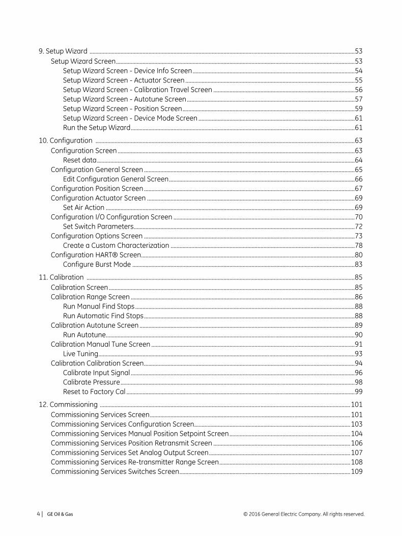
9. Setup Wizard ....................................................................................................................................................................................53Setup Wizard Screen..................................................................................................................................................................53
Setup Wizard Screen - Device Info Screen..............................................................................................................54Setup Wizard Screen - Actuator Screen ...................................................................................................................55Setup Wizard Screen - Calibration Travel Screen ................................................................................................56Setup Wizard Screen - Autotune Screen..................................................................................................................57Setup Wizard Screen - Position Screen.....................................................................................................................59Setup Wizard Screen - Device Mode Screen ..........................................................................................................61Run the Setup Wizard........................................................................................................................................................61
10. Configuration ................................................................................................................................................................................63Configuration Screen .................................................................................................................................................................63
Reset data...............................................................................................................................................................................64Configuration General Screen ...............................................................................................................................................65
Edit Configuration General Screen..............................................................................................................................66Configuration Position Screen ...............................................................................................................................................67Configuration Actuator Screen .............................................................................................................................................69
Set Air Action .........................................................................................................................................................................69Configuration I/O Configuration Screen ...........................................................................................................................70
Set Switch Parameters......................................................................................................................................................72Configuration Options Screen ...............................................................................................................................................73
Create a Custom Characterization .............................................................................................................................78Configuration HART® Screen.................................................................................................................................................80
Configure Burst Mode .......................................................................................................................................................83
11. Calibration ......................................................................................................................................................................................85Calibration Screen.......................................................................................................................................................................85Calibration Range Screen ........................................................................................................................................................86
Run Manual Find Stops.....................................................................................................................................................88Run Automatic Find Stops...............................................................................................................................................88
Calibration Autotune Screen ..................................................................................................................................................89Run Autotune.........................................................................................................................................................................90
Calibration Manual Tune Screen ..........................................................................................................................................91Live Tuning..............................................................................................................................................................................93
Calibration Calibration Screen...............................................................................................................................................94Calibrate Input Signal ........................................................................................................................................................96Calibrate Pressure...............................................................................................................................................................98Reset to Factory Cal ...........................................................................................................................................................99
12. Commissioning ..........................................................................................................................................................................101Commissioning Services Screen........................................................................................................................................101Commissioning Services Configuration Screen..........................................................................................................103Commissioning Services Manual Position Setpoint Screen..................................................................................104Commissioning Services Position Retransmit Screen .............................................................................................106Commissioning Services Set Analog Output Screen................................................................................................107Commissioning Services Re-transmitter Range Screen.........................................................................................108Commissioning Services Switches Screen....................................................................................................................109
© 2016 General Electric Company. All rights reserved.4 | =GE Oil & Gas
13. Diagnostics ................................................................................................................................................................................. 111Diagnostics Screen .................................................................................................................................................................. 111Diagnostics Continuous Diagnostics Data Screen ................................................................................................... 112Diagnostics Signature Screen ............................................................................................................................................ 114
Perform a Std. Actuator Sig. Test .............................................................................................................................. 116Perform a Step Test......................................................................................................................................................... 118Perform a Ramp Test...................................................................................................................................................... 119Perform an Extended Actuator Signature Test .................................................................................................. 120View Results - Extended Actuator Test Results.................................................................................................. 121
Diagnostics Signature Analysis Screen.......................................................................................................................... 122Load a Curve ...................................................................................................................................................................... 124Save a Curve....................................................................................................................................................................... 125
Diagnostics Check Raw Data Screen.............................................................................................................................. 126Set I/P..................................................................................................................................................................................... 128
Diagnostics Status Screen ................................................................................................................................................... 129General .......................................................................................................................................................................................... 131Instrumentation ........................................................................................................................................................................ 132Actuator ........................................................................................................................................................................................ 133Critical ............................................................................................................................................................................................ 134Pneumatics.................................................................................................................................................................................. 135Electronics.................................................................................................................................................................................... 136Clear Current Faults ................................................................................................................................................................ 137Clear All Faults ........................................................................................................................................................................... 138Diagnostics Health Screen................................................................................................................................................... 139Device Variables........................................................................................................................................................................ 142Device Info Screen ................................................................................................................................................................... 143
14. Troubleshooting ........................................................................................................................................................................ 145
15. Security View .............................................................................................................................................................................. 155Security View Screen .............................................................................................................................................................. 155
Change Privileges............................................................................................................................................................. 156Load Security Settings from File................................................................................................................................ 156Save Security Settings to File...................................................................................................................................... 156
16. Switching HART® Versions .................................................................................................................................................. 159
17. AMS® Communication DTM ............................................................................................................................................... 161AMS Communication DTM.................................................................................................................................................... 161
18. Configuring Frame Application to Work With the SVI II AP DTM ........................................................................ 165PRM 3.10............................................................................................................................................................................... 166FieldMate 2.03 ................................................................................................................................................................... 166
Masoneilan Products SVI II AP DTM Software Manual =| 5© 2016 General Electric Company. All rights reserved.

This page intentionally left blank.
Figures
1 SVI II AP Advanced DTM.................................................................................................................................................... 132 Audit Trail................................................................................................................................................................................. 173 ValVue Registration ............................................................................................................................................................ 194 Contact Information........................................................................................................................................................... 215 Email Registration ............................................................................................................................................................... 226 Browse for Folder ................................................................................................................................................................ 227 Included Features................................................................................................................................................................ 238 Included Features................................................................................................................................................................ 249 Unregister................................................................................................................................................................................ 2410 Included Features................................................................................................................................................................ 2511 Trial Registration Dialog: Newly Installed................................................................................................................. 2612 Advanced Features Expired............................................................................................................................................ 2613 Ongoing Expiration ............................................................................................................................................................. 2714 Trial Expired............................................................................................................................................................................ 2715 Report........................................................................................................................................................................................ 2916 SVI II AP Advanced DTM Install Welcome Screen................................................................................................. 3517 SVI II AP Advanced DTM License Screen................................................................................................................... 3618 SVI II AP Advanced DTM Choose Destination Folder Screen........................................................................... 3619 SVI II AP Advanced DTM Ready to Install the Program Screen ...................................................................... 3720 SVI II AP Advanced DTM Finish Screen ...................................................................................................................... 3721 Install GE NI-FF-H1 Comm. DTM................................................................................................................................... 4022 ValVue Install Welcome.................................................................................................................................................... 4123 ValVue License...................................................................................................................................................................... 4124 Choose Destination Location......................................................................................................................................... 4225 ValVue Login .......................................................................................................................................................................... 4226 Change Password ............................................................................................................................................................... 4327 Passwords Constraints ..................................................................................................................................................... 4328 SVI II AP Advanced DTM Main Screen ........................................................................................................................ 4529 Leaving Normal Mode Warning.................................................................................................................................... 4630 SVI AP Advanced DTM Directory Tree ........................................................................................................................ 4731 Topology Right-Click Menu ............................................................................................................................................. 4832 SVI II AP HART® Screen .................................................................................................................................................... 4933 Leaving Normal Mode Warning.................................................................................................................................... 5234 Position Indicator Set Button with Pen...................................................................................................................... 5235 Setup Wizard Screen - Device Info.............................................................................................................................. 5436 Setup Wizard Screen - Actuator ................................................................................................................................... 5537 Setup Wizard - Calibration Travel Screen ................................................................................................................ 5638 Setup Wizard - Autotune Screen.................................................................................................................................. 5739 Setup Wizard - Position Screen..................................................................................................................................... 5940 Setup Wizard - Device Mode Screen .......................................................................................................................... 6141 Configuration Screen......................................................................................................................................................... 6342 Reset Basic Config and Cal to Defaults Message................................................................................................. 6443 Configuration General Screen....................................................................................................................................... 65
Masoneilan Products SVI II AP DTM Software Manual =| 7© 2016 General Electric Company. All rights reserved.
44 Configuration Position Screen .......................................................................................................................................6745 Configuration Actuator Screen......................................................................................................................................6946 Configuration I/O Configuration Screen ...................................................................................................................7047 Configuration Options Screen........................................................................................................................................7348 Characterization Curves...................................................................................................................................................7549 Custom Characterization Dialog ..................................................................................................................................7650 Custom Characterization Dialog ..................................................................................................................................7851 Invalid Segment Dialog .....................................................................................................................................................7852 Linearization Dialog............................................................................................................................................................7953 Burst Mode Configuration................................................................................................................................................8154 Configuration HART® Screen.........................................................................................................................................8255 Calibration Screen...............................................................................................................................................................8556 Open Stop Adjustment Diagram...................................................................................................................................8657 Calibration Range Screen ................................................................................................................................................8758 Calibration Autotune Screen ..........................................................................................................................................8959 Calibration Aggressiveness Screen.............................................................................................................................9060 Calibration Manual Tune Screen ..................................................................................................................................9161 Live Tuning Wizard..............................................................................................................................................................9362 Calibration Calibration Tune Screen ...........................................................................................................................9463 Calibration Calibration Screen with Calibration Information Pane..............................................................9664 Calibration Calibration Screen with Calibration Information Pane - Input Signal.................................9765 Calibration Calibration Screen with Calibration Information Pane - Pressure .......................................9866 Calibration Calibration Screen with Calibration Information Pane - Factory Cal..................................9967 Commissioning Services Screen................................................................................................................................ 10168 Commissioning Services Configuration Screen.................................................................................................. 10369 Commissioning Services Manual Position Setpoint Screen.......................................................................... 10470 Commissioning Services Position Retransmit Screen ..................................................................................... 10671 Commissioning Services Set Analog Output Screen........................................................................................ 10772 Commissioning Services Re-transmitter Range Screen................................................................................. 10873 Commissioning Services Switches Screen............................................................................................................ 10974 Diagnostics Screen .......................................................................................................................................................... 11175 Diagnostics Continuous Diagnostics Data Screen............................................................................................ 11276 Diagnostics Signature Screen..................................................................................................................................... 11477 Information Field - Standard Actuator Test ......................................................................................................... 11678 Diagnostics Standard Signature Test Traces ...................................................................................................... 11779 Information Field - Step Test ....................................................................................................................................... 11880 Information Field - Ramp Test .................................................................................................................................... 11981 Extended Actuator Signature Test Results ........................................................................................................... 12082 Information Field - Extended Act. Sig. Test ........................................................................................................... 12183 Diagnostics Extended Act. Sig. Test Traces .......................................................................................................... 12184 Diagnostics Signature Analysis Screen .................................................................................................................. 12285 SVI Files Open Dialog ...................................................................................................................................................... 12486 Pick Signature Data ......................................................................................................................................................... 12487 SVI Files Save Dialog........................................................................................................................................................ 12588 Diagnostics Check Raw Data Screen ...................................................................................................................... 12689 Set IP Warning Dialog..................................................................................................................................................... 128
© 2016 General Electric Company. All rights reserved.8 | =GE Oil & Gas
90 Diagnostics: Active Faults Tab.................................................................................................................................... 12991 Status Tab: General ......................................................................................................................................................... 13192 Status Tab: Instrumentation........................................................................................................................................ 13293 Status Tab: Actuator........................................................................................................................................................ 13394 Status Tab: Critical ........................................................................................................................................................... 13495 Status Tab: Pneumatics ................................................................................................................................................. 13596 Status Tab: Electronics................................................................................................................................................... 13697 Current Faults Cleared ................................................................................................................................................... 13798 Diagnostics Health Screen........................................................................................................................................... 13999 Hysteresis and Deadband Graph.............................................................................................................................. 141100 Device Variables Screen................................................................................................................................................ 142101 Device Info Screen ........................................................................................................................................................... 143102 Security View ...................................................................................................................................................................... 155103 Save Security Settings to Default File Confirmation ........................................................................................ 156104 HART® Switch .................................................................................................................................................................... 159105 Success.................................................................................................................................................................................. 159106 Fail To Change ................................................................................................................................................................... 160107 AMS OPC Scan Next Level ............................................................................................................................................ 161108 Add a Field Network with AMS Communication DTM...................................................................................... 162109 AMS Communications Page ........................................................................................................................................ 163110 AMS Server Hierarchy Page......................................................................................................................................... 164111 Registration dll Error ....................................................................................................................................................... 165
Masoneilan Products SVI II AP DTM Software Manual =| 9© 2016 General Electric Company. All rights reserved.

This page intentionally left blank.

Tables
1 Burst Mode Data Return.................................................................................................................................................. 802 Troubleshooting Guide for the SVI II AP ................................................................................................................ 1453 Security View Permissions........................................................................................................................................... 157
Masoneilan Products SVI II AP DTM Software Manual =| 11© 2016 General Electric Company. All rights reserved.

This page intentionally left blank.
1. Introduction
SVI II AP DTM Introduction
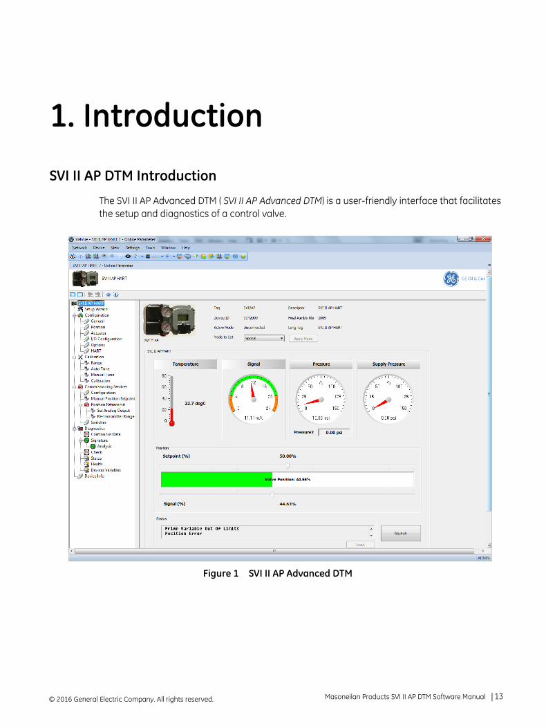
The SVI II AP Advanced DTM ( SVI II AP Advanced DTM) is a user-friendly interface that facilitates the setup and diagnostics of a control valve.
Figure 1 SVI II AP Advanced DTM
© 2016 General Electric Company. All rights reserved. Masoneilan Products SVI II AP DTM Software Manual =| 13
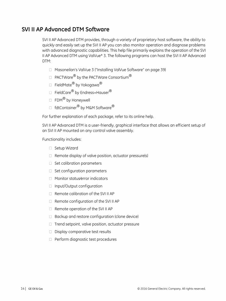
SVI II AP Advanced DTM Software
SVI II AP Advanced DTM provides, through a variety of proprietary host software, the ability to quickly and easily set up the SVI II AP you can also monitor operation and diagnose problems with advanced diagnostic capabilities. This help file primarily explains the operation of the SVI II AP Advanced DTM using ValVue* 3. The following programs can host the SVI II AP Advanced DTM:
Masoneilan’s ValVue 3 (“Installing ValVue Software” on page 39)
PACTWare® by the PACTWare Consortium®
FieldMate® by Yokogawa®
FieldCare® by Endress+Hauser®
FDM® by Honeywell
fdtContainer® by M&M Software®
For further explanation of each package, refer to its online help.
SVI II AP Advanced DTM is a user-friendly, graphical interface that allows an efficient setup of an SVI II AP mounted on any control valve assembly.
Functionality includes:
Setup Wizard
Remote display of valve position, actuator pressure(s)
Set calibration parameters
Set configuration parameters
Monitor status⁄error indicators
Input/Output configuration
Remote calibration of the SVI II AP
Remote configuration of the SVI II AP
Remote operation of the SVI II AP
Backup and restore configuration (clone device)
Trend setpoint, valve position, actuator pressure
Display comparative test results
Perform diagnostic test procedures
© 2016 General Electric Company. All rights reserved.14 | =GE Oil & Gas
Advanced and Online Diagnostics
The SVI II AP offers various levels of control valve diagnostics. Up to five pressure sensors that detect circuit board temperature, loop current, and reference voltage, are available for diagnostics. For the most recent software visit and for licensing information visit our SVI II AP web site at: http://www.ge-mcs.com/en/download.html.
Available Options
Some of the options available for the SVI II AP are listed below:
Remote Position Sensor
Two Contact Outputs User Linked to Various Status and Alarm Flags
Offshore Construction - Stainless Steel Housing and Components
Pushbutton Display
Masoneilan Products SVI II AP DTM Software Manual =| 15© 2016 General Electric Company. All rights reserved.
About This Help File
These instructions are intended to help a field engineer install, setup, and calibrate an SVI II AP in the most efficient manner possible. If you experience problems that are not documented, contact GE or your local representative.
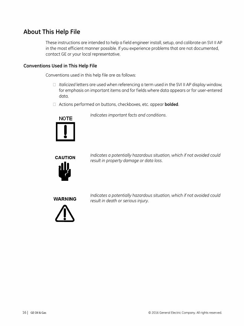
Conventions Used in This Help File
Conventions used in this help file are as follows:
Italicized letters are used when referencing a term used in the SVI II AP display window, for emphasis on important items and for fields where data appears or for user-entered data.
Actions performed on buttons, checkboxes, etc. appear bolded.
Indicates important facts and conditions.
Indicates a potentially hazardous situation, which if not avoided could result in property damage or data loss.
Indicates a potentially hazardous situation, which if not avoided could result in death or serious injury.
© 2016 General Electric Company. All rights reserved.16 | =GE Oil & Gas
2. Audit Trail
Audit Trail
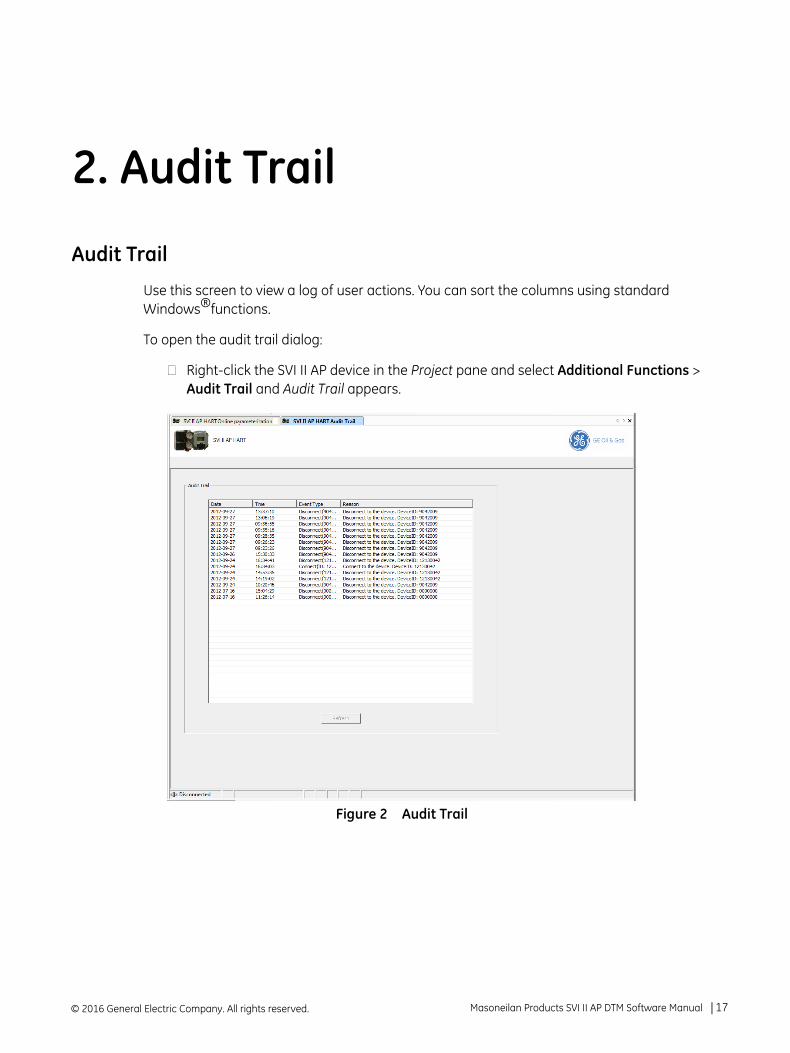
Use this screen to view a log of user actions. You can sort the columns using standard Windows®functions.
To open the audit trail dialog:
Right-click the SVI II AP device in the Project pane and select Additional Functions > Audit Trail and Audit Trail appears.
Figure 2 Audit Trail
© 2016 General Electric Company. All rights reserved. Masoneilan Products SVI II AP DTM Software Manual =| 17
Buttons and Fields
Date Displays the date the event occurred.
Time Displays the time the event occur ed.
Event Type Displays the event type.
Reason Displays the reason for the event.
Refresh button
Click to populate the screen with events since the screen was opened.
© 2016 General Electric Company. All rights reserved.18 | =GE Oil & Gas
3. Registration Process
ValVue Licensing
This section is meant to be a generic discussion of the licensing process for ValVue and Masoneilan software DTMs. In this discussion we use ValVue as an example. Dialogs that appear will differ based on the Masoneilan software is use. For example, the SVi*1000 and 12400 DTMs have only 30 day trial periods.
Registration Process
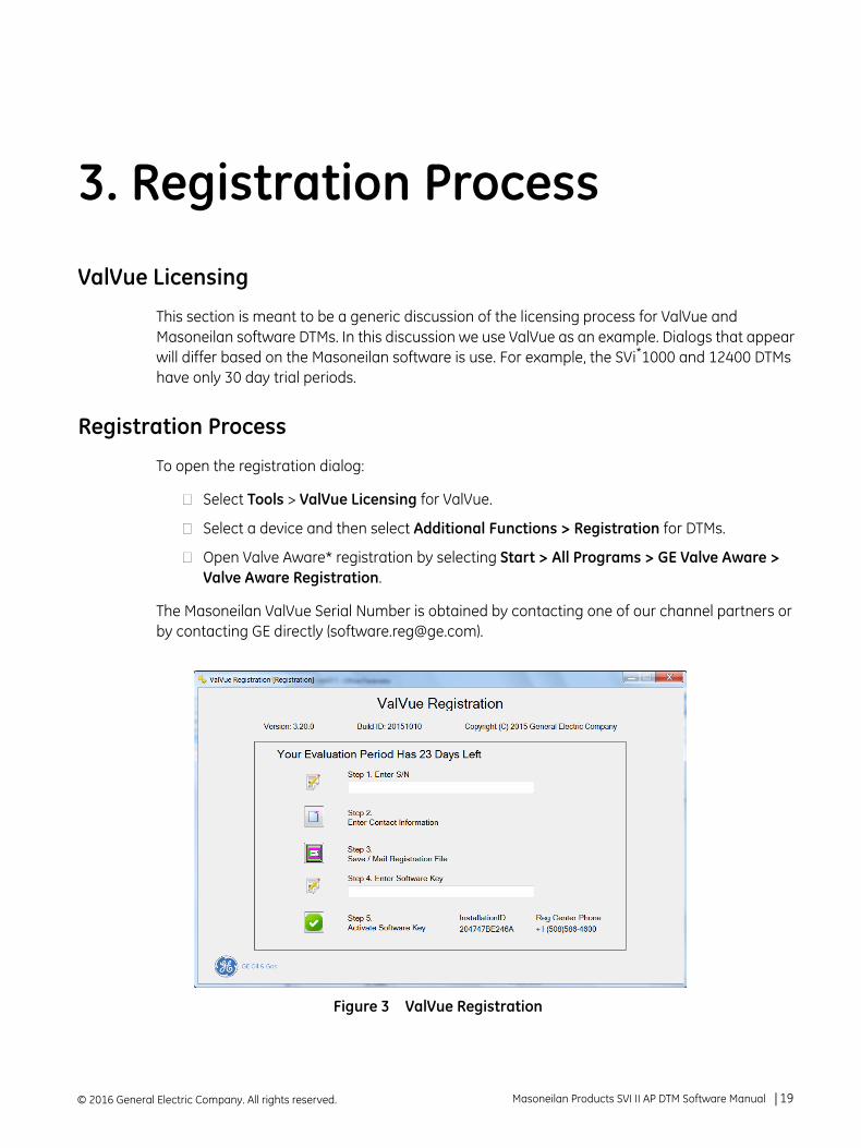
To open the registration dialog:
Select Tools > ValVue Licensing for ValVue.
Select a device and then select Additional Functions > Registration for DTMs.
Open Valve Aware* registration by selecting Start > All Programs > GE Valve Aware > Valve Aware Registration.
The Masoneilan ValVue Serial Number is obtained by contacting one of our channel partners or by contacting GE directly ([email protected]).
Figure 3 ValVue Registration
© 2016 General Electric Company. All rights reserved. Masoneilan Products SVI II AP DTM Software Manual =| 19
Use the registration dialog (Figure 3) to:
“Register the Product” on page 21 - Required before use or at the end of the 30 day trial period.
“Activate License” on page 23 - Required before use or at the end of the 30 day trial period.
“Unregister the Product” on page 24 - Unregister the product. You can then transfer the license to another machine.
“Upgrade the Product” on page 25 - Upgrade the product. Contact GE’s Masoneilan to discuss upgrade features options.
© 2016 General Electric Company. All rights reserved.20 | =GE Oil & Gas
r
Register the Product
To register the product:
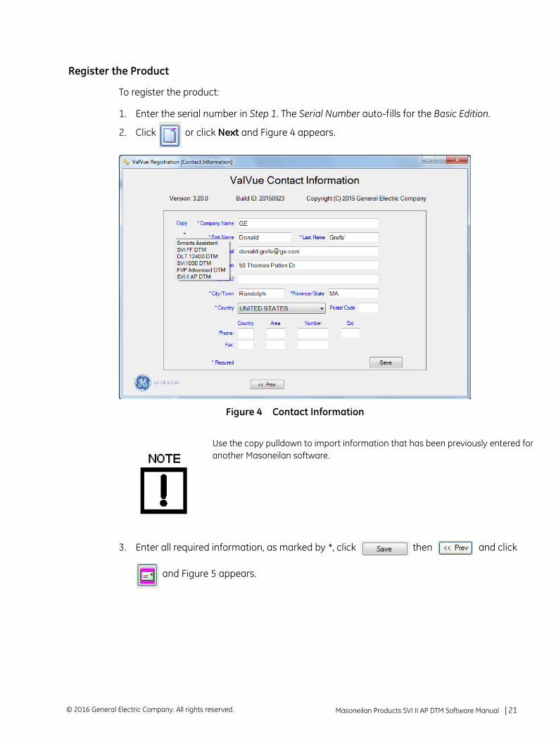
1. Enter the serial number in Step 1. The Serial Number auto-fills for the Basic Edition.
2. Click or click Next and Figure 4 appears.
Figure 4 Contact Information
3. Enter all required information, as marked by *, click then and click
and Figure 5 appears.
Use the copy pulldown to import information that has been previously entered foanother Masoneilan software.
Masoneilan Products SVI II AP DTM Software Manual =| 21© 2016 General Electric Company. All rights reserved.
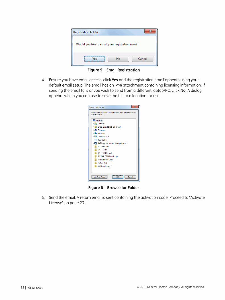
Figure 5 Email Registration
4. Ensure you have email access, click Yes and the registration email appears using your default email setup. The email has an .xml attachment containing licensing information. If sending the email fails or you wish to send from a different laptop/PC, click No. A dialog appears which you can use to save the file to a location for use.
Figure 6 Browse for Folder
5. Send the email. A return email is sent containing the activation code. Proceed to “Activate License” on page 23.
© 2016 General Electric Company. All rights reserved.22 | =GE Oil & Gas
Activate License
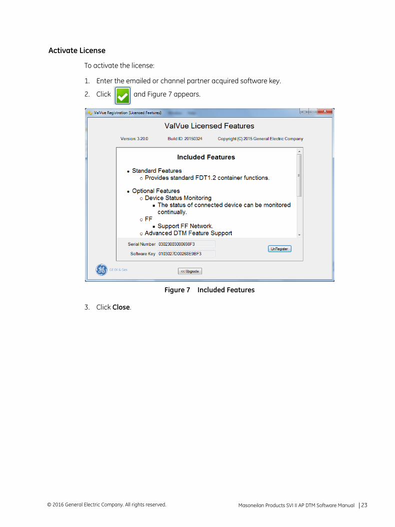
To activate the license:
1. Enter the emailed or channel partner acquired software key.
2. Click and Figure 7 appears.
Figure 7 Included Features
3. Click Close.
Masoneilan Products SVI II AP DTM Software Manual =| 23© 2016 General Electric Company. All rights reserved.
Unregister the Product
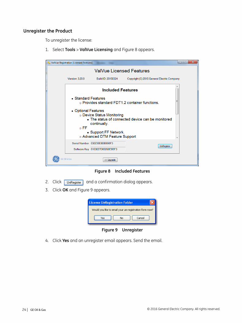
To unregister the license:
1. Select Tools > ValVue Licensing and Figure 8 appears.
Figure 8 Included Features
2. Click and a confirmation dialog appears.
3. Click OK and Figure 9 appears.
Figure 9 Unregister
4. Click Yes and an unregister email appears. Send the email.
© 2016 General Electric Company. All rights reserved.24 | =GE Oil & Gas
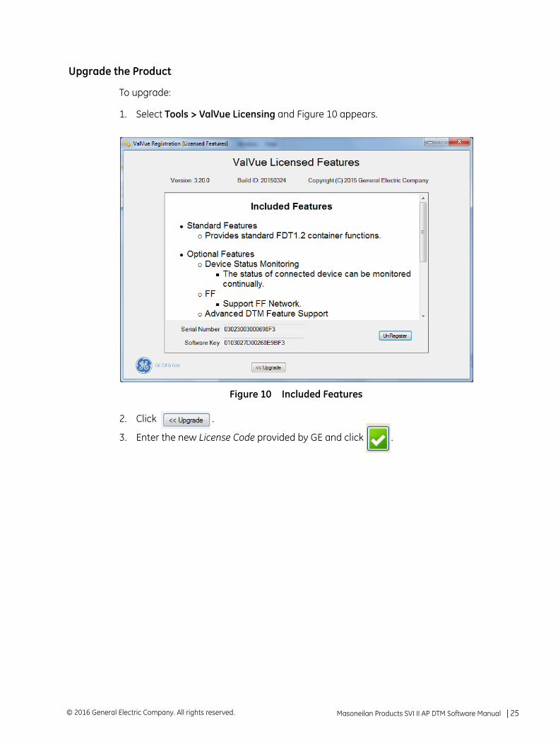
Upgrade the Product
To upgrade:
1. Select Tools > ValVue Licensing and Figure 10 appears.
Figure 10 Included Features
2. Click .
3. Enter the new License Code provided by GE and click .
Masoneilan Products SVI II AP DTM Software Manual =| 25© 2016 General Electric Company. All rights reserved.
Registration During the Trial Period
The license trial period works as follows:
1. Once you download and install the ValVue software, you are granted a 30 day trial period. We strongly encourage you to register your license with us as soon as possible. During the 30 days, you have access to all the advanced features of ValVue.
2. Once the first 30 days expires, you lose the advanced features. You then have an additional 30 day period, after which you must register to continue using the product. Contact GE at [email protected].
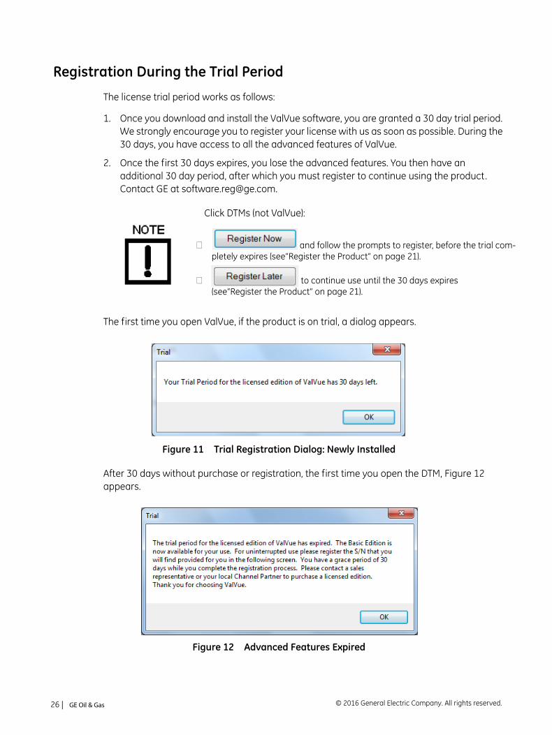
The first time you open ValVue, if the product is on trial, a dialog appears.
Figure 11 Trial Registration Dialog: Newly Installed
After 30 days without purchase or registration, the first time you open the DTM, Figure 12 appears.
Figure 12 Advanced Features Expired
Click DTMs (not ValVue):
and follow the prompts to register, before the trial com-pletely expires (see“Register the Product” on page 21).
to continue use until the 30 days expires(see“Register the Product” on page 21).
© 2016 General Electric Company. All rights reserved.26 | =GE Oil & Gas
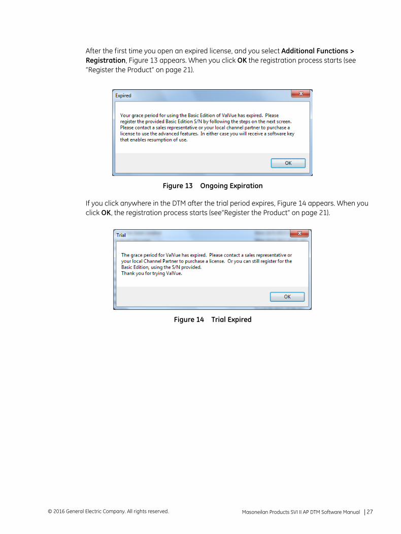
After the first time you open an expired license, and you select Additional Functions > Registration, Figure 13 appears. When you click OK the registration process starts (see “Register the Product” on page 21).
Figure 13 Ongoing Expiration
If you click anywhere in the DTM after the trial period expires, Figure 14 appears. When you click OK, the registration process starts (see“Register the Product” on page 21).
Figure 14 Trial Expired
Masoneilan Products SVI II AP DTM Software Manual =| 27© 2016 General Electric Company. All rights reserved.

This page intentionally left blank.
4. Report
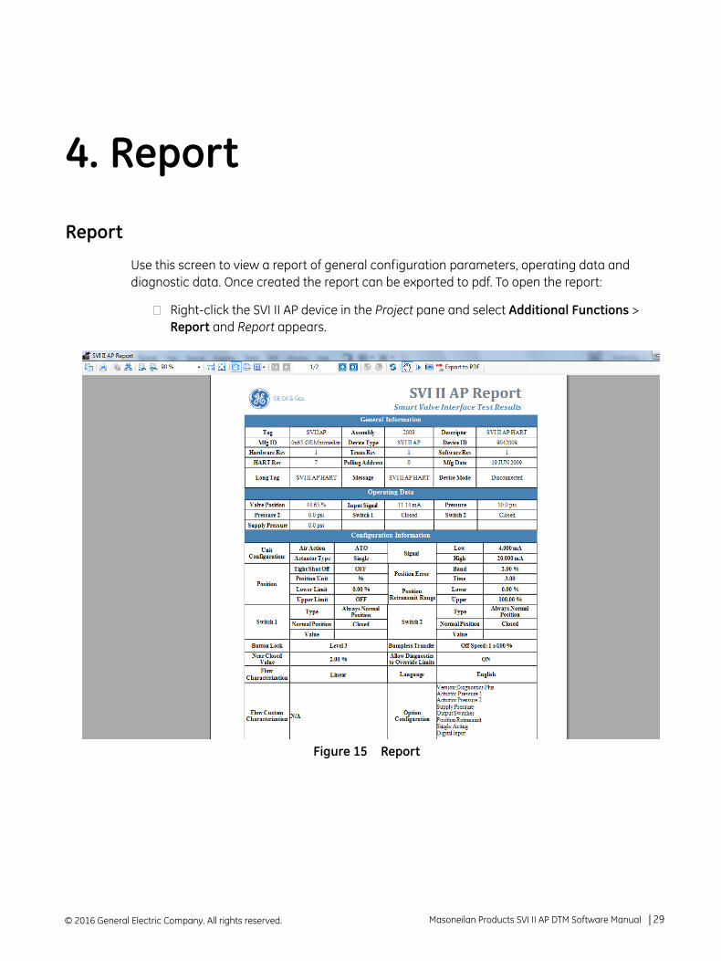
Report
Use this screen to view a report of general configuration parameters, operating data and diagnostic data. Once created the report can be exported to pdf. To open the report:
Right-click the SVI II AP device in the Project pane and select Additional Functions > Report and Report appears.
Figure 15 Report
© 2016 General Electric Company. All rights reserved. Masoneilan Products SVI II AP DTM Software Manual =| 29
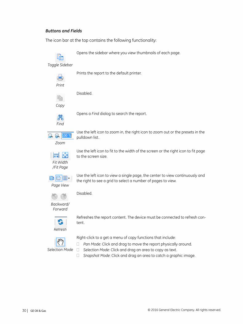
Buttons and Fields
The icon bar at the top contains the following functionality:
Toggle Sidebar
Opens the sidebar where you view thumbnails of each page.
Prints the report to the default printer.
Copy
Disabled.
Find
Opens a Find dialog to search the report.
Zoom
Use the left icon to zoom in, the right icon to zoom out or the presets in the pulldown list .
Fit Width/Fit Page
Use the left icon to fit to the width of the screen or the right icon to fit page to the screen size.
Page View
Use the left icon to view a single page, the center to view continuously and the right to see a grid to select a number of pages to view.
Backward/Forward
Disabled.
Refresh
Refreshes the report content. The device must be connected to refresh con-tent.
Selection Mode
Right-click to a get a menu of copy functions that include:
Pan Mode: Click and drag to move the report physically around.Selection Mode: Click and drag an area to copy as text.Snapshot Mode: Click and drag an area to catch a graphic image.
© 2016 General Electric Company. All rights reserved.30 | =GE Oil & Gas

Snapshot
Use to take a snapshot of a selected area.
Export to PDF
Exports the report to a selected directory.
Masoneilan Products SVI II AP DTM Software Manual =| 31© 2016 General Electric Company. All rights reserved.

This page intentionally left blank.
5. Installing SVI II AP Advanced DTM Software
Requirements
Using the SVI II AP Advanced DTM installation procedures discussed requires basic knowledge of Microsoft® Windows® operating systems and the Masoneilan SVI II AP positioner. For additional information describing the SVI II AP, consult the SVI II AP Instruction Manual.
Operation of the SVI II AP Advanced DTM requires installation of the following software components:
SVI II AP Advanced DTM software
MTL Communications® DTM V1.07 (http://www.mtl-inst.com/images/uploads/datasheets/4850/software/MTLCommsDTM_1.07_20100810.zip)
P+F Wireless Gateway (http://www.pepperl-fuchs.us/usa/en/classid_1804.htm?view=productdetails&prodid=47782)
CodeWright HART® Comm. DTM v1.0.44 (http://www.pepperl-fuchs.us/usa/en/classid_1804.htm?view=productdetails&prodid=32796)
P+F Mux2700 (http://www.pepperl-fuchs.us/usa/en/classid_2256.htm?view=productdetails&prodid=42264)
Additionally, you can use the following software to access the AP Advanced DTM:
PACTWare software, which includes Generic HART® DTM software and HART® Communications software
FieldCare software from Endress + Hauser
FieldMate software from Yokogawa
Field Device Manager (FDM) from Honeywell
fdtContainer from M&M Software GmbH
© 2016 General Electric Company. All rights reserved. Masoneilan Products SVI II AP DTM Software Manual =| 33
Hardware and Operating System Requirements
To successfully install and run SVI II AP Advanced DTM software, your computer system must meet or exceed the following minimum hardware and software requirements.
HART® Related Issues
Before installing the DTM, determine which port the computer uses for serial (RS-232 or USB) communication. The HART® modem uses this port for communication with the SVI II AP positioner.
HART® Compliance
The SVI II AP Advanced DTM requires a HART® compliant communications loop. The HART® protocol specifies the noise level, impedance requirements, and configuration of the loop. Conventional communications loops consisting of the following components meet requirements for HART® compliance.
Quality current source having low noise and high impedance
Minimum loop impedance of 250 Ohms
Twisted pair cable suitable for 4 - 20 mA current loops
When a safe barrier separates the communicating devices, a HART® compliant barrier must be used.
Windows® XP (SP3), Windows Server® 2003 (SP2), Windows Server® 2008, Windows Server® 2012, Windows® 7, Windows® 8 or Windows® 10
Windows® Pentium® or compatible microprocessor
An available serial communication port or USB port A HART® modem
1 G of free hard disk space
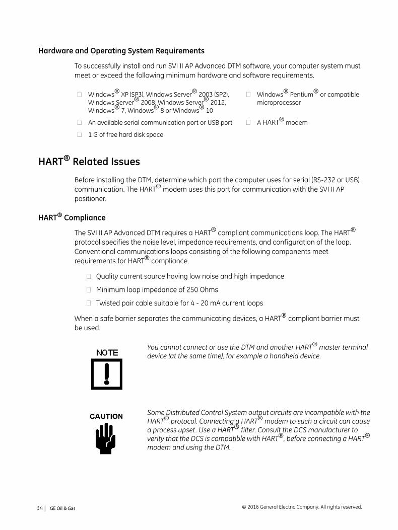
You cannot connect or use the DTM and another HART® master terminal device (at the same time), for example a handheld device.
Some Distributed Control System output circuits are incompatible with theHART® protocol. Connecting a HART® modem to such a circuit can causea process upset. Use a HART® filter. Consult the DCS manufacturer to verity that the DCS is compatible with HART®, before connecting a HART®
modem and using the DTM.
© 2016 General Electric Company. All rights reserved.34 | =GE Oil & Gas
Failure to Communicate
If the PC (using a modem) fails to communicate with the HART® or SVI II AP Advanced DTM the PC displays the message No Devices Found in the DTM main screen. The message HART I/O Failed appears if the device communications fails during the session. Communication failure prevents the PC from establishing a link. Possible causes of communications failure related to installation include:
Insufficient loop current and voltage
Poor wiring contacts
Improper connection of the HART® modem to the computer
Incorrect serial port
Using the DTM with another HART® master terminal in service
Insufficient loop impedance (a minimum of 250 Ohms is required)
Field device has a non-zero polling address (Set to multidrop)
If HART® compliance problems are suspect prepare a detailed description of the loop, including all devices on the loop, type of wiring used, loop length, and presence of any possible interference sources before contacting the factory for assistance.
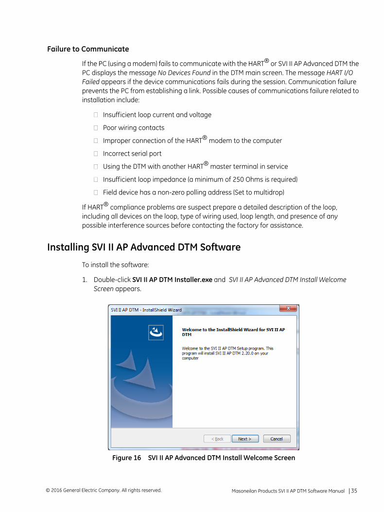
Installing SVI II AP Advanced DTM Software
To install the software:
1. Double-click SVI II AP DTM Installer.exe and SVI II AP Advanced DTM Install Welcome Screen appears.
Figure 16 SVI II AP Advanced DTM Install Welcome Screen
Masoneilan Products SVI II AP DTM Software Manual =| 35© 2016 General Electric Company. All rights reserved.
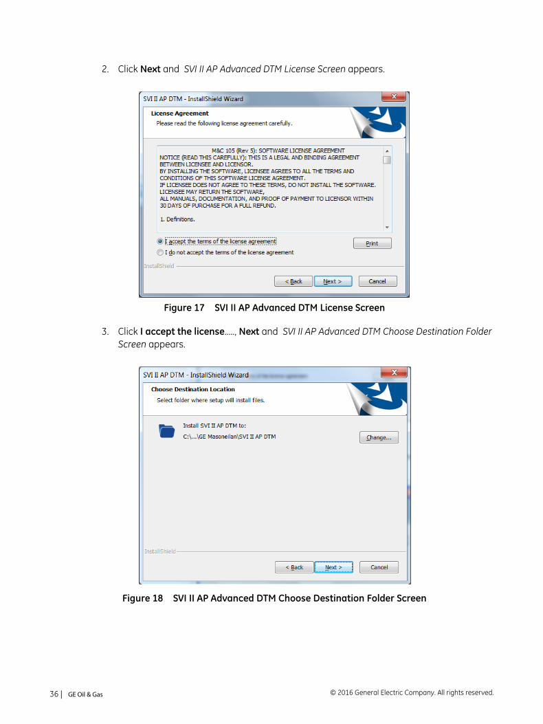
2. Click Next and SVI II AP Advanced DTM License Screen appears.
Figure 17 SVI II AP Advanced DTM License Screen
3. Click I accept the license....., Next and SVI II AP Advanced DTM Choose Destination Folder Screen appears.
Figure 18 SVI II AP Advanced DTM Choose Destination Folder Screen
© 2016 General Electric Company. All rights reserved.36 | =GE Oil & Gas
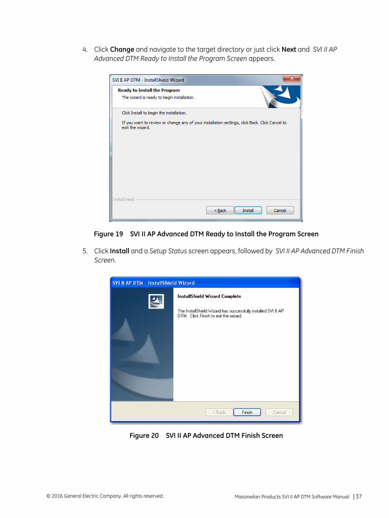
4. Click Change and navigate to the target directory or just click Next and SVI II AP Advanced DTM Ready to Install the Program Screen appears.
Figure 19 SVI II AP Advanced DTM Ready to Install the Program Screen
5. Click Install and a Setup Status screen appears, followed by SVI II AP Advanced DTM Finish Screen.
Figure 20 SVI II AP Advanced DTM Finish Screen
Masoneilan Products SVI II AP DTM Software Manual =| 37© 2016 General Electric Company. All rights reserved.

This page intentionally left blank.
6. ValVue* 3 Installation and Logon
Installation
Requirements
Using the ValVue installation procedures discussed requires basic knowledge of Microsoft® Windows® operating systems.
Hardware and Operating System Requirements
To successfully install and run ValVue software, your computer system must meet or exceed the following minimum hardware and software requirements.
Installing ValVue Software
This installs not only the ValVue software but the SQL Express® software, the GE NI-FBUS-H1 Comm. DTM, Microsoft® VC++ Redistributable package and the .Net framework.
Windows® XP SP3, Windows® Server 2003 SP2, Windows® Server 2008, Windows® Server 2012, Windows® 7 or Windows® 8
Windows® Pentium® or compatible microprocessor
10 G of free hard disk space
If you have a previous installation of the GE NI-FBUS-H1 Comm. DTM, you need to use Control Panel to uninstall before proceeding.
During the install, SQL is installed. It is highly recommended that you check for ValVue updates on the GE website (http://www.ge-mcs.com/en/download.html) every six months to keep this program current for security issues.
© 2016 General Electric Company. All rights reserved. Masoneilan Products SVI II AP DTM Software Manual =| 39
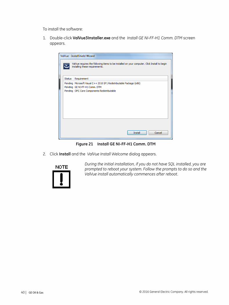
To install the software:
1. Double-click ValVue3Installer.exe and the Install GE NI-FF-H1 Comm. DTM screen appears.
Figure 21 Install GE NI-FF-H1 Comm. DTM
2. Click Install and the ValVue Install Welcome dialog appears.
During the initial installation, if you do not have SQL installed, you are prompted to reboot your system. Follow the prompts to do so and the ValVue install automatically commences after reboot.
© 2016 General Electric Company. All rights reserved.40 | =GE Oil & Gas
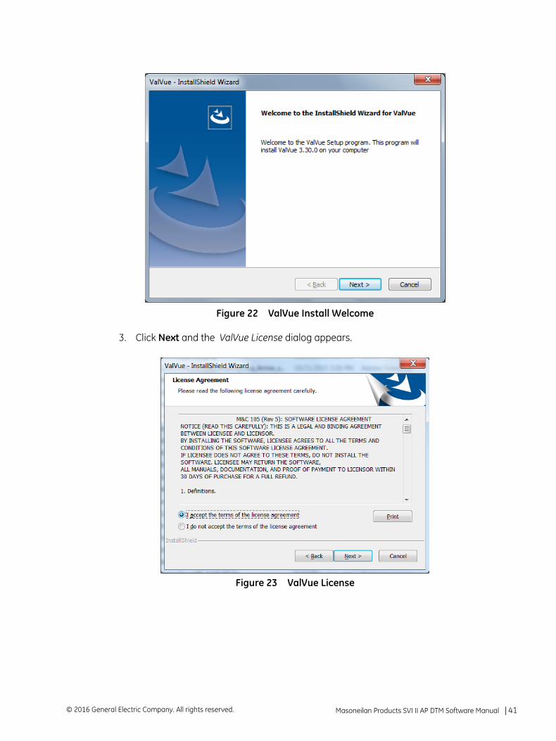
Figure 22 ValVue Install Welcome
3. Click Next and the ValVue License dialog appears.
Figure 23 ValVue License
Masoneilan Products SVI II AP DTM Software Manual =| 41© 2016 General Electric Company. All rights reserved.
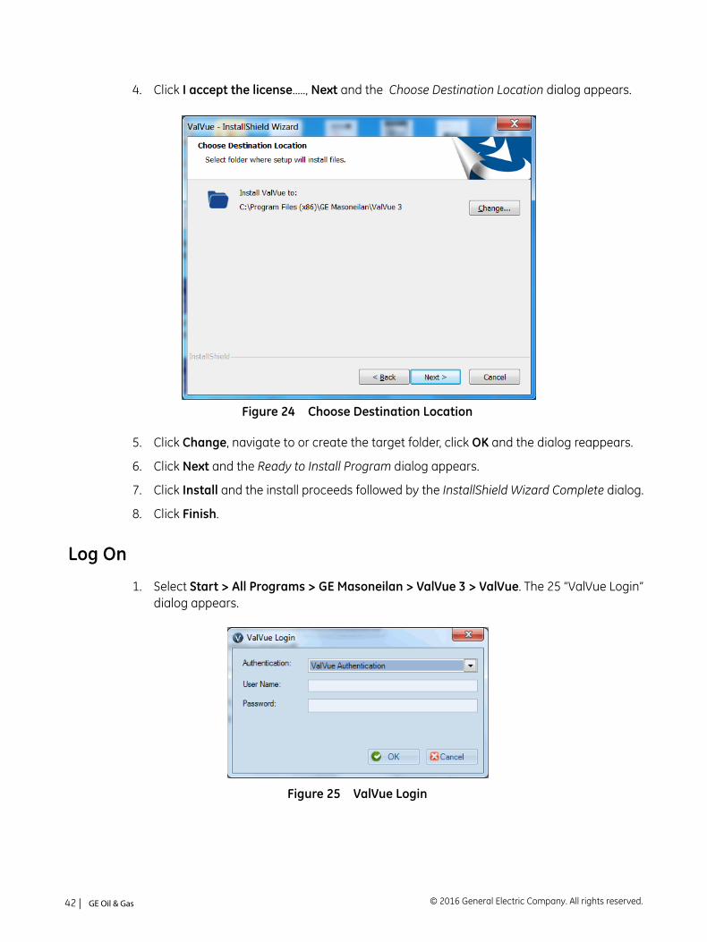
4. Click I accept the license....., Next and the Choose Destination Location dialog appears.
Figure 24 Choose Destination Location
5. Click Change, navigate to or create the target folder, click OK and the dialog reappears.
6. Click Next and the Ready to Install Program dialog appears.
7. Click Install and the install proceeds followed by the InstallShield Wizard Complete dialog.
8. Click Finish.
Log On
1. Select Start > All Programs > GE Masoneilan > ValVue 3 > ValVue. The 25 “ValVue Login” dialog appears.
Figure 25 ValVue Login
© 2016 General Electric Company. All rights reserved.42 | =GE Oil & Gas
og
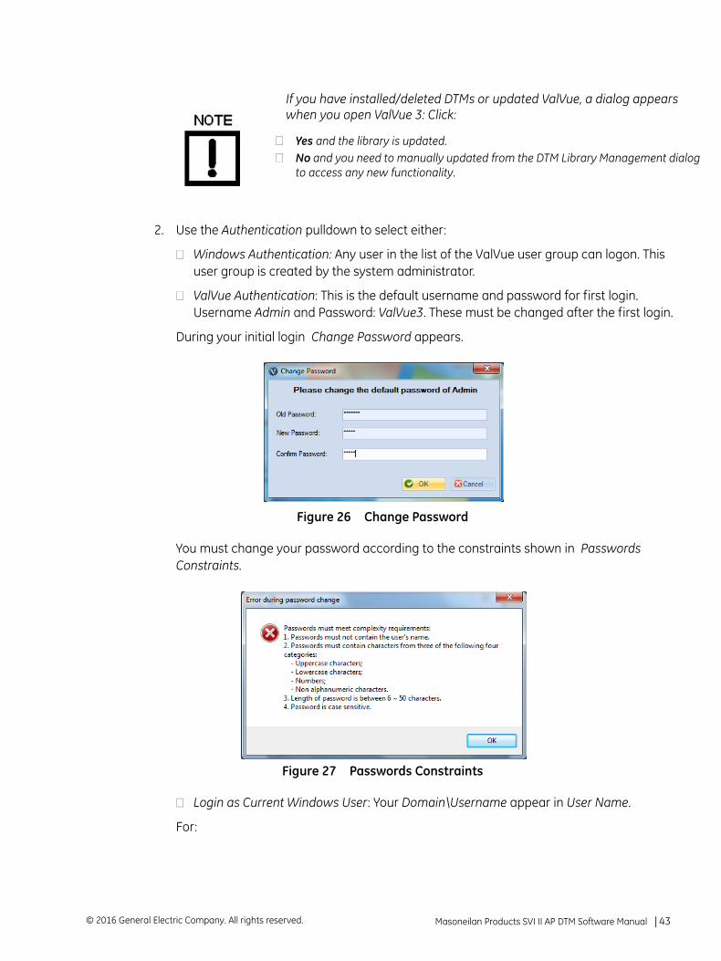
2. Use the Authentication pulldown to select either:
Windows Authentication: Any user in the list of the ValVue user group can logon. This user group is created by the system administrator.
ValVue Authentication: This is the default username and password for first login. Username Admin and Password: ValVue3. These must be changed after the first login.
During your initial login Change Password appears.
Figure 26 Change Password
You must change your password according to the constraints shown in Passwords Constraints.
Figure 27 Passwords Constraints
Login as Current Windows User: Your Domain\Username appear in User Name.
For:
If you have installed/deleted DTMs or updated ValVue, a dialog appears when you open ValVue 3: Click:
Yes and the library is updated.No and you need to manually updated from the DTM Library Management dialto access any new functionality.
Masoneilan Products SVI II AP DTM Software Manual =| 43© 2016 General Electric Company. All rights reserved.
Windows Authentication: Enter a Username, Password and use the Domain pulldown to select the domain.
ValVue Authentication: Enter a User Name and Password.
Login as Current Windows User
3. Click OK and the main screen appears.
After you successfully login into ValVue3, the User Authentication Mode is saved and next time you login, the last authentication mode automaticallyappears.
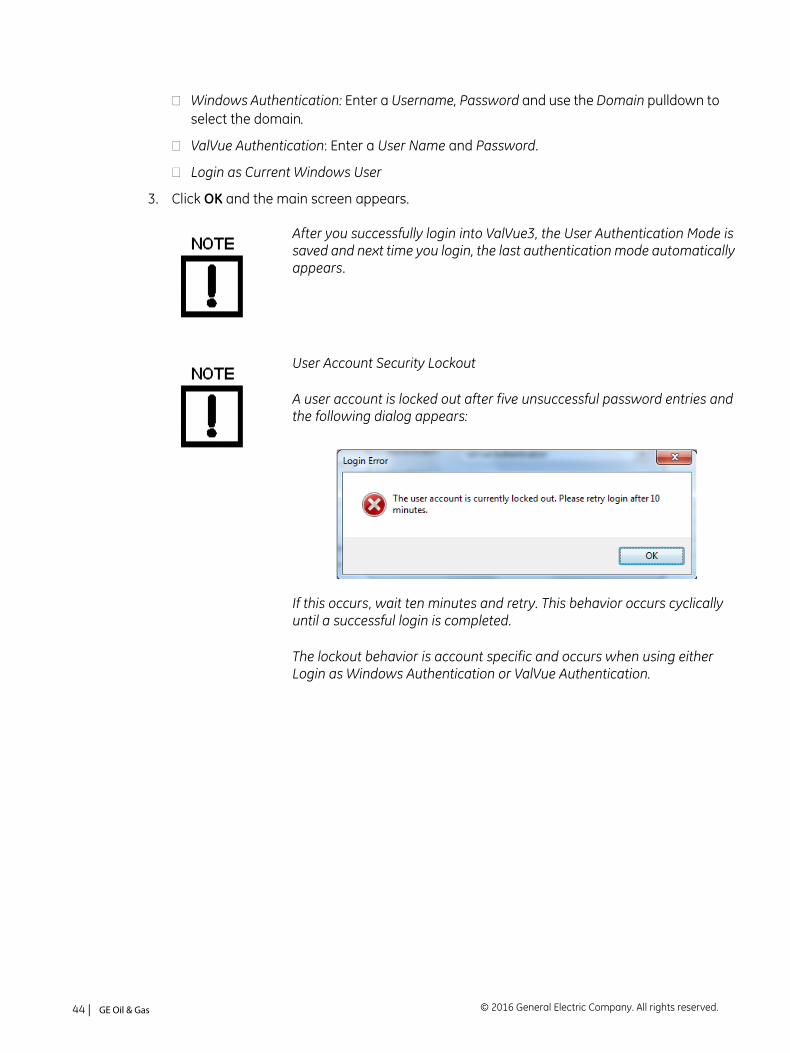
User Account Security Lockout
A user account is locked out after five unsuccessful password entries and the following dialog appears:
If this occurs, wait ten minutes and retry. This behavior occurs cyclically until a successful login is completed.
The lockout behavior is account specific and occurs when using either Login as Windows Authentication or ValVue Authentication.
© 2016 General Electric Company. All rights reserved.44 | =GE Oil & Gas
7. AP DTM Work Environment
Overview
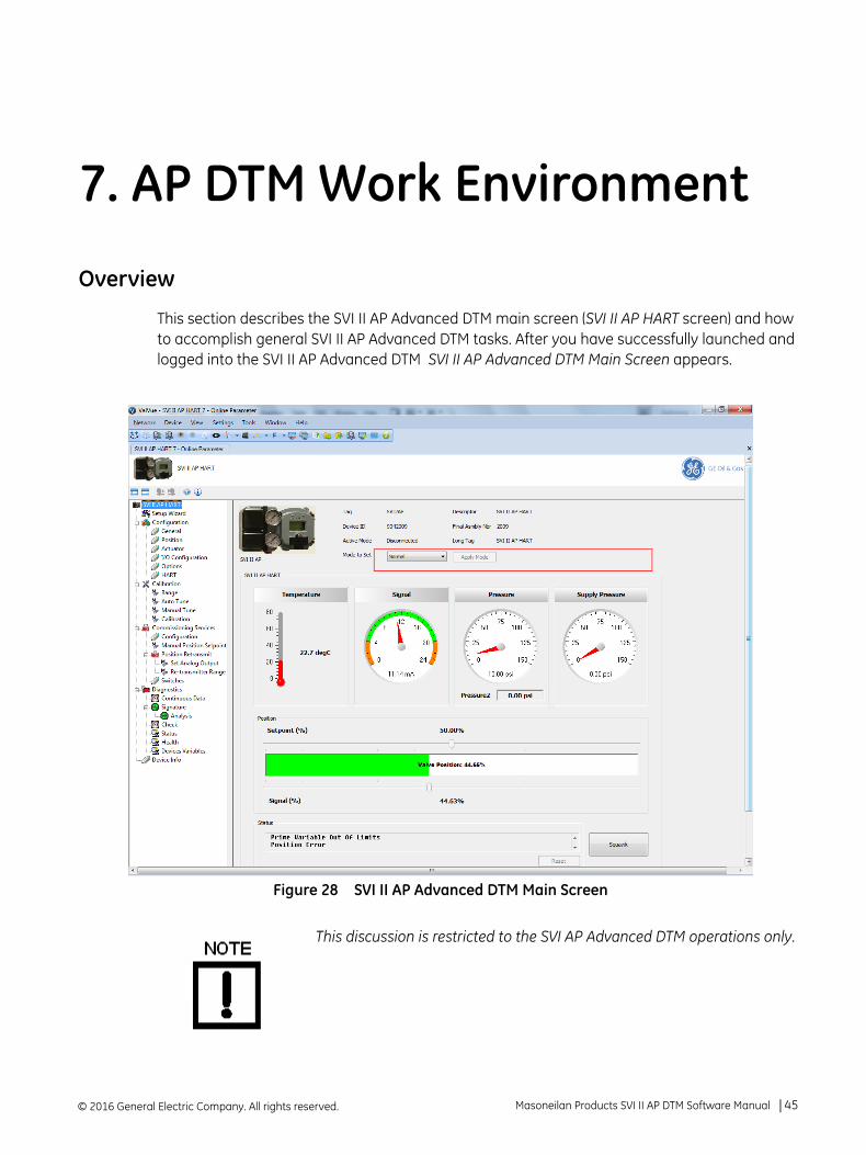
This section describes the SVI II AP Advanced DTM main screen (SVI II AP HART screen) and how to accomplish general SVI II AP Advanced DTM tasks. After you have successfully launched and logged into the SVI II AP Advanced DTM SVI II AP Advanced DTM Main Screen appears.
Figure 28 SVI II AP Advanced DTM Main Screen
This discussion is restricted to the SVI AP Advanced DTM operations only.
© 2016 General Electric Company. All rights reserved. Masoneilan Products SVI II AP DTM Software Manual =| 45
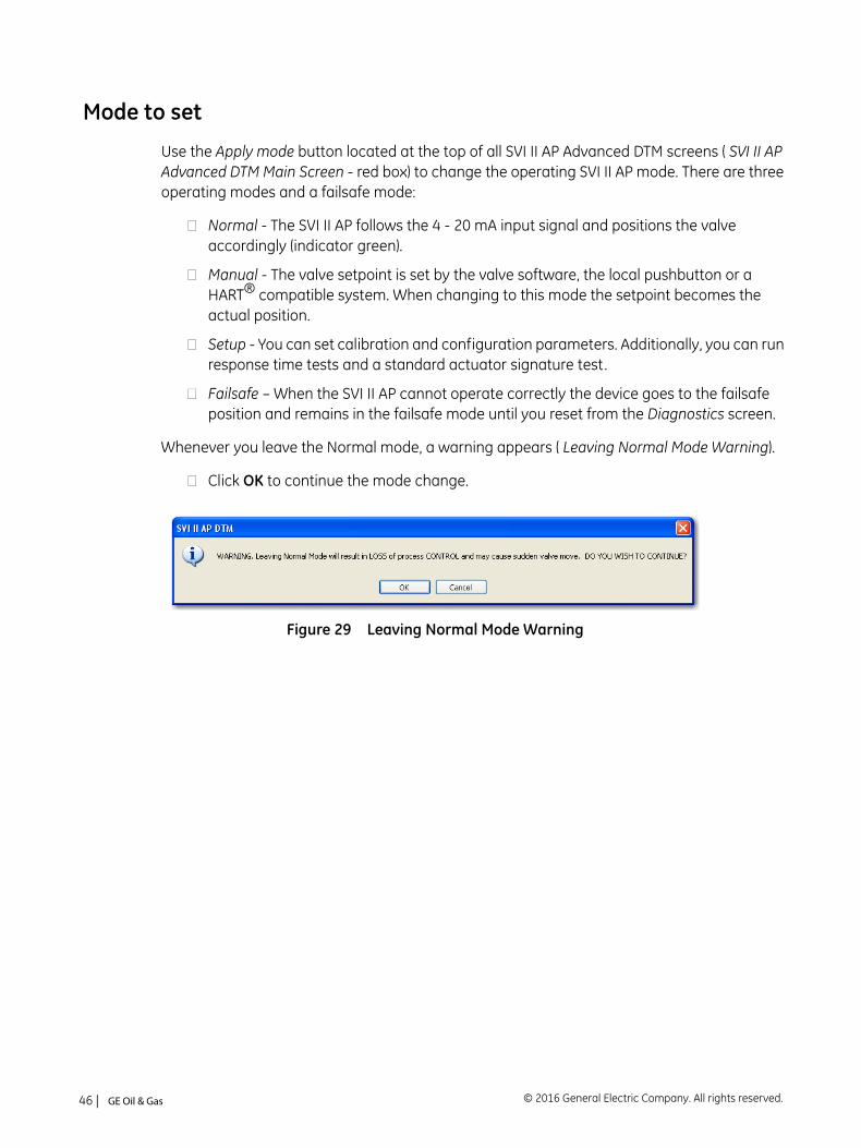
Mode to set
Use the Apply mode button located at the top of all SVI II AP Advanced DTM screens ( SVI II AP Advanced DTM Main Screen - red box) to change the operating SVI II AP mode. There are three operating modes and a failsafe mode:
Normal - The SVI II AP follows the 4 - 20 mA input signal and positions the valve accordingly (indicator green).
Manual - The valve setpoint is set by the valve software, the local pushbutton or a HART® compatible system. When changing to this mode the setpoint becomes the actual position.
Setup - You can set calibration and configuration parameters. Additionally, you can run response time tests and a standard actuator signature test.
Failsafe – When the SVI II AP cannot operate correctly the device goes to the failsafe position and remains in the failsafe mode until you reset from the Diagnostics screen.
Whenever you leave the Normal mode, a warning appears ( Leaving Normal Mode Warning).
Click OK to continue the mode change.
Figure 29 Leaving Normal Mode Warning
© 2016 General Electric Company. All rights reserved.46 | =GE Oil & Gas
SVI II AP Advanced DTM Directory Tree
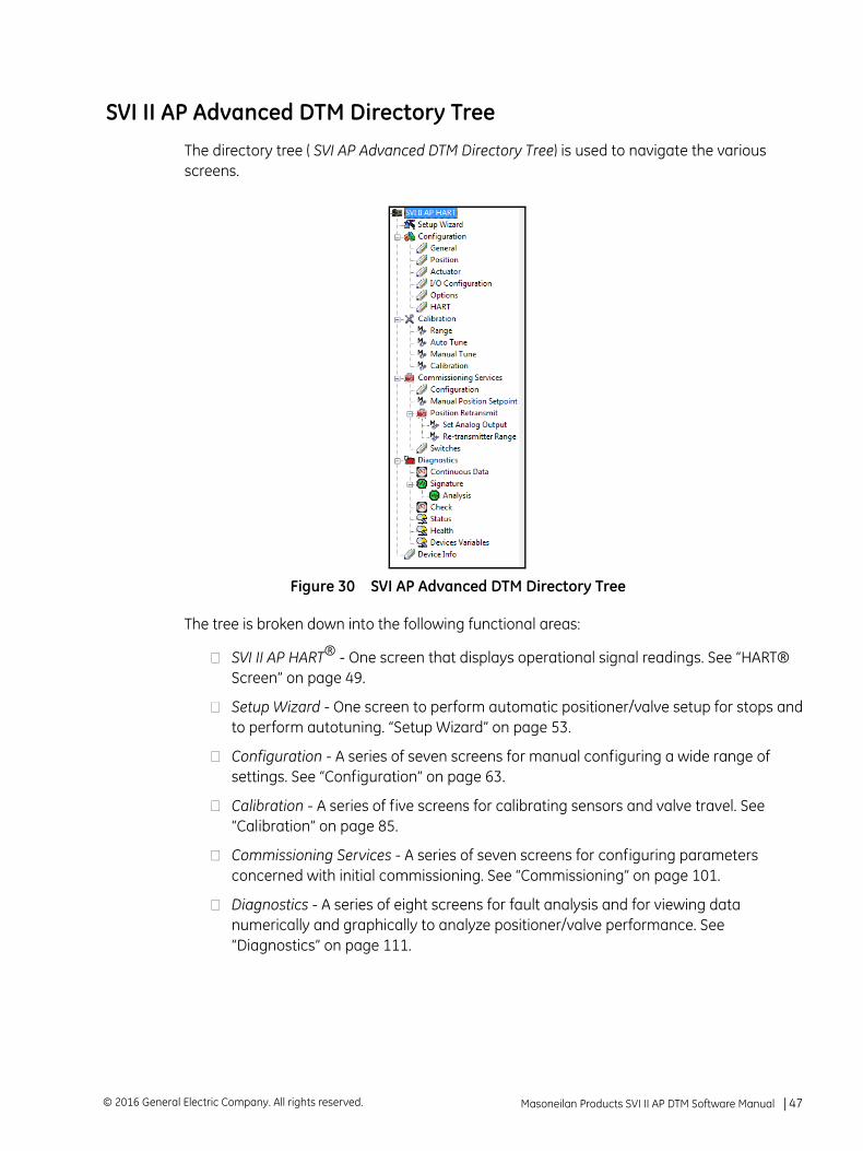
The directory tree ( SVI AP Advanced DTM Directory Tree) is used to navigate the various screens.
Figure 30 SVI AP Advanced DTM Directory Tree
The tree is broken down into the following functional areas:
SVI II AP HART® - One screen that displays operational signal readings. See “HART® Screen” on page 49.
Setup Wizard - One screen to perform automatic positioner/valve setup for stops and to perform autotuning. “Setup Wizard” on page 53.
Configuration - A series of seven screens for manual configuring a wide range of settings. See “Configuration” on page 63.
Calibration - A series of five screens for calibrating sensors and valve travel. See “Calibration” on page 85.
Commissioning Services - A series of seven screens for configuring parameters concerned with initial commissioning. See “Commissioning” on page 101.
Diagnostics - A series of eight screens for fault analysis and for viewing data numerically and graphically to analyze positioner/valve performance. See “Diagnostics” on page 111.
Masoneilan Products SVI II AP DTM Software Manual =| 47© 2016 General Electric Company. All rights reserved.
Topology Right-Click Menu
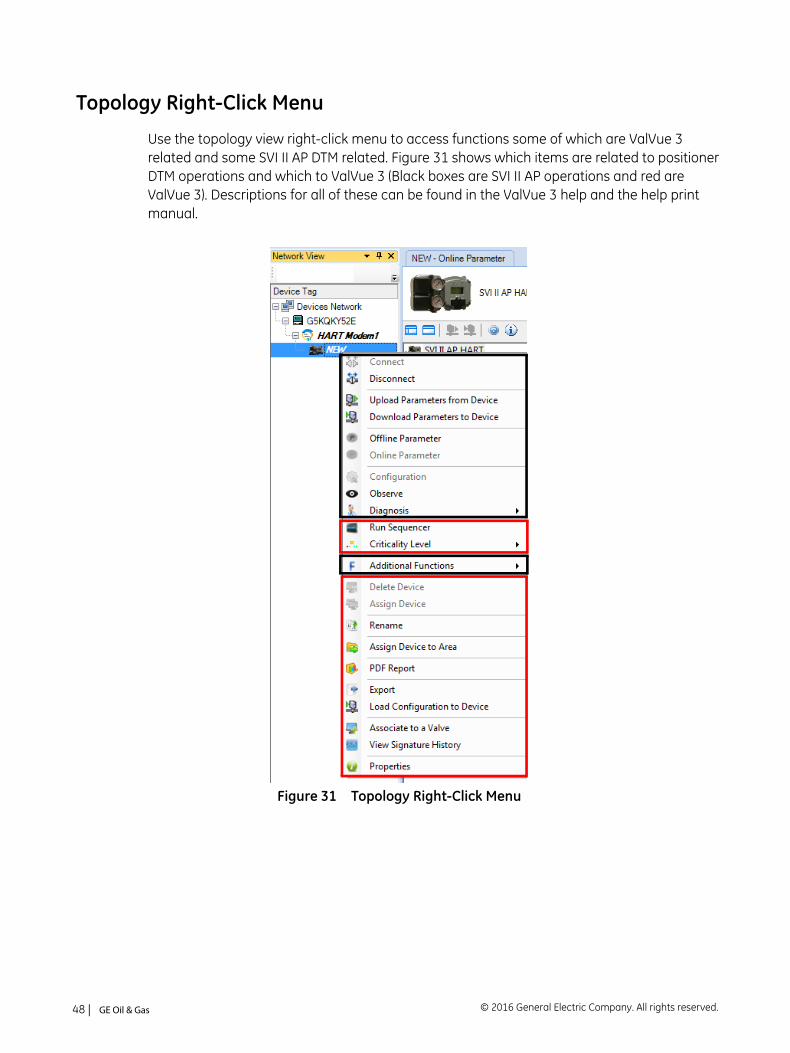
Use the topology view right-click menu to access functions some of which are ValVue 3 related and some SVI II AP DTM related. Figure 31 shows which items are related to positioner DTM operations and which to ValVue 3 (Black boxes are SVI II AP operations and red are ValVue 3). Descriptions for all of these can be found in the ValVue 3 help and the help print manual.
Figure 31 Topology Right-Click Menu
© 2016 General Electric Company. All rights reserved.48 | =GE Oil & Gas
8. HART® Screen
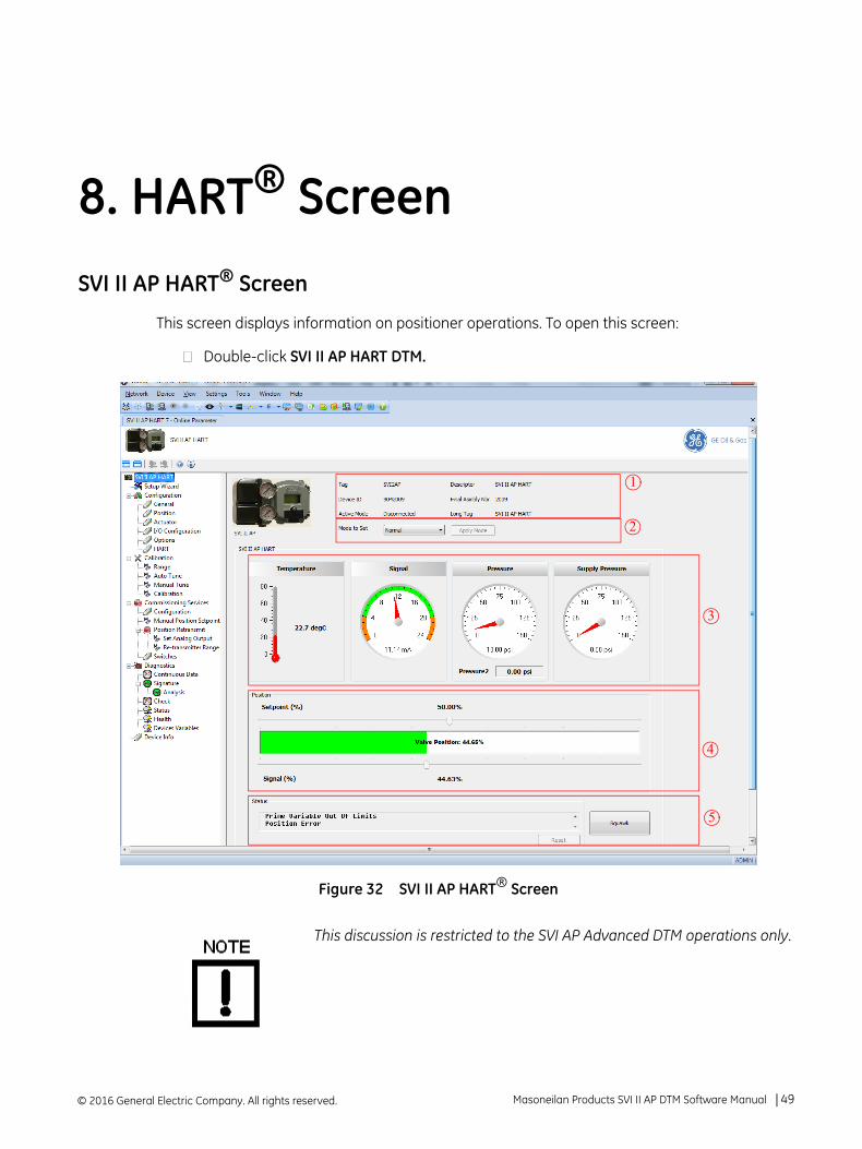
SVI II AP HART® Screen
This screen displays information on positioner operations. To open this screen:
Double-click SVI II AP HART DTM.
Figure 32 SVI II AP HART® Screen
This discussion is restricted to the SVI AP Advanced DTM operations only.
1
2
3
4
5
© 2016 General Electric Company. All rights reserved. Masoneilan Products SVI II AP DTM Software Manual =| 49
Buttons and Fields
Tag Information
Tag
Descriptor
Device ID
Final Asmbly Nbr
Long Tag: Available for HART® 6 only.
Active Mode
This data appears at the same location on all screens but can only be changed on the Setup Wizard (“Setup Wizard Screen” on page 53), General screen (see “Configuration General Screen” on page 65) and the Configura-tion screen for Tag and Long Tag only. (See “Commissioning Services Config-uration Screen” on page 103).
Mode area
Mode to set
Apply mode
These items appear at the same location on all screens and is used to change mode.
Signals area
Temperature - Displays the current temperature the positioner has read as a thermometer and text.
Signal - Displays the input analog signal strength expressed in % and in mA of the configured signal range as an analog meter. The range is set on the Configuration screen (“Configuration” on page 63).
Pressure - Displays the pressure read from the sensor as an analog meter. The SVI II AP continuously monitors the actuator pressure. It is displayed according to the configured units (psi, bar, or kpa). Pressure2 displays the pressure detected for the second actuator pressure specific for double acting.
Supply Pressure - Displays the supply pressure read from the sensor as a an analog meter. The SVI II AP continuously monitors the pressure. It is displayed according to the configured units (psi, bar, or kpa).
© 2016 General Electric Company. All rights reserved.50 | =GE Oil & Gas
Position area
The Position indicator shows the valve position graphically. The indicator consists of four parts:
Setpoint (%) - Contains an indicator showing the valve setpoint. In operating mode this is the same as the signal. In manual mode it is the valve setpoint. In MANUAL mode, it is the target position to which the SVI II AP is controlling the valve. The manual setpoint may be changed by dragging the upper arrow on the position indicator. While dragging, the number in the center bar shows the selected manual setpoint and the pen icon appears. Click Set to save the setting.In NORMAL mode, the setpoint is the target position based on the characterized input.
Valve Position indicator - Contains a center green bar showing the actual valve position in % of valve opening. The numerical valve position appears in the center. 0% is always closed and 100% is open. Because the travel of a valve may exceed its nominal travel, positions greater than 100% are possible (see “Calibration Range Screen” on page 86. The range is set on the “Calibration Range Screen” on page 86. See “Configure the Setpoint Using the Position Indicator” on page 52.
Signal (%) - Contains an indicator showing the value of the input signal. In Normal mode this is the position setpoint.
Status area
The Status area consists of:
Status - Displays health indicators. When there is a fault code from the SVI II AP, Additional Status Available appears. The fault codes also appear on the Status screen (“Diagnostics Status Screen” on page 129.)The status block also contains other status codes returned by HART®. These include Configuration Changed, Device malfunction, and Variable out of limits.
- Sends the squawk command.
For HART® 6 and 7 units, use the squawk command (HART® Command 72) to assist technicians to find specific devices in an installation. Send this command using ValVue and a specific device will audibly indicate the reception of the command. For HART® 6, you need to push an any button on the SVI II AP to clear the command from the LCD.
- Clears the Configuration Changed Flag, which clears the Status.
5
Masoneilan Products SVI II AP DTM Software Manual =| 51© 2016 General Electric Company. All rights reserved.
Mode to Set
Use the pulldown list and Apply mode button on all screens to change the operating mode. There are three operating modes:
Normal - In this mode the SVI II responds to the input signal and positions the valve accordingly (indicator green).
Manual - in this mode the valve does not respond to the input signal. Instead it remains stable in one position, which is the position that the valve was in when manual mode was entered or a new position selected by you (by changing the setpoint on the “SVI II AP HART® Screen” on page 49 or on the “Commissioning Services Manual Position Setpoint Screen” on page 104).
Setup - In this mode you can set calibration and configuration parameters. Additionally, you can run response time tests, step and response tests.
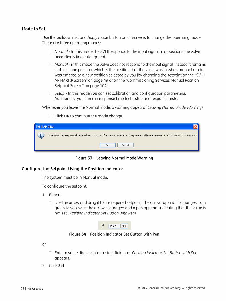
Whenever you leave the Normal mode, a warning appears ( Leaving Normal Mode Warning).
Click OK to continue the mode change.
Figure 33 Leaving Normal Mode Warning
Configure the Setpoint Using the Position Indicator
The system must be in Manual mode.
To configure the setpoint:
1. Either:
Use the arrow and drag it to the required setpoint. The arrow top and tip changes from green to yellow as the arrow is dragged and a pen appears indicating that the value is not set ( Position Indicator Set Button with Pen).
Figure 34 Position Indicator Set Button with Pen
or
Enter a value directly into the text field and Position Indicator Set Button with Pen appears.
2. Click Set .
© 2016 General Electric Company. All rights reserved.52 | =GE Oil & Gas

9. Setup Wizard
Setup Wizard Screen
Running the Setup Wizard is one of two ways to set up the SVI II AP. When you decide to run the setup you can either run the entire wizard or pick and choose which components to run.
From the Setup Wizard screen you can rapidly setup the SVI II AP by configuring some basic parameters. You can set the device identification, select the air action, perform a travel calibration, and autotune the positioning parameters. When the selected tasks are started a progress screen appears. The Setup Wizard can dramatically reduce commissioning time in the field. To customize the valve setup refer to “Calibration Manual Tune Screen” on page 91.
To run the Setup Wizard you must first be in Setup mode. See “Mode to set” on page 46 for information on changing modes.
© 2016 General Electric Company. All rights reserved. Masoneilan Products SVI II AP DTM Software Manual =| 53
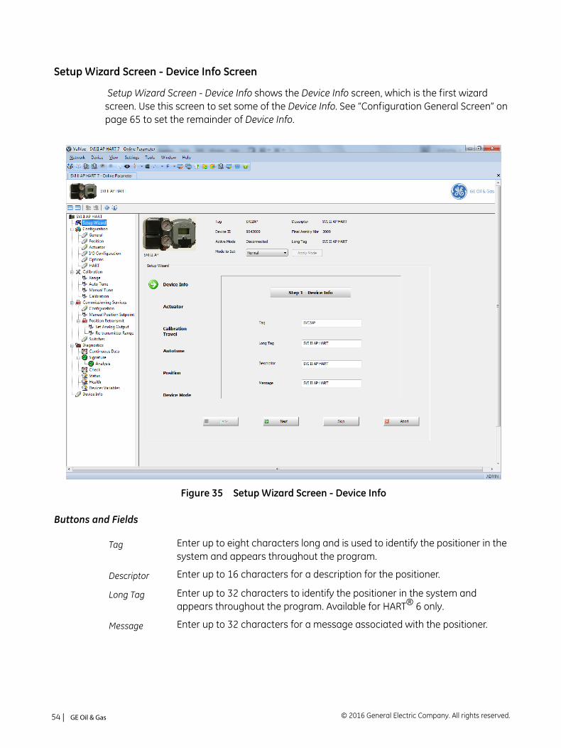
Setup Wizard Screen - Device Info Screen
Setup Wizard Screen - Device Info shows the Device Info screen, which is the first wizard screen. Use this screen to set some of the Device Info. See “Configuration General Screen” on page 65 to set the remainder of Device Info.
Figure 35 Setup Wizard Screen - Device Info
Buttons and Fields
Tag Enter up to eight characters long and is used to identify the positioner in the system and appears throughout the program.
Descriptor Enter up to 16 characters for a description for the positioner.
Long Tag Enter up to 32 characters to identify the positioner in the system and appears throughout the program. Available for HART® 6 only.
Message Enter up to 32 characters for a message associated with the positioner.
© 2016 General Electric Company. All rights reserved.54 | =GE Oil & Gas
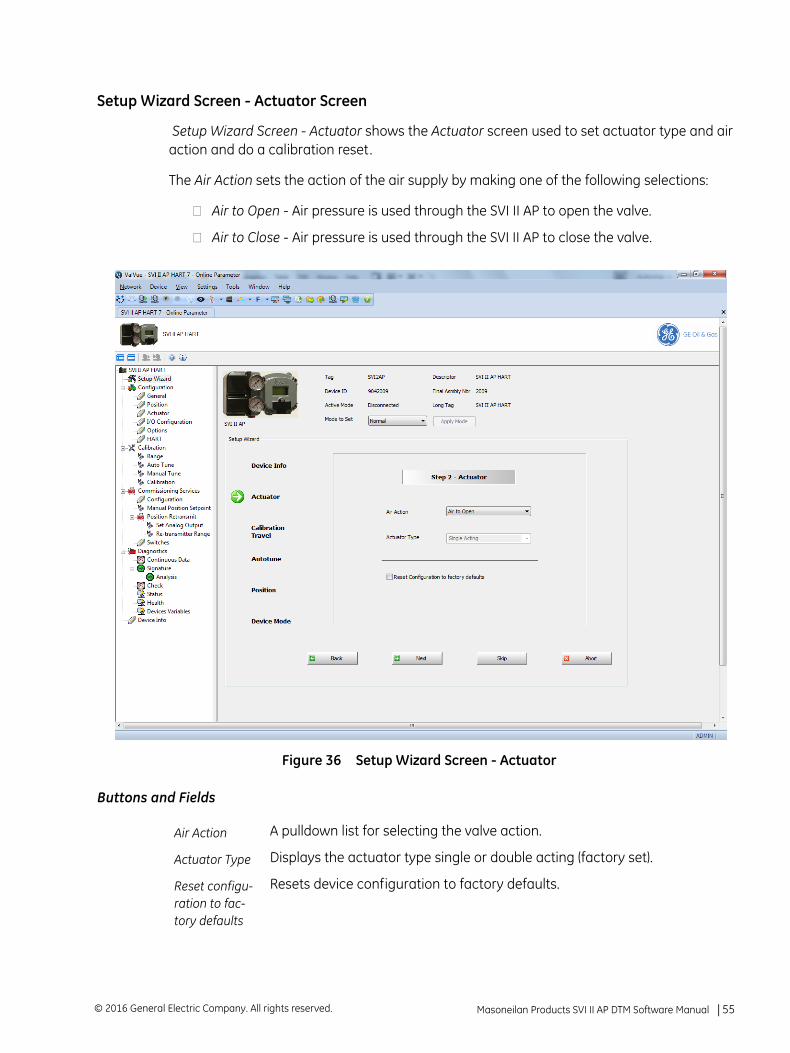
Setup Wizard Screen - Actuator Screen
Setup Wizard Screen - Actuator shows the Actuator screen used to set actuator type and air action and do a calibration reset.
The Air Action sets the action of the air supply by making one of the following selections:
Air to Open - Air pressure is used through the SVI II AP to open the valve.
Air to Close - Air pressure is used through the SVI II AP to close the valve.
Figure 36 Setup Wizard Screen - Actuator
Buttons and Fields
Air Action A pulldown list for selecting the valve action.
Actuator Type Displays the actuator type single or double acting (factory set).
Reset configu-ration to fac-tory defaults
Resets device configuration to factory defaults.
Masoneilan Products SVI II AP DTM Software Manual =| 55© 2016 General Electric Company. All rights reserved.
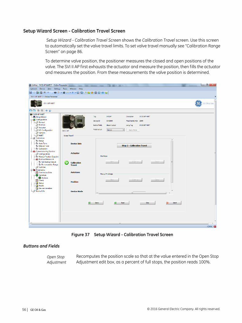
Setup Wizard Screen - Calibration Travel Screen
Setup Wizard - Calibration Travel Screen shows the Calibration Travel screen. Use this screen to automatically set the valve travel limits. To set valve travel manually see “Calibration Range Screen” on page 86.
To determine valve position, the positioner measures the closed and open positions of the valve. The SVI II AP first exhausts the actuator and measure the position, then fills the actuator and measures the position. From these measurements the valve position is determined.
Figure 37 Setup Wizard - Calibration Travel Screen
Buttons and Fields
Open Stop Adjustment
Recomputes the position scale so that at the value entered in the Open Stop Adjustment edit box, as a percent of full stops, the position reads 100%.
© 2016 General Electric Company. All rights reserved.56 | =GE Oil & Gas
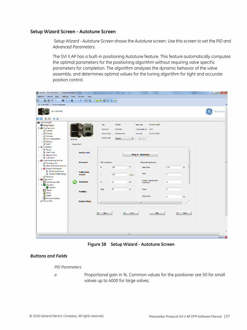
Setup Wizard Screen - Autotune Screen
Setup Wizard - Autotune Screen shows the Autotune screen. Use this screen to set the PID and Advanced Parameters.
The SVI II AP has a built-in positioning Autotune feature. This feature automatically computes the optimal parameters for the positioning algorithm without requiring valve specific parameters for completion. The algorithm analyzes the dynamic behavior of the valve assembly, and determines optimal values for the tuning algorithm for tight and accurate position control.
Figure 38 Setup Wizard - Autotune Screen
Buttons and Fields
PID Parameters
P Proportional gain in %. Common values for the positioner are 50 for small valves up to 4000 for large valves.
Masoneilan Products SVI II AP DTM Software Manual =| 57© 2016 General Electric Company. All rights reserved.
I Integral time or reset time in 1/10th sec, is the time constant of integral con-trol. Higher values of I cause less integral action. 0 gives no integral action. Common values are 10 to 200.
D Derivative time or rate time (msec) is the time constant of derivative control. Common values are 10 to 100.
Padj Valves often have significantly different response when filling verses exhausting. The proportional gain is adjusted by adding Padj (%) to P when the valve is exhausting.
Advanced Parameters
Dead Zone When the valve position is within the setpoint +/- the dead zone, no addi-tional position control is performed. This value is normally 0%, however for high friction valves (e.g. valves with graphite packing) a higher dead zone (%) helps avoid limit cycling due to the stick/slip action of the valve. In these cases the dead zone chosen might be 0.5% to 1%. Range: 0 to 5%.
Beta This is a nonlinear gain factor, ranging from -9 to 9. When Beta is 0, the con-troller gain is linear. Otherwise, the gain is the function of error. The larger the beta, the smaller the gain for small error.
Position Com-pensation
The response of the valve is different when the valve is nearly closed than when the valve is nearly open. The position compensation coefficient, which is a number between 0 and 20, make adjustments to try to equalize the valve response. The normal value is 6. For springless actuators the value is 15.
Boost This controls a supplemental pressure, or boost, to speed up initial valve response. This compensates for pneumatic deadband. Range: 0 to 20.
Stroke Time Enter a time to limit the rate of change for travel (sec/100% of travel). This prevents the valve from slamming open or shut.
Both Direction
Click this button to apply Stroke Time to both valve directions.
Open Click this button to apply Stroke Time to valve open only.
Close Click this button to apply Stroke Time to valve close only.
Supply Pressure
Enter the expected supply pressure. Required if the sensor is not enabled.
Aggressiveness Enter a value that tends the valve to either fast response or overshoot. Higher aggressiveness leads to higher gains and generally faster valve per-formance. This can cause more overshoot.
© 2016 General Electric Company. All rights reserved.58 | =GE Oil & Gas
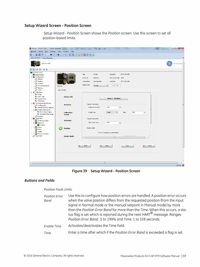
Setup Wizard Screen - Position Screen
Setup Wizard - Position Screen shows the Position screen. Use this screen to set all position-based limits.
Figure 39 Setup Wizard - Position Screen
Buttons and Fields
Position Fault Limits
Position Error Band
Use this to configure how position errors are handled. A position error occurs when the valve position differs from the requested position (from the input signal in Normal mode or the manual setpoint in Manual mode) by more than the Position Error Band for more than the Time. When this occurs, a sta-tus flag is set which is reported during the next HART® message. Ranges: Position Error Band: .5 to 199% and Time: 1 to 328 seconds.
Enable Time Activates/deactivates the Time field.
Time Enter a time after which if the Position Error Band is exceeded a flag is set.
Masoneilan Products SVI II AP DTM Software Manual =| 59© 2016 General Electric Company. All rights reserved.

Near Closed Value
Use the text field to enter a value that determines the value of position below which the valve is considered near closed by the continuous diagnos-tic calculations. This value is defined as a percentage of the total partial stroke and must be between 0% and 20%. If you set a Near Closed value outside the range, a red ! appears.
PositionLimits
The SVI II AP allows you to establish software limit stops. If enabled, during correct operation of the SVI II AP, the control functions of the SVI II AP will not allow the valve position to be lower than the lower position limit or above the upper position limit.
This option does not provide mechanical stops for the valve. In an electrical or air failure the valve will go to the fail safe position without regard to the software limit stops.
The full open and full closed buttons similarly ignore the settings of the soft-ware limit stops.
Some of the diagnostic tests cannot be performed with position limit stops set.
Allow Diag/Tune to Over-ride Limits
A checkbox for enabling/disabling autotuning and diagnostics to override limits.
Tight Shutoff Below (%)
Use this checkbox to enable/disable the use of Tight Shutoff ’s value. Acti-vates a tight shutoff below the value in the field. If the input signal would position the valve below the Tight Shutoff value, then air is supplied to fully seat the valve. Range: -0.99 and 19.99%.
Position Lower Limit
Use this checkbox to enable/disable the use of the value in the field. Acti-vates a software limit stop. No valve position lower than this occurs when enabled. This is software only. During electrical/air failure, the valve moves to failsafe position. This stop is ignored during manual full open or close opera-tions.
Position Upper Limit
Use this checkbox to enable/disable the use of the value in the field. Acti-vates a software limit stop. No valve position higher than this occurs when enabled. This is software only. During electrical/air failure, the valve moves to failsafe position. This stop is ignored during manual full open or close opera-tions.
© 2016 General Electric Company. All rights reserved.60 | =GE Oil & Gas
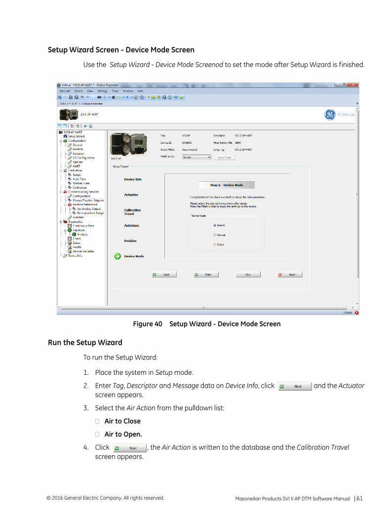
Setup Wizard Screen - Device Mode Screen
Use the Setup Wizard - Device Mode Screenod to set the mode after Setup Wizard is finished.
Figure 40 Setup Wizard - Device Mode Screen
Run the Setup Wizard
To run the Setup Wizard:
1. Place the system in Setup mode.
2. Enter Tag, Descriptor and Message data on Device Info, click and the Actuator screen appears.
3. Select the Air Action from the pulldown list:
Air to Close
Air to Open.
4. Click , the Air Action is written to the database and the Calibration Travel screen appears.
Masoneilan Products SVI II AP DTM Software Manual =| 61© 2016 General Electric Company. All rights reserved.
5. Open an Open Stop Adjustment , if required.
6. Click to start the Find Stops procedure.
A warning appears above.
7. Click .
The Find Stops runs and the Autotune screen appears, if successful.
If the procedure fails:
1. Reset the SVI II AP on the Diagnostics screen (see “Diagnostics Screen” on page 111).
2. Rerun Find Stops.
If it fails a second time, reset to factory defaults (see “Calibration Screen” on page 85).
3. Run the procedure from the start.
8. Configure PID Parameters, Advanced Parameters, Supply Pressure and Aggressiveness as required, click and a warning appears about stroking the valve.
9. Click . Autotune is completed appears.
10. Click and the Position screen appears.
11. Configure as required and click and the Device Mode screen appears.
12. Set the mode and click .
To run Manual Find Stops:
1. Click .
A warning appears above.
2. Click , wait until the valve is fully closed and click .
3. Wait until the valve is fully open and click .
This procedure moves the valve.
© 2016 General Electric Company. All rights reserved.62 | =GE Oil & Gas
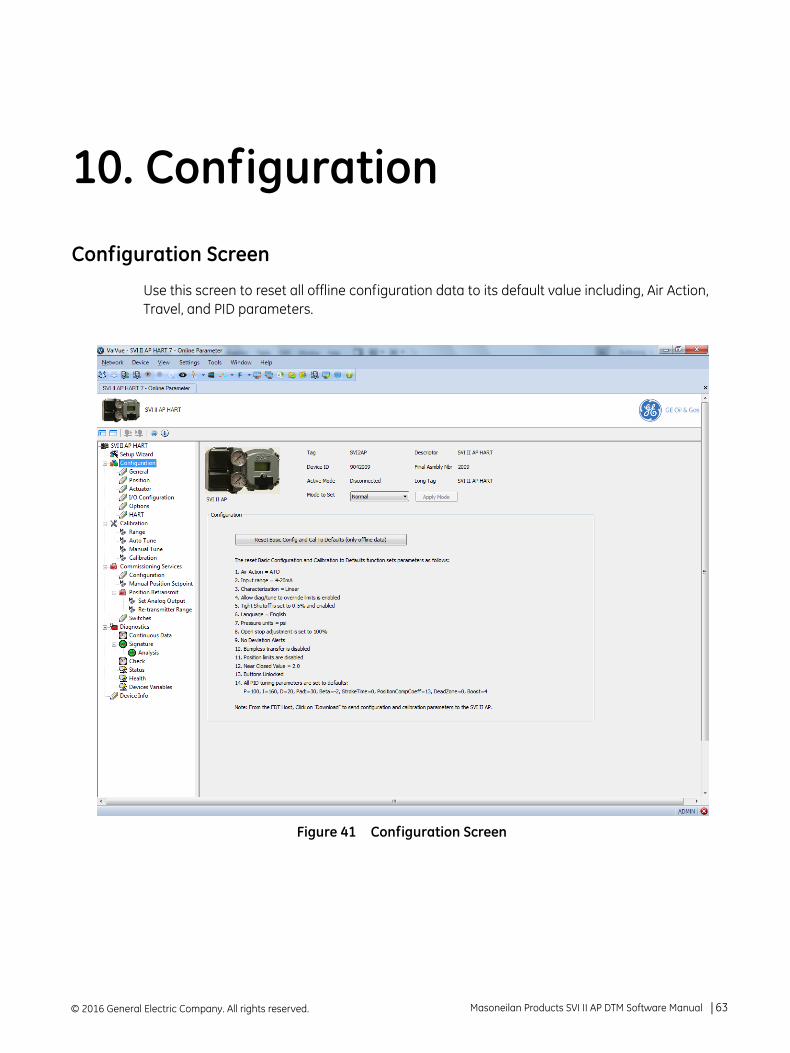
10. Configuration
Configuration Screen
Use this screen to reset all offline configuration data to its default value including, Air Action, Travel, and PID parameters.
Figure 41 Configuration Screen
© 2016 General Electric Company. All rights reserved. Masoneilan Products SVI II AP DTM Software Manual =| 63
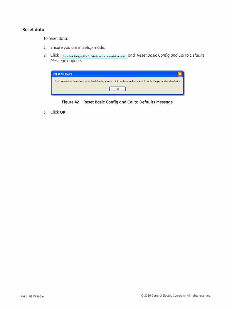
Reset data
To reset data:
1. Ensure you are in Setup mode.
2. Click and Reset Basic Config and Cal to Defaults Message appears.
Figure 42 Reset Basic Config and Cal to Defaults Message
3. Click OK.
© 2016 General Electric Company. All rights reserved.64 | =GE Oil & Gas
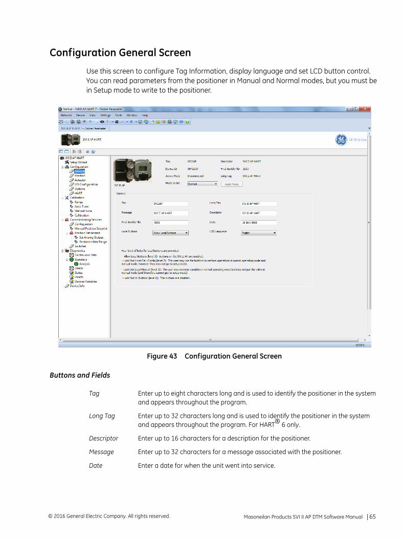
Configuration General Screen
Use this screen to configure Tag Information, display language and set LCD button control. You can read parameters from the positioner in Manual and Normal modes, but you must be in Setup mode to write to the positioner.
Figure 43 Configuration General Screen
Buttons and Fields
Tag Enter up to eight characters long and is used to identify the positioner in the system and appears throughout the program.
Long Tag Enter up to 32 characters long and is used to identify the positioner in the system and appears throughout the program. For HART® 6 only.
Descriptor Enter up to 16 characters for a description for the positioner.
Message Enter up to 32 characters for a message associated with the positioner.
Date Enter a date for when the unit went into service.
Masoneilan Products SVI II AP DTM Software Manual =| 65© 2016 General Electric Company. All rights reserved.
Edit Configuration General Screen
To configure these items:
Enter data as required into the text fields and pulldown lists.
Final Asmbly Numbr
Entered at the factory. Usually not changed.
Local Buttons
A pulldown list to select security level for SVI II AP pushbutton. The SVI II AP comes with an optional local display and buttons for data entry. These buttons can be used to perform basic SVI II AP setup without the need for ValVue or a handheld. It may, however, be desirable after initial setup to lock the buttons so that the SVI II AP parameters cannot be inadvertently changed from the buttons. Several level of locks are provided:
Allow Local Buttons: All buttons on the SVI II AP are enabled.Lock out Local Cal-Config (level 2): You can use the buttons to perform opera-tions in Normal mode and Manual mode, but not in Setup mode.Lock out Local Manual (level 1): You are precluded from Manual and Setup mode but can perform normal operations in Normal mode.Lock out All Buttons (level 0): All buttons are disabled.
LCD Language
A pulldown list to select what language the valve positioner display its menu in: English or French. The DTM program is not affected.
© 2016 General Electric Company. All rights reserved.66 | =GE Oil & Gas
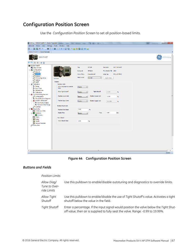
Configuration Position Screen
Use the Configuration Position Screen to set all position-based limits.
Figure 44 Configuration Position Screen
Buttons and Fields
Position Limits
Allow Diag/Tune to Over-ride Limits
Use this pulldown to enable/disable autotuning and diagnostics to override limits.
Allow Tight Shutoff
Use this pulldown to enable/disable the use of Tight Shutoff’s value. Activates a tight shutoff below the value in the field.
Tight Shutoff Enter a percentage. If the input signal would position the valve below the Tight Shut-off value, then air is supplied to fully seat the valve. Range: -0.99 to 19.99%.
Masoneilan Products SVI II AP DTM Software Manual =| 67© 2016 General Electric Company. All rights reserved.
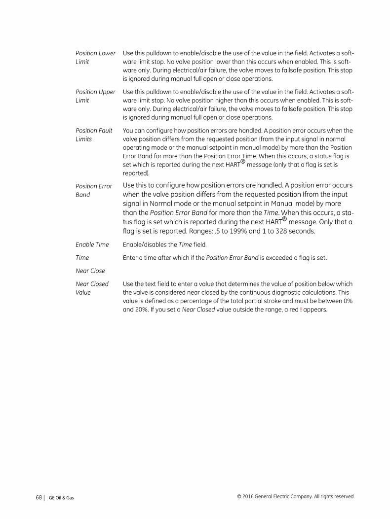
Position Lower Limit
Use this pulldown to enable/disable the use of the value in the field. Activates a soft-ware limit stop. No valve position lower than this occurs when enabled. This is soft-ware only. During electrical/air failure, the valve moves to failsafe position. This stop is ignored during manual full open or close operations.
Position Upper Limit
Use this pulldown to enable/disable the use of the value in the field. Activates a soft-ware limit stop. No valve position higher than this occurs when enabled. This is soft-ware only. During electrical/air failure, the valve moves to failsafe position. This stop is ignored during manual full open or close operations.
Position Fault Limits
You can configure how position errors are handled. A position error occurs when the valve position differs from the requested position (from the input signal in normal operating mode or the manual setpoint in manual mode) by more than the Position Error Band for more than the Position Error Time. When this occurs, a status flag is set which is reported during the next HART® message (only that a flag is set is reported).
Position Error Band
Use this to configure how position errors are handled. A position error occurs when the valve position differs from the requested position (from the input signal in Normal mode or the manual setpoint in Manual mode) by more than the Position Error Band for more than the Time. When this occurs, a sta-tus flag is set which is reported during the next HART® message. Only that a flag is set is reported. Ranges: .5 to 199% and 1 to 328 seconds.
Enable Time Enable/disables the Time field.
Time Enter a time after which if the Position Error Band is exceeded a flag is set.
Near Close
Near Closed Value
Use the text field to enter a value that determines the value of position below which the valve is considered near closed by the continuous diagnostic calculations. This value is defined as a percentage of the total partial stroke and must be between 0% and 20%. If you set a Near Closed value outside the range, a red ! appears.
© 2016 General Electric Company. All rights reserved.68 | =GE Oil & Gas
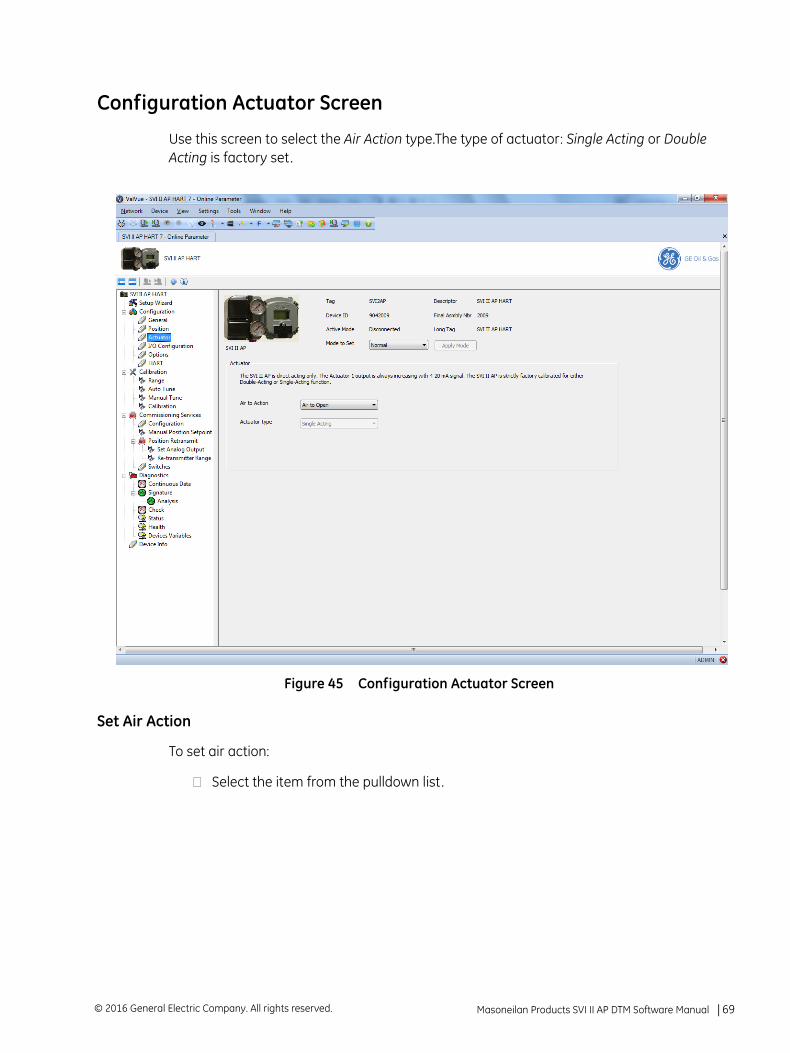
Configuration Actuator Screen
Use this screen to select the Air Action type.The type of actuator: Single Acting or Double Acting is factory set.
Figure 45 Configuration Actuator Screen
Set Air Action
To set air action:
Select the item from the pulldown list.
Masoneilan Products SVI II AP DTM Software Manual =| 69© 2016 General Electric Company. All rights reserved.
Configuration I/O Configuration Screen
Use the Configuration I/O Configuration screen to configure switch states, activate/deactivate digital input, configure the input signal range and valve retransmit range.
Figure 46 Configuration I/O Configuration Screen
Buttons and Fields
The contacts are OPEN when the SVI II AP is unpowered and may be madeto be open or closed when the flag is asserted after boot.
© 2016 General Electric Company. All rights reserved.70 | =GE Oil & Gas
DO Output Switches
Switch 1/Switch 2
The SVI II AP supports two identical contact outputs which can be logically linked to status bits. The two output switches can be opened or closed in response to condi-tions that the SVI II AP detects. Use this pulldown to select the type of action:
Always Normal Position - The switch is not controlled by the SVI II AP and remains in the default position. The two digital output switches can be opened or closed in response to detected conditions. The default configuration setting is Always Normal Position, where normal is closed, which means that the switch will not switch for any valve travel. To activate the switch at a given valve posi-tion, configure the switch Position Low Limit or Position High Limit .Failsafe - The switch is activated when the SVI II AP is in Failsafe modeReset - The switch is activated whenever a reset has occurred and the switch remains activated until the SVI II AP status is clearedPosition Error - The switch is activated whenever a position error has occurred and is deactivated when the position recovers to the correct positionTight Shutoff Active - The switch is activated whenever the device is in tight shut-off (tight shutoff is on and the valve position is less than the tight shutoff posi-tion).Position Low Limit - The switch is activated whenever the valve position is less than the position setting of this switch control.Position Upper Limit - The switch is activated whenever the valve position is greater than the position setting of this switch control.Manual Mode - The switch is activated whenever the SVI II AP is in Manual mode.
Normally Open/Closed
Use this to set the switch as normally open or closed.
DI (Digital Input)
Digital Input Use this pulldown to enable/disable digital inputs.
SI (Input Signal Range)
Use this parameter to adjust the current range Input Signal the low and high signal values. The low value must between 3.8 and 14 mA and the high value must be between 8 and 20.2 mA.
Low Input Signal
Enter a value for the low end for the input signal.
High Input Signal
Enter a value for the high end for the input signal.
AO (Valve Position Retransmit)
The SVI II AP has the ability to retransmit the position signal as an output to another device with 4 - 20 mA current output proportional to position.
Lower Range Value
Enter a position for the valve in percent for the closed (4 mA) position.
Higher Range Value
Enter a position for the valve in percent for the open (20 mA) position.
Masoneilan Products SVI II AP DTM Software Manual =| 71© 2016 General Electric Company. All rights reserved.
Set Switch Parameters
To set switch parameters:
1. Use the Switch 1 or Switch 2 pulldown to select an action:
2. Use the Normally radio buttons to select an action: Closed or Open.
3. Use the Digital Input pulldown to select enable or disable digital inputs.
4. Edit the values in the Low Input Signal or High Input Signal fields, as required.
5. Edit the values in the Lower Range Value or Higher Range Value fields, as required.
Always Normal Position
Failsafe Reset
Position Error Tight Shutoff Active Position Low Limit
Position Upper Limit Manual Mode
If both Position Low Limit and Tight Shut Off are used, the Position Low Limit must be above the Tight Shut Off.
If both Position High Limit and Full Open Above are used, the Position High Limit must be below the Full Open Above.
© 2016 General Electric Company. All rights reserved.72 | =GE Oil & Gas
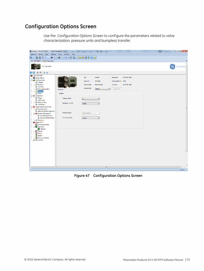
Configuration Options Screen
Use the Configuration Options Screen to configure the parameters related to valve characterization, pressure units and bumpless transfer.
Figure 47 Configuration Options Screen
Masoneilan Products SVI II AP DTM Software Manual =| 73© 2016 General Electric Company. All rights reserved.
Buttons and Fields
Pressure Units A pulldown list for selecting the pressure units for use: psi, bar or kPa.
Bumpless Transfer
Use the pulldown list to select/deselect this option.
This option provides a means to maintain smooth valve control positioning when changing to Normal mode from Manual or Setup. Without Bumpless Transfer, when changing to Normal mode, the setpoint could vary in a manner that causes a signif-icant process disturbance. Bumpless Transfer moves the controller signal to match the valve position so that smooth resumption of control with little disturbance results.
When Bumpless Transfer is selected, returning to Normal mode from Manual or Setup mode is deferred until the input signal matches the current valve position. Either the input signal or the valve position can be changed to match. If nothing is done, the system slowly changes the position until it matches the signal setpoint. The time taken to move to the position is determined by the Transfer Time which is a number between 0 and 255 and is approximately the number of seconds required to move the valve 100% toward the signal position.
Position Sensor Displays the type of sensor installed.
© 2016 General Electric Company. All rights reserved.74 | =GE Oil & Gas
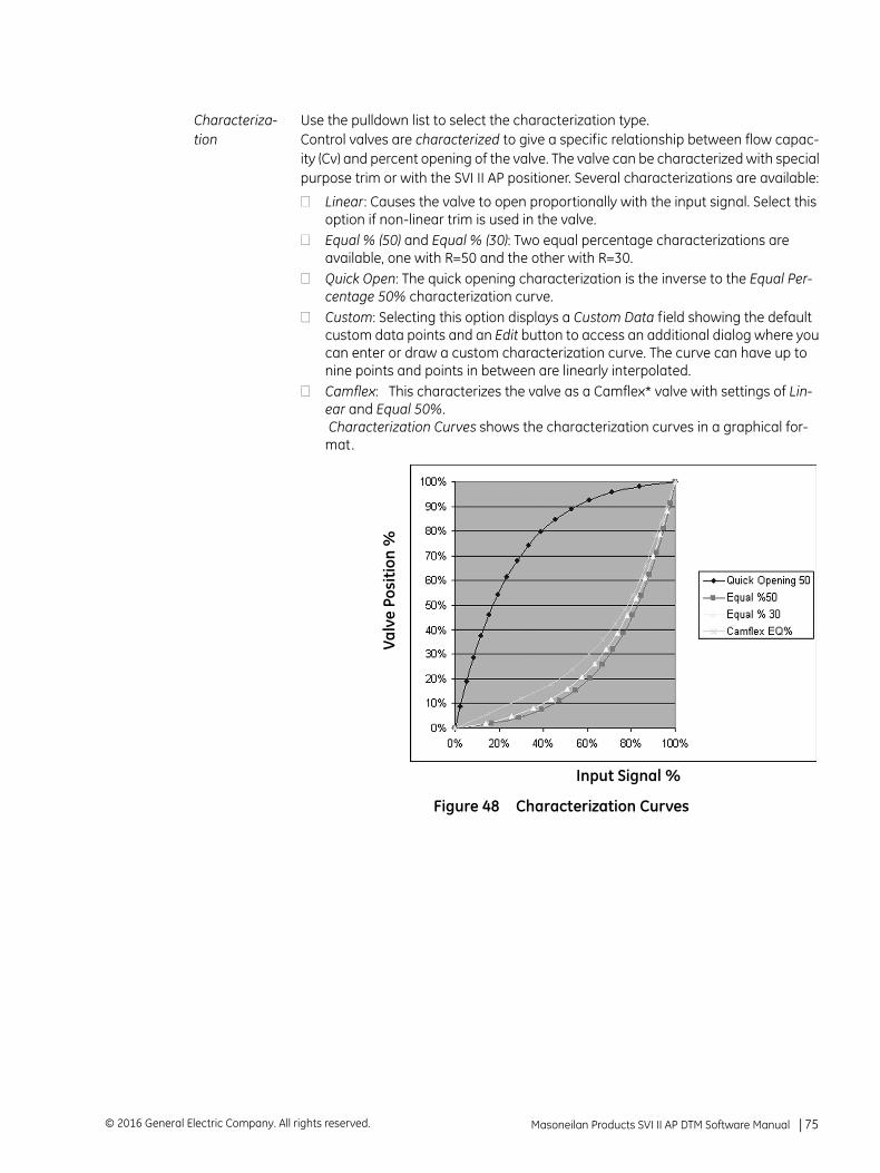
Characteriza-tion
Use the pulldown list to select the characterization type. Control valves are characterized to give a specific relationship between flow capac-ity (Cv) and percent opening of the valve. The valve can be characterized with special purpose trim or with the SVI II AP positioner. Several characterizations are available:
Linear: Causes the valve to open proportionally with the input signal. Select this option if non-linear trim is used in the valve.Equal % (50) and Equal % (30): Two equal percentage characterizations are available, one with R=50 and the other with R=30.Quick Open: The quick opening characterization is the inverse to the Equal Per-centage 50% characterization curve.Custom: Selecting this option displays a Custom Data field showing the default custom data points and an Edit button to access an additional dialog where you can enter or draw a custom characterization curve. The curve can have up to nine points and points in between are linearly interpolated.Camflex: This characterizes the valve as a Camflex* valve with settings of Lin-ear and Equal 50%.Characterization Curves shows the characterization curves in a graphical for-
mat.
Figure 48 Characterization Curves
Valv
e Po
siti
on %
Input Signal %
Masoneilan Products SVI II AP DTM Software Manual =| 75© 2016 General Electric Company. All rights reserved.
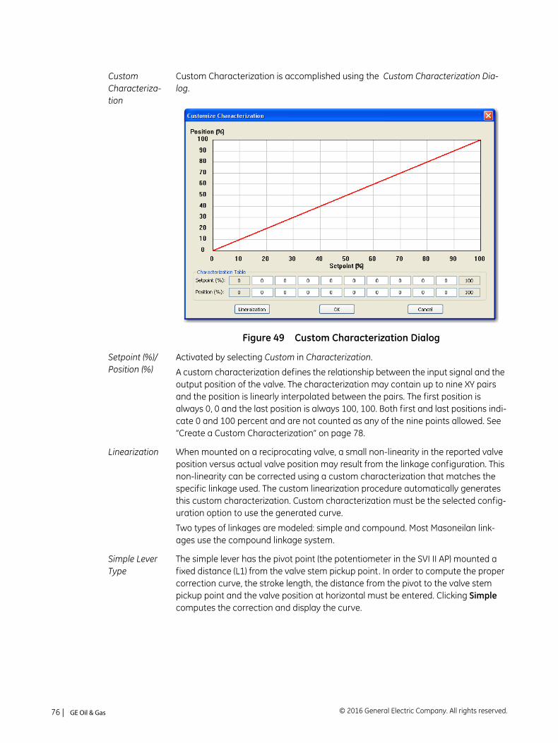
Custom Characteriza-tion
Custom Characterization is accomplished using the Custom Characterization Dia-log.
Figure 49 Custom Characterization Dialog
Setpoint (%)/Position (%)
Activated by selecting Custom in Characterization.
A custom characterization defines the relationship between the input signal and the output position of the valve. The characterization may contain up to nine XY pairs and the position is linearly interpolated between the pairs. The first position is always 0, 0 and the last position is always 100, 100. Both first and last positions indi-cate 0 and 100 percent and are not counted as any of the nine points allowed. See “Create a Custom Characterization” on page 78.
Linearization When mounted on a reciprocating valve, a small non-linearity in the reported valve position versus actual valve position may result from the linkage configuration. This non-linearity can be corrected using a custom characterization that matches the specific linkage used. The custom linearization procedure automatically generates this custom characterization. Custom characterization must be the selected config-uration option to use the generated curve.
Two types of linkages are modeled: simple and compound. Most Masoneilan link-ages use the compound linkage system.
Simple Lever Type
The simple lever has the pivot point (the potentiometer in the SVI II AP) mounted a fixed distance (L1) from the valve stem pickup point. In order to compute the proper correction curve, the stroke length, the distance from the pivot to the valve stem pickup point and the valve position at horizontal must be entered. Clicking Simple computes the correction and display the curve.
© 2016 General Electric Company. All rights reserved.76 | =GE Oil & Gas
Compound Lever Type
The compound lever linkage has two lever segments attached at one end to the pivot and the other end to the valve stem pickup point. In order to compute the proper correction curve, enter the stroke length, first lever segment length (L1), sec-ond lever segment length (L2), the distance from the pivot to the valve stem pickup (L3), the valve position at horizontal. Clicking Compound computes the correction and display the curve.
Most Masoneilan linkages use a linkage with L3 equal to L1, i.e. the second lever arm is vertical when the first lever arm is horizontal. The correction computation will cor-rectly compute the correction curve when L3 is not equal to L1, however L3 must be greater than 0 which requires that the valve stem pickup not be lined up with the pivot and that the pickup be on the same side of the pivot as the link between the first and second lever segments.
Edit button Click this and Custom Characterization Dialog appears. Use this sub-screen to con-figure custom characterizations. See “Create a Custom Characterization” on page 78.
Masoneilan Products SVI II AP DTM Software Manual =| 77© 2016 General Electric Company. All rights reserved.
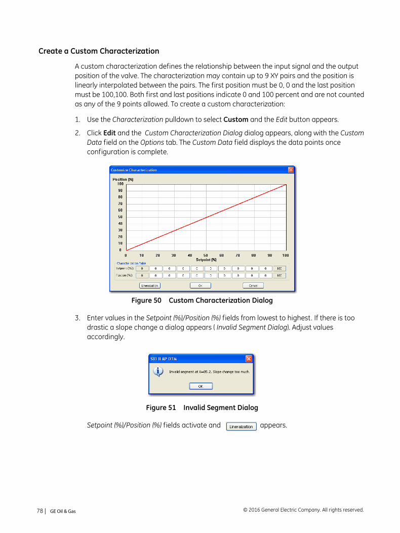
Create a Custom Characterization
A custom characterization defines the relationship between the input signal and the output position of the valve. The characterization may contain up to 9 XY pairs and the position is linearly interpolated between the pairs. The first position must be 0, 0 and the last position must be 100,100. Both first and last positions indicate 0 and 100 percent and are not counted as any of the 9 points allowed. To create a custom characterization:
1. Use the Characterization pulldown to select Custom and the Edit button appears.
2. Click Edit and the Custom Characterization Dialog dialog appears, along with the Custom Data field on the Options tab. The Custom Data field displays the data points once configuration is complete.
Figure 50 Custom Characterization Dialog
3. Enter values in the Setpoint (%)/Position (%) fields from lowest to highest. If there is too drastic a slope change a dialog appears ( Invalid Segment Dialog). Adjust values accordingly.
Figure 51 Invalid Segment Dialog
Setpoint (%)/Position (%) fields activate and appears.
© 2016 General Electric Company. All rights reserved.78 | =GE Oil & Gas
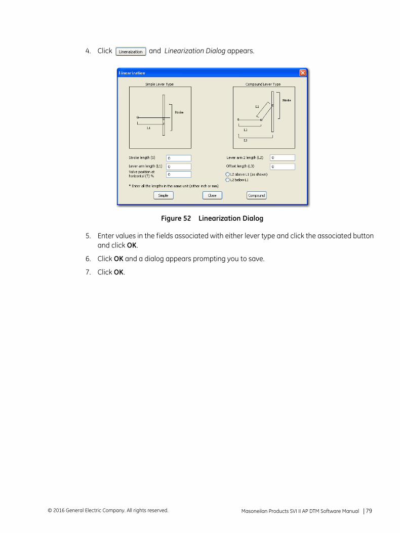
4. Click and Linearization Dialog appears.
Figure 52 Linearization Dialog
5. Enter values in the fields associated with either lever type and click the associated button and click OK.
6. Click OK and a dialog appears prompting you to save.
7. Click OK.
Masoneilan Products SVI II AP DTM Software Manual =| 79© 2016 General Electric Company. All rights reserved.
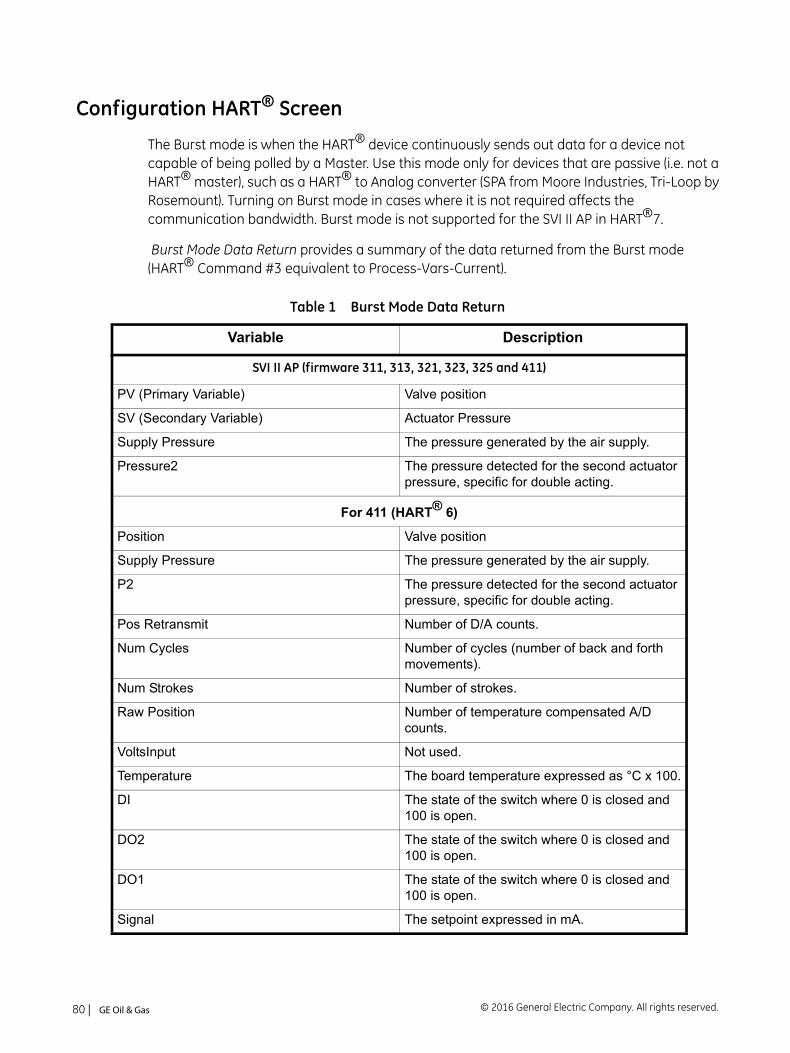
Configuration HART® Screen
The Burst mode is when the HART® device continuously sends out data for a device not capable of being polled by a Master. Use this mode only for devices that are passive (i.e. not a HART® master), such as a HART® to Analog converter (SPA from Moore Industries, Tri-Loop by Rosemount). Turning on Burst mode in cases where it is not required affects the communication bandwidth. Burst mode is not supported for the SVI II AP in HART®7.
Burst Mode Data Return provides a summary of the data returned from the Burst mode (HART® Command #3 equivalent to Process-Vars-Current).
Table 1 Burst Mode Data Return
Variable Description
SVI II AP (firmware 311, 313, 321, 323, 325 and 411)
PV (Primary Variable) Valve position
SV (Secondary Variable) Actuator Pressure
Supply Pressure The pressure generated by the air supply.
Pressure2 The pressure detected for the second actuator pressure, specific for double acting.
For 411 (HART® 6)
Position Valve position
Supply Pressure The pressure generated by the air supply.
P2 The pressure detected for the second actuator pressure, specific for double acting.
Pos Retransmit Number of D/A counts.
Num Cycles Number of cycles (number of back and forth movements).
Num Strokes Number of strokes.
Raw Position Number of temperature compensated A/D counts.
VoltsInput Not used.
Temperature The board temperature expressed as °C x 100.
DI The state of the switch where 0 is closed and 100 is open.
DO2 The state of the switch where 0 is closed and 100 is open.
DO1 The state of the switch where 0 is closed and 100 is open.
Signal The setpoint expressed in mA.
© 2016 General Electric Company. All rights reserved.80 | =GE Oil & Gas
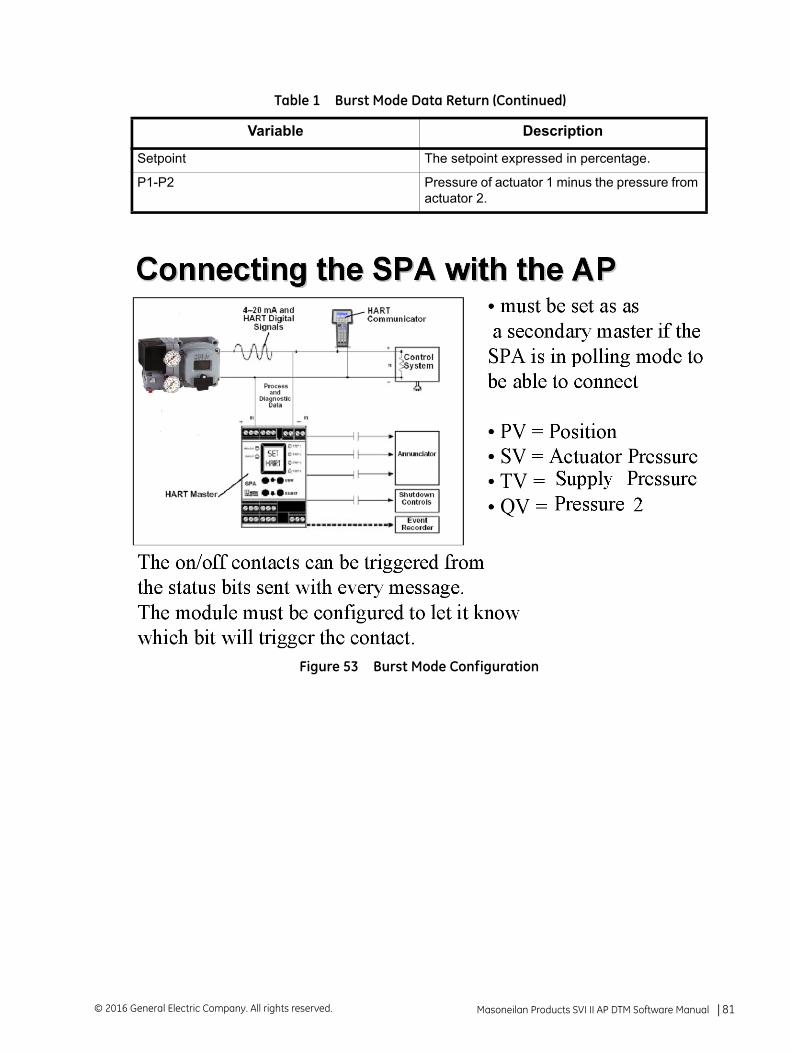
Figure 53 Burst Mode Configuration
Setpoint The setpoint expressed in percentage.
P1-P2 Pressure of actuator 1 minus the pressure from actuator 2.
Table 1 Burst Mode Data Return (Continued)
Variable Description
Masoneilan Products SVI II AP DTM Software Manual =| 81© 2016 General Electric Company. All rights reserved.
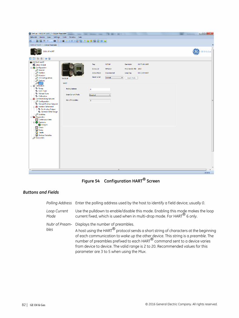
Figure 54 Configuration HART® Screen
Buttons and Fields
Polling Address Enter the polling address used by the host to identify a field device; usually 0.
Loop Current Mode
Use the pulldown to enable/disable this mode. Enabling this mode makes the loop current fixed, which is used when in multi-drop mode. For HART® 6 only.
Nubr of Pream-bles
Displays the number of preambles.
A host using the HART® protocol sends a short string of characters at the beginning of each communication to wake up the other device. This string is a preamble. The number of preambles prefixed to each HART® command sent to a device varies from device to device. The valid range is 2 to 20. Recommended values for this parameter are 3 to 5 when using the Mux.
© 2016 General Electric Company. All rights reserved.82 | =GE Oil & Gas

Configure Burst Mode
To configure a burst mode:
1. Set the system to manual or Normal mode.
2. Use the Burst Mode Select pulldown to select an action: Enter (enables the mode) or Exit .
3. Use the Burst Command Number pulldown to select the data sent:
Cmd 1 - Reads the PV only.
Cmd 2 - Read the current.
Cmd 3 - Reads all variables, including: PV and SV.
Cmd 9 - Reads device vars w/status. HART® 6 only.
Cmd 33 - Reads device variables. HART® 6 only.
4. If using Cmd9 or Cmd33: Choose the variables for the burst command and the order for command variables to be returned using the four Burst Variable pulldowns. There are 15 variables:
Burst Mode Select
Use the pulldown list to activate/deactivate the mode.
Burst Com-mand Number
Use the pulldown to select the data for transmission:
Cmd 1 - Reads the PV only.
Cmd 2 - Read the current.
Cmd 3 - Reads all variables, including: PV and SV.
Cmd 9 - Reads device vars w/status. HART® 6 only.
Cmd 33 - Reads device variables. HART® 6 only.
Position P2 P1-P2
Supply Pressure
Setpoint Signal
DO2 DO1 Temperature
DI Raw Position VoltsInput
Num Strokes Num Cycles Pos Retransmit
Masoneilan Products SVI II AP DTM Software Manual =| 83© 2016 General Electric Company. All rights reserved.

This page intentionally left blank.
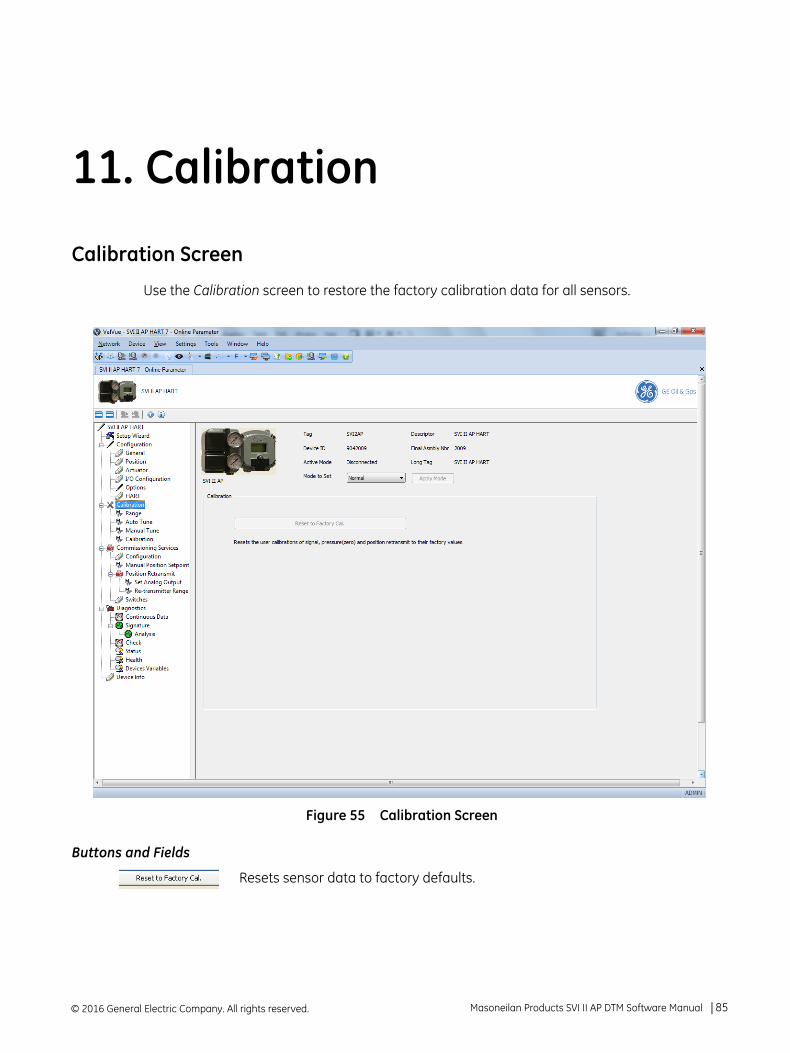
11. Calibration
Calibration Screen
Use the Calibration screen to restore the factory calibration data for all sensors.
Figure 55 Calibration Screen
Buttons and Fields
Resets sensor data to factory defaults.
© 2016 General Electric Company. All rights reserved. Masoneilan Products SVI II AP DTM Software Manual =| 85
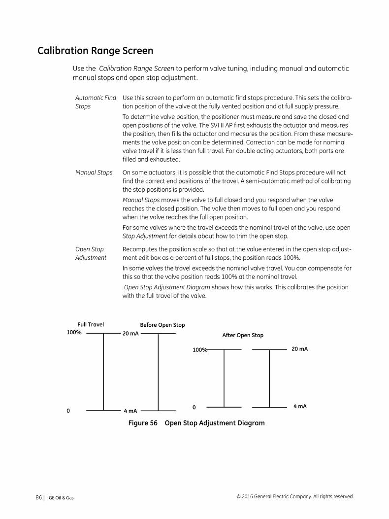
Calibration Range Screen
Use the Calibration Range Screen to perform valve tuning, including manual and automatic manual stops and open stop adjustment.
Figure 56 Open Stop Adjustment Diagram
Automatic Find Stops
Use this screen to perform an automatic find stops procedure. This sets the calibra-tion position of the valve at the fully vented position and at full supply pressure.
To determine valve position, the positioner must measure and save the closed and open positions of the valve. The SVI II AP first exhausts the actuator and measures the position, then fills the actuator and measures the position. From these measure-ments the valve position can be determined. Correction can be made for nominal valve travel if it is less than full travel. For double acting actuators, both ports are filled and exhausted.
Manual Stops On some actuators, it is possible that the automatic Find Stops procedure will not find the correct end positions of the travel. A semi-automatic method of calibrating the stop positions is provided.
Manual Stops moves the valve to full closed and you respond when the valve reaches the closed position. The valve then moves to full open and you respond when the valve reaches the full open position.
For some valves where the travel exceeds the nominal travel of the valve, use open Stop Adjustment for details about how to trim the open stop.
Open Stop Adjustment
Recomputes the position scale so that at the value entered in the open stop adjust-ment edit box as a percent of full stops, the position reads 100%.
In some valves the travel exceeds the nominal valve travel. You can compensate for this so that the valve position reads 100% at the nominal travel.
Open Stop Adjustment Diagram shows how this works. This calibrates the position with the full travel of the valve.
Full Travel
After Open Stop
Before Open Stop
0
100%
4 mA
20 mA
0
100%
4 mA
20 mA
© 2016 General Electric Company. All rights reserved.86 | =GE Oil & Gas
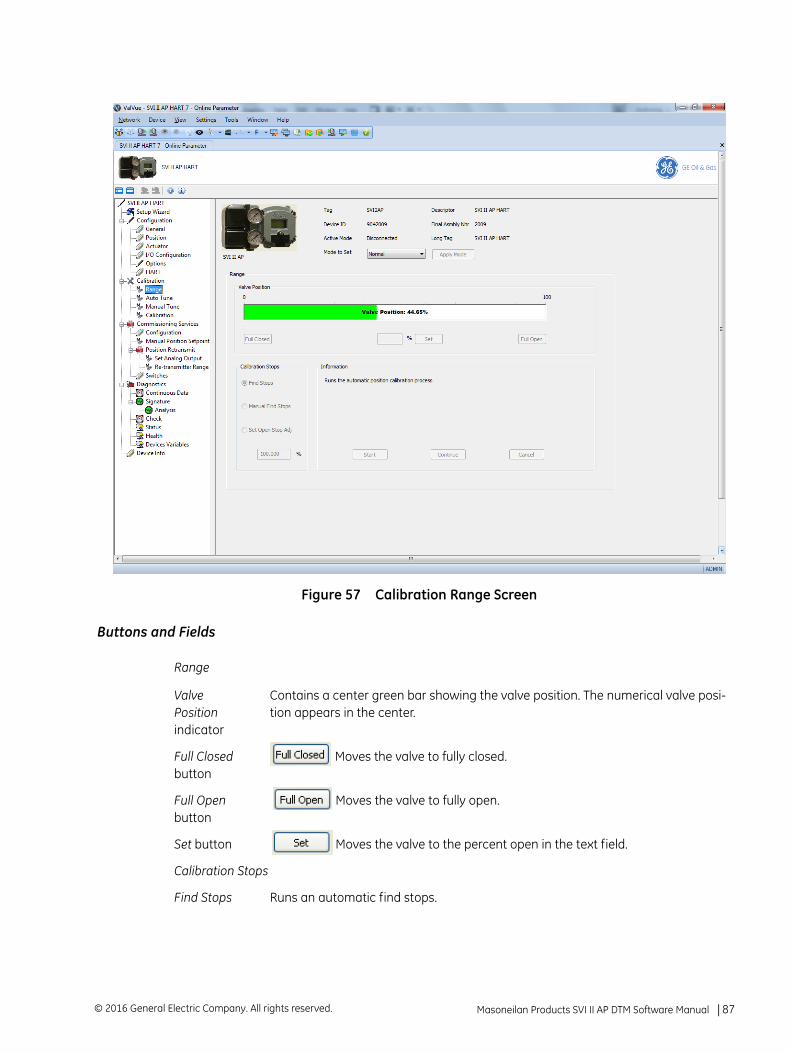
Figure 57 Calibration Range Screen
Buttons and Fields
Range
Valve Position indicator
Contains a center green bar showing the valve position. The numerical valve posi-tion appears in the center.
Full Closed button
Moves the valve to fully closed.
Full Openbutton
Moves the valve to fully open.
Set button Moves the valve to the percent open in the text field.
Calibration Stops
Find Stops Runs an automatic find stops.
Masoneilan Products SVI II AP DTM Software Manual =| 87© 2016 General Electric Company. All rights reserved.
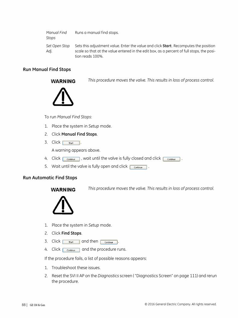
Run Manual Find Stops
To run Manual Find Stops:
1. Place the system in Setup mode.
2. Click Manual Find Stops.
3. Click .
A warning appears above.
4. Click , wait until the valve is fully closed and click .
5. Wait until the valve is fully open and click .
Run Automatic Find Stops.
1. Place the system in Setup mode.
2. Click Find Stops.
3. Click and then .
4. Click and the procedure runs.
If the procedure fails, a list of possible reasons appears:
1. Troubleshoot these issues.
2. Reset the SVI II AP on the Diagnostics screen ( “Diagnostics Screen” on page 111) and rerun the procedure.
Manual Find Stops
Runs a manual find stops.
Set Open Stop Adj.
Sets this adjustment value. Enter the value and click Start . Recomputes the position scale so that at the value entered in the edit box, as a percent of full stops, the posi-tion reads 100%.
This procedure moves the valve. This results in loss of process control.
This procedure moves the valve. This results in loss of process control.
© 2016 General Electric Company. All rights reserved.88 | =GE Oil & Gas
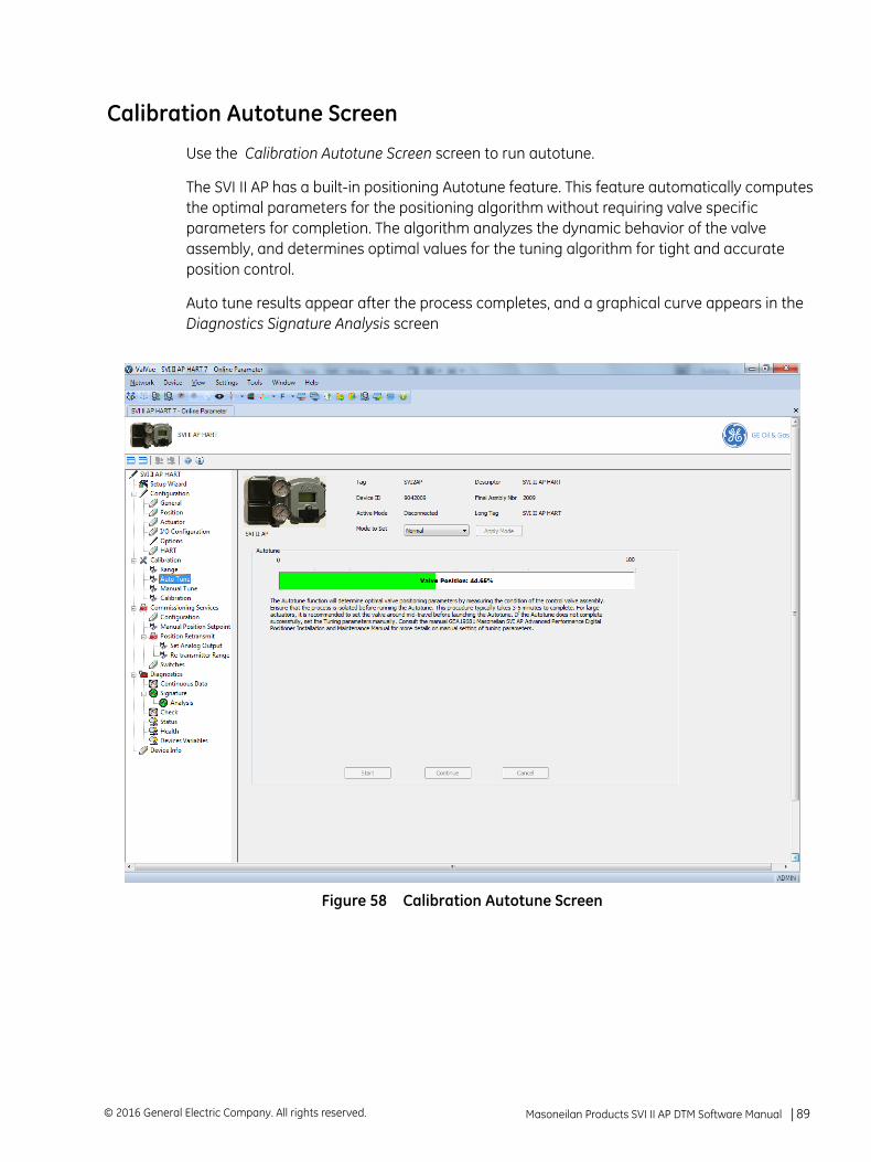
Calibration Autotune Screen
Use the Calibration Autotune Screen screen to run autotune.
The SVI II AP has a built-in positioning Autotune feature. This feature automatically computes the optimal parameters for the positioning algorithm without requiring valve specific parameters for completion. The algorithm analyzes the dynamic behavior of the valve assembly, and determines optimal values for the tuning algorithm for tight and accurate position control.
Auto tune results appear after the process completes, and a graphical curve appears in the Diagnostics Signature Analysis screen
Figure 58 Calibration Autotune Screen
Masoneilan Products SVI II AP DTM Software Manual =| 89© 2016 General Electric Company. All rights reserved.
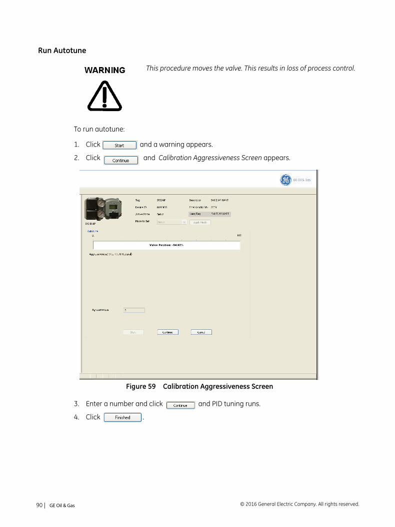
Run Autotune
To run autotune:
1. Click and a warning appears.
2. Click and Calibration Aggressiveness Screen appears.
Figure 59 Calibration Aggressiveness Screen
3. Enter a number and click and PID tuning runs.
4. Click .
This procedure moves the valve. This results in loss of process control.
© 2016 General Electric Company. All rights reserved.90 | =GE Oil & Gas
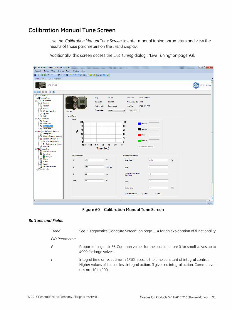
Calibration Manual Tune Screen
Use the Calibration Manual Tune Screen to enter manual tuning parameters and view the results of those parameters on the Trend display.
Additionally, this screen access the Live Tuning dialog ( “Live Tuning” on page 93).
Figure 60 Calibration Manual Tune Screen
Buttons and Fields
Trend See “Diagnostics Signature Screen” on page 114 for an explanation of functionality.
PID Parameters
P Proportional gain in %. Common values for the positioner are 0 for small valves up to 4000 for large valves.
I Integral time or reset time in 1/10th sec, is the time constant of integral control. Higher values of I cause less integral action. 0 gives no integral action. Common val-ues are 10 to 200.
Masoneilan Products SVI II AP DTM Software Manual =| 91© 2016 General Electric Company. All rights reserved.
D Derivative time or rate time (msec) is the time constant of derivative control. Com-mon values are 10 to 100.
Padj Valves often have significantly different response when filling verses exhausting. The proportional gain is adjusted by adding Padj (%) to P when the valve is exhaust-ing.
Live Tuning button
click and the Live Tuning Wizard dialog appears.
Advanced Parameters
Dead Zone When the valve position is within the setpoint +/- the dead zone, no additional posi-tion control is performed. This value is normally 0%, however for high friction valves (e.g. valves with graphite packing) a higher dead zone (%) helps avoid limit cycling due to the stick/slip action of the valve. In these cases the dead zone chosen might be 0.5% to 1%. Range: 0 to 5%.
Beta This is a nonlinear gain factor, ranging from -9 to 9. When Beta is 0, the controller gain is linear. Otherwise, the gain is the function of error. The larger the beta, the smaller the gain for small error.
Position Compensation
The response of the valve is different when the valve is nearly closed than when the valve is nearly open. The position compensation coefficient, which is a number between 0 and 20, make adjustments to try to equalize the valve response. The nor-mal value is 6. For springless actuators the value is 15.
Boost This controls a supplemental pressure, or boost, to speed up initial valve response. This compensates for pneumatic deadband. Range: 0 to 20.
Stroke Time Enter a time to limit the rate of change for travel (sec/100% of travel). This prevents the valve from slamming open or shut.
Both Direction
Click this button to apply Stroke Time to both valve directions.
Open Click this button to apply Stroke Time to valve open only.
Close Click this button to apply Stroke Time to valve close only.
© 2016 General Electric Company. All rights reserved.92 | =GE Oil & Gas
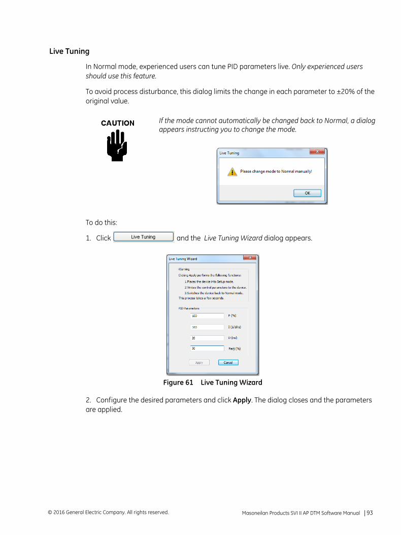
Live Tuning
In Normal mode, experienced users can tune PID parameters live. Only experienced users should use this feature.
To avoid process disturbance, this dialog limits the change in each parameter to ±20% of the original value.
To do this:
1. Click and the Live Tuning Wizard dialog appears.
Figure 61 Live Tuning Wizard
2. Configure the desired parameters and click Apply. The dialog closes and the parameters are applied.
If the mode cannot automatically be changed back to Normal, a dialog appears instructing you to change the mode.
Masoneilan Products SVI II AP DTM Software Manual =| 93© 2016 General Electric Company. All rights reserved.
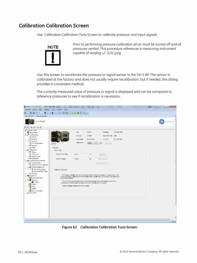
Calibration Calibration Screen
Use Calibration Calibration Tune Screen to calibrate pressure and input signals.
Use this screen to recalibrate the pressure or signal sensor in the SVI II AP. The sensor is calibrated at the factory and does not usually require recalibration, but if needed, this dialog provides a convenient method.
The currently measured value of pressure or signal is displayed and can be compared to reference pressures to see if recalibration is necessary.
Figure 62 Calibration Calibration Tune Screen
Prior to performing pressure calibration all air must be turned off and all pressures vented. This procedure references a measuring instrument capable of reading +/- 0.01 psig.
© 2016 General Electric Company. All rights reserved.94 | =GE Oil & Gas
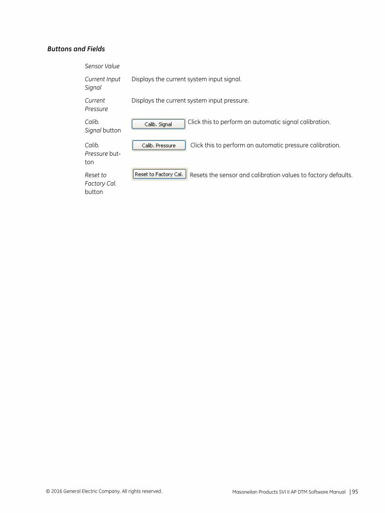
Buttons and Fields
Sensor Value
Current Input Signal
Displays the current system input signal.
Current Pressure
Displays the current system input pressure.
Calib. Signal button
Click this to perform an automatic signal calibration.
Calib. Pressure but-ton
Click this to perform an automatic pressure calibration.
Reset to Factory Cal. button
Resets the sensor and calibration values to factory defaults.
Masoneilan Products SVI II AP DTM Software Manual =| 95© 2016 General Electric Company. All rights reserved.
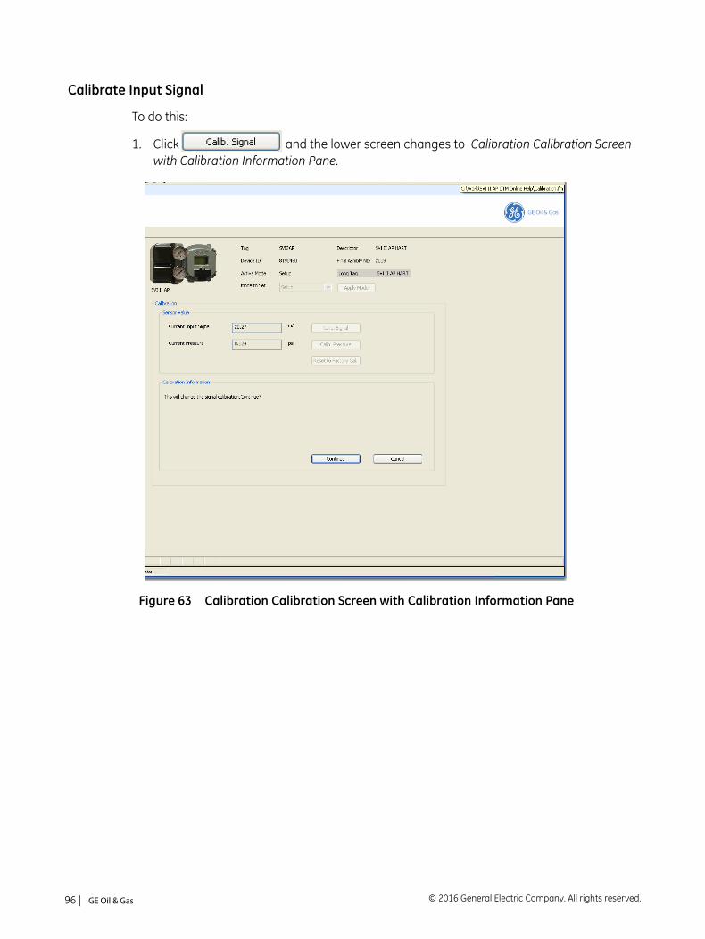
Calibrate Input Signal
To do this:
1. Click and the lower screen changes to Calibration Calibration Screen with Calibration Information Pane.
Figure 63 Calibration Calibration Screen with Calibration Information Pane
© 2016 General Electric Company. All rights reserved.96 | =GE Oil & Gas
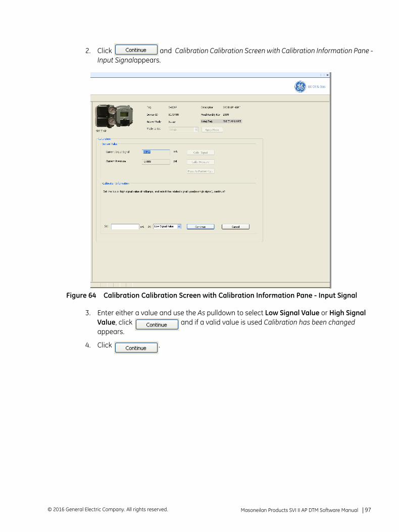
2. Click and Calibration Calibration Screen with Calibration Information Pane - Input Signalappears.
Figure 64 Calibration Calibration Screen with Calibration Information Pane - Input Signal
3. Enter either a value and use the As pulldown to select Low Signal Value or High Signal Value, click and if a valid value is used Calibration has been changed appears.
4. Click .
Masoneilan Products SVI II AP DTM Software Manual =| 97© 2016 General Electric Company. All rights reserved.
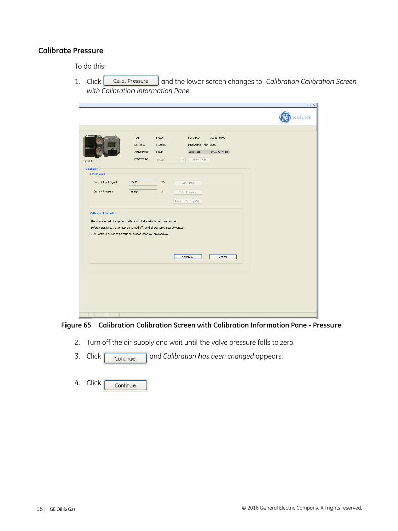
Calibrate Pressure
To do this:
1. Click and the lower screen changes to Calibration Calibration Screen with Calibration Information Pane.
Figure 65 Calibration Calibration Screen with Calibration Information Pane - Pressure
2. Turn off the air supply and wait until the valve pressure falls to zero.
3. Click and Calibration has been changed appears.
4. Click .
© 2016 General Electric Company. All rights reserved.98 | =GE Oil & Gas
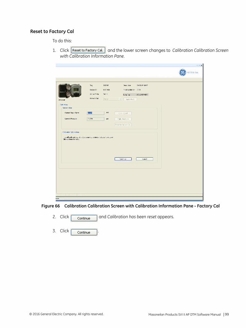
Reset to Factory Cal
To do this:
1. Click and the lower screen changes to Calibration Calibration Screen with Calibration Information Pane.
Figure 66 Calibration Calibration Screen with Calibration Information Pane - Factory Cal
2. Click and Calibration has been reset appears.
3. Click .
Masoneilan Products SVI II AP DTM Software Manual =| 99© 2016 General Electric Company. All rights reserved.

This page intentionally left blank.
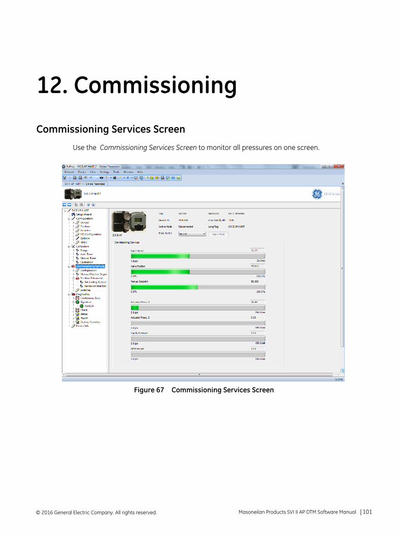
12. Commissioning
Commissioning Services Screen
Use the Commissioning Services Screen to monitor all pressures on one screen.
Figure 67 Commissioning Services Screen
© 2016 General Electric Company. All rights reserved. Masoneilan Products SVI II AP DTM Software Manual =| 101
Buttons and Fields
Input Signal Displays the input signal strength in mA as a bar graph and in a text box. The signal strength appears on the bar graph and the in the text box. The range at the bottom is set on the Configuration screen (“Configuration” on page 63).
Valve Position
Displays the valve position as a bar graph and in a text box. The position from 0 to 100% percent appears on the bar graph and the user-configured limit appears in the text box, The range at the bottom is set on the Configuration screen (“Configura-tion” on page 63).
Manual Setpoint
Displays the Manual Setpoint set on the Manual Position Setpoint screen (“Commis-sioning Services Manual Position Setpoint Screen” on page 104). The value from 0 to 100% percent appears on the bar graph and the user-configured limit appears in the text box.
Actuator Press. 1/Actuator Press. 2
Displays the actuator pressures in a bar graph and text field. These characteristics change depending on whether the valve is single or double acting. If your unit is:
Single acting, Actuator Press. 1 shows the pressure and the other is grayed out.Double acting, both actuator pressures appear. In both cases it displays the sensor pressure read as a bar graph and in a text box.
Supply Pressure
Displays the pressure generated by the air supply in a bar graph and text box.
I/P Pressure Displays the pressure generated by the I/P in a bar graph and text box.
© 2016 General Electric Company. All rights reserved.102 | =GE Oil & Gas
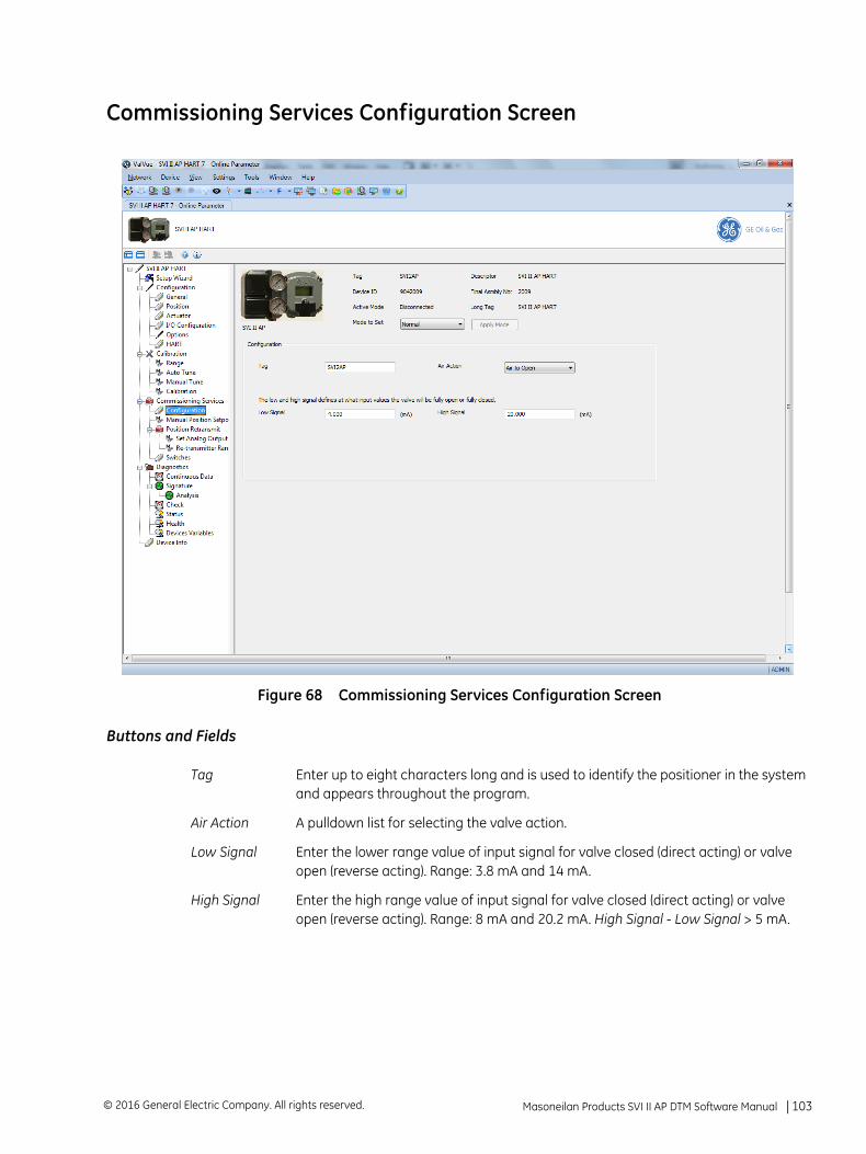
Commissioning Services Configuration Screen
Figure 68 Commissioning Services Configuration Screen
Buttons and Fields
Tag Enter up to eight characters long and is used to identify the positioner in the system and appears throughout the program.
Air Action A pulldown list for selecting the valve action.
Low Signal Enter the lower range value of input signal for valve closed (direct acting) or valve open (reverse acting). Range: 3.8 mA and 14 mA.
High Signal Enter the high range value of input signal for valve closed (direct acting) or valve open (reverse acting). Range: 8 mA and 20.2 mA. High Signal - Low Signal > 5 mA.
Masoneilan Products SVI II AP DTM Software Manual =| 103© 2016 General Electric Company. All rights reserved.
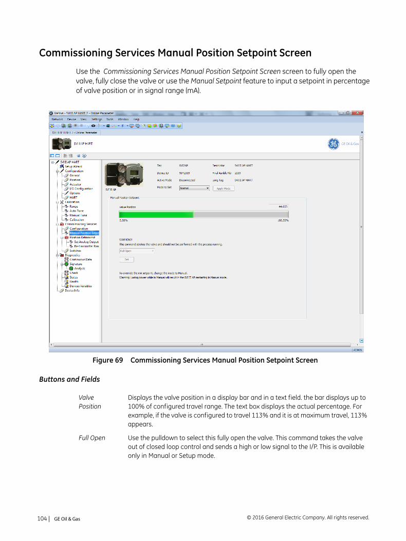
Commissioning Services Manual Position Setpoint Screen
Use the Commissioning Services Manual Position Setpoint Screen screen to fully open the valve, fully close the valve or use the Manual Setpoint feature to input a setpoint in percentage of valve position or in signal range (mA).
Figure 69 Commissioning Services Manual Position Setpoint Screen
Buttons and Fields
ValvePosition
Displays the valve position in a display bar and in a text field. the bar displays up to 100% of configured travel range. The text box displays the actual percentage. For example, if the valve is configured to travel 113% and it is at maximum travel, 113% appears.
Full Open Use the pulldown to select this fully open the valve. This command takes the valve out of closed loop control and sends a high or low signal to the I/P. This is available only in Manual or Setup mode.
© 2016 General Electric Company. All rights reserved.104 | =GE Oil & Gas
Full Closed Use the pulldown to select this fully close the valve. This takes the valve out of closed loop control and sends a high or low signal to the I/P. This is avail-able only in Manual or Setup mode.
Manual Setpoint
Enter a value for the manual setpoint and click one of the button to the right. This is available in Setup and Manual mode. Range -5% and 160% or 4 mA to 20 mA. To override this setting change the mode to Setup or Manual.
Set Valve Position in %
Click and text field that appears. Enter a value and click Set .
Set Valve Position in mA
Click and text field that appears. Enter a value and click Set .
Set button Sets the configured items to the positioner.
Masoneilan Products SVI II AP DTM Software Manual =| 105© 2016 General Electric Company. All rights reserved.
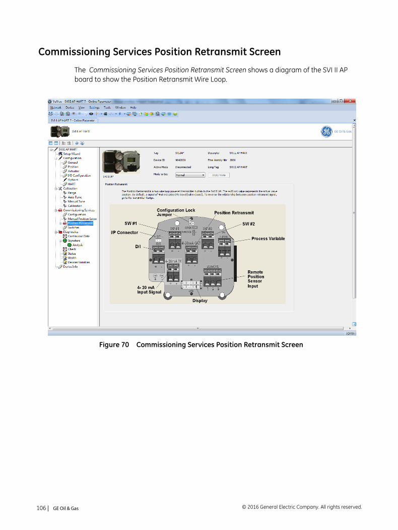
Commissioning Services Position Retransmit Screen
The Commissioning Services Position Retransmit Screen shows a diagram of the SVI II AP board to show the Position Retransmit Wire Loop.
Figure 70 Commissioning Services Position Retransmit Screen
© 2016 General Electric Company. All rights reserved.106 | =GE Oil & Gas
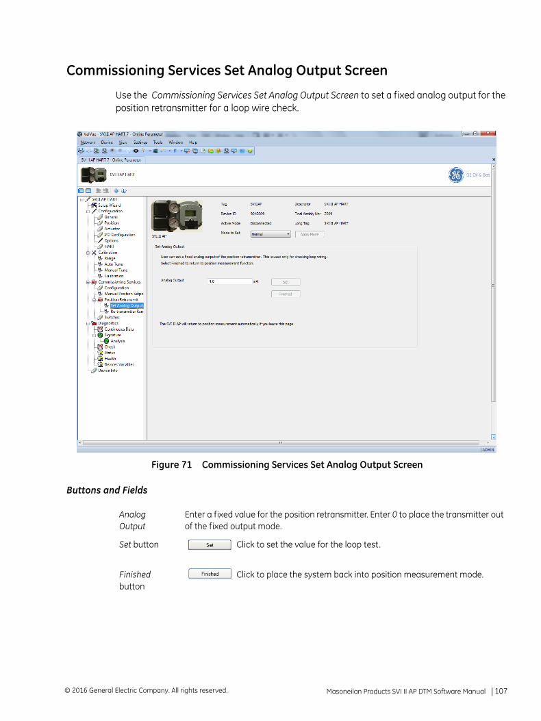
Commissioning Services Set Analog Output Screen
Use the Commissioning Services Set Analog Output Screen to set a fixed analog output for the position retransmitter for a loop wire check.
Figure 71 Commissioning Services Set Analog Output Screen
Buttons and Fields
Analog Output
Enter a fixed value for the position retransmitter. Enter 0 to place the transmitter out of the fixed output mode.
Set button Click to set the value for the loop test.
Finished button
Click to place the system back into position measurement mode.
Masoneilan Products SVI II AP DTM Software Manual =| 107© 2016 General Electric Company. All rights reserved.
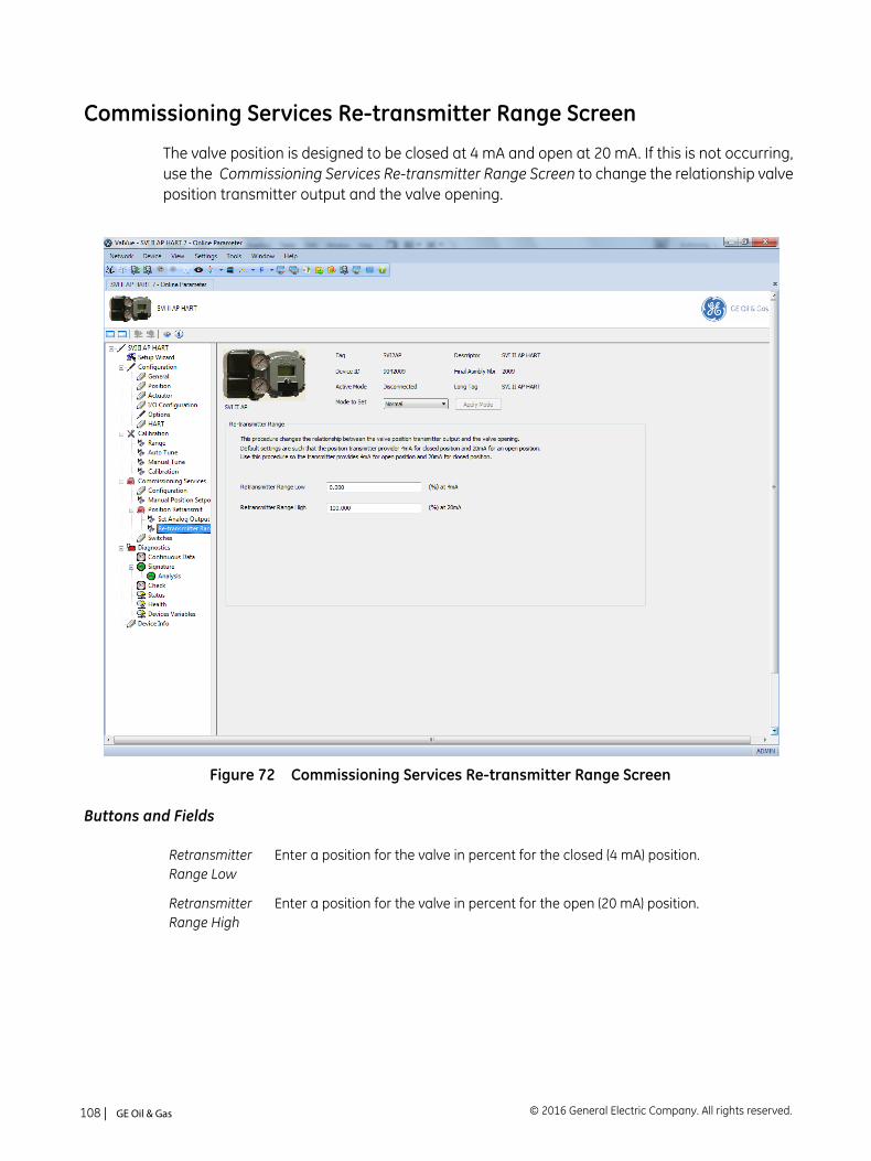
Commissioning Services Re-transmitter Range Screen
The valve position is designed to be closed at 4 mA and open at 20 mA. If this is not occurring, use the Commissioning Services Re-transmitter Range Screen to change the relationship valve position transmitter output and the valve opening.
Figure 72 Commissioning Services Re-transmitter Range Screen
Buttons and Fields
Retransmitter Range Low
Enter a position for the valve in percent for the closed (4 mA) position.
Retransmitter Range High
Enter a position for the valve in percent for the open (20 mA) position.
© 2016 General Electric Company. All rights reserved.108 | =GE Oil & Gas
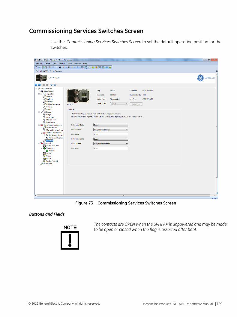
Commissioning Services Switches Screen
Use the Commissioning Services Switches Screen to set the default operating position for the switches.
Figure 73 Commissioning Services Switches Screen
Buttons and Fields
The contacts are OPEN when the SVI II AP is unpowered and may be madeto be open or closed when the flag is asserted after boot.
Masoneilan Products SVI II AP DTM Software Manual =| 109© 2016 General Electric Company. All rights reserved.
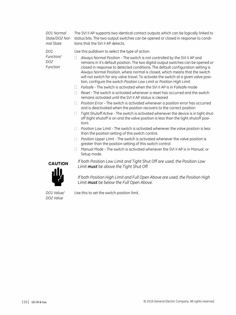
DO1 Normal State/DO2 Nor-mal State
The SVI II AP supports two identical contact outputs which can be logically linked to status bits. The two output switches can be opened or closed in response to condi-tions that the SVI II AP detects.
DO1 Function/DO2 Function
Use this pulldown to select the type of action:
Always Normal Position - The switch is not controlled by the SVI II AP and remains in it’s default position. The two digital output switches can be opened or closed in response to detected conditions. The default configuration setting is Always Normal Position, where normal is closed, which means that the switch will not switch for any valve travel. To activate the switch at a given valve posi-tion, configure the switch Position Low Limit or Position High Limit .Failsafe - The switch is activated when the SVI II AP is in Failsafe modeReset - The switch is activated whenever a reset has occurred and the switch remains activated until the SVI II AP status is clearedPosition Error - The switch is activated whenever a position error has occurred and is deactivated when the position recovers to the correct positionTight Shutoff Active - The switch is activated whenever the device is in tight shut-off (tight shutoff is on and the valve position is less than the tight shutoff posi-tion).Position Low Limit - The switch is activated whenever the valve position is less than the position setting of this switch control.Position Upper Limit - The switch is activated whenever the valve position is greater than the position setting of this switch control.Manual Mode - The switch is activated whenever the SVI II AP is in Manual, or Setup mode.
If both Position Low Limit and Tight Shut Off are used, the Position Low Limit must be above the Tight Shut Off.
If both Position High Limit and Full Open Above are used, the Position High Limit must be below the Full Open Above.
DO1 Value/DO2 Value
Use this to set the switch position limit.
© 2016 General Electric Company. All rights reserved.110 | =GE Oil & Gas
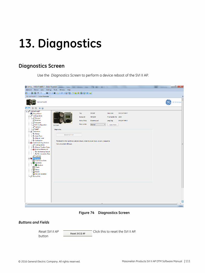
13. Diagnostics
Diagnostics Screen
Use the Diagnostics Screen to perform a device reboot of the SVI II AP.
Figure 74 Diagnostics Screen
Buttons and Fields
Reset SVI II AP button
Click this to reset the SVI II AP.
© 2016 General Electric Company. All rights reserved. Masoneilan Products SVI II AP DTM Software Manual =| 111
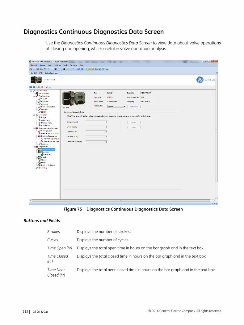
Diagnostics Continuous Diagnostics Data Screen
Use the Diagnostics Continuous Diagnostics Data Screen to view data about valve operations at closing and opening, which useful in valve operation analysis.
Figure 75 Diagnostics Continuous Diagnostics Data Screen
Buttons and Fields
Strokes Displays the number of strokes.
Cycles Displays the number of cycles.
Time Open (hr) Displays the total open time in hours on the bar graph and in the text box.
Time Closed (hr)
Displays the total closed time in hours on the bar graph and in the text box.
Time Near Closed (hr)
Displays the total near closed time in hours on the bar graph and in the text box.
© 2016 General Electric Company. All rights reserved.112 | =GE Oil & Gas

Update button
Click this to read the screen values from the positioner.
Reset button Click this to reset all historian values to zero.
Masoneilan Products SVI II AP DTM Software Manual =| 113© 2016 General Electric Company. All rights reserved.
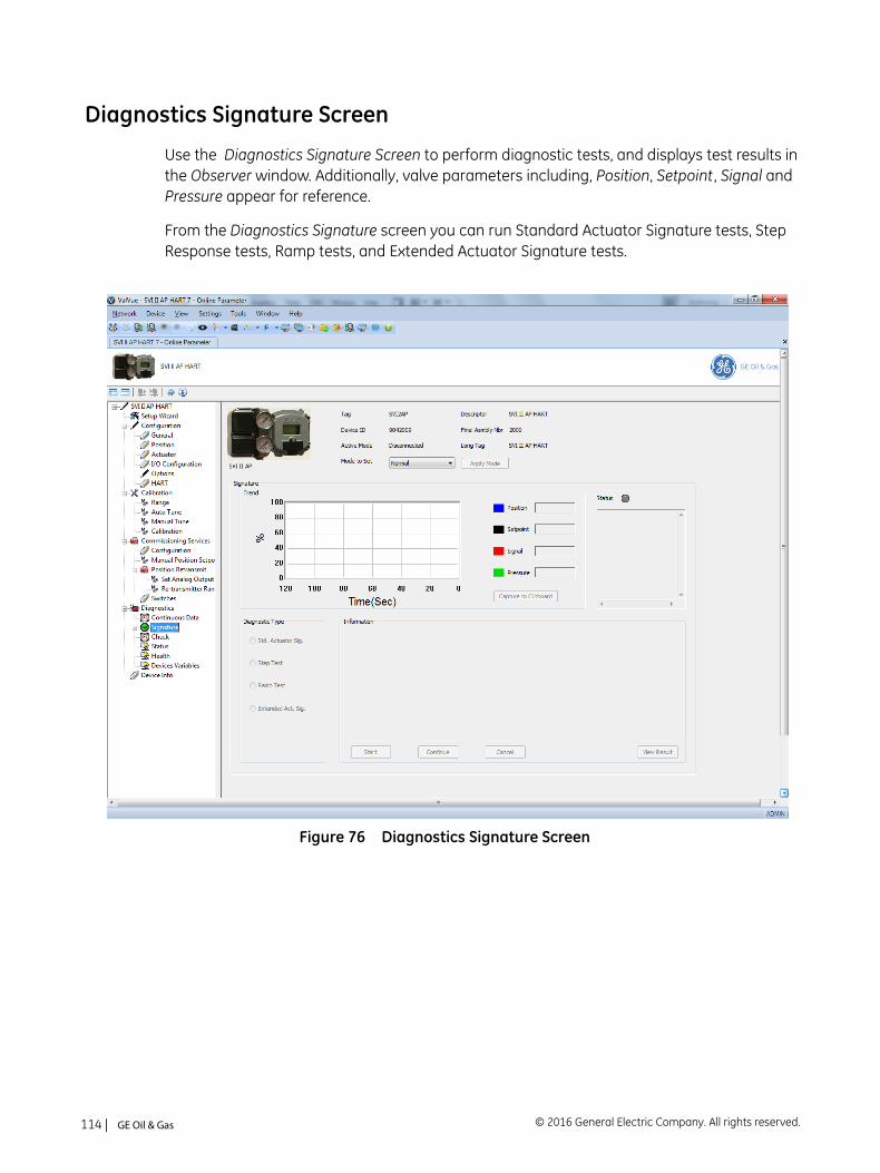
Diagnostics Signature Screen
Use the Diagnostics Signature Screen to perform diagnostic tests, and displays test results in the Observer window. Additionally, valve parameters including, Position, Setpoint , Signal and Pressure appear for reference.
From the Diagnostics Signature screen you can run Standard Actuator Signature tests, Step Response tests, Ramp tests, and Extended Actuator Signature tests.
Figure 76 Diagnostics Signature Screen
© 2016 General Electric Company. All rights reserved.114 | =GE Oil & Gas
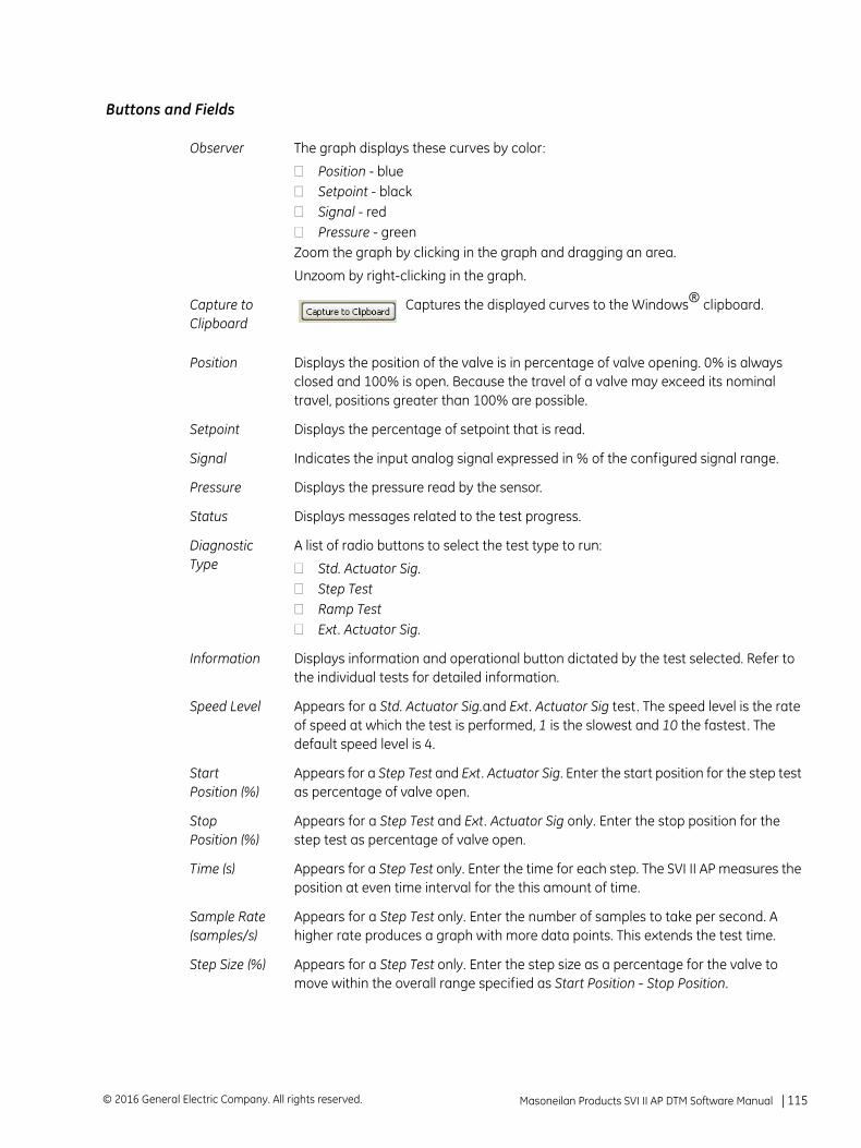
Buttons and Fields
Observer The graph displays these curves by color:
Position - blueSetpoint - blackSignal - redPressure - green
Zoom the graph by clicking in the graph and dragging an area.
Unzoom by right-clicking in the graph.
Capture to Clipboard
Captures the displayed curves to the Windows® clipboard.
Position Displays the position of the valve is in percentage of valve opening. 0% is always closed and 100% is open. Because the travel of a valve may exceed its nominal travel, positions greater than 100% are possible.
Setpoint Displays the percentage of setpoint that is read.
Signal Indicates the input analog signal expressed in % of the configured signal range.
Pressure Displays the pressure read by the sensor.
Status Displays messages related to the test progress.
Diagnostic Type
A list of radio buttons to select the test type to run:
Std. Actuator Sig.Step TestRamp TestExt. Actuator Sig.
Information Displays information and operational button dictated by the test selected. Refer to the individual tests for detailed information.
Speed Level Appears for a Std. Actuator Sig.and Ext. Actuator Sig test. The speed level is the rate of speed at which the test is performed, 1 is the slowest and 10 the fastest. The default speed level is 4.
Start Position (%)
Appears for a Step Test and Ext. Actuator Sig. Enter the start position for the step test as percentage of valve open.
Stop Position (%)
Appears for a Step Test and Ext. Actuator Sig only. Enter the stop position for the step test as percentage of valve open.
Time (s) Appears for a Step Test only. Enter the time for each step. The SVI II AP measures the position at even time interval for the this amount of time.
Sample Rate (samples/s)
Appears for a Step Test only. Enter the number of samples to take per second. A higher rate produces a graph with more data points. This extends the test time.
Step Size (%) Appears for a Step Test only. Enter the step size as a percentage for the valve to move within the overall range specified as Start Position - Stop Position.
Masoneilan Products SVI II AP DTM Software Manual =| 115© 2016 General Electric Company. All rights reserved.
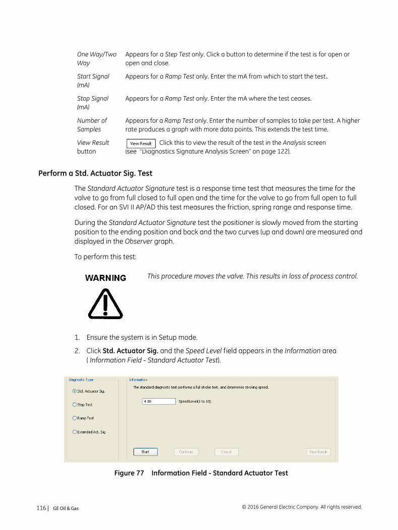
Perform a Std. Actuator Sig. Test
The Standard Actuator Signature test is a response time test that measures the time for the valve to go from full closed to full open and the time for the valve to go from full open to full closed. For an SVI II AP/AD this test measures the friction, spring range and response time.
During the Standard Actuator Signature test the positioner is slowly moved from the starting position to the ending position and back and the two curves (up and down) are measured and displayed in the Observer graph.
To perform this test:
1. Ensure the system is in Setup mode.
2. Click Std. Actuator Sig. and the Speed Level field appears in the Information area ( Information Field - Standard Actuator Test).
Figure 77 Information Field - Standard Actuator Test
One Way/Two Way
Appears for a Step Test only. Click a button to determine if the test is for open or open and close.
Start Signal (mA)
Appears for a Ramp Test only. Enter the mA from which to start the test.
Stop Signal (mA)
Appears for a Ramp Test only. Enter the mA where the test ceases.
Number of Samples
Appears for a Ramp Test only. Enter the number of samples to take per test. A higher rate produces a graph with more data points. This extends the test time.
View Result button
Click this to view the result of the test in the Analysis screen (see “Diagnostics Signature Analysis Screen” on page 122).
This procedure moves the valve. This results in loss of process control.
© 2016 General Electric Company. All rights reserved.116 | =GE Oil & Gas
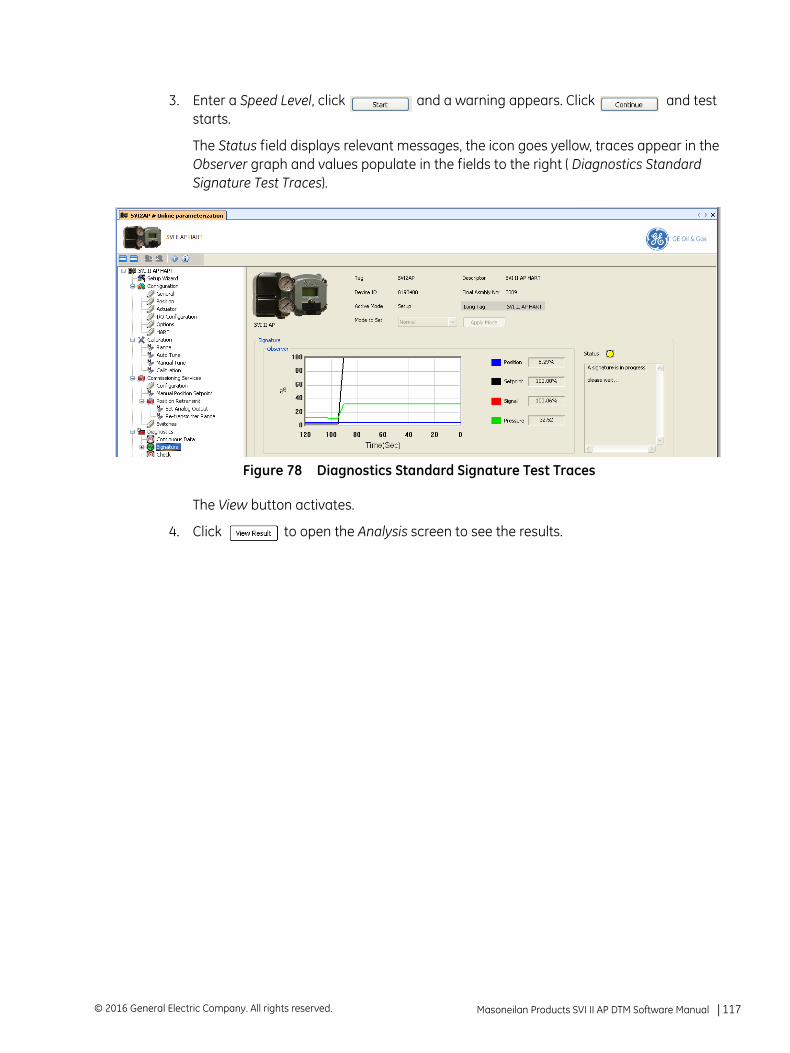
3. Enter a Speed Level, click and a warning appears. Click and test starts.
The Status field displays relevant messages, the icon goes yellow, traces appear in the Observer graph and values populate in the fields to the right ( Diagnostics Standard Signature Test Traces).
Figure 78 Diagnostics Standard Signature Test Traces
The View button activates.
4. Click to open the Analysis screen to see the results.
Masoneilan Products SVI II AP DTM Software Manual =| 117© 2016 General Electric Company. All rights reserved.
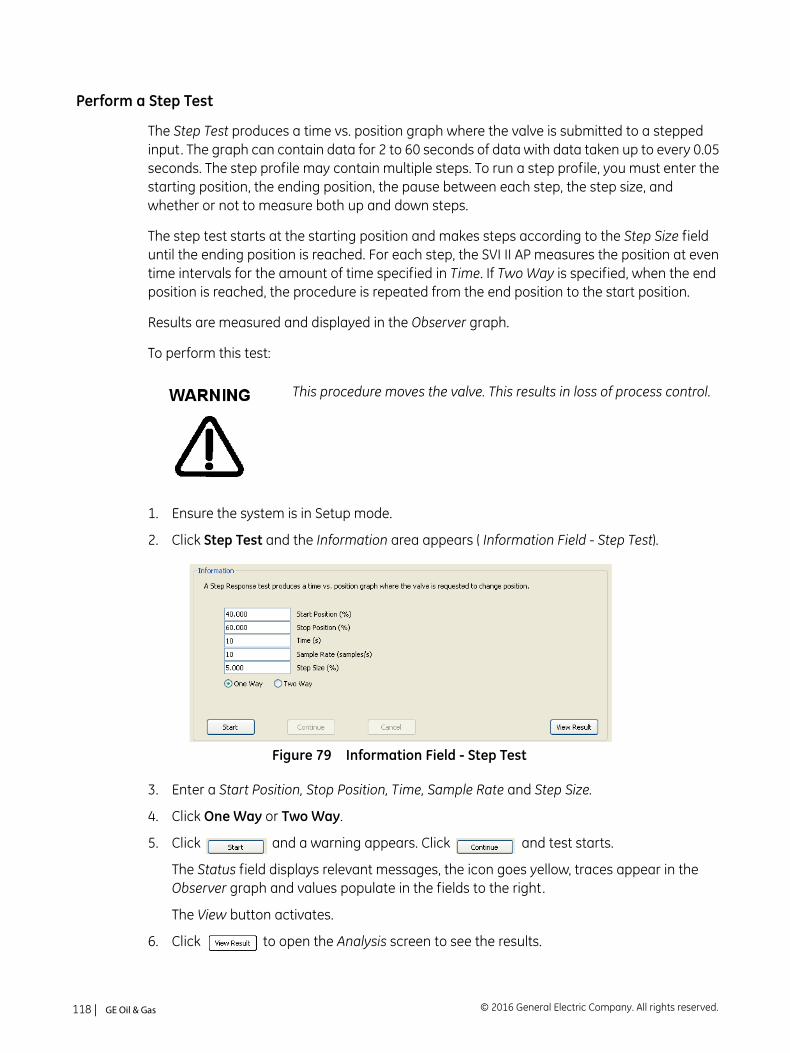
Perform a Step Test
The Step Test produces a time vs. position graph where the valve is submitted to a stepped input. The graph can contain data for 2 to 60 seconds of data with data taken up to every 0.05 seconds. The step profile may contain multiple steps. To run a step profile, you must enter the starting position, the ending position, the pause between each step, the step size, and whether or not to measure both up and down steps.
The step test starts at the starting position and makes steps according to the Step Size field until the ending position is reached. For each step, the SVI II AP measures the position at even time intervals for the amount of time specified in Time. If Two Way is specified, when the end position is reached, the procedure is repeated from the end position to the start position.
Results are measured and displayed in the Observer graph.
To perform this test:
1. Ensure the system is in Setup mode.
2. Click Step Test and the Information area appears ( Information Field - Step Test).
Figure 79 Information Field - Step Test
3. Enter a Start Position, Stop Position, Time, Sample Rate and Step Size.
4. Click One Way or Two Way.
5. Click and a warning appears. Click and test starts.
The Status field displays relevant messages, the icon goes yellow, traces appear in the Observer graph and values populate in the fields to the right.
The View button activates.
6. Click to open the Analysis screen to see the results.
This procedure moves the valve. This results in loss of process control.
© 2016 General Electric Company. All rights reserved.118 | =GE Oil & Gas
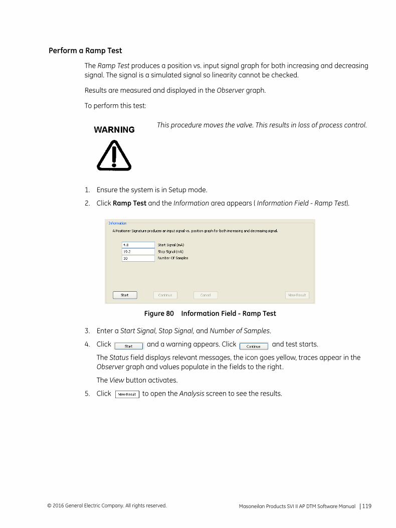
Perform a Ramp Test
The Ramp Test produces a position vs. input signal graph for both increasing and decreasing signal. The signal is a simulated signal so linearity cannot be checked.
Results are measured and displayed in the Observer graph.
To perform this test:
1. Ensure the system is in Setup mode.
2. Click Ramp Test and the Information area appears ( Information Field - Ramp Test).
Figure 80 Information Field - Ramp Test
3. Enter a Start Signal, Stop Signal, and Number of Samples.
4. Click and a warning appears. Click and test starts.
The Status field displays relevant messages, the icon goes yellow, traces appear in the Observer graph and values populate in the fields to the right.
The View button activates.
5. Click to open the Analysis screen to see the results.
This procedure moves the valve. This results in loss of process control.
Masoneilan Products SVI II AP DTM Software Manual =| 119© 2016 General Electric Company. All rights reserved.
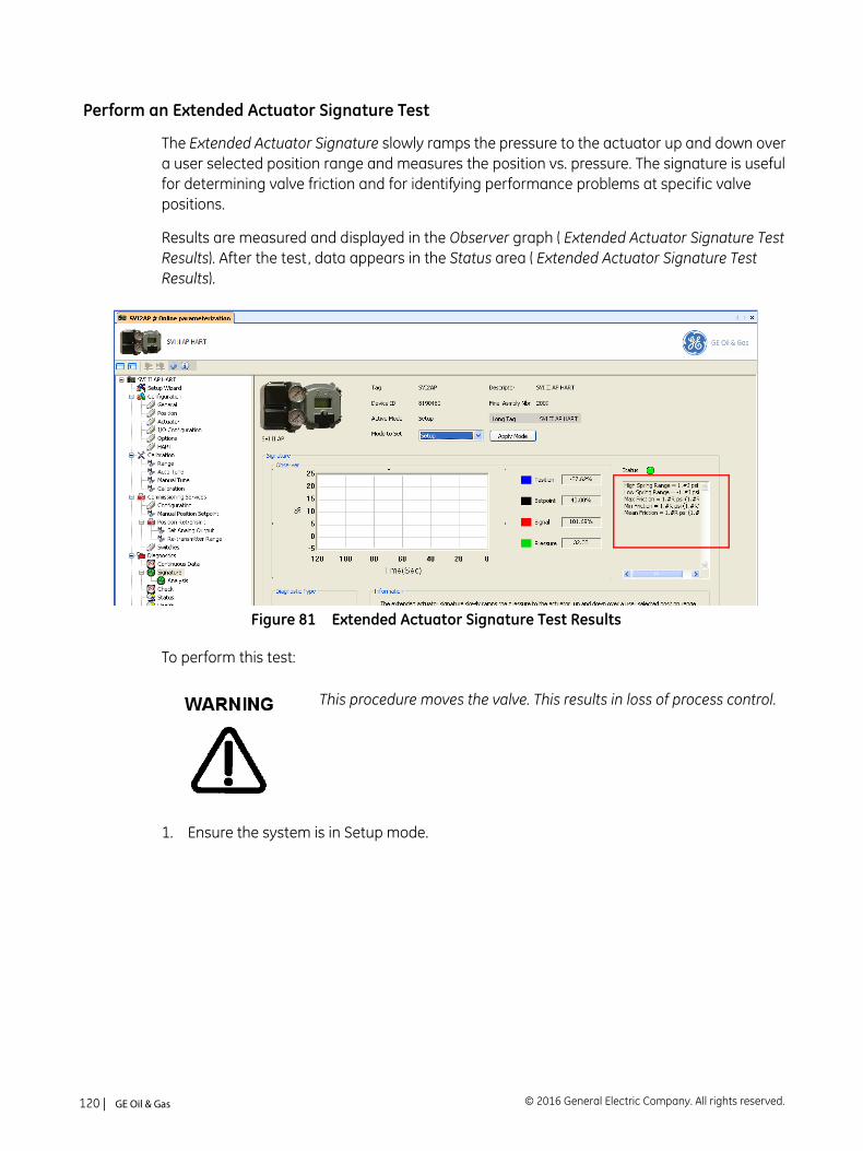
Perform an Extended Actuator Signature Test
The Extended Actuator Signature slowly ramps the pressure to the actuator up and down over a user selected position range and measures the position vs. pressure. The signature is useful for determining valve friction and for identifying performance problems at specific valve positions.
Results are measured and displayed in the Observer graph ( Extended Actuator Signature Test Results). After the test, data appears in the Status area ( Extended Actuator Signature Test Results).
Figure 81 Extended Actuator Signature Test Results
To perform this test:
1. Ensure the system is in Setup mode.
This procedure moves the valve. This results in loss of process control.
© 2016 General Electric Company. All rights reserved.120 | =GE Oil & Gas
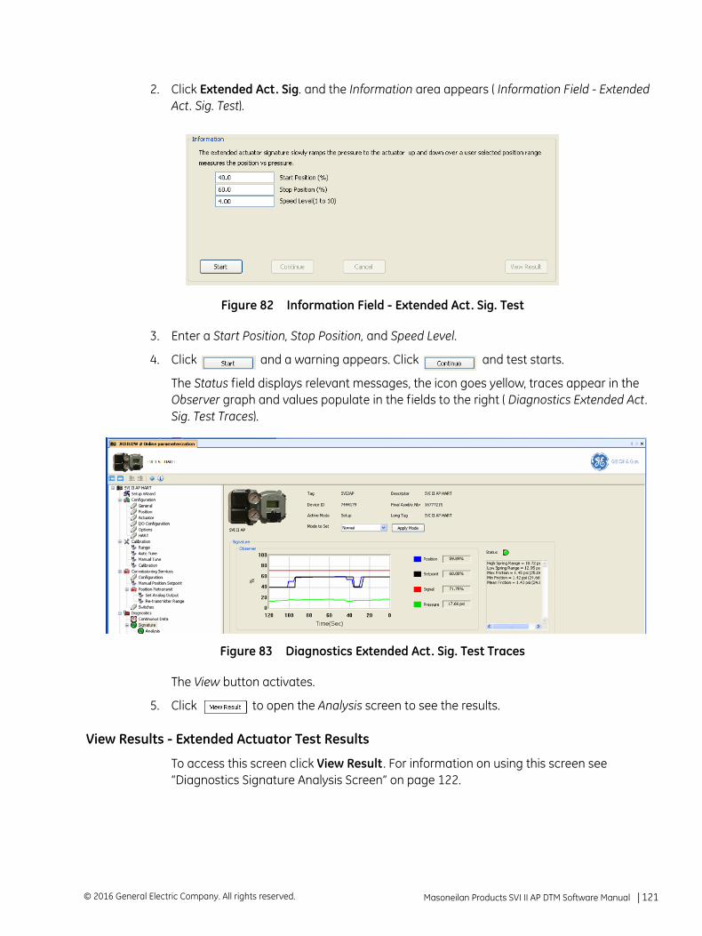
2. Click Extended Act. Sig. and the Information area appears ( Information Field - Extended Act. Sig. Test).
Figure 82 Information Field - Extended Act. Sig. Test
3. Enter a Start Position, Stop Position, and Speed Level.
4. Click and a warning appears. Click and test starts.
The Status field displays relevant messages, the icon goes yellow, traces appear in the Observer graph and values populate in the fields to the right ( Diagnostics Extended Act. Sig. Test Traces).
Figure 83 Diagnostics Extended Act. Sig. Test Traces
The View button activates.
5. Click to open the Analysis screen to see the results.
View Results - Extended Actuator Test Results
To access this screen click View Result . For information on using this screen see “Diagnostics Signature Analysis Screen” on page 122.
Masoneilan Products SVI II AP DTM Software Manual =| 121© 2016 General Electric Company. All rights reserved.
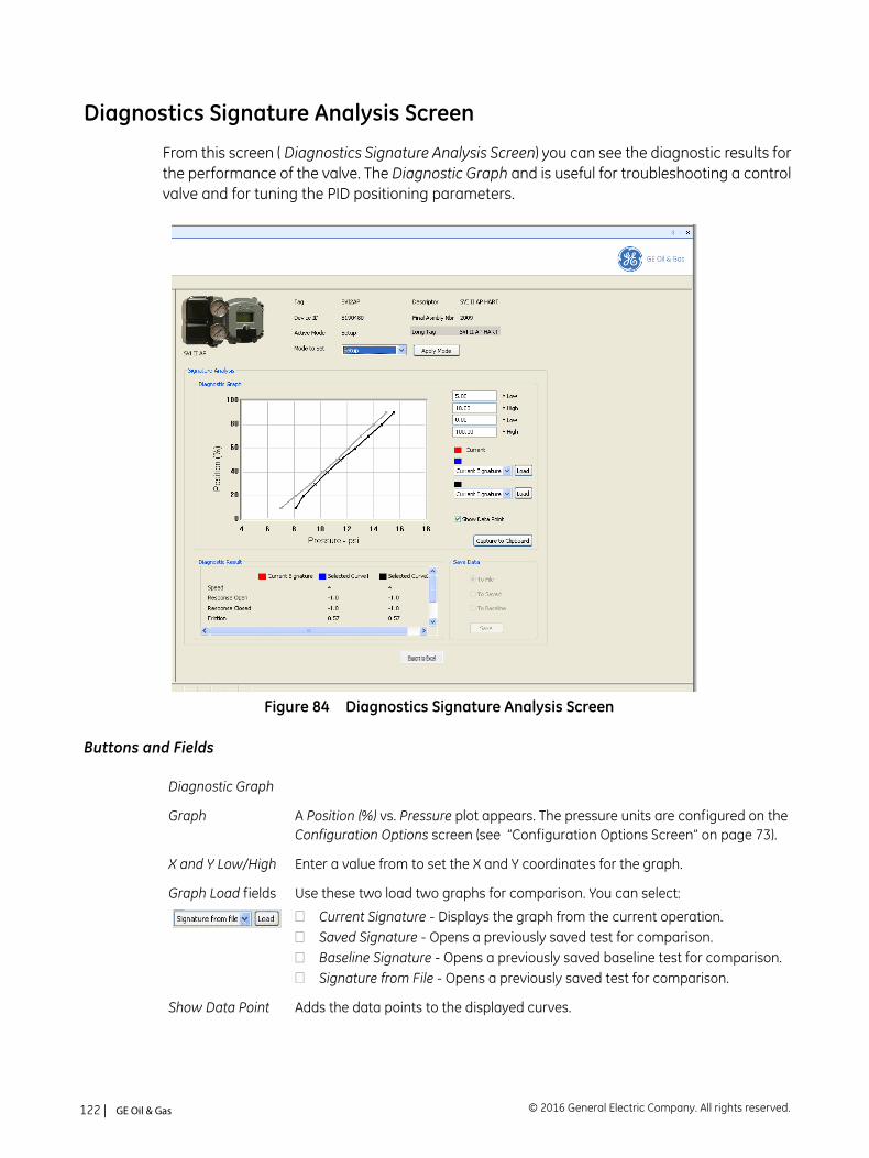
Diagnostics Signature Analysis Screen
From this screen ( Diagnostics Signature Analysis Screen) you can see the diagnostic results for the performance of the valve. The Diagnostic Graph and is useful for troubleshooting a control valve and for tuning the PID positioning parameters.
Figure 84 Diagnostics Signature Analysis Screen
Buttons and Fields
Diagnostic Graph
Graph A Position (%) vs. Pressure plot appears. The pressure units are configured on the Configuration Options screen (see “Configuration Options Screen” on page 73).
X and Y Low/High Enter a value from to set the X and Y coordinates for the graph.
Graph Load fields Use these two load two graphs for comparison. You can select:
Current Signature - Displays the graph from the current operation.Saved Signature - Opens a previously saved test for comparison.Baseline Signature - Opens a previously saved baseline test for comparison.Signature from File - Opens a previously saved test for comparison.
Show Data Point Adds the data points to the displayed curves.
© 2016 General Electric Company. All rights reserved.122 | =GE Oil & Gas
Capture to Clipboard
Captures the displayed curves to the Windows® clipboard.
Diagnostic Result Displays color-coded data results for each curve in the following (depending on testtype):
SpeedResponse OpenResponse CloseFrictionFriction %Lower Spring RangeUpper Spring Range
Save Data Use the radio buttons to select the type of curve to save.
Export to Excel button
Use this button to export the results to an Excel .csv file for analysis.
Masoneilan Products SVI II AP DTM Software Manual =| 123© 2016 General Electric Company. All rights reserved.
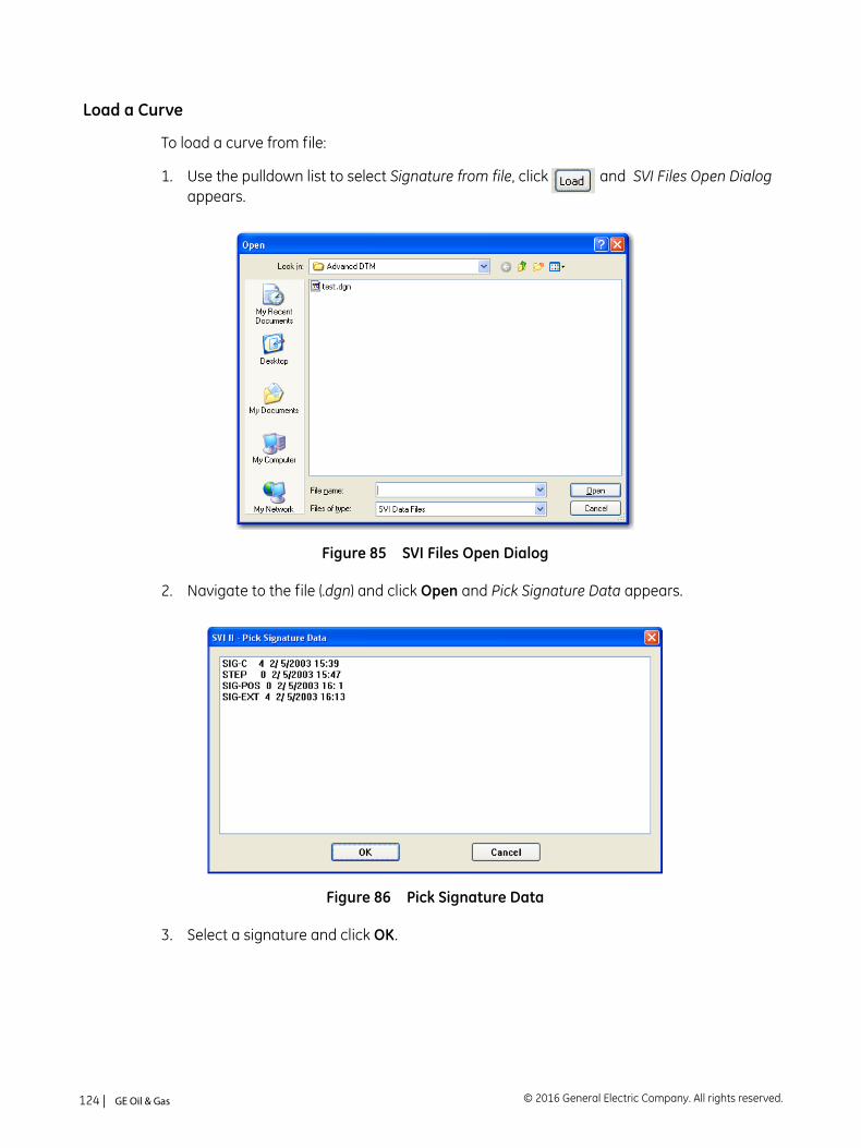
Load a Curve
To load a curve from file:
1. Use the pulldown list to select Signature from file, click and SVI Files Open Dialog appears.
Figure 85 SVI Files Open Dialog
2. Navigate to the file (.dgn) and click Open and Pick Signature Data appears.
Figure 86 Pick Signature Data
3. Select a signature and click OK.
© 2016 General Electric Company. All rights reserved.124 | =GE Oil & Gas
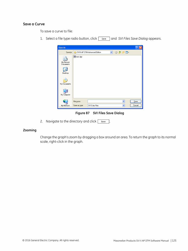
Save a Curve
To save a curve to file:
1. Select a file type radio button, click and SVI Files Save Dialog appears.
Figure 87 SVI Files Save Dialog
2. Navigate to the directory and click .
Zooming
Change the graph’s zoom by dragging a box around an area. To return the graph to its normal scale, right-click in the graph.
Masoneilan Products SVI II AP DTM Software Manual =| 125© 2016 General Electric Company. All rights reserved.
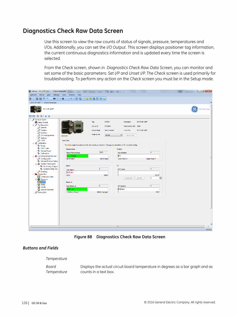
Diagnostics Check Raw Data Screen
Use this screen to view the raw counts of status of signals, pressure, temperatures and I/Os. Additionally, you can set the I/O Output . This screen displays positioner tag information, the current continuous diagnostics information and is updated every time the screen is selected.
From the Check screen, shown in Diagnostics Check Raw Data Screen, you can monitor and set some of the basic parameters: Set I/P and Unset I/P. The Check screen is used primarily for troubleshooting. To perform any action on the Check screen you must be in the Setup mode.
Figure 88 Diagnostics Check Raw Data Screen
Buttons and Fields
Temperature
Board Temperature
Displays the actual circuit board temperature in degrees as a bar graph and as counts in a text box.
© 2016 General Electric Company. All rights reserved.126 | =GE Oil & Gas
Min Temperature
Displays the historical low temperature to which the positioner was be exposed as abar graph and as counts in a text box.
Max Temperature
Displays the historical high temperature to which the positioner was be exposed asa bar graph and as counts in a text box.
Signal
Raw Signal Displays the input signal strength in counts as a bar graph and as counts in a text box.
Pressure
Raw Pressure Displays the raw A/D values for pressure, which is useful to GE engineers for diag-nostic purposes. Displays the data strength in counts in a text box and as in a bar graph in the user-configured pressure units.
Position
Raw Position Displays the raw A/D values for position, which is useful to GE engineers for diagnos-tic purposes. Displays the data strength in counts in a text box and as in a bar graphas a percentage of open.
Lower Stop Displays the position raw counts at the stop.
Upper Stop Displays the position raw counts at the stop.
I/P
I/P Output Displays the I/P output in counts as a bar graph and in a text box.
Use this field and two buttons to enter and set the I/P output in counts and to unsetthe I/P value. This value is the constant signal to the I/P. 0 resets the device to Nor-mal mode. A red ! appears if an input value is out of range. The LED to right indicatesgray if unset and red when manually set.
I/P Current
I/P Current Displays the I/P current in mA as a bar graph and as counts in a text box.
Masoneilan Products SVI II AP DTM Software Manual =| 127© 2016 General Electric Company. All rights reserved.
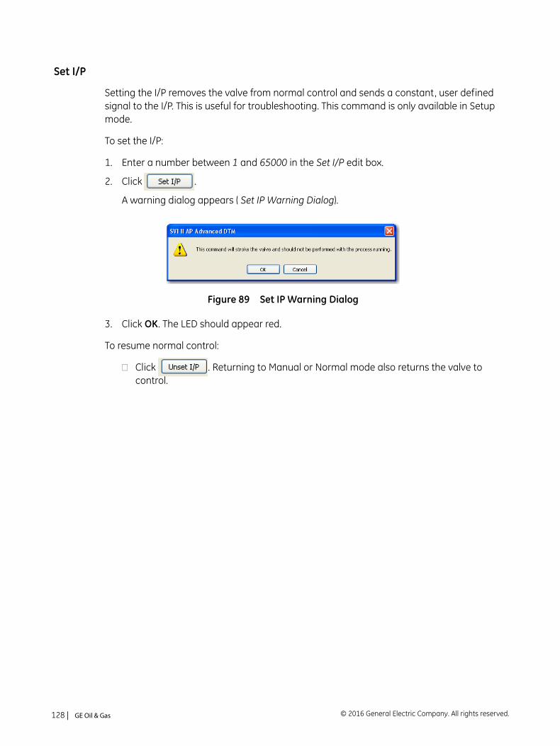
Set I/P
Setting the I/P removes the valve from normal control and sends a constant, user defined signal to the I/P. This is useful for troubleshooting. This command is only available in Setup mode.
To set the I/P:
1. Enter a number between 1 and 65000 in the Set I/P edit box.
2. Click .
A warning dialog appears ( Set IP Warning Dialog).
Figure 89 Set IP Warning Dialog
3. Click OK. The LED should appear red.
To resume normal control:
Click . Returning to Manual or Normal mode also returns the valve to control.
© 2016 General Electric Company. All rights reserved.128 | =GE Oil & Gas
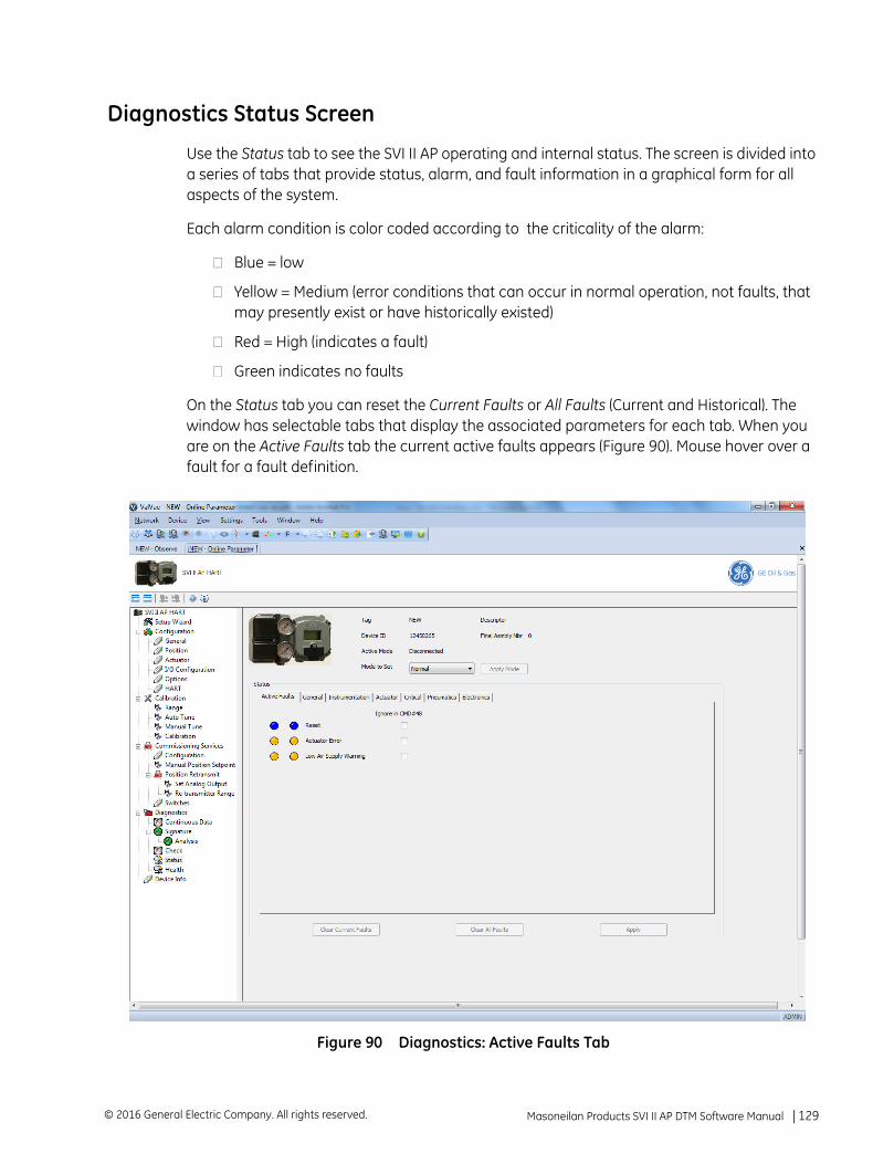
Diagnostics Status Screen
Use the Status tab to see the SVI II AP operating and internal status. The screen is divided into a series of tabs that provide status, alarm, and fault information in a graphical form for all aspects of the system.
Each alarm condition is color coded according to the criticality of the alarm:
Blue = low
Yellow = Medium (error conditions that can occur in normal operation, not faults, that may presently exist or have historically existed)
Red = High (indicates a fault)
Green indicates no faults
On the Status tab you can reset the Current Faults or All Faults (Current and Historical). The window has selectable tabs that display the associated parameters for each tab. When you are on the Active Faults tab the current active faults appears (Figure 90). Mouse hover over a fault for a fault definition.
Figure 90 Diagnostics: Active Faults Tab
Masoneilan Products SVI II AP DTM Software Manual =| 129© 2016 General Electric Company. All rights reserved.
The ValVue 3 Device Criticality settings determine the scan period for monitoring of a positioner. Selecting Do Not Bother means no status is monitored for display. Ensure if you use Inherent from Parent Area that the settings do not include Do Not Bother. The ValVue 3 Device Status Monitor Running must also be active for any status to appear on an individual DTM’s Status tab. Status updates for active faults also appear on the Healthy Status and Device Monitor: Data Displayed - refer to the ValVue 3 help or GEA31426 Masoneilan Products ValVue 3 Software Manual.
Buttons and Fields
Current Faults Faults that have occurred and have not been cleared.
Historical Faults Faults that have occurred but been cleared from Current Faults.
Ignore in CMD #48 Click an individual checkbox to remove that fault’s status from any Command 48 status updates. You must click to complete configuration. This functionality does not appear for HART® 5.
Clear Current Faults button
Click to clear Current Faults, if the fault cause no longer exists.
Clear All Faults button
Click to clear Current Faults and Historical Faults, if the fault cause no longer exists.
Apply buttonClick to remove Command 48 status returns for user-selected individual Ignore in CMD #48 checkboxes on each tab. This functionality does not appear for HART® 5.
© 2016 General Electric Company. All rights reserved.130 | =GE Oil & Gas
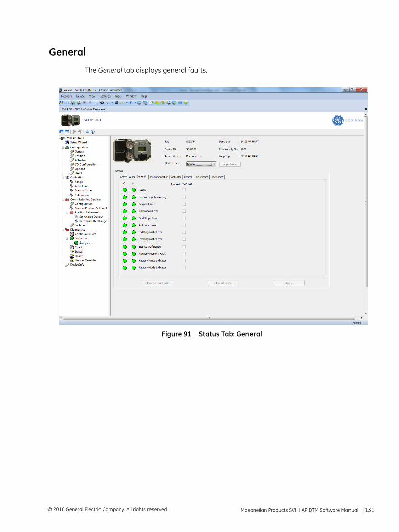
General
The General tab displays general faults.
Figure 91 Status Tab: General
Masoneilan Products SVI II AP DTM Software Manual =| 131© 2016 General Electric Company. All rights reserved.
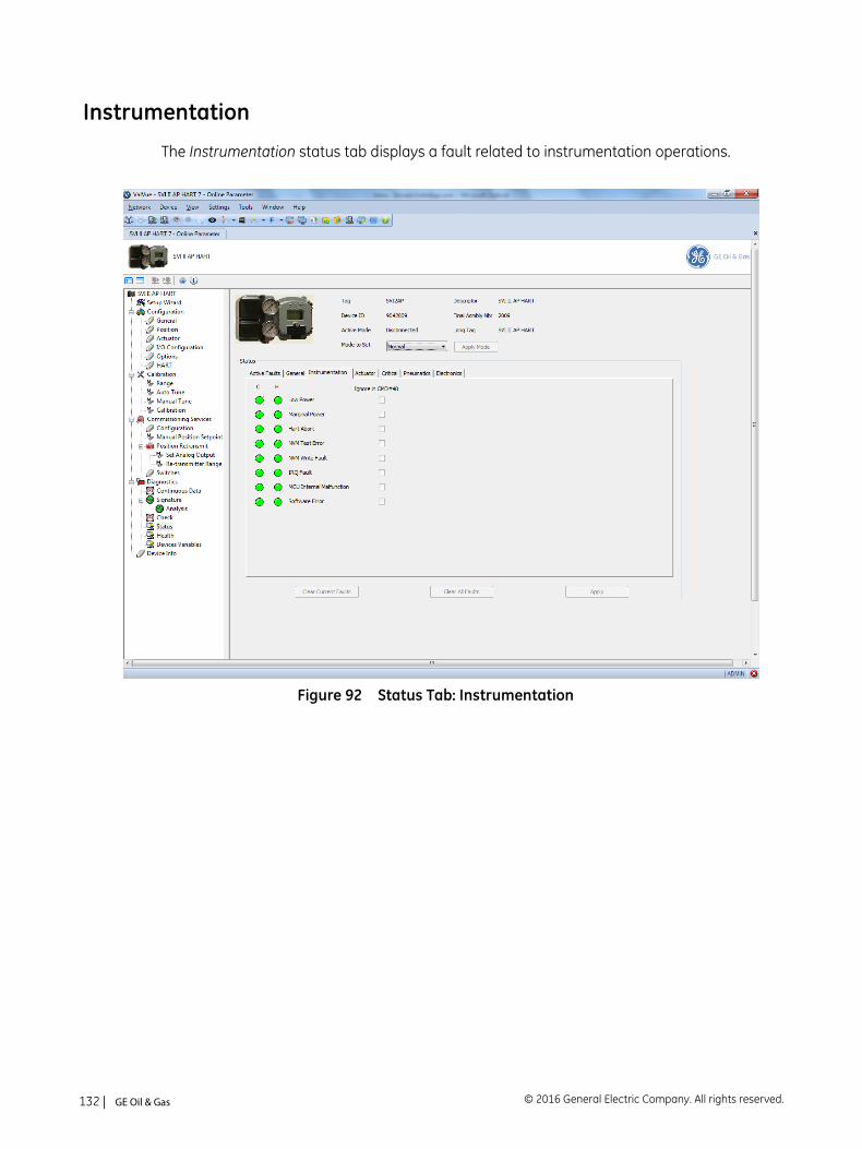
Instrumentation
The Instrumentation status tab displays a fault related to instrumentation operations.
Figure 92 Status Tab: Instrumentation
© 2016 General Electric Company. All rights reserved.132 | =GE Oil & Gas
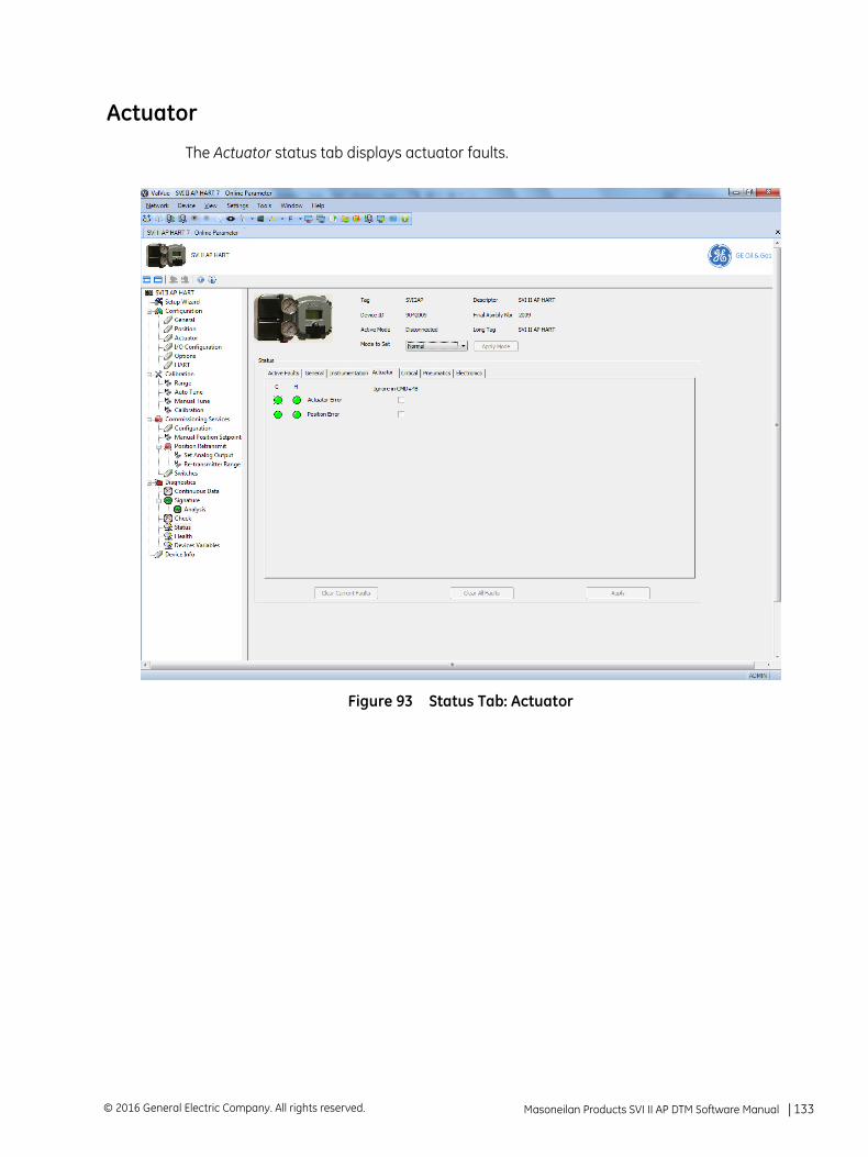
Actuator
The Actuator status tab displays actuator faults.
Figure 93 Status Tab: Actuator
Masoneilan Products SVI II AP DTM Software Manual =| 133© 2016 General Electric Company. All rights reserved.
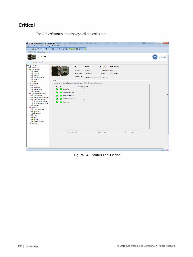
Critical
The Critical status tab displays all critical errors.
Figure 94 Status Tab: Critical
© 2016 General Electric Company. All rights reserved.134 | =GE Oil & Gas
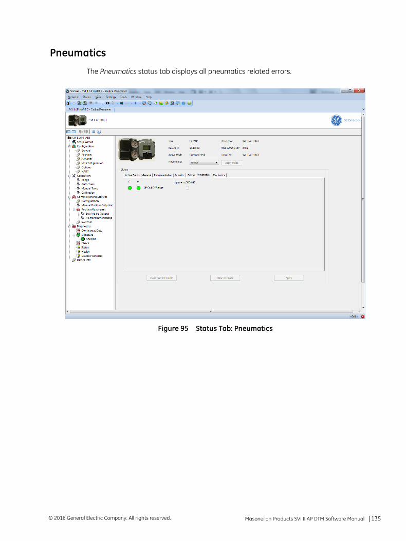
Pneumatics
The Pneumatics status tab displays all pneumatics related errors.
Figure 95 Status Tab: Pneumatics
Masoneilan Products SVI II AP DTM Software Manual =| 135© 2016 General Electric Company. All rights reserved.
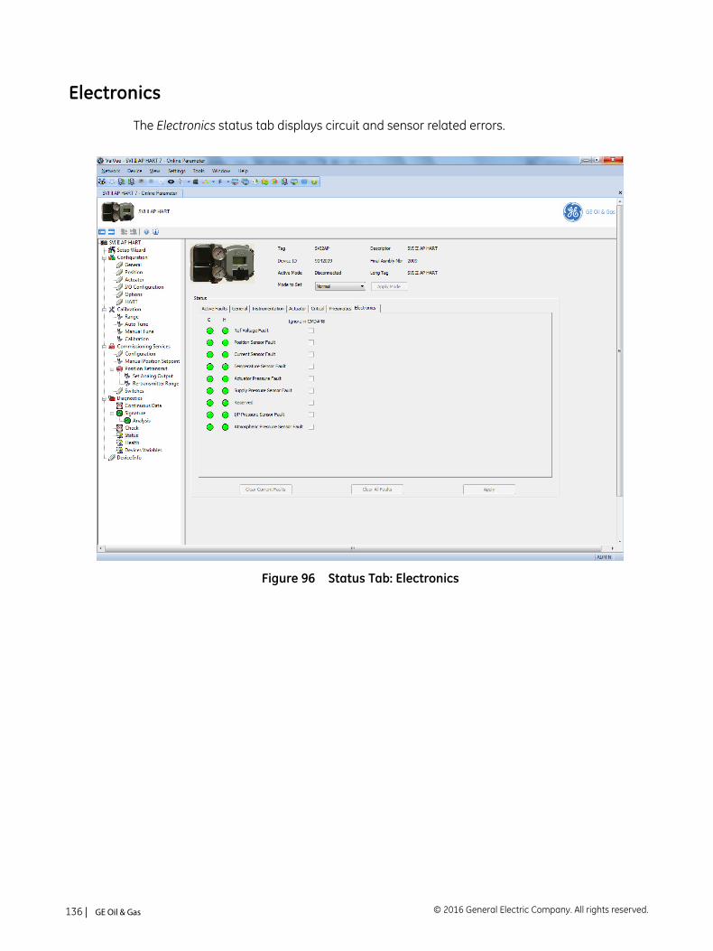
Electronics
The Electronics status tab displays circuit and sensor related errors.
Figure 96 Status Tab: Electronics
© 2016 General Electric Company. All rights reserved.136 | =GE Oil & Gas
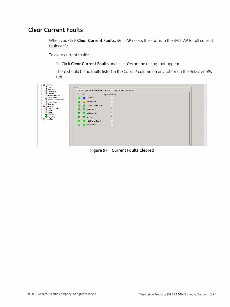
Clear Current Faults
When you click Clear Current Faults, SVI II AP resets the status in the SVI II AP for all current faults only.
To clear current faults:
Click Clear Current Faults and click Yes on the dialog that appears.
There should be no faults listed in the Current column on any tab or on the Active Faults tab.
Figure 97 Current Faults Cleared
Masoneilan Products SVI II AP DTM Software Manual =| 137© 2016 General Electric Company. All rights reserved.

Clear All Faults
When you click Clear All Faults SVI II AP resets the status bit in the SVI II AP for all faults, both historical and current and all indicators, current and historical, revert to green.
To clear all faults:
Click Clear All Faults and click Yes on the dialog that appears.
There should be no faults listed as current and historical on any tab.
© 2016 General Electric Company. All rights reserved.138 | =GE Oil & Gas
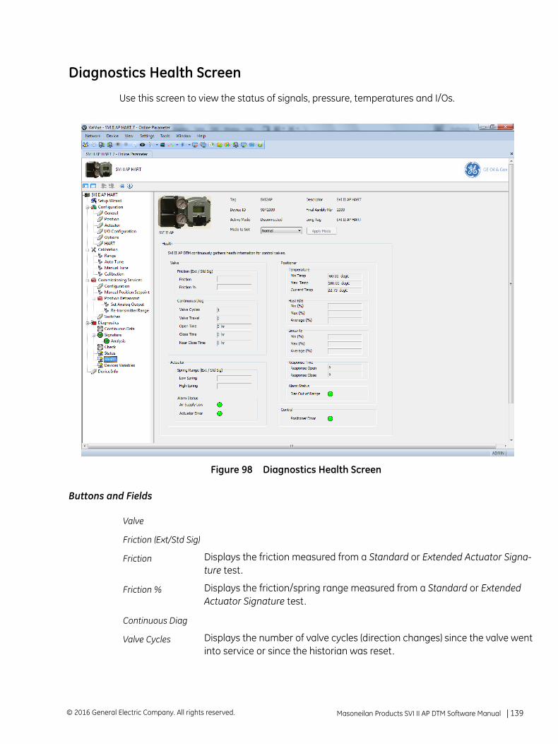
Diagnostics Health Screen
Use this screen to view the status of signals, pressure, temperatures and I/Os.
Figure 98 Diagnostics Health Screen
Buttons and Fields
Valve
Friction (Ext/Std Sig)
Friction Displays the friction measured from a Standard or Extended Actuator Signa-ture test.
Friction % Displays the friction/spring range measured from a Standard or Extended Actuator Signature test.
Continuous Diag
Valve Cycles Displays the number of valve cycles (direction changes) since the valve wentinto service or since the historian was reset.
Masoneilan Products SVI II AP DTM Software Manual =| 139© 2016 General Electric Company. All rights reserved.
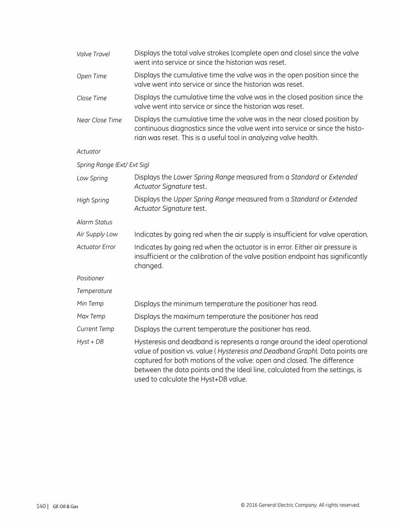
Valve Travel Displays the total valve strokes (complete open and close) since the valve went into service or since the historian was reset.
Open Time Displays the cumulative time the valve was in the open position since the valve went into service or since the historian was reset.
Close Time Displays the cumulative time the valve was in the closed position since the valve went into service or since the historian was reset.
Near Close Time Displays the cumulative time the valve was in the near closed position by continuous diagnostics since the valve went into service or since the histo-rian was reset. This is a useful tool in analyzing valve health.
Actuator
Spring Range (Ext/ Ext Sig)
Low Spring Displays the Lower Spring Range measured from a Standard or Extended Actuator Signature test.
High Spring Displays the Upper Spring Range measured from a Standard or Extended Actuator Signature test.
Alarm Status
Air Supply Low Indicates by going red when the air supply is insufficient for valve operation.
Actuator Error Indicates by going red when the actuator is in error. Either air pressure is insufficient or the calibration of the valve position endpoint has significantly changed.
Positioner
Temperature
Min Temp Displays the minimum temperature the positioner has read.
Max Temp Displays the maximum temperature the positioner has read
Current Temp Displays the current temperature the positioner has read.
Hyst + DB Hysteresis and deadband is represents a range around the ideal operational value of position vs. value ( Hysteresis and Deadband Graph). Data points are captured for both motions of the valve: open and closed. The difference between the data points and the Ideal line, calculated from the settings, is used to calculate the Hyst+DB value.
© 2016 General Electric Company. All rights reserved.140 | =GE Oil & Gas
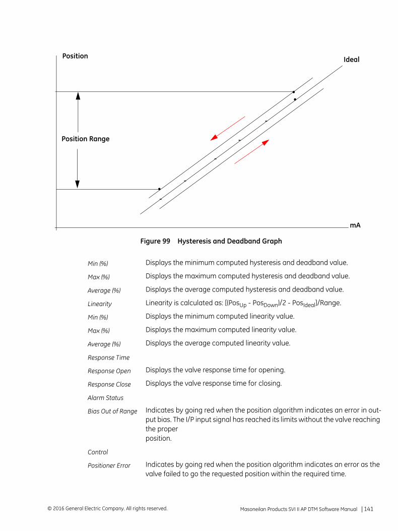
Figure 99 Hysteresis and Deadband Graph
Min (%) Displays the minimum computed hysteresis and deadband value.
Max (%) Displays the maximum computed hysteresis and deadband value.
Average (%) Displays the average computed hysteresis and deadband value.
Linearity Linearity is calculated as: [(PosUp - PosDown)/2 - PosIdeal]/Range.
Min (%) Displays the minimum computed linearity value.
Max (%) Displays the maximum computed linearity value.
Average (%) Displays the average computed linearity value.
Response Time
Response Open Displays the valve response time for opening.
Response Close Displays the valve response time for closing.
Alarm Status
Bias Out of Range Indicates by going red when the position algorithm indicates an error in out-put bias. The I/P input signal has reached its limits without the valve reachingthe proper position.
Control
Positioner Error Indicates by going red when the position algorithm indicates an error as thevalve failed to go the requested position within the required time.
mA
Position Ideal
.
..
.
.
.
.
.
Position Range
Masoneilan Products SVI II AP DTM Software Manual =| 141© 2016 General Electric Company. All rights reserved.
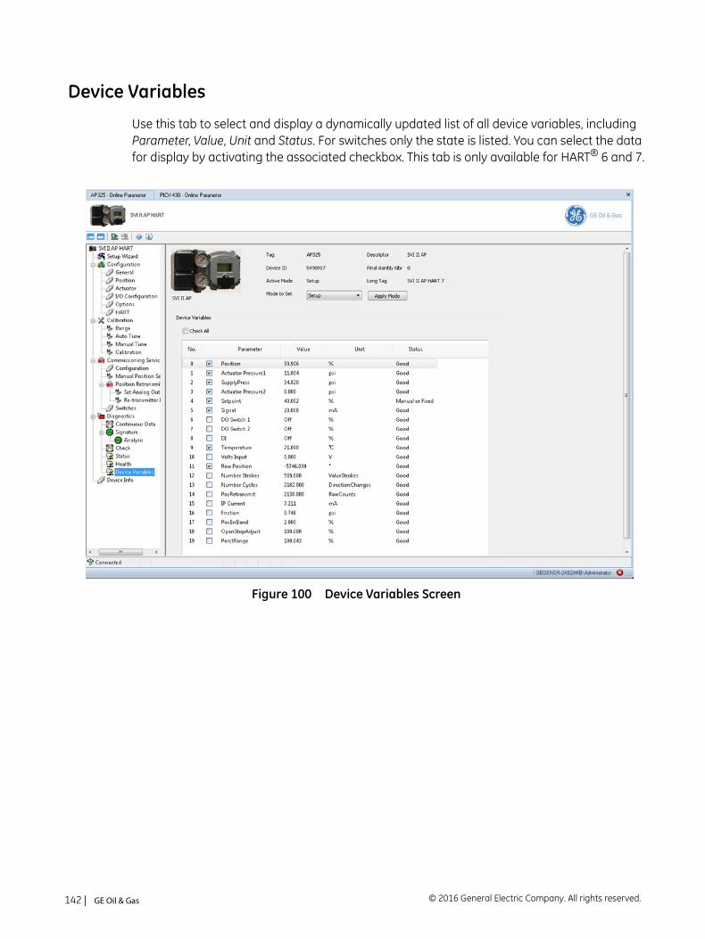
Device Variables
Use this tab to select and display a dynamically updated list of all device variables, including Parameter, Value, Unit and Status. For switches only the state is listed. You can select the data for display by activating the associated checkbox. This tab is only available for HART® 6 and 7.
Figure 100 Device Variables Screen
© 2016 General Electric Company. All rights reserved.142 | =GE Oil & Gas
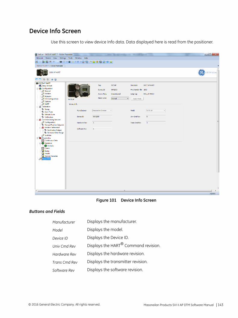
Device Info Screen
Use this screen to view device Info data. Data displayed here is read from the positioner.
Figure 101 Device Info Screen
Buttons and Fields
Manufacturer Displays the manufacturer.
Model Displays the model.
Device ID Displays the Device ID.
Univ Cmd Rev Displays the HART® Command revision.
Hardware Rev Displays the hardware revision.
Trans Cmd Rev Displays the transmitter revision.
Software Rev Displays the software revision.
Masoneilan Products SVI II AP DTM Software Manual =| 143© 2016 General Electric Company. All rights reserved.

This page intentionally left blank.
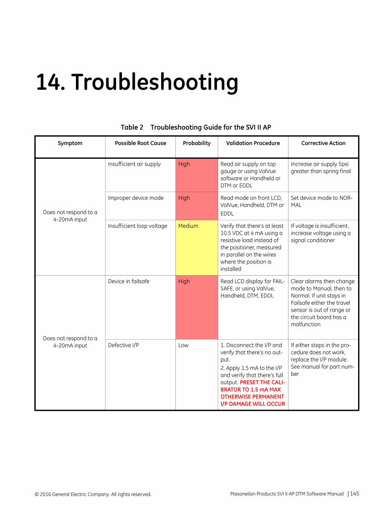
14. Troubleshooting
Table 2 Troubleshooting Guide for the SVI II AP
Symptom Possible Root Cause Probability Validation Procedure Corrective Action
Does not respond to a 4-20mA input
Insufficient air supply High Read air supply on top gauge or using ValVue software or Handheld or DTM or EDDL
Increase air supply 5psi greater than spring final
Improper device mode High Read mode on front LCD, ValVue, Handheld, DTM orEDDL
Set device mode to NOR-MAL
Insufficient loop voltage Medium Verify that there's at least 10.5 VDC at 4 mA using a resistive load instead of the positioner, measured in parallel on the wires where the position is installed
If voltage is insufficient, increase voltage using a signal conditioner
Does not respond to a 4-20mA input
Device in failsafe High Read LCD display for FAIL-SAFE, or using ValVue, Handheld, DTM, EDDL
Clear alarms then change mode to Manual, then to Normal. If unit stays in Failsafe either the travel sensor is out of range or the circuit board has a malfunction
Defective I/P Low 1. Disconnect the I/P and verify that there's no out-put. 2. Apply 1.5 mA to the I/P and verify that there's full output. PRESET THE CALI-BRATOR TO 1.5 mA MAX OTHERWISE PERMANENT I/P DAMAGE WILL OCCUR
If either steps in the pro-cedure does not work, replace the I/P module. See manual for part num-ber
© 2016 General Electric Company. All rights reserved. Masoneilan Products SVI II AP DTM Software Manual =| 145
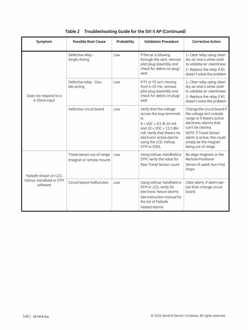
Does not respond to a 4-20mA input
Defective relay - Single-Acting
Low If the air is blowing through the vent, remove pilot plug assembly and check for debris on plug/seat
1- Clear relay using clean dry air and a white cloth to validate air cleanliness2- Replace the relay if #1 doesn't solve the problem
Defective relay - Dou-ble-acting
Low If P1 or P2 isn't moving from 4-20 mA, remove pilot plug assembly and check for debris on plug/seat
1- Clear relay using clean dry air and a white cloth to validate air cleanliness2- Replace the relay if #1 doesn't solve the problem
Defective circuit board Low Verify that the voltage across the loop terminals is:8 < VDC < 9.5 @ 20 mA and 10 < VDC < 11.5 @4 mA. Verify that there's no electronic active alarms using the LCD, ValVue, DTM or EDDL
Change the circuit board if the voltage isn't outside range or if there's active electronic alarms that can't be cleared.NOTE: If Travel Sensor alarm is active, this could simply be the magnet being out of range.
Failsafe shown on LCD, ValVue, Handheld or DTM
software
Travel sensor out of range(magnet or remote mount)
Low Using ValVue, Handheld or DTM, verify the value forRaw Travel Sensor count
Re-align magnets or the Remote PositionerSensor (if used). Run Find Stops
Circuit board malfunction Low Using ValVue, handheld or DTM or LCD, verify for electronic failure alarmsSee instruction manual for the list of Failsaferelated alarms
Clear alarm, if alarm per-sist than change circuit board
Table 2 Troubleshooting Guide for the SVI II AP (Continued)
Symptom Possible Root Cause Probability Validation Procedure Corrective Action
© 2016 General Electric Company. All rights reserved.146 | =GE Oil & Gas
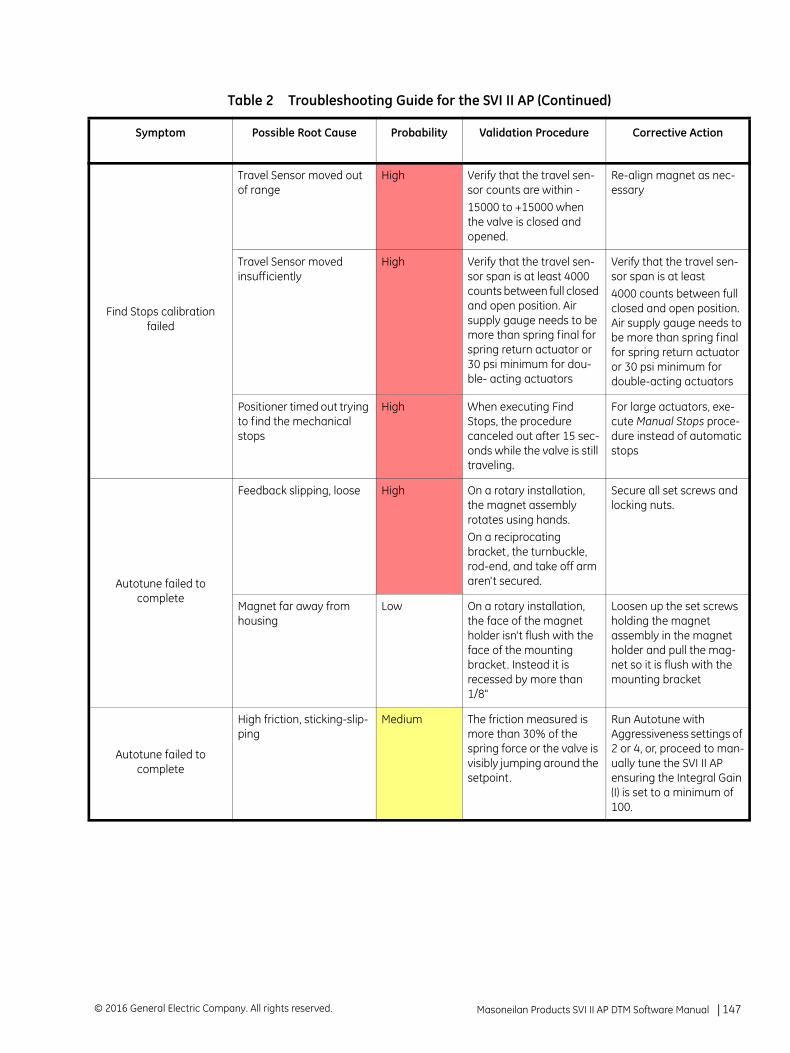
Find Stops calibration failed
Travel Sensor moved out of range
High Verify that the travel sen-sor counts are within -15000 to +15000 when the valve is closed and opened.
Re-align magnet as nec-essary
Travel Sensor moved insufficiently
High Verify that the travel sen-sor span is at least 4000 counts between full closed and open position. Air supply gauge needs to be more than spring final for spring return actuator or 30 psi minimum for dou-ble- acting actuators
Verify that the travel sen-sor span is at least4000 counts between full closed and open position. Air supply gauge needs to be more than spring final for spring return actuator or 30 psi minimum for double-acting actuators
Positioner timed out trying to find the mechanical stops
High When executing Find Stops, the procedure canceled out after 15 sec-onds while the valve is still traveling.
For large actuators, exe-cute Manual Stops proce-dure instead of automatic stops
Autotune failed to complete
Feedback slipping, loose High On a rotary installation, the magnet assembly rotates using hands. On a reciprocating bracket, the turnbuckle, rod-end, and take off arm aren't secured.
Secure all set screws and locking nuts.
Magnet far away from housing
Low On a rotary installation, the face of the magnet holder isn't flush with the face of the mounting bracket. Instead it is recessed by more than 1/8"
Loosen up the set screws holding the magnet assembly in the magnet holder and pull the mag-net so it is flush with the mounting bracket
Autotune failed to complete
High friction, sticking-slip-ping
Medium The friction measured is more than 30% of the spring force or the valve is visibly jumping around the setpoint.
Run Autotune with Aggressiveness settings of 2 or 4, or, proceed to man-ually tune the SVI II AP ensuring the Integral Gain (I) is set to a minimum of 100.
Table 2 Troubleshooting Guide for the SVI II AP (Continued)
Symptom Possible Root Cause Probability Validation Procedure Corrective Action
Masoneilan Products SVI II AP DTM Software Manual =| 147© 2016 General Electric Company. All rights reserved.
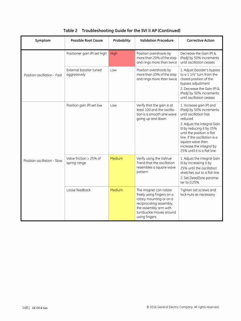
Position oscillation - Fast
Positioner gain (P) set high High Position overshoots by more than 20% of the step and rings more than twice
Decrease the Gain (P) & (Padj) by 50% increments until oscillation ceases
External booster tuned aggressively
Low Position overshoots by more than 20% of the step and rings more than twice
1. Adjust booster's bypass to a 1 1/4" turn from the closed position of the bypass adjustment 2. Decrease the Gain (P) & (Padj) by 50% increments until oscillation ceases
Position oscillation - Slow
Position gain (P) set low Low Verify that the gain is at least 100 and the oscilla-tion is a smooth sine wave going up and down
1. Increase gain (P) and (Padj) by 50% increments until oscillation has reduced. 2. Adjust the Integral Gain (I) by reducing it by 25% until the position is flat line. If the oscillation is a square wave then increase the integral by 25% until it is a flat line.
Valve friction > 25% of spring range
Medium Verify using the ValVue Trend that the oscillation resembles a square wave pattern
1. Adjust the integral Gain (I) by increasing it by25% until the oscillation stretches out to a flat line.2. Set DeadZone parame-ter to 0.25%
Loose feedback Medium The magnet can rotate freely using fingers on a rotary mounting or on a reciprocating assembly, the assembly arm with turnbuckle moves around using fingers
Tighten set screws and lock nuts as necessary
Table 2 Troubleshooting Guide for the SVI II AP (Continued)
Symptom Possible Root Cause Probability Validation Procedure Corrective Action
© 2016 General Electric Company. All rights reserved.148 | =GE Oil & Gas
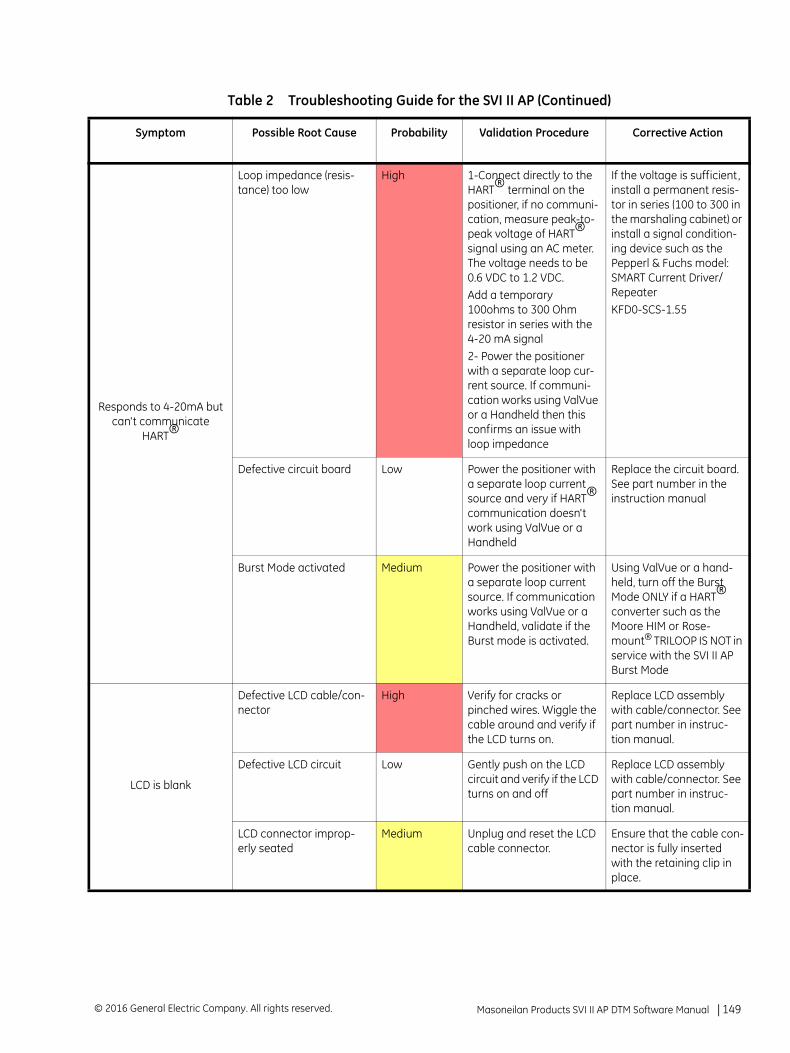
Responds to 4-20mA but can't communicate
HART®
Loop impedance (resis-tance) too low
High 1-Connect directly to the HART® terminal on the positioner, if no communi-cation, measure peak-to- peak voltage of HART® signal using an AC meter. The voltage needs to be 0.6 VDC to 1.2 VDC.Add a temporary 100ohms to 300 Ohm resistor in series with the 4-20 mA signal2- Power the positioner with a separate loop cur-rent source. If communi-cation works using ValVue or a Handheld then this confirms an issue with loop impedance
If the voltage is sufficient, install a permanent resis-tor in series (100 to 300 in the marshaling cabinet) or install a signal condition-ing device such as the Pepperl & Fuchs model: SMART Current Driver/RepeaterKFD0-SCS-1.55
Defective circuit board Low Power the positioner with a separate loop current source and very if HART® communication doesn't work using ValVue or a Handheld
Replace the circuit board. See part number in the instruction manual
Burst Mode activated Medium Power the positioner with a separate loop current source. If communication works using ValVue or a Handheld, validate if the Burst mode is activated.
Using ValVue or a hand-held, turn off the Burst Mode ONLY if a HART® converter such as the Moore HIM or Rose-mount® TRILOOP IS NOT in service with the SVI II AP Burst Mode
LCD is blank
Defective LCD cable/con-nector
High Verify for cracks or pinched wires. Wiggle the cable around and verify if the LCD turns on.
Replace LCD assembly with cable/connector. See part number in instruc-tion manual.
Defective LCD circuit Low Gently push on the LCD circuit and verify if the LCD turns on and off
Replace LCD assembly with cable/connector. See part number in instruc-tion manual.
LCD connector improp-erly seated
Medium Unplug and reset the LCD cable connector.
Ensure that the cable con-nector is fully inserted with the retaining clip in place.
Table 2 Troubleshooting Guide for the SVI II AP (Continued)
Symptom Possible Root Cause Probability Validation Procedure Corrective Action
Masoneilan Products SVI II AP DTM Software Manual =| 149© 2016 General Electric Company. All rights reserved.
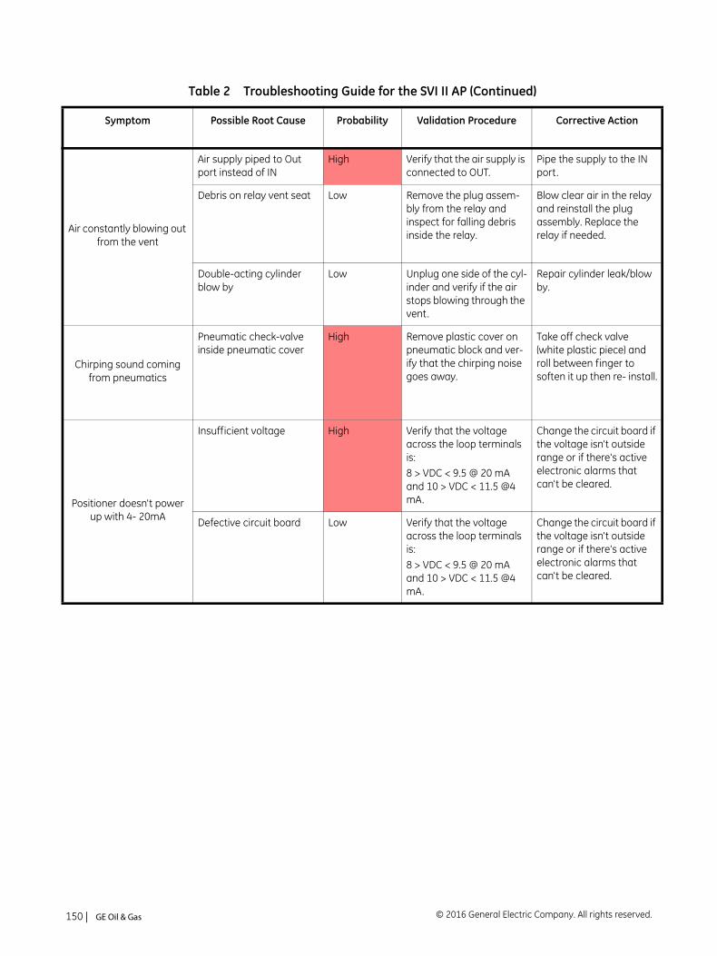
Air constantly blowing out from the vent
Air supply piped to Out port instead of IN
High Verify that the air supply is connected to OUT.
Pipe the supply to the IN port.
Debris on relay vent seat Low Remove the plug assem-bly from the relay and inspect for falling debris inside the relay.
Blow clear air in the relay and reinstall the plug assembly. Replace the relay if needed.
Double-acting cylinder blow by
Low Unplug one side of the cyl-inder and verify if the air stops blowing through the vent.
Repair cylinder leak/blow by.
Chirping sound coming from pneumatics
Pneumatic check-valve inside pneumatic cover
High Remove plastic cover on pneumatic block and ver-ify that the chirping noise goes away.
Take off check valve (white plastic piece) and roll between finger to soften it up then re- install.
Positioner doesn't power up with 4- 20mA
Insufficient voltage High Verify that the voltage across the loop terminals is:8 > VDC < 9.5 @ 20 mA and 10 > VDC < 11.5 @4 mA.
Change the circuit board if the voltage isn't outside range or if there's active electronic alarms that can't be cleared.
Defective circuit board Low Verify that the voltage across the loop terminals is:8 > VDC < 9.5 @ 20 mA and 10 > VDC < 11.5 @4 mA.
Change the circuit board if the voltage isn't outside range or if there's active electronic alarms that can't be cleared.
Table 2 Troubleshooting Guide for the SVI II AP (Continued)
Symptom Possible Root Cause Probability Validation Procedure Corrective Action
© 2016 General Electric Company. All rights reserved.150 | =GE Oil & Gas
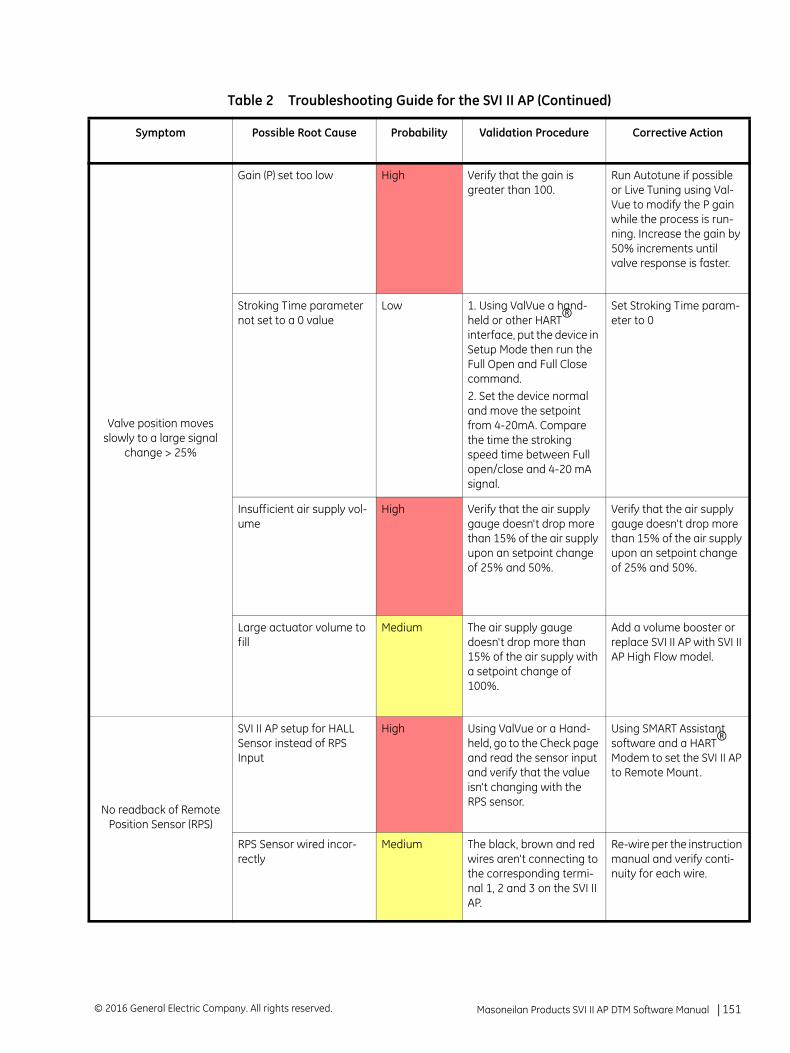
Valve position moves slowly to a large signal
change > 25%
Gain (P) set too low High Verify that the gain is greater than 100.
Run Autotune if possible or Live Tuning using Val-Vue to modify the P gain while the process is run-ning. Increase the gain by 50% increments until valve response is faster.
Stroking Time parameter not set to a 0 value
Low 1. Using ValVue a hand-held or other HART® interface, put the device in Setup Mode then run the Full Open and Full Close command. 2. Set the device normal and move the setpoint from 4-20mA. Compare the time the stroking speed time between Full open/close and 4-20 mA signal.
Set Stroking Time param-eter to 0
Insufficient air supply vol-ume
High Verify that the air supply gauge doesn't drop more than 15% of the air supply upon an setpoint change of 25% and 50%.
Verify that the air supply gauge doesn't drop more than 15% of the air supply upon an setpoint change of 25% and 50%.
Large actuator volume to fill
Medium The air supply gauge doesn't drop more than 15% of the air supply with a setpoint change of 100%.
Add a volume booster or replace SVI II AP with SVI II AP High Flow model.
No readback of Remote Position Sensor (RPS)
SVI II AP setup for HALL Sensor instead of RPS Input
High Using ValVue or a Hand-held, go to the Check page and read the sensor input and verify that the value isn't changing with the RPS sensor.
Using SMART Assistant software and a HART® Modem to set the SVI II AP to Remote Mount.
RPS Sensor wired incor-rectly
Medium The black, brown and red wires aren't connecting to the corresponding termi-nal 1, 2 and 3 on the SVI II AP.
Re-wire per the instruction manual and verify conti-nuity for each wire.
Table 2 Troubleshooting Guide for the SVI II AP (Continued)
Symptom Possible Root Cause Probability Validation Procedure Corrective Action
Masoneilan Products SVI II AP DTM Software Manual =| 151© 2016 General Electric Company. All rights reserved.
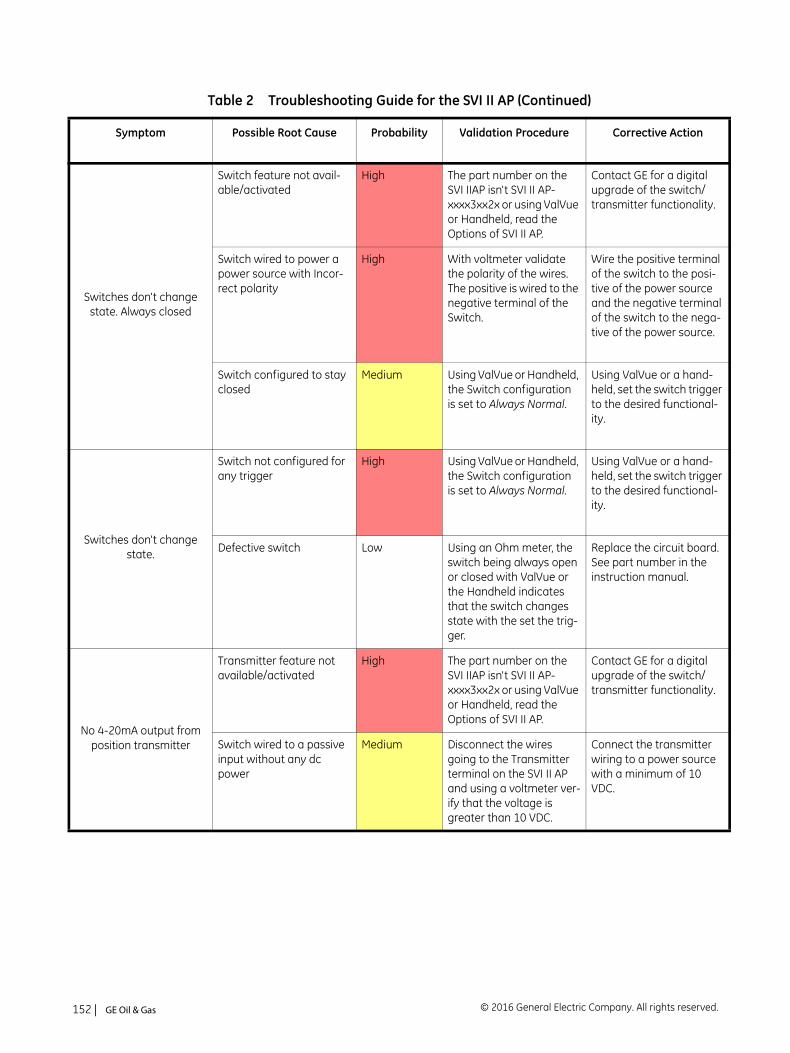
Switches don't change state. Always closed
Switch feature not avail-able/activated
High The part number on the SVI IIAP isn't SVI II AP- xxxx3xx2x or using ValVue or Handheld, read the Options of SVI II AP.
Contact GE for a digital upgrade of the switch/transmitter functionality.
Switch wired to power a power source with Incor-rect polarity
High With voltmeter validate the polarity of the wires. The positive is wired to the negative terminal of the Switch.
Wire the positive terminal of the switch to the posi-tive of the power source and the negative terminal of the switch to the nega-tive of the power source.
Switch configured to stay closed
Medium Using ValVue or Handheld, the Switch configuration is set to Always Normal.
Using ValVue or a hand-held, set the switch trigger to the desired functional-ity.
Switches don't change state.
Switch not configured for any trigger
High Using ValVue or Handheld, the Switch configuration is set to Always Normal.
Using ValVue or a hand-held, set the switch trigger to the desired functional-ity.
Defective switch Low Using an Ohm meter, the switch being always open or closed with ValVue or the Handheld indicates that the switch changes state with the set the trig-ger.
Replace the circuit board. See part number in the instruction manual.
No 4-20mA output from position transmitter
Transmitter feature not available/activated
High The part number on the SVI IIAP isn't SVI II AP- xxxx3xx2x or using ValVue or Handheld, read the Options of SVI II AP.
Contact GE for a digital upgrade of the switch/transmitter functionality.
Switch wired to a passive input without any dc power
Medium Disconnect the wires going to the Transmitter terminal on the SVI II AP and using a voltmeter ver-ify that the voltage is greater than 10 VDC.
Connect the transmitter wiring to a power source with a minimum of 10 VDC.
Table 2 Troubleshooting Guide for the SVI II AP (Continued)
Symptom Possible Root Cause Probability Validation Procedure Corrective Action
© 2016 General Electric Company. All rights reserved.152 | =GE Oil & Gas
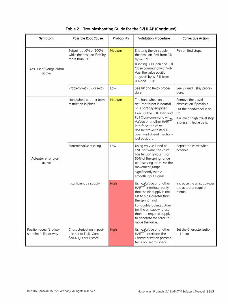
Bias Out of Range alarm active
Setpoint at 0% or 100% while the position if off by more than 5%
Medium Shutting the air supply, the position if off from 0% by +/- 5%Running Full Open and Full Close command with Val-Vue, the valve position stays off by +/-5% from 0% and 100%.
Re-run find stops.
Problem with I/P or relay Low See I/P and Relay proce-dure.
See I/P and Relay proce-dure.
Actuator error alarm active
Handwheel or other travel restriction in place.
Medium The handwheel on the actuator is not in neutral or is partially engagedExecute the Full Open and Full Close command with ValVue or another HART® interface, the valve doesn't travel to its full open and closed mechan-ical position.
Remove the travel obstruction if possible.Put the handwheel in neu-tral.If a low or high travel stop is present, leave as is.
Extreme valve sticking Low Using ValVue Trend or OVD software, the valve has friction greater than 50% of the spring range or observing the valve, the movement jumpssignificantly with a smooth input signal.
Repair the valve when possible.
Insufficient air supply High Using ValVue or another HART® interface, verify that the air supply is not set to 5 psi greater than the spring final.For double-acting actua-tor, the air supply is less than the required supply to generate the force to move the valve.
Increase the air supply per the actuator require-ments.
Position doesn't follow setpoint in linear way
Characterization in posi-tion set to Eq%, Cam-flex%, QO or Custom
High Using ValVue or another HART® Interface, the Characterization parame-ter is not set to Linear.
Set the Characterization to Linear.
Table 2 Troubleshooting Guide for the SVI II AP (Continued)
Symptom Possible Root Cause Probability Validation Procedure Corrective Action
Masoneilan Products SVI II AP DTM Software Manual =| 153© 2016 General Electric Company. All rights reserved.

This page intentionally left blank.
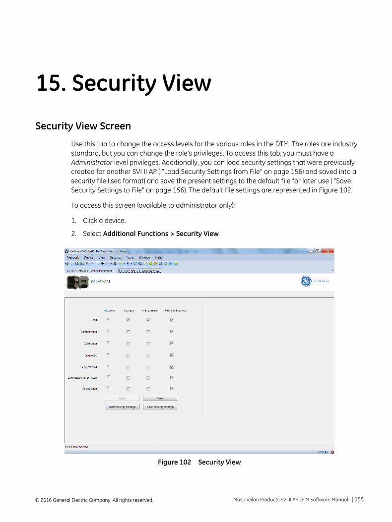
15. Security View
Security View Screen
Use this tab to change the access levels for the various roles in the DTM. The roles are industry standard, but you can change the role’s privileges. To access this tab, you must have a Administrator level privileges. Additionally, you can load security settings that were previously created for another SVI II AP ( “Load Security Settings from File” on page 156) and saved into a security file (.sec format) and save the present settings to the default file for later use ( “Save Security Settings to File” on page 156). The default file settings are represented in Figure 102.
To access this screen (available to administrator only):
1. Click a device.
2. Select Additional Functions > Security View.
Figure 102 Security View
© 2016 General Electric Company. All rights reserved. Masoneilan Products SVI II AP DTM Software Manual =| 155
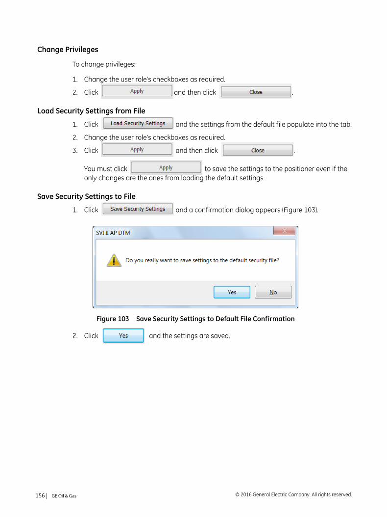
Change Privileges
To change privileges:
1. Change the user role’s checkboxes as required.
2. Click and then click .
Load Security Settings from File
1. Click and the settings from the default file populate into the tab.
2. Change the user role’s checkboxes as required.
3. Click and then click .
You must click to save the settings to the positioner even if the only changes are the ones from loading the default settings.
Save Security Settings to File
1. Click and a confirmation dialog appears (Figure 103).
Figure 103 Save Security Settings to Default File Confirmation
2. Click and the settings are saved.
© 2016 General Electric Company. All rights reserved.156 | =GE Oil & Gas
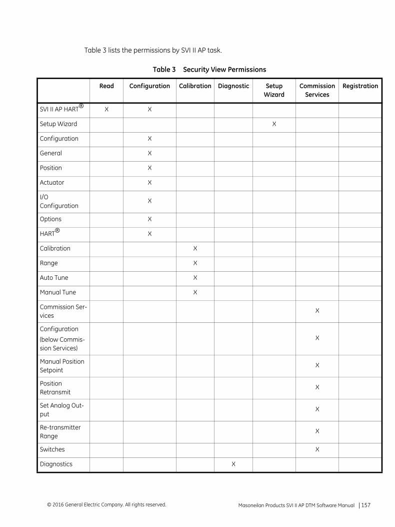
S
S
C
G
P
A
I/C
O
H
C
R
A
M
Cv
C
(bs
MS
PR
Sp
RR
S
D
Table 3 lists the permissions by SVI II AP task.
Table 3 Security View Permissions
Read Configuration Calibration Diagnostic Setup Wizard
Commission Services
Registration
VI II AP HART® X X
etup Wizard X
onfiguration X
eneral X
osition X
ctuator X
O onfiguration
X
ptions X
ART® X
alibration X
ange X
uto Tune X
anual Tune X
ommission Ser-ices
X
onfiguration
elow Commis-ion Services)
X
anual Position etpoint
X
osition etransmit
X
et Analog Out-ut
X
e-transmitter ange
X
witches X
iagnostics X
Masoneilan Products SVI II AP DTM Software Manual =| 157© 2016 General Electric Company. All rights reserved.
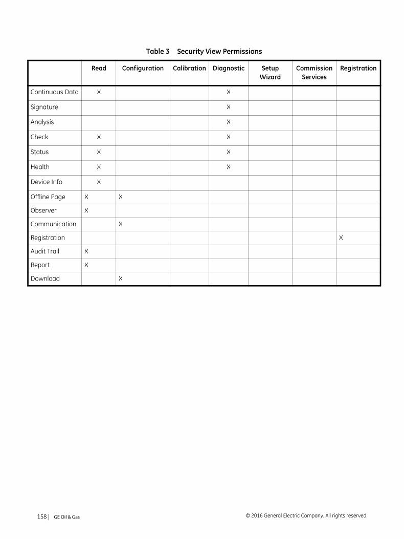
C
S
A
C
S
H
D
O
O
C
R
A
R
D
ontinuous Data X X
ignature X
nalysis X
heck X X
tatus X X
ealth X X
evice Info X
ffline Page X X
bserver X
ommunication X
egistration X
udit Trail X
eport X
ownload X
Table 3 Security View Permissions
Read Configuration Calibration Diagnostic Setup Wizard
Commission Services
Registration
© 2016 General Electric Company. All rights reserved.158 | =GE Oil & Gas
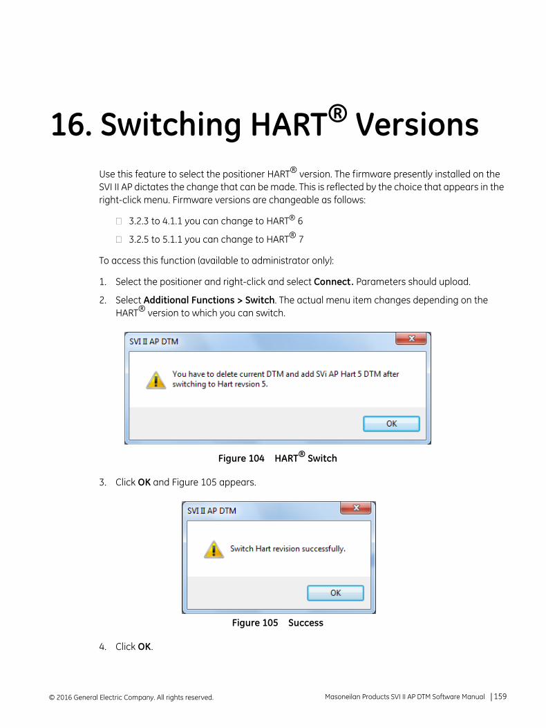
16. Switching HART® Versions
Use this feature to select the positioner HART® version. The firmware presently installed on the SVI II AP dictates the change that can be made. This is reflected by the choice that appears in the right-click menu. Firmware versions are changeable as follows:3.2.3 to 4.1.1 you can change to HART® 6
3.2.5 to 5.1.1 you can change to HART® 7
To access this function (available to administrator only):
1. Select the positioner and right-click and select Connect. Parameters should upload.
2. Select Additional Functions > Switch. The actual menu item changes depending on the HART® version to which you can switch.
Figure 104 HART® Switch
3. Click OK and Figure 105 appears.
Figure 105 Success
4. Click OK.
© 2016 General Electric Company. All rights reserved. Masoneilan Products SVI II AP DTM Software Manual =| 159
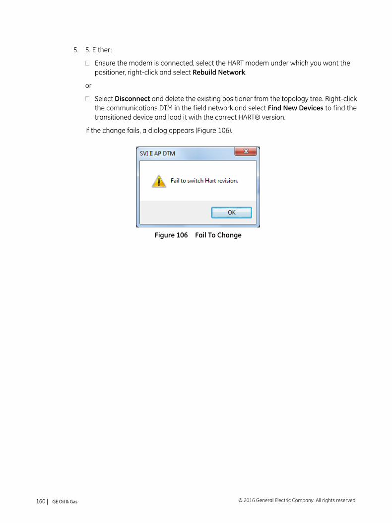
5. 5. Either:
Ensure the modem is connected, select the HART modem under which you want the positioner, right-click and select Rebuild Network.
or
Select Disconnect and delete the existing positioner from the topology tree. Right-click the communications DTM in the field network and select Find New Devices to find the transitioned device and load it with the correct HART® version.
If the change fails, a dialog appears (Figure 106).
Figure 106 Fail To Change
© 2016 General Electric Company. All rights reserved.160 | =GE Oil & Gas
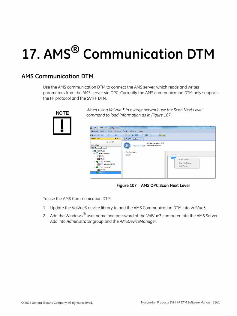
17. AMS® Communication DTM
AMS Communication DTMUse the AMS communication DTM to connect the AMS server, which reads and writes parameters from the AMS server via OPC. Currently the AMS communication DTM only supports the FF protocol and the SVIFF DTM.
To use the AMS Communication DTM:
1. Update the ValVue3 device library to add the AMS Communication DTM into ValVue3.
2. Add the Windows® user name and password of the ValVue3 computer into the AMS Server. Add into Administrator group and the AMSDeviceManager.
When using ValVue 3 in a large network use the Scan Next Level command to load information as in Figure 107.
Figure 107 AMS OPC Scan Next Level
© 2016 General Electric Company. All rights reserved. Masoneilan Products SVI II AP DTM Software Manual =| 161
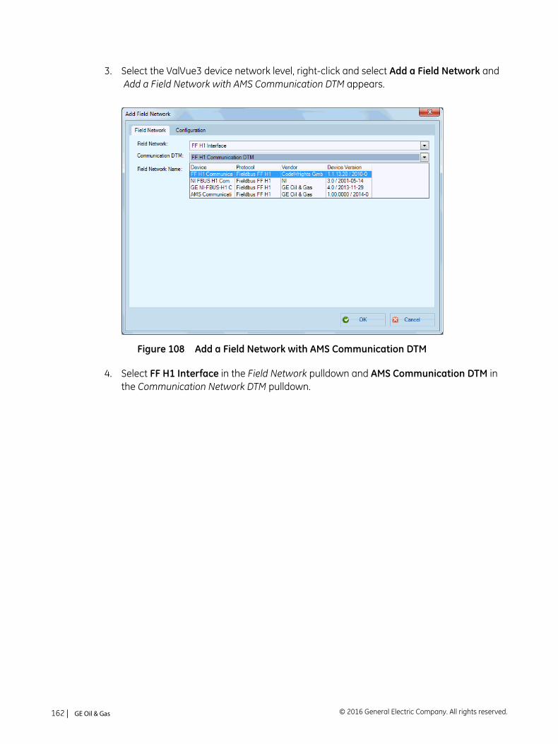
3. Select the ValVue3 device network level, right-click and select Add a Field Network and Add a Field Network with AMS Communication DTM appears.
Figure 108 Add a Field Network with AMS Communication DTM
4. Select FF H1 Interface in the Field Network pulldown and AMS Communication DTM in the Communication Network DTM pulldown.
© 2016 General Electric Company. All rights reserved.162 | =GE Oil & Gas
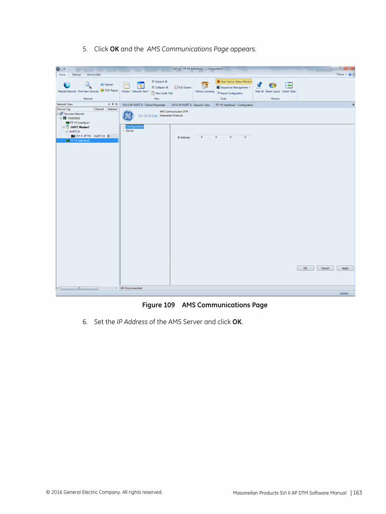
5. Click OK and the AMS Communications Page appears.
Figure 109 AMS Communications Page
6. Set the IP Address of the AMS Server and click OK.
Masoneilan Products SVI II AP DTM Software Manual =| 163© 2016 General Electric Company. All rights reserved.
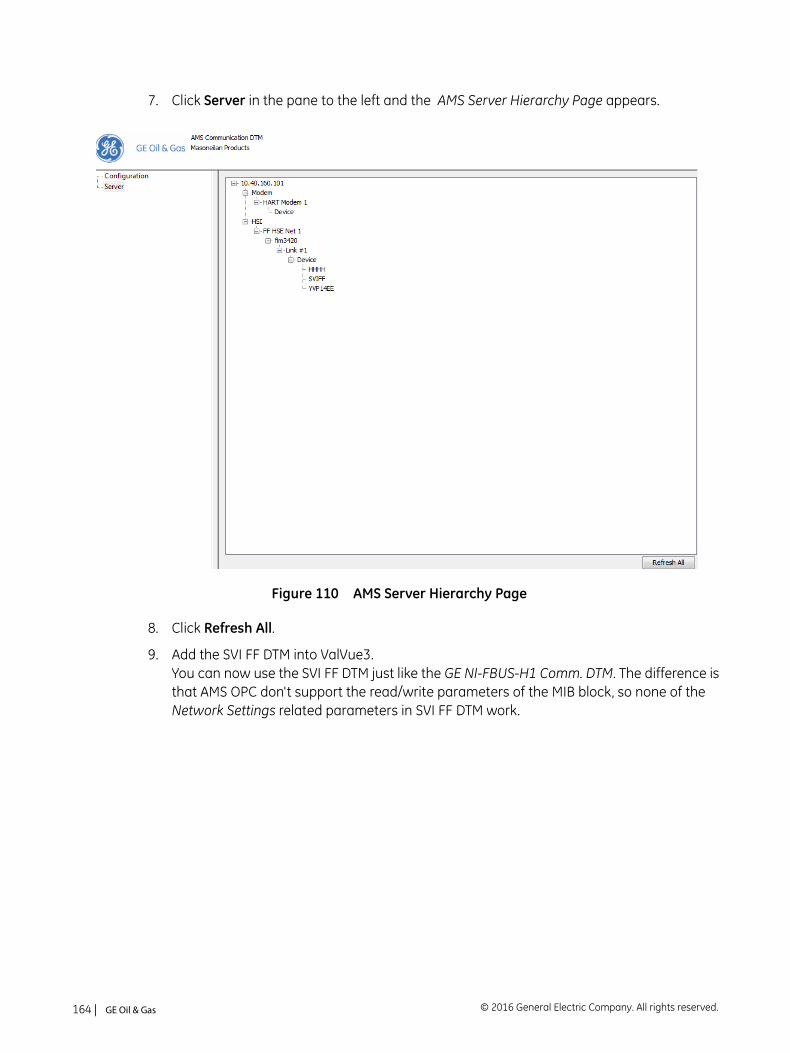
7. Click Server in the pane to the left and the AMS Server Hierarchy Page appears.
Figure 110 AMS Server Hierarchy Page
8. Click Refresh All.
9. Add the SVI FF DTM into ValVue3. You can now use the SVI FF DTM just like the GE NI-FBUS-H1 Comm. DTM. The difference is that AMS OPC don't support the read/write parameters of the MIB block, so none of the Network Settings related parameters in SVI FF DTM work.
© 2016 General Electric Company. All rights reserved.164 | =GE Oil & Gas
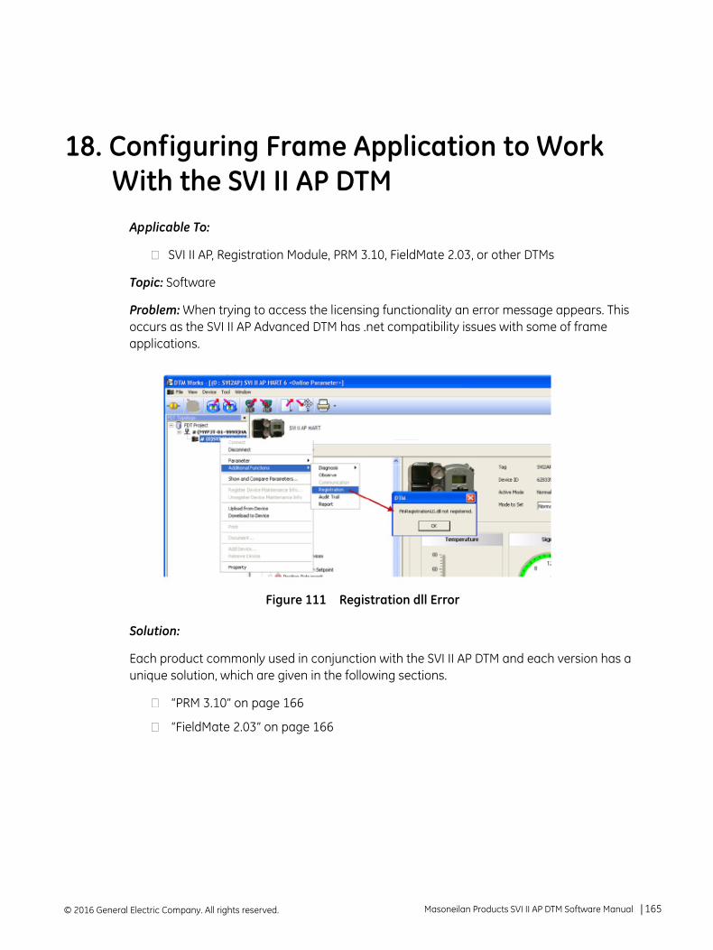
18. Configuring Frame Application to Work With the SVI II AP DTM
Applicable To:
SVI II AP, Registration Module, PRM 3.10, FieldMate 2.03, or other DTMs
Topic: Software
Problem: When trying to access the licensing functionality an error message appears. This occurs as the SVI II AP Advanced DTM has .net compatibility issues with some of frame applications.
Figure 111 Registration dll Error
Solution:
Each product commonly used in conjunction with the SVI II AP DTM and each version has a unique solution, which are given in the following sections.
“PRM 3.10” on page 166
“FieldMate 2.03” on page 166
© 2016 General Electric Company. All rights reserved. Masoneilan Products SVI II AP DTM Software Manual =| 165
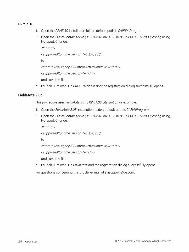
PRM 3.10
1. Open the PRM3.10 installation folder; default path is C:\PRM\Program.
2. Open the FMFdtContainer.exe.{036D1490-387B-11D4-86E1-00E0987270B9}.config using Notepad. Change:
<startup>
<supportedRuntime version="v1.1.4322"/>
to
<startup useLegacyV2RuntimeActivationPolicy="true">
<supportedRuntime version="v4.0" />
and save the file.
3. Launch DTM works in PRM3.10 again and the registration dialog successfully opens.
FieldMate 2.03
This procedure uses FieldMate Basic R2.03.00 Lite Edition as example.
1. Open the FieldMate 2.03 installation folder; default path is C:\FM\Program.
2. Open the FMFdtContainer.exe.{036D1490-387B-11D4-86E1-00E0987270B9}.config using Notepad. Change:
<startup>
<supportedRuntime version="v1.1.4322"/>
to
<startup useLegacyV2RuntimeActivationPolicy="true">
<supportedRuntime version="v4.0" />
and save the file.
3. Launch DTM works in FieldMate and the registration dialog successfully opens.
For questions concerning this article, e- mail at [email protected].
© 2016 General Electric Company. All rights reserved.166 | =GE Oil & Gas


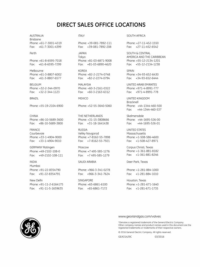
e the
DIRECT SALES OFFICE LOCATIONS
AUSTRALIA BrisbanePhone: +61-7-3001-4319Fax: 88+61-7-3001-4399
ITALY
Phone: +39-081-7892-111Fax: 88+39-081-7892-208
SOUTH AFRICA
Phone: +27-11-452-1550Fax: 88+27-11-452-6542
Perth
Phone: +61-8-6595-7018Fax: 88+61-8-6595-7299
JAPAN Tokyo Phone: +81-03-6871-9008Fax: ==+81-03-6890-4620
SOUTH & CENTRAL AMERICA AND THE CARIBBEAN Phone: +55-12-2134-1201Fax: 88+55-12-2134-1238
MelbournePhone: +61-3-8807-6002Fax: 88+61-3-8807-6577
KOREAPhone: +82-2-2274-0748Fax: 88+82-2-2274-0794
SPAINPhone: +34-93-652-6430Fax: 88+34-93-652-6444
BELGIUMPhone: +32-2-344-0970Fax: 88+32-2-344-1123
MALAYSIAPhone: +60-3-2161-0322Fax: 88+60-3-2163-6312
UNITED ARAB EMIRATESPhone: +971-4-8991-777Fax: 88+971-4-8991-778
BRAZIL
Phone: +55-19-2104-6900
MEXICO
Phone: +52-55-3640-5060
UNITED KINGDOM BracknellPhone: ++44-1344-460-500Fax: ++++44-1344-460-537
CHINAPhone: +86-10-5689-3600Fax: 88+86-10-5689-3800
THE NETHERLANDSPhone: +31-15-3808666Fax: 88+31-18-1641438
SkelmersdalePhone: ++44-1695-526-00Fax: +44-1695-526-01
FRANCE CourbevoiePhone: +33-1-4904-9000Fax: 88+33-1-4904-9010
RUSSIAVeliky NovgorodPhone: +7-8162-55-7898Fax: 88+7-8162-55-7921
UNITED STATES MassachusettsPhone: +1-508-586-4600Fax: 88+1-508-427-8971
GERMANY RatingenPhone: +49-2102-108-0Fax: 88+49-2102-108-111
MoscowPhone: +7 495-585-1276Fax: 88+7 495-585-1279
Corpus Christi, Texas Phone: +1-361-881-8182Fax: 88+1-361-881-8246
INDIA MumbaiPhone: +91-22-8354790Fax: 88+91-22-8354791
SAUDI ARABIA
Phone: +966-3-341-0278Fax: 88+966-3-341-7624
Deer Park, Texas
Phone: +1-281-884-1000Fax: 88+1-281-884-1010
New DelhiPhone: +91-11-2-6164175Fax: 88+91-11-5-1659635
SINGAPOREPhone: +65-6861-6100Fax: 88+65-6861-7172
Houston, TexasPhone: +1-281-671-1640Fax: 88+1-281-671-1735
Jacksonville, FloridaPhone: +1-844-VALVE-GE
www.geoilandgas.com/valves
*Denotes a registered trademark of the General Electric Company.Other company names and product names used in this document arregistered trademarks or trademarks of their respective owners.
© 2016 General Electric Company. All rights reserved.
GEA31429C 03/2016