make sure you display hidden notes in microsoft word to see
TRANSCRIPT
07530-1
SECTION 075416
ETHYLENE INTERPOLYMER (KEE) ROOFING
Make sure you display hidden notes in Microsoft Word to see notes to specifier http://www.hyload.com/ PART 1 GENERAL 1.1 SECTION INCLUDES
A. Cold Applied Coal-Tar Elastomeric Roofing System
B. Hot Applied Coal-Tar Elastomeric Roofing System 1.2 RELATED SECTIONS
A. Section 05300 - Metal Roof Deck.
B. Section 06100 - Rough Carpentry.
C. Section 06114 - Wood Blocking and Curbing: Wood nailers and cant strips.
D. Section 07220 - Insulation Board: Insulation and fastening.
E. Section 07620 - Sheet Metal Flashing and Trim: Weather protection for base flashings.
F. Section 07710 - Manufactured Roof Specialties: Counter flashing gravel stops, and
fascia.
G. Section 07724 - Roof Hatches: Frame and integral curb; Counter flashing.
H. Section 08620 - Unit Skylights: Skylight frame and integral curb and counter flashing.
I. Section 08630 - Metal-Framed Skylights: Skylight frame and integral curb and
counter flashing.
J. Section 15120 - Piping Specialties: Roof Drains, Sumps. 1.3 REFERENCES
A. ASTM D 312 - Standard Specification for Asphalt used in Roofing.
B. ASTM D 412 -
C. ASTM D 624 -
07530-2
D. ASTM D 1863 - Standard Specification for Mineral Aggregate Used as a Protective Coating for Roofing.
E. ASTM D 2178 - Standard Specification for Asphalt Glass Felt Used in Roofing and
Waterproofing.
F. ASTM D 2822 Standard Specification for Asphalt Roof Cement.
G. ASTM D 2824 - Standard Specification for Aluminum-Pigmented Asphalt Roof Coating.
H. ASTM D 4586 - 86, Specification for Asphalt Roof Cement, Asbestos Free
I. Factory Mutual Research (FM): Roof Assembly Classifications.
J. National Roofing Contractors Association (NRCA): Roofing and Waterproofing
Manual.
K. Sheet Metal and Air Conditioning Contractors National Association, Inc. (SMACNA) - Architectural Sheet Metal Manual.
L. Underwriters Laboratories, Inc. (UL): Fire Hazard Classifications.
M. Warnock Hersey (WH): Fire Hazard Classifications.
N. ASCE 7-05, Minimum Design Loads for Buildings and Other Structures
O. UL - Fire Resistance Directory.
P. FM Approvals - Roof Coverings and/or RoofNav assembly database.
Q. FBC - Florida Building Code.
R. Miami-Dade Building Code Compliance - N.O.A. (Notice of Acceptance).
1.4 DESIGN / PERFORMANCE REQUIREMENTS
A. Perform work in accordance with all federal, state and local codes.
B. Exterior Fire Test Exposure: Roof system shall achieve a UL, FM or WH Class rating for roof slopes indicated on the Drawings as follows: 1. Factory Mutual Class A Rating. 2. Underwriters Laboratory Class A Rating. 3. Warnock Hersey Class A Rating.
C. Design Requirements:
1. Uniform Wind Uplift Load Capacity: ______
D. Energy Star: Roof System shall comply with the initial and aged reflectivity required by the U.S. Federal Government's Energy Star program.
E. LEED: Roof system shall meet the reflectivity and emissivity criteria to qualify for
one point under the LEED credit category, Credit 7.2, Landscape & Exterior Design to Reduce Heat Island - Roof.
07530-3
F. Roof System membranes containing recycled or bio-based materials shall be third party certified through UL Environment.
G. Roof system shall have been tested in compliance with the following codes and test
requirements: 1. Florida FBC (For use outside Miami-Dade and Broward Counties):
a. Membrane Systems FL____ b. Roofing Underlayments FL_____ c. Roofing Cements and Coatings FL____
2. Miami-Dade County: a. Self-Adhered Membrane Systems Over:
1) Concrete Decks N.O.A. 2) Lightweight Concrete Decks N.O.A. 3) Recover Decks N.O.A. 4) Steel Decks N.O.A. 5) Wood Decks N.O.A.
b. Mop Membrane Systems Over 1) Concrete Decks N.O.A. 2) Lightweight Concrete Decks N.O.A. 3) Recover Decks N.O.A. 4) Steel Decks N.O.A. 5) Wood Decks N.O.A.
3. Cool Roof Rating Council: a. CRRC Directory CRRC ____
4. International Code Council Evaluation Service (ICC-ES): a. Membrane Systems
1) _____ b. Roofing Underlayments
1) _____ 2) _____
5. Texas Department of Insurance: a. Product Evaluation RC-___
6. Underwriters Laboratories: a. Certification TGFU.R________
7. Warnock Hersey a. ITS Directory of Listed Products
8. FM Approvals: a. RoofNav Website
1.5 SUBMITTALS
A. Submit under provisions of Section 01300.
B. Product Data: Manufacturer's data sheets on each product to be used, including: 1. Preparation instructions and recommendations. 2. Storage and handling requirements and recommendations. 3. Installation methods.
C. Shop Drawings: Submit shop drawings including installation details of roofing,
flashing, fastening, insulation and vapor barrier, including notation of roof slopes and fastening patterns of insulation and base modified bitumen membrane, prior to job start.
D. Verification Samples: For each finish product specified, two samples, minimum size
6 inches (150 mm) square, representing actual product, color, and patterns.
07530-4
E. Manufacturer's Certificates: Certify products meet or exceed specified requirements.
F. Closeout Submittals: Provide manufacturer’s maintenance instructions that include recommendations for periodic inspection and maintenance of all completed roofing work. Provide product warranty executed by the manufacturer. Assist Owner in preparation and submittal of roof installation acceptance certification as may be necessary in connection with fire and extended coverage insurance on roofing and associated work.
1.6 QUALITY ASSURANCE
A. Manufacturer Qualifications: Company specializing in manufacturing products specified with a minimum of ten years of documented experience.
B. Installer Qualifications: Company specializing in performing Work of this section with
minimum five years documented experience and a certified Pre-Approved Hyload Contractor.
C. Installer's Field Supervision: Maintain a full-time Supervisor/Foreman on job site
during all phases of roofing work while roofing work is in progress.
D. Source Limitations: Obtain all components of roof system from a single manufacturer. Secondary products that are required shall be recommended and approved in writing by the roofing system Manufacturer. Upon request of the Architect or Owner, submit Manufacturer's written approval of secondary components in list form, signed by an authorized agent of the Manufacturer.
1.7 PRE-INSTALLATION MEETINGS
A. Convene minimum two weeks prior to commencing Work of this section.
B. Review installation procedures and coordination required with related Work.
C. Inspect and make notes of job conditions prior to installation: 1. Record minutes of the conference and provide copies to all parties present. 2. Identify all outstanding issues in writing designating the responsible party for
follow-up action and the timetable for completion. 3. Installation of roofing system shall not begin until all outstanding issues are
resolved to the satisfaction of the Architect. 1.8 DELIVERY, STORAGE, AND HANDLING
A. Deliver and store products in manufacturer's unopened packaging with labels intact until ready for installation.
B. Store all roofing materials in a dry place, on pallets or raised platforms, out of direct
exposure to the elements until time of application. Store materials at least 4 inches above ground level and covered with "breathable" tarpaulins.
C. Stored in accordance with the instructions of the manufacturer prior to their
application or installation. Store roll goods on end on a clean flat surface. No wet or damaged materials will be used in the application.
D. Store at room temperature wherever possible, until immediately prior to installing the
roll. During winter, store materials in a heated location with a 50 degree F (10
07530-5
degree C) minimum temperature, removed only as needed for immediate use. Keep materials away from open flame or welding sparks.
E. Avoid stockpiling of materials on roofs without first obtaining acceptance from the
Architect/Engineer.
F. Adhesive storage shall be between the range of above 40 degree F (4 degree C) and below 80 degree F (27 degree C). Area of storage shall be constructed for flammable storage.
1.9 COORDINATION
A. Coordinate Work of this section with associated roof mounted equipment, roof penetrations and related metal flashings as work of this section proceeds.
1.10 PROJECT CONDITIONS
A. Maintain environmental conditions (temperature, humidity, and ventilation) within limits recommended by manufacturer for optimum results. Do not install products under environmental conditions outside manufacturer's absolute limits.
1.11 WARRANTY
A. Materials Warranty: Upon completion of the work, provide the Manufacturer's written and signed Limited Warranty, warranting that, if a leak develops in the roof during the term of this warranty, due to defective material, the manufacturer shall provide the Owner, at the Manufacturer's expense, with the material necessary to return the defective area to a watertight condition. 1. Warranty Period:
a. 10 years from date of acceptance. b. 15 years from date of acceptance. c. 20 years from date of acceptance.
B. Labor and Materials Warranty: Upon completion of the work, provide the
Manufacturer's written and signed Limited Warranty, warranting that, if a leak develops in the roof during the term of this warranty, due to defective material, the manufacturer shall provide the Owner, at the Manufacturer's expense, with the labor and material necessary to return the defective area to a watertight condition. 1. Warranty Period:
a. 10 years from date of acceptance. b. 15 years from date of acceptance. c. 20 years from date of acceptance.
C. NDL System Warranty: Upon completion of the work, provide the Manufacturer's
written and signed NDL Warranty, warranting that, if a leak develops in the roof during the term of this warranty, due either to defective material or defective workmanship by the installing contractor, the manufacturer shall provide the Owner, at the Manufacturer's expense, with the labor and material necessary to return the defective area to a watertight condition. 1. Warranty Period:
a. 10 years from date of acceptance. b. 15 years from date of acceptance. c. 20 years from date of acceptance.
D. Installer is to guarantee all work against defects in materials and workmanship for a
period indicated following final acceptance of the Work.
07530-6
1. Warranty Period: a. 2 years from date of acceptance. b. 3 years from date of acceptance. c. 4 years from date of acceptance. d. 5 years from date of acceptance.
PART 2 PRODUCTS 2.1 MANUFACTURERS
A. Acceptable Manufacturer: Hyload Roofing Systems; 5020 Enterprise Pkwy., Seville, OH 44273. ASD. Phone Toll Free: 800-457-4056. Phone: 330-769-3546. Fax: 330-769-4153. Web: www.hyload.com. Email: _____
B. Substitutions: Not permitted.
C. Requests for substitutions will be considered in accordance with provisions of
Section 01600. 2.2 COLD APPLIED HYLOAD WS ROOF SYSTEM DESCRIPTION If an FM class 1 roof installation is required, consult Hyload for instructions.
A. Hyload WS System applied over Nailable deck of Plywood, Wood Plank, Lightweight Insulating Concrete, Structural Wood Fiber, Poured and Precast Gypsum with a minimum slope or dead level surface: 1. Wood Plank / Plywood Deck with No Insulation:
a. Smooth, dry, solid and properly anchored. b. Lumber must be 1 inch (25 mm) nominal thickness and plywood a
minimum of 15/32 inch (13 mm) thickness c. Install one layer of red rosin sheeting paper end and side lapped 2
inches (51 mm) and secured to the wood deck by occasional nailing. d. Apply over entire surface one ply of base sheet lapping each sheet 3
inches (76 mm) over preceding sheet and nailing at lap no less than 9 inches (229 mm) on center. End laps shall be 6 inches (152 mm). Nail heads and/or metal caps must be a minimum diameter of 1 inch (25 mm) with approximately 100 nails per 100 sq.ft. (9.3 m cubed).
2. Wood Plank / Plywood Deck with Insulation: a. Smooth, dry, solid and properly anchored. b. Lumber must be 1 inch (25 mm) nominal thickness and plywood a
minimum of 15/32 inch (13 mm) thickness c. Install one layer of red rosin sheeting paper end and side lapped 2
inches (51 mm) and secured to the wood deck by occasional nailing. d. Apply over entire surface one ply of base sheet lapping each sheet 3
inches (76 mm) over preceding sheet and nailing at lap no less than 9 inches (229 mm) on center. End laps shall be 6 inches (152 mm). Nail heads and/or metal caps must be a minimum diameter of 1 inch (25 mm) with approximately 100 nails per 100 sq.ft. (9.3 m cubed).
e. Install approved roof insulation board. Use HyBond Insulation Adhesive. Overlay insulation boards may be set in HyBond Insulation Adhesive.
3. Light Weight Insulating Concrete Deck with No Insulation: a. Smooth, dry, solid and properly anchored. b. Substrate must vent moisture to the underside.
07530-7
c. Apply over entire surface one ply of base sheet lapping each sheet 3 inches (76 mm) over preceding sheet and nailing at lap no less than 9 inches (229 mm) on center. End laps shall be 6 inches (152 mm). Nail heads and/or metal caps must be a minimum diameter of 1 inch (25 mm) with approximately 100 nails per 100 sq.ft. (9.3 m cubed).
4. Light Weight Insulating Concrete Deck with Insulation: a. Smooth, dry, solid and properly anchored. b. Joints and welded plates, where used, must be grouted with
cementitious or gypsum grout feathered to provide a smooth gradual transition between adjacent panels. Additionally apply, a minimum 8 inch (203 mm) wide felt stripping centered on joint and set in troweling of asphaltic cement.
c. Install approved roof insulation board. For metal decks mechanically fasten or use HyBond Insulation Adhesive.
5. Structural Wood Fiber Deck with No Insulation: a. Smooth, dry, solid and properly anchored. b. Apply over entire surface one ply of base sheet lapping each sheet 3
inches (76 mm) over preceding sheet and nailing at lap no less than 9 inches (229 mm) on center. End laps shall be 6 inches (152 mm). Nail heads and/or metal caps must be a minimum diameter of 1 inch (25 mm) with approximately 100 nails per 100 sq.ft. (9.3 m cubed).
6. Structural Wood Fiber Deck with Insulation: a. Smooth, dry, solid and properly anchored. b. Apply over entire surface one ply of base sheet lapping each sheet 3
inches (76 mm) over preceding sheet and nailing at lap no less than 9 inches (229 mm) on center. End laps shall be 6 inches (152 mm). Nail heads and/or metal caps must be a minimum diameter of 1 inch (25 mm) with approximately 100 nails per 100 sq.ft. (9.3 m cubed).
c. Install approved roof insulation board. Use HyBond Insulation Adhesive. Overlay insulation boards may be set in HyBond Insulation Adhesive.
d. First ply of system must be one ply of base sheet set in Hyload self- adhered underlayment membrane.
7. Precast Gypsum Deck with No Insulation: a. Smooth, dry, solid and properly anchored. b. Joints and welded plates, where used, must be grouted with
cementitious or gypsum grout feathered to provide a smooth gradual transition between adjacent panels. Additionally, a minimum 8 inch (203 mm) wide felt stripping centered on joint and set in troweling of asphaltic cement.
c. Apply over entire surface one ply of base sheet lapping each sheet 3 inches (76 mm) over preceding sheet and nailing at lap no less than 9 inches (229 mm) on center. End laps shall be 6 inches (152 mm). Nail heads and/or metal caps must be a minimum diameter of 1 inch (25 mm) with approximately 100 nails per 100 sq.ft. (9.3 m cubed).
8. Precast Gypsum Deck with Insulation: a. Smooth, dry, solid and properly anchored. b. Joints and welded plates, where used, must be grouted with
cementitious or gypsum grout feathered to provide a smooth gradual transition between adjacent panels. Additionally, a minimum 8 inch (203 mm) wide felt stripping centered on joint and set in troweling of asphaltic cement.
c. Apply over entire surface one ply of base sheet lapping each sheet 3 inches (76 mm) over preceding sheet and nailing at lap no less than 9 inches (229 mm) on center. End laps shall be 6 inches (152 mm). Nail
07530-8
heads and/or metal caps must be a minimum diameter of 1 inch (25 mm) with approximately 100 nails per 100 sq.ft. (9.3 m cubed).
d. Install approved roof insulation board. Use HyBond Insulation Adhesive. Overlay insulation boards may be set in HyBond Insulation Adhesive.
9. Coverboard: Hyload Hyglass Recover Board over insulation. 10. Primer: Prime coverboard with Hyprime. or other approved primer. 11. Membrane: Over the entire surface, install 1 ply of membrane lapping side
laps 3 inches and end laps 6 inches such that the seams do not line up. Hot air weld all side and end laps. Check all laps with probe to assure they are sealed tightly. a. Hyload WS 75-mils b. Hyload WS 90-mils
12. Flashing: One layer of Hyload WS self-adhered welded seam flashing. Hot air weld all side and end laps. Check all laps with probe to assure they are sealed tightly. a. Hyload WS 75-mils b. Hyload WS 90-mils
13. Perimeter Membrane: All perimeter areas and projections shall be picture framed with a full-width roll of Hyload WS self-adhered welded seam membrane applied parallel to all perimeters with framing sheet overlapping field sheets a minimum of 12 inches. On perimeters that are already parallel to field sheets, no additional framing is required. Hot air weld all side and end laps. Check all laps with probe to assure they are sealed tightly. a. Hyload WS 75-mils b. Hyload WS 90-mils
14. Coating: Coat the entire surface with a reflective or decorative coating specified in accordance with the manufacturer recommendations.
B. Hyload CTEM System applied over Non-Nailable deck of Metal, Poured Concrete
and Precast Concrete with a minimum slope or dead level surface: 1. Metal Deck with Insulation:
a. Smooth, dry, solid and properly anchored. b. First layer of board type insulation shall be mechanically attached or
set in HyBond Insulation Adhesive prior to the application of the roofing system.
c. Install approved roof insulation board. For metal decks mechanically fasten or use HyBond Insulation Adhesive. Overlay insulation boards may also be set HyBond Insulation Adhesive.
2. Poured Concrete Deck with No Insulation: a. Smooth, dry, solid and properly anchored. b. Prime entire surface with HyPrime or other approved primer.
3. Poured Concrete Deck with Insulation: a. Smooth, dry, solid and properly anchored. b. Prime entire surface with HyPrime or other approved primer. c. Install approved roof insulation board. For metal decks mechanically
fasten or use HyBond Insulation Adhesive. For all other applications use Type III or IV asphalt. Overlay insulation boards may also be set in HyBond Insulation Adhesive.
4. Precast Concrete Deck with Insulation: a. Smooth, dry, solid and properly anchored. b. Joints and welded plates, where used, must be grouted with
cementitious or gypsum grout feathered to provide a smooth gradual transition between adjacent panels. Additionally apply, a minimum 8 inch (203 mm) wide felt stripping centered on joint and set in troweling of asphaltic cement.
07530-9
c. Prime entire surface with HyPrime or other approved primer. d. Install approved roof insulation board. For metal decks mechanically
fasten or use HyBond Insulation Adhesive. Overlay insulation boards may be set in HyBond Insulation Adhesive.
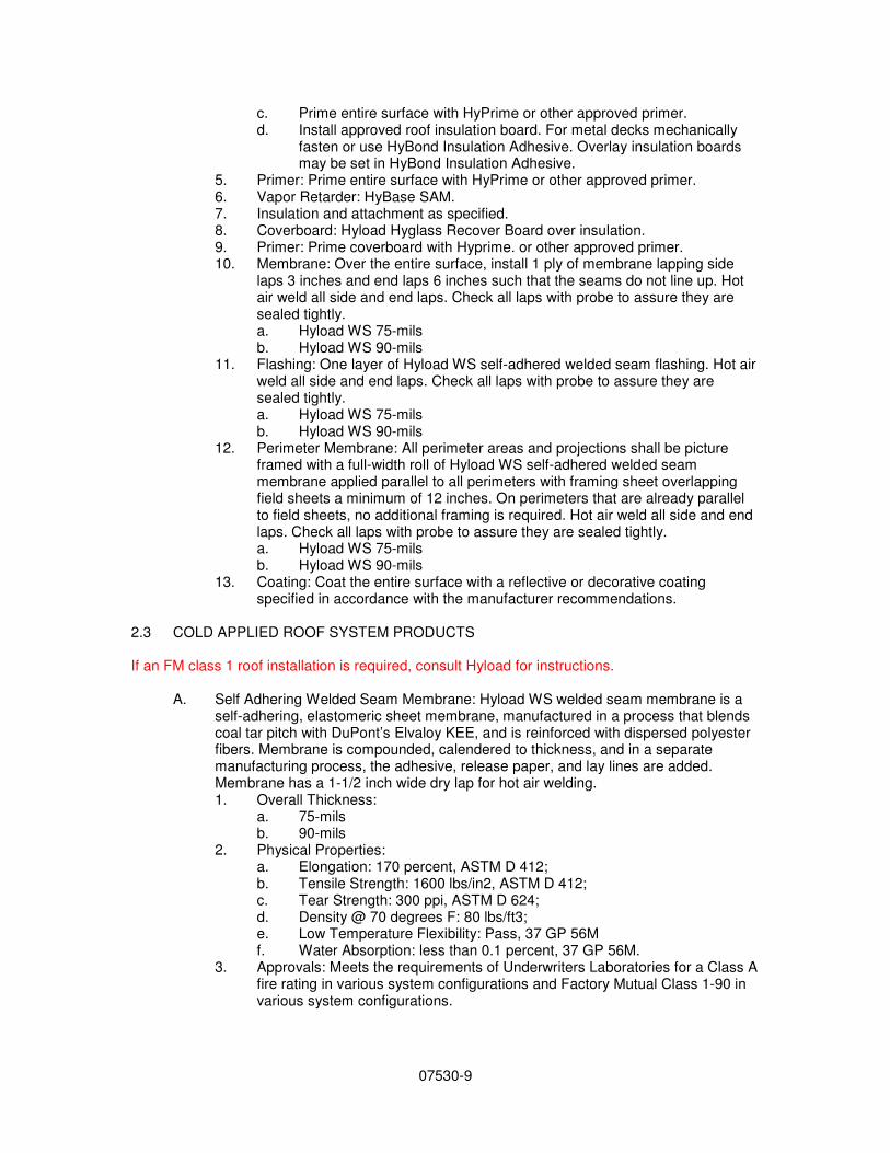
5. Primer: Prime entire surface with HyPrime or other approved primer. 6. Vapor Retarder: HyBase SAM. 7. Insulation and attachment as specified. 8. Coverboard: Hyload Hyglass Recover Board over insulation. 9. Primer: Prime coverboard with Hyprime. or other approved primer. 10. Membrane: Over the entire surface, install 1 ply of membrane lapping side
laps 3 inches and end laps 6 inches such that the seams do not line up. Hot air weld all side and end laps. Check all laps with probe to assure they are sealed tightly. a. Hyload WS 75-mils b. Hyload WS 90-mils
11. Flashing: One layer of Hyload WS self-adhered welded seam flashing. Hot air weld all side and end laps. Check all laps with probe to assure they are sealed tightly. a. Hyload WS 75-mils b. Hyload WS 90-mils
12. Perimeter Membrane: All perimeter areas and projections shall be picture framed with a full-width roll of Hyload WS self-adhered welded seam membrane applied parallel to all perimeters with framing sheet overlapping field sheets a minimum of 12 inches. On perimeters that are already parallel to field sheets, no additional framing is required. Hot air weld all side and end laps. Check all laps with probe to assure they are sealed tightly. a. Hyload WS 75-mils b. Hyload WS 90-mils
13. Coating: Coat the entire surface with a reflective or decorative coating specified in accordance with the manufacturer recommendations.
2.3 COLD APPLIED ROOF SYSTEM PRODUCTS If an FM class 1 roof installation is required, consult Hyload for instructions.
A. Self Adhering Welded Seam Membrane: Hyload WS welded seam membrane is a self-adhering, elastomeric sheet membrane, manufactured in a process that blends coal tar pitch with DuPont’s Elvaloy KEE, and is reinforced with dispersed polyester fibers. Membrane is compounded, calendered to thickness, and in a separate manufacturing process, the adhesive, release paper, and lay lines are added. Membrane has a 1-1/2 inch wide dry lap for hot air welding. 1. Overall Thickness:
a. 75-mils b. 90-mils
2. Physical Properties: a. Elongation: 170 percent, ASTM D 412; b. Tensile Strength: 1600 lbs/in2, ASTM D 412; c. Tear Strength: 300 ppi, ASTM D 624; d. Density @ 70 degrees F: 80 lbs/ft3; e. Low Temperature Flexibility: Pass, 37 GP 56M f. Water Absorption: less than 0.1 percent, 37 GP 56M.
3. Approvals: Meets the requirements of Underwriters Laboratories for a Class A fire rating in various system configurations and Factory Mutual Class 1-90 in various system configurations.
07530-10
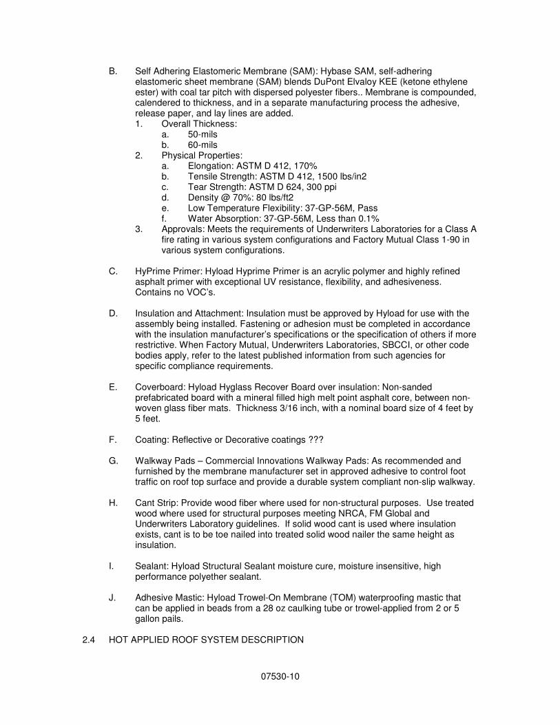
B. Self Adhering Elastomeric Membrane (SAM): Hybase SAM, self-adhering elastomeric sheet membrane (SAM) blends DuPont Elvaloy KEE (ketone ethylene ester) with coal tar pitch with dispersed polyester fibers.. Membrane is compounded, calendered to thickness, and in a separate manufacturing process the adhesive, release paper, and lay lines are added. 1. Overall Thickness:
a. 50-mils b. 60-mils
2. Physical Properties: a. Elongation: ASTM D 412, 170% b. Tensile Strength: ASTM D 412, 1500 lbs/in2 c. Tear Strength: ASTM D 624, 300 ppi d. Density @ 70%: 80 lbs/ft2 e. Low Temperature Flexibility: 37-GP-56M, Pass f. Water Absorption: 37-GP-56M, Less than 0.1%
3. Approvals: Meets the requirements of Underwriters Laboratories for a Class A fire rating in various system configurations and Factory Mutual Class 1-90 in various system configurations.
C. HyPrime Primer: Hyload Hyprime Primer is an acrylic polymer and highly refined
asphalt primer with exceptional UV resistance, flexibility, and adhesiveness. Contains no VOC’s.
D. Insulation and Attachment: Insulation must be approved by Hyload for use with the
assembly being installed. Fastening or adhesion must be completed in accordance with the insulation manufacturer’s specifications or the specification of others if more restrictive. When Factory Mutual, Underwriters Laboratories, SBCCI, or other code bodies apply, refer to the latest published information from such agencies for specific compliance requirements.
E. Coverboard: Hyload Hyglass Recover Board over insulation: Non-sanded
prefabricated board with a mineral filled high melt point asphalt core, between non-woven glass fiber mats. Thickness 3/16 inch, with a nominal board size of 4 feet by 5 feet.
F. Coating: Reflective or Decorative coatings ???
G. Walkway Pads – Commercial Innovations Walkway Pads: As recommended and
furnished by the membrane manufacturer set in approved adhesive to control foot traffic on roof top surface and provide a durable system compliant non-slip walkway.
H. Cant Strip: Provide wood fiber where used for non-structural purposes. Use treated
wood where used for structural purposes meeting NRCA, FM Global and Underwriters Laboratory guidelines. If solid wood cant is used where insulation exists, cant is to be toe nailed into treated solid wood nailer the same height as insulation.
I. Sealant: Hyload Structural Sealant moisture cure, moisture insensitive, high
performance polyether sealant.
J. Adhesive Mastic: Hyload Trowel-On Membrane (TOM) waterproofing mastic that can be applied in beads from a 28 oz caulking tube or trowel-applied from 2 or 5 gallon pails.
2.4 HOT APPLIED ROOF SYSTEM DESCRIPTION
07530-11
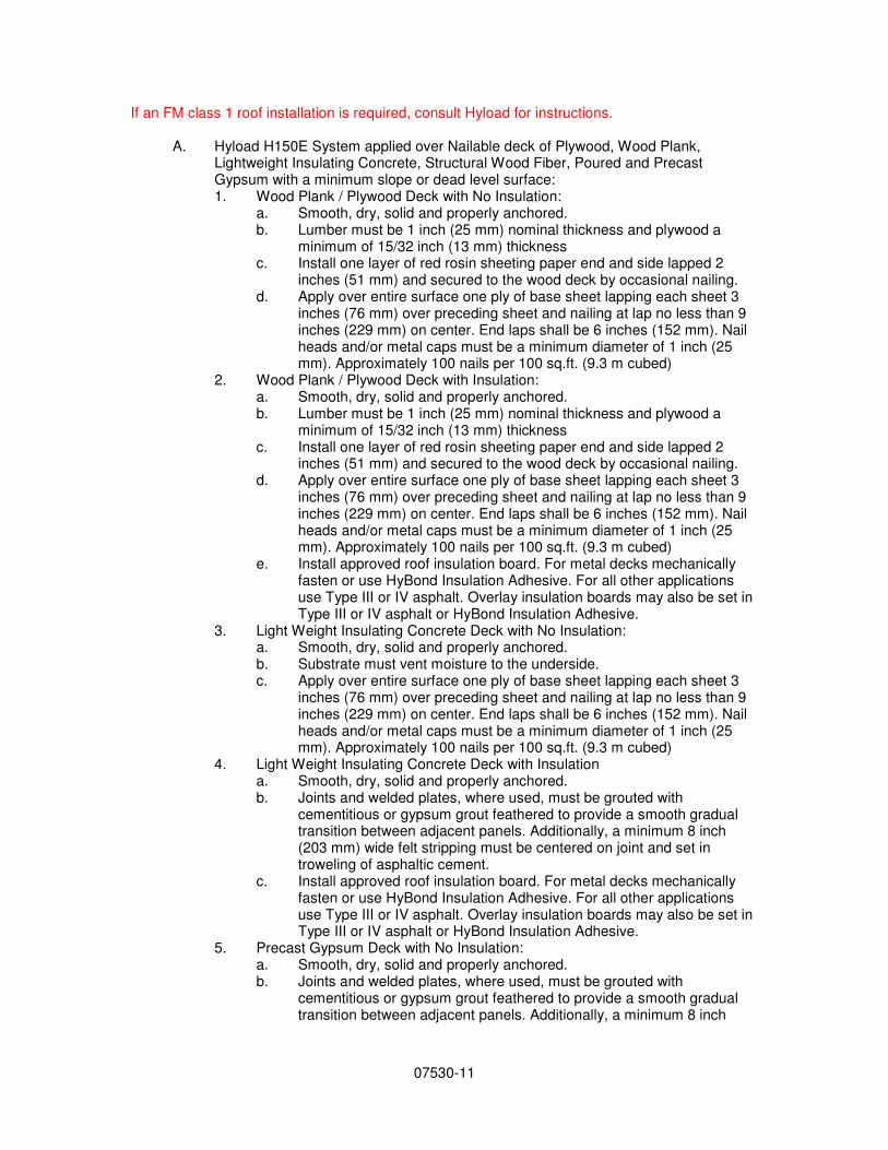
If an FM class 1 roof installation is required, consult Hyload for instructions.
A. Hyload H150E System applied over Nailable deck of Plywood, Wood Plank, Lightweight Insulating Concrete, Structural Wood Fiber, Poured and Precast Gypsum with a minimum slope or dead level surface: 1. Wood Plank / Plywood Deck with No Insulation:
a. Smooth, dry, solid and properly anchored. b. Lumber must be 1 inch (25 mm) nominal thickness and plywood a
minimum of 15/32 inch (13 mm) thickness c. Install one layer of red rosin sheeting paper end and side lapped 2
inches (51 mm) and secured to the wood deck by occasional nailing. d. Apply over entire surface one ply of base sheet lapping each sheet 3
inches (76 mm) over preceding sheet and nailing at lap no less than 9 inches (229 mm) on center. End laps shall be 6 inches (152 mm). Nail heads and/or metal caps must be a minimum diameter of 1 inch (25 mm). Approximately 100 nails per 100 sq.ft. (9.3 m cubed)
2. Wood Plank / Plywood Deck with Insulation: a. Smooth, dry, solid and properly anchored. b. Lumber must be 1 inch (25 mm) nominal thickness and plywood a
minimum of 15/32 inch (13 mm) thickness c. Install one layer of red rosin sheeting paper end and side lapped 2
inches (51 mm) and secured to the wood deck by occasional nailing. d. Apply over entire surface one ply of base sheet lapping each sheet 3
inches (76 mm) over preceding sheet and nailing at lap no less than 9 inches (229 mm) on center. End laps shall be 6 inches (152 mm). Nail heads and/or metal caps must be a minimum diameter of 1 inch (25 mm). Approximately 100 nails per 100 sq.ft. (9.3 m cubed)
e. Install approved roof insulation board. For metal decks mechanically fasten or use HyBond Insulation Adhesive. For all other applications use Type III or IV asphalt. Overlay insulation boards may also be set in Type III or IV asphalt or HyBond Insulation Adhesive.
3. Light Weight Insulating Concrete Deck with No Insulation: a. Smooth, dry, solid and properly anchored. b. Substrate must vent moisture to the underside. c. Apply over entire surface one ply of base sheet lapping each sheet 3
inches (76 mm) over preceding sheet and nailing at lap no less than 9 inches (229 mm) on center. End laps shall be 6 inches (152 mm). Nail heads and/or metal caps must be a minimum diameter of 1 inch (25 mm). Approximately 100 nails per 100 sq.ft. (9.3 m cubed)
4. Light Weight Insulating Concrete Deck with Insulation a. Smooth, dry, solid and properly anchored. b. Joints and welded plates, where used, must be grouted with
cementitious or gypsum grout feathered to provide a smooth gradual transition between adjacent panels. Additionally, a minimum 8 inch (203 mm) wide felt stripping must be centered on joint and set in troweling of asphaltic cement.
c. Install approved roof insulation board. For metal decks mechanically fasten or use HyBond Insulation Adhesive. For all other applications use Type III or IV asphalt. Overlay insulation boards may also be set in Type III or IV asphalt or HyBond Insulation Adhesive.
5. Precast Gypsum Deck with No Insulation: a. Smooth, dry, solid and properly anchored. b. Joints and welded plates, where used, must be grouted with
cementitious or gypsum grout feathered to provide a smooth gradual transition between adjacent panels. Additionally, a minimum 8 inch
07530-12
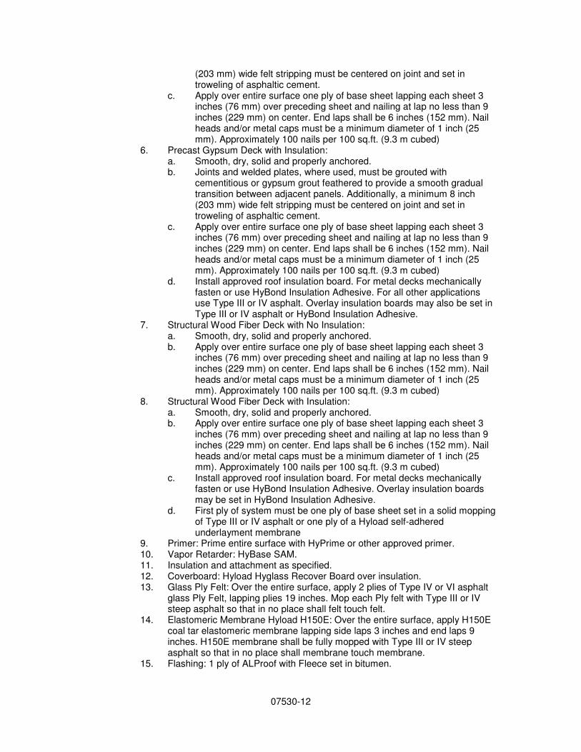
(203 mm) wide felt stripping must be centered on joint and set in troweling of asphaltic cement.
c. Apply over entire surface one ply of base sheet lapping each sheet 3 inches (76 mm) over preceding sheet and nailing at lap no less than 9 inches (229 mm) on center. End laps shall be 6 inches (152 mm). Nail heads and/or metal caps must be a minimum diameter of 1 inch (25 mm). Approximately 100 nails per 100 sq.ft. (9.3 m cubed)
6. Precast Gypsum Deck with Insulation: a. Smooth, dry, solid and properly anchored. b. Joints and welded plates, where used, must be grouted with
cementitious or gypsum grout feathered to provide a smooth gradual transition between adjacent panels. Additionally, a minimum 8 inch (203 mm) wide felt stripping must be centered on joint and set in troweling of asphaltic cement.
c. Apply over entire surface one ply of base sheet lapping each sheet 3 inches (76 mm) over preceding sheet and nailing at lap no less than 9 inches (229 mm) on center. End laps shall be 6 inches (152 mm). Nail heads and/or metal caps must be a minimum diameter of 1 inch (25 mm). Approximately 100 nails per 100 sq.ft. (9.3 m cubed)
d. Install approved roof insulation board. For metal decks mechanically fasten or use HyBond Insulation Adhesive. For all other applications use Type III or IV asphalt. Overlay insulation boards may also be set in Type III or IV asphalt or HyBond Insulation Adhesive.
7. Structural Wood Fiber Deck with No Insulation: a. Smooth, dry, solid and properly anchored. b. Apply over entire surface one ply of base sheet lapping each sheet 3
inches (76 mm) over preceding sheet and nailing at lap no less than 9 inches (229 mm) on center. End laps shall be 6 inches (152 mm). Nail heads and/or metal caps must be a minimum diameter of 1 inch (25 mm). Approximately 100 nails per 100 sq.ft. (9.3 m cubed)
8. Structural Wood Fiber Deck with Insulation: a. Smooth, dry, solid and properly anchored. b. Apply over entire surface one ply of base sheet lapping each sheet 3
inches (76 mm) over preceding sheet and nailing at lap no less than 9 inches (229 mm) on center. End laps shall be 6 inches (152 mm). Nail heads and/or metal caps must be a minimum diameter of 1 inch (25 mm). Approximately 100 nails per 100 sq.ft. (9.3 m cubed)
c. Install approved roof insulation board. For metal decks mechanically fasten or use HyBond Insulation Adhesive. Overlay insulation boards may be set in HyBond Insulation Adhesive.
d. First ply of system must be one ply of base sheet set in a solid mopping of Type III or IV asphalt or one ply of a Hyload self-adhered underlayment membrane
9. Primer: Prime entire surface with HyPrime or other approved primer. 10. Vapor Retarder: HyBase SAM. 11. Insulation and attachment as specified. 12. Coverboard: Hyload Hyglass Recover Board over insulation. 13. Glass Ply Felt: Over the entire surface, apply 2 plies of Type IV or VI asphalt
glass Ply Felt, lapping plies 19 inches. Mop each Ply felt with Type III or IV steep asphalt so that in no place shall felt touch felt.
14. Elastomeric Membrane Hyload H150E: Over the entire surface, apply H150E coal tar elastomeric membrane lapping side laps 3 inches and end laps 9 inches. H150E membrane shall be fully mopped with Type III or IV steep asphalt so that in no place shall membrane touch membrane.
15. Flashing: 1 ply of ALProof with Fleece set in bitumen.
07530-13
16. Perimeter Membrane Hyload H150E: All perimeter areas and projections shall be picture framed with a full-width roll of elastomeric membrane applied parallel to all perimeters with framing sheet overlapping field sheets a minimum of 12 inches (300 mm). On perimeters that are already parallel to field sheets, no additional framing is required.
17. Gravel Surface: Over the entire surface of the roofing membrane, pour a continuous coating of Type III or IV steep asphalt at the rate of 60 lbs per 100 SF, and while hot, apply not less than 500 pounds of aggregate per 100 SF
18. Smooth Surface: Hot air weld all H150E exposed side and end laps with a hot air machine. Check all laps with probe to assure laps are sealed tightly.
19. Coating: Coat the entire surface with a reflective or decorative coating in accordance with the manufacturer recommendations.
B. Hyload H150E System applied over Non-Nailable deck of Metal, Poured Concrete and Precast Concrete with a minimum slope or dead level surface: 1. Metal Deck with Insulation
a. Smooth, dry, solid and properly anchored. b. First layer of board type insulation shall be mechanically attached or
set in HyBond Insulation Adhesive prior to the application of the roofing system.
c. Install approved roof insulation board. For metal decks mechanically fasten or use HyBond Insulation Adhesive. Overlay insulation boards may also be set HyBond Insulation Adhesive.
2. Poured Concrete Deck with No Insulation: a. Smooth, dry, solid and properly anchored. b. Prime entire surface with HyPrime or other approved primer.
3. Poured Concrete Deck with Insulation a. Smooth, dry, solid and properly anchored. b. Prime entire surface with HyPrime or other approved primer. c. Install approved roof insulation board. For metal decks mechanically
fasten or use HyBond Insulation Adhesive. For all other applications use Type III or IV asphalt. Overlay insulation boards may also be set in HyBond Insulation Adhesive.
4. Precast Concrete Deck with Insulation: a. Smooth, dry, solid and properly anchored. b. Joints and welded plates, where used, must be grouted with
cementitious or gypsum grout feathered to provide a smooth gradual transition between adjacent panels. Additionally apply, a minimum 8 inch (203 mm) wide felt stripping centered on joint and set in troweling of asphaltic cement.
c. Prime entire surface with HyPrime or other approved primer. d. Install approved roof insulation board. For metal decks mechanically
fasten or use HyBond Insulation Adhesive. Overlay insulation boards may be set in HyBond Insulation Adhesive.
5. Primer: Prime entire surface with HyPrime or other approved primer. 6. Vapor Retarder: HyBase SAM. 7. Insulation and attachment as specified. 8. Coverboard: Hyload Hyglass Recover Board over insulation. 9. Glass Ply Felt: Over the entire surface, apply 2 plies of Type IV or VI asphalt
glass Ply Felt, lapping plies 19 inches. Mop each Ply felt with Type III or IV steep asphalt so that in no place shall felt touch felt.
10. Elastomeric Membrane Hyload H150E: Over the entire surface, apply H150E coal tar elastomeric membrane lapping side laps 3 inches and end laps 9 inches. H150E membrane shall be fully mopped with Type III or IV steep asphalt so that in no place shall membrane touch membrane.
07530-14
11. Flashing: 1 ply of ALProof with Fleece set in bitumen. 12. Perimeter Membrane Hyload H150E: All perimeter areas and projections shall
be picture framed with a full-width roll of elastomeric membrane applied parallel to all perimeters with framing sheet overlapping field sheets a minimum of 12 inches (300 mm). On perimeters that are already parallel to field sheets, no additional framing is required.
13. Gravel Surface: Over the entire surface of the roofing membrane, pour a continuous coating of Type III or IV steep asphalt at the rate of 60 lbs per 100 SF, and while hot, apply not less than 500 pounds of aggregate per 100 SF
14. Smooth Surface: Hot air weld all H150E exposed side and end laps with a hot air machine. Check all laps with probe to assure laps are sealed tightly.
15. Coating: Coat the entire surface with a reflective or decorative coating in accordance with the manufacturer recommendations.
2.5 HOT APPLIED ROOF SYSTEM PRODUCTS
If an FM class 1 roof installation is required, consult Hyload for instructions.
A. Self Adhering Elastomeric Membrane (SAM): Hybase SAM, self-adhering
elastomeric sheet membrane (SAM) blends DuPont Elvaloy KEE (ketone ethylene ester) with coal tar pitch with dispersed polyester fibers.. Membrane is compounded, calendered to thickness, and in a separate manufacturing process the adhesive, release paper, and lay lines are added. 1. Overall Thickness:
a. 50-mils b. 60-mils
2. Physical Properties: a. Elongation: ASTM D 412, 170% b. Tensile Strength: ASTM D 412, 1500 lbs/in2 c. Tear Strength: ASTM D 624, 330 ppi d. Density @ 70%: 80 lbs/ft2 e. Low Temperature Flexibility: 37-GP-56M, Pass f. Water Absorption: 37-GP-56M, Less than 0.1%
3. Approvals: Meets the requirements of Underwriters Laboratories for a Class A fire rating in various system configurations and Factory Mutual Class 1-90 in various system configurations.
B. Hyload H150E Coal Tar Membrane: H150 Coal tar elastomeric membrane (CTEM)
has a 60 mil overall calendered thickness and incorporates DuPont Elvaloy KEE (ketone ethylene ester), extended with coal tar pitch and reinforced with polyester fibers. Overall Thickness: 60 mils 1. Physical Properties:
a. Elongation: ASTM D 412, 170% b. Tensile Strength: ASTM D 412, 1500 lbs/in2 c. Tear Strength: ASTM D 624, 300 ppi d. Density @ 70%: 80 lbs/ft2 e. Low Temperature Flexibility: 37-GP-56M, Pass f. Water Absorption: 37-GP-56M, Less than 0.1%
2. Approvals: Meets the requirements of Underwriters Laboratories for a Class A fire rating in various system configurations. HyBase SAM has Factory Mutual Class 1-90 approval in various system configurations.
C. HyPrime Primer: Hyload Hyprime Primer is an acrylic polymer and highly refined
asphalt primer with exceptional UV resistance, flexibility, and adhesiveness. Contains no VOC’s.
07530-15
D. ALProof with Fleece: Alproof is composed of an elastomeric blend of DuPont Elvaloy along with other unique ingredients reinforced with dispersed polyester fibers. Overall Thickness: 60 mils 1. Physical Properties:
a. Elongation: ASTM D 412, 170% b. Tensile Strength: ASTM D 412, 1300 lbs/in2 c. Tear Strength: ASTM D 624, 270 ppi d. Density @ 70%: 80 lbs/ft2 e. Low Temperature Flexibility: 37-GP-56M, Pass f. Water Absorption: 37-GP-56M, Less than 0.1%
2. Approvals: Meets the requirements of Underwriters Laboratories for a Class A fire rating in various system configurations. ALProof has Factory Mutual Class 1-90 approval in various system configurations.
E. Insulation and Attachment:: Insulation must be approved by Hyload for use with the
assembly being installed. Fastening or adhesion must be completed in accordance with the insulation manufacturer’s specifications or the specification of others if more restrictive. When Factory Mutual, Underwriters Laboratories, SBCCI, or other code bodies apply, refer to the latest published information from such agencies for specific compliance requirements.
F. Hyload Hyglass Recover Board: Non-sanded prefabricated board with a mineral
filled high melt point asphalt core, between non-woven glass fiber mats. Thickness 3/16 inch, with a nominal board size of 4 feet by 5 feet.
G. Glass Ply Felt: ASTM D 2178, Type III, IV or VI. (NO DATA ON WEB SITE)
H. Type III or IV steep asphalt: Conforming to ASTM D 312. (WHY ASPHALT WITH
COAL TAR MEMBRANE?)
I. Gravel Surfacing: Aggregate conforming to ASTM D 1863; clean, sound, hard stone, free of clay, loam, sand, or other foreign substances, and shall conform to size grading and property requirements 1/4 inch (6 mm) minimum to 3/4 inch (19 mm) maximum size.
J. Coating: Reflective or Decorative coating ????
K. Walkway Pads – Commercial Innovations Walkway Pads: As recommended and
furnished by the membrane manufacturer set in approved adhesive to control foot traffic on roof top surface and provide a durable system compliant non-slip walkway.
L. Cant Strip: Provide wood fiber where used for non-structural purposes. Use treated
wood where used for structural purposes meeting NRCA, FM Global and Underwriters Laboratory guidelines. If solid wood cant is used where insulation exists, cant is to be toe nailed into treated solid wood nailer the same height as insulation.
M. Sealant: Hyload Structural Sealant moisture cure, moisture insensitive, high
performance polyether sealant.
N. Adhesive Mastic: Hyload Trowel-On Membrane (TOM) waterproofing mastic that can be applied in beads from a 28 oz caulking tube or trowel-applied from 2 or 5 gallon pails.
PART 3 EXECUTION
07530-16
3.1 EXAMINATION
A. Do not begin installation until substrates have been properly prepared.
B. Inspect and approve the deck condition, slopes and fastener backing if applicable, parapet walls, expansion joints, roof drains, stack vents, vent outlets, nailers and surfaces and elements.
C. Verify that work penetrating the roof deck, or which may otherwise affect the roofing,
has been properly completed.
D. If substrate preparation and other conditions are the responsibility of another installer, notify Architect of unsatisfactory preparation before proceeding.
3.2 PREPARATION
A. General: Clean surfaces thoroughly prior to installation. 1. Prepare surfaces using the methods recommended by the manufacturer for
achieving the best result for the substrate under the project conditions. 2. Fill substrate surface voids that are greater than 1/4 inch wide with an
acceptable fill material. 3. Roof surface to receive roofing system shall be smooth, clean, free from loose
gravel, dirt and debris, dry and structurally sound. 4. Wherever necessary, all surfaces to receive roofing materials shall be power
broom and vacuumed to remove debris and loose matter prior to starting work.
5. Do not apply roofing during inclement weather. Do not apply roofing membrane to damp, frozen, dirty, or dusty surfaces.
6. Fasteners and plates for fastening components mechanically to the substrate shall provide a minimum pull-out capacity of 300 lbs. (136 k) per fastener. Base or ply sheets attached with cap nails require a minimum pullout capacity of 40 lb. per nail.
7. Prime decks where required, in accordance with requirements and recommendations of the primer and deck manufacturer.
B. Metal Deck: Metal deck shall be installed as specified in Section 05300. 1. Fastening of the deck should comply with the anticipated live and dead loads
pertaining to the building as well as applicable Code. 2. Steel decks shall be minimum 22-gauge factory galvanized or zinc alloy
coated for protection against corrosion. 3. Suitable insulation shall be mechanically attached as recommended by the
insulation manufacturer. 4. Decks shall comply with the gauge and span requirements in the current
Factory Mutual FM Approval Guide and be installed in accordance with Loss Prevention Data Sheet 1-28 or specific FM approval.
5. When re-roofing over steel decks, surface corrosion shall be removed, and repairs to severely corroded areas made. Loose or inadequately secured decking shall be fastened, and irreparable or otherwise defective decking shall be replaced.
C. Wood Deck:
1. Dimensional wood deck shall be minimum 1 inch (25 mm) thick, knotholes and cracks larger than 1/4 inch shall be covered with sheet metal. All boards
07530-17
shall be appropriately nailed and have adequate end bearing to the centers of beams/rafters. Lumber shall be kiln dried.
2. Plywood shall be a minimum 15/32 inch (11.9 mm) thick and conform to the standards and installation requirements of the American Plywood Association (APA).
3. If no roof insulation is specified, provide a suitable dry sheathing paper, followed by an approved base sheet nailed appropriately for the specified roof system, with 1 inch (25 mm) diameter caps and annular nails unless otherwise required by the applicable Code or Approval agency.
4. Insulation is to be mechanically attached in accordance with the insulation manufacturer’s recommendations unless otherwise required by the applicable Code.
5. In all retrofit roof applications, it is required that deck be inspected for defects. Any defects are to be corrected per the deck manufacturer's recommendations and standards of the APA/Engineered Wood Association prior to new roof application.
6. Light metal wall ties or other structural metal exposed on top of the wood deck shall be covered with one ply of a heavy roofing sheet, such as HPR Glasbase Base Sheet, extending 2 inches to 6 inches (51 mm to 152 mm) beyond the metal in all directions. Nail in place before applying the base ply.
D. Precast concrete:
1. Decks shall be clean, dry, fully cured and free of flaws and attached securely to the supporting structure as recommended by the deck manufacturer.
2. All joints shall be caulked or grouted. 3. Concrete surfaces to receive roofing shall be fully primed at the rate of 1
gallon per 100 sq. ft. 4. When applying roofing or insulation directly to the deck with asphalt, prime
with asphalt/concrete primer, ASTM D41, at a rate of 1 gal/square (.4 L/m2) and allow the primer to dry prior to the application of the roofing system. Hold back bitumen at the joints approximately 4 inches (102 mm) to prevent bitumen drippage.
5. Deck joints shall be stripped in with a 12 inch (305 mm) wide strip of modified membrane unadhered a minimum of 2 inches (51 mm) immediately on either side of the joint.
E. Poured reinforced concrete
1. Shall be smooth, dry, clean and free of ice/frost, projections and depressions. Concrete shall be fully cured and the surface shall be broom cleaned and free of release/curing agents prior to commencement of work.
2. Prepared concrete surfaces for roofing or insulation by priming with asphalt/concrete primer conforming to ASTM D 41. Apply at a rate of approx. 1 gallon/100 sq. ft. (.4 L/m2). All primed areas shall be fully dried before proceeding with the application of the roof system. Hold back bitumen at the joints approximately 4 inches (102 mm) to prevent bitumen drippage.
F. Lightweight Insulating Concrete Deck
1. Lightweight insulating concrete decks are required to have a minimum thickness of 2 inches (51 mm), a minimum compressive strength of 125 psi (0.86 MPa) and a minimum density of 22 pcf (352 kg/sm).
2. Install roof system immediately following deck curing to prevent damage from exposure to precipitation. The deck manufacturer determines the minimum curing time and maximum exposure limitations.
3. LWIC shall not be poured during rainy periods. Deck areas that have frozen before they have cured shall be removed and replaced. Decks which receive
07530-18
precipitation prior to installation of the roof membrane shall be checked for moisture content and dryness.
4. Lightweight insulating concrete decks are acceptable only on slopes up to 1 inch per foot (83 mm/m).
5. Do not attach insulation directly to lightweight concrete decks. Over old, dry decks, additional board insulation may be solidly mopped to an approved mechanically attached anchor sheet (base sheet).
G. Cementitious Wood Fiber
1. Protect decks from the weather during storage and application. Any wet or deformed decking shall be removed and replaced.
2. Cementitious wood fiber decks shall not be installed over high humidity occupancies.
3. Cementitious wood fiber decks shall have a minimum design load as recommended by the deck manufacturer.
4. Anchor cementitious wood fiber deck panels against uplift and lateral movement.
5. Install deck level. Correct or replace deck with any deflection, irregularities, or otherwise damaged panels.
6. Install a mechanically attached base sheet prior to installation of insulation or roofing membrane.
H. Gypsum
1. Gypsum decks shall be smooth and free from deflections or ridges. 2. An average fastener withdrawal resistance as recommended by the fastener
manufacturer shall be obtained; however, at no time shall it be less than 40 lbs. (178 N) per fastener.
3. Wet or frozen poured gypsum decks are not suitable to receive a roof. 4. Poured-in-place gypsum roof decks contain a large percentage of moisture.
All necessary precautions shall be taken to avoid the entrapment of moisture under the roofing system. In addition to ventilation of the underside to allow for proper curing, topside and perimeter venting shall be implemented.
5. Install a mechanically attached base sheet prior to installation of insulation or roofing membrane.
I. Deck Preparation for Self-Adhered Roof System: Insulation shall be installed as
specified in Section 05300. Sweep or blow away any dust, dirt or sand particles that could interfere with adhesion to approved substrate.
J. Other deck types:
K. Re-Roofing Applications:
1. Remove existing roof flashings from curbs and parapet walls down to the surface of the roof. Remove existing flashings at roof drains and roof penetrations.
2. Remove all wet, deteriorated, blistered or delaminated roofing membrane or insulation and fill in any low spots occurring as a result of removal work to create a smooth, even surface for application of new roof membranes.
3. Install new wood nailers as necessary to accommodate insulation/recovery board or new nailing patterns.
4. When mechanically attached, the fastening pattern for the insulation/recovery board shall be as recommended by the specific product manufacturer.
5. Re-roofing over coal tar pitch requires a mechanically attached recovery board or insulation and a base sheet prior to the application of roofing system.
6. Existing roof surfaces shall be primed as necessary with asphalt primer meeting ASTM D 41 and allowed to dry prior to installing the roofing system.
07530-19
3.3 INSTALLATION – GENERAL
A. Application of materials shall be in strict accordance with the manufacturer's recommendations and current NRCA, Underwriters Laboratory and IBC guidelines, except where more stringent requirements are shown or specified. In the instance of a conflict between these specifications and those of the manufacturer and/or current NRCA, Underwriters Laboratory and IBC guidelines, the more stringent specifications shall take precedence.
3.4 INSTALLATION COLD APPLIED ROOF SYSTEM
A. Nailable Base Sheet: Install base sheet nailed to the substrate with the appropriate fastener and fastening pattern determined from your wind uplift calculation.
B. Base Ply: Cut base ply sheets into 18 foot lengths and allow plies to relax before
installing. Install base sheet in Interply Adhesive: applied at the rate required by the manufacturer. Shingle base sheets uniformly to achieve one ply throughout over the prepared substrate. Shingle in proper direction to shed water on each large area of roofing. 1. Lap ply sheet ends 8 inches. Stagger end laps 12 inches minimum. 2. Solidly bond to the substrate and adjacent ply with specified cold adhesive at
the rate of 2 to 2-1/2 gallons per 100 square feet. 3. Roll must push a puddle of adhesive in front of it with adhesive slightly visible
at all side laps. Use care to eliminate air entrapment under the membrane. 4. Install subsequent rolls of modified across the roof as above with a minimum
of 4 inch side laps and 8 inch staggered end laps. Lay modified membrane in the same direction as the underlayers but the laps shall not coincide with the laps of the base layers.
5. Extend plies 2 inches beyond top edges of cants at wall and projection bases. 6. Install base flashing ply to all perimeter and projection details. 7. Allow the one ply of base sheet to cure at least 30 minutes before installing
the modified membrane. However, the modified membrane must be installed the same day as the base plies.
C. Modified Cap Ply(s): Cut cap ply sheets into 18 foot lengths and allow plies to relax
before installing. Install in interplay adhesive applied at the rate required by the manufacturer. Shingle sheets uniformly over the prepared substrate to achieve the number of plys specified. Shingle in proper direction to shed water on each large area of roofing. 1. Lap ply sheet ends 8 inches. Stagger end laps 12 inches minimum. 2. Solidly bond to the base layers with specified cold adhesive at the rate of 2 to
2-1/2 gallons per 100 square feet. 3. Roll must push a puddle of adhesive in front of it with adhesive slightly visible
at all side laps. Care should be taken to eliminate air entrapment under the membrane.
4. Install subsequent rolls of modified across the roof as above with a minimum of 4 inch side laps and 8 inch staggered end laps. Lay modified membrane in the same direction as the underlayers but the laps shall not coincide with the laps of the base layers.
5. Allow cold adhesive to set for 5 to 10 minutes before installing the top layer of modified membrane.
6. Extend membrane 2 inches beyond top edge of all cants in full moppings of the cold adhesive as shown on the Drawings.
07530-20
D. Fibrous Cant Strips: Provide non-combustible perlite or glass fiber cant strips at all
wall/curb detail treatments where angle changes are greater than 45 degrees. Cant may be set in approved cold adhesives, hot asphalt or mechanically attached with approved plates and fasteners.
E. Wood Blocking, Nailers and Cant Strips: Provide wood blocking, nailers and cant
strips as specified in Section 06114. 1. Provide nailers at all roof perimeters and penetrations for fastening
membrane flashings and sheet metal components. 2. Wood nailers should match the height of any insulation, providing a smooth
and even transition between flashing and insulation areas. 3. Nailer lengths should be spaced with a minimum 1/8 inch gap for expansion
and contraction between each length or change of direction. 4. Nailers and flashings should be fastened in accordance with Factory Mutual
“Loss Prevention Data Sheet 1–49, Perimeter Flashing” and be designed to be capable of resisting a minimum force of 200 lbs/lineal foot in any direction.
F. Metal Work: Provide metal flashings, counter flashings, parapet coping caps and
thru-wall flashings as specified in Section 07620 or Section 07710. Install in accordance with the SMACNA ”Architectural Sheet Metal Manual” or the NRCA Roofing Waterproofing manual.
G. Termination Bar: Provide a metal termination bar or approved top edge securement
at the terminus of all flashing sheets at walls and curbs. Fasten the bar a minimum of 8 inches (203 mm) o/c to achieve constant compression. Provide suitable, sealant at the top edge if required.
H. Flashing Base Ply: Install flashing sheets by the same application method used for
the base ply. 1. Seal curb, wall and parapet flashings with an application of mastic and mesh
on a daily basis. Do not permit conditions to exist that will allow moisture to enter behind, around or under the roof or flashing membrane.
2. Prepare all walls, penetrations, expansion joints and where shown on the Drawings to be flashed with required primer at the rate of 100 square feet per gallon. Allow primer to dry tack free.
3. Adhere to the underlying base ply with specified flashing ply adhesive unless otherwise specified. Nail off at a minimum of 8 inches (203 mm) o.c. from the finished roof at all vertical surfaces.
4. Solidly adhere the entire flashing ply to the substrate. Secure the tops of all flashings that are not run up and over curb through termination bar fastened at 6 inches (152 mm) O.C. and sealed at top.
5. Seal all vertical laps of flashing ply with a three-course application of trowel-grade mastic and fiberglass mesh.
6. Coordinate counter flashing, cap flashings, expansion joints and similar work with modified bitumen roofing work as specified.
7. Coordinate roof accessories, miscellaneous sheet metal accessory items, including piping vents and other devices with the roofing system work.
8. Secure the top edge of the flashing sheet using a termination bar only when the wall surface above is waterproofed, or nailed 4 inches on center and covered with an acceptable counter flashing.
I. Flood Coat/Aggregate: 1. Install after cap sheets and modified flashing, tests, repairs and corrective
actions have been completed and approved.
07530-21
2. Apply flood coat materials in the quantities recommended by the manufacturer.
3. Uniformly embed aggregate in the flood coat of cold adhesive at a rate recommended by the manufacturer.
4. Aggregate must be dry and placed in a manner required to form a compact, embedded overlay. To aid in embedment, lightly roll aggregate.
J. Flashing Cap Ply: Install flashing cap sheets by the same application method used
for the base ply. 1. Seal curb, wall and parapet flashings with an application of mastic and mesh
on a daily basis. Do not permit conditions to exist that will allow moisture to enter behind, around or under the roof or flashing membrane.
2. Prepare all walls, penetrations, expansion joints and where shown on the Drawings to be flashed with required primer at the rate of 100 square feet per gallon. Allow primer to dry tack free.
3. Adhere to the underlying base flashing ply with specified flashing ply adhesive unless otherwise specified. Nail off at a minimum of 8 inches (203 mm) o.c. from the finished roof at all vertical surfaces.
4. Coordinate counter flashing, cap flashings, expansion joints and similar work with modified bitumen roofing work as specified.
5. Coordinate roof accessories, miscellaneous sheet metal accessory items with the roofing system work.
6. All stripping shall be installed prior to flashing cap sheet installation. 7. Heat and scrape granules when welding or adhering at cut areas and seams
to granular surfaces at all flashings. 8. Secure the top edge of the flashing sheet using a termination bar only when
the wall surface above is waterproofed, or nailed 4 inches on center and covered with an acceptable counter flashing.
K. Surface Coatings: Apply roof coatings in strict conformance with the manufacturer’s
recommended procedures.
L. Roof Walkways: Provide walkways in areas indicated on the Drawings. 3.5 INSTALLATION HOT APPLIED ROOF SYSTEM
A. Nailable Base Sheet: Install base sheet nailed to the substrate with the appropriate fastener and fastening pattern determined from your wind uplift calculation.
B. Base/Felt Ply(s): Install base sheet or felt plies in twenty five (25) lbs (11.3kg) per
square of bitumen shingled uniformly to achieve one or more plies over the entire prepared substrate. Shingle in direction of slope of roof to shed water on each area of roof. Do not step on base rolls until asphalt has cooled, fish mouths should be cut and patched. 1. Lap ply sheet ends 8 inches (203 mm). Stagger end laps 2 inches (304mm)
minimum. 2. Install base flashing ply to all perimeter and projection details after membrane
application. 3. Extend plies 2 inches beyond top edges of cants at wall and projection bases. 4. Install base flashing ply to all perimeter and projection details. 5. Allow the one ply of base sheet to cure at least 30 minutes before installing
the modified membrane. However, the modified membrane must be installed the same day as the base plies.
C. Modified Cap Ply(s): Solidly bond the modified membrane to the base layers with
specified material at the rate of 25 to thirty 30 lbs. (11-13kg) per 100 square feet.
07530-22
1. Roll must push a puddle of hot material in front of it with material slightly visible at all side laps. Use care to eliminate air entrapment under the membrane. Exercise care during application to eliminate air entrapment under the membrane.
2. Apply pressure to all seams to ensure that the laps are solidly bonded to substrate.
3. Install subsequent rolls of modified membrane as above with a minimum of 4 inch (101 mm) side laps and 8 inch (203 mm) end laps. Stagger end laps. Apply membrane in the same direction as the previous layers but stagger the laps so they do not coincide with the laps of the base layers.
4. Apply hot material no more than 5 feet (1.5 m) ahead of each roll being embedded.
5. Extend membrane 2 inches (50 mm) beyond top edge of all cants in full moppings of the specified hot material.
D. Fibrous Cant Strips: Provide non-combustible perlite or glass fiber cant strips at all
wall/curb detail treatments where angle changes are greater than 45 degrees. Cant may be set in approved cold adhesives, hot asphalt or mechanically attached with approved plates and fasteners.
E. Wood Blocking, Nailers and Cant Strips: Provide wood blocking, nailers and cant
strips as specified in Section 06114. 1. Provide nailers at all roof perimeters and penetrations for fastening
membrane flashings and sheet metal components. 2. Wood nailers should match the height of any insulation, providing a smooth
and even transition between flashing and insulation areas. 3. Nailer lengths should be spaced with a minimum 1/8 inch gap for expansion
and contraction between each length or change of direction. 4. Nailers and flashings should be fastened in accordance with Factory Mutual
“Loss Prevention Data Sheet 1–49, Perimeter Flashing” and be designed to be capable of resisting a minimum force of 200 lbs/lineal foot in any direction.
F. Metal Work: Provide metal flashings, counter flashings, parapet coping caps and
thru-wall flashings as specified in Section 07620 or Section 07710. Install in accordance with the SMACNA ”Architectural Sheet Metal Manual” or the NRCA Roofing Waterproofing manual.
G. Termination Bar: Provide a metal termination bar or approved top edge securement
at the terminus of all flashing sheets at walls and curbs. Fasten the bar a minimum of 8 inches (203 mm) o/c to achieve constant compression. Provide suitable, sealant at the top edge if required.
H. Flashing Base Ply: Install flashing sheets by the same application method used for
the base ply. 1. Seal curb, wall and parapet flashings with an application of mastic and mesh
on a daily basis. Do not permit conditions to exist that will allow moisture to enter behind, around or under the roof or flashing membrane.
2. Prepare all walls, penetrations, expansion joints and surfaces to be flashed with required primer at the rate of 100 square feet per gallon. Allow primer to dry tack free.
3. Adhere to the underlying base flashing ply with specified hot material unless otherwise noted in these specifications. Nail off at a minimum of 8 inches (203 mm) o.c. from the finished roof at all vertical surfaces.
4. Solidly adhere the entire sheet of flashing membrane to the substrate. 5. Seal all vertical laps of flashing membrane with a three-course application of
trowel-grade mastic and mesh.
07530-23
6. Coordinate counter flashing, cap flashings, expansion joints, and similar work with modified bitumen roofing work as specified.
7. Coordinate roof accessories, miscellaneous sheet metal accessory items, including piping vents and other devices with the roofing system work.
I. Flood Coat/Aggregate: 1. Install after cap sheets and modified flashing, tests, repairs and corrective
actions have been completed and approved. 2. Apply flood coat materials in the quantities recommended by the
manufacturer. 3. Uniformly embed aggregate in the flood coat of cold adhesive at a rate
recommended by the manufacturer. 4. Aggregate must be dry and placed in a manner required to form a compact,
embedded overlay. To aid in embedment, lightly roll aggregate.
J. Flashing Cap Ply: Install flashing cap sheets by the same application method used for the base ply. 1. Seal curb, wall and parapet flashings with an application of mastic and mesh
on a daily basis. Do not permit conditions to exist that will allow moisture to enter behind, around or under the roof or flashing membrane.
2. Prepare all walls, penetrations, expansion joints and where shown on the Drawings to be flashed with required primer at the rate of 100 square feet per gallon. Allow primer to dry tack free.
3. Adhere to the underlying base flashing ply with specified flashing ply adhesive unless otherwise specified. Nail off at a minimum of 8 inches (203 mm) o.c. from the finished roof at all vertical surfaces.
4. Coordinate counter flashing, cap flashings, expansion joints and similar work with modified bitumen roofing work as specified.
5. Coordinate roof accessories, miscellaneous sheet metal accessory items with the roofing system work.
6. All stripping shall be installed prior to flashing cap sheet installation. 7. Heat and scrape granules when welding or adhering at cut areas and seams
to granular surfaces at all flashings. 8. Secure the top edge of the flashing sheet using a termination bar only when
the wall surface above is waterproofed, or nailed 4 inches on center and covered with an acceptable counter flashing.
K. Surface Coatings: Apply roof coatings in strict conformance with the manufacturer’s
recommended procedures.
L. Roof Walkways: Provide walkways in areas indicated on the Drawings. 3.6 PROTECTION
A. Protect installed products until completion of project.
B. Touch-up, repair or replace damaged products before Substantial Completion. 3.7 SCHEDULES
A. : 1. 2.

07530-24
3.
B. : 1. 2. 3.
END OF SECTION