linear motion slides
TRANSCRIPT

The Drive & Control Company
Linear Motion Slides R310EN 3001 (2012-06)
Headquarters: Stuttgart, Registration: Amtsgericht Stuttgart HRB 23192 Executive Board: Dr. Karl Tragl (President), Dr. Georg Hanen; Dr. Bertram Hoffmann; Dr. Stefan Spindler Chairman of the Supervisory Board: Dr. Siegfried Dais
Bosch Rexroth AG Postfach 1661 97806 Lohr am Main Maria-Theresien-Straße 23 97816 Lohr am Main Tel. +49 9352 18-0 www.boschrexroth.com
Martin Hauk, DC-IA/MKT43 [email protected]
22 February 2013
Catalog Linear Motion Slides R310xx 3001 (2012-06) Ladies and gentlemen, The current PDF version of the catalog differs from the printed catalog concerning the following items: Page 14/15: ms of size 30-180 Page 45: option motor attachment 03 (SOK 12-85/16-100) Page 55: option carriage 01 Yours sincerely Bosch Rexroth AG Martin Hauk

22 February 2013 Page 2 of 2
2 Bosch Rexroth AG
S G K 16 -100
Linear Motion Slides | R310EN 3001 (2012-06)
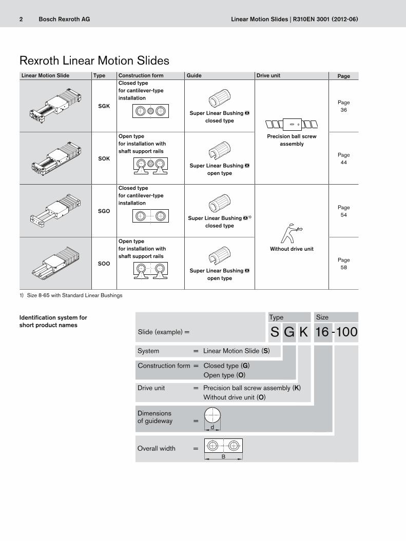
Rexroth Linear Motion SlidesLinear Motion Slide Type Construction form Guide Drive unit Page
SGK
Closed typefor cantilever-type installation
Super Linear Bushing aclosed type
Precision ball screw assembly
Page 36
SOK
Open typefor installation with shaft support rails
Super Linear Bushing aopen type
Page 44
SGO
Closed typefor cantilever-type installation
Super Linear Bushing a1)
closed type
Without drive unit
Page 54
SOO
Open typefor installation with shaft support rails
Super Linear Bushing aopen type
Page 58
1) Size 8-65 with Standard Linear Bushings
Identification system for short product names
Type Size
Slide (example) =
System = Linear Motion Slide (S)
Construction form = Closed type (G) Open type (O)
Drive unit = Precision ball screw assembly (K) Without drive unit (O)
Dimensions of guideway =
Overall width =
d
B
3Bosch Rexroth AGR310EN 3001 (2012-06) | Linear Motion Slides
Rexroth Linear Motion SlidesGeneral Product Description 4
Product Description 4
Product Overview, Motors and Controllers (Control Sys-tems) 6
Overview of Types with Load Capacities 8
Structural Design 10
Technical Data 12
Load Capacities and Moments 12
Drive Data 18
Deflection 20
Calculations 21
Calculation Principles 21
Sizing the Drive Unit 24
Calculation Example for Sizing the Drive Unit 29
Linear Motion Slide with Ball Screw Drive 34
Product Description 34
SGK 12-85 to SGK 20-130 36
SGK 25-160 to SGK 50-280 40
SOK 12-85 to SOK 20-130 44
SOK 25-160 to SOK 50-280 48
Motor attachment for SGK / SOK 25-160 to 50-280 52
Linear Motion Slide without Drive Unit 54
Product Description 54
SGO 8-65 to SGO 50-280 54
SOO 12-85 to SOO 50-280 58
Switch Mounting Arrangements 62
Overview of Switching System 62
Switch Mounting Arrangements SGK/SOK 64
Motors 66
IndraDyn S Servo Motors MSK 66
IndraDyn S Servo Motors MSM 68
Maintenance 70
Operating Conditions 70Normal operating conditions 70Design notes 70Intended use 70Misuse 70
Lubrication 71
Parameterization (start-up) 72
Documentation 73
Further Information 74
Inquiry/Order 76
Selection and Ordering Example 76
4 Bosch Rexroth AG Linear Motion Slides | R310EN 3001 (2012-06)
Product Description
Characteristic features
– Particularly smooth running and long service life thanks to Rexroth Super Linear Bushings
– Oil- and moisture-resistant PU bellows-type protective cover (the last fold is mechanically clamped)
– Ready-to-install Linear Motion Slides in any length up to Lmax
– Integrated Rexroth Super Linear Bushings – Version with drive unit includes Precision Ball Screw
Assembly
Further highlights – Greater flexibility due to options – One-point lubrication ports for the Super Linear
Bushings are provided on both sides of the carriage – Ready for installation with different attachments
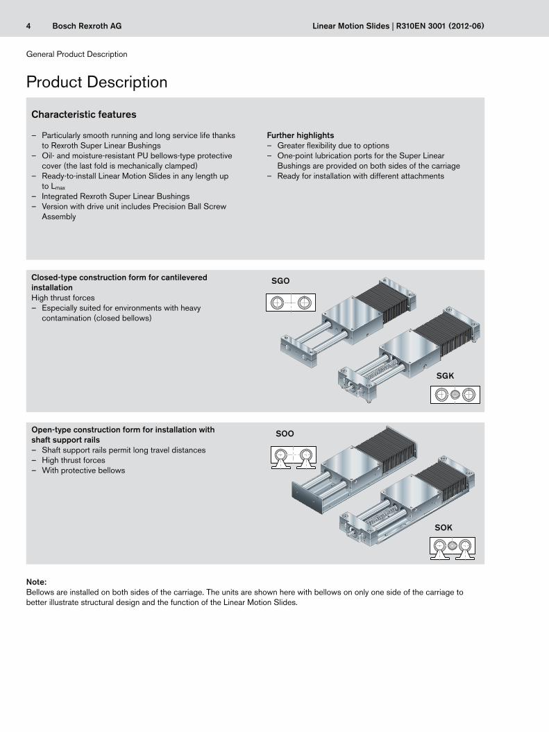
Closed-type construction form for cantilevered installationHigh thrust forces
– Especially suited for environments with heavy contamination (closed bellows)
SGK
SGO
Open-type construction form for installation with shaft support rails
– Shaft support rails permit long travel distances – High thrust forces – With protective bellows
SOO
SOK
General Product Description
Note:Bellows are installed on both sides of the carriage. The units are shown here with bellows on only one side of the carriage to better illustrate structural design and the function of the Linear Motion Slides.
5Bosch Rexroth AGR310EN 3001 (2012-06) | Linear Motion Slides
Delivery condition:
Instructions:
Length L:
General information
Linear motion slide with drive unit (closed and open construction form) SGK and SOK: The Linear Motion Slides with ball screw drive are delivered fully assembled. Also as-sembled are the bellows, motor attachment and motor, if these options were included in the order. All further attachments, such as switches, switching cams, cable ducts, etc., are delivered as separate parts along with the slide. Linear Motion Slides with drive unit are delivered prelubricated with grease.
Linear Motion Slide without drive unit (closed and open construction form) SGO and SOO:Linear Motion Slides without drive unit are delivered unassembled. Shafts and end blocks are provided. The carriage is mounted as a sub-assembly without pre-greasing. Initial grease lubrication must be performed by the customer in accordance with the instructions provided. If bellows have been ordered, these are mounted on frames and included in the delivery. Fastening screws are not included in scope of delivery. Linear Motion Slides without drive unit can also be supplied with corrosion-resistant steel shafts per DIN 17230 / EN 10088.For more information on Linear Bushings and precision steel shafts, see the “Linear Bushings and Shafts” catalog.
Linear Motion Slides in open construction form (with and without drive unit) SOK and SOO: The precision steel shafts are screw-fastened to the shaft support rails.
Linear Motion Slides consist of components of varying length and assemblies of fixed length. The length-dependent components are cut to size as required for each order. Linear Motion Slides can thus be custom-designed in any desired length (infinitely variable).Lengths in excess of the specified Lmax are available on request.
Each Linear Motion Slide is delivered complete with the relevant instructions for mounting and maintenance.
6 Bosch Rexroth AG Linear Motion Slides | R310EN 3001 (2012-06)
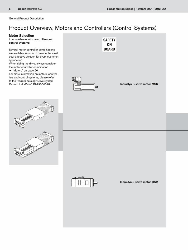
Product Overview, Motors and Controllers (Control Systems)
IndraDyn S servo motor MSK
IndraDyn S servo motor MSM
Motor Selectionin accordance with controllers and control systems
Several motor-controller combinations are available in order to provide the most cost-effective solution for every customer application.When sizing the drive, always consider the motor-controller combination ! “Motors” on page 66.For more information on motors, control-lers and control systems, please refer to the Rexroth catalog “Drive System Rexroth IndraDrive” R999000018.
General Product Description
7Bosch Rexroth AGR310EN 3001 (2012-06) | Linear Motion Slides
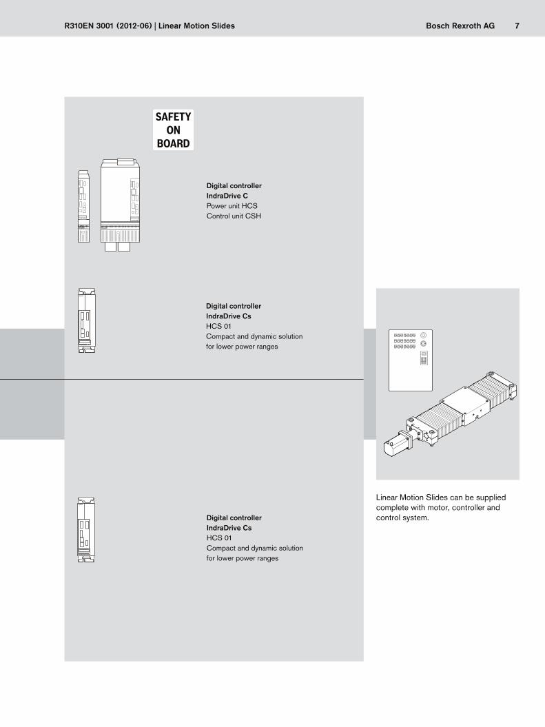
Digital controller IndraDrive CsHCS 01Compact and dynamic solution for lower power ranges
Digital controllerIndraDrive CPower unit HCSControl unit CSH
Linear Motion Slides can be supplied complete with motor, controller and control system.
Digital controllerIndraDrive CsHCS 01Compact and dynamic solution for lower power ranges
8 Bosch Rexroth AG
Fz
Mt
Mx
Fy
C
C
ML
Mz
ML
My
z
yx
Linear Motion Slides | R310EN 3001 (2012-06)
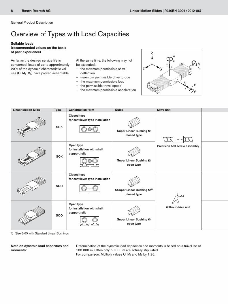
Overview of Types with Load CapacitiesSuitable loads (recommended values on the basis of past experience)
As far as the desired service life is concerned, loads of up to approximately 20% of the dynamic characteristic val-ues (C, Mt, ML) have proved acceptable.
At the same time, the following may not be exceeded:
– the maximum permissible shaft deflection
– maximum permissible drive torque – the maximum permissible load – the permissible travel speed – the maximum permissible acceleration
Determination of the dynamic load capacities and moments is based on a travel life of 100 000 m. Often only 50 000 m are actually stipulated.For comparison: Multiply values C, Mt and ML by 1.26.
Note on dynamic load capacities and moments:
General Product Description
Linear Motion Slide Type Construction form Guide Drive unit Type Size 8-65 12-85 16-100 20-130 25-160 30-180 40-230 50-280
SGK
Closed typefor cantilever-type installation
Super Linear Bushing aclosed type
Precision ball screw assembly
SGK
Maximum length Lmax (mm) 1 000 1 500 2 500 3 000 3 000 4 000 4 000
Dynamic load capacity C (N) 2 700 3 310 6 560 12 830 15 600 26 770 39 180
SOK
Open typefor installation with shaft support rails
Super Linear Bushing aopen type
SOK
Maximum length Lmax (mm) 1 000 1 500 2 500 3 000 3 000 4 000 4 000
Dynamic load capacity C (N) 2 850 3 440 6 100 11 950 14 520 24 950 36 380
SGO
Closed typefor cantilever-type installation
SSuper Linear Bushing a1)
closed type
Without drive unit
SGO
Maximum length Lmax (mm) 700 1 000 1 500 2 500 3 000 3 000 4 000 4 000
Dynamic load capacity C (N) 1 040 2700 3 310 6 560 12 830 15 600 26 770 39 180
SOO
Open typefor installation with shaft support rails
Super Linear Bushing aopen type
SOO
Maximum length Lmax (mm) 4 000 4 000 4 000 5 300 5 300 5 300 5 300
Dynamic load capacity C (N) 2 850 3 440 6 100 11 950 14 520 24 950 36 380
1) Size 8-65 with Standard Linear Bushings

9Bosch Rexroth AG
C'
C'
R310EN 3001 (2012-06) | Linear Motion Slides
The load capacities of the open versions are reduced as follows under lift-off loads:Sizes 12 and 16 C’ = 0.42 · CSizes 20 to 50 C’ = 0.60 · C
Linear Motion Slide Type Construction form Guide Drive unit Type Size 8-65 12-85 16-100 20-130 25-160 30-180 40-230 50-280
SGK
Closed typefor cantilever-type installation
Super Linear Bushing aclosed type
Precision ball screw assembly
SGK
Maximum length Lmax (mm) 1 000 1 500 2 500 3 000 3 000 4 000 4 000
Dynamic load capacity C (N) 2 700 3 310 6 560 12 830 15 600 26 770 39 180
SOK
Open typefor installation with shaft support rails
Super Linear Bushing aopen type
SOK
Maximum length Lmax (mm) 1 000 1 500 2 500 3 000 3 000 4 000 4 000
Dynamic load capacity C (N) 2 850 3 440 6 100 11 950 14 520 24 950 36 380
SGO
Closed typefor cantilever-type installation
SSuper Linear Bushing a1)
closed type
Without drive unit
SGO
Maximum length Lmax (mm) 700 1 000 1 500 2 500 3 000 3 000 4 000 4 000
Dynamic load capacity C (N) 1 040 2700 3 310 6 560 12 830 15 600 26 770 39 180
SOO
Open typefor installation with shaft support rails
Super Linear Bushing aopen type
SOO
Maximum length Lmax (mm) 4 000 4 000 4 000 5 300 5 300 5 300 5 300
Dynamic load capacity C (N) 2 850 3 440 6 100 11 950 14 520 24 950 36 380
10 Bosch Rexroth AG
B
A
2
7
3
1
8
13
910
11
4
5
6
12
14
16
14
15
Linear Motion Slides | R310EN 3001 (2012-06)
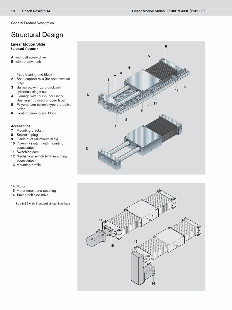
Structural Design
1 Fixed bearing end block2 Shaft support rails (for open version
only)3 Ball screw with zero-backlash
cylindrical single nut4 Carriage with four Super Linear
Bushings1) (closed or open type)5 Polyurethane bellows-type protective
cover6 Floating bearing end block
Accessories:
A with ball screw driveB without drive unit
Linear Motion Slide(closed / open)
7 Mounting bracket8 Socket + plug9 Cable duct (aluminum alloy)10 Proximity switch (with mounting
accessories)11 Switching cam12 Mechanical switch (with mounting
accessories)13 Mounting profile
14 Motor15 Motor mount and coupling16 Timing belt side drive
1) Size 8-65 with Standard Linear Bushings
General Product Description
11Bosch Rexroth AG
2 31 4
6
7
Fpr
4
1
3
5
8
2
9
R310EN 3001 (2012-06) | Linear Motion Slides
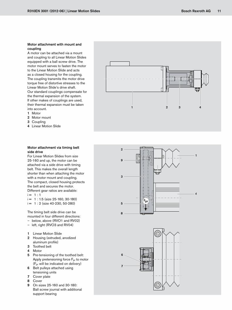
Motor attachment with mount and couplingA motor can be attached via a mount and coupling to all Linear Motion Slides equipped with a ball screw drive. The motor mount serves to fasten the motor to the Linear Motion Slide and acts as a closed housing for the coupling. The coupling transmits the motor drive torque free of distortive stresses to the Linear Motion Slide’s drive shaft.Our standard couplings compensate for the thermal expansion of the system.If other makes of couplings are used, their thermal expansion must be taken into account.1 Motor2 Motor mount3 Coupling4 Linear Motion Slide
Motor attachment via timing belt side driveFor Linear Motion Slides from size 25-160 and up, the motor can be attached via a side drive with timing belt. This makes the overall length shorter than when attaching the motor with a motor mount and coupling.The compact, closed housing protects the belt and secures the motor. Different gear ratios are available:i = 1 : 1i = 1 : 1.5 (size 25-160, 30-180)i = 1 : 2 (size 40-230, 50-280) The timing belt side drive can be mounted in four different directions:
– below, above (RVO1 and RV02) – left, right (RVO3 and RV04)
1 Linear Motion Slide2 Housing (extruded, anodized
aluminum profile)3 Toothed belt4 Motor5 Pre-tensioning of the toothed belt:
Apply pretensioning force Fpr to motor (Fpr will be indicated on delivery)
6 Belt pulleys attached using tensioning units
7 Cover plate8 Cover9 On sizes 25-160 and 30-180:
Ball screw journal with additional support bearing
12 Bosch Rexroth AG
z
yx
Fz
Mt
Mx
Fy
C
C
ML
Mz
ML
My
Linear Motion Slides | R310EN 3001 (2012-06)
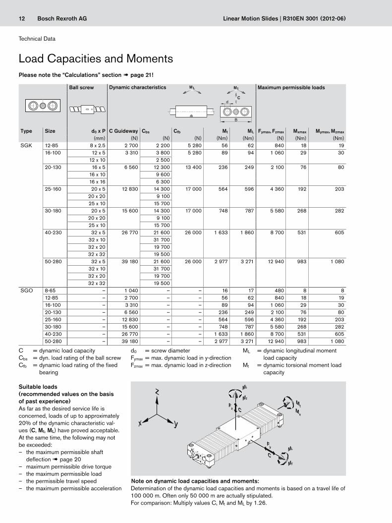
Load Capacities and Moments
Determination of the dynamic load capacities and moments is based on a travel life of 100 000 m. Often only 50 000 m are actually stipulated.For comparison: Multiply values C, Mt and ML by 1.26.
Note on dynamic load capacities and moments:
Please note the “Calculations” section ! page 21!
Suitable loads (recommended values on the basis of past experience)As far as the desired service life is concerned, loads of up to approximately 20% of the dynamic characteristic val-ues (C, Mt, ML) have proved acceptable.At the same time, the following may not be exceeded:
– the maximum permissible shaft deflection ! page 20
– maximum permissible drive torque – the maximum permissible load – the permissible travel speed – the maximum permissible acceleration
Technical Data
Ball screw Dynamic characteristics MtML
C
B
d
Maximum permissible loads Ball screw Dynamic characteristics
B
d
MtML
C
Maximum permissible loads
Type Size d0 x P C Guideway Cbs Cfb Mt ML Fymax, Fzmax Mxmax Mymax, Mzmax Type Size d0 x P C Guideway Cbs Cfb Mt ML Fymax, Fzmax Mxmax Mymax, Mzmax
(mm) (N) (N) (N) (Nm) (Nm) (N) (Nm) (Nm) (mm) (N) (N) (N) (Nm) (Nm) (N) (Nm) (Nm)SGK 12-85 8 x 2.5 2 700 2 200 5 280 56 62 840 18 19 SOK 12-85 8 x 2.5 2 850 2 200 5 280 25 27 1 020 10 11
16-100 12 x 5 3 310 3 800 5 280 89 94 1 060 29 30 16-100 12 x 5 3 440 3 800 5 280 39 41 1 260 16 1712 x 10 2 500 12 x 10 2 500
20-130 16 x 5 6 560 12 300 13 400 236 249 2 100 76 80 20-130 16 x 5 6 100 12 300 13 400 134 141 2 140 49 5216 x 10 9 600 16 x 10 9 60016 x 16 6 300 16 x 16 6 300
25-160 20 x 5 12 830 14 300 17 000 564 596 4 360 192 203 25-160 20 x 5 11 950 14 300 17 000 320 339 4 500 127 13420 x 20 9 100 20 x 20 9 10025 x 10 15 700 25 x 10 15 700
30-180 20 x 5 15 600 14 300 17 000 748 787 5 580 268 282 30-180 20 x 5 14 520 14 300 17 000 425 447 5 760 177 18620 x 20 9 100 20 x 20 9 10025 x 10 15 700 25 x 10 15 700
40-230 32 x 5 26 770 21 600 26 000 1 633 1 860 8 700 531 605 40-230 32 x 5 24 950 21 600 26 000 928 1 057 8 960 350 39932 x 10 31 700 32 x 10 31 70032 x 20 19 700 32 x 20 19 70032 x 32 19 500 32 x 32 19 500
50-280 32 x 5 39 180 21 600 26 000 2 977 3 271 12 940 983 1 080 50-280 32 x 5 36 380 21 600 26 000 1 687 1 853 13 240 644 70832 x 10 31 700 32 x 10 31 70032 x 20 19 700 32 x 20 19 70032 x 32 19 500 32 x 32 19 500
SGO 8-65 – 1 040 – – 16 17 480 8 8 SOO 8-65 – – – – – – – – –12-85 – 2 700 – – 56 62 840 18 19 12-85 – 2 850 – – 25 27 1 020 10 1116-100 – 3 310 – – 89 94 1 060 29 30 16-100 – 3 440 – – 39 41 1 260 16 1720-130 – 6 560 – – 236 249 2 100 76 80 20-130 – 6 100 – – 134 141 2 140 49 5225-160 – 12 830 – – 564 596 4 360 192 203 25-160 – 11 950 – – 320 339 4 500 127 13430-180 – 15 600 – – 748 787 5 580 268 282 30-180 – 14 520 – – 425 447 5 760 177 18640-230 – 26 770 – – 1 633 1 860 8 700 531 605 40-230 – 24 950 – – 928 1 057 8 960 350 39950-280 – 39 180 – – 2 977 3 271 12 940 983 1 080 50-280 – 36 380 – – 1 687 1 853 13 240 644 708
C = dynamic load capacityCbs = dyn. load rating of the ball screwCfb = dynamic load rating of the fixed
bearing
d0 = screw diameterFymax = max. dynamic load in y-directionFzmax = max. dynamic load in z-direction
ML = dynamic longitudinal moment load capacity
Mt = dynamic torsional moment load capacity
13Bosch Rexroth AG
12 16 20 25 30 40 50
0 20 40 60 80 100 120 140 180 200 220 240 260160
1,0
0,9
0,8
0,7
0,6
0,5
fw
C'
C'
R310EN 3001 (2012-06) | Linear Motion Slides
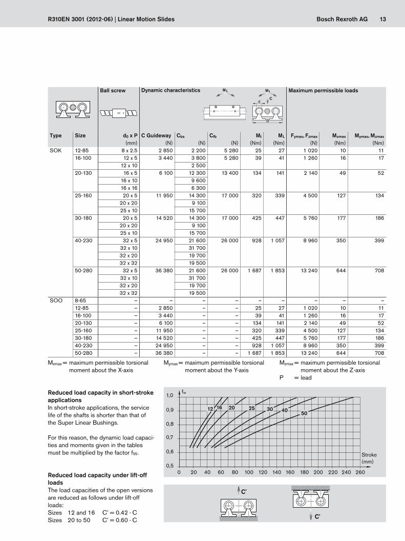
Reduced load capacity in short-stroke applications In short-stroke applications, the service life of the shafts is shorter than that of the Super Linear Bushings.
For this reason, the dynamic load capaci-ties and moments given in the tables must be multiplied by the factor fW.
Reduced load capacity under lift-off loadsThe load capacities of the open versions are reduced as follows under lift-off loads:Sizes 12 and 16 C’ = 0.42 · CSizes 20 to 50 C’ = 0.60 · C
Stroke (mm)
Ball screw Dynamic characteristics MtML
C
B
d
Maximum permissible loads Ball screw Dynamic characteristics
B
d
MtML
C
Maximum permissible loads
Type Size d0 x P C Guideway Cbs Cfb Mt ML Fymax, Fzmax Mxmax Mymax, Mzmax Type Size d0 x P C Guideway Cbs Cfb Mt ML Fymax, Fzmax Mxmax Mymax, Mzmax
(mm) (N) (N) (N) (Nm) (Nm) (N) (Nm) (Nm) (mm) (N) (N) (N) (Nm) (Nm) (N) (Nm) (Nm)SGK 12-85 8 x 2.5 2 700 2 200 5 280 56 62 840 18 19 SOK 12-85 8 x 2.5 2 850 2 200 5 280 25 27 1 020 10 11
16-100 12 x 5 3 310 3 800 5 280 89 94 1 060 29 30 16-100 12 x 5 3 440 3 800 5 280 39 41 1 260 16 1712 x 10 2 500 12 x 10 2 500
20-130 16 x 5 6 560 12 300 13 400 236 249 2 100 76 80 20-130 16 x 5 6 100 12 300 13 400 134 141 2 140 49 5216 x 10 9 600 16 x 10 9 60016 x 16 6 300 16 x 16 6 300
25-160 20 x 5 12 830 14 300 17 000 564 596 4 360 192 203 25-160 20 x 5 11 950 14 300 17 000 320 339 4 500 127 13420 x 20 9 100 20 x 20 9 10025 x 10 15 700 25 x 10 15 700
30-180 20 x 5 15 600 14 300 17 000 748 787 5 580 268 282 30-180 20 x 5 14 520 14 300 17 000 425 447 5 760 177 18620 x 20 9 100 20 x 20 9 10025 x 10 15 700 25 x 10 15 700
40-230 32 x 5 26 770 21 600 26 000 1 633 1 860 8 700 531 605 40-230 32 x 5 24 950 21 600 26 000 928 1 057 8 960 350 39932 x 10 31 700 32 x 10 31 70032 x 20 19 700 32 x 20 19 70032 x 32 19 500 32 x 32 19 500
50-280 32 x 5 39 180 21 600 26 000 2 977 3 271 12 940 983 1 080 50-280 32 x 5 36 380 21 600 26 000 1 687 1 853 13 240 644 70832 x 10 31 700 32 x 10 31 70032 x 20 19 700 32 x 20 19 70032 x 32 19 500 32 x 32 19 500
SGO 8-65 – 1 040 – – 16 17 480 8 8 SOO 8-65 – – – – – – – – –12-85 – 2 700 – – 56 62 840 18 19 12-85 – 2 850 – – 25 27 1 020 10 1116-100 – 3 310 – – 89 94 1 060 29 30 16-100 – 3 440 – – 39 41 1 260 16 1720-130 – 6 560 – – 236 249 2 100 76 80 20-130 – 6 100 – – 134 141 2 140 49 5225-160 – 12 830 – – 564 596 4 360 192 203 25-160 – 11 950 – – 320 339 4 500 127 13430-180 – 15 600 – – 748 787 5 580 268 282 30-180 – 14 520 – – 425 447 5 760 177 18640-230 – 26 770 – – 1 633 1 860 8 700 531 605 40-230 – 24 950 – – 928 1 057 8 960 350 39950-280 – 39 180 – – 2 977 3 271 12 940 983 1 080 50-280 – 36 380 – – 1 687 1 853 13 240 644 708
Mxmax = maximum permissible torsional moment about the X-axis
Mymax = maximum permissible torsional moment about the Y-axis
Mzmax = maximum permissible torsional moment about the Z-axis
P = lead
14 Bosch Rexroth AG Linear Motion Slides | R310EN 3001 (2012-06)
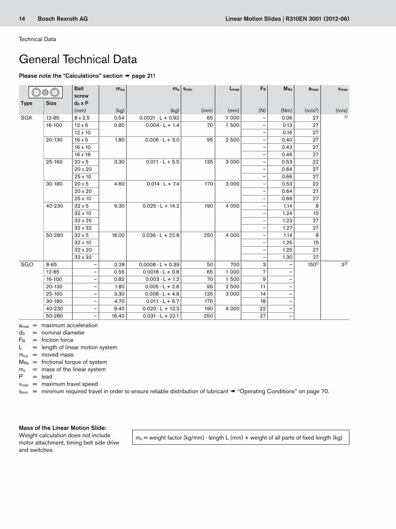
General Technical Data
Mass of the Linear Motion Slide:Weight calculation does not include motor attachment, timing belt side drive and switches.
ms = weight factor (kg/mm) · length L (mm) + weight of all parts of fixed length (kg)
Technical Data
Ballscrew
mca ms smin Lmax FR MRs amax vmax
Type Size d0 x P(mm) (kg) (kg) (mm) (mm) (N) (Nm) (m/s2) (m/s)
SGK 12-85 8 x 2.5 0.54 0.0021 · L + 0.92 65 1 000 – 0.06 27 2)
16-100 12 x 5 0.80 0.004 · L + 1.4 70 1 500 – 0.13 2712 x 10 – 0.16 27
20-130 16 x 5 1.80 0.006 · L + 3.0 95 2 500 – 0.40 2716 x 10 – 0.43 2716 x 16 – 0.46 27
25-160 20 x 5 3.30 0.011 · L + 5.5 135 3 000 – 0.53 2220 x 20 – 0.64 2725 x 10 – 0.66 27
30-180 20 x 5 4.60 0.014 · L + 7.4 170 3 000 – 0.53 2220 x 20 – 0.64 2725 x 10 – 0.66 27
40-230 32 x 5 9.30 0.025 · L + 14.2 190 4 000 – 1.14 832 x 10 – 1.24 1532 x 20 – 1.23 2732 x 32 – 1.27 27
50-280 32 x 5 16.00 0.036 · L + 22.8 250 4 000 – 1.14 832 x 10 – 1.25 1532 x 20 – 1.25 2732 x 32 – 1.30 27
SGO 8-65 – 0.28 0.0008 · L + 0.39 50 700 3 – 1501) 33)
12-85 – 0.55 0.0018 · L + 0.8 65 1 000 7 –16-100 – 0.82 0.003 · L + 1.2 70 1 500 9 –20-130 – 1.80 0.005 · L + 2.6 95 2 500 11 –25-160 – 3.30 0.008 · L + 4.8 135 3 000 14 –30-180 – 4.70 0.011 · L + 6.7 170 18 –40-230 – 9.40 0.020 · L + 13.3 190 4 000 22 –50-280 – 16.40 0.031 · L + 22.1 250 27 –
amax = maximum accelerationd0 = nominal diameterFR = friction forceL = length of linear motion systemmca = moved massMRs = frictional torque of systemms = mass of the linear systemP = leadvmax = maximum travel speedsmin = minimum required travel in order to ensure reliable distribution of lubricant ! “Operating Conditions” on page 70.
Please note the “Calculations” section ! page 21!

15Bosch Rexroth AGR310EN 3001 (2012-06) | Linear Motion Slides
Ball screw
mca ms smin Lmax. FR MRs amax vmax
Type Size d0 x P(mm) (kg) (kg) (mm) (mm) (N) (Nm) (m/s2) (m/s)
SOK 12-85 8 x 2.5 0.47 0.0040 · L + 0.82 65 1 000 – 0.06 27 2)
16-100 12 x 5 0.76 0.006 · L + 1.3 70 1 500 – 0.13 2712 x 10 – 0.16 27
20-130 16 x 5 1.60 0.010 · L + 2.7 95 2 500 – 0.40 2716 x 10 – 0.43 2716 x 16 – 0.46 27
25-160 20 x 5 2.90 0.015 · L + 5.0 135 3 000 – 0.53 2220 x 20 – 0.64 2725 x 10 – 0.66 27
30-180 20 x 5 4.20 0.020 · L + 6.8 170 3 000 – 0.53 2220 x 20 – 0.64 2725 x 10 – 0.66 27
40-230 32 x 5 8.50 0.032 · L + 13.2 190 4 000 – 1.14 832 x 10 – 1.24 1532 x 20 – 1.23 2732 x 32 – 1.27 27
50-280 32 x 5 14.80 0.046 · L + 21.3 250 4 000 – 1.14 832 x 10 – 1.25 1532 x 20 – 1.25 2732 x 32 – 1.30 27
SOO 12-85 – 0.47 0.0035 · L + 0.47 65 4 000 7 – 1501) 33)
16-100 – 0.75 0.005 · L + 0.75 70 9 –20-130 – 1.60 0.008 · L + 1.6 95 11 –25-160 – 2.80 0.011 · L + 2.8 135 5 300 14 –30-180 – 4.10 0.016 · L + 4.1 170 18 –40-230 – 8.30 0.026 · L + 8.3 190 22 –50-280 – 14.80 0.039 · L + 14.8 250 27 –
1) Linear Motion Slides without drive unit SGO/SOO differ from the SGK/SOK models as they have no ball screw drive acting as a limiting factor for the acceleration.
2) vmax ! graphs on page 17 3) Travel speeds of up to 5 m/s are possible. Service life is limited by the increased wear on plastic parts.
16 Bosch Rexroth AG
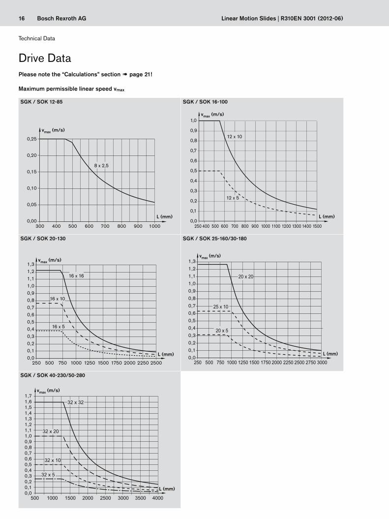
SGK / SOK 12-85 SGK / SOK 16-100
300
0,25
0,20
0,15
0,10
0,05
0,00400 500 600 700 800
vmax (m/s)
L (mm)
900 1000
8 x 2,5
1,0
0,9
0,8
0,7
0,6
0,5
0,4
0,3
0,2
0,1
0,0500400250
12 x 5
12 x 10
600 700 800 900 1000 1100 1200 1300 1400 1500
L (mm)
vmax (m/s)
SGK / SOK 20-130 SGK / SOK 25-160/30-180
1,31,21,11,00,90,80,70,60,50,40,30,20,10,0
16 x 10
16 x 5
16 x 16
500250 750 1000 1250 2000 22501500 1750 2500
L (mm)
vmax (m/s)
500250 1000 1500 25002000 30001250 1750 27502250750
20 x 20
25 x 10
20 x 5
1,31,21,11,00,90,80,70,60,50,40,30,20,10,0
L (mm)
vmax (m/s)
SGK / SOK 40-230/50-280
1000500
32 x 32
32 x 20
32 x 10
32 x 5
1500 2500 35002000 3000 4000
1,71,61,51,41,31,21,11,00,90,80,70,60,50,40,30,20,10,0
L (mm)
vmax (m/s)
Linear Motion Slides | R310EN 3001 (2012-06)
Maximum permissible linear speed vmax
Technical Data
Drive DataPlease note the “Calculations” section ! page 21!
17Bosch Rexroth AG
SGK / SOK 12-85 SGK / SOK 16-100
Mp (Nm)
8 x 2,5
300200100 400 500 600 700 800 900 1000
0,9
0,8
0,7
0,6
0,5
0,4
0,3
0,2
0,1
0,0L (mm)
Mp (Nm)3,5
3,0
2,5
2,0
1,5
1,0
0,5
0,0
12 x 5
L (mm)
250 500 750 1000 1250 1500
12 x 10
SGK / SOK 20-1301) SGK / SOK 25-160/ 30-1802)
L (mm)
500
7,0
6,0
5,0
4,0
3,0
2,0
1,0
0,0750250 1000 1250 1500 1750 2000 2250 2500
KGT 16x16
KGT 16x10
KGT 16x5
Mp (Nm) Mp (Nm)
0,0
2,0
4,0
6,0
8,0
10,0
12,0
L (mm)
500250 750 1000 1250 1500 1750 2000 2250 2500 2750 3000
KGT 20x20
KGT 20x5
KGT 25x10
SGK / SOK 40-230/ 50-2803)
Mp (Nm)
0,0
5,0
10,0
15,0
20,0
25,0
30,0
35,0
40,0
45,0
50,0
55,0
60,0
L (mm)1000500 1500 2000 2500 3000 3500 4000
KGT 32x32
KGT 32x20
KGT 32x10
KGT 32x5
R310EN 3001 (2012-06) | Linear Motion Slides
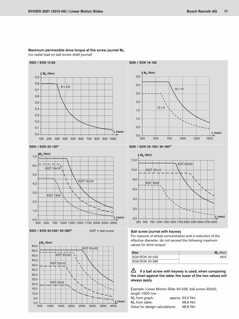
Maximum permissible drive torque at the screw journal Mp
(no radial load on ball screw shaft journal)
c If a ball screw with keyway is used, when comparing the chart against the table, the lower of the two values will always apply.
Ball screw journal with keywayFor reasons of stress concentration and a reduction of the effective diameter, do not exceed the following maximum values for drive torque!
Example: Linear Motion Slide 40-230, ball screw 32x20, length 1500 mm.Mp from graph: approx. 53.0 NmMp from table: 48.6 NmValue for design calculations: 48.6 Nm
Size Mp (Nm)SGK/SOK 40-230 48.6SGK/SOK 50-280
KGT = ball screw

18 Bosch Rexroth AG Linear Motion Slides | R310EN 3001 (2012-06)
Motor attachment via timing belt side drive (on fixed bearing side of the Linear Motion Slide)
Bt = belt typei = gear ratio of timing belt side driveJc = mass moment of inertia, couplingJsd = reduced mass moment of inertia of timing belt side
drive at motor journalF = width of belt pulley housing (! page 52)
McN = rated torque of coupling mfc = mass of motor mount and couplingMRsd = frictional torque of timing belt side drive at motor journalMsd = maximum permissible drive torque of the timing belt
side drivemsd = mass of timing belt side drive
1) Values for Msd do not take motor torque into account.2) For longer lengths, the permitted drive torque is determined by the length-dependent value Mp of the linear system as given in the graphs
! graphs in “Drive Data” section, page 17.
Linear Motion Slide Motor type McN Jc mfc
(Nm) (10–6 kgm2) (kg)SGK/SOK 12-85 MSM 031B-0300 3.7 7 0.3SGK/SOK 16-100SGK/SOK 20-130 MSK 030C-0900 19.0 57 0.5
MSK 040C-0600 0.6MSM 031C-0300 0.5MSM 041B-0300 0.7
SGK/SOK 25-160 MSM 041B-0300 19.0 57 0.8MSK 040C-0600
SGK/SOK 30-180 MSM 041B-0300MSK 040C-0600
SGK/SOK 40-230 MSK 060C-0600 50.0 200 1.7MSK 076C-0450 98.0 390 2.2
SGK/SOK 50-280 MSK 060C-0600 50.0 200 1.7MSK 076C-0450 98.0 390 2.2
Motor attachment via motor mount and coupling (on fixed bearing side of the Linear Motion Slide)The couplings with the specifications shown in the table are used with standard motors.
Technical Data
Drive Data
MSK 040C-0600, MSM 041B-0300
Msd1) Jsd MRsd msd F Bt
Ball screw up to L2) (Nm) (10–6 kgm2) (Nm) (kg) (mm)d0 x P (mm) i = 1 i =1.5 i =1 i =1.5
SGK/SOK 25-160 SGK/SOK 30-180
20 x 5 1000 6.61 4.41250 84 0.4 1.5 88 16 AT520 x 20 1800
8.22 5.4825 x 10 2200
MSK 060C-0600
Msd1) Jsd MRsd msd F Bt
Ball screw up to L2) (Nm) (10–6 kgm2) (Nm) (kg) (mm)d0 x P (mm) i = 1 i = 2 i = 1 i = 2 i = 1 i = 2
SGK/SOK 40-230 SGK/SOK 50-280
32 x 5 1800 19.10 9.55
1400 260 0.5 3.8 116 25 AT5 32 AT532 x 10 220032 x 20 3000 19.21 12.3032 x 32 3800
Please note the “Calculations” section ! page 21!
19Bosch Rexroth AG
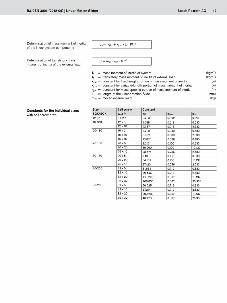
Jt = mex · kj m · 10–6
Js = (kj fix + kj var · L)· 10–6
R310EN 3001 (2012-06) | Linear Motion Slides
Constants for the individual sizes SizeSGK/SOK
Ball screwd0 x P
Constantkj fix kj var kj m
12-85 8 x 2.5 0.203 0.002 0.15816-100 12 x 5 1.088 0.013 0.633
12 x 10 2.367 0.013 2.53320-130 16 x 5 3.238 0.039 0.633
16 x 10 6.692 0.039 2.53316 x 16 13.878 0.039 6.485
25-160 20 x 5 8.216 0.100 0.63320 x 20 39.990 0.100 10.13225 x 10 23.575 0.256 2.533
30-180 20 x 5 9.103 0.100 0.63320 x 20 54.169 0.100 10.13225 x 10 27.120 0.256 2.533
40-230 32 x 5 51.853 0.712 0.63332 x 10 69.446 0.712 2.53332 x 20 138.210 0.667 10.13232 x 32 268.830 0.667 25.938
50-280 32 x 5 56.025 0.712 0.63332 x 10 87.214 0.712 2.53332 x 20 209.280 0.667 10.13232 x 32 468.780 0.667 25.938
with ball screw drive
Js = mass moment of inertia of system (kgm2)Jt = translatory mass moment of inertia of external load (kgm2)kj fix = constant for fixed-length portion of mass moment of inertia (–)kj var = constant for variable-length portion of mass moment of inertia (–)kj m = constant for mass-specific portion of mass moment of inertia (–)L = length of the Linear Motion Slide (mm)mex = moved external load (kg)
Determination of translatory mass moment of inertia of the external load
Determination of mass moment of inertia of the linear system components
20 Bosch Rexroth AG
F
α
L / 2
L
tan α ≤ tanαmax
tan α ≤ tan αmax
Linear Motion Slides | R310EN 3001 (2012-06)
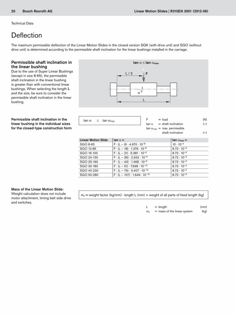
Due to the use of Super Linear Bushings (except in size 8-65), the permissible shaft inclination in the linear bushing is greater than with conventional linear bushings. When selecting the length L and the size, be sure to consider the permissible shaft inclination in the linear bushing.
Permissible shaft inclination in the linear bushing
Permissible shaft inclination in the linear bushing in the individual sizes for the closed-type construction form
Linear Motion Slide tan α = tan αmax =SGO 8-65 F · (L – 9) · 4.970 · 10–8 10 · 10–4
SGO 12-85 F · (L – 18) · 1.376 · 10–8 8.72 · 10–3
SGO 16-100 F · (L – 21) · 5.381 · 10–9 8.72 · 10–3
SGO 20-130 F · (L – 36) · 2.932 · 10–9 8.72 · 10–3
SGO 25-160 F · (L – 43) · 1.468 · 10–9 8.72 · 10–3
SGO 30-180 F · (L – 51) · 7.698 · 10–10 8.72 · 10–3
SGO 40-230 F · (L – 79) · 3.407 · 10–10 8.72 · 10–3
SGO 50-280 F · (L – 107) · 1.649 · 10–10 8.72 · 10–3
F = load (N)tan a = shaft inclination (—)tan amax = max. permissible
shaft inclination (—)
L = length (mm)ms = mass of the linear system (kg)
Mass of the Linear Motion Slide:Weight calculation does not include motor attachment, timing belt side drive and switches.
ms = weight factor (kg/mm) · length L (mm) + weight of all parts of fixed length (kg)
Deflection
Technical Data
The maximum permissible deflection of the Linear Motion Slides in the closed version SGK (with drive unit) and SGO (without drive unit) is determined according to the permissible shaft inclination for the linear bushings installed in the carriage.
21Bosch Rexroth AGR310EN 3001 (2012-06) | Linear Motion Slides
Calculations
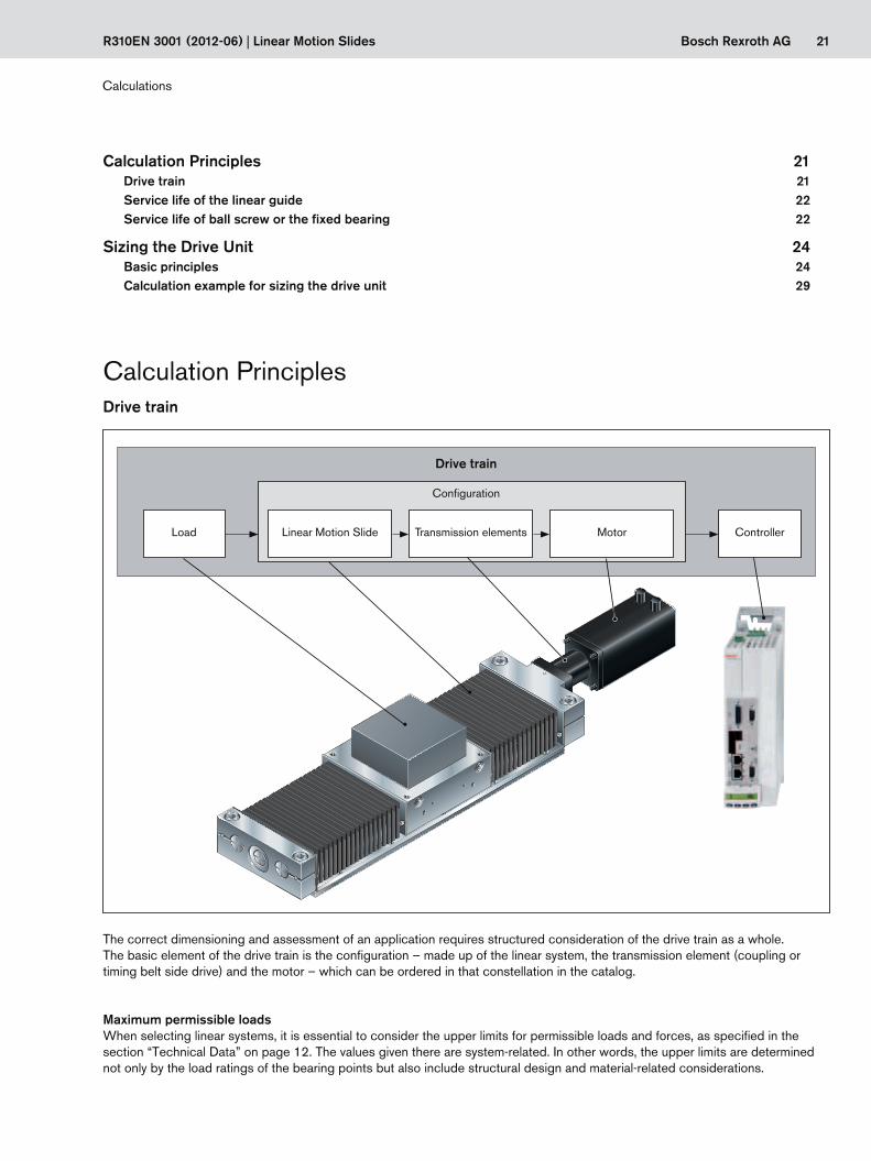
Calculation Principles
Load Linear Motion Slide
Configuration
Drive train
Transmission elements Motor Controller
Drive train
The correct dimensioning and assessment of an application requires structured consideration of the drive train as a whole.The basic element of the drive train is the configuration – made up of the linear system, the transmission element (coupling or timing belt side drive) and the motor – which can be ordered in that constellation in the catalog.
Maximum permissible loadsWhen selecting linear systems, it is essential to consider the upper limits for permissible loads and forces, as specified in the section “Technical Data” on page 12. The values given there are system-related. In other words, the upper limits are determined not only by the load ratings of the bearing points but also include structural design and material-related considerations.
Calculation Principles 21Drive train 21Service life of the linear guide 22Service life of ball screw or the fixed bearing 22
Sizing the Drive Unit 24Basic principles 24Calculation example for sizing the drive unit 29
22 Bosch Rexroth AG
Fz
Mt
Mx
Fy
C
C
ML
Mz
ML
My
L10 =( ) · 105CFcomb
3
L10h = 3600 · vm
L10
Fcomb = Fy + Fz + C · + C · + C ·Mx
Mt
My
ML
Mz
ML
t1
n1 n3
nm
n2
t2 t3
n1 ... n =nA1 ... n + nE1 ... n
2
Linear Motion Slides | R310EN 3001 (2012-06)
Combined equivalent load on bearing of the linear guide
Nominal lifeNominal life in meters
C = dynamic load capacity (N)Fcomb = combined equivalent load
on bearing (N)Fy = load due to a resulting force
in the y-direction (N)Fz = load due to a resulting force
in the z-direction (N)L10 = nominal life (m)L10h = nominal life (h)ML = dynamic longitudinal
moment load (Nm)Mt = dynamic torsional
moment load (Nm)Mx = dynamic torsional moment
about the X-axis (Nm)My = dynamic torsional moment
about the Y-axis (Nm)Mz = dynamic torsional moment
about the Z-axis (Nm)vm = average travel speed (m/s)
Calculations
Nominal life in hours
Service life of the linear guideThe linear guide of a linear system must bear the load and any processing forces.
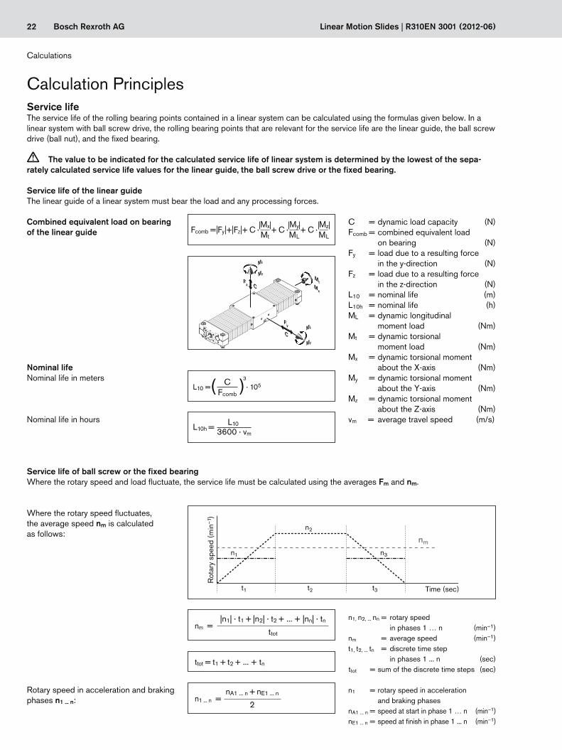
Service life of ball screw or the fixed bearingWhere the rotary speed and load fluctuate, the service life must be calculated using the averages Fm and nm.
Rot
ary
spee
d (m
in–1
)
Time (sec)
Where the rotary speed fluctuates, the average speed nm is calculated as follows:
Rotary speed in acceleration and braking phases n1 ... n:
n1 = rotary speed in acceleration and braking phases
nA1 ... n = speed at start in phase 1 … n (min–1)nE1 ... n = speed at finish in phase 1 ... n (min–1)
Service lifeThe service life of the rolling bearing points contained in a linear system can be calculated using the formulas given below. In a linear system with ball screw drive, the rolling bearing points that are relevant for the service life are the linear guide, the ball screw drive (ball nut), and the fixed bearing.
c The value to be indicated for the calculated service life of linear system is determined by the lowest of the sepa-rately calculated service life values for the linear guide, the ball screw drive or the fixed bearing.
Calculation Principles
n1, n2, ... nn = rotary speed in phases 1 … n (min–1)
nm = average speed (min–1)t1, t2, ... tn = discrete time step
in phases 1 ... n (sec)ttot = sum of the discrete time steps (sec)
nm =|n1| · t1 + |n2| · t2 + ... + |nn| · tn
ttot
ttot = t1 + t2 + ... + tn
23Bosch Rexroth AG
L10h = L10
nm · 60
L10 = ( )3 · 106C
Fm
t1
F1
F3 Fm
F2
t2 t3
R310EN 3001 (2012-06) | Linear Motion Slides
Load
(N
)
Time (sec)
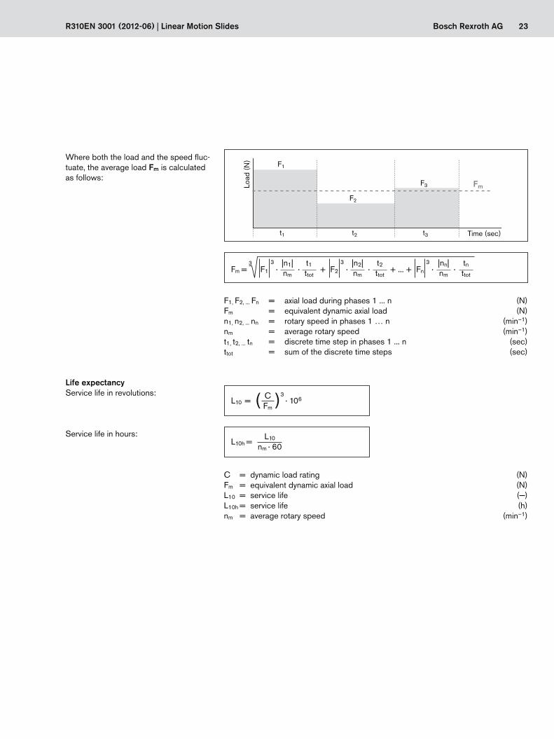
Where both the load and the speed fluc-tuate, the average load Fm is calculated as follows:
Life expectancyService life in revolutions:
Service life in hours:
F1, F2, ... Fn = axial load during phases 1 ... n (N)Fm = equivalent dynamic axial load (N)n1, n2, ... nn = rotary speed in phases 1 … n (min–1)nm = average rotary speed (min–1)t1, t2, ... tn = discrete time step in phases 1 ... n (sec)ttot = sum of the discrete time steps (sec)
C = dynamic load rating (N)Fm = equivalent dynamic axial load (N)L10 = service life (—)L10h = service life (h)nm = average rotary speed (min–1)
Fm = 3 F1
3 · · + F2
3 · · + ... + Fn
3 · ·
|n1|nm
|n2|nm
|nn|nm
t1ttot
t2ttot
tnttot
24 Bosch Rexroth AG Linear Motion Slides | R310EN 3001 (2012-06)
Load Linear Motion Slide
Mechanical system Drive unit
Drive train
Transmission elements
Drive sizing referred to the motor shaft
Motor Controller
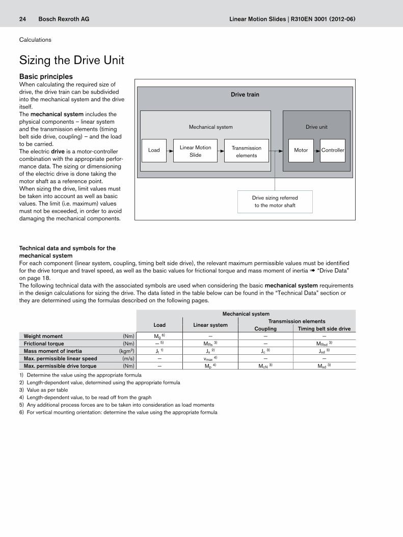
Basic principlesWhen calculating the required size of drive, the drive train can be subdivided into the mechanical system and the drive itself.The mechanical system includes the physical components – linear system and the transmission elements (timing belt side drive, coupling) – and the load to be carried.The electric drive is a motor-controller combination with the appropriate perfor-mance data. The sizing or dimensioning of the electric drive is done taking the motor shaft as a reference point.When sizing the drive, limit values must be taken into account as well as basic values. The limit (i.e. maximum) values must not be exceeded, in order to avoid damaging the mechanical components.
Technical data and symbols for the mechanical system
Mechanical system
Load Linear systemTransmission elements
Coupling Timing belt side driveWeight moment (Nm) Mg 6) — — —Frictional torque (Nm) — 5) MRs 3) — MRsd 3)
Mass moment of inertia (kgm2) Jt 1) Js 2) Jc 3) Jsd 3)
Max. permissible linear speed (m/s) — vmax 4) — —Max. permissible drive torque (Nm) — Mp 4) McN 3) Msd 3)
1) Determine the value using the appropriate formula2) Length-dependent value, determined using the appropriate formula3) Value as per table4) Length-dependent value, to be read off from the graph5) Any additional process forces are to be taken into consideration as load moments6) For vertical mounting orientation: determine the value using the appropriate formula
For each component (linear system, coupling, timing belt side drive), the relevant maximum permissible values must be identified for the drive torque and travel speed, as well as the basic values for frictional torque and mass moment of inertia ! “Drive Data” on page 18.The following technical data with the associated symbols are used when considering the basic mechanical system requirements in the design calculations for sizing the drive. The data listed in the table below can be found in the “Technical Data” section or they are determined using the formulas described on the following pages.
Sizing the Drive Unit
Calculations
25Bosch Rexroth AG
MR = MRs
Jex = Js + Jt + Jc
Js = (kj fix + kj var · L)· 10–6
Jt = mex · kj m · 10–6
MR = MRsd +MRs
i
Jex = Jsd + (Js + Jt)
i2
R310EN 3001 (2012-06) | Linear Motion Slides
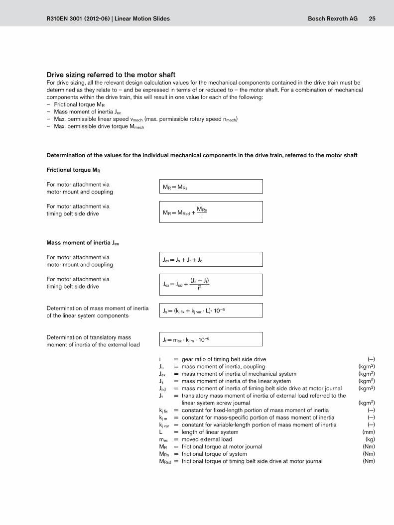
Drive sizing referred to the motor shaftFor drive sizing, all the relevant design calculation values for the mechanical components contained in the drive train must be determined as they relate to – and be expressed in terms of or reduced to – the motor shaft. For a combination of mechanical components within the drive train, this will result in one value for each of the following:
– Frictional torque MR
– Mass moment of inertia Jex
– Max. permissible linear speed vmech (max. permissible rotary speed nmech) – Max. permissible drive torque Mmech
Frictional torque MR
Determination of translatory mass moment of inertia of the external load
Determination of mass moment of inertia of the linear system components
For motor attachment via timing belt side drive
For motor attachment via motor mount and coupling
Mass moment of inertia Jex
For motor attachment via timing belt side drive
For motor attachment via motor mount and coupling
i = gear ratio of timing belt side drive (—) Jc = mass moment of inertia, coupling (kgm2)Jex = mass moment of inertia of mechanical system (kgm2)Js = mass moment of inertia of the linear system (kgm2)Jsd = mass moment of inertia of timing belt side drive at motor journal (kgm2)Jt = translatory mass moment of inertia of external load referred to the
linear system screw journal (kgm2)kj fix = constant for fixed-length portion of mass moment of inertia (—)kj m = constant for mass-specific portion of mass moment of inertia (—)kj var = constant for variable-length portion of mass moment of inertia (—)L = length of linear system (mm)mex = moved external load (kg)MR = frictional torque at motor journal (Nm)MRs = frictional torque of system (Nm)MRsd = frictional torque of timing belt side drive at motor journal (Nm)
Determination of the values for the individual mechanical components in the drive train, referred to the motor shaft
26 Bosch Rexroth AG
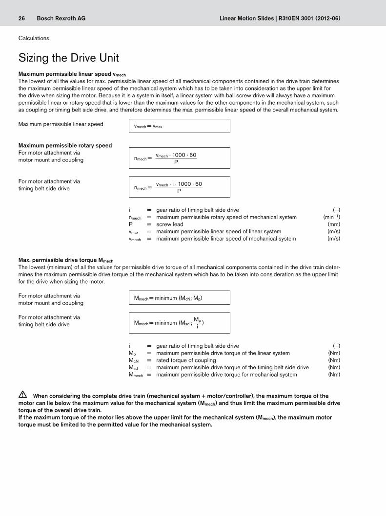
vmech = vmax
nmech = vmech · 1000 · 60P
nmech = vmech · i · 1000 · 60P
Linear Motion Slides | R310EN 3001 (2012-06)
Max. permissible drive torque Mmech
The lowest (minimum) of all the values for permissible drive torque of all mechanical components contained in the drive train deter-mines the maximum permissible drive torque of the mechanical system which has to be taken into consideration as the upper limit for the drive when sizing the motor.
For motor attachment via motor mount and coupling
For motor attachment via timing belt side drive
i = gear ratio of timing belt side drive (—) Mp = maximum permissible drive torque of the linear system (Nm)McN = rated torque of coupling (Nm)Msd = maximum permissible drive torque of the timing belt side drive (Nm)Mmech = maximum permissible drive torque for mechanical system (Nm)
i = gear ratio of timing belt side drive (—) nmech = maximum permissible rotary speed of mechanical system (min–1)P = screw lead (mm)vmax = maximum permissible linear speed of linear system (m/s)vmech = maximum permissible linear speed of mechanical system (m/s)
Maximum permissible linear speed vmech
The lowest of all the values for max. permissible linear speed of all mechanical components contained in the drive train determines the maximum permissible linear speed of the mechanical system which has to be taken into consideration as the upper limit for the drive when sizing the motor. Because it is a system in itself, a linear system with ball screw drive will always have a maximum permissible linear or rotary speed that is lower than the maximum values for the other components in the mechanical system, such as coupling or timing belt side drive, and therefore determines the max. permissible linear speed of the overall mechanical system.
For motor attachment via timing belt side drive
For motor attachment via motor mount and coupling
Maximum permissible rotary speed
Maximum permissible linear speed
Calculations
Sizing the Drive Unit
c When considering the complete drive train (mechanical system + motor/controller), the maximum torque of the motor can lie below the maximum value for the mechanical system (Mmech) and thus limit the maximum permissible drive torque of the overall drive train. If the maximum torque of the motor lies above the upper limit for the mechanical system (Mmech), the maximum motor torque must be limited to the permitted value for the mechanical system.
Mmech = minimum (McN; Mp)
Mmech = minimum (Msd ; )Mp
i
27Bosch Rexroth AG
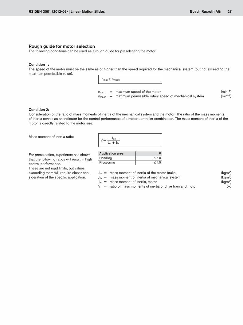
nmax ≥ nmech
V = Jex
Jm + Jbr
R310EN 3001 (2012-06) | Linear Motion Slides
nmax = maximum speed of the motor (min–1)nmech = maximum permissible rotary speed of mechanical system (min–1)
Rough guide for motor selectionThe following conditions can be used as a rough guide for preselecting the motor.
Condition 1:The speed of the motor must be the same as or higher than the speed required for the mechanical system (but not exceeding the maximum permissible value).
Jbr = mass moment of inertia of the motor brake (kgm2)Jex = mass moment of inertia of mechanical system (kgm2)Jm = mass moment of inertia, motor (kgm2)V = ratio of mass moments of inertia of drive train and motor (—)
Condition 2:Consideration of the ratio of mass moments of inertia of the mechanical system and the motor. The ratio of the mass moments of inertia serves as an indicator for the control performance of a motor-controller combination. The mass moment of inertia of the motor is directly related to the motor size.
Mass moment of inertia ratio:
For preselection, experience has shown that the following ratios will result in high control performance. These are not rigid limits, but values exceeding them will require closer con-sideration of the specific application.
Application area VHandling ≤6.0Processing ≤1.5

28 Bosch Rexroth AG
Mg = P · (mex + mca) · g
2000 · p · i
Mstat = MR + Mg
Linear Motion Slides | R310EN 3001 (2012-06)
Condition 3:Estimation of the ratio of the static load moment to the continuous torque of the motor. The torque ratio must be smaller than or equal to the empirical value of 0.6. By looking at the required motor torque levels, this estimation roughly covers the dynamic characteristics which still have be determined by plotting an exact motion profile.
Static load moment:
Torque ratio:
For motor attachment via motor mount and coupling: i = 1
Weight moment: For vertical mounting orientation only!
g = gravitational acceleration (= 9.81) (m/s2)i = gear ratio of timing belt side drive (—)mca = moved mass of carriage (kg)mex = moved external load (kg)Mg = weight moment at motor journal (Nm)M0 = continuous motor torque (Nm)MR = frictional torque at motor journal (Nm)Mstat = static longitudinal moment load (Nm)P = screw lead (mm)p = pi (—)
In the section ! “Components and Ordering” users can put together standard configurations, including motor attachment and motor, for the various linear system sizes by selecting the appropriate options. By checking the above conditions it is possible to see whether a standard motor selected in a particular configuration will generally be of a suitable size for the specific application.
Precise sizing of the drive unitPreselecting the motor according to this rough guide is no substitute for the required precise design calculations for the drive, taking all moments/torques and speed levels into account. For precise calculation of the electric drive, including consideration of the specific motion profile, please refer to the performance data in the catalogs “IndraDrive Cs” and “IndraDrive C”.When sizing the drive, the maximum permitted values for linear speed, drive torque and acceleration must not be exceeded, in order to avoid damaging the mechanical system.
Calculations
Sizing the Drive Unit
Mstat
M0≤ 0.6
29Bosch Rexroth AG
500 mm
F = 0 N30 kg 30 kg
L
R310EN 3001 (2012-06) | Linear Motion Slides
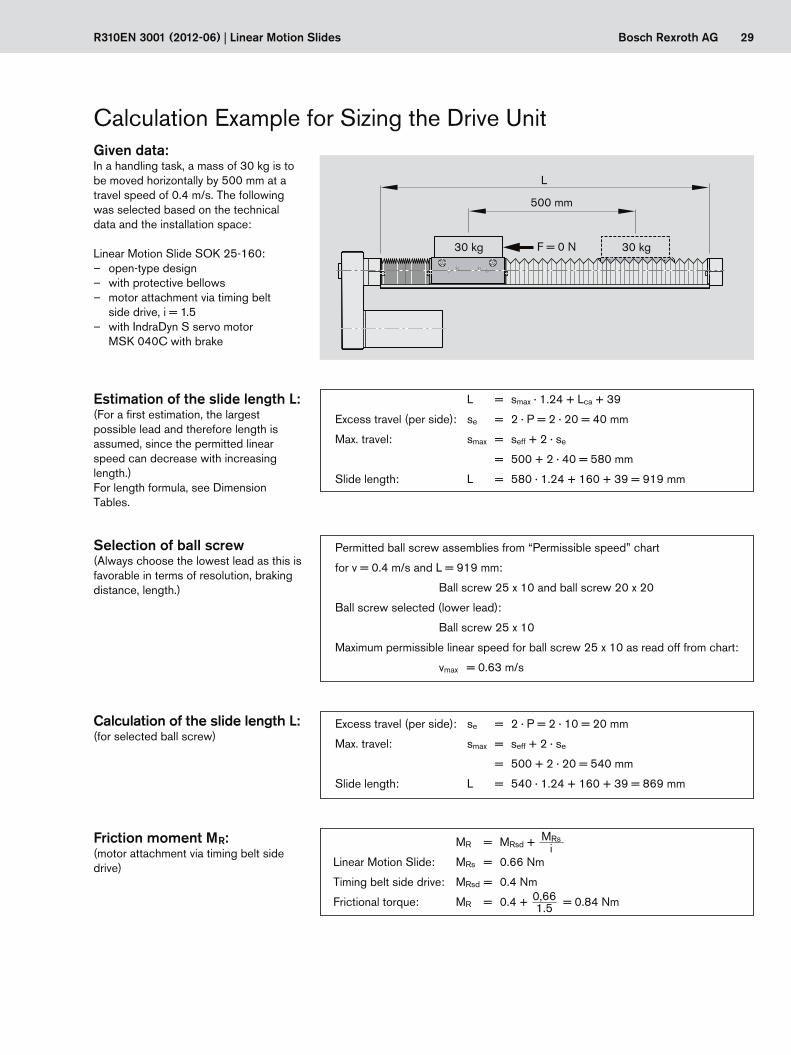
Given data:In a handling task, a mass of 30 kg is to be moved horizontally by 500 mm at a travel speed of 0.4 m/s. The following was selected based on the technical data and the installation space:
Linear Motion Slide SOK 25-160: – open-type design – with protective bellows – motor attachment via timing belt
side drive, i = 1.5 – with IndraDyn S servo motor
MSK 040C with brake
Calculation Example for Sizing the Drive Unit
Estimation of the slide length L:(For a first estimation, the largest possible lead and therefore length is assumed, since the permitted linear speed can decrease with increasing length.)For length formula, see Dimension Tables.
Selection of ball screw(Always choose the lowest lead as this is favorable in terms of resolution, braking distance, length.)
Calculation of the slide length L:(for selected ball screw)
Friction moment MR:(motor attachment via timing belt side drive)
MRsi
0,661.5
L = smax · 1.24 + Lca + 39
Excess travel (per side): se = 2 · P = 2 · 20 = 40 mm
Max. travel: smax = seff + 2 · se
= 500 + 2 · 40 = 580 mm
Slide length: L = 580 · 1.24 + 160 + 39 = 919 mm
Excess travel (per side): se = 2 · P = 2 · 10 = 20 mm
Max. travel: smax = seff + 2 · se
= 500 + 2 · 20 = 540 mm
Slide length: L = 540 · 1.24 + 160 + 39 = 869 mm
Permitted ball screw assemblies from “Permissible speed” chart
for v = 0.4 m/s and L = 919 mm:
Ball screw 25 x 10 and ball screw 20 x 20
Ball screw selected (lower lead):
Ball screw 25 x 10
Maximum permissible linear speed for ball screw 25 x 10 as read off from chart:
vmax = 0.63 m/s
MR = MRsd +
Linear Motion Slide: MRs = 0.66 Nm
Timing belt side drive: MRsd = 0.4 Nm
Frictional torque: MR = 0.4 + = 0.84 Nm
30 Bosch Rexroth AG Linear Motion Slides | R310EN 3001 (2012-06)
Calculations
Travel speed: vmech = 0.4 m/s
Rotary speed: nmech =
= 3600 min–1
Rotary speed of application nmech:(motor attachment via timing belt side drive)
0.4 · 1.5 · 1000 · 6010
(Js + Jt)i2
(246.039 · 10–6 + 75.99 · 10–6)1.52
Mass moment of inertia Jex:(motor attachment via timing belt side drive)
Jex = Jsd +
Timing belt side drive: Jsd = 84 · 10–6 kgm2
Linear Motion Slide: Js = (kJ fix + kJ var · L) · 10–6
= (23.575 + 0.256 · 869) · 10–6
= 246.039 · 10–6 kgm2
External load: Jt = mex · kJ m · 10–6
= 30 · 2.533 · 10–6
= 75.99 · 10–6 kgm2
Mass moment of inertia: Jex = 84 · 10–6 +
= 227.124 · 10–6 kgm2
(vmech · i · 1000 · 60)P
(0.63 · 1.5 · 1000 · 60)10
nmech =
Max. permissible linear speed: vmech = vmax = 0.63 m/s
Max. permissible rotary speed: nmech =
= 5670 min–1
Maximum permissible rotary speed nmech:(motor attachment via timing belt side drive)Limit for mechanical system
Calculation Example for Sizing the Drive Unit
31Bosch Rexroth AGR310EN 3001 (2012-06) | Linear Motion Slides
Mass moment of inertia ratio: V =
Motor moment of inertia: Jm = 140 · 10–6 kgm2
Brake moment of inertia: Jbr = 23 · 10–6 kgm2
Mass moment of inertia ratio: V =
= 1.393
Condition for handling: V ≤ 6
1.393 ≤ 6 Condition met – motor size OK.
227.124 · 10–6 (140 · 10–6 + 23 · 10–6)
JexJm + Jbr
Mstat
M0
0.842.7
Condition 2:
Condition 3:
Rotary speed: nmax ≥ nmech
7500 ≥ 3600 Condition met – motor size OK.
Checking the motor preselection:Selected motor: MSK 040C with brake
Condition 1:
Mmech = minimum (Msd, )
Timing belt side drive: Msd = 4.41 Nm (gear ratio i = 1.5 and MSK 040C)
Linear Motion Slide: Mp = 9.4 Nm
Drive torque: Mmech = minimum (4.41; )
= minimum (4.41; 6.26)
= 4.41 Nm
Mp
i
9.41.5
Maximum permissible drive torque Mmech:(motor attachment via timing belt side drive)Limit for mechanical system
Torque ratio: ≤ 0.6
Static load moment: Mstat = MR + Mg (horizontal mounting orientation Mg = 0)
= 0.84 Nm
Continuous motor torque: M0 = 2.7 Nm
Torque ratio: = 0.31
0.31 ≤ 0.6 Condition met – motor size OK.
32 Bosch Rexroth AG Linear Motion Slides | R310EN 3001 (2012-06)
Result: Linear Motion Slide SOK 25-160Length L = 869 mm,Max. travel smax = 540 mmCarriage length Lca = 160 mmBall screw: Diameter d0: 25 mm Lead P: 10 mmWith protective bellowsMotor attachment via timing belt side drive, gear ratio i = 1.5Preselected motor: MSK 040C with brake
For precise sizing of the electric drive, the motor-controller combination must always be considered, as the performance data (e.g. maximum useful speed and maximum torque) will depend on the controller used.
When doing this, the following data must be considered.
Frictional torque MR = 0.84 NmMass moment of inertia Jex = 227.124 · 10–6 kgm2
Travel speed vmech = 0.4 m/s (nmech = 3600 min–1)Limit for drive torque Mmech = 4.41 Nm! The motor torque must be limited to 4.41 Nm on the drive side!Limit for acceleration amax = 27 m/s2
Limit for travel speed vmax = 0.63 m/s (nmech = 5670 min–1)
Besides the preferred type MSK 040C, other motors with identical connection dimensions can be adapted while taking care not to exceed the calculated limits.
Calculation Example for Sizing the Drive Unit
Calculations

33Bosch Rexroth AGR310EN 3001 (2012-06) | Linear Motion Slides
34 Bosch Rexroth AG
Bosch Rexroth AG D-97419 Schweinfurt Made in Germany
7210
MNR: R12345678TYP: SGKCS: 9876543210 20 07
FD: 483
smax (mm) u (mm/U) vmax (m/s) amax (m/s2) M1max (Nm) d i -- -- -- -- -- -- --
20-130
Linear Motion Slides | R310EN 3001 (2012-06)
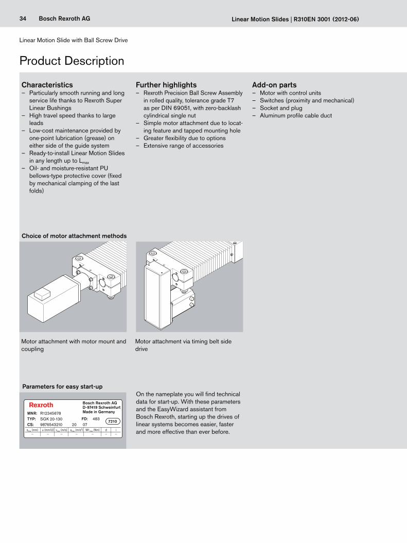
Linear Motion Slide with Ball Screw Drive
Product Description
Characteristics – Particularly smooth running and long
service life thanks to Rexroth Super Linear Bushings
– High travel speed thanks to large leads
– Low-cost maintenance provided by one-point lubrication (grease) on either side of the guide system
– Ready-to-install Linear Motion Slides in any length up to Lmax
– Oil- and moisture-resistant PU bellows-type protective cover (fixed by mechanical clamping of the last folds)
Choice of motor attachment methods
Motor attachment with motor mount and coupling
Motor attachment via timing belt side drive
Further highlights – Rexroth Precision Ball Screw Assembly
in rolled quality, tolerance grade T7 as per DIN 69051, with zero-backlash cylindrical single nut
– Simple motor attachment due to locat-ing feature and tapped mounting hole
– Greater flexibility due to options – Extensive range of accessories
Add-on parts – Motor with control units – Switches (proximity and mechanical) – Socket and plug – Aluminum profile cable duct
Parameters for easy start-upOn the nameplate you will find technical data for start-up. With these parameters and the EasyWizard assistant from Bosch Rexroth, starting up the drives of linear systems becomes easier, faster and more effective than ever before.
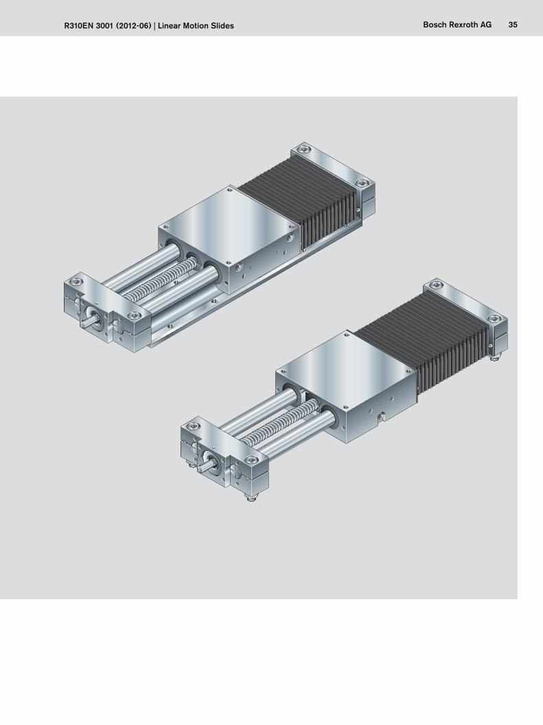
35Bosch Rexroth AGR310EN 3001 (2012-06) | Linear Motion Slides
36 Bosch Rexroth AG
Linear Motion Slide with Ball Screw Drive
Linear Motion Slides | R310EN 3001 (2012-06)
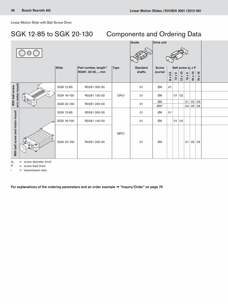
Components and Ordering DataSGK 12-85 to SGK 20-130Guide Drive unit Carriage Motor attachment Motor Cover Switches / Cable duct /
Socket-plugDocumentation
Slide Part number, length1) R0261 .00 00, ... mm
Type Standard shafts
Screw journal
Ball screw d0 x P Standard i = Attachment kit3)
for motor Brake PU bellows Standard report
Measure-ment
report6)
8 x
2.5
12 x
5
12 x
10
16 x
5
16 x
10
16 x
16 with-
outwith without with
With
bal
l scr
ew,
w/o
mot
or m
ount
SGK 12-85 R0261 000 00
OF01
01 Ø6 01 01 — 00 00
00 01
Without switches00Without cable duct
Without socket and plug
Switches:– PNP NC 11– PNP NO 13– Mechanical 15
Ordering data:Switch type
Cable duct5) 20
Socket-plug 17
Switching cam and profiled support for switches
16
01
02
SGK 16-100 R0261 100 00 01 Ø6 01 02 01 — 00 00
SGK 20-130 R0261 200 00 01Ø9 01 02 03
01 — 00 00Ø92) 04 05 06
With
bal
l scr
ew a
nd m
otor
mou
nt SGK 12-85 R0261 000 00
MF01
01 Ø6 01 01 — 03 MSM 031B 1064) 1074)
SGK 16-100 R0261 100 00 01 Ø6 01 02 01 — 03 MSM 031B 1064) 1074)
03SGK 20-130 R0261 200 00 01 Ø9 01 02 03 01 —
01 MSK 040C 864) 874)
04 MSK 030C 844) 854)
05 MSM 031C 1084) 1094)
06 MSM 041B 1104) 1114)
For explanations of the ordering parameters and an order example ! “Inquiry/Order” on page 76
d0 = screw diameter (mm)P = screw lead (mm) i = transmission ratio

37Bosch Rexroth AG
L
0 L/2
R310EN 3001 (2012-06) | Linear Motion Slides
1) Length calculation ! Dimensions tables.2) With keyway3) Attachment kit also available without motor. When ordering,
enter “00” for motor!4) Recommended motor. Motor data and type designations
! “Motors” on page 66.
The switch activation point is determined by the mounting side, the direction of travel and the switching distance (see table above and ordering example).Mounting side: Switches may be mounted on the left (L) or right (R) side of the slide.Direction of travel: Switches may be mounted on the minus (-) or plus (+) side of zero.
Switching distance: The switching distance is the distance between the carriage center (CC) and the zero point (0) when a switch is activated (given in mm).Refer to the section “Switch mounting arrangements” for more information on switch mounting, switch types, and fixing the mounting duct.
Determining the switch activation point
Left (L)
Right (R)
Switch mounting side:
Stroke
– Travel direction +
5) The length of the delivered cable duct is the same as that of the profiled support. If a different length is required, please order the cable duct as a separate part (! “Ordering the switches and accessories” on page 62).
6) “02” = Moment of friction measurement; “03” = Lead deviation: ! “Documentation” on page 73.
Guide Drive unit Carriage Motor attachment Motor Cover Switches / Cable duct / Socket-plug
Documentation
Slide Part number, length1) R0261 .00 00, ... mm
Type Standard shafts
Screw journal
Ball screw d0 x P Standard i = Attachment kit3)
for motor Brake PU bellows Standard report
Measure-ment
report6)
8 x
2.5
12 x
5
12 x
10
16 x
5
16 x
10
16 x
16 with-
outwith without with
With
bal
l scr
ew,
w/o
mot
or m
ount
SGK 12-85 R0261 000 00
OF01
01 Ø6 01 01 — 00 00
00 01
Without switches00Without cable duct
Without socket and plug
Switches:– PNP NC 11– PNP NO 13– Mechanical 15
Ordering data:Switch type
Cable duct5) 20
Socket-plug 17
Switching cam and profiled support for switches
16
01
02
SGK 16-100 R0261 100 00 01 Ø6 01 02 01 — 00 00
SGK 20-130 R0261 200 00 01Ø9 01 02 03
01 — 00 00Ø92) 04 05 06
With
bal
l scr
ew a
nd m
otor
mou
nt SGK 12-85 R0261 000 00
MF01
01 Ø6 01 01 — 03 MSM 031B 1064) 1074)
SGK 16-100 R0261 100 00 01 Ø6 01 02 01 — 03 MSM 031B 1064) 1074)
03SGK 20-130 R0261 200 00 01 Ø9 01 02 03 01 —
01 MSK 040C 864) 874)
04 MSK 030C 844) 854)
05 MSM 031C 1084) 1094)
06 MSM 041B 1104) 1114)
CC CC
38 Bosch Rexroth AG
B15
ød1
H15H10
S15
B4
B5
E4E2A
L1
L2
E1
A
Lca
B1
B12
L
H1
se se
smax2
seff2
smax2
L2
seff2
Linear Motion Slide with Ball Screw Drive
Linear Motion Slides | R310EN 3001 (2012-06)
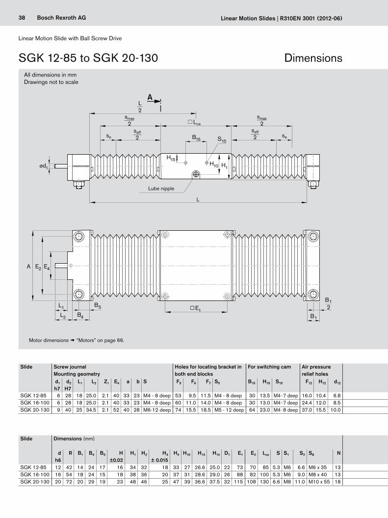
All dimensions in mmDrawings not to scale
Motor dimensions ! “Motors” on page 66.
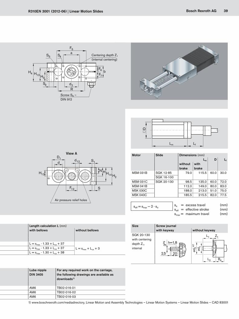
Lube nipple
Slide Dimensions (mm) Lube nipple For any required work on the carriage, the following drawings are available as downloads1)
DIN 3405d R B1 B4 B5 H H1 H2 H3 H4 H10 H13 H14 D1 E1 E2 Lca S S1 S2 S8 N
h6 ±0.02 ± 0.015 SGK 12-85 12 42 14 24 17 16 34 32 18 33 27 26.6 25.0 22 73 70 85 5.3 M6 6.6 M6 x 35 13 AM6 TB02-016-01SGK 16-100 16 54 18 24 15 18 38 36 20 37 31 28.6 29.0 26 88 82 100 5.3 M6 9.0 M8 x 40 13 AM6 TB02-016-02SGK 20-130 20 72 20 29 19 23 48 46 25 47 39 36.6 37.5 32 115 108 130 6.6 M8 11.0 M10 x 55 18 AM6 TB02-016-03
DimensionsSGK 12-85 to SGK 20-130
Slide Screw journalMounting geometry
Holes for locating bracket in both end blocks
For switching cam Air pressure relief holes
Length calculation L (mm) Size Screw journalwith bellows without bellows with keyway without keyway
d1 d2 L1 L2 Z1 E4 a b S F5 F6 F7 S5 B15 H15 S15 F12 H12 d12 SGK 20-130with centering depth Z1, internal
h=1,8
202,5
3P9
202,5
284
h = 1,8
3 P
9
ød2
–0,
01h = 3
5 P
9
L1
B4
ød1
ød2 H
7
Z1
L2
L1 Z1L2 B4
ød1
h7 H7SGK 12-85 6 28 18 25.0 2.1 40 33 23 M4 - 8 deep 53 9.5 11.5 M4 - 8 deep 30 13.5 M4 - 7 deep 16.0 10.4 6.8 L = smax · 1.33 + Lca + 37
L = smax + Lca + 3SGK 16-100 6 28 18 25.0 2.1 40 33 23 M4 - 8 deep 60 11.0 14.0 M4 - 8 deep 30 13.0 M4 - 7 deep 24.4 12.0 8.5 L = smax · 1.33 + Lca + 37SGK 20-130 9 40 25 34.5 2.1 52 40 28 M6-12 deep 74 15.5 18.5 M5 - 12 deep 64 23.0 M4 - 8 deep 37.0 15.5 10.0 L = smax · 1.30 + Lca + 38
39Bosch Rexroth AG
F5a
d2
S5 S4
bH4 F7
F6
H3H13
R
S2
H12
dd12 S1
F12 S
D1
H2H14
HN
Lm LfD
R310EN 3001 (2012-06) | Linear Motion Slides
Slide Dimensions (mm) Lube nipple For any required work on the carriage, the following drawings are available as downloads1)
DIN 3405d R B1 B4 B5 H H1 H2 H3 H4 H10 H13 H14 D1 E1 E2 Lca S S1 S2 S8 N
h6 ±0.02 ± 0.015 SGK 12-85 12 42 14 24 17 16 34 32 18 33 27 26.6 25.0 22 73 70 85 5.3 M6 6.6 M6 x 35 13 AM6 TB02-016-01SGK 16-100 16 54 18 24 15 18 38 36 20 37 31 28.6 29.0 26 88 82 100 5.3 M6 9.0 M8 x 40 13 AM6 TB02-016-02SGK 20-130 20 72 20 29 19 23 48 46 25 47 39 36.6 37.5 32 115 108 130 6.6 M8 11.0 M10 x 55 18 AM6 TB02-016-03
Centering depth Z1
(internal centering)
View A
Air pressure relief holes
Screw S8 – DIN 912
Motor Slide Dimensions (mm)Lm D Lf
without brake
with brake
MSM 031B SGK 12-85 79.0 115.5 60.0 30.0SGK 16-100
MSM 031C SGK 20-130 98.5 135.0 60.0 72.0MSM 041B 112.0 149.0 80.0 83.0MSK 030C 188.0 213.0 51.0 75.0MSK 040C 185.5 215.5 82.0 77.5
Slide Screw journalMounting geometry
Holes for locating bracket in both end blocks
For switching cam Air pressure relief holes
Length calculation L (mm) Size Screw journalwith bellows without bellows with keyway without keyway
d1 d2 L1 L2 Z1 E4 a b S F5 F6 F7 S5 B15 H15 S15 F12 H12 d12 SGK 20-130with centering depth Z1, internal
h=1,8
202,5
3P9
202,5
284
h = 1,8
3 P
9
ød2
–0,
01h = 3
5 P
9
L1
B4
ød1
ød2 H
7
Z1
L2
L1 Z1L2 B4
ød1
h7 H7SGK 12-85 6 28 18 25.0 2.1 40 33 23 M4 - 8 deep 53 9.5 11.5 M4 - 8 deep 30 13.5 M4 - 7 deep 16.0 10.4 6.8 L = smax · 1.33 + Lca + 37
L = smax + Lca + 3SGK 16-100 6 28 18 25.0 2.1 40 33 23 M4 - 8 deep 60 11.0 14.0 M4 - 8 deep 30 13.0 M4 - 7 deep 24.4 12.0 8.5 L = smax · 1.33 + Lca + 37SGK 20-130 9 40 25 34.5 2.1 52 40 28 M6-12 deep 74 15.5 18.5 M5 - 12 deep 64 23.0 M4 - 8 deep 37.0 15.5 10.0 L = smax · 1.30 + Lca + 38
1) www.boschrexroth.com/mediadirectory, Linear Motion and Assembly Technologies – Linear Motion Systems – Linear Motion Slides – CAD 83001
se = excess travel (mm)seff = effective stroke (mm)smax = maximum travel (mm)
seff = smax — 2 · se
40 Bosch Rexroth AG
Linear Motion Slide with Ball Screw Drive
Linear Motion Slides | R310EN 3001 (2012-06)
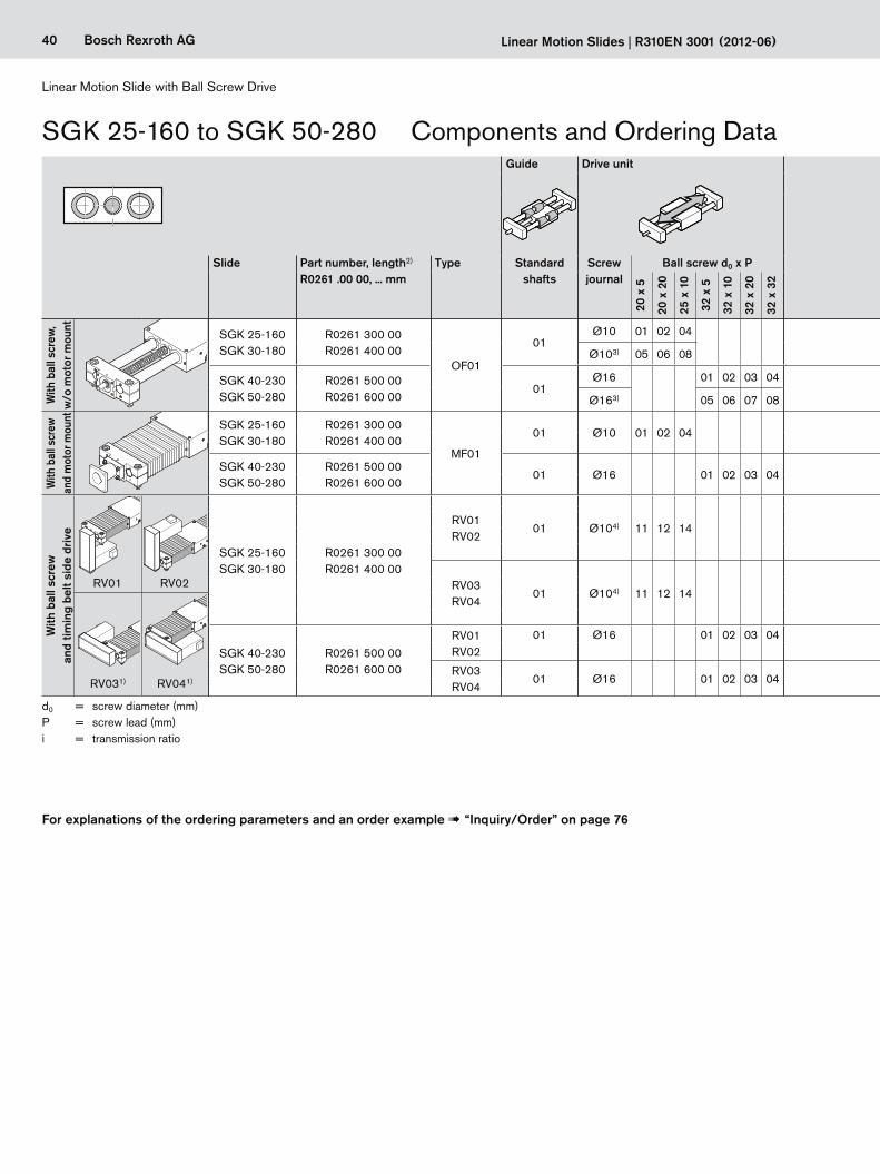
SGK 25-160 to SGK 50-280
d0 = screw diameter (mm)P = screw lead (mm) i = transmission ratio
Components and Ordering DataGuide Drive unit Carriage Motor attachment Motor Cover Switches / Cable duct /
Socket-plugDocumentation
Slide Part number, length2) R0261 .00 00, ... mm
Type Standard shafts
Screw journal
Ball screw d0 x P Standard i = Attach-ment kit5)
for motor Brake PU bellows Standard report
Measure-ment
report8)
20 x
5
20 x
20
25 x
10
32 x
5
32 x
10
32 x
20
32 x
32 with-
outwith without with
With
bal
l scr
ew,
w/o
mot
or m
ount
SGK 25-160SGK 30-180
R0261 300 00R0261 400 00
OF01
01Ø10 01 02 04
01 — 00 00
00 01
Without switches00Without cable duct
Without socket and plug
Switches:– PNP NC 11– PNP NO 13– Mechanical 15
Ordering data:Switch type
Cable duct (loose) 7) 20
Socket-plug 17
Switching cam and profiled support for switches
16
01
02
Ø103) 05 06 08
SGK 40-230SGK 50-280
R0261 500 00R0261 600 00
01Ø16 01 02 03 04
01 — 00 00Ø163) 05 06 07 08
With
bal
l scr
ew
and
mot
or m
ount SGK 25-160
SGK 30-180R0261 300 00R0261 400 00
MF01
01 Ø10 01 02 04 01 —03 MSK 040C 866) 876)
06 MSM 041B 1106) 1116)
SGK 40-230SGK 50-280
R0261 500 00R0261 600 00
01 Ø16 01 02 03 04 01 —02 MSK 076C 926) 936)
05 MSK 060C 906) 916)
With
bal
l scr
ew
and
timin
g be
lt si
de d
rive
SGK 25-160SGK 30-180
R0261 300 00R0261 400 00
RV01RV02
01 Ø104) 11 12 14 011
10 MSK 040C 866) 876)
03
20 MSM 041B 1106) 1116)
1.512 MSK 040C 866) 876)
22 MSM 041B 1106) 1116)
RV03RV04
01 Ø104) 11 12 14 011
14 MSK 040C 866) 876)
RV01 RV02 24 MSM 041B 1106) 1116)
1.516 MSK 040C 866) 876)
26 MSM 041B 1106) 1116)
SGK 40-230SGK 50-280
R0261 500 00R0261 600 00
RV01RV02
01 Ø16 01 02 03 04 01 1 30
MSK 060C 906) 916)2 31
RV03RV04
01 Ø16 01 02 03 04 011 32
RV031) RV041)2 33
For explanations of the ordering parameters and an order example ! “Inquiry/Order” on page 76
41Bosch Rexroth AG
L
0 L/2
R310EN 3001 (2012-06) | Linear Motion Slides
Guide Drive unit Carriage Motor attachment Motor Cover Switches / Cable duct / Socket-plug
Documentation
Slide Part number, length2) R0261 .00 00, ... mm
Type Standard shafts
Screw journal
Ball screw d0 x P Standard i = Attach-ment kit5)
for motor Brake PU bellows Standard report
Measure-ment
report8)
20 x
5
20 x
20
25 x
10
32 x
5
32 x
10
32 x
20
32 x
32 with-
outwith without with
With
bal
l scr
ew,
w/o
mot
or m
ount
SGK 25-160SGK 30-180
R0261 300 00R0261 400 00
OF01
01Ø10 01 02 04
01 — 00 00
00 01
Without switches00Without cable duct
Without socket and plug
Switches:– PNP NC 11– PNP NO 13– Mechanical 15
Ordering data:Switch type
Cable duct (loose) 7) 20
Socket-plug 17
Switching cam and profiled support for switches
16
01
02
Ø103) 05 06 08
SGK 40-230SGK 50-280
R0261 500 00R0261 600 00
01Ø16 01 02 03 04
01 — 00 00Ø163) 05 06 07 08
With
bal
l scr
ew
and
mot
or m
ount SGK 25-160
SGK 30-180R0261 300 00R0261 400 00
MF01
01 Ø10 01 02 04 01 —03 MSK 040C 866) 876)
06 MSM 041B 1106) 1116)
SGK 40-230SGK 50-280
R0261 500 00R0261 600 00
01 Ø16 01 02 03 04 01 —02 MSK 076C 926) 936)
05 MSK 060C 906) 916)
With
bal
l scr
ew
and
timin
g be
lt si
de d
rive
SGK 25-160SGK 30-180
R0261 300 00R0261 400 00
RV01RV02
01 Ø104) 11 12 14 011
10 MSK 040C 866) 876)
03
20 MSM 041B 1106) 1116)
1.512 MSK 040C 866) 876)
22 MSM 041B 1106) 1116)
RV03RV04
01 Ø104) 11 12 14 011
14 MSK 040C 866) 876)
RV01 RV02 24 MSM 041B 1106) 1116)
1.516 MSK 040C 866) 876)
26 MSM 041B 1106) 1116)
SGK 40-230SGK 50-280
R0261 500 00R0261 600 00
RV01RV02
01 Ø16 01 02 03 04 01 1 30
MSK 060C 906) 916)2 31
RV03RV04
01 Ø16 01 02 03 04 011 32
RV031) RV041)2 33
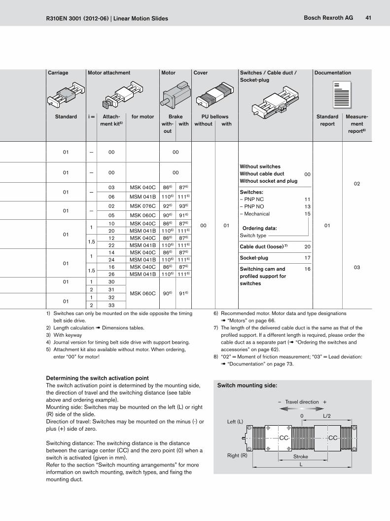
The switch activation point is determined by the mounting side, the direction of travel and the switching distance (see table above and ordering example).Mounting side: Switches may be mounted on the left (L) or right (R) side of the slide.Direction of travel: Switches may be mounted on the minus (-) or plus (+) side of zero.
Switching distance: The switching distance is the distance between the carriage center (CC) and the zero point (0) when a switch is activated (given in mm).Refer to the section “Switch mounting arrangements” for more information on switch mounting, switch types, and fixing the mounting duct.
Determining the switch activation point
Left (L)
Right (R)
Switch mounting side:
Stroke
– Travel direction +
1) Switches can only be mounted on the side opposite the timing belt side drive.
2) Length calculation ! Dimensions tables.3) With keyway4) Journal version for timing belt side drive with support bearing.5) Attachment kit also available without motor. When ordering,
enter “00” for motor!
6) Recommended motor. Motor data and type designations ! “Motors” on page 66.
7) The length of the delivered cable duct is the same as that of the profiled support. If a different length is required, please order the cable duct as a separate part (! “Ordering the switches and accessories” on page 62).
8) “02” = Moment of friction measurement; “03” = Lead deviation: ! “Documentation” on page 73.
CC CC
42 Bosch Rexroth AG
L
B1
A
B15
Lca
S15
H15 H10ød1
B4B5
E4E2A
L1
L2
E1
H1
smax2
seff2 sese
B12
smax2
L2
seff2
Linear Motion Slide with Ball Screw Drive
Linear Motion Slides | R310EN 3001 (2012-06)
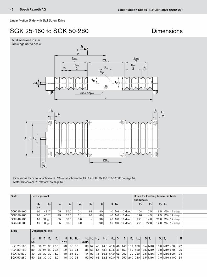
All dimensions in mmDrawings not to scale
Dimensions for motor attachment ! “Motor attachment for SGK / SOK 25-160 to 50-280” on page 52.Motor dimensions ! “Motors” on page 66.
Lube nipple
Slide Dimensions (mm) Lube nipple For any required work on the carriage, the following drawings are available as downloads2)
DIN 3405d R B1 B4 B5 H H1 H2 H3 H4 H10 H13 H14 D1 E1 E2 Lca S S1 S2 S8 N
h6 ±0.02 ± 0.015 SGK 25-160 25 88 25 33 20.5 28 58 56 30 57 48 44.6 45.0 40 140 132 160 8.4 M10 13.0 M12 x 60 22 AM8 x 1 TB02-016-04SGK 30-180 30 96 25 33 20.5 32 67 64 35 66 55 53.6 50.5 47 158 150 180 10.5 M12 13.0 M12 x 70 26 AM8 x 1 TB02-016-05SGK 40-230 40 122 30 30 15.0 40 84 80 44 83 71 66.6 64.0 62 202 190 230 13.5 M16 17.0 M16 x 90 34 AM8 x 1 TB02-016-06SGK 50-280 50 152 30 30 15.0 48 100 96 52 99 86 82.6 80.0 75 250 240 280 13.5 M16 17.0 M16 x 100 34 AM8 x 1 TB02-016-07
Slide Screw journal Holes for locating bracket in both end blocks
For switching cam Air pressure relief holes Length calculation L (mm)with bellows without bellows
d1 d2 L1 L2 Z1 E4 a b S4 F5 F6 F7 S5 B15 H15 S15 F12 H12 d12
h7SGK 25-160 10 48 H7 25 35.5 2.1 63 40 40 M6 - 12 deep 104 17.5 16.5 M5 - 12 deep 64 26 M4 - 10 deep 40 18.5 12.5 L = smax · 1.24 + Lca + 39
L = smax + Lca + 3SGK 30-180 10 48 H7 25 35.5 2.1 63 40 40 M6 - 12 deep 126 14.5 19.5 M5 - 12 deep 64 33 M4 - 10 deep 40 21.0 15.0 L = smax · 1.20 + Lca + 38SGK 40-230 16 68–0.01 35 58.0 8.0 – 90 46 M8 - 16 deep 221 14.0 20.0 M5 - 12 deep 64 21 M4 - 10 deep 54 28.0 18.0 L = smax · 1.17 + Lca + 43SGK 50-280 16 68–0.01 35 58.0 8.0 – 90 46 M8 - 16 deep 271 22.0 12.0 M5 - 12 deep 64 21 M4 - 10 deep 60 30.0 22.0 L = smax · 1.14 + Lca + 43
SGK 25-160 to SGK 50-280 Dimensions

43Bosch Rexroth AG
S2
S1
F12 S
N
d12
H2H14
HH12
dD1
F5a
d2
H3
H13
R
bH4
F7
F6
S4S5
R310EN 3001 (2012-06) | Linear Motion Slides
Slide Dimensions (mm) Lube nipple For any required work on the carriage, the following drawings are available as downloads2)
DIN 3405d R B1 B4 B5 H H1 H2 H3 H4 H10 H13 H14 D1 E1 E2 Lca S S1 S2 S8 N
h6 ±0.02 ± 0.015 SGK 25-160 25 88 25 33 20.5 28 58 56 30 57 48 44.6 45.0 40 140 132 160 8.4 M10 13.0 M12 x 60 22 AM8 x 1 TB02-016-04SGK 30-180 30 96 25 33 20.5 32 67 64 35 66 55 53.6 50.5 47 158 150 180 10.5 M12 13.0 M12 x 70 26 AM8 x 1 TB02-016-05SGK 40-230 40 122 30 30 15.0 40 84 80 44 83 71 66.6 64.0 62 202 190 230 13.5 M16 17.0 M16 x 90 34 AM8 x 1 TB02-016-06SGK 50-280 50 152 30 30 15.0 48 100 96 52 99 86 82.6 80.0 75 250 240 280 13.5 M16 17.0 M16 x 100 34 AM8 x 1 TB02-016-07
Slide Screw journal Holes for locating bracket in both end blocks
For switching cam Air pressure relief holes Length calculation L (mm)with bellows without bellows
d1 d2 L1 L2 Z1 E4 a b S4 F5 F6 F7 S5 B15 H15 S15 F12 H12 d12
h7SGK 25-160 10 48 H7 25 35.5 2.1 63 40 40 M6 - 12 deep 104 17.5 16.5 M5 - 12 deep 64 26 M4 - 10 deep 40 18.5 12.5 L = smax · 1.24 + Lca + 39
L = smax + Lca + 3SGK 30-180 10 48 H7 25 35.5 2.1 63 40 40 M6 - 12 deep 126 14.5 19.5 M5 - 12 deep 64 33 M4 - 10 deep 40 21.0 15.0 L = smax · 1.20 + Lca + 38SGK 40-230 16 68–0.01 35 58.0 8.0 – 90 46 M8 - 16 deep 221 14.0 20.0 M5 - 12 deep 64 21 M4 - 10 deep 54 28.0 18.0 L = smax · 1.17 + Lca + 43SGK 50-280 16 68–0.01 35 58.0 8.0 – 90 46 M8 - 16 deep 271 22.0 12.0 M5 - 12 deep 64 21 M4 - 10 deep 60 30.0 22.0 L = smax · 1.14 + Lca + 43
Air pressure relief holes
Centering depth Z1
(internal centering 1) )
Screw S8 – DIN 912
View A
Size Screw journalwith keyway without keyway
SGK 25-160SGK 30-180with centering depth Z1, internal
202,5
284
h = 1,8
3 P
9
ød2
–0,
01h = 3
5 P
9
L1
B4
ød1
ød2 H
7
Z1
L2
L1 Z1L2 B4
ød1
202,5
284
h = 1,8
3 P
9
ød2
–0,
01h = 3
5 P
9
L1
B4
ød1
ød2 H
7
Z1
L2
L1 Z1L2 B4
ød1
SGK 40-230SGK 50-280with centering depth Z1, external
202,5
284
h = 1,8
3 P
9
ød2
–0,
01h = 3
5 P
9
L1
B4
ød1
ød2 H
7
Z1
L2
L1 Z1L2 B4
ød1
202,5
284
h = 1,8
3 P
9
ød2
–0,
01h = 3
5 P
9
L1
B4
ød1
ød2 H
7
Z1
L2
L1 Z1L2 B4
ød1
se = excess travel (mm)seff = effective stroke (mm)smax = maximum travel (mm)
seff = smax — 2 · se
2) www.boschrexroth.com/mediadirectory, Linear Motion and Assembly Technologies – Linear Motion Systems – Linear Motion Slides – CAD 83001
1) Only for SOK 25-160 and SOK 30-180

44 Bosch Rexroth AG
Linear Motion Slide with Ball Screw Drive
Linear Motion Slides | R310EN 3001 (2012-06)
SOK 12-85 to SOK 20-130
d0 = screw diameter (mm)P = screw lead (mm)
Components and Ordering DataGuide Drive unit Carriage Motor attachment Motor Cover Switches / Cable duct /
Socket-plugDocumentation
Slide Part number, length1) R0266 .00 00, ... mm
Type Standard shafts
Screw journal
Ball screw d0 x P Standard i = Attachment kit3)
for motor Brake PU bellows Standard report
Measure-ment
report6)
8 x
2.5
12 x
5
12 x
10
16 x
5
16 x
10
16 x
16 with-
outwith with-
outwith
With
bal
l scr
ew,
w/o
mot
or m
ount SOK 12-85 R0266 000 00
OF01
02 Ø6 01 01 — 00 00
00 01
Without switches00Without cable duct
Without socket and plug
Switches:– PNP NC 11– PNP NO 13– Mechanical 15
Ordering data:Switch type
Cable duct (loose) 5) 20
Socket-plug 17
Switching cam and profiled support for switches
16
01
02
SOK 16-100 R0266 100 00 02 Ø6 01 02 01 — 00 00
SOK 20-130 R0266 200 00 02Ø9 01 02 03
01 — 00 00Ø92) 04 05 06
With
bal
l scr
ew a
nd m
otor
mou
nt SOK 12-85 R0266 000 00
MF01
02 Ø6 01 01 — 03 MSM 031B 1064) 1074)
SOK 16-100 R0266 100 00 02 Ø6 01 02 01 — 03 MSM 031B 1064) 1074)
03SOK 20-130 R0266 200 00 02 Ø9 01 02 03 01 —
01 MSK 040C 864) 874)
04 MSK 030C 844) 854)
05 MSM 031C 1084) 1094)
06 MSM 041B 1104) 1114)
For explanations of the ordering parameters and an order example ! “Inquiry/Order” on page 76
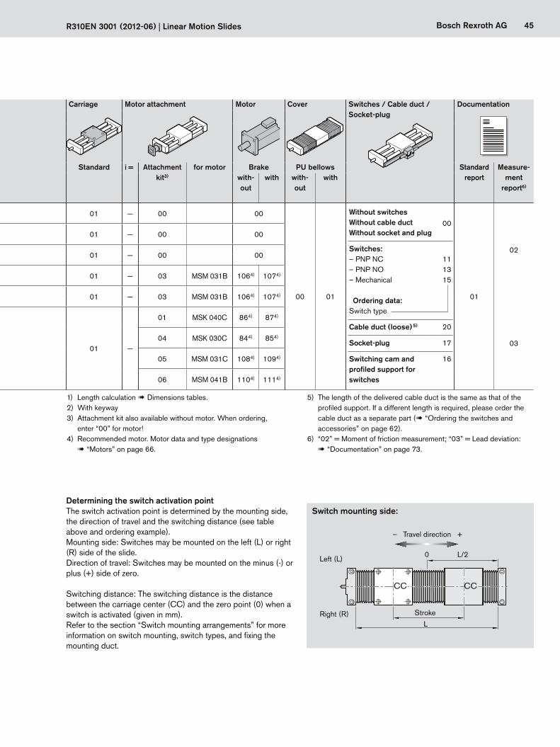
45Bosch Rexroth AG
L
0 L/2
R310EN 3001 (2012-06) | Linear Motion Slides
Guide Drive unit Carriage Motor attachment Motor Cover Switches / Cable duct / Socket-plug
Documentation
Slide Part number, length1) R0266 .00 00, ... mm
Type Standard shafts
Screw journal
Ball screw d0 x P Standard i = Attachment kit3)
for motor Brake PU bellows Standard report
Measure-ment
report6)
8 x
2.5
12 x
5
12 x
10
16 x
5
16 x
10
16 x
16 with-
outwith with-
outwith
With
bal
l scr
ew,
w/o
mot
or m
ount SOK 12-85 R0266 000 00
OF01
02 Ø6 01 01 — 00 00
00 01
Without switches00Without cable duct
Without socket and plug
Switches:– PNP NC 11– PNP NO 13– Mechanical 15
Ordering data:Switch type
Cable duct (loose) 5) 20
Socket-plug 17
Switching cam and profiled support for switches
16
01
02
SOK 16-100 R0266 100 00 02 Ø6 01 02 01 — 00 00
SOK 20-130 R0266 200 00 02Ø9 01 02 03
01 — 00 00Ø92) 04 05 06
With
bal
l scr
ew a
nd m
otor
mou
nt SOK 12-85 R0266 000 00
MF01
02 Ø6 01 01 — 03 MSM 031B 1064) 1074)
SOK 16-100 R0266 100 00 02 Ø6 01 02 01 — 03 MSM 031B 1064) 1074)
03SOK 20-130 R0266 200 00 02 Ø9 01 02 03 01 —
01 MSK 040C 864) 874)
04 MSK 030C 844) 854)
05 MSM 031C 1084) 1094)
06 MSM 041B 1104) 1114)
The switch activation point is determined by the mounting side, the direction of travel and the switching distance (see table above and ordering example).Mounting side: Switches may be mounted on the left (L) or right (R) side of the slide.Direction of travel: Switches may be mounted on the minus (-) or plus (+) side of zero.
Switching distance: The switching distance is the distance between the carriage center (CC) and the zero point (0) when a switch is activated (given in mm).Refer to the section “Switch mounting arrangements” for more information on switch mounting, switch types, and fixing the mounting duct.
Determining the switch activation point
Left (L)
Right (R)
Switch mounting side:
Stroke
– Travel direction +
1) Length calculation ! Dimensions tables.2) With keyway3) Attachment kit also available without motor. When ordering,
enter “00” for motor!4) Recommended motor. Motor data and type designations
! “Motors” on page 66.
5) The length of the delivered cable duct is the same as that of the profiled support. If a different length is required, please order the cable duct as a separate part (! “Ordering the switches and accessories” on page 62).
6) “02” = Moment of friction measurement; “03” = Lead deviation: ! “Documentation” on page 73.
CC CC
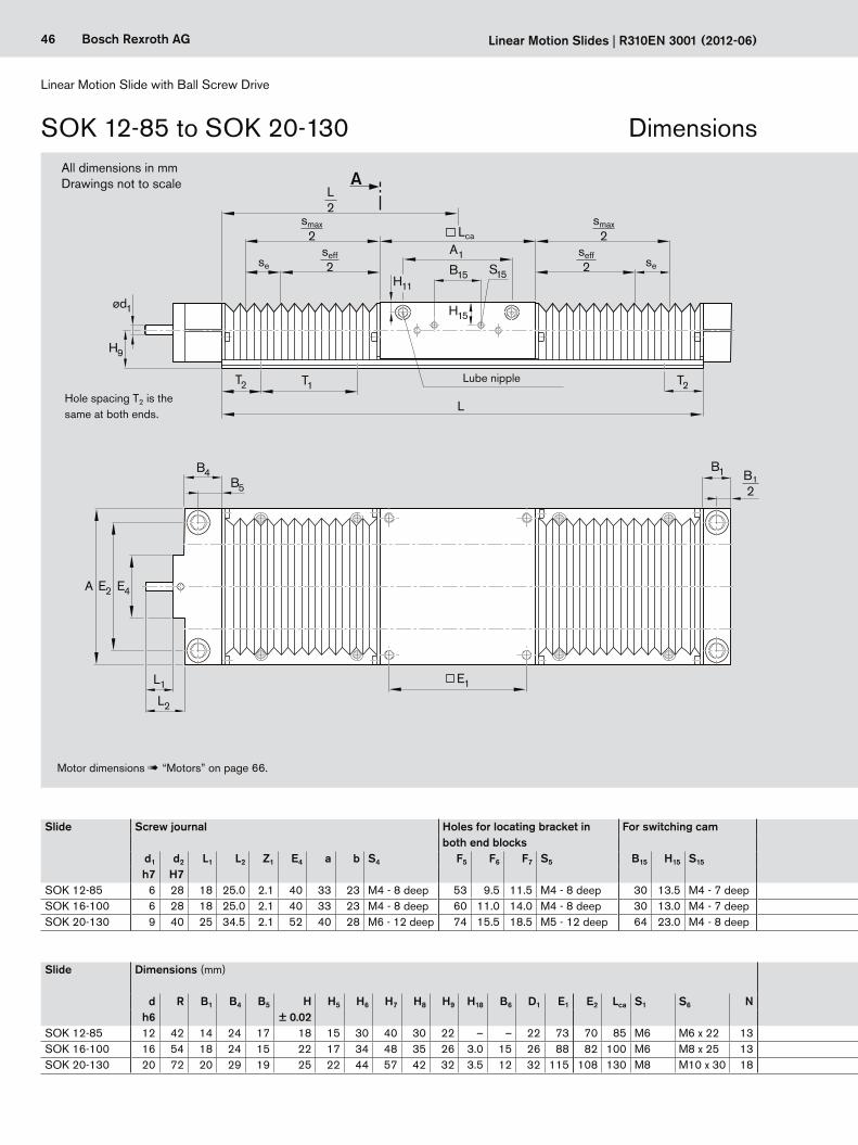
46 Bosch Rexroth AG
B1
T2 T1 T2
B15 S15
A
Lca
ød1 H15
E4E2A
L1
L2
E1
L
B4B5
A1
H9
H11
sese
smax2
L2
smax2
B12
seff2
seff2
Linear Motion Slide with Ball Screw Drive
Linear Motion Slides | R310EN 3001 (2012-06)
SOK 12-85 to SOK 20-130
Hole spacing T2 is the same at both ends.
Lube nipple
Motor dimensions ! “Motors” on page 66.
All dimensions in mmDrawings not to scale
Dimensions
Slide Screw journal Holes for locating bracket in both end blocks
For switching cam Length calculation L (mm) Size Screw journalwith bellows without bellows with keyway without keyway
d1 d2 L1 L2 Z1 E4 a b S4 F5 F6 F7 S5 B15 H15 S15 SOK 20-130 with centering depth Z1, internal
h=1,8
202,5
3P9
202,5
284
h = 1,8
3 P
9
ød2
–0,
01h = 3
5 P
9
L1
B4
ød1
ød2 H
7
Z1
L2
L1 Z1L2 B4
ød1
h7 H7SOK 12-85 6 28 18 25.0 2.1 40 33 23 M4 - 8 deep 53 9.5 11.5 M4 - 8 deep 30 13.5 M4 - 7 deep L = smax · 1.33 + Lca + 37
L = smax + Lca + 3SOK 16-100 6 28 18 25.0 2.1 40 33 23 M4 - 8 deep 60 11.0 14.0 M4 - 8 deep 30 13.0 M4 - 7 deep L = smax · 1.33 + Lca + 37SOK 20-130 9 40 25 34.5 2.1 52 40 28 M6 - 12 deep 74 15.5 18.5 M5 - 12 deep 64 23.0 M4 - 8 deep L = smax · 1.30 + Lca + 38
Slide Dimensions (mm) Shaft support rails Lube nipple For any required work on the carriage, the following drawings are available as downloads1)d R B1 B4 B5 H H5 H6 H7 H8 H9 H18 B6 D1 E1 E2 Lca S1 S6 N H16 H17 E3 S3 T1 T2 A1 H11 DIN 3405
h6 ± 0.02SOK 12-85 12 42 14 24 17 18 15 30 40 30 22 – – 22 73 70 85 M6 M6 x 22 13 5 6.5 29 4.5 75 ≥ 15 57 7.0 AM6 TB02-016-11SOK 16-100 16 54 18 24 15 22 17 34 48 35 26 3.0 15 26 88 82 100 M6 M8 x 25 13 5 8.3 33 5.5 100 ≥ 20 68 7.2 AM6 TB02-016-12SOK 20-130 20 72 20 29 19 25 22 44 57 42 32 3.5 12 32 115 108 130 M8 M10 x 30 18 6 9.8 37 6.6 100 ≥ 20 94 7.2 AM6 TB02-016-13
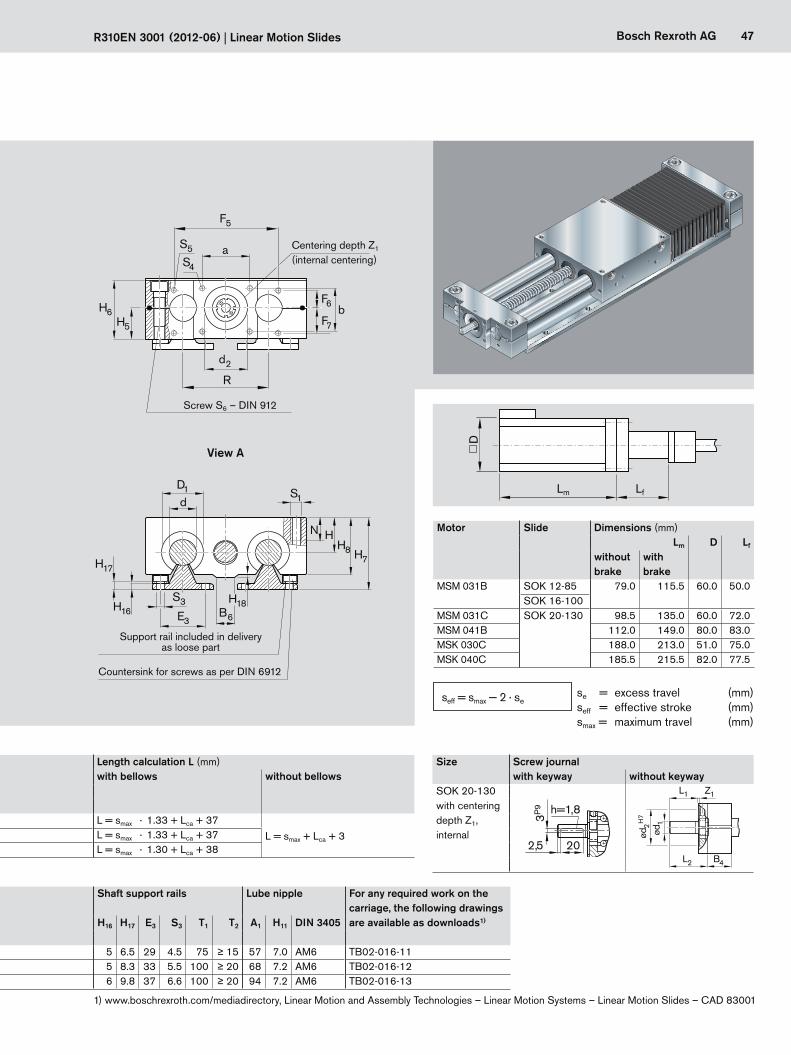
47Bosch Rexroth AG
B6
H18
S4
S5
F5
a
d2
bF6
H5
R
H6
dS1
E3
D1
H8HN
S3
H17
H16
H7
F7
Lm Lf
D
R310EN 3001 (2012-06) | Linear Motion Slides
Slide Screw journal Holes for locating bracket in both end blocks
For switching cam Length calculation L (mm) Size Screw journalwith bellows without bellows with keyway without keyway
d1 d2 L1 L2 Z1 E4 a b S4 F5 F6 F7 S5 B15 H15 S15 SOK 20-130 with centering depth Z1, internal
h=1,8
202,5
3P9
202,5
284
h = 1,8
3 P
9
ød2
–0,
01h = 3
5 P
9
L1
B4
ød1
ød2 H
7
Z1
L2
L1 Z1L2 B4
ød1
h7 H7SOK 12-85 6 28 18 25.0 2.1 40 33 23 M4 - 8 deep 53 9.5 11.5 M4 - 8 deep 30 13.5 M4 - 7 deep L = smax · 1.33 + Lca + 37
L = smax + Lca + 3SOK 16-100 6 28 18 25.0 2.1 40 33 23 M4 - 8 deep 60 11.0 14.0 M4 - 8 deep 30 13.0 M4 - 7 deep L = smax · 1.33 + Lca + 37SOK 20-130 9 40 25 34.5 2.1 52 40 28 M6 - 12 deep 74 15.5 18.5 M5 - 12 deep 64 23.0 M4 - 8 deep L = smax · 1.30 + Lca + 38
Screw S6 – DIN 912
Countersink for screws as per DIN 6912
Support rail included in delivery as loose part
Centering depth Z1
(internal centering)
View A
Slide Dimensions (mm) Shaft support rails Lube nipple For any required work on the carriage, the following drawings are available as downloads1)d R B1 B4 B5 H H5 H6 H7 H8 H9 H18 B6 D1 E1 E2 Lca S1 S6 N H16 H17 E3 S3 T1 T2 A1 H11 DIN 3405
h6 ± 0.02SOK 12-85 12 42 14 24 17 18 15 30 40 30 22 – – 22 73 70 85 M6 M6 x 22 13 5 6.5 29 4.5 75 ≥ 15 57 7.0 AM6 TB02-016-11SOK 16-100 16 54 18 24 15 22 17 34 48 35 26 3.0 15 26 88 82 100 M6 M8 x 25 13 5 8.3 33 5.5 100 ≥ 20 68 7.2 AM6 TB02-016-12SOK 20-130 20 72 20 29 19 25 22 44 57 42 32 3.5 12 32 115 108 130 M8 M10 x 30 18 6 9.8 37 6.6 100 ≥ 20 94 7.2 AM6 TB02-016-13
Motor Slide Dimensions (mm)Lm D Lf
without brake
with brake
MSM 031B SOK 12-85 79.0 115.5 60.0 50.0SOK 16-100
MSM 031C SOK 20-130 98.5 135.0 60.0 72.0MSM 041B 112.0 149.0 80.0 83.0MSK 030C 188.0 213.0 51.0 75.0MSK 040C 185.5 215.5 82.0 77.5
se = excess travel (mm)seff = effective stroke (mm)smax = maximum travel (mm)
seff = smax — 2 · se
1) www.boschrexroth.com/mediadirectory, Linear Motion and Assembly Technologies – Linear Motion Systems – Linear Motion Slides – CAD 83001
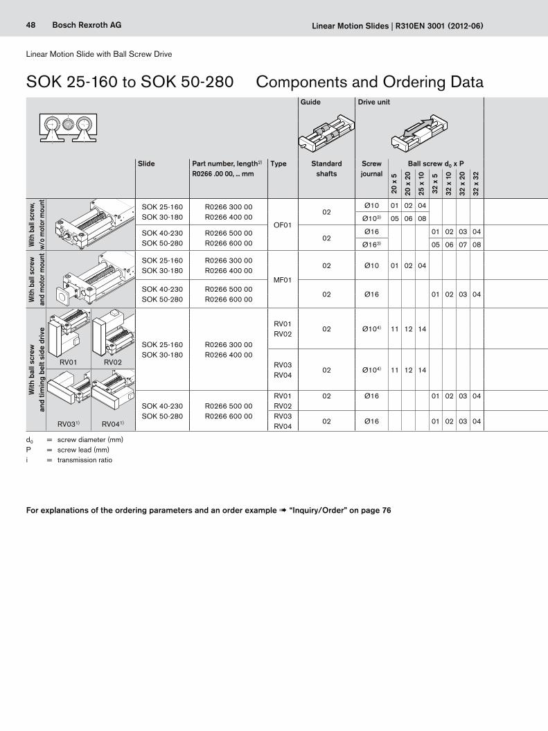
48 Bosch Rexroth AG
Linear Motion Slide with Ball Screw Drive
Linear Motion Slides | R310EN 3001 (2012-06)
SOK 25-160 to SOK 50-280
d0 = screw diameter (mm)P = screw lead (mm) i = transmission ratio
Components and Ordering DataGuide Drive unit Carriage Motor attachment Motor Cover Switches / Cable duct /
Socket-plugDocumentation
Slide Part number, length2) R0266 .00 00, ... mm
Type Standard shafts
Screw journal
Ball screw d0 x P Standard i = Attach-ment kit5)
for motor Brake PU bellows Standard report
Measure-ment
report8)
20 x
5
20 x
20
25 x
10
32 x
5
32 x
10
32 x
20
32 x
32 with-
outwith with-
outwith
With
bal
l scr
ew,
w/o
mot
or m
ount SOK 25-160
SOK 30-180R0266 300 00R0266 400 00
OF01
02Ø10 01 02 04
01 1 00 00
00 01
Without switches00Without cable duct
Without socket and plug
Switches:– PNP NC 11– PNP NO 13– Mechanical 15
Ordering data:Switch type
Cable duct (loose) 7) 20
Socket-plug 17
Switching cam and profiled support for switches
16
01
02
Ø103) 05 06 08
SOK 40-230SOK 50-280
R0266 500 00R0266 600 00
02Ø16 01 02 03 04
01 1 00 00Ø163) 05 06 07 08
With
bal
l scr
ew
and
mot
or m
ount SOK 25-160
SOK 30-180R0266 300 00R0266 400 00
MF01
02 Ø10 01 02 04 01 103 MSK 040C 866) 876)
06 MSM 041B 1106) 1116)
SOK 40-230SOK 50-280
R0266 500 00R0266 600 00
02 Ø16 01 02 03 04 01 102 MSK 076C 926) 936)
05 MSK 060C 906) 916)
With
bal
l scr
ew
and
timin
g be
lt si
de d
rive
SOK 25-160SOK 30-180
R0266 300 00R0266 400 00
RV01RV02
02 Ø104) 11 12 14 011
10 MSK 040C 866) 876)
03
20 MSM 041B 1106) 1116)
1.512 MSK 040C 866) 876)
22 MSM 041B 1106) 1116)
RV03RV04
02 Ø104) 11 12 14 011
14 MSK 040C 866) 876)
RV01 RV02 24 MSM 041B 1106) 1116)
1.516 MSK 040C 866) 876)
26 MSM 041B 1106) 1116)
SOK 40-230SOK 50-280
R0266 500 00R0266 600 00
RV01RV02
02 Ø16 01 02 03 04 01 1 30
MSK 060C 906) 916)2 31RV03RV04
02 Ø16 01 02 03 04 011 32
RV031) RV041) 2 33
For explanations of the ordering parameters and an order example ! “Inquiry/Order” on page 76
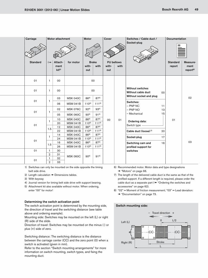
49Bosch Rexroth AG
L
0 L/2
R310EN 3001 (2012-06) | Linear Motion Slides
Guide Drive unit Carriage Motor attachment Motor Cover Switches / Cable duct / Socket-plug
Documentation
Slide Part number, length2) R0266 .00 00, ... mm
Type Standard shafts
Screw journal
Ball screw d0 x P Standard i = Attach-ment kit5)
for motor Brake PU bellows Standard report
Measure-ment
report8)
20 x
5
20 x
20
25 x
10
32 x
5
32 x
10
32 x
20
32 x
32 with-
outwith with-
outwith
With
bal
l scr
ew,
w/o
mot
or m
ount SOK 25-160
SOK 30-180R0266 300 00R0266 400 00
OF01
02Ø10 01 02 04
01 1 00 00
00 01
Without switches00Without cable duct
Without socket and plug
Switches:– PNP NC 11– PNP NO 13– Mechanical 15
Ordering data:Switch type
Cable duct (loose) 7) 20
Socket-plug 17
Switching cam and profiled support for switches
16
01
02
Ø103) 05 06 08
SOK 40-230SOK 50-280
R0266 500 00R0266 600 00
02Ø16 01 02 03 04
01 1 00 00Ø163) 05 06 07 08
With
bal
l scr
ew
and
mot
or m
ount SOK 25-160
SOK 30-180R0266 300 00R0266 400 00
MF01
02 Ø10 01 02 04 01 103 MSK 040C 866) 876)
06 MSM 041B 1106) 1116)
SOK 40-230SOK 50-280
R0266 500 00R0266 600 00
02 Ø16 01 02 03 04 01 102 MSK 076C 926) 936)
05 MSK 060C 906) 916)
With
bal
l scr
ew
and
timin
g be
lt si
de d
rive
SOK 25-160SOK 30-180
R0266 300 00R0266 400 00
RV01RV02
02 Ø104) 11 12 14 011
10 MSK 040C 866) 876)
03
20 MSM 041B 1106) 1116)
1.512 MSK 040C 866) 876)
22 MSM 041B 1106) 1116)
RV03RV04
02 Ø104) 11 12 14 011
14 MSK 040C 866) 876)
RV01 RV02 24 MSM 041B 1106) 1116)
1.516 MSK 040C 866) 876)
26 MSM 041B 1106) 1116)
SOK 40-230SOK 50-280
R0266 500 00R0266 600 00
RV01RV02
02 Ø16 01 02 03 04 01 1 30
MSK 060C 906) 916)2 31RV03RV04
02 Ø16 01 02 03 04 011 32
RV031) RV041) 2 33
1) Switches can only be mounted on the side opposite the timing belt side drive.
2) Length calculation ! Dimensions tables.3) With keyway4) Journal version for timing belt side drive with support bearing.5) Attachment kit also available without motor. When ordering,
enter “00” for motor!
The switch activation point is determined by the mounting side, the direction of travel and the switching distance (see table above and ordering example).Mounting side: Switches may be mounted on the left (L) or right (R) side of the slide.Direction of travel: Switches may be mounted on the minus (-) or plus (+) side of zero.
Switching distance: The switching distance is the distance between the carriage center (CC) and the zero point (0) when a switch is activated (given in mm).Refer to the section “Switch mounting arrangements” for more information on switch mounting, switch types, and fixing the mounting duct.
Determining the switch activation point
Left (L)
Right (R)
Switch mounting side:
Stroke
– Travel direction +
6) Recommended motor. Motor data and type designations ! “Motors” on page 66.
7) The length of the delivered cable duct is the same as that of the profiled support. If a different length is required, please order the cable duct as a separate part (! “Ordering the switches and accessories” on page 62).
8) “02” = Moment of friction measurement; “03” = Lead deviation: ! “Documentation” on page 73.
CC CC
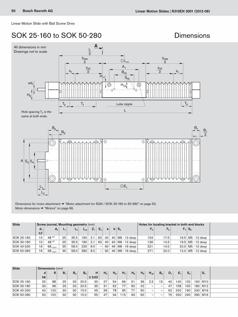
50 Bosch Rexroth AG
B1
T2 T1 T2
B15
S15
Lca
ød1 H15
E4E2A
L1
L2
E1
L
B4B5
A1
H9
H11
A
sese
smax2
L2
smax2
B12
seff2
seff2
Linear Motion Slide with Ball Screw Drive
Linear Motion Slides | R310EN 3001 (2012-06)
SOK 25-160 to SOK 50-280
Hole spacing T2 is the same at both ends.
All dimensions in mmDrawings not to scale
Slide Screw journal, Mounting geometry (mm) Holes for locating bracket in both end blocks For switching cam Length calculation2) L (mm)d1 d2 L1 L2 Lca Z1 E4 a b S4 F5 F6 F7 S5 B15 H15 S15 with bellows without bellowsh7
SOK 25-160 10 48 H7 25 35.5 160 2.1 63 40 40 M6 - 12 deep 104 17.5 16.5 M5 - 12 deep 64 28 M4 - 10 deep L = smax · 1.24 + Lca + 39
L = smax + Lca + 3SOK 30-180 10 48 H7 25 35.5 180 2.1 63 40 40 M6 - 12 deep 126 14.5 19.5 M5 - 12 deep 64 36 M4 - 10 deep L = smax · 1.20 + Lca + 38SOK 40-230 16 68–0.01 35 58.0 230 8.0 – 90 46 M8 - 16 deep 221 14.0 20.0 M5 - 12 deep 64 26 M4 - 10 deep L = smax · 1.14 + Lca + 39SOK 50-280 16 68–0.01 35 58.0 280 8.0 – 90 46 M8 - 16 deep 271 22.0 12.0 M5 - 12 deep 64 28 M4 - 10 deep L = smax · 1.112 + Lca + 40
Slide Dimensions (mm) Shaft support rails Lube nipple For any required work on the carriage, the following drawings are available as downloads3)d R B1 B4 B5 H H5 H6 H7 H8 H9 H18 B6 D1 E1 E2 S1 S6 N H16 H17 E3 S3 T1 T2 A1 H11 DIN 3405
h6 ± 0.02SOK 25-160 25 88 25 33 20.5 30 27 54 66 51 36 2.5 15 40 140 132 160 M10 M12 x 40 22 6 9.8 42 6.6 120 ≥ 24 116 9.5 AM8 x 1 TB02-016-14SOK 30-180 30 96 25 33 20.5 35 31 62 77 60 42 – – 47 158 150 180 M12 M12 x 45 26 7 10.0 51 9.0 150 ≥ 30 130 9.5 AM8 x 1 TB02-016-15SOK 40-230 40 122 30 30 15.0 45 39 78 95 77 50 – – 62 202 190 230 M16 M16 x 60 34 8 11.8 55 9.0 200 ≥ 30 170 11.5 AM8 x 1 TB02-016-16SOK 50-280 50 152 30 30 15.0 55 47 94 115 93 60 – – 75 250 240 280 M16 M16 x 60 34 9 14.3 63 11.0 200 ≥ 30 220 15.0 AM8 x 1 TB02-016-17
Lube nipple
Dimensions
Dimensions for motor attachment ! “Motor attachment for SGK / SOK 25-160 to 50-280” on page 52.Motor dimensions ! “Motors” on page 66.
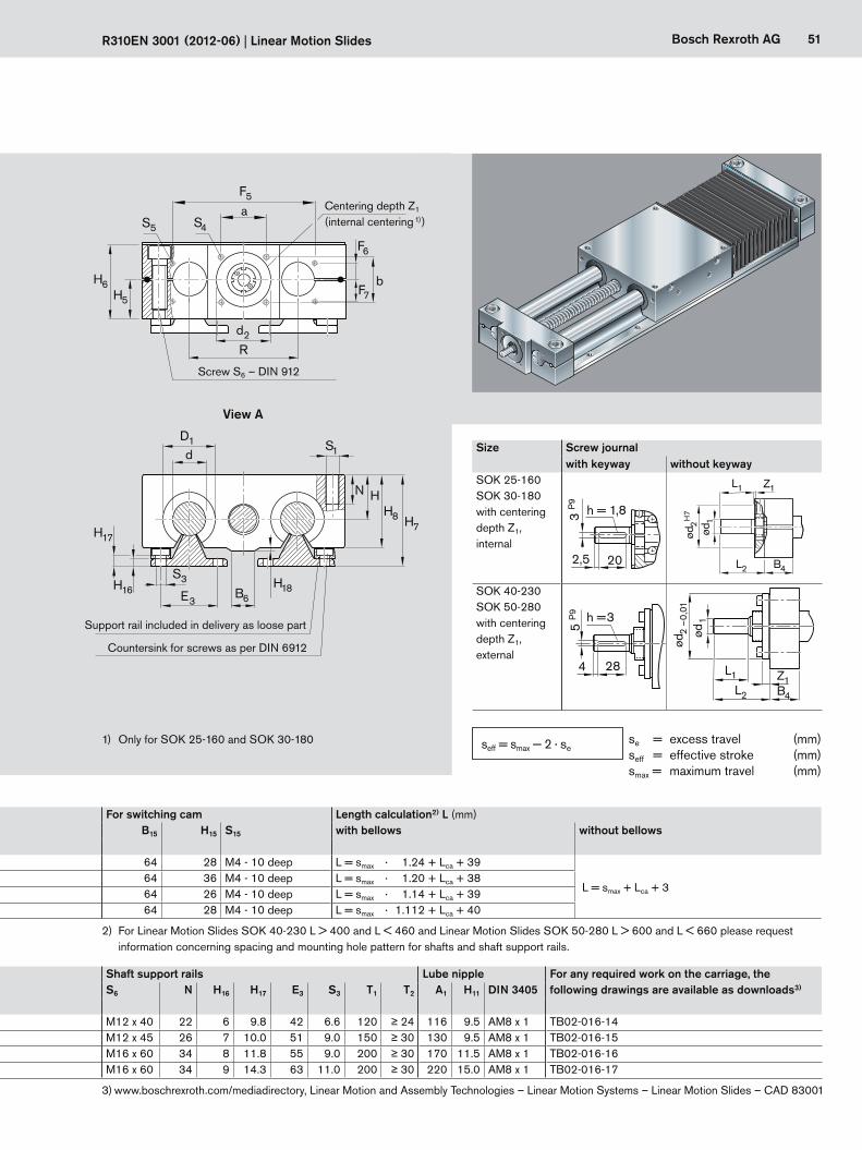
51Bosch Rexroth AG
B6H18
d2
F5
a
H5
H6
R
bF7
F6
S4S5
dS1
E3
D1
H8
HN
S3
H17
H16
H7
R310EN 3001 (2012-06) | Linear Motion Slides
Slide Screw journal, Mounting geometry (mm) Holes for locating bracket in both end blocks For switching cam Length calculation2) L (mm)d1 d2 L1 L2 Lca Z1 E4 a b S4 F5 F6 F7 S5 B15 H15 S15 with bellows without bellowsh7
SOK 25-160 10 48 H7 25 35.5 160 2.1 63 40 40 M6 - 12 deep 104 17.5 16.5 M5 - 12 deep 64 28 M4 - 10 deep L = smax · 1.24 + Lca + 39
L = smax + Lca + 3SOK 30-180 10 48 H7 25 35.5 180 2.1 63 40 40 M6 - 12 deep 126 14.5 19.5 M5 - 12 deep 64 36 M4 - 10 deep L = smax · 1.20 + Lca + 38SOK 40-230 16 68–0.01 35 58.0 230 8.0 – 90 46 M8 - 16 deep 221 14.0 20.0 M5 - 12 deep 64 26 M4 - 10 deep L = smax · 1.14 + Lca + 39SOK 50-280 16 68–0.01 35 58.0 280 8.0 – 90 46 M8 - 16 deep 271 22.0 12.0 M5 - 12 deep 64 28 M4 - 10 deep L = smax · 1.112 + Lca + 40
Slide Dimensions (mm) Shaft support rails Lube nipple For any required work on the carriage, the following drawings are available as downloads3)d R B1 B4 B5 H H5 H6 H7 H8 H9 H18 B6 D1 E1 E2 S1 S6 N H16 H17 E3 S3 T1 T2 A1 H11 DIN 3405
h6 ± 0.02SOK 25-160 25 88 25 33 20.5 30 27 54 66 51 36 2.5 15 40 140 132 160 M10 M12 x 40 22 6 9.8 42 6.6 120 ≥ 24 116 9.5 AM8 x 1 TB02-016-14SOK 30-180 30 96 25 33 20.5 35 31 62 77 60 42 – – 47 158 150 180 M12 M12 x 45 26 7 10.0 51 9.0 150 ≥ 30 130 9.5 AM8 x 1 TB02-016-15SOK 40-230 40 122 30 30 15.0 45 39 78 95 77 50 – – 62 202 190 230 M16 M16 x 60 34 8 11.8 55 9.0 200 ≥ 30 170 11.5 AM8 x 1 TB02-016-16SOK 50-280 50 152 30 30 15.0 55 47 94 115 93 60 – – 75 250 240 280 M16 M16 x 60 34 9 14.3 63 11.0 200 ≥ 30 220 15.0 AM8 x 1 TB02-016-17
1) Only for SOK 25-160 and SOK 30-180
Screw S6 – DIN 912
Centering depth Z1
(internal centering 1) )
Countersink for screws as per DIN 6912
Support rail included in delivery as loose part
View A
Size Screw journalwith keyway without keyway
SOK 25-160SOK 30-180with centering depth Z1, internal
202,5
284
h = 1,83 P
9
ød2
–0,
01h = 3
5 P
9
L1
B4
ød1
ød2 H
7
Z1
L2
L1 Z1L2 B4
ød1
202,5
284
h = 1,83 P
9
ød2
–0,
01h = 3
5 P
9
L1
B4
ød1
ød2 H
7
Z1
L2
L1 Z1L2 B4
ød1
SOK 40-230SOK 50-280with centering depth Z1, external
202,5
284
h = 1,83 P
9
ød2
–0,
01h = 3
5 P
9
L1
B4
ød1
ød2 H
7
Z1
L2
L1 Z1L2 B4
ød1
202,5
284
h = 1,83 P
9
ød2
–0,
01h = 3
5 P
9
L1
B4
ød1
ød2 H
7
Z1
L2
L1 Z1L2 B4
ød1
2) For Linear Motion Slides SOK 40-230 L > 400 and L < 460 and Linear Motion Slides SOK 50-280 L > 600 and L < 660 please request information concerning spacing and mounting hole pattern for shafts and shaft support rails.
se = excess travel (mm)seff = effective stroke (mm)smax = maximum travel (mm)
seff = smax — 2 · se
3) www.boschrexroth.com/mediadirectory, Linear Motion and Assembly Technologies – Linear Motion Systems – Linear Motion Slides – CAD 83001
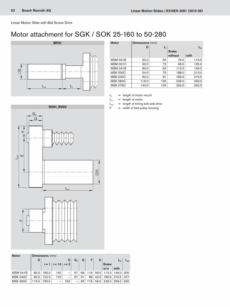
52 Bosch Rexroth AG
L sd
D
KF
G1
Lm
D
LfLm
MF01
RV01, RV02
Linear Motion Slide with Ball Screw Drive
Linear Motion Slides | R310EN 3001 (2012-06)
Motor attachment for SGK / SOK 25-160 to 50-280Motor Dimensions (mm)
D Lf Lm
Brakewithout with
MSM 031B 60.0 50 79.0 115.5MSM 031C 60.0 72 98.5 135.0MSM 041B 80.0 83 112.0 149.0MSK 030C 54.0 75 188.0 213.0MSK 040C 82.0 81 185.5 215.5MSK 060C 116.0 125 226.0 259.0MSK 076C 140.0 125 292.5 292.5
Motor Dimensions (mm)D E G1 G F K Lm Lsd
i = 1 i = 1.5 i = 2 Brakew/o with
MSM 041B 80.0 165.0 162 – 57 66 116 59.0 112.0 149.0 300MSK 040C 82.0 122.5 122 – 57 51 88 43.5 185.5 215.5 227MSK 060C 116.0 165.0 – 162 – 66 116 59.0 226.0 259.0 300
Lf = length of motor mountLm = length of motor Lsd = length of timing belt side driveF = width of belt pulley housing
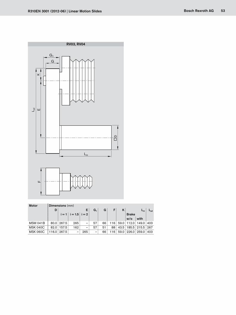
53Bosch Rexroth AG
L sd
D
G1
Lm
FK
RV03, RV04
R310EN 3001 (2012-06) | Linear Motion Slides
Motor Dimensions (mm)D E G1 G F K Lm Lsd
i = 1 i = 1.5 i = 2 Brakew/o with
MSM 041B 80.0 267.5 265 – 57 66 116 59.0 112.0 149.0 403MSK 040C 82.0 157.5 162 – 57 51 88 43.5 185.5 215.5 267MSK 060C 116.0 267.5 – 265 – 66 116 59.0 226.0 259.0 403
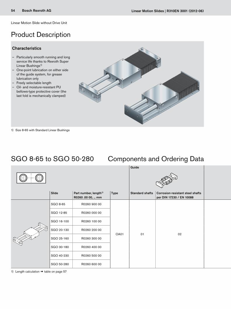
54 Bosch Rexroth AG Linear Motion Slides | R310EN 3001 (2012-06)
Product Description
Linear Motion Slide without Drive Unit
Characteristics
– Particularly smooth running and long service life thanks to Rexroth Super Linear Bushings1)
– One-point lubrication on either side of the guide system, for grease lubrication only
– Freely selectable length – Oil- and moisture-resistant PU
bellows-type protective cover (the last fold is mechanically clamped)
1) Size 8-65 with Standard Linear Bushings
Guide Drive Unit (end block) Carriage Cover Documentation
Slide Part number, length1) Type Standard shafts Corrosion-resistant steel shafts per DIN 17230 / EN 10088
End block A End block B Standard Polyurethane bellows StandardR0260 .00 00, ... mm without with
SGO 8-65 R0260 900 00
OA01 01 02 01 02 01 00 01 01
SGO 12-85 R0260 000 00
SGO 16-100 R0260 100 00
SGO 20-130 R0260 200 00
SGO 25-160 R0260 300 00
SGO 30-180 R0260 400 00
SGO 40-230 R0260 500 00
SGO 50-280 R0260 600 00
SGO 8-65 to SGO 50-280 Components and Ordering Data
1) Length calculation ! table on page 57
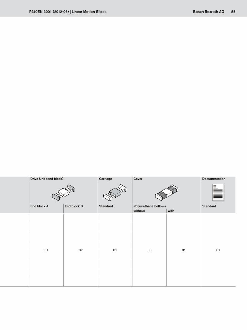
55Bosch Rexroth AGR310EN 3001 (2012-06) | Linear Motion Slides
Guide Drive Unit (end block) Carriage Cover Documentation
Slide Part number, length1) Type Standard shafts Corrosion-resistant steel shafts per DIN 17230 / EN 10088
End block A End block B Standard Polyurethane bellows StandardR0260 .00 00, ... mm without with
SGO 8-65 R0260 900 00
OA01 01 02 01 02 01 00 01 01
SGO 12-85 R0260 000 00
SGO 16-100 R0260 100 00
SGO 20-130 R0260 200 00
SGO 25-160 R0260 300 00
SGO 30-180 R0260 400 00
SGO 40-230 R0260 500 00
SGO 50-280 R0260 600 00
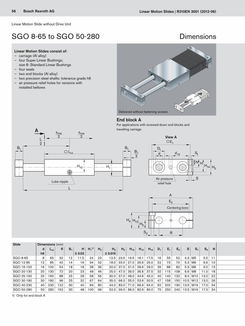
56 Bosch Rexroth AG
B1B1
A
H10
L
Lca
H1
d12
D1d S1
N HH14 H2
S
E1
S2 R
E2
H3
H13H4
A
smax2
smax2
L2
B12
Linear Motion Slides | R310EN 3001 (2012-06)
Linear Motion Slide without Drive Unit
Linear Motion Slides consist of: – carriage (Al alloy) – four Super Linear Bushings;
size 8: Standard Linear Bushings – four seals – two end blocks (Al alloy) – two precision steel shafts: tolerance grade h6 – air pressure relief holes for versions with
installed bellows
End block AFor applications with screwed-down end blocks and travelling carriage
View A
Centering bore
Air pressure relief holeLube nipple
Delivered without fastening screws
Slide Dimensions (mm)d
h6Lca R B1 H
± 0.02H1
1) H2 H3
± 0.015H4 H10 H13 H14 D1 E1 E2 S S1 S2 N
SGO 8-65 8 65 32 12 11.5 24 23 12.5 23.5 19.5 18.1 17.5 16 55 52 4.3 M5 5.5 11SGO 12-85 12 85 42 14 16 34 32 18.0 33.0 27.0 26.6 25.0 22 73 70 5.3 M6 6.6 13SGO 16-100 16 100 54 18 18 38 36 20.0 37.0 31.0 28.6 29.0 26 88 82 5.3 M6 9.0 13SGO 20-130 20 130 72 20 23 48 46 25.0 47.0 39.0 36.6 37.5 32 115 108 6.6 M8 11.0 18SGO 25-160 25 160 88 25 28 58 56 30.0 57.0 48.0 44.6 45.0 40 140 132 8.4 M10 13.0 22SGO 30-180 30 180 96 25 32 67 64 35.0 66.0 55.0 53.6 50.5 47 158 150 10.5 M12 13.0 26SGO 40-230 40 230 122 30 40 84 80 44.0 83.0 71.0 66.6 64.0 62 202 190 13.5 M16 17.0 34SGO 50-280 50 280 152 30 48 100 96 52.0 99.0 86.0 82.6 80.0 75 250 240 13.5 M16 17.0 34
1) Only for end block A
SGO 8-65 to SGO 50-280 Dimensions
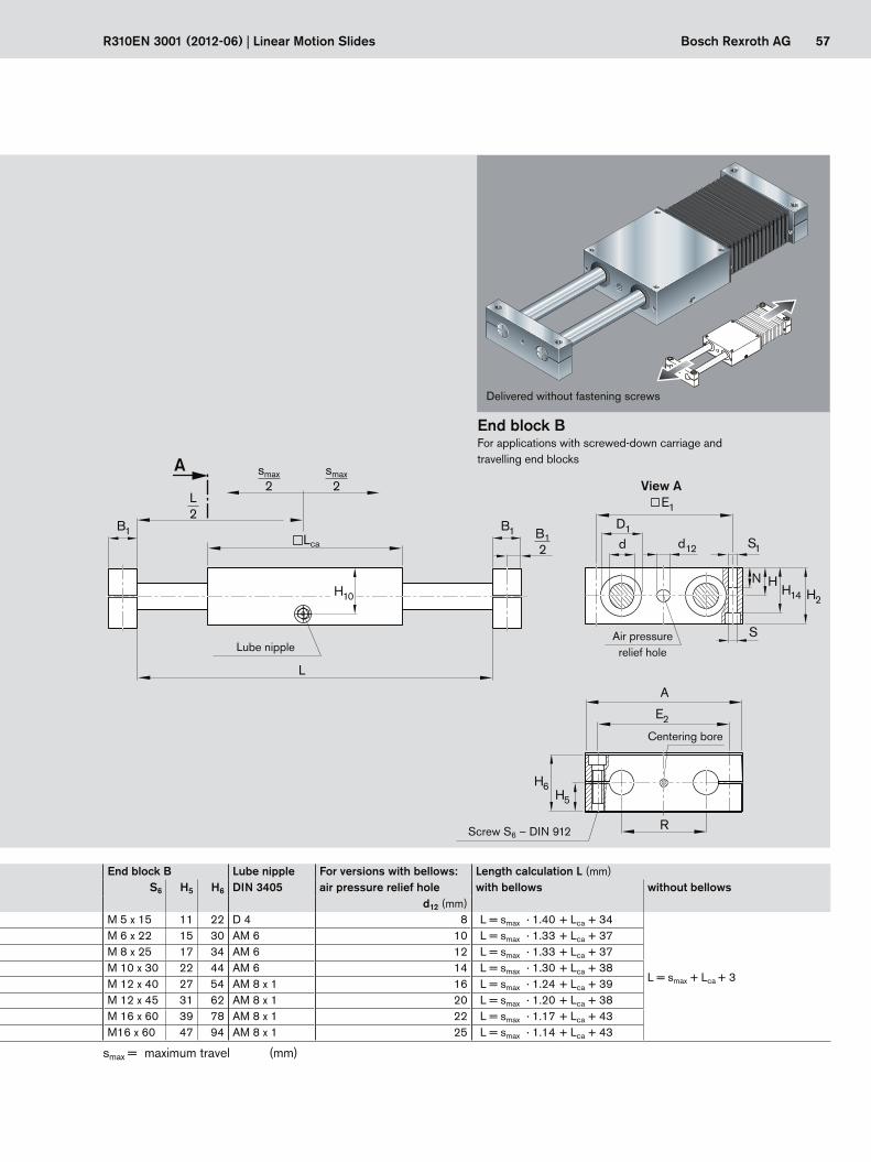
57Bosch Rexroth AG
B1B1
A
L
Lca
R
E2
H5
H6
A
d12
D1
d S1
N HH14 H2
S
E1
H10
smax2
L2
smax2
B12
R310EN 3001 (2012-06) | Linear Motion Slides
Slide Dimensions (mm)d
h6Lca R B1 H
± 0.02H1
1) H2 H3
± 0.015H4 H10 H13 H14 D1 E1 E2 S S1 S2 N
SGO 8-65 8 65 32 12 11.5 24 23 12.5 23.5 19.5 18.1 17.5 16 55 52 4.3 M5 5.5 11SGO 12-85 12 85 42 14 16 34 32 18.0 33.0 27.0 26.6 25.0 22 73 70 5.3 M6 6.6 13SGO 16-100 16 100 54 18 18 38 36 20.0 37.0 31.0 28.6 29.0 26 88 82 5.3 M6 9.0 13SGO 20-130 20 130 72 20 23 48 46 25.0 47.0 39.0 36.6 37.5 32 115 108 6.6 M8 11.0 18SGO 25-160 25 160 88 25 28 58 56 30.0 57.0 48.0 44.6 45.0 40 140 132 8.4 M10 13.0 22SGO 30-180 30 180 96 25 32 67 64 35.0 66.0 55.0 53.6 50.5 47 158 150 10.5 M12 13.0 26SGO 40-230 40 230 122 30 40 84 80 44.0 83.0 71.0 66.6 64.0 62 202 190 13.5 M16 17.0 34SGO 50-280 50 280 152 30 48 100 96 52.0 99.0 86.0 82.6 80.0 75 250 240 13.5 M16 17.0 34
View A
End block BFor applications with screwed-down carriage and travelling end blocks
Centering bore
Air pressure relief holeLube nipple
Screw S6 – DIN 912
Delivered without fastening screws
smax = maximum travel (mm)
End block B Lube nippleDIN 3405
For versions with bellows: Length calculation L (mm)S6 H5 H6 air pressure relief hole with bellows without bellows
d12 (mm)M 5 x 15 11 22 D 4 8 L = smax · 1.40 + Lca + 34
L = smax + Lca + 3
M 6 x 22 15 30 AM 6 10 L = smax · 1.33 + Lca + 37M 8 x 25 17 34 AM 6 12 L = smax · 1.33 + Lca + 37M 10 x 30 22 44 AM 6 14 L = smax · 1.30 + Lca + 38M 12 x 40 27 54 AM 8 x 1 16 L = smax · 1.24 + Lca + 39M 12 x 45 31 62 AM 8 x 1 20 L = smax · 1.20 + Lca + 38M 16 x 60 39 78 AM 8 x 1 22 L = smax · 1.17 + Lca + 43M16 x 60 47 94 AM 8 x 1 25 L = smax · 1.14 + Lca + 43
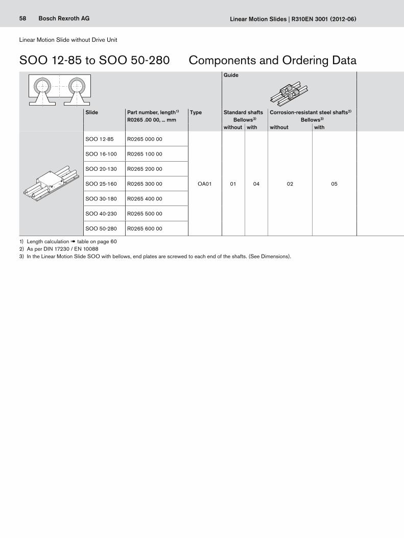
58 Bosch Rexroth AG Linear Motion Slides | R310EN 3001 (2012-06)
Linear Motion Slide without Drive Unit
1) Length calculation ! table on page 602) As per DIN 17230 / EN 100883) In the Linear Motion Slide SOO with bellows, end plates are screwed to each end of the shafts. (See Dimensions).
Guide Carriage Cover Documentation
Slide Part number, length1) R0265 .00 00, ... mm
Type Standard shafts Corrosion-resistant steel shafts2) Standard Polyurethane bellows StandardBellows3) Bellows3) without with
without with without with
SOO 12-85 R0265 000 00
OA01 01 04 02 05 01 00 01 01
SOO 16-100 R0265 100 00
SOO 20-130 R0265 200 00
SOO 25-160 R0265 300 00
SOO 30-180 R0265 400 00
SOO 40-230 R0265 500 00
SOO 50-280 R0265 600 00
SOO 12-85 to SOO 50-280 Components and Ordering Data
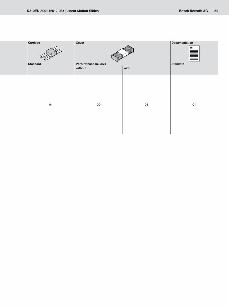
59Bosch Rexroth AGR310EN 3001 (2012-06) | Linear Motion Slides
Guide Carriage Cover Documentation
Slide Part number, length1) R0265 .00 00, ... mm
Type Standard shafts Corrosion-resistant steel shafts2) Standard Polyurethane bellows StandardBellows3) Bellows3) without with
without with without with
SOO 12-85 R0265 000 00
OA01 01 04 02 05 01 00 01 01
SOO 16-100 R0265 100 00
SOO 20-130 R0265 200 00
SOO 25-160 R0265 300 00
SOO 30-180 R0265 400 00
SOO 40-230 R0265 500 00
SOO 50-280 R0265 600 00

60 Bosch Rexroth AG
L
Lca
A1
T2T2 T1
H8HN
E1
R
D1
WE3
S3
α
H16
H11
B6
H7 H18
S1d
Asmax2
smax2
L2
Linear Motion Slides | R310EN 3001 (2012-06)
Linear Motion Slide without Drive Unit
Linear Motion Slides consist of:– carriage (Al alloy)– four Super Linear Bushings– four seals– two precision steel shafts, tolerance grade h6,
with shaft support rails (Al alloy)
View A
Centering bore
Hole spacing T2 is the same at both ends.
2 lube nipples on each side
Slide Dimensions (mm) – except for angle α Shaft support rails Lube nipple Length calculation1) L (mm)d Lca R H H7 H8 H18 B6 W α D1 E1 S1 N H16 H17 S3 E3 T1 T2 A1 H11 DIN 3405 with bellows without bellows
h6 ± 0.02SOO 12-85 12 85 42 18 40 30 – – 6.5 66 ° 22 73 M6 13 5 6.5 4.5 29 75 ≥ 15 57 7.0 AM6 L = smax · 1.330 + Lca + 37
L = smax + Lca + 3
SOO 16-100 16 100 54 22 48 35 3.0 15 9.0 68 ° 26 88 M6 13 5 8.3 5.5 33 100 ≥ 20 68 7.2 AM6 L = smax · 1.330 + Lca + 37SOO 20-130 20 130 72 25 57 42 3.5 12 9.0 55 ° 32 115 M8 18 6 9.8 6.6 37 100 ≥ 20 94 7.2 AM6 L = smax · 1.300 + Lca + 38SOO 25-160 25 160 88 30 66 51 2.5 15 11.5 57 ° 40 140 M10 22 6 9.8 6.6 42 120 ≥ 24 116 9.5 AM8 x 1 L = smax · 1.240 + Lca + 39SOO 30-180 30 180 96 35 77 60 – – 14.0 57 ° 47 158 M12 26 7 10.0 9.0 51 150 ≥ 30 130 9.5 AM8 x 1 L = smax · 1.200 + Lca + 38SOO 40-230 40 230 122 45 95 77 – – 19.5 56 ° 62 202 M16 34 8 11.8 9.0 55 200 ≥ 30 170 11.5 AM8 x 1 L = smax · 1.140 + Lca + 39SOO 50-280 50 280 152 55 115 93 – – 22.5 54 ° 75 250 M16 34 9 14.3 11.0 63 200 ≥ 30 220 15.0 AM8 x 1 L = smax · 1.112 + Lca + 40
SOO 12-85 to SOO 50-280 Dimensions
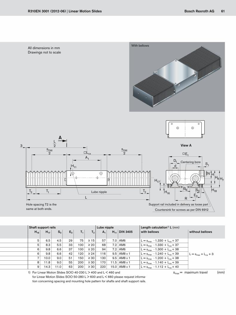
61Bosch Rexroth AG
B6
R
H18
3
T2 T1 T2
Lca
H11
L
A1
d S1
E3
D1
H8HN
H17
H16
H7
E1
S3
A
smax2
smax2
L2
R310EN 3001 (2012-06) | Linear Motion Slides
Slide Dimensions (mm) – except for angle α Shaft support rails Lube nipple Length calculation1) L (mm)d Lca R H H7 H8 H18 B6 W α D1 E1 S1 N H16 H17 S3 E3 T1 T2 A1 H11 DIN 3405 with bellows without bellows
h6 ± 0.02SOO 12-85 12 85 42 18 40 30 – – 6.5 66 ° 22 73 M6 13 5 6.5 4.5 29 75 ≥ 15 57 7.0 AM6 L = smax · 1.330 + Lca + 37
L = smax + Lca + 3
SOO 16-100 16 100 54 22 48 35 3.0 15 9.0 68 ° 26 88 M6 13 5 8.3 5.5 33 100 ≥ 20 68 7.2 AM6 L = smax · 1.330 + Lca + 37SOO 20-130 20 130 72 25 57 42 3.5 12 9.0 55 ° 32 115 M8 18 6 9.8 6.6 37 100 ≥ 20 94 7.2 AM6 L = smax · 1.300 + Lca + 38SOO 25-160 25 160 88 30 66 51 2.5 15 11.5 57 ° 40 140 M10 22 6 9.8 6.6 42 120 ≥ 24 116 9.5 AM8 x 1 L = smax · 1.240 + Lca + 39SOO 30-180 30 180 96 35 77 60 – – 14.0 57 ° 47 158 M12 26 7 10.0 9.0 51 150 ≥ 30 130 9.5 AM8 x 1 L = smax · 1.200 + Lca + 38SOO 40-230 40 230 122 45 95 77 – – 19.5 56 ° 62 202 M16 34 8 11.8 9.0 55 200 ≥ 30 170 11.5 AM8 x 1 L = smax · 1.140 + Lca + 39SOO 50-280 50 280 152 55 115 93 – – 22.5 54 ° 75 250 M16 34 9 14.3 11.0 63 200 ≥ 30 220 15.0 AM8 x 1 L = smax · 1.112 + Lca + 40
All dimensions in mmDrawings not to scale
With bellows
Hole spacing T2 is the same at both ends.
Lube nipple
Countersink for screws as per DIN 6912
Support rail included in delivery as loose part
View A
Centering bore
1) For Linear Motion Slides SOO 40-230 L > 400 and L < 460 and for Linear Motion Slides SOO 50-280 L > 600 and L < 660 please request informa-tion concerning spacing and mounting hole pattern for shafts and shaft support rails.
smax = maximum travel (mm)
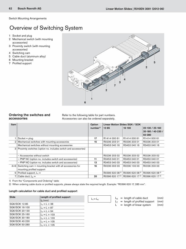
62 Bosch Rexroth AG Linearschlitten R310DE 3001 (2012-06)
62 Bosch Rexroth AG
1
2
5
34
7
2
6
Linear Motion Slides | R310EN 3001 (2012-06)
1 Socket and plug2 Mechanical switch (with mounting
accessories)3 Proximity switch (with mounting
accessories)4 Switching cam5 Cable duct (aluminum alloy)6 Mounting bracket7 Profiled support
Switch Mounting Arrangements
Ordering the switches and accessories
Refer to the following table for part numbers.Accessories can also be ordered separately.
1) From the “Components and Ordering” table2) When ordering cable ducts or profiled supports, please always state the required length. Example: “R0396 620 17, 285 mm”.
Item Option number1)
Linear Motion Slides SGK / SOK12-85 16-100 20-130 / 25-160
30-180 / 40-230 / 50-280
1 Socket + plug 17 R1414 000 61 R1414 000 61 R1414 000 612 Mechanical switches with mounting accessories 15 R0236 203 01 R0236 203 01 R0236 203 01
Mechanical switches without mounting accessories R3453 040 16 R3453 040 16 R3453 040 163 Proximity switches (option no. includes switch and accessories)
– Accessories without switch R0236 203 02 R0236 203 02 R0236 203 02– PNP NC (option no. includes switch and accessories) 11 R3453 040 01 R3453 040 01 R3453 040 01– PNP NO (option no. includes switch and accessories) 13 R3453 040 03 R3453 040 03 R3453 040 03
4+6 Switching cam + mounting bracket with all accessories for mounting profiled support
16 R0236 003 03 R0236 103 03 R0236 203 03
5 Profiled support, LT = R0396 620 08 2) R0396 620 08 2) R0396 620 08 2)
7 Cable duct, LK = 20 R0396 620 17 2) R0396 620 17 2) R0396 620 17 2)
LK = length of cable duct (mm)LT = length of profiled support (mm)L = length of linear system (mm)
Length calculation for cable duct and profiled support
Slide Length of profiled supportLT (mm)
SGK/SOK 12-85 LT = L + 38SGK/SOK 16-100 LT = L + 87SGK/SOK 20-130 LT = L + 94SGK/SOK 25-160 LT = L + 103SGK/SOK 30-180 LT = L + 103SGK/SOK 40-230 LT = L + 105SGK/SOK 50-280 LT = L + 105
LT = LK
Overview of Switching System
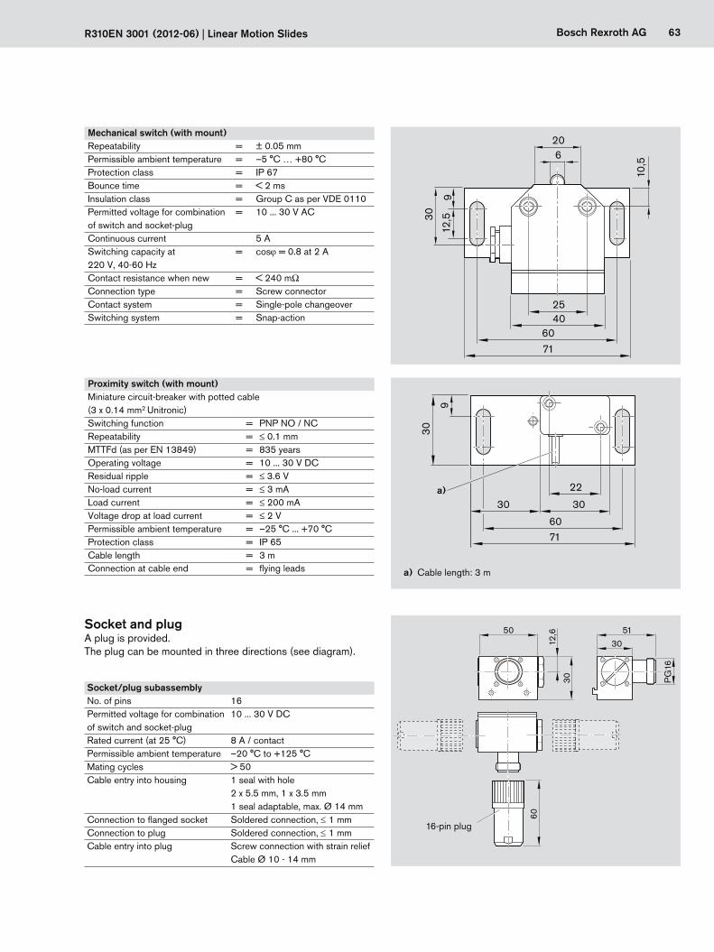
R310DE 3001 (2012-06) Linearschlitten 63Bosch Rexroth AG
63Bosch Rexroth AG
50
12,6
30
60
PG
16
5130
30
9
30a)
71
30
22
60
R310EN 3001 (2012-06) | Linear Motion Slides
Socket and plugA plug is provided.The plug can be mounted in three directions (see diagram).
16-pin plug
620
40
7160
12,530
10,5
25
9
a) Cable length: 3 m
Mechanical switch (with mount)Repeatability = ± 0.05 mmPermissible ambient temperature = –5 °C … +80 °CProtection class = IP 67Bounce time = < 2 msInsulation class = Group C as per VDE 0110Permitted voltage for combination of switch and socket-plug
= 10 ... 30 V AC
Continuous current 5 ASwitching capacity at 220 V, 40-60 Hz
= cosϕ= 0.8 at 2 A
Contact resistance when new = < 240 mΩConnection type = Screw connectorContact system = Single-pole changeoverSwitching system = Snap-action
Proximity switch (with mount)Miniature circuit-breaker with potted cable (3 x 0.14 mm2 Unitronic)Switching function = PNP NO / NCRepeatability = ≤ 0.1 mmMTTFd (as per EN 13849) = 835 yearsOperating voltage = 10 ... 30 V DCResidual ripple = ≤3.6 VNo-load current = ≤ 3 mALoad current = ≤ 200 mAVoltage drop at load current = ≤ 2 V Permissible ambient temperature = –25 °C ... +70 °CProtection class = IP 65 Cable length = 3 mConnection at cable end = flying leads
Socket/plug subassemblyNo. of pins 16Permitted voltage for combination of switch and socket-plug
10 ... 30 V DC
Rated current (at 25 °C) 8 A / contactPermissible ambient temperature –20 °C to +125 °CMating cycles > 50Cable entry into housing 1 seal with hole
2 x 5.5 mm, 1 x 3.5 mm1 seal adaptable, max. Ø 14 mm
Connection to flanged socket Soldered connection, ≤ 1 mmConnection to plug Soldered connection, ≤ 1 mmCable entry into plug Screw connection with strain relief
Cable Ø 10 - 14 mm
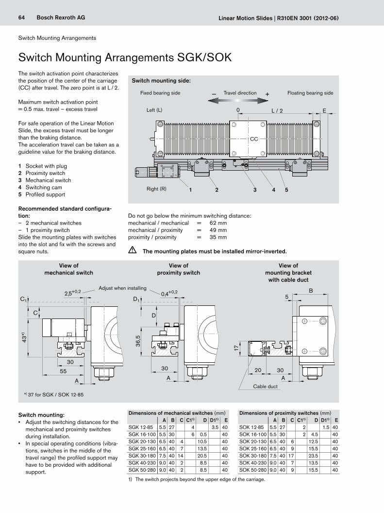
64 Bosch Rexroth AG Linearschlitten R310DE 3001 (2012-06)
64 Bosch Rexroth AG
0 L / 2 E
36,5
30
A
2,5+0,2
C
55
D
D1C10,4+0,2
17
20
5B
3030
A A
43 *)
1 2 3 54
Linear Motion Slides | R310EN 3001 (2012-06)
Dimensions of mechanical switches (mm)A B C C11) D D11) E
SGK 12-85 5.5 27 4 3.5 40SGK 16-100 5.5 30 6 0.5 40SGK 20-130 6.5 40 4 10.5 40SGK 25-160 6.5 40 7 13.5 40SGK 30-180 7.5 40 14 20.5 40SGK 40-230 9.0 40 2 8.5 40SGK 50-280 9.0 40 2 8.5 40
Dimensions of proximity switches (mm)A B C C11) D D11) E
SOK 12-85 5.5 27 2 1.5 40SOK 16-100 5.5 30 2 4.5 40SOK 20-130 6.5 40 6 12.5 40SOK 25-160 6.5 40 9 15.5 40SOK 30-180 7.5 40 17 23.5 40SOK 40-230 9.0 40 7 13.5 40SOK 50-280 9.0 40 9 15.5 40
The switch activation point characterizes the position of the center of the carriage (CC) after travel. The zero point is at L / 2. Maximum switch activation point= 0.5 max. travel – excess travel
For safe operation of the Linear Motion Slide, the excess travel must be longer than the braking distance.The acceleration travel can be taken as a guideline value for the braking distance.
1 Socket with plug2 Proximity switch3 Mechanical switch4 Switching cam5 Profiled support
Do not go below the minimum switching distance:mechanical / mechanical = 62 mmmechanical / proximity = 49 mmproximity / proximity = 35 mm
c The mounting plates must be installed mirror-inverted.
Recommended standard configura-tion:
– 2 mechanical switches – 1 proximity switch
Slide the mounting plates with switches into the slot and fix with the screws and square nuts.
Right (R)
Left (L)
1) The switch projects beyond the upper edge of the carriage.
Switch mounting:• Adjusttheswitchingdistancesforthe
mechanical and proximity switches during installation.
• Inspecialoperatingconditions(vibra-tions, switches in the middle of the travel range) the profiled support may have to be provided with additional support.
*) 37 for SGK / SOK 12-85
View of mechanical switch
View of proximity switch
View of mounting bracket
with cable duct
Cable duct
Adjust when installing
Fixed bearing side
Switch mounting side:
Travel direction Floating bearing side
Switch Mounting Arrangements
Switch Mounting Arrangements SGK/SOK
CC
− +

65Bosch Rexroth AG
L
0 L/2
250250150
0 L/2
R310EN 3001 (2012-06) | Linear Motion Slides
Determining the switchactivation point
The switch activation point is determinedby the following factors:
– Mounting side: Switches may be mounted on the left (L) or right (R) side of the slide.
– Direction of travel: Switches may be mounted on the minus (-) or plus (+) side of zero.
– Switching distance: The switching distance is the dis-tance between the carriage center (CC) and the zero point (0) when a switch is activated (given in mm).
ExampleEffective stroke = 500 mmLimit switches:Switch position for 1st switch = + 250 mmSwitch position for 3rd switch = – 250 mmPositioning switch:Switch position for 2nd switch = – 150 mm
Length LFor length calculations, see “Length calculation” for the respective Linear Motion Slide.
Left (L)
Right (R) Stroke
– Travel direction +
– +
Switch activation point
Switch activation point example
CC CC
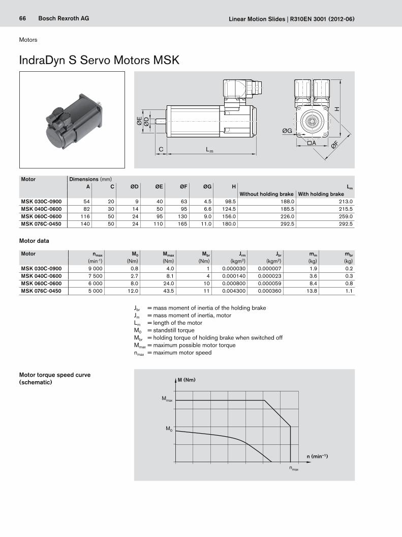
66 Bosch Rexroth AG Linearschlitten R310DE 3001 (2012-06)
66 Bosch Rexroth AG
Mmax
M0
M (Nm)
n (min–1)
nmax
ØE
ØD
C Lm
AØF
H
ØG
Linear Motion Slides | R310EN 3001 (2012-06)
IndraDyn S Servo Motors MSK
Motor Dimensions (mm)A C ØD ØE ØF ØG H Lm
Without holding brake With holding brakeMSK 030C-0900 54 20 9 40 63 4.5 98.5 188.0 213.0MSK 040C-0600 82 30 14 50 95 6.6 124.5 185.5 215.5MSK 060C-0600 116 50 24 95 130 9.0 156.0 226.0 259.0MSK 076C-0450 140 50 24 110 165 11.0 180.0 292.5 292.5
Motor nmax M0 Mmax Mbr Jrm Jbr mm mbr
(min-1) (Nm) (Nm) (Nm) (kgm2) (kgm2) (kg) (kg)MSK 030C-0900 9 000 0.8 4.0 1 0.000030 0.000007 1.9 0.2MSK 040C-0600 7 500 2.7 8.1 4 0.000140 0.000023 3.6 0.3MSK 060C-0600 6 000 8.0 24.0 10 0.000800 0.000059 8.4 0.8MSK 076C-0450 5 000 12.0 43.5 11 0.004300 0.000360 13.8 1.1
Motor data
Motor torque speed curve (schematic)
Jbr = mass moment of inertia of the holding brakeJm = mass moment of inertia, motorLm = length of the motorM0 = standstill torqueMbr = holding torque of holding brake when switched offMmax = maximum possible motor torquenmax = maximum motor speed
Motors

67Bosch Rexroth AGR310EN 3001 (2012-06) | Linear Motion Slides
Option number1) Motor Part number Version Type designationHolding brakewithout with
84 MSK 030C-0900 R911308683 X MSK030C-0900-NN-M1-UG0-NNNN85 R911308684 X MSK030C-0900-NN-M1-UG1-NNNN86 MSK 040C-0600 R911306060 X MSK040C-0600-NN-M1-UG0-NNNN87 R911306061 X MSK040C-0600-NN-M1-UG1-NNNN90 MSK 060C-0600 R911306052 X MSK060C-0600-NN-M1-UG0-NNNN91 R911306053 X MSK060C-0600-NN-M1-UG1-NNNN92 MSK 076C-0450 R911318098 X MSK076C-0450-NN-M1-UG0-NNNN93 R911315713 X MSK076C-0450-NN-M1-UG1-NNNN
1) From the “Components and Ordering” table
NoteThe motors can be supplied complete with controllers and control units. For further motor types and more information on motors, controllers and control systems, please refer to the following Rexroth catalogs on drive technology:
– Drive System Rexroth IndraDrive, R999000018 – Rexroth IndraDyn S Synchronous Motors MSK, R911296289 – Rexroth IndraDrive C Drive Controllers, R911314904 – Rexroth IndraDrive Cs Drive Systems with HCS01, R911322209.
Recommended motor controller combinations
Motor ControllerMSK 030C-0900 HCS 01.1E-W0005MSK 040C-0600 HCS 01.1E-W0008
HCS 01.1E-W0018MSK 060C-0600 HCS 01.1E-W0028
with HNL01.1EMSK 076C-0450
Specification: – Plain shaft with shaft seal ring – Multiturn absolute encoder M1 (Hiperface) – Cooling system: natural convection – Protection class IP65 (casing) – With or without holding brake

68 Bosch Rexroth AG Linearschlitten R310DE 3001 (2012-06)
68 Bosch Rexroth AG
ØE
ØD
C Lm
ØG
ØF
H
A
Mmax
M0
M (Nm)
n (min–1)
nmax
Linear Motion Slides | R310EN 3001 (2012-06)
Motors
IndraDyn S Servo Motors MSM
Motor Dimensions (mm)A C ØD ØE ØF ØG H Lm
Without holding brake With holding brakeMSM 031B-0300 60 30 11 50 70 4.5 73 79.0 115.5MSM 031C-0300 60 30 14 50 70 4.5 73 98.5 135.0MSM 041B-0300 80 35 19 70 90 6.0 93 112.0 149.0
Motor data
Motor nmax M0 Mmax Mbr Jm Jbr mm mbr
(min-1) (Nm) (Nm) (Nm) (kgm2) (kgm2) (kg) (kg)MSM 031B-0300 5 000 0.64 1.91 1.27 0.0000140 0.0000018 0.82 0.48MSM 031C-0300 5 000 1.30 3.80 1.27 0.0000260 0.0000018 1.20 0.50MSM 041B-0300 4 500 2.40 7.10 2.45 0.0000870 0.0000075 2.30 0.80
Motor torque speed curve (schematic)
Jbr = mass moment of inertia of the holding brakeJm = mass moment of inertia, motorLm = length of the motorM0 = standstill torqueMbr = holding torque of holding brake when switched offMmax = maximum possible motor torquenmax = maximum motor speed
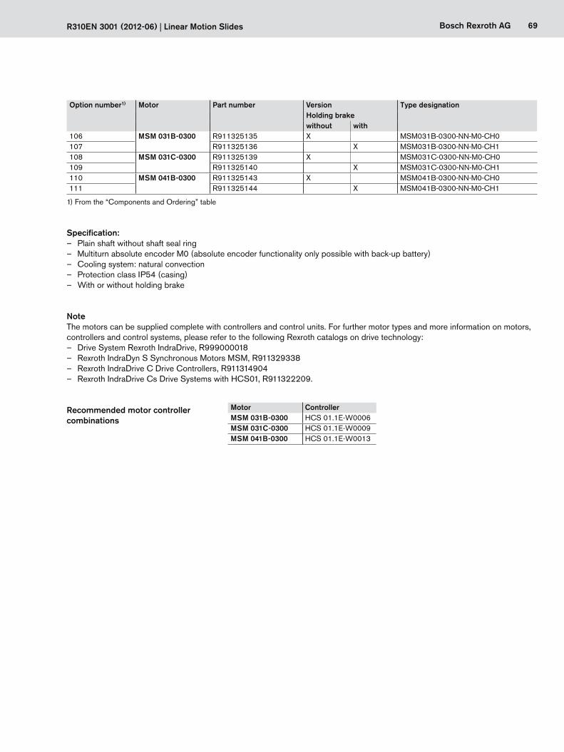
69Bosch Rexroth AGR310EN 3001 (2012-06) | Linear Motion Slides
Option number1) Motor Part number Version Type designationHolding brakewithout with
106 MSM 031B-0300 R911325135 X MSM031B-0300-NN-M0-CH0107 R911325136 X MSM031B-0300-NN-M0-CH1108 MSM 031C-0300 R911325139 X MSM031C-0300-NN-M0-CH0109 R911325140 X MSM031C-0300-NN-M0-CH1110 MSM 041B-0300 R911325143 X MSM041B-0300-NN-M0-CH0111 R911325144 X MSM041B-0300-NN-M0-CH1
1) From the “Components and Ordering” table
Specification: – Plain shaft without shaft seal ring – Multiturn absolute encoder M0 (absolute encoder functionality only possible with back-up battery) – Cooling system: natural convection – Protection class IP54 (casing) – With or without holding brake
NoteThe motors can be supplied complete with controllers and control units. For further motor types and more information on motors, controllers and control systems, please refer to the following Rexroth catalogs on drive technology:
– Drive System Rexroth IndraDrive, R999000018 – Rexroth IndraDyn S Synchronous Motors MSM, R911329338 – Rexroth IndraDrive C Drive Controllers, R911314904 – Rexroth IndraDrive Cs Drive Systems with HCS01, R911322209.
Recommended motor controller combinations
Motor ControllerMSM 031B-0300 HCS 01.1E-W0006MSM 031C-0300 HCS 01.1E-W0009MSM 041B-0300 HCS 01.1E-W0013
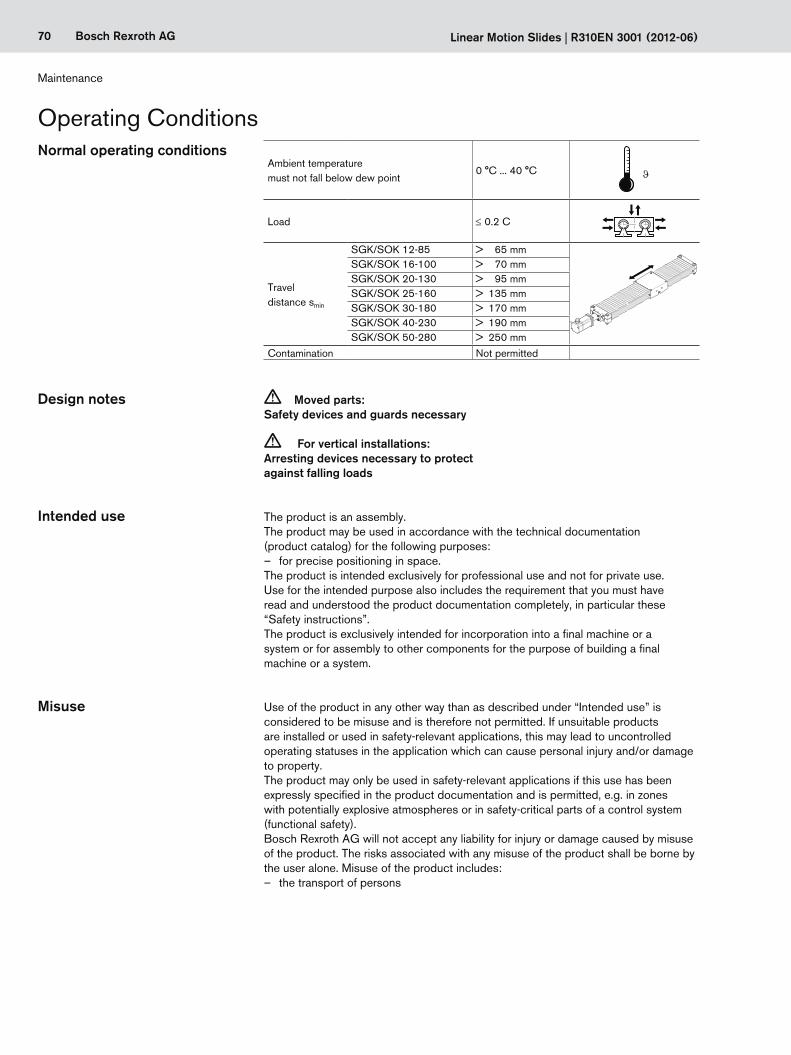
70 Bosch Rexroth AG Linear Motion Slides | R310EN 3001 (2012-06)
Maintenance
Normal operating conditions
Design notes c Moved parts: Safety devices and guards necessary
c For vertical installations: Arresting devices necessary to protect against falling loads
The product is an assembly.The product may be used in accordance with the technical documentation (product catalog) for the following purposes:
– for precise positioning in space.The product is intended exclusively for professional use and not for private use. Use for the intended purpose also includes the requirement that you must have read and understood the product documentation completely, in particular these “Safety instructions”.The product is exclusively intended for incorporation into a final machine or a system or for assembly to other components for the purpose of building a final machine or a system.
Use of the product in any other way than as described under “Intended use” is considered to be misuse and is therefore not permitted. If unsuitable products are installed or used in safety-relevant applications, this may lead to uncontrolled operating statuses in the application which can cause personal injury and/or damage to property.The product may only be used in safety-relevant applications if this use has been expressly specified in the product documentation and is permitted, e.g. in zones with potentially explosive atmospheres or in safety-critical parts of a control system (functional safety).Bosch Rexroth AG will not accept any liability for injury or damage caused by misuse of the product. The risks associated with any misuse of the product shall be borne by the user alone. Misuse of the product includes:
– the transport of persons
Operating Conditions
Ambient temperaturemust not fall below dew point
0 °C ... 40 °C
ϑ
Load ≤ 0.2 C
Travel distance smin
SGK/SOK 12-85 > 65 mmSGK/SOK 16-100 > 70 mmSGK/SOK 20-130 > 95 mmSGK/SOK 25-160 > 135 mmSGK/SOK 30-180 > 170 mmSGK/SOK 40-230 > 190 mmSGK/SOK 50-280 > 250 mm
Contamination Not permitted
Intended use
Misuse
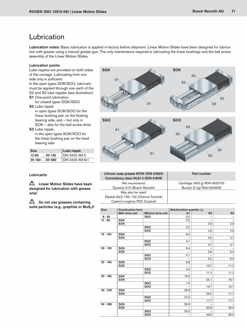
71Bosch Rexroth AG
SOK
SOO
SGK
SGO
S1
S1
S3
S3
S2
S2
S3
S3
S2
S2
S1
S1
R310EN 3001 (2012-06) | Linear Motion Slides
Lubricants
c Linear Motion Slides have been designed for lubrication with grease only!
c Do not use greases containing solid particles (e.g., graphite or MoS2)!
Size Lube nipple12-85 … 20-130 DIN 3405 AM 625-160 … 50-280 DIN 3405 AM 8x1
Lubrication pointsLube nipples are provided on both sides of the carriage. Lubricating from one side only is sufficient.In the open types SOK/SOO, lubricant must be applied through one each of the S2 and S3 lube nipples (see illustration).S1 One-point lubrication for closed types SGK/SGOS2 Lube nipple in open types SOK/SOO for the
linear bushing pair on the floating bearing side, and – but only in SOK – also for the ball screw drive
S3 Lube nipple in the open types SOK/SOO for
the linear bushing pair on the fixed bearing side
Size Construction form Relubrication quantity (g)With drive unit Without drive unit S1 S2 S3
8 - 65 SGO 2.0 – –12 - 85 SGK 3.5 – –
SOK – 3.9 2.6SGO 2.2 – –SOO – 2.6 2.6
16 - 100 SGK 6.0 – –SOK – 5.6 3.7
SGO 4.1 – –SOO – 3.7 3.7
20 - 130 SGK 8.4 – –SOK – 9.8 6.5
SGO 5.1 – –SOO – 6.5 6.5
25 - 160 SGK 9.8 – –SOK – 16.7 11.2
SGO 4.3 – –SOO – 11.2 11.2
30 - 180 SGK 16.3 – –SOK – 25.1 16.7
SGO 7.9 – –SOO – 16.7 16.7
40 - 230 SGK 35.8 – –SOK – 26.5 17.7
SGO 27.0 – –SOO – 17.7 17.7
50 - 280 SGK 55.8 – –SOK – 69.8 46.5
SGO 32.5 – –SOO – 46.5 46.5
LubricationLubrication notes: Basic lubrication is applied in-factory before shipment. Linear Motion Slides have been designed for lubrica-tion with grease using a manual grease gun. The only maintenance required is lubricating the linear bushings and the ball screw assembly of the Linear Motion Slides.
Lithium soap grease KP2K (DIN 51825)Consistency class NLGI 2 (DIN 51818)
Part number
We recommend:Dynalub 510 (Bosch Rexroth)
Cartridge (400 g) R341603700Bucket (5 kg) R341603500
May also be used:Elkalub GLS 135 / N2 (Chemie-Technik)
Castrol Longtime PD2 (Castrol)
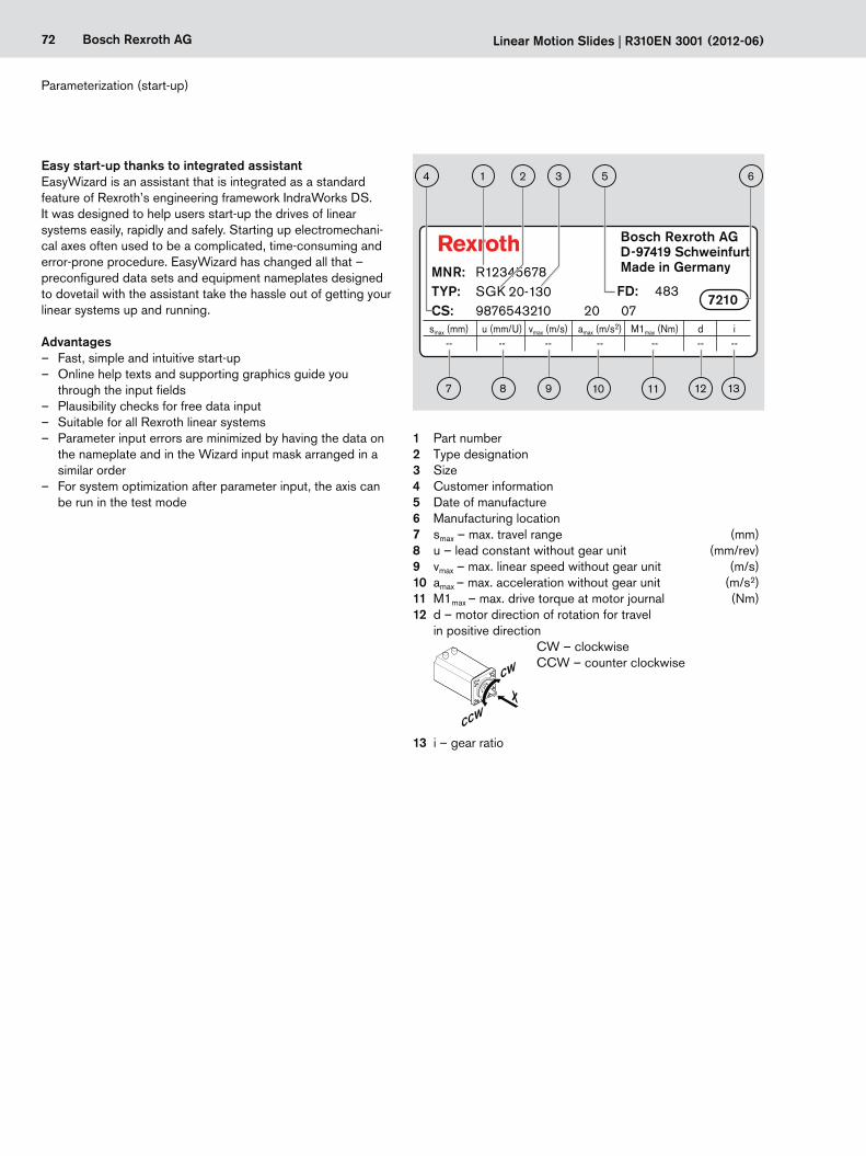
72 Bosch Rexroth AG Linearschlitten R310DE 3001 (2012-06)
72 Bosch Rexroth AG
Bosch Rexroth AG D-97419 Schweinfurt Made in Germany
7210
MNR: R12345678TYP: SGKCS: 9876543210 20 07
FD: 483
smax (mm) u (mm/U) vmax (m/s) amax (m/s2) M1max (Nm) d i -- -- -- -- -- -- --
20-130
214
7 8 9 10 11 12 13
653
Linear Motion Slides | R310EN 3001 (2012-06)
Easy start-up thanks to integrated assistantEasyWizard is an assistant that is integrated as a standard feature of Rexroth’s engineering framework IndraWorks DS. It was designed to help users start-up the drives of linear systems easily, rapidly and safely. Starting up electromechani-cal axes often used to be a complicated, time-consuming and error-prone procedure. EasyWizard has changed all that – preconfigured data sets and equipment nameplates designed to dovetail with the assistant take the hassle out of getting your linear systems up and running.
Advantages – Fast, simple and intuitive start-up – Online help texts and supporting graphics guide you
through the input fields – Plausibility checks for free data input – Suitable for all Rexroth linear systems – Parameter input errors are minimized by having the data on
the nameplate and in the Wizard input mask arranged in a similar order
– For system optimization after parameter input, the axis can be run in the test mode
1 Part number2 Type designation3 Size4 Customer information5 Date of manufacture6 Manufacturing location7 smax – max. travel range (mm)8 u – lead constant without gear unit (mm/rev)9 vmax – max. linear speed without gear unit (m/s)10 amax – max. acceleration without gear unit (m/s2)11 M1max – max. drive torque at motor journal (Nm)12 d – motor direction of rotation for travel
in positive direction CW – clockwise CCW – counter clockwise
CW
CCW
X
13 i – gear ratio
Parameterization (start-up)
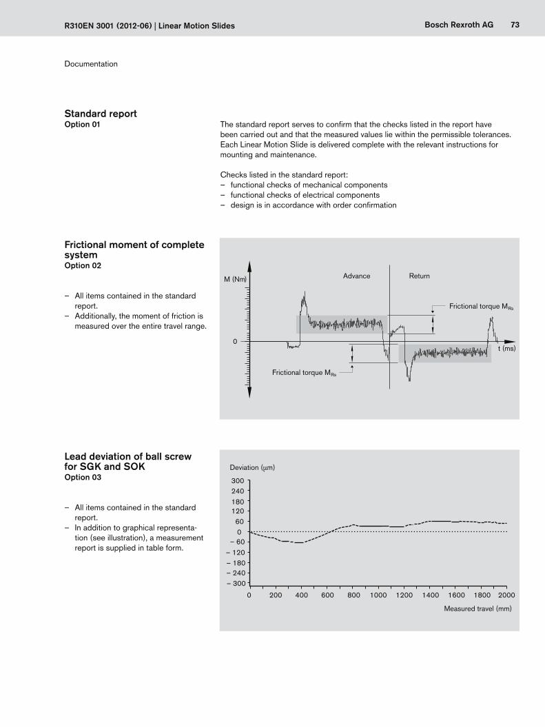
R310DE 3001 (2012-06) Linearschlitten 73Bosch Rexroth AG
73Bosch Rexroth AG
0
M (Nm)
t (ms)
200 400 600 800 1000 1200 1400 1600 1800 20000
300 240 180 120 60 0– 60
– 120– 180– 240– 300
R310EN 3001 (2012-06) | Linear Motion Slides
Standard reportOption 01 The standard report serves to confirm that the checks listed in the report have
been carried out and that the measured values lie within the permissible tolerances.Each Linear Motion Slide is delivered complete with the relevant instructions for mounting and maintenance.
Checks listed in the standard report: – functional checks of mechanical components – functional checks of electrical components – design is in accordance with order confirmation
Lead deviation of ball screw for SGK and SOKOption 03
– All items contained in the standard report.
– In addition to graphical representa-tion (see illustration), a measurement report is supplied in table form.
Frictional moment of completesystemOption 02
– All items contained in the standard report.
– Additionally, the moment of friction is measured over the entire travel range.
Documentation
Deviation (µm)
Measured travel (mm)
Advance Return
Frictional torque MRs
Frictional torque MRs
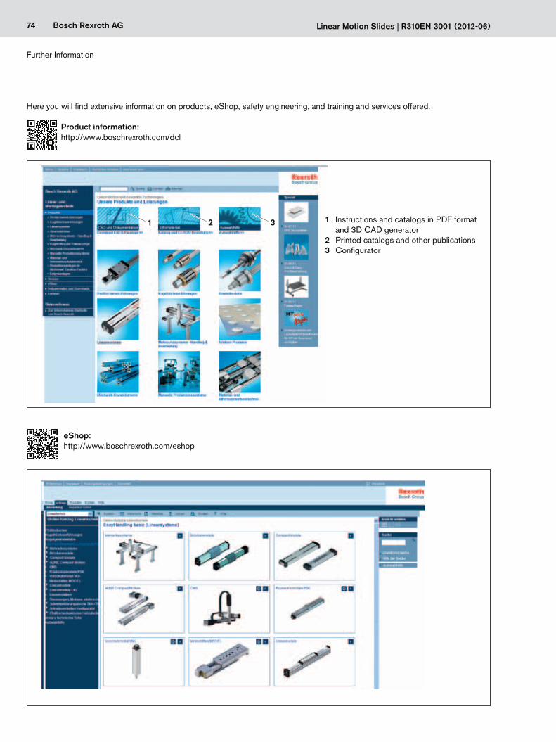
74 Bosch Rexroth AG
1 2 3
Linear Motion Slides | R310EN 3001 (2012-06)
1 Instructions and catalogs in PDF format and 3D CAD generator
2 Printed catalogs and other publications3 Configurator
Here you will find extensive information on products, eShop, safety engineering, and training and services offered.
Further Information
http://www.boschrexroth.com/eshop
Product information:
eShop:
http://www.boschrexroth.com/dcl
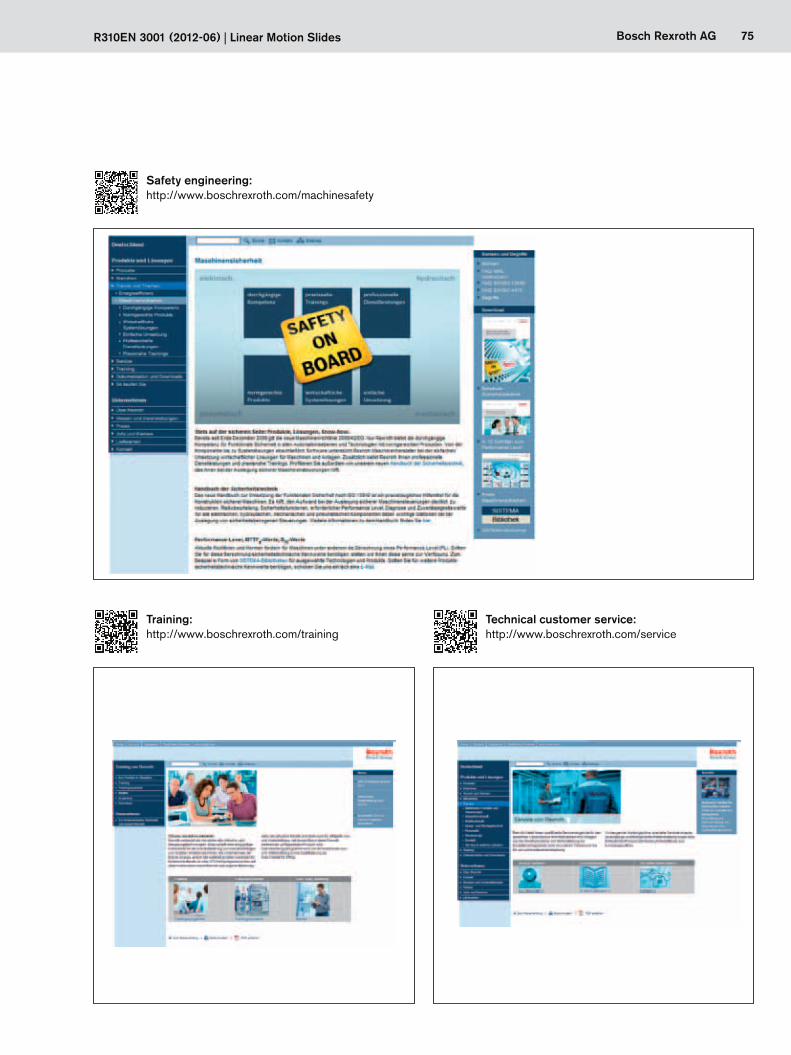
75Bosch Rexroth AGR310EN 3001 (2012-06) | Linear Motion Slides
http://www.boschrexroth.com/service
http://www.boschrexroth.com/machinesafetySafety engineering:
Training:http://www.boschrexroth.com/training
Technical customer service:
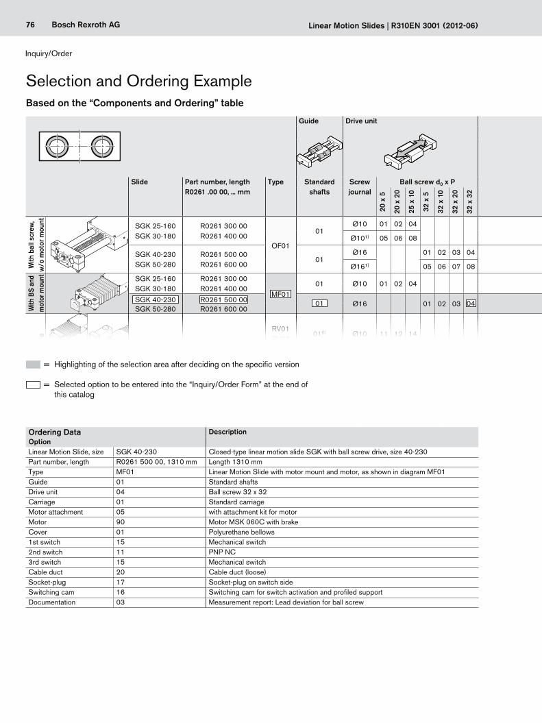
76 Bosch Rexroth AG Linearschlitten R310DE 3001 (2012-06)
76 Bosch Rexroth AG Linear Motion Slides | R310EN 3001 (2012-06)
Guide Drive unit Carriage Motor attachment Motor Cover Switches / Cable duct / Socket-plug
Documentation
Slide Part number, length R0261 .00 00, ... mm
Type Standard shafts
Screw journal
Ball screw d0 x P Standard i = Attach-ment kit3)
for motor Brake PU bellows Standard report
Measure-ment
report4)
20 x
5
20 x
20
25 x
10
32 x
5
32 x
10
32 x
20
32 x
32 with-
outwith without with
With
bal
l scr
ew,
w/o
mot
or m
ount
SGK 25-160SGK 30-180
R0261 300 00R0261 400 00
OF01
01Ø10 01 02 04
01 — 00 00
00 01
Without switches00Without cable duct
Without socket and plug
Switches:– PNP NC 11– PNP NO 13_– Mechanical 15
Ordering data:Switch type
Cable duct5) 20
Socket-plug 17
Switching cam and profiled support for switches
16
01
02
Ø101) 05 06 08
SGK 40-230SGK 50-280
R0261 500 00R0261 600 00
01Ø16 01 02 03 04
01 — 00 00Ø161) 05 06 07 08
With
BS
and
mot
or m
ount SGK 25-160
SGK 30-180R0261 300 00R0261 400 00
MF0101 Ø10 01 02 04 01 —
03 MSK 040C 86 8706 MSM 041B 74 75
SGK 40-230SGK 50-280
R0261 500 00R0261 600 00
01 Ø16 01 02 03 04 01 —02 MSK 076C – 9305 MSK 060C 90 91
With
bal
l scr
ew
and
timin
g be
lt si
de d
rive
SGK 25-160SGK 30-180
R0261 300 00R0261 400 00
RV01RV02
016) Ø10 11 12 14 011
10 MSK 040C 86 8720 MSM 041B 74 75
03
1.512 MSK 040C 86 8722 MSM 041B 74 75
RV032)
RV042) 016) Ø10 11 12 14 011
14 MSK 040C 74 75RV01 RV02 24 MSM 041B 86 87
1.516 MSK 040C 86 8726 MSM 041B 74 75
SGK 40-230SGK 50-280
R0261 500 00R0261 600 00
RV01RV02
01 Ø16 01 02 03 0401
1 30
MSK 060C 90 912 31
RV032)
RV042) 01 Ø16 01 02 03 041 32
RV032) RV042)2 33
Based on the “Components and Ordering” table
BS = ball screwd0 = screw diameter (mm)P = screw lead (mm) i = transmission ratio
Inquiry/Order
Selection and Ordering Example
Ordering Data DescriptionOptionLinear Motion Slide, size SGK 40-230 Closed-type linear motion slide SGK with ball screw drive, size 40-230Part number, length R0261 500 00, 1310 mm Length 1310 mmType MF01 Linear Motion Slide with motor mount and motor, as shown in diagram MF01Guide 01 Standard shaftsDrive unit 04 Ball screw 32 x 32Carriage 01 Standard carriageMotor attachment 05 with attachment kit for motorMotor 90 Motor MSK 060C with brakeCover 01 Polyurethane bellows1st switch 15 Mechanical switch2nd switch 11 PNP NC3rd switch 15 Mechanical switchCable duct 20 Cable duct (loose)Socket-plug 17 Socket-plug on switch sideSwitching cam 16 Switching cam for switch activation and profiled supportDocumentation 03 Measurement report: Lead deviation for ball screw
= Highlighting of the selection area after deciding on the specific version
= Selected option to be entered into the “Inquiry/Order Form” at the end of this catalog

R310DE 3001 (2012-06) Linearschlitten 77Bosch Rexroth AG
77Bosch Rexroth AGR310EN 3001 (2012-06) | Linear Motion Slides
Guide Drive unit Carriage Motor attachment Motor Cover Switches / Cable duct / Socket-plug
Documentation
Slide Part number, length R0261 .00 00, ... mm
Type Standard shafts
Screw journal
Ball screw d0 x P Standard i = Attach-ment kit3)
for motor Brake PU bellows Standard report
Measure-ment
report4)
20 x
5
20 x
20
25 x
10
32 x
5
32 x
10
32 x
20
32 x
32 with-
outwith without with
With
bal
l scr
ew,
w/o
mot
or m
ount
SGK 25-160SGK 30-180
R0261 300 00R0261 400 00
OF01
01Ø10 01 02 04
01 — 00 00
00 01
Without switches00Without cable duct
Without socket and plug
Switches:– PNP NC 11– PNP NO 13_– Mechanical 15
Ordering data:Switch type
Cable duct5) 20
Socket-plug 17
Switching cam and profiled support for switches
16
01
02
Ø101) 05 06 08
SGK 40-230SGK 50-280
R0261 500 00R0261 600 00
01Ø16 01 02 03 04
01 — 00 00Ø161) 05 06 07 08
With
BS
and
mot
or m
ount SGK 25-160
SGK 30-180R0261 300 00R0261 400 00
MF0101 Ø10 01 02 04 01 —
03 MSK 040C 86 8706 MSM 041B 74 75
SGK 40-230SGK 50-280
R0261 500 00R0261 600 00
01 Ø16 01 02 03 04 01 —02 MSK 076C – 9305 MSK 060C 90 91
With
bal
l scr
ew
and
timin
g be
lt si
de d
rive
SGK 25-160SGK 30-180
R0261 300 00R0261 400 00
RV01RV02
016) Ø10 11 12 14 011
10 MSK 040C 86 8720 MSM 041B 74 75
03
1.512 MSK 040C 86 8722 MSM 041B 74 75
RV032)
RV042) 016) Ø10 11 12 14 011
14 MSK 040C 74 75RV01 RV02 24 MSM 041B 86 87
1.516 MSK 040C 86 8726 MSM 041B 74 75
SGK 40-230SGK 50-280
R0261 500 00R0261 600 00
RV01RV02
01 Ø16 01 02 03 0401
1 30
MSK 060C 90 912 31
RV032)
RV042) 01 Ø16 01 02 03 041 32
RV032) RV042)2 33
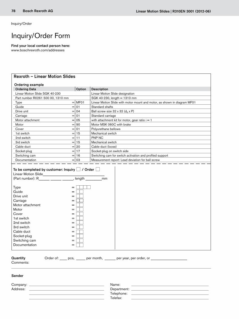
78 Bosch Rexroth AG Linearschlitten R310DE 3001 (2012-06)
78 Bosch Rexroth AG Linear Motion Slides | R310EN 3001 (2012-06)
To be completed by customer: Inquiry / OrderLinear Motion Slide__________________________________(Part number): R______ ______ ______, length _________mm
Type = Guide = Drive unit = Carriage = Motor attachment = Motor = Cover = 1st switch = 2nd switch = 3rd switch = Cable duct = Socket-plug = Switching cam = Documentation =
Company: Name: Address: Department: Telephone: Telefax:
QuantityComments:
Sender
Order of: ____ pcs, _____ per month, ______ per year, per order, or ____________________
Rexroth – Linear Motion Slides
Ordering exampleOrdering Data Option DescriptionLinear Motion Slide SGK 40-230 Linear Motion Slide designationPart number R0261 500 00, 1310 mm SGK 40-230, length = 1310 mmType = MF01 Linear Motion Slide with motor mount and motor, as shown in diagram MF01Guide = 01 Standard shaftsDrive unit = 04 Ball screw size 32 x 32 (d0 x P)Carriage = 01 Standard carriage Motor attachment = 05 with attachment kit for motor, gear ratio i = 1Motor = 90 Motor MSK 060C with brakeCover = 01 Polyurethane bellows1st switch = 15 Mechanical switch2nd switch = 11 PNP NC3rd switch = 15 Mechanical switchCable duct = 20 Cable duct (loose)Socket-plug = 17 Socket-plug on switch sideSwitching cam = 16 Switching cam for switch activation and profiled supportDocumentation = 03 Measurement report: Lead deviation for ball screw
Find your local contact person here:www.boschrexroth.com/addresses
Inquiry/Order Form
Inquiry/Order

79Bosch Rexroth AGR310EN 3001 (2012-06) | Linear Motion Slides
Bosch Rexroth AGErnst-Sachs-Straße 10097424 Schweinfurt, GermanyTel. +49 9721 937-0 Fax +49 9721 937-275www.boschrexroth.com
Subject to technical modifications
© Bosch Rexroth AG 2013Printed in GermanyR310EN 3001 (2012-06) EN•DC-IA/MKT
Find your local contact person here:www.boschrexroth.com/addresses