investigating self-centering steel plate shear wall boundary
TRANSCRIPT

16th World Conference on Earthquake, 16WCEE 2017
Santiago Chile, January 9th to 13th 2017
Paper N° 3138 (Abstract ID)
Registration Code: S-K1461815980
INVESTIGATING SELF-CENTERING STEEL PLATE SHEAR WALL BOUNDARY FRAME EFFICIENCY USING FINITE-ELEMENT ANALYSES
C.Y. Tsai (1), P.M. Clayton (2), J.W. Berman (3), K.C. Tsai (4), L.N. Lowes (5), C.H. Li (6)
(1) Post-Doctoral Fellow, Dept. of Civil Engineering, National Taiwan University, Taipei, Taiwan, [email protected] (2) Assistant Professor, Dept. of Civil, Architectural and Environmental Engineering, University of Texas, Austin,
USA, [email protected] (3) Associate Professor, Dept. of Civil and Environmental Engineering, University of Washington, Seattle, USA, [email protected] (4) Professor, Dept. of Civil Engineering, National Taiwan University, Taipei, Taiwan, [email protected] (5) Professor, Dept. of Civil and Environmental Engineering, University of Washington, Seattle, USA, [email protected] (6) Assistant Research Fellow, National Center for Research on Earthquake Engineering, Taipei, Taiwan, [email protected]
Abstract This paper presents the finite-element analytical results of the self-centering steel plate wall (SC-SPSW) specimen which was tested using pseudo-dynamic testing procedures in the National Center for Research on Earthquake Engineering in Taiwan. This specimen was designed such that no boundary frame yielding occurred under earthquake excitations with a 2% probability of exceedance in 50 years, resulting in large and overly conservative column sizes. Simplified analytical procedures of using the tension-only strips to represent the web plate, and beam-column elements for the boundary frame capture the SC-SPSW overall responses well when the boundary frame remains elastic, as designed, under the cyclic loadings. However, this approach is not able to gain the insights into the local behavior of the PT beam-to-column connection such as local flange buckling and stress concentrations at the rocking connections. Thus, a detailed ABAQUS shell element model is constructed to analyze these local PT connection behaviors. The optimal boundary frame size is determined using the shell models by reducing the boundary element sizes while simultaneously ensuring that the desired level of performance is achieved. Based on these analyses, this paper summarizes the impact of varied boundary frame member sizes on the SC-SPSW performance.
Keywords: self-centering; steel plate shear; post-tensioned connection;

16th World Conference on Earthquake, 16WCEE 2017
Santiago Chile, January 9th to 13th 2017
1. Introduction The steel plate shear wall (SPSW) has been widely used as a lateral-force resisting system in North America and Asia. The significant lateral strength, energy dissipation, and ductility [1-3] of SPSWs make them ideal for use in high-seismic areas. This system includes a steel frame composed of an infilled steel plate, referred to as the web plate, beams (horizontal boundary elements or HBE) and columns (vertical boundary elements or VBE). Thick and stiffened steel plates were commonly used in earlier SPSW applications in Japan to resist the lateral load through shear yielding. Later in the early 1980s, slender and unstiffened web plates were used to improve ductile performance and promise potential to reduce the demands on surrounding boundary elements. In SPSWs, the web plates are intended to buckle in shear and resist horizontal earthquake loads through the development of diagonal tension field action. Then, the energy is dissipated through the cyclic yielding of the web plates in tension. The SPSW system offers benefits such as: more architectural flexibility than comparable concrete shear walls, due to its thin profile; high initial stiffness and ultimate strength; distributed yielding over multiple stories; ease of construction and post-earthquake replacement of web plates; and stable ductile performance where the web plate has significant deformation capacity following initial onset of tearing in the plate.
A self-centering SPSW (SC-SPSW) system combines the lateral load resisting benefits of the SPSW with the self-centering capabilities of the post-tensioned (PT) connection by substituting the typical moment resisting connections of a conventional SPSW with PT HBE-to-VBE connections. This system resists lateral load and dissipates energy through yielding of the web plate, while the PT HBE-to-VBE connections reduce the potential for damage in the HBEs and provide system re-centering and post-earthquake functionality. In the event that yielded or damaged web plates require repair or replacement following an earthquake, the building will return to a re-centered and fully functional state while the relatively quick and easy repair of the plates takes place, significantly reducing the downtime associated with costly VBE and HBE repairs.
Recent experimental and analytical studies have revealed that the SC-SPSW can provide excellent seismic performance, achieving performance objectives that are out of reach for conventional steel systems [4, 5]. SC-SPSWs utilize PT beam-to-column connections to provide frame re-centering under an earthquake excitation. Compared with the conventional beam-to-column connections used in the regular SPSW, the SC-SPSW with the PT beam-to-column connections avoids boundary frame damage by concentrating energy dissipation of the system to the web plates only. Moreover, by eliminating boundary frame damage this approach reduces the post-earthquake repair costs and retains the strength and energy dissipating characteristics of SPSWs.
As the range of physical specimens and loading conditions that can be tested in the laboratory are restricted due to resource limitations, numerical models can be used to approximate actual system behavior for a wider range of SC-SPSWs and earthquake loading. The main goal of this study aims at understanding global behavior and local component demands of the SC-SPSW system and how they impact seismic performance. In addition, this research is intended to evaluate and validate numerical modeling methods used to simulate SC-SPSW behavior. This paper describes the methodologies employed for numerical modeling of a SC-SPSW. These methods are used in a numerical model of a full-scale one-bay two-story SC-SPSW and the results of nonlinear cyclic analyses are compared to the experimental outcomes.
In order to validate the modeling approach for predicting SC-SPSW response, commercial finite element program ABAQUS [6] was employed to simulate the response of a two-story SC-SPSW test specimen done at National Center for Research on Earthquake Engineering (NCREE) in Taiwan using a pseudo-dynamic testing procedure and ground motion histories scaled to represent three seismic hazard levels. The specimen and test program are briefly described later; however, further details can be found in Dowden et al. [4] and Clayton [5].
2. Full-scale two-story SC-SPSW tests The two-story, full-scale specimen [4, 5] showed in Fig.1(a) consisted of two A992 W12×230 columns (H381×327×33×52mm), a W21×147 top beam (TB, H560×318×19×29mm), a W18×158 middle beam (MB, H502×284×21×37mm), and a W18×86 bottom beam (BB, H467×282×13×19mm). These members were shipped from the U.S. and the frame specimen was fabricated in Taiwan. This SC-SPSW specimen had 2.7 mm thick
2

16th World Conference on Earthquake, 16WCEE 2017
Santiago Chile, January 9th to 13th 2017
web plates with the low yield strength steel (LYS225) of 208 MPa yield strength in both stories as shown in Fig.1(b). And it had a centerline column spacing of 3.42 m and story heights of approximately 3.8 m. Two actuators attached to one of the columns at the location of the top transfer beam applied displacement control loads to the specimen. PT connections were adopted for both ends of the top and middle beams and the bases of the two columns, while the double-angle shear connection was used for each end of the bottom beam as shown in Fig.1(b). The beam PT was provided by two seven-strand bundles of 15 mm diameter Grade 270 PT strands. Shear tabs with horizontally slotted holes at both ends of the top and middle beams were provided to transfer shear force in the PT beam-to-column connections. Two 69 mm diameter high-strength threaded bars anchored along the height of the column were used to provide the post-tensioning in each of the columns. The initial PT forces in the beam and column PT elements were approximately 30% and 35% of yield, respectively.
Further details of the test setup and loading can be found in Dowden et al. [4] and Clayton [5]. A series of pseudo-dynamic tests representing the three seismic hazard levels (In this study, the 50% in 50 year earthquake is assumed to approximate a frequently occurred earthquake (FOE, E5050); the 10% in 50 year earthquake is assumed to approximate a design-basis earthquake (DBE, E1050); the 2% in 50 year earthquake is assumed to approximate a maximum considered earthquake (MCE, E250).) as shown in Fig.2 and cyclic loading tests on this two-story SC-SPSW were conducted to verify the SC-SPSW was able to meet all intended performance objectives [5]. (http://exp.ncree.org/sc-spsw/)
(a) (b) (c)
Fig. 1 – Specimen FR: (a) Test setup, (b) Elevation details, and (c) ABAQUS model
Fig. 2 – Acceleration time histories of three pseudo-dynamic tests
3
16th World Conference on Earthquake, 16WCEE 2017
Santiago Chile, January 9th to 13th 2017
3. Numerical modeling Abaqus FEA (formerly ABAQUS) produced by Dassault Systemes Simulia Corp. [6] is a powerful software suite for finite element analysis and computer-aided engineering. There are five core software products in ABAQUS: Abaqus/CAE, Abaqus/Standard, Abaqus/Explicit, Abaqus/CFD, and Abaqus/Electromagnetic. Abaqus/CAE (Complete Abaqus Environment) is a graphic user interface application used for both modeling and analysis of mechanical components and assembles and visualizing the finite element analysis results. Abaqus/Standard is a general purpose finite element analyzer that uses implicit integration scheme. This study uses these two products to conduct and analyze the numerical models of SPSWs. A description of the ABAQUS model shown in Fig.1(c) and comparisons with experimental results are presented below.
3.1 Web plate shell element model This study uses shell elements to explicitly simulate web plate buckling and development of tension field action as shown in Fig.3(a). The shell web plate model, implemented in Abaqus/Standard [6] with four-node, reduced integration shell elements (S4R), elements was seeded with small initial out-of-plane imperfections (with approximate peak amplitudes of 4 mm which is close to 1/1000 of the column span) representing web plate buckled shapes under lateral loading.
Clayton [5] simulated the shell web plate model with the line element PT boundary frame model (named as AB-L-iso, where AB stands for ABAQUS model and L-iso stands for line elements used in BEs with pure isotropic hardening materials for web plates), the web plate mesh had approximately thirty elements along the height and length of the web plate, resulting in elements of approximately 100 mm-by-100 mm based on modeling recommendations per Webster [7]. In this study, the shell web plate was modeled with shell PT boundary frame model (named as AB-S-iso and AB-S-kin, where S-iso or S-kin stand for shell elements used in BEs with pure isotropic or kinematic hardening materials for web plates), representing a more detailed model, the web plate mesh had approximately fifty elements along the height and length of the web plate, resulting in elements of approximately 50 mm-by-50mm. Fig.3(a) shows the mesh model of this specimen. The web plate material was defined in ABAQUS by the elastic modulus and true stress versus logarithmic plastic strain response derived from the engineering stress and strain measured during monotonic coupon tests [5] of the web plate material. More details about the web plate material model will present in Section 3.4.
3.2 PT connection modeling (truss and connector elements) The model AB-L-iso in Clayton [5] was modeled using two-node truss (T3D2 element in ABAQUS) for the PT bar or PT strands. The PT members were modeled as single truss elements for each boundary frame member (e.g. one truss to represent all of the PT strands in each beam, or one truss element to represent the two PT bars in one column) with cross-sectional areas, elastic modulus corresponding to the nominal properties. The PT connections were modeled using a stiff compression-only springs rigidly offset from the boundary element centerlines to transfer forces between the beam flanges and the column flanges, while shear transfer was provided by vertical-direction displacement restraints at the beam ends. More details about AB-L-iso model could be found in Clayton [5].
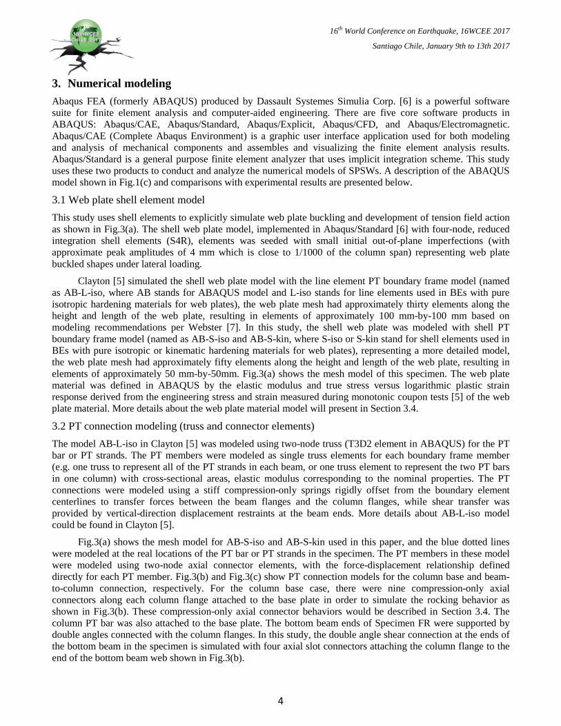
Fig.3(a) shows the mesh model for AB-S-iso and AB-S-kin used in this paper, and the blue dotted lines were modeled at the real locations of the PT bar or PT strands in the specimen. The PT members in these model were modeled using two-node axial connector elements, with the force-displacement relationship defined directly for each PT member. Fig.3(b) and Fig.3(c) show PT connection models for the column base and beam-to-column connection, respectively. For the column base case, there were nine compression-only axial connectors along each column flange attached to the base plate in order to simulate the rocking behavior as shown in Fig.3(b). These compression-only axial connector behaviors would be described in Section 3.4. The column PT bar was also attached to the base plate. The bottom beam ends of Specimen FR were supported by double angles connected with the column flanges. In this study, the double angle shear connection at the ends of the bottom beam in the specimen is simulated with four axial slot connectors attaching the column flange to the end of the bottom beam web shown in Fig.3(b).
4
16th World Conference on Earthquake, 16WCEE 2017
Santiago Chile, January 9th to 13th 2017
For the beam-to-column PT connection, the same compression-only axial connector was used to model the beam end rocking behavior as shown in Fig.3(c). Shear springs at the end of the beam web shown in Fig.3(c), similar to the horizontally-slotted holes used in the shear tab connections at the beam ends, were provided at the locations of the bolts to transfer shear forces in the PT beam-to-column connections while allowing the connection to rock open. The end of the PT bar or PT strands was simulated using the coupling constraints to connect with the surrounding members.
3.3 Boundary element modeling The boundary frame of model AS-L-iso in [5] was modeled using two-node linear beam (B31 element in ABAQUS). These beams and columns were modeled as beam elements with the cross-sectional and material properties corresponding to the nominal W-shape. The main purpose of this line element model was to understand the complex web plate behavior and how it affects the SC-SPSW behavior. However, in this study, the PT boundary frame was also modeled using shell elements representing the boundary frame webs and flanges to simulate behaviors that are not captured in conventional beam-column line element formulations (e.g. shear deformation, local buckling, and stress concentrations). The PT boundary frame shell model also includes the continuity and reinforcement plates that were presented in the test specimen as shown in Fig.3(c). The boundary frame members and reinforcing plates were all modeled using S4R elements in ABAQUS with edge lengths of approximately 50 mm. The edge of the web plate (located where the web plate was welded to the fish plate in the specimen) is offset from the beam and column flanges using a tie constraint.
(a) (b) (c)
Fig. 3 – ABAQUS model of Specimen FR: (a) mesh, and PT connection model (b) at column base , and (c) at beam-to-column connection
3.4 Boundary Conditions and Material models The six degree of freedoms of each base plate in the AB-S-iso and AB-S-kin models were constrained to simulate the base plates anchored at the strong floor. Out-of-plane restraint is provided on the PT-BF at the beam-to-column connection regions corresponding to locations of out-of-plane restraint in the test specimen. In order to prevent some numerical errors, the torsional degree of freedom at both end of top beam and middle beam were restrained. In addition, the horizontal displacement degree of freedom at centerline of the column base end stiffener was restrained instead of modeling the shear bracket.
Webster [7] indicated that the kinematic, isotropic, or combined hardening properties of the web plate defined in the model have significant impacts on predicting the web plate capacity and reloading behavior. And it is very difficult to determine web plate hardening parameters only based on monotonic material coupon tests. When simulating cyclic tests of web plates in pinned boundary frames, the hardening parameters that best fit envelope and reloading experimental responses vary depending on the web plate material, production batch, and thickness. Webster [7] suggested using pure isotropic hardening to simulate an upper-bound estimation of web
PT axial connector elements
compression-only axial connectors
double-angle slot connector elements
5

16th World Conference on Earthquake, 16WCEE 2017
Santiago Chile, January 9th to 13th 2017
plate strength; however, some of the web plate test specimens did exhibit hardening that was more closely approximated by pure kinematic hardening rules. For this reason, SC-SPSWs were investigated with pure multilinear isotropic (AB-L-iso and AB-S-iso) and pure multilinear kinematic (AB-S-kin) hardening to evaluate the impact of hardening rules on SC-SPSW behavior. In both the isotropic and kinematic hardening models, the monotonic yield surface was fit to the coupon data [4, 5]. The boundary frame material had a yield strength of 380 MPa (the expected yield strength, RyFy, of ASTM A992 steel), although no boundary frame yielding was observed under the loading imposed in this study.
The double angle shear connection at the ends of the bottom beam in the specimen was simulated with four slot type connectors connecting the column flange and the end of the bottom beam web (Fig.3(b)). The slot connector properties were calibrated according to Shen and Astaneh-Asl [8] to represent the trilinear response of double angle connections yielding because of rotation demands.
The PT members were modeled as axial connector elements with an initial stress that align with the centroid of each PT group on each side of the beam or column web. The initial stress was applied to the PT elements using a constant predefined temperature field on the PT truss elements in AS-L-iso model [5]. The PT material was given an arbitrary isotropic thermal expansion coefficient, and the predefined temperature was adjusted in each member to reach the expected initial PT force. For the AS-S-iso and AS-S-kin models, the initial PT force was directly applied to the PT connector element using connector load command. The PT stuffiness was calculated from the cross section areas of the PT bar or total PT strands, the steel young modulus, and the corresponding length of the PT bar or PT strands. Then, the temperature load or connector load was applied in the first analysis step, prior to any other loading to apply the initial PT force and was held constant during subsequent loading steps.
The lateral displacement control point was at the same location as the test specimen was, but the force transfer beam was not modeled in ABAQUS instead of using reference point and coupling constraint to achieve it. Thus, the input displacement was applied to the reference point and then transferred into the whole frame. The applied loads were the experimental roof displacement histories of the specimen from all test results.
4. Comparison with full-scale experimental results The sequence of test loadings for the specimen described is Elastic cyclic, E5050 (FOE), E1050 (DBE), E250 (MCE), and Inelastic cyclic. In ABAQUS analyses, the same loading sequence was applied into the AB-S-kin model. Fig.4 shows the AB-S-kin analysis responses comparing to the test results. Comparing base shear versus roof drift relationship to the test result, ABAQUS predicts the frame behavior very well, and it only has 5% errors. At Elastic cyclic and E5050 (FOE) stages, no matter test or ABAQUS results are remained elastic and have the similar behavior. Even for E1050 (DBE), ABAQUS model still can capture the test behavior very well. Under the E250 (MCE) Hazard level earthquake, ABAQUS model could simulate the peak response in both directions. However, the ABAQUS model did not consider the web plate tearing effect, so it overestimated the force responses after the two peaks. This also could be observed in Inelastic cyclic results shown too. The numerical model used in this study did not consider the web plate tearing. Thus, only the specimen responses under the E1050 (DBE) excitation, where the web plate tearing was minimal and had no noticeable effect on specimen strength, will be used to compare with other finite element results.
Fig. 4 – Base shear vs. roof drift ratio relationships
6

16th World Conference on Earthquake, 16WCEE 2017
Santiago Chile, January 9th to 13th 2017
To compare response of the models with that of the specimen, the models were subjected to the same displacement history that was measured during the E1050 pseudo-dynamic test. Results from the numerical models and the experimental specimen are discussed in below.
4.1 Global responses Fig.5 compares the base shear versus roof drift response of AB-S-iso and AB-S-kin models with the experimental results. In order to know the web plate response during large cycles of loading when the web plate tension field is fully engaged and during smaller cycles later in the ground motion after significant web plate yielding, Fig.5 also includes the responses at different cycles. According to these comparisons of the global responses, it could be concluded that actual web plate hardening may be some combination of the two hardening rules. However, combined hardening parameters are difficult to determine from the monotonic coupon tests. In addition, both hardening models provide reasonable approximations of web plate resistance during free vibration.
Fig.6 show von Mises stress and cumulative plastic strain distributions of AB-S-iso model under negative peak displacement at earthquake time of 11.85 sec. It could found that the boundary frame essentially remained elastic and the inelastic deformations are only concentrated in web plates, especially at edge of the web plate.
Fig. 5 – Comparisons of base shear vs. roof drift ratio relationships on different material models
7
16th World Conference on Earthquake, 16WCEE 2017
Santiago Chile, January 9th to 13th 2017
Fig. 6 – Distributions of von Mises stress and cumulative plastic strain for AB-S-iso under negative peak displacement at earthquake time of 11.85 sec.
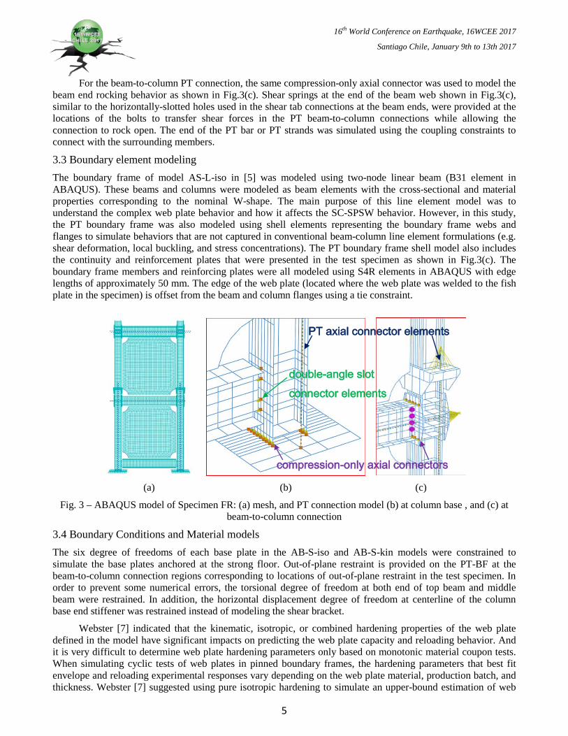
4.2 Boundary frame demands The test specimen was instrumented with strain gages to estimate boundary frame axial force and moment demands at discrete locations along the beams and the first story columns. These strain gage sections were located sufficiently far from the connections such that linear strain profiles can be assumed. Details on specimen instrumentation and derivation of PT-BF demands can be found in [5]. Axial force and moment demands were measured in the PT-BF numerical models at the same locations as the specimen. The locations discussed in this paper, and corresponding labels, include the middle of the top beam (TB-M), a section 0.5 m (approximately 17% of the beam length) from the east end of the top beam (TB-E) and 1.6 m from the base of the east column (approximately one-third up the height of the column between the bottom and middle beams) (EC-B).
The data in Fig.7 shows comparisons of the experimental and numerical PT-BF demands during the peak cycle, which corresponds to the peak boundary element demands. For the top beam, the axial force is shown for the middle of the beam, and the moment is shown for the section closer to the east end of the beam (because the moment in the middle of the beam is near-zero due to the linear moment distribution at this location). The AB-L-iso and AB-S-iso models provide a better representation of the complex hysteretic web plate reloading and unloading behavior; however, they overestimate PT-BF demands. In particular, the AB-L-iso and AB-S-iso models overestimate beam and column compressive axial forces. The difference between the axial PT-BF demands in the shell element web plate models and the test specimen is believed to be due, in part, to the overestimation of web plate strain hardening in the isotropic hardening model and minor tearing in the specimen web plate that was not simulated in the models. The boundary frame demands in the AB-S-kin model are similar to those of the AB-S-iso model. Differences in the AB-S-kin and AB-S-iso PT-BF demands are consistent with those observed in the global responses in Fig.6 due to differences in the web plate model, namely, the peak PT-BF demands in the AB-S-kin model are slightly less than those of the AB-S-iso models and the increase in PT-BF demands during reloading begins at slightly lower drifts in the AB-S-kin model.
Fig. 7 – BE member forces vs. roof drift relationships at peak cycle
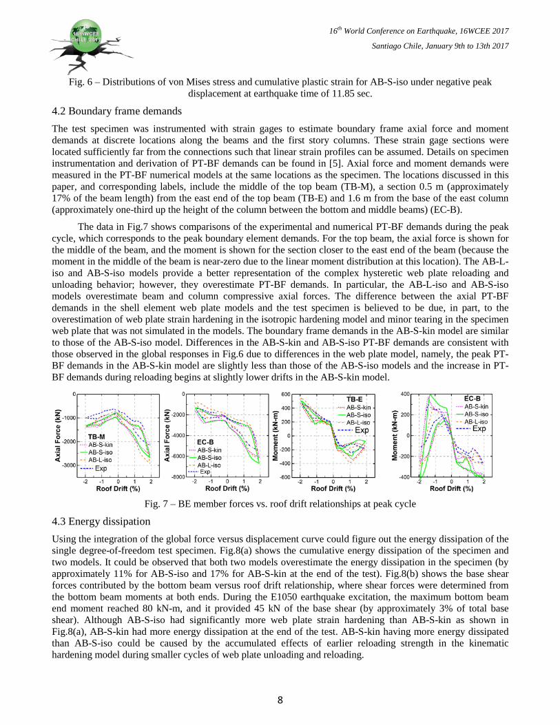
4.3 Energy dissipation Using the integration of the global force versus displacement curve could figure out the energy dissipation of the single degree-of-freedom test specimen. Fig.8(a) shows the cumulative energy dissipation of the specimen and two models. It could be observed that both two models overestimate the energy dissipation in the specimen (by approximately 11% for AB-S-iso and 17% for AB-S-kin at the end of the test). Fig.8(b) shows the base shear forces contributed by the bottom beam versus roof drift relationship, where shear forces were determined from the bottom beam moments at both ends. During the E1050 earthquake excitation, the maximum bottom beam end moment reached 80 kN-m, and it provided 45 kN of the base shear (by approximately 3% of total base shear). Although AB-S-iso had significantly more web plate strain hardening than AB-S-kin as shown in Fig.8(a), AB-S-kin had more energy dissipation at the end of the test. AB-S-kin having more energy dissipated than AB-S-iso could be caused by the accumulated effects of earlier reloading strength in the kinematic hardening model during smaller cycles of web plate unloading and reloading.
8
16th World Conference on Earthquake, 16WCEE 2017
Santiago Chile, January 9th to 13th 2017
(a) (b)
Fig. 8 – (a) Dissipated energy history of E1050 DBE test and (b) bottom beam shears vs. roof drift relationship
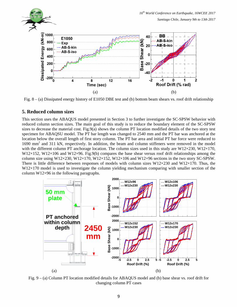
5. Reduced column sizes This section uses the ABAQUS model presented in Section 3 to further investigate the SC-SPSW behavior with reduced column section sizes. The main goal of this study is to reduce the boundary element of the SC-SPSW sizes to decrease the material cost. Fig.9(a) shows the column PT location modified details of the two story test specimen for ABAQSU model. The PT bar length was changed to 2540 mm and the PT bar was anchored at the location below the overall length of first story column. The PT bar area and initial PT bar force were reduced to 1690 mm2 and 311 kN, respectively. In addition, the beam and column stiffeners were removed in the model with the different column PT anchorage location. The column sizes used in this study are W12×230, W12×170, W12×152, W12×106 and W12×96. Fig.9(b) compares the base shear versus roof drift relationships among the column size using W12×230, W12×170, W12×152, W12×106 and W12×96 sections in the two story SC-SPSW. There is little difference between responses of models with column sizes W12×230 and W12×170. Thus, the W12×170 model is used to investigate the column yielding mechanism comparing with smaller section of the column W12×96 in the following paragraphs.
50 mm plate
2450mm
PT anchored within column
depth
-5 -2.5 0 2.5 5Roof Drift (%)
-2000
-1000
0
1000
2000
Bas
e Sh
ear (
kN)
W12x152W12x230
-5 -2.5 0 2.5 5Roof Drift (%)
W12x170W12x230
-2000
-1000
0
1000
2000
Bas
e Sh
ear (
kN)
W12x96W12x230
W12x106W12x230
(a) (b)
Fig. 9 – (a) Column PT location modified details for ABAQUS model and (b) base shear vs. roof drift for changing column PT cases
9

16th World Conference on Earthquake, 16WCEE 2017
Santiago Chile, January 9th to 13th 2017
Fig.10 presents the cyclic cumulated plastic strain distribution of a SC-SPSW at the 2%, 3%, 4%, and 5% drift ratio for smaller column cases W12×170 and W12×96, respectively. Fig.10(a) shows that there was no significant yielding developed on the boundary elements when the column section was changed to W12×170, even when the SC-SPSW was at 5% roof drift ratio. When the column is weaker, as is the case of the W12×96 columns, the plastic hinge formed at the top of the first story column around 2% roof drift ratio. The bottom of the first story column, the plastic hinge developed at a roof drift ratio of 4%. Fig.11 presents the west and east column force demands form three different column sizes of SC-SPSW, respectively. And these force demands on the boundary columns do not have significant difference when column sizes are different.
The purpose of this study is to reduce column sizes and improve boundary element design efficiency by understanding the impact of frame yielding on SC-SPSW performance. The original design procedure of the SC-SPSW assumed the columns should not yield even when the drift ratio of the frame is 5%. However, this design concept could lead the column size overdesign and increase the construction cost. Fig.9(b) shows that the column designed with section W12×170 could have the similar cyclic behavior as the overdesign column W12×230 has. And in this case, it could save 26% of the construction cost from columns. Fig.9(b) also indicates that when the column is strong enough, the overall performance of the SC-SPSW would have no significant difference on the stiffness or strength. Moreover, if the column is allowed to yield at 2% drift ratio, it could save over 50% of the material cost for the columns. Thus, a suitable design of the boundary is very important.
(a)
(b)
Fig. 10 – Cyclic PEEQ distributions: (a) Model W12×170 and (b) Model W12×96
10

16th World Conference on Earthquake, 16WCEE 2017
Santiago Chile, January 9th to 13th 2017
Fig. 11 – Column force distributions of smaller columns at 3% drift along the WC and EC heights
6. Conclusions From the comparison of numerical models and test responses on the SC-SPSW specimen, the following conclusions can be drawn:
(1) The hardening rules used for the web plate material in the model can significantly affect peak strength demands in cyclic analyses. In general, isotropic hardening models tend to overestimate web plate demands, while kinematic hardening tends to underestimate web plate demands. Thus, it is likely that the actual web plate behavior could be simulated with combined hardening rules; however, it is difficult to determine combined hardening parameters from only monotonic coupon tests.
(2) The comparison of energy dissipation shows that two models overestimated dissipated energy at least 10% more than was observed in the test.
(3) The boundary frame of numerical models remained essentially elastic, and this is consistent with the test behavior. The overall responses of the numerical models have good agreement with the test result. If the PT boundary frame with the localized yielding is considered, the shell PT boundary frame model is expected to provide a more accurate representation of stress concentrations and shear stresses developed in the rocking PT connections than the conventional beam-column line element boundary frame model could.
(4) The construction cost of the SC-SPW could be decreased when the column is designed with the suitable design goal. For example, the column designed to remain elastic only up to 3% drift ratio could save 26% of the material cost for the columns.
7. References [1] RG Driver, GL Kulak, DJL Kennedy, AE Elwi (1998): Cyclic Test of Four-Story Steel Plate Shear Wall. Journal of
Structural Engineering, ASCE, 124 (2), 112-120.
[2] JW Berman, M Bruneau (2005): Experimental Investigation of Light-Gauge Steel Plate Shear Wall. Journal of Structural Engineering, ASCE, 131 (2), 259-267.
[3] B Qu, M Bruneau, CH Lin, KC Tsai (2008): Testing of Full Scale Two-Story Steel Plate Shear Wall with Reduced Beam Sections Connections and Composite Floors. Journal of Structural Engineering, ASCE, 134(3), 364-373.
[4] DM Dowden, PM Clayton, CH Li, JW Berman, M Bruneau, KC Tsai (2016): Full-scale pseudo-dynamic testing of self-centering steel plate shear wall. Journal of Structural Engineering, 142 (1), 04015100-1-10.
[5] PM Clayton (2013): Self-centering steel plate shear walls: Subassembly and full-scale testing. PhD dissertation, Civil and Environmental Engineering Dept., University of Washington, Seattle, WA, USA.
[6] ABAQUS (2013): ABAQUS version 6.13 documentation. Simulia 2013.
[7] DJ Webster (2013): The behavior of un-stiffened steel plate shear wall web plates and their impact on the vertical boundary elements. PhD. dissertation, Civil and Environmental Engineering Dept., University of Washington, Seattle, WA, USA.
[8] J Shen, A Astaneh-Asl (2000): Hysteresis model of bolted-angle connections. Journal of Constructional Steel Research, 54, 317–343.
11