brazed plate heat exchanger
TRANSCRIPT
Brazed Plate Heat Exchanger

IndexCompany Profile . . . . . . . . . . . . . . . . . . . . . . . . . . . . . . . . . . . . . . . . . . . . . . . . . . . . . . . . . . . . . . . . . . . . . . . . . . . . . . . . . . . . . . . . . . . . . 2
Facility and Test Equipment . . . . . . . . . . . . . . . . . . . . . . . . . . . . . . . . . . . . . . . . . . . . . . . . . . . . . . . . . . . . . . . . . . . . . . . . . . . . . . . . . . 2
Certificate . . . . . . . . . . . . . . . . . . . . . . . . . . . . . . . . . . . . . . . . . . . . . . . . . . . . . . . . . . . . . . . . . . . . . . . . . . . . . . . . . . . . . . . . . . . . . . . . . . 3
Patent . . . . . . . . . . . . . . . . . . . . . . . . . . . . . . . . . . . . . . . . . . . . . . . . . . . . . . . . . . . . . . . . . . . . . . . . . . . . . . . . . . . . . . . . . . . . . . . . . . . . . . 3
All Series of Brazed Plate Heat Exchanger . . . . . . . . . . . . . . . . . . . . . . . . . . . . . . . . . . . . . . . . . . . . . . . . . . . . . . . . . . . . . . . . . . . . . 4
Product Introduction . . . . . . . . . . . . . . . . . . . . . . . . . . . . . . . . . . . . . . . . . . . . . . . . . . . . . . . . . . . . . . . . . . . . . . . . . . . . . . . . . . . . . . . . 5
Advantage . . . . . . . . . . . . . . . . . . . . . . . . . . . . . . . . . . . . . . . . . . . . . . . . . . . . . . . . . . . . . . . . . . . . . . . . . . . . . . . . . . . . . . . . . . . . . . . . . . 5
Working Principle . . . . . . . . . . . . . . . . . . . . . . . . . . . . . . . . . . . . . . . . . . . . . . . . . . . . . . . . . . . . . . . . . . . . . . . . . . . . . . . . . . . . . . . . . . . 5
Brazed Plate Heat Exchanger Dimension . . . . . . . . . . . . . . . . . . . . . . . . . . . . . . . . . . . . . . . . . . . . . . . . . . . . . . . . . . . . . . . . . . . . . . 6
K Series-Standard Brazed Plate Heat Exchanger . . . . . . . . . . . . . . . . . . . . . . . . . . . . . . . . . . . . . . . . . . . . . . . . . . . . . . . . . . . . . . . 8
Z Series-Large Diagonal Flow Brazed Plate Heat Exchanger . . . . . . . . . . . . . . . . . . . . . . . . . . . . . . . . . . . . . . . . . . . . . . . . . . 12
C Series- Super High Pressure Brazed Plate Heat Exchanger . . . . . . . . . . . . . . . . . . . . . . . . . . . . . . . . . . . . . . . . . . . . . . . . . . 14
R Series-High Heat Transfer Performance Brazed Plate Heat Exchanger . . . . . . . . . . . . . . . . . . . . . . . . . . . . . . . . . . . . . . . 16
E/F Series-Low Pressure Brazed Plate Heat Exchanger . . . . . . . . . . . . . . . . . . . . . . . . . . . . . . . . . . . . . . . . . . . . . . . . . . . . . . . 17
H Series-High Temperature Brazed Plate Heat Exchanger . . . . . . . . . . . . . . . . . . . . . . . . . . . . . . . . . . . . . . . . . . . . . . . . . . . . . 18
M Series-Corrosion Resistant Brazed Plate Heat Exchanger . . . . . . . . . . . . . . . . . . . . . . . . . . . . . . . . . . . . . . . . . . . . . . . . . . . 19
A Series- Air Dryer Brazed Plate Heat Exchanger . . . . . . . . . . . . . . . . . . . . . . . . . . . . . . . . . . . . . . . . . . . . . . . . . . . . . . . . . . . . . 20
I Series-Impact Resistant Brazed Plate Heat Exchanger . . . . . . . . . . . . . . . . . . . . . . . . . . . . . . . . . . . . . . . . . . . . . . . . . . . . . . 21
Q Series – Oil Cooler Brazed Plate Heat Exchanger . . . . . . . . . . . . . . . . . . . . . . . . . . . . . . . . . . . . . . . . . . . . . . . . . . . . . . . . . . . 22
What BPHE Do We Offer? . . . . . . . . . . . . . . . . . . . . . . . . . . . . . . . . . . . . . . . . . . . . . . . . . . . . . . . . . . . . . . . . . . . . . . . . . . . . . . . . . . . 23
Standard Connections . . . . . . . . . . . . . . . . . . . . . . . . . . . . . . . . . . . . . . . . . . . . . . . . . . . . . . . . . . . . . . . . . . . . . . . . . . . . . . . . . . . . . . 24
Caution . . . . . . . . . . . . . . . . . . . . . . . . . . . . . . . . . . . . . . . . . . . . . . . . . . . . . . . . . . . . . . . . . . . . . . . . . . . . . . . . . . . . . . . . . . . . . . . . . . . . 25
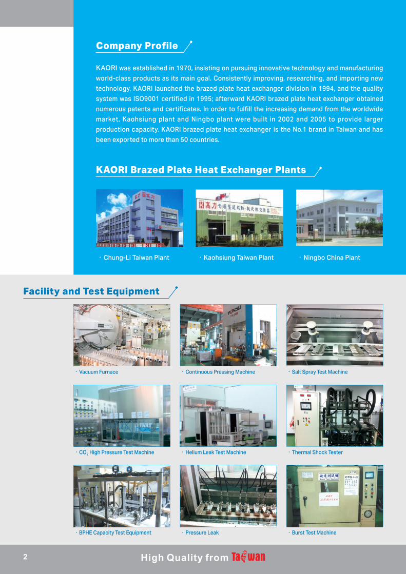
KAORI was established in 1970, insisting on pursuing innovative technology and manufacturing
world-class products as its main goal. Consistently improving, researching, and importing new
technology, KAORI launched the brazed plate heat exchanger division in 1994, and the quality
system was ISO9001 certified in 1995; afterward KAORI brazed plate heat exchanger obtained
numerous patents and certificates. In order to fulfill the increasing demand from the worldwide
market, Kaohsiung plant and Ningbo plant were built in 2002 and 2005 to provide larger
production capacity. KAORI brazed plate heat exchanger is the No.1 brand in Taiwan and has
been exported to more than 50 countries.
.Chung-Li Taiwan Plant .Kaohsiung Taiwan Plant .Ningbo China Plant
Facility and Test Equipment
.Vacuum Furnace
.CO2 High Pressure Test Machine
.BPHE Capacity Test Equipment
.Continuous Pressing Machine
.Helium Leak Test Machine
.Pressure Leak
.Salt Spray Test Machine
.Thermal Shock Tester
.Burst Test Machine
Company Profile
KAORI Brazed Plate Heat Exchanger Plants
2
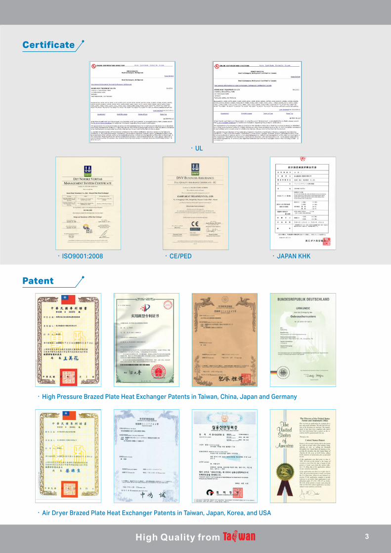
Certificate
Patent
.UL
.ISO9001:2008
.High Pressure Brazed Plate Heat Exchanger Patents in Taiwan, China, Japan and Germany
.CE/PED .JAPAN KHK
.Air Dryer Brazed Plate Heat Exchanger Patents in Taiwan, Japan, Korea, and USA
3
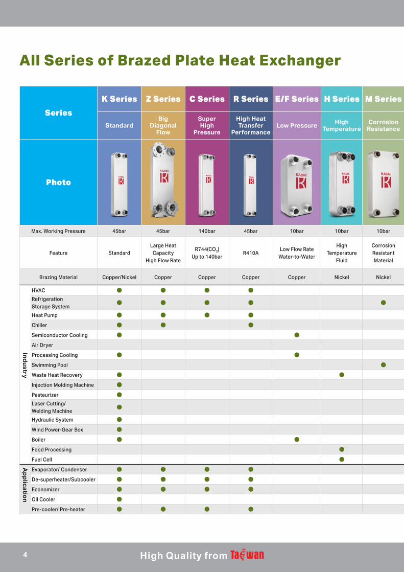
All Series of Brazed Plate Heat Exchanger
Series
K Series Z Series C Series R Series E/F Series H Series M Series A Series I Series Q Series
Standard Big
Diagonal Flow
Super High
Pressure
High Heat Transfer
PerformanceLow Pressure High
TemperatureCorrosion
Resistance Air Dryer ImpactResistance Oil Cooler
Photo
Max. Working Pressure 45bar 45bar 140bar 45bar 10bar 10bar 10bar 16bar 30bar 30bar
Feature Standard Large Heat
CapacityHigh Flow Rate
R744(CO2)Up to 140bar
R410ALow Flow Rate
Water-to-Water
High Temperature
Fluid
Corrosion Resistant Material
Evaporator, Separator and
Precooler all in one
Pressure and Thermal Shock
Endurable For Oil Cooler
Brazing Material Copper/Nickel Copper Copper Copper Copper Nickel Nickel Copper Copper Copper
HVAC ● ● ● ●Refrigeration Storage System
● ● ● ● ●
Heat Pump ● ● ● ●
Chiller ● ● ● ● ●Semiconductor Cooling ● ●Air Dryer ●Processing Cooling ● ● ●
Swimming Pool ●Waste Heat Recovery ● ●Injection Molding Machine ● ● ●Pasteurizer ●Laser Cutting/Welding Machine
● ●
Hydraulic System ● ● ●
Wind Power-Gear Box ● ● ●Boiler ● ● ●Food Processing ● ●Fuel Cell ●
Evaporator/ Condenser ● ● ● ●De-superheater/Subcooler ● ● ● ●Economizer ● ● ● ● ●Oil Cooler ● ● ●Pre-cooler/ Pre-heater ● ● ● ●
Ind
ustry
Ap
plicatio
n
4
Cold side
Series
K Series Z Series C Series R Series E/F Series H Series M Series A Series I Series Q Series
Standard Big
Diagonal Flow
Super High
Pressure
High Heat Transfer
PerformanceLow Pressure High
TemperatureCorrosion
Resistance Air Dryer ImpactResistance Oil Cooler
Photo
Max. Working Pressure 45bar 45bar 140bar 45bar 10bar 10bar 10bar 16bar 30bar 30bar
Feature Standard Large Heat
CapacityHigh Flow Rate
R744(CO2)Up to 140bar
R410ALow Flow Rate
Water-to-Water
High Temperature
Fluid
Corrosion Resistant Material
Evaporator, Separator and
Precooler all in one
Pressure and Thermal Shock
Endurable For Oil Cooler
Brazing Material Copper/Nickel Copper Copper Copper Copper Nickel Nickel Copper Copper Copper
HVAC ● ● ● ●Refrigeration Storage System
● ● ● ● ●
Heat Pump ● ● ● ●
Chiller ● ● ● ● ●Semiconductor Cooling ● ●Air Dryer ●Processing Cooling ● ● ●
Swimming Pool ●Waste Heat Recovery ● ●Injection Molding Machine ● ● ●Pasteurizer ●Laser Cutting/Welding Machine
● ●
Hydraulic System ● ● ●
Wind Power-Gear Box ● ● ●Boiler ● ● ●Food Processing ● ●Fuel Cell ●
Evaporator/ Condenser ● ● ● ●De-superheater/Subcooler ● ● ● ●Economizer ● ● ● ● ●Oil Cooler ● ● ●Pre-cooler/ Pre-heater ● ● ● ●
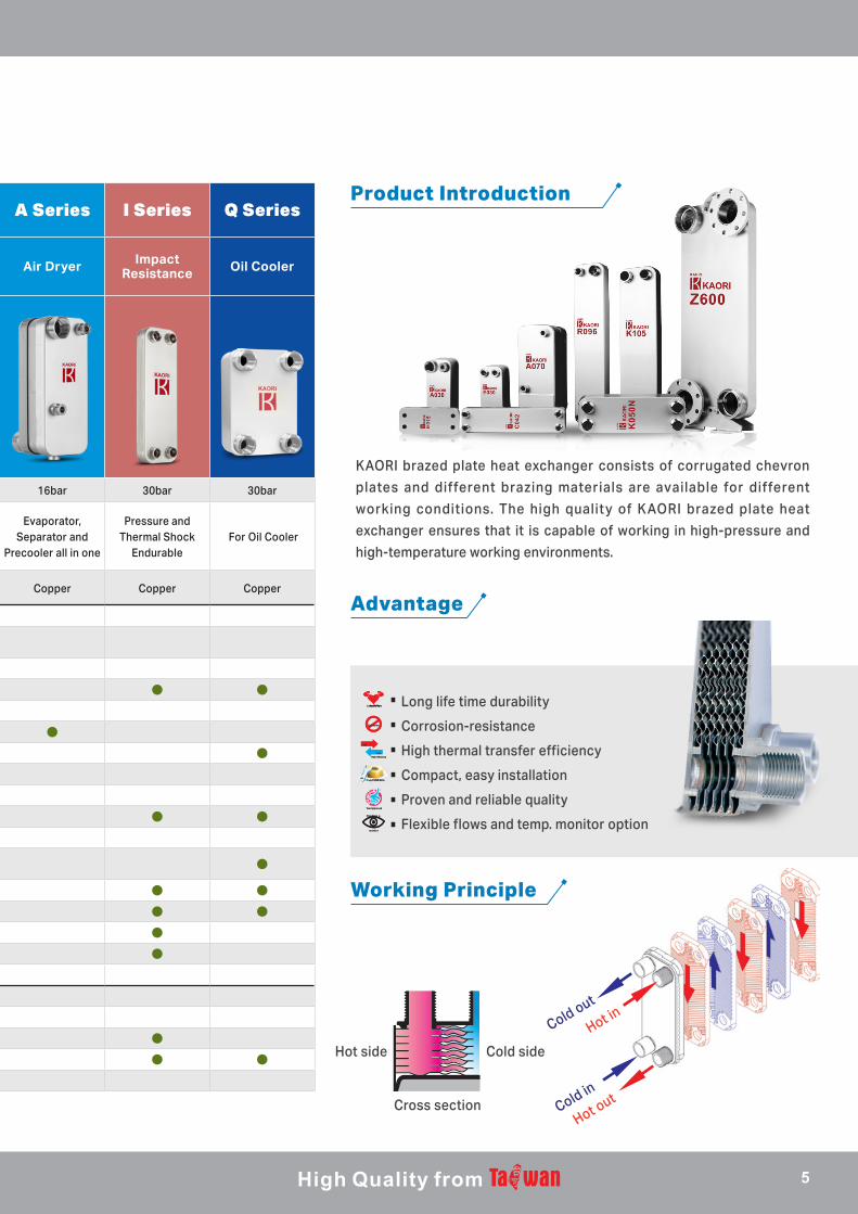
Product Introduction
Advantage
Working Principle
Long
life time
durabilityLong
life time
durability
CorrosionCorrosion
High efficiency
Hot
High efficiency
Hot
Cold
Easy InstallationEasy Installation
Tesl ApprovedTesl Approved
monito r
Flow&tem p
monito r
Flow&tem p
Long life time durability
Corrosion-resistance
High thermal transfer efficiency
Compact, easy installation
Proven and reliable quality
Flexible flows and temp. monitor option
Hot side
Cross sectionHot out
Cold in
Cold out
Hot in
KAORI brazed plate heat exchanger consists of corrugated chevron
plates and different brazing materials are available for different
working conditions. The high quality of KAORI brazed plate heat
exchanger ensures that it is capable of working in high-pressure and
high-temperature working environments.
5
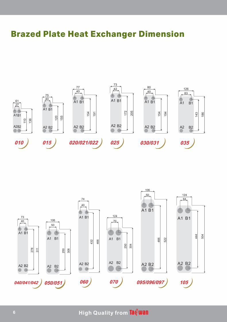
Brazed Plate Heat Exchanger Dimension
6127
7540
7740
7342 80
4012683
110
136 12
0
155 15
4
191
172
205
154
194
143
186
010 015 020/021/022 025 030/031 035
7340 106
50
40
74
70
124
50
106
64124
278
311
250
306 25
0
304
466
522
432
466
444
504
040/041/042 050/051 060 070 095/096/097 105
6
18692 246
174 245148
247
16751
9
613
456
528
430
527
449
529
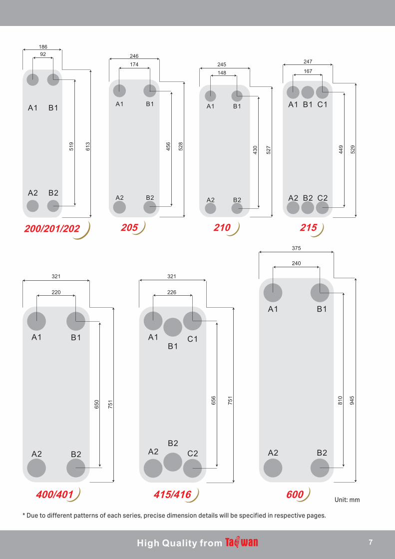
200/201/202 205 210 215
321 321
220 226
375
240
650
751 65
6
751
810
945
400/401 415/416 600
* Due to different patterns of each series, precise dimension details will be specified in respective pages.
Unit: mm
7
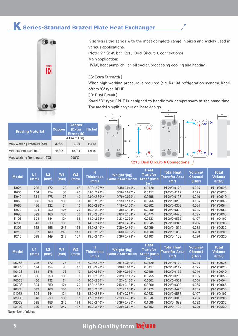
K Series-Standard Brazed Plate Heat Exchanger
K series is the series with the most complete range in sizes and widely used in
various applications.
(Note: K***S: 45 bar, K215: Dual Circuit- 6 connections)
Main application:
HVAC, heat pump, chiller, oil cooler, processing cooling and heating.
[ S: Extra Strength ]
When high working pressure is required (e.g. R410A refrigeration system), Kaori
offers "S" type BPHE.
[ D: Dual Circuit ]
Kaori "D" type BPHE is designed to handle two compressors at the same time.
The model simplifies your delicate design.
Brazing MaterialCopper
Copper (Extra
Strength)Nickel
(A1,A2/B1,B2)
Max. Working Pressure (bar) 30/30 45/30 10/10
Min. Test Pressure (bar) 43/43 65/43 15/15
Max. Working Temperature (°C) 200°C
ModelL1
(mm)L2
(mm)W1
(mm)W2
(mm)
HThickness
(mm)
Weight*(kg)(Without Connection)
Heat Transfer
Area/ plate (m2)
Total Heat Transfer Area
(m2)
Volume/ Channel
(liter)
Total Volume
(liter)
K025 205 172 73 42 6.70+2.27*N 0.48+0.040*N 0.0120 (N-2)*0.0120 0.025 (N-1)*0.025K030 194 154 80 40 9.00+2.20*N 0.50+0.047*N 0.0117 (N-2)*0.0117 0.025 (N-1)*0.025K040 311 278 73 40 9.00+2.30*N 0.79+0.070*N 0.0195 (N-2)*0.0195 0.040 (N-1)*0.040K050 306 250 106 50 10.0+2.38*N 1.19+0.116*N 0.0255 (N-2)*0.0255 0.055 (N-1)*0.055K060 466 432 74 40 10.0+2.30*N 1.19+0.100*N 0.0302 (N-2)*0.0302 0.064 (N-1)*0.064K070 304 250 124 70 10.0+2.38*N 1.38+0.134*N 0.0300 (N-2)*0.0300 0.065 (N-1)*0.065K095 522 466 106 50 11.0+2.38*N 2.83+0.204*N 0.0475 (N-2)*0.0475 0.095 (N-1)*0.095K105 504 444 124 64 11.0+2.38*N 3.23+0.230*N 0.0533 (N-2)*0.0533 0.107 (N-1)*0.107K200 613 519 186 92 14.0+2.40*N 6.89+0.404*N 0.0945 (N-2)*0.0945 0.206 (N-1)*0.206K205 528 456 246 174 14.0+2.40*N 7.30+0.480*N 0.1099 (N-2)*0.1099 0.232 (N-1)*0.232K210 527 430 245 148 11.5+2.85*N 6.68+0.465*N 0.1036 (N-2)*0.1036 0.289 (N-1)*0.289K215 529 449 247 167 13.0+2.40*N 7.36+0.473*N 0.1103 (N-2)*0.1103 0.220 (N-1)*0.220
ModelL1
(mm)L2
(mm)W1
(mm)W2
(mm)
HThickness
(mm)
Weight*(kg)(Without Connection)
Heat Transfer
Area/ plate (m2)
Total Heat Transfer Area
(m2)
Volume/ Channel
(liter)
Total Volume
(liter)
K025S 205 172 73 42 7.30+2.27*N 0.51+0.040*N 0.0120 (N-2)*0.0120 0.025 (N-1)*0.025K030S 194 154 80 40 11.0+2.20*N 0.96+0.047*N 0.0117 (N-2)*0.0117 0.025 (N-1)*0.025K040S 311 278 73 40 9.00+2.30*N 0.84+0.070*N 0.0195 (N-2)*0.0195 0.040 (N-1)*0.040K050S 306 250 106 50 12.0+2.38*N 2.39+0.116*N 0.0255 (N-2)*0.0255 0.055 (N-1)*0.055K060S 466 432 74 40 10.0+2.30*N 1.23+0.100*N 0.0302 (N-2)*0.0302 0.064 (N-1)*0.064K070S 304 250 124 70 12.0+2.38*N 2.52+0.134*N 0.0300 (N-2)*0.0300 0.065 (N-1)*0.065K095S 522 466 106 50 13.0+2.38*N 3.77+0.204*N 0.0475 (N-2)*0.0475 0.095 (N-1)*0.095K105S 504 444 124 64 13.0+2.38*N 5.47+0.237*N 0.0533 (N-2)*0.0533 0.107 (N-1)*0.107K200S 613 519 186 92 17.0+2.40*N 12.12+0.404*N 0.0945 (N-2)*0.0945 0.206 (N-1)*0.206K205S 528 456 246 174 16.5+2.40*N 13.36+0.480*N 0.1099 (N-2)*0.1099 0.232 (N-1)*0.232K215S 529 449 247 167 16.0+2.40*N 13.20+0.567*N 0.1103 (N-2)*0.1103 0.220 (N-1)*0.220
B1 C1
B2 C2
K215: Dual Circuit- 6 Connections
N: number of plates
8
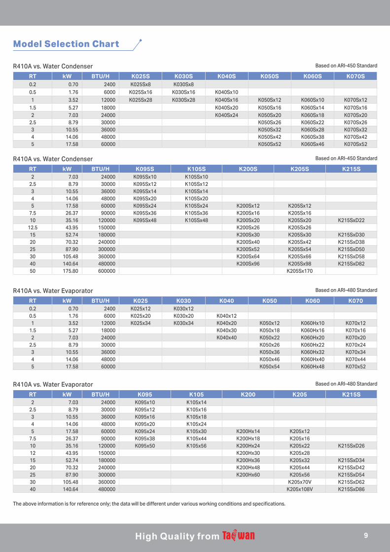
RT kW BTU/H K025S K030S K040S K050S K060S K070S0.2 0.70 2400 K025Sx8 K030Sx80.5 1.76 6000 K025Sx16 K030Sx16 K040Sx101 3.52 12000 K025Sx28 K030Sx28 K040Sx16 K050Sx12 K060Sx10 K070Sx12
1.5 5.27 18000 K040Sx20 K050Sx16 K060Sx14 K070Sx162 7.03 24000 K040Sx24 K050Sx20 K060Sx18 K070Sx20
2.5 8.79 30000 K050Sx26 K060Sx22 K070Sx263 10.55 36000 K050Sx32 K060Sx28 K070Sx324 14.06 48000 K050Sx42 K060Sx38 K070Sx425 17.58 60000 K050Sx52 K060Sx46 K070Sx52
RT kW BTU/H K025 K030 K040 K050 K060 K0700.2 0.70 2400 K025x12 K030x120.5 1.76 6000 K025x20 K030x20 K040x121 3.52 12000 K025x34 K030x34 K040x20 K050x12 K060Hx10 K070x12
1.5 5.27 18000 K040x30 K050x18 K060Hx16 K070x162 7.03 24000 K040x40 K050x22 K060Hx20 K070x20
2.5 8.79 30000 K050x26 K060Hx22 K070x243 10.55 36000 K050x36 K060Hx32 K070x344 14.06 48000 K050x46 K060Hx40 K070x445 17.58 60000 K050x54 K060Hx48 K070x52
RT kW BTU/H K095S K105S K200S K205S K215S2 7.03 24000 K095Sx10 K105Sx10
2.5 8.79 30000 K095Sx12 K105Sx123 10.55 36000 K095Sx14 K105Sx144 14.06 48000 K095Sx20 K105Sx205 17.58 60000 K095Sx24 K105Sx24 K200Sx12 K205Sx12
7.5 26.37 90000 K095Sx36 K105Sx36 K200Sx16 K205Sx1610 35.16 120000 K095Sx48 K105Sx48 K200Sx20 K205Sx20 K215SxD22
12.5 43.95 150000 K200Sx26 K205Sx2615 52.74 180000 K200Sx30 K205Sx30 K215SxD3020 70.32 240000 K200Sx40 K205Sx42 K215SxD3825 87.90 300000 K200Sx52 K205Sx54 K215SxD5030 105.48 360000 K200Sx64 K205Sx66 K215SxD5840 140.64 480000 K200Sx96 K205Sx98 K215SxD8250 175.80 600000 K205Sx170
RT kW BTU/H K095 K105 K200 K205 K215S2 7.03 24000 K095x10 K105x14
2.5 8.79 30000 K095x12 K105x163 10.55 36000 K095x16 K105x184 14.06 48000 K095x20 K105x245 17.58 60000 K095x24 K105x30 K200Hx14 K205x12
7.5 26.37 90000 K095x38 K105x44 K200Hx18 K205x1610 35.16 120000 K095x50 K105x56 K200Hx24 K205x22 K215SxD2612 43.95 150000 K200Hx30 K205x2815 52.74 180000 K200Hx36 K205x32 K215SxD3420 70.32 240000 K200Hx48 K205x44 K215SxD4225 87.90 300000 K200Hx60 K205x56 K215SxD5430 105.48 360000 K205x70V K215SxD6240 140.64 480000 K205x108V K215SxD86
Model Selection Chart
R410A vs. Water Condenser
R410A vs. Water Evaporator
R410A vs. Water Condenser
R410A vs. Water Evaporator
Based on ARI-450 Standard
Based on ARI-480 Standard
Based on ARI-450 Standard
Based on ARI-480 Standard
The above information is for reference only; the data will be different under various working conditions and specifications.
9
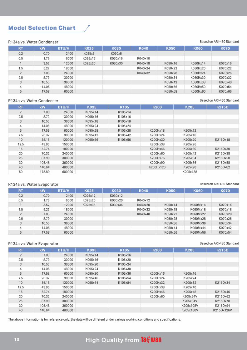
R134a vs. Water Condenser
R134a vs. Water Evaporator
R134a vs. Water Condenser
R134a vs. Water Evaporator
Based on ARI-450 Standard
Based on ARI-480 Standard
Based on ARI-450 Standard
Based on ARI-480 Standard
The above information is for reference only; the data will be different under various working conditions and specifications.
Model Selection Chart
RT kW BTU/H K025 K030 K040 K050 K060 K0700.2 0.70 2400 K025x8 K030x80.5 1.76 6000 K025x16 K030x16 K040x101 3.52 12000 K025x30 K030x30 K040x18 K050x16 K060Hx14 K070x16
1.5 5.27 18000 K040x24 K050x22 K060Hx20 K070x222 7.03 24000 K040x32 K050x28 K060Hx24 K070x26
2.5 8.79 30000 K050x34 K060Hx30 K070x323 10.55 36000 K050x42 K060Hx38 K070x404 14.06 48000 K050x56 K060Hx50 K070x545 17.58 60000 K050x68 K060Hx60 K070x66
RT kW BTU/H K025 K030 K040 K050 K060 K0700.2 0.70 2400 K025x12 K030x120.5 1.76 6000 K025x20 K030x20 K040x121 3.52 12000 K025x36 K030x36 K040x20 K050x14 K060Mx14 K070x14
1.5 5.27 18000 K040x32 K050x18 K060Mx18 K070x182 7.03 24000 K040x40 K050x22 K060Mx22 K070x20
2.5 8.79 30000 K050x28 K060Mx28 K070x263 10.55 36000 K050x36 K060Mx36 K070x344 14.06 48000 K050x44 K060Mx44 K070x425 17.58 60000 K050x56 K060Mx56 K070x54
RT kW BTU/H K095 K105 K200 K205 K215D2 7.03 24000 K095x14 K105x14
2.5 8.79 30000 K095x16 K105x163 10.55 36000 K095x18 K105x184 14.06 48000 K095x24 K105x245 17.58 60000 K095x28 K105x28 K200Hx18 K205x12
7.5 26.37 90000 K095x42 K105x42 K200Hx24 K205x1810 35.16 120000 K095x56 K105x56 K200Hx30 K205x20 K215Dx18
12.5 43.95 150000 K200Hx38 K205x2615 52.74 180000 K200Hx46 K205x30 K215Dx3020 70.32 240000 K200Hx60 K205x42 K215Dx3825 87.90 300000 K200Hx76 K205x54 K215Dx5030 105.48 360000 K200Hx90 K205x66 K215Dx5840 140.64 480000 K200Hx120 K205x98 K215Dx8250 175.80 600000 K205x138
RT kW BTU/H K095 K105 K200 K205 K215D2 7.03 24000 K095x14 K105x16
2.5 8.79 30000 K095x16 K105x203 10.55 36000 K095x20 K105x244 14.06 48000 K095x24 K105x305 17.58 60000 K095x30 K105x36 K200Hx16 K205x16
7.5 26.37 90000 K095x46 K105x54 K200Hx24 K205x2410 35.16 120000 K095x64 K105x84 K200Hx32 K205x32 K215Dx34
12.5 43.95 150000 K200Hx38 K205x4015 52.74 180000 K200Hx46 K205x48 K215Dx4620 70.32 240000 K200Hx60 K205x64V K215Dx6225 87.90 300000 K205x84V K215Dx7830 105.48 360000 K205x108V K215Dx9440 140.64 480000 K205x180V K215Dx126V
10
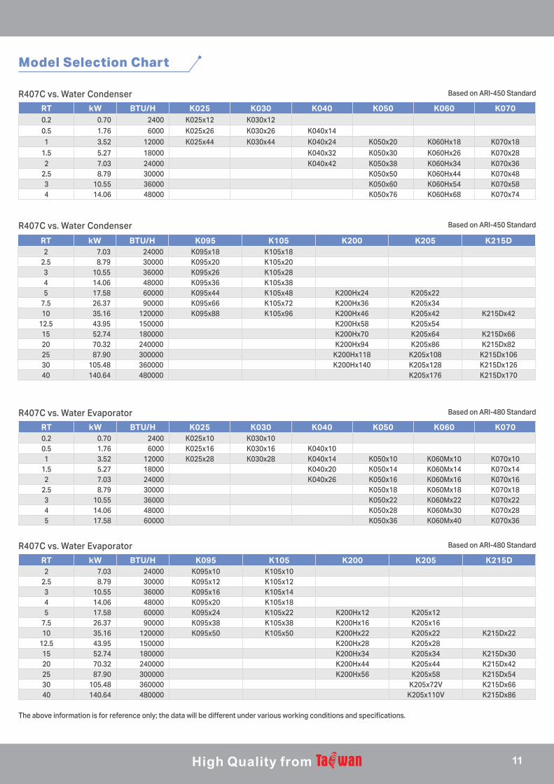
R407C vs. Water Condenser
R407C vs. Water Evaporator
R407C vs. Water Condenser
R407C vs. Water Evaporator
Based on ARI-450 Standard
Based on ARI-480 Standard
Based on ARI-450 Standard
Based on ARI-480 Standard
The above information is for reference only; the data will be different under various working conditions and specifications.
Model Selection Chart
RT kW BTU/H K025 K030 K040 K050 K060 K0700.2 0.70 2400 K025x12 K030x120.5 1.76 6000 K025x26 K030x26 K040x141 3.52 12000 K025x44 K030x44 K040x24 K050x20 K060Hx18 K070x18
1.5 5.27 18000 K040x32 K050x30 K060Hx26 K070x282 7.03 24000 K040x42 K050x38 K060Hx34 K070x36
2.5 8.79 30000 K050x50 K060Hx44 K070x483 10.55 36000 K050x60 K060Hx54 K070x584 14.06 48000 K050x76 K060Hx68 K070x74
RT kW BTU/H K025 K030 K040 K050 K060 K0700.2 0.70 2400 K025x10 K030x100.5 1.76 6000 K025x16 K030x16 K040x101 3.52 12000 K025x28 K030x28 K040x14 K050x10 K060Mx10 K070x10
1.5 5.27 18000 K040x20 K050x14 K060Mx14 K070x142 7.03 24000 K040x26 K050x16 K060Mx16 K070x16
2.5 8.79 30000 K050x18 K060Mx18 K070x183 10.55 36000 K050x22 K060Mx22 K070x224 14.06 48000 K050x28 K060Mx30 K070x285 17.58 60000 K050x36 K060Mx40 K070x36
RT kW BTU/H K095 K105 K200 K205 K215D2 7.03 24000 K095x18 K105x18
2.5 8.79 30000 K095x20 K105x203 10.55 36000 K095x26 K105x284 14.06 48000 K095x36 K105x385 17.58 60000 K095x44 K105x48 K200Hx24 K205x22
7.5 26.37 90000 K095x66 K105x72 K200Hx36 K205x3410 35.16 120000 K095x88 K105x96 K200Hx46 K205x42 K215Dx42
12.5 43.95 150000 K200Hx58 K205x5415 52.74 180000 K200Hx70 K205x64 K215Dx6620 70.32 240000 K200Hx94 K205x86 K215Dx8225 87.90 300000 K200Hx118 K205x108 K215Dx10630 105.48 360000 K200Hx140 K205x128 K215Dx12640 140.64 480000 K205x176 K215Dx170
RT kW BTU/H K095 K105 K200 K205 K215D2 7.03 24000 K095x10 K105x10
2.5 8.79 30000 K095x12 K105x123 10.55 36000 K095x16 K105x144 14.06 48000 K095x20 K105x185 17.58 60000 K095x24 K105x22 K200Hx12 K205x12
7.5 26.37 90000 K095x38 K105x38 K200Hx16 K205x1610 35.16 120000 K095x50 K105x50 K200Hx22 K205x22 K215Dx22
12.5 43.95 150000 K200Hx28 K205x2815 52.74 180000 K200Hx34 K205x34 K215Dx3020 70.32 240000 K200Hx44 K205x44 K215Dx4225 87.90 300000 K200Hx56 K205x58 K215Dx5430 105.48 360000 K205x72V K215Dx6640 140.64 480000 K205x110V K215Dx86
11
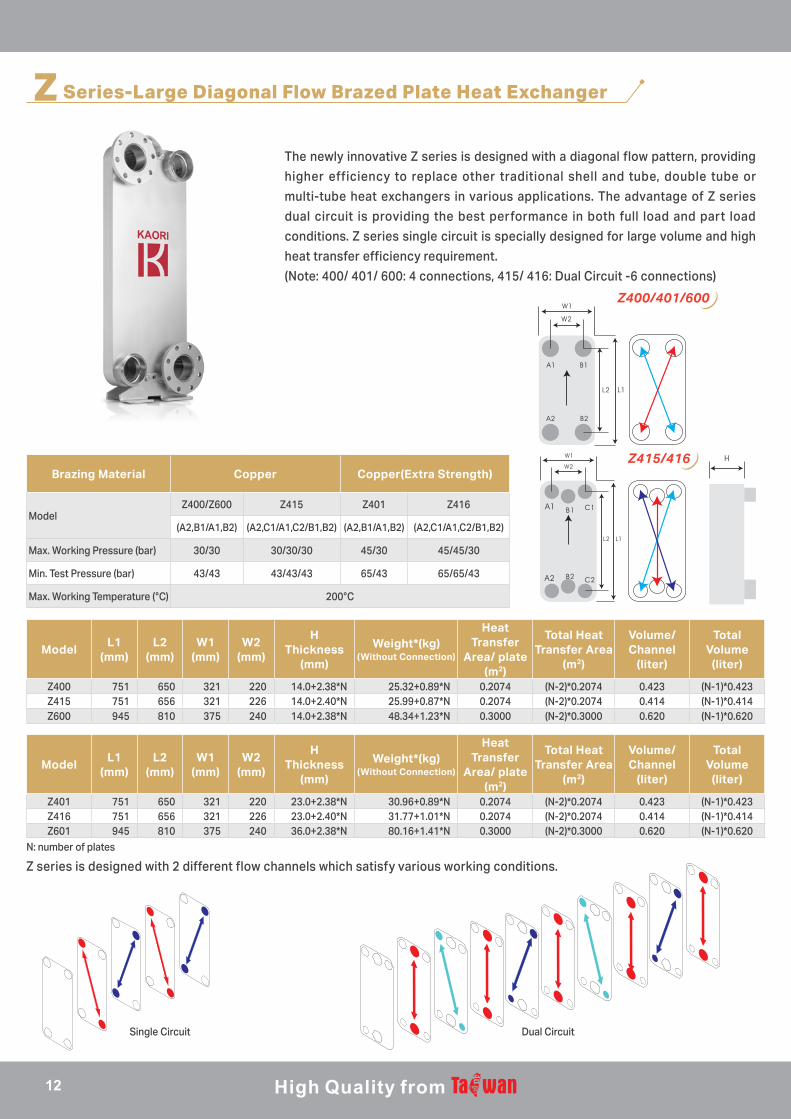
Z Series-Large Diagonal Flow Brazed Plate Heat Exchanger
The newly innovative Z series is designed with a diagonal flow pattern, providing
higher efficiency to replace other traditional shell and tube, double tube or
multi-tube heat exchangers in various applications. The advantage of Z series
dual circuit is providing the best performance in both full load and part load
conditions. Z series single circuit is specially designed for large volume and high
heat transfer efficiency requirement.
(Note: 400/ 401/ 600: 4 connections, 415/ 416: Dual Circuit -6 connections)
Brazing Material Copper Copper(Extra Strength)
ModelZ400/Z600 Z415 Z401 Z416
(A2,B1/A1,B2) (A2,C1/A1,C2/B1,B2) (A2,B1/A1,B2) (A2,C1/A1,C2/B1,B2)
Max. Working Pressure (bar) 30/30 30/30/30 45/30 45/45/30
Min. Test Pressure (bar) 43/43 43/43/43 65/43 65/65/43
Max. Working Temperature (°C) 200°C
ModelL1
(mm)L2
(mm)W1
(mm)W2
(mm)
HThickness
(mm)
Weight*(kg)(Without Connection)
Heat Transfer
Area/ plate (m2)
Total Heat Transfer Area
(m2)
Volume/ Channel
(liter)
Total Volume
(liter)
Z400 751 650 321 220 14.0+2.38*N 25.32+0.89*N 0.2074 (N-2)*0.2074 0.423 (N-1)*0.423Z415 751 656 321 226 14.0+2.40*N 25.99+0.87*N 0.2074 (N-2)*0.2074 0.414 (N-1)*0.414Z600 945 810 375 240 14.0+2.38*N 48.34+1.23*N 0.3000 (N-2)*0.3000 0.620 (N-1)*0.620
ModelL1
(mm)L2
(mm)W1
(mm)W2
(mm)
HThickness
(mm)
Weight*(kg)(Without Connection)
Heat Transfer
Area/ plate (m2)
Total Heat Transfer Area
(m2)
Volume/ Channel
(liter)
Total Volume
(liter)
Z401 751 650 321 220 23.0+2.38*N 30.96+0.89*N 0.2074 (N-2)*0.2074 0.423 (N-1)*0.423Z416 751 656 321 226 23.0+2.40*N 31.77+1.01*N 0.2074 (N-2)*0.2074 0.414 (N-1)*0.414Z601 945 810 375 240 36.0+2.38*N 80.16+1.41*N 0.3000 (N-2)*0.3000 0.620 (N-1)*0.620
B1 C1
B2 C2
N: number of plates
Single Circuit Dual Circuit
Z series is designed with 2 different flow channels which satisfy various working conditions.
Z400/401/600
Z415/416
12
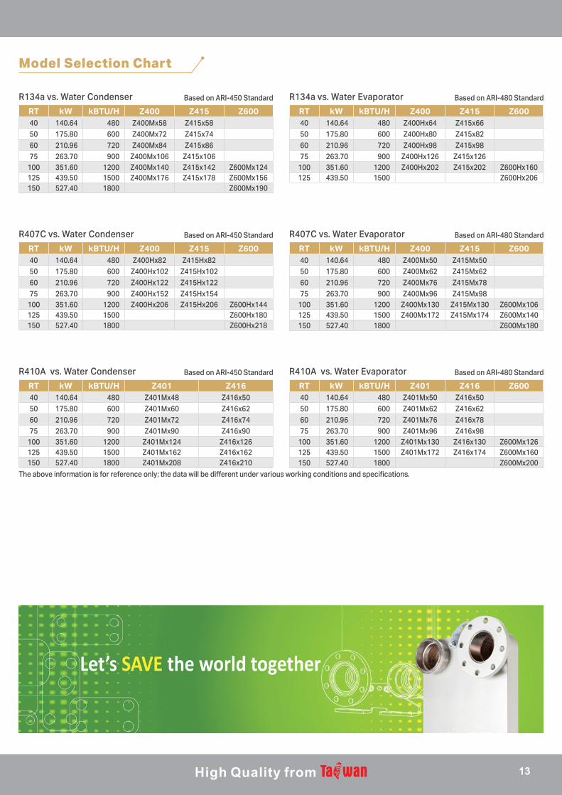
RT kW kBTU/H Z400 Z415 Z60040 140.64 480 Z400Mx58 Z415x5850 175.80 600 Z400Mx72 Z415x7460 210.96 720 Z400Mx84 Z415x8675 263.70 900 Z400Mx106 Z415x106
100 351.60 1200 Z400Mx140 Z415x142 Z600Mx124125 439.50 1500 Z400Mx176 Z415x178 Z600Mx156150 527.40 1800 Z600Mx190
RT kW kBTU/H Z400 Z415 Z60040 140.64 480 Z400Hx64 Z415x6650 175.80 600 Z400Hx80 Z415x8260 210.96 720 Z400Hx98 Z415x9875 263.70 900 Z400Hx126 Z415x126
100 351.60 1200 Z400Hx202 Z415x202 Z600Hx160125 439.50 1500 Z600Hx206
R134a vs. Water Condenser R134a vs. Water EvaporatorBased on ARI-450 Standard Based on ARI-480 Standard
Model Selection Chart
RT kW kBTU/H Z401 Z41640 140.64 480 Z401Mx48 Z416x5050 175.80 600 Z401Mx60 Z416x6260 210.96 720 Z401Mx72 Z416x7475 263.70 900 Z401Mx90 Z416x90
100 351.60 1200 Z401Mx124 Z416x126125 439.50 1500 Z401Mx162 Z416x162150 527.40 1800 Z401Mx208 Z416x210
RT kW kBTU/H Z401 Z416 Z60040 140.64 480 Z401Mx50 Z416x5050 175.80 600 Z401Mx62 Z416x6260 210.96 720 Z401Mx76 Z416x7875 263.70 900 Z401Mx96 Z416x98
100 351.60 1200 Z401Mx130 Z416x130 Z600Mx126125 439.50 1500 Z401Mx172 Z416x174 Z600Mx160150 527.40 1800 Z600Mx200
R410A vs. Water Condenser R410A vs. Water EvaporatorBased on ARI-450 Standard Based on ARI-480 Standard
The above information is for reference only; the data will be different under various working conditions and specifications.
R407C vs. Water Condenser R407C vs. Water EvaporatorBased on ARI-450 Standard Based on ARI-480 Standard
RT kW kBTU/H Z400 Z415 Z60040 140.64 480 Z400Hx82 Z415Hx8250 175.80 600 Z400Hx102 Z415Hx10260 210.96 720 Z400Hx122 Z415Hx12275 263.70 900 Z400Hx152 Z415Hx154
100 351.60 1200 Z400Hx206 Z415Hx206 Z600Hx144125 439.50 1500 Z600Hx180150 527.40 1800 Z600Hx218
RT kW kBTU/H Z400 Z415 Z60040 140.64 480 Z400Mx50 Z415Mx5050 175.80 600 Z400Mx62 Z415Mx6260 210.96 720 Z400Mx76 Z415Mx7875 263.70 900 Z400Mx96 Z415Mx98
100 351.60 1200 Z400Mx130 Z415Mx130 Z600Mx106125 439.50 1500 Z400Mx172 Z415Mx174 Z600Mx140150 527.40 1800 Z600Mx180
13
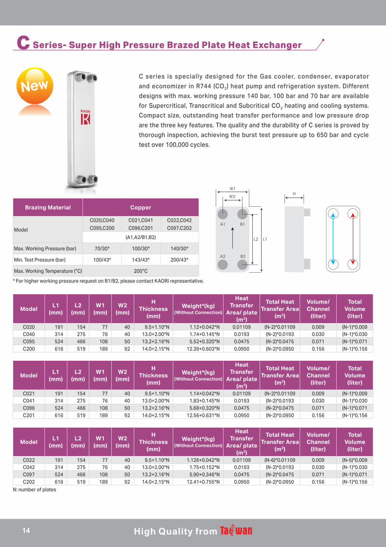
C Series- Super High Pressure Brazed Plate Heat Exchanger
C series is specially designed for the Gas cooler, condenser, evaporator
and economizer in R744 (CO2) heat pump and refrigeration system. Different
designs with max. working pressure 140 bar, 100 bar and 70 bar are available
for Supercritical, Transcritical and Subcritical CO2 heating and cooling systems.
Compact size, outstanding heat transfer performance and low pressure drop
are the three key features. The quality and the durability of C series is proved by
thorough inspection, achieving the burst test pressure up to 650 bar and cycle
test over 100,000 cycles.
Brazing Material Copper
Model
C020,C040C095,C200
C021,C041C096,C201
C022,C042C097,C202
(A1,A2/B1,B2)
Max. Working Pressure (bar) 70/30* 100/30* 140/30*
Min. Test Pressure (bar) 100/43* 143/43* 200/43*
Max. Working Temperature (°C) 200°C
ModelL1
(mm)L2
(mm)W1
(mm)W2
(mm)
HThickness
(mm)
Weight*(kg)(Without Connection)
Heat Transfer
Area/ plate (m2)
Total Heat Transfer Area
(m2)
Volume/ Channel
(liter)
Total Volume
(liter)
C020 191 154 77 40 9.5+1.10*N 1.12+0.042*N 0.01109 (N-2)*0.01109 0.009 (N-1)*0.009C040 314 275 76 40 13.0+2.00*N 1.74+0.145*N 0.0193 (N-2)*0.0193 0.030 (N-1)*0.030C095 524 466 108 50 13.2+2.16*N 5.52+0.320*N 0.0475 (N-2)*0.0475 0.071 (N-1)*0.071C200 616 519 189 92 14.0+2.15*N 12.39+0.603*N 0.0950 (N-2)*0.0950 0.156 (N-1)*0.156
ModelL1
(mm)L2
(mm)W1
(mm)W2
(mm)
HThickness
(mm)
Weight*(kg)(Without Connection)
Heat Transfer
Area/ plate (m2)
Total Heat Transfer Area
(m2)
Volume/ Channel
(liter)
Total Volume
(liter)
C021 191 154 77 40 9.5+1.10*N 1.14+0.042*N 0.01109 (N-2)*0.01109 0.009 (N-1)*0.009C041 314 275 76 40 13.0+2.00*N 1.83+0.145*N 0.0193 (N-2)*0.0193 0.030 (N-1)*0.030C096 524 466 108 50 13.2+2.16*N 5.68+0.320*N 0.0475 (N-2)*0.0475 0.071 (N-1)*0.071C201 616 519 189 92 14.0+2.15*N 12.56+0.631*N 0.0950 (N-2)*0.0950 0.156 (N-1)*0.156
ModelL1
(mm)L2
(mm)W1
(mm)W2
(mm)
HThickness
(mm)
Weight*(kg)(Without Connection)
Heat Transfer
Area/ plate (m2)
Total Heat Transfer Area
(m2)
Volume/ Channel
(liter)
Total Volume
(liter)
C022 191 154 77 40 9.5+1.10*N 1.126+0.042*N 0.01109 (N-6)*0.01109 0.009 (N-5)*0.009C042 314 275 76 40 13.0+2.00*N 1.75+0.152*N 0.0193 (N-2)*0.0193 0.030 (N-1)*0.030C097 524 466 108 50 13.2+2.16*N 5.90+0.346*N 0.0475 (N-2)*0.0475 0.071 (N-1)*0.071C202 616 519 189 92 14.0+2.15*N 12.41+0.755*N 0.0950 (N-2)*0.0950 0.156 (N-1)*0.156
* For higher working pressure request on B1/B2, please contact KAORI representative.
N: number of plates
14
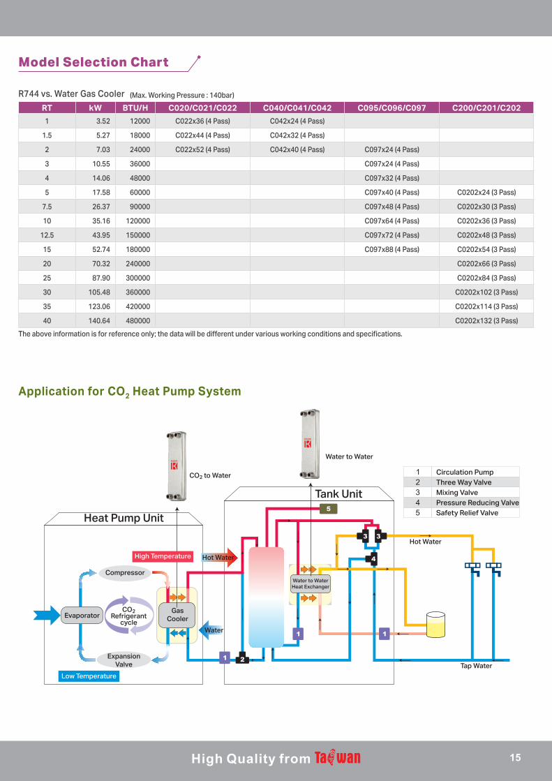
RT kW BTU/H C020/C021/C022 C040/C041/C042 C095/C096/C097 C200/C201/C202
1 3.52 12000 C022x36 (4 Pass) C042x24 (4 Pass)
1.5 5.27 18000 C022x44 (4 Pass) C042x32 (4 Pass)
2 7.03 24000 C022x52 (4 Pass) C042x40 (4 Pass) C097x24 (4 Pass)
3 10.55 36000 C097x24 (4 Pass)
4 14.06 48000 C097x32 (4 Pass)
5 17.58 60000 C097x40 (4 Pass) C0202x24 (3 Pass)
7.5 26.37 90000 C097x48 (4 Pass) C0202x30 (3 Pass)
10 35.16 120000 C097x64 (4 Pass) C0202x36 (3 Pass)
12.5 43.95 150000 C097x72 (4 Pass) C0202x48 (3 Pass)
15 52.74 180000 C097x88 (4 Pass) C0202x54 (3 Pass)
20 70.32 240000 C0202x66 (3 Pass)
25 87.90 300000 C0202x84 (3 Pass)
30 105.48 360000 C0202x102 (3 Pass)
35 123.06 420000 C0202x114 (3 Pass)
40 140.64 480000 C0202x132 (3 Pass)
R744 vs. Water Gas Cooler (Max. Working Pressure : 140bar)
The above information is for reference only; the data will be different under various working conditions and specifications.
Water to Water
Hot Water
Tap Water
Heat Pump Unit
Tank Unit
CO2 to Water Circulation PumpThree Way ValveMixing ValvePressure Reducing ValveSafety Relief Valve
Low Temperature
High Temperature Hot Water
Water
Evaporator
ExpansionValve
Compressor
GasCooler
CO2Refrigerant
cycle
Water to WaterHeat Exchanger
Model Selection Chart
Application for CO2 Heat Pump System
15
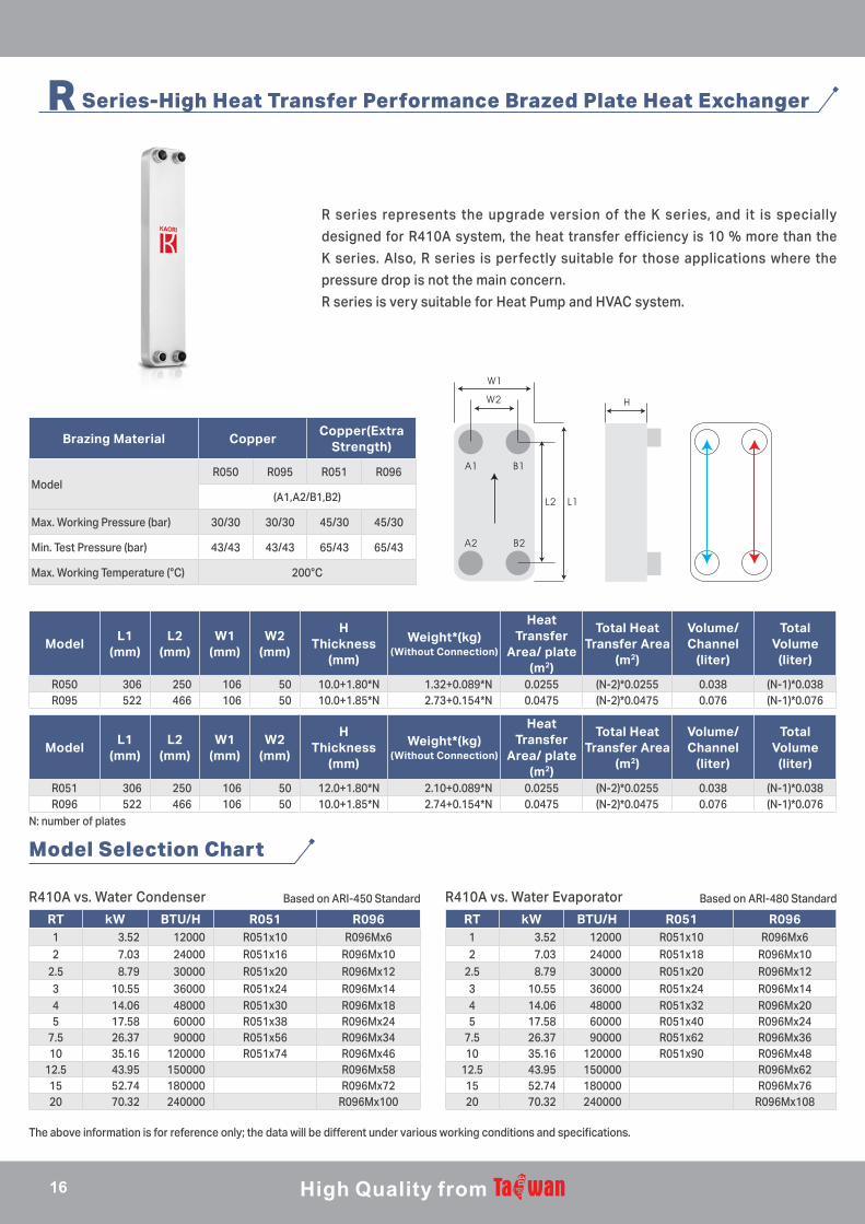
R Series-High Heat Transfer Performance Brazed Plate Heat Exchanger
R series represents the upgrade version of the K series, and it is specially
designed for R410A system, the heat transfer efficiency is 10 % more than the
K series. Also, R series is perfectly suitable for those applications where the
pressure drop is not the main concern.
R series is very suitable for Heat Pump and HVAC system.
Brazing Material CopperCopper(Extra
Strength)
ModelR050 R095 R051 R096
(A1,A2/B1,B2)
Max. Working Pressure (bar) 30/30 30/30 45/30 45/30
Min. Test Pressure (bar) 43/43 43/43 65/43 65/43
Max. Working Temperature (°C) 200°C
ModelL1
(mm)L2
(mm)W1
(mm)W2
(mm)
HThickness
(mm)
Weight*(kg)(Without Connection)
Heat Transfer
Area/ plate (m2)
Total Heat Transfer Area
(m2)
Volume/ Channel
(liter)
Total Volume
(liter)
R050 306 250 106 50 10.0+1.80*N 1.32+0.089*N 0.0255 (N-2)*0.0255 0.038 (N-1)*0.038R095 522 466 106 50 10.0+1.85*N 2.73+0.154*N 0.0475 (N-2)*0.0475 0.076 (N-1)*0.076
ModelL1
(mm)L2
(mm)W1
(mm)W2
(mm)
HThickness
(mm)
Weight*(kg)(Without Connection)
Heat Transfer
Area/ plate (m2)
Total Heat Transfer Area
(m2)
Volume/ Channel
(liter)
Total Volume
(liter)
R051 306 250 106 50 12.0+1.80*N 2.10+0.089*N 0.0255 (N-2)*0.0255 0.038 (N-1)*0.038R096 522 466 106 50 10.0+1.85*N 2.74+0.154*N 0.0475 (N-2)*0.0475 0.076 (N-1)*0.076
R410A vs. Water Condenser R410A vs. Water EvaporatorBased on ARI-450 Standard Based on ARI-480 Standard
The above information is for reference only; the data will be different under various working conditions and specifications.
N: number of plates
Model Selection Chart
RT kW BTU/H R051 R0961 3.52 12000 R051x10 R096Mx62 7.03 24000 R051x16 R096Mx10
2.5 8.79 30000 R051x20 R096Mx123 10.55 36000 R051x24 R096Mx144 14.06 48000 R051x30 R096Mx185 17.58 60000 R051x38 R096Mx24
7.5 26.37 90000 R051x56 R096Mx3410 35.16 120000 R051x74 R096Mx46
12.5 43.95 150000 R096Mx5815 52.74 180000 R096Mx7220 70.32 240000 R096Mx100
RT kW BTU/H R051 R0961 3.52 12000 R051x10 R096Mx62 7.03 24000 R051x18 R096Mx10
2.5 8.79 30000 R051x20 R096Mx123 10.55 36000 R051x24 R096Mx144 14.06 48000 R051x32 R096Mx205 17.58 60000 R051x40 R096Mx24
7.5 26.37 90000 R051x62 R096Mx3610 35.16 120000 R051x90 R096Mx48
12.5 43.95 150000 R096Mx6215 52.74 180000 R096Mx7620 70.32 240000 R096Mx108
16
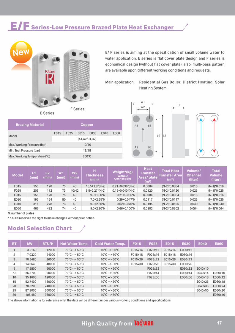
E SeriesF Series
E/F Series-Low Pressure Brazed Plate Heat Exchanger
E/ F series is aiming at the specification of small volume water to
water application. E series is flat cover plate design and F series is
economical design (without flat cover plate); also, multi-pass pattern
are available upon different working conditions and requests.
Main application: Residential Gas Boiler, District Heating, Solar
Heating System.
Brazing Material Copper
ModelF015 F025 E015 E030 E040 E060
(A1,A2/B1,B2)
Max. Working Pressure (bar) 10/10
Min. Test Pressure (bar) 15/15
Max. Working Temperature (°C) 200°C
ModelL1
(mm)L2
(mm)W1
(mm)W2
(mm)
HThickness
(mm)
Weight*(kg)(Without
Connection)
Heat Transfer
Area/ plate (m2)
Total Heat Transfer Area
(m2)
Volume/ Channel
(liter)
Total Volume
(liter)
F015 155 120 75 40 10.5+1.8*(N-2) 0.21+0.036*(N-2) 0.0084 (N-2)*0.0084 0.016 (N-1)*0.016F025 206 172 73 40/42 6.5+2.27*(N-2) 0.19+0.040*(N-2) 0.0120 (N-2)*0.0120 0.025 (N-1)*0.025E015 155 120 75 40 9.0+1.80*N 0.21+0.036*N 0.0084 (N-2)*0.0084 0.016 (N-1)*0.016E030 195 154 80 40 7.0+2.25*N 0.29+0.047*N 0.0117 (N-2)*0.0117 0.025 (N-1)*0.025E040 311 278 73 40 9.0+2.30*N 0.62+0.070*N 0.0195 (N-2)*0.0195 0.040 (N-1)*0.040E060 466 432 74 40 9.0+2.30*N 0.66+0.100*N 0.0302 (N-2)*0.0302 0.064 (N-1)*0.064
N: number of plates* KAORI reserves the right to make changes without prior notice.
The above information is for reference only; the data will be different under various working conditions and specifications.
Model Selection Chart
RT kW BTU/H Hot Water Temp. Cold Water Temp. F015 F025 E015 E030 E040 E060
1 3.5160 12000 70°C --> 50°C 10°C --> 60°C F015x14 F025x12 E015x14 E030x122 7.0320 24000 70°C --> 50°C 10°C --> 60°C F015x18 F025x16 E015x18 E030x163 10.5480 36000 70°C --> 50°C 10°C --> 60°C F015x26 F025x22 E015x26 E030x224 14.0640 48000 70°C --> 50°C 10°C --> 60°C F015x30 F025x26 E015x30 E030x265 17.5800 60000 70°C --> 50°C 10°C --> 60°C F025x32 E030x32 E040x10
7.5 26.3700 90000 70°C --> 50°C 10°C --> 60°C F025x44 E030x44 E040x14 E060x1010 35.1600 120000 70°C --> 50°C 10°C --> 60°C F025x56 E030x56 E040x18 E060x1215 52.7400 180000 70°C --> 50°C 10°C --> 60°C E040x26 E060x1820 70.3200 240000 70°C --> 50°C 10°C --> 60°C E040x36 E060x2425 87.9000 300000 70°C --> 50°C 10°C --> 60°C E040x50 E060x3030 105.480 360000 70°C --> 50°C 10°C --> 60°C E060x40
17
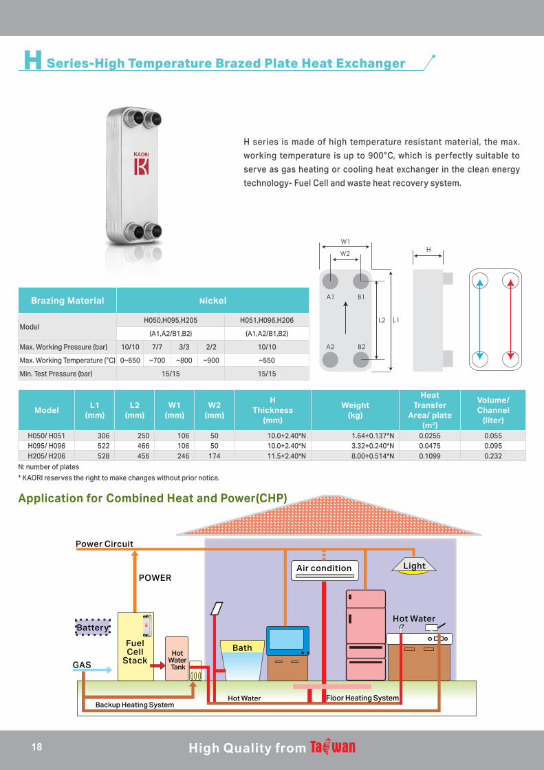
H Series-High Temperature Brazed Plate Heat Exchanger
H series is made of high temperature resistant material, the max.
working temperature is up to 900°C, which is perfectly suitable to
serve as gas heating or cooling heat exchanger in the clean energy
technology- Fuel Cell and waste heat recovery system.
ModelL1
(mm)L2
(mm)W1
(mm)W2
(mm)
HThickness
(mm)
Weight(kg)
Heat Transfer
Area/ plate (m2)
Volume/ Channel
(liter)
H050/ H051 306 250 106 50 10.0+2.40*N 1.64+0.137*N 0.0255 0.055H095/ H096 522 466 106 50 10.0+2.40*N 3.32+0.240*N 0.0475 0.095H205/ H206 528 456 246 174 11.5+2.40*N 8.00+0.514*N 0.1099 0.232
N: number of plates* KAORI reserves the right to make changes without prior notice.
Brazing Material Nickel
ModelH050,H095,H205 H051,H096,H206
(A1,A2/B1,B2) (A1,A2/B1,B2)
Max. Working Pressure (bar) 10/10 7/7 3/3 2/2 10/10
Max. Working Temperature (°C) 0~650 ~700 ~800 ~900 ~550
Min. Test Pressure (bar) 15/15 15/15
Power Circuit
Battery
GASHot
Water Tank
POWERAir condition Light
Bath
Hot Water
Floor Heating System
Fuel Cell
Stack
Hot WaterBackup Heating System
Application for Combined Heat and Power(CHP)
18
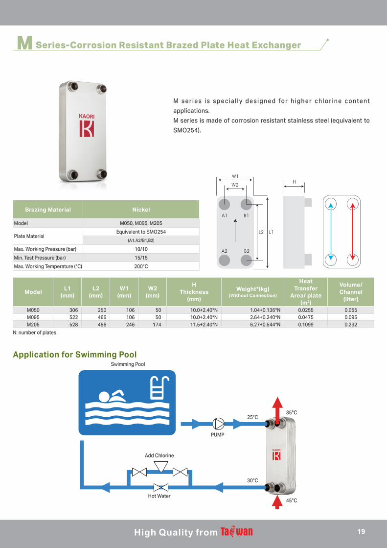
M Series-Corrosion Resistant Brazed Plate Heat Exchanger
M s e r i e s i s s p e c i a l l y d e s i g n e d fo r h i g h e r c h l o r i n e co n te n t
applications.
M series is made of corrosion resistant stainless steel (equivalent to
SMO254).
Brazing Material Nickel
Model M050, M095, M205
Plate MaterialEquivalent to SMO254
(A1,A2/B1,B2)
Max. Working Pressure (bar) 10/10
Min. Test Pressure (bar) 15/15
Max. Working Temperature (°C) 200°C
ModelL1
(mm)L2
(mm)W1
(mm)W2
(mm)
HThickness
(mm)
Weight*(kg)(Without Connection)
Heat Transfer
Area/ plate (m2)
Volume/ Channel
(liter)
M050 306 250 106 50 10.0+2.40*N 1.04+0.136*N 0.0255 0.055M095 522 466 106 50 10.0+2.40*N 2.64+0.240*N 0.0475 0.095M205 528 456 246 174 11.5+2.40*N 6.27+0.544*N 0.1099 0.232
N: number of plates
Swimming Pool
Add Chlorine
Hot Water
PUMP
25°C
30°C
45°C
35°C
Application for Swimming Pool
19
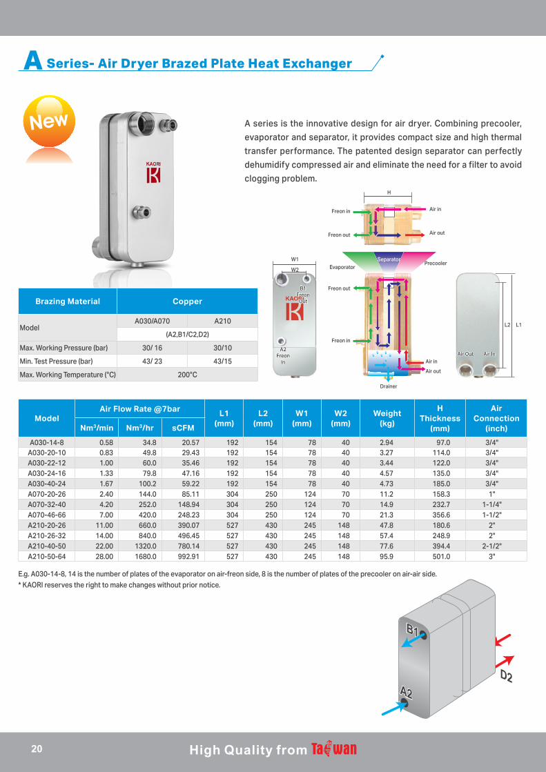
A Series- Air Dryer Brazed Plate Heat Exchanger
A series is the innovative design for air dryer. Combining precooler,
evaporator and separator, it provides compact size and high thermal
transfer performance. The patented design separator can perfectly
dehumidify compressed air and eliminate the need for a filter to avoid
clogging problem.
ModelAir Flow Rate @7bar L1
(mm)L2
(mm)W1
(mm)W2
(mm)Weight
(kg)
HThickness
(mm)
Air Connection
(inch)Nm3/min Nm3/hr sCFM
A030-14-8 0.58 34.8 20.57 192 154 78 40 2.94 97.0 3/4"A030-20-10 0.83 49.8 29.43 192 154 78 40 3.27 114.0 3/4"A030-22-12 1.00 60.0 35.46 192 154 78 40 3.44 122.0 3/4"A030-24-16 1.33 79.8 47.16 192 154 78 40 4.57 135.0 3/4"A030-40-24 1.67 100.2 59.22 192 154 78 40 4.73 185.0 3/4"A070-20-26 2.40 144.0 85.11 304 250 124 70 11.2 158.3 1"A070-32-40 4.20 252.0 148.94 304 250 124 70 14.9 232.7 1-1/4"A070-46-66 7.00 420.0 248.23 304 250 124 70 21.3 356.6 1-1/2"A210-20-26 11.00 660.0 390.07 527 430 245 148 47.8 180.6 2"A210-26-32 14.00 840.0 496.45 527 430 245 148 57.4 248.9 2"A210-40-50 22.00 1320.0 780.14 527 430 245 148 77.6 394.4 2-1/2"A210-50-64 28.00 1680.0 992.91 527 430 245 148 95.9 501.0 3"
E.g. A030-14-8, 14 is the number of plates of the evaporator on air-freon side, 8 is the number of plates of the precooler on air-air side.* KAORI reserves the right to make changes without prior notice.
Brazing Material Copper
ModelA030/A070 A210
(A2,B1/C2,D2)
Max. Working Pressure (bar) 30/ 16 30/10
Min. Test Pressure (bar) 43/ 23 43/15
Max. Working Temperature (°C) 200°C
H
W1
W2
L1L2
Separator
Freon in
Freon in
Drainer
Air in
Air inAir InAir Out
Freon out
Freon outB1Freon
Out
A2Freon
In
Evaporator
Air out
Air out
Precooler
D1D1
D2D2
C1C1
C2C2 C2C2
D2D2
C2C2
D2D2
C2C2
D2D2
A1A1
A2A2
B1B1
B2B2A2A2
B1B1
A2A2 B2B2
A1A1
A2A2
B1B1
B2B2
A1A1
A2A2
A2A2
B1B1
20
ModelL1
(mm)L2
(mm)W1
(mm)W2
(mm)
HThickness
(mm)
Weight*(kg)(Without
Connection)
Heat Transfer
Area/ plate (m2)
Total Heat Transfer Area
(m2)
Volume/ Channel
(liter)
Total Volume
(liter)
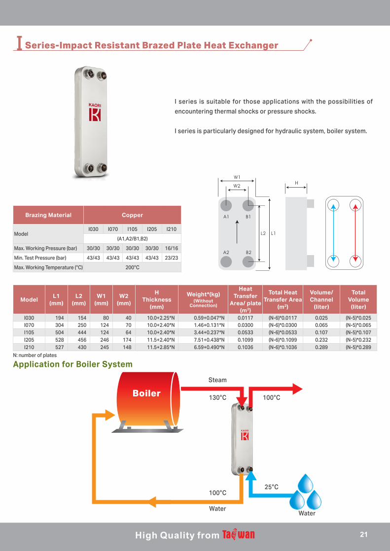
I030 194 154 80 40 10.0+2.25*N 0.59+0.047*N 0.0117 (N-6)*0.0117 0.025 (N-5)*0.025I070 304 250 124 70 10.0+2.40*N 1.46+0.131*N 0.0300 (N-6)*0.0300 0.065 (N-5)*0.065I105 504 444 124 64 10.0+2.40*N 3.44+0.237*N 0.0533 (N-6)*0.0533 0.107 (N-5)*0.107I205 528 456 246 174 11.5+2.40*N 7.51+0.438*N 0.1099 (N-6)*0.1099 0.232 (N-5)*0.232I210 527 430 245 148 11.5+2.85*N 6.59+0.490*N 0.1036 (N-6)*0.1036 0.289 (N-5)*0.289
I Series-Impact Resistant Brazed Plate Heat Exchanger
I series is suitable for those applications with the possibilities of
encountering thermal shocks or pressure shocks.
I series is particularly designed for hydraulic system, boiler system.
N: number of plates
Brazing Material Copper
ModelI030 I070 I105 I205 I210
(A1,A2/B1,B2)
Max. Working Pressure (bar) 30/30 30/30 30/30 30/30 16/16
Min. Test Pressure (bar) 43/43 43/43 43/43 43/43 23/23
Max. Working Temperature (°C) 200°C
Boiler
Steam
130°C 100°C
100°C25°C
WaterWater
Application for Boiler System
21
ModelL1
(mm)L2
(mm)W1
(mm)W2
(mm)
HThickness
(mm)
Weight*(kg)(Without Connection)
Heat Transfer
Area/ plate (m2)
Volume/ Channel
(liter)
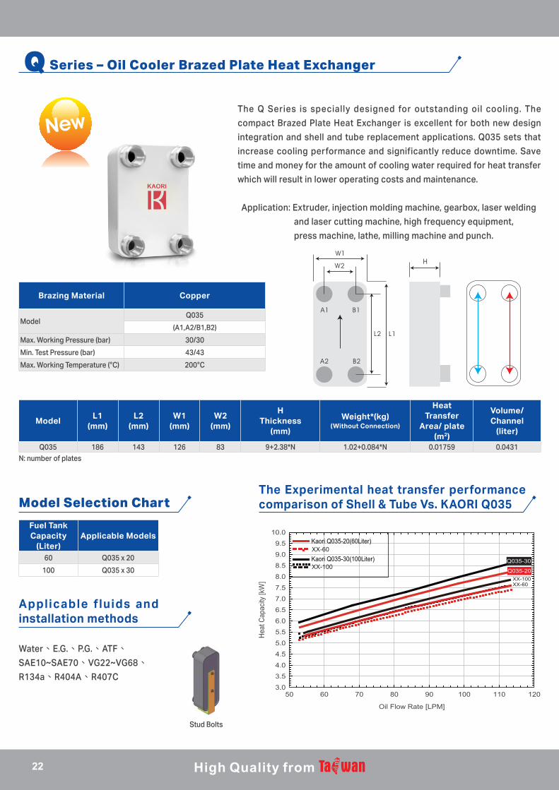
Q035 186 143 126 83 9+2.38*N 1.02+0.084*N 0.01759 0.0431N: number of plates
Stud Bolts
Q Series – Oil Cooler Brazed Plate Heat Exchanger
The Q Series is specially designed for outstanding oil cooling. The
compact Brazed Plate Heat Exchanger is excellent for both new design
integration and shell and tube replacement applications. Q035 sets that
increase cooling performance and significantly reduce downtime. Save
time and money for the amount of cooling water required for heat transfer
which will result in lower operating costs and maintenance.
Application: Extruder, injection molding machine, gearbox, laser welding
and laser cutting machine, high frequency equipment,
press machine, lathe, milling machine and punch.
Brazing Material Copper
ModelQ035
(A1,A2/B1,B2)
Max. Working Pressure (bar) 30/30
Min. Test Pressure (bar) 43/43
Max. Working Temperature (°C) 200°C
Fuel Tank Capacity
(Liter)Applicable Models
60 Q035 x 20
100 Q035 x 30
XX-60
XX-100
XX-60XX-100
Model Selection ChartThe Experimental heat transfer performance comparison of Shell & Tube Vs. KAORI Q035
Applicable f luids and installation methods
Water、E.G.、P.G.、ATF、SAE10~SAE70、VG22~VG68、R134a、R404A、R407C
a.正面植釘法 b.背部植釘法 c.板金挾持法 d.旗桿與螺桿挾持法 e.腳架固定法
22
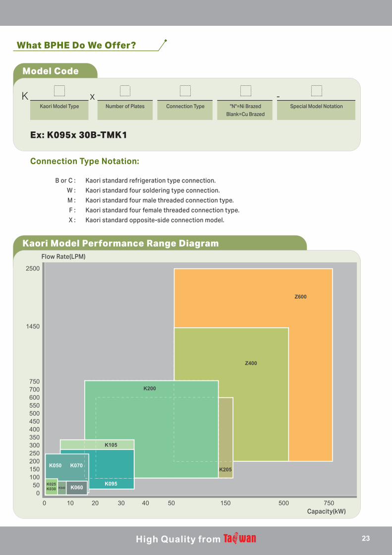
What BPHE Do We Offer?
Model Code
Kaori Model Performance Range Diagram
K x -Kaori Model Type Number of Plates Connection Type Special Model Notation"N"=Ni Brazed
Blank=Cu Brazed
Ex: K095x 30B-TMK1
Connection Type Notation:
B or C : Kaori standard refrigeration type connection.
W : Kaori standard four soldering type connection.
M : Kaori standard four male threaded connection type.
F : Kaori standard four female threaded connection type.
X : Kaori standard opposite-side connection model.
2500
1450
750700600550500450400
K060
350300250200150100
500
0 10 20 30 40 50 150 500 750
K025K030 K040
K050 K070
K060K095
K105
K200
Z400
Z600
K205
Flow Rate(LPM)
Capacity(kW)
23
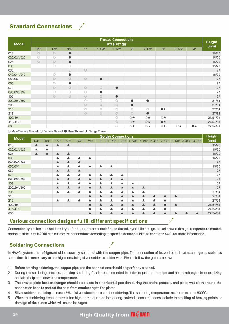
Standard Connections
Soldering Connections
ModelThread Connections
Height(mm)PT/ NPT/ GB
3/8" 1/2" 3/4" 1" 1 1/4" 1 1/2" 2" 2 1/2" 3" 3 1/2" 4"015 ◎ ◎ ● 15/20020/021/022 ◎ ◎ ● 15/20025 ◎ ◎ ● 15/20030 ◎ ◎ 15/20035 ○ ○ 27040/041/042 ◎ ● 15/20050/051 ◎ ◎ ◎ ● 27060 ◎ ● 27070 ◎ ◎ ◎ ◎ ● 27095/096/097 ◎ ◎ ◎ ● 27105 ◎ ◎ ◎ ◎ ● 27200/201/202 ◎ ◎ ◎ ● ● 27/54205 ◎ ◎ ◎ ● 27/54210 ◎ ◎ ◎ ◎ ◎ ●★ 27/54215 ◎ ◎ ◎ ◎ ● 27/54400/401 ◎ ◎★ ◎★ ◎★ 27/54/81415/416 ◎ ◎★ ◎★ ●★ 27/54/81600 ◎ ◎★ ◎★ ◎★ ◎★ ●★ 27/54/81
◎ Male/Female Thread ○ Female Thread ● Male Thread ★ Flange Thread
ModelSolder Connections Height
(mm)1/4" 3/8" 1/2" 5/8" 3/4" 7/8" 1" 1 1/8" 1 3/8" 1 5/8" 2 1/8" 2 3/8" 2 5/8" 3 1/8" 3 3/8" 3 7/8"015 ▲ ▲ ▲ ▲ 15/20020/021/022 ▲ ▲ 15/20025 ▲ ▲ ▲ ▲ 15/20030 ▲ ▲ ▲ ▲ 15/20040/041/042 ▲ ▲ ▲ 27050/051 ▲ ▲ ▲ ▲ ▲ ▲ 15/20060 ▲ ▲ ▲ 27070 ▲ ▲ ▲ ▲ ▲ ▲ ▲ 27095/096/097 ▲ ▲ ▲ ▲ ▲ ▲ ▲ 27105 ▲ ▲ ▲ ▲ ▲ ▲ ▲ ▲ 27200/201/202 ▲ ▲ ▲ ▲ ▲ ▲ ▲ ▲ ▲ 27205 ▲ ▲ ▲ ▲ ▲ ▲ ▲ ▲ ▲ 27/54210 ▲ ▲ ▲ ▲ ▲ ▲ ▲ ▲ ▲ 27/54215 ▲ ▲ ▲ ▲ ▲ ▲ ▲ ▲ ▲ ▲ ▲ 27/54400/401 ▲ ▲ ▲ ▲ ▲ ▲ ▲ ▲ ▲ 27/54/81415/416 ▲ ▲ ▲ ▲ ▲ ▲ ▲ ▲ 27/54/81600 ▲ ▲ ▲ ▲ ▲ ▲ ▲ ▲ ▲ ▲ ▲ 27/54/81
Connection types include: soldered type for copper tube, female/ male thread, hydraulic design, nickel brazed design, temperature control, opposite side...etc. KAORI can customize connections according to specific demands. Please contact KAORI for more information.
In HVAC system, the refrigerant side is usually soldered with the copper pipe. The connection of brazed plate heat exchanger is stainless steel, thus, it is necessary to use high containing silver solder to solder with. Please follow the guides below:
1. Before starting soldering, the copper pipe and the connections should be perfectly cleaned. 2. During the soldering process, applying soldering flux is recommended in order to protect the pipe and heat exchanger from oxidizing
and also help cool down the temperature.3. The brazed plate heat exchanger should be placed in a horizontal position during the entire process, and place wet cloth around the
connection base to protect the heat from conducting to the plates.4. Silver solder containing at least 45% of silver should be used for soldering. The soldering temperature must not exceed 800°C. 5. When the soldering temperature is too high or the duration is too long, potential consequences include the melting of brazing points or
damage of the plates which will cause leakages.
Various connection designs fulfill different specifications
24
Caution
1
2
3
4
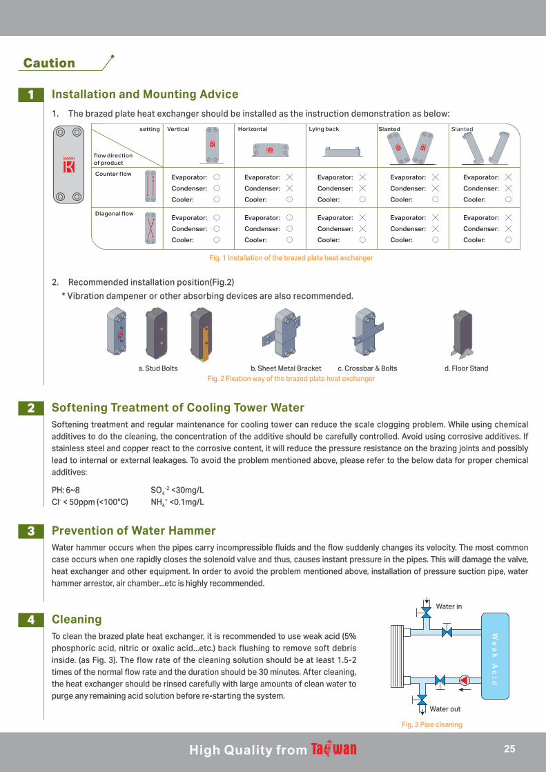
Installation and Mounting Advice
Softening Treatment of Cooling Tower Water
Prevention of Water Hammer
Cleaning
1. The brazed plate heat exchanger should be installed as the instruction demonstration as below:
Softening treatment and regular maintenance for cooling tower can reduce the scale clogging problem. While using chemical additives to do the cleaning, the concentration of the additive should be carefully controlled. Avoid using corrosive additives. If stainless steel and copper react to the corrosive content, it will reduce the pressure resistance on the brazing joints and possibly lead to internal or external leakages. To avoid the problem mentioned above, please refer to the below data for proper chemical additives:
Water hammer occurs when the pipes carry incompressible fluids and the flow suddenly changes its velocity. The most common case occurs when one rapidly closes the solenoid valve and thus, causes instant pressure in the pipes. This will damage the valve, heat exchanger and other equipment. In order to avoid the problem mentioned above, installation of pressure suction pipe, water hammer arrestor, air chamber...etc is highly recommended.
To clean the brazed plate heat exchanger, it is recommended to use weak acid (5% phosphoric acid, nitric or oxalic acid...etc.) back flushing to remove soft debris inside. (as Fig. 3). The flow rate of the cleaning solution should be at least 1.5-2 times of the normal flow rate and the duration should be 30 minutes. After cleaning, the heat exchanger should be rinsed carefully with large amounts of clean water to purge any remaining acid solution before re-starting the system.
Fig. 1 Installation of the brazed plate heat exchanger
Fig. 2 Fixation way of the brazed plate heat exchangera. Stud Bolts b. Sheet Metal Bracket c. Crossbar & Bolts d. Floor Stand
Fig. 3 Pipe cleaning
2. Recommended installation position(Fig.2)
* Vibration dampener or other absorbing devices are also recommended.
PH: 6~8 SO4-2 <30mg/L
Cl- < 50ppm (<100°C) NH4+ <0.1mg/L
We
ak
Ac
id
Water in
Water out
flow directionof product
Vertical Horizontal Lying back Slanted Slantedsetting
Counter flow
Diagonal flow
Evaporator: ○Condenser: ○Cooler: ○
Evaporator: ╳Condenser: ╳Cooler: ○
Evaporator: ╳Condenser: ╳Cooler: ○
Evaporator: ╳Condenser: ╳Cooler: ○
Evaporator: ╳Condenser: ╳Cooler: ○
Evaporator: ○Condenser: ○Cooler: ○
Evaporator: ○Condenser: ○Cooler: ○
Evaporator: ╳Condenser: ╳Cooler: ○
Evaporator: ╳Condenser: ╳Cooler: ○
Evaporator: ╳Condenser: ╳Cooler: ○
25

Professionals in Customized Heat Exchangers
HEAD OFFICE5-2, Chilin North Road, Chung-Li Industrial Zone, Chung-Li District, Taoyuan City, Taiwan