instruction manual - vmc
TRANSCRIPT
INSTRUCTION MANUAL(M202BVM-03-21A)
RCCB with automatic reclosing device
DREC Compact (DREC-C)

2
DREC-C
Instruction Manual
PENDIENTE DE VALID
ACIÓN
SAFETY PRECAUTIONS
DISCLAIMER
VMC, reserves the right to make modifi cations to the device or the unit specifi cations set out in this instruction manual without prior notice.
VMC, on its web site, supplies its customers with the latest versions of the device specifi ca-tions and the most updated manuals.
www.vmc.es
VMC, recommends using the original cables and accessories that are supplied with the device.
DANGERWarns of a risk, which could result in personal injury or material damage.
ATTENTIONIndicates that special attention should be paid to a specifi c point.
Follow the warnings described in this manual with the symbols shown below.
If you must handle the unit for its installation, start-up or maintenance, the following should be taken into consideration:
Incorrect handling or installation of the unit may result in injury to personnel as well as damage to the unit. In particular, handling with voltages applied may result in electric shock, which may cause death or serious injury to personnel. Defective installation or maintenance may also lead to the risk of fi re.Read the manual carefully prior to connecting the unit. Follow all installation and maintenance instructions throughout the unit’s working life. Pay special attention to the installation stan-dards of the National Electrical Code.
Refer to the instruction manual before using the unit
In this manual, if the instructions marked with this symbol are not respected or carried out correctly, it can result in injury or damage to the unit and /or installations.
VMC, reserves the right to modify features or the product manual without prior notifi cation.
3Instruction Manual
DREC-C
CONTENTSSAFETY PRECAUTIONS �������������������������������������������������������������������������������������������������������������������������������������3DISCLAIMER ���������������������������������������������������������������������������������������������������������������������������������������������������������3CONTENTS ������������������������������������������������������������������������������������������������������������������������������������������������������������4REVISION LOG �����������������������������������������������������������������������������������������������������������������������������������������������������5SYMBOLS ��������������������������������������������������������������������������������������������������������������������������������������������������������������51�- VERIFICATION UPON RECEPTION ��������������������������������������������������������������������������������������������������������������62�- PRODUCT DESCRIPTION ������������������������������������������������������������������������������������������������������������������������������63�- DEVICE INSTALLATION ���������������������������������������������������������������������������������������������������������������������������������7
3�1�- PRIOR RECOMMENDATIONS������������������������������������������������������������������������������������������������������������������7 3�2�- INSTALLATION �����������������������������������������������������������������������������������������������������������������������������������������7 3�3�- CONNECTION �������������������������������������������������������������������������������������������������������������������������������������������8
3�3�1�- CONNECTION DIAGRAM 2-POLE MODEL: DREC-C-2P �����������������������������������������������������������������8 3�3�2�- CONNECTION DIAGRAM 4-POLE MODEL: DREC-C-4P �����������������������������������������������������������������9
4�- OPERATION ��������������������������������������������������������������������������������������������������������������������������������������������������10 4�1�- DESCRIPTION �����������������������������������������������������������������������������������������������������������������������������������������10 4�2�- LEDs �������������������������������������������������������������������������������������������������������������������������������������������������������� 11 4�3�- START-UP ������������������������������������������������������������������������������������������������������������������������������������������������12
4�3�1�- AUTOMATIC MODE ��������������������������������������������������������������������������������������������������������������������������124�3�2�- MANUAL MODE ��������������������������������������������������������������������������������������������������������������������������������12
4�4�- OPERATING MODES ������������������������������������������������������������������������������������������������������������������������������134�4�1�- MANUAL ��������������������������������������������������������������������������������������������������������������������������������������������134�4�2�- AUTOMATIC ��������������������������������������������������������������������������������������������������������������������������������������13
5�- MAINTENANCE ���������������������������������������������������������������������������������������������������������������������������������������������156�- TECHNICAL FEATURES ������������������������������������������������������������������������������������������������������������������������������167�- TECHNICAL SERVICE ����������������������������������������������������������������������������������������������������������������������������������198�- GUARANTEE �������������������������������������������������������������������������������������������������������������������������������������������������19
4
DREC-C
Instruction Manual

PENDIENTE DE VALID
ACIÓN
REVISION LOG
Table 1: Revision log�Date Revision Description06/21 M202BVM-03-21A Initial Version
Note: The images of the devices are solely for the purpose of illustration and may differ from the original device.
SYMBOLS
Table 2: SymbolsSymbol Description
In compliance with the relevant European directive.
Device covered by European directive 2012/19/EC. At the end of its useful life, do not leave the unit in a household waste container. Follow local regulations on electronic equi-pment recycling.
DC current
~ AC current
5Instruction Manual
DREC-C
1�- VERIFICATION UPON RECEPTION
Check the following points when you receive the device:
a) The device meets the specifications described in your order.b) The device has not suffered any damage during transport.c) Perform an external visual inspection of the device prior to switching it on.d) Check that it has been delivered with the following:
- Installation guide
If any problem is noticed upon reception, immediately contact the transport company and/or VMC’s after-sales service.
2�- PRODUCT DESCRIPTION
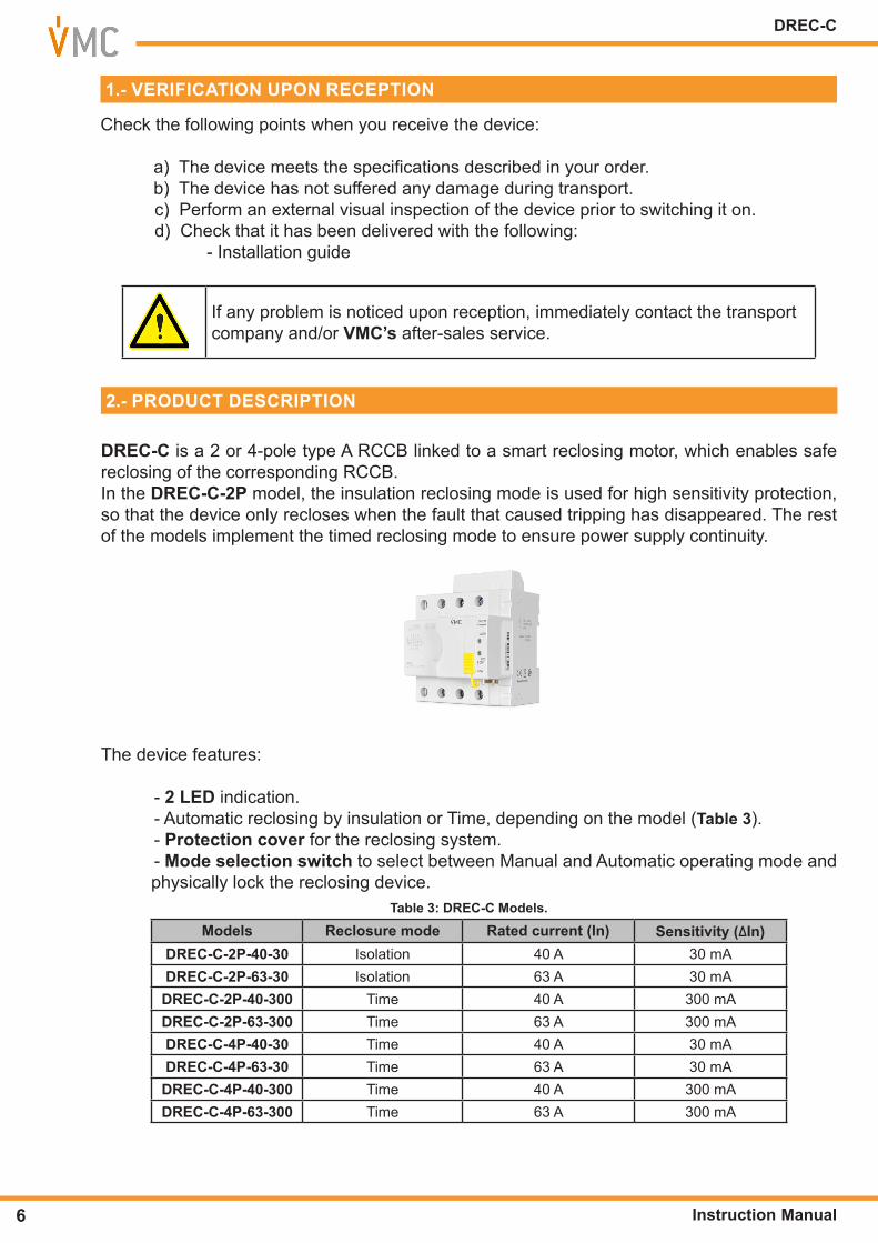
DREC-C is a 2 or 4-pole type A RCCB linked to a smart reclosing mo tor, which enables safe reclosing of the corresponding RCCB. In the DREC-C-2P model, the insulation reclosing mode is used for high sensitivity protection, so that the device only recloses when the fault that caused tripping has disappeared. The rest of the models imple ment the timed reclosing mode to ensure power supply continuity.
The device features:
- 2 LED indication.- Automatic reclosing by insulation or Time, depending on the model (Table 3).- Protection cover for the reclosing system. - Mode selection switch to select between Manual and Automatic operating mode andphysically lock the reclosing device.
Table 3: DREC-C Models�Models Reclosure mode Rated current (In) Sensitivity (ΔIn)
DREC-C-2P-40-30 Isolation 40 A 30 mADREC-C-2P-63-30 Isolation 63 A 30 mADREC-C-2P-40-300 Time 40 A 300 mADREC-C-2P-63-300 Time 63 A 300 mADREC-C-4P-40-30 Time 40 A 30 mADREC-C-4P-63-30 Time 63 A 30 mADREC-C-4P-40-300 Time 40 A 300 mADREC-C-4P-63-300 Time 63 A 300 mA
6
DREC-C
Instruction Manual
PENDIENTE DE VALID
ACIÓN
3�- DEVICE INSTALLATION
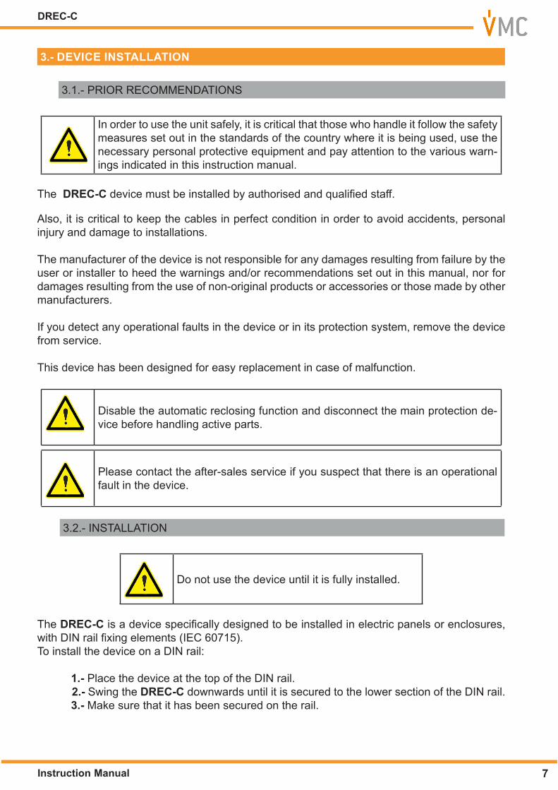
3.1.- PRIOR RECOMMENDATIONS
In order to use the unit safely, it is critical that those who handle it follow the safety measures set out in the standards of the country where it is being used, use the necessary personal protective equipment and pay attention to the various warn-ings indicated in this instruction manual.
The DREC-C device must be installed by authorised and qualified staff.
Also, it is critical to keep the cables in perfect condition in order to avoid accidents, personal injury and damage to installations.
The manufacturer of the device is not responsible for any damages resulting from failure by the user or installer to heed the warnings and/or recommendations set out in this manual, nor for damages resulting from the use of non-original products or accessories or those made by other manufacturers.
If you detect any operational faults in the device or in its protection system, remove the device from service.
This device has been designed for easy replacement in case of malfunction.
Disable the automatic reclosing function and disconnect the main protection de-vice before handling active parts.
Please contact the after-sales service if you suspect that there is an operational fault in the device.
3.2.- INSTALLATION
Do not use the device until it is fully installed.
The DREC-C is a device specifically designed to be installed in electric panels or enclosures, with DIN rail fixing elements (IEC 60715). To install the device on a DIN rail:
1�- Place the device at the top of the DIN rail.2�- Swing the DREC-C downwards until it is secured to the lower section of the DIN rail.3�- Make sure that it has been secured on the rail.
7Instruction Manual
DREC-C

3.3.- CONNECTION
The DREC-C must be connected to an installation protected with fuses suitable for its power supply range and consumption.
Note: Cross-section of the cable: 16 - 25mm2
Terminals, opening covers or removing elements can expose parts that are hazardous to the touch while the device is powered
If the DREC-C indicates a permanent failure (AUTO and REC LEDs are lit), you must check the RCCB and the installation.
If the installation of the device is done with the RCCB in the OFF state, when panel receives voltage the device will not activate the automatic reclosing sys-tem for safety reasons And the AUTO and REC LEDs turn on to turn off in a few seconds. A manual reclosing of the system must be done on the panel with voltage.
3�3�1�- CONNECTION DIAGRAM 2-POLE MODEL: DREC-C-2P
FN
CARGA / LOAD
Figure 1: Connection diagram DREC-C-2P�
8
DREC-C
Instruction Manual
PENDIENTE DE VALID
ACIÓN
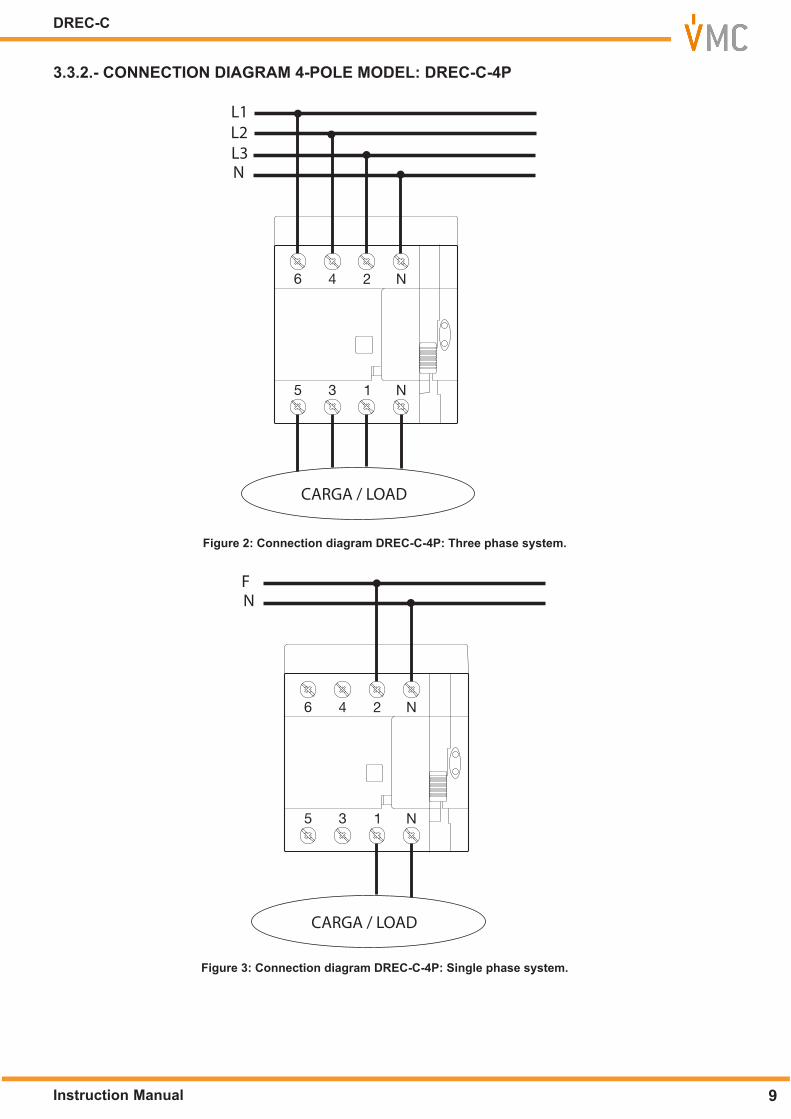
3�3�2�- CONNECTION DIAGRAM 4-POLE MODEL: DREC-C-4P
CARGA / LOAD
L3N
L1L2
Figure 2: Connection diagram DREC-C-4P: Three phase system�
CARGA / LOAD
FN
Figure 3: Connection diagram DREC-C-4P: Single phase system�
9Instruction Manual
DREC-C
4�- OPERATION
4.1.- DESCRIPTION
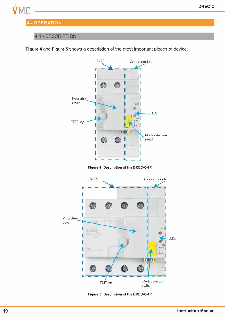
Figure 4 and Figure 5 shows a description of the most important pieces of device.
LEDs
Protectioncover
TEST key
Mode selection switch
RCCB Control module
Figure 4: Description of the DREC-C-2P�
LEDs
Protectioncover
TEST key Mode selection switch
RCCB Control module
Figure 5: Description of the DREC-C-4P�
10
DREC-C
Instruction Manual
PENDIENTE DE VALID
ACIÓN
4.2.- LEDs
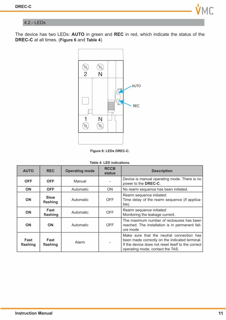
The device has two LEDs: AUTO in green and REC in red, which indicate the status of the DREC-C at all times. (Figure 6 and Table 4)
AUTO
REC
AUTO
REC
Figure 6: LEDs DREC-C�
Table 4: LED indications�
AUTO REC Operating mode RCCB status Description
OFF OFF Manual - Device is manual operating mode. There is no power to the DREC-C.
ON OFF Automatic ON No rearm sequence has been initiated.
ON Slow flashing Automatic OFF
Rearm sequence initiated:Time delay of the rearm sequence (if applica-ble).
ON Fast flashing Automatic OFF Rearm sequence initiated:
Monitoring the leakage current.
ON ON Automatic OFFThe maximum number of reclosures has been reached. The installation is in permanent fail-ure mode
Fast flashing
Fast flashing Alarm -
Make sure that the neutral connection has been made correctly on the indicated terminal. If the device does not reset itself to the correct operating mode, contact the TAS.
11Instruction Manual
DREC-C
4.3.- START-UP
Once the device is installed you must carry out the following start-up sequence for it to work properly.
4�3�1�- AUTOMATIC MODE
If the device is going to operate in automatic mode, see Section “4.4.2.- AUTOMATIC”, the start-up sequence is:
1�- Put the mode selector switch in Manual Mode (OFF). 2�- Lift the RCCB cover. 3�- Put the RCCB contact in ON mode. 4�- Lower the RCCB cover. 5�- Put the mode selector switch in Automatic Mode (ON).
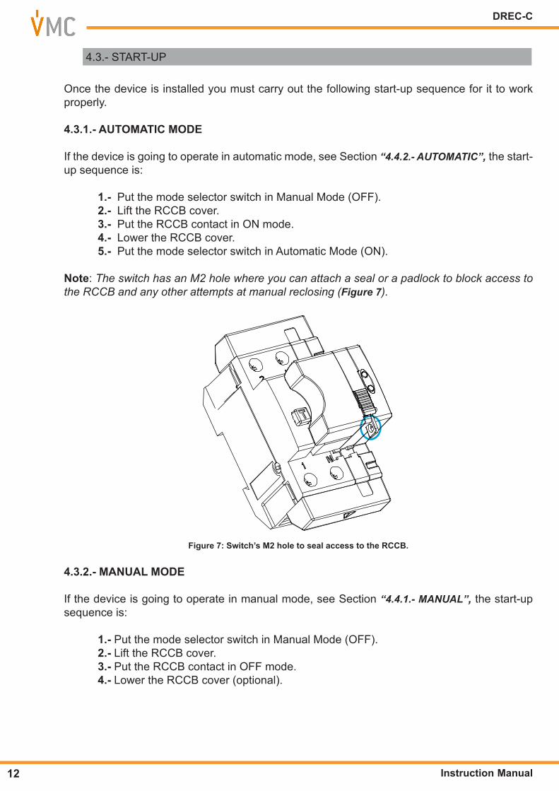
Note: The switch has an M2 hole where you can attach a seal or a padlock to block access to the RCCB and any other attempts at manual reclosing (Figure 7).
Figure 7: Switch’s M2 hole to seal access to the RCCB�
4�3�2�- MANUAL MODE
If the device is going to operate in manual mode, see Section “4.4.1.- MANUAL”, the start-up sequence is:
1�- Put the mode selector switch in Manual Mode (OFF). 2�- Lift the RCCB cover. 3�- Put the RCCB contact in OFF mode. 4�- Lower the RCCB cover (optional).
12
DREC-C
Instruction Manual
PENDIENTE DE VALID
ACIÓN
4.4.- OPERATING MODES
The device has two operating modes, manual and automatic, which can be selected using the mode selector switch (Figure 4 and Figure 5).
4�4�1�- MANUAL
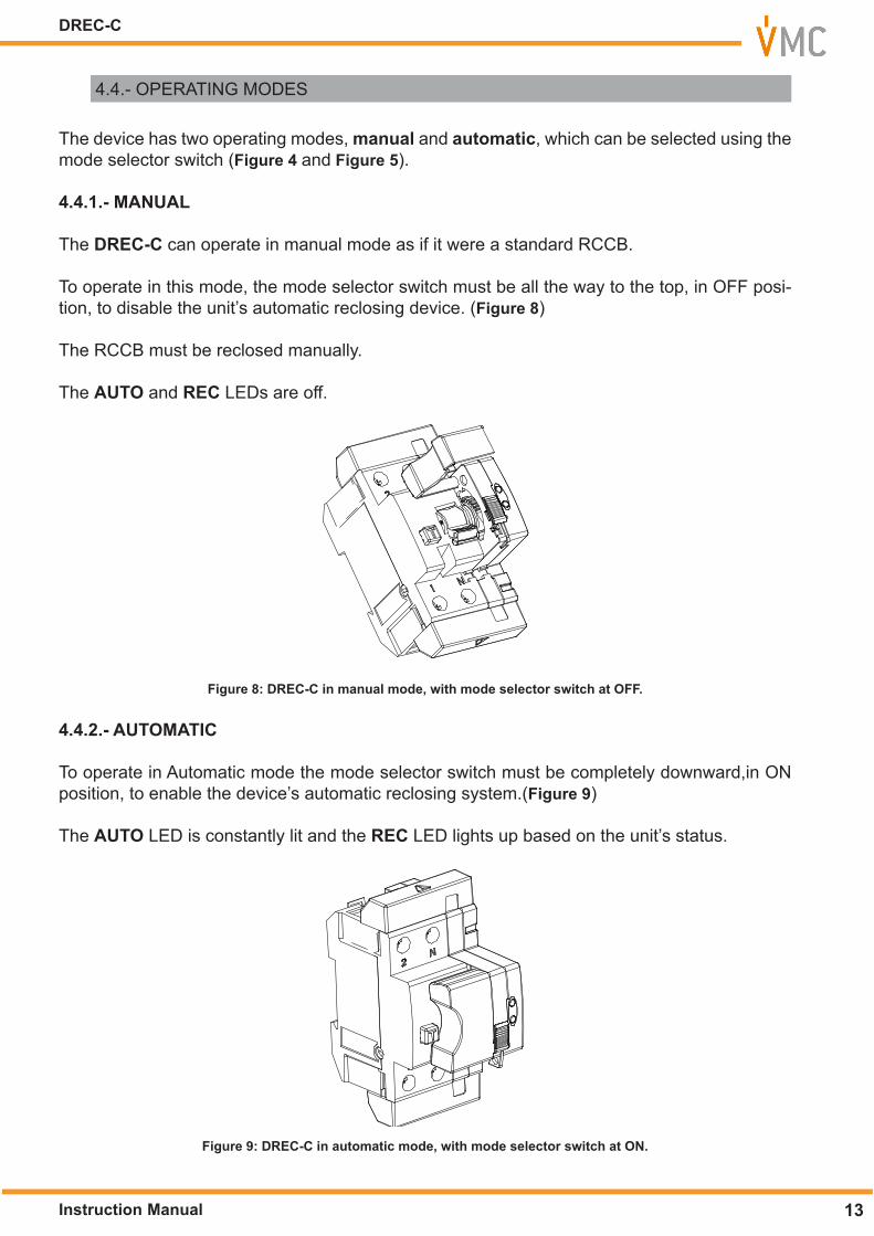
The DREC-C can operate in manual mode as if it were a standard RCCB.
To operate in this mode, the mode selector switch must be all the way to the top, in OFF posi-tion, to disable the unit’s automatic reclosing device. (Figure 8)
The RCCB must be reclosed manually.
The AUTO and REC LEDs are off.
Figure 8: DREC-C in manual mode, with mode selector switch at OFF�
4�4�2�- AUTOMATIC
To operate in Automatic mode the mode selector switch must be completely downward,in ON position, to enable the device’s automatic reclosing system.(Figure 9)
The AUTO LED is constantly lit and the REC LED lights up based on the unit’s status.
Figure 9: DREC-C in automatic mode, with mode selector switch at ON�
13Instruction Manual
DREC-C

The DREC-C allows one mode of automatic reclosing:
- Reclosing by insulation, the device does not reclose until the leakage has disap-peared.
4�4�2�1�- Reclosing by insulation
Following a time delay after a disconnection due to an RCCB trip, the DREC-C makes a meas-urement to check whether there is a leakage current. If there is none it begins to reclose.
The DREC-C attempts a maximum of 3 measurements to check the leakage current; following this the unit stays locked and does not automatically reclose.
If the time between a reclosure and the next trip is greater than the restart time, the reclosing attempts start over at zero.
The delay and restart times depend on the number of attempts the reclosing device has made, as shown in Table 5.
Table 5: Delay and Restart Times�Reclosures
1 2 3Delay Restart Delay Restart Delay Restart
<3 sec. 10 sec. 20 sec. 20 sec. 180 sec. 60 sec.
The leakage current will be supervised by measuring the resistance downstream of the tripped RCCB.
4�4�2�2�- Restarting the reclosing system meter
There are two ways to restart the internal reclosing system meter:
- Manually, by moving the mode selector switch from ON to OFF position and back toON.
- Automatically, when the restart time elapses after the last reclosing without trippingagain.
4�4�2�3�- Restart in case of blocking
In case of blocking of the device, the start-up sequence is:1�- Check installation.2�- Put the mode selector switch in Manual Mode (OFF).
3�- Lift the RCCB cover. 4�- Put the RCCB contact in ON mode. 5�- Lower the RCCB cover. 6�- Put the mode selector switch in Manual mode (ON).
Note: The switch has an M2 hole where you can attach a seal or a padlock to block access to the RCCB and any other attempts at manual reclosing (Figure 7).
14
DREC-C
Instruction Manual
PENDIENTE DE VALID
ACIÓN
5�- MAINTENANCE
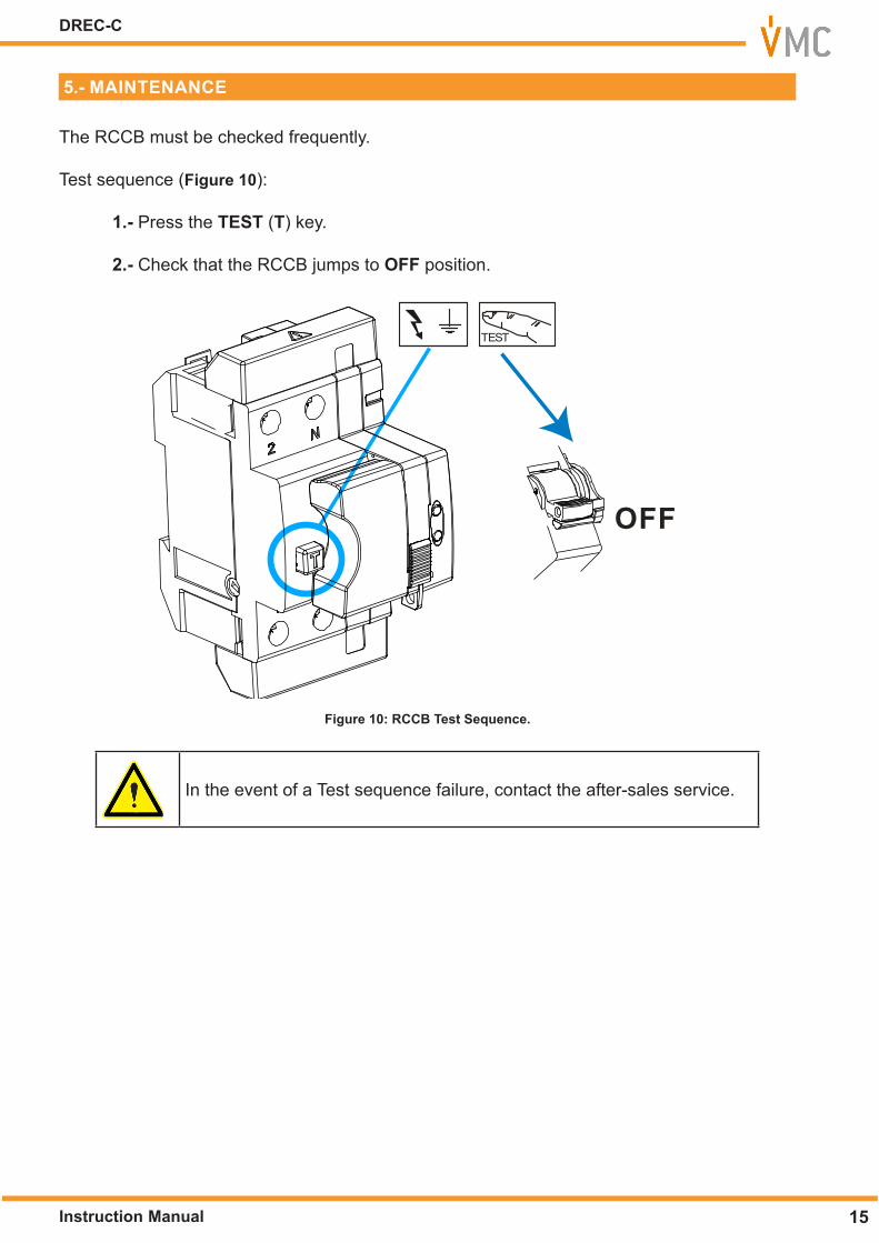
The RCCB must be checked frequently.
Test sequence (Figure 10):
1�- Press the TEST (T) key.
2�- Check that the RCCB jumps to OFF position.
TEST
OFF
Figure 10: RCCB Test Sequence�
In the event of a Test sequence failure, contact the after-sales service.
15Instruction Manual
DREC-C
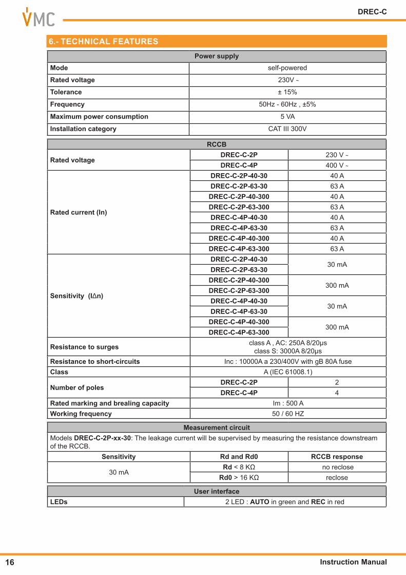
6�- TECHNICAL FEATURESPower supply
Mode self-powered
Rated voltage 230V ~
Tolerance ± 15%
Frequency 50Hz - 60Hz , ±5%
Maximum power consumption 5 VA
Installation category CAT III 300V
RCCB
Rated voltageDREC-C-2P 230 V ~DREC-C-4P 400 V ~
Rated current (In)
DREC-C-2P-40-30 40 ADREC-C-2P-63-30 63 ADREC-C-2P-40-300 40 ADREC-C-2P-63-300 63 ADREC-C-4P-40-30 40 ADREC-C-4P-63-30 63 ADREC-C-4P-40-300 40 ADREC-C-4P-63-300 63 A
Sensitivity (IΔn)
DREC-C-2P-40-3030 mA
DREC-C-2P-63-30DREC-C-2P-40-300
300 mADREC-C-2P-63-300DREC-C-4P-40-30
30 mADREC-C-4P-63-30DREC-C-4P-40-300
300 mADREC-C-4P-63-300
Resistance to surges class A , AC: 250A 8/20μs class S: 3000A 8/20μs
Resistance to short-circuits Inc : 10000A a 230/400V with gB 80A fuseClass A (IEC 61008.1)
Number of polesDREC-C-2P 2DREC-C-4P 4
Rated marking and brealing capacity Im : 500 AWorking frequency 50 / 60 HZ
Measurement circuit Models DREC-C-2P-xx-30: The leakage current will be supervised by measuring the resistance downstream of the RCCB.
Sensitivity Rd and Rd0 RCCB response
30 mARd < 8 KΩ no reclose
Rd0 > 16 KΩ reclose
User interfaceLEDs 2 LED : AUTO in green and REC in red
16
DREC-C
Instruction Manual
PENDIENTE DE VALID
ACIÓN
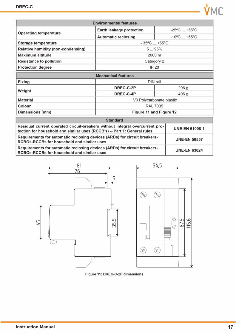
Environmental features
Operating temperatureEarth leakage protection -25ºC ... +55ºC
Automatic reclosing -10ºC ... +55ºCStorage temperature - 35ºC ... +65ºCRelative humidity (non-condensing) 5 ... 95%Maximum altitude 2000 mResistance to pollution Category 2Protection degree IP 20
Mechanical featuresFixing DIN rail
WeightDREC-C-2P 296 g.DREC-C-4P 496 g.
Material V0 Polycarbonate plasticColour RAL 7035Dimensions (mm) Figure 11 and Figure 12
StandardResidual current operated circuit-breakers without integral overcurrent pro-tection for household and similar uses (RCCB’s) -- Part 1: General rules UNE-EN 61008-1
Requirements for automatic reclosing devices (ARDs) for circuit breakers-RCBOs-RCCBs for household and similar uses UNE-EN 50557
Requirements for automatic reclosing devices (ARDs) for circuit breakers-RCBOs-RCCBs for household and similar uses UNE-EN 63024
81 54,5
5
35,5
115,6
87,545
76
Figure 11: DREC-C-2P dimensions�
17Instruction Manual
DREC-C

81 91
5
35,5
101,55
87,545
76
Figure 12:DREC-C-4P dimensions�
18
DREC-C
Instruction Manual
PENDIENTE DE VALID
ACIÓN
7�- TECHNICAL SERVICE
In the case of any query in relation to device operation or malfunction, please contact the VMC, Technical Support Service.
Technical Assistance ServiceC/ Montcada 7, Pol. Ind. Les Pereres08130 - Santa Perpètua de Mogoda (Barcelona)Tel: (+34) 935 748 206 - Fax: (+34) 935 748 248email: [email protected]
8�- GUARANTEE
• No returns will be accepted and no unit will be repaired or replaced if it is not ac-companied by a report indicating the defect detected or the reason for the return.•The guarantee will be void if the units has been improperly used or the storage,installation and maintenance instructions listed in this manual have not been fol-lowed. “Improper usage” is defi ned as any operating or storage condition contraryto the national electrical code or that surpasses the limits indicated in the techni-cal and environmental features of this manual.• VMC accepts no liability due to the possible damage to the unit or other partsof the installation, nor will it cover any possible sanctions derived from a possiblefailure, improper installation or “improper usage” of the unit. Consequently, thisguarantee does not apply to failures occurring in the following cases:- Overvoltages and/or electrical disturbances in the supply;- Water, if the product does not have the appropriate IP classifi cation;- Poor ventilation and/or excessive temperatures;- Improper installation and/or lack of maintenance;- Buyer repairs or modifi cations without the manufacturer’s authorisation.
VMC guarantees its products against any manufacturing defect for two years after the delivery of the units.
VMC will repair or replace any defective factory product returned during the guarantee period.
19Instruction Manual
DREC-C

VMC C/ Montcada, 7 - Pol. Ind. Les Pereres08130 - Santa Perpètua de Mogoda (Barcelona)Tel: (+34) 935 748 206 - Fax: (+34) 935 748 248 www.vmc.es [email protected]