instruction manual - coolblue
TRANSCRIPT
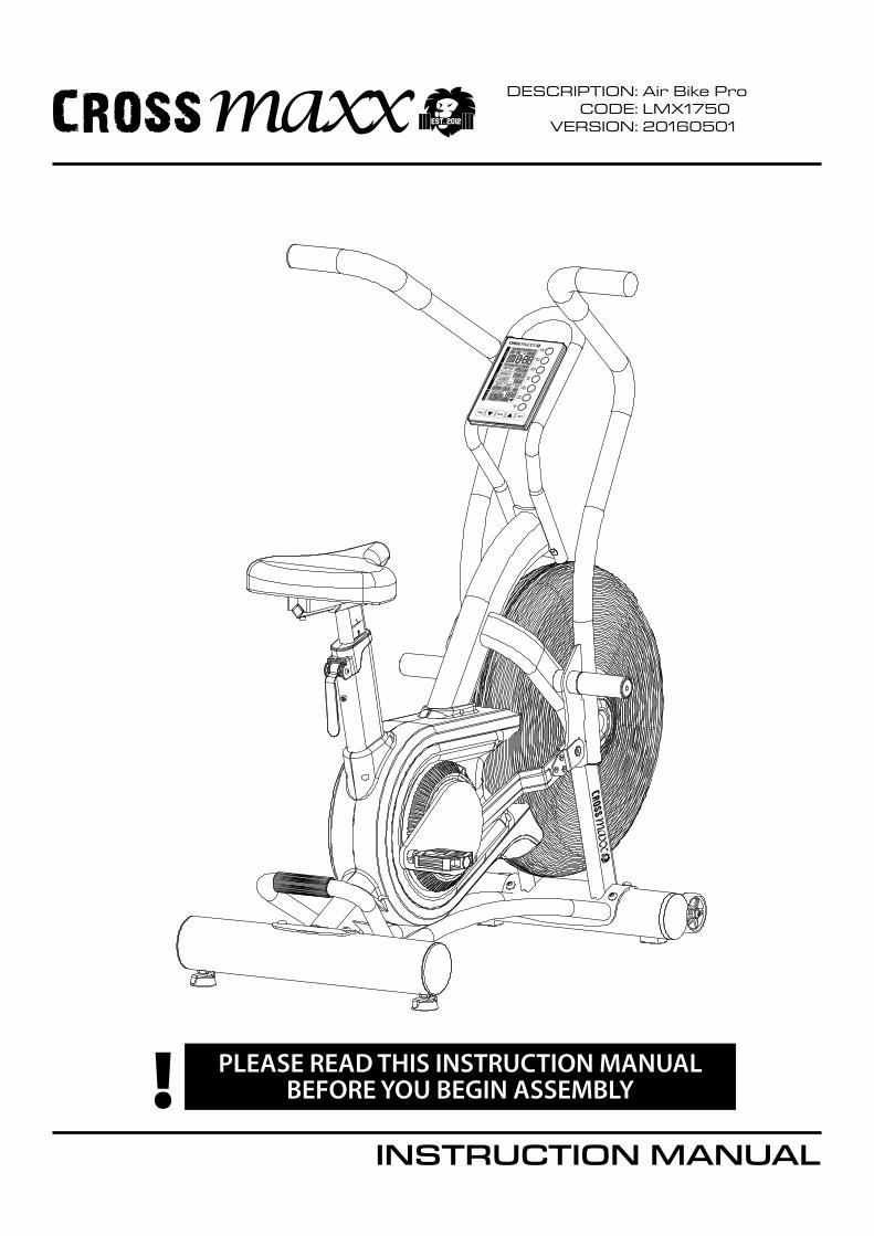
InstructIon Manual
Description:coDe:
Version:
Air Bike pro LMX175020160501
PLEASE READ THIS INSTRUCTION MANUAL BEFORE YOU BEGIN ASSEMBLY!
stop enter start
inte
rval
read
outs
hear
t rat
e
target HR
interval20-10
interval 10-20
custominterval
target time
target distance
target calories
INTERVAL 20/10 10/20 CUSTOMTOTALTIMEREADYWORK
RESTTARGET TIME DISTANCE CALORIESTIME?AGE?
DISTANCE?CALORIES?
WATTS SPEED RPM
HEART RATETARGET HEART RATE65% OF
80% OFMAX HR
REMAINIGELAPSED
KILOMETERSMILES
USE UP & DOWN KEYS TO ADJUSTPRESS ENTER TO ACCEPT
TOTAL
AVERAGETOTAL AVEMAX KM/Hr AVEMAX
BPMNO HR SIGNALTARGET HEARTRATE ACHIEVED
SPEED
SLOWUP
D WN
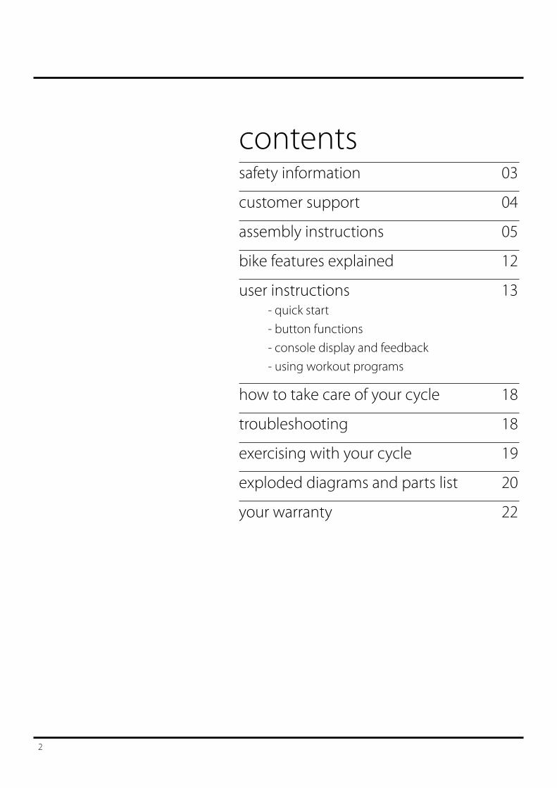
contentssafety information 03
customer support 04
assembly instructions 05
bike features explained 12
user instructions 13 - quick start - button functions - console display and feedback - using workout programs
how to take care of your cycle 18
troubleshooting 18
exercising with your cycle 19
exploded diagrams and parts list 20
your warranty 22
2
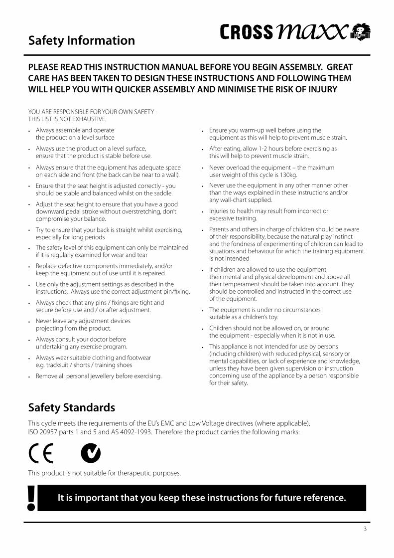
PLEASE READ THIS INSTRUCTION MANUAL BEFORE YOU BEGIN ASSEMBLY. GREAT CARE HAS BEEN TAKEN TO DESIGN THESE INSTRUCTIONS AND FOLLOWING THEM WILL HELP YOU WITH QUICKER ASSEMBLY AND MINIMISE THE RISK OF INJURY
Safety StandardsThis cycle meets the requirements of the EU’s EMC and Low Voltage directives (where applicable), ISO 20957 parts 1 and 5 and AS 4092-1993. Therefore the product carries the following marks:
It is important that you keep these instructions for future reference.!This product is not suitable for therapeutic purposes.
Safety Information
3
YOU ARE RESPONSIBLE FOR YOUR OWN SAFETY - THIS LIST IS NOT EXHAUSTIVE.
• Always assemble and operate the product on a level surface
• Always use the product on a level surface, ensure that the product is stable before use.
• Alwaysensurethattheequipmenthasadequatespace on each side and front (the back can be near to a wall).
• Ensurethattheseatheightisadjustedcorrectly-youshould be stable and balanced whilst on the saddle.
• Adjusttheseatheighttoensurethatyouhaveagooddownward pedal stroke without overstretching, don’t compromise your balance.
• Trytoensurethatyourbackisstraightwhilstexercising,especially for long periods
• The safety level of this equipment can only be maintained if it is regularly examined for wear and tear
• Replace defective components immediately, and/or keep the equipment out of use until it is repaired.
• Useonlytheadjustmentsettingsasdescribedintheinstructions.Alwaysusethecorrectadjustmentpin/fixing.
• Alwayscheckthatanypins/fixingsaretightand securebeforeuseand/orafteradjustment.
• Neverleaveanyadjustmentdevices projectingfromtheproduct.
• Always consult your doctor before undertaking any exercise program.
• Always wear suitable clothing and footwear e.g. tracksuit / shorts / training shoes
• Removeallpersonaljewellerybeforeexercising.
• Ensure you warm-up well before using the equipment as this will help to prevent muscle strain.
• After eating, allow 1-2 hours before exercising as this will help to prevent muscle strain.
• Neveroverloadtheequipment–themaximum user weight of this cycle is 130kg.
• Never use the equipment in any other manner other than the ways explained in these instructions and/or any wall-chart supplied.
• Injuriestohealthmayresultfromincorrector excessive training.
• Parents and others in charge of children should be aware of their responsibility, because the natural play instinct and the fondness of experimenting of children can lead to situations and behaviour for which the training equipment is not intended
• If children are allowed to use the equipment, their mental and physical development and above all their temperament should be taken into account. They should be controlled and instructed in the correct use of the equipment.
• The equipment is under no circumstances suitable as a children’s toy.
• Children should not be allowed on, or around the equipment - especially when it is not in use.
• This appliance is not intended for use by persons (including children) with reduced physical, sensory or mental capabilities, or lack of experience and knowledge, unless they have been given supervision or instruction concerning use of the appliance by a person responsible for their safety.
Customer SupportShould you require any assistance regarding this product please gather the following information, and then contact us using the details below:
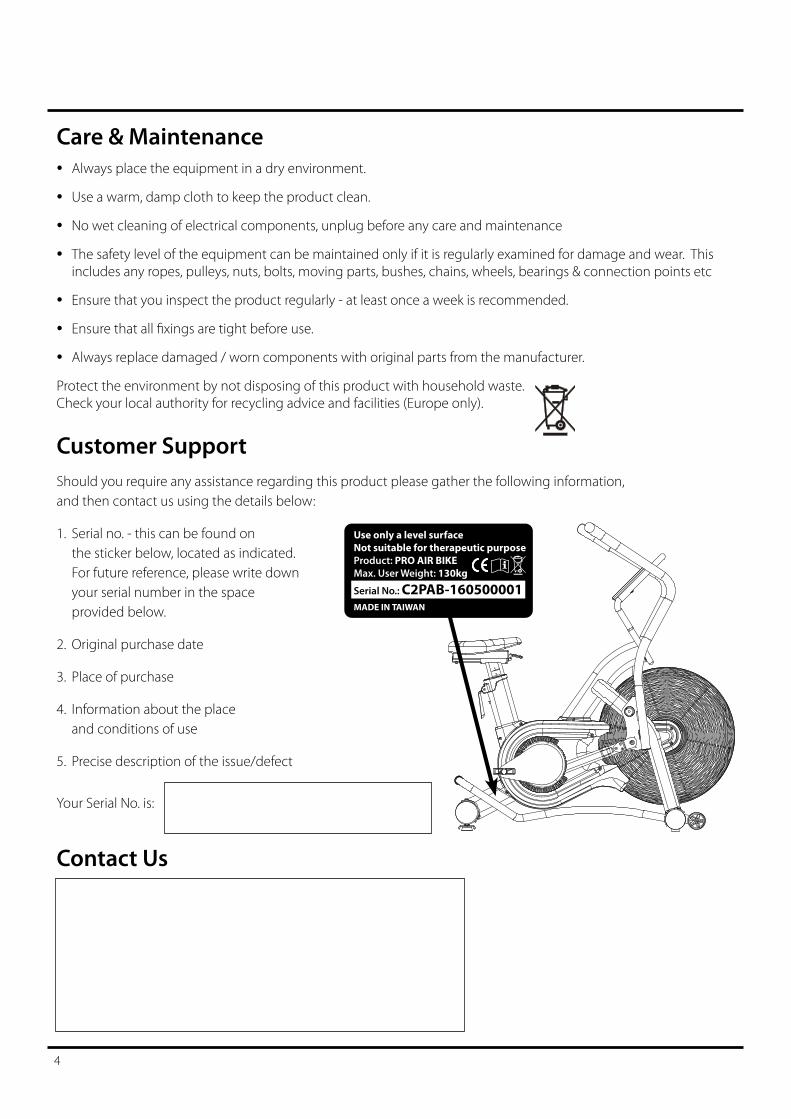
1. Serial no. - this can be found on the sticker below, located as indicated. For future reference, please write down your serial number in the space provided below.
2. Original purchase date
3. Place of purchase
4. Information about the place and conditions of use
5. Precise description of the issue/defect
Your Serial No. is:
Care & Maintenance• Always place the equipment in a dry environment.
• Use a warm, damp cloth to keep the product clean.
• No wet cleaning of electrical components, unplug before any care and maintenance
• The safety level of the equipment can be maintained only if it is regularly examined for damage and wear. This includes any ropes, pulleys, nuts, bolts, moving parts, bushes, chains, wheels, bearings & connection points etc
• Ensure that you inspect the product regularly - at least once a week is recommended.
• Ensurethatallfixingsaretightbeforeuse.• Always replace damaged / worn components with original parts from the manufacturer.
Protect the environment by not disposing of this product with household waste. Check your local authority for recycling advice and facilities (Europe only).
Contact Us
4
Use only a level surface Not suitable for therapeutic purposeProduct: PRO AIR BIKEMax. User Weight: 130kg
Serial No.: C2PAB-160500001MADE IN TAIWAN
Assembly Instruction
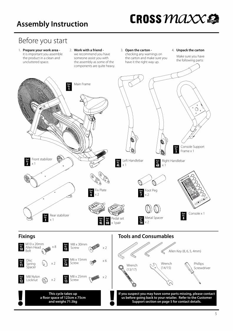
If you suspect you may have some parts missing, please contact us before going back to your retailer. Refer to the Customer
Support section on page 5 for contact details.!This cycle takes up a floor space of 123cm x 75cm
and weighs 71.5kg!
Before you start1. Prepare your work area -
it is important you assemble the product in a clean and uncluttered space.
2. Work with a friend - we recommend you have someone assist you with the assembly as some of the components are quite heavy.
3. Open the carton - checking any warnings on the carton and make sure you have it the right way up.
4. Unpack the carton
Make sure you have the following parts:
Console x 1
Console Support Frame x 1
Fixings Tools and Consumables
Wrench (13/17)
Part No.2
Part No.8
Front stabilizerx 1
Part No.3
Rear stabilizerx 1
Part No.5
Allen Key (8, 6, 5, 4mm)
Part No.6
Main FramePart No.1
Part No.4L
Left Handlebar x 1
Part No.4R
Right Handlebar x 1
stop
enter
start
inte
rval
read
outs
hear
t rat
e
target HR
interval20-10
interval 10-20
custominterval
target time
target
distance
target calories
INTERVAL 20/10 10/20 CUSTOM
TOTALTIME
READY
WORKREST
TARGET TIME DISTANCE CALORIES
TIME?AGE?
DISTANCE?
CALORIES?
WATTS SPEED RPM
HEART RATE
TARGET HEART RATE
65%OF
80%OFMAX HR
REMAINIGELAPSED
KILOMETERSMILES
USE UP & DOWN KEYS TO ADJUST
PRESS ENTER TO ACCEPT
TOTAL
AVERAGETOTALAVEMAX KM/Hr
AVEMAX
BPMNO HR SIGNAL
TARGET HEART
RATE ACHIEVEDSPEED
SLOWUPD WN
Fix Platex 2
Part No.7
Foot Pegx 2
Wrench (14/15)
Phillips Screwdriver
5
Part No.11
Part No.14
Part No.9L
x 2
x 2
Pedal set x 1pair
Disc Spring Spacer
M8 Nylon Locknut
Part No.15
Part No.9R
Part No.13 x 2
M8 x 30mm Screw
M6 x 15mm Screw
M8 x 25mm Screw
x 6
x 2
Part No.10
M10 x 20mm Allen Head Bolt
x 8
Part No.12
Part No.16
Metal Spacerx 2
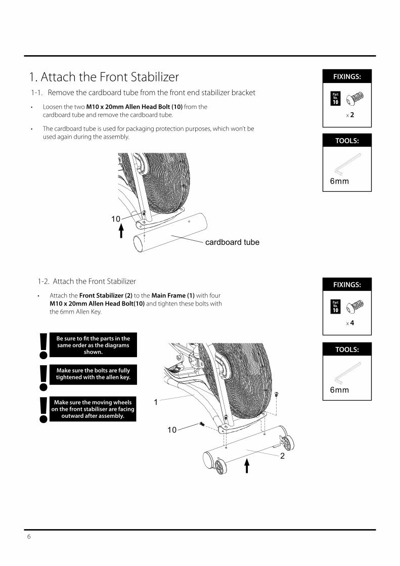
1. Attach the Front Stabilizer
Be sure to fit the parts in the same order as the diagrams
shown. !Make sure the bolts are fully tightened with the allen key.!!
FIXINGS:TOOLS:
FIXINGS:TOOLS:
6
Make sure the moving wheels on the front stabiliser are facing
outward after assembly.
1-1. Remove the cardboard tube from the front end stabilizer bracket
Loosen the two • M10 x 20mm Allen Head Bolt (10) from the cardboard tube and remove the cardboard tube.
The cardboard tube is used for packaging protection purposes, which won’t be •used again during the assembly.
FIXINGS:FIXINGS:
x 2
Part No.10
FIXINGS:FIXINGS:
x 4
Part No.10
1-2. Attach the Front Stabilizer
Attach the • Front Stabilizer (2) to the Main Frame (1) with four M10 x 20mm Allen Head Bolt(10) and tighten these bolts with the 6mm Allen Key.
cardboard tube
10
10
1
2
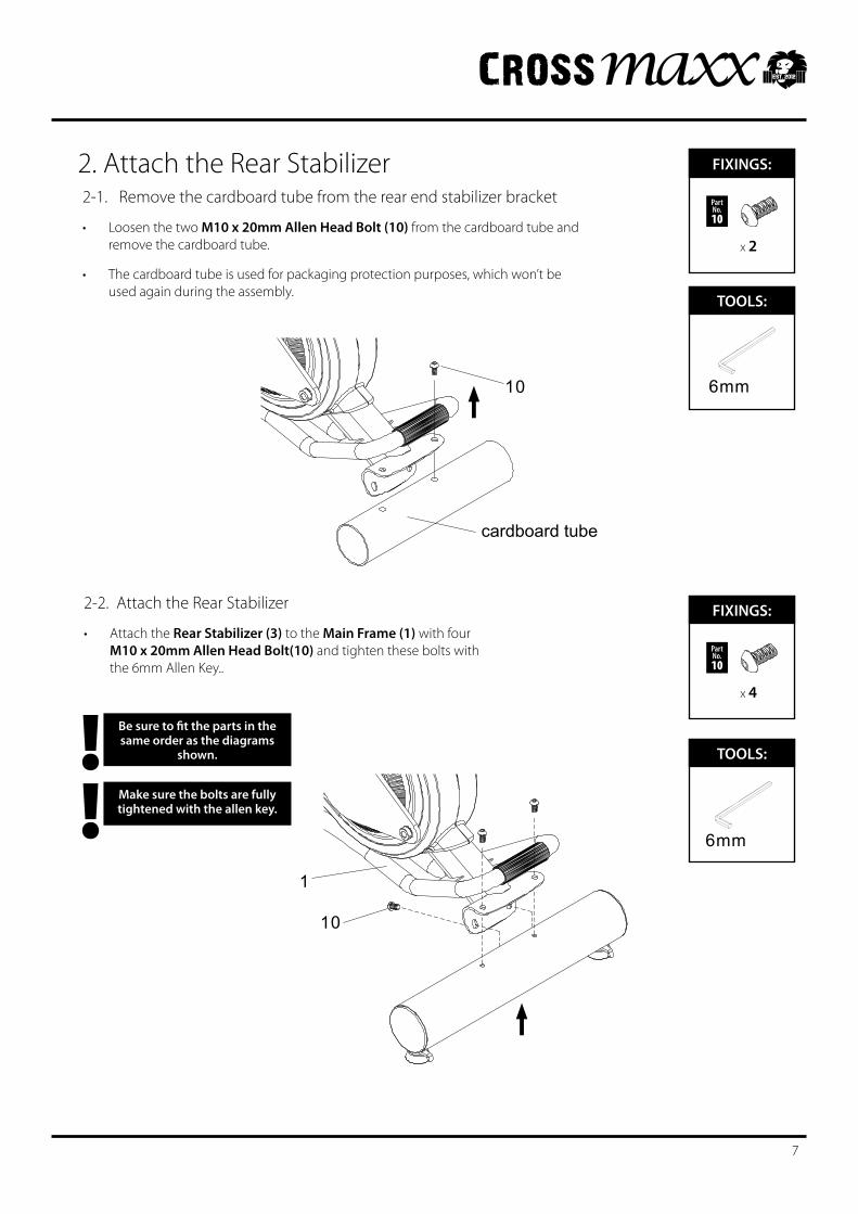
Be sure to fit the parts in the same order as the diagrams
shown. !Make sure the bolts are fully tightened with the allen key.!
2. Attach the Rear Stabilizer
FIXINGS:TOOLS:
FIXINGS:TOOLS:
7
FIXINGS:FIXINGS:
x 2
Part No.10
FIXINGS:FIXINGS:
x 4
Part No.10
2-1. Remove the cardboard tube from the rear end stabilizer bracket
Loosen the two • M10 x 20mm Allen Head Bolt (10) from the cardboard tube and remove the cardboard tube.
The cardboard tube is used for packaging protection purposes, which won’t be •used again during the assembly.
2-2. Attach the Rear Stabilizer
Attach the • Rear Stabilizer (3) to the Main Frame (1) with four M10 x 20mm Allen Head Bolt(10) and tighten these bolts with the 6mm Allen Key..
10
1
cardboard tube
10
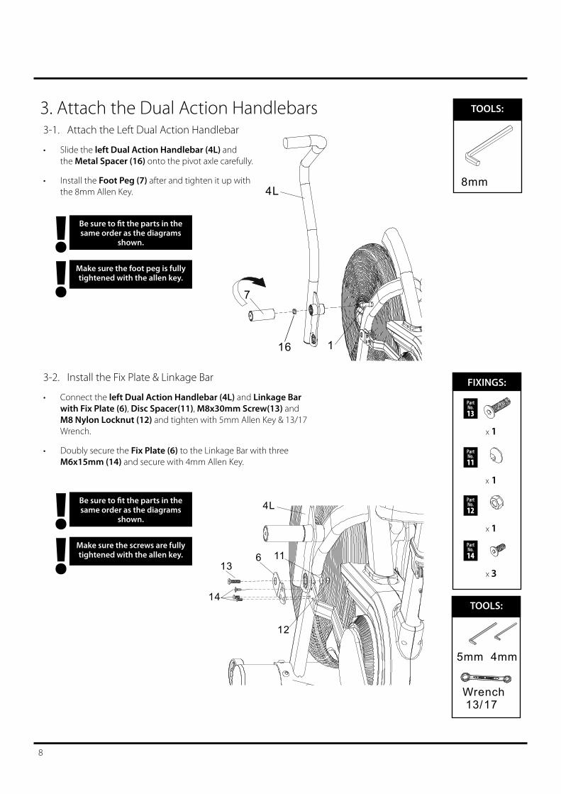
3. Attach the Dual Action Handlebars
Be sure to fit the parts in the same order as the diagrams
shown. !Make sure the screws are fully tightened with the allen key.!
FIXINGS:FIXINGS:
x 1
Part No.13
Be sure to fit the parts in the same order as the diagrams
shown. !Make sure the foot peg is fully tightened with the allen key.!
x 1
Part No.11
x 1
Part No.12
x 3
Part No.14
FIXINGS:TOOLS:
14
613
11
12
4L
FIXINGS:TOOLS:
Wrench 13/17
8
3-2. Install the Fix Plate & Linkage Bar
Connect the • left Dual Action Handlebar (4L) and Linkage Bar with Fix Plate (6), Disc Spacer(11), M8x30mm Screw(13) and M8 Nylon Locknut (12) and tighten with 5mm Allen Key & 13/17 Wrench.
Doubly secure the • Fix Plate (6) to the Linkage Bar with three M6x15mm (14) and secure with 4mm Allen Key.
3-1. Attach the Left Dual Action Handlebar
Slide the • left Dual Action Handlebar (4L) and the Metal Spacer (16) onto the pivot axle carefully.
Install the • Foot Peg (7) after and tighten it up with the 8mm Allen Key.
7
4L
116
Be sure to fit the parts in the same order as the diagrams
shown. !Make sure the screws are fully tightened with the allen key.!
FIXINGS:FIXINGS:
x 1
Part No.13
Be sure to fit the parts in the same order as the diagrams
shown. !Make sure the foot peg is fully tightened with the allen key.!
x 1
Part No.11
x 1
Part No.12
x 3
Part No.14
FIXINGS:TOOLS:
13
14
6
1112
4R
FIXINGS:TOOLS:
Wrench 13/17
9
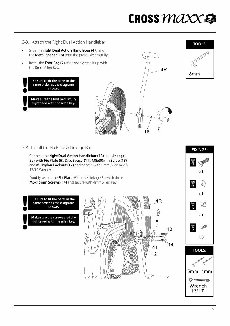
3-4. Install the Fix Plate & Linkage Bar
Connect the • right Dual Action Handlebar (4R) and Linkage Bar with Fix Plate (6), Disc Spacer(11), M8x30mm Screw(13) and M8 Nylon Locknut (12) and tighten with 5mm Allen Key & 13/17 Wrench.
Doubly secure the • Fix Plate (6) to the Linkage Bar with three M6x15mm Screws (14) and secure with 4mm Allen Key.
3-3. Attach the Right Dual Action Handlebar
Slide the • right Dual Action Handlebar (4R) and the Metal Spacer (16) onto the pivot axle carefully.
Install the • Foot Peg (7) after and tighten it up with the 8mm Allen Key.
7
4R
1 16
Be sure to fit the parts in the same order as the diagrams
shown. !Make sure the screw is fully
tightened with the allen key.!
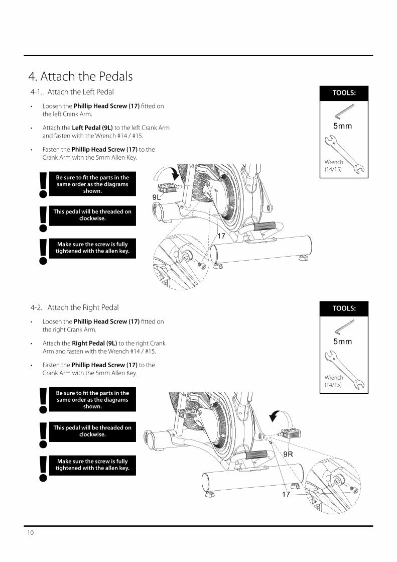
4. Attach the Pedals4-1. Attach the Left Pedal
Loosen the • Phillip Head Screw (17)fittedonthe left Crank Arm.
Attach the • Left Pedal (9L) to the left Crank Arm and fasten with the Wrench #14 / #15.
Fasten the • Phillip Head Screw (17) to the Crank Arm with the 5mm Allen Key.
FIXINGS:TOOLS:
5mm
Wrench (14/15)
Be sure to fit the parts in the same order as the diagrams
shown. !Make sure the screw is fully
tightened with the allen key.!
4-2. Attach the Right Pedal
Loosen the • Phillip Head Screw (17)fittedonthe right Crank Arm.
Attach the • Right Pedal (9L) to the right Crank Arm and fasten with the Wrench #14 / #15.
Fasten the • Phillip Head Screw (17) to the Crank Arm with the 5mm Allen Key.
FIXINGS:TOOLS:
5mm
Wrench (14/15)
This pedal will be threaded on clockwise.!
This pedal will be threaded on clockwise.!
17
9R
10
9L
17
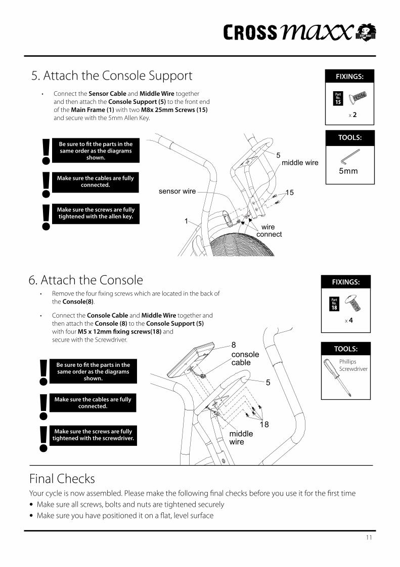
Final ChecksYourcycleisnowassembled.Pleasemakethefollowingfinalchecksbeforeyouuseitforthefirsttime
• Make sure all screws, bolts and nuts are tightened securely
• Make sure you have positioned it on a flat, level surface
6. Attach the Console
Be sure to fit the parts in the same order as the diagrams
shown. !Make sure the screws are fully
tightened with the screwdriver.!Make sure the cables are fully
connected.!
5. Attach the Console Support
Be sure to fit the parts in the same order as the diagrams
shown. !Make sure the screws are fully tightened with the allen key.!
Make sure the cables are fully connected.!
FIXINGS:FIXINGS:
x 2
Part No.15
FIXINGS:TOOLS:
5mm
FIXINGS:FIXINGS:
x 4
Part No.18
FIXINGS:TOOLS:
Phillips Screwdriver
8
18
5
consolecable
middlewire
15
5
1wire
connect
middle wire
sensor wire
11
Removethefourfixingscrewswhicharelocatedinthebackof•the Console(8).
Connect the • Console Cable and Middle Wire together and then attach the Console (8) to the Console Support (5) with four M5 x 12mm fixing screws(18) and secure with the Screwdriver.
Connect the • Sensor Cable and Middle Wire together and then attach the Console Support (5) to the front end of the Main Frame (1) with two M8x 25mm Screws (15) and secure with the 5mm Allen Key.
Bike Features Explained
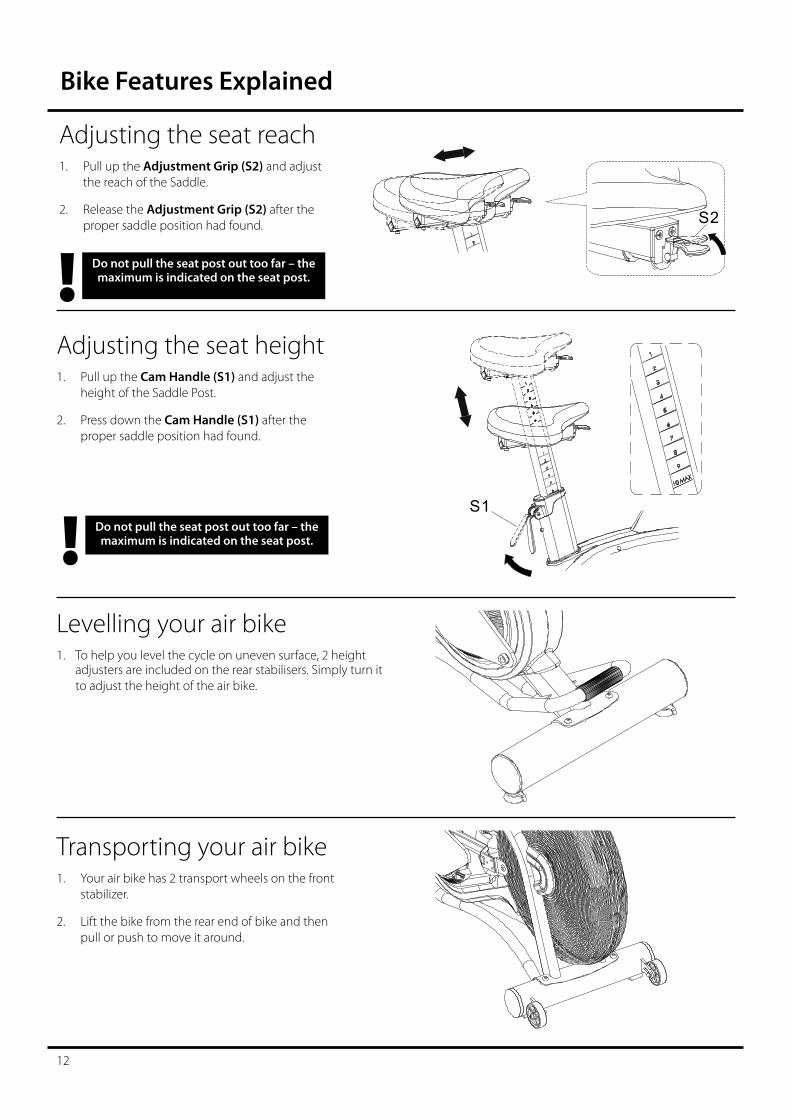
Do not pull the seat post out too far – the maximum is indicated on the seat post.!
AdjustingtheseatheightPull up the 1. Cam Handle (S1)andadjusttheheight of the Saddle Post.
Press down the 2. Cam Handle (S1) after the proper saddle position had found.
AdjustingtheseatreachPull up the 1. Adjustment Grip (S2)andadjustthe reach of the Saddle.
Release the 2. Adjustment Grip (S2) after the proper saddle position had found. S2
S1
Levelling your air bike1. To help you level the cycle on uneven surface, 2 height
adjustersareincludedontherearstabilisers.Simplyturnittoadjusttheheightoftheairbike.
Transporting your air bikeYour air bike has 2 transport wheels on the front 1. stabilizer.
Lift the bike from the rear end of bike and then 2. pull or push to move it around.
Do not pull the seat post out too far – the maximum is indicated on the seat post.!
12
Computer Instructions
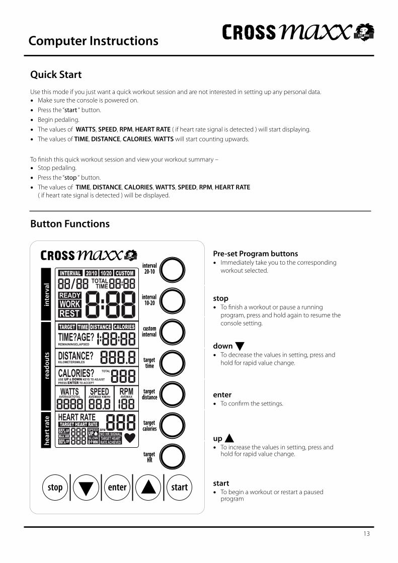
Quick StartUsethismodeifyoujustwantaquickworkoutsessionandarenotinterestedinsettingupanypersonaldata.• Make sure the console is powered on.
• Press the “start “ button.
• Begin pedaling.
• The values of WATTS, SPEED, RPM, HEART RATE ( if heart rate signal is detected ) will start displaying.
• The values of TIME, DISTANCE, CALORIES, WATTS will start counting upwards.
Tofinishthisquickworkoutsessionandviewyourworkoutsummary–• Stop pedaling.
• Press the “stop “ button.
• The values of TIME, DISTANCE, CALORIES, WATTS, SPEED, RPM, HEART RATE ( if heart rate signal is detected ) will be displayed.
Button Functions
Pre-set Program buttons• Immediately take you to the corresponding
workout selected.
stop• Tofinishaworkoutorpausearunning
program, press and hold again to resume the console setting.
start• To begin a workout or restart a paused
program
down
• To decrease the values in setting, press and hold for rapid value change.
enter• Toconfirmthesettings.
up
• To increase the values in setting, press and hold for rapid value change.
stop enter start
inte
rval
read
outs
hear
t rat
e
target HR
interval20-10
interval 10-20
custominterval
target time
target distance
target calories
INTERVAL 20/10 10/20 CUSTOMTOTAL
TIMEREADYWORKRESTTARGET TIME DISTANCE CALORIES
TIME?AGE?DISTANCE?CALORIES?WATTS SPEED RPM
HEART RATETARGET HEART RATE
65% OF
80% OFMAX HR
REMAININGELAPSED
KILOMETERSMILES
USE UP & DOWN KEYS TO ADJUSTPRESS ENTER TO ACCEPT
TOTAL
AVERAGETOTAL AVEMAX KM/Hr AVEMAX
BPMNO HR SIGNALTARGET HEARTRATE ACHIEVED
SPEED
SLOWUPD WN
13
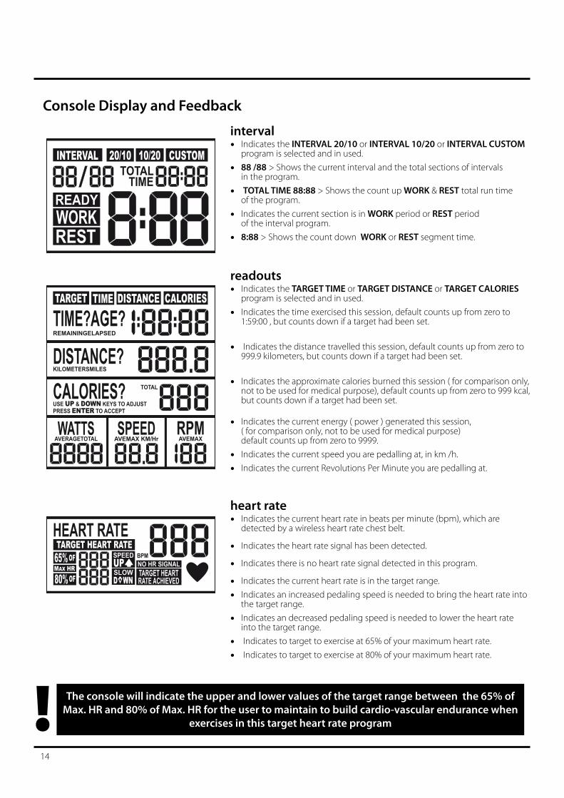
Console Display and Feedback
interval• Indicates the INTERVAL 20/10 or INTERVAL 10/20 or INTERVAL CUSTOM
program is selected and in used.
• 88 /88 > Shows the current interval and the total sections of intervals in the program.
• TOTAL TIME 88:88 > Shows the count up WORK & REST total run time of the program.
• Indicates the current section is in WORK period or REST period of the interval program.
• 8:88 > Shows the count down WORK or REST segment time.
INTERVAL 20/10 10/20 CUSTOMTOTAL
TIMEREADYWORKREST
readouts• Indicates the TARGET TIME or TARGET DISTANCE or TARGET CALORIES
program is selected and in used.
• Indicates the time exercised this session, default counts up from zero to 1:59:00 , but counts down if a target had been set.
• Indicates the distance travelled this session, default counts up from zero to 999.9 kilometers, but counts down if a target had been set.
• Indicates the approximate calories burned this session ( for comparison only, not to be used for medical purpose), default counts up from zero to 999 kcal, but counts down if a target had been set.
• Indicates the current energy ( power ) generated this session, ( for comparison only, not to be used for medical purpose) default counts up from zero to 9999.
• Indicates the current speed you are pedalling at, in km /h.
• Indicates the current Revolutions Per Minute you are pedalling at.
HEART RATETARGET HEART RATE
65% OF
80% OFMAX HR
BPMNO HR SIGNALTARGET HEARTRATE ACHIEVED
SPEED
SLOWUPD WN
The console will indicate the upper and lower values of the target range between the 65% of Max. HR and 80% of Max. HR for the user to maintain to build cardio-vascular endurance when
exercises in this target heart rate program!14
heart rate• Indicates the current heart rate in beats per minute (bpm), which are
detected by a wireless heart rate chest belt.
• Indicates the heart rate signal has been detected.
• Indicates there is no heart rate signal detected in this program.
• Indicates the current heart rate is in the target range.
• Indicates an increased pedaling speed is needed to bring the heart rate into the target range.
• Indicates an decreased pedaling speed is needed to lower the heart rate into the target range.
• Indicates to target to exercise at 65% of your maximum heart rate.
• Indicates to target to exercise at 80% of your maximum heart rate.
TARGET TIME DISTANCE CALORIES
TIME?AGE?DISTANCE?CALORIES?WATTS SPEED RPM
REMAININGELAPSED
KILOMETERSMILES
USE UP & DOWN KEYS TO ADJUSTPRESS ENTER TO ACCEPT
TOTAL
AVERAGETOTAL AVEMAX KM/Hr AVEMAX
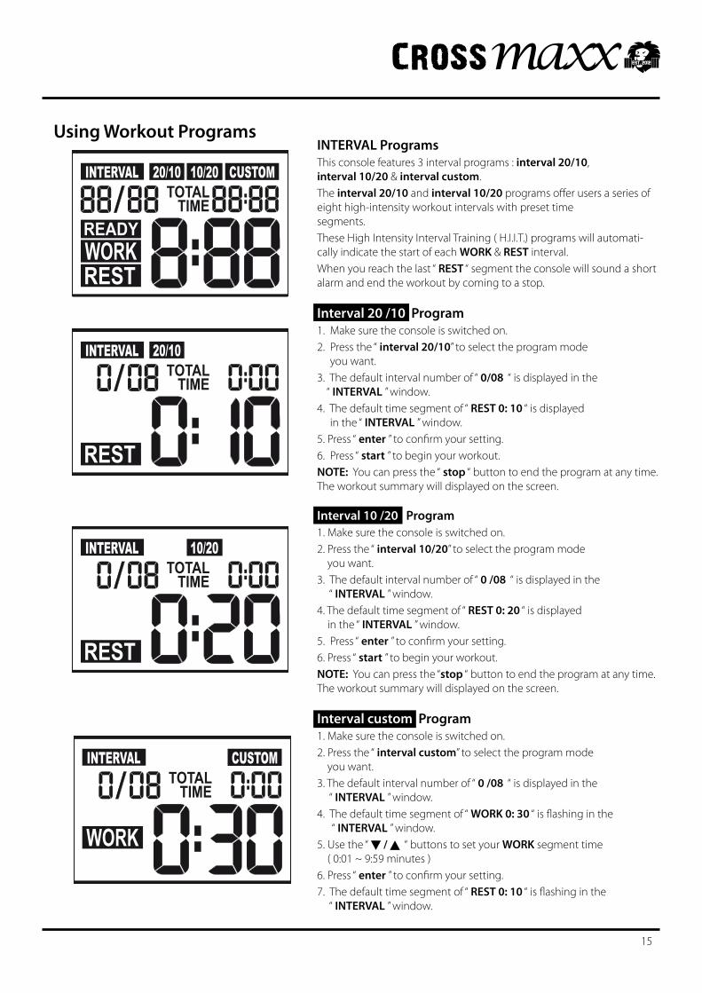
INTERVAL ProgramsThis console features 3 interval programs : interval 20/10, interval 10/20 & interval custom.The interval 20/10 and interval 10/20 programs offer users a series of eight high-intensity workout intervals with preset time segments.These High Intensity Interval Training ( H.I.I.T.) programs will automati-cally indicate the start of each WORK & REST interval.When you reach the last “ REST “ segment the console will sound a short alarm and end the workout by coming to a stop.
Interval 20 /10 Program1. Make sure the console is switched on.2. Press the “ interval 20/10” to select the program mode you want.3. The default interval number of “ 0/08 “ is displayed in the “ INTERVAL ” window.4. The default time segment of “ REST 0: 10 “ is displayed in the “ INTERVAL ” window.5. Press “ enter”toconfirmyoursetting.6. Press “ start ” to begin your workout.NOTE: You can press the “ stop “ button to end the program at any time. The workout summary will displayed on the screen.
Interval 10 /20 Program1. Make sure the console is switched on.2. Press the “ interval 10/20” to select the program mode you want.3. The default interval number of “ 0 /08 “ is displayed in the “ INTERVAL ” window.4. The default time segment of “ REST 0: 20 “ is displayed in the “ INTERVAL ” window.5. Press “ enter”toconfirmyoursetting.6. Press “ start ” to begin your workout.NOTE: You can press the “stop “ button to end the program at any time. The workout summary will displayed on the screen.
Interval custom Program1. Make sure the console is switched on.2. Press the “ interval custom” to select the program mode you want.3. The default interval number of “ 0 /08 “ is displayed in the “ INTERVAL ” window.4. The default time segment of “ WORK 0: 30 “ is flashing in the “ INTERVAL ” window.5. Use the “ / “ buttons to set your WORK segment time ( 0:01 ~ 9:59 minutes ) 6. Press “ enter”toconfirmyoursetting.7. The default time segment of “ REST 0: 10 “ is flashing in the “ INTERVAL ” window.
INTERVAL 20/10TOTAL
TIME
REST
INTERVAL 20/10 10/20 CUSTOMTOTAL
TIMEREADYWORKREST
INTERVAL 10/20TOTAL
TIME
REST
INTERVAL CUSTOMTOTAL
TIME
WORK
15
Using Workout Programs
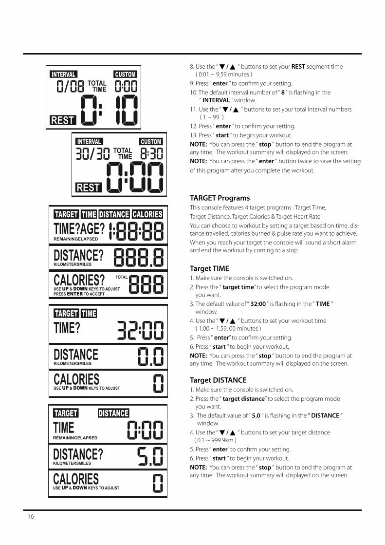
8. Use the “ / “ buttons to set your REST segment time ( 0:01 ~ 9:59 minutes ) 9. Press “ enter”toconfirmyoursetting.10. The default interval number of “ 8 “ is flashing in the “ INTERVAL ” window.11. Use the “ / “ buttons to set your total interval numbers ( 1 ~ 99 ) 12. Press “ enter”toconfirmyoursetting.13. Press “ start ” to begin your workout.NOTE: You can press the “ stop “ button to end the program at any time. The workout summary will displayed on the screen. NOTE: You can press the “ enter “ button twice to save the setting of this program after you complete the workout.
TARGET ProgramsThis console features 4 target programs : Target Time, Target Distance, Target Calories & Target Heart Rate.You can choose to workout by setting a target based on time, dis-tance travelled, calories burned & pulse rate you want to achieve.When you reach your target the console will sound a short alarm and end the workout by coming to a stop.
Target TIME1. Make sure the console is switched on.2. Press the “ target time” to select the program mode you want.3. The default value of “ 32:00 “ is flashing in the “ TIME ” window.4. Use the “ / “ buttons to set your workout time ( 1:00 ~ 1:59: 00 minutes ) 5. Press “ enter”toconfirmyoursetting.6. Press “ start ” to begin your workout.NOTE: You can press the “ stop “ button to end the program at any time. The workout summary will displayed on the screen.
Target DISTANCE1. Make sure the console is switched on.2. Press the “ target distance” to select the program mode you want.3. The default value of “ 5.0 “ is flashing in the “ DISTANCE ” window.4. Use the “ / “ buttons to set your target distance ( 0.1 ~ 999.9km ) 5. Press “ enter”toconfirmyoursetting.6. Press “ start ” to begin your workout.NOTE: You can press the “ stop “ button to end the program at any time. The workout summary will displayed on the screen.
INTERVAL CUSTOMTOTAL
TIME
REST
INTERVAL CUSTOMTOTAL
TIME
REST
TARGET TIME
TIME?DISTANCECALORIESKILOMETERSMILES
USE UP & DOWN KEYS TO ADJUST
16
TARGET TIME DISTANCE CALORIES
TIME?AGE?DISTANCE?CALORIES?
REMAININGELAPSED
KILOMETERSMILES
USE UP & DOWN KEYS TO ADJUSTPRESS ENTER TO ACCEPT
TOTAL
TARGET DISTANCE
TIMEDISTANCE?CALORIES
REMAININGELAPSED
KILOMETERSMILES
USE UP & DOWN KEYS TO ADJUST
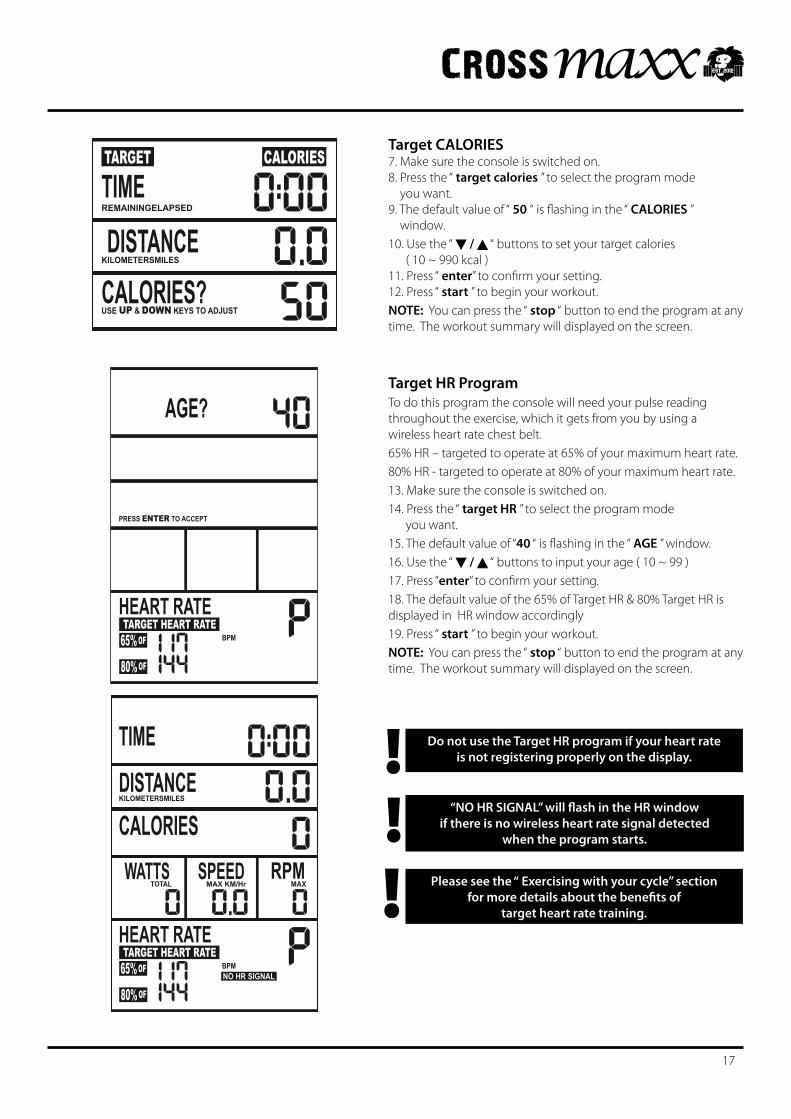
Target CALORIES7. Make sure the console is switched on.8. Press the “ target calories ” to select the program mode you want.9. The default value of “ 50 “ is flashing in the “ CALORIES ” window.10. Use the “ / “ buttons to set your target calories ( 10 ~ 990 kcal ) 11. Press “ enter”toconfirmyoursetting.12. Press “ start ” to begin your workout.NOTE: You can press the “ stop “ button to end the program at any time. The workout summary will displayed on the screen. Target HR ProgramTo do this program the console will need your pulse reading throughout the exercise, which it gets from you by using a wireless heart rate chest belt. 65%HR–targetedtooperateat65%ofyourmaximumheart rate.80% HR - targeted to operate at 80% of your maximum heart rate.13. Make sure the console is switched on.14. Press the “ target HR ” to select the program mode you want.15. The default value of “40 “ is flashing in the “ AGE ” window.16. Use the “ / “ buttons to input your age ( 10 ~ 99 ) 17. Press “enter”toconfirmyoursetting.18. The default value of the 65% of Target HR & 80% Target HR is displayed in HR window accordingly 19. Press “ start ” to begin your workout.NOTE: You can press the “ stop “ button to end the program at any time. The workout summary will displayed on the screen.
Do not use the Target HR program if your heart rate is not registering properly on the display.!
!Please see the “ Exercising with your cycle” section
for more details about the benefits of target heart rate training.!
AGE?
HEART RATETARGET HEART RATE
65% OF
80% OF
PRESS ENTER TO ACCEPT
BPM
TIMEDISTANCECALORIESWATTS SPEED RPM
HEART RATETARGET HEART RATE
65% OF
80% OF
KILOMETERSMILES
TOTAL MAX KM/Hr MAX
BPMNO HR SIGNAL
17
“NO HR SIGNAL” will flash in the HR window if there is no wireless heart rate signal detected
when the program starts.
TARGET CALORIES
TIMEDISTANCE
CALORIES?
REMAININGELAPSED
KILOMETERSMILES
USE UP & DOWN KEYS TO ADJUST
Troubleshooting
Ifyouarehavingproblemswithyourheartratereadingpleasenotethatsomefibresusedinclotheseg)polyester,createstaticelectricity that may prevent a reliable heart rate reading. Mobile phones, TV’s, microwaves and other electrical appliances that generateanelectromagneticfieldmayalsointerferewithheartratemeasurement.
If you are still having problems with your equipment, please get in touch with your local distributor using the details found in the Customer Support section on page 5.
StorageKeep the equipment in a dry place with as little temperature variation as possible. Try to protect from dust and always unplug when not in use (if applicable).
CleaningUse a warm, damp cloth to wipe the surfaces. Mild detergent may be used if necessary.
MaintenanceEnsure you regularly check components for wear and make sure all the nuts and bolts are tightened before each exercise session.
How to Take Care of Your Cycle
Never remove the protective casing.!
If you have a problem with your equipment, before you do anything else please check that all the cables have been connected correctly. Loose cables are very common and many problems
can be solved by making sure the cables are properly connected!
18
Exercising with Your Cycle
Always consult your doctor before undertaking a new
exercise regime
If you experience nausea, dizziness or other abnormal symptoms during exercise, stop at once and consult
your doctor!
Correct cycling form• Sit on the cycle, with your feet on the pedals and inside the
pedal straps
• Ensurethattheseatheightisadjustedcorrectly-youshouldbe stable and balanced whilst on the saddle. The basic rule for getting the seat height right is that as the pedal reaches its lowest point, the leg is almost straight.
• Try to ensure that your back is straight whilst exercising, especially for long periods.
How long should I exercise for? Thatreallydependsonyourcurrentleveloffitness.Ifyou’rejuststartingoutonanewexerciseprogram,youshouldstartgraduallyandbuildup–donottrytodotoomuchtooquickly. 30 minutes, 3 times a week should be enough.
Don’t push yourself too hard - you should never feel exhausted during or following exercise.
Heart Rate TrainingTogetthemostoutofyournewpieceoffitnessequipmentand see the best results from your training you should exercise at the right level of effort, and that means listening to your heart! Working out to a target heart rate means you can direct your workout to achieve different goals:
Good health - For those wishing to improve quality of life and general well being. Your sessions will need to be done at an intensity of between 50-60% of your estimated maximum heart rate, should last about 30 minutes and can be done on most days of the week.
Weight loss–Toseeasignificantreductioninbodyfat,yoursessions must be a little more intense - between 60 and 70% of your estimated maximum heart rate. These sessions can also be performed on most days of the week for up to 30 minutes.
Improving Fitness levels–Thesesessionsshouldbeperformed at 70-80% of your estimated maximum heart rate and can also involve bouts of interval training that would have your heart rate peaking for short times near your maximum heart rate level. These are intense sessions and will require at least a 48 hour rest between sessions.
Calculating your target heart rateFirst,youneedtofindyourestimatedmaximumheartrateusing the formula ‘220 minus your age in years’. So, if you are 35 years old your estimated maximum heart rate is:
220 – 35 = 185 beats per minute (bpm)
Next, to calculate your target heart rate, simply multiply your estimated maximum heart rate (185bpm) by the applicable percentage. So, if your goal is better heath:
185 x 60% = 111bpm
NOTE: The important issue to remember with all estimated calculations is that they are just estimates – if you don’t feel comfortable exercising at your target
then reduce it to a level you are comfortable with.!Note: Heart rate training requires you to monitor your heart rate throughout the workout. For this we recommend using a chest strap (if your machine has a wireless receiver) or a heart rate monitor.
StartingandfinishingyourworkoutBeginandendeachworkoutwithaWarmUp/Downsession–afewminutesofstretchingtohelppreventstrains, pulls and cramps
19
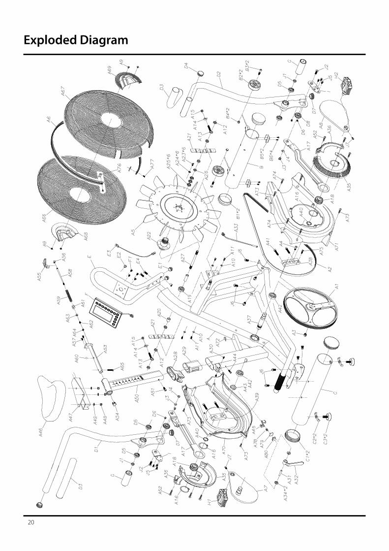
Exploded Diagram
20
21
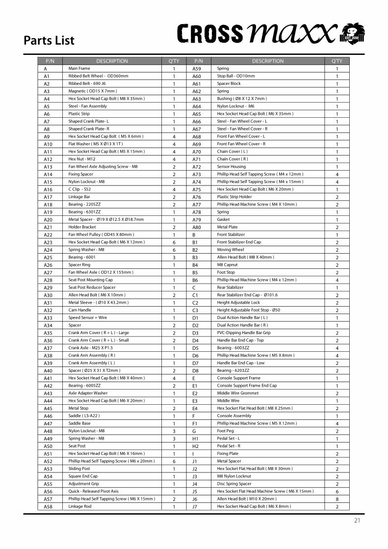
Parts ListP/N DESCRIPTION Q'TY P/N DESCRIPTION Q'TY
A Main Frame 1 A59 Spring 1A1 Ribbed Belt Wheel - OD360mm 1 A60 Stop Ball - OD10mm 1A2 Ribbed Belt - 690 J6 1 A61 Spacer Block 1A3 Magnetic ( OD15 X 7mm ) 1 A62 Spring 1A4 Hex Socket Head Cap Bolt ( M8 X 35mm ) 1 A63 Bushing ( Ø8 X 12 X 7mm ) 1A5 Steel - Fan Assembly 1 A64 Nylon Locknut - M6 1A6 Plastic Strip 1 A65 Hex Socket Head Cap Bolt ( M6 X 35mm ) 1A7 Shaped Crank Plate- L 1 A66 Steel - Fan Wheel Cover - L 1A8 Shaped Crank Plate- R 1 A67 Steel - Fan Wheel Cover - R 1A9 Hex Socket Head Cap Bolt ( M5 X 6mm ) 4 A68 Front Fan Wheel Cover - L 1A10 Flat Washer ( M5 X Ø13 X 1T ) 4 A69 Front Fan Wheel Cover - R 1A11 Hex Socket Head Cap Bolt ( M5 X 15mm ) 4 A70 Chain Cover ( L ) 1A12 Hex Nut - M12 4 A71 Chain Cover ( R ) 1A13 Fan Wheel Axle Adjusting Screw - M8 2 A72 Sensor Housing 1A14 Fixing Spacer 2 A73 Phillip Head Self Tapping Screw ( M4 x 12mm ) 4A15 Nylon Locknut - M8 2 A74 Phillip Head Self Tapping Screw ( M4 x 15mm ) 4A16 C Clip - S52 4 A75 Hex Socket Head Cap Bolt ( M6 X 20mm ) 1A17 Linkage Bar 2 A76 Plastic Strip Holder 2A18 Bearing - 2205ZZ 2 A77 Phillip Head Machine Screw ( M4 X 10mm ) 2A19 Bearing - 6301ZZ 1 A78 Spring 1A20 Metal Spacer - Ø19 X Ø12.5 X Ø18.7mm 1 A79 Gasket 1A21 Holder Bracket 2 A80 Metal Plate 2A22 Fan Wheel Pulley ( OD45 X 80mm ) 1 B Front Stabilizer 1A23 Hex Socket Head Cap Bolt ( M6 X 12mm ) 6 B1 Front Stabilizer End Cap 2A24 Spring Washer - M8 6 B2 Moving Wheel 2A25 Bearing - 6001 3 B3 Allen Head Bolt ( M8 X 40mm ) 2A26 Spacer Ring 1 B4 M8 Capnut 2A27 Fan Wheel Axle ( OD12 X 155mm ) 1 B5 Foot Stop 2A28 Seat Post Mounting Cap 1 B6 Phillip Head Machine Screw ( M4 x 12mm ) 4A29 Seat Post Reducer Spacer 1 C Rear Stabilizer 1A30 Allen Head Bolt ( M6 X 10mm ) 2 C1 Rear Stabilizer End Cap - Ø101.6 2A31 Metal Sleeve - ( Ø10 X 43.2mm ) 1 C2 Height Adjustable Lock 2A32 Cam Handle 1 C3 Height Adjustable Foot Stop - Ø50 2A33 Speed Sensor + Wire 1 D1 Dual Action Handle Bar ( L ) 1A34 Spacer 2 D2 Dual Action Handle Bar ( R ) 1A35 Crank Arm Cover ( R + L ) - Large 2 D3 PVC-Dipping Handle Bar Grip 2A36 Crank Arm Cover ( R + L ) - Small 2 D4 Handle Bar End Cap - Top 2A37 Crank Axle - M25 X P1.5 1 D5 Bearing - 6003ZZ 4A38 Crank Arm Assembly ( R ) 1 D6 Phillip Head Machine Screw ( M5 X 8mm ) 4A39 Crank Arm Assembly ( L ) 1 D7 Handle Bar End Cap - Low 2A40 Spacer ( Ø25 X 31 X T2mm ) 2 D8 Bearing - 6203ZZ 2A41 Hex Socket Head Cap Bolt ( M8 X 40mm ) 4 E Console Support Frame 1A42 Bearing - 6005ZZ 2 E1 Console Support Frame End Cap 1A43 Axle Adapter Washer 1 E2 Middle Wire Grommet 2A44 Hex Socket Head Cap Bolt ( M6 X 20mm ) 1 E3 Middle Wire 1A45 Metal Stop 2 E4 Hex Socket Flat Head Bolt ( M8 X 25mm ) 2A46 Saddle ( LS-A22 ) 1 F Console Assembly 1A47 Saddle Base 1 F1 Phillip Head Machine Screw ( M5 X 12mm ) 4A48 Nylon Locknut - M8 3 G Foot Peg 2A49 Spring Washer - M8 3 H1 Pedal Set - L 1A50 Seat Post 1 H2 Pedal Set - R 1A51 Hex Socket Head Cap Bolt ( M6 X 16mm ) 1 I Fixing Plate 2A52 Phillip Head Self Tapping Screw ( M6 x 20mm ) 6 J1 Metal Spacer 2A53 Sliding Post 1 J2 Hex Socket Flat Head Bolt ( M8 X 30mm ) 2A54 Square End Cap 1 J3 M8 Nylon Locknut 2A55 Adjustment Grip 1 J4 Disc Spring Spacer 2A56 Quick - Released Pivot Axis 1 J5 Hex Socket Flat Head Machine Screw ( M6 X 15mm ) 6A57 Phillip Head Self Tapping Screw ( M6 X 15mm ) 2 J6 Allen Head Bolt ( M10 X 20mm ) 8A58 Linkage Rod 1 J7 Hex Socket Head Cap Bolt ( M6 X 8mm ) 2
22
Your Warranty
This product is supplied with a standard warranty as follows:
• Lifetime frame• 12 month other parts• 12 months labour
This product is warranted for use in a home, personal, family or household environment
Please Note: Warranty details may vary from one market area to another
Warranty Terms
We warrants that the Product you have purchased from an authorised reseller is free from defects in materials and workmanship. TheWarrantyisvalidsubjecttonormalandreasonableuseintheenvironmentasdescribedabove,andcorrectassemblyoftheproduct during the warranty period. The warranty period extends to the original purchaser only. It is not transferable to anyone who subsequently purchases the Product from you.
The warranty excludes normal wear and tear on parts.
Your sales receipt, showing the date of purchase of the product, is your proof of the date of purchase.
This warranty becomes valid only if the Product is assembled / installed according to the instructions / directions included with the product. This warranty does not extend to any product that has been damaged or rendered defective: (a) as a result of accident,misuse,abuseorlackofreasonablecare;(b)bytheuseofpartsnotmanufacturedbyusorsoldbyusbymodificationof the product; (d) as a result of service by anyone else other than us or an authorised warranty service provider.
During the warranty period we will at no additional charge provide replacement part(s) or repair the product (at our option) if it becomes defective, malfunctions or otherwise fails to conform with this warranty under normal, non-commercial, personal, family or household use. In repairing the product, we may replace defective parts or at the option of ours, use serviceable used parts that are equivalent to new parts in performance. All exchanged parts and products replaced under this warranty will become the property of ours. We reserves the right to change manufacturers of any part to cover any existing warranty.
If the product must be returned, you must return the Product or defective part to us in its original container (or equivalent) with Proof of Purchase. Any evidence of alteration, erasing or forgery of proof of purchase documents will be cause to void this warranty. You must prepay any shipping charges and you are responsible for insuring any product or part that is returned. Should any product submitted for warranty service be found to be ineligible, an estimate of repair cost will be furnished and the repair will be made if requested, upon our receipt of payment or acceptable arrangement of payment. Under no circumstances will returns be accepted without return authorisation by our Customer Service department.
To obtain warranty service you must and provide the following information:
Name of Product, Product Code, Batch No, Date Purchased, and Nature of fault or part number required.
Neither dealer of this product nor any retail establishment selling this product has any authority to make any warranties or to promise remedies in addition to, or inconsistent with, those stated above. This warranty does not affect your statutory rights.
Please note that warranty terms may vary from one market area to another