instruction manual - circutor
TRANSCRIPT
INSTRUCTION MANUAL(M114B01-03-16A)
Inverter
CirPower

2
CirPower
Instruction Manual
SAFETY PRECAUTIONS
DISCLAIMER
CIRCUTOR, SA reserves the right to make modifi cations to the device or the unit specifi ca-tions set out in this instruction manual without prior notice.
CIRCUTOR, SA on its web site, supplies its customers with the latest versions of the device specifi cations and the most updated manuals.
www.circutor.com
DANGERWarns of a risk, which could result in personal injury or material damage.
ATTENTIONIndicates that special attention should be paid to a specifi c point.
Follow the warnings described in this manual with the symbols shown below.
If you must handle the unit for its installation, start-up or maintenance, the following should be taken into consideration:
Incorrect handling or installation of the unit may result in injury to personnel as well as damage to the unit. In particular, handling with voltages applied may result in electric shock, which may cause death or serious injury to personnel. defective installation or maintenance may also lead to the risk of fi re.read the manual carefully prior to connecting the unit. Follow all installation and maintenance instructions throughout the unit’s working life. Pay special attention to the installation stan-dards of the national electrical code.
Refer to the instruction manual before using the unit
In this manual, if the instructions marked with this symbol are not respected or carried out correctly, it can result in injury or damage to the unit and /or installations.
cIrcuTor, sA reserves the right to modify features or the product manual without prior notifi cation.
3Instruction Manual
CirPower

CONTENTS
SAFETY PRECAUTIONS ���������������������������������������������������������������������������������������������������������������������������������������3DISCLAIMER ����������������������������������������������������������������������������������������������������������������������������������������������������������3CONTENTS �������������������������������������������������������������������������������������������������������������������������������������������������������������4REVISION LOG �������������������������������������������������������������������������������������������������������������������������������������������������������6SYMBOLS ���������������������������������������������������������������������������������������������������������������������������������������������������������������61�- INSTALLATION �������������������������������������������������������������������������������������������������������������������������������������������������7
1�1�- VISUAL INSPECTION �������������������������������������������������������������������������������������������������������������������������������7 1�2�-UNPACkING �����������������������������������������������������������������������������������������������������������������������������������������������7 1�3�-SAFETY CONSIDERATIONS ���������������������������������������������������������������������������������������������������������������������9 1�4�- ENVIRONMENTAL CONSIDERATIONS ���������������������������������������������������������������������������������������������������9
1�4�1�- LOAD-BEARING CAPACITY OF ThE FLOOR ��������������������������������������������������������������������������������9 1�4�2�- TEMPERATURE AND hUMIDITY ���������������������������������������������������������������������������������������������������101�5�- INSTALLATION LOCATION OF INVERTERS �����������������������������������������������������������������������������������������101�6�- INSTALLATION LOCATION OF OUTDOOR INVERTERS ���������������������������������������������������������������������� 111�7�- POSITIONING AND VENTILATION ��������������������������������������������������������������������������������������������������������� 11
1�7�1�- CirPower-10TR, CirPower-20TR, CirPower-30TR ������������������������������������������������������������������������ 111�7�2�- CirPower-45TR, CirPower-55TR����������������������������������������������������������������������������������������������������121�7�3�- CirPower-80TR, CirPower-110TR, CirPower-90TL-280, CirPower-110TL-280 ���������������������������121�7�4�- CirPower-250TR, CirPower-250TL, CirPower-330TL, CirPower-380TL, CirPower-500TL-M, CirPower-660TL-M, CirPower-760TL-M, CirPower-800TL-M������������������������������������������������������������������131�7�5�- CirPower-500TL, CirPower-660TL, CirPower-760TL, CirPower-800TL ��������������������������������������13
1�7�6�- CirPower-500TL-M, CirPower-660TL-M, CirPower-760TL-M outdoor ����������������������������������������141�8�- POwER SUPPLY AND AUxILIARY CONNECTIONS ����������������������������������������������������������������������������14
1�8�1�- MEChANICAL LAYOUT������������������������������������������������������������������������������������������������������������������151�8�2�- AC CIRCUIT BREAkERS ON ThE MAChINE �������������������������������������������������������������������������������20
1�9�- SERIAL COMMUNICATION CONNECTIONS ����������������������������������������������������������������������������������������23 1�10�- CONNECTION OF ExTERNAL FANS �������������������������������������������������������������������������������������������������25 1�11�- USER SETTING �������������������������������������������������������������������������������������������������������������������������������������26 1�12�- PREVENTIVE MAINTENANCE �������������������������������������������������������������������������������������������������������������27
2�- SAFETY �����������������������������������������������������������������������������������������������������������������������������������������������������������29 2�1�- GENERAL PRECAUTIONS���������������������������������������������������������������������������������������������������������������������29 2�2�- LIGhTENING AND OVERVOLTAGE ������������������������������������������������������������������������������������������������������34 2�3�- GROUND CONNECTION ������������������������������������������������������������������������������������������������������������������������35 2�4�- DC DISCONNECTOR ������������������������������������������������������������������������������������������������������������������������������35
3�- DESCRIPTION OF ThE EQUIPMENT ������������������������������������������������������������������������������������������������������������36 3�1�- INTRODUCTION ��������������������������������������������������������������������������������������������������������������������������������������36 3�2�- EQUIPMENT BLOCk DIAGRAM ������������������������������������������������������������������������������������������������������������37
3�2�1�- CirPower-xxTR INVERTER FLOwChART wITh ISOLATION TRANSFORMER ������������������������373�2�2�- CirPower-xxTL INVERTER FLOwChART ������������������������������������������������������������������������������������37
3�3�- OPERATING PRINCIPLES����������������������������������������������������������������������������������������������������������������������38 3�4�- MAxIMUM POwER POINT TRACkING (MPPT) ������������������������������������������������������������������������������������38 3�5�- MASTER & SLAVE OPERATION �����������������������������������������������������������������������������������������������������������40
4�- INVERTER OPERATION ���������������������������������������������������������������������������������������������������������������������������������41 4�1�- INVERTER CONTROL PANEL ���������������������������������������������������������������������������������������������������������������41 4�2�- QUICk START �����������������������������������������������������������������������������������������������������������������������������������������41 4�3�- TOUCh SCREEN DISPLAY ��������������������������������������������������������������������������������������������������������������������44
4�3�1�- INTRODUCTION ������������������������������������������������������������������������������������������������������������������������������444�3�2�- NAVIGATION DISPLAY �������������������������������������������������������������������������������������������������������������������454�3�3�- MEASUREMENTS MENU ���������������������������������������������������������������������������������������������������������������454�3�4�- SET-UP MENU ���������������������������������������������������������������������������������������������������������������������������������46
4�4�- MAChINE VALUES ���������������������������������������������������������������������������������������������������������������������������������56 4�5�- STATUS, ALARMS AND INVERTER PROTECTION ������������������������������������������������������������������������������57
4�5�1�- DETAILS ABOUT STATUS AND OPERATING CONDITIONS �������������������������������������������������������574�5�2�- FAULTS, ALARMS AND PROTECTIONS ��������������������������������������������������������������������������������������604�5�3�- POwER DERATING AS A FUNCTION OF POwER MODULE TEMPERATURE �������������������������63
4�6�- IDENTIFICATION OF CODE REVISION FIRMwARE INSTALLED ON SOLAR CONVERTERS ����������63 5�- COMMUNICATIONS AND I/O ������������������������������������������������������������������������������������������������������������������������66
5�1�- PORTS AND PROTOCOLS ��������������������������������������������������������������������������������������������������������������������66 5�2�-COMMUNICATION BOARDS�������������������������������������������������������������������������������������������������������������������69
4
CirPower
Instruction Manual

5�2�1�- RS-232/USB SERIAL INTERFACE CARD �������������������������������������������������������������������������������������695�2�2�- SERIAL RS-485 INTERFACE BOARD �������������������������������������������������������������������������������������������695�2�3�- CONCENTRATOR CARD FOR CSP12 SMART STRING BOxES ������������������������������������������������70
5�3�- SUPERVISION PLATFORMS ������������������������������������������������������������������������������������������������������������������705�3�1�- PLATFORM BASED ON SNMP CARD �������������������������������������������������������������������������������������������70
6�- ACCESSORIES (OPTIONAL) ������������������������������������������������������������������������������������������������������������������������74 6�1�- FIBRE OPTIC SERIAL INTERFACE CARD (OPTIONAL)����������������������������������������������������������������������74 6�2�- NETwORk SNMP ADAPTER �����������������������������������������������������������������������������������������������������������������74 6�3�- RS232 / RS485 ADAPTER ����������������������������������������������������������������������������������������������������������������������75 6�4�- RS485 TO EThERNET CONVERTER ����������������������������������������������������������������������������������������������������75 6�5�-RADIATION SENSOR ������������������������������������������������������������������������������������������������������������������������������76
7�- TEChNICAL FEATURES ��������������������������������������������������������������������������������������������������������������������������������77 7�1�-CirPower-xxTR ����������������������������������������������������������������������������������������������������������������������������������������78
7�1�1�- INVERTER wITh ISOLATION TRANSFORMER ���������������������������������������������������������������������������78 7�2�-CirPower-xxxTR AND CirPower-xxxTL �������������������������������������������������������������������������������������������������79
7�2�1�- INVERTER wITh ISOLATION TRANSFORMER ���������������������������������������������������������������������������797�2�2�- TRANSFORMERLESS INVERTER �������������������������������������������������������������������������������������������������80
7�3�-NOTES ������������������������������������������������������������������������������������������������������������������������������������������������������86 7�4�-ELECTRICAL POwER CONSUMPTION FOR VENTILATION FANS �����������������������������������������������������87
8�- MAINTENANCE AND TEChNICAL SERVICE ������������������������������������������������������������������������������������������������889�- GUARANTEE ���������������������������������������������������������������������������������������������������������������������������������������������������8810�- CE CERTIFICATE ������������������������������������������������������������������������������������������������������������������������������������������89
5Instruction Manual
CirPower

REVISION LOG
Table 1: Revision log�Date Revision Description05/16 M114B01-03-16A Initial Version
SYMBOLS
The following symbols are used in this manual to both warn and advise users of particular situ-ations that warrant attention. The symbols and their meanings are as follows.
Table 2: Symbols�Symbol Description
INFORMATIONAdditional information to be borne in mind. To be used for making notices and/or recommendations.
ATTENTIONThis symbol is used to draw the attention of the user on situations that could cause serious injuries to people and/or serious damage to the system.
ELECTRICAL DANGERThis symbol is used to draw the attention of the user on the risk of electrical shocks.These warnings signal compulsory behaviour.
UNPACkING INSTRUCTIONSThese instructions explain how to remove the system from the packaging.
INSTALLATION INSTRUCTIONSThese step-by-step instructions describe how to install the inverter.
MANDATORY INSTRUCTIONSBefore carrying out any work on the appliance, read the operation and installation manual carefully.
DISPOSALProvides useful information on the disposal of the system.
ThE wARNING TRIANGLES ARE USED TO INDICATE wARNINGS ABOUT PERSONAL SAFETY� FOLLOw ThESE INSTRUCTIONS VERY CAREFULLY TO PREVENT PERSONAL INJURY OR DAMAGE TO ThE APPLIANCE�
6
CirPower
Instruction Manual
Note: Device images are for illustrative purposes only and may differ from the actual device.

1�- INSTALLATION
1.1.- VIsuAl InsPecTIon
All inverter components (electrical and mechanical) are carefully inspected before the unit is delivered to the customer and must be integral even after delivery. Always visually check a uPs after delivery for any transit damage, and immediately inform CIRCUTOR if such damage is evident
1.2.-unPAckIng
The inverter packaging is usually constituted by a plastic ground cloth, put on from the top part of the equipment and lowered till the lower limit of the equipment. Above the ground cloth, a carton box is secured with plastic strips.
In order to unpack the inverter, it firstly required to cut the plastic strips and push the carton toward the top of the unit, until the equipment is totally out of the box. once this operation is done, it is possible to get the inverter out of its plastic ground cloth.
Removal from the pallet (only for inverters up to 30 kVA): secure the dedicated slide (wood-made, included in the packaging), remove the fastening blocks and leave the unit to go down the slide on its wheels. Please take care that the wheels be always moving onto the slide.
Figure 1: Unpacking
Removal from the pallet (for inverters above 30 kVA): please use a forklift (with proper capacity for weight). Please refer to chapter (“7.- TECHNICAL FEATURES”) of this manual to retrieve the weight information.
Forks of the forklift have to be inserted either from the front or from the rear of the cabinet (never from the lateral side of it).
Due to the weight of the equipment, it is strongly recommended the use of all the safety tools as prescribed by the safety regulation in force in any specific country where the equipment is installed.
7Instruction Manual
CirPower

The drive comes with plinths which close the base of the equipment. When the apparatus comes from the factory skirting are not mounted so that it can be lifted from the bottom with a forklift.
Please do not tilt or lay down the inverter on either lateral side. Following tools can be used for transport:
crane Forks Forklift Transpallets
Figure 2: Use for transport�
Please use only tools designed to stand the weight of the inverter to be lifted. In case of a pre-installed inverter removal, please remove the grid at the bottom of the equip-ment.
For weights and dimensions refer to the chapter “7.- TECHNICAL FEATURES” section of this manual
Due to the order of magnitude of the weights, it is strongly recommended to use all the safety devices required by current safety-related standards for movement and place-ment�
8
CirPower
Instruction Manual
1.3.-sAFeTy consIderATIons
Accidents can be prevented by simply following a few precautions:
• Walls, ceilings, floors and any other item placed next to the converter should not be made of inflammable materials.
• The floor on which the inverter is installed should always be kept clean to prevent metal particles or scraps of iron or metal from being sucked inside the unit and causing short circuits.
• A dry powder fire extinguished should be positioned at the installation site.
• For units of 100kW or higher, an automatic fire-fighting system should be installed.
• Access to the inverter installation site should only be given to service staff and maintenance personnel; inward opening doors (with handles) to the room where the inverted is sited and to the inverter itself) should be kept closed at all times (limited access area).
• All service and electrical maintenance personnel must be trained and able to perform both ordinary and emergency procedures. new personnel must be given suitable training before being allowed to work on inverters.
1.4.- enVIronMenTAl consIderATIons
The environmental factors that need to be taken into account are detailed in the paragraphs that follow.
1�4�1�- LOAD-BEARING CAPACITY OF ThE FLOOR
The weight of the inverter (specified in the “7.- TECHNICAL FEATURES” ) is taken by a small floor area. Therefore, it is important to make sure that the area selected for installation can bear the weight of the appliance.
If the inverter is installed on a raised floor, it is important to use a base with ped-estals (this base can be provided by CIRCUTOR sPA upon request).
All cables should be routed from below the floor.
9Instruction Manual
CirPower

1�4�2�- TEMPERATURE AND hUMIDITY
The premises where the inverter is to be installed must be able to dis-perse the kw that the device gives off during operation to keep the tem-perature between -5°c and 45°c; with a humidity percentage between 0 and 95% as shown on the “7.- TECHNICAL FEATURES”
The type and the implementation of any air distribution line must be checked and approved by CIRCUTOR. The manufacturer is not in any way liable for inverter malfunctions due to the failure to observe the rules of Installation, particularly the permitted temperature and humidity re-quirements. It is recommended therefore to adopt design features (for example air-conditioning, heating or dehumidification of the premises), suitable to guarantee the maintenance of the permitted temperature and humidity conditions.
1.5.- InsTAllATIon locATIon oF InVerTers
The inverter must be installed on a stable, level surface that is longer and wider than the base of the appliance.
The inverter is not designed to be installed in areas where it could be exposed to impacts or vibration: being transported by road, rail, sling, air or ship or by similar equipment (e.g. cranes, moving parts of the appliance etc.).
The room intended for installation of the inverter must be a access-restricted only, such as containers, electrical substations or suitable technical rooms suited to ac-commodate electrical power, where no risk of items falling from above is present. The requirement of security to prevent falling objects from that area is IP3X.
For indoor-type inverters, the installation site must be kept clean and dry at all times so as to prevent foreign material or liquids from entering the equipment.1 m clearance, at least, must be kept in front of the inverter to allow all routine and maintenance operations to be carried out.
The top of the equipment should be positioned at least 1m from the ceiling in order to ensure good ventilation.
As these appliances can reach significant power levels, the site where an inverter is positioned should be fitted with an automatic smoke detector that has a remote alarm system that stops the unit and cuts off the power supply. The detector should also be able to set off a fire-fighting system suitable for an electrical device.
10
CirPower
Instruction Manual

1.6.- InsTAllATIon locATIon oF ouTdoor InVerTers
The inverter must be installed on concrete reinforced basement, such to stand the weight of the inverter. The basement has to be prepared with cable conduits and fixation holes before the installation. The inverter has to be secured to the basement through dedicated screws inserted into the fixation holes.
The inverter is not designed to be installed in areas where it could be exposed to impacts or vibration.
1.7.- PosITIonIng And VenTIlATIon
Although CirPower series inverters are highly efficient, be aware that during nor-mal operation a certain amount of heat is generated. If this heat is not properly dissipated, it can lead to an increase in temperature in the room where the inverter is located and so the inverter itself can start to overheat.
In the installation of the CIRCUTOR product, it is recommended that the distance between the inverter and any walls or other objects be respected, as shown in the following diagrams.
1�7�1�- CirPower-10TR, CirPower-20TR, CirPower-30TR
100 cm
20 cm
10 cm75 cm
10 cm
Figure 3:CirPower-10TR, CirPower-20TR, CirPower-30TR
11Instruction Manual
CirPower

1�7�2�- CirPower-45TR, CirPower-55TR
100 cm
60 cm
100 cm
Figure 4:CirPower-45TR, CirPower-55TR
1�7�3�- CirPower-80TR, CirPower-110TR, CirPower-90TL-280, CirPower-110TL-280
60 cm
80 cm
30 cm
Figure 5:CirPower-80TR, CirPower-110TR, CirPower-90TL-280, CirPower-110TL-280
12
CirPower
Instruction Manual
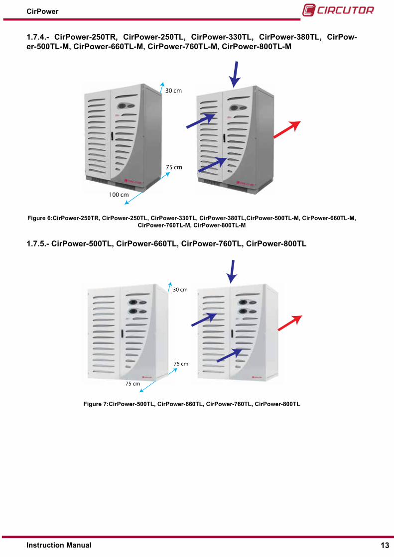
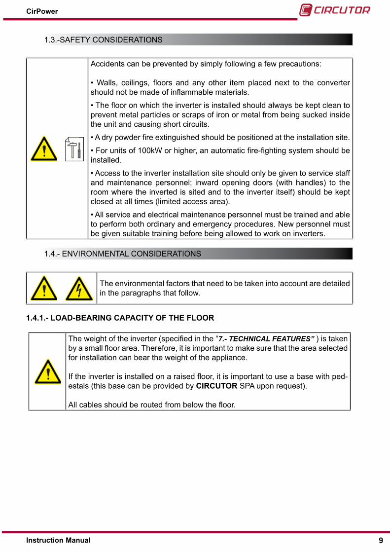
1�7�4�- CirPower-250TR, CirPower-250TL, CirPower-330TL, CirPower-380TL, CirPow-er-500TL-M, CirPower-660TL-M, CirPower-760TL-M, CirPower-800TL-M
30 cm
75 cm
100 cm
Figure 6:CirPower-250TR, CirPower-250TL, CirPower-330TL, CirPower-380TL,CirPower-500TL-M, CirPower-660TL-M, CirPower-760TL-M, CirPower-800TL-M
1�7�5�- CirPower-500TL, CirPower-660TL, CirPower-760TL, CirPower-800TL
30 cm
75 cm
75 cm
Figure 7:CirPower-500TL, CirPower-660TL, CirPower-760TL, CirPower-800TL
13Instruction Manual
CirPower
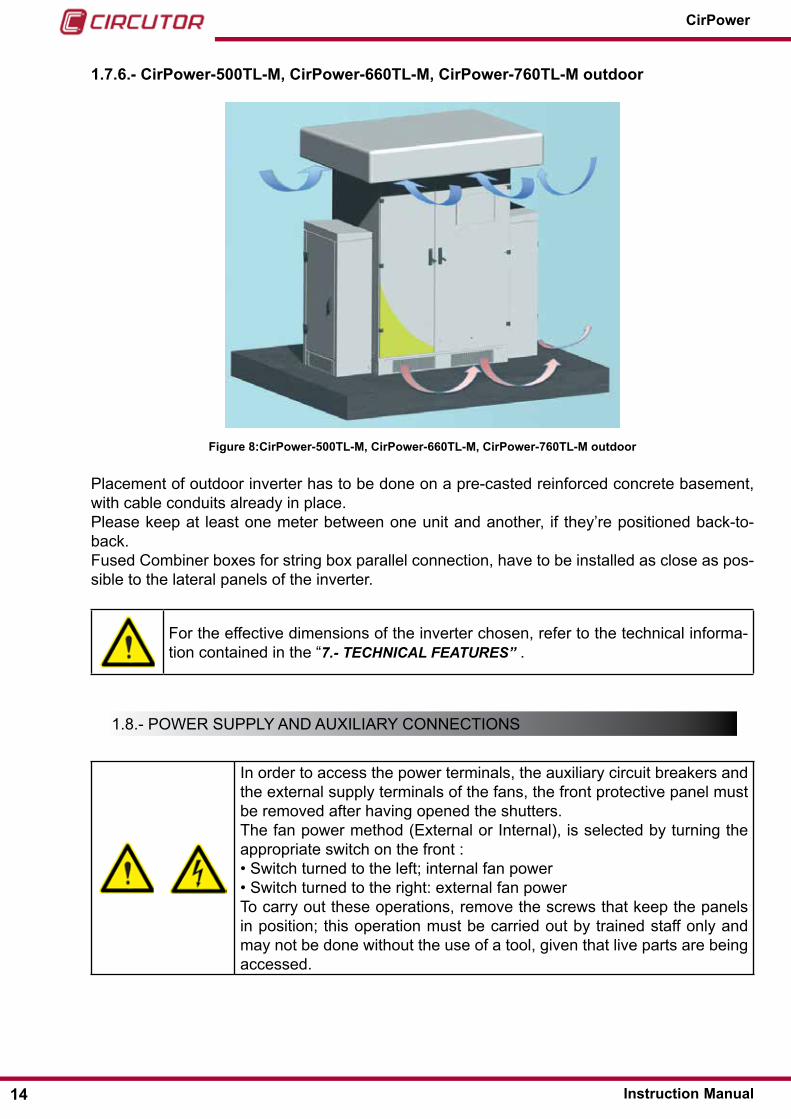
1�7�6�- CirPower-500TL-M, CirPower-660TL-M, CirPower-760TL-M outdoor
Figure 8:CirPower-500TL-M, CirPower-660TL-M, CirPower-760TL-M outdoor
Placement of outdoor inverter has to be done on a pre-casted reinforced concrete basement, with cable conduits already in place.Please keep at least one meter between one unit and another, if they’re positioned back-to-back.Fused combiner boxes for string box parallel connection, have to be installed as close as pos-sible to the lateral panels of the inverter.
For the effective dimensions of the inverter chosen, refer to the technical informa-tion contained in the “7.- TECHNICAL FEATURES” .
1.8.- PoWer suPPly And AuXIlIAry connecTIons
In order to access the power terminals, the auxiliary circuit breakers and the external supply terminals of the fans, the front protective panel must be removed after having opened the shutters.The fan power method (external or Internal), is selected by turning the appropriate switch on the front :• switch turned to the left; internal fan power• switch turned to the right: external fan powerTo carry out these operations, remove the screws that keep the panels in position; this operation must be carried out by trained staff only and may not be done without the use of a tool, given that live parts are being accessed.
14
CirPower
Instruction Manual

Selector for fans supply source (internal / external)
Figure 9:Selector for fans supply source�
1�8�1�- MEChANICAL LAYOUT
The following figures illustrate the power terminals of the dc (input) and Ac (output) sections, and of the external fan power.
1�8�1�1�- CirPower-10TR, CirPower-20TR, CirPower-30TR
From panelDC terminals side
AC Terminals side
L – N TERMINALS EXTERNAL FANS AUX. SUPPLY 230Vac 50Hz 5Amax
External fan power
15Instruction Manual
CirPower

1�8�1�2�- CirPower-45TR, CirPower-55TR
From panel AC-DC terminals side
L – N TERMINALS EXTERNAL FANS AUX. SUPPLY 230Vac 50Hz 5Amax
External fan power
16
CirPower
Instruction Manual
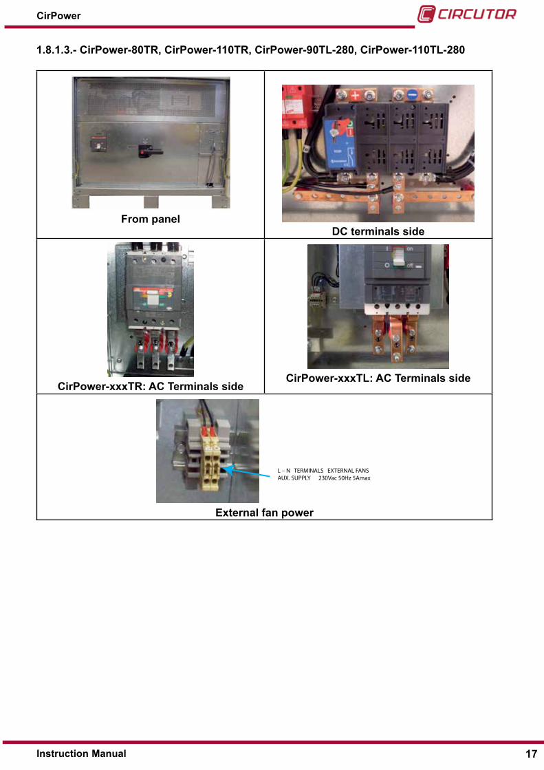
1�8�1�3�- CirPower-80TR, CirPower-110TR, CirPower-90TL-280, CirPower-110TL-280
From panelDC terminals side
CirPower-xxxTR: AC Terminals sideCirPower-xxxTL: AC Terminals side
L – N TERMINALS EXTERNAL FANS AUX. SUPPLY 230Vac 50Hz 5Amax
External fan power
17Instruction Manual
CirPower
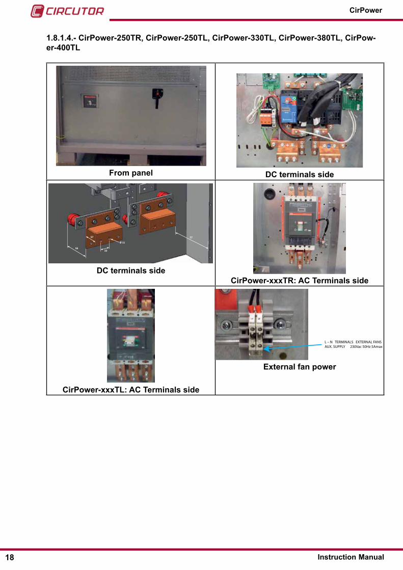
1�8�1�4�- CirPower-250TR, CirPower-250TL, CirPower-330TL, CirPower-380TL, CirPow-er-400TL
From panel DC terminals side
33 56
57
Ø 11 11
57
DC terminals sideCirPower-xxxTR: AC Terminals side
CirPower-xxxTL: AC Terminals side
L – N TERMINALS EXTERNAL FANS AUX. SUPPLY 230Vac 50Hz 5Amax
External fan power
18
CirPower
Instruction Manual
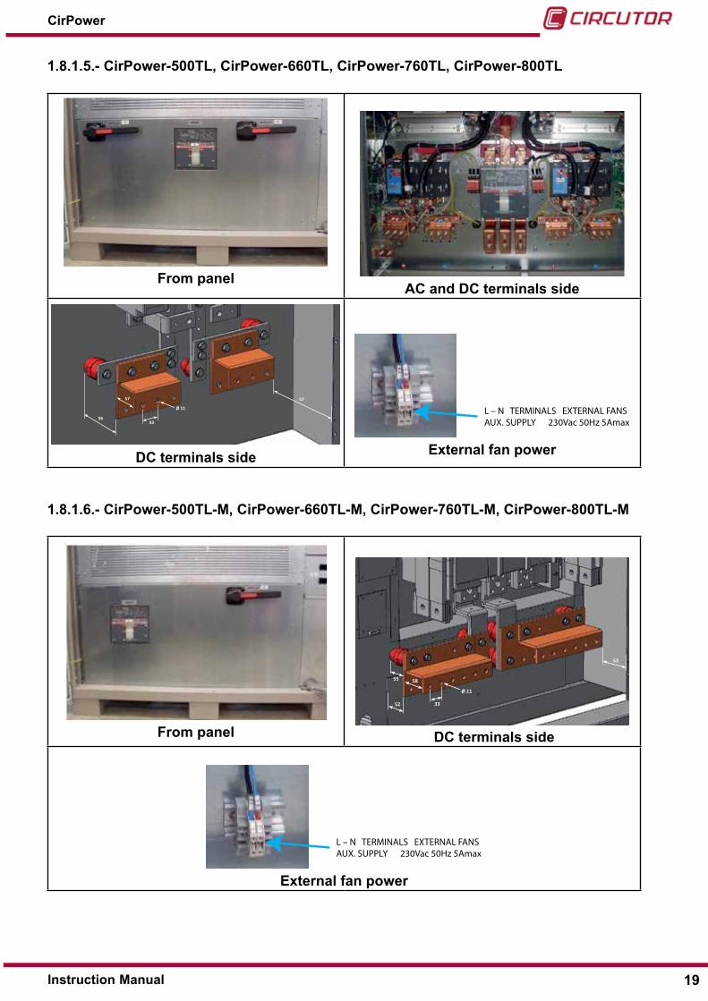
1�8�1�5�- CirPower-500TL, CirPower-660TL, CirPower-760TL, CirPower-800TL
From panelAC and DC terminals side
33 56
57
Ø 11 11
57
DC terminals side
L – N TERMINALS EXTERNAL FANS AUX. SUPPLY 230Vac 50Hz 5Amax
External fan power
1�8�1�6�- CirPower-500TL-M, CirPower-660TL-M, CirPower-760TL-M, CirPower-800TL-M
From panel
53
33
58
52
55
Ø 11 11
DC terminals side
L – N TERMINALS EXTERNAL FANS AUX. SUPPLY 230Vac 50Hz 5Amax
External fan power
19Instruction Manual
CirPower

1�8�2�- AC CIRCUIT BREAkERS ON ThE MAChINE
connecting Ac side cables are dimensioned taking into account the electrical parameters of the circuit breakers, summarised in the following table:
Table 3:AC Circuit breakers
Type Current - Curve Magnetic curve Breaking capacity10Tr 40A-c 10 In 10kA20Tr 40A-c 10 In 10kA30Tr 63A-c 10 In 10kA45Tr 100A-c 10 In 10kA55Tr 100A-c 10 In 10kA 80Tr 200A Programmable (default 10.In) 36kA110Tr 200A Programmable (default 10.In) 36kA250Tr 400A Programmable (default 10.In) 36kA90Tl 250A Programmable (default 10.In) 36kA110Tl 250A Programmable (default 10.In) 36kA250Tl 630A Programmable (default 10.In) 50kA330Tl 800A Programmable (default 10.In) 50kA380Tl 800A Programmable (default 10.In) 50kA
500Tl-M 1250A Programmable (default 10.In) 50kA660Tl 1600A Programmable (default 10.In) 50kA
660Tl-M 1600A Programmable (default 10.In) 50kA760Tl-M 1600A Programmable (default 10.In) 50kA800Tl-M 1600A Programmable (default 10.In) 50kA
The characteristics (curve type, magnetic current) of the switch on the elec-trical board connected to the inverter must be compatible with the character-istics of the machine switch�
1�8�3�- CABLE QUANTITY AND SECTION
The following tables indicate the maximum quantity and the maximum section of copper cables that can be connected to the dc input and the Ac output.
Table 4:AC Cable quantity and section
Inverter transformerlessType DC input AC output Ground conductor
90TL-280110TL-280 Max 8 cables 120 mm2 per pole Max 2 cables 50 mm2 per phase Max 2 cables (1)
250TL-280 Max 12 cables 120 mm2 per pole Max 4 cables 120mm2 per phase Max 2 cables (1)
330TL-280 Max 12 cables 120 mm2 per pole Max 4 cables 150mm2 per phase Max 2 cables (1)
660TL-280 Max 12 cables 120 mm2 per pole (x2) Max 4 cables 300mm2 per phase Max 2 cables (1)
250TL Max 12 cables 120 mm2 per pole Max 4 cables 120mm2 per phase Max 2 cables (1)
330TL380TL Max 12 cables 120 mm2 per pole Max 4 cables 150mm2 per phase Max 2 cables (1)
20
CirPower
Instruction Manual

Table 4 (Continuation): AC Cable quantity and section
Inverter transformerlessType DC input AC output Ground conductor
660TL760TL800TL
Max 12 cables 120 mm2 per pole (x2) Max 4 cables 300mm2 per phase Max 2 cables (1)
500TL-M660TL-M760TL-M800TL-M
Max 24 cables 120 mm2 per pole Max 4 cables 300mm2 per phase Max 2 cables (1)
(1) refer to the table for the sizing of the earth wires for the calculation of the total cable section.
Table 5:AC Cable quantity and section
Transformerless InverterType DC input AC output
Q�ty and section Terminals Q�ty and section Terminals660TL-M760TL-M800TL-M
Max 24 cables 120sqmmper pole
ring terminalhole Ø10
Max 4 cables 300sqmm per phase
ring terminalhole Ø10
330TLMax 12 cables 120sqmmper pole
ring terminalhole Ø10
Max 4 cables 150sqmm per phase
ring terminalhole Ø10
The type of cable and its cross section to be used must be determined at the design stage by the designer or installer�
1�8�4�- GROUND CONDUCTOR SIzING
The size of the ground conductor must be made according to the following table, extracted from the product safety standard ceI en 62109-1.
Table 6:Ground conductor sizing
The cross section of the phase conduc-tors connected to the inverter, ‘S’
mm²
Relevant minimum cross section of the protective conductor to the ground, Sp
s ≤ 1616 < s ≤ 35
35 < s
s16s/2
NOTE: The values shown in the previous table are valid only if the protective earthing conductor is made of the same material used for the phase conductors Ac. If not, the cross section of the protective conductor to ground must be determined in order to get the same conductance value equivalent.
1�8�5�- MAxIMUM TORQUE TIGhTENING CABLES
Table 7:Maximum torque tightening cables
Maximum tightening torqueType DC input AC output Earth cable
10TR, 20TR, 30TR 10 nm 2,8 nm 8 nm45TR, 55TR 10 nm 10 nm 8 nm
80TR, 110TR,110TL 30 nm 30 nm 30 nm
21Instruction Manual
CirPower

Table 7 (Continuation): Maximum torque tightening cables
Maximum tightening torqueType DC input AC output Earth cable
250TR, 330TL,380TL500TL,660TL,500TL-M
660TL-M, 760TL-M30 nm 30 nm 30 nm
1�8�6�- POwER DISSIPATED BY VENTILATION
The following table includes the air flow volume and the power dissipation values.Table 8:Power dissipated by ventilation
Type Air capacity Dissipated power Fan consumption10Tr 660 m3/h 0,68 kW 90 W20Tr 660 m3/h 1,1 kW 90 W30Tr 880 m3/h 1,6 kW 120 W45Tr 750 m3/h 2,3 kW 150 W55Tr 900 m3/h 2,8 kW 300 W 80Tr 3700 m3/h 3,4 kW 490 W110Tr 3700 m3/h 3,8 kW 490 W250Tr 4547 m3/h 8,2 kW 630 W90Tl 3050 m3/h 2,7 kW 420 W110Tl 3050 m3/h 3,4 kW 420 W250Tl 3313 m3/h 6,2 kW 420 W330Tl 3400 m3/h 8 kW 490 W500Tl 6166 m3/h 11,5 kW 840 W660Tl 6300 m3/h 12 kW 980 W760Tl800Tl 6300 m3/h 12 kW 980 W
1�8�7�- CONNECTION OF ThE EPO CIRCUIT
The inverter includes an electronic device (ePo) which can stop the in-verter and disconnect it from the distribution network.The connection between the external ePo contact and the inverter is established by 2 wires which shall be connected to terminal 13 and 14 on the terminal board.This device must be remotely activated by an emergency pushbutton; to restore normal operation, first press the on button and then the enTer key on the touch screen.It is important to ensure that the ePo circuit leads do not run close to the power cables.Although the entire ePo circuit is without hazardous voltages and is me-tallically separated from the internal voltages of the inverter, care must be taken since this circuit completely stops the inverter!
22
CirPower
Instruction Manual

1�8�8�- CONNECTION OF ThE MODULES’ TEMPERATURE SENSOR
The inverter is equipped with a modules temperature sensor, which is temporary wired and is located in the terminal board I/o compartment.
This sensor is placed right behind the modules and connected to terminals 7 (Temp+) and 8 (Temp-) of the inverter terminal board with a 1.5/2.5 mm2 wire pair (according to the distance: Max 250m).
The temperature value reading (°c) can be viewed on the touch screen display and via Modbus.
1.9.- serIAl coMMunIcATIon connecTIons
1�9�1�- TYPE OF CABLES TO BE USED
The inverters of the CirPower series make a rs485 serial port available as a fieldbus, with a standard Modbus rTu protocol; they also have a rs485 serial port (sAc Bus) to collect data from the parallel string boxes.
on the Modbus serial port, information is made available to the user regarding the inverter and the parallel string boxes.
For both serial ports, the use of a bipolar/tripolar eIA rs-485 shielded cable is advised, with typical impedance of 120 ohms.
The shields of the different cable sections shall be interconnected. As a first level check, if com-munications are unstable, check the continuity between the various shield sections.
1�9�2�- POwER SUPPLY UNIT LINE RS485 SAC BUS - 24VDC
The rs485 line sAc side must be powered through the external power supply unit (supplied as an option).
USE A 24Vdc POwER SUPPLY UNIT SPECIFIC FOR EACh INDIVIDUAL RS485 SAC FIELDBUS FV LINE (CORRESPONDING TO ThE INDIVIDUAL INVERTER MODULE)
1�9�3�- ELECTRICAL FEATURES OF ThE POwER SUPPLY UNIT LINE RS485 SAC BUS - 24VDC
The fundamental electrical features of the power supply unit are the following:Table 9:Electrical features
Electrical features
Input voltage According to the auxiliary voltage available in the plant, typically 100÷240Vac
Output voltage 24Vdc ± 2% (power supply csP sAc Bus rs485)
23Instruction Manual
CirPower

Table 9 (Continuation): Electrical features
Electrical featuresOutput current (n. total csP x 5mA + 70mA) minimum.
For ex. for 4 csP the value will be 4 x 5 + 70=90mA. To be safe, the source should have a power equal to double the value cal-culated in this field and short-circuitable (self protection).normally harmonised sized power supply units are used which are readily available at 30W 24Vdc 1.3A and which can be mounted on a dIn rail.
Over-current protection IncludedOver-voltage protection Includedworking temperature range IncludedGalvanic isolation input/output Included
1�9�4�- CONNECTION OF ThE MODBUS SERIAL PORT ShIELD
The shield of the cable section that connects the inverter Modbus serial port to the Modbus converter – TcP/IP (terminal 30), is earthed on the converter side. If communications are un-stable with this type of connection, this may be due to the fact that the earth is ‘noisy’.
In this case, ‘earthing’ the shields means connecting the shields to the negative potential of the Modbus – TCP/IP converter power supply�
1�9�5�- CONNECTION OF ThE SAC BUS SERIAL ShIELD
The shield of the rs485 cable that connects the inverter sAc Bus serial port to the parallel boxes (terminal 29), is not earthed on the box side because it is already earthed inside the in-verter.
24
CirPower
Instruction Manual
1�9�6�- RULES FOR ThE LAYING OF RS485 SERIAL CABLES
In order to minimise possible interference to serial data transmission/reception sig-nals, it is recommended that the following rules be observed for the use and laying of the connecting cables.• The total maximum length of the rs-485 chain shall not exceed 1200m.
• separate, as far as possible, the signal from the power cables (particularly on the photovoltaic field side), utilising different channels.
• separate the 24Vdc/sAc Bus rs485 supply cables from the power cables used for the connections between the FV panels and the InVerTers.
• For sAc Bus use a shield cable with typical impedance of 120 ohms (rs485) with four wires (nr2 for data+ and data- rs485 and nr2 for the positive/negative 24Vdc power supply). Alternatively use a 120 ohm (rs485) bipolar shielded cable for the transmission of information and a bipolar shielded cable for the 24Vdc pow-er supply. utilise the same cable route between the rs485 cable and the 24Vdc power supply cable.
• Maintain a minimum distance of at least 30cm between the signal cable and the power cable.
• If the signal cable and the power cable must be closer than the minimum distance, try as much as possible to minimise the length of the section along which they run parallel.
1.10.- connecTIon oF eXTernAl FAns
Note : Optional for CirPower-45TR and CirPower-45TR.
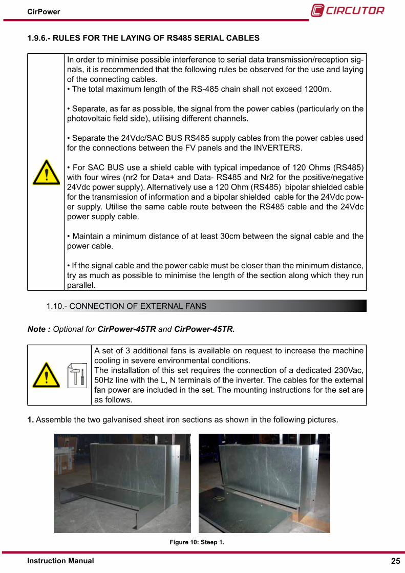
A set of 3 additional fans is available on request to increase the machine cooling in severe environmental conditions.The installation of this set requires the connection of a dedicated 230Vac, 50Hz line with the l, n terminals of the inverter. The cables for the external fan power are included in the set. The mounting instructions for the set are as follows.
1� Assemble the two galvanised sheet iron sections as shown in the following pictures.
Figure 10: Steep 1�
25Instruction Manual
CirPower

2� Fix the assembly to the wall and after placing the equipment in the correct position, fix it to the lower part of the inverter cubicle.
Figure 11:Steep 2�3�- Place the fan box in the correct position and insert the power supply connector.
Figure 12:Steep 3�
1.11.- user seTTIng
1�11�1�- CONNECTING AN INPUT POLE TO ThE PhOTOVOLTAIC FIELD EARTh
For some types of photovoltaic panels the earth connection of a pole is required.
Machines of the CirPower series are designed for the easy earth connection of the positive or negative pole on input (depending on the requirements of the plant design), by means of a special fuse already installed inside the converter.
once the settings have been appropriately configured, the machine is able to detect the open-ing of the fuse and activate the corresponding alarm.
CIRCUTOR default machines are configured in the factory WITHOUT any earth connection of the input poles�
26
CirPower
Instruction Manual
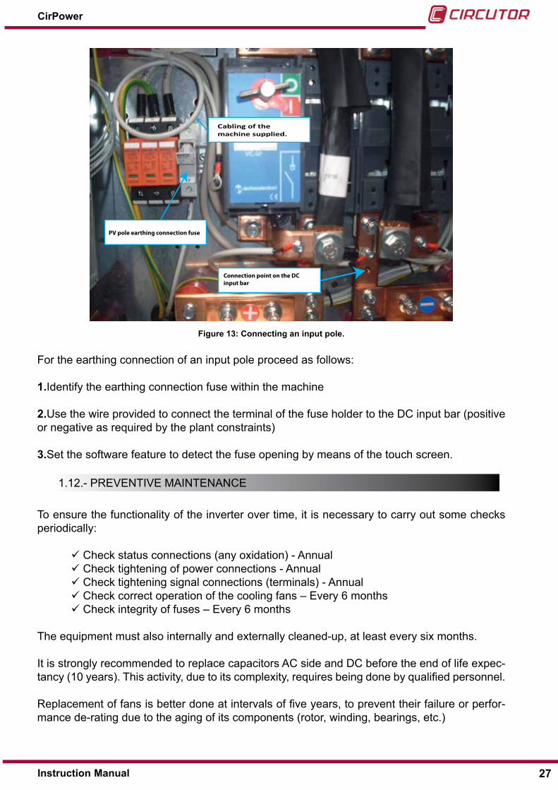
Cabling of the machine supplied.
PV pole earthing connection fuse
Connection point on the DC input bar
Figure 13: Connecting an input pole�
For the earthing connection of an input pole proceed as follows:
1�Identify the earthing connection fuse within the machine
2�use the wire provided to connect the terminal of the fuse holder to the dc input bar (positive or negative as required by the plant constraints)
3�set the software feature to detect the fuse opening by means of the touch screen.
1.12.- PreVenTIVe MAInTenAnce
To ensure the functionality of the inverter over time, it is necessary to carry out some checks periodically:
check status connections (any oxidation) - Annual check tightening of power connections - Annual check tightening signal connections (terminals) - Annual check correct operation of the cooling fans – every 6 months check integrity of fuses – every 6 months
The equipment must also internally and externally cleaned-up, at least every six months.
It is strongly recommended to replace capacitors Ac side and dc before the end of life expec-tancy (10 years). This activity, due to its complexity, requires being done by qualified personnel.
replacement of fans is better done at intervals of five years, to prevent their failure or perfor-mance de-rating due to the aging of its components (rotor, winding, bearings, etc.)
27Instruction Manual
CirPower

All the above operations and access to the internal components have to be carried out by trained technicians�
During operation the inverter must be switched off and secured, opening the switches / disconnectors side AC and DC side,
Particularly, for access to the upper compartment and the rear part of the unit:
1- disconnect the DC input, acting on S2 2- disconnect the AC output acting on S1
3- if the fans are powered by an external source, please make sure that the exter-nal switch for selecting the source of the aux circuits, is open�
To access the lower compartment, where the connection terminals and bars are located, in addition to the steps described above, it is necessary to disconnect the incoming DC source from the photovoltaic field and open the AC switch downstream the inverter.
Before accessing any part of the inverter, make sure that the capacitors are completely discharged and that the fans are not operating�
28
CirPower
Instruction Manual

2�- SAFETY
Failure to observe the following instructions can lead to serious consequences, like, among others, the destruction of the system, injuries to people and death due to electri-cal shocks�
If the appliance is not used according to the manufacturer’s instructions, the protection provided by the device may no longer apply.
It is therefore very important to read and understand all the safety instructions contained in this manual before using the inverter. In case of doubts or for additional information, please contact CIRCUTOR sAT service.
2.1.- generAl PrecAuTIons
This item defines the safety precautions that must be followed during any operation done in the device�
Dangerous voltages
The system uses very high internal voltages that could potentially cause injury.
Dangerous voltages
The inverter has multiple sources of power, pay attention to the marking on the machine and follow the instructions of this manual to ensure the correct proce-dures for connection and use.
Read and understand owner’s manual before operating the switch.
Dangerous voltages
When the solar panels are exposed to sunlight, a dangerous dc voltage is pres-ent at the input terminals of the inverter.
Dangerous voltages
All components with potentially dangerous voltages are grouped in special areas that can be accessed only with tools that are not supplied with the inverter.
Dangerous voltages
All maintenance or repair work which requires access to those areas of the invert-er may only be carried out by technical personnel specially trained by CIRCUTOR.
29Instruction Manual
CirPower

Dangerous voltages
Before opening the inverter, it is essential to disconnect the Ac and dc power sources. Please follow the sequence described in “1.12.- PREvENTIvE MAINTE-NANCE”
Dangerous voltages
once the inverter has been turned-off, some components inside the inverter and all the dc terminals can still be under voltage voltages for at least 20 minutes, with potential dangerous electrical discharges, due to the presence of electrolytic capacitors. Before carrying out any work on the equipment, make sure that the voltage at the dc bars (between positive and negative) has dropped to a safe level (< 60Vdc), my measuring it with a digital multi-meter.
WARNING! WAITING AT LEAST 20 MINUTES FOR THE INTERNAL DC CAPACITORS TO DISCHARGE AFTER INVERTER OFF AND DC BUS DISCONNECTED.
Introduction of objects
do not introduce objects into the ventilation inlets and avoid using liq-uids to clean the system. cleaning operations should only be performed using a dry cloth. These warnings should be observed even when the machine is off.
Trampling
roofs of inverters are not designed to withstand heavy weights. never climb on the top of the device or place service platforms or other similar objects on it and do not use it as a support for further structures (cable raceways, brackets, etc...).
Section of the cables
Always verify that the section of power and/or output cables is adequate. This requirement also applies to the other cables used for the system.
The connections, cable cross sections and inverter installation must all meet the standards regulating the use of low voltage electrical currents.
Ground connection
The first cable to be connected should always be the ground cable. When discon-necting the appliance, always leave the earth cable to last.
due to the presence of high leakage currents, please follow the steps specified in the installation manual to properly connect the inverter to ground.
30
CirPower
Instruction Manual

Initial start-up
Always power the system after it has been thoroughly inspected by qualified personnel.
Subsequent start-ups
Verify that all the disconnecting switches of the system and installation are open before performing the start-up procedure.
handling
Inverters are heavy and should only be handled by qualified personnel.
Before positioning the inverter, it is also important to make sure that the floor and overhead platforms can bear the weight of the appliance.
do not store or transport the system in tilted position or placed on one side.
Installation site
Apparatus not suited to bathrooms or similar wet areas (see “1.4.- EN-vIRONMENTAL CONSIDERATIONS”) and exclusively suited for indoor operation.
The inverter is not designed to be installed in areas where it could be exposed to impacts or vibrations; for example: means of transport for road, rail, rope, air, ship transportation or similar equipment (for exam-ple cranes, hoists, parts of the machine tools that are exposed to move-ments or vibrations, etc.).
do not install the inverter in explosive, corrosive, abrasive or saline en-vironments.
Positioning
never position the invert near sources of heat.
never install the unit in an area with poor ventilation.
never position the inverter in an area that is not well protected. Inverters have not been designed for outdoor installation.
Position the inverter in a dust free environment, as dust may enter the equipment and prevent it from cooling properly.
The inverter must be installed on a stable, level surface that is longer and wider than the base of the appliance.
see the appliance dimensions and warnings shown in the table in this manual in the “1.- INSTALLATION” section.
31Instruction Manual
CirPower

Cleanliness of the site of installation
The inverter installation site must be kept clean and dry at all times so as to prevent foreign material or liquids from entering the appliance. Be-sides affecting the operation of the appliance, dirt and dampness could greatly increase the risk of fire.
Reparations
do not attempt to repair the system directly, but have it serviced by the manufacturer or by an authorised support centre.
Any repair work made to the equipment not explicitly authorized in writ-ten form or not carried out by CIRCUTOR, beside involving actual dan-ger, immediately voids the warranty. CIRCUTOR shall not be liable for any consequent malfunction and for any arising loss or damages.
Technical support
The Technical support team must always be contacted if the system has been damaged, for example if liquid has penetrated the system, if objects have fallen on top of or inside the appliance, if it has been exposed to rain or humidity (out-side the specifications range), if it is not working correctly, if it is performing poorly or if it has been dropped.
Accessories
only use accessories recommended by the manufacturer. The use of unauthorised accessories may seriously affect how the appliance oper-ates. The use of non-original accessories will result in the warranty be-ing invalidated and will exempt the manufacturer from any responsibility whatsoever for malfunctions and any consequences that might stem from them.
MTBF (Mean Time Between Failures)
CIRCUTOR inverters are designed and manufactured with a view to as-suring remarkably high MTBF for the appliance. It is useful to remember that the MTBF is a statistical parameter and therefore has both concep-tual and practical limitations.
The MTBF specification applies only if the equipment has been correctly installed and serviced and therefore specifically excludes all conceptual or practical errors installation errors, negligence or improper use.
According to their specific function, CirPower inverters are designed only for professional users and must not be used by untrained personnel
32
CirPower
Instruction Manual

Maintenance
To ensure that an appliance completes its expected life cycle, it is essen-tial to strictly adhere to the maintenance schedule shown in this manual.
Maintenance must always be carried out by CIRCUTOR, to ensure that only new and genuine spare parts are used and that the inverter (de-pending upon the service contract that is stipulated) is updated to incor-porate any technical improvements that may have been introduced in the meantime (according to the status of the art).
In addition, any appliance that has been fitted with non-original, used or not up-to-date spare parts, will be deemed “modified” with the conse-quences as outlined in “modifications to the appliance”
Product nameplate
The product Id plate which bears the appliance code number, serial number and technical data is situated on the rear of the inverter.
The serial number shown on this Id plate must be quoted in all communications regarding the appliance.
Inverter in the electrical installation
Always use an electrical supply that complies with the technical specifi-cations and data shown on the Id plate.
Protection and disconnection devices
Always check that the mains supply is fitted with suitable protective de-vices and switches and that they are in good working order.
Ventilation
The temperature of the power stage heat sinks may increase to a max-imum of 80°c. never block or obstruct the inverter air vents in any way.
The type and the implementation of any air distribution line must be ap-proved by CIRCUTOR.
Changes made to the system
Any change made to the equipment not explicitly and formally authorized by CIR-CUTOR implies the immediate cancellation of warranty. CIRCUTOR shall not be liable for any consequent malfunction and for any arising loss.
33Instruction Manual
CirPower
User warning systems
All warning signals to users made by means of relay contacts are thor-oughly insulated from dangerous voltages.
The insulation between these contacts is only suitable for voltages of less than 48V Ac (60 Vdc). These contacts should never be used as switches.
User warning systems
Always keep the original packaging.
Inverters should always be returned, if required, in their original pack-aging.
Appliances returned for repair work in unsuitable packaging or that have not been transported horizontally will not be accepted or repaired under warranty.
Limitation of responsibility
CIRCUTOR shall not be liable for any direct or indirect damages (including loss of profits or revenues) deriving from the malfunction of the device, even if CIRCU-TOR was warned in advance of the possibility of such damages.
Disposal
This product should not be disposed of as domestic waste and must instead be handed over to the nearest collection point specialised in the recycling of used electric or electronic equipment.
2.2.- lIgHTenIng And oVerVolTAge
In areas where storms are frequent, electrical discharges can occur through the mains.
It may therefore be advisable to install lighting conductors to protect the appliance control cir-cuits from any damage that might occur due to high voltages in the surrounding atmosphere.
To protect the inverter from voltage peaks caused by atmospheric discharges, it is advisable to install varistors on the input connection lines (modules) and on the output lines (alternate current) of the system.
To protect the appliance from direct lighting strikes, both lightning rods and special protective devices should be installed.
34
CirPower
Instruction Manual

2.3.- ground connecTIon
The inverter must be grounded for compliance and as required by current regulations concern-ing low voltage. All the components of the installation must be grounded to the same system.
The first cable to be connected should always be the ground cable. When disconnecting the appliance, always leave the earth cable to last.
HIGH LEAKAGE CURRENTearth connection essential before connecting supply
2.4.- dc dIsconnecTor
The dc disconnector, cannot be operated (neither opened or closed) when the inverter is in generation mode (‘on load’ condition).
OPERATING THE SWITCH ONLY WITH THE INVERTER OFF
35Instruction Manual
CirPower

3�- DESCRIPTION OF ThE EQUIPMENT
3.1.- InTroducTIon
The CirPower range of inverters provides the ideal solution for connecting photovoltaic power production systems to three-phase power grids.
The series is composed of inverters with an isolation transformer (CirPower-xxTR) and trans-formerless inverters (CirPower-xxxTL).
All inverters use a system which tracks the maximum power point of the photovoltaic generator (MPPT) thus achieving the maximum power efficiency in any operating status.
CirPower inverters permit both automatic and manual operation. In automatic mode, maximum power point tracking is enabled, while in manual mode it is the user who sets system operation (mode used for specific test requirements) at a specific point.
The waveform of the current injected in the electricity distribution grid is identical to that of the voltage with a power factor that can be regulated in accordance with standards.
The inverter has a “touch screen” control panel allowing to view all system operating parame-ters (electrical values, status and alarms) and to input all basic commands.
The device is also equipped with two communication ports, which can be configured according to different serial transmission standards, and with a “volt free” contact terminal board for the remote signalling of the status and most important machine alarms as well as for receiving re-mote commands.
Pulse width modulation (PWM) control technology and IgBT power devices are used on Cir-Power inverters, which permit the switching of significant levels of power with a high degree of sturdiness and reliability.
36
CirPower
Instruction Manual

3.2.- equIPMenT Block dIAgrAM
3�2�1�- CirPower-xxTR INVERTER FLOwChART wITh ISOLATION TRANSFORMER
Figure 14: CirPower-xxTR block diagram�
3�2�2�- CirPower-xxTL INVERTER FLOwChART
Figure 15: CirPower-xxTL block diagram�
37Instruction Manual
CirPower

3.3.- oPerATIng PrIncIPles
When the inverter is energized, the control system checks the power grid, voltage and frequen-cy parameters. If these parameters are within the correct range, the inverter checks the voltage of the photovoltaic generator and when this reading is sufficiently high, the conversion process begins.
When the photovoltaic field voltage reaches the right level, the grid contactor closes and the inverter begins delivering power to the three-phase power grid.
At this point, the control system starts varying the photovoltaic generator’s operating point to track the maximum power point. This tracking takes place at intervals of about 2 seconds.
If the grid voltage and frequency values are within the range of acceptance established by leg-islation, in conditions of low irradiation (dc voltage below the minimum threshold, see chapters 7 and 8, or the power injected into the grid is below a certain threshold), the inverter enters into standby mode for 6 minutes. After this pause, if the photovoltaic generator and grid parameters are correct, the inverter starts up automatically recovering the conversion process.
If the test detects abnormal operating conditions which can jeopardize machine reliability, ad-equate protections are activated. After the activation of a protection, the control system waits 10 seconds and, according to the “severity” level of the protection, it may decide to restart the inverter or to stop it until a repair is carried out by the CIRCUTOR technical service. For more details about alarms and protections, see “4.5.2.- FAULTS, ALARMS AND PROTECTIONS”
3.4.- MAXIMuM PoWer PoInT TrAckIng (MPPT)
When a photovoltaic cell receives solar radiation, it generates an electrical voltage which de-pends on the incident radiation and on the temperature of the cell itself.
When a load is connected to the photovoltaic cell, a current will start to circulate through the load and the voltage of the cell will decrease according to the voltage-current characteristics (V-I).
The Figure 16 below shows the typical V-I characteristic curve of a cell (A), which by analogy is identical to that of a photovoltaic module, or to that of a photovoltaic generator (or field) made up of several suitably connected modules. The same figure shows the load characteristic curve (B) which will be resistive. The intersection of the curve of the photovoltaic generator with the characteristic curve of the charge is called the operating point (C).
38
CirPower
Instruction Manual
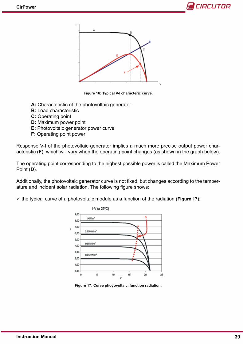
Figure 16: Typical V-I characteric curve�
A: characteristic of the photovoltaic generator B: load characteristic C: operating point D: Maximum power point E: Photovoltaic generator power curve F: operating point power
response V-I of the photovoltaic generator implies a much more precise output power char-acteristic (F), which will vary when the operating point changes (as shown in the graph below).
The operating point corresponding to the highest possible power is called the Maximum Power Point (D).
Additionally, the photovoltaic generator curve is not fixed, but changes according to the temper-ature and incident solar radiation. The following figure shows:
the typical curve of a photovoltaic module as a function of the radiation (Figure 17):
Figure 17: Curve phoyovoltaic, function radiation�
39Instruction Manual
CirPower

the typical curve of a photovoltaic module as a function of the temperature (Figure 18);
Figure 18: Curve phoyovoltaic, function temperature�
The evolution of the maximum power point (G) is also shown on the curves.
Therefore, the purpose of the maximum power tracking algorithm (Maximum Point Power Track-er) is to vary the device’s load resistance to ensure the constant functioning of the photovoltaic system (panel + inverter) in the highest possible point of power; in this way the maximum level of power will be delivered to the power distribution grid.
In automatic mode, the inverter constantly tracks the maximum power point
The device can also be operated in Manual mode, during which the user determines a fixed operating point. obviously, the maximum level of power efficiency for the installation is not achieved in this mode; for this reason, manual operation must only be used as a method of checking the device by trained technical personnel.
3.5.- MAsTer & slAVe oPerATIon
Note : available only for CirPower-500TL-M, CirPower-660TL-M, CirPower-760TL-M @380V output)
Master & slave is a logic of operation available on some of the inverters ‘M’ type. It consists in a control mode performed by the dsP control, that, upon the availability of dc power at the input, enables only one or both power modules for operation. This logic allows achieving higher efficiencies at low power levels, because, below the 50% of the overall power of the inverter (sum of the rated power of the two modules composing it), one of the two modules (the ‘slave’) is turned-off, so that the other one (the ‘Master’) operates at a higher power level, where its ef-ficiency is higher. Therefore, the conversion efficiency of the system benefit of this logic. When the input power gets higher than 45% of the overall inverter rated power (90% of the single module), the ‘slave’ is turned-on back again, to help the ‘Master’ sharing the generation.
40
CirPower
Instruction Manual

4�- INVERTER OPERATION
4.1.- InVerTer conTrol PAnel
The control panel is made up of a monochromatic “touch screen” display and a led signalling panel showing the generated power.
The “touch screen” display acts both as viewer and as an interface to input or change the ma-chine parameters.
Figure 19: Inverter control panel�
The led lights mean as follows:
ALARM it lights up when the machine has stopped because an alarm/a protection has activated
OFF: it lights up when the machine is in the “disabled inverter status”
ON: It lights up when the inverter switches to the operating status energising the power grid (“inverter generating power” status)
ON and OFF flashing alternatively: it happens during the first start up and in the “en-abled inverter” status as well as after an error has been detected, immediately before closing the contactor and starting the generation process
LED power bar the amount of lit up leds is proportional to the instant power percent-age delivered to the grid
4.2.- quIck sTArT
To start the inverter:
The input dc and output Ac cables must be properly connected.
The ePo contacts (terminal contacts 13-14) and eXTernAl sTArT InVerTer must be closed (terminal contacts 11-12). As a default setting, both these contacts are short-circuited by the manufacturer.
closing the alternate current switch, voltage is fed to the control logic, the touch screen lights up showing a welcome screen and an acoustic “beep” is emitted.
Immediately after the welcome message, the main screen appears:
41Instruction Manual
CirPower

Figure 20: Main screen�
The top two lines show status messages and any alarm conditions in rotation. Immediately after the controller has been powered on under suitable grid and voltage conditions, the sequence of messages to appear is as follows:
• Inverter disabled • remote switch open • Mains voltage ok • Mains frequency ok
If you press the ON key on the “touch screen” and confirm by pressing the ENTER key as dis-played in the following screenshot, the inverter will switch to “enabled inverter” mode while the ON and OFF leds will flash alternately.
Figure 21:Confirm screen.
under this condition, the following messages can appear on the display:
• Inverter enabled • remote switch open • Mains voltage ok • Mains frequency ok
The inverter waits for the grid parameters (voltage and frequency) to come into the pre-estab-lished range for at least 5 minutes, after which the generation of grid power can begin.
At this point the ON led stays lit. The messages shown on the display are as follows:
42
CirPower
Instruction Manual

•‘Inverter generating’ •“remote switch closed” •“Mains voltage ok” •“Mains frequency” ok
The default inverter operating mode is AUTOMATIC, i.e. with maximum power point tracking enabled.
during standard operation, if the photovoltaic field voltage drops below the minimum level (see “7.- TECHNICAL FEATURES”) or the available power from the power grid is below a given threshold (1,5% of the rated input power), the inverter switches to “Inverter enabled” mode and starts a 6-minute countdown.
The sequence of the messages displayed is as follows:
•“Inverter enabled” •“remote switch open” •“Mains voltage ok” •“Mains frequency” ok •“Insufficient radiation”
When the countdown is over, if the mains and cell voltage conditions are correct, the inverter starts up again, closes the contactor and resumes the power generation to grid.If the electrical grid is not suitable (voltage or frequency outside specification), the inverter re-mains in “inverter enabled” status, the ON and OFF leds flash alternatively and the sequence of messages displayed is as follows:
•“Inverter enabled” •“remote switch open” •“Mains frequency outside specification” or “Mains voltage outside specification”
When correct conditions of the power grid are restored, the inverter starts up again, closes the contactor and resumes the power generation to grid.
To disable the inverter, all that is needed is to press OFF without having to confirm the com-mand with other buttons. confirmation of switching off the inverter is given by the yellow OFF led that stays lit.
users should take note of the fact that under such conditions, the inverter does noT generate electricity and this condition should only be employed for maintenance work.
43Instruction Manual
CirPower

4.3.- ToucH screen dIsPlAy
4�3�1�- INTRODUCTION
The following picture shows the touch screen main window, displayed immediately after the control system is energized.
Inverter status, alarms and inverter
Levels display (2 lines)
Keyboard
Figure 22: Touch screen main windows�
every screen display is subdivided into three sections as shown in the diagram:
section for status messages, alarms, inverter protection section for measurement values section for keyboard
The messages are shown in rotation in all the screens at about one message a second. The status of the inverter (see “4.5.- STATUS, ALARMS AND INvERTER PROTECTION”) is shown in this section along with any alarm or active protection messages.
The levels, subdivided into Ac and dc, are always shown in the format:
secondary display (lower case, first line) MAIn dIsPlAy (upper case, second line)The section relating to buttons varies in line with the selection made by the user.
The combination of buttons present depends on the screen being shown. For safety purposes, the only key present on all the screens is the OFF button.
The touch screen fades after not being used for 3 minutes� If you touch the panel again, the display lighting is restored�
44
CirPower
Instruction Manual
4�3�2�- NAVIGATION DISPLAY
To navigate around the display, just touch the screen in the designated areas.The touch functions on the main screen are as follows:
Table 10: Touch
key Touch
Arrow buttons: to scroll through all active status/alarm messages
Level access button: give you access to the measurements screen.
Menu set-up access button: give you access to the set-up menu.
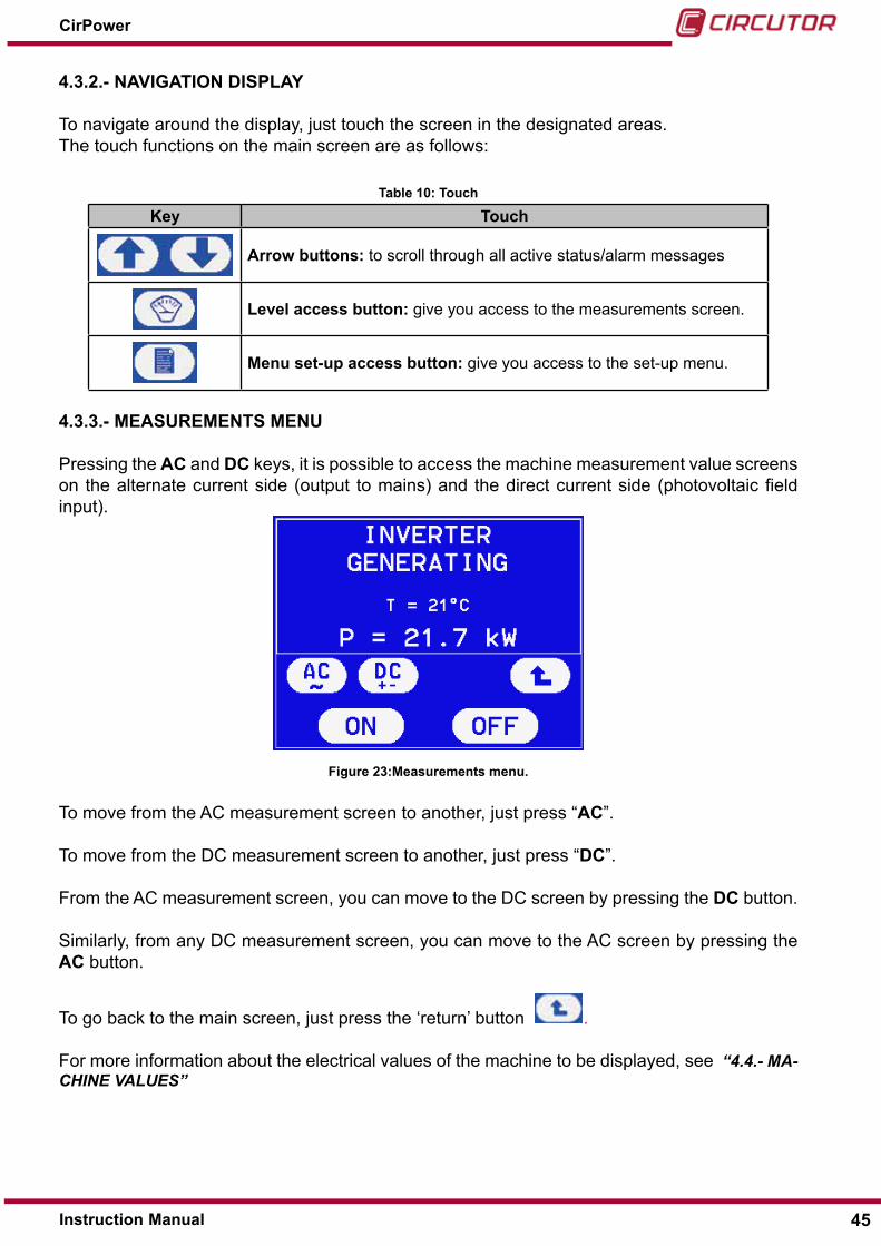
4�3�3�- MEASUREMENTS MENU
Pressing the AC and DC keys, it is possible to access the machine measurement value screens on the alternate current side (output to mains) and the direct current side (photovoltaic field input).
Figure 23:Measurements menu�
To move from the Ac measurement screen to another, just press “AC”.
To move from the dc measurement screen to another, just press “DC”.
From the Ac measurement screen, you can move to the dc screen by pressing the DC button.
similarly, from any dc measurement screen, you can move to the Ac screen by pressing the AC button.
To go back to the main screen, just press the ‘return’ button .
For more information about the electrical values of the machine to be displayed, see “4.4.- MA-CHINE vALUES”
45Instruction Manual
CirPower
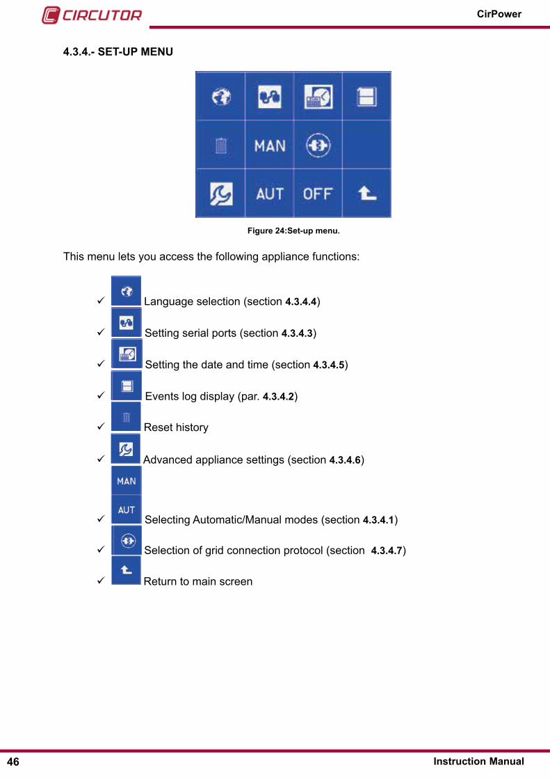
4�3�4�- SET-UP MENU
Figure 24:Set-up menu�
This menu lets you access the following appliance functions:
language selection (section 4�3�4�4)
setting serial ports (section 4�3�4�3)
setting the date and time (section 4�3�4�5)
events log display (par. 4�3�4�2)
reset history
Advanced appliance settings (section 4�3�4�6)
selecting Automatic/Manual modes (section 4�3�4�1)
selection of grid connection protocol (section 4�3�4�7)
return to main screen
46
CirPower
Instruction Manual

4�3�4�1�- Selecting AUTOMATIC/MANUAL modes
To select MANUAL or AUTOMATIC mode, use the AUT/MAN buttons.
The following screen will appear to let you confirm your choice of AUT or MAN:
Figure 25:Confirm screen.Press the white button to confirm.
After selecting AUTOMATIC mode, the main screen will appear. In this operating mode, using the maximum power point tracker (MPPT) system, the inverter will maximises the quantity of power taken from the photovoltaic field.
If you select the MANUAL mode, the maximum power point tracker algorithm is disabled and you may set the desired power level (according to actual radiation condition). For this reason, MAN mode should only be used by qualified personnel for diagnostic purposes.
In this case, the following screen appears:
Figure 26:Manual screen�
using the arrow keys , you can change the delivered power (the arrow direction shows the increase or decrease of power).
To disable MANUAL mode and to return to AUTOMATIC, just press the “return” button .
The set-up menu will then appear. selecting AUT restores AUTOMATIC mode.
47Instruction Manual
CirPower

To return to the main screen from the set-up menu, press the ‘return’ button .
The inverter default setting is in AUTOMATIC�
If you try to select an already active mode, nothing happens
4�3�4�2�- Display and navigation of history
The inverter is fitted with a system that saves events (alarms, malfunctions, protection) to its memory bank. As soon as it occurs, an “event” is saved to a progressive list along with details of time and date it occurred. every record also contains details of the appliance status (Ac and dc measurements).
To access the appliance history section, once you are in the set-up menu (section 4.3.2) :
Press the key with icon . The records list will appear:
Figure 27: history screen�
Back key.
record details access key
Previous record display key
next record display key
each history record has a progressive number (r001 in the diagram) from the date and time that the event took place.
48
CirPower
Instruction Manual

Press the keys to display the different log records (r002, r003, etc).
If you press the key, you access the record details, i.e. all the information regarding device operations stored when the event occurred.
Figure 28: Record details�
The diagram shows one of the conditions applicable to alarm r001 dated 7 november 2008 (‘Inverter desaturation’).
The other indications scroll automatically in the first two lines of the display.
If you press the keys, you enter the machine measurement values which were stored when the event occurred.
For a more detailed description of the electrical measurements that the appliance can display, see section 4.4.
If you press , the status message of the inverter is displayed, including the message re-garding the originating alarm/error of the record (“Inverter desaturation” in this example).
Press , to go back to the record list display, from which you can return to the main
window by pressing , twice.
49Instruction Manual
CirPower
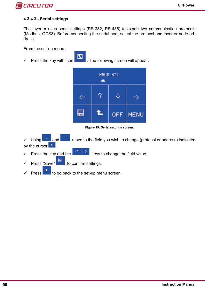
4�3�4�3�- Serial settings
The inverter uses serial settings (rs-232, rs-485) to export two communication protocols (Modbus, ocs3). Before connecting the serial port, select the protocol and inverter node ad-dress.
From the set-up menu:
Press the key with icon . The following screen will appear:
Figure 29: Serial settings screen�
using and move to the field you wish to change (protocol or address) indicated by the cursor .
Press the key and the keys to change the field value.
Press “save” to confirm settings.
Press to go back to the set-up menu screen.
50
CirPower
Instruction Manual

4�3�4�4�- Language selection
Messages can be displayed in the following languages: Italian (default), English, German, Spanish and French. To set the language from the set-up menu:
Press the key with icon . The following screen appears:
ALE
FRA
Figure 30:Language selection screen�
Press the icon of the language you want to select.
Press “save” to confirm settings.
Press to go back to the set-up menu screen. 4�3�4�5�- Date and time settings
To set the date and time from the set-up menu:
Press the key with icon . The following screen will appear:
Figure 31:Date and time screen�
using and move to the field you wish to change (date or time) indicated by the cursor .
Press the key and the keys to change the field value.
51Instruction Manual
CirPower
Press “save” to confirm settings.
Press to go back to the set-up menu screen.
4�3�4�6�- Advanced machine settings
some inverter operating parameters are password protected but can be edited to enable/set up particular features, by entering the value of an accessible parameter through the relevant address.
Parameters can be edited with the machine in a DISABLED status, following the procedure described as follows�
ThIS MANUAL CONTAINS ALL AND ONLY ThE PARAMETERS ACCESSIBLE TO ThE USER, wITh ThE RELATIVE ADMITTED VALUES; A VALUE ThAT IS NOT PROVIDED FOR CAN COMPROMISE CONVERTER OPERATIONS�
From the set-up menu:
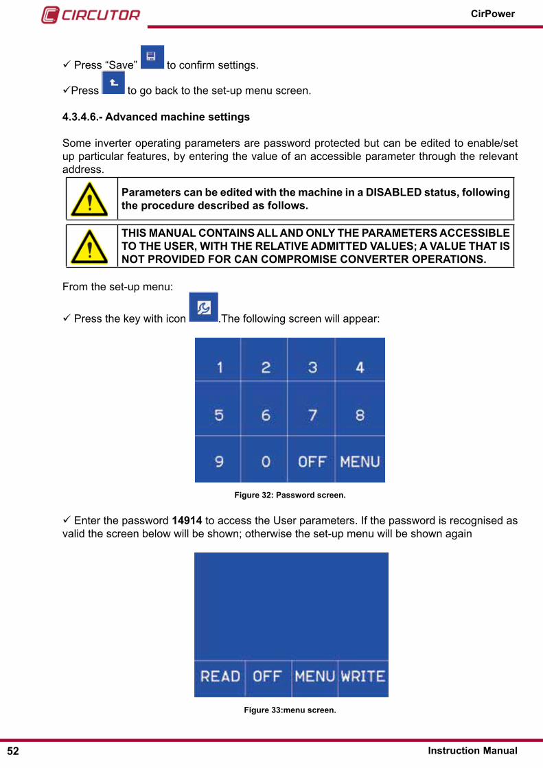
Press the key with icon .The following screen will appear:
Figure 32: Password screen�
enter the password 14914 to access the user parameters. If the password is recognised as valid the screen below will be shown; otherwise the set-up menu will be shown again
Figure 33:menu screen�
52
CirPower
Instruction Manual

Reading parameters
Press the READ key to open the menu to read parameters.
Figure 34: Menu read parameters
Proceed as follows:
Press Ok to enter the address of the parameter of the value you wish to read.
Press to return to the previous menu (by pressing the MENU key you return to the set-up menu, or press OFF to immediately turn off the inverter and immediately return to the main screen).
A numerical keyboard will appear; set up the address always using four digits. If the value of the address is less than 1000, enter a sufficient number of zeroes before it to have four digits (Example: address 99 is entered as 0099).
on pressing the fourth digit a confirmation screen will appear with the address just entered. If its value is correct press Ok to confirm.The display shows the value of the selected parameter.
Figure 35:Value od the selected parameter�
The Value field represents the value of the parameter in the “a byte” format (in the example illustration the byte with the address 1239 has the value 1), while the field word Value is the value in the “a word” format (in the example the word formed from byte 1239 and 1240 has the total value of 260).
53Instruction Manual
CirPower
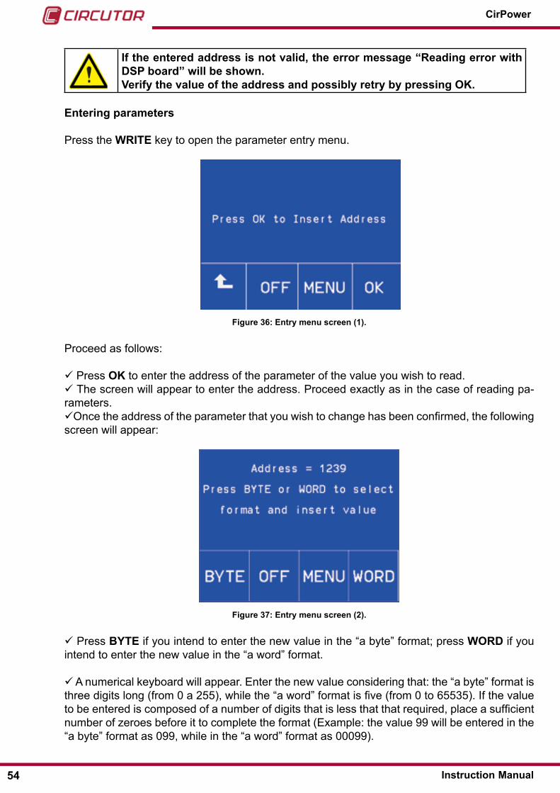
If the entered address is not valid, the error message “Reading error with DSP board” will be shown�Verify the value of the address and possibly retry by pressing Ok�
Entering parameters
Press the wRITE key to open the parameter entry menu.
Figure 36: Entry menu screen (1)�
Proceed as follows:
Press Ok to enter the address of the parameter of the value you wish to read. The screen will appear to enter the address. Proceed exactly as in the case of reading pa-rameters.once the address of the parameter that you wish to change has been confirmed, the following screen will appear:
Figure 37: Entry menu screen (2)�
Press BYTE if you intend to enter the new value in the “a byte” format; press wORD if you intend to enter the new value in the “a word” format.
A numerical keyboard will appear. enter the new value considering that: the “a byte” format is three digits long (from 0 a 255), while the “a word” format is five (from 0 to 65535). If the value to be entered is composed of a number of digits that is less that that required, place a sufficient number of zeroes before it to complete the format (example: the value 99 will be entered in the “a byte” format as 099, while in the “a word” format as 00099).
54
CirPower
Instruction Manual

once the last number has been entered, a confirmation window will appear. Press Ok to confirm the value to be changed.
Figure 38: Entry menu screen (3)�
If the written value is accepted by the inverter, a screen will appear with the word “Wait…” at the end of which the message “done” will be shown for confirmation.
If the value-address is not available to the user, the message “ACCESS DE-NIED� Address Not Available” will be shown, and you will return to the initial wRITE menu screen�
once the writing operation is completed it is possible to choose whether to set a new param-eter, or end the edit phase and save the new machine set-up.
Figure 39: Entry menu screen (4)�
Press Ok to enter a new value.
By pressing OFF to exit the mode you change parameters WITHouT saving the changes. To completely cancel the changes it is necessary to reboot the machine�
Press MENU and then YES to confirm changes and save them in the non-volatile memory.
55Instruction Manual
CirPower

Figure 40: Entry menu screen (5)�
4.3.4.7.- Country-specific grid connection cod selection
In order to select the connection code to the grid, (depending on the country and the utility or network operatior specific regulation).
4.4.- MAcHIne VAlues
The appliance measurements displayed are summarised in the following table:
Table 11:Machine values�
Acronym Measurement Units AD/DC Display(1)
Vrs rs linked voltage V (rms) Ac sVst sT linked voltage V (rms) Ac sVtr Tr linked voltage V (rms) Ac sIr r Phase current A (rms) Ac sIs s Phase current A (rms) Ac sIt T Phase current A (rms) Ac sP Active power kW Ac Pq reactive power kVA Ac P
cos phi Power factor Ac sTamb Ambient temperature °c s
energy energy produced kWh/MWh Ac PHours running hours h Ac sVcel cell voltage V dc sIcel cell current A dc sPcel cell power kW dc PIrry Vertical radiation W/sq mt dc sTcel cell temperature °c dc sRiso Isolation resistance kΩ dc s
(1) P: Principal display, S: secondary display.
As previously explained in section 4.3.3, press to view the alternate current value dis-
56
CirPower
Instruction Manual

play (Ac); to view the direct current value display press .
The measurements are always shown in the ‘main display” format (upper case letters, second line) –secondary display (lower case letters, first line).
4.5.- sTATus, AlArMs And InVerTer ProTecTIon
4�5�1�- DETAILS ABOUT STATUS AND OPERATING CONDITIONS
The inverter features three operating conditions:
Inverterdisabled
Inverterenabled
Invertergenerating
Figure 41: Operating conditions�
The status of the inverter is shown in the two rows at the top of each window.
Inverter disabled
The inverter is still (“OFF” led lit up). PWM impulses are off and the inverter is offline. The inverter is in this status:
As soon as logic control is turned on for the first time. After pressing the oFF key. After the ePo triggers. After appliance protections repeatedly trigger. To enable the inverter, press the on key and confirm on the display.
Inverter enabled
In these conditions the inverter is always offline (contact open) and does not generate power although PWM impulses to the bridge can be on. once in this condition, the controller checks:
For the presence of network synchronism in the voltage and frequency acceptance interval.
For cell voltage (and, eventually, solar radiation) in the acceptance interval. For protections off (the countdown triggered by a protection has elapsed). The contact “eXTernAl sTArT InVerTer”(terminals 11-12) is closed.
57Instruction Manual
CirPower

If all these conditions are met, the inverter releases PWM impulses and accelerates the voltage ramp output to the bridge.
In these conditions, the ON and OFF leds blink alternatively.
When output voltage reaches a set value, the control closes the contact and switches to ‘invert-er in generation’ conditions.
Inverter generating
In these conditions, the inverter is online (contact closed) and generates power (‘ON’ led on). If one of the following events occurs during operations:
radiation conditions are not enough to keep the inverter operating (cell voltage or input power below the respective threshold, see par. 4.5.2), or the voltage and mains synchro-nism values are not in the allowable range (see par. 4.5.2), or
If a machine protection triggers (other than ePo),the contact is opened, PWM impulses are immediately turned off, a countdown starts (depending on the type of protection triggered) and the inverter returns to ‘inverter on’ conditions.If the ePo triggers, the inverter switches to ‘inverter disabled’.If a protection triggers, the ‘ALARM’ led turns on and beeps.
If you press the OFF button, no matter what the condition is, the inverter immedi-ately switches to the “disabled inverter” status.
If a protection triggers, the ‘ALARM’ led turns on and beep sounds. Touching any button on the touch screen silences the beep.
The triggering of a protection causes the inverter to disconnect from the mains and the immediate cancellation of impulses. The inverter is programmed to start again after the activation of a protection (with the exception of ePo), after a spe-cific countdown is over (the amount of the countdown depends on the protection type). The continuous triggering of a protection is however a sign of a “serious” appliance malfunction. For this reason, if the protection activity occurs fairly fre-quently and lasts a long time, the controller can decide not to restart the inverter. In this event, the controller will change the status from ‘inverter generating’ to ‘inverter disabled’ until specialised technical assistance from CIRCUTOR is pro-vided.EPO: if the ePo activates the inverter switches to the “disabled inverter” status. The protection system is restored by reclosing the ePo switch. To re-enable the inverter, press the ON button on the keyboard then confirm.
Below is a table with detailed descriptions of appliance statuses and of events that activate various changes of status.
58
CirPower
Instruction Manual

The input “External start inverter” functions as a go-ahead signal to start the inverter� If the inverter has already been started and stopped by a con-tact opening, on the re-closure of the contact “External start inverter”, the inverter will immediate restart�
Table 12:Current status�
Currentstatus
Previousstatus Event Subsequent
statusGraphic charge Actions
Inve
rter
di
sabl
ed Any Press button on+confirm Inverter enabled A •PWM pulses off
•switch openInverter generating
ePo closes, press button on+confirm
Inverter enabled
Inve
rter
ena
bled
Any
oFF button pressed Inverter disabled e
•PWM pulses off•switch open
10 sec countdown expired with closed “eXTernAl sTArT InVerTer” contact
Inverter generating B
•PWM pulses on•switch open•Voltage ramp
Inverter generating
Minimum radiation 6-minute countdown expired
Inverter generating B
• PWM pulses on• switch open•Voltage ramp
grid parameters verified in the range of acceptance10-second countdown for de-saturation protection has ex-pired10 sec countdown time passed for maximum currentInverter module temperature reset below 75°c
59Instruction Manual
CirPower

Table 12 (Continuation): Current status�
Currentstatus
Previousstatus Event Subsequent
statusGraphic charge Actions
Inve
rter
gen
erat
ing
Inverter enabled - - -
•PWM pulses on•closed contactor•generation of power in the grid
Any oFF button pressed Inverter disabled c -
Inverter generating
Insufficient irradiation
Inverter enabled c
6-minute countdown start
grid parameters (voltage and frequency) outside of the limits
Awaiting re-entry into the range of acceptance
desaturation protection trigge-red
•10-secondcountdown starts.•AlArM led lights up on con-trol panel•Beep sounds
Protection is activated against maximum current
•AlArM led lights up on con-trol panel•Beep sounds
Protection is activated against inverter overtemperature
Any
IMPulse enABlIng contact opens
Inverter enabled c 10-second
countdown starts.
ePo contact opens Inverter disa-bled d
•AlArM led lights up on con-trol panel•Beep sounds
4�5�2�- FAULTS, ALARMS AND PROTECTIONS
The events that can occur during inverter operation can be subdivided into:
Faults
These are events that occur outside the appliance that affect normal operating mode and the appliance to temporarily stop working (transition from ‘inverter generating’ to ‘inverter enabled’ and the start of a countdown).
Alarms
events signalling an incorrect operating condition, which do not jeopardize the proper operation of the inverter.
Protection devices
These are events that indicate a ‘serious’ fault in the appliance and cause the appliance to
60
CirPower
Instruction Manual
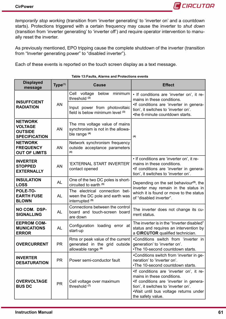
temporarily stop working (transition from ‘inverter generating’ to ‘inverter on’ and a countdown starts). Protections triggered with a certain frequency may cause the inverter to shut down (transition from ‘inverter generating’ to ‘inverter off’) and require operator intervention to manu-ally reset the inverter.
As previously mentioned, ePo tripping cause the complete shutdown of the inverter (transition from “Inverter generating power” to “disabled inverter”).
each of these events is reported on the touch screen display as a text message.
Table 13:Faults, Alarms and Protections events
Displayed message Type(1) Cause Effect
INSUFFCIENT RADIATION An
cell voltage below minimum threshold (2)
• If conditions are ‘inverter on’, it re-mains in these conditions.•If conditions are ‘inverter in genera-tion’, it switches to ‘inverter on’.•the 6-minute countdown starts.
Input power from photovoltaic field is below minimum level (3)
NETwORk VOLTAGE OUTSIDE SPECIFICATION
AnThe rms voltage value of mains synchronism is not in the allowa-ble range (4)
(4)
NETwORk FREQUENCY OUT OF LIMITS
Annetwork synchronism frequency outside acceptance parameters (4)
INVERTER STOPPED ExTERNALLY
An ‘eXTernAl sTArT InVerTer’ contact opened
• If conditions are ‘inverter on’, it re-mains in these conditions.•If conditions are ‘inverter in genera-tion’, it switches to ‘inverter on’.
INSULATION LOSS Al one of the two dc poles is short-
circuited to earth (5) depending on the set behaviour(5), the inverter may remain in the status in which it is found or move to the status of “disabled inverter”.
POLE-TO-EARTh FUSE BLOwN
AlThe electrical connection bet-ween the dc pole and earth was interrupted (5)
NO COM� DSP-SIGNALLING Al
connections between the control board and touch-screen board are down
The inverter does not change its cu-rrent status.
EEPROM COM-MUNICATIONS ERROR
Al configuration loading error at start-up
The inverter is in the “Inverter disabled” status and requires an intervention by a CIRCUTOR qualified technician.
OVERCURRENT Prrms or peak value of the current generated in the grid outside allowable range (6)
•conditions switch from ‘inverter in generation’ to ‘inverter on’.•The 10-second countdown starts.
INVERTER DESATURATION Pr Power semi-conductor fault
•conditions switch from ‘inverter in ge-neration’ to ‘inverter on’.•The 10-second countdown starts.
OVERVOLTAGEBUS DC Pr cell voltage over maximum
threshold (7)
•If conditions are ‘inverter on’, it re-mains in these conditions.•If conditions are ‘inverter in genera-tion’, it switches to ‘inverter on’.•Wait until bus voltage returns under the safety value.
61Instruction Manual
CirPower

Table 13 (Continuation) : Faults, Alarms and Protections events
Displayed message Type(1) Cause Effect
INVERTER OVER TEMPERATURE
Pr Inverter heat sink above 80°c (8).•conditions switch from ‘inverter in generation’ to ‘inverter on’.•The 10-second countdown starts.
EPO TRIGGERED Pr ePo switch opened conditions switch to ‘inverter off’.
AC CONTACTOR FAULT Pr Ac contactor fault
The inverter is in the “Inverter disabled” status and requires an intervention by a CIRCUTOR qualified technician.
AC CONTACTOR A FAULT Pr Ac contactor A fault (9)
The inverter is in the “Inverter disabled” status and requires an intervention by a CIRCUTOR qualified technician.
AC CONTACTOR B FAULT Pr Ac contactor B fault (9)
The inverter is in the “Inverter disabled” status and requires an intervention by a CIRCUTOR qualified technician.
UNBALANCE CURRENT Pr unbalance current between
module A and module B (9)
The inverter is in the “Inverter disabled” status and requires an intervention by a CIRCUTOR qualified technician.
(1) Type of events: AN:Fault, AL:Alarm, PR:Protection.
(2) Minimum cell voltage: see the tables shown in chapter “7.- TECHNICAL FEATURES”
(3) Minimum power: 1,5% of nominal power (at dc side input).
(4) Behaviour complies with the requirements of the ceI-021 regulations and the attachment A70, regarding “voltage dips and frequency variations”, as approved by resolution Aeeg/84/2012/r/enel, Art.4, paragraph 1.
(5) The inverter is equipped with the control of the isolation of the dc side. The same device also permits the detection of the opening of the fuse of the earthing pole, if panels that provide for it are inserted. The two features are complementary. As a default, the inverter measures the insulation resistance with the activation of an alarm if the measurement is less than a set value. should the earthing pole control feature be implemented, contact the CIRCUTOR sPA customer support service. It is possible to choose whether the insulation defect or the operation of the fuse of the earthing pole must only give an alarm or stop the inverter (Protection), also in this case it will be necessary to contact the CIRCUTOR sPA customer support service. The implementations described in the above lines can also be carried out in the factory if requested in the ordering phase.
(6)The intervention threshold of the maximum current protection is equal to 200% of the rms val-ue of the rated inverter current (see the tables reported in chapter “7.-TECHNICAL FEATURES”).
(7) The maximum voltage protection system cuts in when dc Bus voltage exceeds the value shown in the ‘Technical data’ tables in chapter “7.- TECHNICAL FEATURES” . The protection is reset if the direct voltage drops below the safety value (90% of maximum voltage).
(8) contactor A, contactor B and unbalance current faults only concern inverters with dual mod-ule and single control ( CirPower TLh 440 … 833 ), which are equipped with two different Ac contactors, one per power module.
62
CirPower
Instruction Manual

4�5�3�- POwER DERATING AS A FUNCTION OF POwER MODULE TEMPERATURE
The control cPu of the inverter,automatically performs a power limitation, depending on the measured value of the temperature of the inverter power module, according to following logic:
From 0 to 75°c: Max generated power = rated power (data reported on the inverter technical plate)
From 75°c to 80°c: Max generated power = 75% of rated power. From 80°c to 90°c: Max generated power = 50% of rated power. Above 90°c: over-temperature protection trip.
Figure 42: Power module temperature�
4.6.- IdenTIFIcATIon oF code reVIsIon FIrMWAre InsTAlled on solAr
From the main screen of the display of the machine, press the Menu key to access the corre-sponding page.
Figure 43: Press the Menu key�
63Instruction Manual
CirPower

Access the Advanced setup menu by pressing the key on.
Figure 44:Press the Advanced seup key�
enter the code number 13578.
Figure 45:Enter the code number�
go to the screen firmware revision code of the machine using the appropriate button.
Figure 46: Press the ? key
using the arrow keys, scroll the display to the dsP BoArd to read the regulation firmware version installed in the inverter.
64
CirPower
Instruction Manual

Figure 47:DSP board screen
For the converter construction date, the firmware identification code can be viewed in one of the following formats:
MCxxxx � yy � zz for example Mc0162.00.01MCxxxx yy REV zz for example Mc010900 reV 24
For all display formats, the field must be interpreted in accord to the following table:
Table 14:FIeld�
Field Meaning
MCxxxxIdentification code of the firmware.Mc0109 Identification code for CirPower invertersMc0162 Identification code for new generation CirPower inverters
yy Major revision code, indicates changes with the addition of new features
zzMinor revision code, indicates changes related to bugfix and anomaliesFirmware with different minor revision code, from the point of view of func-tionality for Network Services are equivalent
65Instruction Manual
CirPower
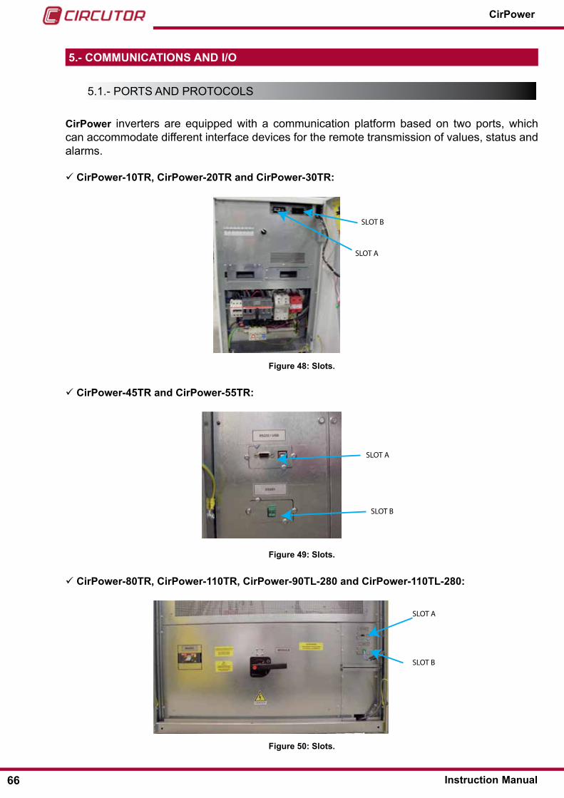
5�- COMMUNICATIONS AND I/O
5.1.- PorTs And ProTocols
CirPower inverters are equipped with a communication platform based on two ports, which can accommodate different interface devices for the remote transmission of values, status and alarms.
CirPower-10TR, CirPower-20TR and CirPower-30TR:
SLOT B
SLOT A
Figure 48: Slots�
CirPower-45TR and CirPower-55TR:
SLOT B
SLOT A
Figure 49: Slots�
CirPower-80TR, CirPower-110TR, CirPower-90TL-280 and CirPower-110TL-280:
SLOT A
SLOT B
Figure 50: Slots�
66
CirPower
Instruction Manual

CirPower-250TR, CirPower-220���416TL:
SLOT A
SLOT B
Figure 51: Slots�
CirPower-440���833TL:
SLOT A1
SLOT B1
SLOT A2
SLOT B2
Figure 52: Slots�
CirPower-440���833TL-M:
SLOT A
SLOT B
Figure 53: Slots�
each of the slots supports differing types of peripherals and communication protocols as can be seen in the following table:
67Instruction Manual
CirPower

Table 15:Card
Card Slot A Slot Brs-232/usB ocs3 protocol ocs3 and Modbus protocolsrs-485 not available ocs3 and Modbus protocolsFibre optic interface (optional) ocs3 protocol ocs3 and Modbus protocolsnetwork adapter (optional) snMP protocol snMP protocol
By default, the appliance is fitted with an rs-232/usB interface board (type B) for point-to-point type connections and with an rs-485 interface board for field bus connections.
To replace one type of board with another, you need to:
• set the communication protocol parameters by touch as explained in section 4�3�4�3�- Serial settings
• unscrew the nuts (1 to 4) as shown in the picture and remove the metal cover.
• remove the card (an empty slot appears as shown in the right section of the picture) and in-sert the new card pushing it until you notice a resistance.
• replace the metal cover (supplied with the board) then refit the four nuts.
• Plug the communications cable into the board connector.
Metal cover Figure 54: Board connectors�
A board can be replaced even while the inverter is running.For more information about other cards (not rs-232 and rs-485) and about communication protocol, contact CIRCUTOR commercial office.
68
CirPower
Instruction Manual

5.2.-coMMunIcATIon BoArds
5�2�1�- RS-232/USB SERIAL INTERFACE CARD
Figure 55:RS-232/USB serial interface card�
The use of this board is combined with point-to-point communication software for Pc ocsys-tem MdB that integrates display functionality, event recording (alarms, faults, protection sys-tems) and graphics of the main appliance measurements.
The installation of a dedicated communication driver is required in order to use the usB port for interfacing with this software (the driver is included in the ocsystem MdB software package).
5�2�2�- SERIAL RS-485 INTERFACE BOARD
Data + Data -
Figure 56:RS-485 serial interface board�
This board allows you to connect the inverter to a rs-485 field bus serial with the Modbus pro-tocol. The connection of each inverter to the rs-485 bus must take place according to a “chain” type (avoiding “star” connections).
69Instruction Manual
CirPower

5�2�3�- CONCENTRATOR CARD FOR CSP12 SMART STRING BOxES
each inverter is equipped with a card which ensures interfacing with up to 8 csP12 string mon-itoring boxes, by means of either datalogger or Tgs monitoring system.
This card can communicate with the csP boxes (up to 8) through a dedicated serial port (termi-nals 25-26 on terminal board, see par. 0). It collects data from the csP boxes and make them available on an “auxiliary” rs-485 (terminals 27-28 on terminal board) to which the datalogger for csP is connected.
The csPs are interconnected by means of a “cascade” .
5.3.- suPerVIsIon PlATForMs
5�3�1 PLATFORM BASED ON SNMP CARD
Gateway
LAN
WEB
Figure 57:Platform based on SNMP card�
This configuration allows the inverter to be connected to an existing lAn network with an snMP slot adapter that is available as accessory (see “6.- ACCESSORIES (OPTIONAL)”). Insert the snMP card in one of the slots (A or B) replacing one of two default cards (rs232 or rs485). consult “5.- COMMUNICATIONS AND I/O” for details regarding the installation of the card.
This adapter allows to monitor the basic values and status of the inverter in the network using a simple web browser (Ms explorer, Mozilla Firefox, etc.).
This board acts as a web server using the snMP network protocol, incorporates remote ac-cess functions (telnet and ftp) and also lets you send messages to configurable addresses to remotely signal possible alarms, faults or appliance protection system interventions.
once the suitable driver (included in the software package) has been installed, it also lets you
70
CirPower
Instruction Manual

send trap to a Pc for the purposes of checking configurable events and for the display of pop-up messages on the Pc.
In this configuration, any inverter on the lAn network can be communicated with by means of a unique IP address.
5.4.- TerMInAl BoArd I/o (TerMInAl Block)
The inverter has a terminal block for cables that lets the user:
Acquire detailed digital information about inverter status (volt free). send commands to the inverter (using relays). send analogue signals (voltage 0-5V) to the inverter (measurements or references).
Table 16:Terminal board I/O
CirPower-10TR ��� 30TR CirPower-45TR ��� 55TR
CirPower-80TR ��� 110TRCirPower-90TL-280 ��� 110TL-280
CirPower-250TR CirPower-440TL��� 833TL
71Instruction Manual
CirPower
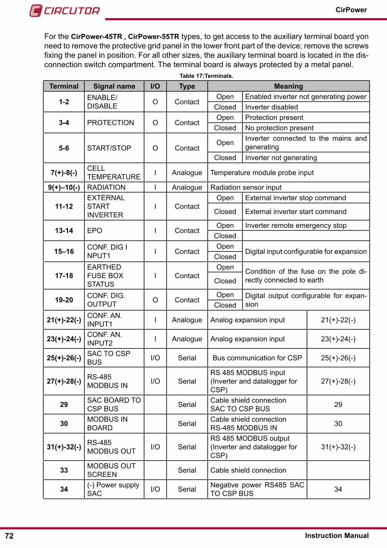
For the CirPower-45TR , CirPower-55TR types, to get access to the auxiliary terminal board yon need to remove the protective grid panel in the lower front part of the device; remove the screws fixing the panel in position. For all other sizes, the auxiliary terminal board is located in the dis-connection switch compartment. The terminal board is always protected by a metal panel.
Table 17:Terminals�
Terminal Signal name I/O Type Meaning
1-2 enABle/dIsABle o contact
open enabled inverter not generating powerclosed Inverter disabled
3-4 ProTecTIon o contactopen Protection present
closed no protection present
5-6 sTArT/sToP o contactopen Inverter connected to the mains and
generatingclosed Inverter not generating
7(+)-8(-) cell TeMPerATure I Analogue Temperature module probe input
9(+)–10(-) rAdIATIon I Analogue radiation sensor input
11-12eXTernAl sTArT InVerTer
I contactopen external inverter stop command
closed external inverter start command
13-14 ePo I contactopen Inverter remote emergency stop
closed
15–16 conF. dIg InPuT1 I contact
opendigital input configurable for expansion
closed
17-18eArTHed Fuse BoX sTATus
I contactopen condition of the fuse on the pole di-
rectly connected to earthclosed
19-20 conF. dIg. ouTPuT o contact
open digital output configurable for expan-sionclosed
21(+)-22(-) conF. An. InPuT1 I Analogue Analog expansion input 21(+)-22(-)
23(+)-24(-) conF. An. InPuT2 I Analogue Analog expansion input 23(+)-24(-)
25(+)-26(-) sAc To csP Bus I/o serial Bus communication for csP 25(+)-26(-)
27(+)-28(-) rs-485 ModBus In I/o serial
rs 485 ModBus input (Inverter and datalogger for csP)
27(+)-28(-)
29 sAc BoArd To csP Bus serial cable shield connection
sAc To csP Bus 29
30 ModBus In BoArd serial cable shield connection
rs-485 ModBus In 30
31(+)-32(-) rs-485 ModBus ouT I/o serial
rs 485 ModBus output (Inverter and datalogger for csP)
31(+)-32(-)
33 ModBus ouT screen serial cable shield connection
34 (-) Power supply sAc I/o serial negative power rs485 sAc
To csP Bus 34
72
CirPower
Instruction Manual
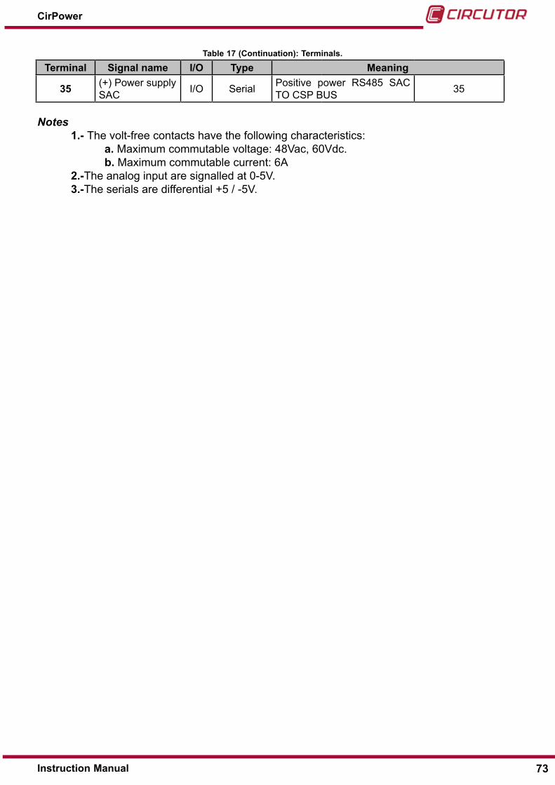
Table 17 (Continuation): Terminals�
Terminal Signal name I/O Type Meaning
35 (+) Power supply sAc I/o serial Positive power rs485 sAc
To csP Bus 35
Notes 1�- The volt-free contacts have the following characteristics: a� Maximum commutable voltage: 48Vac, 60Vdc. b� Maximum commutable current: 6A 2�-The analog input are signalled at 0-5V. 3�-The serials are differential +5 / -5V.
73Instruction Manual
CirPower

6�- ACCESSORIES (OPTIONAL)
only use accessories recommended by the manufacturer. The use of unauthorised accessories may seriously affect how the appliance oper-ates. The use of non-original accessories will result in the warranty be-ing invalidated and will exempt the manufacturer from any responsibility whatsoever for malfunctions and any consequences that might stem from them.
6.1.- FIBre oPTIc serIAl InTerFAce cArd (oPTIonAl)
Figure 58:Fibre optic serial interface card�
This slot card permits communications between Pc and inverter with a fibre optics connection, which is immune to electromagnetic disturbances and is particularly suitable for noisy environ-ment, where signals may be subject to external interference.
This board can be used in both the slots as shown in the following table:Table 18:Card
Card Slot A Slot BFibre optic interface (optional) ocs3 protocol ocs3 and Modbus protocols
A fibre-optic converter/rs232 is also supplied to enable connection to a Pc.
6.2.- neTWork snMP AdAPTer
Figure 59:Network SNMP adapter�
The network adapter board enables direct lAn connection on any individual inverter. To install this card, see “5.- COMMUNICATIONS AND I/O”
74
CirPower
Instruction Manual
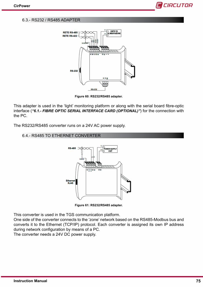
6.3.- rs232 / rs485 AdAPTer
Figure 60: RS232/RS485 adapter�
This adapter is used in the ‘light’ monitoring platform or along with the serial board fibre-optic interface (“6.1.- FIbRE OPTIC SERIAL INTERFACE CARD (OPTIONAL)”) for the connection with the Pc.
The rs232/rs485 converter runs on a 24V Ac power supply.
6.4.- rs485 To eTHerneT conVerTer
Figure 61: RS232/RS485 adapter�
This converter is used in the Tgs communication platform.one side of the converter connects to the ‘zone’ network based on the rs485-Modbus bus and converts it to the ethernet (TcP/IP) protocol. each converter is assigned its own IP address during network configuration by means of a Pc.The converter needs a 24V dc power supply.
75Instruction Manual
CirPower

6.5.-rAdIATIon sensor
An instantaneous radiation sensor is available on request.
The radiation value reading (in W/sq mt) can be viewed on the touch screen display and via Modbus.
The sensor is a 405x355x35mm photovoltaic module and it shall be installed as coplanar as possible to the actual photovoltaic field (same tilt and azimuth angles).
Figure 62: Radiation sensor�
The following table lists the electrical data:
Table 19:Electrical data�
Pmax Imp Vmp Isc Voc15W ±3% 0,85 A 17,7 V 0,92 A 21,6 V
The module shall be connected to terminals 9(Irr+) and 10(Irr-) of the inverter with two 0.5/1.5 sq mm wires (par. 0). The load resistance of the module is setup at factory on the external ma-chine side of terminals 9 and 10 (connect the wires from the parallel module to the resistance).
76
CirPower
Instruction Manual

7�- TEChNICAL FEATURES
The following tables(1) contain the CirPower inverter series technical data:
CirPower-xxx-TR
with isolation transformer
Inverter in compliance with resolution Aeeg 84/2012/r/eel art. 4.1b, and for lV and MV con-nections, with crystalline modules
CirPower-80TR���250TR and CirPower-xxx-TL
with isolation transformer, divided into:
●Inverter in compliance with resolution AEEG 84/2012/R/EEL art� 4�1b, and for lV and MV connections, with crystalline modules
●Inverter in compliance with resolution AEEG 84/2012/R/EEL art� 4�1a, and for lV and MV connections, with amorphous modules (extended dc range)
without isolation transformer
●Inverter in compliance with resolution AEEG 84/2012/R/EEL art� 4�1b, for MV connec-tions, with crystalline modules
●Inverter in compliance with resolution AEEG 84/2012/R/EEL art� 4�1a, for MV connec-tions, with amorphous modules (extended dc range)
Please refer to Notes at the “7.3.-NOTES”, for definitions and conditions in which the technical data are expressed.
(1) The data included in the tables refers to the issue date of this document. CIRCUTOR re-serves the right to change the technical specification at any time.
77Instruction Manual
CirPower

7.1.-cirPower-xxTr
7�1�1�- INVERTER wITh ISOLATION TRANSFORMER7�1�1�1�- Inverter for LV and MV connections for crystalline modules
CirPower-xxTR 10 20 30 45 55DC input side– Recommended power of the modules
Rated 10 kWp 20 kWp 30 kWp 45 kWp 55 kWpMaximum 12,8 kWp 25,3 kWp 37,9 kWp 55,2 kWp 69,0 kWpDC input side– Electrical specifications
Operating voltage range (note 7) 330 – 760 VMPPT voltage (note 7) 330 – 700 VMax� voltage @-10°C 780 V
Min� voltage @+70°C (note 7) 330 VModules max�[A] 33 A 64 A 96 A 140 A 175 AN� DC inputs 1 2N� MPPT inputs 1AC output side
Active power Nominal Pn (note 1) 10 kW 20 kW 30 kW 44 kW 55 kWMaximum power Smax (note 1) 10 kVA 20 kVA 30 kVA 44 kVA 55 kVAConnection 3PhNominal voltage 400 VRated current (note 2) 14.4 A 28.9 A 43.3 A 63.5 A 79.4 AMaximum current (note 3) 16.0 A 32.1 A 48.1 A 70.6 A 88.2 AMin Smax operating voltage (note 4) 90% VnMin operating voltage (note 4) 85% VnMaximum operating voltage 115% VnNominal frequency 50 Hz or 60 HzFrequency interval (note 5) Adjustable (47,5 Hz to 51,5 Hz) or (55.5 Hz to 62.5 Hz)Max. efficiency (note 6) 93 % 94.2 % 94.5 % 95.1 % 95.1 %Euro efficiency (note 6) 92 % 92.7 % 93.1 % 93.7 % 93.7 %ThD% I @Pnom 3Power factor (note 1) 0.9 … 1.0 leading-laggingShort circuit current contribution 21.7 A 43.4 A 65.0 A 95.3 A 119.1 AOther data
Ventilation system Forced airDissipated power without load 32 WControl dsPOutput wave form Pure sine waveOperating temperature (full power) -20ºc / +50ºcOperating temperature range -20°c / +50°c
78
CirPower
Instruction Manual

CirPower-xxTR 10 20 30 45 55Storage temperature range -25°c / +70°cOperating humidity range 5%/95% no condensingMaximum altitude 1.000 m a.s.l.Environment category Indoor non conditionedPollution Degree Pd3 Overvoltage category (DC input) class IIOvervoltage class (output AC) class IIIMechanical characteristics
dBA 60Class of protection IP20Dimensions LxDxh 550x850x1055 mm 700x865x141 mmweight 280 kg 330 kg 420 kg 560 kg 580 kg
7.2.-cirPower-xxxTr And cirPower-xxxTl
7�2�1�- INVERTER wITh ISOLATION TRANSFORMER7�2�1�1�- Inverter for LV and MV connections
CirPower-xxxTR 80 110 250(*)
DC input side– Recommended power of the modules
Rated 80 kWp 110 kWp 250 kWpMaximum 99,4 kWp 136,6 kWp 307,0 kWpDC input side– Electrical specifications
Operating voltage range (note 7) 460 - 930 VMPPT voltage (note 7) 460 - 780 VMax� voltage @-10°C 1000 V
Min� voltage @+70°C (note 7) 460 VModules max� 181 A 249 A 559 AN� DC inputs 8N� MPPT inputs 1AC output side
Active power Nominal Pn (note 1) 80 kW 111 kW 250 kWMaximum power Smax (note 1) 80 kVA 111 kVA 250 kVAConnection 3Ph
Nominal voltage 400 VRated current (note 2) 115.5 A 160.2 A 360.8 AMaximum current (note 3) 128.3 A 178.0 A 400.9 AMin Smax operating voltage (note 4) 90% VnMin operating voltage (note 4) 85% VnMaximum operating voltage 115% VnNominal frequency 50 Hz or 60 Hz
79Instruction Manual
CirPower
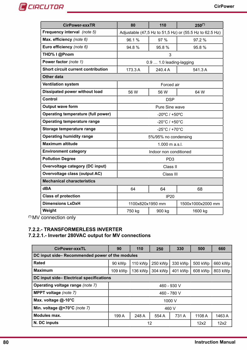
CirPower-xxxTR 80 110 250(*)
Frequency interval (note 5) Adjustable (47,5 Hz to 51,5 Hz) or (55.5 Hz to 62.5 Hz)Max. efficiency (note 6) 96.1 % 97 % 97.2 %Euro efficiency (note 6) 94.8 % 95.8 % 95.8 %ThD% I @Pnom 3Power factor (note 1) 0.9 … 1.0 leading-laggingShort circuit current contribution 173.3 A 240.4 A 541.3 AOther data
Ventilation system Forced airDissipated power without load 56 W 56 W 64 WControl dsPOutput wave form Pure sine waveOperating temperature (full power) -20ºc / +50ºcOperating temperature range -20°c / +50°cStorage temperature range -25°c / +70°cOperating humidity range 5%/95% no condensingMaximum altitude 1.000 m a.s.l.Environment category Indoor non conditionedPollution Degree Pd3 Overvoltage category (DC input) class IIOvervoltage class (output AC) class IIIMechanical characteristics
dBA 64 64 68Class of protection IP20Dimensions LxDxh 1100x820x1950 mm 1500x1000x2000 mmweight 750 kg 900 kg 1600 kg
(*) MV connection only
7�2�2�- TRANSFORMERLESS INVERTER7�2�2�1�- Inverter 280VAC output for MV connections
CirPower-xxxTL 90 110 250 330 500 660DC input side– Recommended power of the modules
Rated 90 kWp 110 kWp 250 kWp 330 kWp 500 kWp 660 kWpMaximum 109 kWp 136 kWp 304 kWp 401 kWp 608 kWp 803 kWpDC input side– Electrical specifications
Operating voltage range (note 7) 460 - 930 VMPPT voltage (note 7) 460 - 780 VMax� voltage @-10°C 1000 V
Min� voltage @+70°C (note 7) 460 VModules max� 199 A 248 A 554 A 731 A 1108 A 1463 AN� DC inputs 12 12x2 12x2
80
CirPower
Instruction Manual

CirPower-xxxTL 90 110 250 330 500 660N� MPPT inputs 1 2 2AC output side
Active power Nominal Pn (note 1) 89 kW 111 kW 250 kW 330 kW 500 kW 660 kWMaximum power Smax (note 1) 89 kVA 111 kVA 250 kVA 330 kVA 500 kVA 660 kVAConnection 3PhNominal voltage 280 VRated current (note 2) 184 A 229 A 515 A 680 A 1031 A 1361 AMaximum current (note 3) 204 A 254 A 573 A 756 A 1146 A 1512 AMin Smax operating voltage (note 4) 90% VnMin operating voltage (note 4) 85% VnMaximum operating voltage 115% VnNominal frequency 50 Hz or 60 HzFrequency interval (note 5) Adjustable (47,5 Hz to 51,5 Hz) or (55.5 Hz to 62.5 Hz)Max. efficiency (note 6) 97,3 % 97,3 % 98,1 % 98,1 % 98,1 % 98,1 %Euro efficiency (note 6) 96,45 % 96,45 % 97,3 % 97,3 % 97,3 % 97,3 %ThD% I @Pnom 3Power factor (note 1) 0.9 … 1.0 leading-laggingShort circuit current contribution 275 A 343 A 773 A 1021 A 1547 A 2041 AOther data
Ventilation system Forced airDissipated power without load 56 W 56 W 64 W 64 W 128 W 128 WControl dsPOutput wave form Pure sine waveOperating temperature (full power) -20ºc / +50ºc
Operating temperature range -20°c / +50°cStorage temperature range -25°c / +70°cOperating humidity range 5%/95% no condensingMaximum altitude 1.000 m a.s.l.Environment category Indoor non conditionedPollution Degree Pd3 Overvoltage category (DC input) class IIOvervoltage class (output AC) class IIIMechanical characteristics
dBA 64 64 68 68 68 68Class of protection IP20Dimensions LxDxh 1100x820x1950 mm 1500x1000x2000 mmweight 350 kg 450 kg 800 kg 850 kg 1520 kg 1600 kg
81Instruction Manual
CirPower
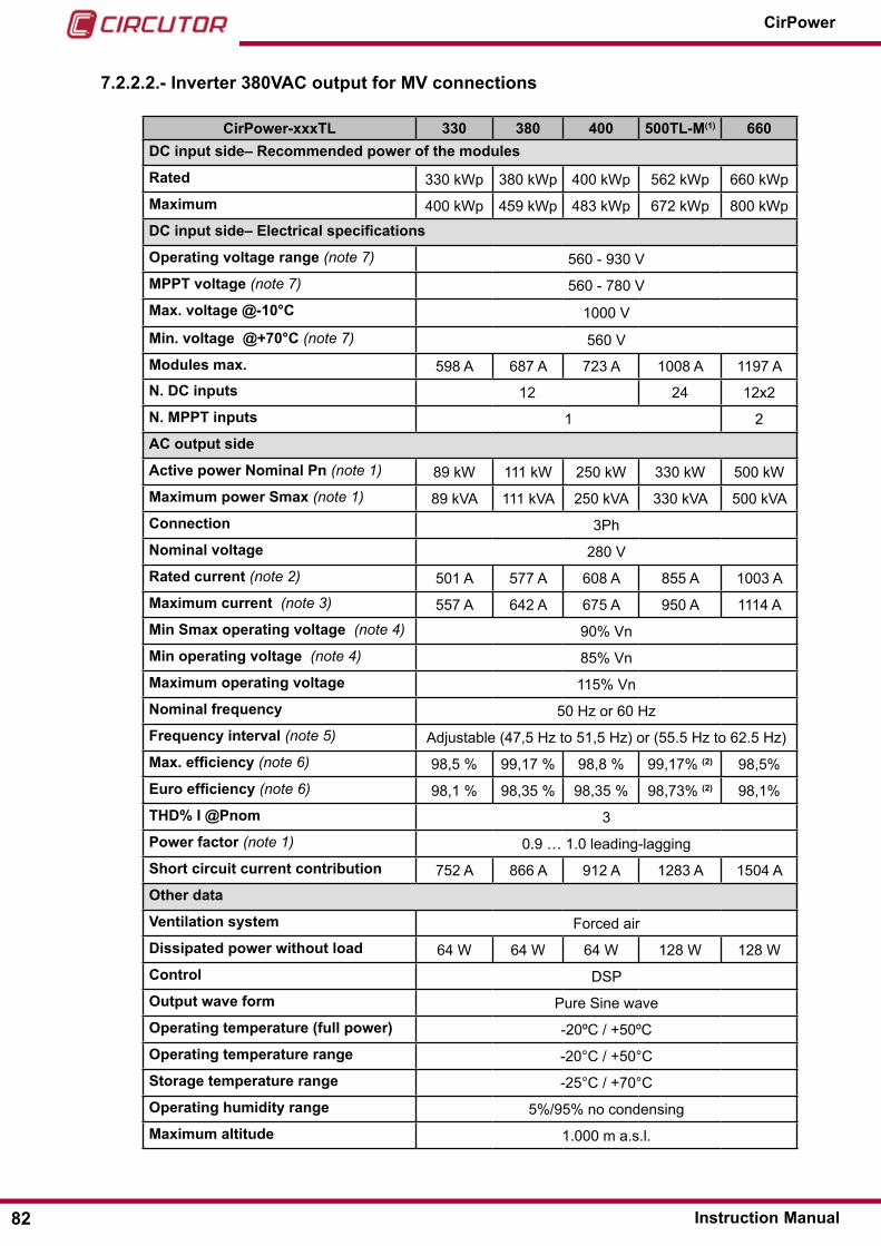
7�2�2�2�- Inverter 380VAC output for MV connections
CirPower-xxxTL 330 380 400 500TL-M(1) 660DC input side– Recommended power of the modules
Rated 330 kWp 380 kWp 400 kWp 562 kWp 660 kWpMaximum 400 kWp 459 kWp 483 kWp 672 kWp 800 kWpDC input side– Electrical specifications
Operating voltage range (note 7) 560 - 930 VMPPT voltage (note 7) 560 - 780 VMax� voltage @-10°C 1000 V
Min� voltage @+70°C (note 7) 560 VModules max� 598 A 687 A 723 A 1008 A 1197 AN� DC inputs 12 24 12x2N� MPPT inputs 1 2AC output side
Active power Nominal Pn (note 1) 89 kW 111 kW 250 kW 330 kW 500 kWMaximum power Smax (note 1) 89 kVA 111 kVA 250 kVA 330 kVA 500 kVAConnection 3PhNominal voltage 280 VRated current (note 2) 501 A 577 A 608 A 855 A 1003 AMaximum current (note 3) 557 A 642 A 675 A 950 A 1114 AMin Smax operating voltage (note 4) 90% VnMin operating voltage (note 4) 85% VnMaximum operating voltage 115% VnNominal frequency 50 Hz or 60 HzFrequency interval (note 5) Adjustable (47,5 Hz to 51,5 Hz) or (55.5 Hz to 62.5 Hz)Max. efficiency (note 6) 98,5 % 99,17 % 98,8 % 99,17% (2) 98,5%Euro efficiency (note 6) 98,1 % 98,35 % 98,35 % 98,73% (2) 98,1%ThD% I @Pnom 3Power factor (note 1) 0.9 … 1.0 leading-laggingShort circuit current contribution 752 A 866 A 912 A 1283 A 1504 AOther data
Ventilation system Forced airDissipated power without load 64 W 64 W 64 W 128 W 128 WControl dsPOutput wave form Pure sine waveOperating temperature (full power) -20ºc / +50ºcOperating temperature range -20°c / +50°cStorage temperature range -25°c / +70°cOperating humidity range 5%/95% no condensingMaximum altitude 1.000 m a.s.l.
82
CirPower
Instruction Manual

CirPower-xxxTL 330 380 400 500TL-M(1) 660Environment category Indoor non conditionedPollution Degree Pd3 Overvoltage category (DC input) class IIOvervoltage class (output AC) class IIIMechanical characteristics
dBA 68 68 68 68 68Class of protection IP20Dimensions LxDxh 1500x1000x2000 mmweight 850 kg 850 kg 850 kg 1600 kg 1600 kg
(1) CirPower-500TL-M operate with Master & slave logic (see 3.5.- MASTER & SLAvE OPERATION for details)(2): efficiency values measured by a third-party independent lab. report available on request.
CirPower-xxxTL 660TL-M (1) 760 760TL-M (1) 800 800TL-M DC input side– Recommended power of the modules
Rated 660 kWp 760 kWp 760 kWp 800 kWp 800 kWpMaximum 800 kWp 918 kWp 918 kWp 966 kWp 966 kWpDC input side– Electrical specifications
Operating voltage range (note 7) 560 - 930 VMPPT voltage (note 7) 560 - 780 VMax� voltage @-10°C 1000 V
Min� voltage @+70°C (note 7) 560 VModules max� 1197 A 1374 A 1374 A 1446 A 1446 AN� DC inputs 24 12x2 24 12x2 24N� MPPT inputs 1 2 1 2 1AC output side
Active power Nominal Pn (note 1) 660 kW 760 kW 750 kW 800 kW 800 kWMaximum power Smax (note 1) 660 kVA 760 kVA 760 kVA 800 kVA 800 kVAConnection 3PhNominal voltage 380 VRated current (note 2) 1003 A 1155 A 1155 A 1215 A 1215 AMaximum current (note 3) 1114 A 1283 A 1283 A 1351 A 1351 AMin Smax operating voltage (note 4) 90% VnMin operating voltage (note 4) 85% VnMaximum operating voltage 115% VnNominal frequency 50 Hz or 60 HzFrequency interval (note 5) Adjustable (47,5 Hz to 51,5 Hz) or (55.5 Hz to 62.5 Hz)Max. efficiency (note 6) 99,17 %(2) 99,17 % 99,22 % (2) 98,8 % 98,8 %Euro efficiency (note 6) 98,76 %(2) 98,35 % 98,77 %(2) 98,35 % 98,35 %ThD% I @Pnom 3Power factor (note 1) 0.9 … 1.0 leading-lagging
83Instruction Manual
CirPower

CirPower-xxxTL 660TL-M (1) 760 760TL-M (1) 800 800TL-M Short circuit current contribution 1504 A 1732 A 1732 A 1823 A 1823 AOther data
Ventilation system Forced airDissipated power without load 128 W 128 W 128 W 128 W 128 WControl dsPOutput wave form Pure sine waveOperating temperature (full power) -20ºc / +50ºcOperating temperature range -20°c / +50°cStorage temperature range -25°c / +70°cOperating humidity range 5%/95% no condensingMaximum altitude 1.000 m a.s.l.Environment category Indoor non conditionedPollution Degree Pd3 Overvoltage category (DC input) class IIOvervoltage class (output AC) class IIIMechanical characteristics
dBA 68 68 68 68 68Class of protection IP20Dimensions LxDxh 1500x1000x2000 mmweight 1600 kg 1600 kg 1600 kg 1600 kg 1600 kg
(1) CirPower-660TL-M and CirPower-760TL-M operate with Master & slave logic (see 3.5.- MASTER & SLAvE OPERATION for details)(2): efficiency values measured by a third-party independent lab. report available on request.
7�2�2�3�- Inverter 380VAC for MV connections and outdoor operation
CirPower-xxxTL 500TL-M (1) 660TL-M (1) 760TL-M (1)
DC input side– Recommended power of the modules
Rated 562 kWp 660 kWp 760 kWpMaximum 672 kWp 800 kWp 918 kWpDC input side– Electrical specifications
Operating voltage range (note 7) 560 - 930 VMPPT voltage (note 7) 560 - 780 VMax� voltage @-10°C 1000 V
Min� voltage @+70°C (note 7) 560 VModules max� 1008 A 1197 A 1374 AN� DC inputs 24N� MPPT inputs 1AC output side
Active power Nominal Pn (note 1) 562 kW 660 kW 750 kWMaximum power Smax (note 1) 562 kVA 660 kVA 760 kVA
84
CirPower
Instruction Manual

CirPower-xxxTL 500TL-M (1) 660TL-M (1) 760TL-M (1)
Connection 3PhNominal voltage 380 VRated current (note 2) 855 A 1003 A 1155 AMaximum current (note 3) 950 A 1114 A 1283 AMin Smax operating voltage (note 4) 90% VnMin operating voltage (note 4) 85% VnMaximum operating voltage 115% VnNominal frequency 50 Hz or 60 HzFrequency interval (note 5) Adjustable (47,5 Hz to 51,5 Hz) or (55.5 Hz to 62.5 Hz)Max. efficiency (note 6) 99,17 % (2) 99,19 % (2) 99,22 % (2)
Euro efficiency (note 6) 98,73 % (2) 98,76% (2) 98,77% (2)
ThD% I @Pnom 3Power factor (note 1) 0.9 … 1.0 leading-laggingShort circuit current contribution 1283 A 1504 A 1732 AOther data
Ventilation system Forced airDissipated power without load 128 W 128 W 128 WControl dsPOutput wave form Pure sine waveOperating temperature (full power) -20ºc / +50ºcOperating temperature range -20°c / +50°cStorage temperature range -25°c / +70°cOperating humidity range 5%/95% no condensingMaximum altitude 1.000 m a.s.l.Environment category ouTdoorPollution Degree Pd3 Overvoltage category (DC input) class IIOvervoltage class (output AC) class IIIMechanical characteristics
dBA 68 68 68Class of protection IP54Footprint size for basement (LxD) 1500x1000 mmOverall Dimensions (LxDxh) (including roof) 2000/1500/2400 mm
weight 1700 kg 1700 kg 1700 kg
(1) CirPower-500TL-M, CirPower-660TL-M and CirPower-760TL-M operate with Master & slave logic (see 3.5.- MASTER & SLAvE OPERATION for details)(2): efficiency values measured by a third-party independent lab. report available on request.
85Instruction Manual
CirPower
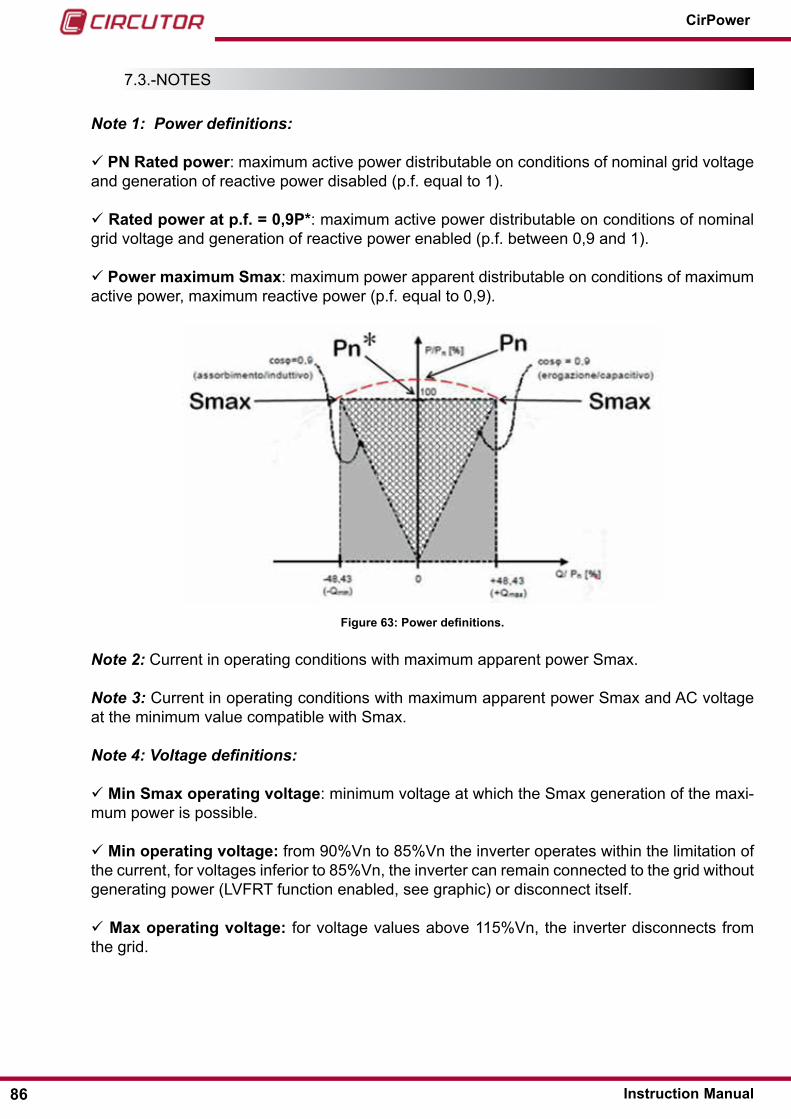
7.3.-noTes
Note 1: Power definitions:
PN Rated power: maximum active power distributable on conditions of nominal grid voltage and generation of reactive power disabled (p.f. equal to 1).
Rated power at p�f� = 0,9P*: maximum active power distributable on conditions of nominal grid voltage and generation of reactive power enabled (p.f. between 0,9 and 1).
Power maximum Smax: maximum power apparent distributable on conditions of maximum active power, maximum reactive power (p.f. equal to 0,9).
Figure 63: Power definitions.
Note 2: current in operating conditions with maximum apparent power smax.
Note 3: current in operating conditions with maximum apparent power smax and Ac voltage at the minimum value compatible with smax.
Note 4: Voltage definitions:
Min Smax operating voltage: minimum voltage at which the smax generation of the maxi-mum power is possible.
Min operating voltage: from 90%Vn to 85%Vn the inverter operates within the limitation of the current, for voltages inferior to 85%Vn, the inverter can remain connected to the grid without generating power (lVFrT function enabled, see graphic) or disconnect itself.
Max operating voltage: for voltage values above 115%Vn, the inverter disconnects from the grid.
86
CirPower
Instruction Manual

Figure 64: Voltage definitions.
Note 5: configurable according to the type of connection
Note 6: efficiency measured at the dc voltage of 400V for Tr model efficiency measured at the dc voltage of 520V for Tr and TlH 280V output models efficiency measured at the dc voltage of 600V for TlH 380V output models
Note 7: For power limitation refer to paragraph “4.5.3.- POwER DERATINg AS A FUNCTION OF POwER MODULE TEMPERATURE”
7.4.-elecTrIcAl PoWer consuMPTIon For VenTIlATIon FAns
Table 20: Electrical power consumptions for ventilation fans�
Model Supply Voltage Frequency Max current Fans Power
consumptionCirPower-10TR 230 50 0.5 90CirPower-20TR 230 50 0.5 90CirPower-30TR 230 50 0.65 120CirPower-45TR 230 50 0.8 150CirPower-55TR 230 50 1.6 300
CirPower-80TR 230 50 2.7 490CirPower-110TR 230 50 2.7 490CirPower-250TR 230 50 3.5 630CirPower-90TL 230 50 2.2 420CirPower-110TL 230 50 2.2 420CirPower-110TL 230 50 2.2 420CirPower-330TL … 400TL 230 50 2.7 490CirPower-500TL 230 50 4.5 840CirPower-660TL ��� 800TL 230 50 5 980
87Instruction Manual
CirPower

8�- MAINTENANCE AND TEChNICAL SERVICE
In the case of any query in relation to unit operation or malfunction, please contact the CIRCUTOR, SA Technical support service.
Technical Assistance ServiceVial sant Jordi, s/n, 08232 - Viladecavalls (Barcelona)Tel: 902 449 459 ( españa) / +34 937 452 919 (outside of spain)email: [email protected]
9�- GUARANTEE
• no returns will be accepted and no unit will be repaired or replaced if it is not ac-companied by a report indicating the defect detected or the reason for the return.•The guarantee will be void if the units has been improperly used or the stora-ge, installation and maintenance instructions listed in this manual have not been followed. “Improper usage” is defi ned as any operating or storage condition con-trary to the national electrical code or that surpasses the limits indicated in the technical and environmental features of this manual.• CIRCUTOR accepts no liability due to the possible damage to the unit or other parts of the installation, nor will it cover any possible sanctions derived from a pos-sible failure, improper installation or “improper usage” of the unit. consequently, this guarantee does not apply to failures occurring in the following cases:- overvoltages and/or electrical disturbances in the supply;- Water, if the product does not have the appropriate IP classifi cation;- Poor ventilation and/or excessive temperatures;- Improper installation and/or lack of maintenance;- Buyer repairs or modifi cations without the manufacturer’s authorisation.
CIRCUTOR guarantees its products against any manufacturing defect for two years after the delivery of the units.
CIRCUTOR will repair or replace any defective factory product returned during the guarantee period.
Warning, damage to the display of to the specifications plate due to the use of cleaning products�
If the inverter has to be cleaned, gently sweep the surface and heatsink with only clean water and a soft cloth.
88
CirPower
Instruction Manual

10�- CE CERTIFICATE
89Instruction Manual
CirPower

CIRCUTOR, SA Vial Sant Jordi, s/n08232 - Viladecavalls (Barcelona)Tel: (+34) 93 745 29 00 - Fax: (+34) 93 745 29 14 www.circutor.es [email protected]