injectable polyhipes as high-porosity bone grafts
TRANSCRIPT
Injectable PolyHIPEs as High Porosity Bone Grafts
Robert S. Moglia1, Jennifer L. Holm1, Nicholas A. Sears1, Caitlin J. Wilson2, Dawn M.Harrison3, and Elizabeth Cosgriff-Hernandez1,*
1Department of Biomedical Engineering, Texas A&M University, College Station, Texas,77843-3120, U.S.A2Department of Chemistry, Texas Lutheran University, Seguin, Texas, 78155, U.S.A3Department of Chemical Engineering, Prairie View A&M University, Prairie View, Texas, 77446,U.S.A
AbstractPolymerization of high internal phase emulsions (polyHIPEs) is a relatively new method for theproduction of high porosity scaffolds. The tunable architecture of these polyHIPE foams makethem attractive candidates for tissue engineered bone grafts. Previously studied polyHIPE systemsrequire either toxic diluents or high cure temperatures which prohibit their use as an injectablebone graft. In contrast, we have developed an injectable polyHIPE that cures at physiologicaltemperatures to a rigid, high-porosity foam. First, a biodegradable macromer, propylene fumaratedimethacrylate (PFDMA), was synthesized that has appropriate viscosity and hydrophobicity foremulsification. The process of surfactant selection is detailed with particular focus on the keystructural features of both polymer (log P values, hydrogen bond acceptor sites) and surfactant(HLB values, hydrogen bond donor sites) that enable stable HIPE formation. Incubation of HIPEsat 37°C was used to initiate radical crosslinking of the unsaturated double bond of themethacrylate groups to polymerize the continuous phase and lock in the emulsion geometry. Theresulting polyHIPEs exhibited ~75% porosity, pore sizes ranging from 4 to 29 μm, and an averagecompressive modulus and strength of 33 and 5 MPa, respectively. These findings highlight thegreat potential of these scaffolds as injectable, tissue engineered bone grafts.
IntroductionLarge bone defects resulting from traumatic injury, tumor resection, or congenitaldeformities fail to heal naturally and often require reconstructive surgery. Bone graftspromote healing at the defect site by providing a template to guide new tissue formation.Autologous bone continues to be the gold standard for reconstruction due to its highpotential for growth and remodeling as well as its ability to osseointegrate; however, itsretrieval has anatomical limitations and often results in donor site pain and morbidity. Awide variety of alloplastic materials have also been utilized including stainless steel,titanium, methylmethacrylate resins, polyethylene, silicone elastomers, and hydroxyapatiteceramics. Drawbacks and complications inherent in the use of current alloplastic materialsinclude inadequate tissue integration, limited biodegradability, and stress shielding. Incontrast, tissue engineering strategies promote bone regeneration by seeding living cells onor attracting endogenous cells to a biomaterial scaffold and delivering appropriate bioactivecues to aid in cell differentiation and tissue growth.1 As such, tissue engineered bone grafts
*Corresponding author: Dr. Elizabeth Cosgriff-Hernandez, Department of Biomedical Engineering, Texas A&M University, ZachryEngineering Center 337, 3120 TAMU, College Station, TX 77843-3120, Tel: (979) 845-1771, Fax: (979) 845-4450,[email protected].
NIH Public AccessAuthor ManuscriptBiomacromolecules. Author manuscript; available in PMC 2012 October 10.
Published in final edited form as:Biomacromolecules. 2011 October 10; 12(10): 3621–3628. doi:10.1021/bm2008839.
NIH
-PA Author Manuscript
NIH
-PA Author Manuscript
NIH
-PA Author Manuscript
combine the osseointegration and remodeling of autografts with the availability andtunability of synthetic grafts, thus limiting the complications associated with each of thesetraditional implants.2–3
Tissue engineering scaffolds typically consist of biodegradable materials that slowly erodeat a rate complementary to tissue growth and facilitate full integration of the de novo tissuewith the host tissue.1 In addition to the choice of a suitable biomaterial, the success of tissueengineered constructs depends on the three-dimensional architecture of the scaffold. Aninterconnected porous structure enables cellular ingrowth and proliferation, vascularization,and the transport of nutrients and metabolic waste. 4–8 Orthopaedic applications also requirescaffolds with adequate mechanical properties to withstand physiological loading andrestore tissue function without causing deleterious stress-shielding effects.2, 6–7, 9–10 Finally,the ability to match the irregular geometries of these types of bone defects is necessary topromote osseointegration and full healing. Injectable grafts that cure in situ are preferable inthis aspect to more costly and time-consuming computer-aided design molds. In summary,the advancement of bone tissue engineering strategies is strongly dependent on thedevelopment of high-porosity scaffolds that meet these key requirements.
Tissue engineers have developed numerous fabrication strategies to create 3D bonegrafts.2, 5–8, 11–15 The selected fabrication process dictates scaffold architecture which is acritical design feature given the effect of architecture on construct mechanical properties,degradation rate, and cellular response. In particular, generation of a scaffold with highporosity that retains sufficient mechanical strength for orthopaedic applications remainschallenging. The most common techniques to produce porous scaffolds include particulateleaching, gas foaming, thermal induced phase separation, and fiber bonding.6, 12, 14–15 Manyof these strategies provide exceptional architecture control; however, control of the constructgeometry (e.g. to match the contours of the defect) is generally limited to the mold used infabrication or post-fabrication shaping. In situ forming scaffolds can fill irregular shapeddefects, improve contact between the scaffold and surrounding tissue, and eliminate the needfor costly molding techniques.16–17 Poly(methyl methacrylate) (PMMA) bone cements areperhaps the most widely used injectable material in orthopaedics; however, PMMA is non-degradable which may impede bone healing.16 Recently, investigators have developedhighly crosslinked, degradable networks such as poly(propylene fumarates) andpolyanhydrides that can be formed in situ using either thermal or photoinitiatedcrosslinking.18–21 Although biodegradable and injectable, these materials lack the porositynecessary to repair critical size defects. In contrast, in situ curing hydrogels have sufficientmass transport properties but lack the mechanical strength necessary for orthopaedicapplications. A scaffold fabrication method that is injectable and porous, yet retains highmechanical strength would provide a significant improvement over current methods.
Polymerization of high internal phase emulsions (polyHIPEs) is a relatively new method forthe production of high porosity scaffolds.22 High internal phase emulsions (HIPEs) arecharacterized by an internal droplet phase volume fraction greater than 74%. Polymerizationof the HIPE’s continuous phase locks in the emulsion geometry at the gel point to generate ahigh porosity monolith or polyHIPE.23–24 A wide range of porosities (75–99%), pore sizes(1–100 μm), compressive moduli (2 kPa-60 MPa) and morphologies (open- vs. closed-pore)can be produced by varying the HIPE composition and processing variables.24–37 A uniquefeature of the polyHIPE system is that the HIPE retains a viscosity that is suitable forinjection prior to cure. An injectable polyHIPE system requires 1) biodegradable macromerswith suitable viscosities for emulsion formation and 2) reaction thermodynamics that allowfor HIPE polymerization at physiological conditions. Previous research on the developmentof polyHIPE bone grafts has focused on styrene-based or unsaturated polyester-basedmacromers.11, 22, 25–26, 38–39 Although past styrene-based systems had excellent pore
Moglia et al. Page 2
Biomacromolecules. Author manuscript; available in PMC 2012 October 10.
NIH
-PA Author Manuscript
NIH
-PA Author Manuscript
NIH
-PA Author Manuscript
morphology, they were non-biodegradable which limited their use as tissue engineeredscaffolds. Biodegradability was achieved by substituting in unsaturated polyesters; however,the macromers studied were often too viscous to form HIPEs without the use of a toxicdiluent, such as toluene. 27, 36, 40–41
We have developed a biodegradable and injectable polyHIPE system based on propylenefumarate dimethacrylate (PFDMA) macromers. The viscosity of PFDMA is suitable forHIPE formation and reactive methacrylate end groups enable in situ crosslinking into rigidmonoliths at 37°C. Furthermore, fumarate-based polymers have shown great promise asbone grafts with established osteoconductivity in vivo.19–20, 42 PFDMA polyHIPEsexhibited ~75% porosity, pore sizes ranging from 4 to 29 μm, and an average compressivemodulus and strength of 33 and 5 MPa, respectively. The ability to synthesize a fullybiodegradable polyHIPE without a toxic diluent that can also cure at physiologicaltemperatures is an important adaptation of emulsion templating. These new polyHIPEs havepotential application as an injectable, tissue engineered bone graft.
Materials and MethodsMaterials
Polyglycerol polyricinoleate (PGPR 4125) was donated by Paalsgard and PEG 600 dilauratewas donated from Unitex Chemical. All other chemicals were purchased from SigmaAldrich. All chemicals were used as received.
PFDMA SynthesisPFDMA was synthesized in a two-step process adapted from Timmer et.al.43 First,propylene oxide was added dropwise to a solution of fumaric acid and pyridine in 2-butanone (2.75:1.0:0.033 mol). The reaction was refluxed at 80°C until the fumaric acidcompletely reacted, approximately 19 hours. Residual propylene oxide and 2-butanone werethen removed in two distillations steps and the product redissolved in dichloromethane. Thesolution was then washed in 0.2 M NaOH/brine (6:4 v/v) until basic to remove residualacidic byproducts, washed with brine, and stirred over anhydrous sodium sulfate to removeresidual water. Dichloromethane was removed using rotary evaporation to yield the diesterbis (1,2 hydroxypropyl) fumarate product as a colorless liquid. The diester was then end-capped with methacrylate groups in an addition process with triethylamine and methacryloylchloride. Hydroquinone was added to inhibit crosslinking during the synthesis. The molarratios of the diester, methacryloyl chloride, trietylamine, and hydroquinone were1:2.1:2.1:0.016, respectively. The reaction was maintained below −10°C to reduceundesirable side reactions and stirred vigorously overnight under a nitrogen blanket. Themacromer was filtered to remove triethylamine salt and neutralized overnight in 2 Mpotassium carbonate. The solution was washed in 0.1 M NaOH/brine (6:4 v/v) to removeresidual byproducts, washed with brine, and stirred over anhydrous sodium sulfate toremove residual water. The dichloromethane was removed by rotary evaporation and thePFDMA structure confirmed using 1H NMR (300 MHz, CdCl3) δ 1.33 (dd, 3H, CH3), 1.92(s, 3H, CH3), 4.20 (m, 2H, -CH2-), 5.30 (m, 1H, -CH-), 5.58 (s, 1H, -C=CH2), 6.10 (s, 1H, -C=CH2), 6.84 (m, 2H, -CH=CH-). The final product was a low viscosity liquid with a paleyellow to amber appearance.
Surfactant StudySorbitan monooleate (Span 80), PEG 600 dilaurate, Tween 80, and PGPR 4125 were studiedto observe their effect on PFDMA HIPE formation. Each surfactant had differenthydrophilic-lipophilic balance (HLB) values and different hydrogen bond donor sites (Table1). PFDMA, surfactant, and DI water (2, 0.4, 8g, respectively) were vortexed for 5 minutes.
Moglia et al. Page 3
Biomacromolecules. Author manuscript; available in PMC 2012 October 10.
NIH
-PA Author Manuscript
NIH
-PA Author Manuscript
NIH
-PA Author Manuscript
HIPE formation was indicated by full incorporation of water without evidence of phaseseparation after mixing stopped. Successful HIPEs were typically characterized by anopaque, white appearance with a notable increase in viscosity, similar to mayonnaise. Thescouting compositions which resulted in HIPEs were fabricated full-scale to investigate theeffect of surfactant structure on pore architecture.
HIPE FabricationHIPEs were prepared using the FlackTek Speedmixer DAC 150 FVZ-K. Briefly, PFDMAwas mixed with the surfactant PGPR in the Speedmixer cup prior to emulsification. ThePGPR concentrations used in this study are listed in Table 2. Once thoroughly mixed, theaqueous solution of calcium chloride (1% v/v), ammonium persulfate (5 wt %) anddeionized water was then added to the organic phase in the speedmixer cup. The calciumchloride was used to prevent Ostwald ripening while the ammonium persulfate initiatedradical crosslinking of the macromer chains. HIPEs were then transferred to a 37°Caluminum bead bath for 12 hours to facilitate cross-linking. The resulting polyHIPE foamswere placed under vacuum for 24 hrs to remove water prior to characterization.
Gravimetric AnalysisPolyHIPE porosity was measured gravimetrically. Briefly, dried HIPE samples were cut intocubic sections (9 × 9 × 3 mm) and weighed. Following equation 1, the HIPE porosity can becalculated by comparing HIPE density (ρH) with the bulk polymer’s density (ρP). Reportedvalues are an average of nine sections per polyHIPE composition.
(1)
SEM AnalysisScanning electron microscopy (SEM) was utilized to characterize the polyHIPEs porearchitecture. Circular specimens were sectioned into quarters, fractured at the center of thequarter, sputter-coated with gold, and imaged using FE-SEM (JEOL JSM-7500F). Images at250× were utilized to determine the average pore size when the pores were 25–100 μm.Higher magnification (500×, 1000×) images were utilized to determine the average pore sizewhen the pores were less than 25μm. Each section was imaged in a rastor pattern yieldingfive images. Measurements were made on the first 10 pores along the image median tominimize user bias. Averages pore sizes for each polyHIPE composition are reported(n=150). A statistical correction was calculated to account for non-perfect spherical pores,h2 = R2–r2 where R is the void diameter’s equatorial value, r is the diameter value measuredfrom the micrograph, and h is the distance from the center. The average diameter valueswere multiplied by this correction factor resulting in a more accurate description of porediameter. These values are listed in Table 2.
In vitro Cell ProliferationInvestigation of 3T3 fibroblast viability was done to assess polyHIPE cytocompatibility.Cell viability was determined using the Live/Dead Viability/Cytotoxicity Kit (MolecularProbes). NIH/3T3 Swiss mouse fibroblast were purchased (ATCC-CCL92) and cultured invitro with Dulbecco’s Modified Eagle Medium (DMEM), Glutamax, high glucosesupplemented with 10% heat-inactivated fetal bovine serum (FBS) and 1% Penicillin-Strepotomycin solution (Gibco). The polyHIPE sample comprised of 5 wt% PGPR, 75/25volume fraction, and mixed at 500 rpm was chosen for cytocompatibility testing because itpossessed the largest pore sizes and contained the least amount of surfactant which could
Moglia et al. Page 4
Biomacromolecules. Author manuscript; available in PMC 2012 October 10.
NIH
-PA Author Manuscript
NIH
-PA Author Manuscript
NIH
-PA Author Manuscript
potentially disrupt the cell membrane. PolyHIPE foams were prepared for cell seeding asfollows: UV irradiation (1 hour per side), ethanol wetting ladder and progressive solventextraction, and overnight media incubation supplemented with 40 v/v% FBS in DMEM.Following overnight incubation in 37°C, 5% CO2, medium was removed, specimens weredried in the hood for 30min, washed 1× with PBS and pre-conditioned with growth mediumfor 15 min. Cells were seeded into wells at 10,000 cells/cm2. Live/Dead staining wasconducted at 24 hours. Images of each of the three specimens were obtained through rastorpatterning (n=15) using a fluorescence microscope (Nikon Eclipse TE2000-S).
Mechanical TestingThe foams mechanical properties were all tested with an Instron 3300, equipped with a1000-N load cell. Three specimens were taken from each sample. The test specimens werecut into flat rectangular shapes (9 × 9 × 3 mm) and compressed at 50 μm/s.44 Thecalculations in ASTM method D1621-04a 45 were used to determine the compressivemodulus. Briefly, a straight edge and computer software were used to determine the linearregion of the stress-strain curve by extending a line from the steepest slope of the curve tothe zero-load axis. The point at which this line crossed the axis was determined to be wherestrain equaled zero and all data points were shifted accordingly. The elastic modulus wasequal to the slope of the line in the linear region, as outlined in the ASTM method. Reportedmoduli data was an average of the three sections for each sample tested (n=9).
Statistical AnalysisThe data are displayed as mean ± standard deviation for each composition. A Student’s t-testwas performed to determine any statistically significant differences between compositions.All tests were carried out at a 95% confidence interval (P<0.05).
Results and DiscussionPFDMA Synthesis and Analysis
PFDMA was synthesized by the two-step reaction described previously. The first stepproduced a diester intermediate, bis-(1,2-hydroxypropyl) fumarate, which was thenfunctionalized with methacrylate endgroups, Figure 1. Following purification, the structureof the resulting PFDMA product was confirmed with 1H NMR. The integration ratio ofmethacryloyl protons to fumarate protons in the 1H NMR spectra, Figure 2, confirmed thestructure of PFDMA as a single fumarate unit with two terminal methacrylate groups. Theaverage functionalization was calculated to be ~83%. The methacrylate and fumarate groupsprovided sites for radical crosslinking of the macromer to permit cure of the HIPE atphysiological temperatures. Furthermore, fumarate-based bone grafts have shown promisingosteoconductivity results in vivo.19–20, 42 The resulting macromer had a sufficiently lowviscosity (125 cP) and hydrophobicity to permit HIPE formation.
Model predictions of the octanol-water partition coefficients (logP) were used in thesestudies as a means of comparing molecular hydrophobicity.46 LogP values are a measure ofthe differential solubility of a compound between two immiscible solvents, typically waterand a hydrophobic solvent such as octanol. Log P values range from negative to positivewhere a negative value corresponds to a hydrophilic molecule and a positive value ahydrophobic one. The method used in these studies for logP prediction was developed atMolinspiration (miLogP2.2 – November 2005). The logP value of each compound wascalculated from the sum of its non-overlapping molecular fragments. The groupcontributions were obtained by fitting calculated logP with experimental logP for a trainingset of more than twelve thousand molecules. The logP value of PFDMA (3.4) wascomparable to macromers that have previously formed stable HIPEs, Table 1.
Moglia et al. Page 5
Biomacromolecules. Author manuscript; available in PMC 2012 October 10.
NIH
-PA Author Manuscript
NIH
-PA Author Manuscript
NIH
-PA Author Manuscript
Selection of HIPE SurfactantSurfactant choice and concentration play a large role in emulsion stability and successfulHIPE formation.24, 27, 34, 47 Selection of HIPE surfactants has largely been based on trialand error and historical precedence. One method of characterizing surfactants is theirhydrophilic-lipophilic balance (HLB) classification. Typically, empirical testing is used toascertain what HLB values are suitable for each application with an HLB range of 2–6designated for water-in-oil emulsions.48 Although several investigators have indicated thelimitations of the HLB approach, it remains the most method for surfactant selection. In thisstudy, we attempt to identify structural features and predictors that may be used to rationallyselect surfactants for new HIPE macromers. It was hypothesized that a relationship betweensurfactant HLB and organic phase hydrophobicity may exist which could then be used toselect appropriate surfactants for the PFDMA HIPE. Log P values were utilized as acomparison between established HIPE macromers/monomers and PFDMA, Table 1. Themost widely studied polyHIPE system is styrene and divinylbenzene with logP valuesranging from 2.8 – 3.6. The surfactant Span 80 (HLB = 4.3) is typically used to stabilizestyrene-based HIPEs. Therefore, it was hypothesized that PFDMA HIPEs with a log P of 3.4should also form stable emulsions with Span 80. Surprisingly, Span 80 did not stabilizePFDMA emulsions despite the similarity between logP and HLB values. Additionalsurfactants and combinations of surfactants with similar structures as Span 80 but a range ofHLB values from 1.8–15 were investigated, Table 2, but these too failed to form stableHIPEs with PFDMA. These studies indicate that HLB alone is insufficient as a selectioncriteria for stable HIPE formation.
Surfactant structures were compared to determine differences that might affect PFDMAemulsification. It was determined that all of the surfactants tested had hydrogen bond donorsites in the polar head, Figure 3. PFDMA has multiple hydrogen bond acceptor sites in itsbackbone that could interact with the polar head of the surfactant. It was hypothesized thatthis hydrogen bonding could prevent the polar head of the surfactant from interacting withthe aqueous phase of the emulsion, thereby attenuating its ability to stabilize the organic/water interface. Previous fumarate and ester-based systems that were effectively stabilizedwith Span 80 utilized a non-polar solvent (e.g. toluene) which may have interrupted thehydrogen bonding.11, 22, 27, 49 To avoid using a toxic diluent, a surfactant without hydrogenbond donor sites in the polar head was needed with the appropriate HLB value. The organicsoluble emulsifier, polyglycerol polyricinoleate (PGPR), was selected to test this theorybased on its comparable HLB (~4.7) and lack of hydrogen bond donor sites in its polarregion. This surfactant has also been used to generate water-in-oil HIPEs with ester-basedmacromers.40–41, 50 Successful formation of PFDMA HIPEs resulted with the addition ofPGPR suggests that hydrogen bonding does indeed play a critical role in surfactantstabilization of high internal phase emulsions. Further investigation of surfactants that lackdonor sites in their polar head could expand the number of biodegradable polymers utilizedin emulsion templating given that many biodegradable polymers (e.g. polyesters) havehydrogen bond acceptor sites in their backbone.
Injectable Porous ScaffoldsStable PFDMA HIPEs were incubated at 37°C to initiate radical crosslinking of theunsaturated double bond of the methacrylate groups. The resulting polyHIPE monolithsexhibited ~75% porosity and an average compressive modulus and strength of 33 and 5MPa, respectively. SEM analysis was utilized to determine pore size and morphology.Polymerization of the continuous phase of the HIPE locked in the emulsion geometryresulting in a high-porosity foam with a closed-pore morphology and average pore sizeranging from 4 – 29 μm, Figure 4. These studies represent an important milestone in thedevelopment of an injectable bone graft. Specifically, these polyHIPEs utilize a
Moglia et al. Page 6
Biomacromolecules. Author manuscript; available in PMC 2012 October 10.
NIH
-PA Author Manuscript
NIH
-PA Author Manuscript
NIH
-PA Author Manuscript
biodegradable and osteoconductive polymer, have a suitable pre-cure viscosity for injection;and cure at physiological temperatures to a rigid, high-porosity monolith. The potentialutility of this new polyHIPE system as an injectable bone graft is illustrated in Figure 4.Damage to surrounding tissues after deployment of bone cements has been attributed to thehigh polymerization exotherm. Therefore, the reaction exotherm of the PFDMA wasmonitored for 4 hours using a thermocouple inserted into the HIPE as it cured at 37°C. Thetemperature of the HIPE did not exceed 37.3ºC which indicates that the mild reaction wouldnot negatively impact surrounding tissues. The cure time of the polyHIPE system (5 wt%PGPR, 75:25) was quantified at 37 °C by monitoring storage and loss modulus in dynamicmechanical analysis. This study indicated that the HIPE has a working time of ~1 h (onset ofstorage modulus increase) and is fully set within 2 h (slope of storage modulus → 0). It ishypothesized that reactivity of the unsaturated double bond and the concentration of initiatorcan be used to modulate these times. Finally, cytocompatibility analysis of 5 wt% PGPRspecimens yielded 95% viability of 3T3 fibroblasts after 24 hours, Figure 5. Overall, theseresults indicate that the PFDMA has great potential as an injectable bone graft.
An open-pore morphology is a common design goal for tissue engineering applications tofacilitate tissue ingrowth and nutrient/waste transport. Previous studies have investigated themechanisms that govern pore opening in the polyHIPE system.22, 24, 34 Interconnectformation in HIPE systems has been attributed to shrinkage of the thin polymer filmseparating droplets that occurs as monomer is converted to higher density polymer. If thisfilm between droplets is sufficiently thin, shrinkage results in a window opening andexpanding. Therefore, whether a HIPE forms an open- or closed-pore morphology uponpolymerization is related to both initial film thickness between droplets and densificationduring polymerization which initiates pore opening.24, 27 Film thickness is dictated by theaqueous phase volume and droplet size; whereas, densification is related to structuralfeatures of the polymer. Current studies are underway to investigate these two mechanismswith the goal of generating open-pore, fumarate-based polyHIPEs.
Effect of PGPR Concentration on Pore ArchitectureGiven that the polyHIPE architecture is dictated by the emulsion geometry prior to cure,modulation of emulsion stability may be used to tune the resulting polyHIPE architecture.This requires a brief review of the thermodynamics involved in both emulsion formation andphase separation. The increase in surface energy of an emulsion compared to the non-emulsified components (ΔW) is a product of both the interfacial energy (σ) and the changein surface area (ΔA) upon emulsification.
ΔW is the free energy of the interface and corresponds to the reversible work brought intothe system during emulsification. The magnitude of ΔW can be considered a measure of thethermodynamic instability of the emulsion and drives phase separation as a means todecrease ΔA. From this relationship, it is evident that ultimate stability against coalescenceprocesses is only achieved if σ approaches zero. The surfactant’s role during emulsificationis to reduce this interfacial tension and form a barrier between the two phases.
Two relationships relevant to polyHIPE architecture can be inferred from this discussion: 1)an increase in interfacial tension (↑ σ) will increase the rate of droplet coalescence due to anincrease in W; 2) an increase in interfacial tension (↑ σ) will correspond to larger initialdroplet sizes (↓ Δ A) for a given ΔW. It follows that the surfactant which directly impactsinterfacial tension can be used to tune pore sizes by changing the initial droplet size and/or
Moglia et al. Page 7
Biomacromolecules. Author manuscript; available in PMC 2012 October 10.
NIH
-PA Author Manuscript
NIH
-PA Author Manuscript
NIH
-PA Author Manuscript
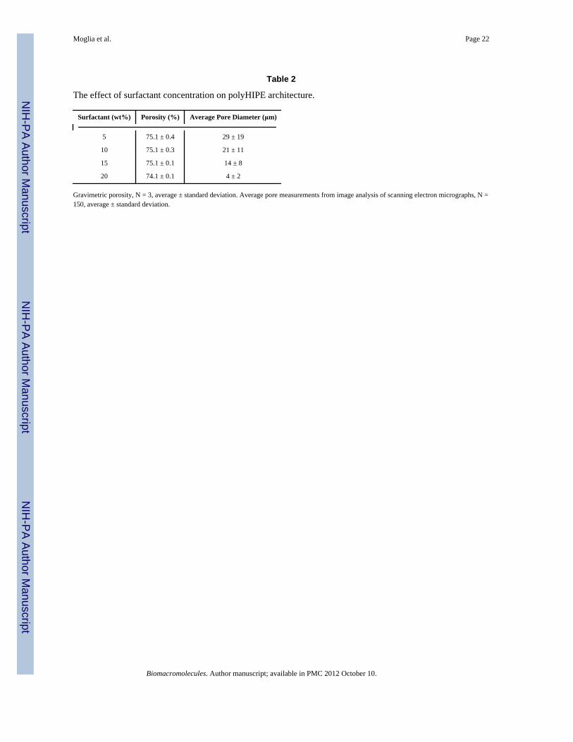
the rate of droplet coalescence prior to cure. To this end, Williams et al. studied the effect ofsurfactant concentration on both pore size and wall thickness between droplets.47 It wasreported that a reduction in surfactant concentration could be used to increase pore size bydestabilizing the HIPE. In addition, an increase in surfactant concentration was found todecrease wall thickness and induce pore opening upon polymerization. We hypothesizedthat HIPE stability could be modulated by changing the surfactant concentration to achieve arange of polyHIPE pore sizes and an open-pore morphology. PGPR concentrations from 5 to40 wt% were utilized to investigate the effect of surfactant concentration on polyHIPE porearchitecture. SEM analysis of polyHIPE monoliths was conducted to quantify pore andinterconnect size using the 10.7 pixels/μm ratio at 1000×, Table 2. Decreasing theconcentration of PGPR from 20 to 5 wt% was found to increase average pore diameter inPFDMA polyHIPEs (6 to 29 μm), Figure 6. A narrowing of pore size distributions withincreasing surfactant concentration was also observed, Figure 7.
The decreased pore size observed at higher surfactant concentration was attributed to adecrease in interfacial tension with a corollary decrease in droplet size, as discussed above.Assuming conservation of organic phase volume, this increase in surface area also decreasesthe film thickness between droplets;48 however, this wall thinning was insufficient to lead topore opening in this system. Based on these preliminary results, it was hypothesized thatincreased densification in combination with decreasing film thickness would be needed togenerate open-pore polyHIPEs. This is the subject of current investigation using alternativefumarate-based macromers. A narrowing of the pore size histograms also indicated that ahigher surfactant concentration resulted in a more uniform pore size, Figure 7. Williams etal. reported that increased pore size homogeneity was observed with increased surfactantdue to a reduction in droplet coalescence.47 However, the droplet coalescence observed inthese studies was characterized by a few large pores surrounded by many smaller pores. Asillustrated in Figure 7, there was a continuum of pore sizes observed rather than the morebimodal distribution reported by Williams et al.47 Ostwald ripening has also been reportedto increase the pore size distribution of polyHIPEs. In this process, diffusion of water fromsmaller droplets to larger droplets causes a more gradual broadening of the pore sizedistribution.51 Both of these processes are affected by the nature and concentration ofsurfactant; however, it is unclear whether droplet coalescence or Ostwald ripening isresponsible for the observed difference in pore size distribution. Based on the histogramsalone, it appears that Ostwald ripening may be more significant; however, additional studiesare needed to make a stronger claim on this front.
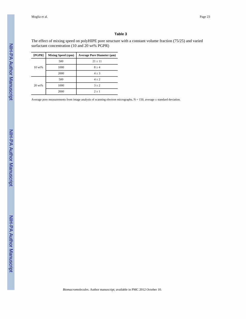
Effect of Mixing Speed on Pore ArchitectureProcessing parameters such as mixing speed can also be utilized to tune the pore architecturethrough manipulation of the emulsion geometry prior to cure. Specifically, we hypothesizedthat pore size would decrease and homogeneity increase with an increase in mixing speeds.Mixing speeds of 500, 1000, and 2000 rpm on the FlackTek SpeedMixer™ were tested toinvestigate the effect on pore architecture. Initially, HIPEs with 20 wt% PGPR were utilizedresulting in minimal change in pore size with an increase in mixing speed as seen in Table 3.We hypothesized that destabilizing the emulsion with a lower concentration of PGPR wouldresult in a larger pore size distribution, thereby clearly illustrating the effect of mixingspeed. Scanning electron micrographs of both 10 and 20 wt% PGPR compositions atvarying mixing speeds are found in Figure 8. A decrease in pore size was observed withboth 10 and 20 wt% PGPR specimens as mixing speed was increased (500 to 2000 rpm). Asdiscussed, the trend was more evident with the 10 wt% PGPR specimens, Table 3, andfurther illustrates the effect of surfactant on emulsion stability and pore architecture. Thenarrowing of the histograms in Figure 9 from 500 to 2000 rpm indicates a morehomogeneous pore size distribution which is illustrated in the SEM images. As stated
Moglia et al. Page 8
Biomacromolecules. Author manuscript; available in PMC 2012 October 10.
NIH
-PA Author Manuscript
NIH
-PA Author Manuscript
NIH
-PA Author Manuscript
previously, increased surfactant produced an increase in pore homogeneity due to decreasedsurface energy. Combining both mixing speed and surfactant had a large effect on pore sizehomogeneity as indicated by a more narrow distribution in Figure 9.
ConclusionsThe application of emulsion templating in the development of tissue engineering scaffolds isa relatively new area of orthopedic research. In this study, polyHIPEs were fabricatedwithout toxic solvents or monomers at cure temperatures appropriate for in situ deployment.These new polyHIPEs have potential application as an injectable, tissue engineered bonegraft. Injectable grafts that are also biodegradable and porous offer unique advantages overcurrent alternatives in terms of deployment and tissue integration. In addition, investigationof the effect of surfactant structure on HIPE stability elucidated additional structural featuresthat can be used to rationally select surfactants for new polyHIPE compositions. Thistransition from a time-intensive trial and error method of selecting surfactants will facilitateadditional biodegradable polyHIPE formulations with utility in a wide range of tissueengineering applications.
AcknowledgmentsFinancial support of this research was provided by the National Science Foundation (ARRA BRIGE 0926824) andthe National Institute of Arthritis and Musculoskeletal and Skin Diseases (1R21AR057531). The authorsacknowledge the Texas A&M Microscopy & Imaging Center for use of their facilities, and Palsgaard USA fordonating PGPR 4125.
References1. Langer R, Vacanti JP. Science. 1993; 260:920–926. [PubMed: 8493529]2. Rose FRAJ, Oreffo ROC. Biochemical and Biophysical Research Communications. 2002; 292:1–7.
[PubMed: 11890663]3. Kenley R, Yim K, Abrams J, Ron E, Turek T, Marden L, Hollinger J. Pharmaceutical Research.
1993; 10:1393–1401. [PubMed: 8272399]4. Mikos AG, Temenoff JS. Electronic Journal of Biotechnology. 2000; 3:114–119.5. Bhatia SN, Chen CS. Biomedical Microdevices. 1999; 2:131–144.6. Hacker M, Ringhofer M, Appel B, Neubauer M, Vogel T, Young S, Mikos AG, Blunk T, Gopferich
A, Schulz MB. Biomaterials. 2007; 28:3497–3507. [PubMed: 17482257]7. Karageorgiou V, Kaplan D. Biomaterials. 2005; 26:5474–5491. [PubMed: 15860204]8. Freyman TM, Yannas IV, Gibson LJ. Progress in Materials Science. 2001; 46:273–282.9. Liu X, Ma PX. Annals of Biomedical Engineering. 2004; 32:477–486. [PubMed: 15095822]10. Sikavitsas VI, Temenoff JS, Mikos AG. Biomaterials. 2001; 22:2581–2593. [PubMed: 11519777]11. Busby W, Cameron NR, Jahoda CAB. Polymer International. 2002; 51:871–881.12. Harris LD, Kim BS, Mooney DJ. Journal of Biomedical Materials Research. 1998; 42:396–402.
[PubMed: 9788501]13. Kim TK, Yoon JJ, Lee DS, Park TG. Biomaterials. 2006; 27:152–159. [PubMed: 16023197]14. Mistry AS, Cheng SH, Yeh T, Christenson E, Jansen JA, Mikos AG. Journal of Biomedical
Materials Research. 200815. Pham QP, Sharma U, Mikos AG. Tissue Engineering. 2006; 12:1197–1211. [PubMed: 16771634]16. Burdick JA, Anseth KS. Biomaterials. 2002; 23:4315–4323. [PubMed: 12219821]17. Jabbari E, Wang S, Lu L, Gruetzmacher JA, Ameenuddin S, Hefferan TE, Currier BL, Windebank
AJ, Yaszemski MJ. Biomacromolecules. 2005; 6:2503–2511. [PubMed: 16153086]18. Svaldi-Muggli D, Burkoth AK, Anseth KS. Journal of Biomedical Materials Research. 1999;
46:271–278. [PubMed: 10380006]
Moglia et al. Page 9
Biomacromolecules. Author manuscript; available in PMC 2012 October 10.
NIH
-PA Author Manuscript
NIH
-PA Author Manuscript
NIH
-PA Author Manuscript
19. Peter SJ, Kim P, Yasko AW, Yaszemski MJ, Mikos AG. Journal of Biomedical MaterialsResearch. 1999; 44:314–321. [PubMed: 10397934]
20. Peter SJ, Lu L, Kim DJ, Mikos AG. Biomaterials. 2000; 21:1207–1213. [PubMed: 10811302]21. Peter SJ, Nolley JA, Widmer MS, Merwin JE, Yaszemski MJ, Yasko AW, Engel PS, Mikos AG.
Tissue Engineering. 1995; 1:41–52. [PubMed: 19877914]22. Christenson EM, Soofi W, Holm JL, Cameron NR, Mikos AG. Biomacromolecules. 2007; 8:3806–
3814. [PubMed: 17979240]23. Barby D, Haq Z. 198224. Cameron NR, Sherrington DC, Albiston L, Gregory DP. Colloid and Polymer Science. 1996;
274:592–595.25. Akay G, Birch MA, Bokhari MA. Biomaterials. 2004; 25:3991–4000. [PubMed: 15046889]26. Hayman MW, Smith KH, Cameron NR, Przyborskia SA. Journal of Biochemical and Biophysical
Methods. 2005; 62:231–240. [PubMed: 15733583]27. Busby W, Cameron NR, Jahoda CAB. Biomacromolecules. 2001; 2:154–164. [PubMed:
11749167]28. Barbetta A, Dentini M, De Vecchis MS, Filippini P, Formisano G, Caiazza S. Advanced
Functional Materials. 2005; 15:118–124.29. Barbetta A, Dentini M, Zannoni EM, De Stefano ME. Langmuir. 2005; 21:12333–12341.
[PubMed: 16343011]30. Cameron NR, Barbetta A, Cooper SJ. Chemical Communications. 2000:221–222.31. Bokhari MA, Birch MA, Akay G. Experimental Medical Biology: Tissue Engineering, Stem Cells,
and Gene Therapies. 2003; 534:247–254.32. Hayman MW, Smith KH, Cameron NR, Przyborski SA. Biochemical and Biophysical Research
Communications. 2004; 314:483–488. [PubMed: 14733931]33. Cameron NR, Sherrington DC, Ando I, Kuroso H. Journal of Material Chemistry. 1996; 6:719–
726.34. Williams JM, Wrobleski DA. Langmuir. 1988; 4:656–662.35. Cameron NR, Sherrington DC. Macromolecules. 1997; 30:5860–5869.36. Lumelsky Y, Silverstein M. Macromolecules. 2009; 42:1627–1633.37. Youssef C, Backov R, Treguer M, Birot M, Deleuze H. Materials Research Society Symposium.
2010; 1269:1–6.38. Umez-Eronini NO, Collins A, Neal DE. European Cells and Materials. 2002; 4:77–78.39. Tai H, Sergienko A, Michael S. Polymer. 2001; 42:4473–4482.40. Lepine O. Polymer. 2005; 46:9653–9663.41. David D, Silverstein M. Journal of Polymer Science: Part A: Polymer Chemistry. 2009; 47:9.42. Mistry A, Pham Q, Schouten C, Yeh T, Christensen E, Mikos A, Jansen J. Journal of Biomedical
Materials Research Part A. 2010; 92A:451–462. [PubMed: 19191316]43. Timmer MD, Horch AR, Ambrose CG, Mikos AG. Journal Biomaterial Science Polymer Edition.
2003; 14:369–382.44. Lin-Gibson S, Cooper JA, Landis FA, Cicerone MT. Biomacromolecules. 2007:1–8.45. ASTM, CDoP. 200446. http://www.molinspiration.com/.47. Williams JM, Gray AJ, Wilkerson MH. Langmuir. 1990; 6:437–444.48. Williams JM. Langmuir. 1991; 7:1370–1377.49. Cameron NR, Barbetta A. Journal of Materials Chemistry. 2000; 10:2466–2471.50. Cohen N, Silverstein M. Polymer. 2011; 52:282–287.51. Carnachan RJ, Bokhari M, Przyborski SA, Cameron NR. Soft Matter. 2006; 2:608–616.
Moglia et al. Page 10
Biomacromolecules. Author manuscript; available in PMC 2012 October 10.
NIH
-PA Author Manuscript
NIH
-PA Author Manuscript
NIH
-PA Author Manuscript

Figure 1.Molecular structure of (A) bis (1,2 hydroxypropyl) fumarate and (B) PFDMA.
Moglia et al. Page 11
Biomacromolecules. Author manuscript; available in PMC 2012 October 10.
NIH
-PA Author Manuscript
NIH
-PA Author Manuscript
NIH
-PA Author Manuscript

Figure 2.Nuclear magnetic resonance spectrum of PFDMA.
Moglia et al. Page 12
Biomacromolecules. Author manuscript; available in PMC 2012 October 10.
NIH
-PA Author Manuscript
NIH
-PA Author Manuscript
NIH
-PA Author Manuscript
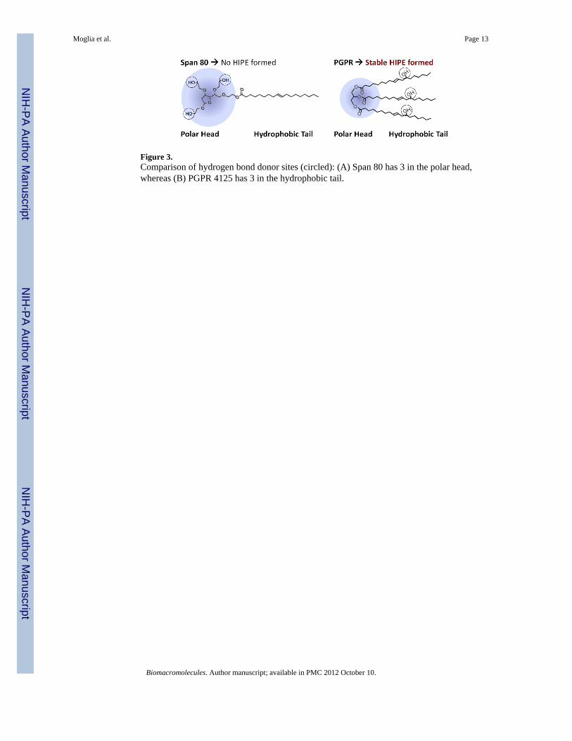
Figure 3.Comparison of hydrogen bond donor sites (circled): (A) Span 80 has 3 in the polar head,whereas (B) PGPR 4125 has 3 in the hydrophobic tail.
Moglia et al. Page 13
Biomacromolecules. Author manuscript; available in PMC 2012 October 10.
NIH
-PA Author Manuscript
NIH
-PA Author Manuscript
NIH
-PA Author Manuscript
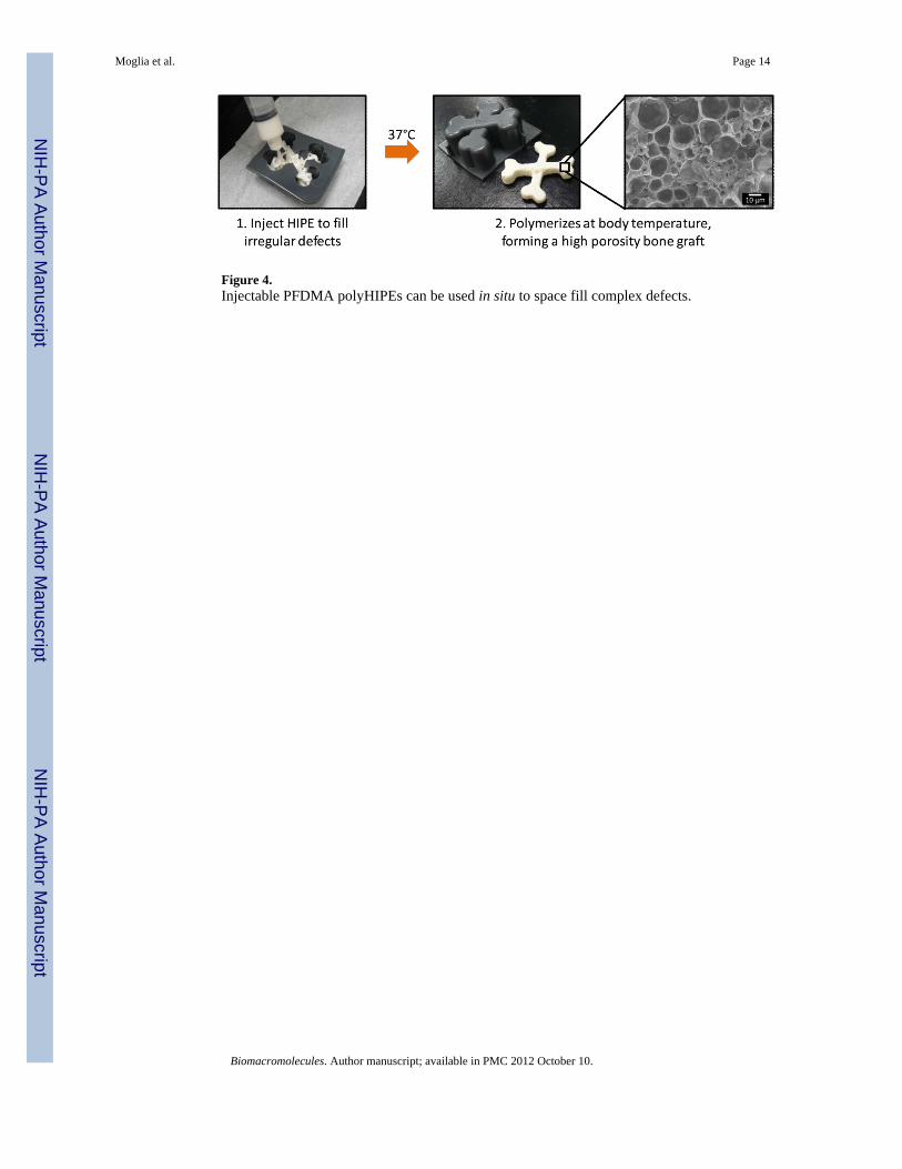
Figure 4.Injectable PFDMA polyHIPEs can be used in situ to space fill complex defects.
Moglia et al. Page 14
Biomacromolecules. Author manuscript; available in PMC 2012 October 10.
NIH
-PA Author Manuscript
NIH
-PA Author Manuscript
NIH
-PA Author Manuscript
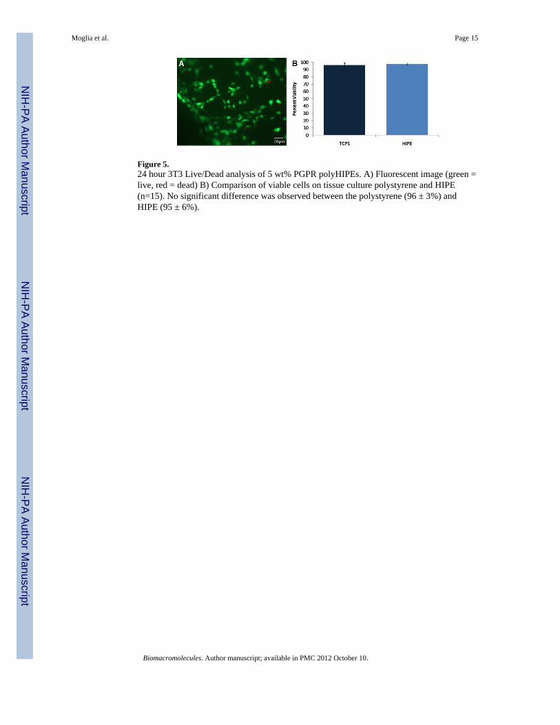
Figure 5.24 hour 3T3 Live/Dead analysis of 5 wt% PGPR polyHIPEs. A) Fluorescent image (green =live, red = dead) B) Comparison of viable cells on tissue culture polystyrene and HIPE(n=15). No significant difference was observed between the polystyrene (96 ± 3%) andHIPE (95 ± 6%).
Moglia et al. Page 15
Biomacromolecules. Author manuscript; available in PMC 2012 October 10.
NIH
-PA Author Manuscript
NIH
-PA Author Manuscript
NIH
-PA Author Manuscript
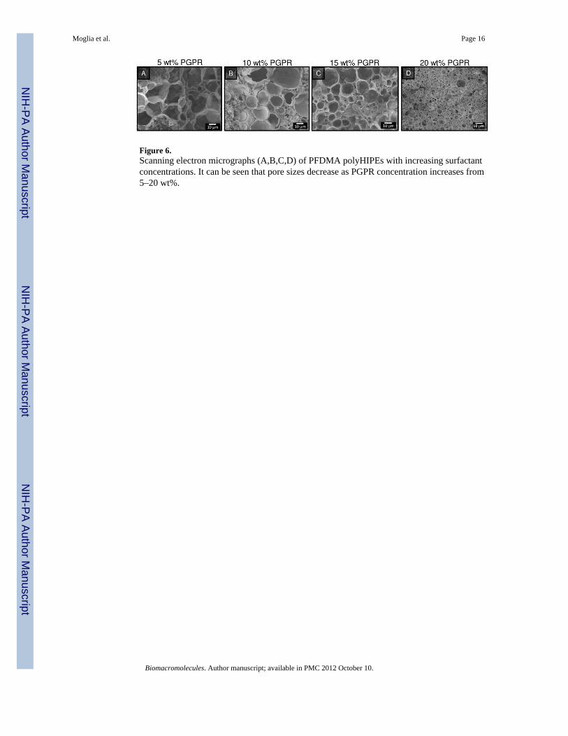
Figure 6.Scanning electron micrographs (A,B,C,D) of PFDMA polyHIPEs with increasing surfactantconcentrations. It can be seen that pore sizes decrease as PGPR concentration increases from5–20 wt%.
Moglia et al. Page 16
Biomacromolecules. Author manuscript; available in PMC 2012 October 10.
NIH
-PA Author Manuscript
NIH
-PA Author Manuscript
NIH
-PA Author Manuscript
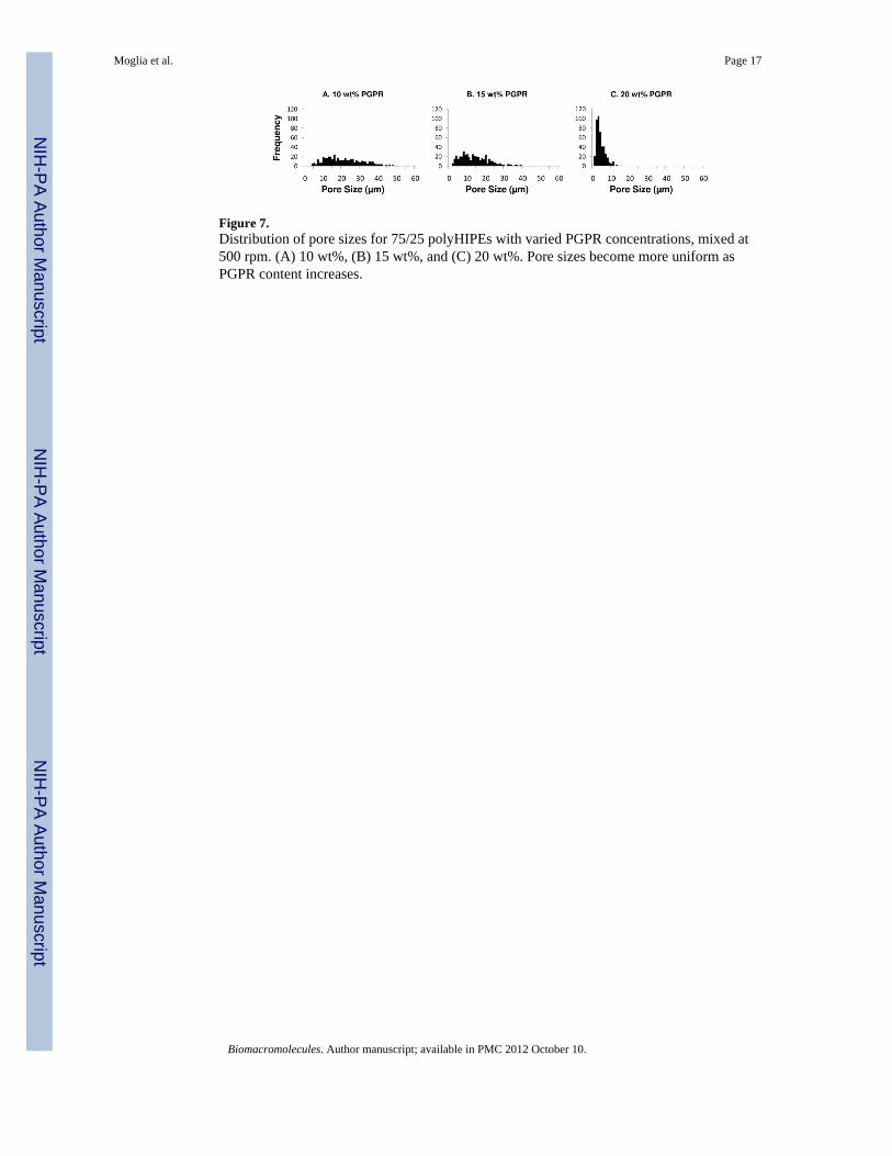
Figure 7.Distribution of pore sizes for 75/25 polyHIPEs with varied PGPR concentrations, mixed at500 rpm. (A) 10 wt%, (B) 15 wt%, and (C) 20 wt%. Pore sizes become more uniform asPGPR content increases.
Moglia et al. Page 17
Biomacromolecules. Author manuscript; available in PMC 2012 October 10.
NIH
-PA Author Manuscript
NIH
-PA Author Manuscript
NIH
-PA Author Manuscript
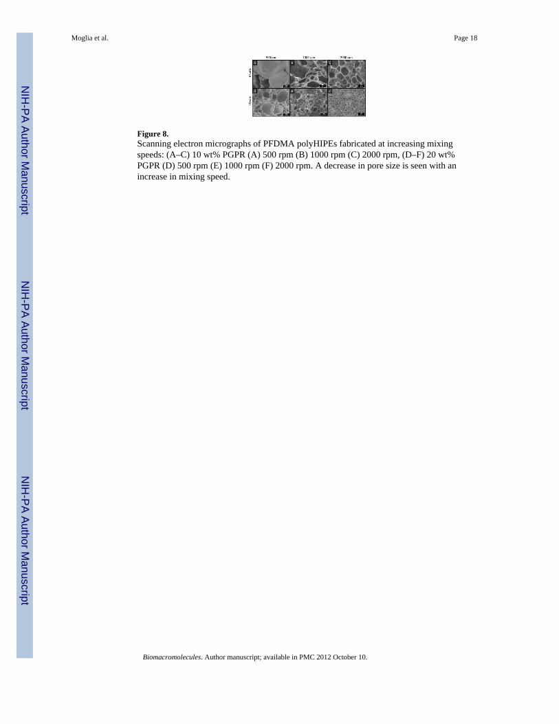
Figure 8.Scanning electron micrographs of PFDMA polyHIPEs fabricated at increasing mixingspeeds: (A–C) 10 wt% PGPR (A) 500 rpm (B) 1000 rpm (C) 2000 rpm, (D–F) 20 wt%PGPR (D) 500 rpm (E) 1000 rpm (F) 2000 rpm. A decrease in pore size is seen with anincrease in mixing speed.
Moglia et al. Page 18
Biomacromolecules. Author manuscript; available in PMC 2012 October 10.
NIH
-PA Author Manuscript
NIH
-PA Author Manuscript
NIH
-PA Author Manuscript

Figure 9.Distribution of pore sizes for 75/25 polyHIPEs fabricated with 10 (black) and 20 wt% PGPR(blue) at 500, 1000, and 2000 rpm.
Moglia et al. Page 19
Biomacromolecules. Author manuscript; available in PMC 2012 October 10.
NIH
-PA Author Manuscript
NIH
-PA Author Manuscript
NIH
-PA Author Manuscript

NIH
-PA Author Manuscript
NIH
-PA Author Manuscript
NIH
-PA Author Manuscript
Moglia et al. Page 20
Table 1
Estimated Octanol-Water Partition Coefficients
Molecule LogP a
Styrene 2.8
Divinyl benzene 3.6
PFDA 2.3
PFDMA 3.4
PPF (n = 5) 2.4
PPF (n = 6) 3.1
aOctanol-water diffusion coefficient calculated with the Molinspiration miLogP model based on molecular structures.
Biomacromolecules. Author manuscript; available in PMC 2012 October 10.

NIH
-PA Author Manuscript
NIH
-PA Author Manuscript
NIH
-PA Author Manuscript
Moglia et al. Page 21
Table 2
The effect of hydrogen bond donor site location and HLB value on HIPE formation.
Surfactant
Hydrogen Bond Donor Site Location
Polar Head Hydrophobic Tail HLB value HIPE Formed
Span 85 1 0 1.8 no
Span 80 3 0 4.3 no
PGPR 4125 0 3 4.7 yes
PEG 600 Dilaurate 0 0 11.7 no
Tween 80 3 0 15 no
Biomacromolecules. Author manuscript; available in PMC 2012 October 10.
NIH
-PA Author Manuscript
NIH
-PA Author Manuscript
NIH
-PA Author Manuscript
Moglia et al. Page 22
Table 2
The effect of surfactant concentration on polyHIPE architecture.
Surfactant (wt%) Porosity (%) Average Pore Diameter (μm)
5 75.1 ± 0.4 29 ± 19
10 75.1 ± 0.3 21 ± 11
15 75.1 ± 0.1 14 ± 8
20 74.1 ± 0.1 4 ± 2
Gravimetric porosity, N = 3, average ± standard deviation. Average pore measurements from image analysis of scanning electron micrographs, N =150, average ± standard deviation.
Biomacromolecules. Author manuscript; available in PMC 2012 October 10.
NIH
-PA Author Manuscript
NIH
-PA Author Manuscript
NIH
-PA Author Manuscript
Moglia et al. Page 23
Table 3
The effect of mixing speed on polyHIPE pore structure with a constant volume fraction (75/25) and variedsurfactant concentration (10 and 20 wt% PGPR)
[PGPR] Mixing Speed (rpm) Average Pore Diameter (μm)
10 wt%
500 21 ± 11
1000 8 ± 4
2000 4 ± 3
20 wt%
500 4 ± 2
1000 3 ± 2
2000 2 ± 1
Average pore measurements from image analysis of scanning electron micrographs, N = 150, average ± standard deviation.
Biomacromolecules. Author manuscript; available in PMC 2012 October 10.