informatica cloud data integration - components - (english)
TRANSCRIPT

Informatica® Cloud Data IntegrationFebruary 2022
Components

Informatica Cloud Data Integration ComponentsFebruary 2022
© Copyright Informatica LLC 2019, 2022
This software and documentation are provided only under a separate license agreement containing restrictions on use and disclosure. No part of this document may be reproduced or transmitted in any form, by any means (electronic, photocopying, recording or otherwise) without prior consent of Informatica LLC.
U.S. GOVERNMENT RIGHTS Programs, software, databases, and related documentation and technical data delivered to U.S. Government customers are "commercial computer software" or "commercial technical data" pursuant to the applicable Federal Acquisition Regulation and agency-specific supplemental regulations. As such, the use, duplication, disclosure, modification, and adaptation is subject to the restrictions and license terms set forth in the applicable Government contract, and, to the extent applicable by the terms of the Government contract, the additional rights set forth in FAR 52.227-19, Commercial Computer Software License.
Informatica, Informatica Cloud, Informatica Intelligent Cloud Services, PowerCenter, PowerExchange, and the Informatica logo are trademarks or registered trademarks of Informatica LLC in the United States and many jurisdictions throughout the world. A current list of Informatica trademarks is available on the web at https://www.informatica.com/trademarks.html. Other company and product names may be trade names or trademarks of their respective owners.
Portions of this software and/or documentation are subject to copyright held by third parties. Required third party notices are included with the product.
The information in this documentation is subject to change without notice. If you find any problems in this documentation, report them to us at [email protected].
Informatica products are warranted according to the terms and conditions of the agreements under which they are provided. INFORMATICA PROVIDES THE INFORMATION IN THIS DOCUMENT "AS IS" WITHOUT WARRANTY OF ANY KIND, EXPRESS OR IMPLIED, INCLUDING WITHOUT ANY WARRANTIES OF MERCHANTABILITY, FITNESS FOR A PARTICULAR PURPOSE AND ANY WARRANTY OR CONDITION OF NON-INFRINGEMENT.
Publication Date: 2022-02-04

Table of Contents
Preface . . . . . . . . . . . . . . . . . . . . . . . . . . . . . . . . . . . . . . . . . . . . . . . . . . . . . . . . . . . . . . . . . . . . . . 6Informatica Resources. . . . . . . . . . . . . . . . . . . . . . . . . . . . . . . . . . . . . . . . . . . . . . . . . . . 6
Informatica Documentation. . . . . . . . . . . . . . . . . . . . . . . . . . . . . . . . . . . . . . . . . . . . . 6
Informatica Intelligent Cloud Services web site. . . . . . . . . . . . . . . . . . . . . . . . . . . . . . . . 6
Informatica Intelligent Cloud Services Communities. . . . . . . . . . . . . . . . . . . . . . . . . . . . . 6
Informatica Intelligent Cloud Services Marketplace. . . . . . . . . . . . . . . . . . . . . . . . . . . . . . 6
Data Integration connector documentation. . . . . . . . . . . . . . . . . . . . . . . . . . . . . . . . . . . 7
Informatica Knowledge Base. . . . . . . . . . . . . . . . . . . . . . . . . . . . . . . . . . . . . . . . . . . . 7
Informatica Intelligent Cloud Services Trust Center. . . . . . . . . . . . . . . . . . . . . . . . . . . . . . 7
Informatica Global Customer Support. . . . . . . . . . . . . . . . . . . . . . . . . . . . . . . . . . . . . . 7
Chapter 1: Components. . . . . . . . . . . . . . . . . . . . . . . . . . . . . . . . . . . . . . . . . . . . . . . . . . . . . . . 8
Chapter 2: API collections. . . . . . . . . . . . . . . . . . . . . . . . . . . . . . . . . . . . . . . . . . . . . . . . . . . 10Creating an API collection. . . . . . . . . . . . . . . . . . . . . . . . . . . . . . . . . . . . . . . . . . . . . . . . 11
Viewing mapping schemas. . . . . . . . . . . . . . . . . . . . . . . . . . . . . . . . . . . . . . . . . . . . . . . 11
Synchronizing a REST API request. . . . . . . . . . . . . . . . . . . . . . . . . . . . . . . . . . . . . . . . . . . 11
Chapter 3: Business services. . . . . . . . . . . . . . . . . . . . . . . . . . . . . . . . . . . . . . . . . . . . . . . . 12Defining a business service. . . . . . . . . . . . . . . . . . . . . . . . . . . . . . . . . . . . . . . . . . . . . . . 12
Chapter 4: File listeners. . . . . . . . . . . . . . . . . . . . . . . . . . . . . . . . . . . . . . . . . . . . . . . . . . . . . 14File listeners in file ingestion tasks. . . . . . . . . . . . . . . . . . . . . . . . . . . . . . . . . . . . . . . . . . 14
File listeners in taskflows . . . . . . . . . . . . . . . . . . . . . . . . . . . . . . . . . . . . . . . . . . . . . . . . 15
File listeners in B2B Gateway partner flows. . . . . . . . . . . . . . . . . . . . . . . . . . . . . . . . . . . . . 15
Behavioral differences in file listeners. . . . . . . . . . . . . . . . . . . . . . . . . . . . . . . . . . . . . . . . 16
Configuring a file listener. . . . . . . . . . . . . . . . . . . . . . . . . . . . . . . . . . . . . . . . . . . . . . . . . 16
Configuring file listener for a server source type. . . . . . . . . . . . . . . . . . . . . . . . . . . . . . . 18
Configuring file listener for a connector source type. . . . . . . . . . . . . . . . . . . . . . . . . . . . 19
Add Parameters. . . . . . . . . . . . . . . . . . . . . . . . . . . . . . . . . . . . . . . . . . . . . . . . . . . 22
Start and stop a file listener manually. . . . . . . . . . . . . . . . . . . . . . . . . . . . . . . . . . . . . . . . . 24
Starting and stopping a file listener. . . . . . . . . . . . . . . . . . . . . . . . . . . . . . . . . . . . . . . 25
Chapter 5: Fixed-width file formats. . . . . . . . . . . . . . . . . . . . . . . . . . . . . . . . . . . . . . . . . . 26Creating a fixed-width file format. . . . . . . . . . . . . . . . . . . . . . . . . . . . . . . . . . . . . . . . . . . 26
Chapter 6: Hierarchical schemas. . . . . . . . . . . . . . . . . . . . . . . . . . . . . . . . . . . . . . . . . . . . 30Creating a hierarchical schema. . . . . . . . . . . . . . . . . . . . . . . . . . . . . . . . . . . . . . . . . . . . . 30
Table of Contents 3

Chapter 7: Intelligent structure models. . . . . . . . . . . . . . . . . . . . . . . . . . . . . . . . . . . . . . 31Using intelligent structure models in mappings. . . . . . . . . . . . . . . . . . . . . . . . . . . . . . . . . . . 32
Using intelligent structure models in elastic mappings. . . . . . . . . . . . . . . . . . . . . . . . . . . . . . 32
Using intelligent structure models in data engineering mappings. . . . . . . . . . . . . . . . . . . . . . . 33
Using intelligent structure models in B2B Gateway inbound partner flows. . . . . . . . . . . . . . . . . . 33
Intelligent Structure Discovery process. . . . . . . . . . . . . . . . . . . . . . . . . . . . . . . . . . . . . . . . 33
Inputs for intelligent structure models. . . . . . . . . . . . . . . . . . . . . . . . . . . . . . . . . . . . . . . . 34
Repeating groups. . . . . . . . . . . . . . . . . . . . . . . . . . . . . . . . . . . . . . . . . . . . . . . . . . . . . . 35
Primary and foreign keys. . . . . . . . . . . . . . . . . . . . . . . . . . . . . . . . . . . . . . . . . . . . . . . . . 36
Data drifts. . . . . . . . . . . . . . . . . . . . . . . . . . . . . . . . . . . . . . . . . . . . . . . . . . . . . . . . . . 38
Unassigned data. . . . . . . . . . . . . . . . . . . . . . . . . . . . . . . . . . . . . . . . . . . . . . . . . . . . . . 38
Intelligent structure model example. . . . . . . . . . . . . . . . . . . . . . . . . . . . . . . . . . . . . . . . . . 39
Use Case. . . . . . . . . . . . . . . . . . . . . . . . . . . . . . . . . . . . . . . . . . . . . . . . . . . . . . . . . . . 39
Creating an intelligent structure model. . . . . . . . . . . . . . . . . . . . . . . . . . . . . . . . . . . . . . . . 42
Exporting an intelligent structure model. . . . . . . . . . . . . . . . . . . . . . . . . . . . . . . . . . . . . . . 43
Troubleshooting intelligent structure models. . . . . . . . . . . . . . . . . . . . . . . . . . . . . . . . . . . . 43
Chapter 8: Refining intelligent structure models. . . . . . . . . . . . . . . . . . . . . . . . . . . . . 45Navigating the output. . . . . . . . . . . . . . . . . . . . . . . . . . . . . . . . . . . . . . . . . . . . . . . . . . . 46
Navigating the intelligent structure. . . . . . . . . . . . . . . . . . . . . . . . . . . . . . . . . . . . . . . . . . 48
Editing the nodes. . . . . . . . . . . . . . . . . . . . . . . . . . . . . . . . . . . . . . . . . . . . . . . . . . . . . . 50
Adding document identifiers to data in a model. . . . . . . . . . . . . . . . . . . . . . . . . . . . . . . . . . 52
Adding prefixes and suffixes to field names. . . . . . . . . . . . . . . . . . . . . . . . . . . . . . . . . . . . . 53
Performing actions on data in nodes. . . . . . . . . . . . . . . . . . . . . . . . . . . . . . . . . . . . . . . . . 53
Performing actions on multiple nodes. . . . . . . . . . . . . . . . . . . . . . . . . . . . . . . . . . . . . . . . 53
Enriching an existing model with new samples. . . . . . . . . . . . . . . . . . . . . . . . . . . . . . . . . . . 54
Edit the structure of Microsoft Excel tables. . . . . . . . . . . . . . . . . . . . . . . . . . . . . . . . . . . . . 55
Transposing a table. . . . . . . . . . . . . . . . . . . . . . . . . . . . . . . . . . . . . . . . . . . . . . . . . 56
Switching between a table and name-value pairs. . . . . . . . . . . . . . . . . . . . . . . . . . . . . . . 56
Defining table headers. . . . . . . . . . . . . . . . . . . . . . . . . . . . . . . . . . . . . . . . . . . . . . . 57
Working with relational output. . . . . . . . . . . . . . . . . . . . . . . . . . . . . . . . . . . . . . . . . . . . . 57
Working with repeating groups. . . . . . . . . . . . . . . . . . . . . . . . . . . . . . . . . . . . . . . . . . . . . 58
Testing the output. . . . . . . . . . . . . . . . . . . . . . . . . . . . . . . . . . . . . . . . . . . . . . . . . . . . . 58
Chapter 9: Mapplets. . . . . . . . . . . . . . . . . . . . . . . . . . . . . . . . . . . . . . . . . . . . . . . . . . . . . . . . . 60Active and passive mapplets. . . . . . . . . . . . . . . . . . . . . . . . . . . . . . . . . . . . . . . . . . . . . . 60
Mapplet Input and Output. . . . . . . . . . . . . . . . . . . . . . . . . . . . . . . . . . . . . . . . . . . . . . . . 60
Mapplet input. . . . . . . . . . . . . . . . . . . . . . . . . . . . . . . . . . . . . . . . . . . . . . . . . . . . . 61
Mapplet output. . . . . . . . . . . . . . . . . . . . . . . . . . . . . . . . . . . . . . . . . . . . . . . . . . . . 61
Parameters in mapplets. . . . . . . . . . . . . . . . . . . . . . . . . . . . . . . . . . . . . . . . . . . . . . . . . 61
Creating a mapplet. . . . . . . . . . . . . . . . . . . . . . . . . . . . . . . . . . . . . . . . . . . . . . . . . . . . . 62
Editing a mapplet. . . . . . . . . . . . . . . . . . . . . . . . . . . . . . . . . . . . . . . . . . . . . . . . . . . . . . 62
4 Table of Contents

Synchronizing a mapplet. . . . . . . . . . . . . . . . . . . . . . . . . . . . . . . . . . . . . . . . . . . . . . 63
Mapplets in Data Integration Elastic. . . . . . . . . . . . . . . . . . . . . . . . . . . . . . . . . . . . . . . . . . 64
Editing a mapplet in Data Integration Elastic. . . . . . . . . . . . . . . . . . . . . . . . . . . . . . . . . 64
PowerCenter mapplets. . . . . . . . . . . . . . . . . . . . . . . . . . . . . . . . . . . . . . . . . . . . . . . . . . 65
Active and passive PowerCenter mapplets. . . . . . . . . . . . . . . . . . . . . . . . . . . . . . . . . . 65
Stored Procedures in mapplets. . . . . . . . . . . . . . . . . . . . . . . . . . . . . . . . . . . . . . . . . . 65
PowerCenter XML files for mapplets. . . . . . . . . . . . . . . . . . . . . . . . . . . . . . . . . . . . . . 66
PowerCenter mapplets in Data Integration tasks. . . . . . . . . . . . . . . . . . . . . . . . . . . . . . . 66
Configuring a PowerCenter mapplet. . . . . . . . . . . . . . . . . . . . . . . . . . . . . . . . . . . . . . . 67
Chapter 10: Saved queries. . . . . . . . . . . . . . . . . . . . . . . . . . . . . . . . . . . . . . . . . . . . . . . . . . . 68Saved query syntax. . . . . . . . . . . . . . . . . . . . . . . . . . . . . . . . . . . . . . . . . . . . . . . . . . . . 68
Using saved queries in synchronization tasks. . . . . . . . . . . . . . . . . . . . . . . . . . . . . . . . . . . . 69
Using saved queries in SQL transformations. . . . . . . . . . . . . . . . . . . . . . . . . . . . . . . . . . . . 70
Configuring a saved query. . . . . . . . . . . . . . . . . . . . . . . . . . . . . . . . . . . . . . . . . . . . . . . . 70
Chapter 11: Shared sequences. . . . . . . . . . . . . . . . . . . . . . . . . . . . . . . . . . . . . . . . . . . . . . 72Shared sequence properties. . . . . . . . . . . . . . . . . . . . . . . . . . . . . . . . . . . . . . . . . . . . . . . 72
Number of reserved values. . . . . . . . . . . . . . . . . . . . . . . . . . . . . . . . . . . . . . . . . . . . . . . 73
Creating a shared sequence. . . . . . . . . . . . . . . . . . . . . . . . . . . . . . . . . . . . . . . . . . . . . . . 74
Using a shared sequence. . . . . . . . . . . . . . . . . . . . . . . . . . . . . . . . . . . . . . . . . . . . . . . . . 74
Resetting a shared sequence. . . . . . . . . . . . . . . . . . . . . . . . . . . . . . . . . . . . . . . . . . . . . . 74
Chapter 12: User-defined functions. . . . . . . . . . . . . . . . . . . . . . . . . . . . . . . . . . . . . . . . . . 75Creating user-defined functions. . . . . . . . . . . . . . . . . . . . . . . . . . . . . . . . . . . . . . . . . . . . 75
User-defined function general properties. . . . . . . . . . . . . . . . . . . . . . . . . . . . . . . . . . . . 76
User-defined function arguments. . . . . . . . . . . . . . . . . . . . . . . . . . . . . . . . . . . . . . . . 76
User-defined function expression. . . . . . . . . . . . . . . . . . . . . . . . . . . . . . . . . . . . . . . . 77
Editing and deleting user-defined functions. . . . . . . . . . . . . . . . . . . . . . . . . . . . . . . . . . . . . 77
Creating expressions with user-defined functions. . . . . . . . . . . . . . . . . . . . . . . . . . . . . . . . . 77
Index. . . . . . . . . . . . . . . . . . . . . . . . . . . . . . . . . . . . . . . . . . . . . . . . . . . . . . . . . . . . 79
Table of Contents 5
PrefaceUse Components to learn about reusable assets that you can create in Data Integration. Learn how to create components and add them to transformations, mappings, and tasks.
Informatica ResourcesInformatica provides you with a range of product resources through the Informatica Network and other online portals. Use the resources to get the most from your Informatica products and solutions and to learn from other Informatica users and subject matter experts.
Informatica DocumentationUse the Informatica Documentation Portal to explore an extensive library of documentation for current and recent product releases. To explore the Documentation Portal, visit https://docs.informatica.com.
If you have questions, comments, or ideas about the product documentation, contact the Informatica Documentation team at [email protected].
Informatica Intelligent Cloud Services web siteYou can access the Informatica Intelligent Cloud Services web site at http://www.informatica.com/cloud. This site contains information about Informatica Cloud integration services.
Informatica Intelligent Cloud Services CommunitiesUse the Informatica Intelligent Cloud Services Community to discuss and resolve technical issues. You can also find technical tips, documentation updates, and answers to frequently asked questions.
Access the Informatica Intelligent Cloud Services Community at:
https://network.informatica.com/community/informatica-network/products/cloud-integration
Developers can learn more and share tips at the Cloud Developer community:
https://network.informatica.com/community/informatica-network/products/cloud-integration/cloud-developers
Informatica Intelligent Cloud Services MarketplaceVisit the Informatica Marketplace to try and buy Data Integration Connectors, templates, and mapplets:
https://marketplace.informatica.com/
6
Data Integration connector documentationYou can access documentation for Data Integration Connectors at the Documentation Portal. To explore the Documentation Portal, visit https://docs.informatica.com.
Informatica Knowledge BaseUse the Informatica Knowledge Base to find product resources such as how-to articles, best practices, video tutorials, and answers to frequently asked questions.
To search the Knowledge Base, visit https://search.informatica.com. If you have questions, comments, or ideas about the Knowledge Base, contact the Informatica Knowledge Base team at [email protected].
Informatica Intelligent Cloud Services Trust CenterThe Informatica Intelligent Cloud Services Trust Center provides information about Informatica security policies and real-time system availability.
You can access the trust center at https://www.informatica.com/trust-center.html.
Subscribe to the Informatica Intelligent Cloud Services Trust Center to receive upgrade, maintenance, and incident notifications. The Informatica Intelligent Cloud Services Status page displays the production status of all the Informatica cloud products. All maintenance updates are posted to this page, and during an outage, it will have the most current information. To ensure you are notified of updates and outages, you can subscribe to receive updates for a single component or all Informatica Intelligent Cloud Services components. Subscribing to all components is the best way to be certain you never miss an update.
To subscribe, go to https://status.informatica.com/ and click SUBSCRIBE TO UPDATES. You can then choose to receive notifications sent as emails, SMS text messages, webhooks, RSS feeds, or any combination of the four.
Informatica Global Customer SupportYou can contact a Customer Support Center by telephone or online.
For online support, click Submit Support Request in Informatica Intelligent Cloud Services. You can also use Online Support to log a case. Online Support requires a login. You can request a login at https://network.informatica.com/welcome.
The telephone numbers for Informatica Global Customer Support are available from the Informatica web site at https://www.informatica.com/services-and-training/support-services/contact-us.html.
Preface 7
C h a p t e r 1
ComponentsComponents are assets that support mappings and tasks.
You can use the following components:API collections
Create REST API requests to use in the Machine Learning transformation.
For more information about API collections, see Chapter 2, “API collections” on page 10.
Business services
Define a business service to use in Web Service transformations.
For more information about business services, see Chapter 3, “Business services” on page 12.
File listeners
Create a file listener that listens to files on a specific location and notifies subscribers when files arrive at the location and when files in the location are updated or deleted.
For more information about file listeners, see Chapter 4, “File listeners” on page 14.
Fixed-width file formats
Configure reusable formats that you can use for fixed-width flat file sources and targets to enhance readability.
For more information about fixed-width file formats, see Chapter 5, “Fixed-width file formats” on page 26.
Hierarchical schemas
Upload an XML schema, XML sample file, or JSON sample file to use in mappings that include a Hierarchy transformation.
For more information about hierarchical schemas, see Chapter 6, “Hierarchical schemas” on page 30.
Intelligent structure models
Create or export a model for the following use cases:
• Create a model and use it in a Structure Parser transformation or in a Hierarchy Builder transformation in a Data Integration mapping.
• Create a model and use it in a Data Integration Elastic mapping.
• Export a model and use it in a Data Engineering Integration mapping.
• Create a model and use it to process partner messages in B2B Gateway.
For more information about intelligent structure models, see Chapter 7, “Intelligent structure models” on page 31.
8
Mapplets
Define reusable transformation logic to use in Mapplet transformations in one of the following ways:
• Create a mapplet in Data Integration.
• Upload a PowerCenter mapplet XML file or an SAP mapplet to extend transformation logic in synchronization tasks and mappings.
For more information about mapplets, see Chapter 9, “Mapplets” on page 60.
Saved queries
Create reusable custom queries that you can use as a source in synchronization tasks.
For more information about saved queries, see Chapter 10, “Saved queries” on page 68.
Shared sequence
Define a reusable sequence to use in multiple Sequence Generator transformations.
For more information about shared sequences, see Chapter 11, “Shared sequences” on page 72.
User-defined functions
Create reusable functions that you can use in transformation expressions and in other user-defined functions.
For more information about user-defined functions, see Chapter 12, “User-defined functions” on page 75.
Visio templates
Design transformation logic in Visio and then upload the template and configure the parameters to use in mapping tasks.
For more information about Visio templates, see Mappings.
Create components on the New Asset page.
9
C h a p t e r 2
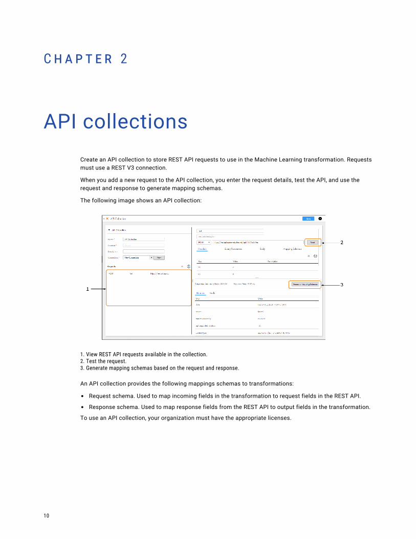
API collectionsCreate an API collection to store REST API requests to use in the Machine Learning transformation. Requests must use a REST V3 connection.
When you add a new request to the API collection, you enter the request details, test the API, and use the request and response to generate mapping schemas.
The following image shows an API collection:
1. View REST API requests available in the collection.2. Test the request.3. Generate mapping schemas based on the request and response.
An API collection provides the following mappings schemas to transformations:
• Request schema. Used to map incoming fields in the transformation to request fields in the REST API.
• Response schema. Used to map response fields from the REST API to output fields in the transformation.
To use an API collection, your organization must have the appropriate licenses.
10
Creating an API collectionCreate an API collection and select a default REST V3 connection to test requests. You can use a different connection when you add the API collection to a transformation.
To create a request, add a new request to the API collection and configure the request details. Append path parameters to the endpoint URL. Then, send the request to test it.
After a request in the API collection receives a response, you can generate the mapping schemas. The API collection uses the request source to generate the request schema, and it uses the response source to generate the response schema.
Viewing mapping schemasView mapping schemas on the Mapping Schemas tab. Transformations use the mapping schemas to interact with the REST API.
Mapping schemas ignore empty structures. For example, the address object in the following response is ignored in the response schema:
{"ID":1,"address":{}}
Synchronizing a REST API requestSynchronize a REST API request to update the request name and the mapping schemas in the Machine Learning transformation.
1. Open the Machine Learning transformation that uses the REST API request.
2. On the Model tab, click Synchronize.
3. Correct any resulting errors in the transformation logic.
To update request details such as the endpoint URL or header parameters, create a new request in the API collection and use the new request in the Machine Learning transformation.
Creating an API collection 11
C h a p t e r 3
Business servicesA business service is a web service with configured operations. Define a business service to add operations to the Web Services transformation in the Mapping Designer.
Define business services and store them in your project folders. You can use business service definitions in multiple mappings.
Defining a business serviceTo define a business service, perform the following steps:
1. Click New > Components > Business Services and then click Create.
2. Enter the business service details and select the Web Services Consumer connection.
3. Select the operation you want to use from the web service.
4. If necessary, configure the operation to specify the choice elements and derived type elements for the request and the response.
If operation components include choice elements or complexType elements where the abstract attribute is true, then you must choose one or more elements or derived types when you configure the operation mapping.
Optionally, for a complexType element where the abstract attribute is false, you can also select a derived type for a complexType element.
a. For the operation you want to configure, click Configure.
b. From the Configure Operation window, click the Request, Response, or Fault tab and navigate to the node you need to configure.
Note: If the WSDL uses the anyAttribute element, the element will not appear for the request or the response.
12
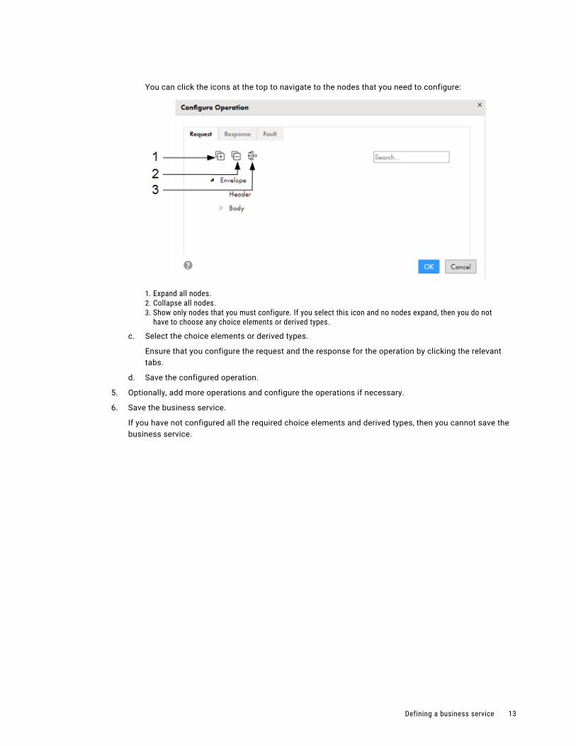
You can click the icons at the top to navigate to the nodes that you need to configure:
1. Expand all nodes.2. Collapse all nodes.3. Show only nodes that you must configure. If you select this icon and no nodes expand, then you do not
have to choose any choice elements or derived types.
c. Select the choice elements or derived types.
Ensure that you configure the request and the response for the operation by clicking the relevant tabs.
d. Save the configured operation.
5. Optionally, add more operations and configure the operations if necessary.
6. Save the business service.
If you have not configured all the required choice elements and derived types, then you cannot save the business service.
Defining a business service 13

C h a p t e r 4
File listenersA file listener listens to files on a defined location. Taskflows, file ingestion tasks, and B2B Gateway partner flows use file listeners to monitor specific folders, and receive notification through a call-back API when a file event occurs. A file event occurs when new files arrive to the monitored folder or the files in the monitored folder are updated or deleted.
You define a file listener that listens to a specific folder and the file pattern. You can define the file events that trigger a notification to the following assets:
• Taskflows
• File ingestion tasks
• B2B Gateway partners
Note: You must have the Read File Listener and Run File Listener privileges to assign a file listener to the assets.
For example, you can define whether file ingestion tasks are notified when new files arrive or files in the monitored location are updated or deleted. You then assign the file listener to a file ingestion task. The file listener listens to source folder, and notifies the file ingestion task when a file arrived, file updated, or file deleted event occurs. You can configure the source as a server event or a connector. The file ingestion task then runs and picks up files from the source folder.
A file listener sends notifications to the user who created it when it starts listening to the folder, when it stops listening to the folder, and if errors occur while it listens to the folder.
The file listener creates a job when the file listener starts and lists the job instance in the file transfer logs page. The file listener updates the job when files events occur. The file listener job details appear in the file listener job properties.
A file listener that is not used by a taskflow, file ingestion task, or B2B Gateway partner is not active and does not listen to the defined folder.
File listeners in file ingestion tasksYou can use a file listener as a source and to schedule file monitors in file ingestion tasks.
In file ingestion tasks with the following source types, you can schedule the task to run when it receives notifications from a file listener:
• Local folder
• Advanced FTP V2
• Advanced SFTP V2
14
• Advanced FTPS V2
• Amazon S3 V2
• Microsoft Azure Data Lake Store Gen2
• Microsoft Azure Data Lake Store V3
• Microsoft Azure Blob Storage V3
• Google Cloud Storage V2
• Hadoop Distributed File Storage (HDFS) V2
Note: For more information on configuring a file ingestion task, see Mass Ingestion guide.
File listeners in taskflowsYou can use a file listener in a taskflow when the file listener is configured to listen to connections.
You can use a file listener in a taskflow for the following use cases:
To invoke a taskflow through a file listener
You can invoke a taskflow through a file listener with the connector source type.
Within the taskflow, define the binding type as Event and select the file listener as the event source. When you publish the taskflow, the taskflow subscribes to the file listener that is defined in it. When a file event occurs, the file listener invokes the taskflow.
For example, if you configure the file listener to listen for new files on a folder, the file listener invokes the associated taskflow each time a new file arrives in the specified folder.
To orchestrate taskflow execution through file events
You can orchestrate taskflow execution through file events by using the File Watch Task step in a taskflow.
You can add a File Watch Task step to a taskflow to listen to files in a defined location and monitor file events. In the File Watch Task step, you can select an existing file listener with the connector source type. You can use file events to orchestrate taskflow execution.
For example, you can wait for a file to arrive at a particular location and then consume the file in a subsequent step.
File listeners in B2B Gateway partner flowsYou can use a file listener to trigger B2B Gateway partner inbound and outbound flows.
When you configure the partner, you select the file listener to trigger the inbound or outbound flow. When you save the partner, the partner subscribes to the file listener. The file listener triggers the flow according to the rules defined in the file listener.
For example, you configure a file listener to listen for new files arriving in a folder and then configure the partner to use the file listener for inbound flows. When the partner puts files into the specified folder, the file listener triggers the inbound flow.
File listeners in taskflows 15
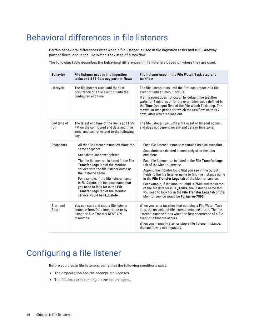
Behavioral differences in file listenersCertain behavioral differences exist when a file listener is used in file ingestion tasks and B2B Gateway partner flows, and in the File Watch Task step of a taskflow.
The following table describes the behavioral differences in file listeners based on where they are used:
Behavior File listener used in file ingestion tasks and B2B Gateway partner flows
File listener used in the File Watch Task step of a taskflow
Lifecycle The file listener runs until the first occurrence of a file event or until the configured end time.
The file listener runs until the first occurrence of a file event or until a timeout occurs.If a file event does not occur, by default, the taskflow waits for 5 minutes or for the overridden value defined in the Time Out input field of the File Watch Task step. The maximum time period for which the taskflow waits is 7 days, after which it times out.
End time of run
The latest end time of the run is at 11:55 PM on the configured end date and time zone, and cannot extend to the following day.
The file listener runs until a file event or timeout occurs, and does not depend on any end date or time zone.
Snapshots - All the file listener instances share the same snapshot.
- Snapshots are never deleted.- The file listener run is listed in the File
Transfer Logs tab of the Monitor service with the file listener name as the instance name.For example, if the file listener name is FL_Delete, the instance name that you need to look for in the File Transfer Logs tab of the Monitor service would be FL_Delete.
- Each file listener instance maintains its own snapshot.- Snapshots are deleted immediately after the jobs
complete.- Each file listener run is listed in the File Transfer Logs
tab of the Monitor service.Append the monitorJobId that you see in the output fields to the file listener name to find the instance name in the File Transfer Logs tab of the Monitor service.For example, if the monitorJobId is 7500 and the name of the file listener is FL_Arrive, the instance name that you need to look for in the File Transfer Logs tab of the Monitor service would be FL_Arrive-7500.
Start and Stop
You can start and stop a file listener instance from Data Integration or by using the File Transfer REST API resources.
When you run a taskflow that contains a File Watch Task step, the associated file listener instance starts. The file listener instance stops when the first occurrence of a file event or a timeout occurs.When you manually start or stop a file listener instance, the taskflow is not impacted.
Configuring a file listenerBefore you create file listeners, verify that the following conditions exist:
• The organization has the appropriate licenses.
• The file listener is running on the secure agent.
16 Chapter 4: File listeners
Perform the following steps to configure a file listener:
1. To create a file listener, click New > Components > File Listener, and then click Create.
To edit a file listener, on the Explore page, navigate to the file listener. In the row that lists the file listener, click Actions and select Edit.When you edit a file listener, such as update the run-time environment, connector type, connection, or listener rule properties, the file listener requires a reset. A warning message appears. Click Ok to continue. This action clears the list of previously tracked files.
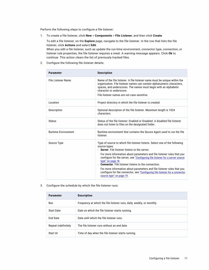
2. Configure the following file listener details:
Parameter Description
File Listener Name Name of the file listener. A file listener name must be unique within the organization. File listener names can contain alphanumeric characters, spaces, and underscores. The names must begin with an alphabetic character or underscore.File listener names are not case sensitive.
Location Project directory in which the file listener is created.
Description Optional description of the file listener. Maximum length is 1024 characters.
Status Status of the file listener: Enabled or Disabled. A disabled file listener does not listen to files on the designated folder.
Runtime Environment Runtime environment that contains the Secure Agent used to run the file listener.
Source Type Type of source to which file listener listens. Select one of the following source types:- Server. File listener listens to the server.
For more information about parameters and file listener rules that you configure for the server, see “Configuring file listener for a server source type” on page 18.
- Connector. File listener listens to the connection.For more information about parameters and file listener rules that you configure for the connector, see “Configuring file listener for a connector source type” on page 19.
3. Configure the schedule by which the file listener runs:
Parameter Description
Run Frequency at which the file listener runs, daily, weekly, or monthly.
Start Date Date on which the file listener starts running.
End Date Date until which the file listener runs.
Repeat indefinitely The file listener runs without an end date.
Start At Time of day when the file listener starts running.
Configuring a file listener 17
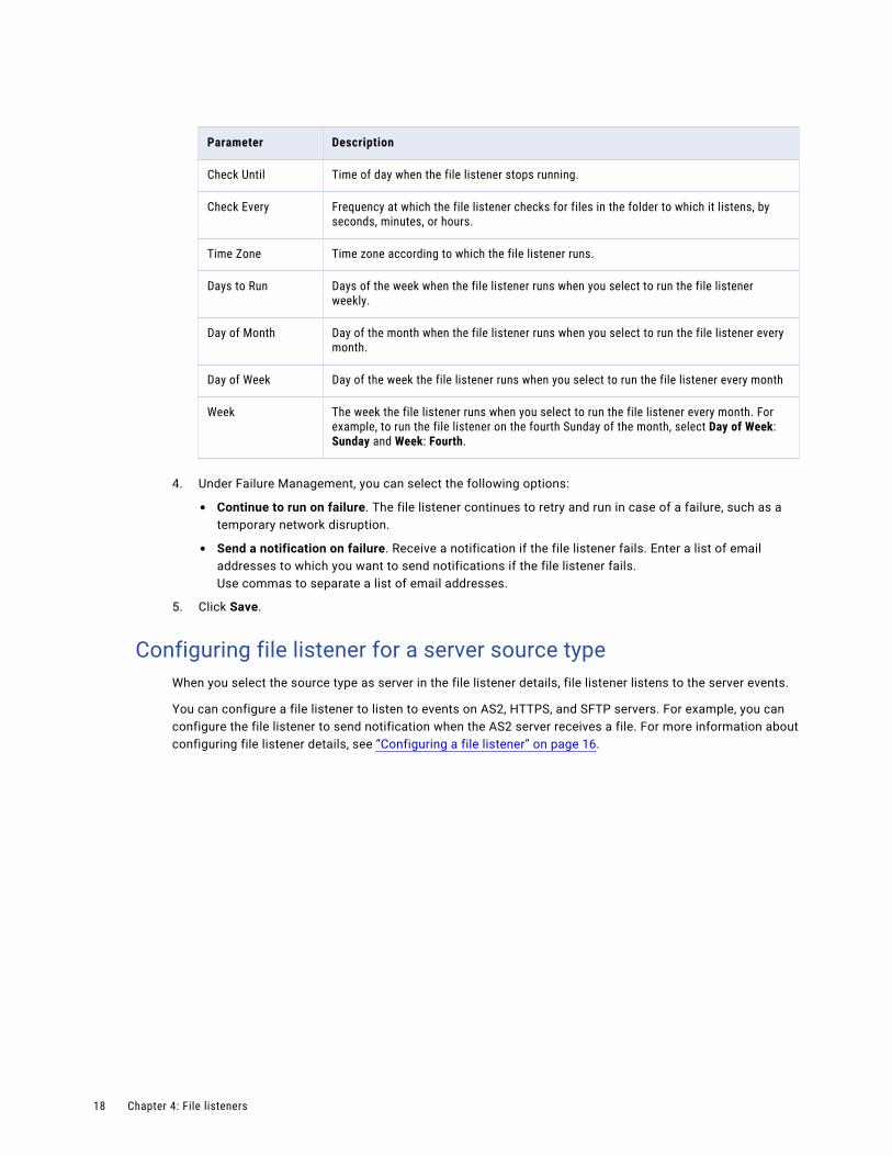
Parameter Description
Check Until Time of day when the file listener stops running.
Check Every Frequency at which the file listener checks for files in the folder to which it listens, by seconds, minutes, or hours.
Time Zone Time zone according to which the file listener runs.
Days to Run Days of the week when the file listener runs when you select to run the file listener weekly.
Day of Month Day of the month when the file listener runs when you select to run the file listener every month.
Day of Week Day of the week the file listener runs when you select to run the file listener every month
Week The week the file listener runs when you select to run the file listener every month. For example, to run the file listener on the fourth Sunday of the month, select Day of Week: Sunday and Week: Fourth.
4. Under Failure Management, you can select the following options:
• Continue to run on failure. The file listener continues to retry and run in case of a failure, such as a temporary network disruption.
• Send a notification on failure. Receive a notification if the file listener fails. Enter a list of email addresses to which you want to send notifications if the file listener fails.Use commas to separate a list of email addresses.
5. Click Save.
Configuring file listener for a server source typeWhen you select the source type as server in the file listener details, file listener listens to the server events.
You can configure a file listener to listen to events on AS2, HTTPS, and SFTP servers. For example, you can configure the file listener to send notification when the AS2 server receives a file. For more information about configuring file listener details, see “Configuring a file listener” on page 16.
18 Chapter 4: File listeners
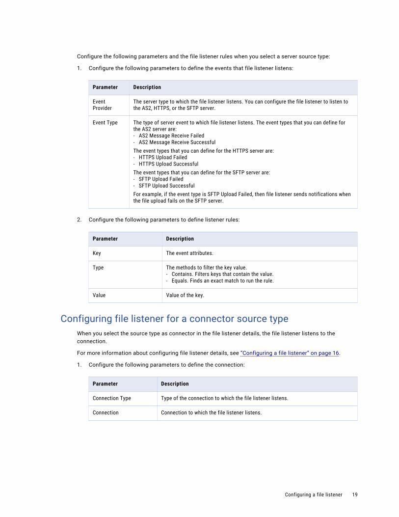
Configure the following parameters and the file listener rules when you select a server source type:
1. Configure the following parameters to define the events that file listener listens:
Parameter Description
Event Provider
The server type to which the file listener listens. You can configure the file listener to listen to the AS2, HTTPS, or the SFTP server.
Event Type The type of server event to which file listener listens. The event types that you can define for the AS2 server are:- AS2 Message Receive Failed- AS2 Message Receive SuccessfulThe event types that you can define for the HTTPS server are:- HTTPS Upload Failed- HTTPS Upload SuccessfulThe event types that you can define for the SFTP server are:- SFTP Upload Failed- SFTP Upload SuccessfulFor example, if the event type is SFTP Upload Failed, then file listener sends notifications when the file upload fails on the SFTP server.
2. Configure the following parameters to define listener rules:
Parameter Description
Key The event attributes.
Type The methods to filter the key value.- Contains. Filters keys that contain the value.- Equals. Finds an exact match to run the rule.
Value Value of the key.
Configuring file listener for a connector source typeWhen you select the source type as connector in the file listener details, the file listener listens to the connection.
For more information about configuring file listener details, see “Configuring a file listener” on page 16.
1. Configure the following parameters to define the connection:
Parameter Description
Connection Type Type of the connection to which the file listener listens.
Connection Connection to which the file listener listens.
Configuring a file listener 19
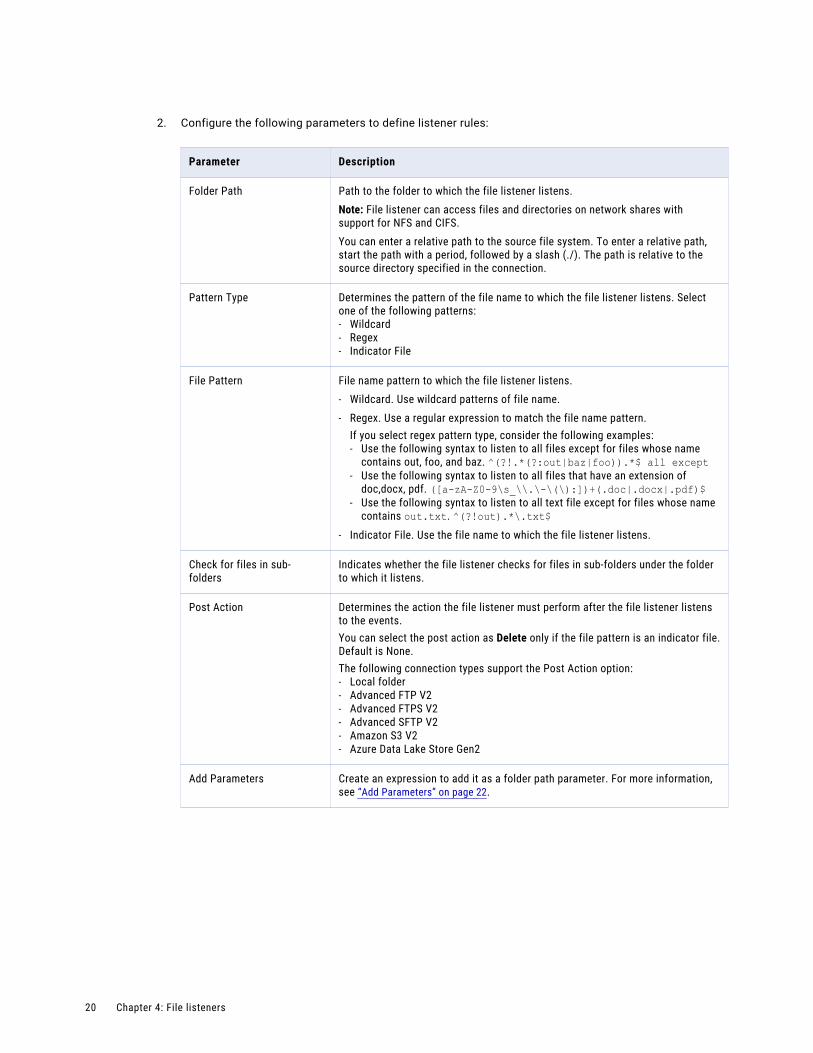
2. Configure the following parameters to define listener rules:
Parameter Description
Folder Path Path to the folder to which the file listener listens.Note: File listener can access files and directories on network shares with support for NFS and CIFS.You can enter a relative path to the source file system. To enter a relative path, start the path with a period, followed by a slash (./). The path is relative to the source directory specified in the connection.
Pattern Type Determines the pattern of the file name to which the file listener listens. Select one of the following patterns:- Wildcard- Regex- Indicator File
File Pattern File name pattern to which the file listener listens.- Wildcard. Use wildcard patterns of file name.
- Regex. Use a regular expression to match the file name pattern.If you select regex pattern type, consider the following examples:- Use the following syntax to listen to all files except for files whose name
contains out, foo, and baz. ^(?!.*(?:out|baz|foo)).*$ all except- Use the following syntax to listen to all files that have an extension of
doc,docx, pdf. ([a-zA-Z0-9\s_\\.\-\(\):])+(.doc|.docx|.pdf)$- Use the following syntax to listen to all text file except for files whose name
contains out.txt. ^(?!out).*\.txt$- Indicator File. Use the file name to which the file listener listens.
Check for files in sub-folders
Indicates whether the file listener checks for files in sub-folders under the folder to which it listens.
Post Action Determines the action the file listener must perform after the file listener listens to the events.You can select the post action as Delete only if the file pattern is an indicator file. Default is None.The following connection types support the Post Action option:- Local folder- Advanced FTP V2- Advanced FTPS V2- Advanced SFTP V2- Amazon S3 V2- Azure Data Lake Store Gen2
Add Parameters Create an expression to add it as a folder path parameter. For more information, see “Add Parameters” on page 22.
20 Chapter 4: File listeners
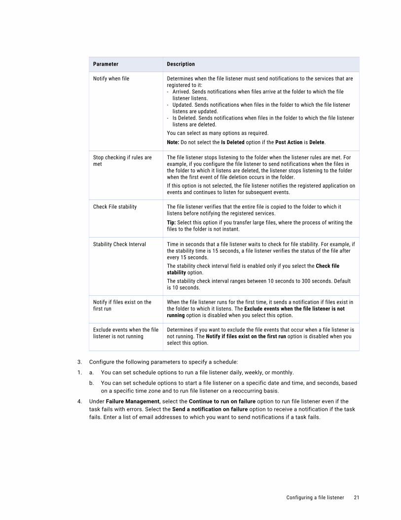
Parameter Description
Notify when file Determines when the file listener must send notifications to the services that are registered to it:- Arrived. Sends notifications when files arrive at the folder to which the file
listener listens.- Updated. Sends notifications when files in the folder to which the file listener
listens are updated.- Is Deleted. Sends notifications when files in the folder to which the file listener
listens are deleted.You can select as many options as required.Note: Do not select the Is Deleted option if the Post Action is Delete.
Stop checking if rules are met
The file listener stops listening to the folder when the listener rules are met. For example, if you configure the file listener to send notifications when the files in the folder to which it listens are deleted, the listener stops listening to the folder when the first event of file deletion occurs in the folder.If this option is not selected, the file listener notifies the registered application on events and continues to listen for subsequent events.
Check File stability The file listener verifies that the entire file is copied to the folder to which it listens before notifying the registered services.Tip: Select this option if you transfer large files, where the process of writing the files to the folder is not instant.
Stability Check Interval Time in seconds that a file listener waits to check for file stability. For example, if the stability time is 15 seconds, a file listener verifies the status of the file after every 15 seconds.The stability check interval field is enabled only if you select the Check file stability option.The stability check interval ranges between 10 seconds to 300 seconds. Default is 10 seconds.
Notify if files exist on the first run
When the file listener runs for the first time, it sends a notification if files exist in the folder to which it listens. The Exclude events when the file listener is not running option is disabled when you select this option.
Exclude events when the file listener is not running
Determines if you want to exclude the file events that occur when a file listener is not running. The Notify if files exist on the first run option is disabled when you select this option.
3. Configure the following parameters to specify a schedule:
1. a. You can set schedule options to run a file listener daily, weekly, or monthly.
b. You can set schedule options to start a file listener on a specific date and time, and seconds, based on a specific time zone and to run file listener on a reoccurring basis.
4. Under Failure Management, select the Continue to run on failure option to run file listener even if the task fails with errors. Select the Send a notification on failure option to receive a notification if the task fails. Enter a list of email addresses to which you want to send notifications if a task fails.
Configuring a file listener 21
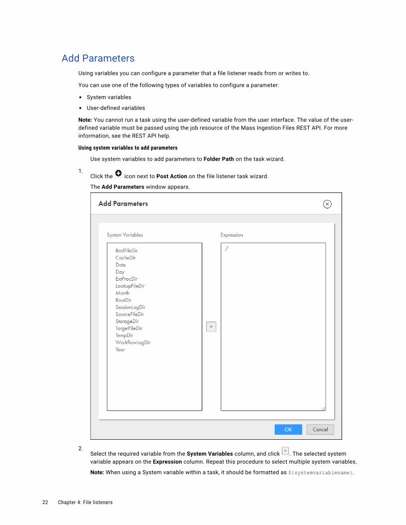
Add ParametersUsing variables you can configure a parameter that a file listener reads from or writes to.
You can use one of the following types of variables to configure a parameter:
• System variables
• User-defined variables
Note: You cannot run a task using the user-defined variable from the user interface. The value of the user-defined variable must be passed using the job resource of the Mass Ingestion Files REST API. For more information, see the REST API help.
Using system variables to add parameters
Use system variables to add parameters to Folder Path on the task wizard.
1.Click the icon next to Post Action on the file listener task wizard.
The Add Parameters window appears.
2.Select the required variable from the System Variables column, and click . The selected system variable appears on the Expression column. Repeat this procedure to select multiple system variables.
Note: When using a System variable within a task, it should be formatted as ${systemvariablename}.
22 Chapter 4: File listeners
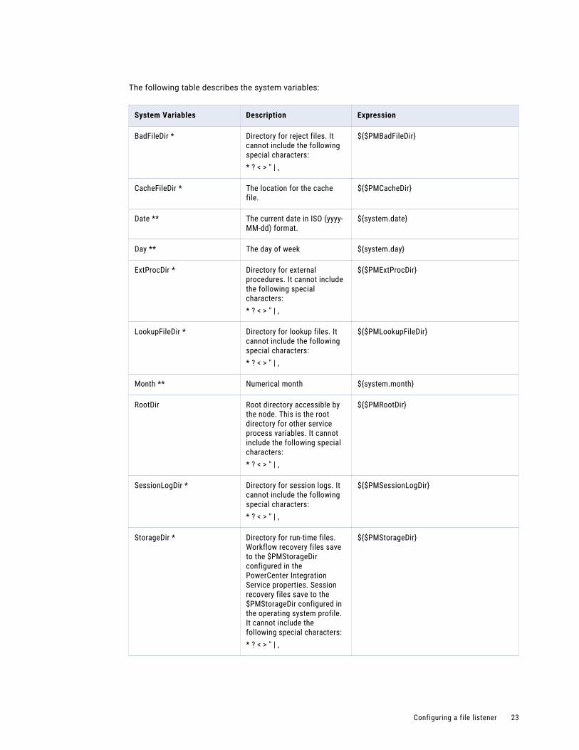
The following table describes the system variables:
System Variables Description Expression
BadFileDir * Directory for reject files. It cannot include the following special characters:* ? < > " | ,
${$PMBadFileDir}
CacheFileDir * The location for the cache file.
${$PMCacheDir}
Date ** The current date in ISO (yyyy-MM-dd) format.
${system.date}
Day ** The day of week ${system.day}
ExtProcDir * Directory for external procedures. It cannot include the following special characters:* ? < > " | ,
${$PMExtProcDir}
LookupFileDir * Directory for lookup files. It cannot include the following special characters:* ? < > " | ,
${$PMLookupFileDir}
Month ** Numerical month ${system.month}
RootDir Root directory accessible by the node. This is the root directory for other service process variables. It cannot include the following special characters:* ? < > " | ,
${$PMRootDir}
SessionLogDir * Directory for session logs. It cannot include the following special characters:* ? < > " | ,
${$PMSessionLogDir}
StorageDir * Directory for run-time files. Workflow recovery files save to the $PMStorageDir configured in the PowerCenter Integration Service properties. Session recovery files save to the $PMStorageDir configured in the operating system profile. It cannot include the following special characters:* ? < > " | ,
${$PMStorageDir}
Configuring a file listener 23
System Variables Description Expression
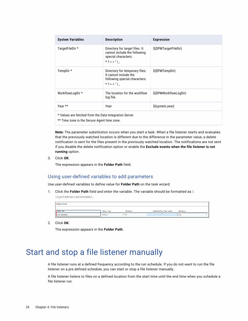
TargetFileDir * Directory for target files. It cannot include the following special characters:* ? < > " | ,
${$PMTargetFileDir}
TempDir * Directory for temporary files. It cannot include the following special characters:* ? < > " | ,
${$PMTempDir}
WorkflowLogDir * The location for the workflow log file.
${$PMWorkflowLogDir}
Year ** Year ${system.year}
* Values are fetched from the Data Integration Server.** Time zone is the Secure Agent time zone.
Note: The parameter substitution occurs when you start a task. When a file listener starts and evaluates that the previously watched location is different due to the difference in the parameter value, a delete notification is sent for the files present in the previously watched location. The notifications are not sent if you disable the delete notification option or enable the Exclude events when the file listener is not running option.
3. Click OK.
The expression appears in the Folder Path field.
Using user-defined variables to add parametersUse user-defined variables to define value for Folder Path on the task wizard.
1. Click the Folder Path field and enter the variable. The variable should be formatted as ${systemvariablename}.
2. Click OK.
The expression appears in the Folder Path.
Start and stop a file listener manuallyA file listener runs at a defined frequency according to the run schedule. If you do not want to run the file listener on a pre defined schedule, you can start or stop a file listener manually.
A file listener listens to files on a defined location from the start time until the end time when you schedule a file listener run.
24 Chapter 4: File listeners

Consider the following file listener behavior when you start and stop a file listener manually:
• You start a file listener before a scheduled run. The file listener that is triggered manually runs and stops at the start time of the schedule run.
• You start a file listener after the end time of a schedule run. The file listener runs once and stops.
• You cannot start a file listener manually when a file listener is already running according to the run schedule.
• When the agent version is upgraded, the file listener is automatically submitted to the new agent version and the old version is stopped.
• If the agent fails, such as a temporary network disruption, the file listener is automatically submitted to the agent when the agent restarts. Events such as Arrive, Update, and Delete that were submitted when the agent failed are notified by the file listener when the agent restarts.
• You stop an existing file listener run. The file listener stops listening to files for that run. A new run starts at the time of the next schedule time unless the file listener is started manually.
• A file listener fails to start if the file listener is disabled, it is not associated to a task, or if the associated secure agent is down.
• A file listener fails to start if the number of file events such as arrive, update, or delete, exceeds the maximum event limit (10000 files).
Starting and stopping a file listenerYou can start and stop a file listener from the Edit file listener component page or the Explore page using the Action menu. Perform the following steps to start or stop a file listener manually.
1. In the Explore page, select one or more file listeners and click the Action menu. If you want to start all file listener, you can filter the file listener asset in the Explore page and click Select All.
The Start and Stop buttons are enabled.If the file listener fails to start, a message with the failure details is displayed.
2. Click Start.
The file listeners validate the configuration and start listening to files defined in the file listener configuration rules.
3. Click Stop to stop the file listener. If you want to stop all file listener, you can filter the file listener asset in the Explore page and click Select All. If the file listener fails to stop, a message with the failure details is displayed.
Start and stop a file listener manually 25
C h a p t e r 5
Fixed-width file formatsYou can create and save fixed-width file formats that specify the formatting details for fixed-width flat files.
You can use a fixed-width flat file as a source or target in mappings and mapping tasks. When you select a flat file connection for a Source transformation or Target transformation, you specify the flat file type. If you select the fixed-width flat file type, you select the most appropriate fixed-width file format to use based on the data in the fixed-width flat file.
You can create multiple fixed-width file formats. For example, you might have a fixed-width file format to use for fixed-width flat files that contain quarterly sales data and another fixed-width file format to use for fixed-width flat files that contain inventory data.
If a fixed-width file format does not already exist, you must create a fixed-width file format before you create a mapping or mapping task that uses a fixed-width flat file.
To configure a fixed-width file format, you specify the number of columns and the width, name, and datatype for each column. You can also set advanced fixed-width format properties. For example, you can specify how to handle null characters or specify the default date format for each column.
You can delete fixed-width file formats that you no longer use. You cannot delete a fixed-width file format that is used in a mapping or mapping task.
Creating a fixed-width file formatCreate a fixed-width file format so that you can use a fixed-width flat file as a source or target in a mapping.
When you specify format options for a fixed-width file format, use a sample flat file. The data in the sample file appears on the page to help you determine the appropriate format options for your data. The format options that you specify do not alter or save the sample file.
1. Click New > Components > Fixed Width File Format and then click Create.
To edit a fixed-width file format, on the Explore page, navigate to the fixed-width file format. In the row that contains the fixed-width file format, click Actions and select Edit.
26
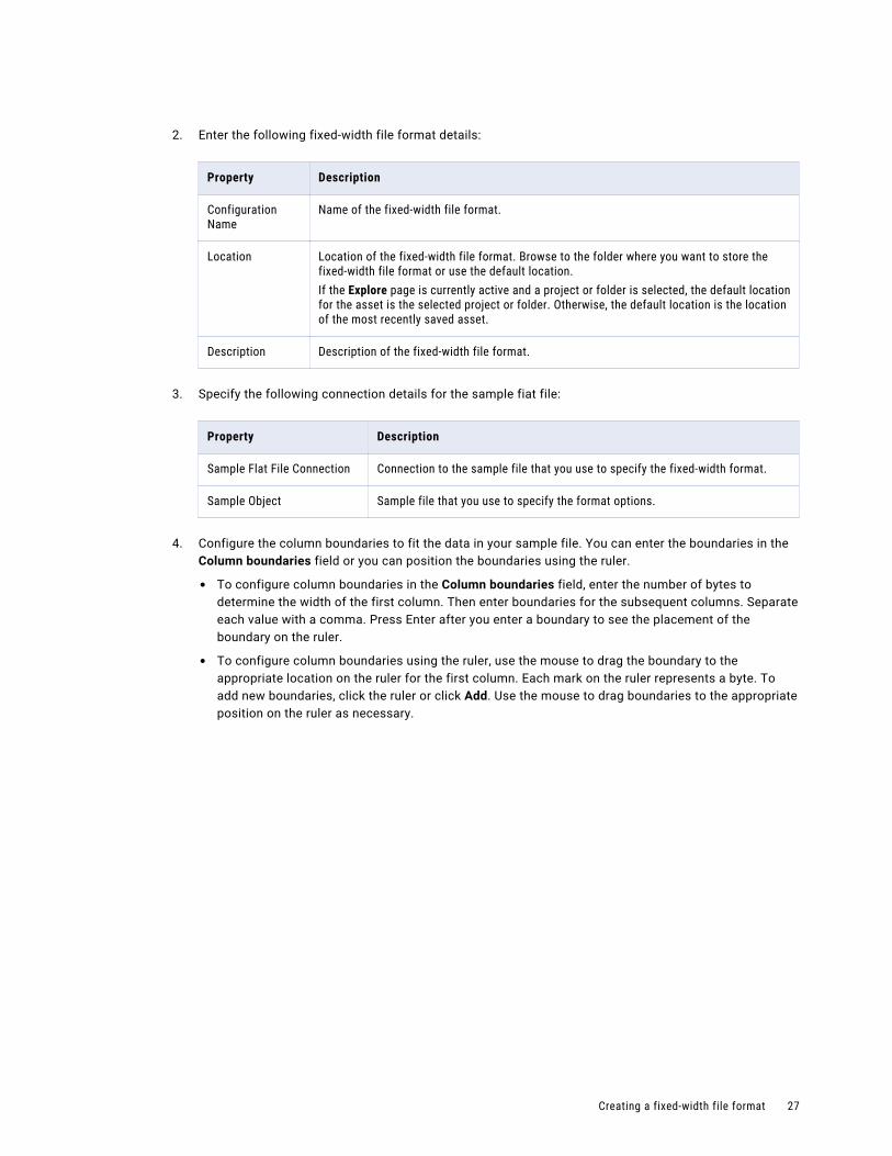
2. Enter the following fixed-width file format details:
Property Description
Configuration Name
Name of the fixed-width file format.
Location Location of the fixed-width file format. Browse to the folder where you want to store the fixed-width file format or use the default location.If the Explore page is currently active and a project or folder is selected, the default location for the asset is the selected project or folder. Otherwise, the default location is the location of the most recently saved asset.
Description Description of the fixed-width file format.
3. Specify the following connection details for the sample fiat file:
Property Description
Sample Flat File Connection Connection to the sample file that you use to specify the fixed-width format.
Sample Object Sample file that you use to specify the format options.
4. Configure the column boundaries to fit the data in your sample file. You can enter the boundaries in the Column boundaries field or you can position the boundaries using the ruler.
• To configure column boundaries in the Column boundaries field, enter the number of bytes to determine the width of the first column. Then enter boundaries for the subsequent columns. Separate each value with a comma. Press Enter after you enter a boundary to see the placement of the boundary on the ruler.
• To configure column boundaries using the ruler, use the mouse to drag the boundary to the appropriate location on the ruler for the first column. Each mark on the ruler represents a byte. To add new boundaries, click the ruler or click Add. Use the mouse to drag boundaries to the appropriate position on the ruler as necessary.
Creating a fixed-width file format 27
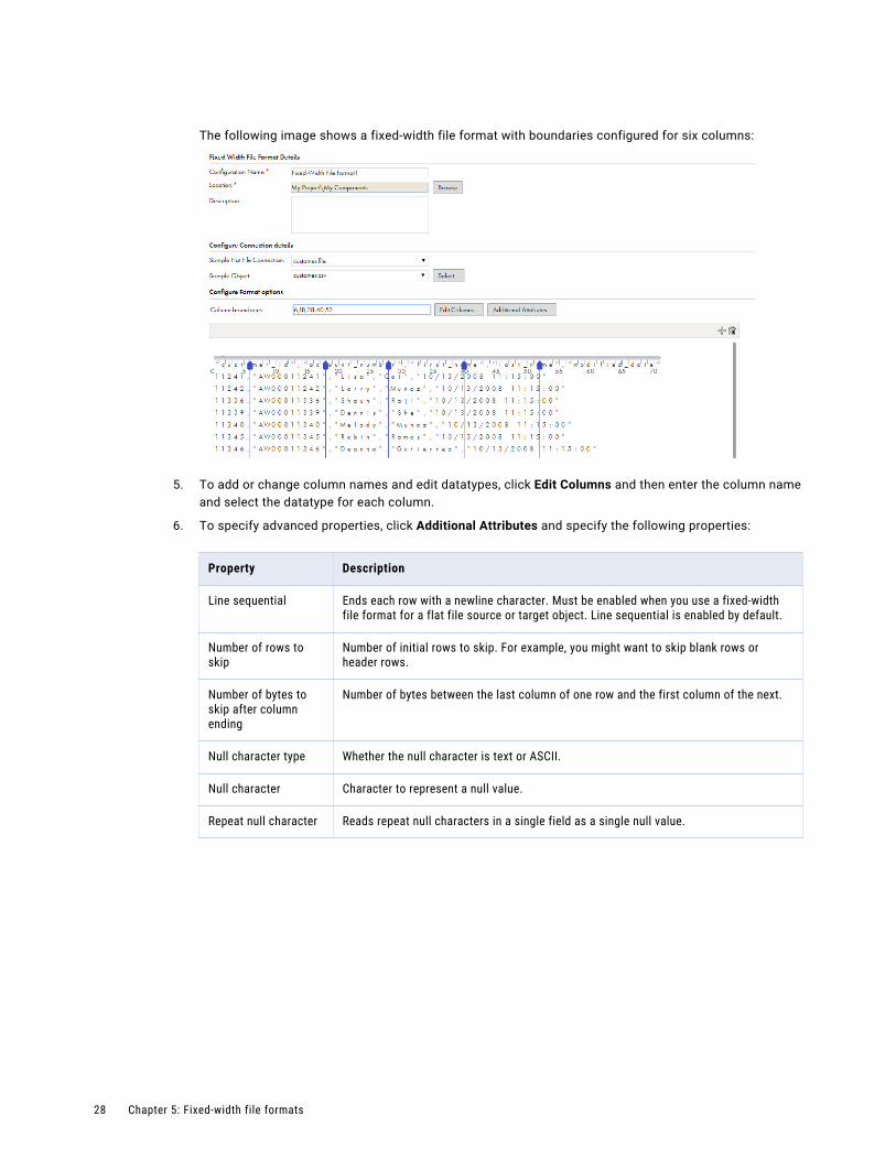
The following image shows a fixed-width file format with boundaries configured for six columns:
5. To add or change column names and edit datatypes, click Edit Columns and then enter the column name and select the datatype for each column.
6. To specify advanced properties, click Additional Attributes and specify the following properties:
Property Description
Line sequential Ends each row with a newline character. Must be enabled when you use a fixed-width file format for a flat file source or target object. Line sequential is enabled by default.
Number of rows to skip
Number of initial rows to skip. For example, you might want to skip blank rows or header rows.
Number of bytes to skip after column ending
Number of bytes between the last column of one row and the first column of the next.
Null character type Whether the null character is text or ASCII.
Null character Character to represent a null value.
Repeat null character Reads repeat null characters in a single field as a single null value.
28 Chapter 5: Fixed-width file formats
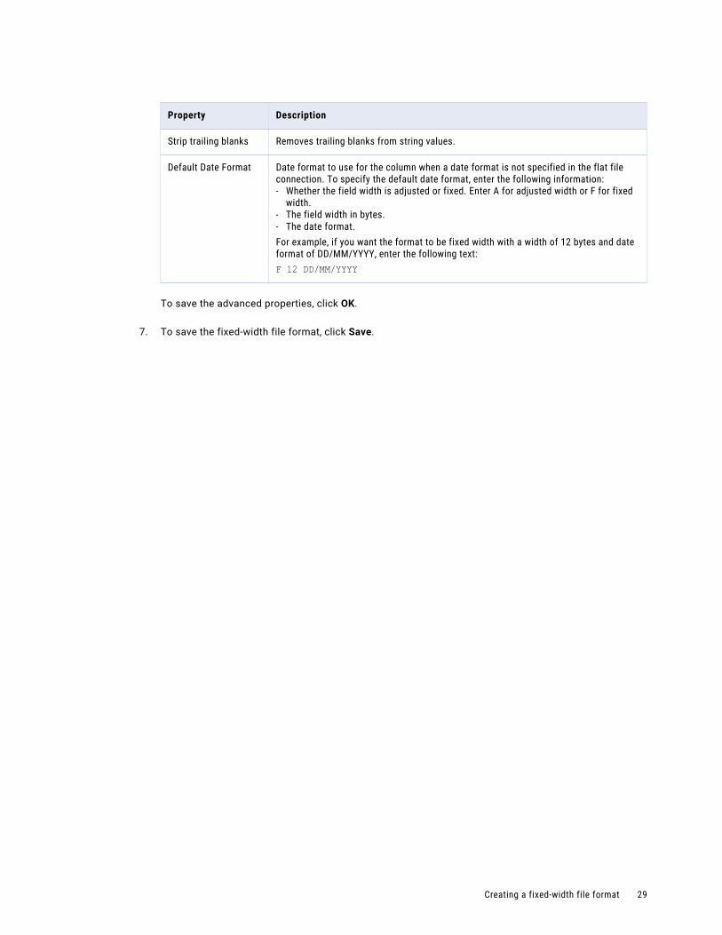
Property Description
Strip trailing blanks Removes trailing blanks from string values.
Default Date Format Date format to use for the column when a date format is not specified in the flat file connection. To specify the default date format, enter the following information:- Whether the field width is adjusted or fixed. Enter A for adjusted width or F for fixed
width.- The field width in bytes.- The date format.For example, if you want the format to be fixed width with a width of 12 bytes and date format of DD/MM/YYYY, enter the following text:F 12 DD/MM/YYYY
To save the advanced properties, click OK.
7. To save the fixed-width file format, click Save.
Creating a fixed-width file format 29

C h a p t e r 6
Hierarchical schemasA hierarchical schema is an asset that is based on a schema file or sample JSON file that you import into Data Integration.
A hierarchical schema is required for the Relational to Hierarchical and Hierarchical to Relational transformations. The schema defines the expected hierarchy of the output data. You can create multiple hierarchical schemas and store them in your project folders.
Note: The hierarchical schema supports XSD schemas with up to 10,000 elements. To process an XSD schema that contains more than 10,000 elements, split the data into two hierarchical schemas.
Creating a hierarchical schemaCreate a hierarchical schema in Data Integration.
1. Click New > Components > Hierarchical Schema.
2. In the New Hierarchical Schema page, enter a name and description. You must provide a name for the hierarchical schema.
3. Browse to select a project location.
4. To select a schema or sample file, click Upload. Click Choose File and browse for an XSD file or select a sample JSON file, and then click OK.
When you add a JSON sample file, Data Integration generates a schema from the sample.
5. If you selected an XSD file with multiple possible root elements, select a root from the drop-down menu.
6. If you selected a schema that refers to another schema, you must also upload the referenced schema. To upload the referenced schema, click Upload, browse for the referenced schema file and click OK.
7. To save the hierarchical schema, click OK.
30

C h a p t e r 7
Intelligent structure modelsA CLAIRE® intelligent structure model is an asset that Intelligent Structure Discovery creates based on input that represents the data that you expect the model to parse at run time.
Intelligent Structure Discovery determines the underlying patterns and structures of the input that you provide for the model and creates a model that can be used to transform, parse, and generate output groups.
Long, complex files with little or no structure can be difficult to parse. Intelligent Structure Discovery can automatically decipher input data and discover the patterns, repetitions, relationships, and types of data in unstructured files.
After intelligent structure discovers the structure of the data, you can refine and test the structure, and then save or export it. When you save or export an intelligent structure, Intelligent Structure Discovery creates an intelligent structure model in an .amodel file.
Intelligent Structure Discovery creates a model that expresses the expected output data. You can use an intelligent structure model in mappings to parse unstructured, semi-structured, or structured data.
You can create models from the following input types:
• Delimited files, for example, CSV files
• Machine generated files such as weblogs and clickstreams
• JSON files
• XML files
• ORC files
• Avro files
• Parquet files
• Microsoft Excel files
• Data within PDF form fields
• Data within Microsoft Word tables
• XSD files
• Cobol copybooks
Preview Notice: Creating intelligent structure models based on Cobol copybooks is available for preview. Preview functionality is supported for evaluation purposes but is unwarranted and is not supported in production environments or any environment that you plan to push to production. Informatica intends to include the preview functionality in an upcoming release for production use, but might choose not to in accordance with changing market or technical circumstances. For more information, contact Informatica Global Customer Support.
31
Using intelligent structure models in mappingsTo use an intelligent structure model in a mapping, add a Structure Parser transformation or a Hierarchy Builder transformation to the mapping.
An intelligent structure model is required for Structure Parser transformations and is optional for Hierarchy Builder transformations.
When you configure the transformation, select or create an intelligent structure model, select the type of input that the transformation expects to receive, and the output that you pass to downstream transformations. The model can generate relational, XML, JSON, JSON Lines, or Hadoop format output.
Models that you use with a Structure Parser transformation can contain up to 12,000 ports. The Structure Parser transformation might fail to load models that contain more than 12,000 ports.
Tip: When you create a model that isn't JSON, XML, or XSD-based, and the model contains nested repeating groups, you can reduce the number of ports in the model by normalizing the output data. Intelligent Structure Discovery normalizes the input data by default for JSON, XML, and XSD-based models that contain nested repeating groups.
For more information about the Structure Parser and Hierarchy Builder transformations, see Transformations.
Using intelligent structure models in elastic mappings
To use an intelligent structure model in an elastic mapping, select an existing model or create a new model when you configure the Source transformation. The model generates hierarchical output.
The following table describes the actions that you perform when you configure the source properties to use an intelligent structure model:
Property Action
Connection Select an Amazon S3 V2 or a Microsoft Azure Data Lake Gen2 connection.
Source Type Select Single Object.
Object Select a file or folder as the source object:- To select a file, select File as the source type in the Advanced area, and then select a file of a
type that is supported by Intelligent Structure Discovery.- To select a folder, select Directory as the source type in the Advanced area, and then select a
folder that contains one or more Avro, Parquet, or ORC files.
Format Select Discover Structure.
Intelligent Structure Model
Select one of the following options to associate a model with the transformation:- Select. Select an existing model.- New. Create a new model. Select Design New to create the model. Select Auto-generate from
sample file for Intelligent Structure Discovery to generate a model based on sample input that you select.
For more information about mapping configuration, see Mappings.
32 Chapter 7: Intelligent structure models
Using intelligent structure models in data engineering mappings
To use an intelligent structure model in a data engineering mapping, add the model to a data object. The model generates HTYPE output.
You can add an intelligent structure model to data objects, and then incorporate them into mappings in data engineering. To use an intelligent structure model in a data object, first export it from Data Integration to your local drive.
Use Informatica Developer to add the intelligent structure to a complex file data object, Amazon S3 data object, or Microsoft Azure Blob data object. You can add the data object to a data engineering mapping and process data on the Spark engine. For more information, see the Data Engineering Integration User Guide.
Using intelligent structure models in B2B Gateway inbound partner flows
To use an intelligent structure model in a B2B Gateway inbound partner flow, select an intelligent structure when you create the partner.
You can use an intelligent structure model to receive incoming Excel, TXT, and CSV files. Intelligent Structure Discovery writes the files to a CSV interface file on the B2B Gateway document store.
For more information, see the B2B Gateway help.
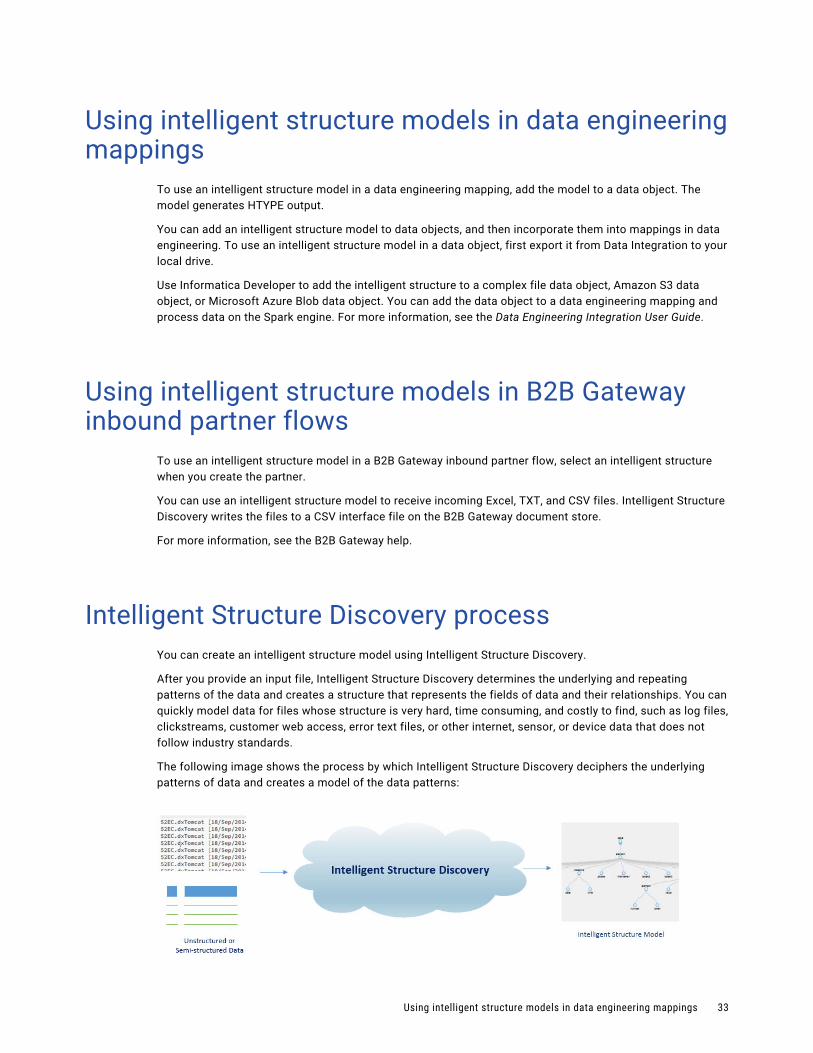
Intelligent Structure Discovery processYou can create an intelligent structure model using Intelligent Structure Discovery.
After you provide an input file, Intelligent Structure Discovery determines the underlying and repeating patterns of the data and creates a structure that represents the fields of data and their relationships. You can quickly model data for files whose structure is very hard, time consuming, and costly to find, such as log files, clickstreams, customer web access, error text files, or other internet, sensor, or device data that does not follow industry standards.
The following image shows the process by which Intelligent Structure Discovery deciphers the underlying patterns of data and creates a model of the data patterns:
Using intelligent structure models in data engineering mappings 33

When the model is based on input from a Hadoop Files source, Intelligent Structure Discovery determines the data types to use in the model based on the types and structures in the Hadoop schema. In the model, Intelligent Structure Discovery creates an array of structures of key-value pairs for data of type map. Nodes of type enum are represented as strings.
Inputs for intelligent structure modelsThe input that you base an intelligent structure model on can be a sample file, an XSD schema, or a Cobol copybook, based on the input that you expect to use the model for at run time.
Input files can be up to 1 MB in size. An input file can contain up to 30,000 simple fields. If the file contains more than 30,000 simple fields, Intelligent Structure Discovery creates the model without groups and ports. The number of levels in the hierarchy isn't limited.
To achieve optimal parsing results, ensure that the input that you provide when you create the model is broad enough and covers all the data elements that you expect the model to receive at run time. If the input is too limited, the parsing output will include unidentified data.
Use simplified input to generate the model. For example, if the input data has tables, provide a table with just a few sample rows rather than many rows of data. If you use a JSON input file that contains repeating groups of data, limit the number of repetitions.
If the model does not match the runtime input data, or only partially matches the input data, there might be a large amount of unidentified data and data loss. However, some variations will still be parsed.
Verify that the length of each combination of group name and field name doesn't exceed 80 characters. For example, if the name of the group that a field belongs to is group, the field name must not exceed 75 characters. If a combination of group name and field name exceeds 80 characters, mappings that use the model fail to run.
ORC files
You can use the model to read ORC files through a flat file connection in Data Integration. You can't use the model for ORC streaming.
Using multiple sample files in a model
After you create a model based on a JSON, XML, ORC, AVRO, or PARQUET sample file, you can use additional sample files to enrich the structure with fields that exist in the new samples. The additional files must be of the same file type as the type of file that the model is based on.
Using multi-file XSD schemas
Consider the following guidelines when you use an XSD schema that contains multiple XSD files as the model input:
• The schema files must be compressed.
• If the XSD files reside in a directory structure, to preserve the structure, the parent directory must be compressed.
Using XML sample files in XSD-based models
When you create an XSD-based model to use in a Structure Parser transformation, you can attach an XML sample file to the model. The names and contents of the groups in the model appear in the Intelligent Structure Model page. When you associate the model with the Structure Parser transformation, use this information to decide which group to connect to the target. Attaching a sample file to the model doesn't affect or change the structure of the model.
34 Chapter 7: Intelligent structure models
Repeating groupsIntelligent Structure Discovery creates a repeating group for input data such as a table or array, where a row or set of fields repeats as a group.
When a model that is based on a JSON, XML, or XSD file contains nested repeating groups, that is, repeating groups within repeating groups, Intelligent Structure Discovery assigns each nested repeating group to its own output group. For models that are based on other input types, you can manually assign nested repeating groups to their output groups. You can assign all nested repeating groups to their output groups by normalizing the data in the model, or you can assign individual nested repeating groups to their output groups by promoting them. Assigning nested repeating groups to their output groups reduces the number of ports in the model.
For example, you create a model based on the following JSON input:
{ "CompanyID": 210850, "Name": "Tollers Shipping", "Address": "701 Natash Ave.", "City": "San Diego", "Department": [ { "Domain": "Logistics", "Identifier": "21973b77", "Employees": [ { "name": "Sujitha Naarana", "employeeID": "2100Z9" }, { "name": "Dwain Lord", "employeeID": "34t001" } ], }, { "Domain": "Accounting", "Identifier": "301ad177", "Employees": [ { "name": "LeTroy Prince", "employeeID": "31910a" } ] } ]}
Repeating groups 35
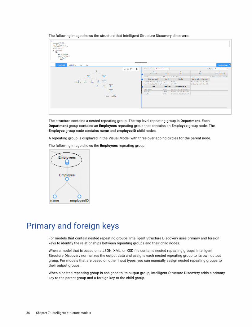
The following image shows the structure that Intelligent Structure Discovery discovers:
The structure contains a nested repeating group. The top level repeating group is Department. Each Department group contains an Employees repeating group that contains an Employee group node. The Employee group node contains name and employeeID child nodes.
A repeating group is displayed in the Visual Model with three overlapping circles for the parent node.
The following image shows the Employees repeating group:
Primary and foreign keysFor models that contain nested repeating groups, Intelligent Structure Discovery uses primary and foreign keys to identify the relationships between repeating groups and their child nodes.
When a model that is based on a JSON, XML, or XSD file contains nested repeating groups, Intelligent Structure Discovery normalizes the output data and assigns each nested repeating group to its own output group. For models that are based on other input types, you can manually assign nested repeating groups to their output groups.
When a nested repeating group is assigned to its output group, Intelligent Structure Discovery adds a primary key to the parent group and a foreign key to the child group.
36 Chapter 7: Intelligent structure models
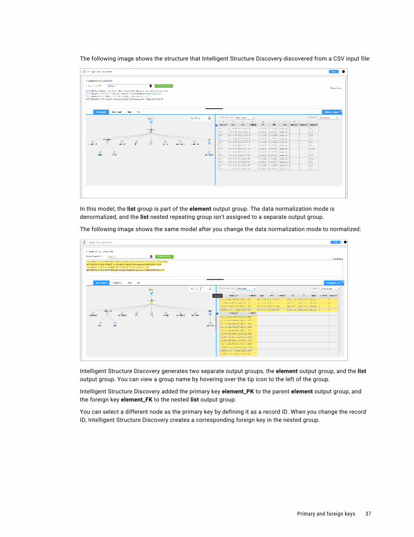
The following image shows the structure that Intelligent Structure Discovery discovered from a CSV input file:
In this model, the list group is part of the element output group. The data normalization mode is denormalized, and the list nested repeating group isn't assigned to a separate output group.
The following image shows the same model after you change the data normalization mode to normalized:
Intelligent Structure Discovery generates two separate output groups, the element output group, and the list output group. You can view a group name by hovering over the tip icon to the left of the group.
Intelligent Structure Discovery added the primary key element_PK to the parent element output group, and the foreign key element_FK to the nested list output group.
You can select a different node as the primary key by defining it as a record ID. When you change the record ID, Intelligent Structure Discovery creates a corresponding foreign key in the nested group.
Primary and foreign keys 37
Data driftsIntelligent structure models can address data drift in certain cases, as in the following example. In this example, the sample data used to create the model contains the following text:
05967|2014-09-19|04:49:50.476|51.88.6.206|custid=83834785|cntry=Tanzania|city=Mtwango|movie={b1027374-6eec-4568-8af6-6c037d828c66|"Touch of Evil"}|paid=true01357|2014-11-13|18:07:57.441|88.2.218.236|custid=41834772|movie={01924cd3-87f4-4492-b26c-268342e87eaf|"The Good, the Bad and the Ugly"}|paid=true00873|2014-06-14|09:16:14.522|134.254.152.84|custid=58770178|movie={cd381236-53bd-4119-b2ce-315dae932782|"Donnie Darko"}|paid=true02112|2015-01-29|20:40:37.210|105.107.203.34|custid=49774177|cntry=Colombia|city=Palmito|movie={ba1c48ed-d9ac-4bcb-be5d-cf3afbb61f04|"Lagaan: Once Upon a Time in India"}|paid=false00408|2014-06-24|03:44:33.612|172.149.175.30|custid=29613035|cntry=Iran|city=Bastak|movie={3d022c51-f87f-487a-bc7f-1b9e5d138791|"The Shining"}|paid=false03568|2015-01-07|11:36:50.52|82.81.202.22|custid=27515249|cntry=Philippines|city=Magallanes|movie={ad3ae2b4-496e-4f79-a6dd-202ec932e0ae|"Inglourious Basterds"}|paid=true
The input data that the model parses contains the following text:
0448|2015-04-07|01:50:5.35|27.248.247.174|custid=613068|cntry=Iran|city=Sarĕb|movie={50fb37b-621-484e-a565-2b5c1cbdc43|"Network"}|paid=false|ua=Mozilla/5.0 (Windows NT 5.1)02780|2014-12-28|08:14:58.685|17.2.236.233|custid=731|cntry=Greece|city=Néa Róda|movie={1876aea0-3cb5-4c7a-22f-d33f233210|"Full Metal Jacket"}|paid=true|ua=Mozilla/5.0 (Macintosh; Intel Mac OS X 10_10_1)03353|2015-04-20|21:02:40.532|143.48.11.171|custid=83736441|cntry=Russia|city=Mozhaysk|movie={67272f85-bfc-418a-82ea-a7c4ae6b028a|"Gangs of Wasseypur"}|paid=true|ua=Mozilla/5.0 (iPad; CPU OS 5_1 like Mac OS X)04073|2014-10-25|15:33:03.442|87.235.48.100|custid=861028|cntry=Indonesia|city=Lamalera|movie={4a511f3-6367-4017-874e-50a46f5ea567|"Shutter Island"}|paid=false|ua=Mozilla/5.0 (X11; Linux x86_64)02170|2015-02-1|23:36:40.271|25.14.204.46|custid=1240203|cntry=Albania|city=Lukovë|movie={2047efa-22c6-431c-87d4-ca73af1034|"The Grapes of Wrath"}|paid=false|ua=Mozilla/5.0 (Windows NT 6.1)
The input data contains additional data that isn't defined in the model. However, the model can parse this variation.
Unassigned dataIntelligent Structure Discovery assigns data to an Unassigned Data field in the following cases:
• When records exceed the maximum record size. The default maximum record size is 640,000 bytes. For information about how to increase the maximum record size, see “Troubleshooting intelligent structure models” on page 43.
• When delimited files, for example CSV files or logs, contain more elements than expected.
38 Chapter 7: Intelligent structure models
Intelligent structure model exampleIntelligent Structure Discovery creates an intelligent structure model based on the structure of the input data that you provide.
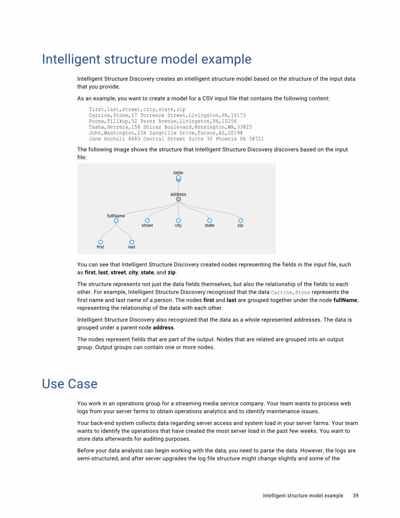
As an example, you want to create a model for a CSV input file that contains the following content:
first,last,street,city,state,zipCarrine,Stone,17 Torrence Street,Livingston,PA,10173Poona,Tillkup,52 Perez Avenue,Livingston,PA,10256Tasha,Herrera,158 Shiraz Boulevard,Kensington,WA,33823John,Washington,22A Zangville Drive,Tucson,AZ,20198Jane Hochuli 4483 Central Street Suite 30 Phoenix PA 38721
The following image shows the structure that Intelligent Structure Discovery discovers based on the input file:
You can see that Intelligent Structure Discovery created nodes representing the fields in the input file, such as first, last, street, city, state, and zip.
The structure represents not just the data fields themselves, but also the relationship of the fields to each other. For example, Intelligent Structure Discovery recognized that the data Carrine,Stone represents the first name and last name of a person. The nodes first and last are grouped together under the node fullName, representing the relationship of the data with each other.
Intelligent Structure Discovery also recognized that the data as a whole represented addresses. The data is grouped under a parent node address.
The nodes represent fields that are part of the output. Nodes that are related are grouped into an output group. Output groups can contain one or more nodes.
Use CaseYou work in an operations group for a streaming media service company. Your team wants to process web logs from your server farms to obtain operations analytics and to identify maintenance issues.
Your back-end system collects data regarding server access and system load in your server farms. Your team wants to identify the operations that have created the most server load in the past few weeks. You want to store data afterwards for auditing purposes.
Before your data analysts can begin working with the data, you need to parse the data. However, the logs are semi-structured, and after server upgrades the log file structure might change slightly and some of the
Intelligent structure model example 39
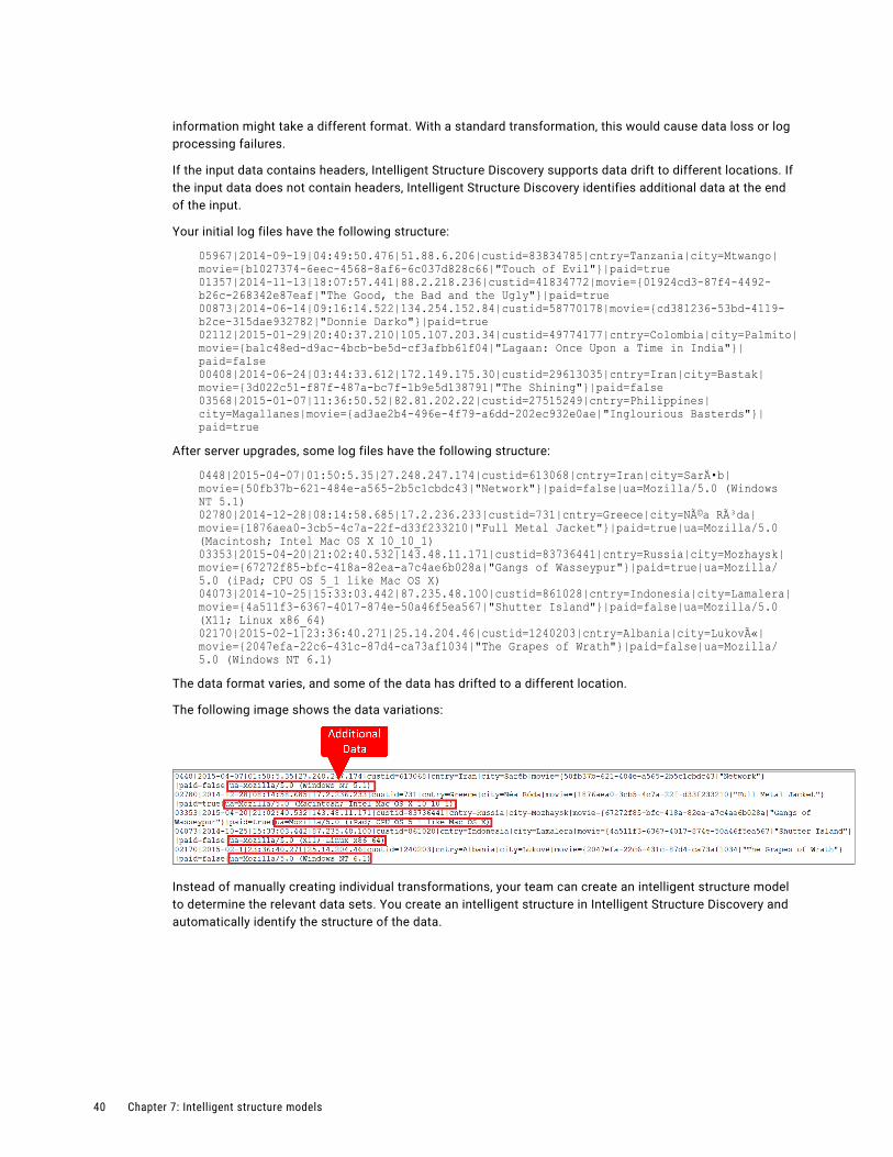
information might take a different format. With a standard transformation, this would cause data loss or log processing failures.
If the input data contains headers, Intelligent Structure Discovery supports data drift to different locations. If the input data does not contain headers, Intelligent Structure Discovery identifies additional data at the end of the input.
Your initial log files have the following structure:
05967|2014-09-19|04:49:50.476|51.88.6.206|custid=83834785|cntry=Tanzania|city=Mtwango|movie={b1027374-6eec-4568-8af6-6c037d828c66|"Touch of Evil"}|paid=true01357|2014-11-13|18:07:57.441|88.2.218.236|custid=41834772|movie={01924cd3-87f4-4492-b26c-268342e87eaf|"The Good, the Bad and the Ugly"}|paid=true00873|2014-06-14|09:16:14.522|134.254.152.84|custid=58770178|movie={cd381236-53bd-4119-b2ce-315dae932782|"Donnie Darko"}|paid=true02112|2015-01-29|20:40:37.210|105.107.203.34|custid=49774177|cntry=Colombia|city=Palmito|movie={ba1c48ed-d9ac-4bcb-be5d-cf3afbb61f04|"Lagaan: Once Upon a Time in India"}|paid=false00408|2014-06-24|03:44:33.612|172.149.175.30|custid=29613035|cntry=Iran|city=Bastak|movie={3d022c51-f87f-487a-bc7f-1b9e5d138791|"The Shining"}|paid=false03568|2015-01-07|11:36:50.52|82.81.202.22|custid=27515249|cntry=Philippines|city=Magallanes|movie={ad3ae2b4-496e-4f79-a6dd-202ec932e0ae|"Inglourious Basterds"}|paid=true
After server upgrades, some log files have the following structure:
0448|2015-04-07|01:50:5.35|27.248.247.174|custid=613068|cntry=Iran|city=Sarĕb|movie={50fb37b-621-484e-a565-2b5c1cbdc43|"Network"}|paid=false|ua=Mozilla/5.0 (Windows NT 5.1)02780|2014-12-28|08:14:58.685|17.2.236.233|custid=731|cntry=Greece|city=Néa Róda|movie={1876aea0-3cb5-4c7a-22f-d33f233210|"Full Metal Jacket"}|paid=true|ua=Mozilla/5.0 (Macintosh; Intel Mac OS X 10_10_1)03353|2015-04-20|21:02:40.532|143.48.11.171|custid=83736441|cntry=Russia|city=Mozhaysk|movie={67272f85-bfc-418a-82ea-a7c4ae6b028a|"Gangs of Wasseypur"}|paid=true|ua=Mozilla/5.0 (iPad; CPU OS 5_1 like Mac OS X)04073|2014-10-25|15:33:03.442|87.235.48.100|custid=861028|cntry=Indonesia|city=Lamalera|movie={4a511f3-6367-4017-874e-50a46f5ea567|"Shutter Island"}|paid=false|ua=Mozilla/5.0 (X11; Linux x86_64)02170|2015-02-1|23:36:40.271|25.14.204.46|custid=1240203|cntry=Albania|city=Lukovë|movie={2047efa-22c6-431c-87d4-ca73af1034|"The Grapes of Wrath"}|paid=false|ua=Mozilla/5.0 (Windows NT 6.1)
The data format varies, and some of the data has drifted to a different location.
The following image shows the data variations:
Instead of manually creating individual transformations, your team can create an intelligent structure model to determine the relevant data sets. You create an intelligent structure in Intelligent Structure Discovery and automatically identify the structure of the data.
40 Chapter 7: Intelligent structure models
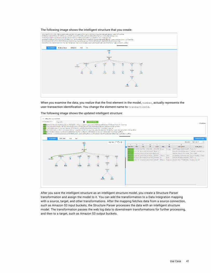
The following image shows the intelligent structure that you create:
When you examine the data, you realize that the first element in the model, number, actually represents the user transaction identification. You change the element name to transactionId.
The following image shows the updated intelligent structure:
After you save the intelligent structure as an intelligent structure model, you create a Structure Parser transformation and assign the model to it. You can add the transformation to a Data Integration mapping with a source, target, and other transformations. After the mapping fetches data from a source connection, such as Amazon S3 input buckets, the Structure Parser processes the data with an intelligent structure model. The transformation passes the web log data to downstream transformations for further processing, and then to a target, such as Amazon S3 output buckets.
Use Case 41
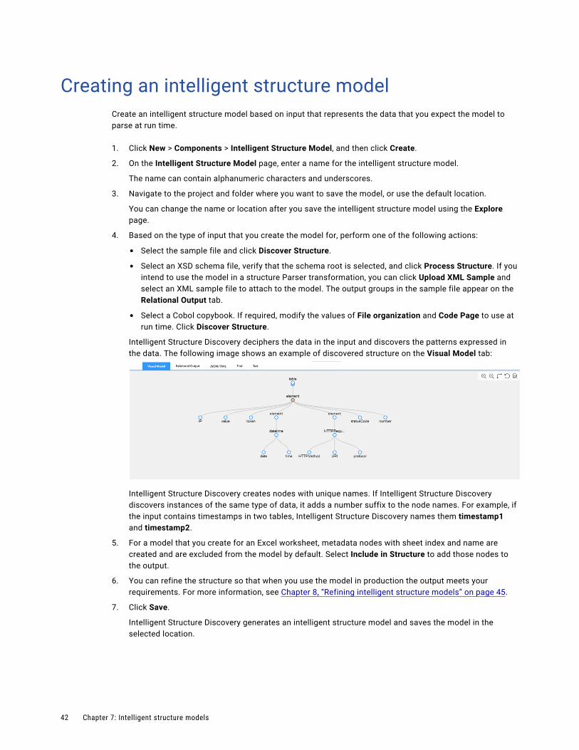
Creating an intelligent structure modelCreate an intelligent structure model based on input that represents the data that you expect the model to parse at run time.
1. Click New > Components > Intelligent Structure Model, and then click Create.
2. On the Intelligent Structure Model page, enter a name for the intelligent structure model.
The name can contain alphanumeric characters and underscores.
3. Navigate to the project and folder where you want to save the model, or use the default location.
You can change the name or location after you save the intelligent structure model using the Explore page.
4. Based on the type of input that you create the model for, perform one of the following actions:
• Select the sample file and click Discover Structure.
• Select an XSD schema file, verify that the schema root is selected, and click Process Structure. If you intend to use the model in a structure Parser transformation, you can click Upload XML Sample and select an XML sample file to attach to the model. The output groups in the sample file appear on the Relational Output tab.
• Select a Cobol copybook. If required, modify the values of File organization and Code Page to use at run time. Click Discover Structure.
Intelligent Structure Discovery deciphers the data in the input and discovers the patterns expressed in the data. The following image shows an example of discovered structure on the Visual Model tab:
Intelligent Structure Discovery creates nodes with unique names. If Intelligent Structure Discovery discovers instances of the same type of data, it adds a number suffix to the node names. For example, if the input contains timestamps in two tables, Intelligent Structure Discovery names them timestamp1 and timestamp2.
5. For a model that you create for an Excel worksheet, metadata nodes with sheet index and name are created and are excluded from the model by default. Select Include in Structure to add those nodes to the output.
6. You can refine the structure so that when you use the model in production the output meets your requirements. For more information, see Chapter 8, “Refining intelligent structure models” on page 45.
7. Click Save.
Intelligent Structure Discovery generates an intelligent structure model and saves the model in the selected location.
42 Chapter 7: Intelligent structure models
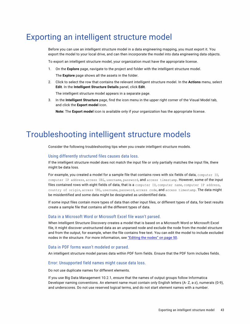
Exporting an intelligent structure modelBefore you can use an intelligent structure model in a data engineering mapping, you must export it. You export the model to your local drive, and can then incorporate the model into data engineering data objects.
To export an intelligent structure model, your organization must have the appropriate license.
1. On the Explore page, navigate to the project and folder with the intelligent structure model.
The Explore page shows all the assets in the folder.
2. Click to select the row that contains the relevant intelligent structure model. In the Actions menu, select Edit. In the Intelligent Structure Details panel, click Edit.
The intelligent structure model appears in a separate page.
3. In the Intelligent Structure page, find the icon menu in the upper right corner of the Visual Model tab, and click the Export model icon.
Note: The Export model icon is available only if your organization has the appropriate license.
Troubleshooting intelligent structure modelsConsider the following troubleshooting tips when you create intelligent structure models.
Using differently structured files causes data loss.If the intelligent structure model does not match the input file or only partially matches the input file, there might be data loss.
For example, you created a model for a sample file that contains rows with six fields of data, computer ID, computer IP address, access URL, username, password, and access timestamp. However, some of the input files contained rows with eight fields of data, that is a computer ID, computer name, computer IP address, country of origin, access URL, username, password, access code, and access timestamp. The data might be misidentified and some data might be designated as unidentified data.
If some input files contain more types of data than other input files, or different types of data, for best results create a sample file that contains all the different types of data.
Data in a Microsoft Word or Microsoft Excel file wasn't parsed.When Intelligent Structure Discovery creates a model that is based on a Microsoft Word or Microsoft Excel file, it might discover unstructured data as an unparsed node and exclude the node from the model structure and from the output, for example, when the file contains free text. You can edit the model to include excluded nodes in the structure. For more information, see “Editing the nodes” on page 50.
Data in PDF forms wasn't modeled or parsed.An intelligent structure model parses data within PDF form fields. Ensure that the PDF form includes fields.
Error: Unsupported field names might cause data loss.
Do not use duplicate names for different elements.
If you use Big Data Management 10.2.1, ensure that the names of output groups follow Informatica Developer naming conventions. An element name must contain only English letters (A- Z, a-z), numerals (0-9), and underscores. Do not use reserved logical terms, and do not start element names with a number.
Exporting an intelligent structure model 43

In later versions of Big Data Management or Data Engineering Integration, Intelligent Structure Discovery replaces special characters in element names with underscores and inserts underscores before element names that start with numerals and before element names that are reserved logical terms.
Intelligent Structure Discovery assigns long records to an Unassigned Data field.Intelligent Structure Discovery assigns records that exceed the maximum record size to an Unassigned Data field. The default maximum record size is 640,000 bytes.
You can increase the maximum record size up to 10 MB by configuring a Data Integration Server service DTM JVM property in Administrator.
Use the following syntax to define the maximum record size:
-DISD_MAX_RECORD_SIZE=<maximum record size in bytes>
For example, to define a maximum record size of 2 MB, enter the following value for the JVMOption1 property:
-DISD_MAX_RECORD_SIZE=2000000
For more information about configuring Data Integration Server service properties, see the Administrator help.
When you try to base a model on a sample ORC file that contains Union data, the model creation fails.Intelligent Structure Discovery doesn't process the Union data type in ORC input. Select a file that doesn't contain Union data to base the model on.
44 Chapter 7: Intelligent structure models
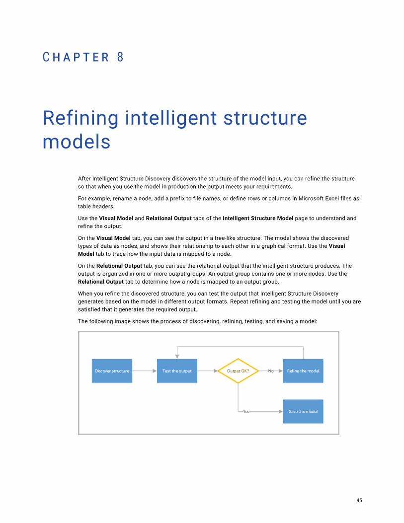
C h a p t e r 8
Refining intelligent structure models
After Intelligent Structure Discovery discovers the structure of the model input, you can refine the structure so that when you use the model in production the output meets your requirements.
For example, rename a node, add a prefix to file names, or define rows or columns in Microsoft Excel files as table headers.
Use the Visual Model and Relational Output tabs of the Intelligent Structure Model page to understand and refine the output.
On the Visual Model tab, you can see the output in a tree-like structure. The model shows the discovered types of data as nodes, and shows their relationship to each other in a graphical format. Use the Visual Model tab to trace how the input data is mapped to a node.
On the Relational Output tab, you can see the relational output that the intelligent structure produces. The output is organized in one or more output groups. An output group contains one or more nodes. Use the Relational Output tab to determine how a node is mapped to an output group.
When you refine the discovered structure, you can test the output that Intelligent Structure Discovery generates based on the model in different output formats. Repeat refining and testing the model until you are satisfied that it generates the required output.
The following image shows the process of discovering, refining, testing, and saving a model:
45
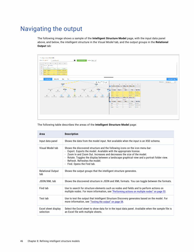
Navigating the outputThe following image shows a sample of the Intelligent Structure Model page, with the input data panel above, and below, the intelligent structure in the Visual Model tab, and the output groups in the Relational Output tab:
The following table describes the areas of the Intelligent Structure Model page:
Area Description
Input data panel Shows the data from the model input. Not available when the input is an XSD schema.
Visual Model tab Shows the discovered structure and the following icons on the icon menu bar:- Export. Exports the model. Available with the appropriate license.- Zoom In and Zoom Out. Increases and decreases the size of the model.- Rotate. Toggles the display between a landscape graphical view and a portrait folder view.- Refresh. Refreshes the model.- Find. Opens the Find tab.
Relational Output tab
Shows the output groups that the intelligent structure generates.
JSON/XML tab Shows the discovered structure in JSON and XML formats. You can toggle between the formats.
Find tab Use to search for structure elements such as nodes and fields and to perform actions on multiple nodes. For more information, see “Performing actions on multiple nodes” on page 53.
Test tab Use to test the output that Intelligent Structure Discovery generates based on the model. For more information, see “Testing the output” on page 58.
Excel sheet display selection
Select the Excel sheet to show data for in the input data panel. Available when the sample file is an Excel file with multiple sheets.
46 Chapter 8: Refining intelligent structure models
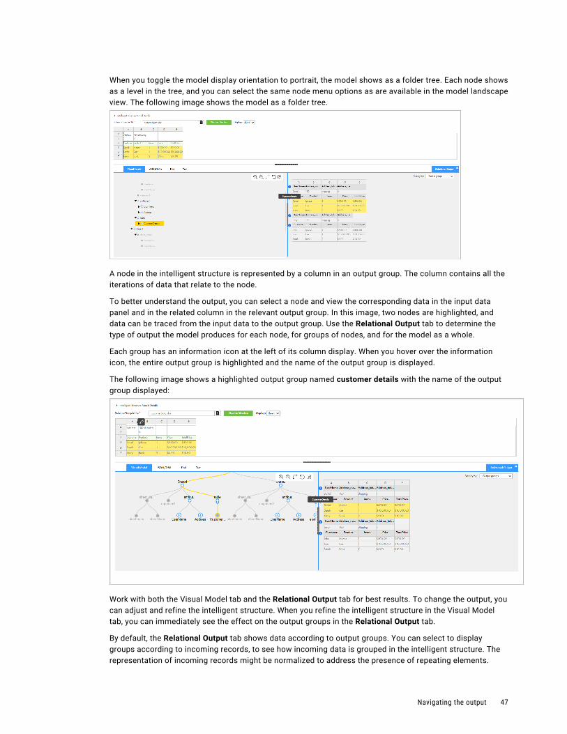
When you toggle the model display orientation to portrait, the model shows as a folder tree. Each node shows as a level in the tree, and you can select the same node menu options as are available in the model landscape view. The following image shows the model as a folder tree.
A node in the intelligent structure is represented by a column in an output group. The column contains all the iterations of data that relate to the node.
To better understand the output, you can select a node and view the corresponding data in the input data panel and in the related column in the relevant output group. In this image, two nodes are highlighted, and data can be traced from the input data to the output group. Use the Relational Output tab to determine the type of output the model produces for each node, for groups of nodes, and for the model as a whole.
Each group has an information icon at the left of its column display. When you hover over the information icon, the entire output group is highlighted and the name of the output group is displayed.
The following image shows a highlighted output group named customer details with the name of the output group displayed:
Work with both the Visual Model tab and the Relational Output tab for best results. To change the output, you can adjust and refine the intelligent structure. When you refine the intelligent structure in the Visual Model tab, you can immediately see the effect on the output groups in the Relational Output tab.
By default, the Relational Output tab shows data according to output groups. You can select to display groups according to incoming records, to see how incoming data is grouped in the intelligent structure. The representation of incoming records might be normalized to address the presence of repeating elements.
Navigating the output 47
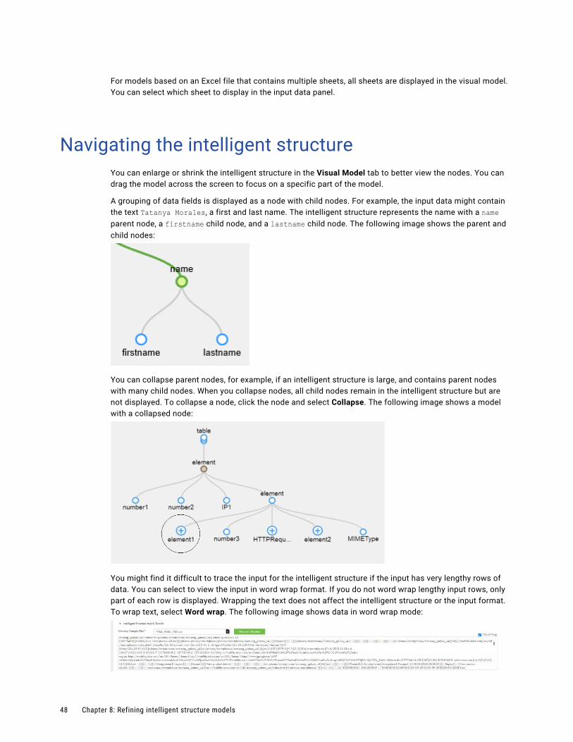
For models based on an Excel file that contains multiple sheets, all sheets are displayed in the visual model. You can select which sheet to display in the input data panel.
Navigating the intelligent structureYou can enlarge or shrink the intelligent structure in the Visual Model tab to better view the nodes. You can drag the model across the screen to focus on a specific part of the model.
A grouping of data fields is displayed as a node with child nodes. For example, the input data might contain the text Tatanya Morales, a first and last name. The intelligent structure represents the name with a name parent node, a firstname child node, and a lastname child node. The following image shows the parent and child nodes:
You can collapse parent nodes, for example, if an intelligent structure is large, and contains parent nodes with many child nodes. When you collapse nodes, all child nodes remain in the intelligent structure but are not displayed. To collapse a node, click the node and select Collapse. The following image shows a model with a collapsed node:
You might find it difficult to trace the input for the intelligent structure if the input has very lengthy rows of data. You can select to view the input in word wrap format. If you do not word wrap lengthy input rows, only part of each row is displayed. Wrapping the text does not affect the intelligent structure or the input format. To wrap text, select Word wrap. The following image shows data in word wrap mode:
48 Chapter 8: Refining intelligent structure models
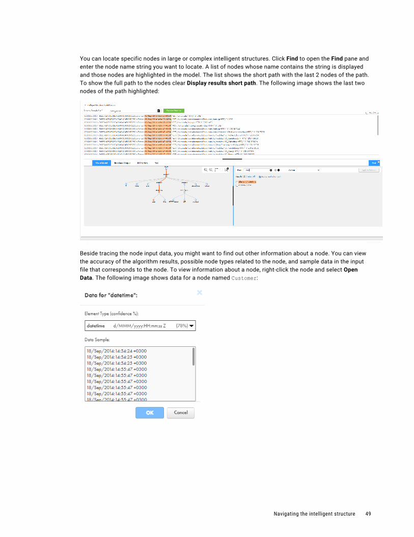
You can locate specific nodes in large or complex intelligent structures. Click Find to open the Find pane and enter the node name string you want to locate. A list of nodes whose name contains the string is displayed and those nodes are highlighted in the model. The list shows the short path with the last 2 nodes of the path. To show the full path to the nodes clear Display results short path. The following image shows the last two nodes of the path highlighted:
Beside tracing the node input data, you might want to find out other information about a node. You can view the accuracy of the algorithm results, possible node types related to the node, and sample data in the input file that corresponds to the node. To view information about a node, right-click the node and select Open Data. The following image shows data for a node named Customer:
Navigating the intelligent structure 49

Editing the nodesYou can change the output of a model by editing the intelligent structure nodes. The available options depend on the type of sample input that you base the model on and on the output data type of the node.
You perform actions on nodes on the Visual Model tab.
Perform the following actions to edit the nodes:
Change the root node.
To change the root, right-click the new root node and select Mark As Root. Changes to root nodes don't affect the XML, JSON, or Relational outputs of the Structure Parser transformation.
Rename a node.
To rename a node, right-click a node, select Rename, and then enter the name, for example Street Address. Node names are not case sensitive. Names must be unique across sibling nodes, that is, nodes that reside under the same node.
Apply unique names to nodes
To apply unique naming across the structure, right-click the root node and select Apply Unique Naming. When you apply unique naming to a model, if the data in the sample input contains fields with identical names in different groups,Intelligent Structure Discovery uses suffixes to rename identical names to unique names.
Restore original node names.
You can restore the original node names and remove the suffixes that Intelligent Structure Discovery adds to identical names in different hierarchy levels.
To restore the original node names in a structure, right-click the root node of the structure and select Restore Original Names.
Note: Don't restore original node names for models that you plan to use in a Data Integration mapping with a relational output. Under these conditions, node names must be unique across the structure.
Combine data in two nodes.
To join two nodes, click and drag a node to the other node. For example, in the following model, the time node is selected and dragged to the date node:
50 Chapter 8: Refining intelligent structure models
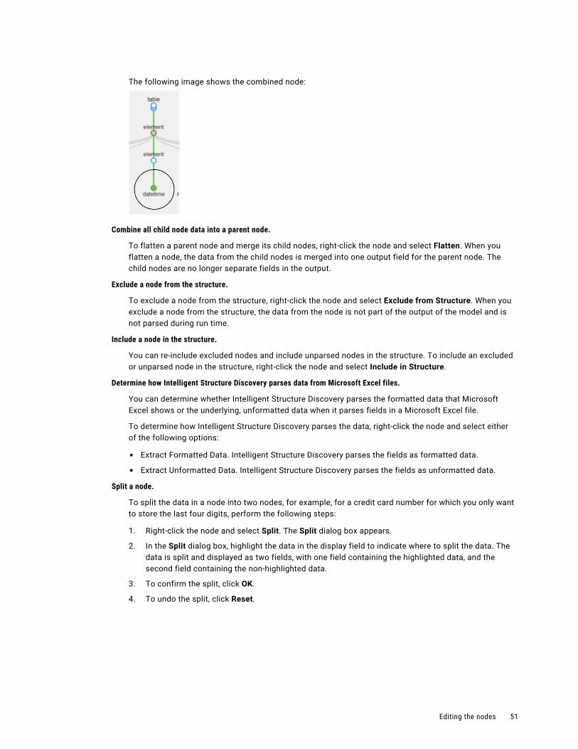
The following image shows the combined node:
Combine all child node data into a parent node.
To flatten a parent node and merge its child nodes, right-click the node and select Flatten. When you flatten a node, the data from the child nodes is merged into one output field for the parent node. The child nodes are no longer separate fields in the output.
Exclude a node from the structure.
To exclude a node from the structure, right-click the node and select Exclude from Structure. When you exclude a node from the structure, the data from the node is not part of the output of the model and is not parsed during run time.
Include a node in the structure.
You can re-include excluded nodes and include unparsed nodes in the structure. To include an excluded or unparsed node in the structure, right-click the node and select Include in Structure.
Determine how Intelligent Structure Discovery parses data from Microsoft Excel files.
You can determine whether Intelligent Structure Discovery parses the formatted data that Microsoft Excel shows or the underlying, unformatted data when it parses fields in a Microsoft Excel file.
To determine how Intelligent Structure Discovery parses the data, right-click the node and select either of the following options:
• Extract Formatted Data. Intelligent Structure Discovery parses the fields as formatted data.
• Extract Unformatted Data. Intelligent Structure Discovery parses the fields as unformatted data.
Split a node.
To split the data in a node into two nodes, for example, for a credit card number for which you only want to store the last four digits, perform the following steps:
1. Right-click the node and select Split. The Split dialog box appears.
2. In the Split dialog box, highlight the data in the display field to indicate where to split the data. The data is split and displayed as two fields, with one field containing the highlighted data, and the second field containing the non-highlighted data.
3. To confirm the split, click OK.
4. To undo the split, click Reset.
Editing the nodes 51
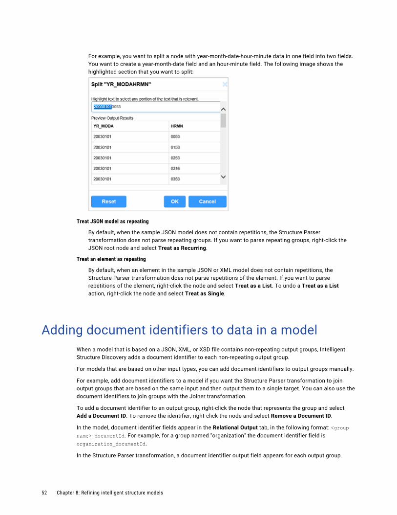
For example, you want to split a node with year-month-date-hour-minute data in one field into two fields. You want to create a year-month-date field and an hour-minute field. The following image shows the highlighted section that you want to split:
Treat JSON model as repeating
By default, when the sample JSON model does not contain repetitions, the Structure Parser transformation does not parse repeating groups. If you want to parse repeating groups, right-click the JSON root node and select Treat as Recurring.
Treat an element as repeating
By default, when an element in the sample JSON or XML model does not contain repetitions, the Structure Parser transformation does not parse repetitions of the element. If you want to parse repetitions of the element, right-click the node and select Treat as a List. To undo a Treat as a List action, right-click the node and select Treat as Single.
Adding document identifiers to data in a modelWhen a model that is based on a JSON, XML, or XSD file contains non-repeating output groups, Intelligent Structure Discovery adds a document identifier to each non-repeating output group.
For models that are based on other input types, you can add document identifiers to output groups manually.
For example, add document identifiers to a model if you want the Structure Parser transformation to join output groups that are based on the same input and then output them to a single target. You can also use the document identifiers to join groups with the Joiner transformation.
To add a document identifier to an output group, right-click the node that represents the group and select Add a Document ID. To remove the identifier, right-click the node and select Remove a Document ID.
In the model, document identifier fields appear in the Relational Output tab, in the following format: <group name>_documentId. For example, for a group named "organization" the document identifier field is organization_documentId.
In the Structure Parser transformation, a document identifier output field appears for each output group.
52 Chapter 8: Refining intelligent structure models
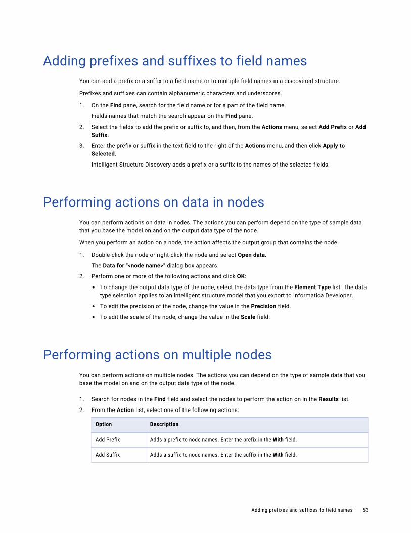
Adding prefixes and suffixes to field namesYou can add a prefix or a suffix to a field name or to multiple field names in a discovered structure.
Prefixes and suffixes can contain alphanumeric characters and underscores.
1. On the Find pane, search for the field name or for a part of the field name.
Fields names that match the search appear on the Find pane.
2. Select the fields to add the prefix or suffix to, and then, from the Actions menu, select Add Prefix or Add Suffix.
3. Enter the prefix or suffix in the text field to the right of the Actions menu, and then click Apply to Selected.
Intelligent Structure Discovery adds a prefix or a suffix to the names of the selected fields.
Performing actions on data in nodesYou can perform actions on data in nodes. The actions you can perform depend on the type of sample data that you base the model on and on the output data type of the node.
When you perform an action on a node, the action affects the output group that contains the node.
1. Double-click the node or right-click the node and select Open data.
The Data for "<node name>" dialog box appears.
2. Perform one or more of the following actions and click OK:
• To change the output data type of the node, select the data type from the Element Type list. The data type selection applies to an intelligent structure model that you export to Informatica Developer.
• To edit the precision of the node, change the value in the Precision field.
• To edit the scale of the node, change the value in the Scale field.
Performing actions on multiple nodesYou can perform actions on multiple nodes. The actions you can depend on the type of sample data that you base the model on and on the output data type of the node.
1. Search for nodes in the Find field and select the nodes to perform the action on in the Results list.
2. From the Action list, select one of the following actions:
Option Description
Add Prefix Adds a prefix to node names. Enter the prefix in the With field.
Add Suffix Adds a suffix to node names. Enter the suffix in the With field.
Adding prefixes and suffixes to field names 53
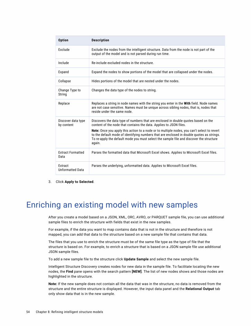
Option Description
Exclude Exclude the nodes from the intelligent structure. Data from the node is not part of the output of the model and is not parsed during run time.
Include Re-include excluded nodes in the structure.
Expand Expand the nodes to show portions of the model that are collapsed under the nodes.
Collapse Hides portions of the model that are nested under the nodes.
Change Type to String
Changes the data type of the nodes to string.
Replace Replaces a string in node names with the string you enter in the With field. Node names are not case sensitive. Names must be unique across sibling nodes, that is, nodes that reside under the same node.
Discover data type by content
Discovers the data type of numbers that are enclosed in double quotes based on the content of the node that contains the data. Applies to JSON files.Note: Once you apply this action to a node or to multiple nodes, you can't select to revert to the default mode of identifying numbers that are enclosed in double quotes as strings. To re-apply the default mode you must select the sample file and discover the structure again.
Extract Formatted Data
Parses the formatted data that Microsoft Excel shows. Applies to Microsoft Excel files.
Extract Unformatted Data
Parses the underlying, unformatted data. Applies to Microsoft Excel files.
3. Click Apply to Selected.
Enriching an existing model with new samplesAfter you create a model based on a JSON, XML, ORC, AVRO, or PARQUET sample file, you can use additional sample files to enrich the structure with fields that exist in the new samples.
For example, if the data you want to map contains data that is not in the structure and therefore is not mapped, you can add that data to the structure based on a new sample file that contains that data.
The files that you use to enrich the structure must be of the same file type as the type of file that the structure is based on. For example, to enrich a structure that is based on a JSON sample file use additional JSON sample files.
To add a new sample file to the structure click Update Sample and select the new sample file.
Intelligent Structure Discovery creates nodes for new data in the sample file. To facilitate locating the new nodes, the Find pane opens with the search pattern [NEW]. The list of new nodes shows and those nodes are highlighted in the structure.
Note: If the new sample does not contain all the data that was in the structure, no data is removed from the structure and the entire structure is displayed. However, the input data panel and the Relational Output tab only show data that is in the new sample.
54 Chapter 8: Refining intelligent structure models
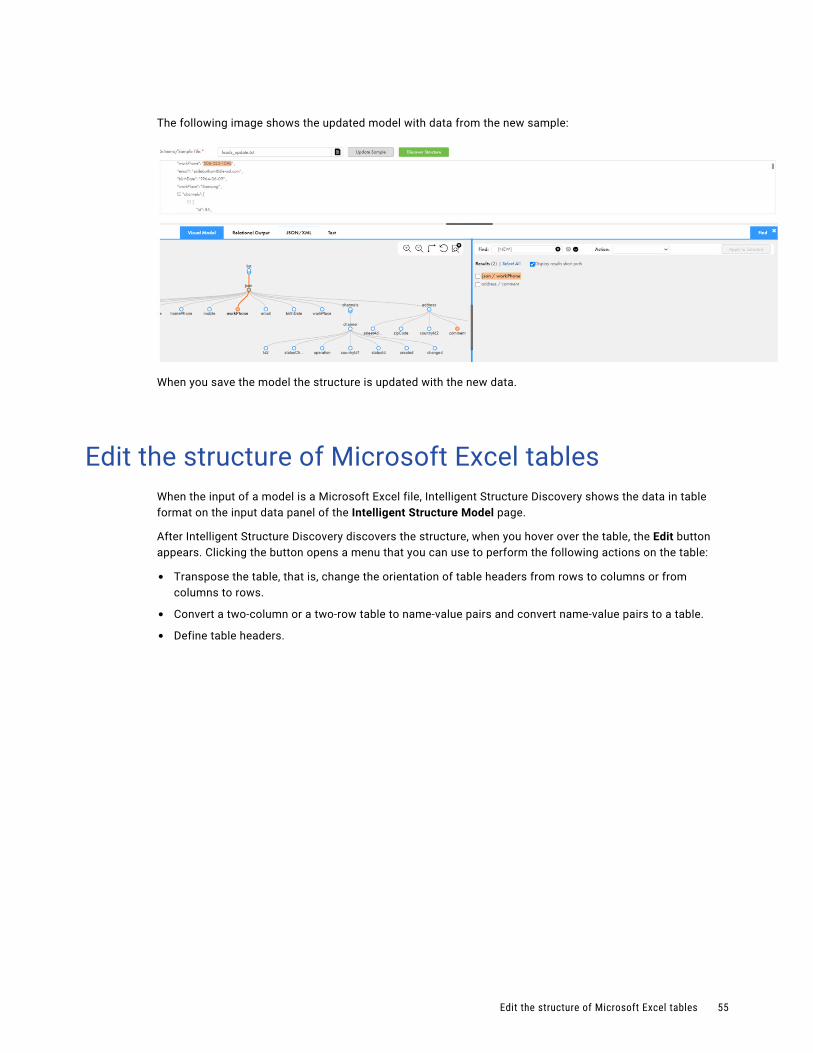
The following image shows the updated model with data from the new sample:
When you save the model the structure is updated with the new data.
Edit the structure of Microsoft Excel tablesWhen the input of a model is a Microsoft Excel file, Intelligent Structure Discovery shows the data in table format on the input data panel of the Intelligent Structure Model page.
After Intelligent Structure Discovery discovers the structure, when you hover over the table, the Edit button appears. Clicking the button opens a menu that you can use to perform the following actions on the table:
• Transpose the table, that is, change the orientation of table headers from rows to columns or from columns to rows.
• Convert a two-column or a two-row table to name-value pairs and convert name-value pairs to a table.
• Define table headers.
Edit the structure of Microsoft Excel tables 55
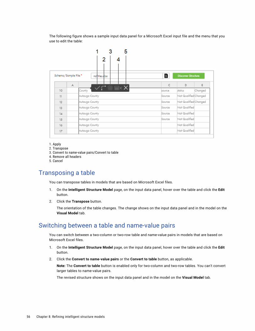
The following figure shows a sample input data panel for a Microsoft Excel input file and the menu that you use to edit the table:
1. Apply2. Transpose3. Convert to name-value pairs/Convert to table4. Remove all headers5. Cancel
Transposing a tableYou can transpose tables in models that are based on Microsoft Excel files.
1. On the Intelligent Structure Model page, on the input data panel, hover over the table and click the Edit button.
2. Click the Transpose button.
The orientation of the table changes. The change shows on the input data panel and in the model on the Visual Model tab.
Switching between a table and name-value pairsYou can switch between a two-column or two-row table and name-value pairs in models that are based on Microsoft Excel files.
1. On the Intelligent Structure Model page, on the input data panel, hover over the table and click the Edit button.
2. Click the Convert to name-value pairs or the Convert to table button, as applicable.
Note: The Convert to table button is enabled only for two-column and two-row tables. You can't convert larger tables to name-value pairs.
The revised structure shows on the input data panel and in the model on the Visual Model tab.
56 Chapter 8: Refining intelligent structure models
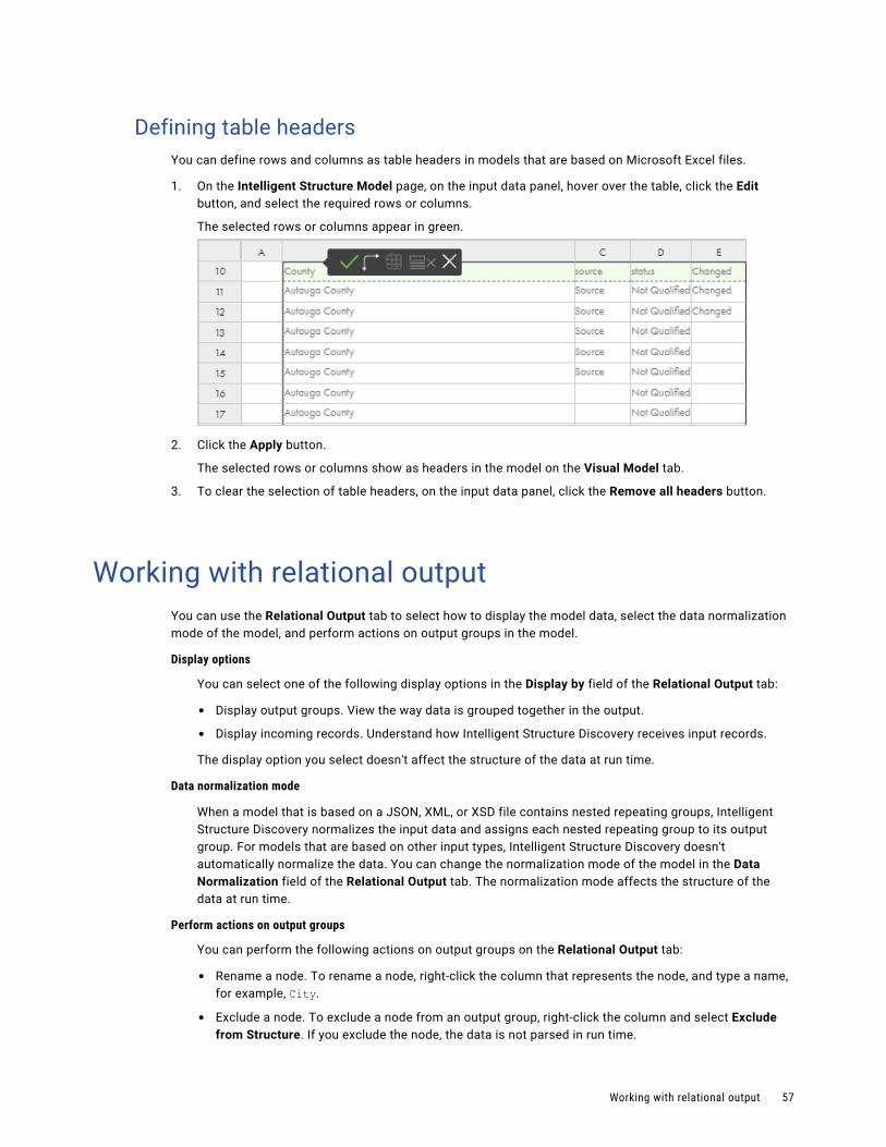
Defining table headersYou can define rows and columns as table headers in models that are based on Microsoft Excel files.
1. On the Intelligent Structure Model page, on the input data panel, hover over the table, click the Edit button, and select the required rows or columns.
The selected rows or columns appear in green.
2. Click the Apply button.
The selected rows or columns show as headers in the model on the Visual Model tab.
3. To clear the selection of table headers, on the input data panel, click the Remove all headers button.
Working with relational outputYou can use the Relational Output tab to select how to display the model data, select the data normalization mode of the model, and perform actions on output groups in the model.
Display options
You can select one of the following display options in the Display by field of the Relational Output tab:
• Display output groups. View the way data is grouped together in the output.
• Display incoming records. Understand how Intelligent Structure Discovery receives input records.
The display option you select doesn't affect the structure of the data at run time.
Data normalization mode
When a model that is based on a JSON, XML, or XSD file contains nested repeating groups, Intelligent Structure Discovery normalizes the input data and assigns each nested repeating group to its output group. For models that are based on other input types, Intelligent Structure Discovery doesn't automatically normalize the data. You can change the normalization mode of the model in the Data Normalization field of the Relational Output tab. The normalization mode affects the structure of the data at run time.
Perform actions on output groups
You can perform the following actions on output groups on the Relational Output tab:
• Rename a node. To rename a node, right-click the column that represents the node, and type a name, for example, City.
• Exclude a node. To exclude a node from an output group, right-click the column and select Exclude from Structure. If you exclude the node, the data is not parsed in run time.
Working with relational output 57
The actions that you perform affect the structure of the data at run time.
Note: The Relational Output tab can display up to 200 rows of data. If you have a large amount of data or many repeating groups, the Relational Output tab might not display all the output groups.
Working with repeating groupsThe output for groups is relational tables. When the intelligent structure contains repeating groups that relate to each other, you can configure the relational output to contain different tables for nested groups, as well as select a record ID.
When an intelligent structure contains nested repeating groups, you can perform the following actions on the Visual Model tab:
Promote to group.
To reduce the number of ports in the model, assign each nested repeating group to its own output group. When you promote a group that is nested within a repeating group, Intelligent Structure Discovery creates a record ID in the parent output group and a foreign key in the child output group. To promote a group to an independent output group, right-click the nested repeating node and select Promote to Group.
Note: For models that are based on a JSON, XML, or XSD file, Intelligent Structure Discovery assigns nested repeating groups to their own output groups when it creates the model.
Join to parent group.
Re-include a nested group in the parent group after you assigned it to its own output group. To re-include a group, right-click the nested repeating node and select Join to Parent Group.
Select as record ID.
Change the record ID. Select a node in the parent group and assign it as a record ID. Intelligent Structure Discovery automatically changes the foreign key in the nested group. To assign a node as record ID, right-click the node and select Select as Record ID.
Deselect as record ID.
Reinstate the initial record ID and foreign key for the repeating groups. To deselect a node as the record ID, right-click the node and select Deselect as Record ID.
Testing the outputAfter Intelligent Structure Discovery discovers the structure of the input that you provide for the model, you can test the model output. You can test different output formats for the model.
1. On the Intelligent Structure Model page, select the Test tab.
2. Select the output format to test from the Test Output Format list.
3. Click Select and Transform, select the input file to test, and click Open.
Intelligent Structure Discovery saves the output to a .zip file in your default downloads folder.
58 Chapter 8: Refining intelligent structure models

4. Unzip the .zip file and open the output file to view the output that Intelligent Structure Discovery generated. If the input contains unidentified data, Intelligent Structure Discovery saves the unidentified data in a separate file.
Testing the output 59

C h a p t e r 9
MappletsA mapplet is reusable transformation logic that you can use to transform source data before it is loaded into the target. If you are an Informatica PowerCenter user, you can import a PowerCenter mapplet to use in Data Integration.
You can create a mapplet in one of the following ways:
• Create a mapplet in Data Integration.
• Import a mapplet from PowerCenter. For information about importing a mapplet, see “PowerCenter mapplets” on page 65.
• Generate an SAP BAPI or IDoc mapplet. For information about configuring and importing SAP mapplets, see the help for SAP Connector.
Create mapplets in Data Integration in the Mapplet Designer in the same way that you create mappings in the Mapping Designer. After you create a mapplet, you can add it to a Mapplet transformation to use its transformation logic.
You can use a mapplet in another mapplet. However, you cannot cyclically reference a mapplet. For example, if Mapplet A uses Mapplet B, Mapplet B cannot also use Mapplet A.
To create and use mapplets, your organization must have the appropriate license.
Active and passive mappletsMapplets can be either active or passive.
Passive mapplets contain a single input group, a single output group, and only passive transformations.
Active mapplets contain at least one active transformation.
When you use a mapplet in a Mapplet transformation, the mapplet type displays on the Mapplet tab.
Mapplet Input and OutputTo use a mapplet in a Mapplet transformation, you must configure the mapplet input and output.
A mapplet receives input from an upstream transformation through an Input transformation, from a Source transformation, or both.
60
A mapplet passes output to a downstream transformation through an Output transformation, to a Target transformation, or both.
A mapplet must contain at least one Input transformation or one Output transformation.
Mapplet inputMapplet input can be an Input transformation, a Source transformation, or both.
Use an Input transformation when you want the mapplet to receive input data from one or more upstream transformations. You can use multiple Input transformations in a mapplet. When you use the mapplet in a Mapplet transformation, each Input transformation becomes an input group. Use multiple Input transformations when you have multiple pipelines in a mapplet, or when you want the mapplet to receive input from multiple upstream transformations.
You include one or more Source transformations in a mapplet to provide source data. When you use only Source transformations for mapplet input, the mapplet is the first object in the mapping pipeline and contains no input groups. If your organization uses Data Integration Elastic and the Source transformation reads hierarchical data, you must specify the mapping type in the Source transformation.
A mapplet must contain at least one Input transformation or Source transformation.
For information about configuring Input and Source transformations, see Transformations.
Mapplet outputMapplet output can be to an Output transformation, a Target transformation, or both.
Use an Output transformation when you want the mapplet to pass data to one or more downstream transformations. When you use the mapplet in a Mapplet transformation, each Output transformation becomes an output group. Each output group can pass data to one or more pipelines in a mapping.
Use a Target transformation when you want the mapplet to write data to a target. When you use a Target transformation with no Output transformation, the mapplet is the last object in the mapping pipeline.
A mapplet must contain at least one Output transformation or Target transformation.
For information about configuring Output and Target transformations, see Transformations.
Parameters in mappletsYou can use input parameters and in-out parameters in a mapplet. You specify the value of the parameters when you configure the mapping task.
You configure parameters in mapplets the same way that you configure parameters in mappings. For information about configuring parameters, see Mappings.
When you include parameters in a mapplet, Data Integration renames the parameters when you use the mapplet in a Mapplet transformation. The parameter names are prefixed with the name of the Mapplet transformation. You can view the corresponding names on the Parameters tab of the Mapplet transformation Properties panel.
For example, you use a Filter transformation in a mapplet and select Completely Parameterized as the filter condition. You create a string parameter called "Filter_Param." You use the mapplet in a Mapplet transformation named "MyMappletTx." In the Mapplet transformation, the filter parameter is renamed to "MyMappletTx_Filter_Param."
Parameters in mapplets 61
If you define in-out parameters in a mapplet, the mapplet is not valid for elastic mappings, even when the in-out parameters are not used in the mapplet.
Creating a mappletCreate a mapplet in the Mapplet Designer.
The Mapplet Designer contains the same design areas and functionality as the Mapping Designer. For information about using the Mapping Designer, see Mappings.
1. Click New > Mapplets > Mapplet.
The Mapplet Designer appears with an Input transformation and an Output transformation on the canvas.
2. Specify the mapplet name and location.
The default name for the mapplet is Mapplet followed by a sequential number.If the Explore page is currently active and a project or folder is selected, the default location for the asset is the selected project or folder. Otherwise, the default location is the location of the most recently saved asset.
You can change the name or location after you save the mapping using the Explore page.
3. Optionally, enter a description for the mapplet.
When you use the mapplet in a Mapplet transformation, the description appears in the Mapplet tab.
4. Optionally, filter the transformations in the transformation palette.
5. Configure the mapplet input.
Input can be a Source transformation, an Input transformation, or both. If you use an Input transformation, add input fields for the fields you want to pass to the mapplet.
6. Add transformations to the mapplet.
7. Configure the mapplet output.
Output can be a Target transformation, an Output transformation, or both. If you use an Output transformation, add output fields for the data you want to pass to the downstream transformation.
8. Validate the mapplet.
9. Resolve errors in the Validation panel.
If your organization uses Data Integration Elastic, resolve errors using the tabs that correspond to the mapping type where you want to use the mapplet.
If the tabs for both mapping types contain no errors, you will be able to use the mapplet in either mapping type.
10. Save the mapplet.
Editing a mappletEdit a mapplet in the Mapplet Designer. To edit a mapplet, open the mapplet from the Explore page.
When you edit a mapplet, the Mapplet Designer validates the transformation logic. If a mapplet is valid when you save it, Data Integration deploys the changes to each mapping and mapplet that use the mapplet.
62 Chapter 9: Mapplets
Use caution when you edit mapplets that are used in mappings and other mapplets. If you edit the mapplet interface, mappings and mapplets that use the mapplet will have validation errors. To resolve the validation errors, you must synchronize the Mapplet transformations that use the mapplet to get the latest changes. If you do not synchronize the mapplet transformation and you run the task, the task fails.
To see the assets that use the mapplet, in the Mapplet Designer, open the Actions menu and select Show Dependencies.
You cannot edit a mapplet in a Mapplet transformation, and you cannot edit a mapplet that you imported from PowerCenter.
Changes that affect dependencies
Changes to a mapplet might affect the mappings and mapplets that use the mapplet.
The following changes to a mapplet do not affect the assets that use the mapplet:
• Change transformation names, descriptions, or properties.
• Add or remove transformations in the mapplet, as long as you do not change the mapplet type from active to passive or from passive to active.
The following changes to a mapplet change the interface of the mapplet and affect the assets that use the mapplet:
• Add or remove transformations that change the mapplet type from active to passive or from passive to active.
• Change the data type, precision, or scale of a connected input or output field.
• Add or remove input or output fields
• Add or remove Input or Output transformations
Synchronizing a mappletIf the interface of a mapplet changes after it has been added to a Mapplet transformation, you must synchronize the mapplet to get the changes. Synchronize a mapplet on the Mapplet tab.
Mappings and mapplets that use the mapplet are invalid until the mapplet is synchronized. If you run a mapping task that includes a changed mapplet, the task fails.
When you synchronize a mapplet, the updates might cause validation errors in other transformations in the mapping or mapplet.
You cannot synchronize a mapplet that you imported into Data Integration from PowerCenter or SAP.
To synchronize a mapplet, perform the following steps:
1. Open the mapping or mapplet that uses the mapplet.
2. Select the mapplet transformation.
3. On the Mapplet tab, click Synchronize.
4. Correct any resulting errors in the transformation logic.
Editing a mapplet 63
Mapplets in Data Integration ElasticIf your organization uses Data Integration Elastic, the Mapplet Designer helps you create and validate mapplets for both non-elastic and elastic mappings.
You can perform the following tasks in the Mapplet Designer:
Filter transformations by mapping type.
You can filter the transformations in the transformation palette by mapping type.
For example, if you create a mapplet to use in an elastic mapping, you can filter the transformation palette to show the transformations that are applicable in an elastic mapping.
View expression validation for multiple mapping types.
The expression editor validates the expression for both non-elastic and elastic mappings. The expression editor shows a different number of validation messages based on the processing differences between the mapping types.
If the expression is valid or the validation error is the same for both mapping types, the expression editor shows one validation message. If the expression is valid for only one mapping type or the validation errors are different, the expression editor shows multiple validation messages.
Validate the mapplet for multiple mapping types.
The Validation panel shows tabs for both non-elastic and elastic mappings. You can resolve errors on each tab based on the mapping type where you want to use the mapplet.
For example, if you create a mapplet to use in an elastic mapping, you must resolve the validation errors on the Elastic Mapping tab. The mapplet can be invalid for a non-elastic mapping.
If the mapplet contains no validation errors on the Mapping or Elastic Mapping tab, you can use the mapplet in either mapping type.
The following table lists the mapplet states and the mapping types where you can use the mapplet based on the error details in the Validation panel:
Mapplet state Can be used in non-elastic mappings Can be used in elastic mappings
Valid Yes Yes
Invalid No No
Valid for mappings Yes No
Valid for elastic mappings No Yes
Editing a mapplet in Data Integration ElasticIf your organization uses Data Integration Elastic and you edit a mapplet, Data Integration deploys the changes to each mapping and mapplet that use the mapplet as long as the mapplet is valid for at least one mapping type.
For example, you create a mapplet that is valid for both non-elastic and elastic mappings. You change the interface of the mapplet such that the mapplet is valid for non-elastic mappings but invalid for elastic mappings.
Data Integration deploys the changes to both the non-elastic and the elastic mappings that use the mapplet. The non-elastic mappings remain valid, but the elastic mappings become invalid.
64 Chapter 9: Mapplets

PowerCenter mappletsIf you are an Informatica PowerCenter user, you can use a PowerCenter mapplet to create a mapplet in Data Integration.
To use a PowerCenter mapplet, you create a mapplet in PowerCenter and export the mapplet to an XML file. Then you upload the XML file in to Data Integration.
A mapplet contains a set of transformations. A PowerCenter mapplet can contain one or more Source transformations but it cannot contain a Target transformation. You can use PowerCenter mapplets in the following Data Integration tasks:
• Synchronization tasks. You can use one mapplet in a synchronization task.
• Mapping tasks. You can use multiple mapplets in a mapping task. You can use mapplets in a Visio template or in a mapping. You cannot use a PowerCenter mapplet in an elastic mapping.
• Masking tasks. You can use passive mapplets in a masking task to mask target fields.
Active and passive PowerCenter mappletsMapplets are either active or passive.
When you upload a PowerCenter mapplet in Data Integration, you specify whether the mapplet is active or passive.
An active mapplet includes at least one active PowerCenter transformation. An active mapplet can return a number of rows different from the number of source rows passed to the mapplet. For example, an active mapplet might aggregate five source rows and return one row.
A passive mapplet includes only passive PowerCenter transformations. A passive mapplet returns the same number of rows that are passed from the source.
Stored Procedures in mappletsWhen a PowerCenter mapplet that you want to use contains a Stored Procedure transformation, the stored procedure must include exception handling.
Exception handling can be as complex as necessary. Or, you can use the following simple example:
Exceptionwhen NO_DATA_FOUNDthen NULL;END;
For example, you have the following stored procedure in a PowerCenter workflow:
CREATE OR REPLACE PROCEDURE SP_GETSAL_WITH_EXCEPTION (EMP_ID NUMBER, EMP_NAME OUT VARCHAR, SAL OUT NUMBER) AS BEGIN SELECT EMPNAME INTO EMP_NAME FROM EMPLOYEE WHERE EMPID=EMP_ID;SELECT SALARY INTO SAL FROM EMPLOYEE WHERE EMPID=EMP_ID;
Before you export the workflow, add exception handling as follows:
CREATE OR REPLACE PROCEDURE SP_GETSAL_WITH_EXCEPTION (EMP_ID NUMBER, EMP_NAME OUT VARCHAR, SAL OUT NUMBER) AS BEGIN SELECT EMPNAME INTO EMP_NAME FROM EMPLOYEE WHERE EMPID=EMP_ID;SELECT SALARY INTO SAL FROM EMPLOYEE WHERE EMPID=EMP_ID; Exceptionwhen NO_DATA_FOUND
PowerCenter mapplets 65

then NULL;END;
PowerCenter XML files for mappletsTo use a mapplet in Data Integration, you upload a PowerCenter XML file that defines a PowerCenter mapplet.
Consider the following rules when you use a PowerCenter XML file to create a Data Integration mapplet:
• If the mapplet includes a transformation that uses a connection, then the PowerCenter XML file must contain only one workflow, one Session task, one mapping, and one mapplet.If the mapplet doesn't include a transformation that uses a connection, then the PowerCenter XML file must include one mapplet. The workflow, Session task, and mapping are optional.
• The session can use any type of connection.
• You do not have to map all source and target fields in the PowerCenter mapping.
• The PowerCenter mapplet can contain the following supported transformations:
- Aggregator transformation
- Expression transformation
- Filter transformation
- HTTP transformation
- Lookup transformation
- Salesforce Lookup transformation (multiple matches returns a single match)
- Salesforce Picklist transformation
- Salesforce Merge transformation
- Sorter transformation
- Stored Procedure transformation with exception handling
- Transaction Control transformation
- Web Services consumer transformation
- XML Generator transformation with flat file or database sources
- XML Parser transformation with flat file or database sources
• If you use a mapplet in a synchronization task, the PowerCenter mapplet cannot contain multiple Input transformations.
• If you use a mapplet in a mapping task, the PowerCenter mapplet can contain multiple Input transformations.
• Data Integration flattens PowerCenter mapplets with multiple input groups into mapplets with one input group. Therefore, the ports in each input group in the PowerCenter mapplet must have unique names. If the names are not unique, rename the input ports in PowerCenter before you export the PowerCenter XML file that contains the mapplet.
• The PowerCenter mapplet cannot contain reusable objects such as shortcuts because Data Integration does not use a repository to store reusable objects. Export the mapplet without reusable objects.
PowerCenter mapplets in Data Integration tasksUse the following rules and guidelines for using PowerCenter mapplets in Data Integration tasks:
• You can add Lookup transformations between the source and a mapplet.
66 Chapter 9: Mapplets
• You can add Expression transformations between the source and a mapplet, and between a mapplet and the target.
• When you add a mapplet to a synchronization task, the synchronization task wizard removes existing field mappings. The synchronization task wizard doesn't remove existing field mappings if you add a passive mapplet between the source and target.
• When you use an active mapplet in a synchronization task that includes a saved query, the synchronization task ignores the configured target option for the task and inserts data to the target.
• Data Integration retains PowerCenter session-level overrides to the mapping.
Configuring a PowerCenter mappletTo create a mapplet in Data Integration, you upload a PowerCenter XML file that contains a PowerCenter mapplet.
When you upload the PowerCenter XML file, Data Integration creates a mapplet based on the mapplet definition in the XML file.
1. To create a mapplet, click New > Mapplets > Mapplet - PC Import and then click Create.
To edit a mapplet, on the Explore page, navigate to the mapplet. In the row that contains the mapplet, click Actions and select Edit.
2. Configure the following details:
Detail Description
Mapplet Name Name of the mapplet.Mapplet names can contain alphanumeric characters, spaces, and the following special characters: _ . + -Maximum length is 100 characters. Mapplet names are not case sensitive.
Location Project folder in which the mapplet is to reside.
Description Description of the mapplet.Maximum length is 255 characters.
Mapplet Type Whether the mapplet is active or passive. The mapplet type depends on the type of PowerCenter transformations in the mapplet:- Active. The mapplet includes one or more active PowerCenter transformations.- Passive. The mapplet includes only passive PowerCenter transformations.
3. To upload the PowerCenter XML file, click Upload.
4. In the Upload Mapplet XML File dialog box, click Choose File.
5. Browse to the appropriate location and select the PowerCenter XML file.
6. Click OK.
The Mapplet XML File Details area shows the connections, input fields, and output fields.
7. Click Save.
PowerCenter mapplets 67
C h a p t e r 1 0
Saved queriesA saved query is a component that you create to run SQL statements against a database. You can use a saved query as the source object in a synchronization task or as the query in an SQL transformation.
You can use a saved query in the following places:
As the source in a synchronization task
Create a saved query when you want to use a database source that you cannot configure using the single- or multiple-object source options. For example, you might create a saved query to include source filters, or to perform a complicated join of multiple tables. The query must be a SELECT statement.
To use a saved query in a synchronization task, first create the saved query component. Then when you configure the synchronization task, select the saved query as the source object. You can add one saved query to a synchronization task.
As the query in an SQL transformation in a mapping
You can create a saved query to use as the query in an SQL transformation. The query can contain one or more SQL statements. You can use one saved query in an SQL transformation.
To use a saved query in an SQL transformation, first create the saved query component. Then when you configure the SQL transformation in a mapping, you select the saved query to use.
To use saved queries, your organization must have the appropriate license. For more information, contact Informatica Global Customer Support.
Saved query syntaxWhen you create a saved query, enter an SQL statement that is valid for the database that you want to run the query against.
You can use different SQL statements based on where you use the saved query:
Synchronization task
When you create a saved query to use as the source in a synchronization task, the SQL statement must be a SELECT statement. Data Integration uses the SQL statement to retrieve source column information. You can edit the data type, precision, or scale of each column before you save the saved query.
For example, you might create a saved query based on a TRANSACTIONS table that includes transactions from 2016 with the following SQL statement:
SELECT TRANSACTION_ID, TRANSACTION_TOTAL, TRANSACTION_TIMESTAMP from dbo.TRANSACTIONS WHERE TRANSACTION_TIMESTAMP>’0:0:0:0 01/01/2016’
68
Data Integration ensures that saved query column names are unique. If an SQL statement returns a duplicate column name, Data Integration adds a number to the duplicate column name as follows:
<column_name><number>
SQL transformation
When you create a saved query to use in an SQL transformation, you can use one or more of the following SQL statements in the query:
ALTER
CALL
COMMENT
COMMIT
CREATE
DELETE
DROP
EXPLAIN PLAN
GRANT
INSERT
LOCK TABLE
MERGE
RENAME
REVOKE
ROLLBACK
SELECT
TRUNCATE
UPDATE
Use the following guidelines when you create the query:
• You can use aggregate functions such as COUNT with Salesforce connections only.
• Do not use conversion functions, such as TO_CHAR or TO_DATE.
• Do not use an asterisk (*) to select all columns of a table. List the columns that you want to select.
• Do not use SQL transformation parameter binding or string substitution notation such as ?input_field? or ~input_field~ in the query. Saved queries have no information about SQL transformation input fields.
Tip: Test the SQL statement you want to use on the source database before you create a saved query. Data Integration does not display specific error messages for invalid SQL statements.
Using saved queries in synchronization tasksUse the following rules and guidelines to use a saved query in a synchronization task:
• You can add one saved query to each synchronization task.
• You cannot delete a saved query that is used in a synchronization task.
Using saved queries in synchronization tasks 69
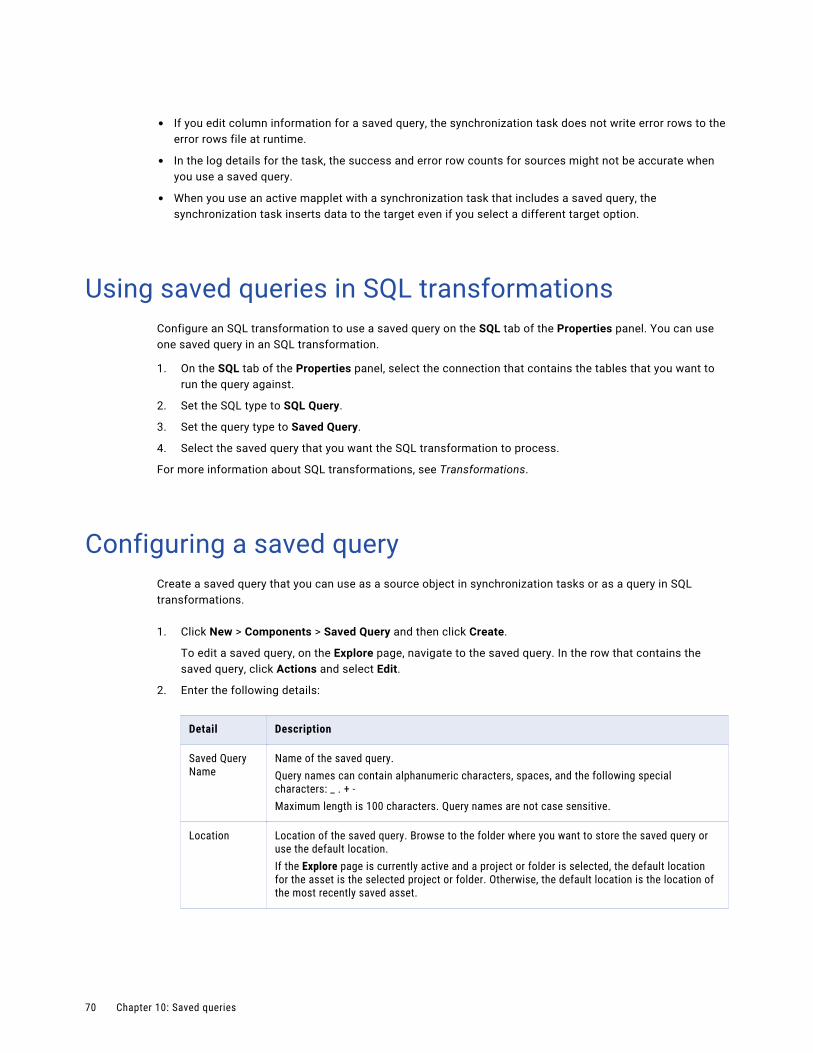
• If you edit column information for a saved query, the synchronization task does not write error rows to the error rows file at runtime.
• In the log details for the task, the success and error row counts for sources might not be accurate when you use a saved query.
• When you use an active mapplet with a synchronization task that includes a saved query, the synchronization task inserts data to the target even if you select a different target option.
Using saved queries in SQL transformationsConfigure an SQL transformation to use a saved query on the SQL tab of the Properties panel. You can use one saved query in an SQL transformation.
1. On the SQL tab of the Properties panel, select the connection that contains the tables that you want to run the query against.
2. Set the SQL type to SQL Query.
3. Set the query type to Saved Query.
4. Select the saved query that you want the SQL transformation to process.
For more information about SQL transformations, see Transformations.
Configuring a saved queryCreate a saved query that you can use as a source object in synchronization tasks or as a query in SQL transformations.
1. Click New > Components > Saved Query and then click Create.
To edit a saved query, on the Explore page, navigate to the saved query. In the row that contains the saved query, click Actions and select Edit.
2. Enter the following details:
Detail Description
Saved Query Name
Name of the saved query.Query names can contain alphanumeric characters, spaces, and the following special characters: _ . + -Maximum length is 100 characters. Query names are not case sensitive.
Location Location of the saved query. Browse to the folder where you want to store the saved query or use the default location.If the Explore page is currently active and a project or folder is selected, the default location for the asset is the selected project or folder. Otherwise, the default location is the location of the most recently saved asset.
70 Chapter 10: Saved queries
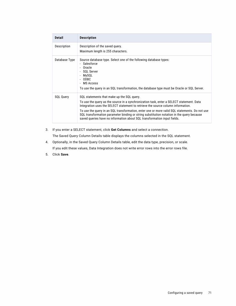
Detail Description
Description Description of the saved query.Maximum length is 255 characters.
Database Type Source database type. Select one of the following database types:- Salesforce- Oracle- SQL Server- MySQL- ODBC- MS AccessTo use the query in an SQL transformation, the database type must be Oracle or SQL Server.
SQL Query SQL statements that make up the SQL query.To use the query as the source in a synchronization task, enter a SELECT statement. Data Integration uses the SELECT statement to retrieve the source column information.To use the query in an SQL transformation, enter one or more valid SQL statements. Do not use SQL transformation parameter binding or string substitution notation in the query because saved queries have no information about SQL transformation input fields.
3. If you enter a SELECT statement, click Get Columns and select a connection.
The Saved Query Column Details table displays the columns selected in the SQL statement.
4. Optionally, in the Saved Query Column Details table, edit the data type, precision, or scale.
If you edit these values, Data Integration does not write error rows into the error rows file.
5. Click Save.
Configuring a saved query 71
C h a p t e r 1 1
Shared sequencesShared sequences are reusable sequences that you can use in multiple Sequence Generator transformations. When you use a shared sequence, the Sequence Generator transformation uses the properties of the shared sequence to generate values. Use a shared sequence when you want to assign numeric values within the same sequence to data in multiple mapping tasks.
Multiple mappings and mapplets can use the same shared sequence. When you run the mapping task, Data Integration reserves a set of values in the sequence so that each mapping task generates unique values.
For example, you want to assign a unique ID to entries in your customer tables. You have two mappings that load customer data to the same target table, and the mappings are scheduled to run at the same time. Use a shared sequence to ensure that you do not get duplicate IDs in the target.
You create shared sequences on the New Assets page. You can create non-shared sequences in a Sequence Generator transformation. For more information about creating non-shared sequences, see Transformations.
Shared sequence propertiesWhen you create a shared sequence, you define general properties such as the sequence name, and properties that define the sequence such as initial value, increment value, and end value.
The following table lists the properties you define for a shared sequence:
Property Description
Name Required. Name of the shared sequence.Can contain alphanumeric characters and underscores (_). Maximum length is 200 characters.
Location Project or folder in which the sequence resides.If the Explore page is currently active and a project or folder is selected, the default location for the asset is the selected project or folder. Otherwise, the default location is the location of the most recently saved asset.
Description Optional. Description for the shared sequence.
Increment By The difference between two consecutive values in a generated sequence. For example, if Increment By is 2 and the existing value is 4, then the next value generated in the sequence will be 6.Default is 1.Maximum is 2,147,483,647.
72
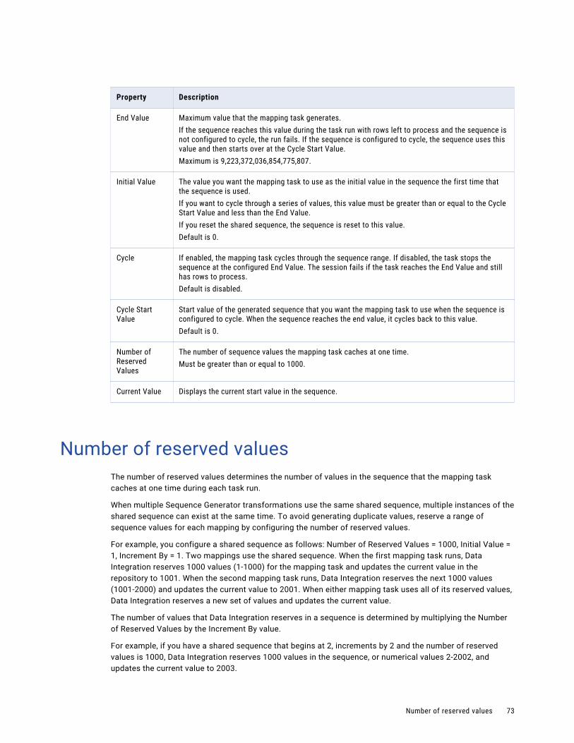
Property Description
End Value Maximum value that the mapping task generates.If the sequence reaches this value during the task run with rows left to process and the sequence is not configured to cycle, the run fails. If the sequence is configured to cycle, the sequence uses this value and then starts over at the Cycle Start Value.Maximum is 9,223,372,036,854,775,807.
Initial Value The value you want the mapping task to use as the initial value in the sequence the first time that the sequence is used.If you want to cycle through a series of values, this value must be greater than or equal to the Cycle Start Value and less than the End Value.If you reset the shared sequence, the sequence is reset to this value.Default is 0.
Cycle If enabled, the mapping task cycles through the sequence range. If disabled, the task stops the sequence at the configured End Value. The session fails if the task reaches the End Value and still has rows to process.Default is disabled.
Cycle Start Value
Start value of the generated sequence that you want the mapping task to use when the sequence is configured to cycle. When the sequence reaches the end value, it cycles back to this value.Default is 0.
Number of Reserved Values
The number of sequence values the mapping task caches at one time.Must be greater than or equal to 1000.
Current Value Displays the current start value in the sequence.
Number of reserved valuesThe number of reserved values determines the number of values in the sequence that the mapping task caches at one time during each task run.
When multiple Sequence Generator transformations use the same shared sequence, multiple instances of the shared sequence can exist at the same time. To avoid generating duplicate values, reserve a range of sequence values for each mapping by configuring the number of reserved values.
For example, you configure a shared sequence as follows: Number of Reserved Values = 1000, Initial Value = 1, Increment By = 1. Two mappings use the shared sequence. When the first mapping task runs, Data Integration reserves 1000 values (1-1000) for the mapping task and updates the current value in the repository to 1001. When the second mapping task runs, Data Integration reserves the next 1000 values (1001-2000) and updates the current value to 2001. When either mapping task uses all of its reserved values, Data Integration reserves a new set of values and updates the current value.
The number of values that Data Integration reserves in a sequence is determined by multiplying the Number of Reserved Values by the Increment By value.
For example, if you have a shared sequence that begins at 2, increments by 2 and the number of reserved values is 1000, Data Integration reserves 1000 values in the sequence, or numerical values 2-2002, and updates the current value to 2003.
Number of reserved values 73
By default, the number of reserved values is 1000. To increase performance, you can increase the number of reserved values. This reduces the number of calls that Data Integration must make to the repository. The number of reserved values cannot be less than 1000.
Values that are reserved for a task run but not used in the task are lost when the task completes. For example, you generate IDs in a table with 1250 rows. You configure the shared sequence to generate values in increments of 1 and set the number of reserved values to 2000. When the task runs, Data Integration reserves 2000 values for the task and updates the current value to 2001. When the next task runs, the sequence begins at 2001, and values 1251-2000 are lost.
Note: If you use partitions, Data Integration reserves a set of values for each partition.
Creating a shared sequenceCreate a shared sequence on the New Asset page.
1. Click New > Components > Shared Sequence and then click Create.
2. Define the sequence properties.
3. Save the sequence.
Using a shared sequenceYou can use a shared sequence in a Sequence Generator transformation in a mapping or mapplet.
1. Open the mapping or mapplet.
2. Add a Sequence Generator transformation to the canvas and connect it to a downstream transformation.
3. On the Sequence tab, select Use Shared Sequence.
4. Select the sequence to use.
5. Configure the Sequence Generator advanced properties and output fields.For more information about configuring a Sequence Generator transformation, see Transformations.
Note: If you do not select Use Shared Sequence, the Sequence Generator transformation generates a non-shared sequence.
Resetting a shared sequenceReset a shared sequence to update the current value of the sequence to the defined initial value.
1. Open the shared sequence.
2. Click Edit.
3. Click Reset Current Value in the Sequence Properties area.
4. Save the shared sequence.
74 Chapter 11: Shared sequences
C h a p t e r 1 2
User-defined functionsUser-defined functions are reusable functions that you can use in expressions. Create user-defined functions to build complex expressions using the Informatica Intelligent Cloud Services transformation language. User-defined functions use the same syntax and can use the same transformation language components as transformation and field expressions.
You can include a user-defined function in a transformation expression in a mapping or mapplet, in a field expression in a mapping task, or in another user-defined function. To use a user-defined function in an expression, you select the user-defined function in the expression editor and enter the required arguments.
You cannot use a user-defined function in an expression in a synchronization task. You also cannot use a user-defined function in any transformation in an elastic mapping.
To create and use user-defined functions, your organization must have the appropriate license.
Example
You want to remove leading and trailing spaces from a text string such as a name or address. You create a user-defined function called RemoveSpaces that takes a text string as an argument and performs the LTRIM and RTRIM functions. When you configure the user-defined function, you enter the following expression:
LTrim( RTrim(TextString) )
After you create the function, you use it in an Expression transformation to remove leading and trailing spaces from the incoming field, LAST_NAME. The expression field contains the following expression:
:UDF.RemoveSpaces(LAST_NAME)
In the expression, the user-defined function name is prefaced with :UDF. The incoming field LAST_NAME is passed to the function as the argument.
Creating user-defined functionsCreate a user-defined function on the New Asset page. The user-defined functions that you create are available to all users in your organization based on their privileges.
1. Click New > Components > User-Defined Function and then click Create.
2. Configure general properties such as the function name, location, and return type.
3. Optionally, create arguments for the function.
When you create arguments, configure the name, data type, and description for each argument.
4. Create the function expression.
5. Validate and save the function.
75
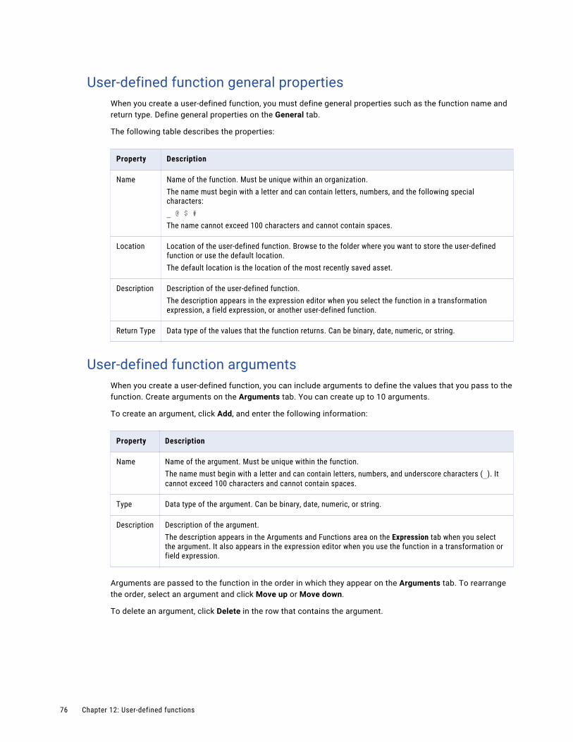
User-defined function general propertiesWhen you create a user-defined function, you must define general properties such as the function name and return type. Define general properties on the General tab.
The following table describes the properties:
Property Description
Name Name of the function. Must be unique within an organization.The name must begin with a letter and can contain letters, numbers, and the following special characters:_ @ $ #The name cannot exceed 100 characters and cannot contain spaces.
Location Location of the user-defined function. Browse to the folder where you want to store the user-defined function or use the default location.The default location is the location of the most recently saved asset.
Description Description of the user-defined function.The description appears in the expression editor when you select the function in a transformation expression, a field expression, or another user-defined function.
Return Type Data type of the values that the function returns. Can be binary, date, numeric, or string.
User-defined function argumentsWhen you create a user-defined function, you can include arguments to define the values that you pass to the function. Create arguments on the Arguments tab. You can create up to 10 arguments.
To create an argument, click Add, and enter the following information:
Property Description
Name Name of the argument. Must be unique within the function.The name must begin with a letter and can contain letters, numbers, and underscore characters (_). It cannot exceed 100 characters and cannot contain spaces.
Type Data type of the argument. Can be binary, date, numeric, or string.
Description Description of the argument.The description appears in the Arguments and Functions area on the Expression tab when you select the argument. It also appears in the expression editor when you use the function in a transformation or field expression.
Arguments are passed to the function in the order in which they appear on the Arguments tab. To rearrange the order, select an argument and click Move up or Move down.
To delete an argument, click Delete in the row that contains the argument.
76 Chapter 12: User-defined functions
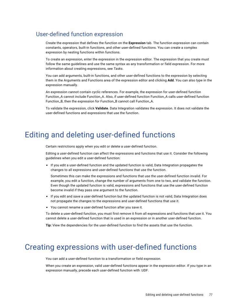
User-defined function expressionCreate the expression that defines the function on the Expression tab. The function expression can contain constants, operators, built-in functions, and other user-defined functions. You can create a complex expression by nesting functions within functions.
To create an expression, enter the expression in the expression editor. The expression that you create must follow the same guidelines and use the same syntax as any transformation or field expression. For more information about creating expressions, see Tasks.
You can add arguments, built-in functions, and other user-defined functions to the expression by selecting them in the Arguments and Functions area of the expression editor and clicking Add. You can also type in the expression manually.
An expression cannot contain cyclic references. For example, the expression for user-defined function Function_A cannot include Function_A. Also, if user-defined function Function_A calls user-defined function Function_B, then the expression for Function_B cannot call Function_A.
To validate the expression, click Validate. Data Integration validates the expression. It does not validate the user-defined functions and expressions that use the function.
Editing and deleting user-defined functionsCertain restrictions apply when you edit or delete a user-defined function.
Editing a user-defined function can affect the expressions and functions that use it. Consider the following guidelines when you edit a user-defined function:
• If you edit a user-defined function and the updated function is valid, Data Integration propagates the changes to all expressions and user-defined functions that use the function.
Sometimes this can make the expressions and functions that use the user-defined function invalid. For example, you edit a function, change the number of arguments from one to two, and validate the function. Even though the updated function is valid, expressions and functions that use the user-defined function become invalid if they pass one argument to the function.
• If you edit and save a user-defined function but the updated function is not valid, Data Integration does not propagate the changes to the expressions and user-defined functions that use it.
• You cannot rename a user-defined function after you save it.
To delete a user-defined function, you must first remove it from all expressions and functions that use it. You cannot delete a user-defined function that is used in an expression or in another user-defined function.
Tip: View the dependencies for the user-defined function to find the assets that use the function.
Creating expressions with user-defined functionsYou can add a user-defined function to a transformation or field expression.
When you create an expression, valid user-defined functions appear in the expression editor. If you type in an expression manually, precede each user-defined function with :UDF.
Editing and deleting user-defined functions 77
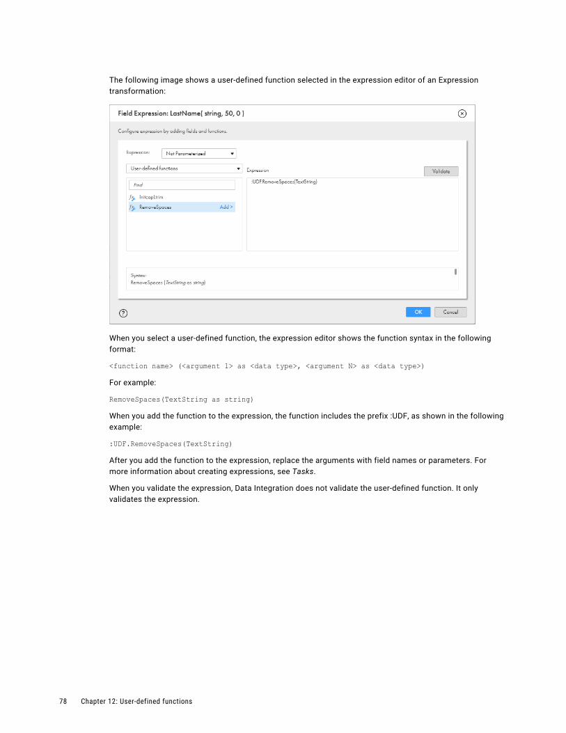
The following image shows a user-defined function selected in the expression editor of an Expression transformation:
When you select a user-defined function, the expression editor shows the function syntax in the following format:
<function name> (<argument 1> as <data type>, <argument N> as <data type>)
For example:
RemoveSpaces(TextString as string)
When you add the function to the expression, the function includes the prefix :UDF, as shown in the following example:
:UDF.RemoveSpaces(TextString)
After you add the function to the expression, replace the arguments with field names or parameters. For more information about creating expressions, see Tasks.
When you validate the expression, Data Integration does not validate the user-defined function. It only validates the expression.
78 Chapter 12: User-defined functions
I n d e x
Aactive mapplets
description 60, 65asset components 8
BB2B Gateway
intelligent structure model 33business services
defining 12
CCloud Application Integration community
URL 6Cloud Developer community
URL 6components
business services 12file listeners 14, 15file listeners in taskflows 15fixed-width file formats 26hierarchical schemas 30intelligent structure models 31mapplets 60saved queries 68shared sequence 72
Ddata engineering
intelligent structure model 33Data Integration community
URL 6
Eelastic mapping
intelligent structure model 32exception handling
in mapplet stored procedures 65
Ffile listeners
configuring 16invoking taskflows 15orchestrating taskflow execution 15
file listeners in partner flows 15
file listeners in taskflows 15fixed-width file formats
configuring 26flat files
fixed-width file formats 26
HHierarchical Schema
creating 30hierarchical schemas 30hierarchy builder transformation
intelligent structure model 32
IInformatica Global Customer Support
contact information 7Informatica Intelligent Cloud Services
web site 6intelligent structure
data drift intelligent structure 38
data in nodes 53document identifiers 52editing 50, 52, 54, 57example 39
intelligent structure navigating 48
model input intelligent structure 34
refining 45repeating groups 35, 58viewing 54Visual Model 48
intelligent structure model B2B Gateway 33creating 42data engineering 33development 33discovery process 33editing 53elastic mapping 32exporting 43hierarchy builder transformation 32prefix 53scenario 39structure parser transformation 32suffix 53
intelligent structure models 31intelligent structure nodes
actions 53data 53editing 50
79
intelligent structures actions 53
foreign keys description 36
nodes 53primary and foreign keys 36
Mmaintenance outages 7mapplet
output 60Mapplet
input 60mapplet input 61mapplet output 61mapplet parameters 61mapplets
active and passive 60, 65configuring 67overview 60rules for PowerCenter XML files 66rules for using in tasks 66
Mapplets PowerCenter 65
Nnumber of reserved values 73
Ooutput groups
editing 57navigating 46
Pparameters
in mapplets 61passive mapplets
description 60, 65PowerCenter mapplets 65PowerCenter XML files
rules for mapplets 66primary keys
description 36properties
shared sequence 72
Rrelational output
working with 57repeating groups
description 35
repeating groups (continued)working with 58
Ssaved queries
configuring 70creating 68overview 68using in synchronization tasks 69
shared sequence creating a shared sequence 74number of reserved values 73resetting a shared sequence 74
sources custom saved queries 68
SQL transformations saved queries 68
status Informatica Intelligent Cloud Services 7
stored procedures exception handling in mapplets 65
structure parser transformation intelligent structure model 32
system status 7
Ttrust site
description 7
Uupgrade notifications 7user-defined functions
arguments 76creating 75deleting 77editing 77expression 77general properties 76overview 75return type 76
VVisual Model
intelligent structures 48
Wweb site 6
80 Index