in situ ground reinforcement
TRANSCRIPT

26-11-2018
1
In Situ Ground Reinforcement
In situ ground reinforcement is a technique to stabilize existing unstable ground due to the
change of geotechnical conditions by nature and/or human activities.
For example,
intensive precipitation may destabilize existing slopes and induce landslides due to increased
soil weight, reduced soil strength, and water seepage.
Scour of a slope toe in a river may destabilize the river bank.
Excavation in the ground for wall or foundation construction (i.e., a cut situation) induces
unbalanced forces and results in ground movement and even failure if not properly designed and
protected.
Underground tunneling may also induce ground movement and even collapse.
Ground anchors, soil nails, micropiles, and slope stabilizing piles have been used as in situ
ground reinforcement techniques to mitigate the preceding problems.

26-11-2018
2
Ground anchors are also called tiebacks.
They rely on long prestressed steel tendons bonded in a stable mass at a greater
depth and distance to provide tensile resistance to the unstable mass near the wall or
slope surface.
The tensile force induced by the prestressing of the steel tendons provides additional
normal stresses to a critical slip surface so that the shear strength along the critical slip
surface is increased thus resulting in a higher factor of safety against sliding.
Ground anchors are cement-grouted prestressed tendons installed in in situ soil or rock
by transmitting applied tensile loads into ground to stabilize earth retaining structures or
to provide uplift resistance to structures.
GROUND ANCHORS

26-11-2018
3
Figure 9.2 shows the basic components of a typical ground anchor, which includes three parts:
• Anchorage set, which consists of an anchor head, a bearing plate, and a trumpet
• Unbonded pre-stressing steel tendon
• Bonded steel tendon with grout
The anchorage component is to transmit the prestressing force from the prestressing
steel to the ground surface or the supported structure.
The unbonded steel is prestressed and can have elastic elongation and transfer the
resistance from the bond length to a structure.
A smooth plastic sleeve as a bond breaker is placed over the steel tendon to separate
the prestressing steel from the surrounding grout.
The bonded steel with grout can provide a tensile load into the ground;
therefore, the bond length should be behind a critical slip surface.

26-11-2018
4
There are four types of ground anchors commonly used in practice as shown in Figure 9.3:
• Straight shaft gravity-grouted ground anchors
• Straight shaft pressure-grouted ground anchors
• Postgrouted ground anchors
• Under-reamed anchors
The details of the installation procedure for each type of ground anchor may be different and are
discussed in Sabatini et al. (1999); however, the general procedure is the same, which includes the
following:
• Drill a hole.
• Insert a steel tendon.
• Grout the hole within the bond length.
• Install the anchorage assembly.
• Prestress the steel tendon.

26-11-2018
5
Suitability :
Ground anchors are suitable for a variety of geotechnical conditions.
They can be used in situ soils, rocks, or other geomaterials.
Different techniques may be used to install ground anchors in different geomaterials, mostly
related to drilling and stability of the hole.
Ground anchors may experience excessive creep deformations when they are installed in organic
soil or soils with high plasticity.
Caution should be exercised when ground anchors are used under such conditions.
ApplicationsGround anchors have been used permanently or temporarily in anchored systems.
Permanent ground anchors are typically designed for a service life of 75–100 years.
Temporary anchored systems are mostly used for earth support before permanent structures are
installed.
The service life of temporary anchored systems depends on project needs, but commonly ranges
from 18 to 36 months.

26-11-2018
6
Temporary Ground Anchors:
Hollow bar is often the product of choice for temporary works.
Its installation method of combining drilling & grouting enables anchors to be installed into a
range of ground conditions,
sometimes unforeseen at the time of initial site investigation, and self-drilling systems are able to
overcome problems with collapsing soils.
Hollow bars are also able to offer a limited prestress function, through the inclusion of bonded
sleeves between the couplers.
It is not possible to provide bonded sleeves over the couplers, as rotary percussive installation
precludes such sleeves.
Furthermore, rod handling and rod release of sleeved hollow bar sections using jaw clamps
requires specialist measures.
Advantages and Limitations
Ground anchored systems have the following advantages over conventional earth
retaining systems, such as gravity walls (Sabatini et al., 1999):
• No obstruction for workspace during excavations
• Tolerable to large lateral earth pressure without a significant increase of wall cross
sections
• Used as temporary excavation support as well as a permanent structure
• No need for select backfill
• No need for deep foundation support
• Fast construction
• Less surface right-of-way issue

26-11-2018
7
Possible Failure Modes

26-11-2018
8
Design Parameters
The design parameters for ground anchors may include the following parameters (mainly for
anchored walls):
• Type of application (temporary or permanent, critical or noncritical)
• Project requirements (tolerable settlement, factor of safety against slope failure)
• Construction constraints
• Geometry of project (such as depth of excavation)
• Type of wall facing
• Site subsurface conditions (type and properties of geomaterial, groundwater table, aggressive or
nonaggressive for corrosion)
• Loading conditions (surcharge, water pressure or seismic)
• Number of ground anchor levels
• Method of installation of anchors
• Length and inclination of anchors
• Depth of the upper level of ground anchor
• Bond length
Design Procedure
The detailed design procedure for an anchored wall is provided by Sabatini et al. (1999) as
follows:
1. Establish project requirements including type of project (temporary and/or permanent), project
geometry, external loading (water, surcharge or seismic), performance criteria, and construction
constraints (right-of-way limitations, nearby structures, and existing utility lines).
2. Evaluate site subsurface conditions and relevant properties of in situ geomaterial.
3. Establish design requirements, including factors of safety and level of corrosion protection.
4. Based on type of geomaterial, select lateral earth pressure distribution behind the wall. Add
water pressure and surcharge for total lateral pressure calculation if they exist.
5. Calculate horizontal ground anchor loads by adjusting vertical anchor locations to achieve the
optimum wall bending moment distribution.
26-11-2018
9
6. Determine required anchor inclination based on construction constraints and geotechnical
conditions.
7. Calculate a vertical force component and a force along the anchor from each horizontal anchor
load.
8. Evaluate horizontal spacing of anchors based on wall type and experience. Calculate
individual anchor load.
9. Select the type of ground anchors.
10. Evaluate the embedment depth and cross section of the wall by calculating vertical and
lateral capacities of the wall below excavation base
11. Calculate factors of safety for internal and external stability of the anchored system and
check them against design requirements.
12. Estimate maximum lateral wall movements and ground surface settlements. Revise design if
necessary.
If any of the calculated values in Steps 10, 11, and 12 does not meet the design requirement,
adjust design parameters of anchors and/or the wall and repeat the above design procedure.

26-11-2018
10
SOIL NAILINGIntroduction
Basic Concept Soil nailing is a technique to install closely spaced, passive
structural inclusions to stabilize existing unstable ground due to the
change of geotechnical conditions by nature and/or human activities.
Common natural causes are precipitation and/or erosion, while the
common human activity is partial removal of the ground for project needs.
The basic procedure for installing a soil nail consists of drilling a hole in
the ground, placing a steel bar in the hole, and grouting the hole.
Soil nails can be installed on existing or cut slopes and walls during excavation.
Figure 9.16 shows a typical cross section of soil nailing, which includes multiple soil nails,
temporary and/or permanent facing, and drainage system.

26-11-2018
11
There are different types of nails in practice, which include
• Grouted nails
• Self-drilling nails
• Jet grouted nails
• Helical nails
• Driven nails
• Shoot-in nails
Most of nails are installed in inclination angles of 10∘–20∘ below the
horizontal.
Different from ground anchors, soil nails are not prestressed when they are
installed.
Tension develops during the service due to ground movements.
Sometimes, nails are installed vertically or perpendicularly to critical slip
surfaces, especially for slope stabilization.
This application is similar to that by micropiles and will not be further
discussed in this book.

26-11-2018
12
Typical temporary facing is installed by steel mesh with shotcreting (i.e.,
spraying concrete).
Cast-in-place, prefabricated concrete facing, or other type of facing may be
installed as the permanent wall facing in front of the temporary wall facing.
A bearing plate and washers
are used to fix the soil nail
on the temporary facing.
Steel reinforcements are
connected with the bearing
plate by studded heads
before the permanent
concrete facing is cast in
place on the temporary
facing.
Figure 9.17 shows the details of facing connection between soil nails, temporary facing
(shotcrete), and permanent facing.

26-11-2018
13
Suitability Soil nailing is suitable for vertical or nearvertical excavations in both soils and
weathered rocks.
It is also suitable for stabilizing steep unstable terrain of soils or weathered rocks.
The favorable geomaterials for soil nailing installation include (Lazarte et al., 2003):
• Stiff to hard fine-grained soils
• Dense to very dense granular soils with some apparent cohesion
• Weathered rock with no weak plane
• Glacial soils
• Ground that can stand unsupported on a vertical or sloped cut of 1–2 m for 1–2 two days.
The unfavorable geomaterial conditions for soil nailing are (Lazarte et al., 2003):
• Dry, poorly graded cohesionless soils
• Soils with high groundwater
• Soils with large boulders or cobbles
• Soft to very soft fine-grained soils
• Organic soils
• Highly corrosive soil (e.g., cinder or slag) or groundwater
• Weathered rock with unfavorable weak planes and karst
• Loess.

26-11-2018
14
Applications
Soil nailing has been used for different applications:
• Vertical or near-vertical excavations
• End slope removal to widen existing bridge abutments
• Tunnel portals
• Repair or stabilization of existing earth retaining structures
• Repair or stabilization of existing natural slopes.
Examples of soil nailing: (a) temporary shoring (Byrne et al., 1998)

26-11-2018
15
Examples of soil nailing: (b) roadway widening (Byrne et al., 1998)
Examples of soil nailing: (c) end slope removal (Byrne et al., 1998)

26-11-2018
16
Advantages
Soil nailing has the following advantages as compared with alternate technologies (Lazarte et al,
2003; Elias et al., 2004):
• Less right-of-way requirements than ground anchors
• Less concrete usage than conventional reinforced concrete retaining walls
• No need for deep foundations or structural elements below the base of excavations
• Rapid installation with less material than ground anchors
• Less disruptive to traffic and less environmental impact
• More accessible to a job site and low overhead requirements due to the use of light
equipment
• Higher redundancy because of the larger number of nails than ground anchors
• More flexible to deformation than conventional rigid structures
• Easy incorporation of temporary wall facing into permanent wall facing
• More cost effective than conventional rigid retaining walls.
Limitations
The possible limitations of soil nailing are (Lazarte et al, 2003; Elias et al., 2004):
• Not appropriate for applications with strict deformation requirements
• Restriction by nearby existing utilities and structures
• Requirement for permanent underground easements
• Difficult to install below the groundwater table
• Low nail capacity and large creep deformation in high-plasticity cohesive soils

26-11-2018
17
Failure Modes Similar to anchored walls, soil-nailed walls may have internal, external, and facing
failures as shown in Figures
The internal failures as shown in Figure 9.19 include nail–soil pullout, bar–grout pullout, nail
tensile failure, and bending and/or shear failure through the reinforced mass.
The external failures as shown in Figure 9.20 include compound failure, sliding failure,
and global failure.
26-11-2018
18
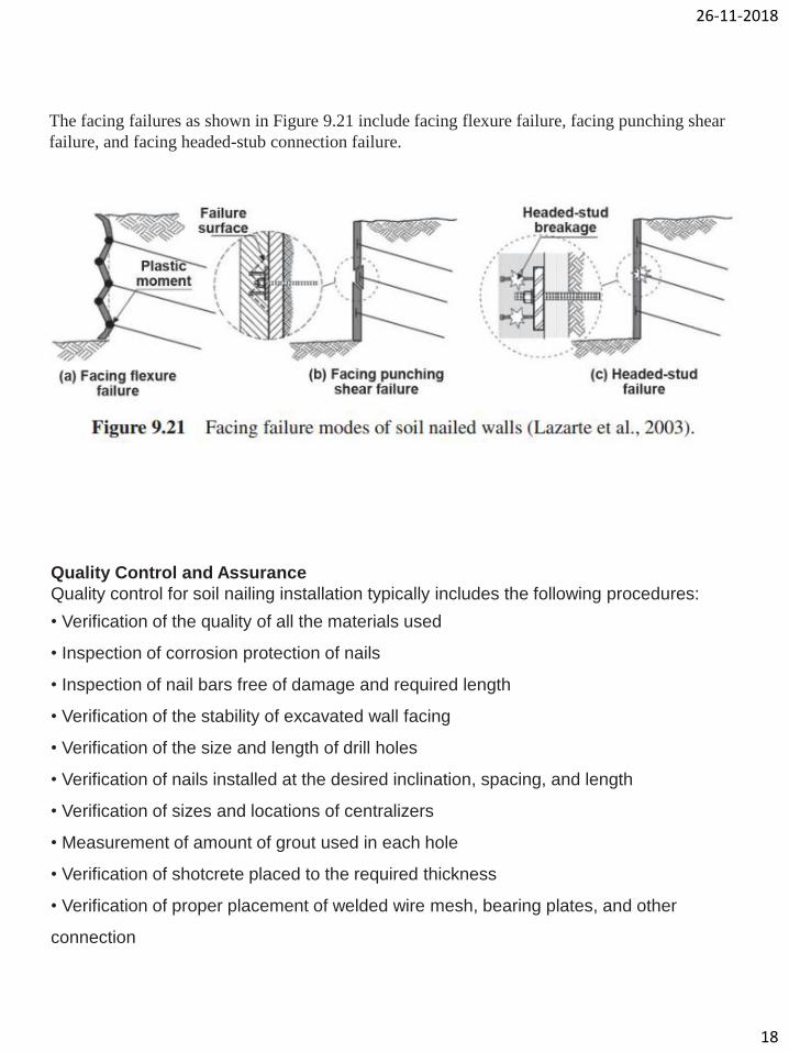
The facing failures as shown in Figure 9.21 include facing flexure failure, facing punching shear
failure, and facing headed-stub connection failure.
Quality Control and Assurance
Quality control for soil nailing installation typically includes the following procedures:
• Verification of the quality of all the materials used
• Inspection of corrosion protection of nails
• Inspection of nail bars free of damage and required length
• Verification of the stability of excavated wall facing
• Verification of the size and length of drill holes
• Verification of nails installed at the desired inclination, spacing, and length
• Verification of sizes and locations of centralizers
• Measurement of amount of grout used in each hole
• Verification of shotcrete placed to the required thickness
• Verification of proper placement of welded wire mesh, bearing plates, and other
connection

26-11-2018
19
Quality assurance during construction should ensure the following items (Lazarte et al.
2003):
• Construction completed in accordance with plans and specifications
• No excavation height exceeding an allowable value
• Not caved nail drill holes during nail installation
• Nail bars of the right size and type (i.e., steel grade, length, diameter)
• Appropriate corrosion protection systems
• Properly grouting, installation of facing rebar and mesh, and shotcrete
• Sufficient grout strength from grout cubes
• Sufficient shotcrete strength from cores
• Nail pullout capacity from field testing meeting the requirements
• Drainage properly installed

26-11-2018
20