ground-penetrating radar (gpr) ground penetrating radar
TRANSCRIPT
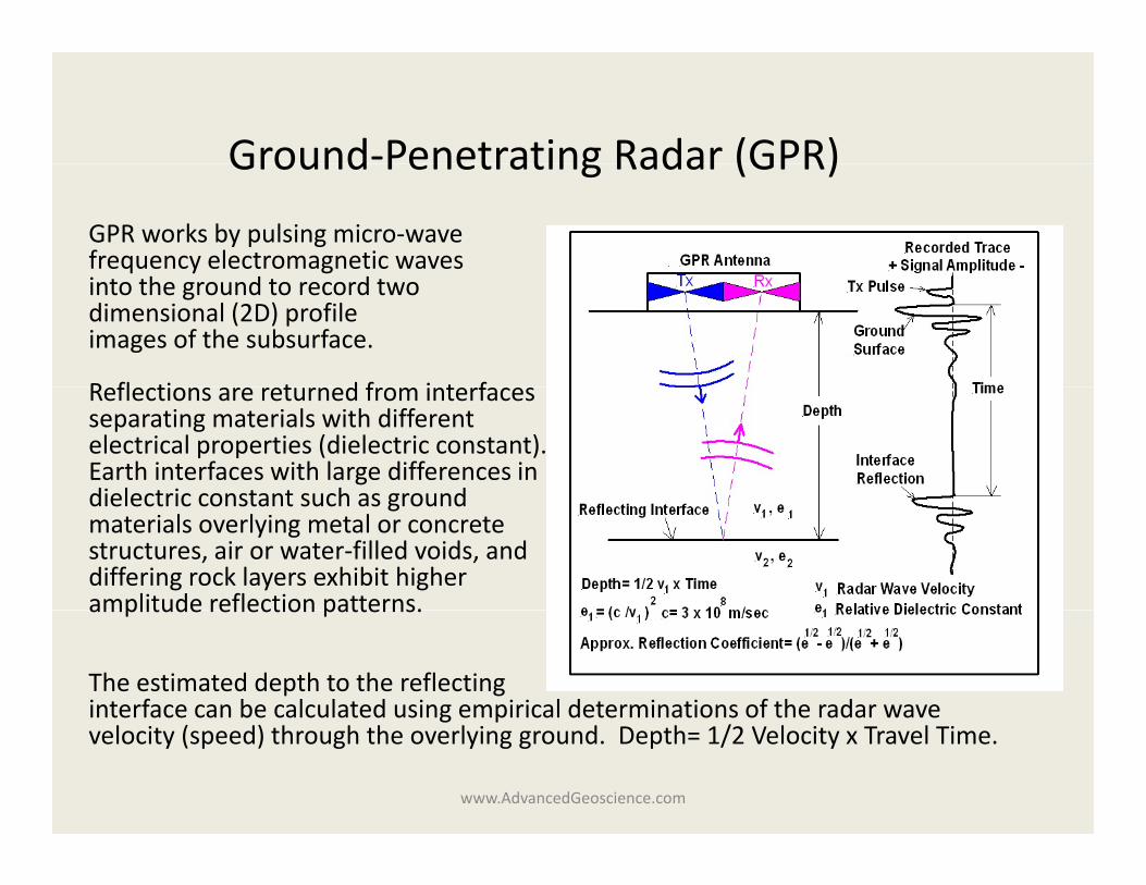
Ground‐Penetrating Radar (GPR)Ground Penetrating Radar (GPR)
GPR works by pulsing micro‐wavefrequency electromagnetic wavesinto the ground to record twodimensional (2D) profileimages of the subsurface.
R fl ti t d f i t fReflections are returned from interfacesseparating materials with differentelectrical properties (dielectric constant).Earth interfaces with large differences indielectric constant such as grounddielectric constant such as groundmaterials overlying metal or concretestructures, air or water‐filled voids, anddiffering rock layers exhibit higheramplitude reflection patterns.amplitude reflection patterns.
The estimated depth to the reflectinginterface can be calculated using empirical determinations of the radar wave
www.AdvancedGeoscience.com
g pvelocity (speed) through the overlying ground. Depth= 1/2 Velocity x Travel Time.
Ground‐Penetrating Radar (GPR)Li i iLimitations
Depth of Penetration‐ Radar wave penetration into the ground is mostly a function of radar wave frequency and the electrical conductivity of subsurfacefunction of radar wave frequency and the electrical conductivity of subsurface materials. Higher‐frequency antennas which offer greater target resolution emit electromagnetic waves that penetrate less deeply. Higher‐conductivity soils such as bentonite clays absorb electromagnetic waves and result in less depth of penetration Sandy soils absorb less and penetrate radar wavesdepth of penetration. Sandy soils absorb less and penetrate radar waves deeper into the subsurface.
Target Resolution Depth and Size‐ Smaller objects buried at greater depth are more difficult and sometimes impossible to detect This limitation canmore difficult and sometimes impossible to detect. This limitation can sometimes be overcome by using higher‐frequency antennas that emit higher‐power electromagnetic waves. However, FCC regulations now limit the amount of power that can be emitted by newer GPR systems.
Target Resolution Orientation‐ The subsurface orientation of linear targets such as pipelines can greatly influence GPR profile detection. For optimum resolution and identification of linear targets antenna survey lines should be orientated nearly perpendicular to target orientationorientated nearly perpendicular to target orientation.
www.AdvancedGeoscience.com
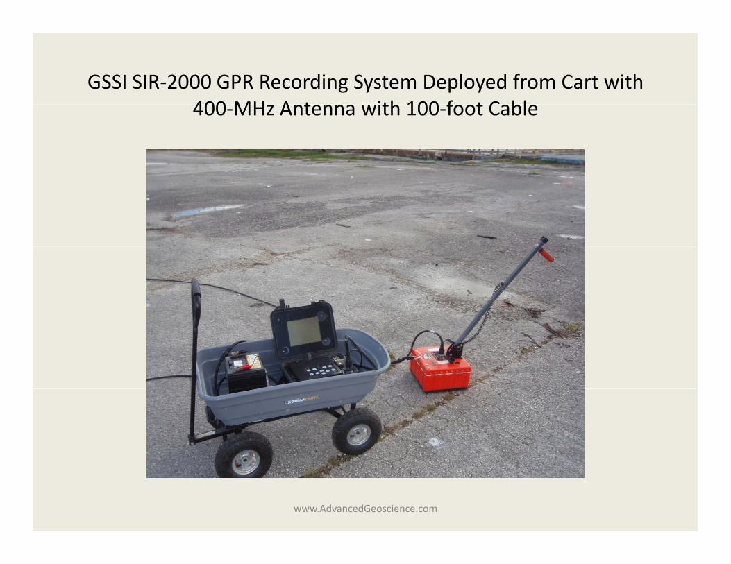
GSSI SIR‐2000 GPR Recording System Deployed from Cart with 400 MH A t ith 100 f t C bl400‐MHz Antenna with 100‐foot Cable
www.AdvancedGeoscience.com
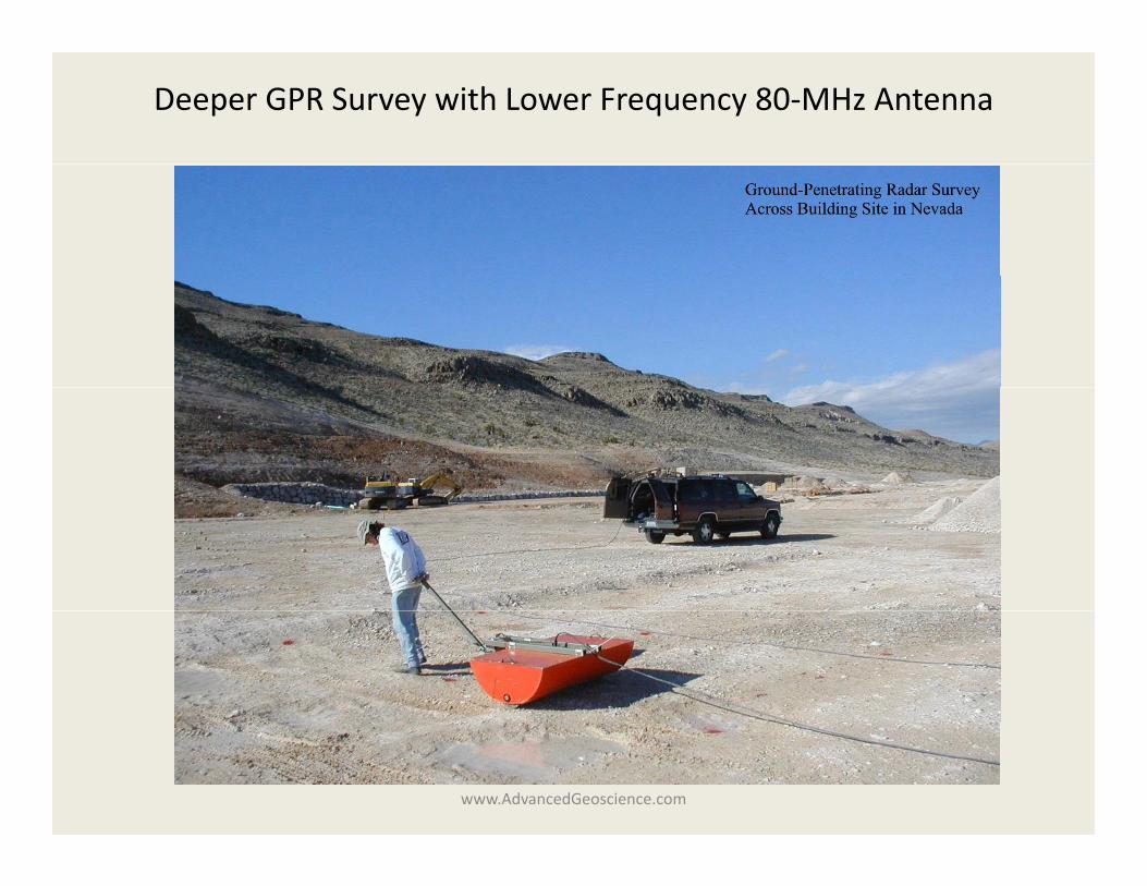
Deeper GPR Survey with Lower Frequency 80‐MHz Antenna
www.AdvancedGeoscience.com
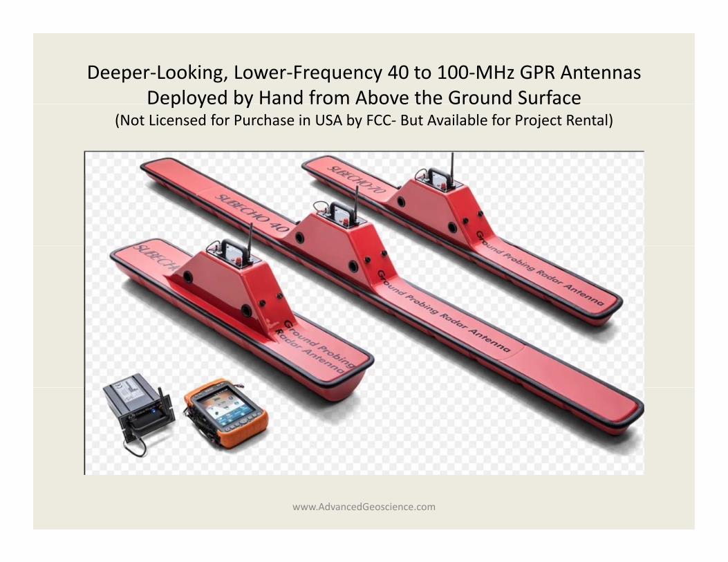
Deeper‐Looking, Lower‐Frequency 40 to 100‐MHz GPR AntennasDeployed by Hand from Above the Ground SurfaceDeployed by Hand from Above the Ground Surface
(Not Licensed for Purchase in USA by FCC‐ But Available for Project Rental)
www.AdvancedGeoscience.com
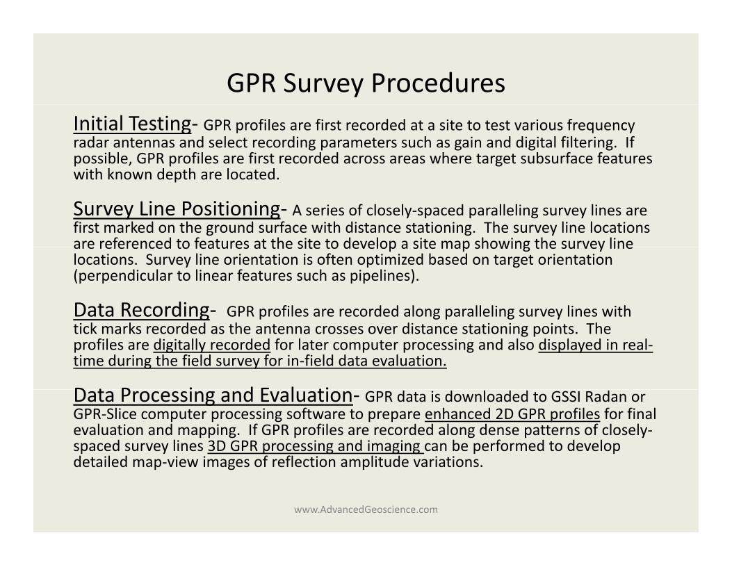
GPR Survey ProceduresInitial Testing‐ GPR profiles are first recorded at a site to test various frequency radar antennas and select recording parameters such as gain and digital filtering. If possible, GPR profiles are first recorded across areas where target subsurface features with known depth are locatedwith known depth are located.
Survey Line Positioning‐ A series of closely‐spaced paralleling survey lines are first marked on the ground surface with distance stationing. The survey line locations are referenced to features at the site to develop a site map showing the survey lineare referenced to features at the site to develop a site map showing the survey line locations. Survey line orientation is often optimized based on target orientation (perpendicular to linear features such as pipelines).
Data Recording‐ GPR profiles are recorded along paralleling survey lines with g p g p g ytick marks recorded as the antenna crosses over distance stationing points. The profiles are digitally recorded for later computer processing and also displayed in real‐time during the field survey for in‐field data evaluation.
D t P i d E l tiData Processing and Evaluation‐ GPR data is downloaded to GSSI Radan or GPR‐Slice computer processing software to prepare enhanced 2D GPR profiles for final evaluation and mapping. If GPR profiles are recorded along dense patterns of closely‐spaced survey lines 3D GPR processing and imaging can be performed to develop detailed map view images of reflection amplitude variationsdetailed map‐view images of reflection amplitude variations.
www.AdvancedGeoscience.com
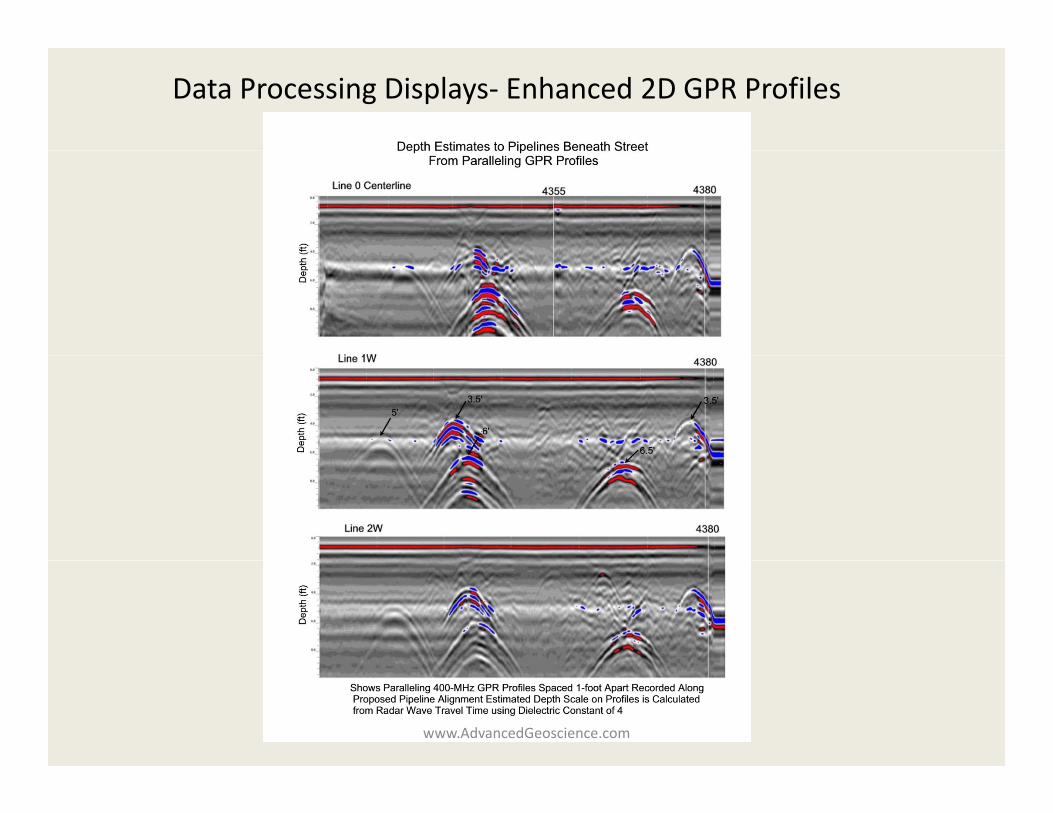
Data Processing Displays‐ Enhanced 2D GPR Profiles
www.AdvancedGeoscience.com
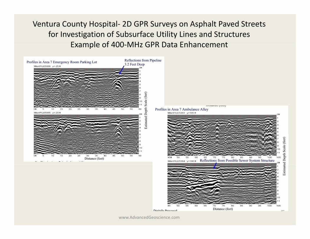
Ventura County Hospital‐ 2D GPR Surveys on Asphalt Paved Streets for Investigation of Subsurface Utility Lines and Structures
Example of 400 MHz GPR Data EnhancementExample of 400‐MHz GPR Data Enhancement
www.AdvancedGeoscience.com
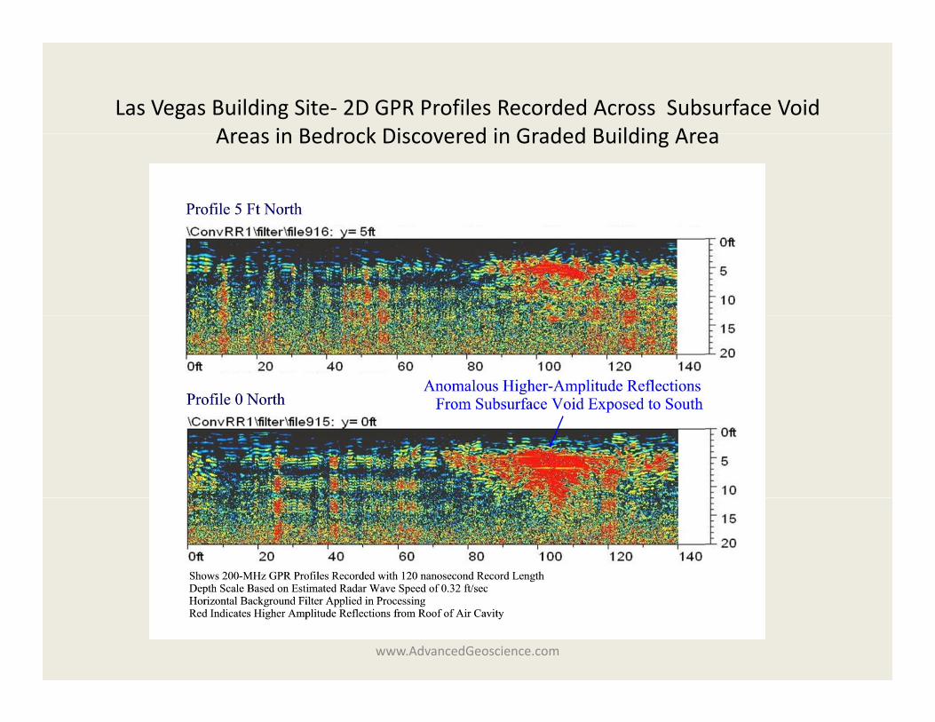
Las Vegas Building Site‐ 2D GPR Profiles Recorded Across Subsurface Void Areas in Bedrock Discovered in Graded Building AreaAreas in Bedrock Discovered in Graded Building Area
www.AdvancedGeoscience.com
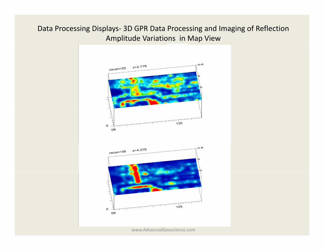
Data Processing Displays‐ 3D GPR Data Processing and Imaging of Reflection Amplitude Variations in Map View
www.AdvancedGeoscience.com
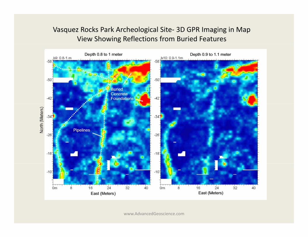
Vasquez Rocks Park Archeological Site‐ 3D GPR Imaging in Map View Showing Reflections from Buried Features
www.AdvancedGeoscience.com
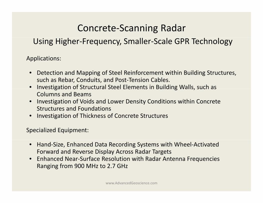
Concrete‐Scanning Radar Using Higher‐Frequency, Smaller‐Scale GPR Technology
Applications:
• Detection and Mapping of Steel Reinforcement within Building Structures, such as Rebar, Conduits, and Post‐Tension Cables.
• Investigation of Structural Steel Elements in Building Walls, such asInvestigation of Structural Steel Elements in Building Walls, such as Columns and Beams
• Investigation of Voids and Lower Density Conditions within Concrete Structures and FoundationsI ti ti f Thi k f C t St t• Investigation of Thickness of Concrete Structures
Specialized Equipment:
• Hand‐Size, Enhanced Data Recording Systems with Wheel‐Activated Forward and Reverse Display Across Radar Targets
• Enhanced Near‐Surface Resolution with Radar Antenna Frequencies Ranging from 900 MHz to 2 7 GHzRanging from 900 MHz to 2.7 GHz
www.AdvancedGeoscience.com
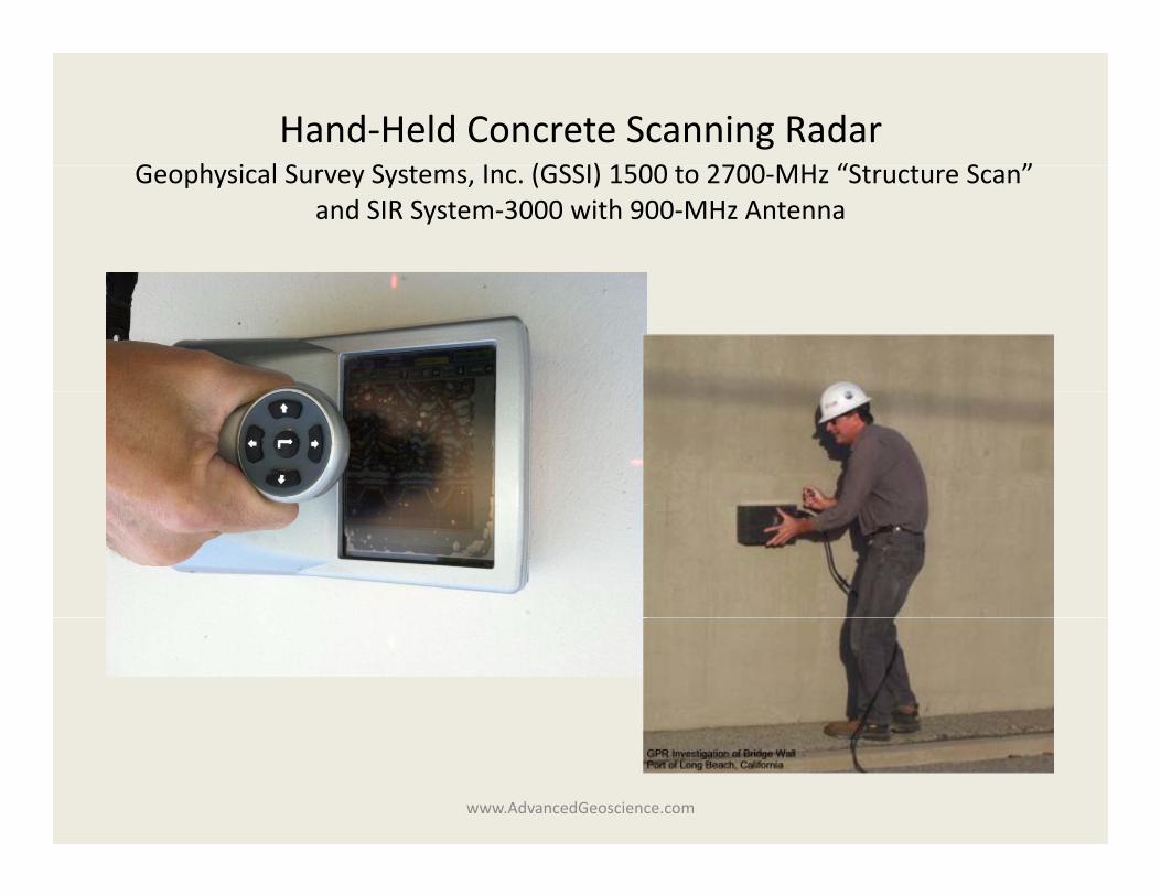
Hand‐Held Concrete Scanning RadarG h i l S S I (GSSI) 1500 2700 MH “S S ”Geophysical Survey Systems, Inc. (GSSI) 1500 to 2700‐MHz “Structure Scan”
and SIR System‐3000 with 900‐MHz Antenna
www.AdvancedGeoscience.com
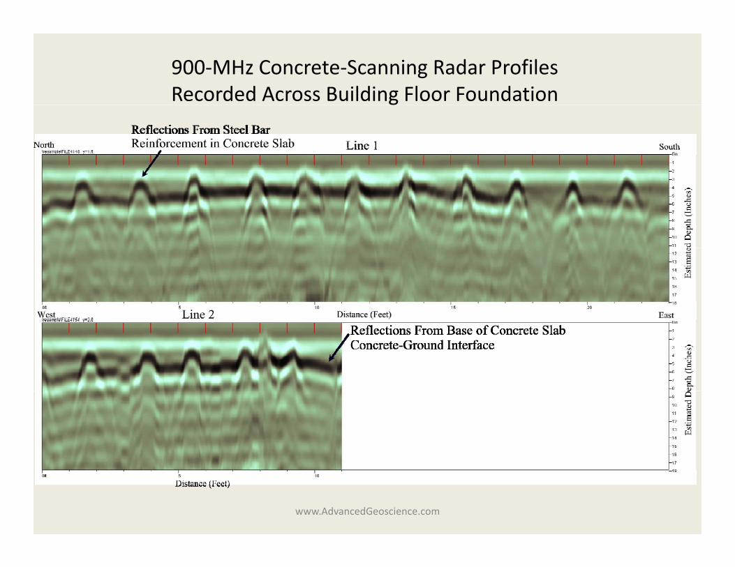
900‐MHz Concrete‐Scanning Radar ProfilesRecorded Across Building Floor Foundationg
www.AdvancedGeoscience.com
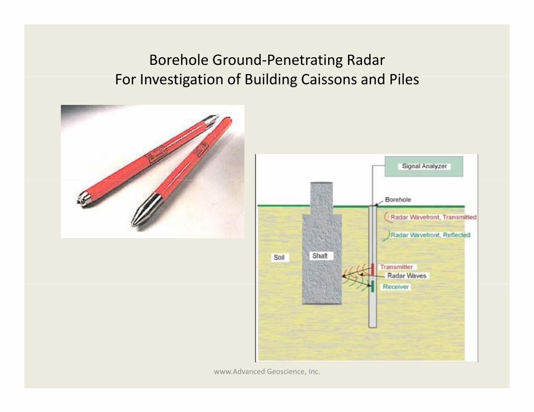
Borehole Ground‐Penetrating RadarF I ti ti f B ildi C i d PilFor Investigation of Building Caissons and Piles
www.Advanced Geoscience, Inc.
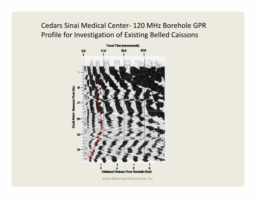
Cedars Sinai Medical Center‐ 120 MHz Borehole GPR Profile for Investigation of Existing Belled CaissonsProfile for Investigation of Existing Belled Caissons
www.Advanced Geoscience, Inc.