high-sensitivity metamaterial-inspired sensor for microfluidic dielectric characterization
TRANSCRIPT

IEEE SENSORS JOURNAL, VOL. 14, NO. 5, MAY 2014 1345
High-Sensitivity Metamaterial-Inspired Sensor forMicrofluidic Dielectric Characterization
Amir Ebrahimi, Student Member, IEEE, Withawat Withayachumnankul,Said Al-Sarawi, Member, IEEE, and Derek Abbott, Fellow, IEEE
Abstract— A new metamaterial-inspired microwave microflu-idic sensor is proposed in this paper. The main part of thedevice is a microstrip coupled complementary split-ring resonator(CSRR). At resonance, a strong electric field will be establishedalong the sides of CSRR producing a very sensitive area to achange in the nearby dielectric material. A micro-channel ispositioned over this area for microfluidic sensing. The liquid sam-ple flowing inside the channel modifies the resonance frequencyand peak attenuation of the CSRR resonance. The dielectricproperties of the liquid sample can be estimated by establishingan empirical relation between the resonance characteristicsand the sample complex permittivity. The designed microfluidicsensor requires a very small amount of sample for testingsince the cross-sectional area of the sensing channel is over fiveorders of magnitude smaller than the square of the wavelength.The proposed microfluidic sensing concept is compatible withlab-on-a-chip platforms owing to its compactness.
Index Terms— Complementary split-ring resonator (CSRR),dielectric characterization, metamaterial, microfluidic sensor.
I. INTRODUCTION
M ICROWAVE sensors are very attractive choicesfor many of electronic, biomedical and industrial
applications [1], [2]. They offer many advantages includinghigh sensitivity, robustness and low fabrication and mea-surement costs [3]. These advantages make them preferablechoices for microfluidic and biosensing applications [4], [5].High sensitivity and accurate identification of chemical andbiological liquid samples using microwave dielectric and cylin-drical resonators have been studied and demonstrated [5]–[9].In these applications, the resonance frequency changes andthe transmission characteristics at resonance are used fordetermination of the complex permittivity. Notably, a relativelylarge device size makes these type of sensors unsuitable forintegrated systems. In [10], a compact microwave sensor isdesigned for broadband microfluidic permittivity measurement
Manuscript received September 30, 2013; revised November 17, 2013;accepted December 2, 2013. Date of publication December 18, 2013; dateof current version March 11, 2014. This work was supported by the SouthAustralian node of the Australian National Fabrication Facility through theNational Collaborative Research Infrastructure Strategy to provide nano andmicrofabrication facilities for Australian researchers. The associate editorcoordinating the review of this paper and approving it for publication wasProf. Sang-Seok Lee.
The authors are with the School of Electrical and ElectronicEngineering, The University of Adelaide, Adelaide 5005, Australia(e-mail: [email protected]; [email protected];[email protected]; [email protected]).
Color versions of one or more of the figures in this paper are availableonline at http://ieeexplore.ieee.org.
Digital Object Identifier 10.1109/JSEN.2013.2295312
with complicated mathematical post-processing. In [11], anew K -band microfluidic device was proposed based on aquarter-wavelength resonator designed on coplanar waveguide.It employs a change in the resonance frequency for dielectriccharacterization. Despite the compactness and high sensitivity,the quality factor of the resonance is moderate, affecting themeasurment accuracy for a small change in the dielectricproperties.
Recently, a new microwave sensing platform is beingdeveloped using the concept of metamaterials [12], [13].Metamaterials are artificially engineered materials made ofsub-wavelength resonators that can manipulate the electro-magnetic waves in a way causing some exotic electromagneticproperties [14]. Metamaterial inspired devices are suited tosensing applications since they offer improved compactnessand a high Q-factor that is very sensitive to environmentalchanges [15]. Various types of new or improved microwaveand terahetz sensors have been introduced so far using this newconcept for different sensing applications such as displacement[16]–[18], rotation [17], [19] thin-film sensing [20]–[22],and strain sensing [23], [24]. Further to that, there are a fewstudies on metamaterial-based microfluidic characterization. In[25] and [26] microfluidic channels were designed to deliverthe fluid sample to an array of resonators causing a significantmodification of the resonance frequency. Nevertheless, thisconfiguration requires a large amount of liquid sample foridentification. In addition, a left handed planar mediumformed, by using a spiral-resonator coupled microstrip linewas designed together with a microfluidic channel for liquidsensing [27]. This device shows a bandpass response thatis not accurate for dielectric characterization. Recently, weproposed a metamaterial-based microfluidic sensor with asingle split-ring resonator (SRR) coupled microstrip line [28].The microfluidic channel was considered in the gap area of theSRR where there is a very strong and localized electric fieldon resonance. Applying the liquid sample to this capacitivegap modifies the resonance frequency and quality factor fromwhich the complex permittivity of mixtures can be determined.However, the sensitivity of the device was not enough todiscriminate small changes in the permittivity of the sampleas the maximum resonance frequency shift was reported tobe around 100 MHz for a permittivity change of 80 [28].
In this paper, a complementary split-ring resonator (CSRR)is used instead of a SRR, to provide a larger area of fringingelectric field that increases the effective interaction area withthe sample. The proposed sensor determines the complex
1530-437X © 2013 IEEE. Personal use is permitted, but republication/redistribution requires IEEE permission.See http://www.ieee.org/publications_standards/publications/rights/index.html for more information.
1346 IEEE SENSORS JOURNAL, VOL. 14, NO. 5, MAY 2014
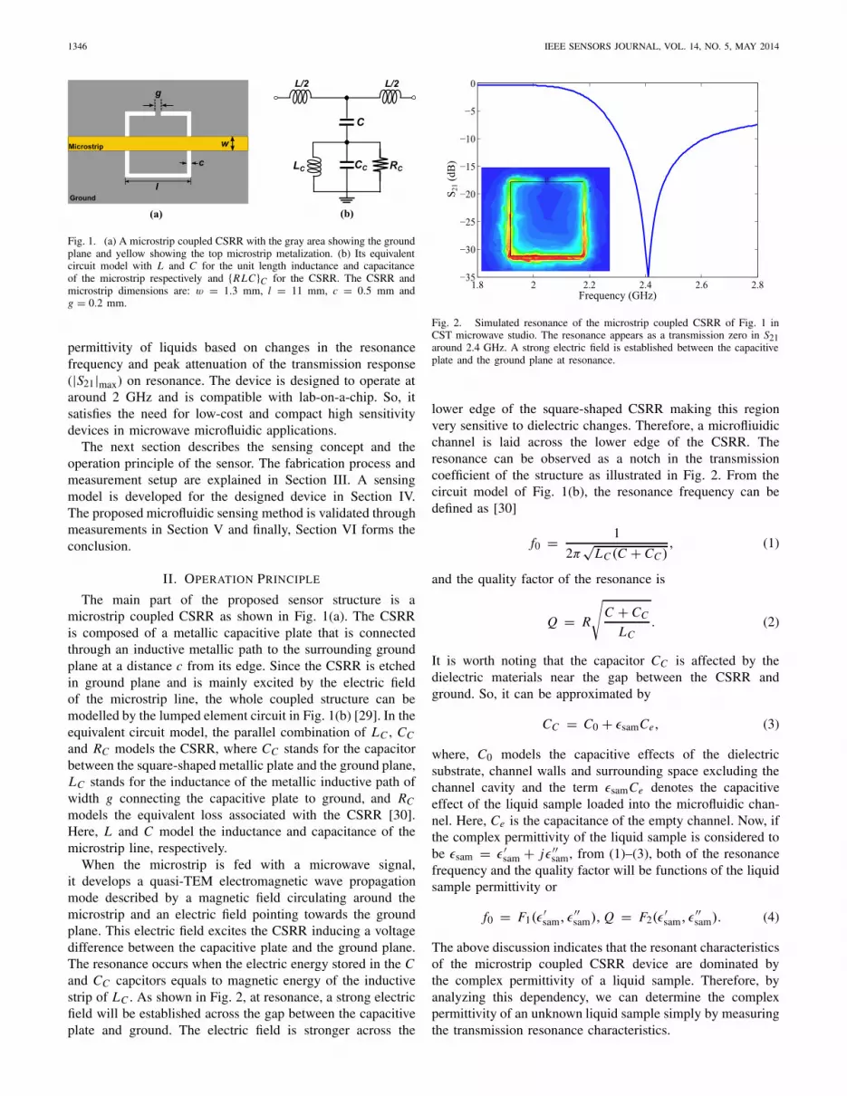
Fig. 1. (a) A microstrip coupled CSRR with the gray area showing the groundplane and yellow showing the top microstrip metalization. (b) Its equivalentcircuit model with L and C for the unit length inductance and capacitanceof the microstrip respectively and {RLC}C for the CSRR. The CSRR andmicrostrip dimensions are: w = 1.3 mm, l = 11 mm, c = 0.5 mm andg = 0.2 mm.
permittivity of liquids based on changes in the resonancefrequency and peak attenuation of the transmission response(|S21|max) on resonance. The device is designed to operate ataround 2 GHz and is compatible with lab-on-a-chip. So, itsatisfies the need for low-cost and compact high sensitivitydevices in microwave microfluidic applications.
The next section describes the sensing concept and theoperation principle of the sensor. The fabrication process andmeasurement setup are explained in Section III. A sensingmodel is developed for the designed device in Section IV.The proposed microfluidic sensing method is validated throughmeasurements in Section V and finally, Section VI forms theconclusion.
II. OPERATION PRINCIPLE
The main part of the proposed sensor structure is amicrostrip coupled CSRR as shown in Fig. 1(a). The CSRRis composed of a metallic capacitive plate that is connectedthrough an inductive metallic path to the surrounding groundplane at a distance c from its edge. Since the CSRR is etchedin ground plane and is mainly excited by the electric fieldof the microstrip line, the whole coupled structure can bemodelled by the lumped element circuit in Fig. 1(b) [29]. In theequivalent circuit model, the parallel combination of LC , CC
and RC models the CSRR, where CC stands for the capacitorbetween the square-shaped metallic plate and the ground plane,LC stands for the inductance of the metallic inductive path ofwidth g connecting the capacitive plate to ground, and RC
models the equivalent loss associated with the CSRR [30].Here, L and C model the inductance and capacitance of themicrostrip line, respectively.
When the microstrip is fed with a microwave signal,it develops a quasi-TEM electromagnetic wave propagationmode described by a magnetic field circulating around themicrostrip and an electric field pointing towards the groundplane. This electric field excites the CSRR inducing a voltagedifference between the capacitive plate and the ground plane.The resonance occurs when the electric energy stored in the Cand CC capcitors equals to magnetic energy of the inductivestrip of LC . As shown in Fig. 2, at resonance, a strong electricfield will be established across the gap between the capacitiveplate and ground. The electric field is stronger across the
Fig. 2. Simulated resonance of the microstrip coupled CSRR of Fig. 1 inCST microwave studio. The resonance appears as a transmission zero in S21around 2.4 GHz. A strong electric field is established between the capacitiveplate and the ground plane at resonance.
lower edge of the square-shaped CSRR making this regionvery sensitive to dielectric changes. Therefore, a microfliuidicchannel is laid across the lower edge of the CSRR. Theresonance can be observed as a notch in the transmissioncoefficient of the structure as illustrated in Fig. 2. From thecircuit model of Fig. 1(b), the resonance frequency can bedefined as [30]
f0 = 1
2π√
LC (C + CC ), (1)
and the quality factor of the resonance is
Q = R
√C + CC
LC. (2)
It is worth noting that the capacitor CC is affected by thedielectric materials near the gap between the CSRR andground. So, it can be approximated by
CC = C0 + εsamCe, (3)
where, C0 models the capacitive effects of the dielectricsubstrate, channel walls and surrounding space excluding thechannel cavity and the term εsamCe denotes the capacitiveeffect of the liquid sample loaded into the microfluidic chan-nel. Here, Ce is the capacitance of the empty channel. Now, ifthe complex permittivity of the liquid sample is considered tobe εsam = ε′
sam + jε′′sam, from (1)–(3), both of the resonance
frequency and the quality factor will be functions of the liquidsample permittivity or
f0 = F1(ε′sam, ε′′
sam), Q = F2(ε′sam, ε′′
sam). (4)
The above discussion indicates that the resonant characteristicsof the microstrip coupled CSRR device are dominated bythe complex permittivity of a liquid sample. Therefore, byanalyzing this dependency, we can determine the complexpermittivity of an unknown liquid sample simply by measuringthe transmission resonance characteristics.

EBRAHIMI et al.: HIGH-SENSITIVITY METAMATERIAL-INSPIRED SENSOR 1347
Fig. 3. Schematic of the microstrip coupled CSRR with the PDMS microflu-idic channel (a) Top view of the structure (b) Side view with dimensions.
III. FABRICATION PROCESS
The designed device has been fabricated on Rogers RO6002microwave substrate with a relative permittivity of 2.94 forallowing significant fringing field in the sensing area andhence increasing the sensitivity. The substrate thickness is0.508 mm. The copper metalization for the ground plane and50 � microstrip line is 18 μm.
As mentioned before, the microfluidic channel is positionedalong the lower edge of the CSRR. The material used for chan-nel is polydimethylsiloxane (PDMS) since it is inexpensive,widely available, biocompatible, durable, and easy to process[10], [11]. For channel fabrication, a mold has been preparedon a silicon substrate by using a thick photoresist mask andchemical etching. Then, a PDMS layer is deposited on theprepared mold and cured at 80 °C. Finally, the PDMS channelis peeled off and attached to the microstrip coupled CSRR.The channel is manually positioned to the lower side of CSRRwhere the fringing electric field is strongest and therefore, thesensitivity to the dielectric property changes is maximum. Theheight, width and length of the channel are 0.06 mm, 0.7 mmand 14 mm, respectively. Fig. 3 shows the bottom view andcross section of the structure when the channel is attached tothe substrate.
The PDMS channel ensures a constant volume and shapeof the liquid sample across the sensing area. It should bementioned that the device response might be influenced by theposition of the channel but it should not be an issue since thechannel position is kept unchanged during all measurements.In a similar manner to [28], the measurements are carried outbased on a stop-flow technique. A binary solution of distilledwater and ethanol is used as a liquid sample for testing since itprovides a broad range of the complex permittivity at the lowmicrowave frequency range [31]. Teflon tubes, together with
Fig. 4. The sensor module. (a) Top view of bare CSRR. (b) Bottom view ofbare CSRR. (c) The complete sensor module when the PDMS channel andin/outlet tubes are attached and the device is packaged. (d) The complete testsetup when the device is connected to the network analyzer for measurments.
Fig. 5. Measured transmission response of the sensor in different conditions.
a syringe, connected to the inlet and outlet of the channelare used for filling and draining the channel. The fabricatedand assembled sensor is shown in Fig. 4 together with themeasurement setup. During the measurements, a very lowpressure is applied to the syringe to avoid channel deformation.In each step, the channel is firstly filled with the liquid sampleand then the flow is stopped for measurement. The resonancefrequency and peak attenuation parameters are then recordedto characterize the liquid test samples. As seen in Fig. 5,the resonance frequency and peak attenuation are maximumwhen the channel is not attached to the sensor. By adding thePDMS channel, the resonance frequency is shifted down witha small decrease of peak attenuation since a part of the CSRRis covered with the PDMS.
IV. DEVICE CHARACTERISTICS
A. Initial Measurements
For investigating the effect of the complex permittivity(ε′
sam + jε′′sam) on the resonance frequency and peak attenu-
ation, a set of experiments has been performed using binarymixtures of distilled water and ethanol. The dielectric proper-ties of water-ethanol mixture was accurately studied in [31].The accurate complex permittivity of the test fluid samples
1348 IEEE SENSORS JOURNAL, VOL. 14, NO. 5, MAY 2014
TABLE I
COMPLEX PERMITTIVITY OF WATER-ETAHNOL MIXTURE AT 1.9 GHZ
[28], [31]. THE VOLUME FRACTION OF WATER IS CHANGED
FROM 10% TO 90% FOR DEVICE TESTING
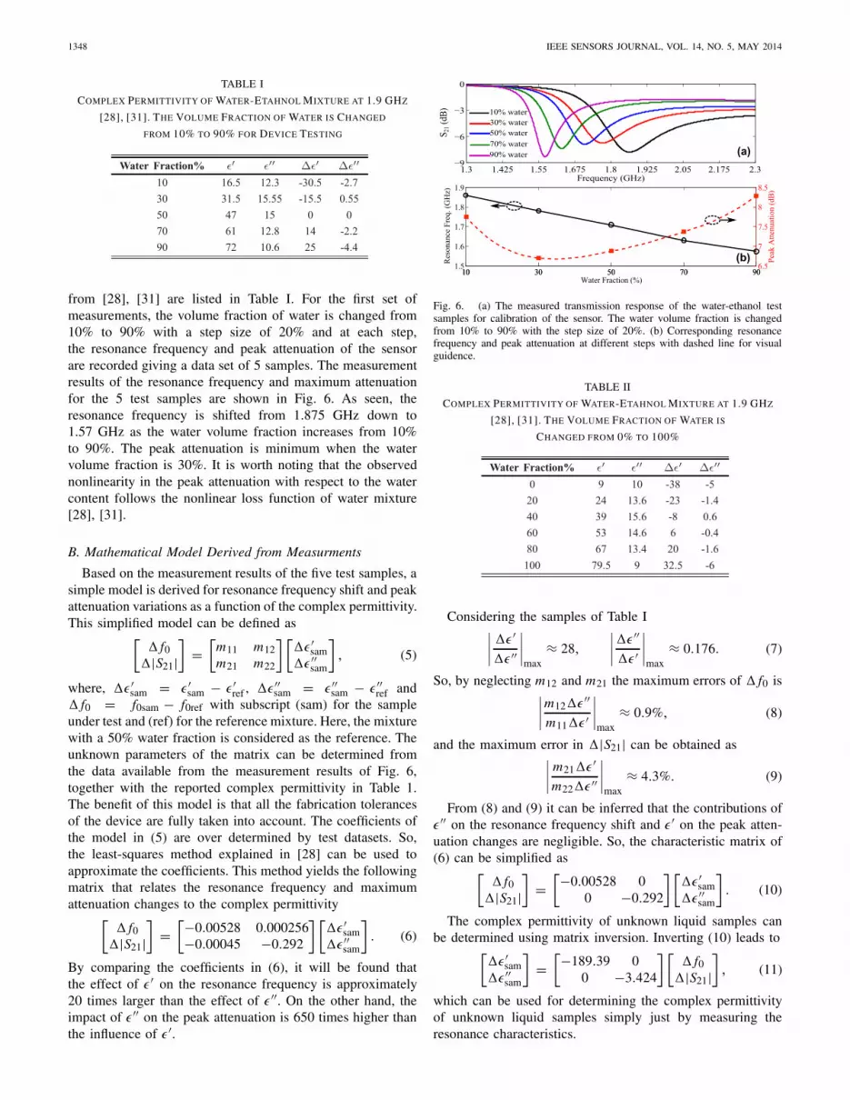
from [28], [31] are listed in Table I. For the first set ofmeasurements, the volume fraction of water is changed from10% to 90% with a step size of 20% and at each step,the resonance frequency and peak attenuation of the sensorare recorded giving a data set of 5 samples. The measurementresults of the resonance frequency and maximum attenuationfor the 5 test samples are shown in Fig. 6. As seen, theresonance frequency is shifted from 1.875 GHz down to1.57 GHz as the water volume fraction increases from 10%to 90%. The peak attenuation is minimum when the watervolume fraction is 30%. It is worth noting that the observednonlinearity in the peak attenuation with respect to the watercontent follows the nonlinear loss function of water mixture[28], [31].
B. Mathematical Model Derived from Measurments
Based on the measurement results of the five test samples, asimple model is derived for resonance frequency shift and peakattenuation variations as a function of the complex permittivity.This simplified model can be defined as[
� f0�|S21|
]=
[m11 m12m21 m22
] [�ε′
sam�ε′′
sam
], (5)
where, �ε′sam = ε′
sam − ε′ref , �ε′′
sam = ε′′sam − ε′′
ref and� f0 = f0sam − f0ref with subscript (sam) for the sampleunder test and (ref) for the reference mixture. Here, the mixturewith a 50% water fraction is considered as the reference. Theunknown parameters of the matrix can be determined fromthe data available from the measurement results of Fig. 6,together with the reported complex permittivity in Table 1.The benefit of this model is that all the fabrication tolerancesof the device are fully taken into account. The coefficients ofthe model in (5) are over determined by test datasets. So,the least-squares method explained in [28] can be used toapproximate the coefficients. This method yields the followingmatrix that relates the resonance frequency and maximumattenuation changes to the complex permittivity[
� f0�|S21|
]=
[−0.00528 0.000256−0.00045 −0.292
] [�ε′
sam�ε′′
sam
]. (6)
By comparing the coefficients in (6), it will be found thatthe effect of ε′ on the resonance frequency is approximately20 times larger than the effect of ε′′. On the other hand, theimpact of ε′′ on the peak attenuation is 650 times higher thanthe influence of ε′.
Fig. 6. (a) The measured transmission response of the water-ethanol testsamples for calibration of the sensor. The water volume fraction is changedfrom 10% to 90% with the step size of 20%. (b) Corresponding resonancefrequency and peak attenuation at different steps with dashed line for visualguidence.
TABLE II
COMPLEX PERMITTIVITY OF WATER-ETAHNOL MIXTURE AT 1.9 GHZ
[28], [31]. THE VOLUME FRACTION OF WATER IS
CHANGED FROM 0% TO 100%
Considering the samples of Table I∣∣∣∣ �ε′
�ε′′
∣∣∣∣max
≈ 28,
∣∣∣∣�ε′′
�ε′
∣∣∣∣max
≈ 0.176. (7)
So, by neglecting m12 and m21 the maximum errors of � f0 is∣∣∣∣m12�ε′′
m11�ε′
∣∣∣∣max
≈ 0.9%, (8)
and the maximum error in �|S21| can be obtained as∣∣∣∣ m21�ε′
m22�ε′′
∣∣∣∣max
≈ 4.3%. (9)
From (8) and (9) it can be inferred that the contributions ofε′′ on the resonance frequency shift and ε′ on the peak atten-uation changes are negligible. So, the characteristic matrix of(6) can be simplified as[
� f0�|S21|
]=
[−0.00528 00 −0.292
] [�ε′
sam�ε′′
sam
]. (10)
The complex permittivity of unknown liquid samples canbe determined using matrix inversion. Inverting (10) leads to[
�ε′sam
�ε′′sam
]=
[−189.39 00 −3.424
] [� f0
�|S21|]
, (11)
which can be used for determining the complex permittivityof unknown liquid samples simply just by measuring theresonance characteristics.
EBRAHIMI et al.: HIGH-SENSITIVITY METAMATERIAL-INSPIRED SENSOR 1349
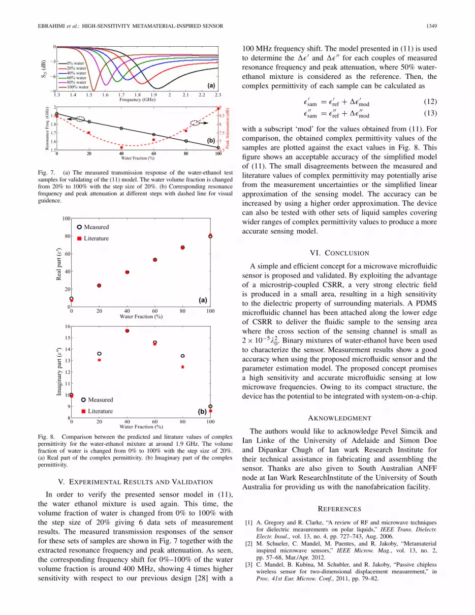
Fig. 7. (a) The measured transmission response of the water-ethanol testsamples for validating of the (11) model. The water volume fraction is changedfrom 20% to 100% with the step size of 20%. (b) Corresponding resonancefrequency and peak attenuation at different steps with dashed line for visualguidence.
Fig. 8. Comparison between the predicted and litrature values of complexpermittivity for the water-ethanol mixture at around 1.9 GHz. The volumefraction of water is changed from 0% to 100% with the step size of 20%.(a) Real part of the complex permittivity. (b) Imaginary part of the complexpermittivity.
V. EXPERIMENTAL RESULTS AND VALIDATION
In order to verify the presented sensor model in (11),the water ethanol mixture is used again. This time, thevolume fraction of water is changed from 0% to 100% withthe step size of 20% giving 6 data sets of measurementresults. The measured transmission responses of the sensorfor these sets of samples are shown in Fig. 7 together with theextracted resonance frequency and peak attenuation. As seen,the corresponding frequency shift for 0%–100% of the watervolume fraction is around 400 MHz, showing 4 times highersensitivity with respect to our previous design [28] with a
100 MHz frequency shift. The model presented in (11) is usedto determine the �ε′ and �ε′′ for each couples of measuredresonance frequency and peak attenuation, where 50% water-ethanol mixture is considered as the reference. Then, thecomplex permittivity of each sample can be calculated as
ε′sam = ε′
ref + �ε′mod (12)
ε′′sam = ε′′
ref + �ε′′mod (13)
with a subscript ‘mod’ for the values obtained from (11). Forcomparison, the obtained complex permittivity values of thesamples are plotted against the exact values in Fig. 8. Thisfigure shows an acceptable accuracy of the simplified modelof (11). The small disagreements between the measured andliterature values of complex permittivity may potentially arisefrom the measurement uncertainties or the simplified linearapproximation of the sensing model. The accuracy can beincreased by using a higher order approximation. The devicecan also be tested with other sets of liquid samples coveringwider ranges of complex permittivity values to produce a moreaccurate sensing model.
VI. CONCLUSION
A simple and efficient concept for a microwave microfluidicsensor is proposed and validated. By exploiting the advantageof a microstrip-coupled CSRR, a very strong electric fieldis produced in a small area, resulting in a high sensitivityto the dielectric property of surrounding materials. A PDMSmicrofluidic channel has been attached along the lower edgeof CSRR to deliver the fluidic sample to the sensing areawhere the cross section of the sensing channel is small as2 × 10−5λ2
0. Binary mixtures of water-ethanol have been usedto characterize the sensor. Measurement results show a goodaccuracy when using the proposed microfluidic sensor and theparameter estimation model. The proposed concept promisesa high sensitivity and accurate microfluidic sensing at lowmicrowave frequencies. Owing to its compact structure, thedevice has the potential to be integrated with system-on-a-chip.
AKNOWLEDGMENT
The authors would like to acknowledge Pevel Simcik andIan Linke of the University of Adelaide and Simon Doeand Dipankar Chugh of Ian wark Research Institute fortheir technical assistance in fabricating and assembling thesensor. Thanks are also given to South Australian ANFFnode at Ian Wark ResearchInstitute of the University of SouthAustralia for providing us with the nanofabrication facility.
REFERENCES
[1] A. Gregory and R. Clarke, “A review of RF and microwave techniquesfor dielectric measurements on polar liquids,” IEEE Trans. Dielectr.Electr. Insul., vol. 13, no. 4, pp. 727–743, Aug. 2006.
[2] M. Schueler, C. Mandel, M. Puentes, and R. Jakoby, “Metamaterialinspired microwave sensors,” IEEE Microw. Mag., vol. 13, no. 2,pp. 57–68, Mar./Apr. 2012.
[3] C. Mandel, B. Kubina, M. Schubler, and R. Jakoby, “Passive chiplesswireless sensor for two-dimensional displacement measurement,” inProc. 41st Eur. Microw. Conf., 2011, pp. 79–82.

1350 IEEE SENSORS JOURNAL, VOL. 14, NO. 5, MAY 2014
[4] H.-J. Lee, J.-H. Lee, H.-S. Moon, I.-S. Jang, J.-S. Choi, J.-G. Yook,et al., “A planar split-ring resonator-based microwave biosensor forlabel-free detection of biomolecules,” Sens. Actuators B, Chem.,vol. 169, pp. 26–31, Jul. 2012.
[5] G. Gennarelli, S. Romeo, M. Scarfi, and F. Soldovieri, “A microwaveresonant sensor for concentration measurements of liquid solutions,”IEEE Sensors J., vol. 13, no. 5, pp. 1857–1864, May 2013.
[6] K. Yu, S. G. Ogourtsov, V. G. Belenky, A. B. Maslenikov, and A. Omar,“Accurate microwave resonant method for complex permittivity mea-surements of liquids [biological],” IEEE Trans. Microw. Theory Tech.,vol. 48, no. 11, pp. 2159–2164, Nov. 2000.
[7] B. Kapilevich and B. Litvak, “Optimized microwave sensor for onlineconcentration measurements of binary liquid mixtures,” IEEE SensorsJ., vol. 11, no. 10, pp. 2611–2616, Oct. 2011.
[8] H. Kawabata and Y. Kobayashi, “Accurate measurements of complexpermittivity of liquid based on a TM010 mode cylindrical cavitymethod,” in Proc. Eur. Microw. Conf., vol. 1. Oct. 2005, pp. 369–372.
[9] J. Kim, A. Babajanyan, A. Hovsepyan, K. Lee, and B. Friedman,“Microwave dielectric resonator biosensor for aqueous glucose solution,”Rev. Sci. Instrum., vol. 79, no. 8, pp. 086107-1–086107-3, 2008.
[10] K. Grenier, D. Dubuc, P.-E. Poleni, M. Kumemura, H. Toshiyoshi,T. Fujii, et al., “Integrated broadband microwave and microfluidic sensordedicated to bioengineering,” IEEE Trans. Microw. Theory Tech., vol. 57,no. 12, pp. 3246–3253, Dec. 2009.
[11] T. Chretiennot, D. Dubuc, and K. Grenier, “A microwave and microflu-idic planar resonator for efficient and accurate complex permittivitycharacterization of aqueous solutions,” IEEE Trans. Microw. TheoryTech., vol. 61, no. 2, pp. 972–978, 2013.
[12] N. I. Zheludev, “The road ahead for metamaterials,” Science, vol. 328,no. 5978, pp. 582–583, 2010.
[13] M. Huang and J. Yang, Microwave Sensor Using Metamaterials. Vienna,Austria: InTech, 2011, pp. 13–36.
[14] A. Ebrahimi, W. Withayachumnankul, S. Al-Sarawi, and D. Abbott,“Compact dual-mode wideband filter based on complementary split-ring resonator,” IEEE Microw. Wireless Compon. Lett., 2014, doi:10.1109/LMWC.2013.2291869.
[15] T. Chen, S. Li, and H. Sun, “Metamaterials application in sensing,”Sensors, vol. 12, no. 3, pp. 2742–2765, 2012.
[16] A. Horestani, C. Fumeaux, S. Al-Sarawi, and D. Abbott, “Displacementsensor based on diamond-shaped tapered split ring resonator,” IEEESensors J., vol. 13, no. 4, pp. 1153–1160, Apr. 2013.
[17] J. Naqui, M. Durán-Sindreu, and F. Martín, “Novel sensors based on thesymmetry properties of split ring resonators (SRRs),” Sensors, vol. 11,no. 8, pp. 7545–7553, 2011.
[18] J. Naqui, M. Durán-Sindreu, and F. Martín, “Alignment and posi-tion sensors based on split ring resonators,” Sensors, vol. 12, no. 9,pp. 11790–11797, 2012.
[19] A. Horestani, D. Abbott, and C. Fumeaux, “Rotation sensor basedon horn-shaped split ring resonator,” IEEE Sensors J., vol. 13, no. 8,pp. 3014–3015, Aug. 2013.
[20] W. Withayachumnankul, H. Lin, K. Serita, C. M. Shah, S. Sriram,M. Bhaskaran, et al., “Sub-diffraction thin-film sensing with planarterahertz metamaterials,” Opt. Exp., vol. 20, no. 3, pp. 3345–3352, 2011.
[21] W. Withayachumnankul, K. Jaruwongrungsee, C. Fumeaux, andD. Abbott, “Metamaterial-inspired multichannel thin-film sensor,” IEEESensors J., vol. 12, no. 5, pp. 1455–1458, May 2012.
[22] I. A. I. Al-Naib, C. Jansen, and M. Koch, “Thin-film sensing with planarasymmetric metamaterial resonators,” Appl. Phys. Lett., vol. 93, no. 8,pp. 083507-1–083507-3, 2008.
[23] R. Melik, E. Unal, N. K. Perkgoz, C. Puttlitz, and H. V. Demir,“Metamaterial-based wireless strain sensors,” Appl. Phys. Lett., vol. 95,no. 1, pp. 011106-1–011106-3, 2009.
[24] J. Li, C. M. Shah, W. Withayachumnankul, B. S.-Y. Ung, A. Mitchell,S. Sriram, et al., “Flexible terahertz metamaterials for dual-axis strainsensing,” Opt. Lett., vol. 38, no. 12, pp. 2104–2106, Jun. 2013.
[25] B. Dong, W. Zhu, Y. H. Fu, J. Tsai, H. Cai, D. L. Kwong, et al.,“An absorptive filter using microfluidic switchable metamaterials,” inProc. 16th Int. Solid-State Sensors, Actuat. Microsyst. Conf., 2011,pp. 530–533.
[26] J. A. Gordon, C. L. Holloway, J. Booth, S. Kim, Y. Wang,J. Baker-Jarvis, et al., “Fluid interactions with metafilms/metasurfacesfor tuning, sensing, and microwave-assisted chemical processes,” Phys.Rev. B, vol. 83, pp. 205130-1–205130-5, May 2011.
[27] N. Wiwatcharagoses, K. Y. Park, J. Hejase, L. Williamson, and P. Chahal,“Microwave artificially structured periodic media microfluidic sensor,”in Proc. IEEE 61st ECTC, May/Jun. 2011, pp. 1889–1893.
[28] W. Withayachumnankul, K. Jaruwongrungsee, A. Tuantranont,C. Fumeaux, and D. Abbott, “Metamaterial-based microfluidic sensorfor dielectric characterization,” Sens. Actuators A, Phys., vol. 189,pp. 233–237, Jan. 2013.
[29] J. Baena, J. Bonache, F. Martín, R. Sillero, F. Falcone, T. Lopetegi, et al.,“Equivalent-circuit models for split-ring resonators and complementarysplit-ring resonators coupled to planar transmission lines,” IEEE Trans.Microw. Theory Tech., vol. 53, no. 4, pp. 1451–1461, Apr. 2005.
[30] J. Bonache, M. Gil, I. Gil, J. García-García, and F. Martín, “On theelectrical characteristics of complementary metamaterial resonators,”IEEE Microw. Wireless Compon. Lett., vol. 16, no. 10, pp. 543–545,Oct. 2006.
[31] J.-Z. Bao, M. L. Swicord, and C. C. Davis, “Microwave dielectriccharacterization of binary mixtures of water, methanol, and ethanol,”J. Chem. Phys., vol. 104, no. 12, pp. 4441–4450, 1996.
Amir Ebrahimi (S’09) was born in Babol, Iran, onSeptember 11, 1986. He received the B.Sc. degreein electrical engineering from the University ofMazandaran, Babol, in 2008, and the M.Sc. degreein electronic engineering from the Babol Universityof Technology, Babol. From 2009 to 2012, he wasa Research Assistant with the Integrated CircuitsResearch Laboratory, Babol University of Technol-ogy. He is currently pursuing the Ph.D. degree inelectrical and electronic engineering with the Uni-versity of Adelaide, Australia. His research interests
include metamaterial-inspired microwave devices, microwave circuit design,microwave filters, and frequency selective surfaces. Mr. Ebrahimi is a recipientof the International Postgraduate Research Ph.D. Scholarship, the AustralianPostgraduate Award, and the Australian National Fabrication Facility Awardfor fabricating high performance microwave microfluidic sensors in collabo-ration with the Ian Wark Research Institute, University of South Australia.
Withawat Withayachumnankul received theB.Eng. (Hons.) and M.Eng. degrees in electronicengineering from the King Mongkut’s Institute ofTechnology Ladkrabang, Thailand, in 2000 and2002, respectively. From 2006 to 2008, he was anAustralian Endeavour International PostgraduateResearch Scholarship and University of AdelaideScholarship for Postgraduate Research. He iscurrently pursuing the Ph.D. degree with the Schoolof Electrical and Electronic Engineering, Universityof Adelaide. He received the IEEE/LEOS Graduate
Student Fellowship and the SPIE Scholarship in Optical Science andEngineering. He is currently an ARC Post-Doctoral Research Fellow withthe School of Electrical and Electronic Engineering, University of Adelaide,and an Associate Professor with RMIT University, Australia. His researchinterests include metamaterials, plasmonics, and terahertz spectroscopy.
Said Al-Sarawi (M’92) received the B.Eng. degree(1st Class Hons.) in marine radio communicationand in marine electronics and communication fromthe Arab Academy for Science and Technology,Egypt, in 1987 and 1990, respectively, and thePh.D. degree in mixed analog and digital cir-cuit design techniques for smart wireless systemswith special commendation in electrical and elec-tronic engineering from The University of Adelaide,Australia, in 2003. He was awarded The Universityof Adelaide Alumni Postgraduate Medal (formerly
Culross Prize) for outstanding academic merit at the postgraduate level. Hereceived the Commonwealth Postgraduate Research Award (Industry). Hereceived the Graduate Certificate in Education (Higher Education) with thesame university in 2006. Currently, he is the Director of the Centre forBiomedical Engineering and a Founding Member of the Education ResearchGroup of Adelaide, University of Adelaide. His research interests includedesign techniques for mixed signal systems in CMOS and optoelectronictechnologies for high performance radio transceivers, low power and lowvoltage radio frequency identification systems, data converters, mixed signaldesign, and microelectromechanical systems for biomedical applications. Hiscurrent educational research is focused on innovative teaching techniquesfor engineering education, research skill development, and factors affectingstudents evaluations of courses in different disciplines.

EBRAHIMI et al.: HIGH-SENSITIVITY METAMATERIAL-INSPIRED SENSOR 1351
Derek Abbott (M’85–SM’99–F’05) was born inLondon, U.K., in 1960. He received the B.Sc.(Hons.) degree in physics from Loughborough Uni-versity, U.K., in 1982, and the Ph.D. degree in elec-trical and electronic engineering from the Universityof Adelaide, Australia, in 1995, under K. Eshraghianand B. R. Davis. From 1978 to 1986, he was aResearch Engineer with the GEC Hirst ResearchCentre, London. From 1986 to 1987, he was aVLSI Design Engineer with Austek Microsystems,Australia. Since 1987, he has been with the Uni-
versity of Adelaide, where he is currently a Full Professor with theSchool of Electrical and Electronic Engineering. He holds over 800 publi-cations/patents and has been an invited speaker at over 100 institutions. He isa fellow of the Institute of Physics (IOP). He has received a number of awards,including the South Australian Tall Poppy Award for Science in 2004,
the Premier’s SA Great Award in Science and Technology for outstandingcontributions to South Australia in 2004, and the Australian ResearchCouncil Future Fellowship in 2012. He has served as an Editor and/orGuest Editor for a number of journals, including the IEEE JOURNAL
OF SOLID-STATE CIRCUITS, the Journal of Optics B (IOP), Microelec-tronics Journal (Elsevier), Chaos (AIP), Smart Structures and Materials(IOP), Journal of Optics B (IOP), Fluctuation Noise Letters (World Sci-entific), and is currently on the editorial boards of the PROCEEDINGS
OF THE IEEE, the IEEE PHOTONICS JOURNAL, and PLoS ONE.He has co-edited Quantum Aspects of Life, Imperial College Press,co-authored Stochastic Resonance (Cambridge University Press) and TerahertzImaging for Biomedical Applications (Springer-Verlag).
His interests are in the area of multidisciplinary physics and electronicengineering applied to complex systems. His research programs span a numberof areas of stochastics, game theory, photonics, biomedical engineering, andcomputational neuroscience.