high-quality drilling with copper vapour lasers
TRANSCRIPT

Optical and Quantum Electronics 27 (1995) 1243-1256
High-quality drilling with copper vapour lasers
R. PINI, R. SALIMBENI , G. TOCI, M. VANNINI Istituto di Elettronica Quantistica del CNR (IEQ-CNR), Via Panciatichi 56/30, 50127 Firenze, Italy
Received 31 October 1994
High-quality materials processing on transparent substrates of BK7 glass, fused silica, corundum and ruby using a copper vapour laser (CVL) is described and discussed. The drilling process using the radiation emitted by a small diffraction-limited CVL is described and investigated by optical diagnostic methods allowed by the transparency of the materials. In particular the hole making was entirely monitored in real time through a video camera. Images achieved in this way are reported to illustrate the morphology of the hole and of the ejected materials via the time-resolved fluorescence. This investigation provides the evaluation of the plume expansion speed, while the imaging supplies the quantitative evaluations of the drilling speed and threshold. The high quality of the hole in terms of wall smoothness and elevated aspect ratio is described in detail. We report according to our findings an interpretation of the peculiar combination of physical processes involved.
1. Introduction Today materials processing is acquiring increasing importance as a field of application for high- power lasers. Over the years laser technology has provided generations of powerful and reliable lasers of different kinds to meet the demands on beam specifications to improve and optimize welding, cutting and drilling with lasers.
Various parameters qualify the laser emission, such as pulsed or continuous wave emission, power and energy, intrinsic divergence and wavelength, together determining a combination of physical effects relevant to materials processing. Among these parameters the wavelength represents a factor that determines the focusability of the radiation, favours power-density- dependent effects in high-power interactions, and for a given material sets the absorption coefficient.
Because of the high absorption in the UV by almost every material, several authors have reported important results in high-quality materials processing with excimer lasers involving mostly photoablative effects in the submicrometre-scale region, achieving negligible thermal damage with neat borders of the cut. For these reasons, international projects are being pursued - in Europe two EUREKA projects - to develop high-average-power excimer lasers for indus- trial applications.
The aim of this work is to present the very high-quality materials processing achievable by means of another class of gas lasers, metal vapour lasers, which are potentially able to emit
0306-8919 �9 1995 Chapman & Hall 1243
R. Pini et aL
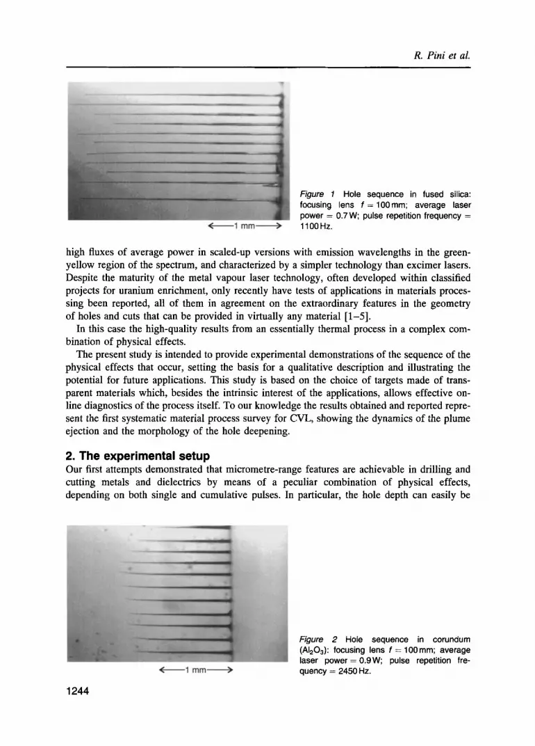
Figure 1 Hole sequence in fused silica: focusing lens f = 1 0 0 m m ; average laser power = 0.7 W; pulse repetition frequency = 1100Hz.
high fluxes of average power in scaled-up versions with emission wavelengths in the green- yellow region of the spectrum, and characterized by a simpler technology than excimer lasers. Despite the maturity of the metal vapour laser technology, often developed within classified projects for uranium enrichment, only recently have tests of applications in materials proces- sing been reported, all of them in agreement on the extraordinary features in the geometry of holes and cuts that can be provided in virtually any material [1-5].
In this case the high-quality results from an essentially thermal process in a complex com- bination of physical effects.
The present study is intended to provide experimental demonstrations of the sequence of the physical effects that occur, setting the basis for a qualitative description and illustrating the potential for future applications. This study is based on the choice of targets made of trans- parent materials which, besides the intrinsic interest of the applications, allows effective on- line diagnostics of the process itself. To our knowledge the results obtained and reported repre- sent the first systematic material process survey for CVL, showing the dynamics of the plume ejection and the morphology of the hole deepening.
2. T h e e x p e r i m e n t a l s e t u p Our first attempts demonstrated that micrometre-range features are achievable in drilling and cutting metals and dielectrics by means of a peculiar combination of physical effects, depending on both single and cumulative pulses. In particular, the hole depth can easily be
1 2 4 4
Figure 2 Hole sequence in corundum (AI203): focusing lens f = 100mm; average laser power=0 .9W; pulse repetition fre- quency = 2450 Hz.

High-quality drilling with copper vapour lasers
several times the Rayleigh range of the focused beam. In our tests it was common to observe holes drilled in relatively hard materials such as homogeneous glasses and fused silica with aspect ratios up to 100 (Fig. 1) and in crystals with aspect ratios of 30-50 (Fig. 2).
The laser source was a home-made prototype with a 90-cm discharge length and 20-mm internal bore diameter. The pulse repetition frequency (PRF) could be continuously varied between 1 and 5 kHz at constant voltage, but in unbalanced thermal conditions and for time- limited burst operation.
At 5 kHz PRF the power output of this device was typically around 10 W with a stable reso- nator, but in this case the intrinsic divergence was around i mrad and no machining effect was produced in transparent materials by focusing this radiation. Seeking minimum divergence and a proper balance between the high losses introduced in the resonator for the spatial mode selec- tion and efficient power extraction, we employed a self-filtering unstable resonator (SFUR) [6]. The beam specifications in this case were 120 #rad of full angle beam divergence, with 3 W average power on both emission lines (510.6 nm and 578.2 nm) at 4 kHz PRF with a pulse dura- tion of 40 ns FWHM, resulting in an overall efficiency of about 0.5%. The outcoming beam was collimated with a diameter of around 15 mm and the measured divergence corresponded to 1.1 times the diffraction limit. The optical paths in air of the SFUR resonator round trip were pro- tected by plastic tubes to avoid refractive index gradients, which otherwise introduced beam pointing instabilities clearly detectable as random wandering over an area some times larger than the spot dimension in the focal plane of a lens.
No specific care was taken to mechanically isolate the optical table hosting the experimental setup because the overall system stability was sufficient to carry out irradiations lasting several seconds without any appreciable wandering of the beam.
The samples under test were placed on a six-axis positioning stage equipped with a program- mable controller; the sample facet, previously polished, was oriented perpendicularly to the optical system axis. The optical system employed to focus the laser beam on the targets was an AR-coated doublet with focal length varying from 50 mm to 100 mm and a camera wide- angle achromat with 50mm focal length. Imaging of the irradiated area was obtained by a microscope-mounted, internally gated monochrome CCD camera (Pulnix TM 765) connected to a standard TV monitor and video recorder.
3. Materials under test To provide experimental documentation of the sequence of events occurring during the hole drilling, the tests were limited to a selection of transparent materials, allowing the application of optical monitoring techniques through the material itself. Crystals such as white sapphire (corundum) and ruby, usually very important as laser optical components, were tested because they belong to the class of the hardest materials. Optical-grade fused silica and BK7 optical glass were also investigated, allowing a comparison of the drilling mechanism in hard and in relatively soft materials.
4. Optical diagnostic This choice of materials avoids the need for retrospective examination that is necessary with metals or opaque dielectrics (longitudinal cross-section) and allows a real-time record of the events via a CCD camera.
The exposure time of the gateable camera could be set down to 125 #s (less than the period between laser pulses), with a constant speed of 50 frames/s, allowing the effect produced by a single pulse to be recorded. Furthermore, from the recorded video sequence of the drilling
1245

R. Pini et aL
process it was possible to directly measure other parameters, such as the growth of the hole depth as a function of the number of pulses and the instantaneous drilling speed. The live video monitoring allowed real-time quality control of the machining process.
A second optical monitoring technique consisted in time-resolved spectroscopy of the plume emission light collected by a 600-#m quartz optical fibre set very close to the hole entrance. The light was analysed by a 0.5-m Jobin Yvon polychromator equipped with a time-gated mul- tichannel analyser (EG&G PARC OMA III). This analysis was undertaken to add information about the vapour ejection speed from an independent method.
External monitoring based on a beam deflection technique was also employed to provide information about the effects of the shockwave expansion in air after each pulse and its recovery, at the maximum undisturbed repetition rate of the pulses.
5. Experimental results and discussion Typically the samples of the different materials were prepared as 5-mm cubes with front, top and bottom facets optically polished. The front facet was positioned for laser irradiation, the other two were employed for the illumination and the collection of the image.
The general procedure of these tests can be schematically described in different phases. (1) First, the sample surface was set perpendicularly to the focused beam aligning the back
1246
Figure 3 (a) Detail of the sample sur- face at the hole entrance; (b) side view of the cylindrical channel; (c) side view of the final apex.

High-quality drifting with copper vapour lasers
Figure 4 Detail of the hole entrance in BK7 glass. The presence of surface defects on the internal hole wall is evident.
reflection over the incoming beam; then, the sample was moved towards the beam waist until external surface breakdown occurred and the drilling process started. This procedure was applied only for the first hole of the sequence, to obtain the exact surface alignment. For sub- sequent holes, the laser irradiation was controlled by the shutter. (2) At the shutter aperture, if the laser power was over the threshold, the drilling process started with bright light scattering from the irradiate site, accompanied by a buzzing sound and by the ejection of a tenuous cloud of ablated material escaping from the hole as it deepened. The interaction is self-terminating in a few seconds, leaving a bright scattering of laser light from the slightly conical hole, typically as represented in Fig. 1.
Microscopic examination of the hole shape shows the presence of three different zones (Figs 3a, b, c): (a) a rough crater on the surface, with irregular aspect but quite reproducible dimen- sions: (b) the properly defined hole, starting with quite reproducible diameter from zone (a), and continuing for up to 100 times the diameter with a very small taper of conicity (~10 #m/3 mm); (c) a final apex, more or less evident depending on the diameter, concluding the hole with an acuminate ogive, observed not only in blind holes but also in those crossing limited thicknesses of material. Both zones (b) and (c) presented smooth walls with minimal imperfections, appearing perfectly transparent in the properly machined holes, while in some cases with BK7 glass, the initial part of the zone (b) appeared burned with the internal surface covered by microbubbles, as shown in Fig. 4, which illustrates well characteristics of the hole in cases of burning under optimum conditions (Fig. 1, Fig. 3b).
The morphological features, such as the high aspect ratio, show marked analogies with the results of the drilling process in metals, as reported by Bergmann et aL [1, 5]. In metals, the hole shape exhibits the slightly conical (b) zone and the apex (c), while at the surface the crater (a) does not show irregular multiple breaks in conical surface but a resolidified regular conical wall with borders rising above the surface.
The occurrence of these morphological similarities suggests that the drilling processes observed in transparent dielectrics and in metals or opaque dielectrics may result from similar mechanisms. Thus, a successful explanation of the laser ablation of transparent material might also result in useful insights for metal drilling. Nevertheless, some differences have to be pointed out.
In contrast to metals the low optical absorption of fused silica at the CVL wavelengths under- lines the importance of the power density reached at the beam waist in the generation of a
1247

R. Pini et al.
Figure 5 Images of the ejected plume fluorescence acquired with the microscope-mounted camera, at 125 #s exposure time. N = number of pulses from the start of the process. The vertical bar marks the position of the surface and the material bulk lies in the left half of the images. Material is fused silica; PRF = 3500 Hz; average power = 1.5 W.
plasma, which behaves as the effective converter of energy from the photon pulse to local heating and mechanical breakage due to photothermal and photomechanical effects. The irregularity of the crater (a) and its large extent are typical symptoms of mechanical stress, and the high temperature causing melting and vaporization of fused silica are evidently thermal effects. To substantiate the explanation of the initiation of drilling by local plasma formation and to evaluate the number of pulses needed to enter zone (b), measurements of the threshold power density were performed with microscopic imaging of the initial drilling phase and a spectral analysis of the plume emission. In the threshold measurements the laser was operated in standard conditions (3500Hz PRF, 1.5 W) and the beam was attentuated by means of calibrated filters. The power was considered to be at threshold if the drilling process occurred with a probability of 50% when the shutter was opened. This evaluation was in any case subject to a large error due to the uncertainty in observation of the start for values of average power
1248

High-quality drilling with copper vapour lasers
between 0.8 and 1.2 W for all the materials tested. Average estimates of the irradiation para- meters at threshold are as follows:
Single pulse energy 290 p.J Peak power 30 kW Focal spot diameter, as measured by translated knife-edge method 16 #m Irradiated area @ 1/e 2 200 #m 2
The measured spot diameter is larger than the expected value given by the beam divergence because of residual spherical and chromatic aberrations due to the achromat, but the power density, evaluated as 15 GWcm -2, remains in a range largely able to induce optical surface breakdown in fused silica and many other materials [7, 8].
The images reproduced in Fig. 5 were recorded with the minimum exposure time of the camera (125 #s) for increasing delays (or numbers of pulses) from the start of the process. As shown, each pulse of the first hundred or so causes surface breakdown, producing mechan- ical surface damage and inducing a plume which expands in the air. The bright illumination is due to the plume's broadband fluorescence. Time-gated spectroscopy of the plume fluorescence shows that the average lifetime of this re-emitted light is about 100 ns.
Comparing the average lifetime with the dimensions of the illuminated area, the plume velo- city has a spatial distribution that is quite peaked on the axis with a maximum value around 5 km s -1 and a lobe shape which spreads with a progressively diminishing angle during the sequence of pulses from N -- 200 to N = 900. The spread is due to the crater at the surface, which develops with multiple damage induced by the repeated photomechanical stress.
Statistically, over hundreds of pulses the crater develops a circular symmetric shape of 50- 100 #m diameter and 20-30 #m depth, but these dimensions could vary accordingly as the beam waist was positioned slightly above or under the surface. Figure 6 presents two examples of holes: in Fig. 6a the beam waist was a few tens of micrometres above the surface and the crater is almost absent, while in Fig. 6b the waist was set below the surface by the same amount, resulting in a much deeper crater, in a reduced diameter of the channel, and in evident traces of thermomechanical stress inside the bulk.
These observations are consistent with the proposed initiating plasma model, because in the first case the reduced power density at the surface and the location of the maximum field plane
Figure 6 Dependence of the hole shape on the beam waist position. In (a) the beam waist is located about 50#m outside the sample surface; in (b) it is about 50#m inside the surface. Material is BK7 glass.
1249
R. Pini et aL
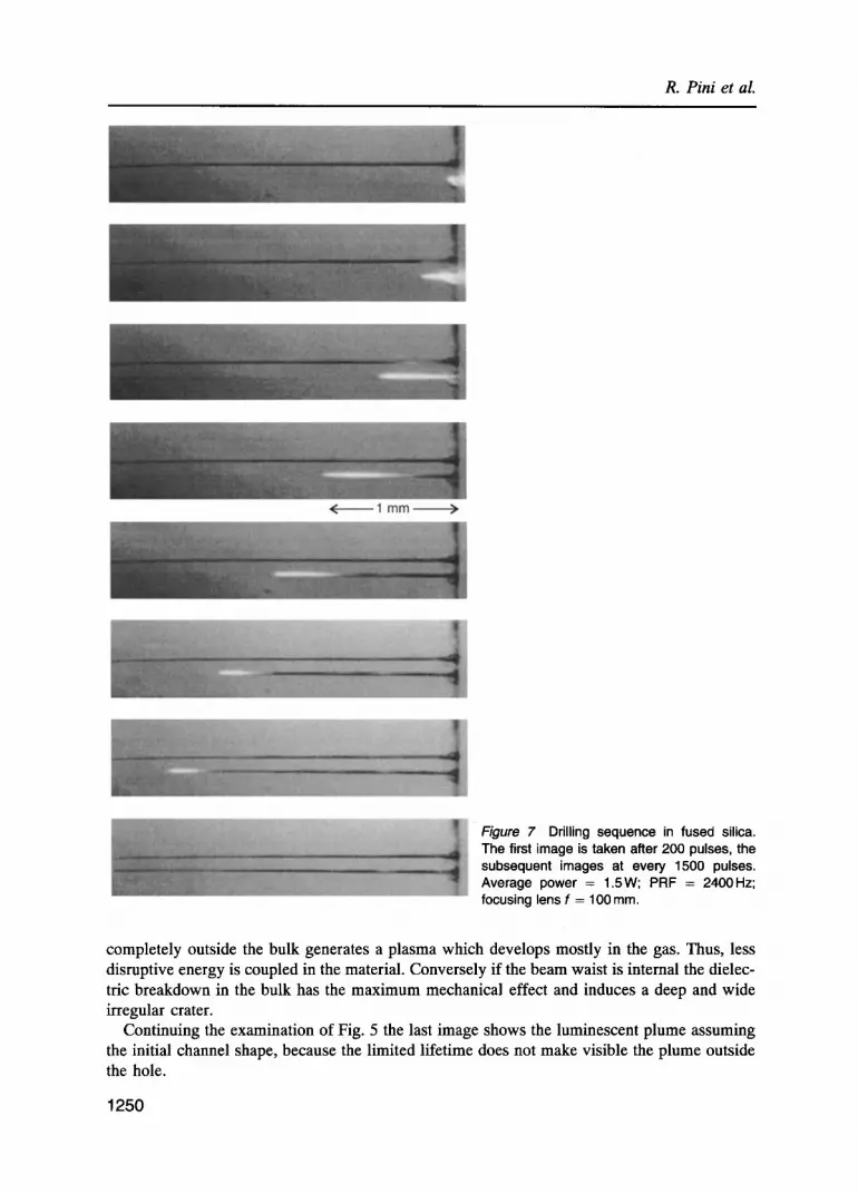
Figure 7 Drilling sequence in fused silica. The first image is taken after 200 pulses, the subsequent images at every 1500 pulses. Average power = 1.5W; PRF = 2400Hz; focusing lens f = 100 mm.
completely outside the bulk generates a plasma which develops mostly in the gas. Thus, less disruptive energy is coupled in the material. Conversely if the beam waist is internal the dielec- tric breakdown in the bulk has the maximum mechanical effect and induces a deep and wide irregular crater.
Continuing the examination of Fig. 5 the last image shows the luminescent plume assuming the initial channel shape, because the limited lifetime does not make visible the plume outside the hole.
1 2 5 0

High-quality drilling with copper vapour lasers
1600
1400
1200
~ 1000 ..c 800-
o 600-
400-
200
0 o 10'00 20'00 30'0o 40'00 50'00 6o'00 70'00 8o'00
No. of pulses
Figure 8 Hole depth in fused silica vs number of pulses at vadous PRF (O, 1460 Hz; &, 2550 Hz, O, 3800 Hz). Focal length f = 50 mm; pulse energy = 0.5 mJ.
The drilling process in the phase of zone Co) can be better understood by considering the type of energy conversion experienced by the pulse energy�9 As we have seen, the power density reached along the leading edge of the pulse initiates a plasma which substantially absorbs the energy content of the pulse and converts it into three main fractions: (a) re-emission of light by fluorescence and recombination transitions, (b) heat transfer to the wall by electron and ions collisions, (c) kinetic energy of the ejected plume and of the shock wave. This energy redistribution calls for specific measurements, which will be undertaken and the results of which will be reported elsewhere.
For this qualitative description, we consider that a substantial fraction will initially be dissi- pated in phase transitions of the material in the removed layer from solid to liquid to gas and in an overheating of the gas phase, whereas, because of the thermal confinement due to the short duration of the pulses, heat conduction through the hole wall will be relatively small�9 At the end of the pulse the overheating is at the maximum and a supersonic expansion begins, the hot vapour forming a luminescent plume and the ambient air being pushed out by the shock wave.
The observed iteration of the removal process, documented, for example, by the con- stancy of the plume luminescence during drilling all along the zone (b) (Fig. 7), can be
3000
2500
2000
~- 1500
o 1000
5oo
I I
0 2000 4000 60'00 8000 10 000 12 000
No. of pulses
Figure 9 Hole depth in fused silica vs number of pulses at various PRF (r-I, 1460 Hz; A, 2320 Hz; O, 3560 Hz). Focal length f = 100 mm; pulse energy = 0.6 mJ.
1251

R. Pini et al.
explained in the plasma model by assuming the uniformity of the following fundamental parameters along the deepening hole: (1) a constant power density distribution with circular symmetry, such as a Gaussian shape when it results from the focused beam or truncated Hermitian when it results from the guided propagation mode EHn; (2) sufficient power density at the distribution peak and (3) enough energy content to supply the explosive process which actually removes the material according to the concept of shock wave energy transport provided by the point explosion theory [9] and verified by experimental determination of the shock velocity [10].
Indirect support also comes from the observation of relative uncertainty in the timing of the start of the process, whereas after the initiation of drilling it proceeds with stable and reliable etching rates. It is reasonable to suppose that the plasma generation could be stabilized by a lowering of the breakdown threshold due to the heating of the material, which provides elec- trons in the bulk lattice, rather than by ionization events triggered by the surface defects.
Figures 8 and 9 report the depth of the hole vs the number of pulses for the same material, fused silica, at a constant pulse energy and at different values of PRF. All the curves are characterized by an initial region of fast etching rate which within a couple of hundred pulses slows down to a well-defined and constant value. The images of Fig. 5 clearly show that the initial fast etching rate is correlated with the photomechanical crater formation, whereas the longer constant-speed phase is established during the thermal regime. The depth reached at the end of the initial phase is greater for increasing values of the focal length of the lens (and thus for increasing values of the focused beam Rayleigh range), so the smooth transition between the two phases can generally be ascribed to the coupling of the Gaussian distribution of the beam waist to the least leaky mode EHn of the capillary waveguide that will be gener- ated as soon as the internal wall begins to be smoothed by the melting of the hole apex at each pulse. The symmetry of the beam and its pointing stability help to make the guide with rela- tively limited losses.
A detailed description of these guiding properties will be object of a further investigation, but some general aspects are worth discussing. The optimum coupling of the laser beam with the guide mode EH n is for
2w 0 = 0.66a (1)
where a is the hole internal diameter and w 0 is the waist radius [11]. For a channel diameter a = 30 #m (almost independent of the beam waist diameter), Equation 1 gives w0 = 10 #m. This is accomplished using lenses with focal length longer than 50 mm. In a test, 100 mm and 150mm lenses were substituted for the preliminary 50 mm achromat. As reported, the lenses were doublets with a comparable compensation for spherical and chromatic aberrations.
The hole drilling rates achieved in typical operating conditions with f = 50mm and f = 100 mm are compared in Figs 8 and 9. With the 150 mm lens, no initiation of the drilling process was possible with the laser power of 1-2 W available at the time of test. As could be expected, the longer Rayleigh range with f = 100 mm stretched to 0.3-0.4 mm the transition between the fast and the slow etching rates of Figs 8 and 9. While the slow rate and the channel diameter remained unchanged at about 0.2 #m/pulse and 20-30 #m, respectively, the maxi- mum depth reached in most of the holes was more than doubled with the 100 mm lens.
These observations allow the following conclusions.
(1) The power density at the waist centre is evaluated as about 12 GW cm -2 for the 100 mm lens and 5 GW cm -2 for the 150 mm lens, consistent with the value of 10 GW cm -2 typically assigned for surface dielectric breakdown of fused silica [7, 8].
1252

High-quality drilling with copper vapour lasers
(2) For a constant average power, the reduction of power density does not produce any reduc- tion of the etching rate according to the constancy of the energy content (of the pulse and of the point explosion).
(3) While Bergmann and Hartmann [5], testing hole drilling with CVL in metals, were able to verify a linear dependence of the hole diameter on the average power (in the range 5-40 W), in all our tests on glasses the hole diameter was typically in the range 25-35 #m, and no cor- relation was possible with the pulse parameters, probably because of the limited dynamic of the laser average power over threshold (1-3 W).
(4) The decrease of the channel diameter along its taper can provide an indirect evaluation of the energy attenuation by the guide losses. Considering the conical shape in the average taper of the holes shown in Fig. 1, the average loss of 20/25 in 10 000 pulses, which corresponds to 80 • 10 -6 per pulse or 20 x 10 -3 dB mm -1.
(5) This approximate attenuation applied to the input specifications gives a power density of about 10 GWcm -2 and an energy of about 0.1 mJ when the drilling stops.
A significant feature generally observed to have a very reproducible shape is the apex of the hole. Several authors have reported experimental observation of this feature under widely dif- ferent conditions of irradiation, CW or relatively high-energy pulses, providing theoretical models to explain the physical process of laser drilling. Olson and Swope [12] give a computa- tional model for drilling holes in strongly absorbing materials with single laser pulses of Gaussian transverse beam profile. The importance of the actual waist shape due to a thorough evaluation of the optical aberrations is taken into account to match the various hole sections observed in the experiments (Gaussian, triangular, cylindrical). In their case the model involved 200-#s pulses of a 1 kW CO2 laser, with a considerable thermal diffusion effect that effectively counterbalanced the input power to determine the local temperature (for vaporization), the spatial extent of the material vaporization, and ultimately the shape of the hole apex. Wagner [13] took into account the thermal conductivity of a gold layer on a ceramic surface to explain an unexpected reduction of the energy density threshold, again in long-pulse high-energy sin- gle-pulse hole drilling. The dynamics of the expulsion of the liquid layer from the molten cavity is also presented on the basis of the radiation pressure peak distribution which ultimately deter- mines the apex shape.
Some differences have to be considered in the case of short-pulse, low-energy, high- PRF lasers regarding the apex formation. This operating regime is usually applicable with
Figure 10 Holes drilled through a 1-mm-thick fused-silica sample. Lens focal length f = 100ram; average power = 1.3W; PRF = 2450 Hz.
1 2 5 3

R. Pini et al.
Q-switched Nd:YAG lasers and a well-known application is the drilling of ruby bearings for watches.
In this respect CVL have similar emission parameters even if with half the wavelength and better focusability. The model in this case cannot rely on the radiation pressure symmetry; nevertheless, to explain the apex shape it is important to recall the point explosion model which for symmetry reasons is expected to initiate the plasma generation at the centred apex of the hole. The energy transport is lately due to the plasma expansion and its collision with the walls, which provides a diffused temperature rise.
Experimental evidence of the occurrence of the plasma onset at the hole apex is given indirectly by the observation of the drilling process in a thin sheet of material. In this case, the ablation process ends when the hole apex arrives at the output side, opening a clear aperture that is much narrower than the internal channel diameter (Fig. 10).
6. Conclusions The characteristics of the drilling with CVL have been obtained with a high-quality beam but a laser of quite low average power.
Varying the operating frequency at constant pulse energy (Figs 8 and 9), a constant removal rate of 0.2 #m per pulse was found, while the drilling speed was typically 0.8 mm s -1 at 4 kHz, with a small dependence on the average power in the range between 1.5 W and 3 W. This finding is consistent with the drilling effectiveness reported by Bergmann and Hartmann [5] who give values in the range 0.2-0.9 mm s -1 W -1 to metals, according to their thermophysical properties, while at average power of several tens of watts the drilling speed for the tested selection of metals and alloys rose as high as 10 mm sec -1. According to these findings with metals, similar improvements in the drilling speed should be expected with glasses at average powers of tens of watts.
For a practical utilization of hole drilling with CVL, the main features of the process should be controlled by suitable tailoring of the laser beam parameters. This control should be applied to the diameter, the depth, the stability of the diameter, the straightness of the axis and the drilling speed.
Despite the uniformity of our results at a relatively low average power, the diameter of the channel is expected to be controlled at larger values by the pulse energy content, according to the results reported by Bergmann and Hartmann [5] for high average power (10-15 W); how- ever it was impossible to obtain holes smaller than the observed ones because, for nonabsorbing materials, the power at threshold required to generate an absorbing plasma is relatively high (30kW). For short pulse duration, the thermal characteristics of the material will play a minimal role in the lateral extension of the hole because the thermal confinement acts to limit the thermally affected region to a very thin layer, while they significantly affect the removal rate.
To reduce the hole diameter by a tighter focus could raise the problem of compensation of the aberrations. To obtain holes with a diameter smaller than the typical figure observed in these tests, a further reduction of wavelength, offered for example by high-PRF excimer lasers, could provide better focusability and a longer Rayleigh range, according to
71" 2 z . = w0 (2)
These features could allow better coupling to the generated optical waveguide as observed in UV-induced etching of semiconductors [14].
1254

High-quality drilling with copper vapour lasers
The depth is essentially established by the optical guide power coupling and by the propa- gation losses. The hole diameter determines the beam coupling configuration, while the losses are evidently induced by the quality of the internal surface, which depends on the material itself (some glasses often present microscopic bubbling because of inhomogeneities) but also on the irradiation parameters. A study has been performed using the beam deflection technique at the hole aperture to evaluate the influence of air refractive index transients and how the input beam coupling can be deteriorated by turbulence in the surrounding air inherited from the previous pulse. The results are reported elsewhere [10] and can be summarized generally as follows. (a) Operating the laser at constant pulse energy and different PRF, a reduction of 30% in the maximum depth was measured on increasing the frequency from 1 to 4 kHz. (b) The point explosion theory describes well the experimental results in the first 2 ~s of the shockwave expansion, giving the orders of magnitude of the peak temperature (104 K ) and peak pressure (108 Pa). (c) The expansion induces an initial depletion in the air density inside the hole and immediately in front of the aperture, which is followed on a 100 #s timescale by a highly turbulent density recovery.
In conclusion, the depth could be affected by the timescale of the refilling of the hole by turbulent air, which takes place in a time comparable with the pulse period. Despite its imprac- ticality in the manufacturing processes, an eventual solution for this limit could be drilling under vacuum conditions [15], which would avoid the refilling phase, leaving as the ultimate limit the perturbation of the escaping plume smoke, which follows a much shorter timescale of a few microseconds.
The natural slightly conical shape could be corrected by a suitable modulation of the pulse energy. By counterbalancing the optical guide propagation losses with a slow rise in the laser energy during the drilling, it should be possible to compensate the diameter variation and to prolong the process itself. This could be a favourable way of employing a higher-power laser system.
In conclusion drilling with CVL appears to benefit materials processing with a new class of laser systems. The observed features represent a top quality standard in respect to similar results achieved by Nd:YAG lasers that are widely employed in the niche of making high-qual- ity holes both by direct drilling and by trepanning. Good control of the fmal characteristics needs to be demonstrated by testing on actual micro-machining systems. The interest in the pre- liminary results relating to the large aspect ratio (>100) and the minimal thermally affected layer (< l#m) has initiated important projects in Europe, Japan and the United States. In the EUREKA Project EU849, Copper vapor laser in manufacturing and production (CLAMP), tests will be performed and laser systems will be developed to provide viable technical solu- tions for micro-machining.
References 1. R. KUPFER, H. W. BERGMANN and M. LINGENAUER, Technical Symposium on Microelectronic Processing
Integration '91, San Jose, 1991, SPIE Proc. 1598 (1991), p. 347. 2. D. D. KAUTZ, L. V. BERZINS, E. P. DRAGON, M. E. WERVE and B. E. WARNER, Proceedings of the International
Conference LASERS "93, Lake Tahoe, 1993 (STS Press, McLean, VA, 1994), p. 30. 3. R. PIN/, R. SALIMBENI, M. VANNINI and G. TOCI, Proceedings of the International Conference LASERS '92,
Houston, 1992 (STS Press, McLean, VA, 1993), p. 932. 4. R. PIN/, R. SALIMBENI, M. VANNINI and G. TOCI, Proceedings of the International Conference LASERS "93, Lake
Tahoe, 1993 (STS Press, McLean, VA, 1994), p. 37. 5. H. W. BERGMANN and M. HARTMANN, Laser Material Processing - IV, edited by J. Mazumder, K. Mukherjee and
B. L. Mordike (The Minerals, Metals and Material Society, 1994), p. 33.
1255

R. Pini et aL
6. R. PIN], R. SALIMBENI, G. TOCI and M. VANNINI, Opt. Commun. 81 (1991) 138. 7. W. KOECHNER, Solid-State Laser Engineering, 2nd edn (Springer, Berlin, 1988) chap. 11. 8. R. PINI, R. SALIMBENI and M. VANN1NI, AppL Opt. 26(19) (1987) 4185. 9. L. I. SEDOV, Similarity and Dimensional Methods in Mechanics, 10th edn (CRC Press, Boca Raton, 1993)
chap. 4. 10. R. PINI, R. SALIMBENI, M. VANNINI and G. TOCI, Appl. Phys. B, in press. 11. W. HEUER and H. ZACHARIAS, IEEE J. Quantum Electron. 24(10) (1988) 2087. 12. R. W. OLSON and W. C. SWOPE, J. AppL Phys. 72(8) (1992) 3686. 13. R. E. WAGNER, J. Appl. Phys. 45(10) (1974) 4631. 14. D. V. PODLESNICK, H. H. GILGEN and R. M. OSGOOD, JR, Appl. Phys. Lett. 48(7) (1986) 496. 15. G. HERZIGER and E. W. KREUTZ, SPIE 1022 (1988) 2.
1256