vapour power cycles
TRANSCRIPT

Vapour Power Cycles
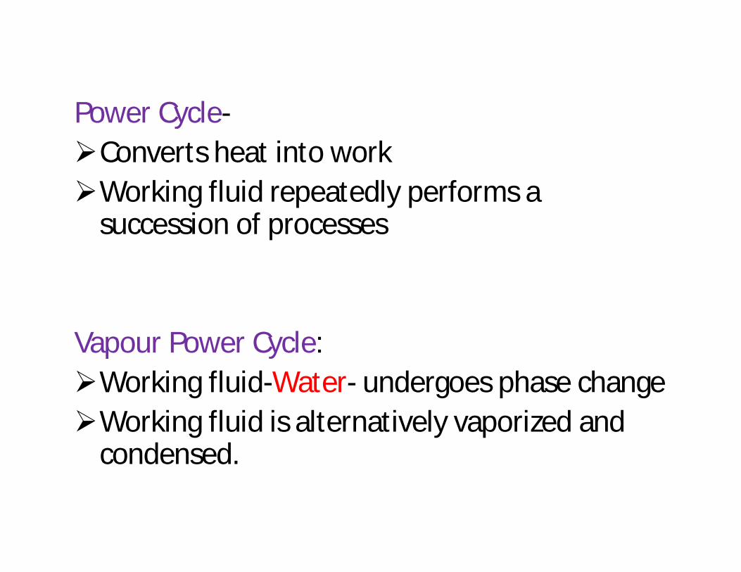
Power Cycle-Converts heat into workWorking fluid repeatedly performs a
succession of processes
Vapour Power Cycle: Working fluid-Water- undergoes phase changeWorking fluid is alternatively vaporized and
condensed.
Quest for higher thermal efficiencies- innovative modifications to basic vapor power cycleReheat Regenerative Cycles
Steam- most common working fluidDesirable CharacteristicsLow costAvailabilityHigh enthalpy of vaporization• Steam power plants- or Coal plants, Nuclear
plants, Natural gas plants- depending on type of fuel used to supply heat to steam.
• Steam goes through same basic cycle in all
Steam Power Cycle
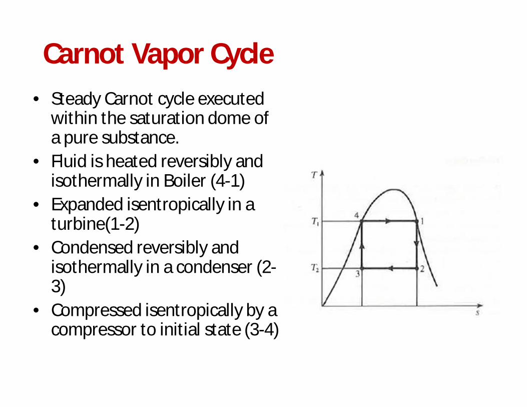
Carnot Vapor Cycle• Steady Carnot cycle executed
within the saturation dome of a pure substance.
• Fluid is heated reversibly and isothermally in Boiler (4-1)
• Expanded isentropically in a turbine(1-2)
• Condensed reversibly and isothermally in a condenser (2-3)
• Compressed isentropically by a compressor to initial state (3-4)
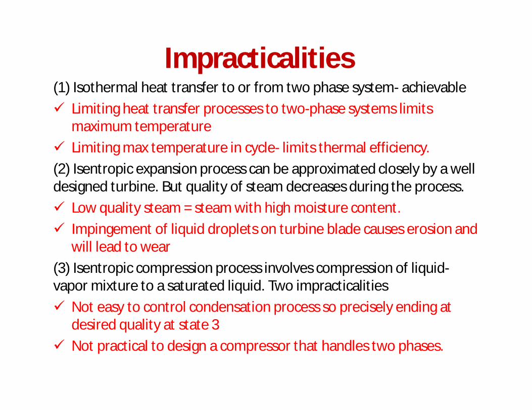
Impracticalities(1) Isothermal heat transfer to or from two phase system- achievable Limiting heat transfer processes to two-phase systems limits
maximum temperature Limiting max temperature in cycle- limits thermal efficiency.(2) Isentropic expansion process can be approximated closely by a well designed turbine. But quality of steam decreases during the process. Low quality steam = steam with high moisture content. Impingement of liquid droplets on turbine blade causes erosion and
will lead to wear(3) Isentropic compression process involves compression of liquid-vapor mixture to a saturated liquid. Two impracticalities Not easy to control condensation process so precisely ending at
desired quality at state 3 Not practical to design a compressor that handles two phases.
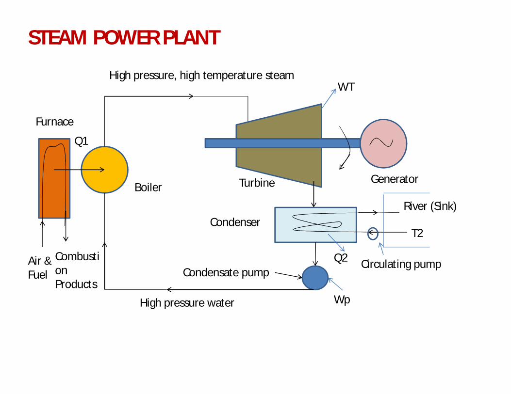
High pressure, high temperature steam
Furnace
Boiler
Air & Fuel
Combustion Products
Turbine Generator
Condenser
Circulating pumpQ2
Wp
Condensate pump
High pressure water
WT
River (Sink)
T2
Q1
STEAM POWER PLANT
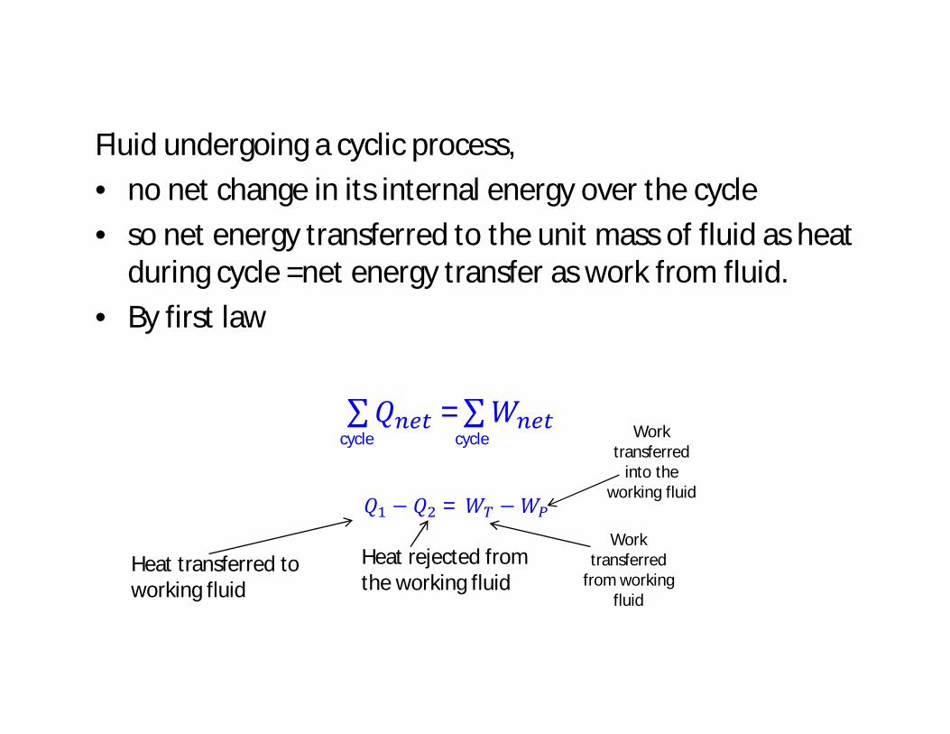
Fluid undergoing a cyclic process, • no net change in its internal energy over the cycle • so net energy transferred to the unit mass of fluid as heat
during cycle =net energy transfer as work from fluid. • By first law
∑푄 = ∑푊cycle cycle
푄 − 푄 = 푊 −푊
Heat transferred to working fluid
Heat rejected from the working fluid
Work transferred
from working fluid
Work transferred
into the working fluid
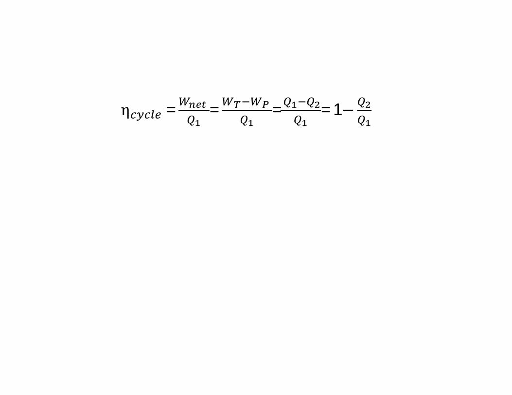
η = = = = 1−
Rankine Cycle
Impracticalities in Carnot Cycle eliminated by
(1) Superheating steam in boiler(2) Condensing completely in condenser
3
4
1
2
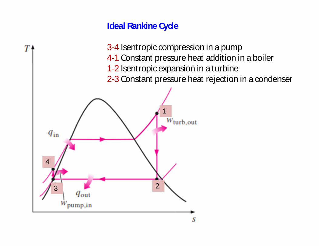
Ideal Rankine Cycle
3-4 Isentropic compression in a pump4-1 Constant pressure heat addition in a boiler1-2 Isentropic expansion in a turbine2-3 Constant pressure heat rejection in a condenser
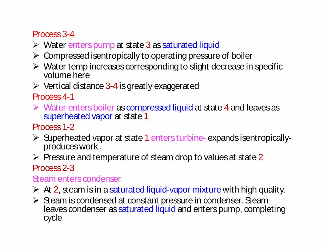
Process 3-4 Water enters pump at state 3 as saturated liquid Compressed isentropically to operating pressure of boiler Water temp increases corresponding to slight decrease in specific
volume here Vertical distance 3-4 is greatly exaggeratedProcess 4-1 Water enters boiler as compressed liquid at state 4 and leaves as
superheated vapor at state 1Process 1-2 Superheated vapor at state 1 enters turbine- expands isentropically-
produces work . Pressure and temperature of steam drop to values at state 2Process 2-3Steam enters condenser At 2, steam is in a saturated liquid-vapor mixture with high quality. Steam is condensed at constant pressure in condenser. Steam
leaves condenser as saturated liquid and enters pump, completing cycle
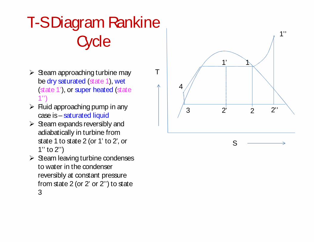
T-S Diagram Rankine Cycle
3
4
1’
2’ 2
1
1’’
2’’
T
S
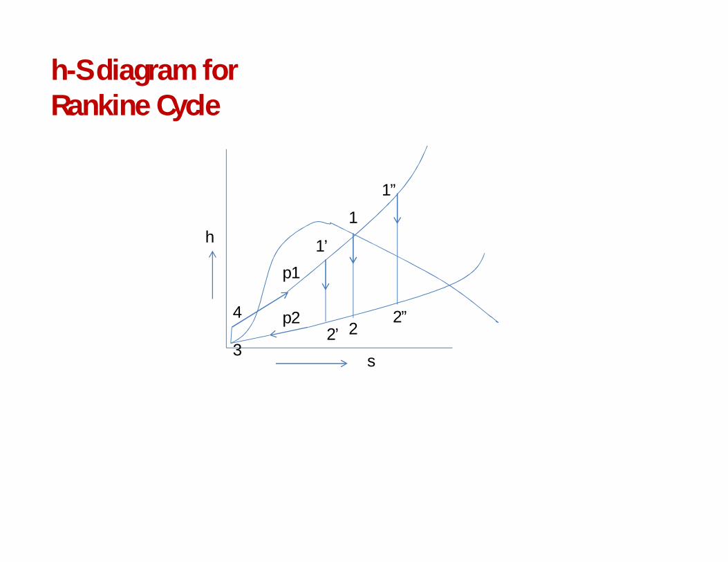
Steam approaching turbine may be dry saturated (state 1), wet(state 1’), or super heated (state 1’’)
Fluid approaching pump in any case is – saturated liquid
Steam expands reversibly and adiabatically in turbine from state 1 to state 2 (or 1’ to 2’, or 1’’ to 2’’)
Steam leaving turbine condenses to water in the condenser reversibly at constant pressure from state 2 (or 2’ or 2’’) to state 3
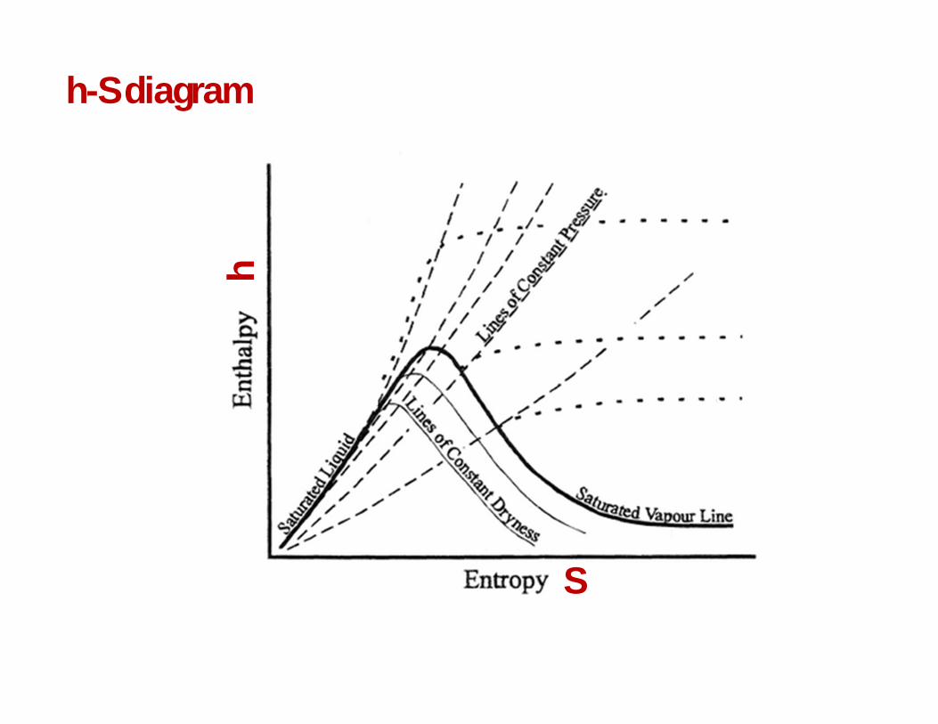
h-S diagram
h
S
1”
2”2
1
1’
2’
p1
p2
3
4
h
s
h-S diagram for Rankine Cycle
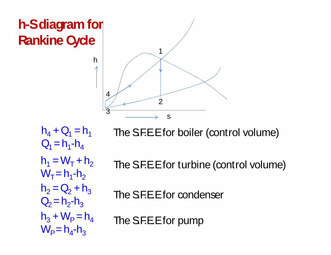
The S.F.E.E for boiler (control volume)
2
1
3
4
h
s
h4 + Q1 = h1Q1 = h1-h4
The S.F.E.E for turbine (control volume)h1 = WT + h2WT = h1-h2
h2 = Q2 + h3Q2 = h2-h3
The S.F.E.E for condenser
h3 + WP = h4WP = h4-h3
The S.F.E.E for pump
h-S diagram for Rankine Cycle
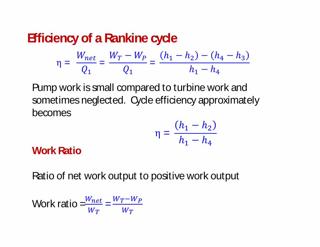
Efficiency of a Rankine cycle
η = 푊푄
=푊 −푊
푄=
ℎ − ℎ − ℎ − ℎℎ − ℎ
Work Ratio
Ratio of net work output to positive work output
Work ratio = =
Pump work is small compared to turbine work and sometimes neglected. Cycle efficiency approximately becomes
η =ℎ − ℎℎ − ℎ
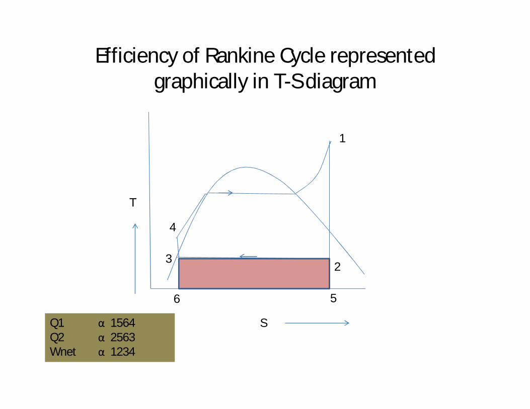
Efficiency of Rankine Cycle represented graphically in T-S diagram
3
4
1
2
T
S
3
6 5
Q1 α 1564Q2 α 2563Wnet α 1234
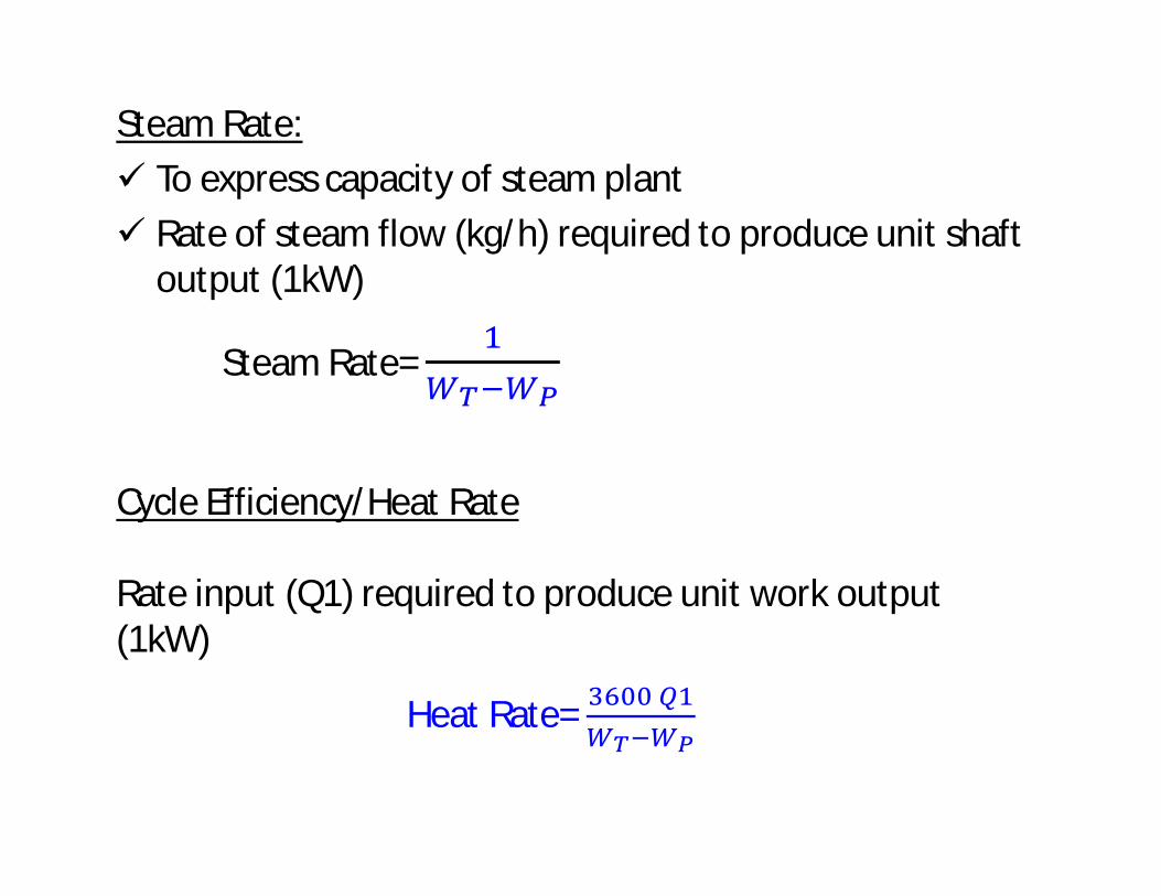
Steam Rate: To express capacity of steam plant Rate of steam flow (kg/h) required to produce unit shaft
output (1kW)
Steam Rate=
Cycle Efficiency/Heat Rate
Rate input (Q1) required to produce unit work output (1kW)
Heat Rate=
Adapted from• (1) Engineering Thermodynamics Text Book –P.K.Nag,5th Edition(2) Thermodynamics-An Engineering Approach-Y.A.Cengel, M.A.Boles
Compiled ByDr.G.R.SabareeshDepartment of Mechanical Engineering