framework for estimation of the lateral earth pressure on
TRANSCRIPT

FRAMEWORK FOR ESTIMATION OF THE LATERAL
EARTH PRESSURE ON RETAINING STRUCTURESWITH
EXPANSIVE AND NON-EXPANSIVE SOILS AS BACKFILL
MATERIAL CONSIDERING THE INFLUENCE OF
ENVIRONMENTAL FACTORS
by
Jiaying Guo
Thesis submitted to the Faculty of Graduate and Postdoctoral Studies in partialfulfillment of the requirements for the degree ofMaster of Applied Science in Civil Engineering
Department of Civil EngineeringFaculty of Engineering, University of Ottawa
Ottawa, Ontario, Canada
© Jiaying Guo, Ottawa, Canada, 2016
ii
DEDICATION
I dedicate this thesis to my beloved parents

iii
ACKNOWLEDGEMENT
The completion of this thesis could not have been possible without the help of Prof. Sai K.
Vanapalli, my beloved supervisor. His expertise, patience, consistent guidance and
unconditional supports have helped me bring this thesis into reality.
I would like to thank my colleagues at the University of Ottawa: Zhong Han, Hongyu Tu,
Shunchao Qi, Yunlong Liu, Ping Li, Penghai Yin, and Junping Ren. These graduate
students are extremely hardworking individuals and passionate with their research in the
area of unsaturated soils. It has been a great pleasure jointly working with this talented
group of students. I have immensely benefited from their friendship, encouragement and
continuous support.
I would also like to take this opportunity to thank my parents. Without their support,
encouragement and understanding, it would not have been possible for me to achieve my
goals of higher education.

iv
ABSTRACT
Lateral earth pressures (LEP) that arise due to backfill on retaining structures are typically
determined by extending the principles of saturated soil mechanics. However, there is
evidence in the literature to highlight the LEP on retaining structures due to the influence
of soil backfill in saturated and unsaturated conditions are significantly different. Some
studies are reported in the literature to interpret the variation of LEP on the retaining
structures assuming that the variation of matric suction in unsaturated backfill material is
hydrostatic (i.e. matric suction is assumed to decrease linearly from the surface to a value
of zero at the ground water table). Such an assumption however is not reliable when the
backfill behind the retaining wall is an expansive soil, which is extremely sensitive to the
changes in variation of water content values. Significant volume changes occur in
expansive soils due to the influence of environmental factors such as the infiltration and
evaporation. In addition to the volume changes, the swelling pressure of the expansive
soils also varies with changes in water content and can significantly influence the LEPs
behind the retaining wall.
In this thesis, a framework for estimating the LEPs of unsaturated soils is proposed
considering the variation of matric suction with respect to various water flow rates (i.e.
infiltration and evaporation). The proposed approach is extended for expansive and
non-expansive soils in this thesis taking into account of the influence of both the cracks

v
and the lateral swelling pressure with changes in water content. A program code LEENES
(Lateral pressure estimation on retaining walls taking account of Environmental factors
for Expansive and Non-Expansive Soils) in MATLAB is written to predict the LEP. The
program LEENES is valuable tool for geotechnical engineers to estimate the LEPs on
retaining structures for various scenarios that are conventionally encountered in
geotechnical engineering practice. The studies presented in this thesis are of interest to the
practitioners who routinely design retaining walls with both expansive and non-expansive
soils as backfill material.
vi
CONTENTS
.............................................................................................................................. 1
INTRODUCTION.....................................................................................................................1
1.1 Statement of the problem...........................................................................................1
1.2 Objectives................................................................................................................... 5
1.3 Novelty of the research..............................................................................................7
1.4 Thesis layout...............................................................................................................9
............................................................................................................................ 11
LITERATURE REVIEW....................................................................................................... 11
2.1 Introduction.............................................................................................................. 11
General.............................................................................................................. 13
Classification.................................................................................................... 14
Mineralogy........................................................................................................19
Swelling Mechanics......................................................................................... 23
2.2 Steady-state water flow............................................................................................25
2.3 Swelling pressure..................................................................................................... 28
Laboratory tests................................................................................................ 29
Semi-empirical and empirical equations........................................................ 30
Relationship between the lateral and vertical swelling pressures.................32
2.4 Fissures and cracks in unsaturated expansive soils............................................... 37

vii
The formation and propagation of fissures and cracks..................................37
The effect of fissures and cracks.....................................................................38
Determination of fissures and cracks..............................................................38
2.5 Stress state variables for unsaturated soils.............................................................42
2.6 Soil-water characteristic curve................................................................................43
Laboratory tests................................................................................................ 46
Mathematical models for the SWCC.............................................................. 51
2.6.3 Shear strength of unsaturated soils..................................................................55
2.6.4 Tensile strength of unsaturated soils...............................................................59
2.7 Retaining walls.........................................................................................................61
2.7.1 Categories of retaining walls and their failure modes................................... 62
2.7.2 Backfill material............................................................................................... 66
2.7.3 Lateral earth pressure....................................................................................... 67
2.8 Summary...................................................................................................................75
............................................................................................................................ 76
PREDICTION OF THE DEPTH OF CRACKS AND LATERAL SWELLING
PRESSURE..............................................................................................................................76
3.1 Introduction.............................................................................................................. 76
3.2 Background...............................................................................................................77
3.3 Prediction of the depth of cracks............................................................................ 79
3.4 Prediction of the lateral swelling pressure............................................................. 81
Determination of the elastic modulus of unsaturated expansive soil........... 81
viii
Proposed method for the relationship between the vertical and lateral
swelling pressure.............................................................................................................83
3.5 Example problem..................................................................................................... 87
3.6 Summary...................................................................................................................92
............................................................................................................................ 94
PROPOSED APPROACH FOR PREDICTING LATERAL EARTH PRESSURE......... 94
4.1 Introduction.............................................................................................................. 94
4.2 Background...............................................................................................................95
4.3 Lateral earth pressure...............................................................................................97
Earth pressure during drying process..............................................................97
Earth pressure during wetting process..........................................................101
4.4 Summary.................................................................................................................105
.......................................................................................................................... 108
APPLICATION OF THE PROPOSED FRAMEWORK FOR LATERAL EARTH
PRESSURE ESTIMATION OF EXPANSIVE AND NON-EXPANSIVE SOILS........ 108
5.1 Introduction............................................................................................................ 108
5.2 Proposed program LEENES used in software MATLAB..................................110
5.3 Example A: Regina clay, Saskatchewan, Canada............................................... 111
Meteorological data and soil properties........................................................111
Matric suction profile.....................................................................................113
Drying conditions...........................................................................................116
Wetting conditions......................................................................................... 119
ix
Analysis and discussion.................................................................................122
5.4 Example B: Indian Head till, Saskatchewan, Canada.........................................125
Meteorological data and soil properties........................................................125
Matric suction profile.....................................................................................127
Drying and wetting conditions...................................................................... 130
Analysis and discussion.................................................................................134
5.5 Summary.................................................................................................................138
.......................................................................................................................... 139
CONCLUSIONS AND PROPOSED RESEARCH FOR FUTURE STUDIES.............. 139
6.1 General....................................................................................................................139
6.2 Conclusions............................................................................................................ 143
6.3 Proposed future studies for estimating lateral earth pressure of unsaturated
expansive soils...................................................................................................................145
REFERENCES.................................................................................................................... 147
APPENDIX............................................................................................................................166
A.1 Program code for example problem......................................................................... 166
A.2 Program code for Example A....................................................................................168
A.3 Program code for Example B....................................................................................175
A.4 Program code for estimating the depth of crack......................................................183
A.5 Detailed calculation results for both examples........................................................185

x
LIST OF FIGURES
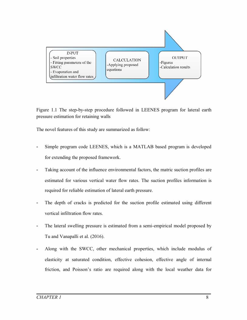
Figure 1.1 The step-by-step procedure followed in LEENES program for lateral earth
pressure estimation for retaining walls.................................................................................... 8
Figure 2.1 Commonly used criteria for determining swell potential (after Yilmaz 2006).
...................................................................................................................................................18
Figure 2.2 Silicon tetrahedron and silicate tetrahedral arranged in a hexagonal network
(after Mitchell and Soga 2005)...............................................................................................19
Figure 2.3 Octahedral unit and sheet structure of octahedral units (after Mitchell and Soga
2005).........................................................................................................................................20
Figure 2.4 Schematic diagram of the structure of clay minerals: (a) montmorillonite, (b)
illite, and (c) kaolinite (after Mitchell and Soga 2005)........................................................ 22
Figure 2.5 Time-swell behavior of compacted cotton soil (after Rao et al. 2006).............23
Figure 2.6 Variation of matric suction profiles in unsaturated soil under the influence of
various environment conditions............................................................................................. 26
Figure 2.7 Gardner’s equation for the water coefficient of permeability as a function of
the matric suction (modified from Gardner 1958)................................................................27
Figure 2.8 Construction procedure to correct for the effect of sampling disturbance
(modified from Fredlund and Rahardjo 1993, Adem 2012)................................................ 30
Figure 2.9 Evolution of the lateral swelling pressure: (a) with the flexible ring Kr = 850
MPa, (b) with the stiff ring Kr = 3045 MPa (modified from Windal and Shahrour 2002).
...................................................................................................................................................34
Figure 2.10 Comparison of swelling pressures in vertical and lateral directions (modified
from Avsar et al. 2009)........................................................................................................... 35
xi
Figure 2.11 Development of lateral pressure with time (modified from Joshi and Katti
1984).........................................................................................................................................36
Figure 2.12 Curves of fissures area ratio changes under wetting and drying cycles
(modified from Zhang et al. 2011).........................................................................................39
Figure 2.13 Typical soil-water characteristic showing zones of desaturation (from
Vanapalli et al. 1999).............................................................................................................. 45
Figure 2.14 Typical soil-water characteristic for four Canadian soils (after Vanapalli et al.
1999).........................................................................................................................................45
Figure 2.15 Cross-section of a Tempe pressure plate cell manufactured by SoilMoiture
Equipment Corporation (modified after Fredlund et al. 2012)............................................ 47
Figure 2.16 Single specimen pressure plate cell developed at University of Saskatchewan,
Saskatoon, Canada (after Fredlund et al. 2012).................................................................... 48
Figure 2.17 Contact and noncontact filter paper methods for measuring matric and total
suction (Modified after Fredlund and Rahardjo, 1993)........................................................49
Figure 2.18 Suction measurement range of several available methods (from Agus and
Schanz 2005)............................................................................................................................50
Figure 2.19 The essential features for estimating the SWRC of fine-grained soils
(modified from Catana et al. 2006)........................................................................................55
Figure 2.20 (a) A typical soil-water characteristic curve. (b) Shear strength behavior of
soil as it relates to the soil-water characteristic curve (from Vanapalli et al. 1996).......... 57
Figure 2.21 The variation of shear strength with respect to the net normal stress and
matric suction (from Tavakkoli and Vanapalli 2011).......................................................... 58
Figure 2.22 Relationship between tensile strength characteristic curve and soil water
characteristic curve for the fine sand (Lu et al. 2007).......................................................... 60
Figure 2.23 Retaining structures: (a) Gravity dam, (b) Cantilever retaining wall, (c)
Bridge abutment, (d) Underground basement (from Connor and Faraji 2013)..................62

xii
Figure 2.24 Types of rigid retaining walls: (a) Gravity retaining wall, (b) Cantilever rigid
retaining wall, (c) Counterfort wall, (d) Buttress wall (from Punmia and Jain 2005)....... 63
Figure 2.25 Types of flexible retaining walls: (a) Cantilever, (b) Anchored or tie-back, (c)
Propped (from Punmia and Jain 2005).................................................................................. 64
Figure 2.26 Failure modes for rigid retaining walls (the dotted lines show the original
position of the wall): (a) Sliding or translational failure, (b) Rotation and bearing capacity
failure (c) Deep-seated failure, (d) Structural failure (from Punmia and Jain 2005).........65
Figure 2.27 Failure modes for flexible retaining walls: (a) Deep-seated failure, (b)
Rotation about the anchor/prop, (c) Rotation near base, (d) Failure of anchor/prop, (e)
Failure by bending (from Punmia and Jain 2005)................................................................ 66
Figure 2.28 Diagrams of earth pressures for unsaturated soils: (a) Active earth pressure,
(b) passive earth pressure (after Pufahl et al. 1992)............................................................. 68
Figure 2.29 Rotation required to mobilize active and passive resistance (after Punmia and
Jain 2005).................................................................................................................................72
Figure 2.30 The relationship between active earth pressures with/without swelling
pressure and depth at water content = 22% and density = 1.43 t/m3 after four days (from
Mohamed et al. 2014)............................................................................................................. 73
Figure 2.31 Relation between active earth force and water content (modified after Zhang
2012).........................................................................................................................................74
Figure 3.1 The relationship between (a) SWCC and (b) the variation of modulus of
elasticity with respect to matric suction (after Oh et al. 2009)............................................ 82
Figure 3.2 Analytical element of expansive soil behind a frictionless retaining wall (from
Liu and Vanapalli 2015)......................................................................................................... 84
Figure 3.3 Analytical element of expansive soil at deep soil layer (after Liu and Vanapalli
2015).........................................................................................................................................85
Figure 3.4 The geometry of the example problem................................................................88

xiii
Figure 3.5 The SWCC of the example problem....................................................................88
Figure 3.6 Matric suction profile with respect to different flow rates of water................. 90
Figure 3.7 The ultimate tensile strength with respect to flow rate of water....................... 91
Figure 3.8 The modulus of elasticity for both saturated and unsaturated conditions........ 92
Figure 3.9 The flow diagram for predicting the depth of cracks......................................... 93
Figure 4.1 Active and passive earth pressures for saturated and unsaturated soils
(modified after Pufahl et al. 1992)......................................................................................... 96
Figure 4.2 Diagrams of earth pressures for unsaturated soils: (a) Active earth pressure, (b)
Passive earth pressure (after Pufahl et al. 1992)................................................................... 97
Figure 4.3 Stress states during drying....................................................................................98
Figure 4.4 Mohr-Coulomb failure envelope at a constant (ua - uw) for the active state
(after Fredlund and Rahardjo 1993).......................................................................................99
Figure 4.5 Active earth pressure distributions: (a) Saturated condition, (b) Unsaturated
condition.................................................................................................................................100
Figure 4.6 Mohr-Coulomb failure envelope at a constant (ua - uw) for the passive state
(after Fredlund and Rahardjo 1993).....................................................................................102
Figure 4.7 Schematic diagram of earth pressure during wetting process: (a) Variation of
matric suction; (b) Lateral swelling pressure; (c) At-rest earth pressure; (d) Typical
distribution of lateral earth pressure during infiltration..................................................... 104
Figure 5.1 Average precipitation data for 1981 to 2010 Canadian Climates Normals from
Regina Int’l A Station (modified from Government of Canada 2015)............................. 111
Figure 5.2 Soil-water characteristic curves of Regina clay................................................114
Figure 5.3 The matric suction profiles for Example A: (a) Drying conditions, (b) Wetting
conditions...............................................................................................................................116
Figure 5.4 The flow diagram for trial procedures conducted in LEENES to estimate the
depth of cracks and the corresponding evaporation flow rate in expansive soils............ 117
xiv
Figure 5.5 The tensile strength and lateral stress distribution with respect to different
evaporation rates for Example A (i.e. q = 1.55×10⁻⁷ m/s, 1.65×10⁻⁷ m/s, 1.75×10⁻⁷ m/s,
1.85×10⁻⁷ m/s)........................................................................................................................117
Figure 5.6 The flow diagram for lateral earth pressure estimation under drying condition
in expansive soils...................................................................................................................118
Figure 5.7 The active earth pressure distributions under drying conditions for Example A.
.................................................................................................................................................119
Figure 5.8 The flow diagram for lateral earth pressure estimation under wetting condition
in expansive soil.................................................................................................................... 120
Figure 5.9 Lateral earth pressure distributions under wetting conditions for Example A: (a)
Saturated at-rest earth pressure; (b) Additional swelling pressure due to variation of
matric suction; (c) Final lateral earth pressure under wetting condition...........................121
Figure 5.10 The depth of cracks and ultimate tensile strength with different steady state
flow rate for Example A....................................................................................................... 122
Figure 5.11 The lateral forces with respect to various infiltration flow rates for Example
A..............................................................................................................................................124
Figure 5.12 Precipitation data from 1981 to 2010 from Canadian Climates Normals in
Indian Head CDA Station (modified from Government of Canada 2015).......................127
Figure 5.13 Soil-water characteristic curves of Indian Head till (modified from Vanapalli
et al. 1996)............................................................................................................................. 128
Figure 5.14 The matric suction profiles for Example B: (a) Drying conditions, (b)
Wetting conditions................................................................................................................ 130
Figure 5.15 The flow diagram for lateral earth pressure estimation under drying and
wetting conditions of Example B.........................................................................................131
Figure 5.16 Lateral earth pressure distributions under drying and saturated conditions: (a)
At-rest earth pressure; (b) Active earth pressure; (c) Passive earth pressure................... 132

xv
Figure 5.17 Lateral earth pressure distributions under wetting and saturated conditions: (a)
At-rest earth pressure; (b) Active earth pressure; (c) Passive earth pressure................... 133
Figure 5.18 Lateral earth forces and depth of tensile zone under drying and wetting
conditions for Example B: (a) At-rest and active earth forces; (b) Depth of tensile zone
for at-rest and active states; (c) Passive earth forces..........................................................137
Figure 6.1 Schematic diagram of the proposed framework............................................... 140
Figure 6.2 Flow chart for the proposed program LEENES............................................... 142

xvi
LIST OF TABLES
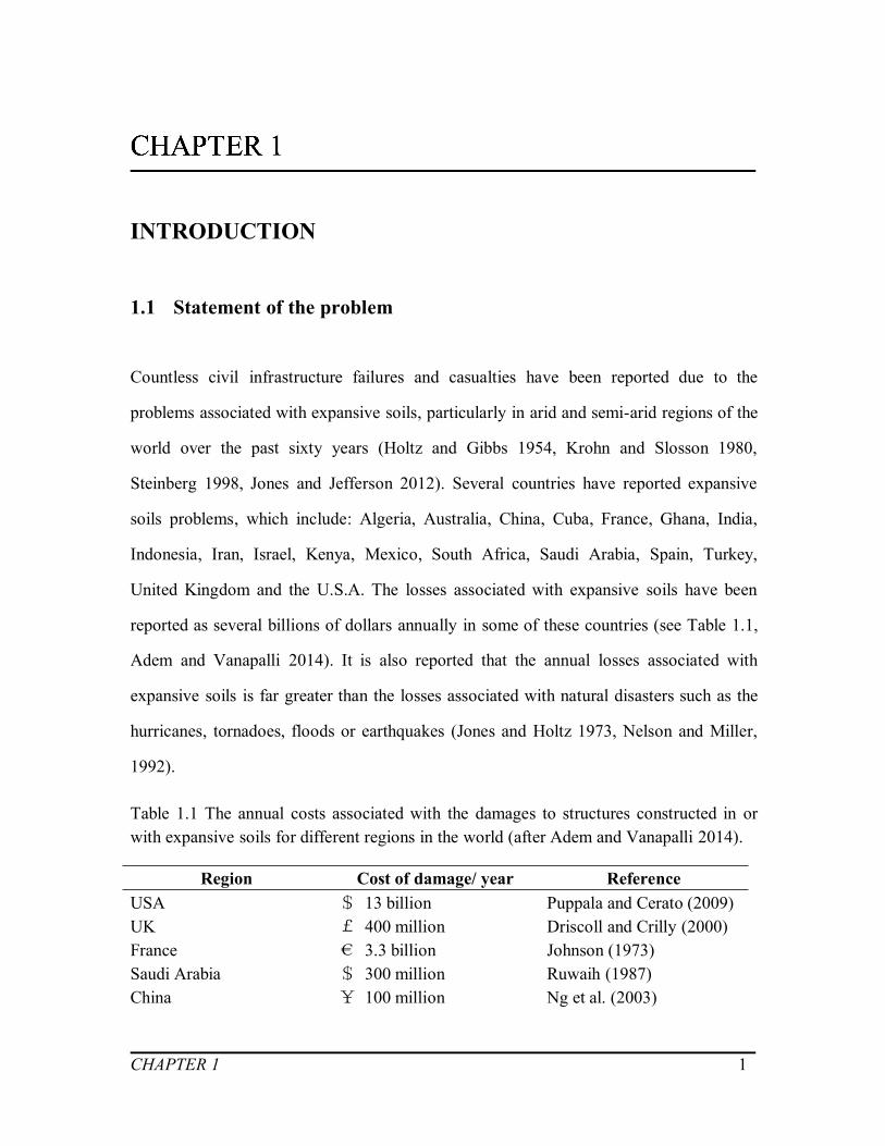
Table 1.1 The annual costs associated with the damages to structures constructed in or
with expansive soils for different regions in the world (after Adem and Vanapalli 2016). 1
Table 2.1 Summary of criteria for classifying swell potential of expansive soils (modified
after Yilmaz 2006)...................................................................................................................14
Table 2.2 Summary of formulations for swell potential determination (modified after
Yilmaz 2006, Nelson and Miller 2007, Rao et al. 2011, Adem 2012, Çimen et al. 2012).
...................................................................................................................................................16
Table 2.3 Advantages and disadvantages of swelling pressure laboratory tests................ 29
Table 2.4 Summary of relationships available in the literature (modified after Nelson and
Miller 1992, Rao et al. 2011, Çimen 2012)...........................................................................31
Table 2.5 The swelling pressure in three directions of expansive soil (modified from
Zhang 1993)............................................................................................................................. 33
Table 2.6 Advantages and disadvantages of various designations for amount of water in
soil (from Fredlund et al. 2012)..............................................................................................43
Table 2.7 Summary of some SWCC models (modified after Sillers et al. 2001).............. 51
Table 2.8 The model parameters (from Sillers et al. 2001)..................................................52
Table 4.1 Equations for lateral earth pressure estimation.................................................. 106
Table 5.1 Lake Evaporation data for 1981 to 2010 Canadian Climates Normals from
Regina Int’l A Station (modified from Government of Canada, 2015)............................ 112
Table 5.2 Soil properties of Regina clay............................................................................. 112
Table 5.3 The active earth forces under drying conditions for Example A......................123
Table 5.4 Soil properties of Indian Head till.......................................................................126

xvii
Table 5.5 Lake evaporation data for 1981 to 2010 Canadian Climates Normals from
Regina Gilmour Station (modified from Government of Canada, 2015)......................... 127
Table A.1 The depth of cracks and ultimate tensile strength under drying conditions
(Example A)...........................................................................................................................185
Table A.2 The resultant lateral forces under wetting conditions (Example A)................185
Table A.3 The critical height under at-rest and active stress states (Example B)............186
Table A.4 The resultant lateral earth forces under drying and wetting conditions
(Example B)...........................................................................................................................186

xviii
NOMENCLATURE
Abbreviations
1-D One dimensionalCVS Constant volume swell testHAE High air entryLEFM Linear elastic fracture mechanicsLEP Lateral earth pressureMBV Methylene blue valuemin MinuteSEM Scanning electron microscopeSPCC Soil permeability characteristic curveSWCC Soil-water characteristic curveTSCC Tensile strength characteristic curveUDEC Universal distinct element code
Symbols
(ua - uw) (kPa) Matric suction(ua - uw)s (kPa) Matric suction at ground surface(- ua) (kPa) Net normal stressa, m, n Fitting parameters for SWCCab, nb Fitting parameters in Brutsaert’s (1966) equationAc, A Activity of soilsAs, λs Regression analysis parameters for swelling pressure estimationAt, Bt, Ct, Dt, Empirical constants in tensile strength estimationB Coefficient of unified strength theoryC, W, F’, G Fitting parameters for depth of initial cracking estimationc’ (kPa) Effective cohesionCC (%) Clay contentCd (kPa) Total cohesive strengthct’ (kPa) Unified effective cohesionCu Coefficient of uniformity

xix
Cw (kPa) Total adhesive strengthD (m) Depth of ground water tablede (mm) Dominant particle size diameterE Void ratio of soilse0 Initial void ratio of soilsEa (kN/m) Active earth forceef Final void ratio of soilsEI Expansion indexEp (kN/m) Passive earth forceEsat, E (kPa) Modulus of elasticity under saturated conditionEunsat (kPa) Modulus of elasticity under unsaturated conditionFi Initial state factorFSI (%) Free swell indexH (kPa) Elastic modulus with respect to a change in matric suctionh0 (m) Depth of elastic areaHe (m) Depth of expansive layerIL Liquidity indexKa Coefficient of active earth pressureKat Unified coefficient of active earth pressureKp Coefficient of passive earth pressureKpt Unified coefficient of passive earth pressureks (m/s) Saturated coefficient of permeabilitykw (m/s) Unsaturated coefficient of permeability depends on matric
suction.LL (%) Liquid limitLLw (%) Weighted liquid limitLS (%) Linear shrinkageM Coefficient of intermediate principal stress in unified strength
theoryms Reduction coefficient of swelling pressureN Coefficient of earth pressurePa (kPa) Atmospheric pressurePf (kPa) Final lateral swelling pressurePI (%) Plastic limitPI, Ip (%) Plastic indexPL (kPa) Lateral swelling pressurePS (%) Probable swellPs (kPa) Vertical swelling pressurePs’ (kPa) Corrected swelling pressure

xx
Ps0 (kPa) Intercept on the Ps axis at zero suction valueq (m/s) Flow rate of water in unsaturated soilsqs (m/s) Flow rate of water in saturated soilsRs Swelling pressure ratioS, Sr (%) Degree of saturationSI (%) Shrinkage indexSL (%) Shrinkage limitSP Swelling potentialSR (%) Residual degree of saturationua (kPa) Pore-air pressureuw (kPa) Pore-water pressureW Gravity of soil massw (%) Gravimetric water contentwi, w0 (%) Natural water contentwr (%) Residual gravimetric water contentws (%) Saturated gravimetric water contentzc (m) Depth of crackszw (m) Distance above ground water tableα ︒ Angle of back wall and vertical planeE, E Fitting parameters of unsaturated modulus of elasticityαT Coefficient of tensile strength of soils︒ Angle of the filling plane of back wall and horizontal planeβS Fitting parameter for swelling pressure estimationγ (kN/m3) Unit weight of soilsγd (kN/m3) Dry unit weightγunst (kN/m3) Unit weight of unsaturated soilsγw (kN/m3) Unit weight of waterδ ︒ Friction angle of filling and back wall Mean-zero Gaussian random error termεx,εy,εz Total strain in the x-, y- and z-diretionθ (%) Volumetric water contentθ ︒ Angle of sliding plane and horizontal planeΚ Fitting parameter for shear strength of unsaturated soilsΜ Poisson’s ratiodn (kg/m3) Natural dry densityσ (kPa) Total normal stressσ’ (kPa) Effective normal stressσ0 (kPa) At-rest earth pressureσc (kPa) Surcharge stress due to cracks

xxi
σh (kPa) Total horizontal stressσh’ (kPa) Effective horizontal stressσha (kPa) Active earth pressureσhp (kPa) Passive earth pressureσs (kPa) Surcharge stressσt, t (kPa) Tensile strength of soilsσv (kPa) Total vertical stressσv’ (kPa) Effective vertical stressσvs (kPa) Vertical self-weight stressσx,σy,σz (kPa) Total normal stress in the x-, y- and z-diretionτnat (kPa) Natural soil suction b︒ Angle of shearing resistance with respect to matric suction’︒ Angle of internal frictiont’︒ Unified angle of internal frictiontb︒ Unified angle of shearing resistanceχt The reduction coefficient of effective cohesion in tensile strength
estimation︒ Dilation angle (kPa) Total suctioni (kPa) Initial soil suction
CHAPTER 1 1
INTRODUCTION
1.1 Statement of the problem
Countless civil infrastructure failures and casualties have been reported due to the
problems associated with expansive soils, particularly in arid and semi-arid regions of the
world over the past sixty years (Holtz and Gibbs 1954, Krohn and Slosson 1980,
Steinberg 1998, Jones and Jefferson 2012). Several countries have reported expansive
soils problems, which include: Algeria, Australia, China, Cuba, France, Ghana, India,
Indonesia, Iran, Israel, Kenya, Mexico, South Africa, Saudi Arabia, Spain, Turkey,
United Kingdom and the U.S.A. The losses associated with expansive soils have been
reported as several billions of dollars annually in some of these countries (see Table 1.1,
Adem and Vanapalli 2014). It is also reported that the annual losses associated with
expansive soils is far greater than the losses associated with natural disasters such as the
hurricanes, tornadoes, floods or earthquakes (Jones and Holtz 1973, Nelson and Miller,
1992).
Table 1.1 The annual costs associated with the damages to structures constructed in orwith expansive soils for different regions in the world (after Adem and Vanapalli 2014).
Region Cost of damage/ year ReferenceUSA $ 13 billion Puppala and Cerato (2009)UK £ 400 million Driscoll and Crilly (2000)France € 3.3 billion Johnson (1973)Saudi Arabia $ 300 million Ruwaih (1987)China ¥ 100 million Ng et al. (2003)

CHAPTER 1 2
Victoria, Australia $ 150 million Osman et al. (2005)
The problems to the geotechnical infrastructure such as the slopes, retaining walls,
pavements and lightly loaded residential structures and its foundations constructed with
or founded within expansive soils may be attributed to the high swelling pressure
associated with volume change behavior due to wetting (Chen 1975, Charlie et al. 1984,
Cameron and Walsh 1984, Dafalla and Shamrani 2011, Yilmaz 2006, Chen 2012, Jones
and Jefferson 2012, Fredlund et al. 2012). In addition, various problems are also reported
due to shrinkage associated with drying of expansive soils (Miller et al. 1997, Puppala et
al. 2004, Chen 2012).
Retaining walls are widely used soil supporting structures for several civil infrastructure
such as the foundations, slopes, tunnels, bridges, pavements and railways. Conventional
theoretical and numerical methods are widely used to determine the lateral earth
pressures (LEP) on the retaining structures. Rankine or Coulomb’s approaches form
conventional methods that are widely used in retaining wall design practice by extending
the mechanics of saturated soils (Tavakkoli and Vanapalli 2011). These methods provide
reasonable estimates of LEPs for soils such as the gravels, sands, silts, glacial tills and
clays under dry or saturated conditions. However, these methods are not applicable for
expansive soils which are typically in a state of unsaturated condition. Expansive soils are
used as backfill material behind the retaining wall in some regions of the world because
of non-availability of other favourable soils (Ireland 1964, Pufahl et al. 1983, Lu 2010).
These soils are prone to swell upon wetting due to precipitation activities such as the rain
or snow or due to water pipe lines leakage within the vicinity of retaining walls.
Expansive soils swell upon wetting and exert additional pressure on the retaining walls.
In addition, expansive soils crack behind the wall due to drying. In other words,
environmental factors have a significant and complex influence on the LEP of a retaining
wall with expansive soils as backfill material.

CHAPTER 1 3
Currently, two approaches are commonly used for estimation of the earth pressure of
unsaturated soils for the design retaining walls (Zhu and Liu 2001). The first approach
extends Fredlund et al. (1978) strength equation for unsaturated soils into Rankine’s earth
pressure theory. The Rankine’s theory uses Mohr-Coulomb failure criterion assuming
plastic equilibrium conditions. The LEPs are calculated using this approach assume that
the back of the retaining structure is vertical, its surface is smooth, and the filling surface
behind the back wall is horizontal. Because of the simplified assumptions of Rankine
theory, this method cannot be used for most cases that are commonly encountered in
practice applications (Pufahl et al. 1983, Zhu and Liu 2001, Zhang 2012).
The second approach uses the Coulomb’s earth pressure theory by incorporating the
influence of matric suction in the unsaturated soil (Zhang 2012). This approach can be
used for retaining walls with a frictional surface; however, it only provides resultant
pressure instead of lateral earth pressure distribution with respect to depth as in Rankine’s
method.
In the above two approaches, the additional contribution arising from swelling pressure
of expansive soils is typically added to the earth pressure directly, for reliable earth
pressure estimation. The laboratory test results (i.e. constant volume test, swell and
load-back test and under pressure test) of the vertical swelling pressure determined is
used as a tool in the estimation of the lateral swelling pressure. Several researchers
suggest a reduction coefficient, typically around 0.2~ 0.6 for estimating lateral pressure
from vertical swelling pressure results (Zhang 1995a, Zhu and Liu 2001). Also, Zhu and
Liu (2001) suggested another approach for accounting the additional swelling pressure
influence on retaining walls with expansive soils as backfill material. In this approach,
instead of conventional angle of internal friction of shear strength, an equivalent angle of
internal friction is used to take into account the influence of swelling pressure. However,

CHAPTER 1 4
the equivalent angle of internal friction is related to the normal stress, which varies with
depth of the retaining wall. It was reported that two thirds of retaining walls in Lechan
and Chenzhou areas in China that used this approach have shown extensive cracks,
displacements or even failures due to misjudgement or erroneous estimation of the
equivalent internal friction angle (Zhang 1995b).
In a study reported by Ireland (1964), more than half of the retaining walls performance
were unsatisfactory which had expansive clays as backfill or are founded upon them. The
unsatisfactory performance may be attributed to the propagation of tensile cracks which
contribute to water seepage due to which the soil swells and acts as an additional lateral
earth pressure. Due to this reason, the influence of swelling pressure towards lateral earth
pressure cannot be neglected in the rational design of retaining wall.
The shrink-swell potential of expansive soils is influenced by its initial water content,
water content variation, void ratio, internal structure and vertical stresses, as well as the
type and amount of clay minerals in the soil (Bell and Culshaw 2001). Of all these
parameters, the variation of water content is considered to be the dominant factor that
contributes to significant changes of bulk volume and swelling pressure. The water
content changes may be due to seasonal variations, or brought about by local site changes
such as the leakage from water supply pipes or drains, changes to surface drainage and
landscaping or following the planting, removal or severe pruning of trees or hedges
(Cheney 1986). As discussed earlier, there are some approaches in the literature to predict
the lateral earth pressure with expansive soils as backfill material on the retaining walls,
for certain scenarios (Pufahl et al. 1983, Zhu and Liu 2001, Hu 2006, Zhang et al. 2011,
Zhang 2012). However, a comprehensive framework taking account of the environmental
factors (i.e. drying and wetting conditions) for estimation of the LEP on retaining walls
with expansive unsaturated soils as backfill is not available. There is a need for a

CHAPTER 1 5
comprehensive framework that can be applied to both the fine-grained soils that do not
swell and expansive soils under both saturated and unsaturated conditions considering the
influence of cracks and other environmental factors extending the mechanics of
unsaturated soils. Such a framework will be valuable for practicing geotechnical
engineers for the design of retaining walls.
1.2 Research objectives
In this study, a comprehensive framework is proposed for estimating the LEP on
retaining walls due to expansive soils by extending the mechanics of unsaturated soils. In
this framework, the evaporation or infiltration water flow rates are the key factors to
estimate the variation of matric suction profile in the expansive soil, when it is used as a
backfill material behind a retaining wall. Under drying conditions, cracks propagate in
expansive soils. An approach is presented in this thesis for estimating the crack depth.
The depth of cracks is estimated extending the assumption that the tensile strength of soil
is equal to the lateral stress. Upon infiltration, the lateral swelling pressure generates as
the degree of saturation changes from a state of unsaturated to saturated condition
associated with an increase in the water content (i.e. matric suction reduction). The lateral
swelling pressure associated with the variation of matric suction profile is estimated from
the relation between vertical and lateral swelling pressure. The framework that is
developed for expansive soils can also be extended for non-expansive soils (i.e.
fine-grained soils such as the clays, glacial tills and silty soils). In other words,
fine-grained soils could be treated as a special case for expansive soils that do not swell
due to wetting associated with infiltration. The lateral earth pressure of non-expansive
soils is estimated in terms of vertical water flow rates, without considering the influence
of cracks and swelling pressures.

CHAPTER 1 6
The key objectives of the present study is summarized below:
(i) Estimate the matric suction profiles for non-expansive and expansive soils taking
account of the local climate records (i.e. monthly evaporation and infiltration water
flow rates) (Yeh 1989, Likos and Lu 2004). In this approach, the soil-water
characteristic curve (SWCC) is used as tool to estimate variation of the matric
suction profile for the soils above the ground water table
(ii) Propose an equation to estimate the depth of tension cracks taking into account of the
influence of various evaporation water flow rates.
(iii) Present the available approaches for estimating the lateral swelling pressure of
expansive unsaturated soils from vertical swelling pressure values determined from
laboratory test results.
(iv) Propose a procedure to estimate the lateral earth pressure (LEP) for unsaturated
expansive soils for both drying and wetting conditions.
(v) Extend the proposed method of lateral earth pressure estimation for non-expansive
unsaturated and saturated soils.
(vi) The earth pressure distributions for both non-expansive and expansive soils
according to the proposed approach are determined by using a program code
developed using the MATLAB software. The program code is referred to as
LEENES in this thesis. LEENES is abbreviated form for Lateral pressure estimation
on the retaining walls taking account of Environmental factors for Expansive and
Non-Expansive Soils.
(vii) Discuss and compare the calculation results of LEP results for different retaining
walls with both expansive and non-expansive soils as backfill material.

CHAPTER 1 7
1.3 Novelty of the research
Environmental factors (i.e. wetting-drying and freeze-thaw cycles) have a significant
influence on the swell-shrinkage behavior of expansive soils because they are extremely
sensitive to the variation of water content. In both natural and compacted expansive soils,
cracks propagate in dry seasons and additional swelling pressures generate upon
infiltration. However, in most cases, the depth of cracks is typically assumed to be
constant and the influence of lateral swelling pressure on the retaining walls is neglected
(Morris et al. 1992, Pufahl et al. 1992). Also, at present, there are limited investigations
that are undertaken which focus on reliable estimation of the LEP for unsaturated
expansive soils extending the mechanics of unsaturated soils (Pufahl et al. 1983, Zhang
1995, Hu 2006, Zhu and Liu 2001, Zhang 2012).
In this thesis, a comprehensive framework is proposed for estimation of LEP on a
retaining wall with expansive soil as backfill material. A program LEENES is developed
using the MATLAB software incorporating all the features of the proposed framework.
LEENES facilitates in calculations and presents the variation of LEP in graphical form.
Instead of numerical procedures using complex finite element programs, the proposed
approach, LEENES is relatively simple for use in conventional practice by geotechnical
engineers. Figure 1.1 provides a summary of the step by procedure is followed using the
LEENES for estimating the LEP and plotting the results.
CHAPTER 1 8
Figure 1.1 The step-by-step procedure followed in LEENES program for lateral earthpressure estimation for retaining walls
The novel features of this study are summarized as follow:
- Simple program code LEENES, which is a MATLAB based program is developed
for extending the proposed framework.
- Taking account of the influence environmental factors, the matric suction profiles are
estimated for various vertical water flow rates. The suction profiles information is
required for reliable estimation of lateral earth pressure.
- The depth of cracks is predicted for the suction profile estimated using different
vertical infiltration flow rates.
- The lateral swelling pressure is estimated from a semi-empirical model proposed by
Tu and Vanapalli et al. (2016).
- Along with the SWCC, other mechanical properties, which include modulus of
elasticity at saturated condition, effective cohesion, effective angle of internal
friction, and Poisson’s ratio are required along with the local weather data for

CHAPTER 1 9
implementing the proposed framework for estimation of the lateral earth pressure
variation behind the retaining wall with expansive and non-expansive clays.
- Proposed framework can be extended and used for both non-expansive and
expansive soils under both unsaturated and saturated conditions using LEENES for
estimating the LEP with respect to the depth in retaining walls.
1.4 Thesis layout
This thesis are presented in six chapters as summarized below:
Chapter 1, entitled, “Introduction”, presents a general background information with
respect to estimation of the LEP of the presently followed approaches in the literature for
both expansive and non-expansive soils taking account of the influence of environmental
factors (i.e. infiltration and evaporation conditions). The need for proposing a rational
method for LEP estimation extending the mechanics of unsaturated soils is highlighted.
The key objectives along with the novelty of this thesis are also summarized in this
chapter.
Chapter 2, entitled, “Literature review”, provides up-to-date relevant background
information of the mechanics of unsaturated soils required for explaining the proposed
framework. Key formulations to calculate the swelling pressure and lateral earth pressure
for expansive unsaturated soils are also summarized.
Chapter 3, entitled, “Prediction of the depth of cracks and lateral swelling pressure”,
describes the swell-shrinkage behavior of expansive soils under both drying and wetting
conditions. The relationship between the environmental factors and matric suction
profiles is highlighted in this chapter (Yeh 1989, Likos and Lu 2004). An equation is
derived for predicting the depth of cracks associated with evaporation considering the

CHAPTER 1 10
vertical steady-state water flow rates. The corresponding matric suction profiles are
applied to estimate the lateral swelling pressures of expansive soils under wetting
conditions.
Chapter 4, entitled “Proposed approach for predicting lateral earth pressure of expansive
unsaturated soils”, provides details of the framework for estimating the LEP of
unsaturated expansive soils by extending the mechanics of unsaturated soils. In the
proposed approach, both the propagation of cracks upon evaporation and lateral swelling
pressures development upon infiltration are also presented.
Chapter 5, entitled, “Application of the proposed framework for LEP estimation of
expansive and non-expansive soils”, employs the proposed framework to investigate the
LEP distributions and calculate lateral earth pressures for hypothetical retaining walls
with different backfill soil types (Regina clay and Indian Head till). Furthermore, the
results are discussed and compared to highlight the influence of the seasonal water
content variation based on the local weather station records.
Chapter 6, “Conclusions and proposed research for future studies”, concisely summarizes
the work presented in this thesis and highlights the major conclusions. The future
research works that can be undertaken for better understanding of the influence of lateral
swelling pressure on the design of the retaining walls are also summarized.

CHAPTER 2 11
LITERATURE REVIEW
2.1 Introduction
Expansive soils pose significant challenges to geotechnical and structural engineers for
providing reliable tools for the design of infrastructure. Significant property losses and
human casualties are attributed to improper classification and understanding of the
engineering behavior of expansive soils (Dhowian et al. 1988, Chen 1975, Erzin and Erol
2004, Puppala and Cerato 2009, Jones and Jefferson 2012, Qi and Vanapalli 2015).
Several failures that were reported in the literature are related to lightly loaded structures
such as the pavements, residential and industrial buildings that are constructed in
unsaturated expansive soils, which suffer damages caused by vertical volumetric
deformations (Vu and Fredlund 2004, Avsar et al. 2009, Kayabali and Demir 2011,
Mohamed et al. 2014). The instability of retaining walls, failure of pile foundations and
certain slopes may predominantly be attributed to the lateral swelling pressure induced by
expansive soils (Chen 1975, Nelson and Miller 1992, Marsh and Walsh 1996). Due to
these reasons, geotechnical engineers require proper training and tools to undertake soil
investigation studies to identify and classify expansive soils. In addition, they need tools
for the proper design, construction and maintenance of the infrastructure to alleviate
problems associated with expansive soils (Baker 1981, Bagge 1985, Sapaz 2004,
Kayabali and Demir 2011).

CHAPTER 2 12
This chapter focus is directed towards providing relevant background literature for better
understanding expansive soils behavior in general and to understand various properties
that have a significant influence in the design of retaining walls with expansive soils as
backfill material, in particular. One of the major problems of using expansive soils as
backfill material is its high sensitivity with respect to water content changes associated
with evaporation and infiltration. In other words, sensitivity associated with water content
changes has a significant influence for evaluating the swell-shrink behavior of expansive
soils. The key information of interest is how cracks develop in expansive soils in addition
to the development of swelling pressure as an additional stress on the retaining wall.
Considerable research has been undertaken during the past six decades which include
both laboratory tests and field studies to better understand the influence of the
swell-shrink behavior on the performance of structures constructed with expansive soils
or structures founded on them (Seed and Chan 1959, Seed et al. 1962, Fredlund 1983,
Chen 1988, Nelson and Miller 1992, Morris et al. 1992, Shuai 1996, Jones and Jefferson
2012). Some of the key studies that are of interest in the rational design of retaining walls
include: (i) estimation or prediction of the swelling pressure; (ii) estimation of crack
depth.
The methods for determining the swelling pressures are commonly divided into two
groups: direct (i.e. laboratory and field tests) and indirect methods (i.e. from index
properties tests) (Nelson and Miller 1992, Fredlund and Rahardjo 1993, Kayabali and
Demir 2011, Vanapalli and Lu 2012, Wang et al. 2013). Both laboratory and field studies
are tedious, time consuming and hence expensive. These limitations to certain extent can
be overcome by proposing empirical and semi-empirical equations or approaches that are
useful for application in engineering practice (Yilmaz 2006). Along similar lines, various
laboratory tests, numerical analysis and analytical methods are available to determine the

CHAPTER 2 13
depth of crack propagation associated with evaporation (Lee et al. 1988, Morris et al.
1992, Konarad and Ayad 1997, Nahlawi and Kodikara 2005, Tavakkoli and Vanapalli
2011, Zhang et al. 2011).
Several investigators have attempted to estimate earth pressure on the retaining walls
with expansive soils as backfill by taking account of the influence of both external and
internal factors, including soil properties, evaporation and precipitation. Several
approaches for lateral earth pressure (LEP) estimation of unsaturated soils that are
available in the literature are also summarized (Pufahl et al. 1983, Tavakkoli and
Vanapalli 2011, Zhang et al. 2010, Zhang 2012).
In this chapter, the general background of expansive soils and a comprehensive review of
its swell-shrink behavior are presented. In order to propose rational approach for LEP
estimation of unsaturated soils, background information about the stress state variables
for interpretation of the unsaturated soils behavior is presented. In addition, Soil-water
Characteristic Curve (SWCC), which can be used as a tool for predicting the unsaturated
soils properties, is succinctly summarized in this chapter. Some key properties of
unsaturated soils that are of interest in the estimation of earth pressures, which includes
the modulus of elasticity, the coefficient of permeability and the shear strength behavior
of unsaturated soils, also are discussed. More specifically, the shear strength and tensile
strength of unsaturated soils, which form the key properties in the estimation of earth
pressure is provided in greater detail.
General
Expansive soils can be categorized as problematic clays which are typically found in
nature are in an unsaturated condition with multiple micro and macro cracks or fractures.
These soils that exhibit remarkable swell-shrink characteristics due to changes in their
CHAPTER 2 14
moisture content from their natural environment conditions. In spite of their well-known
problems, their use is unavoidable as backfill material for retaining walls when other
suitable materials are not available in the close proximity. As a first step to deal with
these problematic soils, appropriate identification and classification systems are built to
guide engineers for their use (Das 1995).
In typical expansive soils, montmorillonite and illite are the primary minerals that have
the capacity to imbibe large amounts of water molecules between their clay sheets (Jia
2010, Zhang 2012). When degree of saturation in expansive soils increases or become
saturated, more water molecules are absorbed between the clay sheets, causing the
volume of soil mass to increase. This process weakens the inter-clay bonds and causes a
reduction in the tensile and shear strength of the soil. When water is removed (i.e.
evaporation or gravitational forces), the overall volume of the soil reduces in addition to
development of cracks (Jones and Jefferson 2012). For this reason, the water flow and
shear strength behavior are the key properties of interest in the design of retaining walls
with expansive soils as backfill material. In addition, information of the swelling
pressures that will generate when the volumetric change is restrained also are required.
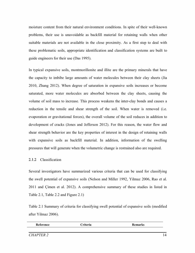
Classification
Several investigators have summarized various criteria that can be used for classifying
the swell potential of expansive soils (Nelson and Miller 1992, Yilmaz 2006, Rao et al.
2011 and Çimen et al. 2012). A comprehensive summary of these studies in listed in
Table 2.1, Table 2.2 and Figure 2.1)
Table 2.1 Summary of criteria for classifying swell potential of expansive soils (modified
after Yilmaz 2006).
Reference Criteria Remarks
CHAPTER 2 15
Altmeyer (1955) LS < 5, SL > 12, PS < 0.5(non-critical)5 ≤ LS ≤ 8, 10 ≤ SL ≤ 12,0.5 ≤ PS ≤ 1.5 (marginal)LS > 8, SL < 10, PS > 1.5 (critical)
Based on LS, SL and PS.Remolded sample.Soaked under 6.9 kPa surcharge.LS = linear shrinkage, %.PS = probable swell, %.SL = shrinkage limit, %.
Holtz (1959) CC > 28, PI > 35, SL > 11 (very high)22 ≤ CC ≤ 31, 25 ≤ PI ≤ 41,7 ≤ SL ≤ 12 (high)13 ≤ CC ≤ 23, 15 ≤ PI ≤ 28,10 ≤ SL ≤16 (medium)
Based on CC, PI and SL.CC = clay content, % (<0.002 mm).PI = plastic limit, %.
Seed et al. (1962) See Figure 2.2 (a) Based on oedometer test usingcompacted specimen, percentage ofclay < 2 m and activity.
Van Der Merwe(1964)
See Figure 2.2 (c) Based on PI, percentage of clay < 2m and activity.
Raman (1967) PI > 32 and SI > 40 (very high)23 ≤ PI ≤ 32, 30 ≤ SI ≤ 40 (high)12 ≤ PI ≤ 23, 15 ≤ SI ≤ 30(medium)PI < 12 and SI < 15 (low)
Based on PI and SI.SI = shrinkage index = LL –SL, %.LL = liquid limit, %.
Uniform BuildingCode (1968)
EI > 130 (very high)91 ≤ EI ≤ 130 (high)51 ≤ EI ≤ 90 (medium)21 ≤ EI ≤ 50 (low)0 ≤ EI ≤ 20 (very low)
Based on oedometer test oncompacted specimen with degree ofsaturation close to 50% andsurcharge of 6.9 kPa.EI = expansion index = 100 ×
percent swell×fraction passingNo.4 sieve.
Sowers and Sowers(1970)
SL < 10 and PI > 30 (high)10 ≤ SL ≤ 12, 15 ≤ PI ≤ 30(moderate)SL > 12 and PI < 15 (low)
Little swell will occur when w0results in LI of 0.25
Dakshanamurthy andRaman (1973)
See Figure 2.2 (b) Based on plasticity chart.
Snethen (1984) LL > 60, PI > 35, nat > 4,SP > 1.5 (high)30 ≤ LL ≤ 60, 25 ≤ PI ≤ 35,
1.5 ≤ nat ≤ 4,0.5 ≤ SP ≤ 1.5 (medium)
PS is representative for fieldcondition, can be used withoutnat,but accuracy will be reduced.SP = swelling potential.

CHAPTER 2 16
LL < 30, PI < 25, nat <1.5,SP < 0.5 (low)
nat = natural soil suction, tsf.
Chen (1988) PI ≥ 35 (very high)20 ≤ PI ≤ 55 (high)10 ≤ PI ≤ 35 (medium)PI ≤ 15 (low)
Based on PI.
McKeen (1992) See 2.2 (d) Based on measurements of softwater content, suction and volumechange on drying.
Table 2.2 Summary of formulations for swell potential determination (modified afterYilmaz 2006, Nelson and Miller 2007, Rao et al. 2011, Adem 2014, Çimen et al. 2012).
Formulation Reference and remarks
SP = 3.6×10 -5Ac 2.44CC 3.44
SP = 0.00216 PI 2.44, for undisturbed soilsSP = 0.0036 PI 2.44, for disturbed soils
Seed et al. (1962)Ac = activity
SP = 0.000413 SI 2.67 Ranganatham and Satyanarayana (1965)
log SP = (1/12) (0.44 LL – wi + 5.5)logSP = (1/19.5) (6.242 d+ 0.65 LL -130.5)
Vijayvergiya and Ghazzaly (1973)For undisturbed soils.wi = natural water content, %.d = dry unit weight, lb/ft3.
log SP = 0.9 (PI / wi) - 1.10 Schneider and Poor (1974)For undisturbed soils.
SP = (0.00229 PI) (1.45 CC) / wi+ 6.38 Nayak and Christensen (1974)For soils compacted to the maximum standardAASHTO unit weight at optimum water content byfree swell test.CC = clay content, % (<0.002 mm).
SP = 7.5 - 0.8 w + 0.203 CCMcCormack and Wilding (1975)w = water content, %.
SP = 2.77 + 0.131 LL - 0.27 wi O’Neil and Ghazzally (1977)
log SP = 0.036 LL - 0.0833 wi+ 0.458 Johnson and Snethen (1978)
SP = 23.82 + 0.7346 PI - 0.1458 He -1.7 w0 +(0.0025 PI) wi - (0.00884 PI) He
Johnson (1978)for undisturbed soils, at PI ≥ 40%.He = depth of expansive layer, ft.
SP = -9.18 + 1.5546 PI + 0.08424 He + 0.1 w0 - Johnson (1978)

CHAPTER 2 17
(0.0432 PI) wi - (0.01215 PI) He for undisturbed soils, at PI ≤ 40%.
SP = 0.00411 (LLw)4.17 q -3.86w0 -2.33Weston (1980)LLw= weighted liquid limit, %.
SP = 0.0000411 Ac 2.559CC 3.44 Bandyopadhyay (1981)
SP = 0.2558 e 0.0838 PI Chen (1988)Compacted soils with initial condition at d = 15.7 ~17.3 kN/m3 and wi = 15 ~20 % by free swell test.
SP = 0.00064 PI 1.37CC 1.37 Basma (1993)for soils compacted to the maxium standardAASHTO unit weight at optimum water content byfree swell test.
SP = 41.161 Ac+ 0.6236
SP = 0.0763 i - 339.03
Çokça (2002)i = initial soil suction, kPa
SP = 4.24d - 0.47 w0 - 0.14 q - 0.06 FSI - 55Rao et al. (2004)FSI = free swell index, %.
SP = 1.0 + 0.06 (CC + PI - w0) Sabtan (2005)
SP = 0.6 PI 1.188 Azam (2007)
SP = 2.098 e -1.7169 IL Yilmaz (2009)IL = liquidity index
SP = -57.865 + 37.076 d + 0.524 MBV + Türköz and Tosun (2011)MBV = methylene blue value. = mean-zero Gaussian random error term.
(SP)1 = (0.3139d 0.3552 - 0.1177 w0 0.4470) PI 0.9626
(SP)2 = (0.4768d 0.3888 - 0.0033 w0 1.6045) PI 0.7224
SP = mean (SP1, SP2)Çimen et al. (2012)
SP = 24.5 (q - 0.26) (PI × CC)1.26 [Fi -7.1 (s 0.22)(PI × CC) 1.26]
Zumrawi (2013)Fi= initial state factor.s = Surcharge, kPa.

CHAPTER 2 18
Figure 2.1 Commonly used criteria for determining swell potential (after Yilmaz 2006).
The degree of expansion significantly varies in different expansive soils and depends on
various parameters. There are several classification methods that are available in the
literature to characterize expansive soils, however, they are typically based on limited
experimental data and can’t be applied to all the expansive problems in practice (Nelson
and Miller 1992).

CHAPTER 2 19
Mineralogy
Most soil classification systems arbitrarily define clay particles as having an effective
diameter of two microns (0.002 mm) or less. However, typical expansive clays which fall
in the category of phyllosilicate family, their minerals are commonly made up of
combinations of two simple structural units, namely, the silicon tetrahedron and the
aluminum or magnesium octahedron (see Figure 2.2 and Figure 2.3). The silica
tetrahedron consists of a silicon atom surrounded tetrahedrally by four oxygen ions as
shown in Figure 2.2 (a) while the alumina octahedron consists of an aluminum atom
surrounded octahedrally by six oxygen ions as shown on Figure 2.3 (a) (Chen 1975).
Figure 2.2 Silicon tetrahedron and silicate tetrahedral arranged in a hexagonal network(after Soga and Mitchell 2005).
CHAPTER 2 20
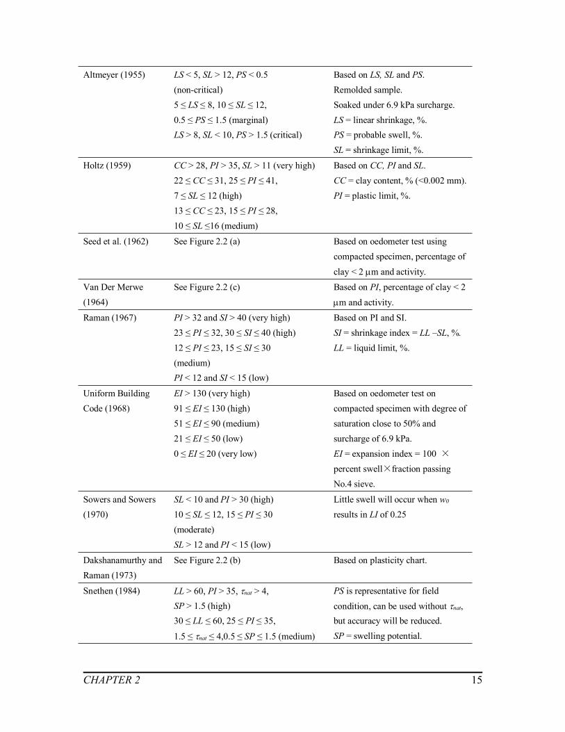
Figure 2.3 Octahedral unit and sheet structure of octahedral units (after Soga and Mitchell
2005).
Substitution of a particular kind of ions with another type, having either the same or
different valence, but the same crystal structure, is termed isomorphous substitution
(Soga and Mitchell 2005). Isomorphous substitution contributes to a net negative charge
on the clay minerals. To preserve electrical neutrality, cations are attracted and held
between the layers, on the surfaces and edges of the particles.
Clay minerals have the property of absorbing certain anions and cations and retaining
them in an exchangeable state. The cation exchange capacity is defined as the charge or
electrical attraction for cation per unit mass as measured in millequivalent per 100 grams
of soil.
Montmorillonite, illite and kaolinite are the three major clay minerals. Among them,
montmorillonite are commonly considered as the primary mineral, which contributes to
unique characteristic behavior of expansive soils (Chen 1975, Jia 2010).
Montmorillonite
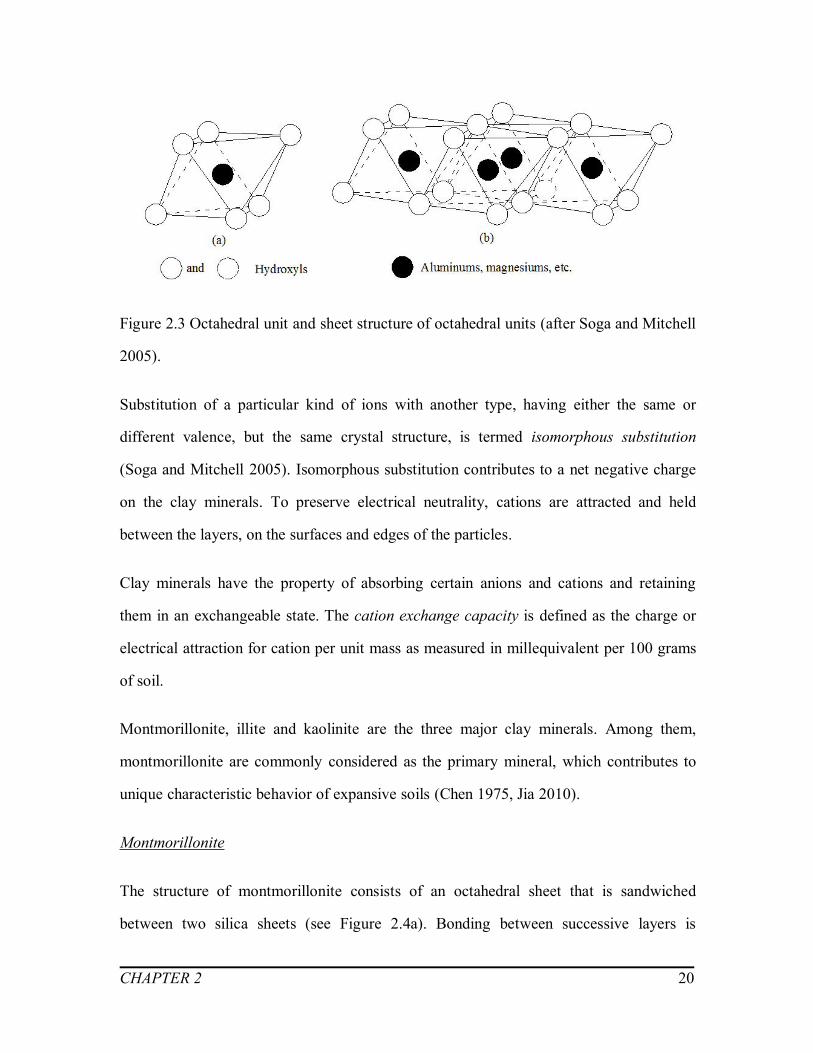
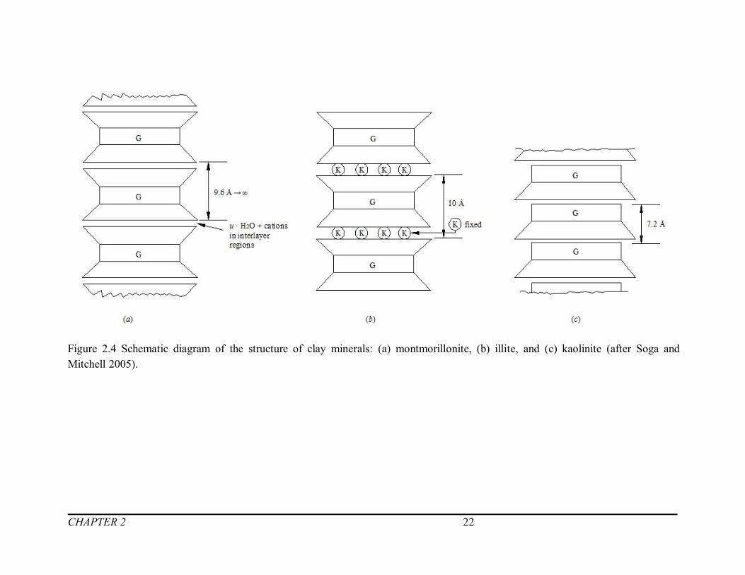
The structure of montmorillonite consists of an octahedral sheet that is sandwiched
between two silica sheets (see Figure 2.4a). Bonding between successive layers is

CHAPTER 2 21
attributed to the van der Waals forces and to cations that balance charge deficiencies in
the structure. These bonds are relatively weak and can easily separate by adsorption of
water or other polar liquids. Because of large amount of unbalanced substitution in the
minerals, montmorillonite has high cation exchange capacity. The hydration energy
overcomes the attractive forces between the unit layers. As a result, the montmorillonite
mineral is the dominant source that contributes to the swelling behavior in the expansive
soils (Soga and Mitchell 2005). Montmorillonite minerals are typically 10 times more
active in absorbing cations compared to kaolinite minerals. This is caused by the large net
negative charge carried by the montmorillonite particle and its greater specific surface as
compared to kaolinite and illite (Chen 1975).
Illite
Illite is the one of the commonly found clay mineral in soils, which usually occurs as
very small, flaky particles mixed with other clay and nonclay materials (Soga and
Mitchell 2005). It is three-layer silica-gibbsite-silica sandwich, which is similar to that of
montmorillonite (see Figure 2.4b). However, some of the silicon atoms are replaced by
aluminum, and, in addition, potassium ions are present between the tetrahedral sheet and
adjacent crystals (Chen 1975). The cation exchange capacity of illite is less than that of
montmorillonite.
Kaolinite
Kaolinite belongs to 1:1 mineral (see Figure 2.4c). The bonding between successive
layers can be attributed to the van der Waals forces and the hydrogen bonds. The cation
exchange capacity is too weak to resist interlayer bonding. Due to this reason, kaolinite is
not an expansive mineral.
CHAPTER 2 22
Figure 2.4 Schematic diagram of the structure of clay minerals: (a) montmorillonite, (b) illite, and (c) kaolinite (after Soga andMitchell 2005).
CHAPTER 2 23
Swelling Mechanics
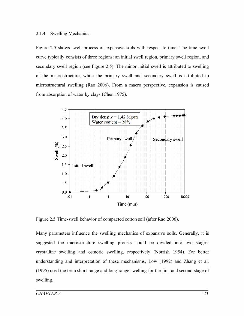
Figure 2.5 shows swell process of expansive soils with respect to time. The time-swell
curve typically consists of three regions: an initial swell region, primary swell region, and
secondary swell region (see Figure 2.5). The minor initial swell is attributed to swelling
of the macrostructure, while the primary swell and secondary swell is attributed to
microstructural swelling (Rao 2006). From a macro perspective, expansion is caused
from absorption of water by clays (Chen 1975).
Figure 2.5 Time-swell behavior of compacted cotton soil (after Rao 2006).
Many parameters influence the swelling mechanics of expansive soils. Generally, it is
suggested the microstructure swelling process could be divided into two stages:
crystalline swelling and osmotic swelling, respectively (Norrish 1954). For better
understanding and interpretation of these mechanisms, Low (1992) and Zhang et al.
(1995) used the term short-range and long-range swelling for the first and second stage of
swelling.
CHAPTER 2 24
Short-range swelling (Crystalline swelling)
Crystalline swelling is a process that dry expansive clay minerals generally intercalate
one, two, three, or four discrete layers of water between the mineral interlayers (Likos
2004). This process depends on the hydration energy of the interlayer cations (Norrish
1954).
With increasing water content, the clay swells but the distance of interlayers remains
almost constant. Simultaneously, the increasing water pressure forces the water
molecules to form two layers. The spacing between layers increases because of an
increased orientation to the counterions, which is the ion that accompanies an ionic
species in order to maintain electric neutrality, and a decreased influence of hydrogen
bonding to the clay mineral surface (Hensen and Smit 2002).
At this stage, the water molecules, of at least the first layers, are probably arranged in a
hexagonal network (Norrish 1954). The hydration is facilitated by the increased interlayer
volume and the increased number of intercalated water molecules (Hensen and Smit
2002).
As the interlayer spacing keep increasing, more water molecules enter the crystal layers
and the ironic hydration becomes weak, hence the crystalline swelling ends.
Long-range swell
A further expansion of the clay leads to an increasing number of sodium ions in the
center of the interlayer and concomitant adsorption of water molecules that hydrate these
ions (Hensen and Smit 2002).
The high concentrate absorbed cations try to diffuse away in order to equalize
concentrations throughout the pore fluid. However, the cations are restricted by the

CHAPTER 2 25
negative electrical field originating in the particle surfaces and ion-surface interactions.
The escaping tendency due to diffusion and the opposing electrostatic attraction lead to
ion distributions adjacent to a single clay particle in suspension. The charged surface and
the distributed charge in the adjacent phase are together termed the diffuse double layer
(Bolt 1956, van Olphen 1963, Mitchell 1993). According to Gouy-Chapman diffuse
double layer theory (Gouy 1910, Chapman 1913), the long-range repulsive force between
particles depends on the iron concentration between two adjacent parallel layers (Bolt
1956, Tripathy et al. 2004, Soga and Mitchell 2005).
2.2 Steady-state water flow
The key factor, which affects the swell-shrink behavior of expansive soils, is the water
content gradient. The water content gradient in unsaturated expansive soils is related to
the rate of water flow and soil permeability (Zhang et al. 2011).
The matric suction profiles above ground water table experience considerable changes
with environmental factors, as shown in Figure 2.6.

CHAPTER 2 26
Figure 2.6 Variation of matric suction profiles in unsaturated soil under the influence ofvarious environment conditions.
Lu and Griffiths (2004) proposed the theoretical formulation of matric suction profiles,
based on the soil water characteristic curve (SWCC) and soil permeability characteristic
curve (SPCC):
Darcy’s law is conventionally used to describe the vertical flow of water in saturated soils.
In Equation (2.1), the rate of water flow through a soil mass is proportional to the
hydraulic head gradient:
w
wss zhkq
(2.1)
where, qs is the flow rate of water in saturated soils, ks is the saturated coefficient of
permeability, zw is the distance above ground water table, as shown in Figure 2.6.

CHAPTER 2 27
By expanding the Darcy’s law, the 1-D vertical steady-state flow rate of unsaturated soils,
q can be described as below:
)1)((
ww
waw dz
uudkq
(2.2)
where, kw is the unsaturated coefficient of permeability depends on the matric suction, (ua
– uw), (ua – uw) is the matric suction, w is the unit weight of water.
In Equation (2.2), the unsaturated coefficient of permeability, kw, is commonly expressed
in terms of the void ratio, e, and matric suction, (ua – uw), (Fredlund 1983). As shown in
Figure 2.7, the unsaturated coefficient of permeability is described using Gardner’s
model (1958):
)( wa uuasw ekk (2.3)
where, e is the void ratio, a is a fitting parameter of the SWCC.
Figure 2.7 Gardner’s equation for the water coefficient of permeability as a function ofthe matric suction (modified from Gardner 1958).

CHAPTER 2 28
The vertical unsaturated flow rate is described as Equation (2.4) by substituting Equation
(2.3) into Equation (2.2). This equation can be used for estimation of the vertical
steady-state water flow rate variation with respect to depth.
)1)(
()(
ww
wauuas dz
uudekq wa
(2.4)
2.3 Swelling pressure
Swelling pressure is defined as the pressure required to hold the soil or restore the soil to
its initial void ratio when given access to water (Shuai 1996). The water content and dry
density are the two essential factors affecting the magnitude of swelling pressure.
The typical failures observed in engineering practice induced by swelling pressure are
due to: (i) uneven heave induced by vertical swelling pressure; (ii) failures of retaining
structures and slopes caused by lateral swelling pressures associated with the seasonal
precipitation.
Direct measurement methods (i.e. laboratory tests) and indirect determination methods
(i.e. semi-empirical and empirical equations) of vertical swelling pressures are employed
by geotechnical engineers to address several complex field problems. Laboratory tests
measure the swelling pressures directly while semi-empirical or empirical formulas are
used when swelling pressures were not measured in the laboratory because of reasons
associated with economics.
In recent years, some modified laboratory and field tests have been conducted to
determine the differences between the lateral and vertical swelling pressures (Zhang 1993,
Sapaz 2004, Xie et al. 2007, Avsar et al. 2009).

CHAPTER 2 29
Laboratory tests
In a conventional laboratory consolidation test, the swelling pressure is referred as the
pressure loaded gradually on the specimen to return to its initial volume after the sample
swelled to its maximum volume (ASTM 1996, 2003). Several different types of
laboratory methods are available to measure the swelling pressure directly from
oedometer tests, which include, free swell test, constant volume and double oedometer
tests (Shuai 1996, Attom and Barakat 2000, Kayabali and Demir 2011). Some key
advantages and disadvantages of these tests are summarized in Table 2.3.
Table 2.3 Advantages and disadvantages of swelling pressure laboratory tests.
Laboratory test Advantages and Disadvantages
Free swell testThe swelling process is combined of chemical and physical processwhile this is a consolidation test.Over-estimate the swelling pressure.
Double oedometer testRequire “identical” soil samples from fieldIgnores the effect of different dry densities and soil structures.
Constant volume testThe lab instrument should have enough stiffness to prevent anydeformation.Easy to conduct tests
The direct laboratory methods are the most convenient way to measure the swelling
pressure (Jones and Jefferson 2012). Nevertheless, the values of swelling pressure values
measured from laboratory tests suffer uncertainty (Sridharan et al. 1986, Kayabali and
Demir 2011). Apart from being quite cumbersome and time consuming, most
experimental techniques accompany with several problems, such as the sample
preparation and control of parameters such as the water content, dry density, surcharge
load, and volume change of the soil specimen (Fredlund 1983, Rao et al. 1988, Tripathy
et al. 2002).

CHAPTER 2 30
Among these problems, the disturbance during sample preparation process in laboratory
has a significant influence on the swelling behaviour of expansive soils (Jones and
Jefferson 2012). To account for sample disturbance, Fredlund (1983) proposed a
procedure to determine the corrected swelling pressure based on the laboratory test
results (see Figure 2.8). If this correction is not applied, it is likely that the soil would be
misinterpreted as a clay with low swelling pressure.
Figure 2.8 Construction procedure to correct for the effect of sampling disturbance
(modified from Fredlund and Rahardjo 1993, Adem 2014).
Semi-empirical and empirical equations
Indirect methods to estimate the swelling pressure in expansive soils are widely used in
geotechnical engineering practice as they are simple, economical and avoid problems
associated with the laboratory tests (Houston et al. 2009, Rao et al. 2011, Vanapalli and
Lu 2012).
In Table 2.4, Nelson and Miller (1992), Rao et al. (2011) and Çimen (2012) listed several
empirical formulas to determine the swelling pressure.
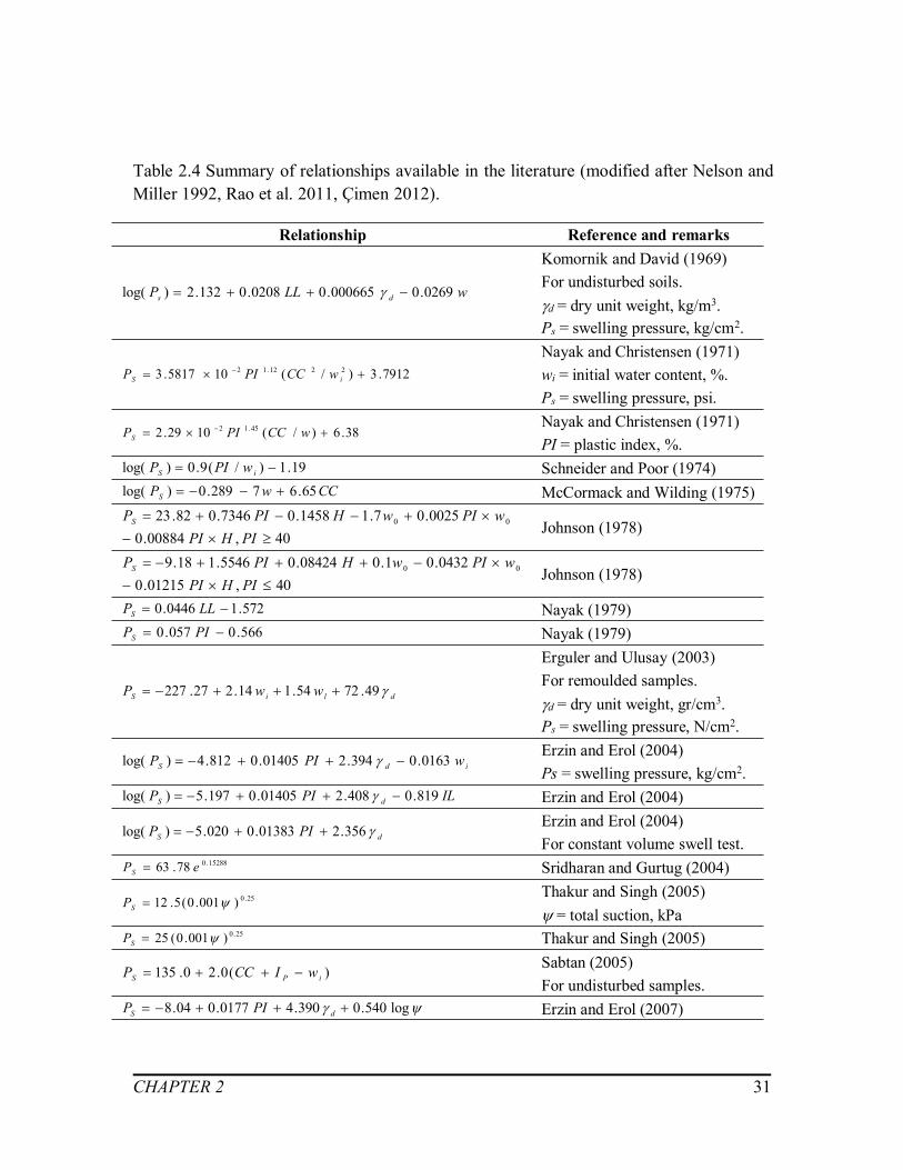
CHAPTER 2 31
Table 2.4 Summary of relationships available in the literature (modified after Nelson andMiller 1992, Rao et al. 2011, Çimen 2012).
Relationship Reference and remarks
wLLP ds 0269.0000665.00208.0132.2)log(
Komornik and David (1969)For undisturbed soils.d = dry unit weight, kg/m3.Ps = swelling pressure, kg/cm2.
7912.3)/(105817.3 2212.12 iS wCCPIP
Nayak and Christensen (1971)wi = initial water content, %.Ps = swelling pressure, psi.
38.6)/(1029.2 45.12 wCCPIPSNayak and Christensen (1971)PI = plastic index, %.
19.1)/(9.0)log( iS wPIP Schneider and Poor (1974)CCwPS 65.67289.0)log( McCormack and Wilding (1975)
40,00884.00025.07.11458.07346.082.23 00
PIHPIwPIwHPIPS Johnson (1978)
40,01215.00432.01.008424.05546.118.9 00
PIHPIwPIwHPIPS Johnson (1978)
572.10446.0 LLPS Nayak (1979)566.0057.0 PIPS Nayak (1979)
dliS wwP 49.7254.114.227.227
Erguler and Ulusay (2003)For remoulded samples.d = dry unit weight, gr/cm3.Ps = swelling pressure, N/cm2.
idS wPIP 0163.0394.201405.0812.4)log( Erzin and Erol (2004)Ps = swelling pressure, kg/cm2.
ILPIP dS 819.0408.201405.0197.5)log( Erzin and Erol (2004)
dS PIP 356.201383.0020.5)log( Erzin and Erol (2004)For constant volume swell test.
15288.078.63 ePS Sridharan and Gurtug (2004)
25.0)001.0(5.12 SPThakur and Singh (2005)= total suction, kPa
25.0)001.0(25 SP Thakur and Singh (2005)
)(0.20.135 iPS wICCP Sabtan (2005)For undisturbed samples.
log540.0390.40177.004.8 dS PIP Erzin and Erol (2007)
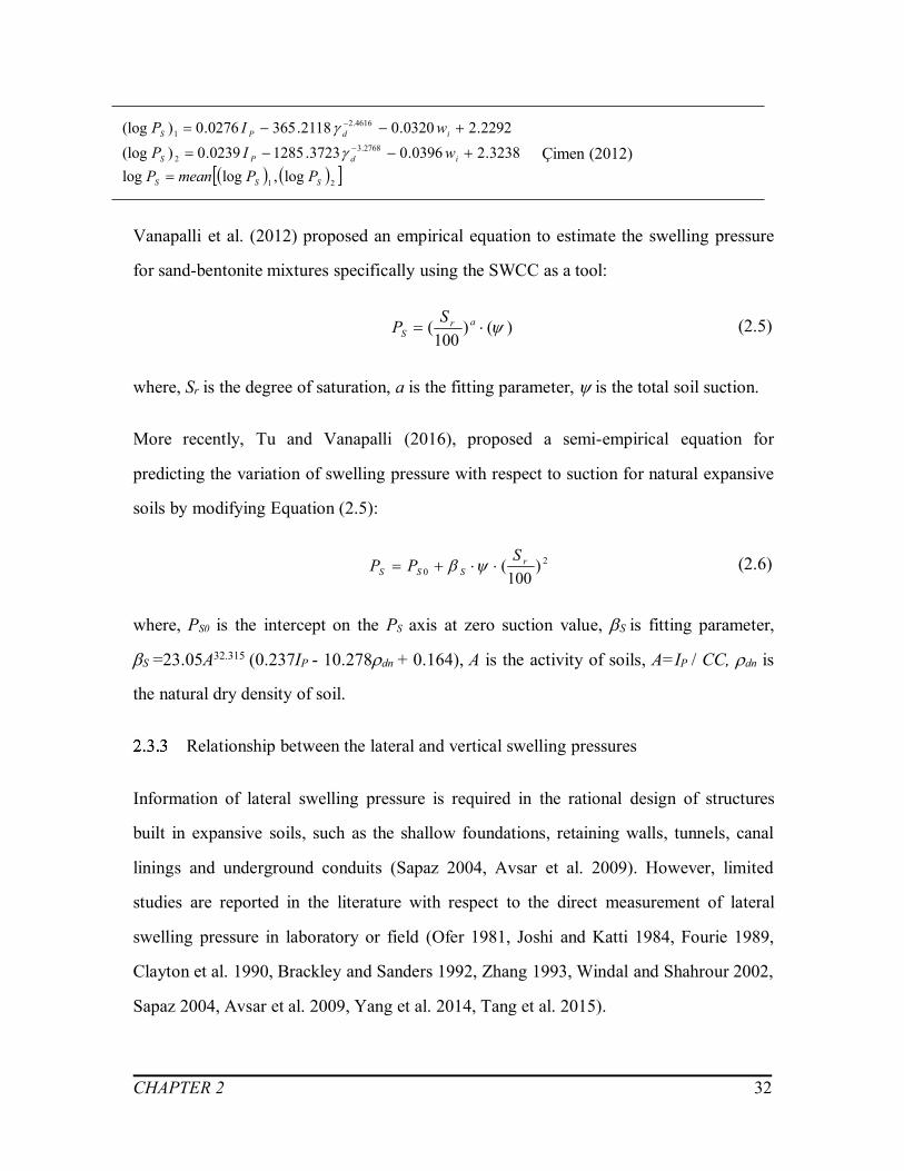
CHAPTER 2 32
21
2768.32
4616.21
log,loglog3238.20396.03723.12850239.0)(log
2292.20320.02118.3650276.0)(log
SSS
idPS
idPS
PPmeanPwIPwIP
Çimen (2012)
Vanapalli et al. (2012) proposed an empirical equation to estimate the swelling pressure
for sand-bentonite mixtures specifically using the SWCC as a tool:
)()100
( arS
SP (2.5)
where, Sr is the degree of saturation, a is the fitting parameter, is the total soil suction.
More recently, Tu and Vanapalli (2016), proposed a semi-empirical equation for
predicting the variation of swelling pressure with respect to suction for natural expansive
soils by modifying Equation (2.5):
20 )
100( r
SSSSPP (2.6)
where, PS0 is the intercept on the PS axis at zero suction value, Sis fitting parameter,
S=23.05A32.315 (0.237IP - 10.278dn + 0.164), A is the activity of soils, A=IP / CC, dn is
the natural dry density of soil.
Relationship between the lateral and vertical swelling pressures
Information of lateral swelling pressure is required in the rational design of structures
built in expansive soils, such as the shallow foundations, retaining walls, tunnels, canal
linings and underground conduits (Sapaz 2004, Avsar et al. 2009). However, limited
studies are reported in the literature with respect to the direct measurement of lateral
swelling pressure in laboratory or field (Ofer 1981, Joshi and Katti 1984, Fourie 1989,
Clayton et al. 1990, Brackley and Sanders 1992, Zhang 1993, Windal and Shahrour 2002,
Sapaz 2004, Avsar et al. 2009, Yang et al. 2014, Tang et al. 2015).
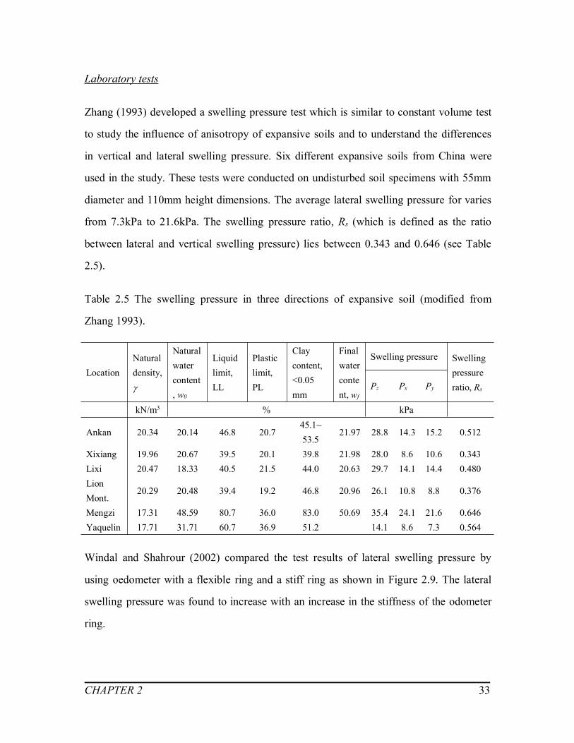
CHAPTER 2 33
Laboratory tests
Zhang (1993) developed a swelling pressure test which is similar to constant volume test
to study the influence of anisotropy of expansive soils and to understand the differences
in vertical and lateral swelling pressure. Six different expansive soils from China were
used in the study. These tests were conducted on undisturbed soil specimens with 55mm
diameter and 110mm height dimensions. The average lateral swelling pressure for varies
from 7.3kPa to 21.6kPa. The swelling pressure ratio, Rs (which is defined as the ratio
between lateral and vertical swelling pressure) lies between 0.343 and 0.646 (see Table
2.5).
Table 2.5 The swelling pressure in three directions of expansive soil (modified from
Zhang 1993).
LocationNaturaldensity,
Naturalwatercontent, w0
Liquidlimit,LL
Plasticlimit,PL
Claycontent,<0.05mm
Finalwatercontent, wf
Swelling pressure Swellingpressureratio, RsPz Px Py
kN/m3 % kPa
Ankan 20.34 20.14 46.8 20.745.1~53.5
21.97 28.8 14.3 15.2 0.512
Xixiang 19.96 20.67 39.5 20.1 39.8 21.98 28.0 8.6 10.6 0.343Lixi 20.47 18.33 40.5 21.5 44.0 20.63 29.7 14.1 14.4 0.480LionMont.
20.29 20.48 39.4 19.2 46.8 20.96 26.1 10.8 8.8 0.376
Mengzi 17.31 48.59 80.7 36.0 83.0 50.69 35.4 24.1 21.6 0.646Yaquelin 17.71 31.71 60.7 36.9 51.2 14.1 8.6 7.3 0.564
Windal and Shahrour (2002) compared the test results of lateral swelling pressure by
using oedometer with a flexible ring and a stiff ring as shown in Figure 2.9. The lateral
swelling pressure was found to increase with an increase in the stiffness of the odometer
ring.

CHAPTER 2 34
Figure 2.9 Evolution of the lateral swelling pressure: (a) with the flexible ring Kr = 850
MPa, (b) with the stiff ring Kr = 3045 MPa (modified from Windal and Shahrour 2002).
Sapaz (2004) conducted series of constant volume swell (CVS) tests to determine lateral
and vertical swelling pressure associated with the changes of soil properties (i.e. initial
dry density and initial water content). It was concluded from this study, that the swelling
pressure ratio, Rs, changes from 0.59 to 0.86. Xie et al. (2007) used three-dimensional
swell-shrink device to compare the lateral and vertical swelling pressures on remolded
expansive soils. The calculated swelling pressure ratio, Rs, from test results lies between
0.367 and 0.679, which shows similarity with the observations reported by Zhang (1993)
and Sapaz (2004).
Avsar et al. (2009) used a thin wall oedometer ring to determine the lateral and vertical
swelling pressures simultaneously and Scanning Electron Microscope (SEM) to verify
the anisotropy swelling behavior. The samples used in this study are the same as Sapaz
(2004), known as Ankara clay, which were collected from Ankara Basin, Turkey. The
modified thin wall oedometer ring acts as a lateral restraint to measure the maximum
value of lateral swelling pressure. The ratio between the swelling pressures in lateral and
vertical directions vary between 0.34 and 0.98, these results are in agreement with the
conclusions reported by Sapaz (2004) (see Figure 2.10).

CHAPTER 2 35
Figure 2.10 Comparison of swelling pressures in vertical and lateral directions (modified
from Avsar et al. 2009).
Yang et al. (2014) conducted a constant volume test to measure the lateral swelling force
of Guangxi expansive soil and the results show that the lateral expansion force is about
25% of the vertical expansion force.
In situ tests
In addition to the laboratory tests mentioned above, some large scale and in-situ studies
are also conducted. Joshi and Katti (1984) built a large scale model with expansive soils
in order to simulate field scenario conditions. The development of lateral pressure and
vertical movement were presented in the study. The typical curve of the lateral pressure
of expansive soils with respect to time is shown in Figure 2.11. The lateral pressure
increased rapidly at the beginning of saturation process and then approached a peak value

CHAPTER 2 36
(i.e. 6.01 kg/cm2 which is approximately 601 kPa), which shows similar trends of results
as Clayton et al. (1991). The lateral swelling pressure decreased slightly and remained at
a constant value (i.e. 4.94 kg/cm2, which close to 494 kPa). The lateral swelling pressure
predominantly contributes for such a development of lateral pressure in expansive soils
(Sapaz 2004).
Figure 2.11 Development of lateral pressure with time (modified from Joshi and Katti
1984).
Brackley and Sanders (1992) also monitored the total horizontal pressure of a highly
expansive clay in-situ for several years. The large seasonal variations of horizontal
pressure were measured in the study with respect to the rainfall or evaporation.

CHAPTER 2 37
2.4 Fissures and cracks in unsaturated expansive soils
The formation and propagation of fissures and cracks
Griffith (1924) suggested that the macro cracks in soils typically result from the growth
of the micro fissures when they are subjected to tensile stresses. The non-uniform
shrinkage in expansive soils during the desiccation is also responsible for the occurrence
of fissures and cracks (Xu et al. 2011).
The micro cracks occur on the surface of soils first and then extend randomly in different
directions. These micro cracks, however, predominantly propagate downwards from
ground surface because of the influence of desiccation. As the water evaporates from soil
mass, the cracks extend to the underground (Morris et al. 1992). The soil suction profile
and the soil properties (i.e. Poisson’s ratio and the coefficient of permeability) are the key
factors to control the degree of cracks in soils.
Generally, there is a "seasonal unsteady zone" in the surface layer of expansive soil,
which is referred as the zone in which water content changes due to climate factors at the
ground surface (Nelson et al. 2001). Within this zone (see Figure 2.6), the water content
of soil is mainly affected by the external environmental factors. Some studies highlighted
the cracks in expansive soils typically occur within the depth of active zone and the
maximum depth of cracks could be around 2 to 4 m (Morris et al. 1992, Konrad and
Ayad 1997, Kodikara et al. 2000, Erguler 2001, Bao 2004, Jones and Jefferson 2012).
However, such estimation is not accurate enough for the rational slope stability analysis
and in the calculation of lateral earth pressures in retaining walls.

CHAPTER 2 38
The effect of fissures and cracks
During the wet seasons, the runoff occurs over the ground surface when the infiltration
rate exceeds the soil infiltrability (Oh and Vanapalli 2010). As such, before fissures
generate, the infiltration is rather limited since the coefficient of permeability of
expansive soils is relatively small.
Upon evaporation, the generation of fissures and cracks in expansive soils provides more
channels in soils for water to evaporate and infiltrate (Bao 2004). In other words, the
more intensive drying and wetting cycles could lead to further fissures and cracks
development (Bao 2004, Ma et al. 2007, Xu et al. 2011).
The matric suction profile experiences significant variation in unsaturated soils associated
with wetting and drying conditions. The matric suction variation which is closely
connected to the physical and mechanical properties of unsaturated soils, such as the
shear strength, soil compressibility and the modulus of elasticity. Apart from the variation
of matric suction, fissures and cracks damage the integrity of soils and contribute to the
reduction of soils strength significantly (Lu et al. 1997, Bao 2004).
Determination of fissures and cracks
Several research studies focussed on the role of fissures and cracks on the soil behavior
during the last two decades from laboratory tests, numerical analysis and mathematical
studies (Morris et al. 1992, Nahlawi and Kodikara 2006, Li et al. 2008, Amarasiri and
Kodikara 2011, Tavakkoli and Vanapalli 2011). Most researchers focused on the
qualitative or statistical analysis of desiccation cracking because the parameters related to
the cracks prediction is difficult to capture in quantitative analysis (Amarasiri et al.
2011).
Laboratory tests and numerical analysis

CHAPTER 2 39
Nahlawi and Kodikara (2005) presented the evolution of the cracking pattern, influence
of the desiccation speed and typical crack spacing to depth ratios for soil layers based the
experimental results on thin layers of clay soils. Ma et al. (2007) designed an
experimental device, which can precisely control the humidity, to reappear the process of
crack formation and propagation. In this study, the length and width of the cracks and the
average space between cracks are observed and presented with respect to time and
humidity. Zhang et al. (2011) used oven drying method and vacuum saturating method to
simulate the drying and wetting process of Nanyang expansive soils in laboratory (see
Figure 2.12). The vector diagram is employed to study the evolution of the fissures. The
propagation of fissures and cracks in expansive soils is mainly governed by the gradient
of water content, instead of the water content.
Figure 2.12 Curves of fissures area ratio changes under wetting and drying cycles
(modified from Zhang et al. 2011).
Lee et al. (1988) proposed a finite element model for estimating the depth of tension
cracking in soils. A stiff embankment on soft soil and an excavated slope are applied to

CHAPTER 2 40
this finite element model to prove that the fracture mechanics could be used in tension
cracking analysis. Amarasiri et al. (2011), in addition, used software Universal Distinct
Element Code (UDEC) to analyse desiccation cracking taking account of soil properties
which include tensile strength, bulk modulus and suction of the soil. The programming
language FISH was embedded in the UDEC code to conduct a sensitive analysis and
capture the variation of properties. By replicating six laboratory tests in the numerical
model, Amarasiri et al. (2011) captured the evolution of desiccation cracks successfully,
for instance, the width and number of cracks and the crack initiation water content.
Mathematical relationships
Morris et al. (1992) proposed mathematical equations to predict the depth of cracks,
based on the properties of the soil and the suction profile, based on three theories: (i)
elasticity theory, (ii) considering the tensile and shear strength behavior of soils, (iii)
linear elastic fracture mechanics (LEFM). Also, Konrad and Ayad (1997) presented a
rational idealized framework to predict the spacing between primary shrinkage cracks in
cohesive soils and analysed the desiccation crack propagation based on the theory of
linear elastic fracture mechanics (LEFM).
However, Prat et al. (2008) and Amarasiri and Kodikara (2011) argued that the
applications based on the LEFM are associated with a key disadvantages because it is
time-consuming. Also, LEFM may be more valid for brittle soils, because it assumes the
infinite tensile stress at the crack tip, which is not consistent with significant plastic
behavior around the crack zone.
Zheng et al. (2006) used the linear elastic mechanics to analyze the relations between the
depth of initial cracking and soil properties of expansive soils such as tensile strength and
Poisson’s ratio as follow:
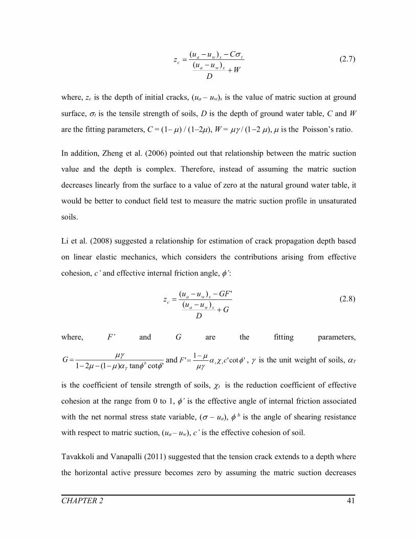
CHAPTER 2 41
WDuu
Cuuzswa
tswac
)()( (2.7)
where, zc is the depth of initial cracks, (ua – uw)s is the value of matric suction at ground
surface, t is the tensile strength of soils, D is the depth of ground water table, C and W
are the fitting parameters, C = (1–) / (1–2), W = , is the Poisson’s ratio.
In addition, Zheng et al. (2006) pointed out that relationship between the matric suction
value and the depth is complex. Therefore, instead of assuming the matric suction
decreases linearly from the surface to a value of zero at the natural ground water table, it
would be better to conduct field test to measure the matric suction profile in unsaturated
soils.
Li et al. (2008) suggested a relationship for estimation of crack propagation depth based
on linear elastic mechanics, which considers the contributions arising from effective
cohesion, c’ and effective internal friction angle, ’:
GDuu
GFuuzswa
swac
)(')( (2.8)
where, F’ and G are the fitting parameters,
'cottan)1(21
bT
G
and 'cot'1' cF tt
, is the unit weight of soils, T
is the coefficient of tensile strength of soils, t is the reduction coefficient of effective
cohesion at the range from 0 to 1, ’ is the effective angle of internal friction associated
with the net normal stress state variable, ( – ua), b is the angle of shearing resistance
with respect to matric suction, (ua – uw), c’ is the effective cohesion of soil.
Tavakkoli and Vanapalli (2011) suggested that the tension crack extends to a depth where
the horizontal active pressure becomes zero by assuming the matric suction decreases

CHAPTER 2 42
linearly from the surface to zero at the ground water table. Hence, the tension crack for
unsaturated soils can be estimated as follow:
aunsatwc KS
DSz
5.0'tan
'tan
(2.9)
where, S is the degree of saturation, is the fitting parameter (Garven and Vanapalli,
2006), = – 0.0016(Ip2)+0.0975(Ip2)+1, w is the unit weight of water,unsat is the unit
weight of unsaturated soils, Ka is the coefficient of active earth pressure,
)2'45(tan 2
aK .
2.5 Stress state variables for unsaturated soils
The engineering behavior of both saturated and unsaturated soils can be interpreted in
terms of stress state variables (Fredlund and Rahardjo 1993). Effective stress (Equation
2.10) proposed by Terzaghi (1936) is a stress state variable that is conventionally used for
rational interpretation of saturated soils:
wu ' (2.10)
where, ’ is the effective normal stress, is the total normal stress, uw is the pore-water
pressure.
Several researchers extended Terzaghi’s effective stress concept for unsaturated soils. Of
the many equations available in the literature, the equation (Equation 2.11) proposed by
Bishop (1959) is more widely used:
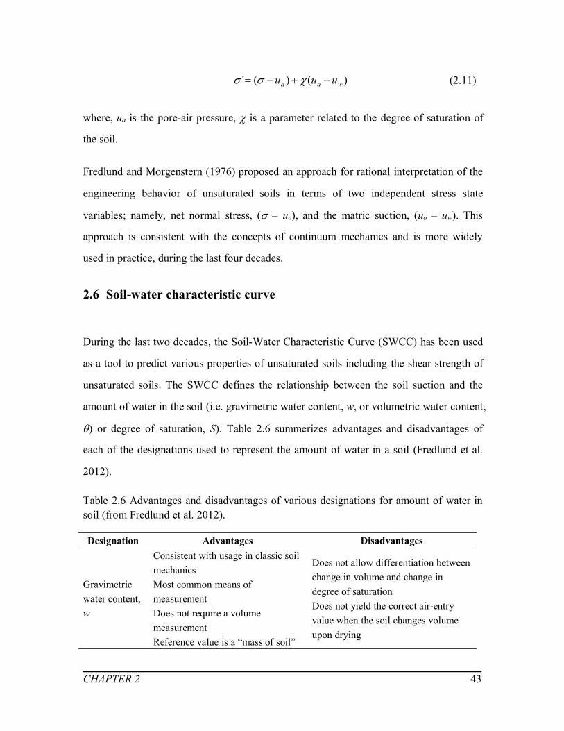
CHAPTER 2 43
)()(' waa uuu (2.11)
where, ua is the pore-air pressure, is a parameter related to the degree of saturation of
the soil.
Fredlund and Morgenstern (1976) proposed an approach for rational interpretation of the
engineering behavior of unsaturated soils in terms of two independent stress state
variables; namely, net normal stress, ( – ua), and the matric suction, (ua – uw). This
approach is consistent with the concepts of continuum mechanics and is more widely
used in practice, during the last four decades.
2.6 Soil-water characteristic curve
During the last two decades, the Soil-Water Characteristic Curve (SWCC) has been used
as a tool to predict various properties of unsaturated soils including the shear strength of
unsaturated soils. The SWCC defines the relationship between the soil suction and the
amount of water in the soil (i.e. gravimetric water content, w, or volumetric water content,
) or degree of saturation, S). Table 2.6 summerizes advantages and disadvantages of
each of the designations used to represent the amount of water in a soil (Fredlund et al.
2012).
Table 2.6 Advantages and disadvantages of various designations for amount of water insoil (from Fredlund et al. 2012).
Designation Advantages Disadvantages
Gravimetricwater content,w
Consistent with usage in classic soilmechanicsMost common means ofmeasurementDoes not require a volumemeasurementReference value is a “mass of soil”
Does not allow differentiation betweenchange in volume and change indegree of saturationDoes not yield the correct air-entryvalue when the soil changes volumeupon drying
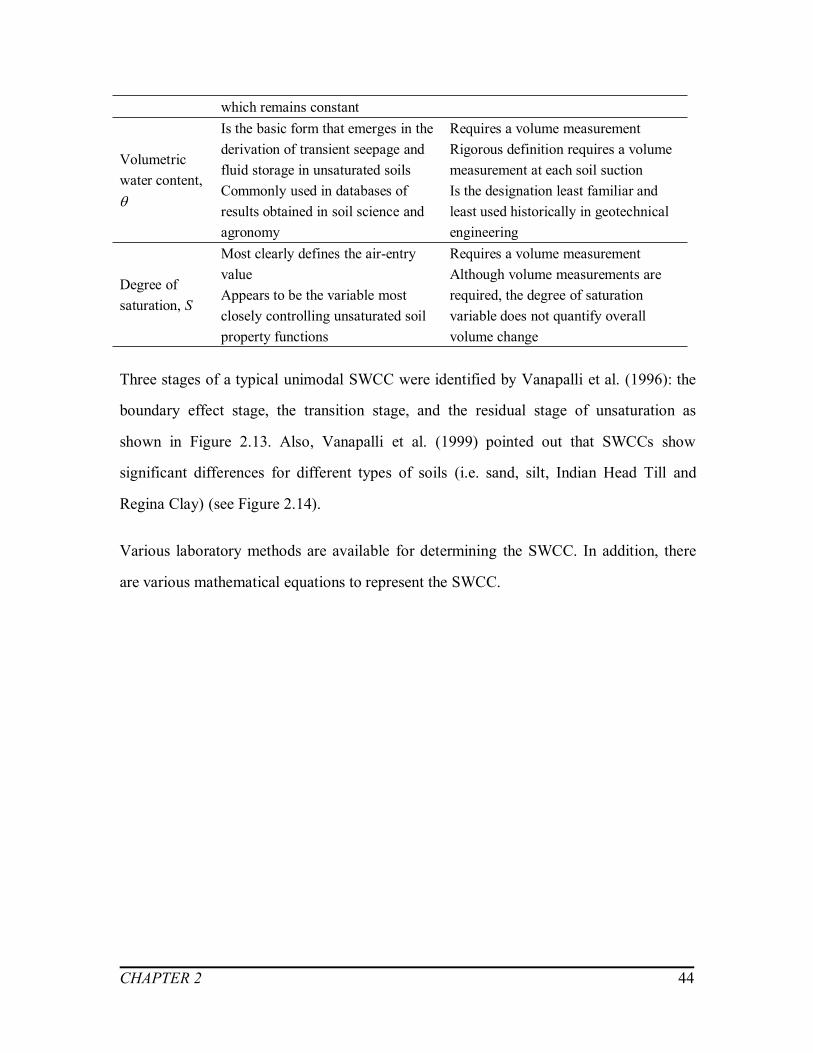
CHAPTER 2 44
which remains constant
Volumetricwater content,
Is the basic form that emerges in thederivation of transient seepage andfluid storage in unsaturated soilsCommonly used in databases ofresults obtained in soil science andagronomy
Requires a volume measurementRigorous definition requires a volumemeasurement at each soil suctionIs the designation least familiar andleast used historically in geotechnicalengineering
Degree ofsaturation, S
Most clearly defines the air-entryvalueAppears to be the variable mostclosely controlling unsaturated soilproperty functions
Requires a volume measurementAlthough volume measurements arerequired, the degree of saturationvariable does not quantify overallvolume change
Three stages of a typical unimodal SWCC were identified by Vanapalli et al. (1996): the
boundary effect stage, the transition stage, and the residual stage of unsaturation as
shown in Figure 2.13. Also, Vanapalli et al. (1999) pointed out that SWCCs show
significant differences for different types of soils (i.e. sand, silt, Indian Head Till and
Regina Clay) (see Figure 2.14).
Various laboratory methods are available for determining the SWCC. In addition, there
are various mathematical equations to represent the SWCC.

CHAPTER 2 45
Figure 2.13 Typical soil-water characteristic showing zones of desaturation (fromVanapalli et al. 1999)
Figure 2.14 Typical soil-water characteristic for four Canadian soils (after Vanapalli et al.1999).

CHAPTER 2 46
Laboratory tests
Soil suction can be determined or estimated from laboratory tests using either by direct or
indirect methods. Tensiometers and the axis translations technique are commonly used
direct methods. However, filter paper technique, thermal conductivity sensor technique,
chilled-mirror hygrometer technique are indirect methods that are widely used for
estimation of soil suction using different techniques or principles.
Pressure plate and Tempe cell test (Axis translation technique)
The axis translation technique is employed to control matric suction by increasing air
pressure while maintaining pore water pressure equal to atmospheric pressure in pressure
plate test or Tempe cell test to determine the SWCC behavior. The axis translation
technique is widely used to generate matric suction values in the soil specimen while
preventing cavitation in the water through the use of high air entry (HAE) ceramic discs
(Nam et al. 2010, Fredlund et al. 2012). As a result, the suction values that can be used is
limited due to the bubbling pressure of the HAE ceramic disc. In pressure plate test (see
Figure 2.16), SWCC of several soil specimens can be determined by placing them on a
large saturated HAE ceramic disc in the pressure chamber. The water content changes in
the soil specimens are determined after achieving equilibrium condition under each
applied suction value. However, in Tempe cell test (see Figure 2.15), only one specimen
can be used. The amount of water that expels from the soil specimen for different applied
suction values, typically from a lower to higher matric suction value is measured to
obtain the SWCC.
The upper limit for suction value for the pressure plate tests is typically 1500 kPa and the
Tempe cell tests is 500 kPa.

CHAPTER 2 47
Figure 2.15 Cross-section of a Tempe pressure plate cell manufactured by Soil Moiture
Equipment Corporation (modified after Fredlund et al. 2012).

CHAPTER 2 48
Figure 2.16 Single specimen pressure plate cell developed at University of Saskatchewan,Saskatoon, Canada (after Fredlund et al. 2012).
Filter paper method
Filter paper method (see Figure 2.17), which uses a filter paper to reach equilibrium
condition with respect to water content in the soil specimen, using contact or non-contact
methods estimate matric or total suction, respectively has been adopted by a number of
researchers (Fredlund and Rahardjo 1993, Bulut et al. 2001). It is difficult to ensure
adequate contact between the soil specimen and the filter paper for the reliable
measurement of matric suction. Based on extensive studies, Power et al. (2008) suggested
a contact pressure of 1 kPa to ensure a good contact and obtain reliable measurements of
suction. The filter paper method is widely used to measure total suction values using
non-contact method. The most commonly used filter papers are the Whatman No. 42, and
the Schleicher and Schuell No. 589 papers, both of which have known ASTM calibration
curves (ASTM D5298, 2003). The advantages of both the contact and non-contact
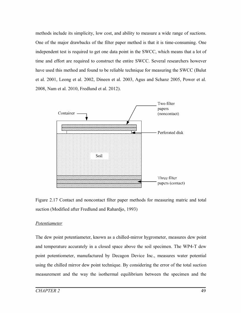
CHAPTER 2 49
methods include its simplicity, low cost, and ability to measure a wide range of suctions.
One of the major drawbacks of the filter paper method is that it is time-consuming. One
independent test is required to get one data point in the SWCC, which means that a lot of
time and effort are required to construct the entire SWCC. Several researchers however
have used this method and found to be reliable technique for measuring the SWCC (Bulut
et al. 2001, Leong et al. 2002, Dineen et al. 2003, Agus and Schanz 2005, Power et al.
2008, Nam et al. 2010, Fredlund et al. 2012).
Figure 2.17 Contact and noncontact filter paper methods for measuring matric and total
suction (Modified after Fredlund and Rahardjo, 1993)
Potentiameter
The dew point potentiameter, known as a chilled-mirror hygrometer, measures dew point
and temperature accurately in a closed space above the soil specimen. The WP4-T dew
point potentiometer, manufactured by Decagon Device Inc., measures water potential
using the chilled mirror dew point technique. By considering the error of the total suction
measurement and the way the isothermal equilibrium between the specimen and the

CHAPTER 2 50
vapor space is maintained, this technique is considered to be the most reliable for
measuring total suction (Decagon Devices Inc. 2003, Petry and Jiang 2003, Agus and
Schanz 2005, Thakur et al. 2005, Shah et al. 2006, Sreedeep and Singh 2006a, b, Thakur
et al. 2005 and 2006, Bulut and Leong 2008).
Figure 2.18 shows the approximate range of suctions that can be measured using different
techniques for measuring suction. They all have advantages and disadvantages and
geotechnical engineers should use appropriate approaches/techniques for measuring
suction according to their objectives.
Figure 2.18 Suction measurement range of several available methods (from Agus and
Schanz 2005).

CHAPTER 2 51
More details about other techniques for suction measurement, such as the tensiometer and
thermal conductivity sensor, can be found in Dineen et al. (2003), Agus and Schanz
(2005), Nam et al. (2010), Fredlund et al. (2012).
Mathematical models for the SWCC
After obtaining the experimental data for the SWCC from laboratory tests, mathematical
functions can then be fitted to the SWCC data. Leong and Rahardjo (1997) and Sillers et
al. (2001) both presented summaries of the different models available to fit the SWCC
data. Among the many formulations available in the literature, Brooks and Corey (1964),
van Genuchten (1980) and Fredlund and Xing (1994) equations are commonly used to fit
the SWCC data.
Table 2.7 Summary of some SWCC models (modified after Sillers et al. 2001).
Models Equations Comments
Burdine(1953) model )/21(1
1nna
S
Provides a reasonably accuraterepresentation of data for a variety of soilsusing two fitting parameters a and n.
Gardner(1956) model na
S
1
1 Is one of the first simple equations used tomodel the SWCC using two fittingparameters a and n.
Brooks andCorey (1964)model
aS ,1
aa
Sn
,
Is one of the first models proposed for theSWCC, and still remains popular.Does not provide a continuousmathematical function for the entireSWCC. More suitable for coarse-grainedsoils
Brutsaert(1966) model
n
aS 1/1
Was one of the early continuoussoil-water characteristic models usingonly two fitting parameters
vanGenuchten(1980) model mna
S
1
1A versatile model that provides a good fitfor a variety of soils over a large suctionrange.The model parameters have physical
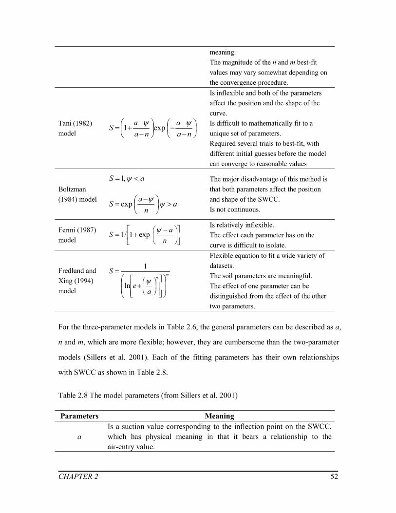
CHAPTER 2 52
meaning.The magnitude of the n and m best-fitvalues may vary somewhat depending onthe convergence procedure.
Tani (1982)model
na
ana
aS exp1
Is inflexible and both of the parametersaffect the position and the shape of thecurve.Is difficult to mathematically fit to aunique set of parameters.Required several trials to best-fit, withdifferent initial guesses before the modelcan converge to reasonable values
Boltzman(1984) model
aS ,1
an
aS
,exp
The major disadvantage of this method isthat both parameters affect the positionand shape of the SWCC.Is not continuous.
Fermi (1987)model
naS exp1/1
Is relatively inflexible.The effect each parameter has on thecurve is difficult to isolate.
Fredlund andXing (1994)model
mn
ae
S
ln
1Flexible equation to fit a wide variety ofdatasets.The soil parameters are meaningful.The effect of one parameter can bedistinguished from the effect of the othertwo parameters.
For the three-parameter models in Table 2.6, the general parameters can be described as a,
n and m, which are more flexible; however, they are cumbersome than the two-parameter
models (Sillers et al. 2001). Each of the fitting parameters has their own relationships
with SWCC as shown in Table 2.8.
Table 2.8 The model parameters (from Sillers et al. 2001)
Parameters Meaning
aIs a suction value corresponding to the inflection point on the SWCC,which has physical meaning in that it bears a relationship to theair-entry value.

CHAPTER 2 53
n Is related to the rate of change of the desaturation zone of the SWCC.m Is related to the asymmetry of the curve about the inflection point.
Based on Fredlund and Xing (1994) model, Vanapalli and Catana (2005) proposed a
simple a method for estimating the SWCC of coarse-grained soils using parameters
derived from the grain-size distribution curve and volume mass properties along with one
data point of the measured SWCC.
The relationship between the dominant particle size diameter, de, and parameter, a, is
estimated using the relation below for coarse-grained soils:
86.1)(33.1
eda (2.12)
The parameter, n, in Fredlund and Xing (1994) model, which corresponds to the slope of
the desaturation is predominantly affected by shape, size and distribution of pore space
and can be expressed as follow:
14.1)(78.7eC
nu
(2.13)
where, Cu is the coefficient of uniformity.
The last parameter, m, is related to the asymmetry of SWCC and cannot be estimated by
volume mass properties and grain size information (Sillers et al. 2001, Vanapalli and
Canata 2005). Hence, based on one measured data point and the equations mentioned
above (Equation 2.12 and 2.13), Vanapalli and Canata (2005) presented a mathematical
formulation for estimating the SWCC by Fredlund and Xing (1994) model as below:

CHAPTER 2 54
)]ln(/1[)( fwwww rsr (2.14)
where, w is the gravimetric water content, ws is the saturated gravimetric water content,
wr is the residual gravimetric water content,
mfeC
e
u
def
14.1)/(78.7
86.033.1 .
In addition to the SWCC estimation of coarse-grained soils, Catana et al. (2006) also
proposed a simplified method to estimate the SWCC for fine-grained soils by using
Brutsaert’s (1966) equation:
bn
b
rsr
a
wwww
1
1)( (2.15)
where, ab and nb are the fitting parameters.
Catana et al. (2006) suggested using only two data points information to estimate the
SWCC: one measured point in the suction range of 50 to 500 kPa and anther estimated
point in the suction range of 1000 to 3000 kPa, as shown in Figure 2.19.
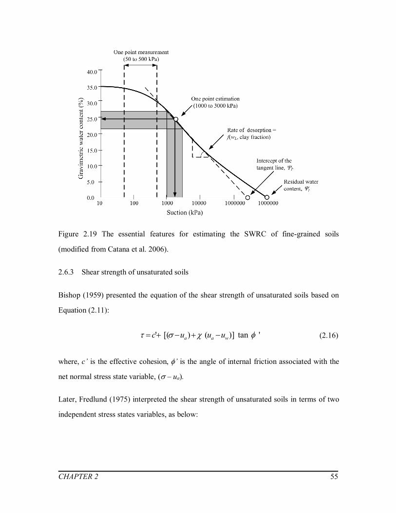
CHAPTER 2 55
Figure 2.19 The essential features for estimating the SWRC of fine-grained soils
(modified from Catana et al. 2006).
2.6.3 Shear strength of unsaturated soils
Bishop (1959) presented the equation of the shear strength of unsaturated soils based on
Equation (2.11):
'tan)]()[(' waa uuuc (2.16)
where, c’ is the effective cohesion’ is the angle of internal friction associated with the
net normal stress state variable, ( – ua).
Later, Fredlund (1975) interpreted the shear strength of unsaturated soils in terms of two
independent stress states variables, as below:
CHAPTER 2 56
bwaa uuuc tan)('tan)(' (2.17)
where, b is the angle of shearing resistance with respect to matric suction, (ua – uw).
The experimental results show shear strength behavior with respect suction, b is
nonlinear with respect to suction when tested over a wide range of suction (see Figure
2.20). The shear strength of unsaturated soils increases linearly up to the air-entry value
(AEV) in the boundary effect zone. After the AEV, the shear strength increases
non-linearly in the transition zone (i.e. desaturation zone). In the residual zone, the shear
strength of an unsaturated soil may increase, decrease, or remain relatively constant
beyond the residual suction conditions (Vanapalli et al. 1996).
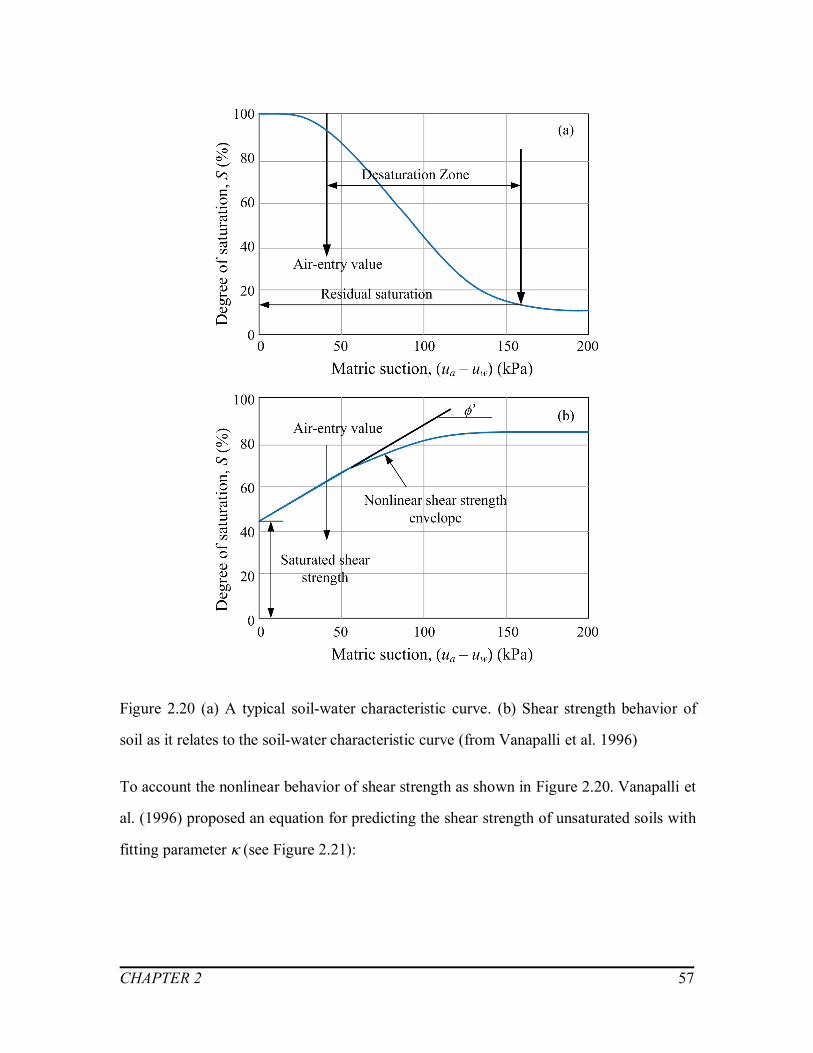
CHAPTER 2 57
Figure 2.20 (a) A typical soil-water characteristic curve. (b) Shear strength behavior of
soil as it relates to the soil-water characteristic curve (from Vanapalli et al. 1996)
To account the nonlinear behavior of shear strength as shown in Figure 2.20. Vanapalli et
al. (1996) proposed an equation for predicting the shear strength of unsaturated soils with
fitting parameter (see Figure 2.21):

CHAPTER 2 58
'tan)()('tan)(' Suuuc waa (2.18)
where, is the fitting parameter.
Figure 2.21 The variation of shear strength with respect to the net normal stress and
matric suction (from Tavakkoli and Vanapalli 2011).
Garven and Vanapalli (2006) evaluated published experimental data of statically
compacted soils and proposed the following equation for the fitting parameter, , in
Equation (2.17) that can be used for predicting the shear strength of unsaturated soils:
1)(0975.0)(0016.0 2 PP II (2.19)
Vanapalli et al. (1996) also presented another equation to predict the shear strength of
unsaturated soils, which alleviates the need of using a fitting parameter as below:
R
Rwaa S
SSuuuc100
'tan)('tan)(' (2.20)
where, SR is the residual degree of saturation.

CHAPTER 2 59
To interpret the shear strength of expansive unsaturated soils, taking account of the
influence of the swelling pressure, Lu et al. (1997) modified Equation (2.16) by replacing
matric suction term with swelling pressure as follow:
'tan'tan)'(' ssa Pmuc (2.21)
where, ms is the reduction coefficient of swelling pressure, PS is the swelling pressure,
PS=Ass, As and s are the regression analysis parameters which can be determined from
soil properties.
Zhan and Ng (2006) stated that the contribution of matric suction to shear strength in
expansive soils could be interpreted into two parts, namely, the effect of capillary force to
the interparticle normal stress, and the effect of suction on soil dilatancy. As such, the
dilation angle, , is introduced in the shear strength equation to account the effect of
suction on soil dilatancy, which depends on the soil structure and the value of matric
suction as below:
bwza uuuc tan)()'tan()'(' (2.22)
where, is the dilation angle.
2.6.4 Tensile strength of unsaturated soils
The upper layer of soil is typically subjected to tensile stress due to drying while the
lower part is subjected to compressive stress. The influence of water content gradient has
a significant influence on the tensile stress. Improved understanding of the tensile
strength of unsaturated soils provides better tools for interpretation of the formation and
propagation of tension cracks in unsaturated expansive clays. When the tensile stress is
greater than the ultimate tensile strength of soils, fissures are generated in unsaturated
expansive soils.

CHAPTER 2 60
Snyder and Miller (1985) suggested that the maximum tensile strength is about half the
gauge pressure of the pore water as the desaturation begins. Lu et al. (2007) presented the
tensile strength characteristic curve (TSCC) of unsaturated sand and compared it with the
SWCC. This study suggests that the maximum value of tensile strength is correlated to
the air-entry pressure (see Figure 2.22).
Figure 2.22 Relationship between tensile strength characteristic curve and soil watercharacteristic curve for the fine sand (Lu et al. 2007)
Tej and Singh (2013) proposed a relatively simple empirical equation (Equation 2.23) to
estimate the tensile strength of fine-grained soils. The proposed empirical equation,
which is given below, takes into account of the various parameters such as the water
content, liquid limit and clay content.
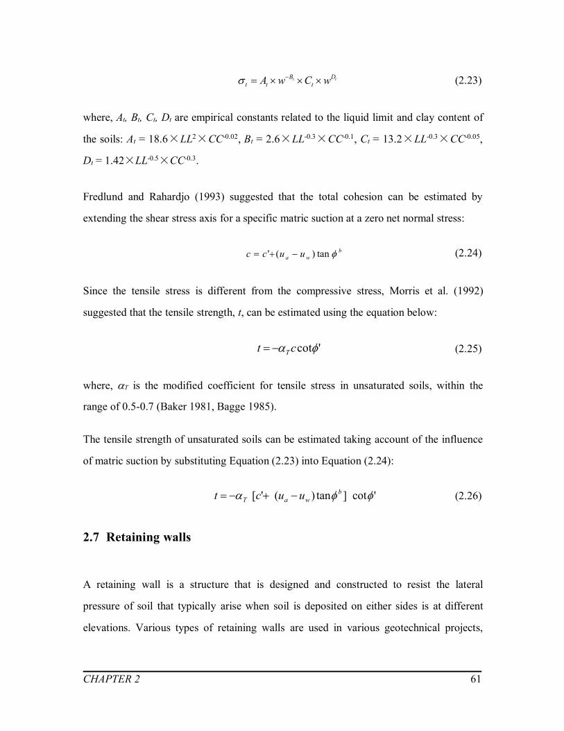
CHAPTER 2 61
tt Dt
Btt wCwA (2.23)
where, At, Bt, Ct, Dt are empirical constants related to the liquid limit and clay content of
the soils: At = 18.6×LL2×CC-0.02, Bt = 2.6×LL-0.3×CC-0.1, Ct = 13.2×LL-0.3×CC-0.05,
Dt = 1.42×LL-0.5×CC-0.3.
Fredlund and Rahardjo (1993) suggested that the total cohesion can be estimated by
extending the shear stress axis for a specific matric suction at a zero net normal stress:
bwa uucc tan)(' (2.24)
Since the tensile stress is different from the compressive stress, Morris et al. (1992)
suggested that the tensile strength, t, can be estimated using the equation below:
'cot ct T (2.25)
where, T is the modified coefficient for tensile stress in unsaturated soils, within the
range of 0.5-0.7 (Baker 1981, Bagge 1985).
The tensile strength of unsaturated soils can be estimated taking account of the influence
of matric suction by substituting Equation (2.23) into Equation (2.24):
'cot]tan)('[ bwaT uuct (2.26)
2.7 Retaining walls
A retaining wall is a structure that is designed and constructed to resist the lateral
pressure of soil that typically arise when soil is deposited on either sides is at different
elevations. Various types of retaining walls are used in various geotechnical projects,

CHAPTER 2 62
such as highways, foundations and dams to prevent fluid or soils damaging the structures
(Connor and Faraji 2013, see Figure 2.23).
Figure 2.23 Retaining structures: (a) Gravity dam, (b) Cantilever retaining wall, (c)
Bridge abutment, (d) Underground basement (from Connor and Faraji 2013).
2.7.1 Categories of retaining walls and their failure modes
Different types of retaining walls can be grouped into two different categories: (i) rigid
structures that consist of concrete walls relying on gravity for stability, and (ii) flexible
structures which consists of long, slender members of either steel or concrete or wood or
plastic and relies on passive soil resistance and anchors for stability (see Figure 2.24 and
Figure 2.25, Punmia and Jain 2005). The modes of failure for these two kinds of retaining
walls are presented in Figure 2.26 and Figure 2.27, respectively.

CHAPTER 2 63
Figure 2.24 Types of rigid retaining walls: (a) Gravity retaining wall, (b) Cantilever rigid
retaining wall, (c) Counterfort wall, (d) Buttress wall (from Punmia and Jain 2005).

CHAPTER 2 64
Figure 2.25 Types of flexible retaining walls: (a) Cantilever, (b) Anchored or tie-back, (c)
Propped (from Punmia and Jain 2005).

CHAPTER 2 65
Figure 2.26 Failure modes for rigid retaining walls (the dotted lines show the originalposition of the wall): (a) Sliding or translational failure, (b) Rotation and bearing capacityfailure (c) Deep-seated failure, (d) Structural failure (from Punmia and Jain 2005).

CHAPTER 2 66
Figure 2.27 Failure modes for flexible retaining walls: (a) Deep-seated failure, (b)Rotation about the anchor/prop, (c) Rotation near base, (d) Failure of anchor/prop, (e)Failure by bending (from Punmia and Jain 2005).
2.7.2 Backfill material
The mechanics of saturated soils are conventionally applied in the design of retaining
walls without considering whether the backfill material is in a state of saturated or
unsaturated condition. Most commonly used approaches in the design of retaining walls
are simple and are based on either Coulomb (1776) or Rankine (1857) theory. The soil
density and effective or total shear strength parameters (i.e. friction angle and cohesion)
are required for the design of retaining walls. These soil parameters can be determined
from conventional laboratory tests.

CHAPTER 2 67
The presently used approaches for the design of retaining walls are not appropriate
because they don’t take into account of the influence of soil suction in the backfill
material (Tawfik et al. 2007, Tavakkoli and Vanapalli 2011, Vo and Russell 2014). In
conventional geotechnical engineering practice, soils are usually assumed to be either
saturated or dry in retaining wall analysis. Geotechnical engineers are well aware of swell
pressures that can be exerted on the retaining wall with expansive soils as backfill
material. However, the influence of swelling is typically not taken into account in
conventional earth pressure theories. Pufahl et al. (1983) highlighted the importance of
taking account of the influence of swelling pressure in the estimation of the active or
passive earth pressure. However, Mohamed et al. (2014) stated that there is no reliable
method presently available that allows the designer to reliably predict the pressures on
retaining structures with expansive soils as backfill.
2.7.3 Lateral earth pressure
2.7.3.1 Lateral earth pressure of unsaturated soils
Rankine’s (1857) and Coulomb’s (1776) earth pressure theories are commonly used in
the calculation of lateral earth pressure both for saturated and unsaturated soils. The
solution from Coulomb’s earth pressure theory is analogous to an upper bound solution
because it gives a solution that is usually greater than the true solution. On the other hand,
the solution for the lateral forces obtained using the Rankine active and passive states is
analogous to a lower bound solution - the solution obtained is usually lower than the true
solution because a more efficient distribution of stress could exist.
Based on Rankine’s earth pressure theory, Pufahl et al. (1983) formulated the expressions
for active and passive earth pressures in terms of total stresses for both the saturated and
unsaturated states using the Mohr-Coulomb failure criterion and plastic equilibrium (see
Figure 2.28):

CHAPTER 2 68
Figure 2.28 Diagrams of earth pressures for unsaturated soils: (a) Active earth pressure,
(b) passive earth pressure (after Pufahl et al. 1993)
The total active earth stress at depth, z:
]tan)/1()('[2 bswa
vh Dzuuc
NN
(2.27)
The total passive earth stress at depth, z:

CHAPTER 2 69
]tan)/1()('[2 bswavh DzuucNN (2.28)
where, h is the total horizontal stress, v is the total vertical stress, (ua – uw)s is the matric
suction at ground surface, N= (1+ sin ’) / (1– sin ’).
More recently, Tavakkoli and Vanapalli (2011) extended the mechanics of unsaturated
soils to estimate the earth pressures on retaining structures by using Equation (2.17)
proposed by Vanapalli et al. (1996) and highlighted the conventional approach is
conservative in estimating earth pressures for backfills that are in a state of unsaturated
condition:
The effective active earth stress at depth, z:
]'tan)('[2''
SuucNN wa
vh (2.29)
The effective passive earth stress at depth, z:
]'tan)('[2'' SuucNN wavh (2.30)
where, h’ is the effective horizontal stress; v’ is the effective vertical stress.
Considering the linear decrease for matric suction from the value at ground surface to
zero at the groundwater table, Zhang et al. (2010) derived a unified solution of active and
passive earth pressures for unsaturated soils in terms of two state stress variables:
The active earth force:

CHAPTER 2 70
)22
(tan
)(2)('2)(21
20
0
2
0020
2
Dhh
DHH
KuuhHKchHKE
bt
atwaattata
(2.31)
where, Kat is the unified coefficient of active earth pressure, )2
'45(tan 2 tatK
, h0 is
the depth of elastic area, )/()tan)('(20 abtwat Kuuch , ct’ is the unified effective
cohesion,'cos
1)'sin1(2
cos')1(2't
t bcbc
, b is the coefficient of unified strength theory, t’ is
the unified angle of internal friction associated with the net normal stress state variable,
(– ua),)'sin1(2
'sin)2()1('sin
bbmbmb
t , m is the coefficient of intermediate
principal stress,tb is the unified angle of shearing resistance with respect to the matric
suction, (ua – uw),)sin1(2
sin)1(2sin b
bbt b
b
.
The passive earth force:
)2
(tan)(2'221 2
02
DHHKuuKHcHKE b
tptwapttptp (2.32)
where, Kpt is the unified coefficient of passive earth pressure, )2
'45(tan 2 tptK
.
However, Zhu et al. (2001) and Hu (2006) stated that the method based on Rankine’s
earth pressure theory is not practical because of the assumption that the wall of the
retaining structures has to be vertical, its surface smooth, and the filling surface of the
wall back horizontal. There are deviations between the mathematical results from
Rankine’s theory and the test results from both lab and field studies. The evidence
showed that the values of active earth pressure calculated by Rankine’s theory are
conservative while the results underestimate the practical situation in passive cases (Xie

CHAPTER 2 71
et al. 2003, Chen et al. 2005, Zhang et al. 2010). Zhao et al. (2013) considered the unified
solution in Equation (2.30) and (2.31) as a special case of Coulomb’s earth pressure for
unsaturated soils, which has a broader application to the determination of soil pressure.
2.7.3.2 Active earth pressure of expansive unsaturated soils
Vahedifard et al. (2015) addressed that changes in the degree of saturation in the backfill
could significantly affect active earth pressures. Although the earth pressure theory of
unsaturated soils has been established and developed over 30 years, limited studies focus
on the lateral earth pressures of unsaturated expansive soils taking into account of the
influence from cracks and swelling pressures.
The active earth pressures associated unsaturated expansive soils should receive more
attention as retaining walls typically move away from the soil mass because of the
influence of lateral swelling pressure. In addition, fissures and cracks would occur in the
surface of expansive soils during the drying process and it is likely that dust or other
materials partly fill up the fissures contributing to active earth pressures (Pufahl et al.
1983).
Also, the strains required to achieve the passive state are much larger than those for the
active state (see Figure 2.29). For sands, a decrease in lateral earth pressure of 40% of the
at-rest lateral earth pressure can be sufficient to reach an active state, but an increase of
several hundred percent in lateral earth pressure over the at-rest lateral earth pressure is
required to achieve a passive state (Punmia and Jain 2005).
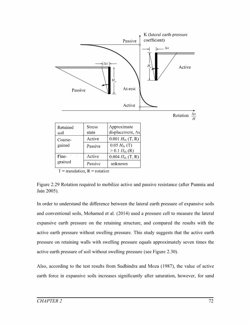
CHAPTER 2 72
Figure 2.29 Rotation required to mobilize active and passive resistance (after Punmia andJain 2005).
In order to understand the difference between the lateral earth pressure of expansive soils
and conventional soils, Mohamed et al. (2014) used a pressure cell to measure the lateral
expansive earth pressure on the retaining structure, and compared the results with the
active earth pressure without swelling pressure. This study suggests that the active earth
pressure on retaining walls with swelling pressure equals approximately seven times the
active earth pressure of soil without swelling pressure (see Figure 2.30).
Also, according to the test results from Sudhindra and Moza (1987), the value of active
earth force in expansive soils increases significantly after saturation, however, for sand

CHAPTER 2 73
and for non-expansive clays, the variation of active earth force is relatively small (Zhu
and Liu 2001).
Figure 2.30 The relationship between active earth pressures with/without swellingpressure and depth at water content = 22% and density = 1.43 t/m3 after four days (fromMohamed et al. 2014).
Lu et al. (1997) introduced the reduction coefficient, ms, to calculate the shear strength of
expansive soil (Equation 2.21). Zhang (2012) adopted this equation for active earth
pressure calculation for unsaturated expansive soils based on Coulomb’s earth pressure
theory taking into account of the swelling pressure considering static equilibrium
conditions of sliding soil. The reacting force for such a scenario can be expressed as
follows:

CHAPTER 2 74
)'cos('cos)'sin()'sin(
dwa
CCWE (2.33)
where, W is the gravity of soil mass, is the angle of back wall and vertical plane, is
the friction angle of filling and back wall, is the angle of sliding plane and horizontal
plane, Cw is the total adhesive strength, Cw = c’ h /cos , Cd is the total cohesive strength,
))sin(
cos)sin()cos(
cos)('tan'( 0
zhPmcC Ssd.
Besides, Zhu and Liu (2001) and Hu (2006) both presented their own approaches to
calculate the active earth force of unsaturated expansive soils based on Coulomb’s earth
pressure theory. As shown in Figure 2.31, by the three methods proposed by Zhu and Liu
(2001), Hu (2006) and Zhang (2012), the value of active earth force all share the same
increasing tendency with respect to the increased water content.
Figure 2.31 Relation between active earth force and water content (modified after Zhang
2012).

CHAPTER 2 75
2.8 Summary
In an attempt to have a comprehensive understanding of the behavior of retaining walls
with expansive soils as backfill, background information of various related topics are
presented in this chapter.
Expansive soils preform unique swell-shrink characteristics when they experience water
content variations during the drying and wetting circles, which have significant influence
to the earth pressure distribution along the retaining walls. Due to this reason, the
variation of matric suction profiles with respect to the changes of water content in
unsaturated soils is highlighted in this chapter. In addition, the various determination
methods of swelling and the propagation of cracks are discussed.
Besides the shrink-swell characteristics of expansive soils, both the tensile and shear
strength behavior of unsaturated soils are essential in the earth pressure estimation.
Therefore, the details of the SWCC prediction of the strength behavior of unsaturated
soils are discussed. In addition, the various formulations available for lateral earth
pressure estimation of unsaturated soils from the literature are reviewed as well.
CHAPTER 3 76
PREDICTION OF THE DEPTH OF CRACKS AND
LATERAL SWELLING PRESSURE
3.1 Introduction
Extensive cracks that develop in the shallow layer due to drying have a significant
influence on the engineering properties of both expansive and non-expansive soils. For
example, cracks affect compressibility, time rate of consolidation, shear strength, and the
rate at which water can flow in a fine-grained soil. The performance of most geotechnical
constructions are affected directly or indirectly due to the influence of cracks in a soil
mass (Morris et al. 1992). Various studies in the literature suggest that the depth of cracks
is typically around 2m to 3m for a majority of fine-grained soils (Pufahl et al. 1983,
Morris et al. 1992). However, for expansive unsaturated soils, the depth of cracks vary
greatly due to complex environmental conditions and influence several other soil
properties, such as the coefficient of permeability, the swelling pressure and the modulus
of elasticity.
The lateral swelling pressure that arises due to the restriction of soil expansion is a key
parameter required in the design of the retaining structures. When the expansion of
expansive soil is restricted, it can cause swelling pressure and has a significant effect on
the distribution of earth pressure behind the retaining structures (Zhang 2012).
Nevertheless, there are limited studies that focused on the relationship between lateral
and vertical swelling pressures. From the limited laboratory tests and field studies,
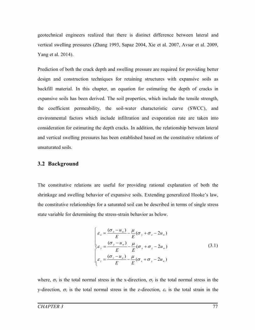
CHAPTER 3 77
geotechnical engineers realized that there is distinct difference between lateral and
vertical swelling pressures (Zhang 1993, Sapaz 2004, Xie et al. 2007, Avsar et al. 2009,
Yang et al. 2014).
Prediction of both the crack depth and swelling pressure are required for providing better
design and construction techniques for retaining structures with expansive soils as
backfill material. In this chapter, an equation for estimating the depth of cracks in
expansive soils has been derived. The soil properties, which include the tensile strength,
the coefficient permeability, the soil-water characteristic curve (SWCC), and
environmental factors which include infiltration and evaporation rate are taken into
consideration for estimating the depth cracks. In addition, the relationship between lateral
and vertical swelling pressures has been established based on the constitutive relations of
unsaturated soils.
3.2 Background
The constitutive relations are useful for providing rational explanation of both the
shrinkage and swelling behavior of expansive soils. Extending generalized Hooke’s law,
the constitutive relationships for a saturated soil can be described in terms of single stress
state variable for determining the stress-strain behavior as below.
)2()(
)2()(
)2()(
wyxwz
z
wzxwy
y
wzywx
x
uEE
u
uEE
u
uEE
u
(3.1)
where, x is the total normal stress in the x-direction, y is the total normal stress in the
y-direction, z is the total normal stress in the z-direction, x is the total strain in the

CHAPTER 3 78
x-direction, y is the total strain in the y-direction, z is the total strain in the z-direction.
uw is the pore-water pressure in soils, E is the saturated elastic modulus. is the
Poisson’s ratio.
Assuming the soil is a linear elastic and isotropic material, the constitutive relations for
saturated soils (Equation 3.1) could be extended and applied to unsaturated soils in terms
of two independent stress state variables; namely, net normal stress, ( – ua) and matric
suction, (ua – uw) as suggested by Fredlund and Morgenstern (1976).
Huuu
EEu
Huuu
EEu
Huuu
EEu
waayx
azz
waazx
ayy
waazy
axx
)()2()(
)()2()(
)()2()(
(3.2)
where, ua is the pore-air pressure and H is the elastic modulus with respect to a change in
(ua – uw).
The above equations can be used to interpret the shrinkage and swelling behavior of
expansive soils. Besides these constitutive relations, the relationship between the matric
suction and the steady-state flow profile in unsaturated soils (Equation 2.4) can be used to
take into account the effects of infiltration and evaporation. However, for achieving this
objective, the 1–D matric suction profile is required. This information can be derived
from the steady state flow rate, permeability of unsaturated soils and the fitting
parameters of the SWCC as follows (Yeh 1989, Lu and Likos 2004):

CHAPTER 3 79
s
uaz
s
uwa k
qekq
auu ww)1(ln1)( (3.3)
where, ks is the saturated coefficient of permeability, a is one of the parameters for fitting
the SWCC relationship (i.e. van Genuchten’s model in this thesis), qu is the unsaturated
flow rate of water (negative for infiltration and positive for evaporation), e is the void
ratio, zw is the elevation, which is the distance above ground water table as shown in
Figure 2.6, w is the density of water.
The runoff occurs over the ground surface if the rate of water application exceeds the soil
infiltrability, which is the saturated coefficient of permeability (Oh and Vanapalli 2010).
To avoid such a scenario, the dimensionless flow ratio is considered in the range of -1 <
qu/ks (Lu and Griffiths 2004).
3.3 Prediction of the depth of cracks
In this section, a mathematical approach is derived to predict the depth of cracks in
unsaturated expansive soils as below:
The lateral strain is zero (x = 0) in Equation (3.2) when the soil mass is at rest or at K0
condition before cracking. For this reason, the lateral stress can be expressed in terms of
vertical stress and matric suction (Morris et al. 1992) as below:
))(1()(1 waazax uu
HEuu
(3.4)
The pore-air pressure ua can be assumed to be equal to zero relative to the atmosphere
and so its effect will not be important (Pufahl et al. 1992). Assuming E/H = (1–2) and
(z – ua) = (D – zw), the above equation can be re-written as:

CHAPTER 3 80
))(1)(21()]([1 wawx uuzD
(3.5)
Recall Equation (2.25) for estimating the tensile strength of soils in Chapter 2:
'cot]tan)('[ bwaT uuct (3.6)
where, T is the modified coefficient for tensile stress in unsaturated soils.
The cracks in expansive soils typically arise at the point where the tensile strength of
unsaturated expansive soils is equal to the lateral stress. This assumption leads to the
expression below:
tx (3.7)
Substituting Equation (3.5) and Equation (3.6) into Equation (3.7), an equation can be
derived for estimating the depth of cracks in expansive unsaturated soils terms of other
soil properties (i.e. Poisson’s ratio and effective internal angle) and matric suction.
'cot]tan)('[))(1)(21()]([1
bwaTwaw uucuuzD
(3.8)
In addition, by replacing the tanb with S κ tan’ (Vanapalli et al. 1996), the relation
between the depth of cracks and water flow rate could be built as below:
'cot]'tan)('[))(1)(21()]([1
SuucuuzD waTwaw
(3.9)
By taking account of the environmental factors, such as the evaporation and infiltration
flow rates, the matric suction term, (ua – uw), could be expressed in terms of the water
flow rate q (Equation 3.3).
CHAPTER 3 81
Instead of measuring the matric suction, this relationship can be used predict the depth of
cracks in expansive soil taking into account of the influence of environmental data.
3.4 Prediction of the lateral swelling pressure
Determination of the elastic modulus of unsaturated expansive soil
Modulus of elasticity is a fundamental parameter required for estimating the swelling and
shrinkage behaviour of the expansive soils associated with variations of environmental
factors such as the drying and wetting (Adem and Vanapalli 2014). Conventionally, the
modulus of elasticity is assumed to be a constant value without taking account of the
influence of matric suction into consideration. However, modulus of elasticity
significantly varies with respect to matric suction in unsaturated soils (see Figure 3.1)
(Oh et al. 2009).

CHAPTER 3 82
Figure 3.1 The relationship between (a) SWCC and (b) the variation of modulus of
elasticity with respect to matric suction (after Oh et al. 2009).
Oh et al. (2009) proposed a semi-empirical model to predict the variation of modulus of
elasticity of unsaturated sandy soils with respect to matric suction using the SWCC.
])3.101/(
)(1[ ES
Puu
EEa
wsEsatunsat
(3.10)
where, Eunsat is modulus of elasticity under unsaturated conditions, and are fitting
parameters, and Pa is atmospheric pressure (i.e. 101.3 kPa).

CHAPTER 3 83
Vanapalli and Oh (2010) extended Equation (3.10) to a more general model to predict the
modulus of elasticity for both coarse- and fine-grained soils. The upper and lower
boundary of the fitting parameter, , are developed using the plastic index, Ip, as follow.
The upper and lower boundary relationship can be used for low and high matric suction
values respectively.
12(%)0,)(109.0)(312.05.01 2 pppE III (3.11)
16(%)0,)(036.0)(063.05.01 2 pppE III (3.12)
The fitting parameter, is recommended for coarse- and fine-grained soils to be 1 and 2,
respectively.
Adem and Vanapalli (2014) extended Equation (3.10) for unsaturated expansive soils (i.e.
IP > 16%) and achieved a reasonable agreement using the fitting parameters E =
0.05~0.15 and E = 2. Therefore, the influence of infiltration or evaporation towards the
elastic modulus of unsaturated soils taken into account by substituting Equation (3.3) into
Equation (3.10). The modulus of elasticity is a key parameter for predicting the lateral
swelling pressure.
Proposed method for the relationship between the vertical and lateral swelling
pressure
Beside the cracks, the lateral swelling pressure of expansive soils also has a significant
influence on the performance of geotechnical infrastructure. Several empirical equations
for the vertical swelling pressure are summarized in Chapter 2. However, it is the lateral
swelling pressure that is the key parameter required in the earth pressure estimation for
expansive unsaturated soils. The relationship which was derived by Liu and Vanapalli
(2016) can be used for estimating magnitude of lateral swelling pressure.
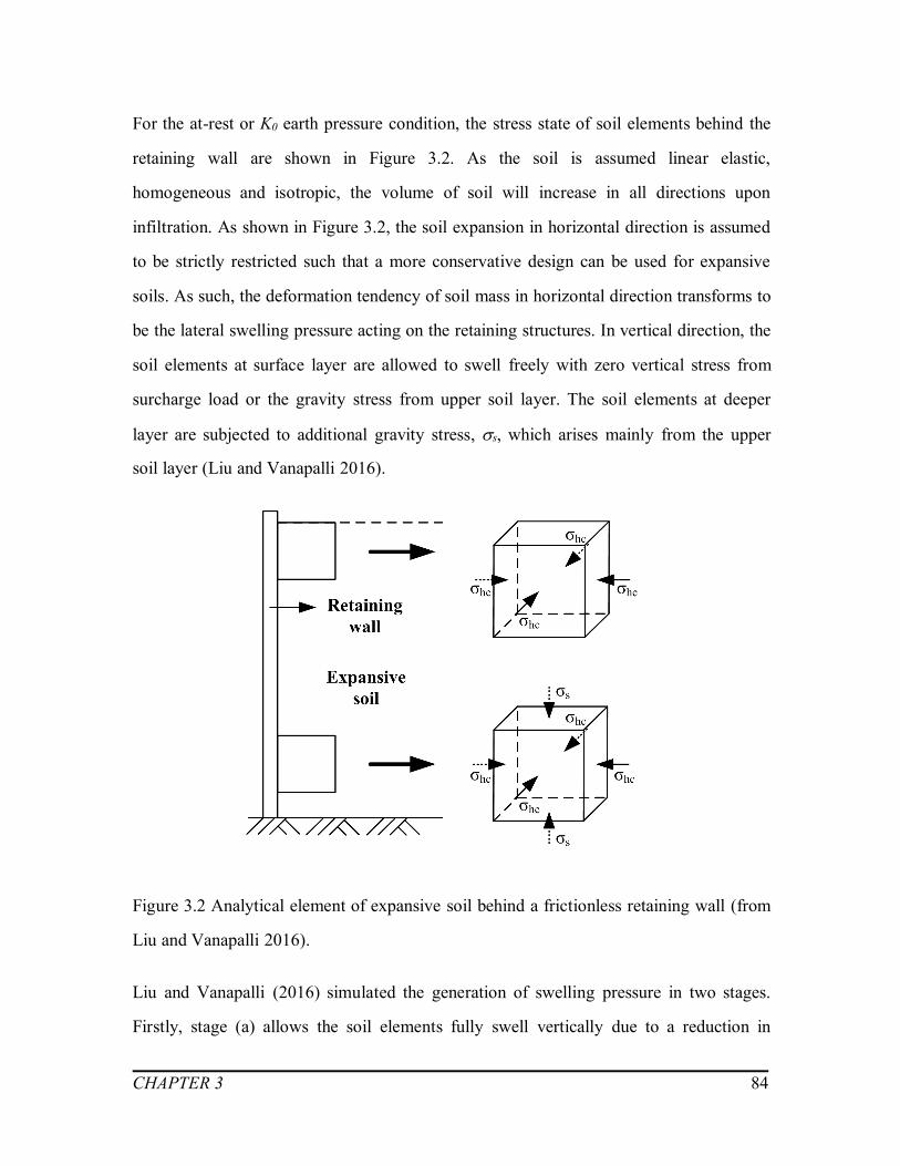
CHAPTER 3 84
For the at-rest or K0 earth pressure condition, the stress state of soil elements behind the
retaining wall are shown in Figure 3.2. As the soil is assumed linear elastic,
homogeneous and isotropic, the volume of soil will increase in all directions upon
infiltration. As shown in Figure 3.2, the soil expansion in horizontal direction is assumed
to be strictly restricted such that a more conservative design can be used for expansive
soils. As such, the deformation tendency of soil mass in horizontal direction transforms to
be the lateral swelling pressure acting on the retaining structures. In vertical direction, the
soil elements at surface layer are allowed to swell freely with zero vertical stress from
surcharge load or the gravity stress from upper soil layer. The soil elements at deeper
layer are subjected to additional gravity stress, s, which arises mainly from the upper
soil layer (Liu and Vanapalli 2016).
Figure 3.2 Analytical element of expansive soil behind a frictionless retaining wall (from
Liu and Vanapalli 2016).
Liu and Vanapalli (2016) simulated the generation of swelling pressure in two stages.
Firstly, stage (a) allows the soil elements fully swell vertically due to a reduction in

CHAPTER 3 85
matric suction while the horizontal deformation is restricted by horizontal confining
stress 3. As a result, the length at horizontal direction remains c while in vertical
direction it changes from c to b (see Figure 3.3 a). At stage (b), horizontal stress 3' and
vertical stress 1' are applied to the element simultaneously to compress the soil element
back to its initial size.
Figure 3.3 Analytical element of expansive soil at deep soil layer (after Liu and Vanapalli
2016).
The constitutive relationships for unsaturated soils (Equation 3.2) proposed by Fredlund
and Morgenstern (1976), can be employed to estimate the stress-strain relationship
(Equation 3.13 and 3.14) for stage (a) and (b) respectively as suggested by Liu and
Vanapalli (2016):

CHAPTER 3 86
HuuP
E
HuuP
EEccb
waL
waL
S
10
2
(3.13)
)(0
2
'3
'3
'3
S
s
PEE
EEP
bbc
(3.14)
For lateral earth pressure estimation, the s which represents the influence of the gravity
stress of upper soil layer and 1' stands for the vertical swelling pressure, PS, which could
be determined by laboratory tests or semi-empirical and empirical equations detailed in
Chapter 2. Solving these equations, the relationship between the lateral and vertical
swelling pressure, PS, can be developed as shown in Equation (3.15).
SS
SL
EP
PP
11)21)(1(
)21(22
2
(3.15)
Tu and Vanapalli (2016) proposed a semi-empirical equation for expansive soils to
estimate the vertical swelling pressure:
20 )
100( r
SSSSPP (3.16)
where, PS0 is the intercept on the PS axis at zero suction value, Sis fitting parameter,
S= 23.05A32.315 (0.237IP – 10.278dn )+ 0.164, A is the activity of soils, A=IP / CC.
Therefore, the lateral swelling pressure can be computed when the matric suction changes
from initial state to zero:
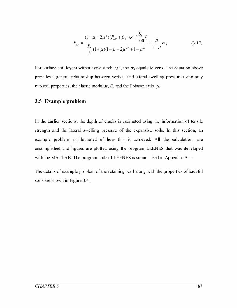
CHAPTER 3 87
SS
rSS
LS
EP
SPP
11)21)(1(
)]100
()[21(
22
02
(3.17)
For surface soil layers without any surcharge, the S equals to zero. The equation above
provides a general relationship between vertical and lateral swelling pressure using only
two soil properties, the elastic modulus, E, and the Poisson ratio, .
3.5 Example problem
In the earlier sections, the depth of cracks is estimated using the information of tensile
strength and the lateral swelling pressure of the expansive soils. In this section, an
example problem is illustrated of how this is achieved. All the calculations are
accomplished and figures are plotted using the program LEENES that was developed
with the MATLAB. The program code of LEENES is summarized in Appendix A.1.
The details of example problem of the retaining wall along with the properties of backfill
soils are shown in Figure 3.4.
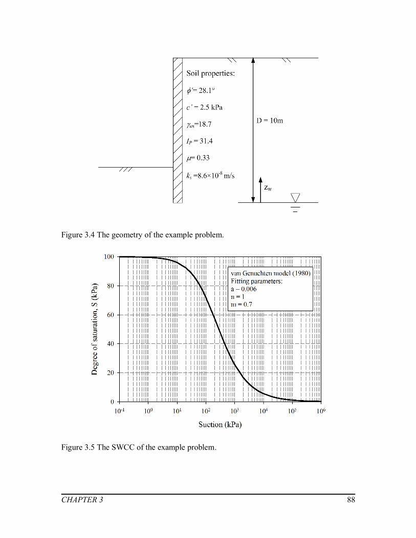
CHAPTER 3 88
Figure 3.4 The geometry of the example problem.
Figure 3.5 The SWCC of the example problem.

CHAPTER 3 89
Several assumptions used for reducing the complexity of the problem is summarized
below:
- The height of backfill is assumed to be 10m and the ground water table is assumed to
be at the depth of 10m below backfill surface
- The SWCC of this example problem is shown in Figure 3.5 by applying van
Genuchten (1980) equation with the fitting parameters a, n, m of 0.006, 1 and 0.7,
respectively.
- The saturated coefficient of permeability, ks is assumed to be 8.6×10⁻⁸ m/s.
- The surface of the wall is assumed vertical and smooth (i.e. there no friction between
backfill soil and the wall; In other words, Rankine theory is used).
Different water flow rates, q were applied to simulate the effects of environmental factors.
The matric suction profiles associated with five different water flow rates (i.e. -3.5×10⁻⁸
m/s, -1.5×10⁻⁸ m/s, 0 m/s, 1.5×10⁻⁸ m/s, 3.5×10⁻⁸ m/s) were plotted based on Equation
(3.3). The positive and negative values of the flow rates represent the evaporation and
infiltration conditions, respectively. The matric suction decreases linearly from the
ground surface when neglecting the influence of environment (i.e. q = 0 m/s). However,
Figure 3.6 shows significant changes of matric suction in the active zone. These changes
influence both the cracks propagation and the magnitude of lateral swelling pressures of
unsaturated expansive soils. For this reason, it is not appropriate to assume a constant
value of matric suction or a linear variation of matric suction with respect to depth.

CHAPTER 3 90
Figure 3.6 Matric suction profile with respect to different flow rates of water.
The ultimate tensile strength of soils at the point where cracks occur for various flow
rates is shown in Figure 3.7. The ultimate strength (i.e. absolute value of tensile strength)
increases significantly when the values of flow rate of water changes from negative to
positive. This curve reveals the significant contribution towards the tensile strength of
soils in the drought seasons or periods.
Note: Negative value of waterflow rates (i.e. q) representsthe infiltration condition.

CHAPTER 3 91
Figure 3.7 The ultimate tensile strength with respect to flow rate of water.
By employing Equation (3.10), the modulus of elasticity for unsaturated conditions
corresponding to the five water different flow rates are plotted in Figure 3.8. The largest
elastic modulus value for unsaturated condition can reach almost eight times of the
saturated one in this example problem. Figure 3.8 highlight the importance of taking
account of the influence of suction on the modulus of elasticity in the calculations.
Note: Negative value of waterflow rates (i.e. q) representsthe infiltration condition.

CHAPTER 3 92
0 1 2 3 4 5 6 7 8
x 104
0
1
2
3
4
5
6
7
8
9
10
Modulus of elasticity, E (kPa)
Dep
th, z
(m)
Saturated conditionq= - 3.510-8 m/sq= - 1.510-8 m/sq= 0 m/sq= 1.510-8 m/sq= 3.510-8 m/s
Figure 3.8 The modulus of elasticity for both saturated and unsaturated conditions.
3.6 Summary
Expansive soils undergo significant volume change and during this process cracks
propagate. These cracks in turn have significant influence on the lateral swelling pressure
on the retaining walls, when expansive soils are used as a backfill material. In this
chapter, relationships are developed for predicting the depth of cracks and lateral
swelling pressures. These two factors are essential for calculation of the earth pressures
behind retaining structures in expansive soils. More details are of these calculations are
provided in Chapter 4.
The procedural steps followed for predicting the depth of cracks is shown in the flow
diagram (Figure 3.9). Infiltration and evaporation are the key factors that affect the water
Note: Negative value of waterflow rates (i.e. q) representsthe infiltration condition.
Modulus of elasticity, E (kPa)

CHAPTER 3 93
content. The suction variation with respect to depth is extremely sensitive to water
content variation in unsaturated soils. By employing constitutive relations and the SWCC
as tools, the depth of cracks is estimated using Equation (3.9).
Figure 3.9 The flow diagram for predicting the depth of cracks.
The lateral swelling pressure that develop due to various infiltration rates are also
important for the design of retaining wall. Based on the constitutive relationships of
unsaturated soils, Equation (3.17) was built to estimate the lateral earth pressure from the
information of vertical swelling pressure. The variation of vertical swelling pressure with
respect soil suction can be estimated from the SWCC and other soil properties which can
be estimated using Equation (3.16).
An example problem is also illustrated to highlight how tensile strength and the modulus
of elasticity of unsaturated soils influence the lateral swell pressure (see Figure 3.7 and
Figure 3.8).

CHAPTER 4 94
PROPOSED APPROACH FOR PREDICTING LATERAL
EARTH PRESSURE
4.1 Introduction
The volumetric changes associated with variation of water content has a significant
influence on the performance of the retaining walls when expansive soils are used as a
backfill material. The restricted volumetric changes (i.e. expansive soils movement)
typically translate to as lateral earth pressure and act on the retaining wall. In
conventional methods, the influence of volumetric changes is not considered in the
calculation of lateral earth pressures. For this reason, a comprehensive calculation
method is required for reliable calculation earth pressures taking account of changes in
matric suctions and lateral swell pressure values associated with changes in water content
variations. A reliable design for retaining walls is possible if lateral pressure variation
with respect to depth is calculated taking account of the influence of environmental
factors which include wetting and drying circles and crack propagation.
In this chapter, extending the relationships that have been developed in Chapter 3, lateral
earth pressure distribution is calculated behind the retaining wall taking account of effects
of cracks and additional swelling pressure that may arise associated with different
infiltration rates. The soil mass of the backfill material when subjected evaporation is
typically in a state unsaturated condition. The evaporation rates likely contribute to the
development of cracks in expansive soils; however, cracks may not occur in certain
non-expansive soils. During wet seasons, the backfill material degree of saturation
increases and becomes saturated as water infiltrates into soil A rigorous calculation
CHAPTER 4 95
framework is proposed for the lateral earth pressures estimation on retaining structures
for both expansive and non-expansive soils as backfill material considering both
saturated and unsaturated conditions.
4.2 Background
Theoretical treatment of lateral earth pressures in cohesive soils where maximum
pressures or resistances are the major unknowns were developed based on the
Mohr-Coulomb failure criteria and concepts of plastic equilibrium extending classic
Rankine earth pressure theory (Pufahl et al. 1992). In order to extend the saturated soil
mechanics for soils that are in a state of unsaturated condition, some assumptions are
used in the Rankine’s analysis, which include: the surface of the backfill is horizontal; the
friction between wall and soils is zero; the failure plane is planar and the soils are elastic
in nature.
The parameter, K0 which is defined as the at-rest earth pressure coefficient, is the ratio of
lateral (i.e. horizontal) to vertical pressures when the retaining structures are fixed. In
Figure 4.1, circle C1 represents the fully active condition at a certain matric suction value.
As the water content increases, the matric suction decreases and the active earth pressure
condition moves from circle C1 towards circle C3, which represents the fully saturated
situation. On the other hand, there are scenarios that soils are under passive conditions in
practice. For instance, expansive soils under the influence rainfall infiltration develop
additional lateral swelling pressures for heavy structures such as the bridges supported
with retaining structures, which have a tendency to push the structure into the softened
expansive soils. Under these circumstances, circle C2 and C4 are in fully passive
conditions for unsaturated and saturated soils, respectively (see Figure 4.1).

CHAPTER 4 96
Figure 4.1 Active and passive earth pressures for saturated and unsaturated soils(modified after Pufahl et al. 1992)
Limited research studies were reported in the literature to provide a comprehensive
theoretical analysis related to the behavior of retaining structures where unsaturated
expansive soils are used as backfill material extending Mohr-Coulomb failure criteria
(Pufahl et al. 1992, Fredlund and Rahardjo 1993, Zhu and Liu 2001, Hu 2006, Zhang
2012). Figure 4.2 shows the diagrams of active and passive earth pressure for unsaturated
soils based on Rankine theory. It contains three parts: the contribution from vertical stress,
cohesion of soils and matric suction.

CHAPTER 4 97
Figure 4.2 Diagrams of earth pressures for unsaturated soils: (a) Active earth pressure, (b)Passive earth pressure (after Pufahl et al. 1992)
4.3 Lateral earth pressure
Earth pressure during drying process
Figure 4.3 shows the horizontal stress behind a retaining wall reduces as the wall moves
away from the soil mass or cracks propagate until they reach a limiting value. Such a
scenario represents evaporation of water from the soil mass which translates to an
increase in the matric suction. The major and minor principal stress can be reasonably
well estimated, however, there are no procedures available for estimating intermediate

CHAPTER 4 98
principal stress. For practice applications, fully active state is typically considered to be
the critical scenario (i.e. failure condition) when the maximum lateral earth pressure (i.e.
active earth pressure) arises as cracks develop in backfill material of the retaining wall,
typically during drought seasons.
Figure 4.3 Stress states during drying.
Saturated soils
The active earth pressure is conventionally estimated assuming the backfill soil material
is in a state of saturated condition. In other words, the contribution from matric suction is
disregarded when ground water table is not at the natural ground surface level (Vanapalli
and Oh 2012). Terzaghi (1943) proposed Equation (4.1) to estimate the active earth
pressure for saturated soils as follow:
'2)( cKK aasvsha (4.1)
where, ha is the active earth pressure,vs is the vertical self-weight stress, vs = z, s is
the surcharge stress, Ka is the coefficient of active earth pressure, )2
'45(tan 2 taK
, c’
is the effective cohesion.

CHAPTER 4 99
Unsaturated soils
The soil behind the retaining wall, however, is typically in a state of unsaturated
condition (Tavakkoli and Vanapalli 2011). A typical active stress state for a given matric
suction (i.e. soil element at a certain depth) of unsaturated soils is shown in Figure 4.4.
Figure 4.4 Mohr-Coulomb failure envelope at a constant (ua – uw) for the active state(after Fredlund and Rahardjo 1993).
The matric suction profile above ground water table can be estimated for different
evaporation water flow rates, which is illustrated in the example problem in Chapter 3
(see Figure 3.5). This profile is necessary for the reliable calculation of lateral pressure
distribution for unsaturated soils. The active earth pressure can be calculated from
vertical stress and the geometric relation (see Figure 4.4) as follow:
]tan)('[2)( bwaaasvsha uucKK (4.2)
where, b is the angle of shearing resistance with respect to matric suction, (ua – uw).
The active earth pressure distribution is plotted in Figure 4.5 for both saturated and
unsaturated soils. For unsaturated soils, the tensile zone above ground water table, zt, is
mainly caused by the cohesion of soils and the matric suction as shown in Figure 4.5.
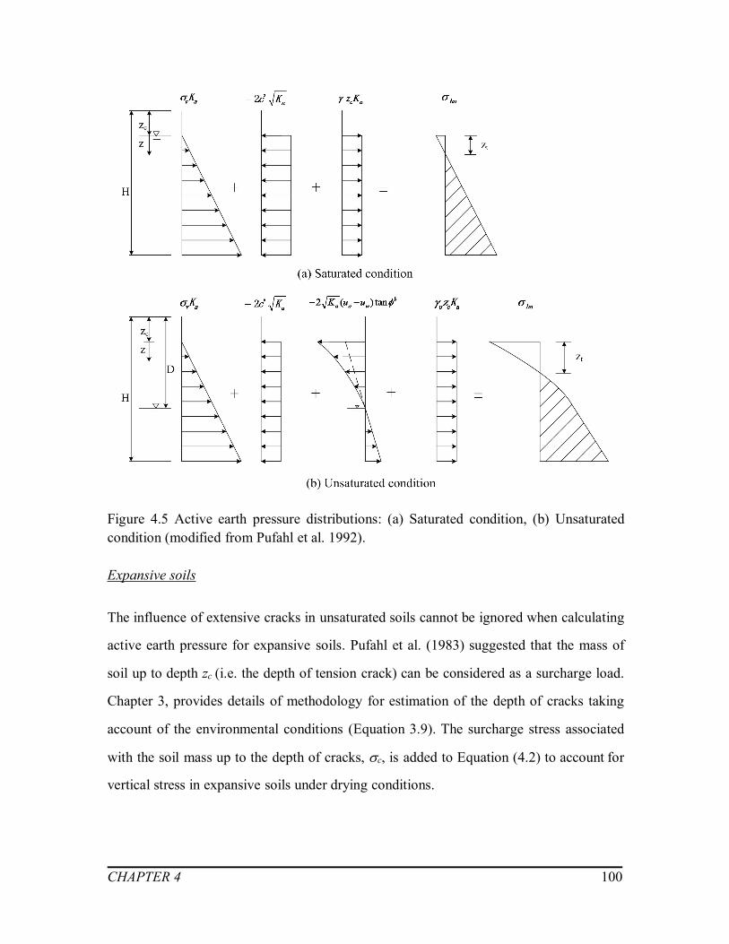
CHAPTER 4 100
Figure 4.5 Active earth pressure distributions: (a) Saturated condition, (b) Unsaturatedcondition (modified from Pufahl et al. 1992).
Expansive soils
The influence of extensive cracks in unsaturated soils cannot be ignored when calculating
active earth pressure for expansive soils. Pufahl et al. (1983) suggested that the mass of
soil up to depth zc (i.e. the depth of tension crack) can be considered as a surcharge load.
Chapter 3, provides details of methodology for estimation of the depth of cracks taking
account of the environmental conditions (Equation 3.9). The surcharge stress associated
with the soil mass up to the depth of cracks, c, is added to Equation (4.2) to account for
vertical stress in expansive soils under drying conditions.

CHAPTER 4 101
]tan)('[2)( bwaaacsvsha uucKK (4.3)
where,c is the surcharge stress due to cracks, c= u zc.
Earth pressure during wetting process
Unsaturated soils
At the beginning of rainy season, the soils above ground water table are typically in a
state of unsaturated condition. The matric suction profile can be predicted by Equation
(3.3) considering different infiltration water flow rates. A typical at-rest earth pressure
distribution behind a fixed wall for unsaturated soils can be simply computed in terms of
vertical stress and matric suction as below (Fredlund and Rahardjo 1993):
)()1(10 wavs uu
HE
(4.4)
where, 0 is the at-rest earth pressure.
When the retaining wall moves towards soil mass, the passive earth pressure for an
unsaturated soil can be computed based on Mohr-Coulomb failure criteria (see Figure 4.6)
as follow:
]tan)('[2)( bwappsvshp uucKK (4.5)
where,hp is the passive earth pressure, Kp is the coefficient of passive earth pressure,
)2
'45(tan 2 tpK
.
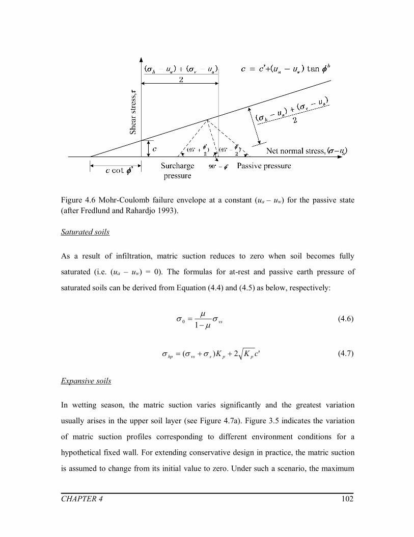
CHAPTER 4 102
Figure 4.6 Mohr-Coulomb failure envelope at a constant (ua – uw) for the passive state(after Fredlund and Rahardjo 1993).
Saturated soils
As a result of infiltration, matric suction reduces to zero when soil becomes fully
saturated (i.e. (ua – uw) = 0). The formulas for at-rest and passive earth pressure of
saturated soils can be derived from Equation (4.4) and (4.5) as below, respectively:
vs
10 (4.6)
'2)( cKK ppsvshp (4.7)
Expansive soils
In wetting season, the matric suction varies significantly and the greatest variation
usually arises in the upper soil layer (see Figure 4.7a). Figure 3.5 indicates the variation
of matric suction profiles corresponding to different environment conditions for a
hypothetical fixed wall. For extending conservative design in practice, the matric suction
is assumed to change from its initial value to zero. Under such a scenario, the maximum

CHAPTER 4 103
lateral swelling pressure is computed by Equation (3.17) and shown in Figure 4.7 (b).
Figure 4.7 (c) shows the typical at-rest earth pressure distribution for saturated soils
behind a retaining wall (Equation 4.4). The environmental factors have more significant
influence on the water content variation in the upper layer of soils due to the high
permeability of expansive soils, associated with the influence of cracks. As a result,
additional lateral swelling pressure exhibits more remarkable effects on the upper soil
layer. At greater depth, the influence of lateral swelling pressure can be neglected and the
conventional method can be used to estimate the at-rest earth pressure (Sahin 2011). It
should be noted that the soils are in a passive state due to additional lateral swelling
pressure. Therefore, the passive earth pressure is still governed by the failure state of
stress, especially for the upper zone (see Figure 4.7d).
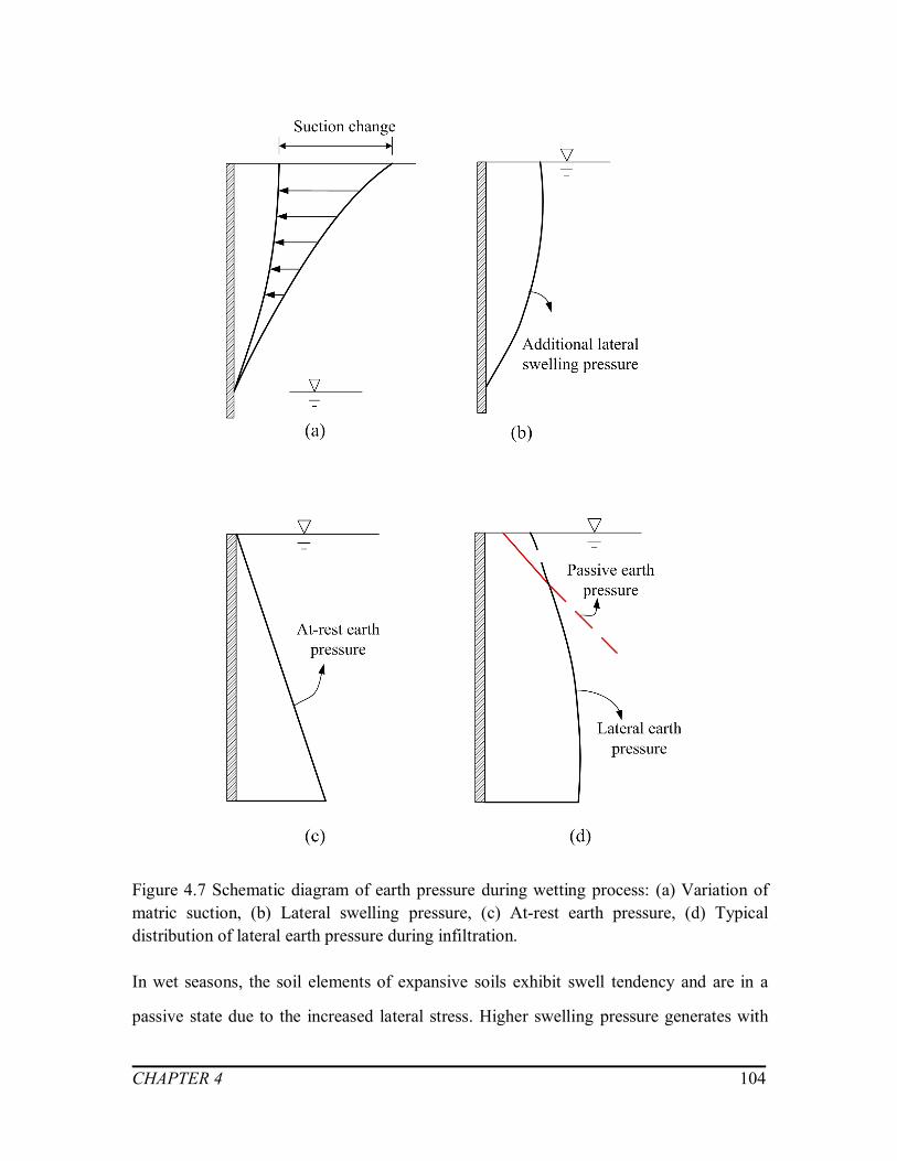
CHAPTER 4 104
Figure 4.7 Schematic diagram of earth pressure during wetting process: (a) Variation ofmatric suction, (b) Lateral swelling pressure, (c) At-rest earth pressure, (d) Typicaldistribution of lateral earth pressure during infiltration.
In wet seasons, the soil elements of expansive soils exhibit swell tendency and are in a
passive state due to the increased lateral stress. Higher swelling pressure generates with

CHAPTER 4 105
greater variation of suction values. Therefore, the most critical scenario occurs when the
matric suction changes from initial condition to zero (i.e. saturated condition). As such,
the lateral earth pressure can be estimated as follow:
The maximum lateral swelling pressure in Figure 4.7 (b) could be calculated by Equation
(3.17) with zero surcharge load:
22
02
1)21)(1(
)]100
()[21(
EP
SPP
S
rSS
LS (4.8)
For this scenario, when the soil is in a state of saturated condition (i.e. (ua – uw) = 0), the
at-rest earth pressure in Figure 4.7 (c) can be computed using Equation (4.6).
In Figure 4.7 (d), the final lateral earth pressure is the sum of additional lateral swelling
pressure (Equation 4.8) and at-rest earth pressure (Equation 4.6) as follow:
vsS
rSS
hp
EP
SP
11)21)(1(
)100
()21(
22
20
2
(4.9)
In addition, in order to avoid shear failure of retaining walls after long period of
infiltration, the lateral pressure is limited by the passive earth pressure of saturated soil as
shown in Figure 4.7(d) (Equation 4.7).
4.4 Summary
The lateral earth pressure distribution for retaining wall are illustrated in this chapter
taking account of the influence of cracks and lateral swelling pressure as per the
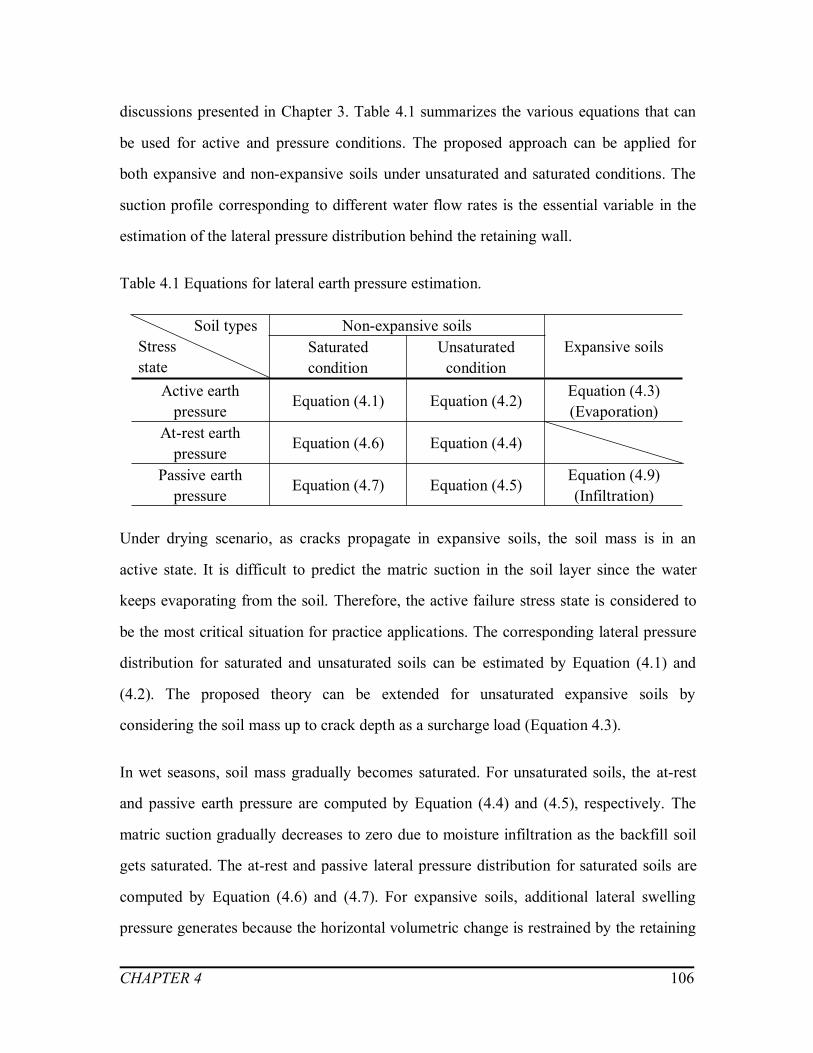
CHAPTER 4 106
discussions presented in Chapter 3. Table 4.1 summarizes the various equations that can
be used for active and pressure conditions. The proposed approach can be applied for
both expansive and non-expansive soils under unsaturated and saturated conditions. The
suction profile corresponding to different water flow rates is the essential variable in the
estimation of the lateral pressure distribution behind the retaining wall.
Table 4.1 Equations for lateral earth pressure estimation.
Soil typesStressstate
Non-expansive soilsExpansive soilsSaturated
conditionUnsaturated
conditionActive earth
pressureEquation (4.1) Equation (4.2) Equation (4.3)
(Evaporation)At-rest earth
pressureEquation (4.6) Equation (4.4)
Passive earthpressure
Equation (4.7) Equation (4.5) Equation (4.9)(Infiltration)
Under drying scenario, as cracks propagate in expansive soils, the soil mass is in an
active state. It is difficult to predict the matric suction in the soil layer since the water
keeps evaporating from the soil. Therefore, the active failure stress state is considered to
be the most critical situation for practice applications. The corresponding lateral pressure
distribution for saturated and unsaturated soils can be estimated by Equation (4.1) and
(4.2). The proposed theory can be extended for unsaturated expansive soils by
considering the soil mass up to crack depth as a surcharge load (Equation 4.3).
In wet seasons, soil mass gradually becomes saturated. For unsaturated soils, the at-rest
and passive earth pressure are computed by Equation (4.4) and (4.5), respectively. The
matric suction gradually decreases to zero due to moisture infiltration as the backfill soil
gets saturated. The at-rest and passive lateral pressure distribution for saturated soils are
computed by Equation (4.6) and (4.7). For expansive soils, additional lateral swelling
pressure generates because the horizontal volumetric change is restrained by the retaining

CHAPTER 4 107
walls. In order to provide a conservative design approach, the distribution of lateral earth
pressure for expansive soils is predicted by Equation (4.9) for the scenario of matric
suction which changes from a known initial value to zero (i.e. soil is fully saturated).
Moreover, for frictionless surface, the maximum lateral earth pressure is limited by the
Mohr-Coulomb passive earth pressure to avoid shear failure Equation (4.7).
CHAPTER 5 108
APPLICATION OF THE PROPOSED FRAMEWORK FOR
LATERAL EARTH PRESSURE ESTIMATION OF
EXPANSIVE AND NON-EXPANSIVE SOILS
5.1 Introduction
Details of expansive soils crack depth prediction and lateral swelling pressure estimation
were presented in Chapter 3. A framework for lateral earth pressure estimation behind a
retaining wall for both unsaturated expansive and unsaturated non-expansive soils has
been proposed in Chapter 4. In this chapter, the proposed framework is employed on a
hypothetical retaining wall with two different backfill soil types (i.e. Regina clay, which
is an expansive soil and Indian Head till, which is a glacial till, and is a non-expansive
soil) taking account of the influence of environmental factors.
Regina clay, is a typical expansive soil that undergoes significant volumetric changes due
to the influence of environmental factors (i.e. evaporation and infiltration conditions).
Active and passive states are the most critical scenarios for a fixed retaining wall during
drought and wet seasons, respectively because of the generation of cracks and additional
swelling pressure. Details of these investigations are summarized as Example A in this
chapter.
In addition, the proposed approach is extended for lateral earth pressure estimation for a
typical non-expansive soil, Indian Head till (i.e. Example B) by taking into account of the
influence of environmental factors considering the variation of matric suction profile. The
stress state of soil element is related to the displacement of retaining structures.

CHAPTER 5 109
The at-rest, active and passive earth pressures for unsaturated soils are calculated for both
drying and wetting conditions and compared with saturated condition for both Examples
A and B.
The climate records from local weather stations (i.e. Regina Int’l A station and Indian
Head CDA Station) is also summarized and used in the analyses to illustrate the changes
of lateral earth pressure for different scenarios that are typically encountered in practice.
The calculation results for both expansive and non-expansive soils are also analyzed and
discussed in the following sections.
The following calculations are conducted using the proposed program LEENES in
MATLAB for each of the examples:
- The fitting parameters of the Soil-Water Characteristic Curve (SWCC) are predicted
in SigmaPlot to best-fit the experimental data of soils by employing van Genuchten
model (1980).
- Matric suction profiles are plotted corresponding to different water flow rates under
drying and wetting conditions as well as the hydrostatic condition for both examples.
- For Example A: (i) The depth of cracks in expansive soils is calculated under drying
conditions. The active earth pressure distributions are plotted and the active earth
forces are integrated with respect to different evaporation flow rates raking account
of the influence of crack depth; (ii) The additional lateral swelling pressures that
arise due to wetting conditions are computed for different infiltration flow rates. The
lateral earth pressure distributions under wetting conditions are obtained by summing
up the additional lateral swelling pressure and at-rest earth pressure condition.
- For Example B: Based on the matric suction profile that were estimated; the at-rest,
active and passive lateral earth pressure distribution of a non-expansive soil is plotted.
The lateral earth forces were determined by integration of earth pressures for both
drying and wetting conditions.

CHAPTER 5 110
5.2 Proposed program LEENES used in software MATLAB
There are several commercial software available for researchers to simulate complex
geotechnical problems; however, tremendous time investment are required for engineers
to write codes and build models (William et al. 2010). There is a need for simple and
efficient methods to achieve the numerical analysis rapidly for researchers and
practitioners in the field of geotechnical engineering. In the present study, MATLAB has
been chosen as the software to write the program LEENES because of following reasons:
- Ubiquitous use in engineering studies as well as practice;
- Users with engineering background are familiar with MATLAB or can easily get
familiar;
- High efficiency in numerical calculation and economical;
- Comprehensive graphic processing functions that facilitates quick analyses and
interpretation of numerical results.
LEENES here is used as a tool to handle the complex iteration and integral computations
using an efficient programming code. The influence of each of the parameters towards
the results is considered independently during the calculation process. The methodology
presented in Chapter 4 is implemented by LEENES and two comprehensive examples are
illustrated using different kind of soils as backfill. This approach is of interest for
practitioners in the rational of design of retaining walls using the mechanics of saturated
and unsaturated soils.

CHAPTER 5 111
5.3 Example A: Regina clay, Saskatchewan, Canada
Meteorological data and soil properties
The climate of the Regina area is classified as a cool, semi-arid to sub-humid type. The
average monthly precipitation for the Regina area, which is recorded from 1981 to 2010
are shown in Figure 5.1 (Government of Canada 2015). Maximum and minimum average
monthly precipitation rate occur typically in June and February are equal to 2.74×10⁻⁸ m/s
and 3.63×10⁻⁹ m/s, respectively. Average monthly lake evaporation rates are listed in
Table 5.1 and the maximum value of evaporation rate in this area is 2.28×10⁻⁹ m/s.
Figure 5.1 Average precipitation data for 1981 to 2010 Canadian Climates Normals from
Regina Int’l A Station (modified from Government of Canada 2015).

CHAPTER 5 112
Table 5.1 Lake Evaporation data for 1981 to 2010 Canadian Climates Normals from
Regina Int’l A Station (modified from Government of Canada 2015).
Month Jan Feb Mar Apr May JunLake Evaporation (mm) 0 0 0 0 5.2 5.8Month Jul Aug Sep Oct Nov DecLake Evaporation (mm) 5.9 5.1 3.6 1.9 0 0
In addition to external factors (i.e. the climate data for Regina area presented above), the
basic soil properties is also essential in lateral earth pressure estimation due to their
significant influence towards the swell-shrink behavior. The predominant mineral in
Regina clay is montmorillonite, with a high swelling potential (Fredlund 1975). Widger
and Fredlund (1979) provided the strength parameters of the soil sample from this area
corresponding to large strain conditions. Shuai (1996) used the falling head permeability
test to determine the saturated coefficient of permeability for Regina clay with respect to
void ratio. Other investigators, Fredlund (1967), Vu and Fredlund (2004) conducted
several lab tests on the Regina clay samples. The key soil properties Regina clay are
summarized in Table 5.2.
Table 5.2 Soil properties of Regina clay
Soil properties References
Atterberg LimitsLiquid limit, LL (%) 77
Vu and Fredlund (2004)Plastic limit, PL (%) 33Plasticity index, IP (%) 44Grain-size DistributionSand sizes, (%) 8
Fredlund (1975)Silt sizes, (%) 41Clay sizes, (%) 51Basic soil propertiesEffective cohesion, c’ (kPa) 17 Widger and Fredlund
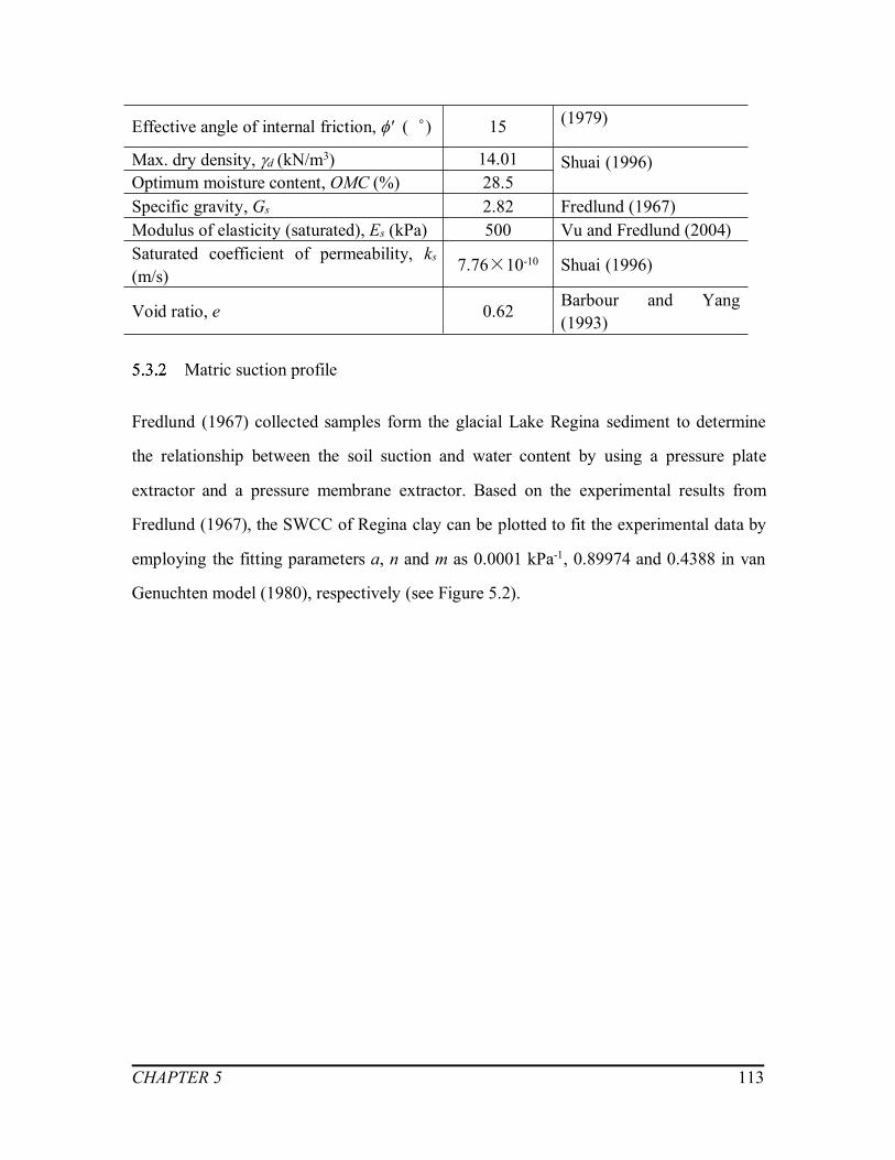
CHAPTER 5 113
(1979)Effective angle of internal friction, ' (︒) 15
Max. dry density, d (kN/m3) 14.01 Shuai (1996)Optimum moisture content, OMC (%) 28.5Specific gravity, Gs 2.82 Fredlund (1967)Modulus of elasticity (saturated), Es (kPa) 500 Vu and Fredlund (2004)Saturated coefficient of permeability, ks(m/s)
7.76×10⁻¹⁰ Shuai (1996)
Void ratio, e 0.62 Barbour and Yang(1993)
Matric suction profile
Fredlund (1967) collected samples form the glacial Lake Regina sediment to determine
the relationship between the soil suction and water content by using a pressure plate
extractor and a pressure membrane extractor. Based on the experimental results from
Fredlund (1967), the SWCC of Regina clay can be plotted to fit the experimental data by
employing the fitting parameters a, n and m as 0.0001 kPa-1, 0.89974 and 0.4388 in van
Genuchten model (1980), respectively (see Figure 5.2).

CHAPTER 5 114
Figure 5.2 Soil-water characteristic curves of Regina clay.
The developed approach is employed on a10m hypothetical retaining wall, assuming the
ground water table to be at a depth of 10m. To evaluate the effects of environmental
factors, the matric suction profiles are plotted under both drying and wetting conditions
with the aid of Equation (3.3) using program LEENES (see Appendix A.2 and Figure
5.3). In Figure 5.3, q = 0 m/s represents the hydrostatic condition (i.e. the dotted black
line).
For drying conditions, several different evaporation water flow rates are used as input to
plot the matric suction profile. Among the input evaporation rates, q = 2.28×10⁻⁹ m/s is
also used which represents average monthly evaporation rate (i.e. the red line in Figure
5.3a) (see also Table 5.1). Several other evaporation rates also used in in LEENES,
including, q = 1.55×10⁻⁷ m/s which represents a value at which cracks generate (i.e. the
purple line in Figure 5.3a). Besides, the matric suction profiles corresponding to q =
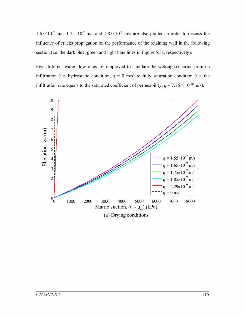
CHAPTER 5 115
1.65×10⁻⁷ m/s, 1.75×10⁻⁷ m/s and 1.85×10⁻⁷ m/s are also plotted in order to discuss the
influence of cracks propagation on the performance of the retaining wall in the following
section (i.e. the dark blue, green and light blue lines in Figure 5.3a, respectively).
Five different water flow rates are employed to simulate the wetting scenarios from no
infiltration (i.e. hydrostatic condition, q = 0 m/s) to fully saturation condition (i.e. the
infiltration rate equals to the saturated coefficient of permeability, q = 7.76×10⁻¹⁰ m/s).
0 1000 2000 3000 4000 5000 6000 7000 80000
1
2
3
4
5
6
7
8
9
10
Matric suction, (ua- uw) (kPa)(a) Drying conditions
Dep
th, z
(m)
q = 1.5510-7 m/sq = 1.6510-7 m/sq = 1.7510-7 m/sq = 1.8510-7 m/sq = 2.2910-9 m/sq = 0 m/s

CHAPTER 5 116
0 10 20 30 40 50 60 700
1
2
3
4
5
6
7
8
9
10
Matric suction, (ua- uw) (kPa)(b) Wetting conditions
Dep
th, z
(m)
q= -310-10 m/sq= -410-10 m/sq= -510-10 m/sq= -610-10 m/sq= -710-10 m/sq = 0 m/s
Saturated coefficient ofpermeability:
ks = 7.7610 -10 m/s
Figure 5.3 The matric suction profiles for Example A: (a) Drying conditions, (b) Wetting
conditions.
Drying conditions
Upon evaporation, extensive cracks generate in expansive soils when the lateral stress
exceeds the tensile strength of soils (Equation 3.7). Therefore, based on the matric
suction profile under drying conditions (see Figure 5.3a), the tensile strength and lateral
stress distributions are plotted along the retaining wall in Figure 5.5 with respect to
various evaporation rates. As shown in Figure 5.4, several trials are required to find the
intersection point. In Example A, crack initiates at the point of intersection of the two
lines when the evaporation flow rate equals to 1.55×10⁻⁷ m/s and propagates after that.
The detailed calculation procedures by LEENES for estimating the depth of cracks are
presented in Appendix A.1. The depth of cracks and corresponding ultimate tensile
strength of soils are summarized in Appendix Table A.1.
Note: Negative value of waterflow rates (i.e. q) representsthe infiltration condition.
Saturated coefficient ofpermeability:ks = 7.76×10⁻¹⁰ m/s

CHAPTER 5 117
Figure 5.4 The flow diagram for trial procedures conducted in LEENES to estimate the
depth of cracks and the corresponding evaporation flow rate in expansive soils.
-2500 -2000 -1500 -1000 -500 0 5000
1
2
3
4
5
6
7
8
9
10
Stress (kPa) (a) q = 1.55 10-7 m/s
Dep
th, z
(m)
Tensile strengthLateral stress
-2500 -2000 -1500 -1000 -500 0 5000
1
2
3
4
5
6
7
8
9
10
Stress (kPa) (b) q = 1.65 10-7 m/s
Dep
th, z
(m)
Tensile strengthLateral stress
-3000 -2000 -1000 0 10000
1
2
3
4
5
6
7
8
9
10
Stress (kPa) (c) q = 1.75 10-7 m/s
Dep
th, z
(m)
Tensile strengthLateral stress
-3000 -2000 -1000 0 10000
1
2
3
4
5
6
7
8
9
10
Stress (kPa) (d) q = 1.85 10-7 m/s
Dep
th, z
(m)
Tensile strengthLateral stress
-2386, 9.97 -2391, 9.42
-2395, 8.92-2397, 8.42
Figure 5.5 The tensile strength and lateral stress distribution with respect to different
evaporation rates for Example A (i.e. q = 1.55×10⁻⁷ m/s, 1.65×10⁻⁷ m/s, 1.75×10⁻⁷ m/s,
1.85×10⁻⁷ m/s).
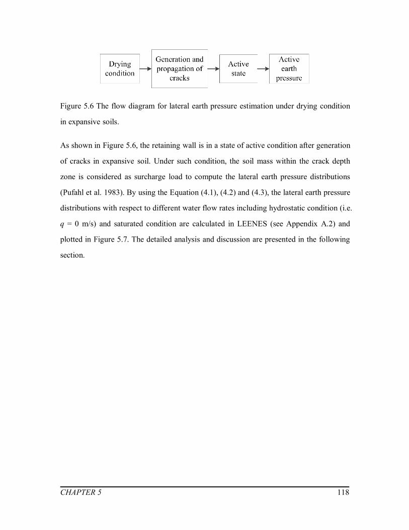
CHAPTER 5 118
Figure 5.6 The flow diagram for lateral earth pressure estimation under drying condition
in expansive soils.
As shown in Figure 5.6, the retaining wall is in a state of active condition after generation
of cracks in expansive soil. Under such condition, the soil mass within the crack depth
zone is considered as surcharge load to compute the lateral earth pressure distributions
(Pufahl et al. 1983). By using the Equation (4.1), (4.2) and (4.3), the lateral earth pressure
distributions with respect to different water flow rates including hydrostatic condition (i.e.
q = 0 m/s) and saturated condition are calculated in LEENES (see Appendix A.2) and
plotted in Figure 5.7. The detailed analysis and discussion are presented in the following
section.
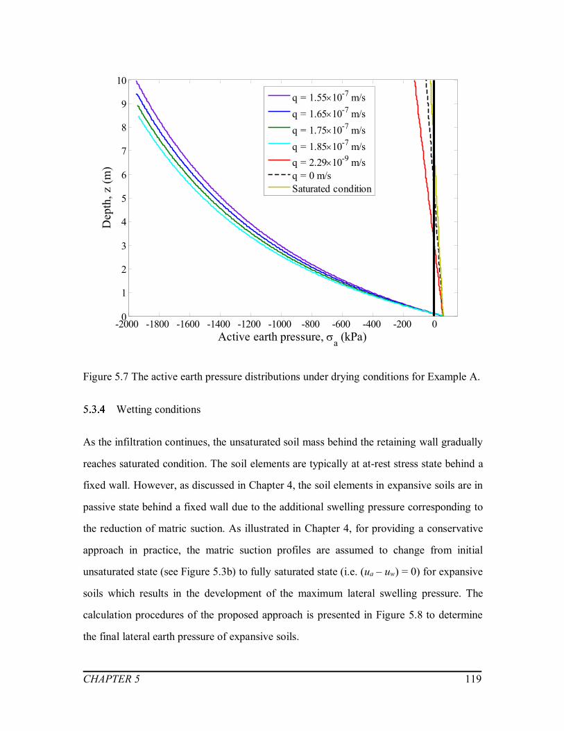
CHAPTER 5 119
-2000 -1800 -1600 -1400 -1200 -1000 -800 -600 -400 -200 00
1
2
3
4
5
6
7
8
9
10
Active earth pressure, a (kPa)
Dep
th, z
(m)
q = 1.5510-7 m/sq = 1.6510-7 m/sq = 1.7510-7 m/sq = 1.8510-7 m/sq = 2.2910-9 m/sq = 0 m/sSaturated condition
Figure 5.7 The active earth pressure distributions under drying conditions for Example A.
Wetting conditions
As the infiltration continues, the unsaturated soil mass behind the retaining wall gradually
reaches saturated condition. The soil elements are typically at at-rest stress state behind a
fixed wall. However, as discussed in Chapter 4, the soil elements in expansive soils are in
passive state behind a fixed wall due to the additional swelling pressure corresponding to
the reduction of matric suction. As illustrated in Chapter 4, for providing a conservative
approach in practice, the matric suction profiles are assumed to change from initial
unsaturated state (see Figure 5.3b) to fully saturated state (i.e. (ua – uw) = 0) for expansive
soils which results in the development of the maximum lateral swelling pressure. The
calculation procedures of the proposed approach is presented in Figure 5.8 to determine
the final lateral earth pressure of expansive soils.

CHAPTER 5 120
Figure 5.8 The flow diagram for lateral earth pressure estimation under wetting condition
in expansive soil.
The final lateral earth pressure in expansive soils under wetting condition (see Figure 5.9
c) can be calculated as the sum of at-rest earth pressure at saturated condition (see Figure
5.9a) and the additional lateral swelling pressure (see Figure 5.9b). The soil elements in
the upper layer are governed by the passive earth pressure at saturated condition
(Equation 4.7) as shown in Figure 5.9 (c) (Hong 2008, Sahin 2011).

CHAPTER 5 121
0 20 40 60 80 1000
1
2
3
4
5
6
7
8
9
10
(a) Saturated at-rest earth pressure, 0 (kPa)
Dep
th, z
(m)
20 30 40 50 600
1
2
3
4
5
6
7
8
9
10
(b) Additional lateral swelling pressure, s (kPa)
q = -310-10 m/sq = -410-10 m/sq = -510-10 m/sq = -610-10 m/sq = -710-10 m/sq = 0 m/s
0 50 100 150 200 250 3000
1
2
3
4
5
6
7
8
9
10
(c) Final lateral earth pressure, h (kPa)
Saturated passiveearth pressure, p (kPa)
Figure 5.9 Lateral earth pressure distributions under wetting conditions for Example A: (a) Saturated at-rest earth pressure; (b)
Additional swelling pressure due to variation of matric suction; (c) Final lateral earth pressure under wetting condition.
Note: Negative value of waterflow rates (i.e. q) representsthe infiltration condition.

CHAPTER 5 122
Analysis and discussion
The formation and propagation of cracks is significantly influenced by the tensile
strength of unsaturated soils (Amarasiri and Kodikara 2011). The tensile strength of
unsaturated soils can be considered as the sum of bridge water stress (i.e. capillary
suction) and negative pore pressure (Schubert 1975, Lu et al. 2007). The development of
the crack depth and ultimate tensile strength in Example A with respect to various
evaporation rates are presented in Figure 5.10. Higher evaporation flow rate results in a
large magnitude of matric suction which contributes to an increase in the ultimate tensile
strength of soils (see Figure 5.10). In addition, cracks propagate to a greater depth at
higher evaporation water flow rates as shown in Figure 5.10. The results of the present
study are consistent with the observations of Wu et al. (2014).
Figure 5.10 The depth of cracks and ultimate tensile strength with different steady state
flow rate for Example A.
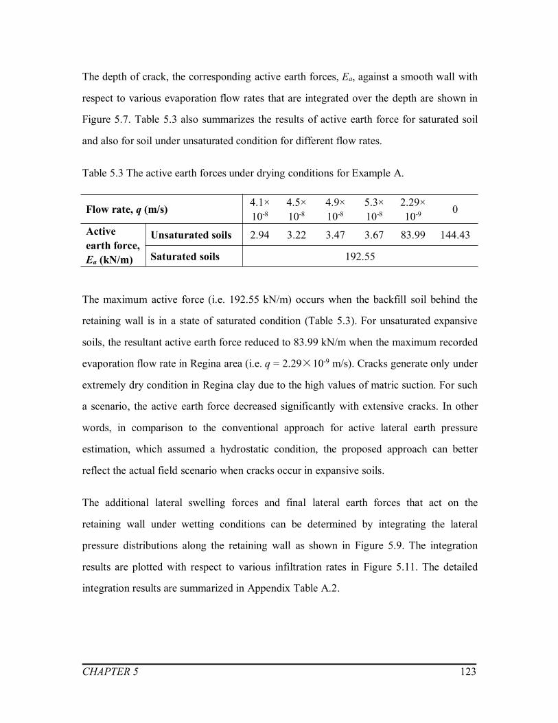
CHAPTER 5 123
The depth of crack, the corresponding active earth forces, Ea, against a smooth wall with
respect to various evaporation flow rates that are integrated over the depth are shown in
Figure 5.7. Table 5.3 also summarizes the results of active earth force for saturated soil
and also for soil under unsaturated condition for different flow rates.
Table 5.3 The active earth forces under drying conditions for Example A.
Flow rate, q (m/s) 4.1×10⁻⁸
4.5×10⁻⁸
4.9×10⁻⁸
5.3×10⁻⁸
2.29×10⁻⁹ 0
Activeearth force,Ea (kN/m)
Unsaturated soils 2.94 3.22 3.47 3.67 83.99 144.43
Saturated soils 192.55
The maximum active force (i.e. 192.55 kN/m) occurs when the backfill soil behind the
retaining wall is in a state of saturated condition (Table 5.3). For unsaturated expansive
soils, the resultant active earth force reduced to 83.99 kN/m when the maximum recorded
evaporation flow rate in Regina area (i.e. q = 2.29×10⁻⁹ m/s). Cracks generate only under
extremely dry condition in Regina clay due to the high values of matric suction. For such
a scenario, the active earth force decreased significantly with extensive cracks. In other
words, in comparison to the conventional approach for active lateral earth pressure
estimation, which assumed a hydrostatic condition, the proposed approach can better
reflect the actual field scenario when cracks occur in expansive soils.
The additional lateral swelling forces and final lateral earth forces that act on the
retaining wall under wetting conditions can be determined by integrating the lateral
pressure distributions along the retaining wall as shown in Figure 5.9. The integration
results are plotted with respect to various infiltration rates in Figure 5.11. The detailed
integration results are summarized in Appendix Table A.2.

CHAPTER 5 124
Figure 5.11 The lateral forces with respect to various infiltration flow rates for Example
A.
A reduction in additional swelling force can be observed from Figure 5.11 with the
increased infiltration flow rates while the saturated at-rest earth force remains constant
(i.e. 510 kN/m). Such a behavior could be explained as follows: relative drying condition
(i.e. lower infiltration flow rate) results in a higher matric suction in the retaining wall
backfill (see Figure 5.3b). This in turn will lead to an increase in the affinity of soil to
imbibe water. Due to this reason, an expansive soil backfill material, with a high initial
value of matric suction contributes to an additional lateral swelling pressure as it moves
from a state of unsaturated to saturated condition (Erol and Ergun 1994, Sapaz 2004).
Overall, in comparison to the saturated at-rest earth force, the final lateral earth force of
expansive soils under wetting conditions is significantly increased because of the
additional lateral swelling pressure.
Note: Negative value of water flow rates(i.e. q) represents the infiltration condition.

CHAPTER 5 125
Under such scenario, as illustrated in Chapter 3, the soil expansion at horizontal direction
is assumed to be strictly restricted. The deformation tendency of expansive soil mass in
horizontal direction transforms to be the lateral swelling pressure acting on the retaining
structures. As such, the soil elements are typically at passive state in expansive soils. Due
to this reason, the upper layer of expansive soils often experienced a passive failure
(Hong 2008, Sahin 2011). Due to this reason, the saturated passive earth pressure for
saturated soils (Equation 4.7) should be taken under consideration in practical retaining
wall design to prevent shear failure on the upper layer of expansive soil.
The traditional method for calculating the lateral earth pressures for unsaturated
expansive soils is conservative for evaporation conditions. The lateral earth pressure in
expansive soils significantly reduces due to the influence of cracks. On the other hand,
under wetting conditions, the lateral earth pressure of expansive soils calculated by
conventional method is not accurate enough without considering the swelling mechanism
of expansive soils. In addition to the earth pressure, additional lateral swelling pressure
generates in expansive soils and acts on the fixed retaining wall due to the variation of
matric suction.
5.4 Example B: Indian Head till, Saskatchewan, Canada
Meteorological data and soil properties
In this Example B, the soil properties from various sources for glacial clay till from
Indian Head, Saskatchewan, Canada are used for analysis (Vanapalli 1994, Vanapalli et
al. 1999 and 2007, Oh and Vanapalli 2010, Fredlund et al. 2012). This soil is classified as
a CL according to Unified Soil Classification System (USCS). The index properties,
grain size distribution and other basic soil properties are summarized in Table 5.4.

CHAPTER 5 126
The meteorological data of monthly precipitation is plotted in Figure 5.12, from which
the maximum precipitation value was found to be 2.99×10⁻⁸ m/s. The Indian Head CDA
Station also records the data for monthly lake evaporation rates; the maximum value
monthly evaporation was equal to 1.20×10⁻⁹ m/s (see Table 5.5).
Table 5.4 Soil properties of Indian Head till
Soil properties References
Atterberg LimitsLiquid limit, LL (%) 35.5
Oh and Vanapalli (2010)Plastic limit, PL (%) 16.8Plasticity index, IP (%) 18.7Grain-size DistributionSand sizes, (%) 28
Fredlund et al. (2012)Silt sizes, (%) 43Clay sizes, (%) 30Basic soil propertiesEffective cohesion, c’ (kPa) 10
Fredlund et al. (2012)Effective angle of internal friction, ’ (︒) 22.5Modulus of elasticity (saturated), Es (kPa) 2000 Vanapalli et al. (2007)Specific gravity, Gs 2.72
Oh and Vanapalli (2010)Max. dry density, d (kN/m3) 18.0Optimum moisture content, OMC (%) 16.3Initial void ratio, e0 0.474 Vanapalli et al. (1999)
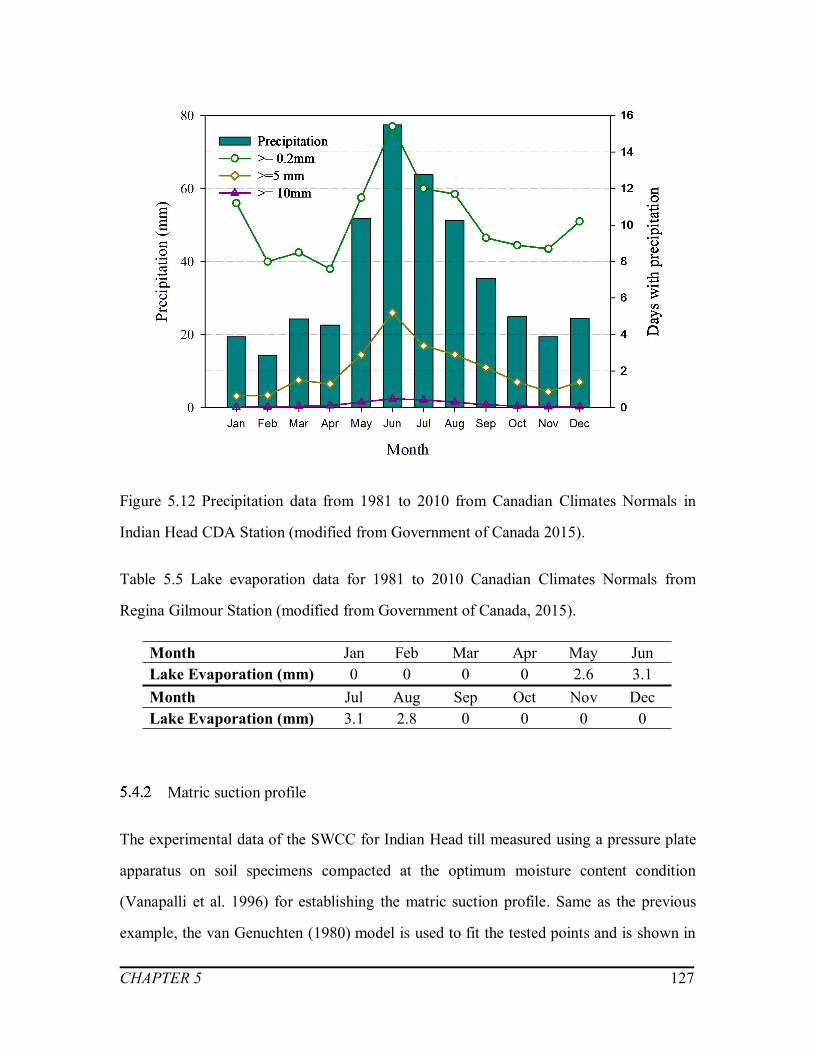
CHAPTER 5 127
Figure 5.12 Precipitation data from 1981 to 2010 from Canadian Climates Normals in
Indian Head CDA Station (modified from Government of Canada 2015).
Table 5.5 Lake evaporation data for 1981 to 2010 Canadian Climates Normals from
Regina Gilmour Station (modified from Government of Canada, 2015).
Month Jan Feb Mar Apr May JunLake Evaporation (mm) 0 0 0 0 2.6 3.1Month Jul Aug Sep Oct Nov DecLake Evaporation (mm) 3.1 2.8 0 0 0 0
Matric suction profile
The experimental data of the SWCC for Indian Head till measured using a pressure plate
apparatus on soil specimens compacted at the optimum moisture content condition
(Vanapalli et al. 1996) for establishing the matric suction profile. Same as the previous
example, the van Genuchten (1980) model is used to fit the tested points and is shown in

CHAPTER 5 128
Figure 5.13. The fitting parameters in the SWCC, namely a, n and m are 0.001 kPa-1,
0.6584 and 0.5852, respectively.
Figure 5.13 Soil-water characteristic curves of Indian Head till (modified from Vanapalli
et al. 1996).
Using LEENES, the hypothetical retaining wall with the same geometrical dimensions as
detailed for Example A is modeled. The fitting parameters for the SWCC and the soil
properties of Indian Head till are summarized in Table 5.4. The saturated coefficient of
permeability, ks, is assumed of 1×10⁻⁷ m/s (Oh and Vanapalli 2010). The matric suction
profiles are established under both drying and wetting conditions using Equation (3.3)
(see Appendix A.3 and Figure 5.14). The continuous black line represents suction profile
for hydrostatic condition (i.e. q = 0 m/s).

CHAPTER 5 129
Several evaporation rates which include, q = 1×10⁻⁹ m/s (i.e. the blue line in Figure 5.14 a)
q = 10×10-9, 50×10-9 and 100×10-9 m/s) are used to plot corresponding matric suction
profiles understand the influence on environmental factors on the performance of
retaining wall. Four different water flow rates were employed as shown in Figure 5.14 (b)
between no infiltration (i.e. hydrostatic condition, q = 0 m/s) to fully saturation condition
(i.e. the infiltration rate equals to the saturated coefficient of permeability, qs = 1×10⁻⁷
m/s) to understand the influence of wetting conditions.
0 25 50 75 100 125 150 175 200 225 2500
1
2
3
4
5
6
7
8
9
10
Matrica suction, (ua- uw) (kPa)(a) Drying conditions
Dep
th, z
(m)
q = 1 10 -9 m/sq = 10 10 -9 m/sq = 50 10 -9 m/sq = 100 10 -9 m/sq = 0 m/s

CHAPTER 5 130
0 20 40 60 80 100 120 1400
1
2
3
4
5
6
7
8
9
10
Matric suction, (ua- uw) (kPa)(b) Wetting conditions
Dep
th, z
(m)
q = -2.010-8 m/sq = -4.010-8 m/sq = -6.010-8 m/sq = -8.010-8 m/sq = 0 m/s
Figure 5.14 The matric suction profiles for Example B: (a) Drying conditions, (b)
Wetting conditions.
Drying and wetting conditions
When there is no significant swell-shrink behavior, the stress state of non-expansive soil
elements is only dependent on the movement of the retaining wall. The at-rest, active and
passive earth pressure distributions for Example B are discussed performing the analyses
following the various steps shown in flow chart (see Figure 5.15) for both drying and
wetting conditions.
Note: Negative value ofwater flow rates (i.e. q)represents the infiltrationcondition.

CHAPTER 5 131
Figure 5.15 The flow diagram for lateral earth pressure estimation under drying and
wetting conditions of Example B.
The matric suction profiles for Example B for different drying conditions are plotted with
respect to various evaporation and infiltration flow rates as well as hydrostatic condition
in Figure 5.14. The at-rest, active and passive earth pressure distributions are plotted in
Figure 5.16 and Figure 5.17, respectively for different environmental factors (i.e.
evaporation and infiltration flow rates) along with the hydrostatic and saturated
conditions.
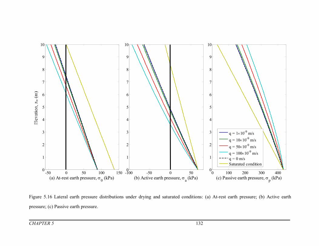
CHAPTER 5 132
-50 0 50 100 1500
1
2
3
4
5
6
7
8
9
10
(a) At-rest earth pressure, 0 (kPa)
Dep
th, z
(m)
-100 -50 0 500
1
2
3
4
5
6
7
8
9
10
(b) Active earth pressure, a (kPa)0 100 200 300 400
0
1
2
3
4
5
6
7
8
9
10
(c) Passive earth pressure, p (kPa)
q = 110-9 m/sq = 1010-9 m/sq = 5010-9 m/sq = 10010-9 m/sq = 0 m/sSaturated condition
Figure 5.16 Lateral earth pressure distributions under drying and saturated conditions: (a) At-rest earth pressure; (b) Active earth
pressure; (c) Passive earth pressure.
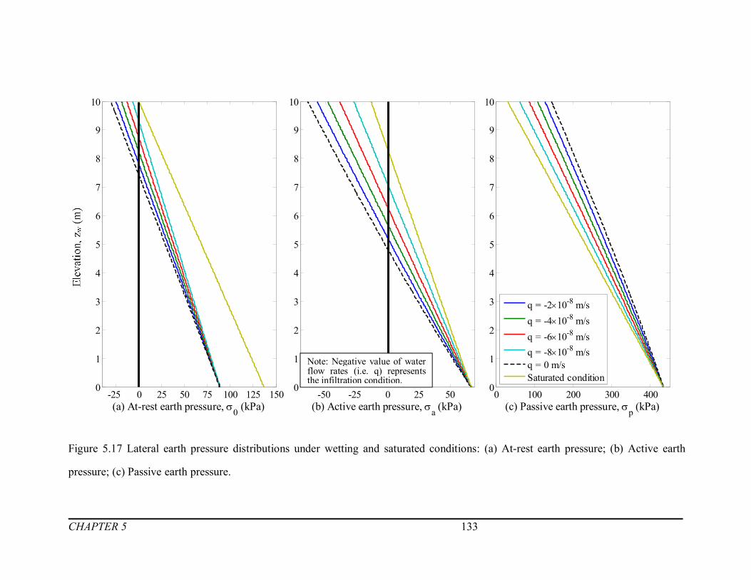
CHAPTER 5 133
-25 0 25 50 75 100 125 1500
1
2
3
4
5
6
7
8
9
10
(a) At-rest earth pressure, 0 (kPa)
Dep
th, z
(m)
-50 -25 0 25 500
1
2
3
4
5
6
7
8
9
10
(b) Active earth pressure, a (kPa)0 100 200 300 400
0
1
2
3
4
5
6
7
8
9
10
(c) Passive earth pressure, p (kPa)
q = -210-8 m/sq = -410-8 m/sq = -610-8 m/sq = -810-8 m/sq = 0 m/sSaturated condition
Figure 5.17 Lateral earth pressure distributions under wetting and saturated conditions: (a) At-rest earth pressure; (b) Active earth
pressure; (c) Passive earth pressure.
Note: Negative value of waterflow rates (i.e. q) representsthe infiltration condition.

CHAPTER 5 134
Analysis and discussion
The critical height (i.e. depth of tensile zone, zt) is an important factor that should be
considered in temporary cuts or excavation projects. The changes of critical height for
various water flow rates is plotted in Figure 5.18 (b) for Example B under at-rest and
active conditions. The detailed calculation results are presented in Appendix Table A.3. It
can be observed from Figure 5.18 (b), the critical height in unsaturated soils increases (i.e.
changes from 0.68m to 3.95m) at-rest condition (i.e. the retaining wall is fixed) when the
water flow rate changes from infiltration to evaporation condition. Similar increasing
trends in critical height (i.e. changes from 2.89m to 6.40m see Figure 5.18b) when the
soil elements are at active stress state (i.e. retaining wall moves away from soil mass).
It is widely acknowledged that matric suction is the main reason that enable the cohesive
soils to stand unsupported (Vanapalli and Oh 2012). However, during the design life
period of retaining wall, the soils usually experience several drying and wetting cycles,
which changes the matric suction profile considerably as shown in Figure 5.14. The value
of matric suction rises as water keeps evaporating and contributes to the self-supporting
ability of soil. Vanapalli and Oh (2012) highlighted the importance of reliable estimation
of the critical height such that geotechnical structures can be designed and constructed
based on rational procedures. The proposed approach in this thesis provides geotechnical
engineers with a relative simple and practical method for estimation of the critical height
by taking into account of the evaporation and infiltration flow rates.
In addition to the critical height, the changes of lateral earth forces for Example B are
plotted in Figure 5.18 (a) and (c) with respect to different water flow rates while the
detailed information could be found in Appendix Table A.4.
When soil elements are at a state of at-rest or active conditions, the resultant earth force
reduces due to the decrease in matric suction value for unsaturated soils when the
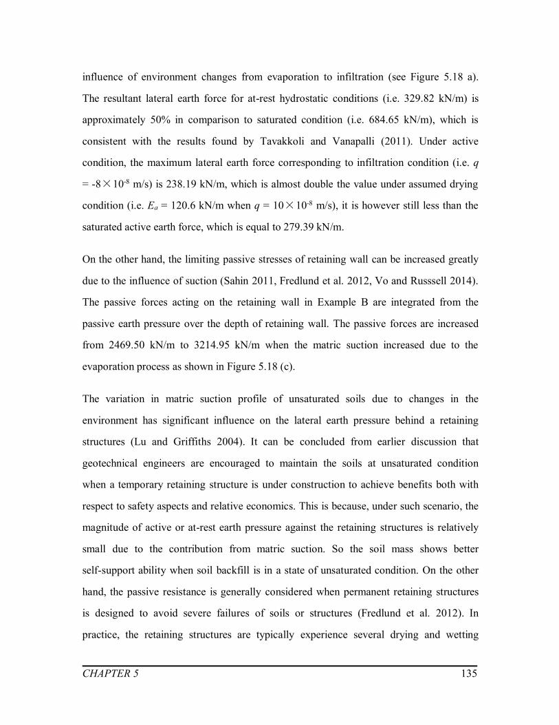
CHAPTER 5 135
influence of environment changes from evaporation to infiltration (see Figure 5.18 a).
The resultant lateral earth force for at-rest hydrostatic conditions (i.e. 329.82 kN/m) is
approximately 50% in comparison to saturated condition (i.e. 684.65 kN/m), which is
consistent with the results found by Tavakkoli and Vanapalli (2011). Under active
condition, the maximum lateral earth force corresponding to infiltration condition (i.e. q
= -8×10⁻⁸ m/s) is 238.19 kN/m, which is almost double the value under assumed drying
condition (i.e. Ea = 120.6 kN/m when q = 10×10-8 m/s), it is however still less than the
saturated active earth force, which is equal to 279.39 kN/m.
On the other hand, the limiting passive stresses of retaining wall can be increased greatly
due to the influence of suction (Sahin 2011, Fredlund et al. 2012, Vo and Russsell 2014).
The passive forces acting on the retaining wall in Example B are integrated from the
passive earth pressure over the depth of retaining wall. The passive forces are increased
from 2469.50 kN/m to 3214.95 kN/m when the matric suction increased due to the
evaporation process as shown in Figure 5.18 (c).
The variation in matric suction profile of unsaturated soils due to changes in the
environment has significant influence on the lateral earth pressure behind a retaining
structures (Lu and Griffiths 2004). It can be concluded from earlier discussion that
geotechnical engineers are encouraged to maintain the soils at unsaturated condition
when a temporary retaining structure is under construction to achieve benefits both with
respect to safety aspects and relative economics. This is because, under such scenario, the
magnitude of active or at-rest earth pressure against the retaining structures is relatively
small due to the contribution from matric suction. So the soil mass shows better
self-support ability when soil backfill is in a state of unsaturated condition. On the other
hand, the passive resistance is generally considered when permanent retaining structures
is designed to avoid severe failures of soils or structures (Fredlund et al. 2012). In
practice, the retaining structures are typically experience several drying and wetting

CHAPTER 5 136
cycles. The simple procedure proposed in the present study is useful to take account of
the influence of matric suction profile in the backfill which can be estimated considering
different evaporation and infiltration flow rates based on the environmental data for
rational design of retaining walls.
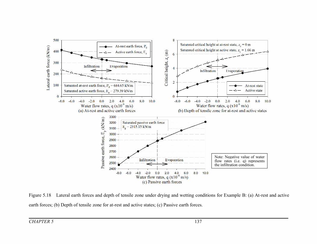
CHAPTER 5 137
Figure 5.18 Lateral earth forces and depth of tensile zone under drying and wetting conditions for Example B: (a) At-rest and active
earth forces; (b) Depth of tensile zone for at-rest and active states; (c) Passive earth forces.
Note: Negative value of waterflow rates (i.e. q) representsthe infiltration condition.

CHAPTER 5 138
5.5 Summary
The framework of lateral earth pressure estimation proposed in the thesis extending the
mechanics of unsaturated sols is demonstrated on a fixed retaining wall with expansive
soils in Example A. The propagations of cracks and additional swelling pressures change
the stress state of expansive soil elements behind the retaining wall. The limiting lateral
earth pressures therefore is discussed in this chapter taking account of variation of matric
suction profile within the backfill which is estimated for different environmental
conditions scenarios (i.e. wetting and drying) using the program code LEENES
developed using MATLAB.
In addition, an extension of the proposed approach is applied to a non-expansive soil as
backfill material in Example B. Lateral earth pressure for three typical stress states (i.e.
at-rest, active and passive state) are presented associated with evaporation and infiltration
water flow rates.
The proposed framework is simple and can be used by practicing geotechnical engineers
in the retaining wall design taking account of the influence of various environmental
factors (i.e. associated with different drying and wetting conditions) of expansive and
non-expansive soils.
CHAPTER 6 139
CONCLUSIONS AND PROPOSED RESEARCH FOR
FUTURE STUDIES
6.1 General
Rational procedures for lateral earth pressure estimation of unsaturated expansive soils
that take account of swelling and shrinkage characteristics due to environmental factors
are valuable for practicing engineers to provide reliable methods for design of retaining
walls. Conventional methods that are used for estimation of lateral earth pressures of
unsaturated soils, the matric suction variation is typically assumed to decrease linearly
from surface to a value of zero as it approaches groundwater table condition, assuming
hydrostatic condition (Fredlund and Rahardjo 1993, Hadži-Niković et al. 2015). However,
the environmental factors (i.e. infiltration and evaporation) have a significant influence
on the suction profiles of unsaturated soils, which is typically non-linear.
Expansive soils typically undergo extensive volumetric changes due to changes in matric
suction associated with the variation of water content due to wetting or drying conditions.
Extensive cracks develop due to evaporation conditions; however, additional lateral
swelling pressure arises on the retaining structures due to the influence of infiltration. In
simple terms, the soil stress state behind the retaining wall is significantly influenced due
to environmental factors.
The key objective of this thesis is to provide a comprehensive framework for estimating
the lateral pressures of unsaturated expansive soils taking into account of influence of

CHAPTER 6 140
both the cracks and the swelling pressure due to evaporation and infiltration, respectively.
In addition, the framework is also extended to apply for non-expansive soils.
Figure 6.1 Schematic diagram of the proposed framework.
As shown in Figure 6.1, soils mass changes from unsaturated condition to saturated
condition during drying-wetting process.
For non-expansive soils, the stress state of soil depends on the relative movement of
retaining wall with respect to the soil mass (i.e. backfill). The soil behind the retaining
wall is typically in an active state when retaining wall moves away from soil mass. The
active earth pressure is computed by Equation 4.1 and 4.2, for saturated and unsaturated
soils, respectively. On the other hand, when the retaining wall has a tendency to move
towards the backfill, the soil behind the wall is in a state of passive condition. The
passive earth pressures for saturated and unsaturated soils are computed by Equation 4.7
and 4.5, respectively. Besides, the at-rest earth pressures for saturated and unsaturated
soils are calculated by Equation 4.6 and 4.4.
For expansive soils, in addition to the movements of retaining walls, the soil stress state
also is significantly influenced to environmental factors as summarized earlier due to the
changes in water content. The vertical steady-state flow rate is employed to account the
CHAPTER 6 141
influence of environmental factors and estimate the variation of suction in the backfill
along the depth of retaining wall (Equation 3.3). The depth of cracks in drought or dry
season and additional lateral swelling pressures in rainy or wet season are estimated using
Equation 3.9 and 3.17, respectively. The lateral earth pressure distributions for expansive
soils under both drying and wetting conditions are computed by Equation 4.3 and 4.9,
respectively.
In this thesis, a program LEENES is developed using the MATLAB software to facilitate
calculations of all elements of the proposed framework, which is discussed in the earlier
paragraph, and plot figures of lateral pressure estimation. Once the information of the
input parameters of soil properties and the SWCC (in the form fitting parameters for the
SWCC equations, a, n and m using the models of van Genuchten (1980) or Fredlund and
Xing (1994), the proposed framework can be realized following the step-by-step
approach shown in a flow chart form in Figure 6.2.

CHAPTER 6 142
Figure 6.2 Flow chart for the proposed program LEENES.

CHAPTER 6 143
Examples with two different types of soils (i.e. Example A: Regina clay, a typical
expansive soil and Example B: Indian Head till, a glacial till which is non-expansive
fine-grained soil) are illustrated to present the calculation procedures and results using the
proposed program LEENES (see Appendix). Combined with the local climate data,
analysis and discussion are performed to compare the computation results for both
examples under drying and wetting conditions.
In the following sections, detailed conclusions of the thesis are summarized. In addition,
future studies that can be undertaken with respect to estimation of the lateral earth
pressures of expansive soils is also suggested.
6.2 Conclusions
- The suction profile variation associated with water content variation is required for
predicting the shrinkage and swelling behavior of expansive soils. The variation of
matric suction profile along the retaining wall depth is estimated taking account of
environmental factors (i.e. evaporation or infiltration using Equation 3.3). The fitting
parameters of the soil-water characteristic curve (SWCC) (i.e. a, n, and m) and the
coefficient of permeability of saturated soils are required for estimation of the matric
suction profile in the backfill.
- Cracks generate in expansive soils under drying conditions to a depth where the
lateral stress equals to tensile strength of soils. The depth of cracks is estimated using
Equation 3.9 with the aid of LEENES.
- Fully active state, which is the critical condition in the design of retaining wall with
expansive soil as a backfill material arises due to evaporation condition. The most
critical scenario arises when cracks propagate. At this condition, the lateral stress (i.e.
minor principal stress) and the vertical stress (i.e. major principal stress) decrease as
shown in Figure 4.3.

CHAPTER 6 144
- The soil mass within the zone of crack depth, zc, in unsaturated expansive soils is
considered as a surcharge load (Pufahl et al. 1983) for the estimation of lateral earth
pressure distribution extending the Mohr-Coulomb failure criterion (Equation 4.3).
- Under wetting conditions, the maximum swelling pressure occurs when there is
greatest variation of matric suction in expansive soils from its initial unsaturated
condition. However, for extending a conservative approach, soils are assumed to be
in a fully saturated condition after prolonged period of rainfall or gradual snow
melting. As a result, the matric suction is assumed to change from its initial condition
value to zero (i.e. soil is fully saturated).
A semi-empirical model proposed by Tu and Vanapalli (2016) to predict the
variation of vertical swelling pressure with respect to suction using SWCC as a tool
is used in the present study. The lateral swelling pressure, which is a key parameter
expressed in terms of vertical swelling pressure for unsaturated soils (Equation 3.17)
(Liu and Vanapalli 2016). The lateral earth pressure distribution for expansive
saturated soils under wetting condition is proposed in Equation (4.9).
- Combined with local climate data for monthly infiltration and evaporation rates from
Regina Int’l A Station and Indian Head CDA Weather Station, two examples
(namely, Example A and Example B) are summarized using LEENES, a MATLAB
program code developed for implementing the framework proposed in this thesis.
The calculation results are analyzed and discussed in this thesis to evaluate the
influence of the environmental factors (i.e. infiltration and evaporation flow rates)
towards expansive and non-expansive soils.
- The evaporation rates of recorded climate rates are not able to trigger cracks
generated in a non-expansive soil analyzed in the present study (Example B: Indian
Head till). However, the situation is different for expansive soils investigated in the
present study (Example A: Regina Clay). Relatively, low evaporation rates are
sufficient for crack generation and propagation in expansive unsaturated soils. In
CHAPTER 6 145
other words, extensive cracks propagate with relative ease in expansive soils. In
addition, large values of matric suction arise in expansive unsaturated soils upon
evaporation, which provide the high shear strength of soils. Due to this reason, the
corresponding lateral earth pressure is reduced significantly under drying condition
in expansive soils.
- Although the precipitation data for both examples are basically the same, the
difference of calculation results between Example A: Regina Clay and Example B:
Indian Head till are considerable. Additional lateral swelling pressures act on the
retaining walls when expansive soils are used as backfill. Consequently, soil
elements are in a passive state and retaining wall are subjected to larger lateral
pressure.
6.3 Proposed future studies for estimating lateral earth pressure of
unsaturated expansive soils
- The fitting parameters of the SWCC have significant influence on matric suction
profile in unsaturated soils. However, SWCCs are expected to undergo hysteresis
during drying and wetting circles. Hence, effects of hysteresis of the SWCCs should
be taken into consideration.
- The elastic modulus of unsaturated soil is a key parameter in the proposed approach
and has great influence to the calculation results. However, limited research is
available to estimate the elastic modulus of unsaturated soils with respect to the
change of matric suction (Oh et al. 2009, Adem and Vanapalli 2014). More
laboratory tests and field studies are required to provide a reliable estimation of the
elastic modulus of unsaturated expansive soils.
- After drying seasons, extensive cracks contribute to the development of preferential
pathways for water to infiltrate into the soil. Due to this reason, expansive soils will

CHAPTER 6 146
be significantly influenced both during the drying and wetting cycles. A more
comprehensive model is required to take into account of influence of both drying and
wetting cycles for expansive soils.
- Upon evaporation, the suction profiles are assumed to change from initial state to
zero (i.e. fully saturated condition) for conservative estimation. Nevertheless,
expansive soils rarely reach fully saturated conditions in practice because of low
coefficient of permeability. There is a need for a method for estimating swelling
pressures when the suction changes from initial state to another intermediate stage
and associated changes taking account of wetting and drying cycles.

REFERENCES 147
REFERENCES
Adem, H. H. (2014). Modulus of elasticity based method for estimating the vertical
movement of natural unsaturated expansive soils. Doctoral dissertation. University of
Ottawa.
Adem, H. H., and Vanapalli, S. K. (2013). Constitutive modeling approach for estimating
1-D heave with respect to time for expansive soils. International Journal of
Geotechnical Engineering, 7(2), 199-204.
Adem, H. H., and Vanapalli, S. K. (2014). Elasticity moduli of expansive soils from
dimensional analysis. Geotechnical Research, 1(2), 60-72.
Agus, S. S., and Schanz, T. (2005). Comparison of four methods for measuring total
suction. Vadose Zone Journal, 4, 1087-1095.
Amarasiri, A., and Kodikara, J. (2011). Use of material interfaces in DEM to simulate
soil fracture propagation in Mode I cracking. International Journal of Geomechanics,
11(8), 314-322.
Amarasiri, A. L., Kodikara, J. K., and Costa, S. (2011). Numerical modelling of
desiccation cracking. International Journal for Numerical and Analytical Methods in
Geomechanics, 35, 82-96.
ASTM (1996). Standard test methods for one-dimensional swell or settlement potential of
cohesive soils. Annual Book of ASTM Standards, D4546-96, American Society of
Testing Material.
ASTM (2003). Standard test methods for one-dimensional swell or settlement potential of
REFERENCES 148
cohesive soils. Annual Book of ASTM Standards, D4546-96, American Society of
Testing Material.
Attom, M. F., and Barakat, S. (2000). Investigation of three methods for evaluating
swelling pressure of soils. Environmental and Engineering Geoscience, 6(3),
293-299.
Avsar, E., Ulusay, R., and Sonmez, H. (2009). Assessments of swelling anisotropy of
Ankara clay. Engineering Geology, 105(1-2), 24-31.
Bagge, G. (1985). Tension cracks in saturated clay cuttings. In Proceedings of the 11th
International Conference on Soil Mechanics and Foundations Engineering, San
Francisco, 2, 393-395.
Baker, R. (1981). Tensile strength, tension cracks, and stability of slopes. Japanese
Society of Soil Mechanics and Foundation Engineering, 21(2), 1-17.
Bao, C. (2004). Behavior of unsaturated soil and stability of expansive soil slope.
Chinese journal of geotechnical engineering-Chinese edition, 26(1), 1-15.
Barbour, S. L., and Yang, N. (1993). A review of the influence of clay-brine interactions
on the geotechnical properties of Ca-montmorillonitic clayey soils from western
Canada. Canadian Geotechnical Journal, 30(6), 920-934.
Bell, F. G., and Culshaw, M. G. (2001). Problem soils: a review from a British
perspective. In Proceedings of the Problematic Soils Conference, 1-37.
Bishop, A. W. (1959). The effective stress principle. Teknisk Ukeblad, 39, 859-863. Soils
and Foundations, 21(2), 1-17.

REFERENCES 149
Bolt, G. H. (1956). Physico-chemical analysis of the compressibility of pure clays.
Géotechnique, 6(2), 86-93
Brackley, I. J. A., and Sanders, P. J. (1992). In situ measurement of total natural
horizontal in an expansive clay. Géotechnique, 42(2), 443-451.
Brooks, R. H., and Corey, A. T. (1964). Hydraulic properties of porous media and their
relation to drainage design. Transactions of the ASAE, 7(1), 26-0028.
Brutsaert, W. (1966). Probability laws for pore size distributions. Soil Science 101,
85-92.
Bulut, R., and Leong, E. C. (2008). Indirect measurement of suction. Journal of
Geotechnical and Geological Engineering, 26(6), 633-644.
Bulut, R., Lytton, R., and Wray, W. (2001). Soil suction measurements by filter paper. In
Expansive Clay Soils and Vegetative Influence on Shallow Foundations, 243-261.
Houston, TX, United States: American Society of Civil Engineers.
Cameron, D. A., and Walsh, P. F. (1984). Damage to buildings on clay soils. Australian
Council of National Trusts.
Catana, M. C., Vanapalli, S. K., and Garga, V. K. (2006). The water retention
characteristics of compacted clays. Unsaturated Soils, 1348-1359.
Chapman, D.L. (1913). A contribution to the theory of electro-capillarity. Philosophical
Magazine, 25, 475–481
Charlie, W. A., Osman, M. A., and Ali, E. M. (1984). Construction on expansive soils in
Sudan. Journal of Construction Engineering and Management, 110(3), 359-374.

REFERENCES 150
Chen, F. H. (1975). Foundations on expansive soils. Elsevier Scientific Publishing
Company, Amsterdam, Netherlands.
Chen, F. H. (2012). Foundations on expansive soils. Elsevier Scientific Publishing
Company, Amsterdam, Netherlands.
Cheney, J.E. (1986). Twenty-five years’ heave of a building constructed on clay, after tree
removal. Ground Engineering. July, 13-27.
Çimen, Ö., Keskin, S. N., and Yıldırım, H. (2012). Prediction of swelling potential and
pressure in compacted clay. Arabian Journal for Science and Engineering, 37(6),
1535-1546.
Clayton, C. R. I., Symons, I. F., and Hiedra-Cobo, J. C. (1991). The pressure of clay
backfill against retaining structures. Canadian Geotechnical Journal, (28), 282-297.
Connor, J. J., and Faraji, S. (2013). Fundamentals of structural engineering. New York,
Springer New York.
Dafalla, M. A., and Shamrani, M. A. (2011). Road damage due to expansive soils: survey
of the phenomenon and measures for improvement. Geotechnical Special Publication,
219, 73-80.
Das, B. M. (1995). Principles of foundation engineering PWS Publ. Co., Boston.
Decagon Devices Inc., (2003). WP4 dewpoint potential. Meter operator's manual.
Version 4, Pullman, WA, USA
Dhowian, A., Erol, O., and Abdulfettah, Y. (1988). Influence of gypsification on
engineering behavior of expansive clay. Journal of Geotechnical and

REFERENCES 151
Geoenvironmental Engineering, 126(6), 538-542.
Dineen, K., Burland, J. B., Ridley, A. M., and Vaughan, P. R. (2003). Soil matrix suction:
some examples of its measurement and application in geotechnical engineering.
Géotechnique, 53(2), 241-253.
Erguler, Z. A. (2001). An investigation on the swelling behavior of Ankara clay and effect
of disturbance on swelling, determination of swelling potential by empirical
equations. Geological Engineering. Ankara, Hacettepe University. M. Sc.
Erol, O., and Ergun, U. (1994). Lateral swell pressures in expansive soils. In Proceedings
of the 8th International Conference on Soil Mechanics and Foundation, New Delhi,
India, 4, 1511-1511.
Erzin, Y., and Erol, O. (2004). Correlations for quick prediction of swell pressures.
Journal of Geotechnical Engineering, 9, 1.
Fourie, A. B., and Potts, D. M. (1989). Comparison of finite element and limiting
equilibrium analyses for an embedded cantilever retaining wall. Géotechnique, 39(2),
175-188.
Fredlund, D. G. (1967). Comparison of soil suction and one-dimensional consolidation
characteristics of a highly plastic clay. National Research Council Canada, Division
of Building Research.
Fredlund, D. G. (1975). Engineering properties of expansive clays. University of
Saskatchewan Transportation and Geotechnical Group.
Fredlund, D. G. (1983). Prediction of ground movements in swelling clays. In
Presentation of the 31st Annual Soil Mechanics and Foundation Engineering

REFERENCES 152
Conference, Minneapolis, Minn. American Society of Civil Engineers, New York.
Fredlund, D. G., Morgenstern, N. R., and Widger, R. A. (1978). The shear strength of
unsaturated soils. Canadian geotechnical journal, 15(3), 313-321.
Fredlund, D. G., and Rahardjo, H. (1993). Soil mechanics for unsaturated soils. Hoboken,
NJ, USA: John Wiley and Sons, Inc.
Fredlund, D. G., Rahardjo, H., and Fredlund, M. D. (2012). Unsaturated soil mechanics
in engineering practice. Hoboken, NJ, USA: John Wiley and Sons, Inc.
Fredlund, D. G., Xing, A., and Huang, S. (1994). Predicting the permeability function for
unsaturated soils using the soil-water characteristic curve. Canadian Geotechnical
Journal, 31(3), 521-532.
Fredlund, M. D., Fredlund, D. G., and Wilson, G. W. (1997). Prediction of the soil-water
characteristic curve from grain-size distribution and volume-mass properties percent
passing. In The 3rd Brazilian Symposium on Unsaturated Soils. Rio de Janeiro,
Brazil.
Gardner, W. R. (1958). Some steady-state solutions of the unsaturated moisture flow
equation with application to evaporation from a water table. Soil science, 85(4),
228-232.
Garven, E., and Vanapalli, S. K. (2006). Evaluation of empirical procedures for predicting
the shear strength of unsaturated soils. Unsaturated Soils 2006, 2570-2581.
Gouy, G. (1910). Electric charge on the surface of an electrolyte. Journal of Physics, 4(9),
457

REFERENCES 153
Griffith, A. A. (1924). The theory of rupture. Proc, First Int. Congress on Applied
Mechanics, Delft, Netherlands, 55-63
Hadži-Niković, G., Đoković, K., and Vujic, S. (2015). Effect of absorption on active
pressure in floury soil. Journal of Mining Science, 51(2), 253-260.
Hensen, E. J. M., and Smit, B. (2002). Why clays swell? The Journal of Physical
Chemistry B, 106(49), 12664-12667.
Holtz, W. G., and Gibbs, H. J. (1956). Engineering properties of expansive clays.
Transactions of the American Society of Civil Engineers, 121(1), 641-663.
Hong, G. T. (2008). Earth pressures and deformations in civil infrastructure in expansive
soils. Doctoral dissertation, Texas, A&M University.
Houston, S. L., Dye, H. B., Zapata, C. E., Walsh, K. D., and Houston, W. N. (2009).
Study of expansive soils and residential foundations on expansive soils in Arizona.
Journal of Performance of Constructed Facilities, 25(1), 31-44.
Hu, X. (2006). Calculation about active earth pressure of unsaturated expansive soil
based on Coulomb theory. Subgrade Engineering, 4, 73-76.
Ireland, H. 0. (1964). Design and construction of retaining walls. In Soil mechanics
lecture series: design of structures to resist earth pressure. American Society of Civil
Engineers, Chicago, IL.
Jia, J. (2010). Study on the swelling mechanism and mesomechanical swelling model of
expansive soils. Doctoral dissertation. Dalian University of Technology, China
Jones, D. E., and Holtz, W. G. (1973). Expansive soils-The hidden disaster. Civil Eng.,

REFERENCES 154
New York, 87-89.
Jones, L. D., and Jefferson, I. (2012). Expansive soils. ICE manual of geotechnical
engineering, London, UK: ICE.
Joshi, R.P. and Katti, R.K. (1984). Lateral pressure development under surcharges. In
Proc. of 5th International Conference on Expansive soils, Adelaide, South Africa,
227-241.
Kayabali, K., and Demir, S. (2011). Measurement of swelling pressure: direct method
versus indirect methods. Canadian Geotechnical Journal, 48(3), 354-364.
Kodikara, J., Barbour, S.L. and Fredlund, D.G., (2000). Desiccation cracking of soils. In
Proceedings of the Asian Conference on unsaturated soils for Asia, Rahardjo, Toll
and Leong eds., Balkema, Rotterdam.
Konrad, J., and Ayad, R. (1997). An idealized framework for the analysis of cohesive
soils undergoing desiccation. Canadian Geotechnical Journal, 34, 477-488.
Konrad, J. M., and Ayad, R. (1997). Desiccation of a sensitive clay: Field experimental
observations. Canadian Geotechnical Journal, 34(6), 929-942.
Krohn, J. P., and Slosson, J. E. (1980). Assessment of expansive soils in the United States.
In Expansive Soils, 596-608.
Lee, F., Lo, K., and Lee, S. (1988). Tension crack development in soils. Journal of
Geotechnical Engineering, 114(8), 915-929.
Leong, E., and Rahardjo, H. (1997). Review of soil-water characteristic curve equations.
Journal of Geotechnical and Geoenvironmental Engineering, 123(12), 1106-1117.
REFERENCES 155
Li, P., Yang, Q., Luan, M., and Wang, D. (2008). Research on influential factors of crack
propagation depth of unsaturated expansive soils. Chinese Journal of Rock
Mechanics and Engineering, 27(2), 2967-2972.
Likos, W. (2004). Measurement of crystalline swelling in expansive clay. Geotechnical
Testing Journal, 27(6), 1-7.
Likos, W. J., and Lu, N. (2004). Hysteresis of capillary stress in unsaturated granular soil.
Journal of Engineering Mechanics, 130(6), 646-655.
Low, P. F. (1987). Structural component of the swelling pressure of clays. Langmuir,
3(1), 18-25.
Low, P. F. (1992). Interparticle forces in clay suspensions: flocculation, viscous flow and
swelling. In CMS Workshop Lectures, 4, 158-190. The Clay Minerals Society
Boulder, CO.
Lu, N., Asce, M., Wu, B., and Tan, C. P. (2007). Tensile strength characteristics of
unsaturated sands. Journal of Geotechnical and Geoenvironmental Engineering, 133,
144-154.
Lu, N., and Griffiths, D. V. (2004). Profiles of steady-state suction stress in unsaturated
soils. Journal of Geotechnical and Geoenvironmental Engineering, 130, 1063-1076.
Lu, Z., Wu, X., Sun, Y., and Yin, W. (1997). The role of swelling pressure in the shear
strength theory of unsaturated soils. Chinese Journal of Geotechnical Engineering,
19(5), 20-27.
Ma, J., Chen, S., Yu, F., and Feng, M. (2007). Experimental research on crack evolution
process in fissured clay. Rock and Soil Mechanics, 28(10), 2203-2208.

REFERENCES 156
Marsh, E. T. and Walsh, R. K. (1996). Common causes of retaining-wall distress: case
study. Journal of Performance of Constructed Facilities, 35(38), 128.
Mitchell, J. K. (1993). Fundamentals of Soil Behavior, 2nd ed., Wiley, New York.
Mohamed, O. Z., Taha, Y. K., and Elaziz, E. M. A. (2014). Field study of the distribution
of lateral swelling pressure of expansive soil on retaining structure. Journal of
Engineering Sciences, 42(2), 289-302.
Morris, P. H., Graham, J., and Williams, D. J. (1992). Cracking in drying soils. Canadian
Geotechnical Journal, 29, 263-277.
Nahlawi, H., and Kodikara, J. K. (2006). Laboratory experiments on desiccation cracking
of thin soil layers. Journal of Geotechnical and Geological Engineering, 24(6),
1641-1664.
Nam, S., Gutierrez, M., Diplas, P., Petrie, J., Wayllace, A., Lu, N., and Muñoz, J. J.
(2010). Comparison of testing techniques and models for establishing the SWCC of
riverbank soils. Engineering Geology, 110(1-2), 1-10.
Nelson, J. D., and Miller, D. J. (1992). Expansive soils-problems and practice in
foundation and pavement engineering. Willy, New York.
Nelson, J. D., Overton, D. D., and Durkee, D. B. (2001). Depth of wetting and the active
zone. In Expansive clay soils and vegetative influence on shallow foundations,
95-109.
Norrish, K. (1954). The swelling of montmorillonite. Discussions of the Faraday Society,
18, 120-134.
REFERENCES 157
Ofer, Z. (1981). Laboratory instrument for measuring lateral soil pressure and swelling
pressure. Geotechnical Testing Journal, 4(4), 177-182.
Oh, W. T., Garga, V. K., and Vanapalli, S. K. (2008). Shear strength characteristics of
statically compacted unsaturated kaolin. Canadian Geotechnical Journal, 45(7),
910-922.
Oh, W. T., and Vanapalli, S. K. (2010). Influence of rain infiltration on the stability of
compacted soil slopes. Computers and Geotechnics, 37(5), 649-657.
Oh, W. T., Vanapalli, S. K., and Puppala, A. J. (2009). Semi-empirical model for the
prediction of modulus of elasticity for unsaturated soils. Canadian Geotechnical
Journal, 46(8), 903-914.
Petry, T. M., and Jiang, C. P. (2003). Evaluation and utilization of the WP4 dewpoint
potentiameter Phase I and II (No. UTC R91-R126).
Power, K. C., Vanapalli, S. K., and Garga, V. K. (2008). A revised contact filter paper
method. Geotechnical Testing Journal, 31(6), 461-469.
Prat, P. C., Ledesma, A., Lakshmikantha, M. R., Levatti, H., and Tapia, J. (2008).
Fracture mechanics for crack propagation in drying soils. In Proceedings of the 12th
International Conference of the International Association for Computer Methods and
Advances in Geomechanics (IACMAG), Goa, India, 1-6.
Pufahl, D. E., Fredlund, D. G., and Rahardjo, H. (1983). Lateral earth pressures in
expansive clay soils. Canadian Geotechnical Journal, 20, 228-241.
Punmia, B., and Jain, A. (2005). Soil mechanics and foundations. The 3rd Edition, 5.

REFERENCES 158
Puppala, A. J., and Cerato, A. (2009). Heave distress problems in chemically-treated
sulfate-laden materials. Geo-Strata-Geo Institute of ASCE, 10(2), 28-30.
Puppala, A. J., Katha, B., and Hoyos, L. R. (2004). Volumetric shrinkage strain
measurements in expansive soils using digital imaging technology. Geotechnical
Testing Journal, 27(6), 547-556.
Qi, S., and Vanapalli, S. K. (2015). Hydro-mechanical coupling effect on surficial layer
stability of unsaturated expansive soil slopes. Computers and Geotechnics, 70, 68-82.
Rankine, W. M. (1857). On the stability of loose earth. Philosophical Transactions of the
Royal Society of London, 147, 9-27.
Rao, B. H., Venkataramana, K., and Singh, D. N. (2011). Studies on the determination of
swelling properties of soils from suction measurements. Canadian Geotechnical
Journal, 48(3), 375-387.
Rao, R. R., Rahardjo, H., and Fredlund, D. G. (1988). Closed-from heave solutions for
expansive soils. Journal of Geotechnical Engineering, 114(5), 573-588.
Rao, S. M. (2006). Identification and classification of expansive soils. Expansive soils:
Recent advances in characterization and treatment, Taylor and Francis Group,
London, UK, 15-224.
Sahin, H. (2011). Characterization of expansive soil for retaining wall design. Texas
A&M University.
Sapaz, B. (2004). Lateral versus vertical swelling pressures in expansive soils. MASc
thesis. Middle East Technical University.

REFERENCES 159
Schubert, H. (1975). Tensile strength of agglomerates. Powder Technology, 11(2),
107-119.
Seed, H. B., and Chan, C. K. (1959). Structure and strength characteristics of compacted
clays. Journal of the Soil Mechanics and Foundations Division, 85(5), 87-128.
Seed, H. B., Woodward Jr, R. J., and Lundgren, R. (1962). Prediction of swelling
potential for compacted clays. Journal of the soil mechanics and foundations division,
88(3), 53-88.
Shah, P. H., Sreedeep, S., and Singh, D. N. (2006). Evaluation of methodologies used for
establishing soil-water characteristic curve. Journal of ASTM International, 3(6),
1-11.
Shuai, F. (1996). Simulation of swelling pressure measurements on expansive soils.
Doctoral dissertation, University of Saskatchewan, Saskatoon, Canada.
Sillers, W. S., Fredlund, D. G., and Zakerzadeh, N. (2001). Mathematical attributes of
some soil -water characteristic curve models. Journal of Geotechnical and Geological
Engineering, 19(3-4), 243-283.
Snyder, V. A., and Miller, R. D. (1985). Tensile strength of unsaturated soils. Soil Science
Society of America Journal, 49(2), 519.
Sobhi, M. A., Li, L., and Aubertin, M. (2014). Numerical investigation of the lateral earth
pressure coefficient along the VCL of vertical backfill slopes. In proceedings of the
GeoRegina 2014.
Soga, K., and Mitchell, J. K. (2005). Fundamentals of soil Behavior. Wiley. Third Edition.
ISBN, 10, 1-471.
REFERENCES 160
Sreedeep, S., and Singh, D. N. (2006a). Methodology for determination of osmotic
suction of soils. Journal of Geotechnical and Geological Engineering, 24(5),
1469-1479.
Sreedeep, S. (2006b). Nonlinear curve-fitting procedures for developing soil-water
characteristic curves. Geotechnical Testing Journal, 29(5), 1-10.
Sridharan, A., Rao, S. M., and Murthy, N. S. (1986). Compressibility behaviour of
homoionized bentonites. Géotechnique, 36(4), 551-564.
Steinberg, M. (1998). Geomembranes and the control of expansive soils in construction.
Sudhindra, C., and Moza, K. K. (1987). An approach for lateral pressure assessment in
expansive soils. In Proceedings of the 6th International Conference of Expansive
Soils, 1, 67-70.
Tang, C. S., Tang, A. M., Cui, Y. J., Delage, P., and De Laure, E. (2015). A new apparatus
for the measurement of swelling pressure under constant volume condition.
Engineering Geology for Society and Territory, 6, 480-492.
Tavakkoli, N., and Vanapalli, S. K. (2011). Rational approach for the design of retaining
structures using the mechanics of unsaturated soils. In Proceedings of the14th
Pan-American Conference on Soil Mechanics and Geotechnical Engineering.
Toronto, Ontario.
Tawfik, E. F., Hamid, T. B., and Aggour, M. S. (2007). Design of cantilever retaining
walls in unsaturated soils using AASHTO load and resistance factor design (LRFD)
Method. In Probabilistic Applications in Geotechnical Engineering, 1-10. Reston, VA:
American Society of Civil Engineers.
REFERENCES 161
Tej, P. R., Singh, D. N., and Asce, F. (2013). Estimation of tensile strength of soils from
penetration resistance. International Journal of Geomechanics, 13, 496-501.
Terzaghi, K. V. (1936). The shearing resistance of saturated soils and the angle between
the planes of shear. In Proceedings of the 1st international conference on soil
mechanics and foundation engineering, Harvard University Press Cambridge, MA. 1,
54-56.
Thakur, V. K., Sreedeep, S., and Singh, D. N. (2005). Parameters affecting soil-water
characteristic curves of fine-grained soils. Journal of Geotechnical and
Geoenvironmental Engineering, 131(4), 521-524.
Thakur, V. K., Sreedeep, S., and Singh, D. N. (2006). Laboratory investigations on
extremely high suction measurements for fine-grained soils. Journal of Geotechnical
and Geological Engineering, 24(3), 565-578.
Tripathy, S., Rao, K. S., and Fredlund, D. G. (2002). Water content-void ratio
swell-shrink paths of compacted expansive soils. Canadian geotechnical journal,
39(4), 938-959.
Tripathy, S., Sridharan, A., and Schanz, T. (2004). Swelling pressures of compacted
bentonites from diffuse double layer theory. Canadian Geotechnical Journal, 41(3),
437-450.
Tu, H., and Vanapalli, S. K. (2016). Prediction of the variation of swelling pressure and
1-D heave of expansive soils with respect to suction using the soil water retention
curve as a tool. Canadian Geotechnical Journal.
Vahedifard, F., Leshchinsky, B. A., Mortezaei, K., and Lu, N. (2015). Active earth
REFERENCES 162
pressures for unsaturated retaining structures. Journal of Geotechnical and
Geoenvironmental Engineering, 141(11), 04015048.
van Genuchten, M. (1980). A closed form equation predicting the hydraulic conductivity
of unsaturated soils. Soil Science Society of America Journal, 44, 892-898.
van Olphen, H. (1963). An introduction to clay colloid chemistry: for clay technologists,
geologists and soil scientists. Inter-science, New York.
Vanapalli, S. K., and Catana, M. C. (2005, July). Estimation of the soil-water
characteristic curve of coarse grained soils using one point measurement and simple
properties. In Proceedings of an International Symposium on Advanced
Experimental Unsaturated Soil Mechanics, 401-410.
Vanapalli, S. K., Fredlund, D. G., and Pufahl, D. E. (1996). Model for the prediction of
shear strength with respect to soil suction. Canadian Geotechnical Journal, 33,
379-392.
Vanapalli, S. K., Fredlund, D. G., and Pufahl, D. E. (1999). The influence of soil structure
and stress history on the soil-water characteristics of a compacted till. Géotechnique,
49(2), 143-159.
Vanapalli, S. K., and Lu, L. (2012). A state of the art review of 1-D heave prediction
methods for expansive soils. International Journal of Geotechnical Engineering, 6(1),
15-41.
Vanapalli, S. K., Lu, L., and Oh, W. T. (2010). A simple technique for estimating the 1-D
heave in expensive soils. In Proceeding of the 5th Int. Conf. on Unsaturated Soils,
Barcelona, Spain, CRC, 1201-1207.
REFERENCES 163
Vanapalli, S. K., and Oh, W. T. (2010). A model for predicting the modulus of elasticity
of unsaturated soils using the soil-water characteristic curve. International Journal of
Geotechnical Engineering, 4(4), 425-433.
Vanapalli, S. K., and Oh, W. T. (2012). Stability analysis of unsupported vertical trenches
in unsaturated soils. In Proceeding of the GeoCongress 2012, 2502-2511.
Vanapalli, S., Wright, A., and Fredlund, D. (1996). Shear strength behavior of a silty soil
over the suction range from 0 to 1,000,000 kPa. In Proceedings of the 53th Canadian
Geotechnical Conference, 15-18.
Vo, T., and Russell, A. R. (2014). Slip line theory applied to a retaining wall-unsaturated
soil interaction problem. Computers and Geotechnics, 55, 416-428.
Vu, H. Q., and Fredlund, D. G. (2004). The prediction of one-, two-, and
three-dimensional heave in expansive soils. Canadian Geotechnical Journal, 41(4),
713-737.
Wang, L., Yang, G., Liu, H., Xu, Y., and Wang, P. (2013). In-situ testing studies of
swelling pressure on weak - medium expansive soil of Yun-Gui Railway. Journal of
Central South University, 44(11), 4658-4663.
Widger, R. A., amd Fredlund, D. G. (1979). Stability of swelling clay embankments.
Canadian Geotechnical Journal, 16(1), 140-151.
Windal, T., and Shahrour, I. (2002). Study of the swelling behavior of a compacted soil
using flexible odometer. Mechanics Research Communications, 29(5), 375-382.
Wu, X., Li, G., Hu, W., and Wang, X. (2014). Study on ground fissure under rainfall and
evaporation. Journal of Disaster Prevention and Mitigation Engineering, 34(1),

REFERENCES 164
113-118.
Xie, Y., Chen, Z., Sun, S., Li, G., and Fang, X. (2007). Test research on three-dimensional
swelling pressure of remolded expansive clay. Rock and Soil Mechanics, 28(8),
1636-1642.
Xu, B., Yin, Z., and Liu, S. (2011). Experimental study of factors influencing expansive
soil strength. Rock and Soil Mechanics, 32(1), 44-50.
Yang, C., Dong, D., Tao, B., and Liu, B. (2014). Laboratory tests on three-directional
swelling deformation of remolded expansive soil. Journal of Engineering Geology,
22(2), 81-87.
Yeh, T. C. J. (1989). One-dimensional steady state infiltration in heterogeneous soils.
Water Resources, 25(10), 2149-2158.
Yilmaz, I. (2006). Indirect estimation of the swelling percent and a new classification of
soils depending on liquid limit and cation exchange capacity. Engineering Geology,
85(3-4), 295-301.
Zhan, T. L. T., and Ng, C. W. W. (2006). Shear strength characteristics of an unsaturated
expansive clay. Canadian Geotechnical Journal, 43, 751-763.
Zhang, C., Zhang, Q., and Zhao, J. (2010). Unified solutions of shear strength and earth
pressure for unsaturated soils. Rock and Soil Mechanics, 31(6), 1871-1876.
Zhang, C., Zhao, J., Zhang, Q., and Xu, F. (2010). Unified solutions for unsaturated soil
shear strength and active earth pressure. In Proceedings of the GeoShanghai,
218-224.
REFERENCES 165
Zhang, J. (2012). Analysis of the calculation method of active earth pressure of
unsaturated expansive soil. Advanced Materials Research, 594, 180-185.
Zhang, J., Gong, B., Hu, B., Zhou, X., and Wang, J. (2011). Study of evolution law of
fissures of expansive clay under wetting and drying cycles. Rock and Soil Mechanics,
32(9), 2729-2734.
Zhang, Y. (1993). Study present situation and review at home and abroad of lateral
swelling pressures of expansive soils. Dam Observation and Geotechnical Tests,
17(3), 28-32.
Zhang, Y. (1995a). Distribution of lateral swelling pressure and the method of design and
computation of retaining wall in expansive soil area. Railway Science, 1, 93-102.
Zhang, Y. (1995b). Distribution, measurement and comparison calculation of earth
pressures on retaining walls in expansive soil regions. Hydropower Automation and
Dam Monitoring, 19(1), 20-26.
Zhao, J., Liang, W., Zhang, C., and Li, Y. (2013). Unified solution of Coulomb’s active
earth pressure for unsaturated soils. Rock and Soil Mechanics, 34(3), 609-614.
Zheng, S., Jin, J., Yao, H., and Ge, X. (2006). Analysis of initial cracking behavior of
expansive soil due to evaporation. Rock and Soil Mechanics, 27(12), 2229-2233.
Zhu, Z., and Liu, S. (2001). Analysis of active earth pressure of unsaturated expansive
soil. Journal of Highway and Transportation Research and Development, 18(5), 8-10.
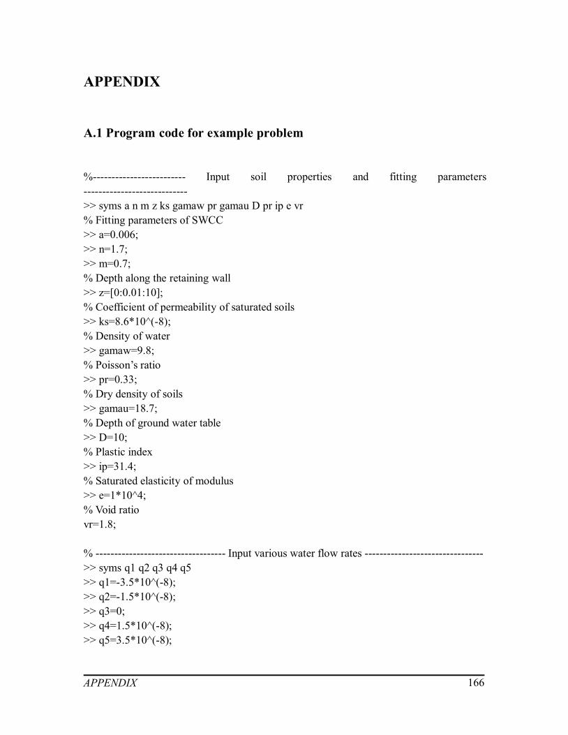
APPENDIX 166
APPENDIX
A.1 Program code for example problem
%------------------------- Input soil properties and fitting parameters---------------------------->> syms a n m z ks gamaw pr gamau D pr ip e vr% Fitting parameters of SWCC>> a=0.006;>> n=1.7;>> m=0.7;% Depth along the retaining wall>> z=[0:0.01:10];% Coefficient of permeability of saturated soils>> ks=8.6*10^(-8);% Density of water>> gamaw=9.8;% Poisson’s ratio>> pr=0.33;% Dry density of soils>> gamau=18.7;% Depth of ground water table>> D=10;% Plastic index>> ip=31.4;% Saturated elasticity of modulus>> e=1*10^4;% Void ratiovr=1.8;
% ----------------------------------- Input various water flow rates -------------------------------->> syms q1 q2 q3 q4 q5>> q1=-3.5*10^(-8);>> q2=-1.5*10^(-8);>> q3=0;>> q4=1.5*10^(-8);>> q5=3.5*10^(-8);

APPENDIX 167
% ----- Calculating matric suction profiles corresponding to different water flow rates ---->> syms ms1 ms2 ms3 ms4 ms5>> ms1=(-log((1+q1/ks)*vr.^(-gamau*a*z)-q1/ks))/a;>> ms2=(-log((1+q2/ks)* vr.^(-gamau*a*z)-q2/ks))/a;>> ms3=(-log((1+q3/ks)* vr.^(-gamau*a*z)-q3/ks))/a;>> ms4=(-log((1+q4/ks)* vr.^(-gamau*a*z)-q4/ks))/a;>> ms5=(-log((1+q5/ks)* vr.^(-gamau*a*z)-q5/ks))/a;
% --------------------------------- Plot the matric suction profiles --------------------------------->> plot(ms1,z,ms2,z,ms3,z,ms4,z,ms5,z)
% ----------------------------------- Calculate degree of saturation -------------------------------->> syms ds1 ds2 ds3 ds4 ds5>> ds1=1./(1+(a*ms1).^n).^m;>> ds2=1./(1+(a*ms2).^n).^m;>> ds3=1./(1+(a*ms3).^n).^m;>> ds4=1./(1+(a*ms4).^n).^m;>> ds5=1./(1+(a*ms5).^n).^m;
% ------------------------------------- Calculate the unsaturated elasticity of modulus alongthe retaining wall with respect to different water flow rates----------------------------------------->> syms eun1 eun2 eun3 eun4 eun5>> eun1=e*(1+0.1*ms1.*ds1.^2);>> eun2=e*(1+0.1*ms2.*ds2.^2);>> eun3=e*(1+0.1*ms3.*ds3.^2);>> eun4=e*(1+0.1*ms4.*ds4.^2);>> eun5=e*(1+0.1*ms5.*ds5.^2);
% -----------------------------Elastic modulus under saturated condition------------------------->> syms x y>> y=z;>> x=0*y+e;
% --------------- Plot the elastic modulus of unsaturated and saturated soils------------------->> plot(x,y,eun1,z,eun2,z,eun3,z,eun4,z,eun5,z),axis([0 8*10^4 0 10])

APPENDIX 168
A.2 Program code for Example A
%------------------------- Input soil properties and fitting parameters---------------------------->> syms c fi D ks gamau a n m ip k Ka Kp e pr vr% Effective cohesion of soils>> c=17;% Effective angle of internal friction>> fi=15;% Depth of ground water table>> D=10;% Coefficient of permeability of saturated soil>> ks=7.9*10^(-10);% Dry density of soils>> gamau=14;% Fitting parameters of SWCC>> a=0.0001;>> n=0.9974;>> m=0.4388;% Plasticity index>> ip=44;% Fitting parameters>> k=-0.0016*ip^2+0.0975*ip+1;% Elastic modulus of saturated soils>> e=500;% Poisson’s ratio>> pr=0.3;% Void ratio>> vr=0.62;
% Coefficient of active earth pressure>> Ka=(tand(45-fi/2))^2;% Coefficient of passive earth pressure>> Kp=(tand(45+fi/2))^2;
%------------------------- Input the water flow rates under drying condition -------------------->> syms q1 q2 q3 q4 q5 qh>> q1=1.55*10^(-7);
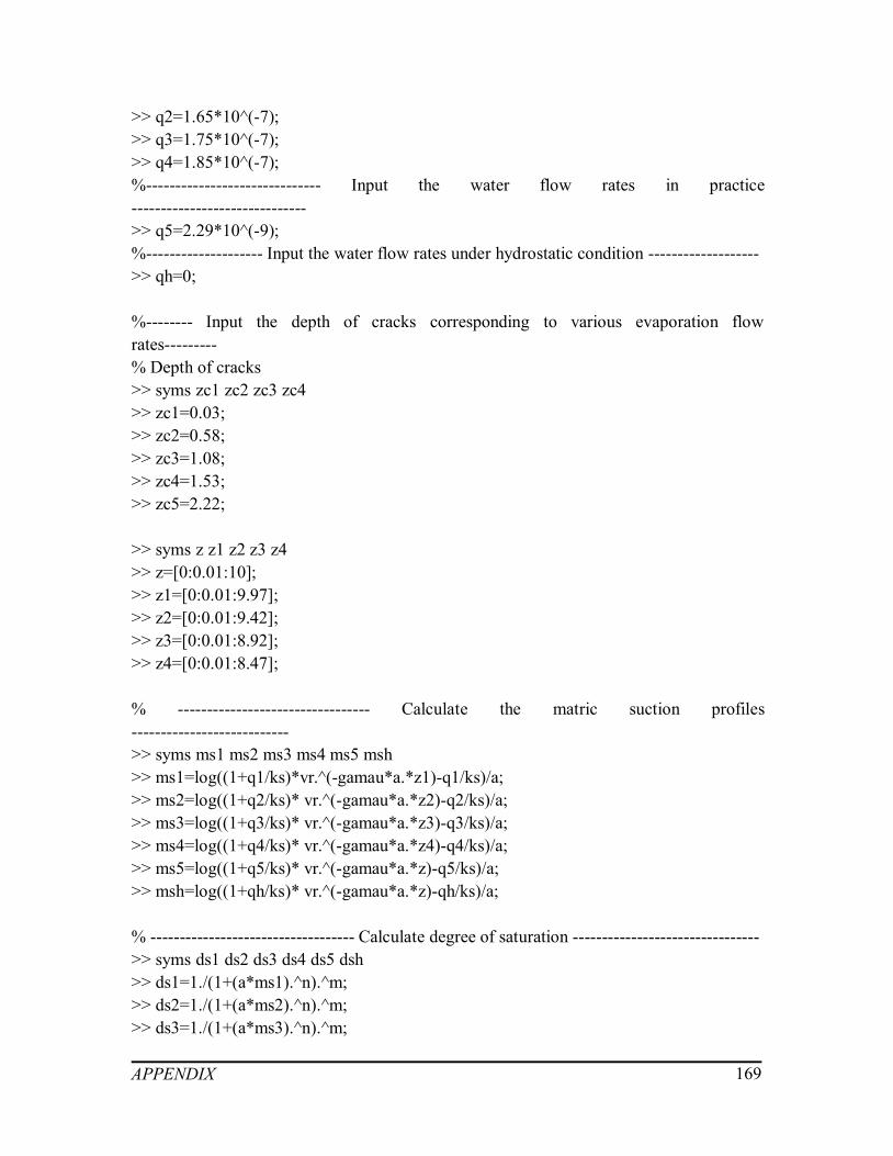
APPENDIX 169
>> q2=1.65*10^(-7);>> q3=1.75*10^(-7);>> q4=1.85*10^(-7);%------------------------------ Input the water flow rates in practice------------------------------>> q5=2.29*10^(-9);%-------------------- Input the water flow rates under hydrostatic condition ------------------->> qh=0;
%-------- Input the depth of cracks corresponding to various evaporation flowrates---------% Depth of cracks>> syms zc1 zc2 zc3 zc4>> zc1=0.03;>> zc2=0.58;>> zc3=1.08;>> zc4=1.53;>> zc5=2.22;
>> syms z z1 z2 z3 z4>> z=[0:0.01:10];>> z1=[0:0.01:9.97];>> z2=[0:0.01:9.42];>> z3=[0:0.01:8.92];>> z4=[0:0.01:8.47];
% --------------------------------- Calculate the matric suction profiles--------------------------->> syms ms1 ms2 ms3 ms4 ms5 msh>> ms1=log((1+q1/ks)*vr.^(-gamau*a.*z1)-q1/ks)/a;>> ms2=log((1+q2/ks)* vr.^(-gamau*a.*z2)-q2/ks)/a;>> ms3=log((1+q3/ks)* vr.^(-gamau*a.*z3)-q3/ks)/a;>> ms4=log((1+q4/ks)* vr.^(-gamau*a.*z4)-q4/ks)/a;>> ms5=log((1+q5/ks)* vr.^(-gamau*a.*z)-q5/ks)/a;>> msh=log((1+qh/ks)* vr.^(-gamau*a.*z)-qh/ks)/a;
% ----------------------------------- Calculate degree of saturation -------------------------------->> syms ds1 ds2 ds3 ds4 ds5 dsh>> ds1=1./(1+(a*ms1).^n).^m;>> ds2=1./(1+(a*ms2).^n).^m;>> ds3=1./(1+(a*ms3).^n).^m;

APPENDIX 170
>> ds4=1./(1+(a*ms4).^n).^m;>> ds5=1./(1+(a*ms5).^n).^m;>> dsh=1./(1+(a*msh).^n).^m;
% ---------- Calculate lateral earth pressure distributions under drying conditions ----------->> syms pa1 pa2 pa3 pa4 pa5 pah pa>> pa1=gamau.*(D-z1+zc1)*Ka-2*(Ka)^0.5.*(c+ms1.*ds1.^k*tand(fi));>> pa2=gamau.*(D-z2+zc2)*Ka-2*(Ka)^0.5.*(c+ms2.*ds2.^k*tand(fi));>> pa3=gamau.*(D-z3+zc3)*Ka-2*(Ka)^0.5.*(c+ms3.*ds3.^k*tand(fi));>> pa4=gamau.*(D-z4+zc4)*Ka-2*(Ka)^0.5.*(c+ms4.*ds4.^k*tand(fi));>> pa5=gamau.*(D-z)*Ka-2*(Ka)^0.5.*(c+ms5.*ds5.^k*tand(fi));>> pah=gamau.*(D-z)*Ka-2*(Ka)^0.5.*(c+msh.*dsh.^k*tand(fi));>> pa=gamau.*(D-z)*Ka-2*(Ka)^0.5.*c;
% Draw the line to show the retaining wall>> syms ul>> ul=0*z;
% ---------------------- Plot matric suction profiles under drying conditions ------------------->> plot(ms1,z1)>> hold on>> plot(ms2,z2)>> plot(ms3,z3)>> plot(ms4,z4)>> plot(ms5,z)>> plot(msh,z)
% ---------------- Plot lateral earth pressure distributions under drying conditions ----------->> plot(pa1,z1)>> hold on>> plot(pa2,z2)>> plot(pa3,z3)>> plot(pa4,z4)>> plot(pa5,z)>> plot(pah,z)>> plot(pa,z)>> plot(ul,z)
% ----------------------- Calculate the lateral forces under drying conditions------------------->> syms num1 pa11

APPENDIX 171
>> num1=size(find(pa1>0));>> num1=num1(1,2);>> pa11=trapz(z(:,1:num1), pa1(:,1:num1))
>> syms num2 pa21>> num2=size(find(pa2>0));>> num2=num2(1,2);>> pa21=trapz(z(:,1:num2), pa2(:,1:num2))
>> syms num3 pa31>> num3=size(find(pa3>0));>> num3=num3(1,2);>> pa31=trapz(z(:,1:num3), pa3(:,1:num3))
>> syms num4 pa41>> num4=size(find(pa4>0));>> num4=num4(1,2);>> pa41=trapz(z(:,1:num4), pa4(:,1:num4))
>> syms num5 pa51>> num5=size(find(pa5>0));>> num5=num5(1,2);>> pa51=trapz(z(:,1:num5), pa5(:,1:num5))
% Saturated condition>> syms nums pas>> nums=size(find(pa>0));>> nums=nums(1,2);>> pas=trapz(z(:,1:nums), pa(:,1:nums))
% Hydrostatic condition>> syms numh pah1>> numh=size(find(pah>0));>> numh=numh(1,2);>> pah1=trapz(z(:,1:numh), pah(:,1:numh))
%--------------------------- Input the water flow rates under wetting condition----------------->> syms q7 q8 q9 q10 q11>> q7=-3*10^(-10);>> q8=-4*10^(-10);

APPENDIX 172
>> q9=-5*10^(-10);>> q10=-6*10^(-10);>> q11=-7*10^(-10);
% -------------------------------- Calculate the matric suction profiles---------------------------->> syms ms7 ms8 ms9 ms10 ms11>> ms7=log((1+q7/ks)*vr.^(-gamau*a.*z)-q7/ks)/a;>> ms8=log((1+q8/ks)*vr.^(-gamau*a.*z)-q8/ks)/a;>> ms9=log((1+q9/ks)*vr.^(-gamau*a.*z)-q9/ks)/a;>> ms10=log((1+q10/ks)*vr.^(-gamau*a.*z)-q10/ks)/a;>> ms11=log((1+q11/ks)*vr.^(-gamau*a.*z)-q11/ks)/a;
% ------------------------------------- Calculate degree of saturation ------------------------------>> syms ds7 ds8 ds9 ds10 ds11>> ds7=1./(1+(a*ms7).^n).^m;>> ds8=1./(1+(a*ms8).^n).^m;>> ds9=1./(1+(a*ms9).^n).^m;>> ds10=1./(1+(a*ms10).^n).^m;>> ds11=1./(1+(a*ms11).^n).^m;
% --------------------------------- Calculate vertical swelling pressures -------------------------->> syms ps7 ps8 ps9 ps10 ps11>> ps7=50+0.7.*ms7.*ds7.^2;>> ps8=50+0.7.*ms8.*ds8.^2;>> ps9=50+0.7.*ms9.*ds9.^2;>> ps10=50+0.7.*ms10.*ds10.^2;>> ps11=50+0.7.*ms11.*ds11.^2;
% ----------------------------- Calculate unsaturated modulus of elasticity ---------------------->> syms e7 e8 e9 e10 e11 eh>> e7=e*(1+0.1*ms7.*ds7.^2);>> e8=e*(1+0.1*ms8.*ds8.^2);>> e9=e*(1+0.1*ms9.*ds9.^2);>> e10=e*(1+0.1*ms10.*ds10.^2);>> e11=e*(1+0.1*ms11.*ds11.^2);>> eh=e*(1+0.1*msh.*dsh.^2);
% -------------- Calculate additional lateral swelling stress due to suction changes ---------->> syms plsh pls7 pls8 pls9 pls10 pls11>> plsh=(1-pr-2*pr^2).*psh/(psh/eh.*(1+pr).*(1-pr-2*pr^2)+1-pr^2);
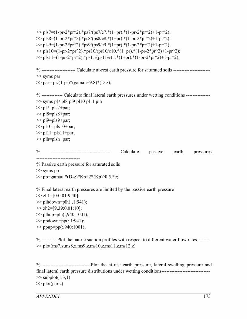
APPENDIX 173
>> pls7=(1-pr-2*pr^2).*ps7/(ps7/e7.*(1+pr).*(1-pr-2*pr^2)+1-pr^2);>> pls8=(1-pr-2*pr^2).*ps8/(ps8/e8.*(1+pr).*(1-pr-2*pr^2)+1-pr^2);>> pls9=(1-pr-2*pr^2).*ps9/(ps9/e9.*(1+pr).*(1-pr-2*pr^2)+1-pr^2);>> pls10=(1-pr-2*pr^2).*ps10/(ps10/e10.*(1+pr).*(1-pr-2*pr^2)+1-pr^2);>> pls11=(1-pr-2*pr^2).*ps11/(ps11/e11.*(1+pr).*(1-pr-2*pr^2)+1-pr^2);
% --------------------- Calculate at-rest earth pressure for saturated soils ----------------------->> syms par>> par= pr/(1-pr)*(gamau+9.8)*(D-z);
% ------------- Calculate final lateral earth pressures under wetting conditions --------------->> syms pl7 pl8 pl9 pl10 pl11 plh>> pl7=pls7+par;>> pl8=pls8+par;>> pl9=pls9+par;>> pl10=pls10+par;>> pl11=pls11+par;>> plh=plsh+par;
% ------------------------------------- Calculate passive earth pressures---------------------------% Passive earth pressure for saturated soils>> syms pp>> pp=gamau.*(D-z)*Kp+2*(Kp)^0.5.*c;
% Final lateral earth pressures are limited by the passive earth pressure>> zh1=[0:0.01:9.40];>> plhdown=plh(:,1:941);>> zh2=[9.39:0.01:10];>> plhup=plh(:,940:1001);>> ppdown=pp(:,1:941);>> ppup=pp(:,940:1001);
% --------- Plot the matric suction profiles with respect to different water flow rates-------->> plot(ms7,z,ms8,z,ms9,z,ms10,z,ms11,z,ms12,z)
% ------------------------------Plot the at-rest earth pressure, lateral swelling pressure andfinal lateral earth pressure distributions under wetting conditions------------------------------>> subplot(1,3,1)>> plot(par,z)

APPENDIX 174
>> subplot(1,3,2)>> plot(pls7,z,pls8,z,pls9,z,pls10,z,pls11,z,plsh,z)>> subplot(1,3,3)>> plot(plhdown,zh1,plhup,zh2)>> hold on>> plot(pl7,z,pl8,z,pl9,z,pl10,z,pl11,z)>> plot(ppdown,zh1,ppup,zh2)
% --------------------------- Calculate additional lateral swelling forces ------------------------->> syms pls71 pls81 pls91 pls101 pls111 plsh1>> pls71=trapz(z,pls7)>> pls81=trapz(z,pls8)>> pls91=trapz(z,pls9)>> pls101=trapz(z,pls10)>> pls111=trapz(z,pls11)>> plsh1=trapz(z,plsh)
% ------------------------- Calculate final lateral forces under wetting conditions-------------->> syms pl71 pl81 pl91 pl101 pl111 pl121>> pl71=trapz(z71,pl7)>> pl81=trapz(z81,pl8)>> pl91= trapz(z91,pl9)>> pl101= trapz(z101,pl10)>> pl111=trapz(z111,pl11)>> plh1=trapz(zh2,ppup)+trapz(zh1,plhdown)

APPENDIX 175
A.3 Program code for Example B
%------------------------- Input soil properties and fitting parameters---------------------------->> syms c fi D ks gamau a n m ip k Ka Kp e pr vr% Effective cohesion of soils>> c=10;% Effective angel of internal friction>> fi=22.5;% Depth of ground water table>> D=10;% Coefficient of permeability of saturated soils>> ks=1*10^(-7);% Dry density of soils>> gamau=18;% Fitting parameters of SWCC>> a=0.0014;>> n=0.6584;>> m=0.5852;% Plasticity index>> ip=18.7;% Fitting parameter>> k=-0.0016*ip^2+0.0975*ip+1;% Elastic modulus of saturated soils>> e=2000;% Poisson’s ratio>> pr=0.33;% Void ratio>> vr=0.474;
% Coefficient of active earth pressure>> Ka=(tand(45-fi/2))^2;% Coefficient of passive earth pressure>> Kp=(tand(45+fi/2))^2;
>> syms z>> z=[0:0.01:10];
%------------------------- Input the water flow rates under drying condition --------------------
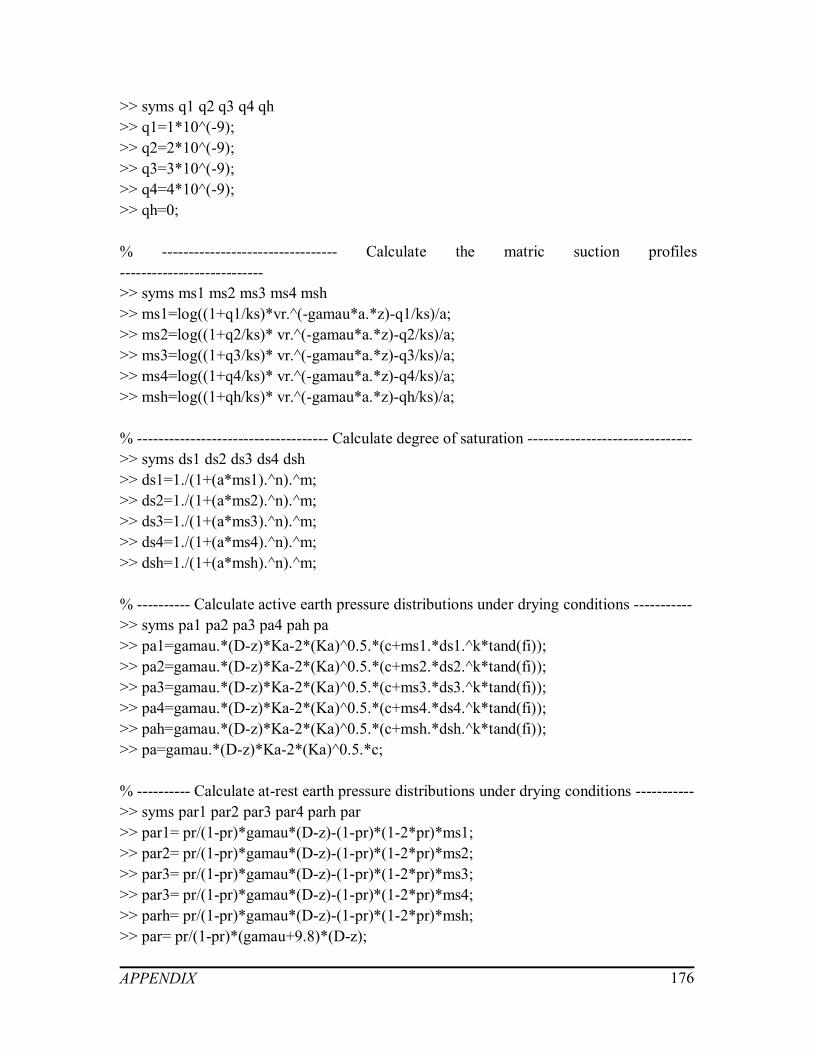
APPENDIX 176
>> syms q1 q2 q3 q4 qh>> q1=1*10^(-9);>> q2=2*10^(-9);>> q3=3*10^(-9);>> q4=4*10^(-9);>> qh=0;
% --------------------------------- Calculate the matric suction profiles--------------------------->> syms ms1 ms2 ms3 ms4 msh>> ms1=log((1+q1/ks)*vr.^(-gamau*a.*z)-q1/ks)/a;>> ms2=log((1+q2/ks)* vr.^(-gamau*a.*z)-q2/ks)/a;>> ms3=log((1+q3/ks)* vr.^(-gamau*a.*z)-q3/ks)/a;>> ms4=log((1+q4/ks)* vr.^(-gamau*a.*z)-q4/ks)/a;>> msh=log((1+qh/ks)* vr.^(-gamau*a.*z)-qh/ks)/a;
% ------------------------------------ Calculate degree of saturation ------------------------------->> syms ds1 ds2 ds3 ds4 dsh>> ds1=1./(1+(a*ms1).^n).^m;>> ds2=1./(1+(a*ms2).^n).^m;>> ds3=1./(1+(a*ms3).^n).^m;>> ds4=1./(1+(a*ms4).^n).^m;>> dsh=1./(1+(a*msh).^n).^m;
% ---------- Calculate active earth pressure distributions under drying conditions ----------->> syms pa1 pa2 pa3 pa4 pah pa>> pa1=gamau.*(D-z)*Ka-2*(Ka)^0.5.*(c+ms1.*ds1.^k*tand(fi));>> pa2=gamau.*(D-z)*Ka-2*(Ka)^0.5.*(c+ms2.*ds2.^k*tand(fi));>> pa3=gamau.*(D-z)*Ka-2*(Ka)^0.5.*(c+ms3.*ds3.^k*tand(fi));>> pa4=gamau.*(D-z)*Ka-2*(Ka)^0.5.*(c+ms4.*ds4.^k*tand(fi));>> pah=gamau.*(D-z)*Ka-2*(Ka)^0.5.*(c+msh.*dsh.^k*tand(fi));>> pa=gamau.*(D-z)*Ka-2*(Ka)^0.5.*c;
% ---------- Calculate at-rest earth pressure distributions under drying conditions ----------->> syms par1 par2 par3 par4 parh par>> par1= pr/(1-pr)*gamau*(D-z)-(1-pr)*(1-2*pr)*ms1;>> par2= pr/(1-pr)*gamau*(D-z)-(1-pr)*(1-2*pr)*ms2;>> par3= pr/(1-pr)*gamau*(D-z)-(1-pr)*(1-2*pr)*ms3;>> par3= pr/(1-pr)*gamau*(D-z)-(1-pr)*(1-2*pr)*ms4;>> parh= pr/(1-pr)*gamau*(D-z)-(1-pr)*(1-2*pr)*msh;>> par= pr/(1-pr)*(gamau+9.8)*(D-z);

APPENDIX 177
% ---------- Calculate passive earth pressure distributions under drying conditions---------->> syms pp1 pp2 pp3 pp4 pph pp>> pp1=gamau.*(D-z)*Kp+2*(Kp)^0.5.*(c+ms1.*ds1.^k*tand(fi));>> pp2=gamau.*(D-z)*Kp+2*(Kp)^0.5.*(c+ms2.*ds2.^k*tand(fi));>> pp3=gamau.*(D-z)*Kp+2*(Kp)^0.5.*(c+ms3.*ds3.^k*tand(fi));>> pp4=gamau.*(D-z)*Kp+2*(Kp)^0.5.*(c+ms4.*ds4.^k*tand(fi));>> pph=gamau.*(D-z)*Kp+2*(Kp)^0.5.*(c+msh.*dsh.^k*tand(fi));>> pp=gamau.*(D-z)*Kp+2*(Kp)^0.5.*c;
% ---------------------- Plot matric suction profiles under drying conditions ------------------->> plot(ms1,z, ms2,z,ms3,z,ms4,z,msh,z)
% ----------------- Plot lateral earth pressure distributions under drying conditions ---------->> subplot(1,3,1)plot(par1,z,par2,z,par3,z,par4,z,parh,z,par,z)>> subplot(1,3,2)>> plot(pa1,z1,pa2,z,pa3,z,pa4,z,pah,z,pa,z)>> subplot(1,3,3)>> plot(pp1,z,pp2,z,pp3,z,pp4,z,pp,z,pph,z)
% ------------------ Calculate the at-rest earth forces under drying conditions ----------------->> syms num1 par11>> num1=size(find(par1>0));>> num1=num1(1,2);>> par11=trapz(z(:,1:num1), par1(:,1:num1))
>> syms num2 par21>> num2=size(find(par2>0));>> num2=num2(1,2);>> par21=trapz(z(:,1:num2), par2(:,1:num2))
>> syms num3 par31>> num3=size(find(par3>0));>> num3=num3(1,2);>> par31=trapz(z(:,1:num3), par3(:,1:num3))
>> syms num4 par41>> num4=size(find(par4>0));>> num4=num4(1,2);

APPENDIX 178
>> par41=trapz(z(:,1:num4), par4(:,1:num4))
% Saturated condition>> syms pars>> nums=size(find(par>0));>> nums=nums(1,2);>> pars=trapz(z(:,1:nums), par(:,1:nums))
% Hydrostatic condition>> syms numh parh1>> numh=size(find(parh>0));>> numh=numh(1,2);>> parh1=trapz(z(:,1:numh), parh(:,1:numh))
% ------------------ Calculate the active earth forces under drying conditions ----------------->> syms num1 pa11>> num1=size(find(pa1>0));>> num1=num1(1,2);>> pa11=trapz(z(:,1:num1), pa1(:,1:num1))
>> syms num2 pa21>> num2=size(find(pa2>0));>> num2=num2(1,2);>> pa21=trapz(z(:,1:num2), pa2(:,1:num2))
>> syms num3 pa31>> num3=size(find(pa3>0));>> num3=num3(1,2);>> pa31=trapz(z(:,1:num3), pa3(:,1:num3))
>> syms num4 pa41>> num4=size(find(pa4>0));>> num4=num4(1,2);>> pa41=trapz(z(:,1:num4), pa4(:,1:num4))
% Saturated condition>> syms pas>> nums=size(find(pa>0));>> nums=nums(1,2);>> pas=trapz(z(:,1:nums), pa(:,1:nums))

APPENDIX 179
% Hydrostatic condition>> syms numh pah1>> numh=size(find(pah>0));>> numh=numh(1,2);>> pah1=trapz(z(:,1:numh), pah(:,1:numh))
% ------------------ Calculate the passive earth forces under drying conditions---------------->> syms pp11 pp21 pp31 pp41 pps pph1>> pp11=trapz(z, pp1)>> pp21=trapz(z, pp2)>> pp31=trapz(z, pp3)>> pp41=trapz(z, pp4)>> pps=trapz(z, pp)>> pph1=trapz(z, pph)
%------------------------- Input the water flow rates under wetting condition------------------->> syms q7 q8 q9 q10>> q7=-2*10^(-8);>> q8=-4*10^(-8);>> q9=-6*10^(-8);>> q10=-8*10^(-8);
% -------------------------------- Calculate the matric suction profiles---------------------------->> syms ms7 ms8 ms9 ms10>> ms7=-log((1+q7/ks)*exp(-gamau*a.*z)-q7/ks)/a;>> ms8=-log((1+q8/ks)*exp(-gamau*a.*z)-q8/ks)/a;>> ms9=-log((1+q9/ks)*exp(-gamau*a.*z)-q9/ks)/a;>> ms10=-log((1+q10/ks)*exp(-gamau*a.*z)-q10/ks)/a;
% ------------------------------------- Calculate degree of saturation ---------------------------->> syms ds7 ds8 ds9 ds10>> ds7=1./(1+(a*ms7).^n).^m;>> ds8=1./(1+(a*ms8).^n).^m;>> ds9=1./(1+(a*ms9).^n).^m;>> ds10=1./(1+(a*ms10).^n).^m;
% --------------------Active earth pressure distributions under wettingconditions-------------
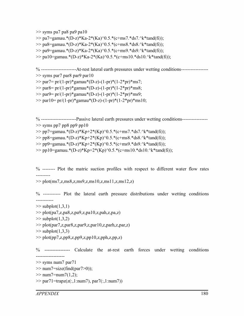
APPENDIX 180
>> syms pa7 pa8 pa9 pa10>> pa7=gamau.*(D-z)*Ka-2*(Ka)^0.5.*(c+ms7.*ds7.^k*tand(fi));>> pa8=gamau.*(D-z)*Ka-2*(Ka)^0.5.*(c+ms8.*ds8.^k*tand(fi));>> pa9=gamau.*(D-z)*Ka-2*(Ka)^0.5.*(c+ms9.*ds9.^k*tand(fi));>> pa10=gamau.*(D-z)*Ka-2*(Ka)^0.5.*(c+ms10.*ds10.^k*tand(fi));
% ----------------------At-rest lateral earth pressures under wetting conditions----------------->> syms par7 par8 par9 par10>> par7= pr/(1-pr)*gamau*(D-z)-(1-pr)*(1-2*pr)*ms7;>> par8= pr/(1-pr)*gamau*(D-z)-(1-pr)*(1-2*pr)*ms8;>> par9= pr/(1-pr)*gamau*(D-z)-(1-pr)*(1-2*pr)*ms9;>> par10= pr/(1-pr)*gamau*(D-z)-(1-pr)*(1-2*pr)*ms10;
% ----------------------Passive lateral earth pressures under wetting conditions---------------->> syms pp7 pp8 pp9 pp10>> pp7=gamau.*(D-z)*Kp+2*(Kp)^0.5.*(c+ms7.*ds7.^k*tand(fi));>> pp8=gamau.*(D-z)*Kp+2*(Kp)^0.5.*(c+ms8.*ds8.^k*tand(fi));>> pp9=gamau.*(D-z)*Kp+2*(Kp)^0.5.*(c+ms9.*ds9.^k*tand(fi));>> pp10=gamau.*(D-z)*Kp+2*(Kp)^0.5.*(c+ms10.*ds10.^k*tand(fi));
% -------- Plot the matric suction profiles with respect to different water flow rates--------->> plot(ms7,z,ms8,z,ms9,z,ms10,z,ms11,z,ms12,z)
% ----------- Plot the lateral earth pressure distributions under wetting conditions----------->> subplot(1,3,1)>> plot(pa7,z,pa8,z,pa9,z,pa10,z,pah,z,pa,z)>> subplot(1,3,2)>> plot(par7,z,par8,z,par9,z,par10,z,parh,z,par,z)>> subplot(1,3,3)>> plot(pp7,z,pp8,z,pp9,z,pp10,z,pph,z,pp,z)
% ---------------- Calculate the at-rest earth forces under wetting conditions------------------>> syms num7 par71>> num7=size(find(par7>0));>> num7=num7(1,2);>> par71=trapz(z(:,1:num7), par7(:,1:num7))

APPENDIX 181
>> syms num8 par81>> num8=size(find(par8>0));>> num8=num8(1,2);>> par81=trapz(z(:,1:num8), par8(:,1:num8))
>> syms num9 par91>> num9=size(find(par9>0));>> num9=num9(1,2);>> par91=trapz(z(:,1:num9), par9(:,1:num9))
>> syms num10 par101>> num10=size(find(par10>0));>> num10=num10(1,2);>> par101=trapz(z(:,1:num10), par10(:,1:num10))
% ------------------ Calculate the active earth forces under wetting conditions ---------------->> syms num7 pa71>> num7=size(find(pa7>0));>> num7=num7(1,2);>> pa71=trapz(z(:,1:num7), pa7(:,1:num7))
>> syms num8 pa81>> num8=size(find(pa8>0));>> num8=num8(1,2);>> pa81=trapz(z(:,1:num8), pa8(:,1:num8))
>> syms num9 pa91>> num9=size(find(pa9>0));>> num9=num9(1,2);>> pa91=trapz(z(:,1:num9), pa9(:,1:num9))
>> syms num10 pa101>> num10=size(find(pa10>0));>> num10=num10(1,2);>> pa101=trapz(z(:,1:num10), pa10(:,1:num10))
% ----------------- Calculate the passive earth forces under wetting conditions --------------->> syms pp71 pp81 pp91 pp101>> pp71=trapz(z, pp7)

APPENDIX 182
>> pp81=trapz(z, pp8)>> pp91=trapz(z, pp9)>> pp101=trapz(z, pp10)

APPENDIX 183
A.4 Program code for estimating the depth of crack
%------------------------- Input soil properties and fitting parameters----------------------------syms a n m z ks gamaw q pr gamau D ms k ip alfat fi c gamaw ds t ls;% Fitting parameters of SWCCa=0.001;n=0.5991;m=0.5;% Depth along the retaining wallz=[0:0.01:10];% Coefficient of permeability of saturated soilsks=5*10^(-8);% Density of watergamaw=9.8;% Water flow rateq=1.6*10^(-7);% Poisson’s ratiopr=0.33;% Dry density of soilsgamau=18;% Depth of ground water tableD=10;% Fitting parameters>> k=-0.0016*ip^2+0.0975*ip+1;% Modified coefficient for tensile stress in unsaturated soil>> alfat=0.5;% Effective angle of internal friction>> fi=22.5;% Effective cohesion of soils>> c=10;% Density of water>> gamaw=9.8;
% ------------------------ Calculate the corresponding matric suction profile -------------------ms=(-log((1+q/ks)*exp(-gamau*a*z)-q/ks))/a;
% -------------------------------- Calculate the degree of saturation ------------------------------->> ds=1./(1+(a*ms).^n).^m;

APPENDIX 184
% ------------------------------ Calculate the tensile stress distribution --------------------------->> t=-alfat.*cotd(fi).*(c+ms.*tand(fi).*ds.^k);
% ----------------------- Calculate the lateral stress along the retaining wall--------------------ls=pr/(1-pr)*gamau*(D-z)-(1-2*pr)*(1-pr)*ms;% Draw the line to show the retaining wallsyms ul;ul=0*z;
% ----------------- Plot the tensile stress of soil and lateral stress distributions ----------------plot(t,z,ls,z,ul,z)
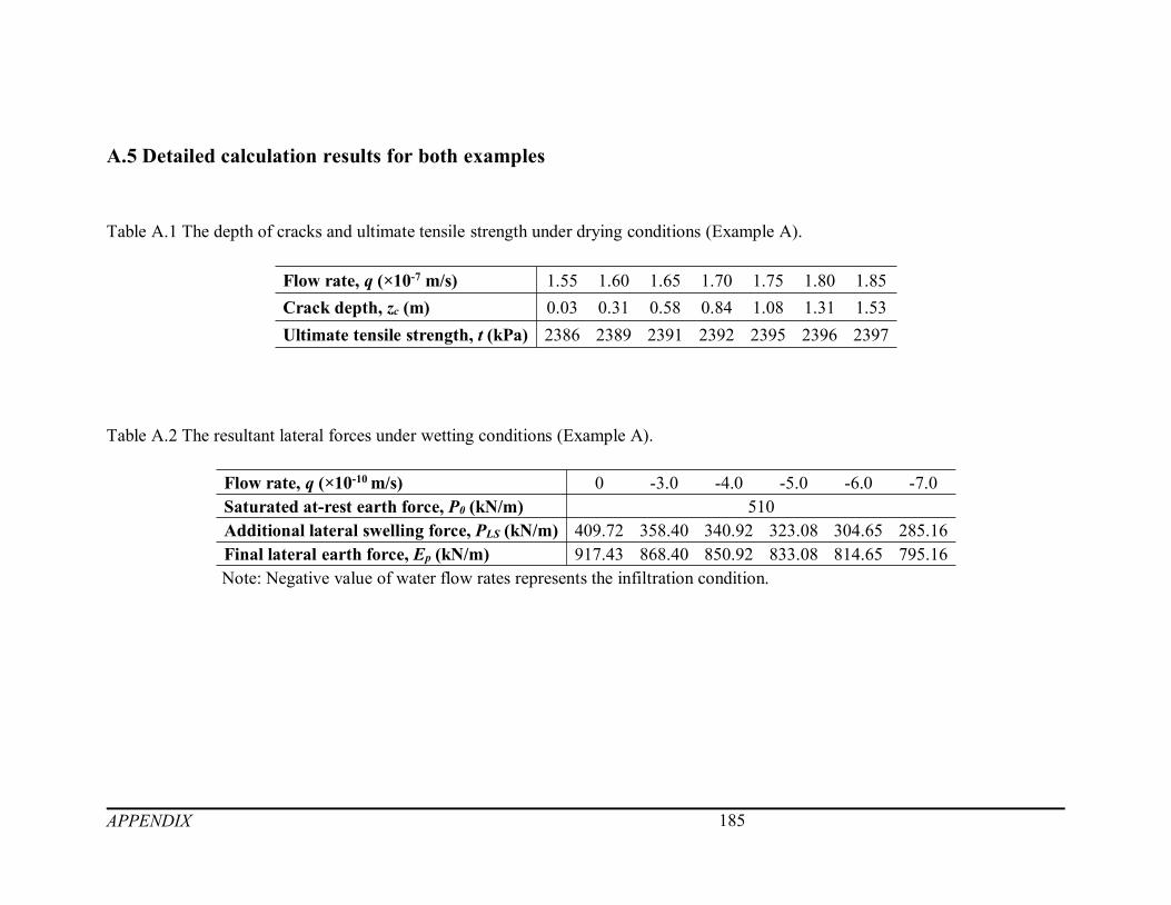
APPENDIX 185
A.5 Detailed calculation results for both examples
Table A.1 The depth of cracks and ultimate tensile strength under drying conditions (Example A).
Flow rate, q (×10-7 m/s) 1.55 1.60 1.65 1.70 1.75 1.80 1.85Crack depth, zc (m) 0.03 0.31 0.58 0.84 1.08 1.31 1.53Ultimate tensile strength, t (kPa) 2386 2389 2391 2392 2395 2396 2397
Table A.2 The resultant lateral forces under wetting conditions (Example A).
Flow rate, q (×10-10m/s) 0 -3.0 -4.0 -5.0 -6.0 -7.0Saturated at-rest earth force, P0 (kN/m) 510Additional lateral swelling force, PLS (kN/m) 409.72 358.40 340.92 323.08 304.65 285.16Final lateral earth force, Ep (kN/m) 917.43 868.40 850.92 833.08 814.65 795.16Note: Negative value of water flow rates represents the infiltration condition.

APPENDIX 186
Table A.3 The critical height under at-rest and active stress states (Example B).
Water flow rates, q (×10-8 m/s) Saturated condition -8 -6 -4 -2 0 0.1 1 5 10
Critical height, zc (m)At-rest state 0 0.68 1.26 1.75 2.18 2.56 2.58 2.73 3.33 3.95Active state 1.66 2.89 3.69 4.29 4.77 5.15 5.17 5.32 5.88 6.4
Note: Negative value of water flow rates represents the infiltration condition.
Table A.4 The resultant lateral earth forces under drying and wetting conditions (Example B).
Water flow rates, q (×10-8 m/s) Saturatedcondition
-8 -6 -4 -2 0 0.1 1 5 10
At-rest earth force, P0 (kN/m) 684.65 413.16 387.44 365.72 346.66 329.82 328.93 322.28 295.68 268.20Active earth force, Ea (kN/m) 279.39 238.19 211.39 191.29 175.21 162.48 161.81 156.78 138.02 120.60Passive earth force, Ep (kN/m) 2315.15 2469.5 2595.3 2703.5 2799.0 2884.5 2888.5 2924.1 3065.7 3215.0Note: Negative value of water flow rates represents the infiltration condition.