mechanical earth drills
TRANSCRIPT

WITH
MAINTENANCE ANDPARTS INFORMATION
P.O. BOX 840 LIVINGSTON, TEXAS 77351PHONE 936/327-3121 FAX 936/327-4025Web: www.littlebeaver.com E-Mail: [email protected]. BY: LB EQUIPMENT, INC. - LIVINGSTON, TEXAS USA
OPERATORS MANUAL
0199
MECHANICALEARTH DRILLS
1-800-227-7515

R0196
Page O-2
CUSTOMER SERVICEPh: 800/227-7515 or 936/327-3121 or Fax 936/327-4025
ORDERS...Place your orders by telephone, fax, or mail. When calling, please have your partsmanual handy for reference. Our hours are 8:00 am - 4:30 pm central time, Monday thruFriday. When ordering by mail or fax, include a description and LITTLE BEAVER partnumber for the items you are ordering, your return address, and payment or yourauthorization for COD shipment.All orders are shipped UPS where possible. Freight charges will be added to your invoice.Some items are oversize, resulting in a higher shipping cost. Power units and largeraugers are shipped via motor freight due to their weight.
PAYMENT TERMS...COD, Cash in Advance, Visa, Mastercard or NET 30 with approved credit. COD limit fornew accounts is $500.00. Personal or company checks on new accounts will be held untilthey clear the bank. To eliminate this delay, you may pay by wire transfer or send acertified or cashiers check. For a NET 30 open account, please call or write for a creditapplication.
SERVICE AND REPAIR...Your LITTLE BEAVER Earth Drill has been designed for user repair with ordinary handtools. No special tools are required. Consult the appropriate section of the parts manualfor instructions.
Service or technical consulation is available, free of charge, from the factory inLivingston, Texas. We will be pleased to help you with any problems or questions. Justwrite, fax, or call. Our hours are 8:00am - 4:30pm central time, Monday thru Friday.
Factory repair is available. If you return a part to the factory, please include the followinginformation: Your name and return address, a description of the problem and paymentor authorization to return the repaired item COD for the repair and shipping charges.
RETURNS...Please call the factory for a return authorization. This will help to ensure that your partsare handled properly. Include your name and address, customer account #, invoice #under which the returned parts were ordered, and a brief description of the problem withthe parts or the reason for returning them. Parts to be considered for warranty must bereturned to the factory for inspection within 10 days after receipt of replacement parts.Be sure to prepay the shipping charges, we will not accept collect or COD packages.
Our mailing address...
LITTLE BEAVER, Inc.2009 South HoustonP. O. Box 840Livingston, Texas 77351
SAFETY ALERT SYMBOL
The symbol shown above is used to call your attention to instructions concerning your personal safety.
WATCH THIS SYMBOL — It points out important safety precautions.
It means — ATTENTION! BECOME ALERT! YOUR PERSONAL SAFETY IS INVOLVED!
Read the message that follows and be alert to the possibility of Personal Injury or Death!
llllllllllllllllllllllllllllllllllllllllllllllllllllllllllllllllllllllllllllllllllllllllllllllllllllllllllllllllllllllllllllllllllllll
1 YEAR LIMITED WARRANTY
For 1 year from purchase, LB EQUIPMENT, INC. will replace for the original purchaser,free of charge, any part or parts, found upon examination by any factory authorized servicecenter, or by the factory at Livingston, Texas, to be defective in material or workmanship orboth. If your equipment cannot be repaired, it will be replaced. All transportation charges onparts submitted for replacement under this warranty must be borne by purchaser.
There is no other express warranty.
Implied warranties, including those of merchantability and fitness for a particular purpose,are limited to 1 year from purchase and to the extent permitted by law. Any and all implied warranties are excluded. This is the exclusive remedy and liability for consequential damages under any and all warranties are excluded to the extentexclusion is permitted by law.
*Notice: Engines are warrantied by the manufacturer of the engine. See separate engine warranty enclosed.
llllllllllllllllllllllllllllllllllllllllllllllllllllllllllllllllllllllllllllllllllllllllllllllllllllllllllllllllllllllllllllllllllllll
MACHINE SERIAL NUMBER
The machine serial number for your mechanical Earth Drill is located on the carrier. For your convenience, whenrequiring service or parts information, refer to this number and your model number. Record the model number,engine make, machine serial number and date of purchase in the space provided below:
MODEL NUMBER ENGINE MAKE
MACHINE SERIAL NUMBER DATE OF PURCHASE
1004Page O-3
WARNING: The Engine Exhaust from this product contains chemicalsknown to the State of California to cause cancer, birth defects or otherreproductive harm.
R
R0196
Page O-4
TABLE OF CONTENTS
OPERATORS MANUALPage #
O-2 Service Information
O-3 Safety Alert, Warranty and Machine Information
O-4 Table of Contents
O-5 Safety Instructions
O-6 Maintenance and Lubrication, Transmission
O-7 Maintenance and Lubrication, Flexible Shaft
O-8 Maintenance and Lubrication, Clutch and Throttle Bracket
O-9 Troubleshooting
O-10 & 11 & 12 Operating Instructions
O-13 Decal Location
PARTS MANUALPage #
P-1 Mechanical Parts Manual, Notes
P-2 & 3 5HP Engine Assembly
P-4 & 5 7-8HP Engine Assembly
P-6 & 7 Handle Torque Tube and Wires
P-8 Flexible Shaft
P-9 Flexible Shaft Dis-assembly & Assembly Instructions
P-10 & 11 Transmission
P-12 & 13 Transmission Dis-assembly & Assembly Instructions
P-14 Clutch
P-15 & 16 Auger Information
P-17 Extensions & Adaptors
P-18 Notes
P-19 & 20 Prices for Mechanical Parts and Augers
Inside Back Cover Torque Information and Conversion Chart
0798Page O-5
SAFETY INSTRUCTIONS
DANGER: Failure to observe safety instructions and reasonable safety practices cancause Property Damage, Serious Bodily Injury and/or Death. BE CAREFUL!! WATCH OUT FORBYSTANDERS!!
DANGER: NEVER drill holes where there is a possibility of underground power cables or other hazards. The exact location of underground services must be determined prior to drilling. Inadvertentsevering of telephone, fiber optic or CATV transmission cable, or damage to sewer pipe is costly;RUPTURING OF GAS OR WATER LINES CAN CAUSE SERIOUS BODILY INJURY AND/OR DEATH.COMING INTO CONTACT WITH BURIED POWER LINES CAN CAUSE SERIOUS BODILY INJURY,SEVERE BURNS, AND/OR ELECTROCUTION. Call local utility companies or your local "One-Call"number at least 48 hours before digging and have underground utilites marked.
DANGER: NEVER run engine inside building or enclosed area. Exhaust gases contain carbonmonoxide, an odorless and deadly poison.
WARNING: Augers are not to be used as anchoring devices.
CAUTION: 1. READ and understand this operator’s manual and the operator’s manual for the engine. 2. NEVER Operate drill without correctly installing torque tube. 3. NEVER Remove auger from hole while auger is turning. 4. NEVER Operate auger at less than full throttle. 5. NEVER Operate drill with damaged auger or other damaged or missing parts. 6. KEEP Hands, Feet and Clothing away from moving parts while engine is running. 7. KEEP All safety shields and devices in place. 8. MAKE Certain everyone is clear before operating the machine. 9. KEEP leg pad against leg while drilling to maintain safe control.10. WEAR SAFETY GLASSES.11. KEEP Bystanders at least 10 feet away from work area.12. SHUT OFF Engine to adjust, service or clean the machine.
NOTICEIt is the responsibility of the contractor, owner and user to maintain and operate the Earth Drill in compliance withoperating instructions provided. Observe all listed safety instructions and other reasonable safety practices. LBEQUIPMENT, INC. accepts no responsibility for damages to this machine, and other property damage and/orbodily injury due to careless or improper operations.
LB EQUIPMENT, INC. does not recommend or condone use of replacement engines greater than eight (8)horsepower.
LB EQUIPMENT, INC. does not recommend or condone any unauthorized modifications to the earth drill,especially those which would eliminate or reduce the effectiveness of the torque tube.
LB EQUIPMENT, INC. reserves the right to make changes in design and changes for improvements upon itsproduct without imposing any obligation upon itself to install the same upon its products theretofore manufactured.
Your operators manual offers recommendations for prolonged and satisfactory service.
R
MAINTENANCE AND LUBRICATION
Engines are shipped without oil or gasoline. Refer to MANUFACTURER'S INSTRUCTIONS for properprocedures and recommended fluids.
The TRANSMISSION and FLEXIBLE SHAFT are shipped fully oiled/greased and READY FOR USE. Referbelow for proper maintenance and lubrication instructions. Refer to the associated repair parts section forproper disassembly and assembly instructions.
SHUT OFF ENGINE to adjust, service or clean the machine.
All nuts, fasteners and fittings must be kept properly torqued.
TRANSMISSION:
The transmission oil should be checked each day prior to operation, and during the day as conditions warrant.
RECOMMENDED OIL: Amalie Tri-Vis Plus Oil 80/85/140Available in quart bottles, individually orin case of 12. ORDER PART #10280.
If this oil is not available, it is very important that you use a highquality gear oil.
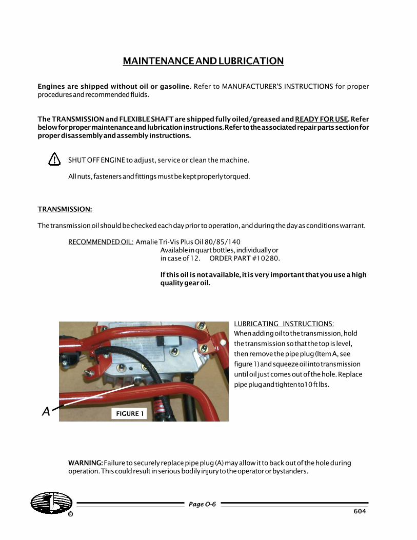
LUBRICATING INSTRUCTIONS:When adding oil to the transmission, hold
the transmission so that the top is level,
then remove the pipe plug (Item A, see
figure 1) and squeeze oil into transmission
until oil just comes out of the hole. Replace
pipe plug and tighten to10 ft lbs.
WARNING: Failure to securely replace pipe plug (A) may allow it to back out of the hole duringoperation. This could result in serious bodily injury to the operator or bystanders.
R 604Page O-6
FIGURE 1A
0396Page O-7
R
Maintenance and lubrication...(cont.)
FLEXIBLE SHAFT:
The flexible shaft should be examined every 50 hours of operation and greased if necessary, using the
recommended grease.
RECOMMENDED GREASE: Lubriplate Portable Tool Grease - GR-132
Available in 10 ounce Tubes, individually or in case of 12.
ORDER PART # 9070-L.
CLEANING AND GREASING INSTRUCTIONS: Follow the instructions provided for proper flexible
shaft dis-assembly (See page P-9 of Parts Manual and follow steps 1, 2,
4 & 5). After the flexible shaft core has been removed, wipe off the old grease
with a cloth. Clean the inside of the flexible shaft housing by pulling a clean
rag through with a long piece of wire. It may be necessary to make several
passes before all grease is removed. Then apply a light coat of
recommended grease to the core and re-assemble. DO NOT over-
lubricate, as this will cause excessive heat to build up in the shaft.
INSPECTION: HOUSING - Check for tears or breaks in the rubber casing. Small tears may be
repaired by covering with duct tape or shrink tubing. If deep cuts are
found and the wire braid is torn, the housing should be replaced.
CORE - Check for broken wires and kinks. The core should be replaced if a broken wire is found.
Small kinks or twists are OK but if a sharp kink is found, the core
should be replaced.
IMPORTANT: Excessive amounts of grease inside the flexible shaft assembly will cause the shaft to produce
excessive heat and reduce the shaft's life. If the shaft becomes over-heated (too hot to touch), it
must be cleaned, inspected (see above) and re-greased. It is also important to follow the proper
procedure when greasing the transmission so that excess grease is not forced into the flexible shaft
assembly.
DECAL LOCATION:
The decals which are provided with your machine are shown at the rear of this manual. The decals are
important and should be maintained in good condition in the locations as described. If any of the decals are missing
or illegible, order replacement kit #9020-O and install before operating the machine.
Maintenance and lubrication...(cont.)
CLUTCH: (See pg. P-13)
Your LITTLE BEAVER Earth Drill utilizes a centrifugal clutch to engage the auger as the engine is
accelerated from idle to full speed. The clutch begins to engage at about 2100 to 2200 rpm, so engine idle should
be kept below 1900 rpm.
The clutch requires no routine maintenance, but should be inspected when the flexible shaft is lubricated
(see above). If excessive slippage occurs, check the shoes and drum and clean or replace if necessary.
If the auger turns when the engine is at idle, first check the engine for proper idle speed (1900 rpm). Also
check the throttle linkage as indicated below. If the problem persists, check for stretched, discolored or broken
clutch springs and/or broken clutch shoes and replace if necessary.
THROTTLE CABLE AND THROTTLE BRACKET ASSEMBLY: (See pg. P-2/3 OR P-4/5)
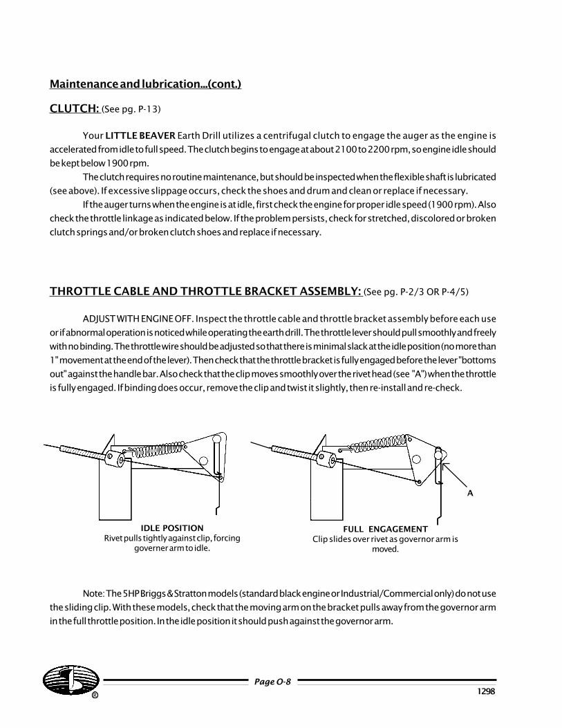
ADJUST WITH ENGINE OFF. Inspect the throttle cable and throttle bracket assembly before each use
or if abnormal operation is noticed while operating the earth drill. The throttle lever should pull smoothly and freely
with no binding. The throttle wire should be adjusted so that there is minimal slack at the idle position (no more than
1" movement at the end of the lever). Then check that the throttle bracket is fully engaged before the lever "bottoms
out" against the handle bar. Also check that the clip moves smoothly over the rivet head (see "A") when the throttle
is fully engaged. If binding does occur, remove the clip and twist it slightly, then re-install and re-check.
Note: The 5HP Briggs & Stratton models (standard black engine or Industrial/Commercial only) do not use
the sliding clip. With these models, check that the moving arm on the bracket pulls away from the governor arm
in the full throttle position. In the idle position it should push against the governor arm.
R 1298Page O-8
A
IDLE POSITIONRivet pulls tightly against clip, forcing
governer arm to idle.
FULL ENGAGEMENTClip slides over rivet as governor arm is
moved.
1298Page O-9
R
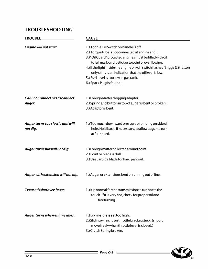
TROUBLESHOOTING
TROUBLE CAUSE
Engine will not start. 1.) Toggle Kill Switch on handle is off.
2.) Torque tube is not connected at engine end.
3.) “Oil Guard” protected engines must be filled with oil
to full mark on dipstick or to point of overflowing.
4.) If the light inside the engine on/off switch flashes (Briggs & Stratton
only), this is an indication that the oil level is low.
5.) Fuel level is too low in gas tank.
6.) Spark Plug is fouled.
Cannot Connect or Disconnect 1.) Foreign Matter clogging adaptor.
Auger. 2.) Spring and button in top of auger is bent or broken.
3.) Adaptor is bent.
Auger turns too slowly and will 1.) Too much downward pressure or binding on side of
not dig. hole. Hold back, if necessary, to allow auger to turn
at full speed.
Auger turns but will not dig. 1.) Foreign matter collected around point.
2.) Point or blade is dull.
3.) Use carbide blade for hard pan soil.
Auger with extension will not dig. 1.) Auger or extensions bent or running out of line.
Transmission over-heats. 1.) It is normal for the transmission to run hot to the
touch. If it is very hot, check for proper oil and
free turning.
Auger turns when engine idles. 1.) Engine idle is set too high.
2.) Sliding wire clip on throttle bracket stuck. (should
move freely when throttle lever is closed.)
3.) Clutch Spring broken.
OPERATING INSTRUCTIONS
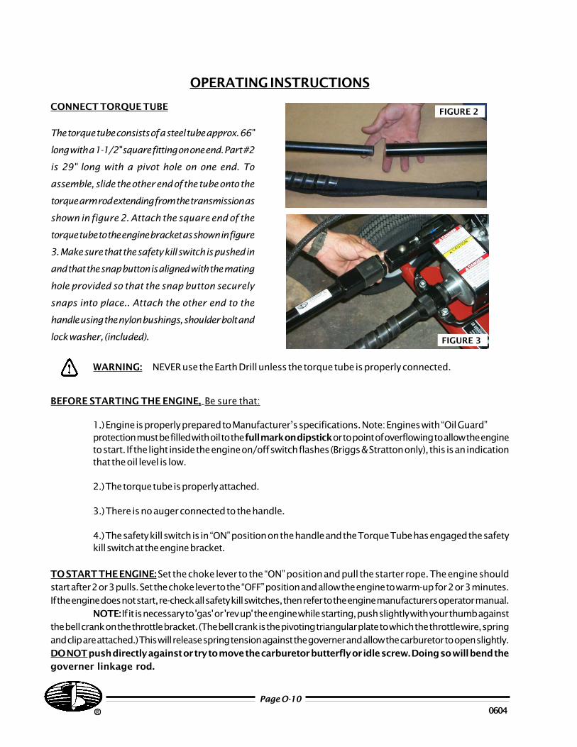
CONNECT TORQUE TUBE
The torque tube consists of a steel tube approx. 66"
long with a 1-1/2" square fitting on one end. Part #2
is 29" long with a pivot hole on one end. To
assemble, slide the other end of the tube onto the
torque arm rod extending from the transmission as
shown in figure 2. Attach the square end of the
torque tube to the engine bracket as shown in figure
3. Make sure that the safety kill switch is pushed in
and that the snap button is aligned with the mating
hole provided so that the snap button securely
snaps into place.. Attach the other end to the
handle using the nylon bushings, shoulder bolt and
lock washer, (included).
WARNING: NEVER use the Earth Drill unless the torque tube is properly connected.
BEFORE STARTING THE ENGINE,_Be sure that:
1.) Engine is properly prepared to Manufacturer’s specifications. Note: Engines with “Oil Guard”protection must be filled with oil to the full mark on dipstick or to point of overflowing to allow the engineto start. If the light inside the engine on/off switch flashes (Briggs & Stratton only), this is an indicationthat the oil level is low.
2.) The torque tube is properly attached.
3.) There is no auger connected to the handle.
4.) The safety kill switch is in “ON” position on the handle and the Torque Tube has engaged the safetykill switch at the engine bracket.
TO START THE ENGINE: Set the choke lever to the “ON” position and pull the starter rope. The engine shouldstart after 2 or 3 pulls. Set the choke lever to the “OFF” position and allow the engine to warm-up for 2 or 3 minutes.If the engine does not start, re-check all safety kill switches, then refer to the engine manufacturers operator manual.
NOTE: If it is necessary to 'gas' or 'rev up' the engine while starting, push slightly with your thumb againstthe bell crank on the throttle bracket. (The bell crank is the pivoting triangular plate to which the throttle wire, springand clip are attached.) This will release spring tension against the governer and allow the carburetor to open slightly.DO NOT push directly against or try to move the carburetor butterfly or idle screw. Doing so will bend thegoverner linkage rod.
R
Page O-10
FIGURE 3
FIGURE 2
0604
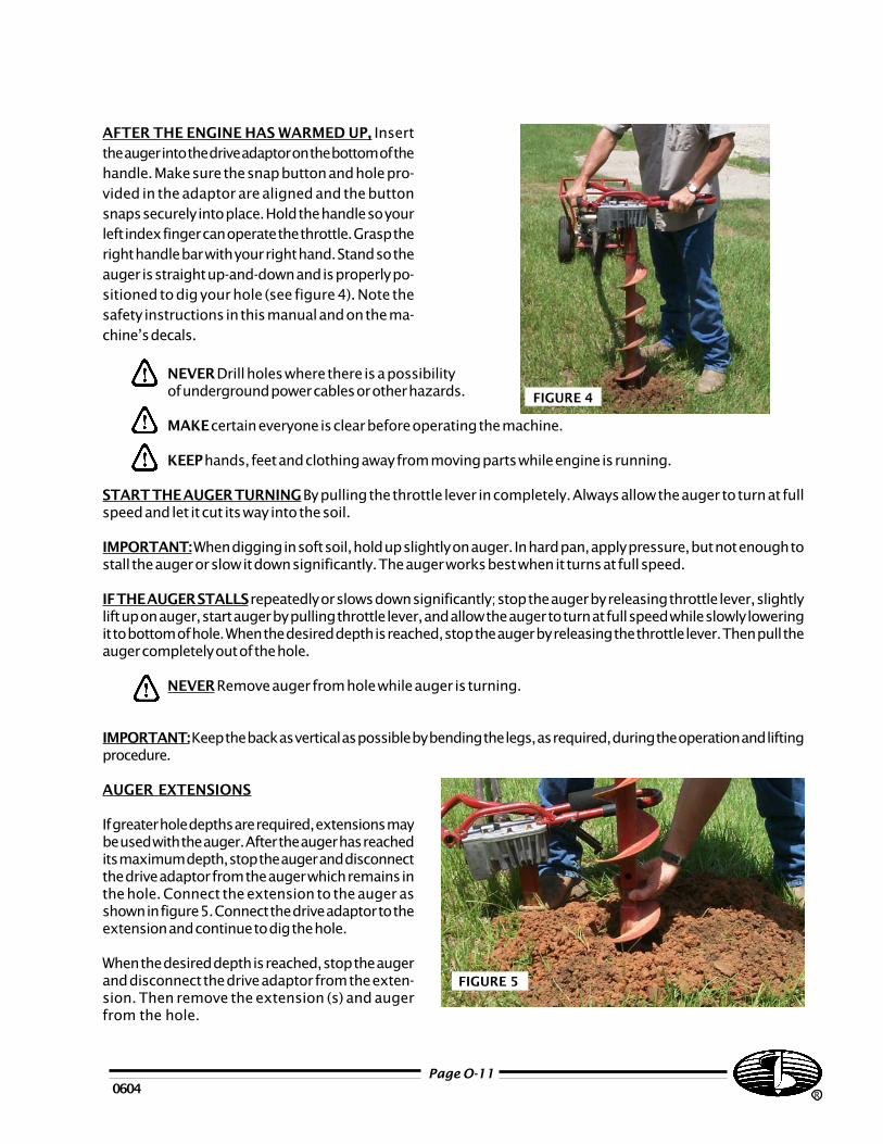
AFTER THE ENGINE HAS WARMED UP, Insertthe auger into the drive adaptor on the bottom of thehandle. Make sure the snap button and hole pro-vided in the adaptor are aligned and the buttonsnaps securely into place. Hold the handle so yourleft index finger can operate the throttle. Grasp theright handle bar with your right hand. Stand so theauger is straight up-and-down and is properly po-sitioned to dig your hole (see figure 4). Note thesafety instructions in this manual and on the ma-chine’s decals.
NEVER Drill holes where there is a possibilityof underground power cables or other hazards.
MAKE certain everyone is clear before operating the machine.
KEEP hands, feet and clothing away from moving parts while engine is running.
START THE AUGER TURNING By pulling the throttle lever in completely. Always allow the auger to turn at fullspeed and let it cut its way into the soil.
IMPORTANT: When digging in soft soil, hold up slightly on auger. In hard pan, apply pressure, but not enough tostall the auger or slow it down significantly. The auger works best when it turns at full speed.
IF THE AUGER STALLS repeatedly or slows down significantly; stop the auger by releasing throttle lever, slightlylift up on auger, start auger by pulling throttle lever, and allow the auger to turn at full speed while slowly loweringit to bottom of hole. When the desired depth is reached, stop the auger by releasing the throttle lever. Then pull theauger completely out of the hole.
NEVER Remove auger from hole while auger is turning.
IMPORTANT: Keep the back as vertical as possible by bending the legs, as required, during the operation and liftingprocedure.
AUGER EXTENSIONS
If greater hole depths are required, extensions maybe used with the auger. After the auger has reachedits maximum depth, stop the auger and disconnectthe drive adaptor from the auger which remains inthe hole. Connect the extension to the auger asshown in figure 5. Connect the drive adaptor to theextension and continue to dig the hole.
When the desired depth is reached, stop the augerand disconnect the drive adaptor from the exten-sion. Then remove the extension (s) and augerfrom the hole.
0604Page O-11
R
FIGURE 5
FIGURE 4
NOTE: If the auger becomes lodged in roots, rocks, or other underground obstructions, and cannot be pulledfree; disconnect the handle from the auger and turn the auger counter-clockwise. It may be necessary to use a pipewrench to turn the auger. If the auger cannot be dislodged by turning counter-clockwise, it may be necessary tomanually dig the auger free.
WHEN WORKING WITH CUTTING BLADE, Point and Auger Flighting, be careful not to be cut bysharp edges.
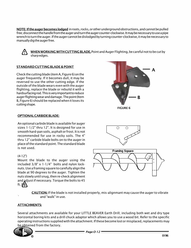
STANDARD CUTTING BLADE & POINT
Check the cutting blade (item A, Figure 6) on theauger frequently. If it becomes dull, it may bereversed to use the other cutting edge. If theoutside of the blade wears even with the augerflighting, replace the blade or rebuild it with ahardsurfacing rod. This is very important to reduceauger flighting wear and damage. The point (ItemB, Figure 6) should be replaced when it loses itscutting shape.
FIGURE 6
A
R 0196Page O-12
OPTIONAL CARBIDE BLADE:
An optional carbide blade is available for augersizes 1-1/2" thru 12". It is designed for use insmooth hard-pan soils, asphalt or frost. It is notrecommended for use in rocky soils. The 4"thru 12" carbide blade bolts on to the auger inplace of the standard point. The standard bladeis not used.
(4-12")Mount the blade to the auger using theincluded 3/8" x 1-1/4" bolts and nylon lock-nuts. Use a framing square to carefully align theblade at 90 degrees to the auger. Tighten thenuts slowly until snug, then re-check alignmentand adjust if necessary. Torque the bolts to 45ft. lbs.
CAUTION: If the blade is not installed properly, mis-alignmant may cause the auger to vibrate` and "walk" in use.
ATTACHMENTS:
Several attachments are available for your LITTLE BEAVER Earth Drill; including both wet and dry typehorizontal boring kits and a drill chuck adaptor which allows you to use a wood bit. Refer to the specificoperating instructions supplied with the attachment. If these become lost or misplaced, replacements maybe obtained from the factory.
B
0900Page O-13
R
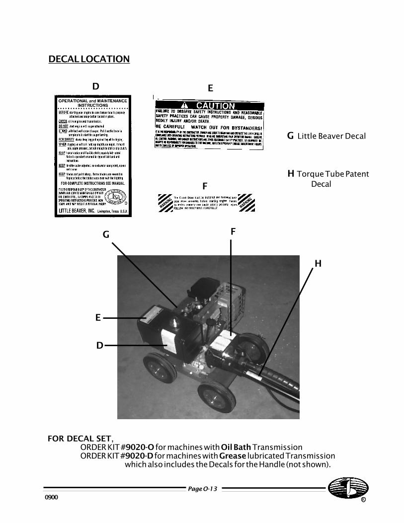
DECAL LOCATION
FOR DECAL SET,ORDER KIT #9020-O for machines with Oil Bath TransmissionORDER KIT #9020-D for machines with Grease lubricated Transmission
which also includes the Decals for the Handle (not shown).
E
D
F
ED
F
G
G Little Beaver Decal
H Torque Tube PatentDecal
H
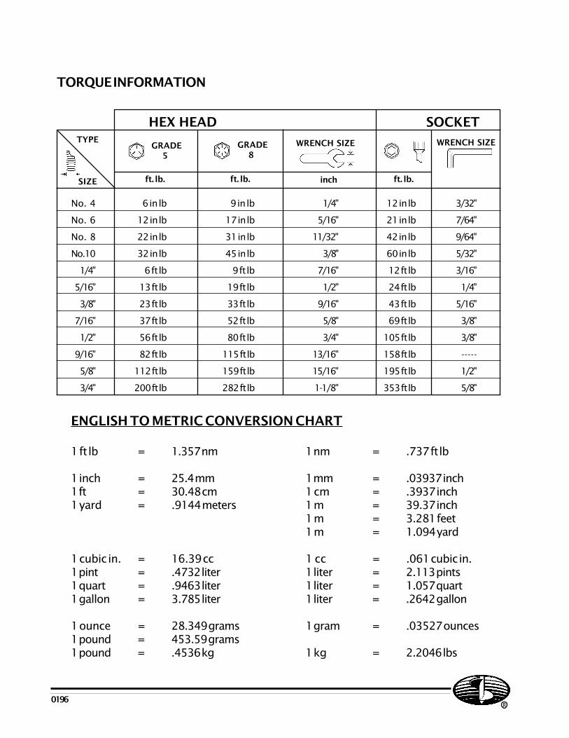
ENGLISH TO METRIC CONVERSION CHART
1 ft lb = 1.357 nm 1 nm = .737 ft lb
1 inch = 25.4 mm 1 mm = .03937 inch1 ft = 30.48 cm 1 cm = .3937 inch1 yard = .9144 meters 1 m = 39.37 inch
1 m = 3.281 feet1 m = 1.094 yard
1 cubic in. = 16.39 cc 1 cc = .061 cubic in.1 pint = .4732 liter 1 liter = 2.113 pints1 quart = .9463 liter 1 liter = 1.057 quart1 gallon = 3.785 liter 1 liter = .2642 gallon
1 ounce = 28.349 grams 1 gram = .03527 ounces1 pound = 453.59 grams1 pound = .4536 kg 1 kg = 2.2046 lbs
0196
TORQUE INFORMATION
HEX HEAD SOCKETTYPE
SIZE inch
GRADE 5
GRADE 8
WRENCH SIZE WRENCH SIZE
ft. lb. ft. lb. ft. lb.
No. 4 6 in lb 9 in lb 1/4" 12 in lb 3/32"
No. 6 12 in lb 17 in lb 5/16" 21 in lb 7/64"
No. 8 22 in lb 31 in lb 11/32" 42 in lb 9/64"
No.10 32 in lb 45 in lb 3/8" 60 in lb 5/32"
1/4" 6 ft lb 9 ft lb 7/16" 12 ft lb 3/16"
5/16" 13 ft lb 19 ft lb 1/2" 24 ft lb 1/4"
3/8" 23 ft lb 33 ft lb 9/16" 43 ft lb 5/16"
7/16" 37 ft lb 52 ft lb 5/8" 69 ft lb 3/8"
1/2" 56 ft lb 80 ft lb 3/4" 105 ft lb 3/8"
9/16" 82 ft lb 115 ft lb 13/16" 158 ft lb -----
5/8" 112 ft lb 159 ft lb 15/16" 195 ft lb 1/2"
3/4" 200 ft lb 282 ft lb 1-1/8" 353 ft lb 5/8"
R

THINKSAFETYFIRST!
P.O. BOX 840 LIVINGSTON, TEXAS 77351PH# 800/227-7515 OR 936/327-3121 FAX# 936/327-4025