study on the earth pressure distribution of excavation
TRANSCRIPT
INTERNATIONAL SOCIETY FOR
SOIL MECHANICS AND
GEOTECHNICAL ENGINEERING
This paper was downloaded from the Online Library of the International Society for Soil Mechanics and Geotechnical Engineering (ISSMGE). The library is available here:
https://www.issmge.org/publications/online-library
This is an open-access database that archives thousands of papers published under the Auspices of the ISSMGE and maintained by the Innovation and Development Committee of ISSMGE.
Geotechnical Aspects of Underground Construction in Soft Ground – Ng, Huang & Liu (eds)© 2009 Taylor & Francis Group, London, ISBN 978-0-415-48475-6
Study on the earth pressure distribution of excavation chamber in EPB
tunneling
T.T. Song & S.H. Zhou
Key Laboratory of Geotechnical and Underground Engineering of Ministry of Education, Tongji University,
Shanghai, P.R. China
Department of Geotechnical Engineering, Tongji University, Shanghai, P.R. Chnia
ABSTRACT: In shield tunneling, the excavation stability is very important. The balance pressure which sup-ports the work face is offered by the the mucks in the earth chamber. The ideal supporting pressure on theexcavation face is trapezoidal. In fact, the pressure is irregular. So, the conceptions of earth pressure supportingratio (EPSR), regular modulus of earth pressure and buffer ability of chamber are put forward. Earth pressures intwo different situations of shield tunneling in clay ground and cobble sand ground are studied. The studies showthat EPSR and regular modulus of earth pressure in soft ground are both better than those in cobble ground.EPSR and regular modulus of earth pressure are two appropriate assessing indexes for EPB tunneling.
1 INTRODUCTION
With the advantages of surrounding influence, excava-tion speed, structure quality, working environment etc.,the shield tunneling method is popularly applied in thetunnels of metro, railway, road, municipal engineeringand so on.
Earth pressure balance machine (EPB) and slurryshield tunneling are the two mostly common method inmetro tunnels. Comparing with slurry shield method,the EPB has the merits of small construction yard, lesscost, simple technology. So the EPB is more popularin metro tunnels.
EPB machine applies pressure to working face bythe mucks which are cut from the face sometimes withinjection of soil conditioning additives. With the pres-sure the working face can maintain stable.The stabilityof working face is a key factor in the EPB tunneling.The accidents brought by destabilization of workingface are the main accidents according to statistics (QinJianshe, 2005).
Present researches about the shield tunneling pres-sure mainly focus on the theoretical pressure neededfor the working face (Anagnostou G, Kov’ari K., 1996;Abdul-Hamid Soubral, 2000 & Qin Jianshe, 2005).As for how to apply the pressure and the pressureproperties are seldom mentioned and researched. Inthis research, features of working face pressure, dis-tribution of pressure in the excavation chamber andthe pressure in the clay and cobble sand strata areresearched. Some conceptions are put forward, andprinciples are summarized.
2 CLASSICAL EPB THEORY
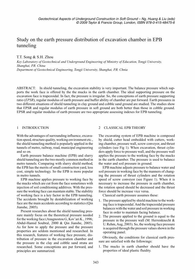
The excavating system of EPB machine is composedby shield, cutter head embedded with cutters, work-ing chamber, pressure wall, screw conveyor, and thrustcylinders (see Fig 1). When excavation, thrust cylin-ders apply force to pressure wall, and the pressure wallapplies the pressure to the working face by the mucksin the earth chamber. The pressure is used to balancethe water and soil pressure in ground.
EPB machine adjusts pressure to balance water andsoil pressure in working face by the manners of chang-ing the pressure of thrust cylinders and the rotationspeed of screw conveyor (see Figure 1). When it isnecessary to increase the pressure in earth chamber,the rotation speed should be decreased and the thrustforce should be increase vice versa.
Classical earth pressure assumes these:
1. The pressure applied by shield machine to the work-ing face is trapezoidal.And the trapezoidal pressurebalances with the water and soil pressure in workingface in order to maintain facing balance.
2. The pressure applied to the ground is equal to thepressure in the pressure wall (M. Herrenknecht &U. Rehm,Aug, 2003). So, the working face pressureis acquired through the pressure values shown in theoperating panel.
Obviously, the conditions for classical earth pres-sure are satisfied with the followings:
1. The mucks in earth chamber should have theproperties of ideal plastic fluidity.
343
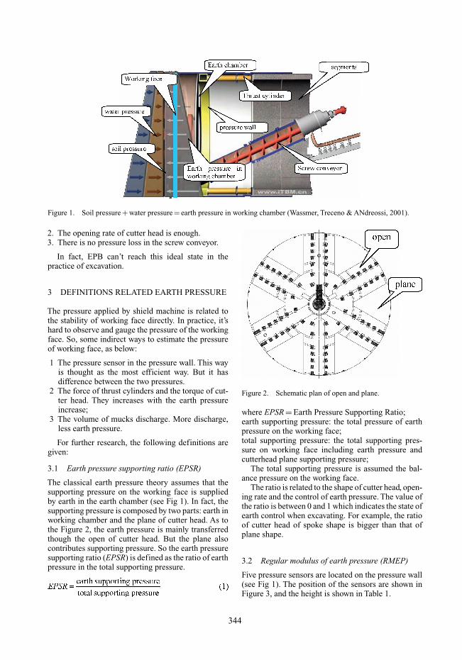
Figure 1. Soil pressure + water pressure = earth pressure in working chamber (Wassmer, Treceno & ANdreossi, 2001).
2. The opening rate of cutter head is enough.3. There is no pressure loss in the screw conveyor.
In fact, EPB can’t reach this ideal state in thepractice of excavation.
3 DEFINITIONS RELATED EARTH PRESSURE
The pressure applied by shield machine is related tothe stability of working face directly. In practice, it’shard to observe and gauge the pressure of the workingface. So, some indirect ways to estimate the pressureof working face, as below:
1 The pressure sensor in the pressure wall. This wayis thought as the most efficient way. But it hasdifference between the two pressures.
2 The force of thrust cylinders and the torque of cut-ter head. They increases with the earth pressureincrease;
3 The volume of mucks discharge. More discharge,less earth pressure.
For further research, the following definitions aregiven:
3.1 Earth pressure supporting ratio (EPSR)
The classical earth pressure theory assumes that thesupporting pressure on the working face is suppliedby earth in the earth chamber (see Fig 1). In fact, thesupporting pressure is composed by two parts: earth inworking chamber and the plane of cutter head. As tothe Figure 2, the earth pressure is mainly transferredthough the open of cutter head. But the plane alsocontributes supporting pressure. So the earth pressuresupporting ratio (EPSR) is defined as the ratio of earthpressure in the total supporting pressure.
Figure 2. Schematic plan of open and plane.
where EPSR = Earth Pressure Supporting Ratio;earth supporting pressure: the total pressure of earthpressure on the working face;total supporting pressure: the total supporting pres-sure on working face including earth pressure andcutterhead plane supporting pressure;
The total supporting pressure is assumed the bal-ance pressure on the working face.
The ratio is related to the shape of cutter head, open-ing rate and the control of earth pressure. The value ofthe ratio is between 0 and 1 which indicates the state ofearth control when excavating. For example, the ratioof cutter head of spoke shape is bigger than that ofplane shape.
3.2 Regular modulus of earth pressure (RMEP)
Five pressure sensors are located on the pressure wall(see Fig 1). The position of the sensors are shown inFigure 3, and the height is shown in Table 1.
344
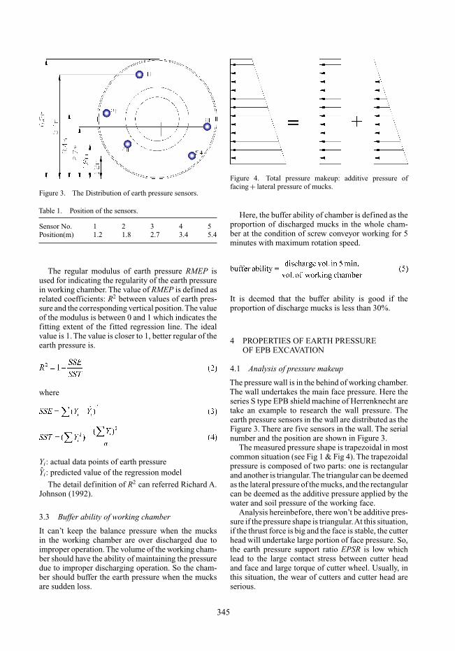
Figure 3. The Distribution of earth pressure sensors.
Table 1. Position of the sensors.
Sensor No. 1 2 3 4 5Position(m) 1.2 1.8 2.7 3.4 5.4
The regular modulus of earth pressure RMEP isused for indicating the regularity of the earth pressurein working chamber. The value of RMEP is defined asrelated coefficients: R2 between values of earth pres-sure and the corresponding vertical position.The valueof the modulus is between 0 and 1 which indicates thefitting extent of the fitted regression line. The idealvalue is 1. The value is closer to 1, better regular of theearth pressure is.
where
Yi: actual data points of earth pressure
Yi: predicted value of the regression model
The detail definition of R2 can referred Richard A.Johnson (1992).
3.3 Buffer ability of working chamber
It can’t keep the balance pressure when the mucksin the working chamber are over discharged due toimproper operation. The volume of the working cham-ber should have the ability of maintaining the pressuredue to improper discharging operation. So the cham-ber should buffer the earth pressure when the mucksare sudden loss.
Figure 4. Total pressure makeup: additive pressure offacing + lateral pressure of mucks.
Here, the buffer ability of chamber is defined as theproportion of discharged mucks in the whole cham-ber at the condition of screw conveyor working for 5minutes with maximum rotation speed.
It is deemed that the buffer ability is good if theproportion of discharge mucks is less than 30%.
4 PROPERTIES OF EARTH PRESSUREOF EPB EXCAVATION
4.1 Analysis of pressure makeup
The pressure wall is in the behind of working chamber.The wall undertakes the main face pressure. Here theseries S type EPB shield machine of Herrenknecht aretake an example to research the wall pressure. Theearth pressure sensors in the wall are distributed as theFigure 3. There are five sensors in the wall. The serialnumber and the position are shown in Figure 3.
The measured pressure shape is trapezoidal in mostcommon situation (see Fig 1 & Fig 4). The trapezoidalpressure is composed of two parts: one is rectangularand another is triangular.The triangular can be deemedas the lateral pressure of the mucks, and the rectangularcan be deemed as the additive pressure applied by thewater and soil pressure of the working face.
Analysis hereinbefore, there won’t be additive pres-sure if the pressure shape is triangular.At this situation,if the thrust force is big and the face is stable, the cutterhead will undertake large portion of face pressure. So,the earth pressure support ratio EPSR is low whichlead to the large contact stress between cutter headand face and large torque of cutter wheel. Usually, inthis situation, the wear of cutters and cutter head areserious.
345
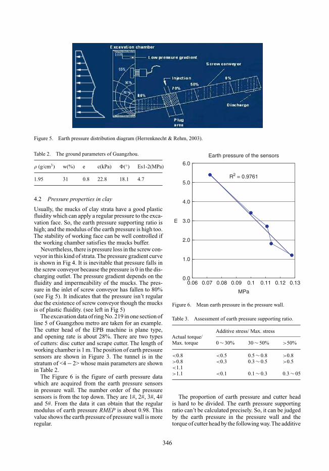
Figure 5. Earth pressure distribution diagram (Herrenknecht & Rehm, 2003).
Table 2. The ground parameters of Guangzhou.
ρ (g/cm3) w(%) e c(kPa) �(◦) Es1-2(MPa)
1.95 31 0.8 22.8 18.1 4.7
4.2 Pressure properties in clay
Usually, the mucks of clay strata have a good plasticfluidity which can apply a regular pressure to the exca-vation face. So, the earth pressure supporting ratio ishigh; and the modulus of the earth pressure is high too.The stability of working face can be well controlled ifthe working chamber satisfies the mucks buffer.
Nevertheless, there is pressure loss in the screw con-veyor in this kind of strata.The pressure gradient curveis shown in Fig 4. It is inevitable that pressure falls inthe screw conveyor because the pressure is 0 in the dis-charging outlet. The pressure gradient depends on thefluidity and impermeability of the mucks. The pres-sure in the inlet of screw conveyor has fallen to 80%(see Fig 5). It indicates that the pressure isn’t regulardue the existence of screw conveyor though the mucksis of plastic fluidity. (see left in Fig 5)
The excavation data of ring No. 219 in one section ofline 5 of Guangzhou metro are taken for an example.The cutter head of the EPB machine is plane type,and opening rate is about 28%. There are two typesof cutters: disc cutter and scrape cutter. The length ofworking chamber is 1 m.The position of earth pressuresensors are shown in Figure 3. The tunnel is in thestratum of <4 − 2> whose main parameters are shownin Table 2.
The Figure 6 is the figure of earth pressure datawhich are acquired from the earth pressure sensorsin pressure wall. The number order of the pressuresensors is from the top down. They are 1#, 2#, 3#, 4#and 5#. From the data it can obtain that the regularmodulus of earth pressure RMEP is about 0.98. Thisvalue shows the earth pressure of pressure wall is moreregular.
Earth pressure of the sensors
R2 = 0.9761
0.0
1.0
2.0
3.0
4.0
5.0
6.0
0.06 0.07 0.08 0.09 0.1 0.11 0.12 0.13
MPa
m
Figure 6. Mean earth pressure in the pressure wall.
Table 3. Assessment of earth pressure supporting ratio.
Additive stress/ Max. stressActual torque/Max. torque 0 ∼ 30% 30 ∼ 50% >50%
<0.8 <0.5 0.5 ∼ 0.8 >0.8>0.8 <0.3 0.3 ∼ 0.5 >0.5<1.1>1.1 <0.1 0.1 ∼ 0.3 0.3 ∼ 05
The proportion of earth pressure and cutter headis hard to be divided. The earth pressure supportingratio can’t be calculated precisely. So, it can be judgedby the earth pressure in the pressure wall and thetorque of cutter head by the following way.The additive
346
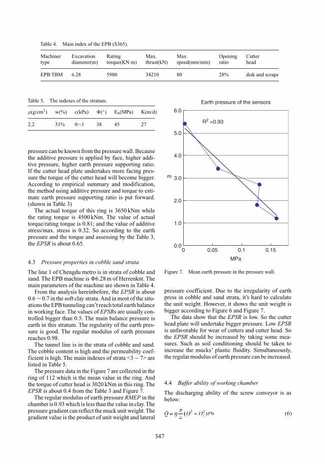
Table 4. Main index of the EPB (S365).
Machiner Excavation Rating Max. Max. Opening Cuttertype diameter(m) torque(KN·m) thrust(kN) speed(mm/min) ratio head
EPB TBM 6.28 5980 34210 80 28% disk and scrape
Table 5. The indexes of the stratum.
ρ(g/cm3) w(%) c(kPa) �(◦) E0(MPa) K(m/d)
2.2 31% 0∼1 38 45 27
pressure can be known from the pressure wall. Becausethe additive pressure is applied by face, higher addi-tive pressure, higher earth pressure supporting ratio.If the cutter head plate undertakes more facing pres-sure the torque of the cutter head will become bigger.According to empirical summary and modification,the method using additive pressure and torque to esti-mate earth pressure supporting ratio is put forward.(shown in Table 3)
The actual torque of this ring is 3650 kNm whilethe rating torque is 4500 kNm. The value of actualtorque/rating torque is 0.81; and the value of additivestress/max. stress is 0.32. So according to the earthpressure and the torque and assessing by the Table 3,the EPSR is about 0.65.
4.3 Pressure properties in cobble sand strata
The line 1 of Chengdu metro is in strata of cobble andsand. The EPB machine is �6.28 m of Herrenknt. Themain parameters of the machine are shown in Table 4.
From the analysis hereinbefore, the EPSR is about0.6 ∼ 0.7 in the soft clay strata.And in most of the situ-ations the EPB tunneling can’t reach total earth balancein working face. The values of EPSRs are usually con-trolled bigger than 0.5. The main balance pressure isearth in this stratum. The regularity of the earth pres-sure is good. The regular modulus of earth pressurereaches 0.98.
The tunnel line is in the strata of cobble and sand.The cobble content is high and the permeability coef-ficient is high. The main indexes of strata <3 − 7> arelisted in Table 5.
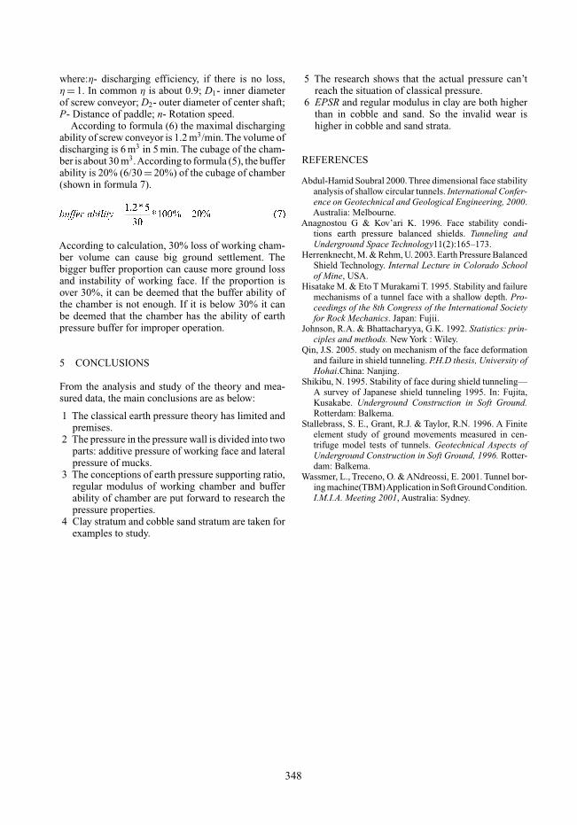
The pressure data in the Figure 7 are collected in thering of 112 which is the mean value in the ring. Andthe torque of cutter head is 3020 kNm in this ring. TheEPSR is about 0.4 from the Table 3 and Figure 7.
The regular modulus of earth pressure RMEP in thechamber is 0.93 which is less than the value in clay.Thepressure gradient can reflect the muck unit weight.Thegradient value is the product of unit weight and lateral
Earth pressure of the sensors
R2 =0.93
0.0
1.0
2.0
3.0
4.0
5.0
6.0
0 0.05 0.1 0.15
MPa
m
Figure 7. Mean earth pressure in the pressure wall.
pressure coefficient. Due to the irregularity of earthpress in cobble and sand strata, it’s hard to calculatethe unit weight. However, it shows the unit weight isbigger according to Figure 6 and Figure 7.
The data show that the EPSR is low. So the cutterhead plate will undertake bigger pressure. Low EPSRis unfavorable for wear of cutters and cutter head. Sothe EPSR should be increased by taking some mea-sures. Such as soil conditioning should be taken toincrease the mucks’ plastic fluidity. Simultaneously,the regular modulus of earth pressure can be increased.
4.4 Buffer ability of working chamber
The discharging ability of the screw conveyor is asbelow:
347
where:η- discharging efficiency, if there is no loss,η = 1. In common η is about 0.9; D1- inner diameterof screw conveyor; D2- outer diameter of center shaft;P- Distance of paddle; n- Rotation speed.
According to formula (6) the maximal dischargingability of screw conveyor is 1.2 m3/min.The volume ofdischarging is 6 m3 in 5 min. The cubage of the cham-ber is about 30 m3.According to formula (5), the bufferability is 20% (6/30 = 20%) of the cubage of chamber(shown in formula 7).
According to calculation, 30% loss of working cham-ber volume can cause big ground settlement. Thebigger buffer proportion can cause more ground lossand instability of working face. If the proportion isover 30%, it can be deemed that the buffer ability ofthe chamber is not enough. If it is below 30% it canbe deemed that the chamber has the ability of earthpressure buffer for improper operation.
5 CONCLUSIONS
From the analysis and study of the theory and mea-sured data, the main conclusions are as below:
1 The classical earth pressure theory has limited andpremises.
2 The pressure in the pressure wall is divided into twoparts: additive pressure of working face and lateralpressure of mucks.
3 The conceptions of earth pressure supporting ratio,regular modulus of working chamber and bufferability of chamber are put forward to research thepressure properties.
4 Clay stratum and cobble sand stratum are taken forexamples to study.
5 The research shows that the actual pressure can’treach the situation of classical pressure.
6 EPSR and regular modulus in clay are both higherthan in cobble and sand. So the invalid wear ishigher in cobble and sand strata.
REFERENCES
Abdul-Hamid Soubral 2000. Three dimensional face stabilityanalysis of shallow circular tunnels. International Confer-ence on Geotechnical and Geological Engineering, 2000.Australia: Melbourne.
Anagnostou G & Kov’ari K. 1996. Face stability condi-tions earth pressure balanced shields. Tunneling andUnderground Space Technology11(2):165–173.
Herrenknecht, M. & Rehm, U. 2003. Earth Pressure BalancedShield Technology. Internal Lecture in Colorado Schoolof Mine, USA.
Hisatake M. & Eto T Murakami T. 1995. Stability and failuremechanisms of a tunnel face with a shallow depth. Pro-ceedings of the 8th Congress of the International Societyfor Rock Mechanics. Japan: Fujii.
Johnson, R.A. & Bhattacharyya, G.K. 1992. Statistics: prin-ciples and methods. New York : Wiley.
Qin, J.S. 2005. study on mechanism of the face deformationand failure in shield tunneling. P.H.D thesis, University ofHohai.China: Nanjing.
Shikibu, N. 1995. Stability of face during shield tunneling—A survey of Japanese shield tunneling 1995. In: Fujita,Kusakabe. Underground Construction in Soft Ground.Rotterdam: Balkema.
Stallebrass, S. E., Grant, R.J. & Taylor, R.N. 1996. A Finiteelement study of ground movements measured in cen-trifuge model tests of tunnels. Geotechnical Aspects ofUnderground Construction in Soft Ground, 1996. Rotter-dam: Balkema.
Wassmer, L., Treceno, O. & ANdreossi, E. 2001. Tunnel bor-ing machine(TBM)Application in Soft Ground Condition.I.M.I.A. Meeting 2001, Australia: Sydney.
348