deepfnd – helixpile 2020 user's manual - deep excavation
TRANSCRIPT
DeepFND – Deep Foundations Design Software
HelixPile – Helical Pile Design Software
Issued: 15-July-2019
www.deepexcavation.com, www.deepex.com
DeepFND – HelixPile 2020 User’s Manual
DEEP EXCAVATION 1
DEEPFND – HELIXPILE 2020 USER’S MANUAL
TABLE OF CONTENTS
TABLE OF CONTENTS ..................................................................................................................... 1
INTRODUCTION ............................................................................................................................. 4
PART A: GENERAL INFORMATION – SOFTWARE USE ..................................................................... 5
SECTION 1: INTRODUCTION TO DeepFND and HelixPile ............................................................ 6
1.1 About DeepFND (Deep Foundation Engineering Program) ......................................... 6
1.2 About HelixPile (Helical Piles Design Engineering Program) ........................................ 6
1.3 Software Compatibility & Installation ......................................................................... 6
1.4 Support & Technical Assistance ................................................................................... 6
1.5 DeepFND Training, Examples and Projects .................................................................. 7
1.6 End User License Agreement ...................................................................................... 7
1.6 Software Basic Version and Additional Optional Modules ........................................ 10
1.7 Activating the software ............................................................................................. 11
1.8 License transfer instructions ..................................................................................... 12
SECTION 2: DeepFND Interface and Main Tabs ........................................................................ 16
2.1 Using DeepFND ......................................................................................................... 16
2.2.1 Toolbar Functions, Design Section List, and Project Tree View ............................... 18
2.3 General menu ........................................................................................................... 21
2.4 Properties menu ....................................................................................................... 27
2.5 Analysis menu ........................................................................................................... 28
2.6 Design menu ............................................................................................................. 31
2.7 Settlement menu ...................................................................................................... 33
2.8 Lateral menu ............................................................................................................. 36
2.9 Pile Caps menu .......................................................................................................... 39
2.10 Results menu .......................................................................................................... 41
2.11 Report menu ........................................................................................................... 42
2.12 View menu .............................................................................................................. 43
2.13 Help menu .............................................................................................................. 44
2.14 Torque menu ........................................................................................................... 46
DEEP EXCAVATION 2
DEEPFND – HELIXPILE 2020 USER’S MANUAL
2.15 Edit Default Software Settings ................................................................................. 47
SECTION 3: MAIN SOFTWARE DIALOGS – USE OF THE SOFTWARE .......................................... 49
3.1 Define Model Elevation and Dimensions .................................................................. 49
3.2 Define Project information ........................................................................................ 50
3.3 Define Soil Properties ................................................................................................ 51
3.5 Define Pile Properties ............................................................................................... 59
3.6 Edit Helical Pile Sections (DeepFND and HelixPile) .................................................... 62
3.7 Edit Non‐Helical Pile Sections (DeepFND Only) ......................................................... 65
3.8: Edit Pile Caps ............................................................................................................ 67
3.9: Define External Loads on the Single Piles ................................................................. 70
3.10 Define loads on pile cap .......................................................................................... 74
3.11: Data Entry: CPT Logs and SPT Records ................................................................... 77
3.12: Edit Structural Materials ........................................................................................ 81
3.13: Report Options ‐ Printed Reports ........................................................................... 85
3.14: Define Analysis Settings ......................................................................................... 86
PART B: SINGLE PILES – DESIGN AND ANALYSIS ........................................................................... 94
SECTION 4: SINGLE PILES – MODELS AND ANALYSIS ................................................................ 95
4.1 Creating a Model Manually and Define Analysis Settings ......................................... 95
4.2 Create a Model with the Model Wizard .................................................................. 100
4.3 Review Analysis Results ........................................................................................... 108
SECTION 5: SINGLE PILES ‐ EXAMPLES ................................................................................... 111
5.1 Example 1: Design of a Drilled Reinforced Concrete Pile ......................................... 111
5.2 Example 2: Design of a Helical Pile .......................................................................... 122
PART C: PILE GROUPS AND PILE RAFTS ...................................................................................... 134
SECTION 6: PILE GROUPS – MODELS AND ANALYSIS.............................................................. 135
6.1 Creating a Pile Cap Model Automatically ................................................................ 135
6.2 Editing the Created Model ...................................................................................... 138
6.3 Creating a Custom Shape Pile Cap Manually ........................................................... 141
6.4 Adding New Piles Graphically .................................................................................. 142
DEEP EXCAVATION 3
DEEPFND – HELIXPILE 2020 USER’S MANUAL
6.5 Review Pile Cap and Pile Group Results .................................................................. 143
PART D: THEORETICAL BACKGROUND ....................................................................................... 147
SECTION 7: THEORETICAL BACKGROUND FOR HELICAL PILES ................................................ 148
7.1 Theoretical background .......................................................................................... 148
7.2: Shaft side resistance .............................................................................................. 151
7.3 Cylinder strength method ....................................................................................... 152
7.4 Installation disturbance factors ............................................................................... 152
7.5 Structural Safety Factors ......................................................................................... 153
7.6 Helical pile settlement estimation procedure ......................................................... 154
5.7 Exponential soil model with linear creep ................................................................ 157
SECTION 8: THEORETICAL BACKGROUND FOR REGULAR PILE TYPES ..................................... 158
8.1 Introduction ............................................................................................................ 158
8.2. A Driven Pile Recommendations ............................................................................ 158
6.3 FHWA Methods for Drilled Piles .............................................................................. 177
6.4 FHWA methods for CFA and Drilled‐In‐Displacement piles ..................................... 181
6.5 Axial structural capacity with building codes .......................................................... 186
TABLE OF FIGURES ..................................................................................................................... 188
REFERENCES .............................................................................................................................. 194
DEEP EXCAVATION 4
DEEPFND – HELIXPILE 2020 USER’S MANUAL
INTRODUCTION This user’s manual provides reference guide for engineers and contractors in the use of the
DeepFND and HelixPile software programs. The document details how different parameters and
settings can be controlled within the program, how to simulate different conditions, and how to
analyze and evaluate software results.
The software programs DeepFND and HelixPile use the exact same interactive interface and they
include the same functions. The software programs are almost identical, with the only difference
being the available pile types each software can handle:
DeepFND can perform vertical and lateral pile analysis, structural and geotechnical design of any
pile type (helical and non‐helical). The non‐helical piles can be installed by any method (drilled,
driven, caissons, CFA piles, drilled‐in‐displacement piles) and they can be timber, reinforced
concrete or steel piles. In DeepFND, we can change the pile section with depth and simulate cases
like belled pile tips. Helical piles can be pipes, square solid or square hollow pile sections with any
helix configuration. The helical piles can be grouted, and we can also use casings on the top of
the piles.
HelixPile can perform vertical and lateral pile analysis, structural and geotechnical design of
helical piles. The HelixPile software is identical to the helical pile component of DeepFND.
The pile design procedure with the use of our software programs can be summarized as follows:
A. Define the soil properties and stratigraphy (manually or with the use of CPT or SPT logs).
B. Define the vertical and lateral loads on the pile head.
C. Define the pile type and pile structural section.
D. Define analysis options (vertical and lateral analysis methods, torque estimation profiles,
surface settlements criteria).
E. Run the analysis – Evaluate the results – Optimize the model.
F. Export reports in PDF or MS Word format.
The following sections present in detail all different software options for the creation and analysis
of any pile model with helical or non‐helical piles. Both programs offer capabilities to model pile
groups and pile supported rafts.
DEEP EXCAVATION 5
DEEPFND – HELIXPILE 2020 USER’S MANUAL
PART A: GENERAL INFORMATION – SOFTWARE USE
INFORMATION – SOFTWARE INTERFACE, FUNCTIONS AND DIALOGS The following sections provide useful information about the software versions and capabilities, system requirements, license activation and transfer, as well as general an introduction to the software interface, main tabs and toolbar functions. The contents of all software, main and secondary, dialogs are also discussed.
DEEP EXCAVATION 6
DEEPFND – HELIXPILE 2020 USER’S MANUAL
SECTION 1: INTRODUCTION TO DeepFND and HelixPile
1.1 About DeepFND (Deep Foundation Engineering Program)
DeepFND is a user friendly, modern and powerful software program for the design of deep foundations. DeepFND allows us to handle an unlimited number of stage conditions and soil profiles. DeepFND incorporates the latest recommendations and allows us to easily view the controlling design conditions. DeepFND can perform analysis of single piles, pile groups, and pile rafts (additional optional modules Pile Groups and Pile Rafts are required). DeepFND can perform vertical and lateral pile analysis of any pile type (reinforced concrete, steel beams (pipes‐channel sections‐H beams), composite sections, timber (wood) piles, belled type piles, helical piles and more). It implements widely accepted recommendations about different pile installation methods (drilled, driven, micropiles, CFA piles, drilled‐in‐displacement piles).
1.2 About HelixPile (Helical Piles Design Engineering Program)
HelixPile is a user friendly, powerful software program for the design of helical piles. HelixPile can perform vertical and lateral pile analysis of all helical pile types (pipes, square solid and square hollow sections) with unlimited number of helix configurations. The software can also perform pile settlement analysis and it can calculate the installation torque. HelixPile can perform analysis of single piles and of pile groups and pile rafts (additional optional modules Pile Groups and Pile Rafts are required). HelixPile and DeepFND software programs are identical, with the only difference being the available pile types. In the rest of the document, we will use the name of DeepFND. The same features and procedures apply for HelixPile.
1.3 Software Compatibility & Installation
DeepFND is compatible with Windows (OS) XP, Vista,7 8 and 10. A minimum of 380 Mb must be available on your hard disk. However, Windows 10 computers with 64bits are generally recommended. Some 32‐bit computers with very old operating systems have demonstrated issues in running parts of the lateral analysis.
1.4 Support & Technical Assistance
Support and technical assistance for DeepFND is offered through our web sites at: www.deepexcavation.com and www.deepex.com
Please send us any question at: [email protected]
DEEP EXCAVATION 7
DEEPFND – HELIXPILE 2020 USER’S MANUAL
1.5 DeepFND Training, Examples and Projects
You can find extensive examples and videos on our official websites (www.deepexcavation.com and www.deepex.com).
For examples and training videos, please visit:
https://www.deepex.com/training/deepfnd_helixpile_presentation_videos
Software training/online presentations:
We can always arrange a free online presentation (up to one hour), where we can present the
main features and capabilities of our software. Extensive training (online or on spot) can be
arranged upon request. The cost of the full training course can be defined according to your
needs. To arrange a presentation and for additional information, please contact:
1.6 End User License Agreement
Deep Excavation makes every effort to ensure quality and accuracy of computations performed by Steel Connect. However, the end user (you) assumes full responsibility for the applicability of the results to actual projects as described in the License Agreement that follows. If you decide to use DeepFND 1.0 you agree to abide by the terms and conditions described in the License Agreement. DeepFND "TERMS OF USE / LICENSE AGREEMENT" This legal document is an agreement between you (the end user) and Deep Excavation. BY CONTINUING WITH/OPENING/DOWNLOADING THIS SOFTWARE PROGRAM, YOU ARE AGREEING TO BECOME BOUND BY THE TERMS OF THIS AGREEMENT, WHICH INCLUDES THE SOFTWARE LICENSE, SOFTWARE DISCLAIMER OF WARRANTY, AND HARDWARE LIMITED WARRANTY "collectively the "Agreement". This agreement constitutes the complete agreement between you and Deep Excavation. IF YOU DO NOT AGREE TO THE TERMS OF THIS AGREEMENT, DO NOT CONTINUE WITH THIS SOFTWARE PROGRAM. Promptly return or delete the software program (cd and jewel case) and other items that are part of this product to Deep Excavation, for a complete refund if a purchasing fee was charged. DeepFND ALL VERSIONS "SOFTWARE LICENSE" THE LICENSE APPLIES TO PURCHASED AND FREE OF PURCHASE VERSIONS OF THE STEEL‐CONNECT SOFTWARE. LICENSE. In consideration of payment of the LICENSE fee, which is a part of the price you paid for this product, Deep Excavation, as Licensor grants to you, the LICENSEE, a nonexclusive right to use and display this copy of STEEL‐CONNECT, Software (hereinafter referred to as "SOFTWARE or DeepFND 1.0 " on a single COMPUTER (i.e., with a single CPU) at a single location. Any "networking", namely operating this program on a "network" is strictly forbidden. You as a Licensee are strictly forbidden to operate, utilize, transfer, distribute, connect, network, link to, attach, or operate in any manner this software on the internet, worldwide web, via email, any
DEEP EXCAVATION 8
DEEPFND – HELIXPILE 2020 USER’S MANUAL
website, networking, any multimedia device, electronic or otherwise or any form of electronic media whatsoever. This includes but is not limited to the written materials, results, output, or resulting answers and/or printed matter without the prior written consent of Deep Excavation. Deep Excavation reserves all rights not expressly granted to LICENSEE. SOFTWARE OWNERSHIP. As the LICENSEE, you own the magnetic or other physical media on which the SOFTWARE is originally or subsequently recorded or fixed, however, Deep Excavation retains title and ownership of the SOFTWARE recorded on the original disk copy/ies and any subsequent copies of the SOFTWARE, regardless of the form or media in or on which the original and other copies may exist. This License is not a sale of the original SOFTWARE or any copy thereof. COPY AND/OR MODIFY RESTRICTIONS. This Licensed Product is copyrighted (copyright 2004 Deep Excavation) and may not be further copied, without the prior written approval of Deep Excavation except that You may make one copy for backup purposes provided You reproduce and include the complete copyright notice, disclaimer, etc., on the backup copy. Any unauthorized copying is in violation of this Agreement and also a violation of the United States Copyright law. You may not use, transfer, modify, copy of otherwise reproduce the License Product, or any part of it, except as expressly permitted in this End User License Agreement. USE RESTRICTIONS. As the LICENSEE, you may physically transfer the SOFTWARE from one computer to another provided that the SOFTWARE is used on only one computer at a time. You may not electronically transfer the SOFTWARE from one computer to another over a network. You may not distribute copies of the SOFTWARE or accompanying written materials to others. You may not operate, utilize, transfer, distribute, connect, network, link to, attach, or operate in any manner this software on the internet, worldwide web, via email, any website, networking, any multimedia device, electronic or otherwise or any form of electronic media whatsoever. You may not modify, adapt, translate, reverse engineer, decompile, disassemble, or create derivative works based on the SOFTWARE. In addition, you may not modify, adapt, translate, or create derivative works based on the written materials, results, output, or resulting answers and/or printed matter without the prior written consent of Deep Excavation. RESTRICTIONS AGAINST TRANSFER. This SOFTWARE is licensed only to you, the LICENSEE, and may not be transferred to anyone without the prior written consent of DEEP EXCAVATION. Any authorized transferee of the SOFTWARE shall be bound by the terms and conditions of this Agreement. In no event may you transfer, assign, copy, rent, lease, sell, or dispose of the SOFTWARE in any manner on a temporary or permanent basis except as expressly provided herein. TERM. This End User License Agreement is effective from the date of purchase by You or granting to you of the Licensed Product and shall remain in force until terminated. You may terminate this End User License Agreement at any time by destroying the Licensed Product together with any backup copy in any form made by You or received by You. In addition, your right to use the Licensed Product will terminate if You fail to comply with any of the terms or conditions of this End User License Agreement. Upon such termination You shall destroy the copies of the Licensed Product in your possession. DISCLAIMER OF WARRANTY AND LIMITED WARRANTY
DEEP EXCAVATION 9
DEEPFND – HELIXPILE 2020 USER’S MANUAL
THE SOFTWARE AND ACCOMPANYING WRITTEN MATERIALS (INCLUDING RESTRICTIONS FOR USE) IF ANY, ARE PROVIDED "AS IS" WITHOUT WARRANTY OF ANY KIND. FURTHER, DEEP EXCAVATION DOES NOT WARRANT, GUARANTEE, OR MAKE ANY REPRESENTATIONS REGARDING THE USE, OR THE RESULTS OF THIS USE, OF THE SOFTWARE OR WRITTEN MATERIALS IN TERMS OF CORRECTNESS, ACCURACY, RELIABILITY, CURRENTNESS, OR OTHERWISE. THE ENTIRE RISK AS TO THE RESULTS AND PERFORMANCE OF THE SOFTWARE IS ASSUMED BY YOU. Deep Excavation warrants to the original LICENSEE (a) the disk(s) on which the SOFTWARE is recorded to be free from defects in materials and workmanship under normal use and service for a period of sixty (60) days from the date of delivery as evidenced by a copy of the receipt. In addition, Deep Excavation hereby limits the duration of any implied warranty(ies) on the disk or such hardware to the respective period stated above. Deep Excavation's entire liability and your exclusive remedy as to the disk(s) or hardware shall be, at Deep Excavation's option, either (1) return of the purchase price or (2) replacement of the disk or hardware that does not meet Deep Excavation's Limited Warranty and which is returned to Deep Excavation with a copy of the receipt. If failure of the disk or hardware has resulted from accident, abuse or misapplication, Deep Excavation shall have no responsibility to replace the disk or hardware or refund the purchase price. Any replacement disk or hardware will be warranted for the remainder of the original warranty period or thirty (30) days, whichever is longer. THE ABOVE ARE THE ONLY WARRANTIES OF ANY KIND, EITHER EXPRESS OR IMPLIED, INCLUDING BUT NOT LIMITED TO THE IMPLIED WARRANTIES OR MERCHANTABILITY AND FITNESS FOR A PARTICULAR PURPOSE THAT ARE MADE BY DEEP EXCAVATION ON THIS PRODUCT. NO ORAL OR WRITTEN INFORMATION OR ADVICE GIVEN BY DEEP EXCAVATION, ITS DEALERS, DISTRIBUTORS, AGENTS, OR EMPLOYEES SHALL CREATE A WARRANTY OR IN ANY WAY INCREASE THE SCOPE OF THIS WARRANTY, AND YOU MAY NOT RELY ON ANY SUCH INFORMATION OR ADVICE. NEITHER DEEP EXCAVATION NOR ANYONE ELSE WHO HAS BEEN INVOLVED IN THE CREATION, PRODUCTION, OR DELIVERY OF THIS PRODUCT SHALL BE LIABLE FOR ANY DIRECT, INDIRECT, CONSEQUENTIAL, OR INCIDENTAL DAMAGES (INCLUDING DAMAGES FOR LOSS OF BUSINESS PROFITS, BUSINESS INTERRUPTION, LOSS OF BUSINESS INFORMATION, AND THE LIKE) ARISING OUT OF THE USE OF OR INABILITY TO USE SUCH PRODUCT EVEN IF DEEP EXCAVATION HAS BEEN ADVISED OF THE POSSIBILITY OF SUCH DAMAGES. IN ALL CASES A LICENCED PROFESSIONAL ENGINEER SHALL APPROVE AND STAMP ANY RESULTS BY D.E.E.P. AND THAT ENGINEER IS ULTIMATELY RESPONSIBLE FOR ANY CONSEQUENCES OR MISUSE OF THE SOFTWARE. This Disclaimer of Warranty and Limited Warranty is governed by the laws of the State of New York. Should you have any questions regarding this agreement please email: Deep Excavation LLC, [email protected]
DEEP EXCAVATION 10
DEEPFND – HELIXPILE 2020 USER’S MANUAL
1.6 Software Basic Version and Additional Optional Modules
DeepFND and HelixPile software programs are customizable. The basic versions can be utilized, or capabilities can be extended by including any of the available additional optional modules. These modules, when activated, can assist us with different analysis options such as pile groups, pile rafts, etc. Basic Version With DeepFND (or HelixPile) basic version, we can design within the same software file an unlimited number of design scenarios (single pile case, or pile groups, etc.). Several design sections can be added where each design section can represent differences in soil layers, pile sections, loading conditions, or even different analysis assumptions. Design sections can be used to model a variety of different conditions within a site, all within a single file. DeepFND Basic version can design any non‐helical pile type. On the other hand, HelixPile Basic version can design only helical piles. Helical Piles Module (DeepFND Only) The Helical Piles module allows DeepFND to design all pile types (helical and non‐helical). With this module activated, DeepFND can perform vertical and lateral pile analysis of all helical pile types (pipes, square solid and square hollow sections) with unlimited number of helix configurations. The software can also calculate the installation torque. The Helical Piles component of DeepFND is identical to the HelixPile software. Pile Groups Module (DeepFND and HelixPile) The Pile Groups additional module allows DeepFND and HelixPile to perform full Lateral and Vertical design of both Single Piles and Pile Groups. Several Pile Cap shapes are implemented (Triangular, Rectangular, Hexagon, Octagon, Custom Cap shape). The pile caps can be generated automatically, with the use of the Pile Cap wizard. All piles and the pile cap can be accessed and modified independently. With the Pile Groups module activated, the software can perform lateral pile analysis on both directions. Pile Rafts Module (Additional to Pile Groups - DeepFND and HelixPile) The Pile Rafts module is an add‐on to the Pile Groups module. It allows the pile cap to behave as a pile raft, that considers the combined effect of the soil response under a raft (slab) and supporting piles. General practice is to design pile rafts for settlement rather than structural checks as piles are usually utilized closed to their ultimate capacity.
DEEP EXCAVATION 11
DEEPFND – HELIXPILE 2020 USER’S MANUAL
1.7 Activating the software
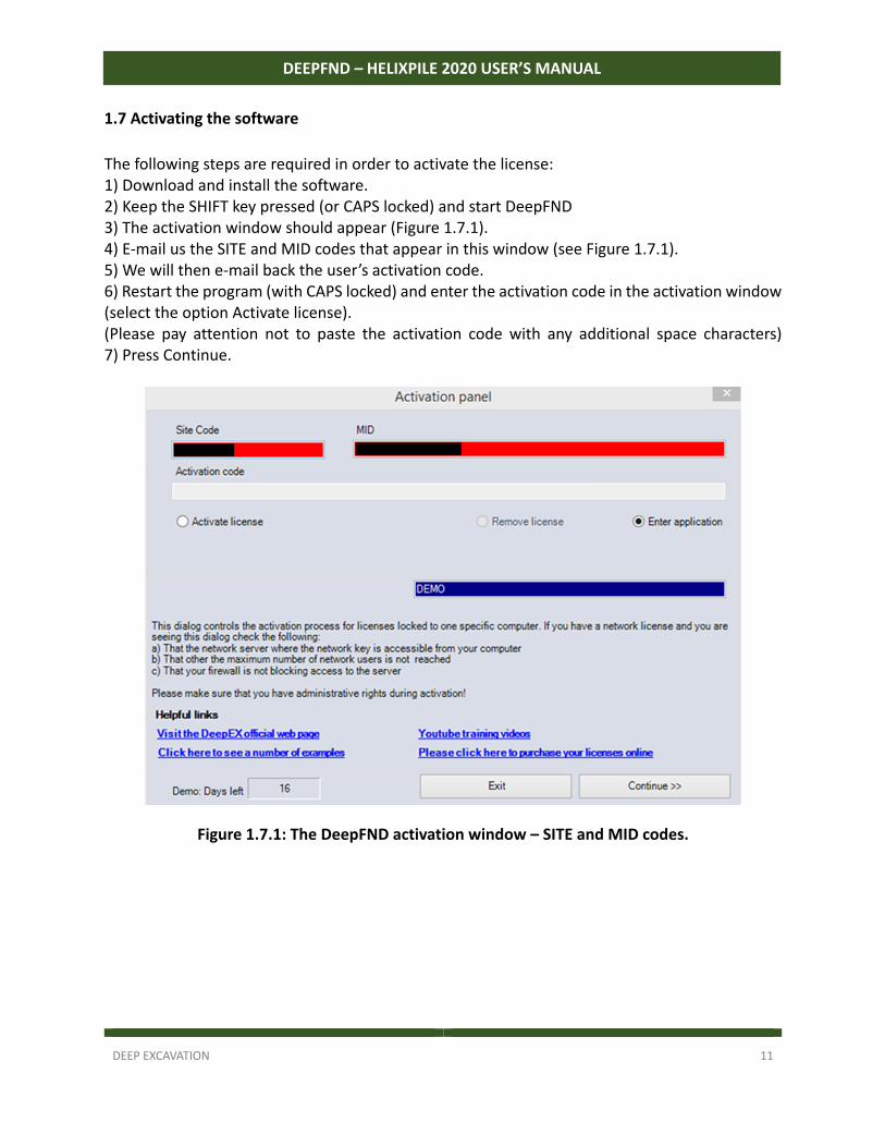
The following steps are required in order to activate the license: 1) Download and install the software. 2) Keep the SHIFT key pressed (or CAPS locked) and start DeepFND 3) The activation window should appear (Figure 1.7.1). 4) E‐mail us the SITE and MID codes that appear in this window (see Figure 1.7.1). 5) We will then e‐mail back the user’s activation code. 6) Restart the program (with CAPS locked) and enter the activation code in the activation window (select the option Activate license). (Please pay attention not to paste the activation code with any additional space characters) 7) Press Continue.
Figure 1.7.1: The DeepFND activation window – SITE and MID codes.
DEEP EXCAVATION 12
DEEPFND – HELIXPILE 2020 USER’S MANUAL
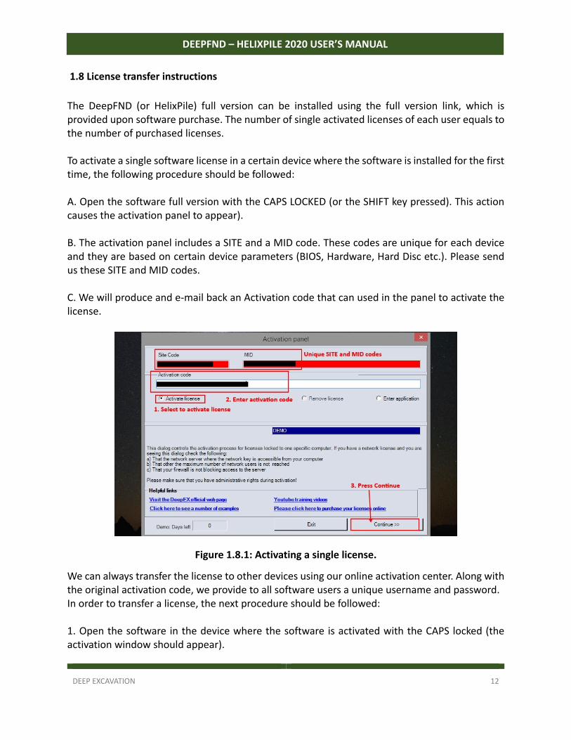
1.8 License transfer instructions
The DeepFND (or HelixPile) full version can be installed using the full version link, which is provided upon software purchase. The number of single activated licenses of each user equals to the number of purchased licenses. To activate a single software license in a certain device where the software is installed for the first time, the following procedure should be followed: A. Open the software full version with the CAPS LOCKED (or the SHIFT key pressed). This action causes the activation panel to appear). B. The activation panel includes a SITE and a MID code. These codes are unique for each device and they are based on certain device parameters (BIOS, Hardware, Hard Disc etc.). Please send us these SITE and MID codes. C. We will produce and e‐mail back an Activation code that can used in the panel to activate the license.
Figure 1.8.1: Activating a single license.
We can always transfer the license to other devices using our online activation center. Along with the original activation code, we provide to all software users a unique username and password. In order to transfer a license, the next procedure should be followed: 1. Open the software in the device where the software is activated with the CAPS locked (the activation window should appear).
DEEP EXCAVATION 13
DEEPFND – HELIXPILE 2020 USER’S MANUAL
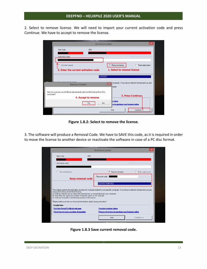
2. Select to remove license. We will need to import your current activation code and press Continue. We have to accept to remove the license.
Figure 1.8.2: Select to remove the license.
3. The software will produce a Removal Code. We have to SAVE this code, as it is required in order to move the license to another device or reactivate the software in case of a PC disc format.
Figure 1.8.3 Save current removal code.
DEEP EXCAVATION 14
DEEPFND – HELIXPILE 2020 USER’S MANUAL
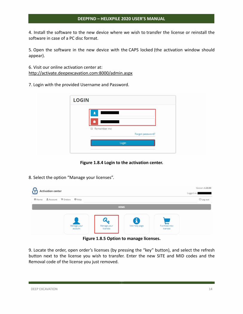
4. Install the software to the new device where we wish to transfer the license or reinstall the software in case of a PC disc format. 5. Open the software in the new device with the CAPS locked (the activation window should appear). 6. Visit our online activation center at: http://activate.deepexcavation.com:8000/admin.aspx 7. Login with the provided Username and Password.
Figure 1.8.4 Login to the activation center.
8. Select the option “Manage your licenses”.
Figure 1.8.5 Option to manage licenses.
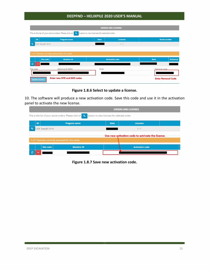
9. Locate the order, open order’s licenses (by pressing the “key” button), and select the refresh button next to the license you wish to transfer. Enter the new SITE and MID codes and the Removal code of the license you just removed.
DEEP EXCAVATION 15
DEEPFND – HELIXPILE 2020 USER’S MANUAL
Figure 1.8.6 Select to update a license.
10. The software will produce a new activation code. Save this code and use it in the activation panel to activate the new license.
Figure 1.8.7 Save new activation code.
DEEP EXCAVATION 16
DEEPFND – HELIXPILE 2020 USER’S MANUAL
SECTION 2: DeepFND Interface and Main Tabs
2.1 Using DeepFND
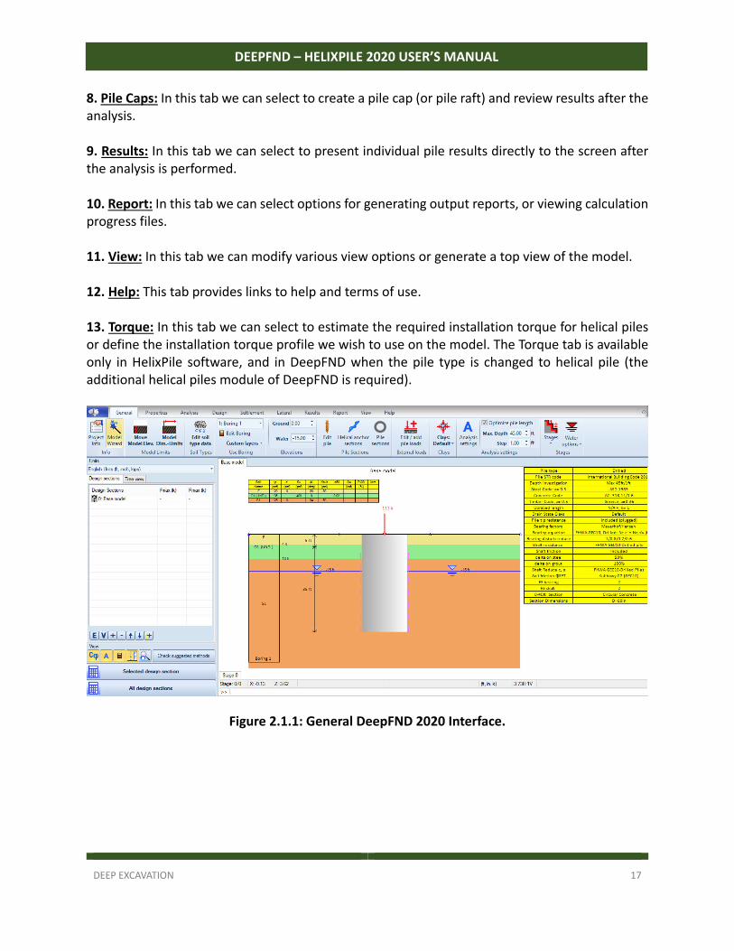
DeepFND is a user‐friendly software program and includes powerful features and versatile options. In DeepFND we can work with many design sections of pile analysis conditions. In a sense, a design section is a design scenario. This way, multiple conditions can be examined simultaneously. The main interface is shown in Figure 2.1.1. The general philosophy in creating a model in DeepFND is: 1) Specify the global coordinates. 2) Specify the soil types and properties. 3) Specify the layers and stratigraphy. 4) Create a generalized water table. 5) Specify the pile properties (installation method, depth, x‐coordinate, pile section). 6) Specify different stages. 7) Specify DeepFND analysis methods, combinations and standards. 8) Analyze the project. 9) Optimize the model. 10) Create and analyze the pile cap or pile raft (if required) The main tabs that appear on the top of the program have the following functions: 1. General: This tab includes the DeepFND wizard, general information about the project, model limits, general settings, soil properties, Pile and pile sections properties, pile loads, stage options and water behavior options. 2. Properties: This tab contains various information about Borings, CPT and SPT records and structural materials. 3. Analysis: This tab contains provides options for single pile Analysis methods, shaft resistance, factors on cohesion and cylinder method. 5. Design: In this tab we can define structural or load combination code options as well as change several structural and geotechnical safety factors. 6. Settlement: In this tab we can choose to perform settlement analysis, define the settlement parameters and edit the pile settlement acceptance criteria. In addition, actual axial load test records can be defined for comparison or calibration against pile settlement estimates. 7. Lateral: In this tab we can define the lateral pile analysis assumptions, methods and options, as well as any lateral load test records.
DEEP EXCAVATION 17
DEEPFND – HELIXPILE 2020 USER’S MANUAL
8. Pile Caps: In this tab we can select to create a pile cap (or pile raft) and review results after the analysis. 9. Results: In this tab we can select to present individual pile results directly to the screen after the analysis is performed. 10. Report: In this tab we can select options for generating output reports, or viewing calculation progress files. 11. View: In this tab we can modify various view options or generate a top view of the model. 12. Help: This tab provides links to help and terms of use. 13. Torque: In this tab we can select to estimate the required installation torque for helical piles or define the installation torque profile we wish to use on the model. The Torque tab is available only in HelixPile software, and in DeepFND when the pile type is changed to helical pile (the additional helical piles module of DeepFND is required).
Figure 2.1.1: General DeepFND 2020 Interface.
DEEP EXCAVATION 18
DEEPFND – HELIXPILE 2020 USER’S MANUAL
2.2.1 Toolbar Functions, Design Section List, and Project Tree View
The following section provides a detailed list of all toolbar functions. The first tab group to encounter contains the following options:
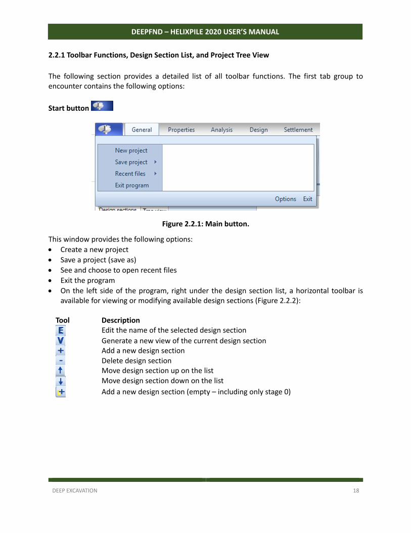
Start button
Figure 2.2.1: Main button.
This window provides the following options:
Create a new project
Save a project (save as)
See and choose to open recent files
Exit the program
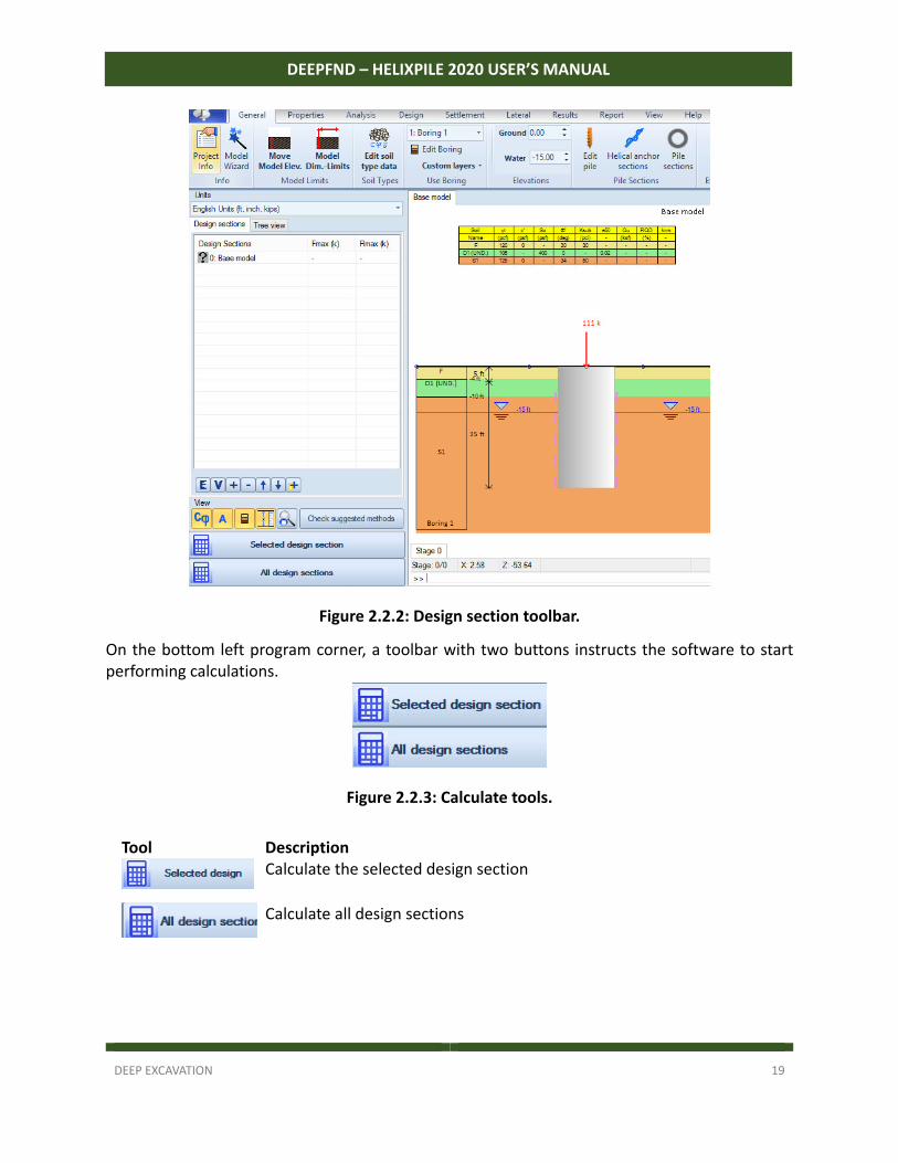
On the left side of the program, right under the design section list, a horizontal toolbar is available for viewing or modifying available design sections (Figure 2.2.2):
Tool Description
Edit the name of the selected design section
Generate a new view of the current design section
Add a new design section
Delete design section
Move design section up on the list
Move design section down on the list
Add a new design section (empty – including only stage 0)
DEEP EXCAVATION 19
DEEPFND – HELIXPILE 2020 USER’S MANUAL
Figure 2.2.2: Design section toolbar.
On the bottom left program corner, a toolbar with two buttons instructs the software to start performing calculations.
Figure 2.2.3: Calculate tools.
Tool Description
Calculate the selected design section
Calculate all design sections
DEEP EXCAVATION 20
DEEPFND – HELIXPILE 2020 USER’S MANUAL
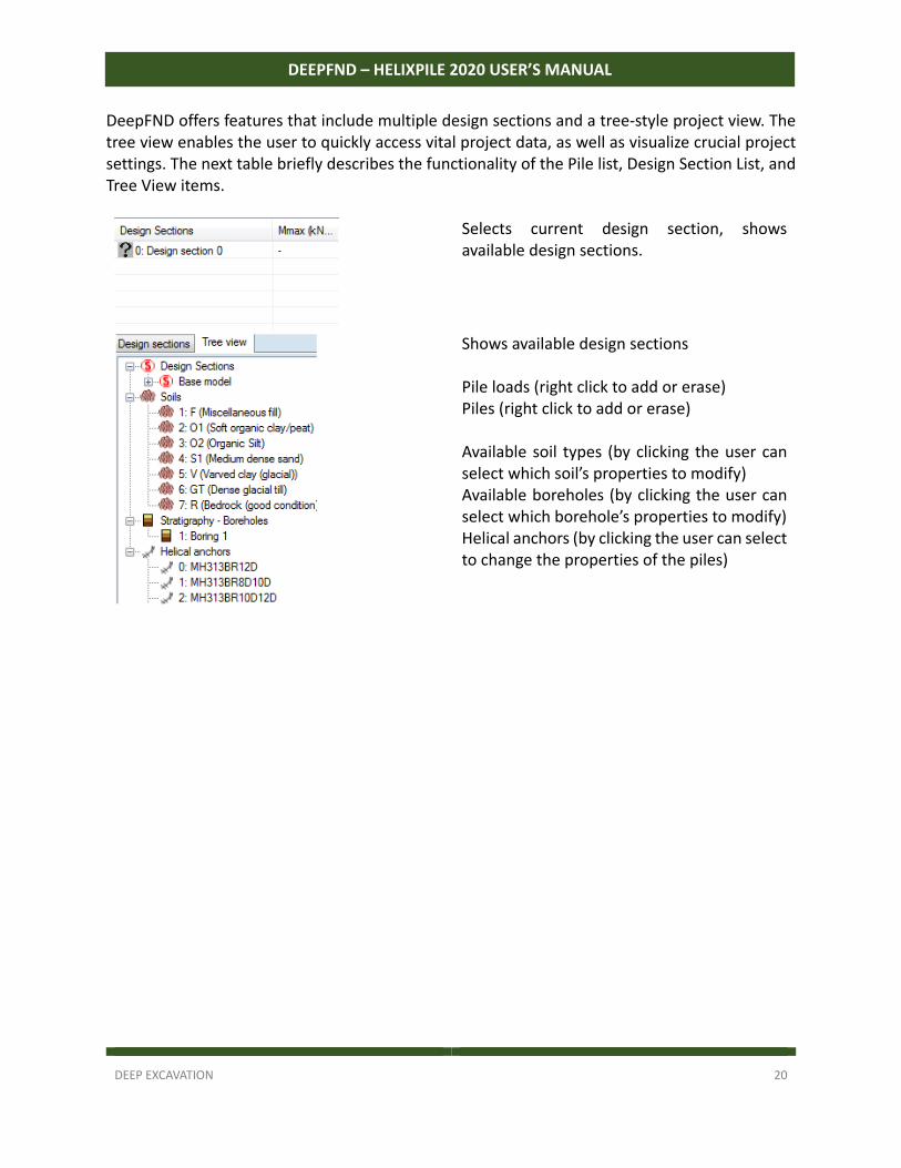
DeepFND offers features that include multiple design sections and a tree‐style project view. The tree view enables the user to quickly access vital project data, as well as visualize crucial project settings. The next table briefly describes the functionality of the Pile list, Design Section List, and Tree View items.
Selects current design section, shows available design sections.
Shows available design sections Pile loads (right click to add or erase) Piles (right click to add or erase) Available soil types (by clicking the user can select which soil’s properties to modify) Available boreholes (by clicking the user can select which borehole’s properties to modify) Helical anchors (by clicking the user can select to change the properties of the piles)
DEEP EXCAVATION 21
DEEPFND – HELIXPILE 2020 USER’S MANUAL
2.3 General menu
Figure 2.3.1: DeepFND 2017: General tab.
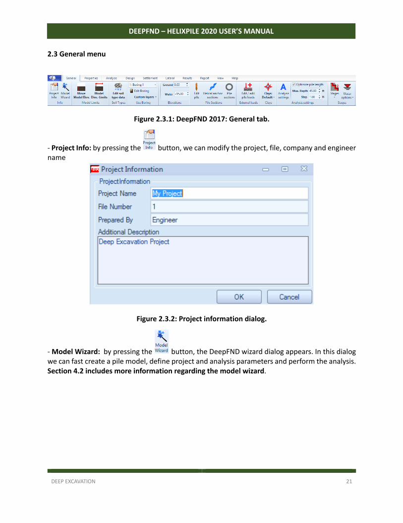
‐ Project Info: by pressing the button, we can modify the project, file, company and engineer name
Figure 2.3.2: Project information dialog.
‐ Model Wizard: by pressing the button, the DeepFND wizard dialog appears. In this dialog we can fast create a pile model, define project and analysis parameters and perform the analysis. Section 4.2 includes more information regarding the model wizard.
DEEP EXCAVATION 22
DEEPFND – HELIXPILE 2020 USER’S MANUAL
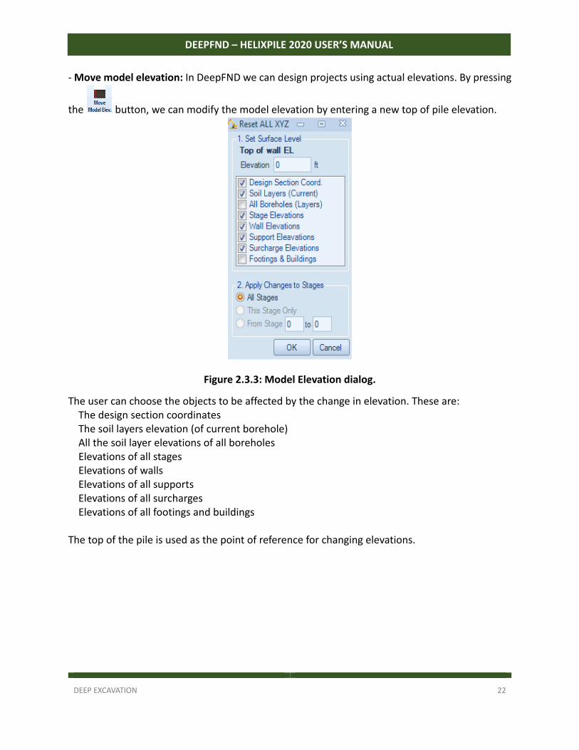
‐ Move model elevation: In DeepFND we can design projects using actual elevations. By pressing
the button, we can modify the model elevation by entering a new top of pile elevation.
Figure 2.3.3: Model Elevation dialog.
The user can choose the objects to be affected by the change in elevation. These are: The design section coordinates The soil layers elevation (of current borehole) All the soil layer elevations of all boreholes Elevations of all stages Elevations of walls Elevations of all supports Elevations of all surcharges Elevations of all footings and buildings
The top of the pile is used as the point of reference for changing elevations.
DEEP EXCAVATION 23
DEEPFND – HELIXPILE 2020 USER’S MANUAL
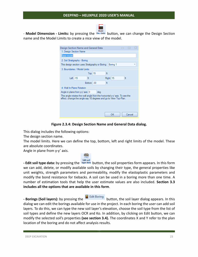
‐ Model Dimension - Limits: by pressing the button, we can change the Design Section name and the Model Limits to create a nice view of the model.
Figure 2.3.4: Design Section Name and General Data dialog.
This dialog includes the following options: The design section name. The model limits. Here we can define the top, bottom, left and right limits of the model. These are absolute coordinates. Angle in plane from y‐y’ axis.
- Edit soil type data: by pressing the button, the soil properties form appears. In this form we can add, delete, or modify available soils by changing their type, the general properties like unit weights, strength parameters and permeability, modify the elastoplastic parameters and modify the bond resistance for tiebacks. A soil can be used in a boring more than one time. A number of estimation tools that help the user estimate values are also included. Section 3.3 includes all the options that are available in this form.
- Borings (Soil layers): by pressing the button, the soil layer dialog appears. In this dialog we can edit the borings available for use in the project. In each boring the user can add soil layers. To do this, we can type the new soil layer’s elevation, choose the soil type from the list of soil types and define the new layers OCR and Ko. In addition, by clicking on Edit button, we can modify the selected soil’s properties (see section 3.4). The coordinates X and Y refer to the plan location of the boring and do not affect analysis results.
DEEP EXCAVATION 24
DEEPFND – HELIXPILE 2020 USER’S MANUAL
- Custom Layers: By pressing the button, we can choose to use the custom layer mode of DeepFND, or choose to reset custom layers from boring. In the custom layer mode, we can define non‐horizontal soil layers. - Elevations: Change the general ground elevation and define the water table.
- Edit pile data: By pressing the button, we can edit the properties of the pile. Properties on this form are described in section 3.5.
- Edit helical anchor sections: By pressing the button we can edit the structural and geotechnical properties of the helical anchor sections. Properties on this form are described in section 3.6. This feature is available if helical piles are enabled (separate purchase in DeepFND).
- Edit pile section data: By pressing the button, we can edit the properties of regular type pile sections. Properties on this form are described in section 3.7.
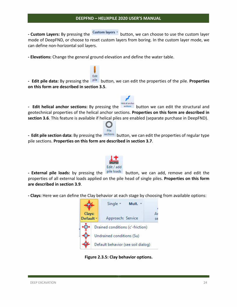
- External pile loads: by pressing the button, we can add, remove and edit the properties of all external loads applied on the pile head of single piles. Properties on this form are described in section 3.9. - Clays: Here we can define the Clay behavior at each stage by choosing from available options:
Figure 2.3.5: Clay behavior options.
DEEP EXCAVATION 25
DEEPFND – HELIXPILE 2020 USER’S MANUAL
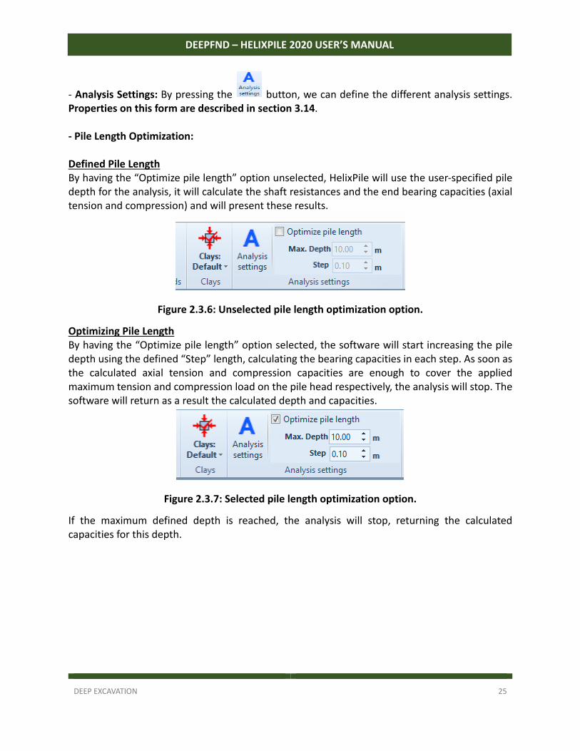
‐ Analysis Settings: By pressing the button, we can define the different analysis settings. Properties on this form are described in section 3.14. - Pile Length Optimization: Defined Pile Length By having the “Optimize pile length” option unselected, HelixPile will use the user‐specified pile depth for the analysis, it will calculate the shaft resistances and the end bearing capacities (axial tension and compression) and will present these results.
Figure 2.3.6: Unselected pile length optimization option.
Optimizing Pile Length By having the “Optimize pile length” option selected, the software will start increasing the pile depth using the defined “Step” length, calculating the bearing capacities in each step. As soon as the calculated axial tension and compression capacities are enough to cover the applied maximum tension and compression load on the pile head respectively, the analysis will stop. The software will return as a result the calculated depth and capacities.
Figure 2.3.7: Selected pile length optimization option.
If the maximum defined depth is reached, the analysis will stop, returning the calculated capacities for this depth.
DEEP EXCAVATION 26
DEEPFND – HELIXPILE 2020 USER’S MANUAL
- Stages: In this area we can add, delete, insert or copy a construction stage. Icon Description
Add a new construction stage
Deletes the current construction stage
Insert a construction stage after the current stage
Copy selected construction stage
Paste construction stage
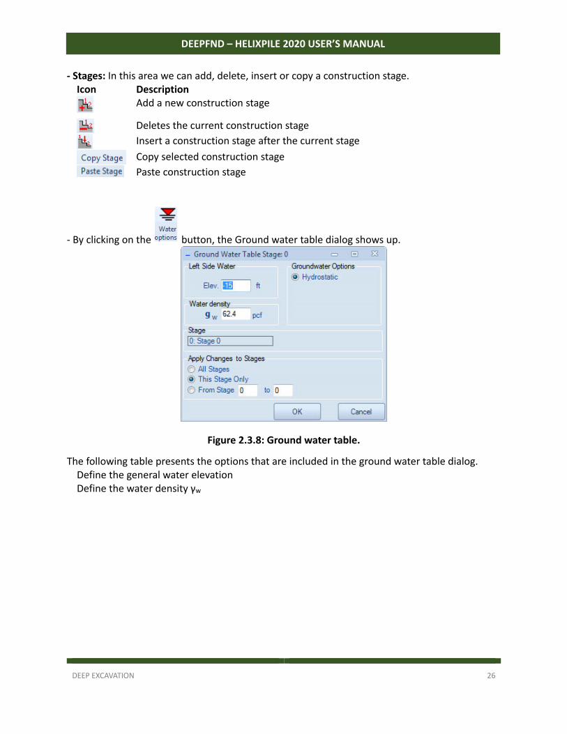
‐ By clicking on the button, the Ground water table dialog shows up.
Figure 2.3.8: Ground water table.
The following table presents the options that are included in the ground water table dialog. Define the general water elevation Define the water density γw
DEEP EXCAVATION 27
DEEPFND – HELIXPILE 2020 USER’S MANUAL
2.4 Properties menu
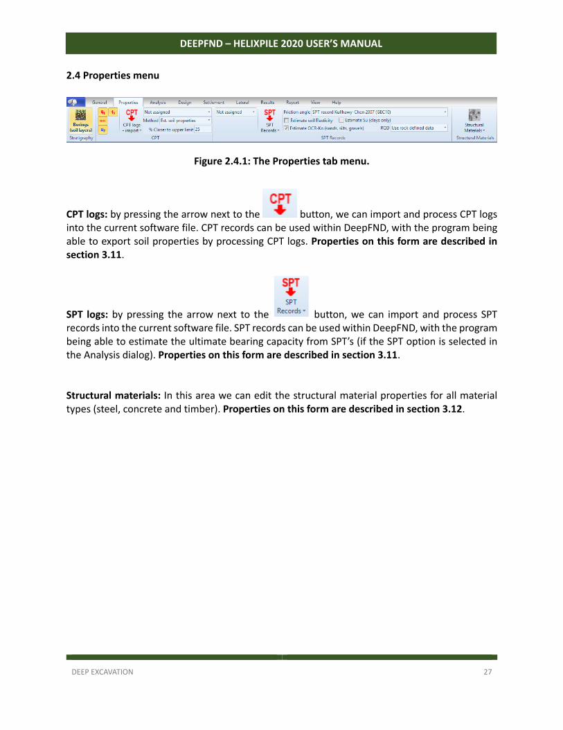
Figure 2.4.1: The Properties tab menu.
CPT logs: by pressing the arrow next to the button, we can import and process CPT logs into the current software file. CPT records can be used within DeepFND, with the program being able to export soil properties by processing CPT logs. Properties on this form are described in section 3.11.
SPT logs: by pressing the arrow next to the button, we can import and process SPT records into the current software file. SPT records can be used within DeepFND, with the program being able to estimate the ultimate bearing capacity from SPT’s (if the SPT option is selected in the Analysis dialog). Properties on this form are described in section 3.11. Structural materials: In this area we can edit the structural material properties for all material types (steel, concrete and timber). Properties on this form are described in section 3.12.
DEEP EXCAVATION 28
DEEPFND – HELIXPILE 2020 USER’S MANUAL
2.5 Analysis menu
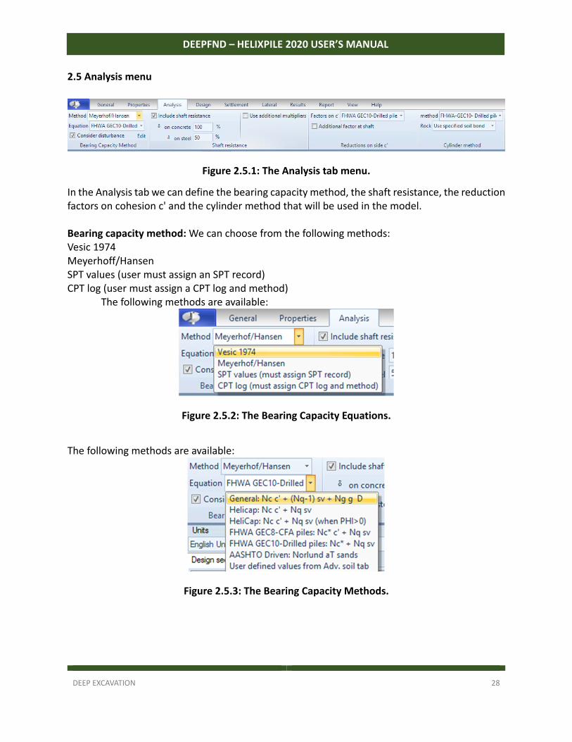
Figure 2.5.1: The Analysis tab menu.
In the Analysis tab we can define the bearing capacity method, the shaft resistance, the reduction factors on cohesion c' and the cylinder method that will be used in the model. Bearing capacity method: We can choose from the following methods: Vesic 1974 Meyerhoff/Hansen SPT values (user must assign an SPT record) CPT log (user must assign a CPT log and method) The following methods are available:
Figure 2.5.2: The Bearing Capacity Equations.
The following methods are available:
Figure 2.5.3: The Bearing Capacity Methods.
DEEP EXCAVATION 29
DEEPFND – HELIXPILE 2020 USER’S MANUAL
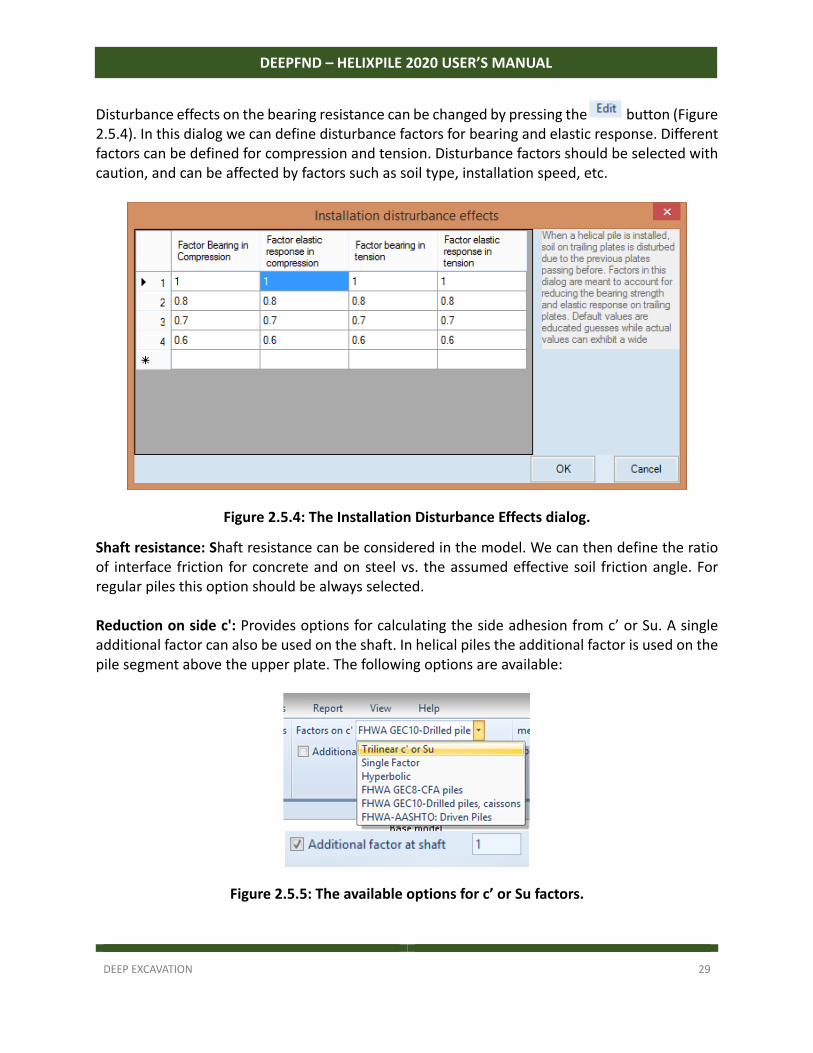
Disturbance effects on the bearing resistance can be changed by pressing the button (Figure 2.5.4). In this dialog we can define disturbance factors for bearing and elastic response. Different factors can be defined for compression and tension. Disturbance factors should be selected with caution, and can be affected by factors such as soil type, installation speed, etc.
Figure 2.5.4: The Installation Disturbance Effects dialog.
Shaft resistance: Shaft resistance can be considered in the model. We can then define the ratio of interface friction for concrete and on steel vs. the assumed effective soil friction angle. For regular piles this option should be always selected. Reduction on side c': Provides options for calculating the side adhesion from c’ or Su. A single additional factor can also be used on the shaft. In helical piles the additional factor is used on the pile segment above the upper plate. The following options are available:
Figure 2.5.5: The available options for c’ or Su factors.
DEEP EXCAVATION 30
DEEPFND – HELIXPILE 2020 USER’S MANUAL
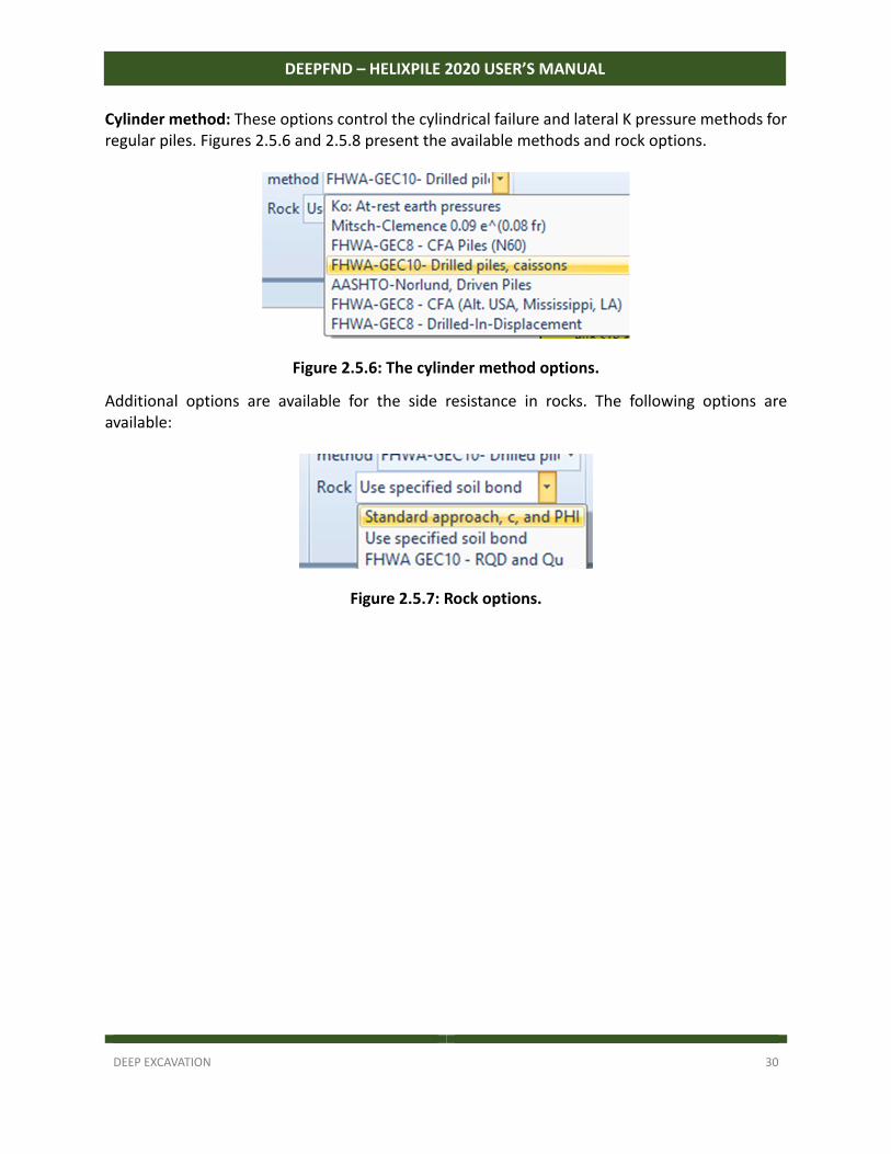
Cylinder method: These options control the cylindrical failure and lateral K pressure methods for regular piles. Figures 2.5.6 and 2.5.8 present the available methods and rock options.
Figure 2.5.6: The cylinder method options.
Additional options are available for the side resistance in rocks. The following options are available:
Figure 2.5.7: Rock options.
DEEP EXCAVATION 31
DEEPFND – HELIXPILE 2020 USER’S MANUAL
2.6 Design menu
Figure 2.6.1: The Design tab menu.
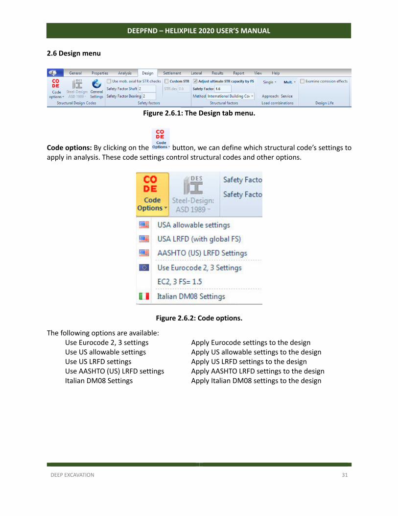
Code options: By clicking on the button, we can define which structural code’s settings to apply in analysis. These code settings control structural codes and other options.
Figure 2.6.2: Code options.
The following options are available: Use Eurocode 2, 3 settings Apply Eurocode settings to the design Use US allowable settings Apply US allowable settings to the design Use US LRFD settings Apply US LRFD settings to the design Use AASHTO (US) LRFD settings Apply AASHTO LRFD settings to the design Italian DM08 Settings Apply Italian DM08 settings to the design
DEEP EXCAVATION 32
DEEPFND – HELIXPILE 2020 USER’S MANUAL
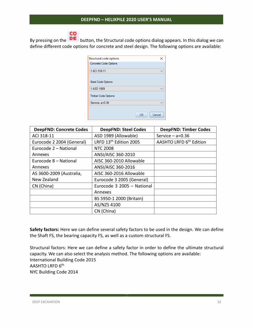
By pressing on the button, the Structural code options dialog appears. In this dialog we can define different code options for concrete and steel design. The following options are available:
DeepFND: Concrete Codes DeepFND: Steel Codes DeepFND: Timber Codes
ACI 318‐11 ASD 1989 (Allowable) Service – a=0.36
Eurocode 2 2004 (General) LRFD 13th Edition 2005 AASHTO LRFD 6th Edition
Eurocode 2 – National Annexes
NTC 2008
ANSI/AISC 360‐2010
Eurocode 8 – National Annexes
AISC 360‐2010 Allowable
ANSI/AISC 360‐2016
AS 3600‐2009 (Australia, New Zealand
AISC 360‐2016 Allowable
Eurocode 3 2005 (General)
CN (China) Eurocode 3 2005 – National Annexes
BS 5950‐1 2000 (Britain)
AS/NZS 4100
CN (China)
Safety factors: Here we can define several safety factors to be used in the design. We can define the Shaft FS, the bearing capacity FS, as well as a custom structural FS. Structural factors: Here we can define a safety factor in order to define the ultimate structural capacity. We can also select the analysis method. The following options are available: International Building Code 2015 AASHTO LRFD 6th NYC Building Code 2014
DEEP EXCAVATION 33
DEEPFND – HELIXPILE 2020 USER’S MANUAL
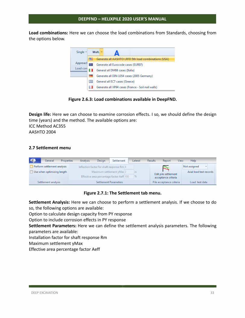
Load combinations: Here we can choose the load combinations from Standards, choosing from the options below.
Figure 2.6.3: Load combinations available in DeepFND.
Design life: Here we can choose to examine corrosion effects. I so, we should define the design time (years) and the method. The available options are: ICC Method AC355 AASHTO 2004
2.7 Settlement menu
Figure 2.7.1: The Settlement tab menu.
Settlement Analysis: Here we can choose to perform a settlement analysis. If we choose to do so, the following options are available: Option to calculate design capacity from PY response Option to include corrosion effects in PY response Settlement Parameters: Here we can define the settlement analysis parameters. The following parameters are available: Installation factor for shaft response Rm Maximum settlement yMax Effective area percentage factor Aeff
DEEP EXCAVATION 34
DEEPFND – HELIXPILE 2020 USER’S MANUAL
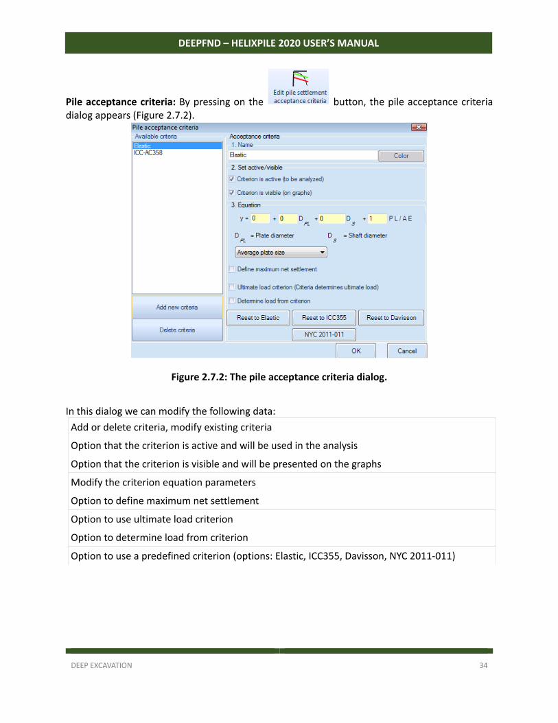
Pile acceptance criteria: By pressing on the button, the pile acceptance criteria dialog appears (Figure 2.7.2).
Figure 2.7.2: The pile acceptance criteria dialog.
In this dialog we can modify the following data:
Add or delete criteria, modify existing criteria
Option that the criterion is active and will be used in the analysis
Option that the criterion is visible and will be presented on the graphs
Modify the criterion equation parameters
Option to define maximum net settlement
Option to use ultimate load criterion
Option to determine load from criterion
Option to use a predefined criterion (options: Elastic, ICC355, Davisson, NYC 2011‐011)
DEEP EXCAVATION 35
DEEPFND – HELIXPILE 2020 USER’S MANUAL
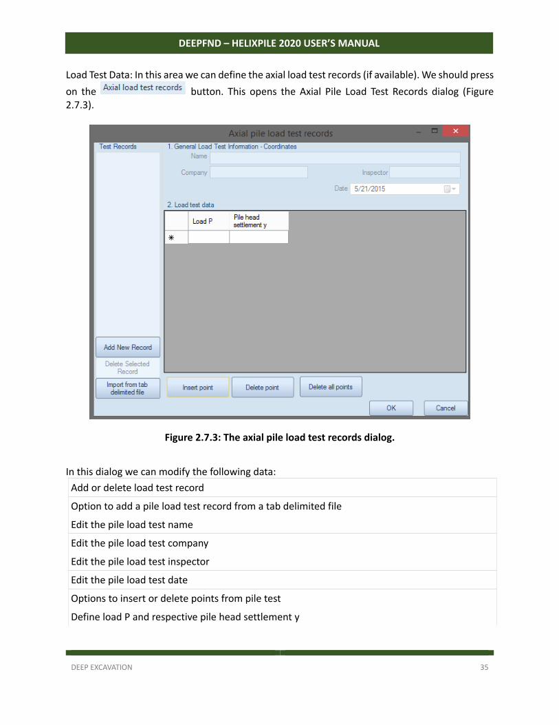
Load Test Data: In this area we can define the axial load test records (if available). We should press
on the button. This opens the Axial Pile Load Test Records dialog (Figure 2.7.3).
Figure 2.7.3: The axial pile load test records dialog.
In this dialog we can modify the following data:
Add or delete load test record
Option to add a pile load test record from a tab delimited file
Edit the pile load test name
Edit the pile load test company
Edit the pile load test inspector
Edit the pile load test date
Options to insert or delete points from pile test
Define load P and respective pile head settlement y
DEEP EXCAVATION 36
DEEPFND – HELIXPILE 2020 USER’S MANUAL
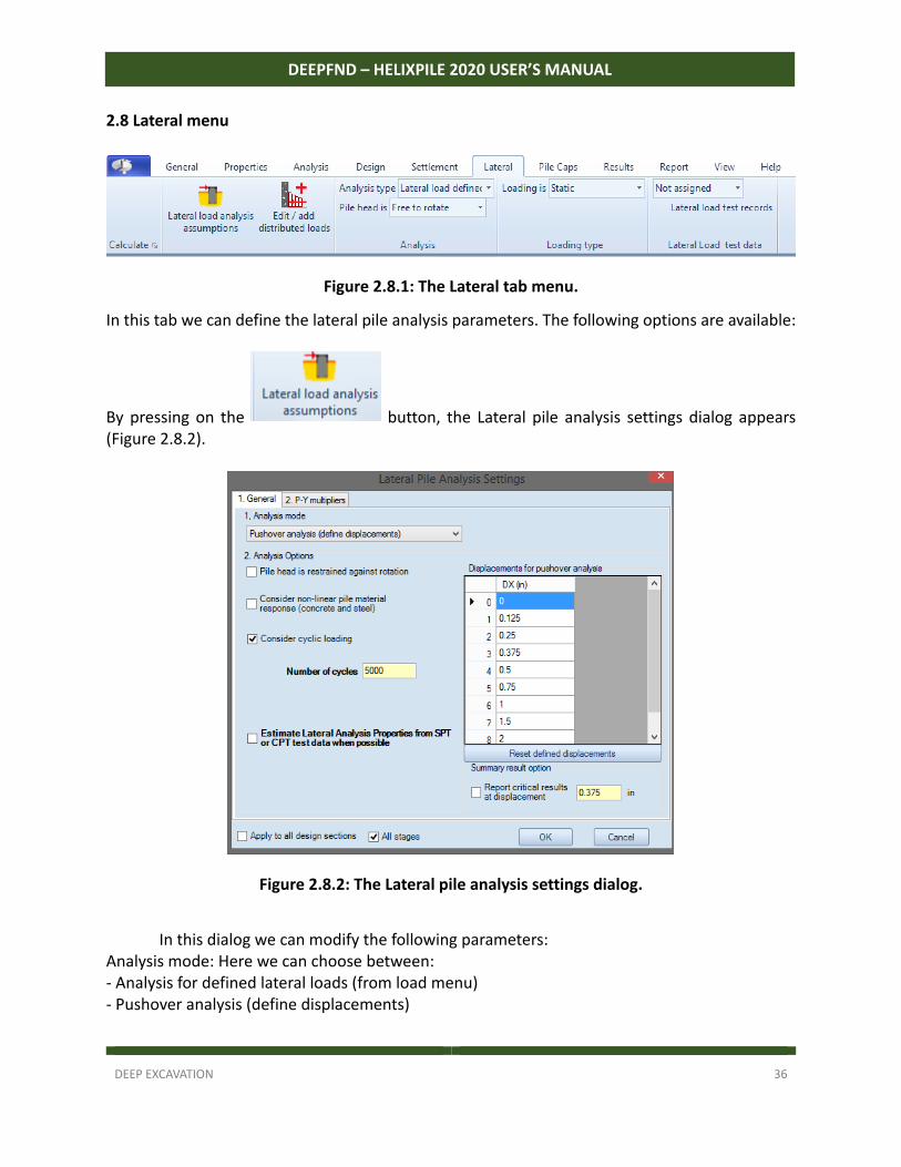
2.8 Lateral menu
Figure 2.8.1: The Lateral tab menu.
In this tab we can define the lateral pile analysis parameters. The following options are available:
By pressing on the button, the Lateral pile analysis settings dialog appears (Figure 2.8.2).
Figure 2.8.2: The Lateral pile analysis settings dialog.
In this dialog we can modify the following parameters: Analysis mode: Here we can choose between: ‐ Analysis for defined lateral loads (from load menu) ‐ Pushover analysis (define displacements)
DEEP EXCAVATION 37
DEEPFND – HELIXPILE 2020 USER’S MANUAL
When the second option is selected, we can define the displacements for pushover analysis in the same dialog. In addition, we can define the displacement at which we should report the critical results.
Option that the pile head is restrained against rotation
Option to consider non‐linear pile material response (concrete and steel)
Option to Consider cyclic loading (when selected we can define the number of cycles)
Option to estimate Lateral Analysis Properties from SPT or CPT test data when possible.
Option to apply changes to all design sections and all stages.
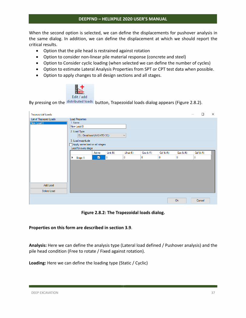
By pressing on the button, Trapezoidal loads dialog appears (Figure 2.8.2).
Figure 2.8.2: The Trapezoidal loads dialog.
Properties on this form are described in section 3.9. Analysis: Here we can define the analysis type (Lateral load defined / Pushover analysis) and the pile head condition (Free to rotate / Fixed against rotation). Loading: Here we can define the loading type (Static / Cyclic)
DEEP EXCAVATION 38
DEEPFND – HELIXPILE 2020 USER’S MANUAL
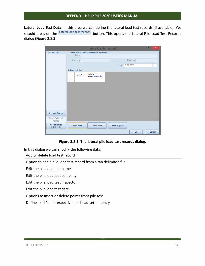
Lateral Load Test Data: In this area we can define the lateral load test records (if available). We
should press on the button. This opens the Lateral Pile Load Test Records dialog (Figure 2.8.3).
Figure 2.8.3: The lateral pile load test records dialog.
In this dialog we can modify the following data:
Add or delete load test record
Option to add a pile load test record from a tab delimited file
Edit the pile load test name
Edit the pile load test company
Edit the pile load test inspector
Edit the pile load test date
Options to insert or delete points from pile test
Define load P and respective pile head settlement y
DEEP EXCAVATION 39
DEEPFND – HELIXPILE 2020 USER’S MANUAL
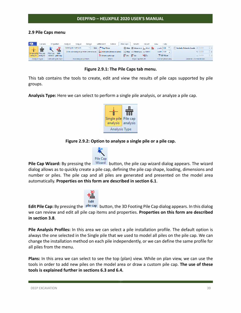
2.9 Pile Caps menu
Figure 2.9.1: The Pile Caps tab menu.
This tab contains the tools to create, edit and view the results of pile caps supported by pile groups. Analysis Type: Here we can select to perform a single pile analysis, or analyze a pile cap.
Figure 2.9.2: Option to analyze a single pile or a pile cap.
Pile Cap Wizard: By pressing the button, the pile cap wizard dialog appears. The wizard dialog allows as to quickly create a pile cap, defining the pile cap shape, loading, dimensions and number or piles. The pile cap and all piles are generated and presented on the model area automatically. Properties on this form are described in section 6.1.
Edit Pile Cap: By pressing the button, the 3D Footing Pile Cap dialog appears. In this dialog we can review and edit all pile cap items and properties. Properties on this form are described in section 3.8. Pile Analysis Profiles: In this area we can select a pile installation profile. The default option is always the one selected in the Single pile that we used to model all piles on the pile cap. We can change the installation method on each pile independently, or we can define the same profile for all piles from the menu. Plans: In this area we can select to see the top (plan) view. While on plan view, we can use the tools in order to add new piles on the model area or draw a custom pile cap. The use of these tools is explained further in sections 6.3 and 6.4.
DEEP EXCAVATION 40
DEEPFND – HELIXPILE 2020 USER’S MANUAL
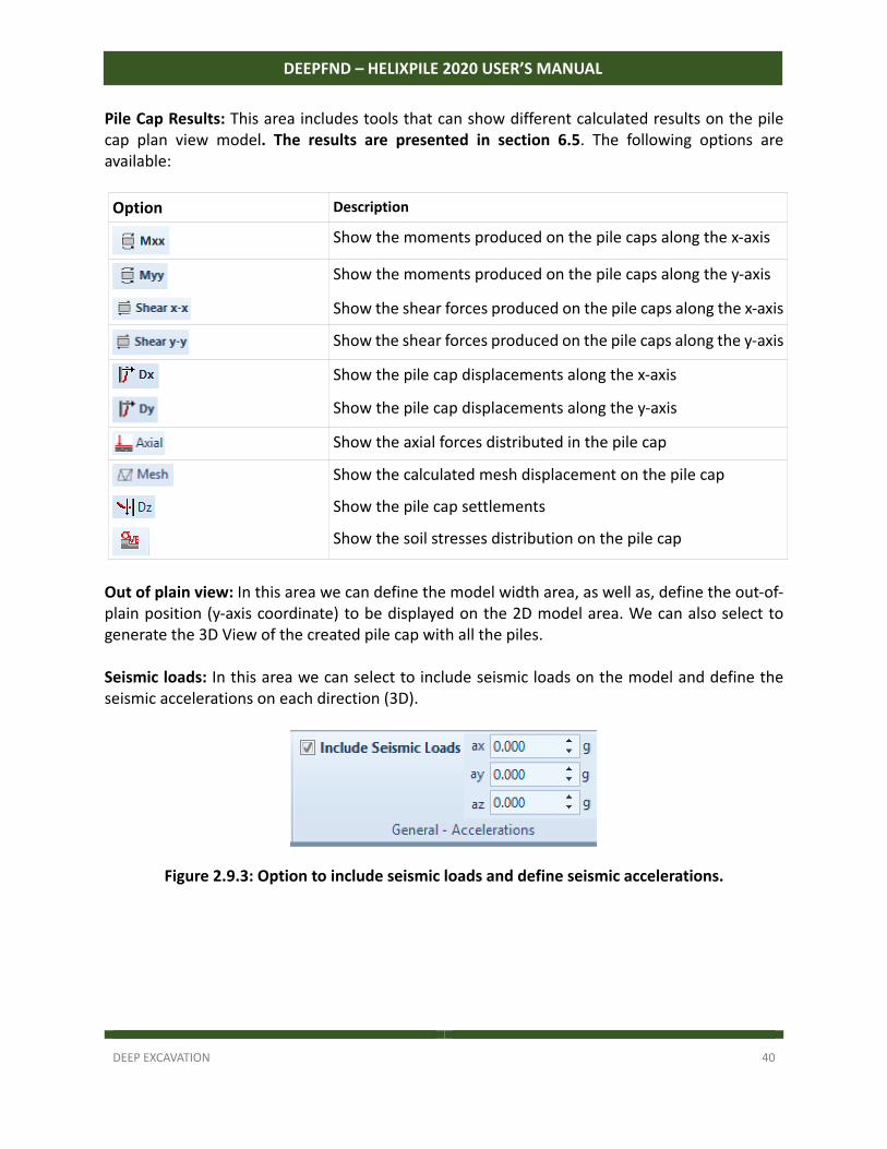
Pile Cap Results: This area includes tools that can show different calculated results on the pile cap plan view model. The results are presented in section 6.5. The following options are available:
Option Description
Show the moments produced on the pile caps along the x‐axis
Show the moments produced on the pile caps along the y‐axis
Show the shear forces produced on the pile caps along the x‐axis
Show the shear forces produced on the pile caps along the y‐axis
Show the pile cap displacements along the x‐axis
Show the pile cap displacements along the y‐axis
Show the axial forces distributed in the pile cap
Show the calculated mesh displacement on the pile cap
Show the pile cap settlements
Show the soil stresses distribution on the pile cap
Out of plain view: In this area we can define the model width area, as well as, define the out‐of‐plain position (y‐axis coordinate) to be displayed on the 2D model area. We can also select to generate the 3D View of the created pile cap with all the piles. Seismic loads: In this area we can select to include seismic loads on the model and define the seismic accelerations on each direction (3D).
Figure 2.9.3: Option to include seismic loads and define seismic accelerations.
DEEP EXCAVATION 41
DEEPFND – HELIXPILE 2020 USER’S MANUAL
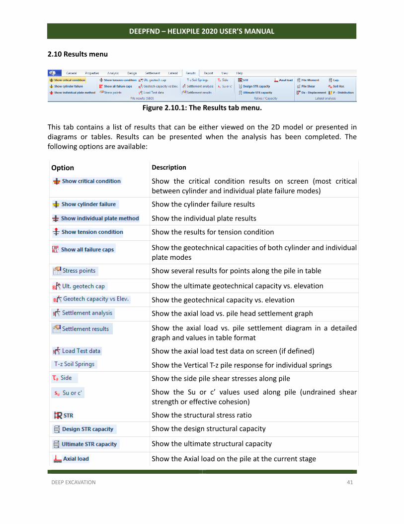
2.10 Results menu
Figure 2.10.1: The Results tab menu. This tab contains a list of results that can be either viewed on the 2D model or presented in diagrams or tables. Results can be presented when the analysis has been completed. The following options are available:
Option Description
Show the critical condition results on screen (most critical between cylinder and individual plate failure modes)
Show the cylinder failure results
Show the individual plate results
Show the results for tension condition
Show the geotechnical capacities of both cylinder and individual plate modes
Show several results for points along the pile in table
Show the ultimate geotechnical capacity vs. elevation
Show the geotechnical capacity vs. elevation
Show the axial load vs. pile head settlement graph
Show the axial load vs. pile settlement diagram in a detailed graph and values in table format
Show the axial load test data on screen (if defined)
Show the Vertical T‐z pile response for individual springs
Show the side pile shear stresses along pile
Show the Su or c’ values used along pile (undrained shear strength or effective cohesion)
Show the structural stress ratio
Show the design structural capacity
Show the ultimate structural capacity
Show the Axial load on the pile at the current stage
DEEP EXCAVATION 42
DEEPFND – HELIXPILE 2020 USER’S MANUAL
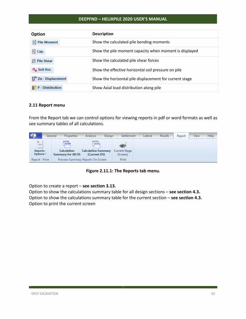
Option Description
Show the calculated pile bending moments
Show the pile moment capacity when moment is displayed
Show the calculated pile shear forces
Show the effective horizontal soil pressure on pile
Show the horizontal pile displacement for current stage
Show Axial load distribution along pile
2.11 Report menu
From the Report tab we can control options for viewing reports in pdf or word formats as well as see summary tables of all calculations.
Figure 2.11.1: The Reports tab menu.
Option to create a report – see section 3.13. Option to show the calculations summary table for all design sections – see section 4.3. Option to show the calculations summary table for the current section – see section 4.3. Option to print the current screen
DEEP EXCAVATION 43
DEEPFND – HELIXPILE 2020 USER’S MANUAL
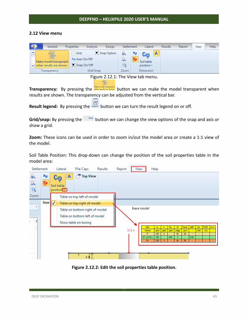
2.12 View menu
Figure 2.12.1: The View tab menu.
Transparency: By pressing the button we can make the model transparent when results are shown. The transparency can be adjusted from the vertical bar.
Result legend: By pressing the button we can turn the result legend on or off.
Grid/snap: By pressing the button we can change the view options of the snap and axis or show a grid. Zoom: These icons can be used in order to zoom in/out the model area or create a 1:1 view of the model. Soil Table Position: This drop‐down can change the position of the soil properties table in the model area:
Figure 2.12.2: Edit the soil properties table position.
DEEP EXCAVATION 44
DEEPFND – HELIXPILE 2020 USER’S MANUAL
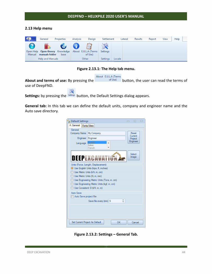
2.13 Help menu
Figure 2.13.1: The Help tab menu.
About and terms of use: By pressing the button, the user can read the terms of use of DeepFND.
Settings: by pressing the button, the Default Settings dialog appears. General tab: In this tab we can define the default units, company and engineer name and the Auto save directory.
Figure 2.13.2: Settings – General Tab.
DEEP EXCAVATION 45
DEEPFND – HELIXPILE 2020 USER’S MANUAL
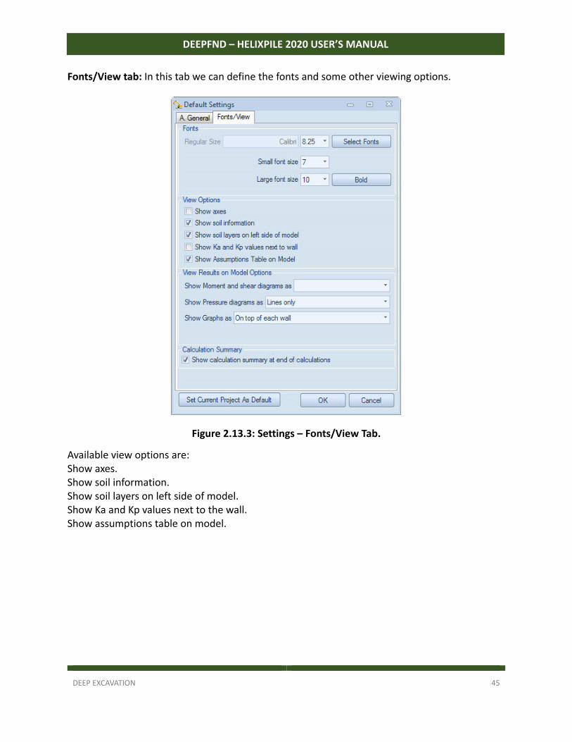
Fonts/View tab: In this tab we can define the fonts and some other viewing options.
Figure 2.13.3: Settings – Fonts/View Tab.
Available view options are: Show axes. Show soil information. Show soil layers on left side of model. Show Ka and Kp values next to the wall. Show assumptions table on model.
DEEP EXCAVATION 46
DEEPFND – HELIXPILE 2020 USER’S MANUAL
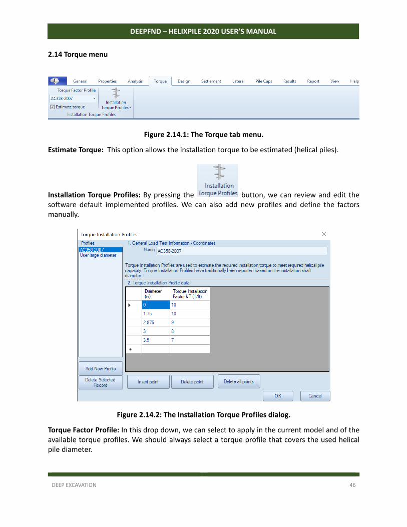
2.14 Torque menu
Figure 2.14.1: The Torque tab menu.
Estimate Torque: This option allows the installation torque to be estimated (helical piles).
Installation Torque Profiles: By pressing the button, we can review and edit the software default implemented profiles. We can also add new profiles and define the factors manually.
Figure 2.14.2: The Installation Torque Profiles dialog.
Torque Factor Profile: In this drop down, we can select to apply in the current model and of the available torque profiles. We should always select a torque profile that covers the used helical pile diameter.
DEEP EXCAVATION 47
DEEPFND – HELIXPILE 2020 USER’S MANUAL
2.15 Edit Default Software Settings
In order to change the software default settings, we have to start the software as administrator, open the Settings dialog from the Help tab and press to set the current project as default.
IMPORTANT: Changing the default software parameters is an important procedure and we have
to be very careful. By setting a project as default, we actually select the project that will be loaded
each time we open the software. It is highly recommended that any settings changes should be
applied in a clear model with no modifications to soil properties, stratigraphies, construction
stages etc., else these settings will be saved as default as well.
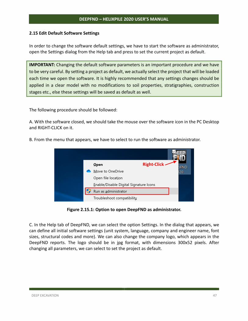
The following procedure should be followed: A. With the software closed, we should take the mouse over the software icon in the PC Desktop and RIGHT‐CLICK on it. B. From the menu that appears, we have to select to run the software as administrator.
Figure 2.15.1: Option to open DeepFND as administrator.
C. In the Help tab of DeepFND, we can select the option Settings. In the dialog that appears, we can define all initial software settings (unit system, language, company and engineer name, font sizes, structural codes and more). We can also change the company logo, which appears in the DeepFND reports. The logo should be in jpg format, with dimensions 300x52 pixels. After changing all parameters, we can select to set the project as default.
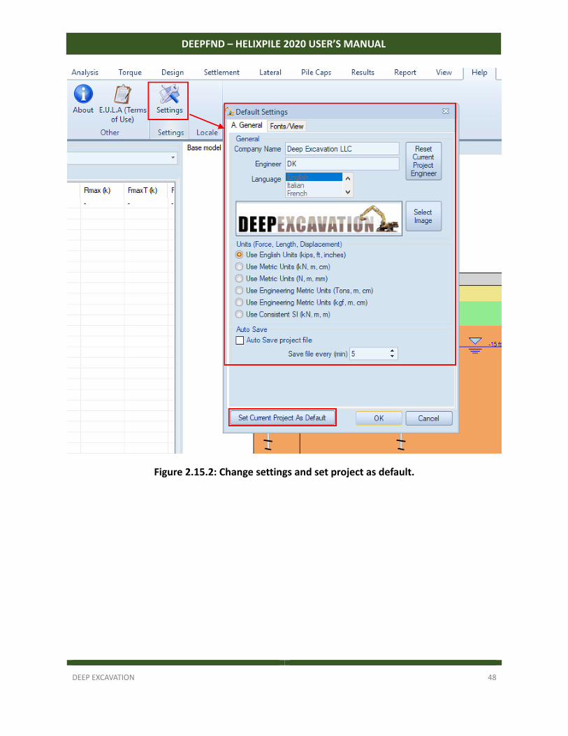
DEEP EXCAVATION 48
DEEPFND – HELIXPILE 2020 USER’S MANUAL
Figure 2.15.2: Change settings and set project as default.
DEEP EXCAVATION 49
DEEPFND – HELIXPILE 2020 USER’S MANUAL
SECTION 3: MAIN SOFTWARE DIALOGS – USE OF THE SOFTWARE
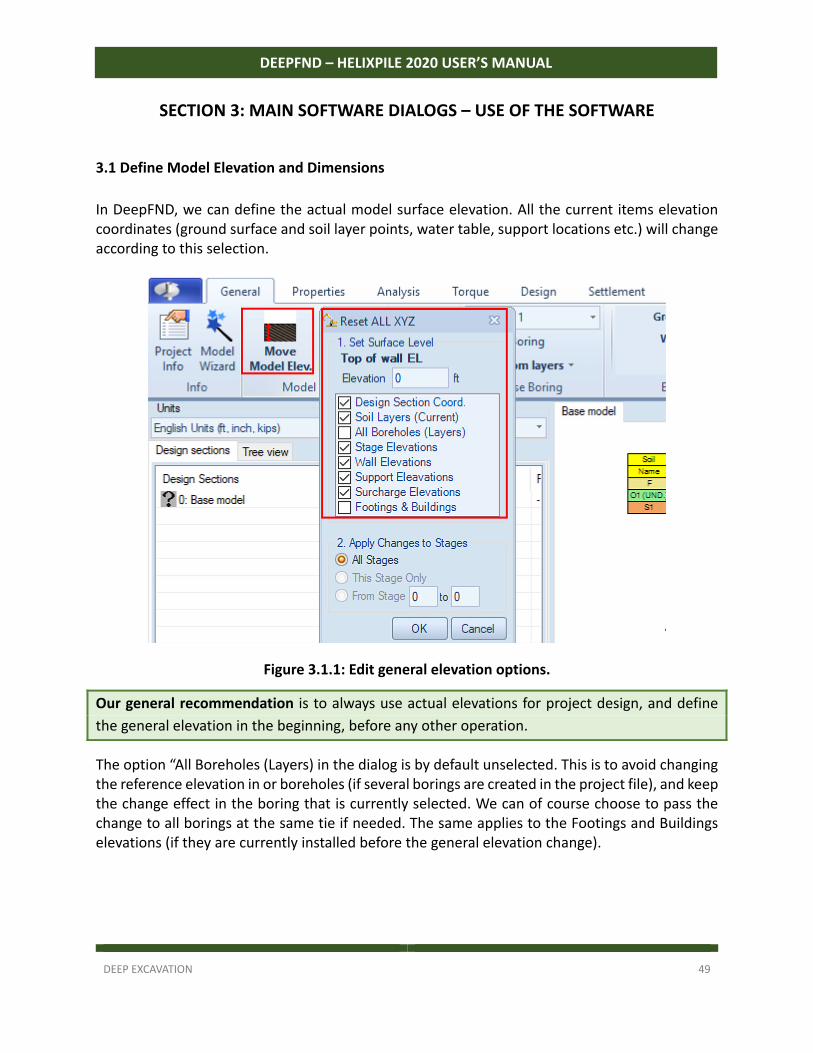
3.1 Define Model Elevation and Dimensions
In DeepFND, we can define the actual model surface elevation. All the current items elevation coordinates (ground surface and soil layer points, water table, support locations etc.) will change according to this selection.
Figure 3.1.1: Edit general elevation options.
Our general recommendation is to always use actual elevations for project design, and define
the general elevation in the beginning, before any other operation.
The option “All Boreholes (Layers) in the dialog is by default unselected. This is to avoid changing the reference elevation in or boreholes (if several borings are created in the project file), and keep the change effect in the boring that is currently selected. We can of course choose to pass the change to all borings at the same tie if needed. The same applies to the Footings and Buildings elevations (if they are currently installed before the general elevation change).
DEEP EXCAVATION 50
DEEPFND – HELIXPILE 2020 USER’S MANUAL
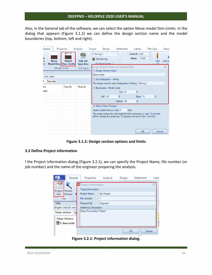
Also, in the General tab of the software, we can select the option Move model Dim‐Limits. In the dialog that appears (Figure 3.1.2) we can define the design section name and the model boundaries (top, bottom, left and right).
Figure 3.1.2: Design section options and limits
3.2 Define Project information
I the Project Information dialog (Figure 3.2.1), we can specify the Project Name, file number (or job number) and the name of the engineer preparing the analysis.
Figure 3.2.1: Project information dialog.
DEEP EXCAVATION 51
DEEPFND – HELIXPILE 2020 USER’S MANUAL
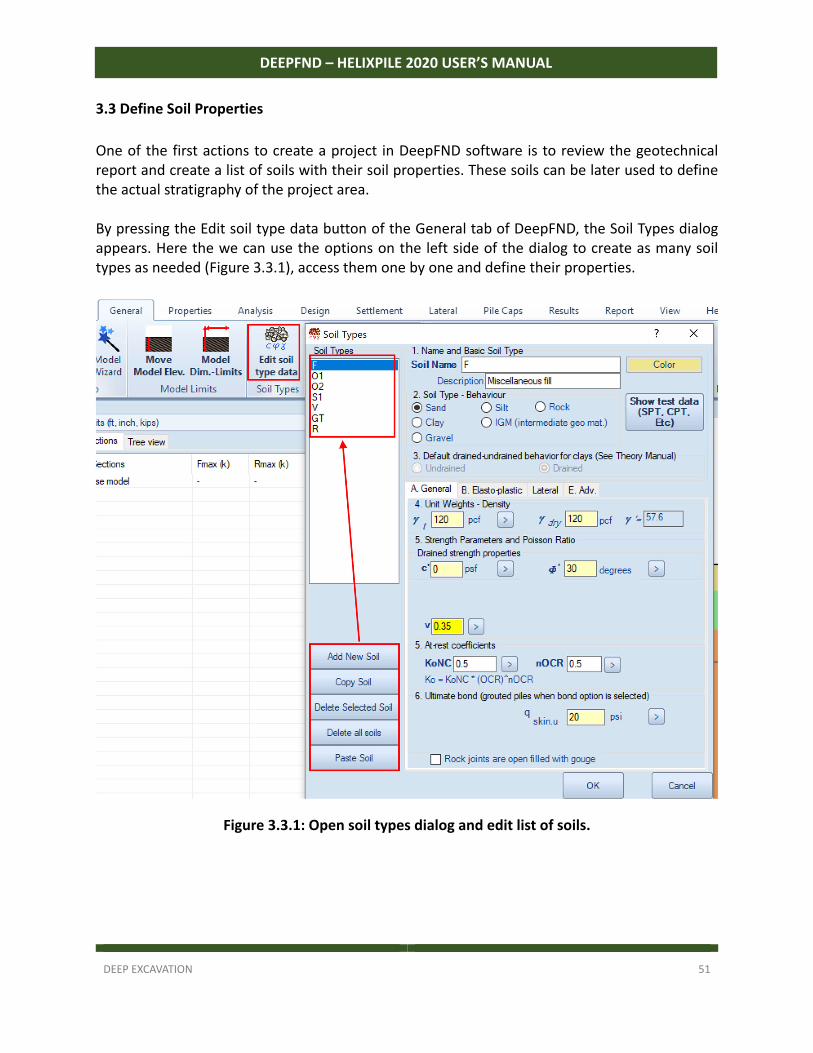
3.3 Define Soil Properties
One of the first actions to create a project in DeepFND software is to review the geotechnical report and create a list of soils with their soil properties. These soils can be later used to define the actual stratigraphy of the project area. By pressing the Edit soil type data button of the General tab of DeepFND, the Soil Types dialog appears. Here the we can use the options on the left side of the dialog to create as many soil types as needed (Figure 3.3.1), access them one by one and define their properties.
Figure 3.3.1: Open soil types dialog and edit list of soils.
DEEP EXCAVATION 52
DEEPFND – HELIXPILE 2020 USER’S MANUAL
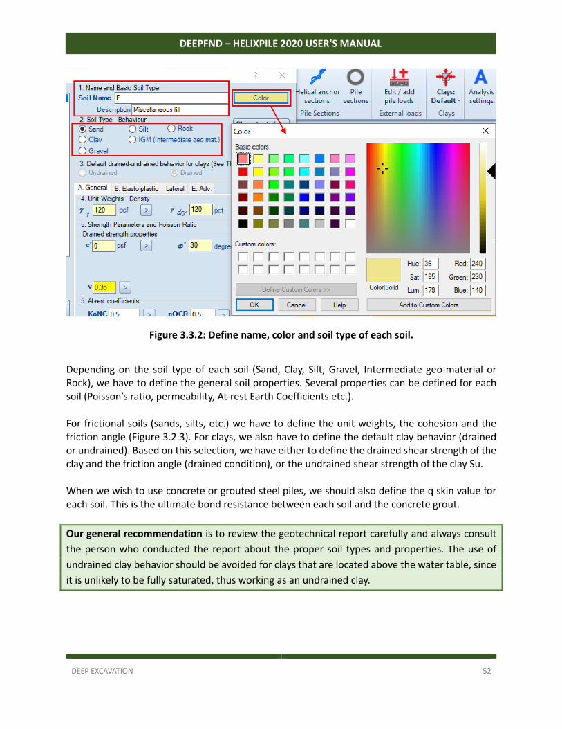
Figure 3.3.2: Define name, color and soil type of each soil.
Depending on the soil type of each soil (Sand, Clay, Silt, Gravel, Intermediate geo‐material or Rock), we have to define the general soil properties. Several properties can be defined for each soil (Poisson’s ratio, permeability, At‐rest Earth Coefficients etc.). For frictional soils (sands, silts, etc.) we have to define the unit weights, the cohesion and the friction angle (Figure 3.2.3). For clays, we also have to define the default clay behavior (drained or undrained). Based on this selection, we have either to define the drained shear strength of the clay and the friction angle (drained condition), or the undrained shear strength of the clay Su. When we wish to use concrete or grouted steel piles, we should also define the q skin value for each soil. This is the ultimate bond resistance between each soil and the concrete grout.
Our general recommendation is to review the geotechnical report carefully and always consult
the person who conducted the report about the proper soil types and properties. The use of
undrained clay behavior should be avoided for clays that are located above the water table, since
it is unlikely to be fully saturated, thus working as an undrained clay.
DEEP EXCAVATION 53
DEEPFND – HELIXPILE 2020 USER’S MANUAL
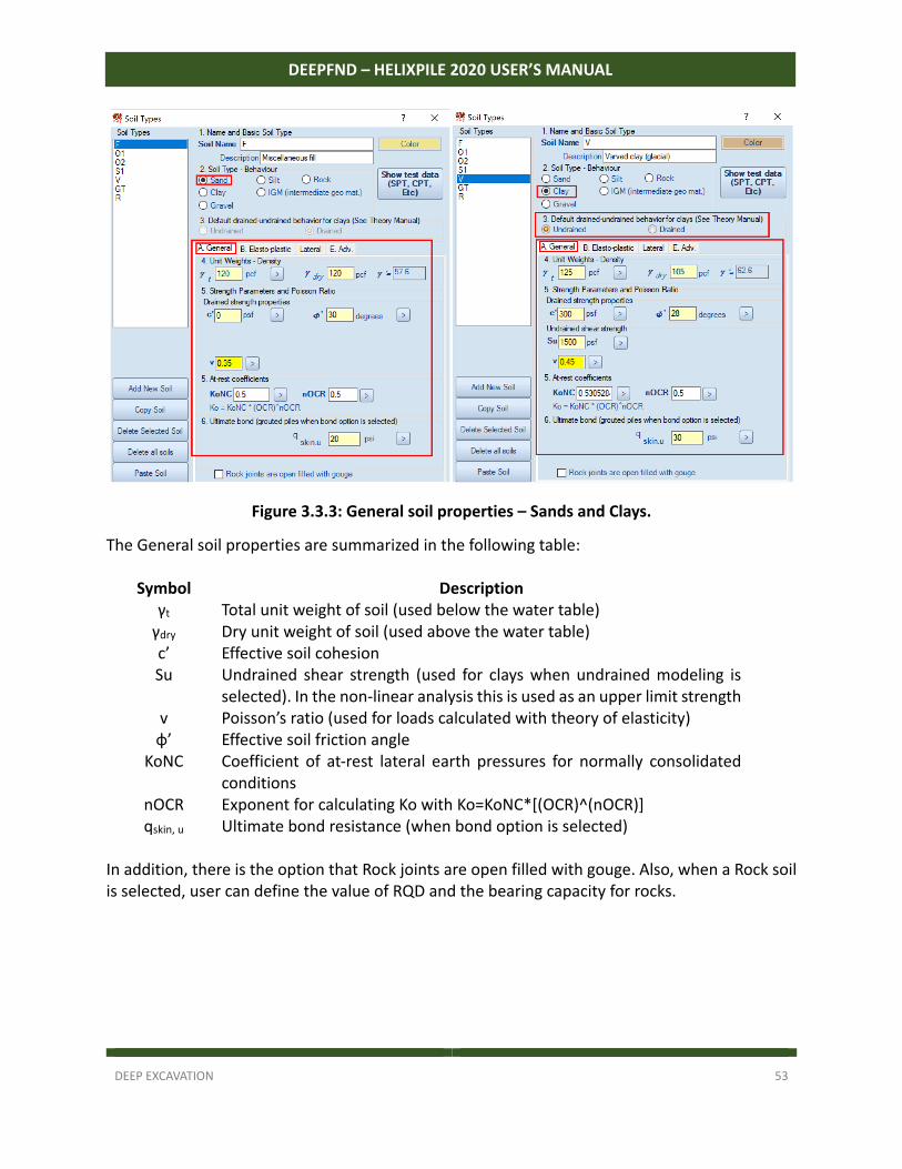
Figure 3.3.3: General soil properties – Sands and Clays.
The General soil properties are summarized in the following table:
Symbol Description γt Total unit weight of soil (used below the water table) γdry Dry unit weight of soil (used above the water table) c’ Effective soil cohesion Su Undrained shear strength (used for clays when undrained modeling is
selected). In the non‐linear analysis this is used as an upper limit strength v Poisson’s ratio (used for loads calculated with theory of elasticity) φ’ Effective soil friction angle
KoNC Coefficient of at‐rest lateral earth pressures for normally consolidated conditions
nOCR Exponent for calculating Ko with Ko=KoNC*[(OCR)^(nOCR)] qskin, u Ultimate bond resistance (when bond option is selected)
In addition, there is the option that Rock joints are open filled with gouge. Also, when a Rock soil is selected, user can define the value of RQD and the bearing capacity for rocks.
DEEP EXCAVATION 54
DEEPFND – HELIXPILE 2020 USER’S MANUAL
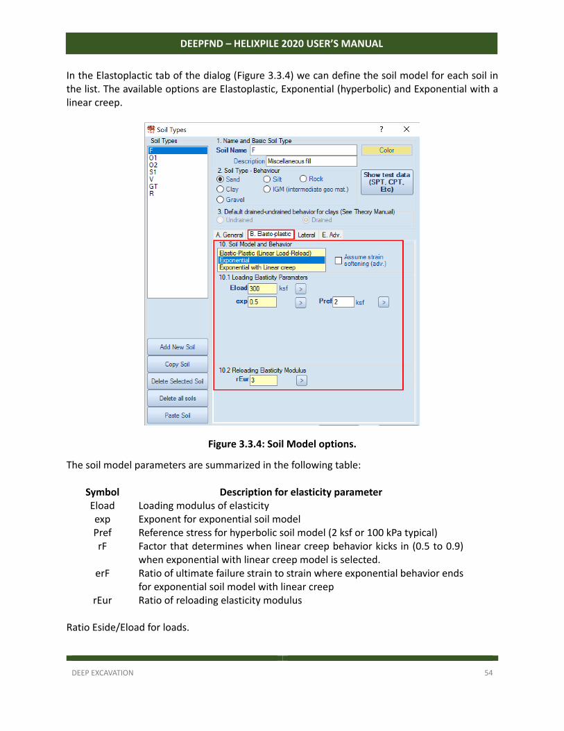
In the Elastoplactic tab of the dialog (Figure 3.3.4) we can define the soil model for each soil in the list. The available options are Elastoplastic, Exponential (hyperbolic) and Exponential with a linear creep.
Figure 3.3.4: Soil Model options.
The soil model parameters are summarized in the following table:
Symbol Description for elasticity parameter Eload Loading modulus of elasticity exp Exponent for exponential soil model Pref Reference stress for hyperbolic soil model (2 ksf or 100 kPa typical) rF Factor that determines when linear creep behavior kicks in (0.5 to 0.9)
when exponential with linear creep model is selected. erF
rEur
Ratio of ultimate failure strain to strain where exponential behavior ends for exponential soil model with linear creep Ratio of reloading elasticity modulus
Ratio Eside/Eload for loads.
DEEP EXCAVATION 55
DEEPFND – HELIXPILE 2020 USER’S MANUAL
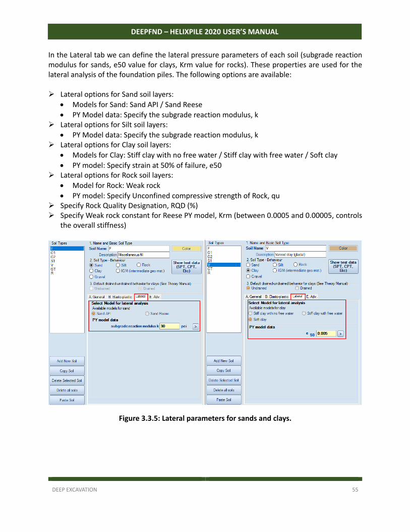
In the Lateral tab we can define the lateral pressure parameters of each soil (subgrade reaction modulus for sands, e50 value for clays, Krm value for rocks). These properties are used for the lateral analysis of the foundation piles. The following options are available: Lateral options for Sand soil layers:
Models for Sand: Sand API / Sand Reese
PY Model data: Specify the subgrade reaction modulus, k Lateral options for Silt soil layers:
PY Model data: Specify the subgrade reaction modulus, k Lateral options for Clay soil layers:
Models for Clay: Stiff clay with no free water / Stiff clay with free water / Soft clay
PY model: Specify strain at 50% of failure, e50 Lateral options for Rock soil layers:
Model for Rock: Weak rock
PY model: Specify Unconfined compressive strength of Rock, qu Specify Rock Quality Designation, RQD (%) Specify Weak rock constant for Reese PY model, Krm (between 0.0005 and 0.00005, controls
the overall stiffness)
Figure 3.3.5: Lateral parameters for sands and clays.
DEEP EXCAVATION 56
DEEPFND – HELIXPILE 2020 USER’S MANUAL
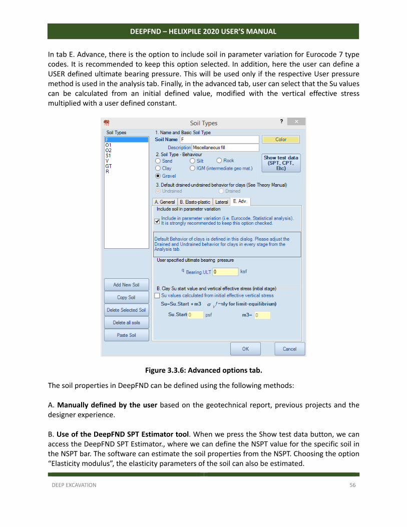
In tab E. Advance, there is the option to include soil in parameter variation for Eurocode 7 type codes. It is recommended to keep this option selected. In addition, here the user can define a USER defined ultimate bearing pressure. This will be used only if the respective User pressure method is used in the analysis tab. Finally, in the advanced tab, user can select that the Su values can be calculated from an initial defined value, modified with the vertical effective stress multiplied with a user defined constant.
Figure 3.3.6: Advanced options tab.
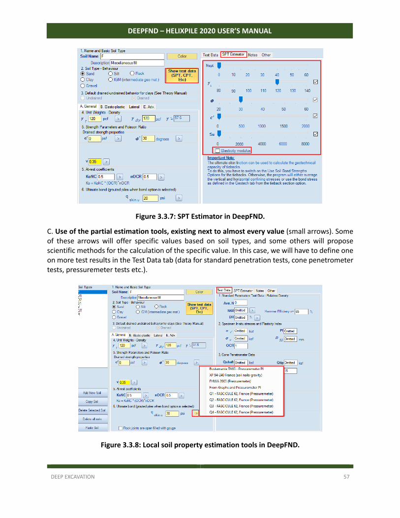
The soil properties in DeepFND can be defined using the following methods: A. Manually defined by the user based on the geotechnical report, previous projects and the designer experience. B. Use of the DeepFND SPT Estimator tool. When we press the Show test data button, we can access the DeepFND SPT Estimator., where we can define the NSPT value for the specific soil in the NSPT bar. The software can estimate the soil properties from the NSPT. Choosing the option “Elasticity modulus”, the elasticity parameters of the soil can also be estimated.
DEEP EXCAVATION 57
DEEPFND – HELIXPILE 2020 USER’S MANUAL
Figure 3.3.7: SPT Estimator in DeepFND.
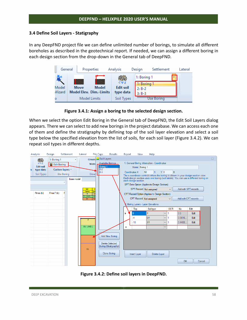
C. Use of the partial estimation tools, existing next to almost every value (small arrows). Some of these arrows will offer specific values based on soil types, and some others will propose scientific methods for the calculation of the specific value. In this case, we will have to define one on more test results in the Test Data tab (data for standard penetration tests, cone penetrometer tests, pressuremeter tests etc.).
Figure 3.3.8: Local soil property estimation tools in DeepFND.
DEEP EXCAVATION 58
DEEPFND – HELIXPILE 2020 USER’S MANUAL
3.4 Define Soil Layers - Statigraphy In any DeepFND project file we can define unlimited number of borings, to simulate all different boreholes as described in the geotechnical report. If needed, we can assign a different boring in each design section from the drop‐down in the General tab of DeepFND.
Figure 3.4.1: Assign a boring to the selected design section.
When we select the option Edit Boring in the General tab of DeepFND, the Edit Soil Layers dialog appears. There we can select to add new borings in the project database. We can access each one of them and define the stratigraphy by defining top of the soil layer elevation and select a soil type below the specified elevation from the list of soils, for each soil layer (Figure 3.4.2). We can repeat soil types in different depths.
Figure 3.4.2: Define soil layers in DeepFND.
DEEP EXCAVATION 59
DEEPFND – HELIXPILE 2020 USER’S MANUAL
3.5 Define Pile Properties
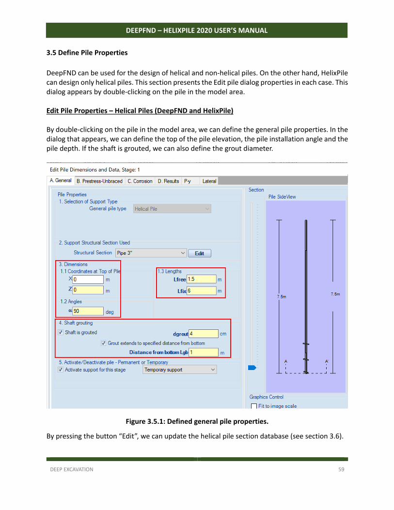
DeepFND can be used for the design of helical and non‐helical piles. On the other hand, HelixPile can design only helical piles. This section presents the Edit pile dialog properties in each case. This dialog appears by double‐clicking on the pile in the model area. Edit Pile Properties – Helical Piles (DeepFND and HelixPile) By double‐clicking on the pile in the model area, we can define the general pile properties. In the dialog that appears, we can define the top of the pile elevation, the pile installation angle and the pile depth. If the shaft is grouted, we can also define the grout diameter.
Figure 3.5.1: Defined general pile properties.
By pressing the button “Edit”, we can update the helical pile section database (see section 3.6).
DEEP EXCAVATION 60
DEEPFND – HELIXPILE 2020 USER’S MANUAL
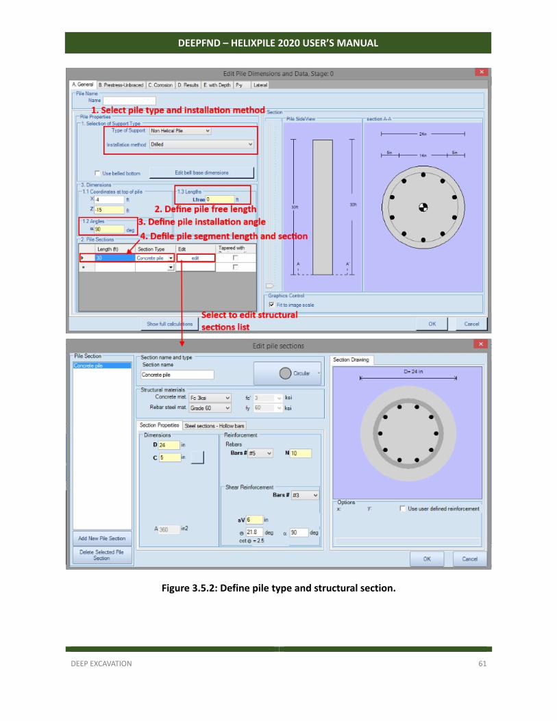
Edit Pile Properties – Non-Helical Piles (DeepFND Only) By double‐clicking on the pile in the model area, we can define the general pile properties. In the “Edit Pile Dimensions and Data” dialog that appears (see Figure 3.5), we can define the following options: Pile Type (Helical or Non‐Helical pile) Free length (where adhesion or side resistance is ignored). Installation angle (90 deg = vertical pile) Installation method (option available for non‐helical piles only). The following options are available:
Drilled piles
Driven piles
Caisson piles
Micropiles
CFA (Continuous Flight Auger) piles
Drilled‐In‐Displacement piles Structural section and pile length. User can define the depth of each pile segment and select a structural section. The structural sections list can be updated by pressing the “Edit” button next to each pile section segment. By selecting to Edit the structural section, we can update the non‐helical pile sections database (see section 3.7).
DEEP EXCAVATION 61
DEEPFND – HELIXPILE 2020 USER’S MANUAL
Figure 3.5.2: Define pile type and structural section.
DEEP EXCAVATION 62
DEEPFND – HELIXPILE 2020 USER’S MANUAL
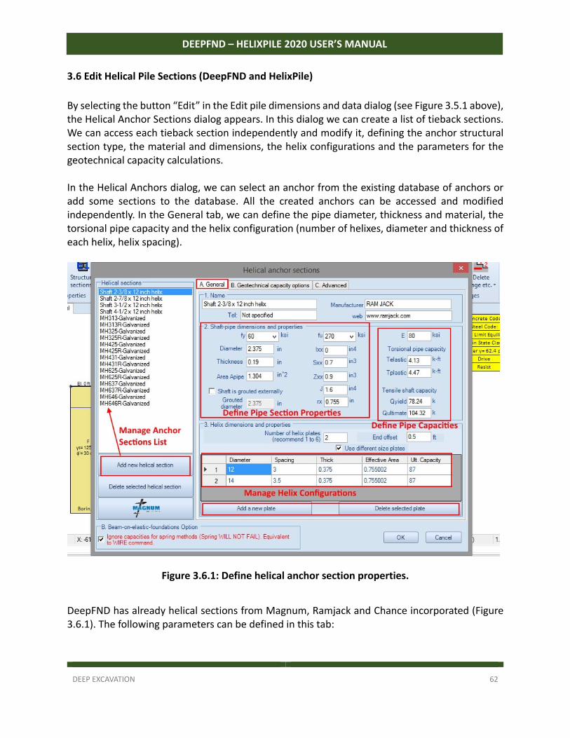
3.6 Edit Helical Pile Sections (DeepFND and HelixPile)
By selecting the button “Edit” in the Edit pile dimensions and data dialog (see Figure 3.5.1 above), the Helical Anchor Sections dialog appears. In this dialog we can create a list of tieback sections. We can access each tieback section independently and modify it, defining the anchor structural section type, the material and dimensions, the helix configurations and the parameters for the geotechnical capacity calculations. In the Helical Anchors dialog, we can select an anchor from the existing database of anchors or add some sections to the database. All the created anchors can be accessed and modified independently. In the General tab, we can define the pipe diameter, thickness and material, the torsional pipe capacity and the helix configuration (number of helixes, diameter and thickness of each helix, helix spacing).
Figure 3.6.1: Define helical anchor section properties.
DeepFND has already helical sections from Magnum, Ramjack and Chance incorporated (Figure 3.6.1). The following parameters can be defined in this tab:
DEEP EXCAVATION 63
DEEPFND – HELIXPILE 2020 USER’S MANUAL
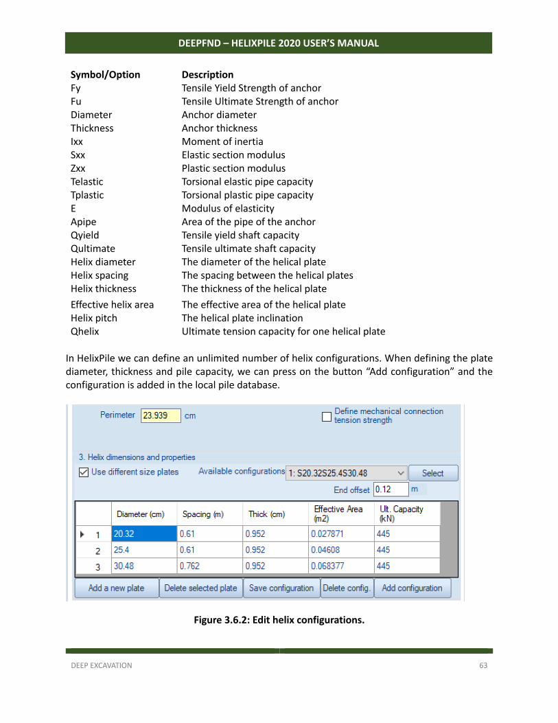
Symbol/Option Description Fy Tensile Yield Strength of anchor Fu Tensile Ultimate Strength of anchor Diameter Anchor diameter Thickness Anchor thickness Ixx Moment of inertia Sxx Elastic section modulus Zxx Plastic section modulus Telastic Torsional elastic pipe capacity Tplastic Torsional plastic pipe capacity E Modulus of elasticity Apipe Area of the pipe of the anchor Qyield Tensile yield shaft capacity Qultimate Tensile ultimate shaft capacity Helix diameter The diameter of the helical plate Helix spacing The spacing between the helical plates Helix thickness The thickness of the helical plate
Effective helix area The effective area of the helical plate Helix pitch The helical plate inclination Qhelix Ultimate tension capacity for one helical plate In HelixPile we can define an unlimited number of helix configurations. When defining the plate diameter, thickness and pile capacity, we can press on the button “Add configuration” and the configuration is added in the local pile database.
Figure 3.6.2: Edit helix configurations.
DEEP EXCAVATION 64
DEEPFND – HELIXPILE 2020 USER’S MANUAL
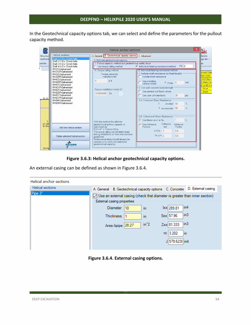
In the Geotechnical capacity options tab, we can select and define the parameters for the pullout capacity method.
Figure 3.6.3: Helical anchor geotechnical capacity options.
An external casing can be defined as shown in Figure 3.6.4.
Figure 3.6.4. External casing options.
DEEP EXCAVATION 65
DEEPFND – HELIXPILE 2020 USER’S MANUAL
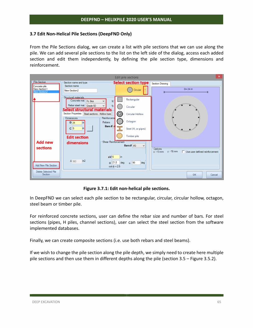
3.7 Edit Non-Helical Pile Sections (DeepFND Only)
From the Pile Sections dialog, we can create a list with pile sections that we can use along the pile. We can add several pile sections to the list on the left side of the dialog, access each added section and edit them independently, by defining the pile section type, dimensions and reinforcement.
Figure 3.7.1: Edit non-helical pile sections.
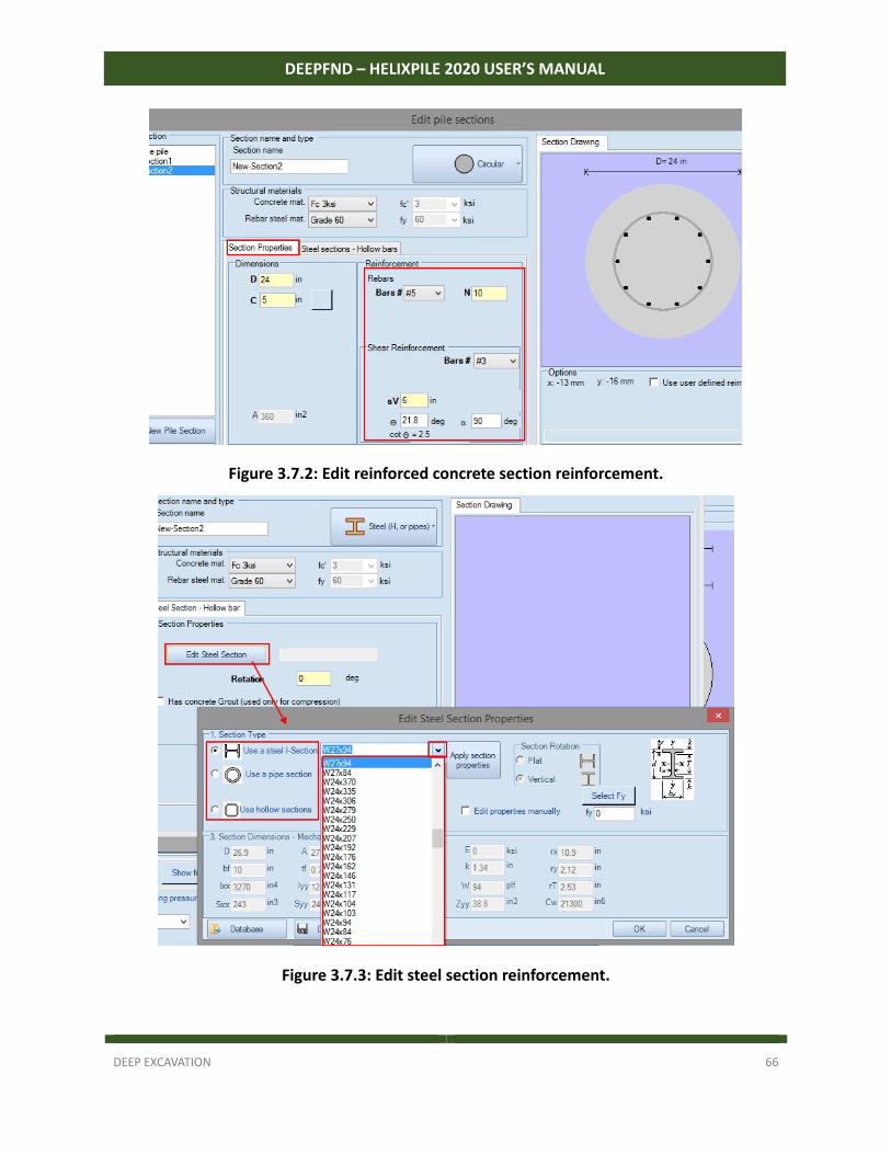
In DeepFND we can select each pile section to be rectangular, circular, circular hollow, octagon, steel beam or timber pile. For reinforced concrete sections, user can define the rebar size and number of bars. For steel sections (pipes, H piles, channel sections), user can select the steel section from the software implemented databases. Finally, we can create composite sections (i.e. use both rebars and steel beams). If we wish to change the pile section along the pile depth, we simply need to create here multiple pile sections and then use them in different depths along the pile (section 3.5 – Figure 3.5.2).
DEEP EXCAVATION 66
DEEPFND – HELIXPILE 2020 USER’S MANUAL
Figure 3.7.2: Edit reinforced concrete section reinforcement.
Figure 3.7.3: Edit steel section reinforcement.
DEEP EXCAVATION 67
DEEPFND – HELIXPILE 2020 USER’S MANUAL
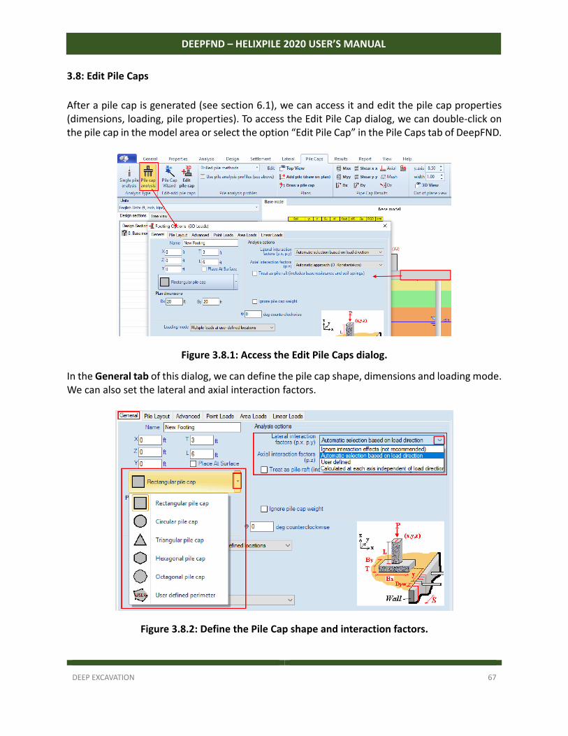
3.8: Edit Pile Caps
After a pile cap is generated (see section 6.1), we can access it and edit the pile cap properties (dimensions, loading, pile properties). To access the Edit Pile Cap dialog, we can double‐click on the pile cap in the model area or select the option “Edit Pile Cap” in the Pile Caps tab of DeepFND.
Figure 3.8.1: Access the Edit Pile Caps dialog.
In the General tab of this dialog, we can define the pile cap shape, dimensions and loading mode. We can also set the lateral and axial interaction factors.
Figure 3.8.2: Define the Pile Cap shape and interaction factors.
DEEP EXCAVATION 68
DEEPFND – HELIXPILE 2020 USER’S MANUAL
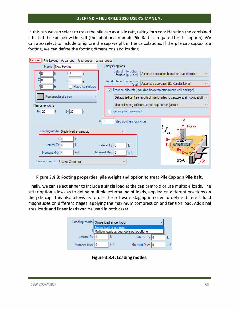
In this tab we can select to treat the pile cap as a pile raft, taking into consideration the combined effect of the soil below the raft (the additional module Pile Rafts is required for this option). We can also select to include or ignore the cap weight in the calculations. If the pile cap supports a footing, we can define the footing dimensions and loading.
Figure 3.8.3: Footing properties, pile weight and option to treat Pile Cap as a Pile Raft.
Finally, we can select either to include a single load at the cap centroid or use multiple loads. The latter option allows as to define multiple external point loads, applied on different positions on the pile cap. This also allows as to use the software staging in order to define different load magnitudes on different stages, applying the maximum compression and tension load. Additinal area loads and linear loads can be used in both cases.
Figure 3.8.4: Loading modes.
DEEP EXCAVATION 69
DEEPFND – HELIXPILE 2020 USER’S MANUAL
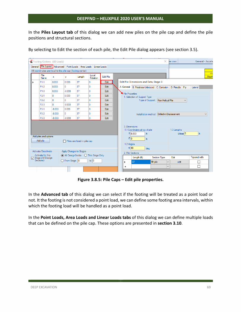
In the Piles Layout tab of this dialog we can add new piles on the pile cap and define the pile positions and structural sections. By selecting to Edit the section of each pile, the Edit Pile dialog appears (see section 3.5).
Figure 3.8.5: Pile Caps – Edit pile properties.
In the Advanced tab of this dialog we can select if the footing will be treated as a point load or not. It the footing is not considered a point load, we can define some footing area intervals, within which the footing load will be handled as a point load. In the Point Loads, Area Loads and Linear Loads tabs of this dialog we can define multiple loads that can be defined on the pile cap. These options are presented in section 3.10.
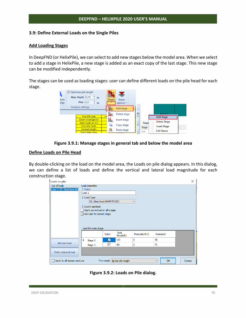
DEEP EXCAVATION 70
DEEPFND – HELIXPILE 2020 USER’S MANUAL
3.9: Define External Loads on the Single Piles
Add Loading Stages In DeepFND (or HelixPile), we can select to add new stages below the model area. When we select to add a stage in HelixPile, a new stage is added as an exact copy of the last stage. This new stage can be modified independently. The stages can be used as loading stages: user can define different loads on the pile head for each stage.
Figure 3.9.1: Manage stages in general tab and below the model area
Define Loads on Pile Head By double‐clicking on the load on the model area, the Loads on pile dialog appears. In this dialog, we can define a list of loads and define the vertical and lateral load magnitude for each construction stage.
Figure 3.9.2: Loads on Pile dialog.
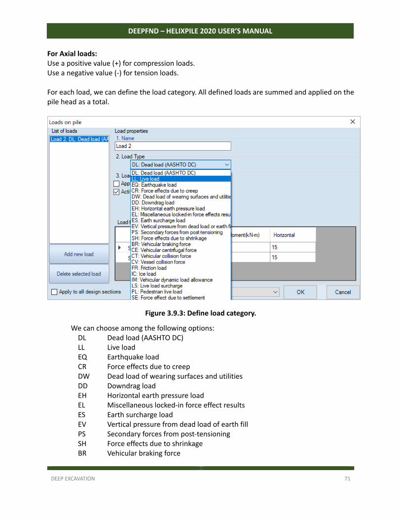
DEEP EXCAVATION 71
DEEPFND – HELIXPILE 2020 USER’S MANUAL
For Axial loads: Use a positive value (+) for compression loads. Use a negative value (‐) for tension loads. For each load, we can define the load category. All defined loads are summed and applied on the pile head as a total.
Figure 3.9.3: Define load category.
We can choose among the following options: DL Dead load (AASHTO DC) LL Live load EQ Earthquake load CR Force effects due to creep DW Dead load of wearing surfaces and utilities DD Downdrag load EH Horizontal earth pressure load EL Miscellaneous locked‐in force effect results ES Earth surcharge load EV Vertical pressure from dead load of earth fill PS Secondary forces from post‐tensioning SH Force effects due to shrinkage BR Vehicular braking force
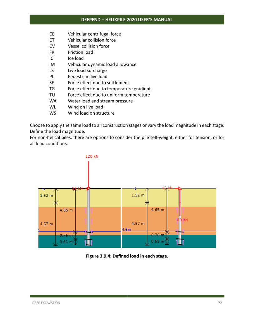
DEEP EXCAVATION 72
DEEPFND – HELIXPILE 2020 USER’S MANUAL
CE Vehicular centrifugal force CT Vehicular collision force CV Vessel collision force FR Friction load IC Ice load IM Vehicular dynamic load allowance LS Live load surcharge PL Pedestrian live load SE Force effect due to settlement TG Force effect due to temperature gradient TU Force effect due to uniform temperature WA Water load and stream pressure WL Wind on live load WS Wind load on structure
Choose to apply the same load to all construction stages or vary the load magnitude in each stage. Define the load magnitude. For non‐helical piles, there are options to consider the pile self‐weight, either for tension, or for all load conditions.
Figure 3.9.4: Defined load in each stage.
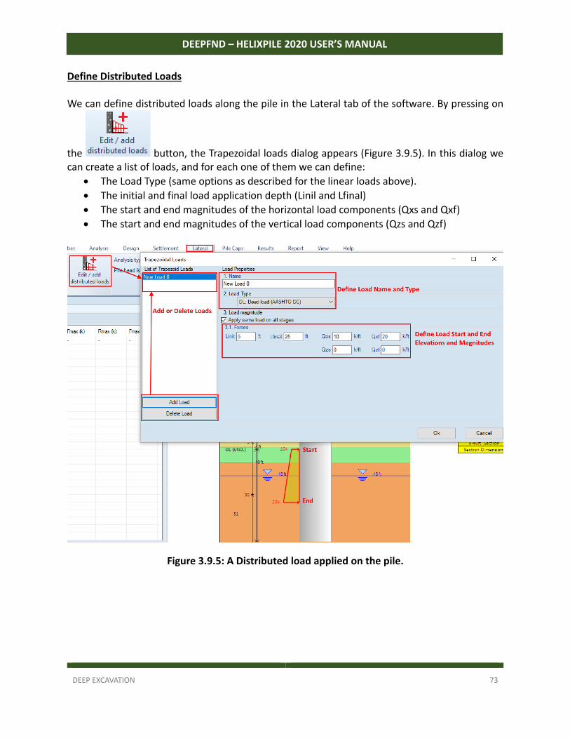
DEEP EXCAVATION 73
DEEPFND – HELIXPILE 2020 USER’S MANUAL
Define Distributed Loads We can define distributed loads along the pile in the Lateral tab of the software. By pressing on
the button, the Trapezoidal loads dialog appears (Figure 3.9.5). In this dialog we can create a list of loads, and for each one of them we can define:
The Load Type (same options as described for the linear loads above).
The initial and final load application depth (Linil and Lfinal)
The start and end magnitudes of the horizontal load components (Qxs and Qxf)
The start and end magnitudes of the vertical load components (Qzs and Qzf)
Figure 3.9.5: A Distributed load applied on the pile.
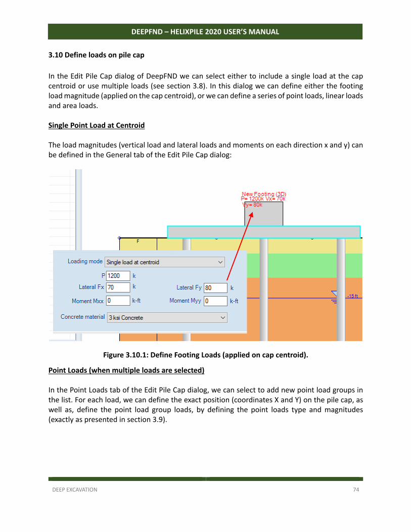
DEEP EXCAVATION 74
DEEPFND – HELIXPILE 2020 USER’S MANUAL
3.10 Define loads on pile cap
In the Edit Pile Cap dialog of DeepFND we can select either to include a single load at the cap centroid or use multiple loads (see section 3.8). In this dialog we can define either the footing load magnitude (applied on the cap centroid), or we can define a series of point loads, linear loads and area loads. Single Point Load at Centroid The load magnitudes (vertical load and lateral loads and moments on each direction x and y) can be defined in the General tab of the Edit Pile Cap dialog:
Figure 3.10.1: Define Footing Loads (applied on cap centroid).
Point Loads (when multiple loads are selected) In the Point Loads tab of the Edit Pile Cap dialog, we can select to add new point load groups in the list. For each load, we can define the exact position (coordinates X and Y) on the pile cap, as well as, define the point load group loads, by defining the point loads type and magnitudes (exactly as presented in section 3.9).
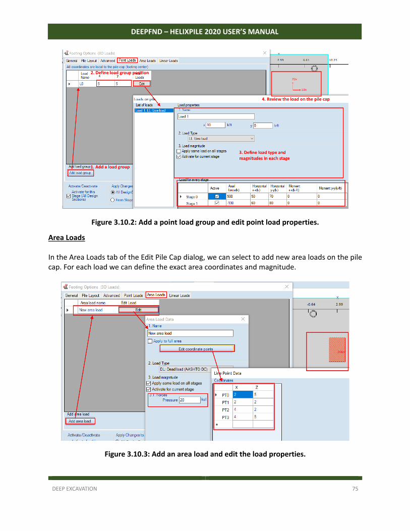
DEEP EXCAVATION 75
DEEPFND – HELIXPILE 2020 USER’S MANUAL
Figure 3.10.2: Add a point load group and edit point load properties.
Area Loads In the Area Loads tab of the Edit Pile Cap dialog, we can select to add new area loads on the pile cap. For each load we can define the exact area coordinates and magnitude.
Figure 3.10.3: Add an area load and edit the load properties.
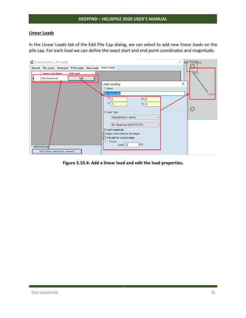
DEEP EXCAVATION 76
DEEPFND – HELIXPILE 2020 USER’S MANUAL
Linear Loads In the Linear Loads tab of the Edit Pile Cap dialog, we can select to add new linear loads on the pile cap. For each load we can define the exact start and end point coordinates and magnitude.
Figure 3.10.4: Add a linear load and edit the load properties.
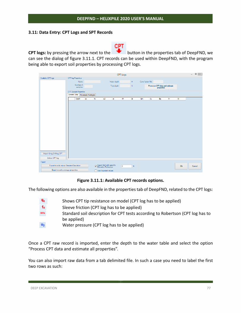
DEEP EXCAVATION 77
DEEPFND – HELIXPILE 2020 USER’S MANUAL
3.11: Data Entry: CPT Logs and SPT Records
CPT logs: by pressing the arrow next to the button in the properties tab of DeepFND, we can see the dialog of figure 3.11.1. CPT records can be used within DeepFND, with the program being able to export soil properties by processing CPT logs.
Figure 3.11.1: Available CPT records options.
The following options are also available in the properties tab of DeepFND, related to the CPT logs:
Shows CPT tip resistance on model (CPT log has to be applied)
Sleeve friction (CPT log has to be applied)
Standard soil description for CPT tests according to Robertson (CPT log has to be applied)
Water pressure (CPT log has to be applied)
Once a CPT raw record is imported, enter the depth to the water table and select the option “Process CPT data and estimate all properties”. You can also import raw data from a tab delimited file. In such a case you need to label the first two rows as such:
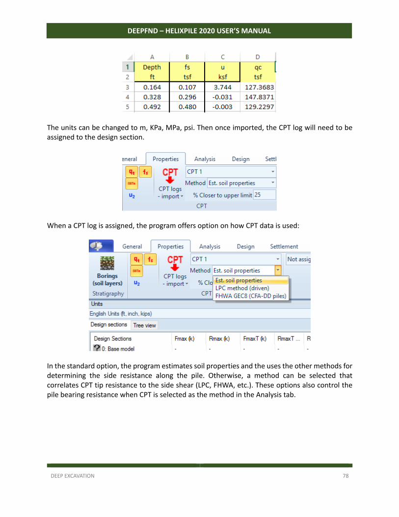
DEEP EXCAVATION 78
DEEPFND – HELIXPILE 2020 USER’S MANUAL
The units can be changed to m, KPa, MPa, psi. Then once imported, the CPT log will need to be assigned to the design section.
When a CPT log is assigned, the program offers option on how CPT data is used:
In the standard option, the program estimates soil properties and the uses the other methods for determining the side resistance along the pile. Otherwise, a method can be selected that correlates CPT tip resistance to the side shear (LPC, FHWA, etc.). These options also control the pile bearing resistance when CPT is selected as the method in the Analysis tab.
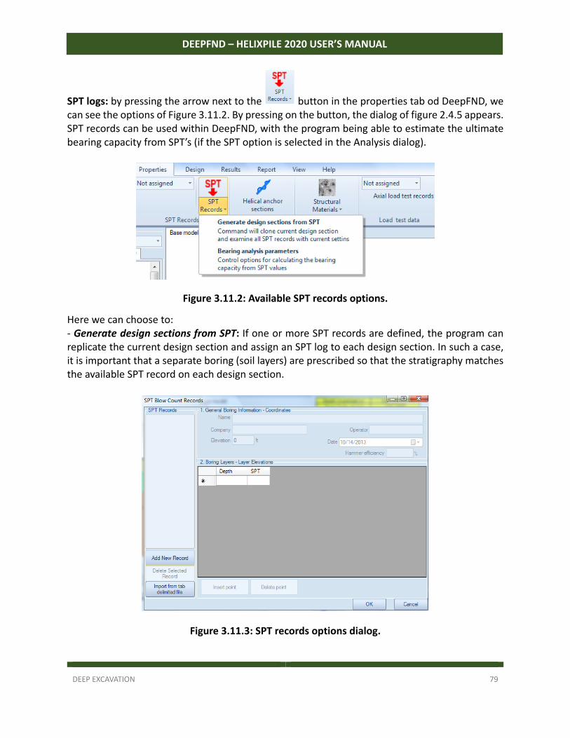
DEEP EXCAVATION 79
DEEPFND – HELIXPILE 2020 USER’S MANUAL
SPT logs: by pressing the arrow next to the button in the properties tab od DeepFND, we can see the options of Figure 3.11.2. By pressing on the button, the dialog of figure 2.4.5 appears. SPT records can be used within DeepFND, with the program being able to estimate the ultimate bearing capacity from SPT’s (if the SPT option is selected in the Analysis dialog).
Figure 3.11.2: Available SPT records options.
Here we can choose to: ‐ Generate design sections from SPT: If one or more SPT records are defined, the program can replicate the current design section and assign an SPT log to each design section. In such a case, it is important that a separate boring (soil layers) are prescribed so that the stratigraphy matches the available SPT record on each design section.
Figure 3.11.3: SPT records options dialog.
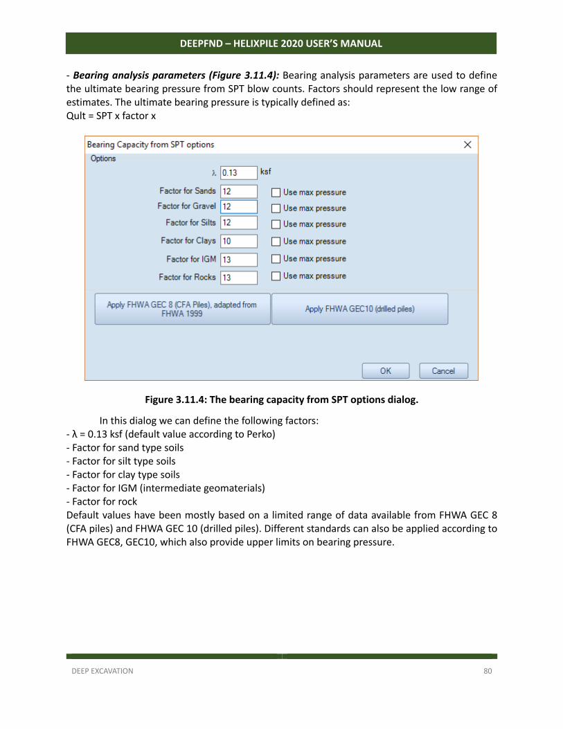
DEEP EXCAVATION 80
DEEPFND – HELIXPILE 2020 USER’S MANUAL
‐ Bearing analysis parameters (Figure 3.11.4): Bearing analysis parameters are used to define the ultimate bearing pressure from SPT blow counts. Factors should represent the low range of estimates. The ultimate bearing pressure is typically defined as: Qult = SPT x factor x �
Figure 3.11.4: The bearing capacity from SPT options dialog.
In this dialog we can define the following factors: ‐ λ = 0.13 ksf (default value according to Perko) ‐ Factor for sand type soils ‐ Factor for silt type soils ‐ Factor for clay type soils ‐ Factor for IGM (intermediate geomaterials) ‐ Factor for rock Default values have been mostly based on a limited range of data available from FHWA GEC 8 (CFA piles) and FHWA GEC 10 (drilled piles). Different standards can also be applied according to FHWA GEC8, GEC10, which also provide upper limits on bearing pressure.
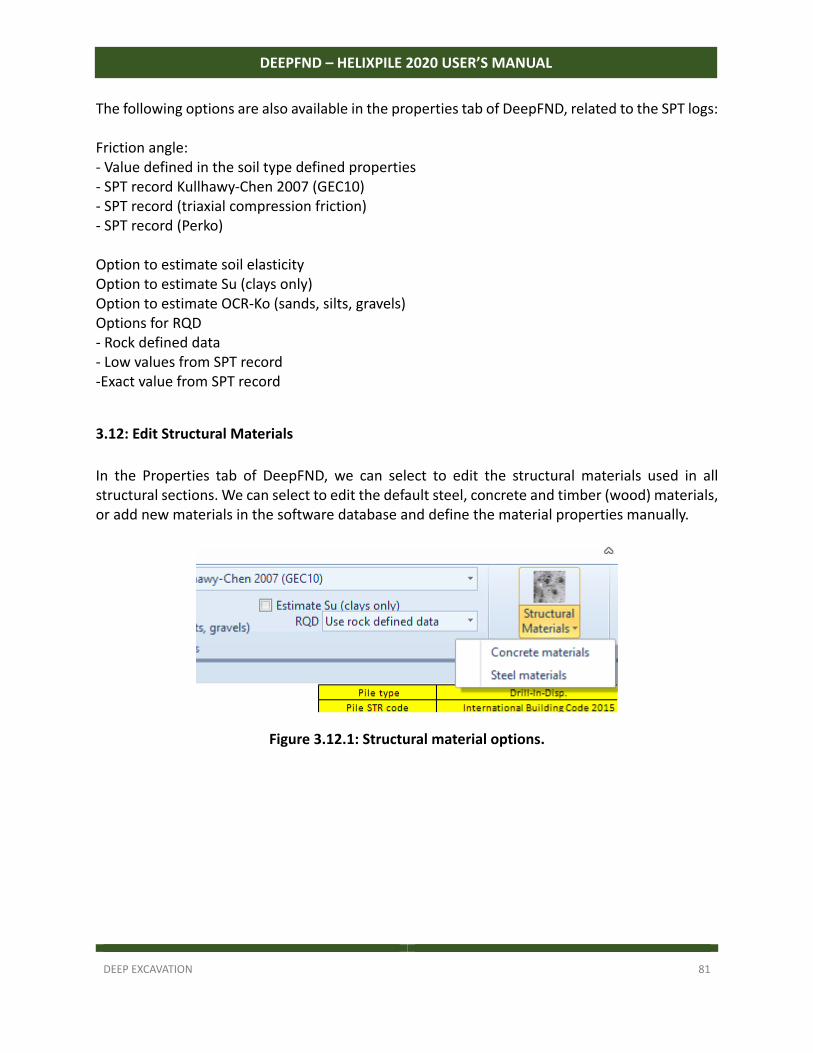
DEEP EXCAVATION 81
DEEPFND – HELIXPILE 2020 USER’S MANUAL
The following options are also available in the properties tab of DeepFND, related to the SPT logs: Friction angle: ‐ Value defined in the soil type defined properties ‐ SPT record Kullhawy‐Chen 2007 (GEC10) ‐ SPT record (triaxial compression friction) ‐ SPT record (Perko) Option to estimate soil elasticity Option to estimate Su (clays only) Option to estimate OCR‐Ko (sands, silts, gravels) Options for RQD ‐ Rock defined data ‐ Low values from SPT record ‐Exact value from SPT record
3.12: Edit Structural Materials
In the Properties tab of DeepFND, we can select to edit the structural materials used in all structural sections. We can select to edit the default steel, concrete and timber (wood) materials, or add new materials in the software database and define the material properties manually.
Figure 3.12.1: Structural material options.
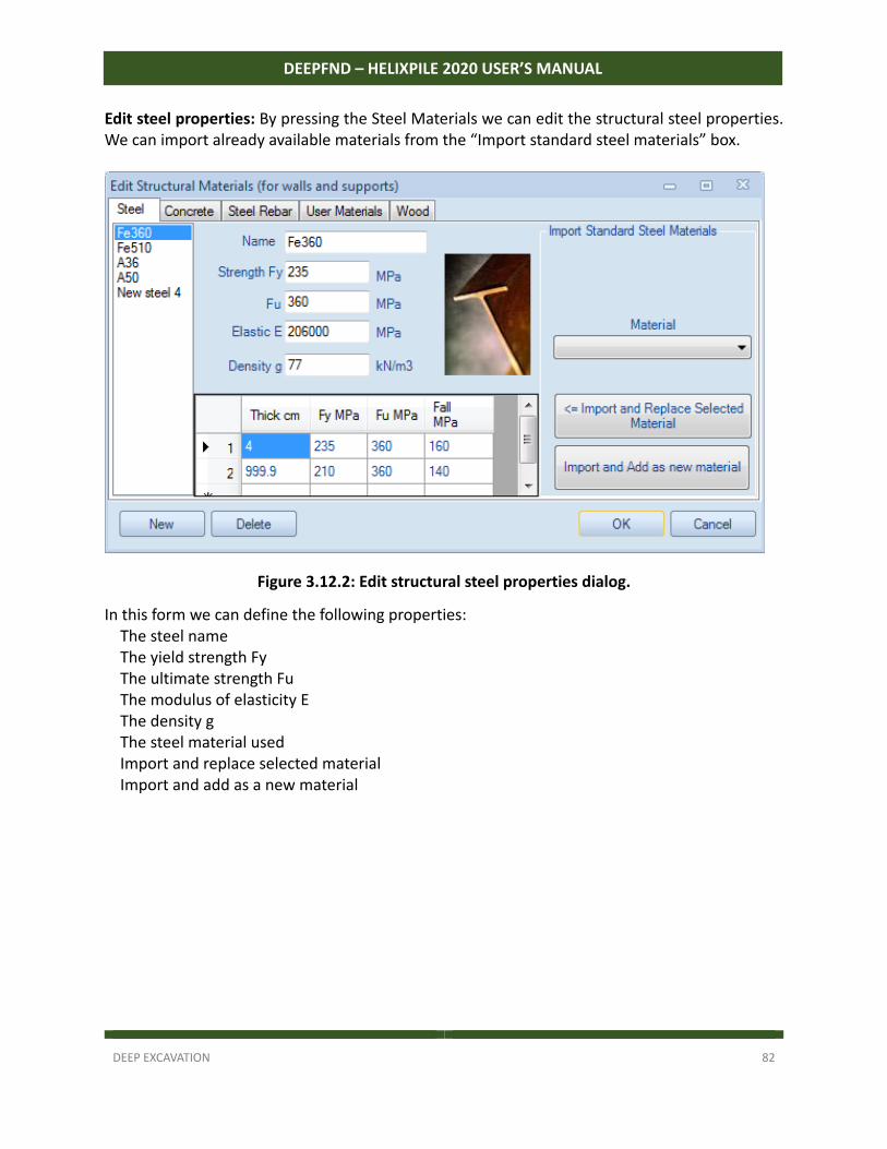
DEEP EXCAVATION 82
DEEPFND – HELIXPILE 2020 USER’S MANUAL
Edit steel properties: By pressing the Steel Materials we can edit the structural steel properties. We can import already available materials from the “Import standard steel materials” box.
Figure 3.12.2: Edit structural steel properties dialog.
In this form we can define the following properties: The steel name The yield strength Fy The ultimate strength Fu The modulus of elasticity E The density g The steel material used Import and replace selected material Import and add as a new material
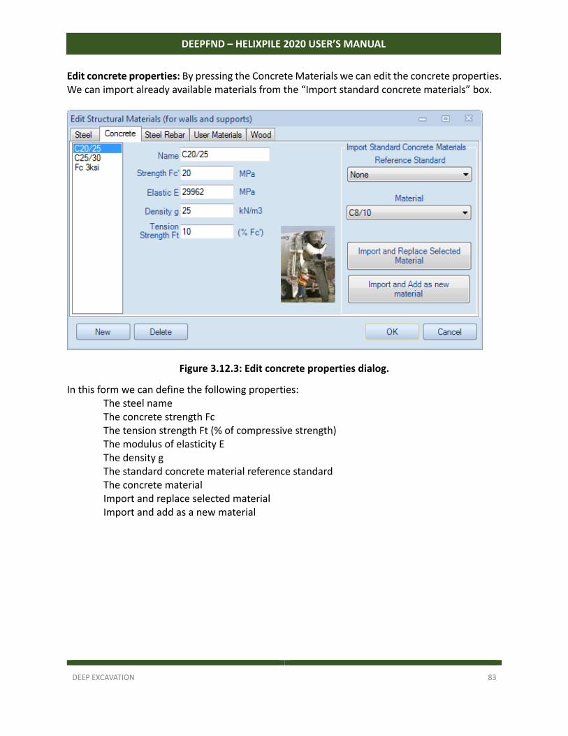
DEEP EXCAVATION 83
DEEPFND – HELIXPILE 2020 USER’S MANUAL
Edit concrete properties: By pressing the Concrete Materials we can edit the concrete properties. We can import already available materials from the “Import standard concrete materials” box.
Figure 3.12.3: Edit concrete properties dialog.
In this form we can define the following properties: The steel name The concrete strength Fc The tension strength Ft (% of compressive strength) The modulus of elasticity E The density g The standard concrete material reference standard The concrete material Import and replace selected material Import and add as a new material
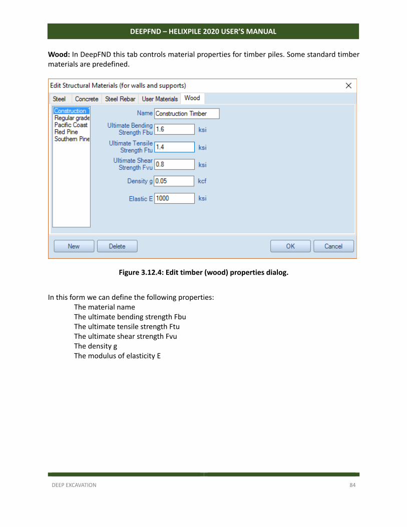
DEEP EXCAVATION 84
DEEPFND – HELIXPILE 2020 USER’S MANUAL
Wood: In DeepFND this tab controls material properties for timber piles. Some standard timber materials are predefined.
Figure 3.12.4: Edit timber (wood) properties dialog.
In this form we can define the following properties:
The material name The ultimate bending strength Fbu The ultimate tensile strength Ftu The ultimate shear strength Fvu The density g The modulus of elasticity E
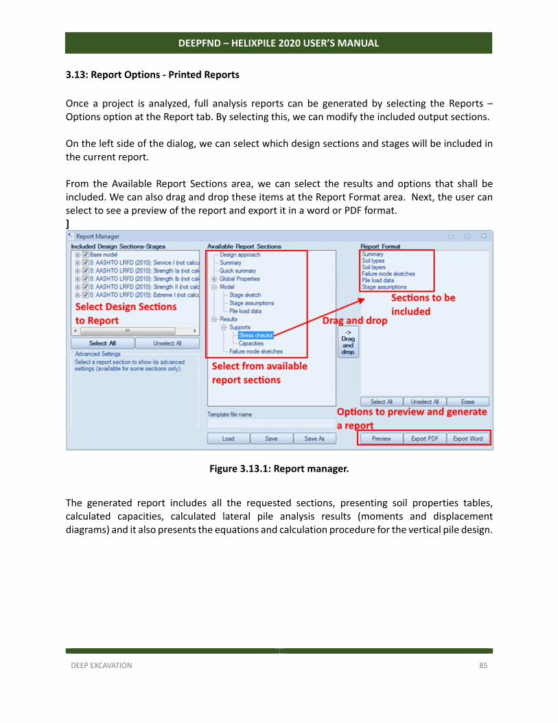
DEEP EXCAVATION 85
DEEPFND – HELIXPILE 2020 USER’S MANUAL
3.13: Report Options - Printed Reports
Once a project is analyzed, full analysis reports can be generated by selecting the Reports – Options option at the Report tab. By selecting this, we can modify the included output sections. On the left side of the dialog, we can select which design sections and stages will be included in the current report. From the Available Report Sections area, we can select the results and options that shall be included. We can also drag and drop these items at the Report Format area. Next, the user can select to see a preview of the report and export it in a word or PDF format. ]
Figure 3.13.1: Report manager.
The generated report includes all the requested sections, presenting soil properties tables, calculated capacities, calculated lateral pile analysis results (moments and displacement diagrams) and it also presents the equations and calculation procedure for the vertical pile design.
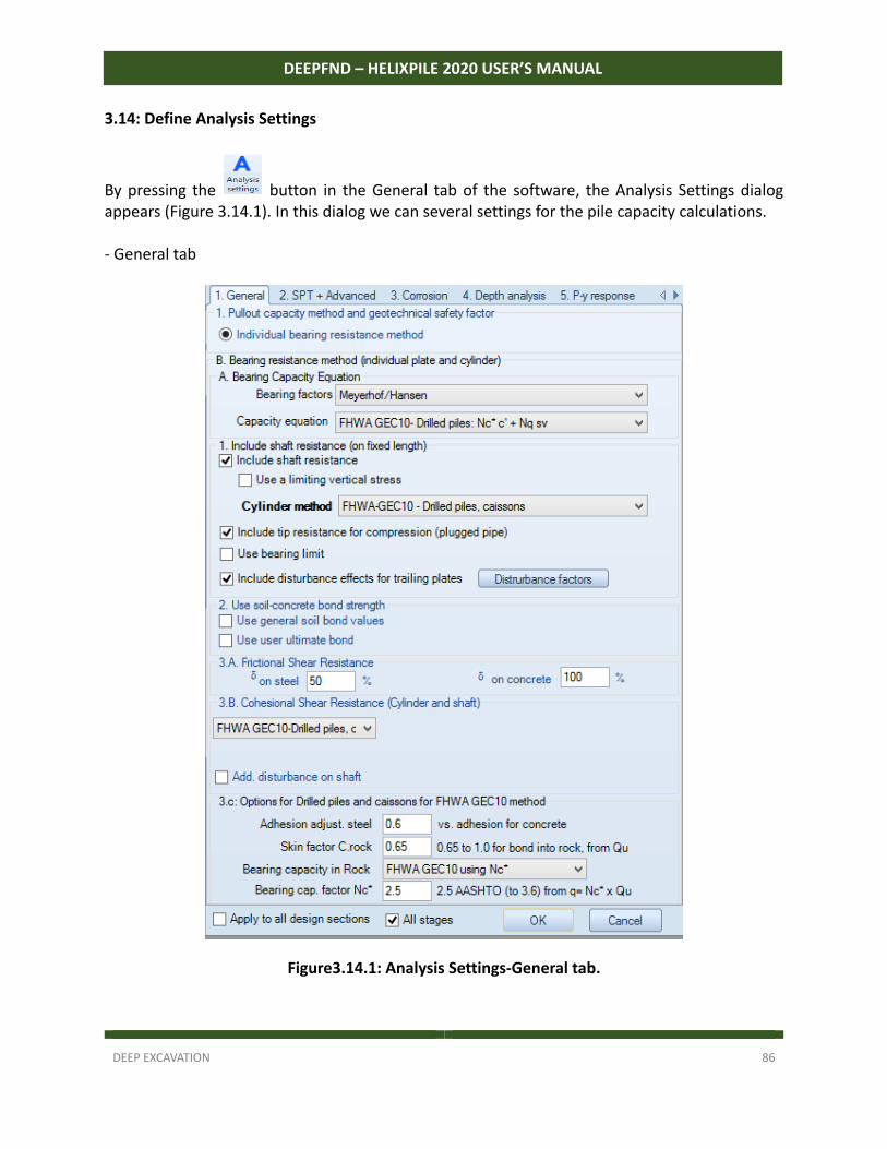
DEEP EXCAVATION 86
DEEPFND – HELIXPILE 2020 USER’S MANUAL
3.14: Define Analysis Settings
By pressing the button in the General tab of the software, the Analysis Settings dialog appears (Figure 3.14.1). In this dialog we can several settings for the pile capacity calculations. ‐ General tab
Figure3.14.1: Analysis Settings-General tab.
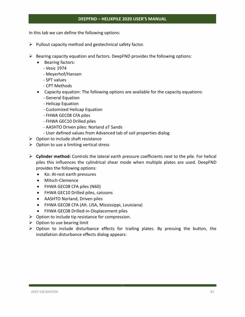
DEEP EXCAVATION 87
DEEPFND – HELIXPILE 2020 USER’S MANUAL
In this tab we can define the following options: Pullout capacity method and geotechnical safety factor. Bearing capacity equation and factors. DeepFND provides the following options:
Bearing factors: ‐ Vesic 1974 ‐ Meyerhof/Hansen ‐ SPT values ‐ CPT Methods
Capacity equation: The following options are available for the capacity equations: ‐ General Equation ‐ Helicap Equation ‐ Customized Helicap Equation ‐ FHWA GEC08 CFA piles ‐ FHWA GEC10 Drilled piles ‐ AASHTO Driven piles: Norland aT Sands ‐ User defined values from Advanced tab of soil properties dialog
Option to include shaft resistance Option to use a limiting vertical stress Cylinder method: Controls the lateral earth pressure coefficients next to the pile. For helical
piles this influences the cylindrical shear mode when multiple plates are used. DeepFND provides the following options:
Ko: At‐rest earth pressures
Mitsch‐Clemence
FHWA GEC08 CFA piles (N60)
FHWA GEC10 Drilled piles, caissons
AASHTO Norland, Driven piles
FHWA GEC08 CFA (Alt. USA, Mississippi, Louisiana)
FHWA GEC08 Drilled‐in‐Displacement piles Option to include tip resistance for compression. Option to use bearing limit Option to include disturbance effects for trailing plates. By pressing the button, the
installation disturbance effects dialog appears:
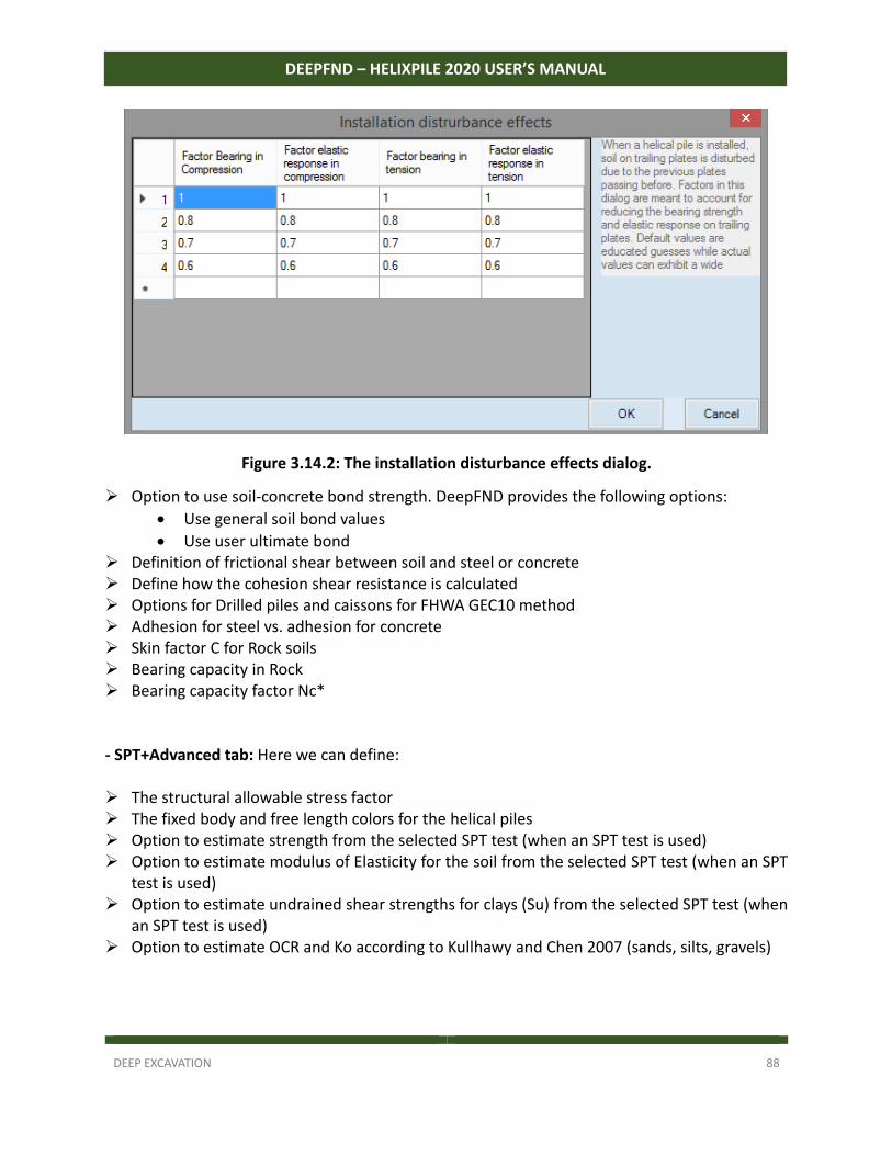
DEEP EXCAVATION 88
DEEPFND – HELIXPILE 2020 USER’S MANUAL
Figure 3.14.2: The installation disturbance effects dialog.
Option to use soil‐concrete bond strength. DeepFND provides the following options:
Use general soil bond values
Use user ultimate bond Definition of frictional shear between soil and steel or concrete Define how the cohesion shear resistance is calculated Options for Drilled piles and caissons for FHWA GEC10 method Adhesion for steel vs. adhesion for concrete Skin factor C for Rock soils Bearing capacity in Rock Bearing capacity factor Nc* - SPT+Advanced tab: Here we can define: The structural allowable stress factor The fixed body and free length colors for the helical piles Option to estimate strength from the selected SPT test (when an SPT test is used) Option to estimate modulus of Elasticity for the soil from the selected SPT test (when an SPT
test is used) Option to estimate undrained shear strengths for clays (Su) from the selected SPT test (when
an SPT test is used) Option to estimate OCR and Ko according to Kullhawy and Chen 2007 (sands, silts, gravels)
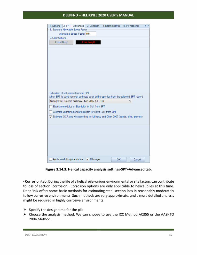
DEEP EXCAVATION 89
DEEPFND – HELIXPILE 2020 USER’S MANUAL
Figure 3.14.3: Helical capacity analysis settings-SPT+Advanced tab.
- Corrosion tab: During the life of a helical pile various environmental or site factors can contribute to loss of section (corrosion). Corrosion options are only applicable to helical piles at this time. DeepFND offers some basic methods for estimating steel section loss in reasonably moderately to low corrosive environments. Such methods are very approximate, and a more detailed analysis might be required in highly corrosive environments: Specify the design time for the pile. Choose the analysis method. We can choose to use the ICC Method AC355 or the AASHTO
2004 Method.
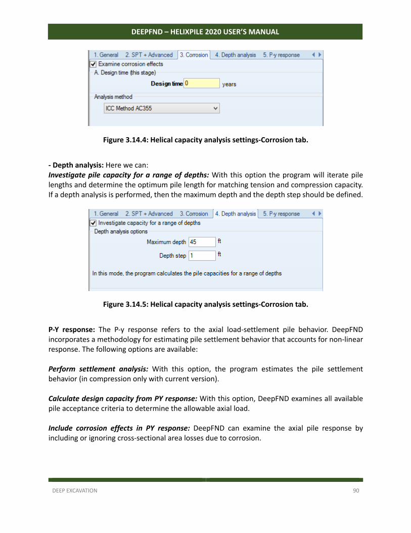
DEEP EXCAVATION 90
DEEPFND – HELIXPILE 2020 USER’S MANUAL
Figure 3.14.4: Helical capacity analysis settings-Corrosion tab.
- Depth analysis: Here we can: Investigate pile capacity for a range of depths: With this option the program will iterate pile lengths and determine the optimum pile length for matching tension and compression capacity. If a depth analysis is performed, then the maximum depth and the depth step should be defined.
Figure 3.14.5: Helical capacity analysis settings-Corrosion tab.
P-Y response: The P‐y response refers to the axial load‐settlement pile behavior. DeepFND incorporates a methodology for estimating pile settlement behavior that accounts for non‐linear response. The following options are available: Perform settlement analysis: With this option, the program estimates the pile settlement behavior (in compression only with current version). Calculate design capacity from PY response: With this option, DeepFND examines all available pile acceptance criteria to determine the allowable axial load. Include corrosion effects in PY response: DeepFND can examine the axial pile response by including or ignoring cross‐sectional area losses due to corrosion.
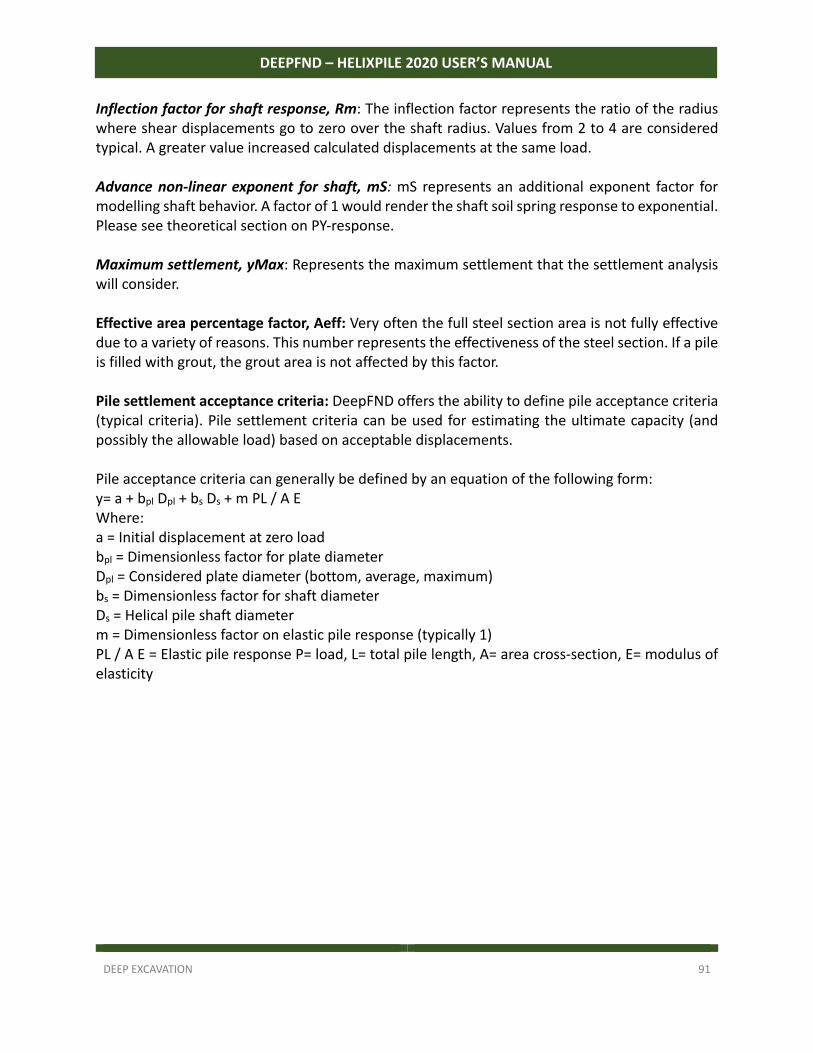
DEEP EXCAVATION 91
DEEPFND – HELIXPILE 2020 USER’S MANUAL
Inflection factor for shaft response, Rm: The inflection factor represents the ratio of the radius where shear displacements go to zero over the shaft radius. Values from 2 to 4 are considered typical. A greater value increased calculated displacements at the same load. Advance non‐linear exponent for shaft, mS: mS represents an additional exponent factor for modelling shaft behavior. A factor of 1 would render the shaft soil spring response to exponential. Please see theoretical section on PY‐response. Maximum settlement, yMax: Represents the maximum settlement that the settlement analysis will consider. Effective area percentage factor, Aeff: Very often the full steel section area is not fully effective due to a variety of reasons. This number represents the effectiveness of the steel section. If a pile is filled with grout, the grout area is not affected by this factor. Pile settlement acceptance criteria: DeepFND offers the ability to define pile acceptance criteria (typical criteria). Pile settlement criteria can be used for estimating the ultimate capacity (and possibly the allowable load) based on acceptable displacements. Pile acceptance criteria can generally be defined by an equation of the following form: y= a + bpl Dpl + bs Ds + m PL / A E Where: a = Initial displacement at zero load bpl = Dimensionless factor for plate diameter Dpl = Considered plate diameter (bottom, average, maximum) bs = Dimensionless factor for shaft diameter Ds = Helical pile shaft diameter m = Dimensionless factor on elastic pile response (typically 1) PL / A E = Elastic pile response P= load, L= total pile length, A= area cross‐section, E= modulus of elasticity
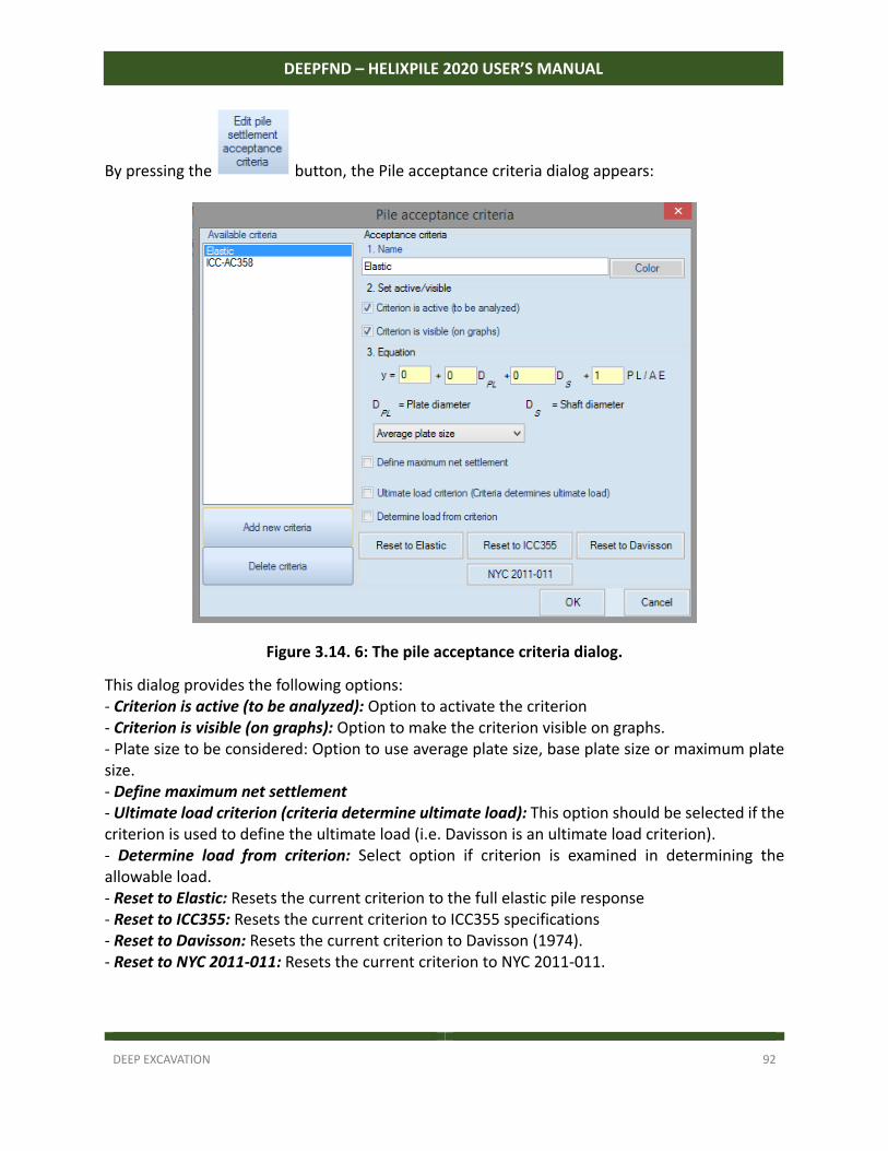
DEEP EXCAVATION 92
DEEPFND – HELIXPILE 2020 USER’S MANUAL
By pressing the button, the Pile acceptance criteria dialog appears:
Figure 3.14. 6: The pile acceptance criteria dialog.
This dialog provides the following options: ‐ Criterion is active (to be analyzed): Option to activate the criterion ‐ Criterion is visible (on graphs): Option to make the criterion visible on graphs. ‐ Plate size to be considered: Option to use average plate size, base plate size or maximum plate size. ‐ Define maximum net settlement ‐ Ultimate load criterion (criteria determine ultimate load): This option should be selected if the criterion is used to define the ultimate load (i.e. Davisson is an ultimate load criterion). ‐ Determine load from criterion: Select option if criterion is examined in determining the allowable load. ‐ Reset to Elastic: Resets the current criterion to the full elastic pile response ‐ Reset to ICC355: Resets the current criterion to ICC355 specifications ‐ Reset to Davisson: Resets the current criterion to Davisson (1974). ‐ Reset to NYC 2011‐011: Resets the current criterion to NYC 2011‐011.
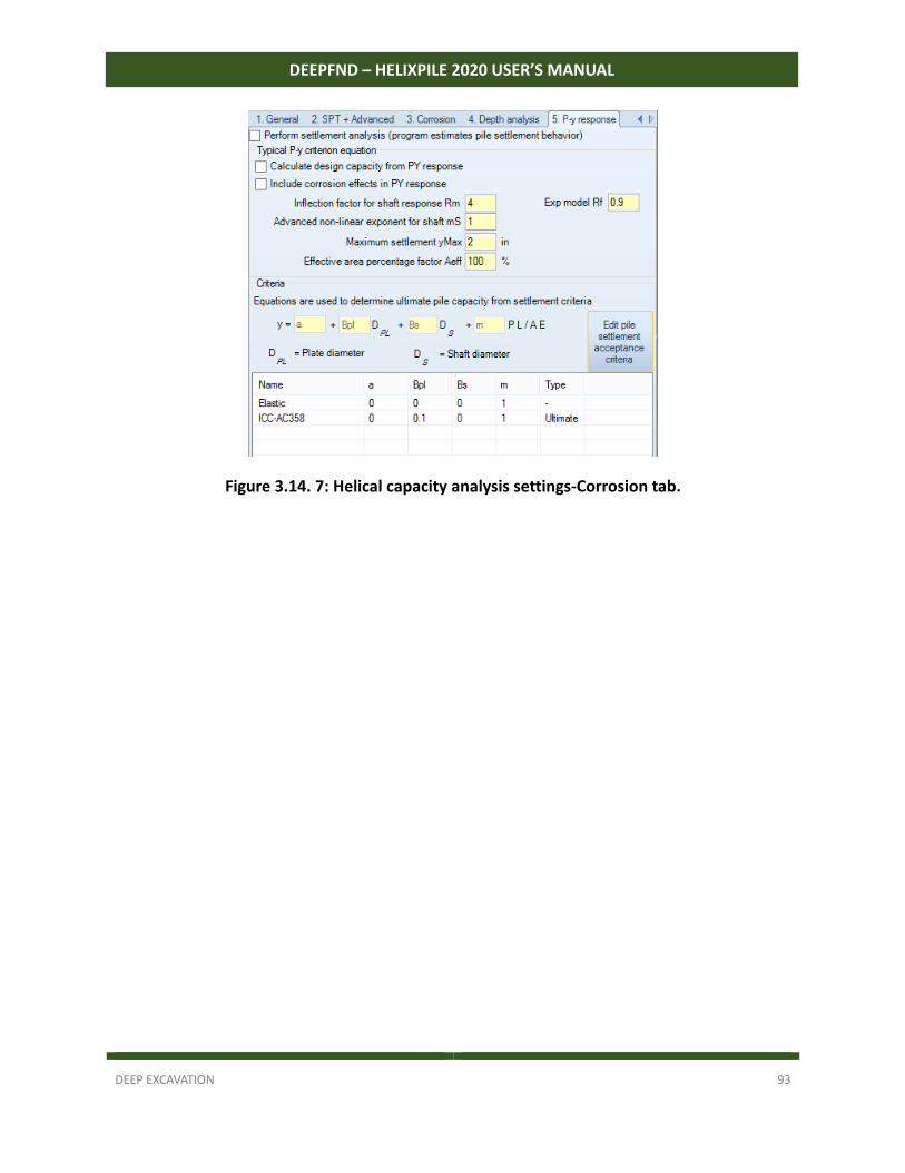
DEEP EXCAVATION 93
DEEPFND – HELIXPILE 2020 USER’S MANUAL
Figure 3.14. 7: Helical capacity analysis settings-Corrosion tab.

DEEP EXCAVATION 94
DEEPFND – HELIXPILE 2020 USER’S MANUAL
PART B: SINGLE PILES – DESIGN AND ANALYSIS
MODEL CREATION – ANALYSIS SETTINGS – RESULTS - EXAMPLES The following sections provide useful information about the use of the software for the design of single piles. We examine the procedures to create a model, define the analysis and perform the model optimization using the calculated results. A series of examples present the use of the software in the design of different pile types.
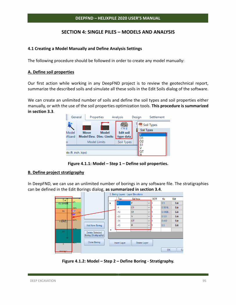
DEEP EXCAVATION 95
DEEPFND – HELIXPILE 2020 USER’S MANUAL
SECTION 4: SINGLE PILES – MODELS AND ANALYSIS
4.1 Creating a Model Manually and Define Analysis Settings
The following procedure should be followed in order to create any model manually: A. Define soil properties Our first action while working in any DeepFND project is to review the geotechnical report, summarize the described soils and simulate all these soils in the Edit Soils dialog of the software. We can create an unlimited number of soils and define the soil types and soil properties either manually, or with the use of the soil properties optimization tools. This procedure is summarized in section 3.3.
Figure 4.1.1: Model – Step 1 – Define soil properties.
B. Define project stratigraphy In DeepFND, we can use an unlimited number of borings in any software file. The stratigraphies can be defined in the Edit Borings dialog, as summarized in section 3.4.
Figure 4.1.2: Model – Step 2 – Define Boring - Stratigraphy.
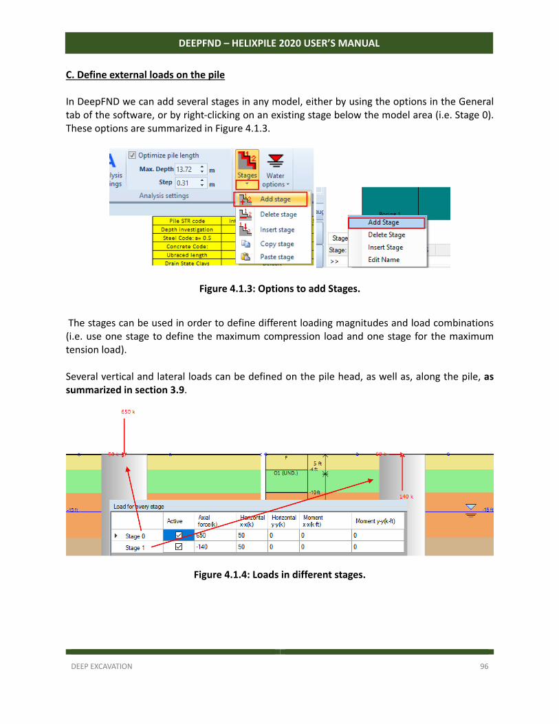
DEEP EXCAVATION 96
DEEPFND – HELIXPILE 2020 USER’S MANUAL
C. Define external loads on the pile In DeepFND we can add several stages in any model, either by using the options in the General tab of the software, or by right‐clicking on an existing stage below the model area (i.e. Stage 0). These options are summarized in Figure 4.1.3.
Figure 4.1.3: Options to add Stages.
The stages can be used in order to define different loading magnitudes and load combinations (i.e. use one stage to define the maximum compression load and one stage for the maximum tension load). Several vertical and lateral loads can be defined on the pile head, as well as, along the pile, as summarized in section 3.9.
Figure 4.1.4: Loads in different stages.
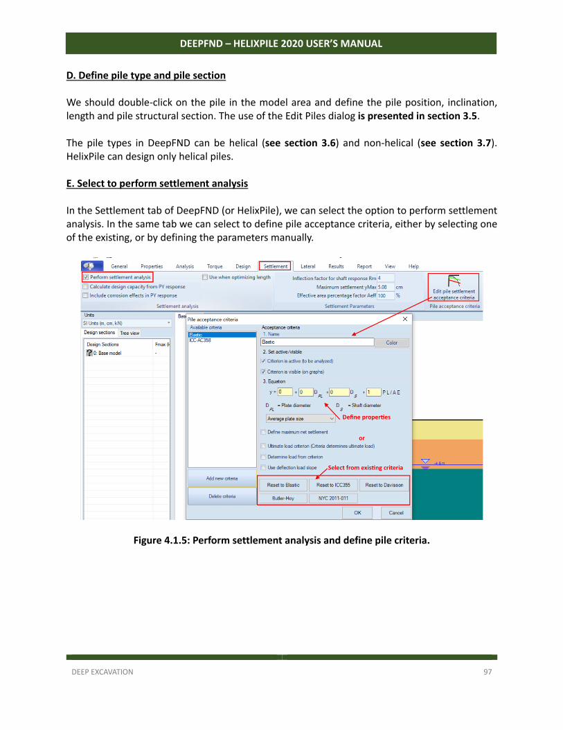
DEEP EXCAVATION 97
DEEPFND – HELIXPILE 2020 USER’S MANUAL
D. Define pile type and pile section We should double‐click on the pile in the model area and define the pile position, inclination, length and pile structural section. The use of the Edit Piles dialog is presented in section 3.5. The pile types in DeepFND can be helical (see section 3.6) and non‐helical (see section 3.7). HelixPile can design only helical piles. E. Select to perform settlement analysis In the Settlement tab of DeepFND (or HelixPile), we can select the option to perform settlement analysis. In the same tab we can select to define pile acceptance criteria, either by selecting one of the existing, or by defining the parameters manually.
Figure 4.1.5: Perform settlement analysis and define pile criteria.
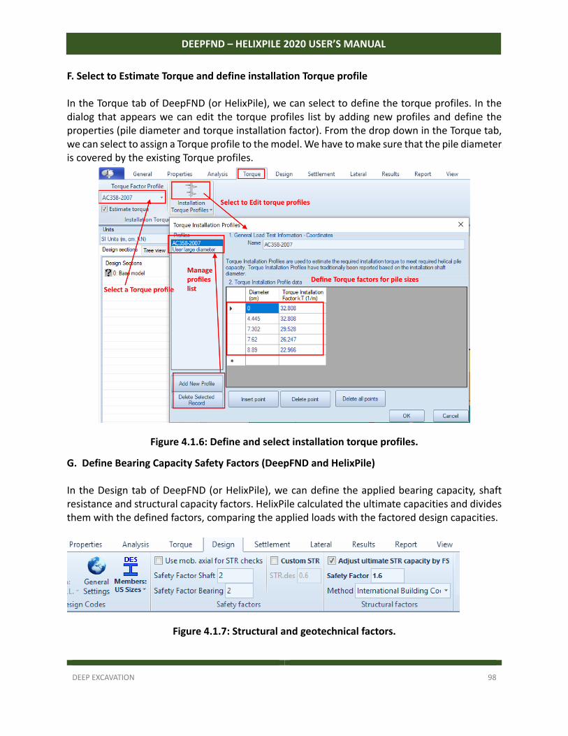
DEEP EXCAVATION 98
DEEPFND – HELIXPILE 2020 USER’S MANUAL
F. Select to Estimate Torque and define installation Torque profile In the Torque tab of DeepFND (or HelixPile), we can select to define the torque profiles. In the dialog that appears we can edit the torque profiles list by adding new profiles and define the properties (pile diameter and torque installation factor). From the drop down in the Torque tab, we can select to assign a Torque profile to the model. We have to make sure that the pile diameter is covered by the existing Torque profiles.
Figure 4.1.6: Define and select installation torque profiles.
G. Define Bearing Capacity Safety Factors (DeepFND and HelixPile) In the Design tab of DeepFND (or HelixPile), we can define the applied bearing capacity, shaft resistance and structural capacity factors. HelixPile calculated the ultimate capacities and divides them with the defined factors, comparing the applied loads with the factored design capacities.
Figure 4.1.7: Structural and geotechnical factors.
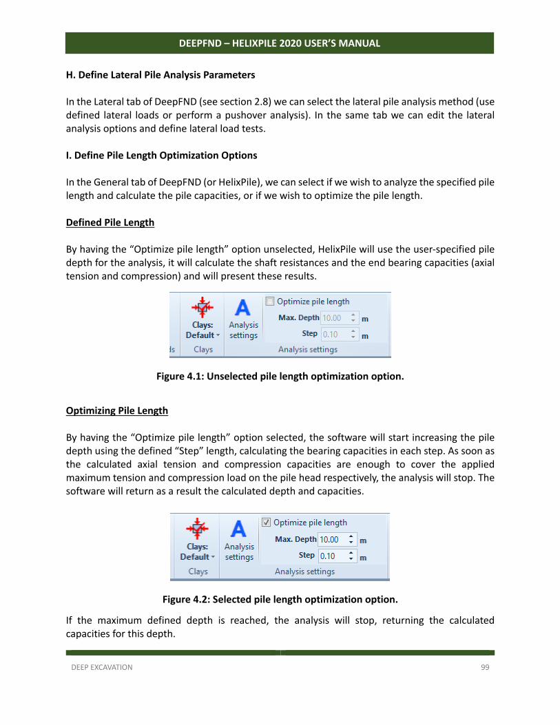
DEEP EXCAVATION 99
DEEPFND – HELIXPILE 2020 USER’S MANUAL
H. Define Lateral Pile Analysis Parameters In the Lateral tab of DeepFND (see section 2.8) we can select the lateral pile analysis method (use defined lateral loads or perform a pushover analysis). In the same tab we can edit the lateral analysis options and define lateral load tests. I. Define Pile Length Optimization Options In the General tab of DeepFND (or HelixPile), we can select if we wish to analyze the specified pile length and calculate the pile capacities, or if we wish to optimize the pile length. Defined Pile Length By having the “Optimize pile length” option unselected, HelixPile will use the user‐specified pile depth for the analysis, it will calculate the shaft resistances and the end bearing capacities (axial tension and compression) and will present these results.
Figure 4.1: Unselected pile length optimization option.
Optimizing Pile Length By having the “Optimize pile length” option selected, the software will start increasing the pile depth using the defined “Step” length, calculating the bearing capacities in each step. As soon as the calculated axial tension and compression capacities are enough to cover the applied maximum tension and compression load on the pile head respectively, the analysis will stop. The software will return as a result the calculated depth and capacities.
Figure 4.2: Selected pile length optimization option.
If the maximum defined depth is reached, the analysis will stop, returning the calculated capacities for this depth.
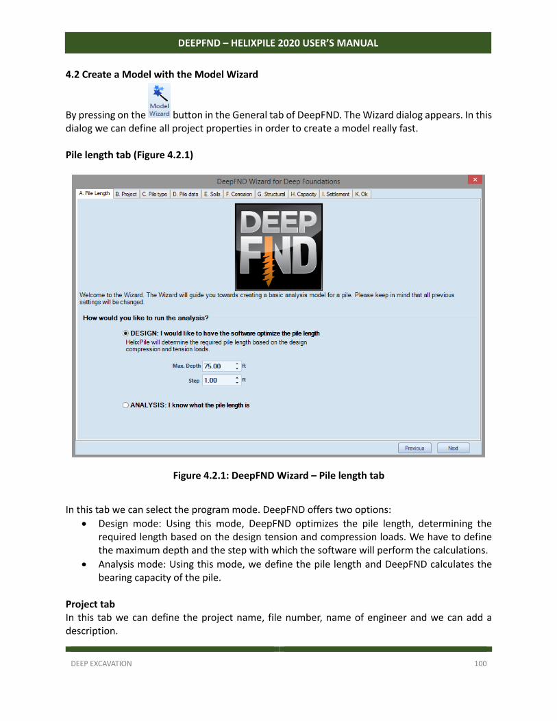
DEEP EXCAVATION 100
DEEPFND – HELIXPILE 2020 USER’S MANUAL
4.2 Create a Model with the Model Wizard
By pressing on the button in the General tab of DeepFND. The Wizard dialog appears. In this dialog we can define all project properties in order to create a model really fast. Pile length tab (Figure 4.2.1)
Figure 4.2.1: DeepFND Wizard – Pile length tab
In this tab we can select the program mode. DeepFND offers two options:
Design mode: Using this mode, DeepFND optimizes the pile length, determining the required length based on the design tension and compression loads. We have to define the maximum depth and the step with which the software will perform the calculations.
Analysis mode: Using this mode, we define the pile length and DeepFND calculates the bearing capacity of the pile.
Project tab In this tab we can define the project name, file number, name of engineer and we can add a description.
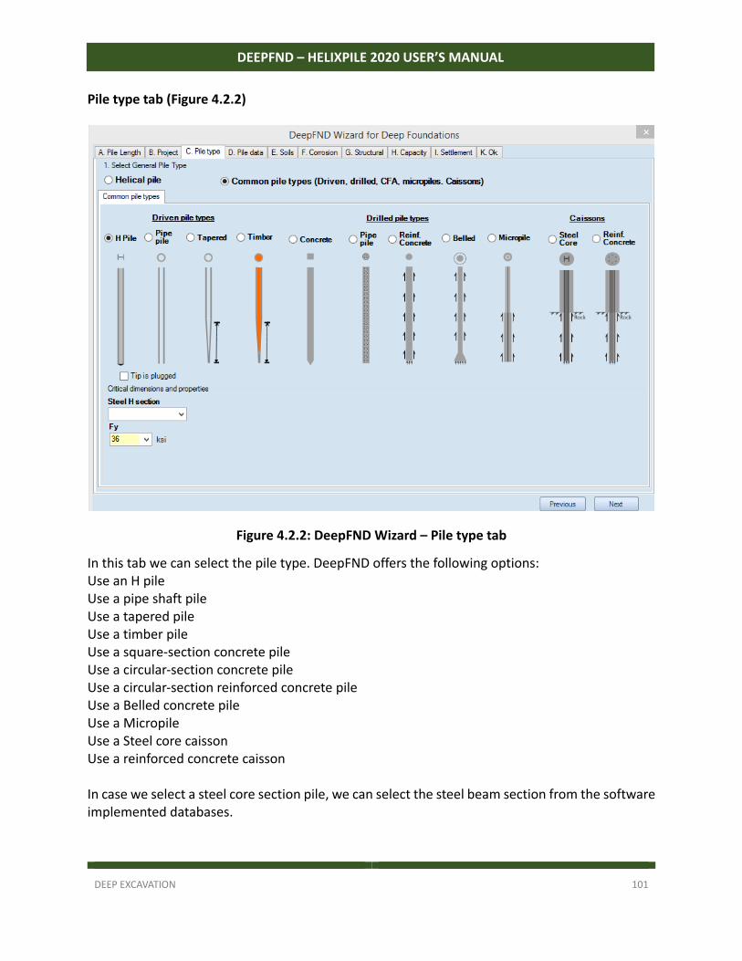
DEEP EXCAVATION 101
DEEPFND – HELIXPILE 2020 USER’S MANUAL
Pile type tab (Figure 4.2.2)
Figure 4.2.2: DeepFND Wizard – Pile type tab
In this tab we can select the pile type. DeepFND offers the following options: Use an H pile Use a pipe shaft pile Use a tapered pile Use a timber pile Use a square‐section concrete pile Use a circular‐section concrete pile Use a circular‐section reinforced concrete pile Use a Belled concrete pile Use a Micropile Use a Steel core caisson Use a reinforced concrete caisson In case we select a steel core section pile, we can select the steel beam section from the software implemented databases.
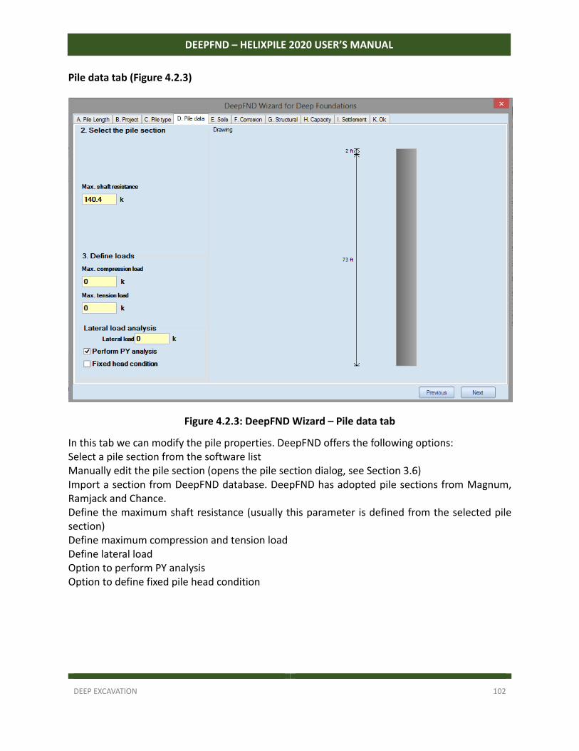
DEEP EXCAVATION 102
DEEPFND – HELIXPILE 2020 USER’S MANUAL
Pile data tab (Figure 4.2.3)
Figure 4.2.3: DeepFND Wizard – Pile data tab
In this tab we can modify the pile properties. DeepFND offers the following options: Select a pile section from the software list Manually edit the pile section (opens the pile section dialog, see Section 3.6) Import a section from DeepFND database. DeepFND has adopted pile sections from Magnum, Ramjack and Chance. Define the maximum shaft resistance (usually this parameter is defined from the selected pile section) Define maximum compression and tension load Define lateral load Option to perform PY analysis Option to define fixed pile head condition
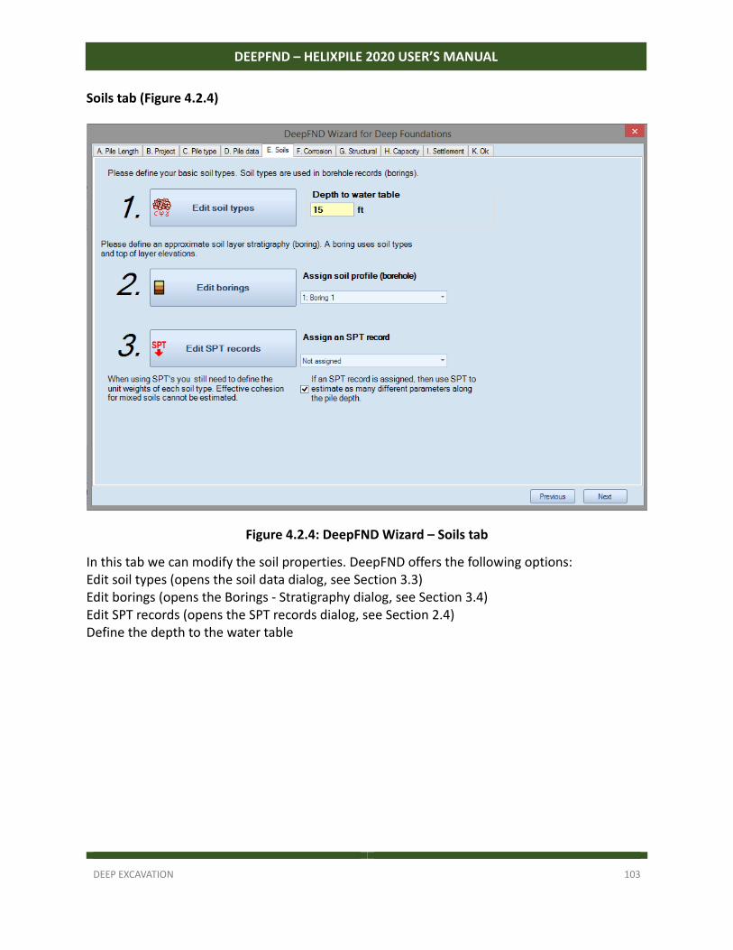
DEEP EXCAVATION 103
DEEPFND – HELIXPILE 2020 USER’S MANUAL
Soils tab (Figure 4.2.4)
Figure 4.2.4: DeepFND Wizard – Soils tab
In this tab we can modify the soil properties. DeepFND offers the following options: Edit soil types (opens the soil data dialog, see Section 3.3) Edit borings (opens the Borings ‐ Stratigraphy dialog, see Section 3.4) Edit SPT records (opens the SPT records dialog, see Section 2.4) Define the depth to the water table
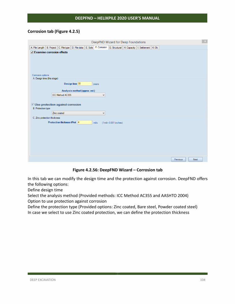
DEEP EXCAVATION 104
DEEPFND – HELIXPILE 2020 USER’S MANUAL
Corrosion tab (Figure 4.2.5)
Figure 4.2.56: DeepFND Wizard – Corrosion tab
In this tab we can modify the design time and the protection against corrosion. DeepFND offers the following options: Define design time Select the analysis method (Provided methods: ICC Method AC355 and AASHTO 2004) Option to use protection against corrosion Define the protection type (Provided options: Zinc coated, Bare steel, Powder coated steel) In case we select to use Zinc coated protection, we can define the protection thickness
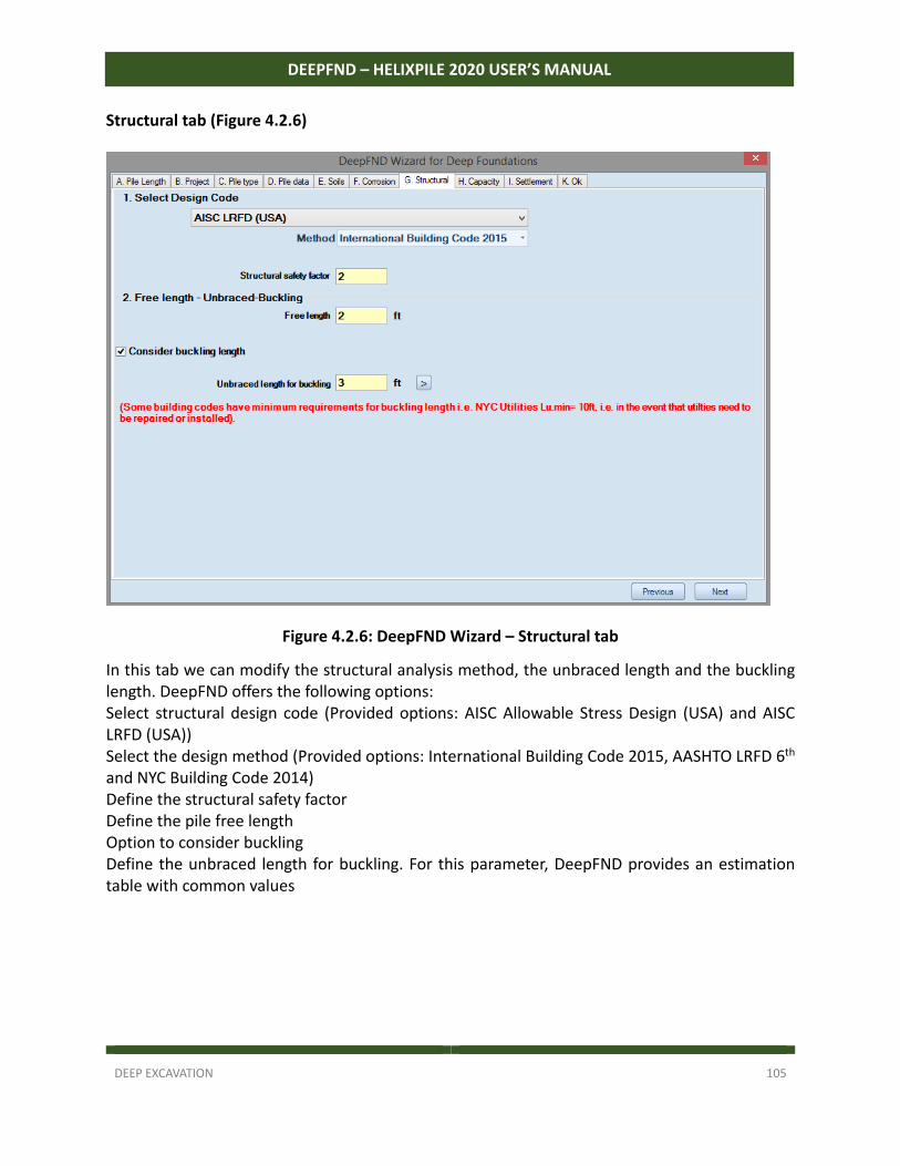
DEEP EXCAVATION 105
DEEPFND – HELIXPILE 2020 USER’S MANUAL
Structural tab (Figure 4.2.6)
Figure 4.2.6: DeepFND Wizard – Structural tab
In this tab we can modify the structural analysis method, the unbraced length and the buckling length. DeepFND offers the following options: Select structural design code (Provided options: AISC Allowable Stress Design (USA) and AISC LRFD (USA)) Select the design method (Provided options: International Building Code 2015, AASHTO LRFD 6th and NYC Building Code 2014) Define the structural safety factor Define the pile free length Option to consider buckling Define the unbraced length for buckling. For this parameter, DeepFND provides an estimation table with common values
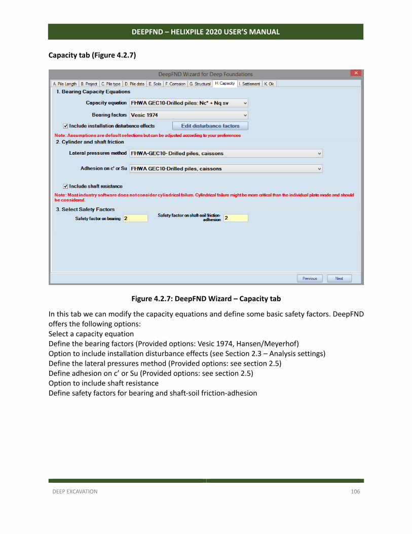
DEEP EXCAVATION 106
DEEPFND – HELIXPILE 2020 USER’S MANUAL
Capacity tab (Figure 4.2.7)
Figure 4.2.7: DeepFND Wizard – Capacity tab
In this tab we can modify the capacity equations and define some basic safety factors. DeepFND offers the following options: Select a capacity equation Define the bearing factors (Provided options: Vesic 1974, Hansen/Meyerhof) Option to include installation disturbance effects (see Section 2.3 – Analysis settings) Define the lateral pressures method (Provided options: see section 2.5) Define adhesion on c’ or Su (Provided options: see section 2.5) Option to include shaft resistance Define safety factors for bearing and shaft‐soil friction‐adhesion
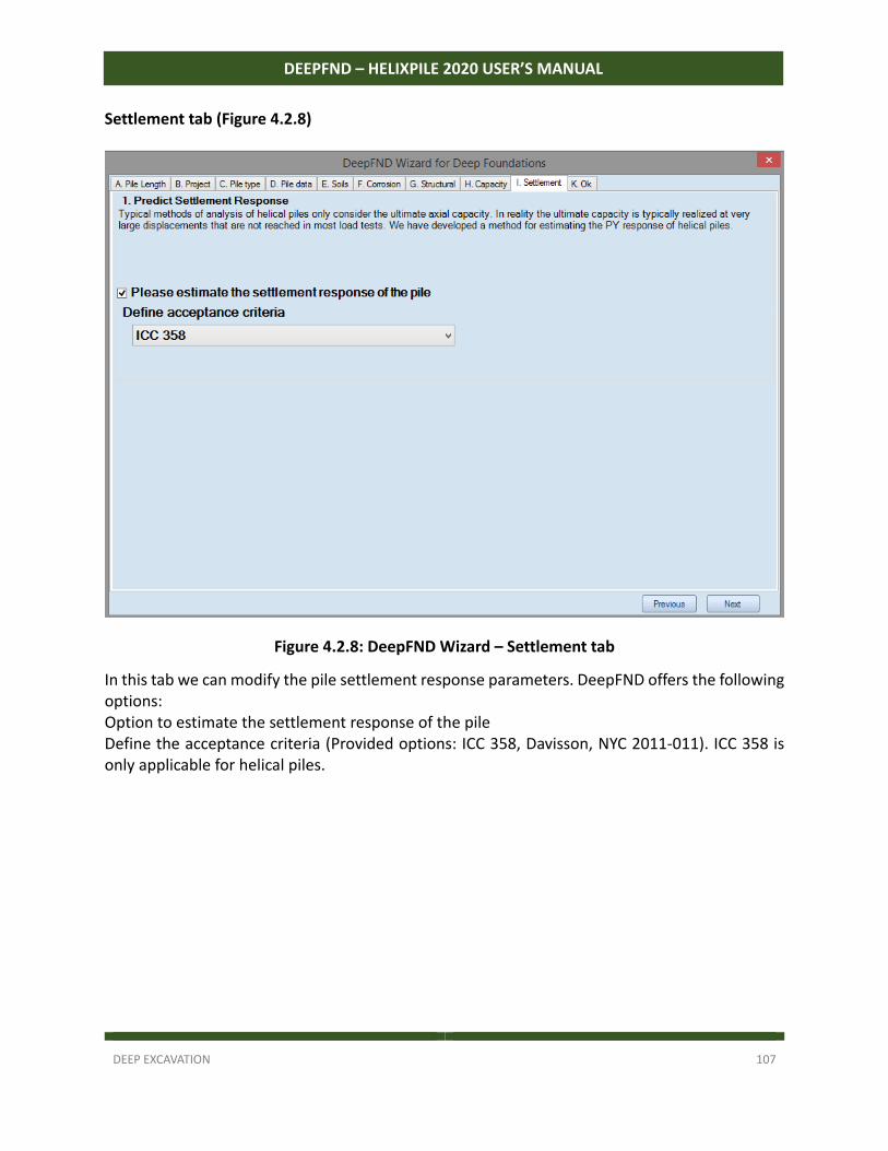
DEEP EXCAVATION 107
DEEPFND – HELIXPILE 2020 USER’S MANUAL
Settlement tab (Figure 4.2.8)
Figure 4.2.8: DeepFND Wizard – Settlement tab
In this tab we can modify the pile settlement response parameters. DeepFND offers the following options: Option to estimate the settlement response of the pile Define the acceptance criteria (Provided options: ICC 358, Davisson, NYC 2011‐011). ICC 358 is only applicable for helical piles.
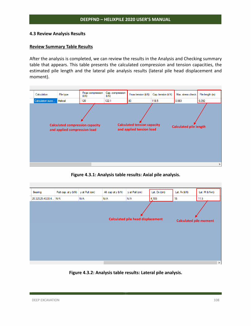
DEEP EXCAVATION 108
DEEPFND – HELIXPILE 2020 USER’S MANUAL
4.3 Review Analysis Results
Review Summary Table Results After the analysis is completed, we can review the results in the Analysis and Checking summary table that appears. This table presents the calculated compression and tension capacities, the estimated pile length and the lateral pile analysis results (lateral pile head displacement and moment).
Figure 4.3.1: Analysis table results: Axial pile analysis.
Figure 4.3.2: Analysis table results: Lateral pile analysis.
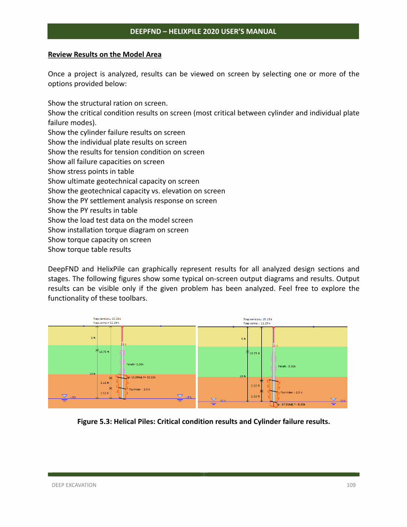
DEEP EXCAVATION 109
DEEPFND – HELIXPILE 2020 USER’S MANUAL
Review Results on the Model Area Once a project is analyzed, results can be viewed on screen by selecting one or more of the options provided below: Show the structural ration on screen. Show the critical condition results on screen (most critical between cylinder and individual plate failure modes). Show the cylinder failure results on screen Show the individual plate results on screen Show the results for tension condition on screen Show all failure capacities on screen Show stress points in table Show ultimate geotechnical capacity on screen Show the geotechnical capacity vs. elevation on screen Show the PY settlement analysis response on screen Show the PY results in table Show the load test data on the model screen Show installation torque diagram on screen Show torque capacity on screen Show torque table results DeepFND and HelixPile can graphically represent results for all analyzed design sections and stages. The following figures show some typical on‐screen output diagrams and results. Output results can be visible only if the given problem has been analyzed. Feel free to explore the functionality of these toolbars.
Figure 5.3: Helical Piles: Critical condition results and Cylinder failure results.
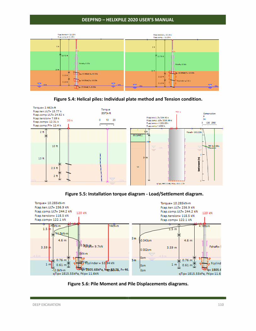
DEEP EXCAVATION 110
DEEPFND – HELIXPILE 2020 USER’S MANUAL
Figure 5.4: Helical piles: Individual plate method and Tension condition.
Figure 5.5: Installation torque diagram - Load/Settlement diagram.
Figure 5.6: Pile Moment and Pile Displacements diagrams.
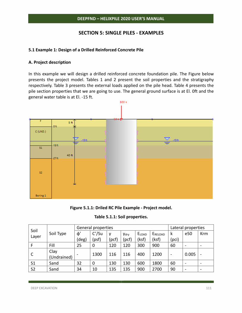
DEEP EXCAVATION 111
DEEPFND – HELIXPILE 2020 USER’S MANUAL
SECTION 5: SINGLE PILES - EXAMPLES
5.1 Example 1: Design of a Drilled Reinforced Concrete Pile
A. Project description In this example we will design a drilled reinforced concrete foundation pile. The Figure below presents the project model. Tables 1 and 2 present the soil properties and the stratigraphy respectively. Table 3 presents the external loads applied on the pile head. Table 4 presents the pile section properties that we are going to use. The general ground surface is at El. 0ft and the general water table is at El. ‐15 ft.
Figure 5.1.1: Driled RC Pile Example - Project model.
Table 5.1.1: Soil properties.
Soil Layer
Soil Type General properties Lateral properties
φ’ (deg)
C’/Su (psf)
γ (pcf)
γdry (pcf)
ELOAD (ksf)
ERELOAD (ksf)
k (pci)
e50 Krm
F Fill 25 0 120 120 300 900 60 ‐ ‐
C Clay (Undrained)
‐ 1300 116 116 400 1200 ‐ 0.005 ‐
S1 Sand 32 0 130 130 600 1800 60 ‐ ‐
S2 Sand 34 10 135 135 900 2700 90 ‐ ‐
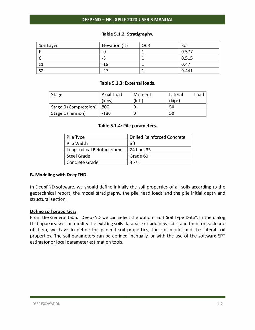
DEEP EXCAVATION 112
DEEPFND – HELIXPILE 2020 USER’S MANUAL
Table 5.1.2: Stratigraphy.
Soil Layer Elevation (ft) OCR Ko
F ‐0 1 0.577
C ‐5 1 0.515
S1 ‐18 1 0.47
S2 ‐27 1 0.441
Table 5.1.3: External loads.
Stage Axial Load (kips)
Moment (k‐ft)
Lateral Load (kips)
Stage 0 (Compression) 800 0 50
Stage 1 (Tension) ‐180 0 50
Table 5.1.4: Pile parameters.
Pile Type Drilled Reinforced Concrete
Pile Width 5ft
Longitudinal Reinforcement 24 bars #5
Steel Grade Grade 60
Concrete Grade 3 ksi
B. Modeling with DeepFND In DeepFND software, we should define initially the soil properties of all soils according to the geotechnical report, the model stratigraphy, the pile head loads and the pile initial depth and structural section. Define soil properties: From the General tab of DeepFND we can select the option “Edit Soil Type Data”. In the dialog that appears, we can modify the existing soils database or add new soils, and then for each one of them, we have to define the general soil properties, the soil model and the lateral soil properties. The soil parameters can be defined manually, or with the use of the software SPT estimator or local parameter estimation tools.
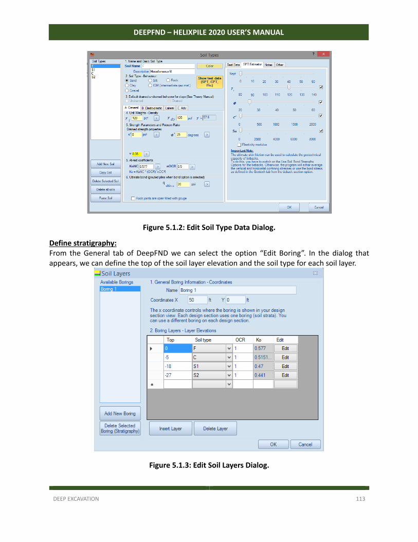
DEEP EXCAVATION 113
DEEPFND – HELIXPILE 2020 USER’S MANUAL
Figure 5.1.2: Edit Soil Type Data Dialog.
Define stratigraphy: From the General tab of DeepFND we can select the option “Edit Boring”. In the dialog that appears, we can define the top of the soil layer elevation and the soil type for each soil layer.
Figure 5.1.3: Edit Soil Layers Dialog.
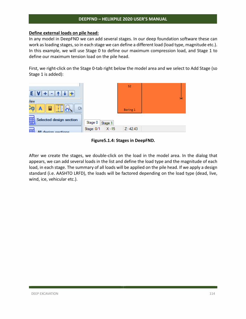
DEEP EXCAVATION 114
DEEPFND – HELIXPILE 2020 USER’S MANUAL
Define external loads on pile head: In any model in DeepFND we can add several stages. In our deep foundation software these can work as loading stages, so in each stage we can define a different load (load type, magnitude etc.). In this example, we will use Stage 0 to define our maximum compression load, and Stage 1 to define our maximum tension load on the pile head. First, we right‐click on the Stage 0‐tab right below the model area and we select to Add Stage (so Stage 1 is added):
Figure5.1.4: Stages in DeepFND.
After we create the stages, we double‐click on the load in the model area. In the dialog that appears, we can add several loads in the list and define the load type and the magnitude of each load, in each stage. The summary of all loads will be applied on the pile head. If we apply a design standard (i.e. AASHTO LRFD), the loads will be factored depending on the load type (dead, live, wind, ice, vehicular etc.).
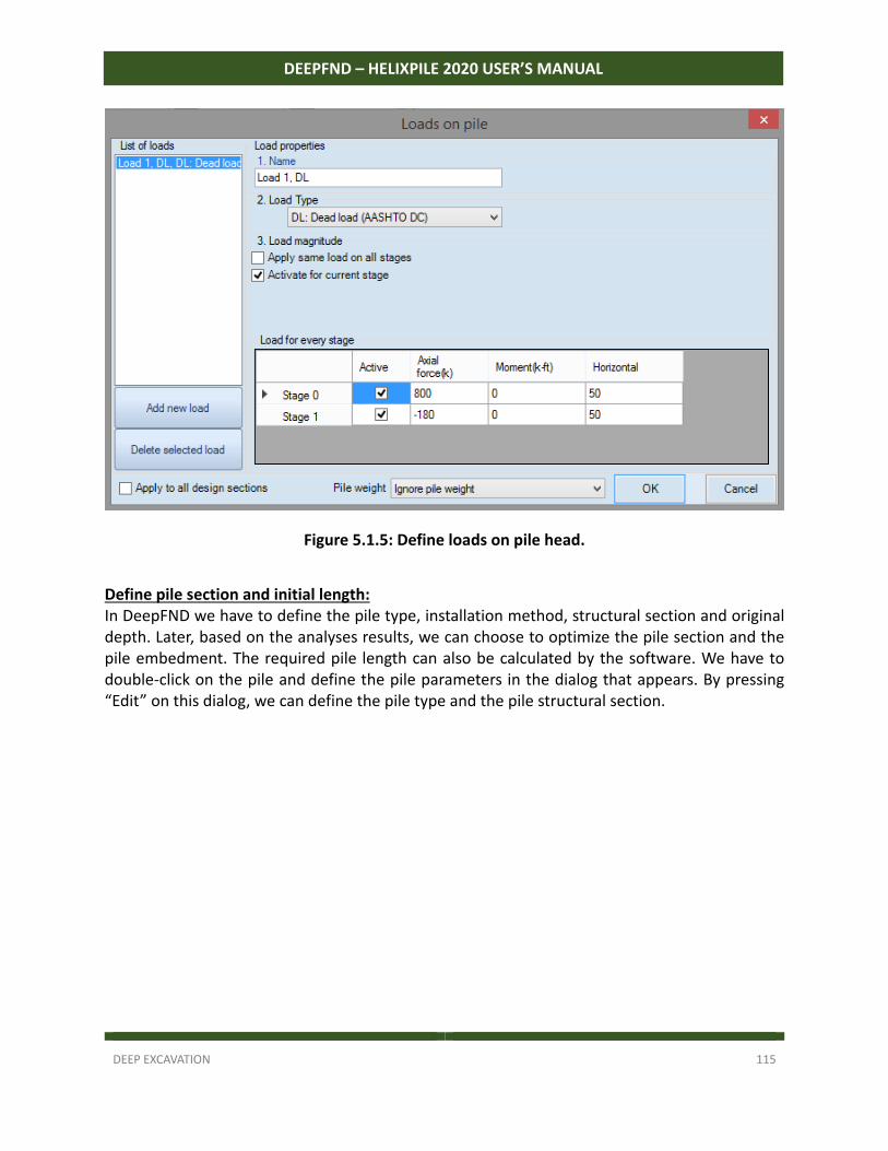
DEEP EXCAVATION 115
DEEPFND – HELIXPILE 2020 USER’S MANUAL
Figure 5.1.5: Define loads on pile head.
Define pile section and initial length: In DeepFND we have to define the pile type, installation method, structural section and original depth. Later, based on the analyses results, we can choose to optimize the pile section and the pile embedment. The required pile length can also be calculated by the software. We have to double‐click on the pile and define the pile parameters in the dialog that appears. By pressing “Edit” on this dialog, we can define the pile type and the pile structural section.
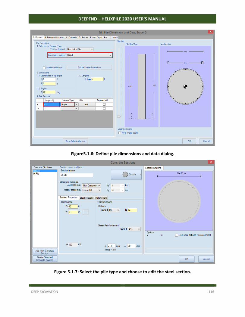
DEEP EXCAVATION 116
DEEPFND – HELIXPILE 2020 USER’S MANUAL
Figure5.1.6: Define pile dimensions and data dialog.
Figure 5.1.7: Select the pile type and choose to edit the steel section.
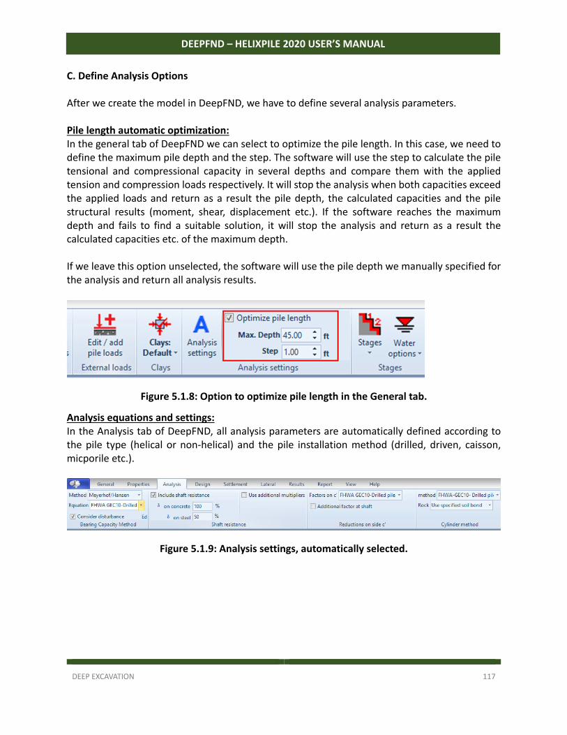
DEEP EXCAVATION 117
DEEPFND – HELIXPILE 2020 USER’S MANUAL
C. Define Analysis Options After we create the model in DeepFND, we have to define several analysis parameters. Pile length automatic optimization: In the general tab of DeepFND we can select to optimize the pile length. In this case, we need to define the maximum pile depth and the step. The software will use the step to calculate the pile tensional and compressional capacity in several depths and compare them with the applied tension and compression loads respectively. It will stop the analysis when both capacities exceed the applied loads and return as a result the pile depth, the calculated capacities and the pile structural results (moment, shear, displacement etc.). If the software reaches the maximum depth and fails to find a suitable solution, it will stop the analysis and return as a result the calculated capacities etc. of the maximum depth. If we leave this option unselected, the software will use the pile depth we manually specified for the analysis and return all analysis results.
Figure 5.1.8: Option to optimize pile length in the General tab.
Analysis equations and settings: In the Analysis tab of DeepFND, all analysis parameters are automatically defined according to the pile type (helical or non‐helical) and the pile installation method (drilled, driven, caisson, micporile etc.).
Figure 5.1.9: Analysis settings, automatically selected.
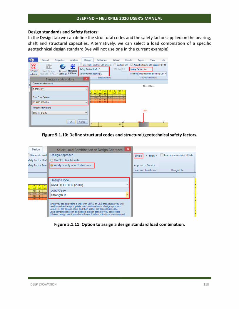
DEEP EXCAVATION 118
DEEPFND – HELIXPILE 2020 USER’S MANUAL
Design standards and Safety factors: In the Design tab we can define the structural codes and the safety factors applied on the bearing, shaft and structural capacities. Alternatively, we can select a load combination of a specific geotechnical design standard (we will not use one in the current example).
Figure 5.1.10: Define structural codes and structural/geotechnical safety factors.
Figure 5.1.11: Option to assign a design standard load combination.
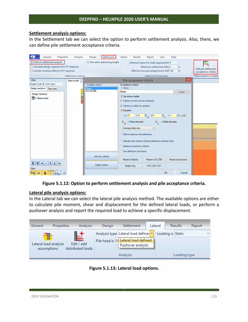
DEEP EXCAVATION 119
DEEPFND – HELIXPILE 2020 USER’S MANUAL
Settlement analysis options: In the Settlement tab we can select the option to perform settlement analysis. Also, there, we can define pile settlement acceptance criteria.
Figure 5.1.12: Option to perform settlement analysis and pile acceptance criteria.
Lateral pile analysis options: In the Lateral tab we can select the lateral pile analysis method. The available options are either to calculate pile moment, shear and displacement for the defined lateral loads, or perform a pushover analysis and report the required load to achieve a specific displacement.
Figure 5.1.13: Lateral load options.
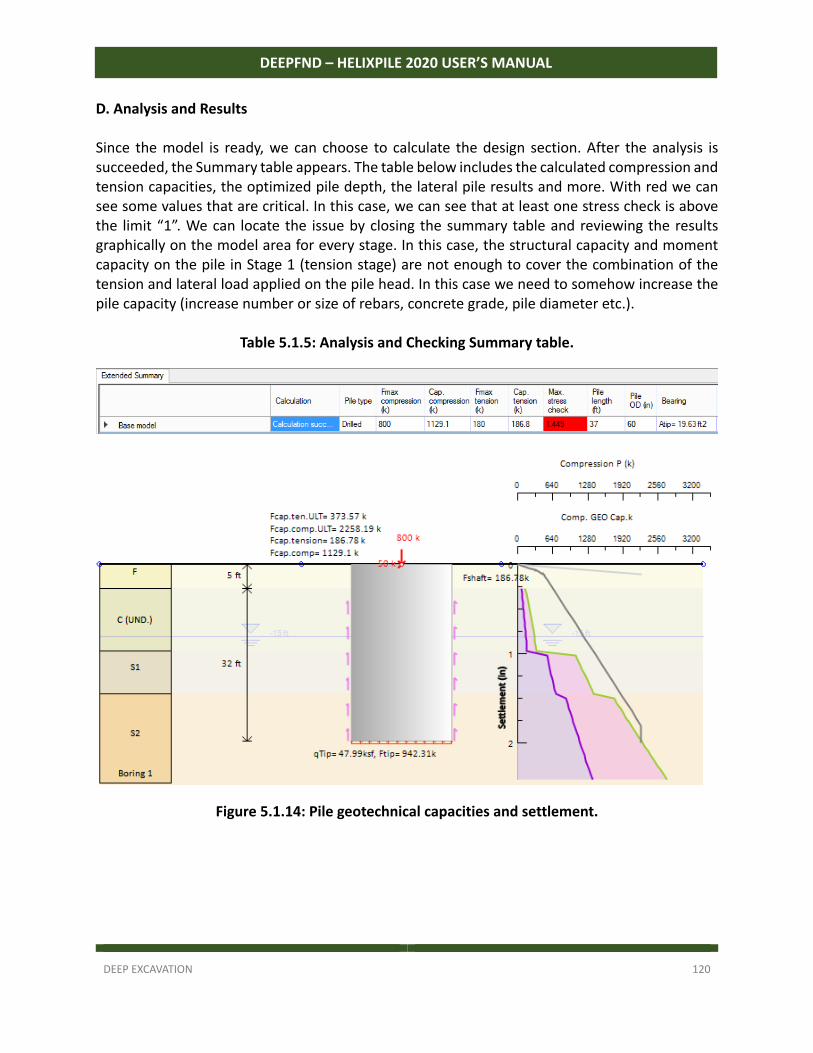
DEEP EXCAVATION 120
DEEPFND – HELIXPILE 2020 USER’S MANUAL
D. Analysis and Results Since the model is ready, we can choose to calculate the design section. After the analysis is succeeded, the Summary table appears. The table below includes the calculated compression and tension capacities, the optimized pile depth, the lateral pile results and more. With red we can see some values that are critical. In this case, we can see that at least one stress check is above the limit “1”. We can locate the issue by closing the summary table and reviewing the results graphically on the model area for every stage. In this case, the structural capacity and moment capacity on the pile in Stage 1 (tension stage) are not enough to cover the combination of the tension and lateral load applied on the pile head. In this case we need to somehow increase the pile capacity (increase number or size of rebars, concrete grade, pile diameter etc.).
Table 5.1.5: Analysis and Checking Summary table.
Figure 5.1.14: Pile geotechnical capacities and settlement.

DEEP EXCAVATION 121
DEEPFND – HELIXPILE 2020 USER’S MANUAL
Figure 5.1.15: Pile displacement, shear and moment diagrams – Stage 0.
Figure 5.1.16: Pile displacement, shear and moment diagrams – Stage 1.
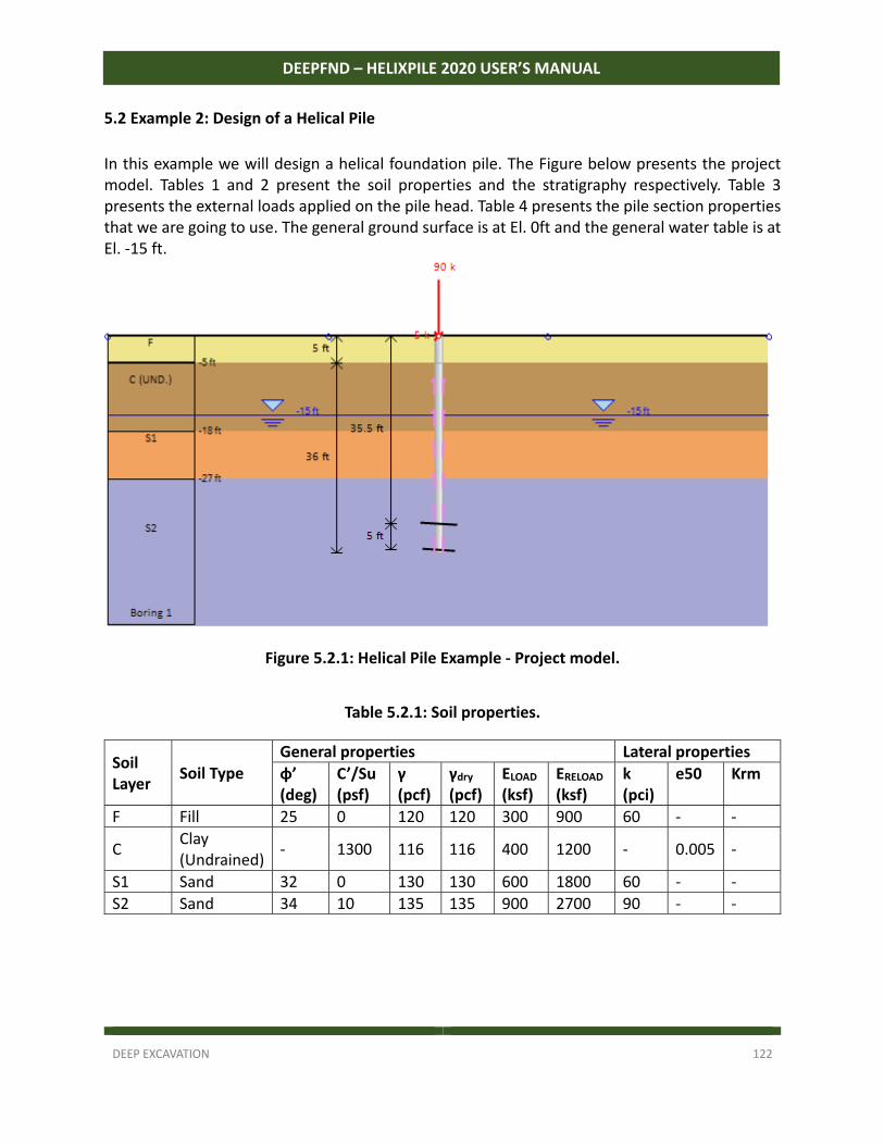
DEEP EXCAVATION 122
DEEPFND – HELIXPILE 2020 USER’S MANUAL
5.2 Example 2: Design of a Helical Pile
In this example we will design a helical foundation pile. The Figure below presents the project model. Tables 1 and 2 present the soil properties and the stratigraphy respectively. Table 3 presents the external loads applied on the pile head. Table 4 presents the pile section properties that we are going to use. The general ground surface is at El. 0ft and the general water table is at El. ‐15 ft.
Figure 5.2.1: Helical Pile Example - Project model.
Table 5.2.1: Soil properties.
Soil Layer
Soil Type General properties Lateral properties
φ’ (deg)
C’/Su (psf)
γ (pcf)
γdry (pcf)
ELOAD
(ksf) ERELOAD
(ksf) k (pci)
e50 Krm
F Fill 25 0 120 120 300 900 60 ‐ ‐
C Clay (Undrained)
‐ 1300 116 116 400 1200 ‐ 0.005 ‐
S1 Sand 32 0 130 130 600 1800 60 ‐ ‐
S2 Sand 34 10 135 135 900 2700 90 ‐ ‐
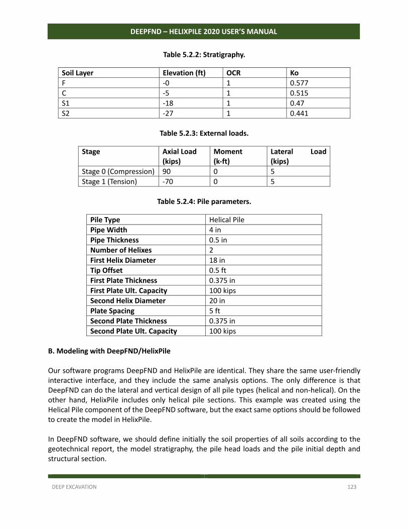
DEEP EXCAVATION 123
DEEPFND – HELIXPILE 2020 USER’S MANUAL
Table 5.2.2: Stratigraphy.
Soil Layer Elevation (ft) OCR Ko
F ‐0 1 0.577
C ‐5 1 0.515
S1 ‐18 1 0.47
S2 ‐27 1 0.441
Table 5.2.3: External loads.
Stage Axial Load (kips)
Moment (k-ft)
Lateral Load (kips)
Stage 0 (Compression) 90 0 5
Stage 1 (Tension) ‐70 0 5
Table 5.2.4: Pile parameters.
Pile Type Helical Pile
Pipe Width 4 in
Pipe Thickness 0.5 in
Number of Helixes 2
First Helix Diameter 18 in
Tip Offset 0.5 ft
First Plate Thickness 0.375 in
First Plate Ult. Capacity 100 kips
Second Helix Diameter 20 in
Plate Spacing 5 ft
Second Plate Thickness 0.375 in
Second Plate Ult. Capacity 100 kips
B. Modeling with DeepFND/HelixPile Our software programs DeepFND and HelixPile are identical. They share the same user‐friendly interactive interface, and they include the same analysis options. The only difference is that DeepFND can do the lateral and vertical design of all pile types (helical and non‐helical). On the other hand, HelixPile includes only helical pile sections. This example was created using the Helical Pile component of the DeepFND software, but the exact same options should be followed to create the model in HelixPile. In DeepFND software, we should define initially the soil properties of all soils according to the geotechnical report, the model stratigraphy, the pile head loads and the pile initial depth and structural section.
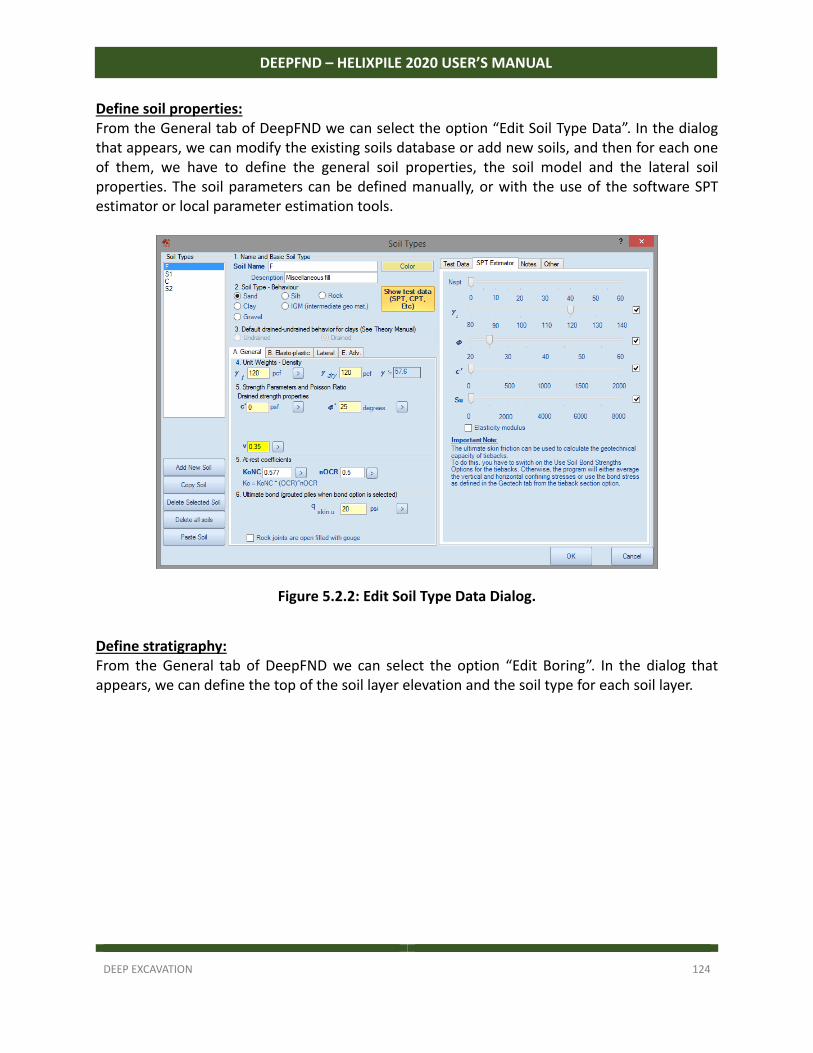
DEEP EXCAVATION 124
DEEPFND – HELIXPILE 2020 USER’S MANUAL
Define soil properties: From the General tab of DeepFND we can select the option “Edit Soil Type Data”. In the dialog that appears, we can modify the existing soils database or add new soils, and then for each one of them, we have to define the general soil properties, the soil model and the lateral soil properties. The soil parameters can be defined manually, or with the use of the software SPT estimator or local parameter estimation tools.
Figure 5.2.2: Edit Soil Type Data Dialog.
Define stratigraphy: From the General tab of DeepFND we can select the option “Edit Boring”. In the dialog that appears, we can define the top of the soil layer elevation and the soil type for each soil layer.
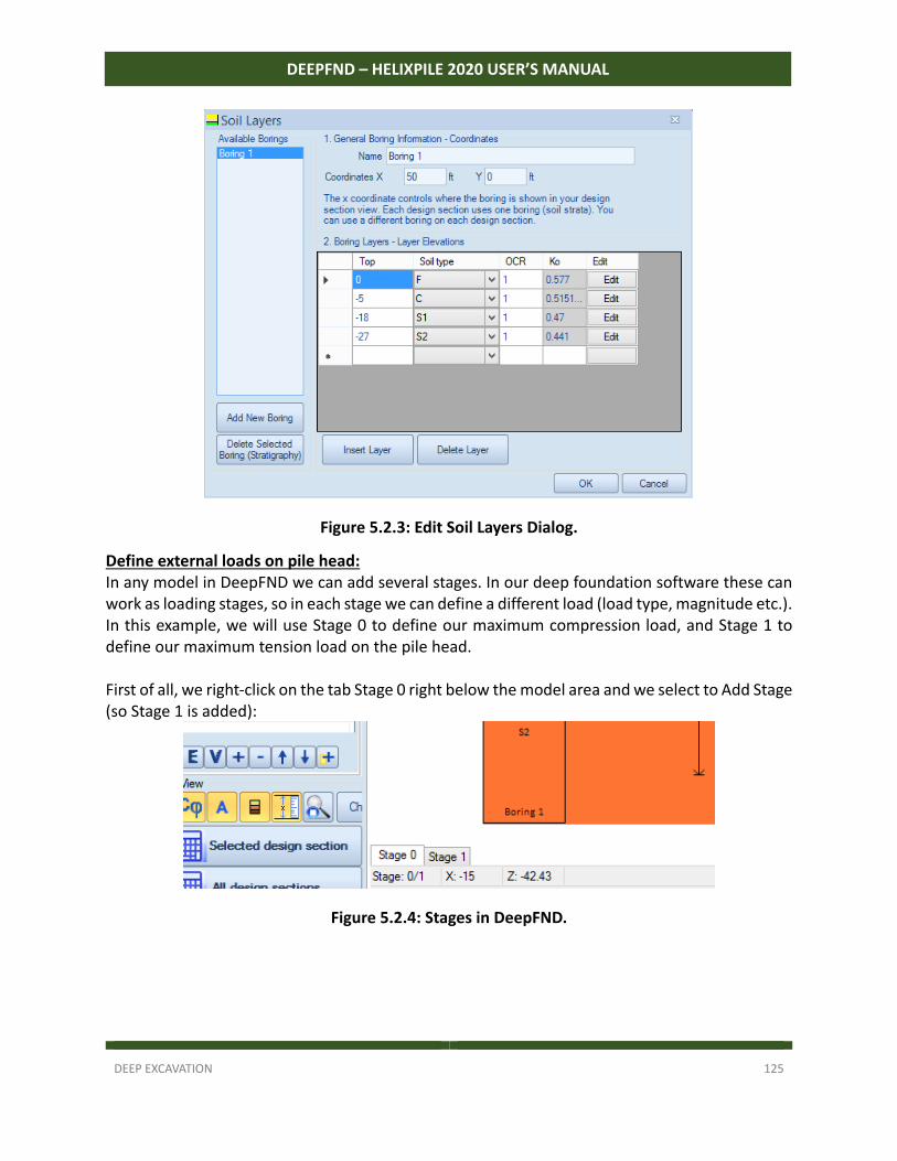
DEEP EXCAVATION 125
DEEPFND – HELIXPILE 2020 USER’S MANUAL
Figure 5.2.3: Edit Soil Layers Dialog.
Define external loads on pile head: In any model in DeepFND we can add several stages. In our deep foundation software these can work as loading stages, so in each stage we can define a different load (load type, magnitude etc.). In this example, we will use Stage 0 to define our maximum compression load, and Stage 1 to define our maximum tension load on the pile head. First of all, we right‐click on the tab Stage 0 right below the model area and we select to Add Stage (so Stage 1 is added):
Figure 5.2.4: Stages in DeepFND.
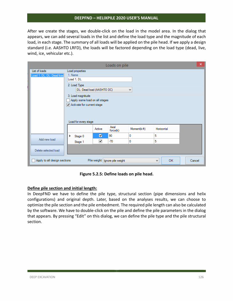
DEEP EXCAVATION 126
DEEPFND – HELIXPILE 2020 USER’S MANUAL
After we create the stages, we double‐click on the load in the model area. In the dialog that appears, we can add several loads in the list and define the load type and the magnitude of each load, in each stage. The summary of all loads will be applied on the pile head. If we apply a design standard (i.e. AASHTO LRFD), the loads will be factored depending on the load type (dead, live, wind, ice, vehicular etc.).
Figure 5.2.5: Define loads on pile head.
Define pile section and initial length: In DeepFND we have to define the pile type, structural section (pipe dimensions and helix configurations) and original depth. Later, based on the analyses results, we can choose to optimize the pile section and the pile embedment. The required pile length can also be calculated by the software. We have to double‐click on the pile and define the pile parameters in the dialog that appears. By pressing “Edit” on this dialog, we can define the pile type and the pile structural section.
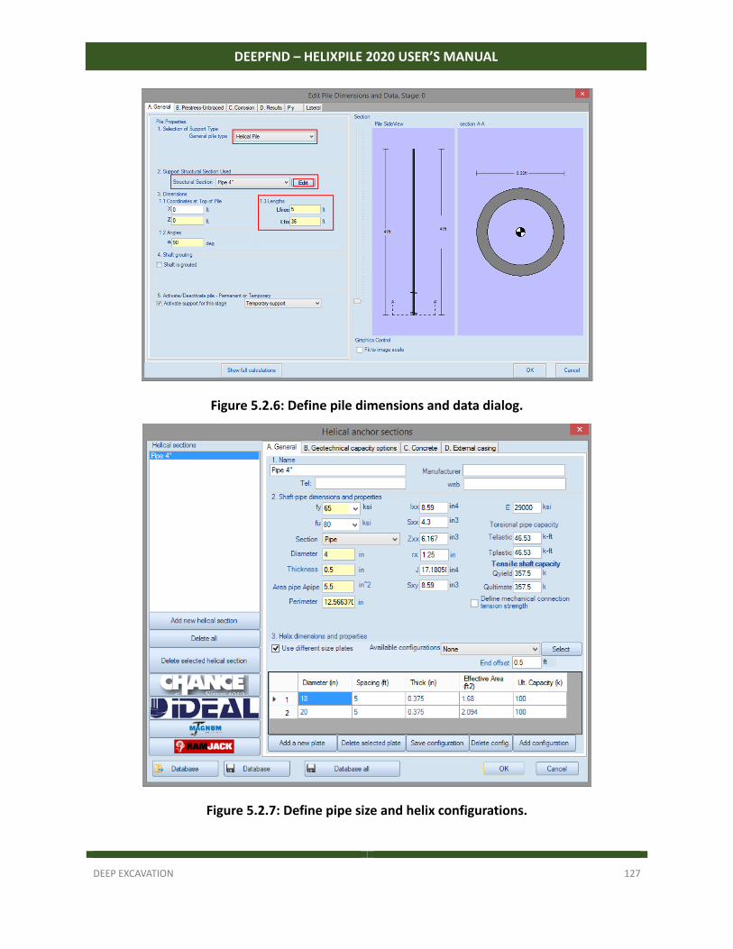
DEEP EXCAVATION 127
DEEPFND – HELIXPILE 2020 USER’S MANUAL
Figure 5.2.6: Define pile dimensions and data dialog.
Figure 5.2.7: Define pipe size and helix configurations.
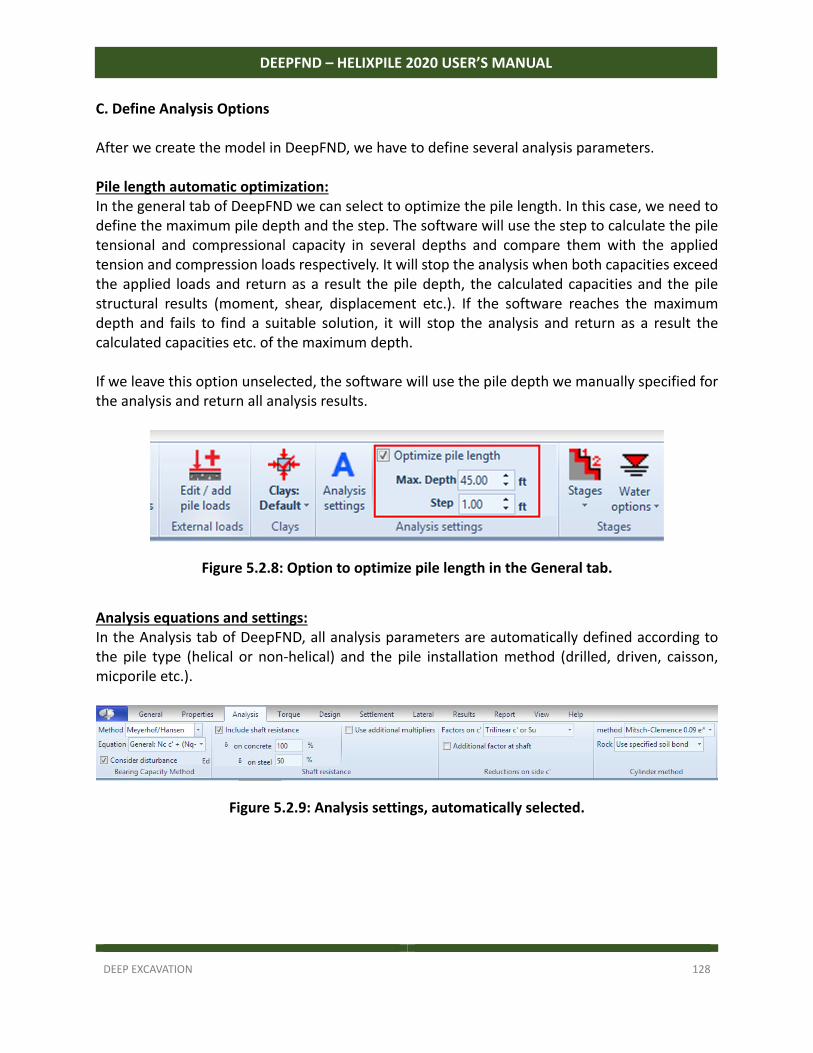
DEEP EXCAVATION 128
DEEPFND – HELIXPILE 2020 USER’S MANUAL
C. Define Analysis Options After we create the model in DeepFND, we have to define several analysis parameters. Pile length automatic optimization: In the general tab of DeepFND we can select to optimize the pile length. In this case, we need to define the maximum pile depth and the step. The software will use the step to calculate the pile tensional and compressional capacity in several depths and compare them with the applied tension and compression loads respectively. It will stop the analysis when both capacities exceed the applied loads and return as a result the pile depth, the calculated capacities and the pile structural results (moment, shear, displacement etc.). If the software reaches the maximum depth and fails to find a suitable solution, it will stop the analysis and return as a result the calculated capacities etc. of the maximum depth. If we leave this option unselected, the software will use the pile depth we manually specified for the analysis and return all analysis results.
Figure 5.2.8: Option to optimize pile length in the General tab.
Analysis equations and settings: In the Analysis tab of DeepFND, all analysis parameters are automatically defined according to the pile type (helical or non‐helical) and the pile installation method (drilled, driven, caisson, micporile etc.).
Figure 5.2.9: Analysis settings, automatically selected.
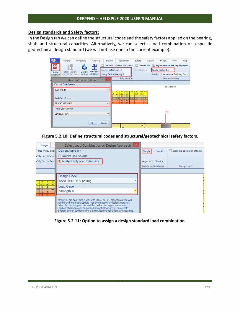
DEEP EXCAVATION 129
DEEPFND – HELIXPILE 2020 USER’S MANUAL
Design standards and Safety factors: In the Design tab we can define the structural codes and the safety factors applied on the bearing, shaft and structural capacities. Alternatively, we can select a load combination of a specific geotechnical design standard (we will not use one in the current example).
Figure 5.2.10: Define structural codes and structural/geotechnical safety factors.
Figure 5.2.11: Option to assign a design standard load combination.
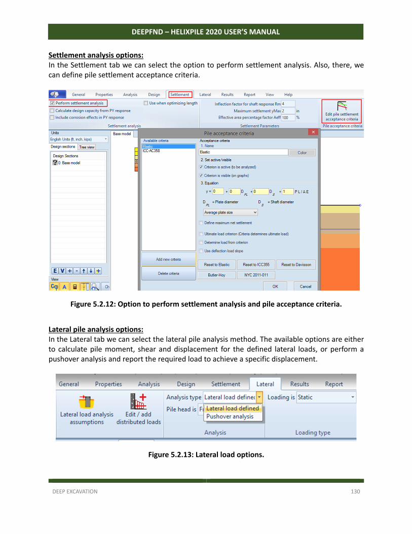
DEEP EXCAVATION 130
DEEPFND – HELIXPILE 2020 USER’S MANUAL
Settlement analysis options: In the Settlement tab we can select the option to perform settlement analysis. Also, there, we can define pile settlement acceptance criteria.
Figure 5.2.12: Option to perform settlement analysis and pile acceptance criteria.
Lateral pile analysis options: In the Lateral tab we can select the lateral pile analysis method. The available options are either to calculate pile moment, shear and displacement for the defined lateral loads, or perform a pushover analysis and report the required load to achieve a specific displacement.
Figure 5.2.13: Lateral load options.
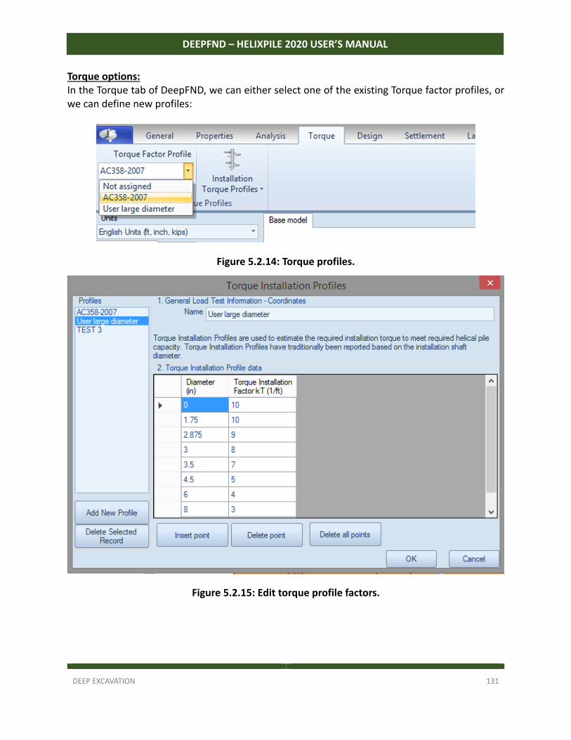
DEEP EXCAVATION 131
DEEPFND – HELIXPILE 2020 USER’S MANUAL
Torque options: In the Torque tab of DeepFND, we can either select one of the existing Torque factor profiles, or we can define new profiles:
Figure 5.2.14: Torque profiles.
Figure 5.2.15: Edit torque profile factors.
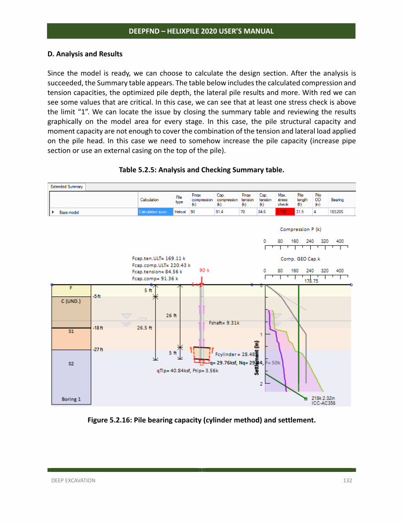
DEEP EXCAVATION 132
DEEPFND – HELIXPILE 2020 USER’S MANUAL
D. Analysis and Results Since the model is ready, we can choose to calculate the design section. After the analysis is succeeded, the Summary table appears. The table below includes the calculated compression and tension capacities, the optimized pile depth, the lateral pile results and more. With red we can see some values that are critical. In this case, we can see that at least one stress check is above the limit “1”. We can locate the issue by closing the summary table and reviewing the results graphically on the model area for every stage. In this case, the pile structural capacity and moment capacity are not enough to cover the combination of the tension and lateral load applied on the pile head. In this case we need to somehow increase the pile capacity (increase pipe section or use an external casing on the top of the pile).
Table 5.2.5: Analysis and Checking Summary table.
Figure 5.2.16: Pile bearing capacity (cylinder method) and settlement.
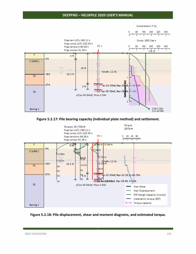
DEEP EXCAVATION 133
DEEPFND – HELIXPILE 2020 USER’S MANUAL
Figure 5.2.17: Pile bearing capacity (individual plate method) and settlement.
Figure 5.2.18: Pile displacement, shear and moment diagrams, and estimated torque.
DEEP EXCAVATION 134
DEEPFND – HELIXPILE 2020 USER’S MANUAL
PART C: PILE GROUPS AND PILE RAFTS
MODEL CREATION – ANALYSIS SETTINGS – RESULTS The following section provides useful information about the use of the software for the design of pile groups and pile rafts. We examine the procedures to create a model, define the analysis settings and perform the model optimization using the calculated results. We present how to effectively use the tools of the software in order to create any pile cap shape.

DEEP EXCAVATION 135
DEEPFND – HELIXPILE 2020 USER’S MANUAL
SECTION 6: PILE GROUPS – MODELS AND ANALYSIS
6.1 Creating a Pile Cap Model Automatically
DeepFND (and HelixPile) can design pile caps supported by pile groups. The pile caps can be of any shape and the piles can be of any structural section. When we wish to perform a pile cap design, it is recommended to analyze first the single piles. This way we can examine the pile settlements and the torque capacity of the piles, since these parameters are not examined in the pile cap mode. By analyzing a single pile first, we can also do an initial pile depth optimization, since the automatic optimization does not work in Pile Cap mode. The following steps should be followed for the creation of a pile cap model: A. Define the soil properties and Stratigraphy These procedures are summarized in sections 3.3 and 3.4. B. Define the single pile type and structural section We should access the single pile on the model area and define the pile type (see section 3.5) and the pile section (see sections 3.6 and 3.7 for helical and non‐helical piles respectively). All the piles generated in the pile cap will use the same pile type and section, as defined in the single pile. After the pila cap generation, we can access and modify each pile section, position and inclination independently. C. Analyze and optimize the single pile (optional) The analysis and optimization of the single pile is recommended in order to achieve an efficient solution. We could define the loads on the pile head, define the analysis settings and perform the analysis as described in section 4.1. D. Create the pile cap with the use of the Pile Cap Wizard In the Pile Caps tab of DeepFND we can select to open the Pile Cap wizard. In the wizard, we can define the basic pile cap shape, geometry, piles layout and loading.
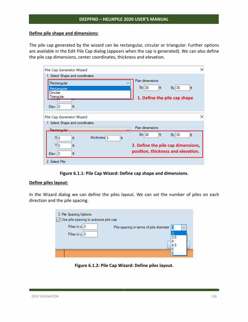
DEEP EXCAVATION 136
DEEPFND – HELIXPILE 2020 USER’S MANUAL
Define pile shape and dimensions: The pile cap generated by the wizard can be rectangular, circular or triangular. Further options are available in the Edit Pile Cap dialog (appears when the cap is generated). We can also define the pile cap dimensions, center coordinates, thickness and elevation.
Figure 6.1.1: Pile Cap Wizard: Define cap shape and dimensions.
Define piles layout: In the Wizard dialog we can define the piles layout. We can set the number of piles on each direction and the pile spacing.
Figure 6.1.2: Pile Cap Wizard: Define piles layout.

DEEP EXCAVATION 137
DEEPFND – HELIXPILE 2020 USER’S MANUAL
E. Edit the pila cap parameters (shape – loading – analysis options) When we close the Wizard, the Edit Pile Cap dialog appears automatically. The same dialog can be accessed any time by double‐clicking on the pile cap in the model area. In this dialog we can readjust the pile shape and dimensions, choosing from a big variety of pile shapes (rectangular, circular, triangular, hexagonal, octagonal, random shape). We can also define the analysis settings and we can access and modify the position and structural section of every generated pile. All these options are presented in section 3.8. Finally, in the Edit Pile Caps dialog we can define additional area and linear loads on the pile cap, as well as, we can define if there will be a single point load on the cap centroid or if we will use several point loads on user‐defined locations. All the load options are presented in section 3.10.
Figure 6.1.3: Generated pile cap – Top and side view.
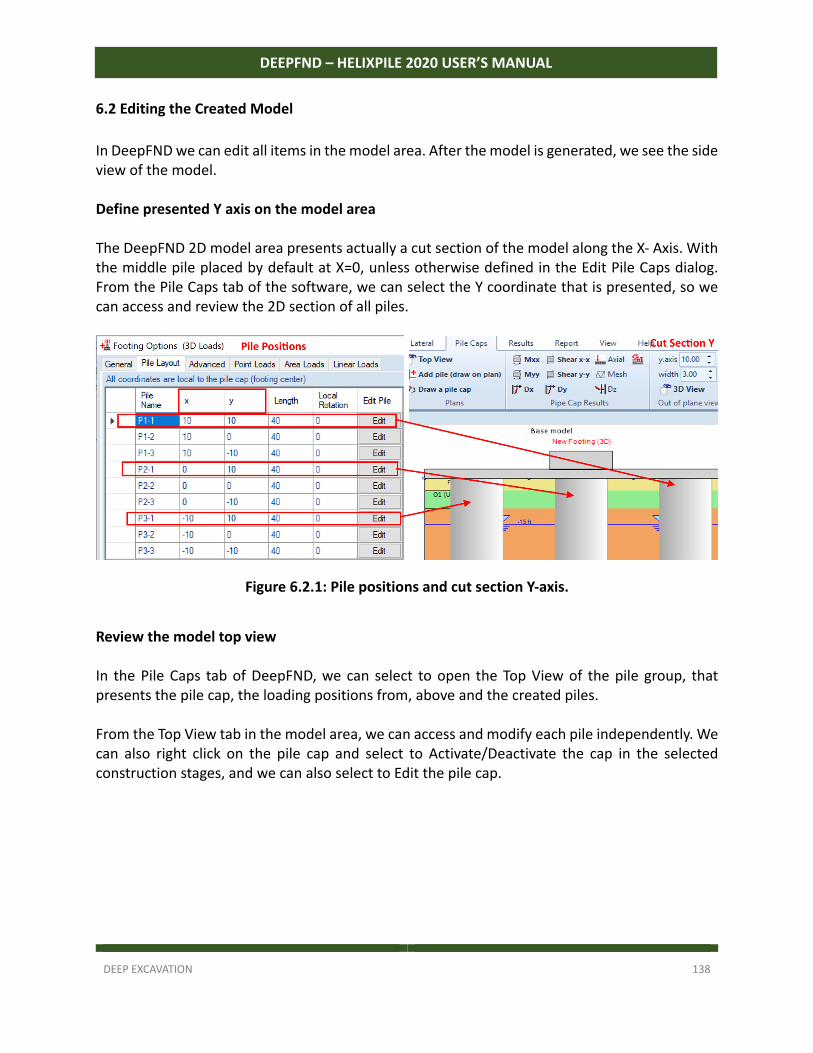
DEEP EXCAVATION 138
DEEPFND – HELIXPILE 2020 USER’S MANUAL
6.2 Editing the Created Model
In DeepFND we can edit all items in the model area. After the model is generated, we see the side view of the model. Define presented Y axis on the model area The DeepFND 2D model area presents actually a cut section of the model along the X‐ Axis. With the middle pile placed by default at X=0, unless otherwise defined in the Edit Pile Caps dialog. From the Pile Caps tab of the software, we can select the Y coordinate that is presented, so we can access and review the 2D section of all piles.
Figure 6.2.1: Pile positions and cut section Y-axis.
Review the model top view In the Pile Caps tab of DeepFND, we can select to open the Top View of the pile group, that presents the pile cap, the loading positions from, above and the created piles. From the Top View tab in the model area, we can access and modify each pile independently. We can also right click on the pile cap and select to Activate/Deactivate the cap in the selected construction stages, and we can also select to Edit the pile cap.
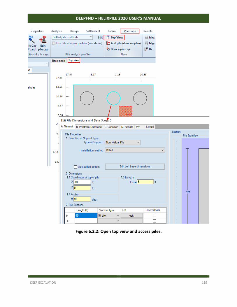
DEEP EXCAVATION 139
DEEPFND – HELIXPILE 2020 USER’S MANUAL
Figure 6.2.2: Open top view and access piles.
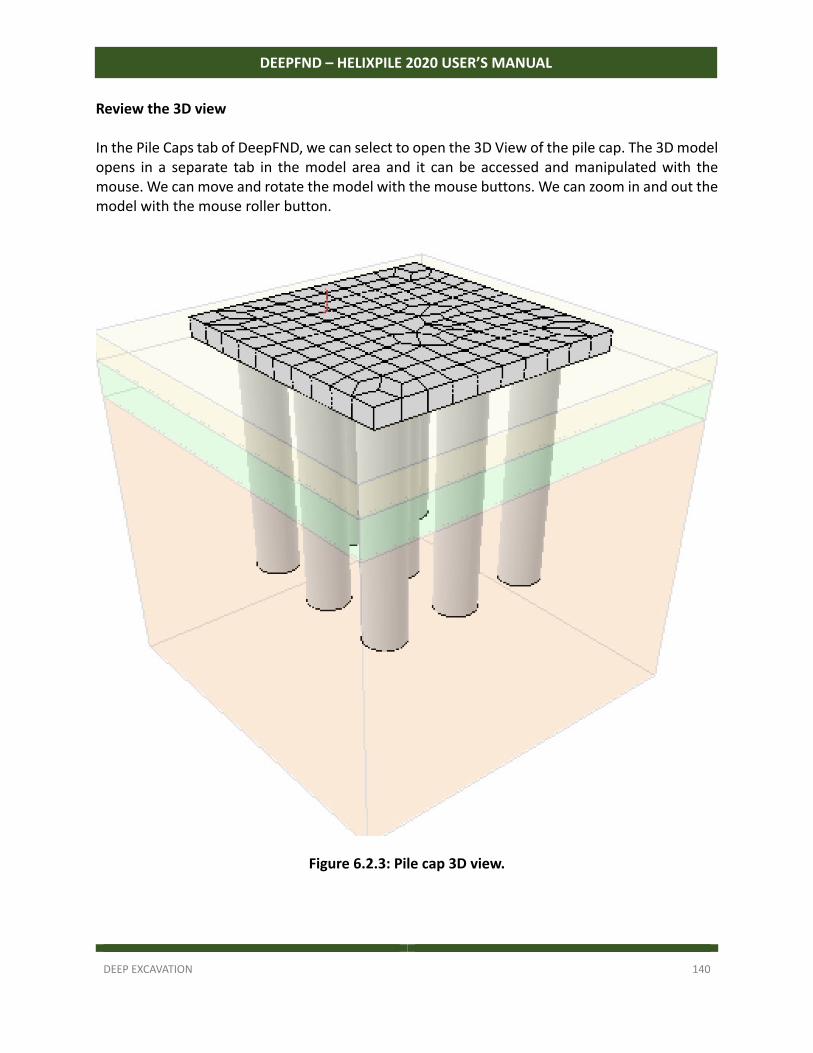
DEEP EXCAVATION 140
DEEPFND – HELIXPILE 2020 USER’S MANUAL
Review the 3D view In the Pile Caps tab of DeepFND, we can select to open the 3D View of the pile cap. The 3D model opens in a separate tab in the model area and it can be accessed and manipulated with the mouse. We can move and rotate the model with the mouse buttons. We can zoom in and out the model with the mouse roller button.
Figure 6.2.3: Pile cap 3D view.
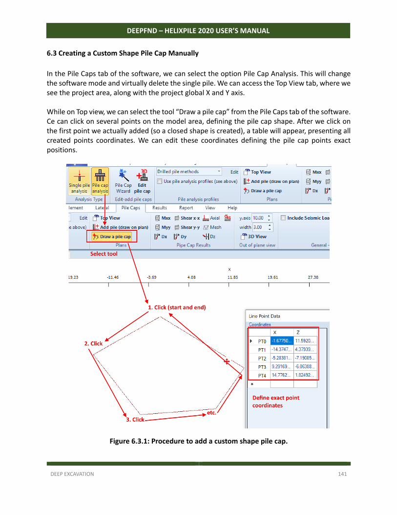
DEEP EXCAVATION 141
DEEPFND – HELIXPILE 2020 USER’S MANUAL
6.3 Creating a Custom Shape Pile Cap Manually
In the Pile Caps tab of the software, we can select the option Pile Cap Analysis. This will change the software mode and virtually delete the single pile. We can access the Top View tab, where we see the project area, along with the project global X and Y axis. While on Top view, we can select the tool “Draw a pile cap” from the Pile Caps tab of the software. Ce can click on several points on the model area, defining the pile cap shape. After we click on the first point we actually added (so a closed shape is created), a table will appear, presenting all created points coordinates. We can edit these coordinates defining the pile cap points exact positions.
Figure 6.3.1: Procedure to add a custom shape pile cap.
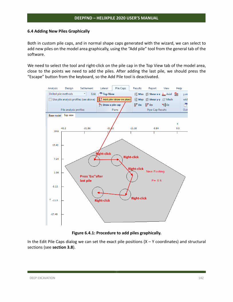
DEEP EXCAVATION 142
DEEPFND – HELIXPILE 2020 USER’S MANUAL
6.4 Adding New Piles Graphically
Both in custom pile caps, and in normal shape caps generated with the wizard, we can select to add new piles on the model area graphically, using the “Add pile” tool from the general tab of the software. We need to select the tool and right‐click on the pile cap in the Top View tab of the model area, close to the points we need to add the piles. After adding the last pile, we should press the “Escape” button from the keyboard, so the Add Pile tool is deactivated.
Figure 6.4.1: Procedure to add piles graphically.
In the Edit Pile Caps dialog we can set the exact pile positions (X – Y coordinates) and structural sections (see section 3.8).
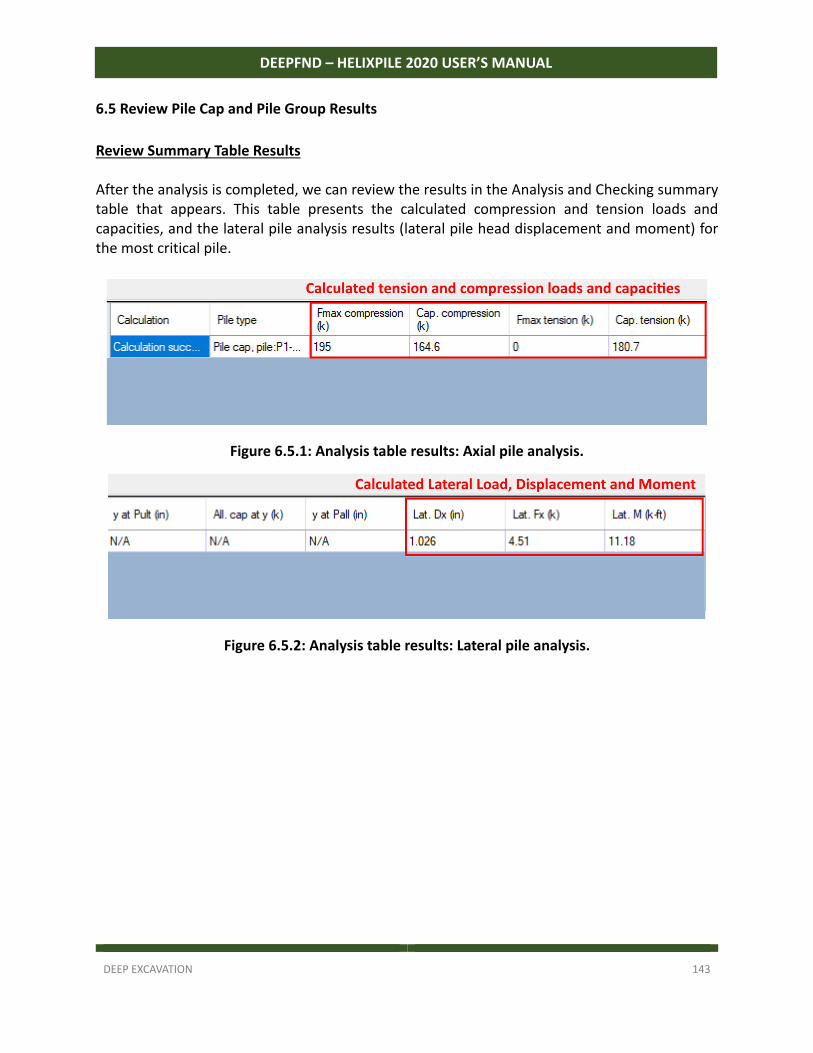
DEEP EXCAVATION 143
DEEPFND – HELIXPILE 2020 USER’S MANUAL
6.5 Review Pile Cap and Pile Group Results
Review Summary Table Results After the analysis is completed, we can review the results in the Analysis and Checking summary table that appears. This table presents the calculated compression and tension loads and capacities, and the lateral pile analysis results (lateral pile head displacement and moment) for the most critical pile.
Figure 6.5.1: Analysis table results: Axial pile analysis.
Figure 6.5.2: Analysis table results: Lateral pile analysis.
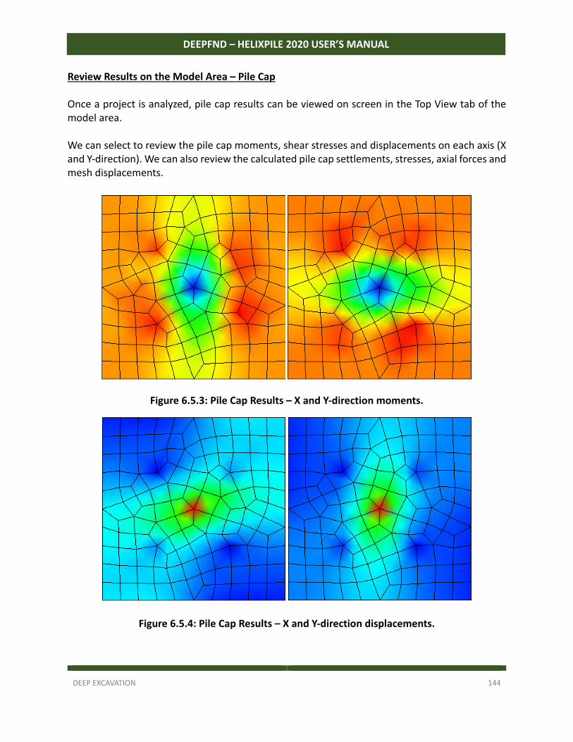
DEEP EXCAVATION 144
DEEPFND – HELIXPILE 2020 USER’S MANUAL
Review Results on the Model Area – Pile Cap Once a project is analyzed, pile cap results can be viewed on screen in the Top View tab of the model area. We can select to review the pile cap moments, shear stresses and displacements on each axis (X and Y‐direction). We can also review the calculated pile cap settlements, stresses, axial forces and mesh displacements.
Figure 6.5.3: Pile Cap Results – X and Y-direction moments.
Figure 6.5.4: Pile Cap Results – X and Y-direction displacements.
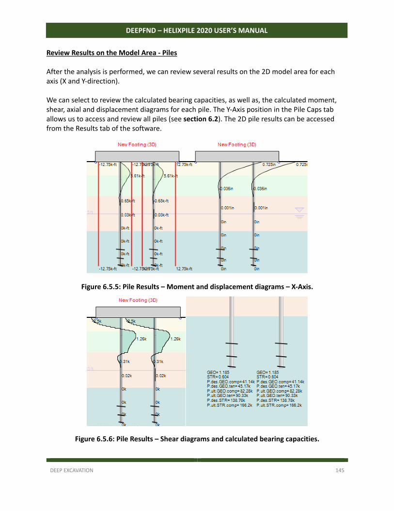
DEEP EXCAVATION 145
DEEPFND – HELIXPILE 2020 USER’S MANUAL
Review Results on the Model Area - Piles After the analysis is performed, we can review several results on the 2D model area for each axis (X and Y‐direction). We can select to review the calculated bearing capacities, as well as, the calculated moment, shear, axial and displacement diagrams for each pile. The Y‐Axis position in the Pile Caps tab allows us to access and review all piles (see section 6.2). The 2D pile results can be accessed from the Results tab of the software.
Figure 6.5.5: Pile Results – Moment and displacement diagrams – X-Axis.
Figure 6.5.6: Pile Results – Shear diagrams and calculated bearing capacities.
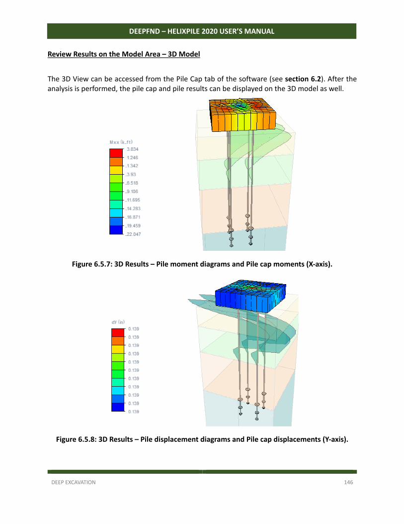
DEEP EXCAVATION 146
DEEPFND – HELIXPILE 2020 USER’S MANUAL
Review Results on the Model Area – 3D Model
The 3D View can be accessed from the Pile Cap tab of the software (see section 6.2). After the analysis is performed, the pile cap and pile results can be displayed on the 3D model as well.
Figure 6.5.7: 3D Results – Pile moment diagrams and Pile cap moments (X-axis).
Figure 6.5.8: 3D Results – Pile displacement diagrams and Pile cap displacements (Y-axis).
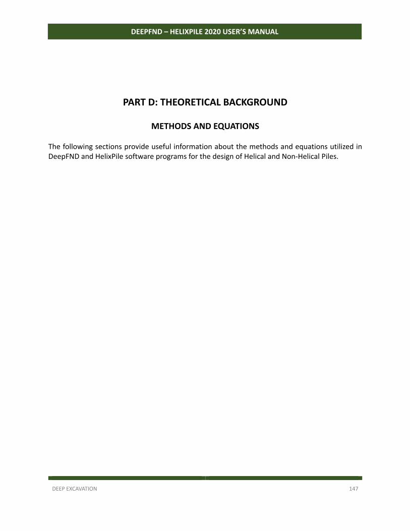
DEEP EXCAVATION 147
DEEPFND – HELIXPILE 2020 USER’S MANUAL
PART D: THEORETICAL BACKGROUND
METHODS AND EQUATIONS The following sections provide useful information about the methods and equations utilized in DeepFND and HelixPile software programs for the design of Helical and Non‐Helical Piles.
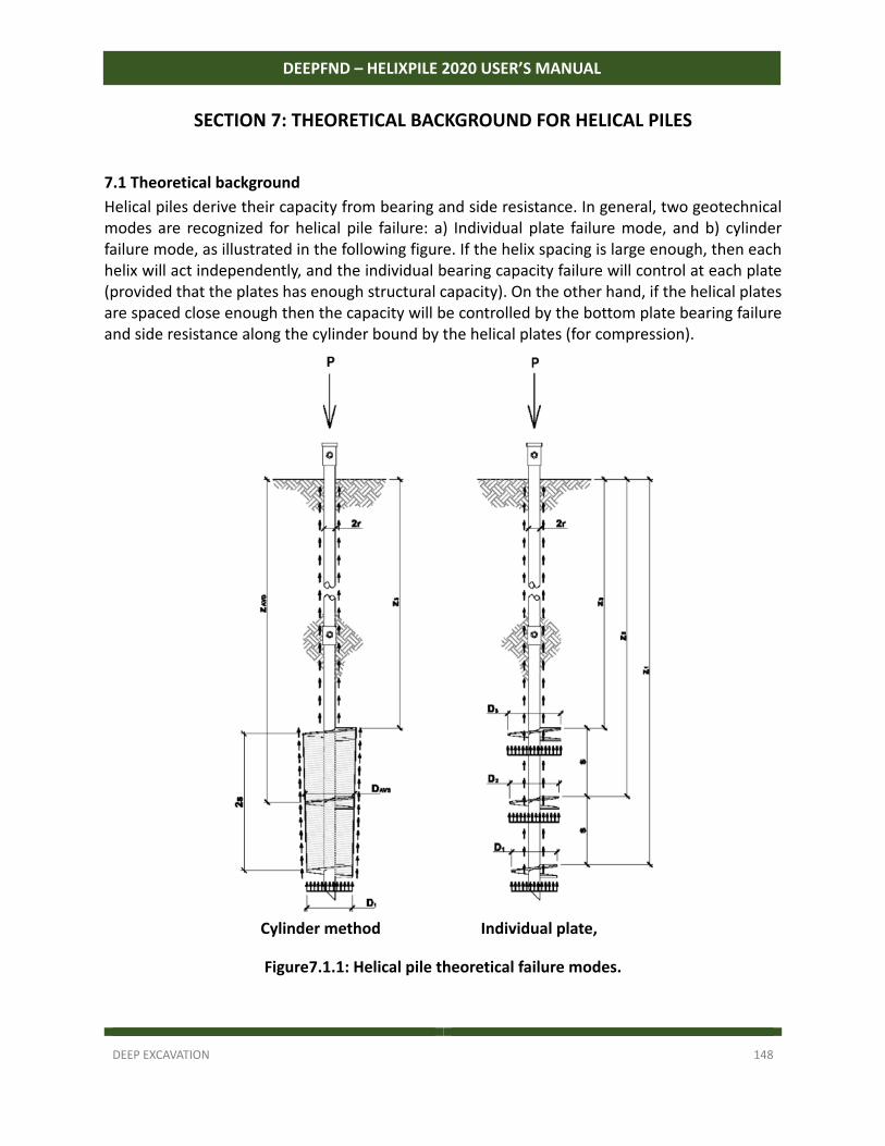
DEEP EXCAVATION 148
DEEPFND – HELIXPILE 2020 USER’S MANUAL
SECTION 7: THEORETICAL BACKGROUND FOR HELICAL PILES
7.1 Theoretical background
Helical piles derive their capacity from bearing and side resistance. In general, two geotechnical modes are recognized for helical pile failure: a) Individual plate failure mode, and b) cylinder failure mode, as illustrated in the following figure. If the helix spacing is large enough, then each helix will act independently, and the individual bearing capacity failure will control at each plate (provided that the plates has enough structural capacity). On the other hand, if the helical plates are spaced close enough then the capacity will be controlled by the bottom plate bearing failure and side resistance along the cylinder bound by the helical plates (for compression).
Cylinder method Individual plate,
Figure7.1.1: Helical pile theoretical failure modes.
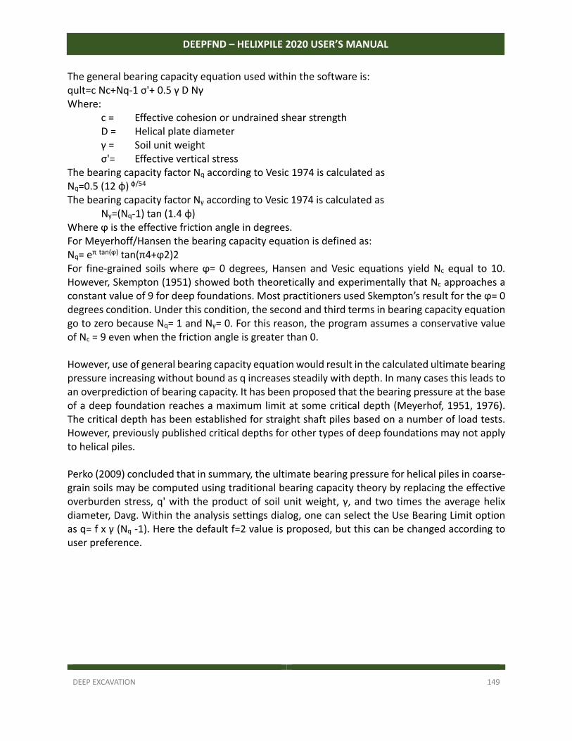
DEEP EXCAVATION 149
DEEPFND – HELIXPILE 2020 USER’S MANUAL
The general bearing capacity equation used within the software is: qult=c Nc+Nq‐1 σ'+ 0.5 γ D Nγ Where: c = Effective cohesion or undrained shear strength D = Helical plate diameter γ = Soil unit weight σ'= Effective vertical stress The bearing capacity factor Nq according to Vesic 1974 is calculated as Nq=0.5 (12 φ) φ/54 The bearing capacity factor Nγ according to Vesic 1974 is calculated as Ny=(Nq‐1) tan (1.4 φ) Where ϕ is the effective friction angle in degrees. For Meyerhoff/Hansen the bearing capacity equation is defined as: Nq= eπ tan(ϕ) tan(π4+ϕ2)2 For fine‐grained soils where ϕ= 0 degrees, Hansen and Vesic equations yield Nc equal to 10. However, Skempton (1951) showed both theoretically and experimentally that Nc approaches a constant value of 9 for deep foundations. Most practitioners used Skempton’s result for the ϕ= 0 degrees condition. Under this condition, the second and third terms in bearing capacity equation go to zero because Nq= 1 and Nγ= 0. For this reason, the program assumes a conservative value of Nc = 9 even when the friction angle is greater than 0. However, use of general bearing capacity equation would result in the calculated ultimate bearing pressure increasing without bound as q increases steadily with depth. In many cases this leads to an overprediction of bearing capacity. It has been proposed that the bearing pressure at the base of a deep foundation reaches a maximum limit at some critical depth (Meyerhof, 1951, 1976). The critical depth has been established for straight shaft piles based on a number of load tests. However, previously published critical depths for other types of deep foundations may not apply to helical piles. Perko (2009) concluded that in summary, the ultimate bearing pressure for helical piles in coarse‐grain soils may be computed using traditional bearing capacity theory by replacing the effective overburden stress, q' with the product of soil unit weight, γ, and two times the average helix diameter, Davg. Within the analysis settings dialog, one can select the Use Bearing Limit option as q= f x γ (Nq ‐1). Here the default f=2 value is proposed, but this can be changed according to user preference.
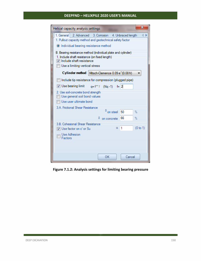
DEEP EXCAVATION 150
DEEPFND – HELIXPILE 2020 USER’S MANUAL
Figure 7.1.2: Analysis settings for limiting bearing pressure
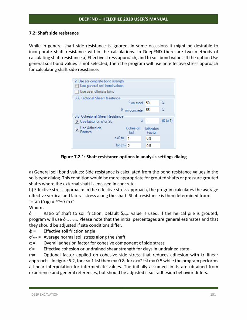
DEEP EXCAVATION 151
DEEPFND – HELIXPILE 2020 USER’S MANUAL
7.2: Shaft side resistance
While in general shaft side resistance is ignored, in some occasions it might be desirable to incorporate shaft resistance within the calculations. In DeepFND there are two methods of calculating shaft resistance a) Effective stress approach, and b) soil bond values. If the option Use general soil bond values is not selected, then the program will use an effective stress approach for calculating shaft side resistance.
Figure 7.2.1: Shaft resistance options in analysis settings dialog
a) General soil bond values: Side resistance is calculated from the bond resistance values in the soils type dialog. This condition would be more appropriate for grouted shafts or pressure grouted shafts where the external shaft is encased in concrete. b) Effective stress approach: In the effective stress approach, the program calculates the average effective vertical and lateral stress along the shaft. Shaft resistance is then determined from: τ=tan (δ ϕ) σ'ave+α m c' Where: δ = Ratio of shaft to soil friction. Default δsteel value is used. If the helical pile is grouted, program will use δconcrete. Please note that the initial percentages are general estimates and that they should be adjusted if site conditions differ. φ = Effective soil friction angle σ'ave = Average normal soil stress along the shaft α = Overall adhesion factor for cohesive component of side stress c'= Effective cohesion or undrained shear strength for clays in undrained state. m= Optional factor applied on cohesive side stress that reduces adhesion with tri‐linear approach. In figure 5.2, for c<= 1 ksf then m= 0.8, for c>=2ksf m= 0.5 while the program performs a linear interpolation for intermediate values. The initially assumed limits are obtained from experience and general references, but should be adjusted if soil‐adhesion behavior differs.
DEEP EXCAVATION 152
DEEPFND – HELIXPILE 2020 USER’S MANUAL
7.3 Cylinder strength method
DeepFND also examines cylinder strength to determine which axial loading condition is more critical. The program subdivides the space between plates into a number of nodes where the side shear strength on the cylinder is integrated from a side resistance of: τ=tanϕ σ'ave+c' Where: δ = Ratio of shaft to soil friction. Default δsteel value is used. If the helical pile is grouted, program will use δconcrete. Please note that the initial percentages are general estimates and that they should be adjusted if site conditions differ. φ = Effective soil friction angle σ'ave = Average normal soil stress along the shaft If the plate sizes are different, then the program calculates and includes both the cylinder angle (from the pile axis) as well as the effective diameter along the virtual cylinder. The angle inclination of the cylinder in respect to the pile axis should make little difference in most cases. The side cohesion factors in 5.2 are also applied in the cylinder method.
7.4 Installation disturbance factors
As a helical pile is installed and helical plates cut through insitu soils, the very process of individual helical plates passing through disturbs the original soil. As a result, it has been observed that trailing plates do not experience their full bearing capacity potential. Such installation disturbance factors are applied both to the bearing capacity of each individual bearing plate as well as the elastic (or non‐linear) soil response. Disturbance factors can be affected by many factors, including pile size (shaft, shape), installation speed, and original soil conditions. Stiffer clays have been observed to experience a greater reduction in strength as a result of helical pile installation. Default installation disturbance are estimates based on engineering judgment and may have to be adjusted on each analysis. 5.5 Structural capacity calculations Initially the design structural capacity of the pile is calculated as: Pdes= α ·Py Where: Pdes = Design axial capacity Py= Yield strength of shaft α= Design stress factor (for allowable design typically taken as 0.5) α is controlled from the Analysis settings dialog, tab B. Its value is automatically updated when a new structural code is selected from the Design tab. The program also considers the structural capacity according to the selected structural code standards. This affects the compressive structural capacity when buckling is considered. DeepFND determines which loading condition is controlling in each stage, and reports the respective structural capacity.
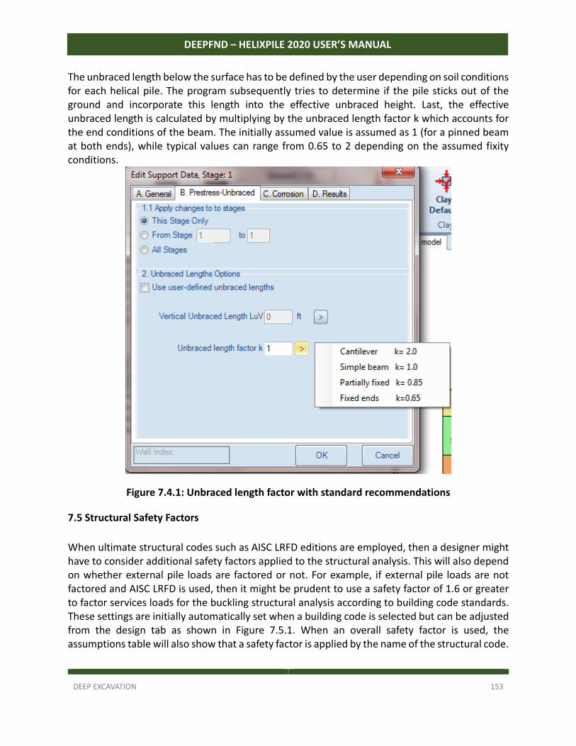
DEEP EXCAVATION 153
DEEPFND – HELIXPILE 2020 USER’S MANUAL
The unbraced length below the surface has to be defined by the user depending on soil conditions for each helical pile. The program subsequently tries to determine if the pile sticks out of the ground and incorporate this length into the effective unbraced height. Last, the effective unbraced length is calculated by multiplying by the unbraced length factor k which accounts for the end conditions of the beam. The initially assumed value is assumed as 1 (for a pinned beam at both ends), while typical values can range from 0.65 to 2 depending on the assumed fixity conditions.
Figure 7.4.1: Unbraced length factor with standard recommendations
7.5 Structural Safety Factors
When ultimate structural codes such as AISC LRFD editions are employed, then a designer might have to consider additional safety factors applied to the structural analysis. This will also depend on whether external pile loads are factored or not. For example, if external pile loads are not factored and AISC LRFD is used, then it might be prudent to use a safety factor of 1.6 or greater to factor services loads for the buckling structural analysis according to building code standards. These settings are initially automatically set when a building code is selected but can be adjusted from the design tab as shown in Figure 7.5.1. When an overall safety factor is used, the assumptions table will also show that a safety factor is applied by the name of the structural code.
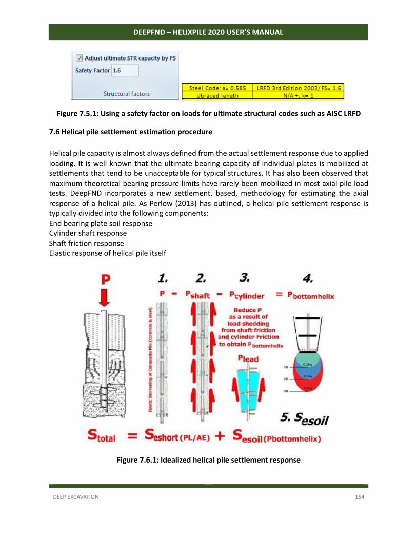
DEEP EXCAVATION 154
DEEPFND – HELIXPILE 2020 USER’S MANUAL
Figure 7.5.1: Using a safety factor on loads for ultimate structural codes such as AISC LRFD
7.6 Helical pile settlement estimation procedure
Helical pile capacity is almost always defined from the actual settlement response due to applied loading. It is well known that the ultimate bearing capacity of individual plates is mobilized at settlements that tend to be unacceptable for typical structures. It has also been observed that maximum theoretical bearing pressure limits have rarely been mobilized in most axial pile load tests. DeepFND incorporates a new settlement, based, methodology for estimating the axial response of a helical pile. As Perlow (2013) has outlined, a helical pile settlement response is typically divided into the following components: End bearing plate soil response Cylinder shaft response Shaft friction response Elastic response of helical pile itself
Figure 7.6.1: Idealized helical pile settlement response
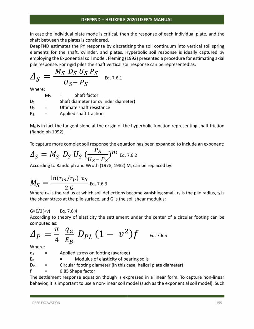
DEEP EXCAVATION 155
DEEPFND – HELIXPILE 2020 USER’S MANUAL
In case the individual plate mode is critical, then the response of each individual plate, and the shaft between the plates is considered. DeepFND estimates the PY response by discretizing the soil continuum into vertical soil spring elements for the shaft, cylinder, and plates. Hyperbolic soil response is ideally captured by employing the Exponential soil model. Fleming (1992) presented a procedure for estimating axial pile response. For rigid piles the shaft vertical soil response can be represented as:
𝛥
Eq. 7.6.1
Where: MS = Shaft factor DS = Shaft diameter (or cylinder diameter) US = Ultimate shaft resistance PS = Applied shaft traction MS is in fact the tangent slope at the origin of the hyperbolic function representing shaft friction (Randolph 1992). To capture more complex soil response the equation has been expanded to include an exponent:
𝛥 𝑀 𝐷 𝑈
Eq. 7.6.2
According to Randolph and Wroth (1978, 1982) Ms can be replaced by:
𝑀/
Eq. 7.6.3
Where rm is the radius at which soil deflections become vanishing small, rp is the pile radius, τs is the shear stress at the pile surface, and G is the soil shear modulus: G=E/2(+v) Eq. 7.6.4 According to theory of elasticity the settlement under the center of a circular footing can be computed as:
𝛥 𝐷 1 𝑣 𝑓 Eq. 7.6.5
Where: qa = Applied stress on footing (average) EB = Modulus of elasticity of bearing soils DPL = Circular footing diameter (in this case, helical plate diameter) f = 0.85 Shape factor The settlement response equation though is expressed in a linear form. To capture non‐linear behavior, it is important to use a non‐linear soil model (such as the exponential soil model). Such
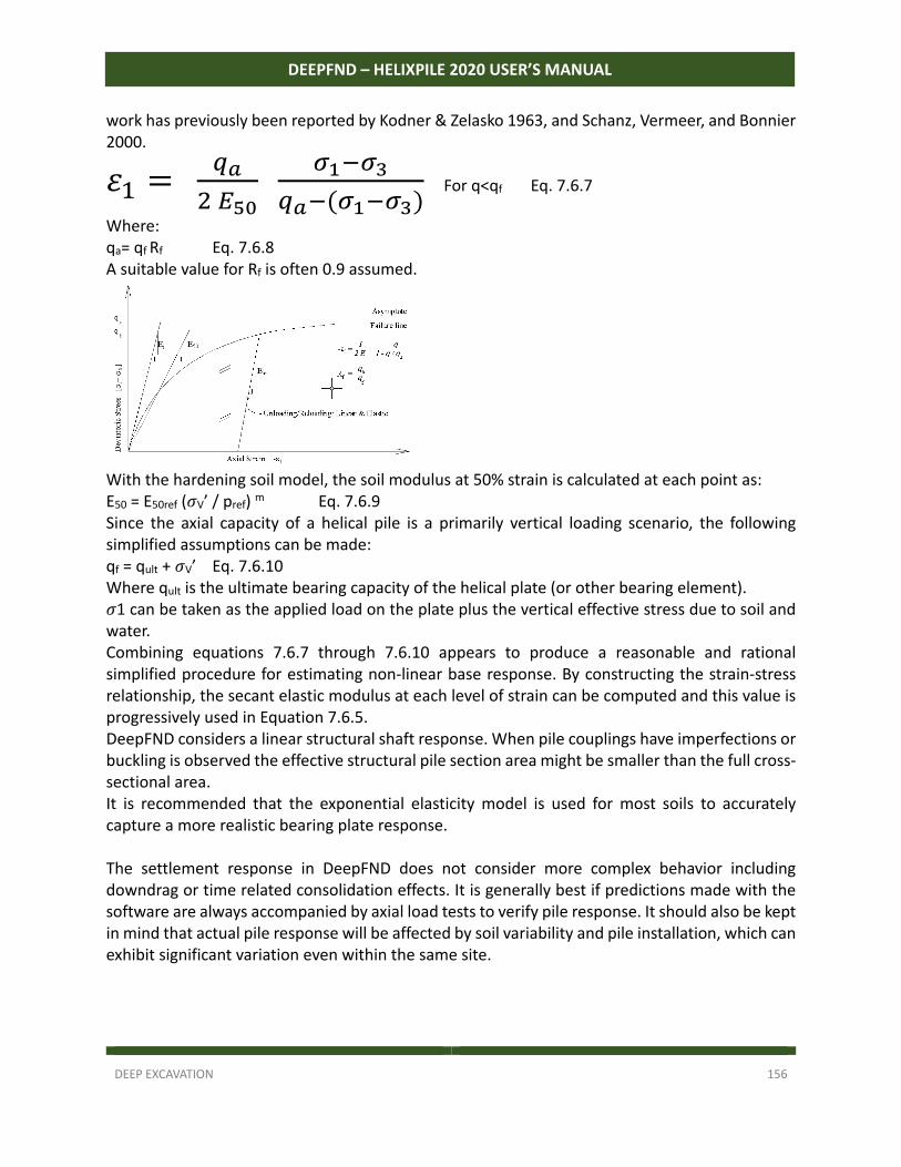
DEEP EXCAVATION 156
DEEPFND – HELIXPILE 2020 USER’S MANUAL
work has previously been reported by Kodner & Zelasko 1963, and Schanz, Vermeer, and Bonnier 2000.
𝜀
For q<qf Eq. 7.6.7
Where: qa= qf Rf Eq. 7.6.8 A suitable value for Rf is often 0.9 assumed.
With the hardening soil model, the soil modulus at 50% strain is calculated at each point as: E50 = E50ref (𝜎V’ / pref) m Eq. 7.6.9 Since the axial capacity of a helical pile is a primarily vertical loading scenario, the following simplified assumptions can be made: qf = qult + 𝜎V’ Eq. 7.6.10 Where qult is the ultimate bearing capacity of the helical plate (or other bearing element). 𝜎1 can be taken as the applied load on the plate plus the vertical effective stress due to soil and water. Combining equations 7.6.7 through 7.6.10 appears to produce a reasonable and rational simplified procedure for estimating non‐linear base response. By constructing the strain‐stress relationship, the secant elastic modulus at each level of strain can be computed and this value is progressively used in Equation 7.6.5. DeepFND considers a linear structural shaft response. When pile couplings have imperfections or buckling is observed the effective structural pile section area might be smaller than the full cross‐sectional area. It is recommended that the exponential elasticity model is used for most soils to accurately capture a more realistic bearing plate response. The settlement response in DeepFND does not consider more complex behavior including downdrag or time related consolidation effects. It is generally best if predictions made with the software are always accompanied by axial load tests to verify pile response. It should also be kept in mind that actual pile response will be affected by soil variability and pile installation, which can exhibit significant variation even within the same site.
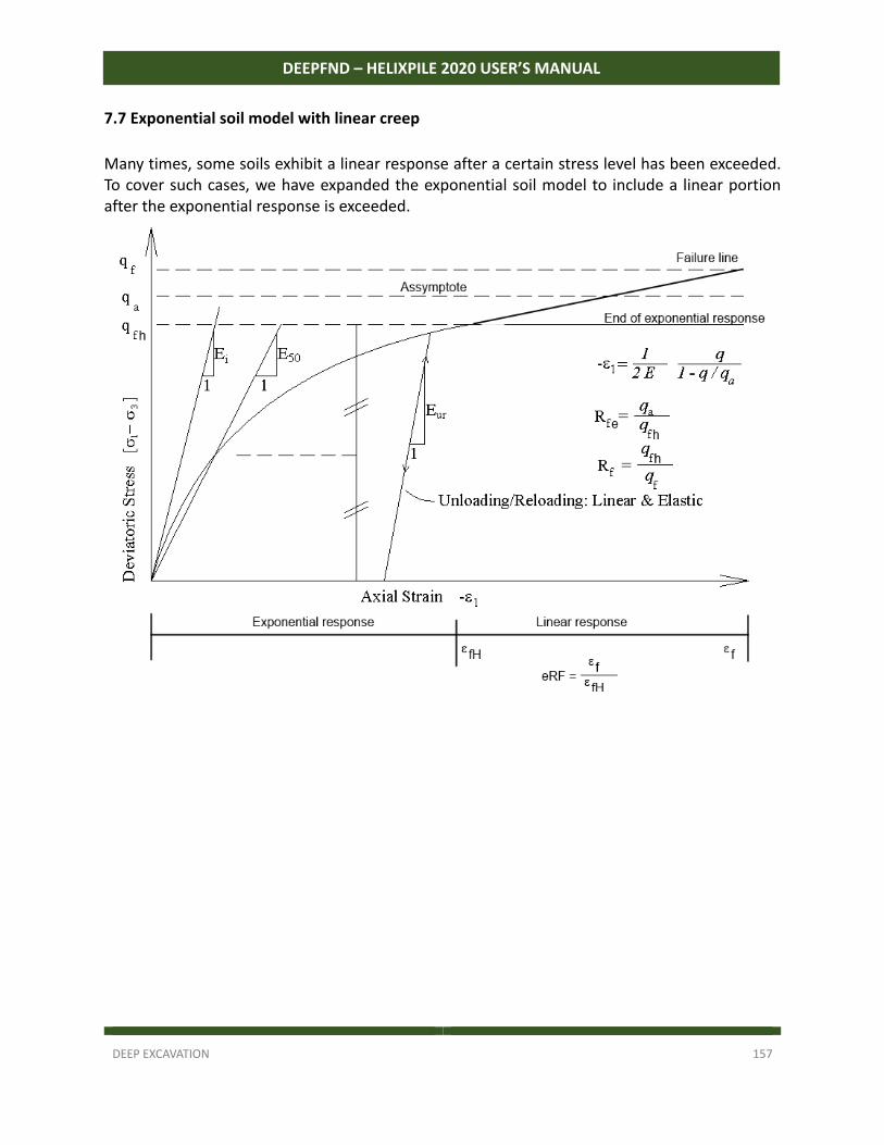
DEEP EXCAVATION 157
DEEPFND – HELIXPILE 2020 USER’S MANUAL
7.7 Exponential soil model with linear creep
Many times, some soils exhibit a linear response after a certain stress level has been exceeded. To cover such cases, we have expanded the exponential soil model to include a linear portion after the exponential response is exceeded.
DEEP EXCAVATION 158
DEEPFND – HELIXPILE 2020 USER’S MANUAL
SECTION 8: THEORETICAL BACKGROUND FOR REGULAR PILE TYPES
8.1 Introduction
In order to properly estimate the axial pile capacity different methods will have to be adopted. Amongst other factors, such methods may depend on the pile installation method as well as on different soil or rock type properties. DeepFND offers a number of well accepted methods for estimating the geotechnical axial pile capacity. Most methods are either based on AASHTO, FHWA, or Eurocode 7 type recommendations. All methods should be used by experienced professionals who understand their limitations. DeepFND also gives direct options for overriding many of these settings with user defined options.
8.2. A Driven Pile Recommendations
For driven piles, DeepFND has incorporated Norlund’s method as outlined in AASHTO Bridge design specifications (2012 and on). The program will automatically classify the pile as tapered, steel monotube, or step tapered, depending on the selected pile geometry. A series of verification examples with DeepFND are presented in the following sections. For adhesion, the program uses Tomlinson’s method (Tomlinson 1979). The program interpolates for values of D/d between 10 and 40.
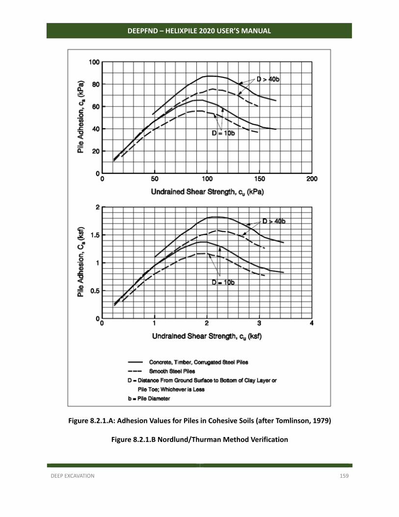
DEEP EXCAVATION 159
DEEPFND – HELIXPILE 2020 USER’S MANUAL
Figure 8.2.1.A: Adhesion Values for Piles in Cohesive Soils (after Tomlinson, 1979)
Figure 8.2.1.B Nordlund/Thurman Method Verification
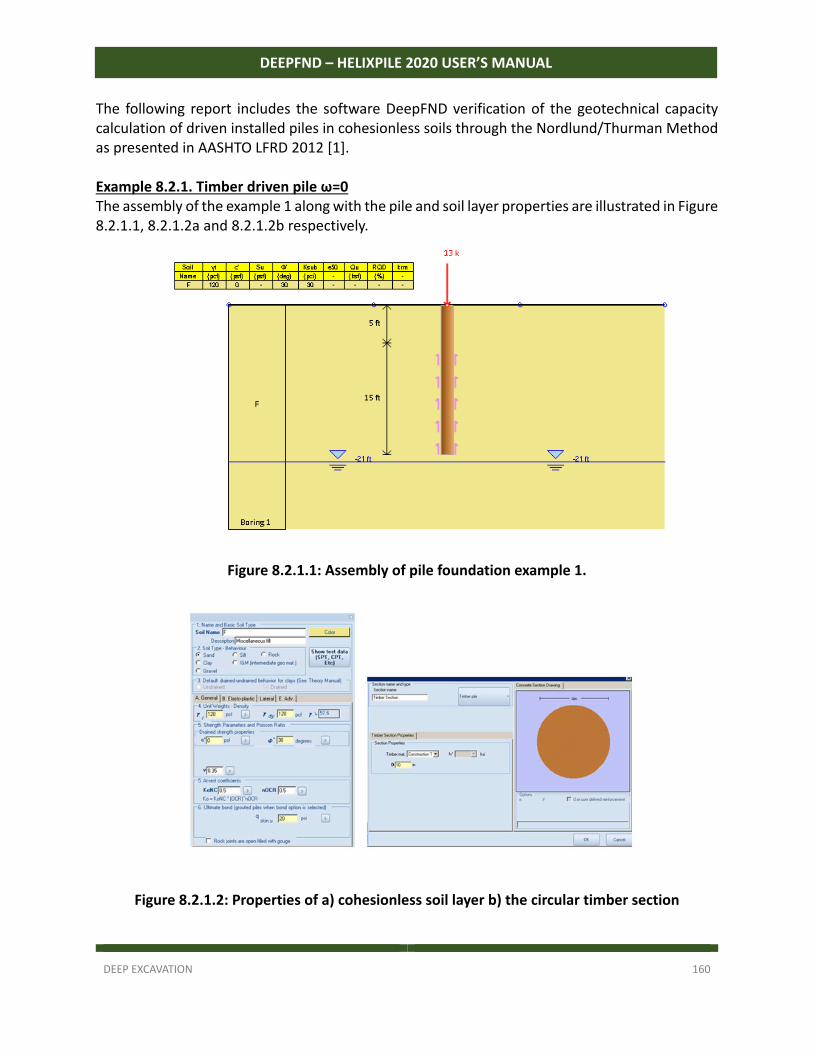
DEEP EXCAVATION 160
DEEPFND – HELIXPILE 2020 USER’S MANUAL
The following report includes the software DeepFND verification of the geotechnical capacity calculation of driven installed piles in cohesionless soils through the Nordlund/Thurman Method as presented in AASHTO LFRD 2012 [1]. Example 8.2.1. Timber driven pile ω=0 The assembly of the example 1 along with the pile and soil layer properties are illustrated in Figure 8.2.1.1, 8.2.1.2a and 8.2.1.2b respectively.
Figure 8.2.1.1: Assembly of pile foundation example 1.
Figure 8.2.1.2: Properties of a) cohesionless soil layer b) the circular timber section
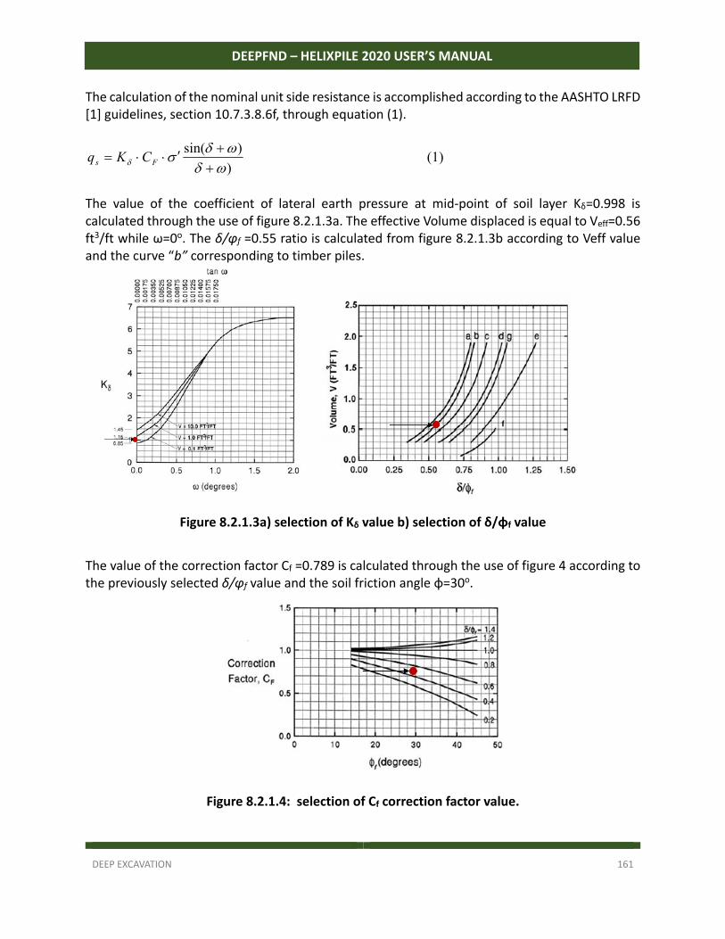
DEEP EXCAVATION 161
DEEPFND – HELIXPILE 2020 USER’S MANUAL
The calculation of the nominal unit side resistance is accomplished according to the AASHTO LRFD [1] guidelines, section 10.7.3.8.6f, through equation (1).
)
)sin(
Fs CKq (1)
The value of the coefficient of lateral earth pressure at mid‐point of soil layer Κδ=0.998 is calculated through the use of figure 8.2.1.3a. The effective Volume displaced is equal to Veff=0.56 ft3/ft while ω=0o. The δ/φf =0.55 ratio is calculated from figure 8.2.1.3b according to Veff value and the curve “b” corresponding to timber piles.
Figure 8.2.1.3a) selection of Kδ value b) selection of δ/φf value
The value of the correction factor Cf =0.789 is calculated through the use of figure 4 according to the previously selected δ/φf value and the soil friction angle φ=30ο.
Figure 8.2.1.4: selection of Cf correction factor value.
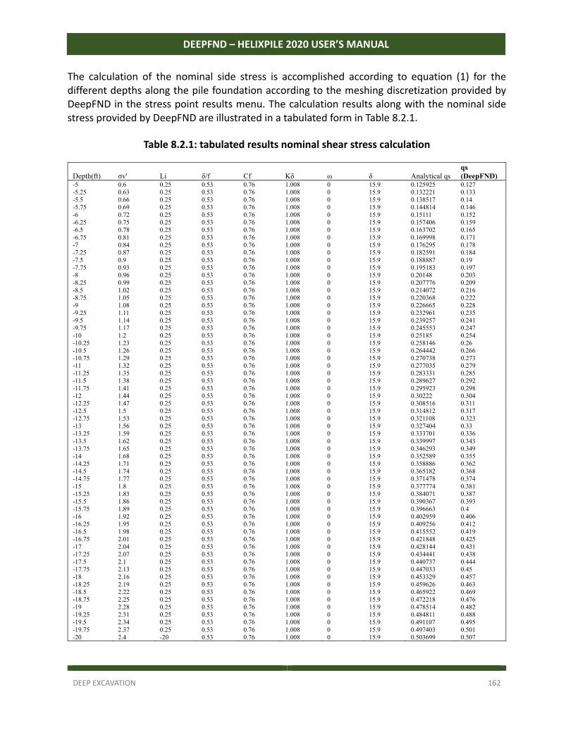
DEEP EXCAVATION 162
DEEPFND – HELIXPILE 2020 USER’S MANUAL
The calculation of the nominal side stress is accomplished according to equation (1) for the different depths along the pile foundation according to the meshing discretization provided by DeepFND in the stress point results menu. The calculation results along with the nominal side stress provided by DeepFND are illustrated in a tabulated form in Table 8.2.1.
Table 8.2.1: tabulated results nominal shear stress calculation
Depth(ft) σv' Li δ/f Cf Kδ ω δ Analytical qs qs (DeepFND)
-5 0.6 0.25 0.53 0.76 1.008 0 15.9 0.125925 0.127 -5.25 0.63 0.25 0.53 0.76 1.008 0 15.9 0.132221 0.133 -5.5 0.66 0.25 0.53 0.76 1.008 0 15.9 0.138517 0.14 -5.75 0.69 0.25 0.53 0.76 1.008 0 15.9 0.144814 0.146 -6 0.72 0.25 0.53 0.76 1.008 0 15.9 0.15111 0.152 -6.25 0.75 0.25 0.53 0.76 1.008 0 15.9 0.157406 0.159 -6.5 0.78 0.25 0.53 0.76 1.008 0 15.9 0.163702 0.165 -6.75 0.81 0.25 0.53 0.76 1.008 0 15.9 0.169998 0.171 -7 0.84 0.25 0.53 0.76 1.008 0 15.9 0.176295 0.178 -7.25 0.87 0.25 0.53 0.76 1.008 0 15.9 0.182591 0.184 -7.5 0.9 0.25 0.53 0.76 1.008 0 15.9 0.188887 0.19 -7.75 0.93 0.25 0.53 0.76 1.008 0 15.9 0.195183 0.197 -8 0.96 0.25 0.53 0.76 1.008 0 15.9 0.20148 0.203 -8.25 0.99 0.25 0.53 0.76 1.008 0 15.9 0.207776 0.209 -8.5 1.02 0.25 0.53 0.76 1.008 0 15.9 0.214072 0.216 -8.75 1.05 0.25 0.53 0.76 1.008 0 15.9 0.220368 0.222 -9 1.08 0.25 0.53 0.76 1.008 0 15.9 0.226665 0.228 -9.25 1.11 0.25 0.53 0.76 1.008 0 15.9 0.232961 0.235 -9.5 1.14 0.25 0.53 0.76 1.008 0 15.9 0.239257 0.241 -9.75 1.17 0.25 0.53 0.76 1.008 0 15.9 0.245553 0.247 -10 1.2 0.25 0.53 0.76 1.008 0 15.9 0.25185 0.254 -10.25 1.23 0.25 0.53 0.76 1.008 0 15.9 0.258146 0.26 -10.5 1.26 0.25 0.53 0.76 1.008 0 15.9 0.264442 0.266 -10.75 1.29 0.25 0.53 0.76 1.008 0 15.9 0.270738 0.273 -11 1.32 0.25 0.53 0.76 1.008 0 15.9 0.277035 0.279 -11.25 1.35 0.25 0.53 0.76 1.008 0 15.9 0.283331 0.285 -11.5 1.38 0.25 0.53 0.76 1.008 0 15.9 0.289627 0.292 -11.75 1.41 0.25 0.53 0.76 1.008 0 15.9 0.295923 0.298 -12 1.44 0.25 0.53 0.76 1.008 0 15.9 0.30222 0.304 -12.25 1.47 0.25 0.53 0.76 1.008 0 15.9 0.308516 0.311 -12.5 1.5 0.25 0.53 0.76 1.008 0 15.9 0.314812 0.317 -12.75 1.53 0.25 0.53 0.76 1.008 0 15.9 0.321108 0.323 -13 1.56 0.25 0.53 0.76 1.008 0 15.9 0.327404 0.33 -13.25 1.59 0.25 0.53 0.76 1.008 0 15.9 0.333701 0.336 -13.5 1.62 0.25 0.53 0.76 1.008 0 15.9 0.339997 0.343 -13.75 1.65 0.25 0.53 0.76 1.008 0 15.9 0.346293 0.349 -14 1.68 0.25 0.53 0.76 1.008 0 15.9 0.352589 0.355 -14.25 1.71 0.25 0.53 0.76 1.008 0 15.9 0.358886 0.362 -14.5 1.74 0.25 0.53 0.76 1.008 0 15.9 0.365182 0.368 -14.75 1.77 0.25 0.53 0.76 1.008 0 15.9 0.371478 0.374 -15 1.8 0.25 0.53 0.76 1.008 0 15.9 0.377774 0.381 -15.25 1.83 0.25 0.53 0.76 1.008 0 15.9 0.384071 0.387 -15.5 1.86 0.25 0.53 0.76 1.008 0 15.9 0.390367 0.393 -15.75 1.89 0.25 0.53 0.76 1.008 0 15.9 0.396663 0.4 -16 1.92 0.25 0.53 0.76 1.008 0 15.9 0.402959 0.406 -16.25 1.95 0.25 0.53 0.76 1.008 0 15.9 0.409256 0.412 -16.5 1.98 0.25 0.53 0.76 1.008 0 15.9 0.415552 0.419 -16.75 2.01 0.25 0.53 0.76 1.008 0 15.9 0.421848 0.425 -17 2.04 0.25 0.53 0.76 1.008 0 15.9 0.428144 0.431 -17.25 2.07 0.25 0.53 0.76 1.008 0 15.9 0.434441 0.438 -17.5 2.1 0.25 0.53 0.76 1.008 0 15.9 0.440737 0.444 -17.75 2.13 0.25 0.53 0.76 1.008 0 15.9 0.447033 0.45 -18 2.16 0.25 0.53 0.76 1.008 0 15.9 0.453329 0.457 -18.25 2.19 0.25 0.53 0.76 1.008 0 15.9 0.459626 0.463 -18.5 2.22 0.25 0.53 0.76 1.008 0 15.9 0.465922 0.469 -18.75 2.25 0.25 0.53 0.76 1.008 0 15.9 0.472218 0.476 -19 2.28 0.25 0.53 0.76 1.008 0 15.9 0.478514 0.482 -19.25 2.31 0.25 0.53 0.76 1.008 0 15.9 0.484811 0.488 -19.5 2.34 0.25 0.53 0.76 1.008 0 15.9 0.491107 0.495 -19.75 2.37 0.25 0.53 0.76 1.008 0 15.9 0.497403 0.501 -20 2.4 -20 0.53 0.76 1.008 0 15.9 0.503699 0.507
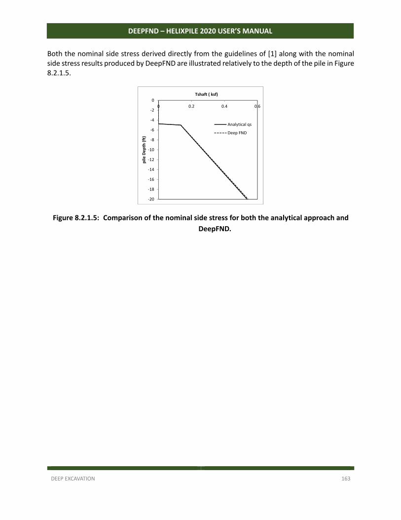
DEEP EXCAVATION 163
DEEPFND – HELIXPILE 2020 USER’S MANUAL
Both the nominal side stress derived directly from the guidelines of [1] along with the nominal side stress results produced by DeepFND are illustrated relatively to the depth of the pile in Figure 8.2.1.5.
Figure 8.2.1.5: Comparison of the nominal side stress for both the analytical approach and
DeepFND.
‐20
‐18
‐16
‐14
‐12
‐10
‐8
‐6
‐4
‐2
0
0 0.2 0.4 0.6
pile
De
pth
(ft
)
Tshaft ( ksf)
Analytical qs
Deep FND
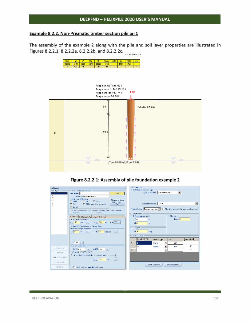
DEEP EXCAVATION 164
DEEPFND – HELIXPILE 2020 USER’S MANUAL
Example 8.2.2. Non-Prismatic timber section pile ω=1 The assembly of the example 2 along with the pile and soil layer properties are illustrated in Figures 8.2.2.1, 8.2.2.2a, 8.2.2.2b, and 8.2.2.2c.
Figure 8.2.2.1: Assembly of pile foundation example 2
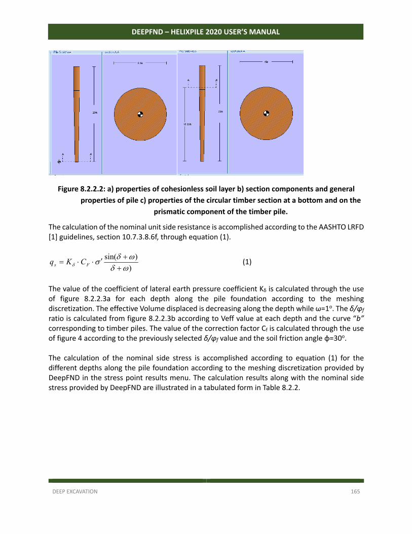
DEEP EXCAVATION 165
DEEPFND – HELIXPILE 2020 USER’S MANUAL
Figure 8.2.2.2: a) properties of cohesionless soil layer b) section components and general
properties of pile c) properties of the circular timber section at a bottom and on the
prismatic component of the timber pile.
The calculation of the nominal unit side resistance is accomplished according to the AASHTO LRFD [1] guidelines, section 10.7.3.8.6f, through equation (1).
)
)sin(
Fs CKq (1)
The value of the coefficient of lateral earth pressure coefficient Κδ is calculated through the use of figure 8.2.2.3a for each depth along the pile foundation according to the meshing discretization. The effective Volume displaced is decreasing along the depth while ω=1o. The δ/φf ratio is calculated from figure 8.2.2.3b according to Veff value at each depth and the curve “b” corresponding to timber piles. The value of the correction factor Cf is calculated through the use of figure 4 according to the previously selected δ/φf value and the soil friction angle φ=30ο. The calculation of the nominal side stress is accomplished according to equation (1) for the different depths along the pile foundation according to the meshing discretization provided by DeepFND in the stress point results menu. The calculation results along with the nominal side stress provided by DeepFND are illustrated in a tabulated form in Table 8.2.2.
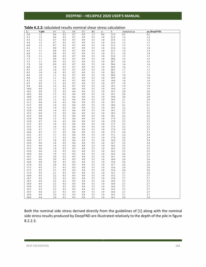
DEEP EXCAVATION 166
DEEPFND – HELIXPILE 2020 USER’S MANUAL
Table 6.2.2: tabulated results nominal shear stress calculation Li V.pile σv' Li δ/f Cf Kδ ω δ Analytical qs qs (DeepFND) -5.0 1.2 0.6 0.3 0.7 0.9 1.2 0.0 21.9 0.2 0.2 -5.3 1.2 0.6 0.3 0.7 0.9 5.3 1.0 21.9 1.2 1.2 -5.5 1.2 0.7 0.3 0.7 0.9 5.3 1.0 21.8 1.2 1.2 -5.8 1.2 0.7 0.3 0.7 0.9 5.3 1.0 21.6 1.3 1.3 -6.0 1.2 0.7 0.3 0.7 0.9 5.3 1.0 21.5 1.3 1.3 -6.3 1.1 0.8 0.3 0.7 0.9 5.3 1.0 21.4 1.4 1.4 -6.5 1.1 0.8 0.3 0.7 0.9 5.3 1.0 21.2 1.4 1.4 -6.8 1.1 0.8 0.3 0.7 0.9 5.3 1.0 21.1 1.4 1.4 -7.0 1.1 0.8 0.3 0.7 0.9 5.3 1.0 21.0 1.5 1.5 -7.3 1.1 0.9 0.3 0.7 0.9 5.3 1.0 20.8 1.5 1.5 -7.5 1.1 0.9 0.3 0.7 0.9 5.3 1.0 20.7 1.6 1.6 -7.8 1.0 0.9 0.3 0.7 0.9 5.3 1.0 20.6 1.6 1.6 -8.0 1.0 1.0 0.3 0.7 0.9 5.3 1.0 20.4 1.6 1.7 -8.3 1.0 1.0 0.3 0.7 0.9 5.3 1.0 20.3 1.7 1.7 -8.5 1.0 1.0 0.3 0.7 0.9 5.3 1.0 20.2 1.7 1.7 -8.8 1.0 1.1 0.3 0.7 0.9 5.3 1.0 20.0 1.8 1.8 -9.0 1.0 1.1 0.3 0.7 0.9 5.3 1.0 19.9 1.8 1.8 -9.3 1.0 1.1 0.3 0.7 0.9 5.3 1.0 19.8 1.8 1.8 -9.5 0.9 1.1 0.3 0.7 0.9 5.3 1.0 19.7 1.9 1.9 -9.8 0.9 1.2 0.3 0.7 0.9 5.3 1.0 19.5 1.9 1.9 -10.0 0.9 1.2 0.3 0.6 0.9 5.3 1.0 19.4 1.9 1.9 -10.3 0.9 1.2 0.3 0.6 0.9 5.3 1.0 19.3 2.0 2.0 -10.5 0.9 1.3 0.3 0.6 0.9 5.3 1.0 19.1 2.0 2.0 -10.8 0.9 1.3 0.3 0.6 0.9 5.3 1.0 19.0 2.0 2.0 -11.0 0.9 1.3 0.3 0.6 0.9 5.3 1.0 18.9 2.1 2.0 -11.3 0.8 1.4 0.3 0.6 0.9 5.3 1.0 18.7 2.1 2.1 -11.5 0.8 1.4 0.3 0.6 0.9 5.3 1.0 18.6 2.1 2.1 -11.8 0.8 1.4 0.3 0.6 0.9 5.3 1.0 18.5 2.2 2.1 -12.0 0.8 1.4 0.3 0.6 0.9 5.3 1.0 18.3 2.2 2.2 -12.3 0.8 1.5 0.3 0.6 0.9 5.3 1.0 18.2 2.2 2.2 -12.5 0.8 1.5 0.3 0.6 0.9 5.3 1.0 18.1 2.2 2.2 -12.8 0.8 1.5 0.3 0.6 0.9 5.3 1.0 17.9 2.3 2.2 -13.0 0.7 1.6 0.3 0.6 0.9 5.3 1.0 17.8 2.3 2.3 -13.3 0.7 1.6 0.3 0.6 0.9 5.3 1.0 17.7 2.3 2.3 -13.5 0.7 1.6 0.3 0.6 0.9 5.3 1.0 17.5 2.3 2.3 -13.8 0.7 1.7 0.3 0.6 0.9 5.3 1.0 17.4 2.4 2.3 -14.0 0.7 1.7 0.3 0.6 0.9 5.3 1.0 17.3 2.4 2.3 -14.3 0.7 1.7 0.3 0.6 0.9 5.3 1.0 17.1 2.4 2.4 -14.5 0.7 1.7 0.3 0.6 0.9 5.3 1.0 17.0 2.4 2.4 -14.8 0.7 1.8 0.3 0.6 0.9 5.3 1.0 16.9 2.5 2.4 -15.0 0.6 1.8 0.3 0.6 0.8 5.3 1.0 16.7 2.5 2.4 -15.3 0.6 1.8 0.3 0.6 0.8 5.3 1.0 16.6 2.5 2.5 -15.5 0.6 1.9 0.3 0.5 0.8 5.3 1.0 16.5 2.5 2.5 -15.8 0.6 1.9 0.3 0.5 0.8 5.3 1.0 16.3 2.5 2.5 -16.0 0.6 1.9 0.3 0.5 0.8 5.3 1.0 16.2 2.6 2.5 -16.3 0.6 2.0 0.3 0.5 0.8 5.3 1.0 16.1 2.6 2.5 -16.5 0.6 2.0 0.3 0.5 0.8 5.3 1.0 16.0 2.6 2.6 -16.8 0.6 2.0 0.3 0.5 0.8 5.3 1.0 15.8 2.6 2.6 -17.0 0.5 2.0 0.3 0.5 0.8 5.3 1.0 15.7 2.6 2.6 -17.3 0.5 2.1 0.3 0.5 0.8 5.3 1.0 15.6 2.6 2.6 -17.5 0.5 2.1 0.3 0.5 0.8 5.3 1.0 15.4 2.6 2.6 -17.8 0.5 2.1 0.3 0.5 0.8 5.3 1.0 15.3 2.7 2.6 -18.0 0.5 2.2 0.3 0.5 0.8 5.3 1.0 15.2 2.7 2.7 -18.3 0.5 2.2 0.3 0.5 0.8 5.3 1.0 15.0 2.7 2.7 -18.5 0.5 2.2 0.3 0.5 0.8 5.3 1.0 14.9 2.7 2.7 -18.8 0.5 2.3 0.3 0.5 0.8 5.3 1.0 14.8 2.7 2.7 -19.0 0.5 2.3 0.3 0.5 0.8 5.3 1.0 14.6 2.7 2.7 -19.3 0.5 2.3 0.3 0.5 0.8 5.3 1.0 14.5 2.7 2.7 -19.5 0.4 2.3 0.3 0.5 0.8 5.3 1.0 14.4 2.7 2.7 -19.8 0.4 2.4 0.3 0.5 0.8 5.3 1.0 14.2 2.7 2.7 -20.0 0.4 2.4 0.1 0.5 0.8 5.3 1.0 14.1 2.8 2.8
Both the nominal side stress derived directly from the guidelines of [1] along with the nominal side stress results produced by DeepFND are illustrated relatively to the depth of the pile in figure 8.2.2.3.
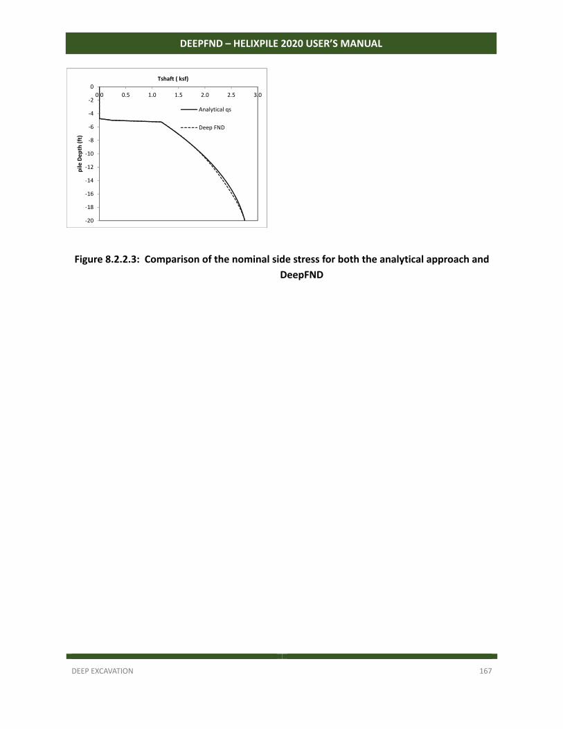
DEEP EXCAVATION 167
DEEPFND – HELIXPILE 2020 USER’S MANUAL
Figure 8.2.2.3: Comparison of the nominal side stress for both the analytical approach and
DeepFND
‐20
‐18
‐16
‐14
‐12
‐10
‐8
‐6
‐4
‐2
0
0.0 0.5 1.0 1.5 2.0 2.5 3.0
pile
De
pth
(ft
) Tshaft ( ksf)
Analytical qs
Deep FND
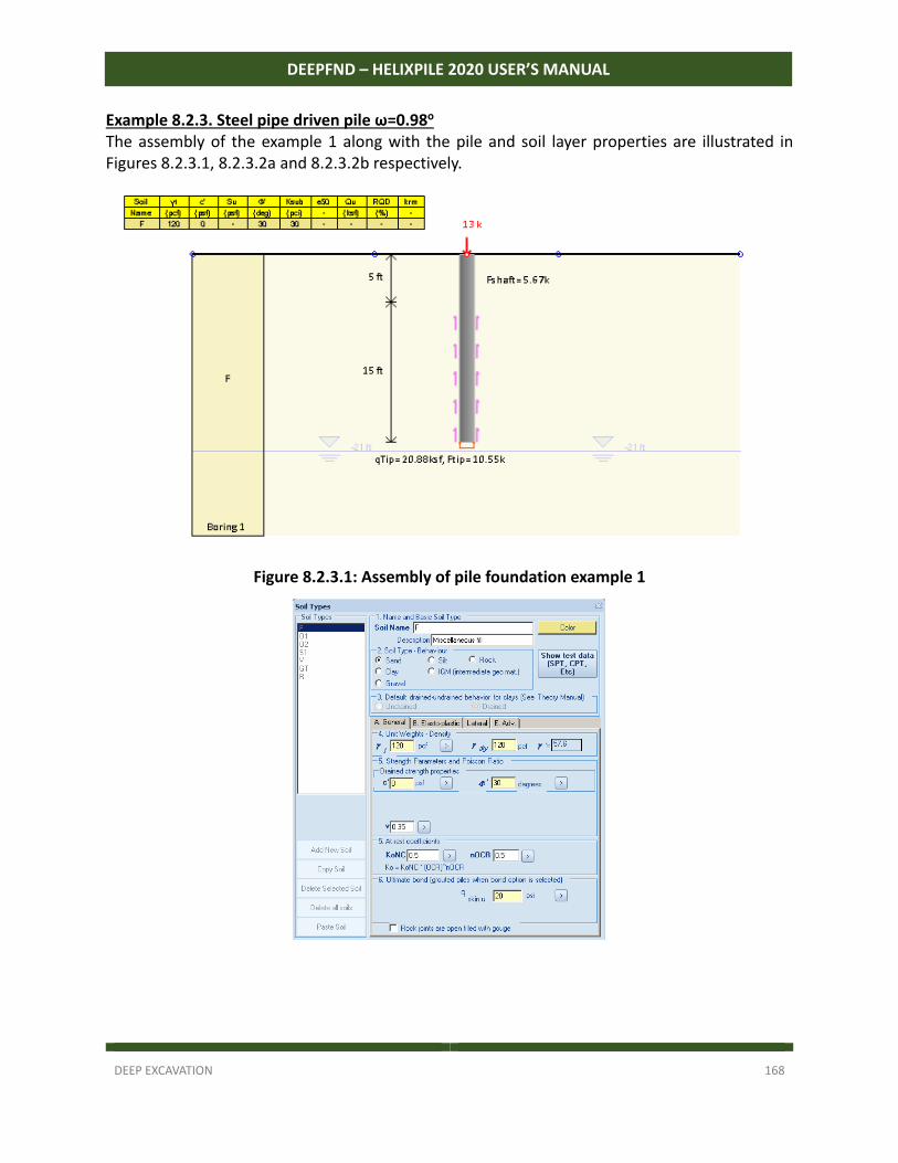
DEEP EXCAVATION 168
DEEPFND – HELIXPILE 2020 USER’S MANUAL
Example 8.2.3. Steel pipe driven pile ω=0.98o The assembly of the example 1 along with the pile and soil layer properties are illustrated in Figures 8.2.3.1, 8.2.3.2a and 8.2.3.2b respectively.
Figure 8.2.3.1: Assembly of pile foundation example 1
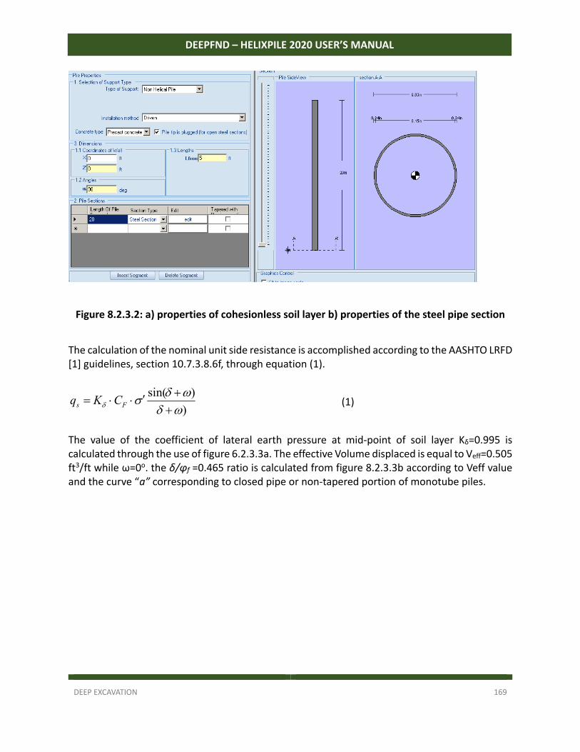
DEEP EXCAVATION 169
DEEPFND – HELIXPILE 2020 USER’S MANUAL
Figure 8.2.3.2: a) properties of cohesionless soil layer b) properties of the steel pipe section
The calculation of the nominal unit side resistance is accomplished according to the AASHTO LRFD [1] guidelines, section 10.7.3.8.6f, through equation (1).
)
)sin(
Fs CKq (1)
The value of the coefficient of lateral earth pressure at mid‐point of soil layer Κδ=0.995 is calculated through the use of figure 6.2.3.3a. The effective Volume displaced is equal to Veff=0.505 ft3/ft while ω=0o. the δ/φf =0.465 ratio is calculated from figure 8.2.3.3b according to Veff value and the curve “a” corresponding to closed pipe or non‐tapered portion of monotube piles.
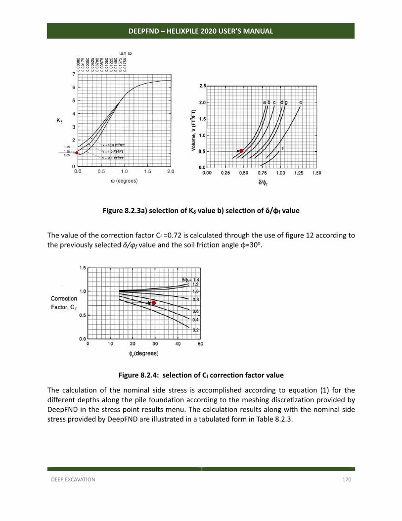
DEEP EXCAVATION 170
DEEPFND – HELIXPILE 2020 USER’S MANUAL
Figure 8.2.3a) selection of Kδ value b) selection of δ/φf value
The value of the correction factor Cf =0.72 is calculated through the use of figure 12 according to the previously selected δ/φf value and the soil friction angle φ=30ο.
Figure 8.2.4: selection of Cf correction factor value
The calculation of the nominal side stress is accomplished according to equation (1) for the different depths along the pile foundation according to the meshing discretization provided by DeepFND in the stress point results menu. The calculation results along with the nominal side stress provided by DeepFND are illustrated in a tabulated form in Table 8.2.3.
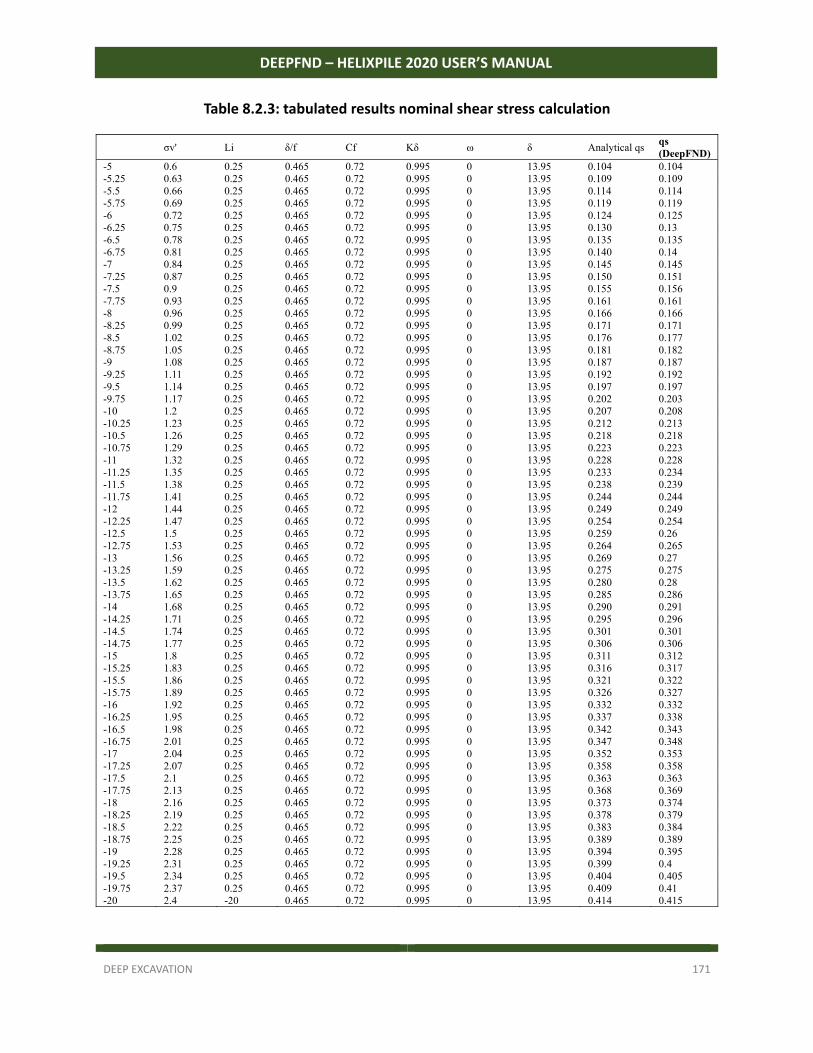
DEEP EXCAVATION 171
DEEPFND – HELIXPILE 2020 USER’S MANUAL
Table 8.2.3: tabulated results nominal shear stress calculation
σv' Li δ/f Cf Kδ ω δ Analytical qs qs (DeepFND)
-5 0.6 0.25 0.465 0.72 0.995 0 13.95 0.104 0.104 -5.25 0.63 0.25 0.465 0.72 0.995 0 13.95 0.109 0.109 -5.5 0.66 0.25 0.465 0.72 0.995 0 13.95 0.114 0.114 -5.75 0.69 0.25 0.465 0.72 0.995 0 13.95 0.119 0.119 -6 0.72 0.25 0.465 0.72 0.995 0 13.95 0.124 0.125 -6.25 0.75 0.25 0.465 0.72 0.995 0 13.95 0.130 0.13 -6.5 0.78 0.25 0.465 0.72 0.995 0 13.95 0.135 0.135 -6.75 0.81 0.25 0.465 0.72 0.995 0 13.95 0.140 0.14 -7 0.84 0.25 0.465 0.72 0.995 0 13.95 0.145 0.145 -7.25 0.87 0.25 0.465 0.72 0.995 0 13.95 0.150 0.151 -7.5 0.9 0.25 0.465 0.72 0.995 0 13.95 0.155 0.156 -7.75 0.93 0.25 0.465 0.72 0.995 0 13.95 0.161 0.161 -8 0.96 0.25 0.465 0.72 0.995 0 13.95 0.166 0.166 -8.25 0.99 0.25 0.465 0.72 0.995 0 13.95 0.171 0.171 -8.5 1.02 0.25 0.465 0.72 0.995 0 13.95 0.176 0.177 -8.75 1.05 0.25 0.465 0.72 0.995 0 13.95 0.181 0.182 -9 1.08 0.25 0.465 0.72 0.995 0 13.95 0.187 0.187 -9.25 1.11 0.25 0.465 0.72 0.995 0 13.95 0.192 0.192 -9.5 1.14 0.25 0.465 0.72 0.995 0 13.95 0.197 0.197 -9.75 1.17 0.25 0.465 0.72 0.995 0 13.95 0.202 0.203 -10 1.2 0.25 0.465 0.72 0.995 0 13.95 0.207 0.208 -10.25 1.23 0.25 0.465 0.72 0.995 0 13.95 0.212 0.213 -10.5 1.26 0.25 0.465 0.72 0.995 0 13.95 0.218 0.218 -10.75 1.29 0.25 0.465 0.72 0.995 0 13.95 0.223 0.223 -11 1.32 0.25 0.465 0.72 0.995 0 13.95 0.228 0.228 -11.25 1.35 0.25 0.465 0.72 0.995 0 13.95 0.233 0.234 -11.5 1.38 0.25 0.465 0.72 0.995 0 13.95 0.238 0.239 -11.75 1.41 0.25 0.465 0.72 0.995 0 13.95 0.244 0.244 -12 1.44 0.25 0.465 0.72 0.995 0 13.95 0.249 0.249 -12.25 1.47 0.25 0.465 0.72 0.995 0 13.95 0.254 0.254 -12.5 1.5 0.25 0.465 0.72 0.995 0 13.95 0.259 0.26 -12.75 1.53 0.25 0.465 0.72 0.995 0 13.95 0.264 0.265 -13 1.56 0.25 0.465 0.72 0.995 0 13.95 0.269 0.27 -13.25 1.59 0.25 0.465 0.72 0.995 0 13.95 0.275 0.275 -13.5 1.62 0.25 0.465 0.72 0.995 0 13.95 0.280 0.28 -13.75 1.65 0.25 0.465 0.72 0.995 0 13.95 0.285 0.286 -14 1.68 0.25 0.465 0.72 0.995 0 13.95 0.290 0.291 -14.25 1.71 0.25 0.465 0.72 0.995 0 13.95 0.295 0.296 -14.5 1.74 0.25 0.465 0.72 0.995 0 13.95 0.301 0.301 -14.75 1.77 0.25 0.465 0.72 0.995 0 13.95 0.306 0.306 -15 1.8 0.25 0.465 0.72 0.995 0 13.95 0.311 0.312 -15.25 1.83 0.25 0.465 0.72 0.995 0 13.95 0.316 0.317 -15.5 1.86 0.25 0.465 0.72 0.995 0 13.95 0.321 0.322 -15.75 1.89 0.25 0.465 0.72 0.995 0 13.95 0.326 0.327 -16 1.92 0.25 0.465 0.72 0.995 0 13.95 0.332 0.332 -16.25 1.95 0.25 0.465 0.72 0.995 0 13.95 0.337 0.338 -16.5 1.98 0.25 0.465 0.72 0.995 0 13.95 0.342 0.343 -16.75 2.01 0.25 0.465 0.72 0.995 0 13.95 0.347 0.348 -17 2.04 0.25 0.465 0.72 0.995 0 13.95 0.352 0.353 -17.25 2.07 0.25 0.465 0.72 0.995 0 13.95 0.358 0.358 -17.5 2.1 0.25 0.465 0.72 0.995 0 13.95 0.363 0.363 -17.75 2.13 0.25 0.465 0.72 0.995 0 13.95 0.368 0.369 -18 2.16 0.25 0.465 0.72 0.995 0 13.95 0.373 0.374 -18.25 2.19 0.25 0.465 0.72 0.995 0 13.95 0.378 0.379 -18.5 2.22 0.25 0.465 0.72 0.995 0 13.95 0.383 0.384 -18.75 2.25 0.25 0.465 0.72 0.995 0 13.95 0.389 0.389 -19 2.28 0.25 0.465 0.72 0.995 0 13.95 0.394 0.395 -19.25 2.31 0.25 0.465 0.72 0.995 0 13.95 0.399 0.4 -19.5 2.34 0.25 0.465 0.72 0.995 0 13.95 0.404 0.405 -19.75 2.37 0.25 0.465 0.72 0.995 0 13.95 0.409 0.41 -20 2.4 -20 0.465 0.72 0.995 0 13.95 0.414 0.415
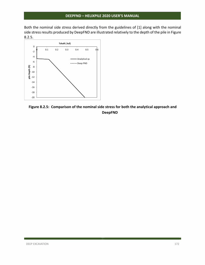
DEEP EXCAVATION 172
DEEPFND – HELIXPILE 2020 USER’S MANUAL
Both the nominal side stress derived directly from the guidelines of [1] along with the nominal side stress results produced by DeepFND are illustrated relatively to the depth of the pile in Figure 8.2.5.
Figure 8.2.5: Comparison of the nominal side stress for both the analytical approach and
DeepFND
‐20
‐18
‐16
‐14
‐12
‐10
‐8
‐6
‐4
‐2
0
0 0.1 0.2 0.3 0.4 0.5 0.6
pile
De
pth
(ft
)
Tshaft ( ksf)
Analytical qs
Deep FND
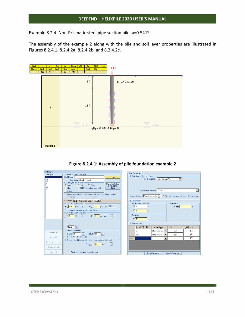
DEEP EXCAVATION 173
DEEPFND – HELIXPILE 2020 USER’S MANUAL
Example 8.2.4. Non‐Prismatic steel pipe section pile ω=0.541o The assembly of the example 2 along with the pile and soil layer properties are illustrated in Figures 8.2.4.1, 8.2.4.2a, 8.2.4.2b, and 8.2.4.2c.
Figure 8.2.4.1: Assembly of pile foundation example 2
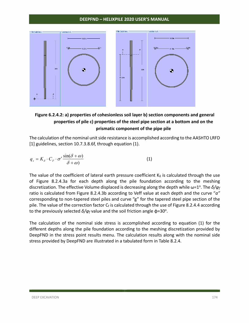
DEEP EXCAVATION 174
DEEPFND – HELIXPILE 2020 USER’S MANUAL
Figure 6.2.4.2: a) properties of cohesionless soil layer b) section components and general
properties of pile c) properties of the steel pipe section at a bottom and on the
prismatic component of the pipe pile
The calculation of the nominal unit side resistance is accomplished according to the AASHTO LRFD [1] guidelines, section 10.7.3.8.6f, through equation (1).
)
)sin(
Fs CKq (1)
The value of the coefficient of lateral earth pressure coefficient Κδ is calculated through the use of Figure 8.2.4.3a for each depth along the pile foundation according to the meshing discretization. The effective Volume displaced is decreasing along the depth while ω=1o. The δ/φf ratio is calculated from Figure 8.2.4.3b according to Veff value at each depth and the curve “a” corresponding to non‐tapered steel piles and curve “g” for the tapered steel pipe section of the pile. The value of the correction factor Cf is calculated through the use of Figure 8.2.4.4 according to the previously selected δ/φf value and the soil friction angle φ=30ο. The calculation of the nominal side stress is accomplished according to equation (1) for the different depths along the pile foundation according to the meshing discretization provided by DeepFND in the stress point results menu. The calculation results along with the nominal side stress provided by DeepFND are illustrated in a tabulated form in Table 8.2.4.
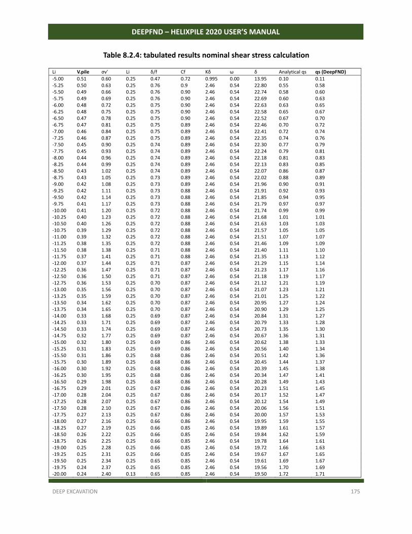
DEEP EXCAVATION 175
DEEPFND – HELIXPILE 2020 USER’S MANUAL
Table 8.2.4: tabulated results nominal shear stress calculation
Li V.pile σv' Li δ/f Cf Kδ ω δ Analytical qs qs (DeepFND)
‐5.00 0.51 0.60 0.25 0.47 0.72 0.995 0.00 13.95 0.10 0.11 ‐5.25 0.50 0.63 0.25 0.76 0.9 2.46 0.54 22.80 0.55 0.58 ‐5.50 0.49 0.66 0.25 0.76 0.90 2.46 0.54 22.74 0.58 0.60 ‐5.75 0.49 0.69 0.25 0.76 0.90 2.46 0.54 22.69 0.60 0.63 ‐6.00 0.48 0.72 0.25 0.75 0.90 2.46 0.54 22.63 0.63 0.65 ‐6.25 0.48 0.75 0.25 0.75 0.90 2.46 0.54 22.58 0.65 0.67 ‐6.50 0.47 0.78 0.25 0.75 0.90 2.46 0.54 22.52 0.67 0.70 ‐6.75 0.47 0.81 0.25 0.75 0.89 2.46 0.54 22.46 0.70 0.72 ‐7.00 0.46 0.84 0.25 0.75 0.89 2.46 0.54 22.41 0.72 0.74 ‐7.25 0.46 0.87 0.25 0.75 0.89 2.46 0.54 22.35 0.74 0.76 ‐7.50 0.45 0.90 0.25 0.74 0.89 2.46 0.54 22.30 0.77 0.79 ‐7.75 0.45 0.93 0.25 0.74 0.89 2.46 0.54 22.24 0.79 0.81 ‐8.00 0.44 0.96 0.25 0.74 0.89 2.46 0.54 22.18 0.81 0.83 ‐8.25 0.44 0.99 0.25 0.74 0.89 2.46 0.54 22.13 0.83 0.85 ‐8.50 0.43 1.02 0.25 0.74 0.89 2.46 0.54 22.07 0.86 0.87 ‐8.75 0.43 1.05 0.25 0.73 0.89 2.46 0.54 22.02 0.88 0.89 ‐9.00 0.42 1.08 0.25 0.73 0.89 2.46 0.54 21.96 0.90 0.91 ‐9.25 0.42 1.11 0.25 0.73 0.88 2.46 0.54 21.91 0.92 0.93 ‐9.50 0.42 1.14 0.25 0.73 0.88 2.46 0.54 21.85 0.94 0.95 ‐9.75 0.41 1.17 0.25 0.73 0.88 2.46 0.54 21.79 0.97 0.97 ‐10.00 0.41 1.20 0.25 0.72 0.88 2.46 0.54 21.74 0.99 0.99 ‐10.25 0.40 1.23 0.25 0.72 0.88 2.46 0.54 21.68 1.01 1.01 ‐10.50 0.40 1.26 0.25 0.72 0.88 2.46 0.54 21.63 1.03 1.03 ‐10.75 0.39 1.29 0.25 0.72 0.88 2.46 0.54 21.57 1.05 1.05 ‐11.00 0.39 1.32 0.25 0.72 0.88 2.46 0.54 21.51 1.07 1.07 ‐11.25 0.38 1.35 0.25 0.72 0.88 2.46 0.54 21.46 1.09 1.09 ‐11.50 0.38 1.38 0.25 0.71 0.88 2.46 0.54 21.40 1.11 1.10 ‐11.75 0.37 1.41 0.25 0.71 0.88 2.46 0.54 21.35 1.13 1.12 ‐12.00 0.37 1.44 0.25 0.71 0.87 2.46 0.54 21.29 1.15 1.14 ‐12.25 0.36 1.47 0.25 0.71 0.87 2.46 0.54 21.23 1.17 1.16 ‐12.50 0.36 1.50 0.25 0.71 0.87 2.46 0.54 21.18 1.19 1.17 ‐12.75 0.36 1.53 0.25 0.70 0.87 2.46 0.54 21.12 1.21 1.19 ‐13.00 0.35 1.56 0.25 0.70 0.87 2.46 0.54 21.07 1.23 1.21 ‐13.25 0.35 1.59 0.25 0.70 0.87 2.46 0.54 21.01 1.25 1.22 ‐13.50 0.34 1.62 0.25 0.70 0.87 2.46 0.54 20.95 1.27 1.24 ‐13.75 0.34 1.65 0.25 0.70 0.87 2.46 0.54 20.90 1.29 1.25 ‐14.00 0.33 1.68 0.25 0.69 0.87 2.46 0.54 20.84 1.31 1.27 ‐14.25 0.33 1.71 0.25 0.69 0.87 2.46 0.54 20.79 1.33 1.28 ‐14.50 0.33 1.74 0.25 0.69 0.87 2.46 0.54 20.73 1.35 1.30 ‐14.75 0.32 1.77 0.25 0.69 0.87 2.46 0.54 20.67 1.36 1.31 ‐15.00 0.32 1.80 0.25 0.69 0.86 2.46 0.54 20.62 1.38 1.33 ‐15.25 0.31 1.83 0.25 0.69 0.86 2.46 0.54 20.56 1.40 1.34 ‐15.50 0.31 1.86 0.25 0.68 0.86 2.46 0.54 20.51 1.42 1.36 ‐15.75 0.30 1.89 0.25 0.68 0.86 2.46 0.54 20.45 1.44 1.37 ‐16.00 0.30 1.92 0.25 0.68 0.86 2.46 0.54 20.39 1.45 1.38 ‐16.25 0.30 1.95 0.25 0.68 0.86 2.46 0.54 20.34 1.47 1.41 ‐16.50 0.29 1.98 0.25 0.68 0.86 2.46 0.54 20.28 1.49 1.43 ‐16.75 0.29 2.01 0.25 0.67 0.86 2.46 0.54 20.23 1.51 1.45 ‐17.00 0.28 2.04 0.25 0.67 0.86 2.46 0.54 20.17 1.52 1.47 ‐17.25 0.28 2.07 0.25 0.67 0.86 2.46 0.54 20.12 1.54 1.49 ‐17.50 0.28 2.10 0.25 0.67 0.86 2.46 0.54 20.06 1.56 1.51 ‐17.75 0.27 2.13 0.25 0.67 0.86 2.46 0.54 20.00 1.57 1.53 ‐18.00 0.27 2.16 0.25 0.66 0.86 2.46 0.54 19.95 1.59 1.55 ‐18.25 0.27 2.19 0.25 0.66 0.85 2.46 0.54 19.89 1.61 1.57 ‐18.50 0.26 2.22 0.25 0.66 0.85 2.46 0.54 19.84 1.62 1.59 ‐18.75 0.26 2.25 0.25 0.66 0.85 2.46 0.54 19.78 1.64 1.61 ‐19.00 0.25 2.28 0.25 0.66 0.85 2.46 0.54 19.72 1.66 1.63 ‐19.25 0.25 2.31 0.25 0.66 0.85 2.46 0.54 19.67 1.67 1.65 ‐19.50 0.25 2.34 0.25 0.65 0.85 2.46 0.54 19.61 1.69 1.67 ‐19.75 0.24 2.37 0.25 0.65 0.85 2.46 0.54 19.56 1.70 1.69 ‐20.00 0.24 2.40 0.13 0.65 0.85 2.46 0.54 19.50 1.72 1.71
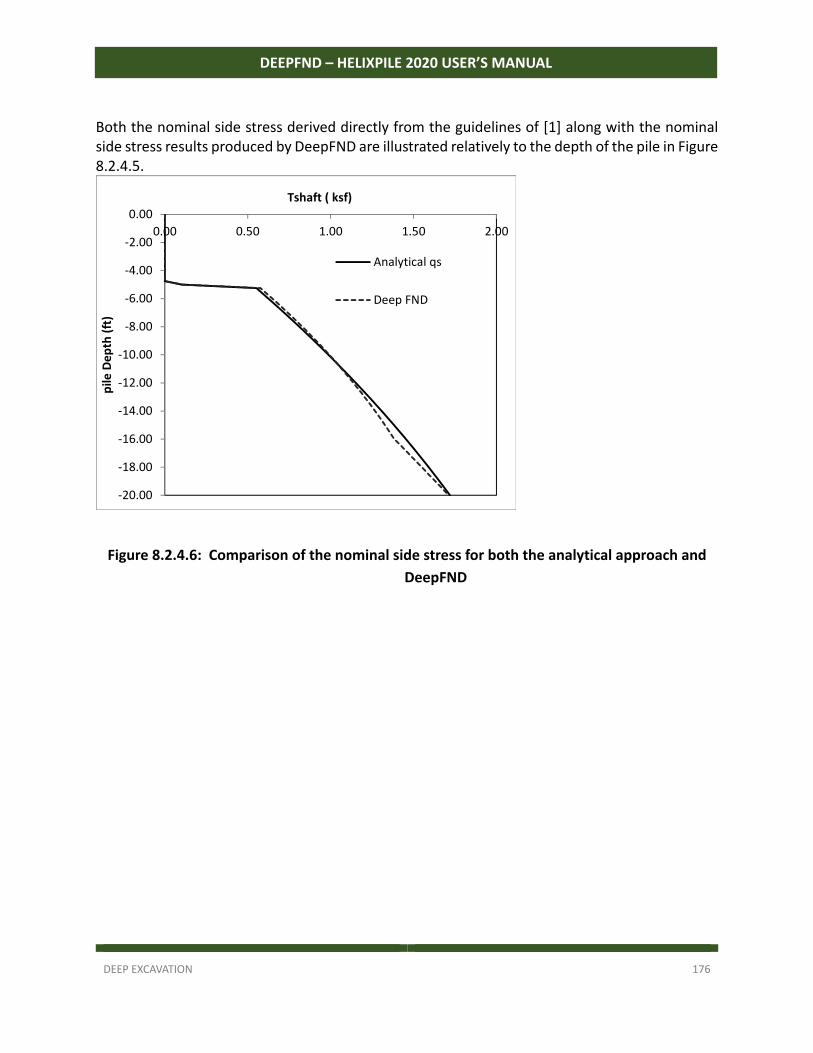
DEEP EXCAVATION 176
DEEPFND – HELIXPILE 2020 USER’S MANUAL
Both the nominal side stress derived directly from the guidelines of [1] along with the nominal side stress results produced by DeepFND are illustrated relatively to the depth of the pile in Figure 8.2.4.5.
Figure 8.2.4.6: Comparison of the nominal side stress for both the analytical approach and
DeepFND
‐20.00
‐18.00
‐16.00
‐14.00
‐12.00
‐10.00
‐8.00
‐6.00
‐4.00
‐2.00
0.00
0.00 0.50 1.00 1.50 2.00
pile
De
pth
(ft
)
Tshaft ( ksf)
Analytical qs
Deep FND
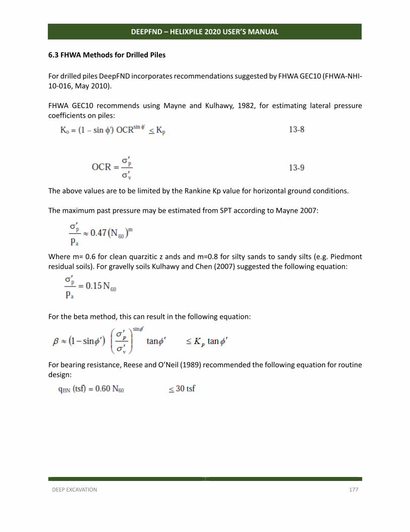
DEEP EXCAVATION 177
DEEPFND – HELIXPILE 2020 USER’S MANUAL
6.3 FHWA Methods for Drilled Piles
For drilled piles DeepFND incorporates recommendations suggested by FHWA GEC10 (FHWA‐NHI‐10‐016, May 2010). FHWA GEC10 recommends using Mayne and Kulhawy, 1982, for estimating lateral pressure coefficients on piles:
The above values are to be limited by the Rankine Kp value for horizontal ground conditions. The maximum past pressure may be estimated from SPT according to Mayne 2007:
Where m= 0.6 for clean quarzitic z ands and m=0.8 for silty sands to sandy silts (e.g. Piedmont residual soils). For gravelly soils Kulhawy and Chen (2007) suggested the following equation:
For the beta method, this can result in the following equation:
For bearing resistance, Reese and O’Neil (1989) recommended the following equation for routine design:
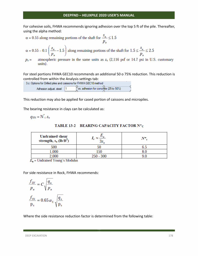
DEEP EXCAVATION 178
DEEPFND – HELIXPILE 2020 USER’S MANUAL
For cohesive soils, FHWA recommends ignoring adhesion over the top 5 ft of the pile. Thereafter, using the alpha method:
For steel portions FHWA GEC10 recommends an additional 50 o 75% reduction. This reduction is controlled from within the Analysis settings tab:
This reduction may also be applied for cased portion of caissons and micropiles. The bearing resistance in clays can be calculated as:
For side resistance in Rock, FHWA recommends:
Where the side resistance reduction factor is determined from the following table:
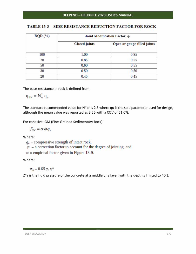
DEEP EXCAVATION 179
DEEPFND – HELIXPILE 2020 USER’S MANUAL
The base resistance in rock is defined from:
The standard recommended value for N*cr is 2.5 where qu is the sole parameter used for design, although the mean value was reported as 3.56 with a COV of 61.0%. For cohesive IGM (Fine‐Grained Sedimentary Rock):
Where:
Where:
Z*1 is the fluid pressure of the concrete at a middle of a layer, with the depth z limited to 40ft.
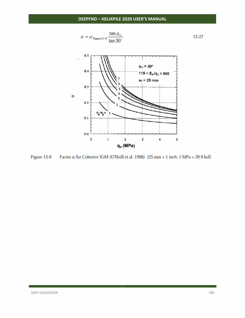
DEEP EXCAVATION 180
DEEPFND – HELIXPILE 2020 USER’S MANUAL
DEEP EXCAVATION 181
DEEPFND – HELIXPILE 2020 USER’S MANUAL
6.4 FHWA methods for CFA and Drilled-In-Displacement piles
For pile adhesion FHWA recommends using the tri‐linear relationship from FHWA 1999, similar to the one outline before for drilled piles. End bearing in clays is also treated in a similar way with FHWA GEC10:
The alternative methods for side‐shear estimates using the undrained shear strength can also be used. The method by Coleman and Acrement (2002) was derived from pile load tests conducted in mixed soil conditions of mostly alluvial and loessial deposits and interbedded sands and clays in Mississippi and Louisiana:
For the TXDOT 1971 method, a single adhesion factor of 0.7 can be applied with a maximum value of 1.25 tsf (to be manually controlled by the user).
DEEP EXCAVATION 182
DEEPFND – HELIXPILE 2020 USER’S MANUAL
For cohesionless soil, FHWA 1999 recommends:
For the alternative method by Coleman and Acrement (2002), using SPT values:
DEEP EXCAVATION 183
DEEPFND – HELIXPILE 2020 USER’S MANUAL
For other SPT methods:
For tip resistance:
The interpolation of these parameters is controlled from user input in the soils tab:
This previous interpolation should be treated as approximate. For CPT test data methods, DeepFND can utilize the recommended methods. The user though can select how close to the upper or lower limit the estimation should be from:
The default value is 25% above the lower recommended limit, 100% will produce the upper limit for both the shaft and the bearing resistance.
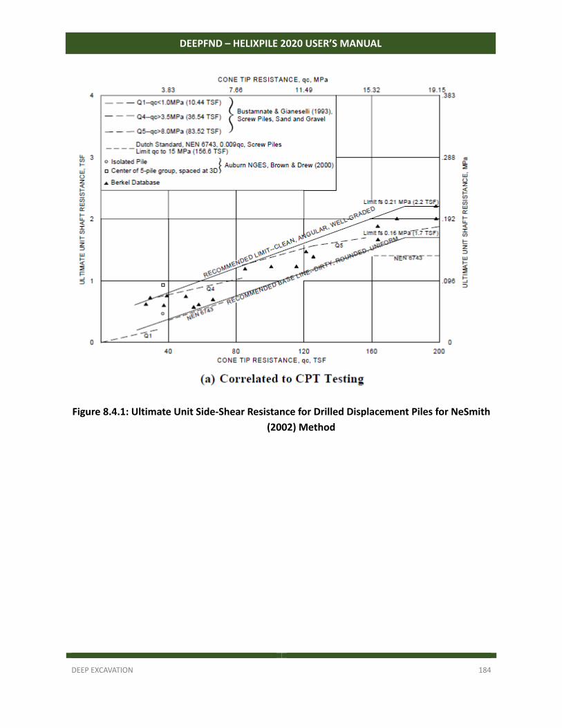
DEEP EXCAVATION 184
DEEPFND – HELIXPILE 2020 USER’S MANUAL
Figure 8.4.1: Ultimate Unit Side-Shear Resistance for Drilled Displacement Piles for NeSmith
(2002) Method
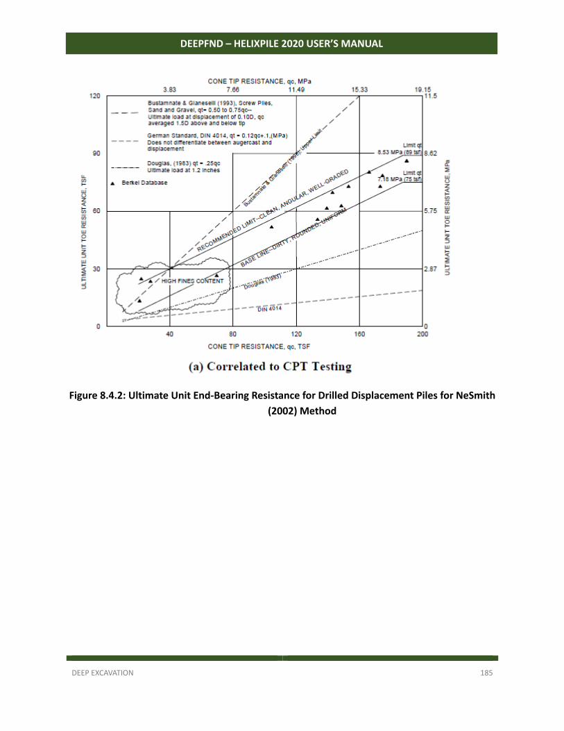
DEEP EXCAVATION 185
DEEPFND – HELIXPILE 2020 USER’S MANUAL
Figure 8.4.2: Ultimate Unit End-Bearing Resistance for Drilled Displacement Piles for NeSmith
(2002) Method
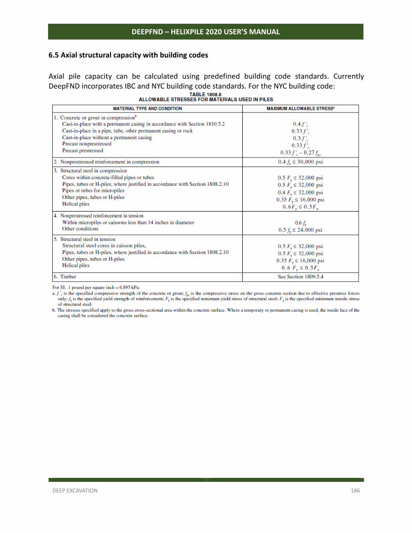
DEEP EXCAVATION 186
DEEPFND – HELIXPILE 2020 USER’S MANUAL
6.5 Axial structural capacity with building codes
Axial pile capacity can be calculated using predefined building code standards. Currently DeepFND incorporates IBC and NYC building code standards. For the NYC building code:
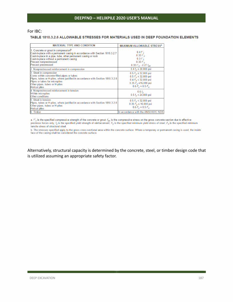
DEEP EXCAVATION 187
DEEPFND – HELIXPILE 2020 USER’S MANUAL
For IBC:
Alternatively, structural capacity is determined by the concrete, steel, or timber design code that is utilized assuming an appropriate safety factor.
DEEP EXCAVATION 188
DEEPFND – HELIXPILE 2020 USER’S MANUAL
TABLE OF FIGURES Figure 1.7.1: The DeepFND activation window – SITE and MID codes. ....................................... 11
Figure 1.8.1: Activating a single license. ...................................................................................... 12
Figure 1.8.2: Select to remove the license. ................................................................................. 13
Figure 1.8.3 Save current removal code. ..................................................................................... 13
Figure 1.8.4 Login to the activation center. ................................................................................. 14
Figure 1.8.6 Select to update a license. ....................................................................................... 15
Figure 1.8.7 Save new activation code. ....................................................................................... 15
Figure 2.1.1: General DeepFND 2020 Interface. .......................................................................... 17
Figure 2.2.1: Main button. .......................................................................................................... 18
Figure 2.2.2: Design section toolbar. ........................................................................................... 19
Figure 2.2.3: Calculate tools. ....................................................................................................... 19
Figure 2.3.1: DeepFND 2017: General tab. .................................................................................. 21
Figure 2.3.2: Project information dialog. ..................................................................................... 21
Figure 2.3.3: Model Elevation dialog. .......................................................................................... 22
Figure 2.3.4: Design Section Name and General Data dialog. ...................................................... 23
Figure 2.3.5: Clay behavior options. ............................................................................................ 24
Figure 2.3.6: Unselected pile length optimization option. ........................................................... 25
Figure 2.3.7: Selected pile length optimization option. ............................................................... 25
Figure 2.3.8: Ground water table. ............................................................................................... 26
Figure 2.4.1: The Properties tab menu. ....................................................................................... 27
Figure 2.5.1: The Analysis tab menu. ........................................................................................... 28
Figure 2.5.2: The Bearing Capacity Equations. ............................................................................ 28
Figure 2.5.3: The Bearing Capacity Methods. .............................................................................. 28
Figure 2.5.4: The Installation Disturbance Effects dialog. ............................................................ 29
Figure 2.5.5: The available options for c’ or Su factors. ............................................................... 29
Figure 2.5.6: The cylinder method options. ................................................................................. 30
Figure 2.5.7: Rock options. .......................................................................................................... 30
Figure 2.6.2: Code options. ......................................................................................................... 31
Figure 2.6.3: Load combinations available in DeepFND. .............................................................. 33
Figure 2.7.1: The Settlement tab menu. ...................................................................................... 33
Figure 2.7.2: The pile acceptance criteria dialog. ........................................................................ 34
Figure 2.7.3: The axial pile load test records dialog. .................................................................... 35
Figure 2.8.1: The Lateral tab menu. ............................................................................................. 36
Figure 2.8.2: The Lateral pile analysis settings dialog. ................................................................. 36
Figure 2.8.2: The Trapezoidal loads dialog. .................................................................................. 37
DEEP EXCAVATION 189
DEEPFND – HELIXPILE 2020 USER’S MANUAL
Figure 2.8.3: The lateral pile load test records dialog. ................................................................. 38
Figure 2.9.1: The Pile Caps tab menu. ......................................................................................... 39
Figure 2.9.2: Option to analyze a single pile or a pile cap. ........................................................... 39
Figure 2.9.3: Option to include seismic loads and define seismic accelerations. ......................... 40
Figure 2.11.1: The Reports tab menu. ......................................................................................... 42
Figure 2.12.2: Edit the soil properties table position. .................................................................. 43
Figure 2.13.1: The Help tab menu. .............................................................................................. 44
Figure 2.13.2: Settings – General Tab. ......................................................................................... 44
Figure 2.13.3: Settings – Fonts/View Tab. ................................................................................... 45
Figure 2.14.1: The Torque tab menu. .......................................................................................... 46
Figure 2.14.2: The Installation Torque Profiles dialog. ................................................................. 46
Figure 2.15.1: Option to open DeepFND as administrator. .......................................................... 47
Figure 2.15.2: Change settings and set project as default. .......................................................... 48
Figure 3.1.1: Edit general elevation options. ............................................................................... 49
Figure 3.1.2: Design section options and limits ........................................................................... 50
Figure 3.2.1: Project information dialog ...................................................................................... 50
Figure 3.3.1: Open soil types dialog and edit list of soils. ............................................................ 51
Figure 3.3.2: Define name, color and soil type of each soil. ........................................................ 52
Figure 3.3.3: General soil properties – Sands and Clays. ............................................................. 53
Figure 3.3.4: Soil Model options. ................................................................................................. 54
Figure 3.3.5: Lateral parameters for sands and clays. .................................................................. 55
Figure 3.3.6: Advanced options tab. ............................................................................................ 56
Figure 3.3.7: SPT Estimator in DeepFND. ..................................................................................... 57
Figure 3.3.8: Local soil property estimation tools in DeepFND. ................................................... 57
Figure 3.4.1: Assign a boring to the selected design section. ...................................................... 58
Figure 3.4.2: Define soil layers in DeepFND. ................................................................................ 58
Figure 3.5.1: Defined general pile properties. ............................................................................. 59
Figure 3.5.2: Define pile type and structural section. .................................................................. 61
Figure 3.6.1: Define helical anchor section properties. ............................................................... 62
Figure 3.6.2: Edit helix configurations. ........................................................................................ 63
Figure 3.6.3: Helical anchor geotechnical capacity options. ........................................................ 64
Figure 3.6.4. External casing options. .......................................................................................... 64
Figure 3.7.1: Edit non‐helical pile sections. ................................................................................. 65
Figure 3.7.2: Edit reinforced concrete section reinforcement. .................................................... 66
Figure 3.7.3: Edit steel section reinforcement. ............................................................................ 66
Figure 3.8.1: Access the Edit Pile Caps dialog. ............................................................................. 67
Figure 3.8.2: Define the Pile Cap shape and interaction factors. ................................................. 67
DEEP EXCAVATION 190
DEEPFND – HELIXPILE 2020 USER’S MANUAL
Figure 3.8.3: Footing properties, pile weight and option to treat Pile Cap as a Pile Raft. ............ 68
Figure 3.8.4: Loading modes. ...................................................................................................... 68
Figure 3.8.5: Pile Caps – Edit pile properties. .............................................................................. 69
Figure 3.9.1: Manage stages in general tab and below the model area ...................................... 70
Figure 3.9.2: Loads on Pile dialog. ............................................................................................... 70
Figure 3.9.3: Define load category. .............................................................................................. 71
Figure 3.9.4: Defined load in each stage...................................................................................... 72
Figure 3.9.5: A Distributed load applied on the pile. ................................................................... 73
Figure 3.10.1: Define Footing Loads (applied on cap centroid). .................................................. 74
Figure 3.10.2: Add a point load group and edit point load properties. ....................................... 75
Figure 3.10.3: Add an area load and edit the load properties. .................................................... 75
Figure 3.10.4: Add a linear load and edit the load properties. .................................................... 76
Figure 3.11.1: Available CPT records options. ............................................................................. 77
Figure 3.11.2: Available SPT records options. .............................................................................. 79
Figure 3.11.3: SPT records options dialog. .................................................................................. 79
Figure 3.11.4: The bearing capacity from SPT options dialog. ..................................................... 80
Figure 3.12.1: Structural material options. .................................................................................. 81
Figure 3.12.2: Edit structural steel properties dialog. .................................................................. 82
Figure 3.12.3: Edit concrete properties dialog. ............................................................................ 83
Figure 3.12.4: Edit timber (wood) properties dialog. .................................................................. 84
Figure 3.13.1: Report manager. ................................................................................................... 85
Figure3.14.1: Analysis settings‐General tab. ............................................................................... 86
Figure 3.14.2: The installation disturbance effects dialog. .......................................................... 88
Figure 3.14.3: Helical capacity analysis settings‐SPT+Advanced tab. ........................................... 89
Figure 3.14.4: Helical capacity analysis settings‐Corrosion tab. .................................................. 90
Figure 3.14.5: Helical capacity analysis settings‐Corrosion tab. .................................................. 90
Figure 3.14. 6: The pile acceptance criteria dialog. ..................................................................... 92
Figure 3.14. 7: Helical capacity analysis settings‐Corrosion tab. .................................................. 93
Figure 4.1.1: Model – Step 1 – Define soil properties.................................................................. 95
Figure 4.1.2: Model – Step 2 – Define Boring ‐ Stratigraphy. ....................................................... 95
Figure 4.1.3: Options to add Stages. ............................................................................................ 96
Figure 4.1.4: Loads in different stages. ........................................................................................ 96
Figure 4.1.5: Perform settlement analysis and define pile criteria. ............................................. 97
Figure 4.1.6: Define and select installation torque profiles. ........................................................ 98
Figure 4.1.7: Structural and geotechnical factors. ....................................................................... 98
Figure 4.1: Unselected pile length optimization option. .............................................................. 99
Figure 4.2: Selected pile length optimization option. .................................................................. 99
DEEP EXCAVATION 191
DEEPFND – HELIXPILE 2020 USER’S MANUAL
Figure 4.2.1: DeepFND Wizard – Pile length tab ........................................................................ 100
Figure 4.2.2: DeepFND Wizard – Pile type tab ........................................................................... 101
Figure 4.2.3: DeepFND Wizard – Pile data tab ........................................................................... 102
Figure 4.2.4: DeepFND Wizard – Soils tab ................................................................................. 103
Figure 4.2.56: DeepFND Wizard – Corrosion tab ....................................................................... 104
Figure 4.2.6: DeepFND Wizard – Structural tab ......................................................................... 105
Figure 4.2.7: DeepFND Wizard – Capacity tab ........................................................................... 106
Figure 4.2.8: DeepFND Wizard – Settlement tab ....................................................................... 107
Figure 4.3.1: Analysis table results: Axial pile analysis. .............................................................. 108
Figure 4.3.2: Analysis table results: Lateral pile analysis. .......................................................... 108
Figure 5.3: Helical Piles: Critical condition results and Cylinder failure results. ......................... 109
Figure 5.4: Helical piles: Individual plate method and Tension condition. ................................. 110
Figure 5.5: Installation torque diagram ‐ Load/Settlement diagram. ......................................... 110
Figure 5.6: Pile Moment and Pile Displacements diagrams. ...................................................... 110
Figure 5.1.1: Driled RC Pile Example ‐ Project model. ............................................................... 111
Figure 5.1.2: Edit Soil Type Data Dialog. .................................................................................... 113
Figure 5.1.3: Edit Soil Layers Dialog. .......................................................................................... 113
Figure5.1.4: Stages in DeepFND. ............................................................................................... 114
Figure 5.1.5: Define loads on pile head. .................................................................................... 115
Figure5.1.6: Define pile dimensions and data dialog. ................................................................ 116
Figure 5.1.7: Select the pile type and choose to edit the steel section. .................................... 116
Figure 5.1.8: Option to optimize pile length in the General tab. ............................................... 117
Figure 5.1.9: Analysis settings, automatically selected. ............................................................. 117
Figure 5.1.10: Define structural codes and structural/geotechnical safety factors. ................... 118
Figure 5.1.11: Option to assign a design standard load combination. ....................................... 118
Figure 5.1.12: Option to perform settlement analysis and pile acceptance criteria. ................. 119
Figure 5.1.13: Lateral load options. ........................................................................................... 119
Figure 5.1.14: Pile geotechnical capacities and settlement. ...................................................... 120
Figure 5.1.15: Pile displacement, shear and moment diagrams – Stage 0. ................................ 121
Figure 5.1.16: Pile displacement, shear and moment diagrams – Stage 1. ................................ 121
Figure 5.2.1: Helical Pile Example ‐ Project model..................................................................... 122
Figure 5.2.2: Edit Soil Type Data Dialog. .................................................................................... 124
Figure 5.2.3: Edit Soil Layers Dialog. .......................................................................................... 125
Figure 5.2.4: Stages in DeepFND. .............................................................................................. 125
Figure 5.2.5: Define loads on pile head. .................................................................................... 126
Figure 5.2.6: Define pile dimensions and data dialog. ............................................................... 127
Figure 5.2.7: Define pipe size and helix configurations. ............................................................ 127
DEEP EXCAVATION 192
DEEPFND – HELIXPILE 2020 USER’S MANUAL
Figure 5.2.8: Option to optimize pile length in the General tab. ............................................... 128
Figure 5.2.9: Analysis settings, automatically selected. ............................................................. 128
Figure 5.2.10: Define structural codes and structural/geotechnical safety factors. ................... 129
Figure 5.2.11: Option to assign a design standard load combination. ....................................... 129
Figure 5.2.12: Option to perform settlement analysis and pile acceptance criteria. ................. 130
Figure 5.2.13: Lateral load options. ........................................................................................... 130
Figure 5.2.14: Torque profiles. ................................................................................................... 131
Figure 5.2.15: Edit torque profile factors. .................................................................................. 131
Figure 5.2.16: Pile bearing capacity (cylinder method) and settlement. ................................... 132
Figure 5.2.17: Pile bearing capacity (individual plate method) and settlement. ....................... 133
Figure 5.2.18: Pile displacement, shear and moment diagrams, and estimated torque. ........... 133
Figure 6.1.1: Pile Cap Wizard: Define cap shape and dimensions. ............................................ 136
Figure 6.1.2: Pile Cap Wizard: Define piles layout. .................................................................... 136
Figure 6.1.3: Generated pile cap – Top and side view. ............................................................... 137
Figure 6.2.1: Pile positions and cut section Y‐axis. .................................................................... 138
Figure 6.2.2: Open top view and access piles. ........................................................................... 139
Figure 6.2.3: Pile cap 3D view. ................................................................................................... 140
Figure 6.3.1: Procedure to add a custom shape pile cap. .......................................................... 141
Figure 6.4.1: Procedure to add piles graphically. ....................................................................... 142
Figure 6.5.1: Analysis table results: Axial pile analysis. .............................................................. 143
Figure 6.5.2: Analysis table results: Lateral pile analysis. .......................................................... 143
Figure 6.5.3: Pile Cap Results – X and Y‐direction moments. ..................................................... 144
Figure 6.5.4: Pile Cap Results – X and Y‐direction displacements. ............................................. 144
Figure 6.5.5: Pile Results – Moment and displacement diagrams – X‐Axis. ............................... 145
Figure 6.5.6: Pile Results – Shear diagrams and calculated bearing capacities. ......................... 145
Figure 6.5.7: 3D Results – Pile moment diagrams and Pile cap moments (X‐axis). .................... 146
Figure 6.5.8: 3D Results – Pile displacement diagrams and Pile cap displacements (Y‐axis). ..... 146
Figure7.1.1: Helical pile theoretical failure modes. ................................................................... 148
Figure 7.1.2: Analysis settings for limiting bearing pressure ..................................................... 150
Figure 7.2.1: Shaft resistance options in analysis settings dialog .............................................. 151
Figure 7.4.1: Unbraced length factor with standard recommendations .................................... 153
Figure 7.5.1: Using a safety factor on loads for ultimate structural codes such as AISC LRFD ... 154
Figure 7.6.1: Idealized helical pile settlement response ............................................................ 154
Figure 8.2.1.A: Adhesion Values for Piles in Cohesive Soils (after Tomlinson, 1979) ................. 159
Figure 8.2.1.B Nordlund/Thurman Method Verification ............................................................ 159
Figure 8.2.1.1: Assembly of pile foundation example 1. ............................................................ 160
Figure 8.2.1.2: Properties of a) cohesionless soil layer b) the circular timber section ............... 160
DEEP EXCAVATION 193
DEEPFND – HELIXPILE 2020 USER’S MANUAL
Figure 8.2.1.3a) selection of Kδ value b) selection of δ/φf value ............................................... 161
Figure 8.2.1.4: selection of Cf correction factor value. ............................................................. 161
Figure 8.2.1.5: Comparison of the nominal side stress for both the analytical approach and
DeepFND. .................................................................................................................................. 163
Figure 8.2.2.1: Assembly of pile foundation example 2 ............................................................. 164
Figure 8.2.2.2: a) properties of cohesionless soil layer b) section components and general
properties of pile c) properties of the circular timber section at a bottom and on the prismatic
component of the timber pile. .................................................................................................. 165
Figure 8.2.2.3: Comparison of the nominal side stress for both the analytical approach and
DeepFND ................................................................................................................................... 167
Figure 8.2.3.1: Assembly of pile foundation example 1 ............................................................. 168
Figure 8.2.3.2: a) properties of cohesionless soil layer b) properties of the steel pipe section . 169
Figure 8.2.3a) selection of Kδ value b) selection of δ/φf value .................................................. 170
Figure 8.2.4: selection of Cf correction factor value ................................................................. 170
Figure 8.2.5: Comparison of the nominal side stress for both the analytical approach and
DeepFND ................................................................................................................................... 172
Figure 8.2.4.1: Assembly of pile foundation example 2 ............................................................. 173
Figure 6.2.4.2: a) properties of cohesionless soil layer b) section components and general
properties of pile c) properties of the steel pipe section at a bottom and on the prismatic
component of the pipe pile ....................................................................................................... 174
Figure 8.2.4.6: Comparison of the nominal side stress for both the analytical approach and
DeepFND ................................................................................................................................... 176
Figure 8.4.1: Ultimate Unit Side‐Shear Resistance for Drilled Displacement Piles for NeSmith
(2002) Method .......................................................................................................................... 184
Figure 8.4.2: Ultimate Unit End‐Bearing Resistance for Drilled Displacement Piles for NeSmith
(2002) Method .......................................................................................................................... 185
DEEP EXCAVATION 194
DEEPFND – HELIXPILE 2020 USER’S MANUAL
REFERENCES AASHTO 2010. LRFD Bridge Design Specifications., Washington, DC: American Association of State Highway Transportation Officials. AASHTO LRFD Bridge Design Specifications, 6th edition, 2012, ISBN: 978‐1‐56051‐523‐4 A.B. Chance Co. 1992. Anchor Corrosion Reference and Examples, Bulletin 01‐9204. Centralia, MO: A. B. Chance Co. 1993a. Helical‐Pier Foundation System. Manufacturer technical support document. Centralia, MO: A.B. Chance. 1993b. Tension Anchor System for Tieback Applications. Manufacturer technical support document. Centralia, MO: A.B. Chance. 1995. Sample Calculations for Helical Pier Application. Manufacturer technical support document. Centralia, MO: A.B. Chance. 1996. Buckling of Helical Anchors in Underpinning Applications. Bulletin 01‐ 9602, manufacturer technical support document. Centralia, MO: A.B. Chance. 2003. Helical Screw Foundation Design Manual for New Construction. Manufacturer technical support document. A.B. Chance: Centralia, MO 2006. Corrosion—An Overview. Version 1. 0, manufacturer technical support document. Centralia, MO: A. B. Chance. ACI318. 2008. Building Code Requirements for Structural Concrete and Commentary. ACI Standard, ACI Committee 318. Farmington Hills, MI: American Concrete Institute. Adams, J.I. and D.C. Hayes. 1967. “The Uplift Capacity of Shallow Foundations.” Ontario Hydro Research Quarterly, Vol. 19, No. 1, pp. 1–13. Adams, J.I. and T. W. Klym. 1972. “A Study of Anchors for Transmission Tower Foundations.” Canadian Geotechnical Journal, Vol. 9, No. 1, pp. 89–104. American Galvanizers Association (AGA). 2000a. Hot‐Dip Galvanizing for Corrosion Protection of Steel Products. Englewood, CO: American Galvanizers Association. 2000b. Zinc Coatings. Englewood, CO: American Galvanizers Association. AISC. 1989. Manual of Steel Construction allowable stress design 9th edition. Chicago, IL: American Institute of Steel Construction. AISC. 2001. Manual of Steel Construction 3rd ed. Chicago, IL: American Institute of Steel Construction. American Society of Civil Engineers (ASCE). 2006. Minimum Design Loads for Buildings and Other Structures (ASCE7). Reston, VA: American Society of Civil Engineers. ASTM International. 2008. “ASTM A123 Standard Specifications for Zinc (Hot‐Dip Galvanized) Coatings on Iron and Steel Products.” Annual Book of Standards. West Conshohocken, PA: ASTM International. “ASTM A153 Standard Specifications for Zinc (Hot‐Dip Galvanized) Coatings on Iron and Steel Hardware.” Annual Book of Standards. West Conshohocken, PA: ASTM International. “ASTM B633 Standard Specifications for Electrodeposited Coatings of Zinc on Iron and Steel.” Annual Book of Standards. West Conshohocken, PA: ASTM International.
DEEP EXCAVATION 195
DEEPFND – HELIXPILE 2020 USER’S MANUAL
“ASTM A653 Standard Specifications for Continuous Sheet Galvanizing.” Annual Book of Standards. West Conshohocken, PA: ASTM International. “ASTM B695 Standard Specifications for Coatings of Zinc Mechanically Deposited on Iron and Steel.” Annual Book of Standards. West Conshohocken, PA: ASTM International. “ASTM D1143 Standard Test Method for Piles under Static Axial Compressive Load.” Annual Book of Standards. West Conshohocken, PA: ASTM International. “ASTM D1586 Standard Test Method for Standard Penetration Test (SPT) and Split‐ Barrel Sampling of Soils.” Annual Book of Standards. West Conshohocken, PA: ASTM International. “ASTM D2166 Standard Test Method for Unconfined Compressive Strength of Cohesive Soil.” Annual Book of Standards. West Conshohocken, PA: ASTM International. “ASTM D2487 Standard Classification of Soils for Engineering Purposes (Unified Soil Classification System).” Annual Book of Standards. West Conshohocken, PA: ASTM International. “ASTM D2488 Standard Practice for Description and Identification of Soils (Visual‐manual Procedure).” Annual Book of Standards.West Conshohocken, PA: ASTM International. “ASTM D3441 Standard Test Method for Mechanical Cone Penetration Tests of Soil.” Annual Book of Standards. West Conshohocken, PA: ASTM International. “ASTM D3689 Standard Test Method for Individual Piles under Static Axial Tensile Load.” Annual Book of Standards. West Conshohocken, PA: ASTM International. Atlas Systems, Inc. 2000. Technical Guide, ed. 1.4. Centralia, MO. Bassett, R.H. 1978. “Underreamed Ground Anchors.” Bulletin of Engineering Geology and the Environment, Vol. 18, No. 1, December Springer, Berlin/Heidelberg, pp. 11–17. Beer, F.P. and E.R. Johnston, Jr. 1981. Mechanics of Materials. New York: McGraw‐Hill. Black, D.R. and J. S. Pack. 2001. “Design and Performance of Helical Screw Piles in Collapsible and Expansive Soils in Arid Regions.” In Proceedings of the 36th Symposium, Engineering Geology and Geotechnical Engineering, University of Nevada, Las Vegas, pp. 567–576. 2002. “Design and Performance of Helical Screw Piles in Collapsible and Expansive Soils in Arid Regions of the United States.” Proceedings of the 9th International Conference on Piling and Deep Foundations, Nice, France. Presses Ponts et Chaussees, Paris, pp. 469–476. Bobbitt, B.E. and S.P. Clemence. 1987. “Helical Anchors: Applications and Design Criteria.” Proceedings of the 9th Southwest Asian Geotechnical Conference, Bangkok, Thailand, Vol. 2, pp. 105–120. Bradka, T.D. 1997. Vertical Capacity of Helical Screw Anchor Piles, M.S. report, Department of Civil Engineering, University of Alberta, Edmonton, Alberta. Brinch‐Hansen, J. 1961. “The Ultimate Resistance of Rigid Piles against Transversal Forces.” Danish Geotechnical Institute Bulletin No. 12, pp. 5–9. 1963. “Discussion on Hyperbolic Stress‐Strain Response: Cohesive Soils.” Journal of the Soil Mechanics and Foundation Division, Vol. 89, pp. 241–242. 1970. “A Revised and Extended Formula for Bearing Capacity.” Danish Geotechnical Institute Bulletin No. 28, pp. 5–11.
DEEP EXCAVATION 196
DEEPFND – HELIXPILE 2020 USER’S MANUAL
Broms, B.B. 1964a. “Lateral Resistance of Piles in Cohesive Soils.” Journal of the SoilMechanics and Foundation Division, Vol. 90, pp. 123–156. 1964b. “Lateral Resistance of Piles in Cohesionless Soils.” Journal of the SoilMechanics and Foundation Division, Vol. 90, pp. 27–63. Bustamante, M. and L. Gianeselli. 1982. “Pile Bearing Capacity Prediction by Means of Static Penetrometer CPT.” Proceedings of the 2nd European Symposium on Penetration Testing, EWOPT‐II, Vol. 2, pp. 493–500. Carville, C.A. and R.W. Walton. 1994. “Design Guidelines for Screw Anchors.” In Proceedings of the International Conference on Design and Construction of Deep Foundations, Orlando, FL, Vol. 2, pp. 646–655. ———–. 1995. “Foundation Repair Using Helical Screw Anchors.” In FoundationUpgrading and Repair for Infrastructure Improvement pp. 56–75. Reston, VA: American Society of Civil Engineers. Cerato, A.B. 2007. “Dynamically Loaded Helical Anchors for Small Wind Tower Guyed Cable Foundations.” Presented at the Proceedings of the Helical Foundations and Tie‐Backs Seminar, Deep Foundation Institute, New Orleans. Cerato, A.B. and R. Victor. 2008. “Effects of Helical Anchor Geometry on Long‐Term Performance for Small Wind Tower Foundations Subject to Dynamic Loads.” Journal of Deep Foundations Institute, Vol 2, pp 30–41. “Effects of Long‐Term Dynamic Loading and Fluctuating Water Table on Helical Anchor Performance for SmallWind Tower Foundations.” Journal of Performance of Constructed Facilities. Chapel, T.A. 1998. “Field Investigation of Helical and Concrete Piers in Expansive Soils.” Master’s thesis, Colorado State University, Fort Collins, CO. Chapel, T.A. and J.D. Nelson. 2002. “Field Investigation of Helical and Concrete Piers in Expansive Soils.” In Proceedings of Geotechnical. Engineering Conference, Rio de Janeiro, Brazil. Chen, F.H. 1988. Foundations on Expansive Soils (Developments in Geotechnical Engineering). Amsterdam: Elsevier Science Publishers. Chuan, H.S. 2006. “Uplift Capacity of Helical Anchor in Sand.” undergraduate thesis, University of Technology, Malaysia. Clemence, S.P. 1985. “Uplift Behavior of Anchor Foundations in Soil.” In Proceedingsof a Session Sponsored by the Geotechnical Engineering Division of ASCE, Detroit, MI. Clemence, S.P., L.K. Crouch, and R.W. Stephenson. 1994. “Uplift Capacity of Helical Anchors in Soils.” Proceedings of the 2nd Geotechnical Engineering Conference, Cairo, Egypt, Vol. 1, pp. 332–343. Clemence, S.P. and Y. Li. 2008. “Review of Helical Foundations over Twenty Years.” Presented at the Proceedings of Helical Foundations and Tie‐Backs Specialty Seminar, Deep Foundation Institute, Los Angeles, CA. Clemence, S.P., and F.D. Pepe Jr. 1984. “Measurement of Lateral Stress around Multihelix Anchors in Sand.” Geotechnical Testing Journal, Vol. 7, No. 3, pp. 145–152. Clemence, S.P., and A. P. Smithling. 1984. “Dynamic Uplift Capacity of Helical Anchors in Sand.” In Proceedings of the 4th Australia‐New Zealand Conference, Geomechanics, No. 1, pp. 88–93. Clemence, S.P. and C.J. Veesaert. 1977. “Dynamic Pullout Resistance of Anchors in Sand.” Proceedings of the International Symposium on Soil‐Structure Interaction, Roorkee, India, pp. 389–397.
DEEP EXCAVATION 197
DEEPFND – HELIXPILE 2020 USER’S MANUAL
Cole, W.H. 1978. “An Innovative Use for Multi‐Helix Anchors.” Presented at the EEI T&D Subcommittee, Key Biscayne, FL (unpublished). Craig, B.D. 1995. Handbook of Corrosion Data. Materials Park, OH: ASM International. Curle, R. 1995. “Screw Anchors Economically Control Pipeline Buoyancy in Muskeg.” Oil and Gas Journal, Vol. 93, No. 17, pp. 49–54. Dai, S.H. and M.O. Wang. 1992. Reliability Analysis in Engineering Applications. New York: Van Nostrand, Reinhold. Das, B.M. 1990. Principles of Geotechnical Engineering 2nd ed. Boston: PWS‐Kent Publishing Company. Davisson, M.T. 1972. “High Capacity Piles.” In Proceedings of Lecture Series on Innovations in Foundation Construction, ASCE, Illinois Section, Chicago (March), pp. 81–112. Davisson, M.T. and H.L. Gill. 1963. “Laterally Loaded Piles in Layered Soil System.” Journal of Soil Mechanics and Foundation Division, ASCE, Vol. 89, No. SM3, pp. 63–94. Deardorff, D. 2007. “Torque Correlation Factors for Round Shaft Helical Piles.” In Proceedings of the 32nd Annual Conference of the Deep Foundation Institute, Colorado Springs, CO, pp. 439–450. DeBeer, E.E.1967/1968. “Proefondervindlijke Bijdrage Tot de Studie van Het Grensdraag Vermogen van Zand onder Funderingen op Staal.” Tijdshift der Openbar Verken van Belgie, No. 6 (1967), and Nos. 4, 5, and 6 (1968). 1970. “Experimental Determination of Shape Factor and Bearing Capacity Factors of Sand.” Geotechnique, Vol. 20, No. 4, pp. 387–411. Diewald, G.A. 2003. A Modified Soil Suction Heave Prediction Protocol: With New Data from Denver Area Expansive Soil Sites, MS Thesis, University of Colorado at Denver, Denver, CO. Dobry, R., E. Vicente, M.J. O’Rourke, and J.M. Roesset. 1982. “Horizontal Stiffness and Damping of Single Piles.” Journal of the Geotechnical Engineering Division, Vol. 108, No. GT3, pp. 439–459. Downey, S. 2008. “A Quality Foundation.” Presented at the Proceedings of Helical Foundations and Tie‐Backs Specialty Seminar (November) Deep Foundation Institute, Los Angeles, CA. Duncan, J.M. 2000. “Factors of Safety and Reliability in Geotechnical Engineering.” Journal of Geotechnical and Geoenvironmental Engineering, Vol. 126, No. 4, pp. 307–316. Duncan, J.M. and S.G. Wright. 2005. Soil Strength and Slope Stability. New York: John Wiley and Sons. Duzceer, R. and A. Saglamer. 2002. “Evaluation of Pile Load Test Results.” Proceedingsof the 9th International Conference on Piling and Deep Foundations Nice, France. Paris: Presses Ponts et Chaussees, pp. 469–476. El Marsafawi, H., Y.C. Han, and M. Novak. 1992. “Dynamic Experiments on Two Pile Groups.” Journal of Geotechnical Engineering, Vol. 118, No. 4, pp. 576–592. Elias, V. 2000. “Corrosion/Degradation of Soil Reinforcement for Mechanically Stabilized EarthWalls and Reinforced Soil Slopes.” Report No. FHWA‐NHI‐00‐044, Federal Highway Administration. Fellenius, B.H. 2001a. “We Have Determined the Capacity, then What?” Fulcrum (Deep Foundation Institute) (Fall), pp. 23–26. 2001b. “What Capacity Value to Choose from the Results of a Static LoadTest.” Fulcrum (Deep Foundation Institute) (Winter), pp. 19–22. Fleming, W.G.K., A.J. Weltman, M.F. Randolph, and W.K. Elson. 1985. Piling Engineering.
DEEP EXCAVATION 198
DEEPFND – HELIXPILE 2020 USER’S MANUAL
Fleming, W.G.K. 1992, “A new method for single pile settlement prediction and analysis”, Geotechnique 42, No. 3, 411‐425. Glasgow: Surrey University Press. Gazetas, G. and R. Dobry. 1984a. “Horizontal Response of Piles in Layered Soils.” Journal of Geotechnical Engineering, Vol. 110, No. 1, pp. 20–40. 1984b. “Simple Radiation Damping Model for Piles and Footings.” Journalof Engineering Mechanics, Vol. 110, No. 6, pp. 937–956. Ghaly, A.M. and S.P. Clemence. 1998. “Pullout Performance of Inclined Helical Screw Anchors in Sand.” Journal of Geotechnical and Geoenvironmental Engineering, Vol. 124, No. 7, pp. 617–627. 1999. “Closure to Pullout Performance of Inclined Helical Screw Anchors in Sand.” Journal of Geotechnical and Geoenvironmental Engineering, Vol. 125, No. 12, pp. 1102–1104. Ghaly, A.M. and A.M. Hanna. 1991a. “Experimental and Theoretical Studies on Installation Torque of Screw Anchors.” Canadian Geotechnical Journal, 28, No. 3, pp. 353–364. 1991b. “Stress Development in Sand Due to Installation and Uplifting of Screw Anchors.” Proceedings of the 4th International Conference on Piling and Deep Foundations, Vol. 1, pp. 565–570. Ghaly, A. and A. Hanna. 1992. “Stresses and Strains around Helical Screw Anchors in Sand.” Soils and Foundations, Vol. 32, No. 4, pp. 27–42. 1993. “Model Investigation of the Performance of Single Anchors and Groups of Anchors.” Canadian Geotechnical Journal, Vol. 31, pp. 273–284. Ghaly, A.M. and A.M. Hanna. 1994a. “Model Investigation of the Performance of Single Anchors and Groups of Anchors.” Canadian Geotechnical Journal, Vol. 31, pp. 273–284. 1994b. “Ultimate Pullout Resistance of Single Vertical Anchors.” Canadian Geotechnical Journal, Vol. 31, No. 5, pp. 661–672. Ghaly, A., A. Hanna, and M. Hanna. 1991a. “Uplift Behavior of Screw Anchors in Sand. I: Dry Sand.” Journal of Geotechnical Engineering, Vol. 117, No. 5, pp. 773–793. 1991b. “Uplift Behavior of Screw Anchors in Sand. II: Hydrostatic and Flow Conditions.” Journal of Geotechnical Engineering, Vol. 117, No. 5, pp. 794–808. 1991c. “Installation Torque of Screw Anchors in Dry Sand.” Soils and Foundations, Japanese Society of Soil Mechanics and Foundation Engineering, Vol. 31, No. 2, pp. 77–92. Ghaly, A.M., Hanna, A., Ranjan, G. and Hanna, M. 1991. “Helical Anchors in Dry and Submerged Sand Subjected to Surcharge.” Journal of Geotechnical Engineering, Vol. 117, No. 10, pp. 1463–1470. Gill, H.S. and J.J. Udwari. 1980. “Pullout Tests: Multi‐Helix Screw Anchors.” report prepared for the Virginia Electric and Power Company, Richmond, VA. Gregory, S. and R.M. Hoyt. 2005. “Strength Assessment of Helix Plates for Helical Piles.” Proceedings of the Helical Foundations and Tiebacks Seminar. Torrence, CA: Deep Foundation Institute. Hanna, A. and A. Ghaly. 1992. “Effects of Ko and Overconsolidation on Uplift Capacity.” Journal of Geotechnical Engineering, Vol. 118, No. 9, pp. 1449–1469. 1994. “Ultimate Pullout Resistance of Groups of Vertical Anchors.” Canadian Geotechnical Journal, Vol. 31, No. 5, pp. 673–682.
DEEP EXCAVATION 199
DEEPFND – HELIXPILE 2020 USER’S MANUAL
Hanna, T.H., E. Sivapalan, and A. Senturk. 1978. “The Behavior of Dead Anchors Subjected to Repeated and Alternating Loads,” Ground Engineering, Vol. 2, No.4, pp. 28–34. Hardesty, R. 2007. “Helical Piers vs. Drilled Concrete Piers in Highly Expansive Soil Areas.” Hardesty Consulting, LLC, Denver, CO, www.helicalpierworld.com. Hargrave, R.L. and R.E. Thorsten. 1992. “Helical Piers in Expansive Soils of Dallas, Texas.” 7th International Conference on Expansive Soils, Vol. 1, pp. 125–130. Lubbock, TX: Texas Tech University Press. Helmers, M.J., J.M. Duncan, and G.M. Filz. 1997. “Use of Ultimate Load Theories for Design of Drilled Shaft Sound Wall Foundations.” Report of the Virginia Transportation Research Council. Hovland H.J. 1993. “Discussion of Helical Anchors in Dry and Submerged Sand Subjected to Surcharge.” Journal of Geotechnical Engineering, Vol. 119, No. 2, pp. 391–392. Hoyt, R. 2007. Engineering Manual: Ram Jack Helix Screw Anchors, Ram Jack Steel Piers. Ada, OK: Ram Jack Systems Distribution, LLC. Hoyt, R.M. and S.P. Clemence. 1989. “Uplift Capacity of Helical Anchors in Soil.” Proceedings of the 12th International Conference on Soil Mechanics and FoundationEngineering, Rio de Janeiro, Brazil Vol. 2, pp. 1019–1022. Hoyt, R.M., G. Seider, L.C. Reese, M. Hon, and S. Wang. 1995. “Buckling of Helical Anchors Used for Underpinning.” In Foundation Upgrading and Repair for Infrastructure Improvement, pp. 89–108. Reston, VA: American Society of Civil Engineers. Hsu, T.T.C. 1968. “Torsion of Structural Concrete‐Plain Concrete Rectangular Sections.” Torsion of Structural Concrete, Portland Cement Association, Bulletin D134, pp. 203–238. Huang, F.C., I. Mohmood, M. Joolazadeh, and G.W. Axten. 1995. “Design Considerations and Field Load Tests of a Helical Anchoring System for Foundation Renovation.” Foundation Upgrading and Repair for Infrastructure Improvement, pp. 76–88. Reston, VA: American Society of Civil Engineers. ICC‐Evaluation Services. 2003. “AC228 Acceptance Criteria for Corrosion Protection of Steel Foundation Systems Using Polymer (EAA) Coatings.” www.icc‐es.org. 2004. “Dixie Anchoring Helical Foundation System.”, ICC‐ES Legacy Report 21‐47, www.icc‐es.org. 2007. “AC358 Acceptance Criteria for Helical Pile Foundations and Devices.” www.icc‐es.org. Industrial Galvanizers America. 1999. “Product Galvanizing Brochure. International Business Publishers, Atlanta, GA. International Code Council. 2006. International Building Code (IBC). Washington, DC: International Code Council. Johnston, G.H. and B. Ladanyi. 1974. “Field Tests of Deep Power‐Installed Screw Anchors in Permafrost.” Canadian Geotechnical Journal, Vol. 11, No. 3, pp. 348–359. Jones, D.A. 1986. Principles and Prevention of Corrosion 2nd ed. London: Prentice‐Hall. Kondner, R. L. & Zelasko, J.S. 1963. “A hyperbolic stress strain formulation for sands”, Proc 2nd Pan. Am. ICOSFE Brazil 1, 289‐394 Klym, T.W., H.S. Radhakrishna, et al. 1986. “Helical Plate Anchors for Tower Foundations.” In Proceedings of Symposium on Anchor Systems in Geotechnical Engineering. Toronto: Canadian Geotechnical Society.
DEEP EXCAVATION 200
DEEPFND – HELIXPILE 2020 USER’S MANUAL
Lutenegger, A.J. 2003. “Helical Screw Piles and Screw Anchors—An Historical Prospective and Introduction.” In Proceedings of the Helical Foundations and Tie‐Backs Seminar, Deep Foundation Institute, Cincinnati, OH. Lutenegger, A.J., B.L. Smith, and M.G. Kabir. 1988. “Use of In Situ Tests to Predict Uplift Performance of Multi‐Helix Anchors.” Special Topics in Foundations, ASCE, pp. 93–110. MacLean Dixie. 2009. Product Information Bulletin No. 008‐0, Manufacturer Product Literature, MacLean Dixie, Franklin Park, IL. McKeen, R.G. and L.D. Johnson. 1990. “Climate‐Controlled Soil Design Parameters for Mat Foundations.” Journal of Geotechnical Engineering, 116(7), pp. 1073–1094. McOmber, R.M. and R.W. Thompson. 2000. “Verification of Depth of Wetting for Potential Heave Calculations.” In Advances in Unsaturated Geotechnics: Proc. Sessions of Geo‐Denver, C. Shackelford, S. Houston, and N.Y. Chang, eds., pp. 409–422, Meyerhof, G.G. 1951. “The Ultimate Bearing Capacity of Foundations.” Geotechnique, Vol. 2, No. 4, pp. 301–331. 1976. “Bearing Capacity and Settlement of Pile Foundations.” Journal of Geotechnical and Geoenvironmental Engineering, Vol. 102, No. 3, pp. 195–228. Meyerhof, G.G. and J.I. Adams. 1968. “The Ultimate Uplift Capacity of Foundations.” Canadian Geotechnical Journal, Vol. 5, No. 4, pp. 224–244. Michaelides, O., G. Gazetas, G. Bouckovalas, and E. Chrysikou. 1997. “Approximate Non‐linear Dynamic Axial Response of Piles.” Geotechnique, Vol. 48, No. 1, pp. 33–53. Miller, F.E., J.E. Foss, and D.C. Wolf. 1981. ASTM STP 741, American Society for Testing and Materials, p. 19. Mitsch, M.P. and S.P. Clemence. 1985a. “The Uplift Capacity of Helix Anchors and Sand.” Uplift Behavior of Anchor Foundations in Soil, ASCE, pp. 26–47. 1985b. “Uplift Behavior of Anchor Foundations in Soil.” Journal of Geotechnical Engineering, pp. 26–47. Mizuno, H. 1987. “Pile Damage during Earthquake in Japan (1923–1983).” DynamicResponse of Pile Foundations—Experiment, Analysis and Observation, ASCE Special Geotechnical Publication No. 11, T. Nogami, Ed., pp. 53–78. Mooney, J.S., S. Adamczak Jr., and S.P. Clemence. 1985. “Uplift Capacity of Helix Anchors in Clay and Silt.” Uplift Behavior of Anchor Foundations in Soil, ASCE pp. 48–72. Narasimha Rao, S. and Y.V.S.N. Prasad. 1993a. “Behavior of Model Screw Anchors in Soft Clays.” Geotechnique, Vol. 43, No. 44, pp. 605–614. 1993b. “Estimation of Uplift Capacity of Helical Anchors in Clays.” Journal of eotechnical Engineering, Vol. 119, No. 2, pp. 352–357. Narasimha Rao, S., Y.V.S.N. Prasad, and C.V. Prasad. 1990. “Experimental Studies on Model Screw Pile Anchors.” Proceedings of the Indian Geotechnical Conference, Bombay, pp. 465–468. Narasimha Rao, S., Y.V.S.N. Prasad, and M.D. Shetty. 1991. “The Behavior of Model Screw Piles in Cohesive Soils.” Soil and Foundations, Vol. 31, No. 2, pp. 35–50. Narasimha Rao, S., Y.V.S.N. Prasad, M.D. Shetty, and V.V. Joshi. 1989. “Uplift Capacity of Screw Pile Anchors.” Geotechnical Engineering, Vol. 20, No. 2, pp. 139–159. Narasimha Rao, S., Y.V.S.N. Prasad, and C. Veeresh. 1993. “Behavior of Embedded Model Screw Anchors in Soft Clays.” Geotechnique, Vol. 43, pp. 605–614.
DEEP EXCAVATION 201
DEEPFND – HELIXPILE 2020 USER’S MANUAL
Nasr, M.H. 2004. “Large Capacity Screw Piles.” In Proceedings of International Conference: Future Vision and Challenges for Urban Development, Cairo, Egypt. Nasr, M.H. 2007. “Use of Large Capacity Screw Piles—High Pressure Grouted Piles—Barbados.” Proceedings of the Helical Foundations and Tie‐Backs Seminar, Deep Foundation Institute, New Orleans. Nasr, M.H. 2008. “Behavior of High Pressure Grouted Screw Piles in Santa Clara, CA.” www.helicalpiersystems.com/pdf/HPS‐Paper%20Santa%Clara.pdf. Novak, M., and F. Aboul‐Ella. 1978. “Stiffness and Damping of Piles in Layered Media.” Proceedings of the ASCE Geotechnical Engineering Division Specialty Conference on Earthquake Engineering and Soil Dynamics, June 19‐21 1978, Pasadena, CA, Vol. 2, pp. 704–719. Reston, VA: ASCE Press. Novak, M., and B. El Sharnouby. 1983. “Stiffness Constants for Single Piles.” Journal of Geotechnical Engineering, ASCE, Vol. 109, No. 7, pp. 961–974. National Park Service (NPS). 2007. List of National Historic Landmarks. www.nps.gov. U.S. Department of the Interior. Occupational Health and Safety Administration (OSHA). 2008. Excavations (Document 2226). Washington, DC: Occupational Safety and Health Administration. Pack, J.S. 2000. “Design of Helical Piles for Heavily Loaded Structures.” In New Technological and Design Developments in Deep Foundations, Reston, VA: ASCEPress, pp. 353–367. 2004. Practical Design and Inspection Guide for Helical Screw Piles and Helical Tension Anchors, 3rd ed. Aurora, CO: IMR, Inc. 2006. “Performance of Square Shaft Helical Pier Foundations in Swelling Soil.” Proceedings of Geo‐volution, ASCE and AGU Joint Conference Denver, CO ASCE Geotechnical Practice Publication No. 4, pp. 76–85. 2007. “Design, Specification and Installation of Square Shaft Helical Piers in Expansive Soils.” Proceedings of the 32nd Annual Conference of the Deep Foundation Institute, Colorado Springs, CO, pp. 321–330. Pack, J.S. and K.M. McNeill. 2003. “Square Shaft Helical Screw Piles in Expansive Clay Areas.” Proceedings of the 12th Pan American Conference on Soil Mechanics and Geotechnical Engineering, pp. 1825–1832. Parry, R.H.G. 1977. “Estimating Bearing Capacity of Sand from SPT Values.” Journalof Geotechnical Engineering Division, Vol. 103, No. GT 9, pp. 1014–1019. Peck, R.B. 1969. “Deep Excavations and Tenneling in Soft Ground,” Proceedings of 7th International Congress of Soil Mechanics and Foundation Engineering, State‐of‐Art Volume, pp. 225–290. Peck, R.B., W.E. Hanson, and T.H. Thornburn. 1965. Foundation Engineering, New York: John Wiley and Sons. Perko, H.A. 1999. “Summary of Earth Retaining Methods Utilizing Helical Anchors.” Magnum Piering Technical Reference Guide, Engineering Analysis, Section 3, Cincinnati, OH: Magnum Piering, Inc. 2001. “Energy Method for Predicting the Installation Torque of HelicalFoundations and Anchors.” In New Technological and Design Developments in Deep Foundations, pp. 342–352. Reston, VA: American Society of Civil Engineers.
DEEP EXCAVATION 202
DEEPFND – HELIXPILE 2020 USER’S MANUAL
2003. “Lateral Capacity and Buckling of Helix Pier Foundations.” In Proceedings of the Helical Foundations and Tie‐Backs Specialty Seminar, Deep Foundation Institute, Cincinnati, OH. 2004a. “Introduction to Corrosion and Galvanizing of Helix Foundations.” In Proceedings of the Helical Foundations and Tie‐Backs Specialty Seminar, Deep Foundation Institute, Tampa, FL. 2004b HelipostTM Engineering Handbook, Rev. 2. Fort Collins, CO: Secure Piers, LLC. 2005. “Underpinning and Shoring for Underground MRI Research Facility at Ohio State University.” In Proceedings of Underground Construction in UrbanEnvironments, Specialty Seminar by ASCE Metropolitan Section GeotechnicalGroup at the Geo‐Institute of ASCE, New York, NY. 2006a “Geotechnical Techniques Used in Planetary Exploration.” Keynote address, Proceedings of Geo‐volution, ASCE and AGU Joint Conference, Denver, CO, pp. 109–119. 2006b “ICC‐ES Acceptance Criteria for Helical Foundations and Devices.” In Proceedings of the Helical Foundations and Tie‐Backs Specialty Seminar, Deep Foundation Institute, Newark, NJ. 2006c. “Installation Torque as a Predictor of Helical Pier Axial Capacity.” Electronic publication, www.helicalpierworld.com. 2007a. “Lateral Resistance of Helical Foundations for Hurricane‐Prone Coastal Areas.” In Proceedings of the Helical Foundations and Tie‐Backs Specialty Seminar, Deep Foundation Institute, New Orleans, LA. 2007b. “Evidence of Seismic Resistance of Helical Foundations.” In Proceedingsof the Helical Foundations and Tie‐Backs Specialty Seminar, Deep Foundation Institute, New Orleans, LA. 2007c. “Creating Acceptance for Helical Foundations.” Code Updates, Structure Magazine. December, pp. 49–50. 2008a “Helical Pile Foundation for Alexan Broadway Parking Structure.” Proceedings of Case Histories in Deep Foundations, Deep Foundation Institute, Cincinnati, OH. 2008b “Helical Piles in the Building Codes.” Proceedings of the Helical Foundationsand Tie‐Backs Specialty Seminar, Deep Foundation Institute, Los Angeles, CA. 2009. "Helical Piles: A practical guide to design and installation" John Willey & Sons Perko, H.A. and J.B. Boulden. 2008. “Lateral Earth Pressure on Lagging in Soldier Pile Wall Systems.” DFI Journal, Vol. 2 (November), pp. 52–60. Perko, H.A., and R.A. Doner. (in press). “Full‐Displacement, Augered Friction Piles and a Method for Estimating Capacity.” Proceedings of the 34th Annual Conference of the Deep Foundation Institute, Kansas City, MO. Perko, H.A. and S. Rupiper. 2002. Helical Pile Engineering Handbook. Manufacturer technical Literature. Larkspur, CO: Precision Pier USA. Prasad, Y.V.S.N. and S. Rao. 1994. “Pullout Behavior of Model Piles and Helical Pile Anchors Subjected to Lateral Cyclic Loading.” Canadian Geotechnical Journal, Vol. 31, No. 1, pp. 110–119. Perlow, M. J. 2013 “Settlement Based Helical Pile Desig”, 1st International Helical Pile Conference at University of Massachusetts Amherst. Prasad, Y.V.S.N. and S.N. Rao. 1996. “Lateral Capacity of Helical Piles in Clays.” Journal of Geotechnical Engineering, Vol. 122, No. 11, pp. 938–941.
DEEP EXCAVATION 203
DEEPFND – HELIXPILE 2020 USER’S MANUAL
Prayer, J.H., et al. 1980. Material Performance (as referenced by Jones, 1986). Puri, V.K., R.W. Stephenson, E. Dziedzic, and L. Goen. 1984. “Helical Anchor Piles under Lateral Loading.” Laterally Loaded Deep Foundations: Analysis and Performance, ASTM STP 835, Langer, Mosley, and Thompson, Eds. West Conshohocken, PA: American Society for Testing and Materials, pp. 194–213. Radhakrishna, H.S. 1972. “Helix Anchor Tests in Stiff Fissured Clay.” Ontario Hydro Research Division Report No. 72‐12‐H. Nanticoke, Ontario, Ontario Hydro. Radhakrishna, H.S. 1976. “Helix Anchor Tests in Sand.” Ontario Hydro Research Division Research Report No. 76‐130‐K, pp. 1–33. Rao, S.N. and Y.V.S.N. Prasad. 1993. “Estimation of Uplift Capacity of Helical Anchors in Clays.” Journal of Geotechnical Engineering, Vol. 119, No. 2, pp. 352–357. Rao, S.N., Y.V.S.N. Prasad, and C.V. Prasad. 1990. “Experimental Studies on Model Screw Pile Anchors.” Proceedings of the Indian Geotechnical Conference, Vol. 1, Bombay, pp. 465–468. Rao, S.N., Y.V.S.N. Prasad, and M.D. Shetty. 1991. “Behavior of Model Screw Piles in Cohesive Soils.” Soils and Foundations, Vol. 31, No. 2, pp. 35–50. Rao, S.N., Y.V.S.N. Prasad, and C. Veeresh. 1993. “Behavior of Embedded Model Screw Anchors in Soft Clays.” Geotechnique, Vol. 43, No. 4, pp. 605–614. Read, A.A.L. and S. Sritharan. 1993. “Reconnaissance Report on the Ormond Earthquake—August 10, 1993.” Bulletin of the New Zealand National Society for Earthquake Engineering, Vol. 26, No. 3, pp. 292–308. Revie, R.W. (ed.). 2000. Uhilig’s Corrosion Handbook, 2nd ed. Electrochemical Society Series. New York: Wiley Interscience. Robinson, K.E. and H. Taylor. (1969). “Selection and Performance of Anchors for Guyed Transmission Towers.” Canadian Geotechnical Journal, Vol. 6, pp. 119–135. Rodgers, T.E. Jr. 1987. “High Capacity Multi‐Helix Screw Anchors for Transmission Line Foundations.” Foundation for Transmission Line Towers, ASCE Reston, VA, ASCE Press, pp. 81–95. Romanoff, M. [1957] 1989. Underground Corrosion. National Bureau of StandardsNo. 579. Reprinted by NACE, Houston, TX. 1972. “NBS Papers on Underground Corrosion of Steel Piling.” National Bureau of Standards Monograph 127. Gaithersburg, MD: NIST. Rupiper, S. 1990. “Helix Piers Are Solutions for Column Reactions.” In Abstracts of the Proceedings of the 8th Structures Congress. Baltimore, MD: ASCE. 1994. “Helical Plate Bearing Members, A. Practical Solution to Deep Foundations.” In Proceedings of the International Conference on the Design and Construction of Deep Foundations, Vol. 2, Hawthorne, NJ: Deep FoundationInstitute, pp. 980–991. Rupiper, S. and W.G. Edwards. 1989. “Helical Bearing Plate Foundations for Underpinning.” In Proceedings of Foundation Engineering Congress/SCE/CO Division, Evanston, IL, June 25–29. Sailer, D. and B. Soth. 2004. “Helical Pier Foundations for Problem Sites.” Journal of Light Construction (May). Schmidt, R. 2004. “Screw Piles: Uses and Considerations.” Structure Magazine (June), pp. 25–31. Schanz, T, Vermeer, P. A., Bonnier, P. G. 2000. “The hardening soil model: Formulation and verification”, Beyond 2000 in Computational Geotechnics – 10 years of Plaxi @1999 Balkema, Rotterdam, ISBN 90 5809 040 X
DEEP EXCAVATION 204
DEEPFND – HELIXPILE 2020 USER’S MANUAL
Seider, G. 1993a. “Eccentrically Loaded Helical Pier Systems,” Bulletin 01‐9303.Centralia, MO: A.B. Chance Company. 1993b. “Eccentric Loading of Helical Piers for Underpinning.” In Proceedings of the 3rd International Conference on Case Histories in Geotechnical Engineering, St. Louis, MO, Vol. 1, pp. 139–145. 2004. “Helical Foundations: What an Engineer Needs to Know.” Structure Magazine, Vol. 11, No. 6, pp. 27–28. Skempton, A.W. 1951. “The Bearing Capacity of Clays.” In Proceedings of the Building Research Congress, Vol. 1, pp. 180–189. Slemons, P.E. 2008. “A Rational Approach to Calculating Torque to Capacity in Cohesive Soils.” Proceedings of the Helical Foundations and Tie‐Backs Specialty Seminar. Deep Foundation Institute, Los Angeles, CA, Hawthorne, NJ: DeepFoundation Institute. Stagg, K.G. and O.C. Zienkiewicz. 1968. Rock Mechanics in Engineering Practice, New York: John Wiley and Sons. Sun, K. and J.A. Pires. 1993. “Simplified Approach for Pile and Foundation Interaction Analysis.” Journal of Geotechnical Engineering, Vol. 119 No. 9, pp. 1462–1479. Tabesh, A. and H.G. Poulos. 1999. “The Effect of Soil Yielding on Internal Pile Response.” In Proceedings of the 2nd International Conference on Earthquake Geotechnical Engineering, ed. Seco e Pinto vol. 1, 327–333. Rotterdam: A.A. Balkema. Tappenden, K.M. 2004. “Predicting the Axial Capacity of Screw Piles Installed in Western Canadian Soils.” Master’s thesis, University of Alberta, Edmonton, Alberta. Terzaghi, K. 1943. Theoretical Soil Mechanics. New York: John Wiley and Sons. Terzaghi, K. and R.B. Peck. 1967. Soil Mechanics in Engineering Practice. New York: John Wiley and Sons. Thompson, R.W., W. Rethamel, and H.A. Perko. 2006. “Comparison of Constant Volume and Oedometer Swell Pressures.” In Proceedings of Unsat 2006, American Society of Civil Engineers, Phoenix, AZ. Tomlinson, M.J. 1986. Foundation Design and Construction, 5th ed. New York: John Wiley and Sons. Trofimenkov, J.G., and L.G. Maruipolshii. 1965. “Screw Piles Used for Mast and Tower Foundations.” In Proceedings of the 6th International Conference on Soil Mechanics and Foundation Engineering, Vol. 2, pp. 328–332. Udwari, J.J., T.D. Rodgers, and H. Singh. 1979. “A Rational Approach to the Design of High Capacity Multi‐Helix Screw Anchors.” Proceedings of the 7th Annual IEEE/PES, Transmission and Distribution Exposition, Piscataway, NJ: IEEE Publishing, pp. 606–610. Uhlig, H.H. and R.W. Revie. 1985. Corrosion and Corrosion Control, 3rd ed. New York: John Wiley and Sons. U.S. Navy. 1988. “Military Handbook: Seawalls, Bulkheads, and Quaywalls.” MILHDBK‐1025/4. Velez, A., G. Gazetas, and R. Krishnan. 1983. “Lateral Dynamic Response of Constrained Head Piles.” Journal of Geotechnical Engineering, Vol. 109, No. 8, pp. 1063–1081. Vermeer, P.A., “A Double Hardening Model for Sand”, 1978, Géotechnique 28, No.4, 413 ‐ 433 Vesic, A.S. 1973. “Analysis of Ultimate Loads of Shallow Foundations.” Journal of Soil Mechanics and Foundation Design, Vol. 99, No. SM 1, pp. 45–73.
DEEP EXCAVATION 205
DEEPFND – HELIXPILE 2020 USER’S MANUAL
Vickars, R.A. and S.P. Clemence. 2000. “Performance of Helical Piles with Grouted Shafts.” In New Technological and Design Developments in Deep Foundations, pp. 327–341. Reston, VA: American Society of Civil Engineers. Victor, R. and A. Cerato. 2008. “Helical Anchors as Wind Tower Guyed Cable Foundations.” In Proceedings of the BGA International Conference on Foundations. Dundee, Scotland: HIS BRE Press. Vyazmensky, A.M. 2005. Numerical Modeling of Time Dependent Pore Pressure Response Induced by Helical Pile Installation.” Masters. thesis, University of British Columbia, Vancouver. Walsh, K.D. et al. 2009. “Method for Evaluation of Depth of Wetting in Residential Areas”, Journal of Geotechnical and Geoenvironmental Engineering, February Edition, ASCE, pp. 169–176. Weech, C.N. 2002. “Installation and Load Testing of Helical Piles in Sensitive Fine‐Grained Soil.” Master’s thesis, University of British Columbia, Vancouver. Weikart, A.M., and S.P. Clemence. 1987. “Helix Anchor Foundations—Two CaseHistories.” Foundations for Transmission Line Towers, pp. 72–80. Reston, VA: American Society for Civil Engineers. Wesolek, D.A., F.C. Schmednecht, and G.L. Seider. 2005. “Helical Piers/Anchors in the Chicago Building Code.” In Proceedings of the 30th Annual Conference on Deep Foundations. Chicago, IL Witherspoon, T.W. 2006. Underpinning Systems in Expansive Clay Environment, Ph.D. diss., University of Texas at Arlington. Yokel, F.Y., R.M. Chung, and C.W.C. Yancey. 1981. “NBS Studies of Mobile Home Foundations.” U.S. National Bureau of Standards Report NBSIR 81‐2238.Gaithersburg, MD: NIST. Zaki, A. 2006. Principles of Corrosion Engineering and Corrosion Control. Oxford, U.K: Butterworth‐Heinemann. Zhang, D.J.Y. 1999. “Predicting Capacity of Helical Screw Piles in Alberta Soils.” Master’s thesis, University of Alberta, Edmonton.