fire-fighting products and systems catalogue - sdm
TRANSCRIPT

CTG FF12 BR
Fire Fighting products
and systems
INDEXINTRODUCTION............................................................................................................................ 3
TECHNICAL INFORMATION ........................................................................................................ 4 International Unit System ................................................................................................. 5 SDM material coding ........................................................................................................ 6 Conversion table: American units to Si units .................................................................. 6 Conversion table: temperature scales ............................................................................ 7 Metric and decimal equivalents of fractions of an inch ................................................. 8
FOAM MIxERs .............................................................................................................................. 9 Positive displacement ...................................................................................................... 10 Bladder tanks .................................................................................................................... 15 Balanced pressure proportioner ..................................................................................... 20 Wide Range proportioner ................................................................................................. 23 Small capacity bladder tanks .......................................................................................... 24
MONITORs .................................................................................................................................... 25 Manual control .................................................................................................................. 26 Hand wheel control .......................................................................................................... 27 Automatic oscillation monitors ........................................................................................ 28 Water motor ...................................................................................................................... 29 Electric drive monitors ..................................................................................................... 30 Hydraulic drive monitors .................................................................................................. 31 End devices / Adjustable nozzles ................................................................................... 32 End devices....................................................................................................................... 33 Platform towers ................................................................................................................ 34
FIRE HYDRANTs AND HYDRANTs WITH MONITOR ............................................................... 35
FOAM EQUIPMENT ...................................................................................................................... 36 In line Venturi mixers ........................................................................................................ 37 Foam concentrate tanks .................................................................................................. 38 Mobile low expansion branch pipes ................................................................................ 39 Medium expansion foam generator ................................................................................ 40 High expansion foam generator ...................................................................................... 41 Low expantion water / foam nozzle ................................................................................ 42 Medium expansion foam nozzle ...................................................................................... 43 Foam chambers and lances ............................................................................................ 44 Foam pourer ..................................................................................................................... 45 Low expansion foam branchipipe mod. LBE .................................................................. 46 Test valve USB-F .............................................................................................................. 46
MOBILE MONITOR TRAILERs .................................................................................................... 47
WATER sPRAY NOZZLEs ........................................................................................................... 48 Full cone spray nozzles .................................................................................................... 49 Flat fan jet spray nozzles ................................................................................................. 51 Open sprinklers ................................................................................................................. 52 Full cone adjustable nozze............................................................................................... 54 Swivel joints ...................................................................................................................... 54 Pop-up nozzles ................................................................................................................. 55 Mushroom nozzles ........................................................................................................... 55 Full cone spiral nozzles .................................................................................................... 56 Watermist Technology ..................................................................................................... 57 Watermist nozzles design ................................................................................................ 58 Watermist nozzles ............................................................................................................ 59
INDE
X
www.sdmantincendio.com CTG FF12 BR
Our technical literature is continuously revised and updated and sent to our Customers who are listed in our Catalogues Delivery List.
WAIVER OF RESPONSABILITYThe information contained herein is provided “as is” and SDM does not guarantee the correctness and accuracy of the same.This publication may contain technical inaccuracies or typographical errors. It may also be subject to periodic changes without prior notice.
www.sdmantincendio.comCTG FF12 BR 3
SDM is active in the field of fire fighting since 1975, having designed and installed hundreds of systems based on any possible extinguishing technology, be it gas, powder, water or foam.We offer today a complete range of products and systems designed and manufactured at the highest technical level, including nozzles and systems working on the modern concept of watermist extinguishing.
These systems, having been widely approved and tested in marine applications, will drive a deep change in the design of land based systems.
Our engineering staff, our modern computer systems and software, and our complete and efficient laboratories allow us to offer our customers designs of proven efficiency at a competitive cost, which shall be followed up from a professional service team at any time along their life.
INTRODUCTION
www.sdmantincendio.com CTG FF12 BR4
TECHNICAL INFORMATION
In the following pages some technical information from our spray engineering handbook. This booklet can be obtained free of charge from any SDM company or SDM distributor.
International Unit System ................................................................................................................................ 5
SDM material coding ....................................................................................................................................... 6
Conversion table: American units to Si units ................................................................................................. 6
Conversion table: temperature scales ............................................................................................................ 7
Metric and decimal equivalents for fractions of an inch ............................................................................... 8
www.sdmantincendio.comCTG FF12 BR 5
Description
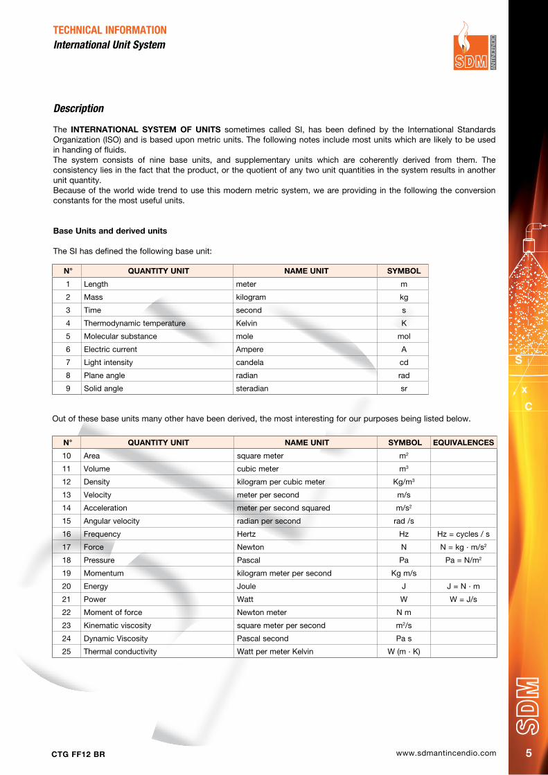
The INTERNATIONAL SYSTEM OF UNITS sometimes called SI, has been defined by the International Standards Organization (ISO) and is based upon metric units. The following notes include most units which are likely to be used in handing of fluids. The system consists of nine base units, and supplementary units which are coherently derived from them. The consistency lies in the fact that the product, or the quotient of any two unit quantities in the system results in another unit quantity. Because of the world wide trend to use this modern metric system, we are providing in the following the conversion constants for the most useful units.
Base Units and derived units
The SI has defined the following base unit:
N° QUANTITY UNIT NAME UNIT SYMBOL
1 Length meter m
2 Mass kilogram kg
3 Time second s
4 Thermodynamic temperature Kelvin K
5 Molecular substance mole mol
6 Electric current Ampere A
7 Light intensity candela cd
8 Plane angle radian rad
9 Solid angle steradian sr
Out of these base units many other have been derived, the most interesting for our purposes being listed below.
N° QUANTITY UNIT NAME UNIT SYMBOL EQUIVALENCES
10 Area square meter m2
11 Volume cubic meter m3
12 Density kilogram per cubic meter Kg/m3
13 Velocity meter per second m/s
14 Acceleration meter per second squared m/s2
15 Angular velocity radian per second rad /s
16 Frequency Hertz Hz Hz = cycles / s
17 Force Newton N N = kg . m/s2
18 Pressure Pascal Pa Pa = N/m2
19 Momentum kilogram meter per second Kg m/s
20 Energy Joule J J = N . m
21 Power Watt W W = J/s
22 Moment of force Newton meter N m
23 Kinematic viscosity square meter per second m2/s
24 Dynamic Viscosity Pascal second Pa s
25 Thermal conductivity Watt per meter Kelvin W (m . K)
TECHNICAL INFORMATIONInternational Unit System
www.sdmantincendio.com CTG FF12 BR6
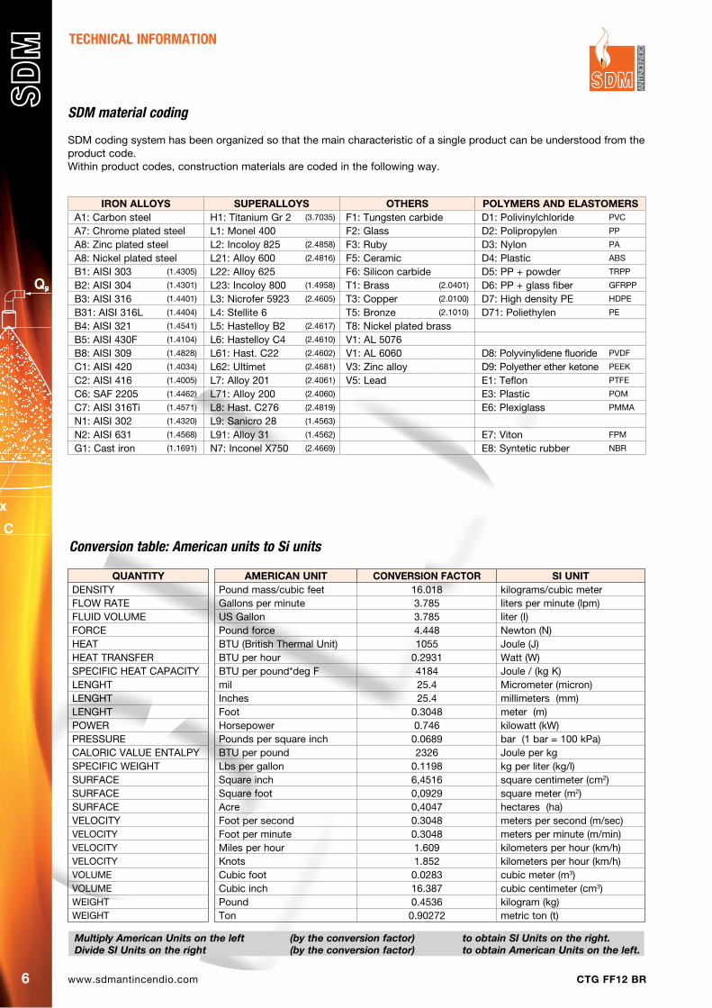
QUANTITYDENSITYFLOW RATEFLUID VOLUMEFORCEHEATHEAT TRANSFERSPECIFIC HEAT CAPACITYLENGHTLENGHTLENGHTPOWERPRESSURECALORIC VALUE ENTALPYSPECIFIC WEIGHTSURFACESURFACESURFACEVELOCITYVELOCITYVELOCITYVELOCITYVOLUMEVOLUMEWEIGHTWEIGHT
Multiply American Units on the left (by the conversion factor) to obtain SI Units on the right. Divide SI Units on the right (by the conversion factor) to obtain American Units on the left.
TECHNICAL INFORMATION
SDM material coding
SDM coding system has been organized so that the main characteristic of a single product can be understood from the product code. Within product codes, construction materials are coded in the following way.
Conversion table: American units to Si units
IRON ALLOYS SUpERALLOYS OThERS pOLYMERS ANd ELASTOMERSA1: Carbon steel H1: Titanium Gr 2 (3.7035) F1: Tungsten carbide D1: Polivinylchloride PVC
A7: Chrome plated steel L1: Monel 400 F2: Glass D2: Polipropylen PP
A8: Zinc plated steel L2: Incoloy 825 (2.4858) F3: Ruby D3: Nylon PA
A8: Nickel plated steel L21: Alloy 600 (2.4816) F5: Ceramic D4: Plastic ABS
B1: AISI 303 (1.4305) L22: Alloy 625 F6: Silicon carbide D5: PP + powder TRPP
B2: AISI 304 (1.4301) L23: Incoloy 800 (1.4958) T1: Brass (2.0401) D6: PP + glass fiber GFRPP
B3: AISI 316 (1.4401) L3: Nicrofer 5923 (2.4605) T3: Copper (2.0100) D7: High density PE HDPE
B31: AISI 316L (1.4404) L4: Stellite 6 T5: Bronze (2.1010) D71: Poliethylen PE
B4: AISI 321 (1.4541) L5: Hastelloy B2 (2.4617) T8: Nickel plated brassB5: AISI 430F (1.4104) L6: Hastelloy C4 (2.4610) V1: AL 5076B8: AISI 309 (1.4828) L61: Hast. C22 (2.4602) V1: AL 6060 D8: Polyvinylidene fluoride PVDF
C1: AISI 420 (1.4034) L62: Ultimet (2.4681) V3: Zinc alloy D9: Polyether ether ketone PEEK
C2: AISI 416 (1.4005) L7: Alloy 201 (2.4061) V5: Lead E1: Teflon PTFE
C6: SAF 2205 (1.4462) L71: Alloy 200 (2.4060) E3: Plastic POM
C7: AISI 316Ti (1.4571) L8: Hast. C276 (2.4819) E6: Plexiglass PMMA
N1: AISI 302 (1.4320) L9: Sanicro 28 (1.4563)
N2: AISI 631 (1.4568) L91: Alloy 31 (1.4562) E7: Viton FPM
G1: Cast iron (1.1691) N7: Inconel X750 (2.4669) E8: Syntetic rubber NBR
AMERICAN UNIT CONVERSION FACTOR SI UNITPound mass/cubic feet 16.018 kilograms/cubic meterGallons per minute 3.785 liters per minute (lpm)US Gallon 3.785 liter (I)Pound force 4.448 Newton (N)BTU (British Thermal Unit) 1055 Joule (J)BTU per hour 0.2931 Watt (W)BTU per pound*deg F 4184 Joule / (kg K)mil 25.4 Micrometer (micron)Inches 25.4 millimeters (mm)Foot 0.3048 meter (m)Horsepower 0.746 kilowatt (kW)Pounds per square inch 0.0689 bar (1 bar = 100 kPa)BTU per pound 2326 Joule per kgLbs per gallon 0.1198 kg per liter (kg/l)Square inch 6,4516 square centimeter (cm2)Square foot 0,0929 square meter (m2)Acre 0,4047 hectares (ha)Foot per second 0.3048 meters per second (m/sec)Foot per minute 0.3048 meters per minute (m/min)Miles per hour 1.609 kilometers per hour (km/h)Knots 1.852 kilometers per hour (km/h)Cubic foot 0.0283 cubic meter (m3)Cubic inch 16.387 cubic centimeter (cm3)Pound 0.4536 kilogram (kg)Ton 0.90272 metric ton (t)
www.sdmantincendio.comCTG FF12 BR 7
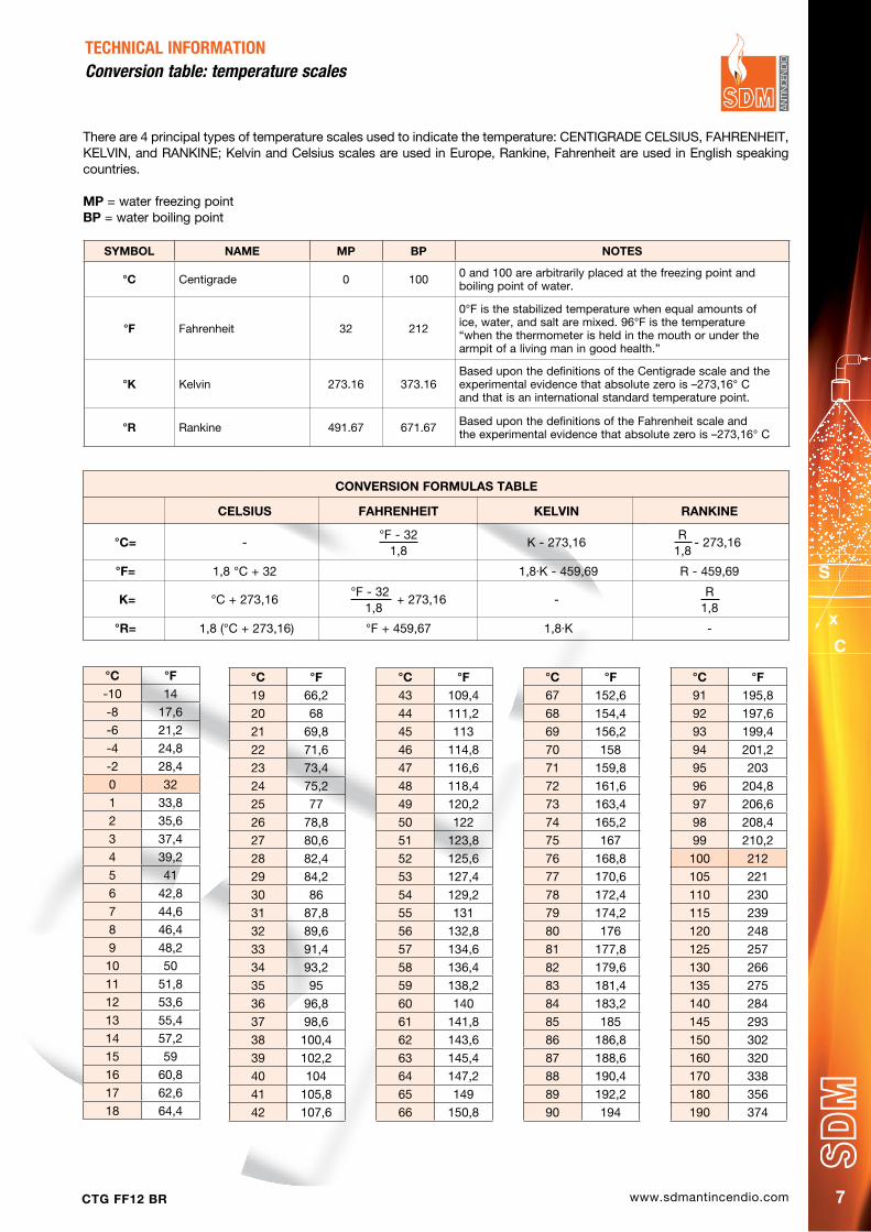
There are 4 principal types of temperature scales used to indicate the temperature: CENTIGRADE CELSIUS, FAHRENHEIT, KELVIN, and RANKINE; Kelvin and Celsius scales are used in Europe, Rankine, Fahrenheit are used in English speaking countries.
Mp = water freezing pointBp = water boiling point
SYMBOL NAME Mp Bp NOTES
°C Centigrade 0 100 0 and 100 are arbitrarily placed at the freezing point andboiling point of water.
°F Fahrenheit 32 212
0°F is the stabilized temperature when equal amounts ofice, water, and salt are mixed. 96°F is the temperature“when the thermometer is held in the mouth or under thearmpit of a living man in good health.”
°K Kelvin 273.16 373.16Based upon the definitions of the Centigrade scale and theexperimental evidence that absolute zero is –273,16° Cand that is an international standard temperature point.
°R Rankine 491.67 671.67 Based upon the definitions of the Fahrenheit scale andthe experimental evidence that absolute zero is –273,16° C
°C °F43 109,4
44 111,2
45 113
46 114,8
47 116,6
48 118,4
49 120,2
50 122
51 123,8
52 125,6
53 127,4
54 129,2
55 131
56 132,8
57 134,6
58 136,4
59 138,2
60 140
61 141,8
62 143,6
63 145,4
64 147,2
65 149
66 150,8
°C °F67 152,6
68 154,4
69 156,2
70 158
71 159,8
72 161,6
73 163,4
74 165,2
75 167
76 168,8
77 170,6
78 172,4
79 174,2
80 176
81 177,8
82 179,6
83 181,4
84 183,2
85 185
86 186,8
87 188,6
88 190,4
89 192,2
90 194
°C °F91 195,8
92 197,6
93 199,4
94 201,2
95 203
96 204,8
97 206,6
98 208,4
99 210,2
100 212
105 221
110 230
115 239
120 248
125 257
130 266
135 275
140 284
145 293
150 302
160 320
170 338
180 356
190 374
°C °F19 66,2
20 68
21 69,8
22 71,6
23 73,4
24 75,2
25 77
26 78,8
27 80,6
28 82,4
29 84,2
30 86
31 87,8
32 89,6
33 91,4
34 93,2
35 95
36 96,8
37 98,6
38 100,4
39 102,2
40 104
41 105,8
42 107,6
°C °F-10 14
-8 17,6
-6 21,2
-4 24,8
-2 28,4
0 32
1 33,8
2 35,6
3 37,4
4 39,2
5 41
6 42,8
7 44,6
8 46,4
9 48,2
10 50
11 51,8
12 53,6
13 55,4
14 57,2
15 59
16 60,8
17 62,6
18 64,4
CONVERSION FORMULAS TABLE
CELSIUS FAhRENhEIT KELVIN RANKINE
°C= -
°F - 32 K - 273,16
R - 273,16
1,8 1,8
°F= 1,8 °C + 32 1,8.K - 459,69 R - 459,69
K= °C + 273,16
°F - 32 + 273,16
- R
1,8 1,8
°R= 1,8 (°C + 273,16) °F + 459,67 1,8.K -
TECHNICAL INFORMATIONConversion table: temperature scales
www.sdmantincendio.com CTG FF12 BR8
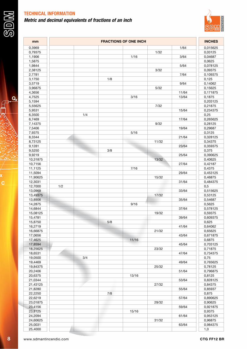
TECHNICAL INFORMATION Metric and decimal equivalents of fractions of an inch
mm FRACTIONS OF ONE INCh INChES
0,3969 1/64 0,0156250,79375 1/32 0,031251,1906 1/16 3/64 0,046871,5875 0,06251,9844 5/64 0,0781252,38125 3/32 0,093752,7781 7/64 0,1093753,1750 1/8 0,1253,5719 9/64 0,140623,96875 5/32 0,156254,3656 11/64 0,1718754,7525 3/16 13/64 0,18755,1594 0,2031255,55625 7/32 0,218755,9531 15/64 0,2343756,3500 1/4 0,256,7469 17/64 0,2656257,14375 9/32 0,281257,5406 19/64 0,296877,9375 5/16 0,31258,3344 21/64 0,3281258,73125 11/32 0,343759,1281 23/64 0,3593759,5250 3/8 0,3759,9219 25/64 0,39062510,31875 13/32 0,4062510,7156 27/64 0,4218711,1125 7/16 0,437511,5094 29/64 0,45312511,90625 15/32 0,4687512,3031 31/64 0,48437512,7000 1/2 0,513,0969 33/64 0,51562513,49375 17/32 0,5312513,8906 35/64 0,5468714,2875 9/16 0,562514,6844 37/64 0,57812515,08125 19/32 0,5937515,4781 39/64 0,60937515,8750 5/8 0,62516,2719 41/64 0,6406216,66875 21/32 0,6562517,0656 43/64 0,67187517,4625 11/16 0,687517,8594 45/64 0,70312518,25625 23/32 0,7187518,6531 47/64 0,73437519,0500 3/4 0,7519,4469 49/64 0,76562519,84375 25/32 0,7812520,2406 51/64 0,79687520,6375 13/16 0,812521,0344 53/64 0,82812521,43125 27/32 0,8437521,8280 55/64 0,8593722,2250 7/8 0,87522,6219 57/64 0,89062523,01875 29/32 0,9062523,4156 59/64 0,92187523,8125 15/16 0,937524,2094 61/64 0,95312524,60625 31/32 0,9687525,0031 63/64 0,98437525,4000 1,0
www.sdmantincendio.comCTG FF12 BR 9
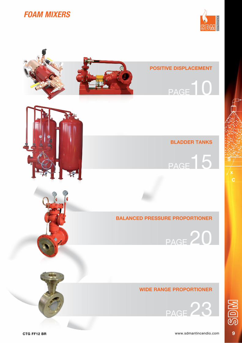
foAM MIxerS
pOSITIVE dISpLACEMENT
PAGE10
BLAddER TANKS
PAGE15
BALANCEd pRESSURE pROpORTIONER
PAGE 20
WIdE RANGE pROpORTIONER
PAGE 23
www.sdmantincendio.com CTG FF12 BR10
The precise makeup of water and foaming agent to feed monitors and nozzles in fire fighting systems is of fundamental importance for the efficient performance of the same.In the past this process has been performed mainly through system based onto the Venturi effect, which allows for sinplicity of construction and an acceptable performance, and used both in mobile and fixed systems like bladder tanks and automatic balanced pressure mixing systems.
When used in fixed systems the typical problems of the Ventury concept (sensitivity to pressure drops between mixer and monitors/nozzles) have often added up to problems connected to the system design.As an example balanced pressure system require the foam agent to be supplied under pressure and therefore an electric line for a pump, while bladder tanks have forcibly a limit to the quantity of foam agent available this beeing a huge problem for those systems supposed or required from the circumstances to remain operative for extended time periods.
In recent years a more sophisticated concept has been developed, allowing for the make up of foam mix witha precise and constant percentage, while assuring the possibility to feed foam agent for indefinite periods of time, actually dependent only from the quantity of foam agent available.These systems are based upon the use of volumetric pumps, that is pumps which push forward a precise quantity of liquid for each shaft revolution, and use a specific characteristics of those pump which are reversible machines this meaning they can be put in operation from a motor pumping liquid, or the can be made to turn from a liquid flowing through them and work as a motor using part of the energy of the liquid flowing through to supply mechanical energy and put another pump in operation.
It is then possible to use two volumetric pumps, whose capacity has the same percentage mix required, and use the larger one as a motor while being flown through from the water directed to the monitors to puth the smaller one in operation to pickup foam agent from a tank and inject the right percentage inside the output pipe of the first : this process does not require any other energy.The concept was first applied on large machines consisting of two screw pumps, delivering large flows of foam mix in oil refineries and oil stock plants, with totally satisfactory performances and excellent servive life.These machines, our URW models have noticable capacities and dimensions and require careful servicing from well trained personnel, which is possible in large dimension plants.
One of the best advantages of these machines is that, by the concept itself, they assure a precise mixing percentage over an extended range of capacities and this fits very well the requirements of smaller systems for general purpose applications.This has led to the design of smaller size machines, always consisting of two cpupled volumetric pumps albeit of simpler design ans smaller dimensions.In these machines the motive pump is generally a rotary blade pump, while the foam agent pump maybe a gear or a piston pump the latter allowing a variable percentage mix when possible to exclude one or more of the plungers.
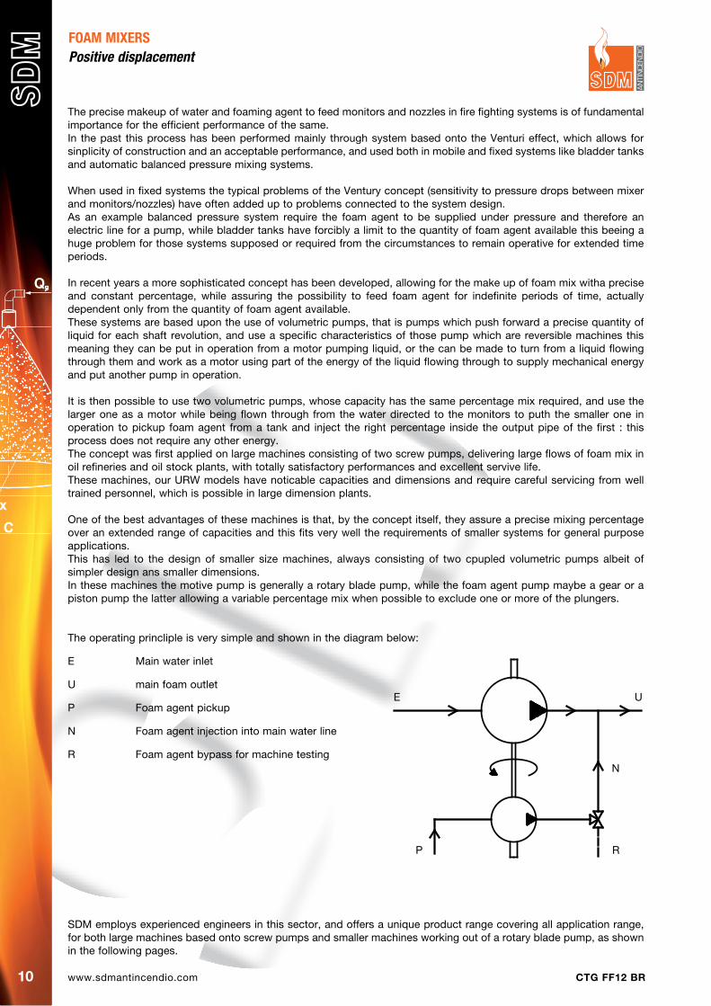
The operating princliple is very simple and shown in the diagram below:
E Main water inlet
U main foam outlet
P Foam agent pickup
N Foam agent injection into main water line
R Foam agent bypass for machine testing
FOAM MIXERSPositive displacement
E U
P
N
R
SDM employs experienced engineers in this sector, and offers a unique product range covering all application range, for both large machines based onto screw pumps and smaller machines working out of a rotary blade pump, as shown in the following pages.
www.sdmantincendio.comCTG FF12 BR 11
FOAM MIXERS Positive displacement
CodeCapacity Suction and discharge
flange water Foam inlet size
dimensions (mm)
Lpm dN pN 150 A B C d E h1 h2
URY A025 T5 XY 500 - 2500 100 16 4” 1 ½” 123 460 830 640 987 227 212
URY B025 T5 XY 250 - 2500 100 16 4” 1 ½” 123 460 830 640 987 227 212
URY A040 T5 XY 800 - 4000 125 16 5” 1 ½” 123 460 830 640 987 227 212
URY B040 T5 XY 400 - 4000 125 16 5” 1 ½” 123 460 830 640 987 227 212
URY A060 T5 XY 1200 - 6000 150 16 6” 2”
URY B060 T5 XY 600 - 6000 150 16 6” 2”
URY A080 T5 XY 1600 - 8000 200 16 8” 2 ½”
URY B080 T5 XY 800 - 8000 200 16 8” 2 ½”
URY A100 T5 XY 2000 - 10000 250 16 10” 3”
URY B100 T5 XY 1000 - 10000 250 16 10” 3”
URY A120 T5 XY 2500 - 12000 300 16 12” 4”
URY B120 T5 XY 1200 - 12000 300 16 12” 4”
A = Pump type X = Flange type Y = Mixing %
A = Gear pump A = ANSI 3 = 3%
B = Plunger pump B = UNI 6 = 6%
SdM order code:Ex.: URY A025 T5 XY
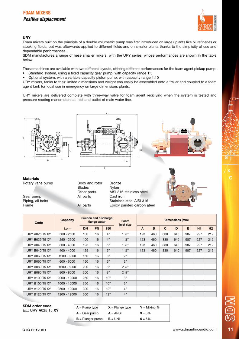
URYFoam mixers built on the principle of a double volumetric pump was first introduced on large üplants like oil refineries or stocking fields, but was afterwards applied to different fields and on smaller plants thanks to the simplicity of use and dependable performances.SDM manufactures a range of hese smaller mixers, with the URY series, whose performances are shown in the table below.
These machines are available with two different layouts, offering different performances for the foam agent pickup pump:• Standardsystem,usingafixedcapacitygearpump,withcapacityrange1:5• Optionalsystem,withavariablecapacitypistonpump,withcapacityrange1:10URY mixers, tanks to their limited dimensions and weight can easily be assembled onto a trailer and coupled to a foam agent tank for local use in emergency on large dimensions plants.
URY mixers are delivered complete with three-way valve for foam agent reciclying when the system is tested and pressure reading manometers at inlet and outlet of main water line.
MaterialsRotary vane pump Body and rotor Bronze Blades Nylon Other parts AISI 316 stainless steelGear pump All parts Cast ironPiping, all bolts Stainless steel AISI 316Frame All parts Epoxy painted carbon ateel
�
�
www.sdmantincendio.com CTG FF12 BR12
The sturdiness of the system and the very strong design of screw pumps assure the highest reliability year over year, even when the system is tested in operation every month.In addition these machines assure the following advantages:• System can work for unlimited time, foaming agent being supplied from any atmospheric pressure container, like
trucks or even 200 litre barrels• System works fine even at very little load, e.g. using one only monitor out of a group• In a large plant one only foam agent stock can be built in a central location serving all systems• Workers can supply foam agent away from the fire area, with lower risks• The system is compliant with NFPA 11• The machine can work with sea water
MaterialsThe materials used are resistant to the most common foam agents and allow the machine to be flushed with sweet water after testing.
Drive motorBody Epoxy coated cast iron / Full bronze on small sizesIdle rotor BronzeDrive rotor Cr Stainless steel
Injection pumpBody Cast iron GG25 with internal Teflon / Graphite coatingRotors Cr Stainless steel
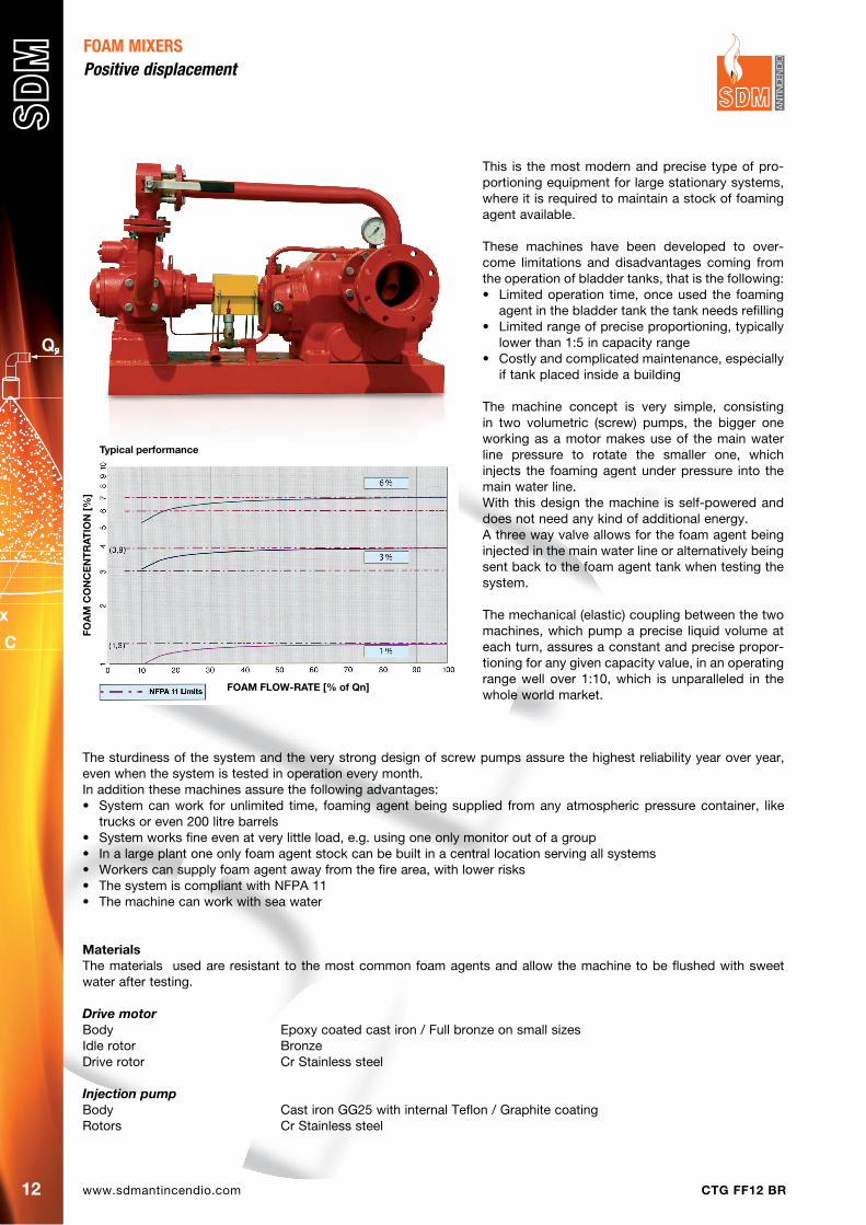
Typical performance
FOA
M C
ON
CE
NT
RA
TIO
N [
%]
FOAM FLOW-RATE [% of Qn]
This is the most modern and precise type of pro-portioning equipment for large stationary systems, where it is required to maintain a stock of foaming agent available.
These machines have been developed to over-come limitations and disadvantages coming from the operation of bladder tanks, that is the following:• Limitedoperation time,onceused the foaming
agent in the bladder tank the tank needs refilling• Limitedrangeofpreciseproportioning,typically
lower than 1:5 in capacity range• Costlyandcomplicatedmaintenance,especially
if tank placed inside a building
The machine concept is very simple, consisting in two volumetric (screw) pumps, the bigger one working as a motor makes use of the main water line pressure to rotate the smaller one, which injects the foaming agent under pressure into the main water line.With this design the machine is self-powered and does not need any kind of additional energy.A three way valve allows for the foam agent being injected in the main water line or alternatively being sent back to the foam agent tank when testing the system.
The mechanical (elastic) coupling between the two machines, which pump a precise liquid volume at each turn, assures a constant and precise propor-tioning for any given capacity value, in an operating range well over 1:10, which is unparalleled in the whole world market.
FOAM MIXERSPositive displacement

www.sdmantincendio.comCTG FF12 BR 13
FOAM MIXERS Positive displacement
* Pump sizeThe pump size figure shows both the maximum capacity and the mix percentage, eg: 120.3 = maximum capacity 120 cubic metres per hour (minimum capacity 12 cubic metres per hour) and mix percentage 3%
Data for information purpose onlyNot valid for construction
CodepumpSize
*
pump dimensionsSuction and discharge
Flange WaterSuction
Flange Foamer
A B C d E h1 h2 h4 dN pN 150 RS dN
URW 1203 G4SE 120.3 370 320 892 1115 170 316 358 574 100 16 4“ SAE 1 ¼” 32
URW 1206 G4SE 120.6 370 320 925 1155 170 316 358 574 100 16 4“ SAE 1 ¼” 32
URW 1503 G4SE 150.3 420 370 994 1249 195 371 403 615 125 16 5“ SAE 1 ¼” 32
URW 1506 G4SE 150.6 420 370 1071 1310 195 371 403 615 125 16 5“ SAE 1 ½” 40
URW 2403 G4SE 240.3 420 400 1079 1350 215 383 423 615 150 16 6“ SAE 1 ¼” 32
URW 2406 G4SE 240.6 420 400 1215 1476 215 383 433 615 150 16 6“ SAE 2” 50
URW 3003 G4SE 300.3 460 440 1222 1449 230 423 443 700 150 16 6“ SAE 1 ½” 40
URW 3006 G4SE 300.6 460 440 1281 1564 230 423 453 700 150 16 6“ SAE 2” 50
URW 3603 G4SE 360.3 460 460 1311 1604 250 423 468 820 200 16 8“ SAE 2” 50
URW 3606 G4SE 360.6 460 460 1330 1674 250 423 478 820 200 16 8“ SAE 2 ½” 65
URW 4503 G4SE 450.3 500 480 1401 1720 265 458 503 820 200 16 8“ SAE 2” 50
URW 4506 G4SE 450.6 500 480 1420 1790 265 458 513 820 200 16 8“ SAE 2 ½” 65
URW 6003 G4SE 600.3 550 520 1484 1887 280 483 553 850 250 16 10“ SAE 2 ½” 65
URW 6006 G4SE 600.6 550 520 1556 1955 280 483 563 850 250 16 10“ SAE 3” 80
URW 7503 G4SE 750.3 550 550 1500 1914 280 478 568 850 300 16 12“ SAE 2 ½” 65
URW 7506 G4SE 750.6 550 550 1662 2067 280 478 593 850 300 16 12“ SAE 4” 100
URW 9003 G4SE 900.3 680 740 1657 2104 320 633 688 880 300 16 12“ SAE 2 ½” 65
URW 9006 G4SE 900.6 680 740 1819 2257 320 633 703 880 300 16 12“ SAE 4” 100
G ½” outlet gauge
G ½” inlet pressure gauge
D
C
A E
B
H2
H4
H1

www.sdmantincendio.com CTG FF12 BR14
foAM MIxerS
VERTICAL
PAGE 17
hORIzONTAL
PAGE 19
WALL-MOUNT BOX
PAGE 24
INdEpENdENT MIXING UNIT
PAGE 22
www.sdmantincendio.comCTG FF12 BR 15
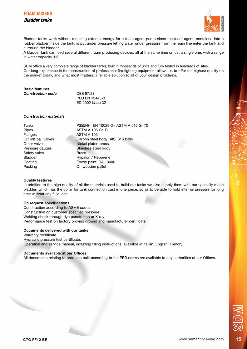
Bladder tanks work without requiring external energy for a foam agent pump since the foam agent, contained into a rubber bladder inside the tank, is put under pressure letting water under pressure from the main line enter the tank and surround the bladder.A bladder tank can feed several different foam producing devices, all at the same time or just a single one, with a range in water capacity 1:6.
SDM offers a very complete range of bladder tanks, built in thousands of units and fully tested in hundreds of sites.Our long experience in the construction of professional fire fighting equipment allows us to offer the highest quality on the market today, and what most matters, a reliable solution to all of your design problems.
Basic featuresConstruction code CEE 97/23 PED EN 13445-3 ED 2002 issue 32
Construction materials
Tanks P355NH EN 10028-3 / ASTM A 516 Gr 70Pipes ASTM A 106 Gr. BFlanges ASTM A 105Cut-off ball valves Carbon steel body, AISI 316 ballsOther valves Nickel plated brassPressure gauges Stainless steel bodySafety valve BrassBladder Hypalon / NeopreneCoating Epoxy paint, RAL 3000Packing On wooden pallet
Quality featuresIn addition to the high quality of all the materials used to build our tanks we also supply them with our specially made bladder, which has the collar for tank connection cast in one piece, so as to be able to hold internal pressure for long time without any fluid loss.
On request specificationsConstruction according to ASME codes.Construction on customer specified pressure.Welding check through dye penetration or X-ray.Performance test on factory proving ground and manufacturer certificate.
documents delivered with our tanksWarranty certificate.Hydraulic pressure test certificate.Operation and service manual, including filling instructions (available in Italian, English, French).
documents available at our OfficesAll documents relating to products built according to the PED norms are available to any authorities at our Offices.
FOAM MIXERSBladder tanks
www.sdmantincendio.com CTG FF12 BR16
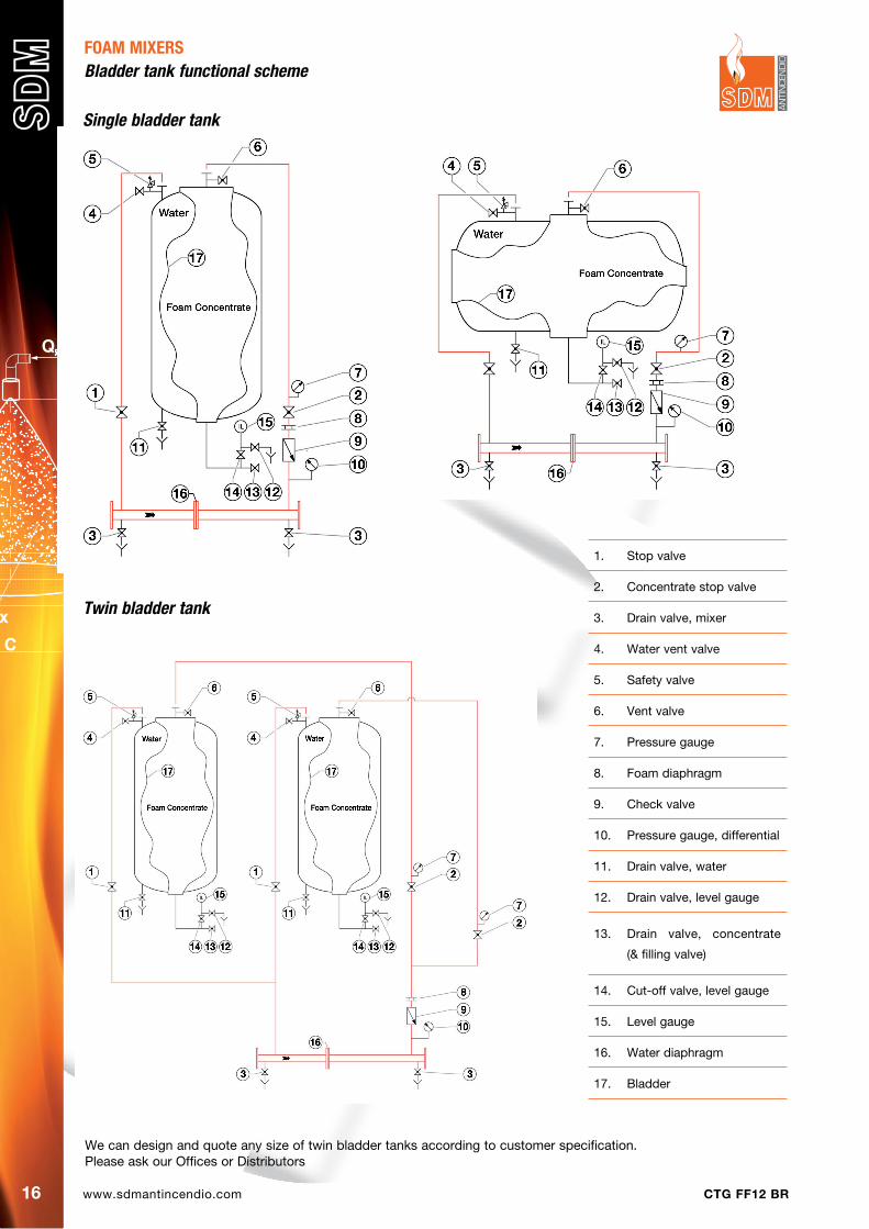
FOAM MIXERSBladder tank functional scheme
1. Stop valve
2. Concentrate stop valve
3. Drain valve, mixer
4. Water vent valve
5. Safety valve
6. Vent valve
7. Pressure gauge
8. Foam diaphragm
9. Check valve
10. Pressure gauge, differential
11. Drain valve, water
12. Drain valve, level gauge
13. Drain valve, concentrate
(& filling valve)
14. Cut-off valve, level gauge
15. Level gauge
16. Water diaphragm
17. Bladder
We can design and quote any size of twin bladder tanks according to customer specification.Please ask our Offices or Distributors
Twin bladder tank
Single bladder tank

www.sdmantincendio.comCTG FF12 BR 17
FOAM MIXERSBladder tanks
Tanks shown in this page are fitted with a foam mixer, therefore the weight value shown include the weight for the mixer and the related piping.See the materials specifications at page 15.Detailed dimensions for the tank and fixing instructions on the ground are available at our offices.
CodeA C E Weight full Capacity
mm mm mm kg litres
URT A004 A2 650 2030 440 700 400
URT A006 A2 750 2176 650 1170 600
URT A010 A2 900 2246 750 1730 1000
URT A015 A2 1000 2926 750 2430 1500
URT A020 A2 1050 3300 800 3360 2000
URT A025 A2 1200 3800 800 4030 2500
URT A030 A2 1290 3430 860 4700 3000
URT A035 A2 1400 3930 900 5580 3500
URT A040 A2 1500 3530 950 6300 4000
URT A050 A2 1600 3606 1050 7660 5000
URT A060 A2 1800 3680 1150 9030 6000
URT A080 A2 2000 4008 1200 11700 8000
Vertical with foam mixer
Wide range capacity model
These tanks can be equipped with the Wide Range proportioner shown at page 23 to extend their operation range.Such models are identified adding a W at the end of the product code.EG Standard type URT A080 A2 has a code URT A080 A2W when equipped with above said proportioner.
C
A
Ø D
E
1000
800
www.sdmantincendio.com CTG FF12 BR18
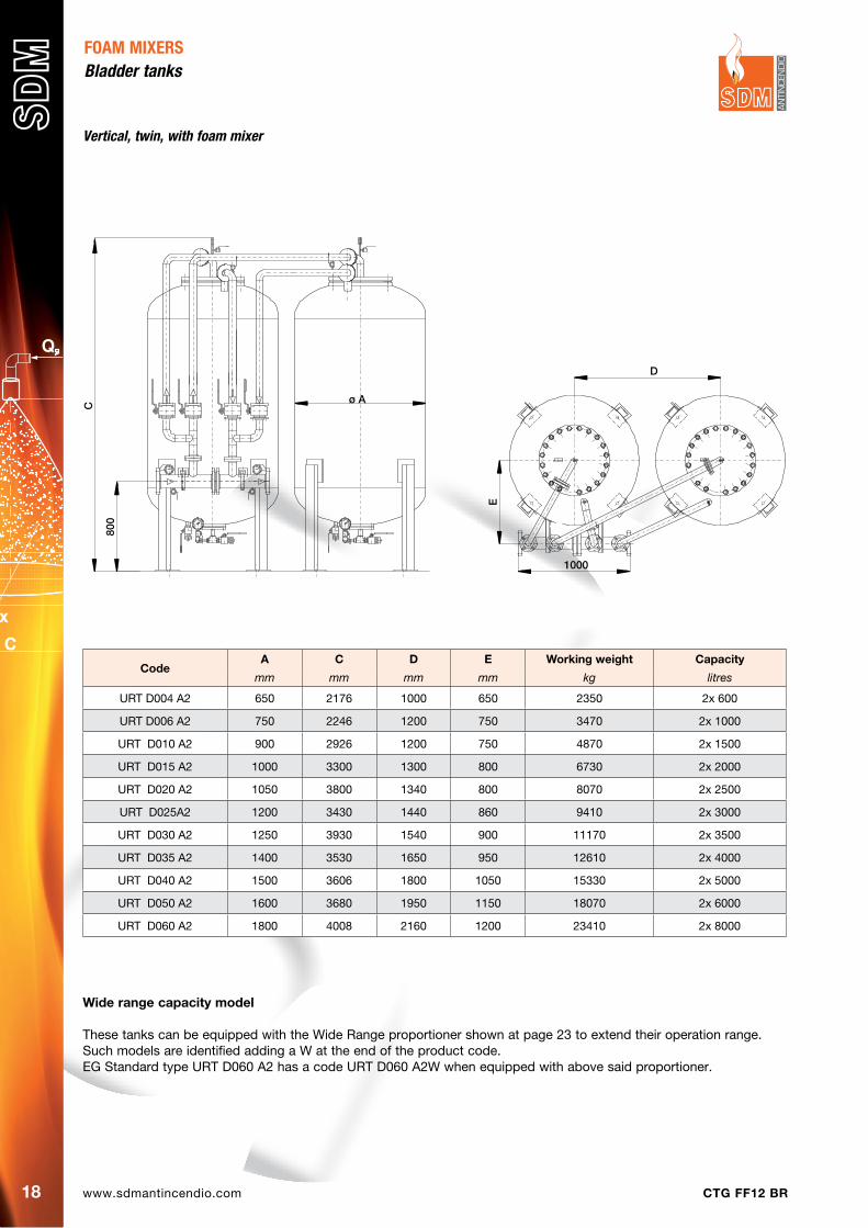
FOAM MIXERSBladder tanks
Wide range capacity model
These tanks can be equipped with the Wide Range proportioner shown at page 23 to extend their operation range.Such models are identified adding a W at the end of the product code.EG Standard type URT D060 A2 has a code URT D060 A2W when equipped with above said proportioner.
CodeA C d E Working weight Capacity
mm mm mm mm kg litres
URT D004 A2 650 2176 1000 650 2350 2x 600
URT D006 A2 750 2246 1200 750 3470 2x 1000
URT D010 A2 900 2926 1200 750 4870 2x 1500
URT D015 A2 1000 3300 1300 800 6730 2x 2000
URT D020 A2 1050 3800 1340 800 8070 2x 2500
URT D025A2 1200 3430 1440 860 9410 2x 3000
URT D030 A2 1250 3930 1540 900 11170 2x 3500
URT D035 A2 1400 3530 1650 950 12610 2x 4000
URT D040 A2 1500 3606 1800 1050 15330 2x 5000
URT D050 A2 1600 3680 1950 1150 18070 2x 6000
URT D060 A2 1800 4008 2160 1200 23410 2x 8000
Vertical, twin, with foam mixer
C
ø A
800
D
1000
E
www.sdmantincendio.comCTG FF12 BR 19
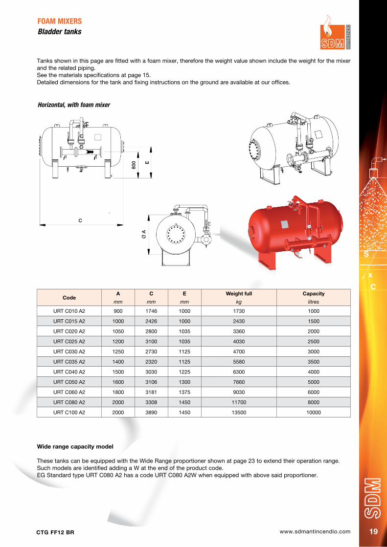
FOAM MIXERSBladder tanks
Tanks shown in this page are fitted with a foam mixer, therefore the weight value shown include the weight for the mixer and the related piping.See the materials specifications at page 15.Detailed dimensions for the tank and fixing instructions on the ground are available at our offices.
CodeA C E Weight full Capacity
mm mm mm kg litres
URT C010 A2 900 1746 1000 1730 1000
URT C015 A2 1000 2426 1000 2430 1500
URT C020 A2 1050 2800 1035 3360 2000
URT C025 A2 1200 3100 1035 4030 2500
URT C030 A2 1250 2730 1125 4700 3000
URT C035 A2 1400 2320 1125 5580 3500
URT C040 A2 1500 3030 1225 6300 4000
URT C050 A2 1600 3106 1300 7660 5000
URT C060 A2 1800 3181 1375 9030 6000
URT C080 A2 2000 3308 1450 11700 8000
URT C100 A2 2000 3890 1450 13500 10000
Horizontal, with foam mixer
Wide range capacity model
These tanks can be equipped with the Wide Range proportioner shown at page 23 to extend their operation range.Such models are identified adding a W at the end of the product code.EG Standard type URT C080 A2 has a code URT C080 A2W when equipped with above said proportioner.
E
800
C
Ø A

www.sdmantincendio.com CTG FF12 BR20
This mixer works balancing the pressure from water and foaming agent in order to assure a correct mixing ratio for different water pressure values, the device adjusts instantly the mixing ratio since the two pressure values are picked up from the water line and the foaming agent line and transferred into a balancing diaphragm at the top of the device.Therefore the stem of the inside regulation valve positions itself to assure the correct quantity of foaming agent to be injected into the water line, which happens in the low pressure area of the Venturi mixer contained in the lower part.A calibrated diaphragm at the inlet of the lower body defines the nominal mix percentage.It is required for a correct operation the foaming agent pressure to be about 2 bar higher than the main water pressure line.
Adjustable mixing rateAn optional valve can be assembled between the lower Venturi on the water line and the upper balacing section, allowing to adjust the device mixing ratio, which allows to use the same mixer with foaming agents working at a different percentages. Therefore a proportioner designed for 6% mixing ratio can work with a 3% foaming agent when required.These mixers carry a RINA Type Approval Certificate, which is available on request.
FOAM MIXERSBalanced pressure proportioner
MaterialsMixer body Inox AISI 304/316Venturi nozzle BronzeAutomatic valve parts AISI 316 stainless steelMix ratio valve Body carbon steel Ball AISI 316 stainless steel
Mix percentageThe codes given in the above table refer to a mix percentage of 3%. Please refer to following page for complete coding information.
Code(standard)
Flange Water Flange Foamer A B C d W
PN16 ANSI 150 PN16 ANSI 150 mm mm mm mm kg
URD 0100 G1 XY DN 100 4’’ DN 40 1 ½’’ 205 661 198 120 57
URD 0125 G1 XY DN 125 5’’ DN 40 1 ½’’ 250 673 210 120 61
URD 0150 G1 XY DN 150 6’’ DN 50 2’’ 300 729 266 135 76
URD 0200 G1 XY DN 200 8’’ DN 50 2’’ 400 749 286,5 135 93
URD 0250 G1 XY DN 250 10’’ DN 65 2 ½’’ 500 785 322 145 147
URD 0300 G1 XY DN 300 12’’ DN 65 2 ½’’ 600 813 350,5 145 177
URD 0350 G1 XY DN 350 14’’ DN 65 2 ½’’ 690 830 367 145 215
STANDARD OPTIONAL
Code(optional)
Flange Water Flange Foamer A B C d W
PN16 ANSI 150 PN16 ANSI 150 mm mm mm mm kg
URD 0100 MMXY DN 100 4’’ DN 40 1 ½’’ 205 725 262 322 72
URD 0125 MMXY DN 125 5’’ DN 40 1 ½’’ 250 737 274 322 76
URD 0150 MMXY DN 150 6’’ DN 50 2’’ 300 805 342 367 95
URD 0200 MMXY DN 200 8’’ DN 50 2’’ 400 825 362,5 367 112
URD 0250 MMXY DN 250 10’’ DN 65 2 ½’’ 500 885 422 437 179
URD 0300 MMXY DN 300 12’’ DN 65 2 ½’’ 600 913 450,5 437 209
URD 0350 MMXY DN 350 14’’ DN 65 2 ½’’ 690 930 467 437 247
Modello Flange acqua Flangia schiuma A (mm)
B (mm)
C (mm)
D (mm)
Peso (kg) PN16 ANSI 150 PN16 ANSI 150
URD 0100 MMXY DN 100 4’’ DN 40 1½’’ 205 661 198 120 57 URD 0125 MMXY DN 125 5’’ DN 40 1½’’ 250 673 210 120 61 URD 0150 MMXY DN 150 6’’ DN 50 2’’ 300 729 266 135 76 URD 0200 MMXY DN 200 8’’ DN 50 2’’ 400 749 286,5 135 93 URD 0250 MMXY DN 250 10’’ DN 65 2½’’ 500 785 322 145 147 URD 0300 MMXY DN 300 12’’ DN 65 2½’’ 600 813 350,5 145 177 URD 0350 MMXY DN 350 14’’ DN 65 2½’’ 690 830 367 145 215
Modello Flange acqua Flangia schiuma A (mm)
B (mm)
C (mm)
D (mm)
Peso (kg) PN16 ANSI 150 PN16 ANSI 150
URD 0100 MMXY DN 100 4’’ DN 40 1½’’ 205 725 262 322 72 URD 0125 MMXY DN 125 5’’ DN 40 1½’’ 250 737 274 322 76 URD 0150 MMXY DN 150 6’’ DN 50 2’’ 300 805 342 367 95 URD 0200 MMXY DN 200 8’’ DN 50 2’’ 400 825 362,5 367 112 URD 0250 MMXY DN 250 10’’ DN 65 2½’’ 500 885 422 437 179 URD 0300 MMXY DN 300 12’’ DN 65 2½’’ 600 913 450,5 437 209 URD 0350 MMXY DN 350 14’’ DN 65 2½’’ 690 930 467 437 247
D
www.sdmantincendio.comCTG FF12 BR 21
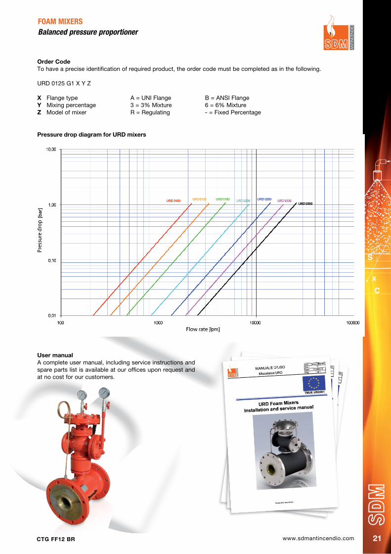
pressure drop diagram for URd mixers
User manualA complete user manual, including service instructions and spare parts list is available at our offices upon request and at no cost for our customers.
FOAM MIXERSBalanced pressure proportioner
Order CodeTo have a precise identification of required product, the order code must be completed as in the following.
URD 0125 G1 X Y Z
X Flange type A = UNI Flange B = ANSI FlangeY Mixing percentage 3 = 3% Mixture 6 = 6% Mixturez Model of mixer R = Regulating - = Fixed Percentage

www.sdmantincendio.com CTG FF12 BR22
FOAM MIXERSIndependent mixing unit
This system is designed as a replacement for bladder tanks in those cases where an emergency electrical line is available, and works with a balanced pressure proportioner where the foaming agent is supplied froam a simple atmospheric pressure tank by means of a pump powered by an electro-motor.Sensible advantages in terms of lower investment cost, ease of refilling the foaming agent change and no bladder to be replaced are immediately apparent to service technicians.Such systems can be designed making use of any of the URD proportioner types shown in the previous pages, and with the foaming agent tank capacity required, therefore we are not showing any standard types and design each one of these systmes based on the customer requirements.
MaterialsMixer Cast iron/Stainless SteelPump Stainless SteelFrame&Tank Carbon SteelSurface coating Epoxy primer / Polyurethanic enamel RAL 3000
Technical characteristicsCapacity From 1000 l up to 10.000 lFoam mixer URD 100 Pump type Centrifugal PumpA wide series of mixer types, tank capacities and pump performance can be combined, to follow any custumer request.
Order CodeTo have a precise identification of required product, the order code must be completed with this code:
URE 0100 X Y z
X Mixing percentage 3 = 3% Mixture 6 = 6% MixtureY Model of mixer R = Regulating - = Fixed Percentagez Foaming agent tank capacity
The product shown in this page has a very flexible design and can be developed considering the customer requests.
SDM Impianti Srl
UNITA’ MISCELAZIONE SCHIUMA UMS FOAM MIXING UNIT UMS
Data Sheet 250
MODELLO RANGE PORTATA Lt/1’
UMS 20 216 - 2160
UMS 30 325 - 3250
UMS 40 475 - 4750
UMS 80 850 - 8700
www.sdmantincendio.comCTG FF12 BR 23
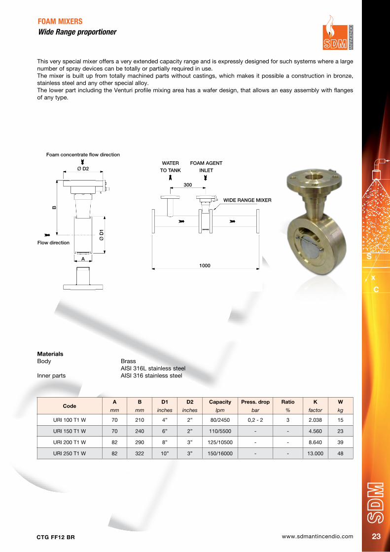
FOAM MIXERSWide range proportioner
CodeA B d1 d2 Capacity press. drop Ratio K W
mm mm inches inches Ipm bar % factor kg
URI 100 T1 W 70 210 4” 2” 80/2450 0,2 - 2 3 2.038 15
URI 150 T1 W 70 240 6” 2” 110/5500 - - 4.560 23
URI 200 T1 W 82 290 8” 3” 125/10500 - - 8.640 39
URI 250 T1 W 82 322 10” 3” 150/16000 - - 13.000 48
This very special mixer offers a very extended capacity range and is expressly designed for such systems where a large number of spray devices can be totally or partially required in use.The mixer is built up from totally machined parts without castings, which makes it possible a construction in bronze, stainless steel and any other special alloy.The lower part including the Venturi profile mixing area has a wafer design, that allows an easy assembly with flanges of any type.
MaterialsBody Brass AISI 316L stainless steelInner parts AISI 316 stainless steel
Foam concentrate flow direction
Flow direction
Ø D2
Ø D
1
B
A
WATER
TO TANK
FOAM AGENT
INLET
WIDE RANGE MIXER
1000
300
www.sdmantincendio.com CTG FF12 BR24
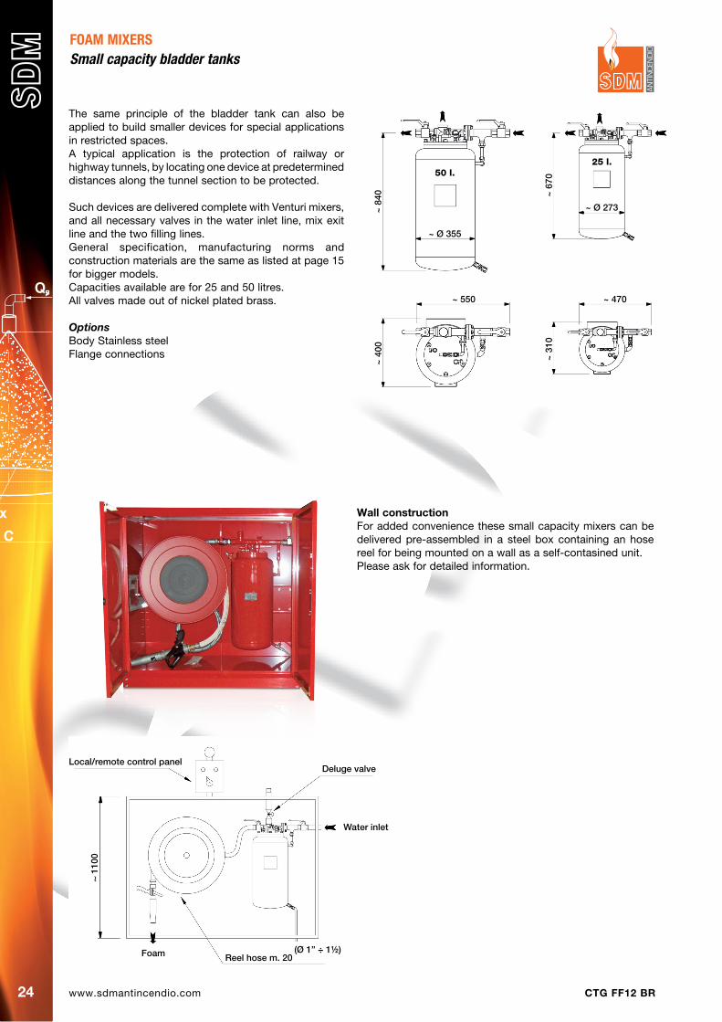
The same principle of the bladder tank can also be applied to build smaller devices for special applications in restricted spaces.A typical application is the protection of railway or highway tunnels, by locating one device at predetermined distances along the tunnel section to be protected.
Such devices are delivered complete with Venturi mixers, and all necessary valves in the water inlet line, mix exit line and the two filling lines.General specification, manufacturing norms and construction materials are the same as listed at page 15 for bigger models.Capacities available are for 25 and 50 litres.All valves made out of nickel plated brass.
OptionsBody Stainless steelFlange connections
Wall constructionFor added convenience these small capacity mixers can be delivered pre-assembled in a steel box containing an hose reel for being mounted on a wall as a self-contasined unit.Please ask for detailed information.
FOAM MIXERSSmall capacity bladder tanks
50 l.
~ Ø 355
25 l.
~ Ø 273
~ 6
70
~ 8
40
~ 470~ 550
~ 3
10
~ 4
00
Local/remote control panelDeluge valve
Water inlet
Foam Reel hose m. 20
~ 11
00
(Ø 1” ÷ 1½)

www.sdmantincendio.comCTG FF12 BR 25
Since many years SDM manufactures high quality monitors, showing a perfect inside surface finish which allows for superior values of throw.In addition our range is a very complete one and covers all the requirements for professional fire-fighting systems, including the most sophisticated remote control models.
Our range of monitors is shown in the following pages and organized in different groups, by type of monitor operation.Accessories and equipment related to monitors like poles are shown at the end of this section.
MoNITorS
MANUAL CONTROL
here lever and wheel operated monitors are shown.
They are available in any possible combinationPAGE 26
AUTOMATIC OSCILLATION MONITORS
These models are operated by the classic water turbine device, taken to perfection
through years of continuous improvement
PAGE 28
ELECTRIC dRIVE MONITORS
A perfect device, also available as ATEX model and/or fitted with remote control
PAGE 30
hYdRAULIC dRIVE MONITORS
A real high class product, including the most modern and proven components,
also delivered with remote control.
PAGE 31
www.sdmantincendio.com CTG FF12 BR26
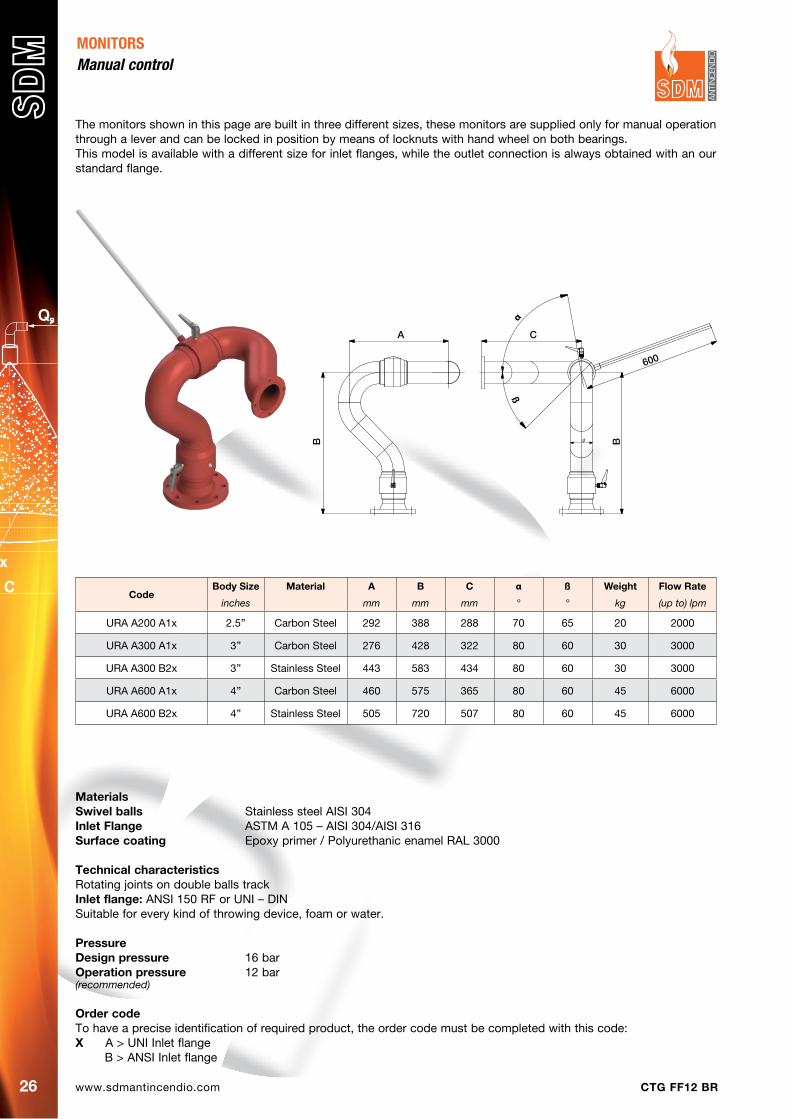
The monitors shown in this page are built in three different sizes, these monitors are supplied only for manual operation through a lever and can be locked in position by means of locknuts with hand wheel on both bearings.This model is available with a different size for inlet flanges, while the outlet connection is always obtained with an our standard flange.
MONITORSManual control
CodeBody Size Material A B C α ß Weight Flow Rate
inches mm mm mm ° ° kg (up to) lpm
URA A200 A1x 2.5’’ Carbon Steel 292 388 288 70 65 20 2000
URA A300 A1x 3’’ Carbon Steel 276 428 322 80 60 30 3000
URA A300 B2x 3’’ Stainless Steel 443 583 434 80 60 30 3000
URA A600 A1x 4’’ Carbon Steel 460 575 365 80 60 45 6000
URA A600 B2x 4’’ Stainless Steel 505 720 507 80 60 45 6000
MaterialsSwivel balls Stainless steel AISI 304Inlet Flange ASTM A 105 – AISI 304/AISI 316Surface coating Epoxy primer / Polyurethanic enamel RAL 3000
Technical characteristicsRotating joints on double balls trackInlet flange: ANSI 150 RF or UNI – DINSuitable for every kind of throwing device, foam or water.
pressuredesign pressure 16 barOperation pressure 12 bar(recommended)
Order codeTo have a precise identification of required product, the order code must be completed with this code:X A > UNI Inlet flange B > ANSI Inlet flange
600
C
B
α
ß
B
A
www.sdmantincendio.comCTG FF12 BR 27
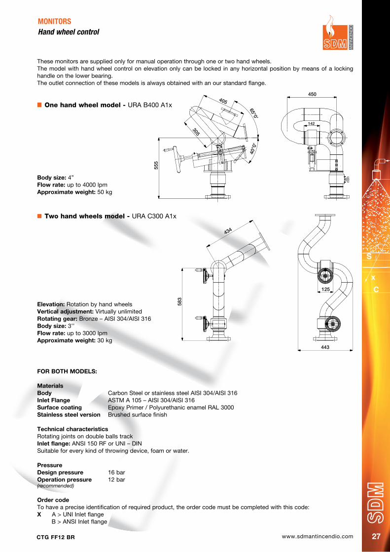
These monitors are supplied only for manual operation through one or two hand wheels.The model with hand wheel control on elevation only can be locked in any horizontal position by means of a locking handle on the lower bearing.The outlet connection of these models is always obtained with an our standard flange.
MONITORSHand wheel control
Two hand wheels model - URA C300 A1x
FOR BOTh MOdELS:
MaterialsBody Carbon Steel or stainless steel AISI 304/AISI 316Inlet Flange ASTM A 105 – AISI 304/AISI 316Surface coating Epoxy Primer / Polyurethanic enamel RAL 3000Stainless steel version Brushed surface finish
Technical characteristicsRotating joints on double balls trackInlet flange: ANSI 150 RF or UNI – DINSuitable for every kind of throwing device, foam or water.
pressuredesign pressure 16 barOperation pressure 12 bar(recommended)
Order codeTo have a precise identification of required product, the order code must be completed with this code:X A > UNI Inlet flange B > ANSI Inlet flange
One hand wheel model - URA B400 A1x
Body size: 4”Flow rate: up to 4000 lpmApproximate weight: 50 kg
Elevation: Rotation by hand wheels Vertical adjustment: Virtually unlimitedRotating gear: Bronze – AISI 304/AISI 316Body size: 3’’Flow rate: up to 3000 lpmApproximate weight: 30 kg
434
125
583
443
450
142
555
305
405
65°0’
40°0
’
www.sdmantincendio.com CTG FF12 BR28
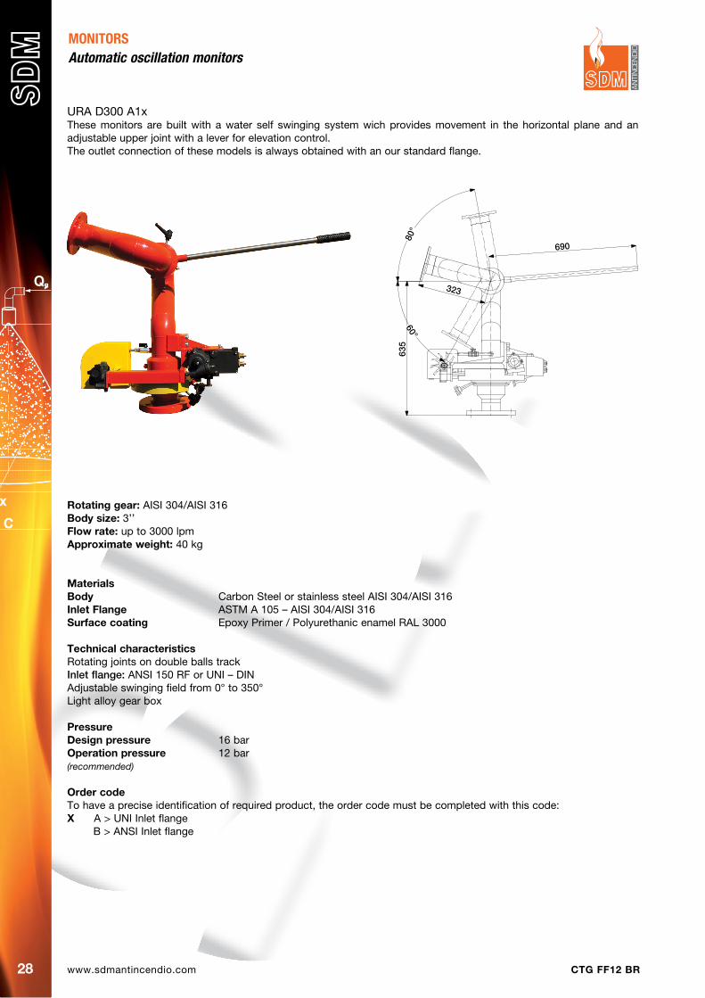
URA D300 A1xThese monitors are built with a water self swinging system wich provides movement in the horizontal plane and an adjustable upper joint with a lever for elevation control. The outlet connection of these models is always obtained with an our standard flange.
MONITORSAutomatic oscillation monitors
Rotating gear: AISI 304/AISI 316Body size: 3’’Flow rate: up to 3000 lpmApproximate weight: 40 kg
MaterialsBody Carbon Steel or stainless steel AISI 304/AISI 316Inlet Flange ASTM A 105 – AISI 304/AISI 316Surface coating Epoxy Primer / Polyurethanic enamel RAL 3000
Technical characteristicsRotating joints on double balls trackInlet flange: ANSI 150 RF or UNI – DINAdjustable swinging field from 0° to 350°Light alloy gear box
pressuredesign pressure 16 barOperation pressure 12 bar(recommended)
Order codeTo have a precise identification of required product, the order code must be completed with this code:X A > UNI Inlet flange B > ANSI Inlet flange
690
323
635
60°
80°
www.sdmantincendio.comCTG FF12 BR 29
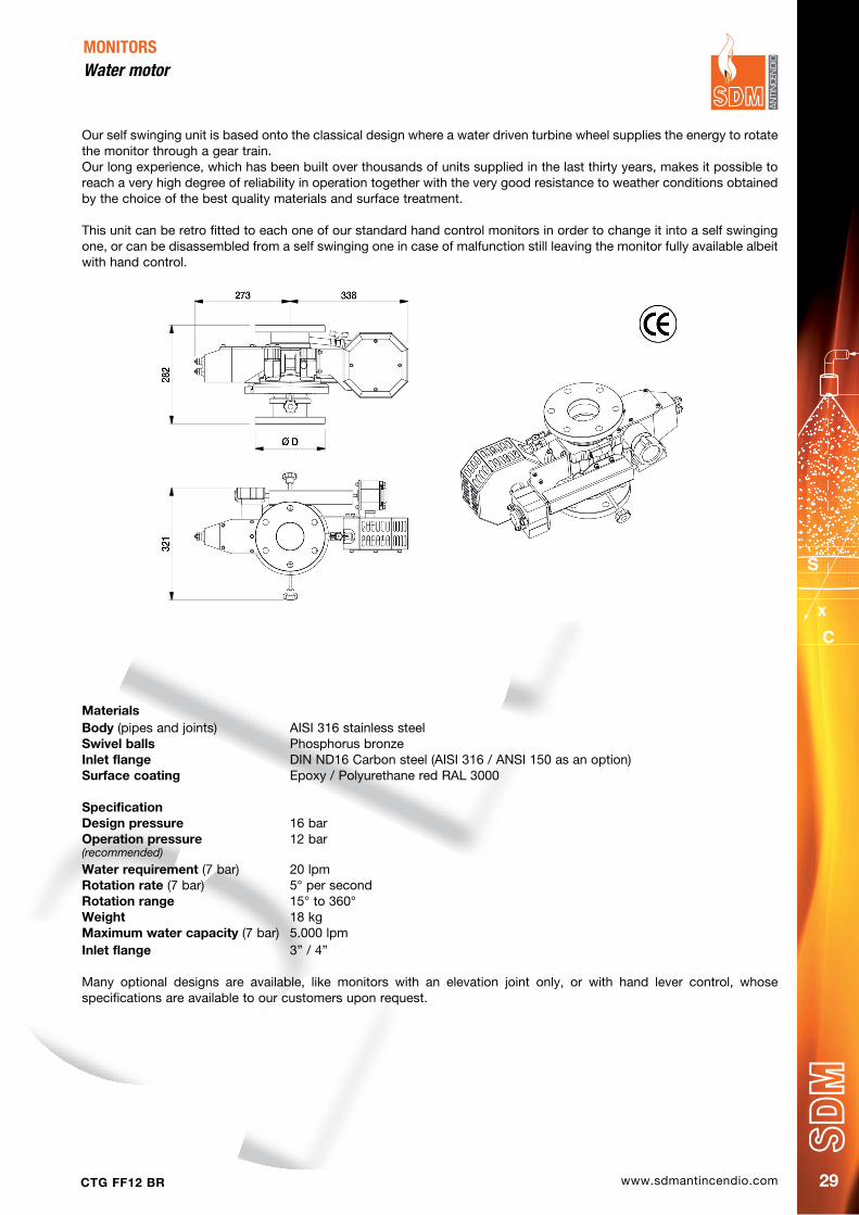
Our self swinging unit is based onto the classical design where a water driven turbine wheel supplies the energy to rotate the monitor through a gear train.Our long experience, which has been built over thousands of units supplied in the last thirty years, makes it possible to reach a very high degree of reliability in operation together with the very good resistance to weather conditions obtained by the choice of the best quality materials and surface treatment.
This unit can be retro fitted to each one of our standard hand control monitors in order to change it into a self swinging one, or can be disassembled from a self swinging one in case of malfunction still leaving the monitor fully available albeit with hand control.
MONITORS Water motor
MaterialsBody (pipes and joints) AISI 316 stainless steelSwivel balls Phosphorus bronzeInlet flange DIN ND16 Carbon steel (AISI 316 / ANSI 150 as an option)Surface coating Epoxy / Polyurethane red RAL 3000
Specificationdesign pressure 16 barOperation pressure 12 bar(recommended) Water requirement (7 bar) 20 lpmRotation rate (7 bar) 5° per secondRotation range 15° to 360°Weight 18 kgMaximum water capacity (7 bar) 5.000 lpmInlet flange 3” / 4”
Many optional designs are available, like monitors with an elevation joint only, or with hand lever control, whose specifications are available to our customers upon request.
www.sdmantincendio.com CTG FF12 BR30
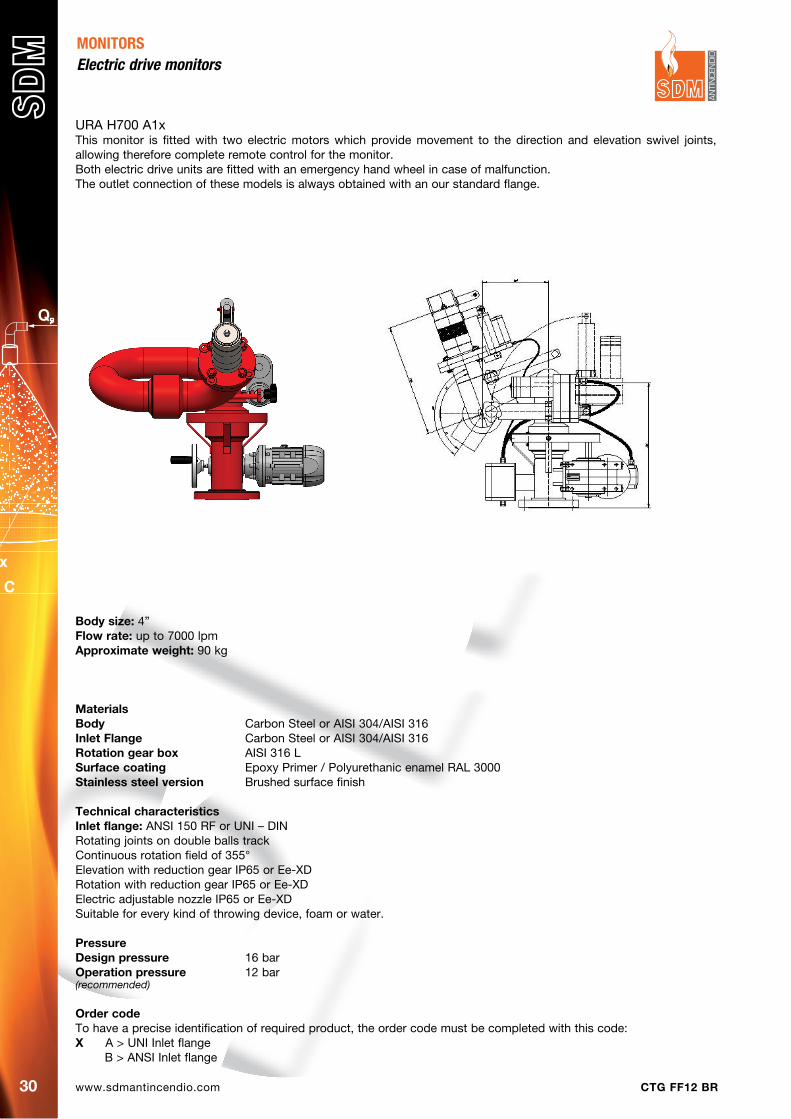
URA H700 A1xThis monitor is fitted with two electric motors which provide movement to the direction and elevation swivel joints, allowing therefore complete remote control for the monitor.Both electric drive units are fitted with an emergency hand wheel in case of malfunction.The outlet connection of these models is always obtained with an our standard flange.
MONITORS electric drive monitors
Body size: 4”Flow rate: up to 7000 lpmApproximate weight: 90 kg
MaterialsBody Carbon Steel or AISI 304/AISI 316Inlet Flange Carbon Steel or AISI 304/AISI 316Rotation gear box AISI 316 LSurface coating Epoxy Primer / Polyurethanic enamel RAL 3000Stainless steel version Brushed surface finish
Technical characteristicsInlet flange: ANSI 150 RF or UNI – DINRotating joints on double balls trackContinuous rotation field of 355°Elevation with reduction gear IP65 or Ee-XDRotation with reduction gear IP65 or Ee-XDElectric adjustable nozzle IP65 or Ee-XDSuitable for every kind of throwing device, foam or water.
pressuredesign pressure 16 barOperation pressure 12 bar(recommended)
Order codeTo have a precise identification of required product, the order code must be completed with this code:X A > UNI Inlet flange B > ANSI Inlet flange
www.sdmantincendio.comCTG FF12 BR 31
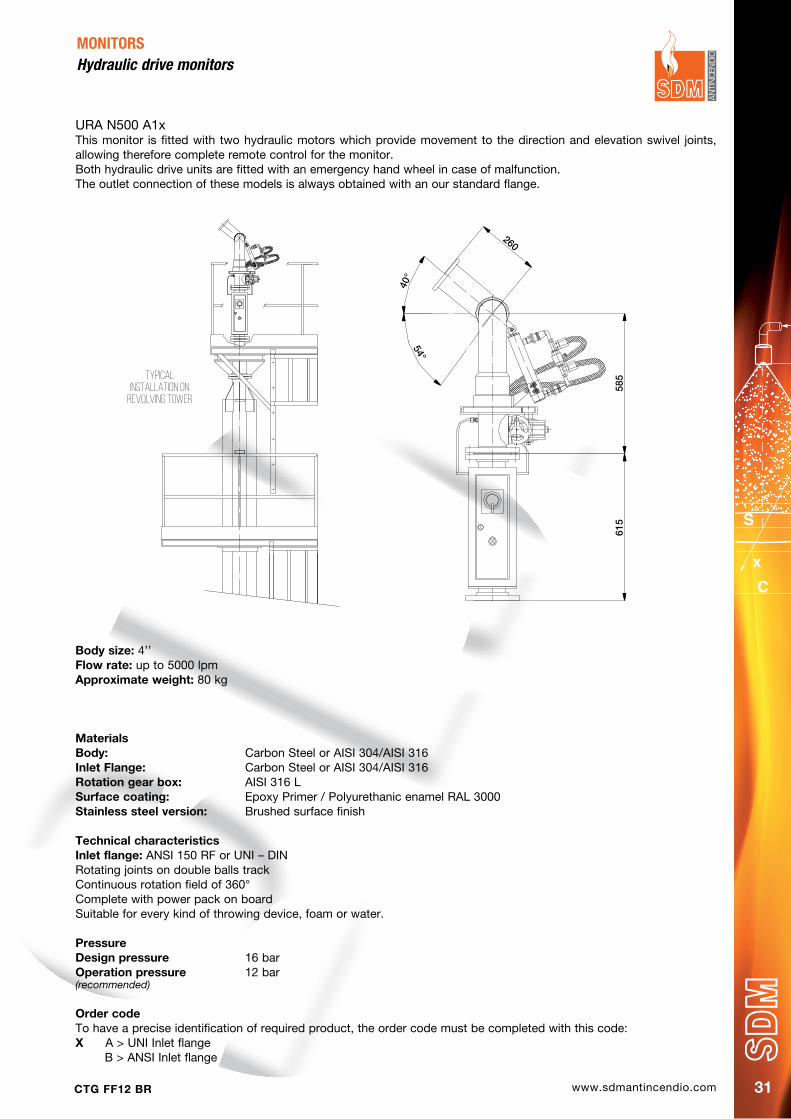
URA N500 A1xThis monitor is fitted with two hydraulic motors which provide movement to the direction and elevation swivel joints, allowing therefore complete remote control for the monitor.Both hydraulic drive units are fitted with an emergency hand wheel in case of malfunction.The outlet connection of these models is always obtained with an our standard flange.
MONITORS Hydraulic drive monitors
Body size: 4’’Flow rate: up to 5000 lpmApproximate weight: 80 kg
MaterialsBody: Carbon Steel or AISI 304/AISI 316Inlet Flange: Carbon Steel or AISI 304/AISI 316Rotation gear box: AISI 316 LSurface coating: Epoxy Primer / Polyurethanic enamel RAL 3000Stainless steel version: Brushed surface finish
Technical characteristicsInlet flange: ANSI 150 RF or UNI – DINRotating joints on double balls trackContinuous rotation field of 360°Complete with power pack on boardSuitable for every kind of throwing device, foam or water.
pressuredesign pressure 16 barOperation pressure 12 bar(recommended)
Order codeTo have a precise identification of required product, the order code must be completed with this code:X A > UNI Inlet flange B > ANSI Inlet flange
Typical installation on
revolving tower
260
40°
54°
585
615
www.sdmantincendio.com CTG FF12 BR32
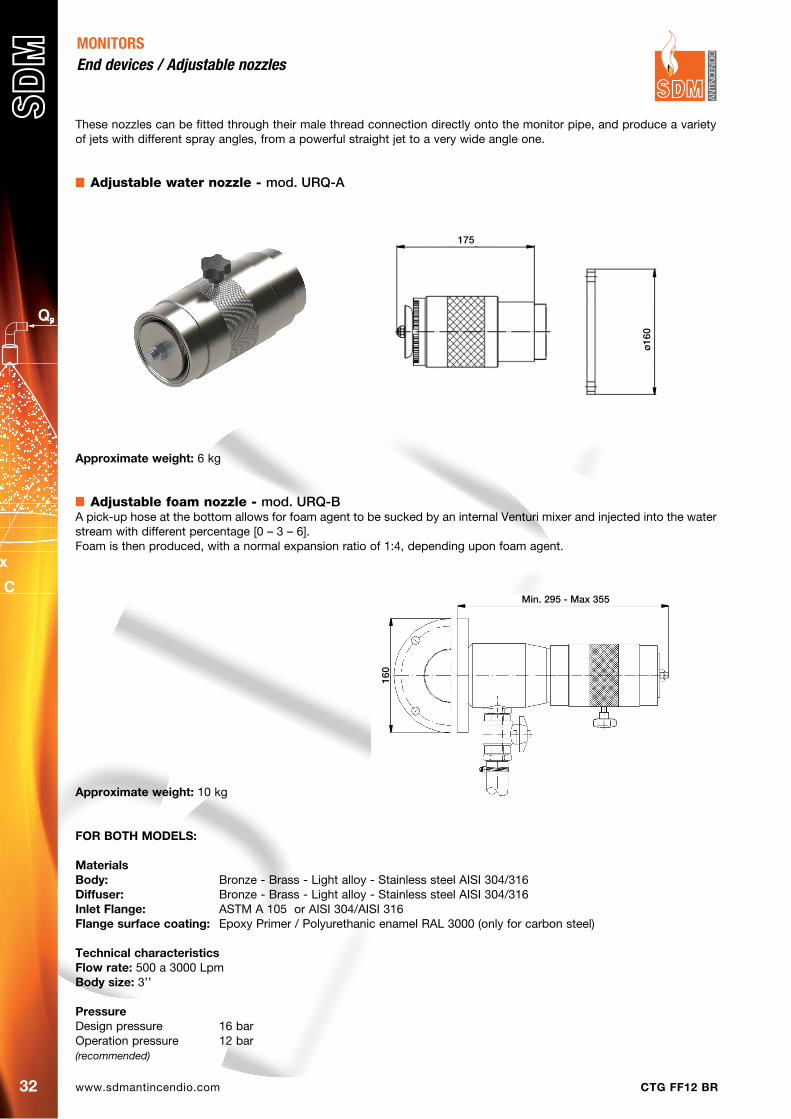
These nozzles can be fitted through their male thread connection directly onto the monitor pipe, and produce a variety of jets with different spray angles, from a powerful straight jet to a very wide angle one.
Adjustable water nozzle - mod. URQ-A
MONITORS end devices / Adjustable nozzles
Approximate weight: 6 kg
Adjustable foam nozzle - mod. URQ-BA pick-up hose at the bottom allows for foam agent to be sucked by an internal Venturi mixer and injected into the water stream with different percentage [0 – 3 – 6].Foam is then produced, with a normal expansion ratio of 1:4, depending upon foam agent.
Approximate weight: 10 kg
FOR BOTh MOdELS:
MaterialsBody: Bronze - Brass - Light alloy - Stainless steel AISI 304/316diffuser: Bronze - Brass - Light alloy - Stainless steel AISI 304/316 Inlet Flange: ASTM A 105 or AISI 304/AISI 316Flange surface coating: Epoxy Primer / Polyurethanic enamel RAL 3000 (only for carbon steel)
Technical characteristicsFlow rate: 500 a 3000 LpmBody size: 3’’
pressureDesign pressure 16 barOperation pressure 12 bar(recommended)
175
ø16
0
Min. 295 - Max 355
160
www.sdmantincendio.comCTG FF12 BR 33
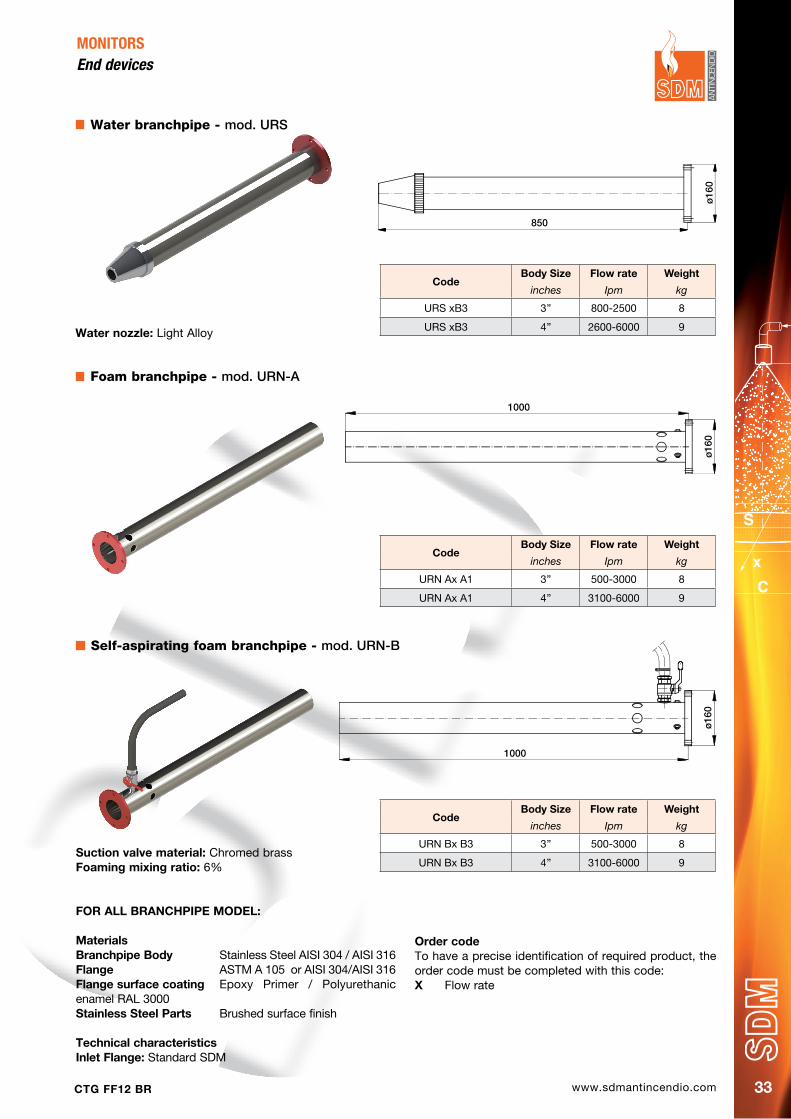
Water branchpipe - mod. URS
MONITORS end devices
Water nozzle: Light Alloy
Foam branchpipe - mod. URN-A
Suction valve material: Chromed brassFoaming mixing ratio: 6%
FOR ALL BRANChpIpE MOdEL:
MaterialsBranchpipe Body Stainless Steel AISI 304 / AISI 316Flange ASTM A 105 or AISI 304/AISI 316Flange surface coating Epoxy Primer / Polyurethanic enamel RAL 3000 Stainless Steel parts Brushed surface finish
Technical characteristicsInlet Flange: Standard SDM
Self-aspirating foam branchpipe - mod. URN-B
CodeBody Size Flow rate Weight
inches Ipm kg
URS xB3 3’’ 800-2500 8
URS xB3 4’’ 2600-6000 9
CodeBody Size Flow rate Weight
inches Ipm kg
URN Ax A1 3’’ 500-3000 8
URN Ax A1 4’’ 3100-6000 9
CodeBody Size Flow rate Weight
inches Ipm kg
URN Bx B3 3’’ 500-3000 8
URN Bx B3 4’’ 3100-6000 9
Order codeTo have a precise identification of required product, the order code must be completed with this code:X Flow rate
1000
ø16
0�
1000
ø16
0
850
ø16
0
www.sdmantincendio.com CTG FF12 BR34
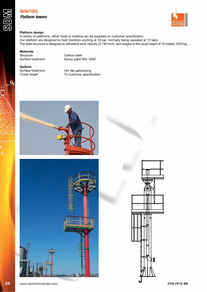
platform designA variety of platforms, either fixed or rotating can be supplied on customer specification.Our platform are designed to host monitors working at 16 bar, normally being operated at 12 bars.The steel structure is designed to withstand wind velocity of 130 km/h, and weighs in the usual height of 10 meters 1670 kg.
MaterialsStructure Carbon steelSurface treatment Epoxy paint RAL 3000
OptionsSurface treatment Hot dip galvanizingTower height To customer specification
MONITORSPlatform towers

www.sdmantincendio.comCTG FF12 BR 35
FIRE HYDRANTS AND HYDRANTS WITH MONITOR
Several types of hydrants can be supplied, for any kind of necessity and environment; typically, they can be grouped into these typologies:
• Carbonsteelpillarhydrants• Carbonsteelpillarhydrantswithmonitor• Castironhydrant,self-drainingtype• Castironhydrant,self-drainingtypewithmonitor
The sizes, for all kinds of hydrant, can vary from 3”, 4”, 6” and in any case, the number and the size of the outlets, must be specified.
Technical characteristics
Body Carbon Steel - AISI 304 / AISI 316Inlet Flanged ANSI 150 RF or UNI - DINFlange material ASTM A 105 - AISI 304 / AISI 316Available sizes 3” - 4” - 6”Number and size of outlet on requestGate valves and couplings in brass - bronzeCouplings codes UNI and all International Stdpainting 1 coat of epoxy primer and 2 coats of polyurethanic enamel RAL 3000 in the carbon steel versionMonitor base butterfly valve in cast iron
280
250
750
280
280 280
840
140

www.sdmantincendio.com CTG FF12 BR36
IN LINE VENTURY MIXERS
PAGE 37
HIGH EXPANSION FOAM GENERATORS
PAGE 41
MOBILE MONITOR TRAILERS
PAGE 47
LOW EXPANSION WATER / FOAM NOZZLES
PAGE 42
FOAM CHAMBERS AND LANCES
PAGE 44
FOAM EQUIPMENT
www.sdmantincendio.comCTG FF12 BR 37
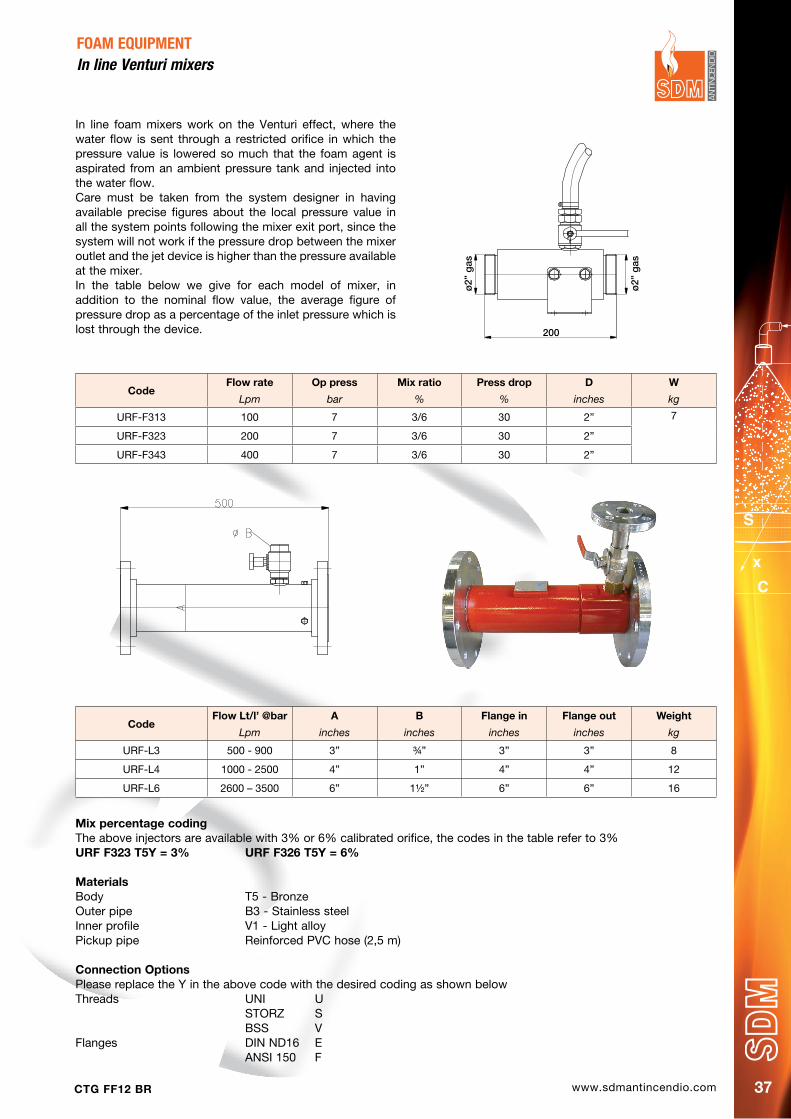
In line foam mixers work on the Venturi effect, where the water flow is sent through a restricted orifice in which the pressure value is lowered so much that the foam agent is aspirated from an ambient pressure tank and injected into the water flow.Care must be taken from the system designer in having available precise figures about the local pressure value in all the system points following the mixer exit port, since the system will not work if the pressure drop between the mixer outlet and the jet device is higher than the pressure available at the mixer.In the table below we give for each model of mixer, in addition to the nominal flow value, the average figure of pressure drop as a percentage of the inlet pressure which is lost through the device.
FOAM EQUIPMENTIn line Venturi mixers
CodeFlow rate Op press Mix ratio press drop d W
Lpm bar % % inches kg
URF-F313 100 7 3/6 30 2” 7
URF-F323 200 7 3/6 30 2”
URF-F343 400 7 3/6 30 2”
Mix percentage codingThe above injectors are available with 3% or 6% calibrated orifice, the codes in the table refer to 3%URF F323 T5Y = 3% URF F326 T5Y = 6%
MaterialsBody T5 - BronzeOuter pipe B3 - Stainless steelInner profile V1 - Light alloyPickup pipe Reinforced PVC hose (2,5 m) Connection OptionsPlease replace the Y in the above code with the desired coding as shown belowThreads UNI U STORZ S BSS VFlanges DIN ND16 E ANSI 150 F
CodeFlow Lt/l’ @bar A B Flange in Flange out Weight
Lpm inches inches inches inches kg
URF-L3 500 - 900 3” ¾” 3” 3” 8
URF-L4 1000 - 2500 4” 1” 4” 4” 12
URF-L6 2600 – 3500 6” 1½” 6” 6” 16
200
ø2”
gas
ø2”
gas
www.sdmantincendio.com CTG FF12 BR38
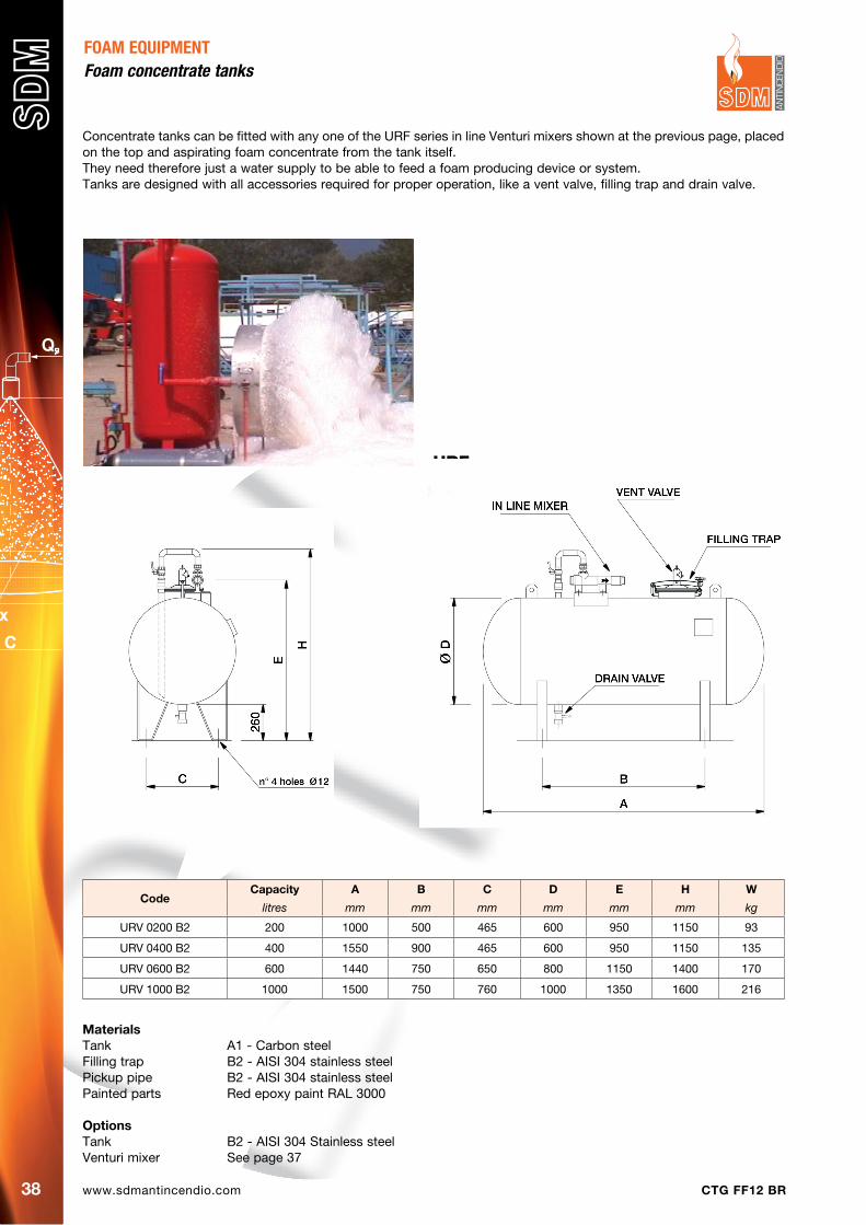
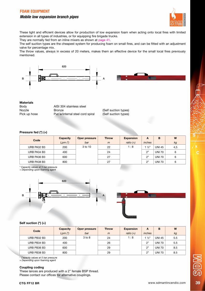
Concentrate tanks can be fitted with any one of the URF series in line Venturi mixers shown at the previous page, placed on the top and aspirating foam concentrate from the tank itself.They need therefore just a water supply to be able to feed a foam producing device or system.Tanks are designed with all accessories required for proper operation, like a vent valve, filling trap and drain valve.
FOAM EQUIPMENTfoam concentrate tanks
CodeCapacity A B C d E h W
litres mm mm mm mm mm mm kg
URV 0200 B2 200 1000 500 465 600 950 1150 93
URV 0400 B2 400 1550 900 465 600 950 1150 135
URV 0600 B2 600 1440 750 650 800 1150 1400 170
URV 1000 B2 1000 1500 750 760 1000 1350 1600 216
MaterialsTank A1 - Carbon steelFilling trap B2 - AISI 304 stainless steelPickup pipe B2 - AISI 304 stainless steelPainted parts Red epoxy paint RAL 3000
OptionsTank B2 - AISI 304 Stainless steelVenturi mixer See page 37
URF
www.sdmantincendio.comCTG FF12 BR 39
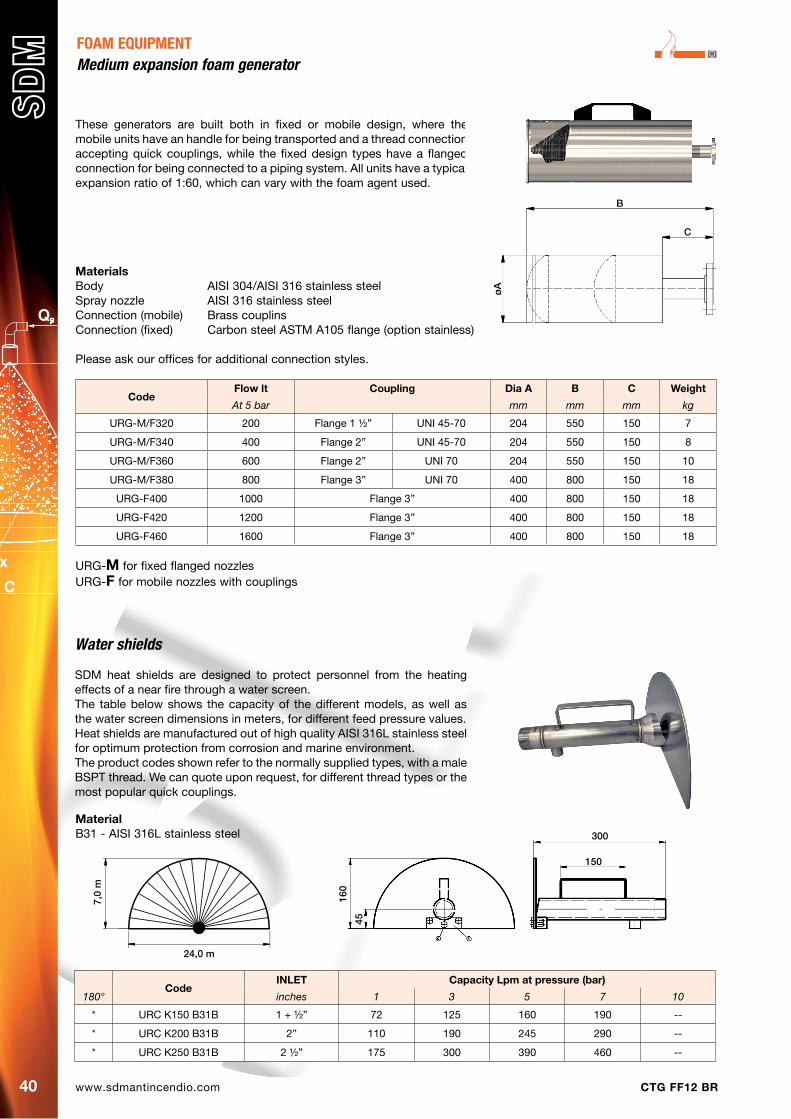
These light and efficient devices allow for production of low expansion foam when acting onto local fires with limited extension in all types of industries, or for equipping fire brigade trucks.They are normally fed from an inline mixers as shown at page 41.The self suction types are the cheapest system for producing foam on small fires, and can be fitted with an adjustment valve for percentage mix.The throw values, always in excess of 20 meters, makes them an effective device for the small local fires previously mentioned.
FOAM EQUIPMENTMobile low expansion branch pipes
Self suction (*) (+)
CodeCapacity Oper pressure Throw Expansion A B W
Lpm (*) bar m ratio (+) inches kg
URB PB32 B3 200 3 to 8 24 1 : 8 1 ½” UNI 45 5.5
URB PB34 B3 400 26 2” UNI 70 5.5
URB PB36 B3 600 29 2” UNI 70 8.5
URB PB38 B3 800 29 2” UNI 70 8.5
MaterialsBody AISI 304 stainless steelNozzle Bronze (Self suction types)Pick up hose Pvc w/internal steel cord spiral (Self suction types)
CodeCapacity Oper pressure Throw Expansion A B W
Lpm (*) bar m ratio (+) inches kg
URB PA32 B3 200 3 to 10 22 1 : 8 1 ½” UNI 45 4,5
URB PA34 B3 400 24 2” UNI 70 6
URB PA36 B3 600 27 2” UNI 70 6
URB PA38 B3 800 27 2” UNI 70 6
* Capacity values at 5 bar pressure+ Depending upon foaming agent
pressure fed (*) (+)
* Capacity values at 5 bar pressure+ Depending upon foaming agent
Coupling codingThese lances are produced with a 2” female BSP thread.Please contact our offices for alternative couplings.
AB
820
AB
820
www.sdmantincendio.com CTG FF12 BR40
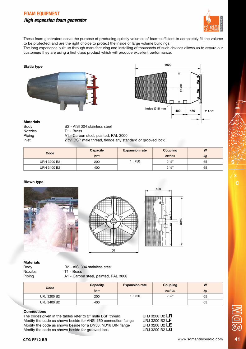
These generators are built both in fixed or mobile design, where the mobile units have an handle for being transported and a thread connection accepting quick couplings, while the fixed design types have a flanged connection for being connected to a piping system. All units have a typical expansion ratio of 1:60, which can vary with the foam agent used.
FOAM EQUIPMENTMedium expansion foam generator
MaterialsBody AISI 304/AISI 316 stainless steelSpray nozzle AISI 316 stainless steelConnection (mobile) Brass couplinsConnection (fixed) Carbon steel ASTM A105 flange (option stainless)
Please ask our offices for additional connection styles.
Water shields
SDM heat shields are designed to protect personnel from the heating effects of a near fire through a water screen.The table below shows the capacity of the different models, as well as the water screen dimensions in meters, for different feed pressure values.Heat shields are manufactured out of high quality AISI 316L stainless steel for optimum protection from corrosion and marine environment.The product codes shown refer to the normally supplied types, with a male BSPT thread. We can quote upon request, for different thread types or the most popular quick couplings.
CodeINLET Capacity Lpm at pressure (bar)
180° inches 1 3 5 7 10
* URC K150 B31B 1 + ½” 72 125 160 190 --
* URC K200 B31B 2” 110 190 245 290 --
* URC K250 B31B 2 ½” 175 300 390 460 --
160
45
300
150
7,0
m
24,0 m
URG-M for fixed flanged nozzlesURG-F for mobile nozzles with couplings
CodeFlow lt Coupling dia A B C Weight
At 5 bar mm mm mm kg
URG-M/F320 200 Flange 1 ½” UNI 45-70 204 550 150 7
URG-M/F340 400 Flange 2” UNI 45-70 204 550 150 8
URG-M/F360 600 Flange 2” UNI 70 204 550 150 10
URG-M/F380 800 Flange 3” UNI 70 400 800 150 18
URG-F400 1000 Flange 3” 400 800 150 18
URG-F420 1200 Flange 3” 400 800 150 18
URG-F460 1600 Flange 3” 400 800 150 18
C
B
øA
MaterialB31 - AISI 316L stainless steel
www.sdmantincendio.comCTG FF12 BR 41
MaterialsBody B2 - AISI 304 stainless steelNozzles T1 - BrassPiping A1 - Carbon steel, painted, RAL 3000Inlet 2 ½” BSP male thread, flange any standard or grooved lock
These foam generators serve the purpose of producing quickly volumes of foam sufficient to completely fill the volume to be protected, and are the right choice to protect the inside of large volume buildings.The long experience built up through manufacturing and installing of thousands of such devices allows us to assure our customers they are using a first class product which will produce excellent performance.
FOAM EQUIPMENTHigh expansion foam generator
ConnectionsThe codes given in the tables refer to 2” male BSP thread URJ 3200 B2 LRModify the code as shown beside for ANSI 150 connection flange URJ 3200 B2 LFModify the code as shown beside for a DN50, ND16 DIN flange URJ 3200 B2 LEModify the code as shown beside for grooved lock URJ 3200 B2 LG
CodeCapacity Expansion rate Coupling W
lpm inches kg
URH 3200 B2 200 1 : 750 2 ½” 65
URH 3400 B2 400 2 ½” 65
MaterialsBody B2 - AISI 304 stainless steelNozzles T1 - BrassPiping A1 - Carbon steel, painted, RAL 3000
CodeCapacity Expansion rate Coupling W
lpm inches kg
URJ 3200 B2 200 1 : 750 2 ½” 65
URJ 3400 B2 400 65
Static type 1920
400 450 2 1/2”holes Ø15 mm
Ø93
0
500
ø95
0
D1
Blown type

www.sdmantincendio.com CTG FF12 BR42
A classic fire fighting component, in the two models pendent and upright, made our of a cast brass body and an impact dish studied for optimal jet distribution.The liquid mix of water and foam agent is first broken inside the body by impact onto a fix member and then distributed by the bottom dish with an angle up 95° and an expansion ratio of about 1:7.The applied density (flow per unit of area) of foam solution must meet the requirements of the Authority Having Jurisdiction for the type flammable liquid and occupancy. Per NFPA 16, coverage density must not be less than 0.16 GPM/ft2 (6,52 mm/min) of floor area with a resulting minimum discharge pressure of not less than 30 psi (2,1 bar).Foam-water sprinkler spacing must not exceed the requirements of NFPA 13 for extra hazard occupancies and the system must be hydraulically calculated to obtain the required density and discharge pressure.
FOAM EQUIPMENTLow expantion water / foam nozzle
MaterialsBody T52 - Naval brassDish B2 - AISI 304 stainless steel
OptionsNickel plated body
CodeCapacity in Ipm for pressure values in Bar Weight Expansion rate
1.0 3.0 5.0 7.0 kg
URK A080 T52DB 36 62 80 95 0.54 1 : 7
URK A090 T52DB 40 69 90 106 0.54
URK A100 T52DB 45 77 100 119 0.54
Pendent nozzle
These nozzles provide a foam projection onto specific points where a fire hazard can be expected.The nozzle is entirely made out stainless steel, connection nipple, body and deflector plate and provides foam with an expansion rate of about 1:10.
URK-A
CodeCapacity in Ipm for pressure values in Bar pressure range Weight Expansion rate
5.0 bar kg
URK C058 B31 80 3 to 8 1.1 1 : 70
URK-C
RG1/2
H
URK nozzles allow to obtain an expantion rate of 1:70 thanks to their doublestainless steel screens. Their robust construction in high quality stainless steelmakes them suitable for mobile service.
7 bar
4
1
2
9
0 112 2
Radius [m]
Mou
ntin
g he
ight
[ft]
3
0
3
5
6
8
7
2,5
Moun ting
heigh t[m]
45678
Radius [ft]
FOR REFERENCE ONLY. Not intended for design.
0
1
2
3
COVERAGE EXAMPLE (K = 23,5 lpm/bar0,5)
5 bar
3 bar
We can supply coverage diagrams for water and foam mix at different pressures
SPRAY WIDTH DIAGRAMDOW 140014
Rev. C
RFC E044 T8SNFoamNozzle
Producer PNRDate: 23/12/2014
Page: 1 of 1
NEW DEFLECTOR
Remarks :1) The work fluid used is industrial water @ Room Temperature2) The test is performed at zero wind velocity condition3) Foam agent: AFFF (AQUEOUS FILM-FORMING FOAM)4) RFC E044 T8SN: 44,0 lpm @ Pressure 1,0 bar
Prepared by : TAMBORNINI M. First Issue Date 23/12/2014
This document is of property of the PNR Italy S.r.l. Every reproduction, also partial, have to be preventively authorized.
Form: MOD LDOE W01A4V dd 09/07/2009
0
1
2 0 11 2 2
Radius [m]
Mo
un
tin
g h
eig
ht
[ft]
3
foam 3%
water
45678
Radius [ft]
FOR REFERENCE ONLY. Not intended for design.
0
1
2
3
4
5
6
COVERAGE EXAMPLE (K = 44 lpm/bar0,5
) @2bar
Mo
un
ting
he
igh
t [m]
3 3,59101112
H
D11’
www.sdmantincendio.comCTG FF12 BR 43
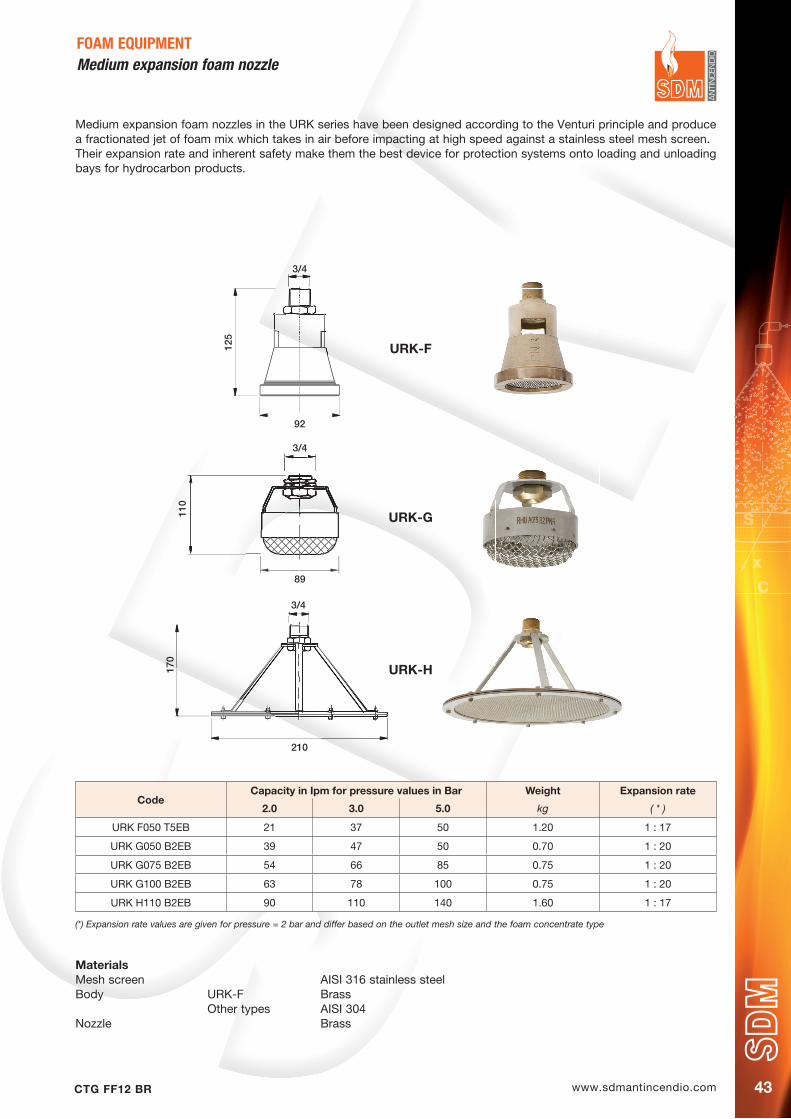
Medium expansion foam nozzles in the URK series have been designed according to the Venturi principle and produce a fractionated jet of foam mix which takes in air before impacting at high speed against a stainless steel mesh screen.Their expansion rate and inherent safety make them the best device for protection systems onto loading and unloading bays for hydrocarbon products.
FOAM EQUIPMENTMedium expansion foam nozzle
CodeCapacity in Ipm for pressure values in Bar Weight Expansion rate
2.0 3.0 5.0 kg ( * )
URK F050 T5EB 21 37 50 1.20 1 : 17
URK G050 B2EB 39 47 50 0.70 1 : 20
URK G075 B2EB 54 66 85 0.75 1 : 20
URK G100 B2EB 63 78 100 0.75 1 : 20
URK H110 B2EB 90 110 140 1.60 1 : 17
(*) Expansion rate values are given for pressure = 2 bar and differ based on the outlet mesh size and the foam concentrate type
MaterialsMesh screen AISI 316 stainless steelBody URK-F Brass Other types AISI 304Nozzle Brass
110
89
3/4
URK-G
125
92
3/4
URK-F
170
210
3/4
URK-H
www.sdmantincendio.com CTG FF12 BR44
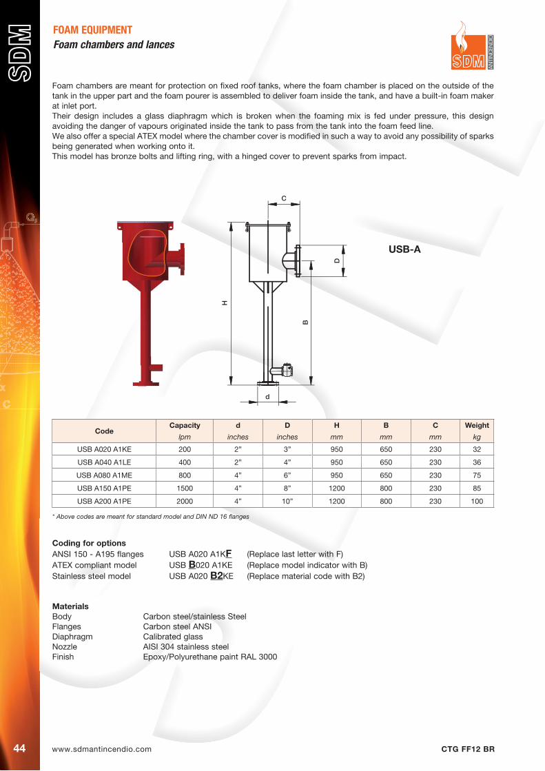
Foam chambers are meant for protection on fixed roof tanks, where the foam chamber is placed on the outside of the tank in the upper part and the foam pourer is assembled to deliver foam inside the tank, and have a built-in foam maker at inlet port.Their design includes a glass diaphragm which is broken when the foaming mix is fed under pressure, this design avoiding the danger of vapours originated inside the tank to pass from the tank into the foam feed line.We also offer a special ATEX model where the chamber cover is modified in such a way to avoid any possibility of sparks being generated when working onto it.This model has bronze bolts and lifting ring, with a hinged cover to prevent sparks from impact.
FOAM EQUIPMENTFoam chambers and lances
Coding for options ANSI 150 - A195 flanges USB A020 A1KF (Replace last letter with F)ATEX compliant model USB B020 A1KE (Replace model indicator with B)Stainless steel model USB A020 B2KE (Replace material code with B2)
MaterialsBody Carbon steel/stainless SteelFlanges Carbon steel ANSIDiaphragm Calibrated glassNozzle AISI 304 stainless steelFinish Epoxy/Polyurethane paint RAL 3000
CodeCapacity d D H B C Weight
lpm inches inches mm mm mm kg
USB A020 A1KE 200 2” 3” 950 650 230 32
USB A040 A1LE 400 2” 4” 950 650 230 36
USB A080 A1ME 800 4” 6” 950 650 230 75
USB A150 A1PE 1500 4” 8” 1200 800 230 85
USB A200 A1PE 2000 4” 10” 1200 800 230 100
* Above codes are meant for standard model and DIN ND 16 flanges
D
d
C
B
H
USB-A
www.sdmantincendio.comCTG FF12 BR 45
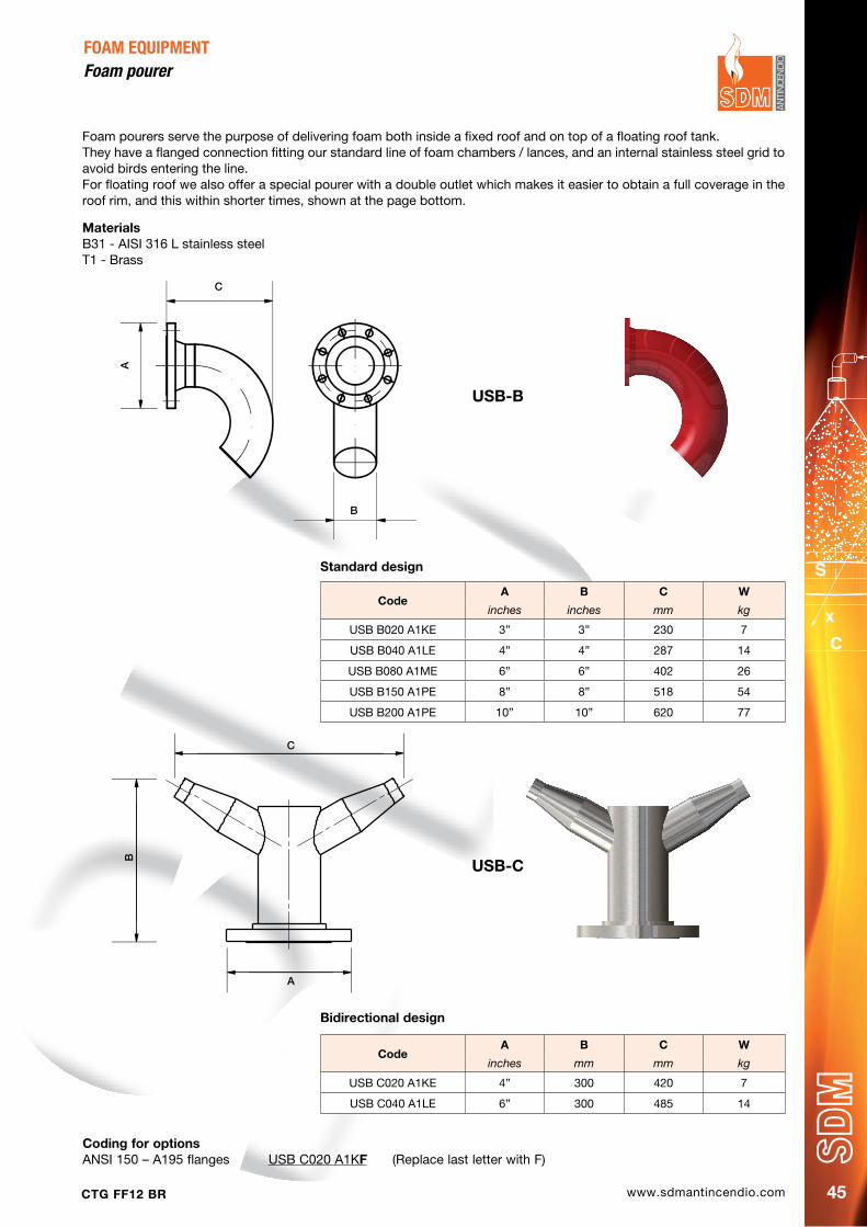
FOAM EQUIPMENTfoam pourer
Foam pourers serve the purpose of delivering foam both inside a fixed roof and on top of a floating roof tank.They have a flanged connection fitting our standard line of foam chambers / lances, and an internal stainless steel grid to avoid birds entering the line.For floating roof we also offer a special pourer with a double outlet which makes it easier to obtain a full coverage in the roof rim, and this within shorter times, shown at the page bottom.
CodeA B C W
inches inches mm kg
USB B020 A1KE 3” 3” 230 7
USB B040 A1LE 4” 4” 287 14
USB B080 A1ME 6” 6” 402 26
USB B150 A1PE 8” 8” 518 54
USB B200 A1PE 10” 10” 620 77
Standard design
Bidirectional design
Coding for options ANSI 150 – A195 flanges USB C020 A1KF (Replace last letter with F)
CodeA B C W
inches mm mm kg
USB C020 A1KE 4” 300 420 7
USB C040 A1LE 6” 300 485 14
USB-B
USB-C
C
A
B
B
C
A
MaterialsB31 - AISI 316 L stainless steelT1 - Brass

www.sdmantincendio.com CTG FF12 BR46
CodeFlow A B C d Weigth
litres mm inches inches inches kg
LBE2 200 700 2” 3” 2” 12
LBE4 400 700 2” 4” 2” 12
LBE6 600 700 3” 4” 3” 18
LBE8 800 700 3” 4” 3” 18
LBE10 1000 1000 3” 4” 3” 18
LBE15 1500 1000 4” 6” 4” 33
LBE30 3000 1000 6” 8” 6” 38
FOAM EQUIPMENT
Technical characteristicsBody Carbon Steel - AISI 304 / AISI 316Inlet Flanged ANSI 150 RF or UNI - DINFlange material ASTM A 105 - AISI 304 / AISI 316Working pressure 5 barpainting 1 coat of epoxy primer and 2 coats of polyurethanic enamel RAL 3000 in the carbon steel versionStainless steel version Brushed surface finish
Low expansion foam branchpipe mod. LBe
Code Mod.FE FU RU Weigth
inches inches mm kg
USB F080 A1X VDS 080 3” 3” 70 380
USB F100 A1X VDS 100 4” 4” 70 380
USB F150 A1X VDS 150 6” 6” 70 380
Test valve USB-f
The USB-F test valves have been designed designed to be assembled in the foam line ascending to the tank roof, just before the foam maker, and to allow for easy testing procedures. The valve can be set to divert the foam from the line while testing the system, and prevents foam from being poured onto or inside the tank.
MaterialsBody T1 - BrassFlanges A1 - Carbon steel
Flange type codingFoam chambers and foam makers are normally supplied fitted with Ansi Flangess, other standards on request. Listed codes show Ansi Flangess, for DIN / UNI Flangess please replace the final B B with an A.
Example:USB F080 A1A flanges AnsiUSB F080 A1B flanges DIN
RU
FU
H
45°
FoamPourer
FE
A
BDC
www.sdmantincendio.comCTG FF12 BR 47
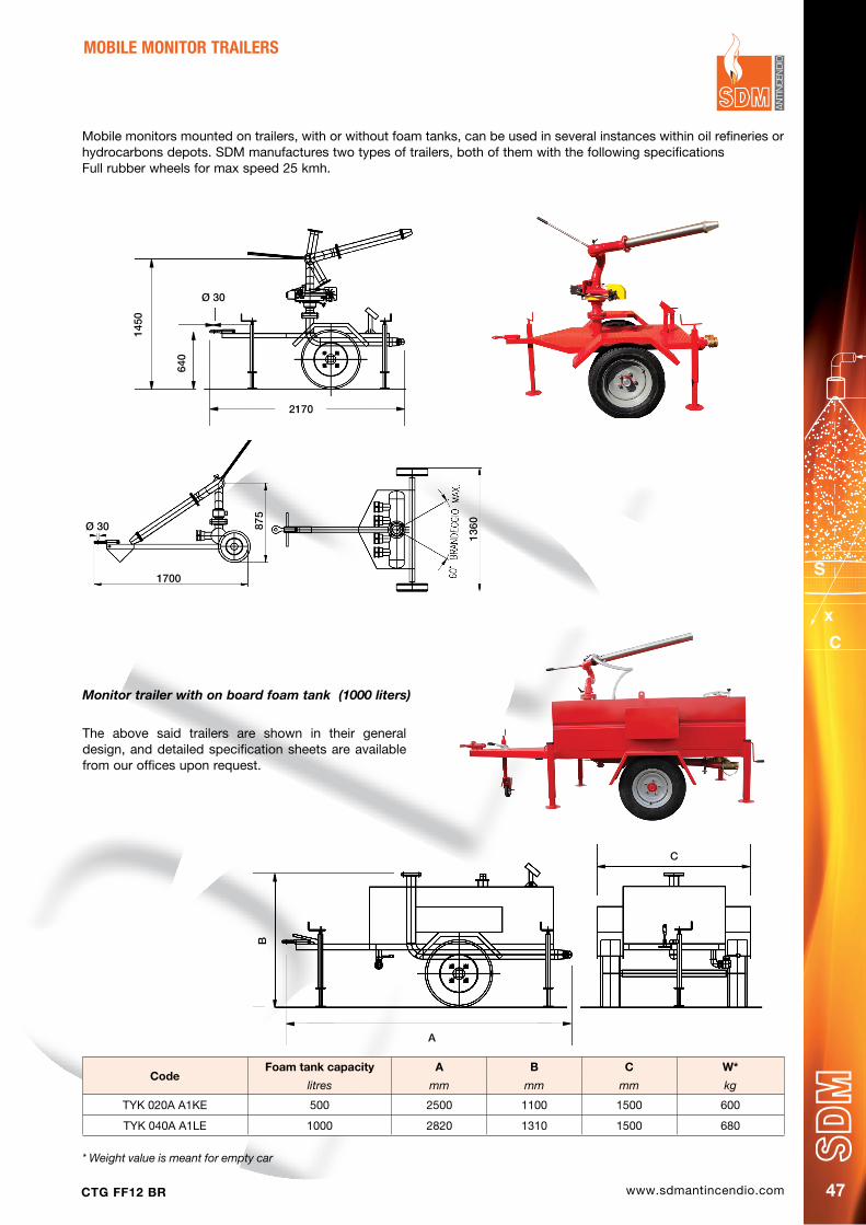
The above said trailers are shown in their general design, and detailed specification sheets are available from our offices upon request.
Mobile monitors mounted on trailers, with or without foam tanks, can be used in several instances within oil refineries or hydrocarbons depots. SDM manufactures two types of trailers, both of them with the following specificationsFull rubber wheels for max speed 25 kmh.
Monitor trailer with on board foam tank (1000 liters)
MOBILE MONITOR TRAILERS
CodeFoam tank capacity A B C W*
litres mm mm mm kg
TYK 020A A1KE 500 2500 1100 1500 600
TYK 040A A1LE 1000 2820 1310 1500 680
* Weight value is meant for empty car
1700
875
1360Ø 30
1450
640
2170
Ø 30
A
B
C
www.sdmantincendio.com CTG FF12 BR48
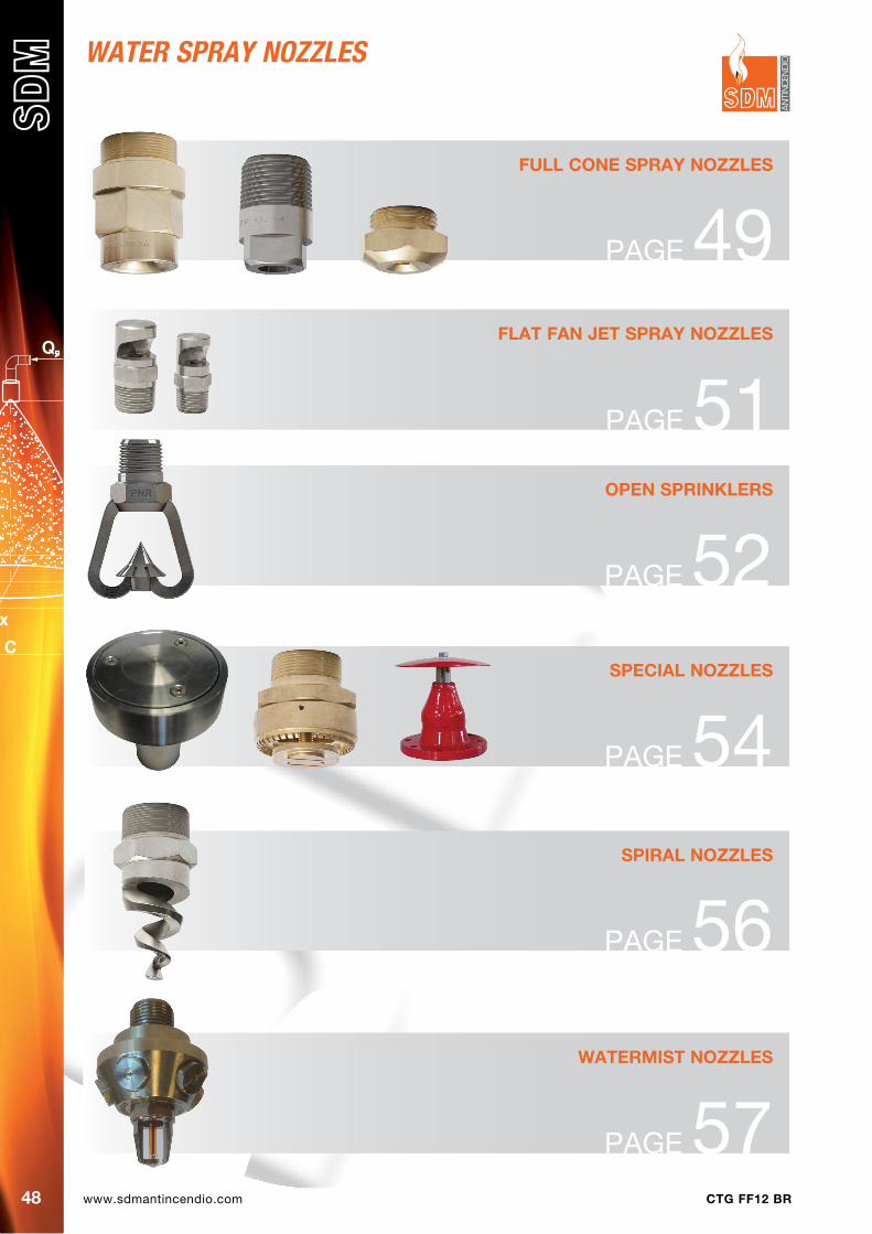
FULL CONE SpRAY NOzzLES
PAGE 49FLAT FAN jET SpRAY NOzzLES
PAGE 51
WATERMIST NOzzLES
PAGE 57
OpEN SpRINKLERS
PAGE 52SpECIAL NOzzLES
PAGE 54
WATer SPrAY NoZZLeS
SpIRAL NOzzLES
PAGE 56
www.sdmantincendio.comCTG FF12 BR 49
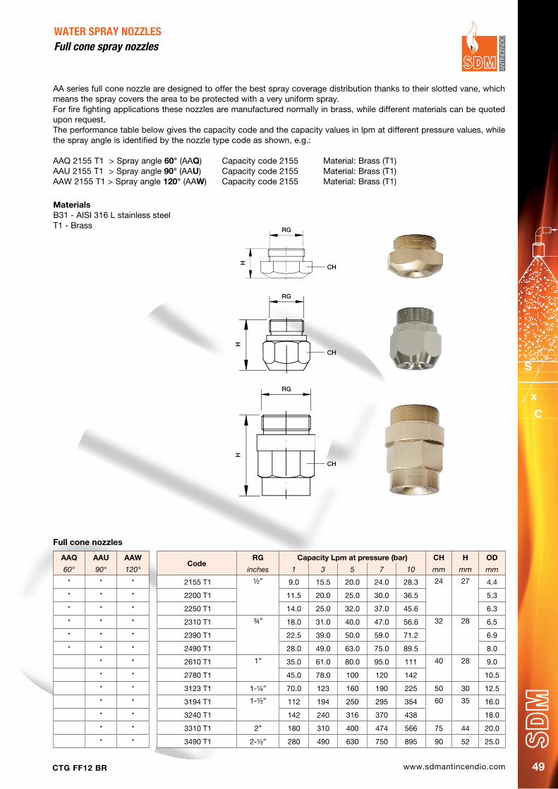
AA series full cone nozzle are designed to offer the best spray coverage distribution thanks to their slotted vane, which means the spray covers the area to be protected with a very uniform spray.For fire fighting applications these nozzles are manufactured normally in brass, while different materials can be quoted upon request.The performance table below gives the capacity code and the capacity values in lpm at different pressure values, while the spray angle is identified by the nozzle type code as shown, e.g.:
AAQ 2155 T1 > Spray angle 60° (AAQ) Capacity code 2155 Material: Brass (T1)AAU 2155 T1 > Spray angle 90° (AAU) Capacity code 2155 Material: Brass (T1)AAW 2155 T1 > Spray angle 120° (AAW) Capacity code 2155 Material: Brass (T1)
WATER SPRAY NOzzLESfull cone spray nozzles
AAQ AAU AAWCode
RG Capacity Lpm at pressure (bar) Ch h Od
60° 90° 120° inches 1 3 5 7 10 mm mm mm
* * * 2155 T1 ½” 9.0 15.5 20.0 24.0 28.3 24 27 4.4
* * * 2200 T1 11.5 20.0 25.0 30.0 36.5 5.3
* * * 2250 T1 14.0 25.0 32.0 37.0 45.6 6.3
* * * 2310 T1 ¾” 18.0 31.0 40.0 47.0 56.6 32 28 6.5
* * * 2390 T1 22.5 39.0 50.0 59.0 71.2 6.9
* * * 2490 T1 28.0 49.0 63.0 75.0 89.5 8.0
* * 2610 T1 1” 35.0 61.0 80.0 95.0 111 40 28 9.0
* * 2780 T1 45.0 78.0 100 120 142 10.5
* * 3123 T1 1-¼” 70.0 123 160 190 225 50 30 12.5
* * 3194 T1 1-½” 112 194 250 295 354 60 35 16.0
* * 3240 T1 142 240 316 370 438 18.0
* * 3310 T1 2” 180 310 400 474 566 75 44 20.0
* * 3490 T1 2-½” 280 490 630 750 895 90 52 25.0
Full cone nozzles
RG
H
CH
RG
H
CH
RG
H
CH
MaterialsB31 - AISI 316 L stainless steelT1 - Brass
www.sdmantincendio.com CTG FF12 BR50
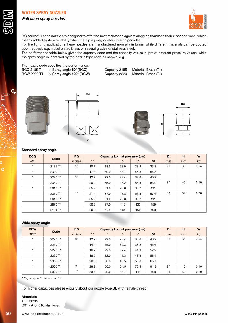
WATER SPRAY NOzzLESfull cone spray nozzles
BG series full cone nozzle are designed to offer the best resistance against clogging thanks to their x-shaped vane, which means added system reliability when the piping may contain foreign particles.For fire fighting applications these nozzles are manufactured normally in brass, while different materials can be quoted upon request, e.g. nickel plated brass or several grades of stainless steel.The performance table below gives the capacity code and the capacity values in lpm at different pressure values, while the spray angle is identified by the nozzle type code as shown, e.g.
The nozzle code specifies the performance:BGQ 2185 T1 > Spray angle 60° (BGQ) Capacity 2185 Material: Brass (T1)BGW 2220 T1 > Spray angle 120° (BGW) Capacity 2220 Material: Brass (T1)
For higher capacities please enquiry about our nozzle type BE with female thread
MaterialsT1 - BrassB31 - AISI 316 stainless
BGQCode
RG Capacity Lpm at pressure (bar) d h W
60° inches 1* 3 5 7 10 mm mm kg
* 2185 T1 ½” 10.7 18.5 23.9 28.3 33.8 21 33 0.04
* 2300 T1 17.3 30.0 38.7 45.8 54.8
* 2220 T1 ¾” 12.7 22.0 28.4 33.6 40.2
* 2350 T1 20.2 35.0 45.2 53.5 63.9 27 40 0.10
* 2610 T1 35.2 61.0 78.8 93.2 111
* 2370 T1 1” 21.4 37.0 47.8 56.5 67.6 33 52 0.20
2610 T1 35.2 61.0 78.8 93.2 111
2870 T1 50.2 87.0 112 133 159
3104 T1 60.0 104 134 159 190
BGWCode
RG Capacity Lpm at pressure (bar) d h W
120° inches 1* 3 5 7 10 mm mm kg
* 2220 T1 ½” 12.7 22.0 28.4 33.6 40.2 21 33 0.04
* 2250 T1 14.4 25.0 32.3 38.2 45.6
* 2290 T1 16.7 29.0 37.4 44.3 52.9
* 2320 T1 18.5 32.0 41.3 48.9 58.4
* 2360 T1 20.8 36.0 46.5 55.0 65.7
* 2500 T1 ¾” 28.9 50.0 64.5 76.4 91.3 27 40 0.10
2920 T1 1” 53.1 92.0 119 141 168 33 52 0.20
Standard spray angle
Wide spray angle
* Capacity at 1 bar = K factor
RG
H
D
RG
H
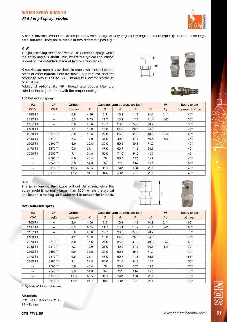
www.sdmantincendio.comCTG FF12 BR 51
K series nozzles produce a flat fan jet spray with a large or very large spray angle, and are typically used to cover large area surfaces. They are available in two different types e.g.:
WATER SPRAY NOzzLESflat fan jet spray nozzles
1/2 3/4 Orifice Capacity Lpm at pressure (bar) W Spary angle
KDW KEW dia mm 1* 3 5 7 10 kg at pressure 4 bar
1780 T1 -- 2.6 4.50 7.8 10.1 11.9 14.2 0.11 140°
2117 T1 -- 3.3 6.75 11.7 15.1 17.9 21.4 (1/2) 130°
2157 T1 -- 3.8 9.06 15.7 20.3 24.0 28.7 130°
2188 T1 -- 4.1 10.9 18.8 24.3 28.7 34.3 142°
2270 T1 2270 T1 5.0 15.6 27.0 35.0 41.2 49.3 0.40 128°
2310 T1 2310 T1 5.3 17.9 31.0 40.0 47.4 56.6 (3/4) 135°
2390 T1 2390 T1 6.0 22.5 39.0 50.3 59.6 71.2 140°
2470 T1 2470 T1 6.5 27.1 47.0 60.7 71.8 85.8 140°
2550 T1 2550 T1 7.1 31.8 55.0 71.0 84.0 100 140°
-- 2700 T1 8.0 40.4 70 90.4 107 128 140°
-- 2940 T1 9.3 54.3 94 121 144 172 150°
-- 3110 T1 10.3 63.5 110 142 168 201 145°
-- 3110 T1 12.2 94.7 164 212 251 299 145°
1/2 3/4 Orifice Capacity Lpm at pressure (bar) W Spary angle
KDX KEX dia mm 1* 3 5 7 10 kg at 4 bar
1780 T1 -- 2.6 4.50 7.8 10.1 11.9 14.2 0.11 160°
2117 T1 -- 3.3 6.75 11.7 15.1 17.9 21.4 (1/2) 165°
2157 T1 -- 3.8 9.06 15.7 20.3 24.0 28.7 170°
2188 T1 -- 4.1 10.9 18.8 24.3 28.7 34.3 170°
2270 T1 2270 T1 5.0 15.6 27.0 35.0 41.2 49.3 0.40 168°
2310 T1 2310 T1 5.3 17.9 31.0 40.0 47.4 56.6 (3/4) 172°
2390 T1 2390 T1 6.0 22.5 39.0 50.3 59.6 71.2 172°
2470 T1 2470 T1 6.5 27.1 47.0 60.7 71.8 85.8 168°
2550 T1 2550 T1 7.1 31.8 55.0 71.0 84.0 100 172°
-- 2700 T1 8.0 40.4 70 90.4 107 128 170°
-- 2940 T1 9.3 54.3 94 121 144 172 170°
-- 3110 T1 10.3 63.5 110 142 168 201 170°
-- 3110 T1 12.2 94.7 164 212 251 299 170°
K-X The jet is leaving the nozzle without deflection, while the spray angle is normally larger than 150°, where the typical application is making up a water wall to contain fire smokes.
K-W The jet is leaving the nozzle with a 15° deflected spray, while the spray angle is about 120°, where the typical application is cooling the outside surface of hydrocarbon tanks.
K nozzles are normally available in brass, while nickel plated brass or other materials are available upon request, and are produced with a tapered BSPT thread to allow for proper jet orientation.Additional options like NPT thread and copper filter are listed at the page bottom with the proper coding.
H
H
15° deflected spray
Not deflected spray
* Capacity at 1 bar = K factor
MaterialsB31 - AISI stainless 316LT1 - Brass
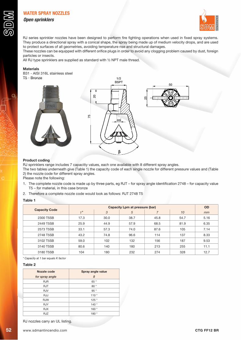
www.sdmantincendio.com CTG FF12 BR52
WATER SPRAY NOZZLESOpen sprinklers
RJ series sprinkler nozzles have been designed to perform fire fighting operations when used in fixed spray systems. They produce a directional spray with a conical shape, the spray being made up of medium velocity drops, and are used to protect surfaces of all geometries, avoiding temperature rise and structural damages.These nozzles can be equipped with different orifice plugs in order to avoid any clogging problem caused by dust, foreign particles or insects.All RJ type sprinklers are supplied as standard with ½ NPT male thread.
MaterialsB31 - AISI 316L stainless steelT5 - Bronze
Product codingRJ sprinklers range includes 7 capacitiy values, each one available with 8 different spray angles.The two tables underneath give (Table 1) the capacity code of each single nozzle for different pressure values and (Table 2) the nozzle code for different spray angles.Please note the following:
1. The complete nozzle code is made up by three parts, eg RJT – for spray angle identification 2748 – for capacity value T5 – for material, in this case bronze
2. Therefore a complete nozzle code would look as follows: RJT 2748 T5
RJ nozzles carry an UL listing.
Capacity CodeCapacity Lpm at pressure (bar) OD
1* 3 5 7 10 mm
2300 T5SB 17.3 30.0 38.7 45.8 54.7 5.16
2449 T5SB 25.9 44.9 57.9 68.5 81.9 6.35
2573 T5SB 33.1 57.3 74.0 87.6 105 7.14
2748 T5SB 43.2 74.8 96.6 114 137 8.33
3102 T5SB 59.0 102 132 156 187 9.53
3140 T5SB 80.6 140 180 213 255 11.1
3180 T5SB 104 180 232 274 328 12.7
Table 1
* Capacity at 1 bar equals K factor
T5 - Bronze
50
2520
1/2BSPT
75
Nozzle code Spray angle value
for spray angle ß
RJR 65 °
RJT 80 °
RJV 95 °
RJJ 110 °
RJW 125 °
RJY 140 °
RJX 160 °
RJZ 180 °
Table 2

www.sdmantincendio.comCTG FF12 BR 53
WATER SPRAY NOzzLESopen Sprinklers
RO series sprinkler nozzles produce a full jet spray whose angle can reach very large values, which allows for cooling operations onto very large surfaces.The same nozzle body can be supplied with both an ½” and a ¾” tapered BSPT thread, while NPT threads are available as an option, as well as copper or stainless inlet filters (see bottom of page for appropriate coding).
MaterialsB31 - AISI 316 L stainless steelT1 - Brass
CodeCapacity Lpm at pressure (bar) Od
1* 3 5 7 10 mm
ROY 2156 T1SB 9.00 15.6 20.0 24.0 29.0 4.0
ROY 2198 T1SB 11.5 19.8 25.0 30.0 36.0 4.5
ROY 2270 T1SB 15.8 27.0 35.0 42.0 50.0 5.0
ROY 2300 T1SB 18.0 30.0 40.0 48.0 57.0 5.5
ROY 2390 T1SB 23.0 39.0 50.0 60.0 71.0 6.0
ROY 2470 T1SB 27.0 47.0 61.0 72.0 86.0 6.5
ROY 2550 T1SB 31.0 55.0 72.0 84.0 91.0 7.0
ROY 2700 T1SB 41.0 70.0 92.0 112 130 8.0
ROY 2910 T1SB 52.0 91.0 117 140 165 9.0
ROY 3110 T1SB 64.0 110 139 165 200 10.0
Thread 1/2”
* Capacity at 1 Bar in liters per minute equals K factor
CodeCapacity Lpm at pressure (bar) Od
1* 3 5 7 10 mm
ROY 2157 T1SB 9.00 15.6 20.0 24.0 29.0 4.00
ROY 2199 T1SB 11.5 19.8 25.0 30.0 36.0 4.50
ROY 2271 T1SB 15.8 27.0 35.0 42.0 50.0 5.00
ROY 2301 T1SB 18.0 30.0 40.0 48.0 57.0 5.50
ROY 2391 T1SB 23.0 39.0 50.0 60.0 71.0 6.00
ROY 2471 T1SB 27.0 47.0 61.0 72.0 86.0 6.50
ROY 2551 T1SB 31.0 55.0 72.0 84.0 91.0 7.00
ROY 2701 T1SB 41.0 70.0 92.0 112 130 8.00
ROY 2911 T1SB 52.0 91.0 117 140 165 9.00
ROY 3111 T1SB 64.0 110 139 165 200 10.0
Thread 3/4”
* Capacity at 1 Bar in liters per minute equals K factor
Coding for nozzle optionsAdding the following codes at the end of standard codes as shown in the above tables, specifies nozzle options as follows
SN NPT ThreadFB Copper filter, BSPT threadFN Copper filter, NPT threadGB Stainless filter, BSPT thread
70
25
RG
www.sdmantincendio.com CTG FF12 BR54
Our range of full cone nozzles, series URP, are typically designed to offer design flexibility in fire fighting, applications since offering the advantages of an adjustable flow rate and an adjustable spray angle.Capacity and spray angle values can be easily preset both at the factory, or right on the installation site.The wide internal passages allow foreign particles up to 1/8 to be in the feed water, while larger particles must be dealt with by means of a filter or screen on the feed line.
MaterialsT1 - BrassT5 - BronzeV1 - Aluminum
Water spray nozzlesFull cone adjustable nozzles
CodeRG Capacity Lpm at pressure (bar) CH H* H1 OD
inches 1** 3 5 7 10 mm mm mm mm
URP E070 T1FN ¾” 14.4 24.9 32.1 37.8 45.4 30 45 14 34
URP E071 T1FN 28.7 49.8 64.2 75.6 90.8URP E072 T1FN 43.1 74.6 96.3 113 136URP H100 T1FN 1” 57.5 99.5 128 151 182 50 70 22 54
URP H102 T1FN 136 236 304 359 430URP H103 T1FN 180 311 401 472 568URP H150 T1FN 1+ ½” 180 311 401 472 568 50 73 25 54
URP H151 T1FN 251 435 562 661 795URP H152 T1FN 359 622 803 945 1135
* Height dimension for fully extended nozzle - ** Capacity at 1 bar = K factor - + Capacity values in the table shows typical settings for each siz
Swivel joints
Swivel joints are designed to accommodate larger size nozzles. The orientation of the unit is fixed by tightening the clamping flanges with bolts. The connection to the feedline is a male thread, while the connection to the nozzle can be male or female.
Max operative pressureLP 9 bar
MaterialsB3 - Stainless Steel AISI 316T1 - Brass
CodeRG RG1 RF L D A W
inches inches inches mm mm degrees kg
ZRQ 8080 xx 1” 1” 89 92 40 1.8ZRQ 8282 xx 1 ¼” 1 ¼” 130 2.1ZRQ 8482 xx 1 ½” 1 ¼” 133 2.4ZRR 8282 xx 1 ¼” 1 ¼” 130 92 40 2.2ZRR 8284 xx 1 ½” 1 ¼” 130 2.2ZRR 8484 xx 1 ½” 1 ½” 130 2.4ZRR 8686 xx 2” 2 ½” 203 158 40 8.0ZRR 8888 xx 2 ½” 2 ½” 229 8.0
Order codeTo have a precise identification of required product, the order code must be completed with this code:ZRQ 8080 T1 (brass)
RG
H
H1
CH
www.sdmantincendio.comCTG FF12 BR 55
WATER SPRAY NOzzLES
Pop-up nozzles
The UMM pop-up nozzles, for cooling and foam-water fire extinguishing system, is specially designed to be fully recessed, which is a key advantage for installation on aircraft carrier’s flight deck or other areas that needs surface protection.This nozzles has been tested for assuring operation after being exposed to a jet engine discarge gases for fifteen minutes.Inlet water connection: 1 ¼” gas thread.
Technical characteristicsMaterial B31 Stainless steel AISI 316LOperative pressure 6 barFlow rate 90 LpmCoverage diameter 5.5 meter
Order codeTo have a precise identification of required product, the order code must be completed with this code:
UMM x116 B31 X B > Coverage angle 160° d > Coverage angle 360°
Mushroom nozzles
The mushroom type nozzle in the URC series are designed for protection of large size tanks, in oil and petrochemical plants.Their sturdy construction and large size passages can assure for a very high degree of reliability.Connection can be either by means of thread, or with flanges according to the most popular standards.
MaterialsA1 - Mild steel, epoxy paintedB31 - AISI 316 stainless steel
A
B
C
CodeFlow min Flow max A B C Weight
At 5 bar At 5 bar mm mm inches kg
URC-M001 200 400 235 180 1½” 3.5
URC-M002 400 650 235 200 2” 5.5
URC-M003 800 1500 235 210 3” 7.5
URC-M004 1500 3200 400 285 4” 14
URC-M006 3200 5500 400 335 6” 20
130
ø51
ø120ø106
160°
ø58
www.sdmantincendio.com CTG FF12 BR56
WATER SPRAY NOzzLESfull cone spiral nozzles
E type spiral nozzles have been designed to offer a very high resistance to clogging dangers, and at the same time an effective spray distribution for the purpose of performing efficient cooling processes.Their design, in fact, does not require an inside swirl component so that the internal liquid passage is totally free, and the jet spray angle value varies very little even with sensible feed pressure changes.In addition, thanks to their design, the feed pipe size required is consistently smaller than the one required by conventional swirl nozzles, with the advantages of lower weight and cost.
MaterialsB31 - AISI 316L stainless steelT1 - Brass
CodeRG dO dM Capacity Lpm at pressure (bar) Ch h
inches mm mm 1* 3 5 7 mm mm
90° ECU 2230 T1SB 3/8” 4,8 3,2 13,6 23,5 30,3 42,8 19 48
ECU 2317 T1SB 5,6 18,3 31,2 40,9 57,8
ECU 2410 T1SB 6,4 24,0 41,5 53,6 75,8
ECU 2640 T1SB 7,9 37,7 64,6 83,0 117
EDU 2940 T1SB 1/2” 9,5 4,7 54,5 94,4 122 172 22 64
EDU 3128 T1SB 11,1 74,5 129 166 235
EEU 3165 T1SB 3/4” 12,7 4,7 92,0 165 213 301 27 70
EFU 3260 T1SB1”
15,9 6,3 152 253 339 479 34 92
EFU 3372 T1SB 19,0 215 372 480 679
120° ECW 2156 T1SB 3/8” 4,0 3,2 9,0 15,6 20,1 28,4 19 48
ECW 2230 T1SB 4,8 13,5 23,5 30,3 42,8
ECW 2317 T1SB 5,6 18,3 31,7 40,9 57,8
ECW 2410 T1SB 6,4 24,0 41,5 53,6 75,8
ECW 2640 T1SB 7,9 37,0 64,6 83,0 117
EDW 2940 T1SB 1/2” 9,5 4,7 54,5 94,4 122 172 22 64
EDW 3104 T1SB 10,5 60,0 104 134 190
EDW 3128 T1SB 11,1 74,5 129 166 235
EEW 3165 T1SB 3/4” 12,7 4,7 92,0 165 213 301 27 70
EFW 3260 T1SB 1” 15,9 6,3 152 263 339 479 34 92
EFW 3372 T1SB 19,0 215 372 480 379
* Capacity at 1 bar = K factor
h
Ch
RG

www.sdmantincendio.comCTG FF12 BR 57
Watermist nozzles are the newest development in fire fighting from recent years. After having been developed for fire protection systems on ship cabins for crew/passenger their specific advantages have shown to be extremely useful in a growing number of traditional ground applications.In addition, the small dimensions of the nozzles and the limited quantities of water required have made possible interesting applications in new fields.The watermist principle is relatively simple, and it is based on the physical law that a fire cannot survive in an atmosphere where the oxygen percentage is lower than 11%.Based on this, in every closed ambient, it is enough to evaporate a limited quantity of water and therefore introduce in the atmosphere enough steam to lower the oxygen percentage below the above said threshold to extinguish the fire.It is then clear that a watermist system will not work in any application in any open application.
Therefore a watermist system offers a number of noticeable advantages when compared to a classic sprinkler system• Obtain a very quick action, since the fire stops in very short times when the Oxygen percentage is reduced.• Avoid the heating of wall surfaces through convection and irradiation therefore a slow down in fire extension• Extract from the atmosphere the evaporation heat of water, therefore cooling the ambient. 2• Require smaller pipe dimensions• Require smaller waterstocking tanks• The mist floating in the air, last but not least, will make it easier for any person finding themselves in the ambient
to breathe.
Even considering that watermist systems are not to be used in open spaces, where wind would diminish or eliminate their efficiency, it is possible to list a number of applications which are ideally suited for this technique:
• Cable tunnels in power plants• Turbine casing in poower plants• Biblioteques and archives• Floating floors in computer rooms• Engine compartment in truck or buses• Frying pans in industrial kitchens• Passenger areas in trains or subway
Normally the watermist principle requires a quick evaporation of the droplets injected into the ambient, which means that a watermist nozzles should produce rather small droplets, whose D32 diameter is lower than 150 microns.D32 is a technical parameter which gives the dimension of that drop whose surface/volume ratio is the same of the average value calculated on all the drops in the sample under examination.This parameter is typically used when examining an evaporation process.The most practical way of producing small droplets is by means of a pressure nozzle fed with high pressure water, therefore watermist systems are usually powered by high pressure pumps or high pressure gas bottles.Both principles allow for the design of compact/portable systems, with limited dimensions and weight.
A recent development also shows that, under given conditions, the watermist concept can be used at relatively low pressures with effective results.
In this page two diagrams showing the temperature graph in a test performed at low pressure (30 bar), some years ago when PNR started to investigate this technology.
Since many years PNR, directly and through one of the companies in the Flowtech group is among the world leaders for the production of systems for evaporative cooling, and in recent years we have developed high technology systems for air cooling and fogging processes for gas turbines.All the above systems are based on the know-how required to use the evaporation of tiny dropsAnd produce the high precision nozzles required henceforth.
PNR is active since 15 years on research and application for watermist nozzles, and has designed several nozzles upon request of some important customers, one of which having obtained an IMO approval.Our experience has allowed to define and produce, in addition to special nozzles, our own standard range of watermist nozzles..We make available to our customers both standard nozzles and special ones, designed to fill specific needs, manufactured exclusively, under strict confidential agreements, for single customers and branded with their names.
WATERMISTWatermist Technology
HEPTANE FIRE (8 B)
ACETONE FIRE (8 B)

www.sdmantincendio.com CTG FF12 BR58
WATERMISTWatermist nozzles design
The first watermist nozzles offered on the market were nothing else than multiple full cone nozzles, a design known since decades in Europe and used primarily for gas and smoke washing.
These nozzles consist in a main body housing a number of cavities, each one of them being the whirling chamber of an hollow cone nozzle and each one provided with an outlet orifice.By assembling into each cavity a whirl-insert one obtains a multiple nozzle, which produces a full cone spray by interaction of several hollow cone nozzles arranged on a circle onto the main body.
All nozzle engineers know the dimensional relation between orifice and droplet dimension, which says that a smaller nozzle makes a smaller drop, these nozzles where very popular since a small
droplet spray could easily be produced with a low pressure water supply, e.g. 3 bar.The step to obtain a watermist nozzle consisted then into feeding these nozzles with higher pressures, since higher exit velocities from the orifice contributed to even smaller droplets.
Such nozzles, completed with an inlet filter, and when necessary with a temperature activated glass bulb, are the vast majority of the watermist nozzles today on the market.Of course some design modifications have been made to adapt the nozzles to the required specifications in term of jet penetration, throw distance and volume filling.
Research on new nozzle design
In addition to produce watermist nozzles for customers using proprietary design and ou standard range of watermist nozzles we continuously run research projects to investigate new designs for more efficient and convenient nozzles.
The project actually under evaluation is a new cocept where vey small orifices are distributed over an hemispherical surface, onto which any layout of orifices is possible so as to obtain directional sprays in any possible desired direction.To address this problem a new nozzle has been developed, based onto a well know principle, that is the one based on a straight jet at high speed, which is fractionated by air drag and resistance.It has been possible to produce such a straight jet with a very small diameter, so that the jet break up happens at a very small distance from the nozzle.
Typical values for this process are jet diameter 0.13 mm and break up length 1.5 meters.The microscope picture shows one of these tiny orifices,
Our laboratories are equipped with state of the art instruments, including a laser interferometer which allows examination of drops diameter and report of several data like droplet size spectrum and droplet velocity diagrams.We can then deliver to our customers nozzles with certified performances.
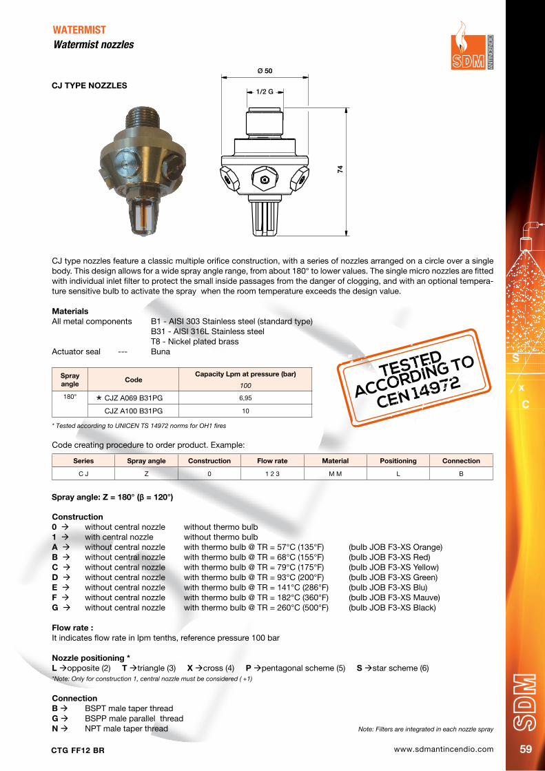
www.sdmantincendio.comCTG FF12 BR 59
WATERMISTWatermist nozzles
CJ type nozzles feature a classic multiple orifice construction, with a series of nozzles arranged on a circle over a single body. This design allows for a wide spray angle range, from about 180° to lower values. The single micro nozzles are fitted with individual inlet filter to protect the small inside passages from the danger of clogging, and with an optional tempera-ture sensitive bulb to activate the spray when the room temperature exceeds the design value. MaterialsAll metal components B1 - AISI 303 Stainless steel (standard type) B31 - AISI 316L Stainless steel T8 - Nickel plated brassActuator seal --- Buna
Cj TYpE NOzzLES
TESTED
ACCORDING TO
CEN 14972
* Tested according to UNICEN TS 14972 norms for OH1 fires
Sprayangle
CodeCapacity Lpm at pressure (bar)
100
180° CJZ A069 B31PG 6,95
CJZ A100 B31PG 10
Ø 50
74
1/2 G
Construction0 without central nozzle without thermo bulb 1 with central nozzle without thermo bulbA without central nozzle with thermo bulb @ TR = 57°C (135°F) (bulb JOB F3-XS Orange)B without central nozzle with thermo bulb @ TR = 68°C (155°F) (bulb JOB F3-XS Red)C without central nozzle with thermo bulb @ TR = 79°C (175°F) (bulb JOB F3-XS Yellow)d without central nozzle with thermo bulb @ TR = 93°C (200°F) (bulb JOB F3-XS Green)E without central nozzle with thermo bulb @ TR = 141°C (286°F) (bulb JOB F3-XS Blu)F without central nozzle with thermo bulb @ TR = 182°C (360°F) (bulb JOB F3-XS Mauve)G without central nozzle with thermo bulb @ TR = 260°C (500°F) (bulb JOB F3-XS Black)
Flow rate :It indicates flow rate in lpm tenths, reference pressure 100 bar
Nozzle positioning * L opposite (2) T triangle (3) X cross (4) p pentagonal scheme (5) S star scheme (6)*Note: Only for construction 1, central nozzle must be considered ( +1)
ConnectionB BSPT male taper thread G BSPP male parallel thread N NPT male taper thread
Series Spray angle Construction Flow rate Material positioning Connection
C J Z 0 1 2 3 M M L B
Code creating procedure to order product. Example:
Spray angle: z = 180° (β = 120°)
Note: Filters are integrated in each nozzle spray
www.sdmantincendio.com CTG FF12 BR60

www.sdmantincendio.comCTG FF12 BR 61
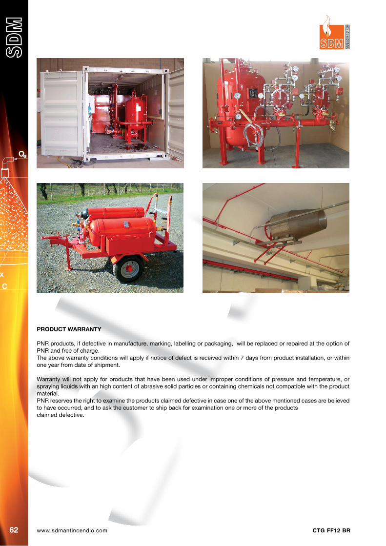
www.sdmantincendio.com CTG FF12 BR62
pROdUCT WARRANTY
PNR products, if defective in manufacture, marking, labelling or packaging, will be replaced or repaired at the option of PNR and free of charge.The above warranty conditions will apply if notice of defect is received within 7 days from product installation, or within one year from date of shipment.
Warranty will not apply for products that have been used under improper conditions of pressure and temperature, or spraying liquids with an high content of abrasive solid particles or containing chemicals not compatible with the product material.PNR reserves the right to examine the products claimed defective in case one of the above mentioned cases are believed to have occurred, and to ask the customer to ship back for examination one or more of the productsclaimed defective.

www.sdmantincendio.comCTG FF12 BR
COPYRIGHT
All content on this catalogue, such as text, graphics, logos and images is the property of PNR and is protected by international copyright laws.
Our technical literature is continuously being revised and updated and may be sent to our Customers upon request. If you are interested in receiving the latest version of our catalogues, please contact the nearest PNR office.
DIsCLAIMER
All information contained herein is provided “as is”. Some information on this catalogue may be out of date at any given time, or contain typing mistakes. PNR makes a reasonable effort to include accurate, complete, and current information on this catalogue, however, PNR does not guarantee the adequacy, correctness, completeness, accuracy, or reliability of any information on this catalogue, and is not responsible for any errors or omissions or for the results obtained from the use of such information.Moreover it is not possible to show in the catalogue pages all technical information about a product, like for example spray distribution charts and droplet size reports.
Should your process require that one or more technical characteristics for a given product are strictly adhered to, you are requested here to contact our offices and obtain the technical information you require, before sending your order.

CTG FF12 BRwww.sdmantincendio.com
©20
16 B
ell&
Tany
Fire Fighting products
and systems
Our products are distributed on the most important world markets through a network of agents and distributors
SDM Antincendio S.r.l. via dei Belcredi - zona Artigianale Romera 27050 Torricella Verzate (PV)
tel. +39 0383 896239 - fax +39 0383 876316e-mail [email protected]
www.sdmantincendio.com