fine-grained power management for multi-core systems
TRANSCRIPT
Thread Motion: Fine-Grained Power Management forMulti-Core Systems
Krishna K. Rangan†‡ Gu-Yeon Wei† David Brooks†
†Harvard University33 Oxford St., Cambridge, MA 02138
{kkrangan, guyeon, dbrooks}@eecs.harvard.edu
‡Intel Massachusetts77 Reed Road, Hudson, MA 01749
{krishna.rangan}@intel.com
ABSTRACTDynamic voltage and frequency scaling (DVFS) is a commonly-used power-management scheme that dynamically adjusts power and performance tothe time-varying needs of running programs. Unfortunately, conventionalDVFS, relying on off-chip regulators, faces limitations in terms of temporalgranularity and high costs when considered for future multi-core systems.To overcome these challenges, this paper presents thread motion (TM), afine-grained power-management scheme for chip multiprocessors (CMPs).Instead of incurring the high cost of changing the voltage and frequency ofdifferent cores, TM enables rapid movement of threads to adapt the time-varying computing needs of running applications to a mixture of cores withfixed but different power/performance levels. Results show that for the samepower budget, two voltage/frequency levels are sufficient to provide perfor-mance gains commensurate to idealized scenarios using per-core voltagecontrol. Thread motion extends workload-based power management intothe nanosecond realm and, for a given power budget, provides up to 20%better performance than coarse-grained DVFS.
Categories and Subject DescriptorsC.1.4 [Processor Architectures]: Parallel Architectures—Dis-tributed architectures
General TermsPerformance, Design
1. INTRODUCTIONPower dissipation continues to be a primary design constraint in
the multi-core chip era. Increasing power consumption not only re-sults in increasing energy costs, but also results in high die temper-atures that affect chip reliability, performance, and packaging cost.From the performance standpoint, current and future multi-coresystems will have to carefully constrain application performanceto stay within power envelopes. For example, power constraints re-sult in reduced per-core throughput when multiple cores are activein current Intel processors [2]. Fortunately, multi-core systems hostapplications that exhibit runtime variability in their performance re-quirements, which can be exploited to optimize throughput whilestaying within the system-power envelope.
Dynamic voltage and frequency scaling (DVFS) schemes seek toexploit runtime variability in application behavior to achieve maxi-
Permission to make digital or hard copies of all or part of this work forpersonal or classroom use is granted without fee provided that copies arenot made or distributed for profit or commercial advantage and that copiesbear this notice and the full citation on the first page. To copy otherwise, torepublish, to post on servers or to redistribute to lists, requires prior specificpermission and/or a fee.ISCA’09, June 20–24, 2009, Austin, Texas, USACopyright 2009 ACM 978-1-60558-526-0/09/06 ...$5.00.
mum energy savings with minimal performance degradation. How-ever, traditional DVFS scaling, which is initiated by the operatingsystem (OS), has two primary drawbacks: First, OS scheduler sam-pling intervals are on the millisecond time scale, while computa-tional requirements can vary on the nanosecond time scale due toevents such as cache misses. Hence, OS-driven DVFS is too slowto respond to such fine variations in program behavior. Second,multi-core systems execute multiple applications with potentiallyvery different computational needs. Even though the performanceadvantages of per-core DVFS in multi-core systems have been sug-gested [11, 15], providing per-core, independent voltage control inchips with more than two cores can be expensive [15]. Moreover,when DVFS is applied across multiple cores, determining a singleoptimal DVFS setting that simultaneously satisfies all cores will beextremely difficult; some applications will suffer performance lossor power overheads. This problem worsens as the number of coresand running applications increase in future systems.
Clearly, a fast-acting, yet cost-effective mechanism to obtain thebenefits of per-core DVFS on systems with a large number of coresis desirable. Trends in current multi-core systems suggest: (1) Eventhough per-core, independent voltage control is currently impracti-cal, future systems with a multitude of cores can be expected tohave a small number of independent voltage and frequency do-mains [1, 3]. As such, cores that differ in power-performance ca-pabilities will exist. (2) Future high-throughput systems are likelyto pack together a large number of simple cores [23,25,27] hostingmany more applications. Unfortunately, these trends further exac-erbate the problems of using conventional DVFS. To address theselimitations, we propose a fast, fine-grained power-management ap-proach that we call thread motion (TM).
Thread motion is a power-management technique that enablesapplications to migrate between cores in a multi-core system withsimple, homogeneous cores but heterogeneous power-performancecapabilities. For example, envision a homogeneous multi-core sys-tem where cores differ only in terms of their operating frequencyand voltage. Such power-performance heterogeneity offers a wayto accommodate a wide range of power envelope levels withoutlimiting the performance of all of the cores together. Instead, itoffers a mixture of performance capabilities with a small num-ber of static voltage/frequency (VF) domains. As applications runon these cores, TM enables applications to migrate to cores withhigher or lower VF settings depending on a program’s time-varyingcompute intensity. If one application could benefit from higher VFwhile another is stalled on a cache miss, a swap of these two appli-cations between cores of different power capabilities may provideoverall improvements in power-performance efficiency. Comparedto slow transition times of conventional regulator-based DVFSschemes, thread motion can be applied at much finer time intervals
302
AB
X Y
(Return from cache miss)
time
App A
(Cache Miss)High-VF
Act
ivity
App B
Low-VF
time
Act
ivity
App A
App B
High-VF
(c)
Low-VF
Low IPC
High IPC
(b)
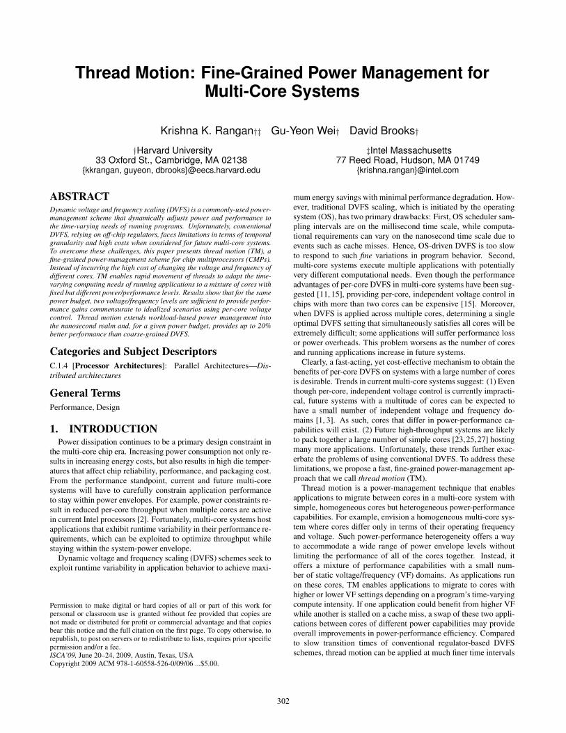
(a)Figure 1: (a) Illustration of thread motion in a multi-core system. (b) Exploiting fine-grained application variability in two running threads. (c) Duty cyclingbetween 2 VF levels to match application IPC.
and applied more often. Another potential benefit of rapidly mov-ing applications between cores is that, by doing so, applicationsexperience a virtual (effective) voltage that is in between the fixedvoltage levels of different cores. In fact, thread motion yields thenet effect of implementing multiple VF domains while only usingtwo VF levels and keeping system-level costs in check.
While the potential performance benefits of thread motion maybe intuitively obvious, it is important to identify and evaluate all ofthe costs and overheads associated with it. Future multi-core sys-tems offer a plethora of design choices in terms of the number ofcores and core complexity. Simple cores with shared resources arelikely to be present in future many-core systems featuring tens orhundreds of cores among other possible design alternatives. Hence,we evaluate thread motion in the context of a high-throughput ma-chine featuring clusters of simple in-order cores with some sharedL1 cache state (similar to Rock [27]). We study the performancebenefits of thread motion constrained to different power envelopesusing two approaches: (1) a coarse-grained prediction-driven ap-proach evaluated at fine granularities, called time-driven TM; and(2) a last-level cache miss driven approach, called miss-driven TM.To understand the cost-benefit tradeoff, we provide a detailed anal-ysis of all power and performance costs associated with TM.
The main contributions of this paper are as follows:
1. Fine-grained program variability motivates the need for fine-grained power management—we analyze SPEC CPU 2006applications and show that applications can have significantfine-grained performance variability (Section 2). For severalapplications, we show that variability observed at 300-cyclegranularities is an order of magnitude higher than when ob-served at coarser 10000-cycle granularities.
2. Thread motion on systems with two VF domains can performnearly as well as having continuous, per-core VF levels butno motion. In other words, thread motion can be used to pro-vide applications with any virtual (effective) power level be-tween the lowest and the highest voltage/frequency settings(Section 3).
3. Thread motion can exploit fine-grained variability in appli-cation behavior. Even after accounting for all motion-relatedcosts, up to 20% higher performance can be achieved com-pared to a design without motion that uses ideal (oracle-based) static VF assignments and equivalent power budgets(Section 5).
2. MOTIVATIONIn this section, we take a closer look at traditional DVFS and
elaborate on its limitations. We then introduce the basic conceptsof thread motion, illustrate how it can overcome traditional DVFSlimitations using synthetic examples, and briefly explain how it isdifferent from other contemporary fine-grained power managementschemes. Finally, we present studies of real applications that un-derscore the importance of fine-grained power management usingthread motion.
2.1 Limitations of traditional DVFSDVFS is a well-known and widely-used power management
technique in contemporary microprocessors. In the context ofCMPs, power management using dynamic VF scaling seeks to re-duce power consumption when cores are idle, boost single-threadedperformance in the presence of large workloads, and remap VF set-tings to improve performance and energy utilization. DVFS algo-rithms typically use application behavior to arrive at the appropri-ate VF setting for the core the application is running on. In multi-core systems with DVFS applied with a single power domain (ora small number of domains), the individual needs from all coresare consolidated to arrive at a single chip-wide VF setting, whichoften compromises performance and/or power efficiency. Other-wise, each core dictates individual settings on systems that supportper-core VF, but there are cost and scalability concerns of imple-menting per-core DVFS on systems with a large number of cores.State-of-the-art systems such as Intel’s Core 2 series use power gat-ing to shut down power to the unused cores, but all active cores usethe same voltage setting. AMD’s Griffin processor does providedual-power planes for per-core voltage/frequency control [1], butprohibitively high costs of off-chip regulators will likely limit per-core voltage control beyond dual core systems.
DVFS algorithms are typically implemented in the operating sys-tem. Consequently, the application phase monitoring and requestsfor core power mode transitions occur at the millisecond time scaleof the OS scheduler. Previous work [11] has recognized the impor-tance of monitoring application phase activity on finer time scalesand has proposed using a global power manager framework to re-evaluate DVFS decisions at intervals on the order of hundreds ofmicroseconds. However, all state-of-the-art DVFS-based powermanagement schemes in use (or proposed earlier) incur a large VFtransition delay to arrive at the target power mode. The voltagetransition delay, which is on the order of tens of microseconds, is
303
1
10
100
1000
10000V
aria
bilit
y P
er M
illio
n In
stru
ctio
ns
cal
culix
perl.
split
nam
d
ton
to
pov
ray
s
jeng
bzip
2.te
xtga
mes
s.h2
ogo
bmk.
scor
h264
ref.m
ago
bmk.
nngs
perl.
chec
kga
mes
s.tri
gobm
k.tre
vga
mes
s.cy
tbz
ip2.
sour
h264
ref.b
agc
c.sc
ilab
gobm
k.tre
v
gcc.
g23
perl.
diffm
bzip
2.pr
ogbz
ip2.
com
b
dea
lII
gcc.
166
gcc.
c−ty
pe
gcc.
200
h264
ref.s
slib
quan
tum
cac
tusA
DM
hmm
er.re
tras
tar.r
ive
gr
omac
s
gcc.
s04
gcc
.exp
r2 g
cc.e
xpr
asta
r.big
lgc
c.cp
−dec
les
lie3d
bzip
2.ch
icbz
ip2.
libe
mcf
hmm
er.s
wis
om
netp
pso
plex
.pds
gobm
k.13
x1so
plex
.ref
milc
s
phin
x
lb
m g
emsf
dtd
10000 4000 1000 500 300
(a) Variability for different intervals
0 0.5 1 1.5 2 2.5 3 3.50.1
0.2
0.3
0.4
0.5
0.6
0.7
0.8
0.9
1
Variability Per Thousand Instructions (VPKI)
IPC
Low Variability (C)
High Variability (A)
Mid IPC & High Var (D)
Mid IPC (B)
(b) Variability & IPC
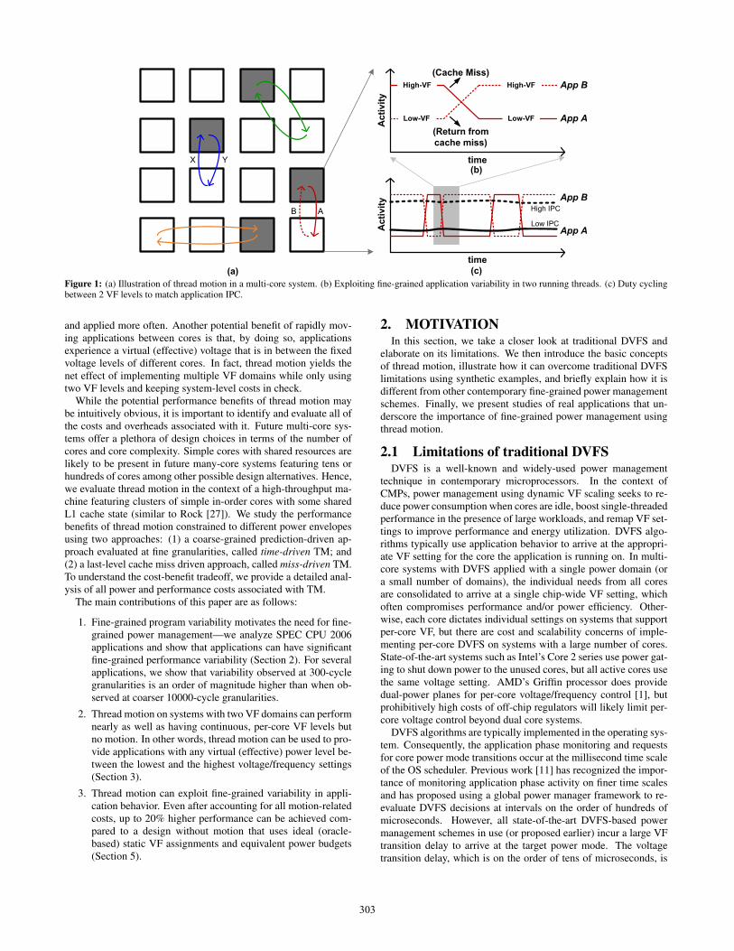
Figure 2: Variability and IPC of SPEC CPU 2006 workloads.
due to off-chip voltage regulators that limit how quickly voltage canchange, and the frequency transition delay comes from PLL relocktimes. These transition delays fundamentally limit re-evaluation ofapplication behavior and remapping core VFs at finer time scales.In contrast, microarchitectural events such as cache misses intro-duce application variability at nanosecond granularities. Threadmotion seeks to adapt to this microarchitectural variability and ex-tend DVFS benefits to the nanosecond realm by working aroundthe aforementioned VF transition delay.
Illustration of thread motion benefits. We illustrate the ba-sic concepts of thread motion in Figure 1 given a collection ofcores with heterogeneous performance. Figure 1(a) assumes twolevels of core performance, where dark cores have higher perfor-mance. As the performance needs of the applications vary overtime, thread motion moves applications amongst the cores. Fine-grained power management with thread motion offers two impor-tant benefits: (1) TM provides an opportunity to apply DVFS ben-efits to program variability arising out of microarchitectural events,which is impractical with conventional DVFS, and boost perfor-mance at a given power budget. This is illustrated in Figure 1(b)—fast TM enables application B to benefit from running on the high-VF core when application A is stalled on a cache miss. (2) TMenables fast movement of applications between cores, and by do-ing so, applications can appear to operate off of a virtual (effective)voltage that is between the fixed voltage levels of the two cores.As Figure 1(c) shows, the high IPC application B spends a largerfraction of its running time on the high-VF core, and realizes aneffective VF that hovers near the upper range, between high- andlow-VF levels. This has a net effect of achieving per-core DVFSbenefits even on systems with only 2 VF levels.
Differences from other fine-grained approaches. Typically,contemporary fine-grained power management involves: (1) clockgating and gating of pipeline stages, but it is important to note thatthese benefits are orthogonal to the cubic-reduction in power ben-efits achieved using DVFS; and (2) fine-grained, rapid schedulingof new threads (using an SMT scheduler, for example), when thehardware or the compiler cannot avoid a thread stall. The newlyscheduled thread masks the latency of the cache access of the wait-ing thread. However, systems that employ large degrees of multi-
threading to exploit fine-grained variations in program behaviorand increase throughput also require significant memory bandwidthand incur high system power penalties [29]. Furthermore, all coreshave to run at peak power to always mask the latency of cacheaccesses, which may not scale in the context of future systemswith many more cores. We expect future systems to be power-constrained; that is, not all cores will be at peak power all of thetime. The goal of thread motion is to increase system throughputby maximally squeezing performance out of a fixed set of runningapplications at a given power budget.
2.2 Application VariabilityHaving looked at synthetic examples to illustrate the basic con-
cepts of TM, we now turn our attention to understanding the behav-ior of real workloads. Our analysis of fine-grained power manage-ment begins by studying the characteristics of SPEC benchmarks.We collected representative program traces of SPEC CPU 2006IA32/x86 binaries for use with our simulator (complete details ofthe simulation framework are provided in Section 4.2). Our simu-lator includes an in-order timing model for the core and a two-levelcache hierarchy—separate 16KB L1 instruction and data cachesand a unified 2MB L2 cache. For each memory instruction in thetrace, the simulator determines hit/miss information and the levelof the hierarchy where the hit occurred. Each memory instructiontakes a number of cycles equal to the latency of the level in whichit hits, and each non-memory instruction takes a cycle to finish.We assume hit latencies of 2, 12, and 150 cycles for L1, L2, andmemory accesses. We found that the other hit latencies have littleimpact on the relative ordering of applications based on our vari-ability metric. We use the IPC information to compute variabilitiesat various window sizes.
In order to understand variability in the runtime performanceneeds of applications, we have devised a simple metric. Our vari-ability metric evaluates the magnitude of fine-grained change in ap-plication behavior across various window sizes. It is computed asfollows. For each SPEC 2006 workload, we track the IPC for sev-eral different window sizes, by measuring the ratio of instructionscommitted to the total number of cycles within a window interval.We define Interval Variability as the absolute difference between
304
Data Switch
IO
Core 0 Core 1
Core 2 Core 3
L1 L1
Cluster 1
L1
Cluster 2
L1
Cluster 3
L2 Data
L2 Data
Inst
ruct
ion
Dec
ode
Inte
ger U
nit
FP U
nit
Bas
ic E
xe
Reg
iste
rsFP
Reg
iste
rs
Shar
ed L
1 I &
D C
ache
Dat
a Sw
itch
Eight 32-bit Registers
Six 16-bit registers
EFLAGS
Instruction Pointer
Eight 80-bit Registers
16-bit Control/Status Registers
FPU Instruction Pointer
CPU core and Int. & FP Register State
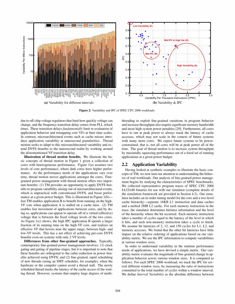
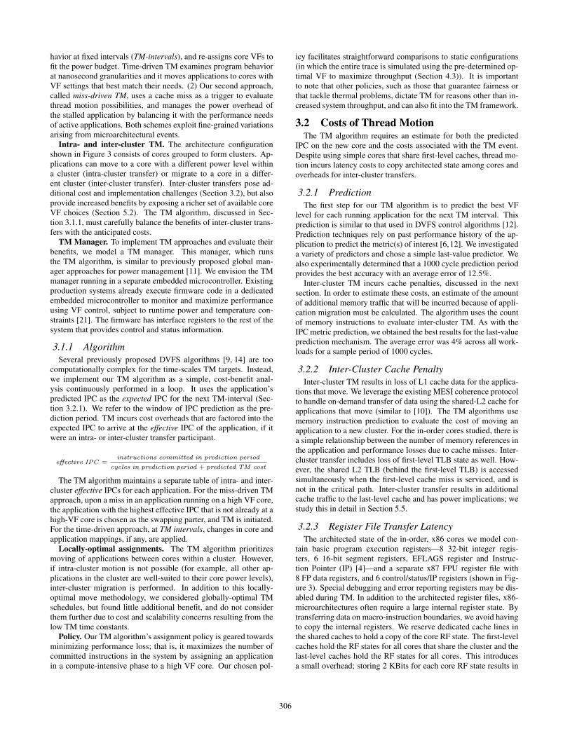
Figure 3: Architecture resembling Sun’s Rock which has all cores sharing first-level cache [27]. Also shown are CPU core details and core RF states.
the IPC in an interval compared to the IPC in the previous interval.Total variability in the benchmark is the sum of interval variabil-ity across all of the intervals. Variability Per Instruction (VPI) isarrived at by dividing this total application variability by the totalnumber of instructions in the trace. Figure 2(a) shows Variabil-ity Per Million Instructions for SPEC 2006 benchmarks and inputcombinations. Each stacked bar in the figure shows the cumulativevariability for each window size (in log scale). As can be seen,variability is more pronounced at smaller window sizes (an orderof magnitude higher for several workloads), but is muted at coarserlevels. In other words, the amount of application variability is astrong function of the window (or sampling) interval. Smaller inter-vals help capture cache effects that stall the processor, while coarserintervals that span tens of thousands of processor cycles mask oraverage out the effects of different microarchitectural events. Thisvariability at fine granularities has an important implication thatmotivates our work—increased power savings are possible usingfine-grained power-management techniques.
In addition to understanding application variability, it is impor-tant to understand the relationship between variability and IPC.Figure 2(b) shows the relationship between the overall IPC of anapplication and variability. Cache effects dictate both variabilityand IPC, and the metrics are moderately correlated: low-IPC ap-plications tend to have high variability and mid-IPC applicationshave moderate variability. Understandably, the two applicationswith highest overall IPC, calculix and perl.splitmail, are computeintensive with fewer last-level cache misses, and they exhibit verylow variability. The figure shows four groups of applications thatcover a range of application variabilities and IPCs. We will usethese four groups to examine the performance impact of TM in Sec-tion 5.4. As we will see later, TM not only helps applications withhigh variability, but also benefits applications with little variabilitywhen the mixture of applications running in the multi-core proces-sor has variability in IPCs (previously illustrated in Figure 1(c)).We will also show that TM can take advantage of variability avail-able at fine resolutions for seemingly static, high-IPC workloads.
3. THREAD MOTIONThe goal of thread motion is to enable DVFS benefits at nanosec-
ond time scales by exploiting variations arising from microarchitec-tural events. However, the benefits of the technique must be care-fully studied in the context of all the overheads it incurs. In this
section, we take a closer look at TM limitations and introduce thearchitecture used to evaluate TM. We propose different TM strate-gies, highlight all the costs incurred, and discuss implementation ofTM approaches using a TM manager.
Benefits and limitations. Thread motion enables fine-grainedtracking of program behavior that conventional DVFS cannot. As aresult, TM can increase the system throughput for different powerenvelopes. Equally important to the performance benefits, is theability of TM to provide an effective intermediate voltage withonly two VF settings, thus cutting down system costs. As men-tioned in Section 1, this paper evaluates TM on a multi-core de-sign setting featuring simple cores, and makes a couple of assump-tions. First, TM relies on rapid movement of applications betweencores and, hence, is constrained to systems featuring simple homo-geneous cores with relatively small amounts of architected state.Second, TM targets power-constrained multi-core systems, whichdo not have all cores operating at the peak power, featuring coresthat differ in their power-performance capabilities through volt-age/frequency settings. Implementation of TM on other multi-corealternatives may require additional hardware support and is beyondthe scope of this paper.
Architecture. With these assumptions in place, we study TMon a 16-core CMP system featuring simple, in-order, x86 coressharing 2MB L2 cache. The architecture, shown in Figure 3, con-sists of cores grouped to form clusters—four cores form a clus-ter and all clusters share the last-level cache. L1 I&D caches areshared by all cores in each cluster. As mentioned in Section 1, thisarchitectural configuration resembles a production system, Sun’sRock [27], which has small cores sharing first level caches and a2MB L2 cache. The shared L1 caches enable low-overhead move-ment of applications within a cluster, but as we will see later, eveninter-cluster movement can provide benefits. We elaborate on thearchitectural parameters along with our simulation framework inSection 4, but use this framework to overview the costs associatedwith TM and the TM algorithms that can be used.
3.1 TM FrameworkIn order to extend DVFS benefits to nanosecond time scales, we
propose two approaches to implement TM that leverage applica-tion variability arising out of microarchitectural events: (1) Ourfirst approach, called time-driven TM, is a straight-forward exten-sion of traditional DVFS techniques that re-evaluate program be-
305
havior at fixed intervals (TM-intervals), and re-assigns core VFs tofit the power budget. Time-driven TM examines program behaviorat nanosecond granularities and it moves applications to cores withVF settings that best match their needs. (2) Our second approach,called miss-driven TM, uses a cache miss as a trigger to evaluatethread motion possibilities, and manages the power overhead ofthe stalled application by balancing it with the performance needsof active applications. Both schemes exploit fine-grained variationsarising from microarchitectural events.
Intra- and inter-cluster TM. The architecture configurationshown in Figure 3 consists of cores grouped to form clusters. Ap-plications can move to a core with a different power level withina cluster (intra-cluster transfer) or migrate to a core in a differ-ent cluster (inter-cluster transfer). Inter-cluster transfers pose ad-ditional cost and implementation challenges (Section 3.2), but alsoprovide increased benefits by exposing a richer set of available coreVF choices (Section 5.2). The TM algorithm, discussed in Sec-tion 3.1.1, must carefully balance the benefits of inter-cluster trans-fers with the anticipated costs.
TM Manager. To implement TM approaches and evaluate theirbenefits, we model a TM manager. This manager, which runsthe TM algorithm, is similar to previously proposed global man-ager approaches for power management [11]. We envision the TMmanager running in a separate embedded microcontroller. Existingproduction systems already execute firmware code in a dedicatedembedded microcontroller to monitor and maximize performanceusing VF control, subject to runtime power and temperature con-straints [21]. The firmware has interface registers to the rest of thesystem that provides control and status information.
3.1.1 AlgorithmSeveral previously proposed DVFS algorithms [9, 14] are too
computationally complex for the time-scales TM targets. Instead,we implement our TM algorithm as a simple, cost-benefit anal-ysis continuously performed in a loop. It uses the application’spredicted IPC as the expected IPC for the next TM-interval (Sec-tion 3.2.1). We refer to the window of IPC prediction as the pre-diction period. TM incurs cost overheads that are factored into theexpected IPC to arrive at the effective IPC of the application, if itwere an intra- or inter-cluster transfer participant.
effective IPC =instructions committed in prediction period
cycles in prediction period + predicted TM cost
The TM algorithm maintains a separate table of intra- and inter-cluster effective IPCs for each application. For the miss-driven TMapproach, upon a miss in an application running on a high VF core,the application with the highest effective IPC that is not already at ahigh-VF core is chosen as the swapping parter, and TM is initiated.For the time-driven approach, at TM intervals, changes in core andapplication mappings, if any, are applied.
Locally-optimal assignments. The TM algorithm prioritizesmoving of applications between cores within a cluster. However,if intra-cluster motion is not possible (for example, all other ap-plications in the cluster are well-suited to their core power levels),inter-cluster migration is performed. In addition to this locally-optimal move methodology, we considered globally-optimal TMschedules, but found little additional benefit, and do not considerthem further due to cost and scalability concerns resulting from thelow TM time constants.
Policy. Our TM algorithm’s assignment policy is geared towardsminimizing performance loss; that is, it maximizes the number ofcommitted instructions in the system by assigning an applicationin a compute-intensive phase to a high VF core. Our chosen pol-
icy facilitates straightforward comparisons to static configurations(in which the entire trace is simulated using the pre-determined op-timal VF to maximize throughput (Section 4.3)). It is importantto note that other policies, such as those that guarantee fairness orthat tackle thermal problems, dictate TM for reasons other than in-creased system throughput, and can also fit into the TM framework.
3.2 Costs of Thread MotionThe TM algorithm requires an estimate for both the predicted
IPC on the new core and the costs associated with the TM event.Despite using simple cores that share first-level caches, thread mo-tion incurs latency costs to copy architected state among cores andoverheads for inter-cluster transfers.
3.2.1 PredictionThe first step for our TM algorithm is to predict the best VF
level for each running application for the next TM interval. Thisprediction is similar to that used in DVFS control algorithms [12].Prediction techniques rely on past performance history of the ap-plication to predict the metric(s) of interest [6,12]. We investigateda variety of predictors and chose a simple last-value predictor. Wealso experimentally determined that a 1000 cycle prediction periodprovides the best accuracy with an average error of 12.5%.
Inter-cluster TM incurs cache penalties, discussed in the nextsection. In order to estimate these costs, an estimate of the amountof additional memory traffic that will be incurred because of appli-cation migration must be calculated. The algorithm uses the countof memory instructions to evaluate inter-cluster TM. As with theIPC metric prediction, we obtained the best results for the last-valueprediction mechanism. The average error was 4% across all work-loads for a sample period of 1000 cycles.
3.2.2 Inter-Cluster Cache PenaltyInter-cluster TM results in loss of L1 cache data for the applica-
tions that move. We leverage the existing MESI coherence protocolto handle on-demand transfer of data using the shared-L2 cache forapplications that move (similar to [10]). The TM algorithms usememory instruction prediction to evaluate the cost of moving anapplication to a new cluster. For the in-order cores studied, there isa simple relationship between the number of memory references inthe application and performance losses due to cache misses. Inter-cluster transfer includes loss of first-level TLB state as well. How-ever, the shared L2 TLB (behind the first-level TLB) is accessedsimultaneously when the first-level cache miss is serviced, and isnot in the critical path. Inter-cluster transfer results in additionalcache traffic to the last-level cache and has power implications; westudy this in detail in Section 5.5.
3.2.3 Register File Transfer LatencyThe architected state of the in-order, x86 cores we model con-
tain basic program execution registers—8 32-bit integer regis-ters, 6 16-bit segment registers, EFLAGS register and Instruc-tion Pointer (IP) [4]—and a separate x87 FPU register file with8 FP data registers, and 6 control/status/IP registers (shown in Fig-ure 3). Special debugging and error reporting registers may be dis-abled during TM. In addition to the architected register files, x86-microarchitectures often require a large internal register state. Bytransferring data on macro-instruction boundaries, we avoid havingto copy the internal registers. We reserve dedicated cache lines inthe shared caches to hold a copy of the core RF state. The first-levelcaches hold the RF states for all cores that share the cluster and thelast-level caches hold the RF states for all cores. This introducesa small overhead; storing 2 KBits for each core RF state results in
306
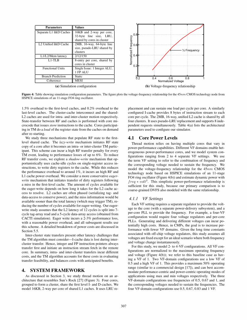
Parameters ValuesSeparate L1 I&D Caches 16KB and 2-way per core,
32-byte line size, LRU,shared by cores in cluster
L2 Unified I&D Cache 2MB, 16-way, 64-byte linesize, pseudo-LRU shared byclusters
L1/L2/Mem latency 2/12/150
L1-TLB 8-entry per core, shared bycores in cluster
Functional Units Single Issue: 1 Integer ALU,1 FP ALU
Branch Prediction Static
Coherence MESI
(a) Simulation configuration
0.2 0.4 0.6 0.8 10
0.2
0.4
0.6
0.8
1
Normalized Voltage
½ Frequency
Nor
mal
ized
Fre
quen
cy
(b) Voltage-frequency relationship
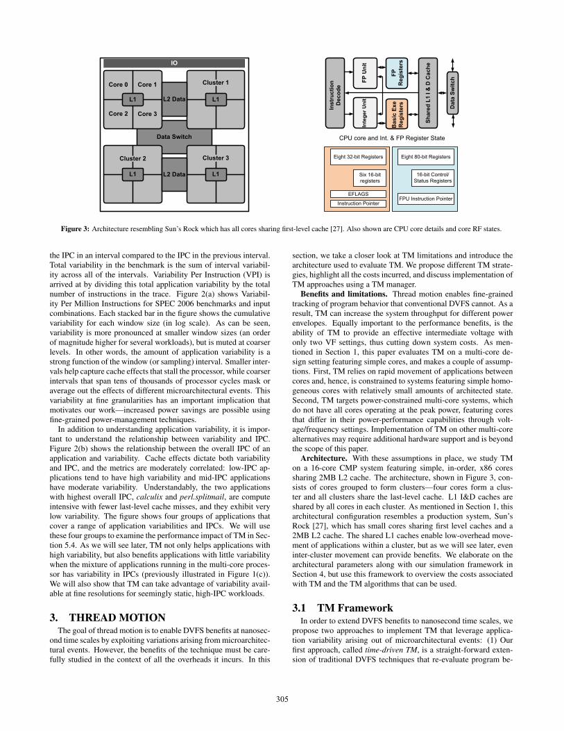
Figure 4: Table showing simulation configuration parameters. The figure plots the voltage-frequency relationship for the 45nm CMOS technology node fromHSPICE simulations of an 11-stage FO4 ring oscillator.
1.5% overhead to the first-level caches, and 0.2% overhead to thelast-level caches. The cluster-cache interconnect and the shared-L2 caches are used for intra- and inter-cluster motion respectively.State-transfer between RF and caches is performed with core mi-crocode that issues store instructions to the cache. Cores participat-ing in TM do a load of the register state from the caches on demandafter re-starting.
We study three mechanisms that populate RF state to the first-level shared cache. The lazy-write mechanism initiates RF statecopy of a core after it becomes an intra- or inter-cluster TM partic-ipant. This scheme can incur a high RF transfer penalty for everyTM event, leading to performance losses of up to 6%. To reduceRF transfer costs, we explore a shadow-write mechanism that op-portunistically uses cache-idle cycles on single-register access in-structions, to write dirty registers to the cache. While this reducesthe performance overhead to around 1%, it incurs an high RF andL1 cache power overhead. We consider a more conservative eager-write mechanism that initiates transfer of dirty registers followinga miss in the first-level cache. The amount of cycles available forthe eager-write depends on how long it takes for the L2 cache ac-cess to resolve. L2 caches are often phased (serializing tag- anddata-access to conserve power), and the miss information would beavailable sooner than the total latency (which may trigger TM), re-ducing the number of cycles available for eager-writing. Our eager-write study assumes that the L2 latency of 12 cycles is split into 7-cycle tag-array read and a 5-cycle data-array access (obtained fromCACTI simulation). Eager write incurs a 2-3% performance loss,with a reasonable power overhead, and all subsequent results usethis scheme. A detailed breakdown of power costs are discussed inSection 5.5.
Inter-cluster state transfers present other latency challenges thatthe TM algorithm must consider—I-cache data is lost during inter-cluster transfer. Hence, integer and FP instruction pointers alwaystransfer first and initiate an instruction stream fetch in the remotecore. In summary, intra- and inter-cluster transfers incur differentcosts, and the TM algorithm accounts for these costs in evaluatingtransfer feasibility, and balances costs with anticipated benefits.
4. SYSTEM FRAMEWORKAs discussed in Section 3, we study thread motion on an ar-
chitecture that resembles Sun’s Rock [27] (Figure 3). Four cores,grouped to form a cluster, share the first level I- and D-caches. Wemodel 16KB, 2-way per core of shared L1 caches. It uses LRU re-
placement and can sustain one load per cycle per core. A similarlyconfigured I-cache provides 8 bytes of instruction stream to eachcore per cycle. The 2MB, 16-way, unified L2 cache is shared by allfour clusters. It uses pseudo-LRU replacement and supports 8 inde-pendent requests simultaneously. Table 4(a) lists the architecturalparameters used to configure our simulator.
4.1 Core Power LevelsThread motion relies on having multiple cores that vary in
power-performance capabilities. Different VF domains enable het-erogeneous power-performance cores, and we model system con-figurations ranging from 2 to 4 separate VF settings. We usethe term VF setting to refer to the combination of frequency andthe corresponding voltage needed to sustain the frequency. Wemodel the voltage-frequency relationship for the 45nm CMOStechnology node based on HSPICE simulations of an 11-stageFO4 ring oscillator (Figure 4(b)) and estimate dynamic power withfreq ∗ volt2. This simplistic power-performance relationship issufficient for this study, because our primary comparison is tocoarse-grained DVFS also modeled with the same relationship.
4.1.1 VF SettingsEach VF setting requires a separate regulator to provide the volt-
age to the core (with a separate power-delivery subsystem), and aper-core PLL to provide the frequency. For example, a four-VFconfiguration would require four voltage regulators and per-corePLLs. Generating and delivering different voltages can incur po-tentially high costs. Hence, in CMPs, the goal is to increase per-formance with fewer VF domains. Given the long time constantsassociated with off-chip voltage regulators, this study assumes allvoltages are fixed except for an ideal scenario where both frequencyand voltage change instantaneously.
For this study, we model 2- to 4-VF configurations. All VF con-figurations are normalized to the maximum operating frequencyand voltage (Figure 4(b)); we refer to this baseline case as hav-ing a VF of 1. Two VF-domain configurations use a low VF of0.5 and a high VF of 1. This provides a maximum 50% operatingrange (similar to a commercial design [17]), and can best accom-modate performance-centric and power-centric operating modes ofapplications using max and min voltages respectively. The threeVF-domain configurations use frequencies of 0.5, 0.67 and 1, andthe corresponding voltages needed to sustain the frequencies. Thefour VF-domain configurations use 0.5, 0.67, 0.83 and 1 VF.
307
20 40 60 800
5
10
15
20
25
30
35
40
45
Power Budget (%)
Ave
rage
Deg
rada
tion
(%)
0.5/1 Static0.5/0.67/1 Static0.5/0.67/0.83/1 Static0.5/1 TM−enabledStatic Cont VFIdeal VF
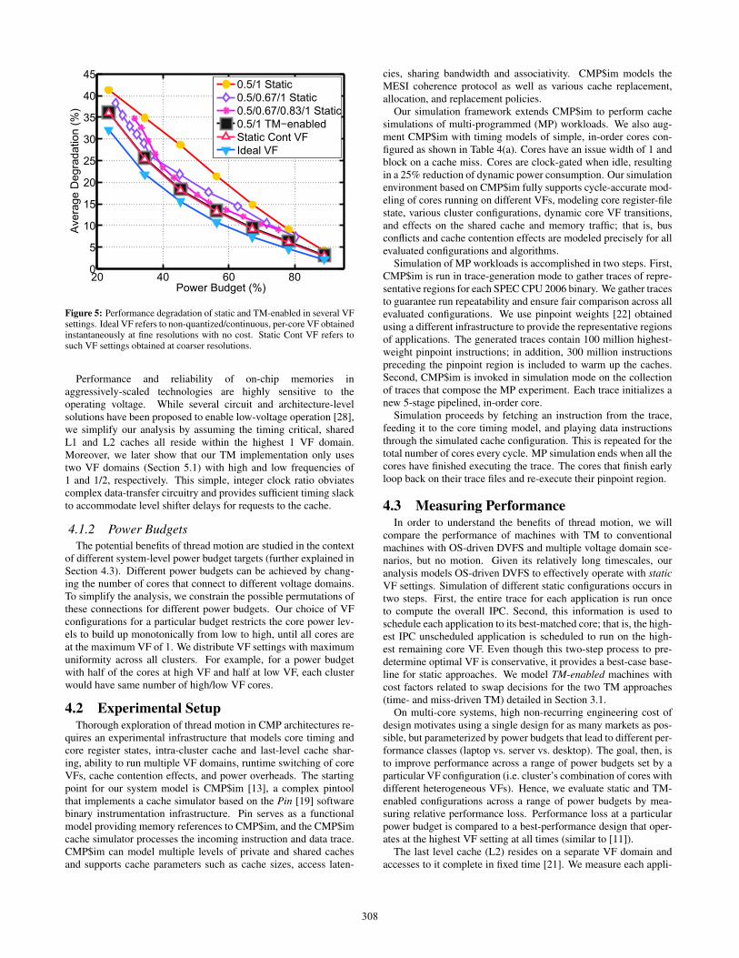
Figure 5: Performance degradation of static and TM-enabled in several VFsettings. Ideal VF refers to non-quantized/continuous, per-core VF obtainedinstantaneously at fine resolutions with no cost. Static Cont VF refers tosuch VF settings obtained at coarser resolutions.
Performance and reliability of on-chip memories inaggressively-scaled technologies are highly sensitive to theoperating voltage. While several circuit and architecture-levelsolutions have been proposed to enable low-voltage operation [28],we simplify our analysis by assuming the timing critical, sharedL1 and L2 caches all reside within the highest 1 VF domain.Moreover, we later show that our TM implementation only usestwo VF domains (Section 5.1) with high and low frequencies of1 and 1/2, respectively. This simple, integer clock ratio obviatescomplex data-transfer circuitry and provides sufficient timing slackto accommodate level shifter delays for requests to the cache.
4.1.2 Power BudgetsThe potential benefits of thread motion are studied in the context
of different system-level power budget targets (further explained inSection 4.3). Different power budgets can be achieved by chang-ing the number of cores that connect to different voltage domains.To simplify the analysis, we constrain the possible permutations ofthese connections for different power budgets. Our choice of VFconfigurations for a particular budget restricts the core power lev-els to build up monotonically from low to high, until all cores areat the maximum VF of 1. We distribute VF settings with maximumuniformity across all clusters. For example, for a power budgetwith half of the cores at high VF and half at low VF, each clusterwould have same number of high/low VF cores.
4.2 Experimental SetupThorough exploration of thread motion in CMP architectures re-
quires an experimental infrastructure that models core timing andcore register states, intra-cluster cache and last-level cache shar-ing, ability to run multiple VF domains, runtime switching of coreVFs, cache contention effects, and power overheads. The startingpoint for our system model is CMP$im [13], a complex pintoolthat implements a cache simulator based on the Pin [19] softwarebinary instrumentation infrastructure. Pin serves as a functionalmodel providing memory references to CMP$im, and the CMP$imcache simulator processes the incoming instruction and data trace.CMP$im can model multiple levels of private and shared cachesand supports cache parameters such as cache sizes, access laten-
cies, sharing bandwidth and associativity. CMP$im models theMESI coherence protocol as well as various cache replacement,allocation, and replacement policies.
Our simulation framework extends CMP$im to perform cachesimulations of multi-programmed (MP) workloads. We also aug-ment CMP$im with timing models of simple, in-order cores con-figured as shown in Table 4(a). Cores have an issue width of 1 andblock on a cache miss. Cores are clock-gated when idle, resultingin a 25% reduction of dynamic power consumption. Our simulationenvironment based on CMP$im fully supports cycle-accurate mod-eling of cores running on different VFs, modeling core register-filestate, various cluster configurations, dynamic core VF transitions,and effects on the shared cache and memory traffic; that is, busconflicts and cache contention effects are modeled precisely for allevaluated configurations and algorithms.
Simulation of MP workloads is accomplished in two steps. First,CMP$im is run in trace-generation mode to gather traces of repre-sentative regions for each SPEC CPU 2006 binary. We gather tracesto guarantee run repeatability and ensure fair comparison across allevaluated configurations. We use pinpoint weights [22] obtainedusing a different infrastructure to provide the representative regionsof applications. The generated traces contain 100 million highest-weight pinpoint instructions; in addition, 300 million instructionspreceding the pinpoint region is included to warm up the caches.Second, CMP$im is invoked in simulation mode on the collectionof traces that compose the MP experiment. Each trace initializes anew 5-stage pipelined, in-order core.
Simulation proceeds by fetching an instruction from the trace,feeding it to the core timing model, and playing data instructionsthrough the simulated cache configuration. This is repeated for thetotal number of cores every cycle. MP simulation ends when all thecores have finished executing the trace. The cores that finish earlyloop back on their trace files and re-execute their pinpoint region.
4.3 Measuring PerformanceIn order to understand the benefits of thread motion, we will
compare the performance of machines with TM to conventionalmachines with OS-driven DVFS and multiple voltage domain sce-narios, but no motion. Given its relatively long timescales, ouranalysis models OS-driven DVFS to effectively operate with staticVF settings. Simulation of different static configurations occurs intwo steps. First, the entire trace for each application is run onceto compute the overall IPC. Second, this information is used toschedule each application to its best-matched core; that is, the high-est IPC unscheduled application is scheduled to run on the high-est remaining core VF. Even though this two-step process to pre-determine optimal VF is conservative, it provides a best-case base-line for static approaches. We model TM-enabled machines withcost factors related to swap decisions for the two TM approaches(time- and miss-driven TM) detailed in Section 3.1.
On multi-core systems, high non-recurring engineering cost ofdesign motivates using a single design for as many markets as pos-sible, but parameterized by power budgets that lead to different per-formance classes (laptop vs. server vs. desktop). The goal, then, isto improve performance across a range of power budgets set by aparticular VF configuration (i.e. cluster’s combination of cores withdifferent heterogeneous VFs). Hence, we evaluate static and TM-enabled configurations across a range of power budgets by mea-suring relative performance loss. Performance loss at a particularpower budget is compared to a best-performance design that oper-ates at the highest VF setting at all times (similar to [11]).
The last level cache (L2) resides on a separate VF domain andaccesses to it complete in fixed time [21]. We measure each appli-
308
0 20 40 60 80 1000
10
20
30
40
50
Power Budget (%)
Ave
rage
Deg
rada
tion
(%)
StaticTM−enabledIdeal VF
(a) 2 Cores Per Cluster
0 20 40 60 80 1000
10
20
30
40
50
Power Budget (%)
Ave
rage
Deg
rada
tion
(%)
StaticTM−enabledIdeal VF
(b) 4 Cores Per Cluster
0 20 40 60 80 1000
10
20
30
40
50
Power Budget (%)
Ave
rage
Deg
rada
tion
(%)
StaticTM−enabledIdeal VF
(c) 8 Cores Per Cluster
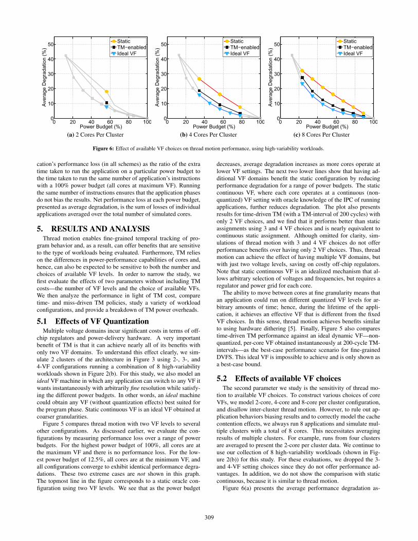
Figure 6: Effect of available VF choices on thread motion performance, using high-variability workloads.
cation’s performance loss (in all schemes) as the ratio of the extratime taken to run the application on a particular power budget tothe time taken to run the same number of application’s instructionswith a 100% power budget (all cores at maximum VF). Runningthe same number of instructions ensures that the application phasesdo not bias the results. Net performance loss at each power budget,presented as average degradation, is the sum of losses of individualapplications averaged over the total number of simulated cores.
5. RESULTS AND ANALYSISThread motion enables fine-grained temporal tracking of pro-
gram behavior and, as a result, can offer benefits that are sensitiveto the type of workloads being evaluated. Furthermore, TM relieson the differences in power-performance capabilities of cores and,hence, can also be expected to be sensitive to both the number andchoices of available VF levels. In order to narrow the study, wefirst evaluate the effects of two parameters without including TMcosts—the number of VF levels and the choice of available VFs.We then analyze the performance in light of TM cost, comparetime- and miss-driven TM policies, study a variety of workloadconfigurations, and provide a breakdown of TM power overheads.
5.1 Effects of VF QuantizationMultiple voltage domains incur significant costs in terms of off-
chip regulators and power-delivery hardware. A very importantbenefit of TM is that it can achieve nearly all of its benefits withonly two VF domains. To understand this effect clearly, we sim-ulate 2 clusters of the architecture in Figure 3 using 2-, 3-, and4-VF configurations running a combination of 8 high-variabilityworkloads shown in Figure 2(b). For this study, we also model anideal VF machine in which any application can switch to any VF itwants instantaneously with arbitrarily fine resolution while satisfy-ing the different power budgets. In other words, an ideal machinecould obtain any VF (without quantization effects) best suited forthe program phase. Static continuous VF is an ideal VF obtained atcoarser granularities.
Figure 5 compares thread motion with two VF levels to severalother configurations. As discussed earlier, we evaluate the con-figurations by measuring performance loss over a range of powerbudgets. For the highest power budget of 100%, all cores are atthe maximum VF and there is no performance loss. For the low-est power budget of 12.5%, all cores are at the minimum VF, andall configurations converge to exhibit identical performance degra-dations. These two extreme cases are not shown in this graph.The topmost line in the figure corresponds to a static oracle con-figuration using two VF levels. We see that as the power budget
decreases, average degradation increases as more cores operate atlower VF settings. The next two lower lines show that having ad-ditional VF domains benefit the static configuration by reducingperformance degradation for a range of power budgets. The staticcontinuous VF, where each core operates at a continuous (non-quantized) VF setting with oracle knowledge of the IPC of runningapplications, further reduces degradation. The plot also presentsresults for time-driven TM (with a TM-interval of 200 cycles) withonly 2 VF choices, and we find that it performs better than staticassignments using 3 and 4 VF choices and is nearly equivalent tocontinuous static assignment. Although omitted for clarity, sim-ulations of thread motion with 3 and 4 VF choices do not offerperformance benefits over having only 2 VF choices. Thus, threadmotion can achieve the effect of having multiple VF domains, butwith just two voltage levels, saving on costly off-chip regulators.Note that static continuous VF is an idealized mechanism that al-lows arbitrary selection of voltages and frequencies, but requires aregulator and power grid for each core.
The ability to move between cores at fine granularity means thatan application could run on different quantized VF levels for ar-bitrary amounts of time; hence, during the lifetime of the appli-cation, it achieves an effective VF that is different from the fixedVF choices. In this sense, thread motion achieves benefits similarto using hardware dithering [5]. Finally, Figure 5 also comparestime-driven TM performance against an ideal dynamic VF—non-quantized, per-core VF obtained instantaneously at 200-cycle TM-intervals—as the best-case performance scenario for fine-grainedDVFS. This ideal VF is impossible to achieve and is only shown asa best-case bound.
5.2 Effects of available VF choicesThe second parameter we study is the sensitivity of thread mo-
tion to available VF choices. To construct various choices of coreVFs, we model 2-core, 4-core and 8-core per cluster configuration,and disallow inter-cluster thread motion. However, to rule out ap-plication behaviors biasing results and to correctly model the cachecontention effects, we always run 8 applications and simulate mul-tiple clusters with a total of 8 cores. This necessitates averagingresults of multiple clusters. For example, runs from four clustersare averaged to present the 2-core per cluster data. We continue touse our collection of 8 high-variability workloads (shown in Fig-ure 2(b)) for this study. For these evaluations, we dropped the 3-and 4-VF setting choices since they do not offer performance ad-vantages. In addition, we do not show the comparison with staticcontinuous, because it is similar to thread motion.
Figure 6(a) presents the average performance degradation as-
309
18 28 39 49 59 69 80 90 1000
5
10
15
20
25
30
35
40
45
50
55
Power Budget (%)
Ave
rage
Deg
rada
tion
(%)
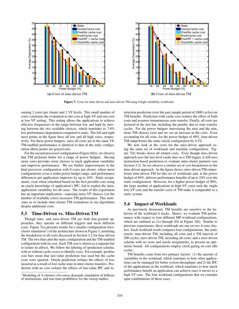
StaticOracle/Cache costPred/No cache costPred/Cache costPred/RF + cache costOracle/No cache cost
(a) Costs of time-driven TM
18 28 39 49 59 69 80 90 1000
5
10
15
20
25
30
35
40
45
50
55
Power Budget (%)
Ave
rage
Deg
rada
tion
(%)
StaticOracle/Cache costPred/No cache costPred/Cache costPred/RF + cache costOracle/No cache cost
(b) Costs of miss-driven TM
Figure 7: Costs for time-driven and miss-driven TM using 8 high-variability workloads.
suming 2 cores per cluster and 2 VF levels. This small number ofcores constrains the evaluation to one core at high-VF and one coreat low-VF setting. This setting allows the applications to achieveeffective frequencies in the range between low and high by mov-ing between the two available choices, which translates to 7.6%less performance degradation compared to static. The left and rightmost points in the figure have all low and all high cores, respec-tively. For these power budgets, since all cores are at the same VF,TM-enabled performance is identical to that of the static configu-ration (these points are grayed out).
For the second processor configuration (Figure 6(b)), we observethat TM performs better for a range of power budgets. Havingmore cores provides more choices to track application variabilityand improves performance. We see further improvements in thefinal processor configuration with 8 cores per cluster, where moreconfigurations cover a wider power budget range, and performancedifferences per application improves by up to 10%. Static assign-ments, even when scheduled based on the best possible core usingan oracle knowledge of application’s IPC, fail to exploit the intra-application variability for all cases. The results of this experimenthas an important implication—exposing more VF choices (via thenumber of available cores) increases TM performance. This moti-vates us to include inter-cluster TM evaluations in our algorithmsdespite additional costs.
5.3 Time-Driven vs. Miss-Driven TMThough time- and miss-driven TM are both fine-grained ap-
proaches, they operate on different triggers and incur differentcosts. Figure 7(a) presents results for a smaller configuration (two-cluster simulation1) of the architecture shown in Figure 3, assumingthe breakdown of all costs discussed in Section 3.2 for time-drivenTM. The two lines plot the static configuration and the TM-enabledconfiguration with no cost. Each TM cost is shown as a separate barto isolate its effects. We follow the labeling of (prediction scheme,with or without cache costs) to identify costs. For example, pred/nocost bars mean that last-value prediction was used but the cachecosts were ignored. Oracle prediction isolates the effects of lossincurred as a result of lost cache state in inter-cluster transfers. Pre-diction with no cost isolates the effects of last-value IPC and in-
1Modeling of 4-clusters (16-cores) demands simulation of billionsof instructions, and was time-prohibitive for the sweep studies.
struction prediction (over the past sample period of 1000 cycles) onTM benefits. Prediction with cache cost isolates the effect of bothcosts and assumes instantaneous state transfer. Finally, all costs arefactored in the last bar, including the penalty due to state transfercycles. For the power budgets intervening the max and the min,more TM choices exist and we see an increase in the costs. Evenaccounting for all costs, for the power budget of 49%, time-drivenTM outperforms the static oracle configuration by 4.5%.
We now look at the costs for the miss-driven approach us-ing the same set of workloads and machine configuration. Fig-ure 7(b) breaks down all related costs. Even though miss-drivenapproach uses the last-level cache miss as a TM trigger, it still usesinstruction-based prediction to evaluate inter-cluster partners (seeSection 3.2). So we observe a similar set of cost breakdowns to thetime-driven approach. As the figure shows, miss-driven TM outper-forms time-driven TM for this set of workloads and, at the powerbudget of 49%, delivers performance benefits of up to 10% over thestatic configuration. However, for a higher power budget of 90%,the large number of applications in high-VF cores seek the singlelow-VF core and the transfer costs of TM make it comparable to astatic system.
5.4 Impact of WorkloadsAs previously discussed, TM benefits are sensitive to the be-
havior of the workload it tracks. Hence, we evaluate TM perfor-mance with respect to four different MP-workload configurations,which are outlined as (A) through (D) in Figure 2(b). Similar toprevious experiments, these workloads are run on two 4-core clus-ters. Each workload result compares four configurations: the staticoracle; time-driven TM, including all costs and a TM interval of200 cycles; miss-driven TM, including all costs; and a miss-drivenscheme with no costs and oracle assignments, to present an opti-mistic bound. All configurations employ clock-gating on core idlecycles.
TM benefits come from two primary factors: (1) the amount ofvariability in the workload, which translates to how often applica-tions can be managed for better system throughput; and 2) the IPCof the applications in the workload, which translates to how muchperformance benefit an application can achieve once it moves to ahigh VF core. The four workload configurations that we considerspan combinations of these cases.
310
0 20 40 60 80 1000
10
20
30
40
50
60
Power Budget (%)
Ave
rage
Deg
rada
tion
(%)
StaticTime−drivenMiss−drivenMD Oracle/No cost
(a) High-variability workloads
0 20 40 60 80 1000
20
40
60
80
Power Budget (%)
Ave
rage
Deg
rada
tion
(%)
StaticTime−drivenMiss−drivenMD Oracle/No cost
(b) Mid-IPC workloads
0 20 40 60 80 1000
20
40
60
80
100
Power Budget (%)
Ave
rage
Deg
rada
tion
(%)
StaticTime−drivenMiss−drivenMD Oracle/No cost
(c) Low-variability workloads
0 20 40 60 80 1000
20
40
60
80
100
Power Budget (%)
Ave
rage
Deg
rada
tion
(%)
StaticTime−drivenMiss−drivenMD Oracle/No cost
(d) High Variability & Mid IPC
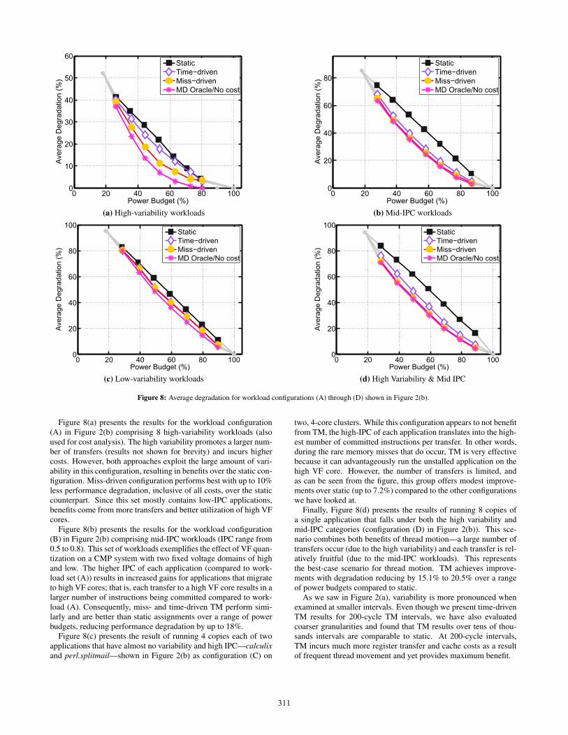
Figure 8: Average degradation for workload configurations (A) through (D) shown in Figure 2(b).
Figure 8(a) presents the results for the workload configuration(A) in Figure 2(b) comprising 8 high-variability workloads (alsoused for cost analysis). The high variability promotes a larger num-ber of transfers (results not shown for brevity) and incurs highercosts. However, both approaches exploit the large amount of vari-ability in this configuration, resulting in benefits over the static con-figuration. Miss-driven configuration performs best with up to 10%less performance degradation, inclusive of all costs, over the staticcounterpart. Since this set mostly contains low-IPC applications,benefits come from more transfers and better utilization of high VFcores.
Figure 8(b) presents the results for the workload configuration(B) in Figure 2(b) comprising mid-IPC workloads (IPC range from0.5 to 0.8). This set of workloads exemplifies the effect of VF quan-tization on a CMP system with two fixed voltage domains of highand low. The higher IPC of each application (compared to work-load set (A)) results in increased gains for applications that migrateto high VF cores; that is, each transfer to a high VF core results in alarger number of instructions being committed compared to work-load (A). Consequently, miss- and time-driven TM perform simi-larly and are better than static assignments over a range of powerbudgets, reducing performance degradation by up to 18%.
Figure 8(c) presents the result of running 4 copies each of twoapplications that have almost no variability and high IPC—calculixand perl.splitmail—shown in Figure 2(b) as configuration (C) on
two, 4-core clusters. While this configuration appears to not benefitfrom TM, the high-IPC of each application translates into the high-est number of committed instructions per transfer. In other words,during the rare memory misses that do occur, TM is very effectivebecause it can advantageously run the unstalled application on thehigh VF core. However, the number of transfers is limited, andas can be seen from the figure, this group offers modest improve-ments over static (up to 7.2%) compared to the other configurationswe have looked at.
Finally, Figure 8(d) presents the results of running 8 copies ofa single application that falls under both the high variability andmid-IPC categories (configuration (D) in Figure 2(b)). This sce-nario combines both benefits of thread motion—a large number oftransfers occur (due to the high variability) and each transfer is rel-atively fruitful (due to the mid-IPC workloads). This representsthe best-case scenario for thread motion. TM achieves improve-ments with degradation reducing by 15.1% to 20.5% over a rangeof power budgets compared to static.
As we saw in Figure 2(a), variability is more pronounced whenexamined at smaller intervals. Even though we present time-drivenTM results for 200-cycle TM intervals, we have also evaluatedcoarser granularities and found that TM results over tens of thou-sands intervals are comparable to static. At 200-cycle intervals,TM incurs much more register transfer and cache costs as a resultof frequent thread movement and yet provides maximum benefit.
311
(A) (B) (C) (D)0
1
2
3
4
5
Workload Configuration
RF
Pow
er O
verh
ead
(%)
Lazy−write Eager−write Shadow−write
(a) RF-transfer mechanisms (miss-driven TM)
(A) (B) (C) (D)0
0.5
1
1.5
2
2.5
Workload Configuration
Pow
er O
verh
ead
(%)
L2 Cache L1 Cache RF Chip
(b) Miss-Driven TM on workload configurations
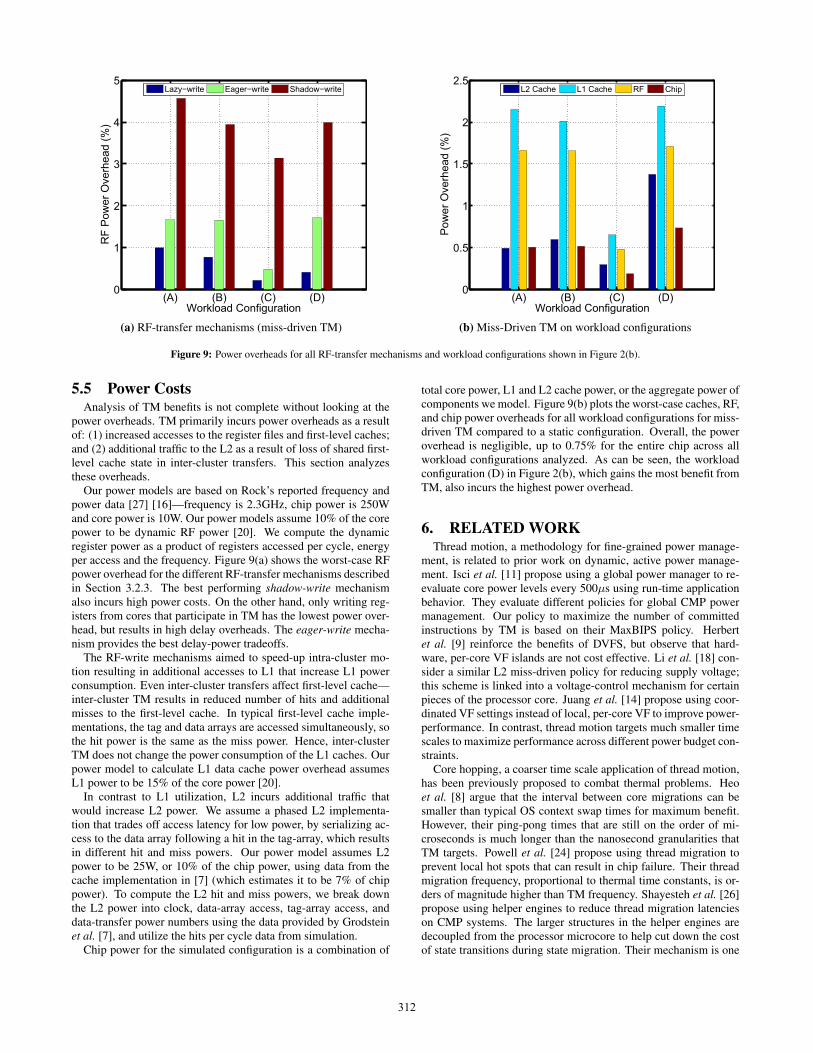
Figure 9: Power overheads for all RF-transfer mechanisms and workload configurations shown in Figure 2(b).
5.5 Power CostsAnalysis of TM benefits is not complete without looking at the
power overheads. TM primarily incurs power overheads as a resultof: (1) increased accesses to the register files and first-level caches;and (2) additional traffic to the L2 as a result of loss of shared first-level cache state in inter-cluster transfers. This section analyzesthese overheads.
Our power models are based on Rock’s reported frequency andpower data [27] [16]—frequency is 2.3GHz, chip power is 250Wand core power is 10W. Our power models assume 10% of the corepower to be dynamic RF power [20]. We compute the dynamicregister power as a product of registers accessed per cycle, energyper access and the frequency. Figure 9(a) shows the worst-case RFpower overhead for the different RF-transfer mechanisms describedin Section 3.2.3. The best performing shadow-write mechanismalso incurs high power costs. On the other hand, only writing reg-isters from cores that participate in TM has the lowest power over-head, but results in high delay overheads. The eager-write mecha-nism provides the best delay-power tradeoffs.
The RF-write mechanisms aimed to speed-up intra-cluster mo-tion resulting in additional accesses to L1 that increase L1 powerconsumption. Even inter-cluster transfers affect first-level cache—inter-cluster TM results in reduced number of hits and additionalmisses to the first-level cache. In typical first-level cache imple-mentations, the tag and data arrays are accessed simultaneously, sothe hit power is the same as the miss power. Hence, inter-clusterTM does not change the power consumption of the L1 caches. Ourpower model to calculate L1 data cache power overhead assumesL1 power to be 15% of the core power [20].
In contrast to L1 utilization, L2 incurs additional traffic thatwould increase L2 power. We assume a phased L2 implementa-tion that trades off access latency for low power, by serializing ac-cess to the data array following a hit in the tag-array, which resultsin different hit and miss powers. Our power model assumes L2power to be 25W, or 10% of the chip power, using data from thecache implementation in [7] (which estimates it to be 7% of chippower). To compute the L2 hit and miss powers, we break downthe L2 power into clock, data-array access, tag-array access, anddata-transfer power numbers using the data provided by Grodsteinet al. [7], and utilize the hits per cycle data from simulation.
Chip power for the simulated configuration is a combination of
total core power, L1 and L2 cache power, or the aggregate power ofcomponents we model. Figure 9(b) plots the worst-case caches, RF,and chip power overheads for all workload configurations for miss-driven TM compared to a static configuration. Overall, the poweroverhead is negligible, up to 0.75% for the entire chip across allworkload configurations analyzed. As can be seen, the workloadconfiguration (D) in Figure 2(b), which gains the most benefit fromTM, also incurs the highest power overhead.
6. RELATED WORKThread motion, a methodology for fine-grained power manage-
ment, is related to prior work on dynamic, active power manage-ment. Isci et al. [11] propose using a global power manager to re-evaluate core power levels every 500μs using run-time applicationbehavior. They evaluate different policies for global CMP powermanagement. Our policy to maximize the number of committedinstructions by TM is based on their MaxBIPS policy. Herbertet al. [9] reinforce the benefits of DVFS, but observe that hard-ware, per-core VF islands are not cost effective. Li et al. [18] con-sider a similar L2 miss-driven policy for reducing supply voltage;this scheme is linked into a voltage-control mechanism for certainpieces of the processor core. Juang et al. [14] propose using coor-dinated VF settings instead of local, per-core VF to improve power-performance. In contrast, thread motion targets much smaller timescales to maximize performance across different power budget con-straints.
Core hopping, a coarser time scale application of thread motion,has been previously proposed to combat thermal problems. Heoet al. [8] argue that the interval between core migrations can besmaller than typical OS context swap times for maximum benefit.However, their ping-pong times that are still on the order of mi-croseconds is much longer than the nanosecond granularities thatTM targets. Powell et al. [24] propose using thread migration toprevent local hot spots that can result in chip failure. Their threadmigration frequency, proportional to thermal time constants, is or-ders of magnitude higher than TM frequency. Shayesteh et al. [26]propose using helper engines to reduce thread migration latencieson CMP systems. The larger structures in the helper engines aredecoupled from the processor microcore to help cut down the costof state transitions during state migration. Their mechanism is one
312
possible approach to implement our methodology on systems withnon-shared caches or complex cores.
Finally, fine-grained power management techniques using volt-age dithering [5] and using on-chip regulators to obtain fast, per-core DVFS [15] have been previously proposed. Local voltagedithering has been shown to handle workload variations at finegranularities, but applying voltage dithering on an entire chip re-sults in delays on the order of microseconds. On-chip regulators areanother promising approach to achieve fast, per-core power control.However, it is not clear how well their on-chip regulators intendedfor low-power systems can scale to higher-power system. We showthat TM achieves results similar to these other works with loweroverheads.
7. CONCLUSIONOur workload studies show that variability observed at finer
granularities is masked for larger sample sizes. This suggests apower-management mechanism that can operate at fine time scalescan offer higher power-performance efficiency. We present threadmotion as a fine-grained, power-management technique for multi-core systems consisting of simple, homogeneous cores capable ofoperating with heterogeneous power-performance characteristics.
We show that moving threads between cores with only two VFdomains can perform nearly as well as having continuous, per-coreVF levels. Analysis of TM on the architectural configuration ofa modern processor like Rock shows that it can be highly effec-tive. Performance benefits corresponding to reductions in averagedegradation by up to 20% are observed when compared to a static,OS-driven DVFS scheme. TM provides applications the flexibil-ity to adapt time-varying fluctuations in computing needs to high-and low-performance cores available. Thorough evaluations showthat TM offers benefits despite all of the penalties associated withmotion, and power overheads are negligibly small.
AcknowledgmentsWe are thankful to Aamer Jaleel for providing us the initial in-frastructure, and to Carl Beckmann for his suggestions. We arealso grateful to the anonymous reviewers for their comments andsuggestions. This work is partially supported by National ScienceFoundation grants CCF-0048313 and CSR-0720566. Any opin-ions, findings, conclusions, or recommendations expressed in thismaterial are those of the authors and do not necessarily reflect theviews of the NSF.
References[1] AMD Turion X2 Ultra Dual-Core Processor.
http://multicore.amd.com/us-en/AMD-Multi-Core.aspx.
[2] Intel Turbo Boost Technology.http://www.intel.com/technology/turboboost/index.htm.
[3] Nehalem Microarchitecture.http://www.intel.com/technology/architecture-silicon/next-gen/.
[4] Intel 64 and IA-32 Architectures Software Developer’s Manual,Volume 1: Basic Architecture, 2008.
[5] B. Calhoun and A. Chandrakasan. Ultra-Dynamic Voltage Scaling(UDVS) Using Sub-Threshold Operation and Local VoltageDithering. IEEE Journal of Solid-State Circuits, Jan. 2006.
[6] E. Duesterwald, C. Cascaval, and S. Dwarkadas. Characterizing andPredicting Program Behavior and its Variability. In ParallelArchitectures and Compilation Techniques, 2003.
[7] J. Grodstein et al. Power and CAD considerations for the 1.75MByte,1.2GHz L2 cache on the alpha 21364 CPU. In Great LakesSymposium on VLSI, 2002.
[8] S. Heo, K. Barr, and K. Asanovic. Reducing Power Density throughActivity Migration. In International Symposium on Low PowerElectronics and Design, 2003.
[9] S. Herbert and D. Marculescu. Analysis of DynamicVoltage/Frequency Scaling in Chip-Multiprocessors. In InternationalSymposium on Low Power Electronics and Design, 2007.
[10] E. Ipek, M. Kirman, N. Kirman, and J. Martinez. Core Fusion:Accommodating Software Diversity in Chip Multiprocessors. InInternational Symposium on Computer Architecture, 2007.
[11] C. Isci, A. Buyuktosunoglu, C. Cher, P. Bose, and M. Martonosi. Ananalysis of Efficient Multi-Core Global Power Management Policies:Maximizing Performance for a Given Power Budget. In InternationalSymposium on Microarchitecture, 2006.
[12] C. Isci, A. Buyuktosunoglu, and M. Martonosi. Long-Term WorkloadPhases: Duration Predictions and Applications to DVFS. IEEEMicro, 2005.
[13] A. Jaleel, R. Cohn, and C. Luk. CMP$im: Using Pin to CharacterizeMemory Behavior of Emerging workloads on CMPs. In Intel Design,Test and Technologies Conference (DTTC), 2006.
[14] P. Juang, Q. Wu, L. Peh, M. Martonosi, and D. Clark. Coordinated,Distributed, Formal Energy Management of Chip Multiprocessors. InInternational Symposium on Low Power Electronics and Design,2005.
[15] W. Kim, M. Gupta, G.-Y. Wei, and D. Brooks. System level analysisof fast, per-core DVFS using on-chip switching regulators. InSymposium on High-Performance Computer Architecture, 2008.
[16] G. Konstadinidis et al. Implementation of a Third-Generation16-Core 32-Thread Chip-Multithreading SPARC Processor. In IEEEInternational Solid-State Circuits Conference, 2008.
[17] D. Krueger, E. Francom, and J. Langsdorf. Circuit Design for VoltageScaling and SER Immunity on a Quad-Core Itanium Processor. InIEEE International Solid-State Circuits Conference, 2008.
[18] H. Li, C. Cher, T. N. Vijaykumar, and K. Roy. Combined circuit andarchitectural level variable supply-voltage scaling for low power.Transactions on Very Large Scale Integration Systems, 2005.
[19] C.-K. Luk et al. Pin: Building Customized Program Analysis Toolswith Dynamic Instrumentation. SIGPLAN Conference onProgramming Language Design and Implementation, 2005.
[20] S. Manne, A. Klauser, and D. Grunwald. Pipeline Gating:Speculation Control for Energy Reduction. In InternationalSymposium on Computer Architecture, 1998.
[21] R. McGowen et al. Power and Temperature Control on a 90-nmItanium Family Processor. IEEE Journal of Solid-State Circuits, Jan.2006.
[22] H. Patil et al. Pinpointing Representative Portions of Large IntelItanium Programs with Dynamic Instrumentation. In InternationalSymposium on Microarchitecture, 2004.
[23] D. Pham et al. The Design and Implementation of a First GenerationCELL Processor. In IEEE International Solid-State CircuitsConference, 2005.
[24] M. D. Powell, M. Gomaa, and T. Vijaykumar. Heat-and-run:Leveraging SMT and CMP to Manage Power Density Through theOperating System. In International Conference on ArchitecturalSupport for Programming Languages and Operating Systems, 2004.
[25] L. Seiler, D. Carmean, E. Sprangle, et al. Larrabee: A Many-Corex86 Architecture for Visual Computing. ACM Transactions onGraphics, 2008.
[26] A. Shayesteh, E. Kursun, T. Sherwood, S. Siar, and G. Reinman.Reducing the Latency and Area Cost of Core Swapping throughShared Helper Engines. In IEEE International Conference onComputer Design, 2005.
[27] M. Tremblay and S. Chaudhry. A Third-Generation 65nm 16-Core32-Thread Plus 32-Scout-Thread CMT SPARC Processor. In IEEEInternational Solid-State Circuits Conference, 2008.
[28] C. Wilkerson et al. Trading Off Cache Capacity for Reliability toEnable Low Voltage Operation. In International Symposium onComputer Architecture, 2008.
[29] S. Williams et al. Optimization of Sparse Matrix-VectorMultiplication on Emerging Multicore Platforms. In InternationalConference for High Performance Computing, Networking, Storageand Analysis, 2007.
313